invitation for bids contract documents notice ... - bidnet
TRANSCRIPT
VOLUME 1 OF 2
04 - CC / Mrn - 580 - 5.0, 0.0 - 7.8, 3.3 BATA-013
Caltrans Contract No. 04-2J6804 Project ID 04-14000552
INVITATION FOR BIDS
Contract Documents NOTICE TO CONTRACTORS AND SPECIAL
PROVISIONS
RICHMOND-SAN RAFAEL BRIDGE ACCESS IMPROVEMENT PROJECT IN CONTRA COSTA AND MARIN COUNTIES IN AND NEAR RICHMOND AND SAN RAFAEL FROM CASTRO STREET IN RICHMOND TO 0.1 MILE EAST OF SIR FRANCIS DRAKE BOULEVARD IN
SAN RAFAEL
Issued for Bid: August 23, 2016
For use in Connection with Standard Specifications Dated 2010, Standard Plans Dated 2010 of the California Department of Transportation
BAY AREA TOLL AUTHORITY Bay Area Metro Center 375 Beale Street, Suite 800 San Francisco, CA 94105
DocuSign Envelope ID: 0308BBC7-C948-49AC-A76E-91F00185BA7F
BAY AREA TOLL AUTHORITY RICHMOND-SAN RAFAEL BRIDGE ACCESS IMPROVEMENT PROJECT
BATA-013
************************************************************************************************************************
SPECIAL NOTICES ************************************************************************************************************************
• Time is of the essence and this project and all milestones must be completed as quickly as possible. Thus, the time of completion for the overall project and all milestones is accelerated. Working 40-hour work weeks with single crews will not be sufficient to complete the project and all milestones on time. You will have to work double shifts, weekends, and have multiple crews working simultaneously for many operations. Submission of a bid for this project is acknowledgment that that you have prepared a detailed schedule to complete the project and all milestones on time and that you have included all acceleration costs in your bid prices for the various items of work. See Special Condition Section 4 for more information.
DocuSign Envelope ID: 0308BBC7-C948-49AC-A76E-91F00185BA7F
BAY AREA TOLL AUTHORITY RICHMOND-SAN RAFAEL BRIDGE ACCESS IMPROVEMENT PROJECT
BATA-013
BAY AREA TOLL AUTHORITY Contract No. BATA-013 The Special Provisions contained herein have been prepared by or under the direction of the following Registered persons.
CIVIL
8/18/16
REGISTERED CIVIL ENGINEER DATE HNTB CORPORATION
STRUCTURAL
7/13/16 REGISTERED STRUCTURAL ENGINEER DATE HNTB CORPORATION
SECTIONS 5-1.36D, 10-7, 12-3.05, 12-3.20, 12-8 and 12-9
7/13/16 REGISTERED CIVIL ENGINEER DATE MARK THOMAS & COMPANY
DocuSign Envelope ID: 0308BBC7-C948-49AC-A76E-91F00185BA7F
BAY AREA TOLL AUTHORITY RICHMOND-SAN RAFAEL BRIDGE ACCESS IMPROVEMENT PROJECT
BATA-013
LANDSCAPE ARCHITECT
REGISTERED LANDSCAPE ARCHITECT DATE HAYGOOD & ASSOCIATES
ELECTRICAL
7/13/16
REGISTERED CIVIL ENGINEER DATE Y&C TRANSPORTATION
DocuSign Envelope ID: 0308BBC7-C948-49AC-A76E-91F00185BA7F
BAY AREA TOLL AUTHORITY RICHMOND-SAN RAFAEL BRIDGE ACCESS IMPROVEMENT PROJECT
BATA-013
Page i
TABLE OF CONTENTS VOLUME1 PART 1. INVITATION FOR BID .............................................................................................................. 1 PART 2. FORWARD ................................................................................................................................ 6
1. BAY AREA TOLL AUTHORITY ................................................................................................ 7
2. General Description of Work ..................................................................................................... 7
3. Description of the Contracting Process ..................................................................................... 8
4. Notice of Award ......................................................................................................................... 8
5. Certificates of Insurance ............................................................................................................ 9
6. Forfeiture of Bid Security ........................................................................................................... 9
7. Return of Bid Security ............................................................................................................... 9
8. Executed Contract ..................................................................................................................... 9
9. Notice to Proceed ...................................................................................................................... 9
PART 3. INSTRUCTIONS TO BIDDERS .............................................................................................. 10 1. Scope of Work ......................................................................................................................... 11
2. Mandatory Pre-Bid Conference ............................................................................................... 11
3. Examination of the Contract Documents ................................................................................. 11
4. Examination of Site and Existing Conditions ........................................................................... 16
5. Addenda to Contract Documents ............................................................................................ 16
6. Prevailing Wage Rates ............................................................................................................ 16
7. Preparation and Submittal of Bid ............................................................................................ 17
8. Bid Security ............................................................................................................................. 18
9. Opening of Bids ....................................................................................................................... 18
10. Withdrawal of Bid .................................................................................................................... 18
11. Conditional Bids ...................................................................................................................... 18
12. Single Bid Response ............................................................................................................... 19
13. Award or Rejection of Bids ...................................................................................................... 19
14. Basis of Award ........................................................................................................................ 19
15. Protest Procedures .................................................................................................................. 19
16. Public Records ........................................................................................................................ 20
PART 4. CONTRACT FORMS .............................................................................................................. 21 Construction Agreement ........................................................................................................................ 22
Performance Bond for Public Works ..................................................................................................... 25
Payment Bond for Public Works ............................................................................................................ 27
Warranty Bond for Public Works ........................................................................................................... 30
Alternate to Form W-9 ........................................................................................................................... 32
PART 5. BID FORMS ........................................................................................................................... 34 Bid Form ................................................................................................................................................ 35
Bidder’s Bond ........................................................................................................................................ 52
DocuSign Envelope ID: 0308BBC7-C948-49AC-A76E-91F00185BA7F
BAY AREA TOLL AUTHORITY RICHMOND-SAN RAFAEL BRIDGE ACCESS IMPROVEMENT PROJECT
BATA-013
Page ii
Designation Of Subcontractors ............................................................................................................. 54
Affidavit Of Non-Collusion ..................................................................................................................... 55
Iran Contracting Act ............................................................................................................................... 56
Contractors Reference Form ................................................................................................................. 58
Insurance Certificate Checklist .............................................................................................................. 61
Designation of Subcontractors in Compliance with the BATA Construction Project SBE Program ...... 65
PART 6. SPECIAL CONDITIONS ......................................................................................................... 66 SC-1 Indemnification ........................................................................................................................ 67
SC-2 Insurance ................................................................................................................................. 67
SC-3 Contract Bonds ........................................................................................................................ 70
SC-4 Time for Performance .............................................................................................................. 72
SC-5 Beginning of Work, Time of Completion, and Liquidated Damages ....................................... 72
SC-6 Contract Data Requirements ................................................................................................... 73
SC-7 Permits and Fees .................................................................................................................... 76
SC-8 Reserved ................................................................................................................................. 77
SC-9 Delivery, Unloading and Storage ............................................................................................ 77
SC-10 Reserved ................................................................................................................................. 77
SC-11 Reserved ................................................................................................................................. 77
SC-12 Reserved ................................................................................................................................. 77
SC-13 Worker’s Safety Provisions ..................................................................................................... 77
SC-14 Hazardous Materials ............................................................................................................... 79
SC-15 Construction Water Conservation ........................................................................................... 79
SC-16 Reserved ................................................................................................................................. 79
SC-17 Reserved ................................................................................................................................. 79
SC-18 Reserved ................................................................................................................................. 79
SC-19 Final Pay Quantities ................................................................................................................ 79
SC-20 Reserved ................................................................................................................................. 79
SC-21 Reserved ................................................................................................................................. 79
SC-22 Project Close-Out Requirements - Record Drawings ............................................................. 79
SC-23 Reserved ................................................................................................................................. 79
SC-24 Reserved ................................................................................................................................. 80
SC-25 Reserved ................................................................................................................................. 80
SC-26 Laboratory ............................................................................................................................... 80
SC-27 Reserved ................................................................................................................................. 80
SC-28 Reserved ................................................................................................................................. 80
SC-29 Reserved ................................................................................................................................. 80
SC-30 Value Engineering Change Proposals (VECP) ....................................................................... 80
SC-31 Alternative Methods of Construction ....................................................................................... 81
SC-32 Reserved ................................................................................................................................. 81
DocuSign Envelope ID: 0308BBC7-C948-49AC-A76E-91F00185BA7F
BAY AREA TOLL AUTHORITY RICHMOND-SAN RAFAEL BRIDGE ACCESS IMPROVEMENT PROJECT
BATA-013
Page iii
SC-33 Quality Control Program .......................................................................................................... 81
SC-34 Conformity With Contract Documents and Allowable Deviations ........................................... 81
SC-35 Use of Materials Found On the Work ...................................................................................... 82
SC-36 Reserved ................................................................................................................................. 82
SC-37 Reserved ................................................................................................................................. 82
SC-38 Bird Protection ......................................................................................................................... 82
SC-39 Final Inspection and Acceptance ............................................................................................ 82
SC-40 Dust Control ............................................................................................................................ 83
SC-41 Reserved ................................................................................................................................. 83
SC-42 Public Convenience and Safety .............................................................................................. 83
SC-43 Reserved ................................................................................................................................. 84
SC-44 Clearing and Grubbing ............................................................................................................ 84
SC-45 Reserved ................................................................................................................................. 84
SC-46 Preservation of Property .......................................................................................................... 84
SC-47 Utilities ..................................................................................................................................... 84
SC-48 Sanitary Facilities .................................................................................................................... 85
SC-49 Reserved ................................................................................................................................. 85
SC-50 Contract Data Requirements List ............................................................................................ 85
SC-51 Technical Submittals List ......................................................................................................... 86
PART 7. GENERAL CONDITIONS ....................................................................................................... 88 GC-1 Applicable Law and Jurisdiction ............................................................................................. 89
GC-2 Compliance with Laws and Regulations ................................................................................ 89
GC-3 Contractors’ Licensing Requirements .................................................................................... 89
GC-4 Independent Contractor .......................................................................................................... 89
GC-5 Permits, Licenses, Fees and Notices ..................................................................................... 90
GC-6 Nondiscrimination ................................................................................................................... 90
GC-7 Prohibited Interests ................................................................................................................ 90
GC-8 Labor Provisions ..................................................................................................................... 91
GC-9 Hazardous Materials or Unusual Conditions .......................................................................... 92
GC-10 Organization Conflicts of Interest ........................................................................................... 93
GC-11 Small Business Enterprise (SBE) Bid Preference .................................................................. 93
GC-12 Archaeological/Historical Discoveries .................................................................................... 96
GC-13 Reserved ................................................................................................................................ 97
GC-14 Patent Rights .......................................................................................................................... 97
GC-15 Intellectual Property, Copyright and Patent Infringement ...................................................... 97
GC-16 Rights in Technical Data ........................................................................................................ 97
GC-17 Ownership of Work and Material ............................................................................................ 98
GC-18 Title and Risk of Loss ............................................................................................................. 98
GC-19 Assignment and Delegation ................................................................................................... 98
DocuSign Envelope ID: 0308BBC7-C948-49AC-A76E-91F00185BA7F
BAY AREA TOLL AUTHORITY RICHMOND-SAN RAFAEL BRIDGE ACCESS IMPROVEMENT PROJECT
BATA-013
Page iv
GC-20 Subcontracts .......................................................................................................................... 98
GC-21 Waiver and Non-waiver .......................................................................................................... 99
GC-22 Antitrust Claims ...................................................................................................................... 99
GC-23 Stop Notices ........................................................................................................................... 99
GC-24 Authorized Representatives ................................................................................................... 99
GC-25 Notices and Communications .............................................................................................. 100
GC-26 Pre-Construction Meeting..................................................................................................... 101
GC-27 Project Meetings ................................................................................................................... 102
GC-28 Publicity Releases ................................................................................................................ 102
GC-29 Reserved .............................................................................................................................. 102
GC-30 Reserved .............................................................................................................................. 102
GC-31 Progress Schedule ............................................................................................................... 102
GC-32 Excusable Delays and Extensions of Time .......................................................................... 103
GC-33 Failure to Complete the Work on Time ................................................................................ 103
GC-34 Reserved .............................................................................................................................. 103
GC-35 Temporary Construction Facilities and Utilities .................................................................... 103
GC-36 Character of Workmen ......................................................................................................... 103
GC-37 Working Environment ........................................................................................................... 103
GC-38 Public Convenience and Safety ........................................................................................... 104
GC-39 Cooperation/Coordination and Work by Others ................................................................... 104
GC-40 Security................................................................................................................................. 104
GC-41 Product Options, Supplier Approval and Substitutions ........................................................ 104
GC-42 Source of Materials .............................................................................................................. 105
GC-43 Reserved .............................................................................................................................. 105
GC-44 Reserved .............................................................................................................................. 105
GC-45 Protection and Restoration of Property ................................................................................ 105
GC-46 Utility Paint Markings ............................................................................................................ 106
GC-47 Reserved .............................................................................................................................. 106
GC-48 Inspection ............................................................................................................................. 106
GC-49 Reserved .............................................................................................................................. 106
GC-50 Removal of Rejected or Unauthorized Work ........................................................................ 106
GC-51 Disposal of Materials ............................................................................................................ 106
GC-52 Protection of Completed Portions of Work ........................................................................... 107
GC-53 Cleanup ................................................................................................................................ 107
GC-54 Redlined Construction Drawings .......................................................................................... 107
GC-55 Final Inspection and Acceptance of All or a Portion of the Work ......................................... 107
GC-56 Compensation ...................................................................................................................... 108
GC-57 Increased or Decreased Quantities and Quantity Variation ................................................. 108
GC-58 Certified Payrolls .................................................................................................................. 109
DocuSign Envelope ID: 0308BBC7-C948-49AC-A76E-91F00185BA7F
BAY AREA TOLL AUTHORITY RICHMOND-SAN RAFAEL BRIDGE ACCESS IMPROVEMENT PROJECT
BATA-013
Page v
GC-59 Invoicing and Progress Payments ........................................................................................ 109
GC-60 Force Account Payment ....................................................................................................... 114
GC-61 Prompt Payment ................................................................................................................... 114
GC-62 Final Payment ...................................................................................................................... 115
GC-63 Project Records .................................................................................................................... 115
GC-64 Reserved .............................................................................................................................. 115
GC-65 Change Requests and Change Notices ............................................................................... 115
GC-66 Change Orders ..................................................................................................................... 117
GC-67 Differing Site Conditions ....................................................................................................... 117
GC-68 Claims................................................................................................................................... 117
GC-69 Suspension of the Work ....................................................................................................... 121
GC-70 Termination for Convenience or in the Public Interest ......................................................... 122
GC-71 Termination for Default ......................................................................................................... 122
GC-72 Contractor's Duties upon Termination .................................................................................. 122
GC-73 Warranty ............................................................................................................................... 123
GC-74 Warranty Work ..................................................................................................................... 123
GC-75 Warranty on Replaced Parts ................................................................................................ 123
GC-76 Systematic Failures .............................................................................................................. 123
GC-77 Iran Contracting Act of 2010 ................................................................................................ 124
PARTS 8 AND 9. (NOT USED) .............................................................................................................. 125 PART 10 CONSTRUCTION DETAILS (SPECIAL PROVISIONS) ........................................................ 126
SPECIAL PROVISIONS ORGANIZATION ......................................................................................... 127
DIVISION I GENERAL PROVISIONS ................................................................................................ 127
1 GENERAL ........................................................................................................................................ 127
2 BIDDING ........................................................................................................................................... 128
3 CONTRACT AWARD AND EXECUTION ....................................................................................... 129
5 CONTROL OF WORK ..................................................................................................................... 129
6 CONTROL OF MATERIALS ........................................................................................................... 134
8 PROSECUTION AND PROGRESS ................................................................................................ 134
9 PAYMENT ....................................................................................................................................... 144
DIVISION II GENERAL CONSTRUCTION ........................................................................................ 145
10 GENERAL ..................................................................................................................................... 145
12 TEMPORARY TRAFFIC CONTROL ............................................................................................. 147
13 WATER POLLUTION CONTROL ................................................................................................. 167
14 ENVIRONMENTAL STEWARDSHIP ............................................................................................ 168
15 EXISTING FACILITIES .................................................................................................................. 177
DIVISION III GRADING ...................................................................................................................... 185
16 CLEARING AND GRUBBING ....................................................................................................... 185
17 WATERING ................................................................................................................................... 185
DocuSign Envelope ID: 0308BBC7-C948-49AC-A76E-91F00185BA7F

BAY AREA TOLL AUTHORITY RICHMOND-SAN RAFAEL BRIDGE ACCESS IMPROVEMENT PROJECT
BATA-013
Page vi
19 EARTHWORK ............................................................................................................................... 186
20 LANDSCAPE ................................................................................................................................. 188
DIVISION IV SUBBASES AND BASES ............................................................................................. 192
29 TREATED PERMEABLE BASES .................................................................................................. 192
DIVISION V SURFACINGS AND PAVEMENTS ................................................................................ 192
39 HOT MIX ASPHALT ...................................................................................................................... 192
DIVISION VI STRUCTURES .............................................................................................................. 194
46 GROUND ANCHORS AND SOIL NAILS ...................................................................................... 194
48 TEMPORARY STRUCTURES ...................................................................................................... 194
49 PILING ........................................................................................................................................... 197
51 CONCRETE STRUCTURES ......................................................................................................... 202
52 REINFORCEMENT ....................................................................................................................... 204
57 WOOD AND PLASTIC LUMBER STRUCTURES ........................................................................ 204
59 PAINTING ...................................................................................................................................... 205
DIVISION VIII MISCELLANEOUS CONSTRUCTION ....................................................................... 206
73 CONCRETE CURBS AND SIDEWALKS ...................................................................................... 206
75 MISCELLANEOUS METAL ........................................................................................................... 206
80 FENCES ........................................................................................................................................ 206
DIVISION IX TRAFFIC CONTROL FACILITIES ................................................................................ 207
82 MARKERS AND DELINEATORS .................................................................................................. 207
83 RAILINGS AND BARRIERS .......................................................................................................... 208
84 TRAFFIC STRIPES AND PAVEMENT MARKINGS ..................................................................... 216
86 ELECTRICAL SYSTEMS .............................................................................................................. 217
DIVISION X MATERIALS ................................................................................................................... 273
88 GEOSYNTHETICS ........................................................................................................................ 273
90 CONCRETE .................................................................................................................................. 274
VOLUME 2 APPENDIX A – CALTRANS 2010 REVISED STANDARD SPECIFICATIONS .................................... 275 APPENDIX B – CALTRANS 2010 STANDARD PLANS LIST .............................................................. 784 APPENDIX C – WAGE DETERMINATIONS ......................................................................................... 791
DocuSign Envelope ID: 0308BBC7-C948-49AC-A76E-91F00185BA7F
BAY AREA TOLL AUTHORITY RICHMOND-SAN RAFAEL BRIDGE ACCESS IMPROVEMENT PROJECT
BATA-013
Page 1
PART 1. INVITATION FOR BID
DocuSign Envelope ID: 0308BBC7-C948-49AC-A76E-91F00185BA7F
BAY AREA TOLL AUTHORITY RICHMOND-SAN RAFAEL BRIDGE ACCESS IMPROVEMENT PROJECT
BATA-013
Page 2
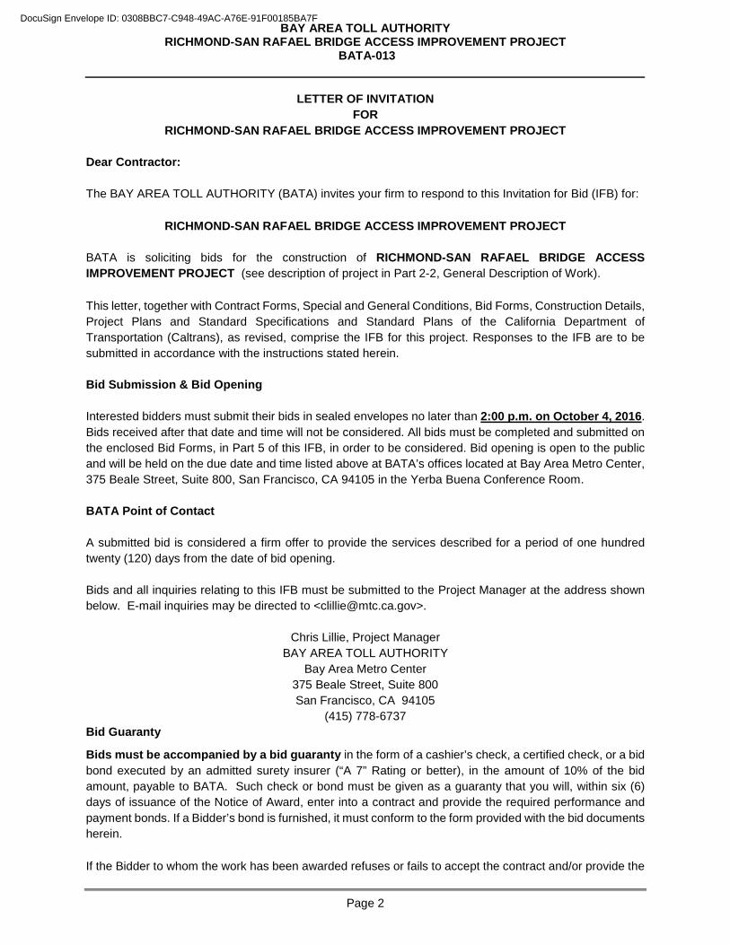
LETTER OF INVITATION FOR
RICHMOND-SAN RAFAEL BRIDGE ACCESS IMPROVEMENT PROJECT
Dear Contractor:
The BAY AREA TOLL AUTHORITY (BATA) invites your firm to respond to this Invitation for Bid (IFB) for:
RICHMOND-SAN RAFAEL BRIDGE ACCESS IMPROVEMENT PROJECT
BATA is soliciting bids for the construction of RICHMOND-SAN RAFAEL BRIDGE ACCESS IMPROVEMENT PROJECT (see description of project in Part 2-2, General Description of Work).
This letter, together with Contract Forms, Special and General Conditions, Bid Forms, Construction Details, Project Plans and Standard Specifications and Standard Plans of the California Department of Transportation (Caltrans), as revised, comprise the IFB for this project. Responses to the IFB are to be submitted in accordance with the instructions stated herein.
Bid Submission & Bid Opening
Interested bidders must submit their bids in sealed envelopes no later than 2:00 p.m. on October 4, 2016. Bids received after that date and time will not be considered. All bids must be completed and submitted on the enclosed Bid Forms, in Part 5 of this IFB, in order to be considered. Bid opening is open to the public and will be held on the due date and time listed above at BATA’s offices located at Bay Area Metro Center, 375 Beale Street, Suite 800, San Francisco, CA 94105 in the Yerba Buena Conference Room.
BATA Point of Contact
A submitted bid is considered a firm offer to provide the services described for a period of one hundred twenty (120) days from the date of bid opening.
Bids and all inquiries relating to this IFB must be submitted to the Project Manager at the address shown below. E-mail inquiries may be directed to <[email protected]>.
Chris Lillie, Project Manager BAY AREA TOLL AUTHORITY
Bay Area Metro Center 375 Beale Street, Suite 800 San Francisco, CA 94105
(415) 778-6737Bid Guaranty
Bids must be accompanied by a bid guaranty in the form of a cashier’s check, a certified check, or a bid bond executed by an admitted surety insurer (“A 7” Rating or better), in the amount of 10% of the bid amount, payable to BATA. Such check or bond must be given as a guaranty that you will, within six (6) days of issuance of the Notice of Award, enter into a contract and provide the required performance and payment bonds. If a Bidder’s bond is furnished, it must conform to the form provided with the bid documents herein.
If the Bidder to whom the work has been awarded refuses or fails to accept the contract and/or provide the
DocuSign Envelope ID: 0308BBC7-C948-49AC-A76E-91F00185BA7F
BAY AREA TOLL AUTHORITY RICHMOND-SAN RAFAEL BRIDGE ACCESS IMPROVEMENT PROJECT
BATA-013
Page 3
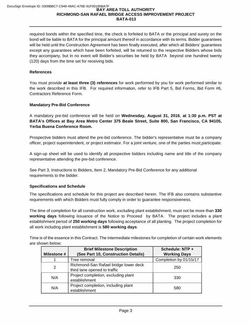
required bonds within the specified time, the check is forfeited to BATA or the principal and surety on the bond will be liable to BATA for the principal amount thereof in accordance with its terms. Bidder guarantees will be held until the Construction Agreement has been finally executed, after which all Bidders’ guarantees except any guarantees which have been forfeited, will be returned to the respective Bidders whose bids they accompany, but in no event will Bidder’s securities be held by BATA beyond one hundred twenty (120) days from the time set for receiving bids. References You must provide at least three (3) references for work performed by you for work performed similar to the work described in this IFB. For required information, refer to IFB Part 5, Bid Forms, Bid Form #6, Contractors Reference Form.
Mandatory Pre-Bid Conference A mandatory pre-bid conference will be held on Wednesday, August 31, 2016, at 1:30 p.m. PST at BATA’s Offices at Bay Area Metro Center 375 Beale Street, Suite 800, San Francisco, CA 94105, Yerba Buena Conference Room. Prospective bidders must attend the pre-bid conference. The bidder's representative must be a company officer, project superintendent, or project estimator. For a joint venture, one of the parties must participate.
A sign-up sheet will be used to identify all prospective bidders including name and title of the company representative attending the pre-bid conference. See Part 3, Instructions to Bidders, Item 2, Mandatory Pre-Bid Conference for any additional requirements to the bidder. Specifications and Schedule
The specifications and schedule for this project are described herein. The IFB also contains substantive requirements with which Bidders must fully comply in order to guarantee responsiveness.
The time of completion for all construction work, excluding plant establishment, must not be more than 330 working days following issuance of the Notice to Proceed by BATA. The project includes a plant establishment period of 250 working days following acceptance of all planting. The project completion for all work including plant establishment is 580 working days. Time is of the essence in this Contract. The intermediate milestones for completion of certain work elements are shown below:
Milestone # Brief Milestone Description
(See Part 10, Construction Details) Schedule: NTP +
Working Days 1 Tree removal Completion by 01/15/17
2 Richmond-San Rafael bridge lower deck third lane opened to traffic 250
N/A Project completion, excluding plant establishment 330
N/A Project completion, including plant establishment 580
DocuSign Envelope ID: 0308BBC7-C948-49AC-A76E-91F00185BA7F

BAY AREA TOLL AUTHORITY RICHMOND-SAN RAFAEL BRIDGE ACCESS IMPROVEMENT PROJECT
BATA-013
Page 4
Bid Evaluation
Bids will be initially evaluated for responsiveness and adherence to the IFB. Quality and customer service are of the highest importance. In order to ensure superior service, references will be checked, and bidders may be required to provide additional information verifying their experience.
Bidders may be eligible for a Small Business Enterprise (SBE) Bid Preference. The SBE Bid Preference price calculations are for evaluation purposes only. Applying the SBE Bid Preference does not change the Contractor’s actual bid or the amount of any subsequent contract award.
A contract, if awarded, will be to the responsible bidder submitting the lowest responsive bid, as indicated in the “Total Contract Price” space on the Bid Form #1, Schedule of Quantities and Prices.
Small Business Enterprise Bid Preference
In order to provide economic opportunity for the residents and businesses, and stimulate economic development in the San Francisco Bay Area, BATA has established a Construction Project SBE Program for its construction contracts to assist SBE firms in participating in BATA’s non-federally funded contracts.
Participating in the SBE Program is encouraged and is not a condition of award or indicator of responsiveness. However, it is the policy of BATA to provide the maximum opportunity for SBE firms to compete on its non-federally funded construction contracts over $25,000.
To apply for a SBE Bid Preference, you must complete Bid Form #8, Designation of Subcontractors in Compliance with BATA Construction Project SBE Program, in Part 5, Bid Forms, of this IFB. Refer to Part 7, General Conditions.
Performance, Labor & Materials Payment and Warranty Bonds
Prior to contract award, BATA will require a Performance and Labor & Materials Payment Bond, and Warranty Bond executed by an admitted surety insurer with a Best’s Rating of A- or better with a Financial Size Category of VII or better. Both the Performance and Payment bond will be in a sum not less than 100% of the Total Contract Price, as described in Part 6, SC 3.1 (Payment Bond) and SC 3.2 (Performance Bond). The Warranty Bond will be in a sum of 10% of the Total Contract Price as described in Part 6, SC 3.3 (Warranty Bond), of this IFB.
Bidder Selection Timetable*
Wednesday, August 31, 2016, 1:30 p.m. Mandatory Pre-Bid Conference
Friday, September 9, 2016, 4:00 p.m. Deadline for requests for clarification or exception
Tuesday, October 4, 2016, 2:00 p.m. Closing date & time for receipt of bids & bid opening
Wednesday, October 12, 2016 BATA Oversight Committee consideration of recommendation for award
Wednesday, October 12, 2016 (approx.) Issuance of Notice of Award
* Award and approval dates are approximates and are subject to change before or after the closing dateof the IFB.
DocuSign Envelope ID: 0308BBC7-C948-49AC-A76E-91F00185BA7F
BAY AREA TOLL AUTHORITY RICHMOND-SAN RAFAEL BRIDGE ACCESS IMPROVEMENT PROJECT
BATA-013
Page 5
Supplemental Information All information related to this IFB, including Contract Documents, Addenda (if any), Questions and Answers, As-Builts, Caltrans 2010 Standard Specifications, Updates, and other project related information will be posted on BATA’s website:
http://procurements.mtc.ca.gov/
Bidders are responsible for checking this website to insure Bidders know what documents are available.
General Conditions
BATA reserves the right to award a contract or to reject all bids.
A signed BATA Construction Agreement mailed or delivered to a particular bidder constitutes a binding contract, which incorporates this IFB and its addenda, if any, and all documents referenced herein, any deviations from the specifications expressly accepted by BATA, and all terms and conditions of the Construction Agreement.
This is a public works project subject to the requirements of the California Labor Code. Bidders and all its subcontractors must be registered with the Department of Industrial Relations pursuant to Labor Code section 1725.5 with limited exceptions from this requirement for bid purposes only under Labor Code section 1771.1(a) in order to be considered or awarded a contract.
This project is subject to compliance monitoring and enforcement by the Department of Industrial Relations.
Authority to Commit BATA
The Executive Director of BATA will recommend the successful bidder to the BATA, which will commit BATA to the expenditure of funds in connection with this IFB.
Thank you for your participation.
Sincerely,
Andrew B. Fremier Deputy Executive Director
J:\CONTRACT\Procurements\Engineer&Architect\BATA\RSRB Access Improvement\BATA-013_IFB_SPs_VOL-1_final.docx
DocuSign Envelope ID: 0308BBC7-C948-49AC-A76E-91F00185BA7F
BAY AREA TOLL AUTHORITY RICHMOND-SAN RAFAEL BRIDGE ACCESS IMPROVEMENT PROJECT
BATA-013
Page 6
PART 2. FORWARD
DocuSign Envelope ID: 0308BBC7-C948-49AC-A76E-91F00185BA7F
BAY AREA TOLL AUTHORITY RICHMOND-SAN RAFAEL BRIDGE ACCESS IMPROVEMENT PROJECT
BATA-013
Page 7
1. BAY AREA TOLL AUTHORITY There are seven state-owned toll bridges (Antioch, Benicia-Martinez, Carquinez, Richmond-San Rafael, Dumbarton, San Mateo Hayward and the San Francisco-Oakland Bay Bridge) that are owned and operated by the California Department of Transportation (Caltrans) in the San Francisco Bay Area. State-owned toll bridge operations and capital improvement projects are funded by toll revenues, which are administered by the Bay Area Toll Authority (BATA). 2. General Description of Work
The Bay Area Toll Authority (BATA) in cooperation with the California Department of Transportation (Caltrans) is improving the current multimodal access on Interstate 580 (I-580) within Marin and Contra Costa Counties, including the Richmond-San Rafael (RSR) Bridge. Proposed multimodal access improvements will accommodate bicycle and pedestrian access on the upper bridge deck (westbound), and a third lane on the lower deck (eastbound). Bicycle and pedestrian access on the upper deck of the RSR Bridge would be provided by installing a barrier to separate bicyclists and pedestrians from vehicles. The project consists of two major components that are interrelated:
• Element 1: A third eastbound lane between Marin County and Contra Costa County • Element 2: Bicycle/Pedestrian Path in Contra Costa County
The project includes Milestones #1 and #2 which reflects BATA’s prioritization of the work and has specific duration and liquidated damages associated with delivery (see SC-4 and SC-5 for details). Milestone #1 is completion of the tree removal. All tree removal must be completed by January 15, 2017. Stumps may be removed after January 15, 2017 as long as tree trunks are cut off no higher than 3 feet above the ground line. If you fail to remove all trees by January 15, 2017 and birds nest in the remaining trees, you will be responsible all project delays caused by the nesting birds. Milestone #2 is the opening of the Richmond-San Rafael Bridge third eastbound lane to traffic. The work includes but is not limited to the following:
• Construction of the utility culvert extension • Reconfiguration of E. Standard Avenue to two lanes per Stage 1 and Stage 2 as shown in SC-
sheets excluding the bike path • Completion of the Signal and Lighting at Locations, 1, 2 and 3 as shown in the E-sheets • Completion of the EB I-580 improvements per Stage 1 and Stage 2 as shown in SC-sheets • Completion of the necessary TOS and CMS elements for the EB lanes as shown on sheets • Open to traffic three 12-foot lanes from Sir Francis Drake on-ramp “MRN” Sta. 213+00 thru
Marine Street off-ramp “CC-M” Sta. 1046+00 , as shown on PD- and S- sheets • Third lane open to traffic and operational per Caltrans operating hours anticipated to be 3 pm to 8
pm on weekdays. The third lane must remain operational through the completion of the project with no interruptions to service.
DocuSign Envelope ID: 0308BBC7-C948-49AC-A76E-91F00185BA7F
BAY AREA TOLL AUTHORITY RICHMOND-SAN RAFAEL BRIDGE ACCESS IMPROVEMENT PROJECT
BATA-013
Page 8
3. Description of the Contracting Process
The procedure that will be followed during the period between BATA’s determination of the successful Bidder and its issuance of a Notice to Proceed consists of the steps listed and explained below:
1. Issuance of Notice of Award (NOA) 2. Signing of Construction Agreement by successful Bidder 3. Submittals of Performance Bond, Payment Bond, Warranty Bond and Insurance Certificate(s) 4. Execution of Contract by BATA 5. Issuance of Notice to Proceed
4. Notice of Award After Bids are opened at the time and place stipulated in Part 1, Bids will be reviewed by BATA. Bids are considered preliminary pending review and verification of applicable bid requirements such as licensing, bonding, qualifications, or other requirements as stated in the IFB. Eligibility for the SBE Bid Preference will also be evaluated and verified. The contract will be awarded to the lowest responsive and responsible Bidder subject to the approval of BATA. BATA reserves the right to award a contract or to reject any or all bids. No Bidder may withdraw its bid for the period of days stipulated in Part 3, Instructions to Bidders, Section 10, Withdrawal of Bid, after the date set for the Bid Opening. The Bid is subject to acceptance by BATA during this period. Promptly upon BATA’s approval of the award of the Contract, BATA will issue a Notice of Award letter to the successful Bidder. Included with the NOA will be two originals of Construction Agreement and one original of the following:
1. Performance Bond in the amount of 100% of the Total Contract Price, to guarantee faithful performance of the work under the Contract, including the replacing of or making acceptable, any defective materials or faulty workmanship.
2. Payment Bond in the amount of 100% of the of the Total Contract Price, to inure to the benefit of
persons performing labor or furnishing materials in connection with the work of the proposed contract. This bond must be maintained in full force and effect until all work under the contract is completed and accepted by BATA, and until all claims for materials and labor have been paid.
3. Warranty Bond in the amount of 10% of the Total Contract Price and must insure the faithful performance by you to insure the replacing of, or making acceptable, any defective materials or faulty workmanship for a period of two years.
Within sixth (6th) calendar days from the date of NOA, the successful Bidder must return executed copies of these documents. Within this same period, Bidder must furnish Certificates of Insurance as more fully described below.
The Performance Bond, Payment Bond and Warranty Bond must be issued by a surety company(ies) acceptable to BATA with a Best Guide Rating of A7 or better and authorized to execute such in the State of California.
Should any surety or sureties be deemed unsatisfactory at any time by BATA, notice will be given to you to that effect, and you must forthwith substitute a new surety or sureties satisfactory to BATA, at your expense.
DocuSign Envelope ID: 0308BBC7-C948-49AC-A76E-91F00185BA7F
BAY AREA TOLL AUTHORITY RICHMOND-SAN RAFAEL BRIDGE ACCESS IMPROVEMENT PROJECT
BATA-013
Page 9
All alterations, time extensions, extra work, additional work or any other changes authorized in the Contract, may be made without notice to, or securing the prior consent of, the surety or sureties on the Performance Payment or Warranty Bonds. Should the Bidder to whom the Contract is awarded fail to execute the Construction Agreement within the specified time frame, BATA may award the Contract to the second successful Bidder selected, per Part 3, Instructions to Bidders. 5. Certificates of Insurance You must furnish original certificates, within six (6) calendar days from NOA, showing evidence that the insurance coverages specified in the Special Conditions herein have been obtained and are in force. All certificates must provide that not less than sixty (60) calendar days written notice must be given to BATA and any additional insureds in the event of cancellation, non-renewal or material change in the policy. 6. Forfeiture of Bid Security Failure of the Bidder to whom the Notice of Award was issued to sign the Construction Agreement and submit all of the documents required within six (6) calendar days from NOA will be just cause for the annulment of the award and forfeiture of Bidder's security. 7. Return of Bid Security If the Bid is not accepted by BATA within one hundred twenty (120) days after the date set for Bid Opening, or if the Bidder to whom the Contract is awarded executes and delivers to BATA the required documents, then the Bidder’s Bond, cash, or the amount of the certified or cashier's check will be returned to all bidders. 8. Executed Contract After your delivery of two (2) signed original Construction Agreements and all required submissions as stipulated above, BATA will sign the Construction Agreement. No agreement between BATA and you are in effect until BATA executes the Construction Agreement. You may be required to use electronic signatures to execute the Construction Agreement. 9. Notice to Proceed BATA will issue a Notice to Proceed (NTP) promptly following execution of the Construction Agreement. Commence performance of work after receipt of the Notice to Proceed, and continuously and diligently prosecute the work to completion on or before the time or times set forth in Part 6, Special Conditions. Do not enter upon nor occupy State property or commence any materials fabrication prior to receiving the Notice to Proceed. Any work performed or expenses incurred by you prior to your receipt of Notice to Proceed are entirely at your risk.
DocuSign Envelope ID: 0308BBC7-C948-49AC-A76E-91F00185BA7F
BAY AREA TOLL AUTHORITY RICHMOND-SAN RAFAEL BRIDGE ACCESS IMPROVEMENT PROJECT
BATA-013
Page 10
PART 3. INSTRUCTIONS TO BIDDERS
DocuSign Envelope ID: 0308BBC7-C948-49AC-A76E-91F00185BA7F
BAY AREA TOLL AUTHORITY RICHMOND-SAN RAFAEL BRIDGE ACCESS IMPROVEMENT PROJECT
BATA-013
Page 11
1. Scope of Work
The scope of work includes, but is not limited to:
• Removal of existing concrete barriers, retaining wall, raised median • Construction of new curb, sidewalk, and curb ramps • Construction of pavement widening, retaining wall and temporary curb ramps • Construction of bike path • Construction of concrete barriers, raised median and placement of visual screen • Reconstruction of shoulder and gore area • Signal modifications • Upgrade of drainage systems • Paving, grinding, and striping • Installation of surface mounted channelizers and temporary crash cushion modules • Replacement/relocation of signs (including sign bridges) and MBGR • Replacement/relocation of lighting and utilities • Installation of new ITS/TOS field elements and relocation of existing elements (ramp meters,
CCTVs, CMSs) • Installation of traffic monitoring stations and fiber optic lines
2. Mandatory Pre-Bid Conference A mandatory pre-bid conference will be held at the time and place set out in Part 1, Invitation for Bid (IFB). The purpose of this meeting is to inform prospective Bidders and potential subcontractors of subcontracting and material supply opportunities and to receive comments and questions regarding the work and the Contract Documents from attendees. Each bidder must attend the mandatory prebid meeting. The bidder's representative must be a company officer, project superintendent, or project estimator. For a joint venture, one of the parties must attend the mandatory prebid meeting. BATA will not accept a bid from a bidder who did not attend the meeting. 3. Examination of the Contract Documents Each prospective Bidder must carefully examine the Contract Documents and become thoroughly familiar with the terms and conditions contained therein prior to the Bid Opening date. The bid submitted must include a sum to cover the cost of all items necessary to perform the work as set forth in the Contract Documents. No allowance of any kind will be made to you because of lack of such examination or knowledge. The submittal of a bid is conclusive evidence that you have made such an examination. 3.1 Definitions
“Definitions and Terms,” are included in 1-1.07 of the Standard Specifications and below. Whenever in the Standard Specifications, Standard Plans and these contract documents the following terms are used, unless the context otherwise requires, , the intent and meaning is interpreted as follows: 1st Tier Subcontractor: A subcontractor to a Prime Contractor.
DocuSign Envelope ID: 0308BBC7-C948-49AC-A76E-91F00185BA7F
BAY AREA TOLL AUTHORITY RICHMOND-SAN RAFAEL BRIDGE ACCESS IMPROVEMENT PROJECT
BATA-013
Page 12
Acceptance: The formal written acceptance by BATA of an entire contract that has been completed in all respects in accordance with the plans and specifications and any modifications thereof previously approved. Acts of God: “Acts of God” as defined in Public Contract Code § 7105. BATA: Bay Area Toll Authority. Bidder: Any individual, firm, partnership, corporation, or combination thereof, submitting a bid for the work contemplated, acting directly or through a duly authorized representative. With respect to the context prior to award of the contract, You may be used to mean Bidder. Caltrans: California Department of Transportation Commercially Useful Function (CUF): A SBE performs a commercially useful function when it is responsible for the execution of the work of the contract and is carrying out its responsibilities by actually performing, managing, and supervising the work involved. A SBE does not perform a CUF if it does not perform or exercise responsibility for at least 60 percent of the total cost of its contract than would be expected on the basis of normal industry practice for the type of work involved. If, in BATA’s judgment, the SBE does not perform a CUF in the transaction, no SBE Bid Preference will be granted. Conduit: A pipe or tube in which smaller pipes, tubes or electrical conductors are inserted or are to be inserted. Contract: The written agreement covering the performance of the work and the furnishing of labor, materials, tools and equipment in the construction of the work. The contract incorporates this IFB, and its addenda, if any, all documents referenced herein, any deviations from the specifications expressed and accepted by BATA, and includes the notice to Contractors, proposal, plans, special conditions, general conditions, applicable Caltrans Standard plans and Specifications including revisions and updates, and contract bonds; also any and all supplemental agreements amending or extending the work contemplated and which may be required to complete the work in a substantial and acceptable manner. Supplemental Agreements are written agreements covering alterations, amendments or extensions to the contract and include contract change orders. Contract Documents: Contract Documents consist of the documents referenced above under the “Contract” definition. Contractor: The person or persons, firm, partnership, corporation, or combination thereof, private or municipal, who have entered into a contract with the BAY AREA TOLL AUTHORITY. Used interchangeably with “You” and “you”. Department: California Department of Transportation, unless with respect to the Contract Drawings, Standard Plans, Special Provisions and Standard Specifications the context requires that Department mean BAY AREA TOLL AUTHORITY (BATA). Day: 24 consecutive hours running from midnight to midnight; calendar day
Business Day: Day on the calendar except Saturday, Sunday or legal holidays Calendar Days: A calendar day is any day including all legal holidays, Saturday and Sunday. Working Day: Time measure unit as defined by the State of California Department of Transportation Standard Specifications, Section 1.
DocuSign Envelope ID: 0308BBC7-C948-49AC-A76E-91F00185BA7F
BAY AREA TOLL AUTHORITY RICHMOND-SAN RAFAEL BRIDGE ACCESS IMPROVEMENT PROJECT
BATA-013
Page 13
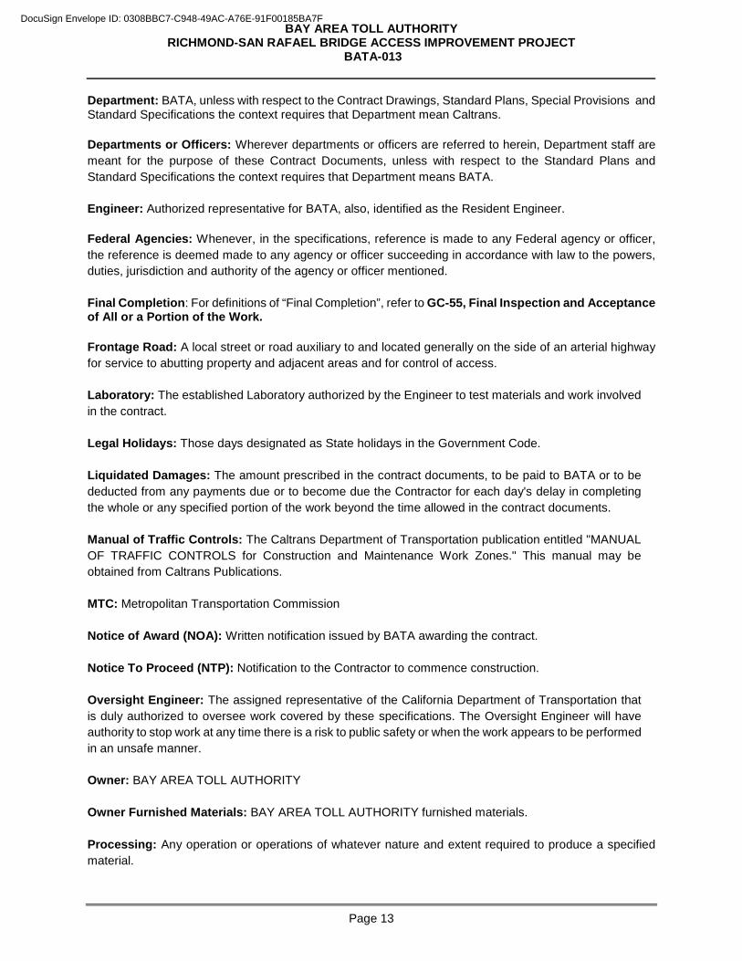
Department: BATA, unless with respect to the Contract Drawings, Standard Plans, Special Provisions and Standard Specifications the context requires that Department mean Caltrans. Departments or Officers: Wherever departments or officers are referred to herein, Department staff are meant for the purpose of these Contract Documents, unless with respect to the Standard Plans and Standard Specifications the context requires that Department means BATA. Engineer: Authorized representative for BATA, also, identified as the Resident Engineer. Federal Agencies: Whenever, in the specifications, reference is made to any Federal agency or officer, the reference is deemed made to any agency or officer succeeding in accordance with law to the powers, duties, jurisdiction and authority of the agency or officer mentioned. Final Completion: For definitions of “Final Completion”, refer to GC-55, Final Inspection and Acceptance of All or a Portion of the Work. Frontage Road: A local street or road auxiliary to and located generally on the side of an arterial highway for service to abutting property and adjacent areas and for control of access. Laboratory: The established Laboratory authorized by the Engineer to test materials and work involved in the contract. Legal Holidays: Those days designated as State holidays in the Government Code. Liquidated Damages: The amount prescribed in the contract documents, to be paid to BATA or to be deducted from any payments due or to become due the Contractor for each day's delay in completing the whole or any specified portion of the work beyond the time allowed in the contract documents. Manual of Traffic Controls: The Caltrans Department of Transportation publication entitled "MANUAL OF TRAFFIC CONTROLS for Construction and Maintenance Work Zones." This manual may be obtained from Caltrans Publications. MTC: Metropolitan Transportation Commission Notice of Award (NOA): Written notification issued by BATA awarding the contract. Notice To Proceed (NTP): Notification to the Contractor to commence construction. Oversight Engineer: The assigned representative of the California Department of Transportation that is duly authorized to oversee work covered by these specifications. The Oversight Engineer will have authority to stop work at any time there is a risk to public safety or when the work appears to be performed in an unsafe manner. Owner: BAY AREA TOLL AUTHORITY Owner Furnished Materials: BAY AREA TOLL AUTHORITY furnished materials. Processing: Any operation or operations of whatever nature and extent required to produce a specified material.
DocuSign Envelope ID: 0308BBC7-C948-49AC-A76E-91F00185BA7F
BAY AREA TOLL AUTHORITY RICHMOND-SAN RAFAEL BRIDGE ACCESS IMPROVEMENT PROJECT
BATA-013
Page 14
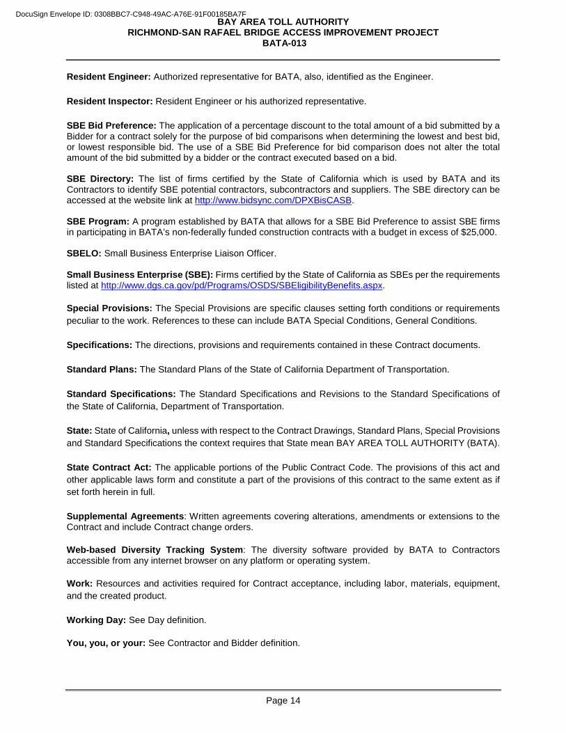
Resident Engineer: Authorized representative for BATA, also, identified as the Engineer. Resident Inspector: Resident Engineer or his authorized representative. SBE Bid Preference: The application of a percentage discount to the total amount of a bid submitted by a Bidder for a contract solely for the purpose of bid comparisons when determining the lowest and best bid, or lowest responsible bid. The use of a SBE Bid Preference for bid comparison does not alter the total amount of the bid submitted by a bidder or the contract executed based on a bid. SBE Directory: The list of firms certified by the State of California which is used by BATA and its Contractors to identify SBE potential contractors, subcontractors and suppliers. The SBE directory can be accessed at the website link at http://www.bidsync.com/DPXBisCASB. SBE Program: A program established by BATA that allows for a SBE Bid Preference to assist SBE firms in participating in BATA’s non-federally funded construction contracts with a budget in excess of $25,000. SBELO: Small Business Enterprise Liaison Officer. Small Business Enterprise (SBE): Firms certified by the State of California as SBEs per the requirements listed at http://www.dgs.ca.gov/pd/Programs/OSDS/SBEligibilityBenefits.aspx. Special Provisions: The Special Provisions are specific clauses setting forth conditions or requirements peculiar to the work. References to these can include BATA Special Conditions, General Conditions. Specifications: The directions, provisions and requirements contained in these Contract documents. Standard Plans: The Standard Plans of the State of California Department of Transportation. Standard Specifications: The Standard Specifications and Revisions to the Standard Specifications of the State of California, Department of Transportation. State: State of California, unless with respect to the Contract Drawings, Standard Plans, Special Provisions and Standard Specifications the context requires that State mean BAY AREA TOLL AUTHORITY (BATA). State Contract Act: The applicable portions of the Public Contract Code. The provisions of this act and other applicable laws form and constitute a part of the provisions of this contract to the same extent as if set forth herein in full. Supplemental Agreements: Written agreements covering alterations, amendments or extensions to the Contract and include Contract change orders. Web-based Diversity Tracking System: The diversity software provided by BATA to Contractors accessible from any internet browser on any platform or operating system. Work: Resources and activities required for Contract acceptance, including labor, materials, equipment, and the created product. Working Day: See Day definition. You, you, or your: See Contractor and Bidder definition.
DocuSign Envelope ID: 0308BBC7-C948-49AC-A76E-91F00185BA7F
BAY AREA TOLL AUTHORITY RICHMOND-SAN RAFAEL BRIDGE ACCESS IMPROVEMENT PROJECT
BATA-013
Page 15
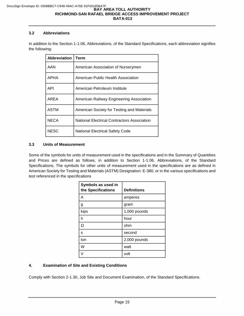
3.2 Abbreviations In addition to the Section 1-1.06, Abbreviations, of the Standard Specifications, each abbreviation signifies the following:
Abbreviation Term
AAN American Association of Nurserymen
APHA American Public Health Association
API American Petroleum Institute
AREA American Railway Engineering Association
ASTM American Society for Testing and Materials
NECA National Electrical Contractors Association
NESC National Electrical Safety Code
3.3 Units of Measurement Some of the symbols for units of measurement used in the specifications and in the Summary of Quantities and Prices are defined as follows, in addition to Section 1-1.06, Abbreviations, of the Standard Specifications. The symbols for other units of measurement used in the specifications are as defined in American Society for Testing and Materials (ASTM) Designation: E-380, or in the various specifications and test referenced in the specifications
Symbols as used in the Specifications
Definitions
A amperes
g gram
kips 1,000 pounds
h hour
Ω ohm
s second
ton 2,000 pounds
W watt
V volt 4. Examination of Site and Existing Conditions Comply with Section 2-1.30, Job Site and Document Examination, of the Standard Specifications.
DocuSign Envelope ID: 0308BBC7-C948-49AC-A76E-91F00185BA7F
BAY AREA TOLL AUTHORITY RICHMOND-SAN RAFAEL BRIDGE ACCESS IMPROVEMENT PROJECT
BATA-013
Page 16
Prospective bidders must make arrangements to visit the project sites by contacting the BATA Project Manager. 5. Addenda to Contract Documents BATA reserves the right to make changes in the Contract Documents as it may deem appropriate up to the time set for opening of bids. Any and all changes in the Contract Documents will be made by written Addendum, which is issued by BATA at http://www.procurements.mtc.ca.gov. All potential bidders are responsible for checking the BATA website for any addenda to the bid document. If such Addenda require changes in quantities or might affect the prices bid, or both, the date set for opening of bids may be postponed by such number of days as BATA deems sufficient to enable Bidders to revise their bids. Failure to acknowledge receipt of all Addenda may cause the bid to be considered non-responsive to the Contract Documents. You certify that the Contract Documents and Addenda thereto have been thoroughly read and that there are no misunderstandings as to the meaning, purpose or intent of any provision in the Contract Documents as modified by those Addenda. 6. Prevailing Wage Rates You and all your subcontractors will comply with applicable sections of the California Labor Code and regulations promulgated thereunder (including without limitation, Sections 1720 et seq. and Title 8 of the California Code of Regulations Sections 16000 et seq.) governing the payment of prevailing wages, as determined by the Director of the California Department of Industrial Relations, in regards to all work performed under this Contract. In particular, your attention is drawn to Labor Code Sections 1771 (payment of prevailing wage rate), 1775 (penalty for non-payment), 1776 (payroll records), and 1777.5 (use of apprentices). Appendix C, Wage Determinations, is attached hereto and incorporated herein by this reference. You and all your subcontractors, to the extent the work of such subcontractors under this Contract is subject to California Labor Code Section 1720 et seq. will be registered with the Department of Industrial Relations pursuant to Labor Code section 1725.5 and will furnish electronic certified payroll records directly to the Labor Commissioner through the internet portal of the Division of Labor Standards Enforcement. BATA reserves the right to require you and all your subcontractors to furnish electronic certified payroll records directly to BATA via a web-based system in addition to the reporting requirement stated above. BATA will provide a web-based system to verify that prevailing wage requirements are met. This system is web-based, accessible from any computer via the internet. You and your subcontractors will receive an email providing log on identification, and a temporary password and instructions on how to use the system. Training will also be provided upon request. 7. Preparation and Submittal of Bid Prepare your bid in strict accordance with all of the requirements of the Contract Documents and any addenda thereto. In order to receive consideration, all bids must comply with the following instructions:
DocuSign Envelope ID: 0308BBC7-C948-49AC-A76E-91F00185BA7F
BAY AREA TOLL AUTHORITY RICHMOND-SAN RAFAEL BRIDGE ACCESS IMPROVEMENT PROJECT
BATA-013
Page 17
7.1 Bids must be submitted on the forms provided in these Contract Documents in signed original. Bids submitted in any other form may be considered non-responsive and rejected. 7.2 Blank spaces in each bid form must be properly filled in, and the phraseology thereof must not be changed. Any conditions or limitations made to the items mentioned therein may be cause for rejection. Alterations by erasure or interlineation must be explained or noted in the bid over the signature of the Bidder. 7.3 No telegraphic or FAX bid or telegraphic or FAX modification of a bid will be considered. No bids received after the time fixed for receiving them will be considered. Late bids will be returned to the Bidder unopened. 7.4 All bids must be enclosed in a sealed envelope bearing the Contract Number, the title of the project, the date and hour of the opening, and the name of the Bidder. Bids must be addressed to the Project Manager, BAY AREA TOLL AUTHORITY, and delivered to the BATA Office at Bay Area Metro Center 375 Beale Street, Suite 800, San Francisco, CA 94105 no later than the time scheduled for Bid Opening. It is the sole responsibility of the Bidder to see that its bid is received in a timely manner. 7.5 Bids must include full compensation for furnishing all labor, material, tools, and equipment and doing all the work complete in place in accordance with the requirements of the Contract. Bid prices must include all applicable surcharges and fees such as taxes, insurance and fringe benefits, indirect costs, overhead (field and office), profit, subcontractors’ costs, travel, freight charges and other applicable surcharges and fees of any kind. 7.6 The quantities given in the Schedule of Quantities and Prices of the contract bid form for which unit prices are asked to be bid are approximate only, being given as a basis for the comparison of bids, and BATA does not, expressly or by implication, represent that the actual quantities required will correspond therewith, but reserves the right to increase or decrease the quantity of any class or portion of the work, or to omit portions of the work, as BATA may deem necessary or advisable. 7.7 You must show the Contract number and title on your bid and on all correspondence:
Contract No.: BATA-013 Contract Title: Richmond-San Rafael Bridge Access Improvement Project
DocuSign Envelope ID: 0308BBC7-C948-49AC-A76E-91F00185BA7F
BAY AREA TOLL AUTHORITY RICHMOND-SAN RAFAEL BRIDGE ACCESS IMPROVEMENT PROJECT
BATA-013
Page 18
7.8 Wherever in this Bid an amount is stated in both words and figures, in case of discrepancy between words and figures the words prevail. If all or any portion of the Bid is required to be given in unit prices and totals and a discrepancy exists between any such unit prices and totals so given, the unit prices prevail. If the Bid contains an arithmetic error in the computation of unit price extensions or in the summation of Bid item totals, BATA will correct and revise the Total Contract Bid for Comparison accordingly. BATA will not make any changes on the total shown for “lump sum” items. 8. Bid Security Each bid must be accompanied by a certified or cashier’s check, cash, or a Bidder's bond in the sum of not less than 10% of the Total Contract Price. Any said checks must be made payable to the order of the BAY AREA TOLL AUTHORITY. In case the successful Bidder fails to file satisfactory bonds or provide the insurance required by the Contract Documents, or refuses to enter into a Contract within the specified time, it forfeits its bid security. If the bid is not accepted by BATA within one hundred twenty (120) calendar days after the date set for the opening of bids, or if the Bidder to whom the contract is awarded executes and delivers to BATA the required Contract Forms, then the amount of the cash or the certified or cashier's check will be returned to the Bidder. 9. Opening of Bids Bids will be opened and publicly read aloud, including each Bid’s Total Contract Price and SBE Bid Preference, if applicable, by BATA at the time and place stated in Part 1, Invitation to Bid. Bidders are invited (but not required) to be present. 10. Withdrawal of Bid Any Bidder may withdraw its bid, either personally or by a written request by a duly authorized representative, at any time prior to the scheduled time for opening of bids. However, no Bidder may withdraw its bid for a period of one hundred twenty (120) calendar days after the Bid Opening. Bidder's attention is directed to the provisions of the Public Contract Code Sections 5100 to 5107 regarding relief of bidders. 11. Conditional Bids Conditional bids, or those which take exception to the Contract Documents, will be considered non-responsive and will be rejected. 12. Single Bid Response If only one bid is received in response to the Invitation to Bid, a detailed cost proposal may be required of the single Bidder. A cost/price analysis and evaluation and/or audit will be performed of the cost proposal in order to determine if the price is fair and reasonable.
DocuSign Envelope ID: 0308BBC7-C948-49AC-A76E-91F00185BA7F
BAY AREA TOLL AUTHORITY RICHMOND-SAN RAFAEL BRIDGE ACCESS IMPROVEMENT PROJECT
BATA-013
Page 19
13. Award or Rejection of Bids The award of the contract to the successful Bidder will be made within one hundred twenty (120) calendar days after the opening of bids. If the first Bidder selected as a successful Bidder refuses or fails to execute the contract, BATA may award the contract to the second successful Bidder selected as provided herein and such an award, if made, will be made within one hundred twenty (120) calendar days after the opening of the bid proposals. If the second successful Bidder refuses or fails to execute the contract, BATA may award the contract to the third successful Bidder selected as above provided and such an award, if made, will be made within one hundred twenty (120) calendar days after opening of the bid proposals. The periods of time specified above within which the award of contract may be made is subject to an extension for such further period as may be agreed upon in writing between BATA and the Bidder concerned. BATA reserves the right to reject any or all bids and to waive any informality in the bids or in the bid process. Cases of bid unbalancing may be cause for rejection. For purposes of this paragraph, an “unbalanced Bid” is one having nominal prices for some Bid items and inflated prices for other Bid items. BATA reserves the right to reject any and all bids and not award a Contract to a Bidder that does not meet the requirement of the Department of Industrial Relations pursuant to Labor Code section 1725.5. Refer to Part 1, Invitation for Bid, General Conditions, of this IFB. BATA is in the process of obtaining an Encroachment Permit from Caltrans. If after receipt of the bids for the project, an Encroachment Permit has not been obtained, BATA reserves the right to reject all bids and re-advertise the project or extend the award period as agreed in writing between BATA and the Bidder(s). 14. Basis of Award The criteria for determining the successful Bidder will include the Bidder’s responsiveness to the requirements of the Contract Documents, Bidder’s responsibility and price, inclusive of SBE Bid Preference, if applicable. Any Bidder may be required to furnish evidence satisfactory to BATA that it and its proposed subcontractors have sufficient means and experience in the type of work called for in the Contract Documents to assure completion of the Contract in a satisfactory manner. Award, if made, will be to the lowest responsible and responsive Bidder, based on the Total Contract Price. 15. Protest Procedures The following procedures must be used by Bidders seeking review of the Contract Documents or the Contract process: 15.1 General Bidder protests must be addressed to the BAY AREA TOLL AUTHORITY, Attention: Chris Lillie, Project Manager and clearly marked “Bid Protest” on the outside of the envelope. 15.2 Protest of Specifications Prospective bidders may submit written protest of items in the Contract Documents on the grounds that the specifications are biased, unduly restrictive, discourage competition, or do not comply with state or local law or regulation no later than seven (7) calendar days prior to the date bids are due. Such protests will be
DocuSign Envelope ID: 0308BBC7-C948-49AC-A76E-91F00185BA7F
BAY AREA TOLL AUTHORITY RICHMOND-SAN RAFAEL BRIDGE ACCESS IMPROVEMENT PROJECT
BATA-013
Page 20
reviewed by BATA and responded to prior to bid opening. If appropriate, the time of bid opening will be extended to accommodate any changes in the IFB. 15.3 Selection Disputes You may protest the selection of a Contractor on the grounds that BATA procedures, or applicable provisions of state or local law, have been violated or inaccurately and/or inappropriately applied by BATA by submitting to the Project Manager a written explanation of the basis for protest no later than 4:00 p.m. on the third business day after the date BATA Oversight Committee approves the award or the date the bidder is notified that it was not selected, whichever is later, for objection to Contractor selection. Protests of recommended awards must clearly and specifically describe the basis for the protest in sufficient detail for the BATA review officer to recommend a resolution to the BATA Executive Director. The BATA Executive Director will respond to the protest in writing, based on the recommendation of a staff review officer. Should the protesting proposer wish to appeal the decision of the Executive Director, it may file a written appeal with the BATA Oversight Committee, no later than 4:00 p.m. on the third business day after receipt of the written response from the Executive Director. The BATA Oversight Committee’s decision will be the final agency decision. Authorization to award a contract to a particular Contractor by the BATA Oversight Committee is deemed conditional until the expiration of the protest period or, if a protest is filed, the issuance of a written response to the protest by the Executive Director or if the decision of the Executive Director is appealed, the issuance of the BATA Oversight Committee’s decision. 16. Public Records This IFB and any material submitted by a bidder in response to this IFB are subject to public inspection under the California Public Records Act (Government Code Section 6250 et seq.), unless exempt by law. 17. Small Business Enterprise (SBE) Bid Preference SBE Bid Preference will be granted on this IFB. To apply for a SBE Bid Preference, you must complete Bid Form #9, Designation of Subcontractors in Compliance with BATA Construction Project SBE Program, in Part 5, Bid Forms, of this IFB. Refer to Part 7, General Conditions, for details.
DocuSign Envelope ID: 0308BBC7-C948-49AC-A76E-91F00185BA7F
BAY AREA TOLL AUTHORITY RICHMOND-SAN RAFAEL BRIDGE ACCESS IMPROVEMENT PROJECT
BATA-013
Page 21
PART 4. CONTRACT FORMS 1. Construction Agreement *
2. Performance Bond *
3. Payment Bond *
4. Warranty Bond*
5. Alternate IRS Form W-9
* Form must be acknowledged by a Notary
Return ALL Contract Forms To: Chris Lillie, Project Manager
Bay Area Metro Center 375 Beale Street, Suite 800 San Francisco, CA 94105
Direct Phone: (415) 778-6737 Main Phone: (415) 778-6700
PLEASE NOTE: It is not necessary to complete these forms to bid on this project. But the Bidder who is awarded the Contract will be required to execute all Contract Forms.
DocuSign Envelope ID: 0308BBC7-C948-49AC-A76E-91F00185BA7F
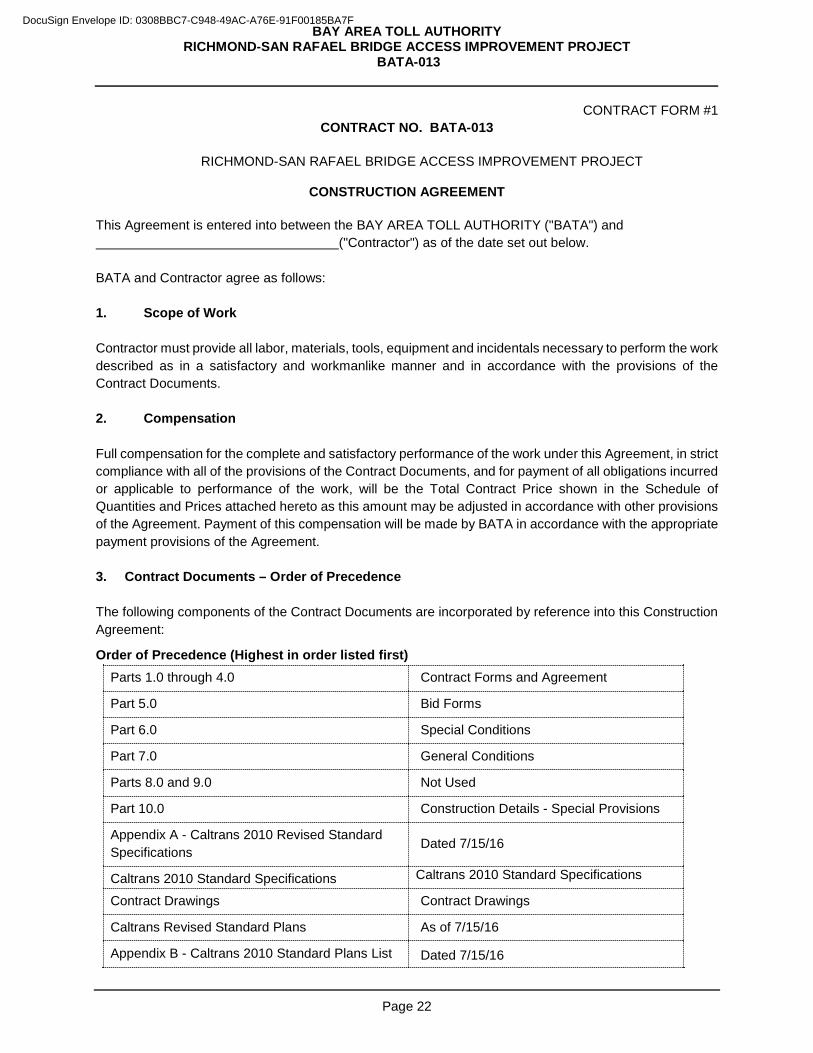
BAY AREA TOLL AUTHORITY RICHMOND-SAN RAFAEL BRIDGE ACCESS IMPROVEMENT PROJECT
BATA-013
Page 22
CONTRACT FORM #1 CONTRACT NO. BATA-013
RICHMOND-SAN RAFAEL BRIDGE ACCESS IMPROVEMENT PROJECT
CONSTRUCTION AGREEMENT
This Agreement is entered into between the BAY AREA TOLL AUTHORITY ("BATA") and ("Contractor") as of the date set out below. BATA and Contractor agree as follows: 1. Scope of Work Contractor must provide all labor, materials, tools, equipment and incidentals necessary to perform the work described as in a satisfactory and workmanlike manner and in accordance with the provisions of the Contract Documents. 2. Compensation Full compensation for the complete and satisfactory performance of the work under this Agreement, in strict compliance with all of the provisions of the Contract Documents, and for payment of all obligations incurred or applicable to performance of the work, will be the Total Contract Price shown in the Schedule of Quantities and Prices attached hereto as this amount may be adjusted in accordance with other provisions of the Agreement. Payment of this compensation will be made by BATA in accordance with the appropriate payment provisions of the Agreement. 3. Contract Documents – Order of Precedence The following components of the Contract Documents are incorporated by reference into this Construction Agreement:
Order of Precedence (Highest in order listed first) Parts 1.0 through 4.0 Contract Forms and Agreement
Part 5.0 Bid Forms
Part 6.0 Special Conditions
Part 7.0 General Conditions
Parts 8.0 and 9.0 Not Used
Part 10.0 Construction Details - Special Provisions
Appendix A - Caltrans 2010 Revised Standard Specifications
Dated 7/15/16
Caltrans 2010 Standard Specifications Caltrans 2010 Standard Specifications
Contract Drawings Contract Drawings
Caltrans Revised Standard Plans As of 7/15/16
Appendix B - Caltrans 2010 Standard Plans List Dated 7/15/16
DocuSign Envelope ID: 0308BBC7-C948-49AC-A76E-91F00185BA7F
BAY AREA TOLL AUTHORITY RICHMOND-SAN RAFAEL BRIDGE ACCESS IMPROVEMENT PROJECT
BATA-013
Page 23
These documents are essential parts of the agreement between the parties and are intended to be complementary and to describe and provide for a complete work. In the event of any discrepancy between any drawing and the dimensions written thereon, the dimensions will be taken as correct. Detail drawings prevail over general drawings. In the event of any other conflict among the documents, precedence is given in the order listed above. 4. Quality of Work
Where the plans or specifications describe portions of the work in general terms, but not in complete detail, it is understood that only the best general practice is to prevail and that only materials and workmanship of the first quality are to be provided. 5. Time of Performance Commence work under the Agreement immediately upon issuance by BATA of a Notice to Proceed and complete all of the work under the Agreement by the dates specified in Part 6.0, Special Conditions. The issuance of a Notice to Proceed is contingent upon your submittal of all contract documents as specified in Part 4, Contract Forms and insurance certificates. 6. Entire Agreement This Agreement constitutes the entire agreement between BATA and Contractor respecting the subject matter hereof. All other agreements, understandings and communications between the parties hereto are deemed to be merged into and superseded by the provisions of this Agreement. No modification or change to this Agreement will have any force or effect unless it is in writing and expressly referred to as being a Change Order to this Agreement. 7. Responsible Conduct Contractor must, at all times, deal in good faith and truthfully with BATA. Contractor must submit documentation to BATA, including reports, claims, requests for change orders, equitable adjustment, contract modifications or requests of any kind seeking increased compensation or decreases of an obligation on this contract only in good faith and upon an honest evaluation of the underlying circumstances and an honest calculation of any amount being sought. A violation of this standard of conduct will subject the Contractor to being deemed “non-responsible” and potentially ineligible for future contracts with BATA.
DocuSign Envelope ID: 0308BBC7-C948-49AC-A76E-91F00185BA7F
BAY AREA TOLL AUTHORITY RICHMOND-SAN RAFAEL BRIDGE ACCESS IMPROVEMENT PROJECT
BATA-013
Page 24
IN WITNESS WHEREOF two identical counterparts of this instrument, each of which will for all purposes be deemed an original thereof, have been duly executed by BATA and Contractor respectively, on the dates set out below.
BAY AREA TOLL AUTHORITY CONTRACTOR
Steve Heminger, Executive Director Name, Title
Date
Date
Contractor’s License No.
Class/Expiration Date
DocuSign Envelope ID: 0308BBC7-C948-49AC-A76E-91F00185BA7F
BAY AREA TOLL AUTHORITY RICHMOND-SAN RAFAEL BRIDGE ACCESS IMPROVEMENT PROJECT
BATA-013
Page 25
CONTRACT FORM #2
PERFORMANCE BOND FOR PUBLIC WORKS KNOW ALL PEOPLE BY THESE PRESENTS: That WHEREAS, the BAY AREA TOLL AUTHORITY (“BATA”) has awarded to ("Principal") a contract described as:
CONTRACT NO. BATA-013 RICHMOND-SAN RAFAEL BRIDGE ACCESS IMPROVEMENT PROJECT
and all of the Contract Documents attached to or forming a part of said Agreement are hereby referred to and made a part hereof; and WHEREAS, said Principal is required under the terms of said contract to furnish a bond for the faithful performance of said contract, NOW THEREFORE, we, the Principal and as Surety, are held and firmly bound unto the BAY AREA TOLL AUTHORITY (hereinafter called "BATA"), in the penal sum of $ ___________________, lawful money of the United States, for the payment of which sum well and truly to be made, we bind ourselves, our heirs, executors, administrators and successors, jointly and severally, firmly by these presents. The condition of this obligation is such that if the above-bound Principal, its heirs, executors, administrators, successors or assigns, will in all things stand to and abide by, and well and truly keep and perform the covenants, conditions and agreements in the said contract and any alteration thereof made as therein provided, on their part, to be kept and performed at the time and in the manner therein specified, and in all respects according to their true intent and meaning, and indemnifies and save harmless BATA, its officers, agents, and employees, as therein stipulated, then this obligation becomes null and void; otherwise it will be and remain in full force and effect. And the said Surety for value received, hereby stipulates and agrees that no change, extension of time, alteration or addition to the terms of the contract or to the work to be performed thereunder will in any way affect its obligations on this bond, and it does hereby waive notice of any change, extension of time, alteration or additions to the terms of the contract. In the event suit is brought upon this bond by BATA and judgment is recovered, Surety will pay all costs incurred by BATA in such suit, including a reasonable attorney's fee to be fixed by the Court.
DocuSign Envelope ID: 0308BBC7-C948-49AC-A76E-91F00185BA7F
BAY AREA TOLL AUTHORITY RICHMOND-SAN RAFAEL BRIDGE ACCESS IMPROVEMENT PROJECT
BATA-013
Page 26
IN WITNESS WHEREOF this instrument has been duly executed by Principal and Surety on this ________ day of ___________________________, 2016. PRINCIPAL: SURETY: (Company) (Company) (Signature) (Signature) (Name – Please Print) (Name – Please print) (Title) (Title)
NOTE: Signatures of those executing for Surety must be acknowledged by a Notary. NOTE TO SURETY COMPANY: The following form of acknowledgement should be used. If any other form of acknowledgement is used, there must be submitted a certified copy of unrevoked resolution of authority for the attorney-in-fact.
SURETY COMPANY ATTORNEY-IN-FACT State of California ) County of ) On ________________________________________, before me, the undersigned, a Notary Public in and for the State, personally appeared __________________________________________________________, known to me to be the duly authorized Attorney-in-Fact of the corporate Surety named in the within instrument, known to me to be authorized to execute that instrument on behalf of said corporation, known to me to be the person whose name is subscribed to such instrument as the Attorney-in-Fact of said corporation, and acknowledged to me that he (she) subscribed the name of said corporation thereto as Surety, and his (her) own name as Attorney-in-Fact and that said corporation executed the same. WITNESS MY HAND AND OFFICIAL SEAL: (SEAL) Notary Public for the State of California Acknowledgement by Attorney-in-Fact must be attached. Corporate seals of Principal and Surety must be attached.
DocuSign Envelope ID: 0308BBC7-C948-49AC-A76E-91F00185BA7F
BAY AREA TOLL AUTHORITY RICHMOND-SAN RAFAEL BRIDGE ACCESS IMPROVEMENT PROJECT
BATA-013
Page 27
CONTRACT FORM #3
PAYMENT BOND FOR PUBLIC WORKS KNOW ALL PEOPLE BY THESE PRESENTS: That WHEREAS, the BAY AREA TOLL AUTHORITY (“BATA”) and ("Principal") have entered into a Construction Agreement for the furnishing of all materials, labor, services and transportation necessary, convenient and proper to the performance of
CONTRACT NO. BATA-013 RICHMOND-SAN RAFAEL BRIDGE ACCESS IMPROVEMENT PROJECT
and all of the Contract Documents attached to or forming a part of said Agreement are hereby referred to and made a part hereof; and WHEREAS, said Principal is required by Chapter 5 (commencing at Section 3225) and Chapter 7 (commencing at Section 3247), Title 15, Part 4, Division 3 of the California Civil Code to furnish a bond in connection with said contract; NOW THEREFORE, we, the Principal and as Surety, are held and firmly bound unto the BAY AREA TOLL AUTHORITY (hereinafter called “BATA”) in the penal sum of $ ___________________ in lawful money of the United States of America for the payment of which sum well and truly to be made, we bind ourselves, our heirs, executors, administrators, successors and assigns, jointly and severally, firmly by these presents. THE CONDITION OF THIS OBLIGATION IS SUCH that if said Principal or its subcontractors, heirs, executors, administrators, successors, or assigns, fails to pay any of the persons named in Section 3181 of the California Civil Code, amounts due under the Unemployment Insurance Code with respect to work or labor performed by any such claimant, or for any amounts required to be deducted, withheld and paid over to the Employment Development Department from the wages of employees of the Contractor and Subcontractors pursuant to Section 13020 of the Unemployment Insurance Code with respect to the work and labor, the Surety will pay for the same, in an amount not exceeding the sum hereinabove specified, and also, in case suit is brought upon this bond, a reasonable attorney's fee to be fixed by the court. This bond must inure to the benefit of any of the persons named in Section 3181 of the California Civil Code, so as to give a right of action to such persons or their assigns in any suit brought upon this bond. It is further stipulated and agreed that the Surety on this bond will not be exonerated or released from the obligation of this bond by any change, extension of time for performance, addition, alteration or modification in, to, or any contract, plans, or agreement pertaining or relating to any scheme or work of improvement hereinabove described or pertaining to or relating to the furnishing of labor, materials, or equipment therefore, nor by any change or modification of any terms of payment or extension of the time for any payment pertaining or relating to any scheme or work of improvement hereinabove described, nor by any rescission or attempted rescission of the contract, agreement or bond, nor by any conditions precedent or subsequent in the bond attempting to limit the right of recovery of claimants otherwise entitled to recover
DocuSign Envelope ID: 0308BBC7-C948-49AC-A76E-91F00185BA7F
BAY AREA TOLL AUTHORITY RICHMOND-SAN RAFAEL BRIDGE ACCESS IMPROVEMENT PROJECT
BATA-013
Page 28
under any such contract or agreement or under the bond, nor by any fraud practiced by any person other than the claimant seeking to recover on the bond and that this bond be construed most strongly against the Surety and in favor of all persons for whose benefit such bond is given, and under no circumstances will Surety be released from liability to those for whose benefit such bond has been given, by reason of any breach of contract between BATA and original Contractor or on the part of any oblige named in such bond, but the sole conditions of recovery will be that claimant is a person described in Section 3110 or 3112 of the California Civil Code, and has not been paid the full amount of its claim and that Surety does hereby waive notice of any such change, extension of time, addition, alteration or modification herein mentioned. IN WITNESS WHEREOF this instrument has been duly executed by Principal and Surety on this ________ day of ___________________________, 2016. PRINCIPAL: SURETY: (Company) (Company) (Signature) (Signature) (Name – Please Print) (Name – Please print) (Title) (Title) NOTE TO SURETY COMPANY: The following form of acknowledgement should be used. If any other form of acknowledgement is used, there must be submitted a certified copy of un-revoked resolution of authority for the attorney-in-fact.
SURETY COMPANY ATTORNEY-IN-FACT State of California ) County of ) On ________________________________________, before me, the undersigned, a Notary Public in and for the State, personally appeared__________________________________________________________, known to me to be the duly authorized Attorney-in-Fact of the corporate Surety named in the within instrument, known to me to be authorized to execute that instrument on behalf of said corporation, known to me to be the person whose name is subscribed to such instrument as the Attorney-in-Fact of said corporation, and acknowledged to me that he (she) subscribed the name of said corporation thereto as Surety, and his (her) own name as Attorney-in-Fact and that said corporation executed the same.
DocuSign Envelope ID: 0308BBC7-C948-49AC-A76E-91F00185BA7F
BAY AREA TOLL AUTHORITY RICHMOND-SAN RAFAEL BRIDGE ACCESS IMPROVEMENT PROJECT
BATA-013
Page 29
WITNESS MY HAND AND OFFICIAL SEAL: (SEAL) Notary Public for the State of California Acknowledgement by Attorney-in-Fact must be attached. Corporate seals of Principal and Surety must be attached.
DocuSign Envelope ID: 0308BBC7-C948-49AC-A76E-91F00185BA7F
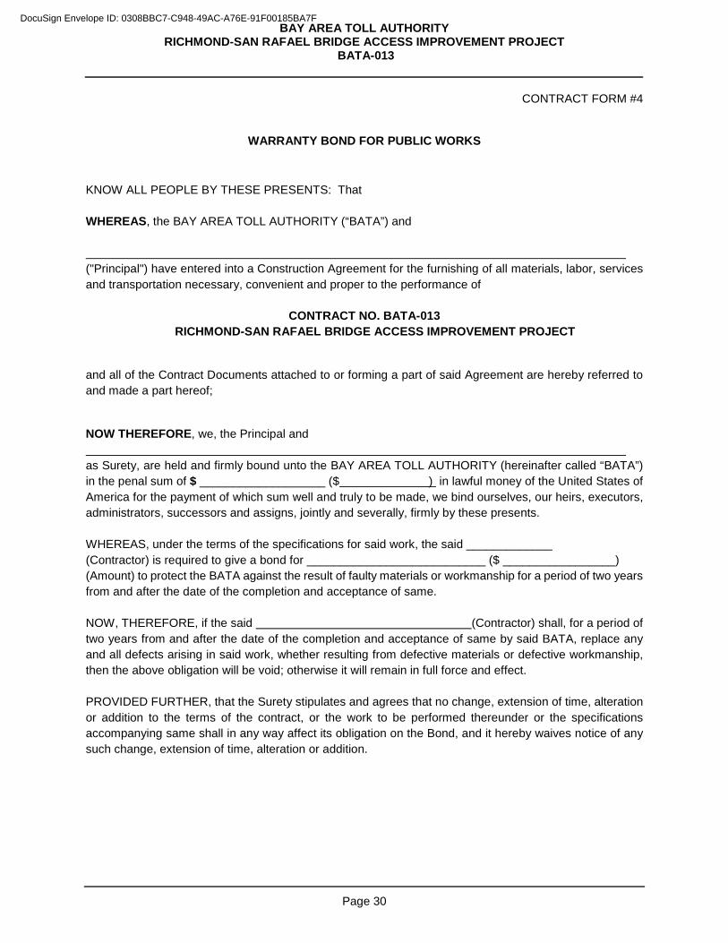
BAY AREA TOLL AUTHORITY RICHMOND-SAN RAFAEL BRIDGE ACCESS IMPROVEMENT PROJECT
BATA-013
Page 30
CONTRACT FORM #4
WARRANTY BOND FOR PUBLIC WORKS KNOW ALL PEOPLE BY THESE PRESENTS: That WHEREAS, the BAY AREA TOLL AUTHORITY (“BATA”) and ("Principal") have entered into a Construction Agreement for the furnishing of all materials, labor, services and transportation necessary, convenient and proper to the performance of
CONTRACT NO. BATA-013 RICHMOND-SAN RAFAEL BRIDGE ACCESS IMPROVEMENT PROJECT
and all of the Contract Documents attached to or forming a part of said Agreement are hereby referred to and made a part hereof;
NOW THEREFORE, we, the Principal and as Surety, are held and firmly bound unto the BAY AREA TOLL AUTHORITY (hereinafter called “BATA”) in the penal sum of $ ___________________ ($ ) in lawful money of the United States of America for the payment of which sum well and truly to be made, we bind ourselves, our heirs, executors, administrators, successors and assigns, jointly and severally, firmly by these presents. WHEREAS, under the terms of the specifications for said work, the said _____________ (Contractor) is required to give a bond for ___________________________ ($ _________________) (Amount) to protect the BATA against the result of faulty materials or workmanship for a period of two years from and after the date of the completion and acceptance of same. NOW, THEREFORE, if the said (Contractor) shall, for a period of two years from and after the date of the completion and acceptance of same by said BATA, replace any and all defects arising in said work, whether resulting from defective materials or defective workmanship, then the above obligation will be void; otherwise it will remain in full force and effect. PROVIDED FURTHER, that the Surety stipulates and agrees that no change, extension of time, alteration or addition to the terms of the contract, or the work to be performed thereunder or the specifications accompanying same shall in any way affect its obligation on the Bond, and it hereby waives notice of any such change, extension of time, alteration or addition.
DocuSign Envelope ID: 0308BBC7-C948-49AC-A76E-91F00185BA7F
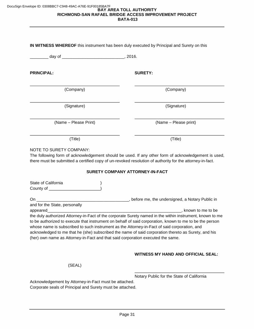
BAY AREA TOLL AUTHORITY RICHMOND-SAN RAFAEL BRIDGE ACCESS IMPROVEMENT PROJECT
BATA-013
Page 31
IN WITNESS WHEREOF this instrument has been duly executed by Principal and Surety on this ________ day of ___________________________, 2016. PRINCIPAL: SURETY: (Company) (Company) (Signature) (Signature) (Name – Please Print) (Name – Please print) (Title) (Title) NOTE TO SURETY COMPANY: The following form of acknowledgement should be used. If any other form of acknowledgement is used, there must be submitted a certified copy of un-revoked resolution of authority for the attorney-in-fact.
SURETY COMPANY ATTORNEY-IN-FACT State of California ) County of ) On ________________________________________, before me, the undersigned, a Notary Public in and for the State, personally appeared__________________________________________________________, known to me to be the duly authorized Attorney-in-Fact of the corporate Surety named in the within instrument, known to me to be authorized to execute that instrument on behalf of said corporation, known to me to be the person whose name is subscribed to such instrument as the Attorney-in-Fact of said corporation, and acknowledged to me that he (she) subscribed the name of said corporation thereto as Surety, and his (her) own name as Attorney-in-Fact and that said corporation executed the same. WITNESS MY HAND AND OFFICIAL SEAL: (SEAL) Notary Public for the State of California Acknowledgement by Attorney-in-Fact must be attached. Corporate seals of Principal and Surety must be attached.
DocuSign Envelope ID: 0308BBC7-C948-49AC-A76E-91F00185BA7F
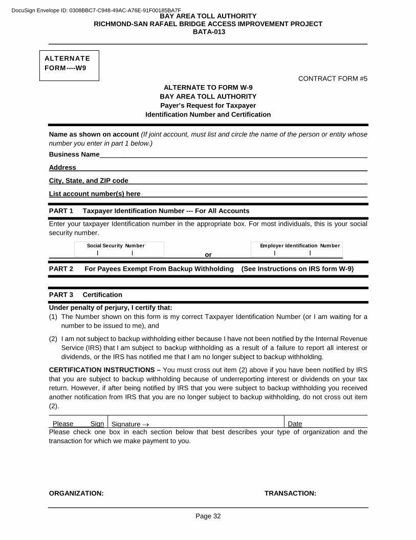
BAY AREA TOLL AUTHORITY RICHMOND-SAN RAFAEL BRIDGE ACCESS IMPROVEMENT PROJECT
BATA-013
Page 32
CONTRACT FORM #5 ALTERNATE TO FORM W-9
BAY AREA TOLL AUTHORITY Payer’s Request for Taxpayer
Identification Number and Certification
Name as shown on account (If joint account, must list and circle the name of the person or entity whose number you enter in part 1 below.) Business Name _________________________________________________________________
Address
City, State, and ZIP code
List account number(s) here
PART 1 Taxpayer Identification Number --- For All Accounts
Enter your taxpayer Identification number in the appropriate box. For most individuals, this is your social security number.
or
PART 2 For Payees Exempt From Backup Withholding (See Instructions on IRS form W-9)
PART 3 Certification
Under penalty of perjury, I certify that: (1) The Number shown on this form is my correct Taxpayer Identification Number (or I am waiting for a
number to be issued to me), and
(2) I am not subject to backup withholding either because I have not been notified by the Internal Revenue Service (IRS) that I am subject to backup withholding as a result of a failure to report all interest or dividends, or the IRS has notified me that I am no longer subject to backup withholding.
CERTIFICATION INSTRUCTIONS – You must cross out item (2) above if you have been notified by IRS that you are subject to backup withholding because of underreporting interest or dividends on your tax return. However, if after being notified by IRS that you were subject to backup withholding you received another notification from IRS that you are no longer subject to backup withholding, do not cross out item (2).
Please Sign
Signature → Date Please check one box in each section below that best describes your type of organization and the transaction for which we make payment to you.
ORGANIZATION: TRANSACTION:
Social Security Number | |
Employer Identification Number | |
ALTERNATE FORM----W9
DocuSign Envelope ID: 0308BBC7-C948-49AC-A76E-91F00185BA7F
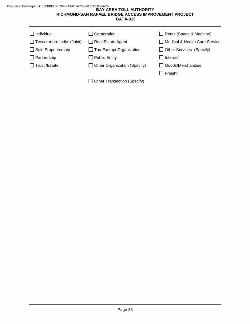
BAY AREA TOLL AUTHORITY RICHMOND-SAN RAFAEL BRIDGE ACCESS IMPROVEMENT PROJECT
BATA-013
Page 33
Individual Corporation Rents (Space & Machine)
Two or more Indiv. (Joint) Real Estate Agent Medical & Health Care Service
Sole Proprietorship Tax-Exempt Organization Other Services (Specify)
Partnership Public Entity Interest
Trust /Estate Other Organization (Specify) Goods/Merchandise
Freight
Other Transaction (Specify)
DocuSign Envelope ID: 0308BBC7-C948-49AC-A76E-91F00185BA7F
BAY AREA TOLL AUTHORITY RICHMOND-SAN RAFAEL BRIDGE ACCESS IMPROVEMENT PROJECT
BATA-013
Page 34
PART 5. BID FORMS 1. Bid Form, Schedule of Quantities and Prices, Contractor Information
2. Bidder’s Bond *
3. Designation of Subcontractors – Fair Practices Act
4. Affidavit of Non-Collusion **
5. Certification Regarding Iran Contracting Act of 2010
6. Contractor’s Reference Form
7. Insurance Certificate Checklist
8. Designation of Subcontractors in Compliance with the BATA Construction Project SBE Program
* Form must be acknowledged by a Notary **Form must be subscribed and sworn to before Notary Public or other Officer
PLEASE NOTE: These forms are designed to contain essential information concerning the Bidder and the bid, and must be completed such that they can be read. If any of the completed forms are illegible, BATA may, at its option, declare the entire bid unresponsive.
DocuSign Envelope ID: 0308BBC7-C948-49AC-A76E-91F00185BA7F
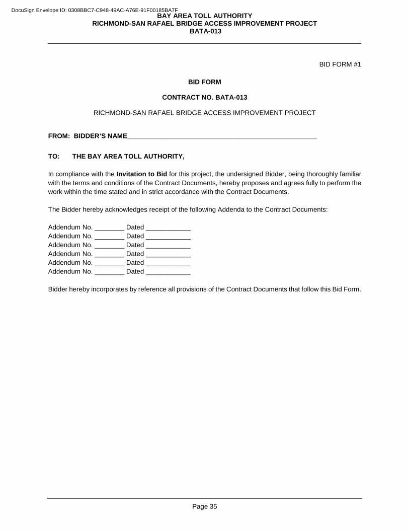
BAY AREA TOLL AUTHORITY RICHMOND-SAN RAFAEL BRIDGE ACCESS IMPROVEMENT PROJECT
BATA-013
Page 35
BID FORM #1
BID FORM
CONTRACT NO. BATA-013
RICHMOND-SAN RAFAEL BRIDGE ACCESS IMPROVEMENT PROJECT
FROM: BIDDER’S NAME___________________________________________________
TO: THE BAY AREA TOLL AUTHORITY, In compliance with the Invitation to Bid for this project, the undersigned Bidder, being thoroughly familiar with the terms and conditions of the Contract Documents, hereby proposes and agrees fully to perform the work within the time stated and in strict accordance with the Contract Documents. The Bidder hereby acknowledges receipt of the following Addenda to the Contract Documents: Addendum No. ________ Dated ____________ Addendum No. ________ Dated ____________ Addendum No. ________ Dated ____________ Addendum No. ________ Dated ____________ Addendum No. ________ Dated ____________ Addendum No. ________ Dated ____________ Bidder hereby incorporates by reference all provisions of the Contract Documents that follow this Bid Form.
DocuSign Envelope ID: 0308BBC7-C948-49AC-A76E-91F00185BA7F
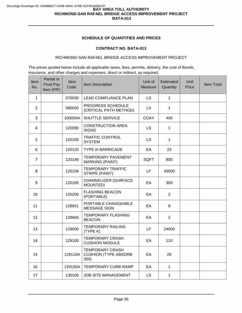
BAY AREA TOLL AUTHORITY RICHMOND-SAN RAFAEL BRIDGE ACCESS IMPROVEMENT PROJECT
BATA-013
Page 36
SCHEDULE OF QUANTITIES AND PRICES
CONTRACT NO. BATA-013
RICHMOND-SAN RAFAEL BRIDGE ACCESS IMPROVEMENT PROJECT
The prices quoted below include all applicable taxes, fees, permits, delivery, the cost of Bonds, insurance, and other charges and expenses, direct or indirect, as required.
Item No.
Partial or Final Pay Item (P/F)
Item Code Item Description
Unit of Measure
Estimated Quantity
Unit Price Item Total
1 070030 LEAD COMPLIANCE PLAN LS 1
2 080050 PROGRESS SCHEDULE (CRITICAL PATH METHOD) LS 1
3 100000A SHUTTLE SERVICE CDAY 400
4 120090 CONSTRUCTION AREA SIGNS LS 1
5 120100 TRAFFIC CONTROL SYSTEM LS 1
6 120120 TYPE III BARRICADE EA 23
7 120149 TEMPORARY PAVEMENT MARKING (PAINT) SQFT 800
8 120159 TEMPORARY TRAFFIC STRIPE (PAINT) LF 43000
9 120165 CHANNELIZER (SURFACE MOUNTED) EA 300
10 120200 FLASHING BEACON (PORTABLE) EA 2
11 128651 PORTABLE CHANGEABLE MESSAGE SIGN EA 8
12 128660 TEMPORARY FLASHING BEACON EA 2
13 129000 TEMPORARY RAILING (TYPE K) LF 24000
14 129100 TEMPORARY CRASH CUSHION MODULE EA 110
15 129110A TEMPORARY CRASH CUSHION (TYPE ABSORB 350)
EA 29
16 129150A TEMPORARY CURB RAMP EA 1
17 130100 JOB SITE MANAGEMENT LS 1
DocuSign Envelope ID: 0308BBC7-C948-49AC-A76E-91F00185BA7F
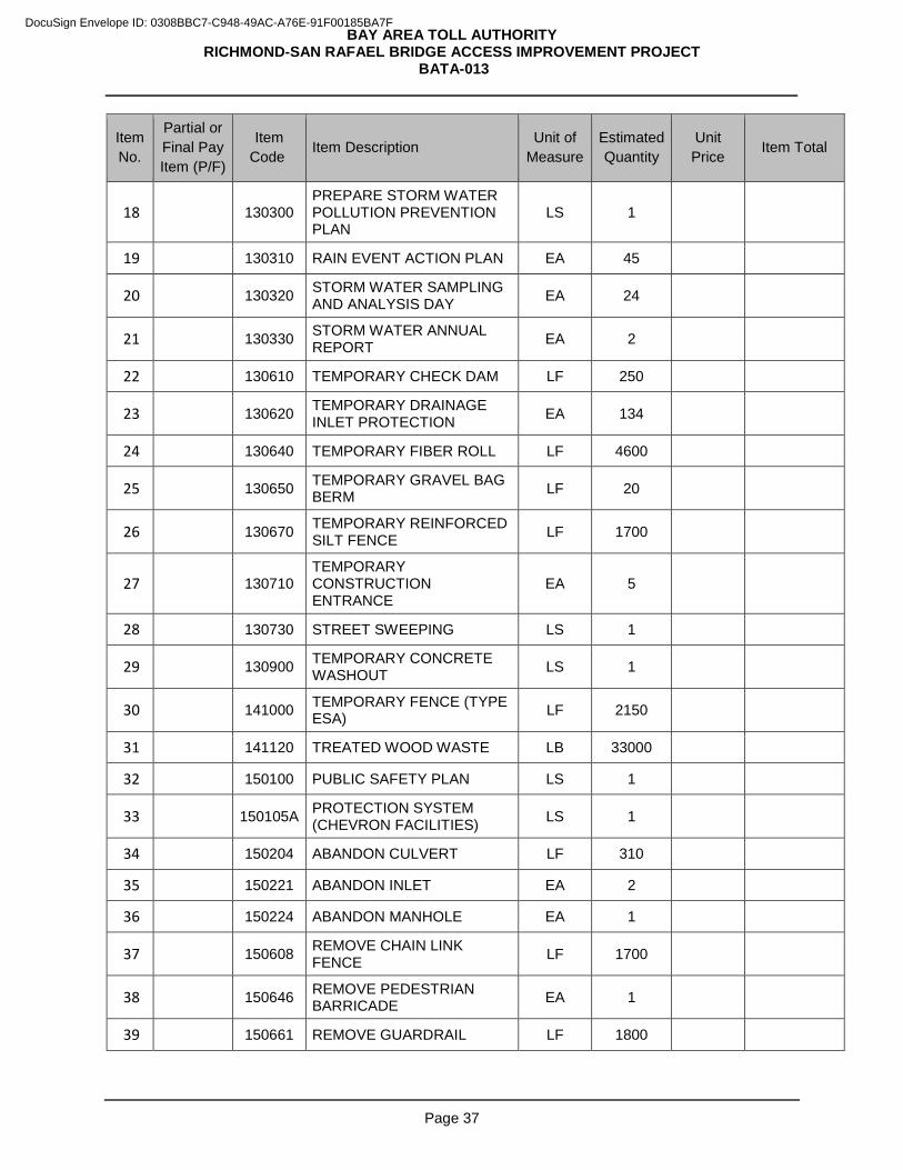
BAY AREA TOLL AUTHORITY RICHMOND-SAN RAFAEL BRIDGE ACCESS IMPROVEMENT PROJECT
BATA-013
Page 37
Item No.
Partial or Final Pay Item (P/F)
Item Code Item Description Unit of
Measure Estimated Quantity
Unit Price Item Total
18 130300 PREPARE STORM WATER POLLUTION PREVENTION PLAN
LS 1
19 130310 RAIN EVENT ACTION PLAN EA 45
20 130320 STORM WATER SAMPLING AND ANALYSIS DAY EA 24
21 130330 STORM WATER ANNUAL REPORT EA 2
22 130610 TEMPORARY CHECK DAM LF 250
23 130620 TEMPORARY DRAINAGE INLET PROTECTION EA 134
24 130640 TEMPORARY FIBER ROLL LF 4600
25 130650 TEMPORARY GRAVEL BAG BERM LF 20
26 130670 TEMPORARY REINFORCED SILT FENCE LF 1700
27 130710 TEMPORARY CONSTRUCTION ENTRANCE
EA 5
28 130730 STREET SWEEPING LS 1
29 130900 TEMPORARY CONCRETE WASHOUT LS 1
30 141000 TEMPORARY FENCE (TYPE ESA) LF 2150
31 141120 TREATED WOOD WASTE LB 33000
32 150100 PUBLIC SAFETY PLAN LS 1
33 150105A PROTECTION SYSTEM (CHEVRON FACILITIES) LS 1
34 150204 ABANDON CULVERT LF 310
35 150221 ABANDON INLET EA 2
36 150224 ABANDON MANHOLE EA 1
37 150608 REMOVE CHAIN LINK FENCE LF 1700
38 150646 REMOVE PEDESTRIAN BARRICADE EA 1
39 150661 REMOVE GUARDRAIL LF 1800
DocuSign Envelope ID: 0308BBC7-C948-49AC-A76E-91F00185BA7F
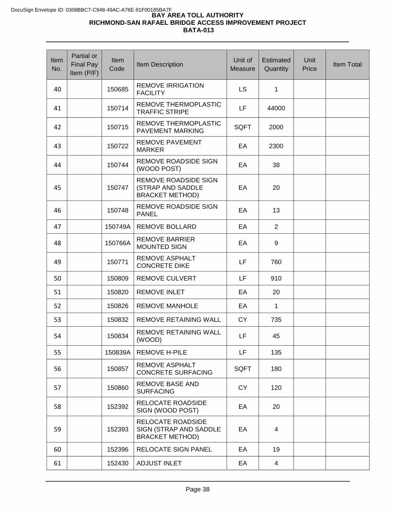
BAY AREA TOLL AUTHORITY RICHMOND-SAN RAFAEL BRIDGE ACCESS IMPROVEMENT PROJECT
BATA-013
Page 38
Item No.
Partial or Final Pay Item (P/F)
Item Code Item Description Unit of
Measure Estimated Quantity
Unit Price Item Total
40 150685 REMOVE IRRIGATION FACILITY LS 1
41 150714 REMOVE THERMOPLASTIC TRAFFIC STRIPE LF 44000
42 150715 REMOVE THERMOPLASTIC PAVEMENT MARKING SQFT 2000
43 150722 REMOVE PAVEMENT MARKER EA 2300
44 150744 REMOVE ROADSIDE SIGN (WOOD POST) EA 38
45 150747 REMOVE ROADSIDE SIGN (STRAP AND SADDLE BRACKET METHOD)
EA 20
46 150748 REMOVE ROADSIDE SIGN PANEL EA 13
47 150749A REMOVE BOLLARD EA 2
48 150766A REMOVE BARRIER MOUNTED SIGN EA 9
49 150771 REMOVE ASPHALT CONCRETE DIKE LF 760
50 150809 REMOVE CULVERT LF 910
51 150820 REMOVE INLET EA 20
52 150826 REMOVE MANHOLE EA 1
53 150832 REMOVE RETAINING WALL CY 735
54 150834 REMOVE RETAINING WALL (WOOD) LF 45
55 150839A REMOVE H-PILE LF 135
56 150857 REMOVE ASPHALT CONCRETE SURFACING SQFT 180
57 150860 REMOVE BASE AND SURFACING CY 120
58 152392 RELOCATE ROADSIDE SIGN (WOOD POST) EA 20
59 152393 RELOCATE ROADSIDE SIGN (STRAP AND SADDLE BRACKET METHOD)
EA 4
60 152396 RELOCATE SIGN PANEL EA 19
61 152430 ADJUST INLET EA 4
DocuSign Envelope ID: 0308BBC7-C948-49AC-A76E-91F00185BA7F
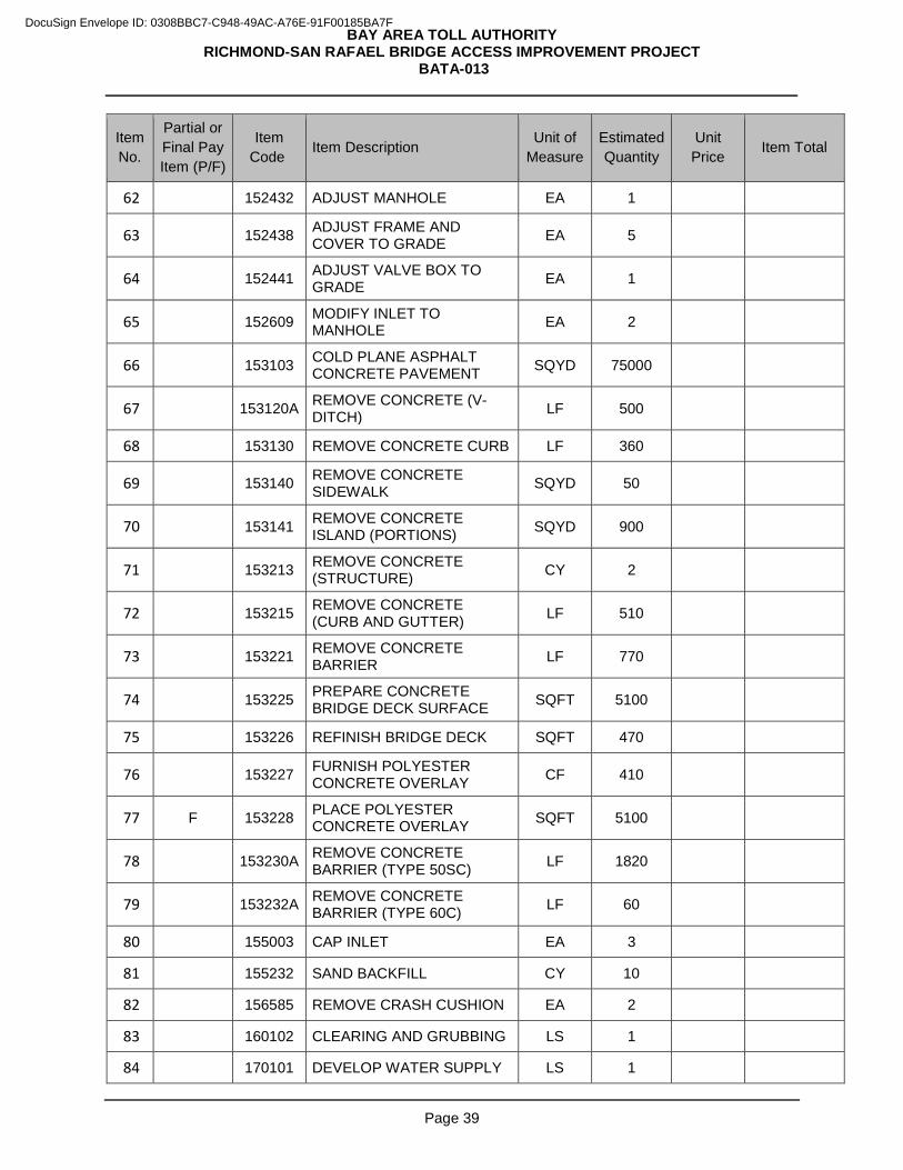
BAY AREA TOLL AUTHORITY RICHMOND-SAN RAFAEL BRIDGE ACCESS IMPROVEMENT PROJECT
BATA-013
Page 39
Item No.
Partial or Final Pay Item (P/F)
Item Code Item Description Unit of
Measure Estimated Quantity
Unit Price Item Total
62 152432 ADJUST MANHOLE EA 1
63 152438 ADJUST FRAME AND COVER TO GRADE EA 5
64 152441 ADJUST VALVE BOX TO GRADE EA 1
65 152609 MODIFY INLET TO MANHOLE EA 2
66 153103 COLD PLANE ASPHALT CONCRETE PAVEMENT SQYD 75000
67 153120A REMOVE CONCRETE (V-DITCH) LF 500
68 153130 REMOVE CONCRETE CURB LF 360
69 153140 REMOVE CONCRETE SIDEWALK SQYD 50
70 153141 REMOVE CONCRETE ISLAND (PORTIONS) SQYD 900
71 153213 REMOVE CONCRETE (STRUCTURE) CY 2
72 153215 REMOVE CONCRETE (CURB AND GUTTER) LF 510
73 153221 REMOVE CONCRETE BARRIER LF 770
74 153225 PREPARE CONCRETE BRIDGE DECK SURFACE SQFT 5100
75 153226 REFINISH BRIDGE DECK SQFT 470
76 153227 FURNISH POLYESTER CONCRETE OVERLAY CF 410
77 F 153228 PLACE POLYESTER CONCRETE OVERLAY SQFT 5100
78 153230A REMOVE CONCRETE BARRIER (TYPE 50SC) LF 1820
79 153232A REMOVE CONCRETE BARRIER (TYPE 60C) LF 60
80 155003 CAP INLET EA 3
81 155232 SAND BACKFILL CY 10
82 156585 REMOVE CRASH CUSHION EA 2
83 160102 CLEARING AND GRUBBING LS 1
84 170101 DEVELOP WATER SUPPLY LS 1
DocuSign Envelope ID: 0308BBC7-C948-49AC-A76E-91F00185BA7F
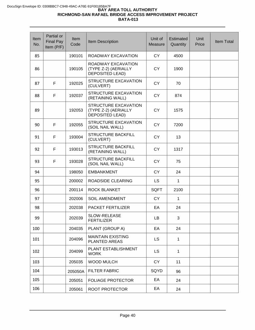
BAY AREA TOLL AUTHORITY RICHMOND-SAN RAFAEL BRIDGE ACCESS IMPROVEMENT PROJECT
BATA-013
Page 40
Item No.
Partial or Final Pay Item (P/F)
Item Code Item Description Unit of
Measure Estimated Quantity
Unit Price Item Total
85 190101 ROADWAY EXCAVATION CY 4500
86 190105 ROADWAY EXCAVATION (TYPE Z-2) (AERIALLY DEPOSITED LEAD)
CY 1900
87 F 192025 STRUCTURE EXCAVATION (CULVERT) CY 70
88 F 192037 STRUCTURE EXCAVATION (RETAINING WALL) CY 874
89 192053 STRUCTURE EXCAVATION (TYPE Z-2) (AERIALLY DEPOSITED LEAD)
CY 1575
90 F 192055 STRUCTURE EXCAVATION (SOIL NAIL WALL) CY 7200
91 F 193004 STRUCTURE BACKFILL (CULVERT) CY 13
92 F 193013 STRUCTURE BACKFILL (RETAINING WALL) CY 1317
93 F 193028 STRUCTURE BACKFILL (SOIL NAIL WALL) CY 75
94 198050 EMBANKMENT CY 24
95 200002 ROADSIDE CLEARING LS 1
96 200114 ROCK BLANKET SQFT 2100
97 202006 SOIL AMENDMENT CY 1
98 202038 PACKET FERTILIZER EA 24
99 202039 SLOW-RELEASE FERTILIZER LB 3
100 204035 PLANT (GROUP A) EA 24
101 204096 MAINTAIN EXISTING PLANTED AREAS LS 1
102 204099 PLANT ESTABLISHMENT WORK LS 1
103 205035 WOOD MULCH CY 11
104 205050A FILTER FABRIC SQYD 96
105 205051 FOLIAGE PROTECTOR EA 24
106 205061 ROOT PROTECTOR EA 24
DocuSign Envelope ID: 0308BBC7-C948-49AC-A76E-91F00185BA7F
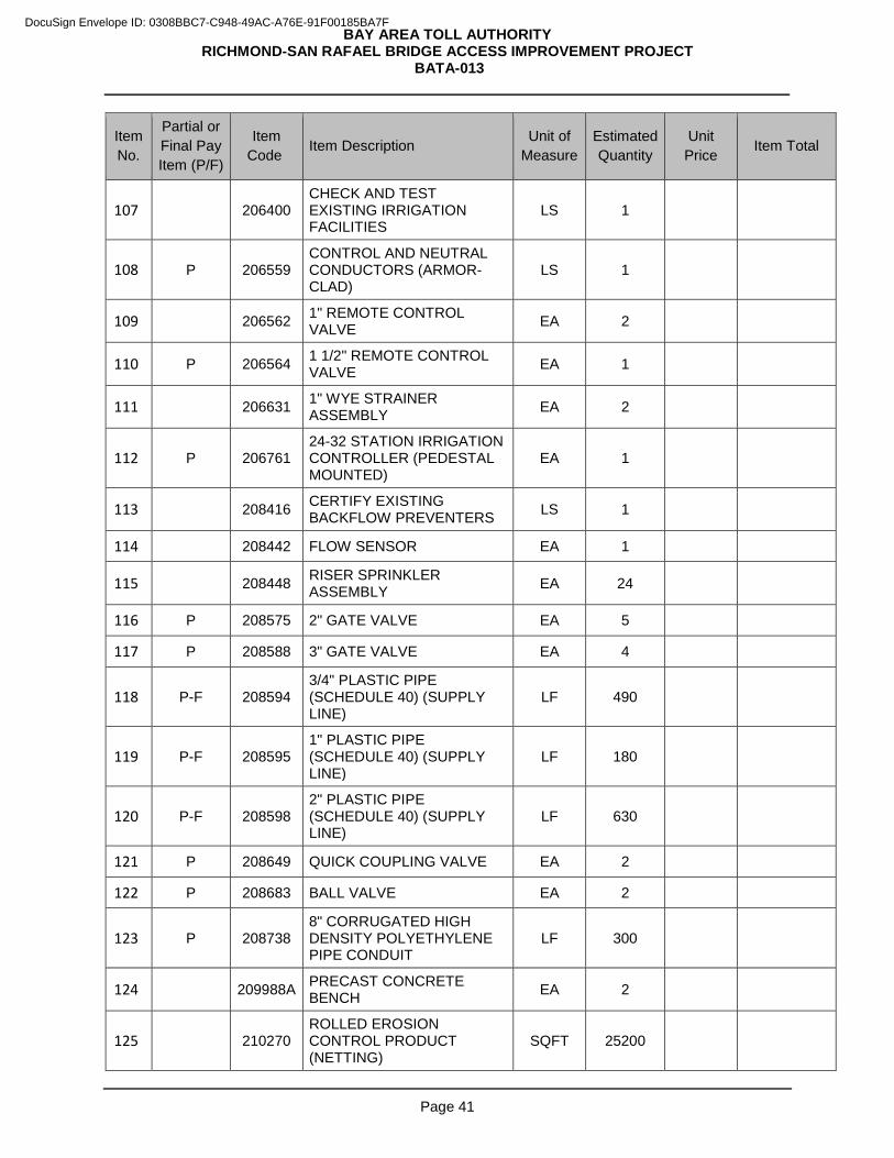
BAY AREA TOLL AUTHORITY RICHMOND-SAN RAFAEL BRIDGE ACCESS IMPROVEMENT PROJECT
BATA-013
Page 41
Item No.
Partial or Final Pay Item (P/F)
Item Code Item Description Unit of
Measure Estimated Quantity
Unit Price Item Total
107 206400 CHECK AND TEST EXISTING IRRIGATION FACILITIES
LS 1
108 P 206559 CONTROL AND NEUTRAL CONDUCTORS (ARMOR-CLAD)
LS 1
109 206562 1" REMOTE CONTROL VALVE EA 2
110 P 206564 1 1/2" REMOTE CONTROL VALVE EA 1
111 206631 1" WYE STRAINER ASSEMBLY EA 2
112 P 206761 24-32 STATION IRRIGATION CONTROLLER (PEDESTAL MOUNTED)
EA 1
113 208416 CERTIFY EXISTING BACKFLOW PREVENTERS LS 1
114 208442 FLOW SENSOR EA 1
115 208448 RISER SPRINKLER ASSEMBLY EA 24
116 P 208575 2" GATE VALVE EA 5
117 P 208588 3" GATE VALVE EA 4
118 P-F 208594 3/4" PLASTIC PIPE (SCHEDULE 40) (SUPPLY LINE)
LF 490
119 P-F 208595 1" PLASTIC PIPE (SCHEDULE 40) (SUPPLY LINE)
LF 180
120 P-F 208598 2" PLASTIC PIPE (SCHEDULE 40) (SUPPLY LINE)
LF 630
121 P 208649 QUICK COUPLING VALVE EA 2
122 P 208683 BALL VALVE EA 2
123 P 208738 8" CORRUGATED HIGH DENSITY POLYETHYLENE PIPE CONDUIT
LF 300
124 209988A PRECAST CONCRETE BENCH EA 2
125 210270 ROLLED EROSION CONTROL PRODUCT (NETTING)
SQFT 25200
DocuSign Envelope ID: 0308BBC7-C948-49AC-A76E-91F00185BA7F
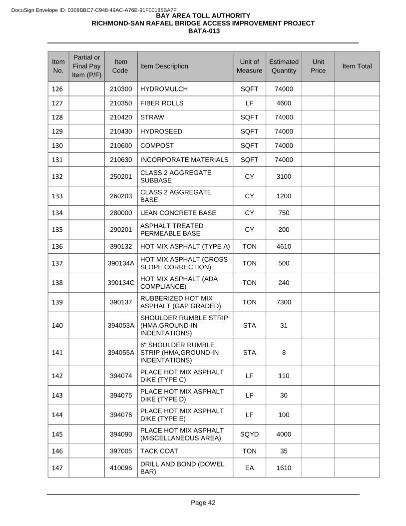
BAY AREA TOLL AUTHORITY RICHMOND-SAN RAFAEL BRIDGE ACCESS IMPROVEMENT PROJECT
BATA-013
Page 42
Item No.
Partial or Final Pay Item (P/F)
Item Code Item Description Unit of
Measure Estimated Quantity
Unit Price Item Total
126 210300 HYDROMULCH SQFT 74000
127 210350 FIBER ROLLS LF 4600
128 210420 STRAW SQFT 74000
129 210430 HYDROSEED SQFT 74000
130 210600 COMPOST SQFT 74000
131 210630 INCORPORATE MATERIALS SQFT 74000
132 250201 CLASS 2 AGGREGATE SUBBASE CY 3100
133 260203 CLASS 2 AGGREGATE BASE CY 1200
134 280000 LEAN CONCRETE BASE CY 750
135 290201 ASPHALT TREATED PERMEABLE BASE CY 200
136 390132 HOT MIX ASPHALT (TYPE A) TON 4610
137 390134A HOT MIX ASPHALT (CROSS SLOPE CORRECTION) TON 500
138 390134C HOT MIX ASPHALT (ADA COMPLIANCE) TON 240
139 390137 RUBBERIZED HOT MIX ASPHALT (GAP GRADED) TON 7300
140 394053A SHOULDER RUMBLE STRIP (HMA,GROUND-IN INDENTATIONS)
STA 31
141 394055A 6" SHOULDER RUMBLE STRIP (HMA,GROUND-IN INDENTATIONS)
STA 8
142 394074 PLACE HOT MIX ASPHALT DIKE (TYPE C) LF 110
143 394075 PLACE HOT MIX ASPHALT DIKE (TYPE D) LF 30
144 394076 PLACE HOT MIX ASPHALT DIKE (TYPE E) LF 100
145 394090 PLACE HOT MIX ASPHALT (MISCELLANEOUS AREA) SQYD 4000
146 397005 TACK COAT TON 35
147 410096 DRILL AND BOND (DOWEL BAR) EA 1610
DocuSign Envelope ID: 0308BBC7-C948-49AC-A76E-91F00185BA7F
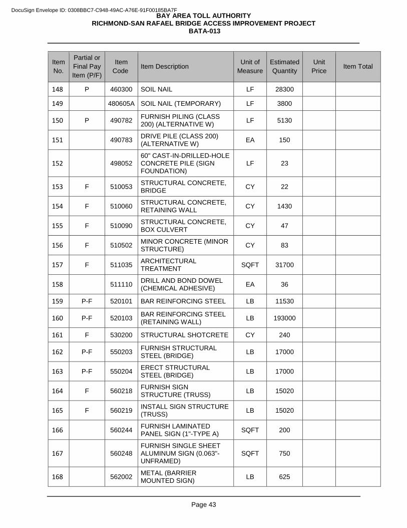
BAY AREA TOLL AUTHORITY RICHMOND-SAN RAFAEL BRIDGE ACCESS IMPROVEMENT PROJECT
BATA-013
Page 43
Item No.
Partial or Final Pay Item (P/F)
Item Code Item Description Unit of
Measure Estimated Quantity
Unit Price Item Total
148 P 460300 SOIL NAIL LF 28300
149 480605A SOIL NAIL (TEMPORARY) LF 3800
150 P 490782 FURNISH PILING (CLASS 200) (ALTERNATIVE W) LF 5130
151 490783 DRIVE PILE (CLASS 200) (ALTERNATIVE W) EA 150
152 498052 60" CAST-IN-DRILLED-HOLE CONCRETE PILE (SIGN FOUNDATION)
LF 23
153 F 510053 STRUCTURAL CONCRETE, BRIDGE CY 22
154 F 510060 STRUCTURAL CONCRETE, RETAINING WALL CY 1430
155 F 510090 STRUCTURAL CONCRETE, BOX CULVERT CY 47
156 F 510502 MINOR CONCRETE (MINOR STRUCTURE) CY 83
157 F 511035 ARCHITECTURAL TREATMENT SQFT 31700
158 511110 DRILL AND BOND DOWEL (CHEMICAL ADHESIVE) EA 36
159 P-F 520101 BAR REINFORCING STEEL LB 11530
160 P-F 520103 BAR REINFORCING STEEL (RETAINING WALL) LB 193000
161 F 530200 STRUCTURAL SHOTCRETE CY 240
162 P-F 550203 FURNISH STRUCTURAL STEEL (BRIDGE) LB 17000
163 P-F 550204 ERECT STRUCTURAL STEEL (BRIDGE) LB 17000
164 F 560218 FURNISH SIGN STRUCTURE (TRUSS) LB 15020
165 F 560219 INSTALL SIGN STRUCTURE (TRUSS) LB 15020
166 560244 FURNISH LAMINATED PANEL SIGN (1"-TYPE A) SQFT 200
167 560248 FURNISH SINGLE SHEET ALUMINUM SIGN (0.063"-UNFRAMED)
SQFT 750
168 562002 METAL (BARRIER MOUNTED SIGN) LB 625
DocuSign Envelope ID: 0308BBC7-C948-49AC-A76E-91F00185BA7F
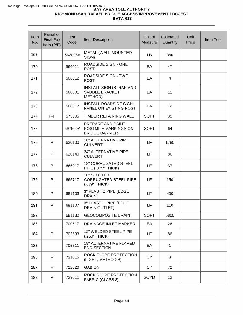
BAY AREA TOLL AUTHORITY RICHMOND-SAN RAFAEL BRIDGE ACCESS IMPROVEMENT PROJECT
BATA-013
Page 44
Item No.
Partial or Final Pay Item (P/F)
Item Code Item Description Unit of
Measure Estimated Quantity
Unit Price Item Total
169 562005A METAL (WALL MOUNTED SIGN) LB 360
170 566011 ROADSIDE SIGN - ONE POST EA 47
171 566012 ROADSIDE SIGN - TWO POST EA 4
172 568001 INSTALL SIGN (STRAP AND SADDLE BRACKET METHOD)
EA 11
173 568017 INSTALL ROADSIDE SIGN PANEL ON EXISTING POST EA 12
174 P-F 575005 TIMBER RETAINING WALL SQFT 35
175 597500A PREPARE AND PAINT POSTMILE MARKINGS ON BRIDGE BARRIER
SQFT 64
176 P 620100 18" ALTERNATIVE PIPE CULVERT LF 1780
177 P 620140 24" ALTERNATIVE PIPE CULVERT LF 86
178 P 665017 18" CORRUGATED STEEL PIPE (.079" THICK) LF 37
179 P 665717 18" SLOTTED CORRUGATED STEEL PIPE (.079" THICK)
LF 150
180 P 681103 3" PLASTIC PIPE (EDGE DRAIN) LF 400
181 P 681107 3" PLASTIC PIPE (EDGE DRAIN OUTLET) LF 110
182 681132 GEOCOMPOSITE DRAIN SQFT 5800
183 700617 DRAINAGE INLET MARKER EA 26
184 P 703533 12" WELDED STEEL PIPE (.250" THICK) LF 86
185 705311 18" ALTERNATIVE FLARED END SECTION EA 1
186 F 721015 ROCK SLOPE PROTECTION (LIGHT, METHOD B) CY 3
187 F 722020 GABION CY 72
188 P 729011 ROCK SLOPE PROTECTION FABRIC (CLASS 8) SQYD 12
DocuSign Envelope ID: 0308BBC7-C948-49AC-A76E-91F00185BA7F
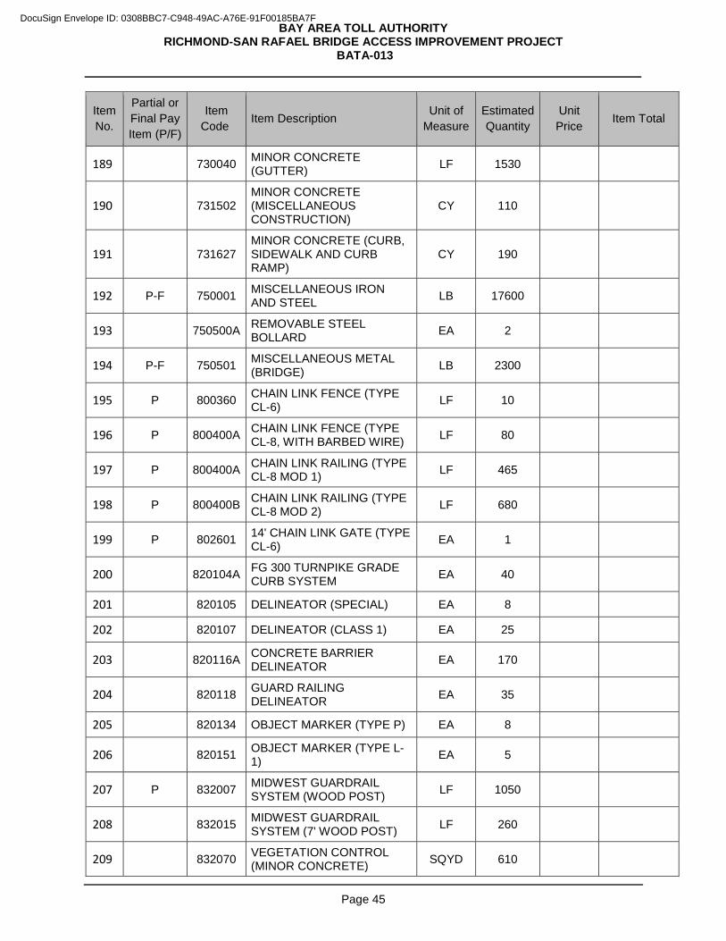
BAY AREA TOLL AUTHORITY RICHMOND-SAN RAFAEL BRIDGE ACCESS IMPROVEMENT PROJECT
BATA-013
Page 45
Item No.
Partial or Final Pay Item (P/F)
Item Code Item Description Unit of
Measure Estimated Quantity
Unit Price Item Total
189 730040 MINOR CONCRETE (GUTTER) LF 1530
190 731502 MINOR CONCRETE (MISCELLANEOUS CONSTRUCTION)
CY 110
191 731627 MINOR CONCRETE (CURB, SIDEWALK AND CURB RAMP)
CY 190
192 P-F 750001 MISCELLANEOUS IRON AND STEEL LB 17600
193 750500A REMOVABLE STEEL BOLLARD EA 2
194 P-F 750501 MISCELLANEOUS METAL (BRIDGE) LB 2300
195 P 800360 CHAIN LINK FENCE (TYPE CL-6) LF 10
196 P 800400A CHAIN LINK FENCE (TYPE CL-8, WITH BARBED WIRE) LF 80
197 P 800400A CHAIN LINK RAILING (TYPE CL-8 MOD 1) LF 465
198 P 800400B CHAIN LINK RAILING (TYPE CL-8 MOD 2) LF 680
199 P 802601 14' CHAIN LINK GATE (TYPE CL-6) EA 1
200 820104A FG 300 TURNPIKE GRADE CURB SYSTEM EA 40
201 820105 DELINEATOR (SPECIAL) EA 8
202 820107 DELINEATOR (CLASS 1) EA 25
203 820116A CONCRETE BARRIER DELINEATOR EA 170
204 820118 GUARD RAILING DELINEATOR EA 35
205 820134 OBJECT MARKER (TYPE P) EA 8
206 820151 OBJECT MARKER (TYPE L-1) EA 5
207 P 832007 MIDWEST GUARDRAIL SYSTEM (WOOD POST) LF 1050
208 832015 MIDWEST GUARDRAIL SYSTEM (7' WOOD POST) LF 260
209 832070 VEGETATION CONTROL (MINOR CONCRETE) SQYD 610
DocuSign Envelope ID: 0308BBC7-C948-49AC-A76E-91F00185BA7F
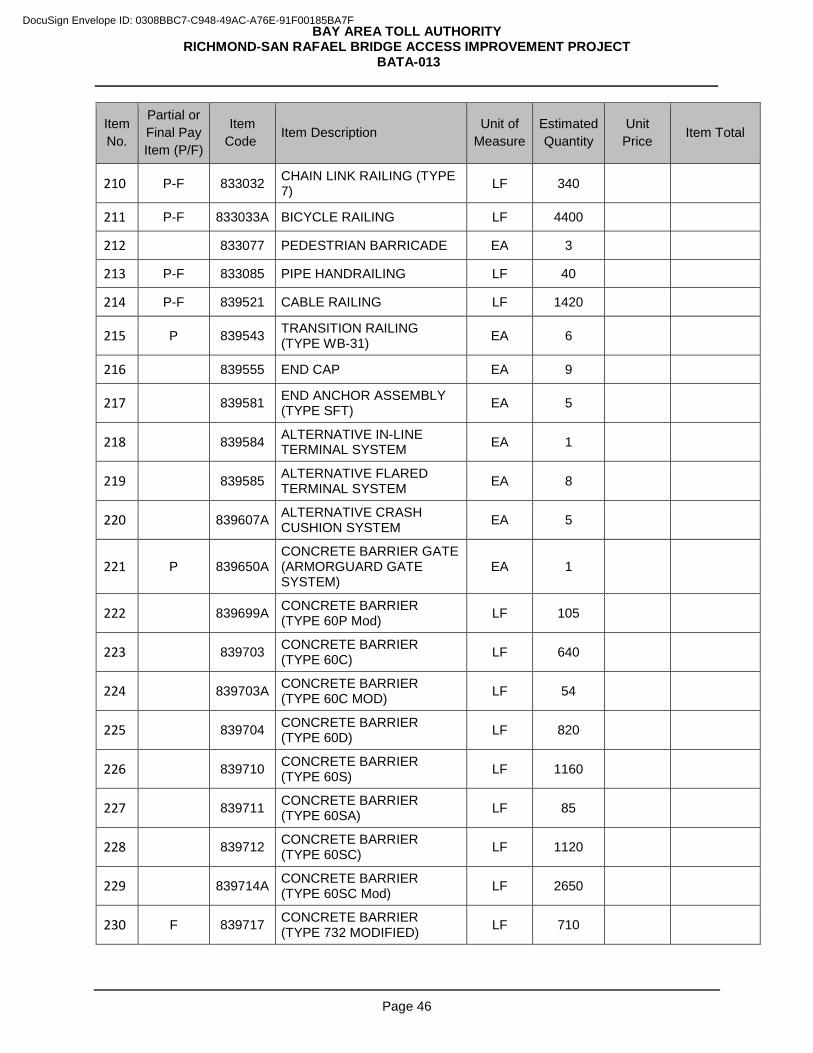
BAY AREA TOLL AUTHORITY RICHMOND-SAN RAFAEL BRIDGE ACCESS IMPROVEMENT PROJECT
BATA-013
Page 46
Item No.
Partial or Final Pay Item (P/F)
Item Code Item Description Unit of
Measure Estimated Quantity
Unit Price Item Total
210 P-F 833032 CHAIN LINK RAILING (TYPE 7) LF 340
211 P-F 833033A BICYCLE RAILING LF 4400
212 833077 PEDESTRIAN BARRICADE EA 3
213 P-F 833085 PIPE HANDRAILING LF 40
214 P-F 839521 CABLE RAILING LF 1420
215 P 839543 TRANSITION RAILING (TYPE WB-31) EA 6
216 839555 END CAP EA 9
217 839581 END ANCHOR ASSEMBLY (TYPE SFT) EA 5
218 839584 ALTERNATIVE IN-LINE TERMINAL SYSTEM EA 1
219 839585 ALTERNATIVE FLARED TERMINAL SYSTEM EA 8
220 839607A ALTERNATIVE CRASH CUSHION SYSTEM EA 5
221 P 839650A CONCRETE BARRIER GATE (ARMORGUARD GATE SYSTEM)
EA 1
222 839699A CONCRETE BARRIER (TYPE 60P Mod) LF 105
223 839703 CONCRETE BARRIER (TYPE 60C) LF 640
224 839703A CONCRETE BARRIER (TYPE 60C MOD) LF 54
225 839704 CONCRETE BARRIER (TYPE 60D) LF 820
226 839710 CONCRETE BARRIER (TYPE 60S) LF 1160
227 839711 CONCRETE BARRIER (TYPE 60SA) LF 85
228 839712 CONCRETE BARRIER (TYPE 60SC) LF 1120
229 839714A CONCRETE BARRIER (TYPE 60SC Mod) LF 2650
230 F 839717 CONCRETE BARRIER (TYPE 732 MODIFIED) LF 710
DocuSign Envelope ID: 0308BBC7-C948-49AC-A76E-91F00185BA7F
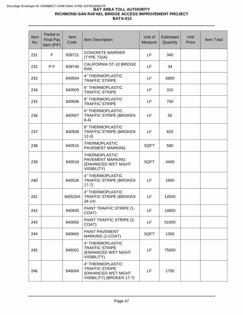
BAY AREA TOLL AUTHORITY RICHMOND-SAN RAFAEL BRIDGE ACCESS IMPROVEMENT PROJECT
BATA-013
Page 47
Item No.
Partial or Final Pay Item (P/F)
Item Code Item Description Unit of
Measure Estimated Quantity
Unit Price Item Total
231 F 839721 CONCRETE BARRIER (TYPE 732A) LF 340
232 P-F 839740 CALIFORNIA ST-10 BRIDGE RAIL LF 34
233 840504 4" THERMOPLASTIC TRAFFIC STRIPE LF 6800
234 840505 6" THERMOPLASTIC TRAFFIC STRIPE LF 310
235 840506 8" THERMOPLASTIC TRAFFIC STRIPE LF 750
236 840507 6" THERMOPLASTIC TRAFFIC STRIPE (BROKEN 8-4)
LF 50
237 840508 8" THERMOPLASTIC TRAFFIC STRIPE (BROKEN 12-3)
LF 620
238 840515 THERMOPLASTIC PAVEMENT MARKING SQFT 580
239 840516
THERMOPLASTIC PAVEMENT MARKING (ENHANCED WET NIGHT VISIBILITY)
SQFT 4400
240 840526 4" THERMOPLASTIC TRAFFIC STRIPE (BROKEN 17-7)
LF 1900
241 840526A 4" THERMOPLASTIC TRAFFIC STRIPE (BROKEN 34-14)
LF 14500
242 840655 PAINT TRAFFIC STRIPE (1-COAT) LF 14800
243 840656 PAINT TRAFFIC STRIPE (2-COAT) LF 51000
244 840665 PAINT PAVEMENT MARKING (1-COAT) SQFT 1300
245 846001
4" THERMOPLASTIC TRAFFIC STRIPE (ENHANCED WET NIGHT VISIBILITY)
LF 75000
246 846004
4" THERMOPLASTIC TRAFFIC STRIPE (ENHANCED WET NIGHT VISIBILITY) (BROKEN 17-7)
LF 1750
DocuSign Envelope ID: 0308BBC7-C948-49AC-A76E-91F00185BA7F

BAY AREA TOLL AUTHORITY RICHMOND-SAN RAFAEL BRIDGE ACCESS IMPROVEMENT PROJECT
BATA-013
Page 48
Item No.
Partial or Final Pay Item (P/F)
Item Code Item Description Unit of
Measure Estimated Quantity
Unit Price Item Total
247 846004A
4" THERMOPLASTIC TRAFFIC STRIPE (ENHANCED WET NIGHT VISIBILITY) (BROKEN 34-14)
LF 30000
248 846007
6" THERMOPLASTIC TRAFFIC STRIPE (ENHANCED WET NIGHT VISIBILITY)
LF 150
249 846008A
6" THERMOPLASTIC TRAFFIC STRIPE (ENHANCED WET NIGHT VISIBILITY) (BROKEN 6-2)
LF 200
250 846009
8" THERMOPLASTIC TRAFFIC STRIPE (ENHANCED WET NIGHT VISIBILITY)
LF 6000
251 846010
8" THERMOPLASTIC TRAFFIC STRIPE (ENHANCED WET NIGHT VISIBILITY) (BROKEN 12-3)
LF 1000
252 P 850101 PAVEMENT MARKER (NON-REFLECTIVE) EA 3650
253 P 850111 PAVEMENT MARKER (RETROREFLECTIVE) EA 2800
254 860090
MAINTAINING EXISTING TRAFFIC MANAGEMENT SYSTEM ELEMENTS DURING CONSTRUCTION
LS 1
255 860297A SIGNAL AND LIGHTING (STAGE CONSTRUCTION) LS 1
256 860468A LIGHTING (STAGE CONSTRUCTION) LS 1
257 861547A TRAFFIC OPERATIONS SYSTEM (STAGE CONSTRUCTION)
LS 1
258 872131A
MODIFYING EXISTING ELECTRICAL SYSTEM (SIGNAL AND LIGHTING) (LOCATION 1)
LS 1
259 872132A
MODIFYING EXISTING ELECTRICAL SYSTEM (SIGNAL AND LIGHTING) (LOCATION 2)
LS 1
DocuSign Envelope ID: 0308BBC7-C948-49AC-A76E-91F00185BA7F
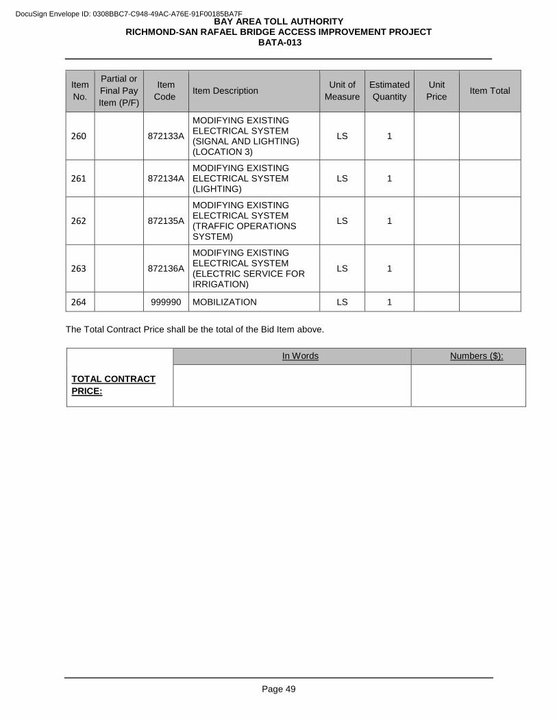
BAY AREA TOLL AUTHORITY RICHMOND-SAN RAFAEL BRIDGE ACCESS IMPROVEMENT PROJECT
BATA-013
Page 49
Item No.
Partial or Final Pay Item (P/F)
Item Code Item Description Unit of
Measure Estimated Quantity
Unit Price Item Total
260 872133A
MODIFYING EXISTING ELECTRICAL SYSTEM (SIGNAL AND LIGHTING) (LOCATION 3)
LS 1
261 872134A MODIFYING EXISTING ELECTRICAL SYSTEM (LIGHTING)
LS 1
262 872135A
MODIFYING EXISTING ELECTRICAL SYSTEM (TRAFFIC OPERATIONS SYSTEM)
LS 1
263 872136A
MODIFYING EXISTING ELECTRICAL SYSTEM (ELECTRIC SERVICE FOR IRRIGATION)
LS 1
264 999990 MOBILIZATION LS 1 The Total Contract Price shall be the total of the Bid Item above.
In Words Numbers ($):
TOTAL CONTRACT PRICE:
DocuSign Envelope ID: 0308BBC7-C948-49AC-A76E-91F00185BA7F
BAY AREA TOLL AUTHORITY RICHMOND-SAN RAFAEL BRIDGE ACCESS IMPROVEMENT PROJECT
BATA-013
Page 50
SUBMITTED BY:
Full and Correct Name of Bidder:
Business Address:
Phone:
Fax:
California Contractor’s License:
Number:
Class:
Expires:
CONTRACTOR INFORMATION
The names of all persons as principals interested in the foregoing bid are as follows: (IMPORTANT NOTICE: If Bidder or other interested person is a corporation, give legal name of corporation, and names of the President and Secretary thereof; if a partnership, give name of the firm, also names of all individual partners composing firm; if Bidder or other interested person is an individual, give first and last names in full. If a Bidder is a joint venture, supply the above information for each joint venture partner.)
DocuSign Envelope ID: 0308BBC7-C948-49AC-A76E-91F00185BA7F
BAY AREA TOLL AUTHORITY RICHMOND-SAN RAFAEL BRIDGE ACCESS IMPROVEMENT PROJECT
BATA-013
Page 51
The person signing this Bid Form for the Bidder certifies that he or she is authorized by the Bidder to do so and that the Bidder is bound contractually by that signature.
Signature
Name (Print)
Title
Date
DocuSign Envelope ID: 0308BBC7-C948-49AC-A76E-91F00185BA7F
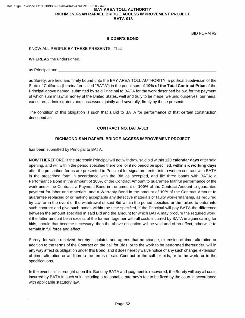
BAY AREA TOLL AUTHORITY RICHMOND-SAN RAFAEL BRIDGE ACCESS IMPROVEMENT PROJECT
BATA-013
Page 52
BID FORM #2 BIDDER’S BOND
KNOW ALL PEOPLE BY THESE PRESENTS: That WHEREAS the undersigned, as Principal and as Surety, are held and firmly bound unto the BAY AREA TOLL AUTHORITY, a political subdivision of the State of California (hereinafter called "BATA") in the penal sum of 10% of the Total Contract Price of the Principal above named, submitted by said Principal to BATA for the work described below, for the payment of which sum in lawful money of the United States, well and truly to be made, we bind ourselves, our heirs, executors, administrators and successors, jointly and severally, firmly by these presents. The condition of this obligation is such that a Bid to BATA for performance of that certain construction described as
CONTRACT NO. BATA-013
RICHMOND-SAN RAFAEL BRIDGE ACCESS IMPROVEMENT PROJECT
has been submitted by Principal to BATA. NOW THEREFORE, if the aforesaid Principal will not withdraw said bid within 120 calendar days after said opening, and will within the period specified therefore, or if no period be specified, within six working days after the prescribed forms are presented to Principal for signature, enter into a written contract with BATA in the prescribed form in accordance with the Bid as accepted, and file three bonds with BATA; a Performance Bond in the amount of 100% of the Contract Amount to guarantee faithful performance of the work under the Contract, a Payment Bond in the amount of 100% of the Contract Amount to guarantee payment for labor and materials, and a Warranty Bond in the amount of 10% of the Contract Amount to guarantee replacing of or making acceptable any defective materials or faulty workermanship, as required by law, or in the event of the withdrawal of said Bid within the period specified or the failure to enter into such contract and give such bonds within the time specified, if the Principal will pay BATA the difference between the amount specified in said Bid and the amount for which BATA may procure the required work, if the latter amount be in excess of the former, together with all costs incurred by BATA in again calling for bids, should that become necessary, then the above obligation will be void and of no effect, otherwise to remain in full force and effect. Surety, for value received, hereby stipulates and agrees that no change, extension of time, alteration or addition to the terms of the Contract on the call for Bids, or to the work to be performed thereunder, will in any way affect its obligation under this Bond, and it does hereby waive notice of any such change, extension of time, alteration or addition to the terms of said Contract or the call for bids, or to the work, or to the specifications. In the event suit is brought upon this Bond by BATA and judgment is recovered, the Surety will pay all costs incurred by BATA in such suit, including a reasonable attorney's fee to be fixed by the court in accordance with applicable statutory law.
DocuSign Envelope ID: 0308BBC7-C948-49AC-A76E-91F00185BA7F
BAY AREA TOLL AUTHORITY RICHMOND-SAN RAFAEL BRIDGE ACCESS IMPROVEMENT PROJECT
BATA-013
Page 53
IN WITNESS WHEREOF, we have hereunto set our hands and seals on this ________________ day of __________________________, 2016. PRINCIPAL: SURETY: (Company) (Company) (Signature) (Signature) (Name – Please Print) (Name – Please print) (Title) (Title)
NOTE: Signatures of those executing for Surety must be acknowledged by a Notary. NOTE TO SURETY COMPANY: The following form of acknowledgement should be used. If any other form of acknowledgement is used, there must be submitted a certified copy of unrevoked resolution of authority for the attorney-in-fact.
SURETY COMPANY ATTORNEY-IN-FACT State of California ) County of ) On ________________________________________, before me, the undersigned, a Notary Public in and for the State, personally appeared__________________________________________________________, known to me to be the duly authorized Attorney-in-Fact of the corporate Surety named in the within instrument, known to me to be authorized to execute that instrument on behalf of said corporation, known to me to be the person whose name is subscribed to such instrument as the Attorney-in-Fact of said corporation, and acknowledged to me that he (she) subscribed the name of said corporation thereto as Surety, and his (her) own name as Attorney-in-Fact and that said corporation executed the same. WITNESS MY HAND AND OFFICIAL SEAL: (SEAL) Notary Public for the State of California Acknowledgement by Attorney-in-Fact must be attached. Corporate seals of Principal and Surety must be attached.
DocuSign Envelope ID: 0308BBC7-C948-49AC-A76E-91F00185BA7F
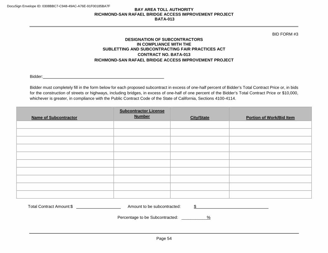
BAY AREA TOLL AUTHORITY RICHMOND-SAN RAFAEL BRIDGE ACCESS IMPROVEMENT PROJECT
BATA-013
Page 54
BID FORM #3 DESIGNATION OF SUBCONTRACTORS
IN COMPLIANCE WITH THE SUBLETTING AND SUBCONTRACTING FAIR PRACTICES ACT
CONTRACT NO. BATA-013 RICHMOND-SAN RAFAEL BRIDGE ACCESS IMPROVEMENT PROJECT
Bidder: Bidder must completely fill in the form below for each proposed subcontract in excess of one-half percent of Bidder’s Total Contract Price or, in bids for the construction of streets or highways, including bridges, in excess of one-half of one percent of the Bidder’s Total Contract Price or $10,000, whichever is greater, in compliance with the Public Contract Code of the State of California, Sections 4100-4114.
Name of Subcontractor
Subcontractor License Number
City/State
Portion of Work/Bid Item
Total Contract Amount:$ Amount to be subcontracted: $
Percentage to be Subcontracted: ___________%
DocuSign Envelope ID: 0308BBC7-C948-49AC-A76E-91F00185BA7F
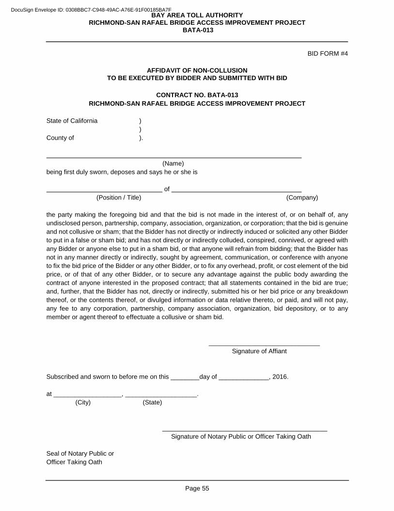
BAY AREA TOLL AUTHORITY RICHMOND-SAN RAFAEL BRIDGE ACCESS IMPROVEMENT PROJECT
BATA-013
Page 55
BID FORM #4
AFFIDAVIT OF NON-COLLUSION TO BE EXECUTED BY BIDDER AND SUBMITTED WITH BID
CONTRACT NO. BATA-013
RICHMOND-SAN RAFAEL BRIDGE ACCESS IMPROVEMENT PROJECT
State of California ) ) County of ). (Name) being first duly sworn, deposes and says he or she is of (Position / Title) (Company) the party making the foregoing bid and that the bid is not made in the interest of, or on behalf of, any undisclosed person, partnership, company, association, organization, or corporation; that the bid is genuine and not collusive or sham; that the Bidder has not directly or indirectly induced or solicited any other Bidder to put in a false or sham bid; and has not directly or indirectly colluded, conspired, connived, or agreed with any Bidder or anyone else to put in a sham bid, or that anyone will refrain from bidding; that the Bidder has not in any manner directly or indirectly, sought by agreement, communication, or conference with anyone to fix the bid price of the Bidder or any other Bidder, or to fix any overhead, profit, or cost element of the bid price, or of that of any other Bidder, or to secure any advantage against the public body awarding the contract of anyone interested in the proposed contract; that all statements contained in the bid are true; and, further, that the Bidder has not, directly or indirectly, submitted his or her bid price or any breakdown thereof, or the contents thereof, or divulged information or data relative thereto, or paid, and will not pay, any fee to any corporation, partnership, company association, organization, bid depository, or to any member or agent thereof to effectuate a collusive or sham bid.
_______________________________ Signature of Affiant Subscribed and sworn to before me on this ________day of ______________, 2016. at ___________________, ____________________.
(City) (State)
______________________________________________ Signature of Notary Public or Officer Taking Oath Seal of Notary Public or Officer Taking Oath
DocuSign Envelope ID: 0308BBC7-C948-49AC-A76E-91F00185BA7F
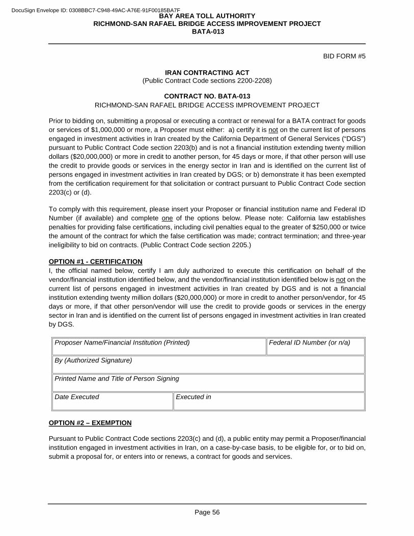
BAY AREA TOLL AUTHORITY RICHMOND-SAN RAFAEL BRIDGE ACCESS IMPROVEMENT PROJECT
BATA-013
Page 56
BID FORM #5
IRAN CONTRACTING ACT (Public Contract Code sections 2200-2208)
CONTRACT NO. BATA-013
RICHMOND-SAN RAFAEL BRIDGE ACCESS IMPROVEMENT PROJECT Prior to bidding on, submitting a proposal or executing a contract or renewal for a BATA contract for goods or services of $1,000,000 or more, a Proposer must either: a) certify it is not on the current list of persons engaged in investment activities in Iran created by the California Department of General Services (“DGS”) pursuant to Public Contract Code section 2203(b) and is not a financial institution extending twenty million dollars ($20,000,000) or more in credit to another person, for 45 days or more, if that other person will use the credit to provide goods or services in the energy sector in Iran and is identified on the current list of persons engaged in investment activities in Iran created by DGS; or b) demonstrate it has been exempted from the certification requirement for that solicitation or contract pursuant to Public Contract Code section 2203(c) or (d). To comply with this requirement, please insert your Proposer or financial institution name and Federal ID Number (if available) and complete one of the options below. Please note: California law establishes penalties for providing false certifications, including civil penalties equal to the greater of $250,000 or twice the amount of the contract for which the false certification was made; contract termination; and three-year ineligibility to bid on contracts. (Public Contract Code section 2205.) OPTION #1 - CERTIFICATION I, the official named below, certify I am duly authorized to execute this certification on behalf of the vendor/financial institution identified below, and the vendor/financial institution identified below is not on the current list of persons engaged in investment activities in Iran created by DGS and is not a financial institution extending twenty million dollars ($20,000,000) or more in credit to another person/vendor, for 45 days or more, if that other person/vendor will use the credit to provide goods or services in the energy sector in Iran and is identified on the current list of persons engaged in investment activities in Iran created by DGS.
Proposer Name/Financial Institution (Printed) Federal ID Number (or n/a)
By (Authorized Signature)
Printed Name and Title of Person Signing
Date Executed Executed in
OPTION #2 – EXEMPTION Pursuant to Public Contract Code sections 2203(c) and (d), a public entity may permit a Proposer/financial institution engaged in investment activities in Iran, on a case-by-case basis, to be eligible for, or to bid on, submit a proposal for, or enters into or renews, a contract for goods and services.
DocuSign Envelope ID: 0308BBC7-C948-49AC-A76E-91F00185BA7F
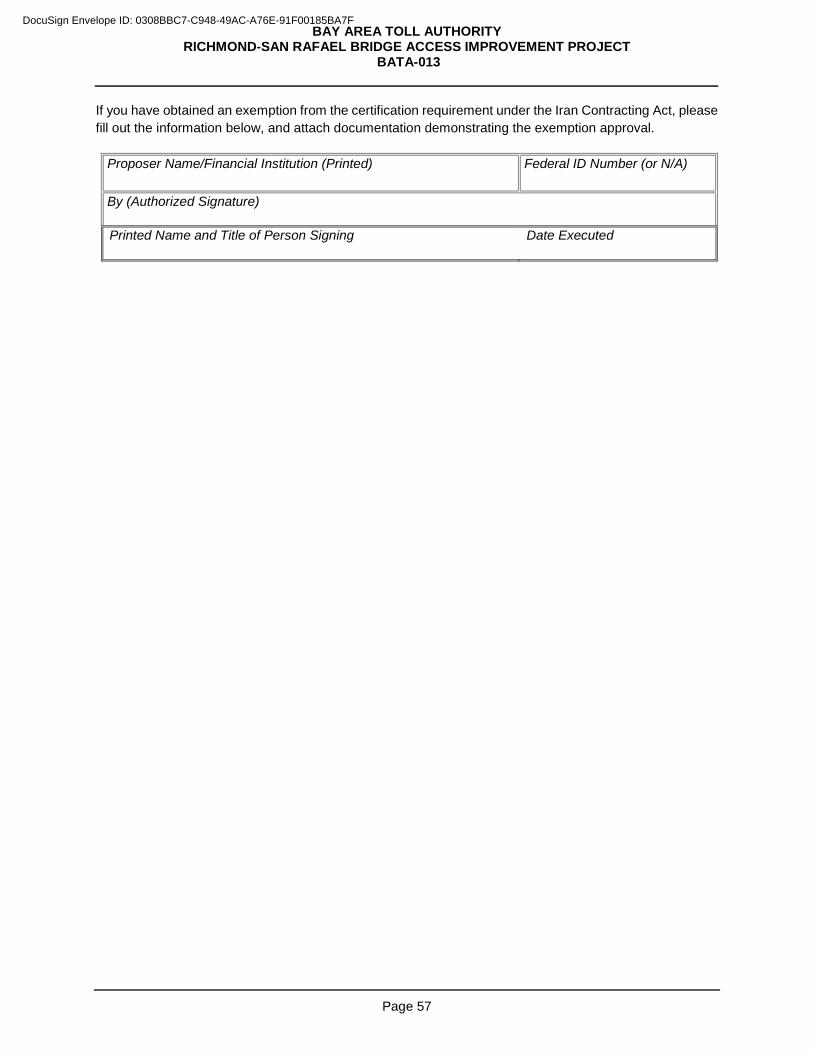
BAY AREA TOLL AUTHORITY RICHMOND-SAN RAFAEL BRIDGE ACCESS IMPROVEMENT PROJECT
BATA-013
Page 57
If you have obtained an exemption from the certification requirement under the Iran Contracting Act, please fill out the information below, and attach documentation demonstrating the exemption approval.
Proposer Name/Financial Institution (Printed) Federal ID Number (or N/A)
By (Authorized Signature)
Printed Name and Title of Person Signing Date Executed
DocuSign Envelope ID: 0308BBC7-C948-49AC-A76E-91F00185BA7F
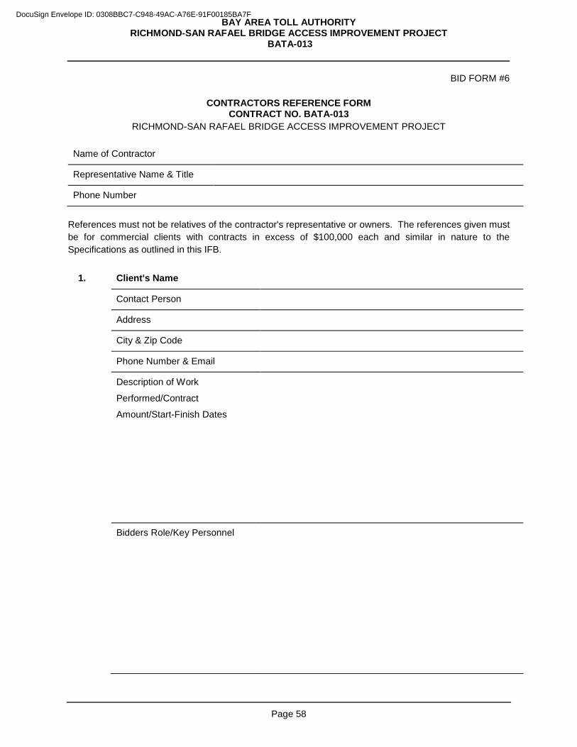
BAY AREA TOLL AUTHORITY RICHMOND-SAN RAFAEL BRIDGE ACCESS IMPROVEMENT PROJECT
BATA-013
Page 58
BID FORM #6
CONTRACTORS REFERENCE FORM CONTRACT NO. BATA-013
RICHMOND-SAN RAFAEL BRIDGE ACCESS IMPROVEMENT PROJECT
Name of Contractor
Representative Name & Title
Phone Number
References must not be relatives of the contractor's representative or owners. The references given must be for commercial clients with contracts in excess of $100,000 each and similar in nature to the Specifications as outlined in this IFB.
1. Client's Name
Contact Person
Address
City & Zip Code
Phone Number & Email
Description of Work
Performed/Contract
Amount/Start-Finish Dates
Bidders Role/Key Personnel
DocuSign Envelope ID: 0308BBC7-C948-49AC-A76E-91F00185BA7F

BAY AREA TOLL AUTHORITY RICHMOND-SAN RAFAEL BRIDGE ACCESS IMPROVEMENT PROJECT
BATA-013
Page 59
2. Client's Name
Contact Person
Address
City & Zip Code
Phone Number & Email
Description of Work
Performed/Contract
Amount/Start-Finish Dates
Bidders Role/Key Personnel
DocuSign Envelope ID: 0308BBC7-C948-49AC-A76E-91F00185BA7F
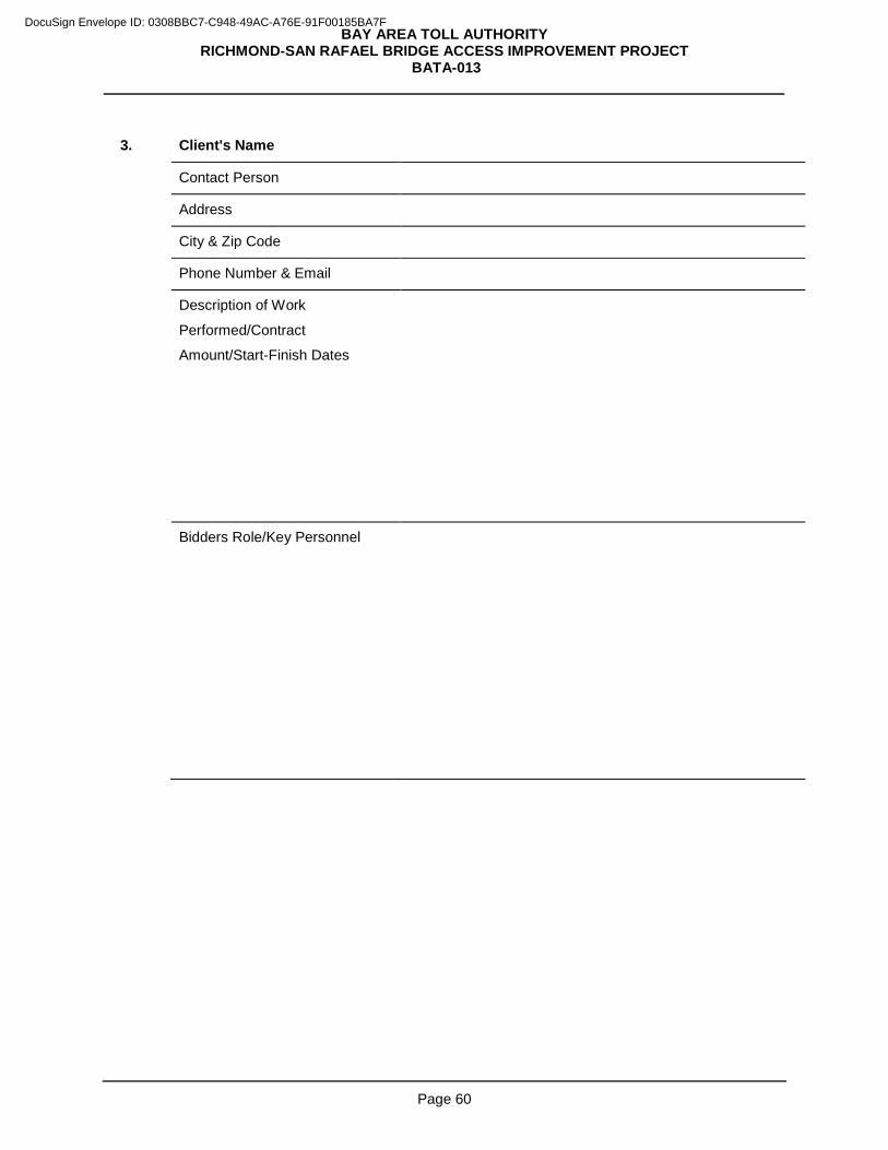
BAY AREA TOLL AUTHORITY RICHMOND-SAN RAFAEL BRIDGE ACCESS IMPROVEMENT PROJECT
BATA-013
Page 60
3. Client's Name
Contact Person
Address
City & Zip Code
Phone Number & Email
Description of Work
Performed/Contract
Amount/Start-Finish Dates
Bidders Role/Key Personnel
DocuSign Envelope ID: 0308BBC7-C948-49AC-A76E-91F00185BA7F
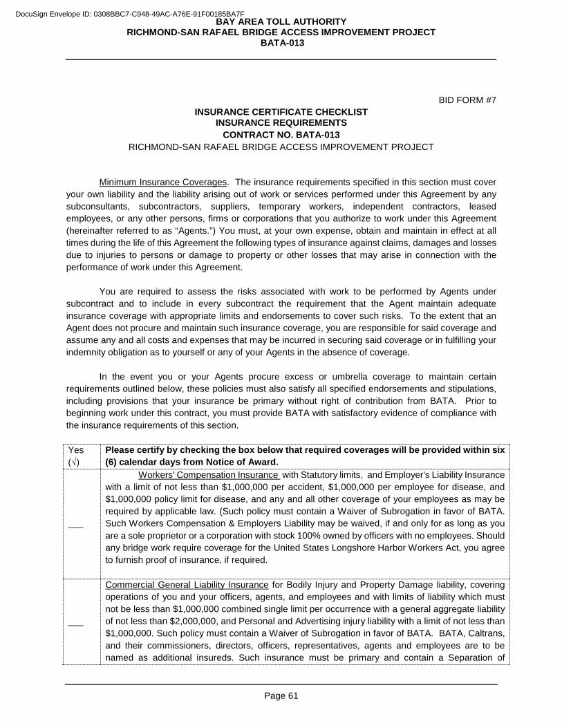
BAY AREA TOLL AUTHORITY RICHMOND-SAN RAFAEL BRIDGE ACCESS IMPROVEMENT PROJECT
BATA-013
Page 61
BID FORM #7 INSURANCE CERTIFICATE CHECKLIST
INSURANCE REQUIREMENTS CONTRACT NO. BATA-013
RICHMOND-SAN RAFAEL BRIDGE ACCESS IMPROVEMENT PROJECT
Minimum Insurance Coverages. The insurance requirements specified in this section must cover
your own liability and the liability arising out of work or services performed under this Agreement by any subconsultants, subcontractors, suppliers, temporary workers, independent contractors, leased employees, or any other persons, firms or corporations that you authorize to work under this Agreement (hereinafter referred to as “Agents.”) You must, at your own expense, obtain and maintain in effect at all times during the life of this Agreement the following types of insurance against claims, damages and losses due to injuries to persons or damage to property or other losses that may arise in connection with the performance of work under this Agreement.
You are required to assess the risks associated with work to be performed by Agents under
subcontract and to include in every subcontract the requirement that the Agent maintain adequate insurance coverage with appropriate limits and endorsements to cover such risks. To the extent that an Agent does not procure and maintain such insurance coverage, you are responsible for said coverage and assume any and all costs and expenses that may be incurred in securing said coverage or in fulfilling your indemnity obligation as to yourself or any of your Agents in the absence of coverage. In the event you or your Agents procure excess or umbrella coverage to maintain certain requirements outlined below, these policies must also satisfy all specified endorsements and stipulations, including provisions that your insurance be primary without right of contribution from BATA. Prior to beginning work under this contract, you must provide BATA with satisfactory evidence of compliance with the insurance requirements of this section. Yes (√)
Please certify by checking the box below that required coverages will be provided within six (6) calendar days from Notice of Award.
___
Workers' Compensation Insurance with Statutory limits, and Employer's Liability Insurance with a limit of not less than $1,000,000 per accident, $1,000,000 per employee for disease, and $1,000,000 policy limit for disease, and any and all other coverage of your employees as may be required by applicable law. (Such policy must contain a Waiver of Subrogation in favor of BATA. Such Workers Compensation & Employers Liability may be waived, if and only for as long as you are a sole proprietor or a corporation with stock 100% owned by officers with no employees. Should any bridge work require coverage for the United States Longshore Harbor Workers Act, you agree to furnish proof of insurance, if required.
___
Commercial General Liability Insurance for Bodily Injury and Property Damage liability, covering operations of you and your officers, agents, and employees and with limits of liability which must not be less than $1,000,000 combined single limit per occurrence with a general aggregate liability of not less than $2,000,000, and Personal and Advertising injury liability with a limit of not less than $1,000,000. Such policy must contain a Waiver of Subrogation in favor of BATA. BATA, Caltrans, and their commissioners, directors, officers, representatives, agents and employees are to be named as additional insureds. Such insurance must be primary and contain a Separation of
DocuSign Envelope ID: 0308BBC7-C948-49AC-A76E-91F00185BA7F
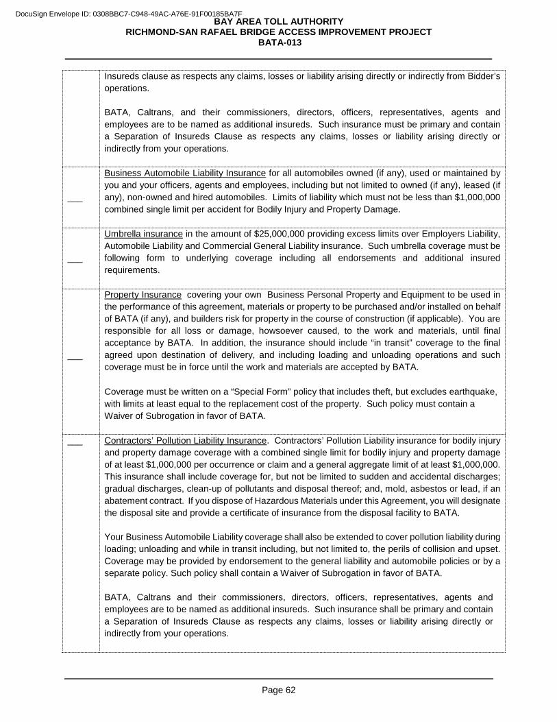
BAY AREA TOLL AUTHORITY RICHMOND-SAN RAFAEL BRIDGE ACCESS IMPROVEMENT PROJECT
BATA-013
Page 62
Insureds clause as respects any claims, losses or liability arising directly or indirectly from Bidder’s operations. BATA, Caltrans, and their commissioners, directors, officers, representatives, agents and employees are to be named as additional insureds. Such insurance must be primary and contain a Separation of Insureds Clause as respects any claims, losses or liability arising directly or indirectly from your operations.
___
Business Automobile Liability Insurance for all automobiles owned (if any), used or maintained by you and your officers, agents and employees, including but not limited to owned (if any), leased (if any), non-owned and hired automobiles. Limits of liability which must not be less than $1,000,000 combined single limit per accident for Bodily Injury and Property Damage.
___
Umbrella insurance in the amount of $25,000,000 providing excess limits over Employers Liability, Automobile Liability and Commercial General Liability insurance. Such umbrella coverage must be following form to underlying coverage including all endorsements and additional insured requirements.
___
Property Insurance covering your own Business Personal Property and Equipment to be used in the performance of this agreement, materials or property to be purchased and/or installed on behalf of BATA (if any), and builders risk for property in the course of construction (if applicable). You are responsible for all loss or damage, howsoever caused, to the work and materials, until final acceptance by BATA. In addition, the insurance should include “in transit” coverage to the final agreed upon destination of delivery, and including loading and unloading operations and such coverage must be in force until the work and materials are accepted by BATA.
Coverage must be written on a “Special Form” policy that includes theft, but excludes earthquake, with limits at least equal to the replacement cost of the property. Such policy must contain a Waiver of Subrogation in favor of BATA.
___ Contractors’ Pollution Liability Insurance. Contractors’ Pollution Liability insurance for bodily injury and property damage coverage with a combined single limit for bodily injury and property damage of at least $1,000,000 per occurrence or claim and a general aggregate limit of at least $1,000,000. This insurance shall include coverage for, but not be limited to sudden and accidental discharges; gradual discharges, clean-up of pollutants and disposal thereof; and, mold, asbestos or lead, if an abatement contract. If you dispose of Hazardous Materials under this Agreement, you will designate the disposal site and provide a certificate of insurance from the disposal facility to BATA. Your Business Automobile Liability coverage shall also be extended to cover pollution liability during loading; unloading and while in transit including, but not limited to, the perils of collision and upset. Coverage may be provided by endorsement to the general liability and automobile policies or by a separate policy. Such policy shall contain a Waiver of Subrogation in favor of BATA. BATA, Caltrans and their commissioners, directors, officers, representatives, agents and employees are to be named as additional insureds. Such insurance shall be primary and contain a Separation of Insureds Clause as respects any claims, losses or liability arising directly or indirectly from your operations.
DocuSign Envelope ID: 0308BBC7-C948-49AC-A76E-91F00185BA7F
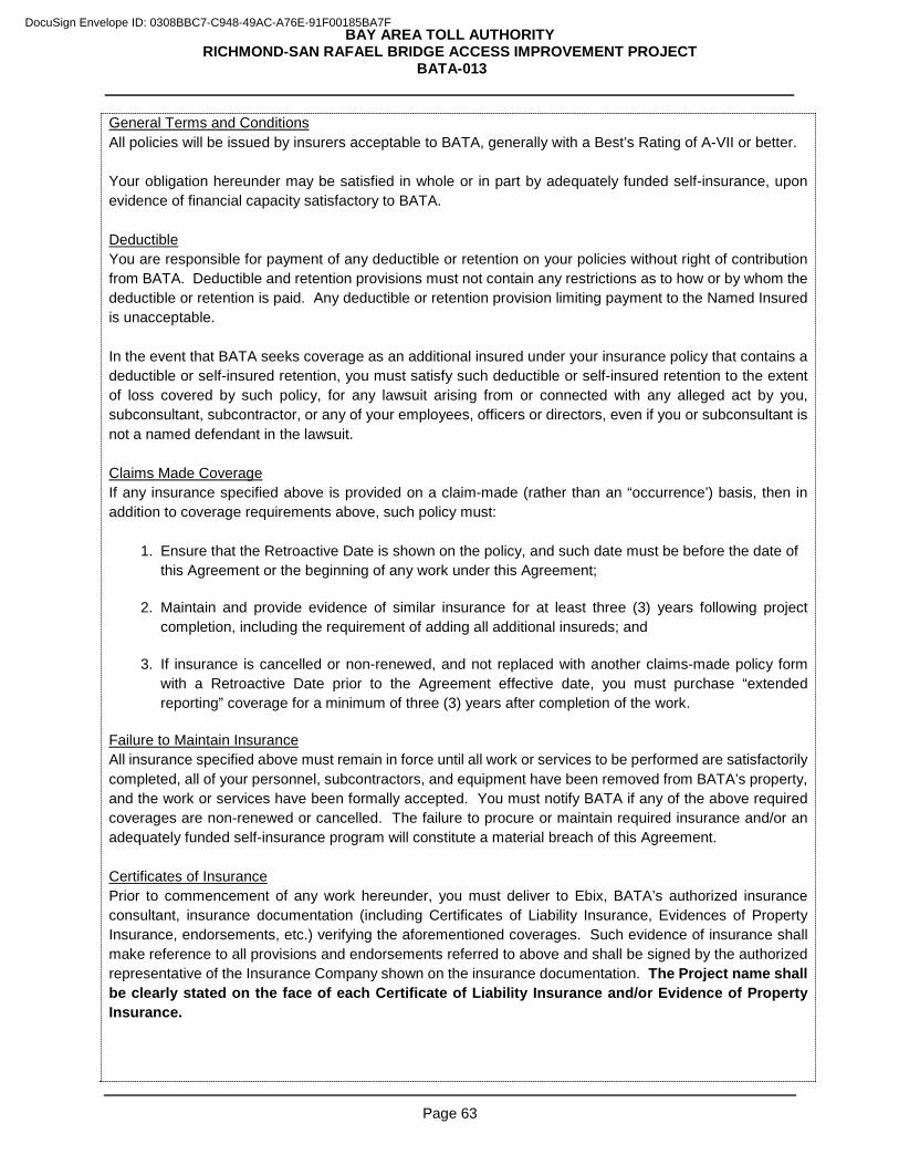
BAY AREA TOLL AUTHORITY RICHMOND-SAN RAFAEL BRIDGE ACCESS IMPROVEMENT PROJECT
BATA-013
Page 63
General Terms and Conditions All policies will be issued by insurers acceptable to BATA, generally with a Best’s Rating of A-VII or better. Your obligation hereunder may be satisfied in whole or in part by adequately funded self-insurance, upon evidence of financial capacity satisfactory to BATA. Deductible You are responsible for payment of any deductible or retention on your policies without right of contribution from BATA. Deductible and retention provisions must not contain any restrictions as to how or by whom the deductible or retention is paid. Any deductible or retention provision limiting payment to the Named Insured is unacceptable.
In the event that BATA seeks coverage as an additional insured under your insurance policy that contains a deductible or self-insured retention, you must satisfy such deductible or self-insured retention to the extent of loss covered by such policy, for any lawsuit arising from or connected with any alleged act by you, subconsultant, subcontractor, or any of your employees, officers or directors, even if you or subconsultant is not a named defendant in the lawsuit.
Claims Made Coverage If any insurance specified above is provided on a claim-made (rather than an “occurrence’) basis, then in addition to coverage requirements above, such policy must:
1. Ensure that the Retroactive Date is shown on the policy, and such date must be before the date of
this Agreement or the beginning of any work under this Agreement;
2. Maintain and provide evidence of similar insurance for at least three (3) years following project completion, including the requirement of adding all additional insureds; and
3. If insurance is cancelled or non-renewed, and not replaced with another claims-made policy form with a Retroactive Date prior to the Agreement effective date, you must purchase “extended reporting” coverage for a minimum of three (3) years after completion of the work.
Failure to Maintain Insurance All insurance specified above must remain in force until all work or services to be performed are satisfactorily completed, all of your personnel, subcontractors, and equipment have been removed from BATA’s property, and the work or services have been formally accepted. You must notify BATA if any of the above required coverages are non-renewed or cancelled. The failure to procure or maintain required insurance and/or an adequately funded self-insurance program will constitute a material breach of this Agreement. Certificates of Insurance Prior to commencement of any work hereunder, you must deliver to Ebix, BATA’s authorized insurance consultant, insurance documentation (including Certificates of Liability Insurance, Evidences of Property Insurance, endorsements, etc.) verifying the aforementioned coverages. Such evidence of insurance shall make reference to all provisions and endorsements referred to above and shall be signed by the authorized representative of the Insurance Company shown on the insurance documentation. The Project name shall be clearly stated on the face of each Certificate of Liability Insurance and/or Evidence of Property Insurance.
DocuSign Envelope ID: 0308BBC7-C948-49AC-A76E-91F00185BA7F
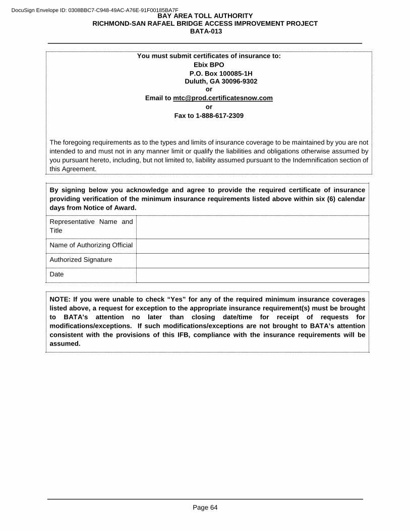
BAY AREA TOLL AUTHORITY RICHMOND-SAN RAFAEL BRIDGE ACCESS IMPROVEMENT PROJECT
BATA-013
Page 64
You must submit certificates of insurance to: Ebix BPO
P.O. Box 100085-1H Duluth, GA 30096-9302
or Email to [email protected]
or Fax to 1-888-617-2309
The foregoing requirements as to the types and limits of insurance coverage to be maintained by you are not intended to and must not in any manner limit or qualify the liabilities and obligations otherwise assumed by you pursuant hereto, including, but not limited to, liability assumed pursuant to the Indemnification section of this Agreement.
By signing below you acknowledge and agree to provide the required certificate of insurance providing verification of the minimum insurance requirements listed above within six (6) calendar days from Notice of Award.
Representative Name and Title
Name of Authorizing Official
Authorized Signature
Date
NOTE: If you were unable to check “Yes” for any of the required minimum insurance coverages listed above, a request for exception to the appropriate insurance requirement(s) must be brought to BATA’s attention no later than closing date/time for receipt of requests for modifications/exceptions. If such modifications/exceptions are not brought to BATA’s attention consistent with the provisions of this IFB, compliance with the insurance requirements will be assumed.
DocuSign Envelope ID: 0308BBC7-C948-49AC-A76E-91F00185BA7F
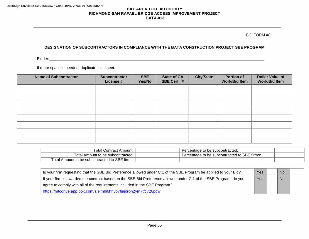
BAY AREA TOLL AUTHORITY RICHMOND-SAN RAFAEL BRIDGE ACCESS IMPROVEMENT PROJECT
BATA-013
Page 65
BID FORM #8
DESIGNATION OF SUBCONTRACTORS IN COMPLIANCE WITH THE BATA CONSTRUCTION PROJECT SBE PROGRAM
Bidder:___________________________________________________________________________________________________ If more space is needed, duplicate this sheet.
Name of Subcontractor Subcontractor
License # SBE
Yes/No State of CA SBE Cert. #
City/State Portion of Work/Bid Item
Dollar Value of Work/Bid Item
Total Contract Amount: Percentage to be subcontracted:
Total Amount to be subcontracted: Percentage to be subcontracted to SBE firms: Total Amount to be subcontracted to SBE firms:
Is your firm requesting that the SBE Bid Preference allowed under C.1 of the SBE Program be applied to your Bid? Yes No If your firm is awarded the contract based on the SBE Bid Preference allowed under C.1 of the SBE Program, do you agree to comply with all of the requirements included in the SBE Program? https://mtcdrive.app.box.com/s/elmhi6hhvb7fiajoroh2ym7tfc726pgw
Yes No
DocuSign Envelope ID: 0308BBC7-C948-49AC-A76E-91F00185BA7F
BAY AREA TOLL AUTHORITY RICHMOND-SAN RAFAEL BRIDGE ACCESS IMPROVEMENT PROJECT
BATA-013
Page 66
PART 6. SPECIAL CONDITIONS
DocuSign Envelope ID: 0308BBC7-C948-49AC-A76E-91F00185BA7F
BAY AREA TOLL AUTHORITY RICHMOND-SAN RAFAEL BRIDGE ACCESS IMPROVEMENT PROJECT
BATA-013
Page 67
SC-1 Indemnification Consistent with California Civil Code Section 2782 and except where the injury, loss, damage or expense arises from the sole negligence or the willful misconduct of BATA or Caltrans, you agree to indemnify and hold BATA, Caltrans and their commissioners, directors, officers, employees and agents harmless from all claims, demands, suits, losses, damages, injury, and liability, direct or indirect (including any and all costs and expenses in connection therewith), incurred by reason of any act or omission by you, your officers, agents, employees and subcontractors or any of them, under or in connection with this contract; and you agree at your own cost expense and risk to defend any and all claims, demands, suits, or other legal proceedings brought or instituted against BATA, Caltrans, or their commissioners, directors, officers, agents, and employees, or any of them arising out of such act or omission, and to pay and satisfy any resulting judgments.
Except as otherwise provided by law, these requirements apply regardless of the existence or degree of fault of the State. Your defense and indemnity obligation must extend to Claims arising after the work is completed and accepted if the Claims are directly related to alleged acts or omissions by you that occurred during the course of the work. Any inspection of the work by the State is not a waiver of full compliance with these requirements.
Except as otherwise provided by law, these requirements apply regardless of the existence or degree of fault of BATA. Your defense and indemnity obligation must extend to Claims arising after the work is completed and accepted if the Claims are directly related to alleged acts or omissions by you that occurred during the course of the work. Any inspection of the work by BATA is not a waiver of full compliance with these requirements.
Your obligation to defend and indemnify is not excused because of your inability to evaluate liability or because you evaluate liability and determine that you are not liable. You must respond within 30 days to the tender of any Claim for defense and indemnity by BATA, unless this time has been extended by BATA. If you fail to accept or reject a tender of defense and indemnity within 30 days, in addition to any other remedy authorized by law, BATA may withhold such funds BATA reasonably considers necessary for its defense and indemnity until disposition has been made of the Claim or until you accept or reject the tender of defense, whichever occurs first. With respect to third-party claims against you, you waive all rights of any type to express or implied indemnity against BATA, its officers, employees, or agents (excluding agents who are design professionals).
SC-2 Insurance 2.1 Minimum Coverage The insurance requirements specified in this section must cover your own liability and the liability arising out of work or services performed under this Agreement by any subconsultants, subcontractors, suppliers, temporary workers, independent contractors, leased employees, or any other persons, firms or corporations that you authorize to work under this Agreement (hereinafter referred to as “Agents.”) You must, at your own expense, obtain and maintain in effect at all times during the life of this Agreement the following types of insurance against claims, damages and losses due to injuries to persons or damage to property or other losses that may arise in connection with the performance of work under this Agreement.
DocuSign Envelope ID: 0308BBC7-C948-49AC-A76E-91F00185BA7F
BAY AREA TOLL AUTHORITY RICHMOND-SAN RAFAEL BRIDGE ACCESS IMPROVEMENT PROJECT
BATA-013
Page 68
You are also required to assess the risks associated with work to be performed by Agents under subcontract and to include in every subcontract the requirement that the Agent maintain adequate insurance coverage with appropriate limits and endorsements to cover such risks. To the extent that an Agent does not procure and maintain such insurance coverage, you are responsible for said coverage and assume any and all costs and expenses that may be incurred in securing said coverage or in fulfilling your indemnity obligation as to yourself or any of your Agents in the absence of coverage. In the event you or your Agents procure excess or umbrella coverage to maintain certain requirements outlined below, these policies must also satisfy all specified endorsements and stipulations, including provisions that your insurance be primary without right of contribution from BATA. Prior to beginning work under this contract, you must provide BATA with satisfactory evidence of compliance with the insurance requirements of this section.
2.1.1 Workers' Compensation Insurance with Statutory limits, and Employer's Liability Insurance with a limit of not less than $1,000,000 per accident, $1,000,000 per employee for disease, and $1,000,000 policy limit for disease, and any and all other coverage of your employees as may be required by applicable law. (Such policy must contain a Waiver of Subrogation in favor of BATA. Such Workers Compensation & Employers Liability may be waived, if and only for as long as you are a sole proprietor or a corporation with stock 100% owned by officers with no employees. Should any bridge work require coverage for the United States Longshore Harbor Workers Act, you agree to furnish proof of insurance, if required.
2.1.2 Commercial General Liability Insurance for Bodily Injury and Property Damage liability,
covering operations of you and your officers, agents, and employees and with limits of liability which must not be less than $1,000,000 combined single limit per occurrence with a general aggregate liability of not less than $2,000,000, and Personal and Advertising injury liability with a limit of not less than $1,000,000. Such policy must contain a Waiver of Subrogation in favor of BATA. BATA, Caltrans, and their commissioners, directors, officers, representatives, agents and employees are to be named as additional insureds. Such insurance must be primary and contain a Separation of Insureds clause as respects any claims, losses or liability arising directly or indirectly from your operations.
2.1.3 Business Automobile Liability Insurance for all automobiles owned (if any), used or
maintained by you and your officers, agents and employees, including but not limited to owned (if any), leased (if any), non-owned and hired automobiles. Limits of liability which must not be less than $1,000,000 combined single limit per accident for Bodily Injury and Property Damage.
2.1.4 Umbrella insurance in the amount of $25,000,000 providing excess limits over Employers
Liability, Automobile Liability and Commercial General Liability insurance. Such umbrella coverage must be following form to underlying coverage including all endorsements and additional insured requirements.
2.1.5 Property Insurance covering your own Business Personal Property and Equipment to be
used in the performance of this agreement, materials or property to be purchased and/or installed on behalf of BATA (if any), and builders risk for property in the course of construction (if applicable). You are responsible for all loss or damage, howsoever caused, to the work and materials, until final acceptance by BATA. In addition, the insurance should
DocuSign Envelope ID: 0308BBC7-C948-49AC-A76E-91F00185BA7F
BAY AREA TOLL AUTHORITY RICHMOND-SAN RAFAEL BRIDGE ACCESS IMPROVEMENT PROJECT
BATA-013
Page 69
include “in transit” coverage to the final agreed upon destination of delivery, and including loading and unloading operations, and such coverage must be in force until the work and materials are accepted by BATA.
Coverage must be written on a “Special Form” policy that includes theft, but excludes earthquake, with limits at least equal to the replacement cost of the property. Such policy must contain a Waiver of Subrogation in favor of BATA.
2.1.6 Contractors’ Pollution Liability insurance for bodily injury and property damage coverage
with a combined single limit for bodily injury and property damage of at least $1,000,000 per occurrence or claim and a general aggregate limit of at least $1,000,000. This insurance shall include coverage for, but not be limited to sudden and accidental discharges; gradual discharges, clean-up of pollutants and disposal thereof; and, mold, asbestos or lead, if an abatement contract. If you dispose of Hazardous Materials under this Agreement, you will designate the disposal site and provide a certificate of insurance from the disposal facility to BATA.
Your Business Automobile Liability coverage shall also be extended to cover pollution liability during loading; unloading and while in transit including, but not limited to, the perils of collision and upset. Coverage may be provided by endorsement to the general liability and automobile policies or by a separate policy. Such policy shall contain a Waiver of Subrogation in favor of BATA.
BATA, Caltrans and their commissioners, directors, officers, representatives, agents and employees are to be named as additional insureds. Such insurance shall be primary and contain a Separation of Insureds Clause as respects any claims, losses or liability arising directly or indirectly from your operations.
2.2 Deductibles You are responsible for payment of any deductible or retention on your policies without right of contribution from BATA. Deductible and retention provisions must not contain any restrictions as to how or by whom the deductible or retention is paid. Any deductible or retention provision limiting payment to the Named Insured is unacceptable. In the event that BATA seeks coverage as an additional insured under any Bidder insurance policy that contains a deductible or self-insured retention, you must satisfy such deductible or self-insured retention to the extent of loss covered by such policy, for any lawsuit arising from or connected with any alleged act by you, subconsultant, subcontractor, or any of your employees, officers or directors, even if you or subconsultant is not a named defendant in the lawsuit. 2.3 Failure to Maintain Insurance All insurance specified above must remain in force until all work or services to be performed are satisfactorily completed, all of your personnel, subcontractors, and equipment have been removed from BATA’s property, and the work or services have been formally accepted. You must notify BATA if any of the above required coverages are non-renewed or cancelled. The failure to procure or maintain required insurance and/or an adequately funded self-insurance program will constitute a material breach of this Agreement.
DocuSign Envelope ID: 0308BBC7-C948-49AC-A76E-91F00185BA7F
BAY AREA TOLL AUTHORITY RICHMOND-SAN RAFAEL BRIDGE ACCESS IMPROVEMENT PROJECT
BATA-013
Page 70
2.4 Self-Insurance Your obligation hereunder may be satisfied in whole or in part by adequately funded self-insurance, upon evidence of financial capacity satisfactory to BATA. 2.5 Claims Made Coverage If any insurance specified above be provided on a claim-made (rather than an “occurrence’) basis, then in addition to coverage requirements above, such policy must:
2.5.1 Ensure that the Retroactive Date is shown on the policy, and such date must be before the date of this Agreement or the beginning of any work under this Agreement;
2.5.2 Maintain and provide evidence of similar insurance for at least three (3) years following
project completion, including the requirement of adding all additional insureds; and 2.5.3 If insurance is cancelled or non-renewed, and not replaced with another claims-made
policy form with a Retroactive Date prior to the Agreement effective date, you must purchase “extended reporting” coverage for a minimum of three (3) years after completion of the work.
2.6 Certificates of Insurance Prior to commencement of any work hereunder, you must deliver to BATA Certificates of Insurance verifying the aforementioned coverages. Such certificates must make reference to all provisions and endorsements referred to above and must be signed on behalf of the insurer by an authorized representative thereof. 2.7 Disclaimer The foregoing requirements as to the types and limits of insurance coverage to be maintained by you are not intended to and must not in any manner limit or qualify the liabilities and obligations otherwise assumed by you pursuant hereto, including, but not limited to, liability assumed pursuant to Section 7-1.05, Indemnification, of the Standard Specifications. 2.8 Acceptable Insurers All policies will be issued by insurers acceptable to BATA, generally with a Best’s Rating of A-VII or better. SC-3 Contract Bonds Prior to execution of the Contract, file with BATA consistent with the forms provided herein, three surety bonds in the amounts and for the purposes noted below, duly executed by a reputable surety company satisfactory to BATA; provided, however, that no bonds are required on contracts of $25,000 or less. Pay all premiums and costs relating to required bonds, whether direct or incidental thereto. Both you and surety must sign each bond. Concurrent with the execution and delivery of the Contract and prior to the commencement of any work under the Agreement, you must deliver to Ebix, BATA’s authorized insurance consultant, documentation
DocuSign Envelope ID: 0308BBC7-C948-49AC-A76E-91F00185BA7F
BAY AREA TOLL AUTHORITY RICHMOND-SAN RAFAEL BRIDGE ACCESS IMPROVEMENT PROJECT
BATA-013
Page 71
of bonds verifying the coverages listed below. You must submit documentation of bonds as noted below under SC-3. Such evidence of bond requirements shall include the project name and be signed by the authorized representative of the Surety. You will provide and must maintain in effect for the term of the Contract unless otherwise specified herein, the bonds as financial security for the Project.
You must submit documentation of bonds to:
Ebix BPO P.O. Box 100085-1H
Duluth, GA 30096-9302 or
Email to [email protected] or
Fax to 1-888-617-2309 3.1 Payment Bond The Payment Bond must be in an amount of 100% of the Total Contract Price and must inure to the benefit of persons performing labor or furnishing materials in connection with the work of the proposed Contract. This bond must be maintained in full force and effect until all work under the Contract is completed and accepted by BATA, and until all claims for materials and labor have been paid. 3.2 Performance Bond The Performance Bond must be in an amount of 100% of the Total Contract Price and must insure the faithful performance by you for all work under the Contract. It must also insure the replacing of, or making acceptable, any defective materials or faulty workmanship. 3.3 Warranty Bond The Warranty Bond must be in an amount of 10% of the Total Contract Price and must insure the faithful performance by you to insure the replacing of, or making acceptable, any defective materials or faulty workmanship for a period of two years.
3.4 Surety Requirements Sureties for necessary bonds (including Bid Bond, Performance Bond, Payment Bond, and Warranty Bond) must be executed by an admitted surety(ies) insurer acceptable to BATA with a Best Guide Rating of A7 or better and authorized to execute such in the State of California. Should any surety or sureties be deemed unsatisfactory at any time by BATA notice will be given to that effect, and you must forthwith substitute a new surety or sureties satisfactory to BATA, within 30 days, at your expense; provided, however, that the time set out in the Notice of Award for submitting bonds must not be extended thereby. No further payment will be deemed due or will be made under the Contract until the new sureties qualify and are accepted by BATA. All alterations, time extensions, extra and additional work, and other changes authorized by the Specifications, or any part of the Contract, may be made without securing consent of the surety or sureties on the contract bonds.
DocuSign Envelope ID: 0308BBC7-C948-49AC-A76E-91F00185BA7F
BAY AREA TOLL AUTHORITY RICHMOND-SAN RAFAEL BRIDGE ACCESS IMPROVEMENT PROJECT
BATA-013
Page 72
SC-4 Time for Performance Time is of the essence and this project and all milestones must be completed as quickly as possible. Thus, the time of completion for the overall project and all milestones are accelerated. Working 40-hour work weeks with single crews will not be sufficient to complete the project and all milestones on time. You will have to work double shifts, weekends, and have multiple crews working simultaneously for many operations. Submission of a bid for this project is acknowledgment that that you have prepared a detailed schedule to complete the project and all milestones on time and that you have included all acceleration and premium costs in your bid prices for the various items of work. The time limit for completion of all construction work, including plant establishment, under the Contract is 580 working days following the issuance by BATA of a Notice to Proceed. The project includes a plant establishment period of 250 working days following acceptance of all planting by the Engineer and the following interim completion dates: (1) Completion of Milestone #1 - Tree removal: by January 15, 2017 (2) Completion of Milestone #2 - Third lane open: within 250 working days (3) Completion of all construction work (excluding plant establishment): within 330 working days Should you fail to maintain the progress of the work in conformance with 8-1.02 Schedule, additional shifts will be required to the extent necessary to ensure that the progress conforms to the above mentioned schedule and that the work will be completed within the time limit specified. Payment for complying with the requirements in this section is included in the payment for the bid items involved. SC-5 Beginning of Work, Time of Completion, and Liquidated Damages Refer to Part 2.0, Section 9, Notice to Proceed for the anticipated Notice to Proceed issue date. Liquidated damages will be assessed as follows for every day passed the total working days as stated in Section SC-4, Time for Performance. (1) Milestone #1 - Tree removal completed by January 15, 2017. Liquidated damages will be assessed if Milestone #1 is not completed within the specified time frame and if nesting birds cause a delay to the completion of either or both Milestone #2 and the completion of all construction work. Liquidated damages will be assessed as appropriate under Milestone #2 and/or the completion of construction work. (2) Milestone #2 - Third lane open: $9,600/day (3) Completion of all construction work, excluding plant establishment: $13,500/day (4) Plant establishment: $950/day (Starts after all work has been completed and plant establishment period has expired). Comply with Section 8-1.10, Liquidated Damages, of the Standard Specifications.
DocuSign Envelope ID: 0308BBC7-C948-49AC-A76E-91F00185BA7F
BAY AREA TOLL AUTHORITY RICHMOND-SAN RAFAEL BRIDGE ACCESS IMPROVEMENT PROJECT
BATA-013
Page 73
SC-6 Contract Data Requirements Submit to BATA the items shown on the Contract Data Requirement List and the Technical Submittals List (both appearing in this Part 6.0, Special Conditions) in compliance with the times and in the number of copies specified therein. Requirements and procedures for preparing and transmitting items shown on the Technical Submittals List must conform to the following: 6.1 Drawings Prepare working and shop drawings as required by BATA for the performance of the work. Drawings must be prepared on a reproducible sheet measuring 22 inches x 34 inches, unless otherwise approved. Each drawing must have a blank area 5 inches x 5 inches minimum, located above the title block, for the acceptance stamp. The title block must display the following:
1. Contract number and name 2. District and County 3. Number and title of drawing 4. Date of drawing or revision 5. Name of the Contractor and Subcontractor originating drawing 6. Clear identification of contents and location of work 7. Structure name and number, if any 8. Structural calculations signed and sealed by a California licensed civil Engineer, where applicable.
6.2 Detail Drawings Furnish detail drawings for temporary work and method of proposed construction for the safe and successful completion of the work. 6.3 Submittal Cover Letter Submittals must be accompanied by a “Submittal Cover Letter” form neatly and properly filled out. Forms will be furnished by BATA. 6.4 Copies of Drawings Submit six (6) hard copies and one (1) electronic copy (PDF Format) of complete and detailed working and shop drawings, which must be suitable for microfilming, to BATA. Such drawings must include but not be limited to:
1. Fabrication and erection drawings, schedule drawings and manufacturer’s scale drawings. If requested by BATA, Furnish calculations and information substantiating the details shown on the drawings satisfactory to BATA.
2. Plans for temporary structures, and for such other work as may be required for construction, which does not become an integral part of the completed project. Submit two copies of the calculations and other information needed to describe in detail the temporary structures or systems and their intended use.
DocuSign Envelope ID: 0308BBC7-C948-49AC-A76E-91F00185BA7F
BAY AREA TOLL AUTHORITY RICHMOND-SAN RAFAEL BRIDGE ACCESS IMPROVEMENT PROJECT
BATA-013
Page 74
All submittals for electrical equipment must conform to the provisions of the contract. All electrical materials must be tagged in conformance with the provisions of GC-49, Certificates of Compliance and Testing, before delivery to the work site. Untagged electrical materials will be rejected. 6.5 Time for Submittal Submit drawings and schedules sufficiently in advance of construction requirements as indicated in SC-51. Unless specified elsewhere in the Contract Documents, within 10 days of Notice to Proceed, You must prepare a preliminary Schedule of Submittals coordinated with the Progress Schedule, listing Shop Drawings, Product Data, Samples, work descriptions, Subcontractor qualifications, and Field Samples, and indicating therein the times for submitting, reviewing, and processing such submittals. Submit one hard copy and one electronic copy of supporting data such as manufacturer’s literature for all items. Except for shop drawings and test samples, allow 15 days for review. Allow 20 days for review of shop drawings. The approval of drawings and schedules will be general and will not be construed as:
1. Permitting any departure from contract requirements; 2. Offering relief from the responsibility for any errors, or omissions including details, dimensions, and
materials; 3. Approving departures from details furnished by the Engineer, except as otherwise provided in Part
10 Construction Details. 6.6 Variations If drawings show variations from contract requirements because of standard shop practice or for any other reason, such variations must be described in the letter of submittal.
1. BATA may approve or reject any or all variations. 2. If variations result in an adjustment to the contract price or time for performance, the adjustment
will be subject to approval by BATA. 3. Failure to describe variations does not relieve you from the responsibility of executing the work in
accordance with the Contract, even though such drawings have been approved. 6.7 Corrections If corrections to the drawings are required, each print will be marked “MAKE CORRECTIONS NOTED” or “AMEND AND RESUBMIT” and the required corrections will be explained. One print and one reproducible copy will be returned for correction. 6.8 Re-submittals Re-submittals will be handled in the same manner as first submittals, and the same review time will apply.
DocuSign Envelope ID: 0308BBC7-C948-49AC-A76E-91F00185BA7F
BAY AREA TOLL AUTHORITY RICHMOND-SAN RAFAEL BRIDGE ACCESS IMPROVEMENT PROJECT
BATA-013
Page 75
1. Specific attention is directed to revisions other than those requested by BATA on previous submittals by an accompanying letter or on the resubmitted drawings.
2. If any corrections shown on the drawings constitute a change of contract requirements, BATA must be notified, as previously specified.
6.9 Acceptance If accepted by BATA, each copy of the drawing will be stamped and dated indicating acceptance. One print and one reproducible copy will be returned. 6.10 Changes When working and shop drawings have been completed to the satisfaction of BATA, the construction will be carried out in accordance with such drawings, and no changes will be made thereon except upon written direction from the Engineer. During execution of the work, use only drawings that are either stamped “MAKE CORRECTION NOTED” or “NO EXCEPTIONS TAKEN” and bear BATA’s signature. 6.11 Damages You are responsible for, and bear all cost of, damages that may result from ordering material or from proceeding with work before approval by BATA. 6.12 Samples Furnish samples as specified and requested by BATA as soon as possible after request. Unless otherwise indicated, not less than two identical samples of each type required must be submitted. Comply with Section 6-3.05G, Test Samples, of the Standard Specifications for BATA’s testing. Shipping charges on samples will be prepaid by you. Products for which samples are requested must not be used until approved in writing by BATA. Each sample must be labeled to indicate:
1. Name of project and Contract number 2. Name of the Contractor and Subcontractor or Supplier, if applicable 3. Material or equipment represented 4. Source 5. Name of producer and brand (if any) 6. References to the parts of Part 10.0, which are applicable to the sample 7. Location of work
Certain samples may be tested by BATA. Approved samples not destroyed in testing may be retained by BATA. Samples not approved will be returned at your expense, if so requested at the time of submittal.
DocuSign Envelope ID: 0308BBC7-C948-49AC-A76E-91F00185BA7F
BAY AREA TOLL AUTHORITY RICHMOND-SAN RAFAEL BRIDGE ACCESS IMPROVEMENT PROJECT
BATA-013
Page 76
6.13 Shipment Letter A letter must be mailed under separate cover submitting each shipment of samples and detailing the information required in the preceding paragraph. A copy of the letter must be enclosed with the shipment.
6.14 Test Results Documents such as certificates, reports, and test results specified in Part 10, Construction Details, will be submitted to BATA. Three copies of each required must be submitted, unless specified otherwise. Notice of completion of work to hold points specified in the encroachment permit must be given to BATA fourteen (14) calendar days before estimated completion of that work. 6.15 Payment You will receive no separate payment from BATA for complying with the above requirements and are presumed to have allocated such costs to bid price.
SC-7 Permits and Fees Secure a copy of BATA acquired permits from BATA and comply with said permits requirements. Pay all charges required to comply with the conditions outlined in the permits. Refer to Part 10 Construction Details for project permits. Apply for all jurisdictional permits required to perform the work and include the cost of the required permits in the bid price. Caltrans Permit – Obtain a copy of the Caltrans encroachment permit issued to the BAY AREA TOLL AUTHORITY and comply with all provisions of said permit. Apply for Caltrans' construction encroachment permit within two (2) calendar days after the Notice of Award. The Obtained Caltrans’ construction encroachment permit will require, but is not limited to, the following provisions:
1. Proof of payment and performance surety bonds. 2. Permit fee may be waived by Caltrans. 3. Other conditions as stipulated in said permit to be issued by Caltrans to BATA.
Payment for complying with the requirements in SC-7 is included in the payment for the bid items involved. City of Richmond Permit - Apply for City of Richmond's construction encroachment permit in your name within two (2) working days after the Notice of Award. You are responsible for preparing all necessary documents and all fees associated with getting the permit.
DocuSign Envelope ID: 0308BBC7-C948-49AC-A76E-91F00185BA7F
BAY AREA TOLL AUTHORITY RICHMOND-SAN RAFAEL BRIDGE ACCESS IMPROVEMENT PROJECT
BATA-013
Page 77
City of San Rafael Permit - Apply for City of San Rafael's construction encroachment permit in your name within two (2) working days after the Notice of Award. You are responsible for preparing all necessary documents and all fees associated with getting the permit. Chevron Property Access - You are responsible for applying to Chevron for any access to the Chevron property and for preparing all necessary documents and all fees associated for the access. Refer to special provision section 15-4.01C(2)(b) for Chevron training requirements. SC-8 Reserved SC-9 Delivery, Unloading and Storage You are completely responsible for all delivery, unloading and storage activities required for the completion of work under this contract, including “Owner Furnished Materials” of these special conditions. SC-10 Reserved SC-11 Reserved SC-12 Reserved SC-13 Worker’s Safety Provisions Supply personal protective equipment, training, and washing facilities required by your lead compliance plan for five (5) BATA employees.
13.1 You are responsible for initiating, maintaining and supervising all safety precautions and programs in connection with the Work. To that end you must: (1) No later than ten (10) days after receipt of the Notice of Award, submit for review your Injury Prevention Program (IPP), which must be site and task specific, and must meet or exceed the requirements of BATA’s Injury Prevention Program, and must comply with California Labor Code Section 6401.7. You are responsible for overseeing compliance of their Subcontractors IPP, upon request, the Subcontractors IPP may be reviewed by BATA; and (2) No later than ten days after receipt of Notice of Award, submit the resume of the full time, qualified Safety Representative(s) who reports directly to the your Project Manager or Superintendent, and allocates 100% of their time to safety oversight for field operations on the above mentioned project. Your Safety Representative(s) must have a minimum of five (5) years heavy construction experience in administering safety programs on construction job sites, the last two of which have been administering safety in the construction discipline for which you are contracting with Owner. Your Safety Representatives(s) must be onsite during all operational hours. The full time Safety Representative(s) must set up, carry forward and aggressively and effectively maintain the aforementioned Safety Program covering all phases of the Work. If at any time you wish to replace their Safety Representative(s), provide written notice thirty (30) days prior to change of personnel to BATA. Take all precautions and follow all procedures for the safety of, and provide all protection to prevent injury to, all persons involved in any way in the Work and all other persons,
DocuSign Envelope ID: 0308BBC7-C948-49AC-A76E-91F00185BA7F
BAY AREA TOLL AUTHORITY RICHMOND-SAN RAFAEL BRIDGE ACCESS IMPROVEMENT PROJECT
BATA-013
Page 78
including, without limitation, the employees, agents, guests, visitors, invitees and licensees of BATA who may be involved. These precautions must include, but in no event be limited to the provisions of BATA’s IPP. This requirement applies continuously and is not limited to normal working hours.
13.2 Use or storage of explosives is prohibited.
13.3
Open fires on the Project Site are not permitted. 13.4 Forward the Emergency Action Plans to BATA no later than ten days following award. 13.5 No later than five (5) working days prior to the arrival of a crane, provide the most recent annual and quadrennial certificates. Also provide crane operator certificates from the National Commission for the Certifying of Crane Operators (NCCCO), as outlined in IPP, no later than five working days prior to a crane operator working onsite.
13.6 Job Hazard Analysis must be forwarded to BATA no later than five working days prior to operation being performed. All accident investigations must be forwarded to BATA no later than five working days following an accident.
13.7 Emergencies In any emergency affecting the safety of persons or property, or in the event of a claimed violation of any Federal or State safety or health law or regulation, arising out of or in any way connected with the Work or its performance, ensure that at least one of your employees with authority be on duty during working hours, and act immediately to prevent threatened damage, injury or loss or to remedy said violation, whichever is applicable, failing which BATA may immediately take whatever action it deems necessary, including, but not limited to, suspending the Work as provided in GC-69. Also establish and maintain adequate First Aid facilities at locations close to work areas, and mark such locations with signs of adequate size and composition. Also ensure that at least one CPR/ first aid trained employee for every fifteen (15) employees are onsite. No less than two (2) CPR/first aid trained employees be onsite during operational hours, at all times. Forward training records or certificates for initial and renewal CPR/ first aid training to BATA no later than ten (10) days following Notice of Award. SC-14 Hazardous Materials Submit Material Safety Data Sheets (MSDS) for all hazardous materials being brought onto the project site, including but not limited to: asphalts, solvents, adhesives, epoxy resins, roofing sealants and bonding agents.
DocuSign Envelope ID: 0308BBC7-C948-49AC-A76E-91F00185BA7F
BAY AREA TOLL AUTHORITY RICHMOND-SAN RAFAEL BRIDGE ACCESS IMPROVEMENT PROJECT
BATA-013
Page 79
SC-15 Construction Water Conservation Whenever possible and not in conflict with other requirements of the Contract, minimize the use of water during construction of the project. Watering equipment must be kept in good working order; water leaks must be repaired promptly; and washing of equipment, except when necessary for safety or for the protection of equipment, is discouraged. All water used for construction purposes such as dust control, compaction, cleaning streets, etc., may be reclaimed water. SC-16 Reserved SC-17 Reserved SC-18 Reserved SC-19 Final Pay Quantities Comply with Section 9-1.02C, Final Pay Item Quantities, of the Standard Specifications. When portions of an item have been designated on the plans or in the Schedule of Quantities and Prices of the contract bid form as final pay quantities, portions so designated will be measured and paid for in accordance with the provisions of GC-59, Invoicing and Progress Payments. SC-20 Reserved SC-21 Reserved SC-22 Project Close-Out Requirements - Record Drawings During the project, keep a master set of drawings updated, noting any variation of the Work. Upon completion of the Work, produce a master “Record” set of plans by neatly transferring all such noted variations to blueprint copies of the same drawings, and deliver same to the Engineer for signed receipt, certification, and certification. Payment for complying with the requirements in SC-22, Project Close-Out Requirements - Record Drawings, is included in the payment for the bid items involved SC-23 Reserved SC-24 Reserved SC-25 Reserved SC-26 Laboratory When a reference is made in the specifications to the "Laboratory," the reference means Division of Engineering Services - Materials Engineering and Testing Services and Division of Engineering Services - Geotechnical Services of the Department of Transportation, or established laboratories of the various
DocuSign Envelope ID: 0308BBC7-C948-49AC-A76E-91F00185BA7F
BAY AREA TOLL AUTHORITY RICHMOND-SAN RAFAEL BRIDGE ACCESS IMPROVEMENT PROJECT
BATA-013
Page 80
Districts of the Department, or other laboratories authorized by the State to test materials and work involved in the contract. When a reference is made in the specifications to the "Transportation Laboratory," the reference means Caltrans Division of Engineering Services - Materials Engineering and Testing Services and Division of Engineering Services – Geotechnical Services, located at 5900 Folsom Boulevard, Sacramento, CA 95819, Telephone (916) 227-7000. SC-27 Reserved SC-28 Reserved
SC-29 Reserved SC-30 Value Engineering Change Proposals (VECP) Comply with Section 4-1.07B, Value Engineering Change Proposal, of the Standard Specifications. 30.1 Acceptance of VECP BATA may accept or reject part or all of any VECP by giving you written notice thereof. Until such notice is issued, you remain obligated to perform in accordance with the terms of the Contract. VECPs will be processed expeditiously; however, BATA is not liable for any delay in acting upon any proposal submitted pursuant to this Article. The decision of BATA as to acceptance of any such proposal is final. The denial of any VECP does not provide you with any basis for claim for damages or delay, nor for release from contractual responsibilities. BATA’s approval of a value engineering proposal does not entitle you to additional compensation or time if the work incorporating the proposal is defective, more expensive, or takes more time. 30.2 Inclusion in Subcontracts Include value engineering arrangements in any subcontract which, in your judgment, appears to offer sufficient value Engineering potential. 30.3 Identical VECP A VECP identical to one submitted under any other contract, by this or by any other Contractor, may also be submitted under the Contract, provided that the proposal originated with such Contractor and not with BATA. 30.4 Restrictions You may restrict BATA’s right to use any VECP data by marking it with the following statement: “This data, furnished pursuant to the Value Engineering article of the Contract, will not be duplicated, used or disclosed in whole or in part, for any purpose except to evaluate the VECP, unless the proposal is accepted by BATA. The restriction does not limit BATA’s right to use information contained in this data if it is or has been obtained, or is otherwise available, from Contractor or from another source, without limitations. When this proposal is accepted by BATA, BATA will have the right to duplicate, use and disclose
DocuSign Envelope ID: 0308BBC7-C948-49AC-A76E-91F00185BA7F
BAY AREA TOLL AUTHORITY RICHMOND-SAN RAFAEL BRIDGE ACCESS IMPROVEMENT PROJECT
BATA-013
Page 81
any data in any manner and for any purpose whatsoever, and have others do so whether under this or any Contract.” You have no right to share any future savings derived from incorporation of the VECP in future BATA Contracts. SC-31 Alternative Methods of Construction Whenever the plans or specifications provide that more than one specified method of construction or more than one specified type of material or construction equipment may be used to perform portions of the work and leave the selection of the method of construction or the type of material or equipment to be used up to you, it is understood that BATA does not guarantee that every specified method of construction or type of material or equipment can be used successfully throughout all or any part of any project. Attention is directed to Part 2-2 “General Description of Work” of these Contract Documents. It is your responsibility to select and use the alternative or alternatives, which will satisfactorily perform the work under the conditions encountered. SC-32 Reserved SC-33 Quality Control Program At your own expense, arrange and submit for BATA’s approval and implement a Quality Control Program consistent with the requirements of the Standard Specifications. Regulatory Requirements: California Building Standards Code, Title 24, California Code of Regulations (CCR Title 24). Codes can be found at: http://www.bsc.ca.gov/Home/Current2013Codes.aspx For CCR, Title 24, Part 11:
1. Comply with the Tier 1 requirements of Appendix A5, "Nonresidential Voluntary Measures," in addition to all other requirements.
2. Use the sample forms referenced in Section 5.408.1.4, "Documentation," to comply with the documentation requirements of Section 5.408, "Construction Waste Reduction Disposal and Recycling."
3. Prepare all verification of compliances required in Section 5.504, "Pollutant Control." SC-34 Conformity With Contract Documents and Allowable Deviations Work and materials must conform to the lines, grades, typical cross sections, dimensions and material requirements, including tolerances, shown on the plans or indicated in the specifications. Although measurement, sampling and testing may be considered evidence as to conformity, the Engineer is the sole judge as to whether the work or materials deviate from the plans and specifications, and the Engineer's decision as to any allowable deviations there from is final. SC-35 Use of Materials Found On the Work
DocuSign Envelope ID: 0308BBC7-C948-49AC-A76E-91F00185BA7F
BAY AREA TOLL AUTHORITY RICHMOND-SAN RAFAEL BRIDGE ACCESS IMPROVEMENT PROJECT
BATA-013
Page 82
Unless designated as selected material as provided in Section 19-2.03D, "Selected Material" of the Standard Specifications, You, with approval, may use in the proposed construction such stone, gravel, sand or other material suitable in the opinion of the Engineer as may be found in excavation. You will be paid for the excavation of those materials at the contract price for the excavation, but replace at your expense with other suitable material all of that portion of the material so removed and used which was contemplated for use in the work, except that you need not replace, at your expense, any material obtained from structure excavation used as structure backfill. No charge for materials so used will be made against you. Do not excavate or remove any material from within the highway location that is not within the excavation, as indicated by the slope and grade lines, without written authorization. SC-36 Reserved SC-37 Reserved
SC-38 Bird Protection
Comply with Section 14-6.03, Bird Protection, of the Standard Specifications and 14-6.02 of the special provisions.
When ordered, use exclusion devices, nesting prevention measures or remove and dispose of partially constructed and unoccupied nests of migratory or nongame birds on a regular basis to prevent their occupation. Nest removal activities must not result in depositing into or allowing materials to enter waters of this state.
Exclusion devices, nesting prevention measures and nest removal that are ordered by the Engineer will be paid for as extra work as specified in Section 4-1.05, “Changes and Extra Work” of the Standard Specifications. A delay to the controlling operation due to migratory or nongame birds or their nests will be considered a temporary suspension of work under Section 8-1.06, “Suspensions” of the Standard Specifications. Adjustments will be made for delays that the Engineer determines are not due to your failure to perform the provision of the contract in the same manner as for suspensions due to unsuitable weather in Section 8-1.06, “Suspensions,” of the Standard Specifications. SC-39 Final Inspection and Acceptance Refer to GC-55, Final Inspection and Acceptance of All or a Portion of the Work. This paragraph is amended to include the following: There will be no portions of the work, including Milestone #2, for which you may be relieved of the duty of maintenance and protection as provided in the above paragraph. SC-40 Dust Control
Comply with Section 14-9.03 Dust Control, of the Standard Specifications. BATA does not pay for applying water, dust palliative or both, if ordered to control dust caused by public traffic.
DocuSign Envelope ID: 0308BBC7-C948-49AC-A76E-91F00185BA7F
BAY AREA TOLL AUTHORITY RICHMOND-SAN RAFAEL BRIDGE ACCESS IMPROVEMENT PROJECT
BATA-013
Page 83
SC-41 Reserved SC-42 Public Convenience and Safety 42.1 Public Convenience Comply with Section 7-1.03, Public Convenience, of the Standard Specifications. Attention is directed GC-38, Public Convenience and Safety for provisions relating to the passage of traffic around the work over detours or lane closures. In the event of a suspension of the work, attention is directed to GC-69, Suspension of Work. You may be required to cover certain signs that regulate or direct public traffic to roadways that are not open to traffic. The Engineer will determine which signs will be covered. Except as otherwise provided for construction area signs in Section 12, Temporary Traffic Control, of the Standard Specifications, furnishing, installing and removing covers will be paid for as extra work as provided in GC-65, Change Requests and Change Notices, and GC-66, Change Orders. After the surface of the roadbed has been brought to a smooth and even condition for the passage of public traffic as above provided, any work ordered by the Engineer for the accommodation of public traffic prior to commencing subgrade operations will be paid for as extra work as provided in GC-65, Change Requests and Change Notices, and GC-66, Change Orders. Any shaping of shoulders or reshaping of subgrade necessary for the accommodation of public traffic thereon during subgrade preparation and paving operations will be paid for as extra work as provided in GC-65, Change Requests and Change Notices, and GC-66, Change Orders. When ordered, furnish a pilot car and driver and flaggers for the purpose of expediting the passage of public traffic through the work under one-way controls, and the cost thereof will be paid for as extra work as provided in GC-65, Change Requests and Change Notices, and GC-66, Change Orders, except that the cost of flaggers furnished for this purpose will be paid for as provided under Section 12-1.04, Flagging. At locations where traffic is being routed through construction under one-way controls and when ordered, the movement of your equipment from one portion of the work to another will be governed in accordance with the one-way controls. In order to expedite the passage of public traffic through or around the work and where ordered, install signs, lights, flares, temporary railing (Type K), barricades and other facilities for the sole convenience and direction of public traffic. Also where directed by the Engineer, furnish competent flaggers whose sole duties consist of directing the movement of public traffic through or around the work. The cost of furnishing and installing the signs, lights, flares, temporary railing (Type K), barricades, and other facilities, not to be paid for as separate contract items, will be paid for as extra work as provided in GC-65, Change Requests and Change Notices, and GC-66, Change Orders. 42.2 Public Safety Comply with Section 7-1.04, Public Safety, of the Standard Specifications.
DocuSign Envelope ID: 0308BBC7-C948-49AC-A76E-91F00185BA7F
BAY AREA TOLL AUTHORITY RICHMOND-SAN RAFAEL BRIDGE ACCESS IMPROVEMENT PROJECT
BATA-013
Page 84
SC-43 Reserved SC-44 Clearing and Grubbing In addition to any requirements which may be included in GC-53, Cleanup, comply with Section 16, "Clearing and Grubbing," of the Standard Specifications and these special conditions. Clearing and grubbing operations must result in no visible dust. No material containing lead will be deposited on public roads. Indemnify BATA and State from any costs due to any discharge of material containing lead. Activities controlled by you, except cleanup or other required work, will be confined within the roadway right of way. Nothing herein will be construed as relieving you of the responsibility for final cleanup of the highway as provided in GC-53, Cleanup, and GC-55, Final Inspection and Acceptance of All or a Portion of the Work. SC-45 Reserved SC-46 Preservation of Property Comply with GC-45, Protection and Restoration of Property, and Section 5-1.36, Property and Facility Preservation, of the Standard Specifications. Damaged or injured plants must be removed and disposed of outside the highway right of way in conformance with the provisions in GC-51, Disposal of Materials. Replacement planting of injured or damaged trees, shrubs and other plants must be completed not less than 20 working days prior to acceptance of the contract. Replacement plants must be watered as necessary to maintain the plants in a healthy condition. All landscaping within any project temporary construction easement (TCE) or property of which BATA has been granted a permit to enter during the construction period must be left, upon project completion, in a condition equal to or better than the pre-existing construction condition. Landscaping, hardscape, etc. which is damaged must be replaced in these areas at your expense. Prior to the start of any work within a TCE, provide the Engineer with a photo record, with date shown on the photo, of the existing condition prior to construction. Additionally, tour the area with the Engineer, to confirm the condition of the area with the photos. Failure to provide and perform these duties will result in you restoring the TCE to the satisfaction of the Engineer at your expense. The material and work necessary for the preservation of property will be paid under bid items involved. SC-47 Utilities Make arrangements to obtain electrical power, water or compressed air or other utilities required for your operations and make and maintain the necessary service connections at your own expense. SC-48 Sanitary Facilities State sanitary facilities will not be available for use by your employees.
DocuSign Envelope ID: 0308BBC7-C948-49AC-A76E-91F00185BA7F
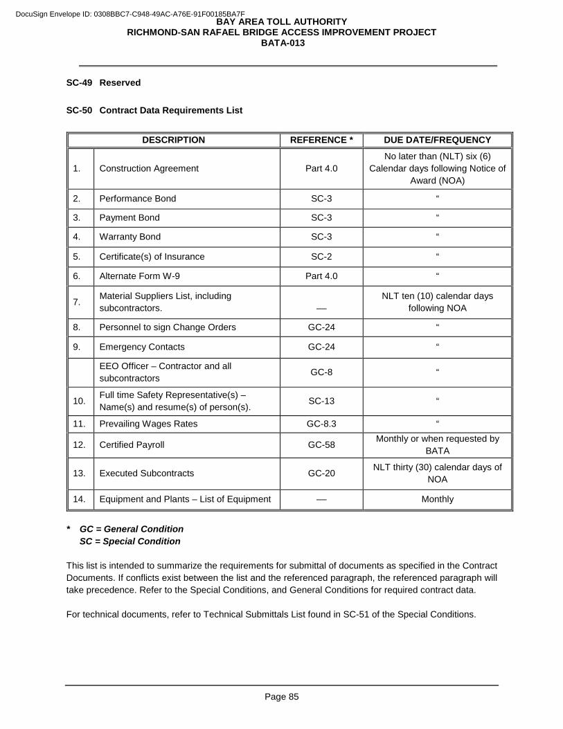
BAY AREA TOLL AUTHORITY RICHMOND-SAN RAFAEL BRIDGE ACCESS IMPROVEMENT PROJECT
BATA-013
Page 85
SC-49 Reserved
SC-50 Contract Data Requirements List
DESCRIPTION REFERENCE * DUE DATE/FREQUENCY
1. Construction Agreement Part 4.0 No later than (NLT) six (6)
Calendar days following Notice of Award (NOA)
2. Performance Bond SC-3 “
3. Payment Bond SC-3 “
4. Warranty Bond SC-3 “
5. Certificate(s) of Insurance SC-2 “
6. Alternate Form W-9 Part 4.0 “
7. Material Suppliers List, including subcontractors.
––
NLT ten (10) calendar days following NOA
8. Personnel to sign Change Orders GC-24 “
9. Emergency Contacts GC-24 “
EEO Officer – Contractor and all subcontractors GC-8 “
10. Full time Safety Representative(s) – Name(s) and resume(s) of person(s). SC-13 “
11. Prevailing Wages Rates GC-8.3 “
12. Certified Payroll GC-58 Monthly or when requested by BATA
13. Executed Subcontracts GC-20 NLT thirty (30) calendar days of NOA
14. Equipment and Plants – List of Equipment –– Monthly
* GC = General Condition SC = Special Condition This list is intended to summarize the requirements for submittal of documents as specified in the Contract Documents. If conflicts exist between the list and the referenced paragraph, the referenced paragraph will take precedence. Refer to the Special Conditions, and General Conditions for required contract data. For technical documents, refer to Technical Submittals List found in SC-51 of the Special Conditions.
DocuSign Envelope ID: 0308BBC7-C948-49AC-A76E-91F00185BA7F
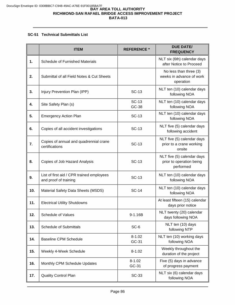
BAY AREA TOLL AUTHORITY RICHMOND-SAN RAFAEL BRIDGE ACCESS IMPROVEMENT PROJECT
BATA-013
Page 86
SC-51 Technical Submittals List
ITEM REFERENCE * DUE DATE/ FREQUENCY
1. Schedule of Furnished Materials NLT six (6th) calendar days after Notice to Proceed
2. Submittal of all Field Notes & Cut Sheets No less than three (3)
weeks in advance of work operation
3. Injury Prevention Plan (IPP) SC-13 NLT ten (10) calendar days following NOA
4. Site Safety Plan (s) SC-13 GC-38
NLT ten (10) calendar days following NOA
5. Emergency Action Plan SC-13 NLT ten (10) calendar days following NOA
6. Copies of all accident investigations SC-13 NLT five (5) calendar days following accident
7. Copies of annual and quadrennial crane certifications SC-13
NLT five (5) calendar days prior to a crane working
onsite
8. Copies of Job Hazard Analysis SC-13 NLT five (5) calendar days
prior to operation being performed
9. List of first aid / CPR trained employees and proof of training SC-13 NLT ten (10) calendar days
following NOA
10. Material Safety Data Sheets (MSDS) SC-14 NLT ten (10) calendar days following NOA
11. Electrical Utility Shutdowns At least fifteen (15) calendar
days prior notice
12. Schedule of Values 9-1.16B NLT twenty (20) calendar days following NOA
13. Schedule of Submittals SC-6 NLT ten (10) days following NTP
14. Baseline CPM Schedule 8-1.02 GC-31
NLT ten (10) working days following NOA
15. Weekly 4-Week Schedule 8-1.02 Weekly throughout the duration of the project
16. Monthly CPM Schedule Updates 8-1.02 GC-31
Five (5) days in advance of progress payment
17. Quality Control Plan SC-33 NLT six (6) calendar days following NOA
DocuSign Envelope ID: 0308BBC7-C948-49AC-A76E-91F00185BA7F
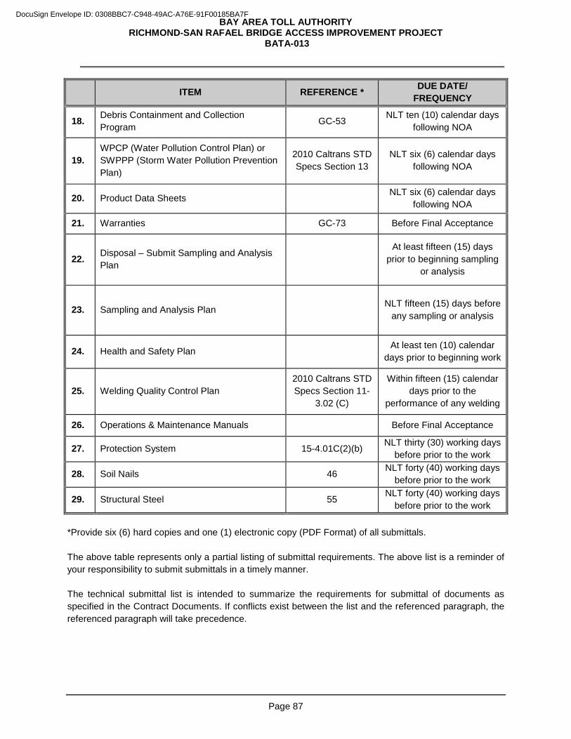
BAY AREA TOLL AUTHORITY RICHMOND-SAN RAFAEL BRIDGE ACCESS IMPROVEMENT PROJECT
BATA-013
Page 87
ITEM REFERENCE * DUE DATE/ FREQUENCY
18. Debris Containment and Collection Program GC-53 NLT ten (10) calendar days
following NOA
19. WPCP (Water Pollution Control Plan) or SWPPP (Storm Water Pollution Prevention Plan)
2010 Caltrans STD Specs Section 13
NLT six (6) calendar days following NOA
20. Product Data Sheets NLT six (6) calendar days following NOA
21. Warranties GC-73 Before Final Acceptance
22. Disposal – Submit Sampling and Analysis Plan
At least fifteen (15) days
prior to beginning sampling or analysis
23. Sampling and Analysis Plan NLT fifteen (15) days before
any sampling or analysis
24. Health and Safety Plan At least ten (10) calendar days prior to beginning work
25. Welding Quality Control Plan 2010 Caltrans STD Specs Section 11-
3.02 (C)
Within fifteen (15) calendar days prior to the
performance of any welding
26. Operations & Maintenance Manuals Before Final Acceptance
27. Protection System 15-4.01C(2)(b) NLT thirty (30) working days before prior to the work
28. Soil Nails 46 NLT forty (40) working days before prior to the work
29. Structural Steel 55 NLT forty (40) working days before prior to the work
*Provide six (6) hard copies and one (1) electronic copy (PDF Format) of all submittals. The above table represents only a partial listing of submittal requirements. The above list is a reminder of your responsibility to submit submittals in a timely manner. The technical submittal list is intended to summarize the requirements for submittal of documents as specified in the Contract Documents. If conflicts exist between the list and the referenced paragraph, the referenced paragraph will take precedence.
DocuSign Envelope ID: 0308BBC7-C948-49AC-A76E-91F00185BA7F
BAY AREA TOLL AUTHORITY RICHMOND-SAN RAFAEL BRIDGE ACCESS IMPROVEMENT PROJECT
BATA-013
Page 88
PART 7. GENERAL CONDITIONS
DocuSign Envelope ID: 0308BBC7-C948-49AC-A76E-91F00185BA7F
BAY AREA TOLL AUTHORITY RICHMOND-SAN RAFAEL BRIDGE ACCESS IMPROVEMENT PROJECT
BATA-013
Page 89
7.1 LEGAL RESPONSIBILITIES AND RELATIONSHIPS
GC-1 Applicable Law and Jurisdiction This Contract incorporates provisions required by the laws of the State of California and the Federal Government. It is your responsibility to determine the applicability of State and Federal laws, rules and regulations to the work to be performed under this Contract. This Contract is governed by California law. Any lawsuit or legal action arising from this Contract will be commenced and prosecuted in the State or Federal courts located in San Francisco County, California. GC-2 Compliance with Laws and Regulations Keep informed of, comply with, and cause all of your agents, employees, suppliers and subcontractors of any tier, to observe and comply with all applicable Federal, State, and local laws, regulations, and policies, including, but not limited to, all applicable terms and conditions prescribed for third party contracts by the U.S. Department of Transportation (DOT). Contractor will indemnify, defend, and hold harmless the State, BATA, the municipality or other entity within whose jurisdiction or on whose property the work is being performed, and Commissioners, their Board of Supervisors, Board of Directors, Councils, officers, agents, consultants and employees from any claim, liability, loss, injury or damage arising out of, or in connection with, the performance of this Contract by you and/or your agents, employees or subcontractors, excepting only loss, injury or damage caused by the active or sole negligence or willful misconduct of personnel employed by the indemnities. GC-3 Contractors’ Licensing Requirements Contractors are required by law to be licensed in the State of California and are regulated by the Contractors’ State License Board. Any questions related thereto may be referred to the Registrar of the Board whose address is:
Contractors’ State License Board 1020 N Street Sacramento, CA 95814
GC-4 Independent Contractor You represent that you are fully experienced and properly qualified to perform the class of work provided for herein, and that you are properly licensed, equipped, organized and financed to perform such work. You must act as an independent Contractor and not as the agent or employee of BATA in performing the Contract, maintaining complete control over its employees. Nothing contained in this Contract or any subcontract awarded by you creates any contractual relationship between any such subcontractor and BATA, and you must perform all work in accordance with your own methods subject to compliance with the Contract.
DocuSign Envelope ID: 0308BBC7-C948-49AC-A76E-91F00185BA7F
BAY AREA TOLL AUTHORITY RICHMOND-SAN RAFAEL BRIDGE ACCESS IMPROVEMENT PROJECT
BATA-013
Page 90
GC-5 Permits, Licenses, Fees and Notices As specified in Part 6.0 - Special Conditions, or as otherwise required by law, before beginning any work which requires a permit or similar authorization, secure and pay for all necessary licenses, fees, bonds, charges, inspections, customs or import duties, permits, and similar authorizations from all governmental authorities required to fulfill the Contract requirements and the Contractor's obligations. GC-6 Nondiscrimination Comply with Section 1735 of the California Labor Code, which reads as follows: “A contractor shall not discriminate in the employment of persons upon public works on any basis listed in subdivision (a) of Section 12940 of the Government Code, as those bases are defined in Sections 12926 and 12926.1 of the Government Code, except as otherwise provided in Section 12940 of the Government Code. Every contractor for public works who violates this section is subject to all the penalties imposed for a violation of this chapter..” In the performance of this Contract, you and your subcontractors must not unlawfully discriminate, harass or allow harassment, against any employee or applicant for employment because of race, religious creed, color, national origin, ancestry, physical disability, mental disability, medical condition, genetic information, marital status, sex, gender, gender identity, gender expression, age, sexual orientation, or military and veteran status of any person. You and your subcontractors must ensure that the evaluation and treatment of their employees and applicants for employment are free from such discrimination and harassment. You and your subcontractors must comply with the provisions of the Fair Employment and Housing Act (Government Code §12900 et seq.) and the applicable regulations promulgated thereunder (California Code of Regulations, Title 2, Section 7285.0 et seq.). The applicable regulations of the Fair Employment and Housing Commission implementing Government Code, Section 12290 (a-f), set forth in Chapter 5 of Division 4 of Title 2 of the California Code of Regulations are incorporated into this Contract by reference and made a part hereof as if set forth in full. You and your subcontractors must give written notice of their obligations under this clause to labor organizations with which they have a collective bargaining or other agreement. Include the nondiscrimination and compliance provisions of this clause in all subcontracts to perform work under this Contract. You and your subcontractors must permit access to all records of employment, employment advertisements, application forms, and other pertinent data and records by the State Fair Employment Practices and Housing Commission, or any other agency of the State of California designated by the State, for the purpose of investigation to ascertain compliance with this clause. GC-7 Prohibited Interests You covenant that you presently have no interest and will not acquire any interest, direct or indirect, that would conflict in any manner or degree or have the potential of conflicting with the performance of services required under this Contract or the impartial rendering of assistance or advice to BATA. You must further covenant that in the performance of this Contract no person having any such interest will be employed. No member, officer, employee or agent of BATA, during his/her tenure will have any prohibited interest as defined by California Government Code Sections 1090, et seq. and 87100 et seq., direct or indirect, in this Contract or the proceeds thereof. Prohibited interests include interests of immediate family members, domestic partners, and their employers or prospective employers. Accordingly, you further covenant that
DocuSign Envelope ID: 0308BBC7-C948-49AC-A76E-91F00185BA7F
BAY AREA TOLL AUTHORITY RICHMOND-SAN RAFAEL BRIDGE ACCESS IMPROVEMENT PROJECT
BATA-013
Page 91
you have made a complete disclosure to BATA of all facts of which you are aware upon due inquiry bearing upon any possible interest, direct or indirect, that it believes any member, officer, agent or employee of BATA (or an immediate family member, domestic partner or employer or prospective employer of such member, officer, agent or employee) presently has, or will have in this Contract, or in the performance thereof, or in any portion of the profits thereunder. Willful failure to make such disclosure, if any, shall constitute grounds for cancellation and termination hereof by BATA. GC-8 Labor Provisions 8.1 Safety In addition to your own safety procedures, and any safety procedures required under Federal, state, or local laws or regulations, including compliance with the provisions of the California Occupational Safety and Health Act of 1973 and any additional safety requirements contained in Part 6.0 Special Conditions, implement and enforce all safety requirements that are determined by BATA's Safety Coordinator to be applicable to the performance of any Work under this Contract. 8.2 Overtime Requirements Neither you nor any subcontractor of any tier require or permit any worker to work in excess of eight (8) hours in any day or in excess of forty (40) hours in any work week (defined as seven (7) sequential calendar days) unless such worker receives compensation at a rate not less than one and one-half times the basic rate of pay for all hours worked in excess of eight hours in any day or in excess of forty (40) hours in such work week, whichever is greater. Failure to comply with the preceding requirements will subject you or any subcontractor of any tier to the penalties specified in Labor Code §1813. 8.3 Prevailing Wage Rates You and all your subcontractors will comply with applicable sections of the California Labor Code and regulations promulgated thereunder (including without limitation, Sections 1720 et seq. and Title 8 of the California Code of Regulations Sections 16000 et seq.) governing the payment of prevailing wages, as determined by the Director of the California Department of Industrial Relations, in regards to all work performed under this Contract. In particular, your attention is drawn to Labor Code Sections 1771 (payment of prevailing wage rate), 1775 (penalty for non-payment), 1776 (payroll records), and 1777.5 (use of apprentices). Appendix C, Wage Determinations, is attached hereto and incorporated herein by this reference. You and all your subcontractors, to the extent the work of such subcontractors under this Contract is subject to California Labor Code Section 1720 et seq., will be registered with the Department of Industrial Relations pursuant to Labor Code section 1725.5 and will furnish electronic certified payroll records directly to the Labor Commissioner through the internet portal of the Division of Labor Standards Enforcement. BATA reserves the right to require you and all your subcontractors to furnish electronic certified payroll records via a web-based system directly to BATA in addition to the reporting requirement stated above. BATA will provide a web-based system to verify that prevailing wage requirements are met. This system is web-based, accessible from any computer via the internet. You and your subcontractors will receive an email providing log on identification, and a temporary password and instructions on how to use the system. Training will also be provided upon request.
DocuSign Envelope ID: 0308BBC7-C948-49AC-A76E-91F00185BA7F
BAY AREA TOLL AUTHORITY RICHMOND-SAN RAFAEL BRIDGE ACCESS IMPROVEMENT PROJECT
BATA-013
Page 92
8.4 Retention of Labor Records In the performance of the work specified in this Contract, You are responsible for compliance with California Labor Code Section 1776 pertaining to payroll records. You and all of your subcontractors of any tier must maintain all payrolls and basic payroll records during the course of the work and must preserve them for a period of three (3) years from the completion of the Contract. Such records must contain the names of all employees, their address, social security number, correct classifications, hourly rates of wages paid, daily and weekly number of hours worked, deductions made, and actual wages paid. These records will be made available by you or any of your subcontractors of any tier for inspection, copying, or transcription by authorized representatives of BATA or the State of California, and you or any of your subcontractors of any tier must permit such representatives to interview employees during working hours on the job. 8.5 Employment of Apprentices In the performance of the work specified in this Contract, you are responsible for compliance with California Labor Code Section 1777.5, pertaining to the employment of registered apprentices. 8.6 Subcontracts Insert in all of your subcontracts the clauses set forth in this GC-8, Labor Provisions and also a clause requiring its subcontractors to include these clauses in any lower tier subcontracts. You are responsible for compliance by any subcontractor or lower tier subcontractor with the clauses set forth in this GC-8, Labor Provisions. Pursuant to Public Contract Code §6109, you are prohibited from performing work on the Project with a subcontractor who is ineligible to perform work on a public works project pursuant to Sections 1777.1 or 1777.7 of the California Labor Code. GC-9 Hazardous Materials or Unusual Conditions In accordance with Public Contract Code §7104 if any of the following conditions are encountered during prosecution of the Work, promptly, and before disturbing such conditions, notify BATA in writing :
1. Material that you believe may be material that is hazardous waste as defined in Section 25117 of
the Health and Safety Code that is required to be removed to a Class I, II or III disposal site in accordance with the provisions of existing law.
2. Subsurface or latent physical conditions at the site differing from those indicated by information about the site made available to bidders prior to the deadline for submitting bids.
3. Unknown physical conditions at the site of any unusual nature, different materially from those ordinarily encountered and generally recognized as inherent in work of the character provided for in this Contract.
BATA will promptly investigate the conditions, and if it finds the conditions to be materially different or to involve hazardous waste, and cause a decrease or increase in the your cost of, or the time required for, performance of any part of the work, will issue a Change Order under the procedures described in GC-65, Change Requests and Change Notices and GC-66, Change Order. Any suspension of Work will be administered in accordance with the provisions of GC-69, Suspension of the Work. If a dispute arises between BATA and you whether the conditions materially differ, or involve hazardous waste, or cause a decrease or increase in your cost of, or time required for, performance of any part of the work, you are not excused from any scheduled completion date provided for by this Contract, but must proceed with all work
DocuSign Envelope ID: 0308BBC7-C948-49AC-A76E-91F00185BA7F
BAY AREA TOLL AUTHORITY RICHMOND-SAN RAFAEL BRIDGE ACCESS IMPROVEMENT PROJECT
BATA-013
Page 93
to be performed under this Contract; provided, however, you retain any and all rights provided either by contract or by law which pertain to the resolution of disputes and protests between the contracting parties. GC-10 Organization Conflicts of Interest Whenever BATA is awarding a contract that involves the rendering of advice, it will consider whether there exists the potential for bias, because of other activities, relationships or contracts to you, and if so, whether any potential bias can be mitigated acceptably by BATA and you.
Take all reasonable measures to preclude the existence or development of an organizational conflict of interest in connection with work performed under the agreement resulting from this and other BATA solicitations. An organizational conflict of interest occurs when, due to other activities, relationships, or contracts, a firm or person is unable, or potentially unable, to render impartial assistance or advice to BATA; a firm or person’s objectivity in performing the contract work is or might be impaired; or a firm or person has an unfair competitive advantage in proposing for award of a contract as a result of information gained in performance of this or some other Project.
Do not engage the services of any subcontractor or independent contractor on any work related to this Agreement if the subcontractor or independent contractor, or any employee of the subcontractor or independent contractor, has an actual or apparent organizational conflict of interest related to work or services contemplated under this Contract.
If at any time during the term of this Contract you become aware of an organizational conflict of interest in connection with the work performed hereunder, you will immediately provide BATA with written notice of the facts and circumstances giving rise to this organizational conflict of interest. Your written notice will also propose alternatives for addressing or eliminating the organizational conflict of interest. If at any time during the period of performance of this Contract, BATA becomes aware of an organizational conflict of interest in connection with your performance of the work hereunder, BATA will similarly notify you. In the event a conflict is presented, whether disclosed by you or discovered by BATA, BATA will consider the conflict presented and any alternatives proposed and meet with you to determine an appropriate course of action. BATA’s determination as to the manner in which to address the conflict will be final.
Failure to comply with this section may subject you to damages incurred by the BATA in addressing organizational conflicts that arise out of work performed by you, or to termination of this Contract for breach.
GC-11 Small Business Enterprise (SBE) Bid Preference 11.1 SBE Bid Preference BATA will allow a SBE Bid Preference applied as a percentage discount to the total amount of a bid submitted by a Bidder for a contract solely for the purpose of bid comparisons when determining the lowest and best bid, or lowest responsible bid. The use of a SBE Bid Preference for bid comparison does not alter the total amount of the bid submitted by a bidder or the contract executed based on a bid. The SBE Bid Preference will be applied to non-federally funded construction contracts with a budget in excess of $25,000, based on the level of participation proposed prior to the award of a contract. The SBE Bid Preference will be applied as follows after BATA verifies responsiveness requirements and eligibility for the SBE Bid Preference have been met:
A discount of five percent (5%) to the total amount bid, when the bidder meeting specifications is a certified SBE and is performing at least forty percent (40%) of the work, or
DocuSign Envelope ID: 0308BBC7-C948-49AC-A76E-91F00185BA7F
BAY AREA TOLL AUTHORITY RICHMOND-SAN RAFAEL BRIDGE ACCESS IMPROVEMENT PROJECT
BATA-013
Page 94
A discount of five percent (5%) to the total amount bid, when the bidder is a non-SBE Prime Contractor that commits to subcontract with SBE firms for at least forty percent (40%) of the work in its bid submittal.
BATA does not administer a SBE certification program. Only firms (prime or subcontractor) that are certified by the State of California Department of General Services (DGS) as SBEs per the requirements listed at http://www.dgs.ca.gov/pd/Programs/OSDS/SBEligibilityBenefits.aspx are eligible for the SBE Bid Preference allowed hereunder. The State of California SBE Directory can be accessed at http://www.bidsync.com/DPXBisCASB 11.2 Maintaining Participation Following commencement of work under this Contract, you are responsible for achieving and maintaining the participation that allowed the SBE Bid Preference. You must maintain the SBE percentages as indicated in Bid Form #9, Designation of Subcontractors in Compliance with BATA Construction Project SBE Program, in Part 5, Bid Forms, of this IFB at the time of bid submittal throughout the term of the Contract. If BATA modifies the original scope of work, you must make reasonable efforts to maintain the SBE participation for the SBE Bid Preference. In the event of change orders, BATA may use its discretion to allow adjustments to SBE percentages for the change order portion of the work. Upon request, BATA will help firms determine methods of maintaining percentages. Should you fail to maintain the SBE participation listed at the time of bid submittal, BATA reserves the right to enforce compliance with its SBE Program through one or more of the remedies stated below in GC-11.8, Program Enforcement. 11.3 Substitution of Subcontractors Substitution of listed subcontractors shall be in accordance with Public Contracts Code Section 4107. The SBELO must concur in any decision to permit substitution of a SBE subcontractor(s) when the award was made on the basis of the SBE Bid Preference listed in GC-11.1 above. 11.4 Joint Venture Agreements A business that is bidding or competing for BATA contracts may associate with a certified SBE business to compete for contracts as a joint venture. A joint venture should be between two entities with the same discipline or license as required by BATA. Joint ventures are eligible to receive a SBE Bid Preference depending upon the SBE percentage of participation as set forth in GC-11.1 above. The parties must agree to enter into the relationship for at least the term of the project. Specific requirements are set forth in the SBE Program. 11.5 Counting SBE Participation SBEs may perform as Contractors, or 1st Tier Subcontractors. Only the value of the work to be performed by the SBE, including materials and supplies, will be counted toward SBE participation.
DocuSign Envelope ID: 0308BBC7-C948-49AC-A76E-91F00185BA7F
BAY AREA TOLL AUTHORITY RICHMOND-SAN RAFAEL BRIDGE ACCESS IMPROVEMENT PROJECT
BATA-013
Page 95
A SBE must perform a commercially useful function (i.e., must be responsible for the execution of a distinct element of the work and must carry out its responsibility by actually performing, managing and supervising the work). If a SBE 1st Tier Subcontractor does not perform or exercise responsibility for at least sixty percent (60%) of the total cost of the Contract with its own work force, or if a SBE subcontracts a greater portion of Contract work than would be expected on the basis of normal industry practice, then it will be presumed that the SBE is not performing a CUF. Credit for a SBE vendor of materials or supplies is limited to sixty percent (60%) of the amount to be paid to the vendor for the materials or supplies unless the vendor manufactures or substantially alters the goods. Credit for SBE brokers is limited to only the fees and commissions portion of the amount paid. All other firms receive 100% credit, less work subcontracted by the SBE to non-SBE firms, toward the SBE. During the term of a contract, work performed by SBE firms whose certification has expired will continue to be counted toward the SBE participation. 11.6 SBE Monitoring BATA will monitor the Contract to confirm that you are in compliance with the requirements of the SBE Program. You must maintain records and documents of payments to all subcontractors (SBEs and non-SBEs) for four years following the performance of the contract. BATA will perform interim reviews of contract payments to SBEs. Payments to SBE subcontractors will be reviewed to verify that the actual amount paid to SBE subcontractors equals or exceeds the dollar amounts stated in the schedule of SBE participation included in the Contract. Upon request, you must provide BATA with executed copies of its subcontractor agreements to verify dollar amounts stated for all SBEs. 11.7 SBE Utilization Reporting Requirements BATA will provide a web-based diversity tracking system to verify that work committed to SBEs at contract award is actually performed by the SBEs. This system is web-based, accessible from any computer via the internet. You and your subcontractors will receive an email providing log on identification, and a temporary password and instructions on how to use the system. Training will also be provided upon request. You must submit monthly SBE Utilization Reports electronically to BATA using a web-based diversity tracking system designated by BATA to which BATA will provide system access at no cost to you or your subcontractors and/or suppliers. You must require each of your subcontractors and/or suppliers to enter required information into the web-based diversity tracking system. These monthly reports must be submitted electronically and you will document the dollar value of payments to SBE firms and the percentage of the contract completed. BATA will monitor the Contract for compliance with SBE requirements. If you or any of your subcontractors and/or suppliers fail to enter required information and/or verify information on a timely basis, this may result in delay of payment by BATA and an assessment of SBE non-compliance for reporting requirements. If the SBE Utilization Reports indicate potential problems, such as a failure to comply with the contract SBE participation, you must meet with the BATA SBELO or designee to address any deficiencies and discuss
DocuSign Envelope ID: 0308BBC7-C948-49AC-A76E-91F00185BA7F
BAY AREA TOLL AUTHORITY RICHMOND-SAN RAFAEL BRIDGE ACCESS IMPROVEMENT PROJECT
BATA-013
Page 96
appropriate corrective actions. When the Contract completion reaches 50% and the SBE participation completed is less than 50%, a detailed report of the reasons why must be submitted to BATA stating a plan to reach the SBE participation by Contract completion. Prior to final payment, you will be required to submit a final SBE Utilization Report by selecting the “Final Audit” reporting designation within the web-based diversity tracking system. In addition to payments to the SBEs, the final report must include payments to and other information about all other businesses, including non-SBE subcontractors, suppliers of materials and others. Non-compliance with the SBE participation may result in administrative sanctions or other contract enforcement activities. Refer to GC 11.8, SBE Program Enforcement. 11.8 SBE Program Enforcement BATA may use one or more remedies to enforce compliance of the SBE Program requirements for this Contract, including, but not limited to, the following:
1. Breach of contract action, pursuant to the terms of this IFB and Contract. 2. Assessment of a penalty of up to one and one half times the amount, including any
approved change orders, that should have been awarded to SBE(s). 3. Termination of Contractor’s performance of Work under the Contract. 4. Any other remedy available to BATA in the Contract or this IFB.
GC-12 Archaeological/Historical Discoveries If this project has been designated in the Part 1.0 Invitation to Bidders as an archaeological sensitive project, refer to Part 6.0 Special Conditions. Should any archaeological or historical artifacts or skeletal material be discovered or unearthed during construction activities, all work within thirty (30) feet of the find must be halted. The Contractor (Subcontractor) [or Engineer or Inspector as appropriate] must immediately notify BATA, and BATA will initiate procedures in accordance with 36 CFR 800.11, State Law (California Public Resources Code Section 5097.98, Health and Safety Code Section 7050.5, and Marin County Ordinance Code 22.20.040 Archaeological/Historical Resources. Construction activities within thirty (30) feet of the find must remain halted until authorization is obtained from the Environmental Program Manager, or the Environmental Program Manager’s named and designated agent, that construction in the vicinity of the find may resume. In the event of work suspension pursuant to this section, within twenty-four (24) hours, notify BATA of the costs involved resulting from said work stoppage. Maintain a log of each such stoppage of work, setting forth the date and time of notification of work stoppage, date and time of actual cessation of operations in the area, and date and time of commencement of operations and costs incurred herein. Submit a claim for reimbursement of such costs within seventy-two (72) hours thereof and must notify BATA of the anticipated amount of claim within twenty-four (24) hours of said work suspension. In the event of work suspension thereunder, exert all reasonable efforts to otherwise utilize labor and equipment affected by the suspension in other portions of the project. GC-13 Reserved
DocuSign Envelope ID: 0308BBC7-C948-49AC-A76E-91F00185BA7F
BAY AREA TOLL AUTHORITY RICHMOND-SAN RAFAEL BRIDGE ACCESS IMPROVEMENT PROJECT
BATA-013
Page 97
GC-14 Patent Rights Any discovery or invention which is an integral part of the items being furnished under this Contract, as well as all information, design, specifications, data and findings which arise or is developed in the course of performing the work under this Contract, becomes the property of BATA. GC-15 Intellectual Property, Copyright and Patent Infringement You, upon BATA's request, shall indemnify defend and hold harmless BATA, Caltrans and their commissioners, directors, officers, and employees from and against any claim, liability, loss, damage, or expense (including attorneys’ fees and related costs) for patent, copyright, trademark, trade secret, or other intellectual property infringement based upon BATA's, Caltrans’ and or municipality’s use of any work, goods, or services provided by you pursuant to this Contract. Provided that (i) BATA notifies you in writing promptly, but not more than thirty (30) days after BATA has actual notice of the claim; (ii) you have sole control of the defense and all related settlement negotiations, unless otherwise agreed by the Parties; and (iii) BATA gives you all available information and reasonable assistance for that defense. If you fail or refuse to defend any such claim, BATA and/or Caltrans may assume control of the defense and you must indemnify and hold BATA and Caltrans harmless for all fees, costs and expenses associated with or arising from such defense. This obligation does not apply when the alleged infringement arises entirely from modification of the work, goods, or services by BATA without your approval. GC-16 Rights in Technical Data BATA has the right to use, duplicate or disclose, in whole or in part, in any manner and for any purpose whatsoever, and to have or permit others to use: Any manuals, instructional materials prepared for installation, operation, maintenance or training purposes and technical data pertaining to end items, components or processes which were prepared for the purpose of identifying sources, size, configuration, mating and attachment characteristics, functional characteristics and performance requirements ("form, fit and function" data; e.g., specification control drawings, catalog sheets, outline drawing). The term Technical Data as used herein means technical writing, sound records, pictorial reproductions, drawings, or other graphic representations and works of a technical nature, whether or not copyrighted, which are specified to be delivered pursuant to this Contract. The term does not include financial reports, costs analyses, and other information incidental to contract administration. For copyrighted material, you agree to and do hereby grant to BATA and Caltrans, and to their Commissioners, Directors, officers, agents and employees acting within the scope of their official duties, a royalty-free, nonexclusive and irrevocable license for BATA and/or Caltrans to publish, translate, reproduce, deliver, perform, dispose of, and to authorize others to use, all Technical Data now or hereafter covered by copyright. No such copyrighted matter will be included in Technical Data furnished hereunder without written notice of the copyright owner granting BATA and State consent to use such copyrighted matter in the manner above described. Report to BATA promptly and in reasonable written detail each notice or claim of copyright infringement received by you with respect to any Technical Data delivered hereunder.
DocuSign Envelope ID: 0308BBC7-C948-49AC-A76E-91F00185BA7F
BAY AREA TOLL AUTHORITY RICHMOND-SAN RAFAEL BRIDGE ACCESS IMPROVEMENT PROJECT
BATA-013
Page 98
BATA reserves the right to use the design and the tooling developed for the furnishing of equipment under this Contract in future contracts based on this specification. Maintain design data, including drawings, layouts, and any relevant Engineering data, and all necessary tooling in good order for a minimum of four (4) years after final acceptance of the last items furnished under this Contract, and transfer that data, including tooling, to BATA upon request at no cost to BATA. All plans, drawings, diagrams, schematics, and specifications become the property of BATA, unless otherwise designated by BATA. GC-17 Ownership of Work and Material BATA owns all materials, work in progress, and finished goods produced by you pursuant to this Contract, for which progress payments have been made and which have been satisfactorily delivered to a designated area. Such ownership must be free of all encumbrances. Nevertheless, you are responsible for risk of loss for those items of Work for which you have care, custody and control, until Final acceptance of all work as discussed in GC-55, Final Inspection and Acceptance of All or a Portion of the Work. Unless otherwise specifically provided in this Contract, provide and pay for materials, equipment, tools, utilities, transportation, and other facilities and services necessary for the prosecution of the Work provided for in this Contract. Submit to BATA a "Final Release of All Liens and Claims" as a condition precedent to receiving final payment under this Contract.
GC-18 Title and Risk of Loss Unless otherwise provided for, title to the Work and risk of loss will pass to BATA upon final acceptance of the Work, and furnish or execute all necessary documents of title at that time. GC-19 Assignment and Delegation Do not assign any of your rights or delegate any of your responsibilities under this Contract without the prior written consent of BATA. GC-20 Subcontracts You are fully responsible and liable for the products and actions of all subcontractors and suppliers of any tier, and must include in each subcontract any provisions necessary to make all of the provisions of this Contract fully effective. Provide all necessary plans, specifications, schedules, and instructions to your suppliers and subcontractors to enable them to properly perform their work. Submit executed copies of all subcontracts entered into pursuant to this Contract to BATA within sixty (60) calendar days from issuance of a Notice of Award. GC-21 Waiver and Non-waiver A waiver by one party of a right to a remedy for breach of this Contract by the other party is not deemed to waive the right to a remedy for a subsequent breach by the other party. BATA's acceptance of goods, or services or payment under this Contract, does not preclude BATA from recovering against you or your surety for damages due to your failure to comply with this Contract.
DocuSign Envelope ID: 0308BBC7-C948-49AC-A76E-91F00185BA7F
BAY AREA TOLL AUTHORITY RICHMOND-SAN RAFAEL BRIDGE ACCESS IMPROVEMENT PROJECT
BATA-013
Page 99
GC-22 Antitrust Claims In entering into a public works contract, or a subcontract to supply goods, services, or materials pursuant to a public works contract, you agree to assign to the awarding body all rights and title to, and all interest in all causes of action it may have under Section 4 of the Clayton Act, or under the Cartwright Act, arising from the purchases of goods, services, or materials pursuant to the public works contracts or subcontracts. This assignment must be made and become effective at the time the awarding body tenders final payment to you, without further acknowledgement by the parties. GC-23 Stop Notices BATA will withhold payments otherwise due to you in order to satisfy Stop Notices which have been properly filed, in accordance with the requirements of California Civil Code Title 15, Chapter 4, regarding Stop Notices. Include this GC - 23, Stop Notices in all subcontracts and similar documents entered into by you for the performance of Work under this Contract.
7.2 AUTHORIZED REPRESENTATIVES AND COMMUNICATIONS
GC-24 Authorized Representatives Designate, in writing, before starting work, an Authorized Representative who, during performance of the Contract, has full authority to act on your behalf in all matters within the scope of this Contract. When the Contractor is comprised of two or more persons, firms, partnerships, or corporations functioning on a joint venture basis, said authorized representative must have the authority to represent and act for the joint venture. Said authorized representative must be present at the site of the Work at all times while work is actually in progress on the Contract. When work is not in progress and during periods when work is suspended, arrangements acceptable to BATA must be made for any emergency work that may be required. Whenever said authorized representative is not present on any particular part of the Work where BATA may desire to give direction, orders will be given by BATA, which must be received and obeyed by the superintendent or foremen who may have charge of the particular work in reference to which the orders are given. Except as hereinafter provided, all orders by BATA are given in writing. Those not so given are considered to be invalid and not binding. Emergency conditions dealing with safety of persons and protection of property are excepted, and such oral directions will be confirmed in writing as soon as possible, but must be immediately complied by you. BATA will similarly designate, in writing, an Authorized Representative to be its formal contact between BATA and you. Said Authorized Representative will be responsible for all matters relating to the execution of work within the scope of this Contract and will decide all questions which may arise as to the quality or acceptability of the Work and as to the manner of performance and rate of progress of the Work; all questions which may arise as to the interpretation of plans and specifications; all questions as to the
DocuSign Envelope ID: 0308BBC7-C948-49AC-A76E-91F00185BA7F
BAY AREA TOLL AUTHORITY RICHMOND-SAN RAFAEL BRIDGE ACCESS IMPROVEMENT PROJECT
BATA-013
Page 100
acceptable fulfillment of the Contract on the part of you; and all questions as to compensation for work performed. Written notification to the other party must be provided, in advance, of changes in the name or address or the scope of authority vested in such Authorized Representative. Each Authorized Representative may, from time to time, delegate to other named individuals certain authority and responsibilities. The names of such individuals, the scope of their authority and responsibility, and the designation of their titles will be communicated to the other party in writing. The designation of Authorized Representatives of the parties and their delegates as outlined above must take place at the pre-construction meeting as specified in GC-26, Pre-Construction Meeting. GC-25 Notices and Communications
25.1 Notices All notices and other communications concerning this Contract must be written in English, must bear the number assigned to this Contract by BATA and must follow BATA's correspondence format and reference system. Notices and other communications may be delivered personally, by email, by private package delivery, by FAX, or by regular, certified, or registered mail. The names of the individuals for each of the parties and their addresses to which other communications and correspondence should be delivered will be established and made known to the other party at the pre-construction meeting as specified in GC-26, Pre-Construction Meeting. A notice to BATA will be effective only if it is delivered to BATA's Authorized Representative at the address to be made known to Contractor at the pre-construction meeting as specified in GC-26, Pre-Construction Meeting. A notice to you will be effective only if it is delivered to your Authorized Representative at the address to be made known to BATA at the pre-construction meeting as specified in GC-26, Pre-Construction Meeting. 25.2 Drawing/Plan Clarification A drawing/plan clarification is an answer from the Owner, in response to an inquiry from you, intended to make some requirement(s) of the drawings or plans clearly understood. Drawing clarifications/plan clarifications may be sketches, drawings or in narrative form and will not change any requirement of the drawings or plans. Responses to Contractor inquiries are as outlined in the Article 25.3 “Requests for Information” of these General Conditions. 25.3 Requests for Information (RFIs) In the event that you, subcontractor or supplier, at any tier, determines that some portion of the drawings, specifications or other contract documents requires clarification or interpretation by the owner, submit a Request for Information (RFI) in writing to BATA. Requests for Information may only be submitted by you and must only be submitted on the Request for Information form provided by BATA. Clearly and concisely set forth the issue for which clarification or interpretation is sought and why a response is needed from
DocuSign Envelope ID: 0308BBC7-C948-49AC-A76E-91F00185BA7F
BAY AREA TOLL AUTHORITY RICHMOND-SAN RAFAEL BRIDGE ACCESS IMPROVEMENT PROJECT
BATA-013
Page 101
BATA. In the RFI, set forth your own interpretation or understanding of the requirement along with the reasons why you have reached such an understanding. BATA will review all RFI to determine whether they are Requests for Information within the meaning of this Contract. If BATA determines that the document is not a RFI it will be returned to you, unreviewed as to content, for resubmittal as the appropriate document required by the subject matter. Responses to RFI are issued within five (5) working days of receipt of the request from you unless BATA determines that a longer period of time is necessary to provide an adequate response. If a longer period of time is determined necessary by BATA, BATA will, within five (5) working days of receipt of the request notify you of the anticipated response time. The five (5) working days referred to herein will start on the date stamped received "In From Contractor” by BATA and depends on the date stamped “Out to Contractor” by BATA. If you submit a RFI on an activity with five (5) working days or less of float on the current project schedule, mark the RFI as “Critical.” You are not entitled to any time extension due to the time it takes BATA to respond to such Critical request provided that BATA responds within the five (5) working days set forth above. Responses from BATA will not change any requirement of the Contract documents unless so noted in the response to the RFI. In the event you believe that a response to a RFI will cause a change to the requirements of the Contract, immediately give written notice to BATA in accordance with GC-65, Change Requests and Change Notices. Failure to give such written notice waives your right to seek additional time or cost in accordance with GC-65.1, Change Requests, of the Contract documents. GC-26 Pre-Construction Meeting Prior to issuance of a Notice to Proceed, a pre-construction meeting will be held at a time and place to be designated by notice from BATA. At this meeting, detailed procedures will be discussed for handling the following items:
1. Authorized Representative 2. Correspondence 3. Notices 4. Change requests and change notices 5. Change orders 6. Submittals 7. Approvals 8. Progress payments 9. Schedules 10. Community relations 11. Inspection plans 12. Requests for Information (RFI) 13. Other pertinent agenda items
GC-27 Project Meetings
DocuSign Envelope ID: 0308BBC7-C948-49AC-A76E-91F00185BA7F
BAY AREA TOLL AUTHORITY RICHMOND-SAN RAFAEL BRIDGE ACCESS IMPROVEMENT PROJECT
BATA-013
Page 102
BATA will schedule and preside over all meetings (including but not limited to weekly, pre-production, periodic, and special meetings) throughout the progress of the Work. Agendas for the meetings may include, but are not necessarily limited to, discussions of performance observations, problems, conflicts, schedules, delivery schedules, supplier fabrication, quality standards, Contract modifications, and any other topics that BATA determines to be relevant to the project. Your attendance at these meetings is mandatory. GC-28 Publicity Releases All publicity releases or releases of reports, papers, articles, maps, or other documents in any way concerning this Contract or the Work hereunder which you or any of your subcontractors desires to make are subject to approval by BATA prior to release.
7.3 TIME FOR PERFORMANCE OF WORK
GC-29 Reserved GC-30 Reserved GC-31 Progress Schedule Develop and maintain progress schedules in CPM format identifying critical events involved in the performance of the Work under the Contract in accordance with the requirements of Part 10.0 Construction Details (Special Provisions). GC-32 Excusable Delays and Extensions of Time Except with respect to defaults of Subcontractors, you are considered in default by reason of any failure to perform in accordance with the Contract schedule if such failure arises out of causes beyond the control and without the fault or negligence of the defaulting party. Such causes may include, but are not restricted to, acts of God or of the public enemy, acts of the government in its sovereign or contractual capacity, fires, floods, epidemics, quarantine restrictions, strikes or other labor disputes, freight embargoes, and unusually severe weather, but in every case the failure to perform must be beyond the control and without the fault or negligence of the defaulting party. If the failure to perform by you is caused by the default of a Subcontractor, and if such default arises out of causes beyond the control of you or the Subcontractor, and without either parties’ fault or negligence you are not in default by reason of any such failure to perform. As used herein, the terms "Subcontractor" and "Subcontractors" mean Subcontractor(s) or Supplier(s) to Contractor at any tier. GC-33 Failure to Complete the Work on Time If the Work is not completed by you in the time specified, as that time may be extended as authorized elsewhere in the Contract, it is understood that BATA will suffer damage; and, it being impracticable and extremely difficult to determine the amount of actual damage, it is agreed that Contractor pays as fixed and liquidated damages, and not as a penalty, the sum set forth in SC-5 of Part 6.0 Special Conditions of the Contract for each calendar day of delay until the Work is completed and accepted, and you and your surety are liable for the amount thereof.
DocuSign Envelope ID: 0308BBC7-C948-49AC-A76E-91F00185BA7F
BAY AREA TOLL AUTHORITY RICHMOND-SAN RAFAEL BRIDGE ACCESS IMPROVEMENT PROJECT
BATA-013
Page 103
7.4 PERFORMANCE OF WORK
GC-34 Reserved GC-35 Temporary Construction Facilities and Utilities Furnish all temporary construction facilities, utilities, and services that are necessary to prosecute the Work. This includes, but is not limited to, fencing, flagmen, sanitary facilities, security, power, water and weather protection. Remove all temporary facilities upon completion of the Work or when they are no longer needed for your purposes, whichever is earlier. GC-36 Character of Workmen If any Subcontractor or person employed by you appears to BATA to be incompetent or to act in a disorderly, improper or unsafe manner, such person will be discharged immediately on the request of BATA, and such person will not again be employed on the Work. GC-37 Working Environment Ensure and maintain a working environment free of personal harassment and intimidation between your forces and BATA employees and members of the public at all BATA project sites and in all BATA facilities at which your forces are assigned to work. Conduct that creates an intimidating, hostile, or offensive working environment is prohibited. Failure to comply with the above will be considered a material breach of this Contract. GC-38 Public Convenience and Safety Conduct your operations as to offer the least possible obstruction and inconvenience to the public and have under construction no greater length or amount of work than can be prosecuted properly with due regard to the rights of the public. Unless otherwise provided in the Contract, all public traffic must be permitted to pass through the Work with as little inconvenience or delay as possible. Where possible, such traffic must be routed on new or existing paved surfaces. Spillage resulting from hauling operations along or across any public traveled way must be removed immediately by you at your expense. Existing traffic signal and highway lighting systems must be kept in operation for the benefit of the traveling public during progress of the Work, and other forces will continue routine maintenance of existing systems. Install signs, lights, flares, barricades, and other facilities for the sole convenience and direction of public traffic and furnish competent flaggers or a uniformed police officer whose sole duties consist of directing the movement of public traffic through or around the Work. Work must be performed in such a manner as to eliminate unnecessary noise, obstructions and other annoyances to occupants. Do not encumber premises with materials, equipment, and/or parking of cars; store materials, equipment and park cars in designated areas. See Part 10 Construction Details for additional traffic control requirements, if any.
DocuSign Envelope ID: 0308BBC7-C948-49AC-A76E-91F00185BA7F
BAY AREA TOLL AUTHORITY RICHMOND-SAN RAFAEL BRIDGE ACCESS IMPROVEMENT PROJECT
BATA-013
Page 104
GC-39 Cooperation/Coordination and Work by Others Coordinate your Work with all other Contractors and subcontractors performing Work on the site. Schedule your Work so as to avoid conflicts with other Contractors and to avoid damage to completed or incomplete Work. You are responsible for any damage to the Work of other Contractors or subcontractors if your actions resulted in such damage and are a) willful or b) negligent and the proximate cause. Take immediate action to remedy such damage so as to not delay the immediate prosecution of the Work. GC-40 Security Provide and be responsible for all security at the job site that is required to protect your material and equipment and all Work in place. You are also responsible for providing all security and traffic control required by any city having jurisdiction in the area where Work is being performed. GC-41 Product Options, Supplier Approval and Substitutions For products specified in this Contract or in your submittals by brand name or manufacturer, whether or not followed by the words "or approved equal," select any product or manufacturer named, or submit a request to substitute an equal product or manufacturer. As required by the California Public Contract Code §3400, such request must be made within thirty-five (35) calendar days from date of the Notice of Award in order to receive consideration, unless later submission of a request is agreed to by BATA. Submit a separate request for each substitution. The burden of proof as to the equality of any material, process or article rests with you. BATA's determination of the equality or superiority of an article proposed for substitution will be based upon but need not be limited to consideration of such factors as are specified in the Technical Specifications; dimensional compatibility with other materials with which it combines to produce a unified design system; all aspects of finished appearance including form, texture, and color, as it affects other design elements. In the event an approved substitution is more expensive than the specified materials, process or article, the difference in cost of such material, process or article so furnished is at your cost. You may not make a substitution without BATA's prior written approval. If applicable, specific requirements for the submittal of such requests will be contained in Part 6.0 Special Conditions. BATA will approve or disapprove your request for substitution of suppliers or products within thirty (30) days of BATA's receipt of all information required by BATA for such determination. GC-42 Source of Materials You are completely responsible for locating, identifying, and furnishing all materials required to be furnished under this Contract, except for BATA furnished materials specified in Part 6.0 Special Conditions. GC-43 Reserved GC-44 Reserved GC-45 Protection and Restoration of Property In addition to any other requirements imposed by law, shore up, brace, underpin, and protect as may be necessary, all foundations and other parts of all existing structures adjacent to and adjoining the site of the
DocuSign Envelope ID: 0308BBC7-C948-49AC-A76E-91F00185BA7F
BAY AREA TOLL AUTHORITY RICHMOND-SAN RAFAEL BRIDGE ACCESS IMPROVEMENT PROJECT
BATA-013
Page 105
Work which are in any way affected by your operations. Whenever any notice is required to be given by BATA or you to any adjoining or adjacent landowner or other party before beginning any Work under this Contract, such notice is given by you. Any damage arising from or in consequence of the performance of the Contract, to improvements or property, whether above or below ground, private or public, within or adjacent to the project limits, must be repaired at once by you. If the best interests of BATA require such repair to be made prior to the execution of any part of the Work included in this Contract, BATA will so notify you who will delay or discontinue the performance of that part of the Work until the necessary repair has been made. Such delay will not be considered unavoidable, and no extension of time for completion of the Contract will be made. When ordered by BATA to make any such repair, start work thereon within four hours and prosecute the same with diligence to completion. Upon failure to so comply with such order, or upon failure to make immediate emergency repairs which are necessary in the best interests of BATA or of the Public, BATA has the authority to cause such repair to be made and to deduct the costs thereof from any money due, or which may become due you. In any emergency affecting the safety of life or property including adjoining property, you, without special instructions or authorization from BATA, are authorized to act at your discretion to prevent such threatened loss or injury, and you must so act whether or not it is instructed to do so by BATA. GC-46 Utility Paint Markings Completely remove all utility paint markings at project completion. Removal must be by use of the high water pressure method only. Payment for removal of all utility paint markings is considered as included in the price paid for other items of work. GC-47 Reserved GC-48 Inspection BATA must at all times have access to the Work and will be furnished every reasonable facility for verifying that the materials and workmanship conform to the requirements of the Contract. BATA may test and inspect, either at your, subcontractor's or supplier's facility, all components, subsystems or workmanship prior to assembly of such components into the Work and prior to acceptance of the Work by BATA. Following such testing and inspection, BATA will issue a deficiency list to you listing those items that fail to comply with the Contract. BATA may either reject or require correction of defective material, workmanship, or nonconformity to this Contract. At your own expense, make available tools, pits, hoists, scaffolds, platforms, other equipment, facilities, drawings, and assistance as may be necessary for inspections or tests. Costs of the Inspectors are borne by BATA and are not a part of the Contract Price. Costs of re-inspection are back charged to you. The performance of, or the failure to perform, such inspection does not relieve you of any responsibility for complete Contract compliance. Where shop inspection is required by the terms of the Contract, do not ship materials until BATA releases such materials for shipment. GC-49 Reserved
DocuSign Envelope ID: 0308BBC7-C948-49AC-A76E-91F00185BA7F
BAY AREA TOLL AUTHORITY RICHMOND-SAN RAFAEL BRIDGE ACCESS IMPROVEMENT PROJECT
BATA-013
Page 106
GC-50 Removal of Rejected or Unauthorized Work All work that has been rejected must be remedied, or removed and replaced by you in a manner acceptable to BATA, and no compensation will be made for such removal, replacement or remedial work. Any work performed outside of the limits of Work shown on the drawings or established by BATA or any extra work done without written authorization of BATA will not be paid for. Upon order of BATA such unauthorized work must be remedied, removed or replaced at your expense. If you fail to comply promptly with any such order of BATA, BATA may cause the rejected or unauthorized work to be removed, replaced, or remedied, and to deduct the costs thereof from any moneys due to you. GC-51 Disposal of Materials Except for materials generated pursuant to GC-9, Hazardous Materials or Unusual Conditions, you are responsible for the disposal of all excess materials generated during the performance of this Contract. When any material is to be disposed of outside the project area, other than a public dump, Contractor must first obtain a written permit from the property owner on whose property the disposal is to be made and he must file with BATA said permit or a certified copy thereof together with a written release from the property owner absolving BATA from any and all responsibility in connection with the disposal of material and said property, and before any material is disposed of on said property, obtain written permission from BATA to dispose of the material at the location designated in said permit. GC-52 Protection of Completed Portions of Work Protect completed portions of the Work until final acceptance of the Work by BATA. Contractor must take prompt action to remedy or repair any and all damage sustained to Work that is partially or wholly complete and has not yet been accepted by BATA. GC-53 Cleanup In addition to any requirements which may be included in Part 10, Construction Details, at all times during performance of Work under this Contract, keep the site clean from all rubbish and debris. Before final inspection of the Work, clean the material sites and all ground occupied by it in connection with the Work of all rubbish, excess materials, falsework, forms, temporary structures, and equipment. All parts of the Work must be left in a neat and presentable condition. GC-54 Redlined Construction Drawings Drawings showing all approved changes made during construction which differ from the approved drawing set for construction, must be furnished by you prior to the acceptance of the Work. Final construction drawings submitted to BATA must be in the form of redlined drawings clearly and neatly indicating all changes made with the approval of BATA and other field changes made which reflect the as-built condition of the Contract. During the construction period, redlined construction drawings must be maintained by you and made available to BATA for review on a daily basis.
DocuSign Envelope ID: 0308BBC7-C948-49AC-A76E-91F00185BA7F
BAY AREA TOLL AUTHORITY RICHMOND-SAN RAFAEL BRIDGE ACCESS IMPROVEMENT PROJECT
BATA-013
Page 107
GC-55 Final Inspection and Acceptance of All or a Portion of the Work 55.1 Final Inspection and Acceptance of all the Work When you consider that all of the Work, or any discrete portion of the Work covered under this Contract has reached final completion, inform BATA in writing. If necessary and required, acceptance tests on the Work or discrete portion thereof will be performed as set forth in Part 10, Construction Details, and the Standard Specifications. BATA will prepare a punch list covering any part of the Work that fails to pass the acceptance tests or is otherwise unacceptable and will reject such work. Proceed immediately to correct or replace unsatisfactory, incomplete or unacceptable work. For items of work not completed by you, BATA may proceed to have the items corrected or completed using BATA or third party forces. The costs of such corrections will be deducted from compensation due to you. Unless otherwise stipulated, title to such rejected work and risk of loss will remain with you, and you have the responsibility and bear all costs to correct all defects or damage. All acceptance testing of Work which has been rejected previously will be at your expense and costs incurred by BATA to perform such re-tests will be deducted and withheld by BATA from payments otherwise due to you. Final acceptance of all of the Work or the particular discrete portion deemed complete will occur after successful completion of all testing, corrections of deficiencies, punch list items, and BATA's determination that the Work conforms in all respects to all the Contract requirements. BATA will inform you of such acceptance of the Work by issuing a final certificate stating that the Work has been completed in accordance with the Contract requirements and is accepted under the terms and conditions thereof. Acceptance of the Work will be made by BATA only upon issuance of said certificate together with a final estimate. After BATA has accepted the Work, you will be relieved of the duty of maintaining and protecting the accepted Work and will not be required to perform any further work thereon; and are relieved of your responsibility for injury to persons or property or damage to the Work that occurs after formal acceptance by BATA. Such final acceptance of the Work does not relieve you from responsibility for errors, improper fabrication, non-conformance to a Contract requirement, latent defects, or for deficiencies within your control. Unless otherwise stipulated, all warranties begin with the date of such final acceptance. Coincident with such final acceptance, BATA will record a Notice of Completion. 55.2 Final Inspection and Acceptance of a Portion of the Work The following will apply if BATA accepts, pays for, takes title to and occupies the portion of the Work so accepted:
1. You will be responsible for the maintenance for that portion of the Work. 2. Your warranty on that portion of the Work will commence upon Final Acceptance of all the Work.
BATA retains the right to direct you to complete a portion of the Work at a time different than that specified in the Contract or reflected in the currently approved progress schedule. Such direction will be in writing. If such direction modifies the amount of compensation or time required for the completion of the Work, a change order will be issued.
DocuSign Envelope ID: 0308BBC7-C948-49AC-A76E-91F00185BA7F
BAY AREA TOLL AUTHORITY RICHMOND-SAN RAFAEL BRIDGE ACCESS IMPROVEMENT PROJECT
BATA-013
Page 108
7.5 COMPENSATION, PAYMENTS, RECORDS AND AUDIT
GC-56 Compensation
You will accept the compensation set out in the Contract as full payment for:
1. Furnishing all labor, materials, tools, equipment, and incidentals necessary to properly perform and
satisfactorily complete all the Work included under this Contract; 2. all loss or damage arising from the nature of the Work, or from the action of the elements, or from
any unforeseen difficulties which may be encountered during the prosecution of the Work until final acceptance by BATA;
3. all risks of every description connected with the prosecution of the Work, and for all expenses incurred in consequence of the suspension or discontinuance of the Work as provided in the Contract.
Neither the payment of any progress payment nor any retained percentage will relieve you of any obligation to make good any defective work or material. No compensation will be made in any case for the loss of anticipated profits. GC-57 Increased or Decreased Quantities and Quantity Variation Comply with Section 9-1.06, Changed Quantity Payment Adjustments, of the Standard Specifications. GC-58 Certified Payrolls BATA reserves the right to require you and all your subcontractors to furnish electronic certified payroll records directly to BATA via a web-based system on a monthly basis for each week in which any Contract Work is performed or when requested by BATA, in addition to the reporting requirement stated below. You and all your subcontractors must register with the Department of Industrial Relations pursuant to Labor Code section 1725.5 and furnish electronic certified payroll records directly to the Labor Commissioner through the internet portal of the Division of Labor Standards Enforcement. GC-59 Invoicing and Progress Payments You are paid for the value of all accepted quantities for the various items of work satisfactorily completed in accordance with the Contract and computed in accordance with the applicable measurement for payment provisions of the Contract. Before any payment becomes due, prepare for BATA's approval a schedule of values of the main categories of the Work included in any items paid for as a lump sum and any items for which partial payment for materials on hand will be made. Each item in the schedule of values must include its proper share of overhead and profit. The values in the schedule will be used only for determining the amount of each progress payment. A proposed schedule may be rejected if any item is determined by BATA to be unbalanced. BATA may request a detailed schedule of values of such items. Prior to the end of each payment period, prepare and forward to BATA a progress payment invoice in writing consisting of the value of the total amount of Work done plus the value of the acceptable materials on hand.
DocuSign Envelope ID: 0308BBC7-C948-49AC-A76E-91F00185BA7F
BAY AREA TOLL AUTHORITY RICHMOND-SAN RAFAEL BRIDGE ACCESS IMPROVEMENT PROJECT
BATA-013
Page 109
Acceptable materials on hand consist of materials or equipment furnished and delivered by you to the site but not yet incorporated in the Work and properly stored in a location acceptable to BATA. In order for materials on hand to be considered for payment, request payment for them on BATA-furnished forms accompanied by documentation as therein required including, but not limited to, evidence of purchase if appropriate. BATA will retain five percent of such invoiced value as part security for the fulfillment of the Contract by you, and will pay to you the balance not retained, after deducting therefrom all previous payments and all sums to be kept or retained under the provisions of the Contract. No such invoice or payment will be construed to be an acceptance of any defective work or improper materials. After 50% of the Contract Amount, as modified by any Change Orders, has been earned, and if satisfactory progress has been made in accordance with the approved Contract progress schedule, BATA will make the remaining progress payments in full, without retention. If, however, you subsequently fall behind the approved Contract progress schedule, BATA may resume retention up to five percent of all progress payments, including those payments that were made in full. In accordance with the provisions of applicable California law, you may be permitted to substitute securities in lieu of the withholding from progress payments specified above. Substitutions must be done in accordance with California Public Contract Code Section 22300 (see below). Work completed in place is an estimate only, and no inaccuracy or error in said estimates operates to release you or any Surety from damages arising from such Work or from enforcing each and every provision of this Contract, and BATA has the right to subsequently correct any error made in any invoice submitted for payment. No such invoice or payment is required to be made when, as determined by BATA, the Work is not proceeding in accordance with the provisions of the Contract, or when the total value of the Work done since the last estimate amounts to less than $500.00. In addition to the amounts that BATA may retain as provided hereinabove, BATA may withhold additional amounts from any payments otherwise due to Contractor as it determines necessary to cover:
1. Payments which may be past due and payable for just claims against you or any Subcontractor for
labor or materials furnished in performance of the Work under the Contract; 2. For defective work not remedied; 3. For failure of you to make proper payments to any of your Subcontractors; 4. A reasonable doubt that you will complete the Work within the Contract time limits; 5. Damage to other work or property caused by you or your Subcontractor of any tier; if applicable; 6. An amount, not less than 10 percent of the total progress payment, due to the failure to abate,
within one (1) working day or immediately in cases of imminent danger, infractions of BATA’s Injury Prevention Program (BATA/IPP), Contractor’s Safety Plan, CAL/OSHA, FEDERAL OSHA, ANSI or other applicable safety standards;
7. An amount not to exceed 20 percent of the total progress payment, due to four or more repeated infractions in a single payment period of BATA/IPP, Contractor’s Safety Plan CAL/OSHA, FEDERAL OSHA, ANSI and all other applicable safety standards.
You are not entitled to have any payment estimates processed or be entitled to have any payment made for work performed so long as any lawful or proper direction concerning the Work or any portion thereof given by BATA remains uncomplied with.
DocuSign Envelope ID: 0308BBC7-C948-49AC-A76E-91F00185BA7F
BAY AREA TOLL AUTHORITY RICHMOND-SAN RAFAEL BRIDGE ACCESS IMPROVEMENT PROJECT
BATA-013
Page 110
Whenever BATA, in accordance herewith, withholds any moneys otherwise due to you, written notice of the amount withheld and the reasons therefore will be given to you, and when you remove the grounds for such withholding, BATA will pay you the amount so withheld. Progress payments will be based on a four-week period as mutually agreed to by BATA. Securities may be substituted in lieu of the withholding of progress payments in accordance with Public Contract Code § 22300, which states: § 22300 Substitution of Securities for Retentions; Escrow Account (a) Provisions shall be included in any invitation for bid and in any contract documents to permit the substitution of securities for any moneys withheld by a public agency to ensure performance under a contract, however, substitution of securities provisions shall not be required in contracts in which there will be financing provided by the Farmers Home Administration of the United States Department of Agriculture pursuant to the Consolidated Farm and Rural Development Act (7 U.S.C. § 1921 et. seq.), and where federal regulations or policies, or both, do not allow the substitution of securities. At the request and expense of Contractor, securities equivalent to the amount withheld shall be deposited with the public agency, or with a state or federally chartered bank in this state as the escrow agent, who shall then pay those moneys to the Contractor. Upon satisfactory completion of the contract, the securities shall be returned to Contractor. (b) Alternatively, Contractor may request and the Owner shall make payment of retentions earned directly to the escrow agent at the expense of Contractor. At the expense of Contractor, Contractor may direct the investment of the payments into securities and Contractor shall receive the interest earned on the investments upon the same terms provided for in this section for securities deposited by Contractor. Upon satisfactory completion of the contract, Contractor shall receive from the escrow agent all securities, interest, and payments received by the escrow agent from the owner, pursuant to the terms of this section. (c) Securities eligible for investment under this section shall include those listed in Section 16430 of the Government Code, bank or savings and loan certificates of deposit, interest-bearing demand deposit accounts, standby letters of credit, or any other security mutually agreed to by Contractor and the public agency. Contractor shall be the beneficial owner of any securities substituted for moneys withheld and shall receive any interest thereon. Failure to include these provisions in bid and contract documents shall void any provisions for performance retentions in a public agency contract. For purposes of this section, the term “public agency” shall include, but shall not be limited to, chartered cities. (d)(1) Any Contractor who elects to receive interest on moneys withheld in retention by a public agency shall, at the request of any subcontractor, make that option available to the subcontractor regarding any moneys withheld in retention by the Contractor from the subcontractor. If the Contractor elects to receive the identical rate of interest received by the Contractor on any retention moneys withheld from the subcontractor by the Contractor, less any actual pro rata costs associated with administering and
DocuSign Envelope ID: 0308BBC7-C948-49AC-A76E-91F00185BA7F
BAY AREA TOLL AUTHORITY RICHMOND-SAN RAFAEL BRIDGE ACCESS IMPROVEMENT PROJECT
BATA-013
Page 111
calculating that interest. In the event that the interest rate is a fluctuating rate, the rate for the subcontractor shall be determined by calculating the interest rate paid during the time that retentions were withheld from the subcontractor. If the Contractor elects to substitute securities in lieu of retention, then, by mutual consent of the Contractor and subcontractor, the subcontractor may substitute securities in exchange for the release of moneys held in retention by the Contractor. (2) This subdivision shall apply only to those subcontractors performing more than five percent of the Contractor’s total bid.
(3) No Contractor shall require any subcontractor to waive any provision of this section. (e) The Legislature hereby declares that the provisions of this section are of statewide concern and are necessary to encourage full participation by Contractors and subcontractors in public contract procedures. (f) The escrow agreement used hereunder shall be null, void, and unenforceable unless it is substantially similar to the following form: ESCROW AGREEMENT FOR SECURITY DEPOSITS IN LIEU OF RETENTION This Escrow Agreement is made and entered into by and between _______________________ whose address is __________________________
hereinafter called “Owner,”
_______________________ whose address is __________________________
hereinafter called “Contractor” and _______________________, a state or federally chartered bank, whose
address is __________________________ hereinafter called “Escrow Agent.”
For the consideration hereinafter set forth, the Owner, Contractor, and Escrow Agent agree as follows: (1) Pursuant to Section 22300 of the Public Contract Code of the State of California, Contractor has the option to deposit securities with Escrow Agent as a substitute for retention earnings required to be withheld by Owner pursuant to the Construction Contract entered into between the owner and Contractor for ________________ in the amount of ________________ dated ____________________ (hereinafter referred to as the “Contract”). Alternatively, on written request of Contractor, the owner shall make payments of the retention earnings directly to the Escrow Agent. When Contractor deposits the securities as a substitute for Contract earnings, the Escrow Agent shall notify the Owner within 10 days of the deposit. The market value of the securities at the time of the substitution shall be at least equal to the cash amount then required to be withheld as retention under the terms of the Contract between the owner and Contractor. Securities shall be held in the name of _______________________, and shall designate Contractor as the beneficial owner. (2) The Owner shall make progress payments to Contractor for those funds which otherwise would be withheld from progress payments pursuant to the Contract provisions, provided that the Escrow Agent holds securities in the form and amount specified above. (3) When the Owner makes payment of retentions earned directly to the Escrow Agent, the Escrow Agent shall hold them for the benefit of the Contractor until the time that the escrow created under this contract is terminated. The Contractor may direct the investment of the payments into securities. All terms and
DocuSign Envelope ID: 0308BBC7-C948-49AC-A76E-91F00185BA7F
BAY AREA TOLL AUTHORITY RICHMOND-SAN RAFAEL BRIDGE ACCESS IMPROVEMENT PROJECT
BATA-013
Page 112
conditions of this agreement and the rights and responsibilities of the parties shall be equally applicable and binding when the Owner pays the Escrow Agent directly. (4) Contractor shall be responsible for paying all fees for the expenses incurred by Escrow Agent in administering the Escrow Account and all expenses of the Owner. These expenses and payment terms shall be determined by the Owner, Contractor, and Escrow Agent. (5) The interest earned on the securities or the money market accounts held in escrow and all interest earned on that interest shall be for the sole account of Contractor and shall be subject to withdrawal by Contractor at any time and from time to time without notice to the Owner. (6) Contractor shall have the right to withdraw all or any part of the principal in the Escrow Account only by written notice to Escrow Agent accompanied by written authorization from the Owner to the Escrow Agent that Owner consents to the withdrawal of the amount sought to be withdrawn by Contractor. (7) The Owner shall have a right to draw upon the securities in the event of default by Contractor. Upon seven days’ written notice to the Escrow Agent from the owner of the default, the Escrow Agent shall immediately convert the securities to cash and shall distribute the cash as instructed by the Owner. (8) Upon receipt of written notification from the owner certifying that the Contract is final and complete, and that Contractor has complied with all requirements and procedures applicable to the Contract, Escrow Agent shall release to Contractor all securities and interest on deposit less escrow fees and charges of the Escrow Account. The escrow shall be closed immediately upon disbursement of all moneys and securities on deposit and payments of fees and charges. (9) Escrow Agent shall rely on the written notifications from the owner and Contractor pursuant to Sections (5) to (8), inclusive, of this agreement and the owner and Contractor shall hold Escrow Agent harmless from Escrow Agent’s release and disbursement of the securities and interest as set forth above. (10) The names of the persons who are authorized to give written notice or to receive written notice on behalf of the owner and on behalf of Contractor in connection with the foregoing, and exemplars of their respective signatures are as follows: On behalf of Owner:
(Title)
(Name)
(Signature)
(Address)
On behalf of Contractor:
(Title)
(Name)
(Signature)
(Address)
On behalf of Escrow Agent:
(Title)
DocuSign Envelope ID: 0308BBC7-C948-49AC-A76E-91F00185BA7F
BAY AREA TOLL AUTHORITY RICHMOND-SAN RAFAEL BRIDGE ACCESS IMPROVEMENT PROJECT
BATA-013
Page 113
(Name)
(Signature)
(Address)
(11) Securities eligible for deposit by Contractor or investment hereunder shall be ______________________________ and no others. At the time the Escrow Account is opened, the Owner and Contractor shall deliver to the Escrow Agent a fully executed counterpart of this Agreement. IN WITNESS WHEREOF, the parties have executed this Agreement by their proper officers on the date first set forth above. (Owner)
(Title)
(Name)
(Signature)
(Contractor)
(Title)
(Name)
(Signature)
GC-60 Force Account Payment Comply with Section 9-1.04, Force Account, of the Standard Specifications.
60.1 Work Performed by Special Forces or Other Special Services When BATA and you, by mutual agreement, determine that a special service or an item or work cannot be performed by your forces, or those of any of your subcontractors, such service or work item may be performed by a specialist. Invoices for such service or item of work, performed by a specialist on the basis of the current market price thereof, may be accepted without complete itemization of labor, material, and equipment rental costs when it is impracticable and not in accordance with the established practice of the special service industry to provide such complete itemization. In those instances wherein a Contractor is required to perform work necessitating a fabrication or machining process in a fabrication or machine shop facility away from the jobsite, the charges for that portion of the Work performed in such a facility, may by mutual agreement, be accepted as a specialist billing. In lieu of the percent markups provided in Section 9-1.04 of the Standard Specifications, a 15 percent markup will be added to the specialist price, less a credit to BATA for any cash or trade discount offered or available, whether or not such discount may have been taken.
DocuSign Envelope ID: 0308BBC7-C948-49AC-A76E-91F00185BA7F
BAY AREA TOLL AUTHORITY RICHMOND-SAN RAFAEL BRIDGE ACCESS IMPROVEMENT PROJECT
BATA-013
Page 114
GC-61 Prompt Payment
61.1 Payment to Contractor Public Contract Code Section 20104.50 requiring prompt payment to Contractors is applicable to this contract. Undisputed and properly submitted payment requests will be paid within thirty (30) days of receipt by BATA. Any undisputed and properly submitted payment request not paid within thirty (30) days will accrue interest at the legal rate set forth in Code of Civil Procedure Section 685.010. Any payment request determined by BATA not to be a proper payment request suitable for payment will be returned to you within seven days of receipt setting forth in writing the reasons why the payment request is not proper. 61.2 Payment to Subcontractors Adhere to all federal and California prompt payment laws and regulations including Business and Professions Code Section 7108.5 requiring Contractor to pay subcontractors within ten (10) days of receipt of each progress payment to the extent of each subcontractor’s interest therein, unless otherwise agreed to in writing. Notwithstanding the time for payment of retention provided for in Public Contract Code Section 7107(d), pay retention proceeds to subcontractors within thirty (30) days after the subcontractor’s work is satisfactorily completed, unless the time for payment calculated pursuant to Section 7107(d) would result in earlier payment of retention to the subcontractor.
GC-62 Final Payment Final payment does not become due until the following actions have been satisfactorily completed:
1. Satisfactory completion of final inspection of all the Work under the Contract and the issuance by
BATA of a Letter of Final Acceptance. 2. The recording of a Notice of Completion by BATA. 3. Contractor submittal to BATA of:
a. An affidavit that all payrolls, bills for materials and equipment, and other indebtedness connected with the Work have been paid or otherwise satisfied, and
b. A release of liens and claims arising out of the Contract, to the extent and in the form designated by BATA. If a claim remains unsatisfied after all payments are made, reimburse BATA for all monies that BATA may be compelled to pay in discharging the claim, including all costs and reasonable attorney's fees.
BATA may at its option and at any time retain out of any amounts due to you, sums sufficient to cover claims, filed pursuant to Section 9100 et seq. of the Civil Code. BATA will make final payment, including outstanding retention, within 30-60 calendar days of the recording of the Notice of Completion. The acceptance of final payment by you constitutes a waiver of all claims against BATA arising under the Contract.
DocuSign Envelope ID: 0308BBC7-C948-49AC-A76E-91F00185BA7F
BAY AREA TOLL AUTHORITY RICHMOND-SAN RAFAEL BRIDGE ACCESS IMPROVEMENT PROJECT
BATA-013
Page 115
GC-63 Project Records Comprehensive records and documentation relating to this project must be kept by you. The records must include, but are not limited to Contract Documents, Drawings, Specifications, Addenda, Shop Drawings and Submittals, Change Orders, Modifications, Test Records, redlined construction plans, As-Built Drawings, and cost and pricing data. Maintain a complete set of records relating to this Contract for a period of seven years from final payment for this Work. The cost records must be complete and in sufficient detail to allow evaluation of the accuracy and completeness, and currency of the costs or prices. Permit the authorized representatives of BATA to examine and audit all such records and any subcontracts under this Contract during the time period so specified. In addition, every contract involving the expenditure of public funds in excess of ten thousand dollars ($10,000) entered into by a public entity in the State of California will be subject to the examination and audit of the State Auditor, at the request of the public entity or as part of any audit of the public entity, for a period of three years after final payment under the contract.
7.6 CONTRACT MODIFICATIONS, DISPUTES AND CLAIMS
GC-64 Reserved GC-65 Change Requests and Change Notices 65.1 Change Requests. You may make a written request to BATA to modify the Contract (Change Request) based upon the receipt of, or the discovery of information that changes the scope, price, schedule, level of performance, or other facet of the Contract. Deliver a document entitled “Change Request” to BATA within 30 calendar days after receipt of, or the discovery of, information (other than receipt of a “Change Notice”) that you believe will cause a change to the scope, price, schedule, level of performance, or other facet of the Contract. Upon receipt of a Change Notice, follow the procedures of GC-65.2. All Change Requests, and any Claims based thereon including any request or claim for cumulative impact costs are deemed waived unless a Change Request is delivered to BATA within the 30 calendar days specified herein. The Change Request must include information necessary to substantiate the effect of the change and any impacts to the work, including any change in schedule or Contract Price, and must include all existing documentation or a description of anticipated documentation. In addition, the Change Request must contain a detailed description of the proposed adjustment to the Contract Price or currently approved progress schedule, or both, and must reference any other provisions of the Contract that will require modification because of the change. If a Change Request proposes an adjustment in the Contract Price, upon request of BATA, submit a complete breakdown of costs including detailed pricing information and back up for all work and any impacts thereto contemplated by the change. The unavailability of all information necessary to quantify the change does not excuse the timely submission of the Change Request. Supplement the Change Request with additional information or documentation, as it becomes available. If BATA has not received sufficient substantiating documentation or information within
DocuSign Envelope ID: 0308BBC7-C948-49AC-A76E-91F00185BA7F
BAY AREA TOLL AUTHORITY RICHMOND-SAN RAFAEL BRIDGE ACCESS IMPROVEMENT PROJECT
BATA-013
Page 116
a reasonable time after receipt of the Change Request, such insufficiency may be grounds to deny the Change Request. If a Change Request or portions thereof are acceptable to BATA, BATA will issue a Contract Change Order consistent therewith. If a Change Request or portions thereof are not acceptable to BATA, BATA will notify you in writing. Any request by you to modify the contract must first be submitted to BATA and proceed as a Change Request pursuant to these provisions. You may submit the matter as a Claim pursuant to GC 68, Claims only if, i) the Change Request has been denied by BATA in whole or in part, or ii) the Change Request has not been resolved within 90 days after receipt by BATA, unless otherwise extended by agreement by you and BATA. In the event of a dispute, Contractor must proceed with the Work without delay, as directed by BATA. 65.2 Change Notice BATA may, at any time during performance of the Contract notify you of changes to the Contract by issuing a Change Notice to that effect. Within 15 calendar days after receipt of such Change Notice, provide to BATA a written response identifying any proposed adjustment in Contract Price, including any adjustment for cumulative impact costs and schedule to perform the changes identified in the Change Notice, unless another time period for response is specified in the Change Notice. BATA will then issue an appropriate Change Order. If BATA directs you to perform additional work, the basis for compensation for such work must be either: 1) extension of Contract items, 2) negotiated lump sum price, or 3) force account, as determined by BATA. The markups described in GC-60.1 are the maximum allowed for all additional work directed by BATA. If you and BATA cannot agree on the appropriate adjustment to the Contract Price or schedule, you may either accept BATA’s determination or identify and submit the matter as a Claim pursuant to the provisions of GC 68, Claims. In the event of a dispute, proceed with the Work without delay as directed by BATA. GC-66 Change Orders A Change Order is a written document issued by BATA, that:
1. Changes the Contract Price, as modified by any previously executed Change Orders, or 2. Alters the scope of Work under the Contract, or 3. Alters the schedule for performance of the Work under the Contract as set forth in the currently
approved schedule, or 4. Makes any other change to the Contract, or makes a combination of any of the aforementioned
Contract changes.
DocuSign Envelope ID: 0308BBC7-C948-49AC-A76E-91F00185BA7F
BAY AREA TOLL AUTHORITY RICHMOND-SAN RAFAEL BRIDGE ACCESS IMPROVEMENT PROJECT
BATA-013
Page 117
GC-67 Differing Site Conditions 67.1 Soil Boring or Other Data Where BATA has included soil boring information or other data in the Contract, they are included for your information only and BATA does not guarantee the accuracy of the information contained therein. 67.2 Notice of Differing Conditions Comply with Section 4-1.06, Differing Site Conditions, of the Standard Specifications. BATA will, as soon as practicable, investigate or cause to be investigated the items noted by you and, if it is determined that such conditions do materially so differ and cause an increase or decrease in your cost of or time required for the performance of any part of the Work under the Contract, whether or not changed as a result of such conditions, an equitable adjustment will be made and the Contract modified. GC-68 Claims
68.1 Claim Defined “Claim” means a separate demand by you for (A) a time extension, (B) payment of money or damages arising from work done by, or on behalf of, you pursuant to the Contract and payment of which is not otherwise expressly provided for or that you are not otherwise entitled to, or (C) an amount the payment of which is disputed by BATA. 68.2 Claim Requirements
1. Any submittal intended by you to be evaluated by BATA as a Claim must be entitled “Claim”.
2. All claims must be submitted by you within thirty (30) days after the date of the event giving rise to the Claim, such as, for example, the denial by BATA of a Change Request, the failure of BATA to respond to a Change Request within ninety (90) days after receipt of required substantiating information and documentation, or the issuance by BATA of a disputed Change Order. Any Claim not submitted within the specified thirty (30) days are deemed waived.
3. Claims must be in writing and must be submitted with all documents necessary to substantiate the Claim. A Claim must state in as much detail as possible the basis for the Claim and the additional compensation or extra time to which you believe you are entitled, including:
a. A detailed factual account of the events causing the potential claim, including: i. Pertinent dates ii. Locations iii. Work items affected by the potential claim
b. The Contract documents supporting the potential claim and a statement of the reasons these parts support entitlement
c. If a payment adjustment is requested, an itemized cost breakdown. Segregate costs into the following categories:
i. Labor, including: 1. Individuals
DocuSign Envelope ID: 0308BBC7-C948-49AC-A76E-91F00185BA7F
BAY AREA TOLL AUTHORITY RICHMOND-SAN RAFAEL BRIDGE ACCESS IMPROVEMENT PROJECT
BATA-013
Page 118
2. Classifications 3. Regular and overtime hours worked 4. Dates worked
ii. Materials, including: 1. Invoices 2. Purchase Orders 3. Location of materials either stored or incorporated into the work
iii. Equipment, including: 1. Detailed descriptions, including make, model and serial number 2. Hours of use 3. Dates of use 4. Equipment rates at the rental rate listed in Labor Surcharge and
Equipment Rental Rates in effect when the affected work related to the claim was performed
d. If a time adjustment is requested: i. Dates for the requested time ii. Reasons for a time adjustment iii. Contract documentation supporting the requested time adjustment iv. Time Impact Analysis (TIA). The TIA must demonstrate entitlement to a time
adjustment. e. Identification and copies of your documents and copies of communications supporting the
potential claim, including certified payrolls, bills, cancelled checks, job cost reports, payment records, and rental agreements
f. Relevant information, references, and arguments that support the potential claim.
4. If the Claim is silent regarding entitlement to extra time, you are entitled to no extra time in connection with the Claim. If the Claim is silent regarding additional compensation, you are entitled to no additional compensation in connection with the Claim.
5. You must notify BATA promptly in writing of any changes in its estimates of additional compensation or extra time, and the notification must state the reasons for the changes.
6. All Claims and any amendments thereto must include the fully executed certification set forth below. Any Claim submitted without a fully executed certification will be rejected by BATA and returned to you.
I,_______________________________________, BEING THE____________________(MUST BE AN OFFICER) OF_____________________________(CONTRACTOR), DECLARE UNDER PENALTY OF PERJURY UNDER THE LAWS OF THE STATE OF CALIFORNIA, AND DO PERSONALLY CERTIFY AND ATTEST THAT I HAVE THOROUGHLY REVIEWED THE ATTACHED CLAIM FOR ADDITIONAL COMPENSATION AND/OR EXTENSION OF TIME, AND KNOW ITS CONTENTS, AND SAID CLAIM IS MADE IN GOOD FAITH; THE SUPPORTING DATA IS TRUTHFUL AND ACCURATE; THAT THE AMOUNT REQUESTED ACCURATELY REFLECTS THE CONTRACT ADJUSTMENT FOR WHICH THE CONTRACTOR BELIEVES THE OWNER IS LIABLE; AND, FURTHER, THAT I AM FAMILIAR WITH CALIFORNIA PENAL CODE SECTION 72 AND CALIFORNIA GOVERNMENT CODE 12650, ET SEQ.,
DocuSign Envelope ID: 0308BBC7-C948-49AC-A76E-91F00185BA7F
BAY AREA TOLL AUTHORITY RICHMOND-SAN RAFAEL BRIDGE ACCESS IMPROVEMENT PROJECT
BATA-013
Page 119
PERTAINING TO FALSE CLAIMS, AND FURTHER KNOW AND UNDERSTAND THAT SUBMISSION OR CERTIFICATION OF A FALSE CLAIM MAY LEAD TO FINES, IMPRISONMENT, AND/OR OTHER SEVERE LEGAL CONSEQUENCES. By________________________________
7. No Claims can be filed later than the date of final payment. 68.3 Claim Review BATA will respond in writing to your Claim within forty-five (45) calendar days after BATA’s receipt of the Claim or BATA may request in writing, within 30 days of receipt of the Claim, any additional information or documentation supporting the Claim or relating to defenses to the Claim BATA may have against you. For claims exceeding $375,000 BATA may, at its option, notify you of extended time periods for review and response. BATA’s written response to the Claim, as further documented, will be submitted to you within fifteen (15) days after receipt of the further information or documentation or within a period of time no greater than that taken by you in producing the additional information, whichever is greater. 68.4 Meet and Confer If you dispute BATA’s written response, or if BATA fails to respond within the time prescribed, you may so notify BATA, in writing, either within fifteen (15) days of receipt of BATA’s response or within fifteen (15) days of BATA’s failure to respond within the time prescribed, respectively, and demand an informal conference to meet and confer for settlement of the issues in dispute. Upon a demand, BATA will schedule a meet and confer conference within thirty (30) days for settlement of the dispute. Following the meet and confer conference, if the Claim or any portion remains in dispute, you may file a Government Code claim as provided in Chapter 1 (commencing with Section 910) of Part 3 of Division 3.6 of Title 1 of the Government Code. For purposes of those provisions, the running of the period of time within which a Government Code claim must be filed will be tolled from the time you submit your written Claim pursuant to the above provisions until the time the Claim is denied as a result of the meet and confer process, including any period of time utilized by the meet and confer process. The above procedures do not apply to Government Code claims for tort damages and are not intended, and will not be construed, to change the time for filing such claims.
68.5 Procedures for Civil Actions Public Contract Code Section 20104.4, set forth below, establishes the following procedures for all civil actions filed to resolve claims of $375,000 or less under this Contract: (a) Within 60 days, but no earlier than 30 days, following the filing of responsive pleadings, the court shall submit the matter to nonbinding mediation unless waived by mutual stipulation of both parties. The mediation process shall provide for the selection within 15 days by both parties of a disinterested third person as mediator, shall be commenced within 30 days of the submittal, and shall be concluded within 15 days from the commencement of the mediation unless a time requirement is extended upon a good cause
DocuSign Envelope ID: 0308BBC7-C948-49AC-A76E-91F00185BA7F
BAY AREA TOLL AUTHORITY RICHMOND-SAN RAFAEL BRIDGE ACCESS IMPROVEMENT PROJECT
BATA-013
Page 120
showing to the court or by stipulation of both parties. If the parties fail to select a mediator within the 15-day period, any party may petition the court to appoint the mediator. (b) (1) If the matter remains in dispute, the case shall be submitted to judicial arbitration pursuant to Chapter 2.5 (commencing with Section 1141.10) of Title 3 of Part 3 of the Code of Civil Procedure, notwithstanding Section 1141.11 of that code. The Civil Discovery Act of 1986 (Article 4 (commencing with Section 2016.010) of Part 4 of the Code of Civil Procedure) shall apply to any proceeding brought under this subdivision consistent with the rules pertaining to judicial arbitration. (2) Notwithstanding any other provision of law, upon stipulation of the parties, arbitrators appointed for purposes of this article shall be experienced in construction law, and, upon stipulation of the parties, mediators and arbitrators shall be paid necessary and reasonable hourly rates of pay not to exceed their customary rate, and such fees and expenses shall be paid equally by the parties, except in the case of arbitration where the arbitrator, for good cause, determines a different division. In no event shall these fees or expenses be paid by state or county funds. (3) In addition to Chapter 2.5 (commencing with Section 1141.10) of Title 3 of Part 3 of the Code of Civil Procedure, any party who after receiving an arbitration award requests a trial de novo but does not obtain a more favorable judgment shall, in addition to payment of costs and fees under that chapter, pay the attorney’s fees of the other party arising out of the trial de novo. (c) The court may, upon request by any party, order any witnesses to participate in the mediation or arbitration process. The above claims procedures are also subject to Public Contract Code § 20104.6, which provides: (a) No local agency shall fail to pay money as to any portion of a claim that is undisputed except as otherwise provided in the contract. (b) In any suit filed under Section 20104.4, the local agency shall pay interest at the legal rate on any arbitration award or judgment. The interest shall begin to accrue on the date the suit is filed in a court of law.
7.7 SUSPENSION OF WORK, CONTRACT TERMINATION
GC-69 Suspension of the Work In addition to the right of BATA to suspend Work under any other provision of this Contract, BATA may require you to suspend all or part of the Work called for by this Contract at any time for up to ninety (90) days after a written Suspension Order is delivered to you, and for any further period to which the parties may agree. The Suspension Order includes the following:
1. A clear description of the Work to be suspended; 2. Guidance as to the action to be taken on subcontracts; and 3. Other requests for minimizing costs.
Upon receipt of a Suspension Order, comply with its terms immediately and take all reasonable steps to minimize cost allocable to the Work covered by the Order during the period of work stoppage. Within the
DocuSign Envelope ID: 0308BBC7-C948-49AC-A76E-91F00185BA7F
BAY AREA TOLL AUTHORITY RICHMOND-SAN RAFAEL BRIDGE ACCESS IMPROVEMENT PROJECT
BATA-013
Page 121
period specified by the Order, or within any extension of that period to which the parties may agree, BATA may:
1. Terminate the Work covered by the Order as set forth in this section. 2. Cancel the Suspension Order; or 3. Allow the period of the Suspension Order to expire.
Resume work upon the cancellation or expiration of a Suspension Order. An equitable adjustment will be made in the Work scope, Contract Price, or Contract time, as appropriate, and the Contract will be modified in writing in accordance with GC-32, Excusable Delays and Extensions of Time and GC-69, Suspension of the Work if:
1. The Suspension Order results in an increase in the time required for, or in your cost properly allocable to, the performance of any part of this Contract; and
2. You assert a claim for an adjustment within 30 days after the end of the period of work stoppage; and
3. The Suspension Order was not caused by your default or other act or omission within the control or responsibility of you.
In preparation for and during suspensions of work, take every reasonable precaution to prevent damage to or deterioration of the Work. Repair or replace, at no cost to BATA, Work that is damaged or deteriorated during a work suspension due to your failure to comply with this duty. If BATA determines that you are not taking reasonable precautions and you fail to take the corrective action within five days after written notice from BATA, BATA may cause such action to be taken and recover the reasonable cost thereof from you. GC-70 Termination for Convenience or in the Public Interest BATA may terminate this Contract in whole or in part at any time by written notice to you if BATA determines that termination is in the best interest of BATA or the public. If this Contract is so terminated, you are entitled to payment for all Work performed acceptably, all acceptable goods or services ordered by and delivered to you before termination, and all reasonable termination costs, up to the maximum amount payable under this Contract, provided that you provide a final itemized invoice for the above amounts within thirty (30) days after receiving the termination notice. GC-71 Termination for Default BATA may, by written notice of default to you, terminate your right to proceed with the Work under the Contract, in whole or with regard to any part if you do not cure a failure to comply with a term of the contract within a period of seven days (or such longer period as BATA may authorize in writing) after receipt of notice from BATA specifying such failure, including, but not limited to, the following:
1. if you fail to supply an adequate working force, or materials of proper quality, or otherwise refuse or fail to prosecute the Work, or any separable part thereof, with such diligence as will ensure your completion within the time specified in this Contract, or authorized extension thereof; or
2. if you fail to make prompt payment to your subcontractors or suppliers upon receipt of progress payments from BATA; or
3. if you persistently disregard laws, ordinances, or instructions of BATA.
DocuSign Envelope ID: 0308BBC7-C948-49AC-A76E-91F00185BA7F
BAY AREA TOLL AUTHORITY RICHMOND-SAN RAFAEL BRIDGE ACCESS IMPROVEMENT PROJECT
BATA-013
Page 122
In the event of such termination for default, BATA may take over the Work and prosecute the same to completion, by contract or otherwise, and may take possession of and use all or any part of your material, tools, equipment, and appliances as may be on the site of the Work and which are necessary for performance of the Work. Upon completion of such work, you are entitled the return of all unused materials and your equipment, tools and appliances, except that there will be no claim on account of usual and ordinary depreciation, loss, or wear and tear. If your right to proceed is so terminated, you are not entitled to receive any further payment until the Work is completed. You and your surety(s) will be liable to BATA for any additional costs of completion of the Work, including compensation for additional managerial and administrative services, plus liquidated damages accruing under the terms of this Contract from the Contract completion date, as extended by authorized time extensions, to the date of final completion. If, after termination for failure to fulfill contract obligations, it is determined that you were not in default, the rights and obligations of the parties will be the same as if the termination had been issued for the convenience of BATA. GC-72 Contractor's Duties upon Termination After receipt of a Notice of Termination, either for default or convenience, you must:
1. stop work under the Contract on the date and to the extent specified in the Notice of Termination; 2. place no further orders or subcontracts for materials, services, or facilities, except as may be
necessary for completion of such portion of the Work under the Contract as is not terminated; 3. terminate all orders and subcontracts to the extent that they relate to the performance of Work
terminated by the Notice of Termination 4. assign to BATA in a manner, at the times, and to the extent directed by BATA, all of the right, title,
and your interest under the orders and subcontracts so terminated.
7.8 WARRANTY PROVISIONS
GC-73 Warranty It is a condition of this Contract that the equipment, materials or design furnished, and workmanship performed by you or any subcontractor or supplier at any tier, complies to the requirements of this contract and must be free of any defect. Neither inspection, testing and acceptance by BATA of such equipment, materials, design or work performed, partial or final payment, nor any provisions of the Contract relieve you from responsibility for any latent defect, gross mistakes or fraud. You and your surety(s) warrant, regardless of the warranties obtained from the Subcontractors, all equipment, materials, design and workmanship for a period of two years from the date of Final Acceptance by BATA of all of the work under the Contract or any discrete portion thereof. Your warranty with respect to work repaired or replaced must also run for two years from the date of repair or replacement. In addition, you must furnish a written guarantee covering all or certain items of work and must extend any warranty from a subcontractor or supplier that exceeds the above warranty period. If such additional or varying guarantees are required, they will be specified in Part 6.0 - Special Conditions of this contract. BATA retains the right, at its sole discretion, to assign to a third Party any warranty received under this Contract.
DocuSign Envelope ID: 0308BBC7-C948-49AC-A76E-91F00185BA7F
BAY AREA TOLL AUTHORITY RICHMOND-SAN RAFAEL BRIDGE ACCESS IMPROVEMENT PROJECT
BATA-013
Page 123
GC-74 Warranty Work You are responsible for all warranty-covered repair work during the warranty period as specified above. Provide at your own expense, all spare products and tools required for repairs. To the extent practicable, BATA will allow you or your designated representative to perform such work. When warranty repairs are required, BATA and your representative will agree on the most appropriate remedy to be performed within a reasonable time. If you fail to remedy any failure or defect within a reasonable time, BATA has the right to replace, repair, or otherwise remedy the failure or defect at your expense. At its discretion, BATA may also perform such work if it deems necessary to do so to meet its operational commitments or other requirements. Reimburse BATA for all expenses for such work including materials and labor. The hourly shop labor rates are based on BATA’s current labor cost accounting system. Reimburse BATA for such work within sixty days of receipt of warranty claim. GC-75 Warranty on Replaced Parts
Any materials, parts or components that are used for replacement under the initial warranty period are warranted again for the total original warranty period of the replaced particular material, part or component. GC-76 Systematic Failures In the event that, during the warranty period, repairs or modifications necessitated by defective design, material, or workmanship occur to an extent in excess of 10 percent of the components used for the same function in the same assembly or subsystem purchased under this Contract, promptly furnish all necessary labor and material to effect such repairs and modifications for every system delivered under the Contract under the terms and conditions outlined, including systems in which the item has not yet failed. When requested by BATA, you are required to provide a written failure analysis report for defective products supplied under this contract and which occurred during the warranty period. The report must be received by BATA within forty-five (45) days from the date of request. GC-77 Iran Contracting Act of 2010 AB 1650, Iran Contracting Act of 2010, which adds Sections 2200 et seq. to the California Public Contract Code, requires Proposers for contracts equal to or in excess of one million dollars ($1,000,000) to certify, at the time of proposal submission that proposer is not identified on a list created pursuant to subdivision (b) of Section 2203 as a person engaging in investment activities in Iran described in subdivision (a) of Section 2202.5, or as a person described in subdivision (b) of Section 2202.5, as applicable. Submit a signed Bid Form #5, Iran Contracting Act Document.
DocuSign Envelope ID: 0308BBC7-C948-49AC-A76E-91F00185BA7F
BAY AREA TOLL AUTHORITY RICHMOND-SAN RAFAEL BRIDGE ACCESS IMPROVEMENT PROJECT
BATA-013
Page 124
PARTS 8 AND 9. (NOT USED)
DocuSign Envelope ID: 0308BBC7-C948-49AC-A76E-91F00185BA7F
BAY AREA TOLL AUTHORITY RICHMOND-SAN RAFAEL BRIDGE ACCESS IMPROVEMENT PROJECT
BATA-013
Page 125
PART 10. CONSTRUCTION DETAILS (SPECIAL PROVISIONS)
DocuSign Envelope ID: 0308BBC7-C948-49AC-A76E-91F00185BA7F
BAY AREA TOLL AUTHORITY RICHMOND-SAN RAFAEL BRIDGE ACCESS IMPROVEMENT PROJECT
BATA-013
Page 126
SPECIAL PROVISIONS ORGANIZATION Special provisions are under headings that correspond with the main-section headings of the Standard Specifications. A main-section heading is a heading shown in the table of contents of the Standard Specifications. Each special provision begins with a revision clause that describes or introduces a revision to the Standard Specifications as revised by any revised standard specification. Any paragraph added or deleted by a revision clause does not change the paragraph numbering of the Standard Specifications for any other reference to a paragraph of the Standard Specifications.
^^^^^^^^^^^^^^^^^^^^^^^^^^^^^^^^^^^^^^^^^^^^^^^^^^^^^^^^^^^^^^^^^
DIVISION I GENERAL PROVISIONS 1 GENERAL
Add to section 1-1.01:
Bid Items and Applicable Sections
Item code Item description Applicable
section
480605A Soil Nail (Temporary) 46
872131A Modify Existing Electrical System (Signal and Lighting) (Location 1) 86
872132A Modify Existing Electrical System (Signal and Lighting) (Location 2) 86
872133A Modify Existing Electrical System (Signal and Lighting) (Location 3) 86
872134A Modify Existing Electrical System (Lighting) 86
872135A Modify Existing Electrical System (Traffic Operations System) 86
872136A Modify Existing Electrical System (Electric Service for Irrigation) 86
^^^^^^^^^^^^^^^^^^^^^^^^^^^^^^^^^^^^^^^^^^^^^^^^^^^^^^^^^^^^^^^^^
DocuSign Envelope ID: 0308BBC7-C948-49AC-A76E-91F00185BA7F
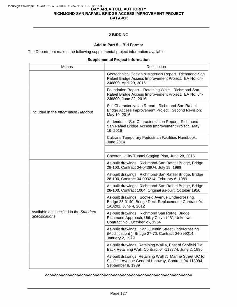
BAY AREA TOLL AUTHORITY RICHMOND-SAN RAFAEL BRIDGE ACCESS IMPROVEMENT PROJECT
BATA-013
Page 127
2 BIDDING
Add to Part 5 – Bid Forms:
The Department makes the following supplemental project information available:
Supplemental Project Information
Means Description
Included in the Information Handout
Geotechnical Design & Materials Report. Richmond-San Rafael Bridge Access Improvement Project. EA No. 04-2J6800, April 29, 2016
Foundation Report – Retaining Walls. Richmond-San Rafael Bridge Access Improvement Project. EA No. 04-2J6800, June 22, 2016
Soil Characterization Report. Richmond-San Rafael Bridge Access Improvement Project. Second Revision: May 19, 2016
Addendum - Soil Characterization Report. Richmond-San Rafael Bridge Access Improvement Project. May 19, 2016
Caltrans Temporary Pedestrian Facilities Handbook, June 2014
Chevron Utility Tunnel Staging Plan, June 28, 2016
Available as specified in the Standard Specifications
As-built drawings: Richmond-San Rafael Bridge, Bridge 28-100, Contract 04-0438U4, July 19, 1999
As-built drawings: Richmond-San Rafael Bridge, Bridge 28-100, Contract 04-003214, February 6, 1989
As-built drawings: Richmond-San Rafael Bridge, Bridge 28-100, Contract 1004, Original as-built, October 1956
As-built drawings: Scofield Avenue Undercrossing, Bridge 28-0140, Bridge Deck Replacement, Contract 04-1A3201, June 4, 2012
As-built drawings: Richmond San Rafael Bridge Richmond Approach, Utility Culvert “B”, Unknown Contract No., October 25, 1954
As-built drawings: San Quentin Street Undercrossing (Modification) ), Bridge 27-70, Contract 04-399214, January 2, 1979
As-built drawings: Retaining Wall 4, East of Scofield Tie Back Retaining Wall, Contract 04-118774, June 2, 1986
As-built drawings: Retaining Wall 7, Marine Street UC to Scofield Avenue General Highway, Contract 04-118994, September 8, 1989
^^^^^^^^^^^^^^^^^^^^^^^^^^^^^^^^^^^^^^^^^^^^^^^^^^^^^^^^^^^^^^^^^
DocuSign Envelope ID: 0308BBC7-C948-49AC-A76E-91F00185BA7F
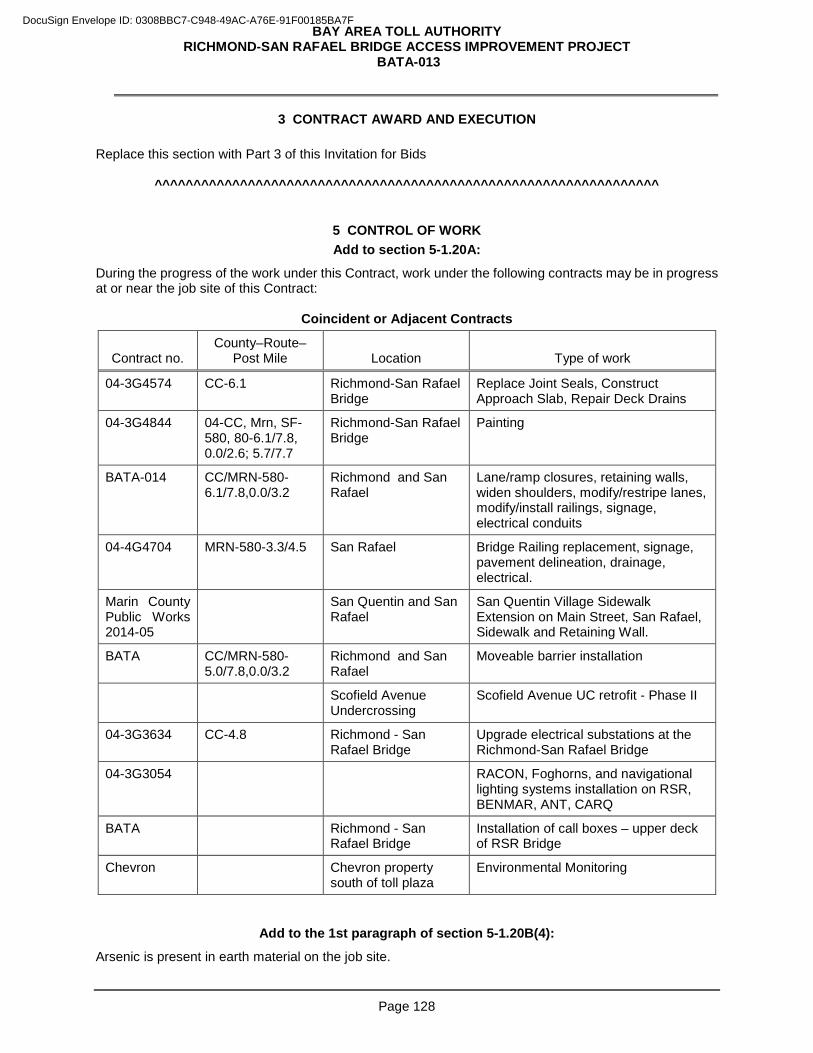
BAY AREA TOLL AUTHORITY RICHMOND-SAN RAFAEL BRIDGE ACCESS IMPROVEMENT PROJECT
BATA-013
Page 128
3 CONTRACT AWARD AND EXECUTION Replace this section with Part 3 of this Invitation for Bids
^^^^^^^^^^^^^^^^^^^^^^^^^^^^^^^^^^^^^^^^^^^^^^^^^^^^^^^^^^^^^^^^^
5 CONTROL OF WORK Add to section 5-1.20A:
During the progress of the work under this Contract, work under the following contracts may be in progress at or near the job site of this Contract:
Coincident or Adjacent Contracts
Contract no. County–Route–
Post Mile Location Type of work
04-3G4574 CC-6.1 Richmond-San Rafael Bridge
Replace Joint Seals, Construct Approach Slab, Repair Deck Drains
04-3G4844 04-CC, Mrn, SF-580, 80-6.1/7.8, 0.0/2.6; 5.7/7.7
Richmond-San Rafael Bridge
Painting
BATA-014 CC/MRN-580-6.1/7.8,0.0/3.2
Richmond and San Rafael
Lane/ramp closures, retaining walls, widen shoulders, modify/restripe lanes, modify/install railings, signage, electrical conduits
04-4G4704 MRN-580-3.3/4.5 San Rafael Bridge Railing replacement, signage, pavement delineation, drainage, electrical.
Marin County Public Works 2014-05
San Quentin and San Rafael
San Quentin Village Sidewalk Extension on Main Street, San Rafael, Sidewalk and Retaining Wall.
BATA CC/MRN-580-5.0/7.8,0.0/3.2
Richmond and San Rafael
Moveable barrier installation
Scofield Avenue Undercrossing
Scofield Avenue UC retrofit - Phase II
04-3G3634 CC-4.8 Richmond - San Rafael Bridge
Upgrade electrical substations at the Richmond-San Rafael Bridge
04-3G3054 RACON, Foghorns, and navigational lighting systems installation on RSR, BENMAR, ANT, CARQ
BATA Richmond - San Rafael Bridge
Installation of call boxes – upper deck of RSR Bridge
Chevron Chevron property south of toll plaza
Environmental Monitoring
Add to the 1st paragraph of section 5-1.20B(4):
Arsenic is present in earth material on the job site.
DocuSign Envelope ID: 0308BBC7-C948-49AC-A76E-91F00185BA7F
BAY AREA TOLL AUTHORITY RICHMOND-SAN RAFAEL BRIDGE ACCESS IMPROVEMENT PROJECT
BATA-013
Page 129
The soil characterization investigation detected concentrations of arsenic on the job site generally between 2.7 (mg/kg) and 9.3 (mg/kg) with one sample location with levels of 19 (mg/kg) and 26 (mg/kg). Refer to the site investigation report, dated May 19, 2016, included in the Information Handout for the locations and the analytical test results for the soil samples Submit a detailed health and safety plan (HSP), signed by a CIH, that identifies potential health and safety hazards associated with work involving soil containing arsenic levels over the Environmental Screening Levels (ESLs) and specifies work practices that will be used to protect workers from those hazards under 22 CA Code of Regs and 8 CA Code of Regs. The HSP must:
1. Identify key site safety personnel
2. Describe risks associated with the work
3. Specify training requirements
4. Specify appropriate personal protective equipment
5. Specify site-specific medical surveillance requirements
6. Specify air monitoring requirements
7. Define appropriate site work zones
8. Specify decontamination requirements Submit the HSP at least 15 working days before starting the work for review and authorization. Resubmit the HSP with revisions required by the Engineer within 5 business days. Do not start excavation work until the HSP is authorized. Disclose the arsenic concentration of the material to the receiving property owner. You are responsible for any additional sampling and analysis required by the receiving property owner.
Add to the list in the 1st paragraph of section 5-1.20B(4):
1.3. Containing acknowledgment of arsenic concentration disclosure
Replace “Reserved” in section 5-1.20D with:
5-1.20D Coordination with Chevron Oil Company for the Utility Culvert Extension The utility tunnel extension requires coordinate with the Chevron Oil Company for the Chevron contractor to relocate their security/communication lines. Refer to structural plans for the scope of work. Contractors are directed to the Informational Handout entitled “Chevron Fiber Optic Relocation / Tunnel Extension Construction Sequence” dated June 28, 2016 which presents a staging concept and sequence of work for:
• the construction of the tunnel extension,
• construction of the u-wall structure,
• construction of Retaining Walls 4 & 7, and
• Chevron’s relocation of their security/ communication lines.
The staging concept and sequence of work shown in the Informational Handout is one approach to conducting the work. You must develop and submit for approval by Chevron and the Engineer a
DocuSign Envelope ID: 0308BBC7-C948-49AC-A76E-91F00185BA7F
BAY AREA TOLL AUTHORITY RICHMOND-SAN RAFAEL BRIDGE ACCESS IMPROVEMENT PROJECT
BATA-013
Page 130
construction staging plan and sequencing of work outlining all the work elements for the construction including a three week window for the Chevron’s security/communication lines relocation activities. You must provide a minimum of two (2) weeks written notice to Chevron and the Engineer to request Chevron to commence relocation of their security/ communication lines. Chevron will have three (3) weeks to complete the relocation activities within the Contractor’s work area from the time they begin the relocation. No construction activities are permitted at this location while Chevron is performing the relocation unless agreed to in writing by Chevron and the Engineer. Chevron may perform relocation activities outside the Contractor’s work area after the 3-week period. All correspondence, submittal s and contact with Chevron are to be with the following Chevron representative:
Wallace Kresley FE Capital Projects, Project Manager Chevron Oil Company 1450 Marina Way S, Rm 2108A Richmond, CA 94804 Office Phone Number: 510.242.9132 Mobile Phone Number: 510.672.2307 Email Address: [email protected] Full compensation for coordinating with Chevron Oil Company and meeting the requirements of this section are included in the various contract items of work for the utility culvert extension and no additional compensation will be allowed therefor.
Replace “Reserved” in section 5-1.20E with:
5-1.20E Coordination with East Bay Municipal Utility District (EBMUD) for Retaining Wall No. 5 and 16-inch Water Line Relocation The construction of retaining wall number 5 requires coordination with EBMUD and the relocation of the 16-inch water line. Refer to the structural plans for the scope of work. Contractors are to be aware of the following conditions: 1. The new 16” water line within the proposed bike path from approximately 1005+50 to 1011+00 will be
installed by EBMUD.
2. In order for EBMUD to construct the water line, you must remove a portion of the existing embankment (and stabilize the cut slope) and/or construct retaining wall number 5 to a level of completion such that the bike path has been rough graded.
3. The Contractor is alerted that due to a conflict with EBMUD’s existing 16” water line between “BP1” 1011+00 and 1011+25.76, retaining wall number 5 cannot be constructed within these limits until EBMUD has completed relocation of their 16” water line in the bike path.
You must develop and submit for approval by EBMUD and the Engineer a construction staging plan and sequence of work outlining all work elements for the construction including the EBMUD relocation activities. You must provide a minimum of eight (8) weeks written notice to EBMUD and the Engineer to request EBMUD to commence relocation of the water line. EBMUD will have eight (8) weeks to complete the relocation activities within the Contractor’s work area from the time EBMUD begins the relocation. No construction activities are permitted at this location while EBMUD is performing the relocation unless agreed to in writing by EBMUD and the Engineer.
DocuSign Envelope ID: 0308BBC7-C948-49AC-A76E-91F00185BA7F
BAY AREA TOLL AUTHORITY RICHMOND-SAN RAFAEL BRIDGE ACCESS IMPROVEMENT PROJECT
BATA-013
Page 131
All correspondence, submittal s and contact with EBMUD are to be with the following EBMUD representative:
Andrew Hawksworth, P.E. Pipeline Infrastructure Division East Bay Municipal Utility District 375 11th Street Oakland, CA 94607 Office Phone Number: 510.287.1388 Email Address: [email protected] Full compensation for coordinating with EBMUD and meeting the conditions of this section are included in the various contract items of work for the retaining wall number 5 and no additional compensation will be allowed therefor.
Replace “Reserved” in section 5-1.20F with:
5-1.20F Relations with United States Coast Guard This project includes work in Substations 2 and 3 which are located more than 100 feet below the Richmond-San Rafael Bridge deck. If, in the performance of your work, you access the substations by water travel, the waterway is a navigable channel and is in an area controlled by the United States Coast Guard (USCG), Eleventh Coast Guard District, Building 50-2, Coast Guard Island, Alameda, CA 94501-5100. You must be fully informed of rules, regulations, and conditions that may govern the operations in the areas and conduct the work accordingly. Comply with Section 7 Legal Relations and Responsibility to the Public of the Standard Specifications. Comply with the following conditions which are among those established by the USCG:
1. Your operations must conform to the USCG regulations. Perform the work such that waterway traffic and navigational clearances are not affected and the navigable depths are not impaired.
2. All flame-producing, spark-producing, welding or other hazardous operations must be halted while
vessels are passing through the bridge. 3. Nothing may interfere with proper display of required bridge navigational lighting or other navigational
signals and bridge markings. 4. If temporary obstructions to navigation such as containment or floating equipment become necessary,
the proposal for such obstruction must be provided to the Eleventh Coast Guard District Bridge Office at least 30 days in advance for review and approval.
5. Floating equipment located in the channel must move when requested for safe passage of waterway
traffic. A good quality marine radio must be present at the jobsite and properly employed to facilitate reliable communications between you and approaching waterway traffic. The marine radio installed on the bridge, work tug or safety boat is considered adequate for this purpose.
6. You must provide anchor plans for USCG review and approval. 7. Moored or stationary obstructions, which include but not limited to scaffolding, barges, falsework,
temporary support, must be lighted at night with steady burning red lights, visible at 2,000 yards from approaching vessels. The USCG Bridge Office will provide details of location and color of lighting when your proposal is reviewed.
8. Nothing may be deposited into the water. If anything is accidentally dropped into the water, immediate action shall be taken to remove it and the waterway must be cleared to the satisfaction of the engineer.
DocuSign Envelope ID: 0308BBC7-C948-49AC-A76E-91F00185BA7F
BAY AREA TOLL AUTHORITY RICHMOND-SAN RAFAEL BRIDGE ACCESS IMPROVEMENT PROJECT
BATA-013
Page 132
9. Floating objects must be immediately recovered or tied down and marked, so that they do not present hazards to navigation. You must give immediate notice of in-place obstructions to the proper authorities and mark or buoy such obstructions until they are removed. Should you neglect or delay compliance with the above requirements, such obstructions will be removed by the Department and the cost of such removal will be deducted from the moneys due to you or may be recovered from your bond.
10. The Federal Water Pollution Control Act prohibits the discharge of oil, including oil based paints, into the navigable waters of the United States. In the event of discharge the responsible party shall immediately take action to halt the discharge and notify the National Response Center, U.S. Coast Guard by calling (800) 424-8802. Failure to report such discharge may result in substantial fines, imprisonment or both. Cleanup costs, if any, is at the Contractor's expenses.
11. Should you neglect or delay compliance with the above requirements, such clean up may be performed
by the Department and the cost of such cleanup will be deducted from the moneys due to you or may be recovered from your bond.
12. You must establish and maintain an adequate communications plan with the designated USCG Vessel Traffic Service. Initial contact may be established with the USCG Bridge Office by telephone at (510) 437-3515. (Actual telephone numbers will be provided in the official USCG letter of approval).
13. Full compensation for coordinating with the USCG and meeting the conditions of this section are included in the various contract items of work and no additional compensation will be allowed therefor.
Add to section 5-1.36D:
Installation of the utilities shown in the following table requires coordination with your activities. You are to provide exclusive, unfettered access to all third parties while their work is being performed. Make the necessary arrangements with the utility company through the Engineer and submit a schedule:
1. Verified by a representative of the utility company
2. Allowing at least the time shown for the utility owner to complete its work
3. Provide written notices to the Engineer one month and again one week before the utilities are to start work.
Utility Relocation and Contractor-Arranged Time for the Relocation
Utility Utility address Location Days
PG&E 12KV overhead electrical and utility pole
1850 Gateway Blvd, 7th Floor, Concord, CA 94520 (925) 270-2771
EB Route 580 Stenmark Dr Off Ramp and Stenmark Dr
15 working days
EBMUD 16” water
375 11th St, MS 504, Oakland, CA 94607 (866) 403-2683
EB Route 580 Stenmark Dr Off Ramp
40 working days
Working days duration in table above are not concurrent durations.
DocuSign Envelope ID: 0308BBC7-C948-49AC-A76E-91F00185BA7F
BAY AREA TOLL AUTHORITY RICHMOND-SAN RAFAEL BRIDGE ACCESS IMPROVEMENT PROJECT
BATA-013
Page 133
Replace section 5-1.38 with:
Partial relief of maintenance for the improvements included in Milestone #2 will not be granted. Relief of maintenance for the entire project will be granted after Final Acceptance of the entire project, as defined in GC-55.
Replace section 5-1.43 with:
5-1.43 RESERVED
^^^^^^^^^^^^^^^^^^^^^^^^^^^^^^^^^^^^^^^^^^^^^^^^^^^^^^^^^^^^^^^^^
6 CONTROL OF MATERIALS
Add to section 6-2.03: The Department furnishes you with:
• Model 2070 controller assemblies, including controller units, completely wired controller cabinets, and detector sensor units
• Model 2070 controller units The Department furnishes you with completely wired controller cabinets with auxiliary equipment but without controller unit at Caltrans Maintenance Station, 30 Rickard Street, San Francisco, CA. At least 48 hours before you pick up the materials, inform the Engineer of what you will pick up and when you will pick it up. The Department furnishes you with a Model 500 changeable message sign, wiring harness, and controller assembly, including the controller unit and completely wired cabinet, at Caltrans Maintenance Station, 30 Rickard Street, San Francisco, CA. At least 48 hours before you pick up the materials, inform the Engineer of what you will pick up and when you will pick it up.
^^^^^^^^^^^^^^^^^^^^^^^^^^^^^^^^^^^^^^^^^^^^^^^^^^^^^^^^^^^^^^^^^
8 PROSECUTION AND PROGRESS
Replace section 8-1.02 with:
8-1.02 PROGRESS SCHEDULE (CRITICAL PATH METHOD) 8-1.02A(1) General Critical path method (CPM) progress schedules are required for this project. Whenever the term "schedule" is used in this section, it means CPM progress schedule. You must shall submit to the Engineer practicable critical path method (CPM) progress schedules in conformance with these special provisions. 8-1.02A(2) Definitions The following definitions shall apply to this section:
1. Activity: A task, event or other project element on a schedule that contributes to completing the project. Activities have a description, start date, finish date, duration and one or more logic ties.
2. Baseline Schedule: The initial schedule representing the Contractor's work plan on the first working day of the project.
DocuSign Envelope ID: 0308BBC7-C948-49AC-A76E-91F00185BA7F
BAY AREA TOLL AUTHORITY RICHMOND-SAN RAFAEL BRIDGE ACCESS IMPROVEMENT PROJECT
BATA-013
Page 134
3. Contract Completion Date: The current date for completion of the contract shown on the weekly statement of working days furnished by the Engineer in conformance with the provisions in Section 8-1.05, “Time” of the Standard Specifications.
4. Critical Path: The longest continuous chain of activities for the project that has the least amount of total float of all chains. In general, a delay on the critical path will extend the scheduled completion date.
5. Critical Path Method (CPM): A network based planning technique using activity durations and the relationships between activities to mathematically calculate a schedule for the entire project.
6. Data Date: The day after the date through which a schedule is current. Everything occurring earlier than the data date is "as-built" and everything on or after the data date is “planned."
7. Early Completion Time: The difference in time between an early scheduled completion date and the contract completion date.
8. Float: The difference between the earliest and latest allowable start or finish times for an activity.
9. Milestone: An event activity that has zero duration and is typically used to represent the beginning or end of a certain stage of the project, or a project constraint.
10. Narrative Report: A document submitted with each schedule that discusses topics related to project progress and scheduling.
11. Near Critical Path: A chain of activities with float exceeding that of the critical path but having no more than 15 working days of float.
12. Scheduled Completion Date: The planned project finish date shown on the current accepted schedule.
13. State Owned Float Activity: The activity documenting time saved on the critical path by actions of the State. It is the last activity prior to the scheduled completion date.
14. Time Impact Analysis: A schedule and narrative report developed specifically to demonstrate what effect a change or delay has on schedule progress.
15. Total Float: The amount of time that an activity or chain of activities can be delayed before extending the scheduled completion date.
16. Update Schedule: A current schedule developed from the baseline or subsequent schedule through regular monthly review to incorporate as-built progress.
8-1.02B General Requirements You must submit to the Engineer baseline, monthly update and final update schedules, each consistent in all respects with the time and order of work requirements of the contract. The project work shall be executed in the sequence indicated on the current accepted schedule. Schedules must show the order in which you propose to carry out the work with logical links between time-scaled work activities, and calculations made using the critical path method to determine the controlling operation or operations. You are responsible for assuring that all activity sequences are logical and that each schedule shows a coordinated plan for complete performance of the work. You must produce schedules using the latest version of Primavera Project Manager 6.0 computer software and furnish compatible software for the Engineer's exclusive possession and use. Furnish network diagrams, narrative reports, tabular reports and schedule data as parts of each schedule submittal. Schedules shall include, but not be limited to, activities that show the following that are applicable to the project:
1. Project characteristics, salient features, or interfaces, including those with outside entities that could affect time of completion.
DocuSign Envelope ID: 0308BBC7-C948-49AC-A76E-91F00185BA7F
BAY AREA TOLL AUTHORITY RICHMOND-SAN RAFAEL BRIDGE ACCESS IMPROVEMENT PROJECT
BATA-013
Page 135
2. Project start date, scheduled completion date and other contract milestones.
3. All Work performed by the Contractor, subcontractors and suppliers.
4. Submittal development, delivery, review and approval, including those from the Contractor, subcontractors and suppliers. Schedule updates shall reflect all re-submittal activities, including re-submittal review.
5. Fabrication, procurement, delivery, installation and testing of materials, plants and equipment.
6. Testing, submission and approval of test reports, and settlement periods.
7. Utility notification and relocation.
8. Erection and removal of falsework and shoring.
9. Major traffic, phase, and stage switches.
10. Finishing and final cleanup.
11. State-owned float as the predecessor activity to the scheduled completion date. Schedules must have not less than 50 and not more than 500 activities, unless otherwise authorized by the Engineer. The number of activities shall be sufficient to assure adequate planning of the project, to permit monitoring and evaluation of progress, and to do an analysis of time impacts. Upon requests of the Engineer, you will provide the anticipated resources for specific activities, substantiation and explanation for specific activity durations in writing. Schedule activities must include the following:
1. A clear and legible description
2. Identifiable Start and finish dates for each activity.
3. A duration of not less than one working day, except for milestone event activities, and not more than 15 working days, unless otherwise authorized by the Engineer.
4. At least one predecessor and one successor activity, except for project start and finish milestones.
5. Required constraints.
6. Codes for responsibility, stage, phase, location, stationing or area, structure, plan sheet, type of work, and contract change order, as applicable shall be provided for each activity.
The Contractor may show early completion time on any schedule provided that the requirements of the contract are met. Early completion time shall be considered a resource for the exclusive use of the Contractor. You may increase early completion time by improving production, reallocating resources to be more efficient, performing sequential activities concurrently or by completing activities earlier than planned. You may also submit for approval a cost reduction incentive proposal in conformance with the provisions in Section 4-1.07,"Value Engineering", of the Standard Specifications that will reduce time of construction. State-owned float shall be considered a resource for the exclusive use of the State. The Engineer may accrue State-owned float by the early completion of review of any type of required submittal, re-submittal, or through any other action of the Engineer and/or State when it saves time on the critical path. For purposes of determining State-owned float, the Engineer will be entitled to the full submittal review times allowed in the contract for each re-submittal. For example, if the Engineer is allowed 30 working days for a particular submittal review and he completes the review in 20 working days, then 10 working days of State-owned float will accrue. If this same submittal must be submitted again, and the Engineer completes the review in 15 working days, then an additional 15 working days of float is accrued, for a total of 25 working days. You must prepare a time impact analysis, when a submittal is on the critical path or when requested by the Engineer, to determine the effect of the action in conformance with the provisions in "Time Impact Analysis" specified herein. The Engineer will document State-owned float by directing the Contractor to update the State-owned float activity on the next update schedule. You must include a log of the action on the State-owned float activity and include a discussion of the action in the narrative report.
DocuSign Envelope ID: 0308BBC7-C948-49AC-A76E-91F00185BA7F
BAY AREA TOLL AUTHORITY RICHMOND-SAN RAFAEL BRIDGE ACCESS IMPROVEMENT PROJECT
BATA-013
Page 136
The Engineer may use State-owned float to mitigate past, present or future State delays by offsetting potential time extensions for contract change orders. The Engineer may adjust contract working days for ordered changes that affect the scheduled completion date, in conformance with the provisions in Section 4-1.05, "Changes and Extra Work", of the Standard Specifications. You must prepare a time impact analysis to determine the effect of the change in conformance with the provisions in "Time Impact Analysis" specified herein, and shall include the impacts acceptable to the Engineer in the next update schedule. Changes that do not affect the controlling operation on the critical path will not be considered as the basis for a time adjustment. Changes that do affect the controlling operation on the critical path will be considered by the Engineer in decreasing time or granting an extension of time for completion of the contract. Time extensions will only be granted if the total float is absorbed and the scheduled completion date is delayed one or more working days because of the ordered change and if efficient mitigation of the change is not directed or feasible. The Engineer's review and acceptance of schedules shall not waive any contract requirements and shall not relieve the Contractor of any obligation thereunder or responsibility for submitting complete and accurate information. Schedules that are rejected shall be corrected by the Contractor and resubmitted to the Engineer within 5 working days of notification by the Engineer, at which time a new review period of one week will begin. Errors or omissions on schedules shall not relieve the Contractor from finishing all work within the time limit specified for completion of the contract. If, after a schedule has been accepted by the Engineer, either the Contractor or the Engineer discover that any aspect of the schedule has an error or omission, it shall be corrected by the Contractor in accordance with the Schedule Revision requirement provided herein. You must be responsible for any errors or omissions in the schedule. 8-1.02C Computer Software You must submit to the Engineer for approval a description of proposed software before delivery. The software shall be the latest version of Primavera Project Manager 6.0, and shall be compatible with Microsoft Windows operating system. You must furnish schedule software and all original software instruction manuals to the Engineer with submittal of the baseline schedule. The furnished schedule software shall become the property of the State and will not be returned to the Contractor. The State will compensate the Contractor in conformance with the provisions in Section 4-1.05, "Changes and Extra Work", of the Standard Specifications for replacement of software which is damaged, lost or stolen after delivery to the Engineer. You must instruct the Engineer in the use of the software and provide software maintenance support through Primavera until the contract is accepted. Within 20 working days of contract approval, You must provide a commercial 8-hour training session for 2 Department employees in the use of the software at a location acceptable to the Engineer. It is recommended that the Contractor also send at least 2 employees to the same training session to facilitate development of similar knowledge and skills in the use of the software. 8-1.02D Schedule Submittals, Network Diagrams, Reports and Data Submit the following for each schedule submittal:
1. Two sets of originally printed, time-scaled network diagrams.
2. Two copies of a narrative report.
3. Two copies of each of 3 sorts of the CPM software-generated tabular reports.
4. One CD containing the schedule data and narrative.
DocuSign Envelope ID: 0308BBC7-C948-49AC-A76E-91F00185BA7F
BAY AREA TOLL AUTHORITY RICHMOND-SAN RAFAEL BRIDGE ACCESS IMPROVEMENT PROJECT
BATA-013
Page 137
The time-scaled network diagrams shall conform to the following:
1. Show a continuous flow of information from left to right.
2. Be based on early start and early finish dates of activities.
3. Clearly show the primary paths of criticality using graphical presentation.
4. Be prepared on 11” x 17” size sheetsInclude a title block and a timeline on each page. The narrative report shall be organized in the following sequence with all applicable documents included:
1. Contractor's transmittal letter.
2. Discussion of current progress and performance
3. Identification of the specific activity and a detailed explanation, including responsible party for any unusual conditions or any restrictions regarding labor, equipment or material; including multiple shifts, 6-day work weeks, specified overtime, accelerative measures, productivity losses, inefficiencies, or work at times other than regular days or hours.
4. Identification of the controlling operations for the update period, identification of critical and near critical paths, and identification and explanation of any changes to the controlling operations, critical, and near-critical paths since the last submittal.
5. Identification and explanation of all changes to as-built work for the period including but not limited to all logic and duration changes.
6. Description and explanation of any adverse activity impacts during the update period.
7. Identification, explanation and responsibility for any negative float.
8. You must identify and explain all delays, including:
8.1 Cause of delay
8.2 Party responsible for delay
8.3 Impact of delay on other activities, milestones and completion dates.
8.4 Corrective action and schedule adjustments taken or proposed to correct the delay.
9. You must identify and explain pending items and status
9.1 Permits
9.2 Change orders, notice of potential claim
9.3 Time impact analysis
9.4 Time adjustments
9.5 Noncompliance notices
10. You must identify and explain reasons for any changes to the contract completion date or contract milestones in comparison to the original contract completion date or previous update.
Tabular reports shall be software-generated and provide information for each activity included in the project schedule. Three different reports shall be sorted by (1) activity number, (2) early start and (3) total float. Tabular reports shall be 8-1/2" x 11" in size and shall include, as a minimum, the following applicable information:
1. Data Date
2. Activity number and description
3. Predecessor and successor activity numbers and descriptions
4. Activity codes
DocuSign Envelope ID: 0308BBC7-C948-49AC-A76E-91F00185BA7F
BAY AREA TOLL AUTHORITY RICHMOND-SAN RAFAEL BRIDGE ACCESS IMPROVEMENT PROJECT
BATA-013
Page 138
5. Scheduled, or actual and remaining durations (work days) for each activity
6. Earliest start (calendar) date
7. Earliest finish (calendar) date
8. Actual start (calendar) date
9. Actual finish (calendar) date
10. Latest start (calendar) date
11. Latest finish (calendar) date
12. Free float (working days)
13. Total float (working days)
14. Percentage of activity complete and remaining duration for incomplete activities
15. Lags
16. Required constraints Schedule submittals will only be considered complete when all documents and data have been provided as described above. 8-1.02E Pre-Construction Scheduling Conference You must schedule and the Engineer will conduct a pre-construction scheduling conference with the Contractor's project manager and construction scheduler within 5 working days of the approval of the contract. At this meeting the Engineer will review the requirements of this section of the special provisions with the Contractor. You must submit a general time-scaled logic diagram displaying the major activities and sequence of planned operations and shall be prepared to discuss the proposed work plan and schedule methodology that comply with the requirements of these special provisions. If the Contractor proposes any deviations to the construction staging of the project, then the general time-scaled logic diagram shall also display the deviations and resulting time impacts. You must be prepared to discuss the proposal. At this meeting, you must additionally submit the alphanumeric coding structure and the activity identification system for labeling the work activities. To easily identify work activities and relationships, each activity description shall indicate its associated scope or location of work by including such terms as quantity of material, type of work, bridge number, station to station location and limits defined by the activity, side of highway (such as left, right, northbound, southbound), lane number, shoulder, ramp name, ramp line descriptor or mainline, drainage system number or component, etc. You must provide a sample outline of the schedule update narrative report and the daily construction report to be provided. The Engineer will review the logic diagram, coding structure, activity identification system, schedule update narrative report outline, and daily construction report outline and provide any additional required changes to the Contractor for implementation. 8-1.02F Baseline Schedule Beginning the week following the pre-construction scheduling conference, you must meet with the Engineer weekly until the baseline schedule is accepted by the Engineer to discuss schedule development and resolve schedule issues. You are advised to expedite preparation of the Baseline Schedule immediately after Contract Approval. You must submit to the Engineer a baseline schedule within 10 working days of approval of the contract. You must allow 10 working days for the Engineer's review after the baseline schedule and all support data are submitted. In addition, the baseline schedule submittal will not be considered complete until the computer software is delivered and installed for use in review of the schedule.
DocuSign Envelope ID: 0308BBC7-C948-49AC-A76E-91F00185BA7F
BAY AREA TOLL AUTHORITY RICHMOND-SAN RAFAEL BRIDGE ACCESS IMPROVEMENT PROJECT
BATA-013
Page 139
The baseline schedule shall include the entire scope of work and how you plan to complete all work contemplated. The baseline schedule shall show the activities that define the Critical path. Multiple critical paths and near-critical paths shall be kept to a minimum. A total of not more than 50 percent of the baseline schedule activities shall be critical or near critical, unless otherwise authorized by the Engineer. There shall be a valid basis for the inclusion of any constraint other than those required by the contract. You must specifically identify and provide a detailed explanation in writing of any included constraints that are not a specific requirement of the contract. Substantiation shall be provided if requested by the Engineer. The baseline schedule shall not extend beyond the number of working days specified in these special provisions. The baseline schedule shall have a data date of the first working day of the contract and not include any completed work to date. Unless specifically addressed by this special provision, any activities to be performed by the Owner, Owner Representative, Utility or Others shall not proceed until after the date specified in the Notice to Proceed letter and within the contract working days defined in Section 8-1.05, “Time”, of these special provisions. Earlier performance of these activities may result in Owner float. The baseline schedule shall not attribute negative float to any activity If you submit an early completion baseline schedule that shows contract completion in less than 90 percent of the working days specified in these special provisions, the baseline schedule shall be supplemented with resource allocations for every task activity and include time-scaled resource histograms. The resource allocations shall be shown to a level of detail that facilitates report generation based on labor crafts and equipment classes for you and your subcontractors. You must use average composite crews to display the labor loading of off-site construction activities. You must optimize and level labor to reflect a reasonable plan for accomplishing the work of the contract and to assure that resources are not duplicated in concurrent activities. The time-scaled resource histograms shall show labor crafts and equipment classes to be utilized on the contract. The Engineer may review the baseline schedule activity resource allocations using Means Productivity Standards or equivalent to determine if the schedules practicable. 8-1.02G Weekly 4-Week Schedule Reports You must prepare and submit each week throughout the duration of the project a 4week rolling schedule identifying daily construction activities as performed the previous 1 weekend as planned for 3 weeks. This 4-week schedule shall identify an activity ID correlating to the monthly update schedule activities providing additional detail of the work to be performed. This 4week schedule shall include changed work. This 4 week schedule does not have to be submitted in Project Manager 6.0 format. Spreadsheet type 4–week schedules will be acceptable, provided that all required information is included. 8-1.02H Update Schedule You must submit an update schedule and meet with the Engineer to review contract progress on or before the first day of each month, beginning one month after the baseline schedule is accepted. You must allow 10 working days for the Engineer's review after the update schedule and all support data are submitted, except that the review period shall not start until the previous month's required schedule is accepted. Update schedules that are not accepted or rejected within the review period will be considered accepted by the Engineer. The Engineers review and acceptance of schedules shall not change or waive any contract requirements and shall not relieve you of any obligation or responsibility for submitting complete and accurate information. You remain responsible for any errors or omissions in the schedule data. The update schedule shall have a data date of the twenty-first day of the month or other date established by the Engineer. Any changes to any schedule data, activities, or logic after the data date are classified as revisions and are to be addressed in accordance with the schedule revision section of this specification. The update schedule shall show the status and performance of work actually completed to date and the work yet to be performed as planned. Actual activity relationships (logic) shall be corrected to reflect the actual logic (activity interdependencies) and actual sequence followed. Actual activity start dates, percent complete and finish dates shall be shown as applicable. Durations and logic for work that has been completed shall be shown on the update schedule as the work actually occurred, including Engineer
DocuSign Envelope ID: 0308BBC7-C948-49AC-A76E-91F00185BA7F
BAY AREA TOLL AUTHORITY RICHMOND-SAN RAFAEL BRIDGE ACCESS IMPROVEMENT PROJECT
BATA-013
Page 140
submittal and re-submittals review and Contractor submittal and re-submittal times. Engineer Submittal and re-submittal review activities shall reflect the allowable contract duration as the original activity duration. For activities in progress that are forecasted to complete longer than originally planned, the remaining durations shall be revised, not the original durations. All out-of-sequence activities shall be reviewed and their relationships verified or corrected to reflect actual as-built performance. All Changed work shall be reflected as a separate activity with actual logic relationships. The Contractor may include as built modifications such as adding or deleting activities or changing activity constraints, durations or logic that do not (1) alter the critical path(s) or near critical path(s) or (2) extend the scheduled completion date compared to that shown on the current accepted schedule. You must identify and state in writing explaining the reasons for any changes to as built work. If any changes in as built work results in (1) or (2) above, or are attributed to the Owner then You must also submit a time impact analysis as described herein. For changes to planned work You must submit a schedule revision in accordance with the schedule revision requirements. Any added activities which may be attributed to the Owner, or for any original activities experiencing any unusual conditions consistent with item B of the narrative for which the unusual condition may be attributed to the owner will be resource loaded to reflect the actual resources utilized to a level of detail that facilitates report generation based on labor crafts and equipment classes for you and your subcontractors. You must also provide the original planned resources for those original activities experiencing any unusual resource conditions consistent with Item B of the narrative. 8-1.02I Time Impact Analysis You must submit a time impact analysis (TIA) including information and data required in Schedule, Submittals, Network Diagrams, Reports and Data section of this specification as applicable, to the Engineer with each request for adjustment of contract time, or when you or Engineer consider that an approved or anticipated change may impact the critical path or contract progress or performance, or in accordance with the identification of Owner float, or as specified in Update Schedule section of this specification. The TIA shall illustrate the impacts of each change, delay, or time saving action of the Engineer and/or State on the current scheduled completion date, internal milestone, or other schedule component as appropriate. The analysis shall use the accepted schedule that has a data date closest to and prior to the event (such as start of performance of changed work, or start of a re-submittal review). If the Engineer determines that the accepted schedule used does not appropriately represent the conditions prior to the event, the accepted schedule shall be updated to the day before the event being analyzed. The TIA shall include impact schedules developed from incorporating the event into the accepted schedule by adding or deleting activities, or by changing durations or logic of existing activities to reflect how the work will be performed consistent with contract requirements. If the impact schedule shows that incorporating the event modifies the critical path and scheduled completion date of the accepted schedule, the difference between scheduled completion dates of the two schedules may be equal to the adjustment of contract time or be subject to mitigate action (including but not limited to the use of Owner float to mitigate delays). If it is determined that the TIA may not accurately reflect the impact of the change, an alternate TIA method may be requested in writing at the discretion of the Engineer. This may include preparation of an as-built impact analysis reflecting the actual work as-performed (actual activities with actual durations and logic) to the day after the event being analyzed (day after changed work, or re-submittal review) with remaining work as-planned. You must submit the TIA induplicate no later than 10 working days of beginning the performance of any changed work which impacts the critical path, interim milestone date, or project completion date, or within 10 working days of receiving a written request for a TIA from the Engineer. You must allow the Engineer 10 working days after receipt to approve or reject the submitted TIA. All approved TIA schedule changes shall be shown in the update following TIA approval. If a TIA submitted by you is rejected by the Engineer, You must meet with the Engineer to discuss and resolve issues related to the TIA within 10 working days. If agreement is not reached, you will be allowed 5 working days from the meeting with the Engineer to give notice in conformance with the provisions in Section 5-1.43, “Potential Claims and Dispute Resolution”, of the Standard Specifications. Until approval of the TIA You must only show actual as-built work as actually performed in subsequent update schedules. If agreement is reached at a later date, approved TIA schedule changes shall be shown on the next update
DocuSign Envelope ID: 0308BBC7-C948-49AC-A76E-91F00185BA7F
BAY AREA TOLL AUTHORITY RICHMOND-SAN RAFAEL BRIDGE ACCESS IMPROVEMENT PROJECT
BATA-013
Page 141
schedule. The Engineer will withhold remaining payment on the schedule contract item if a TIA is not submitted by you within 10 working days in accordance with this specification. The schedule item payment will resume on the next estimate after the requested TIA is submitted. These of any other TIA method, including, but not limited to contemporaneous analysis of the as-built record immediately following completion of the event, shall be at the sole discretion of the Engineer. Failure to provide a time impact analysis or schedule submittal in accordance with the aforementioned requirements shall constitute as your waiver of any claim or delay associated with the time impact analysis or schedule submittal. 8-1.02J Schedule Revision If you desire to make any change to an accepted schedule or planned work, You must request permission from the Engineer in writing, stating the reasons for the change, and proposed revisions to activities, logic and duration. You must submit for acceptance an analysis showing the effect of the revisions on the entire project. The analysis shall include:
1. An updated schedule not including the revisions. The schedule shall have a data date just prior to implementing the proposed revisions and include a project completion date;
2. A revised schedule that includes the proposed revisions. The schedule shall have the same data date as the updated schedule and include a project completion date;
3. A narrative explanation of the revisions and their impact to the schedule; and
4. Computer files of the updated and revised schedules. The Engineer will provide a response within 10 work days. No revision to the accepted baseline schedule or a schedule update shall be made without prior written approval of the Engineer. The Engineer may request you to submit a proposed revised schedule within 15 days when:
1. there is a significant change in the your operations that will affect the critical path;
2. the current updated schedule indicates that the contract progress is 20 work days or more behind the planned schedule, as determined by the Engineer; or
3. The Engineer determines that an approved or anticipated change will impact the critical path, milestone or completion dates, contract progress, or work by other contractors.
The Engineer shall be allowed 10 work days to review and accept or reject a schedule revision. Rejected revisions shall be revised and resubmitted to the Engineer within 10 work days, at which time a new 10 work day review will begin. 8-1.02K Final Update Schedule You must submit a final update as-built schedule with actual schedule logic and actual start and finish dates for the activities within 30 days after completion of contract work. You must provide a written certificate with this submittal signed by your project manager and an officer of the company stating, "To my knowledge and belief, the enclosed final update schedule reflects the actual schedule logic relationships, actual start and actual finish dates of the actual activities performed for the project contained herein." An officer of the company may delegate in writing the authority to sign the certificate to a responsible manager. 8-1.02L Retention The Department will retain an amount equal to 25 percent of the estimated value of the work performed during each estimate period in which you fail to submit an acceptable schedule conforming to the requirements of these special provisions as determined by the Engineer. These deductions are cumulative and will be made for each month that you fail to provide the required information. Schedule retentions will be released for payment on the next monthly estimate for partial payment following the date that acceptable schedules are submitted to the Engineer or as otherwise specified herein. Upon completion of all contract work and submittal of the final update schedule and certification, any remaining retained funds associated
DocuSign Envelope ID: 0308BBC7-C948-49AC-A76E-91F00185BA7F
BAY AREA TOLL AUTHORITY RICHMOND-SAN RAFAEL BRIDGE ACCESS IMPROVEMENT PROJECT
BATA-013
Page 142
with this section, "Progress Schedule (Critical Path Method)", will be released for payment. Retentions held in conformance with this section shall be in addition to other retentions provided for in the contract. No interest will be due to you on retention amounts. Because the Owner places a high value on the importance and use of project scheduling as management tool, for delays in providing any schedule submittal in accordance with these special provisions, in addition to the specified schedule retentions, the Owner will assess liquidated damages of One Hundred Dollars ($100) per day for each day that expires after the time specified herein for submittal of a CPM schedule, including baseline schedule, schedule update, schedule revision, or time impact analysis. 8-1.02M Payment Progress schedule (critical path method) will be paid for at a lump sum price. The contract lump sum price paid for progress schedule (critical path method) shall include full compensation for furnishing all labor, material, tools, equipment, and incidentals, including computer software, and for doing all the work involved in preparing, furnishing, and updating schedules, and instructing and assisting the Engineer in the use of computer software, as specified in the Standard Specifications and these special provisions, and as directed by the Engineer. Payments for the progress schedule (critical path method) contract item will be made progressively as follows:
1. A total of 25 percent of the item amount will be paid upon achieving all of the following:
1.1 Completion of 5 percent of all contract item work
1.2 Acceptance of all schedules and TIAs required to the time when 5 percent of all contract item work is complete.
1.3 Delivery of schedule software to the Engineer.
1.4 Completion of required schedule software training.
2. A total of 50 percent of the item amount will be paid upon completion of 25 percent of all contract item work and acceptance of all schedules and TIAs required to the time when 25 percent of all contract item work is complete.
3. A total of 75 percent of the item amount will be paid upon completion of 50 percent of all contract item work and acceptance of all schedules and TIAs required to the time when 50 percent of all contract item work is complete.
4. A total of 100 percent of the item amount will be paid upon completion of all contract item work, acceptance of all schedules and TIAs required to the time when all contract item work is complete, and submittal of the certified final update schedule.
Replace section 8-1.03 with:
8-1.03 POTHOLING You must physically verify all locations of existing utilities, and certify, in writing, that there are no conflicts with planned improvements. If there are conflicts, you must indicate in writing, the specific conflict and allow the Engineer 30 working days to provide a response. You must include a schedule activity for potholing (Contractor responsibility), and notification to the Engineer in the base line schedule. The 30 working day for Engineer review must be identified as an owner activity in the your baseline schedule. If there are no conflicts identified, this activity will then be shown as owner float.
Replace "Reserved" in section 8-1.04C with:
Section 8-1.04B does not apply. Do not start job site activities until the Department authorizes or accepts your submittal for:
1. CPM baseline schedule
DocuSign Envelope ID: 0308BBC7-C948-49AC-A76E-91F00185BA7F
BAY AREA TOLL AUTHORITY RICHMOND-SAN RAFAEL BRIDGE ACCESS IMPROVEMENT PROJECT
BATA-013
Page 143
2. SWPPP
3. Contingency plan for opening closures to public traffic 4. Receive authorization to start
You may enter the job site only to measure controlling field dimensions and locate utilities. Do not start other job site activities until all the submittals from the above list are authorized or accepted and the following information is received by the Engineer:
1. Notice of Materials To Be Used form.
2. Written statement from the vendor that the order for the sign panels has been received and accepted by the vendor. The statement must show the dates that the materials will be shipped.
3. Written statement from the vendor that the order for electrical material has been received and accepted by the vendor. The statement must show the dates that the materials will be shipped.
4. Temporary bike service shuttle needs to be available prior to work along outside shoulders in Richmond.
Replace section 8-1.05 with:
8-1.05 RESERVED
^^^^^^^^^^^^^^^^^^^^^^^^^^^^^^^^^^^^^^^^^^^^^^^^^^^^^^^^^^^^^^^^^
9 PAYMENT
Replace section 9-1.11:
9-1.11 RESERVED
Add to section 9-1.16C: The following items are eligible for progress payment even if they are not incorporated into the work:
1. Control and Neutral Conductors (ARMOR-CLAD)
2. 24-32 Station Irrigation Controller (Pedestal Mounted)
3. 2" Plastic Pipe (Schedule 40) (Supply Line)
4. 8" Corrugated High Density Polyethylene Pipe Conduit
5. Soil Nail
6. Piling (Class 200) (Alternative W)
7. Bar Reinforcing Steel
8. Structural Steel (Bridge)
9. Timber Retaining Wall
10. 18" Alternative Pipe Culvert
11. 24" Alternative Pipe Culvert
12. 18" Corrugated Steel Pipe (0.079" Thick)
13. 18" Slotted Corrugated Steel Pipe (0.079" Thick)
14. 3" Plastic Pipe (Edge Drain)
DocuSign Envelope ID: 0308BBC7-C948-49AC-A76E-91F00185BA7F
BAY AREA TOLL AUTHORITY RICHMOND-SAN RAFAEL BRIDGE ACCESS IMPROVEMENT PROJECT
BATA-013
Page 144
15. 12” Welded Steel Pipe (0.250” Thick)
16. Miscellaneous Iron and Steel
17. Miscellaneous Metal (Bridge)
18. Chain Link Fence (Type CL-8, with Barbed Wire)
19. Chain Link Railing (Type CL-8 Mod 1)
20. Chain Link Railing (Type CL-8 Mod 2)
21. Midwest Guardrail System (Wood Post)
22. Chain Link Railing (Type 7)
23. Bicycle Railing
24. Cable Railing
25. Transitions Railing (Type WB-31)
26. Concrete Barrier Gate (Armorguard Gate System)
27. California ST-10 Bridge Rail
28. Pavement Marker (Non-Reflective)
29. Pavement Marker (Retroreflective)
^^^^^^^^^^^^^^^^^^^^^^^^^^^^^^^^^^^^^^^^^^^^^^^^^^^^^^^^^^^^^^^^^
DIVISION II GENERAL CONSTRUCTION 10 GENERAL
Replace “Reserved” in section 10-7 of the RSS for section 10 with:
10-7 TEMPORARY BICYCLE SHUTTLE SERVICE 10-7.01 GENERAL 10-7.01A Summary Section 10-7 includes specifications for providing and operating a temporary bicycle shuttle service to safely transport bicyclists and bicycles through the construction zone, as shown on the plans, as specified in the Standard Specifications, and as directed by the Engineer. 10-7.01B Governing Laws Comply with applicable federal, state, county, municipal and local utility laws, rules, and regulations for temporary facilities. Nothing in these contract documents may be construed to permit work not conforming to such codes and regulations. 10-7.01C Mandatory Licenses and Permits You must have the following licenses and permits prior to operating the shuttle service:
1. Business License, which complies with all City(s) and/or County ordinances required for the shuttle service.
2. Charter Party Carrier of Passengers, in accordance with Section 5384, paragraph A of the Public Utilities Code for the entire term of the contract. This Permit can be obtained from the Public Utilities Commission.
3. Driver's License with valid medical certificate – operators of the shuttle must possess minimum of a California Class "B" driver's license with a (P) passenger endorsement and valid medical certificate. If
DocuSign Envelope ID: 0308BBC7-C948-49AC-A76E-91F00185BA7F
BAY AREA TOLL AUTHORITY RICHMOND-SAN RAFAEL BRIDGE ACCESS IMPROVEMENT PROJECT
BATA-013
Page 145
a trailer weighing over 6,000 pounds is used to transport bicycles, the operator must have a CA Class "A" license with a (P) endorsement and valid medical certificate.
10-7.01D Shuttle Operator Safety Rules and Regulations All shuttle operators must demonstrate professional behavior towards riders at all times. Shuttle operator's clothing must always be clean at the start of each day the shuttle is in service. Drinking of alcohol while in service or less than twelve hours prior to the start of each day the shuttle is in service is prohibited. Smoking of any kind and/or use of an illegal substance while in service is prohibited. Shuttle operators must obey all traffic laws and posted speed limits. Any personal objects left on the shuttle after disembarkation of passengers must be delivered to the Engineer at the end of each day's service. 10-7.01E Submittals You must develop a Daily Log of Passengers form, approved by the Engineer, which the shuttle operator is required to complete for each day the shuttle service is in operation. The form must indicate how many bicyclists are picked up during each identified hour the shuttle service is in operation. Submit the Daily Log of Passengers to the Engineer at the end of each week. The data collected from the log may be evaluated according to the shuttle service usage and the shuttle service schedule may be modified by the Engineer. Changes to the shuttle service must be by contract change order in accordance with section 4-1.05. 10-7.02 MATERIAL 10-7.02A Shuttle Vehicles The shuttle vehicle(s) must be capable of transporting a minimum of six passengers and four bicycles. At your option, a single vehicle or van and trailer combination may be used for this purpose. The vehicle(s) must be equipped with seat belts for all passengers and all seat belts must be in good operating condition. Bicycles may be secured inside the transporting vehicle, or properly secured onto a bicycle trailer towed by the vehicle(s). Bicycles must be securely anchored as not to cause damage, scratching or chance of falling from the vehicle(s). Magnetic signs must be placed on the driver and passenger doors of the shuttle. Do not use the shuttle vehicle without the signs. You must replace all signs at your expense if they are damaged or lost. All vehicles utilized for this service shall have no more than three uniform colors. Primed, rusted or damaged sections on the shuttle vehicle(s) will be deemed unacceptable. Vehicles must be inspected and subject to approval by the Engineer 10 days prior to placing the vehicles into service. You are fully responsible for damage of any kind to personal property. All vehicles utilized for the shuttle service are subject to inspection by the Engineer at any time during this contract. 10-7.02B Temporary Bicycle Shuttle Magnetic Signs Provide two magnetic car signs. The text to be included on the signs is:
“Richmond-San Rafael Bridge” “Bicycle Shuttle” The size of the signs must be a minimum of 12 inches by 18 inches. 10-7.03 CONSTRUCTION 10-7.03A General The temporary bicycle shuttle service must be in operation immediately prior to beginning of the closure of the existing bicycle path and freeway shoulder permitted bicyclist prior to construction work.
DocuSign Envelope ID: 0308BBC7-C948-49AC-A76E-91F00185BA7F
BAY AREA TOLL AUTHORITY RICHMOND-SAN RAFAEL BRIDGE ACCESS IMPROVEMENT PROJECT
BATA-013
Page 146
10-7.03B Shuttle Service Schedule The service must operate 7 days a week from 7 A.M. to 7 P.M. on an on-call shuttle service system, as approved by the Engineer, for the duration of the construction project. When the shuttle service is no longer needed, you must obtain a written approval from the Engineer to end the service. 10-7.03C Shuttle Performance Requirements The maximum waiting time for any bicyclist for a shuttle to arrive for pick-up must be no more than 20 minutes after a phone call has been made for the shuttle service by the bicyclist. The shuttle must be free to the bicyclist. 10-7.03D Pick-up/Drop off locations The pick-up/drop-off locations must be located as shown. The exact locations will be determined by the Engineer. 10-7.03E Vehicle Maintenance Keep the vehicles neat and clean inside and out. At the beginning of each day the vehicle is used for the shuttle service, sweep dirt and debris out of the vehicle, clean the windows and clean the seats of all foreign material. Wash the exterior of vehicle weekly, or as needed. Each vehicle must be equipped with a standard first-aid kit and a 20 pound ABC fire extinguisher. 10-7.04 PAYMENT Not used.
^^^^^^^^^^^^^^^^^^^^^^^^^^^^^^^^^^^^^^^^^^^^^^^^^^^^^^^^^^^^^^^^^^
12 TEMPORARY TRAFFIC CONTROL
Replace section 12-1.03 with:
12-1.03 FLAGGING COSTS You are responsible for the cost of furnishing all flaggers, including transporting flaggers and furnishing stands and towers for flaggers to provide for the passage of traffic through the work as specified in sections 7-1.03 and 7-1.04.
Replace section 12-3.05 with:
12-3.05 PORTABLE FLASHING BEACONS 12-3.05A General Section 12-3.05 includes specifications for installing, removing, and moving portable flashing beacons. Each portable flashing beacon must have:
1. Standard and base
2. Lighting unit
3. Flasher unit
4. Battery power source Assemble units to form a complete, self-contained, flashing beacon that can be delivered to the job site and placed into immediate operation. 12-3.05B Materials The lens for the beacon lighting unit must have a visible diameter of 12 inches. The lens must be glass or plastic as specified in ANSI D-10.1 for a yellow traffic signal lens.
DocuSign Envelope ID: 0308BBC7-C948-49AC-A76E-91F00185BA7F
BAY AREA TOLL AUTHORITY RICHMOND-SAN RAFAEL BRIDGE ACCESS IMPROVEMENT PROJECT
BATA-013
Page 147
Provide a minimum 8-inch-long visor and a backplate for the beacon lighting unit. Visors are not required during the hours of darkness. The flasher unit must provide 50 to 60 flashes per minute with 250- to 350-milliseconds dwell time. The standard must be adjustable to provide variable mounting of the lighting unit from 6 to 10 feet, measured from the bottom of the base to the center of the lens, with provisions for securing the standard at the desired height. Securely attach the standard to the base and provide enough length of multi-conductor, neoprene jacketed cable as required for the full vertical height. The base must be large enough to accommodate a minimum of two 12-V automotive-type storage batteries, and must be of such shape and mass that the beacon will not roll in the event it is struck by a vehicle or pushed over. The lamp must be rated at 25 W for operation on 12-V battery current. The flashing beacon assembly must be weatherproof and must be capable of operating a minimum of 150 hours between battery recharging or other routine maintenance. The standard and base must be finished with 2 applications of commercial-quality, orange enamel similar in color to color no. 12473 of Federal Standard 595B. The interior of the visor and the front face of the backplate must be finished with 2 applications of commercial-quality flat black enamel. 12-3.05C Construction Immediately repair and repaint, or replace flashing beacons in their original locations when they are displaced or not in an upright position from any cause. The Department does not pay for repair or replacement of portable flashing beacons. 12-3.05D Payment Portable flashing beacons are measured once at each location.
Add to section 12-3.12C:
Start displaying the message on the portable changeable message sign 5 minutes before closing the lane. Place the portable changeable message sign in advance of the 1st warning sign for each:
1. Stationary lane closure
2. Off-ramp closure
3. Connector closure
4. Shoulder closure
5. Speed reduction zone Have on site, at all times, a minimum of eight (8) portable changeable message signs to be placed as shown on the plans or to be placed as directed by the Engineer.
Replace the 12-3.12D with:
12-3.12D Payment The payment for portable changeable message sign, each, will include full compensation for furnishing, placing, operating, maintaining, repairing, transporting from location to location and removing portable changeable message signs, complete in place as shown in the plans and as directed by the Engineer
DocuSign Envelope ID: 0308BBC7-C948-49AC-A76E-91F00185BA7F
BAY AREA TOLL AUTHORITY RICHMOND-SAN RAFAEL BRIDGE ACCESS IMPROVEMENT PROJECT
BATA-013
Page 148
throughout the project. No additional payment will be made for the movement / relocations of the signs.
Replace "Reserved" in section 12-3.13 with: 12-3.13A General 12-3.13A(1) Summary Section 12-3.13 includes specifications for protecting traffic and workers with an impact attenuator vehicle during moving lane closures and when placing and removing components of stationary lane closures, ramp closures, shoulder closures, or a combination. Impact attenuator vehicles must comply with the following test levels under the National Cooperative Highway Research Program 350:
1. Test level 3 if the preconstruction posted speed limit is 50 mph or more
2. Test levels 2 or 3 if the preconstruction posted speed limit is 45 mph or less The impact attenuator vehicle must comply with the attenuator manufacturer's instructions for: 1. Support truck, except the weight of the support truck must comply with the allowable vehicle weight
limits shown on the Authorized Materials List for highway safety features and the manufacturer's instructions
2. Trailer-mounted attenuator
3. Truck-mounted attenuator Flashing arrow signs must comply with section 12-3.03 except you may use a portable changeable message sign instead of a flashing arrow sign. If a portable changeable message sign is used as a flashing arrow sign, it must comply with section 6F.61 "Arrow Panels" of the California MUTCD. 12-3.13A(2) Definitions impact attenuator vehicle: Support truck that is towing a deployed attenuator mounted to a trailer or a
support truck with a deployed attenuator that is mounted to the support truck.
12-3.13A(3) Submittals Submit a certificate of compliance for each attenuator used on the project. 12-3.13A(4) Quality Control and Assurance Before using an impact attenuator vehicle, conduct a meeting with the Engineer, subcontractors, and other parties involved with traffic control to discuss the operation of the impact attenuator vehicle during moving lane closures and when placing and removing components of a stationary traffic control system. Schedule the location, time, and date for the meeting with all participants. Furnish a meeting facility located within 5 miles of the job site or at another authorized location. 12-3.13B Materials Impact attenuator vehicles must be on the Authorized Materials List for highway safety features. Impact attenuator vehicles must comply with Veh Code Div 12. Each attenuator must be individually identified with the manufacturer's name, address, attenuator model number, and a specific serial number. The name and number must be a minimum 1/2 inch high and located on the left, street side, lower front corner. Do not use an attenuator that is damaged or appears to be in poor condition until it is recertified by the manufacturer. The Engineer determines if a used attenuator supplied under this Contract needs to be recertified. Each unit must be certified by the manufacturer to comply with the requirements for an attenuator under the standards established by the Department's Division of Research, Innovation and System Information.
DocuSign Envelope ID: 0308BBC7-C948-49AC-A76E-91F00185BA7F
BAY AREA TOLL AUTHORITY RICHMOND-SAN RAFAEL BRIDGE ACCESS IMPROVEMENT PROJECT
BATA-013
Page 149
For the Trinity MPS-350 truck–mounted attenuator, the support truck must not have a fuel tank mounted underneath within 10'-6" of the rear of the support truck. Each impact attenuator vehicle must have:
1. Inverted "V" chevron pattern placed across the entire rear of the attenuator composed of alternating 4-inch wide nonreflective black stripes and 4-inch wide yellow retroreflective stripes sloping at 45 degrees
2. Type II flashing arrow sign
3. Flashing or rotating amber light
4. Operable 2-way communication system for maintaining contact with workers 12-3.13C Construction Do not start impact attenuator vehicle activities until authorized. Except where prohibited, use an impact attenuator vehicle:
1. To follow behind equipment and workers who are placing and removing components of a stationary lane closure, ramp closure, shoulder closure, or any combination. Operate the flashing arrow sign in the arrow or caution mode during this activity, whichever applies. Follow at a distance that prevents intrusion into the workspace from passing traffic.
2. As a shadow vehicle in a moving lane closure. Monitor placement and use of the attenuator vehicle on a regular basis and adjust the use of the attenuator to match changing field conditions as construction progresses. After placing components of a stationary traffic control system you may place the impact attenuator vehicle in advance of the work area or at another authorized location to protect traffic and workers. Secure objects, including equipment, tools, and ballast, on impact attenuator vehicles to prevent loosening upon impact by an errant vehicle. Do not use a damaged attenuator. Replace any attenuator damaged from an impact during work activities. 12-3.13D Payment Not Used
Replace "Reserved" in section 12-3.17 with: 12-3.17A General Section 12-3.17 includes specifications for installing temporary flashing beacon systems. A temporary flashing beacon system must comply with section 86-2.20. 12-3.17B Materials 12-3.17B(1) General Not Used 12-3.17B(2) Generators A generator system to power a temporary flashing beacon system must have an operating generator and backup generatorIn the event of a failure to supply voltage for the system, the backup generator must start automatically and transfer the system load upon reaching the operating voltage. The system must have enough fuel storage to operate when it is unattended.
DocuSign Envelope ID: 0308BBC7-C948-49AC-A76E-91F00185BA7F
BAY AREA TOLL AUTHORITY RICHMOND-SAN RAFAEL BRIDGE ACCESS IMPROVEMENT PROJECT
BATA-013
Page 150
If a generator to back up commercial power is specified in the special provisions, the generator must have an automatic transfer switch. Each generator must:
1. Be 120 V(ac) or 120/240 V(ac), 60 Hz, 2.5 kW minimum, continuous-duty type
2. Be powered by a gasoline, LPG, or diesel engine operating at approximately 1,800 rpm with an automatic oil feed
3. Be equipped to provide automatic start-stop operation with a 12 V starting system
4. Have generator output circuits that have overcurrent protection with a maximum setting of 15 A
5. Be equipped with authorized spark arrestors 12-3.17B(3) Automatic Transfer Switches An automatic transfer switch must provide:
1. Line voltage monitoring in the event of a power outage that signals the generator to start.
2. Engine start delay, adjustable from 0 to 6 seconds, to prevent starting if the power outage is only momentary and an engine stop delay, adjustable from 0 to 8 minutes, to allow the generator set to run unloaded to cool before shut down.
3. Transfer delay from 0 to 120 seconds to allow the generator to stabilize before connecting to the load and retransfer delay from 0 to 32 minutes to allow the line voltage to stabilize.
4. Load-No Load switch to allow a test with or without load.
5. Normal-Test switch that will start and run the generator in the test position. The normal position must return the generator to automatic operation.
6. Battery charger powered by the normal line voltage.
7. Generator voltage sensor that signals for a transfer if the generator output is ready. The automatic transfer switch must be:
1. Rated at 100 A for 120/240 V(ac)
2. 3 wire
3. Single phase
4. Compatible with the generator furnished The switch must have a mechanical interlock to prevent an application of power to the load from both sources and backfeeding from the generator to the line. 12-3.17B(4) Sign Panels The sign panels installed on a temporary flashing beacon system must be stationary-mounted construction area signs complying with section 12-3.06. 12-3.17C Construction Relocate each system during the progress of the work such that the systems are located at the ends of the pavement at the end of each work shift. Use commercial power from an existing utility company or generator system to provide power to the temporary flashing beacon system. Do not use power from a private party to provide power to a temporary flashing beacon system.
DocuSign Envelope ID: 0308BBC7-C948-49AC-A76E-91F00185BA7F
BAY AREA TOLL AUTHORITY RICHMOND-SAN RAFAEL BRIDGE ACCESS IMPROVEMENT PROJECT
BATA-013
Page 151
Commercial power must be 120 V(ac) or 120/240 V(ac). Make arrangements with the utility company for providing service. Protect the power source in a locked enclosure. Provide keys to all locks to the Engineer. 12-3.17D Payment Not Used
Replace “Reserved” in section 12-3.20 of the RSS for section 12-3 with:
12-3.20 TEMPORARY CRASH CUSHION (TYPE ABSORB 350)
12-3.20A General 12-3.20B Summary Temporary crash cushions (Type Absorb 350) must be an ABSORB 350, 9-element system, as manufactured by Barrier System, Inc., and must include the items detailed for crash cushion shown on the plans. The successful bidder can obtain the crash cushion from the manufacturer, Barrier Systems Inc., through its distributors, Statewide Safety & Signs, Inc. at the following locations:
Northern California: 130 Grobric Ct, Fairfield, CA 94533 Telephone (800) 884-770-2644, FAX (707) 864-9952 Southern California: 522 Lindon Ln, Nipomo, CA 93444 Telephone (800)559-7080, FAX (805) 929-5786.
12-3.20C Submittals You must provide the Engineer with a Certificate of Compliance from the manufacturer. The Certificate of Compliance must certify that the Temporary crash cushions (Type ABSORB 350) conforms to the plans and specifications, and to the prequalified design and material requirements, and were manufactured in conformance with the approved quality control program. You must furnish the Engineer one copy of the manufacturer's plan and parts list for each Temporary Crash Cushion (Type Absorb 350). 12-3.20D Construction Install temporary crash cushion (Type Absorb 350) in conformance with the manufacturer's recommendations. Secure temporary crash cushion (Type Absorb 350) in place prior to commencing work for which the crash cushions are required. Maintain temporary crash cushion (Type Absorb 350) in place at each location, including times when work is not actively in progress. When no longer required, as determined by the Engineer, temporary crash cushion (Absorb 350) must be removed from the site of the work. A Type R or P marker panel must be attached to the front of the crash cushion as shown on the plans, when the closest point of the crash cushion is within 12 feet of the traveled way. The marker panel, when required, must be firmly fastened to the crash cushion with commercial quality hardware or by other methods determined by the Engineer. Temporary crash cushions (Type ABSORB 350) damaged due to your operations must be repaired immediately by you at your expense. Temporary crash cushions (Type ABSORB 350) damaged beyond repair, as determined by the Engineer, due to your operations must be removed and replaced by you at your expense.
DocuSign Envelope ID: 0308BBC7-C948-49AC-A76E-91F00185BA7F
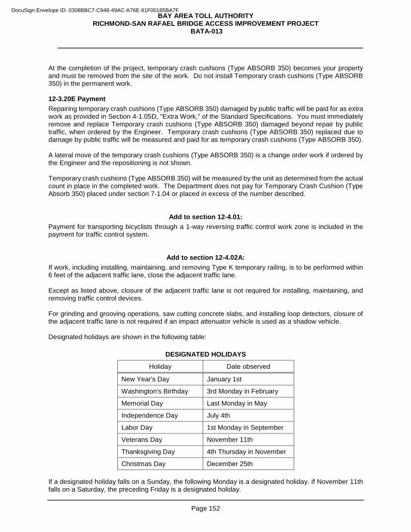
BAY AREA TOLL AUTHORITY RICHMOND-SAN RAFAEL BRIDGE ACCESS IMPROVEMENT PROJECT
BATA-013
Page 152
At the completion of the project, temporary crash cushions (Type ABSORB 350) becomes your property and must be removed from the site of the work. Do not install Temporary crash cushions (Type ABSORB 350) in the permanent work. 12-3.20E Payment Repairing temporary crash cushions (Type ABSORB 350) damaged by public traffic will be paid for as extra work as provided in Section 4-1.05D, "Extra Work," of the Standard Specifications. You must immediately remove and replace Temporary crash cushions (Type ABSORB 350) damaged beyond repair by public traffic, when ordered by the Engineer. Temporary crash cushions (Type ABSORB 350) replaced due to damage by public traffic will be measured and paid for as temporary crash cushions (Type ABSORB 350). A lateral move of the temporary crash cushions (Type ABSORB 350) is a change order work if ordered by the Engineer and the repositioning is not shown. Temporary crash cushions (Type ABSORB 350) will be measured by the unit as determined from the actual count in place in the completed work. The Department does not pay for Temporary Crash Cushion (Type Absorb 350) placed under section 7-1.04 or placed in excess of the number described.
Add to section 12-4.01: Payment for transporting bicyclists through a 1-way reversing traffic control work zone is included in the payment for traffic control system.
Add to section 12-4.02A: If work, including installing, maintaining, and removing Type K temporary railing, is to be performed within 6 feet of the adjacent traffic lane, close the adjacent traffic lane. Except as listed above, closure of the adjacent traffic lane is not required for installing, maintaining, and removing traffic control devices. For grinding and grooving operations, saw cutting concrete slabs, and installing loop detectors, closure of the adjacent traffic lane is not required if an impact attenuator vehicle is used as a shadow vehicle. Designated holidays are shown in the following table:
DESIGNATED HOLIDAYS
Holiday Date observed
New Year's Day January 1st
Washington's Birthday 3rd Monday in February
Memorial Day Last Monday in May
Independence Day July 4th
Labor Day 1st Monday in September
Veterans Day November 11th
Thanksgiving Day 4th Thursday in November
Christmas Day December 25th If a designated holiday falls on a Sunday, the following Monday is a designated holiday. If November 11th falls on a Saturday, the preceding Friday is a designated holiday.
DocuSign Envelope ID: 0308BBC7-C948-49AC-A76E-91F00185BA7F
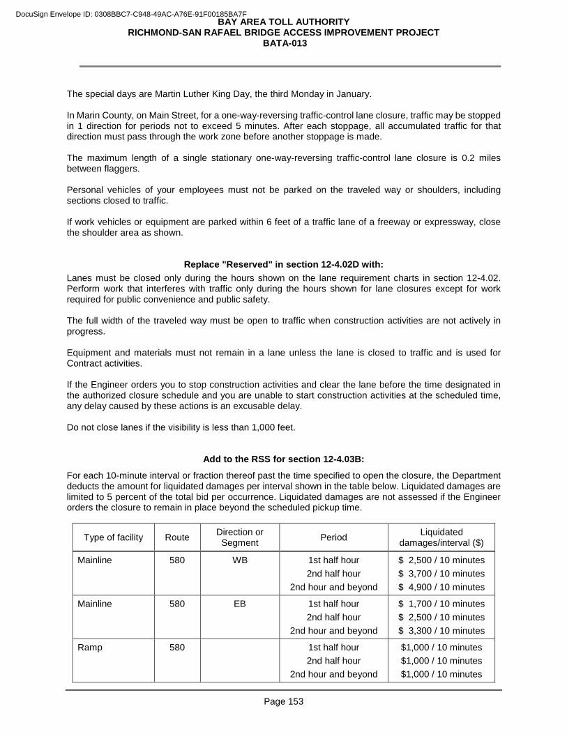
BAY AREA TOLL AUTHORITY RICHMOND-SAN RAFAEL BRIDGE ACCESS IMPROVEMENT PROJECT
BATA-013
Page 153
The special days are Martin Luther King Day, the third Monday in January. In Marin County, on Main Street, for a one-way-reversing traffic-control lane closure, traffic may be stopped in 1 direction for periods not to exceed 5 minutes. After each stoppage, all accumulated traffic for that direction must pass through the work zone before another stoppage is made. The maximum length of a single stationary one-way-reversing traffic-control lane closure is 0.2 miles between flaggers. Personal vehicles of your employees must not be parked on the traveled way or shoulders, including sections closed to traffic. If work vehicles or equipment are parked within 6 feet of a traffic lane of a freeway or expressway, close the shoulder area as shown.
Replace "Reserved" in section 12-4.02D with: Lanes must be closed only during the hours shown on the lane requirement charts in section 12-4.02. Perform work that interferes with traffic only during the hours shown for lane closures except for work required for public convenience and public safety. The full width of the traveled way must be open to traffic when construction activities are not actively in progress. Equipment and materials must not remain in a lane unless the lane is closed to traffic and is used for Contract activities. If the Engineer orders you to stop construction activities and clear the lane before the time designated in the authorized closure schedule and you are unable to start construction activities at the scheduled time, any delay caused by these actions is an excusable delay. Do not close lanes if the visibility is less than 1,000 feet.
Add to the RSS for section 12-4.03B:
For each 10-minute interval or fraction thereof past the time specified to open the closure, the Department deducts the amount for liquidated damages per interval shown in the table below. Liquidated damages are limited to 5 percent of the total bid per occurrence. Liquidated damages are not assessed if the Engineer orders the closure to remain in place beyond the scheduled pickup time.
Type of facility Route Direction or Segment Period Liquidated
damages/interval ($)
Mainline 580 WB 1st half hour 2nd half hour
2nd hour and beyond
$ 2,500 / 10 minutes $ 3,700 / 10 minutes $ 4,900 / 10 minutes
Mainline 580 EB 1st half hour 2nd half hour
2nd hour and beyond
$ 1,700 / 10 minutes $ 2,500 / 10 minutes $ 3,300 / 10 minutes
Ramp 580 1st half hour 2nd half hour
2nd hour and beyond
$1,000 / 10 minutes $1,000 / 10 minutes $1,000 / 10 minutes
DocuSign Envelope ID: 0308BBC7-C948-49AC-A76E-91F00185BA7F
BAY AREA TOLL AUTHORITY RICHMOND-SAN RAFAEL BRIDGE ACCESS IMPROVEMENT PROJECT
BATA-013
Page 154
Add to the RSS for section 12-4.03C: Submit a contingency plan for each of the following activities:
1. Rapid-set concrete activities
2. Roadway excavations encroaching on the traveled way not protected by Type K railing.
3. Rubberized HMA paving
4. Bridge electrical work
5. Striping
Discuss the contingency plan with the Engineer at least 5 business days before starting the activity.
Replace the 5th paragraph of the RSS for section 12-4.03C with: Submit revisions to a contingency plan at least 5 business days before starting the activity requiring a contingency plan. Allow 2 business days for review of the revised contingency plan.
DocuSign Envelope ID: 0308BBC7-C948-49AC-A76E-91F00185BA7F
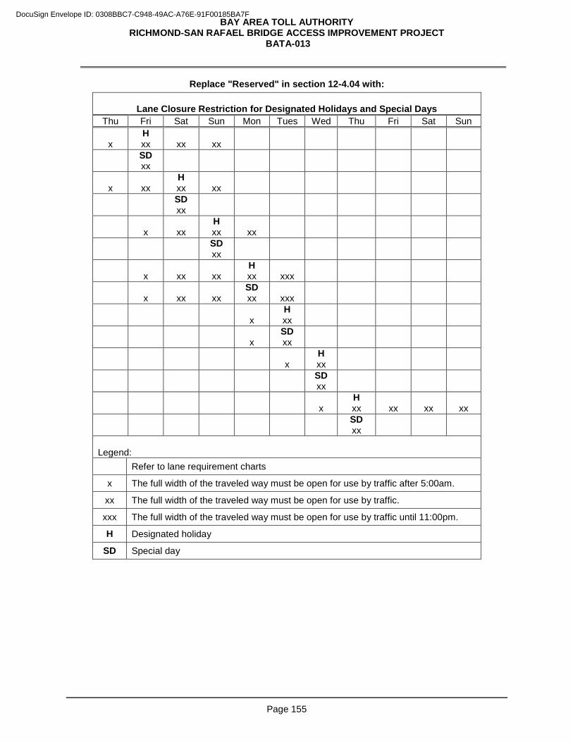
BAY AREA TOLL AUTHORITY RICHMOND-SAN RAFAEL BRIDGE ACCESS IMPROVEMENT PROJECT
BATA-013
Page 155
Replace "Reserved" in section 12-4.04 with:
Lane Closure Restriction for Designated Holidays and Special Days Thu Fri Sat Sun Mon Tues Wed Thu Fri Sat Sun
x
H xx
xx
xx
SD xx
x
xx
H xx
xx
SD xx
x
xx
H xx
xx
SD xx
x
xx
xx
H xx
xxx
x
xx
xx
SD xx
xxx
x
H xx
x
SD xx
x
H xx
SD xx
x
H xx
xx
xx
xx
SD xx
Legend:
Refer to lane requirement charts
x The full width of the traveled way must be open for use by traffic after 5:00am.
xx The full width of the traveled way must be open for use by traffic.
xxx The full width of the traveled way must be open for use by traffic until 11:00pm.
H Designated holiday
SD Special day
DocuSign Envelope ID: 0308BBC7-C948-49AC-A76E-91F00185BA7F
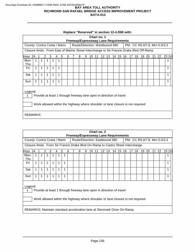
BAY AREA TOLL AUTHORITY RICHMOND-SAN RAFAEL BRIDGE ACCESS IMPROVEMENT PROJECT
BATA-013
Page 156
Replace "Reserved" in section 12-4.05B with:
Chart no. 1 Freeway/Expressway Lane Requirements
County: Contra Costa / Marin Route/Direction: Westbound 580 PM: CC R5.0/7.8, Mrn 0.0/3.3 Closure limits: From East of Marine Street Interchange to Sir Francis Drake Blvd Off-Ramp
Hour 24 1 2 3 4 5 6 7 8 9 10 11 12 13 14 15 16 17 18 19 20 21 22 23 24 Mon-Thu
1 1 1 1 1 1
Fri 1 1 1 1 1 1
Sat 1 1 1 1 1 1
Sun 1 1 1 1 1 1
Legend:
1 Provide at least 1 through freeway lane open in direction of travel Work allowed within the highway where shoulder or lane closure is not required
REMARKS:
Chart no. 2 Freeway/Expressway Lane Requirements
County: Contra Costa / Marin Route/Direction: Eastbound 580 PM: CC R5.0/7.8, Mrn 0.0/3.3 Closure limits: From Sir Francis Drake Blvd On-Ramp to Castro Street Interchange
Hour 24 1 2 3 4 5 6 7 8 9 10 11 12 13 14 15 16 17 18 19 20 21 22 23 24 Mon-Thu
1 1 1 1 1 1 1
Fri 1 1 1 1 1 1 1
Sat 1 1 1 1 1 1 1
Sun 1 1 1 1 1 1 1
Legend:
1 Provide at least 1 through freeway lane open in direction of travel Work allowed within the highway where shoulder or lane closure is not required
REMARKS: Maintain standard acceleration lane at Stenmark Drive On-Ramp.
DocuSign Envelope ID: 0308BBC7-C948-49AC-A76E-91F00185BA7F
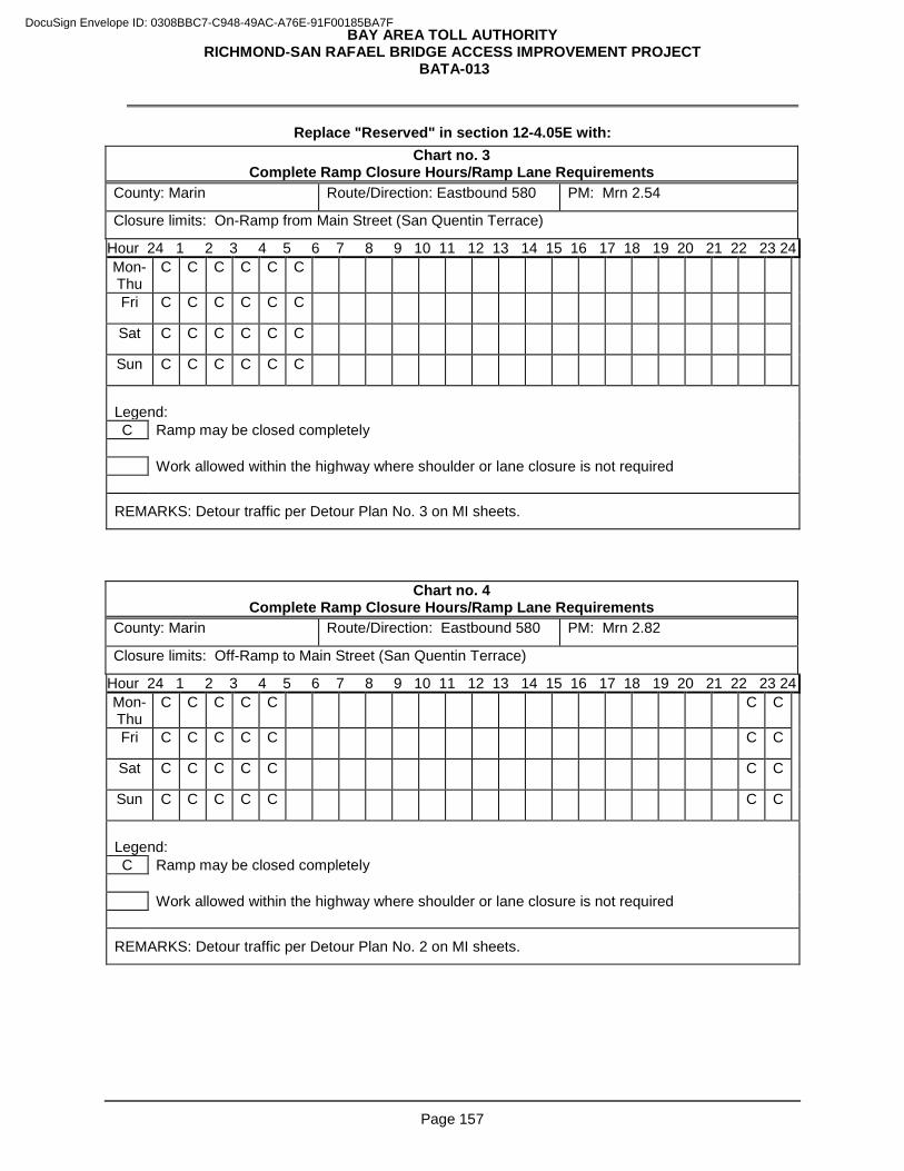
BAY AREA TOLL AUTHORITY RICHMOND-SAN RAFAEL BRIDGE ACCESS IMPROVEMENT PROJECT
BATA-013
Page 157
Replace "Reserved" in section 12-4.05E with: Chart no. 3
Complete Ramp Closure Hours/Ramp Lane Requirements County: Marin Route/Direction: Eastbound 580 PM: Mrn 2.54
Closure limits: On-Ramp from Main Street (San Quentin Terrace)
Hour 24 1 2 3 4 5 6 7 8 9 10 11 12 13 14 15 16 17 18 19 20 21 22 23 24 Mon-Thu
C C C C C C
Fri C C C C C C
Sat C C C C C C
Sun C C C C C C
Legend: C Ramp may be closed completely Work allowed within the highway where shoulder or lane closure is not required
REMARKS: Detour traffic per Detour Plan No. 3 on MI sheets.
Chart no. 4 Complete Ramp Closure Hours/Ramp Lane Requirements
County: Marin Route/Direction: Eastbound 580 PM: Mrn 2.82
Closure limits: Off-Ramp to Main Street (San Quentin Terrace)
Hour 24 1 2 3 4 5 6 7 8 9 10 11 12 13 14 15 16 17 18 19 20 21 22 23 24 Mon-Thu
C C C C C C C
Fri C C C C C C C
Sat C C C C C C C
Sun C C C C C C C
Legend: C Ramp may be closed completely Work allowed within the highway where shoulder or lane closure is not required
REMARKS: Detour traffic per Detour Plan No. 2 on MI sheets.
DocuSign Envelope ID: 0308BBC7-C948-49AC-A76E-91F00185BA7F
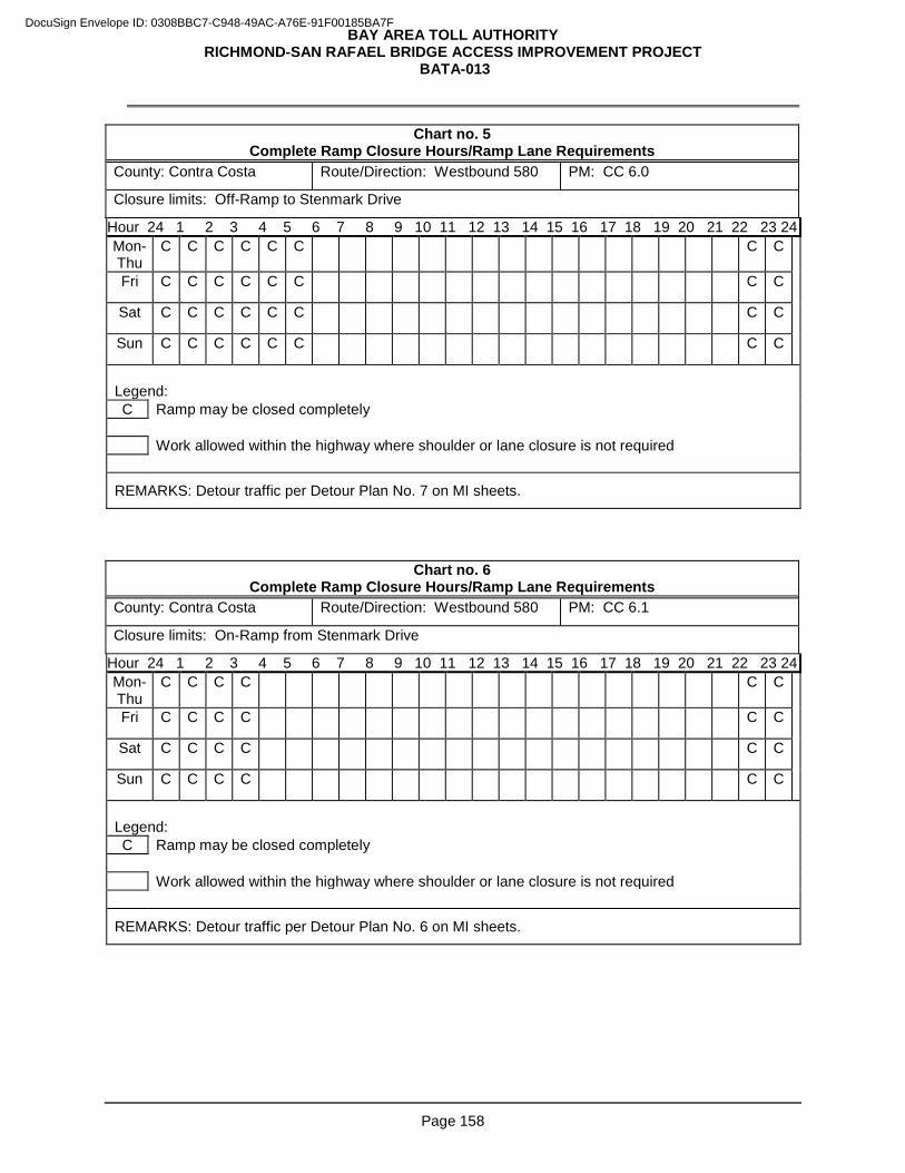
BAY AREA TOLL AUTHORITY RICHMOND-SAN RAFAEL BRIDGE ACCESS IMPROVEMENT PROJECT
BATA-013
Page 158
Chart no. 5 Complete Ramp Closure Hours/Ramp Lane Requirements
County: Contra Costa Route/Direction: Westbound 580 PM: CC 6.0
Closure limits: Off-Ramp to Stenmark Drive
Hour 24 1 2 3 4 5 6 7 8 9 10 11 12 13 14 15 16 17 18 19 20 21 22 23 24 Mon-Thu
C C C C C C C C
Fri C C C C C C C C
Sat C C C C C C C C
Sun C C C C C C C C
Legend: C Ramp may be closed completely Work allowed within the highway where shoulder or lane closure is not required
REMARKS: Detour traffic per Detour Plan No. 7 on MI sheets.
Chart no. 6 Complete Ramp Closure Hours/Ramp Lane Requirements
County: Contra Costa Route/Direction: Westbound 580 PM: CC 6.1
Closure limits: On-Ramp from Stenmark Drive
Hour 24 1 2 3 4 5 6 7 8 9 10 11 12 13 14 15 16 17 18 19 20 21 22 23 24 Mon-Thu
C C C C C C
Fri C C C C C C
Sat C C C C C C
Sun C C C C C C
Legend: C Ramp may be closed completely Work allowed within the highway where shoulder or lane closure is not required
REMARKS: Detour traffic per Detour Plan No. 6 on MI sheets.
DocuSign Envelope ID: 0308BBC7-C948-49AC-A76E-91F00185BA7F
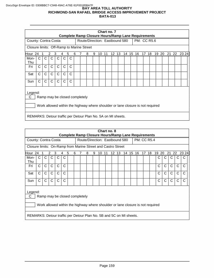
BAY AREA TOLL AUTHORITY RICHMOND-SAN RAFAEL BRIDGE ACCESS IMPROVEMENT PROJECT
BATA-013
Page 159
Chart no. 7 Complete Ramp Closure Hours/Ramp Lane Requirements
County: Contra Costa Route/Direction: Eastbound 580 PM: CC R5.6
Closure limits: Off-Ramp to Marine Street
Hour 24 1 2 3 4 5 6 7 8 9 10 11 12 13 14 15 16 17 18 19 20 21 22 23 24 Mon-Thu
C C C C C C
Fri C C C C C C
Sat C C C C C C
Sun C C C C C C
Legend: C Ramp may be closed completely Work allowed within the highway where shoulder or lane closure is not required
REMARKS: Detour traffic per Detour Plan No. 5A on MI sheets.
Chart no. 8 Complete Ramp Closure Hours/Ramp Lane Requirements
County: Contra Costa Route/Direction: Eastbound 580 PM: CC R5.4
Closure limits: On-Ramp from Marine Street and Castro Street
Hour 24 1 2 3 4 5 6 7 8 9 10 11 12 13 14 15 16 17 18 19 20 21 22 23 24 Mon-Thu
C C C C C C C C C C
Fri C C C C C C C C C C
Sat C C C C C C C C C C
Sun C C C C C C C C C C
Legend: C Ramp may be closed completely Work allowed within the highway where shoulder or lane closure is not required
REMARKS: Detour traffic per Detour Plan No. 5B and 5C on MI sheets.
DocuSign Envelope ID: 0308BBC7-C948-49AC-A76E-91F00185BA7F
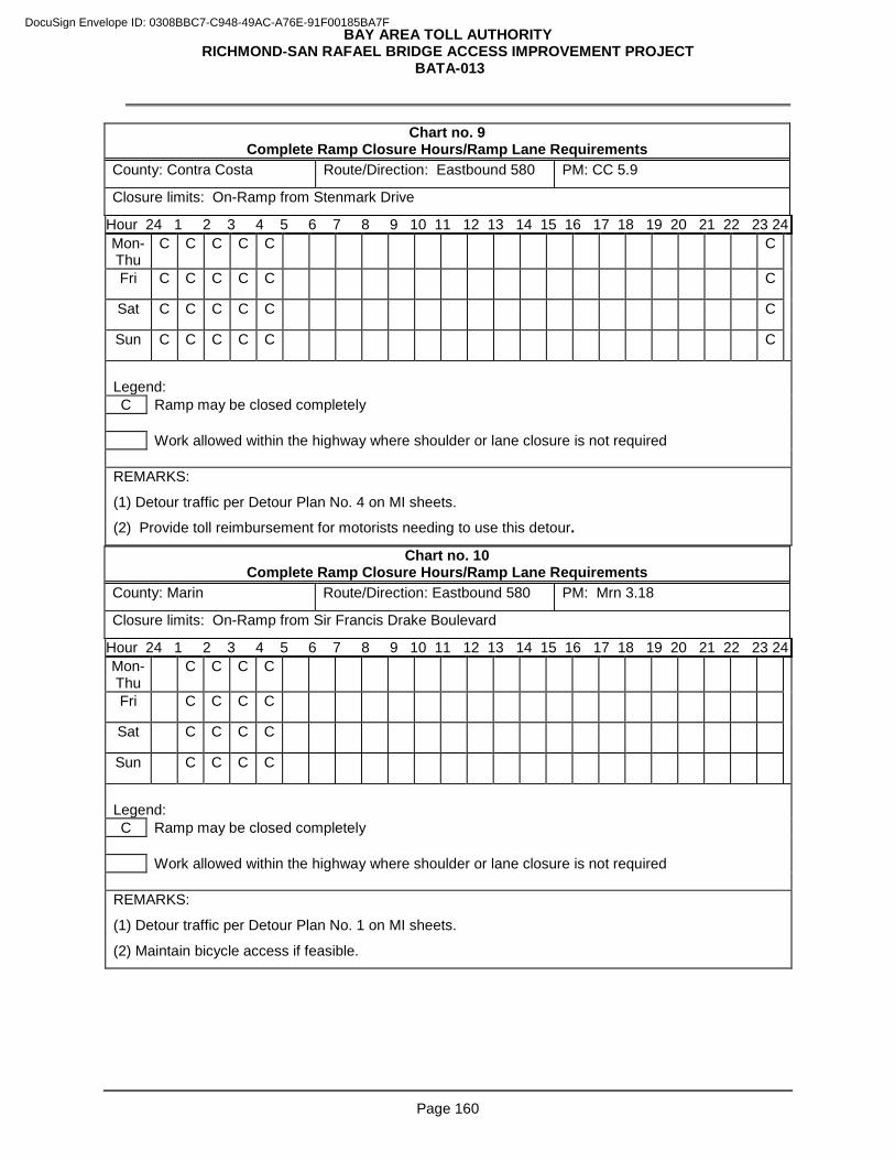
BAY AREA TOLL AUTHORITY RICHMOND-SAN RAFAEL BRIDGE ACCESS IMPROVEMENT PROJECT
BATA-013
Page 160
Chart no. 9 Complete Ramp Closure Hours/Ramp Lane Requirements
County: Contra Costa Route/Direction: Eastbound 580 PM: CC 5.9
Closure limits: On-Ramp from Stenmark Drive
Hour 24 1 2 3 4 5 6 7 8 9 10 11 12 13 14 15 16 17 18 19 20 21 22 23 24 Mon-Thu
C C C C C C
Fri C C C C C C
Sat C C C C C C
Sun C C C C C C
Legend: C Ramp may be closed completely Work allowed within the highway where shoulder or lane closure is not required
REMARKS:
(1) Detour traffic per Detour Plan No. 4 on MI sheets.
(2) Provide toll reimbursement for motorists needing to use this detour.
Chart no. 10 Complete Ramp Closure Hours/Ramp Lane Requirements
County: Marin Route/Direction: Eastbound 580 PM: Mrn 3.18
Closure limits: On-Ramp from Sir Francis Drake Boulevard
Hour 24 1 2 3 4 5 6 7 8 9 10 11 12 13 14 15 16 17 18 19 20 21 22 23 24 Mon-Thu
C C C C
Fri C C C C
Sat C C C C
Sun C C C C
Legend: C Ramp may be closed completely Work allowed within the highway where shoulder or lane closure is not required
REMARKS:
(1) Detour traffic per Detour Plan No. 1 on MI sheets.
(2) Maintain bicycle access if feasible.
DocuSign Envelope ID: 0308BBC7-C948-49AC-A76E-91F00185BA7F
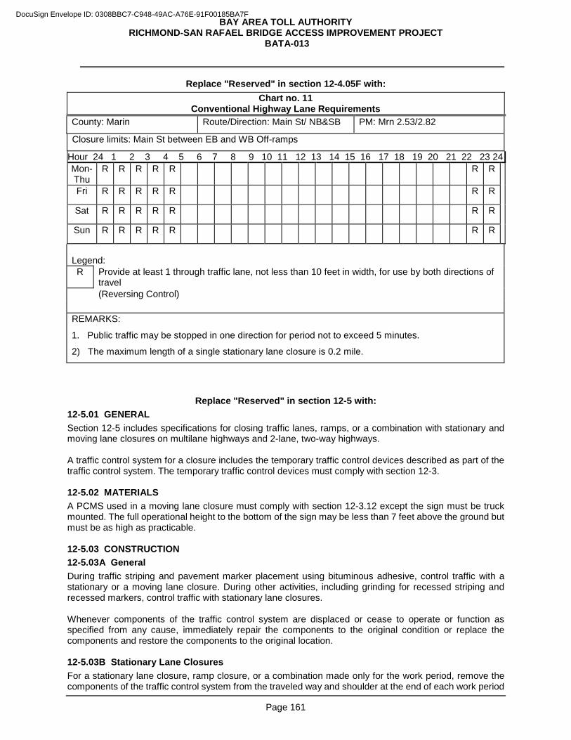
BAY AREA TOLL AUTHORITY RICHMOND-SAN RAFAEL BRIDGE ACCESS IMPROVEMENT PROJECT
BATA-013
Page 161
Replace "Reserved" in section 12-4.05F with: Chart no. 11
Conventional Highway Lane Requirements County: Marin Route/Direction: Main St/ NB&SB PM: Mrn 2.53/2.82
Closure limits: Main St between EB and WB Off-ramps
Hour 24 1 2 3 4 5 6 7 8 9 10 11 12 13 14 15 16 17 18 19 20 21 22 23 24 Mon-Thu
R R R R R R R
Fri R R R R R R R
Sat R R R R R R R
Sun R R R R R R R
Legend: R Provide at least 1 through traffic lane, not less than 10 feet in width, for use by both directions of
travel (Reversing Control)
REMARKS:
1. Public traffic may be stopped in one direction for period not to exceed 5 minutes.
2) The maximum length of a single stationary lane closure is 0.2 mile.
Replace "Reserved" in section 12-5 with:
12-5.01 GENERAL Section 12-5 includes specifications for closing traffic lanes, ramps, or a combination with stationary and moving lane closures on multilane highways and 2-lane, two-way highways. A traffic control system for a closure includes the temporary traffic control devices described as part of the traffic control system. The temporary traffic control devices must comply with section 12-3. 12-5.02 MATERIALS A PCMS used in a moving lane closure must comply with section 12-3.12 except the sign must be truck mounted. The full operational height to the bottom of the sign may be less than 7 feet above the ground but must be as high as practicable. 12-5.03 CONSTRUCTION 12-5.03A General During traffic striping and pavement marker placement using bituminous adhesive, control traffic with a stationary or a moving lane closure. During other activities, including grinding for recessed striping and recessed markers, control traffic with stationary lane closures. Whenever components of the traffic control system are displaced or cease to operate or function as specified from any cause, immediately repair the components to the original condition or replace the components and restore the components to the original location. 12-5.03B Stationary Lane Closures For a stationary lane closure, ramp closure, or a combination made only for the work period, remove the components of the traffic control system from the traveled way and shoulder at the end of each work period
DocuSign Envelope ID: 0308BBC7-C948-49AC-A76E-91F00185BA7F
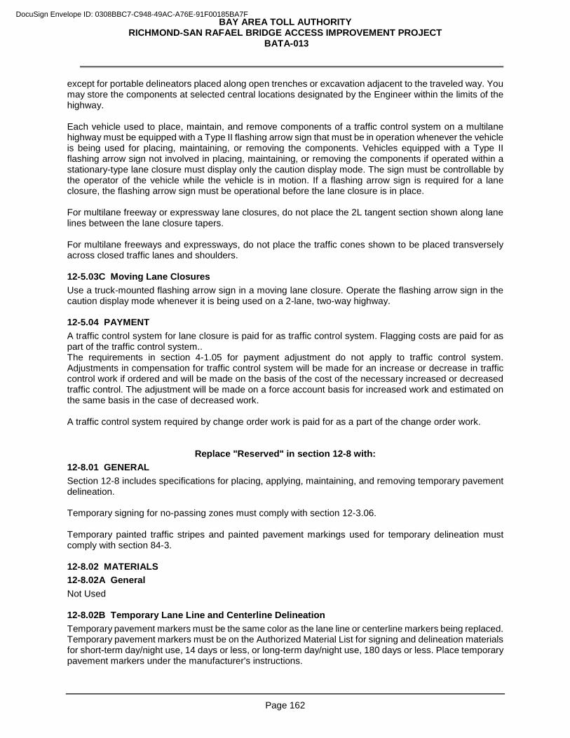
BAY AREA TOLL AUTHORITY RICHMOND-SAN RAFAEL BRIDGE ACCESS IMPROVEMENT PROJECT
BATA-013
Page 162
except for portable delineators placed along open trenches or excavation adjacent to the traveled way. You may store the components at selected central locations designated by the Engineer within the limits of the highway. Each vehicle used to place, maintain, and remove components of a traffic control system on a multilane highway must be equipped with a Type II flashing arrow sign that must be in operation whenever the vehicle is being used for placing, maintaining, or removing the components. Vehicles equipped with a Type II flashing arrow sign not involved in placing, maintaining, or removing the components if operated within a stationary-type lane closure must display only the caution display mode. The sign must be controllable by the operator of the vehicle while the vehicle is in motion. If a flashing arrow sign is required for a lane closure, the flashing arrow sign must be operational before the lane closure is in place. For multilane freeway or expressway lane closures, do not place the 2L tangent section shown along lane lines between the lane closure tapers. For multilane freeways and expressways, do not place the traffic cones shown to be placed transversely across closed traffic lanes and shoulders. 12-5.03C Moving Lane Closures Use a truck-mounted flashing arrow sign in a moving lane closure. Operate the flashing arrow sign in the caution display mode whenever it is being used on a 2-lane, two-way highway. 12-5.04 PAYMENT A traffic control system for lane closure is paid for as traffic control system. Flagging costs are paid for as part of the traffic control system.. The requirements in section 4-1.05 for payment adjustment do not apply to traffic control system. Adjustments in compensation for traffic control system will be made for an increase or decrease in traffic control work if ordered and will be made on the basis of the cost of the necessary increased or decreased traffic control. The adjustment will be made on a force account basis for increased work and estimated on the same basis in the case of decreased work. A traffic control system required by change order work is paid for as a part of the change order work.
Replace "Reserved" in section 12-8 with: 12-8.01 GENERAL Section 12-8 includes specifications for placing, applying, maintaining, and removing temporary pavement delineation. Temporary signing for no-passing zones must comply with section 12-3.06. Temporary painted traffic stripes and painted pavement markings used for temporary delineation must comply with section 84-3. 12-8.02 MATERIALS 12-8.02A General Not Used 12-8.02B Temporary Lane Line and Centerline Delineation Temporary pavement markers must be the same color as the lane line or centerline markers being replaced. Temporary pavement markers must be on the Authorized Material List for signing and delineation materials for short-term day/night use, 14 days or less, or long-term day/night use, 180 days or less. Place temporary pavement markers under the manufacturer's instructions.
DocuSign Envelope ID: 0308BBC7-C948-49AC-A76E-91F00185BA7F
BAY AREA TOLL AUTHORITY RICHMOND-SAN RAFAEL BRIDGE ACCESS IMPROVEMENT PROJECT
BATA-013
Page 163
12-8.02C Temporary Edge Line Delineation On multilane roadways, freeways, and expressways open to traffic where edge lines are obliterated and temporary pavement delineation to replace those edge lines is not shown, provide temporary pavement delineation for:
1. Right edge lines consisting of (1) a solid 4-inch wide traffic stripe tape of the same color as the stripe being replaced, (2) traffic cones, or (3) portable delineators or channelizers placed longitudinally at intervals not exceeding 100 feet
2. Left edge lines consisting of (1) solid 4-inch wide traffic stripe tape of the same color as the stripe being replaced, (2) traffic cones, (3) portable delineators or channelizers placed longitudinally at intervals not exceeding 100 feet, or (4) temporary pavement markers placed longitudinally at intervals not exceeding 6 feet
12-8.02D Temporary Traffic Stripe Tape Not Used 12-8.02E Temporary Traffic Stripe Paint Not Used 12-8.02F Temporary Pavement Marking Tape Not Used 12-8.02G Temporary Pavement Marking Paint Instead of temporary pavement marking paint, you may use one of the types of temporary removable pavement marking tape or permanent pavement marking tape on the Authorized Material List for signing and delineation materials. 12- 8.02H Temporary Pavement Markers Temporary pavement markers must be on the Authorized Material List for signing and delineation materials for long term day/night use, 180 days or less. 12-8.03 CONSTRUCTION 12-8.03A General Wherever work activities obliterate pavement delineation, place temporary or permanent pavement delineation before opening the traveled way to traffic. Place lane line and centerline pavement delineation for traveled ways open to traffic. On multilane roadways, freeways and expressways, place edge line delineation for traveled ways open to traffic. Establish the alignment for the temporary pavement delineation including required lines or markers. Surfaces to receive an application of paint or removable traffic tape must be dry and free of dirt and loose material. Do not apply temporary pavement delineation over existing pavement delineation or other temporary pavement delineation. Maintain temporary pavement delineation until it is superseded or you replace it with a new pattern of temporary pavement delineation or permanent pavement delineation. When the Engineer determines the temporary pavement delineation is no longer required for the direction of traffic, remove the temporary pavement delineation, including any underlying adhesive for temporary pavement markers, from the final layer of surfacing and from the pavement to remain in place. Remove temporary pavement delineation that conflicts with any subsequent or new traffic pattern for the area. 12-8.03B Temporary Lane line and Centerline Delineation Whenever lane lines or centerlines are obliterated and temporary pavement delineation to replace the lines is not shown, the minimum lane line and centerline delineation must consist of temporary pavement markers placed longitudinally at intervals not exceeding 24 feet. For temporary pavement markers on the Authorized Material List for long-term day/night use, 180 days or less, cement the markers to the surfacing with the
DocuSign Envelope ID: 0308BBC7-C948-49AC-A76E-91F00185BA7F
BAY AREA TOLL AUTHORITY RICHMOND-SAN RAFAEL BRIDGE ACCESS IMPROVEMENT PROJECT
BATA-013
Page 164
adhesive recommended by the manufacturer except do not use epoxy adhesive to place the pavement markers in areas where removal of the markers will be required. For temporary lane line or centerline delineation consisting entirely of temporary pavement markers on the Authorized Material List for short-term day/night use, 14 days or less, place the markers longitudinally at intervals not exceeding 24 feet. Do not use the markers for more than 14 days on lanes opened to traffic. Place the permanent pavement delineation before the end of the 14 days. If the permanent pavement delineation is not placed within the 14 days, replace the temporary pavement markers with additional temporary pavement delineation equivalent to the pattern specified or shown for the permanent pavement delineation for the area. The Department does not pay for the additional temporary pavement delineation. Where no-passing centerline pavement delineation is obliterated, install the following temporary no-passing zone signs before opening lanes to traffic. Install a W20-1, "Road Work Ahead," sign from 1,000 to 2,000 feet in advance of a no-passing zone. Install a R4-1, "Do Not Pass," sign at the beginning of a no-passing zone and at 2,000-foot intervals within the no-passing zone. The Engineer determines the exact location of temporary no-passing zone signs. Maintain the temporary no-passing zone signs in place until you place the permanent no-passing centerline pavement delineation. Remove the temporary no-passing zone signs when the Engineer determines they are no longer required for the direction of traffic. 12-8.03C Temporary Edge Line Delineation You may apply temporary painted traffic stripe where removal of a 4-inch wide traffic stripe is not required. The Engineer determines the lateral offset for traffic cones, portable delineators, and channelizers used for temporary edge line delineation. If traffic cones or portable delineators are used for temporary pavement delineation for edge lines, maintain the cones or delineators during hours of the day when the cones or delineators are being used for temporary edge line delineation. Channelizers used for temporary edge line delineation must be an orange surface-mounted type. Cement channelizer bases to the pavement under section 85 for cementing pavement markers to pavement except do not use epoxy adhesive to place channelizers on the top layer of the pavement. Channelizers must be one of the 36-inch, surface-mounted types on the Authorized Material List for signing and delineation materials. Remove the temporary edge line delineation when the Engineer determines it is no longer required for the direction of traffic. 12-8.03D Temporary Traffic Stripe Tape Apply temporary traffic stripe tape under the manufacturer's instructions. Slowly roll the tape with a rubber-tired vehicle or roller to ensure complete contact with the pavement surface. Apply the tape straight on a tangent alignment and on a true arc on a curved alignment. Do not apply the tape when the air or pavement temperature is less than 50 degrees F unless the installation procedures are authorized beforehand. The temporary traffic stripe tape must be complete in place at the location shown before opening the traveled way to traffic. 12-8.03E Temporary Traffic Stripe Paint Apply 1 or 2 coats of temporary traffic stripe paint for new or existing pavement. The painted temporary traffic stripe must be complete in place at the location shown before opening the traveled way to traffic. You are not required to remove painted temporary traffic stripe that will be covered by paving work. 12-8.03F Temporary Pavement Marking Tape Apply temporary pavement marking tape at the locations shown. The tape must be complete in place at the location shown before opening the traveled way to traffic.
DocuSign Envelope ID: 0308BBC7-C948-49AC-A76E-91F00185BA7F
BAY AREA TOLL AUTHORITY RICHMOND-SAN RAFAEL BRIDGE ACCESS IMPROVEMENT PROJECT
BATA-013
Page 165
12-8.03G Temporary Pavement Marking Paint Apply and maintain temporary pavement markings consisting of painted pavement markings at the locations shown. The painted temporary pavement marking must be complete in place at the location shown before opening the traveled way to traffic. You are not required to remove painted temporary pavement marking that will be covered by paving work. Apply 1 or 2 coats of temporary pavement marking paint for new or existing pavement. 12- 8.03H Temporary Pavement Markers Place temporary pavement markers under the manufacturer's instructions. Cement the markers to the surfacing with the manufacturer's recommended adhesive, except do not use epoxy adhesive in areas where removal of the pavement markers is required. You may use retroreflective pavement markers specified in section 85 instead of temporary pavement markers for long term day/night use, 180 days or less, except to simulate patterns of broken traffic stripe. Retroreflective pavement markers used for temporary pavement markers must comply with section 85, except the waiting period before placing pavement markers on new HMA surfacing as specified in section 85-1.03 does not apply. Do not use epoxy adhesive to place pavement markers in areas where removal of the pavement markers is required. Temporary pavement markers must be complete in place before opening the traveled way to traffic. 12-8.04 PAYMENT Not Used
Add to section 12:
12-9 TEMPORARY CURB RAMP 12-9.01 GENERAL 12-9.01A Summary Section 12-9 includes specifications for constructing the temporary curb ramp. 12-9.01B Governing Laws Comply with applicable federal, state, county, municipal and local utility laws, rules, and regulations for temporary facilities. Nothing in these contract documents may be construed to permit work not conforming to such codes and regulations. 12-9.02 MATERIAL The material used to construct the temporary curb ramp must be minor hot mix asphalt and comply with section 39. The surface must be skid resistant and free of irregularities. The material used to construct the detectable warning surface must comply with section 73-1.02B. 12-9.03 CONSTRUCTION The work includes producing hot mix asphalt (HMA) and detectable warning surfacing and placing the temporary curb ramp as shown or as directed by the Engineer. At your option, the detectable warning surface may be prefabricated, cast-in-place, or stamped into the surface of the temporary curb ramp. 12-9.04 PAYMENT For temporary detectable warning surface, section 73-1.04 does not apply.
DocuSign Envelope ID: 0308BBC7-C948-49AC-A76E-91F00185BA7F
BAY AREA TOLL AUTHORITY RICHMOND-SAN RAFAEL BRIDGE ACCESS IMPROVEMENT PROJECT
BATA-013
Page 166
Full compensation for constructing or furnishing and installing curb ramp detectable warning surfaces is included in the contract price paid per each of temporary curb ramp and no separate payment will be made therefor. Full compensation for maintaining and, when no longer needed, removing and disposing of temporary curb ramp and temporary detectable warning surface is included in the contract price paid per each for temporary curb ramp and no separate payment/additional compensation will be made/allowed therefor.
^^^^^^^^^^^^^^^^^^^^^^^^^^^^^^^^^^^^^^^^^^^^^^^^^^^^^^^^^^^^^^^^^
13 WATER POLLUTION CONTROL
Add to section 13-3.01A:
The project is risk level 2.
Add to section 13-4.01B:
Before mobilization, you must prepare and submit a spill response plan. The spill response plan must include: 1. Title sheet and table of contents
2. List of equipment and the maintenance schedule
3. Means and methods to prevent any leaks of automotive fluids such as gasoline, oils or solvents Before working on the RSR Bridge, you must prepare and submit a material containment and collection plan before working on the RSR Bridge. The material containment and collection plan must include: 1. Title sheet and table of contents
2. Description of the work activities, detailing locations, equipment and materials
3. Means and methods for containment and collection to prevent construction related debris from falling from the RSR Bridge
Replace 1st paragraph of section 13-6.03C with: Provide temporary drainage inlet protection around drainage inlets as changing conditions require. Drainage inlet protection must be Type 1, or Type 4B, as appropriate for conditions around the drainage inlet.
Add to section 13-6.03H: Temporary reinforced silt fence must be Type 1.
^^^^^^^^^^^^^^^^^^^^^^^^^^^^^^^^^^^^^^^^^^^^^^^^^^^^^^^^^^^^^^^^^
14 ENVIRONMENTAL STEWARDSHIP
Add to section 14-1.02A:
ESAs exist on this project. Take the management measures shown in the following table for the corresponding ESA shown. Any access to an ESA other than that shown is prohibited.
DocuSign Envelope ID: 0308BBC7-C948-49AC-A76E-91F00185BA7F
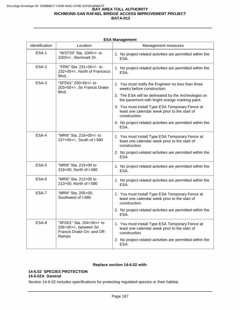
BAY AREA TOLL AUTHORITY RICHMOND-SAN RAFAEL BRIDGE ACCESS IMPROVEMENT PROJECT
BATA-013
Page 167
ESA Management
Identification Location Management measures
ESA-1
“WST03” Sta. 1000+/- to 1003+/-, Stenmark Dr.
1. No project-related activities are permitted within the ESA.
ESA-2
“FRN” Sta. 231+00+/- to 232+00+/-, North of Francisco Blvd.,
1. No project-related activities are permitted within the ESA.
ESA-3
“SFD01” 200+50+/- to 203+00+/-, Sir Francis Drake Blvd.
1. You must notify the Engineer no less than three weeks before construction.
2. The ESA will be delineated by the Archeologist on the pavement with bright orange marking paint.
3. You must install Type ESA Temporary Fence at least one calendar week prior to the start of construction.
4. No project-related activities are permitted within the ESA.
ESA-4
“MRN” Sta. 216+00+/- to 227+00+/-, South of I-580
1. You must install Type ESA Temporary Fence at least one calendar week prior to the start of construction.
2. No project-related activities are permitted within the ESA.
ESA-5
“MRN” Sta. 215+00 to 218+00, North of I-580
1. No project-related activities are permitted within the ESA.
ESA-6
“MRN” Sta. 212+00 to 213+00, North of I-580
1. No project-related activities are permitted within the ESA.
ESA-7
“MRN” Sta. 205+00, Southwest of I-580
1. You must install Type ESA Temporary Fence at least one calendar week prior to the start of construction.
2. No project-related activities are permitted within the ESA.
ESA-8
“SFD01” Sta. 204+50+/- to 206+00+/-, between Sir Francis Drake On- and Off- Ramps
1. You must install Type ESA Temporary Fence at least one calendar week prior to the start of construction.
2. No project-related activities are permitted within the ESA.
Replace section 14-6.02 with:
14-6.02 SPECIES PROTECTION 14-6.02A General Section 14-6.02 includes specifications for protecting regulated species or their habitat.
DocuSign Envelope ID: 0308BBC7-C948-49AC-A76E-91F00185BA7F
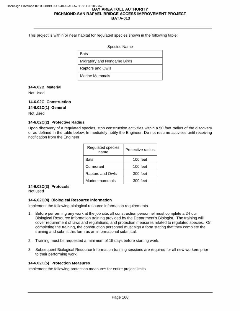
BAY AREA TOLL AUTHORITY RICHMOND-SAN RAFAEL BRIDGE ACCESS IMPROVEMENT PROJECT
BATA-013
Page 168
This project is within or near habitat for regulated species shown in the following table:
Species Name
Bats
Migratory and Nongame Birds
Raptors and Owls
Marine Mammals
14-6.02B Material Not Used 14-6.02C Construction 14-6.02C(1) General Not Used 14-6.02C(2) Protective Radius Upon discovery of a regulated species, stop construction activities within a 50 foot radius of the discovery or as defined in the table below. Immediately notify the Engineer. Do not resume activities until receiving notification from the Engineer.
Regulated species name Protective radius
Bats 100 feet
Cormorant 100 feet
Raptors and Owls 300 feet
Marine mammals 300 feet 14-6.02C(3) Protocols Not used 14-6.02C(4) Biological Resource Information Implement the following biological resource information requirements.
1. Before performing any work at the job site, all construction personnel must complete a 2-hour Biological Resource Information training provided by the Department’s Biologist. The training will cover requirement of laws and regulations, and protection measures related to regulated species. On completing the training, the construction personnel must sign a form stating that they complete the training and submit this form as an informational submittal.
2. Training must be requested a minimum of 15 days before starting work. 3. Subsequent Biological Resource Information training sessions are required for all new workers prior
to their performing work. 14-6.02C(5) Protection Measures Implement the following protection measures for entire project limits.
DocuSign Envelope ID: 0308BBC7-C948-49AC-A76E-91F00185BA7F
BAY AREA TOLL AUTHORITY RICHMOND-SAN RAFAEL BRIDGE ACCESS IMPROVEMENT PROJECT
BATA-013
Page 169
1. You are responsible for obtaining PLACs for and complying with all environmental laws and regulation that apply to the use of existing unpaved or ungraveled property outside of the project limits as shown, for the sole use of the project including:
1.1. Field office sites
1.2. Vehicle parking
1.3. Staging areas
1.4. Storage yard
1.5. Access roads
1.6. Material procurement sites
1.7. Material disposal sites
2. Submit all PLACs obtained by you to the Engineer before the start of the affected work. Implement the following protection measures to prevent construction-related debris from falling off the RSR Bridge into the San Francisco Bay or San Pablo Bay.
1. No work is to occur in the San Francisco Bay or San Pablo Bay.
2. To prevent construction related debris from falling from the RSR Bridge during construction, you must prepare and submit a Material Containment and Collection Plan before working on the RSR Bridge.
Implement the following protection measures to protect the marine mammals from visual and auditory disturbances between Piers 52-57 (approximate Sta. 419+90 to Sta. 434+40).
1. Year-round:
1.1. No work is allowed under the lower deck between Piers 52-57.
1.2. Daytime work between Piers 52 and 57 that generates noise levels greater than or equal to 90 dBA will be limited to 2 hours before high tide until 2 hours after high tide.
1.3. Nighttime work between Piers 52 and 57 that generates noise levels greater than 72 dBA will be limited to 2 hours before high tide until 2 hours after high tide.
2. During pupping season (March 15 to August 1) between Piers 52-57 (approximate Sta. 419+90 to Sta. 434+40):
2.1. Work between Piers 52-57 is only allowed on the north side of the upper deck (north of the broken line between the 2 existing travel lanes).
3. Outside of pupping season (August 2 to March 14):
3.1 Work is allowed on the north side of both decks at any time of the day
3.2 Work on the south side (south of the broken line between the 2 existing travel lanes) of both decks, between Piers 52-57, is limited to 2 hours before high tide until 2 hours after high tide. No work is allowed between Piers 52-57 outside of the 4 hour high tide window.
3.3 Work that requires construction crews to be visible to Castro Rocks will be limited to periods of high tide between Piers 52 and 57. With approval from Caltrans, a visual screen of fabric or a structure could be erected in this area during high tide to shield the work crews from view by the harbor seals.
Implement the following protection measures to protect impacts to bats.
DocuSign Envelope ID: 0308BBC7-C948-49AC-A76E-91F00185BA7F
BAY AREA TOLL AUTHORITY RICHMOND-SAN RAFAEL BRIDGE ACCESS IMPROVEMENT PROJECT
BATA-013
Page 170
1. Notify the Engineer fourteen (14) days prior to any bridge work, tree removal, vegetation work or ground disturbing work.
2. A qualified biologist must conduct a preconstruction survey no more than 2 weeks prior to tree removal for crevice and cavity roosting habitat in trees that have a diameter of 12 inches or greater.
3. No more than 2 weeks prior to bridge construction work, a qualified biologist must conduct a preconstruction survey for crevice and cavity roosting habitat.
4. If an active roosting habitat is identified, avoidance and minimization measures, as determined in consultation with CDFW, will be implemented
Implement the following protection measures to protect impacts to migratory and nongame birds and raptors and owls, during the breeding season, February 15 to August 31:
1. Notify the Engineer fourteen (14) days prior to any bridge work, tree removal, vegetation work or ground disturbing work.
2. A pre-construction survey for nesting birds must be conducted by a qualified biologist no more than seventy-two (72) hours prior to the construction activities.
3. You must receive work authorization before proceeding with the bridge work, tree removal, vegetation work or ground disturbing work. The work must be initiated within seventy-two (72) hours.
4. For subsequent bird surveys and work authorizations, you must notify the Engineer seven (7) days prior to any bridge work, tree removal, vegetation work or ground disturbing work. You must receive work authorization before proceeding with the work.
5. If an active nest is observed either during the pre-construction surveys or during construction, a non-disturbance buffer must be established.
6. If any work is proposed to occur within established buffer zones, you must prepare and submit for approval a nest monitoring plan.
7. To prevent any birds from nesting at a specific location, you must prepare and submit for approval a nesting bird exclusion plan.
Outside of bird breeding season, protected bird species that are expected to occur on site are limited to white tailed kites and peregrine falcons. These species are Fully Protected and cannot be taken or possessed at any time.
14-6.02C(6) Monitoring Schedule Not Used 14-6.02D Payment Payment for the Material Containment and Collection Plan is included in the Job Site Management pay item.
Replace section 14-11.03 with:
14-11.03 MATERIAL CONTAINING HAZARDOUS WASTE CONCENTRATIONS OF AERIALLY DEPOSITED LEAD 14-11.03A General 14-11.03A(1) Summary Section 14-11.03 includes specifications for hazardous waste management while excavating, stockpiling, transporting, placing, and disposing of material containing hazardous waste concentrations of aerially deposited lead (ADL). ADL is present within the project limits.
DocuSign Envelope ID: 0308BBC7-C948-49AC-A76E-91F00185BA7F
BAY AREA TOLL AUTHORITY RICHMOND-SAN RAFAEL BRIDGE ACCESS IMPROVEMENT PROJECT
BATA-013
Page 171
14-11.03A(2) Definitions Type Y-1: Material that contains ADL in average concentrations (using the 90 percent Upper Confidence
Limit) of 1.5 mg/L or less extractable lead (based on a modified waste extraction test using deionized water as the extractant) and 1,411 mg/kg or less total lead. This material is a California hazardous waste that may be reused as permitted under the variance of the DTSC provided that the lead contaminated soil is placed a minimum of 5 feet above the maximum historic water table elevation and covered with at least 1 foot of non-hazardous soil.
Type Y-2: Material that contains ADL in average concentrations (using the 90 percent Upper Confidence
Limit) that exceed either 1.5 mg/L extractable lead (based on a modified waste extraction test using deionized water as the extractant) or 1,411 mg/kg total lead but are less than 150 mg/L extractable lead (based on a modified waste extraction test using deionized water as the extractant) and less than 3,397 mg/kg of total lead. This material is a California hazardous waste that may be reused as permitted under the variance of DTSC provided that the lead contaminated soil is placed a minimum of 5 feet above the maximum historic water table elevation and protected from infiltration by a pavement structure which will be maintained by the Department.
Type Z-2: Material that contains ADL in average concentrations (using the 95 percent Upper Confidence Limit) greater than or equal to 1,000 mg/kg total lead, greater than or equal to 5.0 mg/L soluble lead (as tested using the California Waste Extraction Test), and the material is surplus; or material that contains ADL in average concentrations greater than 150 mg/L extractable lead (based on a modified waste extraction test using deionized water as the extractant) or greater than 3,397 mg/kg total lead. This material is a Department-generated California hazardous waste and must be transported to and disposed of at a California Class I disposal site.
Type Z-3: Material that contains ADL in average concentrations (using the 95 percent Upper Confidence
Limit) greater than 5.0 mg/L soluble lead, (as tested using the Toxicity Characteristic Leaching Procedure). This material is a Department-generated federal hazardous waste and must be transported to and disposed of at a California Class I disposal site.
14-11.03A(3) Site Conditions ADL concentration data and sample locations maps are included in the Information Handout. Type Z-2 is shown on the plans and in the Soils Characterization Report and Soils Characterizations Report Addendum included in the Information Handout. Additionally the Soils Characterization Report identified five locations with hazardous waste characterization that exceed ESL thresholds; requiring special health and safety measures and site practices to mitigate the risk or exposure to lead or diesel. Refer to the Soils Characterization Report and Soils Characterizations Report Addendum provided in the Information Handout for details on the locations and the test results. . 14-11.03A(4) Submittals 14-11.03A(4)(a) Health and Safety Plan Submit a project specific Health and Safety Plan (HASP) to prevent or minimize worker exposure to lead, zinc, copper, and diesel while handling soil containing these materials. The HASP must contain the elements listed in Title 8, California Code of Regulations. Before submission to the Engineer, the HASP must be approved by an industrial Hygienist certified by the American Board of Industrial Hygiene. The HASP must be submitted to the Engineer at least 7 days prior to beginning of work. 14-11.03A(4)(b) Excavation and Transportation Plan Within 15 days after approval of the Contract, submit 3 copies of an excavation and transportation plan. Allow 15 days for review. If revisions are required, as determined by the Engineer, submit the revised plan within 7 days of receipt of the Engineer's comments. For the revision, allow 7 days for the review. Minor changes to or clarifications of the initial submittal may be made and attached as amendments to the excavation and transportation plan. In order to allow construction to proceed, the Engineer may conditionally approve the plan while minor revisions or amendments are being completed.
DocuSign Envelope ID: 0308BBC7-C948-49AC-A76E-91F00185BA7F
BAY AREA TOLL AUTHORITY RICHMOND-SAN RAFAEL BRIDGE ACCESS IMPROVEMENT PROJECT
BATA-013
Page 172
Prepare the written, project specific excavation and transportation plan establishing the procedures you will use to comply with requirements for excavating, stockpiling, transporting, and placing or disposing of material containing ADL. The plan must comply with the regulations of the DTSC and Cal/OSHA and the requirements of the variance. The sampling and analysis portions of the excavation and transportation plan must meet the requirements for the design and development of the sampling plan, statistical analysis, and reporting of test results contained in US EPA, SW 846, "Test Methods for Evaluating Solid Waste," Volume II: Field Manual Physical/Chemical, Chapter Nine, Section 9.1. The plan must include the following elements:
1. Excavation schedule by location and date
2. Temporary locations of stockpiled material
3. Dust control measures
4. Air monitoring. Include the following information:
4.1. Location and type of equipment
4.2. Sampling frequency
4.3. Name and address of the accredited laboratory where the analysis was performed
5. Transportation equipment and routes
6. Method for preventing spills and tracking material onto public roads
7. Truck waiting and staging areas
8. Site for disposal of hazardous waste
9. Spill Contingency Plan for material containing ADL 14-11.03A(4)(c) Burial Location Report Not Used 14-11.03A(5) Quality Control and Assurance Excavation, reuse, and disposal of material with ADL must comply with rules and regulations of the following agencies:
1. US DOT
2. US EPA
3. California Environmental Protection Agency
4. CDPH
5. DTSC
6. Cal/OSHA
7. California Department of Resources Recycling and Recovery
8. RWQCB, Region 2, San Francisco Bay
9. California Air Resources Board
10. Bay Area Air Quality Management District Transport and dispose of material containing hazardous levels of lead under federal and state laws and regulations and county and municipal ordinances and regulations. Laws and regulations that govern this work include:
1. Health & Safety Code, Division 20, Chp 6.5 (California Hazardous Waste Control Act)
2. 22 CA Code of Regs, Div. 4.5 (Environmental Health Standards for the Management of Hazardous Waste)
DocuSign Envelope ID: 0308BBC7-C948-49AC-A76E-91F00185BA7F
BAY AREA TOLL AUTHORITY RICHMOND-SAN RAFAEL BRIDGE ACCESS IMPROVEMENT PROJECT
BATA-013
Page 173
3. 8 CA Code of Regs 14-11.03B Materials Not Used 14-11.03C Construction 14-11.03C(1) General Not Used 14-11.03C(2) Material Management Transport excavated Type Z-2 material using:
1. Hazardous waste manifest
2. Hazardous waste transporter with a current DTSC registration certificate and CA Highway Patrol (CHP) Biennial Inspection of Terminals (BIT) Program compliance documentation.
14-11.03C(3) Dust Control Excavation, transportation, placement, and handling of material containing ADL must result in no visible dust migration. A water truck or tank must be on the job site at all times while clearing and grubbing or performing earthwork operations in work areas containing ADL. Apply water to prevent visible dust. 14-11.03C(4) Surveying Type Y-1 or Y-2 Material Burial Locations Not Used 14-11.03C(5) Material Transportation Before traveling on public roads, remove loose and extraneous material from surfaces outside the cargo areas of the transporting vehicles and cover the cargo with tarpaulins or other cover, as outlined in the approved excavation and transportation plan. You are responsible for costs due to spillage of material containing lead during transport. 14-11.03C(6) Disposal The Engineer will obtain the State of California Board of Equalization identification no, for hazardous waste disposal. The Engineer will sign all hazardous waste manifests. Notify the Engineer 5 business days before the manifests are to be signed. 14-11.03D Payment Payment for a Health and Safety Plan is not included in the payment for environmental stewardship work. Type Z-2 excavation is measured as specified for roadway excavation in section 19-2.04. The Department does not pay for stockpiling of material containing ADL, unless the stockpiling is ordered. The Department does not pay for sampling and analysis unless it is ordered. The Department does not pay for additional sampling and analysis required by the receiving landfill.
Replace section 14-11.06 with:
14-11.06 DEPARTMENT-GENERATED CONTAMINATED SOIL 14-11.06A General 14-11.06A(1) Summary Section 14-11.06 includes specifications for handling of petroleum-impacted soil. The petroleum-impacted soil is Department-generated contaminated soil.
DocuSign Envelope ID: 0308BBC7-C948-49AC-A76E-91F00185BA7F
BAY AREA TOLL AUTHORITY RICHMOND-SAN RAFAEL BRIDGE ACCESS IMPROVEMENT PROJECT
BATA-013
Page 174
14-11.06A(2) Definitions Petroleum-impacted soil: Soil having concentrations of diesel and motor oil above published environmental screening levels established by the San Francisco Bay Regional Water Quality Control Board. 14-11.06A(3) Site Conditions A site investigation report, dated May 19, 2016, containing the analytical test results for soil samples and the recommendation for handling the petroleum-impacted soil is included in the Information Handout. Petroleum-impacted soil exists as shown. 14-11.06A(4) Submittals 14-11.06A(4)(a) Health and Safety Plan Submit a detailed health and safety plan (HSP), signed by a CIH, that identifies potential health and safety hazards associated with work involving petroleum-impacted soil and specifies work practices that will be used to protect workers from those hazards under 22 CA Code of Regs and 8 CA Code of Regs. The HSP must:
1. Identify key site safety personnel
2. Describe risks associated with the work
3. Specify training requirements
4. Specify appropriate personal protective equipment
5. Specify site-specific medical surveillance requirements
6. Specify air monitoring requirements
7. Define appropriate site work zones
8. Specify decontamination requirements Submit the HSP at least 15 working days before starting the work for review and authorization. Resubmit the HSP with revisions required by the Engineer within 5 business days. Do not start excavation work until the HSP is authorized. 14-11.06A(4)(b) Safety Training Certification Not Used
Replace section 14-11.09 with: 14-11.09 TREATED WOOD WASTE 14-11.09A General 14-11.09A(1) Summary Section 14-11.09 includes specifications for handling, storing, transporting, and disposing of treated wood waste (TWW). Wood removed from guardrail, single metal beam barrier, roadside signs, timber retaining wall is TWW. Manage TWW under 22 CA Code of Regs, Div. 4.5, Chp. 34. 14-11.09A(2) Submittals For disposal of TWW, submit as an informational submittal a copy of each completed shipping record and weight receipt within 5 business days. 14-11.09B Materials Not Used
DocuSign Envelope ID: 0308BBC7-C948-49AC-A76E-91F00185BA7F
BAY AREA TOLL AUTHORITY RICHMOND-SAN RAFAEL BRIDGE ACCESS IMPROVEMENT PROJECT
BATA-013
Page 175
14-11.09C Construction 14-11.09C(1) General Not Used 14-11.09C(2) Training Provide training to personnel who handle TWW or may come in contact with TWW. Training must include: 1. Applicable requirements of 8 CA Code of Regs
2. Procedures for identifying and segregating TWW
3. Safe handling practices
4. Requirements of 22 CA Code of Regs, Div. 4.5, Chp. 34
5. Proper disposal methods Maintain records of personnel training for 3 years. 14-11.09C(3) Storage Store TWW before disposal using the following methods: 1. Elevate on blocks above a foreseeable run-on elevation and protect from precipitation for no more
than 90 days.
2. Place on a containment surface or pad protected from run-on and precipitation for no more than 180 days.
3. Place in water-resistant containers designed for shipping or solid waste collection for no more than 1 year.
4. Place in a storage building as defined in 22 CA Code of Regs, Div. 4.5, Chp. 34, § 67386.6(a)(2)(C). Prevent unauthorized access to TWW using a secured enclosure such as a locked chain-link-fenced area or a lockable shipping container located within the job site. Resize and segregate TWW at a location where debris from the operation including sawdust and chips can be contained. Collect and manage the debris as TWW. Provide water-resistant labels that comply with 22 CA Code of Regs, Div. 4.5, Chp. 34, §67386.5, to clearly mark and identify TWW and accumulation areas. Labels must include: 1. Caltrans, District number, Construction, Construction Contract number
2. District office address
3. Engineer's name, address, and telephone number
4. Contractor's contact name, address and telephone number
5. Date placed in storage 14-11.09C(4) Transporting and Disposal Before transporting TWW, obtain an agreement from the receiving facility that the TWW will be accepted. Protect shipments of TWW from loss and exposure to precipitation. For projects with 10,000 lb or more of TWW, request a generator's EPA Identification Number at least 5 business days before the 1st shipment. Each shipment must be accompanied by a shipping record such as a bill of lading or invoice that includes: 1. Caltrans with district number
2. Construction Contract number
DocuSign Envelope ID: 0308BBC7-C948-49AC-A76E-91F00185BA7F
BAY AREA TOLL AUTHORITY RICHMOND-SAN RAFAEL BRIDGE ACCESS IMPROVEMENT PROJECT
BATA-013
Page 176
3. District office address
4. Engineer's name, address, and telephone number
5. Contractor's contact name and telephone number
6. Receiving facility name and address
7. Waste description: Treated Wood Waste with preservative type if known or unknown/mixture
8. Project location
9. Estimated quantity of shipment by weight or volume
10. Date of transport
11. Date of receipt by the receiving TWW facility
12. Weight of shipment as measured by the receiving TWW facility
13. Generator's EPA Identification Number for projects with 10,000 lb or more of TWW The shipping record must be at least a 4-part carbon or carbonless 8-1/2-by-11-inch form to allow retention of copies by the Engineer, transporter, and disposal facility. Dispose of TWW at an approved California disposal site operating under a RWQCB permit that includes acceptance of TWW. Dispose of TWW within: 1. 90 days of generation if stored on blocks
2. 180 days of generation if stored on a containment surface or pad
3. 1 year of generation if stored in a water-resistant container or within 90 days after the container is full, whichever is shorter
4. 1 year of generation if storing in a storage building as defined in 22 CA Code of Regs, Div. 4.5, Chp. 34, § 67386.6(a)(2)(C)
14-11.09D Payment Not Used
^^^^^^^^^^^^^^^^^^^^^^^^^^^^^^^^^^^^^^^^^^^^^^^^^^^^^^^^^^^^^^^^
15 EXISTING FACILITIES
Replace section 15-1.03B with:
15-1.03B Residue Containing Lead from Paint and Thermoplastic Residue from grinding or cold planing contains lead from paint and thermoplastic. The average lead concentrations are less than 1,000 mg/kg total lead and 5 mg/L soluble lead. This residue:
1. Is a nonhazardous waste
2. Does not contain heavy metals in concentrations that exceed thresholds established by the Health and Safety Code and 22 CA Code of Regs
3. Is not regulated under the Federal Resource Conservation and Recovery Act (RCRA), 42 USC § 6901 et seq.
Submit a lead compliance plan under section 7-1.02K(6)(j)(ii).
DocuSign Envelope ID: 0308BBC7-C948-49AC-A76E-91F00185BA7F
BAY AREA TOLL AUTHORITY RICHMOND-SAN RAFAEL BRIDGE ACCESS IMPROVEMENT PROJECT
BATA-013
Page 177
Payment for a lead compliance plan is not included in the payment for existing facilities work. Payment for handling, removal, and disposal of grinding or cold planing residue that is a nonhazardous waste is included in the payment for the type of removal work involved.
Replace section 15-2.02B(3) with: 15-2.02B(3) Cold Planing Asphalt Concrete Pavement 15-2.02B(3)(a) General At all locations except for the bike paths, cross slope corrections and ADA compliance locations , schedule cold planing activities to ensure that cold planing, placement of HMA, and reopening the area to traffic is completed during the same work shiftAt all locations except for the bike paths, cross slope corrections and ADA compliance locations , if you do not complete HMA placement before opening the area to traffic, you must:
1. Construct a temporary HMA taper to the level of the existing pavement.
2. Place HMA during the next work shift.
3. Submit a corrective action plan that shows you will complete cold planing and placement of HMA in the same work shift. Do not resume cold planing activities until the corrective action plan is authorized.
15-2.02B(3)(b) Materials Use the same quality of HMA for temporary tapers that is used for the HMA overlay or comply with the specifications for minor HMA in section 39. 15-2.02B(3)(c) Construction 15-2.02B(3)(c)(i) General Do not use a heating device to soften the pavement. The cold planing machine must be:
1. Equipped with a cutter head width that matches the planing width. If the cutter head width is wider than the cold plane area shown, you may request to use the wider cutter head. Do not cold plane with the wider cutter head unless authorized.
2. Equipped with automatic controls for the longitudinal grade and transverse slope of the cutter head and:
2.1. If a ski device is used, it must be at least 30 feet long, rigid, and a 1-piece unit. The entire length must be used in activating the sensor.
2.2. If referencing from existing pavement, the cold planing machine must be controlled by a self-contained grade reference system. The system must be used at or near the centerline of the roadway. On the adjacent pass with the cold planing machine, a joint-matching shoe may be used.
3. Equipped to effectively control dust generated by the planing operation.
4. Operated such that no fumes or smoke is produced. Replace broken, missing, or worn machine teeth. 15-2.02B(3)(c)(ii) Grade Control and Surface Smoothness Furnish, install, and maintain grade and transverse slope references. The depth, length, width, and shape of the cut must be as shown or as ordered. The final cut must result in a neat and uniform surface. Do not damage the remaining surface.
DocuSign Envelope ID: 0308BBC7-C948-49AC-A76E-91F00185BA7F
BAY AREA TOLL AUTHORITY RICHMOND-SAN RAFAEL BRIDGE ACCESS IMPROVEMENT PROJECT
BATA-013
Page 178
The completed surface of the planed asphalt concrete pavement must not vary more than 0.02 foot when measured with a 12-foot straightedge parallel with the centerline. With the straightedge at right angles to the centerline, the transverse slope of the planed surface must not vary more than 0.03 foot. Where lanes are open to traffic, the drop-off of between adjacent lanes must not be more than 0.15 foot. 15-2.02B(3)(c)(iii) Temporary HMA Tapers If a drop-off between the existing pavement and the planed area at transverse joints cannot be avoided before opening to traffic, construct a temporary HMA taper. Completely remove temporary tapers before placing permanent surfacing. 15-2.02B(3)(c)(iv) Removal of Planed Material Remove cold planed material concurrent with planing activities so that removal does not lag more than 50 feet behind the planer. 15-2.02B(3)(d) Payment Payment for removal of pavement markers, thermoplastic traffic stripe, painted traffic stripe, and pavement marking within the area of cold planing is included in the payment for cold plane asphalt concrete pavement of the types shown in the Bid Item List.
Replace section 15-2.02C(2) with:
15-2.02C(2) Remove Traffic Stripes and Pavement Markings Containing Lead Residue from removing traffic stripes and pavement markings contains lead from the paint or thermoplastic. The average lead concentrations are less than 1,000 mg/kg total lead and 5 mg/L soluble lead. This residue:
1. Is a nonhazardous waste
2. Does not contain heavy metals in concentrations that exceed thresholds established by the Health and Safety Code and 22 CA Code of Regs
3. Is not regulated under the Federal Resource Conservation and Recovery Act (RCRA), 42 USC § 6901 et seq.
Submit a lead compliance plan under section 7-1.02K(6)(j)(ii). Payment for a lead compliance plan is not included in the payment for existing facilities work. Payment for handling, removal, and disposal of pavement residue that is a nonhazardous waste is included in the payment for the type of removal work involved.
Replace section 15-2.02F with:
15-2.02F Remove Asphalt Concrete Dikes Before removing the dike, cut the outside edge of the asphalt concrete on a neat line and to a minimum depth of 0.17 foot. You may dispose of the dike by burial in an embankment in the same manner as specified for burying concrete in an embankment in section 15-3.01.
Replace section 15-2.03A(2)(b) with:
15-2.03A(2)(b) Department Salvage Location
DocuSign Envelope ID: 0308BBC7-C948-49AC-A76E-91F00185BA7F
BAY AREA TOLL AUTHORITY RICHMOND-SAN RAFAEL BRIDGE ACCESS IMPROVEMENT PROJECT
BATA-013
Page 179
A minimum of 2 business days before hauling salvaged material to the Department salvage storage location, notify:
1. Engineer
2. District Regional Recycle coordinator at telephone number (415) 330-6500 The salvage storage location is:
30 Rickard Street, San Francisco, CA 94134
Replace section 15-2.05B with: 15-2.05B Abandon Manholes
Abandon manholes as shown.
Replace section 15-2.05C with:
15-2.05C Abandon Culverts and Pipelines 15-2.05C(1) General Abandon culverts or pipelines by removing portions of the culverts or pipelines, filling the inside, and backfilling the depressions and trenches to grade. As an alternative to abandoning a culvert or pipeline, you may remove the culvert or pipeline, dispose of it, and backfill. Notify the Engineer before abandoning a culvert or pipeline. 15-2.05C(2) Materials Openings into existing structures that are to remain in place must be plugged with minor concrete under section 90. 15-2.05C(3) Construction Wherever culverts or pipelines intersect side slopes, remove them to a depth of at least 3 feet. Measure the depth normal to the plane of the finished side slope. Abandon the remaining portion of the culvert or pipeline. Culverts or pipelines that are 12 inches or more in diameter must be completely filled by authorized methods. Backfill with sand that is clean, free draining, and free from roots and other deleterious substances. As an alternative to sand, you may backfill with one of the following:
1. Controlled low-strength material under section 19-3.02F
2. Slurry cement backfill under section 19-3.02D Ends of culverts and pipelines must be securely closed by a 6-inch-thick, tight-fitting plug or wall of commercial-quality concrete. 15-2.05C(4) Payment If backfilling inside the culvert or pipeline is required, payment for backfilling inside the culvert or pipeline is paid for as sand backfill. Payment for backfilling outside the culvert or pipeline is included in the payment for abandon culvert or abandon pipeline.
Replace section 15-2.05D with: 15-2.05D Abandon Inlets
Abandon pipe inlets and concrete drainage inlets as shown.
DocuSign Envelope ID: 0308BBC7-C948-49AC-A76E-91F00185BA7F
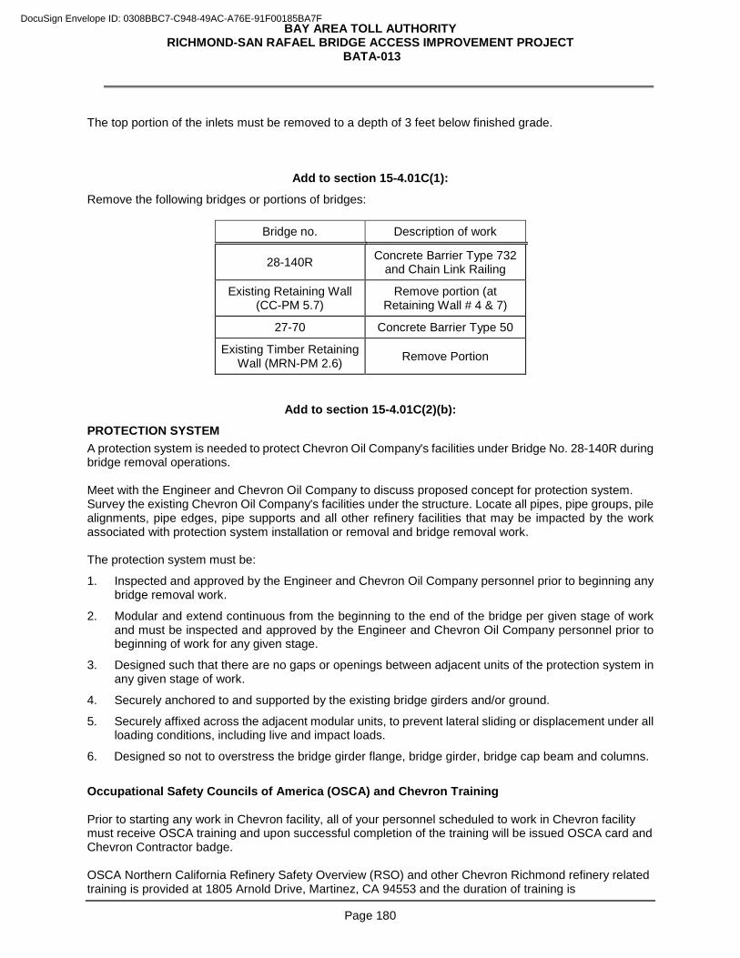
BAY AREA TOLL AUTHORITY RICHMOND-SAN RAFAEL BRIDGE ACCESS IMPROVEMENT PROJECT
BATA-013
Page 180
The top portion of the inlets must be removed to a depth of 3 feet below finished grade.
Add to section 15-4.01C(1):
Remove the following bridges or portions of bridges:
Bridge no. Description of work
28-140R Concrete Barrier Type 732 and Chain Link Railing
Existing Retaining Wall (CC-PM 5.7)
Remove portion (at Retaining Wall # 4 & 7)
27-70 Concrete Barrier Type 50
Existing Timber Retaining Wall (MRN-PM 2.6) Remove Portion
Add to section 15-4.01C(2)(b):
PROTECTION SYSTEM A protection system is needed to protect Chevron Oil Company's facilities under Bridge No. 28-140R during bridge removal operations. Meet with the Engineer and Chevron Oil Company to discuss proposed concept for protection system. Survey the existing Chevron Oil Company's facilities under the structure. Locate all pipes, pipe groups, pile alignments, pipe edges, pipe supports and all other refinery facilities that may be impacted by the work associated with protection system installation or removal and bridge removal work. The protection system must be:
1. Inspected and approved by the Engineer and Chevron Oil Company personnel prior to beginning any bridge removal work.
2. Modular and extend continuous from the beginning to the end of the bridge per given stage of work and must be inspected and approved by the Engineer and Chevron Oil Company personnel prior to beginning of work for any given stage.
3. Designed such that there are no gaps or openings between adjacent units of the protection system in any given stage of work.
4. Securely anchored to and supported by the existing bridge girders and/or ground.
5. Securely affixed across the adjacent modular units, to prevent lateral sliding or displacement under all loading conditions, including live and impact loads.
6. Designed so not to overstress the bridge girder flange, bridge girder, bridge cap beam and columns.
Occupational Safety Councils of America (OSCA) and Chevron Training Prior to starting any work in Chevron facility, all of your personnel scheduled to work in Chevron facility must receive OSCA training and upon successful completion of the training will be issued OSCA card and Chevron Contractor badge. OSCA Northern California Refinery Safety Overview (RSO) and other Chevron Richmond refinery related training is provided at 1805 Arnold Drive, Martinez, CA 94553 and the duration of training is
DocuSign Envelope ID: 0308BBC7-C948-49AC-A76E-91F00185BA7F
BAY AREA TOLL AUTHORITY RICHMOND-SAN RAFAEL BRIDGE ACCESS IMPROVEMENT PROJECT
BATA-013
Page 181
approximately one and half days. To schedule OSCA training go to: http://www.osca.com/. Upon completion of OSCA training, all personnel must also receive Incident Injury Free Indoctrination (IIFI) training at the Chevron Richmond Refinery, Gate 91, in the Safety Training Building. The two hour training is provided every Monday at 6:00 AM. Upon successful completion of the training each personnel will be issued Chevron Contractor Badge. Notify the Engineer and Chevron Oil Company in writing, the start date of building a protection system, at least 2 weeks before beginning the construction of the protection system. City Fire Department and U.S.C.G. must be notified and approval received prior to accessing the wharf. Submit working drawings of the proposed protection system plan, with design calculations, to the Engineer as part of the bridge removal plan. The protection system plan must be prepared and signed by:
1. Engineer who is registered as a Civil Engineer in the State of California.
2. Independent reviewer who is:
2.1. Registered as a civil engineer in the State
2.2. Not employed by the same entity that prepared the drawings
Provide calculations ensuring that the scaffold system can absorb potential falling debris weights and sizes for the Engineer's review and approval. Contractor to ensure that Chevron Oil Company personnel have complete access to the pipeways and / or equipment at all times while protection system is in place. Chevron Oil Company personnel must approve the contingency / access plan to ensure any potential maintenance, emergency, or any unforeseen need to access the pipeways or equipment once the scaffold system is in place. The design calculations must be adequate to demonstrate the stability of the protection system during all stages of the bridge removal operations. Provide calculations for each stage of bridge removal and include dead and live load values assumed in the design of protection system. Include the following in Protection system plans:
1. Descriptions, calculations, and values for all loads anticipated during the erection, use, and removal of protection system.
2. Methods and equipment for erecting, moving, and removing protection system.
3. Design details including bolt layouts, welding details, and any connections to existing structures.
4. Stress sheets including a summary of computed stresses in the (1) protection system, (2) connections between protection system and any existing structures, and (3) existing load supporting members. The computed stresses must include the effects of erection, movement, and removal of the protection system.
5. Locations where protection system will be over Chevron Oil Company's utilities.
6. Details and measures for preventing material, equipment, and debris from falling onto Chevron Oil Company's utilities.
Design and construct protection system in conformance with the provisions in Section 48-2, "Falsework," of the Standard Specifications and these special provisions. Assume horizontal load to be resisted by the protection system, for removal operations only, to be the sum of the actual horizontal loads due to equipment, construction sequence, or other causes and an allowance for wind, but in no case shall the assumed horizontal load to be resisted in any direction be less than 5 percent of the total dead load of the structure to be removed.
DocuSign Envelope ID: 0308BBC7-C948-49AC-A76E-91F00185BA7F
BAY AREA TOLL AUTHORITY RICHMOND-SAN RAFAEL BRIDGE ACCESS IMPROVEMENT PROJECT
BATA-013
Page 182
The following requirements apply to the protection system for Bridge No.28-140R:
1. Protection system must be in place before beginning bridge removal work. The protection system must be supported by shoring, falsework, or members of the existing structure. You are responsible for designing and constructing safe and adequate protection system, shoring, and falsework with sufficient strength and rigidity to support the entire load to be imposed on the protection system.
2. Describe protection system construction methods in the working drawings and provide calculations with details to substantiate loads used in the protection system design. Show the dead and live load values assumed in the design of protection system.
3. Submit a contingency plan to protect Chevron Oil Company piping and equipment while constructing the protection system.
4. Protection system must prevent any materials, equipment, or debris from falling onto Chevron Oil Company's facilities. Furnish additional material as necessary to prevent fine materials or debris from sifting down upon the below ground.
5. Construct protection system complete in place and fully functional prior to beginning any bridge removal work.
6. Clean the protection system of all debris, dirt, mortar and fine material at the end of each work day and before removing the protection system.
7. Remove the protection system as soon as the permanent work is complete on the bridge. Protect Chevron Oil Company's piping and equipment during removal of the protection system.
Add to section 15-5.01C(2):
When abrasive blasting within 10 feet of public traffic, remove residue using a vacuum attachment operating concurrently with the blasting equipment.
Add to section 15-5.01C(3):
Remove 3/4 inch to 1-1/2 inches of deck surface and as shown in the contract plans.
Replace the 3rd paragraph of the RSS for section 15-5.01C(4) with:
Remove existing asphalt concrete surfacing and membrane seal by cold milling. Do not remove more than 1/2 inch of the existing concrete slab during cold-milling activities.
Add to section 15-5.01C(4):
Where a portion of the asphalt concrete overlay is to remain, saw cut a 2-inch-deep neat line along the edge to remain in place before removing asphalt concrete. Remove the asphalt surfacing without damaging the existing surfacing to remain in place.
Add to section 15-5.04C(1):
Clean the cut ends of dowels under SSPC-SP 3. Paint dowel ends immediately after cleaning with 2 coats of organic zinc-rich primer under section 59-2.03C(2)(a).
Replace item 1 in the list in the 1st paragraph of section 15-5.06A(2) with:
1. Schedule of overlay work for the trial overlay and for each bridge
DocuSign Envelope ID: 0308BBC7-C948-49AC-A76E-91F00185BA7F
BAY AREA TOLL AUTHORITY RICHMOND-SAN RAFAEL BRIDGE ACCESS IMPROVEMENT PROJECT
BATA-013
Page 183
Replace the paragraphs of section 15-5.06A(3) with:
Complete a trial polyester concrete overlay before starting overlay activities. Notify the Engineer at least 15 days before constructing the trial overlay. The trial overlay must be:
1. At least 12 by 12 feet and the same thickness as the overlay shown
2. Constructed on a prepared concrete base within the project limits at an authorized location
3. Constructed (1) using the same materials, equipment, and construction methods to be used in the work and (2) under conditions similar to those anticipated when the work will be performed
Use the trial overlay to determine the initial polyester-concrete set time. The Engineer performs friction testing of the trial overlay under California Test 342. Allow 10 days after completion of the trial overlay for the Engineer to perform the testing. The completed trial overlay must demonstrate (1) compliance with these specifications and (2) that the work will be completed within the time allowed. Do not perform overlay activities until the trial overlay is authorized. The authorized trial overlay is the standard of comparison in determining the acceptability of the overlay. The Engineer may perform testing under California Test 342 to verify the coefficient of friction of the overlay surfaces. Dispose of the trial overlay and concrete base after acceptance of all polyester concrete overlay surfaces.
Replace the 8th paragraph of section 15-5.06C(1) with:
Finishing equipment for polyester concrete must:
1. Have grade control capabilities resulting in a roadway surface that meets the smoothness requirements of section 51-1.01D(4)(b) and is capable of adjusting for a variable thickness overlay along and across the existing deck surface. The use of fixed height skid-supported strike off equipment is not allowed.
2. Be used to consolidate the polyester concrete
3. Have a 12-foot minimum paving width
Replace the 13th paragraph of section 15-5.06C(1) with:
The approximate rate of application of methacrylate resin is 90 sq ft/gal.
Replace the 21st paragraph of section 15-5.06C(1) with:
Completed polyester concrete deck surfaces must have a uniform surface texture with a coefficient of friction of at least 0.35 when tested under California Test 342 and a surface smoothness complying with section 51-1.01D(4)(b).
Add to section 15-5.06C(1):
You may use a mechanical mixer to mix the polyester concrete. The mixer capacity must not exceed 9 cu ft unless authorized. Initiate the resin binder and thoroughly blend it immediately before mixing it with the aggregate. Mix the polyester concrete for at least 2 minutes before placing.
DocuSign Envelope ID: 0308BBC7-C948-49AC-A76E-91F00185BA7F
BAY AREA TOLL AUTHORITY RICHMOND-SAN RAFAEL BRIDGE ACCESS IMPROVEMENT PROJECT
BATA-013
Page 184
^^^^^^^^^^^^^^^^^^^^^^^^^^^^^^^^^^^^^^^^^^^^^^^^^^^^^^^^^^^^^^^^
DIVISION III GRADING 16 CLEARING AND GRUBBING
Replace section 16-1.03D with:
You may place vegetation in embankment areas. Comply with Section 19-6. Place vegetation as specified for Method I below:
Method I:
1. Place vegetation outside of the 1:1 inclined plane sloping out and down from the outside edge of the shoulder of the planned roadbed. Do not place vegetation within 5 feet of the finished slope line measured normal to the slope.
2. Mix brush and debris with at least 50 percent earth. Place the mixture in uniform layers.
3. Do not use vegetation material where it will interfere with planned work. Regardless of the method used, do not bury vegetation in areas where less than 10 percent of the embankment material passes a no. 200 sieve or in areas where the plans prohibit burying vegetation. Separate downed trees into stumps and logs. Trim stump roots to within 2 feet of the trunk, place the trunks vertically in the embankment, and space them so that compaction equipment can readily pass between them. Lay logs and trimmed branches parallel to each other and at least 1 foot apart. Cover each single layer of stumps, logs, and branches with at least 3 feet of compacted embankment material.
^^^^^^^^^^^^^^^^^^^^^^^^^^^^^^^^^^^^^^^^^^^^^^^^^^^^^^^^^^^^^^^^
17 WATERING
Replace the 1st sentence of the paragraph in section 17-1.02 with:
Water must be nonpotable.
^^^^^^^^^^^^^^^^^^^^^^^^^^^^^^^^^^^^^^^^^^^^^^^^^^^^^^^^^^^^^^^^
19 EARTHWORK
Replace the 2nd, 3rd, and 4th paragraphs of section 19-2.03B with:
Dispose of surplus material. Ensure enough material is available to complete the embankments before disposing of it.
Add to section 19-2.03G: Roughen embankment slopes to receive erosion control materials by either track-walking or rolling with a sheepsfoot roller. Track-walk slopes by running track-mounted equipment perpendicular to slope contours. Roughen excavation slopes and flat surfaces to receive erosion control materials by scarifying to a depth of 4 inches.
DocuSign Envelope ID: 0308BBC7-C948-49AC-A76E-91F00185BA7F
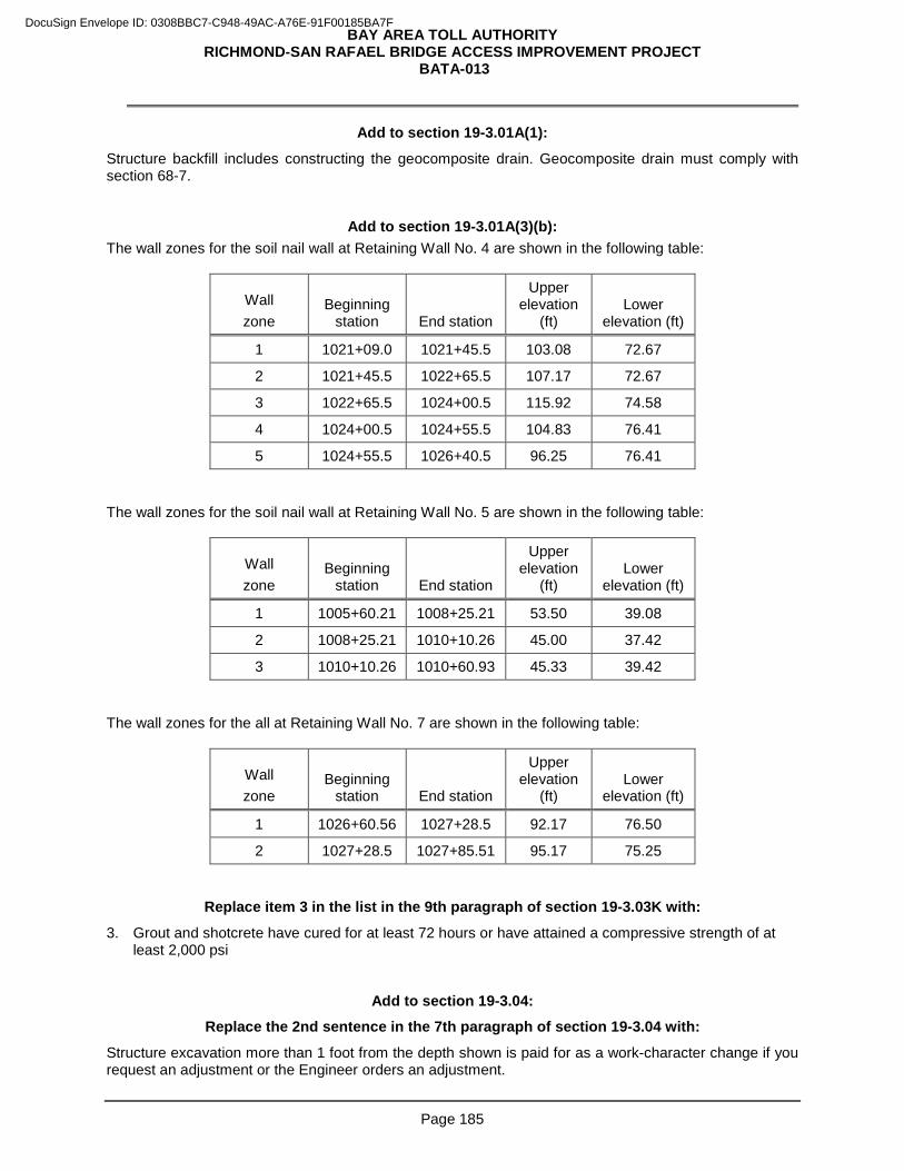
BAY AREA TOLL AUTHORITY RICHMOND-SAN RAFAEL BRIDGE ACCESS IMPROVEMENT PROJECT
BATA-013
Page 185
Add to section 19-3.01A(1):
Structure backfill includes constructing the geocomposite drain. Geocomposite drain must comply with section 68-7.
Add to section 19-3.01A(3)(b): The wall zones for the soil nail wall at Retaining Wall No. 4 are shown in the following table:
Wall zone
Beginning station End station
Upper elevation
(ft) Lower
elevation (ft)
1 1021+09.0 1021+45.5 103.08 72.67
2 1021+45.5 1022+65.5 107.17 72.67
3 1022+65.5 1024+00.5 115.92 74.58
4 1024+00.5 1024+55.5 104.83 76.41
5 1024+55.5 1026+40.5 96.25 76.41 The wall zones for the soil nail wall at Retaining Wall No. 5 are shown in the following table:
Wall zone
Beginning station End station
Upper elevation
(ft) Lower
elevation (ft)
1 1005+60.21 1008+25.21 53.50 39.08
2 1008+25.21 1010+10.26 45.00 37.42
3 1010+10.26 1010+60.93 45.33 39.42 The wall zones for the all at Retaining Wall No. 7 are shown in the following table:
Wall zone
Beginning station End station
Upper elevation
(ft) Lower
elevation (ft)
1 1026+60.56 1027+28.5 92.17 76.50
2 1027+28.5 1027+85.51 95.17 75.25
Replace item 3 in the list in the 9th paragraph of section 19-3.03K with:
3. Grout and shotcrete have cured for at least 72 hours or have attained a compressive strength of at least 2,000 psi
Add to section 19-3.04:
Replace the 2nd sentence in the 7th paragraph of section 19-3.04 with:
Structure excavation more than 1 foot from the depth shown is paid for as a work-character change if you request an adjustment or the Engineer orders an adjustment.
DocuSign Envelope ID: 0308BBC7-C948-49AC-A76E-91F00185BA7F
BAY AREA TOLL AUTHORITY RICHMOND-SAN RAFAEL BRIDGE ACCESS IMPROVEMENT PROJECT
BATA-013
Page 186
Add to section 19-5.03B:
Item 2 of the 1st paragraph does not apply to Bike Paths.
Add to the paragraph in section 19-5.03C: Unless otherwise authorized, compact material without adding water.
Add to section 19-6.04: The volume occupied by vegetation is not deducted from the computed embankment quantities. If an ordered change increases the quantity of excavation or decreases the quantity of embankment so that surplus excavation has to be disposed of, disposing of the surplus material is change order work. Payment will not be given for surplus material used to widen slopes. The quantity of embankment is computed based on planned or authorized cross sections for embankment and the measured ground surface. The quantity of embankment will not be adjusted if subsidence or consolidation occurs after placing embankment material has begun.
Add to the 7th paragraph of section 19-9.02: If 100 percent RAP is used, the requirement for minimum unit weight of shoulder backing under California Test 212 does not apply.
Replace the 6th paragraph of section 19-9.03 with: Complete shoulder backing within 5 days after placement of adjacent new surfacing except complete shoulder backing within 15 days wherever edge treatment under section 39-1.03E is placed.
^^^^^^^^^^^^^^^^^^^^^^^^^^^^^^^^^^^^^^^^^^^^^^^^^^^^^^^^^^^^^^^^^
20 LANDSCAPE Replace the 1st sentence in the 2nd paragraph in section 20-1.02B of the RSS for section 20 with: For erosion control work only, if water is not available, make arrangements for supplying nonpotable water under section 17.
Add to section 20-1.02C of the RSS for section 20: Select herbicides from the following table:
Herbicides
Herbicide name
Herbicide type
Preemergent (granular)
Preemergent (non-granular)
Post- emergent Selective
Non- selective Systemic
Glyphosate X X
Pendimethalin X X X
DocuSign Envelope ID: 0308BBC7-C948-49AC-A76E-91F00185BA7F
BAY AREA TOLL AUTHORITY RICHMOND-SAN RAFAEL BRIDGE ACCESS IMPROVEMENT PROJECT
BATA-013
Page 187
Add to section 20-1.03C(3) of the RSS for section 20: In groundcover areas and within the area extending beyond the outer limits of the groundcover to the adjacent edges of shoulders, dikes, curbs, sidewalks, walls, existing planting, and fences, control weeds with pesticides or by hand pulling. Where groundcover areas are 12 feet or more from the adjacent edges of shoulders, dikes, curbs, sidewalks, walls, and fences, control weeds within the groundcover areas and 6 feet beyond the outer limits of the groundcover areas. In mulched areas and within the area extending beyond the outer limits of the mulched areas to the adjacent edges of shoulders, dikes, curbs, sidewalks, walls, existing planting, and fences, control weeds with pesticides or by hand pulling. Where mulched areas are 12 feet or more from the adjacent edges of shoulders, dikes, curbs, sidewalks, walls, and fences, control weeds within the mulched areas and 6 feet beyond the outer limits of the mulched areas. Within 2 feet of the edges of paved shoulders, dikes, curbs, and sidewalks, control weeds with pesticides or by hand pulling. Control weeds under guard rails, from within asphalt concrete surfacing, concrete surfacingand unpaved gore areas between the edge of pavement and planting areas with pesticides or by hand pulling.
Replace the 3rd paragraph of section 20-2.01A(4)(b)(i) of the RSS for section 20 with: Supply lines on the discharge side of the valve must be tested in conformance with Method B only. Testing by Method A is not allowed. Supply lines installed by trenching and backfilling and supply lines that are completely visible after installation must be tested by Method B.
Add to section 20-2.06B of the RSS for section 20: Flow sensor cable must be rated 600V and 194 degree F, be UL listed as Type TC, meet requirements of ICEA/NEMA, and comply with the following:
1. Consist of two no. 14 minimum stranded copper conductors. Insulated conductor must be color coded with a PVC or nylon jacket.
2. Include a tinned cooper braid or aluminized polyester film shield. Where the film is used, a no. 18 (or larger stranded) or no. 16 (solid), tinned, copper drain wire to be placed between the insulated conductors and the shield and in contact with the conductive surface of the shield.
3. Include a black PVC jacket with a minimum nominal thickness of either 50 mils or 48 mils where capacitance of conductors to other conductors and the shield is 87 pF/ft or better. The cable jacket must be marked with the insulation type designation, conductor size, and voltage and temperature ratings.
4. Have an outside diameter of 0.28 to 0.51 inch.
5. Have no splices between components except where shown.
6. Install wires from flow sensor to irrigation controller within a 1” conduit.
Add to the list in the 1st paragraph of section 20-2.07B(2)(a) of the RSS for section 20: 17. Be EPA WaterSense® approved.
Add after the 1st paragraph of section 20-2.07B(2)(a) of the RSS for section 20: Before the irrigation system functional test begins, furnish 2 remote access devices to the Engineer.
DocuSign Envelope ID: 0308BBC7-C948-49AC-A76E-91F00185BA7F
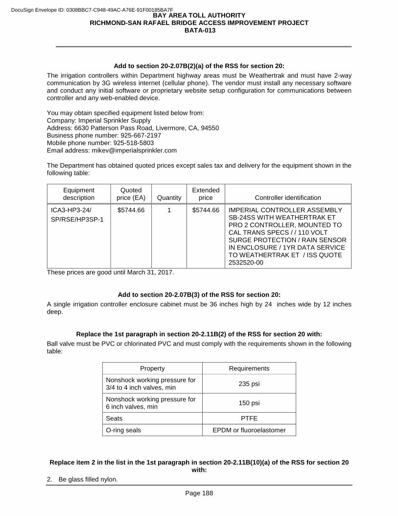
BAY AREA TOLL AUTHORITY RICHMOND-SAN RAFAEL BRIDGE ACCESS IMPROVEMENT PROJECT
BATA-013
Page 188
Add to section 20-2.07B(2)(a) of the RSS for section 20:
The irrigation controllers within Department highway areas must be Weathertrak and must have 2-way communication by 3G wireless internet (cellular phone). The vendor must install any necessary software and conduct any initial software or proprietary website setup configuration for communications between controller and any web-enabled device. You may obtain specified equipment listed below from: Company: Imperial Sprinkler Supply Address: 6630 Patterson Pass Road, Livermore, CA, 94550 Business phone number: 925-667-2197 Mobile phone number: 925-518-5803 Email address: [email protected] The Department has obtained quoted prices except sales tax and delivery for the equipment shown in the following table:
Equipment description
Quoted price (EA) Quantity
Extended price Controller identification
ICA3-HP3-24/ SP/RSE/HP3SP-1
$5744.66 1 $5744.66 IMPERIAL CONTROLLER ASSEMBLY SB-24SS WITH WEATHERTRAK ET PRO 2 CONTROLLER, MOUNTED TO CAL TRANS SPECS / / 110 VOLT SURGE PROTECTION / RAIN SENSOR IN ENCLOSURE / 1YR DATA SERVICE TO WEATHERTRAK ET / ISS QUOTE 2532520-00
These prices are good until March 31, 2017.
Add to section 20-2.07B(3) of the RSS for section 20: A single irrigation controller enclosure cabinet must be 36 inches high by 24 inches wide by 12 inches deep.
Replace the 1st paragraph in section 20-2.11B(2) of the RSS for section 20 with: Ball valve must be PVC or chlorinated PVC and must comply with the requirements shown in the following table:
Property Requirements
Nonshock working pressure for 3/4 to 4 inch valves, min 235 psi
Nonshock working pressure for 6 inch valves, min 150 psi
Seats PTFE
O-ring seals EPDM or fluoroelastomer Replace item 2 in the list in the 1st paragraph in section 20-2.11B(10)(a) of the RSS for section 20
with: 2. Be glass filled nylon.
DocuSign Envelope ID: 0308BBC7-C948-49AC-A76E-91F00185BA7F
BAY AREA TOLL AUTHORITY RICHMOND-SAN RAFAEL BRIDGE ACCESS IMPROVEMENT PROJECT
BATA-013
Page 189
Replace "60 days" in the 1st paragraph of section 20-3.01A(3)(b) with: 30 days
Add to section 20-3.01A(3)(b): Some plants required may not be readily available and must be grown specifically for this project. Submit a statement within 30 days after Contract approval from the vendor that the order to grow the plants, including inspection plants and replacement plants, has been received and accepted by the vendor. The statement from the vendor must include the plant names, sizes, and quantities and the anticipated delivery date. Notify the Engineer when the vendor has started growing the plants.
Replace the 2nd sentence in the 1st paragraph of section 20-3.01B(3) of the RSS for section 20 with:
Soil amendment must be fine compost under section 21-1.02M.
Add to the RSS for section 20-4.01A: This project has a Type 2 plant establishment period.
Add to the RSS for section 20-4.03C: Apply slow-release fertilizer to the plants during the 1st week of March and September of each year.
Replace the 2nd paragraph of section 20-4.01A of the RSS for section 20 with: Plant establishment consists of caring for the plants and vegetated strips and swales, including watering, fertilizing, pruning, replacing damaged plants, pest control, and operating and repairing of all existing irrigation facilities used and irrigation facilities installed as part of the new irrigation system.
Add to section 20-4.03A of the RSS for section 20: If irregular or uneven areas appear within vegetated strip and swale areas, restore to a smooth and even appearance. Reseed vegetated strip and swale areas as ordered. Comply with section 21-1.03E. Reseeding vegetated strip and swale areas is change order work.
Add to section 20-5.03B(2)(a) of the RSS for section 20: Do not use soil sterilant.
Add to section 20-5.05A of the RSS for section 20:
Site furnishings include “Precast Concrete Bench”. Precast concrete bench must be commercially available, designed for outdoor installation. Minor variations in dimensions shown on details for precast concrete bench are acceptable in a commercially available unit. Informational submittals must be furnished in accordance with Section 5-1.23C. Manufacturer’s catalogue sheets and specifications showing product style, dimensions, materials, textures, finishes, colors, installation recommendations and product guarantees for the precast concrete bench must be submitted to the Engineer for written approval prior to ordering. Precast concrete bench must be guaranteed by the
DocuSign Envelope ID: 0308BBC7-C948-49AC-A76E-91F00185BA7F
BAY AREA TOLL AUTHORITY RICHMOND-SAN RAFAEL BRIDGE ACCESS IMPROVEMENT PROJECT
BATA-013
Page 190
manufacturer to be free from defects in material and workmanship for a minimum period of one year from date of delivery.
Replace "Reserved" in section 20-5.05B of the RSS for section 20 with:
20-5.05B Materials Precast concrete bench must be constructed of a mixture of cement, aggregate, additives and natural integral color pigments, reinforced with steel. The mixture must utilize a Type II or Type III cement conforming to ASTM C-150 standard specifications. Color for precast concrete bench must be integral, chemically inert, fade resistant mineral oxide or synthetic type. The color of precast concrete bench must be gray. Texture for precast concrete bench must be as shown on details. Precast concrete bench surfaces must be sealed by the manufacture with a clear matte exterior graffiti resistant sealer. Sealers must be the manufacturer's best quality and must not contain lead. Precast concrete bench surfaces must be true, even and smooth, free of any honeycombing, surface pitting or voids. Rough corners or edges exposed to view or touch must be ground smooth. Precast concrete bench must be free of discoloration and other objectionable marks or defects which effect appearance or serviceability Fastening hardware for precast concrete bench must be stainless steel or galvanized as provided by the manufacturer.
Replace "Reserved" in section 20-5.05C of the RSS for section 20 with:
20-5.05C Construction Work for site furnishings includes furnishing precast concrete bench, preparing the site where precast concrete bench will be installed, assembling precast concrete bench, installing precast concrete bench and anchoring precast concrete bench. The exact placement location of precast concrete bench must be approved by the Engineer prior to installation.
Replace "Reserved" in section 20-5.05D of the RSS for section 20 with:
20-5.05D Payment Work described is paid under bid items specified for precast concrete bench.
^^^^^^^^^^^^^^^^^^^^^^^^^^^^^^^^^^^^^^^^^^^^^^^^^^^^^^^^^^^^^^^^
DIVISION IV SUBBASES AND BASES
29 TREATED PERMEABLE BASES
Add to section 29-1.02B:
The type of asphalt binder to be mixed with aggregate for ATPB must be Grade PG 64-10 for Marin County and PG 64-16 for Contra Costa County.
^^^^^^^^^^^^^^^^^^^^^^^^^^^^^^^^^^^^^^^^^^^^^^^^^^^^^^^^^^^^^^^^
DocuSign Envelope ID: 0308BBC7-C948-49AC-A76E-91F00185BA7F
BAY AREA TOLL AUTHORITY RICHMOND-SAN RAFAEL BRIDGE ACCESS IMPROVEMENT PROJECT
BATA-013
Page 191
DIVISION V SURFACINGS AND PAVEMENTS 39 HOT MIX ASPHALT
Replace section 39-1.03C(3) of the RSS for section 39 with:
39-1.03C(3) Prime Coat Apply a slow-setting asphaltic emulsion as a prime coat to aggregate base areas designated by the Engineer. Apply prime coat at a spread rate of 0.15 to 0.40 gal/sq yd. Do not apply more prime coat than can be absorbed completely by the aggregate base in 24 hours. If you request and the request is authorized, you may modify prime coat application rates. Close areas receiving prime coat to traffic. Do not track prime coat onto pavement surfaces beyond the job site.
Replace section 39-1.03K of the RSS for section 39 with: 39-1.03K Rumble Strips Construct rumble strips in the existing asphalt concrete surfacing by ground-in methods. Select the method and equipment for constructing ground-in indentations.
Do not construct rumble strips:
1. On structures, approach slabs, or concrete weigh-in-motion slabs
2. At intersections
3. Bordering two-way left turn lanes, within intersections, driveways, or other high-volume turning areas Construct rumble strips within 2 inches of the specified alignment. The grinding equipment must be equipped with a sighting device enabling the operator to maintain the rumble strip alignment. Indentations must comply with the dimensions shown and not vary more than:
1. 10 percent in length
2. 0.06 inch in depth
3. 10 percent in width
4. 1 inch in center-to-center spacing between rumble strips Break rumble strips before and after intersections, driveways, railroad crossing, freeway gore areas, and freeway ramps. Place breaks and break distances as shown. The need for breaks and the break distances may be assessed and adjusted as needed at low volume driveways or other locations if authorized by the engineer. The Engineer orders grinding or removal and replacement of noncompliant rumble strips to bring them within specified tolerances. Ground surface areas must be neat and uniform in appearance. The grinding equipment must be equipped with a vacuum attachment to remove residue from the roadbed. Dispose of removed material. On ground areas, apply fog seal coat under section 37-4.02. Rumble strip is measured by the station along the length of the rumble strip without deductions for gaps between indentations.
DocuSign Envelope ID: 0308BBC7-C948-49AC-A76E-91F00185BA7F
BAY AREA TOLL AUTHORITY RICHMOND-SAN RAFAEL BRIDGE ACCESS IMPROVEMENT PROJECT
BATA-013
Page 192
Add to section 39-1.04 of the RSS for section 39:
The aggregate for the HMA Type A must conform to the 1/2–inch HMA Type A and the 3/8-inch HMA Type A aggregate gradation specified in 39-1.02 E. HMA used for cross slope correction, ADA compliance, and for 0.1-foot layer thickness must conform to the 3/8-inch maximum grading. If HMA (miscellaneous area) is not shown, the bid item for place hot mix asphalt (miscellaneous area) is limited to overside drains, ADA compliance and cross-slope correction, and is in addition to the bid items for the materials involved. Rumble strips are measured by the station along the length of the rumble strips without deductions for gaps between indentations.
Replace the 2nd paragraph in section 39-2.01A of the RSS for section 39 with: Produce Type A HMA using a WMA additive technology.
Replace "Reserved" in section 39-2.02C of the RSS for section 39 with: The grade of asphalt binder for Type A HMA must be PG 64-10 for Marin County and PG 64-16 for Contra Costa County.
Replace the 2nd paragraph in section 39-3.01A of the RSS for section 39 with: You must produce RHMA-G using a WMA additive technology.
Add to section 39-3.02C(1) of the RSS for section 39: The grade of asphalt binder for RHMA-G must be PG 64-10 for Marin County and PG 64-16 Contra Costa County.
^^^^^^^^^^^^^^^^^^^^^^^^^^^^^^^^^^^^^^^^^^^^^^^^^^^^^^^^^^^^^^^^
DIVISION VI STRUCTURES 46 GROUND ANCHORS AND SOIL NAILS
Add to the 2nd paragraph of section 46-3.01D(2)(b)(iii):
In addition to the proof test soil nails shown, install and test 20 proof test soil nails at locations determined by the Engineer.
^^^^^^^^^^^^^^^^^^^^^^^^^^^^^^^^^^^^^^^^^^^^^^^^^^^^^^^^^^^^^^^^^
48 TEMPORARY STRUCTURES
Replace "Reserved" in section 48-3 with:
48-3.01 GENERAL 48-3.01A Summary Section 48-3 includes specifications for providing temporary supports for existing structures during retrofit, reconstruction, and removal activities.
DocuSign Envelope ID: 0308BBC7-C948-49AC-A76E-91F00185BA7F
BAY AREA TOLL AUTHORITY RICHMOND-SAN RAFAEL BRIDGE ACCESS IMPROVEMENT PROJECT
BATA-013
Page 193
Temporary supports must include jacking assemblies and required accessories to jack and support structures. 48-3.01B Definitions frame: the portion of a bridge between expansion joints. 48-3.01C Submittals 48-3.01C(1) General Submit 2 copies of the initial location survey signed by an engineer who is registered as a civil engineer in the State. 48-3.01C(2) Shop Drawings Submit shop drawings with design calculations for the temporary support system. Submit 6 copies of shop drawings and 2 copies of design calculations. Include the following:
1. Descriptions and values of all loads, including construction equipment loads.
2. Descriptions of equipment to be used.
3. Details and calculations for jacking and supporting the existing structure.
4. Stress sheets, anchor bolt layouts, shop details, and erection and removal plans for the temporary supports.
5. Assumed soil bearing values and design stresses for temporary support footings, including anticipated foundation settlement.
6. Maximum distance temporary support piles may be pulled for placement under footing caps.
7. Maximum deviation of temporary support piles from a vertical line through the point of fixity.
8. Details for use of permanent piles. Include any additional loads imposed on the piles.
9. Details for additional bracing required during erection and removal of temporary supports.
10. Details of the displacement monitoring system, including equipment, location of control points, and methods and schedule of taking measurements.
11. Details for jacking the structure if settlement occurs in the temporary supports. Shop drawings and calculations must be signed by an engineer who is registered as a civil engineer in the State. 48-3.01D Quality Control and Assurance 48-3.01D(1) General Welding, welder qualification, and welding inspection for temporary supports must comply with AWS D1.1. Calibrate each jack within 6 months of use and after each repair. Each jack and its gage must (1) be calibrated as a unit with the cylinder extension in the approximate position that it will be at the final jacking force and (2) accompanied by a certified calibration chart. Each load cell must be calibrated. Calibration must be performed by an authorized laboratory. Before starting bridge removal activities, an engineer who is registered as a civil engineer in the State must inspect and certify that (1) the temporary supports, jacking system, and displacement monitoring system comply with the authorized shop drawings and (2) the materials and workmanship are satisfactory for the work. A copy of this certification must be available at the job site at all times. An engineer who is registered as a civil engineer in the State must:
1. Be present during jacking activities or adjustments and during bridge removal activities.
DocuSign Envelope ID: 0308BBC7-C948-49AC-A76E-91F00185BA7F
BAY AREA TOLL AUTHORITY RICHMOND-SAN RAFAEL BRIDGE ACCESS IMPROVEMENT PROJECT
BATA-013
Page 194
2. Inspect jacking and removal activities and report daily on the progress of the operation and the status of the remaining structure. The daily report must be available at the job site at all times.
3. Immediately submit proposed procedures to correct or remedy unplanned occurrences. 48-3.01D(2) Displacement Monitoring Monitor and record vertical and horizontal displacements of the temporary supports and the existing structure. Use vandal-resistant displacement monitoring equipment. Perform monitoring continuously during jacking activities and at least weekly during removal and reconstruction activities. Make monitoring records available at the job site during normal work hours. Monitoring records must be signed by an engineer who is registered as a civil engineer in the State. As a minimum, monitor the existing structure at the supported bent and at the midspan of both adjoining spans. Locate control points at each location near the center and at both edges of the superstructure. As a minimum, take elevations at the following times:
1. Before starting jacking activities
2. Immediately after completing jacking
3. After completing bridge removal
4. Before connecting the reconstructed or retrofitted superstructure to the substructure
5. After removing temporary supports Perform an initial survey to record the location of the existing structure before starting work. 48-3.01D(3) Design Criteria The Engineer does not authorize temporary support designs based on allowable stresses greater than those specified in section 48-2.01D(3)(c). If falsework loads are imposed on temporary supports, the temporary supports must also satisfy the deflection criteria in section 48-2.01D(3)(c). The temporary support system must support the initial jacking loads and the minimum temporary support design loads and forces shown. Adjust vertical design loads for the weight of the temporary supports and jacking system, construction equipment loads, and additional loads imposed by jacking activities. Construction equipment loads must be at least 20 psf of deck surface area of the frame involved. Temporary supports must resist the specified lateral design forces applied at the point where the column to be removed meets the superstructure. If the temporary support lateral stiffness exceeds the specified minimum stiffness, increase the lateral design forces to be compatible with the temporary support stiffness. Place temporary supports resisting transverse lateral loads within 1/2 of the span length from the existing bent. Place temporary supports resisting longitudinal lateral loads within the frame where columns are to be removed. You may use the permanent piles as part of the temporary support foundation. Do not move or adjust permanent piles from the locations shown. If you install permanent piles longer than described to support the temporary supports above the top of the footing and later cut off the piles at their final elevation, you must use shear devices adequate to transfer all pile reactions into the footing. Design temporary support footings to carry the loads imposed without exceeding the estimated soil bearing values or anticipated settlements. You must determine soil bearing values. Where temporary supports are placed on the deck of an existing structure:
DocuSign Envelope ID: 0308BBC7-C948-49AC-A76E-91F00185BA7F
BAY AREA TOLL AUTHORITY RICHMOND-SAN RAFAEL BRIDGE ACCESS IMPROVEMENT PROJECT
BATA-013
Page 195
1. Temporary supports must bear either (1) directly on girder stems or bent caps of the supporting structure or (2) on falsework sills that transmit the load to the stems or cap without overstressing any member of the new or existing structure.
2. Temporary supports must not induce permanent forces into the completed structure or produce cracking.
3. Place additional temporary supports beneath the existing structure where temporary support loads are imposed on the existing structure. Design and construct the additional temporary supports to support all loads from the upper structure and construction activities.
Provide additional bracing as required to withstand all imposed loads during each phase of temporary supports erection and removal. Include wind loads complying under section 48-2.01D(3)(b) in the design of additional bracing. Mechanically connect (1) the existing structure to the temporary supports and (2) the temporary supports to their foundations. Mechanical connections must be capable of resisting the lateral design forces. Friction forces developed between the existing structure and temporary supports (1) are not considered an effective mechanical connection and (2) must not be used to reduce lateral forces. Design mechanical connections to accommodate adjustments to the temporary support frame during use. If the concrete is to be prestressed, design temporary supports to support changes to the loads caused by prestressing forces. Temporary supports must comply with section 48-2.01D(3)(d). 48-3.02 MATERIALS Manufactured assemblies must comply with section 48-2.01D(3)(c)(iv). 48-3.03 CONSTRUCTION Where described, install temporary crash cushion modules under section 12-3.15 before starting temporary support activities. Remove crash cushion modules when authorized. The construction sequence and application of temporary support jacking loads is described. You may submit proposed changes to the Engineer for authorization. Construct temporary supports under section 48-2.03C. Equip each jack with a pressure gage or load cell for determining the jacking force. Each pressure gage must have an accurately reading dial at least 6 inches in diameter. Each load cell must be provided with an indicator to determine the jacking force. Provide a redundant system of supports during jacking activities. The redundant system must include stacks of steel plates added as necessary to maintain the redundant supports at each jack location within 1/4 inch of the jacking sill or corbels. Before starting bridge removal work at a location being supported, the temporary support system must (1) apply a force to the structure that is equal to the initial jacking load or the dead load shown and (2) hold that load until all initial compression and settlement of the system is completed. Apply jacking loads simultaneously. Control and monitor jacking operations to prevent distortion and stresses that would damage the structure. Maintain total vertical displacements at control points to less than 1/4 inch from elevations recorded before jacking or as authorized. Stop jacking activities if unanticipated displacements, cracking, or other damage occurs. Apply corrective measures satisfactory to the Engineer before resuming jacking activities.
DocuSign Envelope ID: 0308BBC7-C948-49AC-A76E-91F00185BA7F
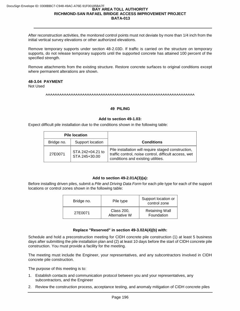
BAY AREA TOLL AUTHORITY RICHMOND-SAN RAFAEL BRIDGE ACCESS IMPROVEMENT PROJECT
BATA-013
Page 196
After reconstruction activities, the monitored control points must not deviate by more than 1/4 inch from the initial vertical survey elevations or other authorized elevations. Remove temporary supports under section 48-2.03D. If traffic is carried on the structure on temporary supports, do not release temporary supports until the supported concrete has attained 100 percent of the specified strength. Remove attachments from the existing structure. Restore concrete surfaces to original conditions except where permanent alterations are shown. 48-3.04 PAYMENT Not Used
^^^^^^^^^^^^^^^^^^^^^^^^^^^^^^^^^^^^^^^^^^^^^^^^^^^^^^^^^^^^^^^^^
49 PILING
Add to section 49-1.03: Expect difficult pile installation due to the conditions shown in the following table:
Pile location Conditions Bridge no. Support location
27E0071 STA 242+04.21 to STA 245+30.00
Pile installation will require staged construction, traffic control, noise control, difficult access, wet conditions and existing utilities.
Add to section 49-2.01A(3)(a): Before installing driven piles, submit a Pile and Driving Data Form for each pile type for each of the support locations or control zones shown in the following table:
Bridge no. Pile type Support location or control zone
27E0071 Class 200, Alternative W
Retaining Wall Foundation
Replace "Reserved" in section 49-3.02A(4)(b) with:
Schedule and hold a preconstruction meeting for CIDH concrete pile construction (1) at least 5 business days after submitting the pile installation plan and (2) at least 10 days before the start of CIDH concrete pile construction. You must provide a facility for the meeting. The meeting must include the Engineer, your representatives, and any subcontractors involved in CIDH concrete pile construction. The purpose of this meeting is to:
1. Establish contacts and communication protocol between you and your representatives, any subcontractors, and the Engineer
2. Review the construction process, acceptance testing, and anomaly mitigation of CIDH concrete piles
DocuSign Envelope ID: 0308BBC7-C948-49AC-A76E-91F00185BA7F
BAY AREA TOLL AUTHORITY RICHMOND-SAN RAFAEL BRIDGE ACCESS IMPROVEMENT PROJECT
BATA-013
Page 197
The Engineer will conduct the meeting. Be prepared to discuss the following:
1. Pile placement plan, dry and wet
2. Acceptance testing, including gamma-gamma logging, cross-hole sonic logging, and coring
3. Pile Design Data Form
4. Mitigation process
5. Timeline and critical path activities
6. Structural, geotechnical, and corrosion design requirements
7. Future meetings, if necessary, for pile mitigation and pile mitigation plan review
8. Safety requirements, including Cal/OSHA and Tunnel Safety Orders
Add to the RSS for section 49-3.02A(4)(d)(ii): If inspection pipes are not shown:
1. Include in the pile installation plan a plan view drawing of the pile showing reinforcement and inspection pipes.
2. Place inspection pipes around the pile reinforcing cage, in contact with the inside of the outermost spiral or hoop reinforcement.
3. Place inspection pipes around the pile at a uniform spacing not exceeding 33 inches measured along the circle passing through the centers of inspection pipes. Use at least 2 inspection pipes per pile. Place inspection pipes to provide the maximum diameter circle that passes through the centers of the inspection pipes while maintaining the spacing required herein.
4. Place inspection pipes at least 3 inches clear of the vertical reinforcement. Where the dimensions of the pile reinforcement do not allow inspection pipes to be placed as specified above, submit a request for deviation before fabricating pile reinforcement.
Add to section 49-3.02B(6)(c):
The synthetic slurry must be one of the materials shown in the following table:
DocuSign Envelope ID: 0308BBC7-C948-49AC-A76E-91F00185BA7F
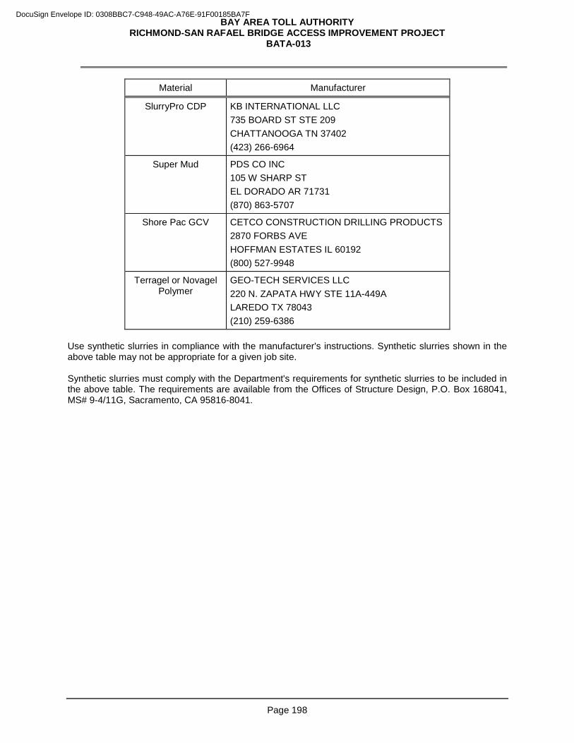
BAY AREA TOLL AUTHORITY RICHMOND-SAN RAFAEL BRIDGE ACCESS IMPROVEMENT PROJECT
BATA-013
Page 198
Material Manufacturer
SlurryPro CDP KB INTERNATIONAL LLC 735 BOARD ST STE 209 CHATTANOOGA TN 37402 (423) 266-6964
Super Mud PDS CO INC 105 W SHARP ST EL DORADO AR 71731 (870) 863-5707
Shore Pac GCV CETCO CONSTRUCTION DRILLING PRODUCTS 2870 FORBS AVE HOFFMAN ESTATES IL 60192 (800) 527-9948
Terragel or Novagel Polymer
GEO-TECH SERVICES LLC 220 N. ZAPATA HWY STE 11A-449A LAREDO TX 78043 (210) 259-6386
Use synthetic slurries in compliance with the manufacturer's instructions. Synthetic slurries shown in the above table may not be appropriate for a given job site. Synthetic slurries must comply with the Department's requirements for synthetic slurries to be included in the above table. The requirements are available from the Offices of Structure Design, P.O. Box 168041, MS# 9-4/11G, Sacramento, CA 95816-8041.
DocuSign Envelope ID: 0308BBC7-C948-49AC-A76E-91F00185BA7F
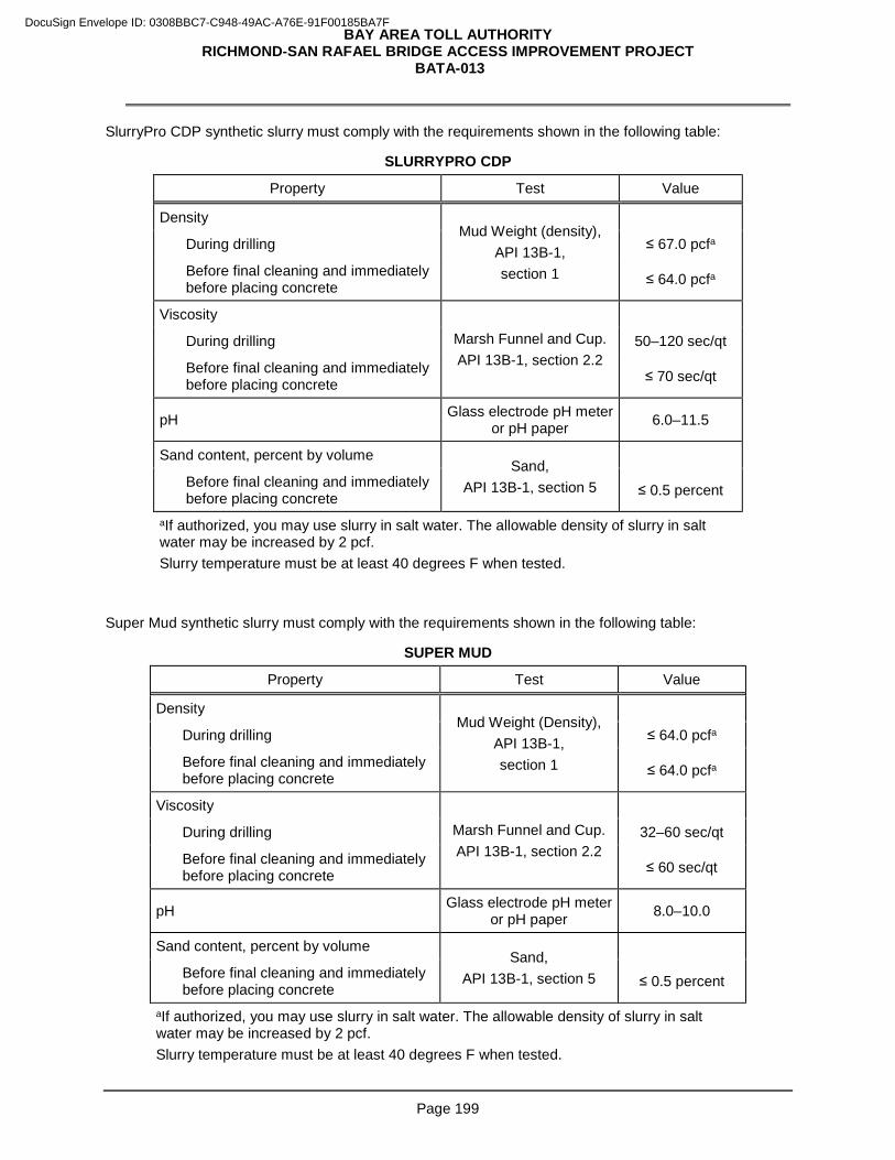
BAY AREA TOLL AUTHORITY RICHMOND-SAN RAFAEL BRIDGE ACCESS IMPROVEMENT PROJECT
BATA-013
Page 199
SlurryPro CDP synthetic slurry must comply with the requirements shown in the following table:
SLURRYPRO CDP
Property Test Value
Density Mud Weight (density),
API 13B-1, section 1
During drilling ≤ 67.0 pcfa
Before final cleaning and immediately before placing concrete ≤ 64.0 pcfa
Viscosity
Marsh Funnel and Cup. API 13B-1, section 2.2
During drilling 50–120 sec/qt
Before final cleaning and immediately before placing concrete ≤ 70 sec/qt
pH Glass electrode pH meter or pH paper 6.0–11.5
Sand content, percent by volume Sand,
API 13B-1, section 5
Before final cleaning and immediately before placing concrete ≤ 0.5 percent
aIf authorized, you may use slurry in salt water. The allowable density of slurry in salt water may be increased by 2 pcf. Slurry temperature must be at least 40 degrees F when tested.
Super Mud synthetic slurry must comply with the requirements shown in the following table:
SUPER MUD
Property Test Value
Density Mud Weight (Density),
API 13B-1, section 1
During drilling ≤ 64.0 pcfa
Before final cleaning and immediately before placing concrete ≤ 64.0 pcfa
Viscosity
Marsh Funnel and Cup. API 13B-1, section 2.2
During drilling 32–60 sec/qt
Before final cleaning and immediately before placing concrete ≤ 60 sec/qt
pH Glass electrode pH meter or pH paper 8.0–10.0
Sand content, percent by volume Sand,
API 13B-1, section 5
Before final cleaning and immediately before placing concrete ≤ 0.5 percent
aIf authorized, you may use slurry in salt water. The allowable density of slurry in salt water may be increased by 2 pcf. Slurry temperature must be at least 40 degrees F when tested.
DocuSign Envelope ID: 0308BBC7-C948-49AC-A76E-91F00185BA7F
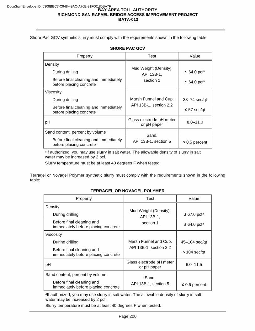
BAY AREA TOLL AUTHORITY RICHMOND-SAN RAFAEL BRIDGE ACCESS IMPROVEMENT PROJECT
BATA-013
Page 200
Shore Pac GCV synthetic slurry must comply with the requirements shown in the following table:
SHORE PAC GCV
Property Test Value
Density Mud Weight (Density),
API 13B-1, section 1
During drilling ≤ 64.0 pcfa
Before final cleaning and immediately before placing concrete ≤ 64.0 pcfa
Viscosity
Marsh Funnel and Cup. API 13B-1, section 2.2
During drilling 33–74 sec/qt
Before final cleaning and immediately before placing concrete ≤ 57 sec/qt
pH Glass electrode pH meter or pH paper 8.0–11.0
Sand content, percent by volume Sand,
API 13B-1, section 5
Before final cleaning and immediately before placing concrete ≤ 0.5 percent
aIf authorized, you may use slurry in salt water. The allowable density of slurry in salt water may be increased by 2 pcf. Slurry temperature must be at least 40 degrees F when tested.
Terragel or Novagel Polymer synthetic slurry must comply with the requirements shown in the following table:
TERRAGEL OR NOVAGEL POLYMER
Property Test Value
Density Mud Weight (Density),
API 13B-1, section 1
During drilling ≤ 67.0 pcfa
Before final cleaning and immediately before placing concrete ≤ 64.0 pcfa
Viscosity
Marsh Funnel and Cup. API 13B-1, section 2.2
During drilling 45–104 sec/qt
Before final cleaning and immediately before placing concrete ≤ 104 sec/qt
pH Glass electrode pH meter or pH paper 6.0–11.5
Sand content, percent by volume Sand,
API 13B-1, section 5
Before final cleaning and immediately before placing concrete ≤ 0.5 percent
aIf authorized, you may use slurry in salt water. The allowable density of slurry in salt water may be increased by 2 pcf. Slurry temperature must be at least 40 degrees F when tested.
DocuSign Envelope ID: 0308BBC7-C948-49AC-A76E-91F00185BA7F
BAY AREA TOLL AUTHORITY RICHMOND-SAN RAFAEL BRIDGE ACCESS IMPROVEMENT PROJECT
BATA-013
Page 201
^^^^^^^^^^^^^^^^^^^^^^^^^^^^^^^^^^^^^^^^^^^^^^^^^^^^^^^^^^^^^^^^^
51 CONCRETE STRUCTURES
Add to section 51-1.01A:
The concrete gray color for all retaining walls with geese, birds and waves structural aesthetics must be uniform and match exactly between each poured sections. All patterns and textures must match exactly throughout each entire numbered retaining wall.
Add to Section 51-1.01D(3):
51-1.01D(3) Test Panels
Scale Models:
• Make three dimensional 1/4 scale models of Geese “G11, “G12”, “G13”, “G14”, “G15”, “G16”, “G17”, “G18” & “G19” and Birds “BL11”, “BL12”, “BL13”, “BL14” and “BL15” that fully show geese and birds articulated bodies.
• Revise and resubmit scale models in accordance with Engineer’s comments. Test Panels:
• Bird “BL11” head with smooth finish and medium sandblast texture in the field surrounding the head
• Bird “BL11” wing with smooth finish, wave with smooth finish and fractured rib in the field surrounding the wing
• Bird "BL1" including wave and fractured fin
• Geese “G11” head with smooth finish and medium sandblast texture in the field surround the head
• Geese “G11” wing with smooth finish, wave with smooth finish and fractured rib in the field surrounding the wing
• Geese "G1" including wave and fractured fin
• Fractured rib texture and wave with smooth finish
• Fractured fin texture and wave with smooth finish
• Medium sandblast texture finish Test panels must be:
1. Constructed at an authorized location
2. At least 4 by 4 feet by 6 inches deep
3. Constructed and finished using the personnel, materials, equipment, and methods to be used in the work
4. Constructed vertically
5. Contain full size design elements described above
6. Have uniform even surfaces with required texture finish without worm holes, gaps, etc.
DocuSign Envelope ID: 0308BBC7-C948-49AC-A76E-91F00185BA7F
BAY AREA TOLL AUTHORITY RICHMOND-SAN RAFAEL BRIDGE ACCESS IMPROVEMENT PROJECT
BATA-013
Page 202
7. Accepted before starting work on mock-up panel The Engineer may request that additional test panels be constructed until the specified finish, texture and detail are attained. The Engineer uses the authorized scale models and test panels to determine acceptability of the work.
Add to section 51-1.01D:
51-1.01D(7) Mock-up Panels
Construct mock-up panels for Geese "G1" & “G11” and Bird "BL1" & “BL11” as shown on the drawings. Mock up panels must be cast vertically and be curved to match the roadway horizontal curve at retaining wall 4. Panels must accurately show all required design elements at full size with required surface finishes. Mock-up panels must be:
1. Constructed at an authorized location that is not within the job site
2. Geese "G1" and Bird "BL1" at least 12 feet wide by 12 feet high by 6 inches deep
3. Geese "G11" and Bird "BL11" at least 16 feet wide by 16 feet high by 6 inches deep
4. Constructed and finished using the personnel, materials, equipment, and methods to be used in the work
5. Constructed vertically and curved to match roadway horizontal curve at retaining wall 4
6. Constructed with no horizontal seams
7. Have uniform even surfaces with required texture finish without worm holes, gaps, etc.
8. Accessible for viewing
9. Displayed in an upright position near the work
10. Authorized before starting work
The Engineer may request that additional mock-up panels be constructed until the specified finish, texture and detail are attained.
The Engineer uses the authorized mock-up panels to determine acceptability of the work.
Dispose of the mock-up panels after the concrete surface texture work is complete and authorized. Notify the Engineer before disposing of the panels.
Add to section 51-1.03G(1):
Formed relief textures must consist of geese, birds, waves and bands with smooth finish and fractured rib and fin textures and medium sandblast texture on field, as shown. Apply class 1 surface finish to raised geese, birds and waves and bands.
Add to the 5th paragraph of section 51-1.03G(1):
For the geese, birds, waves, fractured ribs and fins and medium sandblast test panels and a mock-up panels are required as indicated under test panels and mock-up panels .
Add to section 51-1.03G(2):
DocuSign Envelope ID: 0308BBC7-C948-49AC-A76E-91F00185BA7F
BAY AREA TOLL AUTHORITY RICHMOND-SAN RAFAEL BRIDGE ACCESS IMPROVEMENT PROJECT
BATA-013
Page 203
Forms with form liner patterns must be uniformly and smoothly curved to conform to retaining walls horizontal curves. Angular bends and horizontal joints in form liner patterns will not be accepted.
Add after the 12th paragraph in section 51-1.03G(2):
Do not abrasive blast the retaining walls surface textures. Pressure wash the textured surface with medium water pressure and using a fan pattern. Do not damage the texture or remove concrete surface on texture which will expose aggregate and worm holes below.
Add to section 51-4.02B(3):
Coefficient of friction requirements do not apply for PC concrete slabs.
^^^^^^^^^^^^^^^^^^^^^^^^^^^^^^^^^^^^^^^^^^^^^^^^^^^^^^^^^^^^^^^^
52 REINFORCEMENT
Add to section 52-2.03A(1): Epoxy coat reinforcement at the following locations:
1. Where shown .^^^^^^^^^^^^^^^^^^^^^^^^^^^^^^^^^^^^^^^^^^^^^^^^^^^^^^^^^^^^^^^^
57 WOOD AND PLASTIC LUMBER STRUCTURES
Replace “Reserved” in section 57-2.05 with:
57-2.05 TIMBER RETAINING WALLS
57-2.05A General 57-2.05A(1) Summary Section 57-2.05 includes specifications for constructing timber retaining walls. Structure excavation and structure backfill must comply with section 19-3. 57-2.05A(2) Definitions Not Used 57-2.05A(3) Submittals Not Used 57-2.05A(4) Quality Control and Assurance Not Used 57-2.05B Materials Timber members must be preservative-treated Douglas fir Grade No. 2. The preservative treatment must be a waterborne wood preservative, except that ammoniacal copper zinc arsenate must not be used. Use only 1 type of preservative treatment for treating timber at each installation. Bolts, nuts, screws, and washers must be stainless steel and must comply with the specifications for stainless steel fasteners in section 75-1.02.
DocuSign Envelope ID: 0308BBC7-C948-49AC-A76E-91F00185BA7F
BAY AREA TOLL AUTHORITY RICHMOND-SAN RAFAEL BRIDGE ACCESS IMPROVEMENT PROJECT
BATA-013
Page 204
57-2.05C Construction Before placing filter fabric, the surface to receive filter fabric must be free from loose or extraneous material and sharp objects that could damage the filter fabric. Align and place the filter fabric such that it is wrinkle free. Overlap adjacent rolls of filter fabric by 12 inches. The preceding roll must overlap the following roll in the direction the material is being placed. Replace or repair filter fabric damaged during installation. Place a piece of fabric large enough to cover the damaged area and comply with the overlap requirements. 57-2.05D Payment Not Used
^^^^^^^^^^^^^^^^^^^^^^^^^^^^^^^^^^^^^^^^^^^^^^^^^^^^^^^^^^^^^^^
59 PAINTING
Add to the RSS for section 59-5.03A:
Clean the inside surfaces of bolt holes under SSPC-SP 1. Any visible rust must be removed. Paint the inside surfaces of bolt holes with 1 application of a zinc-rich primer, organic vehicle type, after the application of the undercoat of inorganic zinc on adjacent steel. Keep the steel surfaces adjacent to the bolt holes clean and protected from drippings during the application of the primer.
Replace "Reserved" in section 59-11 with:
59-11 PREPARE AND PAINT POST MILE MARKINGS ON BRIDGE BARRIER 59-11.01 GENERAL Section 59-11 includes specifications for preparing and painting post mile markings must be painted on the bridge barrier. 59-11.02 MATERIALS Post mile marking must:
1. Conform to the provisions in Section 59, "Painting," and Section 91, "Paint," of the Standard Specifications, and these special provisions.
2. Conform to the provisions in Section 91-4.05, "Paint; Acrylic Emulsion, Exterior White and Light and Medium Tints," of the Standard Specifications.
59-11.03 CONSTRUCTION Prepare and paint post mile markings at 0.1 mile intervals and at locations on the bridge as determined by the Engineer. Painted black numerals stenciled onto a painted white rectangular background, as shown on the plans. Protect area not to be painted. 59-11.04 PAYMENT Prepare and paint post mile markings on bridge barrier will be measured by the square foot. Measurement will be determined along the surface of the actual area painted
DocuSign Envelope ID: 0308BBC7-C948-49AC-A76E-91F00185BA7F
BAY AREA TOLL AUTHORITY RICHMOND-SAN RAFAEL BRIDGE ACCESS IMPROVEMENT PROJECT
BATA-013
Page 205
The contract price paid per square foot for prepare and paint post mile markings on bridge will include full compensation for furnishing all labor, materials, tools, equipment, and incidentals, and for doing all the work involved in preparing and applying the paint to the surfaces, as shown on the plans, and as specified in these specifications and the special provisions, and as directed by the Engineer.
^^^^^^^^^^^^^^^^^^^^^^^^^^^^^^^^^^^^^^^^^^^^^^^^^^^^^^^^^^^^^^^^
DIVISION VIII MISCELLANEOUS CONSTRUCTION 73 CONCRETE CURBS AND SIDEWALKS
Add to section 73-3.01C:
Within 2 business days of performing the surveys, submit preconstruction and post construction surveys signed and sealed by one of the following:
1. Land surveyor registered in the State
2. Civil engineer registered in the State
Add to section 73-3.01D: For locations shown, perform a preconstruction survey to verify that forms and site constraints will allow the design dimensioning and slope requirements to be achieved. Upon completing construction of these facilities, perform a post construction survey and verify that design dimensioning and slope requirements were achieved. The post construction survey must include a minimum of 3 measurements for each dimension and slope requirement shown. Individual measurements must be equally distributed across the specified slope or dimensional surface.
Add before the 1st paragraph in section 73-3.03:
Before placing concrete, verify that forms and site constraints allow the required dimensioning and slopes shown. Immediately notify the Engineer if you encounter site conditions that will not accommodate the design details. Modifications ordered by the Engineer are change order work.
^^^^^^^^^^^^^^^^^^^^^^^^^^^^^^^^^^^^^^^^^^^^^^^^^^^^^^^^^^^^^^^^
75 MISCELLANEOUS METAL
Add to the list in the 2nd paragraph of section 75-1.03A: 6. Lane Usage Sign (LUS) supports, Type 1 and Type 2 spacers - W shape connectors
7. Lane Usage Sign (LUS) supports, Type 3 and Type 4 Brackets - L and T shapes including plates
8. High friction girder clamps - LINDAPTER -Type AAF HSR or equal
^^^^^^^^^^^^^^^^^^^^^^^^^^^^^^^^^^^^^^^^^^^^^^^^^^^^^^^^^^^^^^^^
80 FENCES
Replace "Reserved" in section 80-2.02A with:
Posts must be metal.
DocuSign Envelope ID: 0308BBC7-C948-49AC-A76E-91F00185BA7F
BAY AREA TOLL AUTHORITY RICHMOND-SAN RAFAEL BRIDGE ACCESS IMPROVEMENT PROJECT
BATA-013
Page 206
Add to section 80-2.02B:
Galvanize posts under section 75-1.05.
Replace "medium or dark green" in the 1st paragraph of section 80-3.02C with: Black
Replace "Class A coating" in the 1st paragraph of section 80-3.02C with:
Class B coating
^^^^^^^^^^^^^^^^^^^^^^^^^^^^^^^^^^^^^^^^^^^^^^^^^^^^^^^^^^^^^^^
DIVISION IX TRAFFIC CONTROL FACILITIES 82 MARKERS AND DELINEATORS
Add to section 82-1.02D Flexible Posts:
Flexible posts for Delineator (Special) must be green.
Add to section 82-1.02F:
FG 300 EFX Turnpike Grade Curb System
FG 300 EFX Turnpike Grade Curb System must be furnished and installed as shown on the plans and in conformance with the provisions in "Prequalified and Tested Signing and Delineation Materials" of these special provisions and these special provisions. The color of the upright posts must be white. The color of the reflective strip must be either yellow or white and must match the color of the adjacent traffic striping. The height must be 36". You can obtain the FG 300 EFX Curb System from Pexco (www.pexco.com) The price quoted by the manufacturer for each FG 300 EFX Turnpike Grade Curb System is $166 per unit (post, curb and anchor bolts), not including sales tax. Each curb system includes the curb unit with reflective lens, upright EFX post with reflective strip, locking pins, and anchor bolts. The above prices are current as of May, 2016. T h e D e p a r t m e n t does not make any guarantee as to the actual cost of the curb system. Verify the most current prices before submitting a quote. FG 300 EFX Turnpike Grade Curb Systems must be installed in conformance with the manufacturer's installation procedures. The curb unit must be installed using bolts. Prior to installation, the pavement area receiving the curb unit must be cleaned of all dirt, debris, oil, and any other materials that may interfere with adhesion to the pavement. Concrete anchorage bolts used for attaching the curb unit to the pavement must be limited to those which have been provided by the manufacturer. No substitution will be allowed unless authorized by the Engineer. Give the Engineer two FG 300 pin removal tools upon completion of the work.
DocuSign Envelope ID: 0308BBC7-C948-49AC-A76E-91F00185BA7F
BAY AREA TOLL AUTHORITY RICHMOND-SAN RAFAEL BRIDGE ACCESS IMPROVEMENT PROJECT
BATA-013
Page 207
^^^^^^^^^^^^^^^^^^^^^^^^^^^^^^^^^^^^^^^^^^^^^^^^^^^^^^^^^^^^^^^^^
83 RAILINGS AND BARRIERS
Replace "Reserved" in section 83-1.02B(1) with:
83-1.02B(1)(a) General 83-1.02B(1)(a)(i) Summary Section 83-1.02B(1) includes specifications for constructing vegetation control areas around midwest guardrail system, metal beam guardrail to be reconstructed, and thrie beam barrier posts using minor concrete. 83-1.02B(1)(a)(ii) Definitions Not Used 83-1.02B(1)(a)(iii) Submittals Submit a mix design for the minor concrete to be used. The mix design must show proportions of:
1. Coarse aggregate
2. Fine aggregate
3. Cementitious material
4. Reinforcing fiber
5 Water Include compressive strength test results with your mix design. Submit the quantity in pounds of crumb rubber aggregate with your certificate of compliance for crumb rubber aggregate if used. 83-1.02B(1)(a)(iv) Quality Control and Assurance Not Used 83-1.02B(1)(b) Materials 83-1.02B(1)(b)(i) General Not Used 83-1.02B(1)(b)(ii) Minor Concrete Minor concrete must include reinforcing fibers and may include crumb rubber aggregate. Section 90-2.02B does not apply. Minor concrete must contain at least:
1. 505 pounds of cementitious material per cubic yard if crumb rubber aggregate is used
2. 400 pounds of cementitious material per cubic yard if crumb rubber aggregate is not used The 3rd paragraph of section 90-2.02C does not apply. Minor concrete must have a maximum aggregate size of 3/8 inch. All ingredients must be added at the concrete plant before delivery to the job site. You may use volumetric proportioning under ASTM C 685/C 685M or section 90-3.02B.
DocuSign Envelope ID: 0308BBC7-C948-49AC-A76E-91F00185BA7F
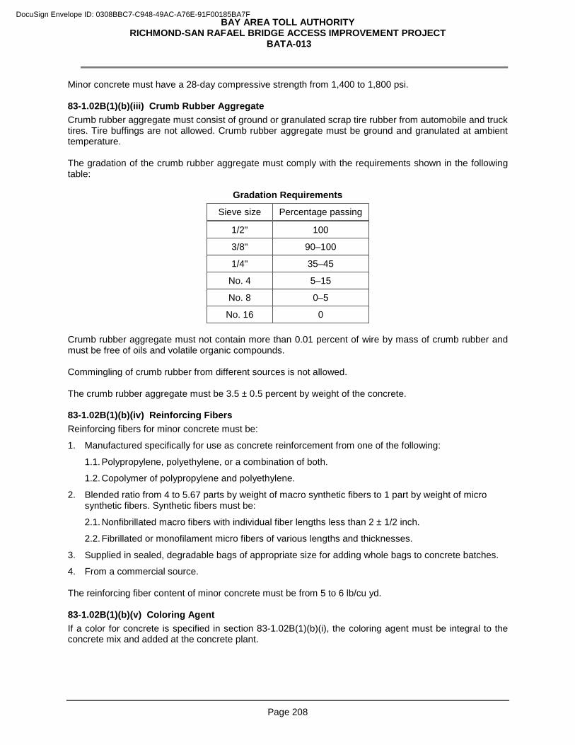
BAY AREA TOLL AUTHORITY RICHMOND-SAN RAFAEL BRIDGE ACCESS IMPROVEMENT PROJECT
BATA-013
Page 208
Minor concrete must have a 28-day compressive strength from 1,400 to 1,800 psi. 83-1.02B(1)(b)(iii) Crumb Rubber Aggregate Crumb rubber aggregate must consist of ground or granulated scrap tire rubber from automobile and truck tires. Tire buffings are not allowed. Crumb rubber aggregate must be ground and granulated at ambient temperature. The gradation of the crumb rubber aggregate must comply with the requirements shown in the following table:
Gradation Requirements
Sieve size Percentage passing
1/2" 100
3/8" 90–100
1/4" 35–45
No. 4 5–15
No. 8 0–5
No. 16 0 Crumb rubber aggregate must not contain more than 0.01 percent of wire by mass of crumb rubber and must be free of oils and volatile organic compounds. Commingling of crumb rubber from different sources is not allowed. The crumb rubber aggregate must be 3.5 ± 0.5 percent by weight of the concrete. 83-1.02B(1)(b)(iv) Reinforcing Fibers Reinforcing fibers for minor concrete must be:
1. Manufactured specifically for use as concrete reinforcement from one of the following:
1.1. Polypropylene, polyethylene, or a combination of both.
1.2. Copolymer of polypropylene and polyethylene.
2. Blended ratio from 4 to 5.67 parts by weight of macro synthetic fibers to 1 part by weight of micro synthetic fibers. Synthetic fibers must be:
2.1. Nonfibrillated macro fibers with individual fiber lengths less than 2 ± 1/2 inch.
2.2. Fibrillated or monofilament micro fibers of various lengths and thicknesses.
3. Supplied in sealed, degradable bags of appropriate size for adding whole bags to concrete batches.
4. From a commercial source. The reinforcing fiber content of minor concrete must be from 5 to 6 lb/cu yd. 83-1.02B(1)(b)(v) Coloring Agent If a color for concrete is specified in section 83-1.02B(1)(b)(i), the coloring agent must be integral to the concrete mix and added at the concrete plant.
DocuSign Envelope ID: 0308BBC7-C948-49AC-A76E-91F00185BA7F
BAY AREA TOLL AUTHORITY RICHMOND-SAN RAFAEL BRIDGE ACCESS IMPROVEMENT PROJECT
BATA-013
Page 209
83-1.02B(1)(b)(vi) Block-Out Material Use a commercially available expanded polystyrene foam for the block-out material. The expanded polystyrene foam must have a compressive strength of 13 ± 5 psi at 10 percent deformation when tested under ASTM D1621. You may substitute an alternative material that meets the compressive strength requirements of the expanded polystyrene foam if authorized. 83-1.02B(1)(c) Construction 83-1.02B(1)(c)(i) General Areas to receive vegetation control must be cleared of vegetation, trash, and debris. Dispose of removed material. 83-1.02B(1)(c)(ii) Earthwork Excavate areas to receive vegetation control. Where vegetation control abuts the existing surfacing, the edge of the existing surfacing must be on a neat line or must be cut on a neat line to a minimum depth of 2 inches before removing the surfacing. The finished elevation of the excavated area to receive vegetation control must maintain planned flow lines, slope gradients, and contours of the job site. Grade areas to receive vegetation control to a smooth, uniform surface and compact to a relative compaction of not less than 95 percent. Dispose of surplus excavated material uniformly along the adjacent roadway except as specified in section 14-11. 83-1.02B(1)(c)(iii) Block Out If block-out material is supplied in more than 1 piece, tape the pieces together to make a smooth surface on the top and sides. Ensure block-out material does not move during concrete placement. 83-1.02B(1)(c)(iv) Placing Minor Concrete Place minor concrete for vegetation control by hand. Strike off and compact minor concrete with a mechanical or vibratory screed device. Apply a broom finish. Match the finished grade to the adjacent section of vegetation control, pavement, shoulder, or existing grade. If the curing compound method is used for colored concrete, use curing compound no. 6. 83-1.02B(1)(d) Payment Not Used
Replace section 83-1.02C(2) with:
83-1.02C(2) Alternative In-Line Terminal System Alternative in-line terminal system must be furnished and installed as shown on the plans and under these special provisions. The allowable alternatives for an in-line terminal system must consist of one of the following or a Department-authorized equal. 1. TYPE SKT-SP-MGS for steel posts or Type SKT-W-MGS for wood posts TERMINAL SYSTEM -
Type SKT-MGS terminal system must be a SKT 350 sequential kinking terminal, system length 53'-1- 1/2", manufactured by Road Systems, Inc., located in Big Spring, Texas, and must include items
DocuSign Envelope ID: 0308BBC7-C948-49AC-A76E-91F00185BA7F
BAY AREA TOLL AUTHORITY RICHMOND-SAN RAFAEL BRIDGE ACCESS IMPROVEMENT PROJECT
BATA-013
Page 210
detailed for Type SKT-MGS terminal system shown on the plans. The SKT 350 sequential kinking terminal can be obtained from the distributor, Universal Industrial Sales, P.O. Box 699, Pleasant Grove, UT 84062, telephone (801) 785–0505 or from the distributor, Gregory Highway Products, 4100 13th Street, S.W., Canton, OH 44708, telephone (330) 477–4800.
2. TYPE X-LITE - Type X-Lite terminal system must be a 31" X-Lite Guard Rail End Terminal as manufactured by Barrier Systems, Inc., located in Vacaville, CA, and must include items detailed for Type 31" X-Lite terminal system shown on the plans. The 31" X-Lite Guard Rail End Terminal can be obtained from the distributor, Statewide Safety and Signs, Inc., 130 Grobric Court, Fairfield, CA 94533, telephone (800) 770–2644.
3. TYPE 31" X-TENSION - Type 31" X-Tension terminal system must be a 31" X-Tension Guard Rail End Terminal as manufactured by Barrier Systems, Inc., located in Vacaville, CA, and must include items detailed for Type 31" X-Tension terminal system shown on the plans. The 31" X-Tension Guard Rail End Terminal can be obtained from the distributor, Statewide Safety and Signs, Inc., 130 Grobric Court, Fairfield, CA 94533, telephone (800) 770–2644.
Submit a certificate of compliance for terminal systems. Terminal systems must be installed under the manufacturer's installation instructions and these specifications. Each terminal system installed must be identified by painting the type of terminal system in neat black letters and figures 2 inches high on the backside of the rail element between system posts numbers 4 and 5. Paint must be metallic acrylic resin type spray paint. Before applying terminal system identification, the surface to receive terminal system identification must be removed of all dirt, grease, oil, salt, or other contaminants by washing the surface with detergent or other suitable cleaner. Rinse thoroughly with fresh water and allow to fully dry. For Type SKT-SP-MGS terminal system, install the soil tube with soil plate attached at Post 1, hinged breakaway post at Post 2, and 6'-0" W6 x 9 steel posts at Posts 3 through 8. Use a W6 x 15 steel post at Post 1. The soil tube with soil plate must be, at your option, driven with or without pilot holes, or placed in drilled holes. Space around the steel foundation tubes must be backfilled with selected earth, free of rock, placed in layers approximately 4 inches thick and each layer must be moistened and thoroughly compacted. For Type SKT-W-MGS terminal system, install the soil tube with soil plate attached at Post 1, breakaway cable terminal post at Post 2, and controlled release terminal posts at Posts 3 through 8. The soil tube must be, at your option, driven with or without pilot holes, or placed in a drilled hole. Space around the steel foundation tube must be backfilled with selected earth, free of rock, placed in layers approximately 4 inches thick and each layer must be moistened and thoroughly compacted. A wood post must be inserted into the steel foundation tube by hand. Before the wood terminal post is inserted, the inside surfaces of the steel foundation tube to receive the wood post must be coated with a grease that will not melt or run at a temperature of 149 degrees F or less. The edge of the wood post may be slightly rounded to facilitate insertion of the post into the steel foundation tube. For Type 31" X-Lite terminal system, all crimped posts and line posts must be W6 x 8.5 or W6 x 9 steel posts. All posts, must be, at your option, either driven or placed in drilled holes. Space around the crimped posts, Post 2 with attached soil plate and lines posts must be backfilled with selected earth, free of rock, placed in layers approximately 4 inches thick and each layer must be moistened and thoroughly compacted. All blocks must be wood or plastic. For Type 31" X-Tension terminal system, the steel post and soil anchor must be, at your option, driven with or without pilot holes, or placed in drilled holes. Space around the steel post and soil anchor must be backfilled with selected earth, free of rock, placed in layers approximately 4 inches thick and each layer must be moistened and thoroughly compacted. The wood terminal posts must be inserted into the drilled holes by hand and backfilled in the same manner as the steel post and soil anchor. Wood terminal posts must not be driven. All blocks must be wood or plastic. For Type 31" X-Tension terminal system, the steel bottom post and I-beam post must be placed in drilled
DocuSign Envelope ID: 0308BBC7-C948-49AC-A76E-91F00185BA7F
BAY AREA TOLL AUTHORITY RICHMOND-SAN RAFAEL BRIDGE ACCESS IMPROVEMENT PROJECT
BATA-013
Page 211
hole. The soil anchor and steel line posts must be, at your option, either driven or placed in drilled holes. Space around the steel bottom post, steel line posts and soil anchor must be backfilled with selected earth, free of rock, placed in layers approximately 4 inches thick and each layer must be moistened and thoroughly compacted. All blocks must be plastic. After installing the terminal system, dispose of surplus excavated material in a uniform manner along the adjacent roadway where designated by the Engineer.
Replace section 83-1.02C(3) with: 83-1.02C(3) Alternative Flared Terminal System
Alternative flared terminal system must be furnished and installed as shown on the plans and under these special provisions. The allowable alternatives for a flared terminal system must consist of one of the following or a Department-authorized equal.
1. TYPE FLEAT-SP-MGS for steel or FLEAT-W-MGS for wood TERMINAL SYSTEM - Type FLEAT-MGS terminal system must be a Flared Energy Absorbing Terminal 350 manufactured by Road Systems, Inc., located in Big Spring, Texas, and must include items detailed for Type FLEAT-MGS terminal system shown on the plans. The Flared Energy Absorbing Terminal 350 can be obtained from the distributor, Universal Industrial Sales, P.O. Box 699, Pleasant Grove, UT 84062, telephone (801) 785–0505 or from the distributor, Gregory Industries, Inc., 4100 13th Street, S.W., Canton, OH 44708, telephone (330) 477–4800.
2. TYPE X-LITE – Type X-Lite terminal system must be 31” X-Lite Guard Rail End Terminal as manufactured by Barrier Systems, Inc. located in Vacaville, CA, and must include items detailed for Type 31” X-Lite terminal system shown on the plans. The 31” X-Lite Guard Rail End Terminal can be obtained from the distributor, Statewide Safety and Signs, Inc., 130 Grobric Court, Fairfield, CA 94533, telephone (800) 770–2644.
3. TYPE 31” X-TENSION – Type 31” X-Tension terminal system must be a 31” X-Tension Guard Rail
End Terminal as manufactured by Barrier Systems, Inc., located in Vacaville, CA, and must include items detailed for Type 31” X-Tension terminal system shown on the plans. The 31” X-Tension Guard Rail End Terminal can be obtained from the distributor, Statewide Safety and Signs, Inc. 130 Grobric Court, Fairfield, CA 94533, telephone (800) 770–2644.
Submit a certificate of compliance for terminal systems. Terminal systems must be installed under the manufacturer's installation instructions and these specifications. Each terminal system installed must be identified by painting the type of terminal system in neat black letters and figures 2 inches high on the backside of the rail element between system posts numbers 4 and 5. Paint must be metallic acrylic resin type spray paint. Before applying terminal system identification, the surface to receive terminal system identification must be removed of all dirt, grease, oil, salt, or other contaminants by washing the surface with detergent or other suitable cleaner. Rinse thoroughly with fresh water and allow to fully dry. For Type FLEAT terminal system, the soil tubes must be, at your option, driven with or without pilot holes, or placed in drilled holes. Space around the steel foundation tubes must be backfilled with selected earth, free of rock, placed in layers approximately 4 inches thick and each layer must be moistened and thoroughly compacted. Wood posts must be inserted into the steel foundation tubes by hand. Before the wood terminal posts are inserted, the inside surfaces of the steel foundation tubes to receive the wood posts must be coated with a grease that will not melt or run at a temperature of 149 degrees F or less. The edges of the wood posts may be slightly rounded to facilitate insertion of the post into the steel foundation tubes. For 31” X-Lite terminal system, one 13’-6 ½” rail element must be connected to Post 7 and the Midwest Guardrail System. All crimped posts and line posts must be W6 x 8.5 or W6 x 9 steel posts. All posts, must be, your option, either driven or place in drilled holes. Space around the crimped posts, Post 2 with attached
DocuSign Envelope ID: 0308BBC7-C948-49AC-A76E-91F00185BA7F
BAY AREA TOLL AUTHORITY RICHMOND-SAN RAFAEL BRIDGE ACCESS IMPROVEMENT PROJECT
BATA-013
Page 212
soil plate and lines posts must be backfilled with selected earth, free of rock, placed in layers approximately 4 inches thick and each layer must be moistened and thoroughly compacted, All blocks must be wood or plastic. For Type 31" X-Tension terminal system, the steel post and soil anchor must be, at your option, driven with or without pilot holes, or placed in drilled holes. Space around the steel post and soil anchor must be backfilled with selected earth, free of rock, placed in layers approximately 4 inches thick and each layer must be moistened and thoroughly compacted. The wood terminal posts must be inserted into the drilled holes by hand and backfilled in the same manner as the steel post and soil anchor. Wood terminal posts must not be driven. All blocks must be wood or plastic. For Type 31" X-Tension terminal system, the steel bottom post and I-beam post must be placed in drilled hole. The soil anchor and steel line posts must be, at your option, either driven or placed in drilled holes. Space around the steel bottom post, steel line posts and soil anchor must be backfilled with selected earth, free of rock, placed in layers approximately 4 inches thick and each layer must be moistened and thoroughly compacted. All blocks must be plastic. After installing the terminal system, dispose of surplus excavated material in a uniform manner along the adjacent roadway where designated by the Engineer.
Replace "Reserved" in section 83-1.02D(2) with:
California ST-10 bridge rail must consist of metal railing mounted on a reinforced concrete parapet. Stud bolts must comply with the specifications for studs in clause 7 of AWS D1.1. Reinforced concrete must comply with sections 51 and 52. Ferrous metal parts must be galvanized. Galvanizing must comply with section 75-1.05. After installing the rail, paint the exposed bolt threads with 2 applications of organic zinc-rich primer that is on the Authorized Material List for organic zinc-rich primers. Submit shop drawings for the bridge rail. The shop drawings must include the following:
1. Details for venting and pickup holes in rails and sleeves
2. Railing layout
3. Complete details for the construction of the work including methods of construction, sequence of shop and field assembly, and installation procedures
Submit 9 copies of shop drawings. Allow 25 days for review. Upon certification, the Engineer will stamp or mark the drawings certified and return 2 copies to you for use during construction. California ST-10 bridge rail is measured from end to end along the face of the railing, including reinforced concrete end blocks and intermediate posts. Bar reinforcing steel for use in concrete parapets must be epoxy coated under section 52-2.03. If the project is in a freeze-thaw area, the parapets must comply with the following requirements:
1. Concrete must contain not less than 675 pounds of cementitious material per cubic yard.
2. Bar reinforcing steel must comply with section 52-2.02.
3. Concrete parapets on bridges or walls must be cured by the water method.
DocuSign Envelope ID: 0308BBC7-C948-49AC-A76E-91F00185BA7F
BAY AREA TOLL AUTHORITY RICHMOND-SAN RAFAEL BRIDGE ACCESS IMPROVEMENT PROJECT
BATA-013
Page 213
Replace "Reserved" in section 83-1.02G(4) with:
The ornamental railing is the CL-8 Mod1, CL-8 Mod2 and Bicycle Railing. Ornamental railing consists of steel frames fabricated from structural tubing, plates, and other required hardware and fittings, and covered with chain link fabric. Structural tubing, plates, bars, bolts, nuts, and washers must comply with section 55-1.02. Other fittings must be commercial quality. All components except chain link fence fabric must be powder coated. Epoxy powder priming and powder coating must be electrostatically sprayed on by the fabricator in a clean room environment to the manufacturer's specifications. Clean all surfaces with an alkaline cleaner and iron phosphate pretreatment to etch surface and remove oils, grease and metal particles prior to priming. Sandblast all pieces to completely remove rust and loose mill scale. Apply a 0.003-inch minimum zinc rich epoxy powder prime coat or approved equal epoxy powder primer immediately after cleaning and sandblasting. Spot prime abraded, bare or insufficiently powder primed areas. Apply a 4-mil minimum final coat of UV resistant, RAL 5003 (blue color) Series 049 with smooth glossy finish powder coat matching the fence fabric blue color. Finished powder coated surface must be smooth and uniform without drips, runs, uneven coloration, pin holes, dust particles or bubbles. Oven bake fully assembled pieces at the manufacturer's recommended curing temperatures. Any field welds and hardware in contact with ornamental railing and chain link fence fabric must be properly primed and painted with two coats of matching and compatible smooth glossy paint. The powder coated railing and the fuse & adhered vinyl-coated chain link fence fabric must match. You must provide a color sample. Chain link fabric must be 9 gage and must comply with AASHTO M 181, Type IV, Class B fuse & adhered vinyl-coated. The color of vinyl-coated chain link fabric must match the RAL 5003 blue color. You must provide a color sample .
Replace the 14th paragraph of section 83-1.02I with:
Chain link fabric must be 9 gage and comply with AASHTO M 181 for Type IV fabric with a Class B coating. The bond strength between the coating material and steel of the bonded vinyl-coated chain link fabric must be equal to or greater than the cohesive strength of the PVC coating material.
Add to section 83-2.02D(1):
Bar reinforcing steel for use in concrete barriers must be epoxy coated under section 52-2.03.
DocuSign Envelope ID: 0308BBC7-C948-49AC-A76E-91F00185BA7F
BAY AREA TOLL AUTHORITY RICHMOND-SAN RAFAEL BRIDGE ACCESS IMPROVEMENT PROJECT
BATA-013
Page 214
Delete the 3rd paragraph of section 83-2.02D(4).
Replace the 1st paragraph of section 83-2.02D(3)(b) with:
Concrete barriers constructed using an extrusion or slip form machine or other similar type of equipment must be made of well-compacted, dense concrete, and the exposed surfaces must comply with section 51. You may be required to submit evidence of successful operation of the extrusion or slip form machine or other equipment. Submit a QC plan for use of the extrusion or slip form construction method if reinforcement is not fixed in place before placing concrete. The QC plan must include:
1. Contingency plan for correcting problems in production, transportation, or placement
2. Procedure for splicing concrete barrier reinforcement
3. Procedure for positioning reinforcement during extrusion or slip form operations
4. Test procedure for verifying final positions of horizontal reinforcement at 100-foot intervals, evaluated a minimum of 20 feet behind the trailing extrusion or slip form edge
5. Test report forms to be used that shows (1) positions of reinforcement relative to the top of the barrier, (2) clearance cover from the faces of the barrier to the reinforcement, and (3) station of the tests
If a QC plan is submitted, submit the test report forms within 48 hours of constructing the concrete barrier. The Department rejects concrete barrier with any reinforcement deviating more than 1 inch from the positions shown.
Replace section 83-2.02E(6) with:
83-2.02E(6) Alternative Crash Cushion System Alternative crash cushion system must be furnished and installed where shown and under these special provisions. The alternative crash cushion must be one of the following or an approve equal: 1. CRASH CUSHION SYSTEM (TYPE SCI70GM) – Crash cushion (Type SCI-70GM) must be
manufactured by Work Area Protection Corporation, and must include all the items detailed as shown on the plans. The crash cushion system (SCI-70GM) can be obtained from the distributor, D&M Traffic Services, 845 Reed Street, Santa Clara, CA 95050, Telephone (408) 436-1127.
2. CRASH CUSHION SYSTEM (TYPE QUADGUARD II) – Crash cushion (Type QUADGUARD II) must
be as manufactured by Energy Absorption Systems, Inc. with a speed rating Test Level 2 and must include all items detailed as shown on the plans. The crash cushion system (QUADGUARD II) can be obtained from the distributor, National Trench Safety, 7849 Stockton Blvd., Sacramento, CA 95823, Telephone (916) 387-6300.
Alternative crash cushion system must be of the type that can be repaired in the field. Submit a certificate of compliance for crash cushion system to be installed. Submit a copy of the manufacturer's plan and parts list for the crash cushion system to be installed. Install the alternative crash cushion system per the manufacturer's installation instructions.
DocuSign Envelope ID: 0308BBC7-C948-49AC-A76E-91F00185BA7F
BAY AREA TOLL AUTHORITY RICHMOND-SAN RAFAEL BRIDGE ACCESS IMPROVEMENT PROJECT
BATA-013
Page 215
Attach Type P marker panel to front of crash cushion system with commercial grade hardware or by other approved methods. Alternative crash cushion system is measured from actual count of the unit in place. After installing the terminal system, dispose of surplus excavated material in a uniform manner along the adjacent roadway where designated by the Engineer.
Replace "Reserved" in section 83-2.02G with:
83-2.02G Armorguard Gate System Armorguard Gate System must be installed where shown. Armorguard Gate System must be as manufactured by Lindsay Transportation Solutions, and must include one Armorguard 8 meter gate assembly and two Armorguard Gate Custom Transition to Type 60SC barrier. The successful bidder can obtain the Armorguard Gate System from the manufacturer, Lindsay Transportation Solutions through its distributor:
Statewide Traffic Safety & Signs (714) 468-1919 www.statewidesafety.com The price quoted by the distributor for the Armorguard Gate System, FOB to Richmond, California is $41,330, not including sales tax and installation. The above price quote expires on June 30, 2017. Submit a copy of the manufacturer's plan and parts list as an informational submittal. Submit a certificate of compliance for Armorguard Gate System. Install the gate system under the manufacturer's installation instructions.
Add to section 83-2.03:
Concrete barrier (Type 60SA Mod) is paid for as concrete barrier (Type 60SA). Concrete barrier (Type 60SC Mod2) is paid for as concrete barrier (Type 60SC Mod). Concrete barrier (Type 60PR) is paid for as concrete barrier (Type 60P).
^^^^^^^^^^^^^^^^^^^^^^^^^^^^^^^^^^^^^^^^^^^^^^^^^^^^^^^^^^^^^^^^
84 TRAFFIC STRIPES AND PAVEMENT MARKINGS
Replace "Reserved" in the RSS for section 84-6 with:
84-6.01 GENERAL 84-6.01A Summary Section 84-6 includes specifications for applying thermoplastic traffic stripes and pavement markings with enhanced wet-night visibility. Thermoplastic must comply with section 84-2.
DocuSign Envelope ID: 0308BBC7-C948-49AC-A76E-91F00185BA7F
BAY AREA TOLL AUTHORITY RICHMOND-SAN RAFAEL BRIDGE ACCESS IMPROVEMENT PROJECT
BATA-013
Page 216
84-6.01B Submittals Submit a certificate of compliance for the glass beads. 84-6.01C Quality Control and Assurance Within 14 days of applying a thermoplastic traffic stripe or pavement marking with enhanced wet-night visibility, the retroreflectivity must be a minimum of 700 mcd/sq m/lx for white stripes and markings and 500 mcd/sq m/lx for yellow stripes and markings. Test the retroreflectivity using a reflectometer under ASTM E 1710. 84-6.02 MATERIALS Thermoplastic traffic stripes and pavement markings with enhanced wet-night visibility must consist of a single uniform layer of thermoplastic and 2 layers of glass beads as follows:
1. The 1st layer of glass beads must be on the Authorized Material List under high-performance retroreflective glass beads for use in thermoplastic traffic stripes and pavement markings. The color of the glass beads must match the color of the stripe or marking to which they are being applied.
2. The 2nd layer of glass beads must comply with AASHTO M 247, Type 2. Both types of glass beads must be surface treated for use with thermoplastic under the bead manufacturer's instructions. 84-6.03 CONSTRUCTION Use a ribbon-extrusion or screed-type applicator to apply thermoplastic traffic stripe. Operate the striping machine at a speed of 8 mph or slower during the application of thermoplastic traffic stripe and glass beads. Apply thermoplastic traffic stripe at a rate of at least 0.38 lb/ft of 4-inch-wide solid stripe. The applied thermoplastic traffic stripe must be at least 0.090 inch thick. Apply thermoplastic pavement marking at a rate of at least 1.06 lb/sq ft. The applied thermoplastic pavement marking must be at least 0.100 inch thick. Apply thermoplastic traffic stripe and both types of glass beads in a single pass. First apply the thermoplastic, followed immediately by consecutive applications of high-performance glass beads and then AASHTO M 247, Type 2, glass beads. Use a separate applicator gun for each type of glass bead. You may apply glass beads by hand on pavement markings. Distribute glass beads uniformly on traffic stripes and pavement markings. Apply high-performance glass beads at a rate of at least 6 lb/100 sq ft of stripe or marking. Apply AASHTO M 247, Type 2, glass beads at a rate of at least 8 lb/100 sq ft of stripe or marking. The combined weight of the 2 types of glass beads must be greater than 14 lb/100 sq ft of stripe or marking. 84-6.04 PAYMENT Not Used
^^^^^^^^^^^^^^^^^^^^^^^^^^^^^^^^^^^^^^^^^^^^^^^^^^^^^^^^^^^^^^^^
86 ELECTRICAL SYSTEMS
Replace "15" in the 6th paragraph of section 86-1.01C(1) with: 20
DocuSign Envelope ID: 0308BBC7-C948-49AC-A76E-91F00185BA7F
BAY AREA TOLL AUTHORITY RICHMOND-SAN RAFAEL BRIDGE ACCESS IMPROVEMENT PROJECT
BATA-013
Page 217
Replace the 1st paragraph in 86-1.01D(4) with: Deliver the material and equipment for testing to the following location:
30 Rickard Street, San Francisco, CA 94134
Replace the 1st sentence in the 15th paragraph of section 86-1.02P(2) with: The interior of the enclosure must accept cable-in/cable-out circuit breakers. The circuit breakers must be mounted on nonenergized clips and vertically with the up position of the handle being the "ON" position.
Add to the beginning of section 86-1.02R(4): The signal face must be made of metal. Limit the shutdown of traffic signal systems between the hours of 10:00 a.m. and 3:00 p.m.
Replace the 21st paragraph of section 86-2.01C(1) of the RSS for section 86 with: The Department places identification characters on the electrical equipment.
Add to the beginning of section 86-2.01C(2)(c)(i) of the RSS for section 86: Use Type 3 conduit for underground installation.
Replace the 3rd paragraph of section 86-2.01C(2)(c)(i) of the RSS for section 86 with: Place a minimum of 2 inches of sand bedding in a trench before installing Type 2 or Type 3 conduit and 4 inches of minor concrete over the conduit before placing additional backfill material. The concrete must contain at least 421 pounds of cementitious material per cubic yard.
Replace the 3rd paragraph of section 86-2.01C(3)(a) of the RSS for section 86 with: Install a pull box on a bed of crushed rock.
Replace the 1st paragraph of section 86-2.01C(6)(b)(ii) of the RSS for section 86 with:
Install a Type B loop detector lead-in cable in conduit.
Replace the 1st paragraph of section 86-2.01C(6)(c)(ii) of the RSS for section 86 with:
Use a Type 2 loop wire. Use only Type 2 loop wire for Type E loop detectors.
Replace the 2nd paragraph of section 86-2.01C(8)(b) of the RSS for section 86 with: Use Method B to insulate a splice.
Add to the beginning of section 86-2.01C(10)(b) of the RSS for section 86: The sign mounting hardware must be installed at the locations shown.
Install non-illuminated street name signs on signal mast arms using a minimum 3/4-by-0.020-inch round-edge stainless steel strap and saddle bracket. Wrap the strap at least twice around the mast arm, tighten, and secure with a 3/4-inch stainless strap seal. Level the sign panel and tighten the hardware securely.
DocuSign Envelope ID: 0308BBC7-C948-49AC-A76E-91F00185BA7F
BAY AREA TOLL AUTHORITY RICHMOND-SAN RAFAEL BRIDGE ACCESS IMPROVEMENT PROJECT
BATA-013
Page 218
Add to the end of section 86-2.01C(12)(b)(ii) of the RSS for section 86:
For irrigation controller ICC “I”, install a single-pole, 20 A circuit breaker in the existing service equipment enclosure 05473. The circuit breaker must be of the same manufacturer, model, and interrupting capacity as the existing circuit breakers.
Add to the end of section 86-2.01C(20) of the RSS for section 86: A manufacturer's representative must program the accessible pedestrian signals with messages or tones at: 1. Intersections where the accessible pedestrian signals at 1 corner are less than 10 feet apart:
1.1. Intersection of Redwood Way and Castro Street
2. Intersections where the accessible pedestrian signals at all corners are 10 feet or more apart:
2.1. Intersection of Marine Street and Route 580 Eastbound Off-ramp
2.2. Intersection of E. Standard Avenue and Castro Street
2.3. Intersection of Castro Street and Chevron Way
At intersections where the accessible pedestrian signals at 1 corner are less than 10 feet apart, program the signals with messages for each street as follows:
1. During the pedestrian clearance interval, the message heard must be "Wait to cross <name of street>_______. Wait."
2. During the beginning of the walk interval and repeated for its duration, the message heard must be "<name of street>__. Walk sign is on to cross <name of street>______."
At intersections where the accessible pedestrian signals at all corners are 10 feet or more apart, program the signals with messages for each street as follows:
1. During the pedestrian clearance interval, the message heard must be "Wait to cross <name of street>_______. Wait."
2. During the beginning of the walk interval and repeated for its duration, the percussive tone must be heard.
Add between the 1st and 2nd sentences in the 2nd paragraph of section 86-2.01C(22)(b) of the RSS for section 86:
Saw the slots to allow a minimum of 2 inches of sealant above the top of the uppermost loop wire in the slot.
Add between the 11th and 12th paragraphs of section 86-2.01C(22)(b) of the RSS for section 86:
Use hot-melt rubberized sealant to fill slots.
Add to the end of section 86-2.21C(3) of the RSS for section 86:
Modifying a lighting system includes removing, adjusting, or adding:
1. Foundations
2. Pull boxes
3. Conduit
4. Conductors
DocuSign Envelope ID: 0308BBC7-C948-49AC-A76E-91F00185BA7F
BAY AREA TOLL AUTHORITY RICHMOND-SAN RAFAEL BRIDGE ACCESS IMPROVEMENT PROJECT
BATA-013
Page 219
5. Standards
6. Luminaires
7. Service equipment enclosure
8. Photoelectric control
9. Fuse splice connectors
Modifying a signal and lighting system includes removing, adjusting, or adding:
1. Foundations
2. Pull boxes
3. Conduit
4. Conductors
5. Cables
6. Standards
7. Signal heads
8 Service equipment enclosure
9. Detectors
10. Accessible pedestrian signals
11. Pedestrian signal heads
12. Luminaires
13. Photoelectric control
14. Fuse splice connectors Modifying an electrical service (irrigation) includes removing, adjusting, or adding:
1. Pull boxes
2. Conduit
3. Conductors Modifying a traffic operations system includes removing, adjusting, or adding:
1. Foundations
2. Pull boxes
3. Conduit
4. Conductors
5. Standards
6. Service equipment enclosure
7. Controller cabinet
8. Telephone demarcation cabinet
9. Signal heads
10. Detectors
11. Variable message signs
DocuSign Envelope ID: 0308BBC7-C948-49AC-A76E-91F00185BA7F
BAY AREA TOLL AUTHORITY RICHMOND-SAN RAFAEL BRIDGE ACCESS IMPROVEMENT PROJECT
BATA-013
Page 220
12. Department-furnished controller cabinet
13. Department-furnished changeable message sign
14. Department-furnished wiring harness
15. Telephone cables
16. Fiber optic system
17. Ethernet switches
18. Layer 2 Ethernet switches
19. Ethernet fiber optic extender
20, Rack with enclosures
21. Monitor in Toll Plaza office
22. Closed circuit televisions (CCTV)
23. General packet radio system (GPRS) wireless modem assemblies
24. Long lead-in cable detector sensor unit
25. Lane use signs
Add to section 86-2.22:
86-2.22 TELEPHONE CABLE 86-2.22A General 86-2.22A(1) Summary Section 86-2.22 includes specifications for installing telephone cable. 86-2.22B Materials 86-2.22B(1) General Telephone cable must conform to these special provisions. 86-2.22B(2) Telephone Cable The telephone cable (TC) must consist of 6 pairs of No. 19 solid copper conductors. Conductors must be twisted in pairs. Each conductor must be insulated with a high molecular weight, heat stabilized, color coded polyethylene material. The insulation must be 18 mils nominal. 86-2.22B(2)(i) Color Code Color code for 6 pairs of No.19 solid copper conductors telephone cable must be as follows:
1. White/Blue
2. White/Orange
3. White/Green
4. White/Brown
5. White/Gray
6. Red/Blue
DocuSign Envelope ID: 0308BBC7-C948-49AC-A76E-91F00185BA7F
BAY AREA TOLL AUTHORITY RICHMOND-SAN RAFAEL BRIDGE ACCESS IMPROVEMENT PROJECT
BATA-013
Page 221
86-2.22B(2)(ii) Core The core of telephone cable must be protected by a non-hygroscopic polyester film with a single longitudinally applied shield. The shield must comply with the following table:
Shield Type Minimum Thickness
(mils)
A corrugated copper shield or 5
A plastic coated aluminum shield 8
86-2.22B(2)(iii) Jacket The cable must be provided with an outer jacket to comply the following table:
Jacket Material Minimum Thickness
(mils)
Black, high molecular weight, heat stabilized polyethylene 60
86-2.22B(2)(iv) Outside Diameter The outer diameter of the cable must be 0.60-inch maximum. 86-2.22C Construction 86-2.22C(1) General All conductors must be terminated inside the telephone demarcation cabinet and the controller cabinet as shown. A moisture barrier of petrolatum-polyethylene compound must be applied over the core tape and over and under the cable shield to fill all cable interstices. 86-2.22D Payment Not Used
Add to section 86-2.23:
86-2.23 VIDEO IMAGE VEHICLE DETECTION SYSTEM 86-2.23A General 86-2.23A(1) Summary Section 86-2.23 includes installing video image vehicle detection system (VIVDS) for traffic signals. 86-2.23A(2) Definitions Video Detection Unit (VDU): Processor unit that converts the video image from the camera and provides vehicle detection in defined zones. Unit includes an image processor, extension module, and communication card.
Video Image Sensor Assembly (VIS): An enclosed and environmentally-protected camera assembly used to collect the video image.
Video Image Vehicle Detection System (VIVDS): A system that detects video images of vehicles in defined zones and provides video output.
86-2.23A(3) Submittals Submit documentation within 30 days after Contract approval but before installing VIVDS equipment.
DocuSign Envelope ID: 0308BBC7-C948-49AC-A76E-91F00185BA7F
BAY AREA TOLL AUTHORITY RICHMOND-SAN RAFAEL BRIDGE ACCESS IMPROVEMENT PROJECT
BATA-013
Page 222
The documentation submittal must include:
1. Certificate of Compliance: As specified in Section 6-3.05E, "Certificates of Compliance," of the Standard Specifications.
2. Site Analysis Report: Written analysis for each detection site, recommending the optimum video image sensor assembly placement approved by the manufacturer.
3. Lane Configuration: Shop drawing showing:
3.1. Detection zone setback
3.2. Detection zone size
3.3. Camera elevation
3.4. Selected lens viewing angle
3.5. Illustration of detection zone mapping to reporting contact output
3.6. Illustration of output connector pin or wire terminal for lane assignment.
4. Configuration Record: Windows PC compatible CD containing:
4.1. Proposed zone designs
4.2. Calibration settings
5. Mounting and Wiring Information: Manufacturer approved wiring video cable and service connection diagrams.
6. Communication Protocol: Industry standard available in public domain. Document defining:
6.1. Message structure organization
6.2. Data packet length
6.3. Message usability
6.4. Necessary information to operate a system from a remote windows based personal computer.
7. Programming Software: CD containing set up and calibration software that observes and detects the vehicular traffic, including bicycles, motorcycles, and sub-compact cars, with overlay of detection zones and allows adjustment of the detection sensitivity for a traffic signal application.
8. Detector Performance DVD Recordings and Analysis: Performance analysis based on 24-hour DVD recording of contiguous activity for each approach. Include:
8.1. Two contiguous hours of sunny condition, with visible shadows projected a minimum of 6 feet into the adjacent lanes
8.2. Two 1-hour night periods with vehicle headlights present.
9. Preventative Maintenance Parts Documentation: List of equipment replacement parts for preventative maintenance, including:
9.1. Electrical parts, wiring and video cable
9.2. Mechanical parts
9.3. Assemblies.
Allow 7 days for the Engineer to review the documentation submittal. If the Engineer requires revisions, submit a revised submittal within 5 days of receipt of the Engineer's comments and allow 5 days for the Engineer to review. If agreed to by the Engineer, revisions may be included as attachments in the resubmittal. The Engineer may conditionally approve, in writing, resubmittals that include revisions submitted as attachments, in order to allow construction activities to proceed.
DocuSign Envelope ID: 0308BBC7-C948-49AC-A76E-91F00185BA7F
BAY AREA TOLL AUTHORITY RICHMOND-SAN RAFAEL BRIDGE ACCESS IMPROVEMENT PROJECT
BATA-013
Page 223
Upon the Engineer's approval of the resubmittal, submit copies of the final documents (with approved revisions incorporated) to the Engineer. Submit an acceptance testing schedule for approval 15 days before starting acceptance testing. When beginning acceptance testing of VIVDS and detector performance and analysis, submit approved copies of the following:
1. Configuration Record: Windows PC compatible CD containing:
1.1. Final zone designs
1.2. Calibration settings to allow reinstallation.
2. Mounting and Wiring Information: Final wiring and service connection diagrams.
2.1. One copy for the Engineer
2.2. A second copy wrapped in clear self-adhesive plastic, be placed in a heavy duty plastic envelope, and secured to the inside of the cabinet door.
86-2.23A(4) Quality Control and Assurance 86-2.23A(4)(a) General VIVDS and support equipment required for acceptance testing must be new and as specified in the manufacturer's recommendations. Date of manufacture, as shown by date codes or serial numbers of electronic circuit assemblies, must not be older than 12 months from the scheduled installation start date. Material substitutions must not deviate from the material list approved by the Engineer. 86-2.23A(4)(b) Training Not used. 86-2.23A(4)(c) Warranty Furnish a 3-year replacement warranty from the manufacturer of VIS and VDU against defects in materials and workmanship or failures. The effective date of the warranty is the date of acceptance of the installation. Submit all warranty documentation before installation. Replacement VIS and VDU must be furnished within 10 days of receipt of a failed unit. The Department does not pay for replacement. Deliver replacement VIS and VDU to Caltrans Maintenance Electrical Shop at: 30 Rickard Street, San Francisco, CA 94134 86-2.23B Materials 86-2.23B(1) General VIVDS must include necessary firmware, hardware, and software for designing the detection patterns or zones at the intersection or approach. Detection zones must be created with a graphic user interface designed to allow to anyone trained in VIVDS system setup to configure and calibrate a lane in less than 15 minutes. System elements must comply with the manufacturer's recommendations and be designed to operate continuously in an outdoor environment. All equipment, cables, and hardware must be part of an engineered system that is designed by the manufacturer to fully interoperate with all other system components. Mounting assemblies must be
DocuSign Envelope ID: 0308BBC7-C948-49AC-A76E-91F00185BA7F
BAY AREA TOLL AUTHORITY RICHMOND-SAN RAFAEL BRIDGE ACCESS IMPROVEMENT PROJECT
BATA-013
Page 224
corrosion resistant. Connectors installed outside the cabinets and enclosures must be corrosion resistant, weather proof, and watertight. Exposed cables must be sunlight and weather resistant. 86-2.23B(1)(a) Physical and Mechanical Requirements VIVDS must include:
1. VIS and mounting hardware. Use a clamping device as mounting hardware on a pole or mast-arm.
2. VDU
3. Power supply
4. Surge suppression
5. Cables
6. Connectors
7. Wiring for connecting to the Department-furnished Model 332L traffic controller cabinet.
8. Communication card with multi-display port
9. Flat panel video display
10. DIN Rail mounted AC power assembly that includes a minimum of one convenience receptacle, four camera chassis ground connections, four camera AC neutral (AC-) connections, four 2 amp camera circuit breakers for hot (AC+) connections, and one AC source connection for Line, Neutral and Ground wires.
11. DIN Rail video surge suppression protection assembly that can accommodate up to six surge suppression modules
86-2.23B(1)(b) Electrical VIVDS must operate between 90 to 135 V(ac) service as specified in NEMA TS-1. VIS, excluding the heater circuit, must draw less than 10 W of power. Power supply or transformer for the VIVDS must meet the following minimum requirements:
DocuSign Envelope ID: 0308BBC7-C948-49AC-A76E-91F00185BA7F
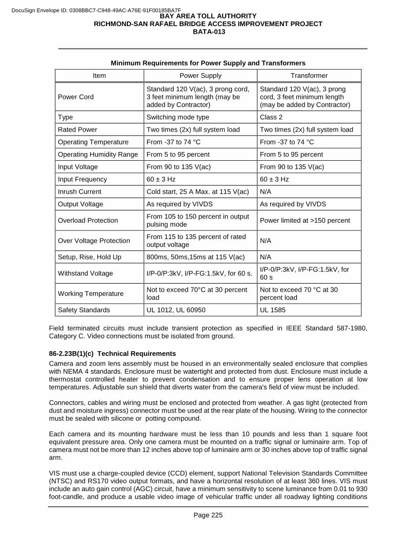
BAY AREA TOLL AUTHORITY RICHMOND-SAN RAFAEL BRIDGE ACCESS IMPROVEMENT PROJECT
BATA-013
Page 225
Minimum Requirements for Power Supply and Transformers
Item Power Supply Transformer
Power Cord Standard 120 V(ac), 3 prong cord, 3 feet minimum length (may be added by Contractor)
Standard 120 V(ac), 3 prong cord, 3 feet minimum length (may be added by Contractor)
Type Switching mode type Class 2
Rated Power Two times (2x) full system load Two times (2x) full system load
Operating Temperature From -37 to 74 °C From -37 to 74 °C
Operating Humidity Range From 5 to 95 percent From 5 to 95 percent
Input Voltage From 90 to 135 V(ac) From 90 to 135 V(ac)
Input Frequency 60 ± 3 Hz 60 ± 3 Hz
Inrush Current Cold start, 25 A Max. at 115 V(ac) N/A
Output Voltage As required by VIVDS As required by VIVDS
Overload Protection From 105 to 150 percent in output pulsing mode Power limited at >150 percent
Over Voltage Protection From 115 to 135 percent of rated output voltage N/A
Setup, Rise, Hold Up 800ms, 50ms,15ms at 115 V(ac) N/A
Withstand Voltage I/P-0/P:3kV, I/P-FG:1.5kV, for 60 s. I/P-0/P:3kV, I/P-FG:1.5kV, for 60 s
Working Temperature Not to exceed 70°C at 30 percent load
Not to exceed 70 °C at 30 percent load
Safety Standards UL 1012, UL 60950 UL 1585 Field terminated circuits must include transient protection as specified in IEEE Standard 587-1980, Category C. Video connections must be isolated from ground. 86-2.23B(1)(c) Technical Requirements Camera and zoom lens assembly must be housed in an environmentally sealed enclosure that complies with NEMA 4 standards. Enclosure must be watertight and protected from dust. Enclosure must include a thermostat controlled heater to prevent condensation and to ensure proper lens operation at low temperatures. Adjustable sun shield that diverts water from the camera's field of view must be included. Connectors, cables and wiring must be enclosed and protected from weather. A gas tight (protected from dust and moisture ingress) connector must be used at the rear plate of the housing. Wiring to the connector must be sealed with silicone or potting compound. Each camera and its mounting hardware must be less than 10 pounds and less than 1 square foot equivalent pressure area. Only one camera must be mounted on a traffic signal or luminaire arm. Top of camera must not be more than 12 inches above top of luminaire arm or 30 inches above top of traffic signal arm. VIS must use a charge-coupled device (CCD) element, support National Television Standards Committee (NTSC) and RS170 video output formats, and have a horizontal resolution of at least 360 lines. VIS must include an auto gain control (AGC) circuit, have a minimum sensitivity to scene luminance from 0.01 to 930 foot-candle, and produce a usable video image of vehicular traffic under all roadway lighting conditions
DocuSign Envelope ID: 0308BBC7-C948-49AC-A76E-91F00185BA7F
BAY AREA TOLL AUTHORITY RICHMOND-SAN RAFAEL BRIDGE ACCESS IMPROVEMENT PROJECT
BATA-013
Page 226
regardless of the time of day. VIS must have a motorized lens with variable focus and zoom control with an aperture of f/1.4 or better. Focal length must allow ± 50 percent adjustment of the viewed detection scene. A flat panel video display with a minimum 17-inch screen and that supports NTSC video output must be enclosed in the Model 332L cabinet for viewing video detector images and for performing diagnostic testing. Display must be viewable in direct sunlight. Each VIVDS must have video system connections that support the NTSC video output format, can be seen in each camera's field of view, and has a program to allow the user to switch to any video signal at an intersection. A metal shelf or pull-out document tray with metal top capable of supporting the VDU and monitor must be furnished and placed on an EIA 19 inch rack with 10-32 "Universal Spacing" threaded holes in the Model 332L cabinet. System must allow independent viewing of a scene while video recording other scenes without interfering with the operation of the system's output. Mounting hardware must be powder-coated aluminum, stainless steel, or treated to withstand 250 hours of salt fog exposure as specified in ASTM B 117 without any visible corrosion damage. VDU must operate between –37 to +74 oC and from 0 to 95 percent relative humidity. VDU front panel must have indicators for power, communication, presence of video input for each VIS, and a real time detector output operation. Hardware or software test switch must be included to allow the user to place either a constant or momentary call for each approach. Indicators must be visible in daylight from 5 feet away. VDU must have a serial communication port, EIA 232/USB 2.0 that supports sensor unit setup, diagnostics, and operation from a local PC compatible laptop with Windows XP or later version operating system. VIVDS must have an Ethernet communication environment, including Ethernet communication card. VIVDS must include central and field software to support remote real-time viewing and diagnostics for operational capabilities through wide area network (WAN). VDU, image processors, extension modules, and video output assemblies must be inserted into the controller input file slots using the edge connector to obtain limited 24 V(dc) power and to provide contact closure outputs. Cabling the output file to a "D" connector on the front of the VDU is acceptable. No rewiring to the standard Model 332L cabinet is allowed. Controller cabinet resident modules must comply with the requirements in Chapter 1 and Sections 5.2.8, 5.2.8.1, 5.2.8.2, 5.4.1, 5.4.5, 5.5.1, 5.5.5, and 5.5.6 of TEES. 86-2.23B(1)(d) Functional Requirements VIVDS must support normal operation of existing detection zones while a zone is being added or modified. Zone must flash or change color on a viewing monitor when vehicular traffic is detected. Length and width of each detection zone for each lane must be approved by the Engineer. Software and firmware must detect vehicular traffic presence, provide vehicle counts, set up detection zones, test VIVDS performance, and allow video scene and system operation viewing from the local traffic management center/office. VIVDS must support a minimum of 2 separate detection patterns or zones that can be enacted by a remote operator at the signal controller cabinet. VIVDS detection zone must detect vehicles by providing an output for presence and pulse. At least one detection output must be provided for each detection zone. One spare detection output must be provided for each approach. Detection performance must be achieved for each detection zone with a maximum of 8 user-defined zones for every camera's field of view. VIVDS must detect the presence of vehicles under all types of adverse weather and environmental conditions, including snow, hail, fog, dirt, dust or contaminant buildup on the lens or faceplate, minor camera motion due to winds, and vibration. Under low visibility conditions, the VIVDS must respond by selecting a fail-safe default pattern, placing a constant call mode for all approaches. VIVDS outputs must assume a fail-safe "on" or "call" pattern for presence detection if video signal or power is not available and must recover from a power failure by restoring normal operations within 3 minutes without manual intervention.
DocuSign Envelope ID: 0308BBC7-C948-49AC-A76E-91F00185BA7F
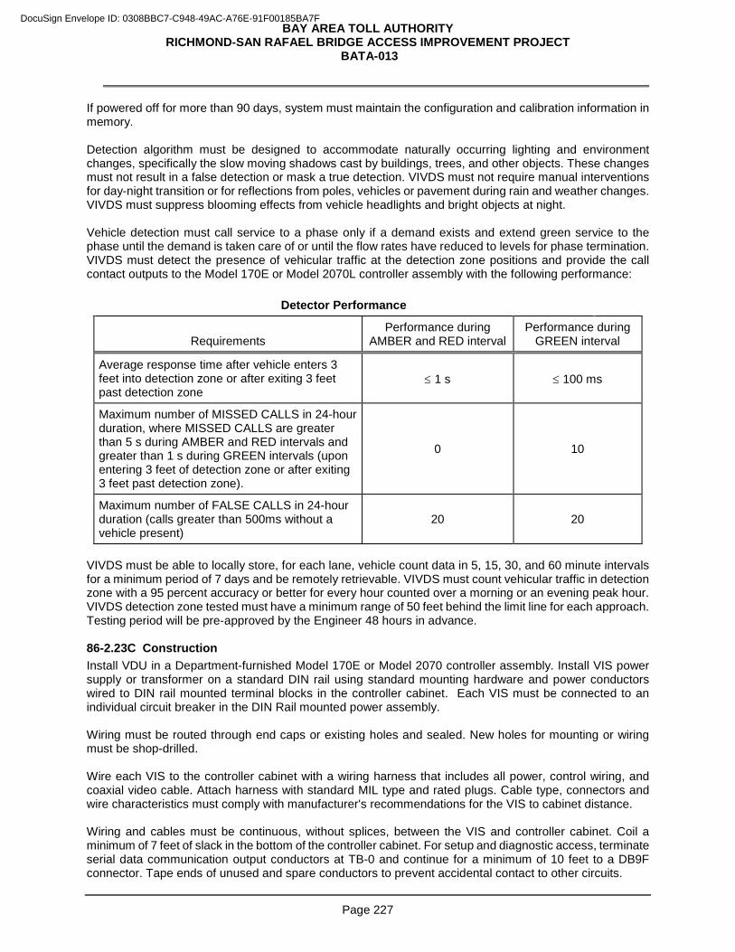
BAY AREA TOLL AUTHORITY RICHMOND-SAN RAFAEL BRIDGE ACCESS IMPROVEMENT PROJECT
BATA-013
Page 227
If powered off for more than 90 days, system must maintain the configuration and calibration information in memory. Detection algorithm must be designed to accommodate naturally occurring lighting and environment changes, specifically the slow moving shadows cast by buildings, trees, and other objects. These changes must not result in a false detection or mask a true detection. VIVDS must not require manual interventions for day-night transition or for reflections from poles, vehicles or pavement during rain and weather changes. VIVDS must suppress blooming effects from vehicle headlights and bright objects at night. Vehicle detection must call service to a phase only if a demand exists and extend green service to the phase until the demand is taken care of or until the flow rates have reduced to levels for phase termination. VIVDS must detect the presence of vehicular traffic at the detection zone positions and provide the call contact outputs to the Model 170E or Model 2070L controller assembly with the following performance:
Detector Performance
Requirements Performance during
AMBER and RED interval Performance during
GREEN interval
Average response time after vehicle enters 3 feet into detection zone or after exiting 3 feet past detection zone
≤ 1 s ≤ 100 ms
Maximum number of MISSED CALLS in 24-hour duration, where MISSED CALLS are greater than 5 s during AMBER and RED intervals and greater than 1 s during GREEN intervals (upon entering 3 feet of detection zone or after exiting 3 feet past detection zone).
0 10
Maximum number of FALSE CALLS in 24-hour duration (calls greater than 500ms without a vehicle present)
20 20
VIVDS must be able to locally store, for each lane, vehicle count data in 5, 15, 30, and 60 minute intervals for a minimum period of 7 days and be remotely retrievable. VIVDS must count vehicular traffic in detection zone with a 95 percent accuracy or better for every hour counted over a morning or an evening peak hour. VIVDS detection zone tested must have a minimum range of 50 feet behind the limit line for each approach. Testing period will be pre-approved by the Engineer 48 hours in advance. 86-2.23C Construction Install VDU in a Department-furnished Model 170E or Model 2070 controller assembly. Install VIS power supply or transformer on a standard DIN rail using standard mounting hardware and power conductors wired to DIN rail mounted terminal blocks in the controller cabinet. Each VIS must be connected to an individual circuit breaker in the DIN Rail mounted power assembly. Wiring must be routed through end caps or existing holes and sealed. New holes for mounting or wiring must be shop-drilled. Wire each VIS to the controller cabinet with a wiring harness that includes all power, control wiring, and coaxial video cable. Attach harness with standard MIL type and rated plugs. Cable type, connectors and wire characteristics must comply with manufacturer's recommendations for the VIS to cabinet distance. Wiring and cables must be continuous, without splices, between the VIS and controller cabinet. Coil a minimum of 7 feet of slack in the bottom of the controller cabinet. For setup and diagnostic access, terminate serial data communication output conductors at TB-0 and continue for a minimum of 10 feet to a DB9F connector. Tape ends of unused and spare conductors to prevent accidental contact to other circuits.
DocuSign Envelope ID: 0308BBC7-C948-49AC-A76E-91F00185BA7F
BAY AREA TOLL AUTHORITY RICHMOND-SAN RAFAEL BRIDGE ACCESS IMPROVEMENT PROJECT
BATA-013
Page 228
Label conductors inside the cabinet for the functions depicted the approved detailed diagrams. Label cables with permanent cable labels at each end. Adjust the lens to view 110 percent of the largest detection area dimension. Zones or elements must be logically combined into reporting contact outputs that are equivalent to the detection loops and with the detection accuracy required. Verify the performance of each unit, individually, and submit the recorded average and necessary material at the conclusion of the performance test. Determine and document the accuracy of each unit, individually, so that each unit may be approved or rejected separately. Failure to submit necessary material at the conclusion of testing invalidates the test. The recorded media serves as acceptance evidence and must not be used for calibration. Calibration must have been completed before testing and verification. Verify the detection accuracy by observing the VIVDS performance and recorded video images for a contiguous 24-hour period. The recorded video images must show the viewed detection scene, the detector call operation, the signal phase status for each approach, the vehicular traffic count, and time-stamp to 1/100 of a second, all overlaid on the recorded video. Transfer the 24-hour analysis to DVD. VIVDS must meet the detection acceptance criterion specified in table titled "Detector Performance." Calculate the VIVDS's vehicular traffic count accuracy as 100[1-(|TC-DC|/TC)], where DC is the detector's vehicular traffic count and TC is the observed media-recorded vehicular traffic count and where the resulting fraction is expressed as an absolute value. The Engineer will review the data findings and accept or reject the results within 7 days. Vehicle anomalies or unusual occurrences will be decided by the Engineer. Data or counts not agreed by the Engineer will be considered errors and count against the unit's calibration. If the Engineer determines that the VIVDS does not meet the performance requirements, you must re-calibrate and retest the unit, and resubmit new test data within 7 days. After 3 failed attempts, you must replace the VIVDS with a new unit. Notify the Engineer 20 days before the unit is ready for acceptance testing. Acceptance testing must be scheduled to be completed before the end of a normal work shift. You must demonstrate that all VIS and VDUs satisfy the functional requirements.
Add to section 86-2.24: 86-2.24 FIBER OPTIC SYSTEM 86-2.24A General 86-2.24A(1) Summary Section 86-2.24 includes specifications for installing fiber optic system. 86-2.24A(2) Definitions Breakout method: See mid-span access method definition.
Connector: A mechanical device used to align and join two fibers together to provide a means for attaching to and decoupling from a transmitter, receiver, or another fiber (i.e., patch panel).
Connectorized: Termination point of a fiber after connectors have been affixed.
Connector Module Housing (CMH): A patch panel used in the FDU to terminate fibers with most common connector types. It may include a jumper storage shelf and a hinged door.
Couplers: Devices which mate two fiber optic connectors to facilitate the transition of optical light signals from one connector into another. Couplers may also be referred to as: adapters, feed-through, and barrels. They are normally located within FDUs mounted in panels. They may also be used unmounted, to join two simplex fiber runs.
DocuSign Envelope ID: 0308BBC7-C948-49AC-A76E-91F00185BA7F
BAY AREA TOLL AUTHORITY RICHMOND-SAN RAFAEL BRIDGE ACCESS IMPROVEMENT PROJECT
BATA-013
Page 229
End-to-End Loss: The maximum permissible end-to-end system attenuation is the total loss in a given link. This loss could be the actual measured loss, or calculated using typical (or specified) values. This number will determine the amount of optical power (in dB) needed to meet the System Performance Margin.
Fiber Distribution Unit (FDU): A rack mountable enclosure containing both a connector module housing (CMH) and a splice module housing in one enclosure.
FO: Fiber optic.
FOOP: Fiber optic outside plant cable.
FOTP: Fiber optic test procedure(s) as defined by ANSI EIA/TIA standards.
FPC: Fiber pigtail drop cable.
FTC: Fiber trunkline cable.
Light Source: A portable fiber optic test equipment that, in conjunction with a power meter, is used to perform end-to-end attenuation testing. It contains a stabilized light source operating at the designed wavelength of the system under test. It also couples light from the source into the fiber to be received at the far end by the receiver.
Link: A passive section of the system, the ends of which are to be connectorized to active components. A link may include splices and couplers. For example, a video data link may be from video FO transmitter to video FO receiver.
Link Loss Budget: A calculation of the overall permissible attenuation from the fiber optic transmitter (source) to the fiber optic receiver (detector).
Loose Tube Cable: Type of cable construction in which fibers are placed in buffer tubes to isolate them from outside forces (stress). A flooding compound or material is applied to the interstitial cable core to prevent water migration and penetration. This type of cable is primarily for outdoor applications.
Mid-Span Access Method: Description of a procedure in which fibers from a single buffer tube are accessed and spliced to an adjoining cable without cutting the unused fibers in the buffer tube, or disturbing the remaining buffer tubes in the cable.
Optical Time Domain Reflectometer (OTDR): A fiber optic test equipment (similar in appearance to an oscilloscope) that is used to measure the total amount of power loss between two points and over the corresponding distance. It provides a visual and printed display of the relative location of system components such as fiber sections, splices and connectors as well as the losses that are attributed to each component and or defects in the fiber.
Patch cord: A short jumper used to join two components.
Pigtail: Relatively short length of fiber optic cable that is connectorized on only one end. All pigtails must be tight buffered cable.
Power Meter: A portable fiber optic test equipment that, when coupled with a light source, is used to perform end-to-end attenuation testing. It contains a detector that is sensitive to light at the designed wavelength of the system under test. Its display indicates the amount of power injected by the light source that arrives at the receiving end of the link.
SM: Singlemode.
SMFO: Singlemode Fiber Optic Cable.
Splice: The permanent joining of fiber ends to identical or similar fibers.
Splice Enclosure: An environmentally sealed container used to organize and protect splice trays. The container allows splitting or routing of fiber cables from and to multiple locations.
DocuSign Envelope ID: 0308BBC7-C948-49AC-A76E-91F00185BA7F
BAY AREA TOLL AUTHORITY RICHMOND-SAN RAFAEL BRIDGE ACCESS IMPROVEMENT PROJECT
BATA-013
Page 230
Splice Module Housing (SMH): Stores splice trays as well as pigtails and short cable lengths.
Splice Tray: A container used to organize and protect spliced fibers.
Segment: A section of fiber optic cable that is not connected to any active device and may or may not have splices per the design.
Splice or Fiber Optic Vault: An underground container used to house excess cable and splice enclosures.
System Performance Margin: A calculation of the overall "End to End" permissible attenuation from the fiber optic transmitter (source) to the fiber optic receiver (detector). The system performance margin should be at least 6 dB. This includes the difference between the active component link loss budget, the passive cable attenuation (total fiber loss) and the total connector/splice loss.
Tight Buffered Cable: Type of non-breakout cable construction where each glass fiber is tightly buffered (directly coated) with a protective thermoplastic coating to 900 µm. The tight buffered cable must meet all the characteristics of the fiber in the fiber optic outside plant cable specified elsewhere in these specifications.
86-2.24A(3) Submittals 86-2.24A(3)(a) General Submit documentation of compliance from manufacturer before ordering the material that shows factory test results. Submit to the Engineer, the cable manufacturer's certificate of compliance for the fiber optic cables before shipment, but while on the shipping reel, 100 percent of all fibers must be tested for attenuation. Copies of test results must be:
1. Maintained on file with a file identification number by the manufacturer for a minimum of seven years
2. Attached to the cable reel in a waterproof pouch 86-2.24A(3)(b) Factory Testing Factory testing must comply with:
1. Part 7 of ICEA S-87-640 "Testing, test methods, and requirement":
1.1. Jacket print test
1.2. Length and marking accuracy
1.3. Cable high and low temperature bend
1.4. Compound flow (drip) for gel filled cables
1.5. Water penetration
1.6. Cable impact
1.7. Cable tensile loading and fiber strain
1.8. Cable compressive loading
1.9. Cable twist
1.10. Lightning damage susceptibility 2. Part 8 of ICEA S-87-640 "Finished cable optical performance requirements":
2.1. Attenuation coefficient
2.2. Point discontinuity
2.3. Multimode optical bandwidth
DocuSign Envelope ID: 0308BBC7-C948-49AC-A76E-91F00185BA7F
BAY AREA TOLL AUTHORITY RICHMOND-SAN RAFAEL BRIDGE ACCESS IMPROVEMENT PROJECT
BATA-013
Page 231
2.4. Singlemode cable cutoff wavelength
Submit the manufacturer's instructions procedures for installing fiber optic cable, 20 working days before installation. Submit the manufacturer's installation instructions for splice enclosures before installation. 86-2.24A(4) Quality Control and Assurance 86-2.24A(4)(a) General Fiber optic system components must be tested:
1. At the factory
2. After delivery to the project site but prior to installation
3. During final system testing Provide all personnel, equipment, instrumentation and materials necessary to perform all non-factory testing. Notify the Engineer two working days prior to all field tests. The notification must include the exact location of the system or components to be tested. A minimum of 15 working days prior to arrival of the cable at the site, provide detailed test procedures for all field testing for the Engineer's review and approval. The procedures must include:
1. Test date and description
2. Test plan
3. Test equipment manufacturer and production date
4. Test equipment operating procedures 86-2.24A(4)(b) Fiber Optic Cable Testing Test the cable under ICEA S-87-640 and NECA/FOA 301. Perform the following tests after installation under post splicing tests:
1. End to end attenuation, using optical power meter and light source.
2. Optical anomalies by OTDR in both directions. 86-2.24B Materials 86-2.24B(1) General The FO cable must be compliant with Chapter XVII, Title 7, Part 1755.900 of the Code of Federal Regulations, "REA Specification for Filled Fiber Optic Cables" FO cable identification and marking must comply with Part 6 of ICEA S-87-640. Markings must be placed on the cable jacket.
DocuSign Envelope ID: 0308BBC7-C948-49AC-A76E-91F00185BA7F
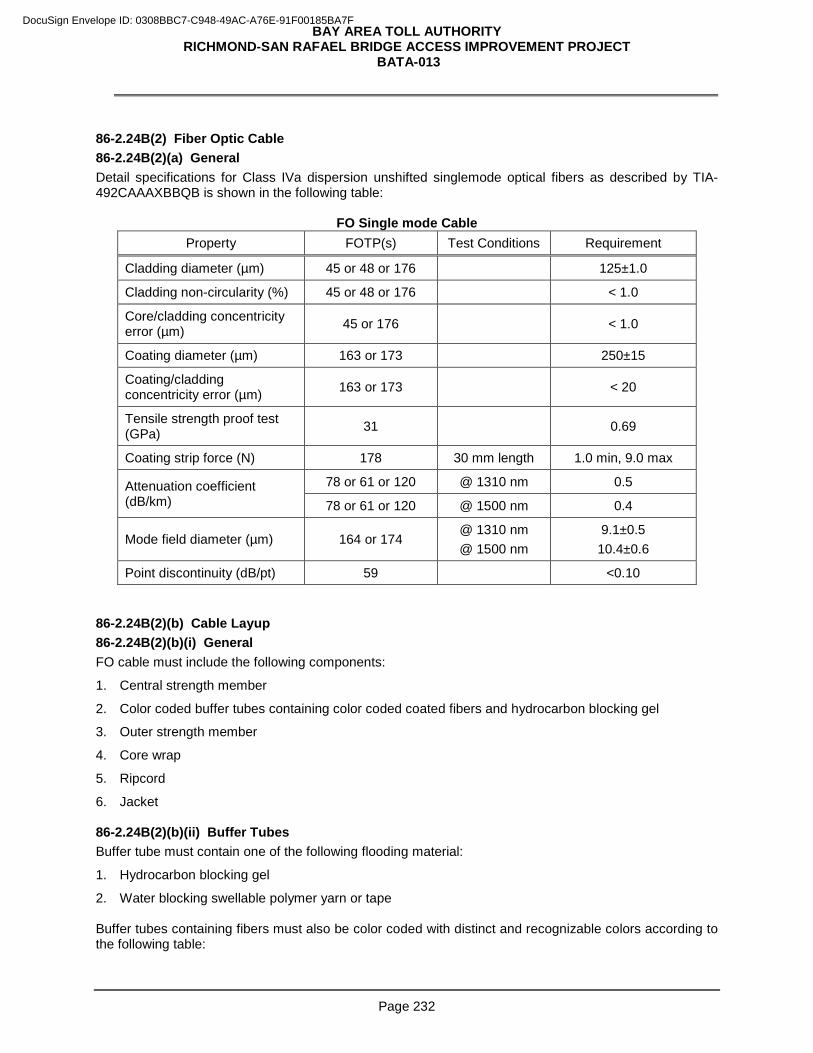
BAY AREA TOLL AUTHORITY RICHMOND-SAN RAFAEL BRIDGE ACCESS IMPROVEMENT PROJECT
BATA-013
Page 232
86-2.24B(2) Fiber Optic Cable 86-2.24B(2)(a) General Detail specifications for Class IVa dispersion unshifted singlemode optical fibers as described by TIA-492CAAAXBBQB is shown in the following table:
FO Single mode Cable Property FOTP(s) Test Conditions Requirement
Cladding diameter (µm) 45 or 48 or 176 125±1.0
Cladding non-circularity (%) 45 or 48 or 176 < 1.0
Core/cladding concentricity error (µm) 45 or 176 < 1.0
Coating diameter (µm) 163 or 173 250±15
Coating/cladding concentricity error (µm) 163 or 173 < 20
Tensile strength proof test (GPa) 31 0.69
Coating strip force (N) 178 30 mm length 1.0 min, 9.0 max
Attenuation coefficient (dB/km)
78 or 61 or 120 @ 1310 nm 0.5
78 or 61 or 120 @ 1500 nm 0.4
Mode field diameter (µm) 164 or 174 @ 1310 nm @ 1500 nm
9.1±0.5 10.4±0.6
Point discontinuity (dB/pt) 59 <0.10 86-2.24B(2)(b) Cable Layup 86-2.24B(2)(b)(i) General FO cable must include the following components:
1. Central strength member
2. Color coded buffer tubes containing color coded coated fibers and hydrocarbon blocking gel
3. Outer strength member
4. Core wrap
5. Ripcord
6. Jacket 86-2.24B(2)(b)(ii) Buffer Tubes Buffer tube must contain one of the following flooding material:
1. Hydrocarbon blocking gel
2. Water blocking swellable polymer yarn or tape Buffer tubes containing fibers must also be color coded with distinct and recognizable colors according to the following table:
DocuSign Envelope ID: 0308BBC7-C948-49AC-A76E-91F00185BA7F
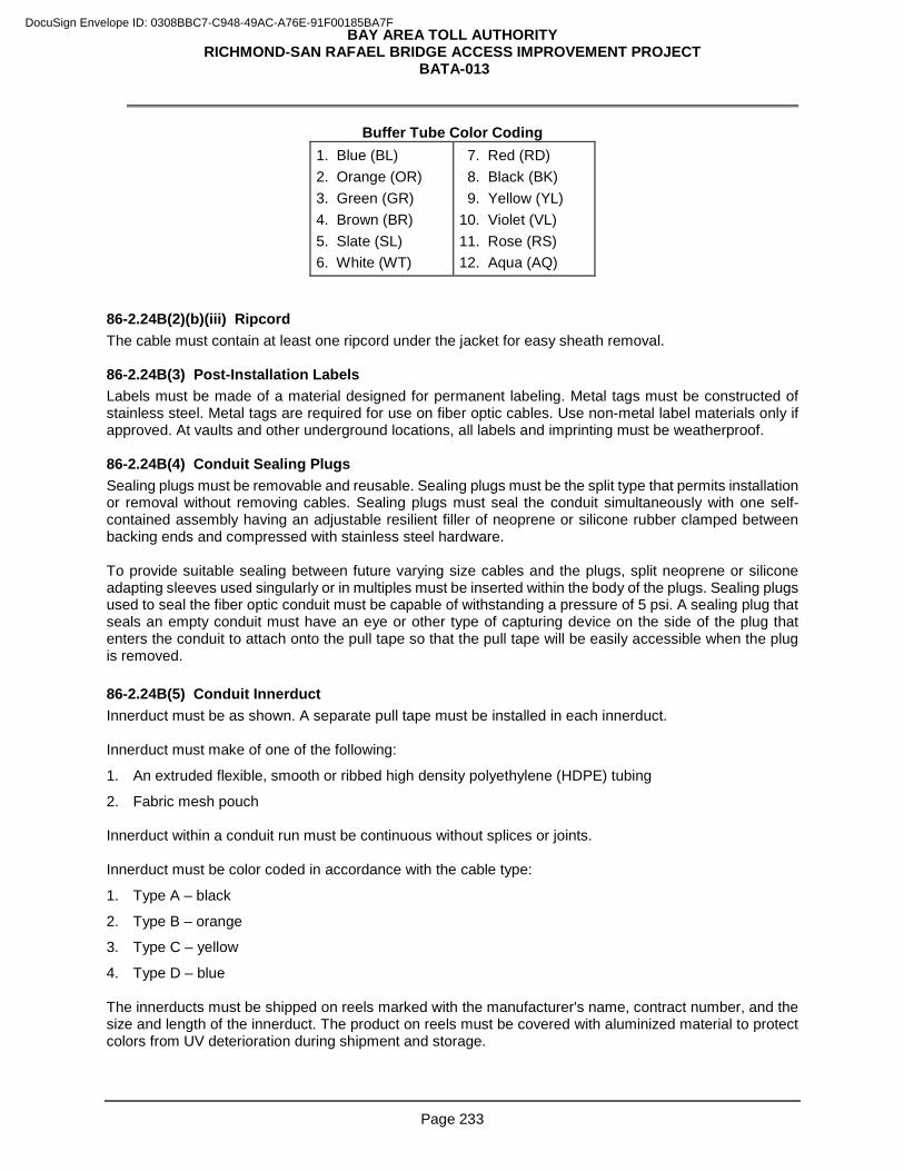
BAY AREA TOLL AUTHORITY RICHMOND-SAN RAFAEL BRIDGE ACCESS IMPROVEMENT PROJECT
BATA-013
Page 233
Buffer Tube Color Coding 1. Blue (BL) 2. Orange (OR) 3. Green (GR) 4. Brown (BR) 5. Slate (SL) 6. White (WT)
7. Red (RD) 8. Black (BK) 9. Yellow (YL) 10. Violet (VL) 11. Rose (RS) 12. Aqua (AQ)
86-2.24B(2)(b)(iii) Ripcord The cable must contain at least one ripcord under the jacket for easy sheath removal. 86-2.24B(3) Post-Installation Labels Labels must be made of a material designed for permanent labeling. Metal tags must be constructed of stainless steel. Metal tags are required for use on fiber optic cables. Use non-metal label materials only if approved. At vaults and other underground locations, all labels and imprinting must be weatherproof. 86-2.24B(4) Conduit Sealing Plugs Sealing plugs must be removable and reusable. Sealing plugs must be the split type that permits installation or removal without removing cables. Sealing plugs must seal the conduit simultaneously with one self-contained assembly having an adjustable resilient filler of neoprene or silicone rubber clamped between backing ends and compressed with stainless steel hardware. To provide suitable sealing between future varying size cables and the plugs, split neoprene or silicone adapting sleeves used singularly or in multiples must be inserted within the body of the plugs. Sealing plugs used to seal the fiber optic conduit must be capable of withstanding a pressure of 5 psi. A sealing plug that seals an empty conduit must have an eye or other type of capturing device on the side of the plug that enters the conduit to attach onto the pull tape so that the pull tape will be easily accessible when the plug is removed. 86-2.24B(5) Conduit Innerduct Innerduct must be as shown. A separate pull tape must be installed in each innerduct. Innerduct must make of one of the following:
1. An extruded flexible, smooth or ribbed high density polyethylene (HDPE) tubing
2. Fabric mesh pouch Innerduct within a conduit run must be continuous without splices or joints. Innerduct must be color coded in accordance with the cable type:
1. Type A – black
2. Type B – orange
3. Type C – yellow
4. Type D – blue The innerducts must be shipped on reels marked with the manufacturer's name, contract number, and the size and length of the innerduct. The product on reels must be covered with aluminized material to protect colors from UV deterioration during shipment and storage.
DocuSign Envelope ID: 0308BBC7-C948-49AC-A76E-91F00185BA7F
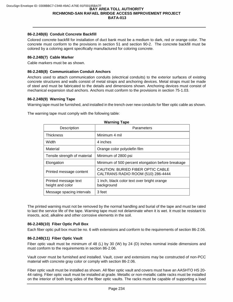
BAY AREA TOLL AUTHORITY RICHMOND-SAN RAFAEL BRIDGE ACCESS IMPROVEMENT PROJECT
BATA-013
Page 234
86-2.24B(6) Conduit Concrete Backfill Colored concrete backfill for installation of duct bank must be a medium to dark, red or orange color. The concrete must conform to the provisions in section 51 and section 90-2. The concrete backfill must be colored by a coloring agent specifically manufactured for coloring concrete. 86-2.24B(7) Cable Marker Cable markers must be as shown. 86-2.24B(8) Communication Conduit Anchors Anchors used to attach communication conduits (electrical conduits) to the exterior surfaces of existing concrete structures and walls consist of metal straps and anchoring devices. Metal straps must be made of steel and must be fabricated to the details and dimensions shown. Anchoring devices must consist of mechanical expansion stud anchors. Anchors must conform to the provisions in section 75-1.03. 86-2.24B(9) Warning Tape Warning tape must be furnished, and installed in the trench over new conduits for fiber optic cable as shown. The warning tape must comply with the following table:
Warning Tape Description Parameters
Thickness Minimum 4 mil
Width 4 inches
Material Orange color polyolefin film
Tensile strength of material Minimum of 2800 psi
Elongation Minimum of 500 percent elongation before breakage
Printed message content CAUTION: BURIED FIBER OPTIC CABLE CALTRANS RADIO ROOM (510) 286-4444
Printed message text height and color
1 inch, black color text over bright orange background
Message spacing intervals 3 feet The printed warning must not be removed by the normal handling and burial of the tape and must be rated to last the service life of the tape. Warning tape must not delaminate when it is wet. It must be resistant to insects, acid, alkaline and other corrosive elements in the soil. 86-2.24B(10) Fiber Optic Pull Box Each fiber optic pull box must be no. 6 with extensions and conform to the requirements of section 86-2.06. 86-2.24B(11) Fiber Optic Vault Fiber optic vault must be minimum of 48 (L) by 30 (W) by 24 (D) inches nominal inside dimensions and must conform to the requirements in section 86-2.06. Vault cover must be furnished and installed. Vault, cover and extensions may be constructed of non-PCC material with concrete gray color or comply with section 86-2.06. Fiber optic vault must be installed as shown. All fiber optic vault and covers must have an AASHTO HS 20-44 rating. Fiber optic vault must be installed at grade. Metallic or non-metallic cable racks must be installed on the interior of both long sides of the fiber optic vaults. The racks must be capable of supporting a load
DocuSign Envelope ID: 0308BBC7-C948-49AC-A76E-91F00185BA7F
BAY AREA TOLL AUTHORITY RICHMOND-SAN RAFAEL BRIDGE ACCESS IMPROVEMENT PROJECT
BATA-013
Page 235
of 100 pounds, minimum, per rack arm. Racks must be supplied in lengths appropriate to the box in which they will be placed. All metallic cable racks must be fabricated from ASTM A36 steel plate and must be hot-dip galvanized after fabrication. Steel plate, hardware and galvanizing must comply with the requirements in section 75. Metallic cable racks must be bonded and grounded. 86-2.24B(12) Splice Enclosure The splice enclosure must be suitable for a direct burial or pull box application. The splice enclosure must comply with the following:
1. Non-filled thermoplastic case
2. Rodent proof, water proof, re-enterable and moisture proof
3. Expandable from 2 cables per end to 8 cables per end by using adapter plates
4. Cable entry ports must accommodate from 3/8 to 1 inch diameter cables
5. Multiple grounding straps
6. Accommodate up to 8 splice trays
7. Suitable for "butt" or "through" cable entry configurations
8. Place no stress on finished splices within the splice trays 86-2.24B(13) Fiber Distribution Units 86-2.24B(13)(a) General FDU must include the following:
1. A patch panel to terminate the appropriate number of single mode fibers with ST type connectors feed through couplers.
2. Splice trays.
3. Storage for splice trays.
4. A slide out metal drawer for storage of spare jumpers. Provide Strain relief for incoming fiber optic cables. Cable accesses must have rubber grommets or similar material to prevent cables from contacting bare metal. Fibers must be terminated and individually identified in FDUs and on patch panels. Patch panels must be hinged or have coupler plates to provide easy access and maintenance. Brackets must be provided to spool incoming fibers a minimum of 2 turns. Turns must not be less than 1 foot before separating out individual fibers to splice trays. FDUs must not exceed 10 inches in height and 15 inches in depth. Termination and distribution cable trays must accommodate fiber optic cables and must have sufficient tray areas for excess optical fiber storage with provisions to assure that optical fibers do not exceed a 2 inch bend radius. Termination and distribution cable trays must include a designation strip for identification of optical fibers. Splice drawers must include splice trays with each splice tray capable of accommodating fusion type splices. Splice drawers must allow storage of excess lengths of optical fibers of fiber optic cables. Fiber distribution units must be provided with cable clamps to secure fiber optic cables to the chassis. 86-2.24B(13)(b) Splice Trays Splice trays must accommodate a minimum of 12 fusion splices and must allow for a minimum bend radius of 2 inches. The splice tray cover may be transparent. Splice trays in the splice enclosure must comply with the following:
DocuSign Envelope ID: 0308BBC7-C948-49AC-A76E-91F00185BA7F
BAY AREA TOLL AUTHORITY RICHMOND-SAN RAFAEL BRIDGE ACCESS IMPROVEMENT PROJECT
BATA-013
Page 236
1. Accommodate up to 24 fusion splices
2. Place no stress on completed splices within the tray
3. Stackable with a snap-on or hinged cover
4. Secure buffer tubes and pigtails entering the tray
5. Labeled after splicing is completed. Only one single splice tray may be secured by a bolt through the center of the tray in the fiber termination unit. Multiple trays must be securely held in place as per the manufacturer’s instruction. 86-2.24B(14) Fiber Optic Pigtails and Jumpers 86-2.24B(14)(a) General Cable assemblies (jumpers and pigtails) must be products of the same manufacturer. The cable used for cable assemblies must be made with optical fiber meeting the performance requirements. 86-2.24B(14)(b) Pigtails Pigtails must be of simplex (one fiber) construction, in 900-µm tight buffer form, surrounded by Aramid yarn for strength, with a PVC jacket with manufacturer's identification information, and a nominal outer jacket diameter no more than of 1/8 inch. Pigtails must be factory terminated and tested and at least 3 feet long. 86-2.24B(14)(c) Jumpers Jumpers may be of simplex or duplex design. Duplex jumpers must be of duplex round cable construction, and must not have zipcord (siamese) construction. All jumpers must be at least 6 feet in length, sufficient to avoid stress and allow orderly routing. 86-2.24B(14)(d) Connectors Connectors must be one of the following types:
1. ST for normal applications
2. SC for normal applications
3. 586SC for network applications
4. LC for network applications Associated couplers must be the same material as connector housings. ST and SC type FO connectors must be 1 inch ferrule type with Zirconia ceramic material with a physical contact pre-radiused tip. The connector operating temperature range must be -40 to +70 degrees C. Insertion loss must not exceed 0.4 dB for singlemode, and the return reflection loss on singlemode connectors must be at least -35 dB. Connection durability must be less than a 0.2 dB change per 500 mating cycles per TIA-455-21A (FOTP-21). All terminations must provide a minimum 50 lbf pull out strength. Factory test results must be documented and submitted before installing any of the connectors. Field terminations must be limited to splicing of adjoining cable ends or cables to pigtails. All connectors must be factory-installed and tested. There must be no installation of connectors in the field. All unmated connectors must have protective caps installed. 86-2.24B(15) Packaging and Shipping Requirements Package the completed cable for shipment on reels. The cable must be wrapped in weather and temperature resistant covering. Both ends of the cable must be sealed to prevent the ingress of moisture.
DocuSign Envelope ID: 0308BBC7-C948-49AC-A76E-91F00185BA7F
BAY AREA TOLL AUTHORITY RICHMOND-SAN RAFAEL BRIDGE ACCESS IMPROVEMENT PROJECT
BATA-013
Page 237
Both ends of the cable must be securely fastened to the reel to prevent the cable from coming loose during transit. Two meters of cable length on each end of the cable must be accessible for testing. Each cable reel must have a durable weatherproof label or tag showing the manufacturer's name, the cable type, the actual length of cable on the reel, your name, the contract number, and the reel number. Provide a shipping record in a weatherproof envelope showing the above information and also include the date of manufacture, cable characteristics such as size, attenuation, bandwidth, factory test results, cable identification number and any other pertinent information. The minimum hub diameter of the reel must be at least thirty times the diameter of the cable. The FO cable must be in one continuous length per reel with no factory splices in the fiber. Each reel must be marked to indicate the direction the reel should be rolled to prevent loosening of the cable. Installation procedures and technical support information must be furnished at the time of delivery. 86-2.24B(16) Equipment Racks with Enclosure Equipment racks with enclosure must be installed in Substation 4, “Battery Room”. Enclosure must have side panel and front and back access doors. Enclosure will be mounted on the concrete floor with stainless steel bolts. Cables access opening with pre-installed brushed. The bottom must allow for unobstructed cables access through a raised floor. The roof includes openings with brush stripes pre-installed in locations biased towards the front of the enclosure to allow for data cable pass through and provisions for air containment . The enclosure dimensions must be 24” width by 24” deep and 84” height. One standard 19” rack cage must be installed inside the enclosure. Each cage unit must be designed to support a minimum of 200 pounds of mounted equipment. Each mounting rail must have 10-32 treaded mounting holes with spacing of 5/8” running along the whole length of the rail. The rack cage must support minimum of 44 mounting unit. Three equipment racks with enclosure must be used inside the battery room inside the Substation 4. The three racks can be joint together. The enclosures must be bolted on the side. The side panel between the adjacent rack can be omitted. 86-2.24B(17) Monitor in Toll Plaza Office Monitor must be installed in Toll Plaza Administration Office. Monitor must be a 1080p high definition type. Monitor must be wall-mounted or ceiling-mounted Type as request by the Toll Plaza officer. Video coaxial cables for the monitor must be connected to a network equipment inside Substation 4 “Battery Room” complete in place and testing. 86-2.24C Construction 86-2.24C(1) General FO cable must be installed in conduit system or cable tray system as shown. FO conduit system consists of conduits, fiber optic pull boxes, FO splice vaults and cabinets. Cable installation must comply with the procedures specified by the manufacturer. Mechanical aids may be used provided that a tension measuring device is placed to the end of the cable. The tension applied must not exceed 600 lb force or the manufacturers recommended pulling tension, whichever is less. 86-2.24C(2) Pulled Cable Installation The FO cable must be installed using a cable pulling lubricant recommended by the cable manufacture and a non-abrasive pull tape. Station your personnel at each pull box, vault, and cabinet through which the cable is pulled to lubricate and prevent kinking or other damage. During cable installation, the bend radius must be maintained at not less than twenty times the outside diameter of the cable. The cable grips for installing the FO cable must have a ball bearing swivel to prevent the cable from twisting during installation.
DocuSign Envelope ID: 0308BBC7-C948-49AC-A76E-91F00185BA7F
BAY AREA TOLL AUTHORITY RICHMOND-SAN RAFAEL BRIDGE ACCESS IMPROVEMENT PROJECT
BATA-013
Page 238
86-2.24C(3) Air Blown Installation The fiber cable may be installed using the air blown method. If integral innerduct is used, the duct splice points or any temporary splices of innerduct used for installation must withstand a static air pressure of 110 psi. The fiber installation equipment must incorporate a mechanical drive unit or pusher that feeds cable into the pressurized innerduct to provide a sufficient push force on the cable, which is coupled with the drag force created by the high-speed airflow. The unit must be equipped with controls to regulate the flow rate of compressed air entering the duct and any hydraulic or pneumatic pressure applied to the cable. It must accommodate longitudinally ribbed or smooth wall ducts from nominal 0.625-inch to 2-inch inner diameter. Mid assist or cascading of equipment must be for the installation of long cable runs. The equipment must incorporate safety shutoff valves to disable the system in the event of sudden changes in pneumatic or hydraulic pressure. The equipment must not require the use of a piston or any other air capturing device to impose a pulling force at the front end of the cable, which also significantly restricts the free flow of air through the inner duct. It must incorporate the use of a counting device to determine the speed of the cable during installation and the length of the cable installed. 86-2.24C(4) Splices and Termination The cable must be installed without splices except where specifically allowed as shown. Minimum slack of the cable must be provided at each cable access location without a cable splice as shown. Store a minimum of 30 feet slack of each cable at fiber optic splice locations. Field cable splices must be done either in splice vaults or in cabinets as shown. The cable splices must be fusion type. The mean splice loss must not exceed 0.07 dB per splice. The mean splice loss must be obtained by measuring the loss through the splice in both directions and then averaging the resultant values. The mid-span access method must be used to access the individual fibers in a cable for splicing to another cable as shown. Cable manufacturers recommended procedures and approved tools must be used when performing a mid-span access. Only the fibers to be spliced may be cut. All measures must be taken to avoid damaging buffer tubes and individual fibers including those not being used in the mid-span access. Use the breakout method to access individual fiber. The cable "breakout" is produced by:
1. Remove the jacket just beyond the last tie-wrap point
2. Expose 3 to 6 feet of the cable buffers, aramid strength yarn and central fiberglass strength member
3. Cut aramid yarn, central strength member and the buffer tubes to expose the individual glass fibers for splicing or connection to the appropriate device
The mid-span access method must be used to access the individual fibers in the trunkline cable for splicing pigtail cable. Cable manufacturer's instructions procedures and approved tools must be used when performing a mid-span access. Measures must be taken to avoid damaging buffer tubes and individual fibers not being used in the mid-span access. You are allowed to splice up to 5 fibers to repair any damage done during mid-span access splicing without penalty. You will be assessed $300.00 penalty for each additional splice. Any single fiber may not have more than 3 unplanned splices. If the fiber needs to be spliced more than 3 times, the entire length of fiber optic cable must be replaced at your expense. The field splices must connect the fibers of the two cable lengths together. These splices must be placed in splice trays and these splice trays must then be placed in the splice enclosure. The termination splices must connect the cable span ends with pigtails. The termination splices must be placed in splice trays and the splice trays must then be placed in the fiber distribution unit (FDU).
DocuSign Envelope ID: 0308BBC7-C948-49AC-A76E-91F00185BA7F
BAY AREA TOLL AUTHORITY RICHMOND-SAN RAFAEL BRIDGE ACCESS IMPROVEMENT PROJECT
BATA-013
Page 239
Splice trays must accommodate a minimum of 12 fusion splices. The individual fibers must be looped at least one full turn within the splice tray to avoid micro bending. A 2 inch minimum bend radius must be maintained during installation and after final assembly in the optical fiber splice tray. Each bare fiber must be individually restrained in a splice tray. The optical fibers in buffer tubes and the placement of the bare optical fibers in the splice tray must be such that there is no discernable tensile force on the optical fiber. All splices must be protected with a metal reinforced thermal shrink sleeve. 86-2.24C(5) Post-Installation Cable Labeling Label all fiber optic cables with tags as specified. All tags placed along one cable must contain the same cable identification code unique for that cable. Tags must be placed on the cables at the following points:
1. Fiber optic vault entrance and exit
2. Splice enclosures entrance and exit
3. FDU entrance All tags must be made of the same material designed for long term permanent labeling of fiber optic and copper communications cables. Metal tags must be constructed of stainless steel. Material for non-metal tags must be approved in writing by the Engineer. Metal tags must be marked with embossed lettering. Non-metal tags must be marked with the permanent ink. Handwritten label markings must not be allowed. Labels must be affixed to the cable under the manufacturer's instructions in a manner that will not cause damage to the cable. Cable identification code on a tag must consist of the groups in the following table:
DocuSign Envelope ID: 0308BBC7-C948-49AC-A76E-91F00185BA7F
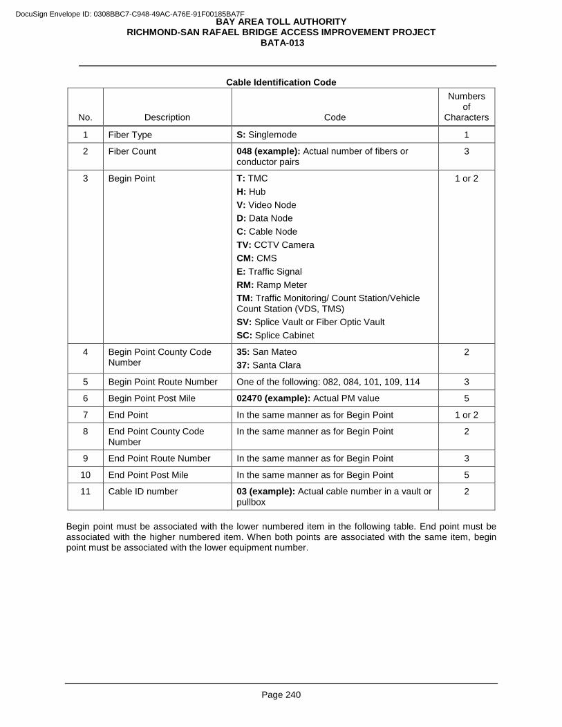
BAY AREA TOLL AUTHORITY RICHMOND-SAN RAFAEL BRIDGE ACCESS IMPROVEMENT PROJECT
BATA-013
Page 240
Cable Identification Code
No. Description Code
Numbers of
Characters
1 Fiber Type S: Singlemode 1
2 Fiber Count 048 (example): Actual number of fibers or conductor pairs
3
3 Begin Point T: TMC H: Hub V: Video Node D: Data Node C: Cable Node TV: CCTV Camera CM: CMS E: Traffic Signal RM: Ramp Meter TM: Traffic Monitoring/ Count Station/Vehicle Count Station (VDS, TMS) SV: Splice Vault or Fiber Optic Vault SC: Splice Cabinet
1 or 2
4 Begin Point County Code Number
35: San Mateo 37: Santa Clara
2
5 Begin Point Route Number One of the following: 082, 084, 101, 109, 114 3
6 Begin Point Post Mile 02470 (example): Actual PM value 5
7 End Point In the same manner as for Begin Point 1 or 2
8 End Point County Code Number
In the same manner as for Begin Point 2
9 End Point Route Number In the same manner as for Begin Point 3
10 End Point Post Mile In the same manner as for Begin Point 5
11 Cable ID number 03 (example): Actual cable number in a vault or pullbox
2
Begin point must be associated with the lower numbered item in the following table. End point must be associated with the higher numbered item. When both points are associated with the same item, begin point must be associated with the lower equipment number.
DocuSign Envelope ID: 0308BBC7-C948-49AC-A76E-91F00185BA7F
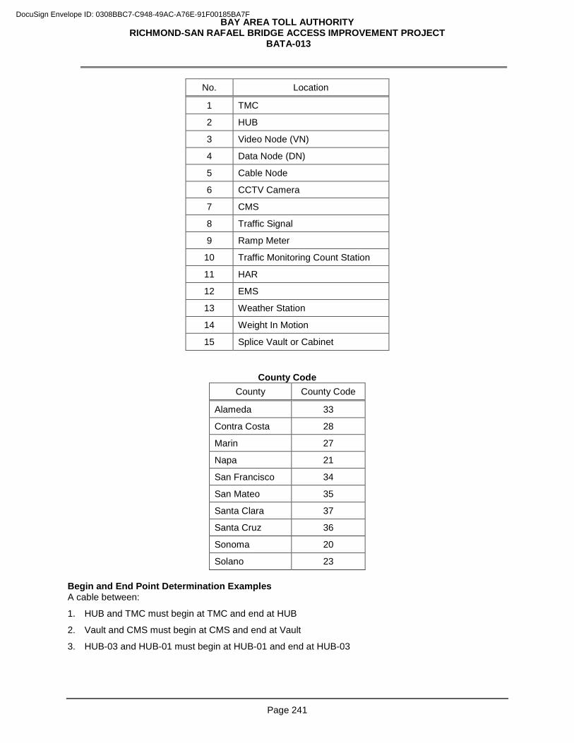
BAY AREA TOLL AUTHORITY RICHMOND-SAN RAFAEL BRIDGE ACCESS IMPROVEMENT PROJECT
BATA-013
Page 241
No. Location
1 TMC
2 HUB
3 Video Node (VN)
4 Data Node (DN)
5 Cable Node
6 CCTV Camera
7 CMS
8 Traffic Signal
9 Ramp Meter
10 Traffic Monitoring Count Station
11 HAR
12 EMS
13 Weather Station
14 Weight In Motion
15 Splice Vault or Cabinet
County Code County County Code
Alameda 33
Contra Costa 28
Marin 27
Napa 21
San Francisco 34
San Mateo 35
Santa Clara 37
Santa Cruz 36
Sonoma 20
Solano 23 Begin and End Point Determination Examples A cable between:
1. HUB and TMC must begin at TMC and end at HUB
2. Vault and CMS must begin at CMS and end at Vault
3. HUB-03 and HUB-01 must begin at HUB-01 and end at HUB-03
DocuSign Envelope ID: 0308BBC7-C948-49AC-A76E-91F00185BA7F
BAY AREA TOLL AUTHORITY RICHMOND-SAN RAFAEL BRIDGE ACCESS IMPROVEMENT PROJECT
BATA-013
Page 242
Cable Code Example The cable code S 048 SV 35 084 02470 SV 37 082 02510 03 must be interpreted as a singlemode, 48 strand, cable starting at a fiber optic vault in San Mateo County on Route 84 at post mile 24.70, and ending at another fiber optic vault in Santa Clara County on Route 82 at postmile 25.10. Cable ID number indicates that the cable is the third of the fiber optic cables in the vault. 86-2.24C(6) Conduit Sealing Plugs All fiber optic conduits must have their ends sealed with commercial preformed plugs which prevent the passage of gas, dust and water into these conduits. 86-2.24C(7) Conduit Innerduct Install innerducts in conduits as shown. 86-2.24C(8) Conduit Concrete Backfill Concrete backfill must conform to the provisions in section 86-2.05C. The concrete backfill must be colored by a coloring agent specifically manufactured for coloring concrete. The coloring agent must be fine ground, synthetic mineral oxide and must be uniformly and homogeneously mixed with the concrete. The color of the concrete backfill after curing and when air dry must be red conforming to color no. 31105 of Federal Standard no. 595B. Adequate spacers, tie-downs and bracing must be provided to maintain conduits in place during the pouring of the concrete. For trenches in paved areas, only the top 4 inch of concrete backfill must be pigmented concrete. 86-2.24C(9) Cable Marker Cable markers must be provided for FO conduits constructed in unpaved locations and placed at 50 feet spacing. 86-2.24C(10) Communication Conduit Anchors When communication conduits are installed vertically on a structure for a distance of 2 feet or more, but less than 8 feet, an anchor must be installed at the top and bottom of the pipe within 0.5-foot of the elbows. Vertical distances of 10 feet or more must have anchors installed at 5 feet on centers as shown. Anchors used to support vertically installed pipe and conduit must be installed as shown. Holes for anchorage devices must conform to the following:
1. Reinforcing steel must be located by nondestructive means before drilling holes for anchors. Holes must not be drilled closer than 0.5-foot to the edge of a concrete structure.
2. Holes must be drilled with rotary drills. Impact drills must not be used. Coring is not allowed.
3. Holes must be relocated if reinforcing steel is encountered. Abandoned holes must be filled with portland cement concrete mortar conforming to the provisions in section 51-1.03E.
4. Holes must be drilled to a minimum depth of 8 times the diameter of the anchor bolt or stud anchor.
5. Anchors must be on the Department approved list for mechanical expansion anchors and installed under manufacturer's instructions:
http://www.dot.ca.gov/hq/esc/approved_products_list/ 86-2.24C(11) Warning Tape Place the warning tape as shown.
DocuSign Envelope ID: 0308BBC7-C948-49AC-A76E-91F00185BA7F
BAY AREA TOLL AUTHORITY RICHMOND-SAN RAFAEL BRIDGE ACCESS IMPROVEMENT PROJECT
BATA-013
Page 243
86-2.24C(12) Fiber Optic Pull Box Conduits must not protrude more than 2 inches inside the pull box and must enter the pull box at no more than 20 degrees in both the vertical and horizontal directions. 86-2.24C(13) Fiber Optic Vault Fiber optic vault must be installed as shown. All fiber optic vault and covers must have an AASHTO HS 20-44 rating. Fiber optic vault must be installed at grade. Metallic or non-metallic cable racks must be installed on the interior of both long sides of the fiber optic vault. The racks must be capable of supporting a load of 100 pounds, minimum, per rack arm. Racks must be supplied in lengths appropriate to the box in which they will be placed. All metallic cable racks must be fabricated from ASTM A36 steel plate and must be hot-dip galvanized after fabrication. Steel plate, hardware and galvanizing must comply with the requirements in section 75. Metallic cable racks must be bonded and grounded. Vault must be installed outside of the pavement maintaining 5 feet distance from the cover centerline to the edge of the pavement or back of the dike. Vault may be installed farther from or closer to the roadway to accommodate buried objects, existing conduits, or similar items. Minimum distance from any part of the vault or backfill material to the edge of the pavement or back of the dike must be 18 inches. The top of the vault cover must be within 1 ±0.5 inch of adjacent finished grade. When fiber optic vaults are installed in paved areas:
1. Distance from the centerline of the vault to the edge of pavement or back of dike must not exceed 3 feet
2. Top of vault cover must be 0.1 ±0.05 inch below of the adjacent pavement finished grade Conduits must not protrude more than 2 inches inside the vault and must enter the vault at no more than20 degrees in both the vertical and horizontal directions. 86-2.24C(14) Splice Enclosure Place the splice enclosure where a splice is required as shown. The splice enclosure must be bolted to the side wall of the splice vault. 86-2.24C(15) Fiber Distribution Units 86-2.24C(15)(a) General Install components to terminate incoming fiber optic communication cables. Install sufficient quantity of fiber distribution units to terminate fibers in the largest cable. Mount fiber distribution in equipment racks as shown. Terminate optical fibers at fiber distribution units. Optical fibers must be fusion spliced to optical fiber cables assemblies within splice trays. Optical fibers must be of appropriate lengths to allow future splicing with splice drawers and must be appropriately identified. Splices must be fusion type and must be arranged within splice trays of fiber distribution units in accordance with the organizational design of splice trays. Appropriate protective coatings must be applied to fusion splices. 86-2.24C(15)(b) Splice Trays Individual fibers must be looped one full turn within the splice tray to allow for future splicing. No stress is to be applied on the fiber when it is located in its final position. 86-2.24D Payment Not Used
DocuSign Envelope ID: 0308BBC7-C948-49AC-A76E-91F00185BA7F
BAY AREA TOLL AUTHORITY RICHMOND-SAN RAFAEL BRIDGE ACCESS IMPROVEMENT PROJECT
BATA-013
Page 244
Add to section 86-2: 86-2.25 ETHERNET SWITCH 86-2.25A General 86-2.25A(1) Summary Section 86-2.25 includes specifications for installing the Ethernet switch. 86-2.25A(2) Definitions Not Used 86-2.25A(3) Submittals Submit:
1. Manufacturer's cut sheets indicating performance and environmental requirement
2. Documentation required for acceptance testing, maintenance and operation
3. Warranty documentation before installation
4. Test equipment, software and, auxiliary items required to perform the testing
5. Test plan for review and authorization 86-2.25A(4) Quality Control and Assurance 86-2.25A(4)(a) General Tests must be performed by or under supervision of personnel certified by the manufacturer. Document test results and have them approved by the Engineer. Tested components of ethernet switch must meet manufacturer's specifications. If the Engineer determines that the equipment fails to pass any performance and functional test, cease testing, determine the cause of the failure and make repairs or replace components. The test plan must include:
1. Power meter tests of small-form factor pluggable (SFP) fast ethernet transceivers
2. Functionality tests on copper ethernet ports
3. Manufacturer recommended tests Power meter test must consist of measurements of the SFP transmitter optical output power and SFP receiver optical sensitivity range. 86-2.25A(4)(b) Warranty Furnish a 5-year replacement warranty from the manufacturer of the ethernet switch against any defects or failures. The effective date of the warranty is the date of acceptance of the installation. Furnish replacement parts within 5 days after receipt of the failed parts. The Department does not pay for the replacement. Deliver replacement parts to:
CALTRANS MAINTENANCE ELECTRICAL SHOP 30 RICKARD STREET SAN FRANCISCO, CA 94134 (415) 330-6500
86-2.25B Materials 86-2.25B(1) General The ethernet switch must include:
1. Switch unit
DocuSign Envelope ID: 0308BBC7-C948-49AC-A76E-91F00185BA7F
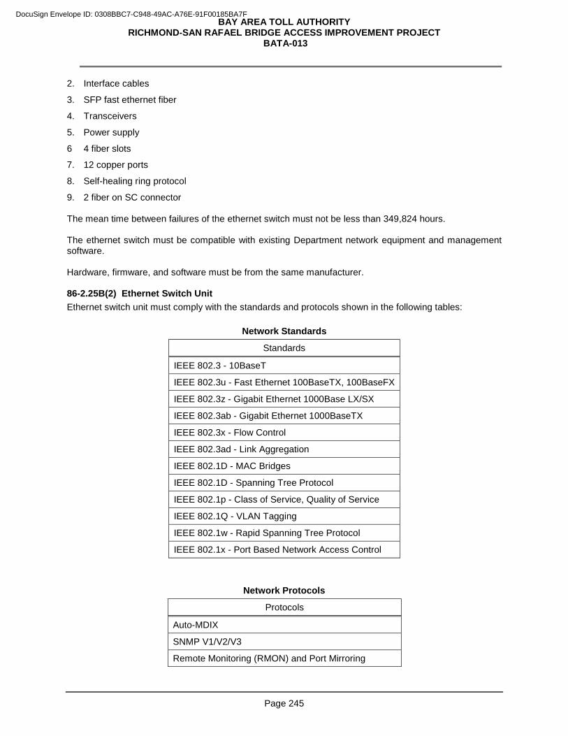
BAY AREA TOLL AUTHORITY RICHMOND-SAN RAFAEL BRIDGE ACCESS IMPROVEMENT PROJECT
BATA-013
Page 245
2. Interface cables
3. SFP fast ethernet fiber
4. Transceivers
5. Power supply
6 4 fiber slots
7. 12 copper ports
8. Self-healing ring protocol
9. 2 fiber on SC connector The mean time between failures of the ethernet switch must not be less than 349,824 hours. The ethernet switch must be compatible with existing Department network equipment and management software. Hardware, firmware, and software must be from the same manufacturer. 86-2.25B(2) Ethernet Switch Unit Ethernet switch unit must comply with the standards and protocols shown in the following tables:
Network Standards
Standards
IEEE 802.3 - 10BaseT
IEEE 802.3u - Fast Ethernet 100BaseTX, 100BaseFX
IEEE 802.3z - Gigabit Ethernet 1000Base LX/SX
IEEE 802.3ab - Gigabit Ethernet 1000BaseTX
IEEE 802.3x - Flow Control
IEEE 802.3ad - Link Aggregation
IEEE 802.1D - MAC Bridges
IEEE 802.1D - Spanning Tree Protocol
IEEE 802.1p - Class of Service, Quality of Service
IEEE 802.1Q - VLAN Tagging
IEEE 802.1w - Rapid Spanning Tree Protocol
IEEE 802.1x - Port Based Network Access Control
Network Protocols
Protocols
Auto-MDIX
SNMP V1/V2/V3
Remote Monitoring (RMON) and Port Mirroring
DocuSign Envelope ID: 0308BBC7-C948-49AC-A76E-91F00185BA7F
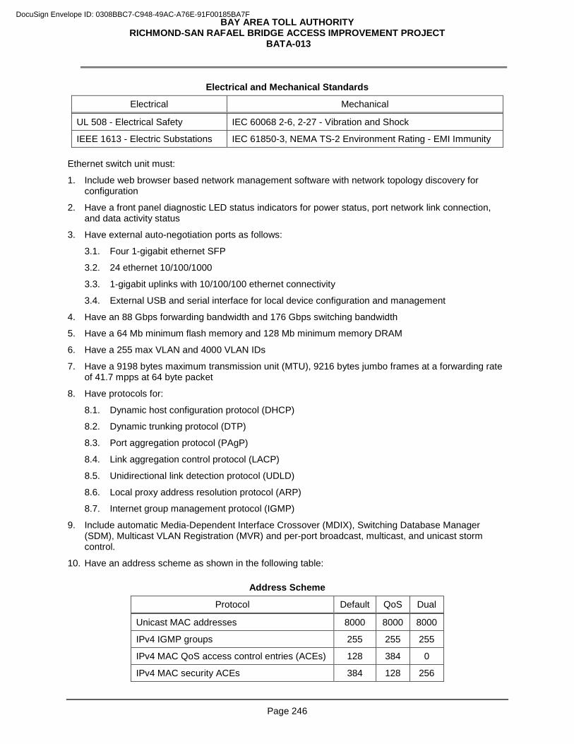
BAY AREA TOLL AUTHORITY RICHMOND-SAN RAFAEL BRIDGE ACCESS IMPROVEMENT PROJECT
BATA-013
Page 246
Electrical and Mechanical Standards
Electrical Mechanical
UL 508 - Electrical Safety IEC 60068 2-6, 2-27 - Vibration and Shock
IEEE 1613 - Electric Substations IEC 61850-3, NEMA TS-2 Environment Rating - EMI Immunity Ethernet switch unit must:
1. Include web browser based network management software with network topology discovery for configuration
2. Have a front panel diagnostic LED status indicators for power status, port network link connection, and data activity status
3. Have external auto-negotiation ports as follows:
3.1. Four 1-gigabit ethernet SFP
3.2. 24 ethernet 10/100/1000
3.3. 1-gigabit uplinks with 10/100/100 ethernet connectivity
3.4. External USB and serial interface for local device configuration and management
4. Have an 88 Gbps forwarding bandwidth and 176 Gbps switching bandwidth
5. Have a 64 Mb minimum flash memory and 128 Mb minimum memory DRAM
6. Have a 255 max VLAN and 4000 VLAN IDs
7. Have a 9198 bytes maximum transmission unit (MTU), 9216 bytes jumbo frames at a forwarding rate of 41.7 mpps at 64 byte packet
8. Have protocols for:
8.1. Dynamic host configuration protocol (DHCP)
8.2. Dynamic trunking protocol (DTP)
8.3. Port aggregation protocol (PAgP)
8.4. Link aggregation control protocol (LACP)
8.5. Unidirectional link detection protocol (UDLD)
8.6. Local proxy address resolution protocol (ARP)
8.7. Internet group management protocol (IGMP)
9. Include automatic Media-Dependent Interface Crossover (MDIX), Switching Database Manager (SDM), Multicast VLAN Registration (MVR) and per-port broadcast, multicast, and unicast storm control.
10. Have an address scheme as shown in the following table:
Address Scheme
Protocol Default QoS Dual
Unicast MAC addresses 8000 8000 8000
IPv4 IGMP groups 255 255 255
IPv4 MAC QoS access control entries (ACEs) 128 384 0
IPv4 MAC security ACEs 384 128 256
DocuSign Envelope ID: 0308BBC7-C948-49AC-A76E-91F00185BA7F
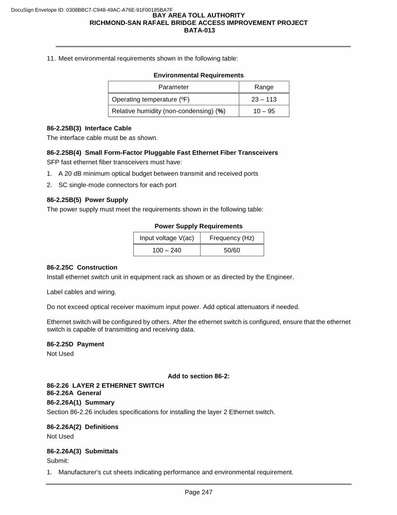
BAY AREA TOLL AUTHORITY RICHMOND-SAN RAFAEL BRIDGE ACCESS IMPROVEMENT PROJECT
BATA-013
Page 247
11. Meet environmental requirements shown in the following table:
Environmental Requirements
Parameter Range
Operating temperature (ºF) 23 – 113
Relative humidity (non-condensing) (%) 10 – 95 86-2.25B(3) Interface Cable The interface cable must be as shown. 86-2.25B(4) Small Form-Factor Pluggable Fast Ethernet Fiber Transceivers SFP fast ethernet fiber transceivers must have:
1. A 20 dB minimum optical budget between transmit and received ports
2. SC single-mode connectors for each port 86-2.25B(5) Power Supply The power supply must meet the requirements shown in the following table:
Power Supply Requirements
Input voltage V(ac) Frequency (Hz)
100 – 240 50/60 86-2.25C Construction Install ethernet switch unit in equipment rack as shown or as directed by the Engineer. Label cables and wiring. Do not exceed optical receiver maximum input power. Add optical attenuators if needed. Ethernet switch will be configured by others. After the ethernet switch is configured, ensure that the ethernet switch is capable of transmitting and receiving data. 86-2.25D Payment Not Used
Add to section 86-2: 86-2.26 LAYER 2 ETHERNET SWITCH 86-2.26A General 86-2.26A(1) Summary Section 86-2.26 includes specifications for installing the layer 2 Ethernet switch. 86-2.26A(2) Definitions Not Used 86-2.26A(3) Submittals Submit:
1. Manufacturer's cut sheets indicating performance and environmental requirement.
DocuSign Envelope ID: 0308BBC7-C948-49AC-A76E-91F00185BA7F
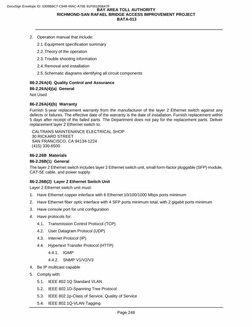
BAY AREA TOLL AUTHORITY RICHMOND-SAN RAFAEL BRIDGE ACCESS IMPROVEMENT PROJECT
BATA-013
Page 248
2. Operation manual that include:
2.1. Equipment specification summary
2.2. Theory of the operation
2.3. Trouble shooting information
2.4. Removal and installation
2.5. Schematic diagrams identifying all circuit components 86-2.26A(4) Quality Control and Assurance 86-2.26A(4)(a) General Not Used 86-2.26A(4)(b) Warranty Furnish 5-year replacement warranty from the manufacturer of the layer 2 Ethernet switch against any defects or failures. The effective date of the warranty is the date of installation. Furnish replacement within 5 days after receipt of the failed parts. The Department does not pay for the replacement parts. Deliver replacement layer 2 Ethernet switch to:
CALTRANS MAINTENANCE ELECTRICAL SHOP 30 RICKARD STREET SAN FRANCISCO, CA 94134-1224 (415) 330-6500
86-2.26B Materials 86-2.26B(1) General The layer 2 Ethernet switch includes layer 2 Ethernet switch unit, small form-factor pluggable (SFP) module, CAT-5E cable, and power supply. 86-2.26B(2) Layer 2 Ethernet Switch Unit Layer 2 Ethernet switch unit must:
1. Have Ethernet copper interface with 6 Ethernet 10/100/1000 Mbps ports minimum
2. Have Ethernet fiber optic interface with 4 SFP ports minimum total, with 2 gigabit ports minimum
3. Have console port for unit configuration
4. Have protocols for:
4.1. Transmission Control Protocol (TCP)
4.2. User Datagram Protocol (UDP)
4.3. Internet Protocol (IP)
4.4. Hypertext Transfer Protocol (HTTP)
4.4.1. IGMP
4.4.2. SNMP V1/V2/V3
4. Be IP multicast capable
5. Comply with:
5.1. IEEE 802.1Q Standard VLAN
5.2. IEEE 802.1D-Spanning Tree Protocol
5.3. IEEE 802.1p-Class of Service, Quality of Service
5.4. IEEE 802.1Q-VLAN Tagging
DocuSign Envelope ID: 0308BBC7-C948-49AC-A76E-91F00185BA7F
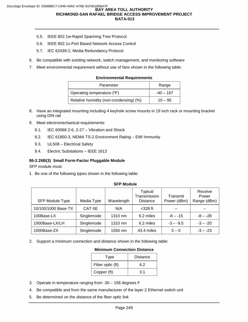
BAY AREA TOLL AUTHORITY RICHMOND-SAN RAFAEL BRIDGE ACCESS IMPROVEMENT PROJECT
BATA-013
Page 249
5.5. IEEE 802.1w-Rapid Spanning Tree Protocol
5.6. IEEE 802.1x-Port Based Network Access Control
5.7. IEC 62439-2, Media Redundancy Protocol
6. Be compatible with existing network, switch management, and monitoring software
7. Meet environmental requirement without use of fans shown in the following table:
Environmental Requirements
Parameter Range
Operating temperature (ºF) -40 – 167
Relative humidity (non-condensing) (%) 10 – 95 8. Have an integrated mounting including 4 keyhole screw mounts in 19 inch rack or mounting bracket
using DIN rail
9. Meet electromechanical requirements:
9.1. IEC 60068 2-6, 2-27 – Vibration and Shock
9.2. IEC 61850-3, NEMA TS-2 Environment Rating – EMI Immunity
9.3. UL508 – Electrical Safety
9.4. Electric Substations – IEEE 1613 86-2.26B(3) Small Form-Factor Pluggable Module SFP module must:
1. Be one of the following types shown in the following table:
SFP Module
SFP Module Type Media Type Wavelength
Typical Transmission
Distance Transmit
Power (dBm)
Receive Power
Range (dBm)
10/100/1000 Base-TX CAT-5E N/A <328 ft -- --
100Base-LX Singlemode 1310 nm 6.2 miles -8 – -15 -8 – -28
1000Base-LX/LH Singlemode 1310 nm 6.2 miles -3 – -9.5 -3 – -20
1000Base-ZX Singlemode 1550 nm 43.4 miles 5 – 0 -3 – -23 2. Support a minimum connection and distance shown in the following table:
Minimum Connection Distance
Type Distance
Fiber optic (ft) 6.2
Copper (ft) 3.1 3. Operate in temperature ranging from -30 – 158 degrees F
4. Be compatible and from the same manufacturer of the layer 2 Ethernet switch unit
5. Be determined on the distance of the fiber optic link
DocuSign Envelope ID: 0308BBC7-C948-49AC-A76E-91F00185BA7F
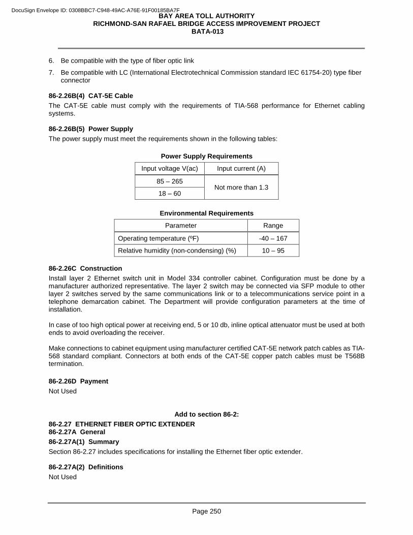
BAY AREA TOLL AUTHORITY RICHMOND-SAN RAFAEL BRIDGE ACCESS IMPROVEMENT PROJECT
BATA-013
Page 250
6. Be compatible with the type of fiber optic link
7. Be compatible with LC (International Electrotechnical Commission standard IEC 61754-20) type fiber connector
86-2.26B(4) CAT-5E Cable The CAT-5E cable must comply with the requirements of TIA-568 performance for Ethernet cabling systems. 86-2.26B(5) Power Supply The power supply must meet the requirements shown in the following tables:
Power Supply Requirements
Input voltage V(ac) Input current (A)
85 – 265 Not more than 1.3
18 – 60
Environmental Requirements
Parameter Range
Operating temperature (ºF) -40 – 167
Relative humidity (non-condensing) (%) 10 – 95 86-2.26C Construction Install layer 2 Ethernet switch unit in Model 334 controller cabinet. Configuration must be done by a manufacturer authorized representative. The layer 2 switch may be connected via SFP module to other layer 2 switches served by the same communications link or to a telecommunications service point in a telephone demarcation cabinet. The Department will provide configuration parameters at the time of installation. In case of too high optical power at receiving end, 5 or 10 db, inline optical attenuator must be used at both ends to avoid overloading the receiver. Make connections to cabinet equipment using manufacturer certified CAT-5E network patch cables as TIA-568 standard compliant. Connectors at both ends of the CAT-5E copper patch cables must be T568B termination. 86-2.26D Payment Not Used
Add to section 86-2: 86-2.27 ETHERNET FIBER OPTIC EXTENDER 86-2.27A General 86-2.27A(1) Summary Section 86-2.27 includes specifications for installing the Ethernet fiber optic extender. 86-2.27A(2) Definitions Not Used
DocuSign Envelope ID: 0308BBC7-C948-49AC-A76E-91F00185BA7F
BAY AREA TOLL AUTHORITY RICHMOND-SAN RAFAEL BRIDGE ACCESS IMPROVEMENT PROJECT
BATA-013
Page 251
86-2.27A(3) Submittals Submit: 1. Warranty documentation before installation
2. Documentation required for acceptance testing, maintenance, and operation
3. Test plan to the Engineer indicating proposed dates, duration and methods of the testing
4. Performance test report and collected data to the Engineer for authorization
5. One set of documents with the parameters configured and related wiring installed 86-2.27A(4) Quality Control and Assurance 86-2.27A(4)(a) General Tests data must be collected in the presence of the Engineer. 86-2.27A(4)(b) Warranty Furnish a 2-year replacement warranty from the manufacturer of the Ethernet switch against any defects or failures. The effective date of the warranty is the date of acceptance of the installation. Furnish replacement parts within 15 days after receipt of the failed parts. The Department does not pay for the replacement. Deliver replacement parts to: CALTRANS MAINTENANCE ELECTRICAL SHOP 30 RICKARD STREET SAN FRANCISCO, CA 94134-1224 (415) 330-6500
86-2.27B Materials 86-2.27B(1) General The Ethernet fiber optic extender includes Ethernet fiber optic extender unit, mounting hardware, power supply, cables, and connectors. 86-2.27B(2) Ethernet Fiber Optic Extender Unit The Ethernet fiber optic extender unit must:
1. Comply with FCC Part 15 Class B, UL 60950
2. Operate over singlemode fiber optic cable to extend or bridge field Ethernet networks
3. Be interoperable with industry standard Ethernet network capable equipment and rated for use in outdoor enclosures without the use of mechanical cooling
4. Have transparent operations to end users and other industry standard Ethernet network capable equipment
5. Include web browser
6. Include a front panel diagnostic LED status indicators for power status, alarm, port network link connection and data activity status
7. Have ports for:
7.1. Fiber optic
7.2. Local management TIA-232 via DE9
7.3. MES: Four type autosensing 10/100BaseT half/full duplex minimum
DocuSign Envelope ID: 0308BBC7-C948-49AC-A76E-91F00185BA7F
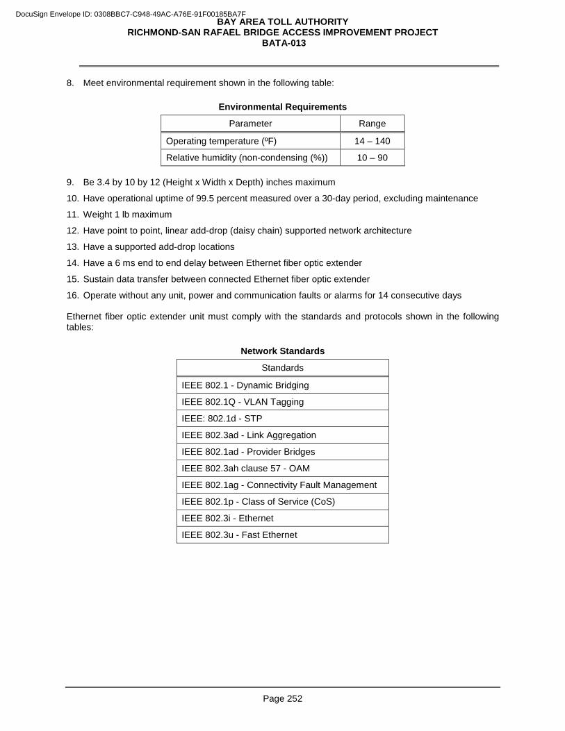
BAY AREA TOLL AUTHORITY RICHMOND-SAN RAFAEL BRIDGE ACCESS IMPROVEMENT PROJECT
BATA-013
Page 252
8. Meet environmental requirement shown in the following table:
Environmental Requirements
Parameter Range
Operating temperature (ºF) 14 – 140
Relative humidity (non-condensing (%)) 10 – 90 9. Be 3.4 by 10 by 12 (Height x Width x Depth) inches maximum
10. Have operational uptime of 99.5 percent measured over a 30-day period, excluding maintenance
11. Weight 1 lb maximum
12. Have point to point, linear add-drop (daisy chain) supported network architecture
13. Have a supported add-drop locations
14. Have a 6 ms end to end delay between Ethernet fiber optic extender
15. Sustain data transfer between connected Ethernet fiber optic extender
16. Operate without any unit, power and communication faults or alarms for 14 consecutive days Ethernet fiber optic extender unit must comply with the standards and protocols shown in the following tables:
Network Standards
Standards
IEEE 802.1 - Dynamic Bridging
IEEE 802.1Q - VLAN Tagging
IEEE: 802.1d - STP
IEEE 802.3ad - Link Aggregation
IEEE 802.1ad - Provider Bridges
IEEE 802.3ah clause 57 - OAM
IEEE 802.1ag - Connectivity Fault Management
IEEE 802.1p - Class of Service (CoS)
IEEE 802.3i - Ethernet
IEEE 802.3u - Fast Ethernet
DocuSign Envelope ID: 0308BBC7-C948-49AC-A76E-91F00185BA7F
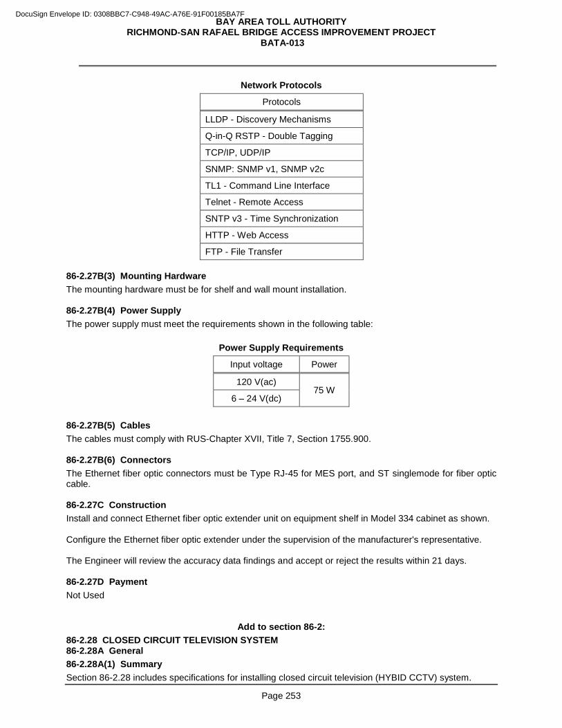
BAY AREA TOLL AUTHORITY RICHMOND-SAN RAFAEL BRIDGE ACCESS IMPROVEMENT PROJECT
BATA-013
Page 253
Network Protocols
Protocols
LLDP - Discovery Mechanisms
Q-in-Q RSTP - Double Tagging
TCP/IP, UDP/IP
SNMP: SNMP v1, SNMP v2c
TL1 - Command Line Interface
Telnet - Remote Access
SNTP v3 - Time Synchronization
HTTP - Web Access
FTP - File Transfer 86-2.27B(3) Mounting Hardware The mounting hardware must be for shelf and wall mount installation. 86-2.27B(4) Power Supply The power supply must meet the requirements shown in the following table:
Power Supply Requirements
Input voltage Power
120 V(ac) 75 W
6 – 24 V(dc) 86-2.27B(5) Cables The cables must comply with RUS-Chapter XVII, Title 7, Section 1755.900. 86-2.27B(6) Connectors The Ethernet fiber optic connectors must be Type RJ-45 for MES port, and ST singlemode for fiber optic cable. 86-2.27C Construction Install and connect Ethernet fiber optic extender unit on equipment shelf in Model 334 cabinet as shown. Configure the Ethernet fiber optic extender under the supervision of the manufacturer's representative. The Engineer will review the accuracy data findings and accept or reject the results within 21 days. 86-2.27D Payment Not Used
Add to section 86-2: 86-2.28 CLOSED CIRCUIT TELEVISION SYSTEM 86-2.28A General 86-2.28A(1) Summary Section 86-2.28 includes specifications for installing closed circuit television (HYBID CCTV) system.
DocuSign Envelope ID: 0308BBC7-C948-49AC-A76E-91F00185BA7F
BAY AREA TOLL AUTHORITY RICHMOND-SAN RAFAEL BRIDGE ACCESS IMPROVEMENT PROJECT
BATA-013
Page 254
86-2.28A(2) Definitions and Abbreviations 86-2.28A(2)(a) Definitions APA: Aluminum polymer and aluminum shield with adhesive
CLI: A Command-Line Interface is a means of interaction with a computer program where the user issues commands to a program in the form of successive lines of text
DE-9: 9 pin subminiature E size D shell connector for TIA-232 applications
DHCP: The Dynamic Host Configuration Protocol is a network protocol to configure network devices so that they can communicate on an IP network
HCC: Hybrid Camera Cable is a power and communication cable for HYBID CCTV system
MPEG-4-ISO/IEC 14496-2: A Moving Picture Expert Group is a method of defining compression of audio and visual digital data
PE: Polyethylene is an insulated material for the cables and conductors
PTZ: Pan and Tilt and Zoom is a function for the HYBID CCTV camera
SD: Secure Digital memory card format
SMPTE-170M: Society of Motion Picture and Television Engineers Committee on Television Technology. SMPTE 170M is used for TV broadcasts
SNMP: Simple Network Management Protocol is an Internet-standard protocol for managing devices on IP networks
TDR: Time-domain reflectometer is an electronic instrument used to characterize and locate faults in metallic cables and connectors
TELNET: Network protocol used on the Internet or local area networks to provide a bidirectional interactive text-oriented communication facility using a virtual terminal connection
TIA: Telecommunications Industries Association organization who developed a common interface standard for data communications equipment
UTP: Unshielded Twisted Pair cable. UTP cable is a 100 ohm copper cable that consist of 2 to 1800 unshielded twisted pairs surrounded by an outer jacket. They have no metallic shield. This makes the cable small in diameter but unprotected against electrical interference. The twist helps to improve its immunity to electrical noise
VW-1: Standard for Vertical Flame Test of the flammability of insulating materials 86-2.28A(2)(b) Abbreviations AMP: Amphenol Connector Type
BNC: Bayonet Neill-Concelman connector
bps: Bits Per Second
CIF: Common Intermediate Format
CLI: Command Line Interface
DHCP: Dynamic Host Configuration Protocol
fps: Frame Per Second
HTTP: Hypertext Transfer Protocol
IEC: International Electrotechnical Commission
IP: Internet Protocol
ISO: International Organization for Standardization
DocuSign Envelope ID: 0308BBC7-C948-49AC-A76E-91F00185BA7F
BAY AREA TOLL AUTHORITY RICHMOND-SAN RAFAEL BRIDGE ACCESS IMPROVEMENT PROJECT
BATA-013
Page 255
JEDEC: Joint Electron Device Engineering Council
LED: Light Emitting Diode
MIL: Military
MCTU: Multiple Camera Termination Unit
MPEG: Motion Picture Experts Group
NTSC: National Television System Committee
QCIF: Quarter Common Intermediate Format
QSIF: Quarter Source Input Format
RTCP: Real-Time Control Protocol
RTP: Real-time Transport Protocol
RTSP: Real Time Streaming Protocol
SIF: Source Input Format
SNMP: Simple Network Management Protocol
UDP: User Datagram Protocol 86-2.28A(3) Submittals Submit:
1. Copies of the CCTV industry standards and specifications.
2. Certificates of compliance from the manufacturers for HCC and cable connectors. Include test results for attenuation and faults.
3. Three copies of service manuals for the hybrid CCTV (PTZ) camera unit. The manuals must include:
3.1. General information:
3.1.1. A list of applicable subassemblies that comprise the specified equipment
3.1.2. Overall description of the equipment design features (including all enhanced features, performance, and applications)
3.1.3. Equipment installation instructions
3.2. Theory of operations:
3.2.1. Theory of operation of the standard equipment, with unique or unusual circuitry described in detail
3.2.2. Theory of operation reflecting any modifications to the standard equipment
3.3. Maintenance:
3.3.1. Recommended test equipment and fixtures, or minimum operational and performance requirements for appropriate test equipment
3.3.2. Troubleshooting information and charts
DocuSign Envelope ID: 0308BBC7-C948-49AC-A76E-91F00185BA7F
BAY AREA TOLL AUTHORITY RICHMOND-SAN RAFAEL BRIDGE ACCESS IMPROVEMENT PROJECT
BATA-013
Page 256
3.3.3. Removal and installation procedures for replacing assemblies and subassemblies, if not obvious or if improper sequencing of steps may result in component damage
3.4. Replacement parts:
3.4.1. Each manual must contain an equipment replacement parts list including electrical parts, mechanical parts, and assemblies
3.4.2. Identify all semiconductors by the supplier's numbers and by Joint Electron Device Engineering Council (JEDEC) numbers if applicable
3.5. Diagram and physical requirements:
3.5.1. Schematic diagram(s) identifying all circuit components and showing normal test voltages and levels
3.5.2. An overall functional block diagram
3.5.3. Detailed interconnecting diagram(s) showing wiring between modules, circuit boards, and major components
3.5.4. Pictorial circuit board layout diagram(s) showing both component placement and printed wiring detail
3.5.5. Diagram(s) showing location of circuit boards and other subassemblies
3.5.6. Exploded view diagram(s) of complex mechanical assemblies
3.6. Physical requirements:
3.6.1. Securely fasten all pages, including latest revisions, together between protective covers (loose-leaf ring binding is acceptable)
3.6.2. Do not subject any page to fading from exposure to any normal source of ambient lighting (ozalid reproduced pages are not acceptable)
4. Warranty documentation before installation 86-2.28A(4) Quality Control and Assurance 86-2.28A(4)(a) General Deliver the following items to METS for acceptance testing:
1. Hybrid CCTV (PTZ) Camera Unit
2. High Mast Camera Lowering Device System
3. Fiber Optic Transmitter and Receiver HCC manufacturer must test the entire length of HCC for attenuation and faults using a TDR. A fault may include any of the following:
1. Return loss measurements indicating:
1.1. Attenuation exceeding 3 dB in the band from 5 to 30 MHz in a portion of cable less than 10 feet long
1.2. Short in the cable
1.3. Cut or open circuit in the cable
2. Exposure of or damage to the cable jacket revealed by a visual inspection Randomly inspect the cable termination for contact crimping quality control. Reject any contact found not crimped with the correct crimping tool and is defective. Redo the termination until all defects are corrected. Before removal or relocation of existing CCTV equipment including cables, pole, camera, pan and tilt unit, controller cabinet, etc., you must test the camera unit in the field. Repair or replace existing equipment that
DocuSign Envelope ID: 0308BBC7-C948-49AC-A76E-91F00185BA7F
BAY AREA TOLL AUTHORITY RICHMOND-SAN RAFAEL BRIDGE ACCESS IMPROVEMENT PROJECT
BATA-013
Page 257
fail this test, repair or replacement is change order work. Notify the Engineer fifteen days before the scheduled testing. Inspect for correct wiring terminations, correct cable interconnections, and good workmanship. Perform functional testing to verify:
1. All local mode CCTV operations using laptop PC and software.
2. Video signal output with NTSC monitor
3. The correct operation of the auto/manual iris and focus, and manual zoom functions
4. The correct operation of the pan and tilt function.
5. The correct operation of the preset positions Upon completion of work, the Department will test each hybrid CCTV (PTZ). Provide and load all software before the start of testing. The testing includes continuous satisfactory operation of each camera unit for 5 consecutive days. Replace any material and equipment found to be defective, unsuitable, or violating standards. The Department does not pay for replacement parts. After you correct all defects, the Department will re-test the camera unit. Allow 30 days for the camera unit equipment testing. You will be notified upon satisfactory completion of the testing. Pick up the equipment from the Laboratory and deliver it to a Department-owned storage location designated by the Engineer. You are responsible for the costs of shipping, handling, and the transportation of equipment to and from the Laboratory. 86-2.28A(4)(b) Warranty Furnish a 1-year replacement written warranty from the manufacturer of the camera unit equipment against any defects or failures. The effective date of the warranty is the date of installation. Replace camera unit equipment within 10 days after receipt of the failed camera unit equipment. The Department does not pay for the replacement. Deliver replacement camera unit to:
CALTRANS MAINTENANCE ELECTRICAL SHOP 30 RICKARD STREET SAN FRANCISCO, CA 94134 (415) 330-6500
86-2.28B Materials 86-2.28B(1) General The CCTV system must include the CCTV pole and camera mounting adapter; hybrid CCTV (PTZ) camera unit; HCC, connectors and fittings; interface cable and conductors; equipment shelf with brackets; and rack-mount power strip. 86-2.28B(2) Hybrid CCTV (PTZ) Camera Unit 86-2.28B(2)(a) General Each hybrid CCTV (PTZ) camera unit must comply with the following table:
DocuSign Envelope ID: 0308BBC7-C948-49AC-A76E-91F00185BA7F
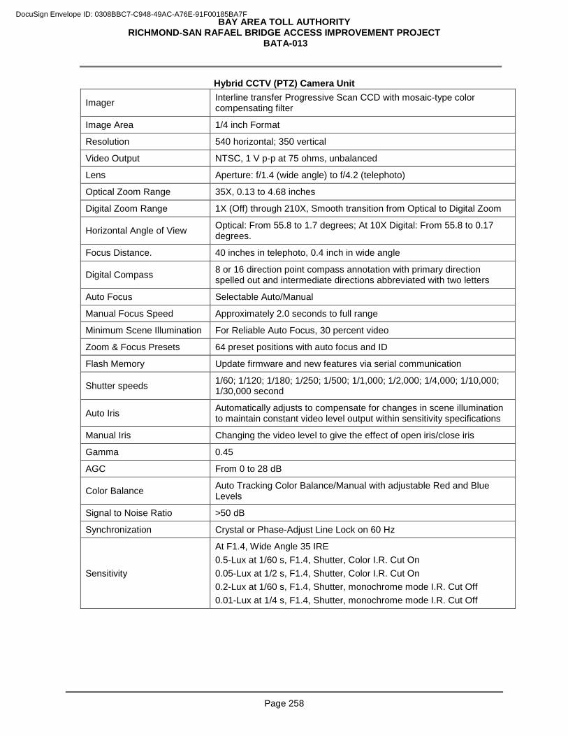
BAY AREA TOLL AUTHORITY RICHMOND-SAN RAFAEL BRIDGE ACCESS IMPROVEMENT PROJECT
BATA-013
Page 258
Hybrid CCTV (PTZ) Camera Unit
Imager Interline transfer Progressive Scan CCD with mosaic-type color compensating filter
Image Area 1/4 inch Format
Resolution 540 horizontal; 350 vertical
Video Output NTSC, 1 V p-p at 75 ohms, unbalanced
Lens Aperture: f/1.4 (wide angle) to f/4.2 (telephoto)
Optical Zoom Range 35X, 0.13 to 4.68 inches
Digital Zoom Range 1X (Off) through 210X, Smooth transition from Optical to Digital Zoom
Horizontal Angle of View Optical: From 55.8 to 1.7 degrees; At 10X Digital: From 55.8 to 0.17 degrees.
Focus Distance. 40 inches in telephoto, 0.4 inch in wide angle
Digital Compass 8 or 16 direction point compass annotation with primary direction spelled out and intermediate directions abbreviated with two letters
Auto Focus Selectable Auto/Manual
Manual Focus Speed Approximately 2.0 seconds to full range
Minimum Scene Illumination For Reliable Auto Focus, 30 percent video
Zoom & Focus Presets 64 preset positions with auto focus and ID
Flash Memory Update firmware and new features via serial communication
Shutter speeds 1/60; 1/120; 1/180; 1/250; 1/500; 1/1,000; 1/2,000; 1/4,000; 1/10,000; 1/30,000 second
Auto Iris Automatically adjusts to compensate for changes in scene illumination to maintain constant video level output within sensitivity specifications
Manual Iris Changing the video level to give the effect of open iris/close iris
Gamma 0.45
AGC From 0 to 28 dB
Color Balance Auto Tracking Color Balance/Manual with adjustable Red and Blue Levels
Signal to Noise Ratio >50 dB
Synchronization Crystal or Phase-Adjust Line Lock on 60 Hz
Sensitivity
At F1.4, Wide Angle 35 IRE 0.5-Lux at 1/60 s, F1.4, Shutter, Color I.R. Cut On 0.05-Lux at 1/2 s, F1.4, Shutter, Color I.R. Cut On 0.2-Lux at 1/60 s, F1.4, Shutter, monochrome mode I.R. Cut Off 0.01-Lux at 1/4 s, F1.4, Shutter, monochrome mode I.R. Cut Off
DocuSign Envelope ID: 0308BBC7-C948-49AC-A76E-91F00185BA7F
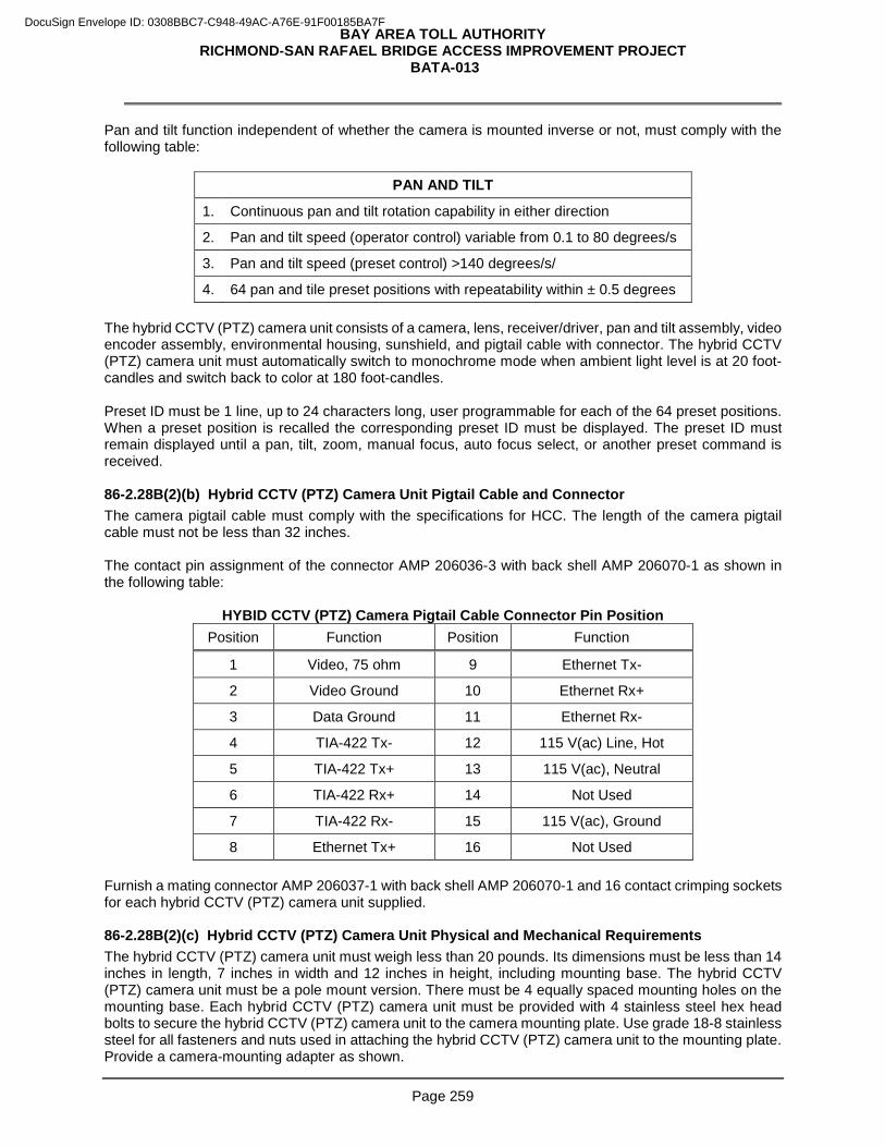
BAY AREA TOLL AUTHORITY RICHMOND-SAN RAFAEL BRIDGE ACCESS IMPROVEMENT PROJECT
BATA-013
Page 259
Pan and tilt function independent of whether the camera is mounted inverse or not, must comply with the following table:
PAN AND TILT
1. Continuous pan and tilt rotation capability in either direction
2. Pan and tilt speed (operator control) variable from 0.1 to 80 degrees/s
3. Pan and tilt speed (preset control) >140 degrees/s/
4. 64 pan and tile preset positions with repeatability within ± 0.5 degrees The hybrid CCTV (PTZ) camera unit consists of a camera, lens, receiver/driver, pan and tilt assembly, video encoder assembly, environmental housing, sunshield, and pigtail cable with connector. The hybrid CCTV (PTZ) camera unit must automatically switch to monochrome mode when ambient light level is at 20 foot-candles and switch back to color at 180 foot-candles. Preset ID must be 1 line, up to 24 characters long, user programmable for each of the 64 preset positions. When a preset position is recalled the corresponding preset ID must be displayed. The preset ID must remain displayed until a pan, tilt, zoom, manual focus, auto focus select, or another preset command is received. 86-2.28B(2)(b) Hybrid CCTV (PTZ) Camera Unit Pigtail Cable and Connector The camera pigtail cable must comply with the specifications for HCC. The length of the camera pigtail cable must not be less than 32 inches. The contact pin assignment of the connector AMP 206036-3 with back shell AMP 206070-1 as shown in the following table:
HYBID CCTV (PTZ) Camera Pigtail Cable Connector Pin Position Position Function Position Function
1 Video, 75 ohm 9 Ethernet Tx-
2 Video Ground 10 Ethernet Rx+
3 Data Ground 11 Ethernet Rx-
4 TIA-422 Tx- 12 115 V(ac) Line, Hot
5 TIA-422 Tx+ 13 115 V(ac), Neutral
6 TIA-422 Rx+ 14 Not Used
7 TIA-422 Rx- 15 115 V(ac), Ground
8 Ethernet Tx+ 16 Not Used Furnish a mating connector AMP 206037-1 with back shell AMP 206070-1 and 16 contact crimping sockets for each hybrid CCTV (PTZ) camera unit supplied. 86-2.28B(2)(c) Hybrid CCTV (PTZ) Camera Unit Physical and Mechanical Requirements The hybrid CCTV (PTZ) camera unit must weigh less than 20 pounds. Its dimensions must be less than 14 inches in length, 7 inches in width and 12 inches in height, including mounting base. The hybrid CCTV (PTZ) camera unit must be a pole mount version. There must be 4 equally spaced mounting holes on the mounting base. Each hybrid CCTV (PTZ) camera unit must be provided with 4 stainless steel hex head bolts to secure the hybrid CCTV (PTZ) camera unit to the camera mounting plate. Use grade 18-8 stainless steel for all fasteners and nuts used in attaching the hybrid CCTV (PTZ) camera unit to the mounting plate. Provide a camera-mounting adapter as shown.
DocuSign Envelope ID: 0308BBC7-C948-49AC-A76E-91F00185BA7F
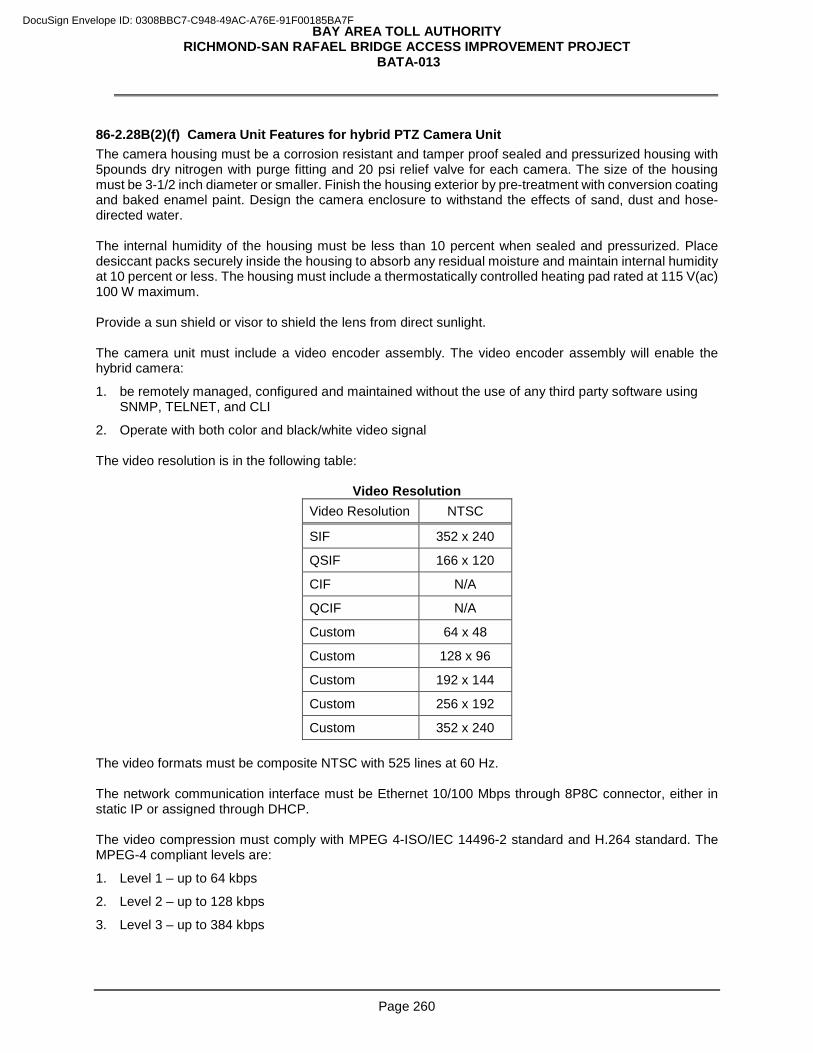
BAY AREA TOLL AUTHORITY RICHMOND-SAN RAFAEL BRIDGE ACCESS IMPROVEMENT PROJECT
BATA-013
Page 260
86-2.28B(2)(f) Camera Unit Features for hybrid PTZ Camera Unit The camera housing must be a corrosion resistant and tamper proof sealed and pressurized housing with 5pounds dry nitrogen with purge fitting and 20 psi relief valve for each camera. The size of the housing must be 3-1/2 inch diameter or smaller. Finish the housing exterior by pre-treatment with conversion coating and baked enamel paint. Design the camera enclosure to withstand the effects of sand, dust and hose-directed water. The internal humidity of the housing must be less than 10 percent when sealed and pressurized. Place desiccant packs securely inside the housing to absorb any residual moisture and maintain internal humidity at 10 percent or less. The housing must include a thermostatically controlled heating pad rated at 115 V(ac) 100 W maximum. Provide a sun shield or visor to shield the lens from direct sunlight. The camera unit must include a video encoder assembly. The video encoder assembly will enable the hybrid camera:
1. be remotely managed, configured and maintained without the use of any third party software using SNMP, TELNET, and CLI
2. Operate with both color and black/white video signal The video resolution is in the following table:
Video Resolution Video Resolution NTSC
SIF 352 x 240
QSIF 166 x 120
CIF N/A
QCIF N/A
Custom 64 x 48
Custom 128 x 96
Custom 192 x 144
Custom 256 x 192
Custom 352 x 240 The video formats must be composite NTSC with 525 lines at 60 Hz. The network communication interface must be Ethernet 10/100 Mbps through 8P8C connector, either in static IP or assigned through DHCP. The video compression must comply with MPEG 4-ISO/IEC 14496-2 standard and H.264 standard. The MPEG-4 compliant levels are:
1. Level 1 – up to 64 kbps
2. Level 2 – up to 128 kbps
3. Level 3 – up to 384 kbps
DocuSign Envelope ID: 0308BBC7-C948-49AC-A76E-91F00185BA7F
BAY AREA TOLL AUTHORITY RICHMOND-SAN RAFAEL BRIDGE ACCESS IMPROVEMENT PROJECT
BATA-013
Page 261
The video rates must be scalable from 1 fps to 30 fps and from 8 kbps to 2 Mbps. User selectable options are:
1. Constant bit rate at constant frame rate
2. Variable bit rate at constant frame rate
3. Constant bit rate at variable frame rate The video delivery options must be either unicast or multicast with protocols DiffServ (QoS), UDP, IP, RTP, RTSP, RTCP, HTTP, SNMP, and TELNET. The camera unit must include a character generator. The text characters must be uppercase white with black border impose on the video stream. A maximum of 6 lines of user programmable alphanumeric text must be displayed through serial communications. Messages may be positioned at either the top or the bottom of display. The right side positioning is accomplished by padding left side of message with spaces. Blank lines must not be displayed. Any programmed line being displayed must fill in toward the top if top positioning is selected or toward the bottom if bottom position is selected. Camera ID must be used for upper 2 lines with each up to 24 characters long. If both lines are programmed, line 1 of camera ID must always appear above line 2 of camera ID regardless of top or bottom selection. An 8-point or 16-point compass annotation must be settable for a true north position. Display must include North, NE, East, SE, South, SW, West and NW. Position must be able to be grouped with the site location or separated from site location. Azimuth position must be displayed in 0 to 359 degrees and elevation position must be displayed in +95 to –95 degrees. All display must be user selectable for enable/disable, 3-second time out or permanent display. Sector message of up to 16 sectors in 360 degrees must be defined with up to 24 characters long. Low-pressure indicator must use 1 line with messages displayed in "blinking" or "non-blinking" mode when activated by low internal pressure. Provide adjustable set points by altitude via the serial port to activate low-pressure. Message must be enabled or disabled. In maintenance mode readings of the internal pressure of the camera housing must be displayed from 5 psi down to 1 psi, in 0.1-psi increments. Internal temperature indicator must use 1 line with messages displayed in "blinking" or "non-blinking" mode. Message must be enabled or disabled. In maintenance mode, camera readings of the internal temperature of the camera housing must be in 1-degree increments. Provide video blanked for up to 8 privacy zones. One line numeric messages must be displayed. Message must be displayed in "blinking" or "non-blinking" mode and be enabled or disabled. Program privacy zones through serial communications. Control and addressing the camera unit must be done through TIA-422 optically isolated serial communications. Additional protocols must consist of Cohu, American Dynamics, Javelin, Philips/Bosch, Vicon and Pelco-D. Include the National Transportation Communications for ITS Protocol (NTCIP) 1205 protocol communications protocol as an option. The camera unit must respond in less than 1.0 second upon receipt of any given command. All programmable functions including camera last operating position must be stored in non-volatile memory and must not be lost if a power failure occurs. Upon power restoration, the camera must go through a series of self-testing/calibration and return to the same position it left before the power interruption. System configurations such as video privacy zones, preset text and sector ID must be able to be stored in a computer file and uploaded into a camera in the event that a camera replacement is necessary. 86-2.28B(2)(g) Power Requirements The camera unit must operate between 89 to 135 V(ac), 120 V(ac) nominal voltage and 60 Hz (±3 Hz). The camera unit must comply with NEMA standard TS-2 for traffic control system 2.1.2. The camera unit must
DocuSign Envelope ID: 0308BBC7-C948-49AC-A76E-91F00185BA7F
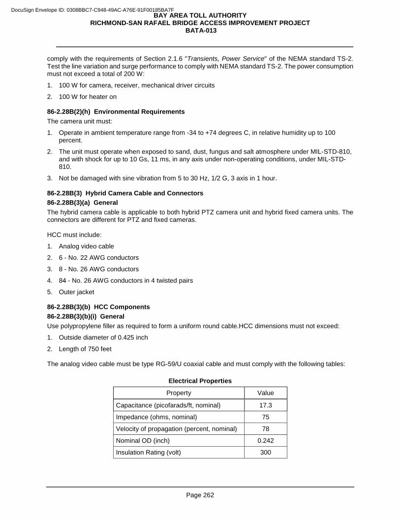
BAY AREA TOLL AUTHORITY RICHMOND-SAN RAFAEL BRIDGE ACCESS IMPROVEMENT PROJECT
BATA-013
Page 262
comply with the requirements of Section 2.1.6 "Transients, Power Service" of the NEMA standard TS-2. Test the line variation and surge performance to comply with NEMA standard TS-2. The power consumption must not exceed a total of 200 W:
1. 100 W for camera, receiver, mechanical driver circuits
2. 100 W for heater on 86-2.28B(2)(h) Environmental Requirements The camera unit must:
1. Operate in ambient temperature range from -34 to +74 degrees C, in relative humidity up to 100 percent.
2. The unit must operate when exposed to sand, dust, fungus and salt atmosphere under MIL-STD-810, and with shock for up to 10 Gs, 11 ms, in any axis under non-operating conditions, under MIL-STD-810.
3. Not be damaged with sine vibration from 5 to 30 Hz, 1/2 G, 3 axis in 1 hour. 86-2.28B(3) Hybrid Camera Cable and Connectors 86-2.28B(3)(a) General The hybrid camera cable is applicable to both hybrid PTZ camera unit and hybrid fixed camera units. The connectors are different for PTZ and fixed cameras. HCC must include:
1. Analog video cable
2. 6 - No. 22 AWG conductors
3. 8 - No. 26 AWG conductors
4. 84 - No. 26 AWG conductors in 4 twisted pairs
5. Outer jacket 86-2.28B(3)(b) HCC Components 86-2.28B(3)(b)(i) General Use polypropylene filler as required to form a uniform round cable.HCC dimensions must not exceed:
1. Outside diameter of 0.425 inch
2. Length of 750 feet The analog video cable must be type RG-59/U coaxial cable and must comply with the following tables:
Electrical Properties
Property Value
Capacitance (picofarads/ft, nominal) 17.3
Impedance (ohms, nominal) 75
Velocity of propagation (percent, nominal) 78
Nominal OD (inch) 0.242
Insulation Rating (volt) 300
DocuSign Envelope ID: 0308BBC7-C948-49AC-A76E-91F00185BA7F
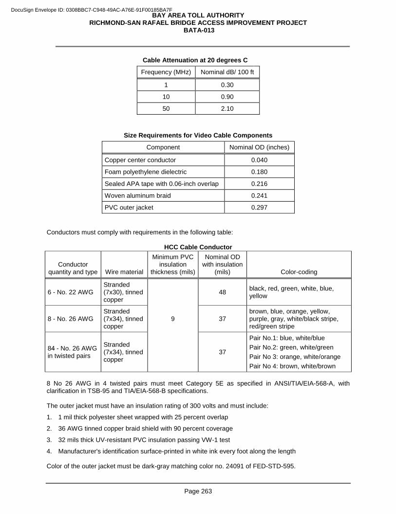
BAY AREA TOLL AUTHORITY RICHMOND-SAN RAFAEL BRIDGE ACCESS IMPROVEMENT PROJECT
BATA-013
Page 263
Cable Attenuation at 20 degrees C
Frequency (MHz) Nominal dB/ 100 ft
1 0.30
10 0.90
50 2.10
Size Requirements for Video Cable Components
Component Nominal OD (inches)
Copper center conductor 0.040
Foam polyethylene dielectric 0.180
Sealed APA tape with 0.06-inch overlap 0.216
Woven aluminum braid 0.241
PVC outer jacket 0.297 Conductors must comply with requirements in the following table:
HCC Cable Conductor
Conductor quantity and type Wire material
Minimum PVC insulation
thickness (mils)
Nominal OD with insulation
(mils) Color-coding
6 - No. 22 AWG Stranded (7x30), tinned copper
48 black, red, green, white, blue, yellow
8 - No. 26 AWG Stranded (7x34), tinned copper
9 37 brown, blue, orange, yellow, purple, gray, white/black stripe, red/green stripe
84 - No. 26 AWG in twisted pairs
Stranded (7x34), tinned copper
37
Pair No.1: blue, white/blue Pair No.2: green, white/green Pair No 3: orange, white/orange Pair No 4: brown, white/brown
8 No 26 AWG in 4 twisted pairs must meet Category 5E as specified in ANSI/TIA/EIA-568-A, with clarification in TSB-95 and TIA/EIA-568-B specifications. The outer jacket must have an insulation rating of 300 volts and must include:
1. 1 mil thick polyester sheet wrapped with 25 percent overlap
2. 36 AWG tinned copper braid shield with 90 percent coverage
3. 32 mils thick UV-resistant PVC insulation passing VW-1 test
4. Manufacturer's identification surface-printed in white ink every foot along the length Color of the outer jacket must be dark-gray matching color no. 24091 of FED-STD-595.
DocuSign Envelope ID: 0308BBC7-C948-49AC-A76E-91F00185BA7F
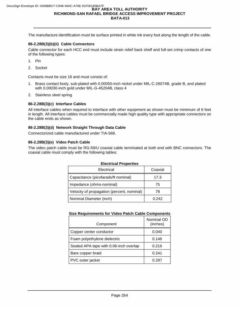
BAY AREA TOLL AUTHORITY RICHMOND-SAN RAFAEL BRIDGE ACCESS IMPROVEMENT PROJECT
BATA-013
Page 264
The manufacture identification must be surface printed in white ink every foot along the length of the cable. 86-2.28B(3)(b)(ii) Cable Connectors Cable connector for each HCC end must include strain relief back shelf and full-set crimp contacts of one of the following types:
1. Pin
2. Socket Contacts must be size 16 and must consist of:
1. Brass contact body, sub-plated with 0.00050-inch nickel under MIL-C-26074B, grade B, and plated with 0.00030-inch gold under MIL-G-45204B, class 4
2. Stainless steel spring 86-2.28B(3)(c) Interface Cables All interface cables when required to interface with other equipment as shown must be minimum of 6 feet in length. All interface cables must be commercially made high quality type with appropriate connectors on the cable ends as shown. 86-2.28B(3)(d) Network Straight Through Data Cable Connectorized cable manufactured under TIA-568. 86-2.28B(3)(e) Video Patch Cable The video patch cable must be RG-59/U coaxial cable terminated at both end with BNC connectors. The coaxial cable must comply with the following tables:
Electrical Properties Electrical Coaxial
Capacitance (picofarads/ft nominal) 17.3
Impedance (ohms-nominal) 75
Velocity of propagation (percent, nominal) 78
Nominal Diameter (inch) 0.242
Size Requirements for Video Patch Cable Components
Component Nominal OD
(inches)
Copper center conductor 0.040
Foam polyethylene dielectric 0.146
Sealed APA tape with 0.06-inch overlap 0.216
Bare copper braid 0.241
PVC outer jacket 0.297
DocuSign Envelope ID: 0308BBC7-C948-49AC-A76E-91F00185BA7F
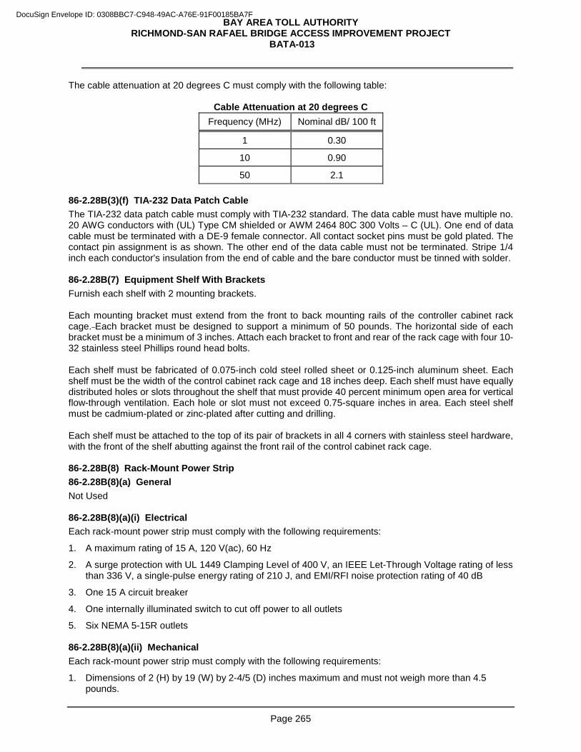
BAY AREA TOLL AUTHORITY RICHMOND-SAN RAFAEL BRIDGE ACCESS IMPROVEMENT PROJECT
BATA-013
Page 265
The cable attenuation at 20 degrees C must comply with the following table:
Cable Attenuation at 20 degrees C Frequency (MHz) Nominal dB/ 100 ft
1 0.30
10 0.90
50 2.1 86-2.28B(3)(f) TIA-232 Data Patch Cable The TIA-232 data patch cable must comply with TIA-232 standard. The data cable must have multiple no. 20 AWG conductors with (UL) Type CM shielded or AWM 2464 80C 300 Volts – C (UL). One end of data cable must be terminated with a DE-9 female connector. All contact socket pins must be gold plated. The contact pin assignment is as shown. The other end of the data cable must not be terminated. Stripe 1/4 inch each conductor's insulation from the end of cable and the bare conductor must be tinned with solder. 86-2.28B(7) Equipment Shelf With Brackets Furnish each shelf with 2 mounting brackets. Each mounting bracket must extend from the front to back mounting rails of the controller cabinet rack cage. Each bracket must be designed to support a minimum of 50 pounds. The horizontal side of each bracket must be a minimum of 3 inches. Attach each bracket to front and rear of the rack cage with four 10-32 stainless steel Phillips round head bolts. Each shelf must be fabricated of 0.075-inch cold steel rolled sheet or 0.125-inch aluminum sheet. Each shelf must be the width of the control cabinet rack cage and 18 inches deep. Each shelf must have equally distributed holes or slots throughout the shelf that must provide 40 percent minimum open area for vertical flow-through ventilation. Each hole or slot must not exceed 0.75-square inches in area. Each steel shelf must be cadmium-plated or zinc-plated after cutting and drilling. Each shelf must be attached to the top of its pair of brackets in all 4 corners with stainless steel hardware, with the front of the shelf abutting against the front rail of the control cabinet rack cage. 86-2.28B(8) Rack-Mount Power Strip 86-2.28B(8)(a) General Not Used 86-2.28B(8)(a)(i) Electrical Each rack-mount power strip must comply with the following requirements:
1. A maximum rating of 15 A, 120 V(ac), 60 Hz
2. A surge protection with UL 1449 Clamping Level of 400 V, an IEEE Let-Through Voltage rating of less than 336 V, a single-pulse energy rating of 210 J, and EMI/RFI noise protection rating of 40 dB
3. One 15 A circuit breaker
4. One internally illuminated switch to cut off power to all outlets
5. Six NEMA 5-15R outlets 86-2.28B(8)(a)(ii) Mechanical Each rack-mount power strip must comply with the following requirements:
1. Dimensions of 2 (H) by 19 (W) by 2-4/5 (D) inches maximum and must not weigh more than 4.5 pounds.
DocuSign Envelope ID: 0308BBC7-C948-49AC-A76E-91F00185BA7F
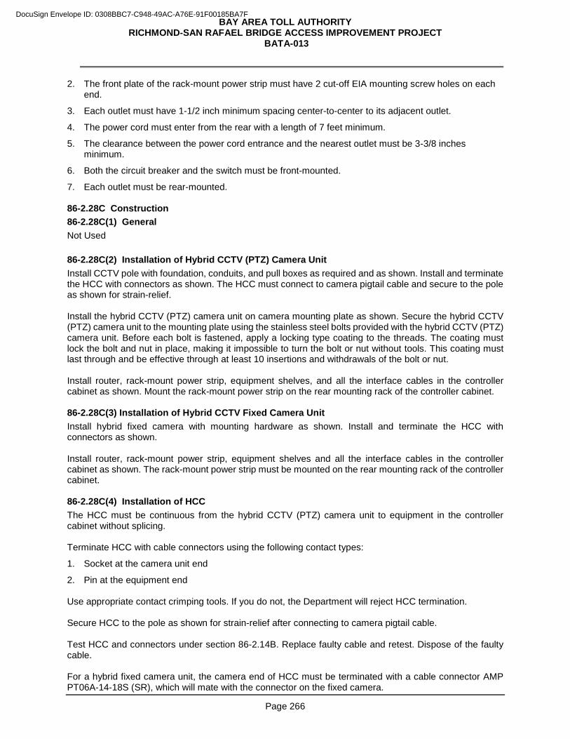
BAY AREA TOLL AUTHORITY RICHMOND-SAN RAFAEL BRIDGE ACCESS IMPROVEMENT PROJECT
BATA-013
Page 266
2. The front plate of the rack-mount power strip must have 2 cut-off EIA mounting screw holes on each end.
3. Each outlet must have 1-1/2 inch minimum spacing center-to-center to its adjacent outlet.
4. The power cord must enter from the rear with a length of 7 feet minimum.
5. The clearance between the power cord entrance and the nearest outlet must be 3-3/8 inches minimum.
6. Both the circuit breaker and the switch must be front-mounted.
7. Each outlet must be rear-mounted. 86-2.28C Construction 86-2.28C(1) General Not Used
86-2.28C(2) Installation of Hybrid CCTV (PTZ) Camera Unit Install CCTV pole with foundation, conduits, and pull boxes as required and as shown. Install and terminate the HCC with connectors as shown. The HCC must connect to camera pigtail cable and secure to the pole as shown for strain-relief. Install the hybrid CCTV (PTZ) camera unit on camera mounting plate as shown. Secure the hybrid CCTV (PTZ) camera unit to the mounting plate using the stainless steel bolts provided with the hybrid CCTV (PTZ) camera unit. Before each bolt is fastened, apply a locking type coating to the threads. The coating must lock the bolt and nut in place, making it impossible to turn the bolt or nut without tools. This coating must last through and be effective through at least 10 insertions and withdrawals of the bolt or nut. Install router, rack-mount power strip, equipment shelves, and all the interface cables in the controller cabinet as shown. Mount the rack-mount power strip on the rear mounting rack of the controller cabinet. 86-2.28C(3) Installation of Hybrid CCTV Fixed Camera Unit Install hybrid fixed camera with mounting hardware as shown. Install and terminate the HCC with connectors as shown. Install router, rack-mount power strip, equipment shelves and all the interface cables in the controller cabinet as shown. The rack-mount power strip must be mounted on the rear mounting rack of the controller cabinet. 86-2.28C(4) Installation of HCC The HCC must be continuous from the hybrid CCTV (PTZ) camera unit to equipment in the controller cabinet without splicing. Terminate HCC with cable connectors using the following contact types:
1. Socket at the camera unit end
2. Pin at the equipment end Use appropriate contact crimping tools. If you do not, the Department will reject HCC termination. Secure HCC to the pole as shown for strain-relief after connecting to camera pigtail cable. Test HCC and connectors under section 86-2.14B. Replace faulty cable and retest. Dispose of the faulty cable. For a hybrid fixed camera unit, the camera end of HCC must be terminated with a cable connector AMP PT06A-14-18S (SR), which will mate with the connector on the fixed camera.
DocuSign Envelope ID: 0308BBC7-C948-49AC-A76E-91F00185BA7F
BAY AREA TOLL AUTHORITY RICHMOND-SAN RAFAEL BRIDGE ACCESS IMPROVEMENT PROJECT
BATA-013
Page 267
86-2.28C(5)(b) Serial Cable Adapter Provide a universal serial bus (USB) to TIA-232 serial adapter at each hybrid PTZ camera location. The adapter must have a DE-9 socket connector for TIA-232 and Type A plug connector for USB. Supply a 6-feet straight-through USB extension cable. The USB function must be version 2.0. Furnish the adapter software in 32 GB secure digital (SD) memory card format. 86-2.28C(7) Equipment Shelf With Brackets Install each equipment shelf with brackets as shown. 86-2.28C(8) Rack-Mount Power Strip Plug the rack-mount power strip into the non-GFCI duplex outlet normally labeled with "Controller Unit Receptacle" in the back of the power distribution assembly (PDA). Mount the rack-mount power strip on the rear of the standard EIA-310 rack cage and across the 2 vertical back rails with 4 stainless steel EIA mounting screws, 2 on each side. The rack-mount power strip must not hinder the accessibility to the back of all existing electrical equipment. Plug all power cords for permanently field installed electrical equipment into the power strip. 86-2.28D Payment Not Used
Add to section 86-3:
86-2.29 GENERAL PACKET RADIO SYSTEM 86-2.29A General 86-2.29A(1) Summary You must furnish and install the General Packet Radio System (GPRS) wireless modem assembly as described in these special provisions and as shown. The General Packet Radio System (GPRS) Wireless Modem Assembly must be furnished and configured with the following major components:
A. Modem
B. Power supply
C. Modem mounting bracket and hardware
D. Serial communication cable
E. Antenna 86-2.29A(2) Quality Control and Assurance 86-2.29A(2)(a) Certificate of Compliance You must provide the Engineer with a Certificate of Compliance from the manufacturer in accordance with the provisions of Section 11-3.02C(4), “Certificates of Compliance” of the Standard Specifications for all of the modems and power supplies furnished for the project. 86-2.29A(2)(b) Warranty The manufacturer must provide a written warranty against defects in materials and workmanship for modems and power supplies for a period of 12 months after installation for parts and labor. Replacement modems and power supplies must be provided within 5 days after receipt of failed modem and power supply at no cost to the State, except the cost of shipping the failed modem and power supply. All warranty documentation must be given to the Engineer before installation. Replacement modem and power supplies must be delivered to Caltrans Maintenance Electrical Shop:
DocuSign Envelope ID: 0308BBC7-C948-49AC-A76E-91F00185BA7F
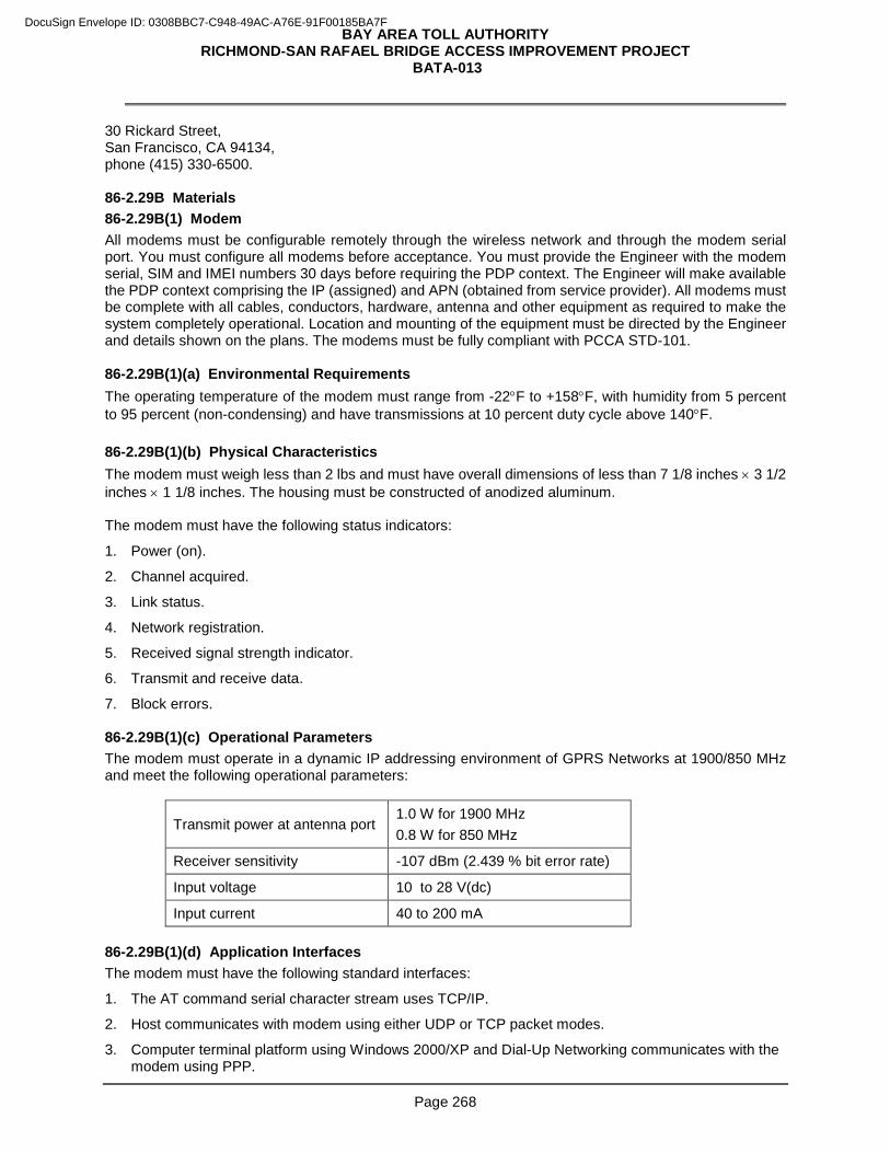
BAY AREA TOLL AUTHORITY RICHMOND-SAN RAFAEL BRIDGE ACCESS IMPROVEMENT PROJECT
BATA-013
Page 268
30 Rickard Street, San Francisco, CA 94134, phone (415) 330-6500. 86-2.29B Materials 86-2.29B(1) Modem All modems must be configurable remotely through the wireless network and through the modem serial port. You must configure all modems before acceptance. You must provide the Engineer with the modem serial, SIM and IMEI numbers 30 days before requiring the PDP context. The Engineer will make available the PDP context comprising the IP (assigned) and APN (obtained from service provider). All modems must be complete with all cables, conductors, hardware, antenna and other equipment as required to make the system completely operational. Location and mounting of the equipment must be directed by the Engineer and details shown on the plans. The modems must be fully compliant with PCCA STD-101. 86-2.29B(1)(a) Environmental Requirements The operating temperature of the modem must range from -22°F to +158°F, with humidity from 5 percent to 95 percent (non-condensing) and have transmissions at 10 percent duty cycle above 140°F. 86-2.29B(1)(b) Physical Characteristics The modem must weigh less than 2 lbs and must have overall dimensions of less than 7 1/8 inches × 3 1/2 inches × 1 1/8 inches. The housing must be constructed of anodized aluminum. The modem must have the following status indicators:
1. Power (on).
2. Channel acquired.
3. Link status.
4. Network registration.
5. Received signal strength indicator.
6. Transmit and receive data.
7. Block errors. 86-2.29B(1)(c) Operational Parameters The modem must operate in a dynamic IP addressing environment of GPRS Networks at 1900/850 MHz and meet the following operational parameters:
Transmit power at antenna port 1.0 W for 1900 MHz 0.8 W for 850 MHz
Receiver sensitivity -107 dBm (2.439 % bit error rate)
Input voltage 10 to 28 V(dc)
Input current 40 to 200 mA 86-2.29B(1)(d) Application Interfaces The modem must have the following standard interfaces:
1. The AT command serial character stream uses TCP/IP.
2. Host communicates with modem using either UDP or TCP packet modes.
3. Computer terminal platform using Windows 2000/XP and Dial-Up Networking communicates with the modem using PPP.
DocuSign Envelope ID: 0308BBC7-C948-49AC-A76E-91F00185BA7F
BAY AREA TOLL AUTHORITY RICHMOND-SAN RAFAEL BRIDGE ACCESS IMPROVEMENT PROJECT
BATA-013
Page 269
86-2.29B(1)(e) Features The modem must have the following features:
1. 53.6 kbps raw data transfer rate minimum.
2. Full duplex transceiver.
3. 1900/850 MHz dual band networking.
4. Integrated TCP/IP protocol stack with UDP.
5. Security such to prevent unauthorized access.
6. Includes a DC power cable at least 1 meter in length with a connector compatible with the modem power connector.
7. Packet buffering and forwarding feature that provides discipline to the output of the serial port. The packet forwarding time interval must be configurable from a rate of 0 (undisciplined ) to 400ms in increments of 100ms or less.
8. Choice of "Friends Only" access mode. 86-2.29B(1)(f) System Compliance The modem and associated firmware, software, hardware, protocol, and other features must be fully and completely compatible with the existing GPRS network currently in use. The existing GPRS network utilizes the AT&T Wireless cellular system (band compatible with this modem), the AirLink Raven GPRS modem, and the AirLink Gateway. You must demonstrate the compatibility to the Engineer by actual installation demonstration or by other means approved by the Engineer. 86-2.29B(2) Power Supply The power supply must be vertically mountable on a 19-inch standard rack rail using two machine screws and two wing nuts. The power supply must have provisions to attach the modem power cable securely without the need for modifying the modem power cable. The power supply must meet the following requirements:
DocuSign Envelope ID: 0308BBC7-C948-49AC-A76E-91F00185BA7F
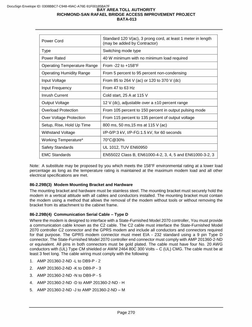
BAY AREA TOLL AUTHORITY RICHMOND-SAN RAFAEL BRIDGE ACCESS IMPROVEMENT PROJECT
BATA-013
Page 270
Power Cord Standard 120 V(ac), 3 prong cord, at least 1 meter in length (may be added by Contractor)
Type Switching mode type
Power Rated 40 W minimum with no minimum load required
Operating Temperature Range From -22 to +158°F
Operating Humidity Range From 5 percent to 95 percent non-condensing
Input Voltage From 85 to 264 V (ac) or 120 to 370 V (dc)
Input Frequency From 47 to 63 Hz
Inrush Current Cold start, 25 A at 115 V
Output Voltage 12 V (dc), adjustable over a ±10 percent range
Overload Protection From 105 percent to 150 percent in output pulsing mode
Over Voltage Protection From 115 percent to 135 percent of output voltage
Setup, Rise, Hold Up Time 800 ms, 50 ms,15 ms at 115 V (ac)
Withstand Voltage I/P-0/P:3 kV, I/P-FG:1.5 kV, for 60 seconds
Working Temperature* 70°C@30%
Safety Standards UL 1012, TUV EN60950
EMC Standards EN55022 Class B, EN61000-4-2, 3, 4, 5 and EN61000-3-2, 3 Note: A substitute may be proposed by you which meets the 158°F environmental rating at a lower load percentage as long as the temperature rating is maintained at the maximum modem load and all other electrical specifications are met. 86-2.29B(3) Modem Mounting Bracket and Hardware The mounting bracket and hardware must be stainless steel. The mounting bracket must securely hold the modem in a vertical attitude with all cables and conductors installed. The mounting bracket must contain the modem using a method that allows the removal of the modem without tools or without removing the bracket from its attachment to the cabinet frame. 86-2.29B(4) Communication Serial Cable – Type D Where the modem is designed to interface with a State-Furnished Model 2070 controller, You must provide a communication cable known as the C2 cable. The C2 cable must interface the State-Furnished Model 2070 controller C2 connector and the GPRS modem and include all conductors and connectors required for that purpose. The GPRS modem connector must meet EIA - 232 standard using a 9 pin Type D connector. The State-Furnished Model 2070 controller end connector must comply with AMP 201360-2-ND or equivalent. All pins in both connectors must be gold plated. The cable must have four No. 20 AWG conductors with (UL) Type CM shielded or AWM 2464 80C 300 Volts – C (UL) CMG. The cable must be at least 3 feet long. The cable wiring must comply with the following:
1. AMP 201360-2-ND -L to DB9-P - 2
2. AMP 201360-2-ND -K to DB9-P - 3
3. AMP 201360-2-ND -N to DB9-P - 5
4. AMP 201360-2-ND -D to AMP 201360-2-ND - H
5. AMP 201360-2-ND -J to AMP 201360-2-ND – M
DocuSign Envelope ID: 0308BBC7-C948-49AC-A76E-91F00185BA7F
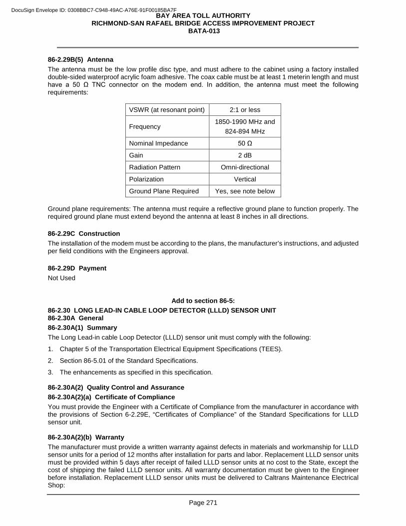
BAY AREA TOLL AUTHORITY RICHMOND-SAN RAFAEL BRIDGE ACCESS IMPROVEMENT PROJECT
BATA-013
Page 271
86-2.29B(5) Antenna The antenna must be the low profile disc type, and must adhere to the cabinet using a factory installed double-sided waterproof acrylic foam adhesive. The coax cable must be at least 1 meterin length and must have a 50 Ω TNC connector on the modem end. In addition, the antenna must meet the following requirements:
VSWR (at resonant point) 2:1 or less
Frequency 1850-1990 MHz and
824-894 MHz
Nominal Impedance 50 Ω
Gain 2 dB
Radiation Pattern Omni-directional
Polarization Vertical
Ground Plane Required Yes, see note below Ground plane requirements: The antenna must require a reflective ground plane to function properly. The required ground plane must extend beyond the antenna at least 8 inches in all directions.
86-2.29C Construction The installation of the modem must be according to the plans, the manufacturer’s instructions, and adjusted per field conditions with the Engineers approval.
86-2.29D Payment Not Used
Add to section 86-5: 86-2.30 LONG LEAD-IN CABLE LOOP DETECTOR (LLLD) SENSOR UNIT 86-2.30A General 86-2.30A(1) Summary The Long Lead-in cable Loop Detector (LLLD) sensor unit must comply with the following:
1. Chapter 5 of the Transportation Electrical Equipment Specifications (TEES).
2. Section 86-5.01 of the Standard Specifications.
3. The enhancements as specified in this specification. 86-2.30A(2) Quality Control and Assurance 86-2.30A(2)(a) Certificate of Compliance You must provide the Engineer with a Certificate of Compliance from the manufacturer in accordance with the provisions of Section 6-2.29E, “Certificates of Compliance” of the Standard Specifications for LLLD sensor unit. 86-2.30A(2)(b) Warranty The manufacturer must provide a written warranty against defects in materials and workmanship for LLLD sensor units for a period of 12 months after installation for parts and labor. Replacement LLLD sensor units must be provided within 5 days after receipt of failed LLLD sensor units at no cost to the State, except the cost of shipping the failed LLLD sensor units. All warranty documentation must be given to the Engineer before installation. Replacement LLLD sensor units must be delivered to Caltrans Maintenance Electrical Shop:
DocuSign Envelope ID: 0308BBC7-C948-49AC-A76E-91F00185BA7F
BAY AREA TOLL AUTHORITY RICHMOND-SAN RAFAEL BRIDGE ACCESS IMPROVEMENT PROJECT
BATA-013
Page 272
30 Rickard Street, San Francisco, CA 94134 86-2.30B Materials 86-2.30B(1) General The LLLD sensor unit must have 2 channels and must be capable of detecting Agency licensed vehicles on a single Type A or E loop with a 3280 feet lead-in-cable. 86-2.30B(2) Sensitivity LLLD sensor unit channel must have a sensitivity based on delta L threshold rather than delta L (only). There must be 8 threshold levels corresponding to 8 nH, 16 nH, 32 nH, 64 nH, 128 nH, 256 nH, 512 nH and 1024 nH. 86-2.30B(3) Variations The LLLD sensor unit channel must be permitted the following exceptions to the TEES and Standard Specifications:
1. Three frequency settings minimum.
2. The operating frequency of 40 kHz is not required as long as the sensor unit adheres to all other FCC rules.
3. The minimum Q requirement of 5 is not required if all other functional requirements are met.
4. Pulse mode requirements may vary from TEES but are subject to the approval of the Engineer. 86-2.30C Construction The installation of the LLLD sensor unit must be according to the plans, the manufacturer’s instructions, and adjusted per field conditions with the Engineers approval. 86-2.30D Payment Not used
^^^^^^^^^^^^^^^^^^^^^^^^^^^^^^^^^^^^^^^^^^^^^^^^^^^^^^^^^^^^^^^^
DIVISION X MATERIALS 88 GEOSYNTHETICS
Add to section 88-1.02B:
Filter fabric for Geocomposite Drain must be Class A.
^^^^^^^^^^^^^^^^^^^^^^^^^^^^^^^^^^^^^^^^^^^^^^^^^^^^^^^^^^^^^^^
90 CONCRETE
Add to section 90-1.02H:
Concrete at following locations are in a corrosive environment.
DocuSign Envelope ID: 0308BBC7-C948-49AC-A76E-91F00185BA7F
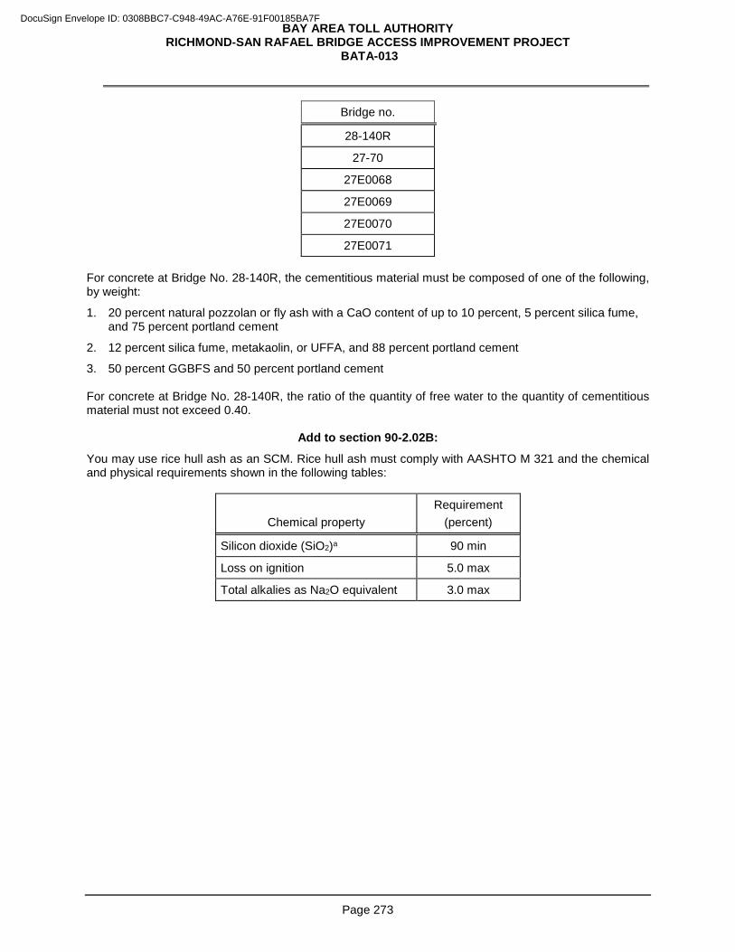
BAY AREA TOLL AUTHORITY RICHMOND-SAN RAFAEL BRIDGE ACCESS IMPROVEMENT PROJECT
BATA-013
Page 273
Bridge no.
28-140R
27-70
27E0068
27E0069
27E0070
27E0071 For concrete at Bridge No. 28-140R, the cementitious material must be composed of one of the following, by weight:
1. 20 percent natural pozzolan or fly ash with a CaO content of up to 10 percent, 5 percent silica fume, and 75 percent portland cement
2. 12 percent silica fume, metakaolin, or UFFA, and 88 percent portland cement
3. 50 percent GGBFS and 50 percent portland cement For concrete at Bridge No. 28-140R, the ratio of the quantity of free water to the quantity of cementitious material must not exceed 0.40.
Add to section 90-2.02B:
You may use rice hull ash as an SCM. Rice hull ash must comply with AASHTO M 321 and the chemical and physical requirements shown in the following tables:
Chemical property Requirement
(percent)
Silicon dioxide (SiO2)a 90 min
Loss on ignition 5.0 max
Total alkalies as Na2O equivalent 3.0 max
DocuSign Envelope ID: 0308BBC7-C948-49AC-A76E-91F00185BA7F
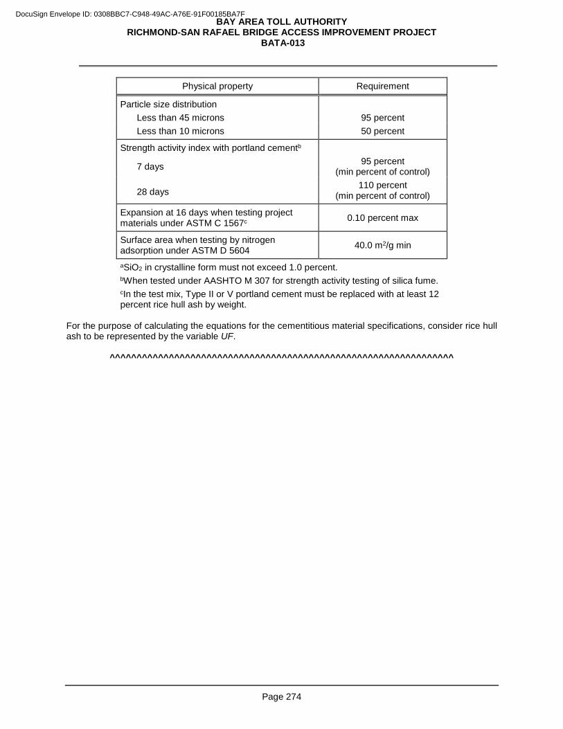
BAY AREA TOLL AUTHORITY RICHMOND-SAN RAFAEL BRIDGE ACCESS IMPROVEMENT PROJECT
BATA-013
Page 274
Physical property Requirement
Particle size distribution Less than 45 microns 95 percent Less than 10 microns 50 percent
Strength activity index with portland cementb
7 days 95 percent (min percent of control)
28 days 110 percent
(min percent of control)
Expansion at 16 days when testing project materials under ASTM C 1567c 0.10 percent max
Surface area when testing by nitrogen adsorption under ASTM D 5604 40.0 m2/g min
aSiO2 in crystalline form must not exceed 1.0 percent. bWhen tested under AASHTO M 307 for strength activity testing of silica fume. cIn the test mix, Type II or V portland cement must be replaced with at least 12 percent rice hull ash by weight.
For the purpose of calculating the equations for the cementitious material specifications, consider rice hull ash to be represented by the variable UF.
^^^^^^^^^^^^^^^^^^^^^^^^^^^^^^^^^^^^^^^^^^^^^^^^^^^^^^^^^^^^^^^^
DocuSign Envelope ID: 0308BBC7-C948-49AC-A76E-91F00185BA7F