bidding instructions for sealed bids fax or e-mail bids
TRANSCRIPT
GRDA Finance Form 005 (10-2006)
BIDDING INSTRUCTIONS FOR SEALED BIDS
Sealed bids will be accepted at the Grand River Dam Authority Administrative Headquarters located at 226 West Dwain Willis Avenue, Vinita, Oklahoma. Bids received after the bid opening time and date will not be opened or considered.
RFQ or RFP Number: 19602 Bid Opening Time & Date: 12/16/15 2:00 PM CT Description: Transformer: 30/40/50/56 MVA
Contracting & Acquisitions Agent: Sammie Prince
Bids must be enclosed in a sealed envelope or package and addressed as follows:
PURCHASING UNIT SEALED BID No. 19602 GRAND RIVER DAM AUTHORITY 226 WEST DWAIN WILLIS AVE VINITA OK 74301
Express Mail/Overnight packages must also be addressed as above.
Bids not addressed as instructed above negate the confidentiality of the sealed bid and, therefore, will be rejected and returned to the bidder without being considered. All bids responses shall be typewritten or handwritten in ink, and any corrections to bids shall be initialed in ink. Bids and proposals submitted in pencil will not be accepted. All bids and proposals shall include an original signature of the bidder and shall be accompanied by a properly executed non-collusion affidavit with original signatures and notary seal. Bid responses are to include payment terms and delivery information. Bids and proposals shall be quoted FOB: Destination/Freight Allowed unless stated otherwise within the Request for Quote. All packaging, handling, shipping and delivery charges shall be included in the unit price quoted for each line item. No exceptions will be granted unless approved by the guidelines of the Chief Financial Officer or designee.
Fax or e-mail Bids will not be accepted.
Bidders opting to decline the bid offering are requested to submit a response with a brief explanation.
Grand River Dam Authority is an agency of the State of Oklahoma, fully supported by customer revenues instead of taxes. Administrative Headquarters • 226 West Dwain Willis Avenue • Vinita, Oklahoma 74301 • Phone: 918-256-5545 • Fax: 918-256-1051
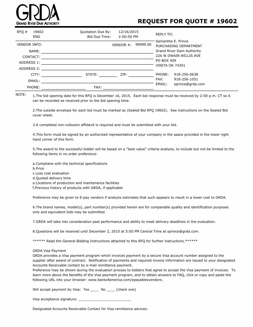
REQUEST FOR QUOTE # 19602RFQ # 19602
ENGQuotation Due By:
Bid Due Time:12/16/20152:00:00 PM
REPLY TO:
Samantha E. PrincePURCHASING DEPARTMENTGrand River Dam Authority226 W DWAIN WILLIS AVEPO BOX 409VINITA OK 74301
PHONE:FAX:EMAIL:
VENDOR INFO: VENDOR #: 99999.00
NAME:
CONTACT:
ADDRESS 1:
ADDRESS 2:
CITY: STATE: ZIP:
EMAIL:
PHONE: FAX:
NOTE: 1.The bid opening date for this RFQ is December 16, 2015. Each bid response must be received by 2:00 p.m. CT so it can be recorded as received prior to the bid opening time.
2.The outside envelope for each bid must be marked as (Sealed Bid RFQ 19602). See instructions on the Sealed Bid cover sheet.
3.A completed non-collusion affidavit is required and must be submitted with your bid.
4.This form must be signed by an authorized representative of your company in the space provided in the lower right hand corner of this form.
5.The award to the successful bidder will be based on a "best value" criteria analysis, to include but not be limited to the following items in no order preference:
a.Compliane with the technical specificationsb.Pricec.Loss cost evaluationd.Quoted delivery timee.Locations of production and maintenance facilitiesf.Previous history of products with GRDA, if applicable
Preference may be given to E-pay vendors if analysis estimates that such appears to result in a lower cost to GRDA.
6.The brand names, model(s), part number(s) provided herein are for comparable quality and identification purposes only and equivalent bids may be submitted.
7.GRDA will take into consideration past performance and ability to meet delivery deadlines in the evaluation.
8.Questions will be received until December 2, 2015 at 5:00 PM Central Time at [email protected].
****** Read the General Bidding Instructions attached to this RFQ for further instructions.******
GRDA Visa PaymentGRDA provides a Visa payment program which invoices payment by a secure Visa account number assigned to the supplier after award of contract. Notification of payments and required invoice information are issued to your designated Accounts Receivable contact by e-mail remittance payment.Preference may be shown during the evaluation process to bidders that agree to accept the Visa payment of invoices. To learn more about the benefits of the Visa payment program, and to obtain answers to FAQ, click or copy and paste the following URL into your browser: www.bankofamerica.com/epayablesvendors.
Will accept payment by Visa: Yes ____ No ____ (check one)
Visa acceptance signature: _________________________
Designated Accounts Receivable Contact for Visa remittance advices:
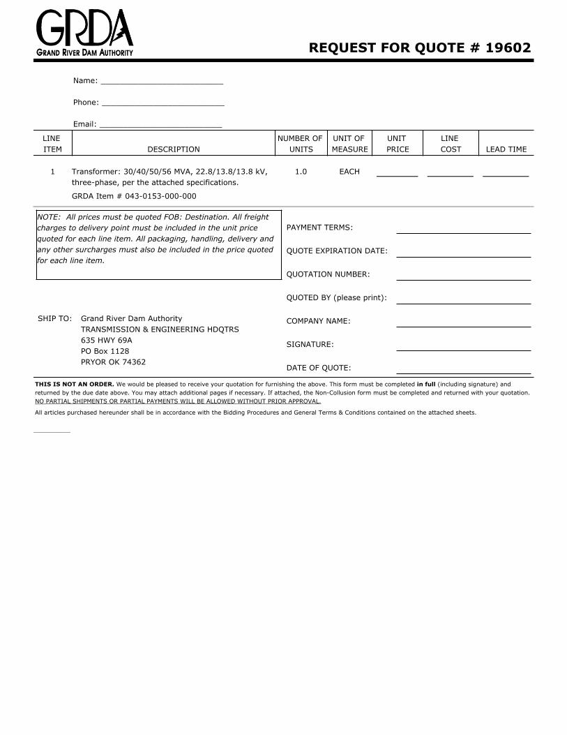
REQUEST FOR QUOTE # 19602
Name: __________________________
Phone: __________________________
Email: __________________________
LINE ITEM DESCRIPTION
NUMBER OF UNITS
UNIT OF MEASURE
UNIT PRICE
LINE COST LEAD TIME
1 Transformer: 30/40/50/56 MVA, 22.8/13.8/13.8 kV, three-phase, per the attached specifications.
1.0 EACH
GRDA Item # 043-0153-000-000
NOTE: All prices must be quoted FOB: Destination. All freight charges to delivery point must be included in the unit price quoted for each line item. All packaging, handling, delivery and any other surcharges must also be included in the price quoted for each line item.
SHIP TO: Grand River Dam AuthorityTRANSMISSION & ENGINEERING HDQTRS635 HWY 69APO Box 1128PRYOR OK 74362
PAYMENT TERMS:
QUOTE EXPIRATION DATE:
QUOTATION NUMBER:
QUOTED BY (please print):
COMPANY NAME:
SIGNATURE:
DATE OF QUOTE:
THIS IS NOT AN ORDER. We would be pleased to receive your quotation for furnishing the above. This form must be completed in full (including signature) and returned by the due date above. You may attach additional pages if necessary. If attached, the Non-Collusion form must be completed and returned with your quotation. NO PARTIAL SHIPMENTS OR PARTIAL PAYMENTS WILL BE ALLOWED WITHOUT PRIOR APPROVAL.
All articles purchased hereunder shall be in accordance with the Bidding Procedures and General Terms & Conditions contained on the attached sheets.
__________
RFQ / RFP #
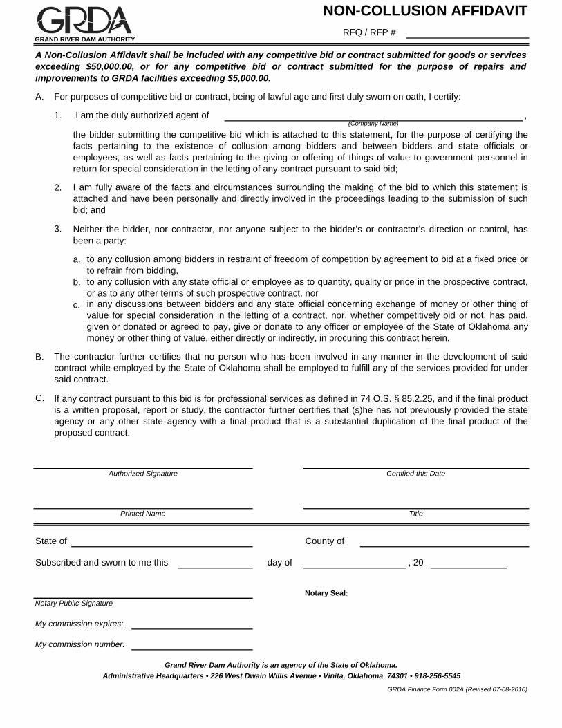
A. For purposes of competitive bid or contract, being of lawful age and first duly sworn on oath, I certify:
1. I am the duly authorized agent of ,
2.
3.
a.
b.
c.
B.
C.
Subscribed and sworn to me this day of , 20
Notary Seal:Notary Public Signature
NON-COLLUSION AFFIDAVIT
GRAND RIVER DAM AUTHORITY
A Non-Collusion Affidavit shall be included with any competitive bid or contract submitted for goods or servicesexceeding $50,000.00, or for any competitive bid or contract submitted for the purpose of repairs andimprovements to GRDA facilities exceeding $5,000.00.
(Company Name)
the bidder submitting the competitive bid which is attached to this statement, for the purpose of certifying thefacts pertaining to the existence of collusion among bidders and between bidders and state officials oremployees, as well as facts pertaining to the giving or offering of things of value to government personnel inreturn for special consideration in the letting of any contract pursuant to said bid;
I am fully aware of the facts and circumstances surrounding the making of the bid to which this statement isattached and have been personally and directly involved in the proceedings leading to the submission of suchbid; and
Neither the bidder, nor contractor, nor anyone subject to the bidder’s or contractor’s direction or control, hasbeen a party:
to any collusion among bidders in restraint of freedom of competition by agreement to bid at a fixed price orto refrain from bidding,to any collusion with any state official or employee as to quantity, quality or price in the prospective contract,or as to any other terms of such prospective contract, norin any discussions between bidders and any state official concerning exchange of money or other thing ofvalue for special consideration in the letting of a contract, nor, whether competitively bid or not, has paid,given or donated or agreed to pay, give or donate to any officer or employee of the State of Oklahoma anymoney or other thing of value, either directly or indirectly, in procuring this contract herein.
The contractor further certifies that no person who has been involved in any manner in the development of saidcontract while employed by the State of Oklahoma shall be employed to fulfill any of the services provided for undersaid contract.
If any contract pursuant to this bid is for professional services as defined in 74 O.S. § 85.2.25, and if the final productis a written proposal, report or study, the contractor further certifies that (s)he has not previously provided the stateagency or any other state agency with a final product that is a substantial duplication of the final product of theproposed contract.
Authorized Signature Certified this Date
Grand River Dam Authority is an agency of the State of Oklahoma.
Printed Name Title
My commission number:
Administrative Headquarters • 226 West Dwain Willis Avenue • Vinita, Oklahoma 74301 • 918-256-5545
GRDA Finance Form 002A (Revised 07-08-2010)
State of County of
My commission expires:
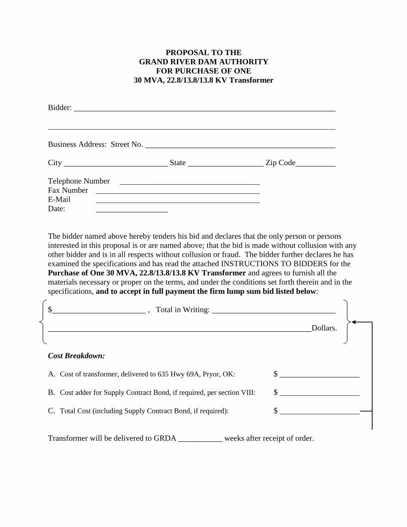
PROPOSAL TO THE GRAND RIVER DAM AUTHORITY
FOR PURCHASE OF ONE 30 MVA, 22.8/13.8/13.8 KV Transformer
Bidder: Business Address: Street No. City State Zip Code Telephone Number ___________________________________ Fax Number _________________________________________ E-Mail _________________________________________ Date: The bidder named above hereby tenders his bid and declares that the only person or persons interested in this proposal is or are named above; that the bid is made without collusion with any other bidder and is in all respects without collusion or fraud. The bidder further declares he has examined the specifications and has read the attached INSTRUCTIONS TO BIDDERS for the Purchase of One 30 MVA, 22.8/13.8/13.8 KV Transformer and agrees to furnish all the materials necessary or proper on the terms, and under the conditions set forth therein and in the specifications, and to accept in full payment the firm lump sum bid listed below: $ , Total in Writing: Dollars. Cost Breakdown: A. Cost of transformer, delivered to 635 Hwy 69A, Pryor, OK: $ ____________________
B. Cost adder for Supply Contract Bond, if required, per section VIII: $ ____________________ C. Total Cost (including Supply Contract Bond, if required): $ ____________________ Transformer will be delivered to GRDA ___________ weeks after receipt of order.
2
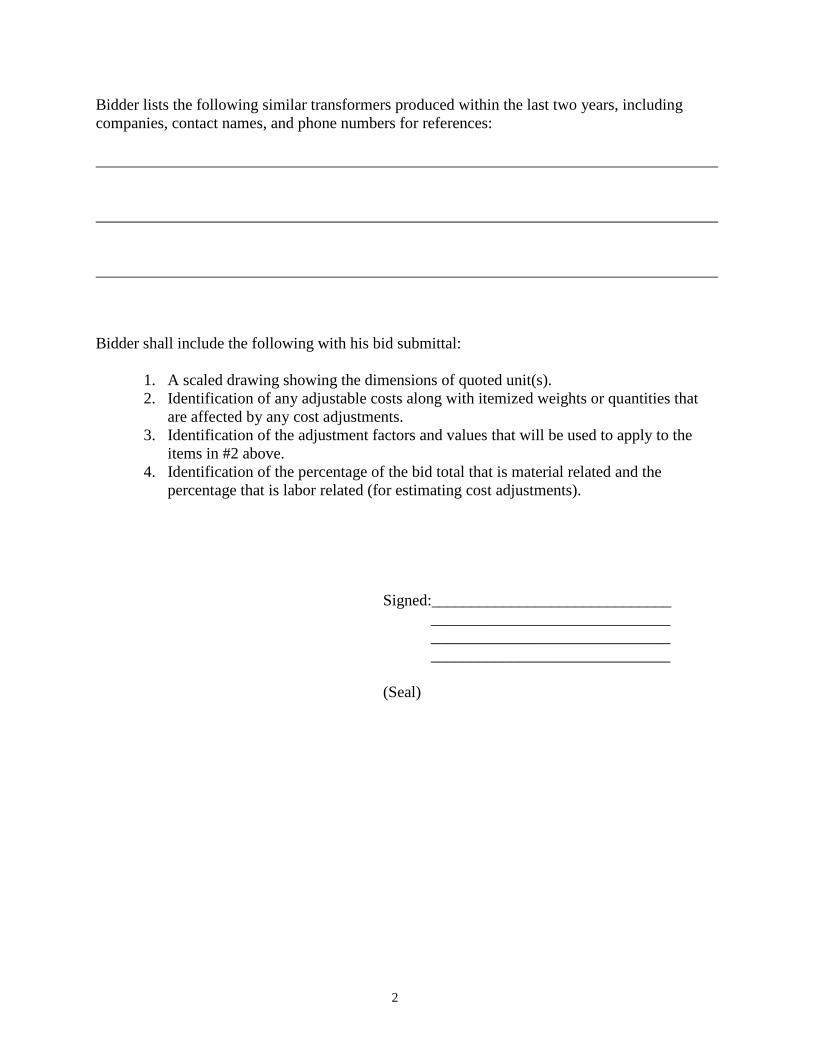
Bidder lists the following similar transformers produced within the last two years, including companies, contact names, and phone numbers for references: Bidder shall include the following with his bid submittal:
1. A scaled drawing showing the dimensions of quoted unit(s). 2. Identification of any adjustable costs along with itemized weights or quantities that
are affected by any cost adjustments. 3. Identification of the adjustment factors and values that will be used to apply to the
items in #2 above. 4. Identification of the percentage of the bid total that is material related and the
percentage that is labor related (for estimating cost adjustments). Signed:______________________________ ______________________________ ______________________________ ______________________________ (Seal)
3
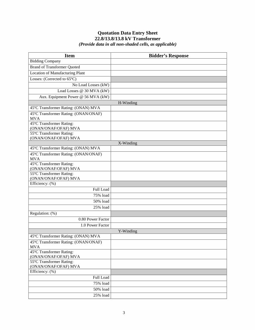
Quotation Data Entry Sheet 22.8/13.8/13.8 kV Transformer
(Provide data in all non-shaded cells, as applicable)
Item Bidder’s Response Bidding Company Brand of Transformer Quoted Location of Manufacturing Plant Losses: (Corrected to 65ºC)
No Load Losses (kW) Load Losses @ 30 MVA (kW)
Aux. Equipment Power @ 56 MVA (kW) H-Winding
45ºC Transformer Rating: (ONAN) MVA 45ºC Transformer Rating: (ONAN/ONAF) MVA
45ºC Transformer Rating: (ONAN/ONAF/OFAF) MVA
55ºC Transformer Rating: (ONAN/ONAF/OFAF) MVA
X-Winding 45ºC Transformer Rating: (ONAN) MVA 45ºC Transformer Rating: (ONAN/ONAF) MVA
45ºC Transformer Rating: (ONAN/ONAF/OFAF) MVA
55ºC Transformer Rating: (ONAN/ONAF/OFAF) MVA
Efficiency: (%) Full Load 75% load 50% load 25% load
Regulation: (%) 0.80 Power Factor 1.0 Power Factor
Y-Winding 45ºC Transformer Rating: (ONAN) MVA 45ºC Transformer Rating: (ONAN/ONAF) MVA
45ºC Transformer Rating: (ONAN/ONAF/OFAF) MVA
55ºC Transformer Rating: (ONAN/ONAF/OFAF) MVA
Efficiency: (%) Full Load 75% load 50% load 25% load
4
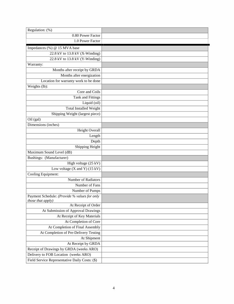
Regulation: (%) 0.80 Power Factor 1.0 Power Factor
Impedances (%) @ 15 MVA base 22.8 kV to 13.8 kV (X-Winding) 22.8 kV to 13.8 kV (Y-Winding)
Warranty: Months after receipt by GRDA
Months after energization Location for warranty work to be done
Weights (lb): Core and Coils
Tank and Fittings Liquid (oil)
Total Installed Weight Shipping Weight (largest piece)
Oil (gal) Dimensions (inches)
Height Overall Length Depth
Shipping Height Maximum Sound Level (dB) Bushings: (Manufacturer)
High voltage (25 kV) Low voltage (X and Y) (15 kV)
Cooling Equipment: Number of Radiators
Number of Fans Number of Pumps
Payment Schedule: (Provide % values for only those that apply)
At Receipt of Order At Submission of Approval Drawings
At Receipt of Key Materials At Completion of Core
At Completion of Final Assembly At Completion of Pre-Delivery Testing
At Shipment At Receipt by GRDA
Receipt of Drawings by GRDA (weeks ARO) Delivery to FOB Location (weeks ARO) Field Service Representative Daily Costs: ($)
5
EXCEPTION STATEMENT
This part of the proposal must be completed even if no exceptions are stated. State only the EXCEPTIONS. Do not include comments and/or clarifications, which may be shown by attachments to the Proposal. EXCEPTIONS (If no exceptions, state “NONE”; provide additional pages if needed). ___________________________________________________________________________ ___________________________________________________________________________ ___________________________________________________________________________ ___________________________________________________________________________ ___________________________________________________________________________ ___________________________________________________________________________ ___________________________________________________________________________ ___________________________________________________________________________

6
NON-COLLUSION AFFIDAVIT (To Accompany Bid Proposal)
STATE OF ______________________) )SS COUNTY OF ____________________) ________________________________________, of lawful age, being first duly sworn, on oath says:
1. (S)He is the duly authorized agent of ______________________, the bidder submitting the competitive bid which is attached to this statement, for the purpose of certifying the facts pertaining to the existence of collusion among bidders and between bidders and state officials or employees, as well as facts pertaining to the giving or offering of things of value to government personnel in return for special consideration in the letting of any Contract pursuant to the bid to which this statement is attached;
2. (S)He is fully aware of the facts and circumstances surrounding the making of the bid to which
this statement is attached and has been personally and directly involved in the proceedings leading to the submission of such bid; and
3. Neither the bidder nor anyone subject to the bidder’s direction or control has been a party:
a. to any collusion among bidders in restraint of freedom of competition by agreement to bid at
a fixed price or to refrain from bidding;
b. to any collusion with any state official or employee as to quantity, quality or price in the prospective Contract, or as to any other terms of such prospective Contract; nor
c. in any discussions between bidders and any state official concerning exchange of money or
other thing of value for special consideration in the letting of a Contract. 4. The bidder further certifies that no person who has been involved in any manner in the
development of that Contract while employed by the State of Oklahoma shall be employed to fulfill any of the services provided for under said Contract.
___________________________________ _________________________________ Signature Date ___________________________________ _________________________________ Printed Name Title _________________________________ Agent
Subscribed and sworn to before me this _______date of ____________, 2015. ______________________________ Notary Public (Seal) My Commission Expires: ________________________________
GENERAL BIDDING INSTRUCTIONS FOR SEALED BIDS 1. Bids shall be opened by the Purchasing Unit at the Grand River Dam Authority (hereinafter referred to as “GRDA” or
“the Authority”) Administrative Headquarters, 226 West Dwain Willis Avenue, Vinita, Oklahoma 74301 on the date (and time, if applicable) shown on the attached RFQ or RFP form. Bids shall be in conformity with these and any additional instructions to bidders and shall be submitted on GRDA’s form. The RFQ (Request for Quote) or RFP (Request for Proposal) form must be completed in full and signed by the bidder. If your bid response necessitates additional space, you may attach additional pages; however, the RFQ or RFP form shall be completed, signed and reference the additional pages. All bid responses shall be typewritten or handwritten in ink, and any corrections to bids shall be initialed in ink. Quotations or proposals submitted in pencil shall not be accepted.
2. Sealed bids shall be submitted to the GRDA Purchasing Unit in a properly marked envelope or package, and shall be
sealed. The name and address of the bidder shall be printed on the exterior of the envelope or package. The RFQ or RFP number and bid opening date shall be referenced on the face of the sealed envelope or package. Unmarked bids shall be rejected and returned to the bidder. Neither fax nor e-mail submissions shall be accepted for sealed bid requirements, as they negate the confidentiality of the bid. Any bid received via fax or e-mail for a sealed bid requirement shall be rejected and returned to the bidder. Bid opening time extensions shall not be granted. Bids received after the opening time and date shall not be considered. This is a formal bidding procedure with all bid packets recorded upon receipt and held unopened under lock until the bid opening at the time, date and location listed on the RFQ or RFP. At public bid openings, a short description of the item and the bid price will be read. The information shall be recorded on a bid tabulation to be used during the subsequent bid evaluation. Interested bidders may make an appointment to review quotations after an evaluation, recommendation and bid award has been made.
3. Non-Collusion Affidavit: RFQs or RFPs anticipated to exceed a total amount of $5,000 shall be accompanied by a
Non-Collusion Affidavit. This affidavit shall be completed by the bidder and include an original signature in ink of an authorized company representative (preferably the bidder) with full knowledge and acceptance of the bid proposal. The Non-Collusion Affidavit with original signature shall be mailed with the bid response to the attention of the Contracting & Acquisitions Agent listed on the RFQ or RFP. Purchase orders in excess of $5,000 will not be released to the successful bidder without receipt of a properly signed affidavit for the bid.
4. In the event the unit price and line total extension do not agree, the unit price shall be considered the quoted price
accepted for evaluation.
5. Freight Terms: All prices shall be quoted FOB: Destination/Freight Allowed. All packaging, handling, shipping and delivery charges shall be included in the unit price quoted for each line item. No exceptions shall be granted unless approved by the guidelines of the GRDA Chief Financial Officer or designee.
6. Other Surcharges: Any additional surcharges (such as HazMat charges, fuel surcharges, set-up fees, etc.) shall be
included in the unit price quoted for each line item. All additional charges are considered a part of the cost of the goods, and bids shall be evaluated to include these additional charges.
7. Tax-Exempt Status: GRDA is an agency of the state of Oklahoma and is specifically exempt from the payment of
sales tax by Oklahoma state statute, Title 68 O.S.A. § 1356 (10). An excerpt from the statute shall be furnished upon request.
8. Questions arising during the bidding process should be submitted in writing to the Contracting & Acquisitions
Agent named on the RFQ or RFP. The GRDA Contracting & Acquisitions Agent shall coordinate a reply from the end user to ensure that all potential bidders are provided the same information. Under no circumstances shall a bidder discuss pricing with any GRDA employee prior to the bid opening.
9. All bids submitted shall be subject to GRDA’s Purchasing Policy and Procedures, General Terms and Conditions, the
bidding instructions and specifications, the Oklahoma Open Records Act, other statutory regulations as applicable, and any other terms and conditions listed or attached herein – all of which are made part of this Request for Quote or Request for Proposal.
10. GRDA reserves the right to reject any and all bids, and to contract as the best interests of the Authority may require.
GRDA reserves the right to reject any bids that do not comply with the requirements and specifications of the Request for Quote or Request for Proposal. All bid responses become the property of GRDA and are subject to the Oklahoma Open Records Act. GRDA shall endeavor to protect technical information designated by the bidder as proprietary information; however, only technical information (i.e., “trade secrets”) may be considered proprietary – pricing and other non-technical aspects of the quote shall be considered non-proprietary.
11. “Sole Brand” or “No Sub” Items: Items with a “Sole Brand” or “No Sub” designation in the description shall be
furnished as the specified manufacturer and model/part number. No exception may be taken to the specification, and no alternate shall be accepted. In those cases where a manufacturer has discontinued the specified model/part number, the bidder shall indicate so on the RFQ. If a replacement item is available, the new model/part number shall be indicated on the RFQ form and the price quoted. It shall also be noted whether the replacement item is a direct
GRAND RIVER DAM AUTHORITY
2
replacement for the obsolete part number originally requested. If not, or if the specifications differ in any way, the bidder shall explain in detail, and corresponding drawings or descriptive literature shall be included with the quote.
12. Approved Equivalents: Unless an item is designated as a “Sole Brand” or “No Sub” item, any manufacturer’s name,
brand name, information and/or catalog number listed in a specification is for informational or cross-reference purposes and is not intended to limit competition. Bidders may offer any brand/manufacturer for which they are an authorized representative, provided it meets or exceeds the specification of the listed item. However, if quoting an equivalent product, bidders shall indicate on the RFQ form the manufacturer’s name and part number. Bidder shall also submit any drawings, descriptive literature and specifications for evaluation purposes. Reference to literature submitted with a previous bid shall not satisfy this provision. The bidder shall also provide written confirmation that the proposed equivalent will meet the requested specifications and is not considered an exception. Bids which do not comply with these requirements may be rejected. GRDA warehouses are not permitted to accept any item with a part number differing from that quoted by the bidder. Bids lacking any written indication of intent to furnish an alternate brand, model or part number shall be considered to be in complete compliance with the specifications as listed on the RFQ.
13. Insurance Certificates: Any service to be performed that requires the vendor’s employee, vehicle or equipment to be on any GRDA property must be covered by minimum insurance requirements. The workscope to be performed for the Authority shall be evaluated and the minimum insurance requirements shall be provided to prospective bidders with the RFQ or RFP. Evidence of insurance coverage shall be furnished in the form of a Certificate of Insurance, and shall be submitted with the bid response. Bidders shall disclose any subcontractors to be used, and the Authority shall consider the supplier as the single point of contact. The supplier shall assume responsibility for the performance of the subcontractor. Policies shall remain current for the duration of the requested service period, and GRDA shall be notified of any cancellation or revision to policies. Purchase Orders shall not be released to the successful bidder without a current Certificate of Insurance naming GRDA as certificate holder on file. A Memorandum of Insurance shall not be acceptable for this requirement.
14. MSDS: Material Safety Data Sheets shall be furnished to GRDA’s Safety Department at the address noted on the PO
prior to delivery of items.
15. Purchase Orders shall be awarded to the “lowest and best” or “best value” bidder. Line items may be split into multiple orders, taking low items from each respective bidder, or orders may be awarded on an “all or none” basis, whichever is in the best interests of the Authority. Award decisions are further subject to consideration of any additional terms and conditions contained in the bid proposal. Vendor protests must be submitted in writing to the Central Purchasing Unit of GRDA within thirty-six (36) hours of award of Contract or Purchase Order.
16. Successful vendor shall deliver the merchandise or perform the service as quoted. Substitutions or changes without
prior approval of the GRDA Contracting & Acquisitions Agent shall be rejected and returned at the vendor’s expense.
17. Bidder Responsibilities: Bidders are to transact all phases of the purchasing function directly with the GRDA Contracting & Acquisitions Agent. Bidders are to conduct all written and verbal communication with the Authority through the GRDA Contracting & Acquisitions Agent. Bidders are to conduct negotiations ethically, without attempts to influence through offers of valuable personal gifts or entertainment. Bidders are to make available as requested any technical information which might be of benefit in the bid evaluation.
18. Supplier List: The Finance Department maintains a current listing of suppliers with a cross-reference as to products
and services offered. Suppliers may have their names added to the list by submitting a completed Vendor Registration/Payee Application, and shall notify the Authority of any update information. If a supplier fails to respond to bid requests after four appropriate solicitations, that supplier may be removed from the active list. Suppliers who do not meet quoted shipping dates or lead times, supply products or services of poor quality, substitute items of unequal quality, continually over-ship or under-ship items, or do not invoice properly may be placed under suspension or disqualified from the active supplier list. Suppliers may voluntarily request to be removed from the supplier database.
19. Service Contracts: By submitting a bid for services, the bidder certifies that they, and any proposed subcontractors,
are in compliance with 25 O.S. §1313 and participate in the Status Verification System. The Status Verification System is defined in 25 O.S. §1312 and includes, but is not limited to, the free Employment Verification Program (E-Verify) available at www.dhs.gov/E-Verify. This shall remain in effect through the entire term, including all renewal periods, of the contract. The State may request verification of compliance for any contractor or subcontractor. Should the State suspect or find the contractor or any of its subcontractors are not in compliance, the State may pursue any and all remedies allowed by law, including, but not limited to: suspension of work, termination of the contract for default, and suspension or debarment of the contractor. All costs necessary to verify compliance are the responsibility of the contractor.
20. Timeliness of Delivery: The date quoted by the Bidder for delivery of the transformers will be considered in the
analysis of this bid due to the need for this material as soon as possible for replacement of units in service. As such, time is of the essence in the delivery of these transformers. Should the contractor neglect or fail to deliver the transformers to the destination in the time frame defined by the contractor in his proposal, the contractor agrees to pay
3
to GRDA, One Thousand Dollars ($1,000) per calendar day per transformer with a cap of 10% of the bid price, not as a penalty, but as liquidated damages for each and every calendar day by which the actual delivery exceeds the quoted delivery of each unit. The liquidated damages described are fixed and agreed upon by the parties because of the impracticability and extreme difficulty of fixing and ascertaining the actual damages GRDA would sustain in such event. The said amount is agreed by the parties to this contract to be the amount of damages which GRDA would sustain.
21. Best Value Award: The award of this contract will be based on a “best value” criteria analysis, to include but not be
limited to the following items in no order of preference: a. Compliance with the technical specifications b. Price c. Loss cost evaluation d. Quoted delivery time e. Locations of production and maintenance facilities f. Previous history of products with GRDA, if applicable
22. Supply Contract Bond or Letter of Credit: The selected Bidder may be required to provide a supply contract bond, or irrevocable letter of credit, with terms approved by GRDA, as described in Section VIII Payment and Bonding of the enclosed Specifications. The amount of this supply contract bond, or irrevocable letter of credit, shall be one hundred percent (100%) of the bid amount including any optional items. Any bid submitted which requires a supply contract bond or letter of credit must be accompanied by a signed letter from an authorized official of a surety firm or bank agreeing to provide this supply contract bond or irrevocable letter of credit. The bond must be issued by a surety authorized to do business in Oklahoma and the surety company must also be listed in Federal Circular 570. The Federal Circular may be found at http://www.fms.treas.gov/C570/c570_a-z.html
- End of Page -
Grand River Dam Authority 30 MVA, 22.8/13.8/13.8 kV
TRANSFORMER SPECIFICATIONS
I. GENERAL CONDITIONS
A. INTENT
It is the intent of these specifications to describe the requirements and conditions for furnishing and delivering FOB destination, via truck, freight prepaid, one (1) power transformer with all equipment, services, accessories, and other material as described herein. GRDA will evaluate bids on the basis of cost per kVA, quoted delivery, weights, dimensions, similarity to existing units and other considerations. GRDA desires quotations for one oil-filled transformer with 3-phase, 30/40/50/56 MVA, 45/55°C rise, 22.8/13.8/13.8 kV, three-winding, delta-wye, ONAN/ONAF/OFAF, 60-Hertz unit. High-voltage bushing mounts shall include flanged connections for attachment to 24 kV bus duct and each set of low-voltage secondary bushings shall be housed within an air-filled removable termination cabinets for secondary terminations. This unit will be used as a spare for two identically sized units manufactured in 1983 by General Electric Company (JN: 56E122037) which presently serve as station service transformers at a GRDA generation facility known as Grand River Energy Center Unit #2.
B. STANDARDS
The transformer shall be designed, built, and tested in accordance with the latest revision of applicable standards of NFPA, EEI, ANSI, NEMA, and IEEE except where these specifications require equipment with characteristics exceeding the requirements of the listed agencies. All equipment furnished shall be in accordance with the best modern practice. Any details not specifically covered shall be subject to the approval of GRDA. In the event of conflicting requirements between the standards and these specifications, these specifications shall apply.
C. BIDDER’S EXPERIENCE
1. The bidder shall have been engaged in the business of constructing substation
transformers for at least 10 years. He shall have successfully proved all equipment in actual central station or substation service.
2. The transformer(s) furnished in response to this bid request shall be manufactured by the
bidder at his own plant(s).
D. DRAWINGS & INSTRUCTION BOOKS
1. The purpose of having drawings checked and approved by GRDA is to assure contract
compliance and to assist the bidder in interpreting specifications. The formal approval given to the bidder is to be considered as in conformance with these purposes and in no manner shall be construed so as to relieve the bidder from any liability or responsibility
2
for proper design, fabrication, or compliance with the specifications. 2. One-line and outline drawings shall be provided to GRDA for approval eight (8) weeks
after receipt of order by the bidder. Formal approval of all drawings by GRDA shall be obtained before any equipment is fabricated or shipped.
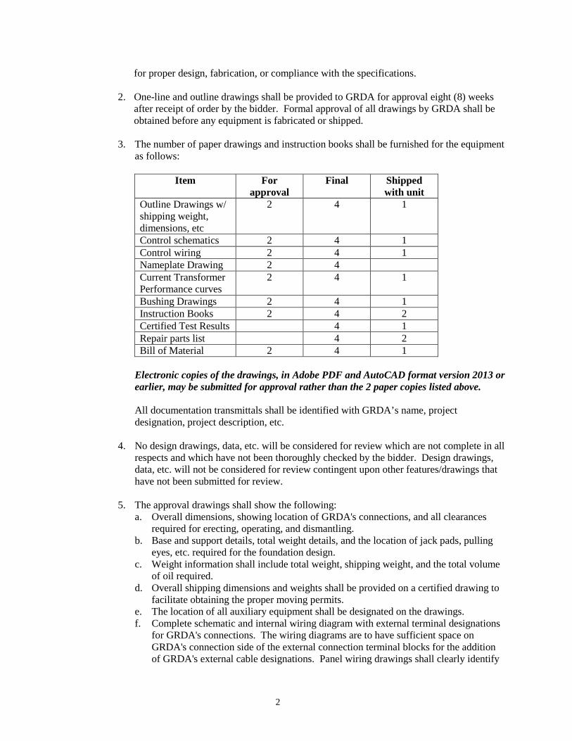
3. The number of paper drawings and instruction books shall be furnished for the equipment
as follows:
Item For approval
Final Shipped with unit
Outline Drawings w/ shipping weight, dimensions, etc
2 4 1
Control schematics 2 4 1 Control wiring 2 4 1 Nameplate Drawing 2 4 Current Transformer Performance curves
2 4 1
Bushing Drawings 2 4 1 Instruction Books 2 4 2 Certified Test Results 4 1 Repair parts list 4 2 Bill of Material 2 4 1
Electronic copies of the drawings, in Adobe PDF and AutoCAD format version 2013 or earlier, may be submitted for approval rather than the 2 paper copies listed above. All documentation transmittals shall be identified with GRDA’s name, project designation, project description, etc.
4. No design drawings, data, etc. will be considered for review which are not complete in all
respects and which have not been thoroughly checked by the bidder. Design drawings, data, etc. will not be considered for review contingent upon other features/drawings that have not been submitted for review.
5. The approval drawings shall show the following:
a. Overall dimensions, showing location of GRDA's connections, and all clearances required for erecting, operating, and dismantling.
b. Base and support details, total weight details, and the location of jack pads, pulling eyes, etc. required for the foundation design.
c. Weight information shall include total weight, shipping weight, and the total volume of oil required.
d. Overall shipping dimensions and weights shall be provided on a certified drawing to facilitate obtaining the proper moving permits.
e. The location of all auxiliary equipment shall be designated on the drawings. f. Complete schematic and internal wiring diagram with external terminal designations
for GRDA's connections. The wiring diagrams are to have sufficient space on GRDA's connection side of the external connection terminal blocks for the addition of GRDA's external cable designations. Panel wiring drawings shall clearly identify
3
all devices and indicate front and/or back of panel wiring. g. Transformer nameplate, connection, and polarity diagrams. h. Instrument transformer connection and polarity diagrams and performance/excitation
curves. i. Bushing drawings. j. Drawings showing additional detail if requested by GRDA, or if otherwise required
for installation and maintenance.
6. GRDA and/or GRDA’s Engineer will review the drawings, data, etc., for compliance with specifications, will mark them to indicate whether changes or corrections are required and will return one set to the bidder. The bidder shall resubmit the corrected or changed drawings, data, etc. Changes or corrections, etc. shall be clearly indicated. A minimum of three (3) weeks shall be allowed for GRDA's drawing approval. The approval of GRDA and/or GRDA’s Engineer does not relieve the bidder from any liability or responsibility for proper design, fabrication, or compliance with this specification.
7. Where standard drawings are furnished which cover a number of variations of the general
class of equipment, each such drawing shall be individually endorsed to describe exactly which parts of the drawing apply to the equipment being furnished. Such endorsement shall be included on the approval drawings and include the job name, purchase order, or contract number and serial number of the particular item covered. Separate sheets of paper bearing the endorsement will not be acceptable unless pasted or stenciled individually on each print submitted.
8. Drawings shall be organized in a logical manner. Schematic drawings shall show all of
one control function on the same drawing. Wiring drawings shall show the relative physical location of the devices, including terminals and adjacent devices to be on the same drawings. All device layouts shall be on the same drawing. Schematic drawings shall show the internal circuits of each device.
9. Installation Drawings: Instructions, drawings, and other specified documentation shall be
submitted for installation purposes after GRDA gives final approval. This documentation shall provide complete installation and operation information.
10. Final Record: Final drawings shall be punched and bound with the instruction book or
enclosed in the instruction books. Final books shall be submitted two (2) weeks prior to shipment and one final book with drawings shall be shipped with the transformer.
a. Final books shall be hard-backed and shall be properly labeled on the front outside
with GRDA’s name and location, the transformer description, order numbers, shop order, etc.
b. Prints of final drawings larger than 11" x 17" may be of reduced size if reduction
does not decrease legibility. c. Digital AutoCAD files, Version 2013 or earlier, shall be provided for GRDA to
reproduce drawings.
d. The factory test reports shall be included in the instruction books.
4
e. One set of the digitized reproducible drawings shall be provided. f. Any modifications required during the warranty period shall be accompanied by
revised final documentation as required to update the copies furnished. g. A transformer damage curve shall be provided on 11” x 16.5”, Keuffel & Esser
Company, Time-Current Characteristic, #48 5259, or equal, log-log graph tracing paper.
h. A spare parts list shall be included in each instruction book. The book shall provide
maintenance and operating instruction for each component of the equipment, including descriptions and ratings of accessory equipment and schematic and wiring drawings of all factory wiring.
12. Detail Requirements:
a. Connection or wiring diagrams shall be the lineless type. All points such as coil
terminals, capacitor terminals, etc., shall be identified on the connection diagrams. b. All drawings shall comply with ANSI Y14, latest published revision. c. Each drawing and certified document shall have the following as a minimum:
1) Purchase order or contract Numbers 2) Manufacturer’s Name 3) Manufacturer’s Shop Order Number 4) Manufacturer’s Drawing Number 5) Manufacturer’s Serial Number, when applicable
d. The following information for each motor shall be shown on the electrical schematic
drawing(s): 1) Voltage, Phase, Power Factor and Horsepower Ratings 2) Starting and Full Load Currents 3) Type of Bearings 4) Quantity and Use (Function)
e. Transformer dimension outline drawing shall include the following:
1) Weight of Transformer Tank 2) Weight and Height of Core and Coils 3) Weight of Heaviest Part to be Handled at On-Site Erection. 4) Total Gallons of Oil 5) The Gallons of Oil lost that would cause a Trip of the Low Oil Alarm (For each
Compartment with low oil alarm) 6) Gallons of Oil Required to Cover Core and Coils 7) Auxiliary Power Requirements:
a) Total b) First Stage of Cooling c) Second Stage of Cooling
8) Type of Winding Material (Copper) 9) Location of All Accessories and Details of GRDA’s Power Connection and
Control Conduit Locations.
5
f. Quality: 1) Legible drawings and data submitted to GRDA shall be of such quality that said
drawings and data shall be capable of yielding hard copy reproductions with every line, character, and letter clearly legible.
2) Documents submitted to GRDA that do not conform to the requirements of this
specification shall be subject to rejection by GRDA. Bidder shall resubmit conforming documents. If conforming submittals cannot be obtained from the source documents, such source documents shall be retraced, redrawn, or photographically restored as may be necessary to meet with such requirements. Bidder’s (or his subcontractor’s) failure to initially satisfy the legible quality requirements herein set forth, will not relieve bidder (or his subcontractor) from meeting the required schedule for submittal or drawings and data.
13. Mailing of Drawings and Data:
a. Approval drawings, etc., shall be transmitted by First Class mail or UPS to GRDA as
follows: Name Jeff Tullis Title Chief Engineer, GRDA Address 9933 E. 16th St. Tulsa, Oklahoma 74128 UPS/Shipping Address: Same as above Telephone: 918-610-9717 Fax: 918-610-9888 E-mail: [email protected]
b. A letter of transmittal must accompany all drawings, data, etc.
E. LOSSES
1. Losses shall be determined and guaranteed at the rated voltage with the tap changers in
the neutral or center positions. 2. No-load (core) losses shall be evaluated at a capitalized cost of $6,862 per kW.
3. Load (copper) losses shall be evaluated at a capitalized cost of $1,390 per kW at the
ONAN 458C rating (Corrected to 658C).
4. Auxiliary equipment power requirements shall be evaluated at a capitalized cost of $2,900 per kW at the maximum 558C rating (Corrected to 658C).
5. In evaluating the proposals, the total purchase price of the transformer will be calculated
by adding the quoted price plus the evaluated cost of the no-load losses, plus the evaluated cost of load losses, plus the evaluated cost of the total auxiliary equipment power requirements.
6
6. A transformer which upon factory test does not have losses equal to or less than the
guaranteed losses stated in the bidder’s Proposal, shall have its selling price reduced. The price reduction shall be the difference between the guaranteed losses and the actual loss(es) that exceed the quoted guarantee as determined by the tests, multiplied by a 1.1 penalty factor, and then multiplied by the appropriate dollar assessments given in the preceding paragraphs. If one area exceeds the quoted value and the two others do not, only the one exceeding the quote will be used to calculate the price reduction. No credit shall be given for losses lower than the quoted values.
F. TESTS
1. All test readings shall be documented, certified, and sent to GRDA as a part of each
instruction book. 2. GRDA shall be notified within the next working day of any test failure. 3. Bidder’s standard test procedures are acceptable. 4. The transformer shall receive all routine tests specified in the latest revision of ANSI
C57.12.00. These tests shall be performed in accordance with the latest revision of ANSI C57.12.90.
5. Resistance measurements of all windings on the rated voltage connection and at the tap
extremes. 6. Ratio tests on the rated voltage connection and on all tap connections. 7. Polarity and phase-relation tests on the rated voltage connection. 8. No-load (core) loss at rated voltage on the rated voltage connection and tap extremes. 9. Exciting current at rated voltage of the rated voltage connection and tap extremes. An
Excitation Curve shall be furnished using test and calculated values to 2 per unit voltage. 10. Impedance and load loss at rated current on the rated voltage connection and on the tap
extremes. Test sheet impedance values shall include both the positive sequence and zero sequence network values.
11. Temperature tests shall be made at the ONAN and ONAN/ONAF/OFAF ratings.
Temperature tests obtained from previously manufactured similar units will be acceptable.
12. Induced potential tests.
13. Applied potential tests 14. Through Faults: Without limiting in any way any obligation of the bidder under this
agreement, the bidder shall demonstrate to the satisfaction of GRDA that the transformer proposed to be furnished under this specification shall have sufficient mechanical strength to withstand, without failure, all through-fault currents. The bidder shall
7
demonstrate that the transformers meet this requirement by one of the following methods:
a. Certified test data showing that a transformer with a core and coil identical in design and construction and identical or similar with respect to kVA capacity, kV ratings, BIL, impedance and voltage taps has been tested without failure for short-circuit strength. A description of the test code under which the transformer was tested for short-circuit strength will be provided by the bidder to GRDA.
b. A history of successful experience with transformers of identical or similar ratings,
design, and construction. The bidder shall list all transformers in-service with core and coils which are essentially identical in design, construction, and manufacture to the transformer covered by this specification and provide the date of installation, location, and failures, if any. Where such transformers have not been built or the cumulative service record is less than 20 transformer years, a list of transformers in service, which represents the closest approximation to the transformer covered by this specification, shall be submitted. The information submitted shall be representative of the total experience of the bidder with the design of the transformer it proposes to furnish and include the dates of installation or shipping, the ratings of the transformers, and the failures and causes of failure, if any have been experienced. This history is not limited to the kVA rating of the transformer to be furnished hereunder. Such history or failures shall also include the approximate percentage of repair cost borne by the bidder and the approximate time the unit was out of service for repairs.
15. Additional tests shall be performed as specified below in accordance with the latest
revision of ANSI C57.12.90.
a. Corona Test (Partial Discharge): 1) This test shall be performed during the induced test.
2) The ratio noise meter shall be coupled to the terminals of the windings under test,
either through a coupling capacitor or through the bushing capacitance taps. Shielding and filters are allowed to discriminate against external interference. The RIV is to be measured within the frequency range of 0.85 to 1.15 MHz.
3) On each winding terminal continuous monitoring or periodic readings at 5-
minute intervals shall accompany the 1-hour test to insure that the apparent discharge level does not exceed 100 microvolts. The 1-hour test readings shall not exceed the RIV level measured at the rated maximum voltage readings by 50 µV or more
b. Impulse Test: (ANSI)
1) This test shall consist of: a) One Reduced Full Wave b) Two Chopped Waves c) One Full Wave
2) Impulse tests shall be made without excitation and performed in accordance with
the latest revision of ANSI C57.12.90.
3) Each transformer shall be excited to 110% of maximum operating voltage before
8
and after impulse testing, noting the change in exciting current and core loss. Changes in either the exciting current or core loss or both which exceed 5% shall be corrected by reverse impulses. If correction to within 5% of before-impulse cannot be obtained, the unit(s) shall be considered failed.
4) Voltage and ground current oscillogram traces shall be made.
5) The bidder shall furnish to GRDA one certified copy of complete impulse test
results including oscillogram traces on a durable stock that will yield legible photocopies.
c. Power factor tests of completely assembled transformer utilizing the Doble test
method, corrected to 208C, shall not exceed 0.5%. d. Sound tests.
1) Audible Sound Level: This transformer shall be designed and guaranteed to have an average sound level not exceeding 5 dB below the level listed in the latest revision of NEMA Publication No. TR1. If the maximum average sound level with all auxiliary cooling equipment in operation exceeds the maximum sound level listed in the latest revision of NEMA Publication No. TR1, GRDA shall be notified so that sound insulation can be installed on the transformer at the bidder’s expense. GRDA may perform an in-service field test.
2) Audible sound testing is required unless an essentially duplicate transformer has
been sound tested by the bidder. The successful bidder shall, if omission of sound testing is requested, submit for approval three copies of such tests showing the design will meet the sound level specified.
16. Sweep Frequency Response Analysis (SFRA) of fully assembled unit just prior to
shipment. 17. GRDA and/or his representatives shall have the right to witness all tests and core and coil
assembly before tanking. The bidder shall advise GRDA 15 working days in advance of tests and tanking of core and coils so travel arrangements may be made. GRDA retains option to waive witnessing tests.
18. Prior to shipment of transformers, all test results shall be sent to GRDA for approval. 19. A copy of bushing bidder’s test reports, including power factor, shall be forwarded to
GRDA.
G. SHIPMENT
1. Shipping shall be f.o.b., destination to location given on the Proposal sheet. 2. GRDA shall approve the delivery schedule for the transformer and auxiliary equipment.
The bidder shall be responsible for all demurrage charges for deliveries during hours other than those approved by GRDA.
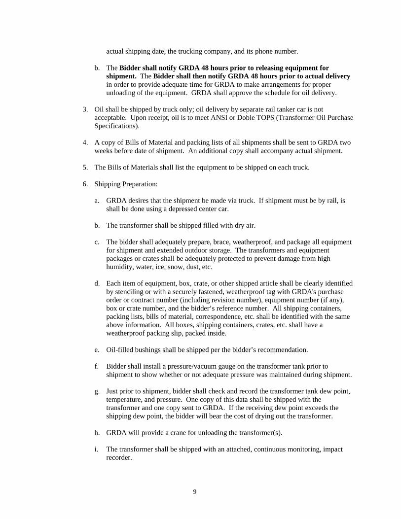
a. GRDA shall be advised of the shipment dates two weeks in advance including the
9
actual shipping date, the trucking company, and its phone number. b. The Bidder shall notify GRDA 48 hours prior to releasing equipment for
shipment. The Bidder shall then notify GRDA 48 hours prior to actual delivery in order to provide adequate time for GRDA to make arrangements for proper unloading of the equipment. GRDA shall approve the schedule for oil delivery.
3. Oil shall be shipped by truck only; oil delivery by separate rail tanker car is not
acceptable. Upon receipt, oil is to meet ANSI or Doble TOPS (Transformer Oil Purchase Specifications).
4. A copy of Bills of Material and packing lists of all shipments shall be sent to GRDA two
weeks before date of shipment. An additional copy shall accompany actual shipment. 5. The Bills of Materials shall list the equipment to be shipped on each truck.
6. Shipping Preparation:
a. GRDA desires that the shipment be made via truck. If shipment must be by rail, is
shall be done using a depressed center car. b. The transformer shall be shipped filled with dry air. c. The bidder shall adequately prepare, brace, weatherproof, and package all equipment
for shipment and extended outdoor storage. The transformers and equipment packages or crates shall be adequately protected to prevent damage from high humidity, water, ice, snow, dust, etc.
d. Each item of equipment, box, crate, or other shipped article shall be clearly identified
by stenciling or with a securely fastened, weatherproof tag with GRDA's purchase order or contract number (including revision number), equipment number (if any), box or crate number, and the bidder’s reference number. All shipping containers, packing lists, bills of material, correspondence, etc. shall be identified with the same above information. All boxes, shipping containers, crates, etc. shall have a weatherproof packing slip, packed inside.
e. Oil-filled bushings shall be shipped per the bidder’s recommendation. f. Bidder shall install a pressure/vacuum gauge on the transformer tank prior to
shipment to show whether or not adequate pressure was maintained during shipment. g. Just prior to shipment, bidder shall check and record the transformer tank dew point,
temperature, and pressure. One copy of this data shall be shipped with the transformer and one copy sent to GRDA. If the receiving dew point exceeds the shipping dew point, the bidder will bear the cost of drying out the transformer.
h. GRDA will provide a crane for unloading the transformer(s).
i. The transformer shall be shipped with an attached, continuous monitoring, impact
recorder.
10
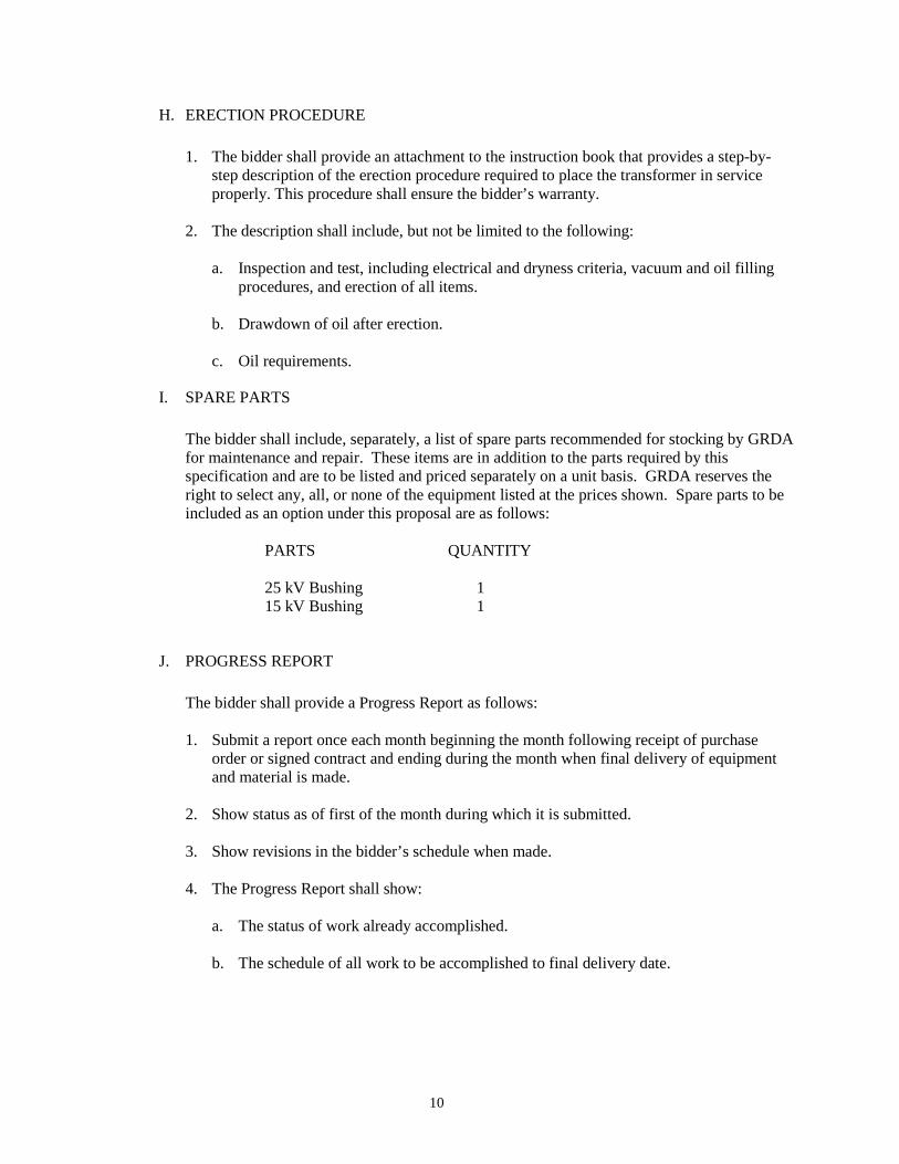
H. ERECTION PROCEDURE
1. The bidder shall provide an attachment to the instruction book that provides a step-by-
step description of the erection procedure required to place the transformer in service properly. This procedure shall ensure the bidder’s warranty.
2. The description shall include, but not be limited to the following:
a. Inspection and test, including electrical and dryness criteria, vacuum and oil filling procedures, and erection of all items.
b. Drawdown of oil after erection.
c. Oil requirements.
I. SPARE PARTS
The bidder shall include, separately, a list of spare parts recommended for stocking by GRDA for maintenance and repair. These items are in addition to the parts required by this specification and are to be listed and priced separately on a unit basis. GRDA reserves the right to select any, all, or none of the equipment listed at the prices shown. Spare parts to be included as an option under this proposal are as follows:
PARTS QUANTITY 25 kV Bushing 1 15 kV Bushing 1
J. PROGRESS REPORT
The bidder shall provide a Progress Report as follows:
1. Submit a report once each month beginning the month following receipt of purchase
order or signed contract and ending during the month when final delivery of equipment and material is made.
2. Show status as of first of the month during which it is submitted. 3. Show revisions in the bidder’s schedule when made. 4. The Progress Report shall show:
a. The status of work already accomplished. b. The schedule of all work to be accomplished to final delivery date.
11
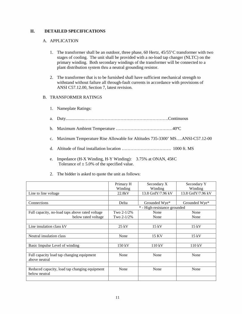
II. DETAILED SPECIFICATIONS
A. APPLICATION
1. The transformer shall be an outdoor, three phase, 60 Hertz, 45/55°C transformer with two
stages of cooling. The unit shall be provided with a no-load tap changer (NLTC) on the primary winding. Both secondary windings of the transformer will be connected to a plant distribution system thru a neutral grounding resistor.
2. The transformer that is to be furnished shall have sufficient mechanical strength to
withstand without failure all through-fault currents in accordance with provisions of ANSI C57.12.00, Section 7, latest revision.
B. TRANSFORMER RATINGS
1. Nameplate Ratings:
a. Duty.................………………………………………………….Continuous b. Maximum Ambient Temperature …………………………………40ºC c. Maximum Temperature Rise Allowable for Altitudes 735-3300’ MS….ANSI-C57.12-00 d. Altitude of final installation location ……………………………. 1000 ft. MS e. Impedance (H-X Winding, H-Y Winding): 3.75% at ONAN, 458C Tolerance of ± 5.0% of the specified value.
2. The bidder is asked to quote the unit as follows:
Primary H
Winding Secondary X
Winding Secondary Y
Winding Line to line voltage 22.8kV 13.8 GrdY/7.96 kV 13.8 GrdY/7.96 kV Connections Delta Grounded Wye* Grounded Wye* * - High-resistance grounded Full capacity, no-load taps above rated voltage below rated voltage
Two 2-1/2% Two 2-1/2%
None None
None None
Line insulation class kV 25 kV 15 kV 15 kV Neutral insulation class None 15 KV 15 kV Basic Impulse Level of winding 150 kV 110 kV 110 kV Full capacity load tap changing equipment above neutral
None None None
Reduced capacity, load tap changing equipment below neutral
None None None
12
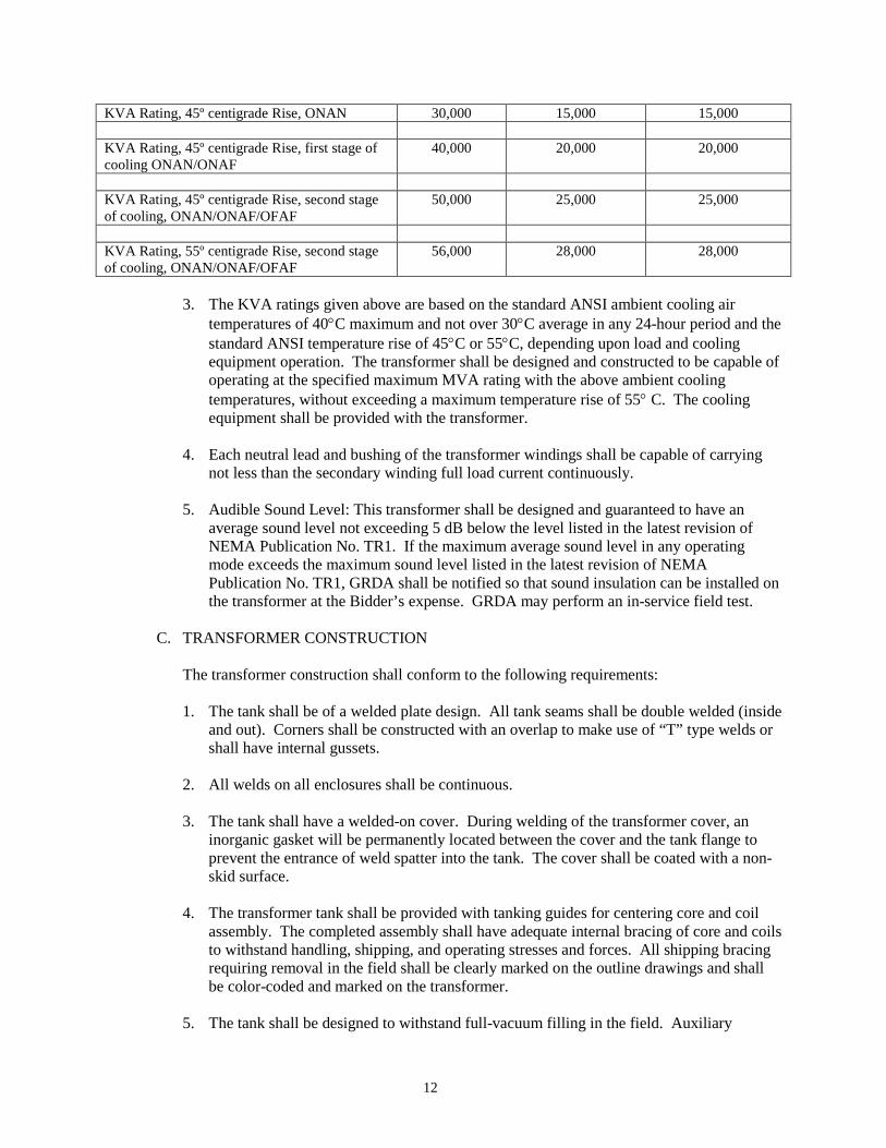
3. The KVA ratings given above are based on the standard ANSI ambient cooling air
temperatures of 40°C maximum and not over 30°C average in any 24-hour period and the standard ANSI temperature rise of 45°C or 55°C, depending upon load and cooling equipment operation. The transformer shall be designed and constructed to be capable of operating at the specified maximum MVA rating with the above ambient cooling temperatures, without exceeding a maximum temperature rise of 55° C. The cooling equipment shall be provided with the transformer.
4. Each neutral lead and bushing of the transformer windings shall be capable of carrying
not less than the secondary winding full load current continuously. 5. Audible Sound Level: This transformer shall be designed and guaranteed to have an
average sound level not exceeding 5 dB below the level listed in the latest revision of NEMA Publication No. TR1. If the maximum average sound level in any operating mode exceeds the maximum sound level listed in the latest revision of NEMA Publication No. TR1, GRDA shall be notified so that sound insulation can be installed on the transformer at the Bidder’s expense. GRDA may perform an in-service field test.
C. TRANSFORMER CONSTRUCTION
The transformer construction shall conform to the following requirements:
1. The tank shall be of a welded plate design. All tank seams shall be double welded (inside and out). Corners shall be constructed with an overlap to make use of “T” type welds or shall have internal gussets.
2. All welds on all enclosures shall be continuous. 3. The tank shall have a welded-on cover. During welding of the transformer cover, an
inorganic gasket will be permanently located between the cover and the tank flange to prevent the entrance of weld spatter into the tank. The cover shall be coated with a non-skid surface.
4. The transformer tank shall be provided with tanking guides for centering core and coil assembly. The completed assembly shall have adequate internal bracing of core and coils to withstand handling, shipping, and operating stresses and forces. All shipping bracing requiring removal in the field shall be clearly marked on the outline drawings and shall be color-coded and marked on the transformer.
5. The tank shall be designed to withstand full-vacuum filling in the field. Auxiliary
KVA Rating, 45º centigrade Rise, ONAN 30,000 15,000 15,000 KVA Rating, 45º centigrade Rise, first stage of cooling ONAN/ONAF
40,000 20,000 20,000
KVA Rating, 45º centigrade Rise, second stage of cooling, ONAN/ONAF/OFAF
50,000 25,000 25,000
KVA Rating, 55º centigrade Rise, second stage of cooling, ONAN/ONAF/OFAF
56,000 28,000 28,000
13
compartments, when not designed for full-vacuum filling, shall be so designated on the outline drawing and labeled as such on the compartment itself as well as on the transformer nameplate. Compartments of this type shall be provided with approved valves and piping for isolating or equalizing as required.
6. The transformer shall have a sealed tank construction for oil preservation with ample gas
blanket space above the oil. A conservator-type tank design is not acceptable and will not be considered. The gas blanket shall be maintained by a closed, fully automatic nitrogen system. The regulating equipment and nitrogen bottle shall be completely enclosed in a cabinet. The door to the cabinet shall have glass or plexiglass installed for viewing the bottle pressure without opening the door. One bottle of nitrogen shall be provided with the transformer.
7. Tank shall be provided with a tapered, gas-sampling valve of 1/4" size. The valve shall
not be located more than 66 inches above the base with a 1/4" or larger line extended to within one inch of the top of the gas space. The sampling valve can be located in the nitrogen regulating cabinet.
8. The main transformer tank and any compartments that are subject to operating pressures shall be designed to withstand without deformation, pressure 25% greater than the maximum operating pressures resulting from the oil preservation system. The minimum design pressure shall be + 12.5 psi (10 psi base plus 2.5 psi safety factor). The maximum operating pressures (positive and negative) that the transformer is designed to withstand shall be indicated on the nameplate.
9. The centerlines of the tank shall be permanently and plainly marked near the base of all four sides of the tank and also shown on the outline drawing.
10. The shipping center of gravity shall be plainly indicated and dimensioned on the outline drawing and marked on the transformer tank sides and cover.
11. The completely equipped and oil filled center of gravity shall be plainly indicated and dimensioned on the outline drawing only for use in foundation design.
12. All accessory mounting brackets shall be adequately supported to provide a stable assembly. Supports for arresters shall be designed to resist a 40-pound per square foot wind loading on the arrester.
13. No welding of any type shall be required for field installation.
14. The design of each transformer shall be such as to permit energizing the transformer at a
minimum oil temperature of -20° C. At this temperature, the oil level shall be above the low level marking and the alarm setting of the oil level gauge.
15. The transformer shall be divided into four segments or quadrants as viewed from the top and including the associated side faces. The top segment opposite the high voltage bushings and its associated side of the transformer is defined as Segment 1. The other segments are numbered 2-3-4 clockwise as viewed from the top of the transformer. Segment 3 includes the high voltage bushings. Segment 2 includes the sidewall-mounted low voltage (X) bushings. Segment 4 includes the sidewall-mounted low voltage (Y) bushings.
14
16. All accessories shall be located in Segment 3, except:
a. Lifting and jacking facilities shall be in all Segments. b. Ground pads shall be in Segment 1 and 3.
c. Primary No-Load Tap Changer shall be in Segment 4 on the high voltage side.
17. Transformer Base Requirements:
a. The base shall be fabricated of flat plate steel of 1-inch minimum thickness. The
exterior of the base shall not have any ribs, grooves, etc. The base edges shall be rounded or sloped upward at an angle of approximately 45°.
b. The center of gravity of the transformer, as normally prepared for shipment, shall not
fall outside the base support members for a tilt of the base of 15° from the horizontal, with or without oil in the transformer.
c. The base shall be designed for jacking, towing, and rolling and shipping in the
directions of the centerlines of all Segments. d. The base shall be designed to support the entire transformer, completely assembled
and oil filled, on piers located only under the outer one-foot of Segments 2 and 4. GRDA reserves the right to support this transformer with either a pier or a slab type foundation.
18. All gasketed joints shall have machined surfaces on both sides to assure even and
effective pressure, to avoid overstressing gaskets, and to maintain oil tightness of joints under all service conditions. Joints shall be provided with gasket retainers and metal-to-metal stops. All gasketed joints on top of the transformer shall utilize flanges that are raised at least 3/4 inch above the cover surface.
All gaskets in contact with oil-bearing surfaces shall be nitrile butadiene synthetic rubber.
Cork, in any form, is unacceptable as gasket material. Gasket joints shall be an overlapping, tapered type. Butt-jointed gaskets are not acceptable
Necessary gaskets shall be provided for the initial installation and assembly of the transformer. These gaskets shall be shipped with the transformer.
19. In addition to the initial set of gaskets, one complete set of spare gaskets for the complete transformer shall be provided and shipped in a separate container. Each gasket shall be labeled or identified with the appropriate use or installation location. These gaskets are for future use only and are in excess of those required for transformer assembly. A complete set of spare gaskets is defined as one gasket for each gasketed location of the transformer that is used to contain the insulating oil.
20. Manholes & Hand/Inspection Holes:
a. GRDA shall approve the number and location of manholes. The minimum
dimension for round, oval, or rectangular manholes shall be 18.5 inches. A minimum
15
of two manholes shall be provided in the tank cover.
b. Hand/inspection holes shall be provided to allow inspection and tightening of all mounting hardware, various tap changer items, all other bolted connections not accessible from manhole entrances, and all other miscellaneous bracing and mounting. The minimum dimension for round, oval, or rectangular hand/inspection holes shall be 12 inches.
c. All manholes and hand/inspection holes shall be bolted. d. Each removable bolted cover, i.e., manholes, hand/inspection holes, etc. weighing
more than 45 pounds shall be hinged, removable, and equipped with lifting eyes. Cover weighing 45 pounds or less shall have handles.
21. Lifting Facilities:
a. Four lifting hooks shall be provided and designed for lifting the completely dressed-
out transformer with slings at a maximum angle of 30° with respect to the vertical axis.
b. Each lifting hook bearing surface shall be free from sharp edges, shall be chamfered, and shall have a hole with a minimum diameter of 2-inches for guying purposes.
22. There shall be two jack lugs in each transformer segment. Each jack lug shall have its
centerline located within 1-foot of each segment corner. Each jack lug shall have its opening so designed that the lifting members of the jacks can be easily inserted. The 2-inch holes in the webbing above the jack pad itself are for attachment of winch lines for skidding of transformer and shall be designed for this purpose.
23. The overall height including bushings shall not exceed that specified under section
“COMPATABILITY WITH EXISTING UNITS”. The shipping height with bushings, radiators, etc. removed, shall not exceed 15 feet-6 inches.
24. A bracket suitable for mounting a fall prevention safety device shall be provided in the
approximate center of the tank cover. This bracket shall be capable supporting hardware including personnel harnesses utilizing gravity brakes.
25. A two-inch minimum pipe connection and plug for venting shall be provided in the top
cover.
E. COOLING EQUIPMENT Transformer cooling equipment shall consist of a combination of radiator(s), fans and pumps. Two stages of cooling shall be provided.
1. Radiator(s)
a. The transformer radiator(s) shall be removable. Valves shall be provided to allow
removal and installation of radiators without lowering the oil level in the main tank. Radiator headers shall be provided with mounting flanges for bolting directly to the radiator shut-off valves mounted on the transformer. The radiator headers shall be provided with drain plugs at the bottom, vent plugs at the top, and lifting eyes.
16
If radiator manifolds are provided on the transformer, shut-off valves to the main
tank, vent plugs, and drain valves must be provided for each manifold. Valves shall be of a type that does not leak around the operating stem. They shall be equipped with indicators which clearly show their position as open or closed and shall be arranged so they can be bolted in either the open or closed position. Packing-gland type valves will not be accepted.
b. Radiators shall be flushed prior to shipment to remove any welding slag or other
foreign material. Radiator flanges shall be sealed during shipment to prevent any moisture or foreign material from entering the radiators.
c. Each removable radiator shall be provided with two lifting eyes with one each on the
top and bottom lifting balance point or four eyes with two each on top and bottom. d. Each removable radiator shall be provided with a brass ball valve at its lowest point
for draining the radiator. The ball valve shall have a brass plug and the vent at the top shall have a steel inlet plug. These fittings will be used to flush/drain the entire radiator assembly.
e. All radiators shall be of suitable material, using welded or brazed construction. They
shall be designed and braced to prevent undue vibration. X-bracing is required for each radiator bank, top and bottom. All radiators shall be capable of full vacuum filling.
f. All plugs shall have square heads and National pipe threads. Teflon tape shall be
applied to all threaded parts prior to assembly.
2. Fans a. Fans shall be provided to facilitate full 55°C nameplate ratings. Fans shall be three-
phase, 480 volts AC. Each bank of fans shall be supplied through a separate breaker installed in the control cabinet. The failure of the first stage of cooling shall not inhibit the second stage from operating in accordance with the settings on the winding temperature gauge contacts.
b. The wiring diagram and schematics for the forced cooling equipment and other
equipment shall be submitted to GRDA for approval before actual assembly is started. Tabular wiring diagrams are not acceptable.
c. Each Transformer shall have one additional fan per cooling stage in excess of the
design requirements. NOTE: The heat run calculations cannot take advantage of this requirement for one additional fan per cooling stage. However, it should be included in the total auxiliary load for loss calculations.
d. Cooling fans shall have their rotating shafts in the horizontal position and mounted
for cross-flow cooling. e. All fan motors shall be totally enclosed, non-ventilated, with sealed, prelubricated
ball bearings. Fans shall be rated for all-weather outdoor operation.
17
f. All fan motors shall have a power factor of 0.8 or better. g. Each fan motor shall be provided with thermal overload devices. h. Fans shall be of slow speed, 1140 RPM or less, high volume design for quiet
operation. Fans shall be Krenz brand or approved equal. i. Fans shall be fully accessible and designed so any individual fan can be easily
removed without disturbing the operation of other fans. j. Fans shall be dynamically balanced and operate without vibration. k. Each fan shall have a flexible cable connection to a ring type disconnect. l. Each fan shall be attached to a radiator and shall be adequately protected by a guard.
Fan guards shall meet or exceed OSHA regulations. m. Fan motors shall not be equipped with centrifugal switches. n. The control circuit shall be wired so that upon the opening of a remote contact
supplied by GRDA, all cooling equipment in that stage of fans shall be de-energized. This circuit shall be designed so that GRDA's connections and remote contact will be subjected only to 120 volts, 60 Hertz, ac duty. The circuit shall be self-resetting when GRDA's remote contact is closed
3. Pumps
a. Each OFAF stage of cooling shall have a minimum of one oil pump. Each pump
shall be supplied through a separate breaker installed in the control cabinet. The failure of the pump on the first stage of cooling shall not inhibit the second stage from operating in accordance with the settings on the winding temperature gauge contacts.
b. Pump motor shall operate on three- phase, 480 volts AC. c. Each OFAF cooled transformer shall be designed and equipped so that the oil pumps
in the automatic mode cannot be energized if the oil temperatures are below 40° C. d. Each oil pump shall be equipped with an oil flow indicator. The oil flow indicator
shall indicate that oil is flowing and shall be provided with one non-grounded Form C contact that is wired to a terminal block in the control cabinet for Owner’s alarm. Contact shall be actuated for the following conditions: Reverse pump operation, restricted oil flow, or closed oil circuit.
e. The pump motor shall operate at 1800 RPM or less. f. The oil circulating pumps shall be efficient, maintenance free, squirrel cage motors
with integral mounted centrifugal pump. g. The pump motor and impeller shall be totally enclosed and oil immersed and shall be
bolted directly to the pump housing.

18
h. The motor and pump shall require no additional lubrication. i. The motor and pump shall have mechanical seals. Packing glands are not allowed. j. An oil-tight terminal outlet shall be provided for electrical connection to the motor. k. Oil pumps to be installed with “oil tight” valves with “covers” to facilitate removal of
pumps for repair. l. Oil pumps to be made in North America. Pumps shall be Cardinal brand or approved
equal.
A. Auxiliary Power
a. Two separate 480 Volt, three-phase feeds with 42,000 ampere symmetrical short circuit capacity will be provided, installed and connected by Others for auxiliary power. Control equipment shall be provided to allow either feed to be selected as “preferred”.
b. Additional equipment including one control power transformer for each 480 Volt
feed and one automatic transfer switch shall be provided. Failure of the “preferred” feed shall automatically transfer auxiliary loads to the “standby” feed, provided there is correct voltage and frequency on the “standby” feeder.
c. The control power transformer secondaries shall also be switched by the transfer
switch when it switches from “preferred” to “standby” 480 Volt feeds.
F. OIL DRAIN AND FILTER VALVES
1. Each component or tank must be equipped with an oil drain valve, vent plug, mechanical pressure relief device, sudden-pressure device with auxiliary contacts, oil sampling valve, and provisions for upper and lower oil filtering connections.
2. All tank drain valves and upper filter press valves shall have 2-inch National pipe
threads. Metric-cut threads are not acceptable. Radiator drain valves shall have 1-inch National pipe threads. Reducers are not allowed in conjunction with valves. All valves shall be equipped with end plugs or caps.
3. All valves shall be brass and ball type, which do not leak around their operating stems. 4. Each valve shall have a steel valve plug with a square head and Teflon tape applied to its
threads. All other plugged locations shall also have a steel plug with a square head and Teflon tape applied to their threads. Each drain and upper filter press valve plug shall be equipped with a 3/8-inch sampling device. This device shall have 5/16 inch x 32 male threads and be equipped with a cap. The sampling device shall be installed in the end plugs.
5. A drain valve shall be located in the bottom of each oil-filled compartment to provide
drainage within 1-inch or less of the bottom of the compartment.
19
6. Main Tank:
a. A combination drain and lower filter valve shall be provided for complete drainage of the oil to the bottom of the tank and for outlet to oil filtering equipment
b. An upper filter valve located below the 25°C liquid level shall be provided. c. A 3-inch vacuum connection with a plug shall be provided on the top of the main
tank for use during filling.
G. GROUNDING
1. All ground pads shall consist of copper-faced steel pads or stainless steel pads without copper facing. The minimum thickness of the copper facing shall be 0.015 inch. Pads shall have NEMA 2-hole spacing and drilling. Thread protection for the ground pads shall consist of a flanged cup of non-corrosive material suitable for press fitting into threaded openings.
2. The bidder shall furnish all connections from the neutral bushing to the ground bus. These connections shall be removable for testing and replacement purposes. The ground bus shall connect both ground pads together and cover both holes on each respective ground pad.
3. Each transformer shall be equipped with two ground pads, one each in Segments 1 and 3.
4. All ground bus shall be copper bar with a minimum number of splices. The bidder shall
provide brackets to securely fasten the ground bus and associated leads to the transformer.
H. CORE AND COIL ASSEMBLY
1. The design shall be core form. 2. Core construction shall be a stepped, round type. Rectangular cores are not acceptable. 3. The core assembly shall have laminations made of “non-aging”, cold rolled, grain
oriented, highly permeable silicon alloy steel. Each lamination shall be covered with a high-resistance, inorganic coating to reduce eddy currents.
4. The core assembly shall be braced adequately to prevent displacement and distortion
under all normal handling conditions including rail shipment and operation under maximum short circuit conditions. Core bolts shall not be used.
5. Cores shall be grounded at only one point and the core grounds for both the main and
series transformer shall be brought outside the tank to a convenient location for testing and be accessible without opening the transformer tank. All hardware necessary for removing the ground lead for testing shall utilize captive hardware.
6. The transformer design shall be adequate to withstand short circuits, with the fault current
limited only by the impedance of the transformer itself.
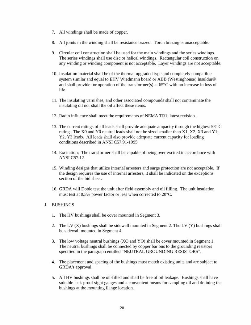
20
7. All windings shall be made of copper. 8. All joints in the winding shall be resistance brazed. Torch brazing is unacceptable. 9. Circular coil construction shall be used for the main windings and the series windings.
The series windings shall use disc or helical windings. Rectangular coil construction on any winding or winding component is not acceptable. Layer windings are not acceptable.
10. Insulation material shall be of the thermal upgraded type and completely compatible
system similar and equal to EHV Wiedmann board or ABB (Westinghouse) Insuldur and shall provide for operation of the transformer(s) at 65°C with no increase in loss of life.
11. The insulating varnishes, and other associated compounds shall not contaminate the insulating oil nor shall the oil affect these items.
12. Radio influence shall meet the requirements of NEMA TR1, latest revision.
13. The current ratings of all leads shall provide adequate ampacity through the highest 55° C
rating. The X0 and Y0 neutral leads shall not be sized smaller than X1, X2, X3 and Y1, Y2, Y3 leads. All leads shall also provide adequate current capacity for loading conditions described in ANSI C57.91-1995.
14. Excitation: The transformer shall be capable of being over excited in accordance with
ANSI C57.12. 15. Winding designs that utilize internal arresters and surge protection are not acceptable. If
the design requires the use of internal arresters, it shall be indicated on the exceptions section of the bid sheet.
16. GRDA will Doble test the unit after field assembly and oil filling. The unit insulation
must test at 0.5% power factor or less when corrected to 20°C.
J. BUSHINGS 1. The HV bushings shall be cover mounted in Segment 3. 2. The LV (X) bushings shall be sidewall mounted in Segment 2. The LV (Y) bushings shall
be sidewall mounted in Segment 4.
3. The low voltage neutral bushings (XO and YO) shall be cover mounted in Segment 1. The neutral bushings shall be connected by copper bar bus to the grounding resistors specified in the paragraph entitled “NEUTRAL GROUNDING RESISTORS”.
4. The placement and spacing of the bushings must match existing units and are subject to
GRDA's approval. 5. All HV bushings shall be oil-filled and shall be free of oil leakage. Bushings shall have
suitable leak-proof sight gauges and a convenient means for sampling oil and draining the bushings at the mounting flange location.
21
5. All HV bushings shall have a shielded tap brought out for making ungrounded power
factor tests. 6. All bushings shall be designed such that impulse voltage flashover occurs outside the
tank before flashover occurs on the bushings inside the transformer. 7. The ampere rating shall provide adequate capacity through the 55°C ONAF/OFAF rating
continuously with a margin for emergency overload. 8. Each bushing shall have a power factor of 0.5% or less. A certified power factor test
shall be provided for each bushing and shall include grounded and ungrounded specimen tests. All test values shall be corrected to 20°C. Factory bushing tests to be forwarded with certified test results.
9. Each bushing shall be manufactured and tested by the bushing manufacturer in
accordance with the latest revision of ANSI C76.1. Test results shall be certified. 10. Acceptable bushings: ABB type "O+C" only. Approval data shall include, but not be
limited to, outline drawing, manufacturer, type, style, and catalog number. 11. Bushings shall be gray in color, shall be transformer breaker interchangeable (TBI), and
shall have the following ratings and characteristics:
Service Voltage KV
Bushing BIL KV
Minimum Current Rating
High Voltage 25 150 2000 Low Voltage 15 110 1500 Neutral 15 110 1500
12. Each bushing shall be supplied with a NEMA four-hole pad connector sized to fit the
bushing stud. 13. Flanges shall be provided at the high voltage bushings for connection to existing isolated
phase bus duct. The throat connection shall be as high as the bushing porcelain and closed with a cover for shipment. See Fig 101, Dwg. 149D7088 (SH. No. 2) referenced in Appendix B.
14. A closed terminal cabinet shall be provided for each set of three LV bushings to receive
the owner’s cable. The cabinet shall have gasketed cover plates for access to the cable terminations. Removable gasketed bottom plates shall be provided to facilitate field punching for owner’s conduit.
K. INSULATING OIL
1. All transformers shall be supplied with the necessary quantity of high quality Type II Naphthenic Insulating Oil.
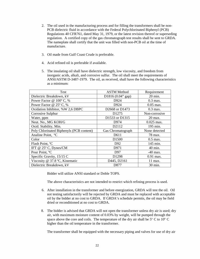
22
2. The oil used in the manufacturing process and for filling the transformers shall be non-PCB dielectric fluid in accordance with the Federal Polychlorinated Biphenyl (PCB) Regulations 40 CFR761, dated May 31, 1979, or the latest revision thereof or superseding regulation. A certified copy of the gas chromatograph test results shall be sent to GRDA. The nameplate shall certify that the unit was filled with non-PCB oil at the time of manufacture.
3. Oil made from Gulf Coast Crude is preferable.
4. Acid refined oil is preferable if available. 5. The insulating oil shall have dielectric strength, low viscosity, and freedom from
inorganic acids, alkali, and corrosive sulfur. The oil shall meet the requirements of ANSI/ASTM D-3487-1979. The oil, as received, shall have the following characteristics as a minimum:
Test ASTM Method Requirement Dielectric Breakdown, kV D1816 (0.04” gap) 20 min. Power Factor @ 100º C, % D924 0.3 max. Power Factor @ 25º C, % D924 0.05 max. Oxidation Inhibitor, %W 2,6 DBPC D2668 or D1473 0.3 max. Corrosive Sulphur D1275 Non-corrosive Water, ppm D1533 or D1315 20 max. Neut. No., MG KOH/G D974 0.025 max. Oxid. Stability, Min. D2112 195 min. Poly Chlorinated Biphenyls (PCB content) Gas Chromatograph None detected Analine Point, ºC D611 78 max. Color D1500 0.5 max. Flash Point, ºC D92 145 min. IFT @ 25º C, Dynes/CM D971 40 min. Pour Point, ºC D97 -40 max. Specific Gravity, 15/15 C D1298 0.91 max. Viscosity @ 37.8 ºC, Kinematic D445, D2161 11 max. Dielectric Breakdown, kV D877 30 min.
Bidder will utilize ANSI standard or Doble TOPS.
The above characteristics are not intended to restrict which refining process is used.
6. After installation in the transformer and before energization, GRDA will test the oil. Oil
not testing satisfactorily will be rejected by GRDA and must be replaced with acceptable oil by the bidder at no cost to GRDA. If GRDA’s schedule permits, the oil may be field dried or reconditioned at no cost to GRDA.
8. The bidder is advised that GRDA will not open the transformer unless dry air is used; dry air, with maximum moisture content of 0.03% by weight, will be pumped through the space above the core and coils. The temperature of the dry air shall be 5° C to 10° C higher than the oil temperature in the transformer.
The transformer shall be equipped with the necessary piping and valves for use of dry air
23
and nitrogen gas. The Bidder is to supply one gas bottle of nitrogen with the transformer, and he shall also furnish a certificate of ownership in GRDA's name for the bottle.
L. PAINTING
1. All exterior and interior surfaces are to be thoroughly cleaned of dirt, mill scale, rust, and welding slag before painting.
2. Oil and grease are to be removed chemically before painting. 3. All exterior surfaces, regardless of when the paint is applied during the fabrication, must
be given three coats of suitable transformer paint prior to shipment. All metal surfaces must have a primer coat applied prior to applying the intermediate and finish coats. The finish coat shall be Gloss Light Gray, ANSI #70.
4. The inside surfaces of the main tank and LTC compartment shall be cleaned and coated
with white paint which will not disintegrate or act as a catalytic agent when in contact with the insulating oil and which will not in any way cause deterioration of the oil.
5. Radiators shall be painted using electrostatic application or they shall be hot-dipped
galvanized. The bidder shall state on the proposal whether the radiators are painted or galvanized.
6. The interior of all control cabinets shall be gloss white.
M. LOAD TAP CHANGING EQUIPMENT (Not Used)
N. TRANSFORMER CONTROL CABINET
1. GRDA will make all control wiring and auxiliary power connections in the control cabinet.
2. All control devices shall be housed in weatherproof cabinet equipped with sufficient heaters and breather vents to prevent moisture condensation and ensure satisfactory operation of the apparatus to -25°F. All vents shall be guarded to prevent the entrance of insects.
3. Heaters shall be equipped with a non-adjustable thermostat and a manual switch for disconnecting purposes. When heaters are mounted in a location that may be hazardous to operating personnel, they shall be provided with protective screens.
4. A weatherproof lockable control cabinet shall be furnished for all control equipment.
The control cabinet shall be equipped with a stainless steel, 3-point latching mechanism and a continuous stainless steel hinge. Handle shall have provisions for locking including a 3/8" minimum diameter hole.
5. Control components shall not be located on any exterior door.
6. Approved terminal blocks shall be provided for terminating GRDA's incoming power
24
supply, potential supply, SCADA control wiring, and alarm indication wires. Shorting type terminal blocks shall be provided for terminating all current transformer leads. All GRDA connections shall be terminated on terminal blocks located in the control cabinet.
7. Auxiliary relays, alarm contacts, and indicator relay contacts shall be rated at 120 volts DC. GRDA's control voltage is 120 volts DC.
8. High quality switches (switchboard type where applicable), auxiliary relays, contacts, and breakers shall be supplied for all control functions and shall be subject to approval by GRDA.
9. Control, alarm, indication, and CT leads shall exit the control cabinet in conduit and shall continue in conduit toward the end device as far as practical in order to provide maximum protection to the wiring. Flexible conduit may be used at the end device.
10. Switches, contactors, breakers, and control devices mounted in the control cabinet shall be clearly identified with the drawing item nomenclature as well as the item name and control position.
11. Adequate space shall be provided for all terminal blocks and control equipment with a 40% expansion capability. The control cabinet dimensions are subject to GRDA's approval.
12. The exterior doors of the control cabinet must be mounted so that the centerline is no higher than 5' above the transformer base line.
13. An approved provision for GRDA's conduit connection shall be made in the bottom of the control cabinet.
14. A rack shall be provided for holding the instruction books and drawings.
15. The bottom of the control cabinet shall be no less than 26" above the transformer base
16. Cabinets shall have no overhang or protrusion within seven feet of the transformer base. 17. Cooling Equipment control devices to be located in the transformer control cabinet shall
include but are not limited to the following:
a. Individual breakers and contactors for energizing each stage of fans. b. Automatic-OFF-Manual control switch with an alarm for the “OFF” position.
c. ON-OFF control switch.
d. Main power supply and individual branch circuit breakers.
e. Selector switch for choosing either bank of fans as the first stage of cooling.
f. Undervoltage alarm for fans utilizing dry contacts for SCADA alarm for each bank of
fans.
25
g. “Fan ON” and “Pump ON” auxiliary contacts for remote indication.
h. Fan controls shall be arranged so that GRDA's transformer lockout relay contacts can be connected to stop fans.
i. Cooling equipment shall be started in two selectable stages, in accordance with the bidder’s instructions, from both the winding temperature and the liquid temperature gauges provided.
18. A lamp receptacle, a toggle switch for illumination, and a GFI-type, three-wire
convenience duplex outlet shall be provided in each control cabinet. The lighting circuit and convenience outlet circuit shall each have an overcurrent automatic-trip air circuit breaker with manual reset.
O. CURRENT TRANSFORMERS
1. All wiring shall be provided for each of the current transformers. All leads from the
current transformer shall be brought to the control cabinet and terminated on shorting type terminal blocks. Conductors from only one CT shall be terminated on each shorting type terminal block. All terminal blocks shall be properly and clearly marked to indicate the transformer and winding. The CT leads of each three-phase set shall all be grouped by sets.
2. Each high voltage bushing (25 KV) shall be equipped with one (1), relay-accuracy,
2000:5, multi-ratio, C800 Class, bushing current transformer and one (1), relay-accuracy, 4000:1, C800 Class, bushing current transformer. These current transformers shall be arranged on the bushing with the 2000:5 transformers nearest the terminal and the 4000:1 transformers nearest the winding.
3. Each low voltage neutral bushing (XO and YO) shall be connected to a neutral grounding
resistor via one of two (2), externally –mounted, relay-accuracy, 50:5, T200 Class current transformers.
P. CONTROL WIRING
1. All control, CT, and alarm wiring shall be isolated from ground. 2. Alarm wiring shall not be smaller than No. 16 AWG, 20+strands. Control wiring shall be
No. 14 AWG stranded copper conductor or larger. Current transformer secondary leads shall be No. 12 AWG or larger. Control wire shall be NEC rated 75°C wet/dry and flame retardant, 60+strands, with 600-volt insulation. All wiring shall not propagate flame or serve as fuel and shall carry Underwriter's Laboratories listing "Self-Extinguishing Group I."
3. All control wiring shall be tagged with the wire code/number at both ends. 4. The insulation or insulation jacket of each insulated conductor in a multi-conductor cable
shall be color-coded for identification. 5. All control wiring shall be terminated with ring-type compression terminals.
26
6. Control wiring terminal blocks shall have no more than two wires under each terminal screw, including ground studs.
7. Control wiring in each cabinet shall be terminated on 30-ampere terminal blocks, GE
type EB-25 or approved equal, having washer head binding screw-type terminals, 10-32 threads, and molded one-piece construction.
8. Each current transformer lead shall terminate in a control cabinet on a shorting type
terminal block rated for 30 amperes with washer head binding screw-type, 10-32 threads, terminals and molded one-piece construction, GE type EB-27 or equal. One shorting type terminal block shall be used per CT.
9. A three-pole power distribution block, Gould Shawmut Catalog Number 67043, shall be
provided for the single phase and neutral AC input (Primary, 2-2/0 through #12; Secondary, 6-#4 through #14; AL/CU connector).
10. An excess of 10% of terminal points shall be furnished for all control wiring. Excess
termination points do not apply to power terminals. 11. All terminal blocks, studs, and wiring shall be readily accessible, and there shall be no
"blind" or back-of-panel wiring. 12. Terminal blocks and studs shall not be mounted on the exterior doors, walls, or floor of
any cabinet. 13. Wiring splices or parallel connectors shall not be made in transformer tank braces or in
other non-accessible locations. Such connections shall be made at terminal blocks or readily accessible splice boxes.
14. All exposed wiring in each cabinet shall be formed with wiring neatly grouped in packs
using wiring cleats, or bands, with groups substantially supported. GRDA will accept the use of Panduct or equal. A 4"-wide Panduct shall be furnished for GRDA cable connections. Banding or tying inside Panduct is not required.
15. Wiring across hinges shall be arranged so that any twisting shall occur in the longitudinal
axis of the conductor rather than across the conductor. A one foot loop (2' of wire) shall be minimum dimension.
16. Conduits: All exterior wiring shall be in rigid or armored conduits. Secondary leads of
current transformers shall not be in a common conduit with control wiring. All conduits shall be metallic and 1" or larger in diameter. Conduit fill shall be in accordance with National Electrical Code.
17. Alarm contacts shall be suitable for interrupting, at 250 volts maximum:
a. 0.02 Ampere DC inductive load b. 0.20 Ampere DC non-inductive load. c. 2.5 Amperes AC non-inductive or inductive load.
18. All control and alarm fuses shall be of the NEC single element, non-renewable, cartridge
type, time-delay curve Bussman ‘NON’ or equal.
27
19. Air circuit breakers shall be thermal-magnetic trip, ambient compensated elements in all phases.
20. Nameplates shall be installed on or near each device, in each control cabinet, describing
the function of the device and bearing the same device number on the schematic and wiring diagrams. Passive devices such as terminal blocks shall be identified with nameplates. This identification shall be the same as that used on the schematic and wiring diagrams. Nameplates shall be made of laminated white and black phenolic plastic with the white on the outside. The lettering shall be engraved through the white outside layer so the letters appear black.
21. All AC electrical devices shall be designed for operation on a nominal 120 volt, 60 Hertz,
single phase, alternating current, unless specified otherwise. The bidder shall guarantee satisfactory operation when the equipment is continuously energized at any voltage from 95 to 135 volts AC. Equipment required for operation at other nominal voltages shall be guaranteed to operate satisfactorily over proportional voltage variations. The dropout voltage shall be less than 75 volts for relays and 90 volts for contactors and starters.
22. All DC electrical devices shall be designed for continuous operation on an ungrounded
station battery that will float on a trickle charge at 132 volts for 60 cell batteries. The bidder shall guarantee satisfactory operation when the equipment is continuously energized at any voltages from 100 to 144 volts for a 60 cell battery. Electrical devices served from this supply shall not impose any ground connections upon it.
23. All AC and DC devices shall be guaranteed to operate satisfactorily under the voltage
conditions specified above and at 50°C ambient temperature. 24. All accessories and features normally furnished shall be included.
Q. SURGE ARRESTERS (Not Used) R. TRANSFORMER ACCESSORIES
In addition to all standard accessories, the transformer shall be furnished with a minimum of the following items: (All gauges and pressure relays shall be manufactured by Qualitrol Corp. No substitutions.)
1. Externally accessible, gang-operated, De-Energized Tap Changer (DETC) with dial type
indicator for indication of tap position and with provisions for pad-locking. The DETC must be accessible from ground level. Tap changer is to operate taps on the high voltage windings. Taps shall be in 2-1/2% steps with two steps above and two steps below nominal voltage.
2. One magnetic liquid level indicator for each separate oil compartment or tank with low-
level alarm contacts. Each gauge shall have two (2), non-grounded, Form C contacts wired to terminal blocks in the control cabinet for GRDA's alarms. Leads and contacts shall be ungrounded and rated for use on 125 volts DC or 250 volts AC. Liquid level gauges shall be mounted at oil level heights.
3. One dial-type liquid thermometer with resettable maximum indicating hand for each
28
separate oil compartment containing heat-producing components. The gauge shall be mounted at eye level. Each thermometer shall have three (3), electrically-separate, separately adjustable, Form C contacts with ranges between 20°C and 180°C, and wired to a terminal block. Contact ranges shall be factory set at 50°, 60°, and 70°C. Contacts and leads shall be ungrounded and rated for use on 125 volt DC or 250 volts AC. Leads shall be brought to terminal blocks in the control cabinet. The thermometer shall be capillary tube type. The capillary tube shall be enclosed in conduit or other suitable protective device.
The contacts shall activate the first and second stages of cooling fans and shall be in parallel with similar contacts in the hot spot thermometer. The third contact is for GRDA's alarm circuitry.
a. The 1st contact shall be used to activate the 1st stage of forced cooling, factory set at
50°C. This contact shall be in parallel with similar contacts in the hot spot thermometer.
b. The 2nd contact shall be used to activate the 2nd stage of forced cooling, factory set at
60°C. This contact shall be in parallel with similar contacts in the hot spot thermometer.
c. The 3rd contact shall be for GRDA's use, factory set at 85°C. 4. Dial type hot spot thermometers shall be provided for the high voltage and low voltage
windings to indicate the hot spot temperature of each respective winding. The gauges shall be mounted at eye level and have a resettable maximum indicating hand. The temperature indication shall be obtained from CT's mounted inside the transformer. Each thermometer shall contain three electrically separate, adjustable, non-grounded Form C contacts wired to a terminal block for providing remote indication of high temperature. The thermometers shall be capillary tube type and the tube shall be enclosed in conduit or other suitable protective device. Contacts and leads shall be ungrounded and rated for use on 125 volts DC or 250 volts ac.
a. Each contact shall be adjustable between 20°C and 160°C.
1) The 1st contact shall be used to activate the 1st stage of forced cooling, factory set
at 55°C. This contact shall be in parallel with similar contacts in the hot oil thermometer.
2) The 2nd contact shall be used to activate the 2nd stage of forced cooling, factory
set at 65°C. This contact shall be in parallel with similar contacts in the hot oil thermometer.
3) The 3rd contact shall be for GRDA's use, factory set at 105°C.
b. Each thermometer shall be in a different phase. c. Each CT used for hot spot indication shall have its leads routed to the control cabinet
and terminated on CT type shorting terminal blocks.
5. All thermometers shall be mounted between 54" and 72" above the transformer base.
29
6. Pressure-vacuum gauge for the main tank with 3-1/2" dial, 1/2 lb. graduations and plus or
minus 10 psi scale range. Gauge shall be mounted in the nitrogen cabinet and shall be provided with adjustable low and high pressure ungrounded alarm contacts rated for 125 volts DC or 250 volts AC.
7. A GRDA approved under-oil, sudden pressure relay designed to operate on sudden abnormal change of pressure inside the transformer due to an internal fault shall be provided on the main tank. The relay shall be provided with separate alarm and trip contacts and reset relay suitable for 125 volts DC or 250 volts AC, but will be operated from a 125 volts DC source. Splices in sudden pressure relay connecting cables, if required, shall only be made on approved terminal boards with approved mounting. Drawings shall indicate that relay must be removed during vacuum operations if this requirement exists.
Each sudden pressure relay shall be furnished as follows: a. Primary element which shall operate on pressure increase if 0.5 psi/sec. or greater
and shall not operate for gradual pressure changes, from surges, vibrations, mechanical shock, external short circuits, etc.
b. Auxiliary relay that will operate and seal in through a reset push button following
operation of the primary element. c. An "A" contact capable of carrying 30 amps DC trip current and a form "C" contact
for alarm wired to terminal blocks from the auxiliary relay.
d. Auxiliary reset push button.
8. Oil Preservation System – Inert Gas Pressure
a. The combustible gas sampling lines shall be equipped with a test valve and so arranged that a Fyrite oxygen Analyzer, or equivalent, can be conveniently attached.
b. The combustible gas sampling line shall be brought down from the top gas space in the main tank, not from any other place, and shall terminate at a point approximately 5' above the transformer base.
c Each sealed gas space shall have purging inlet and outlet lines remotely located from
each other for efficient purging. The line shall terminate approximately 5' above the transformer base and be equipped with a valve.
d. Inert-Gas Pressure: The inert-gas equipment shall have a high-pressure valve and a
gauge equipped with one (1) non-grounded, Form C contact wired to a terminal block for GRDA's alarm. Alarm contact shall be activated when the cylinder pressure drops to approximately 200 psi, to indicate pressure and approximate quantity of gas in the cylinder.
The gas pressure system shall be equipped with the following: 1) A two-stage pressure-reducing valve set at the factory to maintain a desirable
30
minimum pressure of 1 psi or less. 2) A suitable relief valve which discharges at +5 psi. 3) Valves and by-passes for checking setting of regulator and relief valves. 4) Mechanical self-resetting pressure relief device on the cover of main tank, LTC,
and any oil filled compartments. Each device shall have a mechanical indicator which is visible from the base of the transformer and shall have two (2) non-grounded, Form C contacts and leads rated for use on 125 volts DC or 250 volts AC wired to terminal blocks in the control cabinet for GRDA's use. This device shall have a range of 10-15 psi factory set at 10 psi.
S. NEUTRAL GROUNDING RESISTORS
The transformer shall be furnished with a neutral grounding resistor for each LV winding as follows:
1. The resistors will be located outdoors and subjected to conditions where the ambient
temperature range is -208C to 458C. 2. Grounding Resistor Ratings:
a. Ohms at 308C 20ς b. Max. Volts 8,000V c. Max. Current 400A d. Duration 10 sec. e. Max. Temp. Rise 760 C f. Insulation Voltage 15 kV g. Material Stainless Steel h. Location Outdoor
3. The resistor assembly shall be of vendor’s standard construction with one or more subassemblies to give the required resistor and current ratings. Necessary hardware, interconnection cable, and mounting for a complete resistor assembly shall be provided.
4. The resistor assembly shall be mounted on and supported from the transformer tank.
5. Each resistor assembly shall be furnished with a removable and safety-grounded
screened enclosure made of aluminum or galvanized steel wire mesh.
6. A fused potential transformer shall be included in each grounding resistor assembly. The transformer shall have 120 volt secondary and will be used for protective relaying.
7. The ground terminal shall be suitable to receive 500 MCM copper cable for
connection to owner’s station ground. III. WARRANTY
A. The bidder 's warranty shall extend eighteen (18) months from date of energization or twenty-
31
four (24) months from date of receipt by GRDA, whichever time is shorter. B. The bidder 's extended warranty on all or any part of the unit and any associated warranty
related to the transformer movement, reimbursable in and out costs, and other arrangements associated with an extended warranty will receive acknowledgment on bid evaluation.
IV. FIELD REPRESENTATIVE SERVICES AND WARRANTY INITIATION
A. If a factory representative is required to activate the transformer warranty, then the Bidder
shall include in the quoted price of the transformer all costs associated with providing a factory-trained, field service representative to confirm the status of the unit for the warranty.
B. Field service representative shall be fluent with the English language.
V. EXCEPTIONS
A. Any exceptions to this contract/specification shall be clearly set forth in the bidder's initial
proposal and specifically identified as exceptions. Comments shall be clearly separated from exceptions.
B. Should any ambiguities occur within these specifications, the bidder shall request a
clarification before he submits his bid. GRDA will notify all bidders of any ambiguities brought to his attention before the bid due date.
VI. DESIGN/MANUFACTURING CHANGES
The bidder shall keep GRDA informed when quoting and before construction, of any major design or manufacturing changes to be made on this transformer that varies from an established design previously furnished.
VII. MANUFACTURING ERRORS
All equipment and materials shall be complete in all respects and unless stated in writing by the bidder and accepted by GRDA, no exceptions to this contract and specification will be accepted. Any manufacturing errors required to be corrected in the field shall be performed by the bidder at his expense; or if done by GRDA, the cost of the same shall be borne by the bidder. Likewise, if any part of this transformer is not in conformance to this specification, corrections necessary for compliance to this specification shall be performed by the bidder at his expense; or if performed by GRDA, the cost of same shall be borne by the bidder.
VIII. PAYMENT AND BONDING A. GRDA will make payment in full of the total quoted bid price for the transformer(s) and any
optional items only after the transformer(s) has been delivered FOB to GRDA’s designated facility, reassembled, filled with oil, and verified as meeting the specifications.
B. Should the Bidder require advanced prepayments via a payment schedule linked to the transformer(s) production schedule, material acquisition, or any other manufacturing landmarks, GRDA requires that the Bidder provide a Supply Contract Bond or Letter of Credit in the amount of the total cost of the transformer(s). The costs of such bond or letter
32
of credit shall be listed in the bid as a separate line item. The Supply Contract Bond shall be of the form listed in Appendix A of these specifications. The bond must be issued by a surety authorized to do business in Oklahoma and the surety company must also be listed in Federal Circular 570. The Federal Circular may be found at http://www.fms.treas.gov/C570/c570_a-z.html
C. Bidders who accept the total payment for the transformer(s) after receipt of the unit(s) by GRDA do not need to provide a Supply Contract Bond or Letter of Credit.
IX. COMPATIBILITY WITH EXISTING UNITS A. Because this transformer will serve as a spare unit for two existing station service
transformers, it is required to be both electrically and physically compatible with the existing units manufactured by General Electric Company (JN 56E122037). Documentation for the existing units is included within Appendix B for reference.
B. It is critical that the proposed unit physically fits within the space allowed and connects with
the existing power and control cables/ducts. If vendor deems the information provided herewith inadequate to determine dimensions critical to matching existing conditions, he/she should allow for travel expenses within the bid for a field technician from their company to inspect the existing in-service units located near Chouteau, Oklahoma as part of their design effort.
C. GRDA will evaluate compatibility of Bidder’s proposal with existing units based on, but not
limited to, the following:
1. Impedance within +/- 5% of the following:
H-X H-Y X-Y 3.52% at 15 MVA 3.69% at 15 MVA 9.09% at 15 MVA
2. Overall complete width (max) of 22’-4” (or 268”)
3. Overall depth (max) of 17’-0.5” (204.5”).
4. Overall height (max) of 15’-5” (185”) (measured from top of H1 bushing)
5. Base dimensions (max) of 13’-1” (157”) W by 6’-4” (76”) D
6. Total installed weight (max) of 165,000 lbs.
7. Total oil contained (max) of 5,810 gallons. (End) 11/4/15

Appendix A SUPPLY CONTRACT BOND
BOND NUMBER: KNOW ALL MEN BY THESE PRESENTS,
That, as Principal, and organized and existing under the laws of the State of , with an office at , as Surety, are held and firmly bound unto (hereinafter called the Obligee), in the just and full sum of ($ ) Dollars, to the payment of which sum well and truly to be made, the said Principal and Surety bind themselves, and their respective heirs, administrators, executors, successors and assigns, jointly and severally, firmly by these presents.
WHEREAS, the Principal has entered into a certain written contract with the Obligee, dated , 20__, which contract is hereby referred to and made a part hereof as fully and to the same extent as if copied at length herein. NOW, THEREFORE, the condition of this obligation is such that, if Principal shall faithfully perform the contract on his part, and shall fully indemnify and save harmless the Obligee from all costs and damage which the Obligee may suffer by reason of failure so to do and shall fully reimburse and repay the Obligee all outlay and expense which the Obligee may incur in making good any such default, then this obligation shall be null and void, otherwise it shall remain in full force and effect. Provided that in no event shall the liability of the Surety exceed the penal sum of this bond.
PROVIDED, HOWEVER, it shall be a condition precedent to any right of recovery hereunder that, in the event of any default on the part of the Principal, a written statement of the particular facts showing the date and nature of such default shall be given by the Obligee to the Surety within a reasonable time after such default but in no event exceeding thirty (30) days thereafter, and such statement shall be forwarded by registered mail to the Surety at .
AND PROVIDED FURTHER, that no action, suit or proceeding, except as hereinafter set forth, shall be had or maintained against the Surety on this instrument unless the same be brought or instituted and process served upon the Surety within twelve months after completion of the work mentioned in said contract, whether such work be completed by the Principal, Surety, or Obligee; but if there is any maintenance or guarantee period provided in the contract for which said Surety is liable, no action, suit or proceeding for maintenance or guarantee shall be brought after six months from the expiration of the maintenance or guarantee period.
Sealed with our seals and dated this day of , 20__.
Principal: (Witness) (Seal) By: Attest: Surety: By:

33
Appendix B Documentation for General Electric Company JN 56E122037
Document Description 149D7088 (SH. No. 1) Outline 149D7088 (SH. No. 2) Outline 193C4564 (SH. No. 1) Nameplate 149D7444 (SH. No. 1) Connection Diagram 149D7444 (SH. No. 2) Connection Diagram 149D7444 (SH. No. 3) Connection Diagram 149D7444 (SH. No. 4) Connection Diagram 149D7444 (SH. No. 5) Connection Diagram 149D7444 (SH. No. 6) Connection Diagram 149D7444 (SH. No. 7) Connection Diagram 149D7444 (SH. No. 8) Connection Diagram 149D7444 (SH. No. 9) Connection Diagram
149D7444 (SH. No. 10) Connection Diagram 149D7444 (SH. No. 11) Connection Diagram Report (Dated Oct.1983) Factory Test Report (9 pages)
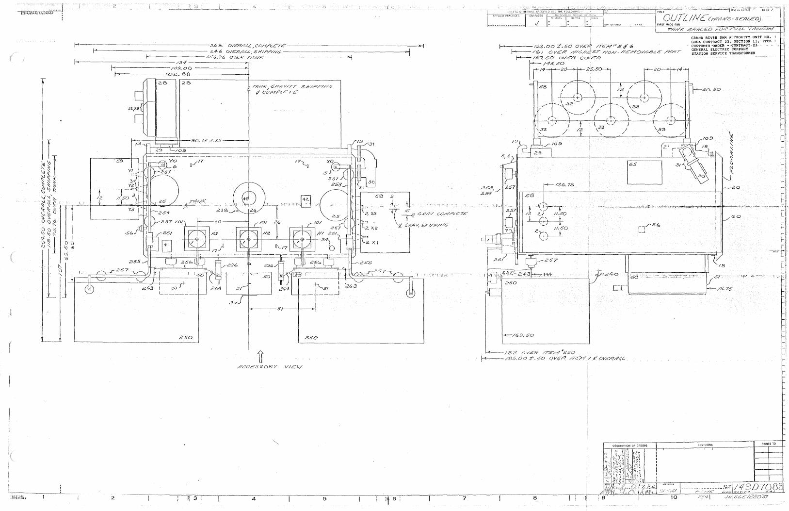
r
z(, e, 0Vcx>9Li_, COH/'.::.CrE----------------f-4-------------------- Z.-1- 6 OVE:P/}t-L, S H/P,0/NG -----------------------:~
1-4---------- k><,. 7(, OVER T.HNI<' --------------.,.; 1-1·----------------/3 <ff---------
1-<----------/09, 00 f....--------102. 8 8----------<>-I
2B
204
TrV/-".1
C.R/?V/7Y Sh"/Pp/,Nc;>
<f CONPL€TC
i-\_$/ : ___ _J
...,_----5 /'.---+-----)>.;
250 z.so
2 4 5 7
TITLE
f-M'PGCDPRAiriili=f"iti~~~~~~'°''~c:::f--------i OU TL IN c {T/'?/l/f"S . .SCA'LEO)
263, 254
FIRST MADE FOR
1-4-----/69. oo ±.-SO OVC.R /TC:-H""S ,j1 6 f-.--/G; OVER ,rT'/6,1/c-sT /'/O,-V-/?EMOV/?..BLE /?)RT
,_ /57. 50 OVCA' covc.-R
~:q.-,;s~O 25.60 -2 141
fl
28
32
'
I+' \ _J
D 21
\ I I
GRAND RIVER DAM AUTHORITY UNIT NO. ' GRDA CONTRACT 23, SECTION 11, ITEM ! CUSTOMi:R ·ORDER - <JONTRACT 23· GENERAL ELECTRIC COMPANY STATION SERVICE TRttNSFORMER
\-'-zo. so
-20
GO
',_ . ·-. ~ "''::'1--:--·Trr lr Sf
:-4--- /2.. 7$ ·---.;·
--/82 OVcR /T~/>11"250 r--.-. /85. Oo r. '50 Q Ve'~ //c/f /->?' OV?Rh'LL
DESCRIPTIOll OF GROUPS PRINTS TO
8
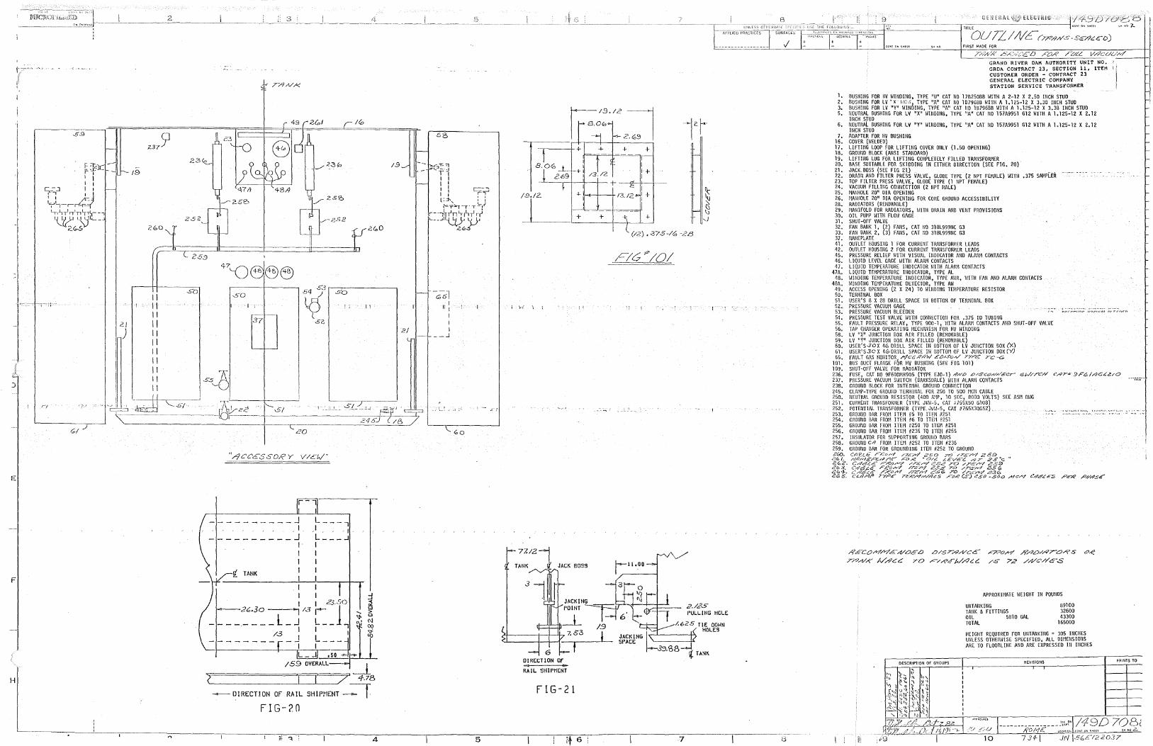
I
I I ,,
I -I
.)
E
F
H
/9
2/
)
11 11 11 11 11 II 11 11 11 11 11
2
So so
37
S.3 54 ) so
LO 11
( Si?,
2/
~r-·1 ____ -_'~·'----''J ! __ ' --~_,_.-_. -~--~~_-I_-____ ~2,2 ---+--'5_1 ______ ._-__ c __ '-_-_.s ___ ~/-2-~-~S:__,I_;::_,.~~/-'/3 __ ..,
20
'1/)CC6S SORY V/C:h/'
__________ J L----, I I . , , 1 __________ J L ___ ..1
[ TANK
I I I I I I I I I I I I I I :J I I 23.SO ~
2t,.3o ___ .,..,I /3 I l .... ~
________ L_J L-JU., ~ ~ /3 I I I '!'
-------- _J L___ Cl)
I I L _ ..J ,so ""'
/59 OVERALL _J_ 4.78
- 0 I RECT! ON Of RAIL SH I PMENT -=-r FIG-?.O
,: "!, : 4
-c;sl Ii :
I I I
- _ _j
5
'>{
77.12
TANK
DIRECTION or
RAIL SHIPMENT
FIG-21
j l q
1.9
l
(/2) • '37.S -/0 -2£3
2,/25 FULLING HOLE
1.625 TIE omni HOLES
~TANK
7
6'
FIRST MAO£ FOR
7/?;,t-;<" .,-5,L,>l.::'ED ro-R roL,:, Vr?cu.u._,,_-./ __ -+-r GRAND RIVER DAM AUTHORITY UNIT NO. GRDA CONTRACT 23, SECTION 11, ITEM l CUSTOMER ORDER - CONTRACT 23 GENERAL ELECTRIC COMPANY STATION SERVICE TRANSFORMER
1. BUSHING FOR llV WlllOING, TYPE "U" CAT 110 17B250BB WITH A 2-12 X 2.50 IllCH STUD 2. BUSH!llG FOR LV ·x· uc:,, TYPE ''A" CAT llO 1B796BB WITH A 1.125-12 x 3.3B !llCH STUD 3. BUSHillG FOR LV "Y" WIHDING, TYPE "A" CAT llO 1B796BB WITH A 1.125-12 X 3.3B INCH STUD 5. liEUTRAL BUSHillG FOR LV "X" WlllO!l{G, TYPE "A" CAT NO 157A9951 G12 WITH A 1.125-12 X 2.12
lllCH STUD 6, NEUTRAL BUSHillG FOR LV "Y" WillOHIG, TYPE "A" CAT NO 157A9951 G12 WITH A 1.125-12 X 2.12
lllCH STUD 7. ADAPTER FOR HV BUSlllllG
16. COVER (WELDED) 17. LIFTillG LOOP FOR LIFTING COVER OllLY (l.5D OPEN!llG) 18. GROUND BLOCK (AUS! STANDARD) 19. LIFTlllG LUG FOR LIFTING COMPLETELY FILLED TRAllSFORllER 20. BASE SUITABLE FOR SKIOOrnG rn EITHER OIRECT!Oll (SEE FIG. 20) 21. JACK BOSS (SEE FIG 21) ,. 22. DRAill AllD FILTER PRESS VALVE, GLOBE TYPE (2 NPT FEMALE) WITH .375 SAMPLER 23. TOP FILTER PRESS VALVE, GLOBE TYPE (1 llPT FEMALE) 24, VACUUM FILLillG COllllECT!Oll (2 llPT HALE) 25. 1-IAllHOLE 20" DIA OPEIHNG 26. HAllllOLE 20" DIA OPElllllG FOR CORE GROUllO ACCESSIBILITY 28. RADIATORS (REMOVABLE) 29. MAlllFOLO FOR RADIATORS, HITH ORAill AllD VEIH PROVISIONS 30. OIL PUMP HITH FLOW GAGE 31. SHUT-OFF VALVE 32. FAii BNIK 1, (2) FANS, CAT llO 318L99911C G3 33. FAN BAllK 2, (3) FANS, CAT NO 31BL99911C G3 37. llAMEPcATE 41, OUTLET HOUSlllG 1 FOR CURRENT TRAllSFORMER LEADS 42. OUTLET HOUS ll!G 2 FOR CUR REI IT TRAllSFORl1ER LEADS 45, PRESSURE RELIEF \!ITH VISUAL IllDICATOR NlO ALAR11 COllTACTS 46, LIQUID LEVEL GAGE WITH ALARM COllTACTS 47. LIQUID TEMPERATURE INDICATOR WITH ALARM CONTACTS
47A. LIQUID TEMPERATURE IllOICATOR, TYPE AL 48. HillDl/IG TEMPERATURE Il<DICATOR, TYPE AllR, \/ITH FNI AND ALARl1 CONTACTS
48A. HillOUIG TEMPERATURE DETECTOR, TYPE AH 49, ACCESS OPEIHllG (2 X 24) TO HillOlllG TEMPERATURE RESISTOR 50. TERl1INAL BOX 51, USER'S 8 X 28 DRILL SPACE IN BOTIOM OF TERIHllAL BOX 52. PRESSURE VACUUM GAGE 53. PRESSURE VACUUM BLEEDER 54. PRESSURE TEST VALVE lHTH CONllECTIOll FOR .375 IO TUBillG 55, FAULT PRESSURE RELAY, TYPE 900-1, \!ITH ALARN CONTACTS AND SHUT-OFF VALVE 56, TAP CHNIGER OPERATillG MECHAlllSM FOR HV HillO!NG 58, LV "X" JUllCTIOH BOX AIR FILLED (REMOVABLE} 59. LV "Y" JUllCTION BOX AIR FILLED (REMOVABLE) 60, USER'S.30X 46 DRILL SPACE Ill BOTTOM OF LV JUllCTION BOX (X) 61. USER'S30X 400RILL SPACE Ill BOTIOI\ OF LV JUllCTIOll BOX(Y) 65, FAULT GAS MOllITOR /"/CC R/?1./ E<'J/SoN' TY~ TC -c;
101. BUS DUCT FLAllGE FOR HV BUSHING (SEE FIG 101) 109. SHUT-OFF VALVE FOR RADIATOR 236, FUSE, CAT 110 9F60DMH905 (TYPE EJ0-1) -9/VD .D/.SC<?,o/,</£cr SW//'C/,/ CAT" 3FC,/,<;G~cUO 237. PRESSURE VACUUM SWITCH (BARKSDALE) WITH ALARM CONTACTS 238. GROUllO BLOCK FOR HITERllAL GROUllD COl!llECTIOH 245. CLAMP-TYPE GROUllO TERl·HllAL FOR 250 TO 500 MCI\ CABLE 250. llEUTRAL GROUllO RESISTOR (400 N·:P, 10 SEC, 8000 VOLTS) SEE ASll OHG 251. CURREllT TRAJISFORHER (TYPE JKH-5, CAT ?755X50 G108) 252. POTENTIAL TRAllSFORMER (TYPE JVll-5, CAT B765X30G52)
' .... • ..... • ...... "" "'-'• .,_.""-" ~ >
253. GROUllD BAR FROM ITEM #5 TO ITEM #251 r.~~ •·"• '''" -·~' '" • -;-,·,. .-- "r.''•
254. GROUllO BAR FROM ITEM #6 TO ITEM #251 255, GROU/IO BAR FROM ITEM #250 TO ITEM #251 256. GROUllO BAR FROM ITEM #236 TO ITEM #255 257, !llSULATOR FOR SUPPORT!JIG GROUllD BARS 258. GROUllO C// FROl1 !TEil #252 TO ITEM #236 259. GROUllD BAR FOR GROUNDillG !TEil #252 TO GRDUllD 2f0. Cl1€l£ FKo/4 /7.£,,.v/ 250 70 /TE/V'! 269
2<'o/. /'//ir.--1c;-~,-;tr.e.-- ,.C-o,e ~ar.c. L£ve:-.:::_ r<7T 2.s 0 c '' 2G2'. Crl8<:'.€ ,,C:-£o--7 /T.€/Y/ 252 TO /T€/'Y/ 25.9 263. C48L.C F.t?o~ //E/I? ZS'-5 TO /~.IV/ e.SG
~~1: f;{gf,'fa f;~C::/Y/ n(~'f.t:~j;~~ ~~ (§fl1foC:J;'f5o ~c,h'/ C4.c?Ge:S Pe-/.? P//&sE
/?ECOM/'?',£>1/0EL> 0/ST/'?/VCE
T/'?A/,o{" ///?CC: 70 ,.c-/,,<pE'/JAC.C:.
,c;<?o,v/ /?.-4.0/A'/ORS
/S 72 //l/C'h"c.S
DESCRIPTION Of GROUPS I
APPROX!HATE WEIGHT Ill POUllDS
UllTAllKillG TAllK & FITTillGS OIL 5Bl0 GAL TOTAL
89100 32600 43300
165000
HEIGHT REQUIRED FOR UllTAllKillG = 305 IllCllES UJILESS OTl!ERWISE SPECIFIED, ALL DlllEllSIOllS ARE TO FLOORLIHE AllO ARE EXPRESSED Ill IllCllES
REVISIONS FRINTS TO
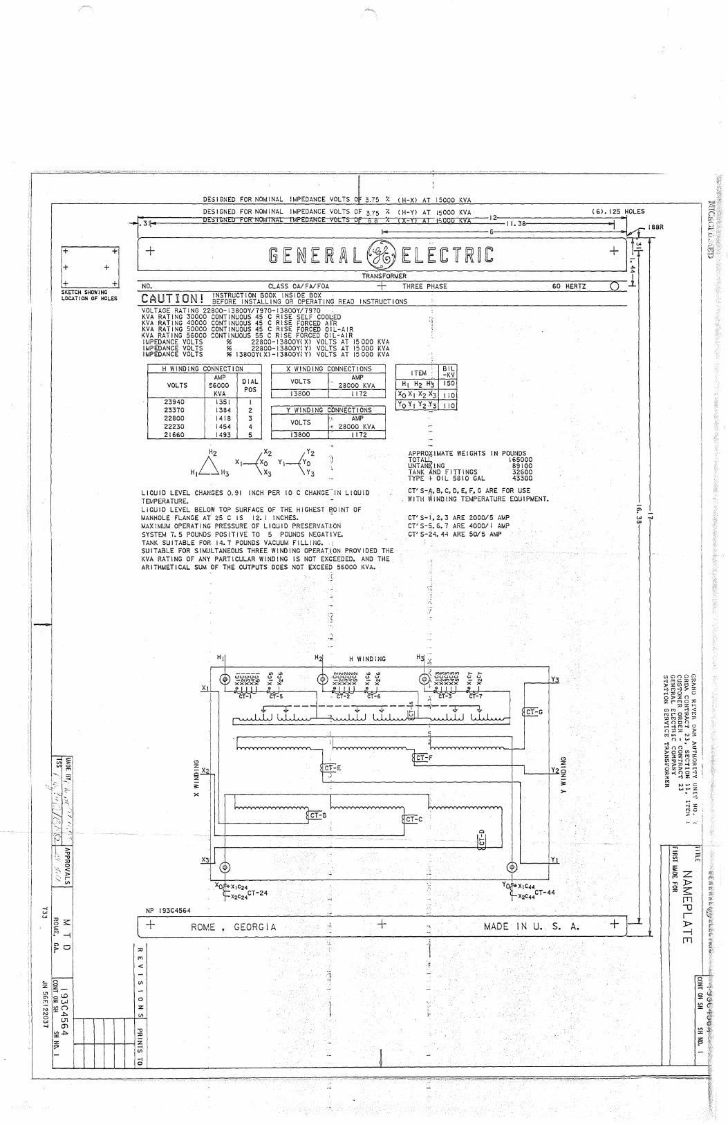
D +
+ SKETCH SHOWING LOCATION OF HOLES
> -0 -0 ::0
':\ ~ ' >
" ~ -.Ir "" ""'::o
~ s::: !" -i
~Cl
c:.. <""> z 0 z
"' -.-
Cl olD
"' ZUJ
"' V> (") "'x 0 J:>.
""I ui -.j (j)
~ J:>. :z: ?
DESIGNED FOR NOMINAL IMPEDANCE VOLTS 3.75 /. C H-Xl AT 15000 KVA
DESIGNED FOR NOMINAL IMPEDANCE VOLTS OF 3 75 /. ( H-Yl AT 15000 KVA ( 6). 125 HOLES -r311,. OE::.IGNED FOR NOMINAL IMPEDANCE VOLTS Of S 8 ~. ( X-Yl Al 15000 KVA ~2 I I. 38 :k 188
R
[ + [ii IE ilJJ IE !U l@IEUEfCTWWC + F' TRANSFORMER l
NO. CLASS OA/ F Al FOA + THREE PHASE 60 HERTZ 0 CAUTION i INSTRUCTION BOOK INSIDE BOX
• BEFORE INSTALLING OR OPERATING READ INSTRUCTIONS VOLTAGE RATING 22800-13800Y/7970-13800Y/7970 KVA RAT I NG 30000 CONT I NUOUS 45 C RI SE SELF COOL::ED 'i KVA RAT I NG 40000 CONT I NUOUS 45 C RI SE FORCED AfR '-KVA RATING 50000 CONTINUOUS 45 C RISE FORCED OIL-AIR KVA RATING 56000 CONTINUOUS 55 C RISE FORCED OIL-AIR IMPEDANCE VOLTS % 22800-13BOOYCXl VOLTS AT 15000 KVA IMPEDANCE VOLTS % 22800-13800YCYl VOLTS AT 15000 KVA IMPEDANCE VOLTS % 13800YCXl-13800YCYl VOLTS AT 15000 KVA
H WINDING CONNECTION X WINDING CONNECTIONS
VOLTS
23940 23370 22800 22230 21660
AMP 56000
KVA 1351 1384 1418 1454 1493
H2
H16H3
DIAL POS
VOLTS I AMP - 28000 KVA
13800 I 1172 I 2 Y WINDING cbNNECTIONS 3 4 VOLTS
5 13800
X2 Y2 X1~0 Y1--__,/yO \x3 \v3
,.,, AMP .,., 28000 KVA 1- 1172
LIQUID LEVEL CHANGES 0.91 INCH PER 10 C CHANGCIN LIQUID TEMPERATURE. LIQUID LEVEL BELOW TOP SURFACE OF THE HIGHEST BOINT OF MANHOLE FLANGE AT 25 C IS 12. I I NCH ES. -MAXIMUM OPERATING PRESSURE OF LIQUID PRESERVATllON SYSTEM 7. 5 POUNDS POSITIVE TO 5 POUNDS NEGATIVE. TANK SUITABLE FOR 14.7 POUNDS VACUUM FILLING. SU I TABLE FOR SIMULTANEOUS THREE WI ND I NG OPERAT:[ ON PROV I OED THE KVA RATING OF ANY PARTICULAR WINDING IS NOT EXCEEDED, AND THE ARITHMETICAL SUM OF THE OUTPUTS DOES NOT EXCEED 56000 KVA.
.fLI I I .I
I
H1
CT-I
"' "' (.) (.)
- "' x x
CT-5
H2i
(
c
H WINDING
ITEM BIL -KV
H1 Hz 143 150
Xo X1 Xz X3 110 YoY1YzY3 110
APPROXIMATE WEIGHTS IN TOTAL[
POUNDS
UNTAN:i{ING TANK ~ND FITTINGS TYPE + OIL 5810 GAL
165000 89100 32600 43300
CT'S-~,B.C,0,E,F,G ARE FOR USE WITH WINDING TEMPERATURE EQUIPMENT.
CT'S- i°, 2, 3 ARE 2000/5 AMP CT'S-~.6,7 ARE 4000/I AMP CT'S-24,44 ARE 50/5 AMP
'~~
•\
(
,._ ,._ (.) (.) - "' xx
CT-7
CT-G
y
C> :z:
~ x'"I Cl z
Y::>;;
NP 193C4564
;;::
x
Xo~X1C24cT-24 'j--X2C24
CT-B
-;
~ CT-C
Cl I
I-
~
:z: ;;::
>-
11 I
I~ X1C44cT-44 X2C44
[ + ~o~~ _.__ GEORG 1 A .l ---+-- = MADE IN~Li-s~--A~ - - +-J cc .1
::0 ·1 rT1
< '.F
- 1 ..:
(/)
-
~I l ... ' ' I-
-0
~ z -1 (/)
-1 0
!" "' -.j O>
c.nC)()C)C1 >-lt'JC::O::O )'ZUlO>' >-l "'>-l >' z H'.ll0 0 o:i-:<n zrrqo::C
:z:i :z: h (/)('IJ ....., < ~ ro::o m
""'""" <OOO H t-3["t]""3 0
() " " >' [J]H N :;\: () ' ...,
>-l • >' ::0 oo c ;l>OOUl>-l z 3' z"'"' (/) "O ""3 (j 0 I ...,,,.,, ... ,, 0 Z>'H t-1 ;o...;OO>-l ~ ...,:;r. t<:
"' :0 Ni-"C: ..., .... z . ._. >-l -...; z
..., "' ~
MO 3' •
~ ~z ;;; )>
"' s:: rn u r )> -j
rn
..... ···- -- -~·~·- ~- '" ·--- -~ 4
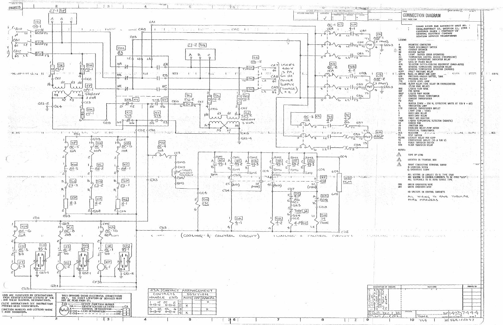
II
CDI
3
IEFI cP1-l "f-Bo/1zoV 3 KVA
' i 'J±-6 \ L+, '-,'/
JL/{10 ~-'' CAet
NA
":;•RJ I<'{\
51 -:;I 5'Z
I K'<I "SIR.
l::;::l
il)j;'.P~ ,1·-)-~-~-7-----<'!~---+---<!1 loA 10A toA
2
~ j\<.<:_l 81./-<"'. al-1-1
2 'I
~ B jµ'P\ 23-2 23- I
R.
@ IB£l l-1-2 /:!-I
~b3 CF5
£A
~ 't:::l
~
s-T R \ 1<'< I CE-lo \--o-t----O--c-l
5'5' 5'"<0 <;,
I-:
A 'D c
I • "'
1-? xz
('i\C:::.
!"'e_I 81::::>-'2
,, LI
I' L
- 1- I
Te LZ
T3 L">
"----------'-'------"'' i,___-o le""e -
'"'"'! 4-\
) [j9] /3(_-8
I ) fil6J &- \()
~1 ~Arnn <!>---------<:>----------------------
ZoA
till IJ::o2J !KM\ · l..1Rj lt«:'>l 8-C~~ ~-3 ~-2 1 8L-1 ~-\
~uo l1<G I I I t<Fl L-2 o~-1
2 2
-CF3
G.b1 Cb~ ------- _, __________
ICf<IS ARE llDICATED BY OCSIGNAT!ctlS fR0'1 IDOfflflCATlctl LETTERS ex nE
, AID T~EI~ Tff<J1ltl.A1. OESIGNATICllS.
r'LETE I NSTRLCT Ill IS SEE nlSTRLCT I al Ol"ll51EO WITII lHAll'Tmt'£R,
rtN::Tlctl IUfffl'.i MD LETTrns ~tERE C: ANS I ST Al{JN\03.
' ' 2
--~-------
THI!! ffiAWlt-U 51fil5 ELECTRICAL Wl£CTll:N3 IN-'I , THE EXACT LOCA Tl ctl Cf' DEV ICES IVST I.UT OC READ fRct1 1T.
710 DEVIU: fUCTICtl HUUER
8HA~IOENTlflCATICN LETTff<S-CA A-TERMINAL DESIGNATlctl-=83 D-CA2-LEAO OESIGNATlctl-liAD ____! C-CA3-- - - - - - - - --HAC 3
I <; 3
<
4~1'-. C.oN\f\C.:T A'KRANGE:\-/\E\.}\ C.ONTAC...T:;, ?OS.\\ION.
HANDLE E:ND A\JTO OFF MA>l\Jl\L
1--1--+---I---'y, 2
3 3c_ ·+c... 4- 3 x o-j J--0 o--Jl--0 r-,4~c-:-)(..-r---t-----1
4 5
4
-;:rrc~~"'"f''s'u~f-T=-~~~:;~~r-------1 CONNECTION DIAGRAM
CA7 LlSE<R.'S
¢1 4BuV
·"' P:1-\ I Go
:t..,, CA8 t-\Z
<l>z \"6W12_(<.
~ul'P'-'< CA9 C":'~c_E_) <\>3
5' ~~I lc:<">I (.,<'-5'
80Q
C-"'DB
I 10.Y(Jill [§:ill G,E4- LI
lbi:,J C'.Ci"._ 14 4-2 1-Plnc\ ~OE
LZ
---0 c'=>2 l <_UU Llhl.(-' "' ('(\h._\\k.()\__ C'\'Rf'l\\-l\
7 8
FIRST MADE FOR
'LEGEND
4 SD
, SC SH SL 23 26Q 27 43A 49 49R 63FP
I : _ 6jFPX 63G 63PR 71Q 74TDOE
OESCRIPTlOtl OF GROUPS
SOQ SSF SSQP CPT CT FU H IL CTO L x y FGM 26QR GB JS S6 PT
_RES TS S6/HR 95 S3 STR
llOTES:
& & &
GRll HHT
GRAND RIVER DMI AUTHORITY UNIT tl<J. GRDA::><l~NTRACT 23, -tEGTION _ ll ~ l'l'fli CUSTOMER ORDER - CONTRACT Z'3 GENERAL ELECTRIC COMPANY STATION SERVICE TRANSFORMER
MAGNETIC CONTACTOR _ POWER DISCONNECT SWITCH CIRCUIT BREAKER HEATER SWITCH LIGHT SWITCH (DOOR OPERATED) TEMPERATURE COllTROL DEVICE (THERMOSTAT) LIQUID TEMPERATURE lllOICATOR RELAY LOSS OF POI/ER RELAY SELECTOR SWITCH-COOLING EQUIPllElff (HAllO-AUTO) HillDING TEMPERATURE lllDICATOR RELAY WlllDIHG TEMPERATERE DETECTOR (REMOTE) FAULT PRESSURE RELAY
ISEAL-111 .rurb\Y :FOR 63FP c '~'"' C~ PRESSURE-VACUUM SliTfC!f, TANK PRESSURE RELIEF LIQUID LEVEL GAGE ALARM RELAY-TIME DELAY OH Et!ERGIZATIOH (FLOW GAGE RELAY) LIQUID FLOW GAGE FAN MOTOR LIQUID PUMP MOTOR CONTROL POWER TRANSFORMER CURRENT TRANSFOR.~ER FUSE HEATER (240V - 250 W; EFFECTIVE WATIS AT 120 V = 62) lllDICATING LAMP CURREllT TRAllSFORf:ER OUTLET LIGHT (25W - l 20V) AUXILIARY RELAY AUXILIARY RELAY FAULT GAS MOii !TOR LIQUID TEMPERATURE DETECTOR (REMOTE) GROUND BAR JUJICTIOH BOX OVERLOAD RELAY-PUMP MOTOR POTEllTIAL TRAJISFORMER RESISTOR ).'.,'~"'- "-----"'L IE=:f".I TEST SlilTCH LOCKOUT RELAY FOR 63FP COllVEllIEllCE OUTLET (15 A 120 V) POWER TRANSFER SWITCH SLAVE TRAJISFER RELAY
TAPE UP LEAD
LOCATED IN TERHil!AL BOX
SHORT CIRCUITHIG TERHlllAL BOARD ~ SHORTlllG SCREW 0 GROUllD!llG SCREH
ALL HIRitlG IN COllOUIT T1l BE TYPE THHll AUL WJJH'lit'-!N CON11ROLICiIBillRS ,l'O BE· TY~El"SIS" tALL TERMINALS TO BE RING TOiiGUE TYPE
GREEll GROUllO!llG HIRE WHITE GROUllDEO WIRE
llO SPLICES Ill COllTROL CABillETS
/'.'-L_ W\l<\N.G., To ~\Av<=- •u&\JLP.«._ 'NtRG- MARKEf>.-'S.
REVISIONS PRINTS TO
r.:lrPx
_ RES
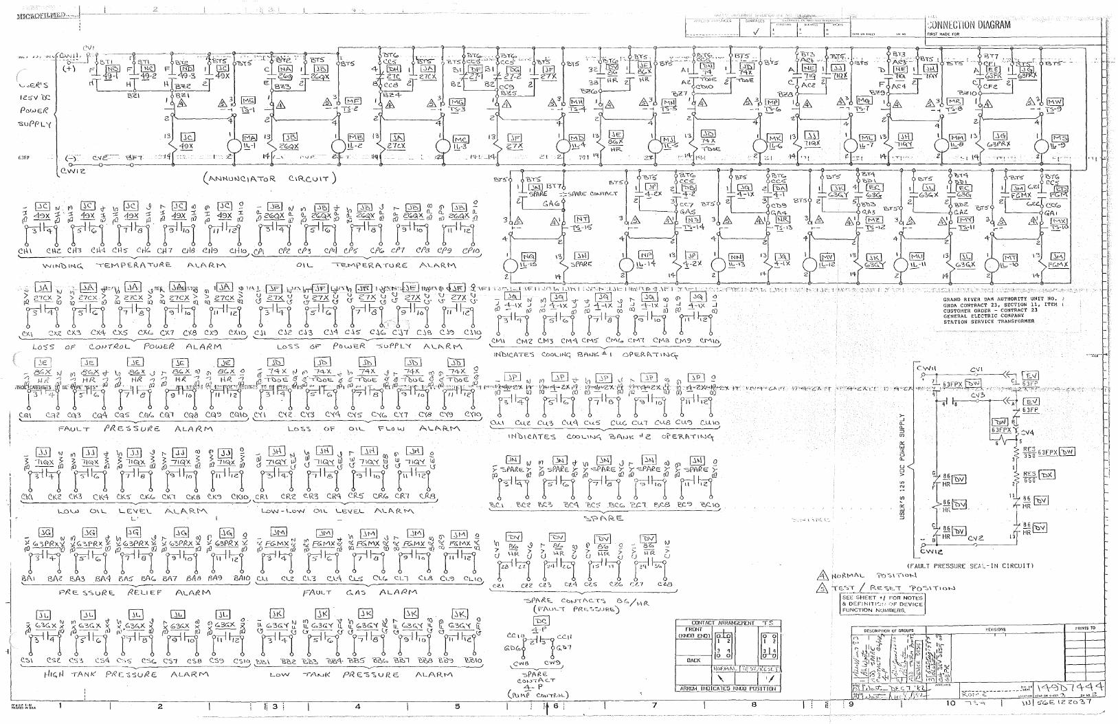
IC'.SY l£:
Pow ER
-suPPL '(
fi3FP
Fr·e!H1 1-81 PRINlEOJNOSA
·~ONNECTION DIAGRAM flRST MADE FOR
(-) c._ .. a'::~--- \:!,;F1 GI o--------0-~--0~~~-4>--~~~--~~~~--<11--~~~~~~~~~~-<11~~-~~~-<'>-----~~-~--~~~-<'>--~~-4-~---~-<~-~--~~-~-----<11~~~~·~~~------i)~~~-<1r--~~~~~~~-{ll~-~~~---@-~~~
QWl'C.
JNG,i 13 l~\..\l ~-16 ::,PAR£
l't
FAULT ALA f<.M OF 0\1_
2
Ck: w ::<: 0 Cl.
u 0 >
GRAND RIVER Dl\M AUTHORITY UN1T NO. GRDA CONTRACT 23, SECTION 11, ITEM I CUSTOMER ORDER - CONTRACT 23 GENERAL ELECTRIC COMPANY STATION SERVICE TRANSFORMER
5
RES 63FPX(~ 350--
RES[~ 650
<FAULT PRESSURE SEA~-IN C!RCU!Tl fil t-10!<.1"'/\L ?O~\\ION
& \~-:~--L~s:;_e.. 1 ?o-.:.1\1D~
I SEE SHEET 'f l'OH NOTES & DEFINl11C.-r1 '~'F DEVICE FUNCTION NUl·l13EHS. ----~~~~~~
P.[VISIOHS
'1f'
PRINTS TO
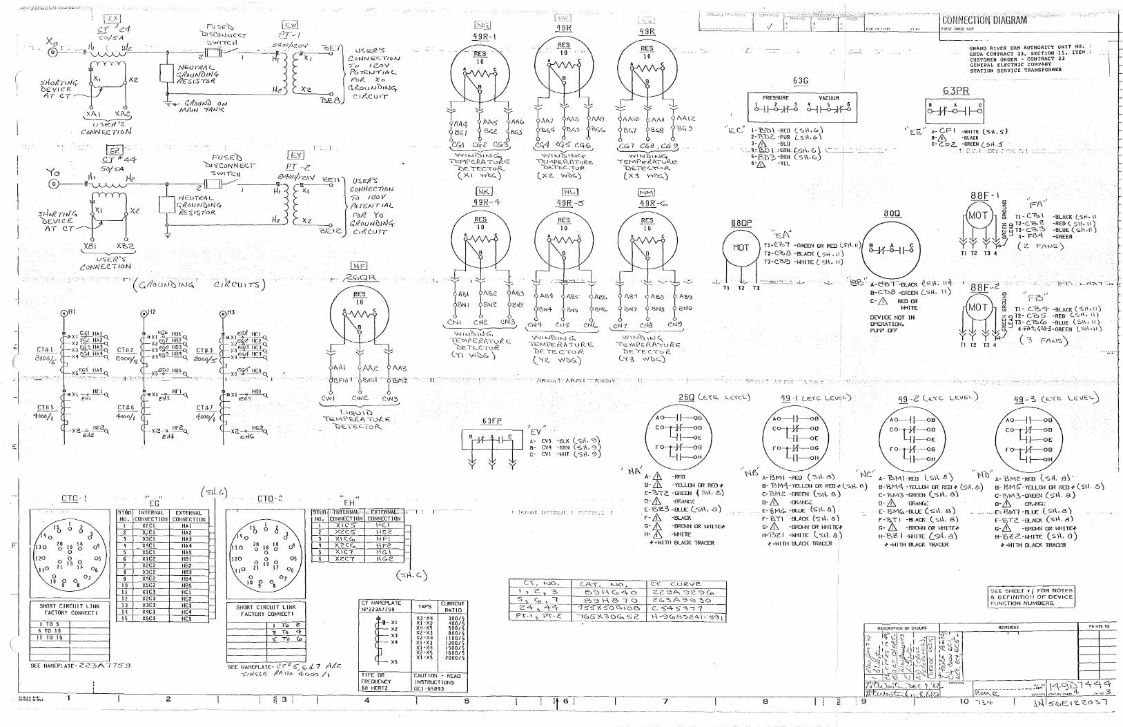
J I
~~)44 Yo ~. 5D/sA He
FU-SElJ DISCoNNEC.T
-SWITCH cYfoo/rz.oV 'bio::i \
u-:e::R 'S CoNN"°C..l10N r o tcJ>V Po -n:=:iJ-r 1 ~ t.__ Fol<. Xo
Gi(.ou 1JLl1Nc:;, C I /(CU q--
~---=-~~-@-~~2~
:sHr:.RnrJG.~1 , Xe
NEUllE'AL ~~ouNC,1NCr Re.-:s 1$ 10R.
__ ,,_..._~\~ USE/( 1'5 C.oNNE:C71DIJ 76 1eoY p& rEtJT 1Al.
RJ~ Yo fYEV/CS Al Cl
Xe1 xr:,c. ~ u.,, E:t< '., CoNN£ClloN
.. ,, (ct?ou1J'c:,1tJc:;,'
ems </-60ti/1
<>XI E~I HAI Q_
X2~ x3%~ xq~~
XS:>, ~AS°'
~XI~
E~i "-
X'.!~ e.1/z
CTC-1 " EG
E xz
CTO-Z
0 C:.C. IC.
<;t?out-.101N<, C1ifC.UIT
L H3:\D \ \:) ll:O: ~/\ \' £.(Z I\ \UV(. C
\::,~ TE:C_ To R.
•\
EH
_j l STl'JO INTERNAL EXTERNAL SlfUO '-lNTERNAlo> " EXTERfTM:~-~ . '
F
ND, CONNECTION CONNECTION ·I
6 0
6 20
18 16 oq 0
.o 0
1 XI_!=!______ ~__l:!_A_!_~
r-:.Lr x.:c1 HA2 '-3 X3CI HA3 I-
r-q- xqc1 HM ~
s XSC! HAS "-
0 0
0 l 9 21 D 06
0 07 10 0 0
9 8
6 X!C2 HB! ,_
7 X2C2 HB2 ~
,_L __ XJC2 HB3 ~
,_1_~ xqc2 HBq I-
10 XSC2 HBS ,_
ll X!C3 HCI I-
12 -·-x2cJ HC2 -
SHORT CIRCUIT LINK FACTORY CONNECT:
13 X3C3 HC3 ~
IT -xqc3 HCq --
I TO S ,_!L _1(5C3 HCS -
6 TO 10 11 TO IS
SEE NA11EPLATE- 2 2 3A 7 75 .9
Fr61ZP1-81 PRC'jf[O rt U!>A 2
NO, CONNECTION CONNECTION
lb 1 0
qo
1 XIC5 \-\12'.I ,_ 2 XC. CS' \-\E.c -3 X.1 <:.<o \-\Fl -
20 18
16 0
0 Ci
q X.cCCo \--\FZ ~
.___L_ )<.IC7 f-\G\ -
0 0
0 21
19 17
.__!____ X2C'7 1-\G<: ·-
SHORT CIRCUIT LINK CT NAMEPLATE NP223A77S9
FACTORY CONNECT:
T'o e
~" I X2 '3 To
XJ ,,- •6<'.o x~
X5 SEE NAMEPLATE- C! i ,;;; G 4- 7 Att'E
C:u.J<; LE ~A no 4-(>00 /1 TYPE BR FREQUENCY 60 HERTZ
~i 3 4
II
TAPS
XJ-Xq XI ·X2 xq-x5 X2-XJ x2-xq Xl-XJ x1-xq X2-X5 XI -XS
CAUT!CN
r· "" TAA4 r M5 TAA" 1BC, / % B"c i&',3 '-C.G-1 ~c CGr3,
V-./1"-"01t-..:IG., TEMP ERA TuA.E
GETEC'TOR. (_ x, I 'N\:y;,)
[Ht<./ qgR-4-
'N1~'t,1,J G, l'E::YlWE:RATuR. E.
\::iE.TE..C.. ToR. ('(1 VVDG)
I
CLRRENT RAT!D
300/5 qoo15 500/5 800/5
1100/5 1200/5 1500/5 1600/5 2000/5
- READ INSTRUCT I CNS GEi -6S093
5
IAA 7 tM 1' AN)
'b<;,4 x~c,s x-~(,
C.~4 <'45 <"-C<G 'Nlhlb\W~
""-MPE\<.(\'Tui<."-'QE..TsC... "To>?.
(_xz. w'C,G,.)
'/'.II "'1\::, IN G.. tE'M?E.:A./\Tui<..~
DE:TECloi?..
l '{ z. Y'il:iG,)
-BLK (_ <;\\. ';)1 -GRN ( S \\, '3 -WHT ( '$\\. '3
it_6
rAAIO rAi\11 f:AA1z. i5C..7 iB<;S B<i 3
\cc;- 7 er:}. CG91
'NINUING,'TG:MPE'l<i\TuiZc_
I:) E. TC G ""-> I'<.,
( x. '?, Y'<IY;,)
jNtv\\
qgR-<o
(
63G
PRESSURE VACUUM
~~ ~>-H-~-~
.--"'- -- ---- ----~"
Tl-Q.'b! -GRITN OR RED (Sr\.11)
T2-C.~8 -BLACK (SI.\, 11)
T3-C.'&".:l -1-i·HTE (_ sH. 11)
CONNECTION DIAGRAM FIRST MA.OE FOR
GRAND RIVER DAM AUTHORITY UNIT NO. GRDh CONTRACT 23, SECTION -11, ITEM CUSTOMER ORDER - CONTRACT 23 GENERAL ELECTRIC COMPANY SThTlON SERVICE TRANSFORMER
"EE" A-CFI -WIHTE lS.i\.S) a-& -BLACK C- C. pz._ -GREEN (.:Si-\-.:!)
1.- E-~~ l ,_:J;\'.I :~ (_:; t
88F- \ " , - ~ r=A
5 Tl - c-r.:, I -BLACK (_sf\. \I z o T2-C."b 2. -RED (SH•\\) :::J~n-c.-&~ -BLUE(sH.1t) 5 -' 4- Fo<\- -GREEH
yy YW (2 FA!-OS) Tl T2 T3 4 §
\d\'
" ' ,L ~ '=~ ..J- --.I- ~· A:.t:'!:ol°CELACK ·{!_'511\. Ill}
Tl T2 T3 B-C.1::>8 -Gl"'1IN (_si-\. I I)
1-AB• rA: rA: 88F-2
i':.N7 r 5'*3 x 8N'3
c.N7 OlS CN"l
"'J1f-..l\\110c,_ 'TsMPto..i'l.A-zuP.E
DE.IECTb R., (_ '\ '3 woe»)
" '-
·' "'(\''
A o--j J--<> 5 c o--Hf----o D
Lj J--<>E Fo--Hf----oG
Lj J--<>H
A-& -RED B- & -YEL.LCM rn RED.,.. C-~TC. -GREEN ~St\. 8)
D- Lt ·IBAN:Z E-~~3 -a.1£ (_-s\\. 8) f-& -a.ACK
G- & -Ell<l:»I CR hH!TE+
H- £ -1-i'f!TE
.... =H!TH BLACK TRACER
7
c-& Rill rn hHITE
DEVIU: MIT IN Cfl:RAT!Cf'l, PUf Cl"f
- ~ ,.Fi~"
~ Tl- c.:?.:>4 -BLACK (s\\.11) zoT2-C.b5 -RED (Sf\, I\) l:J ~ T3- C."'?.:>0 -BLUE l 'S1\ • II) :3-' 4-rA+,G~~-3-GREEH lSr\.11)
yy YW ( 3 FAW'5'\ Tl T2 T3 4 )
'\-.\6' " ,. 1--\c." A-'BMI -RED (-:'>\\.BJ A-'f-:,M\-RED Lsl\.8) "\'\'b" A-~MC.-RED (-sit a) B- 'J:,Mq-YEL.LCl~ CR RED.,.. ( 'S\\. B)
C-'DM c -GREEN ( -s\\. S)
D-& -CFAl\u E-t,l'\~ -a.1£ ($~\. 8) f-\3.TI -a.ACK (s\-\. e) G- & -EJRCJhtl CR hH!TH
H-oz I -hHITE \. sl-\. B) -1' =HI TH BLACK TRACER
8
B-?.,[v\,;\ -YEL.UM rn RED .... (5\\. 8) B- 8MG°-YEL.UM rn RED"' (Sl-1. B) C-/'.!,M3-GREEN (sl-\. B) C-'E,l"'\~-GREEN (s\.\. a) 0- & ·ffiANGC: D-& OR,..N&;
E-81"'1(,-a_u:: (s1\. 8) v• " •. E~EIYl{-BL1£ ,(_51\. 8) f-lo. TI -a.ACK (_ S\~. 6) F-12,TC. --BLACK. (sl-\. 8)
G- & -BROl-tl rn ~l-i!TE°" G-& -BROH-1 OR H-ilTE°" H-BZ I -H-t!TE (.s1J.. 8) H-1Yl2-H-HTE ( S}\. 8)
.... =HlTH BLACK TRACER .... =HITH BLACK TRACER
I SEE SHEET • I FOR NOTES & DEFINITIOfJ OF DEVICE FUNCTION NUMBERS.
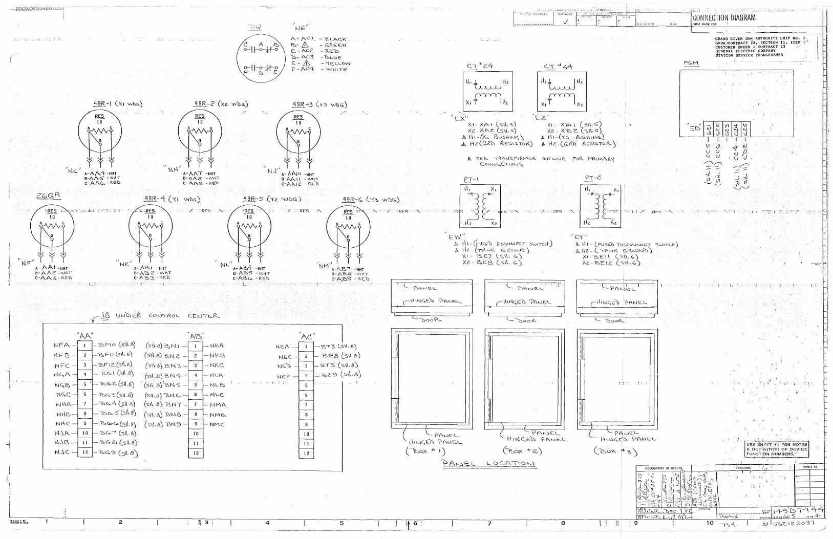
'\-.!< ,. '-" A-Af>,.4 -WHT
B-AA:S" -W\\T c-A AC,, - i<.E."t>
:t'\
"~\-\" y y y A-Ap.._ c -WHT B-AA8 -wfil C-AA.':J -R\2'D
A- AC.I_ ~-& C.. - A.CZ
b- AC3
E- LG F - AC4:
" J'' y y y N A- A.No -WHT
B-p.._/\.\\ -W\H
c-AA..tZ - RE:O
- ~LAc_K
- GREEN -RED - t::,l_\.)E:_
- '<E:.Ll.J)W - WHITE
/ ..•. RFS. !'-..
'\1-•' y y y 1'11-
"NK" y y y "y y y NL A- A eA- -wttr
B-At'0>5 -1N!1T c-A'2,,<.o -Rc.b
L
, . .. Y y y
FF·&IZ-#1-81 PRl.'ITEO IN 0.SA
A- AAl -WHT B-AAc-'NfiT c-AA3-R\Oo
NFA-
NFe,
"A~·
NFC. -
i'1C,,A -
NG,t:,
NG.C.
NI-IA
Nl-\5-
N\.\C
N..';A.-
1-.\..';C,
N..';C.
A- A?:, I -WHT B-Ao 2 -Wl\T c-Ai::-3 -Re:o
jB uwl'::,Ef<. COWTP.O'-.
'/::,FIO (5\\.8) (s ~,e,) t::, N l
"2:,Fll ('51\. e,) (-s\\.s) ~N. z. 12:.F 12.(s1\,8) ('.>1\.c<>) BN3 ,, __ c;_, Csil a)
(s-f\. 8) 'B N. 4-\:!> G,. c:. (;,11. 6) (st\: 8)~N.S
~c.. .. 3(s11.a) (sf\, a) ~N.Co t::,c,..4 (_sl\.BJ (-sl\. B) 'B N (
'O c.,,,,.-:; (sl\.8') (st\. 6) bN 8
C.EWTt::R..._
.. /'>.J=:;,·
NK/\
N\Ze,
-NKC..
NU"-
NL~
'l'lt....C'...
NMA
-NM~
"?.o,&eo C.s1\. s) ( S\\. B) 'Bi'\ '3 - 9 -NMC'..
'2,(,,, ( (:s\l. ~) 10
'?->G-e:. (sq.8) II
~G-9 (sll BJ 12
"
NEA
N.EC.
NED
NEF i - f_ 1
Ac"
NM A-A..B7 -WHT B-A°?.:>8 -WHT C-A_'f!:,'3 - Rc.o
?:."'1"3 (_s\\.e)
'bt:B (_s\.1.8) GT3 (s\td)
q .:.._ -2>2' ':'.:> (_-;;\\.8)
5 - I
6
7
8
9
10
11
12
··---·--·-------------------------]
2 ii 3 4 5
,,E_x·· Xl-X.AI l--s\.l.S) xz. X.""-<:_ (s\.\. s)
A l-\ I - lXa P.:,u:sl-\1wc_, \ A 1-\ Z. (_Ci<.() IZES\ sTo-1<.)
. Ee" XI - X~ I (_ -s\\. s-) Xz - X b 'C. ( ~\\. 5)
t-. \-\1-('(c ,O,os\\11-l<>.) }t. Hz.-(C.i'<ll f/..E.S\SToi<..)
11. SE."'- 1Rf\wSroQ\J\e.R.. C.ot~w~C...\ \O\-~~
PT-l PT-c
-"- / 'RF<; / "RFS.
I
I I
I I
..... I
I I I
I
'-"Doo'?-..
I
"t:..w''
!
.~ r-\1-(f-usEo v1sc.uNtJ£C.T :>w11clfJ .·"- 1-k - (-rt\->-.n:'.. G, £.ou 1JLJ j
'1<,1- !:sE( \_s\-\. Co) Xz. - ~1::8 (_-s\.\. c,)
------------- -- -... ------
I
I I I
I
i
I I I I
\ I
C ?Awl::'.'- ( '-.... '?A"-J~\..... -(
\\11~c_.io_(-,. ?ANE.L
('Lox ""- l) 1-\ INC..E~ ?f\w1::...l._
('.i>c:,D')( *" '2..)
PA~'C:L... \..._OC..0..\1c:n .. _~ --===================
7 8
"E'("
/I,. \.\I - (Fu-s& D\S.C<=>"l'-'8:.\: °Stdl"t"U\)
~ fl z.. (.'Au\<. c,.,Rouw'\,,) ;<1-E.El\ ("5\\.G.) xz. - ts E l C. (.. s 1-1. <::. )
I I I I
! : ! ''
ii -I I
L '- P?\0EL 1-\ l \0 £'.\ £:."\', \Jf\10 E. L
(bm<.. /~ ')
DESCRlPT10N OF GROUP,
t_;QNNECTION DIAGRAM
FG.M
Vi u cJ
GRAND RIV£R DAM AUTHORr'TY UNIT NO. 2 GRDI\ ,ICONTRACT i'J, SEC1'ION ·U, ITEM i 1
CUSTOMER ORDER -,CONTRACT 23 GENERAL ELECTRIC COMPANY STATION SERVICE TRAUSFORMER
'9. <\l- (\.) <J <:.) ~ C)
\..) /""\,,......, ,.,.-..., - ::: ~
-i: -:!. ~ t.,
~~
;:::. . d:
1i V1 '-....../-......_/.'
' .. ·I 1 (
I. . ! I (
.. ' : !' 1 [
J • , SE~ ~~Eu-;:\ f"OH
0
NOTES & DEFi'NITIOJJ OF DE.ViC;E
-~ UNCT\Q~ NUMBERS.'
REVISlOtlS ~:. f' PRINTS TO
10 _;":>'-\ ..1\J l5<,,E1z.z.031
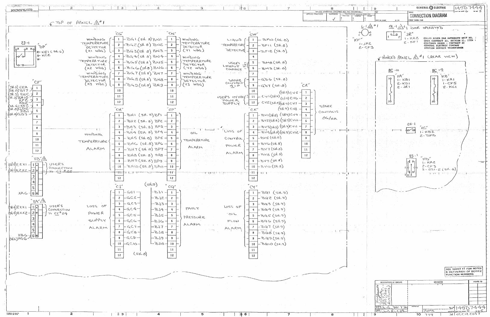
i I
"c_F"
6
8
9
10
11
12
t '\(i~"& )J tsiJ.4-)E~ X.I 1 • lU'SE:i<.'S
i _lsM)s£:X2-_ 2 ~ ~>'-)'--'>"-.c;•ow - --- ,,bQ._,~::j: ;;;;: -s=
3
4
.I
J I
s1l.4)E )( X 1
-\.4-)c::xx 2
X~Co
.1 '"·' )11Gc<D
'
5
3
4
5
2
W'w'-'w'°' { ~MPi::.RATuR~
"\:ii::::_TEC10R
(X1 '-'JOG.)
W•wO•wC~ { ~M?ERA Tul?.E
D1;:.•i=:c:..10F(
(xz. ~l:oc.)
, W•W"'"'" { lEMPERA---ruQc: '(:,t:..,TEC..10R.. ( X;>, V'l~G, J
I ;
\J-;1\-.}'\:::,,1~G.,
\~Mp Ef:~l'\TLlR.E
LDSS. OF
PowEI-<.
-suPPL'f
AL P-.. R \'/\
'cG."
10
11
12
•' c. \-\"
\2:,C-,,\ (sf-l. 8)7::,>-'11
~< ..... 2 ( sJ\. s ') 12:,wc_
D~3(s}\. 8) &N3
1'2:,G, <\- ( s \-\. 5 ') '2:,t-.J <\---
~G,-5 (SI-\. 8) '?.::,h.15
~G.:C.o (_sit.a) ~t--Jco ~c"" 7 (s1.\. a) \::,NI
'2:,G.,; 8 (s1-I. 8) l::,N8 _
t;:,,G., s ( s-t-1. 8 J 'B,N. 9
'?.:::,\--\ \ ( 5)-\, e.) t:ofl
-b\-\Z (s\\. e.) 'b'?c
~r;-::, (_::.\\. e,) f-,?3
~\\<:'.\- (-s\-1. 8) 'BP4
~\-\ s ('s\\. e,) e,p.;
~t-\c,, (s\\. s) "B.'?c:o
-~\--\! (sl-1. BJ 'DP7
1::,\--\6 (sl-\. 8) 'b?8
'bt-\'3 (-s~. e.)B,1=''3
\:::,\--\IO (S\\., 8 ~ -p._)p 1 o --u :- -_1 l __ 1- r··~ -
12
"c.J'' - c,c. I
G.C..<:'.
G. ('._ -=s
c;..e..4
G;C.5
~C.Co
7 -G:.C.i
c',_C:e,
11
12
11 3·--1-
('S\-l. 8)
12,~4
~~$
12,...\Co
~~7
-l:::i~8
'\?,~ '3
\:::,~ \ ()
4
C.N"
10
11
12
C.f' ..
12
C.Q"
11
12
TEVl\'t:Rf\101?.E:; } "''"'"'"'~ C:i\:O. TIO_CTo P. (YI wl:>c;,)
\EM?c Rf\T0 i<E:.. } ""'"'),,we,
bETSCTOI<. ('<c. -w\'::,c,..)
' WI"-'~ li-.'>c;,: : -J '<EM?ER,To<>c "\::,\:;TE. c_ --ro R._
('C5 W~G,)
1---l
OIL
-n::.1-<1PE Rf\-\1)~'2,
A'-A.P-.M
\>RES'$uR~
/'-.LA.'t!M
5
""'"''" 1 t8.l\f'E'2AT.fi
\:,,e_ TE::<:. lo R_
U'SER1S r
\...o<:y_c.\.lT -1,L 7,-
~ON'Tf\<'...\ ~
. -·
;,,PARE:. { C.ow-.:-AGI
4-1"'
U'SER'S 12S-y()<'{+ ~OWER.._ ~u\'>?l_'{ -
c_"" ,,
q
·7
10
11
12
c. ,)(."
H
12
C'<"
7
'2:.F10 (sl-\. e,)
~'Fl\ ls\\. 8)
{'::,\= 12.. (_-s\.\.. (', \
~\'AB ( -s\-\. 8)
'E,M?, (_5\-\. 6)
~\::, <'.., ls\\.e,)
~'t::,( (_s1-\.8)
61\.·?) c. '4 5 - C. '-1 I (Sib) C:siJ. C)) C. 'l<o
c.. v 2 Ls\\.~ >Ls1l-. <>) c '11
{s\-\. s) c:_ '18,
'R:N 1 (sfl.e) (sl-\.C)) C'..'>/ ':>
'E,Y2(sl-\ &) l'Sf\.s)CY16
"fW"'.:>(,-s\\.8.) G;\-\."l)C.'<'1\
--i,-:.:/qGP..s) (-.%.'? )<>t ;c ~Y5 (_s\'i.5)
'e:,'>l(o (s\\. &)
~---r1 (s1--\.e)
'?o,Yf':, (_sH.B.J
II I
13,(:\ I ( s \-\. '::l)
~Qc C_-s\-\.'=>)
-eo.~~ (s!\.'?)
bG>,<-\ (_5\\.<:>)
i:::,Q.5 (_s\\«·'>)
'bG\Co (_-s\-\.3)
7 bG/ I (si-1 '?)
11
12
r---: I 'BG< 8 (_sf\.':>)
1::,~'3 (_SI\«~)
- ~~\O (_s\\.~)
7
"ci!..."
6
9
10
11
12
8G/\-\-R
-1
8
. -1 J:1 It
J
9
~-1£-frt
~ ''i<r"
l-.JP--2-e.- <::.F~
GENERAL
TITLE
CONNECTION DIAGRAM f!RST MADE FOR
BC -10
"i<A" I- I<?->\ 2.-K"Dl 2. - _:,(?_I
95- \
:~A
DESCRIPTION OF GROUPS
/ - ......
<lif<AND RIVER ·01\M AUTHORDl"Y ONIT NO, .GRDA CONTRACT 23, SECTIOli 11, ITEH I \C.USTOHER ORDER - CONTRACl!' 23 .GENERAL ELECTRIC COMPANY STATION SERVICE TRANSFORKEllt
\:.c_" 1:: 1<-B2.. Z-"'D?o
'\<.?.:>" I- \'<A I I - C..F5' '2- KC\
'\<.L:J" \-KAZ 2 - C.F~ s - G··::o1-z (_srL c,)
~ J I 1
-. , I
SEE SHEET I I FOR NOTES & DEFINITIOtJ OF DEVICE FUNCTION NUMBERS.
REVISIONS PRmTS TO
r--
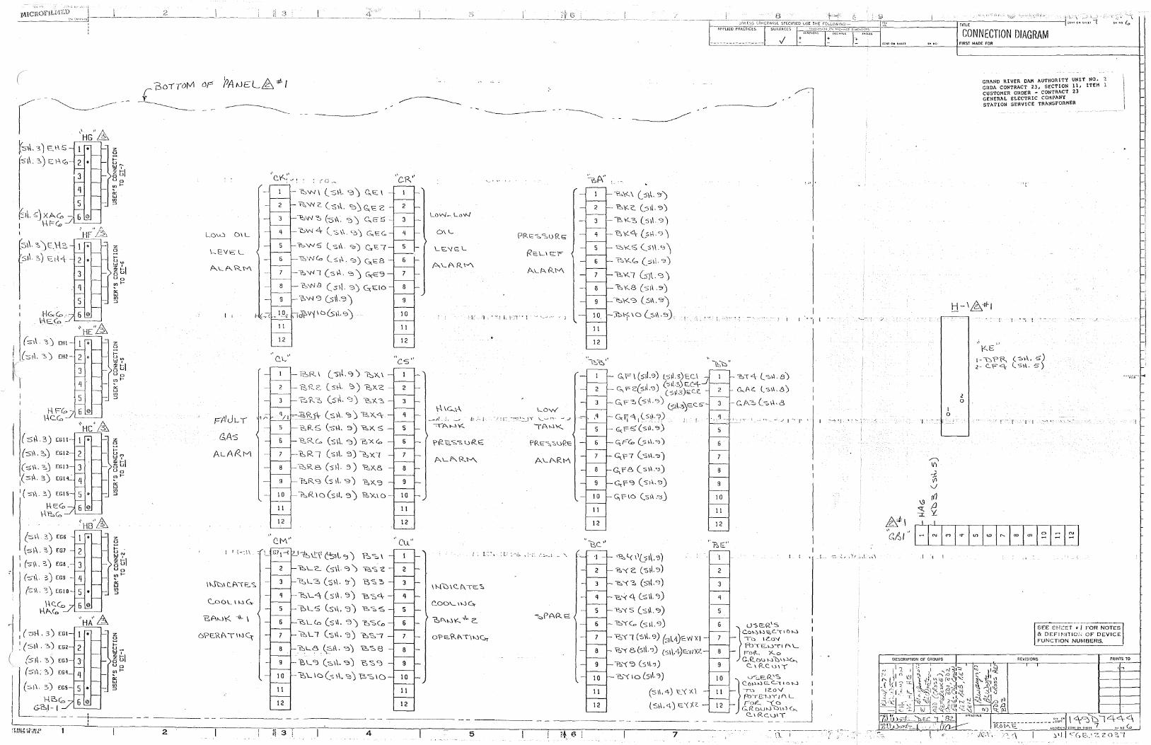
I ! ~
r
:s1\. ~ J C:.\-\3.
s1\. s) t:.tH
HG.c<o. lclECD
(s\\. 3)
{st\. :, )
f 1
( s\\ . 3) EGll
(-s\\, ~)
(st\. ~j
I (sµ,. 3)
I (-sl\. 3,)
(-:s1-\ :S) EG6
(s\\.?,) EG7 I I (-s\\, ?, J EGS .
(:5\\. ",) EG9
(s \\ . 3 J EG IO
\-\C'.G:, \-\~(,,
"I !
f~·:~\2Et \'1\JJ_,,c1
... HA 0 .6.
z a tu~
~~, 6 u Uo !'.' t--
°' w "' ::>
z 0
t-uw w, ~ tJI Uo "'I-
°' w
"' ::>
z 8 I-um ~~, i§u Uo "'I-
"' w "' ::>
z 0
I-u~
~~I i§u Ua "'I-
"' w "' ::>
z 0
;::: u~ w, ~ tJI Uo !'.'I-
"' w
"' ::>
z a ;::: :;J-~~, aU Ua "'I-;;, '" "' ::>
LOuJ DIL
Lt:VSL
I I
FA1J1-1
t;As
ALAl'ZM
I I i-~ l \ -
\"-.\b1 cJ\\E:. s -
<'...ooL 11-.1C,.
B.AwY.. c\\- \
6'?t:.Rl\TllJ~
------
2
l'.:::,w\ (_-sl\. 9) Ct::\
~'Ne Cs>\. 'O~Gx."-2 l2:o\f'/:C, (-S1-\. ';:)) G._E5 -
'DW 4 (_ 'S \\. c_-, ') C-,,E G,
~'N(a Csr\. '=>) G,t::8 -
\0:.'NI (sl-i. '=> J ~S'3 t'::,'N.9 (sf\. 3) G:EIO
1::>"'1 c:i (_s1\.'3) s
1.j?V'{ID(s\\.<ci) 10
·' QL''
BR\ (_-s~.CJ') ~X.\
t=!,R.2'_ (_s1-.I.. ':)) ~X.2
'Bo\<.."::':. (s~. s) ~i<.:, -
q/t - ~Rf\- (s\\. ':l) l?;X.<\
B,R:; (s\-\. 9) -e,.x_ S
B.R.c~ (s1l. c:J) 6xCo
l?:,R I (sit '3) l::,'iC7
'2o'R.B (sf\. 3) 'B,x_e,
1::,R s (s fl. s-) 'B:,X. '3
~R. 10 (s\1. s) 12,1<..1 D
0.M"
l~l!\I ('51-\. ":i J ?:,e:, \
~LC... (s\\. ~) 12.'S 'Z
1->.,::,L3 (sl\. ':}J 'E'S3
l::,\_q (s1\. s) e.~4-'"f-> LS (s1\. ':J) ~"SS -
1':::,Ll.o (s1\, '3) 1'::,SCo
~Ll (s;\. "'l) 'D'SI -
~L8, \s\\. '3J ~'S8
'\?.,L"l (s\\.'3) t', "S ":)
"bL. 10 (s 1\. '3) ~'S 10 -
II
12
~i 3 4
II
12
"cs"
11
12
"cu"
II
12
-~- ·--
LON- Lov-../
0\L
\--\ \C..1-\.
t: 'l,. ~ ! i\ i·-'! • i - J
Low '/l!- -;='_::_JT 1...___.n, --1/ ·-
{AW\<._
II
12
II
12
~\<. \ (_:>\\. '.)')
b\<.C. C_-s1l. ':'>)
~Y.3(5\\.9)
~I<'..<:\ (_sf\.<J)
1:':,Y..S (_:>1-I.">)
'?:,¥.."' (:s1I. "')
~ Y.. 1 G-1l ' '3 )
l'.:i\<..8 (s;\ .3') t::,K ~ (_s1\. "')
};,l-f \O (:::,\\.~)
G.. \='I (s~ .CJ) Ls~. 3) EU f. 11 ) (-sl\s) EC.4-
~ F cL'.5 ,') (S\13)EC:i'..
c;_ F "::> ( s \\ ">) (_ siV;'y=. c. s
G: !J 41 ( s~.'":J) - G;l-~(s\\,c:>)
GJ='"Co (_s \4, "'>)
c,1"7 (s1~·"")
G,F8 (s\-\.ci)
C,f-':} (s14.c:i)
~f-\O (s\\ .":SJ
"t?;,l(1l(5~.'3)
'?.,"{c(<S~.':J)
'&'\~ (s\l.<J)
"Bo-...< q, C_s 1\. "J)
'b't'S (s\\.<:i)
'P.::,'((,, (-s~\.'3)
~'(l (-s\\. 9) (s11.4)i=.w x1 -
~'\ 8(-s\\."l) (S1\.4Jt=-.Y1X<'.
'?.:,\ '3 (_51\.".!)
'D'\' 10 (51\.'?)
(s1\.4) ~'< X\
('S\\.4) to'('/.?.
------ - - --------- -
5 7
t-Ai'PGEori~sfi~f-'t::::=~~~~=r-----~ 11
CONNECTION DIAGRAM
. '_q -
5
6
9
I 0
II
12
·~E"
I
2
q
5
J I
'b\4 l-s\\. 8)
Q,..AZ.. l s1\, 8)
G.A2> (-s\-\.8
I ~'I '' , ..
I t \ t __ --;: -!. , , '..t _,...,\_ ,.,. \
DESCRIPTION OF GROUPS
I 0
FIRST MADE FOR
2 0
GRAND RIVER DAM AUTHORITY UNIT NO. GRDA CONTRACT 23, SECTION 11, ITEM l CUSTOMER ORDER - CONTRACT 23 GENERAL ELECTRIC C011PANY STATION SERVICE TRANSFORMER
"t'
\<.E l-G\"~ (SI-\. 5) 2.e.<=q (s~.5)
' ! ' f . , l __ , '' ' '~
SEE SHCET • / FOR NOTES & DEFI ~HTIOI; OF DEVICE FUNCTION NUMBEflS,
REVISIONS PRINTS TO
',l tJ)-;,"";fo_ 'bu: · sz.. ________________ :;',,.i' I <-\9D144 <'.'.'\ '/tlW:i~-: _ Ro tV\. \::. lcc~1•1P• co~n o~ ~"ur 7 s .. "o ~
· ,. /(,\, · -:., '\ I "'1 I < <, e--'-;: z o "'1
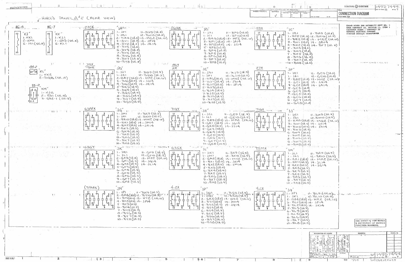
r-\-\1h\L;l:D ?l\weLL2\ 1i2' (l2-t:.0R '11E\N)
~---- -- - ____ \i ---------- - - ------ - - -------
i I I
-1
I
I I
"i<J" lr 1-l<K\
J c-1<M1 Z.-.'l-s1(-s1-Le)
-IL __ I
·-1 r27C-X-_-:-
" KK" lr J - I<-':,\
,{ I - GL:>::, ('SI-\. 8) 2.- KL\
I I
'Ii .I
I I
I - ..'IFI \\-'Po'-!"3 (_sl\. s) I- -'>"P-:. I IC'..-~'-./ 16 (_st\.8 \ C:- r':>'C."\- 0;1\.s) I 3 - MG,.L. l 'S". 10 l 3 - Fc.V I ls;\. B) 14-- ..'l F14 4-"2>v2 (stl.e) 14- ...'\"?:, 14-~-~"?:, (s\\.e.) C, - tW 0, (st\. B\ 7 -~" s (s~I. e_) e, - \'2_,'.J<:a (s\-\. e.) '?-~"! (_sl-1.sj 10-l"__,'/8 (st\. Bj
J~" l-.'l~\ l\-t>:,q9(_51\.'3) \-~El 12".-C::.Q\O (sf\.::>) 2. --e:,c 7 vs\-1.E>) \ 3 - Iv\ Pc {__ -S\\. lo\ 3 - '°"GlJ(si\.0) 14- - -'>>-.\<\-4-"1::,c;i,c:(s1l.s) 14- __)e;14 s--~e_ -s(s1\.ci) Go, - l:Ooq "\--( s~\,g) 7 - t'.:,Q, '5 (_-sl\. °") B-1:',Q «"(s\-1.'3) g - t'-"G:i I (_s1-\. <:5) IO - b~8 (_s~\.'3')
--~ .:_i-
80X HR -.'it:,"
I - --'i le, I
\- .'ir I 2-oZ-Colstl.c.) 3 - '==> --'l I (_s\-\. OJ) 4- 1:::,_, 2 (s\-\. '3) s - 'B~ 3(_51\.c; J «,-oJ4 c_-s\\.'3) 7-"P..'l 5 (sll.'3) B-7:>..'lCo(s\\."J) '3 ~ b~ I (si\. '3) 10 -~..'18 (_s~.'3)
GENERAL ELECTRIC
l-----c=~~C,~~~c~'---'T-"~~~~=:;-~~~=~~~-f-"~hc__'. -------l TITLE
ii- f'=,.C,'3 u~.9) \ Z -~ ..'l I 0 ($\\, '3) I 3 - f"\ H 2 (_ "5\-\. 10 J I<\-- Sb I<\-14- .\Fl"\
7 8
1- .\t::. I \ - ..'l (\I
2 - bZ-5 (:s1-l. 8) 3 - .::'"' C. I lst-l. &) <\- - G, c_z: (S\\.8) 5 - C, C. 3 (_s1l.B) G.,-G;C4 (-s\-\.&) 7 - Gee. :5' ('Si\. b) 8 - G;-CCo (si\.B) 9 - ~c ! (s!-\.e) \o - G-C.8 (_-si~.8)
CONNECTION DIAGRAM FIRST MADE FOR
,,_ c..c."'.:l Cs11.e) iL-- G:-C'...\D (_sl-\.s) l'S-Mt-\2 (s\\.10)! l<'.\--~E14 I 14- :::,A1<\.
GRAND RIVER DAM AUTHORITY UNIT NO. 2 GRDA CONTRACT 23, SECTION 11, ITEM ! CUSTOMER ORDER - CONTRACT 23 GENERAL ELECTRIC COMPANY STATION SERVI9E TRANSFORMER
··:r- ·---~~,"":'"\' --_\'. ~.
I I
::....A - .-~""" f , - --· '
~EE SHEET • / FOR NOTES DEF\NIT\01·1 OF DEVICE
UNCTION NUM._B_ER_S_. _ __,
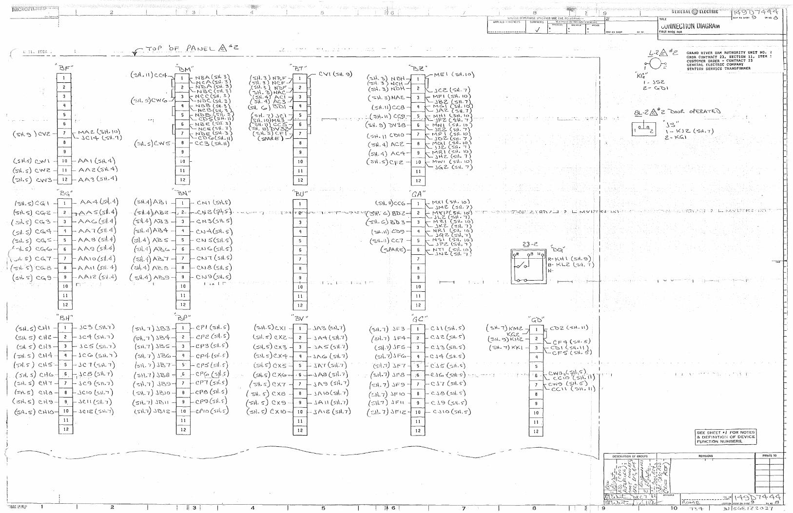
Cs 1-\. s-) c_--N \
( :')\\ . s) c_ w c -(-srl. s-) (_\{'/ 3
("'511. s) cc.. \ -
fs1tsJ c.c,2 -
( st'I. s-) CG, 3
(_s~. s) c.c;.4 (st-\. 5) CG, S --
r -,\. sJ c:.c,.-co
i JI. sJ CG.r 1 (-st\. '>J CGr8
-I
( ::,-\'\. -s-) CG, '3
(s~.s) <:....1-\1
(-s~ s) c. \-IC.
(-s1l. s-) C. I~ 3
( -stl' 5 ) c:.. \-\ 4 (-s-its-) c.i-\~
"
(5ti. s) c.1-\Co
(:si-\. s) C.\-\ < (:>\-\. 5) Q_ \-\ 8
( ::sr\. 5) ('_ 1-\ '2)
(s\\.s) C..\--\10
?.:i F"
2
3
q
5
6
Be;''
10
II
12
51-l"
11
12
NAZ- (_~rt,. \DJ ~C.\4,- l.,;\\.'l)
AA\ (:s\-\.4) AA 2. (s\\.4 l A A..-,, Cs\\. 4)
AA-4 (_s~.4)
f--A5(si\.4) AAG(S!i.4 J AA! (stVIJ
- AAB (s~.4) -AA..9 (s1t4)
AA\O (s!L4)
AA1I (sf! 4) A.A.1 -z Cs~ ,4) ,,
.'le S (S\\. 'l J ~c.4 (s\-\. •)
~ c.5 (S\\, r)
~CG (s1-\.IJ
..I c 1 (-s (-\. 1) -'iC8 (:-:»\. 7)
I: .-
.'\C.CJ (s.11.1)
...'lC.10 l-:,>\.-r) -'iC.11 ('S\\.1)
:ie 12 (_-s\-\:1)
2
11
12
(:sl-\Aj A?::., 1 (-sll.4)1A~ · ("S"1\.4) A?, 3 - ·
(-s~\.ct) A ~4
(01\.4) Al2>5 -
1 - C.N' L-st\.s-) -C'..."i\ C: (~t11S~ · , ~ v .. ·
3 - C..l'-\5(-s\\. s-)
(~1\. ·1) Atsc.o
(:':'.\\.·{)A~ I - 7
(:s1-\.4)A~s- a
l -s\.\.4_) A'P.:::,9 - 9
I 10
II
12
c.w<l..(s\\. 5) C. N :S:(Sl-l.'5')
e_l>.l c., (-stL s-)
-C"'-1\(511.5)
-c_f,._\s (sll.5)
c 10 9 (sl\. ,;-) I "'' I r-
, I l ..:,, n
8
9
10
11
12
'i' 111-.
3
q
5
6
8
9
10
II
12
c_ '-I I (:sA <3) (::,\-\, ::, ) N 5\-1 {--sci 3) NC\-\ (S\~. 3) 1-.\o\-\-
( s \-\. 3) NAE-
Cs\\ .11) CC.5
'' ~.c~)-\.llJ C.<;:.,_9.
- (<s.11. '21) u'-l~e
(_ st-l. I I CC\O
( -s\4. 4) p.,c:c..
(s~. 4) Ac_"\-
( :s\\ .'5') C..rC'..
11
12
··cA" (s1l. 11)c:c<;, -
-~ - ' ~-·-r- ·'-'!' '-'= '""'(-Svv; G,) B.1YZ. '
r . _ I
(-s-\\.G_)t:,\::,3.
(~\'-.1\) C...IY)
(<s\-\-.11) c_c_7
(_ =o-PArze.)- 6
7
8
9
I 0
11
12
_ MX I (_ -s \\. 10) ..it./\2.. Cs1-\.7)
fv\i(\:>(fSf-\, \OlJ •c- :
J L2. (-St\. -1) M "<:..\ (__51\. 10) ..'lK2- (-s\-\. 1) NR\ ls1\. 10) .:iq 2.. (s1-\. •)
NS\ LS\.\. lO) YP2. (SI\,<)
N'Tl (s\-1. 10\ ~t-..i2.. (-:>\\.I~
r----i
---···--- ---1
?J-C.. ~~" ~
R-\<'.,l-t\ (s\-\.9) B- l<LZ. l-s1\. <) H-
I I I
. r-----; '.~--~, .l
·~P" BV" '4c·' ( "S\.\. I J ..'.,'E:,3
('S"t\ 0 I J .:,"B.<:\(-s1-\.t) .)'B,5 -
( S\.\. 7 J .'\ 13,G:, -
{"51-\. -, ) St:, r - s
(s't\.1) SB8
(st-\. I) j~C) l S\\. 7) .'\~10
(s1.\.I) ..\,'f:':.,11 -
1.,s11.-1) -.'it::,12
II
12
CPI (st1.5') c p 2 ( s ~\. s') c P3 (-s1\. 5')
cr4 (s11.,,-)
c. P s Ls 1!. s-) Cf''(:>_(-sjl,s-) CPI (s;-i.5)
cPe (s1!.s)
CY'3(sr1.>J c.f10 (s1l. s-)
1! 3
(~\.\. S') <'-XI jA-CS (c::,"-\_1 J lst1. d C'..KC.. :i A"\ (s\\,1)
(:s\.\.5) ex:, - "'"'.s; (st1.1)
(-s\-\.5)C'_X4- '::,f'..Co (_s1\.1)
(stl. s-) ex:;. s Sf\-1 (s1r1) (sl\.S")C.x._0,, .G,~~-1A8(s\-L7J
(s1\.s) C.X.7 - ..1,A""'> (s1V1)
( -sH. 5'J c.xei - ..iA 1o(s~.1) (sl\. S") Cx':'.l -- _:,p., \\ (-s~\.7) (s1-\.s-) C.x.10 JA1C. (sf.l.7J
II
12
4 5
(-:01-1.1) ~\=3
(s1~.1) .1F4-
(:5t\.7) .JFS
('St\. 7) ~ F<o
(s1\.-1) ~Fr
(srJ...1) ..'iF8
(s1\. 7J -'iF3
(: .. f-\. 7) ~F 10
(S\\.IJ ..\F11
(_:::,\\. 7) ~FIC:
c. ~ \ (_s1\. s-)
C.~ G. (_9\. s-)
c..:.::, (-s\.\. 5)
c ..1, .q. (s11. s)
c__1,~(s1\.s)
Q.-'s{o ·(_s!t.-s-) , , .
c..\1 (:s\.\.s-)
C..~8 (sf.\.'>)
c:_ _\., Cj l"S.I\, '>J C. _;,I 0 (s1+. s')
II
12
7
l "S\\. •) l<fY\2-KG.c.
ls\-\.'Ci)Kl-'iC..
(''Sl-1. {) J<i< \
8
9
10
II
12
8
CF<\ (s11.s') - ct:::,\ ( sl\. I I )
C..FS' (.Si-\. 5)
J.
('._V>j5 D(_ ~\S°/, 1 X .',. , CC \0 (_ S\4. \I)
c..w<') Ls\-\.s-) C.C\\ (-s1-1.11)'
vUNNtl:-1 IUN UIAGHAIVI FlRST MAO.E FOR
L-2~4c
M "i<c."
I - ::,sz.. 2..- Cx \::)'
"~s·'
GRAND RIVER DAM AUTHORITY UNIT NO. 2 GRDA CONTRACT 23, SECTION 11, ITEM l CUSTOMER ORDER - CONTRACT 23 GENERAL ELECTRIC COMPANY STATiON SERVICE TRANSFORMER
\ - \<'. j 'z__ ( '3;\ •I) 2- - \<(G, \
! f
DESCRIPTION OF GROUPS
I'
SEE SHEET • / FOR NOTES & DEFINJTIO:J OF DEVICE FUNCTION NUMBERS.
REVISIONS PRINTS TO
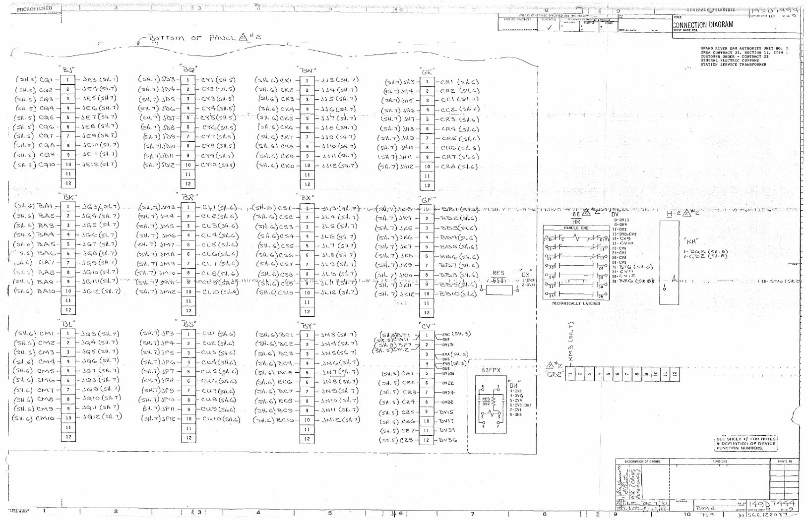
.r ~.~!(O rY\ OF
- ---------(-sf-l.5) C..G.,I
( S\-1. SJ CG\2'
(s\.I. s) C..Gl3
(s1-1 s-) C.G\<\
(:sf\. S') C.G\S
(stt. s-) C.G,G -. (s11. s) (::;-1'\.s) (0:-11.s-) C.G\'3-
( s }\. s) C.q \ 0 -
~_'i"
9
10
II
12
~ E:O, (St\. I)
~t:c\-(s\\.~) .\ 1::.. .. ,q_s~. 7) -'iE::<o (sl-\. 1)
~ E< (s\\. 7) -'it::.5 (sl-l.1)
.:i E:"" ( s \\. 7)
.:ie:.10(.sil..1)
..'i C.1 l (SIL 7)
- j E. I 2. (siJ. 7)
"'bi<'' (s1tG) ~A_\
(s\.\. <:,) t:,A c
(s\\. '°) 'B,/'.\ 3
(s \.\.. c, y-P->p.._ 2\-
1
(s\.\ c,) ~p.._o;;, .· , -11. b) ~~<.,,, f, ,.sLl.. Co) t2,,/'.\ I
. (s\.\ (~) 'f::.,As ~· ('S\\.6) 1:::,f\10
(5\l.. 6) C.M'S
I (s1-\. 6) C.l'-''\(o
(5\\ G,) C.tv\'\
(sf.\ b) C..M& -
(s\l6) C.rv'\5 -
(SI\. bJ C'..MIO
II
12
II
12
. ...)G_ :i,~ si-\.. ') .'lc._4 (s\\. 7) -"G.-5 (s>l. 1) .'i G,--Co (s-1l. '7) .'iG;I (s\\.7)
:i~e, (siJ. 1) ..}G;CJ (s1~.1)
..'iG;-1o(s1\.7)
..'iG,--\ \I (sW. I) -'>G,.1c.. (s~. 7)
jQI (st\. 1)
:iqe 1(s1t 1)
.~G;>0 (s1\. 1) j G\ IO (S j\. 7 J ~Gl,\\ (s~\.7)
.',Q1Z. (sf\. 1)
----- - - -----
~r-etz·r ! 3-et ci ~1•;no IN US.A 2
"
(s\\. 7) ~-:S (-st\. I) St:J4
(st\.1) S1:JS
(st\. I) .'i'\:::iG,
{s~\. -'1) ::i \::; l (:s\\. l) ..)bl)
(S \\. 7) ..'i \:y3
(s:\\, 1)Jt:i10
(S\l.-1 ).'i't::i \I -
(-s\i.. ·1) ..'i°'t>IC:
ls\\,'.'?J..'iM3
(-s\-\. I) .'ifV'I 4
(-st'-. I) ,JM 5
("SI-\. 1) 2\M<P
(-st-1.1) 0M7
(-st-\. 1) '.::iMB
(-s\1.. 7) 2\M '3
(-s1-\. 1) ::n/\ \C>
. '(cs-\\. =i )1 iM 111 r
(s\\,IJ ~MIC'..
""i?:i(y"
C.. '<I ( :;-\\. 5) (=:;.\-\. c,,) C...'«1
c_--< 2 (:::;\\. s) (-s-1-\. G,) C.Kc
e..'<:O.(s1t s) (sit<:;,) C..I<~
C.."'<'-\-(:s11.s-) (-s\\. (,Jc. 1<.4
C.. '{ 1$ (s 1\. 5) ... ~-- (s~. i'.o)C.KS
C."<<o (s1-\. 5J (sf.\ . (.) C. KG,
C"< I (si\. 5) ( sl\. <.,) C .. :~ I
C..'{8 (51\. s-) (s, \\. ('.,) c 1<.5
9 c.. '<9 (sii ") (s 1-\. ('.,) C. \( '3
C.. '{\O (_Si\.'>) (-sf-\.('.,) C.1<10
'BiR ,,
c.1,1 (s~.k,') .. 1-(:si-\.,s) <'...~1.-C'.Lc(s\.\. b) (-s\'J..<a)c.s2 C. L ::,(st\. b J (-s-\~. (.,, J C.:S 3
C. L. <.\-Csf\.C,) C:> f\. GJC S<\-
C. L 5(s\4.6) (s\.\.<o)cs5
C. LC:o(Sf\. c.) fo\.\. s )c_ 'S(o
C..L I (si-\.G.) (s}\.6) c..0,7
C.LS(s\.\.6) (st~.6)C:s8 9'-' "'c.-t!':N.~n.l'J- 11 ' 1 "Ysl\.C:)c~9'
C. LIO (SL.\.<6J (-s\;,,.G,) C.~lo
" tis" (~\-\.7) .'.)'P3 C.U.I (5\\. l.J (::::,\\. <,,, ') t'.:,,Q. I
( -S,\.\, 7) .::i ?"\- - 2 e.uc.. (s~-b) (<:;\\.s) ~c.. c (~\.\- 7) .':iFS c. u.::. Csv~) ( S\\, (,,) \'-...C.. 3
( '?lV7) ,JP(;> ~u..4(s\.\.,G.) (:SI-\.(, 'fDC. "'\ (51-1.1) .-'>Pl C. U;- S (-s,1\. G) (01\. (,, \ E.C.:5 -
(s1-1.7)YP8 C.U..C,,(_-s\\.G) (.st\.,,;, J BC.Go. -
( -sr\.1 ).::ir s - 7 (. D. l (-s1\J,) (:::,,1;\. <:;:,) ~c.. 7
(~. 7) .:i'r'10 c. u.. e, (s't\.l.) ( s\\. <6) \SC.8
~~. 1) SP\\ c. u. ~ (s1-\.G.) (:s\\. (,) ~c. ':') (.:stt7)2\f'IC'. c. u .. ' o (s~\.6) (s\\.G J ~Q..10
II
12
~i 3 i 4
t':::.W"
i:,X."
j.\ 3 (_:;\.\. 7)
-'d 4 (5~\.-,) .'i.!. 5 cs~\. I)
~..'i c,, Lst-\. 1) ~ :i'1(:s~.7) .)J 8 ls~. 1)
--\.\"'.> (_s\\.<)
.!,.\ 10(s\1.1)
.!,.\\\(SI~. 1)
.!....'i1c.(si1.1)
(s1l.'1)~t-\?..
(s~t 7) .2it-\"1-
( si\.1) 2\1-1 '.')'
(st\. 7) .\<\<o
(s\.\. 7} .\\-\7
(_s\l.. 7) :JI-\ 8
( s\1.. 7) ~\\'3 ( 50,. I) .\\-\ \0
( 'S \\. 1) ~\-\\I
(s1L 7) .)t-\12 -
II
12
.. Grf'" --:)\_(~-(~I\. 7-} · '-~{s~;'1}.:i-K~2> .. ·
.C.L<\- lsfl. 1) (-st\. '.~:pl<.4 :iL5 (sf\.1) (co;i4__ 1) jK~
.'iL0(-s1\.7) (:s\.\.7')2\K(,,
..'iL I (s\\.7) (st'\. 7) :OKI
..',LB(-o;~.7) (-s\-\,7)..'iK&
:J 1... 'C) (sf\. -,) (sf.\. 7) .. ws
C. R \ l-s \.\. C.) C. R 2.. l-s\l.. Co.) c..c. \ Csrl. 11)
c..c2.- (s1\. 11')
c..fZ ~ <..st1.Go) C.R"'\ (-st\.(,)
CP.C.. (_-s 1.L 6)
CR! (s\\.c:, 'J C..R8 (sfl.i;,)
t\'D\•(·cjb~.};-"·t..::;H. f i'.' -· '.T~'"''I~
-e,. b z. (st\.(.)
lc:,;e:,.::( s I\. G.)
B.'DC\-(;s-~. (,)
·'\":c;D -S (SI-\ , 6 J 'P-:,'P-:,(c, (-s\.\.. 6) ~ '2::. I (_st\.<:.)
• '' /I
a .. .:iu()~ (s~.1), c ,C.s.t-\. 7) :::,~1D 's '· ~ ·:i d1 ts\\~ 7) --~..r )-Sl 7):::, \.()1
\>~1:::::,B (sf\.<:,) RES DX ' I •- I . ! . I .-&SO I - ·r J.-.Plfr '·2:,~"")(_S~-<'-) A..J-----i.?., 2-0Vll
...\L1'2'. (:s\\.7J (:sf-I. 7) :JKIC'.
'\::, '("
C>N 3 (:sl\. IJ ~11·8~\\ .::-, N. d; (sit -, )
(:s1. s) -wi1 (s\-\.~l:oF7
,::-, N S (-s \\. I) (-s\\. 5 'N\ 'C...
II
12
"c.v ..
B:e:,1o(sf\.c'..) ~ ~
OVI~
., .i: .. :n<.-·::i··4· 816--~~.,.,.0v""''l- _,·:_c;H .. , 1-
a- OVl 3 G·OIH HR
HANDLE ENO ll·OX2
"--'~ I ..Y ~ 13·0VB,CV2 C"°'IJXlc--~fG(Y) 1S·C'<'9
17· C'/10 ~22·CV6
2q- CV7 ~26-CV6
°221 :!-------<: b-° ~· ,fz6o ~ , .. \,.,--,· iko °TI! ; : '36°
MECHANICALLY LA TCHEO
28- CVS 32·\::.T(o (_-s1,, BJ H- CVI\ 36-CVI<".. la- D.'C..Co (:s1h ~b·
_ ,\ N_ c.,, (;s It I J 0115 6 3FPX
, I.
5 ,\\ .. fl (st\. I J ' (-:>\\. s) C.c 1 ovze. --- I
6 \N 6 (S\\-1) ( Srt. 5) C.-C:.2.
.\I°'\ ~ (s1\. 7 ) (s~\.5') Cc'3
..':iNID ('S~.7) Cs 11 • s) c. ~ 4
..',10>\\(Stl.1) (nt s) C..2' s ~N' Z... (s\\.7j LSfl. s) C.CCo
11 (sf\. s) c.i=. 7 12 ls11. s-) c_c.8
l' JI ov;;:a OW
OV<;'.'\- f;:Dq 3
3-0Xl q-ovr:.-s-cvq
E tl ::~:rm .. :
----- --~~::_~---8 --' ~ DESCRIPTION OF GROUPS
5 't 6 l . ' 7 8
\ 0
:ONNECT\ON DIAGRAM nRST M.A.DE FOR
"1<t-1"
GRAND RIVER DAM AUTHORITY UNIT NO, 'I GRDA CONTRACT 23, SECTION 11, ITEM l CUSTOMER ORDER - CONTRACT 23 GENERAL ELECTRIC COMPANY STATION SERVICE TRANSFORMER
I- bQ,R.. (S>\. 5) 2-C,L)C'... lS\\. B)
---~--
I 38- ~"C'-~ ( $\U ·s-,
SEE SHEET • f FOR NOTES & D£FINIT101-I OF DEVICE FUNCTION NUMBERS.
REVISIONS
(
PRINTS TO
-o:s-----.:---------';';,f' 1-4-gl:J i 4 t-.....0\.J\. l;.:_ LCC•TiOll C(ll<TC .. SHUT \Q S>f '10 '3
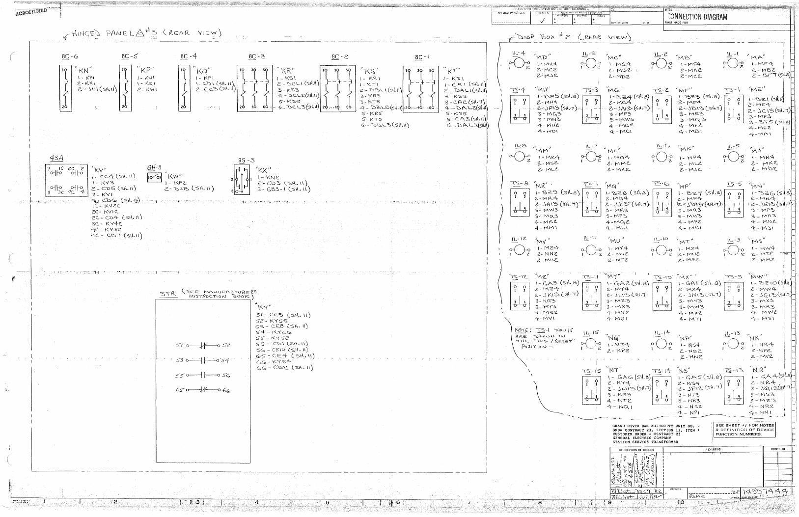
I
J
~!2.P 13-81 (I ,.,,f[O l,'I lJSA
1.
BC -Co BC-5' §~ -4 BC - ::, BC -2:'.
" KN'' " KP" ,,
\<Q" \<\R'' II. 31. SI. 'I. 'I. 'I. 'I. 31. sl I· KPI I- ,:'..1-ll I - KP I I - l<"O> \
,{ 2-IZX\
,{ I - 1<.Q I J \-CD I (S\1. 11? ff{ c_ - t:o>C L\ (-sf\.11) ff{ c.. - ~ u \ ( s\.\, 11) 2-kWI Z -CC..::, ('.011. t) 3-K'S3
4 - "DC.\..c(s1L11) 5-\<-;;.s
- : ,... . ., , ~- L>C:.LS(:sl-l.11)
43A J IC 8H-3
o-11-<> c~~ "Kv" I - CC.c\ ( -s\\. 1\J 1- KY3
l1o/o1 KW" I - \<-PC.
o-H-0 3 3C 1~~
:n:=:-.... ''" ~
- I
C- CD5 (5\-1.i\J 3. - KV I
41.:r c.1:::><0 .(s\.\. '-~~-1c.- l<Y<'.'.C. 2'.C- \<VIC. C'C. - c.."D"\- (_ s\-\. ii) 3C. - K v+c. 4C.- i(Y 3C 4C. - CD! (s\.\.11)
<_2
c..-1:::..:.c (_-st\. 11)
( <;0,c:=:G; MA•->Ul'=AC.<u'R_;::f-_'S INST/:/UC.-llo/V ~001<_)
c:;s o.-:--:j r-'-D'S<f
:> ~ o--j j-----D Sc;
''\-<.'(" 51- C"E..":> (_::,,\-\. ll) 52-K'<S5 s=:, - cEB (-s\.\. n) S-4 - K'<<=Co S.C::- K'\S-2 5 S - Ct::> I (_ S.\-\. I I)
5Go - ci=:-10 (st\. 11) _c;,s-;Cc:::.:4- (_-::,\-\_.\\) Go,(;,- K-YS4 c,c= - Coe:.. (s1\. 11)
----- - - -------- - - -~---- - - ---
5_
BC- I
" 1<1" I - k-s I \ - C. A I ( -5\\. 11)
2. - WI\ L \(-S\\.11) 3- l<'S3 I
3 c_Ae. (s\\. 11) I .q.. - bf'.- L~(?H.1t S'-\<'.'S.5 s--c. A 3(s\\.11) G, - bl". L3(sA.I
I I
_ __J
1.
\l.- 4 '\1\1) ,, IL-3
~ \ - VII-I<\- ;r()-:g 2-- MC2. z_- M..!.2..
---rs-+ ')vi\-\" I"',- '3
~J > b~S (·o•B) Ll~J i".-- M~<\- ? ?
. ~--..\~~~ ( s~y 1) ~ -4 3-MN~ ·p 4- 01-12. 4-- MDI
~'.JNNECTION DIAGRAM FIRST MADE FOR
1\fV\C... JI \L-Z. ,.!"\a" \L -l
I - tv\G..4 M 1-\V\F"'\- -Oi. 2..- MP->'2- Z- M/\2-2..-MbZ Z.-Mc2..
'fv\c.." \S-2'. ''MF" \5-\
I "B<C4 (>il.B) ~ • ,,,,<.,, (5. &l 0 I z_- MC...4 ? ? 2-- MF4 I 2 z.,-. .JA1B·{si1.1). ·· 2.- St::i1 'b Csll1) W 3-Mr? ~ 3- ME~ 3 4 3 - I"\\\?.:> 3-MG.:~ 4-1"\G.'2.. 4-MFZ. 4- IY\C..\ 4- M?->\
IL-Lo ,,
I I
'
1
MA" I l-M>=-<\ I Z..-M'C2-2. - eoFI (SL~)
:"'::, (5d,j 2- ME><\-2,- '.) c. 1~(s1\. <) 3-MF3 3- ~\ 5 (_sH.0)
4- M£.2. I' 4-Mf'- I
\L-2:> , ' - 'MM'
)
c;-0;_ I - MR4
IL -7 i"\K" ~5"
- ''ML"
M ~ 1-M0,4 ~ '1-i\-'>"
\- \"\?<\ I Z 2.- t/ISZ. I 2- Mlv'IL 2.- f'l\Li"..
1- l-'\N4 2.. - r-A 1<. z.. ("._- M b-c_ 2-· MLZ-
,, R" ~-\ M -I U~ b•8)l~ 2.-tv'l\-1..""\- 1 2
t- J\-\1-::>(st-1."i) ·~ 3-MWO> 3 4
3- MG,3
\S- 8
4-- IV\t<-'<'-4-MM\
\L- \ G. ''Mv" IL-II
1-Mc4 c;()-o Z- N NZ. I 2. 2.-MUC'..
N01E"; \S-1 1M0 JS' AIZE: "'S.1--\o\.....JJ.J tJ-..J
-n-\«. "TE>< I R-e>eT" {Jo'S\TtorJ -
2.- MKZ.. 2--1"\.'.L
'f,/\t/ -\'S.-<c, " MP" TS-5 '~1'1''
l-IY~-6 (s\l.8) 0 0 I- 076( (_s\l.1".) 0 0 \ - 'E,-2=.(o (<, .8 Z.-00.4 l 2 G-- MP<\- 1 2
Z.- .Jj\? (is.\-1.1). -ili lz._.o .'i l')\ 5' ( 114;1'7}. -i-4 2.- MN<:\ J
1 z:- .. ..'i£'\(5 ( s, .:i ;,- IAR'=> 4
'3- M?C,
4-0~<". 4-ML\
"Mu 1\.,-IO
I- VI'<<\- ~J1 2.- M'lt:..
2-- Ml2.
3 - lv\8-3 3-M~':::.
4- M'?Z <'."\-- !AK\
"Ml" \- M:X.c\-z_- MLie
z- MSL
'\,1?''
\ - t-\54 L.- NG!C.
.z..-. N!'IS
GRAND RIVER DAM AUTHORITY UNIT NO. 'GRDA CONTRACT 23, S£CT!ON 11, ITEM 1 CUSTOMER ORDER - CCSTRACT 23 GENERAL ELECTRIC COMPANY STATION SERVICE TRANSFORMER
DESCRIPTION OF GROUPS
3 4
~-.3
-0-o l 2-
3 - M?:O, I
3-0\-13 <t--Mhlc 4-M~I
"Ms. " I - tv1W4-z.- Mic -- nit•
2-\<"\Mc
I ,, ' .I ~w·" , I - o-C 1o(s1l.1S
1
2-- M~4 I z - _} G-1 -:o,l'S;\.'l 3- MXS 3- MR3 .-+- lV\vV e. 4--1'/\'S\
SEE SHEO::T • / FOR NOTES & DEFINITIOrJ OF DEVICE FUNCTION NUMBERS.
PRINTS TO
-----:------·----:;·,,;~ \4~\:::i~,<\ 4:J:_ Rb~~ , 1.-cc•~•'C'< Clll<TCN't'<tt~ I.:.-""""~ -
10 1: .. .-'":'-·-:?·---·----~-·.-- . . .
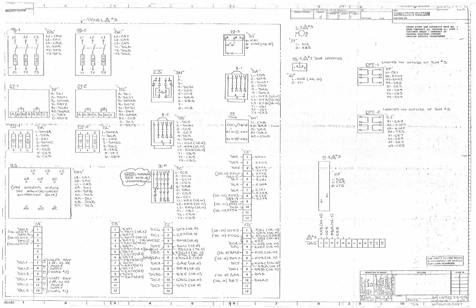
Q,b_·_-1 ____ ·~'b" ' I LI - CA10
L2- C'.A1\ L:,-c.A12-. \1-"DrA. <2--bFC,
T3-\::>F (_
27-l •' ------- '--DF''
A
P.,,-b1<.1
A-D\JTI "P..:,-L:>MN"D "B- b\:YT'Z_ I:,\ - bc;12o,1 "'BC.-bG,~Z. c.. -\::) \<:::, C-l:::>bT3
~ILFU-i I ? _\, \r. \'"'"J / ~g,-1 \
"-DK'' I 3 5 \-""bMN/\
~~ ~ I - \:::iFA. 2'.- C.E I ~-DMNC. 3 - 'bPC
Co '4- - <:_I0._2.. 5 - C.J:o:.-::, Co - CE:~
8~--
LA Li3 0 0
EA ~f.l EC. 0 0 0
(Po(( J1J<£ RJJAL W1r21tJ ~ -SEE mANU FACTu/!ERS 1µ:s-rt<uc(fod 3ooK)
0 NA
l::J-<\ LI\ (-sl'.. 10) \<,Tl
GM Lb e:,~1.10) I<\ 3 -
"\:::,MLC (-st-1.10) l<i '.5
0 Ni2J
/.., c. 0
8b-Z
LI Le
I I
13
bE" Lf-C..A( L2· C.AB L3- !'_A<?;
11-bG,f'>...
12.--Wc;,,e, l~-\:,c;,c_
,, bl-I '' .------ I-
_2_7_-c. _____ ~··~ .. f ~4~) ~~~~~\ Llr W ~-bt\4 A
I '
" DM" LA- CJ".. I L~- ~AZ.
t..C. - C.A3 NA-bl"--\ Nt:,-\:::,pe, NC..-l:::>K3
'E"'-- DL.I E. 1:::, - \::) G, t'::, EC. - \::::,1_~
A- bL \ A.-""LETI ~-\:>ME'&
-e,. "bt:'.TC:
I_ QN\EA I - \::,,e, A 2.- CE'5"
?-::,\ - "DFl:o,1 b\- l>\-\-4 l?,"L- \::)F-e,c.. to, Z.- CC.Si L- DL-:>, c. "'15t:l~3 ':" - '
"3, - bMEC..
~-i:::>G., <:.. "-\--C.l::<O 5" - C.'€.(
0 - C.E16
(:,f\l"\ FAT I (-sf\,:,)
"bi\Tc 'FAT2 (.Sr\,7c.)
(. -cB<\-7-8 - C.C8
"--t:i"G" ~1~3-Ll-L2~L3~ \ - \JC5
<j> <j> <j>-<j> -2.-l:>WAI
1 1 1 1 2 - c...c...'5 !!!! ~-C..C( 2 Tl T2 T3 4-DC4
q 4- l::::>\-\<o L\- 1<sz(st1.1c.) LZ- K.S4-(_5l~. lo) L3 - l<.S0 (s1\.10)
I 2 LI L2 L3
1111 I
3
4 6 Tlt2T3
"cc" \::>CG,
DC\
,,
(I - C:2:.4 IZ - C."Po.5 T3- CcCo
'De.." I - c_c_c:. 2.- c.c.10 3- C.C\\
4-Cb~ * -l::i i2:As - 1:::::i cs 1 5-C..b( Co- C.C I LI - KR Z. (_s1-\, I<>) U':- 1<-R<\- (s;\. 10) L3 - KRCo (s1\. I<>) Tl-C't:,l, TZ. - C'...l"',5
13- c_-e:,~
C..,E~ l -S\l. '3)
c,_ E4 l.S\\. "3)
l:J A ·1:, (_s1\. 10) kG. C: _ FAT3(Sf\.'.'.)
t::,Me, Ls1l.e)
10
II
12
'b'Dll ~\-\5 -\..'. t=~ TI (s1-\. ~ '('Sil.\028 '-1 I
Q"\.',TZ ;e,c_. FE.T2(SH 0 3')
l:::i~T3 )f!:'t1.8)GA I FP.:.•3(;:;t\.3
- DC:TI l::i'b3 C:ATl(st\.3)
-DC.TC. E:..ATC.(:s\.1.3)
-bc.T3 EAT:O(s1J.3J
bc.3
~Ml (_s\\.8) ED G, 2."\- ( 'S\\. 4)
EbCoz.l (s1\.L\) BTG l -st\. B)
E. \:) c.a 2 z. (st\-4
C.-rA-5 (-s1\. 8)
2:>c4lsi-\.f3)
12
---- - - ----- - -
1-1
I 3 LI L2 L3
r r r r ! ! ! ! 2 Tl T2 T3
''bA" 1- LD4 2-n\-\4-c:. -bwf>.. I
3 - C.b':':) 4 - 'D\-\<O 4 -1::::>1J LC. , L\ - \.<..T 2. (_s1-\.1~)i LC. - 1-<.. T4 (SI\. 10) L "3 -1< \ GJ(_Sl\. ID) 11-c:~1
I z. - ('.JO, 2. 1::. -c.'b3
'\:,N ,, ~-----
l\~y;. \
A\ 0
0-j f-o l\Z
0H. 10) K'<<:oS C,.P:;:,"':,-C.
\J1_ z. -
\::,\.. s
(sr\. 10) l<XS~ -G.P->e:.-<\;
l:JKCo (sci. 10) K'<S\
DLCo (:s.\-\. \o) t<YSG:o.
LI - C..'b2:, I q_2J- 'lbh4' - T\WA \
Al-DP..2-f\\ -"C:,"b 2..
E 'Fl-~c'.\
EFx.-1c.: ,,, - SFXs
E F"X 2. t=:.FX"\E. .':,\-\I
- E~\-\4
- E-.\XI E~X.~ 'e.~X.('.
- ~ .... X."\,
I•
C'.b" I
(srl _10) K'<SS l'<G< \ (s\-\. 10) 1
Gb~ (_s1-\.a) (-sr\. 10) \<.'{G,G:, t=b<oC'.. s(s~.4-
G"DJ (:SI'. B) Koe('..
bC.<\- K>< 2. (:sf\. 10) of\\ Kv2.C l'.»1\. 1o)
(sH, 8)\:,M5'
(Jl.\. OJ \';,Ml 1< V"\ (_5;\, ID)
~v4C. (s11. 10)1 \:)C5 'C.. --e,"" l-51\. 3 )I
DNL\ E"F.':,~ (__ 51\, 3)
(-st\. B) (,,P..,<l,: bA.2:.
( S\\. BJ \'.::,Z: ( -
II
12
L-3~*3
M 'J-r"
I - ~UC. c..- K~Z..
BL·3.~.,t3 lJDC)~ oPE!?.P.T~\)
B ''..1u"
l - '{.\--.lC. ( si-\. 10) G.- ~Tl
I 0
2 0
\<'..'C I- \:::,.\R.._ 2 - c. \::)-=::, £:- ..\ TZ..
Hq~
HJ__j
H2~ HI•~·
r-XI
L_X2 r-XJ
L_xq
'/.(. - C.E..., 'f..?o -C.E~
X'\- C.E.4
.. E..)"
1\1- (.E.5 \.\Z.- <=.-.\\-\3
1-13- ~...,t\2: \-\4- CE<O XI-CE.I X.2--C..E6 X3-C..E( x<\--C.EB
GRAND RIVER DAM /\UTHORITY UNIT NO. -~
GRDA CONTRACT 23, ·SECTION 11, ITEM l CUSTOMER ORDER • CONTRACT 23 GENERAL ELECTRIC CoMPANY STAnON SERVICE TRANSFORMER
< )
• 'I
, REVISIONS
~;;,~: sr.lEET ~ 1 F~R N0TEs1 & IJEFINITlOi/ OF DEVICE ·IJNCTION NUMFJERS.
----- <
PRINTS TO
I.
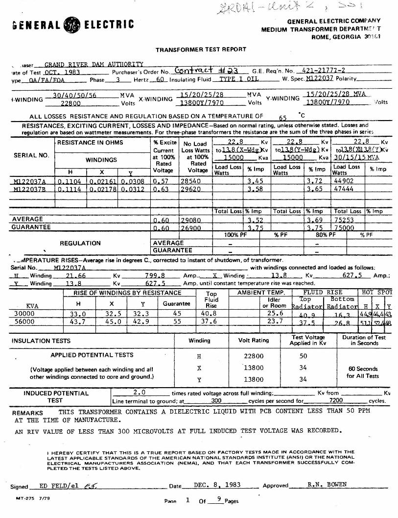
&ENERAL. ELECTRIC
TRANSFORMER TEST REPORT
GENERAL ELECTRIC COMF·ANY MEDIUM TRANSFORMER OEPARTMr ' 'T
ROME, GEORGIA XJ H,1
, .1aser GRAND RIVER DAM AUTHORITY •ate of Test OCT. 1983 Purchaser's Order No. C:Oofo((\.c,..f :ti. Ql3 G.E. Req 'n . No . 421-21772-2 ype OA/FA/FOA Phase 3 Hertz---6.0_ Insulating Fluid TYPE I OIL W. Spec. M122037 Polarity ____ _
_ 3"'0.,.../<....:4u.Ou.l_.5...,.0'4.-/.J-5.._6 ___ M VA X-WI ND ING _......1 ..... 5 /,_.2....,0.._./_.2 ... 5u..l .... 2.._8 ___ ~VA 15 I 2 0 /25 I 28 MYA fWINDING 22800 Volts 13800Y/7970 Volts Y-WINDING 13800Y/7970 _Volts
ALL LOSSES RESISTANCE AND REGULATION BASED ON A TEMPERATURE OF 65 ·c RESISTANCES, EXCITING CURRENT, LOSSES AND IMPEDANCE-Based on normal rating, unless otherwise stated. Losses and regulation are based on wattmeter measurements . For three-phase transformers the resistance are the sum of the three phases in serie:. .
RESISTANCE IN OHMS % Excite No Load 22.8 Kv 22,8 Kv 22.s Kv
Current Loss Watts tol.J.8 (X-Wdi)<v tol.J.tHY-Hd~} Kv tol3.8(Xll.3.8 (Y)<v SERIAL NO. at 100% at 100% 15QQQ Kva l5QQQ Kva JQLl5LJ.5 MVh. WINDINGS
Rated Rated Load Loss Load Loss Load Loss
H x v Voltage Voltage Watts %Imp
Watts %Imp
Watts %Imp
M1??017A 0_11n1. o_n?l hl n n-:tnR 0.57 28540 3_4') 3.72 44902 Ml??01TR n 111L.t n n?17A n n~1? 0 h1 ?Qh?O 1. Ci8 'L65 47444
Total Loss %Imp Total Loss %Imp Total Loss %Imp
AVERAGE n llO 200AO 1 Ci? 1_69 75253 GUARANTEE () Ml ?f\Q()I) ~ 7 r:, ~ 7 c; 7r:.rnn
100% PF %PF 80%PF %PF
REGULATION AVERAGE - -' GUARANTEE - -.
, _.~PERATURE RISES-Average rise in degrees C., corrected to instant of shutdown, of transformer. Serial No. Ml 22037A with windings connected and loaded as follows: __IL_ Winding 21 • 66 Kv 7 99. 8 Amp ., X Winding · 13. 8 Kv 627, 5 Amp.; -3.._ Winding 13 8 Kv 627 5 Amp until constant temperature rise was reached . •
RISE OF WINDINGS BY RESISTANCE Top AMBIENT TEMP. FLUID RISE HOT SPOT
H x y Guarantee Fluid Idler '.!:op Bottom
KVA Rise or Room ).,d.{"'tor R~di<>tOT H x y 30000 33.0 32.5 32.3 45 40.8 25.6 /,n a 1 f; 'l 44..< lli...4 !i1.
56000 43.7 45.0 42.9 55 37.6 23.7 17 - r:, ?I\ R c;11 r::;') I i/&I.
INSULATION TESTS Winding Volt Rating Test Voltage Duration of Test Applied in Kv in Seconds
APPLIED POTENTIAL TESTS H 22800 50
(Voltage applied between each winding and all x 13800 34 60 Seconds other windings connected to core and ground.) y 13800 34 for All Tests
INDUCED POTENTIAL 2.0 times rated voltage across full winding; Kv from Kv TEST Line terminal to ground; at 300 cycles per second for 7200 cycles.
REMARKS THIS TRANSFORMER CONTAINS A DIELECTRIC LIQUID WITH PCB CONTENT LESS THAN 50 PPM
AT THE TIME OF MANUFACTURE.
AN RIV VALUE OF LESS THAN 300 MICROVOLTS AT FULL INDUCED TEST VOLTAGE WAS RECORDED.
I HEREBY CERTIFY THAT THIS IS A TRUE REPORT BASED ON FACTORY TESTS MADE IN ACCORDANCE WITH THE LATEST APPLICABLE STANDARDS OF THE AMERICAN NATIONAL STANDARDS INSTITUTE (ANSI) OR THE NATIONAL ELECTRICAL MANUFACTURERS ASSOCIATION (NEMA), AND THAT EACH TRANSFORMER SUCCESSFULLY COM· PLETED THE TESTS LISTED ABOVE.
Signed _....::E::;;:D:;._;;F:...::E;;.::L:;;;;D:..1./....::e::.::;l~e ......... £.L.--------- Date_.......::;;.D..:..E..;;..C..:... _8_,._, _;1;;_9;_8;;...;3;._ __ Approved ___ R..:..• N__;..._B~OWE_N _____ _
MT-275 7n9 PMe 1 Of _ _ 9_Pages
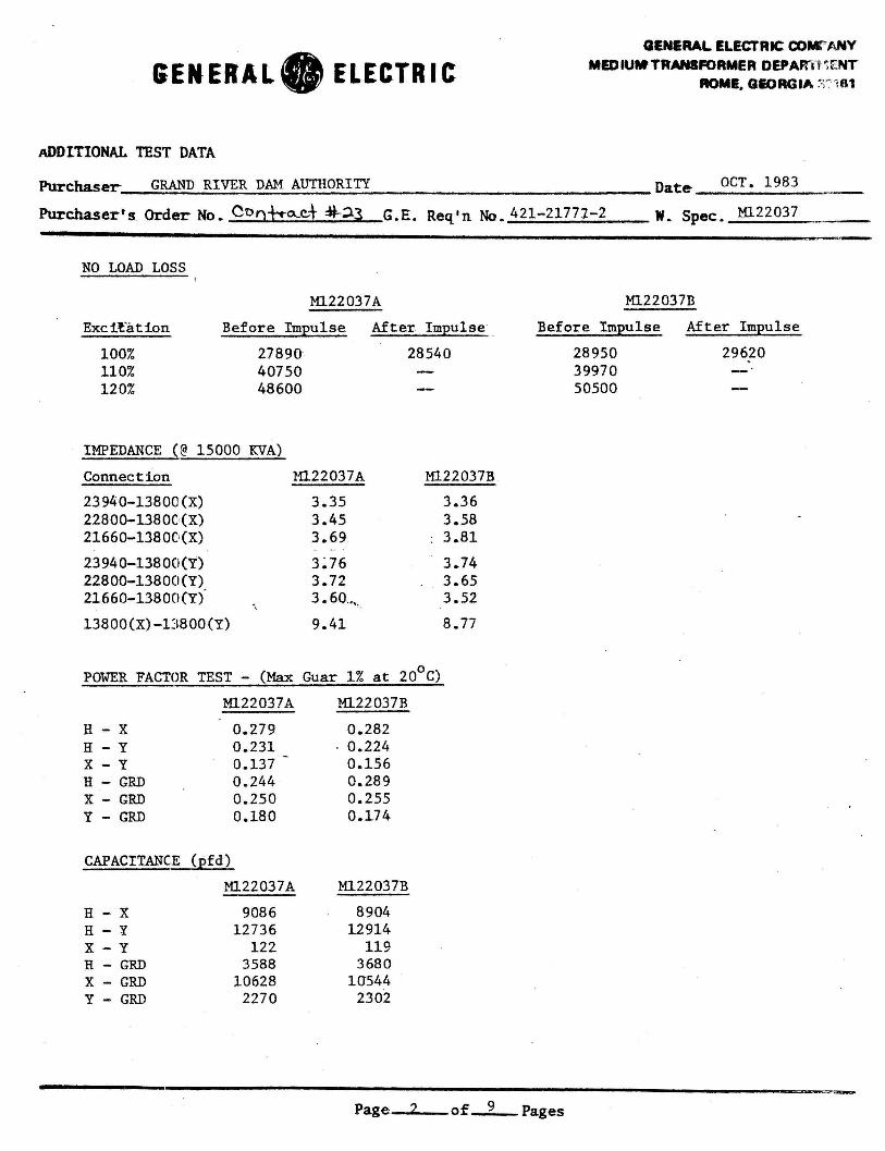
GENERAL. ELECTRIC
ADDITIONAL TEST DATA
Purchaser GRAND RIVER DAM AUTHORITY
GENERAL ELECTRIC COW'ANY MEDIUMTRANSFORMER DEPAF'ZTVi ENT
AOMI. QIOAGIA ~~r 181
Oat~ OCT. 1983
Purchaser's Order No. Cooho....c..+ :ij-;i.3 G.E. Req'n No. 421-21771-2 w. Spec. M122037 -·- -
NO LOAD LOSS
Ml22037A
Exe i?'a t ion Before Impulse After Impulse
100% 110% 120%
2789~ 28540 40750 48600
IMPEDANCE (@ 15000 KVA)
Connection Ml.22037A Ml22037B
23940-13800 (X) 3.35 3.36 22800-1380C(X) 3.45 3.58 21660-13800(X) 3.69 3.81
23940-13800(Y) 3:76 3.74 22800-13800(Y) 3.72 3.65 21660-13800(Y) 3.60 . ..,, 3.52
13800(X)-1J800(Y) 9.41 8.77
POWER FACTOR TEST - (Max Guar 1% at 20°C)
Ml.22037A Ml.22037R
H - X 0.279 0.282 H - y 0.231 . 0.224 x - y 0.137 0.156 H - GRD 0.244 0.289 X - GRD 0.250 0.255 Y - GRD 0.180 0.174
CAPACITANCE (pfd)
M122037A M122037B
H - X 9086 8904 H - y 12736 12914 x - y 122 119 H - GRD 3588 3680 X - GRD 10628 10544 Y - GRD 2270 2302
M122037n
Before Impulse After Impulse
28950 29620 39970 50500
Page of 9 Pages
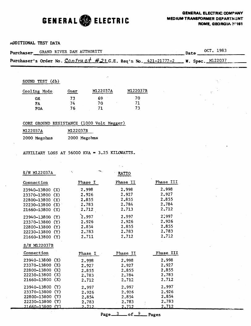
GENERAL. ELECTRIC
l\ODITIONAL. TEST DATA
Purchaser GRAND RIVER DAM AUTHORITY
GENERAL ELECTRIC COM." AMY MEDIUM' TRANSFORMER DEPARTMENT
ROMI. GEORGIA 311'181
Dat& ___ o_c_T_._1_9_8_3 __ ~--
Purchaser's Order No. Contra ec-f #.2.3 G.E. Req'n No. 421-21777-2 W. Spec. Ml22037
SOUND TEST (db)
Cooling Mode . Guar Ml.22037A M122037B
O:A 73 69 70 FA 74 70 71 FOA 76 71 73
CORE GROUND RESISTANCE (1000 Volt Megger)
M122037A
2000 Megohms
M122037B
2000 Megohms
AUXILIARY LOSS AT 56000 KVA ~ 3.25 KILOWATTS.
S/N M122037A ; - RA.T~O
Connection Phase I Phase II
23940-13800 (X) 2.998 2.998 23370-13800 (X) 2.926 2.927 22800-13800 (X) 2.855 2.855 22230-13800 (X) . 2.783 2.784 21660-13800 (X) 2.712 2. 713
23940-13800 (Y) 2.997 2.997 23370-13800 (Y) 2.926 2.926 22800-13800 (Y) 2.854 2.855 22230-13800 (Y) 2.783 2.783 21660-13800 (Y) 2. 711 2.712
S/N M122037B
Connection Phase I Phase II
23940-13800 (X) 2.998 2.998 23370-13800 (X} 2.927 2.927 22800-13800 (X} 2.855 2.855 22230~13800 (X) 2.783 2.784 21660-13800 (X) 2. 712 2. 712
23940-13800 (Y) 2 .. 997 2.997 23370-13800 (Y) 20926 2.926 22800-13800 (Y} 2.854 2.854 22230;,.13800 (Y) 2.783 2.783 2J 66Q-l 38QO CTJ 2 7J 2 2. 712
Page 3 of 9
Phase III
2.998 2.927 2.855 2.784 2.712
2:997 2.926 2.855 2.783 2.712
Phase III
2.998 2.927 2.855 2.783 2.712
2.997 2.926 2.854 2.783 2, 712
Pages
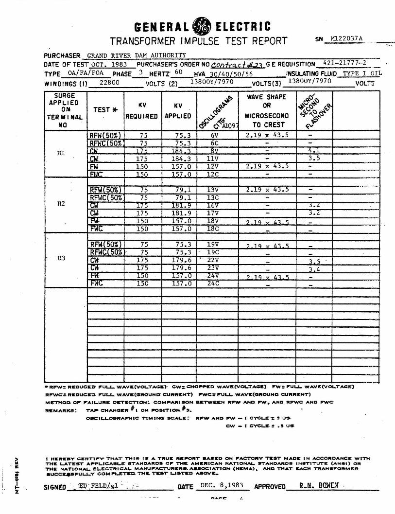
> Ill . a:.
GENERAL. ELECTRIC TRANSFORMER IM PULSE TEST REPORT
PURCMASER GRAND RIVER DAM AUTHORITY
SN M122037 A
DATE" OF TEST OCT. 1'983 PURCHASER'S ORDER NO C£ofts.c.f#-.+J GE REQUISITION 421-21777-2 TYPE OA/FA/FOA PHASE...2._HERTZ 60 MVA 30/40/50/56 INSULATING FLUID TYPE I OI L WINDINGS (I) 22800 VOLTS (2} 13800Y/7970 VOLTS(3) 13BOOY/7970 VOLTS
SURGE ~~ WAVE SHAPE 4c{'N APPLIED KV KV ~ OR ~~o~ ~ OM- TESTM- <¥ "'~"'o ~ TERMINAL REQUIRED APPLIED ~# MICROSECOND
f.t_'V;p: NO # ¢ AlQ9, TO CREST
RFW(50%) 75 75.3 6V 2.19 x 43.5 -RFWCC50% 75 75.3 6C - -
Hl r1J 17 c; 1Rf,_':\ 8V - 4.1 n.I 175 184.3 llV - 3.5 FW 150 157.0 12V 2.19 x 43.S -i:tJ~ 150 157.0 12C - -
RFW<50%l 75 79.1 13V 2.19 x Z.3.5 -RFWC(50% 75 79.1 13C
... - -H2 UM 175 181.9 16V - _j • L
-
cw 175 181.9 17V J.2 . . -
·--- -fW. 150 157.0 18V ?10 ..... l.."J.I:\ -t-W~ 150 157.0 18C - -RFW(50%) 75 75.3 19V ? , a ...,. f,"J. r:; -RFWC.C50% 75 75.3 - 19C - -H3 CW: 175 179.6 - 22V 1. 'i -l,;"" 175 179.6 Z3V - 3.4 t-lt 150 157.0 .24V ?10v/i"J.'\ -FWC 150 157.0 24C - -
•RP'W: REDUCED frUW... WAVIC(VOL..TAGll:): C:W:CHO..,.ICD WAVIC(VOL..TAGIC) fl'W: fl'UU.. WAVE(VOl...TAGE)
Rl'"'WC:: FtSDUCE1 FUt.L. WAVE(GROUHO: CURRENT) trWC: FU&.&.. WAVIC(GROUHD CURRENT)
METHOD OF P°AIL..URE DICTECTtOH~ COM .. ARISOH. BETWEEN Rirw ANCl rrw-. AND RP'WC AND FWC
REMARKS: TA,.. CHANGER II 1 OH. ~51TION Is. 09CILL.OCll'tAP"HIC:: T'tMINGr SCALE:: Rfl'W AMD frW- - I · CVCL.E": !f U~
CW - t C:VCt.S : • !I US
l HEJtlUIY CIERTI~ THAT° T'MIS IS A TRUE Rll:P"ORT llASICD· ON . fl'ACTOltV T1tST M .ADE IN ACCORDAHC:&:: WITH THE L.ATEST Afl"P1..ICAllt.S: STANDARDS 01" THE AMICRICAN NATIONAL. STAMDAftDS INSTITUTll: (ANSI) OR THIE NATIONAi- ICL.ECTIUCAL. MANUJPACTURll:RS. ASSOCIATIO ... (Nll:MA) • AND THAT ~CH TRAHSfl'OltMll:R succ..-iru&.LY COM~TICl1 THIE. TEST USTS.D- AllOVL
SIGNED . ~ ~ED ~FELU/gi : .· ;_; DATE DEC. 8 ,1983 APPROVED ll • .ti. BOWEN' ~~.;;.....;;..~~~~~~~-
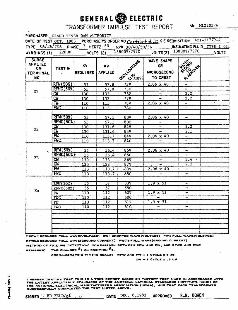
. .. > Ill. . It.
i i
GENERAL. ELEC-TR IC TRANSFORMER IMPULSE TEST REPORT
PURCHASER GRAND RIVER DAM AUTHORITY
SN Ml.22037A
OATC OF" TEST OCT. 1983 PURCHASER'S ORDER NO Cc atrp.cf ;z!:.:0 GE REQUISITION 421-21777-2 TYPE OA/FA/FOA PHASE~HERTZ 60 MVA 30/40/50/56 INSULATING FLUID TYPE I OIL WINDINGS (t) 22800 VOLTS (2} 13800Y/7970 VOLTS(3} 13800Y/7970 VOLTt::
SURGE +' WAVE SHAPE 4ef~ APPLIED KV KV '1:--~ OR ~~c~ ~'3' ON TEST• clO
TERMINAL REQUIRED APPLIED MICROSECOND c:,~.c..c ~~ "'~ NO # (} Al.09 TO CREST ~
RFW.(50%l c;c; 57.8 73V 2.06 x 40 -Xl
RFWCC50% 'i "i 57.8 73C - -Mal , 'l.n 111 7f\V - , ?
r.w· nn 113 77V - 2.2 F\i l Hl 115 78V 2.06 x 40 -i:tJr ,, n 11 c; 7Rr. - -
RFWC soi) "" 57 .1 80V 2.06 x 40 -RFWC ( 50% 55 57.1 BOC - -r.w 11() 131. 6 82V - 2.Z
X2 cw 130 131.6 83V 2.1 -t-W.. 11n 113-7 84V 2.06 x 40 -FWC 110 113.7 84C - -
.. RFWf 50%) "i c; 56.4 85V 2.06 x 40 -RFWC.(50% 'i"i 56.4 - ·a5c - -X3 cw 130 133 - 86V 2.4 -cw. 130 133 87V . - 2.2
·H't 110 113.7 ·88V 2.06 x 40 -FWC 110 113.7 88C - -RFW< 50%) 55 )/ ~tsv l.Y x )1 -RFWC(50% 55 57 SSC - -Xo FW 110 112 60V 1.9 x 51 -FW'C 110 112 60C - -FW' 110 112 61V 1.9 x 51 -FW'C 110 112 61C - -
•RPW: REDUCSQ iruu,_ WAVW:(VOl.TAGIE) CW: CHOP,.tO WAVt(VOl-TACIC) fl'W: fPU&.L. WAVW:(VOL.TAGC)
Rfl'WC:.:."SOUCED l"UL.l.. WAVC(QROUNQ: CURRENT) irwes l"Ul.L.. WAVS(QROUNO CURRENT)
METHOD o..- irAll-URIE CISTICCTION: COM .. ARISON SrTWIEIEN Rfl'W ANO fl'W• ANO "fl'WC ANO fl'WC
"IEMARKS: TA,.. CM~ I 1 ON. ~saTtoN #s. OSC:U;,.&.OCIRAP"MIC TIMING SCALE: Rfl'W AHD F'W- - I C:VCUt: SUS
cw - •. C:VC'-&: .s us
..
I HIERIE8V CCRTll"'V TMAT THIS IS A T .. U1t .. IEP"Olt'T 8A91t0 ON l"ACTOl!n" TEST M .ADr IN ...CC:O .. OANCE WITH TM& 1-ATSST A~JCA8LZ STANCIA .. OS 01" THE AMIERICAH NATIONAL. STANDAll09 INSTITUTIE (AH91) 011111 THIE NAT10NAL.. ltl..SCTRICAI- MANUl"ACTURll: .. S . ASSOCIATION- (HEMA)• ANO THAT 11.ACH TJllANSl"ORMIER succ...-ll'ULL-Y <:;OMfl\.ICTICO TH&. TC9T Ull'TtD AJIOV&.
R .. N. BOWEN"
-
SIGNED . · :ED : FELD/~i . . :.; DATE DEC. 8,1983 APPROVED ~~~~~~~~~~~
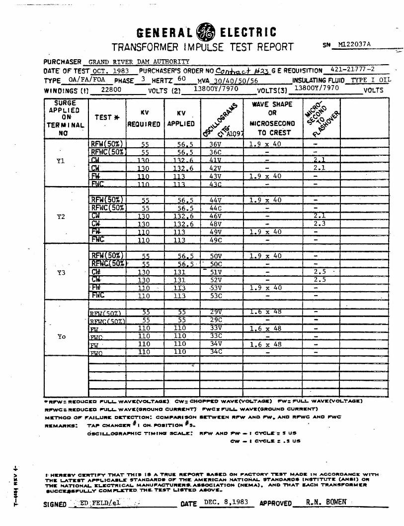
I ... > Iii . a: ... = l
GENERA.Lfj ELECTRIC TRANSFORMER IMPULSE TEST REPORT
PURCHASER GRAND RIVER DAM AUTHORITY
SN M122037A
DATE" o~ TEST OCT. 1983 PURCHASER'S ORDER NO Cd:zotmc..+ #33 GE REQUISITION 421-21777 -2
TYPE OA/FA/FOA PHASE.2._HERTZ 60 MVA 30/40/50/56 INSULATING FLUID TYPE I OIL WINDINGS {I) 22800 VOLTS {2) 13800Y/7970 VOLTS(3) 13800Y/7970 VOLTS
SURGE +c, WAVE SHAPE ~c:{~ APPLIED KV KV ~ OR ~~o~ r3" ON· TEST*' ~d' c,~"~~ TERMINAL REQUIRED APPLIED MICROSECOND
NO ·# G~09i TO CREST ~~ RFWlSO%) c; c; 56.5 36V 1.9 x 40 -RFWCC50% c; c; 56.5 36C - -
Yl MJ , ".l.n 1 ".l.? f, l..lV - 2 1
r.w qo 132.6 42V - 2.1 FW. , , n 111 43V 1.9 x 40 -r:t.Jr. , , n 11 ':\ '11r. - -RFWC50%) c; c; 56.5 44V 1.9 x 40 -RFWCC50% 55 56.5 44C - -
Y2 cw 11() 132.6 46V - -Z.1 CW- 130 132.6 48V - 2.3 t-W. 11 n 113 49V 1.9 x 40 -fW(; 110 113 49C - -
RFWC50%l c; c; 56.5 sov 1.9 x 40 -RF.WC.C 50% , c; c; 56. 5 . - soc - -
Y3 cw 130 131 - SlV - 2.5 CW.· 130 131 52V - 2.5
. t-W: 110 - 1!3 ·53V 1.9 x 40 -Role 110 113 53C - -
''Dm.rfc;n~ ' 55 )) '/.':JV .L.b x 41:S -. 'Rm.rr. r c;n~, 55 55 29C - -
lm.r , 110 110 33V 1.6 x 48 -Yo lm.rr.· 110 110 33C - -
l1<'T.J . 110 110 34V 1.6 x 48 -Im.TO 110 110 j4C - -
..
•"PW: l'HtOUCSD l"'UL.&-. WAVIE(VOLTAGS) CW: CHO .. ,.SD WAVll:(VOL.TAGS) F'W: l"'UU.. WAVIE(VOLTAGS)
Rl"WC:~Rll:OUCSO. .rtJ&..&-. WAVS(QllOUNO CUltltll:NT}' fl'WCS ..Ur..&.. WAvt(<altOUNO CUltJltll:NT)
MrTHOD oir irAIL.Ultlt Dlr.TSCTtOM: COM .. AIHSOH •ETWltltM ltfPW ANO "'*•AND ltl"WC ANO fl'WC::
ltll:MARKS: TA .. CMANGSR' # l ON- l"OSITIOM #s. OSCILJ..OCHtA~tUC: TtMINCS SCAL.JE:: Rl"'W- AND f'W' - I C'YC&..lt: s us
cw - •. C"tC&..lt = • s us
·-
1· H&Jltll:•V Cll:Jlt'Ttfl'V THAT THIS 19 A TltUlt Rlt.-ORT aASSD- ON P'ACTOltV ~ST M .AClt IN ACC:ORDANCIE WITH · THlt L.ATll:ST' AP"PLICA8Lr 9TANDARD9' 0 ... THE AMSIHC:AN NATIONAL. STANDARDS INSTITUTE (ANSI) OJlt TMS NATIONAL. SL.SCTl'UCA&.. MANUllPACTURll:ltS.ASSOCIATIOM (Nll:MA) • ANO TMAT It.ACM TlltANSllPORMIEJlt •uc:c:qsiruu..v COMPl..ltT&D THIL TEST L.IST1tD ...aov11:.
SIGNED . · :ED :_FELn/~i · .. . DATE DEC. 8,1983 APPROVED R.M. BOWEN' ~--;.;.;._.;.... ____________ ~
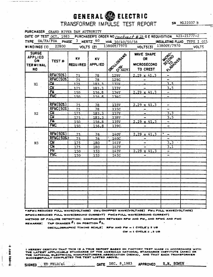
&EN ERAL. ELECTRIC TRANSFORMER IMPULSE TEST REPORT
PURCHASER GRAND RIVER DAM AUTHORITY
SN Ml22037 B
DATE OF TEST OCT. 1-983 PURCHASER'S ORDER NO CtJntrr:y:.f H,?J GE REQUISITION 421-21777-2 TYPE OA/FA/FOA PHASE-2._HERTr 60 MVA 30/40/50/56 INSULATING FLUID TYPE I OIL
WINOINGS (I} 22800 VOLTS (2) 13800Y/7970 VOLTS(3) 13800Y/7970 VOLTS
SURGE ~'? WAVE SHAPE ~r;:{ '!:) APPL.1£0
ON· TEST• KV KV ~~ OR ~co~ f3
TERM:I NAL REQUIRED APPLIED MICROSECOND r:.,~t;"'o ~.,.
#~¢41i.09~ "'~ NO TO CREST «" RFW(50%) 7"i 78 , ') Ql7 2_2q v 41 'l. -RFWCC50% 7 r; 7R 1?0r - -
Rl MJ , "7 r:: , Q 'l 'l 1 'l1U - ~ r;
rw , 7 r; 1 R'l. 'l. 1'l.'l.V - 3.5 FW 1 r;n 1 r;f; . R 1 'l.4V '.)_?Q v 41-3 -i:wr. , i;:n , C:t:. Q , ~1.r - -RFWC50%} 7"i 7R 1'l."iV 2-2Q x 41.3 -RFWC(50% 75 78 135C - -
H2 r.w. , 7 r:; 1 R'l. 'l. 1'l.7V - 3.3 CW 17<; . 1 R'l. 'l. 138V - 3.5 fW.. , c;n , c;,;_8 , -:tqv z_2q x 41-3 -FWC , r;n , r;h_8 , -:tqc - -RFW{50%} 7') 7n 1l..OV 2-2q x 41-3 .. -RFWC.C50~" 7r; ·7h - 11.nr - -
H3 Cti 17"i 180 - 141V 3.3 -~w. 175 180 142V - 3.1
. l'"\1" 1"i0 1 c;1 ·143V 2.29 x 41.3 -I'"\~ 150 153 143C - -
•Rl"W.: ltS.DUC:ED P"UL.&.. WAVE(VOL.TAGIE)· C:.W: CMO .... ltO WAVS:(VOL.'TAQIE) l"W: fl'U&.&.. WAVS:(VOL.TAGIC)
ltl"WC:~ltlEDUC:SO fl'U&..L. WAVE(QltOUND C:U"ltlEKT} fl'WC:S fl'UU... WAV&(Q"OUND C:U"ltENT)
MIETHOO 0 .. fl'AU.U .. S. DIET&CTlON! C:OMP'AIUSON BIETWEEN .. fPW ANO f'W• AND RflPWC: AND flWC:
"ltMARKS: TA,. CMANG1t1t #1 ON- i-os1T10N Is. OSC:U..&..OGIRAll9MIC:: TIM ING SCAl-E': .. arw AND fll'W· - I C'Y'C&..r·: S US
c:w - •· C:VCL.& :: • s us
l HSRIC•Y CERTIP'Y THAT THIS 11!1 A. TRUlt "Sf90RT 8AaS:D ON ,..ACTO"V 'MtST M.AOC IN ACCO"DANCC Wl"i'l-!: TMIE L.ATICST A~IC:A91-lt' STANDA .. DS Otr THIE' AMEltlCAN- NATIONAL. STANDARDS INSTITUTE (ANSI) OR TMIC NAT10NAL.. ELSCTltlCAL. MANUllPACTURCltS • .ul90c:IATION- (NltMA) 0 ANO TMAT ir.AC:H TWANSfPO .. Mltllt-9UC:C~fPULl...V' COM ~TIED TM& TIE.ST UST1ED AaOVlt"'. .
S GNED . . ·"C"1'\ ·FELD Lei . . . ; I - . .,...,_ ~ . '· - . . .. OATE DEC. 8,1983 APPROVED R.N. BOWEN'
~~~~~--~~~----
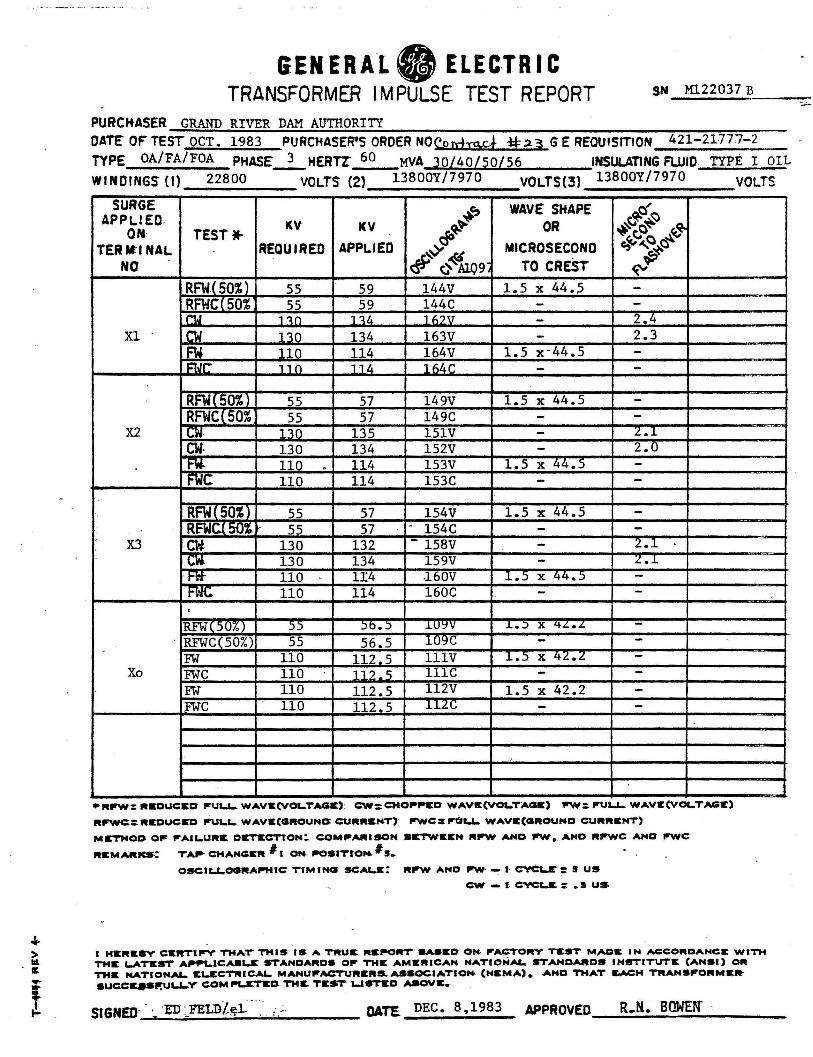
• • > llL
·c .... .. !
GEN ER Al. ELECTRIC TRANSFORMER l M PULSE TEST REPORT
PURCHASER GRAND RIVER DAM AUTHORITY
SN Ml.22037 B
DATE' OF" TEST OCT. 1983 PURCHASER'S ORDER NO<:.on-hs..c..+ * !2. ~ GE REOUISmON 421-2177~-2 TYPE OA/FA/FOA PHASE_]_ HERTZ" 60 MVA 30/40/50/56 INSULATING FLUID TYPE I OIL WINDINGS- (I) 22800 VOLTS (2) 13800Y/7970 VOLTS(3) 13800Y/7970 VOLTS
SURGE +~ WAVE SHAPE ~t;;{~ APPLIED,
ON TEST• KV KV ~ OR ~~Q~ ~
TERM:I NAL REQUIRED APPLIED ~cJ' MICROSECOND c,~,o o~
NO # 0~09· TO CREST "'~ ~ RFW(50%) SS 59 144V 1.5 x 44.5 -RFWCf 50% 55 59 144C - -Md , 'ln 1 'l/, 1 "?" - 2.4
X1 . .. tJ P.n 134 163V - 2.3 • t.i , , n 114 164V 1.5 x-44.5 -
[JC- , , n 11 li. lhli.C - -RFWC50%) 55 57 149V 1.5 x 44.5 -RFWC(50% 55 57 149C - -
X2 cw , ".\n 135 151V - z • .1
cw. 130 134 152V - 2.0 l"'W. 110 . 114 153V 1.5 x 44.5 -FWC 110 114 153C - -RFWC50%1 55 57 154V 1.5 x 44.S -RFWC.C 50'1. 55 57 - 154C - -
X3 •CW 130 132 - 158V - 2.1 cw. 130 134 159V - Z • .1
·H't 110 - 1I4 -160V 1.5 x 44.5 -1-l'IG. 110 114 160C - -.
RFW(5U7oJ 55 )b • .) .LU~V .L • .) X qL.L. -RFWC(50%) 55 56.5 109C - -
-FW 110 112.5 lllV 1.5 x 42.2 -
Xo FWC 110 ]1? .5 lllC - -FW 110 112.5 112V 1.5 x 42.2 -FWC 110 112.5 ll2C - -
1· ;;o
•"PW: "KOUCICD ~U&..1-WAVlt(VO&..TAGC): CW:CMO~~D WAVlt(VOL.TAQlt) fl'W: P'UU- WAVE(VO&..TAGll:)
Rfl'WC::RIEOUCSD fPU&..1- WAVlt(QROUNO: CURRltNT)' fl'WCS fi'tl&.L. WAVC(Qlll?OUNO CURRltNT)
MCTHOO Ofr l"A!LUlll?& Dll:TECTTON!. C:OM~AltlSON 8&TW1Cl:N lltP'W ANO 'fll'Wt ANO ltP'WC ANG l"WC
ltltMAIUCS: TA ... CMAHGElt I I ON- ll'OSITtO ... # s. OSCIU..OCllltAPHIC TIMING' SC:AL.E: lltll'W AND fll'W' - I· cYCt.r: S US
CW - I C:VC-.&: .s US
I HS:RICSV C:1CRT1P'V THAT THIS IS A-TRUllC "llt.-OR'r 8ASEO ON- fl'ACTORY TltST M,ACC IN ACCOltDANCE WITH THIE L.ATltST Af1191..ICA9L.r STANOAlltDS Ofr THlt AMIEIUCAN NATIONAL STANDARDS INSTITUTlt (ANSI) Oft TMK NATIONAi- ltL.ECT1HCAL. MANU,,.ACTURltRS.AaSOCIATION- (NltMA) • .ANO THAT !LACH TAANSfl'ORMltR SUCCQS~U...Y' COM l9L.l:TICD. TH~ TIEST USTEO AaOVllt,.
DATE DEC. 8, 1983 APPROVED ~~~~~~~~~~~
R.M .. BOWEN'
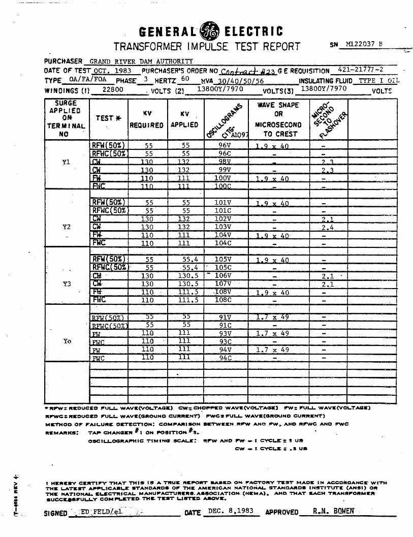
·-.... > Ill
· c •
' t=- . .
GENERAL·· ELEC·TRIC TRANSFORMER IMPULSE TEST REPORT
PURCKASER GRAND RIVER DAM AUTHORITY
SN Ml.22037 B
OATE" OF TEST OCT. 1983 PURCHASER'S ORDER NO Cnafrar.}- Jl.1~ GE REQUISITION 421-21777-2 TYPE OA/FA/FOA PHASE~HERTZ 60 MVA 30/40/50/S6 INSULATING FLUID TYPE I OIL
WINDINGS (I} 22800 . VOLTS (2) 13800Y/7970 VOLTS(3) 13800Y/7970 VOLTc--SURGE
+' WAVE SHAPE ~c{'!:J APPLIED KV KV ~~ OR ~~c~ ~ ON- TEST• dO c,~,~&-TERM.I NAL REQUIRED APPLIED ~~ MICROSECOND NO # ¢~A1Q9, TO CREST 4.".p
RFW(50%) SS S5 96V 1 a v L..O -RFWCf 50% 55 55 96C - -
Yl rw 1-:\0 1 ':l? QRV ~ ') ':l
nJ 130 132 99V - ?.3
FW. 110 111 lOOV 1 . Q v l.O -r:t.Jt: 11 () 111 1 nor. - -RFWC50%) 55 55 lOlV 1 _ q v t..o -RFWC(50% 55 55 lOlC - -cw 130 132 102V - ?.l
Y2 cw. 130 132 103V - 2.4 - t"W. 110 111 104V 1 a v l.O · -
FWC 110 111 104C - -RFW£50%l 55 55.4 lOSV 1 . a v 40 -RFWC.C 50'- · 55 55.4 - 105C - -cw 130 130.5 - 106V - 2.1
Y3 ~l".- 130 130.5 107V - 2.1 t"ft 110 - 111.5 .1osv 1.Q x 40 -l"'\'ll.. 110 111.5 108C - -
lH'TJ ( ')()'i:'.) )) )) 91V 1.7 x 49 -. RFtJC ( 'lQ~C 55 55 91C - -
l<'fJ 110 111 93V 1.7 x 49 -Yo Ft.Jr. 11(!) 111 93C - -
FtJ 110 111 94V 1. 7 x 49 -we llCl 111 94C - -
.
.... rrw: ltEDUC:EO fl'UL.L.. WAVIE(VO&-TAG&). C:.W:CM~ .... co WAVIE(VOL.T"Acnt) rrw: l"UL..L. WAVlt(VOL.TAGE)
ltP'WC:: ftlEOUC:SO ir\JL.C.. WAVIE(GROUNO C:UltRIEKT) P'WC:.S 111'\JU- WAVIE(CIROUNO CUftRIENT)
MICTMOO. Of" ........... u"lt OC'TECTtON: C:OM .. AIUSON 8CTWll:ICN ~l"'W ANO f'W ,,. AND "P'WC ANO rrwe 111tMARKS: TA.- CMANCllCJlt I 1 OM- ..os1Tto.._ #s.
OSCll .. ~OCll'IAPMIC: TIMING SCAL.JE:: Rl"'W ANO P'W· - I C'l'CLC: S US
C:W - I c:vci;.& : • S US
I HICRIE•V CIER'Ttl'Y TMAT THIS IS 4 TJltUC l'lCl'"ORT llASIU~ ON fl'ACTORV Tlt!IT M .AOC IN ACCOiilDANCr WITH TH& L.ATltST' A'"'9t..IC:AIU .. S: ST'AHOA .. DS Ofl' THIC AMIER I CAH NATIONAi... STANDARD• INSTITUTE (ANSI) OR THIE NATIONAL. IEL.&CTIUCAL. MAl'IUirACTUlttlte.ASSOC:IATIOM- (NICMA). AND THAT EACH Tl'AHSfl'O"MIER SUCC:~fl'Ul..&-Y C:OMl"l..&TIEO. THIL TIEST" UST&~ AllOVr.
DATE DEC. 8,1983 APPROVED R.N. BOWE~ ~--------------------
GENERAL TERMS AND CONDITIONS
Any contract or order issued by the Grand River Dam Authority (hereinafter referred to as GRDA) is expressly conditioned upon Seller’s assent to these terms and conditions, unless otherwise agreed in writing. Any order issued or filled by Seller shall be deemed to constitute Seller’s assent to these terms and conditions. Any additional or different terms submitted by the Seller are hereby expressly objected to by GRDA unless expressly agreed to in writing by GRDA.
1. Mail or deliver all invoices or correspondence pertaining to the payment of this Purchase Order to: Accounts Payable Department,
Grand River Dam Authority, P.O. Box 409, 226 West Dwain Willis Avenue, Vinita, Oklahoma 74301. Seller shall submit invoices, with one copy detailing each item with unit prices, with the top copy being distinguishable as an original, accompanied by one copy of complete shipping papers. If shipment is not made by routing instructions as specified on the face of this Purchase Order, GRDA reserves the right to deduct any excess transportation charges resulting therefrom. Copy of original freight bill must be supplied for payment. Time, in connection with any discount offered, will be computed from date of delivery of items, or from date the correct invoice is received in Vinita, Oklahoma, whichever period of time is the later date. No Oklahoma State Sales or Use Tax shall be included in payment of this Purchase Order.
2. All articles, materials, equipment and supplies (hereinafter referred to as “items”) covered by this Purchase Order, unless otherwise specified, are purchased subject to inspection before and during manufacture and upon arrival at destination. GRDA reserves the right to return for full credit and/or refund, at Seller’s sole risks and expense, including all transportation and storage charges, all items found defective or furnished contrary to instructions and/or specifications contained herein.
3. In case of default by Seller, GRDA may procure the items or services from other sources and hold Seller responsible for any excess cost occasioned thereby; provided, that if necessity requires the use of items not conforming to specifications, they may be accepted, and payment made at a proper reduction in price. Notwithstanding anything herein to the contrary, GRDA reserves the right to terminate this Purchase Order for its convenience. In the event of such termination, GRDA shall pay and Seller shall accept the reasonable value of all work performed and items delivered by Seller up through the effective date of such termination.
4. Seller warrants that all items covered by this Purchase Order will conform to the specifications, drawings, samples or other description furnished by GRDA, or any revisions thereof, and any items purchased pursuant to this Purchase Order shall be subject to all warranties expressed or implied by law, and will be merchantable of good material and fit and sufficient for the purpose intended, and shall satisfy any performance guarantee requirements as specified herein by GRDA. In the event the items and/or services purchased hereunder do not meet the warranty specified hereinabove, Seller shall promptly repair or replace any defective item at its expense, or re-perform any necessary services, and shall hold GRDA harmless from any and all costs and expenses incurred due to said defective item or performance of services, including the cost for removing any part or product to be repaired or replaced, as well as transportation and installation charges in connection with the repair, replacement or servicing of any parts or equipment. Seller further agrees that the manufacturer’s warranties and guaranties of the items purchased hereunder extended to Seller shall extend to GRDA.
5. Seller shall indemnify and hold GRDA harmless from and against any and all loss, costs or expenses arising out of any liens or claims in any way related to the items or services furnished hereunder. Seller shall likewise indemnify and hold GRDA harmless from any patent, trademark or copyright infringement, except items supplied in accordance with design originating with GRDA. Seller shall be an independent contractor. Seller shall protect, defend, indemnify and hold GRDA harmless from any damage or injury to any persons, including Seller’s employees or property, and from any claim, demand, action, cost or expense arising out of the activities hereunder as a result of Seller’s negligent or intentional wrongful acts. In no event shall Seller’s liability be limited under this Purchase Order for the negligent or intentional wrongful acts of the Seller.
6. Seller shall, before any items are shipped and/or any services are commenced, provide GRDA with certificates evidencing that the following minimum insurance will remain in force until Seller’s obligations are completed: (a) Workmen’s Compensation Insurance, including Employer’s Liability Insurance, in accordance with the laws of the state in which Seller may be required to pay compensation; and (b) Public Liability Insurance with an individual limit of not less than $100,000 and a total for any one accident of not less than $300,000, unless otherwise specified herein.
7. This Purchase Order (including Seller’s right to receive payments hereunder) shall not be assigned or subcontracted in whole or in part without GRDA’s prior written consent. No assignment hereof shall relieve this assignor of its obligations hereunder.
8. Service Contracts: By submitting a bid for services, the Bidder certifies that they, and any proposed Subcontractors, are in compliance with 25 O.S. §1313 and participate in the Status Verification System. The Supplier/Contractor/Consultant/Construction Manager/etc. certifies that it and all proposed Subcontractors, whether known or unknown at the time a contract is executed or awarded, are in compliance with 25 O.S. §1313 and participate in the Status Verification System. The Status Verification System is defined in 25 O.S. §1312 and includes, but is not limited to, the free Employment Verification Program (E-Verify) available at www.dhs.gov/E-Verify. This shall remain in effect through the entire term, including all renewal periods, of the Contract. The State may request verification of compliance for any Contractor or Subcontractor. Should the State suspect or find the Contractor or any of its Subcontractors are not in compliance, the State may pursue any and all remedies allowed by law, including, but not limited to: suspension of work, termination of the Contract for default, and suspension or debarment of the Contractor. All costs necessary to verify compliance are the responsibility of the Contractor.
9. All Items shipped pursuant to this Purchase Order will conform with all municipal, state and federal laws, ordinances and regulations, and Seller will defend and save harmless GRDA from loss, costs or damage by reason of any actual or alleged violation thereof.
10. GRDA hereby notifies Seller that Seller must comply, and by acceptance of this Purchase Order, Seller represents that it has complied with, and will continue to comply with, all applicable federal, state and local laws, regulations or orders.
11. This Purchase Order shall be construed as being performed by both parties in Craig County, Oklahoma, and shall be governed in accordance with the laws of the State of Oklahoma.
12. AUDIT RIGHTS. Contractor will, at all times during the term of this Contract and for a period of five (5) years after the completion of this Contract, maintain and make available for inspection and audit by GRDA and/or the Oklahoma State Auditor, all books, supporting documents, accounting procedures, practices, and all other items relevant to the Contract.
Grand River Dam Authority is an agency of the State of Oklahoma. Administrative Headquarters • 226 West Dwain Willis Avenue • Vinita, Oklahoma 74301 • Phone: 918-256-5545 • Fax: 918-256-1051
GRDA Finance Form 001 (Revised 06-11, 2015)