notice inviting bids - iit bombay
TRANSCRIPT

INDIAN INSTITUTE OF TECHNOLOGY BOMBAY, POWAI, MUMBAI
MEP & Interior Civil work of Chemistry Research Laboratory
Page 1 of 274
20.06.2022
GOVERNMENT OF INDIA
INDIAN INSTITUTE OF TECHNOLOGY BOMBAY, POWAI
OFFICE OF DEAN (IPS), IITB, MUMBAI
Notice Inviting Bids
NIT NO- IIT(B)/Dean (IPS)/Chemistry Research Lab/DESE-CESE/Tender/2022/01 Date:-
20/06/2022
Dean (IPS) , on behalf of Director, IITB invite percentage rate bid for:
NAME OF ASSIGNMENT: MEP & Interior Civil Works for Chemistry Research
Laboratory in DESE/CESE building of Indian Institute of Technology Bombay,
Powai, Mumbai - 400076.
TOTAL ESTIMATED COST OF WORK:- Rs. 2,12,27,336/-
EARNEST MONEY TO BE DEPOSITED :- Rs. 4,24,547/- ee1466667314666673
TIME ALLOWED:- 09 Months
Dean (IPS)
IITB, Mumbai

INDIAN INSTITUTE OF TECHNOLOGY BOMBAY, POWAI, MUMBAI
MEP & Interior Civil work of Chemistry Research Laboratory
Page 2 of 274
Table of Content
Sl. No. Description Page No.
1 Table of Content 2
2 Notice Inviting Bids 3
3 Information and Instructions for Bidders 4
4 General Conditions of Contract 5 to 10
5 Integrity Pact 11 to 15
6 Form of Performance Guarantee for Services 16 to 17
Part I – Technical Bid (Envelope – I) 18
7 Information to Bidders& Data Sheet 19 to 24
8 Form of Works Contract 25 to 26
9 Eligibility Criteria 27 to 29
10 List of Documents to be scanned and uploaded within the period of bid submission
30
11 Letter of Transmittal 31
12 Forms A – F 32 to 37
13 Annexure – 1 38
14 Annexure – 2 39
15 Appendix A: Description of the Services 40 to 43
16 Appendix B: Deliverables by the Bidder 44 to 45
17 Appendix C: Technical Specifications, BOQ & Makes for Civil Interior & MEP Works – Table of Contents
46
17 A Technical Specifications & Makes for Internal Electrification 47 to 78
17 B Technical Specifications & Makes for HVAC Systems 79 to 164
17 C Technical Specifications & Makes for ELV Systems 165 to 274
18 PART D1 Financial bid- Percentage to be Quoted on Estimated Amount Attached Separately
19 PRAT D2 Schedule of Quantity for Composite Works.
Dean (IPS)
IITB, Mumbai

INDIAN INSTITUTE OF TECHNOLOGY BOMBAY, POWAI, MUMBAI
MEP & Interior Civil work of Chemistry Research Laboratory
Page 3 of 274
Notice Inviting Bids
Dean (IPS ) , IITB, on behalf of Director ,IIT Bombay invite percentage rate bid from eligible firms/contractors in two bid system for the following work:- NIT NO- IIT(B)/Dean (IPS)/Chemistry Research Lab/DESE-CESE/Tender/2022/01 Date:-
20/06/2022 NAME OF ASSIGNMENT: MEP & Interior Civil Works of Chemistry Research Laboratory in
DESE/CESE building of Indian Institute of Technology Bombay, Powai, Mumbai - 400076.
TOTAL ESTIMATED COST OF WORK:- Rs. 2,12,27,336/-
EARNEST MONEY TO BE DEPOSITED :- 4,24,547/-
Time Allowed :- 09 Months
Tender document duly completed in all respects (hard copy- Technical and Financial bid) to
be submitted to Dean (IPS) Office, IITB, Powai, Mumbai, 1stFloor, Main Building, IITB
Campus, Mumbai-400076 on or before 19/07/2022 at 03:00 pm.
The bid forms and other details can be obtained from http:// www.iitb.ac.in/deanpl/tender
Note:- Contractor not registered with IITB shall do vender registration from website portal iit.ac.in/vrp/
Dean (IPS)
INDIAN INSTITUTE OF TECHNOLOGY BOMBAY, POWAI, MUMBAI

INDIAN INSTITUTE OF TECHNOLOGY BOMBAY, POWAI, MUMBAI
MEP & Interior Civil work of Chemistry Research Laboratory
Page 4 of 274
INDIAN INSTITUTE OF TECHNOLOGY BOMBAY, POWAI, MUMBAI
INFORMATION AND INSTRUCTIONS FOR BIDDERS FORMING PART OF BID DOCUMENT
Dean (IPS) Office, IITB, Powai, Mumbai, 1stFloor, Main Building, IITB Campus, Mumbai-
400076, (Telephone No. 022-25764017, email: [email protected]) on behalf of the
IITB, Powai, Mumbai invites turnkey bids in two bid system from specialized Agencies in India
for the following work:
Sl.
No. NIT No.
Name of Work &
location Estimated Cost put to tender
EMD amount
Last Date & time of submission of bid and other documents as specified in press notice
Time and date
of opening of
Eligibility
opening bid
1 IIT(B)/Dean
(IPS)/
Chemistry
Research
Lab/DESE-
CESE/
Tender/
2022/01
Date
20/06/2022
MEP & Civil
Interior Works of
Chemistry
Research
Laboratory in
DESE / CESE
building of
Indian Institute
of Technology
Bombay, Powai,
Mumbai -
400076.
Rs. 2,12,27,336/-
Rs.4,24,547/- Up to 15.00
Hrs on
19-07-2022
After 15.30
Hrs on 19-07-
2022

INDIAN INSTITUTE OF TECHNOLOGY BOMBAY, POWAI, MUMBAI
MEP & Interior Civil work of Chemistry Research Laboratory
Page 5 of 274
GENERAL CONDITIONS OF WORKS CONTRACT 1. GENERAL PROVISION 1.1 Definitions: Unless the context otherwise requires, the following terms whenever used in this Contract shall have the following meanings: a) “IITB” means, Indian Institute of Technology Bombay. b) "Works Contract" means the Contract signed by the Parties, to which these Conditions of Works Contract are attached, together with all the documents of such signed Contract. c) "Applicable Law" means the laws and any other instruments having the force of law in the India, as they may be issued and in force from time to time. d) “Director” means director of IITB or his successors. “Dean–IPS” means Dean Infrastructure Planning and Support of IITB authorized by Director to administer this contract, “Engineer-in-charge” means an engineer so appointed by the IITB for coordinating with agencies connected with project and interacting with successful bidder. e) "Party" means the IITB or the successful bidder, as the case may be, and Parties means both of them. f) "Services" means the work to be performed by the successful bidder pursuant to this Contract. g) "Personnel" means persons hired by the successful bidder or by any Sub-vendor as employees and assigned to the performance of the Services or any part thereof. h) “Site” means the whole of the property belonging to the IITB on which the Services will need to be performed. i) “Month” shall mean a calendar month.
1.2 Law Governing the Contract This Contract, it’s meaning and interpretation and the relation between the Parties will be governed by the Applicable Law and the jurisdiction shall be Mumbai and General Conditions of Contract. 1.3 Notices (a)Any notice, request or consent required or permitted to be given or made pursuant to this Contract shall be in writing and shall be deemed to have been given or made when delivered in person to an authorized representative of the Party to whom the communication is addressed, or when sent by speed-post or facsimile to such Party at the address
(i) For IITB: Dean IPS, IITB, Mumbai 400076 (ii) For successful bidder: ------------------------------------------------------------
(b) Notice will deem to be effective as follow: (i)in the case of personal delivery or registered mail, on delivery (ii)in the case of facsimiles, 24 hours following confirmed transmission. iii)In case of email, 24 hours following confirmed transmission.

INDIAN INSTITUTE OF TECHNOLOGY BOMBAY, POWAI, MUMBAI
MEP & Interior Civil work of Chemistry Research Laboratory
Page 6 of 274
1.4 Authorized Representatives Any action required or permitted to be taken, and any document required or permitted to be executed, under this Contract by the IITB or the successful bidder may be taken or executed by the officials specified as under:
(a)For the IITB: Dean (IPS) (b)For the Successful bidder: --------------------
1.5 Taxes and Duties The Bidder shall include in his bid all taxes, duties, fees & other impositions as may be levied under the Applicable Law, the amount of which is deemed to have been included in the bid. GST as applicable shall be indicated separately.
2. COMMENCEMENT, COMPLETION, MODIFICATION & TERMINATION OF THEWORKS CONTRACT 2.1 Effectiveness of Contract This Works Contract shall come into effect on the date the Contract is signed by both Parties. 2.2 Commencement of Services The successful bidder shall begin carrying out the Services at the end of such time period after the Effective Date as 15 days from the date of contract signed. 2.3 Expiration of the Works Contract The period of Contract shall be over in all respects at the end of 09 months from the Effective Date, which may be suitably extended upon mutual agreement to complete the Assignment in all respects.
2.4 Termination 2.4.1 By the IITB The IITB may terminate this Works Contract, by not less than thirty (30) days' written notice of termination to the successful bidder, to be given after the occurrence of any of the events specified in paragraphs (a) through (d) of this Clause 2.4.1 and sixty (60) days in the case of event referred to in (e) below:
(a) if the successful bidder fails to remedy a failure in the performance of their obligations under
the Contract within fifteen (15) days of receipt after being notified or within such further period
as the IITB may have subsequently approved in writing;
(b) if the successful bidder becomes insolvent or bankrupt or enter into any agreements with their
creditors for relief of debt or take advantage of any law for the benefit of debtors or go into
liquidation or receivership whether compulsory or voluntary;
(c) if the successful bidder submits to the IITB a statement which has a material effect on the rights,
obligation or interests of the IITB and which the successful bidder knows to be false;
(d) if, as the result of Force Majeure, the successful bidder is unable to perform a material portion
of the Services for a period of not less than sixty (60) days;
(e) if the IITB, in its sole discretion and for any reason whatsoever, decides to terminate this
Contract.

INDIAN INSTITUTE OF TECHNOLOGY BOMBAY, POWAI, MUMBAI
MEP & Interior Civil work of Chemistry Research Laboratory
Page 7 of 274
2.4.2 By the Successful bidder The Successful bidder may, by not less than thirty (30) days' written notice to the IITB, such notice to be given after the occurrence of any of the events specified in paragraph (a) of this Clause 2.4.2, terminate this Works Contract:
(a) if the IITB fails to pay any money due to the Successful bidder pursuant to this Contract and not subject to dispute within forty-five (45) days after receiving written notice from the Successful bidder that Such payment is overdue.
2.4.3 Payment upon Termination
Upon termination of this Contract pursuant to Clauses 2.4.1 or 2.4.2 hereof, the IITB shall make the following payments to the Successful bidder after offsetting against these payments any amount that may be due from the Successful bidder to the IITB:
(a)Remuneration for Services satisfactorily performed prior to the effective date of termination; and
2.4.4 The IITB shall not be liable to pay any bonus, damage or other claims of the Successful bidder for the loss of expected profit or interest in uncompleted portions of the work and services.
2.4.5 In the event of termination of Contract, the Successful bidder shall furnish to the IITB all the design, drawings, data, documents and details as are existing with him on that date.
2.4.6 Amicable Settlement: The Parties shall use their best efforts to settle amicably all disputes arising out of or in connection with this Contract or the interpretation thereof.
2.4.7 Dispute Settlement: Any dispute between the Parties as to matters arising pursuant to this Contract which cannot be settled amicably within thirty (30) days after receipt by one Party of the other Party’s request for such amicable settlement may be submitted by either party for settlement in accordance with the following provisions: Any dispute or difference at any time arising between the IITB and the Successful bidder as to the construction, meaning or effect of the Contract or as to any clause, matter or thing herein contained or as to the rights and liabilities of the parties hereto shall be referred to a Sole Arbitrator to be appointed by the Chairman, Board of Governance, IITB in accordance with and subject to the provisions of the Indian Arbitration & Reconciliation Act, 1996 as amended from time to time. All proceedings in any such Arbitration shall be held in Mumbai.
2.4.8 Fairness & Good Faith
a) Good Faith The Parties undertake to act in good faith with respect to each other’s rights under this Contract and to adopt all reasonable measures to ensure the realization of the objectives of this Contract. (b) Operation of the Contract The Parties recognize that it is impractical in this Contract to provide for every contingency which may arise during the currency of the Contract, and the Parties hereby agree that it is their intention that this Contract shall operate fairly between them, and without detriment to the interest of either of them, and that, if during the term of this Contract either Party believes that this Contract is operating unfairly, the Parties will use their best efforts to agree on such action as may be necessary to remove the cause or causes of such unfairness, but no failure to agree on any action pursuant to this Clause shall give rise to a dispute subject to arbitration in accordance with Clause above.

INDIAN INSTITUTE OF TECHNOLOGY BOMBAY, POWAI, MUMBAI
MEP & Interior Civil work of Chemistry Research Laboratory
Page 8 of 274
3. OBLIGATIONS OF THE SUCCESSFUL BIDDER 3.1 General Standard of Performance The Successful bidder shall perform the Services and carry out their obligations hereunder with all due diligence, efficiency and economy, in accordance with generally accepted professional techniques and practices. The Successful bidder shall always act, in respect of any matter relating to this Contract or to the Services, as faithful advisers to the IITB, and shall at all times support and safeguard the IITB’s legitimate interests in any dealings with sub-vendor or Third Parties. 3.2 Confidentiality The Successful bidder, and the Personnel of either of them shall not disclose any information and data furnished to him by IITB to any third party nor shall disclose any drawings, reports, specification, manuals and other information developed and prepared for IITB by the Successful bidder and his Sub-contractors and the Personnel of either of them, without prior written approval of IITB.
3.3 Successful bidder’s Actions requiring IITB’s prior Approval The Successful bidder shall obtain the IITB’s prior approval in writing before entering into a subcontract for the performance of any part of the Services, it being understood (i) that the selection of the sub-vendor and the terms and conditions of the subcontract shall have been approved in writing by the IITB prior to the execution of the subcontract, and (ii) that the Successful bidder shall remain fully liable for the performance of the Services by the sub-vendor and its Personnel pursuant to this Contract.
3.4 Reporting Obligations The Successful bidder shall submit to the IITB the reports, documents and other deliverable, in the form, in the numbers and within the time periods set forth in the technical conditions.
3.5 Documents prepared by the Successful bidder to be the Property of the IITB A) All plans, drawings, specifications, designs, reports and other documents prepared by the Successful bidder in performing the Services shall become and remain the property of the IITB, and the Successful bidder shall, not later than upon termination or expiration of this Contract, deliver all such documents to the IITB, together with a detailed inventory thereof. IITB reserves the right of repetitive use of these designs, drawings, specifications etc. without any financial obligation to the Successful bidder. B) The Successful bidder shall also return, along with the detailed inventory thereof, all plans, drawings, specification, reports etc. made available by the IITB for performing the Services, upon termination or expiration of the Contract. C) Copyrights and all proprietary rights of all design, drawings, specs, software, program, reports, formats, manuals, documents etc. developed and prepared by the Successful bidder for this assignment shall vest with the IITB and shall not use these for any other purpose /assignment without the written permission of the IITB. Any deviation to this effect will be dealt within accordance with law.
3.6 Responsibility for Data & Designs The final responsibility for the correctness, adequacy and accuracy of the designs, drawings, technical specifications, etc. furnished by the Successful bidder, shall lie with the Successful bidder. The Successful bidder shall ensure that all designs and services rendered by him, under this Agreement, are in compliance with the existing statutory regulations of bodies, Safety Council/any other Safety Authority. Inter-institutional coordination in the design &development of codes/software etc. shall also be the responsibility of the Successful bidder.

INDIAN INSTITUTE OF TECHNOLOGY BOMBAY, POWAI, MUMBAI
MEP & Interior Civil work of Chemistry Research Laboratory
Page 9 of 274
4. OBLIGATIONS OF IITB 4.1 Assistance and Exemptions The IITB shall use its best efforts to:
(a) provide the Successful bidder, Sub-vendor and Personnel with work permits, pertinent data and such other documents as shall be necessary to enable the Successful bidder, Sub-Successful bidder or Personnel to perform the Services;
(b) Issue to officials, agents and representatives of the IITB all such instructions as may be necessary or appropriate for the prompt and effective implementation of the Services;
(c) give decisions on all matters laid before the IITB by the Successful bidder in such a reasonable
time as not to delay the work of the Successful bidder.
4.2 Payment (a) In consideration of the Services performed by the Successful bidder under this Contract, the IITB shall
make to the Successful bidder such payments and in such manner as are provided by Milestones of deliverables for Payments.
5. PAYMENTS TO THE SUCCESSFUL BIDDER 5.1 Fees: The fees for the Services payable are set forth in the Financial Bid as per PART D1.
5.2 Mode of Billing & Payment Billing and payments in respect of the Services shall be made as follows: a) The payment to the Successful bidder will be made periodically as per the schedule of payment agreed upon in Milestones for payment of Works Contract Execution Charges mentioned after the data sheet. Successful bidder shall submit his progressive bill in triplicate along with supporting documents. IITB shall cause the payment to the Successful bidder to the amount indicated in the bill within thirty (30) days of receipt of the bill. b) The final payment under this Contract shall be made only after the final report and a final statement identified as such, shall have been submitted by the Successful bidder and approved as satisfactory by the Engineer-in-charge. The Services shall be deemed completed and finally accepted by the Engineer-in-charge– Dean (IPS) and the final report and final statement shall be deemed approved by the IITB as satisfactory ninety (90) days after receipt of the final report and final statement by the IITB unless the IITB, within such ninety (90) day period, gives written notice to the Successful bidder specifying in detail deficiencies in the Services, the final report or final statement. The Successful bidder shall thereupon promptly make any necessary corrections, and upon completion of such corrections, the foregoing process shall be repeated.
5.3 Terms & Conditions of Payment Payments will be made to the account of the Successful bidder and according to the payment schedule stated in the Milestones for Payment of Works execution charges.
5.4 Recovery of Security Deposit
The person/persons whose tender(s) may be accepted (hereinafter called the contractor) shall permit IITB
at the time of making any payment to him for work done under the contract to deduct a sum at the rate of 5
% of the gross amount of each running and final bill till the sum deducted will amount to security deposit of
5% of the tendered value of the work. Such deductions will be made and held by IITB by way of Security

INDIAN INSTITUTE OF TECHNOLOGY BOMBAY, POWAI, MUMBAI
MEP & Interior Civil work of Chemistry Research Laboratory
Page 10 of 274
Deposit unless he/they has/have deposited the amount of Security at the rate mentioned above in cash or
in the form of Government Securities or fixed deposit receipts. In case a fixed deposit receipt of any Bank
is furnished by the contractor to the IITB as part of the security deposit and the Bank is unable to make
payment against the said fixed deposit receipt, the loss caused thereby shall fall on the contractor and the
contractor shall forthwith on demand furnish additional security to the IITB to make good the deficit.
All compensations or the other sums of money payable by the contractor under the terms of this contract may
be deducted from, or paid by the sale of a sufficient part of his security deposit or from the interest arising
there from, or from any sums which may be due to or may become due to the contractor by IITB on any account
whatsoever and in the event of his Security Deposit being reduced by reason of any such deductions or sale
as aforesaid, the contractor shall within 10 days make good in cash or fixed deposit receipt tendered by the
State Bank of India or by Scheduled Banks or Government Securities (if deposited for more than 12 months)
endorsed in favour of the Engineer-in-Charge, any sum or sums which may have been deducted from, or raised
by sale of his security deposit or any part thereof. The security deposit shall be collected from the running bills
and the final bill of the contractor at the rates mentioned above.
The security deposit as deducted above can be released against bank guarantee issued by a scheduled bank,
on its accumulations to a minimum of Rs. 5 lac subject to the condition that amount of such bank
guarantee, except last one, shall not be less than Rs. 5 lac. Provided further that the validity of bank
guarantee including the one given against the earnest money shall be in conformity with provisions contained
in clause 17 of GCC 2020 which shall be extended from time to time depending upon extension of contract granted
under provisions of clause 2 and clause 5 of GCC CPWD 2020*
In case of contracts involving maintenance of building and services/any other work after construction of
same building and services/other work, then 50% of Performance Guarantee shall be retained as Security
Deposit. The same shall be returned year wise proportionately.
Note-1: Government papers tendered as security will be taken at 5% (five per cent) below its market price or at
its face value, whichever is less. The market price of Government paper would be ascertained by the
Divisional Officer at the time of collection of interest and the amount of interest to the extent of deficiency
in value of the Government paper will be withheld if necessary.
Note-2: Government Securities will include all forms of Securities mentioned in Rule No. 274 of the G.F. Rules
except fidelity bond. This will be subject to the observance of the condition mentioned under the rule against
each form of security.
Note-3: Note 1 & 2 above shall be applicable for both clause 1 and 1A of GCC CPWD 2020*

INDIAN INSTITUTE OF TECHNOLOGY BOMBAY, POWAI, MUMBAI
MEP & Interior Civil work of Chemistry Research Laboratory
Page 11 of 274
To be signed by the bidder and same signatory competent / authorized to sign the relevant contract on behalf of IITB.
INTEGRITY AGREEMENT
This Integrity Agreement is made at ............... on this ..............day of ........... 22......
BETWEEN IITB represented through Dean (IPS),
(Name of Division)
IITB, ................................................................................................................................., (Hereinafter referred as the (Address of Division)
‘Principal/Owner’, which expression shall unless repugnant to the meaning or context hereof include its successors and permitted assigns) AND (Name and Address of the Individual/firm/Company)
through ............................................................................................................... (Hereinafter referred to as the (Details of duly authorized signatory) “Bidder/Contractor” and which expression shall unless repugnant to the meaning or context thereof include its successors and permitted assigns) Preamble WHEREAS the Principal / Owner has floated the Tender (NIT No. ................................) (hereinafter referred to as “Tender/Bid”) and intends to award, under laid down organizational procedure, contract for ................................................................................................................................ (Name of work) hereinafter referred to as the “Contract”. AND WHEREAS the Principal/Owner values full compliance with all relevant laws of the land, rules, regulations, economic use of resources and of fairness/transparency in its relation with its Bidder(s) and Contractor(s). AND WHEREAS to meet the purpose aforesaid both the parties have agreed to enter into this Integrity Agreement (hereinafter referred to as “Integrity Pact” or “Pact”), the terms and conditions of which shall also be read as integral part and parcel of the Tender/Bid documents and Contract between the parties. NOW, THEREFORE, in consideration of mutual covenants contained in this Pact, the parties hereby agree as follows and this Pact witnesses as under:

INDIAN INSTITUTE OF TECHNOLOGY BOMBAY, POWAI, MUMBAI
MEP & Interior Civil work of Chemistry Research Laboratory
Page 12 of 274
Article 1: Commitment of the Principal/Owner (1) The Principal/Owner commits itself to take all measures necessary to prevent corruption
and to observe the following principles:
a. No employee of the Principal/Owner, personally or through any of his/her family members, will in connection with the Tender, or the execution of the Contract, demand, take a promise for or accept, for self or third person, any material or immaterial benefit which the person is not legally entitled to.
b. The Principal/Owner will, during the Tender process, treat all Bidder(s) with equity and reason. The Principal/Owner will, in particular, before and during the Tender process, provide to all Bidder(s) the same information and will not provide to any Bidder(s)confidential / additional information through which the Bidder(s) could obtain an advantage in relation to the Tender process or the Contract execution.
c. The Principal/Owner shall endeavour to exclude from the Tender process any person, whose conduct in the past has been of biased nature.
(2) If the Principal/Owner obtains information on the conduct of any of its employees which
is a criminal offence under the Indian Penal code (IPC)/Prevention of Corruption Act, 1988 (PC Act) or is in violation of the principles herein mentioned or if there be a substantive suspicion in this regard, the Principal/Owner will inform the Chief Vigilance Officer and in addition can also initiate disciplinary actions as per its internal laid down policies and procedures.
Article 2: Commitment of the Bidder(s)/Contractor(s) 1. It is required that each Bidder/Contractor (including their respective officers, employees
and agents) adhere to the highest ethical standards, and report to the Government / Department all suspected acts of fraud or corruption or Coercion or Collusion of which it has knowledge or becomes aware, during the tendering process and throughout the negotiation or award of a contract.
2. The Bidder(s)/Contractor(s) commits himself to take all measures necessary to prevent corruption. He commits himself to observe the following principles during his participation in the Tender process and during the Contract execution:
a) The Bidder(s)/Contractor(s) will not, directly or through any other person or firm, offer, promise or give to any of the Principal/Owner’s employees involved in the Tender process or execution of the Contract or to any third person any material or other benefit which he/she is not legally entitled to, in order to obtain in exchange any advantage of any kind whatsoever during the Tender process or during the execution of the Contract.
b) The Bidder(s)/Contractor(s) will not enter with other Bidder(s) into any undisclosed agreement or understanding, whether formal or informal. This applies in particular to prices, specifications, certifications, subsidiary contracts, submission or non-submission of bids or any other actions to restrict competitiveness or to cartelize in the bidding process.
c) The Bidder(s)/Contractor(s) will not commit any offence under the relevant IPC/PC Act. Further the Bidder(s)/ Contract(s) will not use improperly, (for the purpose of competition

INDIAN INSTITUTE OF TECHNOLOGY BOMBAY, POWAI, MUMBAI
MEP & Interior Civil work of Chemistry Research Laboratory
Page 13 of 274
or personal gain), or pass on to others, any information or documents provided by the Principal/Owner as part of the business relationship, regarding plans, technical proposals and business details, including information contained or transmitted electronically.
d) The Bidder(s)/Contractor(s) of foreign origin shall disclose the names and addresses of agents/representatives in India, if any. Similarly, Bidder(s)/Contractor(s) of Indian Nationality shall disclose names and addresses of foreign agents/representatives, if any. Either the Indian agent on behalf of the foreign principal or the foreign principal directly could bid in a tender but not both. Further, in cases where an agent participates in a tender on behalf of one manufacturer, he shall not be allowed to quote on behalf of another manufacturer along with the first manufacturer in a subsequent/parallel tender for the same item.
e) The Bidder(s)/Contractor(s) will, when presenting his bid, disclose any and all payments he has made, is committed to or intends to make to agents, brokers or any other intermediaries in connection with the award of the Contract.
3. The Bidder(s)/Contractor(s) will not instigate third persons to commit offences outlined above or be an accessory to such offences.
4. The Bidder(s)/Contractor(s) will not, directly or through any other person or firm indulge in fraudulent practice means a wilful misrepresentation or omission of facts or submission of fake/forged documents in order to induce public official to act in reliance thereof, with the purpose of obtaining unjust advantage by or causing damage to justified interest of others and/or to influence the procurement process to the detriment of the Government interests.
5. The Bidder(s)/Contractor(s) will not, directly or through any other person or firm use Coercive Practices (means the act of obtaining something, compelling an action or influencing a decision through intimidation, threat or the use of force directly or indirectly, where potential or actual injury may befall upon a person, his/ her reputation or property to influence their participation in the tendering process).
Article 3: Consequences of Breach
Without prejudice to any rights that may be available to the Principal/Owner under law or the Contract or its established policies and laid down procedures, the Principal/Owner shall have the following rights in case of breach of this Integrity Pact by the Bidder(s)/Contractor(s) and the Bidder/ Contractor accepts and undertakes to respect and uphold the Principal/Owner’s absolute right:
1. If the Bidder(s)/Contractor(s), either before award or during execution of Contract has committed a transgression through a violation of Article 2 above or in any other form, such as to put his reliability or credibility in question, the Principal/Owner after giving 14 days’ notice to the contractor shall have powers to disqualify the Bidder(s)/Contractor(s) from the Tender process or terminate/determine the Contract, if already executed or exclude the Bidder/Contractor from future contract award processes. The imposition and duration of the exclusion will be determined by the severity of transgression and determined by the Principal /Owner. Such exclusion may be forever or for a limited period as decided by the Principal/Owner
2. Forfeiture of EMD/Performance Guarantee: If the Principal/Owner has Disqualified the Bidder(s) from the Tender process prior to the award of the Contractor terminated / determined the Contract or has

INDIAN INSTITUTE OF TECHNOLOGY BOMBAY, POWAI, MUMBAI
MEP & Interior Civil work of Chemistry Research Laboratory
Page 14 of 274
accrued the right to terminate/determine the Contract according to Article 3(1), the Principal/Owner apart from exercising any legal rights that may have accrued to the Principal/Owner, may in its considered opinion forfeit the entire amount of Earnest Money Deposit and Performance Guarantee of the Bidder/Contractor.
3. Criminal Liability: If the Principal/Owner obtains knowledge of conduct of a Bidder or Contractor, or of an employee or a representative or an associate of a Bidder or Contractor which constitutes corruption within the meaning of IPC Act, or if the Principal/Owner has substantive suspicion in this regard, the Principal/Owner will inform the same to law enforcing agencies for further investigation.
Article 4: Previous Transgression 1. The Bidder declares that no previous transgressions occurred in the last 5 years with any
other Company in any country confirming to the anti-corruption approach or with Central Government or State Government or any other Central/State Public Sector Enterprises in India that could justify his exclusion from the Tender process.
2. If the Bidder makes incorrect statement on this subject, he can be disqualified from the Tender process or action can be taken for banning of business dealings/ holiday listing of the Bidder/Contractor as deemed fit by the Principal/ Owner.
3. If the Bidder/Contractor can prove that he has resorted / recouped the damage caused by him and has installed a suitable corruption prevention system, the Principal/Owner may, at its own discretion, revoke the exclusion prematurely.
Article 5: Equal Treatment of all Bidders/Contractors/Subcontractors 1. The Bidder(s)/Contractor(s) undertake(s) to demand from all subcontractors a commitment in conformity with this Integrity Pact. The Bidder/Contractor shall be responsible for any violation(s) of the principles laid down in this agreement/Pact by any of its Subcontractors/sub-vendors. 2. The Principal/Owner will enter into Pacts on identical terms as this one with all Bidders and contractors. 3. The Principal/Owner will disqualify Bidders, who do not submit, the duly signed Pact between the Principal/ Owner and the bidder, along with the Tender or violate its provisions at any stage of the Tender process, from the Tender process. Article 6- Duration of the Pact This Pact begins when both the parties have legally signed it. It expires for the Contractor/Vendor 12 months after the completion of work under the contract or till the continuation of defect liability period, whichever is more and for all other bidders, till the Contract has been awarded. If any claim is ade/lodged during the time, the same shall be binding and continue to be valid despite the lapse of this Pacts as specified above, unless it is discharged/determined by the Competent Authority, IITB.

INDIAN INSTITUTE OF TECHNOLOGY BOMBAY, POWAI, MUMBAI
MEP & Interior Civil work of Chemistry Research Laboratory
Page 15 of 274
Article 7- Other Provisions 1. This Pact is subject to Indian Law, place of performance and jurisdiction is the
Headquarters of the Division of the Principal/Owner, who has floated the Tender. 2. Changes and supplements need to be made in writing. Side agreements have not been
made. 3. If the Contractor is a partnership or a consortium, this Pact must be signed by all the
partners or by one or more partner holding power of attorney signed by all partners and consortium members. In case of a Company, the Pact must be signed by a representative duly authorized by board resolution.
4. Should one or several provisions of this Pact turn out to be invalid; the remainder of this Pact remains valid. In this case, the parties will strive to come to an agreement to their original intensions.
5. It is agreed term and condition that any dispute or difference arising between the parties with regard to the terms of this Integrity Agreement / Pact, any action taken by the Owner/Principal in accordance with this Integrity Agreement/ Pact or interpretation thereof shall not be subject to arbitration.
Article 8- LEGAL AND PRIOR RIGHTS All rights and remedies of the parties hereto shall be in addition to all the other legal rights and remedies belonging to such parties under the Contract and/or law and the same shall be deemed to be cumulative and not alternative to such legal rights and remedies aforesaid. For the sake of brevity, both the Parties agree that this Integrity Pact will have precedence over the Tender/Contact documents with regard any of the provisions covered under this Integrity Pact. IN WITNESS WHEREOF the parties have signed and executed this Integrity Pact at the place and date first above mentioned in the presence of following witnesses: (For and on behalf of Principal/Owner) (For and on behalf of Bidder/Contractor) WITNESSES: 1 .................................................... (signature, name and address) 2 .................................................... (signature, name and address) Place: Dated:

INDIAN INSTITUTE OF TECHNOLOGY BOMBAY, POWAI, MUMBAI
MEP & Interior Civil work of Chemistry Research Laboratory
Page 16 of 274
Form of Performance Guarantee for Services
FORM OF BANK GUARANTEE BOND FOR PERFORMANCE SECURITY 1. In consideration of the Director, IIT Bombay Powai Mumbai 400076 (hereinafter called “The IIT Bombay”) having agreed under the terms and conditions of Letter of Intent /Work Order/ Agreement No……………… dated…………….. made between ……...........…………and …….....................................…… (hereinafter called “the said Successful bidder{s}“) for the work …......................................................................... (hereinafter called “ the said Letter of Intent / Agreement”) having agreed to production of an irrevocable bank Guarantee for Rs. ……………. (Rupees.………………………… only), as a security / guarantee from the Successful bidder for compliance of his obligations in accordance with the terms and conditions in the said agreement, we ……....……..(Indicate the name of the Bank) (hereinafter referred to as “the Bank”) hereby undertake to pay to the IIT Bombay an amount not exceeding Rs. ……….......... (Rs.....................................................................................only) on demand by the IIT Bombay. 2. We ………................................…….. (indicate the name of Bank) do hereby undertake to pay the amounts due and payable under this guarantee without any demur, merely on a demand from the IIT Bombay stating that the amount claimed is required to meet the recoveries due or likely to be due from the said Successful bidder. Any such demand made on the bank shall be conclusive as regards the amount due and payable by the Bank under this guarantee. However, our liability under this guarantee shall be restricted to an amount not exceeding Rs………………… (Rupees.................................................................................only). 3. We, the said bank, further undertake to pay to the IIT Bombay any money so emended notwithstanding any dispute or disputes raised by the Successful bidder in any suit or proceeding pending before any Court or Tribunal relating thereto, our liability under this present being absolute and unequivocal. The payment so made by us under this bond shall be a valid discharge of our liability for payment there under and the Successful bidder(s) shall have no claim against us for making such payment.
4. We………………………. (indicate the name of Bank) further agree that the guarantee herein contained shall remain in full force and effect during the period that would be taken for the performance of the said Agreement and that it shall continue to be enforceable till all the dues of the IIT Bombay under or by virtue of the said Agreement have been fully paid and its claims satisfied or discharged or till Engineer-in-charge on behalf of the IIT Bombay certifies that the terms and conditions of the said Agreement have been fully and properly carried out by the said Successful bidder(s) and accordingly discharges this guarantee.
5. We ………………………… (indicate the name of Bank) further agree with the IIT Bombay that the IIT Bombay shall have the fullest liberty without our consent and without affecting in any manner our obligations hereunder to vary any of the terms and conditions of the said Agreement or to extend time of performance by the said Successful bidder(s)) from time to time or to postpone for any time or from time to time any of the powers exercisable by the IIT Bombay against the said Successful bidder(s) and to forbear or enforce any of the terms and conditions relating to the said Agreement and we shall not be relieved from our liability

INDIAN INSTITUTE OF TECHNOLOGY BOMBAY, POWAI, MUMBAI
MEP & Interior Civil work of Chemistry Research Laboratory
Page 17 of 274
by reason of any such variation, or extension being granted to the said Successful bidder(s) or for any forbearance, act of omission on the part of the IIT Bombay or any indulgence by the IIT Bombay to the said Successful bidder(s) or by any such matter or thing whatsoever which under the law relating to sureties would, but for this provision, have effect of so relieving us. 6. This guarantee will not be discharged due to the change in the constitution of the Bank or the Successful bidder(s).
7. We, …………………………. (indicate the name of Bank) lastly undertake not to revoke this guarantee except with the previous consent of the IIT Bombay in writing.
8. This guarantee shall be valid up to ……………………, unless extended on demand. Notwithstanding anything mentioned above, our liability against this guarantee is restricted to Rs. ………………………..… (Rupees …………………………………only) and unless a claim in writing is lodged with us within six months of the date of expiry or the extended date of expiry of this guarantee, all our liabilities under this guarantee shall stand discharged.
Signed and sealed
Dated the ……....... day of ……....……. for ………..........(indicate the name of Bank)
* * *
(Note: The Letter of Intent / Work Order shall form part of the Agreement)

INDIAN INSTITUTE OF TECHNOLOGY BOMBAY, POWAI, MUMBAI
MEP & Interior Civil work of Chemistry Research Laboratory
Page 18 of 274
INDIAN INSTITUTE OF TECHNOLOGY BOMBAY OFFICE OF DEAN (IPS)
Offer Notice No. IITB/Dean (IPS)/Chemistry Research Lab /DESE-CESE/Tender/2022/01
dated 20.06.2022
PART – I TECHNICAL BID (ENVELOPE - I)
For
MEP & Interior Civil Works of Chemistry Research Laboratory inDESE / CESE Building of
Indian Institute of Technology Bombay (IITB), Powai, Mumbai - 400076
ISSUED TO
M/s.
Dean (IPS)

INDIAN INSTITUTE OF TECHNOLOGY BOMBAY, POWAI, MUMBAI
MEP & Interior Civil work of Chemistry Research Laboratory
Page 19 of 274
SECTION – 1: INFORMATION TO BIDDERS & DATA SHEET Name of Assignment: MEP & Interior Civil Works of Chemistry Research Laboratory in DESE / CESE Building of Indian Institute of Technology Bombay (IITB), Powai, Mumbai 400076 1.1. INTRODUCTION 1.1.1 The INDIAN INSTITUE OF TECHNOLOGY BOMBAY (IITB) named in the “Data Sheet” will select a firm
from among the eligible bidders. 1.1.2 Bidders are invited to submit a Technical Proposal & Financial Proposal for MEP &Civil Interiors
Works of Chemistry Research Laboratory inDESE/CESE Building in IITB as mentioned in the Data
Sheet. The proposal will form the basis for future discussions and ultimately, a contract between the IITB and the selected firm.
1.1.3 The Contract will be implemented in accordance with the phasing indicated in the Data Sheet.
When the Contract includes several phases, continuation of services for the next phase will be subject to satisfactory performance of the previous phase, as determined by the IITB.
1.1.4 The Bidders must familiarize themselves with the local conditions and take these into account in
preparing the proposals. 1.1.5 The IITB will provide the inputs specified in the Data Sheet and make available relevant project data,
reports, design information etc. 1.1.6 Bidders may note that the costs incurred in the preparation of the proposal and subsequent
discussions including a visit to the IITB’s office or proposed location(s) connected with the assignment, are not reimbursable, and for which the IITB is not bound to accept any claim.
1. 2 CLARIFICATION & AMENDMENT OF OFFER DOCUMENT 1.2.1 Bidders may request for clarifications on any of the Documents furnished to them up to the
number of days indicated in Data Sheet, before the proposal submission date. Any request for clarification must be sent in writing or by e-mail to the IITB’s address indicated in the Data Sheet. IITB will respond by e-mail to such requests and copies of the response (including an explanation of query but without identifying the source of enquiry) will be sent to all interested bidders who intend to submit the proposal.
1.2.2 At any time before the submission of proposals, IITB may, for any reason, whether at its own
initiative or in response to clarifications sought by an invited Bidding firm, modify the documents, furnished with the offer, by an amendment. The amendment will be notified in writing by e-mail to all interested Bidding firms and will be binding on them. IITB may at its discretion extend the deadline for the submission of proposals.
1.2.3 Pre-Bid meeting: A Pre-Bid meeting shall be held in the Conference room of Dean (IPS) at 11.30 hours on 05.07.2022 to clarify any doubts if any, of intending bidders. If further pre-bid meetings are required for complete and effective interactions, the date and time of same will be communicated at the end of the pre-bid meeting.

INDIAN INSTITUTE OF TECHNOLOGY BOMBAY, POWAI, MUMBAI
MEP & Interior Civil work of Chemistry Research Laboratory
Page 20 of 274
1.3. PREPARATION OF PROPOSAL
Bidder shall submit a Technical Proposal and a Financial Proposal in separate sealed envelopes, written in the language specified in the Data Sheet.
1.3.1 Technical Proposal (shall not include any financial information)
1.3.1.1 The Bidder is required to examine all terms and instructions included in the documents furnished
with offer. Failure to provide any clarification / information sought by IITB may result in rejection of Proposal. The Bidder must ensure the following:
i) The key professional staff, listed in the offer, shall be available for the entire duration of
the execution of the Assignment. These shall preferably be the permanent employees of the firm.
ii) Proposed staff must have relevant educational qualification and experience, necessary for
executing the work. The firm’s personnel shall have a good working knowledge of English.
iii) Any change in key professional staff, if necessary, should be notified to IITB. 1.3.1.2 Technical Proposal: Should provide the following information, but not limited to the same.
i) Comments or suggestions on the scope of work and services; documents and details enclosed with this tender; and the facilities to be provided by the IITB.
ii) A description of the methodology & time line which the Bidder proposes to employ in
performing the Assignment, duly illustrated with bar charts of activities, Critical Path
Method (CPM) or Project Evaluation and Review Technique (PERT) or any other type of
graphics.
iii) The composition of the proposed staff team by speciality, the tasks which would be assigned to each and their working hours.
iv) Curriculum Vitae (C.V.) recently signed by the proposed key professional staff and
countersigned by an authorized officer of the Bidder. Key information should include: years of experience with the firm/entity and the position held in various assignments during the last ten years.
v) Estimates of the total time effort (person x months) to be provided for the services for
each stage or phase of the Contract, supported by breakdown of effort proposed (person x months) for major items of work & services.
vi) Details of specific experience/expertise/ information asked for in the Data Sheet. vii) Confirmation/submission on salient technical conditions mentioned in tender document. viii) Quality assurance system/ program proposed to be employed in the procurement,
inspection, installation commissioning activities.

INDIAN INSTITUTE OF TECHNOLOGY BOMBAY, POWAI, MUMBAI
MEP & Interior Civil work of Chemistry Research Laboratory
Page 21 of 274
1.3.2 Financial Proposal 1.3.2.1The estimated cost of work for which the tendering assignment is sought as well as the time to complete the assignment is stated in the Data Sheet. Financial Proposal may be in accordance with this. In preparing the Financial Proposal, the Bidder is expected to take into account, besides technical requirements, commercial conditions specified in the tender Document. The Financial proposal should follow, but not limited to Part D1 of Financial Bid 1.3.2.2 The Financial Proposal should be on a Percentage Rate tender basis for the tender job as specified in the Financial Bid PART D1. The amount/rates quoted in the Proposal shall be both in figures and words. The L1 vendor will be decided on the basis of overall lowest based on the quotation received in Price Bid Part D1
1.3.2.3 The Financial Proposal, for the assignment and for additional Works shall be all inclusive, and should cover, but not be limited to, remuneration for staff (in the field and at headquarters), gratuity, provident fund, travel assistance, out of pocket expense (per diem), overheads, profits, accommodation (housing), transportation (for mobilization and demobilization), communication, equipment (vehicles, office equipment, furniture, consumable etc.), printing of documents, surveys, training. The Financial Proposal shall also include the tax liability (except GST) and cost of insurance of Successful bidders’ firm and his personnel specified in Data Sheet. 1.3.2.4 The Financial Proposal shall include employer’s compensation insurance for his and his sub-contractor (if applicable) personnel in accordance with the provisions of relevant applicable labor laws.
1.4. SUBMISSION, RECEIPT & OPENING OF PROPOSALS 1.4.1 The original of the Part I Technical Bid (sealed Envelope I) and Part II Financial Bid (sealed Envelope
II) must be prepared in indelible ink. The proposals should contain no inter-lineation or overwriting except as necessary to correct errors made by the Bidders themselves. Any such corrections must be initialed by the person or persons signing the Proposals.
1.4.2 An authorized representative of the firm must initial all pages of the Proposals. The
representative’s authorization shall be confirmed by a written power of attorney accompanying the Proposals. 1.4.3 The Proposals shall be placed in a sealed outer envelope, which will bear the address and
information indicated in the Data Sheet. This outer Envelope will include two separate envelopes,
clearly marked (a) Technical Bid (Envelope I) and (b) Financial Bid (Envelope II).
1.4.4 The completed Proposals in two parts must be delivered at the submission address on or before
the time and date stated in the Data Sheet. Any proposal received after closing time for submission will be returned unopened.
1.4.5 The Proposal must be valid for the number of days stated in the Data Sheet from the date of its
submission during which you must maintain the availability of the key professional staff proposed for the Contract. The IITB will make its best effort to conclude the proposal evaluation process within this period.

INDIAN INSTITUTE OF TECHNOLOGY BOMBAY, POWAI, MUMBAI
MEP & Interior Civil work of Chemistry Research Laboratory
Page 22 of 274
DATA SHEET (Information to the Bidders)
1. Name of the Employer: Dean (IPS) on behalf of Director, Indian Institute of Technology Bombay,1st floor,
Main Building, Powai, Mumbai-400076.e-mail: [email protected] and [email protected]
2. Name of the Contract: MEP & Civil Interiors Works of Chemistry Research Laboratory in DESE / CESE
Building of IIT Bombay, Powai, Mumbai – 400076.
3. The estimated cost of work: a) Civil Interiors & MEP Works in CRL - Rs.2,12,27,336.
4. The Contract needs to be completed within 09 (Nine) Months or as may be required to complete the
contract in all respects as required by IITB. Time schedule for the Contract is included herewith.
5. The proposal shall be submitted in two (2) parts; Part I Technical Bid (Sealed Envelope I) and Part II
Financial Bid (Sealed Envelope II). These two separate envelopes containing the proposals shall be
placed in a sealed outer envelope, bearing the address as mentioned above.
6. The proposal submitted shall be valid for a period of 90 (ninety) days from the tender opening date for
the purpose of evaluation and award of work.
7. Any request by the bidder for clarification on any of the documents furnished to them, should be sent
in writing to the IITB address or email mentioned above on or before the pre-bid meeting.
Schedule for completion of Major Activities
Schedule in months from Date
of award of Consultancy
NAME OF ASSIGMENT MEP & Civil Interiors Works of Chemistry Research Laboratory
in DESE / CESE Building of IIT
Bombay
TIME FOR ASSIGNMENT
09 (Nine) Months (From 0 to 9) – (in months)
Sr.No. Description of Activity
Period of Activity
A Preparing shop drawings for Civil interiors and MEP services for Chemistry Research Lab in DESE/CESE bldg. for submission to IITB.
1 (One) Month/ 30 (Thirty) days
a Based on the DBR, BOQ, Drawings and specifications attached with the tender documents prepare shop drawings of Civil Interiors.
b Based on the DBR, BOQ, Drawings and specifications attached with the tender documents prepare shop drawings of Internal Electrical Wiring.
c Based on the DBR, BOQ, Drawings and specifications attached with the tender documents prepare shop drawings of ELV systems like Fire Alarm, CCTV, Access Control, Fire Fighting & Public Address system

INDIAN INSTITUTE OF TECHNOLOGY BOMBAY, POWAI, MUMBAI
MEP & Interior Civil work of Chemistry Research Laboratory
Page 23 of 274
d Based on the DBR, BOQ, Drawings and specifications attached with the tender documents prepare shop drawings of HVAC system.
B After Consultant / IITB approval of shop drawings to submit
Execution drawings for all the above services 02 (Two) Weeks/ 15 (Fifteen) days
a Execution drawings after IITB approval for Civil Interior Works
b Execution drawings after IITB approval for Internal Electrical Works
c Execution drawings after IITB approval for ELV Works
d Execution drawings after IITB approval for HVAC Works
C Project Planning: Preparation/Submission of CPM/PERT Chart for Procurement, Material delivery, Installation, testing & Commissioning activities
07 (Seven) months Total for both Part C & D
a Action for Procurement of Civil Interior Works
b Action for Procurement of Internal Electrical Works
c Action for Procurement of ELV(FAS, PAS, CCTV, FF& ACS) Works
d Action for Procurement of HVAC Works
D Construction and Project Execution: Included in Part C
a Material receipt, Installation, testing Commissioning of Civil Interior Works
b Material receipt, Installation, testing & Commissioning of Internal Electrical Works
c Material receipt, Installation, testing &Commissioning of ELV (FAS, PAS, CCTV, FF & ACS) Works
d Material receipt, Installation, testing &Commissioning of HVAC Works
E Post-Construction stage:
02 (Two) Weeks/ 15 (Fifteen) days
a Submission of `As built` drawings and Final Statutory Clearance to the Consultant / IITB
b Rectification of snag list as generated by the Consultant / PMC at the end of the project completion.
8. The Eligibility bid shall be opened on 19.07.2022 at 15.30 hours in the presence of the bidders or their accredited representatives. 9. Tax liability, insurance – description or reference to Documents: i) The Successful bidder and his personnel shall pay the taxes and other impositions levied under existing, amended or enacted laws during pendency of the Assignment. ii) The Successful bidder shall cover employer’s compensation insurance for his and his sub vendor (if applicable) personnel in accordance with the provisions of relevant applicable labor laws.
INDIAN INSTITUTE OF TECHNOLOGY BOMBAY, POWAI, MUMBAI
MEP & Interior Civil work of Chemistry Research Laboratory
Page 24 of 274
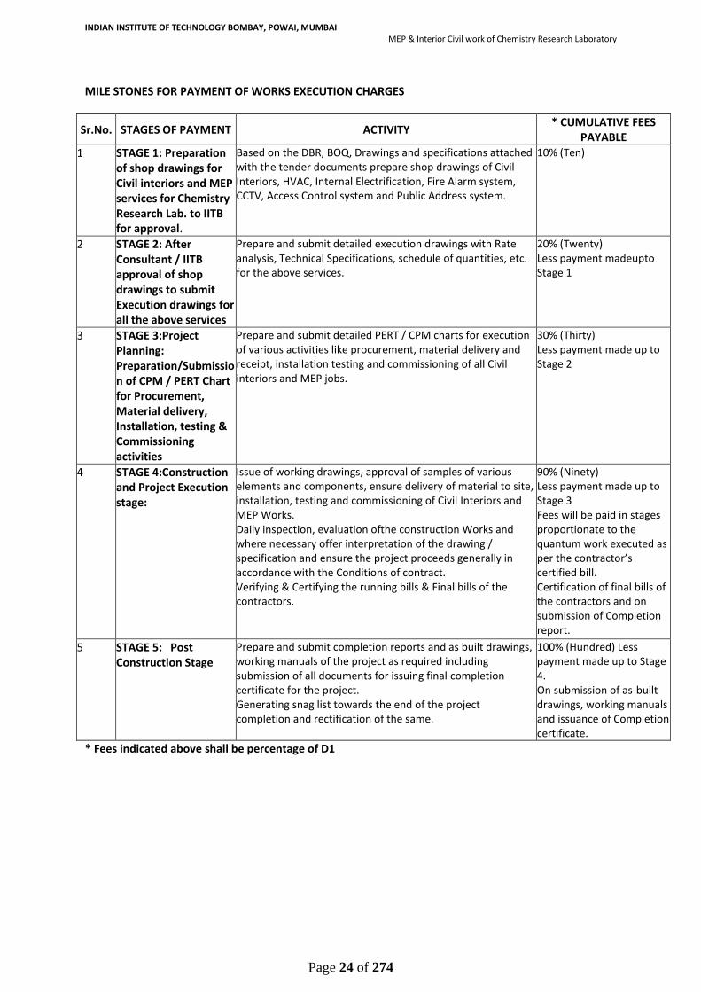
MILE STONES FOR PAYMENT OF WORKS EXECUTION CHARGES
Sr.No. STAGES OF PAYMENT ACTIVITY * CUMULATIVE FEES
PAYABLE
1 STAGE 1: Preparation of shop drawings for Civil interiors and MEP services for Chemistry Research Lab. to IITB for approval.
Based on the DBR, BOQ, Drawings and specifications attached with the tender documents prepare shop drawings of Civil Interiors, HVAC, Internal Electrification, Fire Alarm system, CCTV, Access Control system and Public Address system.
10% (Ten)
2 STAGE 2: After Consultant / IITB approval of shop drawings to submit Execution drawings for all the above services
Prepare and submit detailed execution drawings with Rate analysis, Technical Specifications, schedule of quantities, etc. for the above services.
20% (Twenty) Less payment madeupto Stage 1
3 STAGE 3:Project Planning: Preparation/Submission of CPM / PERT Chart for Procurement, Material delivery, Installation, testing & Commissioning activities
Prepare and submit detailed PERT / CPM charts for execution of various activities like procurement, material delivery and receipt, installation testing and commissioning of all Civil interiors and MEP jobs.
30% (Thirty) Less payment made up to Stage 2
4 STAGE 4:Construction and Project Execution stage:
Issue of working drawings, approval of samples of various elements and components, ensure delivery of material to site, installation, testing and commissioning of Civil Interiors and MEP Works. Daily inspection, evaluation ofthe construction Works and where necessary offer interpretation of the drawing / specification and ensure the project proceeds generally in accordance with the Conditions of contract. Verifying & Certifying the running bills & Final bills of the contractors.
90% (Ninety) Less payment made up to Stage 3 Fees will be paid in stages proportionate to the quantum work executed as per the contractor’s certified bill. Certification of final bills of the contractors and on submission of Completion report.
5 STAGE 5: Post Construction Stage
Prepare and submit completion reports and as built drawings, working manuals of the project as required including submission of all documents for issuing final completion certificate for the project. Generating snag list towards the end of the project completion and rectification of the same.
100% (Hundred) Less payment made up to Stage 4. On submission of as-built drawings, working manuals and issuance of Completion certificate.
* Fees indicated above shall be percentage of D1

INDIAN INSTITUTE OF TECHNOLOGY BOMBAY, POWAI, MUMBAI
MEP & Interior Civil work of Chemistry Research Laboratory
Page 25 of 274
SECTION – 2: FORM OF WORKS CONTRACT (DRAFT)
THIS CONTRACT (hereinafter called the "Contract") is made the _______ day of the month of _________
Two Thousand ____ between, on the one hand, The President of India (hereinafter called the "IITB",
which expression shall include his successors and permitted assigns) acting through his duly authorized
representative, Dean (IPS) IITB, Indian Institute of Technology (Bombay), Powai, Mumbai and, on the
other hand, M/s. _____________, having its Registered Office at _________________(hereinafter called
the "Successful bidder" which expression shall, unless repugnant to the context, be deemed to include its
successors and assigns).
[Note: if the Successful bidders consist of more than one entity, the above should be partially amended to
read as follows:
“… and, on the other hand, a joint venture consisting of the following entities, each of which will be jointly
and severally liable to the IITB for all the Successful bidders’ obligations under this Contract, namely
__________ and __________ (hereinafter called the "Successful bidders"…)].
WHEREAS
(A)the IITB has requested the Successful bidder to provide certain services as defined in the
Technical Proposal attached to this Contract (hereinafter called the "Services");
(B) the Successful bidder, having represented to the IITB that they have the required professional
skills, personnel and technical resources, have agreed to provide the Services on the terms and conditions
set forth in this Contract;
NOW THEREFORE the parties hereto agree as follows:
1. The following documents attached hereto shall be deemed to form an integral part of this RFP and proposal from the Bidder : Technical Bid:
(a) the General Conditions of Contract (hereinafter called “GCC”); (b) the following Appendices:
Appendix A: Description of the Services Appendix B: Deliverables by the Successful bidder Appendix C: BOQ for Civil Interior & MEP Works Appendix D: Drawings for Civil Interior & MEP Works
Financial Bid: (a) Financial Bid (b) Milestones of Deliverables for Payment. (c) Details of reimbursable expenses
1. The mutual rights and obligations of the IITB and the Successful bidder shall be as set forth in the Contract; in particular:
(a) the Successful bidder shall carry out the Services in accordance with the provisions of the Contract; and (b) the IITB shall make payments to the Successful bidder in accordance with the provisions of the Contract.

INDIAN INSTITUTE OF TECHNOLOGY BOMBAY, POWAI, MUMBAI
MEP & Interior Civil work of Chemistry Research Laboratory
Page 26 of 274
IN WITNESS WHEREOF, the Parties hereto have caused this Contract to be signed in their respective names
as of the day and year first above written.
Dean (IPS)
FOR AND ON BEHALF OF IITB
(Director)
In presence of Witness: 1.
2.
FOR AND ON BEHALF OF
[SUCCESSFUL BIDDER]
_______________________ (Authorised Representative) In presence of Witness: 1. 2. [Note: If the Successful bidders consist of more than one entity, all of these entities should appear as signatories, e.g. in the following manner]:
FOR & ON BEHALF OF EACH OF THE MEMBERS OF THE SUCCESSFUL BIDDERS
[Name of the Member]
Authorised Representative) [Name of the Member]

INDIAN INSTITUTE OF TECHNOLOGY BOMBAY, POWAI, MUMBAI
MEP & Interior Civil work of Chemistry Research Laboratory
Page 27 of 274
SECTION – 3: Eligibility Criteria 1. Bidders who fulfil the following requirements shall be eligible to apply. Joint ventures and
Special Purpose Vehicles are not accepted. (a) Should have satisfactorily completed the Works as mentioned below during
the last Five Years ending previous day of last date of submission of tenders.
Three similar Works each costing not less than that Rs.2.00 Cr
OR
Two similar Works each costing not less than that Rs.2.40 Cr
OR
One similar work costing not less than that Rs.2.80 Cr
Similar work means: - “Procurement, Supply, Installation, Testing & Commissioning of MEP and Civil Interiors Works and Allied Equipment of any Chemistry Laboratory, Pharmaceutical Laboratory, Bio-Science or Bio-Medical Laboratory or equivalent.” under single agreement. (a) Client's Experience Details. Bidder should have good execution capabilities of executing
Trunkey project having VAV exhaust systems, Lab furniture, Civil interiors, Electrical,
HVAC, Fire alarm and security systems, LAN etc. The bidder should furnish work
completion certificate from any government/ semi-government institution of a single
contract for turnkey project execution worth Rs. 2.80 crore or two projects of 2.40 crore
each or three projects each costing not less than Rs. 2.00 Curding last five years. Form C
(copy to be enclosed.
(b) The value of executed Works shall be brought to current costing level by enhancing the
actual value of work at simple rate of 7% per annum (without compounding) calculated
from the date of completion to previous day of last date of submission of tenders.
(c) The bidder Should have an average annual financial turnover of Rs. 2.80 Cr on MEP and
Civil Interiors Works and Allied Equipment during the last five years ending 31st March,
2021. (Scanned copy of Certificate from Charted Accountant to be uploaded).
(d) Should not have incurred any loss (profit after tax should be positive) in more than two
years during the last five consecutive years ending 31st March, 2021, duly certified and
audited by the chartered accountant. (The balance sheet in case of Pvt./ Public Ltd.
Company means its standalone finance statement and consolidated financial statement
both).
(e) Should have Bank Solvency Certificate (Form ‘B’) of Rs. 1.20 Cr. (Scanned copy of
Certificate to be uploaded).
(f) The Bidder should have existence of firm for a minimum period of ten years as per The Indian Companies Act, 2013

INDIAN INSTITUTE OF TECHNOLOGY BOMBAY, POWAI, MUMBAI
MEP & Interior Civil work of Chemistry Research Laboratory
Page 28 of 274
(g) Key staff membership Certificate: The bidder/parent company should possess the key
professional staff, at least one, in his organization with good knowledge of codes and standards like SEFA (Scientific Equipment and Furniture Association), OSHA (Occupational Health and Safety Management System), ASHRAE (American Society of Heating, Refrigerating, and Air-Conditioning Engineers) and NFPA 45.
(h) The bidder should not have been barred/blacklisted by the Central Government/State
Government, or any entity controlled by it, from participating in any tender, and the bar
subsists as on the Bid Due Date, such bidder would not be eligible to submit the BID. The
Bidder should upload affidavit for NON – BLACK LISTING in Form F.
(i) At the time of uploading of bid, the bidder shall have also to upload Scanned copy of an
affidavit as under: “I/We undertake and confirm that eligible similar Works(s) has/have
not been got executed through another contractor on back to back basis. Further that,
if such a violation comes to the notice of Department, then I/we shall be debarred for
bidding in IITB, Mumbai in future forever. Also, if such a violation comes to the notice
of Department before date of start of work, the Engineer in-Charge shall be free to
forfeit the entire amount of “Earnest Money Deposit/Performance Guarantee.”
2.a. Earnest Money of Rs. 4,24,547/- in the form of Treasury Challan or Demand Draft or Pay
order or Banker`s Cheque or Deposit at Call Receipt or Fixed Deposit Receipt drawn in favour
of The Registrar, IITB, Powai, Mumbai – 400076 shall be scanned and uploaded to the
tendering website within the period of bid submission. The original EMD should be deposited
either in the office of Dean (IPS), Main Bldg., IITB, Powai, Mumbai – 400076 within the period
of bid submission. The EMD receiving Officer of IITB shall issue a receipt of deposition of
earnest money deposit to the bidder in a prescribed format Annexure –2(enclosed) uploaded
by tender inviting authority in the NIT.
A part of earnest money is acceptable in the form of bank guarantee also. In such case,
minimum 50% of earnest money or Rs. 20 lakh, whichever is less, shall have to be deposited
in shape prescribed above, and balance may be deposited in shape of Bank Guarantee of any
scheduled bank having validity for 6 months or more from the last date of receipt of bids
which is to be scanned and uploaded by the intending bidders. Earnest money deposit
declaration shall also be uploaded to the Tendering website within the period of bid
submission.
Online bid documents submitted by intending bidders shall be opened only of those bidders,
whose original EMD deposited with IIT Bombay and other documents scanned and uploaded
are found in order.
The MSME firms registered in NSIC under PP policy are exempted from payment of EMD for
supply of goods and services only, as per GOI norms. Bidder availing exemption for Earnest

INDIAN INSTITUTE OF TECHNOLOGY BOMBAY, POWAI, MUMBAI
MEP & Interior Civil work of Chemistry Research Laboratory
Page 29 of 274
Money Deposit (EMD) against MSME/NSIC certificate will have to submit Performance
Security Deposit in the form of Demand Draft (mandatory).
2 b. The contractor whose bid is accepted, will be required to furnish Performance Guarantee of 5% (Five Percent) of the bid amount within 15 days from the date of issue of letter of acceptance
This guarantee shall be in the form of cash (in case guarantee amount is less than Rs. 10000/) or Deposit at Call receipt of any scheduled bank/Banker’s cheque of any scheduled bank/ Demand Draft of any scheduled bank/Pay order of any Scheduled Bank (in case guarantee amount is less than Rs. 1,00,000/-) or Government Securities or Fixed Deposit Receipts or Guarantee Bonds of any Scheduled Bank or the State Bank of India in accordance with the prescribed form in favour of Director, IIT Bombay, Powai, Mumbai. In case the contractor fails to deposit the said Performance Guarantee within the specified period in mentioned in 2 b, including the extended period if any, the Earnest Money deposited by the contractor shall be forfeited automatically without any notice to the contractor. The Earnest Money deposited along with the tender shall be returned after receiving the aforesaid performance guarantee.
The bid submitted shall become invalid if:
I. The bidder is found ineligible.
II. The bidder does not deposit original EMD with IIT Bombay.
III. The bidder does not upload scanned copy of all the documents stipulated in bid
documents.
IV. If any discrepancy is noticed between the documents as uploaded at the time of
submission of bid and hard copies as submitted physically / by Registered Post by the
bidder in the office of bid opening authority.
V. If a tenderer quotes nil rate against each item in item rate tender or does not quote
any percentage above/ below on the total amount of the tender or any section / sub
head in percentage rate tender, the tender shall be treated as invalid and will not be
considered lowest tender.

INDIAN INSTITUTE OF TECHNOLOGY BOMBAY, POWAI, MUMBAI
MEP & Interior Civil work of Chemistry Research Laboratory
Page 30 of 274
3 List of Documents to be scanned and uploaded within the period of bid submission:
i) Certificate of Registration for GST.
If the bidder has not obtained GST registration as applicable, then in such case the bidder shall upload following undertaking with the bid document “If work is awarded to me, I/We shall obtain GST registration certificate as applicable within one month from date of receipt of award letter or before release of any payment by IITB, whichever is earlier, failing which I /We shall be responsible for any delay in payments which will be due towards me/us on a/c of work executed and or any action taken by IITB or GST department in this regard.”
ii) Signed copy of Letter of transmittal.
iii) Certificates of Financial Turnover from Chartered Accountant in Form A.
iv) Bank Solvency Certificate in Form B.
v) List of eligible similar nature of works completed in Form-C. (If private works are shown
in support of eligibility, certified copy of the tax deducted at source certificate (TDS)
shall be submitted along with the experience certificate and the TDS amount shall tally
with the actual amount of work done)
vi) Performance Report of works (referred to in Form-C) in Form-D.
vii) Structure &Organization in Form E.
viii) Affidavit for “Proforma Of Affidavit for Non - Black Listing” in Form F.
ix) Affidavit for non-execution of works on back to back basis in Annexure -1.
x) Copy of receipt of deposition of original Earnest Money Deposit issued from IITB in
Annexure 2. The EMD should be made in favour of The Registrar, Indian Institute of
Technology Bombay and sealed in a separate envelope. The name of the project should be
written on the EMD envelope.
DEAN(IPS)
IITB, Mumbai - 400076

INDIAN INSTITUTE OF TECHNOLOGY BOMBAY, POWAI, MUMBAI
MEP & Interior Civil work of Chemistry Research Laboratory
Page 31 of 274
4. INFORMATION REGARDING ELIGIBILITY
LETTER OF TRANSMITTAL
From:-
To: Dean (IPS)
IITB, Mumbai – 400076 Sub: Submission of bids for the works of “MEP & Interior Civil Works of Chemistry Research
Laboratory in DESE/CESE building of Indian Institute of Technology Bombay, Powai,
Mumbai - 400076 including Civil Interiors works, Internal Electrical Installation & cable
laying, Fire fighting system, Automatic Fire Alarm & PA System, HVAC and Access
Control Works, at IIT Bombay, Powai, Mumbai
Sir, Having examined the details given in the bid document for the above work, I/we
hereby submit the relevant information.
1.I/We hereby certify that all the statements made and information supplied in the enclosed Forms from FORM-A to F and accompanying statement are true and correct.
2. I/we have furnished all information and details necessary for eligibility and have no further pertinent information to supply.
3. I / We, submit the requisite certified solvency certificate and authorize the Dean IPS to approach the Bank issuing the solvency certificate to confirm the correctness thereof. I/We, also authorize Dean IPS to approach individuals, employers, firms and corporation to verify our competence and general reputation.
4. I/we submit the following certificates in support of our suitability, technical knowledge and capability for having successfully completed the following eligible similar works:
Name of Work:
Certificate from
It is certified that the information given in the enclosed eligibility bid are correct. It is also certified that I / We shall be liable to be debarred, disqualified / cancellation of enlistment in case any information furnished by me / us is found to be incorrect.
Enclosures: Seal of bidder Date of submission: Signature(s) of Bidder(s).

INDIAN INSTITUTE OF TECHNOLOGY BOMBAY, POWAI, MUMBAI
MEP & Interior Civil work of Chemistry Research Laboratory
Page 32 of 274
FORM-“A”
FINANCIAL INFORMATION
Name of the firm / Bidder……………………………….:
1. Financial Analysis-Details to be furnished duly supported by figures in balance sheet / profit & loss account for the last five financial years duly certified and audited by the Chartered Accountants, as submitted by the applicant to the Income Tax Department (Copies to be attached).
(Figures in Lakhs Rs.)
Year 2016-17 2017-18 2018-19 2019-20 2020-21
Gross Annual Turnover on Construction works
Profit/loss (standalone finance statement and consolidated financial statement both)
SIGNATURE (S) OF BIDDER (S) Signature of Chartered Accountant with Seal

INDIAN INSTITUTE OF TECHNOLOGY BOMBAY, POWAI, MUMBAI
MEP & Interior Civil work of Chemistry Research Laboratory
Page 33 of 274
FORM "B"
BANKERS' CERTIFICATE FROM A SCHEDULED BANK
(Not more than three months old)
This is to certify that to the best of our knowledge and information that M/s./ Sh…………....................................................................... having marginally noted address, as a Customer of our bank are/is respectable and can be treated as good for any engagement up to a limit of Rs................ (Rupees………………………………………………………)
This certificate is issued without any guarantee or responsibility on the bank or any of the officers.
(Signature) For the Bank
NOTE
1. Bankers Certificates should be on letter head of the Bank, addressed to tendering authority.
2. In case of Partnership firm, certificate should include names of all partners as recorded with the Bank.

INDIAN INSTITUTE OF TECHNOLOGY BOMBAY, POWAI, MUMBAI
MEP & Interior Civil work of Chemistry Research Laboratory
Page 34 of 274
FORM “C” DETAILS OF ELIGIBLE SIMILAR NATURE OF WORKS COMPLETED DURING THE LAST SEVEN YEARS ENDING PREVIOUS DAY OF LAST DATE OF SUBMISSION OF TENDERS
Sl. No
Name of
work / Project
and Locatio
n
Owner or
sponsoring
Organization
Cost of work
in crores
of rupees
Date of commencement as per
contract
Stipulated date of completi
on
Actual
date of
completio
n
Litigation/
arbitration
cases pending / in
progress with
details*
Name and
address/ telephone no of
officer to whom
reference may be made
Whether
the work was
done on back to back
basis Yes/ No
1 2 3 4 5 6 7 8 9 10
*Indicate gross Amount Claimed and Amount Awarded by the Arbitrator.
SIGNATURE (S) OF BIDDER (S)

INDIAN INSTITUTE OF TECHNOLOGY BOMBAY, POWAI, MUMBAI
MEP & Interior Civil work of Chemistry Research Laboratory
Page 35 of 274
FORM “D”
PERFORMANCE REPORT OF WORKS REFERRED TO IN FORM ‘C’
1. Name of Work / Project and Location:
2. Agreement No.
3. Estimated Cost:
4. Tendered Cost:
5. Date of start:
6. Date of completion
(a) Stipulated date of completion:
(b) Actual date of completion:
7. Total cost of completed as per Final Bill (Rs.):
8. Amount of compensation levied for delayed Completion, if any
a) Whether case of levy of compensation for delay has been decided or not ? : Yes /No
b) If decided, amount of compensation levied for delayed completion, if any.
9. Amount of reduced rate items, if any:
10. Performance Report:
(i) Quality of Work : Outstanding/Very Good/Good /Poor
(ii) Financial Soundness : Outstanding/Very Good/Good /Poor
(iii) Technical Proficiency : Outstanding/Very Good/Good /Poor
(iv) Resource fullness : Outstanding/Very Good/Good /Poor
(v) General behaviour : Outstanding/Very Good/Good/Poor
Dated: Executive Engineer or Equivalent

INDIAN INSTITUTE OF TECHNOLOGY BOMBAY, POWAI, MUMBAI
MEP & Interior Civil work of Chemistry Research Laboratory
Page 36 of 274
FORM ‘E’
STRUCTURE AND ORGANISATION
1. Name & Address of the bidder
2. Telephone No. / Email id /Mobile No./Fax No.
3. Legal status of the bidder
(attach copies of original document defining the legal status).
a) An Individual
b) A proprietary firm
c) A firm in partnership
d) A limited company or Corporation
4. Particulars of registration with various Government bodies (attach attested photo-copy).
ORGANIZATION/PLACE OF REGISTRATION REGISTRATION No.
1.
2.
3.
5. Names and Titles of Directors & Officers with designation to be
concerned with this work.
6. Designation of individuals authorized to act for the organization.
7. Has the bidder or any constituent partner in case of partnership
firm limited company or Corporation ever abandoned the awarded
work before its completion? If so, give name of the project and
reasons for abandonment.
8. Has the bidder, or any constituent partner in case of partnership
firm/ limited company or corporation ever been convicted by the
court of law? If so, give details.
9. In which field of Engineering Projects & Construction, the bidder
has specialization and interest?
10. Any other information considered necessary but not included
above.

INDIAN INSTITUTE OF TECHNOLOGY BOMBAY, POWAI, MUMBAI
MEP & Interior Civil work of Chemistry Research Laboratory
Page 37 of 274
FORM-“F”
PROFORMA OF AFFIDAVIT FOR NON - BLACK LISTING
(On Rs.100 Stamp Paper)
I/we undertake and confirm that our firm/partnership firm has not been blacklisted
by any state/Central Departments/PSUs/Autonomous bodies during the last 7 years of its
operations. Further that, if such information comes to the notice of the department then I/we
shall be debarred for bidding in IITB in future forever. Also, if such information comes to the
notice of department on any day before date of start of work, the Engineer-in charge shall be
free to cancel the agreement and to forfeit the entire amount of Earnest Money
Deposit/Performance Guarantee (Scanned copy of this notarized affidavit to be uploaded at
the time of submission of bid)
Signature of Bidder(s) or an authorized
Officer of the firm with stamp
Signature of Notary with seal

INDIAN INSTITUTE OF TECHNOLOGY BOMBAY, POWAI, MUMBAI
MEP & Interior Civil work of Chemistry Research Laboratory
Page 38 of 274
Annexure-1
AFFIDAVIT FOR NON-EXECUTION OF WORKS ON BACK TO BACK BASIS
Name of Work: “MEP & Interior Civil Works of Chemistry Research Laboratory in DESE/CESE
building of Indian Institute of Technology Bombay, Powai, Mumbai - 400076 including Civil
Interiors works, Internal Electrical Installation & cable laying, Firefighting system, Automatic
Fire Alarm & PA System, HVAC and Access Control Works, at IIT Bombay, Powai, Mumbai.
I/We undertake and confirm that eligible similar work(s) has / have not been got executed
through another contractor on back to back basis. Further that, if such a violation comes to
the notice of Department, then I/we shall be debarred for bidding in IITB or if it is found that
any information has been concealed, then I / we shall be debarred for tendering in IITB in
future forever. Also, if such a violation comes to the notice of Department before date of start
of work, the Engineer-in-Charge shall be free to forfeit the entire amount of Earnest Money
Deposit/Performance Guarantee.
Date:
Place:
Signature of Bidder (s) or an authorized
Officer of the firm with stamp & seal
Signature of Notary with seal

INDIAN INSTITUTE OF TECHNOLOGY BOMBAY, POWAI, MUMBAI
MEP & Interior Civil work of Chemistry Research Laboratory
Page 39 of 274
Annexure-2
Receipt for deposition of Original EMD (Receipt No………………………………….. / date……………………………….)
NAME OF WORK: “MEP & Interior Civil Works of Chemistry Research Laboratory in DESE/CESE
building of Indian Institute of Technology Bombay, Powai, Mumbai - 400076 including Civil
Interiors works, Internal Electrical Installation & cable laying, Fire fighting system, Automatic
Fire Alarm & PA System, HVAC and Access Control Works, at IIT Bombay, Powai, Mumbai.
NIT NO.IIT(B)/Dean (IPS)/Chemistry Research Lab/DESE-CESE/Tender/2022/01
Dated: 20.06.2022
1. Estimated Cost Rs.2,12,27,336/- 2. Amount of Earnest Money Deposit Rs. 4,24,547/- 3. Last date of submission of bid 19-07-2022 up to 15.00 hours
1. Name of Contractor……………………………………………………………. #
2. Form of EMD…………………………………………………………………… #
3. Amount of EMD Deposit………………………………………………………..#
4. Date of submission of EMD…………………………………………………….. #
Signature of EMD receiving Officer
Name & Designation
Office Stamp
Note: EMD shall be in favour of the registrar, IIT Bombay, Powai, Mumbai- 400076
# To be filled in by EMD Receiving Officer

INDIAN INSTITUTE OF TECHNOLOGY BOMBAY, POWAI, MUMBAI
MEP & Interior Civil work of Chemistry Research Laboratory
Page 40 of 274
SECTION – 4: Appendix A: DESCRIPTION OF THE SERVICES 1. SCOPE OF WORKS 1. The scope of the work includes MEP & Civil Interior Works of Chemistry Research Laboratory in DESE /
CESE Building of IIT Bombay admeasuring=3000sq. ft (approx.) within IITB campus Powai, Mumbai
4000076.
The scope of Works shall be as follows:
A. Preparing shop drawings for Civil interiors and MEP services for Chemistry Research Lab in DESE / CESE bldg. for submission to IITB.
B. After Consultant / IITB approval of shop drawings to submit Execution drawings for all the above services.
C. Project Planning including Preparation /Submission of CPM / PERT Schedule for Procurement, Material
delivery, Installation, testing & Commissioning activities
D. Construction and Project Execution stage: Receipt of Material at site, Installation, Testing and Commissioning of the above mentioned services. Inspection of work during execution. Exercising strict control over material and work quality, estimated
quantities for variation and justification for additional expenditure if any.
E. Post Construction Stage:
a) Checking of `As built` drawings and issuance of Final Statutory Clearance & Certificate.
b) Generating snag list towards end of the Project completion.
2. Providing complete and adequate daily supervision to all the Works such as civil, electrical, HVAC
installation of services etc. and the degree of such supervision commensurate with the nature and
magnitude of Works.
3. Periodically coordinating with IITB and PMC appointed for the job for project execution till completion.
4. Get the Issuance of certificate of virtual completion of Works from PMC after getting the entire work
approved by the Institute.
5. Prompt rectification of any defects in the work pointed out by PMC or IITB, during the construction and
defect liability periods.
6. The Successful bidder shall appoint services vendor or technical consultant, if felt necessary, at no Extra
cost to the IITB, for the services like Public Health Works, Sanitary and Plumbing Works, Electrical Works,
etc., as may be required including periodic site visits or as required to supervise site Works to enable the
project to be completed in a satisfactory manner within the cost and time frame stipulated.
7. The Successful bidder agrees to perform his duties under these Presents promptly and diligently and to
do everything in his power and authority to ensure the completion of the installation work as may be
entrusted to them, according to the proper quality, specification and schedule of time given to them and

INDIAN INSTITUTE OF TECHNOLOGY BOMBAY, POWAI, MUMBAI
MEP & Interior Civil work of Chemistry Research Laboratory
Page 41 of 274
that no unnecessary delay is caused by reason of the Successful bidder’s not furnishing decisions, details
in regard to designs etc. to the Contractor, provided that such delay is not caused by the IITB.
FACILITIES TO BE CONSIDERED:
CHEMISTRY RESEARCH LABORATORY
The MEP & Civil Interiors Works of Chemistry Research Laboratory in DESE/CESE building of
Indian Institute of Technology Bombay, Powai, Mumbai - 400076 will be based on the Design
as given vide BOQ, Specifications and Drawings with necessary modification / changes or
revisions in the design as required by IITB
SN Description Total Carpet Area Sq. ft.
1 Chemistry Research Laboratory 3000 (approx.)
Note: 1. This area is located on the Ground floor
Time for completion: 09 Months

INDIAN INSTITUTE OF TECHNOLOGY BOMBAY, POWAI, MUMBAI
MEP & Interior Civil work of Chemistry Research Laboratory
Page 42 of 274
DETAILED SCOPE OF WORK:
The detailed scope of work shall include and not be limited to the following.
The scope of work includes Supply, Installation, Testing and Commissioning of Civil Interiors,
Internal Electrification, HVAC system, Fire Fighting system, Fire Alarm system, CCTV, Public
Address system, Access Control system for the Chemistry Research Laboratory in DESE / CESE
building. It includes providing of all facilities like power supply distribution, lighting, Air-
conditioning, interior architecture and ELV systems. Preparation and submission of shop
drawings, execution drawings, procurement and receipt of materials, installation, testing and
commissioning of these services are an integral part of the scope of work.
The Successful bidder is required to provide services in respect of the following: Civil Interiors.
Preparation of civil interiors shop drawings for Chemistry Research Lab at ground floor of DESE / CESE
building. It includes preparation of various floor plans, sections, elevations etc. Preparation of execution
drawings by incorporating revisions and comments offered by the IITB on shop drawings. Executing civil
interiors based on the approved drawings. Coordinating with IITB equipment vendors for hassle free job.
Electrical & ELV System
Submitting shop drawings for providing associated electrification system, cablings, power supply network,
preparation of conduit layouts and circuits for individual rooms etc. Similarly shop drawings to be also
provided for other ELV services like Fire Alarm system, Access control system, CCTV, Public address system
and Fire Fighting system. The entire work of supply, Installation, testing and commissioning shall be
executed as per latest IS code provisions and as per recommended Manufacturers.
HVAC Works
The job will include preparation of shop drawings of Ducts of given sizes, layout and routing, submission
and approval of TDS of AHUs and their supply as per the approved data sheet, fabrication and supply of
ducts, grilles, dampers etc. as per the execution drawings. Installation, testing and commissioning of the
system as per the latest ASHRAE, SMACNA, AHRI and relevant IS standards.
STAGES OF WORK:
A) Preparing Drawings: Prepare shop drawings based on inputs and comments from IITB and finalizing the
schedule of quantities for Civil, Electrical, ELV and HVAC. All drawings shall be as per IS and relevant code,
covering aspects like mode of measurement, quality control procedures and other conditions of contract.
B) After Consultant / IITB approval of shop drawings, to submit Execution drawings for all the above
services, taking all site conditions into consideration, any modification required based on comments
received for the shop drawings and following IS codes for the same.

INDIAN INSTITUTE OF TECHNOLOGY BOMBAY, POWAI, MUMBAI
MEP & Interior Civil work of Chemistry Research Laboratory
Page 43 of 274
C) Project Planning including Preparation /Submission of CPM / PERT Schedule for Procurement, Material
delivery, Installation, testing & Commissioning activities. To ensure proper and timely delivery of material
and their receipt at site. Ensure the material received is as per the final execution drawings. Issue working
drawings and details for proper execution of Works during installation. (so as to avoid future litigation
pertaining to non-availability of drawings / documents. It needs to be checked by authorized technical
bodies from client side prior to issue execution drawings to site).
D) Construction and Project Execution stage: Receipt of Material at site, Installation, Testing and
Commissioning of the above-mentioned services. Inspection of work on daily basis to ensure that the work
at site proceeds in accordance with the contract documents/ drawings. Exercising strict control over
material and work quality as well as on estimated quantities for variation and justification for additional
expenditure if any. To evaluate the installation Works and wherever necessary issue clarifications and
decisions to exercise time and quality controls. Verification & Certification of Interim and Final Bills in co-
ordination with and after taking Joint measurements with Contractor’s Supervisor and Engineer-In-Charge.
Issuing Certificate of Virtual Completion of Works.
E) Post Construction stage: Completion Stage:
a) Submission of `As built` drawings and Issuing final Clearance/Completion certificates.
b) Generating snag list and attending to it for rectification towards the end of the project completion and
handover.

INDIAN INSTITUTE OF TECHNOLOGY BOMBAY, POWAI, MUMBAI
MEP & Interior Civil work of Chemistry Research Laboratory
Page 44 of 274
SECTION – 4: Appendix B: DELIVERABLES BY THE SUCCESSFUL BIDDER For all Works the Successful bidder shall submit preliminary drawings for review by the
apartment, incorporate the comments, provide drawings/ details, provide execution and
fabrication drawings, final BOQ, TDS for all equipment etc. Design calculations / details are
also to be submitted with the drawings for review and approval.
A) Following table indicates the number of prints of drawings and tracings / dialers reports
/ design calculations required at each stage.
DELIVERABLES
(Civil Interiors & MEP Works at Chemistry
Research Lab. in DESE / CESE building)
No. of
prints/ hard
copies
Tracing/ Dialer/
soft copy
Requirement*
Frequency
STAGE 1: Preparation of shop drawings for Civil
interiors and MEP services for Chemistry Research
Lab in DESE/CESE bldg. for submission to IITB for
approval.
3
Soft copy
Stage 1 - Within 01(One)
Month from the date of
issue of work order
STAGE 2 : After Consultant / IITB approval of shop
drawings to submit Execution drawings for all the
above services
3
Soft copy
STAGE 2 - Within 02 (Two) Weeks ofapproval of Stage 1
STAGE 3 : Project Planning :
Preparation/Submission of CPM / PERT Chart for
Procurement, Material delivery, Installation,
testing & Commissioning activities
3
soft copy
Stage 3-Within 01(One) week
of Approval by IITB for Stage 2.
STAGE 4 : Construction and Project execution
stage:
a) Construction drawings for commencement
b) Construction drawings for site use based on
approval of vendor shop drwgs
c) Construction drawings site use –Revisions
5
5
5
Softcopy of all
Stage 4- Within 01 (One) week
of Approval by IITB for Stage 2.
To also include
Stage 3 in this period
STAGE 5 Post Construction
Stage: i) Submission of checked
“As-built” drwgs
ii)Submission of snag list post completion
8
3
Soft copy of all
Stage 5–Within 01(One)week
after Approval by IITB for
Stage 4.
* Please provide soft copies of all the drawings and documentation

INDIAN INSTITUTE OF TECHNOLOGY BOMBAY, POWAI, MUMBAI
MEP & Interior Civil work of Chemistry Research Laboratory
Page 45 of 274
1. Persons to receive them & review requirements: Dean (IPS) or his authorized persons to
receive & Review the Requirements.
2. All drawings /documents specified are included in the cost of Fees payable and actual cost
of extra copies shall be reimbursable.

INDIAN INSTITUTE OF TECHNOLOGY BOMBAY, POWAI, MUMBAI
MEP & Interior Civil work of Chemistry Research Laboratory
Page 46 of 274
SECTION – 4: Appendix C: Technical Specifications & Makes for Civil Interior & MEP Works
SR. NO. CONTENTS PAGE NO.
01 LT Switchgears & Distribution Boards 49 to 54
02 Cables & Cable Trays 54 to 60
03 Wiring System 60 to 72
04 Light Fixtures 72 to 75
05 Earthing 75 to 76
06 List of Makes for Electrical 77 to 78

INDIAN INSTITUTE OF TECHNOLOGY BOMBAY, POWAI, MUMBAI
MEP & Interior Civil work of Chemistry Research Laboratory
Page 47 of 274
TECHNICAL SPECIFICATIONS FOR INTERNAL ELECTRIFICATION 1.0 LT SWITCHGEARS & DISTRIBUTION BOARDS: 1.1 SCOPE: This section shall cover supply, assembly, installation, connection, testing and commissioning of medium voltage cubicle type MV Switchgear and Distribution boards as described in these specifications, drawings and schedule of quantities. The distribution boards are designated as: Main Distribution Boards Sub Main Distribution Boards. The unit rate per item shall include design supply, assembly, installation, connection, testing and commissioning of MV Assembly Distribution boards, with all the components in place, internal wiring, as specified in this specification, and shown on the drawing, and load schedule complete with supply and fixing of M.S. channel/ angle iron support on wall/floor etc. In case of switchgears and panels issued by owner for erection the unit rate shall include inspection, receiving, storage, installation, field testing and commissioning activities including co‐ ordination with the suppliers of the switchgears. The rate shall be quoted per set of switchgears/panels as identified in the BOQ. The details of design/Constructional features of these switchgears are specified here below. 1.2 GENERAL: 1.2.1 SYSTEM DETAILS: All the Main Panels/Motor control centres Distribution boards, Sub‐Main Distribution boards, shall be suitable for operation on three phase/ single phase, 433/240 volts, 50 Hz neutral solidly grounded at transformer and short circuit level not less than 415 Volts at 50KA / 35 KA or as specified elsewhere. The Distribution boards shall be designed to withstand tropical condition at site, with maximum expected ambient temperature of 45ºC and 100 percent humidity and dusty weather. Enclosure of the switchboard shall have IP 54 protection for Indoor and IP 65 for outdoor unless otherwise stated. 1.2.2 STANDARDS AND CODES: The Distribution boards shall comply with the latest edition of relevant Indian Standards and Indian Electricity Rules and Regulations. The following Indian Standards shall be complied with: IS 1394 L.V. switchgear and control gear Part‐I ‐ 1993 General rules. IS 5578‐85 Guide for marking of insulated conductors. IS 11353‐85 Guide for uniform system of marking & identification of conductors and apparatus terminals. IS 2147‐62 Degree of protection provided by enclosures for low voltage switch gear and control gears. IS 2675‐83 Enclosed distribution fuse boards and cut outs for Voltages not Exceeding 1000V IS 2551‐82 Danger notice plates. IS13947‐1993 Circuit breakers. (Part‐II) IS13947‐1993 Switches, Disconnectors, switch disconnector (Part ‐ III) and fuse Combination units. IS 1818‐72 Alternating current isolators (disconnectors) and earthing switches. IS 8623‐77 Factory built assembles of switchgear and control gear for voltages upto and including 1000
V AC & 1200 V DC. IS 8828 Miniature air break circuit breakers for voltages not exceeding 1000 V. IS 9926 Fuse wires used in rewireable type Electric fuses upto 1100 Volts. IS 2208 HRC fuse links IS 2705 Current Transformers (Part‐ I, II & III) IS 3156 Voltage Transformers (Part‐ I, II & III) IS 1248 Indicating Instruments IS 722 Integrating Instruments IS 13947‐93 Control devices and switching elements. (Part ‐ 5) Section‐1 IS 13947‐93 Contactors and motor starter section 1 (Part‐4) Electromechanical. Section ‐ 1

INDIAN INSTITUTE OF TECHNOLOGY BOMBAY, POWAI, MUMBAI
MEP & Interior Civil work of Chemistry Research Laboratory
Page 48 of 274
Section ‐ 1 IS 3231 Relays IS 375 Marking and arrangement of busbars Indian Electricity Act and Rules. 1.2.3 SHOP DRAWINGS: Prior to fabrication of the Switchgears, Distribution boards, the contractor shall submit for Clients/Consultants approval the shop drawing, and design calculations, indicating type, size, short circuit rating of all the electrical components used, details & schedule of components & model Nos. type, rating etc., busbar size, internal wiring size, Distribution board dimension, colour, mounting detail etc. The contractor shall submit manufacturer's catalogues of the electrical components installed in the distribution. 1.2.4 INSPECTION: At all reasonable times (min 2 weeks prior invitation) during production and prior to transport of the distribution boards to site, the contractor shall arrange and provide all the facilities at their plant for inspection by Client Engineer In charge /Consultant or authorized representative. 1.2.5 TEST CERTIFICATES: Testing of Distribution boards shall be carried out at factory and or at site as specified in Indian Standards in the presence of Clients/Consultants. The test results shall be recorded on prescribed forms. The test certificates for the test carried out at factory / at site shall be submitted in six copies to the Construction manager of client/Consultants for approval. Note: ‐All ACB shall be tested & witnessed by primary & secondary current injection test method accordingly bidder shall comply & witness to Client Engineer Incharge/Consultant. 1.3 CUBICLE TYPE MV SWITCHGEARS & DISTRIBUTION BOARDS: 1.3.1 STRUCTURE: The MV Switchgears panels and Distribution boards shall be sheet steel enclosed cubicle pattern, floor mounted free standing, totally enclosed dead front, compartmentalized multitier formation design. The panels shall be both sides extensible type with provision for bus bar extensions. Generally all Switchgears, Panels, MDB's, SMDB's & DB's shall be of front access only & suitable for top entry of cables unless otherwise specifically specified for bottom entry. All MS. sheet steel used in the construction of Distribution boards shall be 2mm thick and shall be folded and braced as necessary to provide a rigid support for all components. Sheet steel shrouds and partitions shall be of minimum 2 mm thickness. Joints of any kind in sheet steel shall be seam welded, all welding slag grounded off and welding pits wiped smooth with plumber metal. The height of the panels should not be more than 2200 mm. The operating levels shall not be more than1800 mm. The operating level of the lower most cubicle shall not be less than 450 mm. The Panels / Distribution boards shall be totally enclosed, completely dust and vermin proof. Synthetic rubber gaskets (neoprene/DPDM) between all adjacent units and beneath all covers shall be provided to render the joints dust proof. All doors and covers shall be fully gasketed and shall be lockable. Doors shall have concealed hinges. All the doors shall be suitably reinforced by channel to provide rigidity. All panels and covers shall be properly fitted and secured with the frame, and holes in the panel correctly positioned. Fixing screws shall enter into holes tapped into an adequate thickness of metal or provided with bolt and nuts. Self threading screws shall not be used in the construction of the panels/DBs etc. A base channel of 75mm x 40mm x 5mm thick shall be provided at the bottom. A clearance of300mm between the floor of the Panels/ Distribution Board and the bottom of the lower most unit shall be provided. The Panels/ Distribution boards shall be preferably arranged in multitier formation. These shall be of adequate size with a provision of 20 Percent vacant space to accommodate future additional switch gear in addition to spare feeders presently provided. The size of the boards shall be designed in such a way that

INDIAN INSTITUTE OF TECHNOLOGY BOMBAY, POWAI, MUMBAI
MEP & Interior Civil work of Chemistry Research Laboratory
Page 49 of 274
the internal space is sufficient for hot air movement, and the electrical component do not attain temperature rise more than 40 degree Celsius. Knockout holes of appropriate size and number shall be provided in the gland plate of Panels/Distribution board in conformity with the number, and size of incoming and outgoing conduits/cables. Alternatively, the Panels/Distribution boards shall be provided with removable undrilled gland plates (3mm thick). The switch boards shall be designed to facilitate easy inspection, maintenance and repair. The Panels/Distribution boards shall be sufficiently rigid to support the equipment without distortion under normal and short circuit condition. They shall be suitably braced for short circuit duty. Provision shall be made for permanently earthing the frames and other non current carrying parts of the switchgear by two independent earth connections. 1.3.2 PROTECTION CLASS All indoor Panels/Distribution boards shall have degree of protection conforming to class IP 54. While outdoor panels shall be weather proof dust and water tight IP‐65. 1.3.3 METAL TREATMENT & FINISH All sheet steel work used in the construction of switchboard shall undergo a process of degreasing, pickling in acid, cold rinsing, phosphating, passivating in seven tank metal treatment plant and shall be powder coated to the specified shade of IS.5 of approved colour. The total thickness of paint shall not be less than 40 microns. 1.3.4 BUS BARS The Bus bars shall be of three phases separate neutral and earth bar. The busbars, and interconnection between bus bars and various components shall be of high conductivity, high strength aluminium alloy complying with the requirement of grade E91E of IS 5082. The busbar shall be of rectangular cross section designed to withstand full load current for phase busbars and half rated current for neutral busbars unless specified otherwise and shall be extensible on both sides. The bus bar shall be rated for the rating of the main incoming breaker, but in any case, not less than 200 A capacity. The busbar shall have uniform cross section throughout the length. The busbars and interconnections shall be provided with heat resistant and colour coded sleeves. The busbars shall be supported on unbreakable, non-hygroscopic insulated supports of SMC supports at sufficiently close intervals to prevent busbar sag & shall effectively withstand without damage electromagnetic stresses in the event of short circuit. The neutral as well as earth bar shall also be capable of withstanding the fault level. The busbars shall be housed in a separate compartment. The busbar shall be shrouded with 3mmthick transparent sheet to avoid any accidental contact. All busbars connections shall be done by drilling holes in busbars & connecting by chromium plated high tensile MS bolts, spring washer and nuts. Additional cross section of bus bars shall be provided in all Panels/Distribution boards to coverup the holes drilled in the busbars. Spring and flat washers shall be used for tightening the bolts. All connections between busbars and circuit breakers/ switches and between circuit breakers/switches and cable terminals shall be through solid copper strips of proper size to carry full rated current. These strips shall be insulated with insulating heat resistant paint with colour coding. 1.3.5 CIRCUIT COMPARTMENTS Each circuit breaker shall be housed in separate compartments and shall be enclosed on all sides. Sheet steel hinged lockable door shall be duly interlocked with the breaker units in "ON" and "OFF" positions. Safety interlocks shall be provided for air circuit breaker to prevent the breaker from being drawn‐out when the breaker is in "ON" position. The door shall not form an integral part of the draw out position of the circuit breaker. All instruments and indicating lamp shall be mounted on the compartment door. Sheet steel barrier shall be provided between the tiers in a vertical section. 1.3.6 INSTRUMENT COMPARTMENT

INDIAN INSTITUTE OF TECHNOLOGY BOMBAY, POWAI, MUMBAI
MEP & Interior Civil work of Chemistry Research Laboratory
Page 50 of 274
Separate and adequate compartment shall be provided for accommodating instruments, indicating lamps, control contactors/relays, and control Circuit breaker etc., These components shall be accessible for testing and maintenance without any danger of accidental contact with live parts of the circuit breaker units, bus bars and connections. 1.3.7 TERMINALS The outgoing terminals and neutral link shall be brought out to a cable alley suitably located and accessible from the panel front. The current transformers for instruments metering shall be mounted on the terminal blocks. No direct connection of incoming or outgoing cables to internal components of the Panels/Distribution board is permitted, only one conductor may be connected in one terminal. 1.3.8 WIREWAYS A horizontal PVC wire way with screwed covers shall be provided at the top to take interconnecting control wiring between different vertical sections. 1.3.9 CABLE COMPARTMENTS Cable compartments of adequate size shall be provided in the Panels/Distribution Boards for easy termination of all incoming and outgoing cables entering from bottom or top. Adequate supports shall be provided in the cable compartments to support cables. All outgoing and incoming feeder terminals shall be brought out to terminal blocks in the cable compartment. 1.3.10 EARTHING GI earth bars of suitable size but not less than 25 mm x 3 mm shall be provided in the Panels/Distribution Boards for the entire length of the panel. The frame work of the Panels/Distribution board shall be connected to this earth bar. Provision shall be made for connection from this earth bar to the main earthing bar coming from the earth pit on both sides of the Panels/Distribution board and to take tapping to the outgoing earthing strips to connect to the main distribution boards. The earth continuity conductor of each incoming and outgoing feeder shall be connected to this earth bar. The armour shall be properly connected with earthing clamp, and the clamp shall be ultimately bonded with the earth bar. CT earthing also shall be connected to this earth bar. 1.3.11 LABELS Engraved PVC labels shall be provided on all incoming and outgoing feeders. Single line circuit diagram showing the arrangements of circuit inside the Panels/DBs shall be pasted on inside of the panel door and covered with transparent laminated plastic sheet. 1.3.12 INTERNAL COMPONENTS The Panels/ Distribution boards shall be equipped complete with all type of required number of circuit breakers, contactors, relays, MCB’s, meters, instruments, indicating lamps, push buttons, equipment, fittings, busbars, cable boxes, cable glands etc., and all the necessary internal connections /wiring as required and as indicated on relevant drawings. Components necessary for proper complete functioning of the Panels/Distribution boards, but not indicated on the drawings shall be supplied and installed on the distribution boards. All parts of the Panel/Distribution boards carrying current including the components, connections, joints and instruments shall be capable of carrying their specified rated current continuously, without temperature rise exceeding the permissible values as per the relevant specifications at any part of the Panel/Distribution boards. All units of the same rating and specifications shall be fully interchangeable. 1.4 MCB DISTRIBUTION BOARDS: 1.4.1 SCOPE This section relates to specifications for design supply, assembly, installation, connection, testing and commissioning of lighting and power distribution boards (LPDB’s), using Miniature Circuit Breaker (MCB),

INDIAN INSTITUTE OF TECHNOLOGY BOMBAY, POWAI, MUMBAI
MEP & Interior Civil work of Chemistry Research Laboratory
Page 51 of 274
Earth Leakage Circuit breaker (ELCB), Contactor, Neutral link, Earthing terminals, control switch terminals, cubicle of CRCA sheet steel housing and complete the item installation. 1.4.2 SYSTEM The MCB distribution boards shall be suitable for operation on 400/415 volt, 3 phase, 4 wire, 50 Hz A.C. supply system or 230/240 volt, 1 phase, 2 wire, 50 Hz A.C. supply system. 1.4.3 CONSTRUCTION a) The DB's shall be factory made and preferably of those manufacturers whose MCBs, ELCB's are to be used. General arrangement layout of the DB's shall be approved by the Construction manager/Consultant before manufacture. b) The DB shall be metal clad duly fabricated from 2mm (14/16 SWG) thick high quality CRCA sheet. c) The DB shall be cubicle, compartmentalized, wall/floor mounted and dead front operated. d) The DB shall be totally enclosed and made dust, vermin and weather proof such that it meets IP 54 of IS 2147 protection classification for Indoor & IP 65 for outdoor. e) A detachable cover plate of 2mm thick CRCA sheet to be provided on front of the board such that all live parts of the electrical accessories mounted on the board can be accessible only on removal of the said cover plate. Further, the cover plate shall also, have suitable cut out so that dolly of the MCB's can be operated even if the cover plate is in position. A transparent plastic protection cover shall be provided on the cut out portion of the cover plate. The cover plate shall also provide right above the respective cut outs a suitable arrangement to label the electrical circuit details of the MCB's mounted on it as well as to affix a danger plate in legible manner. The cover plate shall be fixed to the board with adequate size zinc passivated machine screws. Above the detachable cover plate, one additional hinged door of 2mm thick CRCA sheet covering the MCB's etc., shall be provided with a suitable locking arrangement. The hinged door shall be provided with a suitable gasket capable of withstanding Corrosive& humid atmosphere and to meet degree of enclosure protection IP 54 as per IS: 2147. The DB's shall undergo the process of painting as described under cubicle type main/submain distribution boards. f) The DB shall have top/bottom entry arrangement for incoming and outgoing cables / /conduits. g) All hardware to be used in manufacture of the DB shall either be of mild steel zinc passivated or otherwise be treated to prevent corrosion due to humid atmosphere. h) All internal electrical connections shall be carried out using 1100 volt grade, PVC insulated, Copper conductor of ISI approved make, having rated current carrying capacity to carry continuous full current of respective switch/MCB rating at operating conditions prevailing at the project site. I) The DB internals shall be earthed with use of copper strips running throughout the length. Size of the earthing strip shall be as shown in the respective drawing. j) The earthing strip shall be brought out on two sides of the DB's with bolted type earth terminating arrangement, for connecting to the building earthing grid. The earth terminal shall be of either brass or zinc passivated mild steel. j) All non current carrying metal surfaces of the DB's shall be adequately treated with Seven tank pre-treatment process to render it free from grease, oil, oxide, dirt, etc., to make them ready to receive and hold coats of zinc chromate primer. l) The DB's shall be provided with electric components and accessories as per the details shown in the drawing/BOQ for the respective electric distribution board. 1.4.4 INSPECTION: a) The DB's shall be inspected and checked as per inspection manual of the DB manufacturer. b) Various electrical components and accessories of the DB's shall be checked as per drawing for the respective DB's. c) The DB's shall be checked for rigid mounting, earthing connection, proper rating & size of components, internal wiring etc. d) All mechanical fasteners and electrical connections shall be checked and tightened before installation.

INDIAN INSTITUTE OF TECHNOLOGY BOMBAY, POWAI, MUMBAI
MEP & Interior Civil work of Chemistry Research Laboratory
Page 52 of 274
1.4.5 INSTALLATION: a) The DB's shall be assembled and aligned together and be installed at site as per installation manual/ instruction of the DB manufacturer. The installation shall conform to relevant Indian Standard specification and requirement of local site conditions. b) The DB shall be installed in surface/concealed manner at the location as shown in the respective drawings. c)All minor electrical and mechanical work required to be attended to on the DB shall be completed in an approved manner after installation but before energizing the DB's. 1.4.6 TEST: Prior to commissioning of the DB's following tests shall be carried out. a) Mechanical endurance test shall be carried out by closing and opening of all the MCB’s, switches etc. b) Insulation resistance test shall be carried out between phases and between phase to earth bus, keeping the isolating switch in open position. Similar test shall be carried out keeping the isolating switch in closed position. c) All the interlocks, controls and tripping mechanisms of the switch gears shall be tested for their proper functioning. d) Each panel shall be provided with a thermostatically controlled space heater of adequate rating and single-phase plug point and cubicle illumination lamp with switch operated at240V AC, 50 Hz. Heaters shall have individual ON‐OFF switches. 1.5 COMPONENTS: 1.5.1 GENERAL The type, size and rating of the components shall be as indicated on the relevant drawings. While selection of the capacity of the components resulting from the prevailing conditions like room temperature shall be allowed for the thermal and magnetic trip rating shall be compensated for the ambient temperature. The ratings indicated on the drawings are ratings anticipated at prevailing site condition. 1.5.2 AIR CIRCUIT BREAKERS: The air circuit breaker shall comply with the requirements of IS: 13947‐2 (1993) and shall have: i) A service short circuit breaking capacity shall be as specified and equal to short circuit withstand values. All short circuit ratings shall be Ics values. ii) A short circuit making capacity of 105 KA. iii) A short time withstand capacity of 50 KA for 1 second. iv) Mechanical and electrical endurance for 2000 operating cycles out of which 100 cycles should be for electrical endurance. v) Electrical overload performance at 6 times the rated current, 110% of the rated voltage as recovery voltage and 0.5 power factor. vi) Dielectric test of 2.5 KV applied for one minute on main circuits. Test evidence from are cognised independent laboratory/institution shall be furnished for compliance of the breakers with the above requirements. vii) Each pole of the ACB's shall be equipped with an inverse time delay thermal over current trip device and an electro magnetic instantaneous over current trip device. The ACB's shall be equipped with under voltage trip relay. The trip devices shall be direct acting. ACB shall be capable of providing short circuit overload and earth fault protection (in absolute values)if required, thru microprocessor-based control unit sensing the true RMS values to ensure accurate measurement meeting the EMI/EMS requirement as per the standard.

INDIAN INSTITUTE OF TECHNOLOGY BOMBAY, POWAI, MUMBAI
MEP & Interior Civil work of Chemistry Research Laboratory
Page 53 of 274
viii) Disconnecting devices of approved type shall be provided to facilitate the removal of the circuit breakers from the housing for test and maintenance purposes. ix) The ACB's shall be fitted with detachable type arc quenching device on each pole. The ACB's shall have auxiliary contacts for signalling, interlocking etc. The ACB's shall have slow close facilities for checking contact operation and contact gap adjustment. x) All contacts subject to arcing shall be tipped with arc resisting material. Main contacts shall be silver plated to ensure reliability in service. xi) Isolating contacts shall be of the silver plated, multifigure, spring loaded type. Facilities shall be provided to isolate the circuit breaker for inspection purpose. Feature of contact wear inspection indicating the life of contacts shall be provided. The ACB shall have double insulation (class‐II) with moving and fixed contacts totally enclosed for enhanced safety and inaccessibility to live parts. The breaker shall have three distinct positions with in the cassette as follows: a) `Service Position' ‐ with main and auxiliary contacts connected. b) `Test Position' ‐ with power contacts fully disconnected and control circuit contacts connected. c) `Isolated position' ‐ With both power and control circuit contacts fully disconnected. xii) Interlocks shall be provided to : a) Prevent the breaker from being isolated unless it is in the OFF position. b) Prevent the breaker from being racked into the service position unless it is in the OFF position. c) Prevent the breaker from being accidentally pulled completely OFF the guide rail. xiii) Safety shutters of an insulation material shall be provided to prevent access to all live contacts, when the breaker is in the inspection position or completely withdrawn. xiv) Facilities for pad locking the safety shutters when breaker is completely withdrawn shall be provided. Facilities shall be provided for earthing the circuit breaker. xv) Air circuit breaker shall be capable of clearing the maximum fault current which can occur. xvi) All electrical closing of breaker should be with Electrical motor wound stored energy spring closing mechanism with Mechanical indicator to provide ON/OFF status of ACB. xvii) For all ACBs the operating handle should be provided for charging the spring in continuous action. The spring shall be released with ON/OFF push button command in one operation at the correct speed independent of operator speed. A direct mechanical coupling should indicate the ACB in ON to OFF position thus qualifying to disconnection as per the IS/IE Conducting the true position of all the contacts. One set of NO/NC potential free contacts to be provided for operation on building management system. All accessories like shunt, undervoltage motorised mechanism etc shall be front mounted and can be fitted at site. 1.5.3 MOULDED CASE CIRCUIT BREAKERS (MCCB): MCCBs shall satisfy the requirements of IS‐13947 Part (II) and shall be of current limiting type. MCCB shall provide type `C' protection to the contactors as per IEC 158‐1B. MCCBs shall be quick make, quick break, independent manual type with trip free feature with mechanical ON, OFF, and TRIP indications. A trip button shall be provided for tripping the breaker. MCCB shall have electro‐magnetic, under voltage and earth fault releases. Alarm and auxiliary contacts, terminal shrouds, sliding type front operation kit with facility for door interlocking and pad locking shall be provided (ICS=ICU).

INDIAN INSTITUTE OF TECHNOLOGY BOMBAY, POWAI, MUMBAI
MEP & Interior Civil work of Chemistry Research Laboratory
Page 54 of 274
1.5.4 FUSE SWITCH UNITS The fuse switch units shall be 3‐pole double break type suitable for load break duty, quick make and break action. Separate neutral link shall be provided in the switch. All fuse switch units shall be provided with hinged doors duly interlocked with operating mechanism so as to prevent opening of the door when the switch is in "ON" position and also prevent closing of the switch when the door is not properly secured. All contacts shall be silver plated and all live parts shall be shrouded. The incoming and outgoing terminals of switch shall be adequately sized to receive proper size of cables. High rupturing capacity (HRC) fuse links shall be provided with switch fuse units and shall be in accordance with IS: 2208‐1962 and having rupturing capacity of not less than 35 MVA at 415 volts. HRC fuse links shall be provided with visible indicators to show that they have operated. The switch fuse unit shall be manufactured in accordance with IS: 4047‐1967 as amended to date. 1.5.5 MINIATURE CIRCUIT BREAKER Miniature circuit breakers shall be quick make and break type and conform to IS: 8828. The housing of MCBs shall be heat resistant and having high impact strength. The fault current with stand capacity of MCBs shall not be less than 9000 amps, at 230 volts. The MCBs shall be flush mounted and shall be provided with trip free manual operating mechanism with mechanical "ON" and "OFF “indications. The circuit breaker dollies shall be of the trip free pattern to prevent closing the breaker on a faulty circuit. The MCB contacts shall be silver nickel and silver graphite alloy and tip coated with silver. Proper arc chutes shall be provided to quench the arc immediately. MCB's shall be provided with magnetic fluid plunger release for over current and short circuit protection. The over load or short circuit devices shall have a common trip bar in the case of DP and TPN Miniature Circuit Breakers. All the MCB's shall be tested and certified as per Indian Standards, prior to installation. 1.5.6 FUSE: Fuses shall be of high rupturing capacity (HRC) fuse links and shall be in accordance with relevant ISS and having rupturing capacity of not less than 35 MVA at 415 volts. The back up fuse rating for each motor/ equipment shall be so chosen that the fuse does not operate on starting of motors/equipment. 1.5.7 EARTH LEAKAGE CB/RESIDUAL CURRENT CB: The ELCB/RCCB shall comply with IS: 12640‐1988/IEC: 1008. The ELCB/RCCB shall be current operated independent of the line voltage. ELCB/RCCB shall work on the principle of core balance transformer. The ELCB/RCCB shall be rated for current sensitivity of a min of 30mA and a max of 300 mA at 240/415V AC. The terminals shall be protected against finger contact to IP: 20 degree of protection. The ELCB/RCCB shall have a minimum of 20,000 electrical operations. Testing Provision A test device shall be incorporated to check the integrity of the earth leakage detection system and the tripping mechanism. When the unit is connected to service, pressing the test know shall trip the ELCB and the operating handle shall move to the “OFF” position. 1.5.8 CONTACTORS: The contactors shall meet with the requirements of IS: 2959.The contactors shall be of MN series only The contactors shall have minimum making and breaking capacity in accordance with utilization category AC3 and shall be suitable for minimum class II intermittent duty. If the contactor forms part of a distribution board then a separate enclosure is not required, but the installation of the contactor shall be such that it is not possible to make an accidental contact with live parts. 1.5.9 VOLTMETER: Voltmeter shall comply with IS‐1248 (Latest edition) requirements. The dial of the meter shall be square in shape 96 x 96 Sq.mm size. The voltmeter shall be analogue type, flush pattern, with dust and moisture proof enclosure. The voltmeter selector switch shall be arranged to provide line to line voltage reading and line to neutral voltage reading.

INDIAN INSTITUTE OF TECHNOLOGY BOMBAY, POWAI, MUMBAI
MEP & Interior Civil work of Chemistry Research Laboratory
Page 55 of 274
1.5.10 AMMETER: Ammeter shall comply with IS‐1248 (Latest edition). The dial of the ammeter shall be square in shape of 96 x 96 Sq.mm size. The Ammeter shall be analogue type, flush pattern with dust and moisture proof enclosure. The range of the ammeter shall be in accordance with 1 to 1.5 times the feeder full load current. Separate current transformer shall be provided for all ammeters. Three way ON and OFF selector switch shall be provided for measuring current in different phases. 1.5.11 CURRENT TRANSFORMER: Where ammeters are called for C.T's shall be provided for current measuring. Each phase shall be provided with separate current transformer of accuracy class‐I and suitable VA burden for operation of associated metering and controls. Current transformer shall be in accordance with IS: 2705 as amended up to date. 1.5.12 ENERGY MANAGEMENT SYSTEM The system monitors the energy consumption at the individual distribution boards for centralized billing. The requirements are as follows: 1. To monitor each supply breaker Line & Phase Voltage, Current, Power, Energy, reactive power, P.F., Frequency etc. the trend of consumption, maximum demand in kVA time plot with an accuracy class of 0.5 Should be provided with RS 485 port option. 2. Should monitor Demand parameter (KVA or KW) instantaneous demand & maximum demand, Day, Date, Time of MD occurrence. 3. Each outgoing feeder shall be provided with electric 3 phase 4 wire/1 phase Energy Meters to monitor energy parameter with tamper proof cover. Accuracy class 1.0. 2.0 CABLES AND CABLE TRAYS: 2.1 GENERAL SCOPE: Supply, installation, storing, laying, fixing, jointing / termination, testing and commissioning of Medium Voltage XLPE insulated extruded PVC inner sheathed PVC overall Sheathed armoured aluminium/ copper conductor cables laid in built up trenches, directly buried underground, on cable trays, in pipes, clamped directly to wall or Structures etc. as called for in the drawing. a) Type: Medium voltage cables shall be circular, multicore annealed copper or aluminium conductor, XLPE insulated, PVC extended inner sheathed an PVC overall sheathed and steel wire armoured or steel tape armoured construction or unarmoured. The conductors of cable shall be stranded. Sector shaped stranded conductors shall be used for cables of 50sqmm size and above. The cables shall conform to IS: 1554 part‐I in all respects.MV power cables shall be 2, 3, 3.5 or 4 cores, as required and shall have conductors Made from electrical purity aluminium conductors conforming to IS: 8130‐84. Conductors shall be insulated with high quality PVC base compound. Insulation and outer sheathing compounds shall conform to IS: 5831 ‐ 84. A common covering shall be applied over the laid‐up cores by an extruded sheath of PVC. Armouring of galvanised round steel wires or galvanised flat steel strips shall be provided over the inner sheath. Outer sheath of PVC shall be extruded over the armouring cables shall be manufactured and tested in accordance with IS 1554 Part I. Unless otherwise specified, all control cables shall be multicore, 1100V grade PVC insulated, armoured and overall PVC sheathed with stranded copper conductors of 2.5sq.mm, conforming to IS 1554 Part I. Cores shall be identified by colour scheme of PVC insulation. b) Rating: The cables shall be rated for a voltage of 1100 Volts. c) Core Identifications: Cores shall be provided with the following colour scheme of PVC insulation 1. Single Core: Green yellow for earthing. 2. Two Cores: Red and Black, Blue & Black, Yellow & Black. 3. Three Cores: Red, Yellow & Blue 4. Four Cores: Red, Yellow, Blue & Black

INDIAN INSTITUTE OF TECHNOLOGY BOMBAY, POWAI, MUMBAI
MEP & Interior Civil work of Chemistry Research Laboratory
Page 56 of 274
d) Selection of Cable: 1. Cables sizes shall be selected considering the current carrying capacity, voltage drop, maximum short circuit duty and the period of short circuit to meet the present and future anticipated loads. 2. While deciding cable sizes, the derating factors for type and depth of laying, grouping, ambient temperature, ground temperature and soil resistivity shall be taken into account. 2.2 STANDARDS: The following standards and rules shall be applicable. IS 1554 PVC insulated (heavy duty) electric cables Part I for Working voltages upto and including 1100 V. IS 8130 Conductors for insulated electric cables and flexible Cords. IS 3961 Recommended current ratings for cables:(Part 2) PVC Insulated and PVC sheathed heavy duty
cables. IS 5831 PVC insulation and sheath of electric cables. The individual cores shall have continuous numbering of the core all along its length and also be provided with identification ferrules at both ends. Individual control cables shall have 20% spare cores. PVC / XLPE cables shall be used for all electrical works to prevent flame propagation, smoke reduction and to avoid toxic gas emission in the event of a fire. FRLS compound shall be tested rigorously for oxygen index as per ASTM D2863, acid gas generation to IEC 754‐1, smoke density to ASTM D 2843 and flammability SS 424 1475 class F3, IEEE 383 and IEC 332‐1. Manufacturer's name, ISI Mark, cable size and type shall be clearly embossed at regular intervals on all cables. 2.3 INSPECTION: All cables shall be tested inspected at manufacturer’s works. However upon receipt at site cables shall be checked for physical damages during transit. 2.4 JOINTS IN CABLES: The contractor shall take care to see that all the cables received at site are apportioned to various locations in such a manner as to ensure maximum utilisation and avoidance of straight cable jointing. This apportioning shall be got approved by the Construction manager/ Consultant before the cables are cut to lengths. Where straight joints in cable are unavoidable, the use and location of such straight joints shall begot approved by Construction manager/Consultant. 2.5 JOINTING BOXES FOR CABLES: Cable joint boxes shall be of appropriate size, suitable for PVC insulated armoured cables of particular voltage rating. 2.6 JOINTING OF CABLES: All cable joints shall be made in suitable, approved cable joint boxes, jointing of cables in the joint boxes and the filling in of compound shall be done in accordance with manufacturer's instructions and in an approved manner. All straight joints shall be done in epoxy mould boxes with epoxy resin ( Tropolin / M‐Seal resin or approved equal). All jointing accessories shall be of CCI/INCAB or approved equal. All terminal leads of conductors shall be heavy soldered upto at least 50mmlength. All cables shall be joined colour to colour and tested for continuity and insulation resistance before joining commences. The seals of cables shall not be removed until preparations for jointing are completed. Joints shall be finished on the same day as commenced and sufficient protection from the weather shall be arranged. The conductors shall be efficiently insulated with high voltage insulating tape and by using spreaders of approved size and pattern. The joints shall be complete filled with epoxy compound and tapped so as to ensure that the box is properly filled. Epoxy compound shall be filled as follows: Equal quantities of resin and hardener shall be mixed thoroughly by hand until the mixture is free from white patches and has uniform colour. No water, oil or any other liquid shall be added to the mixture to

INDIAN INSTITUTE OF TECHNOLOGY BOMBAY, POWAI, MUMBAI
MEP & Interior Civil work of Chemistry Research Laboratory
Page 57 of 274
make it soft as this will affect the properties of the compound. The mixture shall be used within 30‐40 minutes of mixing. The surface on which epoxy compound is to be used, shall be free from dust, rust, oil, grease and shall be dry. The joint shall neither be disturbed nor moved till the epoxy compound is completely hardened. A smooth surface can be made by rubbing a damp cloth smoothly on the compound before it sets. The joints shall be painted after it has completely hardened. Alternatively, ready mix of epoxy cable jointing compound may also be used. 2.7 CABLE MARKERS/CABLE TAGS: 2.7.1 Cable Markers: All underground cables and cable joints shall be marked on the surface by markers generally manufactured and tested to the requirements of relevant ISS. Approved CI cable markers shall be provided at every 30m along the route of the cables and at both ends of road crossing, indicating cable joints and cables as applicable. Special CI markers shall be provided at all buried cable joints indicating "Electrical Cable Joints". CI plates duly engraved with the size of the cable and the place it serves shall be tied to the cable at regular intervals of 5m for easy identification of cables. 2.7.2 Cable Tags: Cable tags shall be made out of 2 mm thick aluminium sheets, each tag 32 mm in diam. with one hole of 2.5 mm dia. 6 mm below the periphery shall be provided for clamping the same with cables. Cable designations are to be punched with letter/number punches and the tags are to be tied to cables with piano wires of approved quality and size. Tags shall be tied inside the panels beyond the glands as well as below the glands at cable entries. Along trays, tags are to be tied at all bends and on straight lengths, tags shall be provided at every 5 meter. 2.8 TERMINATION OF CABLES: Cable termination shall be done in terminal box or cable end box or distribution boards, or apparatus/equipment. Terminations are to be made with mechanical gland and of the tinned nickel plated, anti‐ corrosive, three piece improved pattern which is to grip inner and outer PVC sheaths as well as the armour of the cable. The cable ends or the core conductor are to be connected by solderless lugs or sockets using crimping tool of approved make for all cables. All terminations of cable conductors and base conductors shall be mechanically and electrically sound and shall comply with the requirements of relevant Standards and Indian electricity regulations. The connectors or connecting sockets are to have such dimensions so as to limit temperature rise. When required the water tightness of the terminal boxes may be obtained by filling with a compound preferably plastic flame retarding and non‐dripping type within the normal range of temperatures. When the cable is cut during the course of installation the open ends are to be sealed immediately by means of self‐adhesive non hygroscopic tape over a wax water seal to make an air and watertight joint. 2.9 INSTALLATION OF CABLES: Cable shall be laid in a manner as indicated on the drawings. Generally cables are laid in the following manner. i. In the underground masonry trench. ii. On the cable tray/or on cable ladders. iii. Buried underground. iv. Through pipe sleeves. Various installation methods are discussed in the following paragraphs. Cables shall be laid by skilled and experienced workmen using adequate rollers to minimize stretching of the cable. The cable drums shall be placed on jacks before unwinding the cable. The cable drums shall be rotated in a direction as indicated by the manufacturer. Care shall be exercised in laying cables to avoid forming kinks. The drums shall be unrolled and cables run over wooden rollers, placed at intervals not exceeding 2 meters.

INDIAN INSTITUTE OF TECHNOLOGY BOMBAY, POWAI, MUMBAI
MEP & Interior Civil work of Chemistry Research Laboratory
Page 58 of 274
2.9.1 General All cables shall be adequately protected against any risk of mechanical damage to which they may be liable in normal conditions of service. When cables pass through holes in metal work, precautions shall be taken to prevent abrasion of the cables on any sharp edges. In every vertical cable ladders, channel or duct or trunking or cable trench containing cables and exceeding three meters in length, internal barriers shall be provided so as to prevent the air at the top of the unit from attaining an excessively high temperature. In every vertical cable shaft, cable trench or any passage of cable through wall, ceiling, floor barriers against spread of fire and smoke shall be provided for compliance with IEE regulations. `Viper' CABLEMASTIC f0r 903 fire resistant painting shall be applied on all power cables. Where cable passes through walls, ceiling, floor, it shall run through sleeve of PVC pipes or hosepipes of adequate diameter. After pulling the cable through sleeve, both the ends of the sleeve shall be sealed water tight with fire resistance material to prevent spread of fire and seepage of water. Generally, along each cable route either in trench or in cable trays/ladders or in pipe separate Two Nos. of earth strips/wires shall run exposed. Where an installation comprises medium voltage cables as well as extra low voltage circuits, precaution shall be taken in accordance with relevant regulations and shall be physically separated by minimum of 300 mm distance. Metal sheaths and armour of all cables, metal conduits, ducts, trunking, and bare earth continuity
conductors associated with such cables, which might otherwise come into fortuitous contact without her
fixed metal summary Work shall be effectively bonded there to earth so as to prevent appreciable potential
difference at such possible points of contact.
2.9.2 Underground Installations The cables shall be laid in an excavated trench. The depth of the trench shall be minimum 750 mm below the final ground level but shall be decided on the number of cables to be laid in the trench so that the vertical distance between two adjacent layers of cables shall not be less than 350mm. of the trench shall be decided on the number of cables to be laid in the trench so that the distance between two adjacent cables shall not be less than one cable diameter. a) Width of Trench: i) The minimum width of trench for laying single cable shall be 350 mm. ii) Where more than over cable is to be laid in the same trench in horizontal formation, of trench shall
be increased such that the inter axial spacing between the cables, except whether otherwise specified shall be at least 200 mm.
iii) There shall be clearance of at least 150 mm between axis of the end cables and the sides of the trench. b) Depth of Trench: I ) Where cables are laid in single tier formation, the total depth of the trench shall not be less than 750
mm. ii) When more than one tier of cables is unavoidable and vertical formation of laying adopted,depth of trench in (i) above shall be increased by 300 mm for each additional tier to be formed. In addition to above, where gradients and changes in depth are unavoidable, these shall be gradual. The cables shall be protected by placing precast concrete tiles or burnt bricks over the cables on toplayer of sand and for the full length of underground cables. Where more than one cable is running in the same trench, the concrete tiles/bricks shall cover all the cables and shall project a minimumof 150mm on either side of the cables. In any case the top layer of the cables shall be minimum 600 mm below the finished level of the ground. The top of the cable trench shall be well compacted till the finished level of the ground and shall be approved by the Construction manager/Consultant. If required a laboratory compaction test shall becarried out in presence of the Construction manager/Consultant. H.V., M.V., cables shall not be laid in the same trench/cable tray and/or along side of water main. Cables under road crossings and any surfaces subjected to heavy traffic shall be protected byrunning them through

INDIAN INSTITUTE OF TECHNOLOGY BOMBAY, POWAI, MUMBAI
MEP & Interior Civil work of Chemistry Research Laboratory
Page 59 of 274
hume pipes of suitable size. Where cables cross one another, the cables of higher voltages shall be laid at lower level than the cable of lower voltage. The relative position of the cables laid in the same trench shall be preserved and the cables shall not cross each other as far as possible. At all changes in direction in horizontal and vertical planes, the cable shall be bent smooth with a radius of bend not less than 15 times the diameter of the cable. Minimum 3 meters long loop shall be provided at both sides of every straight joint and 5 meters at each end of the cable. Distinguishing marks shall be made at the cable ends for identification. Proximity to Communication Cables: MV Cables and communication cables shall as per as possible cross at right angles where power cables are laid in proximity to communication cables the horizontal and vertical clearance shall not normally be less than 600 mm. Insulation tapes of appropriate voltage and in red, yellow, and blue colours shall be wrapped just below the sockets for phase identification. All the excavation and back fill including timbering, shoring, and pumping required for the installation of the cables shall be carried out as indicated on the drawing and as per requirements laid down elsewhere or as per Construction manager/Consultant direction. Trenches shall be dug true to line and grades. Back fill for trenches shall be filled in layers not exceeding 150mm. At each layer compaction test shall be carried out in presence of Construction manager / Consultant Each layer shall be properly rammed and consolidated before laying the next layer. The contractor shall restore all surfaces, roadways, side walls, curbs, walls, landscaping or other works cut for excavation to their original condition, the satisfaction of the Construction manager/Consultant. Suitable approved type cable markers shall be installed along the cable route & wherever change of direction takes place. 2.9.3 Cables Installed Inside the Building The cables inside the building shall be installed in one of the following manners, as indicated in the drawing & approved by the Construction manager / Consultant. 2.9.3.1 Installed in Built‐up Trench The cables laid on the bottom of the structural trenches shall not lay freely upon the trench bottom. They shall be raised to prevent the possibility of their coming into contact with deleterious materials. The cables laid in the trench shall be laid on angle iron brackets/cable tray/cable ladder/cable troughs/cable racks as indicated on the drawings, and as approved by the Construction manager/Consultant. Where cables are clamped to the wall a minimum clearance of 100mm shall be maintained between wall and cable and minimum 150mm vertical clearance shall be maintained between two cables. Where cables are laid on brackets the brackets shall not be fixed more than500mm apart to avoid sag in the cables. Where the cables are laid on cable tray/ladder/troughs/racks, minimum 300mm distance shall be observed between adjacent tier of tray/ladder/troughs/racks, and cable shall be fixed minimum 25mm away from the wall, and minimum of one cable diameter distance shall be observed between two adjacent cables. Cables shall be properly fixed with the tray/ ladder/ troughs/ racks with cable tie or saddles or straps. 2.9.3.2 Cables on Cable Trays/Ladders under the Ceiling or on Wall Where cables are installed under above suspended ceiling or below ceiling or on wall, they shall be laid on a ladder/perforated G.I. cable tray and shall be run in such positions that they are not liable to be damaged by contact with the floor or the ceiling or other fixtures. The ladder/perforated cable tray shall be properly fixed with channels, angles, tie rod, flats to the ceiling. The metal inserts for fixing channels, angles, tie rod, flats shall be put in place while casting the slab. If insert plates are not placed in position, Anchor fasteners shall be used to support cable trays if required. The cable tray route shall be co‐ordinated with other services to avoid crisscross of all the services. While laying the cables on the tray minimum one cable diameter distance shall be observed between two adjacent cables about 20% space shall be kept spare for any future installation.

INDIAN INSTITUTE OF TECHNOLOGY BOMBAY, POWAI, MUMBAI
MEP & Interior Civil work of Chemistry Research Laboratory
Page 60 of 274
The trays shall be made of 2mm thick perforated sheet having minimum 75 mm depth. The width of perforation shall be maximum 10mm spaced at maximum 20mm distance. The width of the cable tray shall be selected so as to accommodate required number of cables to be laid on it, with minimum separation of minimum one cable diameter between two adjacent cables. The cables shall be tied with the cable tray with nylon strip/ Aluminium clamps/GI clamps. All steel work shall be treated in accordance with the following procedure and in accordance with IS:6005 "Code of Practice for Phosphating Iron and Steel”. Oil, grease, dirt and swab shall be thoroughly removed by emulsion cleaning. Rusting and scale shall be removed by Pickling with dilute acid followed by washing with running water, rinsing with slightly alkaline hot water and over drying. The phosphate coating shall be sealed by the application of two coats of ready mixed staving type zinc chromate primer. After application of the primer, two coats of finishing stove enamelled paint shall be applied. The final finished thickness of paint film on steel shall not be less than 50 microns and shall not be more than 100 microns. Finish painted surface of steel shall present an aesthetically pleasing appearance free from uneven surface. The finish painting shall be black matt as per ISS or as approved by consultants. 2.9.3.3 Cables Installed in the Mechanical Room The cable reaching the motors in the mechanical room or plant room or machines room or service area shall be laid on cable tray except where indicated in masonry underground trenches. The cable reaching the motors shall be protected by rigid galvanized conduits up to a height of300mm above the floor. Above that height, the cable shall be protected by means of oil tight flexible metallic G.I. conduits to the terminal box of the motor. The connection between the rigid conduit and the flexible conduit shall be done by a screwed coupling of an approved type. The flexible conduit shall be properly fixed with the terminal box of the motor by means of double hexagonal checkout. 2.10 CABLE TRAY SPECIFICATION: 2.10.1 GI Cable tray shall be manufactured to comply with the specifications of National Electrical Code(NEC) and National Electrical Manufacturer's Association (NEMA). Cable trays shall be of steel as per IS 226 and galvanised and the thickness of galvanization shall be not less than 80 microns. Cable trays shall generally be of the following type :
i. for power cables of medium ‐ ladder type with voltage and high voltage slotted channels. ii. for control cables and ‐ perforated sheet extra low voltage cables steel sheet type.
Perforated cable trays shall be generally of channel type and the perforations in the trays shall be either 8 x 15mm or 10 x 20 mm oval holes. Control cables, extra low voltage cables and instrument cables shall be laid on perforated cable trays. Ladder type cable trays shall be made out of perforated hot dip galvanised M.S. Sheet 2 mm thick. The size of the side channel/rails shall be 75x20x2mm hot dip galvanised M.S. Sheet. The size of the rungs shall be 35x15x2 mm hot dip galvanised M.S. sheet. The pitch of the rungs shall be not more than 250mm centre to centre. Rungs shall be welded to the side rails as per requirement. Cable trays shall be of standard sizes: Length 2500 mm Width 150/300/450/600/800/1000mm as required Flange of perforated tray 75 x 20 x 2 mm

INDIAN INSTITUTE OF TECHNOLOGY BOMBAY, POWAI, MUMBAI
MEP & Interior Civil work of Chemistry Research Laboratory
Page 61 of 274
Rail/Flange of ladder type tray 75 x 20 x 2 mm Cable trays shall be hot dip galvanised, the thickness of galvanizing shall be not less than 80 microns. Quality of zinc used for galvanizing shall be 98.8% purity. 2.10.2 Accessories for Cable Trays Following accessories of cable trays, as required, shall be supplied with the cable trays. Coupler plates Circular bends ‐ Horizontal and Vertical. Tees ‐ Horizontal and Vertical. Reducers 4‐way cross Tray covers Fasteners. Accessories also shall be galvanised, thickness of galvanizing being not less than 80 microns. 2.11 TESTING: Prior to laying cables, and prior to energizing the cables, following tests shall be carried out:‐ 2.11.1 Insulation Resistance test between phases and phase to neutral and phase to earth with a 500Vmegger. 2.11.2 Continuity test of all the phases, neutral and earth continuity conductor. 2.11.3 Sheathing continuity test. 2.11.4 Earth resistance test of all the phases and neutral. All tests shall be carried out in accordance with relevant Indian Standard Code of practice and Indian Electricity Rules. The Contractor shall provide necessary instruments, equipment’s and labour for conducting the above test and shall bear all expenses in connection with such tests. All tests shall be carried out in the presence of the Construction manager/Consultant and results shall be recorded in the prescribed forms. 2.12 STORING: All the cables shall be supplied in drums. On receipt of cables at site, the cables shall be inspected and stored in drums with flanges of the cable drum in vertical position. The end of the cable shall be sealed for water tightness. 3.0 WIRING SYSTEM: 3.1 SCOPE: The scope of work under this section covers installation and wiring for lights, fans, exhaust fans, call bells, fan coil units, geysers and power sockets etc., The wiring shall generally be done using PVC insulated copper conductor multi strand wires FRLS in M.S./FR PVC conduits as called for including providing switches, sockets, plug tops, electronic fan regulators, outlet boxes etc. 3.2 STANDARDS: The following latest standards and rules shall be applicable: IS : 732 Code of practice for electrical wiring installation (System voltage not Exceeding 1100V). IS : 1646 Code of practice for fire safety of buildings (General) Electrical installation. IS : 9537 Conduits for Electrical installations (Part 1‐4) IS : 2667 Fittings for rigid steel conduits for electrical wiring. IS : 3480 Flexible steel conduits for electrical wiring. IS : 3837 Accessories for rigid steel conduit for electrical wiring. IS : 694 PVC insulated cables.

INDIAN INSTITUTE OF TECHNOLOGY BOMBAY, POWAI, MUMBAI
MEP & Interior Civil work of Chemistry Research Laboratory
Page 62 of 274
IS : 6946 Flexible (Pliable) non‐metallic conduits for electrical installation. IS : 1293 Plugs and sockets outlets of rated voltage upto and including 250 V. IS : 8130 Specifications for conduits for electrical installation. IS : 3854 Switches for domestic and similar purposes. IS : 3419 Fittings for rigid non‐metallic conduits. IS : 4648 Guide for electrical layout in residential building. IS : 4649 Adopters for flexible steel conduits. IS : 5133 Boxes for enclosures of the Electrical. IS : 4615 Switch socket outlets. IS : 8884 Code of practice for installation of Electric bells and call system. IS : 2551 Electric Danger notice plates. IS : 3646 Code of practice for interior illumination. IS : 371 Ceiling Roses. IS : 302 General and safety requirements for household and similar electrical appliances. IS : 3043 Code of practice for earthing. IS : 5216 Guide for safety procedures and practices in electrical work. Indian Electricity Act and Rules. Regulations for the electrical equipment in buildings issued by the concerned Electrical Authorities. All standards and codes mean the latest. 3.3 POINT WIRING FOR LIGHTS, FANS, EXHAUST & 6 AMPS CONVENIENCE SOCKETS: 3.3.1 A point wiring shall consist of the branch wiring from the distribution board together with a switch/electronic fan regulator as required, including providing conduit & accessories, pendant holder or a swan holder, or ceiling fan hook box or socket tc., with suitable termination. A point wiring shall include, in addition, the earth continuity conductor/wire from the distribution board to the earth pin/stud of the outlet/switch box/ light fitting & fans & all other such non current carrying metals shall be earthed and to the outlet points. No tee jointing or looping of wires shall be done any anywhere except at a switch box or a light fitting or a plug socket outlet. The point wiring shall be carried out in the under mentioned manner: 3.3.1.1 Supply, installation, fixing of conduits and Steel wire/ G.I. pull wire with necessary accessories, junction/pull/ inspection/switch boxes and outlet boxes/Fan hook box etc. However, Switches, Switch plates & switch boxes are not required for the lights which are controlled directly from the MCB DB's. 3.3.1.2 Supplying and drawing of FRLS wires of required size including earth continuity FRLS PVC insulated wire. 3.3.1.3 Supply, installation and connection of flush type switches, sockets, cover plates, switch plates &fixing fan regulator, lamp holder, ceiling rose etc. 3.3.1.4 The point shall be complete with the branch wiring from the distribution board to the outlet point, through switch board, conduit with accessories, junction, pull/inspection boxes, control switch, socket, outlets boxes, ceiling roses, lamp holder, connector, extension cord wire, flexible conduits etc. 3.3.2 POINT RATE: a) Circuit Main: The circuit main wiring is used for connecting DB to DB using PVC FRLS wires in a conduit pipes. The circuit has phase, neutral & earth wires as mentioned in BOQ.

INDIAN INSTITUTE OF TECHNOLOGY BOMBAY, POWAI, MUMBAI
MEP & Interior Civil work of Chemistry Research Laboratory
Page 63 of 274
The DB to DB wiring includes the following: i) Supply and installation of wiring in concealed/surface conduit using accessories, fish wire, termination & connections in DB, glands, Lungs, ferrules, junction boxes, identifications labels etc. Circuit main will be measured in meters (RMT) a) Primary Point Wiring: For the purpose of point wiring, the rate shall include the following: Circuit Sub Mains Point wiring the submain & point wiring has phase, neutral & earth wires as mention in the BOQ & Classified. b) SITC of piping & wiring from DB to switch board to first light point including following points i) SITC of cancelled / surface piping using accessories & PVC FRLS wires for phase, neutral &earth as mentioned in BOQ, fish wire, termination of wires using lugs, glands, ferrules, junction box, switch, switch plate, switch box, ceiling rose, holders, connectors, adopters connecting from pipe to switch board, saddling etc. complete as per IS ii) The measurement is as per point. c) Secondary Point Wiring: The scope starts form one light point to another light point using conduit with all accessories as above & wiring connections etc. complete as described in primary point. All Primary & Secondary Points shall be measured in nos. d) Wiring for 6/16 Amps Power Sockets for Equipment Wiring The work for wiring of 6A/16A sockets and wiring for power outlets shall include following: i) Supply & installation of conduits from DB (concealed/surface) with its accessories up to the 6/16 A power point in required size of conduit. ii) Wiring from DB to the 6/16 A power point including earth wire of specified size. iii) Supply and installation of the socket outlet with outlet boxes of approved make and Control switch of approved make. iv) The classification of Primary & Secondary shall be as per b) above. All 6/16 A, power socket outlets shall be measured in numbers. 3.4 SYSTEM OF WIRING: Unless otherwise mentioned on the drawings, the system of internal wiring shall be as follows: The system of wiring shall consist of single core, PVC insulated, 1100 Volt grade, stranded copper conductor/cables FRLS laid through concealed or exposed FR PVC/MS conduits as mentioned elsewhere or as directed by Construction manager /Consultant.

INDIAN INSTITUTE OF TECHNOLOGY BOMBAY, POWAI, MUMBAI
MEP & Interior Civil work of Chemistry Research Laboratory
Page 64 of 274
3.4.1 GENERAL: Prior to laying and fixing of conduits and light outlet boxes, contractor shall carefully examine the layout drawings and prepare detailed shop drawings, indicating the exact location of light outlets, with distances marked, conduit routing, with sizes, No. of wires run in each conduit, control switch location etc. The contractor shall obtain the approval of all shop drawings by the Construction manager/Consultant prior to the installation of conduits. Any discrepancy noticed in the design drawings shall be brought to the notice of the Construction manager/Consultant. Any suggestions/modifications suggested by the contractor shall have the approval of Construction manager/Consultant before execution. 3.5 CONDUITS 3.5.1 Type of Conduit: Unless otherwise specified all conduits for concealed/ surface/exposed installation including conduits running above false ceiling shall be of heavy gauge rigid black enamelled MS conduits. All conduits installed below ground level or in the damp/wet area shall be `A' Class G.I. pipes. All conduits for fire alarm system irrespective of surface or concealed shall be of MS conduits painted with post office red colour as specified in the BOQ. 3.5.2 PVC Conduits: If specified to be provided in any special area the Non-metallic conduits and accessories shall conform t IS 9537 (part 3), IS 3419 and each conduit shall bear the ISI Mark. PVC conduits shall be of black, round, heavy gauge polyvinyl chloride (PVC). The conduit shall be plain end type as specified in IS: 9537 (Part‐3). The conduits internal surface shall be smooth. Only approved quality factory made bends/accessories shall be used unless otherwise stated. Minimum size of conduits shall be 20 mm diameter PVC conduits shall be rigid plasticised, heavy gauge having 1.8mm wall thickness upto 20 mm diameter conduit and 2.0 mm wall thickness for all sizes above 20mmdiameter. 3.5.3 Metal Conduits: Conduits and Accessories shall conform to IS: 9537 (Part‐2). Solid drawn 16 gauge screwed steel conduits protected by black bituminous enamel shall be used in all situations except where galvanised steel conduits are called for. Where conduits for buried wiring are passing underground they shall be of galvanised steel conduit. Joints between conduits and accessories shall be securely made to ensure earth continuity. No steel conduit less than 20mm in diameter shall be used. Conduits shall be solid drawn, lap welded, with minimum wall thickness of 1.6mm for conduits upto 20mm diameter and 2mm wall thickness for conduits having 25mm and above diameter. The conduits shall be delivered to the site of construction in original bundles and each length of conduit shall bear the label of the manufacturer & ISI Mark (Engraved Markings) or painted markings. Conduit accessories such as bends, coupling etc., shall be conforming to relevant Indian Standard Specifications. The number of 1100 volt grade PVC insulated copper conductor FRLS wires that may be drawn in the conduits of various size shall be in conformity with code of practice for electrical wiring installation IS 732. 3.6 CONDUIT ACCESSORIES 3.6.1 PVC Conduit Bends & Collars: If PVC conduits are used then the PVC conduit bends & collars shall preferably be of the same makes of conduit. This shall conform to IS 9537/3412 with ISI Mark where necessary bends or diversion may be achieved by means of using bends and or circular inspection boxes with adequate and suitable inlet and outlet termination. In case of recessed installation system, the bends shall be properly secured & flush with the finished wall surface. Elbows shall not be used. No bends shall have radius less than 2 1/2 times the outside diameter of the conduit. Ready made factory bends shall be used where required.

INDIAN INSTITUTE OF TECHNOLOGY BOMBAY, POWAI, MUMBAI
MEP & Interior Civil work of Chemistry Research Laboratory
Page 65 of 274
3.6.2 M.S. Conduit Bends & Collars: The M.S. conduit bends and collars shall be of M.S. black enamelled coated having internal threading for screwed joints of the conduits. The bends and collars shall conform to IS 2667 & having ISI mark. The conduit bends & collars shall preferably be of the same make as of conduit. The minimum radius of conduit bend shall be 2 1/2 times the outer diameter of the conduit pipe. Where necessary conduit bends with inspection door shall be used, only factory-made readymade bends shall be used. 3.6.3 PVC/Inspection/Junction/Pull Boxes: The Inspection/pull box/junction boxes where used with PVC conduit installation shall be of heavy gauge PVC & conform to IS specification and shall match with the conduit sizes. The box shall be of round/square rectangular shape with conduit stub projection for termination of conduit. The box shall be minimum 50mm deep and the size of box shall be suitable to pull /make necessary joints of wires inside the boxes. Extra deep boxes are preferred. The boxes shall have flush type cover. The colour of plate shall match the colour of paint of the surface where installed. The boxes shall have concealed screwed socket for fixing the ceiling rose. 3.6.4 M.S. Conduit/Junction/Pull/Inspection Boxes: The boxes for junction/pull/inspection boxes to be used with M.S. conduit installation shall be heavy gauge black enamelled M.S. boxes. These boxes shall be manufactured in conformity with IS specification and to match the type of conduit used. The boxes shall be of round/square or rectangular shape and shall have minimum 50mm depth. The box shall have threaded stub projection to terminate M.S. conduits. The boxes shall have concealed screwed sockets for fixing the ceiling rose or cover plate. 3.7 SWITCH OUTLET & SOCKET OUTLET BOXES 3.7.1 Concealed Type outlet Boxes The concealed outlet boxes for switches, sockets, power outlets, telephone outlet, fan regulator etc., shall be of same make as of switches/sockets etc. to match the exact requirement of combination of outlets. The boxes shall be fabricated out of heavy gauge CRCA cold rolled carbon alloy sheet steel with zinc plating (G.I). The size of boxes should match the type of outlet/switch plate to be mounted on the box. The adequate No. & size of knockout holes shall be provided to terminate the conduits in the box. These boxes shall be standard factory made product of same make as of switch plates & sockets. Separate screwed earth terminal shall be provided in the box for earthing. The outlet box shall be of minimum depth of 50mm. Boxes shall be suitable for grid mounting type of accessories. Long screw shall be provided to take care of the extra plaster thickness to mount the switch plates. Provision shall be made in the box & switch plate to have the minor adjustment of alignment of switch plate to plumb level. 3.7.2 Surface Type Boxes: The boxes for mounting switches, sockets and other wiring devices shall be either moulded plastic or heavy gauge CRCA sheet steel painted to match the colour of wall. The box shall be suitable to terminate the M.S. surface conduit into the box. The size and shape of box shall match the exact type and combination of switch plates, receptacles & wiring devices. Deep boxes shall be used to facilitate easy termination of conduit & FRLS wires/cables. Separate screwed earth terminal shall be provided in the box for earthing. 3.7.3 Light Outlet Boxes: For concealed PVC conduit installation, the light outlet box shall be of PVC (round/square) with knock out holes, conduit projection suitable to terminate the conduit to the box. The box shall be made of heavy gauge PVC & the sample to have the approval of Construction manager/Consultant before use. The boxes shall have concealed screwed socket to fix the ceiling rose. The boxes shall be minimum 50 mm deep.

INDIAN INSTITUTE OF TECHNOLOGY BOMBAY, POWAI, MUMBAI
MEP & Interior Civil work of Chemistry Research Laboratory
Page 66 of 274
For surface conduit installation the light outlet box shall be of black enamelled M.S. boxes. The boxes shall have threaded stub projection having internal threading to terminate the conduit of different sizes. The boxes shall be minimum 50mm deep. 3.7.4 Ceiling Fan Hook Boxes: The ceiling fan hook box shall be fabricated of 2mm thick M.S. with adequately sized M.S. rod/hook to fix the ceiling fan. The hook shall be concealed within the fan hook box. The side extensions of rod shall be sufficiently long enough to provide adequate anchorage in the concrete. The size of the box shall be such that it should be totally covered by the plastic canopy of the ceiling fan. The box shall have anticorrosive primer coating. 3.8 COVER PLATES FOR SWITCHES & OUTLETS Switches/socket/wiring devices plates shall be the same product as of switches / sockets / wiring devices. This shall be of best quality moulded plastic grid mounting type device plates/frames and shall match with the type of switches/sockets & boxes. 3.9 COVER PLATES FOR INSPECTION/JUNCTION/PULL BOXES The cover plate for PVC boxes shall be minimum 3mm thick of Perspex/Formica sheet cover. ForM.S. boxes cover plate shall be black enamelled M.S. plates. The shape of the plate shall match that of the box. 3.10 RECEPTACLES The sockets shall conform to IS 1293. Each socket shall be provided with control switch of appropriate rating. The sockets shall be moulded type rated for 250 volts and of full 6 Amp or 16Amp capacity as mentioned on the drawings. The 6/16 Amps sockets shall be multipin (6 pin) automatic shutter type suitable for plugging 6 Amps/16 Amps tops. The shutter shall open when the earth pin of the plug top inserts in the socket. Where called for the 16 Amps socket shall have indicating lamp. The socket outlets & switches shall be of grid mounting type. Where called for sockets shall be provided with three pin plug top suitable to the socket & of the same make as of socket. The socket outlets installed outside the building/open to sky or in damp/wet areas shall of weather proof water tight type. 3.11 INDUSTRIAL TYPE SOCKETS The socket outlets single phase or three phase installed in basement area, kitchen etc., shall be three pin or 5 pin industrial type with MCB (Single phase or three phase) control. The socket &MCBs shall be mounted in a sheet steel enclosure and shall be the standard factory made product. 3.12 CONDUCTORS: All PVC insulated Copper conductor FRLS wires shall conform in all respects to standards as listed under sub‐head 'Regulations and Standards' and shall be of 1100V Grade. 3.12.1 PVC insulated FRLS wires (for light & small power wiring) a) The PVC cables shall conform to IS: 694/1977. For all internal wiring PVC insulated cables of1100V grade, single core shall be used. The conductors shall be plain annealed copper conductors complying with relevant ISS. The conductors shall be circular stranded copper conductor. b) The minimum number and diameter of wires for circular stranded conductor shall meet the requirements set out in the relevant Indian Standards. c) The insulation shall be PVC compound complying with the requirements of relevant ISS. It shall be applied by an extrusion process and shall form a compact homogeneous body. The thickness of PVC insulation shall be as set out in the relevant standards. d) The cores of all cables shall be identified by colours in accordance with the following sequence. Single phase ‐ Red Three phase‐ Red, Yellow, Blue Neutral ‐ Black Earth‐ Green or Green/Yellow. A means of identifying the manufacturer shall be provided throughout the length of cable.

INDIAN INSTITUTE OF TECHNOLOGY BOMBAY, POWAI, MUMBAI
MEP & Interior Civil work of Chemistry Research Laboratory
Page 67 of 274
3.12.2 Wire Sizes: Unless otherwise specified in the drawings the size of the cable/wires used for internal wiring shall be as follows: In case of circuit wiring for lights, exhaust fans, ceiling fans, bell, convenience socket outlet points:‐ 2.5 Sq.mm ‐ From DB's to the junction boxes, FCU, first switch board etc. with no joints. In between joints may be at switches, socket outlet, light points only. 2.5 Sq.mm ‐ From junction boxes to lights/fan/ 6 A sockets outlets etc. In case of power socket outlet circuit. 6.0 Sq.mm ‐ From D.B. 20/30 Amps Industrial type sockets. 4.0 Sq.mm ‐ From DBs to 16/20 Amps sockets. The earth continuity conductor size as indicated in the drawing/BOQ shall be drawn through conduit along with other circuit cables/wires. For general guidance the size of the earth continuity conductor shall be as follows: UNLESS OTHERWISE SPECIFIED MINIMUM SIZE OF EARTH CONTINUITY CONDUCTOR WIRES NOTFORMING PART OF THE SAME CABLE AS THE ASSOCIATED CIRCUIT CONDUCTOR, SHALL BE ASFOLLOWS:
NOMINAL Cross‐sectional area of largest associated copper circuit conductor in Sq. mm
NOMINAL Cross‐sectional area of earth continuity Conductor in sq. mm (PVC insulated green colour wire)
2.5 1.5
4.0 2.5
6.0 2.5
10.0 4.0
16.0 6.0
25.0 10.0
35.0 10.0
50.0 10.0
Separate circuit shall run for each water heater, pantry/kitchen equipment, window air conditioner, and similar outlets at location as shown on drawings. 3.13 INSTALLATION OF CONDUIT: 3.13.1 Concealed Conduit System with FR PVC Conduit: a) Unless otherwise Specified all wiring shall be in medium gauge FR PVC conduit embedded in wall, or ceiling and concealed in the false ceiling as specified in case of PVC conduit the size of the conduit shall be selected in conformity with I.S. code and as specified in the table given below. Factory made conduit bends and accessories shall be used. PVC Conduit shall be joined using coupler as supplied by the conduit supplier. The conduit in ceiling slab shall be straight as far as possible. Before the conduits are laid in the ceiling, the position of the outlet points, controls, junction boxes shall be set out clearly as per the dimensions and to minimize off‐sets and bends. Before the reinforcement rods are kept in position electrical contractor should mark in paint the position of outlet points and conduit drop on the shuttering. When the outlet boxes are kept in position & before pouring the concrete, all outlet boxes shall be filled with paper to avoid entry of concrete inside the box. Conduits in ceiling shall be bonded to the reinforcement rods with Steel wire bonding wire at intervals not more than 1000mm, to secure them in position. PVC deep light outlet / pull boxes shall be provided as required. The conduit in ceiling slab shall be laid above the first layer of

INDIAN INSTITUTE OF TECHNOLOGY BOMBAY, POWAI, MUMBAI
MEP & Interior Civil work of Chemistry Research Laboratory
Page 68 of 274
reinforcement rods to avoid cracks in the ceiling surface. In general, the conduit shall not be laid directly on the shuttering surface to avoid cracks in the ceiling surface. b) Conduits Concealed in the wall shall be secured rigidly by means of steel hooks / staples atman. 750 mm intervals. Before conduit is concealed in the walls, all chases, grooves shall be neatly made to proper required dimensions using electrically/manually operated groove cutting tools to accommodate number of conduits. The outlet boxes for control switches, inspection and draw boxes shall be fixed as and when conduits are being fixed. The recessing of conduits in walls shall be so arranged as to allow at least 12mm plaster cover on the same. All grooves, chases etc. shall be refilled with 1:4 cement mortar and finished up to wall surface before plastering of walls is taken up by the general civil contractor. Horizontal chase in walls are not allowed. Where, unavoidable prior permission of Construction manager/Consultant shall be obtained before making any chasing. Where conduits passthrough expansion joints in the building, adequate expansion fitting or other approved devices shall be used to take care of the relative movement. Whenever the conduits terminate into Control Boxes, distribution board’s etc. conduits shall be rigidly connected to the boxes/boards with check nuts on either side of the entry. After conduits, junction boxes, outlet boxes etc. are fixed in position, their outlets shall be properly plugged with PVC stoppers or any other suitable material so that water, mortar, vermin or any other foreign materials do not enter into the conduit system. All conduit ends terminating into an outlet shall be provided with bushes of PVC or rubber after the conduit ends are properly filed to remove burrs and sharp edges. Necessary G.I./Steel wire pull wires shall be inserted into the conduit for drawing wires before concreting. FRLS Insulated earth wires shall be run in eachconduit originating from the panel board up to the Light, Socket and Switch boxes. If the Electrical Contractor forgets to install any conduit/ boxes etc., before the plastering/painting work is done by other agencies, he may be permitted to install the same with prior permission of Construction manager /Consultant and he shall be liable to make good the wall, floor, ceiling etc. at his own cost. c) Conduits shall be so arranged as to facilitate easy drawing of wires through them. Entire conduit layout shall be done in such a way as to avoid additional junction boxes other than light points. The wiring shall be done in a looping manner. All the looping shall be done in either switch boxes or outlet box. Joints in junction / pull boxes are strictly not allowed.
d) All conduits shall be installed so as to avoid touching of steam and hot water pipes. Conduits shall be installed in such a way that the junction and pull boxes shall always be accessible for repairs and maintenance work. The location of junction/pull boxes shall be marked on the shop drawings and approved by the Construction manager/Consultant. A separation of 200mm shall be maintained between electrical conduits and hot water lines in the building.
e) No run of conduit shall exceed ten meters between adjacent draw in points nor shall it contain more than two right angle bends, or other deviation from the straight line.
f) Caution shall be exercised in using the PVC conduits in location where ambient temperature is 50 degree Celsius or above. Use of PVC conduits in places where ambient temperature is more than 60-degree C is prohibited. The entire conduit system including boxes shall be thoroughly cleaned after completion of installations and before drawing of wires. Conduit system shall be erect and straight as far as possible. Traps where water may accumulate from condensation are to be avoided and if unavoidable, suitable provision for draining the water shall be made. All jointing method shall be subject to the approval of the Construction manager/Consultant.
g) Separate conduits shall be provided for the following system. ‐ Lighting wiring ‐ 16 Amp power outlets. ‐ Telephone/intercom system. ‐ Fire Alarm system. ‐ Cable TV/Music system. ‐ Computer data cabling system.

INDIAN INSTITUTE OF TECHNOLOGY BOMBAY, POWAI, MUMBAI
MEP & Interior Civil work of Chemistry Research Laboratory
Page 69 of 274
‐ Equipment wiring/Cabling. h) Conduit Joints Conduits shall be joined by means of plain couplers. Where there are long runs of straight conduit, pull/inspection boxes shall be provided at intervals, as approved by the Construction anger/Consultant. The conduits shall be thoroughly cleaned before making the joints. In case of plain coupler joints, proper jointing material like vinyl solvent cement (gravy in colour) or any material as recommended by the manufacturer shall be used. I) Bends in Conduit Wherever necessary, long bends or diversions may be achieved by bending the conduits or by employing normal bends. No bends shall have radius less than 2.5 times outside diameter of the conduit. Heat may be used to soften the PVC conduit for bending, but while applying heat to the conduit, the conduit shall be filled with sand to avoid any damage to the conduit. Kinks in the conduit bends shall not be acceptable. j) Bunching of Cables: Cables of AC supply of different phase shall be bunched in separate conduits. The number of insulated wires/cables that may be drawn into the conduits shall be as per the following table. In this table, the space factor does not exceed 40%. However, in any case conduits having lesser than 20 mm diameter shall not be used. MAXIMUM PERMISSIBLE NUMBER OF 1100 VOLT GRADE SINGLE CORE CABLES THAT MAY BE DRAWN IN TO RIGID PVC CONDUITS.
CABLE SIZE IN SQ. MM SIZE OF CONDUITS (MM) [MAX NO OF CABLES]
20 25 32 40 50
1.5 4 8 12 ‐ ‐
2.5 4 6 10 - ‐
4.0 2 4 8 12 ‐
6.0 1 4 6 8 -
10.0 1 3 5 10 -
16.0 ‐ 2 4 5 12
Wires carrying current shall be so bunched in the conduit that the outgoing and return wires are drawn into the same conduit. Wires originating from two different phases shall not be run in the same conduit. 3.13.2 Open/Surface Conduit System with M.S. Conduits: a) Wherever specifically called for, surface conduit system shall be adopted with heavy gauge black enamelled. All conduits shall be of rigid MS. Conduit. All conduits and its accessories shall be of threaded type. Conduits shall run in square and Symmetrical lines. Before the conduits are installed, the exact route shall be marked at the site and approval of the Construction manager/ Consultant shall be obtained. Conduits shall be fixed by heavy gauge saddles, secured by suitable raw plugs, at an interval of not more than 1 meter. Wherever, couplers, bends, or similar fittings are used saddles shall be provided at either side at a distance of 300 mm from the centre of such fittings. Conduits shall be joined by means of screwed couplers and screwed accessories only. In long distance straight runs of conduit, inspection type couplers /junction boxes shall be provided. Threading shall be long enough to accommodate pipe to the full threaded portion of the couplers & accessories. Cut ends of conduits shall have no sharp edges nor any burrs left to avoid damage to insulation of wires. b) Bends in conduit runs shall be done by using pipe bending machine. Sharp bends shall be accomplished by introducing solid bends, inspection bends or PVC inspection boxes. Radius of solid bends shall not be less than 75mm. Not less than 90-degree bend shall be used in a conduit run from outlet to outlet.

INDIAN INSTITUTE OF TECHNOLOGY BOMBAY, POWAI, MUMBAI
MEP & Interior Civil work of Chemistry Research Laboratory
Page 70 of 274
c) Wherever conduits terminate into control boxes, outlet boxes, distribution boards etc, they shall be rigidly connected to the box with checkouts on either side of the entry. d) Steel wire /fish wire shall be drawn in each conduit. e) Separate PVC insulated copper conductor earth wire shall be drawn in each conduit. f) Draw boxes shall be located at convenient location for easy drawing of wires. g) Every mains and submains shall run in an independent conduit with an independent earth wire of specified capacity along the entire length of conduit. h) The conduit to be installed shall be of ample cross section area to facilitate the drawing of wires. The diameter of the conduit shall be selected as per table specified in this specification. But in no case it shall be less than 20 mm diameter. i) Entire conduit layout shall be done such as to avoid additional junction boxes other than for outlet points. Conduits shall be free from sharp edge and burrs. Conduits shall be laid in a neat and organized manner as directed and approved by the Construction manager/Consultant. Conduit runs shall be planned so as not to conflict with any other services pipe, lines/duct. j) The conduit shall be painted with two coats of enamel paint, colour as approved by the Construction manager/ Consultant after installation. k) If required, connection between PVC and steel conduits shall be through a junction box. Direct connection between PVC and steel conduits are not allowed. l) Where exposed conduits are suspended from the structure, they shall be clamped firmly and rigidly to hangers of design to be approved by the Construction manager/Consultant Where hanger supports are to be anchored to reinforced concrete, appropriate inserts and necessary devices for their fixing shall be left in position at the time of concreting, making holes and opening in the concrete will generally not be allowed. Where inserts are not provided, contractor shall use only anchor fasteners. In case, it is unavoidable, prior permission of the Construction manager /Consultant shall be obtained to make any openings in the concrete surface. m) Conduit Joints: Conduit pipes shall be joined by means of screwed couplers and screwed accessories, as peris: 2667. The threads shall be free from grease or oil. In long distanced straight runs of conduit, inspection type couplers at reasonable intervals shall be provided or running threads with couplers and lock nuts shall be provided. The bare threaded portion shall be treated with anti‐corrosive paints. Threads on conduit pipes in all cases shall be between11mm or 27mm long, sufficient to accommodate pipes to full threaded portion of couplers or accessories. Cut ends of conduit pipes shall have no sharp edges nor any burrs left, to avoid damage to the insulation of conductors while pulling them through such pipes. Brass female bushes shall be used in each conduit termination in a switch box, outlet box, electrical panel or any other box. Conduit shall be secure in each outlet box, switch box, electrical panel or any other box by means of one G.I. hexagonal lock nut and bush, outside and inside the box. At each building expansion joints, approved oil tight double wire wound flexible steel conduit or any other approved method shall be used. This shall be united on both sides with the rigid conduits by suitable union. Conduits installed in the plant room for mechanical equipment shall be properly clamped with the mechanical supports, but in no case, it shall be fixed with the body of the equipment. The connection of conduit to the mechanical equipment shall be through oil tight double wire wound flexible steel conduit. In any case the length of the flexible conduit shall not exceed one meter. The flexible conduit shall be properly clamped with the body of the equipment. They shall not in any case be clamped to any cover/any removable parts of the equipment.

INDIAN INSTITUTE OF TECHNOLOGY BOMBAY, POWAI, MUMBAI
MEP & Interior Civil work of Chemistry Research Laboratory
Page 71 of 274
n) Bends of Conduits: All necessary bends in the system including diversion shall be done by bending pipes or by inserting suitable solid or circular inspection type normal box or similar fittings. Conduit fittings shall be avoided as far as possible on conduit system exposed to weather, where necessary, solid type fittings shall be used. Radius of such bends in conduit pipes shall be not less than 75mm. No length of conduit shall have more than the equivalent of four quarter bends from outlet, the bends at the outlets not being counted. o) Protection against Dampness: In order to minimize condensation or sweating inside the conduit, all outlets of conduit system shall be properly drained and ventilated, but in such a manner as to prevent the entry of insects, as far as possible. p) Protection of Conduit against Rust: The outer surface of the conduits including bends, junction boxes, etc., forming part of the conduit system shall be adequately protected against rust, particularly when such system is exposed to weather. In all cases, no bare/ threaded portion of conduit pipe shall be allowed unless such bare threaded portion is treated with anti‐corrosive coating or covered with approved plastic compound. All screwed and socketed connections shall be adequately made fully water tight by the use of proper joining material i.e., white lead for metal conduits. q) Bunching of Cables: Unless otherwise specified, insulated conductors of different phases shall be bunched in separate conduit. Wires carrying current shall be so bunched in the conduit that the outgoing and return wires are drawn in to the same conduit. Wires originating from two different phases shall not be run in the same conduit. The number of insulated wires/cables that can be drawn into the conduits shall be as per the following table. MAXIMUM PERMISSIBLE NUMBER OF 1100 VOLTS GRADE SINGLE CORE CABLE THAT CAN BE DRAWN INTO M.S. CONDUITS.
CABLE SIZE IN SQ. MM SIZE OF CONDUITS (MM) [MAX NO OF CABLES]
20 25 32 40 50
1.5 5 10 14 ‐ ‐
2.5 5 8 12 ‐ ‐
4.0 3 6 10 ‐ ‐
6.0 2 5 8 ‐ ‐
10.0 ‐ 4 7 10 ‐
16.0 ‐ 3 5 6 ‐
25.0 ‐ ‐ 3 4 6
35.0 ‐ ‐ 2 3 5
50.0 ‐ ‐ ‐ ‐ 4
3.13.3 Open / Surface conduit System with G.I. Conduits: As per 8.13.2 with matching accessories, elbows & threaded connections etc. 3.14 WIRING: 3.14.1 All final branch circuits for lighting and appliances shall be single conductor cables run inside conduits. Branch circuit conductor sizes shall be as shown in the load analysis of drawing and conforming to the requirements of the I.E. Regulations & I.S. Code. Home runs indicated on the drawings for the final branch circuits shall be kept in a separate condition the panel board via switches wherever called for. No other wiring shall be bunched in the same conduit unless the other circuit main of same phase run in the conduit.

INDIAN INSTITUTE OF TECHNOLOGY BOMBAY, POWAI, MUMBAI
MEP & Interior Civil work of Chemistry Research Laboratory
Page 72 of 274
For each lot of wire supply, Contractor shall supply a certificate issued by the Manufacturer stating its origin, date of manufacture, constitution and standards to which it complies and the test certificates. Looping system of wiring shall be used. Wires shall not be jointed inside the conduit or pull boxes. Where joints are unavoidable, they shall be made through approved mechanical connectors with prior permission of Construction manager / Consultant. Control switches shall be connected in the phase conductors only and shall be 'ON' when knob is down. Switches shall be fixed in galvanised steel boxes. Chromium plated screws shall be used. Power wiring shall be distinctly separate from lighting wiring. Each circuit phase wire from the distribution boards should be followed with a separate neutral wire of the same size as the circuit wire. 3.14.2 Drawing of Conductors: a) The drawing and jointing of PVC insulated copper wire and cables shall be executed with due regard to the following precautions. While drawing wires through conduits, care shall be taken to avoid scratches and kinks which causes breakage of conductors. There shall be no sharp bends. b) Insulation shall be shaved off like sharpening of a pencil and it shall not be removed by cutting it square. c) Strands of wires shall not be cut for connecting terminals. The terminals shall have sufficient cross sectional area to take all strands and shall be soldered. Connecting brass crews shall have flat ends. All looped joints shall be soldered and connected through block/connectors. The pressure applied to tighten terminal screws shall be just adequate, neither too much nor too less. Conductors having nominal cross sectional areas exceeding10 sq.mm. shall always be provided with cable sockets. At all bolted terminals, brass flat washer of large area and approved steel spring shall be used. Brass nuts and bolts shall be used for all connections. d) Only certified wiremen and cable jointers shall be employed to do jointing work. All wires and cables shall bear the manufacturer's label and shall be brought to site in original packing. For all internal wiring, FRLS PVC insulated wires of 1100 volts grade shall be used. The sub‐circuit wiring for point shall be carried out in loop system and no joints shall be allowed in the length of the conductors. If the uses of joints connections are unavoidable due to any specific reason, prior permission, in writing, shall be obtained from the Architect. No wire shall be drawn into any conduit, until all work of any nature, that may cause injury to wire, is completed. Care shall be taken in pulling the wires so that no damage occurs to the insulation of wire. Before the wires are drawn into the conduits, the conduits shall be thoroughly cleaned of moisture, dust, dirt or any other obstruction by forcing compressed air through the conduits. The minimum size of PVC insulated conductor wires for all sub circuit wiring for light points shall be 2.5 sq.mm. as indicated in the drawing. 3.14.3 Joints: All joints shall be made at main switches, distribution boards, socket outlets, lighting outlets and switch boxes only. No joints shall be made in conduits and in junction boxes. Conductors shall be continuous from outlet to inlet. 3.15 MAINS AND SUB‐MAINS: Mains and sub‐mains cable or wires where called for shall be of the rated capacity and approved make. Every main and sub‐main wire shall be drawn into an independent adequate size conduit. An independent earth wire of the proper rating shall be provided for every single-phase submain. Forever 3‐ phase submain, 2 nos. earth wires of proper rating shall be provided along with the submain. The earth wires shall be fixed to conduits by means of clips at not more than 1000 mm distance. Where mains and sub‐ main cables are connected to switchgear, sufficient extra lengths of cable shall be provided to facilitate easy connections and maintenance. 3.16 LOAD BALANCING: Load balancing of circuits in three phase installation shall be planned before the commencement of wiring and shall be strictly adhered to.

INDIAN INSTITUTE OF TECHNOLOGY BOMBAY, POWAI, MUMBAI
MEP & Interior Civil work of Chemistry Research Laboratory
Page 73 of 274
3.17 COLOUR CODE OF CONDUCTORS: Colour code shall be maintained for the entire wiring installation: red, yellow, blue for three phases, black for neutral, green/yellow green for earthing. The control wire from light control switches to the light/ fan points shall be the same colour as that of the phase/ circuit wires feeding that particular loop. 3.18 EARTHING: All earthing system shall be in accordance with IS 3043 code of practice for earthing. The type and size of earthing wire shall be as specified under the heading of cables. Each conduit originating from the DB to various outlets shall have one earth wire (PVC insulated copper conductor green colour wire). 3.19 TESTING OF INSTALLATION: Before a completed installation is put into service, the following tests shall be complied with. 3.19.1 Insulation Resistance: The insulation resistance shall be measured by applying 500volt megger with all fuses in places, circuit breaker and all switches closed. The insulation resistance in megohms of an installation, measured shall not be less than 50 megohms divided by the number of points on the circuit. The insulation resistance shall be measured between Earth to Phase Earth to Neutral Phase to Neutral 3.19.2 Earth Continuity Path: The earth continuity conductors shall be tested for electrical continuity and the electrical resistance of the same along with the earthing lead but excluding any added resistance or earth leakage circuit‐breaker measured from the connection, with the earth electrode to any point in the earth continuity conductor in the completed installation and shall not exceed one ohm. 3.19.3 Polarity of Single Pole Switches: A test shall be made to verify that every non-linked, single pole switch is connected to one of the phases of the supply system. 3.20 COMPLETION CERTIFICATES: All the above tests shall be carried out in presence of Construction manager/Consultant and the results shall be recorded in prescribed forms. Any default during the testing shall be immediately rectified and that section of the installation shall be re‐tested. The completed test results forms shall be submitted to the Construction manager/Consultant for approval. On completion of an electric installation a certificate shall be furnished by the contractor, countersigned by the certified supervisor under whose direct supervision the installation was carried out. This certificate shall be in a prescribed form as required by the local electric supply authority. 4.0 LIGHT FIXTURES: 4.1 SCOPE: Scope of work under this section shall include supply inspection/testing at suppliers/manufacturer’s premises at site, receiving at site, safe storage, transportation from point of storage to point overaction, erection and commissioning of light fittings, fixtures and accessories for back of the house area including all necessary supports, brackets, down rods and painting etc as required.

INDIAN INSTITUTE OF TECHNOLOGY BOMBAY, POWAI, MUMBAI
MEP & Interior Civil work of Chemistry Research Laboratory
Page 74 of 274
4.2 STANDARDS: The lighting and their associated accessories such as lamps, reflectors, housings, ballasts etc., shall comply with the latest applicable standards, more specifically the following: Electric light fittings General and safety requirements ‐ IS ‐ 1913. Industrial lighting fittings with metal reflectors ‐ IS ‐ 1777 Decorative lighting outposts ‐ IS ‐ 5077 Flood Lights ‐ IS ‐ 10322 (Part‐5, Section 5) Luminaries for street lighting ‐ IS‐10322(Partm3) Bayonet lamp holders ‐ IS ‐ 1258 Bi‐pin lamp holders for tubular‐ fluorescent lamps ‐ IS ‐ 3323 Ballasts for use in fluorescent light fittings ‐ IS ‐ 1534 Starters for fluorescent lamp ‐ IS ‐ 2215 Ballast for HP MV lamps ‐ IS ‐ 6616 Capacitors for use in fluorescent, HPMV & LP sodium Vapour lamps circuits – IS‐1569 Tubular Fluorescent lamps‐ IS ‐ 2418 (Part I) High pressure mercury vapour lamps ‐ IS ‐ 9900 (Part I) Tungsten filament general electric lamps - IS‐ 418 4.3 LIGHT FITTINGS‐GENERAL REQUIREMENTS: a) Fittings shall be designed for continuous trouble-free operation under atmospheric conditions without reduction in lamp life or without deterioration of materials and internal wiring. Outdoor fittings shall be weather ‐ proof and rain proof. b) Fittings shall be so designed as to facilitate easy maintenance including cleaning. c) All fittings shall be LED type complete with all accessories like Drivers, fixing accessories. Indoor fitting should be 2’/4’ surface mounted batten type or circular LED downlighter type suitable for surface/ recessed mounting. d) Each fitting shall have a terminal block suitable for loop‐out connection by 1100 V PVC insulated copper conductor wires up to 4 sq.mm. the internal wiring should be completed by the manufacturer by means of standard copper wire and terminated on the terminal block. e) All hardwires used in the fitting shall be suitably plated or anodized and passivated. f) Earthing each lighting fitting shall be provided with an earthing terminal. All metal or metal enclosed parts of the housing shall be bonded and connected to the earthing terminal so as to ensure satisfactory earthing continuity throughout the fixture. g) The housing shall be aluminium extruded type provided with powder coating which shall be scratch resistant. 4.3.1 Decorative Type Fittings: Decorative LED fitting shall be suitable for surface mounted / suspended type/ recessed type. 4.3.2 Accessories for Light Fittings Reflectors: The reflectors shall be made of CRCA sheet steel/aluminium /Silvered glass/Chromium plated sheet copper as required. The thickness of reflectors shall be as per relevant standards. Reflectors made of steel shall have stove enamelled/vitreous enamelled/epoxy coating finish. Aluminium used for reflectors shall be

INDIAN INSTITUTE OF TECHNOLOGY BOMBAY, POWAI, MUMBAI
MEP & Interior Civil work of Chemistry Research Laboratory
Page 75 of 274
anodized/epoxy stove enamelled /mirror polished. The finish for the reflector shall be as specified. The reflectors shall be free from scratches / blisters and shall have a smooth and glossy surface having optimum light reflecting coefficient. Reflectors shall be readily removable from the housing for cleaning and maintenance without use of tools. 4.3.3 Drivers: The LED Driver should be compatible with the type of fitting be used. The operating voltage range for driver should 140 V – 270 V AC supply. The driver should have such protection up to 2.5 KV and efficiency not less than 85%. It should have minimum life of 50,000 burning hours. 4.3.4 Lamps: The LED fitting to be provided shall have LED Lumen efficacy not less than 100 lumen per watt, CRI not less than 80 and THD should be less than 20%. The LED should operate at not less than 0.9 P.F. Lag and should have minimum life of 25000 burning hours. 4.4 INSTALLATION: 4.4.1 The light fixtures and fittings shall be assembled and installed in position complete and ready for service, in accordance with details, drawings, manufacturer’s instructions and to the satisfaction of the Construction manager /Consultants. Pendent fixtures specified with overall stem lengths are subject to change and shall be checked with conditions on the job and installed as directed. All suspended fixtures shall be mounted rigid and fixed in position in accordance with drawings, instructions and to the approval of the Construction manager / Consultants. Fixtures shall be suspended true to alignment, plumb level and capable of resisting all lateral and vertical forces and shall be fixed as required. 4.4.2 All suspended light fixtures, fans etc, shall be provided with concealed suspension arrangement in the concrete slab/roof members. It is the duty of the Contractor to make these provisions at the appropriate stage of construction. Exhaust fans shall be fixed at location shown on drawings. They shall be wired to a plug socket outlet at a convenient location near the fan. All switch and outlet boxes, for fans and light fittings shall be bonded to earth. The recessed type fixtures shall not be supported into the false ceiling frame work. This shall have independent support from the socket of ceiling using conduit down rods/steel chain with provision for adjusting the level of fitting. Wires shall be connected to all fixtures through connector blocks. Wires brought out from junction boxes shall be encased in flexible pipes for connecting to fixtures concealed in suspended ceiling. The flexible pipes shall be check‐noted to the junction box with a brass bush. Double check nut at the fixture and flexible pipes, wherever used shall be of make and quality approved by the Construction manager/Consultants. 5.0 EARTHING: 5.1 SCOPE: All the non‐current carrying metal parts of electrical installation shall be earthed as per IS: 3043. All equipment, metal conduits, rising main cable armour, switch gear, distribution boards, meters, all other metal parts forming part of the work shall be bonded together and connected by two separate and distinct conductors to earth electrodes. Earthing shall be in conformity with the provisions of Rules 32, 61, 62, 67 and 68 of IER 1956. 5.2 EARTHING CONDUCTORS: All earthing conductors shall be of high conductivity copper/or GI as specified and shall be protected against mechanical damage and corrosion. The connection of earth electrodes shall be strong secure and sound and shall be easily accessible. The earth conductors shall be rigidly fixed to the walls, cable trenches, cable tunnel, conduits and cables by using suitable clamps. Main earth bus shall be taken from the main medium voltage panel to the earth electrodes. The number of electrodes required shall be arrived at taking into consideration the anticipated fault on the medium voltage network.

INDIAN INSTITUTE OF TECHNOLOGY BOMBAY, POWAI, MUMBAI
MEP & Interior Civil work of Chemistry Research Laboratory
Page 76 of 274
Earthing conductors for equipment shall be run from the exposed metal surface of the equipment &connected to a suitable point on the sub main or main earthing bus. All switch boards, distribution boards and isolators disconnect switches shall be connected to the earth bus. Earthing conductors shall be terminated at the equipment using suit able lugs, bolts, washers and nuts. All conduits cable armouring etc., shall be connected to the earth all along their run by earthing conductors of suitable cross-sectional area. The electrical resistance of earthing conductors shall below enough to permit the passage of fault current necessary to operate a fuse/ protective device or a circuit breaker and shall not exceed 2 Ohms. 5.3 LOCATION FOR EARTH ELECTRODE: Normally an earth electrode shall not be situated less than 2 M from any building. Care shall be taken that excavation for earth electrode may not affect the column footings or foundation of the building. Further the location shall be such where the soil has reasonable chance of retaining moisture as far as possible. Entrances, pavements and roadways are definitely to be avoided for locating the earth electrode. 5.4 EARTHING SYSTEM: Main earthing grid shall be of 50 x 6 GI strip laid in a grid formation. All other equipment shall be earthed to this strip. All panels, equipment and non-current carrying conductor shall be earthed through the strip/wire of suitable size. Main panels ‐ 50 x 6 Main panels to sub panels ‐ 25 x 3 Sub panel to DB ‐ 25 x 3 DBs to sub DBs ‐ 8 SWG CU. Earthing system shall be mechanically robust and the joints shall be capable of retaining low resistance even after subjection to fault currents. Joints shall be tinned, soldered and/or double riveted. All the joints shall be mechanically and electrically continuous and effective. Joints shall be protected against corrosion. 5.5 TESTING: On the completion of the entire installation, the following tests shall be conducted :
i) Earth resistance of electrodes. ii) Impedance of earth continuity conductors. iii) Effectiveness of earthing. All meters, instruments and labour required for the tests shall be provided by the contractor. The test results shall be submitted in the prescribed tabulated form in triplicate to the consultants for approval.

INDIAN INSTITUTE OF TECHNOLOGY BOMBAY, POWAI, MUMBAI
MEP & Interior Civil work of Chemistry Research Laboratory
Page 77 of 274
LIST OF APPROVED MAKES FOR ELECTRICAL
S. No. Product Make
1 Fabricated panels, DBs’, PCCs, MCCs Arrow Engineers Mumbai / Zenith
2 MCB Distribution Boards Legrand / L & T / Schneider
3 Molded Case Circuit Breaker Legrand / L & T / Schneider
4 Air Circuit Breaker Legrand / L & T / Schneider
5 SFUs’, Fuses & Fuse Bases Legrand / L & T / Schneider
6 Miniature Circuit Breaker Legrand / L & T / Schneider
7 ELCB Legrand / L & T / Schneider
8 Earth Leakage Relay / EFR Prok DVS / L & T / Hager
9 Relays : UV / Shunt / OC Legrand / L & T / Schneider
10 Contactors & Starters Legrand / L & T / Schneider
11 Current Transformer AE / Kappa
12 Push Buttons Teknik / L & T
13 Indicating Lamps Teknik / L & T
14 Selector Switches and Rotary Switches Legrand / L & T / Schneider
15 Measuring Instruments Legrand / L & T / Schneider
16 KWH Meters (EB Approved) HPL / Secure / L & T
17 Cable Glands Braco / Comet
18 Terminals Elmex / Connectwell
19 FRPVC Conduit (ISI Mark) Precision / Modi/ Asian
20 PVC insulated FRLS Copper Wires, control wires
RR Kabel / Finolex / polycab
21 M. S. Black Enameled / GI Conduits (ISI Mark)
BEC / Asian
22 Metal Conduit Accessories PEI / Uma
23 Switches, Sockets, Plugs , Ceiling Rose, TV Outlet, Telephone outlets etc.
Anchor woods / Legrand Arteor
24 Industrial sockets in enclosure with MCB
Legrand / L & T / Schneider
25 Bi‐metallic Crimping Type Lugs Dowells / Jainson
26 Cable Tray / Wireways / Trunking Indiana / Profab

INDIAN INSTITUTE OF TECHNOLOGY BOMBAY, POWAI, MUMBAI
MEP & Interior Civil work of Chemistry Research Laboratory
Page 78 of 274
27 APFC Panel L & T / PMX
28 Power Capacitors L & T / PMX
29 FRLS LT Cables (Power & Control) Finolex / RPG / RR
30 Telephone Cables Delton / ITL
31 Cat‐5 Cable/ Cat 5 E Cable/Fiber Optics Cable / Cat 6
Legrand / D‐Link / Systemax
32 Data / Voice Outlet RJ ‐ 45 Legrand / D‐Link / Systemax
33 Coaxial Cables / Speaker Cables RR Kabel / Finolex / Caliplast
34 Tag Block with boxes Krone (Germany) / ITL
35 UPS / Inverter APC / Ador / Eaton / Socomec
36 L V Transformers / Rectifiers / SMPS Branded / Approved make
37 Motion Detectors Legrand / Schneider/ panosonic
38 Timer Switches Legrand / Schneider
39 Exhaust Fans GEC / CG/ Bajaj
40 Lighting Fixtures (Standard) CG / Wipro / Philips
41 Lighting Fixtures (Decorative) Artlite / Client Procured
Note:
Contractor shall confirm, while bidding, the make of the equipment offered by him and is from the list of Approved makes. Preferably the contractor shall quote for the first make of material from the list ofapproved makes.

INDIAN INSTITUTE OF TECHNOLOGY BOMBAY, POWAI, MUMBAI
MEP & Interior Civil work of Chemistry Research Laboratory
Page 79 of 274
TECHNICAL SPECIFICATIONS FOR HVAC
Contents
Section No. Item
1. GUIDE LINES 2. SYSTEM DESIGN & DIVISION OF WORK 3. REFERENCE DRAWINGS 4. MAKES OF MATERIAL 5. MEASUREMENTS & PAYMENTS 6. REFRIGERATION UNITS 7. AIR HANDLING UNITS 8. FANS 9. VFD 10. AIR DISTRIBUTION 11. MOTIVE & TRANSMISSION EQUIPMENTS 12. THERMAL INSULATION 13. NOISE & VIBRATION CONTROL 14. ELECTRICAL INSTALLATION 15. TEST READINGS 16. EQUIPMENT DATA SHEETS
1) FANs

INDIAN INSTITUTE OF TECHNOLOGY BOMBAY, POWAI, MUMBAI
MEP & Interior Civil work of Chemistry Research Laboratory
Page 80 of 274
1.0 GUIDE LINES
1.0 SCOPE 1.1 The scope of this section covers guidelines for the contractor on the specification and schedule of material and the general requirements.
2.0 SCOPE OF CONTRACT
2.1 The scope of work under this contract covers supply of equipment, material & accessories and labour
required for the specified works and to carry out the erection testing & commissioning as specified and
shown on the drawing and schedule of material.
2.2 Safety, good workmanship, quality and timeliness are the prime requisites of the work covered under
this contract. All the equipment, material and the works carried out shall meet the relevant codes,
the intent of specifications and the proper functioning of the systems and installation and shall be
as per industry standards meeting all statutory requirements and shall be in correct lives levels, aligned
etc.
2.3 The scope of contract shall also cover all taxes and duties, loading and unloading, packing and forwarding, watch and ward, insurance etc. up to commissioning & hand over.
3.0 DIVISION OF WORK
3.1 The division of work by the contractor and other agencies shall be as specified under Sub-Section
12.0 of Section: 2 System Design & Division of Work.
4.0 MATERIAL 4.1 The equipment’s and material shall meet the specifications and requirements indicated in the technical specifications covered under specific section and the relevant equipment data.
4.2 The makes of material shall be one of the recommended makes covered under Section: 4 Makes of
Material. However, when makes are specified in the BOQ, the first mentioned make shall be considered.
Only if the first mentioned make is not available shall the consultant and client accord approval for
considering the 2nd& similarly the 3rd mentioned make.
5.0 SPECIFICATION
5.1 The technical specification given below gives general guidelines and minimum standards for
equipment’s, material and workmanship. However it is the responsibility of the contractor to meet
the statutory provision and local codes.
6.0 SCHEDULE OF WORK
6.1 The schedule of work indicates the scope and quantity of the work estimated at the time
of preparation of this tender. The quantities indicated are based on rough estimate on the basis
of the drawings and subject to variation due to site condition.
6.2 Also additional requirements, deletion or replacement of items may arise during the installation.
Hence there shall be variation in quantities indicated. However, the unit rates quoted shall remain firm
during the contract period.

INDIAN INSTITUTE OF TECHNOLOGY BOMBAY, POWAI, MUMBAI
MEP & Interior Civil work of Chemistry Research Laboratory
Page 81 of 274
7.0 STANDARDS & REGULATIONS
7.1 Each section indicates the Indian Standard Specification to be followed. It is the responsibility of the
contractor to meet the statutory regulation local codes and other relevant standards and
specifications connected to the work being carried out. IITB / HVAC / TS
8.0 INSPECTIONS & TESTING
8.1 The Consultants/Clients have the right to inspect the plants, equipment and materials at manufacturer's work or at site at any stage and reject the materials that are substandard or do not meet the requirements of the specification makes and codes.
8.2 The contractor shall provide at his cost at site and elsewhere instruments and appliances for testing
the equipment and installation at various stages of manufacturing/installation. These instruments shall
be got tested and calibrated for their accuracy and performance from the approved institutions.
8.3 The inspection and testing carried out by the Consultants/ Clients/Third party does not relieve
the contractor of his responsibility of carrying out routine inspection during each stage of
procurement, manufacture and installation and also meeting the intents and requirements of the
specification and statutory requirements.
8.4 All equipment and the installation to be retested in the presence of the Consultants/Clients after
carrying out necessary rectification, adjustments and balancing. Four sets of test readings should
conform to the specification, equipment data, standards and codes.
9.0 TRAINING
9.1 The operating staff of the Client shall be trained free of cost for the operation, maintenance
overhauling etc. of the equipments and installation.
10.0 STATUTORY INSPECTION 10.1 The contractor shall be fully responsible for meeting all the statutory obligations and local
inspectorates pertaining to the works carried out by him. The contractor should prepare all working
drawings and obtain approval of competent authorities and also have the equipment and
installation inspected and got approved.
10.2 All official fees will be paid by the Clients directly against demand in writing from the appropriate
authorities and all other expenses for submission and approval of the various relevant statutory
bodies shall be embodied in the tender prices. Contractor shall also carry out the necessary liaison work
with the statutory bodies / institutions / company on Client's behalf.
11.0 DEVIATIONS
11.1 Should the tenderer wish to deviate from the provision of specification and drawings; the same
shall be indicated separately along with supporting drawing and specifications to decide the merits of
such deviation. In the absence of any deviation it is deemed that the tenderer is fully satisfied with the
intents of specification and drawings and their compliance with the statutory provisions and codes.
11.2 However, the offer shall be strictly on the basis of tender specification and schedule of material.
The offer for the deviated items shall be furnished separately.
12.0 REFERENCE DRAWINGS
The drawings issued with the tender as mentioned in Section: 3, are basic schematic drawings and are
part of the tender documents. These represent a feasible scheme for the optimum capital and

INDIAN INSTITUTE OF TECHNOLOGY BOMBAY, POWAI, MUMBAI
MEP & Interior Civil work of Chemistry Research Laboratory
Page 82 of 274
operational costs. Should the Contractor find any modifications are required, the same shall be
brought with proper supporting computations and approval of the same shall be obtained, in
writing, from the Services Consultant, before execution. Contractor shall preserve one set of this
drawing in good condition incorporating all oddifications carried out from time to time during the
erection period at the site and shall return them to the Consultant/Architect/Clients after completion
of the work. Separate ‘As Executed’ drawings to be submitted.
13.0 WORKING DRAWINGS
13.1 Contractor shall prepare execution drawings and get them approved by the Consultant before
carrying out the execution, modify the drawings, if required, to suit the site conditions and get
the approval. The execution drawings shall contain all details of finishes, levels and sections. The
approval of the drawings does not relieve the contractor of their responsibility of meeting the intents
and requirements of the specification and statutory requirements.
13.2 The contractor shall submit the followings details within 10 days of award of the contract.
(a) List of equipments and the power requirements.
(b) Foundation drawings and structural support details for foundations & supports for equipment to be provided by the civil contractor.
(c) Any other civil, structural, electrical or plumbing requirement.
(d) Bar chart for proper execution of the work along with cash flow statement.
(e) List of working drawings that the Contractor proposes to make
13.3 On completion of the installation, the contractor shall prepare and submit AS EXECUTED drawing
incorporating all modification carried out during the execution.
14.0 MEASUREMENTS AND PAYMENTS
14.1 The mode of measurement and payment shall be strictly indicated under Section: 5
Measurements and Payments. This indicates the mode of measurement, items to be included and items
excluded etc. in a board basis. However, it is the responsibility of the contractor to meet the intents of
the specification and total installation on the works contract/turnkey basis.
15.0 HANDING OVER
15.1 The installation shall be handed over after satisfactory testing along with the following documentation.
a) Three sets of prints of the As Installed “AS BUILT” drawings along with 2 sets on CDs. b) Two sets of test readings duly certified by the SERVICES Consultant.
c) Four sets of detailed equipment data and operation and Maintenance manuals. d) List of recommended spares for 2 years of trouble-free operation.
e) Performance guarantee in the prescribed form.
15.2 The final acceptance shall be effective only after the submission of the above documents as also
Performance Test. Final payment will be released only after the handing over and submission of
documentation.
16.0 PERFORMANCE GUARANTEE
16.1 All equipment and the entire installation shall be guaranteed to yield the specified ratings and design conditions with a plus / minus 3% tolerance. Any equipment found short of the specified ratings by readings shall be rejected. Contractor to replace these at his cost after providing for stand-in equipment.

INDIAN INSTITUTE OF TECHNOLOGY BOMBAY, POWAI, MUMBAI
MEP & Interior Civil work of Chemistry Research Laboratory
Page 83 of 274
17.0 POWER SUPPLY
17.1 Power will be made available at 415/240V, 3 phase 4 wire 50 CPS earthed neutral system and all
equipment shall be suitable for the above power supply with a variation of plus/minus 10%. The Split
Units shall operate on 230V, Single Phase, 2 wire AC supply.
Any equipment / component operating at other than the above power supply shall be provided with necessary transformer at the cost of the HVAC Contractor.
2.0 SYSTEM DESIGN & DIVISION OF WORK
1.0 SCOPE
1.1 The scope under this section shall cover the system design & the scope of the Work.
1.2 The scope of work shall cover the following:
a) Air-cooled VRF System
b) Fans for Ventilation and Exhaust
c) Variable Frequency Drives
d) Air Distribution
e) Insulation works - Ducting
f) Electrical works - related to HVAC
2.0 BASIS OF DESIGN / DESIGN CRITERIA
Proposed HVAC System Design is based on parameters considered in the Basis of Design considering
ambient conditions of Mumbai. Air-Conditioning Load Requirement of the respective areas is as per
enclosed Heat Load Summary. The Lab area is expected to operate on 24 x 7 basis.
The HVAC System shall be designed for following areas only as confirmed by Client.
Ground floor: Chemistry research Laboratory-01, Chemistry research Laboratory-02 & Chemistry research
Laboratory-03.
The Outdoor VRF condensing Units for LAB Areas are proposed to be located at North side side margin
of the building at Ground level. Air Handling units of Lab areas are proposed to be located at Ground
floor level outside the building premises. Exhaust scrubbers are proposed to located at ground level.
Exhaust outlets are proposed to be terminated at external wall upto 3 mtr height from terrace level.
Fresh Air intake is thru’ AHU inlet only.
BASIS OF DESIGN / DESIGN CRITERIA
WEATHER DATA (MUMBAI) (BASED ON ISHRAE PUBLISHED WEATHER DATA) OUTSIDE CONDITIONS:
Location - Mumbai
Latitude - 18.54 Deg.N
Altitude - 11 M from M.S.L
Daily Range - 12 Deg.
Design weather data:
DBT (oC) WBT (oC) RH%
Summer 35 28.3 60
Monsoon 29.4 27.8 88
Winter 18.3 14.4 65

INDIAN INSTITUTE OF TECHNOLOGY BOMBAY, POWAI, MUMBAI
MEP & Interior Civil work of Chemistry Research Laboratory
Page 84 of 274
INSIDE DESIGN CONDITIONS:
Area Temperature
Deg.C
Relative Humidity
(RH) %
Chemistry Lab 1 24 + 2 50+/-5%
Wet Lab 24 + 2 50+/-5%
Other Labs 24 + 2 50+/-5%
OCCUPANCY:
As indicated in the Heat Load Summary Sheet - Annexure-I based on approved layout and URS.
FRESH AIR:
100% Fresh Air System (Once thru’ System) for Chemistry Lab and Wet Lab Treated Fresh Air as per ISHARE / ASHRAE guidelines for other labs.
EXHAUST AIR SYSTEM:
Chemistry Lab-1 - As per Annexure-I Wet Lab - As per Annexure-I
U FACTORS:
U factors considered for Heat load calculations as follows:
• Exposed Walls -0.44 Btu/ft2.h.°F
• Exposed Glass - 0.56 Btu/ft2.h.°F [with venetian blinds and sun control film]
• Partition Walls - Glass - 0.36 Btu/ft2.h.°F ; Partition Wall - 0.3 Btu/ft2.h.°F
EQUIPMENT LOAD & LIGHTING LOADS:
The Equipment loads for each area is considered as mentioned in the Annexure-I - Heat Load Summary and AHU-ODU configuration.
Lighting load is considered as 1.0 watt/sq.ft for HVAC calculation considering LED lighting.
Equipment load for each area is considered as per URS and revised final equipment list /requirement sheet issued by Architect received dated 15.01.19.
30% diversity is considered for equipment heat dissipation in heat load calculation. HEAT LOAD SUMMARY SHEET:
Based on the design parameters considered, the heat load calculations were performed and summarized as mentioned in Annexure-I.
SYSTEM SELECTION & BRIEF DESCRIPTION:
Once thru’ HVAC System - VRF Condensing units + TF Air Handling units for Chemistry Lab 1 & Wet Lab (2 working + 1 stand-by)
HV Filtration level considered - EU9 (90 % down to 10 microns) + EU4 (95 % down to 5 microns)
For fume hood exhaust system 2 Nos Fans (1 working + 1 stand-by) are considered.
Control Logic for Fume Exhaust system along with necessary sensors, controllers and scrubbers shall be as per Clients requirement is being designed and provided by Hood vendor.

INDIAN INSTITUTE OF TECHNOLOGY BOMBAY, POWAI, MUMBAI
MEP & Interior Civil work of Chemistry Research Laboratory
Page 85 of 274
Exhaust Capacity for each Lab is indicated in the Ventilation Summary sheet. The exhaust from areas shall be at periphery of building, 3 metres above terrace level, this is confirmed by client.
Lab exhaust ducts and fans shall be with PP + FRP ducts (PP lined and FRP coated ducts).
Fan Electrical Panel & Cabling (Power and Control) and earthing between Fans & Electrical Panel shall be
provided by the HVAC Contractor. Incoming Power Cabling along with earthing & termination to Elec.
panels shall be provided by Electrical Contractor. Power shall be provided from HVAC distribution Panel to
each of the fans as per HVAC requirement. The Elec Contractor shall provide power to the HVAC
Distribution Panel.
Smoke/Fire dampers shall be provided in accordance with ASHRAE/NFPA Standards within supply air
ducts at AHU room crossings to prevent spread of smoke/fire to the adjoining areas. Smoke/Fire
dampers shall be motorized operated actuated by smoke sensor type.
Client has confirmed that emergency DG backup is available in case of power failure.
HEAT LOAD SUMMARY SHEET:
Based on the design parameters considered, the heat load calculations were performed and summarized as mentioned in Annexure-I.
AC System - VRF Condensing units + Air Handling units for other Labs (1 working + 1 stand-by)
Proposed HVAC System configuration - As per Annexure-I.
HVAC System is designed for 100% Fresh Air requirement. Fresh Air requirement will vary based on Fume hood exhaust system operations. Necessary Sensors, Controllers for operations of HVAC System shall be part of HVAC Vendors scope.
DIVISION OF WORK The division of work between the Low Side HVAC works contractor and others shall be as mentioned below:
BY HVAC CONTRACTOR.
1. Air-cooled VRF System with copper piping, drain piping and ducting.
2. Ventilation & Exhaust Fans.
3. Starter & control panels, Power and Control cabling for Fans and control cabling for sensors.
4. Drain Piping
5. GI ducting, Ducting supports & hangers.
6. PP / FRP Ducting
7. Thermal & Acoustic Insulation of Ducts.
8. Sensors with control cabling and Gauges. 9. Minor civil works including wall openings for pipes, ducting, cabling etc. as required & making good
/sealing of those. Final finish shall be under civil /interior scope.
By Other agencies (in coordination with and under direct supervision of HVAC Agency)
a. Electrical Works:
1. Provision & Termination of main power supply and earthing to all Panels/Equipment.
2. Switch and socket outlet within one-meter distance of fan coil units, inline fans.
3. Hook-up of fire and smoke dampers in ducts and Fan motors to zonal + main fire panels (In case of Motorised Fire and Smoke Dampers)

INDIAN INSTITUTE OF TECHNOLOGY BOMBAY, POWAI, MUMBAI
MEP & Interior Civil work of Chemistry Research Laboratory
Page 86 of 274
b. Plumbing Works: Drain connection / connectivity up to drain lines / floor drain points with ‘P’ traps.
c. Civil Works, False Ceiling & Carpentry:
1. Boxing and false ceiling works. 2. Any slab, structural changes / major openings in masonry and breaking up in the existing
structure & making good.
3. Final finish & painting of openings done for HVAC purpose.
4. False ceiling works, cut-outs in false ceiling for grills and diffusers.
5. Foundations
6. Insulated boxing
All above exclusions are applicable only if they are informed in writing and after obtaining
written instructions from the Consultant / Architect within 2 WEEKS of issue of work order / LOI, failing
which these shall be deemed to have been included by the HVAC contractor.
3.0 REFERENCE DRAWING
1.0 SCOPE 1.1 The scope under this section covers the basic drawings and details to understand the following:
i. Scope of work. ii. location of equipment’s.
iii. General idea on the entire installation. iv. Material requirements and specification requirements for the completion of work in the
stipulated time schedule.
1.2 The reference drawings attached with the tender are schematic to provide a general understanding of the requirement and are prepared on the basis of preliminary requirements and data available. They are subject to undergo changes and modifications subject to the finalisation of details and requirements of the clients.
Following Scheme Drawings are issued as part of the Tender Documents:
Sr. No. Dwg. No. Description
1 1080-AC-01 HVAC Layout
2 1080-AC-02 HVAC Sections
1.3 The detailed working drawings and the drawings required for the submission to statutory authorities
shall be the responsibility of the HVAC Low Side Works contractor. The Contractor shall submit
minimum six copies of the following drawings to the Consultants for their scrutiny / approval before
issuing to the statutory authorities and site for execution.
2.0 NUMBERING OF SHOP DRAWINGS:
Any additional Shop Drawings & Detailing as required for the proper execution of the project shall be the
responsibility of HVAC Low Side Works Contractor & these drawings shall be submitted for prior approval
from the consultant before execution of works. All shop drawings submitted by the Contractor

INDIAN INSTITUTE OF TECHNOLOGY BOMBAY, POWAI, MUMBAI
MEP & Interior Civil work of Chemistry Research Laboratory
Page 87 of 274
shall be properly numbered. GFC drawings issued by the Consultant shall only be used by the contractor
for preparing shop drawings.
4.0 MAKES OF MATERIAL - Refer Annexure
1.0 SCOPE 1.1 The scope of this section covers the recommended makes of equipment & material components. The final choice of makes shall be indicated at the time of making the initial offer.
1.2 The makes of material offered by the contractor shall be indicated at the space provided for proper
evaluation of the offer and shall be one of the recommended makes. In the absence of such indication,
the decision rests with the Consultants / Clients.
1.3 When makes of material are mentioned in the BOQ, these shall supersede the list.
1.4 Items for which makes are not recommended, contractor shall obtain approval from Consultant prior to procurement.
2.0 MAKES RECOMMENDED
2.1 The makes of material recommended are as shown at Annexure below. The offers shall be strictly
on the basis of the makes underlined. However, the bidders can offer alternative makes as a deviation.
Such deviation shall be substantiated with technical literature of the material/equipment offered.
The scope of this section covers the recommended makes of equipment and material components. The tenderer shall quote his rates on the basis of the price of the brand /make stipulated in the item of
works as described in BOQ, specifications and furnished in Summary Sheets/Technical data. The owner
reserves the right to select any of the brands indicated in the "List of Approved Makes". In case of delay
in delivery of ordered `make of item'. The contractor cannot claim anything extra if the owner changes
the make within the list of approved makes. Items for which makes are not recommended, contractor
shall obtain approval from Consultants prior to procurement. The list is mentioned below.
ITEM APPROVED MAKES
Air Handling Units Edgetech, Zeco, Citizen
Filters
Air-cooled VRF System: Daikin, O- General, Mitsubishi
Fans:
Propeller Fans Dynair, Systemair, Kruger
Inline Fans Kruger, Systemair, Dynair
Centrifugal Fans Kruger, Comefri, Nicotra
Motors: (High Eff – IE3) Siemens, ABB, Crompton
Variable Frequency Drives Danfoss-HVAC, ABB HVAC, Schneider, Siemens
Air Distribution:

INDIAN INSTITUTE OF TECHNOLOGY BOMBAY, POWAI, MUMBAI
MEP & Interior Civil work of Chemistry Research Laboratory
Page 88 of 274
GS sheets - LFQ as per IS 277 –Class VIII-120 GSM
Jindal, SAIL-Bhilai, TATA, Posco
ITEM APPROVED MAKES
Fully Factory Fabricated and Boxed Ducts in GI with TDF/TDC Flanges
SA Spiro, ASAWA, Rolastar, Zeco, Radiant
Insulated flexible ducts UP Twiga, ATCO, K-flex
Dampers, Louvers, Motorised Dampers, Cosmos, Dynacraft, George-Rao
Fire & Smoke Dampers Cosmos, Dyancraft, George-Rao
Fire& Smoke Dampers – UL Stamped Cosmos, Dyancraft, George-Rao
Grills, Diffusers, Aluminium Box Type Dampers, Jet Nozzles
Cosmos, Dyancraft, George-Rao, Airproducts
Circular GI Spigots with damper & locking arrangement
Cosmos, Dynacraft, Airproducts
Damper Actuated Motors with Control Panel Belimo, Joventa, Honeywell
Perforated Al Powder coated Sheets Cosmos, Tristar
Filter Plenums Cosmos, Tristar
Air Filters Camfil-Farr, Airtech, Dyna Filters, Thermodyne
Refrigerant Piping:

INDIAN INSTITUTE OF TECHNOLOGY BOMBAY, POWAI, MUMBAI
MEP & Interior Civil work of Chemistry Research Laboratory
Page 89 of 274
Copper pipes & Fittings Nippon, Mandev, Totaline
Controls and Instruments:
Pressure Gauges
Thermometers H'Guru, Fiebig
Flow Switch, Pressure Switch H'Guru, Fiebig, Teddington
DP Ports Dwyer, ALM Systems, Anergy
BMS:
Pressure Balancing System Vemco, Siemens / Tel
Sensors, Controllers, Monitors, Temp. Indicators Siemens, Belimo
Humidistats, Thermostats, Siemens, Belimo
Carel, Siemens
Insulation:
Piping Closed Cell – Class’O’ Owens-Corning, Llyods, Kingspan
Glass wool (Fibre Glass) UP Twiga, Kimmco, Owens-Corning
Class’O’ Closed Cell Nitrile Foam for ducting, copper piping
Armaflex, K-Flex
Cold Compound / CPRX Compound Shalimar, Shalicoat, Proprietary as per Insulation Mfg. Spec’s
Adhesive for Closed Cell / Open cell Pidilite / Proprietary as per Insulation Mfg. Spec’s
Acoustic Lining of Ducts Armaflex, K-Flex
Miscellaneous:
Vibration Isolators/Cushy Foot Mounts
V-Belts Dunlop, Resistoflex, Kanwal
Hardware Dunlop, Fenner
Anchor Fasteners Sundaram Fasteners, GKW, Fittight
Water Storage Tanks, Expansion Tank Shakti, Hilti
Paint Sintex, Surya.
Welding Rods Nerolac, ICI, Asian, Berger
ESAB. Advani-Orelcon
MV Switchgear and Ancillaries:
MCCB
MCB/DB/RCCB Siemens, Schneider, L&T
SFU, HRC & Control Fuses Siemens, L&T, Schneider, MDS

INDIAN INSTITUTE OF TECHNOLOGY BOMBAY, POWAI, MUMBAI
MEP & Interior Civil work of Chemistry Research Laboratory
Page 90 of 274
5.0 MEASUREMENTS & PAYMENTS
1.0 SCOPE
1.1 The scope under this section covers the mode of measurements and payments for the HVAC System.
The general requirements, break-up and mode of payment etc. shall be as specified under
2.0 MEASUREMENTS
Sr No
Item Item Included Item Excluded
1.0 EQUIPMENTS
1.1 AIR WASHERS
Each equipment shall be measured as one unit and classified based on the type and capacity of equipment.
Complete unit with all components and accessories required for the specific duty
1.2 REFRIGERATION UNITS
Each ODU + IDU shall be measured as one unit and classified based on the capacity.
Fan,filter,cooling coil, drain pan, motor & drive assembly, thermal insulation, base frame, outlet flexible connection, vibration isolators, access doors etc.
Nil
2.0 PIPING
The pipes shall be measured on the basis of unit length (meter) and shall be classified based on the material and diameter.
Pipes with all fittings and accessories like coup-lings, tees, bends, reducers, nipples, flanges, plugs, bushes etc. supports and hangers
Nil
3.0 AIR DISTRIBUTION
3.1 DUCTS
The ducts shall be measured on the basis of sq.m of surface area of the fabricated duct and shall be classified on the basis of the thickness of GI sheet.
GI sheet, fabrication stiffeners, flange connection, guide vane, splitters, opening for mounting collars, grills and diffusers, painted supports and hangers
Nil
Starters and Contactors Siemens, L&T, Schneider
Relays Schneider, Siemens, L&T
Timer Schneider, Siemens, L&T, Hager, MDS
Indicating Meters L&T, MDS, Legrand
Signal Lamps IMP, Mecco, L&T, AE, Enercon
Push Buttons Teknic, Siemens
Terminals, Connectors in Panels Siemens, Teknic
Cables & Wires WAGO, Connectwell
Glands Finolex, Polycab
Lugs Commet, Braco
Jainson, Dowel

INDIAN INSTITUTE OF TECHNOLOGY BOMBAY, POWAI, MUMBAI
MEP & Interior Civil work of Chemistry Research Laboratory
Page 91 of 274
3.2 GRILLES & DIFFUSERS
The grilles and diffusers shall be measured on the basis of face area in sq.m.
Grilles and diffusers with flange, collar, damper for supply grilles & damper of neck size for diffusers.
Wooden/Al. frames to be included.
4.0 INSULATION
4.1 FOR DUCTS
The ducts insulation shall be measured on the basis of unit surface area (sq. m) of the bare duct and classified based on thickness of insulation.
Insulation, bonding cladding and fixing material Nil
4.2 WALL, FLOORS & CEILING
The wall, floors & ceiling acoustic insulation shall be measured on the basis of the surface area in sq.m of the surface insulated and shall be classified on the basis of thickness of insulation.
Insulation, bonding cladding and fixing materials and wooden frame work
Nil
Sr. No.
Item Item Included Item Excluded
5.0 ELECTRICAL WORK
5.1 POWER PANELS
Each power panel shall be measured as one unit.
Incoming & outgoing feeders, busbars indicating lamps and control instruments, internal wiring etc. with suitable switchgear as indicated in drawings.
Nil
5.2 CONTROL PANELS
The control panels along with the cabling shall form part of the equipment & hence no extra payment shall be made.
Control panel with instruments and indicators, piping and cabling
Remote start stop push button and connected cabling
5.3 POWER CABLING
The power cabling shall be measured on the basis of unit length of cable between the lugs at each end termination
Terminations.
5.4 CABLE END TERMINATION
Cable end terminations of both ends shall be measured as one unit
Glands, lugs Nil
6.0 MISCELLANEOUS
The structural supports, hangers etc. shall form part of the item supported and hence no additional payments is applicable
Structural supports, grouting, red-oxide, primer, final painting, finishing etc.
Nil

INDIAN INSTITUTE OF TECHNOLOGY BOMBAY, POWAI, MUMBAI
MEP & Interior Civil work of Chemistry Research Laboratory
Page 92 of 274
3.0 MEASUREMENT FOR PAYMENT:
3.1 For insulated piping and drain piping, the measurements shall be based on per running meter basis
and shall include insulation for various fittings such as flanges, elbows etc. No extra quantities shall be
allowed for such fittings etc. However, each valve shall be counted as 1 meter of insulated pipe of
the same diameter for the purpose of measurement.
3.2 For insulation of ducting the measurements shall be based on bare ducting surfaces and this shall
be inclusive of insulation on flanges, elbows, supporting angles etc. For acoustic lining the
insulation measurements shall also be based on bare duct areas.
3.4 For insulation on walls and exposed ceiling etc the measurements shall be taken on bare wall /
ceiling floor surfaces. For beams and columns measurement shall be taken on finished surfaces, after
insulation.
3.5 For grilles/diffusers etc. the measurements shall be based on the neck area of the unit.
3.6 Ducting shall be measured for the actual finished surface as per the surface developed. No
allowance for cut outs, openings less than 1.0 sq. m. shall be considered. However, reduction in
Insulation &ducting measurements for cut outs larger than 1.0 sq. m. shall be applied.
6.0 REFRIGERATION UNITS:
AIR-COOLED VRF/VRV SYSTEMS:
SCOPE: The scope of this section comprises the supply, erection, testing, adjusting and commissioning
of complete VRV / VRF/ SET FREE / MMS Package systems comprising of Outdoor Units with rotary scroll
compressor(s) suitable for outdoor installation and Indoor Units both controlled by full function
microcomputer controller system.
DESIGN BASE: The tender drawings indicate a system based on a selected manufacturer of equipment and
the design data available to the consultant during the document preparation. Electrical services,
size, configuration and space allocations are consistent with that of the manufacturer’s
recommendations and requirements.
Other listed or approved manufacturers are encouraged to provide equipment on this project; however,
it shall be the contractor and/or supplier’s responsibility to assure that the equipment is consistent with
the design base.
GENERAL REQUIREMENTS: The system shall comprise of Outdoor Units with Air-cooled condenser, high
pressure Invertor Scroll Compressors with motor, assembled and wired in a single package complete,
starting controls, safety controls, operating controls and with full feature microcomputer based
controller with real time clock and programming / diagnosis facility. The unit is to be given a complete
factory operating and control sequence test under load conditions with fluid hooked up, and is to be
shipped with full operating charge of refrigerant and oil. Air-cooled Condenser, refrigeration piping
controls, first charge of refrigerant etc.
REFRIGERANT: The refrigerant used in the system shall be environmentally friendly, CFC free gas R410A refrigerant or any other CFC free variant as per approved by the HVAC Consultant.

INDIAN INSTITUTE OF TECHNOLOGY BOMBAY, POWAI, MUMBAI
MEP & Interior Civil work of Chemistry Research Laboratory
Page 93 of 274
GENERAL DESCRIPTION: The multi-pipe system shall be an Air Cooled, Multi Zone, and Variable Refrigerant Flow
(VRF) System. The VRF system shall be of the inverter series suitable for cooling operation. Refer to
schedule of equipment for full details of outdoor unit selections.
Each system / zone shall be based on one air cooled outdoor unit connected via a single refrigerant
circuit, comprising suction and liquid pipe work, to up to 16 indoor units of different models and
capacities. Please refer equipment schedule for full details of indoor unit selections.
The Units should be suitable for refrigerant pipe work extended to up to 150 meters between the outdoor unit and the furthest indoor unit on the circuit. The pipe work may incorporate a 50m (40m if the outdoor
unit is below) height difference, without the necessity of oil traps. The vertical separation between
the indoor units of any one system can be extended to 15 meters. Where more than 9 indoor units
are used then a combination of 4-way and 6-way distribution controllers only shall be used.
OUTDOORUNITS The outdoor unit shall comprise of following facilities:
• Large diameter plastic fan
• DC Fan motor inverter control (preferably all inverter system OR min. one compressor per
outdoor unit.)
• Inverter scroll compressor
• Oil level control sensor
• Resin based grille
• Hot-gas defrosting valve
• Pressure sensor
The outdoor units shall be with an operating range from 2HP / 4HP /5HP to 64HP with increments
from2HP/ 4HP/ 5HP.The multi-pipe outdoor unit shall have at least one inverter scroll compressor,
which is electronically controlled and capable of changing speed linearly to follow the variations in
load. A frequency inverter giving variable capacity control shall control this compressor down to
20% of its capacity.
These units shall incorporate all inverter scroll compressor to provide variable load outputs from 20%
to 100% of the total capacity of the outdoor unit. The scroll compressor shall be complete with
following features: a reluctance DC motor, optimised scroll design, PWM (Pulse Width Modulation)
controlled Inverter Drive, failure back up protection
The outdoor unit shall be suitable for a power supply of 415V + 10% / 3 phase / 50Hz. The outdoor unit shall have a start current and run current as per detailed electrical characteristics recommended by the manufacturer.
The outdoor unit shall be complete with expansion valves, oil separators, crankcase heaters, suction
and liquid shut off valves, strainers, liquid receivers and accumulators. The compressor pack shall be
mounted on a sliding tray with springs and shock absorbing rubbers to facilitate service and
maintenance. The outdoor unit shall be complete with all safety devices including high pressure
switch, fuse, thermal protectors for compressor and fan motors, over current protectors for inverter
and compressor motors, sequential start and recycling timers, and a common fault indication.
The compressors, refrigerant circuits and electrical box should be placed in and enclosed compressor
compartment separated from the air passages.
The outdoor unit shall include a 7-segment light emitting diode (LED), which shall provide a visual display of the current status of the system. This 7-segment display shall be visible from the outside of the unit
during normal operation. The outdoor unit shall be completely weatherproofed and be factory

INDIAN INSTITUTE OF TECHNOLOGY BOMBAY, POWAI, MUMBAI
MEP & Interior Civil work of Chemistry Research Laboratory
Page 94 of 274
assembled, pre-wired and complete with all necessary electronic and refrigerant controls for easy
installation. The unit shall be selected to enable it to run at low noise level of 50 dB(A).
The outdoor unit shall be factory charged with the necessary refrigerant (CFC Free Refrigerant-R410A).
Additional refrigerant charge shall be added, as per the site conditions and as per recommended by
the manufacturer, during the commissioning procedure. The outdoor unit heat exchanger shall be ‘V’
shaped and shall be formed of seamless copper tube with internal grooving, and mechanically
bonded to aluminium fins. The outdoor unit heat exchanger shall be full height at the rear of the unit
and shall be formed of seamless copper tube with internal grooving, and mechanically bonded to
aluminium fins.
The outdoor unit shall be of suitable dimensions to ensure that the unit can be passed through a
standard door opening (650mm). This optimised physical dimension shall assist with the
movement of the equipment to the agreed outdoor unit location as well as ensuring that the area of
steel decking is kept to a minimum.
The outdoor unit fan motor(s) shall be totally enclosed and incorporate a thermal fuse. The outdoor
unit fan motor(s) shall have multi speed operation to maintain constant head pressure control in all
modes of operation within the ambient parameters.
The outdoor fan(s) shall be of the direct drive sickle shape and of plastic construction. Air discharge shall
be angled to ensure that the fan will not stall if overcome by the weight of dust or other debris. The
air outlets shall have plastic coated wire fan guards.
The outdoor fans shall accommodate a short amount of ductwork, where required, in order to
expel discharge air when units are sited internally. Where a discharge air duct is used, removable
ducting is recommended to ensure access to the fan section. The fan static should be able to take care
of the losses due to duct cowl. The unit casing shall be manufactured from polyester powder coated
galvanised sheet steel. The colour finish shall be to the manufacturers’ recommendations. Access to
the units for routine service and maintenance shall be through the front panel only. For installation
purposes only, access to the units shall be via removable panels.
Units shall be installed making provision for the minimum space requirements between adjacent units or obstructions, as specified and as offered in the manufacturers data
Interconnecting pipe work from indoor units shall be made onto the outdoor unit terminations using brazed connections, in accordance with manufacturer’s stated requirements.
INDOOR UNITS:
The following models of indoor units shall only be acceptable:
• Air Handling Units • Hi-Wall Type • Cassette Type
The indoor unit shall be constructed from galvanised sheet metal panels. All surfaces shall be thermally
and acoustically insulated. The indoor unit shall include fan impeller with direct drive fan motor. The
motor shall be sealed and lubricated for life, the whole assembly being statically and dynamically balanced.
The motor shall be of the totally enclosed, permanent split capacitor type with thermal safety cut out.
For Duct able Units the fan static shall be suitable to overcome losses in ducting, accessories, grills and
dampers and return air path.

INDIAN INSTITUTE OF TECHNOLOGY BOMBAY, POWAI, MUMBAI
MEP & Interior Civil work of Chemistry Research Laboratory
Page 95 of 274
Indoor units, which are located above the ceiling, shall include a condensate lift up mechanism. This lift
up mechanism shall raise the condensate to a level of 600mm minimum from the bottom of the unit.
The condensate shall then run either to a gravity drain or a subsequent additional condensate pump
(in case of units below ceiling level, i.e. cassette & high wall types, the same shall be included). The
length and diameter of condensate pipe work from the lift up mechanism shall be kept to a minimum
and shall comply with the manufacturer’s recommendations.
Indoor units located below ceiling level shall require an additional condensate pump and shall be
supplied by the installation contractor. Where required, wall mounted units shall include the standard condensate pump kit as supplied by the manufacturer.
The indoor unit heat exchanger shall be manufactured from seamless copper tubes with internal
grooving, and mechanically bonded to aluminium fins. All tubes shall be brazed into copper headers
and return bends and fully tested at works. The refrigerant pipe terminations shall be fitted with flared
connections, complete with flare nuts.
The indoor unit shall incorporate a one-piece insulated drain tray. The drain connection shall be of
a suitable size and be connected to either the gravity condensate system or a suitable condensate
pump, supplied by the specialist installer.
The indoor unit shall be complete with all necessary controls including air and refrigerant temperature
sensors and electronic expansion valves thus giving individual, variable refrigerant flow. The electronic
expansion valve shall be controlled by the ‘fuzzy logic’ microprocessor control system via a control board
within the indoor unit that includes a unit address recognition system.
The indoor unit shall be provided with its own integral temperature sensor fixed onto or adjacent to
the return air grill, measuring the return air temperature. The indoor unit shall be suitable for a power
supply of 240V/ 1 phase/ 50Hz OR 415V / 3 phase / 50Hz.
The indoor unit shall incorporate a return air filter. Filters shall be removable via the front, or underside of the unit, without removing any screwed panels. Filters shall be of the washable type unless otherwise specified. The unit shall be selected to enable it to run at low noise level of 40~45 dB(A)
CONTROLS:
REMOTE CONTROLLER: Where required individual hard-wired remote controllers shall only be used.
Remote controllers shall be capable of controlling individual indoor units or a group of indoor units (up
to 16) as supplied by the manufacturer.
Remote controllers shall have a liquid crystal display (LCD) and shall incorporate the following control
functions: on/off, fan speed selection, set temperature selection and adjustment, operation
mode selection, auto swing selection, filter cleaning identification, full fault diagnostics display, and 24
hour programmable timer.
Remote controllers shall also include the facility of a sensor housed within the casing of the controller which, when activated, will sense and control the room temperature.
The standard control functions of the remote controller shall also include a master/slave setting.
Functions on the remote controller shall be inhibited or activated through a series of dip switches and
jumper wires on the printed circuit board of the remote controller.

INDIAN INSTITUTE OF TECHNOLOGY BOMBAY, POWAI, MUMBAI
MEP & Interior Civil work of Chemistry Research Laboratory
Page 96 of 274
GROUP CONTROLLER (ZONE CONTROLLER): Where required, group on/off controllers shall only be used.
Group controllers shall incorporate the facility of turning on and off up to 16 groups on any one network
(one network being up to 48 indoor units), as supplied by the manufacturer. A group of units shall be
defined as either a single indoor unit or a series of up to 16 indoor units. There shall be a maximum of 3
Group controllers per network. The group controller shall provide a visual indication (as well as an
electrical signal) for a fault condition, identifying either an individual indoor unit or series of indoor
units (depending on how the indoor units are grouped). Where required, the group on/off controller
shall be interfaced with the central controller.
CENTRAL CONTOLLER / MASTER CONTROLLER: Where required a central controller shall be used. The central
controller shall be capable of controlling one complete network of indoor units (one network being up
to 48 indoor units) as supplied by the manufacturer. IITB / HVAC / TS
The central controller shall have a liquid crystal display (LCD) and have the capability of controlling units
individually, in groups and unanimously. The central controller shall have the unique capability of arranging
indoor units into groups (up to 16 groups per network).
The central controller shall have the following control functions of each series of indoor unit
arrangements:
on/off, fan speed selection, set temperature selection and adjustment, operation mode selection,
auto swing selection, filter cleaning identification and full fault diagnostics display. The central controller
shall have the capability to override the individual remote controller of any unit on the same network.
The central controller shall provide a visual indication (as well as an electrical signal) for a fault
condition, identifying either an individual indoor unit or series of indoor units (depending on how the
indoor units are grouped).
The central controller shall be time clocked by the 7-day-Year round programmable timer supplied by
the manufacturer or by an external time clock (supplied by others). When used in conjunction with the
7-day programmable timer then different programme on/off times for each group of indoor units
shall be available.
7-DAY PROGRAMMABLE TIME CLOCK: Where required, the 7-day programmable timer shall be used. The 7-
day programmable timer shall operate a time clock function for all the indoor units on each network.
It shall be capable of controlling all the indoor units unanimously or up to 16 groups of indoor units
when used with the central controller.
The 7-day programmable timer, as supplied by the manufacturer, shall have a liquid crystal display (LCD)
and be capable of 3 separate cycle times each day for each group. Programmed times can be different
for each day (a true 7-day timer) with the option for day omit as well as the programme advance. The 7-
day programmable timer shall be capable of one-minute timings and have a memory back up which
restores programme times after power interruption.
Indoor Units to trip in case of fire signal.
SEQUENCIAL CONTROL:
The particular set of indoor units shall be controlled in sequence when working on N+1 basis. Controller
for sequencing, programming scheduling the Indoor Units for critical rooms for equal run, auto stand-by
changeover, fault take off etc. as specified. The controller shall be enclosed in an IP-54 Panel. Separate
Panel shall be provided for each critical room VRF indoor unit set. Sequential controller shall be provided
per set of indoor units for working and standby being provided for a particular area.

INDIAN INSTITUTE OF TECHNOLOGY BOMBAY, POWAI, MUMBAI
MEP & Interior Civil work of Chemistry Research Laboratory
Page 97 of 274
CONTROL WIRING: Control wiring shall consist of a 2-core, non-polar, screened cable, specification: RS/823/128. The control wiring shall be installed separate to the mains power wiring and linked to each successive unit as detailed on the manufacturer’s system schematic drawing.
In general the control wiring shall be installed to ensure that all units on any one network are connected
together. The wiring shall follow the most appropriate route to ensure this common linking of units.
The wiring shall not at any time follow a route that would ‘close loop’ the 2-core screened cable. The
following controllers shall be connected at any point along the 2-core control wiring: group on/off,
central controller & 7-day programmable timer. Each of these items shall require a 240V /24 V power
source and shall include the necessary transformer unit. Remote controller wiring only shall consist
of a 3-core, polar, screened cable, specification: RS/361/383/485. The remote control wiring shall be
installed separate to any mains power wiring.
Remote controllers shall be connected using the 3-core wiring system.
The VRF system and Controller shall be able to trip in case of fire signal.
PIPE WORK:
Pipe work shall be sized according to manufacturer’s recommendations in the Engineering Data Manual.
Pipe work routes should always be planned to ensure the shortest route. The following restrictions in
pipe work length shall be adhered to:
• Up to 100 m between outdoor and indoor units.
• 30 m height (max) difference between indoor units, and 50 m between outdoor and indoor units.
• 4 m maximum lift between outdoor units and 20m total separation between them. • 250 m total system piping network, and up to 70 m between outdoor unit and first Y-joint/header
(actual length)
All pipe work shall be insulated with slip on, Closed Cell Foam / EPDM /Close Cell Elastomeric pipe
insulation with a fire performance to ASTM E 84 / Class ’O’ of the current Building Regulations. All pipe
work insulation shall have a minimum wall thickness of 19 mm EPDM /Closed Cell Insulation and shall be
supplied & installed by the specialist installer.
Insulation shall have all joints suitably bonded and shall be protected, when exposed to atmosphere,
by special paint or covered by an enclosure.
Longest possible lengths of copper pipe shall be utilised to minimise joints on site. The appropriate refrigeration tools must be utilised to avoid the use of brazed fittings such as elbows.
Branch pipes and branch pipe kits supplied or recommended by the manufacturer shall only be used.
These branch pipes shall be installed in accordance with the manufacturer’s instructions, allowing
unrestricted flow of refrigerant. The use of reducing tees shall not be permitted, as an equal pressure
drop at the branch connection is essential.
All brazed joints shall be made with dry nitrogen purge to ensure the prevention of oxidisation to the
internal surface of the copper pipes. The ingress of moisture, dirt and any other contaminants to
the interior of the copper pipes, and air conditioning units, shall be prevented during the
installation procedure.
After installation of pipe work and prior to the connection of the outdoor units, sealing of insulation
joints and starting the outdoor unit, the pipe work shall be pressure tested. The pipe work shall be
charged with dry nitrogen to a pressure of 400psi and shall be held for 24 hours (minimum) in order to

INDIAN INSTITUTE OF TECHNOLOGY BOMBAY, POWAI, MUMBAI
MEP & Interior Civil work of Chemistry Research Laboratory
Page 98 of 274
check for leaks. When the pressure has not dropped over the 24 hours, the outdoor units shall then be
connected.
• All brazing to be completed with flowing OFN • 3-stage pressure test up to 38 bar/550 psi • Same vacuum requirement as existing system • Charge in liquid phase
The complete system shall then be evacuated to vacuum of 3 Torr and held at that setting for 1 hour
(minimum) to 4 hours depending on the length of pipe work. Any increase in the Torr gauge shall
represent moisture in the system and it shall be re-evacuated and held for 1 hour (minimum) again.
Only when the above has been completed shall the additional refrigerant be added (as per
manufacturer’s guidelines for additional refrigerant volume required) and the electrical connections
made to the indoor and outdoor units.
COMPATIBILITY WITH BMS:
The advanced Building Management System (BMS) should be user-friendly software with a Windows based
platform, permitting management of up to 1024 units with the possibility to control the entire system
through a Local Area Network (LAN) or remote monitoring via the Internet. Interactive control alerts the
user or the service engineer about system failures through e-mail messages, alphanumeric beepers and
fax should be included. Energy monitoring to meter the system’s power consumption per individual
indoor unit is also possible.
The Variable Refrigerant Flow (VRF) System should be with Open Protocol and fully compatible with the
current suite of advanced air conditioning monitoring and control systems including the ‘Intelligent
Controller”, “Intelligent Manager”, “BAC net Gateway” and “LON works” or any other BMS Protocol.
7. 0 AIR HANDLING UNITS:
The scope of this section comprises the supply, erection, testing, adjusting and commissioning of double
skin air handling unit. The AHU’s shall conform to these specifications and in accordance with Basis of
Design, Requirement of drawings, Annexure-1 and Schedule of Quantities (BOQ). The AHUs shall be
suitable for working with Air-cooled VRF ODUs.
Each AHU shall comprise of following:
i. Extruded Al. Framework for all sections and Double Skin Panels.
ii. Fan section with fan, motor and drive assembly.
iii. Coil section with Direct Expansion (DX) cooling coil with distributor arrangement. iv. Pre-filters section with Pre-filters as specified
v. Post filters vi. RA plenum vii. Damper at AHU Outlet (not required in case of direct drive plug fans)
viii. Double Skin Coil Tray in SS on inside and Pre-plasticised / Pre-coated GI on outside.
The air handling units shall be double skin modular construction with filter section, filters of approved
make, VRF Refrigerant coil, with insulated joint less condensate drain pan and centrifugal fan. Units shall
be of the arrangement shown on the Drawings and mentioned in the Schedule of Quantities (BOQ).
The air moving capacities and maximum motor horsepower shall be as shown on Drawings as per AHU
Summary Sheet and Schedule of Quantities.

INDIAN INSTITUTE OF TECHNOLOGY BOMBAY, POWAI, MUMBAI
MEP & Interior Civil work of Chemistry Research Laboratory
Page 99 of 274
The AHU’s shall be Vertical/Horizontal Construction as specified in Schedule of Quantities (BOQ). The
AHU’s shall be Loft mounted / Floor mounted / Ceiling Suspended and air outlet shall be topside / front
discharge as per requirement and as specified.
The housing/casing of the air-handling unit shall be sectionalised /unitary of double skin construction.
The housing shall be so made that it can be delivered at site in total/semi knocked down conditions
depending upon the locations. The Framework shall be of Extruded Aluminium hollow sections filled
with preformed insulation section duly powder coated /anodized. Frame shall be assembled using
mechanical joints to make a sturdy & strong framework for various sections. All the AHU sections shall
be with Thermal Break profile. Double skin panels (each not exceeding 2750 mm width) shall be made of
24 G pre-plasticised GSS sheet on outside and 22 G galvanized sheet inside injected with 25 mm
thick (as specified) HFC polyurethane foam (PUF) 40Kg/Cu.M + 2 Kg/Cu.m density insulation sandwiched
panels. These panels shall be bolted from inside on to the framework with soft neoprene gasket to make
the joints airtight.
Suitable doors with aluminium die cast hinges and latches shall be provided for access to various panels
for maintenance. Access panel shall be provided with safety screen. The entire housing shall be mounted
on steel channel framework. Units for treated fresh air & ducted return air shall be provided with
thermal break & motor operated modulating dampers.
One-piece drain pan shall be constructed of stainless steel with necessary slope to facilitate fast removal
of condensate water. Necessary supports will be provided to slide the coil in the drain pan. Outlet shall
be provided on both the sides of drain pan. The drain pan shall be sized larger than coil to collect
condensate water from coil bends & other control units. AHU’s requiring mixing box shall be complete
with fresh, return air and exhaust air dampers.
Dampers shall be opposed blade type. Blades shall be made of aerofoil extruded aluminium alloy frame.
Manual dampers shall be provided with a Bakelite knob for locking the damper blades in position. Linkages
shall be extended wherever specified for motorized operation. Damper frames shall be sectional to
minimize blade warping. Air leakage through dampers when in the closed position shall not exceed 1.5%
of the maximum design air volume flow rate at the maximum design air total pressure.
Fan motors shall be 415 V + 10%, 50 cycles three phase AC supply squirrel cage, totally enclosed fan
cooled. Motors shall be High Efficiency type (EFF-1 / IE-3 or better) specially designed for quiet operation;
motor speed shall not exceed 1450 RPM. Fan motors shall be mounted inside the AHU casing on slide rails
for easy belt tensioning. Electrical motors with VFDS should have insulated bearing housing.
Drive to fan shall be provided through flat belt drive with bolt and adjustable motor sheave. Belts shall
be of the oil resistant type. Base frame shall be fixed to casing through mentalistic vibration isolators.
The pulley system shall be toper lock suitable for flat belts. Fan wheel and housing shall be fabricated
from heavy gauge steel.
Fan wheels shall be of the Aerofoil Backward Curve OR Plug type multiple fans / AHU as specified curve
multi-blade type, enclosed in housing and mounted on a common shaft. Fan housing shall be made of
die-formed steel sheets with streamlined inlets and guide vanes to ensure smooth air flow into the
fans. Bearings shall be mounted externally for servicing without dismantling of the unit. All rotating parts
shall be statically and dynamically balanced. The fan assembly shall be statically and dynamically balanced
to ISO 1940 & AMCA 204/3 - G 4.0 std. The fan shall be suitable for operating with Variable Frequency Drive
and the fan should be selected in such a way, which is required to deliver constant airflow rate at varying
static pressures ranging from 50 to 150 mm w.g.
Fan speed shall not exceed 1000 RPM and maximum fan outlet velocity shall be 550 meters per minute
(1800 FPM). However higher velocity at fan outlet shall be acceptable in case of installations requiring
higher static pressures with minimum noise. The fans shall meet the specifications of section 10: fans.

INDIAN INSTITUTE OF TECHNOLOGY BOMBAY, POWAI, MUMBAI
MEP & Interior Civil work of Chemistry Research Laboratory
Page 100 of 274
DX cooling coils shall be of 12.5/15 mm dia tubes min. 24 gauge thick with sine wave aluminium fins, firmly
bonded to copper tubes assembled in zinc coated steel frame, cooling coil shall be integrally finned type.
The copper pipe distributor arrangement shall be provided within the AHU for the VRF system and hook-
up with VRF ODUs.
For application of VRF ODUs with VRF AHUs, the control system and EXV (Expansion Valve) kit shall be as
designed and provided especially by the DX manufacturer based on number of coil sections being
provided. The coil sections shall be extended with proper distribution arrangement.
Face and surface areas shall be such as to ensure rated capacity from each unit and such that the
air velocity across each coil shall not exceed 150 meters per minute. The coil shall be pitched in the unit
casing for proper drainage. Each coil shall be factory tested at 40 bar pressure. Tubes shall be
expanded hydraulically or through passing of bullet for minimum thermal contact resistance with fins.
Fin spacing shall be 12 to 13 fins per inch (4-5 fins/cm.).
Copper bends shall be brazed by holding the coils vertically to achieve clean finish. The coils shall be 4/6/8
rows deep as required and as mentioned against each AHU in the AHU summary sheet and BOQ.
Vibration isolators shall be provided in all floor & Loft mounted air handling units. AHU’s mounted within the ceiling space shall be hung through vibration isolation suspensions.
Pre-filters shall be minimum 50mm thick and shall also be fire retardant type, washable media with 90% down to 10-micron efficiency filters (Filters shall be confirming to MERV-8)
All access doors, coil connections etc., shall be provided on one side of the unit. In other words, access
to the other side of the unit should not be necessary for any purpose what so ever. Min. width of the
door shall be 450 mm.
Special care shall be taken to ensure that doors, handles, hinges, etc. shall be robust enough to with
stand heavy industrial usage. Silicone sealants shall be applied to all joints -both on the inside of the AHU.
The vibration of the AHU fans (as measured on the bearing block after assembly) shall not exceed a peak-
to-peak displacement of 100 microns. For all AHUs serrated rubber pads shall be provided for vibration
isolation.
Shop coats of paint that have become marred during shipment or erection shall be cleaned off
with mineral spirits, wire brushed and spot primed over the affected areas, then coated with enamel
paint to match the finish over the adjoining shop painted surfaces.
PERFORMANCE DATA:
Air handling units shall be selected for the lowest noise level of the equipment. Fan performance rating
and power consumption data with operating points clearly indicated shall be submitted with the tender
or during execution stage to the Consultants and get prior approval from them. This performance is
to be verified at the time of testing and commissioning of the installation. Noise level at 1 meter from
the AHU shall be less than 70 dBA at 1mtr from AHU.
The noise level reduction being achieved for airborne noise to be confirmed in the sound
attenuator selection. Sound spectrum data to be provided and pressure drop across the sound
attenuator to be provided.

INDIAN INSTITUTE OF TECHNOLOGY BOMBAY, POWAI, MUMBAI
MEP & Interior Civil work of Chemistry Research Laboratory
Page 101 of 274
PIPING AND ACCESSORIES:
Each air-handling unit shall be provided with air vent at highest point in the cooling coil and drain plug
at the bottom of coil. In addition, the following accessories shall be required at air handling units,
as described in the schedule of quantities.
TESTING:
Cooling capacity of various air handling unit models shall be computed from the measurements of airflow
and dry and wet bulb temperatures of air entering and leaving the coil. Flow measurements shall
be accurately calibrated. Computed results shall conform to the specified capacities and quoted
ratings. Power consumption shall be computed from measurements of incoming voltage and input
current.
Tests shall be conducted on all AHUs at the factory for measurement of delivery vs. static Pressure, total
pressure, BKW, efficiency & noise level at 100%, 80% 60%, 50% & 40% speeds. Owners / Consultants will
witness the testing of 1 or 2 AHUs of each specified type at the factory. The contractors shall intimate in
advance the date of the tests, which they will witness at their option.
Further, all AHUs shall be leak-tested at 150 mm static pressure using an external testing rig. The test shall
be conducted to Class `D’ level applicable for ducting as per STD DW 141/142. The test rig shall include an
external fan with arrangements for varying the airflow instruments for measuring static pressure, airflow.
The tenderer shall afford every facility for the accepting officer or his authorized representative to witness the tests if they so desire.
The HVAC contractor shall replace the filter set for each AHU being used up to testing, commissioning and
flush out before final handover to client.
8.0 FANS:
Scope of this section comprises of supplying, erection, testing, adjusting and commissioning of following type of fans:
• Inline Ducted Fans • Tube Axial Ducted Fans • Bifurcated Tube Axial Fans • Centrifugal Fans, Cabinet Fans
The above fans shall be as indicated in the Equipment Summary Sheet on drawings and as mentioned in the schedule of quantities.
Fans shall be of the type, size, arrangement and capacity as indicated in the schedule and/or as shown
on the drawings. Unless specified, fan performance rating data shall be tested accordance with
AMCA Standard 210-85 (Air Moving and Conditioning Association), ANSI/ASHRAE Standard 51-1985
“Laboratory Methods of Testing Fans for Rating”. Sound ratings shall conform to AMCA Standard 300-85,
“Reverberant Room Method for Sound Testing of Fans”. A computer printout of fan performance rating
corresponding to the AMCA licensed data, with corrected ratings for altitude and temperature, fan
operating speed, bearing life, etc. shall be submitted for approval. All fans shall be dynamically trim-
balanced to ISO1940 and AMCA 204/3-G2.5 quality grade after assembly. A computer printout with the
vibration spectrum analysis shall be attached to the fans.
Fan motors shall comply in all respects with continuous rating in accordance with IEC34 / ECBG (for energy efficiency) equivalent. Motor bearings shall be of ball or roller type, grease or lubricant sealed for life. Motor HP shall exceed fan BHP by a margin of at least 10%.

INDIAN INSTITUTE OF TECHNOLOGY BOMBAY, POWAI, MUMBAI
MEP & Interior Civil work of Chemistry Research Laboratory
Page 102 of 274
Fan and drive shall be earthed to prevent accumulation of static charge.
Fans shall be installed at staircase or lobby where fresh air intake is free from any obstruction and shall
be energized only by fire alarm system. Fan shall be of Axial Flow Fan or DIDW Centrifugal Fan. Protective
grille at the suction of the fan is required.
Anti-condensation heater is recommended to be installed for all Pressurization and Smoke Spill Fans,
and the control circuit shall be arranged in such the way that the heater is off when the starter is on and
vice versa. Heaters shall be wired from the respective local motor control panel or motor control console.
Fan shall be factory assembled and shipped with all accessories factory-mounted. The Fans shall be installed as per the fan manufacturer’s guidelines.
All the fans shall be provided with High temperature special flexible connections and should be used to connections ducts to the fan.
Wherever specified the fans shall be with PP lining and FRP coating.
CABINET FANS
Fans contained within cabinet shall be licensed to bear the AMCA Air and Sound Certified Rating Seal. Fan
& motor shall be of DIDW Forward or Backward curved with fan scroll, belt drive or direct drive assembled
within a cabinet. Cabinet shall be constructed of Galvanized Steel material. Cabinet shall be of “Panel
Construction”, assembled together by means of fasteners for easy of dismantling for service and
maintenance. Welded cabinets are not acceptable. Cabinet design shall be capable of adding acoustic
insulation (i.e. double skin arrangement) if requested for noise reduction.
DIRECT DRIVE TYPE
Fans shall be of DIDW Forward Curved centrifugal type with fan scroll within a cabinet. Fan speed shall not
exceed 1450 RPM. Motor shall be for power supply 220~240V/50Hz/Single Phase.
INLINE CENTRIFUGAL DUCT FANS: Fan shall be of SISW, forward or backward curved centrifugal, direct driven type. Casing shall be of
Galvanized steel with Oven-baked epoxy coating. Impeller material shall be either galvanized Steel or Glass
Reinforced Polypropylene. Motor shall be external rotor type for power supply 220~240V/50Hz/Single
Phase.
RECTANGULAR INLINE FAN:
These low noise fans shall incorporate SISW direct driven centrifugal fans with TEFC (IP-55) motor. The fan
assembly shall be encased in sheet metal housing of 22G GSS and with necessary inspection cover with
proper gasket assembly. The fan material shall be galvanised steel sheet of heavy gauge. Flanges shall be
provided on both sides of the inline fan to facilitate easy connection. Flexible anti-vibration joints shall
be provided to arrest vibration being communicated to other equipment connected to the inline fan.
Motor shall be single/three phase as per duty conditions required. Capacities and total static pressures
should be as mentioned in schedule of quantities.
All single-phase fans shall be provided with speed regulator and three phase fans shall be provided with
opposed blade damper in GSS construction at fan outlet for air balancing.
Electrical connections should be external, housed in a self-extinguishing techno-polymeric box, resistant
to atmospheric agents and with protection degree IP55.

INDIAN INSTITUTE OF TECHNOLOGY BOMBAY, POWAI, MUMBAI
MEP & Interior Civil work of Chemistry Research Laboratory
Page 103 of 274
CIRCULAR INLINE FAN:
These low noise fans should be of specified make and shall incorporate backward curved impeller directly
connected with external rotor sturdy motor suitable for continuous operation. The inline fan
construction should be such that it is possible to install the assembly in any position. The casing and the
impeller shall be of galvanised steel. Downstream guide vanes of the air outlets should be provided. The
fan motor should be suitable for single-phase electric supply. The motor shall be complete with motor
protection through built-in thermal contact and TEFC (IP-54) enclosure.
The motor construction shall be such that it is possible to regulate the speed from 100%-10%. The fan
assembly shall be reliable and suitable for continuous operation. Electrical connections should be
external, housed in a self-extinguishing techno-polymeric box, resistant to atmospheric agents and with
protection degree IP55.
AXIAL FLOW FANS (DIRECT DRIVE/ BELT DRIVE):
Fans shall be licensed to bear the AMCA Air and Sound Certified Ratings Seal. The test standard used shall
be ANSI/AMCA 210-85, ANSI/ASHRAE Standard 51-1985 “Laboratory Method of Testing Fans for Rating” and
AMCA 300 “Reverberant Room Method for Sound Testing of fans”.
Fans shall be oven-baked with polyester coating for minimum thickness of 60 microns or hot-dipped galvanized.
To achieve the minimum and equal clearance between the blade tips and casing, tube casing shall maintain its roundness by means of using one piece of sheet metal with 90 edge flanging up.
Fan motor base support shall be properly secured (locked and sealed) to the fan housing and be
of adjustable type to have precise control of motor shaft central position as well as running
clearance between blade tips and casing. Motor (KW/HP) shall be able to be changed or upgraded at
site without changing fan housing or ducting construction.
Fans supplied shall be complete with factory fabricated mounting bracket (ceiling or foot mounted) and
suction/discharge matching flanges as accessories.
All hubs shall be cast Aluminium alloy (Grade LM2. For Smoke Extractor Fans where high temperature
(250C/2Hrs) air is expected, Aluminium alloy or steel fan impeller blades are required. Otherwise
impeller blade material with Polypropylene (PP), Glass-reinforced polypropylene (GRP) and Glass-
reinforced Polyamide (PAG), to provide self-balancing, anti-static, anti-sparking characteristic is
preferable. Running clearance between blade tips and casing shall not exceed 1% of the impeller
diameter, and 2% for smoke spill high temperature fan where mechanical expansion coefficient is
different from normal ambient temperature.
Fan manufacturer shall provide the fan assembled with the same clearance between blade tips and casing of the tested prototype. Since the air performance and pressure loss are greatly affected by this clearance.
Impellers shall be secured to the drive shaft by a key and keyway. Axial location shall be provided by a
collar or shoulder on the drive shaft together with a retaining washer and screw fitted into a tapped hole
at the end of the shaft and locked in position. Blades shall be secured in place to the angle setting
by setscrews, locking nuts or setting pins.
Fan motor shall be totally enclosed and external terminal box of at least IP55 protection shall be
provided. Fan speeds shall not exceed 1500 RPM.

INDIAN INSTITUTE OF TECHNOLOGY BOMBAY, POWAI, MUMBAI
MEP & Interior Civil work of Chemistry Research Laboratory
Page 104 of 274
All fans after assembly shall be dynamically trim-balanced to ISO1940 and AMCA 204/3 - G2.5 quality
grade. A computer printout with vibration spectrum analysis shall be attached to the fans.
In case of Belt drives - Fan impellers shall be driven by flat belts with the pulley keyed to the shaft and
retained by taper-bushes. Motor mounting plate shall be supported using four threaded rods for
belt tensioning. Belt tunnel shall be sealed from the air stream and belt guards and proper ventilation
should be provided.
BIFURCATED FAN - AXIAL TYPE
Axial Bifurcated fan shall have the motor isolated from the air stream. The fans shall have a built in central
chamber ventilated to the external ambient containing the direct drive motor. The hub shall be specially
cast in one piece to suit the required distance between impeller and motor shaft. Fan casing shall
be carefully controlled to ensure smooth flow of the air to avoid turbulent airflow and noise.
CENTRIFUGAL FANS: Fans, Aerofoil, forward or backward curved, SISW or DIDW, shall be licensed to bear the AMCA Air and
Sound Certified Ratings Seal. The test standard used shall be ANSI/AMCA 210-85, ANSI/ASHRAE Standard
51- 1985 “Laboratory Method of Testing Fans for Rating” and AMCA 300 “Reverberant Room Method for
Sound Testing of fans”.
All fans shall be dynamically trim-balanced to ISO1940 and AMCA 204/3 - G2.5 quality grade after
assembly. A computer printout with vibration spectrum analysis shall be attached to the fans.
Fans shall be oven-baked with polyester coating for minimum thickness of 60 microns, unless the housing
scroll and side frame is constructed from galvanized steel sheet (G.I.), Stainless Steel, Aluminium and etc.
Fans housing shall be of an appropriate thickness to prevent vibration and drumming. The fan scroll shall
be attached to the side plate by means of continuous lock seam or intermittent spot welding. The
wheel and inlet cone shall be aerodynamically designed and constructed to provide maximum
performance and efficiency as published by the manufacturer.
Fans must be physically capable of operating safely at every point of rating at or below the “minimum
performance” limit for that class as defined in AMCA standard 99-2408-69 “Performance Class of Operating
Limits for Centrifugal Fans”.
Shafts sizes shall be carefully calculated and designed such that the maximum operating speed (RPM) shall not exceed 75% of the first critical speed. For any application that is not a standard product from
catalogue of the fan manufacturer detailed calculation of critical speed characteristic shall be submitted for approval. Shafts shall be made of carbon steel (C45) machined and polished to tolerance of standard
ISO 286-2-grade g6.
Protective coat of anti-rusting shall be applied to all bare surfaces of the shafts at the factory.
Bearings shall be of self-alignment (concentric) type with adaptor sleeve bearing. Bearings of eccentric
locking collar with grub screw type are not acceptable. Bearing shall be maintenance free with
permanently lubricated sealed ball bearing type. Bearing life shall be at least 75,000 hours based on
basic rating life, L10 of ISO 281 standard. Calculation sheet of Bearing Life shall be submitted for approval.
Motor installed shall be of a minimum 130% of the fan power absorbed (Brake horsepower) and shall
have sufficient torque available for starting and continuous operation.

INDIAN INSTITUTE OF TECHNOLOGY BOMBAY, POWAI, MUMBAI
MEP & Interior Civil work of Chemistry Research Laboratory
Page 105 of 274
Belts and pulleys shall be sized for a minimum 150% of the installed motor horsepower. The belt speed
shall not exceed 30m/s & shall be flat belts. The pulley shall be of Taper Lock SPZ, SPA, SPB or SPC type.
Conventional type of pulley is not acceptable. Both fan and motor pulley shall be balanced to the quality
grade G.2.5.
Fan outlet velocity shall not exceed 10% of the main duct air velocity designed (0.1” per 100 ft or 1 Pascal per meter duct length). Pressure Loss is as referred to in SMACNA Standard, unless otherwise specified.
A computer printout on fan performance rating corresponding to the AMCA licensed data, with corrected rating for altitude and temperature, fan operating speed, bearing life, etc. shall be submitted for approval.
INLET GUIDE VANES:
Inlet vane control for modulation of fan where specified for VAV System shall be supplied by the fans
manufacturer. Fans capacity shall be as per catalogue performance with the inlet vane fully open and
capacity shall be able to be reduced to 25% with maximum closed inlet vane.
Fan shall be backward curved and will not surge for the whole operating range of the desired volume
/ system resistance.
An inspection door is required.
PROPELLER FAN
Fans shall be of the ring-mounted type and the blades constructed from heavy gauge metal.
An aerodynamically designed bell mouth constructed from heavy gauge metal shall be provided. The
fan speed shall not exceed 1400RPM at 50Hz operation.
Propeller fans shall be direct driven type, the motor either a single-phase capacitor start-run or a three-
phase squirrel cage induction type. The motor shall have inbuilt inherent protection against overloading.
Motor with shaded pole or centrifugal switch type is not acceptable.
Bearings shall be maintenance free permanently lubricated type. Fans shall be complete with wire guards. External grilles, fan chambers and volume control damper shall be provided where indicated in the specification drawings.
ACCESSORIES FOR FANS:
The following accessories shall be provided with all fans: • Outlet cone for static pressure regain • Inlet cone
• Fan silencers if required
• Speed regulators
• Shutters (back draft)
• Support brackets &Protection guard
• Collars for duct fixing • Deflector/ guide vane on outlet side.
Fan shall be factory assembled and shipped with all accessories factory-mounted. All fans shall be selected
for the lowest operating noise level. Capacity rating, power consumption with operating points clearly
indicated, shall be submitted, and verified at the time of testing and commissioning of the installation.

INDIAN INSTITUTE OF TECHNOLOGY BOMBAY, POWAI, MUMBAI
MEP & Interior Civil work of Chemistry Research Laboratory
Page 106 of 274
VIBRATION CONTROL OF EQUIPMENTS:
1. The equipment’s shall be statically and dynamically balanced and shall be provided with necessary
concrete foundation. The equipment shall be fixed to the foundation/floor through vibration isolators.
2. The duct connection to the air handling equipment shall be through double canvas connection or
other flexible connection.
TESTING:
Capacity of all fans shall be measured by a hot wire anemotherm. Measured airflow capacities shall
conform to the specified capacities and quoted ratings. Power consumption shall be computed
from measurements of incoming voltage and input current.
9.0 VARIABLE FREQUENCY DRIVES:
GENERAL:
A HVAC dedicated variable frequency drive is preferred over standard drives. The manufacturer shall have its own sales and service support network throughout the country. They shall provide full technical
support, spares holding and troubleshooting capability from their own facility. A training course shall be
provided by the manufacturer to the operating and maintenance engineers.
The supplier shall provide complete technical details of the product with the offer including catalogues,
operating manual, dimensional drawings, weights etc.
VFDs shall conform to the recognized international standards like IEC and manufactured according to
ISO 9001, BS 5750 part 1 & 2 and shall be UL listed. It shall carry the CE mark on EMC compliance.
Suppliers shall offer a single series of controller over the whole required power range to ensure a common user interface, common circuit requirements and common spare parts.
VFDs shall be suitable for operation in a “Stand Alone” mode, complete with all necessary protection to the motor or as a part of the centrally controlled Building Management System (BMS).
VFD DESIGN REQUIREMENTS: The VFD shall be of the type suitable for operation on a 3 phase, 415 V, 50 Hz input power supply.
The VFD shall be suitable for operation at full load at the following conditions:
Input supply voltage variations : + 10 %
Input supply frequency variations : + 2 %
Ambient temperature : 0-50 deg.C
Maximum relative humidity : 95% non-condensing
Minimum efficiency at full load : 96%
The VFD shall use the advanced digital Vector Control technology for converting fixed voltage and
frequency to variable voltage and frequency. It should ensure that full motor power is utilised at the
rated speed. The VFD shall automatically correct the output voltage during main’s variations of + 10% to
prevent loss of torque and speed variations occurring during motor operation. The VFDs shall have a
metallic enclosure with a protection of minimum IP 20 and shall be suitable for installing inside a IP 54
control panel without any derating.
The output waveform of the VFD shall be suitable to control the quadratic load torques produced
by pumps and fans to ensure that maximum total efficiency is obtained from the motor and drive at all
loads and speeds. The VFD shall be capable of automatically varying the V/f ratio based on the load

INDIAN INSTITUTE OF TECHNOLOGY BOMBAY, POWAI, MUMBAI
MEP & Interior Civil work of Chemistry Research Laboratory
Page 107 of 274
variations. VFDs providing constant or selectable V/f ratio are not acceptable. The VFD shall be capable
of providing minimum 160% torque for 0.5 sec and 110% torque for 1 min. at starting. The VFD
shall work in conjunction with any IEC standard design motor and shall not require the motor to be
derated or cause the motor temperature to rise above the normal class ‘B’ rise expected on normal
mains operation. The motor shall not require an external blower even at slow speed running.
The VFD shall protection against damage of motor bearings due to the high voltage spikes by providing soft
switching of the IGBTs. Those VFDs without soft switching shall be provided with LC filters (motor chokes)
of suitable ratings.
The VFD shall incorporate an “Automatic Energy Optimiser” function which continually adjusts the output voltage to a reduced level to give maximum motor efficiency at any given partial load.
The VFD shall automatically adjust the output frequency and voltage to maintain a stable motor speed
of +/- 0.5% at the motor’s rated speed. This accuracy shall be maintained over a speed range of 1% to
100% without the use of a closed feedback loop.
The VFD shall allow selection of motors one frame size larger and 4 sizes smaller than its nominal rating.
The VFDs shall be immune to interference from other RFI producing equipment and shall comply to AS/NZS 4252.1 - 1994, EN 61000-4-2, EN 61000-4-3, EN 61000-4-4, EN 61000-4-5, ENV 50204, ENV 61000-4-6 and VDE 0160.
The VFD shall contain as a standard built-in DC reactors with both inductive and capacitive elements to
control the mains harmonics. The harmonic current distortion produced by the controllers shall comply
with IEC 1000-3-2 and IEC 100-3-4 respectively according to the current ratings.
VFDs that do not include built-in DC reactors for harmonic control shall be supplied with external 3-phase
AC reactors on the mains side with a minimum impedance of 3%. These AC reactors shall be of the same
make of the VFD and shall be supplied as an integral part of the VFD by the manufacturer itself.
The VFDs shall be capable of allowing for a minimum of 1 start/min. on mains operation. Start/stop operation using electronic operation shall be unlimited.
The VFDs shall be suitably protected to allow for switching to take place on the output via a contactor or isolator without damage to the inverter transistors or the switching device.
The controller shall include features which limit the rate of the output voltage rise over time (dV/dt), and
prevent peak voltages from occurring. Those VFDs having a higher dV/dt than specified shall be supplied
with integral LC filters by the manufacturer itself.
The switching frequency of the VFD shall be adjustable to reduce the acoustic noise generated from the motor. While adjusting the switching frequency no derating shall be applicable to the VFD.
The VFD shall be capable of allowing up to 150 meters of armoured cabling between the VFD and the
motor. If the offered VFD cannot allow this cable length, the supplier shall include motor chokes (LC filters)
of coil reactance value required to increase the cable length up to 150 meters and quote accordingly.
The VFD shall incorporate automatic motor tuning function to adapt itself to the actual motor parameters. The tuning shall be based on measurements of the motors inductance and resistance.
The VFD shall be capable of automatically reconnecting to a spinning fan, forward or reverse running
without tripping following mains interruption or transfer from bypass running.

INDIAN INSTITUTE OF TECHNOLOGY BOMBAY, POWAI, MUMBAI
MEP & Interior Civil work of Chemistry Research Laboratory
Page 108 of 274
The VFD shall have DC injection braking to ensure that a pre-rotating high inertia load motor, even in the
reverse direction, can be switched onto, braked to zero and then accelerated to the present speed in the correct direction.
The VFD shall be provided with at least 4 by-pass frequencies with adjustable band width in order to
eliminate resonance in duct work and pipe lines occurring within the motor’s operating frequency range.
The VFD shall incorporate an in-built programmable PID controller to enable closed loop control of the
process. It shall respect the minimum and maximum limits and shall include an anti wind-up function.
The PID controller shall be able to operate in the normal or inverse modes. Remote monitoring of the
feedback signal via a 0/4 - 20mA signal from the VFD is required.
The VFD should include an interlock function which allows control and interlocking of other mechanical
equipment such as dampers. In case of a power failure, the VFD shall be capable of automatically
restarting after a programmable time delay.
CONTROL AND MONITORING FUNCTIONS:
Full galvanic isolation between power and control components shall be incorporated to ensure
compliance with VDE 0160 PELV (Protective Extra Low Voltage) to prevent damage to BMS interface
and ensure operator safety. Short circuiting of the control terminals shall not damage the control card.
VFDs without galvanic isolation shall be provided with upto isolators.
At least 6 digital inputs shall be provided with freely programmable functions and shall have a scan time
less than 3ms.Upto 4 analog inputs accepting voltage (max 10V) and current (max 20mA) inputs shall be
provided in the VFD. These inputs shall be freely programmable and scalable.
Two programmable relays shall be provided for remote monitoring of the VFD. The programmable
options shall include as a minimum ready, run, and alarm. The run relay function shall initiate a run
signal only when the frequency output from the VFD is greater than 0.5 Hz.
Two programmable analogue outputs (for providing current and speed feedback to BMS) of 0/4-20 mA
shall be provided for monitoring. The programmable options shall include as a minimum speed, current
and torque.
The VFD shall be capable of accepting input from a thermistor.
The VFD shall be able to accept a pulse train the frequency of which gives an analogue reference of
feedback. The VFD shall have an internal power supply to provide a sensor supply for the digital inputs
and any loop powered analogue sensors. This internal power supply shall have a minimum capacity of
100 mA at 24V DC.
The VFD shall be able to generate a pulse train output, the frequency of which is proportional to the signal being transmitted.
The VFD shall have local control panel with multi-line selectable alpha-numeric display which shall display
the following minimum information: • Frequency in Hz
• Feedback signal in units
• Current in A

INDIAN INSTITUTE OF TECHNOLOGY BOMBAY, POWAI, MUMBAI
MEP & Interior Civil work of Chemistry Research Laboratory
Page 109 of 274
• Output Voltage in V
• Power in kW
• Energy in kWh
• Output voltage V
• Run time in hours
Those VFDs with LED display as standard are not acceptable and shall be supplied with additional
alphanumeric displays. The local control panel shall be used for setting parameters and tuning the VFD.
• The VFD shall display the following minimum faults in clear English text and not by codes. • Mains phase loss • Over voltage • Under voltage • Inverter Overload • Motor Thermal Overload • Over current • Earth fault
• Switch mode power Supply fault
• Output short circuit
• RS485 communications timeout
• Heat sink over temperature
• Motor phase missing
• Inverter fault
The VFD shall provide for Hand /Off /Auto switch to allow for local control by hand or remote Auto control
by the BMS. This function shall be selectable via the Local Control Panel or via digital I/O.
The VFD shall log and display “Total kWh consumed” and Total Hours Run” by the motor without additional
instrumentation and facility to reset.
The VFD shall be fitted with a RS485 serial port with an open protocol for allowing serial communication with the BMS system.
The following indicating lights shall be provided on the local display panel of the VFD:
a) VFD ‘ON’ b) VFD ‘WARNING’ c) VFD ‘ALARM’
A parameter lock shall be available in the VFD local display panel to prevent unauthorized resetting of parameters.
PROTECTION FEATURES:
The VFD shall shut down safely under the following conditions, and operate the alarm relay. The display
shall indicate the nature of the fault in clear English text. • Mains phase loss • Over voltage • Under voltage • Inverter Overload • Motor Thermal Overload • Over current • Earth fault
• Switch mode power supply fault
• Output short circuit

INDIAN INSTITUTE OF TECHNOLOGY BOMBAY, POWAI, MUMBAI
MEP & Interior Civil work of Chemistry Research Laboratory
Page 110 of 274
• RS485 communications timeout
• Heat sink over temperature
• Motor phase missing
• Inverter fault
The VFD shall provide for both automatic and manual reset operation. In automatic mode there shall
be a programmable choice of up to 10 reset attempts per fault before the controller shuts down making
manual reset necessary to restart the system. The restart time after a trip in automatic mode shall be
adjustable. In manual reset mode the reset shall be accomplished from both the keypad on the controller
and by remote signal. The VFD shall be equipped with a data log menu that will allow storage of at least
10 latest faults that have occurred. Last fault memory shall be required in the event of power failures.
The VFD shall have a sufficiently fast current limit feature to survive a continuous short circuit on the
output terminals without damage to any drive components.
The VFD shall not require special type input protection devices such as high speed semi-conductor fuses.
In case, these are necessary for protection of the VFD, the same shall be included in the scope of supply
of the VFD supplier.
The VFD shall maintain operation as long as possible under fault conditions. For example the controller
should automatically derate itself and reduce the speed to a safe level on high temperature or a phase
loss to maintain some control of the process rather than shutting down due to a trip.
The controller shall include electronic motor thermal overload protection where the trip time is based
on the motor’s running frequency, actual motor current, operating time and the motors rated current. The device shall automatically modify the trip time to take into account operation at low speed. On
trip the controller shall indicate that the fault is a motor thermal trip.
No rear access shall be necessary during normal service function.
Technical Specifications:
1.0 Product type Dedicated HVAC Engineered design. General purpose drives are
not acceptable
2.0 Manufacturer Shall have minimum 30 years’ experience in design and
manufacturing VFDs. Brand labelled drives not accepted.
3.0 Certification UL, CE, C tick
4.0 VFD Design requirements:
4.1 Voltage variations 380-480 V + 10%
4.2 Nominal supply frequency 50 Hz + 5%
4.3 True Power Factor (λ) > 0.9 at nominal rated load
4.4 Displacement P.F. (cos φ) > 0.98
4.5 Harmonic current control 5% non-saturating dual reactors on both rails of DC bus. Swinging chokes which do not provide full harmonic filtering throughout the entire load range are not acceptable. VFDs with saturating (non linear) DC reactors to provide additional 3% AC chokes.

INDIAN INSTITUTE OF TECHNOLOGY BOMBAY, POWAI, MUMBAI
MEP & Interior Civil work of Chemistry Research Laboratory
Page 111 of 274
4.6 EMC Compliance (for emission
and immunity)
a)For powers ≤90 kW: Shall comply with requirements of
IEC 61800-3: 2004, Category C1 with 50m motor cable.
SCHEDULE 0 - For powers>90 kW: Shall comply with requirements of IEC 61800-3:2004, Category C2 with 50m motor cable.
4.7 VFD rated continuous output
current
SCHEDULE 1 - Meet or exceed the normal rated currents of
standard IEC induction motors
4.8 Torque mode SCHEDULE 2 - Variable torque. Not programmable in constant torque mode for variable torque fan and pump applications
4.9 Torque ratings a) Starting torque: Min 120% for 0.5 seconds
SCHEDULE 3 - Overload torque: 110% for 1 minute
4.10 Cable lengths SCHEDULE 4 - Upto 150 m for screened / armoured cable
4.11 Cable type SCHEDULE 5 - To allow for SWA (Single Wire Armour) cable &MICS (Mineral Insulated Copper Sheath) cable in the motor circuit.
4.12 V/f ratio Dynamically varying; fixed V/f curves not acceptable. The factory default programming for this function shall be dynamic V/f.
4.13 Energy optimization function Automatic energy optimization algorithm which continuously
adjusts the applied voltage based on load and speed as factory default programming.
4.14 Output power switching Without any interlocks and damage to VFD
4.15 Motor tuning function Automatic, without having to decouple the load and motor.
4.16 Signal Isolation Galvanic Isolation between power and control circuitry
4.17 Motor noise reduction Adjustable carrier frequency modulation. VFDs with fixed
switching frequency not acceptable
4.18 Ramp time Programmable from 1 to 3,600 seconds
5.0 Service Conditions:
5.1 Ambient temperature with full VFD rated output current:
a) For powers ≤90 KW : 45 0C without derating
b) For powers >90 KW : 40 0C without derating
5.2 Relative Humidity 0 to 95%. non-condensing
5.3 Max. altitude above sea level Upto 1000m without derating
5.4 AC line voltage variation + 10% of nominal with full output

INDIAN INSTITUTE OF TECHNOLOGY BOMBAY, POWAI, MUMBAI
MEP & Interior Civil work of Chemistry Research Laboratory
Page 112 of 274
5.5 VFD enclosure protection Minimum IP 55 for rating ≤90 kw & IP54 for rating >90 kw
without any secondary or additional enclosures
5.6 Aggressive environment To offer circuit boards as per Class 3C2
5.7 Vibration 1.0 g
5.8 Input disconnect switch To be made available on the VFD enclosure itself.
6.0 Protective features:
6.1 Motor overload protection SCHEDULE 6 - Class 20 I2t electronic motor overload protection with automatic compensation for changes in motor speed.
6.2 Protective functions SCHEDULE 7 - Against input transients, loss of AC line phase, output short circuit, output ground fault, over voltage, under voltage, VFD over temperature and motor over temperature.
6.3 Function at input phase loss SCHEDULE 8 - Auto derate and warning. Should cause no
damage to VFD
6.4 Function at over temperature SCHEDULE 9 - Automatically reduce carrier frequency or auto derate.
6.5 Function at over load SCHEDULE 10 - Automatically reduce output current to a pre-programmed value
6.6 Alarm log SCHEDULE 11 - Record last 10 alarms with description of alarm, date & time.
6.7 Dry pump detection SCHEDULE 12 - Automatically detect and trip during a dry running situation or no flow condition, when used in pumping application
6.8 End of curve protection SCHEDULE 13 - Detect and display a warning or trip when encountering an end of curve situation, when used in pumping application
7.0 Interface Features: SCHEDULE 14 -
7.1 Customer interface SCHEDULE 15 - Identical interface for full range of VFDs in a
project.
7.2 Display type SCHEDULE 16 - Graphical, alphanumeric, 6 line, back lit
7.3 Auto - Manual operation SCHEDULE 17 - Control panel to have inbuilt Hand - Off – Auto Keys
7.4 Programming assistance key SCHEDULE 18 - Key for displaying on-line context sensitive assistance for programming and troubleshooting.
7.5 Protection against
unauthorized access
SCHEDULE 19 - 2 level password protection for read & write to prevent unauthorized access.

INDIAN INSTITUTE OF TECHNOLOGY BOMBAY, POWAI, MUMBAI
MEP & Interior Civil work of Chemistry Research Laboratory
Page 113 of 274
7.6 Parameter up load / down
load
SCHEDULE 20 - Control panel with program up load / down load function and also size / rating independent parameters.
7.9 Language required SCHEDULE 21 - English
7.10 Indicating lamps SCHEDULE 22 - Red FAULT light, yellow WARNING light and a green
POWER-ON light.
8.0 HVAC Features :
8.1 Quick set up menu SCHEDULE 23 - Menu with factory preset typical HVAC
parameters
8.2 HVAC application menus SCHEDULE 24 - Fan, Pump, and Compressor menus specifically designed to facilitate start-up of these applications.
8.3 Speed control using 3
feedback signals
SCHEDULE 25 - A three-feedback PID controller to control the speed of the VFD.
8.4 3 - zone control SCHEDULE 26 - Sum, difference, average, compare to common set point or compare to individual set point and select min. or max. deviating signal
8.5 Square root function of
feedback signal
SCHEDULE 27 - Calculate the square root of any / all individual feedback signals so that a pressure sensor can be used to measure air flow
8.6 PI programming SCHEDULE 28 - Auto tuning PI controller to facilitate faster
commissioning
8.7 Installation of pressure sensor near to output of pump.
SCHEDULE 29 - Actively adjust its set point based on flow, to
facilitate such installation
8.9 Independent PID controllers SCHEDULE 30 - Three nos. additional PID controllers to control damper and valve positioners in the system and to provide set point reset
8.10 Floating point control
interface
SCHEDULE 31 - To increase/decrease speed in response to contact closures.
8.11 Meter displays SCHEDULE 32 - 5 simultaneous meter displays on LCP
8.12 Display of feedback signals
and set points
SCHEDULE 33 - Display all connected feedback signals
and its set points, in their own engg. units (e.g.: bar / 0C etc.)

INDIAN INSTITUTE OF TECHNOLOGY BOMBAY, POWAI, MUMBAI
MEP & Interior Civil work of Chemistry Research Laboratory
Page 114 of 274
8.13 Sleep mode SCHEDULE 34 - Programmable and be able to stop the VFD in the following situations: a) Output frequency drops below set “sleep” level for a specified time,
b) External contact commands that the VFD go into Sleep Mode, or c) Detects a no-flow situation.
8.14 Run permissive circuit SCHEDULE 35 - Receive a “system ready” signal before starting and also be capable of initiating an output “run request” signal to the external equipment.
8.15 Loss of load detection SCHEDULE 36 - Monitor a broken belt / loose coupling and
indicate via key pad warning, relay output or serial
communication. This function shall be based on torque and shall have a proof timer.
8.16 Real time clock SCHEDULE 37 - Integral feature and shall be capable of :
a) Display current date & time on control panel
b) Start / stop, change speed depending on time
c) Time stamp all faults
d) Program maintenance reminders based on time
8.17 Energy log SCHEDULE 38 - Function to monitor energy consumption
pattern over programmable hours, days & weeks
8.18 Load profile SCHEDULE 39 - Store a load profile to assist in analysing system demand and energy consumption
8.19 Sequential logic controller SCHEDULE 40 - To perform logic functions which has logic
operators, comparators and timer functions.
8.20 Cascade controller for multiple motors
SCHEDULE 41 - To control one variable speed motor and 2 fixed speed motors. Software to have full functionality and not just on / off.
8.21 Automatic restart SCHEDULE 42 - To automatically restart on receiving power
after a power failure.
8.22 Adjustable ramp time SCHEDULE 43 - To avoid nuisance tripping, automatically adjust the ramp times.
8.23 Catching a spinning fan SCHEDULE 44 - To have a flying start function to effectively control an already spinning fan - in both forward and reverse direction
8.24 Programmable current limit SCHEDULE 45 - Programmable for site/application
requirement. Shall be able to program for trip after an adjustable time.
8.25 Start Delay SCHEDULE 46 - A programmable start delay shall be provided.

INDIAN INSTITUTE OF TECHNOLOGY BOMBAY, POWAI, MUMBAI
MEP & Interior Civil work of Chemistry Research Laboratory
Page 115 of 274
8.26 Critical frequency lock out a) Semi-automatic setting of lock out range.
b)4 such lock out ranges to be provided
9 Inputs and Outputs
9.1 Minimum I/Os required SCHEDULE 47 - 4 DI
SCHEDULE 48 - 2 DO
SCHEDULE 49 - 2 relay outputs - of min 240V AC, 2 A;
SCHEDULE 50 - 2 AI programmable for both 0-10V & 4-20 mA
inputs;
SCHEDULE 51 - 1 AO of 4-20 mA
9.2 Display of analog signal SCHEDULE 52 - The Local Control Panel to display each analog signal in its engg. units for trouble shooting & setup.
9.3 Serial com interface for AI/DI SCHEDULE 53 - Capable of reading the status of all analog and digital inputs of the VFD through serial bus communications
9.4 Serial com interface for
AO/DO
SCHEDULE 54 - Capable to command all digital and analog outputs (including options) through the serial communication bus
9.5 Fire over ride mode On receipt of a digital fire input, override all other local or remote commands, ignore most normal safety circuits including motor overload, display FIREMODE, select forward or reverse operation and speed source or preset speed.
10 Control through VFD
10.1 Control 3 additional PID Controllers shall be provided to control 3
external HVAC devices like chilled water valve, hot water valve and fresh air damper etc.
10.2 Additional inputs required 3 nos AI of 0-10V or Pt 1000 selectable
10.3 Additional outputs required 3 nos AO of 4-20 mA
10.4 Transmitter power supply 24 DC power supply to power transmitters and sensors
11 Serial Communications
11.1 Serial Com Port EIA-485 (RS 485)
11.2 Standard serial com protocols Modbus RTU, Johnson Controls Metasys N2
11.3 Protocol options required Bacnet MS/TP, Lonworks, Profibus, Devicenet
11.4 Connection to PC Using USB port
11.5 Communication in case of
power failure to VFD
Facility to provide optional 24 V DC back up power interface for keeping the controls section powered to keep communication to BMS

INDIAN INSTITUTE OF TECHNOLOGY BOMBAY, POWAI, MUMBAI
MEP & Interior Civil work of Chemistry Research Laboratory
Page 116 of 274
OPE 10.0 AIR DISTRIBUTION:
1.0 The scope under this section covers air distribution system consisting of:
a) Ductwork materials, construction, fabrication, and supporting
b) Turning Vanes, Manual Volume control dampers, Fire dampers
c) Flexible duct connections
d) Duct access doors, Duct test holes
e) Diffusers, grilles and registers, Louvers
f) Terminal boxes / Plenums for Diffusers
g) Air control devices
h) Duct sealing, inspection and leak testing
i) Duct cleaning
j) Painting
2.0 STANDARDS
2.1 Following standards shall be applicable:
a) IS: 655 Metal air ducts
b) IS: CP352 Mechanical ventilation and air conditioning in buildings
c) IS: 2629 Recommended practice for hot-dip galvanising of iron
d) SMACNA Standard for low-pressure duct construction (as applicable, as noted specified be below)
3.0 SHOP DRAWINGS
A] The Consultants Drawings show the general layout of ductwork and accessories but do not show all required fittings and offsets that may be necessary to connect ducts to equipment, boxes, diffusers, grilles, etc., and to coordinate with other trades. Fabricate ductwork based on field measurements. Indicate & provide all necessary fittings and offsets as required.
Coordinate with other trades for space availability and relative location of ducting, HVAC equipment and accessories on ceiling grid.
Duct sizes indicated on the drawings are finished inside dimensions which shall be altered by Contractor to other dimensions with the same air handling characteristics where necessary to avoid interferences and clearance difficulties.
The contractor shall submit the CAD generated shop drawings in scaled layout drawings of metal
ductwork and fittings including, but not limited to, duct sizes, locations, elevations and slopes of
horizontal runs, wall and floor penetrations and connections.
The interface and spatial relationship between ductwork and proximate equipment shall also be indicated. The shop drawings shall include following information / data (but not limited to) & any other project relevant details which the contractor feels necessary from execution point of view:

INDIAN INSTITUTE OF TECHNOLOGY BOMBAY, POWAI, MUMBAI
MEP & Interior Civil work of Chemistry Research Laboratory
Page 117 of 274
1. Fabrication, assembly, and installation, including plans, elevations, sections, components, and attachments to other work.
2. Factory fabricated ducts, fittings & joining systems.
3. Duct layout indicating sizes, materials and pressure classes.
4. Elevations of top and bottom of ducts.
5. Dimensions of main duct runs from building grid lines / adjacent walls / columns
6. Duct Fittings.
7. Plenums dimensions, joints, support details, access door
8. Reinforcement and spacing.
9. Seam and joint construction.
10. Penetrations / Openings / cut-outs through fire-rated and other partitions.
11. Equipment installation details based on equipment being used on Project.
12. Duct accessories, including access doors and panels.
13. Hangers and supports, including methods for duct and building attachment, vibration isolation&
seismic restraints.
14. Submit control wiring diagrams for automatic dampers & other automated ductwork accessories.
B] Coordination Drawings: The HVAC contractor shall be responsible for coordination with other trades /
agencies of various services & provide sufficient clearances / provisions to accommodate them.
Reflected ceiling plans, drawn to scale, on which the following items are shown and coordinated with
each other, based on input from installers of the items involved:
1. Ceiling suspension assembly members.
Other systems installed in same space as ducts, including but not limited to power, lighting, building
management system, data and telephone conduits and / or cable trays, piping and plumbing systems, fire
protection piping, structural systems etc.
2. Ceiling and wall-mounting access doors and panels required to provide access to dampers and other operating devices.
3. Ceiling-mounting items, including lighting fixtures, diffusers, grilles, speakers, detectors, response indicators, sprinklers, access panels and special mouldings.
C] Submittals:
a. Product Data: Submit manufacturer's specifications on manufactured products and factory-
fabricated ductwork, used for work of this section.
b. Duct Samples: Duct samples indicating joining methodology, flanges, nut bolt arrangement, gasket & sealants used / application method.
c. Ducting ancillary items samples.
4.0 MATERIAL
4.1 Sheets: The material for sheet metal ducting shall be cold rolled sheets continuous galvanised with zinc coating of total 120 GSM(g /Sq.M) for both sides put together conforming to Class VIII of IS:277. All galvanised plain sheets shall be reasonably flat and free from twist. The zinc coating shall be clean, even

INDIAN INSTITUTE OF TECHNOLOGY BOMBAY, POWAI, MUMBAI
MEP & Interior Civil work of Chemistry Research Laboratory
Page 118 of 274
and free of pits, blisters, slivers & un-galvanised spots. Sheets shall not crack or peel during bending or fabrication. All sheets shall be procured from approved manufactures such as Jindal / SAIL / TATA.
4.2 Sealants: Entire Ducts of the Proposed Hospital Project will be sealed leak tight with Silicon sealant as specified.
1. Joint and Seam Sealants, General: The term "sealant" is not limited to materials of adhesive or mastic nature but includes tapes and combinations of open-weave fabric strips and mastics.
2. Joint and Seam Tape: Not allowed.
3. Water-Based Joint and Seam Sealant: Flexible, adhesive sealant, resistant to UV light when cured and
complying for Class 1 ducts.
4. Solvent-Based Joint and Seam Sealant: One-part, no sag, solvent-release-curing, polymerized butyl sealant formulated with a minimum of 75 percent solids.
5. Flanged Joint Mastic: One-part, acid-curing, silicone, elastomeric joint sealant.
6. Fire Stopping: Seal duct work penetrations to halt the spread of fire, water & smoke thru’ fire walls &
floors as indicated on the drawings with a fire resistant sealant rated for 2 hrs of fire rating. 4.3 Flange Gaskets: The gasket for duct joints shall be 3 mm Butyl rubber or EPDM polymer with
poly-isobutylene plasticizer.
4.4 Hangers & Supports:
1. The duct flanges and supporting material shall be with Galvanised steel angle / channel / structure
section. Galvanized, all-thread rods or galvanized rods with adjustable nuts for levelling and a check nut for safety are recommended. The rod with threads painted with zinc-chromate primer after
installation is also acceptable.
2. Building Attachments: Concrete inserts, powder-actuated fasteners or structural-steel fasteners
appropriate for construction materials to which hangers are being attached. Use powder-actuated
concrete fasteners for standard-weight aggregate concrete or for slabs more than 4 inches (100 mm)
thick. Exception: Do not use powder-actuated concrete fasteners for lightweight-aggregate concretes or
for slabs less than 4 inches (100 mm) thick.
3. Duct Attachments: Sheet metal screws, blind rivets, or self-tapping metal screws; compatible with duct materials.
5.0 DELIVERY, STORAGE & HANDLING:
Protect shop-fabricated and factory-fabricated ductwork, accessories and purchased products from
damage during shipping, storage and handling. Prevent end damage and prevent dirt and moisture from
entering ducts and fittings.
Protection and Cleaning: Adequately protect equipment and materials against physical damage. Place
equipment in first class operating condition, or return to source of supply for repair or replacement, as
determined by Site Project Engineer.
Protect equipment and ducts during construction against entry of foreign matter to the inside and
clean both inside and outside before operation and painting. When new ducts are connected to
existing ductwork, clean both new and existing ductwork by mopping and vacuum cleaning inside and
outside before operation.
6.0 DUCT PRESSURE CLASSIFICATION

INDIAN INSTITUTE OF TECHNOLOGY BOMBAY, POWAI, MUMBAI
MEP & Interior Civil work of Chemistry Research Laboratory
Page 119 of 274
Unless otherwise noted or approved in writing by the Consultant:
a) Supply ductwork should be sized to a maximum velocity of 7.6 mps and pressure drop of 8.5 mm of w.c or less per 100 m of duct equivalent length.
b) For ductwork downstream of VAV / CV terminal units and a maximum velocity of 11 mps and pressure
drop of 17 mm of w.c per 100 m for ductwork upstream of VAV/CV terminal units.
c) Return air ductwork shall be fabricated at max velocity of 6 mps / 6.5 mps OR to meet 25 mm w.c.
internal pressure. In case of other applications such as multiplex, auditorium, clean room, laboratory etc.
please consult prior with the HVAC consultant.
d) Rest room exhaust & general exhaust ductwork shall be fabricated to meet the lower of either 50 mm
2” w.c. negative pressure or exhaust fan pressure at shut-off.
e) For Ducting works for other applications, please refer separate instructions from Consultant.
7.0 GENERAL REQUIREMENTS:
The Contractor is responsible for coordination between the ductwork agency and the other mechanical, electrical and architectural trades.
The HVAC contractor’s representative at site shall also be responsible for onsite coordination with other
trades / agencies of various services & the installation sequences as may be required for installation
for HVAC equipment, ducting & other air distribution items.
1) Construct all ducts, casings and fittings of rigid, galvanized steel, unless otherwise mentioned in the
specifications / bill of quantities.
2) The sheet metal ducting shall be done for the proper distribution of air in air-conditioned space. The
ducting shall be designed on the basis of equal pressure drop and shall incorporate necessary
accessories like reducers, bends, splitters, dampers and guide vanes for proper control and smooth
airflow.
3) The selection of air diffusing attachments and their location shall be done to achieve uniform air
distribution. The grilles and diffusers shall be painted M.S or Aluminium or shall be powder coated as
specified and shown on the drawing.
4) The ducting shall be supported by means of hangers from the ceiling slab using anchor bolts and shall
not rest on the false ceiling.
5) Duct crossing walls and slabs shall be encased in wooden framework and the openings shall be
closed properly unless indicated on the drawing for the purpose of return air.
6) Electrical Equipment Spaces: Route ducts to avoid passing through transformer vaults and electrical equipment spaces and enclosures.
7) Volume control dampers of splitter or louvered type shall be provided as required or as shown on the
drawings. Additional dampers if required shall be provided for proper balancing of the air
distribution system. Provide balancing dampers at points on supply, return and exhaust systems
where branches lead from larger ducts as required for air balancing. Install the damper at a distance of
minimum of one duct width from branch take-off.
8) Fire dampers shall be provided at the SA duct outlet. Additional fire dampers shall be provided as per the codes of local fire authorities.
9) Access door shall be provided adjacent to the fire, splitter and louvered dampers.

INDIAN INSTITUTE OF TECHNOLOGY BOMBAY, POWAI, MUMBAI
MEP & Interior Civil work of Chemistry Research Laboratory
Page 120 of 274
10) Air outlets shall be selected based on the air quantity, throw and aerodynamic noise power not
exceeding NC 30.The location size and shape of the air outlets shall be co-coordinated with interior and
false ceiling scheme.
11) Ducts thru’ masonry openings and along edges of all plenums at floors and walls, shall be
provided with a continuous 50mm x 50 mm x 3.2 mm galvanized angle iron which shall be bolted to the
construction and made airtight to the same by applying silicone caulking compound.
12) Ducts thru’ sheet metal at these locations shall be bolted to the angle irons. Ducts passing thru’
drywall or plaster walls shall be finished with a 22 gauge galvanised sheet flange neatly installed.
13) The contractor shall ensure that filters, dampers, louvers, gauges, electrical components and
other accessories referenced in this document are installed correctly and system is operating in
compliance with requirements.
14) Provide guide vanes for all elbows in main duct & especially the for elbows near Fan outlet.
15) Provide test holes at fan inlets and outlets and elsewhere as indicated.
16) Examine areas where diffusers, registers, and grilles are to be installed for compliance with
requirements for installation tolerances and other conditions affecting performance of equipment.
17) Install diffusers, registers, and grilles level and plumb. Install diffusers, registers, and grilles with
airtight connections to ducts and to allow service and maintenance of dampers. Where diffusers,
registers and grilles cannot be installed to avoid seeing inside the duct, paint the inside of the duct
with flat black paint to reduce visibility. After installation, adjust diffusers, registers, and grilles to air
patterns indicated, or as directed, before starting air balancing.
18) Provide necessary offsets, transitions and streamliners to avoid interference with the building
construction, piping, or equipment. Locate ducts with sufficient space around equipment to allow
normal operating and maintenance activities.
19) Repair damaged galvanized surfaces with zinc rich paint.
20) Enclose dampers located behind architectural intake or exhaust louvers in a sheet metal collar and seal to building construction.
21) Set duct plenum doors 6" to 12" above floor. Arrange door swings so that fan static pressure holds door in closed position.
22) Provide temporary closures on open ductwork to prevent construction dust from entering ductwork system.
23) Provide straight runs of ductwork at equipment, VAV boxes, fans, coils, air terminal units, and humidifiers per manufacturer's recommendations.
24) Provide flexible connector where ductwork connects to fans, air handling units and other rotating
equipment and where indicated on drawings.
25) Do not hang ductwork from piping, other ducts or equipment. Provide at least two supports for
each length of duct - for ducts longer than 4ft. Install supports on both sides of duct turns, branch
fittings and transitions.
26)Use angle iron "V" construction supports or similarly rigid construction for vertical ducting which needs lateral support.
27) Anchor duct and supports to prevent swaying. After system start-up replace or otherwise alleviate
condition of any duct support element which vibrates.
28)Where ductwork system contains heavy equipment, hang equipment independently of the ductwork.

INDIAN INSTITUTE OF TECHNOLOGY BOMBAY, POWAI, MUMBAI
MEP & Interior Civil work of Chemistry Research Laboratory
Page 121 of 274
29) Provide duct test holes where indicated and required for testing and balancing purposes.
30) Provide duct transitions, offsets and connections to dampers, coils, and other equipment in
accordance with the standards. Provide streamliner, when an obstruction cannot be avoided and must
be taken in by a duct. Repair galvanized areas with galvanizing repair compound.
31) Seal openings around duct penetrations of floors and fire rated partitions with fire stop material as
required by NFPA 90A.
32) Control Damper Installation:
a. Provide necessary blank - off plates required to install dampers that are smaller than duct size. Provide necessary transitions required to install dampers larger than duct size.
b. Assemble multiple sections dampers with required interconnecting linkage and extend required
number of shafts through duct for external mounting of damper motors.
c. Provide necessary sheet metal baffle plates to eliminate stratification and provide air volumes
specified. Locate baffles by experimentation, and affix and seal permanently in place, only after
stratification problem has been eliminated.
d. Install all damper control/adjustment devices on stand-offs to allow complete coverage of insulation.
33) Air Flow Measuring Devices (AFMD): Air Flow Measuring Devices (AFMD): Install units with minimum
straight run distances, upstream and downstream as recommended by the manufacturer.
8.0 DUCT FABRICATION:
A) SITE FABRICATED DUCTS:
8.1 Duct construction shall, generally, confirm to IS-655 “Specifications for Metal Air Ducts”. The ducts shall be rectangular or circular as indicated on the drawings. The minimum thickness of the sheets shall be as shown below:
Dimensions
of Ducts (mm)
Gauge
G.I.
Type of Joints Type of Bracings
Upto 600 24 G.I. Flange at 2.5 centre Cross bracing / beads for factory
fabricated ducts.
601 to 750 24 25 x 25 x 3mm angle iron frame with 6mm dia nuts & bolts
25 x 25 x 3mm MS angle bracing at 1500mm from joints
750 to 1000 22 25 x 25 x 3mm angle iron frame with 6mm dia nuts & bolts
25 x 25 x 3mm MS angle bracing at 1500mm from joints
1001 to 1500 22 40 x 40 x 5mm angle iron frame with 8mm dia. nuts & bolts
40 x 40 x 3mm MS angle bracing
at 1500mm from joints.
1501 to 2250
20
50 x 50 x 3mm angle iron to be
cross braced diagonally with 10mm dia nuts & bolts at 125 centre
40 x 40 x 3mm MS angle bracing at 1200mm from joints OR 40 x 40 x 3mm MS angle diagonal bracing
2250 and above
18
50 x 50 x 6mm angle iron to be
cross braced diagonally with 10mm dia nuts & bolts at 125 centre
50 x 50 x 3mm MS angle bracing at 1200mm from joints OR 50 x 50x3 mm MS angle diagonal bracing

INDIAN INSTITUTE OF TECHNOLOGY BOMBAY, POWAI, MUMBAI
MEP & Interior Civil work of Chemistry Research Laboratory
Page 122 of 274
* All duct sizes mentioned above are finished inside sizes.
Sheet metal ducts shall be fabricated out of galvanized steel sheets conforming to BIS 655, BIS 277, BIS 737.
Sheets used shall be produced by Hot dip process and galvanizing shall be Class VIII- Minimum Average
Coating 120 gm / Sq.M (GSM) as per BIS 277: 1992.
8.2 The thickness of all four sides shall be determined by the thickness required for the longest side of
the duct from the above Table. Dimensions on drawings indicate free inside area. Actual duct
dimensions may need to be altered for insulation allowance when required. Ducts shall be
transitioned or divided as may be required; whenever this is necessary, the equivalent area shall be
maintained.
8.3 The companion flanges and girth angles shall be metered and welded at corners and riveted to the
duct at 75 mm centres. The longitudinal seams shall be inside groove or Pittsburgh type or double
corner seams. The flanged joints shall be made air tight with 3 mm rubber or 6 mm felt gasket and
secured with 10 mm GI bolts at 150mm centres. Ducts shall not be cross-broken, if insulated. The seams
and joints shall be rendered air tight with mastic sealant.
8.4 The elbows shall have a minimum R / D ratio of 1:3. The elbows of R / D rate of less than 1:3 and
square elbows wherever provided due to site condition, shall be with equally spaced guide vanes for
smooth flow. Splitter dampers shall be provided for all branch splits. All branches, feeding more than two
outlets, shall be provided with control dampers.
8.5 Radius Elbows - Radius elbows with a rectangular cross section shall have a centreline radius of not less
than the width of the duct or shall be furnished with single thickness splitter vanes. A single splitter
vane shall be used for elbows with a ratio of inside radius to duct width of 0.5 to 0.2. Two splitter vanes
shall be used for ratios less than 0.2.
8.6 Square Elbows: Shall be used for RA ducts turning into the AHU room or to suit site requirements. The
square elbows shall be equipped with either a single or double turning vanes with a radius of 4.5” & with
a separation of 3.25”, pre-assembled on runners as per standard industry practice. Vanes shall be
securely attached to the runners. For ducts with higher velocities the vanes shall be welded on to the
runners.
8.7 Capped airflow connections shall be provided, wherever shown, for testing and balancing of air
distribution.
8.8 Cross-breaking: Ducts & fittings over 18 inches shall be cross-broken; or otherwise stiffened to
eliminate vibration. Vertical & horizontal sheet metal barriers, duct offsets & elbows shall be cross-broken. Cross-breaking shall be applied to duct sheets between the standing seams or reinforcing
angles; the centre of cross-break shall be of the required height to assure surfaces being rigid.
8.9 All nuts, bolts and washers shall be of Zinc plated steel and all rivets shall be galvanised. Self-tapping screws shall not be used.
8.10 The flanged joints shall be used at intervals not exceeding 2500 mm using angle iron of size 35 mm
x 35mm x 5mm. In this case the angle iron bracing shall be provided from outside at half the distance.
Flanges shall be welded at the corners first and then riveted to the duct. All flanged joints shall have at
least 6mm thick felt lining between the flanges.

INDIAN INSTITUTE OF TECHNOLOGY BOMBAY, POWAI, MUMBAI
MEP & Interior Civil work of Chemistry Research Laboratory
Page 123 of 274
8.11 Suitable supply and volume control dampers shall be provided in the branch ducts for balancing air
quantities. Every damper shall have indicating device clearly showing the damper position at all times.
Volume control dampers shall also be provided on the supply air grilles / diffusers, as specified.
8.12 All joints shall be made airtight and all interior surfaces shall be smooth. Bends shall be made with
radius not less than one half the width of the duct or with properly designed interior curved vanes.
8.13 All ducts shall be supported on angle iron supports for duct sizes as indicated. In case of ceiling
suspended ducts anchor fasteners of adequate sizes shall be fixed to the ceiling and threaded rods and
G.I. straps with spring washers and lock nuts shall be used for holding the ducts. Where ducts cannot
be suspended from ceiling, wall brackets or other suitable arrangement shall be adopted.
8.14 A minimum of 6-mm neoprene or other vibration isolation packing shall be provided between the
duct and the angle iron support/ bracket. Where metal ducts or sleeves terminate in woodwork, brick or
masonry openings and tight joints shall be made by means of closely fitting heavy flanged collar.
8.15 Duct connection to the Air-handling units / Duct able Units shall be made by inserting a double
canvas sleeve 100 mm long. The canvas connection shall be made from ‘VIPER‘or an equivalent fire
resistant material. The sleeve shall be securely bent and bolted to the duct and the unit casing.
8.16 The air handling (equipment) plenums shall be factory built as follows-18 gauge galvanized steel,
minimum, double-wall construction (perforated inner walls) with 25 mm thick 48 kg / m3 density rigid
board fibreglass insulation in between (at all sides), hinged access doors with 90 latching handles to all
compartments (double-wall insulated doors with air tight sealing gaskets).The plenums shall be
provided with (end, bottom or top) supply and return duct openings, as shown on the drawings.
Return air & outside air dampers shall be furnished where indicated. Interior partition walls shall be
perforated 20 gauge steel acoustic panels sandwiching 1 inch minimum thickness, 48kg/m3 density rigid
board fibreglass insulation, reinforced to be rigid under all operating conditions. The plenums together
with acoustic lining shall be factory fabricated in pieces & assembled at site.
8.17 All other plenums shall be factory or site built of 18 gauge galvanized metal panels with acoustic lining as indicated.
9.0 DUCT WORK INSTALLATION
9.1Construct and install ducts as per IS-655 and this specification.
9.2 The ducts shall be routed as shown on the drawing or as instructed. Working drawing shall be got approved before taking up the fabrication and erection.
9.3 Ductwork installation shall not proceed, until representatives from the other contracting trades have been consulted to ensure that there are no layout or installation conflicts.
9.4 Structural conditions of the building may indicate that modifications to the ductwork are necessary; hence contractor has to ascertain these changes before duct fabrication & carry out the modifications as per site requirement after the consultant’s approval.
9.5HANGERS FOR DUCT:

INDIAN INSTITUTE OF TECHNOLOGY BOMBAY, POWAI, MUMBAI
MEP & Interior Civil work of Chemistry Research Laboratory
Page 124 of 274
Duct Size (mm) Spacing (M) Size of GI angle (mm x mm) Size of GI rod dia (mm)
Upto 750 2.5 40 x 3 8/10
751 to 1500 2.0 40 x 3 10/12
1501 to 2250 2.0 50 x 3 12/15
2251 to above 2.0 50 x 5 12 /15
* For duct size above 2251 - use 16 /18 mm GI fully threaded rod.
9.6 Additional supports wherever considered necessary by the Consultant / Engineer - in-charge shall be provided. Supports shall be taken from steel members grouted in the RCC work and fixing of steel members shall involve minimum damage. The entire supporting system shall be met with the approval of the Engineer-in-charge.
9.7 All duct supports, flanges; hanger shall be given two coats of red-oxide before installation and one coat of aluminium paint after erection.
9.8 Where ducts are connected to the wall, such connections shall be made through mild steel frame fixed to the wall through suitable shear fasteners.
9.9 Exit passageways, stairs, ramps and other exits shall not be used as a part of the air return, supply or exhaust.
9.10 Installation and workmanship shall be such that the system is free from leakages, buckling, warping, and vibration.
9.11 Open ends of the ducts shall be covered and sealed with the duct tape during installation to
prevent fine dust, debris from contaminating the system. Ducts connecting to air moving apparatus shall
be through 15 oz. mildew resistant double canvas as directed by the Engineer. On all circular spigots the
flexible material is to be screwed or clip band with adjustable screw or toggle fitting. For rectangular
ducts the material is to be flanged and bolted with a backing flat or bolted to mating flange with
backing flat. The flexible connection shall not be less than 75 mm and not more than 200 mm.
B) FACTORY FABRICATED DUCTS & FITTINGS:
Dimensions
of Ducts (mm)
Gauge
G.I.
Type of Joints Type of Bracings
Upto 600 26 Four bolt Rolamate / TDC flange / rolled on TDF flange with groove for rubber gasket.
Stiffening beads at every 300 mm.
601 to 750 24 Four bolt Rolamate / TDC flange / rolled on TDF flange with groove for rubber gasket.
Stiffening beads at every 300 mm.

INDIAN INSTITUTE OF TECHNOLOGY BOMBAY, POWAI, MUMBAI
MEP & Interior Civil work of Chemistry Research Laboratory
Page 125 of 274
750 to 1000 22 Four bolt Rolamate / TDC flange / rolled on TDF flange with groove for rubber gasket
Stiffening beads at every 300 mm.
1001 to 1500 22 Four bolt Rolamate / TDC flange / rolled on TDF flange with groove for rubber gasket
Stiffening beads at every 300 mm.
1501 to 2250 20 50 x 50 x 3mm angle iron to be cross
braced diagonally with10 mm dia nuts &bolts at 125 centre
40 x 40 x 3mm MS angle
bracing at 1200mm from joints OR 40 x 40 x 3mm MS angle diagonal bracing
2250 and above 18 50 x 50 x 6mm angle iron to be cross
braced diagonally with 10mm dia nuts &bolts at 125 centre
50 x 50 x 3mm MS angle
bracing at 1200mm from joints OR 50 x 50x3 mm MS angle diagonal bracing
1.0 All ducts shall be made out of LFQ (lock forming quality) sheets of prime galvanised iron raw material (in roll form/ coil form) & furnished with mill test certificates. The material for sheet metal ducting shall be cold rolled sheets continuous galvanised with zinc coating of total 120 g /Sq.M. for both sides put together conforming to IS: 277, Class VIII.
2.0 Approved manufacturer for GSS coil are Jindal / SAIL / TATA. Use of raw material in coil form /rolled form is necessary in order to limit longitudinal joints at the edges, irrespective of the dimensions.
3.0 In case of necessity, samples of sheet selected at random by Client representative shall be Tested for thickness & zinc coating at supplier / contractor’s expense.
4.0 The duct work construction, erection, testing & performance shall be confirming to IS -655 /SMACNA / DW 144 as applicable - but with sheet thickness for various sizes shall be as described above. 26 G ducting is not allowed unless specifically mentioned.
5.0 The factory fabricated ducts can be in full wrap around / L shape duct in standard 4’ (1200 mm) length with stiffening beads (every 300 mm) duly sealed on seams & joints & with bracing angles omitted. Ducts larger than 600 mm shall be cross broken. In case of duct lengths increasing beyond 1200 mm, bracing may be required.
6.0 Pre-assemble work in shop to greatest extent possible, so as to minimize field assembly of
systems. Disassemble systems only to extent necessary for shipping and handling and mark
sections for re-assembly and coordinated installation.
7.0 Assemble and install ductwork in accordance with recognized industry practices which will achieve air tight (5% leakage) and noiseless (no objectionable noise) systems, capable of performing each indicated service. Install each run with minimum of joints. Align ductwork accurately at connections, within 1/8" misalignment tolerance and with internal surfaces smooth.
Support ducts rigidly with suitable ties, braces, hangers and anchors of type, which will hold ducts true-to-shape, and to prevent buckling.
8.0 Transform duct sizes gradually, not exceeding 20 deg. divergence and 30 deg. convergence.
9.0 All the duct work including straight sections, tapers, elbows, branches, transition pieces, shoe-pieces, collars, droppers, terminal boxes, grill / slot diffuser plenums & transformation pieces shall be

INDIAN INSTITUTE OF TECHNOLOGY BOMBAY, POWAI, MUMBAI
MEP & Interior Civil work of Chemistry Research Laboratory
Page 126 of 274
factory fabricated with state of art equipment such as de-coiler, Plasma / CNC profile cutters, lock-formers & rollers. Plenums shall be factory fabricated panel type & assembled at site.
10.0 Four bolt Rolamate / TDC flange / rolled on TDF flange are acceptable for flanged duct joints. Slip-on flanges are not allowed. The flanges shall have a groove arrangement for fixing of gasket. All the transverse duct connectors (flanges / cleats), accessories & related hardware such as support system shall be zinc coated (i.e. galvanised) The Rolamate / TDC flange / rolled on TDF flange system is acceptable upto 1500 mm wide ducts beyond which it is required to have galvanised angle flanges (or tie rod arrangement at 1200 mm distance.)
11.0 Ductwork supporting arrangement shall be as per IS-655 as described above. Strap supporting system not allowed for rigid GS ducts.
2.0 The ductwork shall be fabricated as per approved drawings & all connecting sections shall be dimensionally matched to avoid any gaps. Dimensional tolerance is + 1.0mm of specified dimension. To obtain perpendicularity, the diagonal tolerance shall also be + 1.0 mm per metre.
13.0 Longitudinal seams shall be made airtight and the corners shall be Pittsburgh or snap button punch to ensure air tightness.
14.0 Each duct pieces shall be identified by coded label / sticker, which shall indicate specific part no., job name, drawing no, duct size & gauge.
15.0 The gauges, joints & bracing for the duct work shall confirm to the provisions as indicated on the approved drawings.
16.0 Shop fabricated ductwork shall be in 1200 mm / 1500 mm / 2400 mm lengths, unless otherwise indicated or required to complete runs. Pre-assemble the duct work in shop to a greatest extent, so as to minimize field assembly of systems. Disassemble systems only to the extent necessary for shipping and handling and mark sections for re-assembly and coordinated installation.
17.0 The duct work supplied & installed shall be free from visual imperfections including pitting,
seam marks, roller marks, stains and discolouration and other imperfections, including those which would impair painting.
10.0 DUCTWORK ACCESSORIES:
1.0 DAMPERS & GUIDE VANES:
1.1 The GUIDE VANES shall be provided as shown below:
a) At every non-split branch take off b) At every bend / elbow of less than 1.3 R/D ratio
c) At first 4 collars after the fans and first two collar after every bends.
The vanes shall be double walled and properly curved for smooth air flow and change in direction of
flow and shall be fabricated out of 0.8 mm GI sheets. The vanes shall be fixed to the side runners at
equidistant and reverted / bolted to the ducts. Turning vanes shall be installed perpendicular to the
entering air and leaving air to minimize air flow turbulence.
1.2 Splitter Dampers shall be double walled aerofoil blade fabricated out 1.6mm (16 SWG) GI sheet. The damper shall be complete with flanged sheet metal enclosure to suit the upstream and downstream duct connections, hinge at the down stream and operating road at the upstream end. The GI enclosure shall be one size thicker than the up stream duct.

INDIAN INSTITUTE OF TECHNOLOGY BOMBAY, POWAI, MUMBAI
MEP & Interior Civil work of Chemistry Research Laboratory
Page 127 of 274
1.3Fire Dampers shall be installed at locations shown on the drawings and shall meet the
requirements of Local Fire Authority / NFPA 90A. Dampers shall be constructed & tested in accordance
with UL555 consistent with the fire rating of the partition in which they are installed.
Dampers shall be classified for “Dynamic Closure” to shutoff against airflow for a minimum of 11.9 mps and
100 mm wc 2375 FPM and 4” w.g. for horizontal or vertical flow. Each damper shall bear a UL stamp be
marked with the UL hour classification, flow direction, and maximum pressure and velocity and “for use
in dynamic systems”. The dampers shall be curtain type and the fire damper's blades shall be retained in
a recess such that the free area of connecting ductwork is not reduced. Fire dampers shall be rated for a
minimum of 1 1/2 hours and have a fusible link rated 45 F above the maximum temperature of the
system, but not less than 160 F. Provide a hook on the fusible link, so that link can be easily removed to
check damper for operation.
Each damper shall be shipped with the manufactures UL installation instructions and the dampers shall be installed in accordance with these instructions.
The FIRE DAMPERS shall be housed in a GI sheet enclosure flanged at both ends and shall include the
damper blades, fusible link, holding spring, manual adjustable handle etc. The material for fabrication of
fire dampers shall be as shown below:
a) Damper blades - 3mm (10 SWG) Galvanised sheet steel
b) Casing - 2mm (14 SWG)
c) Bearing - Sintered
d) Spring - SS 304 e) Fusible link - Set for 70 deg C fusing temperature.
Fire damper sleeve shall be provided wherever specified. The sleeve shall be of rectangular piece of
galvanized sheet (one gauge heavier than the ductwork sheet) & shall be wrapped around the
damper in order to meet the requirements of national codes. The damper and sleeve shall be sized
slightly smaller than the opening in the barrier to ensure proper damper operation during the
expansion that comes with changing temperatures.
It should be noted that a damper sleeve might not be required if the side profile of the fire damper is
wide enough to accommodate retaining angles on either side of the barrier.
The fire dampers shall be installed in accordance with installation details as per drawing issued by HVAC
consultant.
1.4 Outside Air Dampers: Dampers shall be low-leakage, aerofoil type with heavy gauge aluminium blades and frame work with extruded vinyl seals.
1.5 Manual Balancing Dampers: Dampers may be factory fabricated per SMACNA Duct Construction Standards Metal and Flexible section for Volume Dampers with the following exceptions:
a) Dampers shall be prefabricated in a frame to attach to the duct. The frame for rectangular
dampers shall be minimum 16-gauge galvanized steel structural hat channel with reinforced corners.
b) Bearings shall be sleeve type synthetic or oil impregnated bronze, pressed into the frame.
c) Dampers shall have an external locking manual quadrant. On duct systems with external insulation, the quadrant shall be installed with a standoff bracket to clear the insulation.
d) The quadrant shall have a wing nut for locking the damper in place and a scale for indicating the position
of the damper. (A handle attached directly to the damper shaft is not acceptable)
e) The end of the shaft shall be permanently marked to indicate blade position:
1.Dampers shall be of the same material as the duct material.

INDIAN INSTITUTE OF TECHNOLOGY BOMBAY, POWAI, MUMBAI
MEP & Interior Civil work of Chemistry Research Laboratory
Page 128 of 274
2.Blades shall be positively locked to the shafts.
3.Round dampers up to 24” shall be single blade butterfly type. Frames shall include rolled stiffener beads to allow easy sealing of spiral ductwork joints.
4.Reinforce all blades to prevent vibration, flutter, or other noise. Construct dampers in multiple sections with mullions where width is over 48 inches. Use rivets or tack welds to secure individual components; sheet metal screws will not be accepted.
1.5 Manual Balancing Dampers: Dampers may be factory fabricated per SMACNA Duct Construction Standards Metal and Flexible section for Volume Dampers with the following exceptions:
a) Dampers shall be prefabricated in a frame to attach to the duct. The frame for rectangular
dampers shall be minimum 16 gauge galvanized steel structural hat channel with reinforced corners.
b) Bearings shall be sleeve type synthetic or oil impregnated bronze, pressed into the frame.
c) Dampers shall have an external locking manual quadrant. On duct systems with external insulation, the quadrant shall be installed with a standoff bracket to clear the insulation.
d) The quadrant shall have a wing nut for locking the damper in place and a scale for indicating the position
of the damper. (A handle attached directly to the damper shaft is not acceptable)
e) The end of the shaft shall be permanently marked to indicate blade position:
1.Dampers shall be of the same material as the duct material.
2.Blades shall be positively locked to the shafts.
3.Round dampers up to 24” shall be single blade butterfly type. Frames shall include rolled stiffener beads to allow easy sealing of spiral ductwork joints.
4.Reinforce all blades to prevent vibration, flutter, or other noise. Construct dampers in multiple sections with mullions where width is over 48 inches. Use rivets or tack welds to secure individual components; sheet metal screws will not be accepted. Provide operators with locking devices and damper position indicators for each damper; use an elevated platform on insulated ducts. Provide end bearings or bushings for all volume damper rods penetrating ductwork constructed to a 3" w.g. pressure class or above.
1.6 Back draft Dampers: Multiple-blade, parallel action gravity balanced, with [centre-pivoted] blades of maximum 150-mm width, with sealed edges, assembled in rattle-free manner with 90-degree stop, steel ball bearings, and axles; adjustment device to permit setting for varying differential static pressure.
• Frame: 1.6-mm- thick extruded aluminium, with welded corners and mounting flange.
• Blades: 1.2-mm- thick aluminium sheet.
• Blade Seals: Neoprene. • Blade Axles: Galvanized steel.
• Tie Bars and Brackets: Galvanized steel.
• Return Spring: Adjustable tension.
Back draft dampers shall be installed on following occasions unless specified otherwise:
1. Ahead of Toilet Extract Fans.
2. For any 2 Duct able Units which are connected to a common duct / plenum & serving as working
+ standby basis.
3. All extract fans Back draft damper shall open with pressure in case of fan start-up & shall shut-off when the fan is in OFF mode.
1.7 Duct Access Door shall be factory fabricated, galvanized steel, double skin, and insulated. Door shall conform to SMACNA duct construction standards and shall be hinged with sash locks and gaskets. Access doors shall be provided adjacent to each fire damper, smoke damper, smoke detector, and

INDIAN INSTITUTE OF TECHNOLOGY BOMBAY, POWAI, MUMBAI
MEP & Interior Civil work of Chemistry Research Laboratory
Page 129 of 274
control device and for any additional locations shown on the drawings. The opening size shall be large enough to permit maintenance and resetting of the device.
1.8 Plenum Access Door shall be double wall constructed per SMACNA duct construction standards
metal & flexible for casing Access Doors - 3-10” W.G. Doors shall be 20 inches wide unless shown otherwise on the drawings and doors shall open against the air pressure.
Flexible Connectors / Canvass Connectors: Provide flexible connections, not less than 100 mm 4 inches
wide, constructed of approved fireproof, waterproof, non-asbestos, glass fabric, at the inlet and outlet
connection of each fan unit, fans, securely fastened to the unit and to the ductwork by a galvanized iron
band provided with tightening screws. There shall be no metal-to-metal contact at flexible connections.
There shall be no stretching of the flexible material at the flexible connections.
1. Indoor Supply / Return Air: Neoprene coated glass fabric, minimum 30 oz./sq. yd.
2. Outdoor Supply/Return Air: U.V. resistant coated glass fabric, minimum 24 oz/sq. yd.
3. Laboratory / Chemical Exhaust: Teflon coated glass fabric, minimum 16 oz./sq.yd.
4. Smoke Extract / Kitchen Extract: Fire Retardant.
1.10 Wire Mesh Screen: Wire mesh screen shall be manufactured from Galvanised Iron with open Area: upto 70%, Diameter of Rod or Wire: 6mm & Steel Weight kg/sq.m : 1.23.
11.0 AIR OUTLETS / TERMINALS:
All supply air Grilles / Diffusers = 400 FPM
= 2 mps
All return air Grilles / Diffusers = 500 FPM
= 2.50 mps
All exhaust air grilles = 750 FPM
= 3.80 mps
Velocity at return air boxing/inlets = 300 FPM
= 1.52 mps
11.1 The air outlets shall be grille or diffuser type as indicated on the drawing. The grilles and diffusers shall be aluminium powder coated as shown on the drawing and schedule of material. The colour of all grills & diffusers shall be as per approved by Architect / Client / Consultant before / during ordering.
11.2 Supply air grilles shall be double deflection type with horizontal face bars and vertical rear bars placed in a rigid marginal frame. Bars shall be shaped and spaced at 18 mm centres with swaged pivot pins positively holding the defections setting under all conditions of velocity and pressure. All grilles shall be provided with integral opposed blade, grille face kept-operated dampers.
11.3 Return grilles shall have fixed face bars shaped and set at 18 mm centres. Bars shall be set at 30 / 45-degree deflection for vision proof installation. The grilles shall be complete with rigid marginal frames and shall be matching with the supply grilles.
11.4 Ceiling diffusers shall be round /square / rectangular face flush type horizontal air diffusion pattern. Diffusers shall have ample margins to minimise ceiling smudge. Half diffusers shall be provided with face operated volume control dampers. Half diffusers shall be similar to full diffusers.

INDIAN INSTITUTE OF TECHNOLOGY BOMBAY, POWAI, MUMBAI
MEP & Interior Civil work of Chemistry Research Laboratory
Page 130 of 274
11.5 All duct collars terminating on to a grille or diffuser shall be given two coats of black paint for a length of 300 mm.
11.6 Aluminium grilles and diffusers wherever specified shall be of extruded aluminium with margins &GSS butterfly dampers. Grilles shall have horizontal face bars only.
11.7 Linear diffusers / grilles shall be die formed, flush mounted type with single or double direction lair flow. The diffuser / grille shall be in a frame with minimum 20 mm margin. All linear air diffusing equipment shall be fitted with a distribution sheet metal plenum as shown on the drawings. Linear bar grilles shall be with 0 / 15 / 30 / 45 deg. fixed deflection as approved by the consultant.
11.8 Slot Diffusers in single / 2 / 3 slots with 25mm wide - Form slots or use adjustable pattern controllers, to provide stable, horizontal air flow pattern over a wide range of operating conditions.
12.0 AIR INTAKES & EXHAUST OUTLETS:
12.1The outside air intakes and exhaust air outlets shall consist of louvers, bird screen and enclosure, the total assembly fitted into wall with clear opening and the edges sealed with sealant. 12.2 The sheet metal enclosure shall be made out of 1.25 mm GI sheets flanged at both ends and with minimum 4 hold fast. The enclosure shall be minimum 250 mm long or 100 mm more than the width of the wall. 12.3 The bird screen shall be made out of 15 x 15 mm 1.0 mm GI wire mesh inset with 0.8mm GI frame and bolted to the enclosure flange at 150 mm centres using 12mm MS brass bolts and nuts.
13.0 LOUVERS (FOR FRESH AIR & EXHAUST):
The Louvers shall be of extruded aluminium / formed aluminium sections and shall have the
maximum free area (minimum 50% of nominal size) & with minimum pressure drop for each type. The
frame shall be manufactured from heavy gauge / thickness aluminium & with powder coated weatherised
finish.
The slats shall be inclined at least 45 deg. From horizontal and overlap a minimum of 1”. Slats over 48”
shall have intermediate supports. An integral rain channel shall be formed with the slats. Louvers
shall include a ½” ~ ¾” mesh galvanised steel / aluminium bird screen. Louvers shall be compatible with the adjacent substrate.
The louvers shall be custom ordered as per site requirements.
14.0 GRAVITY TYPE AIR-INTAKE / EXHAUST HOODS:
Aluminium, louvered, spun, or fabricated using panel sections with roll-formed edges, 13 mm (1/2 inch)
mesh aluminium or galvanized welded wire bird screen, with gravity or motorized dampers where shown,
accessible interior, designed for wind velocity as specified & required. Area of hood perimeter opening
shall be not less than the throat area.
Dampers for Gravity Ventilators without Duct Connection - Construct damper of the same material as the
ventilator and of the design to completely close opening or remain wide open. Hold damper in closed
position by a brass chain and catch. Extend chains 300 mm (12 inches) below and engage catch when
damper is closed.
15.0 INSULATED FLEXIBLE DUCTS:
Flexible Duct - Supply & Return Air (Insulated, Low Pressure): Duct to be a factory fabricated assembly
with a laminated inner liner of aluminium foil, fibreglass and polyester, a galvanized steel helix coil formed
to the inner liner, a fibreglass insulation blanket, and a polyethylene outer jacket. The insulated flexible

INDIAN INSTITUTE OF TECHNOLOGY BOMBAY, POWAI, MUMBAI
MEP & Interior Civil work of Chemistry Research Laboratory
Page 131 of 274
duct shall have inner core made of double lamination of metalized polyester film permanently bonded
to a coated spring steel wire helix. Fibreglass insulation of a minimum 14 kg./ cu.m. density having a R-
value 4.2o F-Ft2-hr/btu and 25 mm thk shall be wrapped over the inner core and covered with stronger
outer jacket cum vapor barrier made of fibreglass reinforced metalized polyester film laminate.
The insulated flexible duct should be fire retardant type. Limit Flexible Duct to not more than 1 ~ 1.5 m Length/ Diffuser Connection.
Flexible duct shall be rated for upto 6.0” w.g. positive pressure, 4.0” w.g. negative pressure thru 16”
diameter and have a maximum thermal conductance of 0.23 BTUH/Hr-Deg F.
Flexible duct shall have a flame resistant rating of 25 or less and a smoke developed rating of 50 or less.
Flexible duct shall be tested in accordance with UL 181 and listed and labelled as Class 0 or Class 1.
Installation of flex ducts:
a) Provide flexible duct in fully extended condition, free from kinks.
b) Use only the minimum length required to make the connection.
c) Do not exceed 1.5 m in length, fully extended.
d) Where horizontal support is required, hanger or saddle material shall be wide enough so that it
does not reduce the internal diameter of the duct and shall be a minimum 25 mm wide banding
material hangers at not more than 750 mm centres. Maximum allowable sag ½” per foot of support
spacing. Flexible duct shall extend straight for several inches from a connection before bending.
e) Make joints and connections with 12.5mm wide positive locking steel, nylon or plenum rated straps.
f) Use insulated flex where insulated duct is required.
g) Flexible ducts shall not penetrate floors, or any chase or partition designated as a fire or smoke barrier, including corridor partitions fire rated one hour or two hour.
h) For Flexible Ductwork - Unless noted otherwise, install flexible ductwork at maximum lengths of 1.5 m. Provide sheet metal elbow fittings for 90 degree turns.
16.0 SOUND ATTENUATING UNITS:
The duct sound attenuators shall be factory fabricated with the sheet metal enclosure casing, not less
than 1.0 mm (20 gauge) galvanized sheet steel, or 1.3 mm (18 gauge) aluminium fitted with suitable
flanges to make clean airtight connections to ductwork.
Sound - absorbent material faced with glass fibre cloth 48 kg / m3 density / equivalent and covered with
not less than 0,6 mm (24 gage) or heavier galvanized perforated sheet steel, or 0.85 mm (22 gage) or
heavier perforated aluminium. Perforations shall not exceed 4 mm (5/32-inch) diameter, approximately
25 percent free area. Sound absorbent material shall be 48 kg/m3 density rigid fiberglass acoustic
blanket. Entire unit shall be completely air tight and free of vibration and buckling at internal static
pressures up to 2000 Pa (8 inches W.G.) at operating velocities. Pressure drop through each unit: Not to
exceed indicated value at design air quantities indicated. Contractor to submit complete independent
laboratory test data showing pressure drop and acoustical performance.
Till the attenuators are installed in place, the open ends of attenuators shall be capped at factory with
plastic, heavy duty paper, cardboard, or other appropriate material to prevent entrance of dirt, water,
or any other foreign matter to inside of attenuator. Caps shall not be removed until attenuator is
installed in duct system.
17.0 TERMINAL BOXES:
Support boxes independently from adjacent ductwork. Ensure supports do not interfere with
accessibility. Provide a minimum of 2 duct diameters rigid straight duct upstream of terminal box. Label

INDIAN INSTITUTE OF TECHNOLOGY BOMBAY, POWAI, MUMBAI
MEP & Interior Civil work of Chemistry Research Laboratory
Page 132 of 274
reference number on bottom and side of box using permanent marker, legible from floor. Provide
suitable openings for connecting to flex / rigid duct / connecting duct to the diffuser / grille from one side
& to the duct on other side.
18.0 DUCT SEALING:
Greater than 2" w.g. positive or ½” negative classification: All Joints, seams and penetrations
shall be sealed as specified / approved by consultant.
The shop procedure for sealing ducts shall be equivalent to the following: 1. Before fittings and joints are assembled, duct adhesive shall be applied; using pump-type oil can, to rivets, grooved seams, and tap-off collars on the internal side of the metal.
2. Pittsburgh lock pocket shall be flooded with adhesive, using pump-type oil can, and the duct assembled.
3.Duct sealer shall be brushed around reinforcing corners, rivets, notches and tap-off collars after duct is assembled. Where joints are not accessible for proper sealing, hand holes should be cut in the duct and joints sealed from the inside.
4.Fabricate hand hole covers and cover the holes with insulation. Special care shall be taken to seal all duct corners.
5. All supply air ductwork (round, oval or rectangular) from the air handling unit to terminal boxes(VAV) or diffuser (constant volume) should be sealed in accordance with Seal Class A requirements regardless of the operating pressure specified.
6. All supply air ductwork from the terminal box (VAV) to the air supply device should be sealed in accordance with Seal Class B requirements regardless of operating pressure specified.
7. All return and general exhaust duct from the room devices to the return and/or exhaust fan should be sealed in accordance with Seal Class A or B requirements.
8. All return, relief and outside air ductwork located upstream of the air handling unit or between the return fan and the AHU should be sealed in accordance with Seal Class A or B, depending on the operating pressure specified.
9.Ductwork should be laid out to allow for tight joints. Special attention should be paid to ductwork either routed through shafts or otherwise inaccessible after construction.
10.Note that Class C sealing methods are not allowed.
19.0 DUCT PAINTING: (As specified & as per site requirement)
Where interior of duct would be visible through air diffusion devices, paint the viewed portion interior
flat black. Coordinate work with interior agency.
For Plenum Returns: Where construction above ceiling would be visible through return air grilles,
provide black sheet metal baffle with turned edges suspended from building construction. Size and
position of baffle to not restrict air flow. Where space above ceiling precludes use of baffle, paint visible
building surfaces flat black.
20.0 TESTING & BALANCING
20.1 The entire air distribution shall be adjusted and balanced for delivery of design air quantities or as required for achieving design space conditions. After all adjustments are made, the air readings shall be recorded on the drawings vis-à-vis the space conditions. All dampers after adjustment shall be set and locked in position. All air and static pressure measurements shall be done through probe type meters. Vane type meter readings are not considered reliable.
20.2 The entire duct work shall be leak pressure tested & leakages found shall be rectified & sealed properly with the specified sealant as above.

INDIAN INSTITUTE OF TECHNOLOGY BOMBAY, POWAI, MUMBAI
MEP & Interior Civil work of Chemistry Research Laboratory
Page 133 of 274
The test equipment should be to quantify air leakage in ductwork and other areas as well as the ability
to measure the performance of ducted systems. The leakage compliance shall be with SMACNA, DW-
143/144 standards, enhancing energy savings in buildings.
Entire duct work shall be leak tested for 500 Pa with leakage limit as 0.027 x P 0.65 (P = pressure
differential in Pascal (Pa) as applicable for low pressure ductwork class - A as per DW 144. Max leakage
allowed for Class A ducts is 1.53 l/s (litres per second) / Sq.M of duct surface area. The contractor shall
outline the testing procedure & submit the same for approval of the HVAC consultant.
Duct Leakage Test Procedure:
Machine: Duct Pressure Testing Assembly Model No. : Make : Rolastar
Testing Range: 45 sq m to 100 sq m under 2” pressure and 25 sq m to 80 sq m under 4” pressure.
• Calculate the surface area of duct section to be tested.
• Connect the Flexible Adaptor of Testing Machine to the duct section to be tested.
• Connect the Pressure Sensor to the duct.
• Make sure all the openings of the duct are fully sealed as per duct pressure class (Class C).
• Switch on the machine and control the inlet flow to stabilize the duct pressure as required.
• Allow the applied pressure to stabilize for two minutes.
Duct Pressure Test Procedure (SMACNA)
Unless specified or allowed, rectangular ductwork shall be constructed in accordance with the Table for Rectangular Duct Construction, as per 2005*-SMACNA, and with details associated with them.
Find out the Leakage Class CL with reference to applied pressure P (inch of w.c. -Magnehelic pressure gauge reading) from Table – 2
Reference: Table - 4.1 Applicable Leakage Classes
HVAC Air Duct Leakage Test Manual - SMACNA
Duct Class 1/2" 1" , 2" W.G 3" W.G 4", 6" , 10" W.G
Seal Class C B A
Sealing Applicable Transverse Joints only Transverse Joints and Seams Joints Seams and all wall
penetrations
Leakage Class
Rectangular Metal 24 12 6
Round Metal 12 6 3

INDIAN INSTITUTE OF TECHNOLOGY BOMBAY, POWAI, MUMBAI
MEP & Interior Civil work of Chemistry Research Laboratory
Page 134 of 274
• Find leakage factor F (CFM/100Sq.ft) with reference to Leakage class CL and applied pressure P from Table - 3
Find out Maximum permitted leakage Lp (CFM).
Lp = [Leakage Factor F (CFM/100 sq ft duct) x Duct surface are A (sq ft)/100] CFM
• Note down the flow rate reading on the Magnehelic gauge mounted on the
machine.
• Find out the actual airflow from the Calibrated Table of Machine
• Compare the Lp & LA values & tabulate them.
21.0 REFRIGERANT PIPING
1 Refrigerant piping shall be Type-L-Copper piping.
2 All copper piping shall be type 'L' ASTM B-38 or table 'Y' BS 287 Part I -1971 conforming to the following:
-------------------------------------------------------------------------------------------------------------------------
Min. O.D. Thickness Working Pressure
NB (mm) (mm) (Kg/sq. mm)
----------------------------------------------------------------------------------------------------------------
8 7.965 0.8 13.6
12 11.965 0.8 8.7
15 14.965 1.0 8.7
22 21.975 1.2 6.9
28 27.975 1.2 5.5
35 34.99 1.5 5.4 --------------------------------------------------------------------------------------------------------------------------
Leakage Factor F in CFM/100 Sq Ft Duct
Reference : Appendix E, HVAC Air Duct Leakage Test Manual - SMACNA
Pressure
Leakage Class (CL)
P (w.g) Class 3 Class 6 Class 12 Class 24 Unsealed Class 48
1/2 1.9 3.8 7.6 15.3 30.6
1 3 6 12 24 48
2 4.7 9.4 18.8 37.7 75.4
3 6.1 12.2 24.5 49.0 98.0
4 7.4 14.8 29.5 59.0 118.1
5 8.6 17.1
6 9.6 19.2
7 10.6 21.2
8 11.6 23.2
9 12.5 25.6
10 13.4 26.8

INDIAN INSTITUTE OF TECHNOLOGY BOMBAY, POWAI, MUMBAI
MEP & Interior Civil work of Chemistry Research Laboratory
Page 135 of 274
All fittings shall be cast bronze for flared connections. Copper piping shall be carried out only where final equipment connections are to be made as advised by the Engineer-in-charge.
3 Pipe size shall be as shown on the drawing or should follow the following criteria.
• Suction line: Pressure drop not exceeding equivalent to 1.0 deg.
• C Liquid lines: Pressure drop not exceeding equivalent to 0.5 deg.
• C Discharge lines: Pressure drop not exceeding equivalent to 0.5 deg C
4 All suction and liquid lines shall be lapped and together insulated as specified under "THERMAL
INSULATION". CLEANING
The pipe shall be thoroughly cleaned internally and externally during the fabrication, assembling
and completion of the entire piping work using compressed air, clean water etc.
Necessary detergents shall be used while cleaning and flushing the piping system. Strainer buckets shall
be removed while cleaning the system and in-line instruments, traps etc. shall be isolated.
INSULATION
Entire Refrigerant piping shall be covered with 19mm thk EPDM / min. 40 kg/m3 density Insulation.
11.0 MOTIVE & TRANSMISSION EQUIPMENTS
1.0 SCOPE
1.1 The scope of this section covers motive equipment such as:
a) Motors,
b) Pulleys
c) Drive belts
2.0 STANDARDS
2.1 The following standards shall be applicable:
a) IS: 325 3 Ph. Induction Motors
b) IS: 996 1 Ph. small AC and universal electric motors
c) IS: 900 COP for installation & maintenance of induction motors
d) IS:1231 Dimensions of foot mounted induction motors
e) IS: 2223 Dimensions of flange mounted induction motors
f) IS: 2253 Type of construction and mounting of motors
g) IS: 4029 Guide for testing 3 Ph. induction motor
h) IS: 4722 Rotating electrical machinery
i) IS: 4691 Degree of protection provided by enclosure for rotating electrical machinery
j) IS: 4728 Terminal marking for rotating electrical machines
k) IS: 3003 Carbon brushes for electrical machines
l) IS: 6362 Designation of the method of cooling of rotating electrical machines
m) IS: 3142 V-grooved pulleys for V belts give sections A, B, C, D & E
n) IS: 2949 V belts for industrial purpose

INDIAN INSTITUTE OF TECHNOLOGY BOMBAY, POWAI, MUMBAI
MEP & Interior Civil work of Chemistry Research Laboratory
Page 136 of 274
o) IS: 2122 COP for selection, storage, installation and Maintenance of belts for power transmission p) ECBC standard for Motor Efficiency.
3.0 GENERAL REQUIREMENTS
3.1 The motors and transmission equipment shall be suitable for the motive power required and the speed of the equipment to be driven.
3.2 For air handling equipment desired to run for 24 hrs. Shall be provided with 2 nos. motive and transmission equipment. Motor shall be of high efficiency.
4.0 MOTORS
4.1 The motor shall conform to the details shown on the equipment data of the equipment driven and
shall be designed for an average ambient of 45 degree C with a peak of 50 degree C. The motors shall be
squirrel cage induction upto and including 200 hp unless otherwise indicated. The motors shall be
suitable for continuous operation round the clock and statically and dynamically balanced to achieve
smooth operation and low noise level. The enclosure shall be of cast iron having a minimum degree of
protection as shown below for Refrigeration units & Fans.
4.2 The stator and rotor cores shall be made out of high quality magnetic steel stampings of high permeability and low loss. The stator winding shall be with synthetic enamelled copper wire with slot
insulation of minimum class F insulation. The rotor winding shall be of caged construction with copper or copper alloy bars brazed to end ring of same material. The motors shall be with shaft-mounted fans
for cooling the windings.
4.3 The shaft shall be of high-grade tensile steel suitable for heavy duty. The bearing at the free end shall be ball type at free end and roller type at the load end.
5.0 PULLEYS 5.1 The pulleys shall be of heavy duty M.S or Cast Iron with flat groves.
5.2 The pulleys shall have taper lock hub with 2 grub screws for tightening and 1 grub screw for loosening.
6.0 DRIVE BELTS
6.1 The drive belts shall be flat-belts suitable for industrial purpose. The size and number of belts shall be according to the power to be transmitted. The belt safety factor shall be not less than 2.5.
7.0 INSTALLATION
7.1 The motors shall be directly coupled to the equipment. However, indirect driven equipment are
acceptable provided it is essential for the proper performance of the equipment and owing to the
space restrictions.
7.2 The motor and the equipment shall be mounted on a common base frame. The direct driven
equipment shall be provided with flexible couplings. The couplings and the belt and pulley assembly shall
be provided with suitable safety guards.
8.0 TESTING
The motors shall be megarad to record a IR value of not less than 1 mega ohm. The direction of rotation
of the equipment to be checked before putting the equipment to operation. The no load and full
load currents to be recorded.
12.0 INSULATION

INDIAN INSTITUTE OF TECHNOLOGY BOMBAY, POWAI, MUMBAI
MEP & Interior Civil work of Chemistry Research Laboratory
Page 137 of 274
1.0 SCOPE 1.1 The scope under this section covers thermal insulation of pipes, ducting, roof and walls.
2.0 STANDARDS 2.1 The following standards shall be applicable:
a) IS:7240 COP for application and finishing of thermal insulation material at temp. between80 deg.C to 40 deg.C.
b) IS:7413 COP for application and finishing of thermal insulation material at temp. between 40 deg.C to 700 deg.C.
c) IS: 10556 COP for storage and handling of insulation material
d) IS: 3346 Method of determination of thermal conductivity of thermal insulation material
e) IS: 3690 Specification for glass wool mats for thermal insulation
f) IS:4671 Specification for expanded polystyrene for thermal insulation purposes
g) IS:8183 Specification for bonded mineral wool
h) IS: 702 Specification for industrial bitumen
3.0 MATERIALS
DUCT & PIPE INSULATION - MATERIAL - EPDM The EPDM (Ethylene Propylene Diene Monomer) closed cell
tube & sheet insulation shall be made confirming to ASTM, UL & other applicable standards with
following properties:
Thermal Insulation of Ducts: EPDM Closed Cell Elastomeric Foam in roll / sheet form of minimum density
40 kg/m3, thermal conductivity-0.037 W/mdeg. K, Confirming to ASTM E 84 / Class ’O’ fire category,
Thickness -9,12-13, 15, 19, 25mm or 30, 40 OR 50mm thick as specified in the BOQ for supply and return
ducts as indicated / specified in the dwg & BOQ.
The specifications are as below:
PHYSICAL PROPERTIES AEROFLEX TEST METHOD
Cell Structure Closed Cell
Density Ibs/ft3(kg/m3) 3-6 (48-96) ASTM D 1667
Thermal
Conductivity
Mean -4oF 32 oF 75oF 90oF 104oF ASTM C 518, C 177 o
BTU.in/ft2 hr. oF
(W/mk)
Temp. (-20 oC)
(0 oC) (24 oC) (32 oC)
(40 oC) JIS A 1412
DIN 52613
K-value 0.22 0.23 0.25 0.26 0.27
0.032 0.034 0.037 0.038 0.039
Service temperature -70oF to 257oF
-57oC + 125oC
AEROFLEX becomes hard at -
57o.C, but can be used even at
200 oC
ASTM E96

INDIAN INSTITUTE OF TECHNOLOGY BOMBAY, POWAI, MUMBAI
MEP & Interior Civil work of Chemistry Research Laboratory
Page 138 of 274
Thermal Insulation of Pipes: EPDM Closed Cell Elastomeric Foam in pipe sleeves. Tube Insulation is a highly
flexible, closed-cell and lightweight EPDM-rubber based elastomeric product. Tube Insulation is designed
for insulating warm or cold piping, duct, or equipment. EPDM Elastomeric Tube Insulation is supplied in
6mm, 9mm, 12mm, 15/16mm, 19mm, 25mm, 32mm/40mm, 50mm, 65mm and 80mm thicknesses and
popular I.D. sizes up to 200mm IPS. The tightly formed, closed-cell structure of EPDM Tube Insulation is
suitable for all applications
Self-Seal with Protape (SSPT) to be used for sealing all joints to maintain self-seal, Thermal Conductivity:
0.245 Water Vapor Transmission, Perms: 0.03
UV Resistance: Minimal change, ASTM G 7 and ASTM G 90 Fire Rating: Will not contribute significantly to fire (simulated end-use testing).
Tube Insulation, in 6mm through 50mm thickness, has a flame spread rating of 25 or less and a smoke
developed rating of 50 or less as tested by ASTM E 84 “Surface Burning Characteristics of Building Materials.” EPDM Pipe Insulation is acceptable for use in air distribution systems including ducts, plenums,
air handling equipment and air terminal devices.
APPLICATION OF EPDM CLOSED CELL INSULATION
Before assembly
Water Vapour
permeability(g/Pa.s.m)
0.10 perm-in (1.44x10⁻¹⁰)
Moisture Resistance DIN 52615
(µ value) µ 7000
Water Absorption (% by
weight)
5 ASTM D 1056
Ozone Resistance No crack ASTM D 1171, D 1149
Heat Stability (% shrinkage) 6 ASTM C 534
200 oF (93 oC) 7 days
Flammability & smoke,
Density
Class V O UL - 94
25/50 ASTM E 84
Self - extinguishing ASTM E 635
Class 5.3 EMPA (Switzerland)
Non-Flammable JIS K 6911
Pass IMO
U.V. Weather Resistance Excellent -
Corrosion of copper,
stainless
Non corrosive DIN 1988
Nitrosamine Contents Not Detected U.S. FDA
Sound reduction (LAF) 27 dB (20 mm) DIN 52218
Flexibility Excellent -

INDIAN INSTITUTE OF TECHNOLOGY BOMBAY, POWAI, MUMBAI
MEP & Interior Civil work of Chemistry Research Laboratory
Page 139 of 274
For pipe size up to 4”dia (115mm), Slip Closed Cell insulation tube over the pipe. The thick and smooth
inner skin is coated with talcum power for speeding up slipping even around most bends of the pipe. Apply
brush coating of manufacturer recommended adhesive to both butt ends to be joined. Allow the adhesive
to set until non-tacky to the touch (approx, 5-15 minutes) then press the joints together firmly.
Fitting
Closed Cell insulation tube is to be cut and fabricated for tees, elbow, crosses and all other fitting forms
on preassembled lines. Use a clean and sharp knife to cut the insulation to the desired shape, depressing
the insulation as little as possible to avoid irregular cuts. The commonly used fittings shall require only 450
and 900 cuts. A miter box should be used for more accurate cuts but careful free-hand cuts will also be
allowed for faster and more convenient on job- site insulation. After fabricated fitting covers are done,
snap fitting cover in place over a fitting and then apply brush coating of manufacturer recommended
adhesive to all joint surfaces. Allow the adhesive to set until non- tacky to the touch (approx. 5-15
minutes), press the joints together firmly.
For Existing Line
To insulate existing lines, slit Closed Cell insulation tube lengthwise on one side, or use Closed Cell precut
sheet for above 3” dia (90mm I.D.), and snap over the pipe then seal lengthwise- slit surface and butt
joints with manufacturer recommended adhesive. To assure a complete seal, avoiding loss of
insulation efficiency, all joint surfaces must be fully and thinly coated with adhesive. Tape should not
be used on seams and joints because tape is less effective than adhesive and may allow passage of
moisture and air.
For Large Pipes and Irregular Shape
For applications that cannot be accomplished by preformed tubular insulation, like large piping, tanks
and vessels, cut the insulation sheet in a measured size with a clean sharp knife. Apply
manufacturer recommended adhesive on both surfaces to be insulated. Allow the adhesive to set non-
tacky to the touch (5-15 minutes), press the sheet tightly against the surface to be insulated. Be sure
it is in the desired position before the adhesive coated surface makes an initial contact since the
adhesive forms an instant bond and repositioning after contact is difficult. Then seal both sheet rims with
Aero seal adhesive.
APPLYING INSULATION FOR CHILLED WATER SYSTEM
Apply CPRX compound uniformly at 1.5 kg/sq.m on the pipe surface and internal surface of the insulation
pipe section, hold them together and apply pressure till the bond is made. Additional layers shall be done
on similar basis by applying CPRX on the outer surface of previous layer of insulation and the internal
surface of the additional layer. All joints on vertical as well as horizontal shall be staggered.
A vapour seal of hot bitumen at 2.5 kg/ sq.m shall be applied uniformly on the final surface and finished
smoothly with aluminium foil. Pairs of semicircular wooden supports shall be provided for fixing the pipes.
There is no need of additional foil insulation sections are with aluminium foil finish.
The chilled water exposed to ambient shall be clad with shalikote or 4mm PYPKOTE. All chilled water piping shall be covered with 26 G Al. cladding for the entire piping.
DUCT INSULATION - MATERIAL - CLOSED CELL NITRILE FOAM
Insulation material shall be Closed Cell Elastomeric Nitrile Rubber. Thermal conductivity of elastomeric
nitrile rubber shall not exceed 0.033 W/(m.K) at mean temperature of 0 C. Insulation material shall have

INDIAN INSTITUTE OF TECHNOLOGY BOMBAY, POWAI, MUMBAI
MEP & Interior Civil work of Chemistry Research Laboratory
Page 140 of 274
anti-microbial product, which is EPA (Environmental Protection Agency), USA approved, as an integral part
of insulation which cannot be washed off or worn off. It shall give enhanced level of protection against
harmful Microbes such as bacteria, mold, mildew and fungi and shall confirm to following standards: Fungi
Resistance - ASTM G21 and Bacterial resistance - ASTM G 22 / ASTM 2180.
The insulation shall have fire performance such that it passes Class 1 as per BS476 Part 7 for surface spread
of flame as per BS 476 and also pass Fire Propagation requirement as per BS476 Part 6 to meet the Class
‘O’ Fire category as per 1991 Building Regulations (England & Wales) and the Building Standards (Scotland)
Regulations 1990. Material shall be FM (Factory Mutual), USA approved. Moisture Diffusion Resistance Factor or ‘µ’ value shall be minimum 10,000.
External thermal insulation shall be provided as follow:
The thickness of the nitrile rubber shall be as shown on drawing or identified in the schedule of quantity.
Following installation procedure shall be adopted:
Duct surfaces shall be cleaned to remove all grease, oil, dirt, etc. prior to carrying out insulation work.
Measurement of surface dimensions shall be taken properly to cut closed cell elastomeric rubbers sheets
to size with sufficient allowance in dimension. Material shall be fitted under compression and no stretching
of material shall be allowed. A thin film of adhesive shall be applied on the back of the insulating material
sheet and then on to the metal surface. When adhesive is tack dry, insulating material sheet shall be
placed in position and pressed firmly to achieve a good bond. All longitudinal and transverse joints shall
be sealed as per manufacturer recommendations. The adhesive shall be strictly as recommended by
the manufacturer. The detailed Application specifications shall be as per the manufacturer’s
recommendation.
Installation of Ducts Exposed Directly to Sunlight:
For installations exposed to sunlight, after giving 36 hours curing time for the adhesive apply
manufacturer’s recommended UV/Mechanical Protection. Please refer the separate detailed guidelines
on UV/Mechanical Protection.
PIPING INSULATION
MATERIAL
Insulation material shall be Closed Cell Elastomeric Nitrile Rubber. Thermal conductivity of elastomeric
nitrile rubber shall not exceed 0.035 W/(m.K) at an average temperature of 0 C.
The insulation shall have fire performance such that it passes Class 1 as per BS476 Part 7 for surface spread
of flame as per BS 476 and also pass Fire Propagation requirement as per BS476 Part 6 to meet the Class
‘O’ Fire category as per 1991 Building Regulations (England & Wales) and the Building Standards (Scotland)
Regulations 1990. Material shall be FM (Factory Mutual), USA approved. Moisture Diffusion Resistance
Factor or ‘µ’ value shall be minimum 7,000. Thickness of the insulation shall be as specified for the
individual application.
All refrigerant and condensate drain pipe shall be insulated in the manner specified herein. An air gap of
100 mm shall be present between adjacent insulated surfaces carrying refrigerant and also between
the insulated surface and the wall to allow natural ventilation without affecting its external surface
coefficient of heat transfer. Before applying insulation, all pipes shall be brushed and cleaned. All Pipe
surfaces shall be free from dirt, dust, mortar, grease, oil, etc. Nitrile Rubber insulation shall be applied as
follows:
Insulating material in tube form shall be sleeved on the pipes. On existing piping, slit opened tube of the insulating material (slit with a very sharp knife in a straight line) shall be placed over the pipe and adhesive shall be applied as suggested by the manufacturer. Adhesive must be allowed to tack dry and then press

INDIAN INSTITUTE OF TECHNOLOGY BOMBAY, POWAI, MUMBAI
MEP & Interior Civil work of Chemistry Research Laboratory
Page 141 of 274
surface firmly together starting from butt ends and working towards centre. Wherever flat sheets shall be used it shall be cut out in correct dimension. All longitudinal and transverse joints shall be sealed as per manufacturer recommendations. The insulation shall be continuous over the entire run of piping, fittings and valves.
All valves, fittings, joints, strainers, etc. In piping shall be insulated to the same thickness as specified
for the main run of piping and application shall be same as above. Valves bonnet, yokes and spindles shall
be insulated in such a manner as not to cause damage to insulation when the valve is used or serviced.
The detailed application specifications are as mentioned separately. The manufacturer’s trained installer
shall only be used for installation.
RECOMMENDED ADHESIVE:
In all cases, the manufacturer’s recommended Adhesive shall be used for the specified purpose. All Adhesives, Sealants shall be LEED compliant with necessary documents as required for LEED submission.
PUMP INSULATION
Pump shall be insulated to the same thickness as the pipe to which they are connected and application
shall be same as above. Care shall be taken to apply insulation in a manner as to allow the dismantling of
pumps without damaging the insulation.
COLD WATER INSULATION
Cold water tank shall be insulated as per manufacturer’s standard. Pipe Supports All pipe supports shall be factory made as per detailed specification attached
INSTALLATION EXPOSED DIRECTLY TO SUNLIGHT:
For installations exposed to sunlight, after giving 36 hours curing time for the adhesive apply
manufacturer’s recommended UV/Mechanical Protection. Please refer the separate detailed guidelines
on UV/Mechanical Protection and choose the right product, as needed for specific requirement.

INDIAN INSTITUTE OF TECHNOLOGY BOMBAY, POWAI, MUMBAI
MEP & Interior Civil work of Chemistry Research Laboratory
Page 142 of 274
THICKNESS SELECTION CHART FOR NITRILE RUBBER INSULATION Design Basis: Condensation Control
Location Pune
This thickness may be taken for other cities as well. For specific city requirement one may contact manufacturer.
FOR OUTDOOR, ATTIC & UNCONDITIONED SPACES VENTED TO OUTDOOR Design Conditions: 28.3 Deg. C & 85% RH (as per ASHRAE guidelines)
REFRIGERANT PIPING
LINE TEMP 3 Deg C
Pipe NB (mm) Required Thickness (mm)
Up to 50 38 Up to 100 40 DUCT INSULATION Required Thickness (mm)
Supply Air Duct (Line 23 Temperature 14 Deg. C) Return Air Duct (Line 8 Temperature 22 Deg. C)

INDIAN INSTITUTE OF TECHNOLOGY BOMBAY, POWAI, MUMBAI
MEP & Interior Civil work of Chemistry Research Laboratory
Page 143 of 274
THICKNESS SELECTION CHART FOR NITRILE RUBBER INSULATION Design Basis: Condensation Control
INDOOR (CONDITIONED / SEMICONDITIONED AREAS) Design Conditions: 26.1 Deg.C & 85% RH
CHILLED WATER PIPE LINE TEMP( 7 Deg.C)
Pipe NB (mm) Required Thickness
(mm)
Up to 65 19
Up to 600 25
DRAIN PIPING
LINE TEMPERATURE 15 Deg.C
Pipe NB (mm) Required Thickness
(mm)
Up to 50 13
REFRIGERANT PIPING
LINE TEMP 3 Deg C
Pipe NB (mm) Required Thickness
(mm)
Up to 40 25
Up to 100 32
DUCT INSULATION
Required Thickness
(mm)
Supply Air Duct (Line
Temperature 14 Deg. C)
18
Return Air Duct (Line
Temperature 22 Deg. C)
8
Supply Air Duct in Return Air Path
(Line Temp. 14 Deg.C)
8

INDIAN INSTITUTE OF TECHNOLOGY BOMBAY, POWAI, MUMBAI
MEP & Interior Civil work of Chemistry Research Laboratory
Page 144 of 274
ACOUSTIC INSULATION
MATERIAL:
Material shall be engineered Nitrile Rubber open cell foam. The Random Incidence Sound Absorption Coefficient (RISAC); tested as per ISO 354, shall be minimum as per enclosed chart:
Freq 125 250 500 1000 2000 4000 NRC
10 0.03 0.04 0.14 0.04 0.88 1.00 0.35
15 0.01 0.09 0.29 0.74 1.08 0.83 0.55
20 0.04 0.13 0.4 0.9 1.04 0.90 0.60
25 0.02 0.25 0.86 1.14 0.88 0.99 0.80
30 0.07 0.32 0.99 1.16 0.93 1.08 0.85
50 0.23 0.73 1.29 0.99 1.09 1.11 1.05
• The material shall be fibre free • The density of the same shall be within 140-180 Kg/m3
• It shall have Microban; antimicrobial product protection, and shall pass Fungi Resistance as per ASTM
G 21 and Bacterial Resistance as per ASTM G 22, from an independent testing agency. • The material shall have a thermal conductivity not exceeding 0.047 W/m.K @ 20 Deg. C • The material shall withstand maximum surface temperature of +850C and minimum surface
temperature of -200C
• The material shall conform to Class 1 rating for surface spread of Flame in accordance to BS 476 Part 7
& UL 94 (HBF, HF 1 & HF 2) in accordance to UL 94, 1996. • The insulation shall pass Air Erosion Resistance Test in accordance to ASTM Standard C 1071-05 (section
12.7), from an independent accredited testing agency.
Thickness of the material shall be as specified for the individual application. The insulation shall be installed as per manufacturer’s recommendation.
DUCT ACOUSTIC LINING
Ducts so identified and marked on Drawings and included in Schedule of Quantities shall be provided with
acoustic lining of acoustic insulation material for a distance of minimum 5 meters (or 30% of the duct
length whichever is more).
Installation Procedure
The inside surface for the ducts shall be covered with adhesive recommended by the manufacturer. Cut
Foamed sheets into required sizes apply adhesive on the foam and stick it to the duct surface
ACOUSTIC LINING OF MECHANICAL ROOMS
The walls and ceiling of air conditioning plant room and air handling unit rooms may be provided with
acoustic lining. The recommended insulation thickness is 30 mm. May be changed as per individual
application requirements.
Installation Procedure The wall surface shall be cleaned and required surface preparation shall be done for applying adhesive.
Rubber based contact adhesive recommended by the manufacturer shall be used. The foam sheets shall
be cut to required size and a thin layer of adhesive shall be applied to both the surfaces; wall and

INDIAN INSTITUTE OF TECHNOLOGY BOMBAY, POWAI, MUMBAI
MEP & Interior Civil work of Chemistry Research Laboratory
Page 145 of 274
insulation. When it is tack dry, it is applied / stuck with enough pressure to the walls/ceiling. Minimum
5 fasteners with washer (of G.I Sheet 2.5inch x 2.5 inch) / square meter, 4 at corners & 1 at centre
shall be put immediately after sticking with the help of adhesive. The length of the fastener shall be
minimum 75 mm.
INSULATION ACCESSORIES UV / Mechanical Protection for Piping / Ducting / Vessel
Covering... With Polymeric Covering for Mechanical & UV Protection Arma-Chek R - Standard Specification
Clauses
Specification: For protection against mechanical impact and UV attack Arma-Chek R, non-metallic flexible polymeric barrier -- with a high resistance to Oil and Chemicals - should be applied.
Technical Details:
Colour: Black / Grey Temperature Range: - 50°C (-200 °C) to +110°C If based on Class O Armaflex (acc. to EN 14706, EN 14707 and EN 4304)
Moisture Resistance Factor‘µ’: 50,000 Density: 1600 kg/m3 +/-100 kg/m3
Tensile Strength according to EN ISO 1798: 5.0 Mpa +/-1 MPa Tear Strength according to ISO 37: 2.5 N/mm
Elongation according to ISO 37: Black 450-650% / Grey 150-250%
Fire Performance: Euroclass E (acc. To EN 11925-2)
UV Resistance: Very Good. Suitable for Outdoor applications.
Dust & Fibre Free Colour: Black / Grey
Application Notes:
Covering should be cut to size according the circumference of the insulated pipe - please allow an additional 50 mm for the overlap of the covering material. The Overlap shall be securely fixed using Adhesive. All seam and joint details shall be over covered with Arma-Chek Mastic.
Spread thin film of Adhesive on the 50 mm overlap and the corresponding face to be adhered to and close
the seam. For covering butt joints use Mastic. When covering fittings, please consult the Application
Manual. All fittings have to be covered to the same standards as the covering of the pipe work. No
additional vapor barrier is needed.
For further guidance please consult the » Application Manual.
Note: Above Adhesive & Mastic shall be manufacturer supplied / recommended. Application Manual means
manufacturer’s application manual.
Treated Woven Glass Cloth covering for Mechanical & UV Protection Arma-Chek GC - Standard Specification
Clauses
Specification Clause:
For protection against mechanical impact and UV protection, insulation manufacturer supplied Treated
Woven Glass Fibre Covering - shall be applied.
Application Areas: Chilled Water Piping, tanks and HVAC Ducts.

INDIAN INSTITUTE OF TECHNOLOGY BOMBAY, POWAI, MUMBAI
MEP & Interior Civil work of Chemistry Research Laboratory
Page 146 of 274
Technical Details:
Temperature Range: 0°C to +105°C Overall (irrespective of the base product) Colour: Black/white
Treatment: Shall be treated Water Based Acrylic binder to give crisp and non-piling property to the fabric, to help in easy installation, minimize fibre erosion, good aesthetics and resistance to abrasion. Fibre spillage / Thread ravelling should be minimum.
Density: 200 +/- 20 gsm
Tensile Strength: 275 +/- 25 Kg / 50 mm (minimum) Thickness: 0.18 mm / 7 mill
PSA Tape:
Type: Solvent based Acrylic Adhesive
Peel Strength: 1000 gm / 25 mm (minimum) - (Adhesive to steel) Release Liner: Polyester: Application Notes:
The covering should be cut to size according the circumference of the insulated pipe (allow an additional
50 mm for the overlap of the covering material). The Overlap shall be securely fixed using manufacturer’s
recommended Adhesive. It is recommended to use Mastic on all seams and joints. For external application
(outdoors) use of Mastic, is mandatory in addition to the adhesive.
Spread thin film of manufacturer recommended adhesive on the 50 mm overlap and close the seam.
When covering fittings, please consult the Application Manual. All fittings have to be covered to the same
standards as the covering of the pipe work. No additional vapor barrier is needed.
For further guidance please consult the » Application Manual.
Note: Above Adhesive & Mastic shall be manufacturer supplied / recommended. Application Manual means manufacturer’s application manual.
Silver Metal Finish Flexible Covering for Mechanical & UV Protection
( ArmaChek Silver 350 Standard Specification Clause)
Protective coverings shall be installed on areas of insulation that are exposed to weather, subject
to mechanical damage or visible to building occupants.
Specification clause:
The surface covering shall be made from a 3-layer composite film of metallic appearance with aluminium
intermediate layer and UV protection. Material shall be 350μm in thickness, with a total weight ≥500 g/m2,
and on pipe sections have a permanent curl. The material shall be Class B (GB 8624), Class 0 (BS 476) and
have a Flammability Index ≤ 5 (AS1530.2).
Cladding shall be installed with 30mm - 50 mm overlaps on all horizontal and longitudinal joins.
On outdoor applications, joints along the material length shall be installed facing downward. The joints
shall be secured with plastic rivets in the overlap area, installed every 200 mm along the material length.
Manufacturer recommended adhesive can be used for flat sheets, or where restricted access prevents
use of rivets. All joints and overlaps must be finished with manufacturer recommended PSA Tape.

INDIAN INSTITUTE OF TECHNOLOGY BOMBAY, POWAI, MUMBAI
MEP & Interior Civil work of Chemistry Research Laboratory
Page 147 of 274
All bends, T-sections and end caps shall preferably be clad with thermoformed fittings of composite
covering system. For fittings of an unusual shape, or large size, the cladding material should be cut and
installed as per traditional metal cladding.
ADHESIVE (Shall be suitable for LEED requirements
Factory made Elastomeric Nitrile Rubber Pipe Supports
Fire-stop penetration seal for pipes: (Armaflex Protect)
The flexible fire stop pipe seal with a fire resistance of > 90 min. for non-combustible/combustible supply pipes and/or non-combustible waste pipes in solid ceilings/walls or light weight walls.
Create fire-resistant seals for pipe-work using closed-cell, flexible elastomeric insulation with intumescent effect
The material shall have following properties
Temperature Range: -50 Deg. C to +85 Deg.C
Thermal Conductivity: 0.05 W/(m.K) at 0 Deg.C
Water Vapour Diffusion Factor μ > 10,000
Reaction to Fire: B2 in accordance to DIN 4102
Fire reaction to structural element: Minimum R 90
(DIN EN 13501-2: 2008-01, section 7.5.8)
Installation: The intumescent insulation is to be either sleeved over the pipe or slit and sealed using manufacturer’s recommended adhesive. Longitudinal seams and butt joints are to be covered with nitrile rubber self-adhesive tape. The gap remaining between the insulation and the wall/ceiling is to be closed completely using mineral mortar. In lightweight walls, the gap is closed using loose fill within the wall and filler against the gypsum board (annular gap up to 50 mm).
The length of the intumescent insulation is to be determined depending on the pipe material and
diameter according to manufacturer’s recommendation as per the standard / test report for the R 90 test.
The Pipe diameters above 89 mm can be insulated with sheets which are additionally fixed with the
binding wire (wound around 6 times per running meter). Binding of wire shall be done for tubes as well.
Installation with zero clearance between the insulated pipes is permitted in the area of penetration is permitted. In case of chilled water lines condensation aspect shall be considered.
Work shall be carried out in accordance with relevant testing standard / test report.
Project Support:
The manufacturer shall have Application Engineers to support the project execution for training of
insulation installers and project inspection. Only manufacturer certified installers shall execute the job.

INDIAN INSTITUTE OF TECHNOLOGY BOMBAY, POWAI, MUMBAI
MEP & Interior Civil work of Chemistry Research Laboratory
Page 148 of 274
13.0 NOISE AND VIBRATION CONTROL
1.0 SCOPE
1.1 The scope under this section covers control of noise and vibration for the equipment and installation.
2.0 STANDARDS 2.1 The following standards shall be applicable:
a) IS: 1950 COP for sound insulation of non-industrial buildings b) IS: 3483 COP for noise reduction in industrial buildings
c) IS: 4954 Recommendations for noise abetment in town planning.
2.2 In addition to the above standards any other standards prevailing and the general construction and
installation practices shall be applicable for the control of noise and vibration.
3.0 GENERAL REQUIREMENTS
3.1 The equipment’s and the installation shall be selected, designed and erected such a way that the noise
and vibration is minimum where the noise level is high necessary precaution to be taken in the selection
of the equipment and necessary acoustic treatment to be provided. Similarly where the vibration is
high necessary isolator shall be provided to minimise the transmission of the vibration to the structure
or other areas.
4.0 NOISE CONTROL
4.1 The equipment’s shall be selected for low noise level especially on handling equipment’s. Fan and drive
motors shall be statically and dynamically balanced and provided with proper bearings. The sound
pressure level should not exceed NC 60.
4.2 The fan coil and air handling unit R.A plenum shall be acoustically insulated. The supply and return air
ducts shall be acoustically insulated for a minimum length of 3m or as shown on the drawing with 25mm
thick fibre glass crown 200 covered with 28 G perforated aluminium sheet. The sheet metal duct shall be
increased accordingly to accommodate the insulation and get a clear ducts size indicated on the drawings.
4.3 The acoustic treatment of equipment rooms shall be by providing acoustic insulation of walls and
ceiling as shown on the drawing. Resin bonded glass wool of 32-kg/cu.m density and 50 mm thickness shall
be laid over bitumen bonding and wooden framework covered with 50% perforated 28 SWG GI sheets of
3 mm perforation.
4.4 ACOUSTIC LOUVERS: All openings in the wall and ceiling or those behind the return air grills in cabins,
conference rooms, training halls shall be provided with 30/50 mm deep 3-bend (multiple louvers) GI sheet
22 SWG stuck with 25 mm thick resin bonded fibreglass covered with 22 SWG perforated aluminium. The space between adjacent louvers shall not exceed 70 mm.
The excess of the area of the continuous return air grill shall be blanked-off with 22 SWG sheet and painted
black.
4.5 The velocity of air inside the ducts shall be limited to 9 m/sec. for main ducts and 7.5 m/sec. for
branch ducts. The grilles shall be selected such that the noise pressure level should not exceed NC 35
for conference, meeting and guest rooms, NC 55 for open areas.
5.0 AIR TIGHT DOORS

INDIAN INSTITUTE OF TECHNOLOGY BOMBAY, POWAI, MUMBAI
MEP & Interior Civil work of Chemistry Research Laboratory
Page 149 of 274
5.1 The air handling equipment room shall be provided with air tight doors. The doors shall be made of
14 SWG MS frame and 50 mm hollow door panels of 16 SWG MS filled with normal density resin bonded
glass wool. There shall be double acoustic seal at the hinged side of the door and single seal at the other
sides. The latch shall be positive pressure with adjustable strike and push rod release. The leakage shall
not exceed 0.2 cm h/ sq.m.
6.0 VIBRATION CONTROL
6.1 The equipment’s shall be statically and dynamically balanced and shall be provided with necessary
concrete foundation. The equipment shall be fixed to the foundation/floor through vibration isolators.
6.2 The pipe connection to the pumps and other vibrating equipment shall be through flexible connection
and necessary flexible hangers shall be provided for the pipe support near the equipment.
6.3 The duct connection to the air handling equipment shall be through double canvas connection or other flexible connection.
6.4 The equipment foundation shall be provided by other agencies based on the foundation drawing
furnished by the air conditioning contractor. Necessary supervision during the construction of foundation
and grouting of anchor/foundation bolts etc. shall be the responsibility of the air conditioning contractor.
14.0 ELECTRICAL INSTALLATION
1.0 SCOPE 1.1 The scope of this section covers electrical installation connected with the air conditioning work.
2.0 STANDARDS
2.1 The following standards shall be applicable in addition to the relevant standards indicated in the sub-
section.
a) IS : 732 COP for electrical wiring installation b) IS : 1646 COP for fire safety of buildings, (General) electrical installation c) IS : 5216 Guide for safety procedure & practice in electrical work
d) Indian Electricity Act and Rules
3.0 GENERAL REQUIREMENTS
3.1 The electrical work pertaining to the air-conditioning installation shall be the responsibility of HVAC
contractor unless otherwise indicated. The electrical work shall conform to the relevant Indian
Standards and the codes and regulation of local authorities.
4.0 ELECTRICAL PANELS
4.1 The panels shall be cubicle, flush front free standing with individual feeders housed in separate
enclosure and shall conform to IS: 8623, IS: 3072, IS: 2147, IS: 4047, IS: 2516, IS: 2529, IS: 3914 and IS:
5124.
The ratings of feeders and accessories shall be selected for the fill load current of the equipment or the
feeder load. The indicating and measuring instruments shall be 144 x 144 square. All incoming and
outgoing feeders shall be with phase indicating lamps and ammeters. The panel fabrication drawings
shall be got approved before taking up the fabrication work.
HVAC MAIN PANEL : The sheet steel (CRCA) used for fabrication shall be of 2.0 mm for non-load bearing
members and 2.5 mm for load bearing members. The panels shall be supplied with required base
channels. The insulators shall be made of high epoxy resin moulding. The bus bars and cable chambers

INDIAN INSTITUTE OF TECHNOLOGY BOMBAY, POWAI, MUMBAI
MEP & Interior Civil work of Chemistry Research Laboratory
Page 150 of 274
shall be housed in separate chambers. The busbar and cable chambers should be fitted with bolted
covers with gaskets and should be shrouded to avoid direct access to live parts immediately after
opening respective covers. The bus bars and jumper connections shall be insulated to full maximum
operating voltage. The cubicle shall be designed for IP4X protection. The vermin proofing shall be such
that the vermin cannot enter from one compartment to another/ busbar chambers. Neoprene gaskets
shall be used for all doors, covers and openings.
The bus bars and connectors shall be made of high conductivity Aluminium. The busbars and their
connections shall be capable of withstanding, without damage, the thermal and mechanical effects
of through fault currents equivalent to the short time. Switchgear shall be designed for a bottom/top
cable entry and the busbars preferably shall be located at top, unless otherwise specified.
All switch drives other than rotary switches shall be lockable in “OFF” position. Shutters shall be provided
at busbar chamber cut out for closing the same when the withdrawable chassis of the modules are drawn
out.
1) Air Circuit Breaker (ACB’s)
The circuit breaker shall be capable of making and breaking the specified fault currents without straining
or damaging any part of the switchgear. The breakers shall be air break, motor/manual operated (as
specified in specific requirement sheet), and horizontal non draw out type.
a) The circuit breaker shall be stored energy closing type, manual/electrically operated with tripping mechanism. The circuit breaker shall be provided with 4 NO + 4 NC (specifically for purchaser’s use) of
auxiliary potential free contacts required for indication, control, interlocking and other purposes. All
contacts shall be wired to a terminal block.
b) Circuit breakers with stored energy closing mechanism shall be capable of making the rated short-circuit
current, when the stored energy is suitably charged by a spring.
c) The ACBs shall be provided with microprocessor based comprehensive releases for protection against overload, short circuit and earth faults.
d) The circuit breakers shall be suitable for locking in fully isolated condition.
e) Following interlocks and features shall be provided so that:
a. Truck can be moved within panel only when CB is off. b. CB can be closed only when the test (or) service limit switches permit. c. Breaker compartment door cannot be opened when the CB is in Service/test position.
d. Breaker cannot be put in to service position with compartment door open. e. Earth slide beyond the test position till trolley is drawn out.
f) Closing and tripping coil shall operate satisfactorily under the following conditions of supply voltage
variation:
• Closing coils - 85% to 110% of rated voltage.
• Trip coils - 70% to 110% of rated voltage.
2) MCCB’s
a) The MCCB’s shall confirm to the latest applicable standards.

INDIAN INSTITUTE OF TECHNOLOGY BOMBAY, POWAI, MUMBAI
MEP & Interior Civil work of Chemistry Research Laboratory
Page 151 of 274
b) MCCB’s in AC circuits shall be of three/four pole construction arranged for simultaneous four pole
manual closing and opening. Operating mechanism shall be quick-make, quick-break type. The ON, OFF and TRIP positions of the MCCB shall be clearly indicated and visible to the operator. Operating handle for operating MCCB’s from door of board shall be provided.
c) The instantaneous short circuit release shall be so chosen by the SUPPLIER as to operate at a current in excess of the peak motor inrush current and a range of settings shall be provided for the Engineer-in-charge selection.
d) MCCB terminals shall be shrouded and designed to receive cable lugs for cable sizes relevant to circuit ratings.
e) MCCB’s shall incorporate time delay devices to ensure that it will tolerate harmless transient over load unless this is well in excess of 25% of its rated value for a sustained period.
3) MCBs Miniature circuit breakers for use on motor space heater control circuits shall comply with the requirements of applicable standards, unless otherwise mentioned
4)MOTOR STARTERS
a) Contactors:
• Motor starter contactor shall be of the electromagnetic type rated for uninterrupted duty as defined in applicable standard.
• Main contacts of motor-starter contactor s shall be of silver plated copper. Contactors shall be of
the double break, non-gravity type.
b) Direct-on-line starters
• Direct-on-line starters shall be suitable for Class AC-3 utilisation category as specified in applicable standards.
c) Thermal Overload Relays
• Starter shall be complete with a three element, positive acting, ambient temperature compensated,
time lagged thermal overload relay with adjustable settings. The setting range shall be properly
selected in accordance with the rating of the motor.
5) SWITCHES, FUSE, CONTACTORS.
a) The switches shall be with silver plated contacts and capable of breaking safely full load current of
associated equipment. Switches shall be quick make and break type and capable of breaking the circuit
even if the mechanism spring fails. barriers shall be provided to prevent inter phase arcing. Switches and
contactors for motor feeder shall be adequately rated for motor duty (AC-3).
Wherever called or, the same shall be sized for capacitor switching. Fuses shall be HRC line type fuses
shall be provided with plungers and shall be visible without removal of fuse rom service. Fuse pullers shall
be provided.
6) CURRENT TRANSFORMERS

INDIAN INSTITUTE OF TECHNOLOGY BOMBAY, POWAI, MUMBAI
MEP & Interior Civil work of Chemistry Research Laboratory
Page 152 of 274
a) The current transformers shall have synthetic cast resin insulation and be of the single phase type,
with number of cores as per the specific requirements.
b) The primary & secondary connections shall be clearly labelled.
c) All current transformers shall have insulation level and short time rating as per main
switchgear. All current transformers shall be dimensioned to carry continuously current of 120% of
the rated current. The ratios shall be as per the specific requirements.
7)VOLTAGE / POTENTIAL TRANSFORMER (PT):
a) The voltage transformers shall be insulated for full voltage rating.
b) The PT shall have synthetic resin insulation and be of single-phase type. Rated
secondary voltage shall be 110 V/ 3 unless otherwise specified.
PT shall be capable of withstanding thermal and mechanical stresses resulting from short circuit and momentary current rating of breaker/switches.
8) METERS, RELAYS AND OTHER ACCESSORIES:
a) All relays shall be of switchboard pattern, back connected, draw out type suitable for flush
mounting and fitted with dust tight cases and provided with flag indicators and hand reset devices. The
relays shall conform to IS 3231 or BS 3950 and BS 142. A set of test block and test lead for necessary
secondary injection tests shall be included. All relays in draw out cases shall have suitable spring-
loaded contacts for inserting test block.
b) Relays shall be provided with hand reset type contacts. The flag indication shall be suitable for
external hand resetting and mechanically interlocked to prevent falling when relays are subjected to vibration. The rating of the auxiliary contacts shall not be less than 10 amp at 240 V AC and 5 amp for 30V DC.
c) Each incomer / feeder shall be equipped with relays as detailed in the specific requirements.
d) All relays shall have the following features:
a) Shall be suitable for auxiliary supply, as indicated in the specific requirement. b) Shall be of draw out type suitable for flush mounting. c) All auxiliary relays shall be of semi-flush or surface mounting type.
d) All protective relays shall be provided with adequate number of self-reset contacts and hand reset flag indicators.
e) Wherever called for, APFC relays of adequate steps shall be provided in the PCC panels. Required CTs shall be provided in the incomer of the panels for feeding the APFC relay. The APFC relay shall be intelligent microprocessor based type.
f) The thyristorised capacitor panel shall form part of the PCC/MCC panel. The thyristorised capacitor panel shall consist of required no. of fuse switch, contactors, Aux. Contactors, timers and capacitors of specified rating.
g) The scheme for capacitor feeders shall be suitable for Auto/ manual operation. In the auto mode, The capacitor feeders shall be controlled by APFC relay. In the manual mode the same shall be controlled by ON/OFF push buttons mounted on the front of respective feeders.

INDIAN INSTITUTE OF TECHNOLOGY BOMBAY, POWAI, MUMBAI
MEP & Interior Civil work of Chemistry Research Laboratory
Page 153 of 274
h) Suitable timers shall be provided in the manual mode of operation to ensure that a capacitor is not switched ON immediately after switching OFF.
i) Motor duty contactors shall be three pole air break electro-magnetic type suitable for making and breaking locked rotor current of the motor. The connection of the contactor shall be direct-on-line type. Reversible motor contactors shall be mechanically and electrically interlocked with each other. The contact material shall have anti-weld properties. 3 main contacts 2NO and2NC auxiliary contacts shall be provided as a standard future. The aux. Contact shall be rated for min. 5A at 240V AC and 1.5A at 110V DC. Over-load relays for the contactors shall be three element, compensated time lag, hand reset, and bimetallic thermal type with adjustable setting range. The relay shall have at least 1NO + 1NC change over contacts. The thermal overload relay shall have reset facility without opening the door. Required no. of aux. Relays/contactors shall be considered to suit the specific schematic requirement.
9) AMMETERS, VOLTMETERS, KW METERS, KWH METERS:
a) These ammeter, voltmeter and KW meter shall be of moving iron static type. Ammeters for motor feeders shall be of extended scale type. The KW Meter and KWH meter shall be suitable for measuring unbalanced loads on a 3-phase, 4 wire system. The KW Meter, KWH meter and voltmeter shall operate on 415V 3 , 4 wires supply.
10) INDICATING LAMPS / PUSH BUTTONS:
a) These shall be switchboard type, low power consumption, LED type lamps complete with necessary resistors. Lamps shall be provided with screwed translucent covers to diffuse light. The lamp covers shall preferably be unbreakable, moulded, heat resistant material and shall be provided with chromium plated bezels.
b) Push Buttons shall be heavy duty, push to actuate type with coloured button and inscription
marked with its function. Each push button shall have minimum 2 NO + 2 NC contacts or as required,
rated 10 A at operating voltage. Push button shall be shrouded type except for emergency trip
button (if provided) which shall be mushroom type for easy identification. Push button colour shall be
as follows:
a) Stop/off - Red
b) Start/ON - Green
c) Reset - Yellow
d) Test - Black
11) CONTROL WIRING:
a) Stud type terminals with identification ferrules shall be used. Local dependent marking as well as
remote end dependent marking may be indicated in the ferruling at terminal blocks. Interlocking type
ferrules shall be used. All wires carried within the switchgear enclosure shall be HRPVC insulated and
neatly arranged so as to be readily accessible and to be easily replaceable. Wherever necessary the wires
should be run in cable troughs and the wiring should be routed so that the same remains away from
areas where electrical flame or flash over may occur. No conduit or cables shall be carried through the
bus bar chamber.
b) The voltage transformer wiring shall be done by HRPVC insulated, 1100V grade multi stranded flexible copper conductor of size 1.5 sq.mm and all the current transformer and DC control wiring shall be of the

INDIAN INSTITUTE OF TECHNOLOGY BOMBAY, POWAI, MUMBAI
MEP & Interior Civil work of Chemistry Research Laboratory
Page 154 of 274
same type of cable as specified above with conductor size of 2.5 sq.mm. The colour coding shall be as per IS 375.
c) AC and DC wiring are to be distinguishable function wise, AC and DC terminals are to be separated by shrouded terminal separators.
d)All spare contacts of switches / relays shall be wired upto the terminal blocks.
e) 20% extra spare terminals shall be provided. All terminals shall be suitable for terminating 2 wires from bottom and top side of the terminal block. However not more than one wire shall be terminated from either side on any terminal.
f) All CT wiring shall be terminated on shorting and disconnecting type terminals.
12.NAME PLATE:
a)Suitable anodised aluminium name plate of 1.2 mm thick shall be provided on all the switchboards and individual compartments.
13.EARTHING:
a)An earth bus of requisite section not less than 40mmx10mm copper strip, shall be provided. It shall extend throughout and solidly connect all panels in a line with proper terminals, at the end to connect to the station earthing system. The terminal arrangement at the ends shall be suitable for connection by 50x6mm GI flat and shall be complete in the bimetallic washers etc.
14.CABLE CHAMBER:
a) The position of the cable chamber shall be such that the cables can be safely taken and carried
through one meter trench at the bottom of the switchgear line up and the jointing carried out in a
convenient and satisfactory manner. The cable termination arrangement for multiple cables shall permit
connection and disconnection of individual cables without disturbing the other cables. Each panel shall
have a separate cable alley. Cable alleys shall consist of cable supporting arrangement so that the load
of the cable does not act on the terminals. Special warning labels shall be provided on removable
covers (or) doors giving access to cable terminals and busbars.
15.PAINTING
a) All metal surfaces shall be thoroughly cleaned and degreased to remove mill scale, rust, grease and dirt. Fabricated structure shall be pickled and then rinsed to remove any trace of acid. The under surface shall be prepared by applying a coat of phosphate paint and a coat of yellow zinc chromate primer. The under surface shall be made free from all imperfections before undertaking finishing coat.
b) After preparation of the under surface, the switchgear panel shall be spray painted with two coats of final paint. Colour shade of final paint shall be RAL 7032 (epoxy based). The finished panel shall be dried in staving oven in dust free atmosphere. Panel finish shall be free from imperfections like pin holes, orange peels, run off paint etc. The vendor shall furnish painting procedure details along with the drawings submission.
c) All unpainted steel parts shall be cadmium plated or suitably treated to prevent rust corrosion. If these parts are on moving element, then these shall be greased.
16. LIST OF DRAWINGS
The supplier shall furnish the following drawings for the switchgear.

INDIAN INSTITUTE OF TECHNOLOGY BOMBAY, POWAI, MUMBAI
MEP & Interior Civil work of Chemistry Research Laboratory
Page 155 of 274
a) Overall outline dimensions and general arrangement including plan, front elevation, rear & side elevations, clearances recommended in front and back.
b) Switchgear layout plan including floor openings, fixing arrangements and loading details.
c) Schematic control diagrams to cover controls, protection, interlocks, instruments, space heaters,
etc., for each type of module.
d) Detailed internal wiring diagram of each type of module, including terminal block numbers, ferrule
numbers and the external cable connection designations.
e) Itemised bill of material for each module, listing all devices mounted and also otherwise
furnished like cable glands, indicating the Manufacturer’s type, rating, quantity & special notes, if any.
f) Inter panel interconnection wiring diagram including terminal numbers and ferrule numbers.
g) Each type of protection relay and circuit breaker release characteristics.
h) The supplier shall be entirely responsible for the correctness of the internal wiring diagrams.
i) The supplier shall ensure that the characteristics of the CT’s, fuses, protection relays, PT’s and all other
evices offered by him are such as to be suitable for the purpose for which they are intended.
17 TEST CERTIFICATES
Type test certificates of all standard component parts, e.g. contactors, breakers, switches, fuses, relays, CT’s, PT’s, and for the standard factory built assembly shall be submitted by the supplier.
18. INSTRUCTION MANUALS (After award of contract)
The supplier shall furnish specified number of copies of the instruction manual which would contain
detailed instructions for all operational & maintenance requirement. The manual shall be furnished at
the time of dispatch of the equipment and shall include the following aspects: a) Outline dimension drawings showing relevant cross-sectional views, earthing details and constructional features.
b) Rated voltages, current, duty-cycle and all other technical information which may be necessary for correct operation of the switchgear.
c) Catalogue numbers of all components liable to be replaced during the life of the switchgear.
d) Storage for prolonged duration.
e) Unpacking.
f) Handling at site.
g ) Erection.
h) Pre-commissioning tests.
i) Operating procedures
j) Maintenance procedures.
k) Precautions to be taken during operation and maintenance work
The Contractor shall comply with the specification irrespective of the information included in the technical
literature and catalogues.
SPECIFIC REQUIREMENT FOR LV INDOOR SWITCHGEAR

INDIAN INSTITUTE OF TECHNOLOGY BOMBAY, POWAI, MUMBAI
MEP & Interior Civil work of Chemistry Research Laboratory
Page 156 of 274
1.0 System voltage : 415V
2.0 No. of phase : Three
3.0 System frequency : 50Hz
4.0 Voltage variation : + 10%
5.0 Frequency variation : + 5%
6.0 System Neutral Earthing : Effective earthed
6.1 Design ambient : 500C
7.0 Service : Indoor
8.1 Fault level (Sym.) : 50kA for 1 sec
8.2 Fault level (Dyn.) : 125kA (Peak)
9.0 Switchgear details
9.1 Type : Metal enclosed, Compartmentalized
9.2 Degree of protection : IP4X
9.3 Thickness of sheet steel
a. Front : 2.5mm thick CRCA
b. Sides : 2mm thick CRCA
9.4 Paint : Pebble Grey shade (RAL 7032)
9.5 Busbar material : Aluminium
9.6 Support insulators : Epoxy
9.6 Temperature rise : 40o C rise above 50o C ambient
9.7 1 min. power frequency : 2.5kV (rms)
withstand voltage
9.8 Control voltage
For trip circuit and indication : 30V DC
For spring charging, space : 220V 1 phase AC
heater closing and space
heaters
10.0 ACB Feeder
10.1 Type : Electrically operated with manual draw-out facility / manually operated (refer related SLD)
10.2 Protection : Microprocessor based overload, short circuit
and earth fault release and also refer respective
SLD for other relays.
10.3 Metering : Refer respective SLD
10.4 Indication
a. CB ON : 1
b. CB OFF : 1
c. CB AUTO TRIP : 1
d. CB Trip healthy : 1
e. DC supply fail : 1
f. CB “SERVICE” : 1
g. CB “TEST” : 1

INDIAN INSTITUTE OF TECHNOLOGY BOMBAY, POWAI, MUMBAI
MEP & Interior Civil work of Chemistry Research Laboratory
Page 157 of 274
10.5 Aux. Relays
a. Lock out relay : 1 No.
b. Trip circuit Supervision : 1 No.
Relay
10.6 Aux. Components
a. CB ON PB : 1
b. CB OFF PB : 1
11.0 Switch fuse Feeder
11.1 Type : Fixed type combination fuse switch.
11.2 Protection : Fuse.
11.3 Metering : Refer respective SLD
12.0 Current transformer : To be provided wherever metering and protections are indicated.
13.0 Ratio : Refer respective SLD
14.0 VA burden : Refer respective SLD
15.0 Class : Refer respective SLD
16.0 Metering details Refer respective SLD
5.0 CABLING
5.1 All cables shall be PVC insulated, sheathed and armoured cables with copper conductor upto 16 sq.mm
and aluminium conductor of 25 sq.mm and above. The cables and the laying shall conform to IS: 4288/IS:
1255.
6.0 STARTERS
6.1 The starter selection shall be as indicated in the equipment data. The starters shall be totally
enclosed air insulated metal clad conforming to IS: 5124, IS: 3914 and IS: 2959 and shall include adjustable
thermal OL relays, single phase preventers, under voltage protection and additional contactors for inter-
locking arrangement, indicators and remote controls.
7.0 EARTHING
7.1 All electrical equipment’s, panels, starters, cabling and conduiting shall be earthened conforming to
IS: 732 and IS: 3043. The main earth grid shall be provided by others. The earthing conductors shall be
as shown below:
Load Earth conductor-GI
Conduit & load upto 1 kw 2 nos. 10 SWG
2 to 10 kw 2 nos. 4 SWG
11 to 25 kw 2 nos. 12 x 2 mm
26 to 50 kw 2 nos. 20 x 3 mm
51 to 75 kw 2 nos. 25 x 3 mm
76 to 100 kw 2 nos. 20 x 6 mm
100 kw and above 2 nos. 25 x 6 mm
8.0 INSTALLATION & TESTING
8.1 The panels shall be provided with ISMC 75 base framework and grouted to the floor or the pedestal
provided. Individual starters, control station etc. shall be provided with ISA 25 frame support and grouted
properly. Cables and earthing shall be laid in rents indicated and shall be supported on cable trays and
clamped. Cables and earthing laid on floor shall be through PVC pipe sleeves buried in the floor or in cable
trench.

INDIAN INSTITUTE OF TECHNOLOGY BOMBAY, POWAI, MUMBAI
MEP & Interior Civil work of Chemistry Research Laboratory
Page 158 of 274
8.2 The electrical installation shall be tested as indicated is IS: 732 and IS: 3043. The IR valves of panels and cables and the earth resistance shall be measured and recorded. The test reports shall be signed and submitted by the licensed electrical supervisor.
15.0 TEST READINGS:
Provisional Handing over can be completed only after the Plant is commissioned and tested for 48 hrs. of
trouble free operation and test readings are recorded in the following format. Seasonal readings shall
be taken at an interval of 2 months as per our format.
Any other standard format will also be acceptable with the prior approval of the Consultant. Measurement
of Room conditions:
DBT and RH at points designated: minimum 4 set of readings with a 2 hrs. interval to be recorded on 2
consecutive days. Conditions to be demonstrated in each season; i.e. minimum 4 times a year as per
above.
Measurement of Evaporator Parameters:
Air quantity at return air filter location for each Unit along with RA and Canvass temperatures, DBT and WBT: minimum 4 set of readings with a 2 hrs. interval to be recorded on 2 consecutive days.
Measurement of air quantity and temperatures: Recording of CFM thru’ each grill after air balancing is carried out with grill temperatures: minimum 2 set of readings with a 4 hrs. interval to be recorded on 2 consecutive days.
Clean Room Validation and Particle Count Tests:
Testing and validation should be done with the help of approved agency for the following: Test readings to be submitted for:
1. As-Built Facility: OT, which is complete and operating, with all services connected and functioning, but
which has no production equipment or operating personnel.
2. At-Rest Facility: OT, which is complete and has production equipment installed and operating, but which has no personnel.
3. Operating Facility: OT in normal operation, including production equipment and personnel. Test
readings for following to be taken for OT:
• Particle counts to both Federal Standard 209E and ISO 14644-2.
• HEPA Filter leak testing (using PAO or PSL spheres)
• Light intensity testing
• Noise level testing • Airflow Parallelism and Air Pattern Studies
Clean Room Testing should confirm to following standards:
1) IES-RP-CC-OO2 (Institute of Environmental Science - Recommended Practice - 002), IES-RP-CC-
006.2-1993, Testing Cleanrooms and IES-RP-CC-001.3-1993, HEPA and ULPA Filters:
2)US - Federal Standard 209 and ISO 14644 -1 -1999.
Following instruments (duly calibrated) shall be used:
1.Laser based Airborne Particle Counter.

INDIAN INSTITUTE OF TECHNOLOGY BOMBAY, POWAI, MUMBAI
MEP & Interior Civil work of Chemistry Research Laboratory
Page 159 of 274
2.Aerosol photometer.
3.DOP aerosol generator.
4.Vane anemometer.
5.Sound level meter.
6.Lux meter.
16.0 EQUIPMENT DATA
1.0 SCOPE 1.1 The scope under this section shall cover the basic data of equipment’s to be filled in by the tenderer for the equipment that he intends to supply from the approved makes.
1.2 The equipment data indicates the general and basic requirements. The equipment details
especially the motor output etc. shall be as per the manufacturer.
2.0 STANDARDS & SPECIFICATIONS 2.1 The equipment’s shall conform to the relevant Indian Standard specification and shall be as specified under Technical specification.
3.0 GENERAL REQUIREMENTS
3.1 All equipment’s shall meet the details indicated in the equipment data and technical
specification. The tenderer shall submit the detailed catalogues indicating technical details,
physical dimensions, performance chart etc.
3.2 The equipment’s shall be new and free from defects and shall be supplied along with the
manufacturer’s test certificate, operation and maintenance manuals etc.
4.0 EQUIPMENT DATA
4.1 The following are the equipment data sheet enclosed with the tender. The tenderer should
fill-in all the data.
1) Fans
2) AHU

INDIAN INSTITUTE OF TECHNOLOGY BOMBAY, POWAI, MUMBAI
MEP & Interior Civil work of Chemistry Research Laboratory
Page 160 of 274

INDIAN INSTITUTE OF TECHNOLOGY BOMBAY, POWAI, MUMBAI
MEP & Interior Civil work of Chemistry Research Laboratory
Page 161 of 274

INDIAN INSTITUTE OF TECHNOLOGY BOMBAY, POWAI, MUMBAI
MEP & Interior Civil work of Chemistry Research Laboratory
Page 162 of 274

INDIAN INSTITUTE OF TECHNOLOGY BOMBAY, POWAI, MUMBAI
MEP & Interior Civil work of Chemistry Research Laboratory
Page 163 of 274
LIST OF APPROVED MAKES FOR HVAC
Sr.No. Product Make
1. Air Handling Units Filters Edgetech, Zeco, Citizen
2. Air-cooled VRF System: Daikin, O- General, Mitsubishi
3. Fans:
Propeller Fans Dynair, Systemair, Kruger
Inline Fans Kruger, Systemair, Dynair
Centrifugal Fans Kruger, Comefri, Nicotra
4. Motors: (High Eff – IE3) Siemens, ABB, Crompton
5. Variable Frequency Drives Danfoss-HVAC, ABB HVAC, Schneider, Siemens
6. Air Distribution:
GS sheets - LFQ as per IS 277 – ClassVIII-120 GSM
Jindal, SAIL-Bhilai, TATA, Posco
Fully Factory Fabricated and Boxed Ducts in GI with TDF/TDC Flanges
SA Spiro, ASAWA, Rolastar, Zeco, Radiant
Insulated flexible ducts UP Twiga, ATCO, K-flex
Dampers, Louvers, Motorised Dampers
Cosmos, Dynacraft, George-Rao
Fire & Smoke Dampers Cosmos, Dyancraft, George-Rao
Fire& Smoke Dampers – UL Stamped Cosmos, Dyancraft, George-Rao
Grills, Diffusers, Aluminium Box Type Dampers, Jet Nozzles
Cosmos, Dyancraft, George-Rao, Airproducts
Circular GI Spigots with damper & locking arrangement
Cosmos, Dynacraft, Airproducts
Damper Actuated Motors with Control Panel
Belimo, Joventa, Honeywell
Perforated Al Powder coated Sheets Cosmos, Tristar
Filter Plenums Cosmos, Tristar
Air Filters Camfil-Farr, Airtech, Dyna Filters, Thermodyne
7. Refrigerant Piping:
Copper pipes & Fittings Nippon, Mandev, Totaline
8. Controls and Instruments:
Pressure Gauges H'Guru, Fiebig
Thermometers H'Guru, Fiebig, Teddington
Flow Switch, Pressure Switch Dwyer, ALM Systems, Anergy

INDIAN INSTITUTE OF TECHNOLOGY BOMBAY, POWAI, MUMBAI
MEP & Interior Civil work of Chemistry Research Laboratory
Page 164 of 274
DP Ports Vemco, Siemens
9 BMS:
Pressure Balancing System Siemens, Belimo
Sensors, Controllers, Monitors, Temp. Indicators
Siemens, Belimo
Humidistats, Thermostats, Carel, Siemens
10 Insulation:
Piping Closed Cell – Class’O’ Owens-Corning, Llyods, Kingspan
Glass wool (Fibre Glass) UP Twiga, Kimmco, Owens-Corning
Class’O’ Closed Cell Nitrile Foam for ducting, copper piping
Armaflex, K-Flex
Cold Compound / CPRX Compound
Shalimar, Shalicoat, Proprietary as per InsulationMfg. Spec’s
Adhesive for Closed Cell / Open cell Pidilite / Proprietary as per Insulation Mfg. Spec’s
Acoustic Lining of Ducts Armaflex, K-Flex
11 Miscellaneous:
Vibration Isolators/Cushy Foot Mounts Dunlop, Resistoflex, Kanwal
V-Belts Dunlop, Fenner
Hardware Sundaram Fasteners, GKW, Fittight
Anchor Fasteners Shakti, Hilti
Water Storage Tanks, Expansion Tank Sintex, Surya.
Paint Nerolac, ICI, Asian, Berger
Welding Rods ESAB. Advani-Orelcon
12 MV Switchgear and Ancillaries:
MCCB Siemens, Schneider, L&T
MCB/DB/RCCB Siemens, L&T, Schneider, MDS
SFU, HRC & Control Fuses Siemens, L&T, Schneider
Starters and Contactors Schneider, Siemens, L&T
Relays Schneider, Siemens, L&T, Hager, MDS
Indicating Meters IMP, Mecco, L&T, AE, Enercon
Signal Lamps Teknic, Siemens
Terminals, Connectors in Panels WAGO, Connectwell
Cables & Wires Finolex, Polycab
Lugs Jainson, Dowel

INDIAN INSTITUTE OF TECHNOLOGY BOMBAY, POWAI, MUMBAI
MEP & Interior Civil work of Chemistry Research Laboratory
Page 165 of 274
TECHNICAL SPECIFICATIONS FOR ELV SYSTEMS
Sr. No.
Description Page No.
A SPRINKLER SYSTEM 163
B ANALOGUE ADDRESSABLE FIRE ALARM SYSTEM 182
C PUBLIC ADDRESS VOICE EVACUATION SYSTEM 213
D ACCESS CONTROL SYSTEM 225
E CCTV SYSTEM 254

Page 166 of 274
A. SPRINKLER SYSTEM 1.0 DESIGN INTENT
Wet Sprinkler System is proposed on all the floors in room & Ceiling voids only except in UPS/Battery rooms, Electrical rooms, Hub rooms, Server room.
• Spacing& Location of Sprinkler shall be as per NBC Ordinary Hazard. • Coverage shall be 9 sq. mtr per Sprinkler with a density of 5 lpm / 360 sq. mtr for all Office and ceiling void
protection. • The sprinkler shall be 68 deg.C Pendent type except in AHU room where sidewall type sprinklers shall
be used. • Kitchen areas, dry pantry areas shall have 93 deg.C pendent sprinklers with guard. • Sprinklers shall be UL/FM approved. • Flexible Sprinkler SS droppers are considered for all Sprinklers on grid Ceiling. The flexible droppers shall
be certified for use in Sprinkler systems & shall be UL /FM approved. For open ceiling upright sprinklers shall be considered.
• All equipment and devices shall be of a make and type listed by UL, FM, or other nationally recognized testing laboratory for the specific purpose for which it is used.
• Flush Valve & Drain Valve shall be provided at appropriate locations. • Flow Switch is proposed at the floor tap offs. • The pipes used shall be G.I heavy ERW Pipes as per IS 1239, with heavy duty socket weld/screwed fittings,
for & to 50 mm, and butt Weld seamless for 65mm & above. • Supports used shall be of G.I materials clamps & full thread GI stud rods (Hi-Tech) Screwed type anchor
fasteners only shall be used of approved quality. • All floor Valves shall have tamper Switches which shall be interfaced with Fire Panel/BMS. • Areas above 800 mm void space in ceiling shall have Upright sprinklers. • All head end pumping system shall be provided by developer & our scope shall start from floor tap offs.
Entire Hydrant system in the building including our floors shall be provided by developer. PROVISION DONE BY BUILDER
For 1st. 2nd, 3rd, 4th and 5th floors office area the Base Builder has provided 2 x 150 NB Sprinkler tap-
off per floor.
As per Design Actual Tap-off required 2 x 150 NB per floor for 1st. 2nd, 3rd, 4th and 5th floors. The components of
the system are:
a. Types of Sprinklers
− Type: UL / FM approved Sprinklers shall be deployed for the Project. − Pendent / Upright / 68 Deg,C 5mm chrome plated shall be considered in the Sprinkler design. − The maximum area of coverage of any sprinkler shall not exceed 9 sq.mtr. − Sprinklers shall be located at minimum 100mm & maximum 1500 mm from a wall. − Distance between two sprinklers shall be 4500mm, area of coverage not exceeding 9 Sq.mtr Pendent Sprinkler − A Pendent sprinkler designed to be installed in such a way that the water stream is directed downward
against the deflector. − 68 degree C type pendant sprinkler shall be provided in entire office area.
− Pendent Sprinkler shall be provided with SS304 with adjustable escutcheon plate.

Page 167 of 274
Upright Sprinkler - An Upright sprinkler designed to be installed in such a way that the water spray is directed upwards against the deflector.
- Upright sprinklers require where height between the true ceiling & false ceiling is exceeding 800mm.
- Upright Sprinkler shall be provided with SS304 Guard.
b. Flow Switches
Flow switch Contain in weather proof die cast/red baked enamel, oil resistant, aluminium housing with tamper resistant screws, 13 mm (1/2 inch) conduit entrance and necessary facilities for attachment to the Valves. Provide two SPDT switches rated at 2.5 amps at 24 VDC. Water flow switch shall be monitored on FAS systems.
c. Sprinkler Flexible Drops Flexible sprinkler drops shall be of 25 mm dia constructed out of corrugated stainless Steel, with SS Braiding to
ensure “NO PINCHING”. The supports shall be capable to hold the sprinkler vertically down at desired height. The Flexible drops shall be UL / FM listed.
d. Non Return Valve. 100 NB Non Return valves, Flap Type with flanges shall be provided at each Sprinkler Tap-offs.
e. Drain Kit
25 mm Test Valve Drain kit with sight Glass, Union & required fittings etc. shall be provided at the sprinkler piping at the remotest sprinkler of each zone.
Quick acting ball valve shall be provided as a flush valve at the remotest end of the header in each sprinkler zone.
50 mm Test Valve Drain kit with sight Glass, Union & required fittings etc. shall be provided at each sprinkler
zone at the sprinkler tap-off.
f. Butterfly Valve with Tamper switch Ductile Iron Gear Operated butterfly valve with Tamper Switch rated for pressure rating PN 16 kg/cm2 standard pattern (Horizontal / Vertical), with necessary flanged joints by providing necessary pair of M.S. flanges, nuts, bolts, gaskets, etc. shall be provided at each Sprinkler Tap-offs. On / Off Position of Butterfly Valve shall be monitored on FAS.
g. Pressure Gauge
Pressure Gauge 0 - 20 Kg / cm2 glycerine filled with mounting arrangement and ball valve shall be provided at each Sprinkler Tap-offs. h. Inspection & Test Hydro Testing: Complete sprinkler piping network, flexible connections and Sprinklers shall be hydrostatically test, as specified in NBC 2005.

Page 168 of 274
2.0 SCOPE The design and installation of a hydraulically calculated automatic wet Sprinkler system complete and ready for operation for all areas. Materials and Equipment: All equipment and devices shall be of a make and type listed by UL, FM, or other nationally recognized testing laboratory for the specific purpose for which it is used. All materials, devices, and equipment shall be approved by the Consultant/Client. Submittals: Submit as one package in accordance with IS 15105, SAMPLE AND SHOP DRAWINGS. Prepare detailed working drawings that are signed by the PMC / Consultants. As Government review is for technical adequacy only, the installer remains responsible for correcting any conflicts with other trades and building construction that arise during installation. Partial submittals will not be accepted. Material submittals shall be approved prior to the purchase or delivery to the job site. Suitably bind submittals in notebooks or binders and provide index referencing the appropriate specification section. Submittals shall include, but not be limited to, the following: Drawings: Submit detailed 1:100 (1/8 inch) scale (minimum) working drawings conforming to IS 15105. Include a site
plan showing the piping to the water supply test location.
Manufacturers Data Sheets: Provide for materials and equipment proposed for use on the system. Include listing information and installation instructions in data sheets. Where data sheet describes items in addition to that item being submitted, clearly identify proposed item on the sheet. Calculation Sheets: Submit hydraulic calculation sheets in tabular form conforming to the requirements and recommendations of IS 15105 and the calculations shall be approved as per BS 5306 Standards. Final Document Submittals: • Provide as-built drawings, testing and maintenance instructions in accordance with the requirements.
Submittals shall include, but not be limited to, the following: • Three complete set of reproducible as-built drawings showing the installed system with the specific
interconnections between the water flow switch or pressure switch and the fire alarm equipment with soft copy of the same.
• Complete, simple, understandable, step-by-step, testing instructions giving recommended and required testing frequency of all equipment, methods for testing all equipment, and a complete trouble shooting manual. Provide maintenance instructions on replacing any components of the system including internal parts, periodic cleaning and adjustment of the equipment and components with information as to the address and telephone number of both the manufacturer and the local supplier of each item.
• Material and Testing Certificate: Upon completion of the sprinkler system installation or any partial section of the system, including testing and flushing, provide a copy of a completed Material and Testing Certificate as indicated in IS 15105.
• Certificates shall document all parts of the installation.
• Final Hydraulic calculations to be submitted as per 5 lpm/sq.mtr density and 30 Sprinkler operations.

Page 169 of 274
Instruction Manual: Provide one copy of the instruction manual covering the system in a flexible protective cover and mount in an
accessible location adjacent to the riser.
Design Basis Information:
Provide design, materials, equipment, installation, inspection, and testing of the automatic sprinkler system in accordance with the requirements of IS 15051 under moderate hazard category and recommendations in appendices shall be treated as requirements. Perform hydraulic calculations in accordance with IS 15105, BS 5306 standard utilizing the Area/Density method. Do not restrict design area reductions permitted for using quick response sprinklers throughout by the required use of standard response sprinklers in the areas identified in this section.
Sprinkler Protection:
To determining spacing and sizing, apply the following coverage classifications shall be done as per Moderate
Hazard classification as per IS 15105.
Hydraulic Calculations:
Calculated demand including hose stream requirements shall fall no less than 10 percent below the available water supply curve.
3.0 APPLICABLE PUBLICATIONS
The publications listed below form a part of this specification to the extent referenced. The publications are referenced in the text by the basic designation only. National Building Code of India: 2005IS: 15105 Sprinkler System Specifications Underwriters Laboratories Inc.(UL)
Factory Mutual Engineering Corporation (FM): Approval uide - 2001 BS 5306 Standards for Sprinkler Systems -
British
4.0 PRODUCTS 4.1PIPING & FITTINGS
The pipes used shall be galvanized heavy ERW Pipes as per IS 1239, with heavy duty socket weld/screwed
fittings,3000 Class for & to 50 mm , and butt Weld seamless for 65 mm & above.
Supports for branches used shall be of G.I materials clamps & full thread GI stud rods (Hi-Tech) Screwed type anchor fasteners only shall be used of approved quality, as shown in the layout drawings. Main Header shall be supported with MS Angle 50x50x6mm with U clamps upto 100mm dia pipe Hi tech can be used below 100mm dia pipe.
4.2VALVES
4.2.1 Butterfly Valves with pressure rating PN16 gear operated type with inbuilt tamper switch in accordance with relevant IS/BS standards. The Valves shall be fitted with a Tamper switch factory assembled to transfer contacts to BMS/Fire Panel.
Size Range: Wafer type 2" - 24”

Page 170 of 274
Pressure Rating: 2" - 12" 235 psi 14" - 24" 150 psi
Flange Standard: ASME Class 125 / 150
Two-piece body with extended neck shall allow clearance for flanges and insulation. The resilient seat shall provide bi-directional drop-tight shut-off, isolates the valve body and stem from the line media and also serves as the flange seal. The Tamper Switch shall be installed to extend full open position as “Open” contact and partially closed contact as “Closed” 4.2.2 Pressure Reducing Valve shall be used on water filled pipe where it is necessary to reduce a higher
inlet pressure to a lower delivery pressure under static and/or residual flowing conditions. It shall maintain the outlet set pressure within close range, regardless of fluctuations in the higher pressure inlet line or varying flow rates. It shall set pressure within minimum 80 psi to 150 psi. The valve should be able to be installed in any orientation. 4.3 SPRINKLERS
4.3.1Standard Response Pendent/upright Type Sprinkler Maximum Working Pressure 175 psi (12.1 bar)
Discharge Coefficient
K = 5.6 GPM/psi1/2 (80.6 LPM/bar1/2) Temperature Ratings 68 Deg Centigrade Finishes Sprinkler: Chrome Plated
Recessed Escutcheon: White Coated, Chrome Plated, or Brass Plated
4.3.2 Horizontal Sidewall Sprinklers
Maximum Working Pressure
Min 7 psi (0.5 bar) to 175 psi (12.1 bar)
Minimum Operating Pressure
7 psi (0.5 bar)
Discharge Coefficient
K = 5.6 GPM/psi1/2 (80.6 LPM/bar1/2) Temperature Ratings 68 Deg Centigrade Finishes Sprinkler: Chrome Plated Recessed Escutcheon: White Coated, Chrome Plated, or Brass Plated 4.3.3 Concealed horizontal sidewall sprinkler
This should be concealed type horizontal sprinkler with following specifications. sprinkler shall be of decorative type. Each unit shall includes a Cover Plate Assembly that conceals the sprinkler operating components. The Protective Cap is temporarily removed for installation, and it must be replaced to help protect the sprinkler while the wall is being plastered, wallpapered, or painted. When the wall installation is

Page 171 of 274
complete the Protective Cap must be removed and the Cover Plate Assembly installed. The Protective Cap must be removed to ensure proper performance of the sprinklers.
Approvals:
UL and C-UL Listed. Maximum Working Pressure:
175 psi (12,1 bar) Discharge Coefficient: K=8.0 GPM/psi1/2 (115,2 LPM/bar1/2)
Temperature Rating: 155°F (68°C) Sprinkler with 139°F (59°C) Cover Plate
Vertical Adjustment: 1/2 inch (12,7 mm)
Physical Characteristics: Frame ................................................................................... Brass
Button Bronze
Button Spring ........................................................ ………… Stainless Steel Sealing Assembly ............................................................ …. Beryllium
Nickel w/TEFLON
Bulb, 3 mm Diameter ............................................................ Glass
Deflector ............................................................................ …Copper
Compression Screw .............................................................. Brass
Support Cup ......................................................................... Steel Retainer ............................................................................... Brass
Cover Plate .......................................................................... Brass
Cover Plate Ejection Spring . . .Stainless Steel 4.4 SPRINKLER FLEXIBLE DROPS
Provide Flexible sprinkler drops of 25 mm dia. constructed out of corrugated stainless steel. The pipe shall withstand a pressure of 16 Bar and shall have female threads on one end and a reducer on the other welded to the ss braided corrugated pipe. The entire assembly shall be in one piece with no screwed joints. The flexi drop shall be connected to the branch at one end & sprinkler at the other. The supports shall be capable to hold the sprinkler vertically down at desired height. The product shall be UL listed (Rubber hoses with SS braiding are NOT acceptable).
Nominal Assembly Lengths 700 mm 1000 mm 1200 mm 1500 mm 1800 mm
Styles SS Braided
Inlet Connection ISO 7-R 1
Outlet Connections
1/2 inch NPT

Page 172 of 274
Maximum Service Pressure 13,8 bar
Maximum Ambient Temperature
107°C
Discharge Coefficient
115.2
Minimum Installation Bend Radius
150 mm
Bending Angles (Flow Direction)
Up to 180 degrees
Equivalent Length of Schedule 40Steel Pipe C = 120 in Meters shall be as follows.
4.5 SWITCHES: General
1. Water flow alarm apparatus shall be FM/UL Approved listed for the service and so constructed and installed that any flow of water from a sprinkler system equal to or greater than that from a single automatic sprinkler of the smallest orifice size installed on the system will result in and audible alarm on the premises within 5 min after such flow begins and until such flow stops.
2. No any valves should be installed after the main riser control valve (except on the test line) for isolation of water flow switch.
Water flow switch
1. The alarm apparatus for a wet pipe system shall consist of a water motor-operated device and/or electrically operated alarm attachment connected to a listed alarm check valve or a Vane-type water flow alarm installed on the sprinkler riser above a listed swing check valve.
2. This shall be suitable for indoor or outdoor use with factory tested Gasket.
Hose Assembly
Length mm
Outlet Conn- ection NPT
Discharge Coefficient
Maximum Allowable
K-factor lpm/bar0.5
Max no of
90O bends
Max Bend
Radius mm
Equivalent Length
of Schedule40
Steel pipe C=120 M
Braided 13.8 bar ½ inch NPT
700 1/2 115.2 1 150 3.7
1000 1/2 115.2 1 150 5.2
1200 1/2 115.2 2 150 13.1
1500 1/2 115.2 2 150 16.2
1800 1/2 115.2 2 150 19.8

Page 173 of 274
WATER FLOW SWITCH Specifications
Type : Vane Type
Pressure Rating : 450 psi Minimum flow rate : 38 LPM
Maximum surge : 18 FPS (5.5 m/s) Contact Ratings : Min two sets of SPDT (Form c)
10 amps at 125/250 VAC 2 amps at 30 VDC Resistive
10 m Amps min at 24 VDC
Conduit Entrance : Knock outs provided for ½’’ conduit with individual Switch compartments for dissimilar voltages
Temp Range : 40°F to 120°F Features
ii) Gasket : Factory installed
iii) Indication : visual indication plus relay contact
iii) Make : system sensor/Potter Material of Construction
i) Housing : Die - cast housing
ii) Enclosure : IP 54 rated
4.6 FLUSHING CONNECTION: Provisions shall be made to facilitate the flushing of the system. A flushing connection shall be provided at the end of each cross main terminating in 2 inch and larger pipe. Each flushing connection shall have a 2 inch capped nipple not less than 4 inches long. 4.7 DRAIN CONNECTIONS: Provisions shall be made to drain all pockets or low points occurring in the piping systems. The two inch system drainpipe shall be arranged to discharge to the exterior of the building unless prohibited by regulatory authorities. The discharge point shall be low on exterior wall and away from normal pedestrian travel paths. 4.8 TEST AND DRAIN CONNECTIONS:
Test and drain kit with sight glass and all the necessary accessories such as ball valve , gate valve, nipples it shall be installed at every sprinkler zone tapping as shown in the diagram. Drain shall be connected to the shaft drain riser. Refer following tables A and table B and above diagram for the installation and selection of valve:

Page 174 of 274
TABLE: A
a/b 2”
Orifice 7/16” 1/2" 17/32” 5/8" 3/4" 15/16” 1-5/64” 1-9/64”
K factor 4.2 5.6 8.0 11.2 14.0 16.8 22.4 25.2
Inlet size: 50 mm or 2 inch Outlet size: 50mm or 2 Inch K factor: 5.6 mm
Orifice size : ½ inch Sizes available (Nominal) : 25 mm to 50 mm Rated pressure shall be : 300 PSI
Connections: Threaded NPT or BSP.
The valve shall be installed near the sprinkler tapping for test and drain purpose.
TABLE: B
a/b 1” 1” 1” 1” 1-1/4" 1-1/4" 1-1/4" 1-1/4" 1-1/4" 1-1/4"
Orifice 3/8” 7/16" 1/2” 17/32" 3/8" 7/16” 1/2” 17/32” 5/8” 3/4"
K factor 2.8 4.2 5.6 8.0 2.8 4.2 5.6 8.0 11.2 14.0
Inlet size: 25 mm or 1 inch Outlet size: 25 mm or 1 Inch K factor: 5.6 mm Orifice size : ½ inch
Sizes available (Nominal) : 25 mm to 50 mm Rated pressure shall be : 300 PSI
Connections: Threaded NPT or BSP. The valve shall be installed at the remotest sprinkler in every zone on the floor. 4.9 Non Return valve
Non - Return Valve shall beUL/ FM approved. Non-return valves shall be ductile iron wafer type with reinforced rubber coated 300 psi rated working pressure, non-shock Hydrostatically tested at the factory to 600 psi, Aluminium Bronze Clapper and Seat Ring Resilient Seating , "O" Ring End Seals Stainless Steel Spring and Clapper Pin, Fusion Bonded Epoxy Coated Interior and Exterior. Arrow mark in the direction of flow shall

Page 175 of 274
be marked on the body of the valve. All components shall be leadfree. The valve shall be suitable for installation between standard ASME B16.1 class 125 or class 150 flanges.
Specifications
Type : Wafer type
Pressure Rating : PN 1.6
Features
ii) Type of inlet : Flanged
iii) Type of Outlet : Flanged
iv) Make : Kennedy
Material of Construction
Item No Description Material
1 Body Ductile Iron ASTM 536 grade 70-50-5
2 Oring Buna-N
3 Seat Ring Aluminium Bronze, ASTM B806 C95400/C95500
4 Screw 18-8 Stainless Steel
5 Pin 18-8 Stainless Steel
6 Clapper Aluminium Bronze, ASTM B806 C95400/C95500
7 Spring 302 Stainless Steel
8 1/2" NPT Pipe Plug Steel
9 Oring Buna-N
4.10 Glycerine filled Pressure gauges:
Pressure Gauges shall be glycerine filled and constructed to die cast aluminium and shall be stove enamelled. They shall be weather proof with an IP 55 enclosure. They shall be stainless steel Burden type pressure gauges with a scale range from 0 to 12 Kg/ square cm, and shall be constructed as per IS:3624. Pressure Gauges shall be 100 mm dia. Size. Pressure gauge shall be complete with coiled tube / siphon and isolating cock entire unit ready for installation.
Design : EN 837-1 & ASME B40.100
Size : 4” Diameter (100mm) Accuracy : ± 2.5% of span (ANSI B40.100 Grade B ) Dual Calibration : psi and kPa
Ranges : 0 - 300 psi and 0 - 2000 kPa
Operating Temp: Ambient : -40°F to 140°F (-40°C to 60°C) Media : 140°F (60°C) maximum
Bourdon Tube : Copper alloy C-type material

Page 176 of 274
Connection : ¼” NPT
Movement : Copper alloy
Case : ABS, Black finish
Window : Twist-on clear Polycarbonate B INSTALLATION:
Installation shall be accomplished by the licensed contractor. Provide a qualified technician, experienced in the installation and operation of the type of system being installed, to supervise the installation and testing of the system. Installation of Piping: Accurately cut pipe to measurements established by the installer and work into place without springing or forcing. In any situations where bending of the pipe is required, use a standard pipe-bending template. Install concealed piping in spaces that have finished ceilings. Where ceiling mounted equipment exists, such as in operating and radiology rooms, install sprinklers so as not to obstruct the movement or operation of the equipment. Sidewall heads may need to be utilized. Locate piping in stairways as near to the ceiling as possible to prevent tampering by unauthorized personnel, and to provide a minimum headroom clearance of 2250 mm (seven feet six inches). To prevent an obstruction to egress, provide piping clearances in accordance with IS 15105.
Welding:
Conform to the requirements and recommendations of IS 15105/NFPA 13. Preparation for Welding & welding procedure:
Pipe Bevelled by Manufacturer. Pipe to be welded is usually supplied with a single V bevel of 32-1/2 degrees
with a 1/16-in. (1.6-mm) root face for pipe thicknesses up to 3/4 in. (19.1 mm). A single U groove or V groove is used for heavier pipe. If the pipe has not been properly bevelled or has been cut in the field, it must be bevelled prior to welding.
Cutting of Pipe. This operation is necessary when pipe must be cut to suit a specific length requirement. To ensure a leak proof welded joint, the pipe must be cut in a true circle in a plane perpendicular to the centre line of the pipe. Pipe with a wall thickness exceeding 1/8 in. (3.2 mm) should be cut first with a straight cut, then bevelled with a hand torch to a 30 to 35 degree angle, leaving a shoulder of approximately 1/8 in. (3.2 mm).
Cleaning of Pipe. After bevelling, remove all rust, dirt, scale, or other foreign matter from the outside of the pipe in the vicinity of the weld with a file, wire brush, grinding disk, or other type of abrasive.. Care must be taken to clean the scarf faces thoroughly. Aligning the Joint. A pipe line up clamp should be used to align and securely hold the pipe ends before tack welding. A spacing tool to separate the pipe ends can be made from an old automobile spring leaf. The spacing depends on the size of the electrode used for the root pass, or for code work, the root spacing will be specified on the applicable weld procedure. Pipe Welding. The welding electrode needs to be perpendicular to the weld joint plus or minus 15° to insure good penetration and side wall fusion. This means that a pipe welder using this process must be

Page 177 of 274
constantly re-positioning the electrode to maintain this perpendicular position as the welding progresses around the pipe joint. When the pipe is in a fixed horizontal position, the weld shall usually make from the bottom upward. The electrodes used vary from 2.2 to 4.0 mm diameter for the first pass, and up to 3.15 to 4.8 mm for the top passes and reinforcement. Forehand welding shall be deployed for achieving more metal deposit and complete grain refinement when welding upward. When welding in the horizontal fixed position, the pipe is welded in four steps:
Step1 Starting at the bottom of 6 o'clock position, weld upward to the 3 o'clock position.
Step2 Starting back at the bottom, weld upward to the 9 o'clock position.
Step3 Starting back at the 3 o'clock position, weld to the top.
Step4 Starting back at the 9 o'clock position, weld upward to the top overlapping the bead.
Ensure the filler beads are fused into the root bead in order to remove any undercut caused by the deposition of the root bead. One or more filler beads around the pipe will usually be required. The finish beads are applied over the filler beads to complete the joint.
Cleaning and Painting: a. After tests have been made and the systems are ready to be placed in service, examine the entire installation, clean work and other equipment installed to leave work are clean and orderly. b. Each day, remove debris, rubbish and any other waste material resulting from the work. Upon completion of the work, promptly remove tools, equipment, unused materials and other valuable materials from the site. c. Painting works for above ground piping / supporting structures. General The paint manufacturer’s instructions shall be followed as far as possible and special attention shall be paid to
following:-
1) Expiry date of paints, primers wherever the same is indicated on the sealed containers and where not indicated, it shall be six months from the indicated date of manufacture. 2) Proper storage to avoid exposure as well as extreme temperature.
3) Mixing and thinning. 4) Application of paints and the recommended limit on time in intervals between coats.
5) Absence of inclement weather conditions while applying primers and paints. 6) VOC level to be indicated in all paints that shall be used for piping/fittings/accessory. etc. The VOC level shall necessarily be below 250gms per litre. The same shall also apply to sealants. Any rubber lining or gasket used shall have VOC level below 850gms per litre.

Page 178 of 274
Equipment’s
1) All tools, brushes, rollers, spray guns, blast materials, hand/power tools for cleaning and all equipment’s, scaffolding material, shot/sand blasting equipment’s and air compressor etc. required shall be suitable for the work as well as in good order, and shall be arranged by the contractor at site in sufficient quantity.
2) All paints, primers shall be brought to site in sealed containers that shall be opened in order of their manufacturing dates in presence of general contractor or his authorised representative. Time expired paints, primer shall not be used in the work.
Surface preparation
Mill scale, rust and other foreign matter shall be removed fully to ensure that a clean and dry surface is obtained. Remove all other contaminants, oil, grease, etc, by manual / mechanical cleaning before application of paint. Note: In general, all structural and piping to be painted as follows: - a) Two coats of zinc dichromate primer b) Final - Two coats of approved synthetic enamel paint. Post Office Red c) Paints approved are ASIAN PAINTS only.
Support Spacing:
PIPE SIZE TOTAL LOAD IN
EACH SUPPORT SUPPORT THICKNESS
MAX. SPACING
IN MTRS
25 NB 5.25 8 mm 2
32 NB 7.05 8 mm 2
40 NB 11.5 8 mm 2
50 NB 16.5 8 mm 2.5
65 NB 22.6 10 mm 2.5
80 NB 38.25 12 mm 3
100 NB 56.37 12 mm 3
Additionally, other than above table supports shall be installed at every end sprinkler, one support each before & after a bend and one support each at every branch after the T. Drains:
Pipe drains to discharge at safe points outside of the building or to sight cones attached to drains of adequate size to readily carry the full flow from each drain under maximum pressure. Do not provide a direct drain connection to sewer system or discharge into sinks. Install drips and drains where necessary and required by IS 15105.

Page 179 of 274
Supervisory Switches: Provide supervisory switches for sprinkler and control valves.
Water flow Alarm Switches (Where ever applicable)
Install water flow switch and adjacent valves in easily accessible locations. The low air pressure alarm switch shall have the ability to be wired for Class A or Class B service. The low air pressure alarm switch enclosure shall be UL Listed and Factory Mutual Approved for the application in which it is used. Inspector's Test Connection: Install and supply in conformance with IS 15105, locate in a secured area, and discharge to the exterior of the building. Affix cut out disks, which are created by cutting holes in the walls of pipe for flow switches and non-threaded pipe connections to the respective water flow switch or pipe connection near to the pipe from where they were cut.
Sleeves: Provide for pipes passing through masonry or concrete. Provide space between the pipe and the sleeve in accordance with IS 15105. Seal this space with a UL Listed through penetration fire stop material where core drilling is used in lieu of sleeves, also seal space. Seal penetrations of walls, floors and ceilings of other types of construction.
1.0 General
1.1 The Contractor shall furnish the services of an experienced Superintendent who shall be qualified in all phases of the work of this Section and who shall constantly be in charge of the work of this Section.
1.2 Qualified and trained personnel, experienced with the products involved, and the recommended methods of preparation, shall prepare all piping and fittings. All cuts, threads and grooves shall be made according to applicable codes, standards and accepted good practices. Pipe shall be free of damage, flaws and burrs. threads and grooves shall not be excessively shallow or deep. Fittings shall be made onto pipe no tighter than necessary. Contractor shall replace cracked or broken fittings, without exception. Excess thread sealants and oils shall be removed before shipment to job site. 1.3 The Sprinkler Contractor shall be held responsible during the installation and testing periods of the sprinkler system for any damage to the work of others, to the building, its contents, etc., caused by leaks in any sprinkler equipment, by unplugged or disconnected sprinkler pipes, fittings, etc., or by overflow. He shall pay for necessary replacements or repairs to items damaged by such leakage.
1.4 The Contractor shall obtain detailed information from the material and equipment manufacturers as to the proper method of installation and shall execute accordingly. 1.5 Locate and install equipment such that it meets the requirements of IS 15105, the regulatory agency and the local Fire Department. Identification tags shall be provided as required.
1.6 All equipment requiring operation, maintenance or inspection shall be so mounted / located to
allow ready access. Equipment shall not be located behind other permanent fixtures, at a vertical height above the floor not readily accessible, and/or mounted in such a way as to make normal access difficult. The owner/tenant shall require all equipment located in violation to this section to be relocated at no additional cost to the owner/tenant.

Page 180 of 274
1.7 The fire department connection shall be installed and located strictly in accordance with the
regulations of the local fire department or their designated authority.
1.8 The contractor is responsible for all cutting and patching work required for this installation. Locations shall be marked carefully and holes shall be no larger than necessary for the pipe involved. Hole size shall be strictly limited to a size, which can be covered by a standard sized escutcheon. The contractor at no additional cost to the owner will patch misaligned and oversized holes. Cutting/drilling of exterior wall shall require the re-insulation and packing of the opening to meet original R-value and prevent air infiltration. Any cutting of structure shall be subject to approval by the Architect. Beams, decks and other structural components shall not be cut or altered in any way unless previously approved.
1.9. Contractor shall be responsible for all welded joints and any qualifying procedures or certification
required for welders and related personnel. Welding methods shall meet or exceed the requirement
described in relevant IS.
1.10. Holes in pipe for welded outlets shall be cut to full inside diameter of fitting, prior to welding in place. Holes shall be free of slag and welding residue, and of smooth, continuous bore. Fittings shall not penetrate internal diameter of run piping. Holes shall be cut by hole saw or other rotary bit. Torch cutting of holes is strictly prohibited.
1.11. Entire sprinkler system shall be installed in such a manner so that it can be drained in accordance with IS Drains shall be located at suitable points as approved by Architect. No primary or auxiliary drain shall be located in any public area or electrical room. All drains shall discharge into dedicated receptors.
1.12. No work shall be covered or enclosed until inspected, tested, and approved by Architect and authority having jurisdiction. Should any work be concealed before inspection, the Contractor shall, at his own expense, uncover such work and after it has been inspected, tested and approved, provide for all repairs as may be necessary to restore any other affected work to its original and proper condition. 1.13. Upon completion of the work specified, and at other times during the progress of the work when required, the Contractor shall remove all surplus materials, rubbish and debris resulting from this work, and shall leave the entire building and involved portions of the site, insofar as the work of these Sections are concerned, in a neat, clean and acceptable condition.
1.14. Location of control valves, fire department connection, and inspector's test shall be as indicated and as required by authorities having jurisdiction, and as approved by Architect.
1.15. Local alarm bell shall be located so that it can be easily heard and seen by passers by and fire department personnel. Locate on exterior wall, approximately 10'-0" above finished grade, as approved by Architect.
1.16 Hard drop shall be done for the sprinklers fouling below duct or wherever required with 1.5 mtrs25 mm Heavy, ‘C’ class G. I. pipe with a coat of Zinc Dichromate Primer and two coats of approved enamel paint with minimum 2 bends, including all fittings, MS supports, cutting the pipes to correct length jointing with G.I threaded fitting, fixing with clamps to M.S. brackets / hangers threaded or welded fittings. The assembly shall support to true slab with hangers and MS angle (50 mm x 50mm x 6mm ) fabricated supports.

Page 181 of 274
C INSPECTION AND TEST: Preliminary Testing:
Hydrostatically test system, including the fire department connections, as specified in IS 15105 in the presence of the Contracting Officers Technical Representative (CONSULTANT) or his designated representative. Test and flush underground water line prior to performing these hydrostatic tests. Final Inspection and Testing: Subject system to tests in accordance with IS 15105 and when all necessary corrections have been accomplished, advise Consultants/Architect to schedule a final inspection and test. Connection to the fire alarm system shall have been in service for at least ten days prior to the final inspection, with adjustments made to prevent false alarms. Furnish all instruments, labour and materials required for the tests and provide the services of the installation foreman or other competent representative of the installer to perform the tests.
Correct deficiencies and retest system as necessary, prior to the final acceptance. Include the operation of
all features of the systems under normal operations in test.
Testing and Acceptance
a. General
• The installing contractor shall do the following: • Notifying the authority having jurisdiction and the owner’s representative of the time and date testing is
to be performed all required acceptance tests • Completing and signing the contractor’s material and test certificate
b. Acceptance Requirements
• Underground piping, from the water supply to the system riser, and lead-in connections to system riser shall be completely flushed before connection is made to downstream fire protection system piping. The flushing operation shall be continued for a sufficient time to ensure thorough cleaning. • The minimum rate of flow shall be not less than one of the following: • Hydraulically calculated water demand rate of the system, including any hose requirements. • Flow necessary to provide a velocity of 10 ft/sec (3.1 m/sec) • Maximum flow rate available to the system under fire conditions
c. Hydrostatic Test
• All piping and attached appurtenances subjected to system working pressure shall be hydrostatically tested at 200 psi (13.8 bar) or 50 psi (3.5 bar) in excess of the system.
• Working pressure, whichever is greater, and shall maintain that pressure without loss for 2 hours. • Loss shall be determined by a drop in gauge pressure or visual leakage. • The test pressure shall be read from a gauge located at the low elevation point of the system or portion
being tested.
• The system after successful hydro test shall be thoroughly flushed, with water for any unwanted materials
from the remote sprinkler and drain towards the Floor Riser end.
All piping in this installation shall be thoroughly cleaned and tested during the progress of the work, at the completion of the work, or at other times as may be required. All piping shall be hydrostatically tested per

Page 182 of 274
IS 15105, to meet the approval of the local Fire Department or Authority Having Jurisdiction. The Sprinkler Contractor shall complete a standard Contractor's Material &Test Certificate for all above ground piping and forward same to the building owner at completion of all testing. No piping shall be concealed before being tested. All joints shall be inspected for leaks during the test, and any leaks, which develop, shall be repaired and the complete test repeated. Leaks shall be repaired by disassembly, correction and reassembly only. Caulking of joints will not be permitted and leaking joints must be remade. Stuffing boxes on all valves shall be repacked with new packing and made tight. Systems shall be tested and repaired until all requirements are met. Testing shall be done at the expense of the Sprinkler Contractor, with all required equipment furnished by him. The sprinkler contractor shall complete a full fire pump acceptance test when applicable. The contractor is required to engage a qualified representative of the fire pump and controller suppliers to coordinate the equipment final installation details and the acceptance test. Pre-commissioning checks Pre-commissioning checks will be carried out as follows:
• Installation inspection - install to design, accessibility for maintenance, coverage etc.
• Interface of Landlords Flow Switches to Fire Alarm Panel
• Sprinkler Locations as per Drawings and coverage as desired.
• Pressure Gauge check at riser point • Fault checks to ensure all faults are registered, resets etc • Test certificates for Hydro test & Flush test to be checked. • Pressure Gauge and Test Valve installation at Toilet for testing. Test equipment • Measuring Tape • Fire pole to activate Sprinkler
Pre-commissioning checks
Sr. No Description Visual Remarks
1 System installation as per drawing
2
Carry out visual/audio check on all sprinklers & piping, flexible drops etc, to ensure
they are clean and properly installed & are also free from any mechanical damage.
3 Check location of sprinklers as per standards/drawings
4 Check Distribution of sprinklers in piping network as per standard.
Item Description Action Pass/Fail Notes
1 Activation of Test
sprinkler (Hydraulically
remotest) in toilet
Checking of pressure on the pressure
gauge. Visual inspection of spray
pattern & coverage.
Flow switch activation &
alarm extends to BMS to
be verified.

Page 183 of 274
D COMMISSIONING:
At final commissioning of each system, the Contractor shall confirm that: All sprinklers & butterfly valve are tested and operate correctly. Commissioning shall be fully documented and the documentation submitted to the consultant/PMC. The Contractor shall demonstrate each floor zone to the satisfaction of the Engineer by conducting a series of witnessed acceptance tests as directed by the Engineer. This shall take place after the above final commissioning and following receipt of the commissioning documentation by the Engineer. Both the installation and the commissioning activities shall be undertaken as a single continuous operation. Upon completion of the installation activity, the contractor shall Test, Start-up, Commission and Handover the system to the customer. The contractor shall make use of the following documents to record test results and details of commissioning tests: Cable Test Sheets Installation Check Report System AS-BUILT Layout Drawing(s) System Schematic Diagram(s)The contractor shall be responsible for inspecting and testing the complete system. The contractor shall present an Acceptance Certificate for signature by the Consultant/Customer.
E DOCUMENTATION:
The contractor upon completion of the commissioning activity shall hand over the system to the customer.
At the time of hand over, the contractor shall provide the customer with the following documentation: 1. Copy of detailed Hydraulic report
2. Component and equipment list
3. Product description sheets
4. System design drawing(s) 6. System schematic diagram(s) 7. System operating manuals
F HANDOVER: Prior to final acceptance, the installing contractor shall provide complete operation and maintenance instruction manuals to the owner. All aspects of system operation and maintenance shall be detailed, including wiring diagrams of all circuits, a written description of the system design, sequence of operation and drawing(s) illustrating control logic and equipment used in the system. Checklists and procedures for emergency situations maintenance operations and procedures shall be included in the manual. G TRAINING:
General The contractor shall provide the customer with details of the training required by personnel to operate and
maintain the System.
The Contractor and the customer shall jointly agree the number of staff to attend the training
courses. H MAINTENANCE: Routine maintenance should be carried out in accordance with relevant customers’ requirements.
2 Activation of drain on
every floor
Flow switch activation &
alarm extends to BMS to
be verified.

Page 184 of 274
All performance checks undertaken should be recorded in the system log book.
As a minimum, the following performance checks must be undertaken on each maintenance visit. Carry out
verification checks as detailed in the commissioning instructions.
Remove dust and dirt from the sprinklers/pipes/valves using a soft brush or a lint cloth. A solvent which is harmless to the finishes of metal and plastic may be applied to more stubborn stains. Examine the exterior of the enclosure for any signs of damage or loose cable glands and rectify any faults found. Examine the printed circuit boards for signs of over heating, dry joints and/or damaged tracks. Examine the battery terminals for secure connection and for any signs of corrosion. Replace or repair as required
I INSTRUCTIONS:
Furnish the services of a competent instructor for not less than two hours for instructing personnel in the operation and maintenance of the system, on the dates requested by the Consultant. a. All components of pneumatic, hydraulic, or electrical systems shall be compatible.
b. The automatic water control valve shall be provided with hydraulic, pneumatic, or mechanical manual means for operation that is independent of detection devices and of the sprinklers.
c. Listed pressure gauges conforming shall be installed above and below pre action valve, below deluge valve, and on air supplies to pre action and deluge valves
d. A supply of spare fusible elements for heat-responsive devices, not less than two of each temperature rating. e. Hydraulic release systems shall be designed and installed in accordance with manufacturer’s requirements and listing for height limitations above deluge valves or deluge valve actuators to prevent water column.
f. Spacing of detection devices, including automatic sprinklers used as detectors shall be in accordance with their listing and manufacturer’s specifications.
g. Where detection devices installed in circuits are located where not readily accessible foretasting, an additional detection device shall be provided on each circuit for test purposes at an accessible location and shall be connected to the circuit at a point that will assure a proper test of the circuit. Testing apparatus capable of producing the heat or impulse necessary to operate any normal detection device shall be furnished to the owner of the property with each installation. Where explosive vapours or materials are present, hot water, steam, or other methods of testing not involving an ignition source shall be used. h. Battery limit: Battery limit for the present scope stars from floor sprinkler riser tap off position onward.

Page 185 of 274
B. ADDRESSABLE FIRE ALARM SYSTEM
1.0 DESCRIPTION IN GENERAL :
The Fire Alarm System supplier shall furnish and install a fully integrated Fire Detection & Alarm System. All the sensors, modules, devices installed in the facility are to be connected to the Fire alarm Panel.
This section of the specification includes the furnishing, installation, and connection of a microprocessor controlled, analogy addressable, intelligent fire alarm equipment required to form a complete coordinated system ready for operation. It shall include, but not be limited to, alarm initiating devices, alarm notification appliances, control panels, auxiliary control devices, annunciators, power supplies, and wiring as shown on the drawings and specified herein. 2.0 SCOPE :
Microprocessor Based addressable fire alarm UL / FMG Listed System is proposed on all the floors in room
& ceiling voids and in floor voids in areas having false floor more than 300 mm. The addressable fire alarm system is designed as per IS 2189. The system shall be treated as a life safety system, and shall have approvals from UL / FMRC wherever applicable. The Main Fire Alarm Panel shall be located at Reception Area. There shall be Repeater panel in the Lift lobby at each floor and Main fire alarm panel shall be peer to peer networked with the Repeater Panels.
Main Fire Alarm Panel shall consist of multiple loops to accommodate all the sensors and devices with the spare sensors per loop capacity of 20%. All the sensors and devices are connected to main panel and all output circuits are activated from the same.
Cabling shall be with copper multi stranded conductor screened Armoured FRLS Cables with conductor cross section suitable to the length of loop/type of sensor used as per relevant Indian/British Standards.
The Fire Alarm Panel can be hard wired integrated with the building fire alarm panel using addressable control relay modules & input relay modules. In this configuration, when the fire is detected by EATON fire panel, the building fire alarm panel will display that there is a fire in EATON. Likewise, any fire detected in the builder area, the EATON panel will display that there is a fire in builder panel. The System is proposed with backup power from UPS through Workstation centralized UPS System.
The components of the system shall be as described below. • Analogue Addressable Main Fire Alarm Panel
It is proposed to install Analogue addressable UL Listed Fire Alarm Panel with LCD display, Loop cards catering to the no. of sensors & devices, Processing unit, Power supply unit with Battery charging circuit. The panel shall be microprocessor based with all required mandatory circuits &relays housed in aesthetically pleasing MS powder coated Cabinet with IP 20 rating.
• Analogue Addressable Sensors
It is proposed to install Optical Detectors in both Room & Ceiling Void areas. Heat Detectors fixed temperature types are proposed in Pantry/Kitchen. Multi sensors (Combination of Heat & Photo) are

Page 186 of 274
proposed in UPS, Battery, Electrical rooms, Server room, Hub rooms etc. The sensor placing shall comply with relevant standards & manufacturer guidelines.
• Addressable Manual Pull Stations Manual pull stations shall be mounted on all escapes & at all exit points from the floors of a building. Manual pull stations shall be mounted between 4.5 feet from the floor. The maximum distance anyone has to travel in order to activate manual call point shall not be more than 30m. Addressable pull station with Reset Lock & Key arrangement with back box shall be used.
• Notification Appliances
Electronic Sounders delivering a minimum of 85 db @ 3mtrs are proposed at strategic location for audio annunciation. Electronic sounder cum strobe of 85 dB & 110 cd are proposed at exit location for visual annunciation. Remote response indicators shall be installed for all above false ceiling sensors on false ceiling and just above the skirting level for floor voids detectors for visual annunciation.
• Analogue Addressable Modules
Monitor & Control modules are considered for Tripping of AC & Fire dampers, Electrical tripping, Deactivation of Access Doors, Monitor of Sprinkler activation, Monitor of Fire Exit Doors, Monitor of Building Fire Panel etc. Fault isolators shall be after every 15 Detectors.
• Power supply
The system is proposed with backup power from UPS and also independent power backup through maintenance-free storage batteries capable of 48 hrs of normal operation & 1 hr of operation under Alarm condition with 25% system under Alarm. The required Fuse link point shall be provided by Electrical Contractor suitable for 230 VAC - 5 amps for each panel at defined location.
• Cables & Containment
Cabling shall be with copper multi stranded conductor Armoured FRLS Cables with conductor cross
section suitable to the length of loop/type of sensor used as per manufacturer’s specs. Cable shall be laid
on surface / true ceiling slab with GI saddle & spacers with required MS powder coated / galvanized
junction boxes, single compression Glands and necessary ferrules & tags. Any vertical movement of
unexposed Cables shall be through GI perforated cable trays. Multiple cable drops for exposed cables
terminating in all Panels shall be through MS Powder coated Trunks.
EQUIPMENT LOCATIONS
Main Fire Alarm Panel - BMS room
Repeater Panels - Reception / Security area per floor
Manual Call Points & Sounders - Entry / exits with not more than 30 mtrs apart. Sounder with Flashers - Fire Exits only for ease of identification of EXITS, and
floors for hearing impaired. Modules - As per agreed "Cause & Effect" Matrix
Containment - GI Perforated Trays for Vertical movement of cables. - MS Powder Coated Trunking for surface exposed
Cables.

Page 187 of 274
2.1 Basic Performance: 2.1.1 Alarm, trouble and supervisory signals from all intelligent reporting devices shall be encoded on NFPA Style 6 (Class A) Signalling Line Circuits (SLC).
2.1.2 Initiation Device Circuits (IDC) shall be wired Class A (NFPA Style D) as part of an addressable device connected by the SLC Circuit.
2.1.3 Notification Appliance Circuits (NAC) shall be wired Class A (NFPA Style Z) as part of an addressable device connected by the SLC Circuit. 2.1.4 On Style 6 or 7 (Class A) configurations a single ground fault or open circuit on the system Signalling Line Circuit shall not cause system malfunction, loss of operating power or the ability to report an alarm.
2.1.5 Alarm signals arriving at the FACP shall not be lost following a primary power failure (or outage) until the alarm signal is processed and recorded. 2.1.6 Optional : Two-way telephone communication circuits shall be arranged so as to allow
communication between the fire command centre and up to seven (7) remote telephone locations simultaneously.
When a fire alarm condition is detected and reported by one of the system initiating devices, the following
functions shall immediately occur: The System Alarm LED shall flash. A local piezo electric signal in the control panel shall sound.
The 2 x 40-character LCD display shall indicate all information associated with the fire alarm condition,
including the type of alarm point and its location within the protected premises.
All system output programs assigned via control-by-event interlock programming to be activated by the particular point in alarm shall be executed, and the associated system outputs (notification appliances and/or relays) shall be activated. The fire alarm system shall detect all changes in status of monitored points and shall initiate appropriate acts to alert/evacuate occupants, provide event annunciation and activate auxiliary controls as specified herein. The system shall accept process and evaluate the following types of input signals:
(i) Automatic Fire Detectors
(ii) Manual Alarms (iii) Supervisory (Tamper ) Condition
(iv) Trouble
The system shall store a record of alarm, supervisory and trouble events in non-volatile history file. This file shall contain the most recent 1000 events, with time and date of each event. It shall be possible to select the number of events to be viewed in the history file by date, so the entire file does not
have to be downloaded. The history file shall remain intact in the event of a loss of AC and battery power.

Page 188 of 274
The system shall be capable of being expanded and field reprogrammed at any time up to the predetermined maximum capacity of the system, without the requirement to return the operating system to the factory for program changes. All field programming shall be done by an authorized manufacturer's representative.
Intelligent, Analog and Addressable input devices shall receive power and communication protocol signals over a single pair of wires per channel (SLC) from the control unit. Each channel (SLC) shall support 255 analogy and/or addressable devices. Channels shall be field programmable for NFPA 72(1993) Style 4 and 6 operations, with capability for Style 7 when used with approved loop
isolation units.
Photoelectric, Laser and Thermal detectors shall be of the Intelligent, analogy addressable type, and shall provide dual level alarm and pre-alarm reporting. Pre-alarm shall serve as early warning of an impending alarm condition, and shall generate a trouble condition in the panel. Each detector head shall incorporate a microprocessor which provides for distributed system intelligence. The micro shall provide full monitoring and control of the device with memory for storage of pre-set sensitivity levels and other detection device parameters. For security purposes and system integrity no mechanical addressing switches shall be allowed for field devices. All setting of device parameter shall be done electronically. System Power shall be adequate to accommodate all connected addressable and analogy input devices in alarm simultaneously and shall be capable of operating all connected addressable output relays while all addressable inputs are in alarm. Prior to owner / contractor acceptance of installed system, manufacturer or his representative shall demonstrate 100% system alarm status with no loss of performance. Activation of any manual alarm station or any other approved alarm initiating device (excluding Automatic Fire Detectors which will be described later) shall immediately result in the following: Display the alarm condition via an 80 character, back-lit LCD Display; a minimum of 40 characters which will be available for user-defined messaging.
Visual alarm signals shall be provided as indicated on the plans.
System shall shutdown/redirect all HVAC system fans, dampers, etc.; close fire doors, recall
elevators, etc., in accordance with the schedule provided and with appropriate local/national code.
Operation of the system alarm silence switch shall silence all alarm audible connected to the system, with the exception of circuits programmed for the non-silence water flow feature. When properly configured, a silence command shall not extinguish visual alarm appliances. Circuits containing alarm visual circuits shall not be silence able except upon system reset. The system alarm LED and all other associated alarm displays shall remain illuminated until the alarm condition has been corrected and the panel has been reset.
A connected system printer (if supplied) shall record all the status changes that take place within the fire protection system, including alarm / trouble restoration. All status changes shall be logged.

Page 189 of 274
Alarm Verification per device in accordance with NFPA 72 - 1993 and UL 864.
Positive Alarm Sequence in accordance with NFPA 72 -1993 and UL 864. Analog-Addressable smoke detectors shall be equipped with a Day/Night Sensitivity Mode which may be selected by either manual or automatic input. Because certain smoke detector environments change from day (occupied) tonight (unoccupied), a more sensitive or Night setting may be desirable. Adjustable sensitivity smoke detector values shall be distinctly identified in the system memory and by display. Supervisory conditions shall cause a distinct annunciation at the panel. The system printer shall record supervisory events in a manner consistent for all status changes.
The fire alarm panel shall fully supervise its’ operation. The physical opening or cutting of the wiring to any initiation, alarm indicating, signalling line, or associated supervisory monitoring circuit shall cause distinct annunciation via the LCD display.
3.0 APPLICABLE STANDARDS : The publications listed below form a part of this specification. The publications are referenced in
text by the basic designation only. 3.1 Underwriters Laboratories Inc. (UL) - USA:
No. 50 Cabinets and Boxes
No. 268 Smoke Detectors for Fire Protective Signalling Systems
No. 864 Control Units for Fire Protective Signalling Systems
No. 268A Smoke Detectors for Duct Applications. No. 521 Heat Detectors for Fire Protective
No. 228 Door Closers-Holders for Fire Protective Signalling Systems. No. 464 Audible Signalling Appliances. No. 38 Manually Actuated Signalling Boxes. No. 346 Waterflow Indicators for Fire Protective Signalling Systems. No. 1481 Power supplies for Fire Protective Signalling Systems. No. 1076 Control Units for Burglar Alarm Proprietary Protective Signalling Systems. No. 1971 Visual Notification Appliances. No.318 Clean Room Application
(Ninth Edition)
3.2 IS 2189 ; BS 5839: NFPA 72
3.3 All requirements of the Authority Having Jurisdiction (AHJ). NBC 2005
4.0 APPROVALS : The system shall have proper listing and/or approval from the following nationally recognized
agencies: UL Underwriters Laboratories Inc
FM Factory Mutual
The Fire Alarm Control Panel and all transponders shall meet the modular listing requirements of Underwriters Laboratories, Inc. Each subassembly, including all printed circuits, shall include the appropriate

Page 190 of 274
UL modular label. This includes all printed circuit board assemblies, power supplies, and enclosure parts. Systems that do not include modular labels may require return to the factory for system upgrades, and are not acceptable. 5.0 SYSTEM REQUIREMENTS, COMPONENTS &DESCRIPTION: 5.1 General
Analogue signals from detectors shall be processed in such a way as to discriminate, as far as possible, between sources of fire and false alarms, and shall identify detectors that are becoming dirty. As a minimum, multi-state indications, i.e. normal, fire, fault and pre-alarm warning, shall be provided for each detector. It shall be possible to interrogate detectors to determine their analogue values and display these on the alphanumeric display of each control panel. There shall be the facility to display an individual detector’s value separately as well as values of all detectors together. It shall also be possible to set a value and display the addresses of all those detectors with values above that value. The controlling software of the system shall be configured to group detectors and manual call points into zones. Output signals, for example, to sounder circuits and interfaces, corresponding to individual device inputs and/or their related zones, shall be configurable in the controlling software of the system. They shall be freely assignable; i.e. each input shall be capable of being programmed to operate any, some, or all outputs. It shall be possible to modify the configuration of zones and reconfigure the relationship between inputs and outputs. This shall be site programmable. The system shall be immune to EMC-related interference. In particular, the Contractor shall take into account the use of VHF/UHF radio communication systems, mobile telephones, pagers and computers, and other electrical equipment used in the building.
The system shall be installed in accordance with the manufacturer’s instructions. In particular, the Contractor shall take due note of, and shall comply with, the manufacturer’s instructions on circuit design, minimum signal strengths, loadings and end-of-line terminations, where appropriate.
5.1.1 Wiring Arrangements
It shall be the responsibility of the Contractor to determine the number of loops and other circuits required for the system. Where the system is distributed, the network linking the control panels shall be capable of being extended in the future to link to further compatible control panels. The capacity of the network shall be expandable by 25%.
5.1.2 Circuit Design
Each detection loop shall originate and terminate at the control and indicating equipment. The number of loops required for the system shall be determined on the basis of device capacity, total loop length and the area of coverage of each loop. The maximum area coverage per loop shall not exceed 10,000m².

Page 191 of 274
Each loop shall incorporate a minimum of 20% spare device capacity for possible future use. The spare capacity shall relate to manual call points, detectors, sounder and beacons (where relevant) and loop interfaces in any combination. All wiring shall be monitored for faults.
Loop wiring shall tolerate a single open-circuit fault without affecting any device on the same loop. Loop wiring shall also tolerate multiple open-circuit or short-circuit faults in one0 area, without affecting the devices in any other area or on any other loop or circuit.
Removal of a device from a loop shall not cause any remaining devices in the system to become inoperative.
It shall be possible to disable detectors on the system. The controlling software shall permit individual detector disablement and detector group disablement. As a minimum, a group shall correspond with the detectors in a particular zone. Group detector disablement shall not render manual call points in the same area inoperative. Short-circuit isolators shall be provided at the beginning and end of each loop. Also, a single short circuit or open-circuit fault on an automatic fire detector circuit shall neither disable protection within an area of more than 2,000m², nor on more than one floor of the building plus a maximum of five devices (automatic detection, manual call points, sounders or a combination of these) on the floor immediately above and five devices on the floor immediately below that floor. Where the system is distributed, the network between control panels shall be configured as a loop and shall be capable of tolerating a single open- or short-circuit without loss of communication between panels. It shall be a ‘peer to peer’ network that is not wholly dependent on a single, centralized processor or panel. In the event of failure of the network, each control panel on the network shall be capable of operating in a ‘stand-alone’ mode and thus generating fire alarm warnings in response to activation of a device connected to it. 5.1.2 False Alarms Great care shall be taken, at the design stage, to minimize the likelihood of false alarms occurring in the new or modified system. Devices shall be of types appropriate to the local environment. For example, optical smoke detectors shall not be installed in areas where there is likely to be steam or dust present. Also, manual call points shall be fitted with transparent hinged covers where there is the possibility of accidental operation, e.g. in kitchens or service areas.
5.2 System Component: 5.2.1 System Architecture The system shall have a centralized structure. The locations of control and indicating equipment shall be as shown on the Contract Drawings. A centralized system has one set of control and indicating equipment in a single location in the building. (The control panel may also be connected to repeater or mimic panel(s) elsewhere in the building.) This means that

Page 192 of 274
all detection loop wiring, and separate sounders wiring (if appropriate) will emanate from the centrally located control and indicating equipment. Centralized systems are suitable where the lengths of loop and sounder cables do not become excessive because of the size of the building. 5.2.2 Main Components All equipment and components shall be new, and the manufacturer's current model. The materials, appliances, equipment and devices shall be tested and listed by a nationally recognized approvals agency for use as part of a protected premises protective signalling (fire alarm) system. The authorized representative of the manufacturer of the major equipment, such as control panels, shall be responsible for the satisfactory installation of the complete system.
All equipment and components shall be installed in strict compliance with each manufacturer's recommendations. Consult the manufacturer's installation manuals for all wiring diagrams, schematics, physical equipment sizes, etc. before beginning system installation. Refer to the riser/connection diagram for all specific system installation/termination/wiring data.
All equipment shall be attached to walls and ceiling/floor assemblies and shall be held firmly in place (e.g., detectors shall not be supported solely by suspended ceilings). Fasteners and supports shall be adequate to support the required load. 5.2.3 Cabling : All fire alarm system wiring must be as specified here in. Wiring shall be in accordance with local, state and national codes (e.g., NEC Article 760) and as recommended by the manufacturer of the fire alarm system. Number and size of conductors shall be as recommended by the fire alarm system manufacturer, but not less than 1.5 Sq. mm for initiating device circuits and signalling line circuits, for notification appliance circuits. The Cables used shall be Control Cables : 2C x 1.5 mm2, Stranded Copper conductor, Type AST 1 PVC insulated, Armoured FRLS Cable 650 V as per IS 1554, with GI saddle spacers every 0.3 mtr with Single compression Cable Glands, ABS Junction Boxes (wherever required ), terminals, Ferruling complete.
All cable shall be ISI approved or by a recognized testing agency for use with a protective signalling
system.
All field wiring shall be completely supervised. In the event of a primary power failure, disconnected standby battery, removal of any internal modules, or any open circuits in the field wiring; a trouble signal will be activated until the system and its associated field wiring are restored to normal condition. The fire alarm control panel shall be connected to a separate dedicated branch circuit, maximum
20 amperes. This circuit shall be labelled at the main power distribution panel as FIRE ALARM. Fire alarm control panel primary power wiring shall be 12 AWG. The control panel cabinet shall be grounded securely to either a cold water pipe or grounding rod.

Page 193 of 274
5.2.4 Main Fire Alarm Control Panel or Network Node
The main FACP Central Console shall be a suitable to accommodate required number of devices with 20% per Loop as spare for detectors & devices as well. It shall contain a microprocessor based Central Processing Unit (CPU). The CPU shall communicate with and control the following types of equipment used to make up the system: intelligent addressable smoke and thermal (heat) detectors, addressable modules, panel modules including initiating circuits, control circuits, and notification appliance circuits, local and remote operator terminals, printers, annunciators, and other system-controlled devices.
In conjunction with intelligent Loop Control Modules and Loop Expander Modules, the main FACP shall
perform the following functions: 5.2.4.1 Supervise and monitor all intelligent addressable detectors and monitor modules connected to the system for normal, trouble and alarm conditions.
5.2.4.2 Supervise all initiating signalling and notification circuits throughout the facility by way of connection to addressable monitor and control modules.
5.2.4.3 Detect the activation of any initiating device and the location of the alarm condition. Operate all notification appliances and auxiliary devices as programmed. In the event of CPU failure, all SLC loop modules shall fall back to degrade mode. Such degrade mode shall treat the corresponding SLC loop control modules and associated detection devices as conventional two-wire operation. Any activation of a detector in this mode shall automatically activate associated Notification Appliance Circuits.
5.2.4.4 Visually and audibly annunciate any trouble, supervisory, security or alarm condition on operator's terminals, panel display, and annunciators. When a fire alarm condition is detected and reported by one of the system initiating devices or appliances, the following functions shall immediately occur: (i) The system alarm LED shall flash.
(ii) A local piezo-electric audible device in the control panel shall sound a distinctive signal. (iii) The 2 X 40-character backlit LCD display shall indicate all information associated with the fire alarm condition, including the type of alarm point and its location within the protected premises.
(iv) Printing and history storage equipment shall log and print the event information along with a time and
date stamp. (v) All system outputs assigned via pre-programmed equations for a particular point in alarm shall be executed, and the associated system outputs (alarm notification appliances and/or relays) shall be activated. When a trouble condition is detected and reported by one of the system initiating devices or appliances, the following functions shall immediately occur: The system trouble LED shall flash.
(i) A local piezo-electric audible device in the control panel shall sound a distinctive signal. (ii) The 2 x 40 -character backlit LCD display shall indicate all information associated with the trouble condition,
including the type of trouble point and its location within the protected premises.

Page 194 of 274
(iii) Printing and history storage equipment shall log and print the event information along with time and date stamp. (iv) All system outputs assigned via preprogramed equations for a particular point in trouble shall be executed, and the associated system outputs (trouble notification appliances and/or relays) shall be activated.
When a supervisory condition is detected and reported by one of the system initiating devices or appliances, the following functions shall immediately occur:
(i) The system trouble LED shall flash. (ii)A local piezo-electric audible device in the control panel shall sound a distinctive signal. (iii)The 2 x 40 -character backlit LCD display shall indicate all information associated with the supervisory condition, including the type of trouble point and its location within the protected remises.
(iv) Printing and history storage equipment shall log and print the event information along with a time and date stamp.
(v) All system outputs assigned via preprogramed equations for a particular point in trouble shall be executed, and the associated system outputs (notification appliances and/or relays) shall be activated.
When a security alarm condition is detected and reported by one of the system initiating devices or appliances, the following functions shall immediately occur:
(i)The system security LED shall flash. (ii)A local piezo-electric audible device in the control panel shall sound a distinctive signal. (iii)The 2 x 40 -character backlit LCD display shall indicate all information associated with the fire alarm condition, including the type of alarm point and its location within the protected premises. (iv) Printing and history storage equipment shall log and print the event information along with a time and date stamp. (v) All system outputs assigned via preprogramed equations for a particular point in alarm shall be executed, and the associated system outputs (alarm notification appliances and/or relays) shall be activated. When a pre-alarm condition is detected and reported by one of the system initiating devices or appliances, the following functions shall immediately occur:
(i) The system pre-alarm LED shall flash. (ii) A local piezo-electric audible device in the control panel shall sound a distinctive signal. (iii) The 2 x 40 -character backlit LCD display shall indicate all information associated with the fire alarm condition, including the type of alarm point and its location within the protected premises. (iv) Printing and history storage equipment shall log and print the event information along with a time and date stamp. (v) All system outputs assigned via preprogramed equations for a particular point in alarm shall be executed, and the associated system outputs (alarm notification appliances and/or relays) shall be activated.
5.2.5 Operator Control 5.2.5.1 Acknowledge Switch:
5.2.5.1.1 Activation of the control panel acknowledge switch in response to new alarms and/or troubles shall silence the local panel piezo electric signal and change the alarm and trouble LEDs from flashing mode to steady-ON mode. If multiple alarm or trouble conditions exist, depression of this switch shall advance the LCD display to the next alarm or trouble condition. In addition, the FACP shall support Block Acknowledge to allow multiple trouble conditions to be acknowledged with a single depression of this switch.

Page 195 of 274
5.2.5.1.2 Depression of the Acknowledge switch shall also silence all remote annunciator piezo sounders.
5.2.5.2 Signal Silence Switch: Depression of the Signal Silence switch shall cause all programmed alarm notification appliances and relays to return to the normal condition. The selection of notification circuits and relays that are silence able by this switch shall be fully fielded programmable within the confines of all applicable standards. The FACP software shall include silence inhibit and auto-silence timers. 5.2.5.3 Drill Switch Depression of the Drill switch shall activate all programmed notification appliance circuits. The drill function shall latch until the panel is silenced or reset. 5.2.5.4 System Reset Switch
Depression of the System Reset switch shall cause all electronically latched initiating devices to return to their normal condition. Initiating devices shall re-report if active. Active notification appliance circuits shall not silence upon Reset. Systems that de-activate and subsequently re-activate notification appliance circuits shall not be considered equal. All programmed Control By Event equations shall be re-evaluated after the reset sequence is complete if the initiating condition has cleared. Non-latching trouble conditions shall not clear and re-report upon reset. 5.2.5.5 Lamp Test The Lamp Test switch shall activate all local system LEDs, light each segment of the liquid crystal display and display the panel software revision for service personal. 5.2.5.6 Scroll Display Keys There shall be Scroll Display keys for FIRE ALARM, SECURITY, SUPERVISORY, TROUBLE, and OTHER
EVENTS. Depression of the Scroll Display key shall display the next event in the selected queue
allowing the operator to view events by type.
5.2.5.7 Print Screen
Depression of the PRINT SCREEN switch shall send the information currently displayed on the 2 X
40-character display to the printer.
5.3 System Capacity and General Operation
5.3.1 The control panel shall be capable of expansion via up to 10 SLC modules. Each module shall support a maximum of 318 or 127 analogy/addressable devices. 5.3.2 The Fire Alarm Control Panel shall include a full featured operator interface control and annunciation panel that shall include a backlit 2 X 40-character liquid crystal display, individual,

Page 196 of 274
colour coded system status LEDs, and a QWERTY style alphanumeric keypad for the field programming and control of the fire alarm system. Said LCD shall also support graphic bit maps capable of displaying the company name and logo of either the owner or installing company.
5.3.3 All programming or editing of the existing program in the system shall be achieved without special equipment and without interrupting the alarm monitoring functions of the fire alarm control panel.
5.3.4 The FACP shall be able to provide the following software and hardware features:
5.3.4.1 Pre-signal and Positive Alarm Sequence: The system shall provide means to cause alarm signals to only sound in specific areas with a delay of the alarm from 60 to up to 180 seconds after start of alarm processing. In addition, a Positive Alarm Sequence selection shall be available that allows a 15-second time period for acknowledging an alarm signal from a fire detection/initiating device. If the alarm is not acknowledged within 15 seconds, all local and remote outputs shall automatically activate immediately.
5.3.4.2 Smoke Detector Pre-alarm Indication at Control Panel: To obtain early warning of incipient or potential fire conditions, the system shall support a programmable option to determine system response to real-time detector sensing values above the programmed setting. Two levels of Pre- alarm indication shall be available at the control panel: alert and action. 5.3.4.3 Alert: It shall be possible to set individual smoke detectors for pre-programmed pre-alarm thresholds. If the individual threshold is reached, the pre-alarm condition shall be activated.
5.3.4.4 Action: If programmed for action, and the detector reaches a level exceeding the pre-programmed level, the control panel shall indicate an action condition. Sounder bases installed with either heat or smoke detectors shall automatically activate on action Pre-Alarm level, with general evacuation on alarm level.
5.3.4.5 The system shall support a detector response time to meet world annunciation requirements of less than 3 seconds.
5.3.4.6 Device Blink Control: Means shall be provided to turn off detector/module LED strobes for special
areas.
5.3.4.7 NFPA 72 Smoke Detector Sensitivity Test: The system shall provide an automatic smoke detector test
function that meets the requirements of NFPA 72.
5.3.4.8 Programmable Trouble Reminder: The system shall provide means to automatically initiate a reminder that troubles exist in the system. The reminder will appear on the system display and (if enabled) will sound a piezo alarm.
5.3.4.9 On-line or Off-line programming: The system shall provide means to allow panel programming either through an off-line software utility program away from the panel or while connected and on-line. The system shall also support upload and download of programmed database and panel executive system program to a Personal Computer/laptop.
5.3.4.10 History Events: The panel shall maintain a history file of the last 4000 events, each with a time and date stamp. History events shall include all alarms, troubles, operator actions, and programming entries. The

Page 197 of 274
control panels shall also maintain a 1000 event Alarm History buffer, which consists of the 1000 most recent alarm events from the 4000 event history file.
5.3.4.11 Smoke Control Modes: The system shall provide means to perform FSCS mode Smoke Control to meet NFPA-92A and 90B and HVAC mode to meet NFPA 90A.
5.3.4.12 The system shall provide means for all SLC devices on any SLC loop to be auto programmed into the system by specific address. The system shall recognize specific device type ID’s and associate that ID with the corresponding address of the device.
5.3.4.13 Drill: The system shall support means to activate all silence able fire output circuits in the event of a practice evacuation or “drill”. If enabled for local control, the front panel switch shall be held for a minimum of 2 seconds prior to activating the drill function
5.3.4.14 Passwords and Users: The system shall support two password levels, master and user. Up to9 user passwords shall be available, each of which may be assigned access to the programming change menus, the alter status menus, or both. Only the master password shall allow access to password change screens.
5.3.4.15 Two Wire Detection: The system shall support standard two wire detection devices specifically all models of System Sensor devices, Fenwal PDS-7125/7126 and CPD-7021, Hochiki model SLK-24F/24FH, Edwards 6250B/6270B and 6264B and Simplex models 2098-9201/9202 and 9576. 5.3.4.16 Block Acknowledge: The system shall support a block Acknowledge for Trouble Conditions.
5.3.4.17 Sensitivity Adjust: The system shall provide Automatic Detector Sensitivity Adjust based on Occupancy schedules including a Holiday list of up to 15 days.
5.3.4.18 Environmental Drift Control: The system shall provide means for setting Environmental Drift Compensation by device. When a detector accumulates dust in the chamber and reaches an unacceptable level but yet still below the allowed limit, the control panel shall indicate a maintenance alert warning. When the detector accumulates dust in the chamber above the allowed limit, the control panel shall indicate a maintenance urgent warning.
5.3.4.19 Custom Action Messages: The system shall provide means to enter up to 100 custom action messages of up to 160 characters each. It shall be possible to assign any of the 100 messages to any point.
5.3.4.20 Print Functions: The system shall provide means to obtain a variety of reports listing all event, alarm, trouble, supervisory, or security history. Additional reports shall be available for point activation for the last Walk Test performed, detector maintenance report containing the detector maintenance status of each installed addressable detector, all network parameters, all panel Settings including broad cast time, event ordering, and block acknowledge, panel timer values for Auto Silence, Silence Inhibit, AC Fail Delay time and if enabled, Proprietary Reminder, and Remote Reminder timers, supervision Settings for power supply and printers, all programmed logic equations, all custom action messages, all non-fire and output activations (if pre-programmed for logging) all active points filtered by alarms only, troubles only, supervisory alarms, pre alarms, disabled points and activated points, all installed points filtered by SLC points, panel circuits, logic zones, annunciators, releasing zones, spall zones, and trouble zones.

Page 198 of 274
5.3.4.21 Local Mode: If communication is lost to the central processor the system shall provide added survivability through the intelligent loop control modules. Inputs from devices connected to the SLC and loop control modules shall activate outputs on the same loop when the inputs and outputs have been set with point programming to participate in local mode or when the type codes are of the same type: that is, an input with a fir alarm type code shall activate an output with a fire alarm type code.
5.3.4.22 Resound based on type for security or supervisory: The system shall indicate a Security alarm when a monitor module point programmed with a security Type Code activates. If silenced alarms exist, a Security alarm will resound the panel sounder. The system shall indicate a Supervisory alarm when a monitor module point programmed with a supervisory Type Code activates. If there are silenced alarms, a Supervisory alarm will resound the panel sounder.
5.3.4.23 Read status preview - enabled and disabled points: Prior to re-enabling points, the system shall inform the user that a disabled device is in the alarm state. This shall provide notice that the device must be reset before the device is enabled thereby avoiding activation of the notification circuits.
5.3.4.24 Custom Graphics: When fitted with an LCD display, the panel shall permit uploading of a custom bit-mapped graphic to the display screen.
5.3.4.25 Multi-Detector and Cooperating Detectors: The system shall provide means to link one detector to up to two detectors at other addresses on the same loop in cooperative multi-detector sensing. There shall be no requirement for sequential addresses on the detectors and the alarm event shall be a result or product of all cooperating detectors chamber readings.
5.3.4.26 Tracking/Latching Duct (ion and photo): The system shall support both tracking and latching duct
detectors either ion or photo types.
5.3.4.27 ACTIVE EVENT: The system shall provide a Type ID called FIRE CONTROL for purposes of air-handling shutdown, which shall be intended to override normal operating automatic functions. Activation of a FIRE CONTROL point shall cause the control panel to (1) initiate the monitor module Control-by-Event, (2) send a message to the panel display, history buffer, installed printer and annunciators, (3) shall not light an indicator at the control panel, (4) Shall display ACTIVE on the LCD as well a display a FIRE CONTROL Type Code and other information specific to the device.
5.3.4.28 NON-FIRE Alarm Module Reporting: A point with a type ID of NON-FIRE shall be available for use for energy management or other non-fire situations. NON-FIRE point operation shall not affect control panel operation nor shall it display a message at the panel LDC. Activation of a NON-FIRE point shall activate control by event logic but shall not cause any indication on the control panel. 5.3.4.29 Security Monitor Points: The system shall provide means to monitor any point as a type security. 5.3.4.30 One-Man Walk Test: The system shall provide both a basic and advanced walk test for testing the entire fire alarm system. The basic walk test shall allow a single operator to run audible tests on the panel. All logic equation automation shall be suspended during the test and while annunciators can be enabled for the test, all shall default to the disabled state. During an advanced walk test, field-supplied output point programming will react to input stimuli such as CBE and logic equations. When points are activated in advanced test mode, each initiating event shall latch the input. The advanced test shall be audible and shall be used for pull station verification, magnet activated tests on input devices, input and output device and wiring operation/verification.

Page 199 of 274
5.3.4.31 Control by Event Functions: CBE software functions shall provide means to program a variety of output responses based on various initiating events. The control panel shall operate CBE through lists of zones. A zone shall become listed when it is added to a point’s zone map through point programming. Each input point such as detector, monitor module or panel circuit module shall support listing of up to 10 zones into its programmed zone map.
5.3.4.32 Permitted zone types shall be general zone, releasing zone and special zone. Each output point (control module, panel circuit module) can support a list of up to 10 zones including general zone, logic zone, releasing zone and trouble zone. It shall be possible for output points to be assigned to list general alarm. Non-Alarm or Supervisory points shall not activate the general alarm zone. 5.3.4.33 1000 General Zones: The system shall support up to 1000 general purpose software zones for linking inputs to outputs. When an input device activates, any general zone programmed into that device’s zone map will be active and any output device that has an active general zone in its map will be active. It shall also be possible to use general zone as arguments in logic equations.
5.3.4.34 1000 Logic Equations: The system shall support up to 1000 logic equations for AND, OR, NOT, ONLY1, ANYX, XZONE or RANGE operators that allow conditional I/O linking. When any logic equation becomes true, all output points mapped to the logic zone shall activate. 5.3.4.35 10 trouble equations per device: The system shall provide support for up to 10 trouble equations for each device, which shall permit programming parameters to be altered, based on specific fault conditions. If the trouble equation becomes true, all output points mapped to the trouble zone shall activate.
5.3.4.36 Control-By-Time: A time based logic function shall be available to delay an action for a specific period of time based upon a logic input with tracking feature. A latched version shall also be available. Another version of this shall permit activation on specific days of the week or year with ability to set and restore based on a 24 hour time schedule on any day of the week or year.
5.3.4.37 Multiple agent releasing zones: The system shall support up to 10 releasing zones to protect against 10 independent hazards. Releasing zones shall provide up to three cross-zones with four abort options to satisfy any local jurisdiction requirements.
5.3.4.38 Alarm Verification, by device, with timer and tally: The system shall provide a user-defined global software timer function that can be set for a specific detector or indicating panel module input. The timer function shall delay an alarm signal for a user-specified time period and the control panel shall ignore the alarm verification timer if another alarm is detected during the verification period. It shall also be possible to set a maximum verification count between 0 and 20 with the “0” setting producing no alarm verification. When the counter exceeds the threshold value entered, a trouble shall be generated to the panel.
5.4 Central Processing Unit
5.4.1 The Central Processing Unit shall communicate with, monitor, and control all other modules within the control panel. Removal, disconnection or failure of any control panel module shall be detected and reported to the system display by the Central Processing Unit. 5.4.2 The Central Processing Unit shall contain and execute all control-by-event (including Boolean functions including but not limited to AND, OR, NOT, ANYx, and CROSSZONE) programs for specific action to be

Page 200 of 274
taken if an alarm condition is detected by the system. Such control-by-event programs shall be held in non-volatile programmable memory, and shall not be lost with system primary and secondary power failure.
5.4.3 The Central Processing Unit shall also provide a real-time clock for time annotation, to the second, of all system events. The time-of-day and date shall not be lost if system primary and secondary power supplies fail.
5.4.4 The CPU shall be capable of being programmed on site without requiring the use of any external programming equipment. Systems that require the use of external programmers or change of EPROMs are not acceptable.
5.4.5 Consistent with UL864 standards, the CPU and associated equipment are to be protected so that voltage surges or line transients will not affect them.
5.4.6 Each peripheral device connected to the CPU shall be continuously scanned for proper operation. Data transmissions between the CPU and peripheral devices shall be reliable and error free. The transmission scheme used shall employ dual transmission or other equivalent error checking techniques. 5.4.7 The CPU shall provide an EIA-232 interface between the fire alarm control panel and the UL Listed Electronic Data Processing (EDP) peripherals. 5.4.8 The CPU shall provide two EIA-485 ports for the serial connection to annunciation and control subsystem components.
5.4.9 The EIA-232 serial output circuit shall be optically isolated to assure protection from earth ground.
5.4.10 The CPU shall provide one high-speed serial connection for support of network communication modules. 5.4.11 The CPU shall provide double pole relays for FIRE ALARM, SYSTEM TROUBLE, SUPERVISORY, and SECURITY. The SUPERVISORY and SECURITY relays shall provide selection for additional FIRE ALARM contacts.
5.5 Display
5.5.1 The system display shall provide all the controls and indicators used by the system operator and may also be used to program all system operational parameters. 5.5.2 The display assembly shall contain, and display as required, custom alphanumeric labels for all intelligent detectors, addressable modules, and software zones. 5.5.3 The system display shall provide a 2 X 40-character backlit alphanumeric Liquid Crystal Display (LCD). It shall also provide ten Light-Emitting-Diodes (LEDs) that indicate the status of the following system parameters: AC POWER, FIRE ALARM, PREALARM, SECURITY, SUPERVISORY, SYSTEM TROUBLE, OTHER EVENT, SIGNALS SILENCED, POINT DISABLED, and CPU FAILURE.
5.5.4 The system display shall provide a QWERTY style keypad with control capability to command all system functions, entry of any alphabetic or numeric information, and field programming. Two different password levels with up to ten (one Master and nine User) passwords shall be accessible through the display interface assembly to prevent unauthorized system control or programming.
5.5.5 The system display shall include the following operator control switches: ACKNOWLEDGE, SIGNALSILENCE, RESET, DRILL, and LAMP TEST. Additionally, the display interface shall allow scrolling of

Page 201 of 274
events by event type including, FIRE ALARM, SECURITY, SUPERVISORY, TROUBLE and OTHER EVENTS. A PRINT SCREEN button shall be provided for printing the event currently displayed on the 2 X 40-character LCD.
5.6 Loop (Signalling Line Circuit) Control Module
5.6.1 The Loop Control Module shall monitor and control a minimum of 318 / 127 intelligent addressable devices. This includes 159 intelligent detectors (Ionization, Photoelectric, or Thermal) and 159 monitor or control modules.
5.6.2 The Loop Control Module shall contain its own microprocessor and shall be capable of operating in a local/degrade mode (any addressable device input shall be capable of activating any or all addressable device outputs) in the unlikely event of a failure in the main CPU.
5.6.3 The Loop Control Module shall provide power and communicate with all intelligent addressable detectors and modules on a single pair of wires. This SLC Loop shall be capable of operating as a NFPA Style 6 (Class B) circuit. 5.6.4 The SLC interface board shall be able to drive an NFPA Style 6 twisted shielded circuit up to 12,500feet in length. The SLC Interface shall also be capable of driving an NFPA Style 6, no twist, no shield circuit up to 3,000 feet in length. In addition, SLC wiring shall meet the listing requirements for it to exit the building or structure. "T"-tapping shall be allowed in either case. 5.6.5 The SLC interface board shall receive analogy or digital information from all intelligent detectors and shall process this information to determine whether normal, alarm, or trouble conditions exist for that particular device. Each SLC Loop shall be isolated \ and equipped to annunciate an Earth Fault condition. The SLC interface board software shall include software to automatically maintain the detector's desired sensitivity level by adjusting for the effects of environmental factors, including the accumulation of dust in each detector. The analogue information may also be used for automatic detector testing and the automatic determination of detector maintenance requirements.
5.7 Enclosures
5.7.1 The control panel shall be housed in a UL-listed cabinet suitable for surface or semi-flush mounting. The cabinet and front shall be corrosion protected, given a rust-resistant prime coat, and manufacturer's standard finish. 5.7.2 The back box and door shall be constructed of 0.060 steel with provisions for electrical cables connections into the sides and top. 5.7.3 The door shall provide a key lock and include a transparent opening for viewing all indicators. For convenience, the door shall have the ability to be hinged on either the right or left-hand side.
5.7.4 The control unit shall be modular in structure for ease of installation, maintenance, and future expansion.
5.8 Power Supply
5.8.1 The Addressable Main Power Supply shall operate on 230/240 VAC, 50/60 Hz, and shall provide all necessary power for the FACP.

Page 202 of 274
5.8.2 The Addressable Main Power Supply shall provide 9 amps of power to the CPU, using a switching24 VDC regulator and shall incorporate a battery charger for 24 hours of stand by power using dual-rate charging techniques for fast battery recharge.
5.8.3 The Addressable Main Power Supply shall provide a battery charger for 24 hours of standby using dual-rate charging techniques for fast battery recharge. The supply shall be capable of charging batteries ranging in capacity from 25-200 amp-hours within a 48-hour period.
5.8.4 The Addressable Main Power Supply shall provide a very low frequency sweep earth detect circuit, capable of detecting earth faults.
5.8.5 The Addressable Main Power Supply shall be power-limited per 1995 UL864 requirements.
5.9 Remote Transmissions
5.9.1 Provide local energy or polarity reversal or trip circuits as required.
5.9.2 The system shall be capable of operating a polarity reversal or local energy or fire alarm transmitter for automatically transmitting fire information to the fire department. 5.9.3 Provide capability and equipment for transmission of zone alarm and trouble signals to remote operator’s terminals, system printers and annunciators. 5.9.4 Transmitters shall be compatible with the systems and equipment they are connected to such as timing, operation and other required features.
5.10 System Expansion Design the main FACP and transponders so that the system can be expanded in the future (to include the addition of twenty percent more circuits or zones) without disruption or replacement of the existing control panel. This shall include hardware capacity, software capacity and cabinet space.
5.11 Field Programming
5.11.1 The system shall be programmable, configurable and expandable in the field without the need for special tools, laptop computers, or other electronic interface equipment. There shall be no firmware changes required to field modify the system time, point information, equations, or annunciate or programming/information. 5.11.2 It shall be possible to program through the standard FACP keyboard all system functions.
5.11.3 All field defined programs shall be stored in non-volatile memory.
5.11.4 Two levels of password protection shall be provided in addition to a key-lock cabinet. One level shall be used for status level changes such as point/zone disable or manual on/off commands (Building Manager). A second (higher-level) shall be used for actual change of the life safety program (installer). These passwords shall be five (5) digits at a minimum. Upon entry of an invalid password for the third time within a one minute time period an encrypted number shall be displayed. This number can be used as a reference for determining a forgotten password.
5.11.5 The system programming shall be "backed" up on a 3.5" floppy diskette utilizing an upload/download program. This system back-up disk shall be completed and given in duplicate to the building

Page 203 of 274
owner and/or operator upon completion of the final inspection. The program that performs this function shall be "non-proprietary", in that, it shall be possible to forward it to the building owner/operator upon his or her request. The installer's field programming and hardware shall be functionally tested on a computer against known parameters/norms which are established by the FACP manufacturer. A software program shall test Input-to-Output correlations, device Type ID associations, point associations, time equations, etc. This test shall be performed on an IBM-compatible PC with a verification software package. A report shall be generated of the test results and two copies turned in to the engineer(s) on record.
5.12 Specific System Operations
5.12.1 Smoke Detector Sensitivity Adjust: Means shall be provided for adjusting the sensitivity of any or all analogy intelligent smoke detectors in the system from the system keypad or from the keyboard of the video terminal. sensitivity range shall be within the allowed UL window. 5.12.2 Alarm Verification: Each of the Intelligent Addressable Smoke Detectors in the system may be independently selected and enabled to be an alarm verified detector. The alarm verification function shall be programmable from 5 to 50 seconds and each detector shall be able to be selected for verification during the field programming of the system or anytime after system turn-on. Alarm verification shall not require any additional hardware to be added to the control panel. The FACP shall keep a count of the number of times that each detector has entered the verification cycle. These counters may be displayed and reset by the proper operator commands. 5.12.3 System Point Operations -Any addressable device in the system shall have the capability to be enabled or disabled through the system keypad or video terminal. 5.12.4 System output points shall be capable of being turned on or off from the system keypad or the video terminal. 5.12.5 Point Read: The system shall be able to display the following point status diagnostic functions without the need for peripheral equipment. Each point shall be annunciate for the parameters listed: Device Status. Device Type. Custom Device Label.
Software Zone Label. Device Zone Assignments. Analog Detector Sensitivity. All Program Parameters.
System Status Reports: Upon command from an operator of the system, a status report will be generated and printed, listing all system statuses: System History Recording and Reporting: The fire alarm control panel shall contain a history buffer that will be capable of storing up to 4000 system events. Each of these events will be stored, with time and date stamp, until an operator requests that the contents be either displayed or printed. The contents of the history buffer may be manually reviewed; one event at a time, and the actual number of activations may also be displayed and or printed. History events shall include all alarms, troubles, operator actions, and programming entries.
The history buffer shall use non-volatile memory. Systems which use volatile memory for history storage are
not acceptable.

Page 204 of 274
Automatic Detector Maintenance Alert: The fire alarm control panel shall automatically interrogate each intelligent system detector and shall analyse the detector responses over a period of time. If any intelligent detector in the system responds with a reading that is below or above normal limits, then the system will enter the trouble mode, and the particular Intelligent Detector will be enunciated on the system display, and printed on the optional system printer. This feature shall in no way inhibit the receipt of alarm conditions in the system, nor shall it require any special hardware, special tools or computer expertise to perform.
The system shall include the ability (programmable) to indicate a "pre-alarm" condition. This will be used to alert maintenance personal when a detector is at 80% of its alarm threshold in a 60 second period.
5.13 Addressable Devices
5.13.1 Addressable devices shall provide an address-setting means using rotary decimal switches. 5.13.2 Addressable devices shall use simple to install and maintain decade (numbered 0 to 9) type address switches. Devices which use a binary address or special tools for setting the device address, such as a dip switch are not an allowable substitute.
5.13.3 Detectors shall be Analog and Addressable, and shall connect to the fire alarm control panel’s Signalling Line Circuits.
5.13.4 Addressable smoke and thermal detectors shall provide dual (2)status LEDs. Both LEDs shall flash under normal conditions, indicating that the detector is operational and in regular communication with the control panel, and both LEDs shall be placed into steady illumination by the control panel, indicating that an alarm condition has been detected. If required, the flashing mode operation of the detector LEDs can be programmed off via the fire control panel program.
5.13.5 The fire alarm control panel shall permit detector sensitivity adjustment through field programming of the system. Sensitivity can be automatically adjusted by the panel on a time-of-day basis.
5.13.6 Using software in the FACP, detectors shall automatically compensate for dust accumulation and other slow environmental changes that may affect their performance. The detectors shall be listed by UL as meeting the calibrated sensitivity test requirements of NFPA Standard 72, Chapter 7.
5.13.7 The detectors shall be ceiling-mount and shall include a separate twist-lock base which includes a tamper proof feature. The following bases and auxiliary functions shall be available : Sounder base rated at 85 DBA minimum. FORM-C Relay base rated 30VDC, 2.0A 5.14 Isolator base
The detectors shall provide a test means whereby they will simulate an alarm condition and report that condition to the control panel. Such a test may be initiated at the detector itself (by activating a magnetic switch) or initiated remotely on command from the control panel.
Detectors shall also store an internal identifying type code that the control panel shall use to identify the type of device (ION, PHOTO, THERMAL).

Page 205 of 274
5.15 Addressable Pull Box (manual station) 5.15.1 Addressable pull boxes shall, on command from the control panel, send data to the panel representing the state of the manual switch and the addressable communication module status. They shall use a key operated test-reset lock, and shall be designed so that after actual emergency operation, they cannot be restored to normal use except by the use of a key.
5.15.2 All operated stations shall have a positive, visual indication of operation and utilize a key type reset.
5.15.3 Manual stations shall be constructed of Lexan with clearly visible operating instructions provided on the cover. The word FIRE shall appear on the front of the stations in raised letters, 1.75 inches (44 mm) or larger.
5.16 Intelligent Photoelectric Smoke Detector
The detectors shall use the photoelectric (light-scattering) principal to measure smoke density and shall, on command from the control panel, send data to the panel representing the analogue level of smoke density. The detector SHALL NOT respond to refrigerant gas. 5.17 Intelligent Multi Criteria Acclimating Detector
The intelligent multi criteria Acclimate detector shall be an addressable device that is designed to monitor a minimum of photoelectric and thermal technologies in a single sensing device. The design shall include the ability to adapt to its environment by utilizing a built-in microprocessor to determine it's environment and choose the appropriate sensing Settings. The detector design shall allow a wide sensitivity window, no less than 1 to 4% per foot obscuration. This detector shall utilize advanced electronics that react to slow soldering fires and thermal properties all within a single sensing device. The microprocessor design shall be capable of selecting the appropriate sensitivity levels based on the environment type it is in (office, manufacturing, kitchen etc.) and then have the ability to automatically change the setting as the environment changes (as walls are moved or as the occupancy changes). The intelligent multi criteria detection device shall include the ability to combine the signal of the thermal sensor with the signal of the photoelectric signal in an effort to react hastily in the event of a fire situation. It shall also include the inherent ability to distinguish between a fire condition and a false alarm condition by examining the characteristics of the thermal and smoke sensing chambers and comparing them to a database of actual fire and deceptive phenomena. The detector SHALL NOT respond to refrigerant gas. 5.18 Intelligent Thermal Detectors
Thermal detectors shall be intelligent addressable devices rated at 135 degrees Fahrenheit (58 degrees Celsius) and have a rate-of-rise element rated at 15 degrees F (9.4 degrees C) per minute. It shall connect via two wires to the fire alarm control panel signalling line circuit. 5.19 Addressable Dry Contact Monitor Module
5.19.1 Addressable monitor modules shall be provided to connect one supervised IDC zone of conventional alarm initiating devices (any N.O. dry contact device) to one of the fire alarm control panel SLCs.

Page 206 of 274
5.19.2 The monitor module shall mount in a 4-inch square (101.6 mm square), 2-1/8 inch (54 mm) deep electrical box.
5.19.3 The IDC zone shall be suitable for Style D or Style B operation. An LED shall be provided that shall flash under normal conditions, indicating that the monitor module is operational and in regular communication with the control panel. 5.19.4 For difficult to reach areas, the monitor module shall be available in a miniature package and shall be no larger than 2-3/4 inch (70 mm) x 1-1/4 inch (31.7 mm) x 1/2 inch (12.7 mm). This version need not include Style D or an LED. 5.20 Addressable Control Module
5.20.1 Addressable control modules shall be provided to supervise and control the operation of one conventional NACs of compatible, 24 VDC powered, polarized audio/visual notification appliances. For fan shutdown and other auxiliary control functions, the control module may be set to operate as a dry contract relay. 5.20.2 The control module shall mount in a standard 4-inch square (101.6 mm square), 2-1/8 inch (54mm) deep electrical box, or to a surface mounted back box.
5.20.3 The control module NAC may be wired for Style Z or Style Y (Class A/B) with up to 1 amp of inductive A/V signal, or 2 amps of resistive A/V signal operation, or as a dry contact (Form-C) relay. The relay coil shall be magnetically latched to reduce wiring connection requirements, and to insure that 100% of all auxiliary relay or NACs may be energized at the same time on the same pair of wires.
5.20.4 Audio/visual power shall be provided by a separate supervised power circuit from the main fire alarm control panel or from a supervised, UL listed remote power supply.
5.20.5 The control module shall be suitable for pilot duty applications and rated for a minimum of 0.6amps at 30 VDC.
5.21 Isolator Module
Isolator modules shall be provided to automatically isolate wire-to-wire short circuits on an SLC Class A or Class B branch. The isolator module shall limit the number of modules or detectors that may be rendered inoperative by a short circuit fault on the SLC loop segment or branch. At least one isolator module shall be provided for each floor or protected zone of the building. If a wire-to-wire short occurs, the isolator module shall automatically open-circuit (disconnect) the SLC. When the short circuit condition is corrected, the isolator module shall automatically reconnect the isolated section.
The isolator module shall not require any address-setting, and its operations shall be totally automatic. It shall not be necessary to replace or reset an isolator module after its normal operation. The isolator module shall mount in a standard 4-inch (101.6 mm) deep electrical box or in a surface mounted backbox. It shall provide a single LED that shall flash to indicate that the isolator is

Page 207 of 274
operational and shall illuminate steadily to indicate that a short circuit condition has been detected and isolated.
5.22 LCD Alphanumeric Display Annunciator:
The alphanumeric display annunciator shall be a supervised, back-lit LCD display containing a minimum of 160 characters for alarm annunciation in clear English text. The LCD annunciator shall display all alarm and trouble conditions in the system.
Up to 32 LCD annunciators may be connected to an EIA 485 interface. LCD annunciators shall not reduce the annunciation or point capacity of the system. Each LCD shall include vital system wide functions such as, System Acknowledge, Silence and Reset. LCD display annunciators shall mimic the main control panel 80 character displays and shall not require special programming. The LCD annunciator shall have switches which may be programmed for System control such as, Global Acknowledge, Global Signal Silence and Global System Reset. These switch inputs shall be capable of being disabled permanently or by a key lockout function on the front plate. 5.23 Battery
(i) Shall be 12 volt, Lead Acid Maintenance free type. (ii) Battery shall have sufficient capacity to power the fire alarm system for not less than
twenty-four hours plus 5 minutes of alarm upon a normal AC power failure. (iii) The batteries are to be completely maintenance free. No liquids are required. Fluid level checks refilling, spills and leakage shall not be required.
5.24 External Battery Charger
(i) Shall be completely automatic, with constant potential charger maintaining the battery
fully charged under all service conditions. Charger shall operate from a 240-volt 50/60
hertz source. (ii) Shall be rated for fully charging a completely discharged battery within 48 hours while
simultaneously supplying any loads connected to the battery. (iii) Shall have protection to prevent discharge through the charger. (iv) Shall have protection for overloads and short circuits on both AC and DC sides.
5.25 Web Server
(i) The Web Server shall be a web-based device that acts as an HTML server, allowing remote access to the Fire Alarm system network via the Internet or an Intranet. (ii) The Web Server shall be UL/FM listed. (iii)The users shall be able to view fire alarm control panel (FACP) event history, event status, device properties and other information based on access permissions defined by the system administrator.
(iv) All data available on the Web Server shall be a “snapshot” of the data on the Fire Alarm System network at the time the browser requested the information.
(v) Enabling the Event Refresh Time feature shall allow the Web Server to automatically refresh the Multiple Event List with any new events.
(vi) It shall be possible to configure the Web Server to automatically send event informational email to a select group of users. It shall automatically send up to a maximum of 50 emails in response to any system event.
(vii) The Web Server shall interface to the Internet/intranet using an IP-based wire Ethernet connection (armoured CAT 6 cable). The Serial Configuration Tool shall be used to make the necessary network configuration settings which allow the web server to communicate with the browser. (viii) Serial Configuration Tool shall run on any laptop or PC using Windows and having an open COM port. (ix) One Web Server shall support multiple users on Standard Ethernet (existing) over IP

Page 208 of 274
connection.
(x) On-line Authorization log shall keep a record of the user name, time and date of the last 50 users to access the system. (xi) It shall provide for Built-in password security and user-access record. (xii) Multiple users shall be able to access the web server at the same time. It shall support standard Microsoft Internet Explorer 5.0 or higher. 6.0 OPERATIONAL SEQUENCE : 6.1 Action in the Event of a Fire Alarm Condition
The activation of a smoke or multisensor detector shall be treated as an ‘unconfirmed fire alarm’ and hall result in: (a)An appropriate visual and audible indication at all control panels and at the graphics
control and display terminal(s), where installed. (b)Commencement of a delay (‘acknowledge’ period). (c)Broadcast of an ‘alert’ signal throughout the building or ‘alert’ message sequence – see voice alarm specification. Operation of the ‘acknowledge’ control on the main control panel within the ‘acknowledge’ period shall start the ‘extended delay’ period during which time the ‘alert’ signal/ message sequence shall continue to operate/ there shall be silence, i.e. no sounders’ operation/message broadcast*. Failure to operate the acknowledge control within the ‘acknowledge’ period or to cancel the alarm condition before the end of the extended delay period shall result in the actions in as mentioned. The activation of a second smoke or multisensor detector during either the ‘acknowledge’ or ‘extended delay’ periods shall be treated as a ‘confirmed fire alarm’ and shall result in:
(a)An appropriate visual and audible indication at all control panels and at the graphics control and display terminal(s), if installed. (b)For another agreed evacuation strategy. (c)A signal to operate (or de-operate) all auxiliary services as detailed . (d)If the coincidence detection occurred in an area covered by a fixed extinguishing system, a ‘second stage’ signal to that system. The operation of a manual call point, heat detector, pressure switch, or the receipt of an appropriate (likely to be second stage or extinguishant release) fire signal from a suppression system in a computer or server room, at any time, shall be treated as a confirmed fire alarm and shall result in the actions as mentioned.
The operation of the master manual 'Evacuate' control on any fire control panel or at any graphics display and control terminal shall result in the actions as specified. A separate manual ‘Evacuate’ control shall be provided for each alarm zone of the building, to allow the agreed phased evacuation strategy to be implemented. Operation of this control shall
cause any existing ‘Alert’ signal/broadcast or silence in the area concerned to be overridden. 6.2 Resetting and Silencing of Sounders and Cancelling of Visual Warning Beacons Operation of the silence control at any system fire control panel, and at the graphics display and
control terminal(s), shall cancel all sounders/voice alarm emergency messages and visual warning beacons throughout the building. However, once the silence control is activated, certain actions as specified shall persist until the system is reset. The associated output interfaces shall not return to their normal

Page 209 of 274
quiescent conditions when the silence control is operated. Operation of the silence control may be used to cancel the staff alarm delay period and thus prevent operation of sounders/broadcast of voice alarm emergency messages and sending of other appropriate associated outputs in 5.1.3 (e) and (f) from operating. Operation of the reset control at any system fire control panel, and at the graphics display and control terminal(s), shall fully reset all panels in the building, and return to their quiescent state all output interfaces. Details of relevant controls and indications required are given in Section 11.
6.3 Action in the Event of a Pre-alarm Condition
A pre-alarm condition shall result only in appropriate indications at the control and indicating equipment. It shall not result in the operation of any sounders, broadcast of any voice alarm message, operation of any visual warning beacons or operation of any interface outputs, etc. 6.4 Action in the Event of a Fault Condition
A fault condition shall result in appropriate visual and audible indications at all the control panels and at the
graphics control and display terminal(s). 6.5 Action in the Event of Change of Status of a Sprinkler Stop Valve
A change in the status of a sprinkler stop valve (from open to closed, or vice versa) shall result only in an appropriate indication at the fire control panels and repeater panel (if installed), a visible indication at the graphics display and control terminal(s). If appropriate, the BMS VDU(s) shall also indicate the status change. 6.6 Monitoring of Aspirating Smoke Detection Systems
Two present smoke threshold levels detected by each of the aspirating smoke detection systems in the building (including those in UPS, plant or computer rooms) shall be indicated at all control panels and at the graphics display and control terminal(s). These shall be indications only, with no resultant operation of sounders or broadcast of voice alarm messages or activation of auxiliary equipment/systems.
6.7 Warning from Adjacent Separate Fire Alarm Systems
Receipt of a fire signal from the fire alarm system shall give rise to an indication (only) at all the fire control panels and at the graphics display and control terminal(s). 6.8 Cause and Effect Matrix
There may be some variations to the cause and effect scenario of the system as described generally in the remainder and in the flow diagrams for 'unconfirmed' and 'confirmed' fires. The detailed cause and effect matrix for the system shall be issued at construction stage. Any permutation & combinations of operations in terms of activation of outputs/delays/time zones/zoning/programming shall be achieved. 7.0 INSTALLATION :
Installation shall be in accordance with the NEC, NFPA 72, local and state codes, as shown on the drawings,
and as recommended by the major equipment manufacturer. All cables, junction boxes, cables supports and hangers shall be concealed in finished areas and may be exposed in unfinished areas. Smoke detectors shall not be installed prior to the system

Page 210 of 274
programming and test period. If construction is ongoing during this period, measures shall be taken to protect smoke detectors from contamination and physical damage. All fire detection and alarm system devices, control panels and remote annunciators shall be flush mounted when located in finished areas and may be surface mounted when located in unfinished areas.
Manual Pull Stations shall be suitable for surface mounting or semi flush mounting as shown on the plans, and shall be installed not less than 42 inches, nor more than 48 inches above the finished floor.
7.1 Typical Operation
Actuation of any manual station, smoke detector heat detector or water flow switch shall cause the following operations to occur unless otherwise specified:
Activate all programmed speaker circuits. Actuate all strobe units until the panel is reset.
Light the associated indicators corresponding to active speaker circuits.
Release all magnetic door holders to doors to adjacent zones on the floor from that the alarm was
initiated. Return all elevators to the primary or alternate floor of egress. A smoke detector in any elevator lobby shall, in addition to the above functions, return all elevators to
the primary or alternate floor of egress. Smoke detectors in the elevator machine room or top of hoist way shall return all elevators in to
the primary or alternate floor. Smoke detectors or heat detectors installed to shut down elevator power shall do so in accordance with ANSI A17.1 requirements and be coordinated with the electrical contractor. Correct installation, combined with the use of high quality equipment, components and cabling, ensures that the fire detection and alarm system shall operate as designed and provide many years of trouble-free service.
The Fire Alarm contractor shall install the alarm system in accordance with the documented installation
instructions.
The Fire Alarm contractor shall provide all relevant installation documentation required for each component
of the system. Installation of the system shall be in accordance with the recommendations set out in NFPA-72 The Fire Alarm contractor shall be responsible for the correct setting of all equipment and components of the system in accordance with previously agreed plans and drawings. All cabling and wiring shall be tested before they are connected to the fire controller and its associated devices.
WARNING If the tests are carried out after the cables and wires have been connected to the controller and its devices, components within the controller and the devices will be damaged by high voltages used during testing. 7.2 Materials
All cabling and wiring to be used in the system shall be copper with conductor not less than area1.5mm² in cross section.

Page 211 of 274
Wiring used for driving devices requiring high currents (e.g. bells, etc.) shall limit the voltage drop to less than 10% of the nominal operating voltage.
Cables used for the transmission of system data and alarm signals shall be in accordance with the types recommended by the manufacturer of the fire alarm system. The ends of all cables shall be sealed by means of proprietary seals and associated glands. No heat shall be applied to any seal or termination. Cable tails shall be insulated by means of blank PVC sleeving anchored and sealed into the seal. Where protection of the cable glands is required or terminations are on display, the glands shall be enclosed in red coloured shrouds of the appropriate British Standard colour. All cables to brick/concrete shall be securely fixed by means of copper saddles sheathed with red PVC. These saddles shall be provided near bends and on straight runs at intervals no greater than recommended in the British Standards or by the manufacturer. Where multiple cables are to be attached to a wall or soffit, copper saddles shall enclose all cables and shall be secured by means of suitable masonry plugs and two round head plated woodscrews
Where multiple cables are to be attached to the top of horizontal trays they shall be neatly run and securely
fixed at suitable intervals. Copper or plastic cable fixings shall be used.
At detector and sounder locations, cables shall be terminated in approved galvanized junction
boxes. All other devices forming part of the system shall utilize dedicated /custom back boxes.
7.3 Installation of Detectors
All detectors (and bases) shall be installed in accordance with guidelines set out in NFPA -72 and the
installation instructions provided by the manufacturer.
All detectors shall be installed in the exact locations specified in the design drawings; thus providing the
best possible protection.
The type of detector installed in each particular location shall be the type specified in the design drawings. All detector bases shall be securely fixed to approved boxes and allow for easy fitting and removal of detectors.
Cable and wire entries to detector bases shall be fitted with grommets to prevent possible damage to the
insulation. Cable and wire strain relief clamps shall be provided at all entries to detector bases. Cable entries of detector bases used in environments with abnormal atmospheric or operating conditions shall be appropriately sealed to prevent ingress of dust, water, moisture or other such contaminants.
7.4 Installation of Control Devices

Page 212 of 274
All control devices (e.g. call points, sounders, interface modules, etc.) shall be installed in accordance with the guidelines set out in NFPA-72 and the installation instructions provided by the
manufacturer.
All control devices and associated modules shall be installed in the exact locations specified in the design drawings. The type of control device installed in each particular location shall be the type specified in the design drawings. All control devices and associated modules shall be securely fixed, and if required, marked with appropriate notices, warnings, signs as applicable. Cable and wire entries to all control devices and associated modules shall be fitted with grommets or glands so as to prevent possible damage to the insulation.
Cable and wire strain relief clamps shall be provided at entries to control devices and associated modules as
required.
Cable entries of control devices and associated modules used in environments with abnormal atmospheric or operating conditions shall be appropriately sealed to prevent ingress of dust, water, moisture or other such contaminants. 7.5 Installation of Fire Controller Equipment
The fire controller equipment shall be installed in accordance with the guidelines set out in NFPA- 72 and the installation instructions provided by the manufacturer. The fire controller and its associated component parts shall be installed in the location specified in the design drawings.
The type of fire controller and its associated component parts installed shall be the type specified in the design
drawings. The fire controller equipment shall be securely fixed, and if required, marked with appropriate notices, warnings, signs as applicable.
Cable and wire entries to the fire controller and associated devices shall be fitted with grommets or glands to
prevent possible damage to the insulation. Cable and wire strain relief clamps shall be provided at entries to fire controller and associated devices as required. The fire alarm system mains power connections to the fire controller equipment shall be accordance with the guidelines set out in the relevant British Standards and the installation instructions provided by the manufacturer.
The fire alarm system mains power isolating switch shall be coloured red and clearly labelled 'FIRE ALARM: DO NOT SWITCH OFF'. Each circuit of the system shall be connected to the fire controller via associated fuse or circuit breaker devices located within the fire controller unit.

Page 213 of 274
All cables from the fire controller equipment to the detection and alarm devices shall be clearly labelled as
part of the fire detection and alarm system.
8.0 TESTING :- Initial testing can be carried out as per following but not limiting to :-
SsrS
Description Visual Readings Documentation
1 All cables are tested for continuity, insulation, resistance etc.
2
Carry out visual checks on all panels, cables, interphase modules
etc.to ensure they are clean and free from any mechanical damage
3 Check for proper termination & feruling
4 Check input A/C supply voltage
5 Check location/spacing of Detectors as per standards
6 All device are addressed as per drawing
7 Check Distribution of Detector / Loops / Zones as per Drawing.
8 Check all Modules / Detectors, for healthy blinking status.
9
Apply Smoke/Aerosol to random detectors & check output of the
same in panel, shall display proper address/Loop/zone.
10
Check distribution of Amplification Zones as per approved shop
drawings
11
Check tripping of AHU / Fan / Access doors etc. on activation of
detectors.
12
Activation of Speaker circuits as programme, evacuation
message/alert message/emergency message
13 All the manual call point are working properly
14 Hooter / Speaker are working as programmed
15 If power fails, whether panel working on battery supply
16 Panel display and all key working properly
17 Check for seamless integration with BMS
8.1 Provide the service of a competent, factory-trained engineer or technician authorized by the manufacturer of the fire alarm equipment to technically supervise and participate during all of the adjustments and tests for the system.

Page 214 of 274
8.2 Before energizing the cables and wires, check for correct connections and test for short circuits, ground faults, continuity, and insulation.
8.3 Close each sprinkler system flow valve and verify proper supervisory alarm at the FACP.
8.4 Verify activation of all flow switches.
8.5 Open initiating device circuits and verify that the trouble signal actuates.
8.6 Open signalling line circuits and verify that the trouble signal actuates.
8.7 Open and short notification appliance circuits and verify that trouble signal actuates.
8.8 Ground initiating device circuits and verify response of trouble signals.
8.9 Ground signalling line circuits and verify response of trouble signals.
8.10 Ground notification appliance circuits and verify response of trouble signals.
8.11 Check presence and audibility of tone at all alarm notification devices.
8.12 Check installation, supervision, and operation of all intelligent smoke detectors during a walk test.
8.13 Each of the alarm conditions that the system is required to detect should be introduced on the system. Verify the proper receipt and the proper processing of the signal at the FACP and the correct activation of the control points.
8.14 When the system is equipped with optional features, the manufacturer's manual should be consulted to determine the proper testing procedures. This is intended to address such items as verifying controls performed by individually addressed or grouped devices, sensitivity monitoring, verification functionality and similar.
9.0 COMMISSIONING :
9.1 Pre Commissioning At final commissioning of each system, the Contractor shall confirm that: All detection devices, including point detectors, beam smoke detectors, flame detectors, and aspirating smoke detectors and inputs are tested and operate correctly. All manual controls, whether manual call points or centrally located controls, operate correctly. The correct indications are given at the control and indicating equipment, including the repeater panels, mimic panels and graphics PC central control and display terminal. All outputs operate, in the required manner, including alarm sounders or voice alarm system loudspeakers, visual indicators and connections to ancillary services and other systems. In particular, the Contractor

Page 215 of 274
shall check that audibility levels of sounders and/or audibility and intelligibility of voice alarm broadcasts are correct. The fire detection and fire alarm system complies with the operational sequence detailed in Section
5 of this Specification. The standby batteries are adequately sized. (Measurements of the quiescent and alarm loads shall be taken and compared to calculated values used at the design stage). Calculations and measurements shall be submitted to the Engineer.
Commissioning shall be fully documented and the documentation submitted to the Engineer.
The Contractor shall demonstrate each fire detection and fire alarm system to the satisfaction of the Engineer by conducting a series of witnessed acceptance tests as directed by the Engineer. This shall take place after the above final commissioning and following receipt of the commissioning documentation by the Engineer. Acceptance testing shall include the actuation of all devices in the system, simulation of various faults and operation of all manual controls. Following commissioning, a system soak period of not less than one week shall follow, unless the system incorporates fewer than 50 automatic fire detectors, in which case no soak test is necessary.
Both the installation and the commissioning activities shall be undertaken as a single continuous
operation. Upon completion of the installation activity, the Fire Alarm contractor shall Test, Start-up, Commission and Handover the system to the customer.
The Fire Alarm contractor shall make use of the following documents to record test results and details of commissioning tests:
Cable Test Sheets Installation Check Report
System Layout Drawing(s) System Schematic Diagram(s)
The Fire Alarm contractor shall be responsible for inspecting and testing the complete system, including:
1. Detectors
2. Call Points
3. Sounders
4. Ancillary Devices
5. Fire Controller Equipment and Associated Devices
6. Auxiliary Equipment
7. Operating and Control Software.
The fire controller and associated devices and modules shall be tested in accordance with the guidelines set
out in NFPA-72 and the testing instructions provider by the manufacturer.

Page 216 of 274
The Fire Alarm contractor shall start up and operate the system for a trial period to ensure that it operates
correctly.
The Fire Alarm contractor shall test all functions of the system, including the software, to ensure
that it operates in accordance with the requirements of the design specification and relevant standards.
The Fire Alarm contractor shall undertake audibility tests during which the sounders may be operated continuously over a period of two hours. (Should the customer require these tests to be carried out at a separate visit, or out of normal working hours, this can be arranged at additional
cost). Commissioning of the system shall constitute practical completion
Following the satisfactory completion of installation, testing and start up, the Fire Alarm contractor shall demonstrate to the customer that the system successfully performs all of the functions set out in the design specification.
The Fire Alarm contractor shall provide the customer with an agreed quantity of spare parts testing equipment and consumables which are to be used during routine maintenance and testing of the system.
The Fire Alarm contractor shall provide a customer appointed fire system supervisor with on-site training in the use, operation and maintenance of the system and explain the procedures to be followed in the event of fire and false alarms. The system supervisor shall also be shown how to
carry out routine maintenance and testing procedures, and how to keep the Log Book. (also see Section 9).
The Fire Alarm contractor shall prepare a report detailing all tests performed during installation and commissioning of the system. The report shall include the results of the tests and details of any specific Settings or adjustments made. Any outstanding tasks or activities which are to be completed at another time shall also be included in the report. The Fire Alarm contractor shall present an Acceptance Certificate for signature by the customer.
10.0 DOCUMENTATION:
10.1 Pre Commissioning
Prior to handover, the Contractor shall furnish with 'as fitted' drawings / wiring diagrams. As fitted' drawings shall indicate the layout of all equipment, layout of aspirating smoke detector pipework, cable routes and cable sizes/types used. Wiring schematics, including cable termination details, shall also be provided by the Contractor.
‘As fitted’ CAD drawings shall be prepared using a software package capable of providing dwg format and two electronic copies shall be made available in that format. Also, ten sets of A0 prints shall be provided to the Engineer.

Page 217 of 274
Prior to handover, the Contractor shall also furnish with O&M manuals. In addition to the manufacturer's technical data sheets on all components of the system and standard operating and maintenance instructions, the O&M manuals shall include specially written sections covering the specific operation of the system and any special maintenance requirements. Three printed copies of the O&M manuals shall be supplied along with a copy in electronic form in a format that is computer readable, e.g. the Microsoft Office™ range of software i.e. Word™, Excel™, etc.
The following documentation shall also be provided at handover:
• The site-specific software as loaded into each control panel, to be supplied in both electronic format and printed listing for secure storage on site by client. • Alarm audibility and/or intelligibility information. (This can be recorded on the ‘as fitted’ drawings.) • Test results for all system wiring. • Commissioning testing results/listings. • Standby battery calculations.
10.2 Contract Documentation
The Fire Alarm contractor shall provide a complete set of documents describing the system and its design concepts, installation, final testing, commissioning, and required operating and maintenance procedures. As a minimum, the following documentation shall be provided for the system:
(i) System description. (ii) Checklist of equipment and components. (iii) Installation System description. (iv) instructions. (iv) Equipment connection diagrams showing wiring detail of Addressable Device positions with addresses. (v) Standby battery calculations showing system power requirements and formulas used to calculate specified
power. (vi) Final testing instructions. (vii) Commissioning instructions. (viii) Certification documents. (ix) Log book. (x) System operating instructions. (xi) Routine maintenance instructions and schedules. (xii) Remote monitoring link description and operating instructions (if this option is being provided).
As a minimum, the following drawings shall be provided for the system:
(i) System schematic diagram. (ii) Cabling and wiring diagram. (iii) Detailed equipment connection diagrams. (iv) Building plan showing zoning and location of fire controller, detectors, call points, sounder sand ancillary
devices.

Page 218 of 274
The Fire Alarm contractor shall provide a complete set of system operating and service manuals for the following:
(i) Fire controller
(ii) Detectors
(ii) Call points
(iv)Sounders
(v) Ancillary devices
(vi)Remote monitoring link (if this option is being provided). The date for submission of all documentation shall be in accordance with the schedule provided by the Fire Alarm contractor and as agreed with the customer. 10.3 Final Inspection: At the final inspection a factory trained representative of the manufacturer of the major equipment
shall demonstrate that the systems function properly in every respect. 10.4 Instruction: Provide instruction as required for operating the system. Hands-on demonstrations of the operation of all system components and the entire system including program changes and functions shall be provided. The contractor and/or the systems manufacturer's representatives shall provide a typewritten "Sequence of Operation."
11.0 HANDOVER :
The Alarm contractor, upon completion of the commissioning activity, shall hand over the system to the
customer. At the time of hand over, the Fire Alarm contractor shall provide the customer with the following documentation:
1. Copy of detailed report
2. Component and equipment list
3. Product description sheets
4. System design specification
5. System design drawing(s) 6. System schematic diagram(s) 7. System operating and service manuals
8. Certificate of certification 9. Fire system users handbook, containing log book, routine maintenance instructions and schedules 10. Remote monitoring link description and operating instructions (if this option was provided).
12.0 TRAINING :
12.1 General The Fire Alarm contractor shall provide the customer with details of the training required by personnel to operate and maintain the fire detection and alarm system.
The Fire Alarm contractor shall provide two levels of training: * System Supervisor Training

Page 219 of 274
* Other Staff Training
The Fire Alarm contractor and the customer shall jointly agree the number of staff to attend the training courses.
12.2 System Supervisor Training
System supervisor training shall include technical training sessions provided at the Fire Alarm contractor's premises and on-site training given during installation and commissioning of the system. System supervisor training shall be given by an experienced and competent engineer familiar with the fire system being installed.
The scope of training provided shall depend on the type, size and complexity of the system. The Fire Alarm contractor shall initially provide technical training in all aspects of the system. The trainee shall then be given full instructions in the use, operation and maintenance of the system. This shall include instruction in the procedures to be followed in the event of fire and false alarms, routine maintenance and testing procedures, and how to keep the Log Book.
12.3 Other Staff Training
Other staff training shall include training sessions provided on-site after hand over of the system. The training sessions shall be given by an experienced and competent engineer familiar with the
fire system installed. The scope of training provided shall include full operating instructions in the use of the fire system. This shall include instruction in the procedures to be followed in the event of fire and false alarms.
13.0 MAINTAINANCE :
13.1 General According to the recommendations in NFPA-72 fire systems should be regularly maintained under a maintenance agreement.
Fire and planning authorities, and in certain cases insurers, have powers to check that fire systems are maintained. Failure to maintain the fire detection and alarm system could contribute to death or injury in the event of fire. The customer shall be responsible for ensuring that daily, weekly and monthly routine maintenance is carried out in accordance with the recommendations set out in NFPA 72 and the
service and maintenance instructions provided by the Fire Alarm contractor or manufacturer.
The Fire Alarm contractor shall provide detailed information about the maintenance services which can be provided after hand over of the system.
If requested, the Fire Alarm contractor shall prepare and submit a draft maintenance contract for
consideration by the customer.
The draft contract shall include complete details of all materials and labour required to maintain the system in correct working order. It shall also include details of the testing procedures which will be carried out and specify the proposed number of visits per year.

Page 220 of 274
C. PUBLIC ADDRESS VOICE EVACUATION SYSTEM
1.0 GENERAL DESCRIPTION :
The objective is to have an effective public address and evacuation system for the entire area. The system will combine all the essential EVAC functionality such as system supervision, spare amplifier switching, loudspeaker line surveillance, digital message management and a fireman’s panel interface.
DESIGN INTENT: Public Address & Voice evacuation system is proposed on all the floors. The entire floor including all cabins shall have ceiling mount 6 watts high clarity speakers. All these speakers shall be divided in zones as per drawing. The speakers shall be connected to Booster Amplifiers of rating as per speaker zone with sufficient margin. All the amplifiers shall be further connected to a network controller. The network controller shall take input from the music source to play music in normal condition & shall override in case of any emergency with voice message as programmed. Every zone shall have independent sound outputs based on speaker zones. The zoning shall be as follows: • Zone 1 - Upper Parking Reception + UPS Room areas. • Zone 2 - 1st floor • Zone 3 - 2nd floor • Zone 4 - 3rd floor • Zone 5 - 4th floor • Zone 6 - 5th floor • Zone 7 - Spare • Zone 8 - Spare
All the amplification equipment shall be located in the BMS room. 8 zone call station shall be placed in the Reception / Security area on Upper parking floor. The components of the system shall be as described below. Ceiling & Wall Mounted Speakers with fire dome Speakers are capable to reproduce music or speech with sound pressure level of 90db @ 1watts (1 KHz at 1mtr). It is proposed to install 6 watts metal grill ceiling Speakers for all false ceiling area`s and 6 watts metal cabinet wall mounted Speakers in all non-false ceiling areas. It is ensured all enclosed area`s shall have speakers. The optimized Speaker wattage tapping shall be such to deliver a minimum of 10 db above the maximum ambient sound levels. 1. Cabins/ Meeting Rooms - 1.5 watts 2. Washrooms, Corridor & passages, Café, - 1.5 watts 3. Workstation Area`s & Critical Rooms - 1.5 watts
4. AHU/Plant rooms - 6 watts
Network Controller The network controller shall have a 8zone input facility, built-in audio message generator for voice evacuation messages, input for minimum 8 zone call station up to 8 nos. in peer to peer connection, input for music source with 2 Channel Booster Amplifier interface as MAIN &Redundant with Modbus RTU connectivity to IBMS. It shall support the following features through BMS interface:
• Monitor Zone / Speaker line faults for Open, short & Impedance faults
• Monitor Voice / Music amplifiers
• Monitor Call station microphones

Page 221 of 274
• Monitor Fireman Microphone
• Monitor state of zone i.e. Music / Mic / Fireman Mic / Evacuation
• Trigger / Play evacuation messages zone wise
• Trigger / Play normal messages zone wise
• Play / stop music • Route music 1 & or music 2 to different zones
• Adjust volume levels of microphone / music / fireman mic / messages
• Set Date & Time of RTC
Amplifiers
Booster Amplifier of 300/500 watts ratings is proposed to meet the desired speaker load. The booster amplifier shall be connected to the Network controller to boost the amplification over and above the inbuilt amplification of the network controller. Call Station
8 zone, selectable call station connected to the Network Controller through a CAT5 cable is proposed. The call station shall have gain control, speech filter and limiter for improved intelligibility. Interface & Messaging with Fire Alarm
System should be programmed for Simultaneous Alert & Evac messages. The Zone which is under Fire should be broadcasted with EVAC messages & at same time adjacent zones should be broadcasted with ALERT Message. Alert Message: - In entire floor for 3 minutes. (freely programmable time settings & wave file uploads)
• Ladies & Gentlemen your attention please. • An alarm has been activated. • We are investigating the cause. • Please remain calm & stand by near the speakers for further instructions.
Evacuation Message: - In entire floor for 2 minutes. (freely programmable time settings & wave file
uploads)
• Attention! Attention! Attention!
• An emergency has been reported.
• All occupants should immediately walk to the nearest exit & evacuate the building.
• Do not use the elevator. Walk to the nearest stairways. • Do not use the elevator. Walk to the nearest stairways.
Power supply The System is proposed with backup power from UPS. The required Fuse link point shall be provided by Electrical Contractor suitable for 230 VAC - 5 amps.
Cables & Containment
Cabling shall be with copper multi stranded conductor unscreened Armoured Cables with conductor cross
section suitable to the length of loop/type of sensor used as per manufacturer’s specs.

Page 222 of 274
Cable shall be laid on surface / true ceiling slab with GI saddle & spacers with required MS powder coated/galvanized junction boxes, single compression Glands and necessary ferrules & tags. Any vertical movement of unexposed Cables shall be through GI perforated cable trays. Multiple cable drops for exposed cables terminating in all Panels shall be through MS Powder coated Trunks.
EQUIPMENT LOCATIONS Main PA Console - Rack Mounted in BMS room with inbuilt call station
Call station - Reception / Security area on Upper Parking areakp floor
Speakers - Entire floor and enclosed spaces. Interface - As per agreed "Cause & Effect" Matrix
Containment - GI Perforated Trays for Vertical movement of cables. - MS Powder Coated Trunking for surface exposed Cables.
2.0 SCOPE : The system shall provide for emergency call (EMG), business call and BGM audio, 8 zones, 8 call stations and two remote control panels. The voice alarm system shall be a one channel/two channel system. It shall be compatible with BGM sources. It shall be capable of connecting to EVAC compliant loudspeakers and accessories for an integrated public address and voice alarm solution. The system shall be fully IEC 60849 compliant. It shall have full system supervision, loudspeaker line impedance supervision, a supervised emergency microphone on the front panel and a supervised message manager for 255 pre-recorded messages and chimes. It shall be possible to merge messages to allow even more flexible use of pre-recorded announcements and evacuation messages. It shall be possible for each message to have any length within the total available capacity. The memory shall have a capacity of 16 MB. It shall be possible to upload from a PC via USB into the memory, after which the unit shall operate without PC connection. The standard WAV-format shall be used for the messages and sample rates of 8kHz up to 24kHz with 16-bit word length (linear PCM) shall be supported. Volume override relay contacts shall be provided for each zone separately for overriding local loudspeaker volume controls. All current override schemes shall be supported (3-wire and 4-wire override schemes i.e. standard 24V and failsafe). Upon a call or an activated trigger input these contacts shall be activated for the appropriate zones, together with an additional voltage free contact (Call Active) for control purposes.
A 24Vdc output shall be available to supply power to external relays, so no external power supply shall be
required for that purpose. A LED VU-meter shall allow for monitoring of the master output.
The maximum allowed total cable length between the controller and the last router in the chain shall be 1000 meters. The maximum allowed total cable length between the controller and the last call station in the chain shall be 1000 meters. The maximum allowed total cable length between the controller and the RC panel shall be 1000 meters. 3.0 APPLICABLE STANDARD : E54-16 & EN54-24

Page 223 of 274
EVAC compliance acc. to IEC 60849
EMC emission acc. to EN 55103-1
EMC immunity acc. to EN 55103-2
Safety acc. to EN 60065 4.0 Digital PA Processor / Network Controller
The DIGITAL PA PROCESSOR module unit should house: audio digital signal processing (DSP), a matrix, a digital message player, a fully monitored fireman microphone, amplifiers monitoring with switchover to backup amplifier and loudspeaker lines monitoring, on board Zone wise volume control, Front colour LCD display for monitoring/Checking faults. It should be able to process and route one security microphone console or up to eight cascaded paging microphones and two 0 dB audio inputs into 2 different channels (Music + Voice). Each input is fitted with volume controls and equalizers. The PA Processor should be IP based in order to connect it on LAN or VLAN for paging from IP Call Stations. The unit should have capability of Independent MAC Address & Static IP Address so that Multiple PA Processors can be connected on LAN. The DIGITAL PA PROCESSOR shall be capable of handle 8 Zones as stand alone unit & shall be expandable up to 120 Zones minimum by adding slave units. Each slave unit shall be capable of handle
8 zone. Up to sixteen digital messages can be downloaded and recorded as WAV files directly from a computer into DIGITAL PA PROCESSOR. Two messages can be played simultaneously in different zones. One of the messages can be used as a chime for the Paging Station microphone. Nine monitored alarm inputs making it possible to obtain the pre-programmed routings. Each DIGITAL PA PROCESSOR module has eight output zones with a+b wiring. Each zone can be routed manually or automatically to one of the system’s audio channels (Music and Voice). The Music channel can be switched ON/OFF in each zone separately. In case of Evacuation, the Music channel can be used as a second alarm channel. A DIGITAL PA PROCESSOR system shall be integrated with BMS system. From the front panels, the user can manually route the fireman microphone signal and three digital messages into the selected zones, adjust the audio level and switch (ON/OFF) the music in each zone separately. In case of evacuation, the zone attenuators shall be automatically bypassed. As an EN 60849 security system, all DIGITAL PA PROCESSOR components and peripherals are constantly monitored (without music interruption). All incidents are recorded into a data file which can be consulted on the DIGITAL PA PROCESSOR display or on a PC. Also any detected faults and alarm status are signalled by general fault and alarm output contacts. A local loudspeaker enables selective listening to all the sources and the system’s output signals. The setup of DIGITAL PA PROCESSOR is realized through a PC computer and the
PC DIGITAL PA PROCESSOR configuration software (Windows compatible). Access can be password - protected. The routing and the level of the music sources can be controlled directly from microphone console & from the front panel of DIGITAL PA PROCESSOR.

Page 224 of 274
The unit should be EN54-16 compliant & supplier shall submit 3rd Party EN54-16 Approval Certificate for verification.
Digital PA Processor Master shall have following main properties: -
• 0dB Audio Inputs for connecting Music or Wireless Microphones • MODBUS port for 3rd Party BMS system Integration • IP LAN Port for Programming & Audio Streaming • Integrated and monitored Fireman microphone at Front Panel • Red colour EVAC button at Front Panel • LCD Screen to view Status, Fault, Log events • Monitoring of 8 Loudspeaker zones (A+B). • 1000 W max power on each channel • Full monitoring microphone consoles. • Digital message players 40minutes. • Minimum 15 priority level • 4 user levels • Parametric equalization on Input & Output channels • Low and high pass filtering on inputs. • 9 alarm input contacts (with surveillance). • 8 output relay contacts. • Incident data record for minimum 2000 incidents. • Minimum 1 fault relay • Possibility to store the event log file on a computer • Internal Event scheduler
5.0 Network Router / Slave Controller
Digital PA Processor Slave unit shall have RJ45 communication port for connecting to master unit for increasing 8 zones. The minimum number of Slave units should be 12, which means a complete system (master plus 12 slaves) should be expandable up to 104 zones.
Digital PA Processor slave should have facility for long distance transmission from Master so that system can be distributed in Campus or Building. System should support minimum 500m cable distance between Mater & Slave Processors
Digital PA Processor Slave shall have following main properties:-
• Integrated and monitored Fireman microphone.
• Monitoring of 8 Loudspeaker zones (A+B).
• alarm input contacts (with surveillance).
• 8 output relay contacts. • 1000 W max power on each channel

Page 225 of 274
6.0 Paging Consoles a. Touch screen Type Paging Console The Touchscreen paging console shall be EN 54-16 Approved and Certified. Supplier shall submit 3rd Party EN54-16 Approval Certificate for verification.
• The paging console is a man-machine interface shall allow following functionalities
• Paging • Group Paging • 150 Zone buttons • Pre-recorded Messages Broadcasting • Music Mute & Un-mute • Music Volume+ & Volume - • Selection /routing of Music on Zone
Technical Specification
• 5” Full Colour touch screen • RJ45 Port CAT6 Connectivity • Distortion < 0.6% (maximum input ) • Frequency response : 100 Hz to 16 kHz • Voltage Range : 24 VDC +/- 2V • Current Consumption <500mA • LED Indicators: Power/General fault/ Evacuation active • Monitored from PA Processor • Minimum 150 Zones Touch fields • Microphone Flex Length: 200mm Minimum • Material : Metal back, PVC top and sides • Operating Temperature: 0 to 55 Deg Celsius
b. 8 Button Paging Console The Button paging console shall be EN 54-16 Approved and Certified. Supplier shall submit 3rd Party EN54-16 Approval Certificate for verification.
The paging console is a man-machine interface shall allow following functionalities
• Paging • Group Paging
• Display Fault by LED
• Display Evac by LED
• Technical Specification • 8 Programmable Buttons • RJ45 Port CAT6 Connectivity • Cable Distance : 500m from PA Processor • Frequency response : 100 Hz to 16 kHz • Voltage Range : 24 VDC +/- 2V • Current Consumption <500mA

Page 226 of 274
• LED Indicators: Power/General fault/ Evacuation active
• Monitored from PA Processor • Minimum 8 Zones
• Buttons Expandable by addition of Keypads • Microphone Flex Length: 250mm Minimum • Operating Temperature: 0 to 55 Deg Celsius
7.0 Speakers a. 6W Ceiling Speakers with fire dome. The ceiling mounted 6 W speakers shall be installed as depicted in the drawing. The speakers are finished in White in stylish metal chassis. The speakers shall have terminals to allow selection of nominal full power, half power & quarter power. Assembly shall comprise of a twin cone loudspeaker and shall be fitted with a 6Watt/100volt transformer. The loudspeaker baffle shall be a round two part bezel comprising an inner metal mesh grille, and chassis with integral loudspeaker having no visible fixings. Installation shall be by pre mounted torsion-springs for False ceiling mounting. Loudspeaker shall have wide angle dispersion of Cone shall be a damped, high compliance type with a smooth extended frequency response of 120Hz~17kHz. The speakers shall be very easy to install with mounting clamps .It shall have excellent frequency response with wide opening angle & inbuilt 100V line matching transformer. It should blend aesthetically with interiors.
b. 6W Wall Mount Speakers
The enclosure shall be ported and treated with UV inhibitors. The bowed grille will be manufactured from mild steel construction with an epoxy coated finish. The assembly of the speaker shall comprise of a 160mm diameter bass/midrange treated coned loudspeaker. The loudspeaker shall have wide-angle ispersion of 160° and a smooth extended frequency response of 160Hz ~20kHz. Sensitivity shall be a minimum of 96dB @ 1metre, 1watt test signal bandwidth 100Hz ~10kHz. Transformer shall be 100 volt line with 3dB power taps of 6, 3, 1.5, 0.75 and 0.25watts to be clearly marked on the assembly. The speaker shall be compliant to BS5839 part 8 (Voice Alarm Standard) to include all the above features with the addition of thermal fuse and ceramic terminals to take 2 x2.5mm² cables. Fire Rated cable tail must be fitted for full compliance to BS5839 Part 8. All units to be tested to BS6840 Part 5. Speaker shall be EN 54-24 Approved and Certified. Supplier shall submit 3rd Party EN54-16 Approval Certificate for verification.
Technical Specifications
• Rated power 6 W • Tapping’s 100v line 6/3/1.5/0.75/0.25 W
Technical Specifications
Rated power 6 W
Tapping’s 100V line 6/3/1.5W
Operation Voltage 100V or 70V
Effective frequency range 120 ~ 17kHz (10% Variation allowed) >90
SPL @ 1W/m >90 dB
S.P.L. ,@Full power/ 1m, dB >95 dB
Colour White
Ceiling Cut-out 150 to 160 mm
Dimensions 180 mm x 70 mm (10% Variation allowed)

Page 227 of 274
• Effective frequency range 160 ~18Khz • SPL @ 1W/m 96dB • SPL @ Full Power 104dB • Dispersion at 1k/2kHz 180/120 • Axial Q Factor at 1k/2kHz >3.6/5.8 • Colour White • Approval EN54-24 • Environment Indoor
C. 20W Outdoor Sound Projector The unit shall be 20Watt Projector type. Assembly shall comprise of a 130mm, polypropylene twin-cone loudspeaker and a factory mounted 10 watt /100 volt line transformer. The enclosure shall be constructed of a high impact ABS with UV inhibitors. The unit will be weather resistant and fitted with aluminium, epoxy coated mesh grille that covers the drive unit. The mounting will be via a hipped aluminium “U” bracket. Cable entry shall be via a single gland mounted on a removable plate at the rear panel of the loudspeaker. Loudspeaker shall have a wide-angle dispersion of 180°@ 1kHz. Cone shall be damped, high-compliance type with a smooth extended response over a range of 110Hz ~18kHz. Sensitivity shall be a minimum of 92dB@1 meter / 1watt using test signal bandwidth 100Hz - 10kHz. Transformer shall be 100V line with 3dB power taps of 20/10/5/2.5 Watt to be clearly marked on the assembly. The unit shall be compliant to BS5839 part 8 (Voice Alarm Standard) to include all the above features with the addition of thermal fuse and ceramic terminals to take 2 x 2.5mm_ cables. Fire Rated cable tail must be fitted for full compliance to BS5839 Part 8. All units to be tested to BS6840 Part 5. Speaker shall be EN 54-24 Approved and Certified. Supplier shall submit 3rd Party EN54-16 Approval Certificate for verification.
• Technical Specifications • Rated power 20 W • Tapping’s 100v line 20/10/5/2.5W • Effective frequency range 100 ~18Khz • SPL @ 1W/m 91dB • SPL @ Full Power 104dB • Dispersion at 1k/2kHz 180/120 • Axial Q Factor at 1k/2kHz >2.6/5.6 • Colour White • Approval EN54-24 • IP Rating IP65 • Environment Outdoor & Indoor
8.0 Booster Amplifier The booster amplifier shall be used to increase the power of PA system. The 300/500W booster amplifier with following specifications shall be used.
Rated Output Voltage(RMS) : 300/500W
Battery Voltage : 24VDC(max 10% deviation) Frequency Response : 60Hz to 15KHz
Impedance : 20KOhm
S/N : >80db
Sensitivity : 1 V balanced

Page 228 of 274
9.0 CD/DVD Player
The CD/DVD player shall be capable playing MP3 audio tracks from USD or DVD or CD.
Technical Specifications:
• D/A converter24 bit, 192 kHz
• Frequency response30-20000 Hz
• Signal to noise ratio > 90
• Distortion and Noise (1kHz)>65 dB
• Crosstalk (1kHz)>70 dB
• Dynamic Range (1kHz)>80 dB Sound System Dolby Digital
• Playback Media
o CD o MP3-CD
o MP3-DVD o WMA-CD o CD-R/RW
o Audio CD
• Compression format o MP3
o Dolby Digital o PCM
o WMA
• MP3 bit rates
O 32 - 320 kbps
10.0 19” Rack
The equipment shall be housed in a standard rack of suitable height, with Plexiglas door or metal
mesh and lock. Ventilation panels of 1U height shall be provided between each item of equipment. Details of the proposed equipment shall be forwarded to the Consultant with performance specifications, dimensions, construction and finish for approval. Rack should comply with ANSI/EIA RS-310-D; DIN41491; DIN41494; IEC297-2; and GB/T3047.2-92. The Rack should have DIN Rail Mounted Terminal Blocks for termination of Speaker Zone cables on the rear. All cables coming from Speaker zones, Call Stations, Power supply should enter from Bottom. Rack should be installed at location which has minimum 600mm space from front & back for accessing it easily. Rack should be installed in well ventilated room preferable Air conditioned. The unit should have Fans from top. The unit should have Lockable Glass door at front. Dimensions
• Height as per the Quantity of PA Processor & Amplifiers • Depth600mm Deep • Width19”

Page 229 of 274
11.0 Call Station Cables
Call station cables should be 4pair CAT6 STP (Shielded Twisted Pair) type, it should be crimped by RJ45 Shielded Male Connectors.
12.0 Power Supply
The power supply voltage range shall be 18 - 24V with a current consumption of less than 50 mA. The nominal sensitivity shall be 85 dB SPL (gain present 0dB). The nominal output level shall be 700 mV. The maximum allowable sound pressure level shall be 110 d BSPL. The microphone shall have a limiter. The distortion shall be less than 0.6% at maximum input. The equivalent input noise level shall be no more than 30 dB SPLA. The frequency range shall be 100Hz - 16kHz. The speech filter shall be a 315 Hz, high-pass, 6 dB/oct filter. The output impedance shall be 200 Ohms. The stem length with microphone shall be 390 mm.
Mains voltage shall be both 230Vac and 115Vac, ±15%, 50 / 60Hz (selectable) Power consumption of the Controller shall not exceed 600 Watts, the router shall not exceed 50Watts. Battery backup provisions shall be implemented, the battery voltage shall be 24Vdc, +20% / -10%. All low level connections and volume override shall be on MC1,5/XX-ST-3,5 type connector blocks. All high level connections except mains shall be on MSTB 2,5 /XX-ST. The input contact shall have supervision based on a series and parallel resistor. The router and controller shall be rack mountable with removable rack mounts. The router shall be not higher than 2U. The controller shall be not higher than 3U. The rack mounting kit shall be included. The operating temperature range shall be -10°C to +55°C. The storage temperature range shall be -40°C to +70°C. 13.0 Equipment Rack
The equipment shall be housed in a standard rack of suitable height, with Plexiglas door or metal mesh and
lock. Ventilation panels of 1U height shall be provided between each item of equipment.
Details of the proposed equipment shall be forwarded to the Consultant with performance
specifications, dimensions, construction and finish for approval.
The site shall be fitted with man / machine interface terminal facilities, which shall allow live speech broadcasts to be addressed to selected areas of the site. The unit shall also allow initiation of stored messages and alarm signals. 14.0 Speaker Cables All cables associated with PA System shall be of following specifications : Control Cables : 2C x 1.0 mm2, Stranded Copper conductor, Type A ST1 PVC insulated, Armoured FRLS Cable 650 V as per IS 1554, with GI saddle spacers every 0.3 mtr with Single compression Cable Glands, ABS Junction Boxes (wherever required), terminals, Ferruling complete. 15.0 INSTALLATION :
Installation shall be as shown on the drawings, and as recommended by the major equipment manufacturer. All cables, junction boxes, cables supports and hangers shall be concealed in finished areas and may be exposed in unfinished areas.

Page 230 of 274
16.0 TESTING :
17.0 COMMISSIONING :
At final commissioning of each system, the Contractor shall confirm that: All devices, control panels are tested and operate correctly.
The standby batteries are adequately sized. (Measurements of the quiescent and full loads shall be taken and compared to calculated values used at the design stage.) Calculations and measurements shall be submitted to the Engineer. Commissioning shall be fully documented and the documentation submitted to the Engineer.
The Contractor shall demonstrate each zone and main panel to the satisfaction of the Engineer by conducting a series of witnessed acceptance tests as directed by the Engineer. This shall take place after the above final commissioning and following receipt of the commissioning documentation by the Engineer.
Both the installation and the commissioning activities shall be undertaken as a single continuous
operation. Upon completion of the installation activity, the contractor shall Test, Start-up, Commission and
Handover the system to the customer. The contractor shall make use of the following documents to record test results and details of commissioning tests:
Cable Test Sheets Installation Check Report
System Layout Drawing(s)
Sr. No.
Description Visual Test
Readings
Documentation
1 All cables are tested for continuity, insulation, resistance etc.
2 System installation proper as per drawing
3 Carry out visual checks on all speakers &controller free
from any mechanical damage, cables, interphase modules
etc.to ensure they are properly installed.
4 Check for proper termination & feruling
5 Check Input A/C Supply Voltage
6 Check location/spacing of loudspeakers as in drawing.
7 Check Distribution of Zones as per Drawing.
8 Check full load speaker sound quality .
9 Check if local loudspeakers overrides by voice messages in
case of emergency evacuation .
10 If power fails, whether controller working on battery supply
11 Check if recorder messages are CLEAR, free from any noise
distortion & easy to understand.
12 Controller display and all key working properly

Page 231 of 274
System Schematic Diagram(s)
The contractor shall be responsible for inspecting and testing the complete system. The contractor shall present an Acceptance Certificate for signature by the customer.
18.0DOCUMENTATION : The contractor, upon completion of the commissioning activity, shall hand over the system to the customer.
At the time of hand over, the contractor shall provide the customer with the following documentation:
1. Copy of detailed report
2. Component and equipment list 3. Product description sheets
4. System design drawing(s) 6. System schematic diagram(s) 7. System operating manuals
19.0 HANDOVER : Prior to final acceptance, the installing contractor shall provide complete operation and maintenance instruction manuals to the owner. All aspects of system operation and maintenance shall be detailed, including wiring diagrams of all circuits, a written description of the system design, sequence of operation and drawing(s), illustrating control logic and equipment used in the system. Checklists and procedures for emergency situations, maintenance operations and procedures shall be included in the manual. 20.0 TRAINING : General
The contractor shall provide the customer with details of the training required by personnel to operate and
maintain the PA System. The Contractor and the customer shall jointly agree the number of staff to attend
the training courses.
21.0 MAINTENANCE: Routine maintenance should be carried out in accordance with relevant customers’ requirements. All performance checks undertaken should be recorded in the system log book. As a minimum, the following performance checks must be undertaken on each maintenance visit. Carry out verification checks as detailed in the commissioning instructions.
Remove dust and dirt from the Control Panels/speakers using a soft brush or a lint cloth. A solvent which is
harmless to the finishes of metal and plastic may be applied to more stubborn stains. Examine the exterior of
the enclosure for any signs of damage or loose cable glands and rectify any faults found. Examine the printed
circuit boards for signs of overheating, dry joints and/or damaged tracks. Examine the battery terminals for
secure connection and for any signs of corrosion. Replace or repair as required.

Page 232 of 274
D. ACCESS CONTROL SYSTEM
1.0 DESCRIPTION IN GENERAL:
This specification shall be the guideline for Supply, installation, testing and commissioning of Access Control
System installed in the designated floor Areas. The Access Control System & Alarm Management comprises of a Networkable Intelligent Field Controller (IFC), Entry & Exit Card Readers, proximity Cards & Software with accessories etc. Major equipment’s shall be from the same manufacturer. All equipment’s shall be tested prior to installation.
The manufacturer shall have presence in the country to provide the required technical support for the installer and
the end user.
The access control shall be of proximity technology i.e. 125 KHz. All Entry points, Server room, Hub rooms, Communication room, UPS room shall have access controlled doors with IN / OUT card readers. Electrical rooms, BMS room, Battery room to have IN card reader and OUT egress switch.
All emergency exits to have magnetic contacts and piezo sounders. The access doors shall be as finalized by the Client.
The doors with both side readers (either biometric or card based) shall have Emergency Break Glass type release switch for emergency release.
In case of Fire, signal shall be extended to the ACS panel for unlocking of Doors. All doors to enable global anti pass
back. Door Locks shall be suitable to the type of Doors such as Electromagnetic Lock, Drop Bolt type, Electric door
strike etc. Proximity cards shall be with corporate 1000 format. HID Prox card (Clamshell card). Part no. - 1326LMSMV, Format - H53339, Company ID code - 3404. The components of the system shall be as described below.
Access Controllers The Controller shall have onboard IP address to generate, diagnose, report from any PC on the LAN/Wan network.
The enterprise level server software to be installed with one Client software. The ACS system software should
have Time attendance integration. All doors to enable global anti pass back. The Controller shall have battery backup
to support the entire system up to 8 hrs.
Card Readers It is proposed to use Proximity type Card Readers.
Locking Devices 600 lbs Electromagnetic locks monitored type is proposed for all doors with wooden frame. The use of EM locks within the premises shall make the system "Fail Safe".

Page 233 of 274
In case any of the Fire Exit Doors are intended to be used as communicating staircase, it is proposed to install
Door strike 1200 lbs in conjunction with Panic Bar. This will ensure free exit from INSIDE & restricted entry from
Stairwell side (outside). The Door strike used shall be suitable for the type of panic bar proposed. (Pull man type-
Roller keeper).
Notification Appliances
Local Piezo buzzers are recommended to deliver 75db @ 1mtr, to scare unintended persons from exiting the
premises. The door shall be monitored by means of magnetic contacts on ACS system. Panic bars
Panic Bars are touch type made of SS or Zinc alloy UL certified. These are equipped with internal buzzer & battery
with key Switch to ARM. The Panic bar proposed is suitable for Single door width 36" to 48".These doors shall be
monitored additionally through magnetic contact & local scare alarm through ACS system.
Power supply
The System is proposed with backup power from UPS and independent power backup through maintenance-free
storage batteries capable of 8 hrs of normal operation. The required Fuse link point shall be provided by Electrical
Contractor suitable for 230 VAC - 5 amps one for each Panel. Cables & Containment
Cabling shall be with copper multi stranded conductor screened Flexible Cables with conductor cross section
suitable to the length of loop/type of sensor used as per manufacturer’s specs.
Cable shall be laid in aluminium Trunking with surface / true ceiling slab with GI saddle & spacers with required
Aluminium powder coated/galvanized junction boxes, single compression Glands and necessary ferrules & tags.
FRPVC conduits shall be used for extension from the trucking to individual doors and drops.
Any vertical movement of unexposed Cables shall be through GI perforated cable trays. Multiple cable drops for
exposed cables terminating in all Panels shall be through MS Powder coated Trunks.
EQUIPMENT LOCATIONS: Access Control Panels - Hub room per floor
Client Software - BMS room
Piezo Sounder - Fire Exits only
Modules - As per agreed "Cause & Effect" Matrix
Containment - GI Perforated Trays for Vertical movement of cables.
- MS Powder Coated Trunking for surface exposed Cables.
2.0 SCOPE: The Access Control System supplier shall provide new, latest technology, high speed, network able, interoperable, user friendly fully operational, and Enterprise level Access Control System . The System functions desired as under:

Page 234 of 274
2.1 ACCESS CONTROL The security access control system shall provide the following card access control operational objectives: 2.1.1 Controlled entry, via access card readers, of only authorized personnel to secured areas based on cardholder information entered and stored in the system database. 2.1.2 The access request response time from card presentation, database verification, to electric lock/unlock shall be no more than one second in normal operating mode on a fully loaded system. 2.1.3 All access requests, both authorized and denied, shall be sent to the host for storage and annunciation, as required, with the cardholder number, name, and access point/area where access was attempted or gained. 2.1.4 High security area Doors to have alarm if the door is kept open for long (alarm can be adjusted for door openings to duration of 0-40 seconds) 2.1.5 The software package shall provide for global and local anti-pass back, and also provide a facility for soft anti-pass back (i.e. allowing entry following an anti-pass back violation but still report and log the violation.) The system shall also be capable of providing timed anti-pass back at individual readers, and the time shall be capable of being
selected by the operator. Anti-pass back shall operate on a system wide basis across multiple IFCs and across multiple ports on a single server. 2.1.6 The system shall provide for automatic lock/unlock of access-controlled doors on a scheduled basis using time zones.
2.1.7 The system shall provide for the monitoring of the reader controlled door position in order to detect and report door-forced-open and door-held-open alarm conditions. Door-held-open condition shall be based on a user-adjustable time period. The act of opening the door shall initiate the door timer and also cause the immediate reset of the door lock. 2.1.8 Each cardholder shall be specified with access authority to a combination of security areas and of security areas, each security area comprised of one or more card reader controlled door. Each individual security area or group of security areas designated as authorized to an individual cardholder shall include a time zone assignment for that specific area. Each cardholder may be specified as authorized access to any, or all, or any combination of the security areas. 2.1.9 The system shall provide the capability to unlock the door and/or mask (shunt) the door alarm, via a request-to-exit door motion sensor device or exit push-button. The capability shall be software programmable to allow selectable exit reporting.
2.1.10. The system shall provide for a completely downloaded and distributed database such that access control decisions are made locally at the access controller and, in the event of the failure of the host computer or loss of communications to the host computer, the access control system shall continue to operate using full database information for all cardholders including security areas authorizations, time zones, expiration dates of cards, holidays, etc. At no time after a card has been entered into the database of the file server and validated, shall the system fail to respond to an access request by a valid cardholder. In the event that the database in the access control field panel is being downloaded or the database is corrupted or voided for any reason, the AC-AM server shall make the access transaction decisions based on the current information held in the AC-AM server. (Restricted subsets of access control privileges and time zone facilities in the distributed database will not be accepted.)

Page 235 of 274
2.1.11 Communication authentication shall use 1024 bit RSA keys. 2.1.12 Intelligent Field Controllers (IFC) must support peer to peer communications for input and output
communications between IFC’s. Systems that require the main server for communications between panels are
unacceptable. 2.1.13 The system shall provide emergency evacuation reporting. 2.2 Attendance Management 2.2.1 Attendance Management System should be fully featured and highly flexible web based Time &
Attendance software for managing the collection, processing and management of data relating to employee
attendance at the place of work. 2.2.2 It should seamlessly integrate with Access Control System software & Terminals to collect and validate clock-in / clock out and present a set of powerful reports. 2.3 Data Management 2.3.1 The software shall be capable of providing for the recall of system historical transactions with a
minimum of one million transactions recallable by operator command from the main event transaction file on
the file server hard disk. Additional events may be recalled directly from an archived history log file on a removable
hard disk cartridge. 2.3.2 Data searching parameters shall be provided as a menu driven feature of the AC-AM system
software. The search capability shall include, but is not limited to the following:
a. Card activity.
b. Cardholder, by card number or name.
c. Card readers.
d. Security areas
e. Alarm points
f. Alarm categories
g. Date and time periods.
2.4 Cardholder Management
2.4.1 The cardholder database shall be structured so that the name field is the master field for each record. A
background unique identifier may be used as the key field for each record but this must not be required by an
operator to identify a card holder. Use of the card number as the key field is not acceptable. 2.4.2 The system must allow at least 15 Issue Levels per card or token to match that specified. This must deny access and raise an alarm to the operator when a wrong issue level is presented to a reader.

Page 236 of 274
2.4.3 Cardholders must be able to be issued with more than one access token of different description and different
number(i.e. access card, biometric identification and vehicle token) whilst maintaining only one cardholder
record in the database. 2.4.4 Access groups shall be linked to cardholders by both assigning access groups to cardholders or cardholders
to access groups.
2.4.5 At least 64 user-definable “Personal Data” fields shall be provided which may be selectively reported
on.
2.4.5.1 Personal Data Fields shall be able to be set up as either:
a. Text User data may be entered.
b. Text List User selects text from a pre-prepared list of text strings.
c. Numeric User must enter numeric data.
d. Date Calendar dates may be entered based on the workstation date format.
e. Default Value The field has a default value assigned.
f. Image The field may only contain an image to the field.
2.4.5.2 Personal data Fields shall also be able to be configured as:
a. Required field Data must be entered.
b. Unique Values Data must be unique from all other card records.
c. No default Value Default value disabled.
2.4.6 A notes/memo field shall be available, associated with each card record. 2.4.6.1 The notes field shall support word-wrap, insert, delete, cut, copy and paste functions. 2.4.7 It shall be possible to “group” or “filter” cardholders for the purposes of editing access, generating reports and assigning operator privileges. 2.4.8 The following information fields shall be displayed on the Cardholder editing window:
a. The date when a cardholder record was created.
b. The date when the record was last modified.
2.4.9 Access shall have start and end dates and time to within one minute.
2.4.10 The system shall be capable of importing database information, on selected cardholders, from
other systems and be capable of exporting that cardholder’s data, either with or without controlled alteration or
amendment, to other databases.
2.4.11 The system shall support the capability to allow bulk changes to card records. It shall be possible to carry out the following changes as a bulk change:
a. Delete selected cardholder records.
b. Change personal data fields
c. Change card details.
d. Change access options
e. Change the system division the records are assigned to. 2.4.12 A bulk change shall be able to be saved and scheduled to run at a later time.

Page 237 of 274
2.4.13 A window shall be provided to show details of created, saved, edited, pending, successful and failed bulk changes. 2.4.14 A personal user code (4 or 6 digit) shall be a property of the cardholder record to allow code only access or alarm setting and unsettling. 2.4.15 System operator management shall be a property of the cardholder record. 2.4.16 A change history record associated with each cardholder record shall list all changes made to a cardholder record, including details of who made the changes. 3.0 APPLICABLE STANDARDS: Original Equipment Manufacturer Standard 4.0 APPROVALS:
The system shall have proper listing and/or approval from the following nationally recognized agencies:
UL Under writers Laboratories Inc 5.0 SYSTEM COMPONENTS: 5.1The basic components of the system shall include: 5.1.1 Access Control-Attendance Management (henceforth referred as AC-AM) file server system complete with CPU, keyboard, colour monitor, all required database management, configuration software, database storage system software and hardware, as well as complete access control and Attendance Management software package as standard. AC-AM file server shall communicate with AC-AM client workstations over an industry standard Ethernet local area network (LAN). Location of AC-AM file server shall be as specified in contract documents and drawings. 5.1.2 AC-AM client workstations shall be fully functional, and provide all of the features available at the AC-AM
server. The workstations shall be capable of providing full colour graphic representation of the alarm, event and
control facilities (see item 3 below), and shall be capable of configuring, and monitoring the Door Access Controllers
(DAC) s. The AC-AM client workstation shall incorporate a colour monitor and keyboard for data entry, and shall
also support printers for operator requested reports and alarm/event reporting. The operator interface shall be
completely menu-driven through easy to understand menus, text and prompts. AC-AM client work stations
shall communicate with the AC-AM file server over an industry standard Ethernet LAN. Quantity and location of
operator terminals shall be as specified in contract documents and drawings.
5.1.3 Door Access Controllers (DACs) shall be capable of utilizing both central processing and true distributed processing technology. Local processing shall be based on the full local storage of cardholders, access groups, time zones, input and output information in controller RAM. In the event that database information has not been downloaded, is corrupted or is insufficient to make necessary local transaction decisions, the DAC shall access the AC-AM server directly. The AC-AM server shall take over the functions of making access decisions, controlling doors, monitoring alarms, activating relays and performing the functions of remote control and time activated actions. This shall continue until such time as the full database of the DAC has been correctly downloaded from the AC-AM server. This function shall ensure that during database downloads to the DAC; operation of the field panel would be the same as though a proper download had been completed. In addition, it ensures that in the

Page 238 of 274
event of a corruption of the DAC database, all actions which would have been carried out by the DAC in response to transaction requests and alarm or data inputs will still be performed under the control of the AC-AM server. 5.1.4 The DAC shall be a microprocessor-based device, which utilizes a RISC processor. The controller shall have a minimum clock speed of 29 MHz, and shall be configured with at least 512Kbytes of battery backed dynamic RAM. The controller shall feature a direct LAN/WAN connection to the controller bus structure in addition to RS-232 or RS-422 connections, all of which shall be designed for use in communication with the AC-AM server. 5.1.5 The DAC shall be capable of dynamically allocating its memory between database information and transaction history, which shall be stored if the controller has lost communication with the AC-AM server. Such transaction history shall be automatically uploaded to the AC-AM server once communication has been restored. In its maximum configuration, the DAC shall be capable of storing 25,000 cardholders, and its memory utilization shall be such that if storing database information for 25,000 cardholders, it shall also be capable of storing 10,000 transactions. 5.1.6 The DAC shall also be equipped with 12 five-state supervised alarm inputs and 8 auxiliary relay outputs, mounted directly on the main circuit board. The number of inputs and relay outputs available through each DAC shall be expandable. Each DAC shall conform to CE norms and utilize uninterruptible power supply (UPS) that shall be mounted within the DAC enclosure. The power supply shall be capable of supplying power to all associated electronics, card readers and electric locks that are connected to each DAC. Quantity and location of DACs shall be as specified in contract documents and drawings. 5.1.7 DAC shall support all industry standard card reader technologies as well as keypads. DAC shall be
available in individual units, which can control two or four card readers. Each DAC shall support sufficient
supervised input points, and output relays to control the designated number of doors. It shall also provide, 12VDC
output at 500 mA for powering external devices such as readers, PIRs or other request-to-exit (REX) devices and door
Locks & strikes. 5.1.8 Card readers, keypads and access control cards shall be provided in the encoding technology and
quantities specified in the contract documents and drawings. Door contact switches, REX devices,
electric locks, status indicators and other devices shall also be provided as shown on contract
drawings.
5.2 System Hardware 5.2.1 AC-AM File Server 5.2.1.1 The file server shall be provided with 17-inch colour monitor, standard 101-key keyboard and two-button mouse. The file server computer system shall be constructed from commercially available computer hardware.
5.2.1.2 The file server shall utilize an Intel Pentium 4 processor operating at a minimum of 3.0 GHz supporting true multi-user, multi-tasking and multi-threaded capabilities with a minimum of 1Gbytes of RAM. The file server shall be capable of supporting at least two printers.
5.2.1.3 The file server system shall utilize the Microsoft Windows 2000 Server operating system together
with Microsoft SQL Server 2000. The file server shall support the Microsoft Active Directory system which shall be an
integral function of the operating software.
5.2.1.4 The file server shall be supplied with an Ethernet network interface card that supports 10/100topology. The system shall be capable of running and supporting TCP/IP network protocol.

Page 239 of 274
5.2.1.5 The system shall be optionally capable of supporting a true fully hot redundant file server configuration.
5.2.1.6 The system shall be capable of supporting at least 10 AC-AM client workstations, and have the capability of being expanded to support an unlimited number.
5.2.1.7 The system shall be provided with a fixed hard disk drive with a capacity of at least 1 TB and shall be provided with a removable hard disk drive, directly accessible from the on-line system, with a capacity of at least 1 GB for archiving, and archive reporting purposes. Event transaction data copied and archived to a removable hard disk cartridge shall be capable of being accessed directly from the on-line operational system application programs and menus. [The system shall support a RAID (redundant array of inexpensive disks) fixed hard disk system.]
5.2.2 AC-AM Client Workstation
5.2.2.1 The client workstation shall be provided with 17-inch colour monitor, standard 101-key keyboard
and two-button mouse. The computer system shall be constructed from commercially available computer
hardware. The client workstation shall utilize a minimum Intel Pentium 4 processor supporting true multi-user,
multi-tasking capabilities with a minimum of 512Mbyte of RAM. The system shall be capable of supporting up to
two serial I/O ports (expandable to four or more). Each client workstation shall be capable of supporting at least
one printer.
5.2.2.2 The client workstation shall utilize Microsoft Windows XP Professional with Service Pack 2 or the latest available by Microsoft at the time of installation operating system.
5.2.2.3 The client workstation shall be supplied with Ethernet network interface card that supports 10/100topology. 5.2.2.4 Each client workstation shall be capable of supporting colour graphics display facilities. The
workstation shall be equipped with the standard AC-AM Client software package, and shall be provided with USB connection to support the local Card Management system. 5.2.3 Door Access Controller
1.The controllers shall communicate with a host system by using industry standard TCP/IP protocol, over 10/100 Mbps Ethernet, Internet, dial-up modem, or wireless modem.
2.Major components as follows:
a. A networked controller that supports up to 32 Reader, Input or Output interface units, and provides a TCP/IP connection to a Host system.
b. A reader interface module that supports two Wiegand or Clock and Data card / PIN readers. c. An input monitor interface that supports 16 analogue inputs, 2 non-latching output relays. d. An output control interface that supports 12 latching output relays, 2 analogue inputs. e. A networked controller / reader interface that supports two Wiegand or Clock and Data card / PIN readers, and provides a TCP/IP connection to a Host system. 3. Requirements as follows:
a. TCP/IP connections shall be used for high speed connection to host and connectivity to existing and new Ethernet network cabling.
b. RS-232 connections shall be used for connection to host via modem

Page 240 of 274
c. RS-485 connections shall be used for connection to field hardware devices, and offers less impact on network capacity and connectivity to exiting twisted pair cabling.
4.The access control hardware and firmware infrastructure for host-based access control software applications.
5.It shall have ability to migrate to an alternative manufacturer’s host access control software application by remote reconfiguration or firmware upgrade and without intervention from the original controller.
6. It shall provide full distributed processing of all access control functions. The unit shall provide fully
functional off line operation when not actively communicating with the host access control software
application; performing all access decisions and event logging. Upon connection with the host access control
software application, the networked door controller or networked controller/reader shall upload all buffered
off-line transactions (minimum of 99,999) to the host software.
7. Transaction buffer storage is expandable to 1M transactions using USB flash drive.
8. It shall provide diagnostics and configuration operations through connection to a local laptop computer. Installation web pages shall be interfaced using HTTPS and provide abilities to set product security including encryption keys. 9. Network discovery and update tools shall enable the discovery and queued update of multiple controllers on the network.
10. Compatibility
1. Microsoft Windows 7, XP and any other Host System supporting TCP/IP networked interface 2. TCP/IP (using applicable IEEE standards)
3. Category 5 Cable, using RJ-45 connectors
4. HID Wiegand Standard or Long Formats or C&D Output Readers (up to 128-bit data)
5.ODBC Systems and any other data storage systems whose data can be translated for transport over TCP/IP interface. 6.Host systems with HID web browser API or DLL software installed
11. Product Lifetime
a. It shall have a lifetime of ten years based on normal usage levels and environmental conditions. This shall include
components such as batteries, real time clocks and non-volatile memory.
12. Regulatory Compliance a. UL Standards
1. It shall provide input monitoring and reporting functions shall meet applicable UL 1076 Proprietary Burglar
Alarm System standards as a UL Recognized system component, including specific requirements for speed of
reporting time, verifying communications with field hardware, detection of substitution of similar field
hardware device, four-state alarm monitoring.
2. It shall meet applicable UL294 Access Control standards as a UL Recognized system component, including
criteria for false accepts/rejects, attack resistance and electrical safety. b. CE Mark
1. It shall meet European CE Mark standards for electrical safety and RF emissions.
13.Physical Form Factor a. Each family product shall be available in a Printed Circuit Board Assembly (PCBA) mounted in a plastic housing.

Page 241 of 274
14.Housing Configuration
a. Each family product shall consist of a plastic back plate and cover which is approximately 5.8” (14.7
cm) wide by 4.825” (12.6 cm) high and 1.275” (3.2 cm) deep.
b. Applicable family products shall have right-angle Phoenix type removable screw terminal connectors for all
reader, input and output connections, RJ-45 connectors for TCP/IP connections, and pin headers for other
connections. c. Each family product shall contain nomenclature that is clearly marked housing cover.
15.Communication Indicator
a. It shall have communications Indicator LEDs, which flash whenever communications occur between the
interface unit and an upstream device. The communication LED flash codes are as follows: 1. Communications TO the upstream device is green flashing.
2. Communications FROM the upstream device is red flashing.
3. Absence of one colour indicates that communications are occurring in one direction only. 4. Absence of flashing indicates a communications failure.
b. Output and input interfaces shall be capable of providing visual feedback via LED when communicating with the Networked Controller.
16.DC Power Indicator a. It shall have a voltage indicator LED on the interface unit, which shall indicate that sufficient DC voltage is being provided to the unit.
17.Sounder
a. The reader interfaces shall be capable of using beepers in the connected (HID and possibly other) readers to
indicate door held/forced, PIN Retry Error, Tamper Alarm, Communications Failure, AC Power Failure, Battery
Failure, etc.
18.Tamper Input a. It shall include a dedicated input for enclosure tamper configurable to be supervised or unsupervised. 19. AC Fail and Battery Fail Inputs
a. It shall have configurable inputs for AC Failure and Low Battery/ Battery Presence, which are compatible with Supervised DC supplies which monitor the AC Input Voltage and Battery Voltage and report status using two dry contact relay outputs.
20. Mounting
a. It shall be capable of mounting on any flat wall surface, using the appropriate fasteners. They shall be
directly mountable in their standard plastic housings, or they shall be mountable in a stacked configuration on non-
conductive standoffs inside a customer supplied utility box.
b. It shall be installed indoors, inside a secure area, such as in a utility closet or on a wall above a suspended ceiling.
21. Labelling
a. It shall include model name and number, FCC warning label, any required agency approval labels.
b. It shall be clearly marked and visible on the top cover of the plastic housing or on a Mylar overlay.
22. Power Requirements a. It shall require a customer-supplied 12VDC regulated Power Supply, with Battery Backup and Input Surge protection, and AC Failure and Battery Low contact outputs.

Page 242 of 274
b. The reader interfaces shall be capable of supplying 12VDC power to most card readers, but door locking hardware shall require separate power. 23. Operating Parameters
a. It shall be capable of operation from 0° to 50° C (32° to 120° F), 0-95% RH, Non-condensing.
b. It shall be capable of installation in an indoor environment, or otherwise protected in a NEMA-4 Rated Enclosure.
B. General Functional Description 1.It shall control cardholder access to secured areas.
2.It shall monitor and report access control activity. 3. It shall monitor and report input status changes pertaining to intrusion alarms.
4. It shall monitor and report the integrity of all network devices, circuits and communications.
5. It shall control various electrical and annunciation devices.
6. It shall enable a host system to allow a human operator to acknowledge and respond to alarm conditions. 7. It shall enable a host system to allow a human operator to configure the network and obtain configuration and historical reports. 8. It enables a host system to allow an operator to manually unlock and lock doors, and to shunt orun shunt input points.
C. Functional Description for Access Control 1. Access Schedules and Holidays
a. It shall provide access control based on access groups, which shall consist of groups of readers and schedules which can be named and assigned to cardholders.
b. It shall allow cardholder to have one or more access control schedules consisting of a valid time period for valid days of the week, for a given reader (or group of readers).
c. It shall provide a time schedule for each week day (Sunday through Saturday) and the cardholder shall also have
a time schedule for up to 255 Holiday Groups, allowing Holidays to be assigned different schedules than those
normally used for a given day of the week.
d. It shall allow a list of Holiday calendar dates and types to be entered into the networked controller.
e. It shall allow any card to have a start and end date in addition to access groups such that the card shall be denied
access outside the start-end period. f. It shall allow Schedules to be assigned to other functions such as input group suppression or output group activation.
2. Door Monitoring and Control
a. The reader interface shall provide configurable inputs to monitor and report door position to the host.
b. The reader interface shall suppress door monitor input alarm reporting during a valid access transaction for the duration of the lock relay time plus the alarm shunt time.
c. The reader interface shall interpret Door Forced and Door Held Open as two distinct alarm conditions.
d. The reader interface shall send status change data to the Host in real time, if the Door Monitor senses a forced
door (a door opened without using a card, PIN, REX or Host command), and, if configured as a Forced Door Alarm,
the local Aux Relay shall be activated until turned off from the Host (even if the door is re- closed). e. The reader interface shall maintain a forced door alarm until cancelled by the host. f. The reader interface shall have a configurable delay for door forced reporting.
g. The reader interface shall send a Door Held status change to the Host, if the Door Monitor senses a door held open beyond the relay + shunt time + reporting delay time, and (if configured as a Door Held Alarm) the local Aux

Page 243 of 274
Relay shall be triggered and latched until the door is re-closed. It shall provide a user defined reporting delay time to reduce false alarms. h. The reader interface shall have a configurable delay for door held reporting.
3. Local Relays
a. The reader interface shall have one relay per reader, which defaults to be a door lock relay, but shall be
configurable as a general purpose relay.
b. The reader interface shall have a second relay per reader, which can be configured for one of the following
functions: off, door forced alarm; door held alarm, door forced and door held alarm, communication failure alarm,
or general purpose.
c. The reader interface shall allow the Aux Relay to be configured to control an annunciator for both Door
Held and Door Forced conditions by providing two different default annunciation patterns: for Door Held the relay
shall be activated 100ms every2 seconds, and for Door Forced the relay shall be activated for ½ second on, ½ second
off.
d. The reader interface shall allow the Aux Relay to be configured as a Shunt relay, such that it shall bypass a door contact connected to a separate alarm system during the Access/Alarm shunt time period.
4.Extended Access Time
a. The reader interface shall be capable of providing configurable normal and extended access times.
b. It shall be configurable such than any designated card may have extended access time at readers also configured to provide extended access times. A second relay may also be actuated to control a powered door opener. 5. Reader Beeper Control
a. The reader interface shall be capable of causing the HID or certain other readers to beep upon detecting a door forced or door held condition.
b. The reader interface shall be capable of causing the HID or certain other readers to emit a distinctive beep upon denial of access.
c. The reader interface shall be capable of causing the HID or certain other readers to emit a distinctive beep upon entry of an invalid PIN.
d. The reader interface shall be capable of using the HID or certain other readers’ beeper and LED to annunciate AC Failure, Battery Failure, and Enclosure Tamper alarm states.
6. Parity Checking
a. It shall perform parity checking on card data, and shall notify the network device on parity failure. 7. PIN Processing
a. It shall allow any HID or certain other Card/PIN readers to be configurable to require Card+PIN, PIN only, Card
or PIN, or Card only.
b. It shall provide PIN Suppression schedules, so that an HID or certain other PIN/Card readers can operate in Card-
only mode on a scheduled basis, such as during the day when higher security is not required.
c. It shall be capable of signalling the cardholder with an alternating red/green LED on an HID or certain other card
readers when a Card is presented and PIN is also required.
d. It shall invoke a configurable PIN Error lockout period of up to 99 seconds, which shall prevent the reader from
being used after a configurable number of incorrect PINs have been attempted.
8. Anti-Tailgating
a. It shall be capable of invoking the Relay Timer and Alarm Shunt timer to be cancelled 100 ms after the Door
Monitor input senses that the door is closed.

Page 244 of 274
9. Facility Code Only a. The reader interface shall be configurable to provide access on the basis on facility code only when
communications with the network interface are lost; alternately the reader interface shall be configurable to deny
access to all when communications with the network interface are lost.
10. REX Processing
a. The reader interface shall include a Request to Exit (REX) Input for each controlled door, which is used to
suppress the Door Monitor alarm, and optionally, unlock the lock for an authorized entrance or exit without the
use of a card.
b. The reader interface shall allow the Green LED at the associated reader to be suppressed during REX
activation, to avoid alerting potential intruders when the door has been unlocked from the inside. 11. Anti-passback a. It shall allow Anti-Pass back to be implemented in one of two modes: Real and Timed.
b. When implemented in Real mode:
1. when Real Anti-passback is implemented, each cardholder’s APB status can be defined as IN, OUT, UNDEFINED
and EXEMPT.
2. It shall allow an area to be defined by reader-controlled entrances and exits. Readers may be designated as
IN or OUT readers. 3. It shall deny access to a card which is re-used at an IN reader prior to badging at an OUT reader. Alternatively, the family of products can be configured to grant access while logging an Anti-Passback violation at an IN reader, subsequently denying access when the cardholder attempts to exit the Anti-Passback area at an OUT reader. c. When implemented in Timed Anti-Passback mode:
1. It shall provide timed Anti-passback, which prevents a card from being used in a reader (or group of readers) until a configurable timer expires.
2. It shall allow any cardholder to be designated exempt from Anti-passback. 12. Area Control
a. It shall provide Area Control, such that readers which control cardholder access or egress to a contiguous area and/or perimeter are logically associated in software.
b. It shall keep track of which cardholders have entered or left an area. c. It shall be capable of denying access based on incorrect progression of cardholders through controlled areas. 13. Card Formats
a. It shall be capable of accepting multiple card formats, allowing multiple existing card populations to be merged into the same network.
b. It shall be able to accept card format files downloaded from the host.
14. Visitor Control
a. It shall allow cardholders to be designated as visitor cards, which shall be assigned to an escort card such that
badging by visitors shall also require an escort badging to obtain access.

Page 245 of 274
15.Elevator Control a. It shall provide Elevator Control by using a Card/PIN reader to control relays, which in turn can enable or disable elevator floor call buttons. This shall be accomplished by assigning output control relays to be to specific floors, and by allowing cardholders to be configured for access to specified floors and schedules.
b. Elevator control components as follows: 1. A designated reader located in the Elevator Cab.
2. A reader interface device. 3. One or more Output Control Devices, with relay outputs connected to logic inputs of the elevator control equipment.
4. Designated cardholder with an associated predefined group of output relays.
c. It shall allow card badging to invoke timed relay closures which enable the floor call buttons in the elevator, allowing the user to press the desired floor call button(s).
d. It shall have the reader located in the elevator cab, and the Output Control Devices located in the Elevator Machine Room. e. It shall allow Elevator Control to be implemented on a schedule, such that certain
floors shall be configured for public access during normal business hours, and a card shall not be required to use
them. Some or all floor call buttons may be restricted at night and/or on weekends, so that a card is required to
use them. Certain floors shall always require a card for access.
f. It shall allow Elevator Control access privileges to be assigned to cardholders for specific Floors.
16. elevator Control
a. It shall allow biometric readers to be used, where the biometric template is recorded on a smart card, and the
biometric reader compares the stored template with a live biometric read. If the live read compares with the stored template, the reader sends access control data from the card to the reader interface.
17. Card Control a. It shall allow keypad commands to lock or unlock the door -through command entry.
D. Input Point Monitoring 1.Overview
a. It shall provide Input Points to monitor switch contact status changes. All inputs shall be capable of being
supervised, with a specified resistor value wired both in series and parallel with the switch and a voltage applied to
the circuit, allowing an input to be reported in any of three states: Normal, Off-Normal and Alarm.
b. It shall also provide two-state inputs that report either OPEN or SHORT as the active state.
2. Input Point Groups
a. It shall provide input points that can be logically grouped in software to allow simultaneous control.
b. It shall enable input reporting of any point or group of input points to be suppressed on a Scheduled basis.
For example, this can be used to disarm intrusion or door-open detectors during the day. 3. Input Point Status
a. It shall provide input points that shall be configurable such that the normal or off normal state of any given input can be set for NO or NC devices.
b. It shall provide input points that shall be configurable to match the EOL resistance used with any input.
c. It shall allow the host system to query the digital representation of the DC voltage present at any input.

Page 246 of 274
d. It shall allow status changes to be reported to the Host in 0.5 Seconds or less. 4. Input/output Linking
a. It shall allow the status of any input to be linked to any output, or any predefined group of outputs, such that
the outputs shall reflect the status of the input in one of the following ways: 1. Track with the input status
2. Reverse track 3. Latch 4. Reverse Latch
5. Latch for a configurable time period
b. If the output group is latched, the family of products shall allow it to be cleared from the Host or by an existing
time-scheduled reset.
c. If an input is linked to an output on the same interface unit, the family of products shall allow the link to be active even if the network communications fail.
d. It shall allow an Output Relay Group to be defined as a named list of output points which can be activated or reset as a group. It can be associated with an input point or a schedule.
E. Communications 1. Network Communications
a. The networked controller shall have 3 communication channels, TCP/IP and serial ports. Each channel shall
be configurable as a primary or fall back communications channel.
b. The combined networked controller / door interface module shall communicate by TCP/IP only.
c. Both networked controller models shall send a periodic "I'm Alive" message to the host at configurable intervals. d. Both networked controller models shall have a firewall which can be used to restrict access thru the TCP/IP port.
e. The networked door controller shall be capable of deploying AES 256 with symmetrical key encryption for all communications between the controller and host(s) system(s).
f. The networked door controller shall be capable of supporting custom encryption ciphers implemented using libtomcrypt open source cryptography mechanisms for all communications between the controller and host(s) system(s).
g. The networked door controller shall support 802.1X authentication.
2. RS-485 Communications
a. The networked controller shall be capable of supporting up to 32 interface devices on four RS-485 serial ports. b. It shall use CRC validation and calculation on all RS-485 messages.
c. The reader interface, input monitor and output control devices shall have a local indicator LED to report state
of RS-485 connection with the networked controller.
d. It shall be able to detect and respond to any change of local addressing at a reader interface, output control
interface or input interface. e. It shall log and notify the host of interface loss.
3.Reader Supervision
a. The reader interface products shall be capable of monitoring a periodic Reader Supervision message from a
reader with this capability, and shall send a reader offline message to the Host, if the message is not received in the
event of reader failure or tampering.

Page 247 of 274
4. Clock Synchronization
a. It shall allow all networked controllers to be synchronized with the Host. Time Sync shall be sent automatically
at regular intervals.
5. Host Control Commands
a. It shall be able to execute operator or system commands received via the Network from the Host, including:
1. Open Door - specify door name - unlocks door, shunts associated alarm, for locally programmed unlock times -- door relocks automatically when timers expire -- overrides any restrictions
2. Open a Group or list of doors - same as open door - specify door group or list
3. Open all Doors - same as above
4. Unlock Door (or group/list, or All doors)- specify door(s) - unlocks doors indefinitely -- usually used in an
emergency situation -- overrides any restrictions
5. Lock Door (or group/list, or All Doors) - resets Unlock Door --overrides any current/pending “door unlock by
time schedule” controlled at the interface level
6. Set Output Relay - latch a relay, or group/list of relays indefinitely 7. Reset Output Relay (or group/list)
8. Suppress Input Point (or group/list) - disable reporting/logging from a specified input points 9. Un-suppress Input Point (or group/list)
10. Reset Various Local Alarm conditions (as annunciate by aux relay or reader beeper) including:
a. PIN Code error count b. Door Held
c. Door Forced b. It shall allow the Host System to query any local database for status or configuration information.
c. It shall contain persistent application and data storage, allowing them to be reprogrammed from the Host if necessary.
d. It shall be capable of receiving a command from the Host system operator which shall manually override any locally-invoked relay condition, in either latched or timed mode. e. It shall be capable of receiving a command from the Host system operator which shall manually override the condition of any Aux relay. It shall also be capable of enabling, disabling or resetting any individual alarm. f. The reader interfaces shall be capable of receiving a command from the Host system operator which shall manually activate or release the Hold line on any connected reader having the Hold feature.
g. It shall allow the Host system to query any reader, output or input interface as to the application file revision, EEPROM file revision, ID number, and type. h. It shall allow the Host to set time of day on all Network Gateways, to view add or modify card records, to control outputs, to get input or output status, to write to the EEPROM, to read local memory, to get A/D values, to upload the current messages or all messages in the Event log, to clear the event file, to reload the card database, to reload access configuration files, to get or set I/O linker inputs, to reboot any interface.
i. It shall report the current state of each input and output upon query from the host.
6. Event Logger a. It shall be capable of sending the following event messages to the host system:
1. Access Granted 2. Access Granted PIN only
3. Extended Access Granted 4. Deny Access Card not found 5. Deny Access Door Schedule Not Valid 6. Deny Access Unknown Reader

Page 248 of 274
7. Deny Access Card Deleted from database
8. Deny Access PIN not found 9. Deny Access PIN deleted from database
10. Deny Access Wrong PIN used 11. Deny Access Timed Anti-passback violation
12. Deny Access Real Anti-passback violation 13. Deny Access Real Anti-passback violation at Exit Reader 14. Deny Access Area Violation
15. Deny Access Area Violation at Exit Reader 16. Deny Card Access - Not in Door Group b. It shall be capable of sending the following alarm messages to the host system: 1. Door Forced
2. Door Held 3. Tamper Failure
4. Tamper Alarm 5. Battery Failure
6. Battery Alarm 7. AC Failure 8. AC Alarm
9. REX Door Bit 10. REX Door Alarm c. It shall have configurable command priorities for each event type.
d. It shall optionally be encrypted to prevent data from being intercepted or simulated by an intruder.
F. Networked Controller Device 1. The networked controllers shall connect to the Host via TCP/IP (with Modem backup to the Host)and shall connect to downstream interface devices, include door interface, input monitor interface and output control interface.
2. The networked door controller shall incorporate a 32-bit 200 MHz ARM9 processor running the Linux operating system.
3. The networked door controller shall provide on-board Flash memory to allow program updates to be downloaded directly via the network.
The networked door controller or network controller/reader shall provide the following minimum memory:
a.128 MB on-board Flash memory
b.64 MB RAM
4. The networked controller shall store a complete access control and configuration database for any combination of up to 32 downstream devices.
5. The networked controller shall process access control decisions for all connected devices.
6. The networked controller shall process input/output linking for all RS-485 connected devices.
7. The networked controller shall store a transaction history for all RS-485 connected devices.
8. The networked controller shall connect to the Host and to other devices on the TCP/IP network
9. The networked controller shall be capable of supporting cardholder databases of 250,000 cardholders (without database changeover) and 125,000 cardholders (with database changeover).

Page 249 of 274
10. The networked controller shall provide the ability to backup connect to a host via dial-up or wireless modem.
11.The networked controller shall report all activity to the host.
12.The networked controller shall receive and drive execution of all real time commands from the host. 13. The networked controller shall allow local connection of a laptop computer for diagnostics, verification, display or change of card database, configuration database, and transaction history via the TCP/IP or diagnostic port. 14. The networked controller shall control and communicate with all RS-485 connected devices when offline with the host. 15. The networked controller shall upload all buffered transactions to the Host when communications are restored. 16. The networked controller shall have the following IO connections a. RJ-45 connector for Ethernet TCP/IP
b. Four RS-485 connections to Reader, Input or Output Interface Units c. Two configurable analogue inputs for general purpose applications
d. Two non-latching output relays for local alarm annunciation e. AC Fail (if provided by power supply) monitor input battery Fail (if provided by power supply) monitor input.
g. Enclosure Tamper Monitor input
17. The networked controller shall have two RS-232 ports, which shall allow fall back communications with the host system in the event of loss of the network (TCP/IP Ethernet) by means of dialup modem or wireless modem.
18. The networked controller shall provide on-board persistent memory to allow program updates to be downloaded directly via the network.
G. Reader Interface Device
1.The reader interface device shall perform all of the basic input / output and access control functions for two doors (or one door with entry and exit readers). 2. The reader interface device shall connect to a networked controller via an RS-485 network, and
shall have a rotary address switch (Range: 0 - 15). 3. The reader interface device shall have the following IO connections:
a. Two (2) Readers, in one of the following configurations: 1. Two (2) Wiegand interface readers with or without PIN keypads 2. Two (2) Clock-and-Data readers
3. Two (2) Keypad readers
b. Two (2) Door Monitor switch/contact inputs c. Two (2) Request-to-Exit device inputs
d. AC Fail (if provided by power supply) Monitor input e. Battery Fail (if provided by power supply) Monitor input
f. Enclosure Tamper Monitor input
4. The reader interface device shall have non-latching relay outputs for the following:
a. Two (2) door locking devices (configurable)
b. Two (2) auxiliary devices (door held/forced alarm, alarm shunt, communication failure, or general purpose)
5. The reader interface device shall have local processing capabilities as follows: a. Alarm Shunt and Strike relay timing and latching functions
b. Access control decisions based on facility code (degraded mode) c. Simple input/output linking on the same V100
d. LED / Beeper control during Card + PIN and other transactions

Page 250 of 274
H . Input Monitor Device 1.The input monitor device shall connect to a networked controller via RS-485.
2.The input monitor device shall support sixteen (16) input circuits, configurable for unsupervised or2/4-state supervised monitoring.
3.The input monitor device shall support two (2) auxiliary relay outputs.
4.The input monitor device shall be capable of performing simple input / output linking locally on itself using inputs 1 & 2 and aux outputs 1 & 2 when offline. I. Output Control Device 1.The output control device shall connect to a networked controller via RS-485.
2.The output control device shall support twelve (12) form C latching output circuits.
3.The output control device shall support two(2) auxiliary input circuits, configurable for unsupervised or 2/4 state supervised monitoring.
4.The output control device shall be capable of performing simple input / output linking locally on itself using aux inputs 1 & 2 and outputs 1 & 2 when offline.
J. Networked Controller / Reader Interface Device 1. The networked controller / reader interface device shall combine the transaction processing and host interface functions of the networked controller and the reader/door interface functions of the reader interface device, supporting all of the input / output functions for two card readers, as well as being able to make access control decisions and report all transactions to the Host. 2. The networked door controller shall incorporate a 32-bit 200 MHz ARM9 processor running the Linux operating system.
3.The networked controller / reader interface device shall store a complete access control and configuration database for its local reader interface of up to 2 readers. 4.The networked controller / reader interface device shall process access control decisions for all connected devices. 5. The networked controller / reader interface device shall process input/output linking for all on board IO. 6. The networked controller / reader interface device shall store a transaction history all events generated on locally connected door devices. 7. The networked controller / reader interface device shall connect to the Host and to other devices
on the TCP/IP network 8.The networked controller shall be capable of supporting cardholder databases of 250,000 cardholders (without database changeover) and 125,000 cardholders (with database changeover).
9. The networked controller / reader interface device shall provide on-board persistent memory to allow
program updates to be downloaded directly via the network.
10.The networked controller / reader interface device shall be capable of supporting the following:
a. Two Wiegand interface readers with or without PIN keypads
b. Two Clock and Data readers
c. Two Keypad readers
ACS Features:
• Alarm management • User can define alarm priority upto 99. • User can define unlimited alarm policy. • User can escalate alarm upto 5 level. • Pre-define instruction and remarks for alarms.

Page 251 of 274
• Full integration with VMS- Milestone/genetic/axxon • User can view Live as well as archive video of any event. • User can operate PTZ camera from security view while watching live streaming • User can design their own event monitoring screen • User can draw their own area on map • GUI for security view • Faster report generation
• Alarm Categorization: The system shall be able to categorize the alarms in 4 classes - Critical, Warning,
Attention and Normal. For each of the alarm category, the system shall support assigning specific colour and sound. So that an operator may easily comprehend the severity of an event based on colour coding and associated sound.
• Alarm Acknowledgement: The system shall support the method to acknowledge the alarms by entering the remarks
• Alarm Escalation: The system shall support automatic Alarm Escalation upto 5 levels for the alarms which has not been acknowledged by the operator. The escalation shall be email based.
• Instructions: The system shall support defining instructions for various set of alarms. The instructions provide standard operating procedure to an operator on alarm handling.
• Alarm Priority: The system shall support assigning priority level to an alarm. • The system shall support defining multiple alarm management policies (comprising of instruction set, priority
level, alarm acknowledgement, notification and escalation rules and alarm category) and mapping the same to different alarm sources and types. In other words the operator shall be able to assign more stringent alarm management policy for critical alarms arising out critical locations and liberal alarm management policy for non critical alarms arising from non critical locations.
• Users to ‘sketch’ physical and logical access zones on floor plans and facility drawings uploaded .The feature lets security and access control administrators draw regular and irregular closed shapes on these plans to demarcate an Access Zone (AZ) as seen on their interface.
• Users to drag and drop control icons corresponding to Alarms, Inputs, Doors, Locks, Personnel count corresponding to a logical access zone.
• Users to see where exactly on a floor plan a security incident has occurred. For example, the door would turn red from green when a door opens. In case the door has been held open for a time longer than permitted (security incident), the alarm icon would change and blink and the screen would beep to alert security personnel.
• The system shall track exact position of people in respect to access zone and show personnel count or responding to each Access Zone.
• Configuration of readers and group of readers to implement timed, real time anti-pass back and global anti-passback functionality.
• Card Management: The main purpose of card management system is to effectively manage and audit the access card inventory in an organization. This is a very important feature as it allows monitoring the life cycle of a card and defining the branch policy in terms of issuance of access cards to an employee. The system has been designed based on years of experience in access control industry.
• Card Management Policy Options:
o Issuance of card from Inventory only o Issuance of temporary card allowed
o Maximum number of access cards per employee o Default and max expiry of a temporary card
• Card Management Reports:
o Card Life Cycle Report
o Card Access Rule Assignment history report
o Card Current Inventory Report(Active, Inactive, Lost, Available, Suspended)
o Card current access group summary

Page 252 of 274
o Multi company multi branch
o Privileged based Access rights
o Web based user management, Credential issuance, Access Rights management, reporting
o Active directory integration with automatic data pulling and on demand data pulling
o Multi branch access for single employee
o Graphical representation of Access Control Devices in office premises with Real Time moni
o Fixed, Flexible & Automatic Time Attendance shift
o Reports emailing service
o Visitor management
o Escort functionality for visitor
o Door Interlocking
o Web based Attendance regularization by Team Managers
o Search employee based on more than 12 parameters
o Team management facility for team manager, team leader etc
o Define unlimited access group
o Define unlimited holiday group
o Define unlimited elevator group
o Flexible attendance rule
o Auto detect attendance rule
o Support any kind of weekly off
o Send message to other employee
o Request for visitor
o Muster point reports
o Download predefine reports
o Find current employee location in the office (iSpot)
o SMS integration
o Input/output Mapping
o Door scheduling to automatically lock/unlock doors as per predefined schedule
o Relay scheduling to automatically activate/deactivate as per predefined schedule
o Integration with CCTV
o Various Investigative reports - Reader Group Reports, Card Not shown report etc
• Employee Access Audit Reports: o Employee Card Assignment
o Access Rule Assignment History o Current Card Status for Employee
o Current Access Rule Summary
5.2.4 Card Readers
5.2.4.1 Provide surface mounting style 125 KHz proximity card readers suitable for door or window mullion mounting, and for minimal space mounting configurations as shown on the project plans. The reader shall be capable of reading access control data in standard Wiegand formats up to 84 bits in length from any Proximity card or equivalent, outputting the data in one of the following configurations:
a. The card reader shall output credential data in compliance with the SIA AC-01 Wiegand standard, compatible with all standard access control systems.
b. The card reader shall output credential data using a Clock and Data interface, and be compatible with systems requiring a magnetic stripe reader.

Page 253 of 274
The reader shall be capable of outputting a periodic reader supervision message at a configurable time interval, enabling the host system to signal an alarm condition based on the absence of this message.
The Proximity card reader shall provide the ability to change operational features in the field through the use of a
factory-programmed command card. Command card operational programming options shall include: a. Reader beeps and flashes green on a card read, LED normally red, single line control of LED. b. Reader flashes green on a card read, LED normally red, single line control of LED. c. Reader beeps on a card read, LED normally red, single line control of LED.
d. Beeper and LED are controlled by host only, LED normally red, single line control of LED.
e. Reader beeps and flashes green on a card read, LED normally off, red and green LED ‘controlled individually. f. Reader flashes green on a card read, LED normally off, red and green LED's controlled individually. g. Reader beeps on a card read, LED normally off, red and green LED's controlled individually.
h. Beeper and LED are controlled by host only, LED normally off, red and green LED controlled individually i. Change from Wiegand to Mag Stripe output format
j. Change from Mag Stripe to Wiegand output format
k. Reset to Factory Defaults
Proximity card readers shall provide the following programmable audio/visual indication:
a. A piezoelectric sounder shall provide an audible tone upon successful power up/self test, good card read, or
whenever the beeper control line is asserted by the host.
b. A bi-colour, red/green LED shall light upon successful power up/self test, good card read, or whenever the LED
control line(s) are asserted by the host. c. The reader shall have individual control lines for the sounder, and for red and green LED indication. When the LED control lines are asserted simultaneously, an amber LED indication will occur. The reader shall have a configurable hold input, which when asserted shall either buffer a single card read or
disable the reader, until the line is released. This input may be used for special applications or with loop
detectors. The reader shall require that a card, once read, must be removed from the RF field for one second before it will be
read again, to prevent multiple reads from a single card presentation and anti-passback errors.
Typical proximity card read range shall be between 1”(2.5 cm) to 3” (7.6 cm) Proximity card readers shall meet the following physical specifications:
a. Dimensions: 3.135 x 1.70 x 0.66” (7.96 x 4.3 x 1.68 cm)
b. Weight: 2.5.oz (75 g) c. Material: UL94 Polycarbonate
d. Two-part design with separate reader body and cover. e. Colour: Black, Gary, Beige or White as approved by the project architect.
Proximity card readers shall meet the following electrical specifications:
a. Operating voltage: 5 - 16 VDC, reverse voltage protected.
Linear power supply recommended. b. Current requirements: (average/peak) 20/75mA @ 12 VDC
Proximity card readers shall meet the following certifications:

Page 254 of 274
a. UL 294
b. Canada/UL 294 c. FCC Certification
d. Canada Radio Certification e. EU and CB Scheme Electrical Safety f. EU - R&TTE Directive
g. CE Mark (Europe) h. C-Tick (Australia)
i. New Zealand j. Taiwan
k. Korea l. China
Proximity card readers shall meet the following environmental specifications:
a. Operating temperature: -22 to 150 degrees F (-30 to 65 degrees C)
b. Operating humidity: 0% to 95% relative humidity non-condensing
c. Weatherized design suitable to withstand harsh environments The reader shall be of potted,
polycarbonate material, sealed to a NEMA rating of 4X (IP55).
Proximity card reader cabling requirements shall be:
a. Cable distance: (Wiegand): 500 feet (150m); Clock and Data: 50 feet (15m)
b. Cable type: 5-conductor #22 AWG w/overall shield. Additional conductors will be required for 2-line
LED control, beeper, hold, or card present functions c. Standard reader termination: 18” (.5m) cable pigtail
Warranty of Proximity card readers shall be lifetime against defects in materials and workmanship. 5.2.5 Contactless Proximity Card
5.2.5.1 The contactless proximity card shall function as an access control card, used with access readers to gain entry to controlled portals.
5.2.5.2 The contactless proximity card shall be a passive device, with an operating frequency of 125 KHz.
5.2.5.3 The card shall contain a 64 bit unique serial number.
5.2.5.4 The contactless proximity card and card reader shall require matching keys in order to function
together. All radio frequency (RF) communication between card and reader shall be encrypted, using a secure
algorithm.
a. Optionally, the card may be protected with DES or 3DES encryption algorithms through the use of Programmer.
b. Optionally, through the use of formatting program, custom keys uniquely matched to individual sites or
customers may be used to provide a non-interchangeable, high level of security.
c. Wiegand card data, up to 84 bits in length, shall be encoded in Application Area 1 for use with access control
systems.
5.2.5.5 Typical contactless proximity card read ranges shall be:2.0-3.0" (5.0-7.6cm) 5.2.5.6 The contactless proximity card shall meet the following physical characteristics:

Page 255 of 274
a. Dimensions, per ISO 7810: 2.125” x 3.375” x 0.030” (53.98mm x 85.60mm x 0.76mm).
b. Weight: 0.24 oz.
c. Material and construction: PVC card materials. Card surface shall be glossy and of a material compatible with
direct to card dye-sublimation or thermal transfer printing. Card construction shall meet durability requirements
of ISO 7810.
d. Internal antenna configuration shall allow a single slot punch on the vertical or horizontal side of card.
e. The card may be marked with an external ID number, either in inkjet or laser-etched numbering, that may match
the internal programmed ID number. If the external number does not match the internal number, a cross-
reference list is provided to detail the internal/external numbering sequences. f. Optionally, the card may contain a magnetic stripe.
g. Optionally, the card may be printed with custom graphics, may be built to a custom thickness and may contain security and anti-counterfeiting features. 5.2.5.7 Contactless proximity card shall meet the following environmental specifications:
a. Operating Temperature: -40oF to 158oF (-40oC to 70oC) b. Operating Humidity: 5% to 95% relative humidity non-condensing.
5.2.5.8 Warranty of contactless proximity cards shall be minimum 10 years against defects in material and workmanship. 5.2.6 Fingerprint cum Card Reader (Optional)
Fingerprint cum smart card reader should have Industry's most accurate finger-scan algorithm Simple plug and
play installation, reader should support both standard and proprietary Wiegand formats, RS 232 RS 485 and
Ethernet communication. It should generate, maintain and log 4,096 time-stamped transactions with integrated
contactless smart card reader. Integrated 80-character LCD Display and numeric keypad should be mounted on the
top to display informative messages.
5.2.6.1 Technical Feature:
RJ11 - RS 232 ,RJ45 - Ethernet for communication
Terminal Block :Wiegand, TTL, RS 485, RS 232, Verification (1:1): Enrolment Time: < 5 seconds
Verification Time: < 1 seconds (EER) Equal Error Rate (FAR=FRR): 0.1% Adjustable FAR and FRR Number of Templates: ~ 3550 per unit Template Size: ~ 350 bytes
Identification (1:N):
Enrolment Time: < 5 seconds
Identification Time: < 2 seconds
False Acceptance Rate (FAR): 0.2%
False Rejection Rate (FRR): 1.0% Number of Templates: 500 per unit, optimized for 300* Template Size: ~ 2400 bytes
Voltage: 12.5-24 V DC , Idle: 0.50 amps @12 V DC, Max: 1.00 amps @ 12 V DC
Mounting : Triple-gang or dry wall. Other s: keypad, LCD display, RS 232 / RS 485 / Ethernet communications, real-time clock, and logs, approximately 4096 transactions
Integrated with smart card reader for 1:1 verification, unlimited cardholders Quantity and location of card readers shall be as specified in contract documents and drawings.

Page 256 of 274
5.2.7 Door Contact Switches
a. Recessed Mount (concealed)/Surface Mount magnetic contact switches shall be provided to monitor the status of each card reader controller door and auxiliary door as noted on the contract drawings.
b. Quantity and location of door contact switches shall be as specified in contract documents and drawings. 5.2.8 Request-to-Exit Devices
a. Request-to-exit devices shall be provided to allow a person to exit an access controlled door. b. Request-to-Exit Devices shall be installed in accordance with any applicable building or life safety codes requiring free egress during an emergency
c. Quantity and location of request-to-exit devices shall be as specified in contract documents and drawings.
d. Request-to-Exit Device shall be similar in terms of make, colour& style used by the client for electrical application. 5.2.9 Electric Locking Devices
a. Electric locking devices shall be provided to lock (secure) and unlock (unsecured) each card reader controller door
and auxiliary door as note in the contract drawings.
b. Electric Locking Devices shall be installed in accordance with any applicable building or life safety codes requiring
free egress during and emergency
c. Quantity and location of electric locking devices shall be as specified in contract documents and drawings.
5.3 System Software
The software system design shall be object oriented and shall be a native 32-bit application running under the
Windows 2003 Server operating system. It shall be an Open Architecture design supporting industry standard
databases, networks, matrix switchers and other peripheral equipment.
All client workstations and the server(s) shall have full system functionality and shall not be segregated in any
way by function, except as defined by the user authentications of sign on and password.
The system shall have a simple, easy to use graphical user interface which is browser based, and all functions shall
be accessible by use of either mouse or keyboard. Help text shall be provided for each screen function, and shall
be sufficiently interactive that a user may access page help directly and be provided with explicit information relevant
to the particular screen being displayed.
The system shall have a distributed architecture; however, the central server shall have the capability to make
transaction decisions for access requests, alarm handling and output control. The software shall be provided with a
high-speed real time functionality, which allows the server to take over the transaction handling function of DACs
which are being downloaded, or whose database is incomplete or corrupted, and thus maintain the fully
functional access and security response of the DACs under these circumstances.
This same real time functionality shall provide for linking of inputs and outputs globally across all DACs within
the system on a single AC-AM server, and also provide the same global anti-pass back linking of card readers
across all the DACs connected to a single server.
The system shall be provided with the capability to download all of the DACs on the AC-AM server system
simultaneously. Constraints requiring downloads to DACs in groups is not acceptable. It is vitally important that the
access and T&A functionality of the system shall in no way be impaired during periods when database
information is being downloaded to DACs or other field devices, or when these DACs or other field devices have
insufficient information to make necessary transaction decisions. Thus, it is unacceptable for the performance of

Page 257 of 274
DACs to be degraded in any way. Access decisions based solely on company codes or facility codes or even a
combination of the two are not acceptable.
The system software architecture shall be designed not only to provide a high speed open architecture
platform for individual single server applications, but also be specifically designed to insure high speed, high
integrity partitioning and redundancy for large cardholder database systems. The server within the AC-AM
architecture should store its data within both a conventional relational database, such as SQL Server or
Oracle, and a network directory. Data movement between workstations and the server and between the DACs
and the server shall use two distinct connections and protocols. For the relational database, a DCOM
(Distributed Component Object Model) interface shall be utilized in conjunction with an ADO/OLEDB (Active X Data
Objects/Object Linking and Embedding Database) driver into the database. For the Network Directory an LDAP
interface shall be used. These two connection types together in an optimized architecture are directed towards
the following goals:
(i) High-speed cardholder data replication and redundancy in both a small and large-scale LAN/WAN/Internet environment. (ii) Open architecture, insuring the ability to quickly connect to third party software for a seamless integrated enterprise solution for the client, including database sharing, import and export.
(iii)Highly secure, highly reliable access control and security monitoring in an open architecture environment, through the use of Windows 2003 and Secured Socket Layers(SSL) technology.
In a multi-server (Enterprise) environment, the Active Directory shall provide multi-master replication, for all or a
portion (partitioning) of the database between each of the servers. This shall allow cardholder updates to be applied
to any replica of a given partition. The Active Directory replication system shall propagate the changes from a given
replica (Server) to all other replicas (Servers). Replication shall be automatic and transparent. Full Active Directory
replication between two servers shall form the basis for a hot redundant system.
Security provisions within the system shall be native to Windows 2003. At the workstation, Windows 2003
security shall be used for workstation/user authentication. This authentication shall take place under the control of the DCOM. To ensure that the data transmitted between the workstation and server is secure. SSL shall be
incorporated as a layer over the DCOM.
Web based multi-client enterprise level application for time and attendance, access control, visitor management,
anti-pass back, report in inbox, unlimited user log in, event notification pop ups, public and critical area control,
visitor mapping with employees and process driven approval of visitors on both multi-client or virtual server
Managing employees/users/privileges via Web-Interface
Seamless active directory integration for single sign on, automatic import of employee details and automatic
deactivation of access rights on employee profile deactivation in active directory server. Adding employee
photograph along with provision to add at least three more pictures corresponding to an employee such as
scanned copies of national ID card, passport, police verification etc. Defining card start and expiry date.
Activation/ Deactivation of the card. Setting pass-back exemption. Setting extended access. Assigning upto 8
access groups allowing an employee to access various branch locations. Assigning access privileges to
employees in bulk. Assigning current and future shift roster to an employee. Assigning shift roster to employees
in bulk. Security Administrator (Privilege to configure and monitor access control hardware). Advanced search
form to search users on fixed and mixed search criteria such as: name, department, title, access group, time
attendance rule, card status etc.

Page 258 of 274
Leave or absence regularization via Web-Interface
Regularization of employee working hours (used in cases where employee is unable to mark attendance
through the system) Defining absence as Leave, Sick Leave, Casual Leave, Other. (Defining any custom reason
for the absence) Access groups via Web-Interface
Defining and Managing any number of Time Codes, Holidays (yearly repeatable and yearly non-repeatable), Holiday Groups, Time Zones (Map time codes to each day of the week and the holiday groups), Door/Reader Groups, Access Groups (map time zone to reader group).
Shifts/Shift rosters via Web-interface
Defining multiple Shifts. OT (Overtime) management Defining shift specific overtime. Defining and Managing Shift
Rosters defining shift for each day of the week and holiday groups. Defining week-offs in the shift rosters (any
possible week-off rule can be defined e.g. alternate Saturday, third Saturday etc.) Reports via Web-interface Selection and export of following employee(s) information to an excel sheet. Standard employee information fields, Card number, Card issue date/expiry date, Assigned Access Groups, Assigned
Shift roster, Privilege level, Record created by, Record creation date. Exporting report in various standard formats: Acrobat format, MS excel. Reports via Reporting Service (Auto Emailing) Real time event Monitoring & Control
Viewing online status of each controller, viewing other pertinent controller information, Viewing door status,
Door held violation status, Remote closing of door held alarm, Remote closing of door forced alarm, Changing lock
status, Viewing Input to Output mappings. Viewing system events in the real time. Configuration of controllers/readers
All smart card technologies such as I Class-any format, HIDprox, Mifare, Desfire etc. All standard 255 facility codes
corresponding to HID prox and I Class. Support for various card technologies simultaneously. This feature would
enable the users to easily migrate from one card technology to another or different users to possess different smart
cards. Automatic detection of controller(s) on the network. Mapping of general-purpose controller inputs to the
controller output (required for CCTV camera integration, fire integration, emergency exit integration).
Configuration option to open all doors on an event on a specific input(s) (required for fire panel integration). Search
and configuration of controllers and interfaces. Configuring anti-pass-back for a reader. Mapping any interface
input to any interface output. In other words, any sensor can be mapped to any actuator
device support for special access control hardware such as Turnstiles and boom-barriers. Real Anti-pass-back & Global Anti Pass-back
Configuration of readers and group of readers to implement real time anti-pass back and global anti-passback
functionality Defining Logical Access Zones on Uploaded Floor Plans.
Door and Output Scheduling
Real time Alerts via Email and Real time POPUPs
Configuration of POPUP alerts. Door(s) Open or Close, Grant or Deny Access, Door Held condition, Door forced
condition, Tampering, Input Activated/Deactivated, Output Activated/Deactivated, and Controller Online/Offline.
The system shall support Elevator Access Management. The system shall support Database Management in

Page 259 of 274
following ways via specialized utility: Taking database backup, Creating database service for Daily, weekly,
monthly backups, Restoring database, Deleting undesired log tables, Creating database service for automatic log
table size maintenance (Daily, weekly, monthly), Database creation, The system shall support Microsoft SQL server,
The system shall support seamless integration with existing ERP, HR and legacy systems through specialized
database views. Integrated Visitor Access Management System:
Define Visitor approval processes, Pre-register visitor online, Notification via SMS, Email, Pop ups, Design Pass
Templates, Upload identification documents, Banned visitor notification, Multi Day Access Pass and Time-
keeping, Access Control Integration, Self Service Kiosk Mode, Seamless Extensibility, Integrate business card
scanner.
VMware support:
The central access management and visitor management server application is compatible with all Windows server
operating systems including Server 2008 R2/Windows Server 2012 R2 Standard or Express Edition (32/64 bit). The
application server is also fully compatible with Windows server OShosted on a virtualization software such as
VMware. The application can be configured to support virtualization software (VMware) in failover mode as well. 5.4 On-Line System Management & Reporting.
The system shall maintain, on disk, an event transaction log file, and be capable of historical data reports as well as cardholder report listings in a variety of formats.
5.4.1 System Event Transaction Log File. The system shall maintain an event transaction log file on hard disk for the recording of all historical event log data. The historical data file shall maintain the most recent one million event transactions without having to resort to archived media. The system shall warn the user of the need to archive historical data before data is over-written.
5.4.2 Historical Reports.
The system shall be capable of producing the following reports, based on logged historical events over a specified date and time period, both individually and in any combination.
5.4.2.1 Report of valid accesses for a selected cardholder, group of cardholders, selected card reader, group of card readers and selected areas.
5.4.2.2 Report of rejected access attempts for a selected cardholder, group of cardholders, selected card reader, group of card readers and selected alarm activation’s for a selected alarm point, group of alarm points, and by selected areas or group of areas.
5.4.2.3 Report of operator entered comments in conjunction with alarm acknowledgments.
5.4.2.4 Report of manual operator override commands such as performed alarm point asking/unmasking, manual card reader door locking and unlocking, and manual auxiliary relay activate/deactivate.
5.4.2.5 Report of automatic time controlled system commands such as automatic system On/OFF, and automatic door lock/unlocks.
5.4.2.6 Report of visitor card valid access and rejected access attempts.

Page 260 of 274
5.4.2.7 Report of access statistics including the number of valid accesses, rejected access attempts, and card read errors, reported by selected card readers, or group of card readers, or by selected areas, over a selected date and time period.
5.4.2.8 In addition, the system shall offer the user the option of directing the historical reports to a client workstation colour monitor for display or to the report printer. 5.4.3 Cardholder Reports.
The system shall be capable of producing lists of selected cardholder data records on a client workstation colour monitor and/or a report printer. The system shall allow the user to select sorting by card number, cardholder name or other fields.
5.4.3.1 Standard cardholder record reports may be requested by an operator, with the data records sorted numerically by encoded card number, alphabetically by cardholder name, numerically by cardholder ID number, and numerically by the embossed card serial number. Such listings may also be requested to include only those cardholders who are authorized access to a specified area.
5.4.3.2 Special Ad Hoc reports may be created by the operator to provide cardholder record listings that include only operator specified data fields. Each report may include conditional testing on up to 16 data fields in order to include data for only those cardholders that comply to those conditions specified. Each report shall be capable of being sorted in alphabetical or numeric order.
5.4.3.3 Cardholder report formats: The system shall allow the user to create and design the Ad Hoc reports with report format names. The system shall save and store these named formats on the system hard disk for later use and recall by format name.
5.4.3.4 Custom Reporting Facilities The system must be provided with an ODBC compatible database with full SQL facilities, which will allow the interfacing of industry standard report generating facilities such as Crystal Reports, Oracle, or Informix.
6.0 TESTING & COMMISSIONING :
Sr
No Description Visual
Test
Readings Documentation
1 All cables are tested for continuity, insulation, resistance etc.
2 System installation proper as per drawing
3 Carry out visual checks on all readers, Door Locks, Switches &
controllers free from any mechanical damage, cables,
interphase modules etc.to ensure they are properly installed.
4 Check for proper termination & feruling
5 Check Input A/C Supply Voltage
6 Check supply voltage at Each of Electromagnetic Lock & Door
Switches & all Readers.
7 Check for proper Visual Indications on Request to Exit
Devices.
8 All doors open on Fire Signal from Panel
9 Check registered cards for Door Access

Page 261 of 274
10 Check Door Release Time
11 Check AC & AM software properly configured with no Virus or
bugs.
12 Check for integration of all readers &controllers though
software.
13 Check all registered Employee Details randomly.
14 Randomly use cards at IN & OUT readers of various Doors &
Download the Data on the System.
15 Generate various Reports for above Entries
7.0 DOCUMENTATION:
The Access Control system contractor, upon completion of the commissioning activity, shall hand over the system
to the customer.
At the time of hand over, the contractor shall provide the customer with the following documentation:
1. Copy of detailed report
2. Component and equipment list
3. Product description sheets
4. System design drawing(s)
5. System schematic diagram(s)
6. System operating manuals
7. Software Operation Manual
8. Database Management Operation Manual
8.0 HANDOVER :
Prior to final acceptance, the installing contractor shall provide complete operation and maintenance
instruction manuals to the owner. All aspects of system operation and maintenance shall be detailed, including
wiring diagrams of all circuits, a written description of the system design, sequence of operation and drawing(s),
illustrating control logic and equipment used in the system. Checklists and procedures for emergency situations,
maintenance operations and procedures shall be included in the manual. 9.0 TRAINING : The contractor shall provide the customer with details of the training required by personnel to operate and maintain the AC & AM System.
The Contractor and the customer shall jointly agree the number of staff to attend the training courses.
10.0 MAINTENANCE :
Routine maintenance should be carried out in accordance with relevant customers requirements.
All performance checks undertaken should be recorded in the system log book.
As a minimum, the following performance checks must be undertaken on each maintenance visit.

Page 262 of 274
Carry out verification checks as detailed in the commissioning instructions.
Remove dust and dirt from the DAC/Readers/Switches exterior using a soft brush or a lint cloth. A solvent which is
harmless to the finishes of metal and plastic may be applied to more stubborn stains.
Examine the exterior of the enclosure for any signs of damage or loose cable glands and rectify any faults found.
Remove any dust or dirt form the interior of the DAC using a soft brush or a vacuum cleaner.
Examine the printed circuit boards for signs of over heating, dry joints and/or damaged tracks.
Examine the battery terminals for secure connection and for any signs of corrosion. Replace or repair as required.

Page 263 of 274
E CCTV SYSTEM
IP Based CCTV system shall be provided for the entire premises as given in the tender drawings.
1.0 DESCRIPTION IN GENERAL :
The CCTV Vendor shall supply install and commission an IP Camera based CCTV system with the objective shall be
to provide High degree of Electronic surveillance system to the entire Site.
The purpose is to monitor & supervise the entire area for security purposes, as well as the record
and inform officials on unwanted, untoward incidents. It is also essential to have recorded images
to be stored at least for 60 days of all critical areas to facilitate investigations of a reported case. The Hardware required for the System including cameras, NVR, monitors, cables, connectors, conduits, power supplies etc. shall be in vendor’s scope.
Should the Bidder need IT or Networking hardware more than what is provided for in the tender Bill of quantities,
then the Bidder needs to inform the tender committee / Consultants in writing on the same along with the Tender
BID and include the same in his/her bid price. Any additions to the Take off Quantities given in the tender, if required by the Bidder at the tender Stage shall
need to be spelt out by the Bidder at the time of the Bid itself.
It is expected that the Bidder provides a system configuration wherein Main Directory shall be loaded on one of
the Primary Server hardware provided. Power Quality at Site :
• Note that AC Power Quality Available on the Site shall be 230 V AC +/- 5%, 50 Hz +/- 5%.
For the internal and external surveillance of the Switching centre Premises, Strategically placed
video surveillance cameras shall provide continuous monitoring of all parts of the premises.
A. All equipment and materials used shall be standard components that are regularly
manufactured and used in the system. B. All systems and components shall have been thoroughly tested and proven in actual use. 2.0 APPLICABLE STANDARD : Original Equipment Manufacturer Standard 3.0 APPROVALS : All the cameras should be A. CE Compliant
B. FCC C. UL

Page 264 of 274
4.0 SPECIFIC REQUIREMENTS:
4.1 Design Intent:
The CCTV system shall comprise of Closed circuit Cameras, Monitors and Network Video recorders and associated Cabling. All the area`s mentioned above shall have 24/7 coverage with recording facility on motion @ 6 fps for a maximum of 30 days. All the cameras shall be connected to the NVR & Power supply by cables mentioned below. Cameras are placed at strategic locations like,
• All entry points
• Department entry points
• Critical utility rooms etc.
• Emergency exits Inbuilt IP POE Cameras are placed at strategic locations as defined by Client. All camera`s shall be2.0 Mega pixel, high WDR (120 dB). There shall be network video management software including Alarms, maps, audio and additional features. The IP camera shall support dual video streams and multiple compression formats with rates up to 30 frames per second and with built-in low current power over Ethernet (IEEE 802.3af), Class 1, power is supplied to the camera using standard network cabling. The CCTV system to be of motion based video recording of 30 days at 6 fps @ 1080p resolution. The NVR & CCTV monitors of 32” LCD TFT 24 x 7 operation type to be kept in BMS room. The System is proposed with backup power from UPS. The networking of the CCTV system by layer 2 POE switch shall be provided by Client. The components of the system shall be as described below.
• IP Cameras
The Camera’s shall be colour& fixed dome type with 2.8 mm lenses for monitoring Entry / Exit, Critical utility
rooms, Passages / Corridors, Departmental entries etc. The cameras shall be of 2 Megapixels (1920x1080)
resolutions. • Network Video Recorder
64 Ch Smart Network Video Recorder : 32 IP camera license enabled input, H.264/ MJPEG dual codec decoding,
320 Mbps incoming bandwidth , 4k/HDMI/VGA/TV support video output, 8/16 channel synchronous real time
preview, GRID interface, Two-way Talk, Support up to 12 Megapixel Recording, Support Multi-brand network
cameras, ONVIF Version conformance, 16/4 Alarm i/O, Including 8 SATA HDDs up to 48 TB, Support 1 eSATA port,
2 USB 2.0, 2 RJ-45 ports (10/ 100/ 1000 Mbps), 1 RS 485 Port, 1 RS 232 Port, Multiple network monitoring: Web
viewer, CMS & Mobile App, support ANPR camera. The NVR shall store data for minimum 30 days @ 6 fps per
camera, on motion. CCTV surveillance hard disc of 4 TB - 2 nos. to be added.
• Power supply
The System is proposed with backup power from UPS for NVR. All camera`s shall be POE, CCTV vendor shall provide POE enabled switches and required Cabling to the camera & NVR.
• Cables & Containment -
CAT 5e/6 Cable shall be laid in aluminium Trunking with surface / true ceiling slab with GI saddle &spacers with
required Aluminium powder coated/galvanized junction boxes, single compression Glands and necessary
ferrules & tags. FRPVC conduits shall be used for extension from the trucking to individual doors and drops.
Any vertical movement of unexposed Cables shall be through GI perforated cable trays. Multiple cable drops
for exposed cables terminating in all Panels shall be through MS Powder coated Trunks.

Page 265 of 274
EQUIPMENT LOCATIONS:
Cameras - As mentioned above
Network Video Recorder - BMS room
Monitors - BMS room
Containment - GI Perforated Trays for Vertical movement of cables.
- MS Powder Coated Trunking for surface exposed Cables.
4.2 Detailed system specifications Hardware Compliance (To be Necessarily Filled in By Bidders)
Description Compliance
1 IP Fixed Dome Very High Resolution HD1080P (2 MP) Indoor Camera
Progressive scan CMOS 1/2.8”
Minimum Illumination : 0 lux with IR
2.8mm Fixed Lens
Day & Night IR cut filter with auto switch
Rotate Mode, Saturation, Brightness, Contrast, Sharpness adjustable by
client software or web browser
Compression : H.264 and Motion JPEG
Resolution : Adjustable up to 1920 x 1080
Power: Power over Ethernet
TCP/IP, UDP, ICMP, HTTP, HTTPS, FTP, DHCP, DNS, DDNS, RTP, RTSP, RTCP,
PPPoE, NTP, UPnP, SMTP, SNMP, IGMP, 802.1X, QoS, IPv6, Bonjour
Operating Temp: -30° C to 60° C
Humidity : 95% RH (Non-condensing)
UL, CE, FCC
ONVIF Compliance
2 64 channel Network Video Recorder
2 HDMI / VGA port, at least 1 supporting 4K/2K resolution
2 Audio o/p
Alarm 16 i/p and 4 o/p
SATA interfaces - Hot swappable 8 sata interfaces should support 6 TB
each, 1 e-sata interface
RAID 0, RAID 1, RAID 5, RAID 10
Network interfaces - 2, RJ-45 10/100/1000 mbps self-adaptive Ethernet
interface, supporting fault tolerance, multi addressing mode
Serial interfaces - RS-232, RS-485, Keyboard
USB interface - 3 x USB connectors with at least 1 USB 3.0
Power supply - 100 to 240 VAC, 50 to 60 Hz, Dual, redundant required
320 Mbps or 200 Mbps when RAID is enabled
Working Temp & humidity - -10 to +55 deg.C / 10 to 90 %
Recording resolution - shall support recording upto 12 MP
H.265, H.264 compressed videos

Page 266 of 274
Shall support N+1 hot spare function for failover condition
Shall have playback capability atleast 4ch @ 4K resolution and 16ch
@1080p resolution, playback speed selectable upto 256x
Shall allow Smart search for the selected area in the video during playback
and smart playback to improve the playback efficiency, sub period playback
to support playback of a camera simultaneously with different time
intervals
Shall support HDD quota and group modes, different capacity can be
assigned to different channels.
Shall support ANR technology to pull back the data from camera during
failover condition
UL, CE, FCC certified
3 TFT LCD Monitors (20” / 32”)
Screen Size: ≥ 20” / ≥ 32” - Diagonal width
Bezel width: < 15 mm / 9 mm (L/R/T), 10 mm (B)
Native Display resolution: 1920 x 1080
Brightness (Average): 350 cd / sq.mtr.
Landscape and Portrait mode operation: Yes
Certified for 24 / 7 continuous operation: Yes
Fanless architecture: Yes
Audio: 10 W + 10 W stereo with builtin speakers
LCD type: TFT Active Matrix LCD
Number of colours (Apprx): 1064 million
Contrast ratio: 5000:1
Aspect ratio: 16:9
Viewing angle (H/V): 176 deg H x 176 deg V
Active screen area: 36-5/8” W x 20-5/8” H
Frame rate: 60/100 Hz
Pixel pitch: 0.485 mm H x 0.485 mm V
Video system: NTSC (3.58 MHz, 4.43 MHz), PAL, PAL60, SECAM
Computer Input-Video: Analog RGB (0.7 Vp-p) 75 ohm, Digital (Conforms to
DVI 1.0 standards)
Computer Input-Synchronisation: Horizontal / Vertical separation (TTL:
positive/negative), Sync on green, composite sync (TTL:positive/negative)
Computer Input - Plug & play: VESA DDC2B
Power management: VESA DPMS, DVI DMPM
Response Time: 9.5 ms (gray to gray, avg)
Screen adjustment: Auto / Manual
Gain control: Auto / Manual
Digital scaling (expansion): Yes (VGA/SVGA/XGA/SXGA -> 1920 x 1080)
Digital scaling (compression): 1920 x 1200, 1600 x 1200
Real Time Clock setting: Yes
Scheduling function: Yes (time, day of the week)
All Reset: Yes
Power consumption: 65 W
Power source: 220-240 VAC, 50/60 Hz

Page 267 of 274
5.0TESTING & COMMISSIONING:
Sr
No
Description Visual
Test
Readings
Docume
ntation
1 All cables are tested for continuity, insulation, resistance etc.
2 System installation proper as per drawing
3 Carry out visual checks on all cameras, cables, camera housing etc.to
ensure they are clean and free from any mechanical damage
4 Check for proper termination & feruling
5 Check input A/C supply voltage
6 Check Input supply DC voltage at every camera .
7 Check all camera’s signal on monitor. Also check for clarity , sharpness
of the picture
8 Check recording / plaback FRAME RATE
9 Check server software & client software is installed without any bugs.
4 24 Ports 10/100/1000 Semi-Managed POE Switch
i. 24 Ports RJ-45 auto-negotiating 10/100/1000 POE Ports
ii. (IEEE 802.3 Type 10BASE-T, IEEE 802.3u Type 100BASE-TX,)
iii. 2 Nos. SFP 1000 MBPS Ports
iv. 1 RJ-45 Console Port to Access Limited CLI Port
v.
vi. Supports a maximum of 24 autosensing 10/100 ports plus 2 1000BASE-X
SFP
vii. ports, or a combination
viii. ARM @ 333 MHz, 128 MB flash, 128 MB RAM; packet buffer size: 512 KB
ix. 1 U - 19” Rack Mount Form factor
x. 100 Mb Latency - < 5 Micro Seconds
xi. Throughput - up to 41.7 Mpps
xii. Switching Capacity - 56 Gbps
xiii. 4 Routing table Size - 32 entries (IPv4), 32 entries (IPv6)
xiv. MAC Address table size - 8192 entries
xv. Max Power - 255 W
xvi. POE Power - 170 W
xvii. Management - IMC—Intelligent Management Center; limited command-
line interface; Web browser; SNMP Manager; IEEE 802.3 Ethernet MIB
xviii. SFP ports and copper ports work simultaneously, independent of each
other, to provide a total of 28 Gigabit Ethernet capable ports
xix. Layer 2 Support with Smart managed Feature
xx. UL and FCC Certifications
xxi. Operating Voltage - 100-240 V AC
xxii. Operating Temperature - 0 - 45° C
xxiii. Humidity - 10 - 90 % non-condensing
xxiv. Warranty - Lifetime

Page 268 of 274
10
Set programming of all cameras through software.
11
Check remote viewing of cameras on internet/WAN
• The Contractor shall test the complete system operation to the intent specified in this document, and the
functionality described therein, and keep the system ready for the Consultant’s final testing. • The Contractor shall notify the Client/ Consultant / PMC of the date of the final offered test
date, at least 7 days prior to the date. • The Contractor shall get all preliminary test reports, and the final test reports checked and
approved from the Consultant
6.0 DOCUMENTATION : The CCTV system contractor, upon completion of the commissioning activity, shall hand over the system to the customer.
At the time of hand over, the contractor shall provide the customer with the following documentation:
1. Copy of detailed report
2. Component and equipment list
3. Product description sheets
4. System design drawing(s)
6. System schematic diagram(s)
7. System operating manuals 7.0 HANDOVER :
Prior to final acceptance, the installing contractor shall provide complete operation and maintenance instruction manuals to the owner.
All aspects of system operation and maintenance shall be detailed, including wiring diagrams of all circuits, a
written description of the system design, sequence of operation and drawing(s), illustrating control logic and
equipment used in the system. Checklists and procedures for emergency situations, maintenance operations and procedures shall be included in the
manual. 8.0 TRAINING : General The contractor shall provide the customer with details of the training required by personnel to operate and maintain the CCTV system.
The Contractor and the customer shall jointly agree the number of staff to attend the training
courses.
The Trainer designated by the Contractor shall be fully proficient in the IPCCTV Technology, and shall be fully
conversant with the installation of the system for this project. The trainer shall required to provide the training
as per the following minimum schedule :

Page 269 of 274
Once a quarter for a year of the DLP cum operations contract, for 6 hours on one day.
9.0 MAINTENANCE : The Bidder shall offer a DLP of 1 year for the entire installation of the IP CCTV System. During this time frame, any and all maintenance shall be an integral part of the Responsibility of the Contractor. Routine maintenance on the System should be carried out in accordance with customer’s requirements. All performance checks undertaken should be recorded in the system log book.
As a minimum, the following performance checks shall be undertaken on each maintenance visit.
• Remove dust and dirt from the camera enclosures (Inside & outside) exterior using a soft brush or a lint cloth.
A solvent which is harmless to the finishes of metal and plastic may be applied to more stubborn stains.
o Examine the exterior of the enclosure for any signs of damage or loose cable glands and rectify any faults found.
• Remove any dust or dirt form the interior of the camera using a soft brush or a vacuum cleaner.
• Examine the printed circuit boards for signs of overheating, dry joints and/or damaged tracks

Page 270 of 274
LIST OF APPROVED MAKES OF MATERIAL FOR FIRE PROTECTION SYSTEM
SR.NO.
DESCRIPTION
MAKES
1 GI / MS Pipes Tata / Jindal/SAIL
2 GI Fittings Unik / ‘R’ brand
3 MS Fittings Zenith / President Steel
4 Butterfly Valve Audco / Advance / SANT/
KIRLOSKAR/ZOLOTO
5 Dual Plate type NRV (CI) Advance / Equivalent/ZOLOTO/LEADER/SANT
6 Non Return Valve (GM) Zoloto / Equivalent/LEADER/SANT
7 Gun metal Gate valves Leader / Equivalent/ZOLOTO/SANT
8 Gun Metal Air release valve Spirovent / Equivalent/ ZOLOTO/SANT/LEADER
9 Single/Double headed Hydrant valves, Hose reel drum, shut off nozzle, Branch Pipe, Fire
Minimax / Newage / PADMINI /OMEX / SUPERX
10 20 mm dia rubber pipe for hose reel Dunlop / Deep Jyoti
11 Pressure switch Indfoss / Equivalent/ DANFOSS/
HONEYWELL/JOHNSON

Page 271 of 274
12 Pressure Gauges Fiebig / H Guru
13 Strainers Emerald/ Equivalent/ADVANCE/
KIRLOSKAR/ZOLOTO/LEADER/SANT
14 Fire Extinguishers (ISI Branded only) Kanex / Safex
15 Anti corrosive pipe treatment (As per IS:10221
– 1982) Coatek / Pypkote
16 RRL Hose Newage / Deep Jyoti/DUNLOP
18 Mechanical Seal Sealol / Burgman
19 Support, Hanger Chilly/Intello Tech
SR.NO.
DESCRIPTION MAKES
20 Anchor Fasteners, Dash Fasteners
Hilti / Shakti
21 Paint Primer
Asian / Nerolac
22 Enamel Painting of pipes etc.
Asian / Nerolac
23 Welding Electrodes
Advani / Esab
24 Installation control valve
Tyco / Viking

Page 272 of 274
25 Sprinklers
Tyco / Viking/GRINNELL/SPRAYSAFE
26 Flow Switch Indfoss / System Sensor /
Potter
LIST OF APPROVED MAKES FOR FIRE EXTINGUISHER
SR.NO DESCRIPTION MAKES
1 Co2 type fire extinguishers Safex/ Arihant/ New age/ Hiren/ Fire stone Ind.
2 Clean agent type fire extinguishers Safex/ Arihant/ New age/ Hiren/ Fire stone Ind.
3 Chemical Type fire extinguisher Safex/ Arihant/ New age/ Hiren/ Fire stone Ind.
LIST OF APPROVED MAKES FOR FIRE ALARM SYSTEM
SR.NO. DESCRIPTION MAKES
1.
Detection Devices Edwards / System Sensor / Siemens / Honeywell /
Secutron / Cooper / Morley/ BOSH/ NOTIFIRE/ JOHNSON CONTROL
2.
Manual Call Points Edwards / System Sensor / Siemens / Honeywell /
Secutron / Cooper / Morley/ BOSH/ NOTIFIRE/ JOHNSON CONTROL
3.
Monitor /Control Modules Edwards / System Sensor / Siemens / Honeywell /
Secutron / Cooper / Morley/ BOSH/ NOTIFIRE/ JOHNSON CONTROL
4.
Fault Isolators Edwards / System Sensor / Siemens / Honeywell /
Secutron / Cooper / Morley/ BOSH/ NOTIFIRE/ JOHNSON CONTROL
5.
Fire Alarm Control Panel Edwards / System Sensor / Siemens / Honeywell /
Secutron / Cooper / Morley/ BOSH/ NOTIFIRE/ JOHNSON CONTROL
6.
Repeater Panel Edwards / System Sensor / Siemens / Honeywell /
Secutron / Cooper / Morley/ BOSH/ NOTIFIRE/ JOHNSON CONTROL
7.
Copper Conductor Wires
Finolex / RR Kabel / Polycab/ HAYELLS
8.
Public Address System
Pingle Audios / Bose / Bosch/ HONEYWELL

Page 273 of 274
9.
Response Indicators
Local Make as per approved design/ AGNI/MINIMAX/STERLING/ WILSON
10.
PVC Conduit & Accessories
Modi / Precision/ PRESSFIT/POLYCAB
LIST OF APPROVED MAKES FOR CCTV
SR.NO. DESCRIPTION MAKES
1. Camera Panasonic / Bosch / Honeywell / Siemens / Hikvision
2. Co-axial Cable Finolex / Polycab/ RR KABEL/HAVELLS
3. PVC Conduits and Accessories Modi / Precision/ PRESSFIT/POLYCAB
4. Network Video Recorder Panasonic / Honeywell / Siemens / Hikvision/BOSH
5. Monitor Toshibha / LG / Samsung/SONY
LIST OF APPROVED MAKES FOR PA SYSTEM
SR.NO. DESCRIPTION MAKES
1 PA System, accessories Bosch / ATEIS / Ahuja/BOSH/HONEYWELL
2 PA system rack Bosch / ATEIS / Ahuja/ RITTAL/ WALLRACK(LEGRAND)
3 Control cabling Polycab / RR Kabel / Havells
4 CAT5/ CAT6 cable Molex/Legrand/ AMP/ Avaya/DUNK
5 MS / GI Conduit & Accessories BEC/ AKG/ Vimco
LIST OF APPROVED MAKES FOR ACCESS CONTROL SYSTEM
SR.NO. DESCRIPTION MAKES
1 Reader Master Controller HID/BOSH/ HONEYWELL/ eSSL
2 Door Reader Modules HID/BOSH/ HONEYWELL/ eSSL

Page 274 of 274
3 Proximity Card Reader HID/BOSH/ HONEYWELL/ eSSL
4 Finger print cum biometric card reader Invixium / Sagem/BOSH/ HONEYWELL/ eSSL
5 Electromagnetic Locks BEL / EBELCO/BOSH/ HONEYWELL/ eSSL
6 Egress switch As per approved sample/BOSH/ HONEYWELL/ eSSL
7 Panic bar Dorma / SB / Yale
8 Door locks - Electric Door strike Dorma / Yale / Ingersolrand
9 ACS software Idcube / Security Shell
10 Cables Polycab / RR Kabel / Havells/ D LINK/ MOLEX
11 Al trunking Profab / Asian/ POLYCAB
12 GI/MS Conduit & Accessories BEC/ AKG/ Vimco