city of san antonio - bidnet
TRANSCRIPT

CITY OF SAN ANTONIO GOVERNING SPECIFICATIONS, COSA SPECIAL PROVISIONS, AND
SPECIAL SPECIFICATIONS FOR: BELFAST DRIVE AND JANDA SUSAN ROAD AREA PHASE 2
IMPROVEMENTS Standard Specifications, Special Specifications, and Special Provisions applicable to this
project are identified as follows:
Item Name
Mobilization Preparing Right-Of-Way Remove Concrete Street Excavation Embankment (FINAL) Lime Treated Subgrade Flexible Base Tack Coat Surface Treatment Hot Mix Asphaltic Concrete Pavement Salvaging, Hauling & Stockpiling Reclaimable Asphaltic Pavement Reinforced Concrete Pipe Storm Sewer Junction Boxes and Inlets Concrete Encasement, Cradles, Saddles, and Collars Concrete Curb, Gutter, And Concrete Curb and Gutter Concrete Sidewalks Asphaltic Concrete, Portland Cement Concrete, And Gravel Driveways Concrete Riprap Concrete Retaining Walls – Combination Type Chain Link Wire Fence Metal Beam Guard Rail Removing and Relocating Mailboxes Rolling Blading Concrete Reinforcing Steel Metal for Structures Welded Wire Flat Sheets Excavation, Trenching, And Backfilling Cast Iron Castings Relocating Wire Fence Topsoil Sodding *Adjusting of Vehicular & Pedestrian Gates Concrete Steps Concrete Traffic Barrier (Portable) Field Office
ATTACHMENTS:
• Specification 80: Tree and Landscape Protection • Specification 802: Tree Pruning, Soil Amending and Fertilization • Geotech report
*118 Ridgecrest; 726 Everest Ave.
Signs Temporary Erosion, Sedimentation and Water Pollution Prevention and Control Trench Excavation Safety Protection Removing and Relocating Irrigation Systems Cast in Place Detectable Warning Surface Tiles Cost Loaded Project Schedules Tree and Landscape Protection Tree Pruning, Soil Amending and Fertilization Web Portal Junction Boxes, Manholes, and Inlets (TxDOT) Barricades, Signs, And Traffic Handling (TxDOT)


ITEM 801
TREE AND LANDSCAPE PROTECTION
This item shall govern the placing of protection for trees and other landscape plant material or natural areas to be protected during construction. No site preparation work shall begin in areas where tree preservation and treatment measures have not been completed and approved. Where removal of trees is indicated on the drawings, they shall be marked as directed by the engineer or designated representatives. This item shall also govern the excavation, filling, trenching and boring around trees described on the plans, and for furnishing all materials, water, labor, tools, equipment and supplies required as specified by this item or as indicated on the plans. Reference Standards: City of San Antonio Tree Preservation ordinance # 85262 MATERIALS: LEVEL I FENCE PROTECTION (Detail 1.1.2):Fabric: Fabric (4 foot height or 1.2 m) shall consist of orange plastic fencing as shown on the plans and shall be woven with 2-inch (50 mm) mesh openings such that in a vertical dimension of 23 inches (584 mm) along the diagonals of the openings there shall be at least seven meshes. 1. Installation Posts: Installation posts shall be a minimum of 72 inches (1.5 m) long and steel “T” shaped with a minimum weight of 1.3 pounds per linear foot (6.3 kg per meter). 2. Tie Wire: Wire for attaching the fabric to the t-posts shall be not less than No. 12 gauge galvanized wire. Sufficient fastening material shall be furnished to provide for the securing of the fabric to the “T” line posts. 3. Used Materials: Previously-used materials, meeting the above requirements and when approved by the Engineer, may be used. LEVEL IIA FENCE PROTECTION (Detail 1.1.3): Materials same as Level I -OR- LEVEL IIB FENCE PROTECTION (Detail 1.1.4):1. Sleeve: 2x4 lumber to a height of 4 feet above the root crown. 2. 2x4 shall be utilized as called for on plan. 3. Tie Wire: Wire for securing the 2x4s shall not be less than No. 12 gauge. OTHER MATERIALS: 1. Tree Dressing - Asphaltic Tree Wound Paint CONSTRUCTION METHODS: LEVEL I FENCE PROTECTION: All trees and shrubs in the proximity of the construction site shall be protected prior to beginning any development activity. Protective fencing shall be erected outside the dripline at locations shown in the plans or as directed by the Inspector and/or City Arborist or in accordance with the details shown on the plans at the drip line of trees (Root Protection Zone, RPZ) and/or landscape plant material including natural areas. Fencing shall be maintained and repaired by the contractor during site construction. Protective fence locations in close proximity to street intersections or drives shall adhere to the City of San Antonio’s site distance criteria. The protective fencing shall be erected before site work commences and shall remain in place during the entire construction phase. Access to fenced areas will be permitted only with the approval of the engineer.

The installation posts will be placed every 6 feet (2 m) around the drip line or RPZ and embedded to 18 inches (457 mm) deep. Fabric attachment shall be attached to the installation posts by the use of sufficient wire ties to securely fasten the fabric to the “T” posts as to hold the fabric in a stable and upright position.
1. Do not clear, fill or grade in the RPZ of any tree.
2. Do not store, stockpile or dump any job material, soil or rubbish under the spread of the tree branches.
3. Do not park or store any equipment or supplies under the spread of the tree branches.
4. Do not set up any construction operations under the spread of the tree branches. (E.g. pipe cutting
and threading, mortar mixing, painting or lumber cutting)
5. Do not nail or attach temporary signs, meters, switches, wires, bracing or any other item to the trees.
6. Do not permit runoff from waste materials including solvents, concrete washouts, asphalt tack
coats (MC-30 oil), etc. to enter the RPZ. Barriers are to be provided to prevent such runoff substances from entering the RPZ whenever possible, including in an area where rain or surface water could carry such materials to the root system of the tree.
The contractor shall avoid cutting roots larger than one inch in diameter when excavation occurs near existing trees. Excavation in the vicinity of trees shall proceed with caution. The contractor shall contact the city inspector. Remove all trees, shrubs or bushes to be cleared from protected root zone areas as directed by engineer by hand. Trees damaged or lost due to contractor’s negligence during construction shall be mitigated at the contractor’s expense and to the engineer’s satisfaction. Any tree removal shall be approved by the city arborist prior to its removal. Cover exposed roots at the end of each day with soil, mulch or wet burlap. In critical root zone areas that cannot be protected during construction and where heavy traffic is anticipated, cover those areas with (8) inches of organic mulch to minimize soil compaction. This (8) inch depth of mulch shall be maintained throughout construction. Water all trees, most heavily impacted by construction activities, deeply once a week during periods of hot dry weather. Spray tree crowns with water periodically to reduce dust accumulation on the leaves. When installing concrete adjacent to the root zone of a tree, use a plastic vapor barrier behind the concrete to prohibit leaching of lime into the soil. See related specifications. When an excavation or embankment is placed within the dripline of any tree greater than (8) inches in diameter, a Tree well shall be constructed to protect the tree as indicated, when the cut or fill exceeds (8) inches. See related specifications. Where paving or filling is necessary within the dripline of any tree (8) inches or greater, a permeable pavement and aeration system must be installed as indicated. See related specifications.
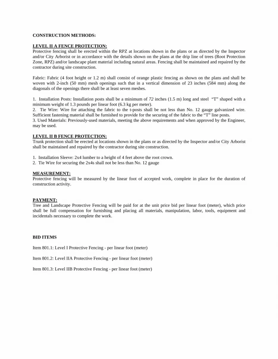
CONSTRUCTION METHODS: LEVEL II A FENCE PROTECTION: Protective fencing shall be erected within the RPZ at locations shown in the plans or as directed by the Inspector and/or City Arborist or in accordance with the details shown on the plans at the drip line of trees (Root Protection Zone, RPZ) and/or landscape plant material including natural areas. Fencing shall be maintained and repaired by the contractor during site construction. Fabric: Fabric (4 foot height or 1.2 m) shall consist of orange plastic fencing as shown on the plans and shall be woven with 2-inch (50 mm) mesh openings such that in a vertical dimension of 23 inches (584 mm) along the diagonals of the openings there shall be at least seven meshes. 1. Installation Posts: Installation posts shall be a minimum of 72 inches (1.5 m) long and steel “T” shaped with a minimum weight of 1.3 pounds per linear foot (6.3 kg per meter). 2. Tie Wire: Wire for attaching the fabric to the t-posts shall be not less than No. 12 gauge galvanized wire. Sufficient fastening material shall be furnished to provide for the securing of the fabric to the “T” line posts. 3. Used Materials: Previously-used materials, meeting the above requirements and when approved by the Engineer, may be used. LEVEL II B FENCE PROTECTION: Trunk protection shall be erected at locations shown in the plans or as directed by the Inspector and/or City Arborist shall be maintained and repaired by the contractor during site construction. 1. Installation Sleeve: 2x4 lumber to a height of 4 feet above the root crown. 2. Tie Wire for securing the 2x4s shall not be less than No. 12 gauge MEASUREMENT: Protective fencing will be measured by the linear foot of accepted work, complete in place for the duration of construction activity. PAYMENT: Tree and Landscape Protective Fencing will be paid for at the unit price bid per linear foot (meter), which price shall be full compensation for furnishing and placing all materials, manipulation, labor, tools, equipment and incidentals necessary to complete the work. BID ITEMS Item 801.1: Level I Protective Fencing - per linear foot (meter) Item 801.2: Level IIA Protective Fencing - per linear foot (meter) Item 801.3: Level IIB Protective Fencing - per linear foot (meter)

ITEM 802
TREE PRUNING, SOIL AMENDING AND FERTILIZATION
PART 1 GENERAL 1.01 DESCRIPTION:
The purpose of this specification is to describe a procedure for maintaining preserved trees before, during and after construction and for furnishing all materials, water, labor, tools, equipments and supplies required as specified by this item or as indicated on the plans.
1.02 REFERENCE STANDARDS:
The contractor shall comply with the applicable provisions and recommendations of the publication listed below and these shall be utilized as reference standards, and form a part of this specification to the extent indicated by reference:
American National Standard Institute - ANSI A300-2002 PART 2 PRODUCTS 2.01 MATERIALS: 1. Tree pruning paint: Any latex, oil or asphalt base wound dressing. 2. Soil amendment: Organic soil amendment with nitrogen content 10% or less. 3. Commercial fertilizer: Urea form based liquid suspension, which is soil injected. Salt Index is less than 3.5 (True Green, Boost) and a longevity period of up to 2 years. 4. Mulch: Shredded wood residue with size of pieces not more than 6 inches in length. 5. Water-By truck for trees.
PART 3 EXECUTION 3.01 CARE OF TREES PRIOR TO AND DURING CONSTRUCTION:
1. Prior to erecting tree enclosure and the start of any phase of construction, arborist will provide mycorrhizal inoculation and deep root fertilization to the tree roots, using 3 lbs. of actual nitrogen per 1000 square feet of root area in a slow release soil injection method. Then a certified arborist will perform pruning before construction to remove dead wood, improve the health of the trees to better tolerate the stresses endured during construction activities. In addition all pruning shall adhere to the standard practices in the American National Standard Institute ANS/A300-1995, and to improve the level of safety
a. Crown Cleaning – shall consist of the removal of dead, dying, and diseased
wood one inch in diameter and greater. Many of the existing trees are above and within the proposed walkway. This dead wood shall be removed to improve safety and liability issues.
2. No site preparation work shall begin in areas where tree preservation and
treatment measures have not been completed and approved.
a. Crown Raising – shall consist of removing lower limbs to provide a clearance specification of 8 feet over walkways and 13 feet over the
TREE PRESERVATION 00802-1

main road for vehicle clearance. Branches may be tied back instead of removed, in order to alleviate conflict. These specifications should protect the existing trees. Tree contractor is to be briefed by Project Engineer/Arborist prior to project commencement. All pruning and removals shall be overseen by a Certified Arborist. The awarded company shall have a Certified Arborist on staff to be able to bid on this Project.
3. No pruning or removal of limbs shall be allowed to provide clearance for work
unless approved by the engineer. 4. Removal of limbs which are 6 inches in diameter or greater is prohibited without
consent of the City Arborist. Occasional branches, up to 1/4 inch in diameter, which are dead, dying, diseased may remain when it is not practical to remove it.
5. Oak wounds must be painted with wound paint within 30 minutes to prevent
infection of the Oak Wilt fungal organism.
6. Soil amendments will be applied within the drip line (RPZ).
7. Soil fertilization will be completed by a soil injection method, which will occur at a spacing of 3 feet on center around the tree within the drip line (Root Protection Zone, RPZ) only for those trees specified.
8. Excavate within drip line of trees only where required. Where excavating for new
construction is required within drip line of trees, hand excavate to minimize damage to root systems. Use narrow spading forks and comb soil to expose roots. Relocate roots back into backfill areas wherever possible. If large main lateral roots are encountered, expose beyond excavation limits as required to bend and relocate without breaking. If root relocation is not practical, then contact Client representative for approval to cut roots 1/2" or greater. If approved, clean cut roots using handsaw or chainsaw approximately 3 inches back from new construction. Where existing grade is above new finish grade, carefully excavate within the drip line to the new finish grade. Carefully hand excavate an additional 8 inch below the finish grade. Use narrow line spading forks to comb the soil to expose the roots and prune the exposed root structure as recommended by the Arborist. After pruning and treatment is complete, backfill to within the finish grade with 8" of approved landscape fill material. Temporarily support and protect roots against damage until permanently relocated and do not allow exposure of root to air to occur beyond 12 hours. Cover with damp soil, peat moss, 8”bark or gunny sacks in order to keep moist so as not to dry out and permanently cover roots as soon as possible. Where it has been determined that trenching for utilities can seriously impact the roots of a desirable tree, then bore or tunnel under tree to minimize root impact.
9. The Contractor shall be responsible for coordinating all construction activities
that may impact trees with clients representative and the Arborist, who will do the necessary pruning and deep root fertilization deemed necessary by the Arborist.
3.02 POST CONSTRUCTION CARE OF TREES:
1. The Contractor shall water when it is necessary to supplement natural rainfalls required preventing excess drying of the tree root area.
TREE PRESERVATION 00802-2
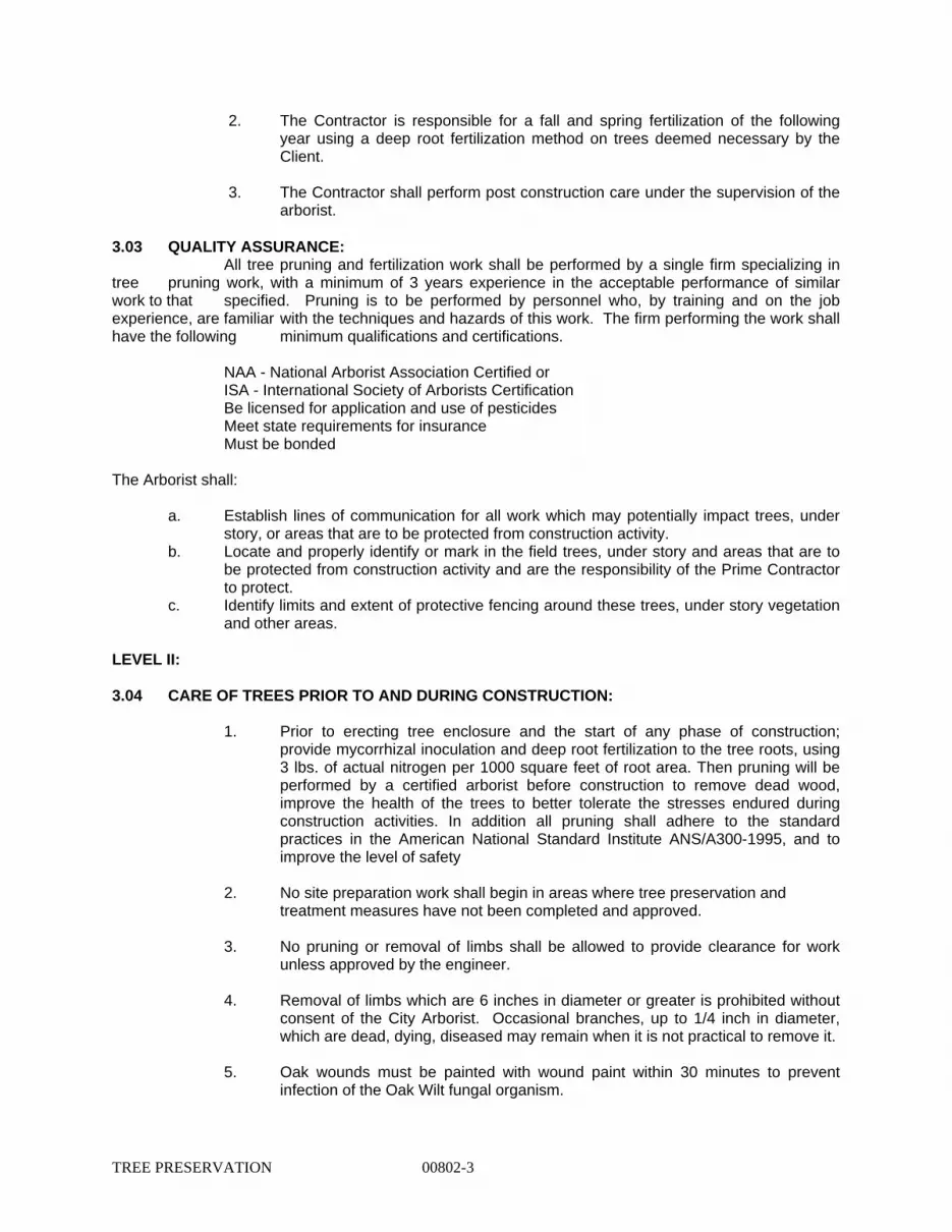
2. The Contractor is responsible for a fall and spring fertilization of the following year using a deep root fertilization method on trees deemed necessary by the Client.
3. The Contractor shall perform post construction care under the supervision of the
arborist. 3.03 QUALITY ASSURANCE: All tree pruning and fertilization work shall be performed by a single firm specializing in tree pruning work, with a minimum of 3 years experience in the acceptable performance of similar work to that specified. Pruning is to be performed by personnel who, by training and on the job experience, are familiar with the techniques and hazards of this work. The firm performing the work shall have the following minimum qualifications and certifications.
NAA - National Arborist Association Certified or ISA - International Society of Arborists Certification Be licensed for application and use of pesticides
Meet state requirements for insurance Must be bonded
The Arborist shall:
a. Establish lines of communication for all work which may potentially impact trees, under story, or areas that are to be protected from construction activity.
b. Locate and properly identify or mark in the field trees, under story and areas that are to be protected from construction activity and are the responsibility of the Prime Contractor to protect.
c. Identify limits and extent of protective fencing around these trees, under story vegetation and other areas.
LEVEL II: 3.04 CARE OF TREES PRIOR TO AND DURING CONSTRUCTION:
1. Prior to erecting tree enclosure and the start of any phase of construction; provide mycorrhizal inoculation and deep root fertilization to the tree roots, using 3 lbs. of actual nitrogen per 1000 square feet of root area. Then pruning will be performed by a certified arborist before construction to remove dead wood, improve the health of the trees to better tolerate the stresses endured during construction activities. In addition all pruning shall adhere to the standard practices in the American National Standard Institute ANS/A300-1995, and to improve the level of safety
2. No site preparation work shall begin in areas where tree preservation and
treatment measures have not been completed and approved. 3. No pruning or removal of limbs shall be allowed to provide clearance for work
unless approved by the engineer. 4. Removal of limbs which are 6 inches in diameter or greater is prohibited without
consent of the City Arborist. Occasional branches, up to 1/4 inch in diameter, which are dead, dying, diseased may remain when it is not practical to remove it.
5. Oak wounds must be painted with wound paint within 30 minutes to prevent
infection of the Oak Wilt fungal organism.
TREE PRESERVATION 00802-3

6. Excavate within drip line of trees only where required. Where excavating for new construction is required within drip line of trees, hand excavate to minimize damage to root systems. Use narrow spading forks and comb soil to expose roots. Relocate roots back into backfill areas wherever possible. If large main lateral roots are encountered, expose beyond excavation limits as required to bend and relocate without breaking. If root relocation is not practical, then contact Client representative for approval to cut roots 1/2" or greater. If approved, clean cut roots using a handsaw or chainsaw approximately 3 inches back from new construction. Where existing grade is above new finish grade, carefully excavate within the drip line to the new finish grade. Carefully hand excavate an additional 8 inch below the finish grade. Use narrow line spading forks to comb the soil to expose the roots and prune the exposed root structure as recommended by the Arborist. After pruning and treatment is complete, backfill to within the finish grade with 8" of approved landscape fill material. Temporarily support and protect roots against damage until permanently relocated and do not allow exposure of root to air to occur beyond 12 hours. Cover with damp soil, peat moss, bark or gunny sacks in order to keep moist so as not to dry out and permanently cover roots as soon as possible. Where it has been determined that trenching for utilities can seriously impact the roots of a desirable tree, then bore or tunnel under tree to minimize root impact.
7. Water deeply trees that are substantially trimmed or within drip line of excavation work for the duration of this contract.
8. Water deeply trees that show signs of stress and are located in areas where the
groundwater table has been lowered due to construction activities. 9. The Contractor shall be responsible for coordinating all construction activities
that may impact trees with clients representative and the Arborist, who will do the necessary pruning and deep root fertilization deemed necessary by the Architect.
3.05 POST CONSTRUCTION CARE OF TREES:
1. The Contractor shall water when it is necessary to supplement natural rainfalls required preventing excess drying of the tree root area. Barring natural rainfall, the Contractor should apply 1” per week over entire root protection zone.
2. The Arborist shall monitor and authorize for removal the trees which show
symptoms of stress, which might be indicated by branch die back chlorosis or fringe browning of the leaves. This would indicate that the crown is not in equilibrium with roots and additional pruning would be necessary. Subsequent pruning should remove only as much green wood as deemed necessary to reestablish equilibrium. If trees die during construction due to contractor negligence up to a one year post construction period, the Contractor will be required to replace trees at his or her own expense as called for in Paragraph 3.6.
3. The Contractor shall perform post construction care under the supervision of an
arborist. 3.06 QUALITY ASSURANCE:
Same as Level I 3.07 MEASUREMENT:
TREE PRESERVATION 00802-4

“Maintenance Pruning” Soil Amendment, and Fertilization” , ½” or larger of dead, diseased wood.
“Maintenance Pruning” 1” or larger of dead, diseased wood.
3.08 PAYMENT:
Work performed and materials furnished as prescribed by this item and measured as provided under “Measurement” will be paid for as follows:
“Level I Pruning, Soil Amendment, and Fertilization” Will be paid for at the unit price bid per each tree receiving “Level I Pruning, Soil Amendment, and Fertilization” of the size called for , which price shall be full compensation for furnishing all materials; preparation, hauling, handling charges, placement, labor, tools, and incidentals necessary to complete the work.
Level II Pruning will be paid for at the contract lump sum price bid, which price shall be full compensation for work herein specified, including the furnishing of all materials, equipment, tools, labor, and incidentals necessary to complete the work.
3.09 BID ITEM:
Item 802.1 - Level I Pruning, Soil Amendment, and Fertilization - per each tree
Item 802.2 - Level II Pruning - per Lump Sum
TREE PRESERVATION 00802-5

Geotechnical Engineering Study
CoSA Bond Project Belfast and Janda Susan Drainage
Improvements San Antonio, Texas
Arias Job No. 2012-938
Prepared For Bury & Partners-SA, Inc.
December 23, 2013

ARIAS & ASSOCIATESGeotechnical • Environmental ‘ Testing
December 23, 2013Arias Job No. 2012-938
Mr. Christopher Otto, P.E.Bury & Partners-SA, Inc.922 Isom Road, Suite No. 100San Antonio, Texas 78216
RE: Geotechnical Engineering StudyCoSA Bond Project - Belfast and Janda Susan Drainage ImprovementsSan Antonio, Texas
Dear Mr. Otto:
Arias & Associates, Inc. (Arias) is pleased to submit the results of a Geotechnical EngineeringStudy for the proposed Belfast and Janda Susan Drainage Improvements Project in San Antonio,Texas. Our findings and recommendations should be incorporated into the design andconstruction documents for the proposed development. Please consult with us as needed duringany part of the design or construction process.
The long-term success of the project will be affected by the quality of materials used forconstruction and the adherence of the construction to the project plans and specifications. Thequality of construction can be evaluated by implementing Quality Assurance (QA) testing. As theGeotechnical Engineer of Record (GER), we recommend that the earthwork, foundations, andpavement construction be tested and observed by Arias in accordance with the reportrecommendations. A summary of our qualifications to provide QA testing is discussed in the“Quality Assurance Testing” section of this report. Furthermore, a message to the Owner withregard to QA testing is provided in the ASFE publication included in Appendix F.
We appreciate the opportunity to serve you during this phase of design. If we may be of furtherservice, please call.
Sincerely,ARIAS & ASSOCIATES, INç~4TBPE Registration No: F-32
/Priya Lad, E.l.T. V(,(/ /2/ V’ ~ -~ Rene P. Gonzales, P..Graduate Geotechnical Engineer Sr. Geotechnical Engil
1295 Thompson Rd 142 Chula Vista 5233 IH 37, Suite B-12 5213 Davis Boulevard, Suite GEagle Pass, Texas 78852 San Antonio, Texas 78232 Corpus Chdsti, Texas 78408 North Richland Hills, TX 76180
(830) 757-8891 (210) 308-5884 (361) 288-2670 (817) 812-3500(80) 757-8899 Fax (210) 308-5886 Fax (361) 288-4672 Fax

TABLE OF CONTENTS
Page
Arias & Associates, Inc. 3 Arias Job No. 2012-938
INTRODUCTION ...................................................................................................................... 5
SCOPE OF SERVICES ............................................................................................................ 5
PROJECT AND SITE DESCRIPTION ..................................................................................... 5
FIELD EXPLORATION ............................................................................................................. 6
LABORATORY TESTING ........................................................................................................ 7
SUBSURFACE CONDITIONS ................................................................................................. 8
Geology ................................................................................................................................ 8
Existing Pavement Structure ................................................................................................ 8
Site Stratigraphy and Engineering Properties ...................................................................... 8
Groundwater ......................................................................................................................... 9
PAVEMENT EVALUATION .................................................................................................... 10
Expansive Soils .................................................................................................................. 10
Moisture Fluctuations Beneath Pavements ........................................................................ 11
Effect of Trees and Vegetation ........................................................................................... 12
PAVEMENT RECOMMENDATIONS ..................................................................................... 13
Design Parameters and Traffic Conditions ......................................................................... 13
Flexible Pavement Recommendations for Local Type A Street without Bus Traffic .......... 14
Site Drainage ...................................................................................................................... 14
Performance and Maintenance Considerations ................................................................. 15
PAVEMENT CONSTRUCTION CRITERIA ............................................................................ 15
Site Preparation .................................................................................................................. 15
Lime Stabilized Subgrade .................................................................................................. 16
Roadway Fill Requirements ............................................................................................... 16
Crushed Limestone Base Material Subgrade ..................................................................... 16
Flexible Base Course ......................................................................................................... 17
Asphaltic Base Course ....................................................................................................... 17
Asphaltic Concrete Surface Course ................................................................................... 17
Curb and Gutter .................................................................................................................. 17
Site Drainage ...................................................................................................................... 17
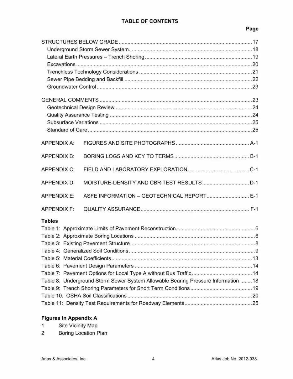
TABLE OF CONTENTS
Page
Arias & Associates, Inc. 4 Arias Job No. 2012-938
STRUCTURES BELOW GRADE ........................................................................................... 17
Underground Storm Sewer System .................................................................................... 18
Lateral Earth Pressures – Trench Shoring ......................................................................... 19
Excavations ........................................................................................................................ 20
Trenchless Technology Considerations ............................................................................. 21
Sewer Pipe Bedding and Backfill ....................................................................................... 22
Groundwater Control .......................................................................................................... 23
GENERAL COMMENTS ........................................................................................................ 23
Geotechnical Design Review ............................................................................................. 24
Quality Assurance Testing ................................................................................................. 24
Subsurface Variations ........................................................................................................ 25
Standard of Care ................................................................................................................ 25
APPENDIX A: FIGURES AND SITE PHOTOGRAPHS .................................................. A-1
APPENDIX B: BORING LOGS AND KEY TO TERMS ................................................... B-1
APPENDIX C: FIELD AND LABORATORY EXPLORATION .......................................... C-1
APPENDIX D: MOISTURE-DENSITY AND CBR TEST RESULTS ................................ D-1
APPENDIX E: ASFE INFORMATION – GEOTECHNICAL REPORT ............................. E-1
APPENDIX F: QUALITY ASSURANCE .......................................................................... F-1
Tables
Table 1: Approximate Limits of Pavement Reconstruction ...................................................... 6
Table 2: Approximate Boring Locations .................................................................................. 6
Table 3: Existing Pavement Structure ..................................................................................... 8
Table 4: Generalized Soil Conditions ...................................................................................... 9
Table 5: Material Coefficients ................................................................................................ 13
Table 6: Pavement Design Parameters ................................................................................ 14
Table 7: Pavement Options for Local Type A without Bus Traffic ......................................... 14
Table 8: Underground Storm Sewer System Allowable Bearing Pressure Information ........ 18
Table 9: Trench Shoring Parameters for Short Term Conditions .......................................... 19
Table 10: OSHA Soil Classifications ..................................................................................... 20
Table 11: Density Test Requirements for Roadway Elements .............................................. 25
Figures in Appendix A
1 Site Vicinity Map
2 Boring Location Plan
Arias & Associates, Inc. 5 Arias Job No. 2012-938
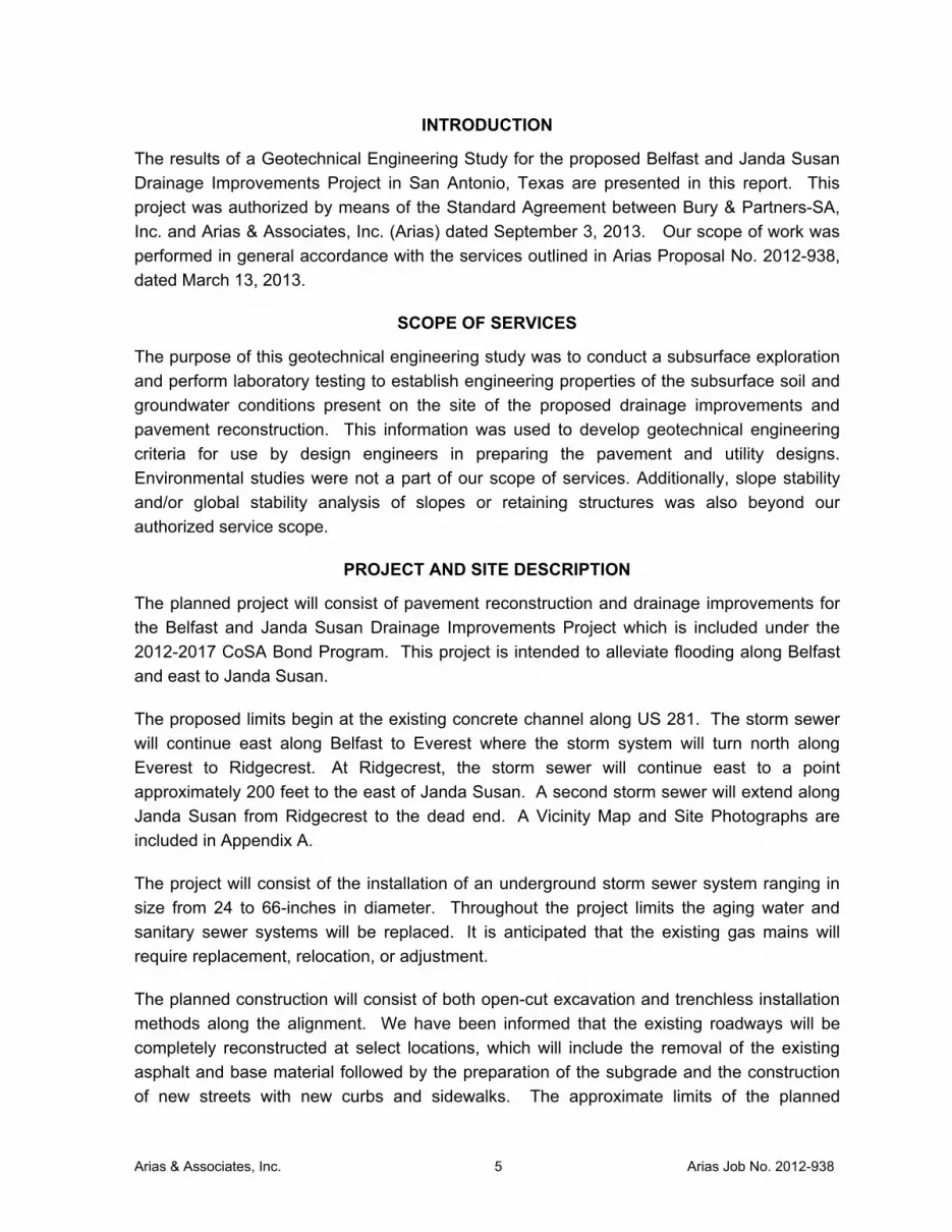
INTRODUCTION
The results of a Geotechnical Engineering Study for the proposed Belfast and Janda Susan
Drainage Improvements Project in San Antonio, Texas are presented in this report. This
project was authorized by means of the Standard Agreement between Bury & Partners-SA,
Inc. and Arias & Associates, Inc. (Arias) dated September 3, 2013. Our scope of work was
performed in general accordance with the services outlined in Arias Proposal No. 2012-938,
dated March 13, 2013.
SCOPE OF SERVICES
The purpose of this geotechnical engineering study was to conduct a subsurface exploration
and perform laboratory testing to establish engineering properties of the subsurface soil and
groundwater conditions present on the site of the proposed drainage improvements and
pavement reconstruction. This information was used to develop geotechnical engineering
criteria for use by design engineers in preparing the pavement and utility designs.
Environmental studies were not a part of our scope of services. Additionally, slope stability
and/or global stability analysis of slopes or retaining structures was also beyond our
authorized service scope.
PROJECT AND SITE DESCRIPTION
The planned project will consist of pavement reconstruction and drainage improvements for
the Belfast and Janda Susan Drainage Improvements Project which is included under the
2012-2017 CoSA Bond Program. This project is intended to alleviate flooding along Belfast
and east to Janda Susan.
The proposed limits begin at the existing concrete channel along US 281. The storm sewer
will continue east along Belfast to Everest where the storm system will turn north along
Everest to Ridgecrest. At Ridgecrest, the storm sewer will continue east to a point
approximately 200 feet to the east of Janda Susan. A second storm sewer will extend along
Janda Susan from Ridgecrest to the dead end. A Vicinity Map and Site Photographs are
included in Appendix A.
The project will consist of the installation of an underground storm sewer system ranging in
size from 24 to 66-inches in diameter. Throughout the project limits the aging water and
sanitary sewer systems will be replaced. It is anticipated that the existing gas mains will
require replacement, relocation, or adjustment.
The planned construction will consist of both open-cut excavation and trenchless installation
methods along the alignment. We have been informed that the existing roadways will be
completely reconstructed at select locations, which will include the removal of the existing
asphalt and base material followed by the preparation of the subgrade and the construction
of new streets with new curbs and sidewalks. The approximate limits of the planned

Arias & Associates, Inc. 6 Arias Job No. 2012-938
pavement reconstruction are summarized in Table 1 below.
Table 1: Approximate Limits of Pavement Reconstruction
Proposed Street Approximate Limits of Reconstruction
From To
Belfast Drive Empire Street Everest Street
Everest Street Belfast Drive Ridgecrest Drive
Ridgecrest Drive Everest Street Janda Susan Road
Janda Susan Road Ridgecrest Drive Janda Susan Road Cul-de-sac
Information provided by the design team indicates that the Street Classifications for this
project will consist of Local Type A (without bus traffic) Streets in accordance with the City of
San Antonio CIMS Design Guidance Manual, Appendix 10-A "City of San Antonio Pavement
Design Standards". If different street classifications are to be utilized, then we should be
contacted to provide additional recommendations.
FIELD EXPLORATION
Six (6) soil borings were drilled at the approximate locations shown on the Boring Location
Plan included as Figure 2 in Appendix A. The borings were drilled to depths ranging from 15
to 25 feet below the existing ground surface at the time of the geotechnical exploration
conducted on October 16, 2013 and November 1, 2013. A summary of the approximate
boring locations is provided in Table 2.
Table 2: Approximate Boring Locations
Boring No. Proposed Street Approximate Location
B-1 -- East of US 281
B-2 Belfast Drive Intersection of Empire Street and Belfast Drive
B-3 Belfast Drive Belfast Drive
B-4 Belfast Drive and Everest Street Intersection of Belfast Drive and Everest
Street
B-5 Everest Street Everest Street – South of Ridgecrest Drive
B-6 Susan Janda Road Susan Janda Road Cul-de-sac
Drilling was performed in general accordance with ASTM D1586 procedures for Split Spoon
sampling techniques and ASTM D 1587 for thin-walled tube sampling techniques as
described in Appendix C. A truck-mounted drill rig using continuous flight augers together
with the sampling tools noted were used to secure the subsurface soil samples. The soil
borings were backfilled after completion of drilling. Boring B-1 was backfilled using cuttings
generated during the drilling process. Borings B-2 through B-6 were backfilled with soil
Arias & Associates, Inc. 7 Arias Job No. 2012-938
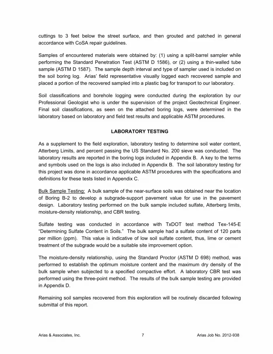
cuttings to 3 feet below the street surface, and then grouted and patched in general
accordance with CoSA repair guidelines.
Samples of encountered materials were obtained by: (1) using a split-barrel sampler while
performing the Standard Penetration Test (ASTM D 1586), or (2) using a thin-walled tube
sample (ASTM D 1587). The sample depth interval and type of sampler used is included on
the soil boring log. Arias’ field representative visually logged each recovered sample and
placed a portion of the recovered sampled into a plastic bag for transport to our laboratory.
Soil classifications and borehole logging were conducted during the exploration by our
Professional Geologist who is under the supervision of the project Geotechnical Engineer.
Final soil classifications, as seen on the attached boring logs, were determined in the
laboratory based on laboratory and field test results and applicable ASTM procedures.
LABORATORY TESTING
As a supplement to the field exploration, laboratory testing to determine soil water content,
Atterberg Limits, and percent passing the US Standard No. 200 sieve was conducted. The
laboratory results are reported in the boring logs included in Appendix B. A key to the terms
and symbols used on the logs is also included in Appendix B. The soil laboratory testing for
this project was done in accordance applicable ASTM procedures with the specifications and
definitions for these tests listed in Appendix C.
Bulk Sample Testing: A bulk sample of the near-surface soils was obtained near the location
of Boring B-2 to develop a subgrade-support pavement value for use in the pavement
design. Laboratory testing performed on the bulk sample included sulfate, Atterberg limits,
moisture-density relationship, and CBR testing.
Sulfate testing was conducted in accordance with TxDOT test method Tex-145-E
“Determining Sulfate Content in Soils.” The bulk sample had a sulfate content of 120 parts
per million (ppm). This value is indicative of low soil sulfate content, thus, lime or cement
treatment of the subgrade would be a suitable site improvement option.
The moisture-density relationship, using the Standard Proctor (ASTM D 698) method, was
performed to establish the optimum moisture content and the maximum dry density of the
bulk sample when subjected to a specified compactive effort. A laboratory CBR test was
performed using the three-point method. The results of the bulk sample testing are provided
in Appendix D.
Remaining soil samples recovered from this exploration will be routinely discarded following
submittal of this report.

Arias & Associates, Inc. 8 Arias Job No. 2012-938
SUBSURFACE CONDITIONS
Geology, existing pavement structure, generalized stratigraphy, and groundwater conditions
at the project site are discussed in the following sections. The subsurface and groundwater
conditions are based on conditions encountered at the boring locations to the depths
explored.
Geology
The earth materials underlying the project site have been regionally mapped as soils of the
Pecan Gap Formation of the Upper Cretaceous age. The Pecan Gap formation consists of
hard bluish-gray calcareous clay shale and very hard bluish-gray marl in the unweathered
subsurface which weathers to a tan gray buff color. Intermittent harder and softer seams and
layers, as well as bentonitic zones, are common to the formation. The material was
deposited in a shallow marine environment and is fossiliferous. The Pecan Gap soils are
described geologically as chalk and chalky marl, and very light yellow to yellowish brown in
color. The near-surface clays of the Pecan Gap typically, but not always, consist of a highly-
plastic (expansive) clay.
Existing Pavement Structure
Five (5) of the six (6) borings were performed within the existing roadways. The observed
pavement structure is summarized in the table below. Based on our observations, there was
no apparent visible evidence of cement or lime treatment of the subgrade.
Table 3: Existing Pavement Structure
Boring No.
Existing Roadway Pavement Section, inches
Asphalt Base Material Total
B-2 Belfast Drive 6 -- 6
B-3 Belfast Drive 4 ½ 7 ½ 12
B-4 Belfast Drive/Everest Street 4 -- 4
B-5 Everest Street/Ridgecrest Drive 2 ½ 6 ½ 9
B-6 Susan Janda Road Cul-de-sac 4 ½ 7 ½ 12
Site Stratigraphy and Engineering Properties
The general stratigraphic conditions at the boring locations are provided in Table 4. The
presence and thickness of the various subsurface materials can be expected to vary away
from and between the exploration locations. The descriptions conform to the Unified Soils
Classification System.

Arias & Associates, Inc. 9 Arias Job No. 2012-938
Table 4: Generalized Soil Conditions
Stratum Depth,
ft Material Type
PI range
No. 200range
N Range
PP Range
Uc Range
PI avg.No. 200
avg. N avg.
PP avg.
Uc avg.
Pavement 0 to
(0.3 - 1)
2.5” to 6” Asphalt over 0” to 7.5” Base
-- -- -- -- --
FILL / Possible
Fill
(0 - 0.3) to
(1.5 - 4)
LEAN CLAY with Gravel (CL), FAT CLAY with Sand (CH); CLAYEY SAND with
Gravel (SC), CLAYEY GRAVEL (GC); stiff to hard; loose to medium dense, gray
and brown, light gray, tan (Borings B-1, B-2, and B-4)
44 -49 43 - 85 8 – 40 -- --
47 64 18 -- --
I (0.8 - 4)
to (6 - 9)
FAT CLAY (CH) with varying amounts of sand, gravel and silt; stiff to hard; dark brown,
brown, tan, and light gray
44 - 56 83 - 95 10 - 18 2.5 - 4.5+
1.5 - 11.69
49 90 14 3.75 6.2
II (6 - 9)
to 20
LEAN/FAT CLAY (CL/CH) with varying amounts of sand,
gravel and silt; hard to very hard; tan, light tan, and gray
12 - 48 67 - 97 30 - 50/4”
3 - 4.5+3.13 - 9.73
34 88 90 4.33 6.3
Where: Depth - Depth from existing ground surface during geotechnical study, feet PI - Plasticity Index, % No. 200 - Percent passing #200 sieve, % N - Standard Penetration Test (SPT) value, blows per foot
PP - Pocket Penetrometer Value (PP), tons per square foot Uc - Unconfined Compressive Strength, tons per foot
Groundwater A dry soil sampling method was used to obtain the soil samples. Groundwater was not
observed within the borings during drilling operations on October 16, 2013 and November 1,
2013. It should be noted that water levels in open boreholes may require several hours to
several days to stabilize depending on the permeability of the soils. Groundwater levels will
often change significantly over time and should be verified immediately prior to construction.
Groundwater levels at this site may differ during construction because fluctuations in
groundwater levels can result from seasonal conditions, rainfall, drought, or temperature
effects. Pockets or seams of gravels, sands, silts or open fractures and joints can store and
transmit “perched” groundwater flow or seepage. Transient groundwater seepage can also
occur at strata interfaces, particularly at clay/sand, clay/gravel and soil/rock interfaces.
The installation of temporary piezometers (observation wells) can be performed to obtain
more accurate groundwater data. Additionally, pump and recharge tests can be performed
using the piezometers to aid in estimating groundwater seepage rates. Subsurface water

Arias & Associates, Inc. 10 Arias Job No. 2012-938
readings and seepage rates will generally provide an indication of groundwater conditions at
that respective location and time. If needed, this information can be used to assist the
contractor in developing construction dewatering plans. We should note that installing
piezometers and performing groundwater testing was beyond our authorized scope of
services for this project. We can provide these services if desired.
PAVEMENT EVALUATION
Expansive Soils
The site soils beneath the pavement structure have high expansion characteristics.
Expansive clays shrink when they lose water and swell or grow in volume when they gain
water content. The potential of expansive clays to shrink and swell is related to the Plasticity
Index (PI). Clays with a higher PI have a greater potential for soil volume changes due to
moisture content variations. Change in soil moisture is the single most important factor
affecting the shrinking and swelling of clays. The most pronounced movements are
commonly observed when soils are exposed to extreme moisture fluctuations that occur
between drought conditions and wet seasons.
It has been our experience that with these soil types moisture content changes (sometimes
deep-seated) within the expansive clay subgrade can lead to pavement cracking and
undulating pavement and curbs. The street may be properly designed and constructed with
the proper section thickness and materials to accommodate the design traffic loading, but still
not perform well due to expansive clay movements.
We estimated potential vertical movement for this site using the Tex-124-E method outlined
by the Texas Department of Transportation (TXDOT). The Tex-124-E method provides an
estimate of potential vertical rise (PVR) using the liquid limits, plasticity indices, and existing
water contents for soils. The PVR is estimated in the seasonally active zone. Using the
TXDOT method, we estimated that the PVR at the boring locations (based on existing
moisture conditions) ranges from about 3 to 6 inches.
Estimated PVRs are based upon assumed changes in soil moisture content from a dry to a
wet condition; however, soil movements in the field depend on the actual changes in
moisture content. Thus, actual soil movements could be less than that calculated if little soil
moisture variations occur or the actual movement could exceed the estimated values if actual
soil moisture content changes exceed the assumed dry and wet limits outlined by the PVR
method. Such moisture conditions that exceed the limits of the PVR method may be the
result of extended droughts, flooding, perched groundwater infiltration, poor surface
drainage, and/or leaking irrigation lines.
We’ve performed our pavement analyses for this project using the 1993 AASHTO Guide for
Design of Pavement Structure. The AASHTO procedure includes provisions to account for
roadbed swelling through a reduction in serviceability or ride quality over time as the roadbed

Arias & Associates, Inc. 11 Arias Job No. 2012-938
swells. Based on the estimated site PVR, we estimate a loss of serviceability of about 1.2
over a 20 year service life due to expansive soil-related movements.
To account for this loss in serviceability, the pavement section can be increased as per the
AASHTO procedure. However, it is Arias’ opinion that this increase in pavement structure
will have little benefit in terms of reducing expansive soil-related pavement distress due to an
estimated active zone of about 15 feet. A more effective approach would be to reduce the
potential for moisture fluctuations beneath the pavement by providing the following:
positive site drainage,
curb and gutter systems,
moisture barriers as discussed in the subsequent report section, and
subgrade treatment.
Moisture Fluctuations Beneath Pavements
It is common for moisture content values to remain more constant in the middle of the
roadway. The moisture levels in the subgrade soils located near the edge of roadways are
more susceptible to changes in moisture that occur due to natural seasonal moisture
fluctuations. The edges will dry and shrink during drought conditions, relative to the center of
the roadway. During extremely wet climate periods, the edges will swell relative to the center
of the roadway. The shrinking and swelling of subgrade soils near the edge of pavements will
result in longitudinal, surface cracking that occurs parallel to the roadway. Undulating
pavement and curbs could also result from these shrink/swell movements. Based on our
experience, edge cracking typically occurs at a distance of 3 to 9 feet from the edge of the
roadway. Edge cracking associated with soil shrinkage movements may occur at greater
distances during extreme environmental conditions. The implementation of moisture barriers
can improve the long term performance of the pavement by reducing the impact of the
expansive soils.
Based the results of this study, the Owner can consider the option of constructing vertical
and/or lateral moisture barriers to help maintain more consistent moisture conditions beneath
the pavement, thus reducing the severity of expansive soil-related distress. Even with the
implementation of a moisture barrier, the Owner should be prepared to provide pavement
maintenance and repair; please refer to the “Performance and Maintenance Considerations”
section of this Report for additional information. The Owner may decide to forgo the
implementation of a moisture barrier and accept an increased risk for expansive soil-related
movement. Potential risks would include costs for maintenance such as patching of cracks
and occasional overlays over the life of the pavements.
Some options for moisture barriers to aid in reducing moisture change in the pavement
subgrade soils include:

Arias & Associates, Inc. 12 Arias Job No. 2012-938
Vertical Moisture Barriers (VMB). VMBs may consist of polyethylene plastic sheeting
placed in an excavated vertical trench that is backfilled with flowable fill. We
recommend that a VMB be installed at least 4-ft deep and be located at the pavement
edges beneath the curb or directly behind curb. VMBs should be considered for
installation along the length of the project on both sides of the street, or at least where
the existing pavement is experiencing more distress. Careful coordination will be
required by the installation contractor during construction to prevent from damaging
existing utilities. It is our opinion that VMBs would be effective in reducing the
chances and severity of edge cracking.
Lateral Moisture Barriers (LMB). LMBs can consist of contiguous sidewalks of
sufficient width located directly adjacent to the planned pavements. The use of
sidewalks along the length of the project will help provide protection from moisture
fluctuations along the pavement edges. It has been our experience that sidewalks
acting as an LMB will be most beneficial when located directly adjacent to the
concrete curbs. As previously noted based on our experience, edge cracking
typically occurs at a distance of 3 to 9 feet from the edge of the roadway. Thus, the
wider the sidewalks the more protection will be provided. Potential landscaping adjacent to the existing roadways will increase the potential for
moisture fluctuations along the pavement edges. Careful consideration should be provided
by the designers to provide positive drainage away from these areas. Ponding should not be
allowed near the edges of the planned pavements.
Effect of Trees and Vegetation
Soil moisture can be affected by the roots of vegetation that extend beneath pavements.
Trees remove large quantities of water from the soil through their root systems during the
growing season and cause localized drier areas in the vicinity of the roots. The limits of
affected areas are typically related to the lateral extent of a root system, which are a function
of the tree height and the spread of its branches. It is generally accepted that a root system
will influence the soil moisture levels to a distance roughly equivalent to the drip line (extent
of branches). Pavements constructed over a tree root system may shrink due to changes in
moisture content and result in cracking. These types of movements result in concentric
crack patterns in street pavements located near trees.
If trees will be located next to the roadways, the designers may wish to consider installing
localized root barriers as part of the pavement construction in these areas. The root barriers
may reduce the potential for future pavement distress due to soil moisture variations from
tree roots. Should root barriers be considered, we recommend the designers consult with a
tree expert to discuss the effect of barriers on the health of the trees.

Arias & Associates, Inc. 13 Arias Job No. 2012-938
PAVEMENT RECOMMENDATIONS
The residential streets will be classified as a “Local Type A without Bus Traffic”. If a different
street classification is to be utilized, then we should be contacted to provide additional
recommendations.
Design Parameters and Traffic Conditions
At the time of this report, the plan-and-profile sheets for the roadways were not available for
review. Based on the results of our field study and the laboratory testing, it appears likely
that the roadway subgrade will consist predominantly of high plasticity clay (CH). We
obtained a bulk sample of the soils near the location of Boring B-2 for laboratory testing to
determine the design CBR. Our laboratory test results indicated a CBR value of 4.9. Based
on the expansive nature and index properties of the subgrade soils, we recommend a CBR
of 2.5 be utilized for pavement design.
It should be noted that the conditions and recommendations contained herein are based on
the materials encountered at the time of field exploration. These conditions may differ if road
grading (cut/fill) operations are performed. We recommend that a representative of Arias be
retained to observe that our recommendations are followed and to assist in determining the
actual subgrade material classification at a particular location. Furthermore, we should be
given an opportunity to review the final plan-and-profile sheets to determine if changes to our
recommendations are needed.
Recommendations in this section were prepared in accordance with the 1993 AASHTO
Guide for Design of Pavement Structure and the CoSA CIMS DGM. Structural material
coefficients are provided subsequently in Table 5, and design parameters utilized in our
pavement evaluation are presented subsequently in Table 6.
Table 5: Material Coefficients
Material Structural Coefficient
Hot Mix Asphaltic Concrete – Type “C” or “D” Surface Course
0.44
Hot Mix Asphaltic Concrete – Type “B” Base Course 0.38
Flexible Base Course – CoSA Item 200, Type A, Grades 1 or 2
0.14
6-inch Lime-Treated Subgrade 0.48
Arias & Associates, Inc. 14 Arias Job No. 2012-938
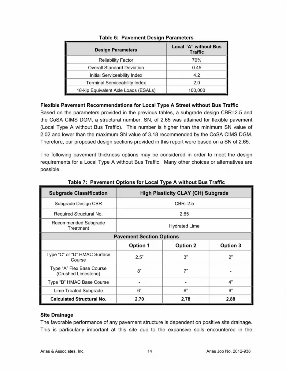
Table 6: Pavement Design Parameters
Design Parameters Local “A” without Bus
Traffic
Reliability Factor 70%
Overall Standard Deviation 0.45
Initial Serviceability Index 4.2
Terminal Serviceability Index 2.0
18-kip Equivalent Axle Loads (ESALs) 100,000
Flexible Pavement Recommendations for Local Type A Street without Bus Traffic
Based on the parameters provided in the previous tables, a subgrade design CBR=2.5 and
the CoSA CIMS DGM, a structural number, SN, of 2.65 was attained for flexible pavement
(Local Type A without Bus Traffic). This number is higher than the minimum SN value of
2.02 and lower than the maximum SN value of 3.18 recommended by the CoSA CIMS DGM.
Therefore, our proposed design sections provided in this report were based on a SN of 2.65.
The following pavement thickness options may be considered in order to meet the design
requirements for a Local Type A without Bus Traffic. Many other choices or alternatives are
possible.
Table 7: Pavement Options for Local Type A without Bus Traffic
Subgrade Classification High Plasticity CLAY (CH) Subgrade
Subgrade Design CBR CBR=2.5
Required Structural No. 2.65
Recommended Subgrade Treatment Hydrated Lime
Pavement Section Options
Option 1 Option 2 Option 3
Type “C” or “D” HMAC Surface Course
2.5” 3” 2”
Type “A” Flex Base Course (Crushed Limestone)
8” 7” -
Type “B” HMAC Base Course - - 4”
Lime Treated Subgrade 6” 6” 6”
Calculated Structural No. 2.70 2.78 2.88
Site Drainage
The favorable performance of any pavement structure is dependent on positive site drainage.
This is particularly important at this site due to the expansive soils encountered in the

Arias & Associates, Inc. 15 Arias Job No. 2012-938
borings. Careful consideration should be provided by the designers to ensure positive
drainage of all storm waters away from the planned pavements. Ponding should not be
allowed either on or along the edges of the pavements.
Performance and Maintenance Considerations
It is common for moisture content values to remain fairly constant in the middle of the
roadway. The moisture levels in the subgrade soils located near the edge of roadways are
more susceptible to changes in moisture that occur due to natural seasonal moisture
fluctuations. The edges will dry and shrink during drought conditions, relative to the center of
the roadway. During extremely wet climate periods, the edges will swell relative to the center
of the roadway. The shrinking and swelling of subgrade soils near the edge of pavements
will result in longitudinal, surface cracking that occurs parallel to the roadway. Based on our
experience, the cracking typically occurs at a distance of 3 to 9 feet from the edge of the
roadway. Edge cracking associated with soil shrinkage movements may occur at greater
distances during extreme environmental conditions.
Our pavement recommendations have been developed to provide an adequate structural
thickness to support the anticipated traffic volumes. Some shrink/swell movements due to
moisture variations in the underlying soils should be anticipated over the life of the
pavements. The owner should recognize that over a period of time, pavements may crack
and undergo some deterioration and loss of serviceability due to the site expansive soils.
We recommend the project budgets include an allowance for maintenance such as patching
of cracks or occasional overlays over the life of the pavement.
It has been our experience that pavement cracking will provide a path for surface runoff to
infiltrate through the pavements and into the subgrade. Once moisture is allowed into the
subgrade the potential for pavement failures and potholes will increase. We recommend the
owners implement a routine maintenance program with regular site inspections to monitor
the performance of the site pavements. Cracking that may occur on the asphalt surface due
to shrink/swell movements should be sealed immediately using a modified polymer hot-
applied asphalt based sealant. Additional crack sealing will likely be required over the design
life of the pavements. Crack sealing is a proven, routine, maintenance practice to preserve
pavements and help reduce pavement wear and deterioration. Failure to provide routine
crack-sealing will increase the potential for pavement failures and potholes to develop.
PAVEMENT CONSTRUCTION CRITERIA
Site Preparation
Topsoil stripping should be performed as needed to remove existing asphalt, concrete, base,
organic materials, loose soils, vegetation, roots, and stumps. A minimum depth of 3 to 4
inches should be planned. Additional excavation may be required due to encountering
deleterious materials such as concrete, organics, debris, soft materials, etc.

Arias & Associates, Inc. 16 Arias Job No. 2012-938
Lime Stabilized Subgrade
The high plasticity clay subgrade may be stabilized the specified thickness with lime by dry
weight in accordance with City of San Antonio Standard Specifications for Construction, Item
108, “Lime Treated Subgrade”. The quantity of lime required should be determined after the
site is stripped of the unsuitable soils noted above and the subgrade soils are exposed. We
anticipate that approximately 8 percent lime will be required depending upon the
material encountered. However, the quantity of lime should be sufficient to: (1) result
in a pH of at least 12.4 when tested in accordance with ASTM C977, Appendix XI; and
(2) reduce the PI of the clay subgrade to less than 20. The target lime content and
optimum moisture content should be determined in accordance with TxDOT test procedure
TEX-120-E.
Roadway Fill Requirements
The general fill used to increase sections of the roadway grade should consist of onsite
materials meeting or exceeding the existing subgrade CBR value. The general fill should be
placed in accordance with City of San Antonio Standard Specifications for Construction, Item
107, “Embankment”. The compaction should be performed in accordance with the “Density
Control” method. Onsite material may be used provided it is placed in maximum 8” loose lifts
and compacted to at least 95 percent of the standard Proctor maximum dry density as
evaluated by TEX-114-E to within optimum to plus four (+4) percent of optimum moisture.
This fill should not have any organics or deleterious materials. When fill material includes
rock, the maximum rock size acceptable shall be 3-inches. No large rocks (>3 inches) shall
be allowed to nest and all voids must be carefully filled with small stones or earth and
properly compacted.
The CBR of all fill materials used should be equal to or exceed the existing subgrade CBR at
each particular location. The suitability of all fill materials should be approved by the
Geotechnical Engineer. Conformance testing during construction to assure quality will be
necessary for this process. If fill is required to raise paving grades, the above compaction
criteria should be utilized with the fill placed in maximum 8-inch thick loose lifts. It should be
noted that if fill materials with lower CBR values are placed, then a higher Structural Number
and a thicker pavement section would be necessary.
Crushed Limestone Base Material Subgrade
The depth of the planned drainage structures will vary with location. At locations where
crushed limestone base material will be used as trench backfill, or areas where the planned
pavement base course will be placed directly over the underground storm sewer system, we
recommend that a geo-fabric be placed on top of the underground storm sewer system and
underneath the initial lift of crushed limestone base fill for the entire width of the roadway.
The geo-fabric should consist of a non-woven 4oz/yd2 minimum fabric, such as “Mirafi 140N”.
This will help to reduce the potential for fines from the base material dispersing into the clean
gravel backfills placed around, between and below the underground storm sewer system.

Arias & Associates, Inc. 17 Arias Job No. 2012-938
The fabric should not be used directly beneath black base or hot mix asphalt due to
detrimental effects caused by higher installation temperatures of these materials.
Flexible Base Course
The base material should comply with City of San Antonio Standard Specifications for
Construction, Item 200, “Flexible Base”, Type A Grade 1 or 2. The compaction should be
performed in accordance with the “Density Control” method. The flexible base should be
compacted in maximum 8-inch loose lifts to at least 95 percent of the maximum dry density
as evaluated by TEX-113-E within plus or minus 3 percent of optimum moisture content.
Compaction tests should be performed as outlined in the “Quality Assurance Testing” section
of this report.
Asphaltic Base Course
The asphalt should comply with City of San Antonio Standard Specifications for Construction,
Item 205, “Hot Mix Asphaltic Concrete Pavement”, Type B, Base Course. Compaction tests
should be performed as outlined in the “Quality Assurance Testing” section of this report.
Asphaltic Concrete Surface Course
The asphalt should comply with City of San Antonio Standard Specifications for Construction,
Item 205, “Hot Mix Asphaltic Concrete Pavement”, Type C or D, Surface Course.
Compaction tests should be performed as outlined in the “Quality Assurance Testing” section
of this report.
Curb and Gutter
It has been our experience that pavements typically perform at a higher level when designed
with adequate drainage including the implementation of curb and gutter systems.
Accordingly, we recommend that curb and gutters be considered for this project.
Furthermore, to aid in reducing the chances for water to infiltrate into the pavement base
course and pond on top of the pavement subgrade, we highly recommend that pavement
curbs be designed to extend through the pavement base course penetrating at least 3 inches
into the onsite subgrade. If water is allowed to infiltrate beneath the site pavements, frequent
and premature pavement distress can occur.
Site Drainage
We recommend that areas along the roadways be properly maintained to allow for positive
drainage as construction proceeds and to keep water from ponding adjacent to the site
pavements. This consideration should be included in the project specifications.
STRUCTURES BELOW GRADE
As previously mentioned in this report, both open-cut excavation and trenchless installation
methods will be utilized to install the planned drainage improvements. Details regarding

Arias & Associates, Inc. 18 Arias Job No. 2012-938
excavation, dewatering, site safety, shoring and excavation retention, selection of machinery
and equipment, and benching and sloping requirements are considered construction means
and methods to accomplish the work, and thus, are the sole responsibility of the Contractor.
The information presented herein pertaining to groundwater control and trenching and
shoring is for informational purposes only. Additional information should be collected by the
Contractor, as they deem appropriate.
Underground Storm Sewer System
The existing water and sanitary sewer systems will be replaced with an underground storm
sewer system ranging in size from 24 to 66 inches in diameter. The depth of the planned site
utilities will vary with location along the project alignment. Based on the results of our
borings, the table below outlines the allowable bearing pressures for the strata encountered
at this site.
Table 8: Underground Storm Sewer System Allowable Bearing Pressure Information
Stratum Description Allowable Bearing
Pressure, psf
FILL Dark Brown, Brown Tan, Gray and Light Gray,
FAT CLAY (CH), LEAN CLAY (CL), Clayey GRAVEL (GC)
500
I Dark Brown, Brown Tan, Gray and Light Gray,
FAT CLAY (CH) 2,000
II Tan and Light Tan, Gray, FAT CLAY (CH),
LEAN CLAY (CL) 3,000
It should be noted that the shallower the underground sewer system is placed, the more
potential for vertical movement there is associated with the expansive clays found at this
project. Thus, from a potential vertical movement standpoint, it is advantageous to place the
underground storm sewer system as deep as possible, while staying above any known
groundwater.
Depending on seasonal weather conditions, excavations may allow groundwater.
Groundwater was not observed within the borings during the soil sampling activities. If
groundwater is encountered, depending on the volume, conventional sump and pumping
methods may be an effective means to temporarily dewater the base of the excavation to
remain sufficiently dry to allow for concrete placement. The dewatering requirements will
depend upon the site conditions at the time of construction. Groundwater control and
dewatering techniques are considered construction means and methods to accomplish the
work, and thus, are the sole responsibility of the Contractor.
Excavation equipment may disturb the bearing soils and loose pockets can occur at the
bearing level that were not disclosed by the borings. For this reason, it is recommended that

Arias & Associates, Inc. 19 Arias Job No. 2012-938
the bottoms of the excavations be compacted prior to form and rebar placement. The upper
six (6) inches should be compacted to achieve a density of at least 95 percent of the
standard Proctor maximum dry density as evaluated by TEX-114-E. Hand operated type
compaction equipment should be utilized. It may also be desirable to construct a working
platform of a lean concrete (minimum 1,000 psi) at the bearing level.
Backfill around below-grade box structures should consist of well graded, free draining,
gravel. A minimum of 12 inches of this material should surround the sides of the boxes. A
minimum of 6 inches of clean gravel should be placed beneath the boxes. We recommend
that all of this backfill material consist of 1 inch clean TxDOT concrete gravel Grade #5
(ASTM C-33 #67). To help prevent the migration of finer grained soils into the voids of the
open-graded backfill, the use of a geotextile filter fabric (Mirafi 140-N or approved equivalent)
should be used to separate the gravel from the adjacent soil. Migration of soil fines into
clean trench backfill can lead to ground subsidence (trench settlement), pavement distress,
and/or the potential development of voids. Plate or vibratory compaction methods should be
performed in maximum 1 foot lifts. A representative of Arias should observe the backfill and
compaction processes.
Lateral Earth Pressures – Trench Shoring
Lateral earth pressure for design of trench shoring can utilize the following soil design
parameters shown in Table 9 for short term conditions:
Table 9: Trench Shoring Parameters for Short Term Conditions
Stratum Description γe C φ ka Kp
FILL Dark Brown, Brown Tan, Gray and Light Gray, FAT CLAY (CH), LEAN CLAY (CL), Clayey GRAVEL (GC)
120 500 0 0.70 0
I Dark Brown, Brown Tan, Gray and
Light Gray, FAT CLAY (CH) 125 1,000 0 0.40 2.5
II Tan and Light Tan, Gray, FAT CLAY
(CH), LEAN CLAY (CL) 125 2,000 0 0.40 2.5
where: γe = effective soil unit weight, pcf C = undrained soil shear strength, psf φ = angle of internal friction, deg. ka = coefficient of active earth pressure Lateral earth pressures on the trench shoring can be calculated considering a rectangular
pressure diagram having a magnitude of:
(γ)(H)(ka)

Arias & Associates, Inc. 20 Arias Job No. 2012-938
where γ and ka are provided above and H is the depth of excavation in feet. Any surcharge
loads including equipment loads, soil stockpiles and hydrostatic pressures should be added to
this value as required.
Excavations
The contractor should be aware that slope height, slope inclination, or excavation depths
(including utility trench excavations) should in no case exceed those specified in local, state,
or federal safety regulations, e.g., OSHA Health and Safety Standards for Excavations, 29
CFR Part 1926, dated October 31, 1989. Such regulations are strictly enforced and, if not
followed, the Owner, Contractor, and/or earthwork and utility subcontractors could be liable
for substantial penalties. The soils encountered at this site were classified as to type in
accordance with this publication and are shown in the table below.
Table 10: OSHA Soil Classifications
Stratum Description OSHA Classification
FILL Dark Brown, Brown Tan, Gray and Light Gray,
FAT CLAY (CH), LEAN CLAY (CL), Clayey GRAVEL (GC)
C
I Dark Brown, Brown Tan, Gray and Light Gray,
FAT CLAY (CH) B
II Tan and Light Tan, Gray, FAT CLAY (CH),
LEAN CLAY (CL) B
**It must be noted that layered slopes cannot be steeper at the top than the underlying
slope and that all materials below the water table must be classified as Type “C” soils.
The OSHA publication should be referenced for layered soil conditions, benching, etc.
For excavations less than 20 feet deep, the maximum allowable slope for Type “C” soils is
1.5H:1V (34°), for Type “B” soils is 1H:1V (45°) and for Type “A” soils is ¾H:1V (53°). It
should be noted that the table and allowable slopes above are for temporary slopes.
Permanent slopes at this site should be sloped no steeper than 4H:1V and flatter slopes may
be required in gravelly/sandy areas. Flatter slopes may also be desired for mowing
purposes.
Appropriate trench excavation methods will depend on the various soil and groundwater
conditions encountered. We emphasize that undisclosed soil conditions may be present at
locations and depths other than those encountered in our borings. Consequently, flatter
slopes and dewatering techniques may be required in these areas.
The soils to be penetrated by excavations may vary significantly across the site. Our
preliminary soil classification is based solely on the materials encountered in widely spaced
exploratory test borings. The contractor should verify that similar conditions exist throughout the

Arias & Associates, Inc. 21 Arias Job No. 2012-938
proposed area of excavation. If different subsurface conditions are encountered at the time of
construction, we recommend that Arias be contacted immediately to evaluate the conditions
encountered.
Trenches less than 5 feet deep are generally not required to be sloped back or braced following
federal OSHA requirements for excavations. Sides of temporarily vertical excavations less than
5 feet deep may stay open for short periods of time, however, the soils that will be encountered
in trench excavations are subject to random caving and sloughing. If side slopes begin to
slough, the sides should be either braced or be sloped back to at least 1V: 1H.
If any excavation, including a utility trench, is extended to a depth of more than twenty (20) feet,
it will be necessary to have the side slopes designed by a professional engineer
registered/licensed in Texas. As a safety measure, it is recommended that all vehicles and soil
piles be kept a minimum lateral distance from the crest of the slope equal to no less than the
slope height.
Specific surcharge loads such as traffic, heavy cranes, earth stockpiles, pipe stacks, etc., should
be considered by the Trench Safety Engineer. It is also important to consider any vibratory
loads such as heavy truck traffic.
It is required by OSHA that the excavations be carefully monitored by a competent person
making daily construction inspections. These inspections are required to verify that the
excavations are constructed in accordance with the intent of OSHA regulations and the Trench
Safety Design. If deeper excavations are necessary or if actual soil conditions vary from the
borings, the trench safety design may have to be revised. It is especially important for the
inspector to observe the effects of changed weather conditions, surcharge loadings, and cuts
into adjacent backfills of existing utilities. The flow of water into the base and sides of the
excavation and the presence of any surface slope cracks should also be carefully monitored by
the Trench Safety Engineer.
The bottoms of trench excavations should expose strong competent soils, and should be dry
and free of loose, soft, or disturbed soil. If fill soils are encountered at the base of trench
excavations, their competency should be verified through probing and density testing. Soft,
wet, weak, or deleterious materials should be overexcavated to expose strong competent
soils.
Trenchless Technology Considerations
We understand the project will require trenchless methods to cross beneath the existing
railroad line. The planned trenchless methods may include directional boring techniques or
micro-tunneling and pipe-jacking techniques. The size of the pipe and pipe flexibility will
often determine what trenchless construction technique will be selected. Our experience is
that directional boring techniques are often selected when more flexible, smaller diameter

Arias & Associates, Inc. 22 Arias Job No. 2012-938
pipes are being installed. If directional boring techniques cannot be accomplished, then
micro-tunneling and pipe-jacking may be the more feasible installation method.
The proposed boring depth is anticipated to be near the 20 to 25 foot depth but has not been
finalized at this time. For roadways crossings, according to Special Provisions for TxDOT –
San Antonio District Utility Permits, Revised December 5, 2003, Paragraph 6, Open
Trenching or Boring Operations for Utility Work and Paragraph 8 Boring and Jacking and The
San Antonio District Minimum Depth of Cover Table dated April 4, 2002, the depth of
horizontal earth boring operations should be a minimum of 10 feet (minimum cover over the
steel casing) below pavement section and 10 feet beyond the edge of the pavement at a
given area. It is also recommended that this minimum depth guideline be used for the
railroad crossings.
It is recommended that the Contractor review the boring logs prior to performing trenchless
boring operations. The boring logs and Table 9 below include our interpreted geotechnical
design parameters typically used for trenchless technology. The information included herein
indicates the soil consistency at the time of exploration, soil strength (SPT value), undrained
cohesion (C, shear strength), value (angle of internal friction), applicable coefficient of
active and passive soil pressures (Ka and Kp), and effective soil unit weight (’). The soil
design parameters as presented in referenced tables are meant to supplement the Boring
Logs to provide general information of the anticipated geotechnical conditions and
constructability issues in constructing the planned site improvements, which bidders should
take into consideration. The purpose of this report is not intended as a sole reliance for bid
development; additional studies may be required to reduce the risk of unanticipated
conditions.
The soil parameters provided in this report can be used to assess temporary pipe installation
techniques. That is, temporary access pits should be designed to consider the short-term
lateral earth pressures and base stability. The soil parameters can be used to calculate
estimated lateral earth pressures for the short-term construction condition. Furthermore, the
soil parameters can be used to assess the passive resistance of a reaction block or anchor
associated with pipe-jacking. A factor of safety of at least 2 should be used for a short-term
passive resistance condition.
Sanitary Sewer Pipe Bedding and Backfill
The aging water and sanitary sewer systems will be replaced at select locations. Various
parameters for pipe bedding and backfill can be considered for the sanitary sewers. The
subgrade conditions at the planned sewer pipe invert will typically consist of very stiff to hard
clay. Pipe bedding and backfill should be performed in accordance with the most current
SAWS Standard Specification of Construction Item No. 804 Excavation, Trenching and
Backfill. The intent of the subsequent discussion is not to cover everything included in the
above noted SAWS document, but rather to highlight certain aspects.

Arias & Associates, Inc. 23 Arias Job No. 2012-938
The trench bottom should terminate in stable bearing materials that are free of water, silt,
muck, trash, debris, and rock material greater than 1-¾ inches in size. If unsuitable materials
are encountered, they should be undercut to stable materials, and backfilled with suitable
materials in accordance with SAWS requirements. The bedding material should consist of a
minimum of 6 inches of well-graded, crushed stone or gravel, and extend up the sides of the
pipe to lower quadrant of the pipe as defined in SAWS requirements. The initial backfill
should meet the requirements of bedding material and extend to a minimum of 12 inches
above the pipe crown. The bedding and initial backfill should be consolidated in accordance
with SAWS requirements.
Secondary backfill is defined to extend above the initial backfill noted above to the top of the
trench. Secondary backfill can consist of the materials removed from the trench provided
that they are free of brush, debris, trash, and rocks larger than 6 inches in size. As per the
SAWS specifications, secondary backfill should be moisture conditioned from minus (-) 2 %
to plus (+) 2 % of optimum moisture content. Secondary backfill should be placed in
maximum loose lifts of 12 inches and be compacted to at least 98 % of the maximum dry
density determined from TxDOT Tex 114-E.
Free-draining granular bedding/backfill materials should be separated from the surrounding
soils by wrapping the granular material with a geotextile filter fabric. The filter fabric will aid
in preventing the migration of finer-grained soils into the void spaces of the free-draining
granular backfill which could lead to settlement of the ground over the pipe trench.
Groundwater Control
During the October/November 2013 field exploration, no free groundwater was observed in
the six explored locations. If water seeps into the excavation, sumps and pumps may be an
effective means for removing the water. Groundwater could also be encountered during
construction due to periods of inclement weather, and/or the presence of granular soils within
the borings. Accordingly, the contractor should be prepared with appropriate dewatering
measures to dewater the site, as necessary, to allow for the proposed construction.
Dewatering could vary from open sump pumping (as noted) to the use of deep wells that may
be required to lower the water table. The dewatering requirements will depend upon the site
conditions at the time of construction and the proposed installation methods.
GENERAL COMMENTS
This report was prepared as an instrument of service for this project exclusively for the use of
Bury & Partners-SA, Inc. and the project design team. If the development plans change
relative to layout, anticipated traffic loads, or if different subsurface conditions are
encountered during construction, we should be informed and retained to ascertain the impact
of these changes on our recommendations. We cannot be responsible for the potential
impact of these changes if we are not informed. Important information about this
geotechnical report is provided in the ASFE publication included in Appendix E.
Arias & Associates, Inc. 24 Arias Job No. 2012-938
Geotechnical Design Review
Arias should be given the opportunity to review the design and construction documents. The
purpose of this review is to check to see if our geotechnical recommendations are properly
interpreted into the project plans and specifications. Please note that design review was not
included in the authorized scope and additional fees may apply.
Quality Assurance Testing
The long-term success of the project will be affected by the quality of materials used for
construction and the adherence of the construction to the project plans and specifications.
As Geotechnical Engineer of Record (GER), we should be engaged by the Owner to provide
Quality Assurance (QA) testing. Our services will be to evaluate the degree to which
constructors are achieving the specified conditions they’re contractually obligated to achieve,
and observe that the encountered materials during earthwork for pavement construction are
consistent with those encountered during this study. In the event that Arias is not retained to
provide QA testing, we should be immediately contacted if differing subsurface conditions are
encountered during construction. Differing materials may require modification to the
recommendations that we provided herein. A message to the Owner with regard to the
project QA is provided in the ASFE publication included in Appendix F.
Arias has an established in-house laboratory that meets the standards of the American
Standard Testing Materials (ASTM) specifications of ASTM E-329 defining requirements for
Inspection and Testing Agencies for soil, concrete, steel and bituminous materials as used in
construction. We maintain soils, concrete, asphalt, and aggregate testing equipment to
provide the testing needs required by the project specifications. All of our equipment is
calibrated by an independent testing agency in accordance with the National Bureau of
Standards. In addition, Arias is accredited by the American Association of State Highway &
Transportation Officials (AASHTO), the United States Army Corps of Engineers (USACE)
and the Texas Department of Transportation (TxDOT), and also maintains AASHTO
Materials Reference Laboratory (AMRL) and Cement and Concrete Reference Laboratory
(CCRL) proficiency sampling, assessments and inspections.
Furthermore, Arias employs a technical staff certified through the following agencies: the
National Institute for Certification in Engineering Technologies (NICET), the American
Concrete Institute (ACI), the American Welding Society (AWS), the Precast/Prestressed
Concrete Institute (PCI), the Mine & Safety Health Administration (MSHA), the Texas Asphalt
Pavement Association (TXAPA) and the Texas Board of Professional Engineers (TBPE).
Our services are conducted under the guidance and direction of a Professional Engineer
(P.E.) licensed to work in the State of Texas, as required by law.
Subgrade preparation and fill placement operations should be observed and tested by the
Geotechnical Engineer or his/her representative. As a guideline, at least one in-place
density test should be performed according to the table below, with a minimum of 3 tests per

Arias & Associates, Inc. 25 Arias Job No. 2012-938
lift. Any areas not meeting the required compaction should be recompacted and retested
until compliance is met.
Table 11: Density Test Requirements for Roadway Elements
Element Street
Classification Pavement Width
Frequency of Density Tests
Subgrade, Flexible Base, Asphaltic Base, Asphalt
Course(s) Local A 28’ to 30’
Every 150 Linear Feet for each Lift
Note: The table above is based on the City of San Antonio requirements.
Subsurface Variations
Soil and groundwater conditions may vary away from the sample boring locations. Transition
boundaries or contacts, noted on the boring logs to separate soil types, are approximate.
Actual contacts may be gradual and vary at different locations. The contractor should verify
that similar conditions exist throughout the proposed area of excavation. If different
subsurface conditions or highly variable subsurface conditions are encountered during
construction, we should be contacted to evaluate the significance of the changed conditions
relative to our recommendations.
Standard of Care
Subject to the limitations inherent in the agreed scope of services as to the degree of care
and amount of time and expenses to be incurred, and subject to any other limitations
contained in the agreement for this work, Arias has performed its services consistent with
that level of care and skill ordinarily exercised by other professional engineers practicing in
the same locale and under similar circumstances at the time the services were performed.
Information about this geotechnical report is provided in the ASFE publication included in
Appendix E.

Arias & Associates, Inc. A-1 Arias Job No. 2012-938
APPENDIX A: FIGURES AND SITE PHOTOGRAPHS

VICINITY MAP
CoSA Bond Project Belfast and Janda Susan Drainage Improvements
San Antonio, Bexar County, Texas
Date: November 25, 2013 Job No.: 2012-938 Figure 1 1 of 1
Drawn By: PPL Checked By: RPG Approved By: SAH Scale: N.T.S.
Approximate Site Limits
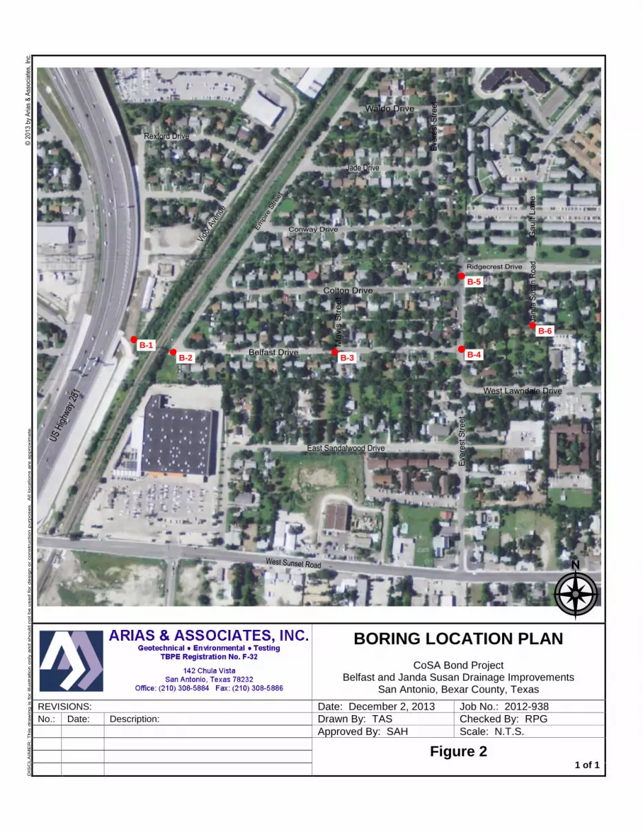
BORING LOCATION PLAN
CoSA Bond Project Belfast and Janda Susan Drainage Improvements
San Antonio, Bexar County, Texas
REVISIONS: Date: December 2, 2013 Job No.: 2012-938 No.: Date: Description: Drawn By: TAS Checked By: RPG
Approved By: SAH Scale: N.T.S.
Figure 2
1 of 1
B-1
B-2 B-3 B-4
B-5
B-6

Photo 1 – View looking at the drilling operations at Boring B-3.
Photo 2 – View looking at the drilling operations at Boring B-6.
SITE PHOTOS
CoSA Bond Project Belfast and Janda Susan Drainage Improvements
San Antonio, Bexar County, Texas
Date: November 25, 2013 Job No.: 2012-938 Appendix A 1 of 1
Drawn By: PPL Checked By: RPG Approved By: SAH Scale: N.T.S.
Arias & Associates, Inc. B-1 Arias Job No. 2012-938
APPENDIX B: BORING LOGS AND KEY TO TERMS

FILL: LEAN CLAY with Gravel (CL), hard, gray andbrown
FILL: FAT CLAY with Sand (CH), stiff, brown
FAT CLAY (CH), very stiff, dark brownStratum I
LEAN CLAY (CL), hard, tanStratum IIa
FAT CLAY (CH), hard, tan, with ferrous depositsStratum IIb
-with gypsum deposits below 18'
Borehole terminated at 20 feet
1.73
5.31
96
109
85
95
87
93
40
11
30
2.5
2.5
4.5+
4.5
4.5+
19
18
16
19
63
63
38
67
44
45
22
48
5
23
26
20
14
11
20
21
SS
SS
T
T
T
SS
T
T
Nomenclature Used on Boring Log
Arias & Associates, Inc.
Backfill: Cuttings
Split Spoon (SS) Thin-walled tube (T)
Job No.: 2012-938
Project: Belfast and Janda Susan Drainage ProjectSan Antonio, Texas
Sampling Date: 11/1/13
Location: See Boring Location Plan
Boring Log No. B-1
Groundwater Data:During drilling: Not encountered
Field Drilling Data:Logged By: J. KniffenDriller: Eagle Drilling, Inc.Equipment: Truck-mounted drill rig WC = Water Content (%)
PL = Plastic LimitLL = Liquid LimitPI = Plasticity Index
PP = Pocket Penetrometer (tsf)
N = SPT Blow Count-200 = % Passing #200 SieveDD = Dry Density (pcf)Uc = Compressive Strength (tsf)
Single flight auger: 0 - 20 ft
Soil Description
2012
-938
.GP
J 12
/23
/13
(BO
RIN
G L
OG
SA
13-0
2,A
RIA
SS
A12
-01.
GD
T,L
IBR
AR
Y20
13-0
1.G
LB)
UcDD-200NPPPL LL PIWCDepth(ft)
5
10
15
20
SN

6" AsphaltCLAYEY SAND with Gravel (SC), loose, light grayand brown, (possible fill)FAT CLAY (CH), stiff, dark brownStratum I
FAT CLAY (CH), very stiff, tanStratum II
-hard beow 10'
-with ferrous deposits from 18' to 20'
-with gypsum deposits below 23'
Borehole terminated at 25 feet
5.54
5.79
109
112
43
94
97
8
10
2.75
3.0
3.5
4.5+
4.5+
4.5+
4.5+
23
22
18
72
78
64
49
56
46
29
25
25
24
20
21
18
17
19
SS
SS
T
T
T
T
T
T
T
Nomenclature Used on Boring Log
Arias & Associates, Inc.
Backfill: Backfill and patched
Split Spoon (SS) Thin-walled tube (T)
Job No.: 2012-938
Project: Belfast and Janda Susan Drainage ProjectSan Antonio, Texas
Sampling Date: 11/1/13
Location: See Boring Location Plan
Boring Log No. B-2
Groundwater Data:During drilling: Not encountered
Field Drilling Data:Logged By: J. KniffenDriller: Eagle Drilling, Inc.Equipment: Truck-mounted drill rig WC = Water Content (%)
PL = Plastic LimitLL = Liquid LimitPI = Plasticity Index
PP = Pocket Penetrometer (tsf)
N = SPT Blow Count-200 = % Passing #200 SieveDD = Dry Density (pcf)Uc = Compressive Strength (tsf)
Single flight auger: 0 - 25 ft
Soil Description
2012
-938
.GP
J 12
/23
/13
(BO
RIN
G L
OG
SA
13-0
2,A
RIA
SS
A12
-01.
GD
T,L
IBR
AR
Y20
13-0
1.G
LB)
UcDD-200NPPPL LL PIWCDepth(ft)
5
10
15
20
25
SN

4.5" Asphalt7.5" BASEFAT CLAY with Sand (CH), stiff, dark brownStratum I-hard below 2'
-brown below 4'
FAT CLAY (CH), hard, tan and gray, with gypsumdepositsStratum II
Borehole terminated at 20 feet
9.16
9.73
3.13
112
116
106
84
96
14
4.5+
4.5+
4.5+
4.5+
4.5+
4.5+
4.5+
20
18
66
54
46
36
5
14
21
19
18
17
18
21
23
SS
T
T
T
T
T
T
T
Nomenclature Used on Boring Log
Arias & Associates, Inc.
Backfill: Backfill and patched
Split Spoon (SS) Thin-walled tube (T)
Job No.: 2012-938
Project: Belfast and Janda Susan Drainage ProjectSan Antonio, Texas
Sampling Date: 10/16/13
Location: See Boring Location Plan
Boring Log No. B-3
Groundwater Data:During drilling: Not encountered
Field Drilling Data:Logged By: R. ArizolaDriller: Eagle Drilling, Inc.Equipment: Truck-mounted drill rig WC = Water Content (%)
PL = Plastic LimitLL = Liquid LimitPI = Plasticity Index
PP = Pocket Penetrometer (tsf)
N = SPT Blow Count-200 = % Passing #200 SieveDD = Dry Density (pcf)Uc = Compressive Strength (tsf)
Single flight auger: 0 - 20 ft
Soil Description
2012
-938
.GP
J 12
/23
/13
(BO
RIN
G L
OG
SA
13-0
2,A
RIA
SS
A12
-01.
GD
T,L
IBR
AR
Y20
13-0
1.G
LB)
UcDD-200NPPPL LL PIWCDepth(ft)
5
10
15
20
SN
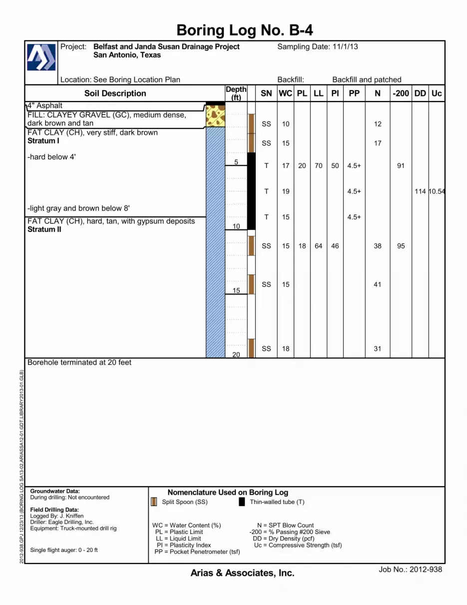
4" AsphaltFILL: CLAYEY GRAVEL (GC), medium dense,dark brown and tanFAT CLAY (CH), very stiff, dark brownStratum I
-hard below 4'
-light gray and brown below 8'
FAT CLAY (CH), hard, tan, with gypsum depositsStratum II
Borehole terminated at 20 feet
10.54114
91
95
12
17
38
41
31
4.5+
4.5+
4.5+
20
18
70
64
50
46
10
15
17
19
15
15
15
18
SS
SS
T
T
T
SS
SS
SS
Nomenclature Used on Boring Log
Arias & Associates, Inc.
Backfill: Backfill and patched
Split Spoon (SS) Thin-walled tube (T)
Job No.: 2012-938
Project: Belfast and Janda Susan Drainage ProjectSan Antonio, Texas
Sampling Date: 11/1/13
Location: See Boring Location Plan
Boring Log No. B-4
Groundwater Data:During drilling: Not encountered
Field Drilling Data:Logged By: J. KniffenDriller: Eagle Drilling, Inc.Equipment: Truck-mounted drill rig WC = Water Content (%)
PL = Plastic LimitLL = Liquid LimitPI = Plasticity Index
PP = Pocket Penetrometer (tsf)
N = SPT Blow Count-200 = % Passing #200 SieveDD = Dry Density (pcf)Uc = Compressive Strength (tsf)
Single flight auger: 0 - 20 ft
Soil Description
2012
-938
.GP
J 12
/23
/13
(BO
RIN
G L
OG
SA
13-0
2,A
RIA
SS
A12
-01.
GD
T,L
IBR
AR
Y20
13-0
1.G
LB)
UcDD-200NPPPL LL PIWCDepth(ft)
5
10
15
20
SN
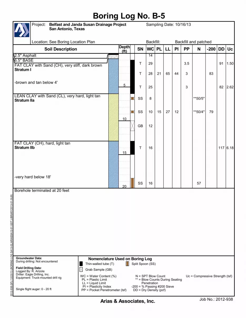
2.5" Asphalt6.5" BASEFAT CLAY with Sand (CH), very stiff, dark brownStratum I
-brown and tan below 4'
LEAN CLAY with Sand (CL), very hard, light tanStratum IIa
FAT CLAY (CH), hard, light tanStratum IIb
-very hard below 18'
Borehole terminated at 20 feet
1.50
2.62
6.18
91
82
117
83
79
**50/5"
**50/4"
57
3.5
3
3
21
15
65
27
44
12
14
29
28
25
8
10
12
16
16
T
T
T
SS
SS
GB
T
SS
Nomenclature Used on Boring Log
Arias & Associates, Inc.
Backfill: Backfill and patched
Thin-walled tube (T) Split Spoon (SS)
Grab Sample (GB)
Job No.: 2012-938
Project: Belfast and Janda Susan Drainage ProjectSan Antonio, Texas
Sampling Date: 10/16/13
Location: See Boring Location Plan
Boring Log No. B-5
Groundwater Data:During drilling: Not encountered
Field Drilling Data:Logged By: R. ArizolaDriller: Eagle Drilling, Inc.Equipment: Truck-mounted drill rig WC = Water Content (%)
PL = Plastic LimitLL = Liquid LimitPI = Plasticity Index
PP = Pocket Penetrometer (tsf)
N = SPT Blow Count** = Blow Counts During Seating
Penetration-200 = % Passing #200 SieveDD = Dry Density (pcf)
Uc = Compressive Strength (tsf)
Single flight auger: 0 - 20 ft
Soil Description
2012
-938
.GP
J 12
/23
/13
(BO
RIN
G L
OG
SA
13-0
2,A
RIA
SS
A12
-01.
GD
T,L
IBR
AR
Y20
13-0
1.G
LB)
UcDD-200NPPPL LL PIWCDepth(ft)
5
10
15
20
SN

4.5" Asphalt7.5" BASEFAT CLAY (CH), very stiff, dark brownStratum I-stiff from 2' to 4'
-hard below 4'
SANDY LEAN CLAY (CL), very hard, tan and grayStratum IIa
-with gypsum deposits from 8' to 12'
Borehole terminated at 15 feet
11.69
8.44
108
70
92
67
18
10
60
4.5+
4.5+
4.5+
23
18
75
46
52
28
7
23
22
21
19
16
18
17
SS
SS
T
T
SS
GB
T
Nomenclature Used on Boring Log
Arias & Associates, Inc.
Backfill: Backfill and patched
Split Spoon (SS) Thin-walled tube (T)
Grab Sample (GB)
Job No.: 2012-938
Project: Belfast and Janda Susan Drainage ProjectSan Antonio, Texas
Sampling Date: 10/16/13
Location: See Boring Location Plan
Boring Log No. B-6
Groundwater Data:During drilling: Not encountered
Field Drilling Data:Logged By: R. ArizolaDriller: Eagle Drilling, Inc.Equipment: Truck-mounted drill rig WC = Water Content (%)
PL = Plastic LimitLL = Liquid LimitPI = Plasticity Index
PP = Pocket Penetrometer (tsf)
N = SPT Blow Count-200 = % Passing #200 SieveDD = Dry Density (pcf)Uc = Compressive Strength (tsf)
Single flight auger: 0 - 15 ft
Soil Description
2012
-938
.GP
J 12
/23
/13
(BO
RIN
G L
OG
SA
13-0
2,A
RIA
SS
A12
-01.
GD
T,L
IBR
AR
Y20
13-0
1.G
LB)
UcDD-200NPPPL LL PIWCDepth(ft)
5
10
15
SN

4.5" Asphalt7.5" BASEFAT CLAY (CH), very stiff, dark brown-stiff from 2' to 4'
-hard below 4'
SANDY LEAN CLAY (CL), very hard, tan and gray
-with gypsum deposits from 8' to 12'
Borehole terminated at 15 feet
11.69
8.44
108
70
92
67
18
10
60
4.5+
4.5+
4.5+
23
18
75
46
52
28
7
23
22
21
19
16
18
17
SS
SS
T
T
SS
GB
T
Nomenclature Used on Boring Log
Arias & Associates, Inc.
Backfill: Backfill and patched
Split Spoon (SS) Thin-walled tube (T)
Grab Sample (GB)
Job No.: 2012-938
Project: Belfast and Janda Susan Drainage ProjectSan Antonio, Texas
Sampling Date: 10/16/13
Location: See Boring Location Plan
Boring Log No. B-6
Soil Description
Groundwater Data:During drilling: Not encountered
Field Drilling Data:Logged By: R. ArizolaDriller: Eagle Drilling, Inc.Equipment: Truck-mounted drill rig WC = Water Content (%)
PL = Plastic LimitLL = Liquid LimitPI = Plasticity Index
PP = Pocket Penetrometer (tsf)
N = SPT Blow Count-200 = % Passing #200 SieveDD = Dry Density (pcf)Uc = Compressive Strength (tsf)
Single flight auger: 0 - 15 ft
2012
-938
.GP
J 12
/20
/13
(BO
RIN
G L
OG
SA
13-0
2,A
RIA
SS
A12
-01.
GD
T,L
IBR
AR
Y20
13-0
1.G
LB)
UcDD-200NPPPL LL PIWCDepth(ft)
5
10
15
SN

SP
SANDSTONE
Cle
an S
ands
(Litt
le o
r no
Fin
es)
San
ds W
ith F
ines
(App
reci
able
Am
ount
of F
ines
)
Liqu
id L
imit
Less
Tha
n50
Liqu
id L
imit
Gre
ater
Tha
n50
SIL
TS
&C
LA
YS
GR
AV
EL
S
CO
AR
SE
-GR
AIN
ED
SO
ILS
FIN
E-G
RA
INE
D S
OIL
S
Silty Sands, Sand-Silt Mixtures
Clayey Sands, Sand-Clay Mixtures
Inorganic Clays of Low to Medium Plasticity,Gravelly Clays, Sandy Clays, Silty Clays,
Lean Clays
Inorganic Silts, Micaceous or Diatomaceous FineSand or Silty Soils, Elastic Silts
Inorganic Clays of High Plasticity, Fat Clays
Massive Sandstones, Sandstoneswith Gravel Clasts
Mor
e T
han
Hal
f of
Mat
eria
l is
SM
ALL
ER
Tha
n N
o. 2
00 S
ieve
Siz
e
SIL
TS
&C
LA
YS
GROUNDWATER
SA
ND
S
Mor
e T
han
Hal
f of
Mat
eria
l LA
RG
ER
Tha
n N
o. 2
00 S
ieve
siz
e
Gra
vels
With
Fin
es(A
ppre
ciab
leA
mou
nt o
f Fin
es)
GW
ML
Indurated Argillaceous Limestones
Massive or Weakly Bedded Limestones
Mudstone or Massive Claystones
Massive or Poorly Bedded Chalk Deposits
Cretaceous Clay Deposits
CLAYSTONE
CHALK
MARINE CLAYS
Poorly-Graded Gravels, Gravel-Sand Mixtures,Little or no Fines
Silty Gravels, Gravel-Sand-Silt Mixtures
Clayey Gravels, Gravel-Sand-Clay Mixtures
Well-Graded Sands, Gravelly Sands,Little or no Fines
Inorganic Silts & Very Fine Sands, Rock Flour,Silty or Clayey Fine Sands or Clayey Silts
with Slight Plasticity
Indicates Final Observed Groundwater Level
Indicates Initial Observed Groundwater Location
GP
GM
GC
SW
Mor
e T
han
Hal
f of
Coa
rse
Fra
ctio
nis
LA
RG
ER
Tha
n N
o. 4
Sie
ve S
ize
CL
MH
CH
SC
Arias & Associates, Inc.
KEY TO CLASSIFICATION SYMBOLS USED ON BORING LOGS
MAJOR DIVISIONS GROUPSYMBOLS DESCRIPTIONS
Poorly-Graded Sands, Gravelly Sands,Little or no Fines
Well-Graded Gravels, Gravel-Sand Mixtures, Littleor no Fines
FO
RM
AT
ION
AL
MA
TE
RIA
LS
Mor
e T
han
Hal
f of
Coa
rse
Fra
ctio
nis
SM
ALL
ER
Tha
n N
o. 4
Sie
ve S
ize
Cle
an G
rave
ls(L
ittle
or
no F
ines
)
MARLSTONE
LIMESTONE
SM

Arias & Associates, Inc. C-1 Arias Job No. 2012-938
APPENDIX C: FIELD AND LABORATORY EXPLORATION
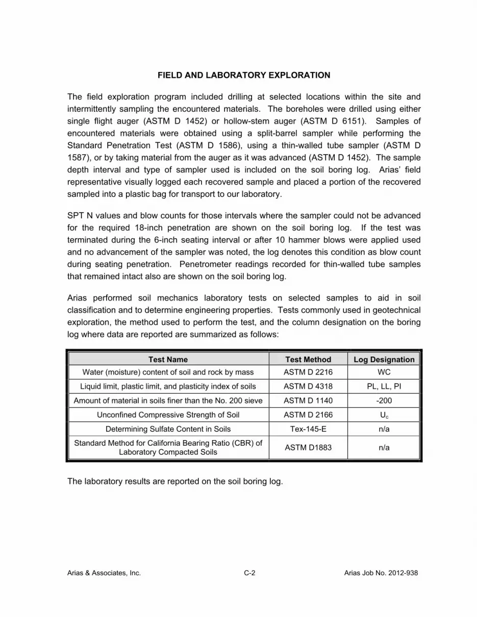
Arias & Associates, Inc. C-2 Arias Job No. 2012-938
FIELD AND LABORATORY EXPLORATION
The field exploration program included drilling at selected locations within the site and
intermittently sampling the encountered materials. The boreholes were drilled using either
single flight auger (ASTM D 1452) or hollow-stem auger (ASTM D 6151). Samples of
encountered materials were obtained using a split-barrel sampler while performing the
Standard Penetration Test (ASTM D 1586), using a thin-walled tube sampler (ASTM D
1587), or by taking material from the auger as it was advanced (ASTM D 1452). The sample
depth interval and type of sampler used is included on the soil boring log. Arias’ field
representative visually logged each recovered sample and placed a portion of the recovered
sampled into a plastic bag for transport to our laboratory.
SPT N values and blow counts for those intervals where the sampler could not be advanced
for the required 18-inch penetration are shown on the soil boring log. If the test was
terminated during the 6-inch seating interval or after 10 hammer blows were applied used
and no advancement of the sampler was noted, the log denotes this condition as blow count
during seating penetration. Penetrometer readings recorded for thin-walled tube samples
that remained intact also are shown on the soil boring log.
Arias performed soil mechanics laboratory tests on selected samples to aid in soil
classification and to determine engineering properties. Tests commonly used in geotechnical
exploration, the method used to perform the test, and the column designation on the boring
log where data are reported are summarized as follows:
Test Name Test Method Log Designation
Water (moisture) content of soil and rock by mass ASTM D 2216 WC
Liquid limit, plastic limit, and plasticity index of soils ASTM D 4318 PL, LL, PI
Amount of material in soils finer than the No. 200 sieve ASTM D 1140 -200
Unconfined Compressive Strength of Soil ASTM D 2166 Uc
Determining Sulfate Content in Soils Tex-145-E n/a
Standard Method for California Bearing Ratio (CBR) of Laboratory Compacted Soils
ASTM D1883 n/a
The laboratory results are reported on the soil boring log.
Arias & Associates, Inc. D-1 Arias Job No. 2012-938
APPENDIX D: MOISTURE-DENSITY AND CBR TEST RESULTS
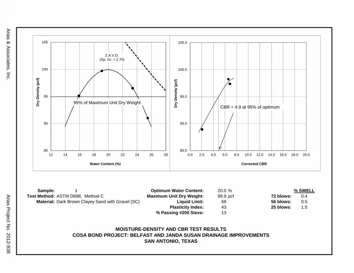
Arias & Associates, Inc.
Sample: 1 Optimum Water Content: 20.0 % % SWELLTest Method: ASTM D698, Method C Maximum Unit Dry Weight: 99.9 pcf 72 blows: 0.4
Material: Dark Brown Clayey Sand with Gravel (SC) Liquid Limit: 66 56 blows: 0.5Plasticity Index: 43 25 blows: 1.5
% Passing #200 Sieve: 13
MOISTURE-DENSITY AND CBR TEST RESULTSCOSA BOND PROJECT: BELFAST AND JANDA SUSAN DRAINAGE IMPROVEMENTS
SAN ANTONIO, TEXAS
Arias Project No. 2012-938
85
90
95
100
105
12 14 16 18 20 22 24 26 28
Dry
Den
sity
(pcf
)
Water Content (%)
85.0
90.0
95.0
100.0
105.0
0.0 2.0 4.0 6.0 8.0 10.0 12.0 14.0 16.0 18.0 20.0
Dry
Den
sity
(pcf
)
Corrected CBR
CBR = 4.9 at 95% of optimum
Z.A.V.D. (Sp. Gr. = 2.70)
95% of Maximum Unit Dry Weight

Arias & Associates, Inc. E-1 Arias Job No. 2012-938
APPENDIX E: ASFE INFORMATION – GEOTECHNICAL REPORT
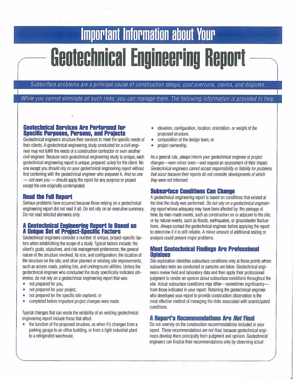

Arias & Associates, Inc. F-1 Arias Job No. 2012-938
APPENDIX F: QUALITY ASSURANCE

8811 Colesville Road Suite G106 Silver Spring, Maryland 20910 Voice: 301.565.2733 Fax: 301.589.2017 E-mail: [email protected] Internet: www.asfe.org
PROJECT QUALITY ASSURANCE
1
Construction materials engineering and testing (CoMET) consultants perform quality-assurance (QA) services to evaluate the degree to which constructors are achieving the specified conditions they’re contractually obligated to achieve. Done right, QA can save you time and money; prevent unanticipated-conditions claims, change orders, and disputes; and reduce short-term and long-term risks, especially by detecting molehills before they grow into mountains.
Many owners don’t do QA right because they follow bad advice; e.g., “CoMET consultants are all the same. They all have accredited facilities and certified personnel. Go with the low bidder.” But there’s no such thing as a standard QA scope of service, meaning that – to bid low – each interested firms must propose the cheapest QA service it can live with, jeopardizing service quality and aggravating risk for the entire project team. Besides, the advice is based on misinformation.
Fact: Most CoMET firms are not accredited, and the quality of those that are varies significantly. Accreditation – which is important – nonetheless means that a facility met an accrediting body’s minimum criteria. Some firms practice at a much higher level; others just barely scrape by. And what an accrediting body typically evaluates – management, staff, facilities, and equipment – can change substantially before the next review, two, three, or more years from now.
Fact: It’s dangerous to assume CoMET personnel are certified. Many have no credentials at all; some are certified by organizations of questionable merit, while others have a valid certification, but not for the services they’re assigned.
Some CoMET firms – the “low-cost providers” – want you to believe that price is the only difference between QA providers. It’s not, of course. Firms that sell low price typically lack the facilities, equipment, personnel, and insurance quality-oriented firms invest in to achieve the reliability concerned owners need to achieve quality in quality assurance.
A Message to Owners
Done right, QA can save you time and
money; prevent claims and disputes; and
reduce risks. Many owners don’t do QA
right because they follow bad advice.
Most CoMET firms are not accredited.
It’s dangerous to assume CoMET
personnel are certified.
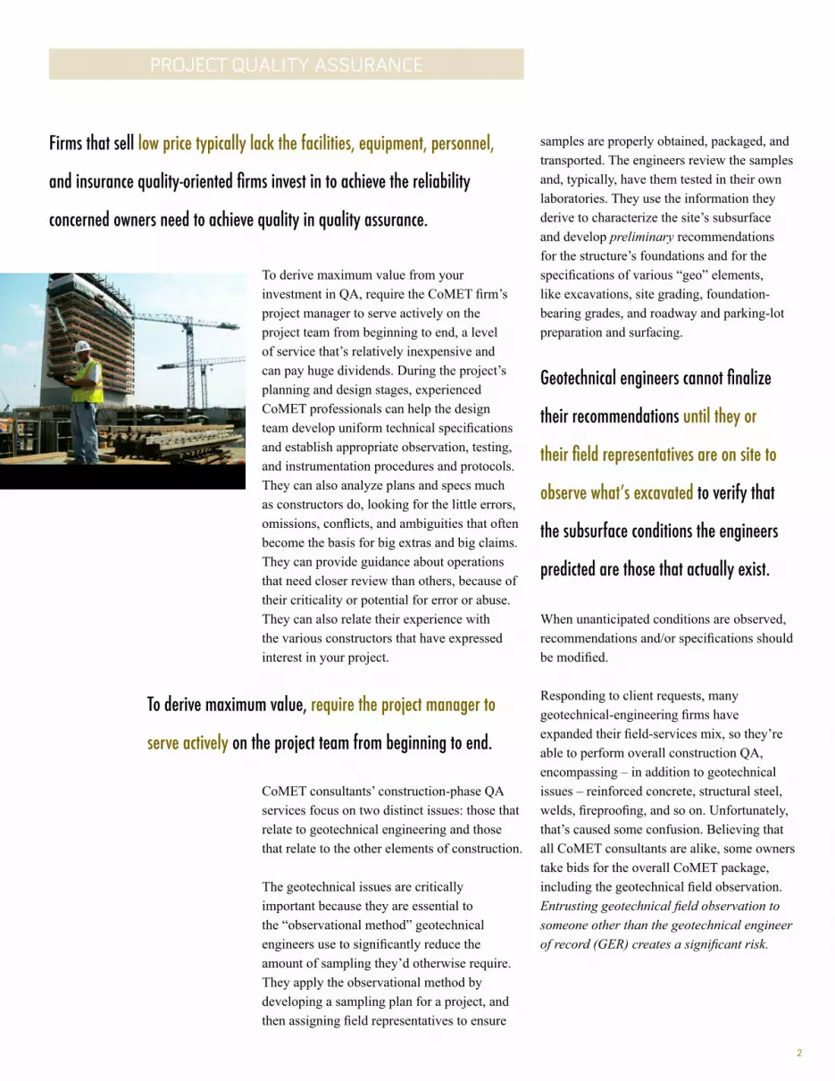
PROJECT QUALITY ASSURANCE
To derive maximum value from your investment in QA, require the CoMET firm’s project manager to serve actively on the project team from beginning to end, a level of service that’s relatively inexpensive and can pay huge dividends. During the project’s planning and design stages, experienced CoMET professionals can help the design team develop uniform technical specifications and establish appropriate observation, testing, and instrumentation procedures and protocols. They can also analyze plans and specs much as constructors do, looking for the little errors, omissions, conflicts, and ambiguities that often become the basis for big extras and big claims. They can provide guidance about operations that need closer review than others, because of their criticality or potential for error or abuse. They can also relate their experience with the various constructors that have expressed interest in your project.
CoMET consultants’ construction-phase QA services focus on two distinct issues: those that relate to geotechnical engineering and those that relate to the other elements of construction.
The geotechnical issues are critically important because they are essential to the “observational method” geotechnical engineers use to significantly reduce the amount of sampling they’d otherwise require. They apply the observational method by developing a sampling plan for a project, and then assigning field representatives to ensure
samples are properly obtained, packaged, and transported. The engineers review the samples and, typically, have them tested in their own laboratories. They use the information they derive to characterize the site’s subsurface and develop preliminary recommendations for the structure’s foundations and for the specifications of various “geo” elements, like excavations, site grading, foundation-bearing grades, and roadway and parking-lot preparation and surfacing.
Geotechnical engineers cannot finalize
their recommendations until they or
their field representatives are on site to
observe what’s excavated to verify that
the subsurface conditions the engineers
predicted are those that actually exist.
When unanticipated conditions are observed, recommendations and/or specifications should be modified.
Responding to client requests, many geotechnical-engineering firms have expanded their field-services mix, so they’re able to perform overall construction QA, encompassing – in addition to geotechnical issues – reinforced concrete, structural steel, welds, fireproofing, and so on. Unfortunately, that’s caused some confusion. Believing that all CoMET consultants are alike, some owners take bids for the overall CoMET package, including the geotechnical field observation. Entrusting geotechnical field observation to someone other than the geotechnical engineer of record (GER) creates a significant risk.
Firms that sell low price typically lack the facilities, equipment, personnel,
and insurance quality-oriented firms invest in to achieve the reliability
concerned owners need to achieve quality in quality assurance.
To derive maximum value, require the project manager to
serve actively on the project team from beginning to end.
2
3
PROJECT QUALITY ASSURANCE
GERs have developed a variety of protocols to optimize the quality of their field-observation procedures. Quality-focused GERs meet with their field representatives before they leave for a project site, to brief them on what to look for and where, when, and how to look. (No one can duplicate this briefing, because no one else knows as much about a project’s geotechnical issues.) And once they arrive at a project site, the field representatives know to maintain timely, effective communication with the GER, because that’s what the GER has trained them to do. By contrast, it’s extremely rare for a different firm’s field personnel to contact the GER, even when they’re concerned or confused about what they observe, because they regard the GER’s firm as “the competition.”
Divorcing the GER from geotechnical field operations is almost always penny-wise and pound-foolish. Still, because owners are given bad advice, it’s commonly done, helping to explain why “geo” issues are the number-one source of construction-industry claims and disputes.
To derive the biggest bang for the QA buck, identify three or even four quality-focused CoMET consultants. (If you don’t know any,
use the “Find a Geoprofessional” service available free at www.asfe.org.) Ask about the firms’ ongoing and recent projects and the clients and client representatives involved; insist upon receiving verification of all claimed accreditations, certifications, licenses, and insurance coverages.
Insist upon receiving verification of all
claimed accreditations, certifications,
licenses, and insurance coverages.
Once you identify the two or three most qualified firms, meet with their representatives, preferably at their own facility, so you can inspect their laboratory, speak with management and technical staff, and form an opinion about the firm’s capabilities and attitude.
Insist that each firm’s designated project manager participate in the meeting. You will benefit when that individual is a seasoned QA professional familiar with construction’s rough-and-tumble. Ask about others the firm will assign, too. There’s no substitute for experienced personnel who are familiar with the codes and standards involved and know how to: • read and interpret plans and specifications; • perform the necessary observation,
inspection, and testing; • document their observations and findings; • interact with constructors’ personnel; and • respond to the unexpected.
Important: Many of the services CoMET QA field representatives perform – like observing operations and outcomes – require the good judgment afforded by extensive training and experience, especially in situations where standard operating procedures do not apply. You need to know who will be exercising that judgment: a 15-year “veteran” or a rookie?
Geotechnical engineers cannot finalize their recommendations until they are
on site to verify that the subsurface conditions they predicted are those that
actually exist. Entrusting geotechnical field observation to someone other than
the geotechnical engineer of record (GER) creates a significant risk.
Divorcing the GER from geotechnical field operations is almost
always penny-wise and pound-foolish, helping to explain
why “geo” issues are the number-one source of construction-
industry claims and disputes.

4
PROJECT QUALITY ASSURANCE
Also consider the tools CoMET personnel use. Some firms are passionate about proper calibration; others, less so. Passion is a good thing! Ask to see the firm’s calibration records. If the firm doesn’t have any, or if they are not current, be cautious. You cannot trust test results derived using equipment that may be out of calibration. Also ask a firm’s representatives about their reporting practices, including report distribution, how they handle notifications of nonconformance, and how they resolve complaints.
For financing purposes, some owners require the constructor to pay for CoMET services. Consider an alternative approach so you don’t convert the constructor into the CoMET consultant’s client. If it’s essential for you to fund QA via the constructor, have the CoMET fee included as an allowance in the bid documents. This arrangement ensures that you remain the CoMET consultant’s client, and it prevents the CoMET fee from becoming part of the constructor’s bid-price competition. (Note that the International Building Code (IBC) requires the owner to pay for Special Inspection (SI) services commonly performed by the CoMET consultant as a service separate from QA, to help ensure the SI services’ integrity. Because failure to comply could result in denial of an occupancy or use permit, having a contractual agreement that conforms to the IBC mandate is essential.)
If it’s essential for you to fund QA via the
constructor, have the CoMET fee included as
an allowance in the bid documents. Note,
too, that the International Building Code
(IBC) requires the owner to pay for Special
Inspection (SI) services.
CoMET consultants can usually quote their fees as unit fees, unit fees with estimated total (invoiced on a unit-fee basis), or lump-sum (invoiced on a percent-completion basis referenced to a schedule of values). No matter which method is used, estimated quantities need to be realistic. Some CoMET firms lower their total-fee estimates by using quantities they know are too low and then request change orders long before QA is complete.
Once you and the CoMET consultant settle on the scope of service and fee, enter into a written contract. Established CoMET firms have their own contracts; most owners sign them. Some owners prefer to use different contracts, but that can be a mistake when the contract was prepared for construction services. Professional services are different. Wholly avoidable problems occur when a contract includes provisions that don’t apply to the services involved and fail to include those that do.
Many of the services CoMET QA field representatives perform
require good judgment.
Scope flexibility is needed to deal promptly
with the unanticipated.
Some owners create wholly avoidable
problems by using a contract prepared for
construction services.
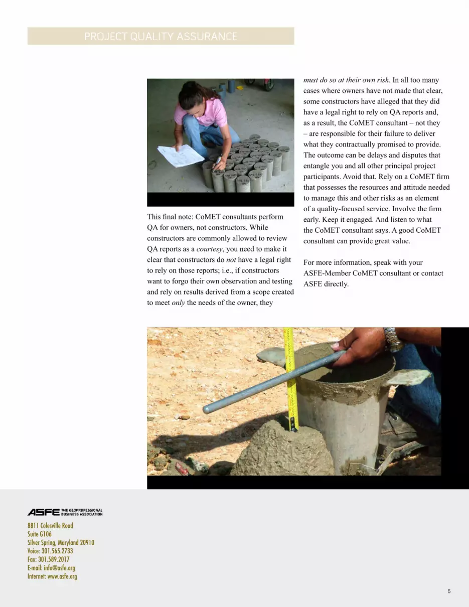
8811 Colesville Road Suite G106 Silver Spring, Maryland 20910 Voice: 301.565.2733 Fax: 301.589.2017 E-mail: [email protected] Internet: www.asfe.org
PROJECT QUALITY ASSURANCE
This final note: CoMET consultants perform QA for owners, not constructors. While constructors are commonly allowed to review QA reports as a courtesy, you need to make it clear that constructors do not have a legal right to rely on those reports; i.e., if constructors want to forgo their own observation and testing and rely on results derived from a scope created to meet only the needs of the owner, they
must do so at their own risk. In all too many cases where owners have not made that clear, some constructors have alleged that they did have a legal right to rely on QA reports and, as a result, the CoMET consultant – not they – are responsible for their failure to deliver what they contractually promised to provide. The outcome can be delays and disputes that entangle you and all other principal project participants. Avoid that. Rely on a CoMET firm that possesses the resources and attitude needed to manage this and other risks as an element of a quality-focused service. Involve the firm early. Keep it engaged. And listen to what the CoMET consultant says. A good CoMET consultant can provide great value.
For more information, speak with your ASFE-Member CoMET consultant or contact ASFE directly.
5