project manual - bidnet
TRANSCRIPT
FIRE STATION 9 REPLACEMENT DIVISION 21
SECTION 21 05 00
COMMON WORK RESULTS
FOR FIRE SUPPRESSION
21 05 00 - 1
PART 1 - GENERAL
1.1 RELATED DOCUMENTS
A. Drawings and general provisions of the Contract, including Municipality of Anchorage
Standard Specifications – Buildings (MASSB), General and Supplementary Conditions
apply to this Section.
1.2 WORK INCLUDED
A. Pipe.
B. Fittings.
C. Valves.
1.3 RELATED SECTIONS
A. Division 09 - Finishes: Execution requirements for piping painting specified by this
section.
1.4 REFERENCES
A. American Society of Mechanical Engineers:
1. ASME B16.1 - Cast Iron Pipe Flanges and Flanged Fittings.
2. ASME B16.11 - Forged Steel Fittings - Socket-Welding and Threaded.
3. ASME B16.18 - Cast Copper Alloy Solder Joint Pressure Fittings.
4. ASME B16.22 - Wrought Copper and Copper Alloy Solder Joint Pressure
Fittings.
5. ASME B16.25 - Buttwelding Ends.
6. ASME B16.3 - Malleable Iron Threaded Fittings.
7. ASME B16.4 - Gray Iron Threaded Fittings.
8. ASME B16.5 - Pipe Flanges and Flanged Fittings.
9. ASME B16.9 - Factory-Made Wrought Steel Buttwelding Fittings.
10. ASME B36.10M - Welded and Seamless Wrought Steel Pipe.
B. ASTM International:
FIRE STATION 9 REPLACEMENT DIVISION 21
SECTION 21 05 00
COMMON WORK RESULTS
FOR FIRE SUPPRESSION
21 05 00 - 2
1. ASTM A53/A53M - Standard Specification for Pipe, Steel, Black and Hot-
Dipped, Zinc-Coated, Welded and Seamless.
2. ASTM A135 - Standard Specification for Electric-Resistance-Welded Steel Pipe.
3. ASTM A234/A234M - Standard Specification for Piping Fittings of Wrought
Carbon Steel and Alloy Steel for Moderate and High Temperature Service.
4. ASTM A795 - Standard Specification for Black and Hot-Dipped Zinc-Coated
(Galvanized) Welded and Seamless Steel Pipe for Fire Protection Use.
5. ASTM B32 - Standard Specification for Solder Metal.
6. ASTM B75 - Standard Specification for Seamless Copper Tube.
7. ASTM B88 - Standard Specification for Seamless Copper Water Tube.
8. ASTM B251 - Standard Specification for General Requirements for Wrought
Seamless Copper and Copper-Alloy Tube.
C. American Welding Society:
1. AWS A5.8 - Specification for Filler Metals for Brazing and Braze Welding.
2. AWS D1.1 - Structural Welding Code - Steel.
D. American Water Works Association:
1. AWWA C110 - American National Standard for Ductile-Iron and Grey-Iron
Fittings, 3 in. through 48 in. (75 mm through 1200 mm), for Water and Other
Liquids.
2. AWWA C111 - American National Standard for Rubber-Gasket Joints for
Ductile-Iron Pressure Pipe and Fittings.
3. AWWA C151 - American National Standard for Ductile-Iron Pipe, Centrifugally
Cast, for Water.
E. National Fire Protection Association:
1. NFPA 13 - Installation of Sprinkler Systems.
2. NFPA 14 - Standard for the Installation of Standpipe, Private Hydrants and Hose
Systems.
3. NFPA 24 - Installation of Private Fire Service Mains and Their Appurtenances.
1.5 SUBMITTALS
A. Supplementary Conditions: Submittal procedures.
B. Shop Drawings: Indicate pipe materials used, jointing methods, supports, floor and wall
penetration seals. Indicate installation, layout, weights, mounting and support details,
and piping connections.
FIRE STATION 9 REPLACEMENT DIVISION 21
SECTION 21 05 00
COMMON WORK RESULTS
FOR FIRE SUPPRESSION
21 05 00 - 3
C. Product Data: Submit manufacturer’s catalogue information. Indicate valve data and
ratings.
D. Manufacturer's Certificate: Certify products meet or exceed specified requirements.
1.6 CLOSEOUT SUBMITTALS
A. Supplementary Conditions - Execution and Closeout Requirements: Closeout
procedures.
B. Project Record Documents: Record actual locations of components and tag numbering.
C. Operation and Maintenance Data: Submit spare parts lists.
1.7 QUALITY ASSURANCE
A. Perform Work in accordance with NFPA 13.
1.8 QUALIFICATIONS
A. Manufacturer: Company specializing in manufacturing products specified in this section
with minimum three years documented experience.
B. Installer: Company specializing in performing Work of this section with minimum three
years documented experience.
1.9 DELIVERY, STORAGE, AND HANDLING
A. Supplementary Conditions: Product storage and handling requirements.
B. Deliver and store valves in shipping containers, with labeling in place.
C. Furnish cast iron and steel valves with temporary protective coating.
D. Furnish temporary end caps and closures on piping and fittings. Maintain in place until
installation.
1.10 WARRANTY
A. Supplementary Conditions: Execution and Closeout Requirements: Product warranties
and product bonds.
FIRE STATION 9 REPLACEMENT DIVISION 21
SECTION 21 05 00
COMMON WORK RESULTS
FOR FIRE SUPPRESSION
21 05 00 - 4
1.11 EXTRA MATERIALS
A. Supplementary Conditions - Execution and Closeout Requirements: Spare parts and
maintenance products.
PART 2 - PRODUCTS
2.1 GENERAL
A. All products shall bear the "UL" label or "FM" listing and be specifically approved for
fire protection application where they are used.
2.2 VALVES
A. Gate Valves:
1. Up to and including 2 inches: Bronze body and trim, rising stem, hand wheel,
solid wedge or disc, threaded ends.
2. Over 2 inches: Iron body, bronze trim, rising stem pre-grooved for mounting
tamper switch, hand wheel, OS&Y, solid bronze or cast iron wedge, flanged or
grooved ends.
3. Over 4 inches: Iron body, bronze trim, non-rising stem with bolted bonnet, solid
bronze wedge, flanged ends, iron body indicator post assembly.
B. Ball Valves:
1. Up to and including 2 inches: Bronze two piece body, brass, chrome plated
bronze, or stainless steel ball, teflon seats and stuffing box ring, lever handle,
threaded ends.
2. Over 2 inches: Cast steel body, chrome plated steel ball, teflon seat and stuffing
box seals, lever handle, flanged.
C. Butterfly Valves:
1. Bronze Body: Stainless steel disc, resilient replaceable seat, threaded or grooved
ends, extended neck, hand wheel and gear drive and integral indicating device.
2. Cast or Ductile Iron Body: Cast or ductile iron, chrome or nickel plated ductile
iron or aluminum bronze disc, resilient replaceable EPDM seat, wafer, lug, or
grooved ends. With extended neck, hand wheel and gear drive and integral
indicating device and external tamper switch.
D. Check Valves:
FIRE STATION 9 REPLACEMENT DIVISION 21
SECTION 21 05 00
COMMON WORK RESULTS
FOR FIRE SUPPRESSION
21 05 00 - 5
1. Up to and including 2 inches: Bronze body and swing disc, rubber seat, threaded
ends.
2. Over 2 inches: Iron body, bronze trim, swing check with rubber disc, renewable
disc and seat, flanged ends.
3. 4 inches and Over: Iron body, bronze disc with stainless steel spring, resilient
seal, threaded, wafer, or flanged ends.
E. Drain Valves:
1. Ball Valve: Brass with cap and chain, 3/4 inch hose thread.
2.3 PIPING
A. Wet Pipe Sprinkler Systems:
1. Any metallic piping system currently recognized by NFPA 13 standards may be
utilized if listed for the intended service by "UL" or "FM".
2. Whenever piping other than steel schedule 40 is utilized, submit a statement that
the piping complies with NFPA 13 standards and that the piping strength is
adequate for the application. Include this data in the equipment submittal under
part 1 of this specification.
2.4 PIPE HANGERS AND SUPPORTS
A. Conform to NFPA 13.
B. Hangers for Pipe Sizes 1/2 to 1-1/2 inch: Malleable iron or Carbon steel, adjustable
swivel, split ring.
C. Hangers for Pipe Sizes 2 inch and Over: Carbon steel, adjustable, clevis.
D. Multiple or Trapeze Hangers: Steel channels with welded spacers and hanger rods.
E. Wall Support for Pipe Sizes to 3 inches: Cast iron hook.
F. Wall Support for Pipe Sizes 4 inches and Over: Welded steel bracket and wrought steel
clamp.
G. Vertical Support: Steel riser clamp.
H. Floor Support: Cast iron adjustable pipe saddle, lock nut, nipple, floor flange, and
concrete pier or steel support.
I. Copper Pipe Support: Carbon steel ring, adjustable, copper plated.
FIRE STATION 9 REPLACEMENT DIVISION 21
SECTION 21 05 00
COMMON WORK RESULTS
FOR FIRE SUPPRESSION
21 05 00 - 6
PART 3 - EXECUTION
3.1 PREPARATION
A. Ream pipe and tube ends. Remove burrs. Bevel plain end ferrous pipe.
B. Remove scale and foreign material, from inside and outside, before assembly.
C. Prepare piping connections to equipment with flanges or unions.
3.2 INSTALLATION
A. Install piping in accordance with NFPA 13 for sprinkler systems.
B. Route piping in orderly manner, plumb and parallel to building structure. Maintain
gradient.
C. Install piping to conserve building space, to not interfere with use of space and other
work.
D. Group piping whenever practical at common elevations.
E. Install pipe sleeve at piping penetrations through footings and floors. Seal pipe and
sleeve penetrations to maintain fire resistance equivalent to fire separation.
F. Install piping to allow for expansion and contraction without stressing pipe, joints, or
connected equipment.
G. Pipe Hangers and Supports:
1. Install in accordance with NFPA 13.
2. Install hangers to with minimum 1/2 inch space between finished covering and
adjacent work.
3. Place hangers within 12 inches of each horizontal elbow.
4. Use hangers with 1-1/2 inch minimum vertical adjustment. Design hangers for
pipe movement without disengagement of supported pipe.
5. Support vertical piping at every floor. Support riser piping independently of
connected horizontal piping.
6. Where installing several pipes in parallel and at same elevation, provide multiple
or trapeze hangers.
7. Install copper plated hangers and supports for copper piping.
H. Slope piping and arrange systems to drain at low points. Install eccentric reducers to
maintain top of pipe level.
FIRE STATION 9 REPLACEMENT DIVISION 21
SECTION 21 05 00
COMMON WORK RESULTS
FOR FIRE SUPPRESSION
21 05 00 - 7
I. Prepare pipe, fittings, supports, and accessories for finish painting. Where pipe support
members are welded to structural building framing, scrape, brush clean, and apply one
coat of zinc rich primer to welding.
J. Do not penetrate building structural members unless indicated.
K. Where more than one piping system material is specified, install compatible system
components and joints. Install flanges, union, and couplings at locations requiring
servicing.
L. Die cut threaded joints with full cut standard taper pipe threads with red lead and
linseed oil or other non-toxic joint compound applied to male threads only.
M. Install valves with stems upright or horizontal, not inverted. Remove protective coatings
after installation.
N. Install gate or ball valves for shut-off or isolating service.
O. Install drain valves at main shut-off valves, low points of piping and apparatus.
3.3 CLEANING
A. Clean entire system after other construction is complete.
END OF SECTION 21 05 00

FIRE STATION 9 REPLACEMENT DIVISION 22
SECTION 22 05 00
COMMON WORK
RESULTS FOR PLUMBING
22 05 00 - 1
PART 1 - GENERAL
1.1 RELATED DOCUMENTS
A. Drawings and general provisions of the Contract, including Municipality of Anchorage
Standard Specifications – Buildings (MASSB), General and Supplementary Conditions
apply to this Section.
1.2 SCOPE
A. All provisions of the Contract including the General and Supplementary Conditions and
the General Requirements apply to this work.
1.3 WORK INCLUDED
A. The work to be included in these and all other mechanical subsections shall consist of
providing, installing, adjusting and setting into proper operation complete and workable
systems for all items shown on the drawings, described in the specifications or
reasonably implied. This shall include the planning and supervision to coordinate the
work with other crafts and to maintain a proper time schedule for delivery of materials
and installation of the work.
1.4 RELATED WORK
A. Related Work Specified Elsewhere:
1. Electrical Specifications: Division 26: Electrical.
2. Starters and Disconnects: Division 26: Electrical.
B. Unless otherwise indicated on the electrical drawings or the electrical schedules,
provide all mechanical equipment motors, motor starters, thermal overload switches,
control relays, time clocks, thermostats, motor operated valves, float controls, electrical
components, wiring and any other miscellaneous Division 22 – Plumbing: controls.
Disconnect switches are included in the electrical work, unless specifically called out on
plumbing plans.
C. Carefully coordinate all work with the electrical work shown and specified elsewhere.
FIRE STATION 9 REPLACEMENT DIVISION 22
SECTION 22 05 00
COMMON WORK
RESULTS FOR PLUMBING
22 05 00 - 2
1.5 REFERENCED CODES - LATEST ADOPTED EDITION
A. NFPA 13 Installation of Sprinkler Systems
B. NFPA 70 National Electrical Code (NEC)
C. IMC International Mechanical Code
D. UPC Uniform Plumbing Code
E. IFC International Fire Code
F. IBC International Building Code
1.6 PROJECT RECORD DRAWINGS
A. In addition to other requirements, mark up a clean set of drawings as the work
progresses to show the dimensioned location and routing of all mechanical work which
will become permanently concealed. Show routing of work in concealed blind spaces
within the building. Show exact dimensions of buried piping off of columns or exterior
walls.
B. Show the location of all valves and their appropriate tag identification.
C. At completion of project, deliver these drawings to the Architect and obtain a written
receipt.
1.7 SUBMITTALS
A. See General Conditions and the General Requirements regarding submittals.
B. Submit by specification section complete and all at one time; partial submittals will not
be considered. Submittals shall be in booklet form. The data shall be arranged and
indexed under basic categories. A typewritten index shall be included with dividers and
identifying tabs between sections and references to sections of specifications. The
engineer will retain one copy for reference and checking.
C. Catalog sheets shall be complete and the item or model to be used shall be clearly
marked, and identified as to which item in the specifications or on the drawings is being
submitted and with drawing fixture number where applicable.
FIRE STATION 9 REPLACEMENT DIVISION 22
SECTION 22 05 00
COMMON WORK
RESULTS FOR PLUMBING
22 05 00 - 3
D. Only submit on items specifically required by each specification section. If a submittal
has not been requested, it will not be reviewed.
1.8 HANDLING
A. See General Conditions and the General Requirements regarding material handling.
B. Deliver packaged materials to job site in unbroken packages with manufacturer's label,
and store to facilitate inspection and installation sequence. All items must be labeled
and identified as to make, size and quality.
1.9 SUBSTITUTIONS
A. In accordance with the General Conditions and the General Requirements, Substitution
and Product Options, all substitute items must fit in the available space, and be of equal
or better quality including efficiency performance, size, and weight, and must be
compatible with existing equipment. The Engineer shall be the final authority regarding
acceptability of substitutes.
1.10 DIMENSIONS
A. Before ordering any material or doing any work, the Contractor shall verify all
dimensions, including elevations, and shall be responsible for the correctness of the
same. No extra charge or compensation will be allowed on account of differences
between actual dimensions and measurements indicated on the drawings.
B. Any differences, which may be found, shall be submitted to the Engineer for
consideration before proceeding with the work.
1.11 MANUFACTURER'S DIRECTIONS
A. All manufactured articles shall be applied, installed and handled as recommended by
the manufacturer, unless specifically called out otherwise. Advise the Engineer of any
such conflicts before installation.
1.12 PERMITS, FEES, ETC.
A. The Contractor under each division of these specifications shall arrange for a permit
from the local authority. The Contractor shall pay for any inspection fees or other fees
and charges required by ordinance, law, codes and these specifications.
FIRE STATION 9 REPLACEMENT DIVISION 22
SECTION 22 05 00
COMMON WORK
RESULTS FOR PLUMBING
22 05 00 - 4
1.13 TESTING
A. The Contractor under each section shall at his own expenses perform the various tests as
specified and required by the Architect and as required by the State and local
authorities. The Contractor shall furnish all fuel and materials necessary for making
tests.
1.14 TERMINOLOGY
A. Whenever the words "furnish", "provide", "furnish and install", "provide and install",
and/or similar phrases occur, it is the intent that the materials and equipment described
be furnished, installed and connected under this Division of the Specifications,
complete for operation unless specifically noted to the contrary.
B. Where a material is described in detail, listed by catalogue number or otherwise called
for, it shall be the Contractor's responsibility to furnish and install the material.
C. The use of the word "shall" conveys a mandatory condition to the contract.
D. "This section" refers to the section in which the statement occurs.
E. "The project" includes all work in progress during the construction period.
F. In describing the various items of equipment, in general, each item will be described
singularly, even though there may be a multiplicity of identical or similar items.
1.15 SCHEDULE OF WORK
A. The work under the various sections must be expedited and close coordination will be
required in executing the work. The various trades shall perform their portion of the
work at such times as directed so as to meeting scheduled completion dates, and to
avoid delaying any other trade. Each contractor shall cooperate in establishing these
times and locations and shall process his work so as to ensure the proper execution of it.
1.16 COOPERATION AND CLEANING UP
A. The contractor for the work under each section of the specifications shall coordinate his
work with the work described in all other sections of the specifications to the end that,
as a whole, the job shall be a finished one of its kind, and shall carry on his work in
such a manner that none of the work under any section of these specifications shall be
handicapped, hindered or delayed at any time.
FIRE STATION 9 REPLACEMENT DIVISION 22
SECTION 22 05 00
COMMON WORK
RESULTS FOR PLUMBING
22 05 00 - 5
B. At all times during the progress of the work, the Contractor shall keep the premises
clean and free of unnecessary materials and debris. The Contractor shall, on direction at
any time from the Architect, clear any designated areas or area of materials and debris.
On completion of any portion of the work, the Contractor shall remove from the
premises all tools and machinery and all debris occasioned by the work, leaving the
premises free of all obstructions and hindrances.
1.17 GUARANTEES AND WARRANTIES
A. Unless a longer guarantee is hereinafter called for, all work, materials and equipment
items shall be guaranteed for a period of one year after acceptance by the Owner. All
defects in labor and materials occurring during this period, as determined by the
Architect, shall be repaired and/or replaced to the complete satisfaction of the Architect.
Guarantee shall be in accordance with Conditions and the General Requirements
1.18 COMPLETION REQUIREMENTS
A. In accordance with the General Conditions and the General Requirements, Project
Closeout; before acceptance and final payment, the Contractor shall furnish:
1. Accurate project record drawings, shown in red ink on Xerox® prints, showing all
changes from the original plans made during installation of the work.
2. All manufacturer's guarantees.
3. Guarantees.
4. Test and balance reports.
5. Operation and maintenance manuals.
PART 2 - PRODUCTS
2.1 MATERIALS
A. All equipment shall be regularly cataloged items of the manufacturer and shall be
supplied as a complete unit in accordance with the manufacturer's standard
specifications along with any optional items required for proper installation unless
otherwise noted. Maintain manufacturer's identification, model number, etc. on all
equipment at all times.
B. Where more than one of an item is to be provided, all of the items shall be identical
manufacture, make, model, color, etc.
FIRE STATION 9 REPLACEMENT DIVISION 22
SECTION 22 05 00
COMMON WORK
RESULTS FOR PLUMBING
22 05 00 - 6
2.2 RESTRICTED MATERIALS
A. No materials containing asbestos in any form shall be allowed. Where materials or
equipment provided by this contractor are found to contain asbestos, such items shall be
removed and replaced with non-asbestos items. Entire cost of asbestos removal and
disposal and cost of installing new items shall be the responsibility of the contractor.
B. No solder containing lead shall be used on this project.
PART 3 - EXECUTION
3.1 DRAWINGS
A. The mechanical drawings are generally diagrammatic. Complete details of the building
which affect the mechanical installation may not be shown. For additional details, see
Architectural, Civil and Electrical Drawings. Coordinate work under this section with
that of all related trades.
3.2 INSTALLATION
A. All work shall comply with the latest adopted applicable codes and ordinances
including, but not limited to, the IMC, UPC, IBC, NFPA and IFC Standards; all local
and state amendments to all codes and standards.
B. Obtain and pay for all inspection fees, connection charges and permits as a part of the
Contract.
C. Compliance with codes and ordinances shall be at the Contractor's expense.
3.3 MEASUREMENTS
A. Verify all measurements on the job site.
B. Locate all equipment and fixtures on the centers of walls, openings, spaces, etc., unless
specified otherwise.
C. Check all piping, etc. to clear openings.
D. Rough-in dimensions shall be per manufacturer's recommendations and in compliance
with ADA Guidelines.
FIRE STATION 9 REPLACEMENT DIVISION 22
SECTION 22 05 00
COMMON WORK
RESULTS FOR PLUMBING
22 05 00 - 7
3.4 OPERATING INSTRUCTIONS
A. Before the facility is turned over to the Owner, instruct the Owner or Owner's personnel
in the operation, care and maintenance of all systems and equipment under the
jurisdiction of the Mechanical Division. These instructions shall also be included in a
written summary in the Operating Maintenance Manuals.
B. The Operation and Maintenance Manuals shall be utilized for the basis of the
instruction. Provide a minimum of eight hours of on site instruction to the Owner
designated personnel.
3.5 OPERATING AND MAINTENANCE MANUALS
A. Submit maintenance manuals to the Engineer covering all equipment, fixtures, devices,
etc. installed by the Contractor.
B. The maintenance manuals shall be bound in a loose leaf three ring binder. The manual
shall contain, but not limited to, the following types of information:
1. Cover sheet with name, address, telephone number of Contractor, General
Contractor and major equipment suppliers.
2. Catalog cuts of all equipment, fixtures, etc. installed (Marked to identify the
specific items used).
3. Manufacturer's maintenance and overhaul instruction booklets including exploded
views.
4. Identification numbers of all parts and nearest sources for obtaining parts and
services.
5. Written summary of instructions to Owner.
C. A periodic maintenance form that includes all of the equipment shall be provided with
the maintenance manual. The form shall list each piece of equipment and how often
maintenance is required (daily, weekly, monthly, annually). Opposite each task shall be
squares for check-off for a full year (initials) to verify that the tasks are being done.
3.6 SYSTEM ADJUSTING
A. Each part of each system shall be adjusted and readjusted as necessary to ensure proper
functioning of all controls, proper air distribution, and elimination of drafts, noise and
vibration.
FIRE STATION 9 REPLACEMENT DIVISION 22
SECTION 22 05 00
COMMON WORK
RESULTS FOR PLUMBING
22 05 00 - 8
3.7 CUTTING, FITTING, REPAIRING, PATCHING AND FINISHING
A. Arrange and pay for all cutting, fitting, repairing, patching and finishing of work by
other trades where it is necessary to disturb such work to permit installation of
mechanical work. Perform work only with craftsmen skilled in their respective trades.
B. Avoid cutting, insofar as possible, by setting sleeves, frames, etc. and by requesting
openings in advance. Assist other trades in securing correct location and placement of
rough-frames, sleeves, openings, etc. for ducts and piping.
C. Cut all holes neatly and as small as possible to admit work. Include cutting where
sleeves or openings have been omitted. Perform cutting in a manner so as not to
weaken walls, partitions or floors. Drill holes required to be cut in floors without
breaking out around holes.
3.8 PAINTING
A. Perform all of the following painting in accordance with provisions of Division 09 -
Finishes with colors as selected by the Architect. Provide the following items as a part
of mechanical work:
1. Factory applied prime and finish coats on mechanical equipment.
2. Factory applied prime coat on access doors.
B. If factory finish on any equipment furnished is damaged in shipment or during
construction, refinish to equal original factory finish.
3.9 INSTALLATION OF EQUIPMENT
A. Unless otherwise indicated, mount all equipment and install in accordance with
manufacturer's recommendations and approved submittals.
B. Maintain manufacture recommended minimum clearances for access and maintenance.
C. Where equipment is to be anchored to structure, furnish and locate necessary anchoring
and vibration isolation devices.
D. Furnish all structural steel, such as angles, channels, beams, etc. required to support all
piping, ductwork, equipment and accessories installed under this Division. Use
structural supports suitable for equipment specified or as indicated. In all cases, support
design will be based upon data contained in manufacturer's catalog.
FIRE STATION 9 REPLACEMENT DIVISION 22
SECTION 22 05 00
COMMON WORK
RESULTS FOR PLUMBING
22 05 00 - 9
E. Openings: Arrange for necessary openings in buildings to allow for admittance and
reasonable maintenance or replacement of all equipment furnished under this Contract.
F. Access Doors: Provide as necessary for reasonable maintenance of all equipment
valves, controls, etc.
END OF SECTION 22 05 00
FIRE STATION 9 REPLACEMENT DIVISION 22
SECTION 22 05 16
EXPANSION FITTINGS AND
LOOPS FOR PLUMBING PIPING
22 05 16 - 1
PART 1 - GENERAL
1.1 RELATED DOCUMENTS
A. Drawings and general provisions of the Contract, including Municipality of Anchorage
Standard Specifications – Buildings (MASSB), General and Supplementary Conditions
apply to this Section.
1.2 SECTION INCLUDES
A. Flexible Pipe Connectors.
B. Expansion Joints and Compensators.
C. Pipe Loops, Offsets, and Swing Joints.
1.3 RELATED SECTIONS
A. Section 22 05 00 – Common Work Results for Plumbing.
B. Section 22 05 29 – Hangers and Supports for Plumbing Piping and Equipment.
C. Section 22 30 00 – Plumbing Equipment.
D. Section 22 40 00 – Plumbing Fixtures.
1.4 PERFORMANCE REQUIREMENTS
A. Provide structural work and equipment required to control expansion and contraction of
piping. Verify that anchors, guides, and expansion joints provided, adequately protect
system.
B. Expansion Calculations:
1. Installation Temperature: 40º F.
2. Domestic Hot Water: 120º F.
3. Safety Factory: 30%.
FIRE STATION 9 REPLACEMENT DIVISION 22
SECTION 22 05 16
EXPANSION FITTINGS AND
LOOPS FOR PLUMBING PIPING
22 05 16 - 2
1.5 SUBMITTALS
A. Submit under provisions of the Supplementary Conditions.
B. Product Data:
1. Flexible Pipe Connectors: Indicate maximum temperature and pressure rating,
face-to-face length, live length, hose wall thickness, hose convolutions per foot
and per assembly, fundamental frequency of assembly, braid structure, and total
number of wires in braid.
2. Expansion Joints: Indicate maximum temperature and pressure rating, and
maximum expansion compensation.
C. Design Data: Indicate selection calculations.
D. Manufacturer's Installation Instructions: Indicate special procedures, and external
controls.
1.6 PROJECT RECORD DOCUMENTS
A. Submit under provisions of the Supplementary Conditions.
B. Record actual locations of flexible pipe connectors, expansion joints, anchors, and
guides.
1.7 OPERATION AND MAINTENANCE DATA
A. Submit under provisions of the Supplementary Conditions.
B. Maintenance Data: Include adjustment instructions.
1.8 QUALIFICATIONS
A. Manufacturer: Company specializing in manufacturing the products specified in this
section with minimum five years documented experience.
1.9 DELIVERY, STORAGE, AND HANDLING
A. Deliver, store, protect and handle products to site under provisions of the
Supplementary Conditions.
FIRE STATION 9 REPLACEMENT DIVISION 22
SECTION 22 05 16
EXPANSION FITTINGS AND
LOOPS FOR PLUMBING PIPING
22 05 16 - 3
B. Accept expansion joints on site in factory packing with shipping bars and positioning
devices intact. Inspect for damage.
C. Protect equipment from exposure by leaving factory coverings, pipe end protection, and
packaging in place until installation.
1.10 WARRANTY
A. Provide five year warranty under provisions of the Supplementary Conditions.
B. Warranty: Include coverage for leak free performance of packed expansion joints.
PART 2 - PRODUCTS
2.1 FLEXIBLE PIPE CONNECTORS
A. Steel Piping:
1. Manufacturers:
a. Mercer Rubber Co., Model BSS.
b. Hyspan, series 4500.
2. Inner Hose: Stainless Steel.
3. Exterior Sleeve: Single braided stainless steel.
4. Pressure Rating: 125 psig WSP and 450º F, 200 psig WOG and 250º F psig at 70º
F.
5. Joint: As specified for pipe joints.
6. Size: Use pipe sized units.
7. Maximum offset: ¾ inch on each side of installed center line.
B. Copper Piping:
1. Manufacturers:
a. Mercer Rubber Co., Model BBF.
b. Hyspan, series 4500.
2. Inner Hose: Bronze
3. Exterior Sleeve: Braided bronze.
4. Pressure Rating: 200 psig WOG and 250º F and 70º F.
5. Joint: As specified for pipe joints.
6. Size: Use pipe sized units.
7. Maximum offset: ¾ inch on each side of installed center line.
FIRE STATION 9 REPLACEMENT DIVISION 22
SECTION 22 05 16
EXPANSION FITTINGS AND
LOOPS FOR PLUMBING PIPING
22 05 16 - 4
2.2 ACCESSORIES
A. Pipe Alignment Guides:
1. Manufacturers: Hyspan, series 9500.
2. Two piece welded steel with enamel paint, bolted, with spider to fit standard pipe,
frame with four mounting holes, clearance for minimum 1 inch thick insulation,
minimum 3 inch travel.
PART 3 - EXECUTION
3.1 INSTALLATION
A. Install in accordance with manufacturer's instructions.
B. Construct spool pieces to exact size of flexible connection for future insertion.
C. Install flexible pipe connectors on pipes connected to equipment supported by vibration
isolation. Provide line size flexible connectors.
D. Install flexible connectors at right angles to displacement. Install one end immediately
adjacent to isolated equipment and anchor other end. Install in horizontal plane unless
indicated otherwise.
E. Rigidly anchor pipe to building structure where necessary. Provide pipe guides so
movement is directed along axis of pipe only. Erect piping such that strain and weight
is not on cast connections or apparatus.
F. Provide support and equipment required to control expansion and contraction of piping.
Provide loops, pipe offsets, and swing joints, or expansion joints where required.
END OF SECTION 22 05 16
FIRE STATION 9 REPLACEMENT DIVISION 22
SECTION 22 05 29
HANGERS AND SUPPORTS FOR
PLUMBING PIPING AND EQUIPMENT
22 05 29 - 1
PART 1 - GENERAL
1.1 RELATED DOCUMENTS
A. Drawings and general provisions of the Contract, including Municipality of Anchorage
Standard Specifications – Buildings (MASSB), General and Supplementary Conditions
apply to this Section.
1.2 WORK INCLUDED
A. Pipe and Equipment Hangers, Supports, and Associated Anchors.
B. Flashing Pipe Stacks.
1.3
A.
B.
RELATED WORK
Section 22 05 00 – Common Work Results for Plumbing.
Section 22 07 00 – Plumbing Insulation.
1.4 REFERENCES
A. ASME B31.9 - Building Services Piping
B. ASTM F708 - Design and Installation of Rigid Pipe Hangers.
C. ANSI/MSS SP58 - Pipe Hangers and Supports - Materials, Design and Manufacturer.
D. ANSI/MSS SP69 - Pipe Hangers and Supports - Selection and Application.
E. MSS SP89 - Pipe Hangers and Supports - Fabrication and Installation Practices.
1.5 REGULATORY REQUIREMENTS
A. Conform to applicable code for support of plumbing piping.
FIRE STATION 9 REPLACEMENT DIVISION 22
SECTION 22 05 29
HANGERS AND SUPPORTS FOR
PLUMBING PIPING AND EQUIPMENT
22 05 29 - 2
1.6 SUBMITTALS
A. Submit under provisions of the Supplementary Conditions.
B. Product Data: Provide manufacturers catalog data.
PART 2 - PRODUCTS
2.1 PIPE HANGERS AND SUPPORTS
A. Acceptable Manufacturers:
1. PHD Manufacturing, Inc.
2. Michigan Hanger Company.
3. B-Line Systems, Inc.
4. Sioux Chief.
B. Plumbing Piping - DWV:
1. Conform to ANSI/MSS SP58.
2. Hangers for Pipe Sizes ½ to 1-½ Inch: Malleable iron or carbon steel, adjustable
swivel, split ring.
3. Hangers for Pipe Sizes 2 Inches and Over: Carbon steel, adjustable, clevis.
4. Wall Support for Pipe Sizes to 3 Inches: Cast iron hook.
5. Vertical Support: Steel riser clamp.
6. Copper Pipe Support: Carbon steel ring, adjustable, copper plated with neoprene
isolation pad.
C. Rigid Plumbing Piping - Water:
1. Conform to ANSI/MSS SP58.
2. Hangers for Pipe Sizes ½ to 2 Inch: Malleable iron or carbon steel, adjustable
swivel, split ring.
3. Hangers for Cold Pipe Sizes 2 Inches and Over: Carbon steel, adjustable, clevis.
4. Vertical Support: Steel riser clamp.
5. Copper Pipe Support: Carbon steel ring, adjustable, copper plated with neoprene
isolation pad.
D. PEX Plumbing Piping - Water:
1. Plastic Tube Talons.
2. Plastic Pipe Clamps.
FIRE STATION 9 REPLACEMENT DIVISION 22
SECTION 22 05 29
HANGERS AND SUPPORTS FOR
PLUMBING PIPING AND EQUIPMENT
22 05 29 - 3
3. Plastic Suspension Pipe Clamps.
2.2 HANGER RODS
A. Steel Hanger Rods: Mild steel, threaded both ends, threaded one end, or continuous
threaded sized in accordance with the 2009 UPC Table 3-1.
2.3 FLASHING
A. Flexible Flashing: 47 mil thick sheet butyl or EPDM; compatible with roofing system.
PART 3 - EXECUTION
3.1 INSTALLATION
A. Install in accordance with manufacturer's instructions.
B. Install pipe hangers in accordance with ANSI/MSS-SP-69.
3.2 PIPE HANGERS AND SUPPORTS
A. Support vertical and horizontal piping in accordance with 2009 UPC Table 3-2.
B. Install hangers on rigid piping to provide minimum ½ inch space between finished
covering and adjacent work.
C. Use hangers with 1-½ inch minimum vertical adjustment on rigid piping.
D. Design hangers on rigid piping system for pipe movement without disengagement of
supported pipe.
E. Provide copper plated hangers and supports for copper piping.
F. Provide plastic piping supports for PEX tubing.
3.3 FLASHING
A. Provide flexible flashing compatible with the roofing system where plumbing vents
penetrate the roof.

FIRE STATION 9 REPLACEMENT DIVISION 22
SECTION 22 05 29
HANGERS AND SUPPORTS FOR
PLUMBING PIPING AND EQUIPMENT
22 05 29 - 4
END OF SECTION 22 05 29
FIRE STATION 9 REPLACEMENT DIVISION 22
SECTION 22 05 53
IDENTIFICATION FOR PLUMBING
PIPING AND EQUIPMENT
22 05 53 - 1
PART 1 - GENERAL
1.1 RELATED DOCUMENTS
A. Drawings and general provisions of the Contract, including Municipality of Anchorage
Standard Specifications – Buildings (MASSB), General and Supplementary Conditions
apply to this Section.
1.2 WORK INCLUDED
A. Division 22 – Plumbing: Identification for Plumbing Piping and Equipment Installed.
1.3 REFERENCES
A. ANSI/ASME A13.1 - Scheme for the Identification of Piping Systems.
1.4 SUBMITTALS
A. Submit product data under provisions of the Supplementary Conditions.
B. Include product data on: Nameplates, tags and pipe markers.
PART 2 - PRODUCTS
2.1 ACCEPTABLE MANUFACTURERS
A. Seton.
B. Substitutions: Under provisions of the Supplementary Conditions.
2.2 MATERIALS
A. Color: Unless specified otherwise, conform to ANSI/ASME A13.1.
B. Plastic Nameplates: Laminated three-layer plastic with engraved black or white letters
on contrasting background color. Plate size minimum 3/4" x 2-1/2".
FIRE STATION 9 REPLACEMENT DIVISION 22
SECTION 22 05 53
IDENTIFICATION FOR PLUMBING
PIPING AND EQUIPMENT
22 05 53 - 2
C. Plastic Tags: Laminated three-layer plastic with engraved black or white letters on
contrasting background color. Tag size minimum 1-1/2 inch square.
D. Plastic Pipe Markers: Factory fabricated, flexible, semi- rigid plastic, preformed to fit
around pipe or pipe covering; minimum information indicating flow direction arrow and
fluid being conveyed.
E. Plastic Tape Pipe Markers: Flexible, vinyl film tape with pressure sensitive adhesive
backing and printed markings.
F. Underground Plastic Pipe Markers: Bright colored continuously printed plastic ribbon
tape of not less than 6 inch wide by 4 mil thick complete with tracer wire, manufactured
for direct burial service.
PART 3 - EXECUTION
3.1 PREPARATION
A. Degrease and clean surfaces to receive adhesive for identification materials.
3.2 INSTALLATION
A. Plastic Nameplates: Install with corrosive-resistant mechanical fasteners, or adhesive.
B. Plastic or Metal Tags: Install with corrosive-resistant bead type chain.
C. Plastic Pipe Markers: Install in accordance with manufacturer's instructions.
D. Plastic Tape Pipe Markers: Install complete with minimum two strips of adhesive
direction arrow tape around pipe in accordance with manufacturer's instructions.
E. Underground Plastic Pipe Markers: Install 6 to 8 inches below finished grade, directly
above all buried pipe.
F. Equipment: Pumps, water heaters, tanks, etc. with plastic nameplates. Small devices,
such as in-line pumps, may be identified with plastic or metal tags.
G. Controls: Identify control panels and major control components outside panels with
plastic nameplates.
H. Piping: Identify piping, concealed or exposed, with plastic tape pipe markers or stencil.
Tags may be used on small diameter piping. Identify service, flow direction, and
pressure. Install in clear view and align with axis of piping. Locate identification not to
FIRE STATION 9 REPLACEMENT DIVISION 22
SECTION 22 05 53
IDENTIFICATION FOR PLUMBING
PIPING AND EQUIPMENT
22 05 53 - 3
exceed 20 feet on straight runs including risers and drops, adjacent to each valve and
"T", at each side of penetration of structure or enclosure, and at each obstruction.
I. Locations: Nameplates shall be located so as to be readily visible to maintenance
personnel. Motor nameplates shall be readily visible on accessible, three phase motors,
otherwise a duplicate motor nameplate shall be permanently affixed to the driven
machinery in a visible locations.
END OF SECTION 22 05 53
FIRE STATION 9 REPLACEMENT DIVISION 22
SECTION 22 07 00
PLUMBING INSULATION
22 07 00 - 1
PART 1 - GENERAL
1.1 RELATED DOCUMENTS
A. Drawings and general provisions of the Contract, including Municipality of Anchorage
Standard Specifications – Buildings (MASSB), General and Supplementary Conditions
apply to this Section.
1.2 WORK INCLUDED
A. Piping Insulation.
B. Jackets and Accessories.
1.3 RELATED WORK
A. Section 22 05 00 – Common Work Results for Plumbing.
B. Section 22 10 00 – Plumbing Piping.
1.4 REFERENCES
A. ANSI/ASTM C547 - Mineral Fiber Preformed Pipe Insulation.
B. ANSI/ASTM C552 - Cellular Glass Block and Pipe Thermal Insulation.
C. UL 723 - Surface Burning Characteristics of Building Materials.
1.5 QUALITY ASSURANCE
A. Applicator: Company specializing in piping insulation application with three years
minimum experience.
B. Materials: Flame spread/smoke developed rating of 25/50 in accordance with UL 723.
FIRE STATION 9 REPLACEMENT DIVISION 22
SECTION 22 07 00
PLUMBING INSULATION
22 07 00 - 2
1.6 SUBMITTALS
A. Submit product data under provisions of the Supplementary Conditions.
B. Include product description, thickness for each service, and locations.
C. Submit manufacturer's installation instructions.
1.7 ENVIRONMENTAL REQUIREMENTS
A. Maintain ambient temperatures and conditions required by manufacturers of adhesive,
mastics, and insulation cements.
PART 2 - PRODUCTS
2.1 ACCEPTABLE MANUFACTURERS
A. Johns Manville.
B. Certain Teed.
C. Owens Corning.
D. Substitutions: Under provisions of the Supplementary Conditions.
2.2 INSULATION - PIPING
A. Type P-A: Glass fiber, rigid, molded, non-combustible insulation; ANSI/ASTM C547;
'k' value of 0.24 at 75º F, rated to 850º F, vapor retarder jacket of Kraft paper bonded to
aluminum foil; Johns Manville "Micro-Lok" or equal.
B. Type P-B: Cellular foam, preformed for P-trap and hot water angle stop and supply tube
at handicap sinks and lavatories. As manufactured by TCI Products.
2.3 FIELD APPLIED JACKET
A. Vapor Barrier Jackets: Kraft reinforced foil vapor barrier with self-sealing adhesive
joints.
FIRE STATION 9 REPLACEMENT DIVISION 22
SECTION 22 07 00
PLUMBING INSULATION
22 07 00 - 3
B. PVC Jackets: One piece, pre-molded type, Johns Manville Zeston 2000, fitting covers
and jacketing material.
2.4 INSULATION ACCESSORIES
A. Adhesives: Waterproof and fire-retardant type.
B. Mastic: Fire resistive to NFPA 255.
PART 3 - EXECUTION
3.1 PREPARATION
A. Install materials after piping and ductwork has been tested and approved.
B. Clean surfaces for adhesives.
C. Prepare surfaces in accordance with manufacturer's recommendations.
3.2 INSTALLATION - PIPING
A. Install materials in accordance with manufacturer's recommendations, building codes
and industry standards.
B. Continue insulation vapor barrier through penetrations except where prohibited by code.
C. Locate insulation and cover seams in least visible locations.
D. Neatly finish insulation at supports, protrusions, and interruptions.
E. Provide insulated cold pipes conveying fluids below ambient temperature with vapor
retardant jackets with self sealing laps. Insulate complete system.
F. For insulated pipes conveying fluids above ambient temperature, secure jackets with
self sealing lap or outward clinched, expanded staples. Bevel and seal ends of
insulation at equipment, flanges, and unions.
G. Provide insert between support shield and piping on piping 1-½" inches diameter or
larger. Fabricate of Johns Manville Thermo-12 or other heavy density insulating
material suitable for temperature. Insulation inserts shall not be less than the following
lengths:
FIRE STATION 9 REPLACEMENT DIVISION 22
SECTION 22 07 00
PLUMBING INSULATION
22 07 00 - 4
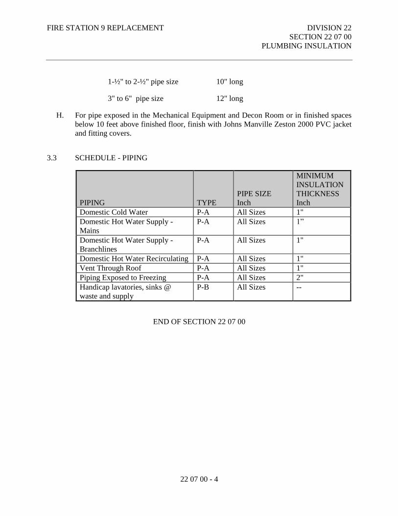
1-½" to 2-½" pipe size 10" long
3" to 6" pipe size 12" long
H. For pipe exposed in the Mechanical Equipment and Decon Room or in finished spaces
below 10 feet above finished floor, finish with Johns Manville Zeston 2000 PVC jacket
and fitting covers.
3.3 SCHEDULE - PIPING
PIPING
TYPE
PIPE SIZE
Inch
MINIMUM
INSULATION
THICKNESS
Inch
Domestic Cold Water P-A All Sizes 1"
Domestic Hot Water Supply -
Mains
P-A All Sizes 1”
Domestic Hot Water Supply -
Branchlines
P-A All Sizes 1"
Domestic Hot Water Recirculating P-A All Sizes 1"
Vent Through Roof P-A All Sizes 1"
Piping Exposed to Freezing P-A All Sizes 2"
Handicap lavatories, sinks @
waste and supply
P-B All Sizes --
END OF SECTION 22 07 00
FIRE STATION 9 REPLACEMENT DIVISION 22
SECTION 22 10 00
PLUMBING PIPING
22 10 00 - 1
PART 1 - GENERAL
1.1 RELATED DOCUMENTS
A. Drawings and general provisions of the Contract, including Municipality of Anchorage
Standard Specifications – Buildings (MASSB), General and Supplementary Conditions
apply to this Section.
1.2 WORK INCLUDED
A. Pipe and Pipe Fittings.
B. Valves.
C. Seismic Valves.
1.3 RELATED WORK
A. Section 22 05 00 – Common Work Results for Plumbing.
B. Section 22 05 29 – Hangers and Supports for Plumbing Piping and Equipment.
C. Section 22 05 53 – Identification for Plumbing Piping and Equipment.
D. Section 22 07 00 – Plumbing Insulation.
1.4 REFERENCES
A. American National Standards Institute:
1. ANSI Z21.22 - Relief Valves for Hot Water Supply Systems.
B. American Society of Mechanical Engineers:
1. ASME B16.18 - Cast Copper Alloy Solder Joint Pressure Fittings.
2. ASME B16.22 - Wrought Copper and Copper Alloy Solder Joint Pressure
Fittings.
3. ASME B16.26 - Cast Copper Alloy Fittings for Flared Copper Tubes.
4. ASME B31.9 - Building Services Piping.
FIRE STATION 9 REPLACEMENT DIVISION 22
SECTION 22 10 00
PLUMBING PIPING
22 10 00 - 2
5. ASME B40.1 - Gauges - Pressure Indicating Dial Type - Elastic Element.
6. ASME Section VIII - Boiler and Pressure Vessel Code - Pressure Vessels.
7. ASME Section IX - Boiler and Pressure Vessel Code - Welding and Brazing
Qualifications.
C. ASTM International:
1. ASTM A53/A53M - Standard Specification for Pipe, Steel, Black and Hot-
Dipped, Zinc-Coated, Welded and Seamless.
2. ASTM A234/A234M - Standard Specification for Piping Fittings of Wrought
Carbon Steel and Alloy Steel for Moderate and High Temperature Service.
3. ASTM A395/A395M - Standard Specification for Ferritic Ductile Iron Pressure-
Retaining Castings for Use at Elevated Temperatures.
4. ASTM A536 - Standard Specification for Ductile Iron Castings.
5. ASTM B32 - Standard Specification for Solder Metal.
6. ASTM B42 - Standard Specification for Seamless Copper Pipe, Standard Sizes.
7. ASTM B88 - Standard Specification for Seamless Copper Water Tube.
8. ASTM B584 - Standard Specification for Copper Alloy Sand Castings for
General Applications.
9. ASTM F708 - Standard Practice for Design and Installation of Rigid Pipe
Hangers.
10. ASTM F1476 - Standard Specification for Performance of Gasketed Mechanical
Couplings for Use in Piping Applications.
D. American Welding Society:
1. AWS A5.8 - Specification for Filler Metals for Brazing and Braze Welding.
E. American Water Works Association:
1. AWWA C104 - American National Standard for Cement-Mortar Lining for
Ductile-Iron Pipe and Fittings for Water.
2. AWWA C105 - American National Standard for Polyethylene Encasement for
Ductile-Iron Pipe Systems.
3. AWWA C110 - American National Standard for Ductile-Iron and Grey-Iron
Fittings, 3 in. through 48 in. (75 mm through 1200 mm), for Water and Other
Liquids.
4. AWWA C111 - American National Standard for Rubber-Gasket Joints for
Ductile-Iron Pressure Pipe and Fittings.
5. AWWA C151 - American National Standard for Ductile-Iron Pipe, Centrifugally
Cast, for Water.
6. AWWA C651 - Disinfecting Water Mains.
F. Manufacturers Standardization Society of the Valve and Fittings Industry:
FIRE STATION 9 REPLACEMENT DIVISION 22
SECTION 22 10 00
PLUMBING PIPING
22 10 00 - 3
1. MSS SP 58 - Pipe Hangers and Supports - Materials, Design and Manufacturer.
2. MSS SP 67 - Butterfly Valves.
3. MSS SP 69 - Pipe Hangers and Supports - Selection and Application.
4. MSS SP 70 - Cast Iron Gate Valves, Flanged and Threaded Ends.
5. MSS SP 71 - Cast Iron Swing Check Valves, Flanged and Threaded Ends.
6. MSS SP 78 - Cast Iron Plug Valves, Flanged and Threaded Ends.
7. MSS SP 80 - Bronze Gate, Globe, Angle and Check Valves.
8. MSS SP 85 - Cast Iron Globe & Angle Valves, Flanged and Threaded.
9. MSS SP 89 - Pipe Hangers and Supports - Fabrication and Installation Practices.
10. MSS SP 110 - Ball Valves Threaded, Socket-Welding, Solder Joint, Grooved and
Flared Ends.
G. National Electrical Manufacturers Association:
1. NEMA 250 - Enclosures for Electrical Equipment (1000 Volts Maximum).
1.5 QUALITY ASSURANCE
A. Valves: Manufacturer's name and pressure rating marked on valve body.
1.6 SUBMITTALS
A. Submit product data under provisions of Supplementary Conditions.
B. Include data on pipe materials, pipe fittings, valves and accessories.
1.7 DELIVERY, STORAGE, AND HANDLING
A. Deliver products to site under provisions of the Supplementary Conditions.
B. Store and protect products under provisions of the Supplementary Conditions.
C. Deliver and store valves in shipping containers with labeling in place.
PART 2 - PRODUCTS
2.1 SANITARY SEWER PIPING, BURIED WITHIN 5 FEET OF BUILDING
A. Cast Iron Pipe: ASTM A74 service weight. Fittings: Cast iron. Joints: Hub-and-spigot,
CISPI HSN compression type with ASTM C564 neoprene gaskets.
FIRE STATION 9 REPLACEMENT DIVISION 22
SECTION 22 10 00
PLUMBING PIPING
22 10 00 - 4
B. Cast Iron Pipe: CISPI 301, hubless, service weight. Fittings: Cast iron. Joints:
Neoprene gaskets and stainless steel clamp-and-shield assemblies.
C. Copper Tubing: ASTM B306, DWV. Fittings: ASME B16.3, cast bronze, or ASME
B16.29, wrought copper. Joints: ASTM B32, solder, Grade 95TA; Flux: ASTM B813.
2.2 SANITARY SEWER PIPING, ABOVE GRADE
A. Cast Iron Pipe: CISPI 301, hubless, service weight. Fittings: Cast iron. Joints: CISPI
310, Neoprene gaskets and stainless steel clamp-and-shield assemblies.
B. Copper Pipe: ASTM B306, DWV. Fittings: ASME B16.3, cast bronze, or ASME
B16.29, wrought copper. Joints: ASTM B32, solder, Grade 95TA; Flux: ASTM B813.
C. ABS Pipe: ASTM D2661. Fittings: ABS. Joints: ASTM D2235, solvent weld.
D. PVC Pipe: ASTM D2729. Fittings: PVC. Joints: ASTM D2855, solvent weld with
ASTM D2564 solvent cement.
2.3 WATER PIPING, ABOVE GRADE
A. Copper Tubing: ASTM B88, Type L, hard drawn. Fittings: ASME B16.18, cast copper
alloy, or ASME B16.22, wrought copper. Joints: ANSI/ASTM B32, solder, Grade
95TA; Flux: ASTM B813, or Viega Pro-Press or Equal.
B. PEX Tubing: Cross-linked polyethylene (PEX), non-barrier type. Tubing shall have a
pressure and temperature rating of 160 PSI at 73°F, 100 PSI at 180°F and 80 PSI at
200°F. Tubing shall be manufactured in accordance with ASTM F876 and ASTM F877
and tested for compliance by an independent third-party agency. Fittings shall be
manufactured in accordance with ASTM F1807 or ASTM F2159 and/or comply with
ASTM F877 system standard as identified on the fitting and shall be a part of a
cataloged system of the same manufacturer as the tubing.
2.4 STORM WATER PIPING, ABOVE GRADE
A. Cast Iron Pipe: CISPI 301, hubless, service weight. Fittings: Cast iron. Joints:
Neoprene gaskets and stainless steel clamp-and-shield assemblies.
B. ABS Pipe: ASTM D2680 or D2751. Fittings: ABS. Joints: ASTM D2235, solvent
weld.
C. PVC Pipe: ASTM D2729. Fittings: PVC. Joints: ASTM D2855, solvent weld.
FIRE STATION 9 REPLACEMENT DIVISION 22
SECTION 22 10 00
PLUMBING PIPING
22 10 00 - 5
2.5 CONDENSATE PIPING
A. PVC Pipe: ASTM D2729. Fittings: PVC. Joints: ASTM D2855, solvent weld with
ASTM D2564 solvent cement.
2.6 FLANGES, UNIONS, AND COUPLINGS
A. 150 psig malleable iron unions for bronze unions for copper pipe, soldered joints or
Viega Pro-Press or Equal.
2.7 ACCEPTABLE MANUFACTURERS - DIELECTRIC CONNECTIONS
A. PPP, Inc. - Clearflow.
B. Substitutions: Under provisions of the Supplementary Condition.
2.8 DIELECTRIC CONNECTIONS
A. Dielectric Connections: ASTM standard F-1545 for continuous use at temperatures up
to +225°F and for pressures up to 300 psi. IAPMO, UPC listed. Thread connections.
2.9 GATE VALVES
A. Not permitted.
2.10 GLOBE VALVES
A. Not permitted.
2.11 ACCEPTABLE MANUFACTURERS - ALL VALVE TYPES
A. Nibco.
B. Apollo.
C. FNW.
D. Substitutions: Under provisions of the Supplementary Conditions.
FIRE STATION 9 REPLACEMENT DIVISION 22
SECTION 22 10 00
PLUMBING PIPING
22 10 00 - 6
2.12 BALL VALVES
A. Bronze two piece body, full port, forged brass, chrome plated ball, Teflon seats and
stuffing box ring, lever handle, solder, screwed or Viega Pro-Press ends.
2.13 SWING CHECK VALVES
A. Bronze swing disc, solder, screwed or Viega Pro-Press ends.
2.14 WATER PRESSURE REDUCING VALVES
A. Bronze body, stainless steel and thermoplastic internal parts, fabric reinforced
diaphragm, strainer, threaded and single union ends.
2.15 ACCEPTABLE MANUFACTURERS – SEISMIC VALVES
A. KOSO Valve.
B. Pacific Seismic,
C. Substitutions: Under provisions of the Supplementary Conditions.
2.16 SEISMIC VALVES
A. ASCE 25-06 and UL listed or AGA listed or International Association of Plumbing and
Mechanical Officials (IAPMO) listed. The valve may be either pendulum or ball
construction, soft seat construction for positive sealing with visual indicator and flanged
connections.
PART 3 - EXECUTION
3.1 PREPARATION
A. Ream pipe and tube ends. Remove burrs. Bevel plain end ferrous pipe.
B. Remove scale and dirt, on inside and outside, before assembly.
C. Prepare piping connections to equipment with flanges or unions.
FIRE STATION 9 REPLACEMENT DIVISION 22
SECTION 22 10 00
PLUMBING PIPING
22 10 00 - 7
D. Install Seismic valve downstream of the gas meter in strict accordance with the
manufacturer’s instructions.
3.2 INSTALLATION
A. Provide non-conducting dielectric connections wherever jointing dissimilar metals.
B. Route piping in orderly manner and maintain gradient.
C. Install piping to conserve building space and not interfere with use of space.
D. Group piping whenever practical at common elevations.
E. Install piping to allow for expansion and contraction without stressing pipe, joints, or
connected equipment.
F. Provide clearance for installation of insulation and access to valves and fittings.
G. Provide access where valves and fittings are not exposed. Coordinate size and location
of access doors.
H. Establish invert elevations, slopes for drainage to ¼ inch per foot, 1/8 inch per foot if 4"
or over, minimum. Maintain gradients.
I. Install valves with stems upright or horizontal, not inverted.
3.3 INSTALLATION PEX TUBING
A. Install PEX tubing in accordance with tubing manufacturer’s recommendations.
B. Do not solder within 18 inches of PEX tubing in the same waterline. Make sweat
connections prior to making PEX connections.
C. Ensure no glues, solvents, sealants or chemicals come in contact with the tubing without
prior permission from the tubing manufacturer.
D. Do not expose PEX tubing to direct sunlight for more than 6 months.
E. Use grommets or sleeves at the penetration for PEX tubing passing through metal studs.
F. Use a PEX manufacturer recommended fire stop sealant manufacturer.
G. Protect PEX tubing with sleeves where abrasion may occur.
FIRE STATION 9 REPLACEMENT DIVISION 22
SECTION 22 10 00
PLUMBING PIPING
22 10 00 - 8
H. Utilize nail plates where PEX tubing penetrates wall stud or joists had has the potential
for being struck with a screw or nail.
I. Allow slack of approximately 1/8 inch per foot of tube length to compensate for
expansion and contraction
3.4 APPLICATION
A. Install ball valves for shut-off and to isolate equipment as indicated.
3.5 TESTING
A. Test all water piping hydrostatically at 100 psig or 150 percent of working pressure,
whichever is greater, for a period of 4 hours. Observe piping during this period and
repair all leaks.
3.6 DISINFECTION OF DOMESTIC WATER PIPING SYSTEM
A. Prior to starting work, verify system is complete, flushed and clean.
B. Disinfect all portions of the domestic water system as per Section 609.9 of the 2009
UPC. Submit written statement indicating test procedure and results.
END OF SECTION 22 10 00
FIRE STATION 9 REPLACEMENT DIVISION 22
SECTION 22 30 00
PLUMBING EQUIPMENT
22 30 00 - 1
PART 1 - GENERAL
1.1 RELATED DOCUMENTS
A. Drawings and general provisions of the Contract, including Municipality of Anchorage
Standard Specifications – Buildings (MASSB), General and Supplementary Conditions
apply to this Section.
1.2 SECTION INCLUDES
A. Hot Water Generator
B. Diaphragm Compression Tanks.
C. In-Line Circulator Pumps.
D. Roof Drains.
E. Floor Drains.
F. Sand Interceptors.
G. Precast Trench Drains.
H. Cleanouts.
I. Backflow Preventers.
J. Water Hammer Arrestors.
K. Hose Bibbs Hydrants.
L. Electronic Trap Primers.
1.3 RELATED WORK
A. Section 23 05 29 - Hangers and Supports for Plumbing Piping and Equipment
FIRE STATION 9 REPLACEMENT DIVISION 22
SECTION 22 30 00
PLUMBING EQUIPMENT
22 30 00 - 2
1.4 SUBMITTALS
A. Submit product data under provisions of the Supplementary Conditions.
B. Provide submittal data on all product listed in this section.
1.5 OPERATION AND MAINTENANCE DATA
A. Submit operation and maintenance data under provisions of the Supplementary
Conditions.
B. Include operation, maintenance, and inspection data, replacement part numbers and
availability, and service depot location and telephone number.
1.6 DELIVERY, STORAGE, AND HANDLING
A. Deliver store and protect products to site under provisions of the Supplementary
Conditions.
B. Store and protect products under provisions of the Supplementary Conditions.
C. Provide temporary inlet and outlet caps. Maintain caps in Place until installation.
1.7 WARRANTY
A. Provide manufacturer's warranty under provisions of the Supplementary Conditions.
PART 2 - PRODUCTS
2.1 ACCEPTABLE MANUFACTURERS – HOT WATER GENERATOR
A. SuperStor.
B. Amtrol.
C. Substitutions: Under provisions of the Supplementary Conditions.
FIRE STATION 9 REPLACEMENT DIVISION 22
SECTION 22 30 00
PLUMBING EQUIPMENT
22 30 00 - 3
2.2 HOT WATER GENERATOR
A. Tank: Type 316L steel shall, for working pressure of minimum 125 psig, steel support
tappings for accessories, threaded connections, 2 inch thick rigid urethane insulation.
B. Heat Exchanger: Double wall, cupronickel, spiral wound heat exchanger. Double wall
vent to atmosphere.
C. Lining: NSF listed lining.
D. Accessories: Tank drain, ASME temperature/pressure relief valve suitable for
maximum working pressure. Relief valve probe must extend into tank.
2.3 ACCEPTABLE MANUFACTURERS - DIAPHRAGM TYPE COMPRESSION
TANKS
A. Amtrol.
B. Wessels.
C. Bell and Gossett.
D. Substitutions: Under provisions of the Supplementary Conditions.
2.4 DIAPHRAGM TYPE COMPRESSION TANKS
A. Construction: Welded steel, rated for working pressure of 150 psig, 200ºF maximum
working temperature, flexible butyl rubber diaphragm, and polypropylene liner sealed
into tank.
B. Accessories: Air-charging fitting, pre-charge to incoming water pressure.
2.5 ACCEPTABLE MANUFACTURERS - IN-LINE CIRCULATOR PUMPS
A. Groundfos.
B. No Substitutions.
FIRE STATION 9 REPLACEMENT DIVISION 22
SECTION 22 30 00
PLUMBING EQUIPMENT
22 30 00 - 4
2.6 IN-LINE CIRCULATOR PUMPS
A. Type: Maintenance free, self-lubricated, industrial/commercial single stage, direct drive
circulator.
1. Casing (Volute): Bronze for open systems.
2. Integral Flow Check:
a. Acetal Plunger Body
b. EPDM O-ring Seal
c. Stainless Steel Spring
3. Stator Housing: Steel
4. Cartridge: Stainless Steel
5. Impeller: Non-Metallic
6. Shaft: Ceramic
7. Bearings: Carbon
8. O-Ring & Gaskets: EPDM - Chlorine Resistant
2.7 ACCEPTABLE MANUFACTURERS - ROOF DRAINS, FLOOR DRAINS and
SAND INTERCEPTORS
A. Mifab.
B. J.R. Smith.
C. Schier Products
D. Substitutions: Under provisions of the Supplementary Conditions.
2.8 ROOF DRAINS
A. Combination Roof and Overflow Drains: ANSI A112.21.2; Coated cast iron bodies
with combination membrane flashing clamp/gravel guards, double deck plate and low
silhouette cast iron domes.
2.9 FLOOR DRAINS
A. FD-1: ANSI A112.21.1; lacquered cast iron two piece body with double drainage
flange, weep holes, reversible clamping collar, and round, adjustable chrome plated
nickel-bronze strainer, vandal resistant stainless steel screws and trap primer
connection.
FIRE STATION 9 REPLACEMENT DIVISION 22
SECTION 22 30 00
PLUMBING EQUIPMENT
22 30 00 - 5
B. FD-2: ANSI A112.21.1; lacquered cast iron two piece body with double drainage
flange, weep holes, reversible clamping collar, and round, adjustable nickel-bronze
strainer and trap primer connection,.
C. FD-3: ANSI A112.21.1; lacquered cast iron two piece body with double drainage
flange, weep holes, reversible clamping collar, and round, trap primer connection,
nickel-bronze dome strainer.
D. FD-4: ANSI A112.21.1; lacquered cast iron drain with flashing collar and solid free
standing sediment bucket with tractor grate.
2.10 SAND INTERCEPTORS
A. Seamless, rotationally-molded High Density Polyethylene. Separator shall be furnished
for above or below grade installation, with field adjustable riser system, built-in flow
control, and vent connections. Cover shall provide water/gas-tight seal and have
minimum 2,000 lbs. load capacity.
2.11 ACCEPTABLE MANUFACTURERS - PRECAST TRENCH DRAIN
A. MEA-Josam.
B. ACO
C. Zurn.
D. Substitutions: Under provisions of the Supplementary Conditions.
2.12 PRECAST TRENCH DRAINS
A. Trench drain, catch basin and grate to be a complete system provided by a single
manufacturer.
B. Trench Drain: Modular system of precast and pre-sloped polymer concrete. 6" wide
trench, radiused bottom, 0.5 percent continuous slope.
C. Grates: Cast iron grating and ductile iron frame rated for 25-ton wheel load with lock
down bolts.
D. Catch Basin: Polymer concrete construction, cast iron grating, galvanized steel sediment
bucket, preformed knockout panels for connection to channels and drain pipe.
FIRE STATION 9 REPLACEMENT DIVISION 22
SECTION 22 30 00
PLUMBING EQUIPMENT
22 30 00 - 6
2.13 ACCEPTABLE MANUFACTURERS - CLEANOUTS
A. J.R. Smith.
B. Zurn.
C. Mifab.
D. Substitutions: Under provisions of the Supplementary Condition.
2.14 CLEANOUTS
A. Exterior Surfaced Areas: Round cast iron access frame and non-skid cover, bronze plug,
vandal resistant screws; Model 4251 manufactured by J.R. Smith.
B. Interior Finished Floor Areas: Enamel paint coated cast iron, two piece body with
double drainage flange, weep holes, reversible clamping collar, bronze plug, and
adjustable round nickel bronze scoriated cover in service areas and round with
depressed cover to accept floor finish in finished floor areas; Model 4021 manufactured
by J.R. Smith.
C. Interior Finished Wall Areas: Line type with lacquered cast iron body and round epoxy
coated gasketed cover, bronze plug, and round stainless steel access cover secured with
machine screw; Model 4422 manufactured by J.R. Smith.
D. Interior Unfinished Accessible Areas: Caulked or threaded type. Provide bolted stack
cleanouts on vertical rainwater leaders.
2.15 ACCEPTABLE MANUFACTURERS - BACKFLOW PREVENTERS
A. Watts Regulator.
B. FEBCO.
C. Zurn.
D. Substitutions: Under provisions of the Supplementary Conditions.
2.16 BACKFLOW PREVENTERS
A. General: Backflow Preventer shall conform to the applicable requirements of AWWA
C510. Furnish a certificate of Full Approval or a current Certificate of Approval for
FIRE STATION 9 REPLACEMENT DIVISION 22
SECTION 22 30 00
PLUMBING EQUIPMENT
22 30 00 - 7
each design, size, and make of backflow preventer being provided for the project. The
certificate shall be from the Foundation for Cross- Connection Control and Hydraulic
Research, University of Southern California, and shall attest that this design, size, and
make of backflow preventer has satisfactorily passed the complete sequence of
performance testing and evaluation for the respective level of approval. A Certificate of
Provisional Approval is not acceptable in lieu of the above. IAPMO (UPC) approved.
B. Reduced Pressure Backflow Preventers: ANSI/ASSE 1013; FDA approved epoxy
coated cast iron (4" or larger) or bronze body (3" or smaller) with bronze and stainless
steel internal parts and stainless steel springs; two independently operating, spring
loaded check valves; diaphragm type differential pressure relief valve located between
check valves; third check valve which opens under back pressure in case of diaphragm
failure; non-threaded vent outlet; assembled with two gate valves, strainer, and four test
cocks; Series 909 manufactured by Watts.
C. Double Check Valve Assemblies: ANSI/ASSE 1012; Bronze body (3" and smaller) or
FDA approved epoxy coated cast iron body (4" and larger) with bronze or stainless steel
internal parts and stainless steel springs; two independently operating check valves with
intermediate atmospheric vent with two gate valves and strainer; Series 709
manufactured by Watts.
2.17 ACCEPTABLE MANUFACTURERS - WATER HAMMER ARRESTORS
A. J.R. Smith.
B. Precision plumbing Products, PPP.
C. Zurn.
D. Substitutions: Under provisions of the Supplementary Conditions.
2.18 WATER HAMMER ARRESTORS
A. ANSI A112.26.1; sized in accordance with PDI WH-201, pre-charged suitable for
operation in temperature range -100 to 300º F and maximum 250 psig working pressure;
Series 5000 manufactured by J.R. Smith.
2.19 ACCEPTABLE MANUFACTURERS – HOSE BIBBS
A. Woodford.
B. Acorn.
FIRE STATION 9 REPLACEMENT DIVISION 22
SECTION 22 30 00
PLUMBING EQUIPMENT
22 30 00 - 8
C. Zurn.
D. Substitutions: Under provisions of the Supplementary Conditions.
2.20 HOSE BIBBS
A. HB-1: Exterior Hose Bibb; ANSI/ASSE 1019; non-freeze, self-draining type with
polished chrome, lockable recessed box hose thread spout, removable key, and vacuum
breaker in conformance with ANSI/ASSE 1011.
B. HB-2 Interior Hose Bibb; Rough chrome plated bronze or brass body, replaceable disc,
hose thread spout, wheel handle, with vacuum breaker in conformance with
ANSI/ASSE 1011.
C. HB-3 Interior Hot & Cold Hose Bibb; exposed wall type service faucet with cross
handles, spout wall brace, vacuum breaker, hose end spout, strainers, eccentric
adjustable inlets, integral screwdriver stops with covering caps and adjustable threaded
wall flanges.
2.21 ACCEPTABLE MANUFACTURERS – ELECTRONIC TRAP PRIMER VALVE
A. Precision Plumbing Products, Inc.
B. Mifab.
C. Zurn.
D. Substitutions: Under provisions of the Supplementary Conditions.
2.22 ELECTRONIC TRAP PRIMER VALVE
A. Valve: Machined of brass, containing no springs or diaphragms. “O” rings acceptable
for –40 to +450 F operation.
B. Distribution Unit: Brass fitting with copper water reservoir. Clear plastic cover.
Tappings for up to four drain taps.
C. Prime-Rite Trap Primer as manufactured by Precision Plumbing Products or equal.
FIRE STATION 9 REPLACEMENT DIVISION 22
SECTION 22 30 00
PLUMBING EQUIPMENT
22 30 00 - 9
PART 3 - EXECUTION
3.1 INSTALLATION
A. Install pumps in accordance with manufacturer's instructions.
B. Provide line sized ball valve on branch piping to expansion tank.
C. Install plumbing equipment in strict accordance with manufacturer's instructions and
coordinate with associated trades.
D. Provide access door as required at trap primer installation, coordinate with General,
END OF SECTION 22 30 00
FIRE STATION 9 REPLACEMENT DIVISION 22
SECTION 22 40 00
PLUMBING FIXTURES
22 40 00 - 1
PART 1 - GENERAL
1.1 RELATED DOCUMENTS
A. Drawings and general provisions of the Contract, including Municipality of Anchorage
Standard Specifications – Buildings (MASSB), General and Supplementary Conditions
apply to this Section.
1.2 SECTION INCLUDES
A. Water Closets.
B. Urinals.
C. Lavatories.
D. Janitors Sink.
E. Showers.
F. Kitchen Sink.
G. Decontamination Room Sink.
H. Island Sink.
I. Decontamination Sink.
J. Washer Rough-in Boxes.
K. Ice Maker Connections.
L. Coffee Maker Connections.
M. Hydration Station.
1.3 SUBMITTALS
A. Submit product data under provisions of the Supplementary Conditions.
FIRE STATION 9 REPLACEMENT DIVISION 22
SECTION 22 40 00
PLUMBING FIXTURES
22 40 00 - 2
B. Include fixtures, sizes, utility sizes, trim, and finishes.
1.4 OPERATION AND MAINTENANCE DATA
A. Submit operation and maintenance data under provisions of the Supplementary
Conditions.
B. Include fixture trim exploded view and replacement parts lists.
1.5 WARRANTY
A. Provide manufacturer's warranty under provisions of the Supplementary Conditions.
PART 2 - PRODUCTS
2.1 PLUMBING FIXTURES
A. Manufacturers for Plumbing Fixtures Throughout Section:
1. Kohler.
2. Sloan. (No Substitutions)
3. Delta Faucet Co., Commercial Div. (No Substitutions)
4. Haws Drinking Faucet Co.
5. Just Manufacturing, Inc.
6. Fiat.
7. Elkay.
8. Advance Tabco.
9. Oatey.
10. Guy Gray.
11. Substitutions: Under provisions of the Supplementary Conditions.
B. Provide plumbing fixture fittings in accordance with ASME A112.18.1 that prevent
backflow from fixture into water distribution system.
C. Refer to plumbing schedules on mechanical drawings for basis of design fixture model
numbers.
FIRE STATION 9 REPLACEMENT DIVISION 22
SECTION 22 40 00
PLUMBING FIXTURES
22 40 00 - 3
PART 3 - EXECUTION
3.1 INSPECTION
A. Review millwork shop drawings. Confirm location and size of fixtures and openings
before rough-in and installation.
B. Verify adjacent construction is ready to receive rough-in work of this section.
3.2 INSTALLATION
A. Install each fixture with removable p-trap, for servicing and cleaning.
B. Install components level and plumb
C. Install and secure fixtures in place with wall supports and bolts.
D. Seal fixtures to wall and floor surfaces with sealant, color to match fixture.
E. Mount fixtures above finished floor in accordance with Architectural.
3.3 ADJUSTING AND CLEANING
A. Adjust stops or valves for intended water flow rate to fixtures without splashing, noise,
or overflow.
B. Remove and clean all aerators and filters from faucets and other plumbing fixtures after
the domestic water system has been tested, flushed and disinfected as per Section
22 10 00 – Plumbing Piping.
C. At completion remove all visible stickers and tags not intended to be left in place,
thoroughly clean all surfaces of plumbing fixtures.
END OF SECTION 22 40 00
FIRE STATION 9 REPLACEMENT DIVISION 23
SECTION 23 05 00
COMMON WORK RESULTS FOR HVAC
23 05 00 - 1
PART 1 - GENERAL
1.1 RELATED DOCUMENTS
A. Drawings and general provisions of the Contract, including Municipality of Anchorage
Standard Specifications – Buildings (MASSB), General and Supplementary Conditions
apply to this Section.
1.2 SCOPE
A. All provisions of the Contract including the General and Supplementary Conditions and
the General Requirements apply to this work.
1.3 SECTION INCLUDES
A. The work to be included in these and all other mechanical subsections shall consist of
providing, installing, adjusting and setting into proper operation complete and workable
systems for all items shown on the drawings, described in the specifications or
reasonably implied. This shall include the planning and supervision to coordinate the
work with other crafts and to maintain a proper time schedule for delivery of materials
and installation of the work.
1.4 RELATED WORK
A. Related Work Specified Elsewhere:
1. Divisions 26 - Electrical, 27 - Communications and 28 - Electronic Safety and
Security.
B. Unless otherwise indicated on the electrical drawings or the electrical schedules,
provide all mechanical equipment motors, motor starters, thermal overload switches,
control relays, time clocks, thermostats, motor operated valves, float controls, damper
motors, electric- pneumatic and pneumatic electric switches, electrical components,
wiring and any other miscellaneous Section 23 09 23 Direct Digital Control System for
HVAC. Disconnect switches are included in the electrical work, unless specifically
called out on mechanical plans.
C. Carefully coordinate all work with the electrical work shown and specified elsewhere.
FIRE STATION 9 REPLACEMENT DIVISION 23
SECTION 23 05 00
COMMON WORK RESULTS FOR HVAC
23 05 00 - 2
1.5 REFERENCED CODES - LATEST ADOPTED EDITION
A. NFPA 13 Installation of Sprinkler Systems
B. NFPA 70 National Electrical Code (NEC)
C. IMC International Mechanical Code
D. UPC Uniform Plumbing Code
E. IFC International Fire Code
F. IBC International Building Code
1.6 PROJECT RECORD DRAWINGS
A. In addition to other requirements, mark up a clean set of drawings as the work
progresses to show the dimensioned location and routing of all mechanical work which
will become permanently concealed. Show routing of work in concealed blind spaces
within the building. Show exact dimensions of buried piping off of columns or exterior
walls.
B. Show the location of all valves and their appropriate tag identification.
C. At completion of project, deliver these drawings to the Architect and obtain a written
receipt.
1.7 SUBMITTALS
A. See General Conditions and the General and Supplementary Conditions.
B. Submit by specification section complete and all at one time; partial submittals will not
be considered. Submittals shall be in booklet form. The data shall be arranged and
indexed under basic categories. A typewritten index shall be included with dividers and
identifying tabs between sections and references to sections of specifications. The
engineer will retain one copy for reference and checking.
C. Catalog sheets shall be complete and the item or model to be used shall be clearly
marked, and identified as to which item in the specifications or on the drawings is being
submitted and with drawing fixture number where applicable.
FIRE STATION 9 REPLACEMENT DIVISION 23
SECTION 23 05 00
COMMON WORK RESULTS FOR HVAC
23 05 00 - 3
D. Only submit on items specifically required by each specification section. If a submittal
has not been requested, it will not be reviewed.
1.8 HANDLING
A. Under the provisions of the General and Supplementary Conditions.
B. Deliver packaged materials to job site in unbroken packages with manufacturer's label,
and store to facilitate inspection and installation sequence. All items must be labeled
and identified as to make, size and quality.
1.9 SUBSTITUTIONS
A. In accordance with the General and Supplementary Conditions, all substitute items must
fit in the available space, and be of equal or better quality including efficiency
performance, size, and weight, and must be compatible with existing equipment. The
Engineer shall be the final authority regarding acceptability of substitutes.
1.10 DIMENSIONS
A. Before ordering any material or doing any work, the Contractor shall verify all
dimensions, including elevations, and shall be responsible for the correctness of the
same. No extra charge or compensation will be allowed on account of differences
between actual dimensions and measurements indicated on the drawings.
B. Any differences, which may be found, shall be submitted to the Engineer for
consideration before proceeding with the work.
1.11 MANUFACTURER'S DIRECTIONS
A. All manufactured articles shall be applied, installed and handled as recommended by
the manufacturer, unless specifically called out otherwise. Advise the Engineer of any
such conflicts before installation.
1.12 PERMITS, FEES, ETC.
A. The Contractor under each division of these specifications shall arrange for a permit
from the local authority. The Contractor shall pay for any inspection fees or other fees
and charges required by ordinance, law, codes and these specifications.
FIRE STATION 9 REPLACEMENT DIVISION 23
SECTION 23 05 00
COMMON WORK RESULTS FOR HVAC
23 05 00 - 4
1.13 TESTING
A. The Contractor under each section shall at his own expenses perform the various tests as
specified and required by the Architect and as required by the State of Alaska and
Municipality of Anchorage. The Contractor shall furnish all fuel and materials
necessary for making tests.
1.14 TERMINOLOGY
A. Whenever the words "furnish", "provide", "furnish and install", "provide and install",
and/or similar phrases occur, it is the intent that the materials and equipment described
be furnished, installed and connected under this Division of the Specifications,
complete for operation unless specifically noted to the contrary.
B. Where a material is described in detail, listed by catalogue number or otherwise called
for, it shall be the Contractor's responsibility to furnish and install the material.
C. The use of the word "shall" conveys a mandatory condition to the contract.
D. "This section" refers to the section in which the statement occurs.
E. "The project" includes all work in progress during the construction period.
F. In describing the various items of equipment, in general, each item will be described
singularly, even though there may be a multiplicity of identical or similar items.
1.15 SCHEDULE OF WORK
A. The work under the various sections must be expedited and close coordination will be
required in executing the work. The various trades shall perform their portion of the
work at such times as directed so as to meeting scheduled completion dates, and to
avoid delaying any other trade. The Architect will set up completion dates. Each
contractor shall cooperate in establishing these times and locations and shall process his
work so as to ensure the proper execution of it.
1.16 COOPERATION AND CLEANING UP
A. The contractor for the work under each section of the specifications shall coordinate his
work with the work described in all other sections of the specifications to the end that,
as a whole, the job shall be a finished one of its kind, and shall carry on his work in
FIRE STATION 9 REPLACEMENT DIVISION 23
SECTION 23 05 00
COMMON WORK RESULTS FOR HVAC
23 05 00 - 5
such a manner that none of the work under any section of these specifications shall be
handicapped, hindered or delayed at any time.
B. At all times during the progress of the work, the Contractor shall keep the premises
clean and free of unnecessary materials and debris. The Contractor shall, on direction at
any time from the Architect, clear any designated areas or area of materials and debris.
On completion of any portion of the work, the Contractor shall remove from the
premises all tools and machinery and all debris occasioned by the work, leaving the
premises free of all obstructions and hindrances.
1.17 GUARANTEES AND WARRANTIES
A. Unless a longer guarantee is hereinafter called for, all work, materials and equipment
items shall be guaranteed for a period of one year after acceptance by the Owner. All
defects in labor and materials occurring during this period, as determined by the
Architect, shall be repaired and/or replaced to the complete satisfaction of the Architect.
Guarantee shall be in accordance with the General and Supplementary Condition.
1.18 COMPLETION REQUIREMENTS
A. In accordance with the General Conditions and Supplementary Conditions. Before
acceptance and final payment, the Contractor shall furnish:
1. Accurate project record drawings, shown in red ink on black-line prints, showing
all changes from the original plans made during installation of the work.
2. All manufacturer's guarantees.
3. Guarantees.
4. Test and balance reports.
5. Operation and maintenance manuals.
PART 2 - PRODUCTS
2.1 MATERIALS
A. All equipment shall be regularly cataloged items of the manufacturer and shall be
supplied as a complete unit in accordance with the manufacturer's standard
specifications along with any optional items required for proper installation unless
otherwise noted. Maintain manufacturer's identification, model number, etc. on all
equipment at all times.
B. Where more than one of an item is to be provided, all of the items shall be identical
manufacture, make, model, color, etc.
FIRE STATION 9 REPLACEMENT DIVISION 23
SECTION 23 05 00
COMMON WORK RESULTS FOR HVAC
23 05 00 - 6
2.2 ELECTRICAL MOTORS
A. Provide motors on all equipment in accordance with Section 23 05 13, Common Motors
Requirements for HVAC Equipment.
2.3 RESTRICTED MATERIALS
A. No materials containing asbestos in any form shall be allowed. Where materials or
equipment provided by this contractor are found to contain asbestos, such items shall be
removed and replaced with non-asbestos items. Entire cost of asbestos removal and
disposal and cost of installing new items shall be the responsibility of the contractor.
B. No solder or flux containing lead shall be used on this project.
PART 3 - EXECUTION
3.1 DRAWINGS
A. The mechanical drawings are generally diagrammatic. Complete details of the building
which affect the mechanical installation may not be shown. For additional details, see
Architectural, Civil and Electrical Drawings. Coordinate work under this section with
that of all related trades.
3.2 INSTALLATION
A. All work shall comply with the latest adopted applicable codes and ordinances
including, but not limited to, the IMC, UPC, IBC, NFPA and IFC Standards; all local
and state amendments to all codes and standards.
B. Obtain and pay for all inspection fees, connection charges and permits as a part of the
Contract.
C. Compliance with codes and ordinances shall be at the Contractor's expense.
3.3 MEASUREMENTS
A. Verify all measurements on the job site.
B. Locate all equipment on the centers of walls, openings, spaces, etc., unless specified
otherwise.
FIRE STATION 9 REPLACEMENT DIVISION 23
SECTION 23 05 00
COMMON WORK RESULTS FOR HVAC
23 05 00 - 7
C. Check all piping, ducts, etc. to clear openings.
3.4 OPERATING INSTRUCTIONS
A. Before the facility is turned over to the Owner, instruct the Owner or Owner's personnel
in the operation, care and maintenance of all systems and equipment under the
jurisdiction of the Mechanical Division. These instructions shall also be included in a
written summary in the Operating Maintenance Manuals.
B. The Operation and Maintenance Manuals shall be utilized for the basis of the
instruction. Provide a minimum of ten (10) hours of onsite instruction to the owner
designated personnel.
3.5 OPERATING AND MAINTENANCE MANUALS
A. Submit maintenance manuals to the Engineer covering all equipment, fixtures, devices,
etc. installed by the Contractor.
B. The maintenance manuals shall be bound in a loose leaf binder. The manual shall
contain, but not limited to, the following types of information:
1. Catalog cuts of all equipment, fixtures, etc. installed (Marked to identify the
specific items used).
2. Manufacturer's maintenance and overhaul instruction booklets including exploded
views.
3. Identification numbers of all parts and nearest sources for obtaining parts and
services.
4. Reduced scale drawings of the control system and a verbal description of how
these controls operate.
5. A copy of the final test and balance report.
6. A copy of valve schedule and reduced scale drawings showing valve locations.
7. Written summary of instructions to Owner.
C. A periodic maintenance form that includes all of the equipment shall be provided with
the maintenance manual. The form shall list each piece of equipment and how often
maintenance is required (daily, weekly, monthly, annually). Opposite each task shall be
squares for check-off for a full year (initials) to verify that the tasks are being done.
3.6 SYSTEM ADJUSTING
A. In accordance with Section 23 05 93, Testing, Adjusting and Balancing for HVAC.
FIRE STATION 9 REPLACEMENT DIVISION 23
SECTION 23 05 00
COMMON WORK RESULTS FOR HVAC
23 05 00 - 8
B. Each part of each system shall be adjusted and readjusted as necessary to ensure proper
functioning of all controls, proper air distribution, and elimination of drafts, noise and
vibration.
C. Balance air and water systems for volume quantities shown and as required to ensure
even temperature and the elimination of drafts. Balancing shall be done by a qualified
firm acceptable to the Engineer. Provide balancing log to the Engineer before
substantial inspection.
3.7 CUTTING, FITTING, REPAIRING, PATCHING AND FINISHING
A. Arrange and pay for all cutting, fitting, repairing, patching and finishing of work by
other trades where it is necessary to disturb such work to permit installation of
mechanical work. Perform work only with craftsmen skilled in their respective trades.
B. Avoid cutting, insofar as possible, by setting sleeves, frames, etc. and by requesting
openings in advance. Assist other trades in securing correct location and placement of
rough-frames, sleeves, openings, etc. for ducts and piping.
C. Cut all holes neatly and as small as possible to admit work. Include cutting where
sleeves or openings have been omitted. Perform cutting in a manner so as not to
weaken walls, partitions or floors. Drill holes required to be cut in floors without
breaking out around holes.
3.8 PAINTING
A. Perform all of the following painting in accordance with provisions of Division 09 -
Finishes with colors as selected by the Architect. Provide the following items as a part
of mechanical work:
1. Factory applied prime and finish coats on mechanical equipment.
2. Factory applied prime and finish coat on all air registers, grilles and diffusers,
unless otherwise specified.
3. Factory applied prime coat on access doors.
4. Pipe identification where specified.
B. If factory finish on any equipment furnished is damaged in shipment or during
construction, refinish to equal original factory finish.
FIRE STATION 9 REPLACEMENT DIVISION 23
SECTION 23 05 00
COMMON WORK RESULTS FOR HVAC
23 05 00 - 9
3.9 INSTALLATION OF EQUIPMENT
A. Unless otherwise indicated, mount all equipment and install in accordance with
manufacturer's recommendations and approved submittals.
B. Maintain manufacture recommended minimum clearances for access and maintenance.
C. Where equipment is to be anchored to structure, furnish and locate necessary anchoring
and vibration isolation devices.
D. Furnish all structural steel, such as angles, channels, beams, etc. required to support all
piping, ductwork, equipment and accessories installed under this Division. Use
structural supports suitable for equipment specified or as indicated. In all cases, support
design will be based upon data contained in manufacturer's catalog.
E. Openings: Arrange for necessary openings in buildings to allow for admittance and
reasonable maintenance or replacement of all equipment furnished under this Contract.
F. Access Doors: Provide as necessary for reasonable maintenance of all equipment
valves, controls, etc.
END OF SECTION 23 05 00
FIRE STATION 9 REPLACEMENT DIVISION 23
SECTION 23 05 13
COMMON MOTOR REQUIREMENTS
FOR HVAC EQUIPMENT
23 05 13 - 1
PART 1 - GENERAL
1.1 RELATED DOCUMENTS
A. Drawings and general provisions of the Contract, including Municipality of Anchorage
Standard Specifications – Buildings (MASSB), General and Supplementary Conditions
apply to this Section.
1.2 SECTION INCLUDES
A. Single Phase Electric Motors.
B. Three Phase Electric Motors.
1.3 RELATED WORK
A. Section 23 05 00 – Common Work Results for HVAC.
B. Section 23 21 23 - Hydronic Pumps.
C. Section 23 34 13 - Axial HVAC Fans.
D. Section 23 34 23 – HVAC Power Ventilators.
E. Section 23 82 00 – Convection Heating and Cooling Units.
1.4 REFERENCES
A. American Bearing Manufacturers Association:
1. ABMA 9 - Load Ratings and Fatigue Life for Ball Bearings.
B. National Electrical Manufacturers Association:
1. NEMA MG 1 - Motors and Generators.
C. International Electrical Testing Association:
FIRE STATION 9 REPLACEMENT DIVISION 23
SECTION 23 05 13
COMMON MOTOR REQUIREMENTS
FOR HVAC EQUIPMENT
23 05 13 - 2
1. NETA ATS - Acceptance Testing Specifications for Electrical Power Distribution
Equipment and Systems.
D. Underwriters Laboratories:
1. UL 674 - UL Standard for Safety Electric Motors and Generators for Use in
Division 1 Hazardous (Classified) Locations.
2. UL 1836 - UL Standard for Safety for Electric Motors for Use in Class I, Division
2 and Class II, Division 2 Hazardous (Classified) Locations.
1.5 OPERATION AND MAINTENANCE DATA
A. Submit operation and maintenance data under provisions of the Supplementary
Conditions.
B. Include assembly drawings, bearing data including replacement sizes, and lubrication
instructions.
1.6 REGULATORY REQUIREMENTS
A. Conform to UL Component Recognition for appropriate sizes.
B. Conform to NFPA 70.
1.7 DELIVERY, STORAGE, AND HANDLING
A. Deliver products to site, store and protect products under provisions the Supplementary
Conditions.
B. Protect motors stored on site from weather and moisture by maintaining factory covers
and suitable weatherproof covering. For extended outdoor storage, remove motors from
equipment and store separately.
1.8 WARRANTY
A. Provide three-year manufacturer's warranty under provisions of the Supplementary
Conditions.
B. Warranty: Include coverage for motors larger than one horsepower.
FIRE STATION 9 REPLACEMENT DIVISION 23
SECTION 23 05 13
COMMON MOTOR REQUIREMENTS
FOR HVAC EQUIPMENT
23 05 13 - 3
PART 2 - PRODUCTS
2.1 MANUFACTURERS
A. Baldor.
B. Marathon.
C. General Electric.
D. A.O. Smith.
E. Substitutions: Under provisions of the Supplementary Conditions.
2.2 GENERAL CONSTRUCTION AND REQUIREMENTS
A. Electrical Service: See Division 26 - Electrical for electrical characteristics.
1. Motors ½ Horsepower and Smaller: Single phase, 60 Hz.
2. Motors ¾ Horsepower and Larger: Three phase, 60 Hz.
B. Motors Less Than 250 Watts, for Intermittent Service: Equipment manufacturer's
standard and need not conform to these specifications.
C. Single Phase Motors: PSC where available.
D. Open drip-proof type except where specifically noted otherwise.
E. Design for continuous operation in 40 degrees C environment.
F. Design for temperature rise in accordance with NEMA MG 1 limits for insulation class,
service factor, and motor enclosure type.
G. Explosion-Proof Motors: UL approved for hazard classification.
H. Visible Nameplate: Indicating manufacturer's name and model number, motor
horsepower, RPM, frame size, voltage, phase, cycles, full load amps, insulation system
class, service factor, maximum ambient temperature, temperature rise at rated
horsepower, minimum efficiency.
I. Wiring Terminations:
FIRE STATION 9 REPLACEMENT DIVISION 23
SECTION 23 05 13
COMMON MOTOR REQUIREMENTS
FOR HVAC EQUIPMENT
23 05 13 - 4
1. Provide terminal lugs to match branch circuit conductor quantities, sizes, and
materials indicated. Enclose terminal lugs in terminal box sized to NFPA 70,
threaded for conduit.
2. For fractional horsepower motors where connection is made directly, provide
conduit connection in end frame.
2.3 SINGLE PHASE POWER - SPLIT PHASE MOTORS
A. Starting Torque: Less than 150 percent of full load torque.
B. Starting Current: Up to seven times full load current.
C. Breakdown Torque: Approximately 200 percent of full load torque.
D. Drip-proof Enclosure: Class A (50º C temperature rise) insulation, NEMA Service
Factor, pre-lubricated sleeve or ball bearings.
E. Enclosed Motors: Class A (50º C temperature rise) insulation, 1.0 Service Factor, pre-
lubricated ball bearings.
2.4 SINGLE PHASE POWER - PERMANENT-SPLIT CAPACITOR MOTORS
A. Starting Torque: Exceeding one fourth of full load torque.
B. Starting Current: Up to six times full load current.
C. Multiple Speed: Through tapped windings.
D. Open Drip-proof or Enclosed Air Over Enclosure: Class A (50º C temperature rise)
insulation, minimum 1.0 Service Factor, pre-lubricated sleeve or ball bearings,
automatic reset overload protector.
2.5 SINGLE PHASE POWER - CAPACITOR START MOTORS
A. Starting Torque: Three times full load torque.
B. Starting Current: Less than five times full load current.
C. Pull-up Torque: Up to 350 percent of full load torque.
D. Breakdown Torque: Approximately 250 percent of full load torque.
FIRE STATION 9 REPLACEMENT DIVISION 23
SECTION 23 05 13
COMMON MOTOR REQUIREMENTS
FOR HVAC EQUIPMENT
23 05 13 - 5
E. Motors: Capacitor in series with starting winding; capacitor-start/capacitor-run motors
shall have two capacitors in parallel with run capacitor remaining in circuit at operating
speeds.
F. Drip-proof Enclosure: Class A (50º C temperature rise) insulation, NEMA Service
Factor, pre-lubricated [sleeve] [ball] bearings.
G. Enclosed Motors: Class A (50º C temperature rise) insulation, 1.0 Service Factor, pre-
lubricated ball bearings.
2.6 THREE PHASE POWER - SQUIRREL CAGE MOTORS
A. Starting Torque: Between one and one and one-half times full load torque.
B. Starting Current: Six times full load current.
C. Power Output, Locked Rotor Torque, Breakdown or Pullout Torque: NEMA Design B
characteristics.
D. Design, Construction, Testing, and Performance: Conform to NEMA MG 1 for Design
B energy efficient motors.
E. Insulation System: NEMA Class B or better.
F. Motor Frames: NEMA standard T-frames of steel, aluminum, or cast iron with end
brackets of cast iron or aluminum with steel inserts.
G. Thermister System (Motor Frame Sizes 254T and Larger): Three PTC thermisters
imbedded in motor windings and epoxy encapsulated solid state control relay for wiring
into motor starter.
H. Bearings: Grease lubricated anti-friction ball bearings with housings equipped with
plugged provision for re-lubrication, rated for minimum AFBMA 9, L-10 life of 20,000
hours. Calculate bearing load with NEMA minimum V-belt pulley with belt center line
at end of NEMA standard shaft extension. Stamp bearing sizes on nameplate.
I. Sound Power Levels: To NEMA MG 1.
J. Nominal Efficiency: To NEMA MG 1, energy efficient for one horsepower and larger
motors.
FIRE STATION 9 REPLACEMENT DIVISION 23
SECTION 23 05 13
COMMON MOTOR REQUIREMENTS
FOR HVAC EQUIPMENT
23 05 13 - 6
PART 3 - EXECUTION
3.1 APPLICATION
A. Install in accordance with the manufacturer’s instructions.
B. Install securely on firm foundation. Mount ball bearing motors with shaft in any
position.
C. Check line voltage and phase and ensure agreement with nameplate.
END OF SECTION 23 05 13
FIRE STATION 9 REPLACEMENT DIVISION 23
SECTION 23 05 16
EXPANSION FITTINGS AND
LOOPS FOR HVAC PIPING
23 05 16 - 1
PART 1 - GENERAL
1.1 RELATED DOCUMENTS
A. Drawings and general provisions of the Contract, including Municipality of Anchorage
Standard Specifications – Buildings (MASSB), General and Supplementary Conditions
apply to this Section.
1.2 SECTION INCLUDES
A. Expansion Joints and Compensators.
B. Pipe Alignment Guides and Pipe Anchors.
1.3
A.
B.
C.
RELATED SECTIONS
Section 21 05 00 - Common Work Results for Fire Suppression.
Section 23 05 00 – Common Work Results for HVAC.
Section 23 05 48 – Vibration and Seismic Controls for Piping and Equipment.
1.4 REFERENCES
A. American Society of Mechanical Engineers:
1. ASME B31.1 - Power Piping.
2. ASME B31.9 - Building Services Piping.
3. ASME Section IX - Boiler and Pressure Vessel Code - Welding and Brazing
Qualifications.
B. American Welding Society:
1. AWS D1.1 - Structural Welding Code - Steel.
FIRE STATION 9 REPLACEMENT DIVISION 23
SECTION 23 05 16
EXPANSION FITTINGS AND
LOOPS FOR HVAC PIPING
23 05 16 - 2
1.5 PERFORMANCE REQUIREMENTS
A. Provide structural work and equipment required to control expansion and contraction of
piping. Verify that anchors, guides, and expansion joints provided, adequately protect
system.
B. Expansion Calculations:
1. Installation Temperature: 40º F.
2. Hot Water Heating: 210º F.
3. Safety Factory: 30%.
1.6 SUBMITTALS
A. Submit under provisions of the Supplementary Conditions.
B. Product Data:
1. Flexible Pipe Connectors: Indicate maximum temperature and pressure rating,
face-to-face length, live length, hose wall thickness, hose convolutions per foot
and per assembly, fundamental frequency of assembly, braid structure, and total
number of wires in braid.
2. Expansion Joints: Indicate maximum temperature and pressure rating, and
maximum expansion compensation.
C. Design Data: Indicate selection calculations.
D. Manufacturer's Installation Instructions: Indicate special procedures, and external
controls.
1.7 PROJECT RECORD DOCUMENTS
A. Submit under provisions of Supplementary Conditions.
B. Record actual locations of flexible pipe connectors, expansion joints, anchors, and
guides.
1.8 OPERATION AND MAINTENANCE DATA
A. Submit under provisions of Supplementary Conditions.
B. Maintenance Data: Include adjustment instructions.
FIRE STATION 9 REPLACEMENT DIVISION 23
SECTION 23 05 16
EXPANSION FITTINGS AND
LOOPS FOR HVAC PIPING
23 05 16 - 3
1.9 QUALIFICATIONS
A. Manufacturer: Company specializing in manufacturing the products specified in this
section with minimum five years documented experience.
B. Design expansion compensating system under direct supervision of a Professional
Engineer experienced in design of this work and licensed at the place where the project
is located.
1.10 DELIVERY, STORAGE, AND HANDLING
A. Deliver, store, protect and handle products to site under provisions of Supplementary
Conditions.
B. Accept expansion joints on site in factory packing with shipping bars and positioning
devices intact. Inspect for damage.
C. Protect equipment from exposure by leaving factory coverings, pipe end protection, and
packaging in place until installation.
1.11 WARRANTY
A. Provide five-year warranty under provisions of Supplementary Conditions.
B. Warranty: Include coverage for leak free performance of packed expansion joints.
PART 2 - PRODUCTS
2.1 ACCEPTABLE MANUFACTUERS
A. Hyspan.
B. Metraflex.
C. Mason Industries, Inc.
D. Substitutions: Under provisions of Supplementary Conditions.
FIRE STATION 9 REPLACEMENT DIVISION 23
SECTION 23 05 16
EXPANSION FITTINGS AND
LOOPS FOR HVAC PIPING
23 05 16 - 4
2.2 EXPANSION JOINTS
A. Stainless Steel Bellows Type:
1. Pressure Rating: 125 psig WSP and 400º F
2. Maximum Compression: 1-¾ inch.
3. Maximum Extension: ¼ inch.
4. Joint: As specified for pipe joints.
5. Size: Use pipe sized units.
6. Application: Steel piping 3 inch and under.
B. External Ring Controlled Stainless Steel Bellows Type:
1. Pressure Rating: 125 psig WSP and 400º F.
2. Maximum Compression: 15/16 inch.
3. Maximum Extension: 3/8 inch.
4. Maximum Offset: 1/8 inch.
5. Joint: Flanged
6. Size: Use pipe sized units.
7. Accessories: Internal flow liner.
8. Application: Steel piping over 3 inch.
C. Flexible Expansion Loop (Thermal Applications)
1. Flexible loops shall consist of two flexible sections of hose and braid, two 90°
elbows, and a 180° return assembled in such a way that the piping does not
change direction, but maintains its course along a single axis.
2. Flexible loops shall have a factory supplied, center support nut located at the
bottom of the 180° return, and a drain/air release plug.
3. Flexible loops shall impart no thrust loads to system support anchors or building
structure. Loops shall be installed in a neutral, pre-compressed or pre-extended
condition as required for the application.
4. Install and guide per manufacturer's recommendations. Materials of construction
and end fitting type shall be consistent with pipe material and equipment/ pipe
connection fittings.
5. For potable water service, connectors shall be UL classified in accordance with
ANSI/NSF 61-1977 standards.
6. Metraflex Model Metraloop or approved equal.
D. Inline Expansion Compensator (Thermal Applications)
1. Inline expansion compensators shall be of the packless, externally pressurized
type. Pressure rating of 175psi @ 750°F. Axial movements shall be rated for 2"
FIRE STATION 9 REPLACEMENT DIVISION 23
SECTION 23 05 16
EXPANSION FITTINGS AND
LOOPS FOR HVAC PIPING
23 05 16 - 5
compression and ½" extension. Compensators shall be all welded construction,
flanged end connections.
2. Multiple ply stainless steel bellows, carbon steel shroud, integral guide rings, and
internal liner (threaded compensators to have anti-torque device). System line
pressure to be external to the bellows to minimize squirm. All materials of
construction, pressure ratings, and end fittings shall be appropriate for the
application. Guiding and anchoring per EJMA recommendations and guidelines.
3. Metraflex Model HPF2 or approved equal.
2.3 ACCESSORIES
A. Pipe Alignment Guides:
1. Primary and intermediate guides shall be of the radial type employing a heavy
wall guide cylinder with weld down or bolt down anchor base. A two section
guide spider, having 1/8" maximum diametrical clearance with guide cylinder
inside diameter, bolted or welded tight to the carrier pipe which slides through the
guide cylinder I.D. Cylinder shall be of sufficient size to clear 1 inch thick pipe
insulation and long enough to prevent over travel of the spider.
2. Metraflex Model PGIV or approved equal.
B. Pipe Anchors
1. Pipe Alignment Guide (Spider Type):
a. Primary and intermediate guides shall be of the radial type employing a
heavy wall guide cylinder with weld down or bolt down anchor base. A two
section guide spider, having 1/8" maximum diametrical clearance with
guide cylinder inside diameter, bolted or welded tight to the carrier pipe
which slides through the guide cylinder I.D. Cylinder shall be of sufficient
size to clear pipe insulation and long enough to prevent over travel of the
spider.
b. Metraflex Model PGIV or approved equal.
2. Pipe Alignment Guide (Slide Type):
a. Primary and intermediate guides shall be of the sliding type. Two piece
construction employing a sliding member to be welded to the carrier pipe
and a weld down or bolt down anchor base. Sliding member shall be of
sufficient height to clear pipe insulation and long enough to prevent over
travel of the slide. Load bearing surfaces shall be Teflon to Teflon (T/T-
standard), Teflon to Stainless (T/S), or Graphite to Graphite (G/G) as
required for the application.
b. Metraflex Model SG or approved equal.
3. Riser Pipe Alignment Guide (Glide Type):
a. Primary guides shall be of the vertical sliding type. Guides to be used in all
building riser, piping systems in conjunction with the Metraflex HPL series
FIRE STATION 9 REPLACEMENT DIVISION 23
SECTION 23 05 16
EXPANSION FITTINGS AND
LOOPS FOR HVAC PIPING
23 05 16 - 6
compensators (specification #35). Glide series floor and ceiling pipe guides
to be installed in pairs, at the floor and ceiling penetrations, and require no
additional intermediate guides. Two piece construction employing a sliding
member to be welded to the carrier pipe and a bolt down anchor base.
Sliding member shall be of sufficient height to clear pipe insulation and
long enough to prevent over travel of the slide. Stationary member shall
consist of a steel mounting bracket, containing an isolating slide bearing to
prevent the transmission of vibration and mechanically transmitted sound to
the building structure.
b. Metraflex Model RG or approved equal.
PART 3 - EXECUTION
3.1 INSTALLATION
A. Install in accordance with manufacturer's instructions.
B. Construct spool pieces to exact size of flexible connection for future insertion.
C. Install flexible pipe connectors on pipes connected to equipment supported by vibration
isolation. Provide line size flexible connectors.
D. Install flexible connectors at right angles to displacement. Install one end immediately
adjacent to isolated equipment and anchor other end. Install in horizontal plane unless
indicated otherwise.
E. Rigidly anchor pipe to building structure where necessary. Provide pipe guides so
movement is directed along axis of pipe only. Erect piping such that strain and weight
is not on cast connections or apparatus.
F. Provide support and equipment required to control expansion and contraction of piping.
Provide loops, pipe offsets, and swing joints, or expansion joints where required and/or
indicated.
G. Provide expansion loops as indicated on drawings.
END OF SECTION 23 05 16
FIRE STATION 9 REPLACEMENT DIVISION 23
SECTION 23 05 29
HANGERS AND SUPPORTS FOR
HVAC PIPING AND EQUIPMENT
23 05 29 - 1
PART 1 - GENERAL
1.1 RELATED DOCUMENTS
A. Drawings and general provisions of the Contract, including Municipality of Anchorage
Standard Specifications – Buildings (MASSB), General and Supplementary Conditions
apply to this Section.
1.2 SECTION INCLUDES
A. Pipe, Duct, and Equipment Hangers, Supports, and Associated Anchors.
B. Hanger Rods.
C. Inserts.
D. Equipment Curbs.
E. Equipment Bases and Supports.
F. Formed Steel Channel.
G. Sleeves and Seals.
1.3 PRODUCTS FURNISHED BUT INSTALLED UNDER OTHER SECTIONS
A. Furnish hanger and support sleeves for placement into formwork.
B. Placement of equipment roof support curbs.
1.4 RELATED WORK
A. Division 03 – Concrete: Cast in Place Concrete: Execution requirements for placement
of concrete housekeeping pads specified in this section.
B. Division 07 – Thermal and Moisture Protection.
C. Section 23 05 48 – Vibration and Seismic Controls for HVAC Piping and Equipment.
FIRE STATION 9 REPLACEMENT DIVISION 23
SECTION 23 05 29
HANGERS AND SUPPORTS FOR
HVAC PIPING AND EQUIPMENT
23 05 29 - 2
D. Section 23 07 00 – HVAC Insulation.
1.5 REFERENCES
A. American Society of Mechanical Engineers:
1. ASME B31.1 - Power Piping.
2. ASME B31.9 - Building Services Piping.
B. ASTM International:
1. ASTM E84 - Test Method for Surface Burning Characteristics of Building
Materials.
2. ASTM E119 - Method for Fire Tests of Building Construction and Materials.
3. ASTM E814 - Test Method of Fire Tests of Through Penetration Firestops.
4. ASTM F708 - Standard Practice for Design and Installation of Rigid Pipe
Hangers.
5. ASTM E1966 - Standard Test Method for Fire-Resistive Joint Systems.
C. American Welding Society:
1. AWS D1.1 - Structural Welding Code - Steel.
D. FM Global:
1. FM - Approval Guide, A Guide to Equipment, Materials & Services Approved By
Factory Mutual Research For Property Conservation.
E. Manufacturers Standardization Society of the Valve and Fittings Industry:
1. MSS SP 58 - Pipe Hangers and Supports - Materials, Design and Manufacturer.
2. MSS SP 69 - Pipe Hangers and Supports - Selection and Application.
3. MSS SP 89 - Pipe Hangers and Supports - Fabrication and Installation Practices.
F. Underwriters Laboratories Inc.:
1. UL 263 - Fire Tests of Building Construction and Materials.
2. UL 723 - Tests for Surface Burning Characteristics of Building Materials.
3. UL 1479 - Fire Tests of Through-Penetration Firestops.
4. UL 2079 - Tests for Fire Resistance of Building Joint Systems.
5. UL - Fire Resistance Directory.
G. Intertek Testing Services (Warnock Hersey Listed):
1. WH - Certification Listings.
FIRE STATION 9 REPLACEMENT DIVISION 23
SECTION 23 05 29
HANGERS AND SUPPORTS FOR
HVAC PIPING AND EQUIPMENT
23 05 29 - 3
1.6 REGULATORY REQUIREMENTS
A. Conform to applicable code for support of plumbing, hydronic, and refrigerant piping.
1.7 SUBMITTALS
A. Submit under provisions of the Supplementary Conditions.
B. Product Data:
1. Hangers and Supports: Provide manufacturers catalog data including load
capacity.
C. Design Data: Indicate load carrying capacity of trapeze, multiple pipe, and riser support
hangers.
D. Manufacturer's Installation Instructions:
1. Hangers and Supports: Indicate special procedures and assembly of components.
1.8 QUALITY ASSURANCE
A. Perform Work in accordance with AWS D1.1 for welding hanger and support
attachments to building structure.
1.9 DELIVERY, STORAGE, AND HANDLING
A. Delivery, storage and handle products under provisions of the Supplementary
Conditions.
B. Accept materials on site in original factory packaging, labeled with manufacturer's
identification.
C. Protect from weather and construction traffic, dirt, water, chemical, and damage, by
storing in original packaging.
1.10 FIELD MEASURMENTS
A. Verify field measurements prior to fabrication.
FIRE STATION 9 REPLACEMENT DIVISION 23
SECTION 23 05 29
HANGERS AND SUPPORTS FOR
HVAC PIPING AND EQUIPMENT
23 05 29 - 4
1.11 WARRANTY
A. Under the provisions of General and Supplementary Conditions
PART 2 - PRODUCTS
2.1 ACCEPTABLE MANUFACTURERS - PIPE HANGERS AND SUPPORTS
A. PHD Manufacturing, Inc.
B. Erico.
C. B-Line Systems, Inc.
2.2 PIPE HANGERS AND SUPPORTS
A. Hydronic Piping:
1. Conform to MSS SP58.
2. Hangers for Pipe Sizes ½ to 1-½ Inch: Malleable iron or carbon steel, adjustable
swivel, split ring.
3. Hangers for Cold Pipe Sizes 2 Inches and Over: Carbon steel, adjustable, clevis.
4. Hangers for Hot Pipe Sizes 2 to 4 Inches: Carbon steel, adjustable, clevis.
5. Hangers for Hot Pipe Sizes 6 Inches and Over: Adjustable steel yoke, cast iron
roll, double hanger.
6. Multiple or Trapeze Hangers: Steel channels with welded spacers and hanger
rods.
7. Multiple or Trapeze Hangers for Hot Pipe Sizes 6 Inches and Over: Steel channels
with welded spacers and hanger rods, cast iron roll.
8. Wall Support for Pipe Sizes to 3 Inches: Cast iron hook.
9. Wall Support for Pipe Sizes 4 Inches and Over: Welded steel bracket and wrought
steel clamp.
10. Wall Support for Hot Pipe Sizes 6 Inches and Over: Welded steel bracket and
wrought steel clamp with adjustable steel yoke and cast iron roll.
11. Vertical Support: Steel riser clamp.
12. Floor Support for Cold Pipe: Cast iron adjustable pipe saddle, lock nut, nipple,
floor flange, and concrete pier or steel support.
13. Floor Support for Hot Pipe Sizes to 4 Inches: Cast iron adjustable pipe saddle,
lock nut, nipple, floor flange, and concrete pier or steel support.
14. Floor Support for Hot Pipe Sizes 6 Inches and Over: Adjustable cast iron roll and
stand, steel screws, and concrete pier or steel support.
FIRE STATION 9 REPLACEMENT DIVISION 23
SECTION 23 05 29
HANGERS AND SUPPORTS FOR
HVAC PIPING AND EQUIPMENT
23 05 29 - 5
15. Copper Pipe Support: Carbon steel ring, adjustable, copper plated with neoprene
pad.
B. Shield for Insulated Piping 1-½ Inches and Smaller: 18 gauge galvanized steel shield
over insulation in 180º segments, minimum 12 inches long at pipe support.
C. Shield for Insulated Piping 2 Inches and Larger: Hard block, calcium silicate insert,
180° segment, 12 inch minimum length, block thickness same as insulation thickness,
flame resistant vapor barrier covering and 18 gauge galvanized shield.
2.3 HANGER RODS
A. Steel Hanger Rods: Mild steel, threaded both ends, threaded one end, or continuous
threaded.
2.4 INSERTS
A. Inserts: Malleable iron case of galvanized steel shell and expander plug for threaded
connection with lateral adjustment, top slot for reinforcing rods, lugs for attaching to
forms; size inserts to suit threaded hanger rods.
2.5 FLASHING
A. Metal Flashing: 26 gauge minimum galvanized steel.
B. Metal Counter Flashing: 22 gauge minimum galvanized steel.
C. Flexible Flashing: 47 mil thick sheet butyl; compatible with roofing.
D. Caps: Steel, 22 gauge minimum; 16 gauge at fire resistant elements.
2.6 EQUIPMENT HOUSEKEEPING PADS
A. Fabricate curbs of concrete.
2.7 SLEEVES
A. Sleeves for Pipes Through Non-fire Rated Floors: Form with 18 gauge galvanized steel
for 4 inch diameter and larger, 22 gauge up to 3" diameter.
FIRE STATION 9 REPLACEMENT DIVISION 23
SECTION 23 05 29
HANGERS AND SUPPORTS FOR
HVAC PIPING AND EQUIPMENT
23 05 29 - 6
B. Sleeves for Pipes Through Non-fire Rated Beams, Walls, Footings, and Potentially Wet
Floors: Form with steel pipe or 18 gauge galvanized steel for 4 inch diameter and larger,
22 gauge up to 3" diameter.
C. Sleeves for Pipes Through Fire Rated and Fire Resistive Floors and Walls, and
Fireproofing: UL listed caulking.
D. Sleeves for Round Ductwork: Form with galvanized steel.
E. Sleeves for Rectangular Ductwork: Form with galvanized steel.
F. Fire Stopping Insulation: Glass fiber type, non- combustible.
G. Caulk: Fire stop sealant in compliance with ASTM E814 and UL 1479, Refer to
Division 07 – Thermal and Moisture Protection.
2.8 FORMED STEEL CHANNEL
A. Manufacturers:
1. Allied Tube & Conduit Corp.
2. B-Line Systems.
3. Midland Ross Corporation, Electrical Products Division
4. Unistrut Corp.
5. Substitutions:.
B. Product Description: Galvanized 12 gauge (2.8 mm) thick steel. With holes 1-1/2 inches
(38 mm) on center.
PART 3 - EXECUTION
3.1 INSTALLATION
A. Install in accordance with manufacturer's instructions.
B. Install pipe hangers in accordance with MSS-SP-69.
3.2 INSERTS
A. Provide inserts for placement in concrete formwork.
B. Provide inserts for suspending hangers from reinforced concrete slabs and sides of
reinforced concrete beams.
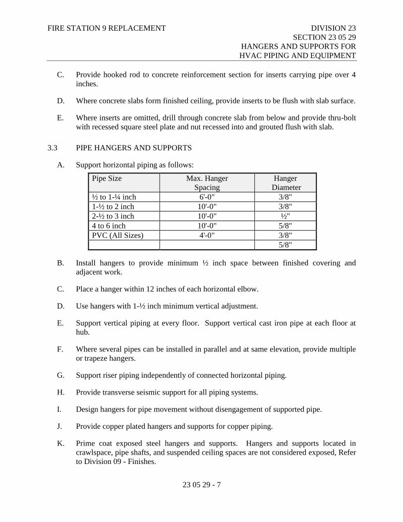
FIRE STATION 9 REPLACEMENT DIVISION 23
SECTION 23 05 29
HANGERS AND SUPPORTS FOR
HVAC PIPING AND EQUIPMENT
23 05 29 - 7
C. Provide hooked rod to concrete reinforcement section for inserts carrying pipe over 4
inches.
D. Where concrete slabs form finished ceiling, provide inserts to be flush with slab surface.
E. Where inserts are omitted, drill through concrete slab from below and provide thru-bolt
with recessed square steel plate and nut recessed into and grouted flush with slab.
3.3 PIPE HANGERS AND SUPPORTS
A. Support horizontal piping as follows:
Pipe Size Max. Hanger
Spacing
Hanger
Diameter
½ to 1-¼ inch 6'-0" 3/8"
1-½ to 2 inch 10'-0" 3/8"
2-½ to 3 inch 10'-0" ½"
4 to 6 inch 10'-0" 5/8"
PVC (All Sizes) 4'-0" 3/8"
5/8"
B. Install hangers to provide minimum ½ inch space between finished covering and
adjacent work.
C. Place a hanger within 12 inches of each horizontal elbow.
D. Use hangers with 1-½ inch minimum vertical adjustment.
E. Support vertical piping at every floor. Support vertical cast iron pipe at each floor at
hub.
F. Where several pipes can be installed in parallel and at same elevation, provide multiple
or trapeze hangers.
G. Support riser piping independently of connected horizontal piping.
H. Provide transverse seismic support for all piping systems.
I. Design hangers for pipe movement without disengagement of supported pipe.
J. Provide copper plated hangers and supports for copper piping.
K. Prime coat exposed steel hangers and supports. Hangers and supports located in
crawlspace, pipe shafts, and suspended ceiling spaces are not considered exposed, Refer
to Division 09 - Finishes.
FIRE STATION 9 REPLACEMENT DIVISION 23
SECTION 23 05 29
HANGERS AND SUPPORTS FOR
HVAC PIPING AND EQUIPMENT
23 05 29 - 8
3.4 EQUIPMENT BASES AND SUPPORTS
A. Provide housekeeping pads of concrete, minimum 4 inches thick and extending 6 inches
beyond supported equipment. Refer to Division 03 - Concrete.
B. Provide templates, anchor bolts, and accessories for mounting and anchoring
equipment.
C. Construct support of steel members. Brace and fasten with flanges bolted to structure.
D. Provide rigid anchors for pipes after vibration isolation components are installed.
3.5 FLASHING
A. Provide flexible flashing and metal counter-flashing where piping and ductwork
penetrate weather or waterproofed walls, floors, and roofs.
B. Flash plumbing vent pipes projecting above finished roof surface with flashing
compatible with roofing membrane system.
C. Flash floor drains in floors with topping over finished areas as per UPC requirements.
Fasten flashing to drain clamp device.
D. Seal floor drains watertight to adjacent materials.
E. Provide curbs for mechanical roof installations 16 inches minimum high above roofing
surface. Flash and counter-flash with sheet metal; seal watertight.
F. Adjust storm collars tight to pipe with bolts; caulk around top edge. Use storm collars
above roof jacks. Screw vertical flange section to face of curb.
3.6 SLEEVES
A. Set sleeves in position in construction. Provide reinforcing around sleeves.
B. Size sleeves large enough to allow for movement due to expansion and contraction.
Provide for continuous insulation wrapping.
C. Extend sleeves through floors one inch above finished floor level. Pack and caulk
sleeves full depth and provide floor plate.
D. Where piping or ductwork penetrates floor, ceiling, or wall, install sleeve, close off
space between pipe or duct and adjacent work with fire stopping insulation and caulk
seal. Use fire rated caulking where area or occupancy separation walls are penetrated.
Provide close fitting metal collar or escutcheon covers at both sides of penetration.

FIRE STATION 9 REPLACEMENT DIVISION 23
SECTION 23 05 29
HANGERS AND SUPPORTS FOR
HVAC PIPING AND EQUIPMENT
23 05 29 - 9
E. Install chrome plated steel escutcheons at finished surfaces.
END OF SECTION 23 05 29
FIRE STATION 9 REPLACEMENT DIVISION 23
SECTION 23 05 48
VIBRATION AND SEISMIC
CONTROLS FOR HVAC
23 05 48 - 1
PART 1 - GENERAL
1.1 RELATED DOCUMENTS
A. Drawings and general provisions of the Contract, including Municipality of Anchorage
Standard Specifications – Buildings (MASSB), General and Supplementary Conditions
apply to this Section.
1.2 SECTION INCLUDES
A. Flexible Pipe Connectors.
B. Isolators.
C. Equipment Bases.
D. Seismic Snubbers.
E. Earthquake Bumpers and Snubbers.
F. Piping Isolators.
G. Miscellaneous Support.
1.3 GENERAL
A. Mechanical system Contractor to furnish, install, and adjust all vibration isolation
components and materials required to isolate the building structure and occupied spaces
from vibrating equipment, piping and ductwork, as specified by this section.
1.4 SEISMIC REQUIREMENTS
A. Refer to the Structural Drawings.
1.5 EXCLUSION
A. Seismic protection of water pipes for fire protection system will be installed in strict
accordance with the provisions of FM Global Data Sheet 2-8.
FIRE STATION 9 REPLACEMENT DIVISION 23
SECTION 23 05 48
VIBRATION AND SEISMIC
CONTROLS FOR HVAC
23 05 48 - 2
1.6 WORK INCLUDED
A. Vibration isolation.
B. Inertia bases.
1.7 REFERENCE STANDARDS
A. Provide and install mechanical equipment so that Average Noise Criteria Curves, as
outlined in ASHRAE Guide, are not exceeded.
B. ASCE 7-05 – Minimum Design Loads for Buildings and Other Structures.
C. SMACNA - Seismic Restraint Manual, Guidelines for Mechanical Systems.
1.8 SUBMITTALS
A. Under the provisions of the Supplementary Conditions.
B. Installing Contractor shall submit complete product data in accordance with the General
Provisions of the Specifications before any materials are delivered to the job site.
C. Contractor shall submit to the Acoustical Consultant shop drawings showing the
following information so that isolation system can be checked for compliance with the
specifications:
1. Sizes, placement and type of isolators, seismic snubbers, and total base mass
(weight) if it is a concrete inertia base.
2. Weight distribution on isolators.
3. Equipment operating speed.
4. Isolator schedule to show size, type, load, and static deflection of each isolator.
5. Number and color-code of each isolator to show its location.
6. Isolator adjustment procedures for setting and adjusting the isolation devices so
that the isolator mount selections can be checked for compliance with the
specification.
1.9 EQUIPMENT VIBRATION ISOLATION
A. The installing Contractor to furnish a balanced set of vibration isolators for each piece
of equipment listed in the Vibration Isolation Schedule.
B. Isolation work to include, but not necessarily be limited to, the following:
FIRE STATION 9 REPLACEMENT DIVISION 23
SECTION 23 05 48
VIBRATION AND SEISMIC
CONTROLS FOR HVAC
23 05 48 - 3
1. Supported isolation of motor-driven equipment.
2. Inertia base frames in conjunction with isolation.
3. Isolation support of air-handling housings.
4. Isolation support of piping, piping risers, and ductwork.
5. Penetration isolation of pipes and ductwork through walls, floors or ceilings.
6. Flexible connections of ductwork and piping to equipment.
C. Each piece of rotating equipment must meet a reasonable criterion for maximum
vibration levels at each bearing, while in operation. The criterion is as follows:
1. Rotating equipment operating peak vibration velocities must not exceed 0.08
in/sec.
2. If it is discovered that the operating vibration velocities exceed this criterion, the
equipment shall be repaired or replaced at no expense to the Owner until approval
of the equipment is given by the Acoustical Consultant.
D. Installing Contractor to provide any components or materials not specifically mentioned
herein, but necessary to the proper vibration isolation of the equipment.
1.10 CONTRACTOR RESPONSIBILITY
A. All vibration isolation devices, including auxiliary steel bases and pouring forms, shall
be designed and furnished by a single manufacturer or supplier.
B. The Contractor shall adequately restrain all equipment, piping, and ductwork to resist
seismic forces. Design and select restraint devices to meet seismic requirements as
defined in the latest issue of the International Building Code and applicable state and
local codes in accordance with project area Seismic Zone with a minimum restraint
capability of 1.0 g.
C. The Contractor shall coordinate with the structural engineer to ensure mounting
attachment points for seismic restrained springs and seismic snubbers will withstand
forces generated from the maximum acceleration rating of the restrained springs and
snubbers.
D. In addition, the Contractor shall have the following responsibilities:
1. Select, install, adjust, and verify the performance of vibration isolators that will
meet the requirements given on the plans or in the specifications.
2. Bring to the Acoustical Consultant’s attention any equipment specified for the
project that is not covered in the Vibration Isolation Schedule herein.
3. Provide whatever assistance necessary to ensure correct installation and
adjustment of the isolators.
FIRE STATION 9 REPLACEMENT DIVISION 23
SECTION 23 05 48
VIBRATION AND SEISMIC
CONTROLS FOR HVAC
23 05 48 - 4
E. Changes or additions necessary to meet the requirements given on the plans or in the
specifications are to be made without any expense to the Owner.
1.11 QUALITY ASSURANCE
A. Isolators shall operate in the linear portion of their load-versus-deflection curve.
B. The ratio of lateral to vertical isolator stiffness shall be not less than 0.9 nor greater than
1.5.
C. The Contractor shall bring to the attention of the Acoustical Consultant any
discrepancies between this Section and other related documents.
PART 2 - PRODUCTS
2.1 ACCEPTABLE MANUFACTURERS
A. Vibration isolators shall be manufactured by:
1. Mason Industries.
2. Kordund, Westery, New York.
3. Consolidated Kinetics Corporation, Columbus, Ohio.
4. Vibration Mountings and Control, Inc.
5. MetraFlex.
6. Hyspan.
B. Ventilating equipment flexible connections and duct flexible connections shall be:
1. DuroDyne Duroprene or equal.
2. Ventfabrics, Chicago, Illinois.
3. Elgen Manufacturing Co., Garfield, New Jersey.
C. Substitutions: Under the provisions of the Supplementary Conditions.
2.2 FLEXIBLE PIPE CONNECTORS
A. Type FC-1 for Steel Piping:
1. Inner Hose: Close pitch, annular corrugated stainless steel.
2. Exterior Sleeve: type 304 stainless steel single braid.
3. Pressure Rating: 125 psig WSP and 450º F, 200 psig WOG and 250º F psig at 70º
F.
FIRE STATION 9 REPLACEMENT DIVISION 23
SECTION 23 05 48
VIBRATION AND SEISMIC
CONTROLS FOR HVAC
23 05 48 - 5
4. Joint: As specified for pipe joints.
5. Size: Use pipe sized units.
6. Maximum offset: ¾ inch on each side of installed center line.
7. Hyspan, 4500 Series or approved equal.
B. Type FC-1 for Copper Piping:
1. Inner Hose: Bronze
2. Exterior Sleeve: Braided bronze.
3. Pressure Rating: 125 psig WSP and 450º F.
4. Joint: As specified for pipe joints.
5. Size: Use pipe sized units.
6. Maximum offset: ¾ inch on each side of installed centerline.
7. Hyspan, 4500 Series or approved equal.
2.3 ISOLATORS
A. Type S-1: Bare Spring
1. Spring isolator without housings or snubbers.
2. Isolator shall be equipped with leveling bolts and 1 layer ribbed or waffled
neoprene pad.
3. Isolator shall be installed with Type WB-1 neoprene washers and bushings at base
plate anchor bolts.
4. Isolator shall have minimum operating static deflection as tabulated in the
Vibration Isolation Schedule.
5. Spring diameter(s) shall be not less than 0.8 of the compressed height of the
spring at rated load.
6. Spring(s) shall have minimum additional travel to solid equal to 50 percent of
rated deflection.
7. Acceptable Products:
a. Model SLF by Mason
b. Model FDS by Kinetics
B. Type S-2: Housed Spring
1. Spring isolator designed shall be free-standing and laterally stable.
2. Isolator shall be equipped with 1/4-inch thick neoprene acoustical friction pads
between the base plate and the support, and between top plate and equipment.
3. Isolator shall be equipped with leveling bolts that must be rigidly bolted to the
equipment.
4. Isolator shall be installed with Type WB-1 neoprene washers and bushings at base
plate anchor bolts.
FIRE STATION 9 REPLACEMENT DIVISION 23
SECTION 23 05 48
VIBRATION AND SEISMIC
CONTROLS FOR HVAC
23 05 48 - 6
5. Isolator to have minimum operating static deflection as tabulated in the Vibration
Isolation Schedule.
6. Spring housing to include vertical limit stops to prevent spring extension when
weight is removed.
7. Limit stops shall not make contact with housing during normal operation.
8. Spring housing to have a minimum clearance of 1/2 inch around the restraining
bolts and between the housing and the spring so as not to interfere with the spring
action.
9. Spring diameter(s) shall be not less than 0.8 of the compressed height of the
spring at rated load.
10. Spring(s) shall have minimum additional travel to solid equal to 50 percent of
rated deflection.
11. All isolators shall be marked to show their height before loading to verify proper
isolation after installation.
12. All isolators for a single piece of equipment shall have approximately equal
deflection.
13. All equipment shall be mounted level.
14. Acceptable Products:
a. Model SLR by Mason
b. Model FLS by Kinetics
C. Type S-3: Spring Seismic Restraint
1. Spring isolator designed to resiliently resist forces in all directions.
2. Snubbing in all modes with adjustment to limit upward, downward and horizontal
travel to a maximum rating of 1.0 g.
3. Isolator shall be equipped with 1/4-inch thick neoprene waffle pad bonded to the
bottom of the base plate.
4. Isolator shall be equipped with leveling bolts that must be rigidly bolted to the
equipment with height-saving brackets.
5. Isolator shall be installed with Type WB-1 neoprene washers and bushings at base
plate anchor bolts.
6. Isolator to have minimum operating static deflection as tabulated in the Vibration
Isolation Schedule.
7. Spring diameter(s) shall be not less than 0.8 of the compressed height of the
spring at rated load.
8. Spring(s) shall have minimum additional travel to solid equal to 50 percent of
rated deflection.
9. Isolators shall have mounting ports for spring inspection.
10. Mounts shall have an anchorage Preapproval “R” Number from OSHPD in the
State of California verifying the maximum certified horizontal and vertical load
ratings.
11. Acceptable Products:
a. Model SSLFH by Mason
FIRE STATION 9 REPLACEMENT DIVISION 23
SECTION 23 05 48
VIBRATION AND SEISMIC
CONTROLS FOR HVAC
23 05 48 - 7
b. Model FHS by Kinetics
c. Model FEQ by McDougall Control
D. Type N-1: Double-Deflection Neoprene Mount
1. Isolator shall contain a cast-in tapped steel load plate to permit bolting to the
supported equipment.
2. Isolator shall be installed with additional restraints to prevent excess motion
during start-up or in response to external loads, such as earthquakes.
3. Isolator shall be selected to provide the minimum operating static deflection
tabulated in the Vibration Isolation Schedule, while not exceeding the published
load capacity for the isolator used.
4. Isolator shall have a minimum static deflection of 0.35 inch.
5. Each isolator shall be color-coded to identify the load capacity.
6. Acceptable Products:
a. Model ND by Mason
b. Model RD, KIP by Kinetics
E. Type N-2: Neoprene Seismic Mount
1. Captive neoprene mounting shall consist of a steel housing with a captive steel
insert embedded in neoprene to prevent contact between the housing and the
central threaded insert.
2. Isolator shall contain a cast-in tapped steel load plate to permit bolting to the
supported equipment.
3. Snubbing to limit deflection in upward, downward, and horizontal directions.
Capacity to withstand not less than 1.0 g without noticeable deformation.
4. Isolators shall be selected to provide the minimum operating static deflection
tabulated in the Vibration Isolation Schedule, while not exceeding the published
load capacity for the isolator used.
5. Isolator shall have a minimum deflection of 0.15 inch
6. Each isolator shall be color-coded to identify the load capacity.
7. Acceptable Products:
a. Model RCA, RBA by Mason
b. Model RQ by Kinetics
F. Type N-3: Neoprene Seismic Mount
1. Captive neoprene mounting shall be arranged in opposition within a steel or
ductile iron housing to provide mechanical restraint in all directions.
2. Isolator shall contain a cast-in tapped steel load plate to permit bolting to the
supported equipment.
3. Snubbing to limit deflection in upward, downward, and horizontal directions.
Capacity to withstand not less than 1.0 g without noticeable deformation.

FIRE STATION 9 REPLACEMENT DIVISION 23
SECTION 23 05 48
VIBRATION AND SEISMIC
CONTROLS FOR HVAC
23 05 48 - 8
4. Isolators shall be selected to provide the minimum operating static deflection
tabulated in the Vibration Isolation Schedule, while not exceeding the published
load capacity for the isolator used.
5. Isolator shall have a minimum static deflection of 0.20 inch
6. Each isolator shall be color-coded to identify the load capacity.
7. Acceptable Products:
a. Model BR by Mason
G. Type N-4: Neoprene Pad
1. Isolator shall consist of 5/16-inch to 3/8-inch thick molded neoprene.
2. Pad shall be either a ribbed or waffle type construction.
3. Isolator shall have a 40 to 50 durometer rating.
4. Isolator shall be loaded to limit surface pressure to a maximum of 50 psi.
5. Isolator shall be equipped with a steel plate bonded to the neoprene pad if
required for proper load distribution.
6. Acceptable Products:
a. Model W, WM by Mason
b. Model NPD, NG by Kinetics
H. Type N-5: Neoprene Pad
1. Isolator shall consist of 3/4-inch thick molded neoprene.
2. Pad shall be either a ribbed or waffle type construction.
3. Isolator shall have a 50-durometer rating.
4. Isolator shall be loaded to limit surface pressure to a maximum of 50 psi.
5. Isolator shall be equipped with a steel plate bonded to the neoprene pad if
required for proper load distribution.
6. Acceptable Products:
a. Model Super W by Mason
I. Type H-1: Spring Hanger
1. Hanger to consist of a combination of a steel spring and a fiberglass or neoprene
isolator placed in series and encased in a welded steel bracket.
2. Isolator to have minimum operating static deflection as tabulated in the Vibration
Isolation Schedule.
3. Isolator shall be designed to carry five (5) times overload without failure.
4. Spring shall have minimum additional travel to solid equal to 50 percent of rated
deflection.
5. Isolator shall be installed to allow up to fifteen (15) degrees of rod misalignment
without metal-to-metal contact or other isolation short circuit.
6. Acceptable Products:
a. Model 30N by Mason
b. Model SRH by Kinetics
FIRE STATION 9 REPLACEMENT DIVISION 23
SECTION 23 05 48
VIBRATION AND SEISMIC
CONTROLS FOR HVAC
23 05 48 - 9
c. Model BSRA by Amber Booth
J. Type H-2: Neoprene or Fiberglass Hanger
1. Hangers to consist of a neoprene-in-shear or fiberglass isolator encased in a
welded steel bracket.
2. Hangers to have a minimum operating static deflection of 0.25 inch.
3. Acceptable Products:
a. Model HD by Mason
b. Model FH by Kinetics
K. Type H-3: Pre-compressed Spring Hanger
1. Hanger to consist of a combination of a steel spring and a fiberglass or neoprene
isolator placed in series and encased in a welded steel bracket.
2. Hanger shall be pre-compressed to the rated deflection, so as to keep the
supported piping or equipment at a fixed elevation during installation.
3. Hanger shall incorporate a release mechanism to free the spring after the
installation is complete and the hanger is subjected to full load condition.
4. Isolator to have minimum operating static deflection as tabulated in the Vibration
Isolation Schedule.
5. Acceptable Products:
a. Model PC 30N by Mason
b. Model SRPH by Kinetics
L. Type H-4: Neoprene Hanger Mount
1. Hangers to consist of an isolated neoprene bushing with embedded steel washer.
2. Acceptable Products:
3. Model HMIB by Mason
2.4 FLEXIBLE DUCTWORK CONNECTORS
A. Type DC-1: Flexible Duct
1. Flexible duct manufactured of flexible neoprene fabric.
2. Acceptable Products:
a. Model “Ventglas” by Vent Fabrics, Chicago
b. Model NFN, NF6N by Duro-Dyne
2.5 EQUIPMENT BASES
A. Type B-1: Integral Structural Steel Frame
FIRE STATION 9 REPLACEMENT DIVISION 23
SECTION 23 05 48
VIBRATION AND SEISMIC
CONTROLS FOR HVAC
23 05 48 - 10
1. Structural steel support members, with welded isolator support brackets and pre-
located and drilled anchor bolt holes, supplied by the equipment manufacturer
with the equipment.
2. Frame shall be manufactured of beams or channels of minimum section depth
equal to 8 percent of the longest span between support isolators, as indicated on
the drawings.
3. Frame size and shape shall be as required for equipment to be supported.
4. Frame shall be equipped with welded isolator support brackets to provide the
lowest possible mounting height of supported equipment.
5. Frame to provide a rigid, distortion free mounting base for supported equipment,
which allows no excessive differential motion between driving or driven
equipment components.
6. Frame shall allow for a minimum operating clearance between structural steel
frame and floor or housekeeping pad of 1 inch.
7. Isolation materials manufacturer to coordinate the isolator locations for each piece
of equipment as required.
8. Acceptable Products:
a. Model WF by Mason
B. Type B-2: Concrete Inertia Base
1. Framing as described under Type B-1.
2. Base to provide support for equipment without overhang, including pump suction
and discharge elbows.
3. Base shall be equipped with equipment anchor bolts fixed into position and
housed in a steel bolt sleeve, allowing minor bolt location adjustment.
4. Base to include reinforced concrete with 1/2 inch reinforcing rods at a maximum
of 8 inches on center.
5. Weight of base shall be not less than twice that of all the equipment and
connections it supports.
6. Each piece of equipment with its driving motor shall be bolted and grouted to a
spring-supported concrete inertia base, reinforced as required.
7. Base to allow for a minimum operating clearance between concrete inertia base
and floor or housekeeping pad of 1 inch.
8. Acceptable Products:
a. Model K by Mason
C. Type B-3: Vertical Steel Hanger Rods
1. Base to consist of four vertical steel hanger rods attached to structure above.
2. Rods shall be sufficient to carry a five (5) times overload without yielding or
failure.
3. Unless otherwise specified, hanger Type H-1 shall be used on all four hanger rods
in series with the supported load.
FIRE STATION 9 REPLACEMENT DIVISION 23
SECTION 23 05 48
VIBRATION AND SEISMIC
CONTROLS FOR HVAC
23 05 48 - 11
4. Rods shall be attached to the support “ears” of the hung equipment. Support
“ears” shall be provided by the equipment manufacturer.
5. Coordination of the location of the ears and the method of attachment is the
responsibility of the vibration isolator manufacturer or its representative.
6. For horizontally mounted vane-axial fans only, mount thrust restraint rods
between the fan and a suitable structural element to limit horizontal motion due to
air thrust from startup and normal operation to no more than 3/8 inch. Mount
hangers Type H-1 on all thrust restraint rods in series with the thrust load.
7. Provide steel cross-bracing rods to base framework above, if needed, to prevent
excess motion during equipment startup and operation. Cross bracing rods should
be threaded to allow adjustment of tension at one end.
8. Unless otherwise specified, seismic restraint to consist of stainless steel aircraft
cables and steel U-bolt clips (restraint Type E-3) attached to the equipment and
the structure above.
D. Type B-4: Structural Steel Support Members Designed to Support Vane Axial Fans
1. Base to consist of two horizontal steel beams or channels with a section depth
equal to either 8 percent of the longest span between support isolators or a
minimum of 4 inches.
2. Horizontal beams shall be supported on both ends by additional steel channels or
beams to raise the point of connection between the isolator and the fan to the
height of the axis of the fan shaft.
3. Base legs to have cross-bracing to provide a rigid, distortion-free mounting base
for supported equipment.
4. Mount thrust restraint rods between all horizontally mounted axial vane fans and a
suitable structural element to limit motion due to air thrust from startup and
normal operation to no more than 3/8 inch. Mount hangers Type H-1 in all thrust
restraint rods in series with the thrust load.
E. Type B-5: Curb Mounted Isolation Base
1. Base consisting of rooftop tubular steel support frame with removable free-
standing springs.
2. Base to allow for a flexible air seal and weather seal on sides and ends.
3. Base springs to have nominal static deflection of 1.0 inch, 2.0 inches, or 3.0
inches as specified in equipment Vibration Isolation Schedule.
4. Acceptable Products:
a. Model ISC by Mason
b. Model KSCR by Kinetics
c. Model Vibro-Curb II by ThyCurb
FIRE STATION 9 REPLACEMENT DIVISION 23
SECTION 23 05 48
VIBRATION AND SEISMIC
CONTROLS FOR HVAC
23 05 48 - 12
2.6 SEISMIC SNUBBERS
A. General
1. Provide restraints capable of safely accepting external forces as defined in latest
issue of International Building Code and applicable state and local codes without
failure, to maintain equipment, piping, duct, and variable volume boxes and fan
coil units in a captive position.
2. Seismic devices should not interfere with vibration isolation during normal
operation. Conflicts between vibration isolation and seismic restraints shall be
brought to the attention of the Acoustical Consultant.
3. All seismic mounts shall have an anchorage Pre-approval “R” Number from
OSHPD in the State of California verifying the maximum certified horizontal and
vertical load ratings.
4. Submit calculations by registered structural engineer to verify snubber capacities.
B. Type E-1: Seismic Restraint
1. Interlocking steel member restrained by shock absorbent rubber materials
compounded to bridge-bearing specifications as tabulated in ASTM D-676,
ASTM D-412, ASTM D-573, ASTM D-1149, and ASTM D-395.
2. Restraint shall be equipped with replaceable elastomeric materials with minimum
thickness of 1/2 inch.
3. Restraint shall be adjusted to have an air gap separating hard and resilient material
between 1/8 inch and 1/4 inch.
4. Number and location of snubbers shall be such that snubber load rating is not
exceeded. Minimum of four snubbers required.
5. Snubbers shall not be in contact with equipment during normal operation.
6. Acceptable Products:
a. Model HS by Kinetics
b. Model ER by Amber Booth
C. Type E-2: Seismic Restraint
1. All-directional seismic snubbers shall consist of interlocking steel members
restrained by a one-piece molded neoprene bushing of bridge bearing neoprene.
2. Bushing shall be replaceable and a minimum of ¼ inch thick. Rated loadings
shall not exceed 1000 psi.
3. A minimum air gap of 1/8 inch (3mm) shall be incorporated in the snubber design
in all directions before contact between the rigid and resilient surfaces.
4. Snubber end caps shall be removable to allow inspection of internal clearances.
5. Neoprene bushings shall be rotated to insure no short circuits exist before systems
are activated.
FIRE STATION 9 REPLACEMENT DIVISION 23
SECTION 23 05 48
VIBRATION AND SEISMIC
CONTROLS FOR HVAC
23 05 48 - 13
6. Snubbers shall not be in contact with equipment during normal operation.
7. Acceptable Products:
a. Model Z-1225 by Mason
D. Type E-3: Seismic Restraint Metal Cable
1. Stainless steel aircraft cables and steel U-bolt clips.
2. Cables to attach to equipment frame and to structure with steel angle clips.
3. Cables shall be installed with enough slack to allow proper functioning of
vibration isolators during normal operation and to become tight and restrict
excessive motion from seismic input.
4. Cables to have a maximum spacing of 20 feet on center for ductwork and piping.
5. Acceptable Products:
a. Model SCB/SCBH by Mason
2.7 PIPING ISOLATORS
A. Type P-1: Piping Mounts
1. Mount to consist of a prefabricated plastic or metal pipe clamp or penetration
mount with an integral resilient, elastomeric isolation pad.
2. Isolation pad shall not deteriorate over time or from normal hot water
temperatures.
a. Isolators shall not be used with PVC or plastic pipes.
3. Acceptable Products:
a. Isolated Pipe Mounts by Acousto-Plumb System
B. Type P-2: Piping Supports
1. Mount to consist of a carbon steel penetration mount with an integral resilient, felt
isolation pad.
2. Isolation pad shall not deteriorate over time or from normal hot water
temperatures.
3. Acceptable Products:
a. Isolators for Copper Tubing or I.P.S. Isolators by Tolco Incorporated
C. Type P-3: Piping Sleeve
1. Sleeve to consist of a 1/4 inch to 5/16 inch thick, flexible, resilient isolation pad.
2. Sleeve shall be wrapped around the entire circumference of the pipe to ensure
there is no rigid contact between pipe and support.
3. Limit sleeve surface pressure to a maximum of 30 psi.
4. Add an additional sheet metal sleeve wrapped around the padded sleeve if
necessary for proper load distribution.
FIRE STATION 9 REPLACEMENT DIVISION 23
SECTION 23 05 48
VIBRATION AND SEISMIC
CONTROLS FOR HVAC
23 05 48 - 14
5. Sleeve(s) shall be secured in place using duct tape or fastening strap.
6. Acceptable Products:
a. Model W by Mason
b. Model NPD, NG by Kinetics
D. Type P-4: All-Directional Pipe Anchor
1. Anchor to consist of telescopic arrangement of two sizes of steel tubing separated
by a minimum of 1/2 inch thick neoprene.
2. Neoprene shall be heavy duty neoprene and duck or neoprene isolation material
3. Acceptable Products:
a. Model ADA by Mason
E. Type P-5: All-Directional Pipe Guide
1. Guide to consist of telescopic arrangement of two sizes of steel tubing separated
by a minimum of 1/2 inch thick neoprene.
2. Neoprene shall be heavy-duty neoprene and duck or neoprene isolation material.
3. Guide height shall be preset with shear pin to allow vertical motion due to pipe
expansion/contraction.
4. Acceptable Products:
a. Model VSG by Mason
2.8 MISCELLANEOUS SUPPORT
A. Type WB-1: Neoprene washers and bushings
1. Washer-bushing shall be manufactured of bridge bearing neoprene.
2. Washer-bushing maximum loading not to exceed 1000 psi.
3. Washer-bushing shall be used such that direct contact between bolt and
equipment is eliminated.
4. Acceptable Products:
a. Model HG by Mason
B. Type CS-1: Cushion Sleeve
1. Fiberglass sleeve sized to fit pipe.
2. Acceptable Products:
a. Owens Corning Fiberglass 25 ASJ/SSL Service Jacket.
b. Johns Manville Micro-Lok Fiberglass Pipe Insulation.
FIRE STATION 9 REPLACEMENT DIVISION 23
SECTION 23 05 48
VIBRATION AND SEISMIC
CONTROLS FOR HVAC
23 05 48 - 15
2.9 MATERIALS AND EQUIPMENT
A. Materials and equipment shall conform to the respective specifications and other
requirements specified below.
B. Bolts and Nuts: Square head bolts and heavy hexagon nuts, ANSI B18.2.1 and B18.2.2,
and ASTM A 307 or A 576.
C. Bolts, underground, ASTM 325.
D. Sway Brace: Material used for members listed in Tables I through III of this
specification, except for pipes, shall be structural steel conforming with ASTM A 36.
Steel pipes shall conform to ASTM A 501.
E. Flexible Couplings: Flexible couplings shall have same pressure ratings as adjoining
pipe.
F. Flexible ball joints conforming to the following requirements may be employed on
above ground piping. Joints shall have cast or wrought steel casing and ball parts
capable of 360º rotation plus not less than 15º angular movement. Joints shall be
certified to be suitable for the service intended by the manufacturer, based on not less
than 2 years satisfactory operation in a similar application.
G. Sleeve type couplings shall be used for joining plain-end pipe section. The couplings
shall consist of one steel middle ring, two steel followers, two gaskets, and necessary
steel bolts and nuts to compress the gaskets.
H. Seismic Cable Restraint: High strength galvanized steel aircraft cable manufactured to
meet or exceed minimum materials and standard requirements pre AISI Manual for
structural applications of steel cables and ASTM A630. Break strengths must be per
ASTM E-8 procedures. UL certified break strength, color coded.
PART 3 - EXECUTION
3.1 GENERAL
A. Isolate mechanical equipment from the building structure by means of vibration
isolators as scheduled herein and on the Drawings. If there is a conflict between the
drawings and the Vibration Isolation Schedule herein, bring this conflict to the Engineer
and/or the Acoustical Consultant’s attention.
FIRE STATION 9 REPLACEMENT DIVISION 23
SECTION 23 05 48
VIBRATION AND SEISMIC
CONTROLS FOR HVAC
23 05 48 - 16
B. Mechanical equipment shall be carefully checked upon delivery for proper mechanical
performance which shall include proper noise and vibration operation.
C. Install isolation systems (isolators, bases, and related hardware) in accordance with the
manufacturer’s written Installation Instructions. The Contractor shall procure the
written installation instructions from the isolator manufacturers.
D. Vibration isolators must not cause any change in position of equipment or piping
resulting in piping stresses or misalignment.
E. Isolated equipment mounting systems must permit equipment motion in all directions.
F. Adjust or provide additional resilient restraints to flexibly limit equipment lateral
motion to 1/2 inch during startup and operation.
G. Prior to startup, clean out all foreign matter between base, isolator, equipment, and
mounting surfaces. Verify that there are no rigid connections between equipment and
building structure that degrade the vibration isolation systems specified herein.
H. Align isolator rods to clear the isolator housing.
I. Unless otherwise directed by this document, suspend isolators with the isolator hanger
housing attached to, or hung as close as possible to, the structure.
J. Do not use wall, floor, or ceiling penetrations to support pipework or ductwork.
Support pipe or duct just prior to and just after the penetration, so that the pipe or duct is
centered in penetration.
K. Coordinate piping supports with equipment supports to maintain uniformly efficient
isolation, expansion, and contraction, without creating excessive stresses at any
equipment connection or in any portion of the piping.
L. All ductwork within the shafts shall not be in contact with the walls and shall be
anchored to the building structure at the concrete floor only.
M. Do not allow contact between isolated ducts or pipes and non-isolated equipment or
structure. “Isolated ducts or pipes” include the isolated portions of their supports or
hangers.
N. Non duct elements should not be in contact with any duct hangers.
O. Provide a minimum 2 inch gap between the top of the ductwork and the underside of the
floor structure above within all the mechanical rooms.
P. Bring to the Acoustical Consultant’s attention prior to installation any conflicts with
other trades which will result in unavoidable rigid contact with equipment or piping as
FIRE STATION 9 REPLACEMENT DIVISION 23
SECTION 23 05 48
VIBRATION AND SEISMIC
CONTROLS FOR HVAC
23 05 48 - 17
described herein, due to inadequate space or other unforeseen conditions. Corrective
work necessitated by conflicts after installation will be at the responsible Contractor’s
expense.
Q. Size anchoring bolts to isolators or snubbers withstand seismic lateral shear and tensile
failure and isolate bolts from direct contact with the structure using Type WB-1 isolator.
R. All vibrating equipment and the interconnecting pipe and ductwork shall be isolated to
eliminate the transmission of objectionable noise and vibration from the structure.
S. Where additional attenuation is required for ventilation equipment, the increased
pressure drop must not cause an increase in power requirements form those specified.
T. All rotating equipment, fans, pumps, compressors, etc., shall be statically and
dynamically balanced.
U. All installed rotating equipment with excessive noise and/or vibration which cannot be
corrected in place shall be replaced at no cost to Owner.
3.2 GENERAL PROCEDURES
A. Select isolators in accordance with the manufacturer's recommendations and the
equipment weight distribution to allow for proper static deflection of the isolators in
relation to the span of the building structure supporting the equipment, considering the
allowable deflection and weight of the structure.
B. Install isolators so they can be easily removed for replacement.
C. Mount all equipment absolutely level.
D. Install all isolators per manufacturer's instructions.
E. Install vibration isolators for mechanical motor driven equipment.
F. Set steel bases for 1" clearance between housekeeping pad and base.
G. All vibration isolated equipment shall be fitted with earthquake bracing and snubbers
suitable for seismic control seismic use group 3, importance factor 1.25, and design
category D. Analysis to be performed and submitted for approval by manufacturer
supplying bracing and snubbers.
H. Secure seismic restraint cable to structure and to braced component through bracket or
stake eye specifically designed by the cable manufacturer to exceed cable restraint rated
capacity.
FIRE STATION 9 REPLACEMENT DIVISION 23
SECTION 23 05 48
VIBRATION AND SEISMIC
CONTROLS FOR HVAC
23 05 48 - 18
3.3 PIPING
A. Provide the first two piping supports away from an isolated piece of equipment to which
piping is connected with spring hangers having deflections equal to that of the
equipment isolation. Size supports for all horizontal piping 2-½" and larger which is
spring isolated for a minimum starting deflection of ¾" with the pipe filled.
B. Where piping 2" and smaller is to be isolated, use either Stoneman #S100, S500, S200
or S600 isolators or support the piping on its insulation with a sheetmetal shield, using a
section of 9# density insulation under the hanger.
C. Size vertical piping supports with deflection capability equal to four times the
anticipated expansion or contraction. Install temporary anchors as required to permit
readjustment of springs in the risers, to fix direction of pipe movement and final
operating deflection of the springs.
D. Piping vibration isolation flexible connections shall make a 90º change of direction
unless otherwise noted.
3.4 RUST PROOFING
A. Treat all vibration isolation hardware for resistance to corrosion.
B. Provide zinc electro-plated nuts, bolts and washers.
C. Provide steel components PVC coated or primed with zinc chromate primer and painted
with two coats of industrial grade enamel. Completely remove all welding slag and
thoroughly clean all surfaces before painting.
3.5 SWAY BRACES
A. Sway braces shall be installed on piping and duct to preclude damage during seismic
activity. All bracing shall conform to the arrangements specified. Provisions on this
paragraph apply to all piping within a 5 foot line around outside of building unless
buried in the ground. Piping grouped for support on trapeze type hangers shall be
braced at the same intervals as determined by the smallest diameter pipe of the group.
The trapeze type hanger shall be secured with less than two ½ inch bolts. Bracing
rigidly attached to pipe flanges, or similar, shall not be used where it would interfere
with thermal expansion of piping.
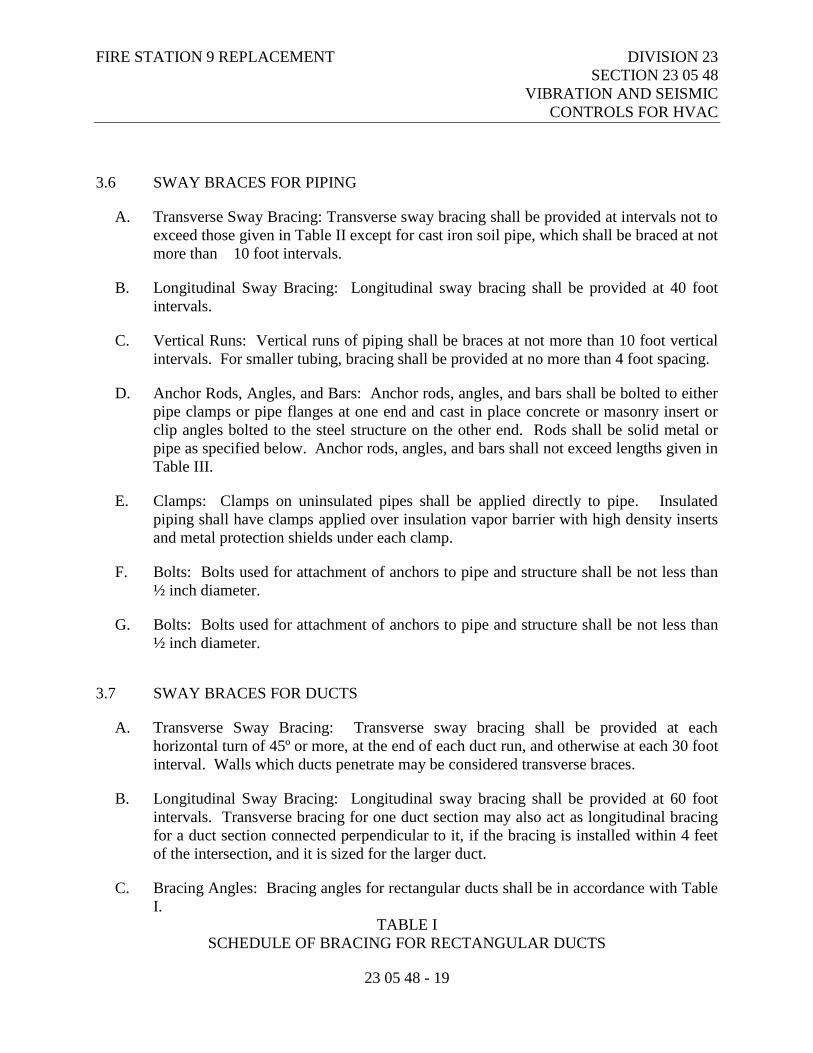
FIRE STATION 9 REPLACEMENT DIVISION 23
SECTION 23 05 48
VIBRATION AND SEISMIC
CONTROLS FOR HVAC
23 05 48 - 19
3.6 SWAY BRACES FOR PIPING
A. Transverse Sway Bracing: Transverse sway bracing shall be provided at intervals not to
exceed those given in Table II except for cast iron soil pipe, which shall be braced at not
more than 10 foot intervals.
B. Longitudinal Sway Bracing: Longitudinal sway bracing shall be provided at 40 foot
intervals.
C. Vertical Runs: Vertical runs of piping shall be braces at not more than 10 foot vertical
intervals. For smaller tubing, bracing shall be provided at no more than 4 foot spacing.
D. Anchor Rods, Angles, and Bars: Anchor rods, angles, and bars shall be bolted to either
pipe clamps or pipe flanges at one end and cast in place concrete or masonry insert or
clip angles bolted to the steel structure on the other end. Rods shall be solid metal or
pipe as specified below. Anchor rods, angles, and bars shall not exceed lengths given in
Table III.
E. Clamps: Clamps on uninsulated pipes shall be applied directly to pipe. Insulated
piping shall have clamps applied over insulation vapor barrier with high density inserts
and metal protection shields under each clamp.
F. Bolts: Bolts used for attachment of anchors to pipe and structure shall be not less than
½ inch diameter.
G. Bolts: Bolts used for attachment of anchors to pipe and structure shall be not less than
½ inch diameter.
3.7 SWAY BRACES FOR DUCTS
A. Transverse Sway Bracing: Transverse sway bracing shall be provided at each
horizontal turn of 45º or more, at the end of each duct run, and otherwise at each 30 foot
interval. Walls which ducts penetrate may be considered transverse braces.
B. Longitudinal Sway Bracing: Longitudinal sway bracing shall be provided at 60 foot
intervals. Transverse bracing for one duct section may also act as longitudinal bracing
for a duct section connected perpendicular to it, if the bracing is installed within 4 feet
of the intersection, and it is sized for the larger duct.
C. Bracing Angles: Bracing angles for rectangular ducts shall be in accordance with Table
I.
TABLE I
SCHEDULE OF BRACING FOR RECTANGULAR DUCTS
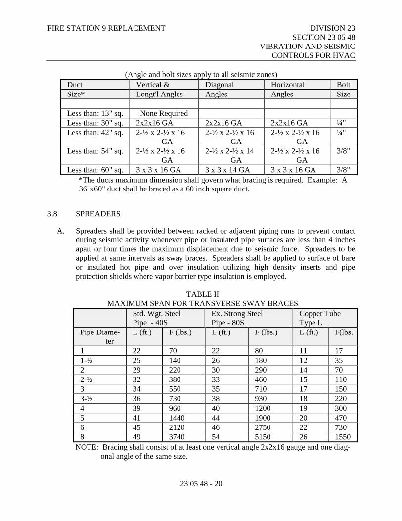
FIRE STATION 9 REPLACEMENT DIVISION 23
SECTION 23 05 48
VIBRATION AND SEISMIC
CONTROLS FOR HVAC
23 05 48 - 20
(Angle and bolt sizes apply to all seismic zones)
Duct Vertical & Diagonal Horizontal Bolt
Size* Longt'l Angles Angles Angles Size
Less than: 13" sq. None Required
Less than: 30" sq. 2x2x16 GA 2x2x16 GA 2x2x16 GA ¼"
Less than: 42" sq. 2-½ x 2-½ x 16
GA
2-½ x 2-½ x 16
GA
2-½ x 2-½ x 16
GA
¼"
Less than: 54" sq. 2-½ x 2-½ x 16
GA
2-½ x 2-½ x 14
GA
2-½ x 2-½ x 16
GA
3/8"
Less than: 60" sq. 3 x 3 x 16 GA 3 x 3 x 14 GA 3 x 3 x 16 GA 3/8"
*The ducts maximum dimension shall govern what bracing is required. Example: A
36"x60" duct shall be braced as a 60 inch square duct.
3.8 SPREADERS
A. Spreaders shall be provided between racked or adjacent piping runs to prevent contact
during seismic activity whenever pipe or insulated pipe surfaces are less than 4 inches
apart or four times the maximum displacement due to seismic force. Spreaders to be
applied at same intervals as sway braces. Spreaders shall be applied to surface of bare
or insulated hot pipe and over insulation utilizing high density inserts and pipe
protection shields where vapor barrier type insulation is employed.
TABLE II
MAXIMUM SPAN FOR TRANSVERSE SWAY BRACES
Std. Wgt. Steel
Pipe - 40S
Ex. Strong Steel
Pipe - 80S
Copper Tube
Type L
Pipe Diame-
ter
L (ft.) F (lbs.) L (ft.) F (lbs.) L (ft.) F(lbs.
)
1 22 70 22 80 11 17
1-½ 25 140 26 180 12 35
2 29 220 30 290 14 70
2-½ 32 380 33 460 15 110
3 34 550 35 710 17 150
3-½ 36 730 38 930 18 220
4 39 960 40 1200 19 300
5 41 1440 44 1900 20 470
6 45 2120 46 2750 22 730
8 49 3740 54 5150 26 1550
NOTE: Bracing shall consist of at least one vertical angle 2x2x16 gauge and one diag-
onal angle of the same size.
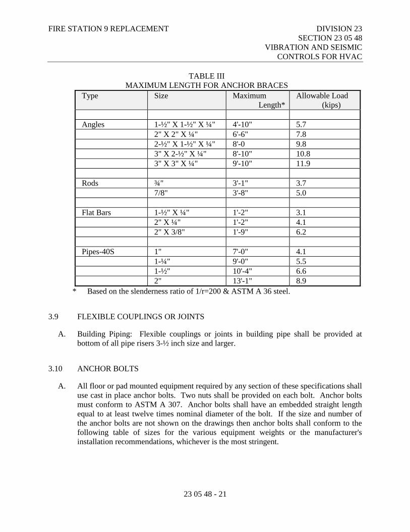
FIRE STATION 9 REPLACEMENT DIVISION 23
SECTION 23 05 48
VIBRATION AND SEISMIC
CONTROLS FOR HVAC
23 05 48 - 21
TABLE III
MAXIMUM LENGTH FOR ANCHOR BRACES
Type Size Maximum
Length*
Allowable Load
(kips)
Angles 1-½" X 1-½" X ¼" 4'-10" 5.7
2" X 2" X ¼" 6'-6" 7.8
2-½" X 1-½" X ¼" 8'-0 9.8
3" X 2-½" X ¼" 8'-10" 10.8
3" X 3" X ¼" 9'-10" 11.9
Rods ¾" 3'-1" 3.7
7/8" 3'-8" 5.0
Flat Bars 1-½" X ¼" 1'-2" 3.1
2" X ¼" 1'-2" 4.1
2" X 3/8" 1'-9" 6.2
Pipes-40S 1" 7'-0" 4.1
1-¼" 9'-0" 5.5
1-½" 10'-4" 6.6
2" 13'-1" 8.9
* Based on the slenderness ratio of 1/r=200 & ASTM A 36 steel.
3.9 FLEXIBLE COUPLINGS OR JOINTS
A. Building Piping: Flexible couplings or joints in building pipe shall be provided at
bottom of all pipe risers 3-½ inch size and larger.
3.10 ANCHOR BOLTS
A. All floor or pad mounted equipment required by any section of these specifications shall
use cast in place anchor bolts. Two nuts shall be provided on each bolt. Anchor bolts
must conform to ASTM A 307. Anchor bolts shall have an embedded straight length
equal to at least twelve times nominal diameter of the bolt. If the size and number of
the anchor bolts are not shown on the drawings then anchor bolts shall conform to the
following table of sizes for the various equipment weights or the manufacturer's
installation recommendations, whichever is the most stringent.
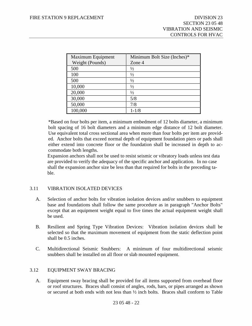
FIRE STATION 9 REPLACEMENT DIVISION 23
SECTION 23 05 48
VIBRATION AND SEISMIC
CONTROLS FOR HVAC
23 05 48 - 22
Maximum Equipment
Weight (Pounds)
Minimum Bolt Size (Inches)*
Zone 4
500 ½
100 ½
500 ½
10,000 ½
20,000 ½
30,000 5/8
50,000 7/8
100,000 1-1/8
*Based on four bolts per item, a minimum embedment of 12 bolts diameter, a minimum
bolt spacing of 16 bolt diameters and a minimum edge distance of 12 bolt diameter.
Use equivalent total cross sectional area when more than four bolts per item are provid-
ed. Anchor bolts that exceed normal depth of equipment foundation piers or pads shall
either extend into concrete floor or the foundation shall be increased in depth to ac-
commodate both lengths.
Expansion anchors shall not be used to resist seismic or vibratory loads unless test data
are provided to verify the adequacy of the specific anchor and application. In no case
shall the expansion anchor size be less than that required for bolts in the preceding ta-
ble.
3.11 VIBRATION ISOLATED DEVICES
A. Selection of anchor bolts for vibration isolation devices and/or snubbers to equipment
base and foundations shall follow the same procedure as in paragraph "Anchor Bolts"
except that an equipment weight equal to five times the actual equipment weight shall
be used.
B. Resilient and Spring Type Vibration Devices: Vibration isolation devices shall be
selected so that the maximum movement of equipment from the static deflection point
shall be 0.5 inches.
C. Multidirectional Seismic Snubbers: A minimum of four multidirectional seismic
snubbers shall be installed on all floor or slab mounted equipment.
3.12 EQUIPMENT SWAY BRACING
A. Equipment sway bracing shall be provided for all items supported from overhead floor
or roof structures. Braces shall consist of angles, rods, bars, or pipes arranged as shown
or secured at both ends with not less than ½ inch bolts. Braces shall conform to Table
FIRE STATION 9 REPLACEMENT DIVISION 23
SECTION 23 05 48
VIBRATION AND SEISMIC
CONTROLS FOR HVAC
23 05 48 - 23
III. Bracing shall be provided for equipment to resist a horizontal force equal to 150
percent of the weight of equipment without exceeding safe working stress of bracing
components. Details of all equipment bracing shall be submitted for approval. In lieu
of bracing with vertical supports, these items may be supported with hangers inclined at
45º directed up and radially away from equipment and oriented symmetrically in 90º
intervals on the horizontal plane, bisecting the angles of each corner of the equipment,
providing that supporting members are properly sized to support operating weight of
equipment when hangers are inclined at 45º angle.
3.13 MISCELLANEOUS EQUIPMENT
A. The following specific items of equipment to be furnished under this contract shall be
constructed and assembled so as to be capable of withstanding the horizontal equivalent
static force of 0.30 times the operating weight of the equipment, at vertical center of
gravity of the equipment without causing permanent deformation, dislocations,
separation of components, or other damage, which would render the equipment
inoperative for significant periods of time following an earthquake.
1. Miscellaneous Equipment
a. Variable frequency drives
b. Computer room cooling units
c. HRV – Heat recovery ventilators
B. Different sections of ductwork requiring the same type of isolator with the same
minimum static deflection may be supported on a common Unistrut support that is
isolated with the same type of isolator.
C. Isolate ductwork penetrations as described under Penetration Isolation.
3.14 PIPEWORK ISOLATION
A. Isolate pipework within the fan room and boiler room using isolator Type H-1, with
minimum static deflection of 1.0 inch, and seismic restraint E-3.
B. Different sections of pipework requiring the same type of isolator with the same
minimum static deflection may be supported on a common Unistrut support that is
isolated with the same type of isolator.
C. Support vertical piping loads, including water strainers, and valves between pump base
elbow supports and the suction and discharge header piping by means of the pump base
spring isolators without stress or strain to the pump housing.
D. Isolate all pipework penetrations through mechanical room and mechanical shaft walls,
ceilings, or floors as described under Penetration Isolation.
FIRE STATION 9 REPLACEMENT DIVISION 23
SECTION 23 05 48
VIBRATION AND SEISMIC
CONTROLS FOR HVAC
23 05 48 - 24
3.15 MISCELLANEOUS
A. The Contractor providing vibration isolation equipment shall coordinate with General
Contractor and structural engineer to ensure mounting attachment points for seismic
restrained springs and seismic snubbers called out in the Vibration Isolation Schedule,
will withstand forces generated from the maximum acceleration rating of the restrained
springs and snubbers.
B. Any and all equipment, ductwork, or piping within mechanical rooms or mechanical
areas, not specifically listed in the vibration isolation schedule or addressed in the
paragraphs above, shall be separated from contact with the structure via isolator Type
N-4, plus neoprene washers and bushings Type WB-1, if equipment is bolted to
structure. Size pads and use metal plates or washers to limit surface pressure on
neoprene to 45 psi.
END OF SECTION 23 05 48
FIRE STATION 9 REPLACEMENT DIVISION 23
SECTION 23 05 53
IDENTIFICATION FOR HVAC
PIPING AND EQUIPMENT
23 05 53 - 1
PART 1 - GENERAL
1.1 RELATED DOCUMENTS
A. Drawings and general provisions of the Contract, including Municipality of Anchorage
Standard Specifications – Buildings (MASSB), General and Supplementary Conditions
apply to this Section.
1.2 SECTION INCLUDES
A. Identification of mechanical products installed under Division 21 – Fire Suppression
System, Division 22 - Plumbing and Division 23 – Heating, Ventilating & Air
Conditioning.
1.3 REFERENCES
A. ASME A13.1 - Scheme for the Identification of Piping Systems.
1.4 SUBMITTALS
A. Submit product data under provisions of Supplementary Conditions.
B. Include product data on: Nameplates, tags, and pipe markers, valve chart frame.
PART 2 - PRODUCTS
2.1 ACCEPTABLE MANUFACTURERS
A. Seton.
B. Substitutions: Under provisions of and Supplementary Conditions.
2.2 MATERIALS
A. Color: Unless specified otherwise, conform to ASME A13.1.
FIRE STATION 9 REPLACEMENT DIVISION 23
SECTION 23 05 53
IDENTIFICATION FOR HVAC
PIPING AND EQUIPMENT
23 05 53 - 2
B. Plastic Nameplates: Laminated three-layer plastic with engraved black or white letters
on contrasting background color. Plate size minimum 3/4 x 2-1/2".
C. Plastic Tags: Laminated three-layer plastic with engraved black or white letters on
contrasting background color. Tag size minimum 1-1/2 inch square.
D. Metal Tags: Brass with stamped letters; tag size minimum 1-1/2 inch diameter with
smooth edges.
E. Plastic Pipe Markers: Factory fabricated, flexible, semi- rigid plastic, preformed to fit
around pipe or pipe covering; minimum information indicating flow direction arrow and
fluid being conveyed.
F. Plastic Tape Pipe Markers: Flexible, vinyl film tape with pressure sensitive adhesive
backing and printed markings.
G. Underground Plastic Pipe Markers: Bright colored continuously printed plastic ribbon
tape of not less than 6 inch wide by 4 mil thick, manufactured for direct burial service
with metallic tracer wire.
H. Valve Chart Frame: Seton #A11P aluminum frame with plastic windows.
PART 3 - EXECUTION
3.1 PREPARATION
A. Degrease and clean surfaces to receive adhesive for identification materials.
3.2 INSTALLATION
A. Plastic Nameplates: Install with corrosive-resistant mechanical fasteners, or adhesive.
B. Plastic or Metal Tags: Install with corrosive-resistant bead type chain.
C. Plastic Pipe Markers: Install in accordance with manufacturer's instructions.
D. Plastic Tape Pipe Markers: Install complete with minimum two strips of adhesive
direction arrow tape around pipe in accordance with manufacturer's instructions.
E. Underground Plastic Pipe Markers: Install underground plastic pipe markers with
metallic tracer wire 6 to 8 inches below finished grade, directly above all buried pipe.
FIRE STATION 9 REPLACEMENT DIVISION 23
SECTION 23 05 53
IDENTIFICATION FOR HVAC
PIPING AND EQUIPMENT
23 05 53 - 3
F. Equipment: Identify air handling units, pumps, heat transfer equipment, tanks, and
water treatment devices with plastic nameplates. Small devices, such as in-line pumps,
may be identified with plastic or metal tags.
G. Controls: Identify control panels and major control components outside panels with
plastic nameplates.
H. Valves: Identify valves in main and branch piping with tags showing service and valve
number.
I. Piping: Identify piping, concealed and exposed, with plastic tape pipe markers. Tags
may be used on small diameter piping. Identify service, flow direction. Install in clear
view and align with axis of piping. Locate identification not to exceed 20 feet on
straight runs including risers and drops, adjacent to each valve and "T", at each side of
penetration of structure or enclosure, and at each obstruction.
J. Ductwork: Identify ductwork with plastic nameplates. Identify as to air handling unit
number, and area served. Locate identification at air handling unit, at each side of
penetration of structure or enclosure, and at each obstruction.
K. Locations: Nameplates shall be located so as to be readily visible to maintenance
personnel. Motor nameplates shall be readily visible on accessible, three phase motors,
otherwise a duplicate motor nameplate shall be permanently affixed to the driven
machinery in a visible locations.
3.3 VALVE CHART AND SCHEDULE
A. Provide valve chart and schedule at location as directed. Chart shall show valve
number, service and normal position. Provide a reduced scale copy of drawings
showing valves and valve number. Provide copies of valve chart and drawings for
inclusion in operation and maintenance manuals.
END OF SECTION 23 05 53
FIRE STATION 9 REPLACEMENT DIVISION 23
SECTION 23 05 93
TESTING, ADJUSTING AND
BALANCING FOR HVAC
23 05 93 - 1
PART 1 - GENERAL
1.1 RELATED DOCUMENTS
A. Drawings and general provisions of the Contract, including Municipality of Anchorage
Standard Specifications – Buildings (MASSB), General and Supplementary Conditions
apply to this Section.
1.2 SECTION INCLUDES
A. Testing, Adjusting, and Balancing of Hydronic Balancing.
B. Testing, Adjusting, and Balancing of Air Systems.
C. Measure of Final Operating Conditions of HVAC Systems.
D. Sound Measurement of Equipment Operating Conditions.
E. Vibration Measurement of Equipment Operation Conditions.
1.3 SCOPE
A. Furnish the professional services of a qualified and approved balancing and testing firm
to perform the work of this specification section.
B. The work of this section includes but is not necessarily limited to:
1. Testing and balancing all fans and all air handling systems.
2. Testing and balancing liquid heat transfer systems.
3. Working directly with the control subcontractor to obtain proper system
adjustments.
C. The work of this section does not include:
1. Adjusting burners for proper combustion operation.
2. Domestic water distribution system adjustment.
3. Liquid waste transfer system adjustment.
4. Fire protection systems.
FIRE STATION 9 REPLACEMENT DIVISION 23
SECTION 23 05 93
TESTING, ADJUSTING AND
BALANCING FOR HVAC
23 05 93 - 2
1.4 APPLICABLE CODES AND STANDARDS
A. Associated Air Balance Council:
1. AABC MN-1 - National Standards for Testing and Balancing Heating,
Ventilating, and Air Conditioning Systems.
B. American Society of Heating, Refrigerating and Air-Conditioning Engineers:
1. ASHRAE 111 - Practices for Measurement, Testing, Adjusting and Balancing of
Building Heating, Ventilation, Air-Conditioning and Refrigeration Systems.
C. Natural Environmental Balancing Bureau:
1. NEBB - Procedural Standards for Testing, Adjusting, and Balancing of
Environmental Systems.
1.5 QUALIFICATION OF THE BALANCING FIRM OR COMPANY
A. Subcontractor minimum qualifications include:
1. Maintain a complete service organization that has operated within Alaska for at
least five years prior to bid date of this project.
2. Demonstrate satisfactory completion of five projects of similar scope in the State
of Alaska during the past five years. Provide references if requested.
3. Perform Work under supervision of NEBB Certified Testing, Balancing and
Adjusting Supervisor or registered professional engineer experienced in
performance of this Work and licensed in State of Alaska.
1.6 TIMING OF WORK
A. Do not begin balancing and testing until the systems, including controls, are completed
and in full working order.
B. Schedule the testing and balancing work in cooperation with other trades.
C. Complete the testing and balancing at least one week before the date of substantial
completion and before any occupancy occurs.
FIRE STATION 9 REPLACEMENT DIVISION 23
SECTION 23 05 93
TESTING, ADJUSTING AND
BALANCING FOR HVAC
23 05 93 - 3
1.7 CONTRACTOR RESPONSIBILITY TO BALANCING AGENCY
A. Award the test and balance contract to an approved firm or company upon receipt of
contract to allow the Balance and Testing Agency to schedule this work in cooperation
with other trades involved and comply with completion date.
B. Put all heating, ventilating and air conditioning systems, equipment and controls into
full operation for the Balancing Agency and continue the operation of same during each
working day of testing balancing.
C. Provide scaffolding, ladders and access to each system for proper testing balancing.
D. Make any changes in pulleys, belts and dampers, or add any dampers as required for
correct balance as recommended by the Balance and Testing Agency at no additional
cost to the Owner.
1.8 REPORT
A. Certified Reports: Submit testing, adjusting, and balancing reports bearing the
signature of the Test and Balance Agency Representative. The reports shall be certified
proof that the systems have been tested, adjusted, and balanced in accordance with the
referenced standards; are an accurate representation of how the systems have been
installed; are a true representation of how the systems are operating at the completion of
the testing, adjusting and balancing procedures; and are an accurate record of all final
quantities measured, to establish normal operating values of the system. Follow the
procedures and format specified below:
1. Draft Reports: Upon completion of testing, adjusting and balancing procedures,
prepare draft reports on the approved forms. Draft reports may be hand written,
but must be complete, factual, accurate, and legible. Organize and format draft
reports in the same manner specified for the final reports.
2. Final Reports: Upon verification and approval of the draft report; prepare final
reports, typewritten, organized and formatted as specified below.
3. Report Format: Report forms shall be those standard forms prepared by the
referenced standard for each respective item and system to be tested, adjusted and
balanced. Bind report forms complete with schematic systems diagrams and other
data in reinforced, vinyl, 3-ring binders. Provide binding edge labels with the
project identification and a title descriptive of the documents. Divide the contents
of the binder into the below listed divisions, separated by divider tabs:
a. General Information and Summary.
b. Air Systems.
c. Hydronic Systems.
FIRE STATION 9 REPLACEMENT DIVISION 23
SECTION 23 05 93
TESTING, ADJUSTING AND
BALANCING FOR HVAC
23 05 93 - 4
d. Temperature Control Systems.
e. Special Systems.
f. Sound and Vibration Systems.
g. System Deficiency Reports and Corrective Actions.
4. Report Contents: Provide the following minimum information, forms and data:
a. General Information and Summary: Inside cover sheet to identify testing,
adjusting, and balancing agency; contractor; owner, architect, engineer and
project. Include addresses, contact names and telephone numbers. Also
include a certification sheet containing the name, address, telephone number
and signature of the Certified Test and Balance Personnel. Include in this
division a listing of the instrumentation used for the procedures along with
the proof of calibration.
b. The remainder of the report shall contain the appropriate forms containing
as a minimum, the information indicated on the standard report forms
prepared by the AABC for each respective item and system. Prepare a
schematic diagram for each item of equipment and system to accompany
each respective report form.
c. Calibration Reports: Submit proof that all required instrumentation has
been calibrated to tolerances specified in the referenced standards, within a
period of six months prior to starting the project.
1.9 SUBMITTALS
A. Under the provisions of the Supplementary Conditions.
B. Submit balancing agency qualifications and sample balancing forms.
C. Provide list of equipment to be used and date of last calibration.
D. Submit preliminary balance report a minimum of one week prior to substantial
inspection.
E. Submit final balance report with written response to comments.
PART 2 - PRODUCTS
2.1 INSTRUMENTS
A. Maintain all instruments accurately calibrated and in good working order. Use
instruments with the following minimum performance characteristics.
1. Air Velocity Instruments: Direct reading in feet per minute, 2% accuracy.
2. Static Pressure Instruments: Direct reading in inches water gauge, 2% accuracy.
FIRE STATION 9 REPLACEMENT DIVISION 23
SECTION 23 05 93
TESTING, ADJUSTING AND
BALANCING FOR HVAC
23 05 93 - 5
3. RPM Instruments: Direct reading in revolutions per minute, .5% accuracy; or
revolution counter accurate within 2 counts per 1,000.
4. Pressure Readout: Direct reading in feet of water or PSI, .5% accuracy.
5. Temperature Instruments - Direct reading in degrees F, +.5% accuracy.
6. Water Flow Instruments: Differential pressure type; direct reading in feet of
water or PSI, 2% accuracy, suitable for readout balancing valve provided.
7. Sound Measuring Instrument: Octave Band Analyzer which essentially complies
to AASA Standards SI.6 1960 with a range of 24DB to 150 DB sound pressure
level ref. .0002 microbar. Calibrate sound test instrument before use to a closed
coupler and a driving loudspeaker that produces a know-sound pressure level at
the microphone of the analyzer.
PART 3 - EXECUTION
3.1 GENERAL PROCEDURES FOR ALL SYSTEMS
A. Start with new, clean filters. The balancing shall be done by providing approximately
10% more air flow and water flow, etc. than shown on the plans. This will allow
performance at the desired level as an approximate average of actual use conditions.
B. In cooperation with the control manufacturer's representative, coordinate adjustments of
automatically operated dampers and valves to operate as specified, indicated and/or
noted.
C. Use manufacturer's ratings on all equipment to make required calculations.
D. Make final adjustments for each space per heating or cooling comfort requirement.
State reason for variance from design CFM, i.e., "too noisy", "drafty", etc.
3.2 REQUIREMENTS FOR ALL HEAT RECOVERY VENTILATOR SYSTEMS
A. Identify each diffuser, grille and register as to location and area.
B. Identify and list size, type and manufacturer of diffusers, grilles, registers and all testing
equipment.
C. In readings and tests of diffusers, grilles and registers, include required FPM velocity
and required CFM and test CFM after adjustments. If test apparatus is designed to read
CFM directly, velocity reading may be omitted. Identify test apparatus used. Identify
wide open (W.O.) runs.
D. Check and record the following items:
FIRE STATION 9 REPLACEMENT DIVISION 23
SECTION 23 05 93
TESTING, ADJUSTING AND
BALANCING FOR HVAC
23 05 93 - 6
1. Air temperatures; mixed air, after coils, outside air, return air and supply air.
2. Pressure drop at each coil, filter bank, etc.
3. Operating suction and discharge pressure.
4. Full nameplate data of all equipment.
5. Ratio and actual running amperage and voltage of all motors.
6. Drive data including sheaves and belts and adjustments.
3.3 BALANCING LOW VELOCITY CONSTANT VOLUME DUCTWORK
A. Analyze system and identify major branches. Tabulate design CFM for each branch.
B. Select the branch which appears to be the longest run from the fan or to have the highest
static pressure requirements.
C. Adjust other branch dampers or the fan to establish 110% design air flow through the
selected branch.
D. Adjust the air flow through each air inlet (exhaust systems) or outlet (supply systems)
on the selected branch to within +5% of the requirements so that at least one branch
damper serving an inlet (or outlet) is wide open.
E. Proceed to another branch and set up 110% design airflow. Balance each inlet or outlet
to within +5% of requirements, again leaving at least one wide open run. Repeat this
process until all branches are balanced 110% airflow.
F. Once each branch has been balanced at 110% flow with one wide open run on each
branch, balance with branches together, leaving at least one branch damper wide open.
At this point, adjust the fan delivery so that each branch is at about 110% design
airflow. Adjust the branch dampers so that each inlet (or outlet) in the system is within
10% of the required airflow.
G. Adjust the fan for design airflow.
H. Read and record the airflow at each inlet and outlet.
I. Secure each branch damper and mark the balanced position of the damper quadrant.
J. Test and record entering air temperatures.
K. Test and record leaving air temperatures.
L. Test and record static pressure drop across each filter and coil bank.
FIRE STATION 9 REPLACEMENT DIVISION 23
SECTION 23 05 93
TESTING, ADJUSTING AND
BALANCING FOR HVAC
23 05 93 - 7
3.4 FLUID SYSTEM TESTING AND BALANCING
A. Preparation of system - Phase I:
1. Complete air balance before beginning fluid balance.
2. Clean all strainers.
3. Examine fluid in system to determine if treated and clean.
4. Check pump rotation.
5. Verify expansion tanks are not air bound and system full of fluid.
6. Verify all air vents at high points of fluid systems are installed properly and are
operating freely. Make certain all air is removed from circuiting system.
7. Open all valves to full flow position including coil and heater stop valves, close
bypass valves and open return line balancing cocks. Set temperature controls so
that automatic valves are open to full flow through apparatus.
8. Check and set operating temperature of boilers and heat exchangers to design
requirements when balancing by temperature drop.
9. Adjust all flows to 110% of design flows as shown.
B. Test and Balance Procedure - Phase II:
1. Set pumps to proper GPM delivery and set proper GPM delivery in main piping
runs from boiler room. Note flow variations for additive alternates.
2. Adjust flow of fluid through primary equipment.
3. Check leaving fluid temperatures and return fluid temperatures and pressure drop
through major equipment. Reset to correct design temperatures.
4. Check fluid temperature at inlet side of coils and other heat transfer equipment.
Note rise or drop of temperatures from source.
5. Balance each coil and all other heat transfer apparatus in system.
6. Upon completion of flow readings and adjustments, mark all settings and record
all data.
C. Test and Balance Procedure - Phase III:
1. After making adjustments to coils and apparatus, recheck settings at pumps and
major equipment. Readjust if required.
2. Attach pressure gauges on each coil, then read pressure drop through coil at set
flow rate on call for full flow through coil. Set pressure drop across bypass valve
to match coil full flow pressure drop. This prevents unbalanced flow conditions
when coils are on full bypass.
3. Check and record the following items with flows set at 100% of design.
a. Inlet and leaving fluid and air temperatures at coils and major equipment.
b. GPM flow of each coil and major equipment.
c. Pressure drop of each coil and major equipment.
FIRE STATION 9 REPLACEMENT DIVISION 23
SECTION 23 05 93
TESTING, ADJUSTING AND
BALANCING FOR HVAC
23 05 93 - 8
d. Pressure drop across bypass valve.
e. Pump operating suction and discharge pressures and final total developed
head.
f. Pump GPM.
g. Rated and actual running amperage and voltage of pump motor.
h. Full nameplate data of all pumps and equipment.
4. Permanently mark adjusted position of all balancing valves. Stamp indicator plate
of B & G circuit setters and other balancing valves without memory stop.
END OF SECTION 23 05 93
FIRE STATION 9 REPLACEMENT DIVISION 23
SECTION 23 07 00
HVAC INSULATION
23 07 00 - 1
PART 1 - GENERAL
1.1 RELATED DOCUMENTS
A. Drawings and general provisions of the Contract, including Municipality of Anchorage
Standard Specifications – Buildings (MASSB), General and Supplementary Conditions
apply to this Section.
1.2 SECTION INCLUDES
A. Piping Insulation.
B. Ductwork Insulation.
C. Jackets and Accessories.
1.3 RELATED WORK
A. Division 09 – Finishes
B. Section 23 05 00 – Common Work Results for HVAC Systems.
C. Section 23 05 29 – Hangers and Supports for HVAC Piping and Equipment.
D. Section 23 05 53 – Identification for HVAC Piping and Equipment.
1.4 REFERENCES
A. ASTM B209 - Aluminum and Aluminum-alloy Sheet and Plate.
B. ASTM C195 - Mineral Fiber Thermal Insulating Cement.
C. ASTM C533 - Calcium Silicate Block and Pipe Thermal Insulation.
D. ASTM C547 - Mineral Fiber Pipe Insulation.
E. ASTM C552 - Cellular Glass Thermal Insulation.
F. ASTM C553 - Mineral Fiber Blanket Insulation.
FIRE STATION 9 REPLACEMENT DIVISION 23
SECTION 23 07 00
HVAC INSULATION
23 07 00 - 2
G. ASTM C578 - Preformed, Block Type Cellular Polystyrene Thermal Insulation.
H. ASTM C612 - Mineral Fiber Block and Board Thermal Insulation.
I. ASTM C449 - Mineral Fiber Hydraulic-setting Thermal Insulating and Finishing
Cement.
J. ASTM C610 - Expanded Perlite Block and Pipe Thermal Insulation.
K. UL 723 - Surface Burning Characteristics of Building Materials.
1.5 SUBMITTALS
A. Submit product data under provisions of the Supplementary Conditions.
B. Include product description, thickness for each service, and locations.
C. Submit manufacturer's installation instructions.
1.6 QUALITY ASSURANCE
A. Applicator: Company specializing in piping insulation application with three years
minimum experience.
B. Materials: Flame spread/smoke developed rating of 25/50 in accordance with UL 723.
C. Maintain temperature during and after installation for a period of 24 hours.
1.7 DELIVERY, STORAGE, AND HANDLING
A. Deliver, store and handle products under provisions of the Supplementary Conditions.
B. Accept materials on site in original factory packaging, labeled with manufacturer's
identification, including product density and thickness.
C. Shipment of materials from manufacturer to installation location shall be in weather
tight transportation.
D. Protect from weather and construction traffic, dirt, water, chemical, and damage, by
storing in original packaging.
FIRE STATION 9 REPLACEMENT DIVISION 23
SECTION 23 07 00
HVAC INSULATION
23 07 00 - 3
1.8 ENVIRONMENTAL REQUIREMENTS
A. Maintain ambient temperatures and conditions required by manufacturers of adhesive,
mastics, and insulation cements.
1.9 FIELD MEASURMENTS
A. Verify field measurements prior to fabrication.
1.10 WARRANTY
A. Under the provisions of the Supplementary Conditions.
PART 2 - PRODUCTS
2.1 ACCEPTABLE MANUFACTURERS
A. Johns Manville.
B. CertainTeed.
C. Armstrong.
D. Substitutions: Under the provisions of the Supplementary Conditions.
2.2 INSULATION - PIPING
A. Type M-A: Glass fiber, rigid, molded, non-combustible insulation; ASTM C547; 'k'
value of 0.24 at 75º F, rated to 850º F, vapor retarder jacket of Kraft paper bonded to
aluminum foil; Johns Manville "Micro-Lok" or equal.
2.3 FIELD APPLIED JACKET
A. Vapor Barrier Jackets: Kraft reinforced foil vapor barrier with self-sealing adhesive
joints.
B. PVC Jackets: One piece, pre-molded type, Schuller Zeston 2000, fitting covers and
jacketing material.
FIRE STATION 9 REPLACEMENT DIVISION 23
SECTION 23 07 00
HVAC INSULATION
23 07 00 - 4
2.4 INSULATION - DUCTWORK
A. Type M-B: Exterior FSK Duct Wrap: Flexible glass fiber; ASTM C553; commercial
grade; 'k' value of 0.27 at 75º F, 3.0 lb./cu. ft. density. 0.00035 inch foil scrim facing.
Minimum thermal performance shall be R=4.8. Johns Manville “Microlite Duct Wrap”
or equal.
B. Type M-C: Exterior FSK Rigid Fiber Board Duct Insulation; ASTM C612, ‘k’ value of
0.23 at 75° F, 3.0 lb./cu. ft. density. 0.00035 inch foil scrim facing. Minimum thermal
performance shall be R=4.35 per inch thickness. CertainTeed “CertaPro” CB-300
board” or equal.
C. Type M-D: Duct Liner: Flexible glass fiber; ASTM C1071; 'k' value of 0.24 at 75º F;
coated air side for maximum 6,000 ft./min. air velocity, UL listed adhesive galvanized
steel pins. Johns Manville “Permacote Linacoustic R-300" or approved equal.
2.5 INSULATION ACCESSORIES
A. Adhesives: Waterproof and fire-retardant type.
B. Indoor Jacket: 6 oz./sq. yd. canvas or presized glass cloth, minimum 7.8 oz./sq. yd.
C. Outdoor Jacket: Coated glass fiber sheet, 30 lb/sq. yd.
D. Lagging Adhesive: Fire resistive to NFPA 255.
E. Impale Anchors: Galvanized steel, 12 gauge, self-adhesive pad.
F. Joint Tape: Glass fiber cloth, open mesh.
G. Tie Wire: Annealed steel, 16 gauge.
PART 3 - EXECUTION
3.1 PREPARATION
A. Verify piping and ductwork has been tested and approved prior to installing insulation
materials.
B. Verify surfaces are clean and dry, with foreign material removed before applying
adhesives.
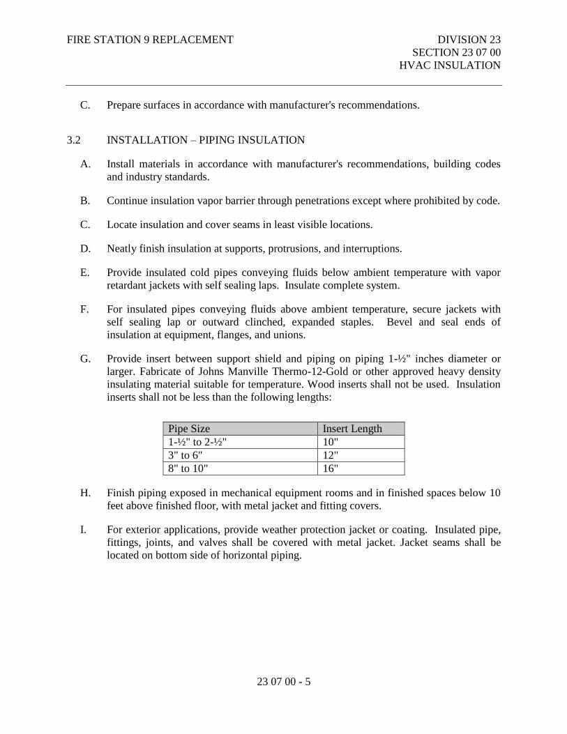
FIRE STATION 9 REPLACEMENT DIVISION 23
SECTION 23 07 00
HVAC INSULATION
23 07 00 - 5
C. Prepare surfaces in accordance with manufacturer's recommendations.
3.2 INSTALLATION – PIPING INSULATION
A. Install materials in accordance with manufacturer's recommendations, building codes
and industry standards.
B. Continue insulation vapor barrier through penetrations except where prohibited by code.
C. Locate insulation and cover seams in least visible locations.
D. Neatly finish insulation at supports, protrusions, and interruptions.
E. Provide insulated cold pipes conveying fluids below ambient temperature with vapor
retardant jackets with self sealing laps. Insulate complete system.
F. For insulated pipes conveying fluids above ambient temperature, secure jackets with
self sealing lap or outward clinched, expanded staples. Bevel and seal ends of
insulation at equipment, flanges, and unions.
G. Provide insert between support shield and piping on piping 1-½" inches diameter or
larger. Fabricate of Johns Manville Thermo-12-Gold or other approved heavy density
insulating material suitable for temperature. Wood inserts shall not be used. Insulation
inserts shall not be less than the following lengths:
Pipe Size Insert Length
1-½" to 2-½" 10"
3" to 6" 12"
8" to 10" 16"
H. Finish piping exposed in mechanical equipment rooms and in finished spaces below 10
feet above finished floor, with metal jacket and fitting covers.
I. For exterior applications, provide weather protection jacket or coating. Insulated pipe,
fittings, joints, and valves shall be covered with metal jacket. Jacket seams shall be
located on bottom side of horizontal piping.
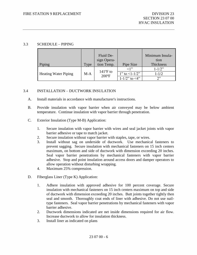
FIRE STATION 9 REPLACEMENT DIVISION 23
SECTION 23 07 00
HVAC INSULATION
23 07 00 - 6
3.3 SCHEDULE – PIPING
Piping
Type
Fluid De-
sign Opera-
tion Temp.
Pipe Size
Minimum Insula-
tion
Thickness
Heating Water Piping M-A 141ºF to
200ºF
<1” 1-1/2”
1” to <1-1/2” 1-1/2
1-1/2” to <4” 2”
3.4 INSTALLATION – DUCTWORK INSULATION
A. Install materials in accordance with manufacturer's instructions.
B. Provide insulation with vapor barrier when air conveyed may be below ambient
temperature. Continue insulation with vapor barrier through penetration.
C. Exterior Insulation (Type M-B) Application:
1. Secure insulation with vapor barrier with wires and seal jacket joints with vapor
barrier adhesive or tape to match jacket.
2. Secure insulation without vapor barrier with staples, tape, or wires.
3. Install without sag on underside of ductwork. Use mechanical fasteners to
prevent sagging. Secure insulation with mechanical fasteners on 15 inch centers
maximum, on bottom and side of ductwork with dimension exceeding 20 inches.
Seal vapor barrier penetrations by mechanical fasteners with vapor barrier
adhesive. Stop and point insulation around access doors and damper operators to
allow operation without disturbing wrapping.
4. Maximum 25% compression.
D. Fiberglass Liner (Type K) Application:
1. Adhere insulation with approved adhesive for 100 percent coverage. Secure
insulation with mechanical fasteners on 15 inch centers maximum on top and side
of ductwork with dimension exceeding 20 inches. Butt joints together tightly then
seal and smooth. Thoroughly coat ends of liner with adhesive. Do not use nail-
type fasteners. Seal vapor barrier penetrations by mechanical fasteners with vapor
barrier adhesive.
2. Ductwork dimensions indicated are net inside dimensions required for air flow.
Increase ductwork to allow for insulation thickness.
3. Install liner as indicated on plans
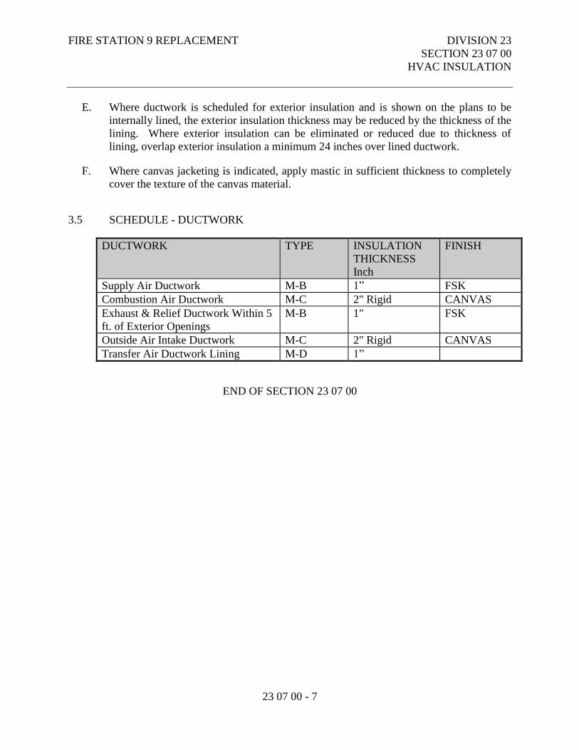
FIRE STATION 9 REPLACEMENT DIVISION 23
SECTION 23 07 00
HVAC INSULATION
23 07 00 - 7
E. Where ductwork is scheduled for exterior insulation and is shown on the plans to be
internally lined, the exterior insulation thickness may be reduced by the thickness of the
lining. Where exterior insulation can be eliminated or reduced due to thickness of
lining, overlap exterior insulation a minimum 24 inches over lined ductwork.
F. Where canvas jacketing is indicated, apply mastic in sufficient thickness to completely
cover the texture of the canvas material.
3.5 SCHEDULE - DUCTWORK
DUCTWORK TYPE INSULATION
THICKNESS
Inch
FINISH
Supply Air Ductwork M-B 1” FSK
Combustion Air Ductwork M-C 2" Rigid CANVAS
Exhaust & Relief Ductwork Within 5
ft. of Exterior Openings
M-B 1" FSK
Outside Air Intake Ductwork M-C 2" Rigid CANVAS
Transfer Air Ductwork Lining M-D 1”
END OF SECTION 23 07 00
FIRE STATION 9 REPLACEMENT DIVISION 23
SECTION 23 09 00
INSTRUMENTATION AND
CONTROL FOR HVAC
23 09 00 - 1
PART 1 - GENERAL
1.1 RELATED DOCUMENTS
A. Drawings and general provisions of the Contract, including Municipality of Anchorage
Standard Specifications – Buildings (MASSB), General and Supplementary Conditions
apply to this Section.
1.2 SECTION INCLUDES
A. Pressure Gauges.
B. Pressure Gauge Taps.
C. Thermometers.
D. Thermometer Wells.
1.4 RELATED SECTIONS
A. Section 23 09 23 – Direct Digital Control Systems for HVAC.
B. Section 23 09 93 - Sequence of Operation for HVAC Controls.
1.5 REFERENCES
A. Air Movement and Control Association International, Inc.:
1. AMCA 500 - Test Methods for Louvers, Dampers, and Shutters.
B. American Society of Mechanical Engineers:
FIRE STATION 9 REPLACEMENT DIVISION 23
SECTION 23 09 00
INSTRUMENTATION AND
CONTROL FOR HVAC
23 09 00 - 2
1. ASME B16.22 - Wrought Copper and Copper Alloy Solder Joint Pressure
Fittings.
C. ASTM International:
1. ASTM B32 - Standard Specification for Solder Metal.
2. ASTM B280 - Standard Specification for Seamless Copper Tube for Air
Conditioning and Refrigeration Field Service.
3. ASTM D1693 - Standard Test Method for Environmental Stress-Cracking of
Ethylene Plastics.
D. National Electrical Manufacturers Association:
1. NEMA DC 3 - Residential Controls - Electrical Wall Mounted Room
Thermostats.
E. National Fire Protection Association:
1. NFPA 90A - Standard for the Installation of Air Conditioning and Ventilating
Systems.
1.6 SUBMITTALS
A. Under the provisions of the Supplementary Conditions.
B. Product Data: Include list which indicates use, operating range, total range and location
for manufactured components.
C. Submit manufacturer's installation instructions under provisions of the Supplementary
Conditions.
1.7 PROJECT RECORD DOCUMENTS
A. Under the provisions of the Supplementary Conditions.
B. Accurately record actual locations of instrumentation.
1.8 ENVIRONMENTAL REQUIREMENTS
A. Do not install instrumentation when areas are under construction, except for required
rough-in, taps, supports and test plugs.
FIRE STATION 9 REPLACEMENT DIVISION 23
SECTION 23 09 00
INSTRUMENTATION AND
CONTROL FOR HVAC
23 09 00 - 3
PART 2 - PRODUCTS
2.1 ACCEPTABLE MANUFACTURERS - INSTUMENTATION
A. Trerice.
B. Weiss.
C. Dwyer.
D. Substitutions: Under the provisions of the Supplementary Conditions.
2.2 PRESSURE GAUGES
A. 4-1/2 inch diameter cast aluminum case, phosphor bronze bourbon tube, rotary bronze
movement, brass socket, with silicone fluid dampening black figures on white
background, one percent mid-scale accuracy, scale calibrated in psi. Model 600C as
manufactured by Trerice.
2.3 PRESSURE GAUGE TAPS
A. Gauge Isolation Valve: Lever handle ball valve, forged brass body, chrome plated brass
ball, viton o-rings for maximum 150 psig. Model Mini T-82-M as manufactured by
Jomar.
B. Needle Valve: Brass for maximum 150 psig. Model 735 as manufactured by Trerice.
C. Pulsation Damper: Pressure snubber, brass with 1/4 inch connections. Series 870 as
manufactured by Trerice.
2.4 SOLAR POWERED DIGITAL THERMOMETER
A. Hi-impact ABS case; -50/ 300°F (-45/150° C) swtichable range; 1/2" LCD digits, wide
ambient formula display; 1% accuracy; 1/10° between -19.9/199.9 °F (-28/93°C)
resolution; 10 Lux (one foot-candle) LUX rating; 10 second update rate; -30/140°F (-
35/60°C) ambient operating range; Glass passivated thermistor – NTC sensor. Model
Digital Vari-angle as manufactured by Weiss Products.
FIRE STATION 9 REPLACEMENT DIVISION 23
SECTION 23 09 00
INSTRUMENTATION AND
CONTROL FOR HVAC
23 09 00 - 4
2.5 TEST PLUGS
A. Test Plug: 1/4 inch or 1/2 inch brass fitting and cap for receiving 1/8 inch outside
diameter pressure or temperature probe with Nordel or Viton core for temperatures up
to 350 degrees F.
PART 3 - EXECUTION
3.1 INSTALLATION
A. Install in accordance with manufacturer's instructions.
B. Provide two pressure gauges per pump, installing taps before strainers and on suction
and discharge of pump. Pipe to gauge with isolation valve to each tapping.
C. Install pressure gauges with pulsation dampers. Provide needle valve or gauge isolation
valve to isolate each gauge.
D. Install thermometers in piping systems in sockets in short couplings Enlarge pipes
smaller than 2-1/2 inch for installation of thermometer sockets. Select bulb length to
reach centerline of pipe.
E. Locate duct mounted thermometers minimum 10 feet downstream of mixing dampers,
coils, or other devices causing air turbulence or provide with averaging bulb.
F. Provide instruments with scale ranges selected according to service with largest
appropriate scale.
G. Install gauges and thermometers in locations where they are easily read from normal
operating level.
3.2 PRESSURE GAUGE SCHEDULE
LOCATION SCALE RANGE
Pumps less than 40' TDH 0 - 30 PSIG
Pumps more than 40' TDH 0 - 60 PSIG
Heating Glycol System 0 - 30 PSIG
Others As applicable
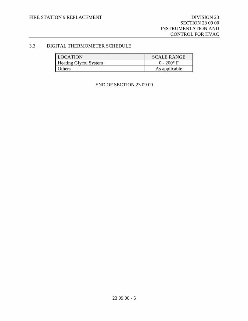
FIRE STATION 9 REPLACEMENT DIVISION 23
SECTION 23 09 00
INSTRUMENTATION AND
CONTROL FOR HVAC
23 09 00 - 5
3.3 DIGITAL THERMOMETER SCHEDULE
LOCATION SCALE RANGE
Heating Glycol System 0 - 200° F
Others As applicable
END OF SECTION 23 09 00
FIRE STATION 9 REPLACEMENT DIVISION 23
SECTION 23 09 23
DIRECT DIGITAL CONTROL
SYSTEM FOR HVAC
23 09 23 - 1
PART 1 - GENERAL
1.1 RELATED DOCUMENTS
A. Drawings and general provisions of the Contract, including Municipality of Anchorage
Standard Specifications – Buildings (MASSB), General and Supplementary Conditions
apply to this Section.
1.2 SECTION INCLUDES
A. Drawings and general provisions of the Contract, including the General and
Supplementary Conditions.
B. Furnish a totally native BACnet-based system, including an operator’s workstation
using Microsoft Windows XP Professional as the operating system and shall be based
on a distributed control system in accordance with this specification. The operator’s
workstation, all building controllers, application controllers, and all input/output devices
shall communicate using the protocols and network standards as defined by
ANSI/ASHRAE Standard 135–2001, BACnet.
C. Provide all necessary BACnet-compliant hardware and software to meet the system’s
functional specifications. Provide Protocol Implementation Conformance Statement
(PICS) for Windows-based control software and every controller in system, including
unitary controllers.
D. Prepare individual hardware layouts, interconnection drawings, and software
configuration from project design data.
E. Implement the detailed design for all analog and binary objects, system databases,
graphic displays, logs, and management reports based on control descriptions, logic
drawings, configuration data, and bid documents.
F. Design, provide, and install all equipment cabinets, panels, data communication
network cables needed, and all associated hardware.
G. Provide and install all interconnecting cables between supplied cabinets, application
controllers, and input/output devices.
H. Provide and install all interconnecting cables between all operator’s terminals and
peripheral devices (such as printers, etc.) supplied under this section.
FIRE STATION 9 REPLACEMENT DIVISION 23
SECTION 23 09 23
DIRECT DIGITAL CONTROL
SYSTEM FOR HVAC
23 09 23 - 2
I. Provide complete manufacturer’s specifications for all items that are supplied. Include
vendor name of every item supplied.
J. Provide supervisory specialists and technicians at the job site to assist in system startup,
and commissioning.
K. Provide a comprehensive operator and technician-training program as described herein.
L. Provide as-built documentation, operator’s terminal software, diagrams, and all other
associated project operational documentation (such as technical manuals) on approved
media, the sum total of which accurately represents the final system.
M. Provide new sensors, dampers, valves, and install only new electronic actuators. No
used components shall be used as any part or piece of installed system.
1.3 SYSTEM DESCRIPTION
A. Distributed logic control systems complete with all software and hardware functions
shall be provided and installed. System shall be completely based on ANSI/ASHRAE
Standard 135-2001, BACnet. This system is to control all mechanical equipment,
including all unitary equipment such as pumps, air handlers, heat exchangers, etc. and
any other listed equipment using native BACnet-compliant components.
B. Operator’s workstation software shall be Microsoft Windows Version 8 as the computer
operating system. The Energy Management and Control System (EMCS) application
program shall be written to communicate specifically utilizing BACnet protocols.
Software shall include password protection, scheduling (including optimum start),
alarming, logging of historical data, full graphics including animation, after-hours
billing program, demand limiting, full suite of field engineering tools including
graphical programming and applications.
C. Building controllers shall include complete energy management software, including
scheduling building control strategies with optimum start and logging routines. All
energy management software and firmware shall be resident in field hardware and shall
not be dependent on the operator’s terminal. Operator’s terminal software is to be used
for access to field-based energy management functions only. Provide zone-by-zone
direct digital logic control of space temperature, scheduling, runtime accumulation,
equipment alarm reporting, and override timers for after-hours usage. All application
controllers all equipment and any other piece of controlled equipment shall be fully
programmable. Application controllers shall be mounted next to controlled equipment
and communicate with building controller via BACnet LAN.
D. Room sensors shall allow room setpoint adjustment within preset limits.

FIRE STATION 9 REPLACEMENT DIVISION 23
SECTION 23 09 23
DIRECT DIGITAL CONTROL
SYSTEM FOR HVAC
23 09 23 - 3
E. Provide all alarms, manual control, and status indication functions at local CRT and
central host as indicated under the sequence of operations.
1.4 SUBMITTALS
A. Under the provisions of the Supplementary Conditions.
B. Shop Drawings:
1. Trunk cable schematic showing programmable control unit locations, and trunk
data conductors.
2. List of connected data points, including connected control unit and input device.
Terminal identification for all control wiring.
3. System configuration with peripheral devices, batteries, power supplies, diagrams,
modems, interconnections, complete wiring, and schematic diagrams.
4. Descriptive data and sequence of operation of operating, user, and application
software.
C. Product Data: Provide data for each system component and software module.
Equipment lists of all proposed devices and equipment.
D. Valve, damper, and well and tap schedules showing size, configuration, capacity and
location of all equipment.
E. Wiring and piping interconnection diagrams including panel and device power and
sources.
F. Manufacturer's Installation Instructions: Include for all manufactured components.
G. Software design data including:
1. Flowchart of each DDC program showing interrelationship between inputs, PID
functions, all other functions, outputs, etc.
2. Sequence of operation relating to all flowchart functions.
H. Licensing agreement for each licensed software module (one copy to be executed by the
owner prior to software delivery).
1.5 PROJECT RECORD DOCUMENTS
A. Submit under provisions of Supplementary Conditions.
B. Accurately record actual location of control components, including panels, thermostats,
and sensors.

FIRE STATION 9 REPLACEMENT DIVISION 23
SECTION 23 09 23
DIRECT DIGITAL CONTROL
SYSTEM FOR HVAC
23 09 23 - 4
C. Revise shop drawings to reflect actual installation and operating sequences.
D. Include data specified in "Submittals" in final "Record Documents" form.
1.6 OPERATION AND MAINTENANCE DATA
A. Submit under provisions of the Supplementary Conditions.
B. Operators Manual with graphic explanations of operator functions.
C. Programmer's Manual with graphic descriptions of function required for software
modifications and development. Programmer's manual will include computer
generated listings of all DDC programs.
D. Computerized printouts of all remote panel data file construction including all point
processing assignments, physical terminal relationships, scales and offsets, command
and alarm limits, etc.
E. A manual including revised As Built documents of all materials required under the
paragraph "SUBMITTALS" on this specification.
F. Three Operators Manuals, two Programmers, and two As Built Manuals will be
provided to the Owner.
G. Upon completion of the work, provide a complete set of drawings and application
software on magnetic floppy disk media. Drawings shall be provided as AutoCAD
compatible files.
1.7 OPERATION AND MAINTENANCE INSTRUCTION
A. Under the provisions of the Supplementary Conditions.
B. Instruction outlined within this section is in addition to that described under
Supplementary Conditions.
C. The Contractor will provide a minimum of 32 hours of classroom and field instruction
to personnel as selected by the Owner. Instruction will be by a qualified factory trained
technician. Instruction will be provided before final completion. The Owner will
provide two weeks’ notice to the Contractor indicating selected personnel and date of
instruction.
FIRE STATION 9 REPLACEMENT DIVISION 23
SECTION 23 09 23
DIRECT DIGITAL CONTROL
SYSTEM FOR HVAC
23 09 23 - 5
1.8 SEQUENCING AND SCHEDULING
A. Sequence work to ensure installation of components is complementary to installation of
similar components in other systems.
B. Coordinate work under provisions of the Supplementary Conditions.
C. Ensure system is completed and commissioned by Date of Substantial Completion.
D. Coordinate installation of system components with installation of mechanical systems
equipment.
1.9 APPROVED MANUFACTURERS
A. Siemens.
B. Automated Logic
C. No Substitutions.
1.10 QUALITY ASSURANCE
A. Responsibility: The supplier of the EMCS shall be responsible for inspection and
Quality Assurance (QA) for all materials furnished.
B. Component Testing: Maximum reliability shall be achieved through extensive use of
high-quality, pre-tested components. Each and every controller, sensor, and all other
DDC components shall be individually tested and listed by the BACnet Testing
Laboratories (BTL).
C. Tools, Testing and Calibration Equipment: The EMCS supplier shall provide all tools,
testing, and calibration equipment necessary to ensure reliability and accuracy of the
system.
1.11 REFERENCE STANDARDS LATEST ADOPTED EDITION
A. American Society of Heating, Refrigerating and Air Conditioning Engineers
(ASHRAE).
B. ANSI/ASHRAE Standard 135-2001, BACnet.
C. International Building Code (IBC), including local amendments.
FIRE STATION 9 REPLACEMENT DIVISION 23
SECTION 23 09 23
DIRECT DIGITAL CONTROL
SYSTEM FOR HVAC
23 09 23 - 6
D. UL 916 Underwriters Laboratories Standard for Energy Management Equipment.
Canada and the US.
E. National Electrical Code (NEC).
F. FCC Part 15, Subpart J, Class A.
1.12 WARRANTY
A. Under the provisions of the Supplementary Conditions.
B. Provide one (1) year manufacturers warranty for field programmable micro-processor
based units from the time of completion
1.13 RELATED WORK IN OTHER SECTIONS
A. Section 23 05 53 – Identification HVAC Piping and Equipment.
B. Section 23 05 93 – Testing, Adjusting and Balancing for HVAC.
C. Section 23 09 00 – Instrumentation and Control for HVAC.
D. Section 23 21 13 – Hydronic Piping.
E. Section 23 21 16 – Hydronic Piping Specialties.
F. Section 23 21 23 – Hydronic Pumps.
G. Section 23 31 00 – HVAC Ducts and Casings.
H. Section 23 33 00 – Air Duct Accessories.
I. Section 23 34 13 – HVAC Axial Fans.
J. Section 23 34 23 – HVAC Power Ventilators.
K. Section 23 52 16 – Condensing Boilers.
L. Section 23 52 23 – Cast-Iron Boilers.
M. Section 23 82 00 - Convection Heating and Cooling Units.
N. Section 23 83 00 – Radiant Heating Units.
O. Section 23 83 05 – Radiant Heating Snowmelt Systems.
FIRE STATION 9 REPLACEMENT DIVISION 23
SECTION 23 09 23
DIRECT DIGITAL CONTROL
SYSTEM FOR HVAC
23 09 23 - 7
PART 2 - PRODUCTS
2.1 OPERATOR’S WORKSTATION
A. General structure of workstation interaction shall be a standard client/server
relationship. Server shall be used to archive data and store system database. Clients
shall access server for all archived data. Each client shall include flexibility to access
graphics from server or local drive.
B. BACnet Conformance:
1. Operator’s workstation shall as a minimum support Point-to-Point (PTP) and
Ethernet BACnet LAN types. It shall communicate directly via these BACnet
LANs as a native BACnet device. Operator’s terminal shall comply with the
requirements of a BACnet conformance class 3 device and support all BACnet
services necessary to provide the following BACnet functional groups:
a. Clock Functional Group.
b. Event Response Functional Group.
c. Time Master Functional Group.
d. Device Communications.
2. Please refer BACnet Functional Groups, in the BACnet standard for a complete
list of the services that must be directly supported to provide each of the
functional groups listed above. All proprietary services, if used in the system,
shall be thoroughly documented and provided as part of the submittal data. All
necessary tools shall be supplied for working with proprietary information.
3. Standard BACnet object types accessed by the workstation shall include as a
minimum: Analog Value, Analog Input, Analog Output, Binary Value, Binary
Input, Binary Output, Calendar, Device, Event Enrollment, File, Notification
Class, Program and Schedule object types. All proprietary object types, if used in
the system, shall be thoroughly documented and provided as part of the submittal
data. All necessary tools shall be supplied for working with proprietary
information.
4. The Operator Workstation shall comply with Annex J of the BACnet specification
for IP connections. This device shall use Ethernet to connect to the IP
internetwork, while using the same Ethernet LAN for non-IP communications to
other BACnet devices on the LAN. Must support interoperability on wide area
networks (WANs) and campus area networks (CANs). Workstation shall support
Foreign Device Registration to allow temporary workstation connection to IP
network.
5. Displays:
a. Operator’s workstation shall display all data associated with project as
called out on drawings and/or object type list supplied. Graphic files shall
be created using digital, full color photographs of system installation,
AutoCAD™ or Visio™ drawing files of field installation drawings and
FIRE STATION 9 REPLACEMENT DIVISION 23
SECTION 23 09 23
DIRECT DIGITAL CONTROL
SYSTEM FOR HVAC
23 09 23 - 8
wiring diagrams from as-built drawings. Operator’s workstation shall
display all data using three-dimensional graphic representations of all
mechanical equipment. System shall be capable of displaying graphic file,
text, and dynamic object data together on each display and shall include
animation. Information shall be labeled with descriptors and shall be shown
with the appropriate engineering units. All information on any display shall
be dynamically updated without any action by the user. Workstation shall
allow user to change all field-resident EMCS functions associated with the
project, such as setpoints, weekly schedules, exception schedules, etc. from
any screen no matter if that screen shows all text or a complete graphic
display. This shall be done without any reference to object addresses or
other numeric/mnemonic indications.
b. All displays and programming shall be generated and customized by the
local EMCS supplier and installer.
c. Displays shall include link for trend log information. Link shall connected
directly to trend reports without additional operator input.
d. Binary objects shall be displayed as ACTIVE/INACTIVE/NULL or with
customized text. Text shall be justified left, right or center as selected by
the user. Also, allow binary objects to be displayed as individual change-
of-state graphic objects on the display screen such that they overlay the
system graphic. Each binary object displayed in this manner shall be
assigned up to three graphic files for display when the point is ON, OFF or
in alarm. For binary outputs, toggle the object’s commanded status when
the graphic item is selected with the system mouse. Similarly, allow the
workstation operator to toggle the binary object’s status by selecting with
the mouse a graphic of a switch or light, for example, which then displays a
different graphic (such as an “ON” switch or lighted lamp). Additionally,
allow binary objects to be displayed as an animated graphic. Animated
graphic objects shall be displayed as a sequence of multiple graphics to
simulate motion. For example: when a pump is in the OFF condition,
display a stationary graphic of the pump. When the operator selects the
pump graphic with the mouse, the represented object’s status is toggled and
the graphic of the pump’s impeller rotates in a time-based animation. The
operator shall be able to click on an animated graphical object or switch it
from the OFF position to ON, or ON to OFF. Allow operator to change
graphic file assignment and also create new and original graphics online.
System shall be supplied with a library of standard graphics, which may be
used unaltered or modified by the operator. Systems that do not allow
customization or creation of new graphic objects by the operator (or with
third-party software) shall not be allowed.
e. Analog objects shall be displayed with operator modifiable units. Analog
input objects may also be displayed as individual graphic items on the
display screen as an overlay to the system graphic. Each analog input
object may be assigned a minimum of five graphic files, each with high/low
FIRE STATION 9 REPLACEMENT DIVISION 23
SECTION 23 09 23
DIRECT DIGITAL CONTROL
SYSTEM FOR HVAC
23 09 23 - 9
limits for automatic selection and display of these graphics. As an example,
a graphic representation of a thermometer would rise and fall in response to
either the room temperature or its deviation from the controlling setpoint.
Analog output objects, when selected with the mouse, shall be displayed as
a prompted dialog (text only) box. Selection for display type shall be
individual for each object. Analog object values may be changed by
selecting either the “increase” or “decrease” arrow in the analog object
spinner box without using the keypad. Pressing the button on the right side
of the analog object spinner box allows direct entry of an analog value and
accesses various menus where the analog value may be used, such as
trendlogs.
f. Analog objects may also be assigned to an area of a system graphic, where
the color of the defined area changes based on the analog object’s value.
For example, an area of a floor-plan graphic served by a single control zone
would change color with respect to the temperature of the zone or its
deviation from setpoint. All editing and area assignment shall be created or
modified online using simple icon tools.
g. A customized menu label (push-button) shall be used for display selection.
Menu items on a display shall allow penetration to lower level displays or
additional menus. Dynamic point information and menu label push buttons
may be mixed on the same display to allow sub-displays to exist for each
item. Each display may be protected from viewing unless operator has
appropriate security level. A security level may be assigned to each display
and system object. The menu label shall not appear on the graphic if the
operator does not have the appropriate security level.
h. A mouse shall be used to move the pointer arrow to the desired item for
selection of new display or to allow the operator to make changes to object
data.
6. Password Protection:
a. Provide security system that prevents unauthorized use unless operator is
logged on. Access shall be limited to operator’s assigned functions when
user is logged on. This includes displays as outlined above.
b. Each operator’s terminal shall provide security for 200 users minimum.
Each user shall have an individual User ID, User Name and Password.
Entries are alphanumeric characters only and are case sensitive (except for
User ID). User ID shall be 0–8 characters, User Name shall be 0–29
characters, and Password shall be 4–8 characters long. Each system user
shall be allowed individual assignment of only those control functions and
menu items to which that user requires access. All passwords, user names,
and access assignments shall be adjustable online at the operator’s terminal.
Each user shall also have a set security level, which defines access to
displays and individual objects the user may control. System shall include
10 separate and distinct security levels for assignment to users.
FIRE STATION 9 REPLACEMENT DIVISION 23
SECTION 23 09 23
DIRECT DIGITAL CONTROL
SYSTEM FOR HVAC
23 09 23 - 10
c. System shall include an Auto Logout Feature that shall automatically logout
user when there has been no keyboard or mouse activity for a set period of
time. Time period shall be adjustable by system administrator. Auto
Logout may be enabled and disabled by system administrator. Operator
terminal shall display message on screen that user is logged out after Auto
Logout occurs.
7. Operator Activity Log:
a. Operator Activity Log shall be included with system that tracks all operator
changes and activities. System shall track what is changed in the system,
who performed this change, date and time of system activity and value of
the change before and after operator activity. Operator shall be able to
display all activity, sort the changes by user and also by operation.
b. Log shall be gathered and archived to hard drive on operator workstation as
needed. Operator shall be able to export data for display and sorting in a
spreadsheet.
c. Any displayed data, that is changeable by the operator, may be selected
using the right mouse button and the operator activity log shall then be
selectable on the screen. Selection of the operator activity log using this
method shall show all operator changes of just that displayed data.
8. Scheduling:
a. Operator’s workstation shall show all information in easy-to-read daily
format including calendar of this month and next. All schedules shall show
actual ON/OFF times for day based on scheduling priority. Priority for
scheduling shall be events, holidays and daily with events being the highest.
b. Operator shall be able to change all information for a given weekly or
exception schedule if logged on with the appropriate security access.
c. System shall include a Schedule Wizard for set up of schedules. Wizard
shall walk user through all steps necessary for schedule generation. Wizard
shall have its own pull-down selection for startup or may be started by right
clicking on value displayed on graphic and then selecting Schedule.
d. Scheduling shall include optimum start based on outside air temperature,
current heating/cooling setpoints, indoor temperature and history of
previous starts. Each and every individual zone shall have optimum start
time independently calculated based on all parameters listed. User shall
input schedules to set time that occupied setpoint is to be attained.
Optimum start feature shall calculate the startup time needed to match zone
temperature to setpoint. User shall be able to set a limit for the maximum
startup time allowed.
9. Alarm Indication and Handling:
a. Operator’s workstation shall provide audible, visual, and printed means of
alarm indication. The alarm dialog box shall always become the top dialog
box regardless of the application(s), currently running. Printout of alarms
shall be sent to the assigned terminal and port.
FIRE STATION 9 REPLACEMENT DIVISION 23
SECTION 23 09 23
DIRECT DIGITAL CONTROL
SYSTEM FOR HVAC
23 09 23 - 11
b. System shall provide log of alarm messages. Alarm log shall be archived to
the hard disk of the system operator’s terminal. Each entry shall include a
description of the event-initiating object generating the alarm. Description
shall be an alarm message of at least 256 characters in length. Entry shall
include time and date of alarm occurrence, time and date of object state
return to normal, time and date of alarm acknowledgment and identification
of operator acknowledging alarm.
c. Alarm messages shall be in user-definable text (English or other specified
language) and shall be entered either at the operator’s terminal or via remote
communication.
d. System shall include an Alarm Wizard for set up of alarms. Wizard shall
walk user through all steps necessary for alarm generation. Wizard shall
have its own pull-down selection for startup or may be started by right
clicking on value displayed on graphic and then selecting alarm setup.
10. Trendlog Information:
a. System server shall periodically gather historically recorded data stored in
the building controllers and archive the information Archived files shall be
appended with new sample data, allowing samples to be accumulated.
Systems that write over archived data shall not be allowed, unless limited
file size is specified. Samples may be viewed at the operator’s workstation.
Operator shall be able to scroll through all trended data. All trendlog
information shall be displayed in standard engineering units.
b. Software shall be included that is capable of graphing the trend logged
object data. Software shall be capable of creating two-axis (x, y) graphs
that display up to ten object types at the same time in different colors.
Graphs shall show object values relative to time.
c. Operator shall be able to change trend log setup information. This includes
the information to be logged as well as the interval at which it is to be
logged. All input, output, and value object types in the system may be
logged. All operations shall be password protected. Setup and viewing may
be accessed directly from any and all graphics on which object is displayed.
d. System shall include a trend Wizard for setup of logs. Wizard shall walk
user through all necessary steps. Wizard shall have its own pull-down
selection for startup, or may be started by right clicking on value displayed
on graphic, and then selecting Trendlogs from the displayed menu.
e. Trendlogs shall be linked from graphical displays for all systems and
equipment.
11. Energy Log Information:
a. System server shall be capable of periodically gathering energy log data
stored in the field equipment and archive the information. Archive files
shall be appended with new data, allowing data to be accumulated. Systems
that write over archived data shall not be allowed unless limited file size is
specified. Display all energy log information in standard engineering units.
FIRE STATION 9 REPLACEMENT DIVISION 23
SECTION 23 09 23
DIRECT DIGITAL CONTROL
SYSTEM FOR HVAC
23 09 23 - 12
b. All data shall be stored in data base file format for direct use by third-party
programs. Operation of system shall stay completely online during all
graphing operations.
c. Operator shall be able to change the energy log setup information as well.
This includes the meters to be logged, meter pulse value, and the type of
energy units to be logged. All meters monitored by the system may be
logged. System shall support using flow and temperature sensors for BTU
monitoring.
d. System shall display archived data in tabular format form for both
consumption and peak values. Data shall be shown in hourly, daily,
weekly, monthly and yearly formats. In each format, the user shall be able
to select a specific period of data to view.
12. Demand Limiting:
a. System shall include demand limiting program that includes two types of
load shedding. One type of load shedding shall shed/restore equipment in
binary fashion based on energy usage when compared to shed and restore
settings. The other type of shedding shall adjust operator selected control
setpoints in an analog fashion based on energy usage when compared to
shed and restore settings. Shedding may be implemented independently on
each and every zone or piece of equipment connected to system.
b. Binary shedding shall include minimum of 5 priority levels of equipment
shedding. All loads in a given priority level shall be shed before any loads
in a higher priority level are shed. Load shedding within a given priority
level shall include two methods. In one, the loads shall be shed/restored in
a “first off-first on” mode and in the other; the loads are just shed/restored
in a linear fashion.
c. Analog shed program shall generate a ramp that is independently used by
each individual zone or individual control algorithm to raise the appropriate
cooling setting and lower appropriate heating setting to reduce energy
usage.
d. Status of each and every load shed program shall be capable of being
displayed on every operator terminal connected to system. Status of each
load assigned to an individual shed program shall be displayed along with
English description of each load.
13. Configuration/Setup:
a. Provide means for operator to display and change system configuration.
This shall include, but not be limited to, system time, day of the week, date
of daylight savings set forward/set back, printer termination, port addresses,
modem port and speed, etc. Items shall be modified using understandable
terminology with simple mouse/cursor key movements.
14. Field Engineering Tools:
a. Operator’s workstation software shall include field-engineering tools for
programming all controllers supplied. All controllers shall be programmed
using graphical tools that allow the user to connect function blocks on
FIRE STATION 9 REPLACEMENT DIVISION 23
SECTION 23 09 23
DIRECT DIGITAL CONTROL
SYSTEM FOR HVAC
23 09 23 - 13
screen that provide sequencing of all control logic. Function blocks shall be
represented by graphical displays that are easily identified and distinct from
other types of blocks. Graphical programming that uses simple rectangles
and squares is not acceptable.
b. User shall be able to pick graphical function block from menu and place on
screen. Provide zoom in and zoom out capabilities. Function blocks shall be
downloaded to controller without any reentry of data.
c. Programming tools shall include a real time operation mode. Function
blocks shall display real time data and be animated to show status of data
inputs and outputs when in real time operation. Animation shall show
change of status on logic devices and countdown of timer devices in
graphical format.
d. Field engineering tools shall also include a database manager of
applications that include logic files for controllers and associated graphics.
Operator shall be able to select unit type, input/output configuration and
other items that define unit to be controlled. Supply minimum of 250
applications as part of workstation software.
e. Field engineering tool shall include Device Manager for automatic detection
of devices connected anywhere on the BACnet network by scanning of the
entire network. This function shall display device instance, network
identification, model number and description of connected devices. It shall
record and display software file loaded into each controller. A copy of each
file shall be stored on the computers hard drive. If needed, this file shall be
downloaded to the appropriate controller by selection using the mouse.
f. System shall include backup/restore function that will back up entire system
to selected medium and then restore system from that media.
15. DDC Notebook:
a. Provide operator’s DDC Notebook, locate in DDC panel in the Mechanical
Room.
b. DDC Notebook Computer Minimum Requirements:
1) Dell Precision M4800 BTX Base
2) 8GB RAM or better.
3) Backlit Keyboard.
4) NVIDIA Quadro K1100M w/ 2GB Video Card.
5) Wireless Mouse
6) 8X DVD Player
7) Dual Band Wireless Network Card.
8) 256GB Solid State Drive.
9) Windows 7 Professional Software.
a) At the conclusion of project, contractor shall leave with owner a
CD ROM that includes the complete software operation system
and project graphics, setpoints, system parameters, etc. This
backup shall allow the owner to completely restore the system
in the case of a computer malfunction.
FIRE STATION 9 REPLACEMENT DIVISION 23
SECTION 23 09 23
DIRECT DIGITAL CONTROL
SYSTEM FOR HVAC
23 09 23 - 14
2.2 BUILDING CONTROLLER
A. General:
1. All communication with operator workstation and all application controllers shall
be via BACnet. Building controller shall incorporate as a minimum, the functions
of a 3-way BACnet router. Controller shall route BACnet messages between the
high-speed LAN (Ethernet 10/100MHz), master slave token passing (MS/TP)
LANs, a point-to-point (PTP – RS-232) connection and modem.
a. Each MS/TP LAN must be software configurable from 9.6 to 76.8Kbps.
b. The RJ-45 Ethernet connection must accept either 10Base-T or 100Base-TX
BACnet over twisted pair cable (UTP).
c. The direct access port must be a female DB-9 connector supporting BACnet
temporary PTP connection of a portable BACnet operator terminal at 9.6 to
115.2 Kbps over RS-232 null modem cable.
2. Building controller shall be capable of providing global control strategies for the
system based on information from any objects in the system regardless if the
object is directly monitored by the controller or by another controller. The
program that implements these strategies shall be completely flexible and user
definable. Any systems utilizing factory pre-programmed global strategies that
cannot be modified by field personnel on-site or downloaded via remote
communications are not acceptable. Changing global strategies via firmware
changes is also unacceptable.
3. Programming shall be object-oriented using control function blocks, supporting
DDC functions, 1000 Analog Values and 1000 Binary Values. All flowcharts
shall be generated and automatically downloaded to controller. Programming tool
shall be resident on workstation and the same tool used for all controllers.
4. Provide means to graphically view inputs and outputs to each program block in
real-time as program is executing. This function may be performed via the
operator’s workstation or field computer.
5. Building controller shall provide battery-backed real-time (hardware) clock
functions.
6. Controller shall have a memory needed to ensure high performance and data
reliability. Battery shall retain static RAM memory and real-time clock functions
for a minimum of 1.5 years (cumulative).
7. Global control algorithms and automated control functions should execute via 32-
bit processor.
8. Controller installation shall include memory-free gel-cell battery providing
ongoing power conditioning and noise filtering for operation data integrity. It
shall provide up to 5 minutes of powerless operation for orderly shutdown and
data backup.
9. The system operator shall have the ability to manually override automatic or
centrally executed commands at the primary control panels via local, point
discrete, on-board hand/off/auto operator override switches. The manual override
FIRE STATION 9 REPLACEMENT DIVISION 23
SECTION 23 09 23
DIRECT DIGITAL CONTROL
SYSTEM FOR HVAC
23 09 23 - 15
switches shall enable digital outputs to be manually placed into HAND, ON/OFF,
or AUTO control. Analog outputs shall be placed into AUTO or HAND control
and shall have ten graduated, manual control positions to vary the output signal to
the controlled device. LEDs on the override module shall provide override status
and I/O status. Manual override switches that are not directly installed and
mounted within the primary control panel are not acceptable.
B. BACnet Conformance:
1. Building Controller shall as a minimum support Point-to-Point (PTP), MS/TP and
Ethernet BACnet LAN types. It shall communicate directly via these BACnet
LANs as a native BACnet device and shall support simultaneous routing
functions between all supported LAN types. Global controller shall be a BACnet
conformance class 3 device and support all BACnet services necessary to provide
the following BACnet functional groups:
a. Clock Functional Group.
b. Files Functional Group.
c. Reinitialize Functional Group.
d. Device Communications Functional Group.
e. Event Initiation Functional Group.
2. Please refer to section 22.2, BACnet Functional Groups, in the BACnet standard
for a complete list of the services that must be directly supported to provide each
of the functional groups listed above. All proprietary services, if used in the
system, shall be thoroughly documented and provided as part of the submittal
data. All necessary tools shall be supplied for working with proprietary
information.
3. Standard BACnet object types supported shall include as a minimum: Analog
Value, Binary Value, Calendar, Device, File, Group, Notification Class, Program
and Schedule object types. All proprietary object types, if used in the system,
shall be thoroughly documented and provided as part of the submittal data. All
necessary tools shall be supplied for working with proprietary information.
4. The Building Controller shall comply with Annex J of the BACnet specification
for IP connections. This device shall use Ethernet to connect to the IP
internetwork, while using the same Ethernet LAN for non-IP communications to
other BACnet devices on the LAN. Must support interoperability on wide area
networks (WANs) and campus area networks (CANs) and function as a BACnet
Broadcast Management Device (BBMD).
C. Schedules:
1. Each building controller shall support a minimum of 250 BACnet Schedule
Objects and 250 BACnet Calendar Objects.
D. Logging Capabilities:
FIRE STATION 9 REPLACEMENT DIVISION 23
SECTION 23 09 23
DIRECT DIGITAL CONTROL
SYSTEM FOR HVAC
23 09 23 - 16
1. Each building controller shall log as minimum 1000 trendlogs. Any object in the
system (real or calculated) may be logged. Sample time interval shall be
adjustable at the operator’s workstation.
2. Logs may be viewed both on-site or off-site via remote communication.
3. Building controller shall periodically upload trended data to networked operator’s
workstation for long term archiving if desired.
4. Archived data stored in database format shall be available for use in third-party
spreadsheet or database programs.
E. Alarm Generation:
1. Alarms may be generated within the system for any object change of value or
state either real or calculated. This includes things such as analog object value
changes, binary object state changes, and various controller communication
failures.
2. Each alarm may be dialed out as noted in paragraph 2 above.
3. Alarm log shall be provided for alarm viewing. Log may be viewed on-site at the
operator’s terminal or off-site via remote communications.
4. Controller must be able to handle up to 1500 alarm setups stored as BACnet event
enrollment objects – system destination and actions individually configurable.
2.3 APPLICATION CONTROLLERS
A. Provide one or more native BACnet application controllers for each air handler and
provide native BACnet application controllers as needed for control that adequately
cover all objects listed in object list. All controllers shall interface to building controller
via MS/TP LAN using BACnet protocol. No gateways shall be used. Controllers shall
include input, output and self-contained logic program as needed for complete control
of units. Controllers shall be fully programmable using graphical programming blocks.
Programming tool shall be resident on operator workstation and be the same tool as
used for the building controller. No auxiliary or non-BACnet controllers shall be used.
B. BACnet Conformance
1. Application controllers shall as a minimum support MS/TP BACnet LAN types.
They shall communicate directly via this BACnet LAN at 9.6, 19.2, 38.4 and 76.8
Kbps, as native BACnet devices. Application controllers shall be of BACnet
conformance class 3 and support all BACnet services necessary to provide the
following BACnet functional groups:
a. Files Functional Group.
b. Reinitialize Functional Group.
c. Device Communications Functional Group.
2. Please refer to BACnet Functional Groups, in the BACnet standard, for a
complete list of the services that must be directly supported to provide each of the
FIRE STATION 9 REPLACEMENT DIVISION 23
SECTION 23 09 23
DIRECT DIGITAL CONTROL
SYSTEM FOR HVAC
23 09 23 - 17
functional groups listed above. All proprietary services, if used in the system,
shall be thoroughly documented and provided as part of the submittal data. All
necessary tools shall be supplied for working with proprietary information.
3. Standard BACnet object types supported shall include as a minimum—Analog
Input, Analog Output, Analog Value, Binary Input, Binary Output, Binary Value,
Device, File, and Program object types. All proprietary object types, if used in the
system, shall be thoroughly documented and provided as part of the submittal
data. All necessary tools shall be supplied for working with proprietary
information.
4. Application controllers shall include universal inputs with 10-bit resolution that
accept 3K and 10K thermistors, 0–10VDC, 0–5 VDC, 4–20 mA and dry contact
signals. Any input on a controller may be either analog or digital with a minimum
of 3 inputs that accept pulses. Controller shall also include support and modifiable
programming for interface to intelligent room sensor with digital display.
Controller shall include binary and analog outputs on board. Analog outputs shall
be switch selectable as either 0–10VDC or 0–20mA. Software shall include
scaling features for analog outputs. Application controller shall include 24VDC
voltage supply for use as power supply to external sensors.
5. All program sequences shall be stored on board application controller in
EEPROM. No batteries shall be needed to retain logic program. All program
sequences shall be executed by controller 10 times per second and capable of
multiple PID loops for control of multiple devices. All calculations shall be
completed using floating-point math and system shall support display of all
information in floating-point nomenclature at operator’s terminal. Programming
of application controller shall be completely modifiable in the field over installed
BACnet LANs or remotely via modem interface. Operator shall program logic
sequences by graphically moving function blocks on screen and tying blocks
together on screen. Application controller shall be programmed using
programming tools as described in operator’s terminal section.
6. Application controller shall include support for intelligent room sensor. Display
on intelligent room sensor shall be programmable at application controller and
include an operating mode and a field service mode. All button functions and
display data shall be programmable to show specific controller data in each mode
based on which button is pressed on the sensor. See sequence of operation for
specific display requirements at intelligent room sensor.
2.4 EXPANDABLE APPLICATION CONTROLLERS
A. General:
1. Expandable application controller shall be capable of providing control strategies
for the system based on information from any or all connected inputs. The
program that implements these strategies shall be completely flexible and user
FIRE STATION 9 REPLACEMENT DIVISION 23
SECTION 23 09 23
DIRECT DIGITAL CONTROL
SYSTEM FOR HVAC
23 09 23 - 18
definable. Any systems utilizing factory pre-programmed global strategies that
cannot be modified by field personnel on-site via simple download are not
acceptable. Changing global strategies via firmware changes is also unacceptable.
Program execution of controller shall be a minimum of once per second.
2. Programming shall be object-oriented using control program blocks. Controller
shall support a minimum of 500 Analog Values and 500 Binary Values. Each and
every analog and binary value shall support standard BACnet priority arrays.
Programming tool shall be provided with system and shall be the same tool that is
used to program the Building Controller. All flowcharts shall be generated and
automatically downloaded to controller. No re-entry of database information
shall be necessary.
3. Provide means to graphically view inputs and outputs to each program block in
real-time as program is executing. This function may be performed via the
operator’s terminal or field computer.
4. Controller shall have adequate data storage to ensure high performance and data
reliability. Battery shall retain static RAM memory and real-time clock functions
for a minimum of 1.5 years (cumulative). Battery shall be a field-replaceable
(non-rechargeable) lithium type. Unused battery life shall be 10 years.
5. The onboard, battery-backed real time clock must support schedule operations
and trend logs.
6. Global control algorithms and automated control functions should execute via 32-
bit processor.
7. Controller shall include both on-board 10BASE-T/100BASE-TX Ethernet
BACnet communication over twisted pair cable (UTP) and shall include BACnet
IP communication. In addition, controller shall include BACnet PTP connection
port.
8. The base unit of the controller shall host up to 8 expansion modules with various
I/O combinations. These inputs and outputs shall include universal 12-bit inputs,
binary triac outputs, and 8-bit switch selectable analog outputs (0-10V or 0-20
mA). Inputs shall support 3K and 10K thermistors, 0-5VDC, 0-10VDC, 4-20mA,
dry contacts and pulse inputs directly.
9. All outputs must have onboard Hand-Off-Auto switches and a status indicator
light. HOA switch position shall be monitored. Each analog output shall include
a potentiometer for manually adjusting the output when the HOA switch is in the
Hand position.
10. The position of each and every HOA switch shall be available system wide as a
BACnet object. Expandable Controller shall provide up to 176 discreet
inputs/outputs per base unit.
B. BACnet Conformance:
1. Controller shall as a minimum support Point-to-Point (PTP), MS/TP and Ethernet
BACnet LAN types. It shall communicate directly via these BACnet LANs as a
native BACnet device and shall support simultaneous routing functions between
FIRE STATION 9 REPLACEMENT DIVISION 23
SECTION 23 09 23
DIRECT DIGITAL CONTROL
SYSTEM FOR HVAC
23 09 23 - 19
all supported LAN types. Building controller shall be a BACnet conformance
class 3 device and support all BACnet services necessary to provide the following
BACnet functional groups:
a. Clock Functional Group.
b. Files Functional Group.
c. Reinitialize Functional Group.
d. Device Communications Functional Group.
e. Event Initiation Functional Group.
2. Please refer to section 22.2, BACnet Functional Groups, in the BACnet standard
for a complete list of the services that must be directly supported to provide each
of the functional groups listed above. All necessary tools shall be supplied for
working with proprietary information.
3. Standard BACnet object types supported shall include as a minimum: Analog
Input, Binary Input, Analog Output, Binary Output, Analog Value, Binary Value,
Device, File, Group, Event Enrollment, Notification Class, Program and Schedule
object types. All necessary tools shall be supplied for working with proprietary
information.
4. The Controller shall comply with Annex J of the BACnet specification for IP
connections. This device shall use Ethernet to connect to the IP Internet work,
while using the same Ethernet LAN for non-IP communications to other BACnet
devices on the LAN. Must support interoperability on wide area networks
(WANs) and campus area networks (CANs) and function as a BACnet Broadcast
Management Device (BBMD).
C. Schedules:
1. Each controller shall support a minimum of 50 BACnet Schedule Objects.
D. Logging Capabilities:
1. Each controller shall support a minimum of 200 trend logs. Any object in the
system (real or calculated) may be logged. Sample time interval shall be
adjustable at the operator’s workstation.
2. Controller shall periodically upload trended data to system server for long term
archiving if desired.
3. Archived data stored in database format shall be available for use in third-party
spreadsheet or database programs.
E. Alarm Generation:
1. Alarms may be generated within the system for any object change of value or
state either real or calculated. This includes things such as analog object value
changes, binary object state changes, and various controller communication
failures.
FIRE STATION 9 REPLACEMENT DIVISION 23
SECTION 23 09 23
DIRECT DIGITAL CONTROL
SYSTEM FOR HVAC
23 09 23 - 20
2. Alarm log shall be provided for alarm viewing. Log may be viewed on-site at the
operator’s terminal or off-site via remote communications.
3. Controller must be able to handle up to 200 alarm setups stored as BACnet event
enrollment objects – system destination and actions individually configurable.
2.5 TERMINAL UNIT APPLICATION CONTROLLERS
A. Provide one native BACnet application controller for each piece of unitary mechanical
equipment that adequately covers all objects listed in object list for unit. All controllers
shall interface to building controller via MS/TP LAN using BACnet protocol. No
gateways shall be used. Controllers shall include input, output and self-contained logic
program as needed for complete control of unit.
B. BACnet Conformance:
1. Application controllers shall as a minimum support MS/TP BACnet LAN types.
They shall communicate directly via this BACnet LAN at 9.6, 19.2, 38.4 and 76.8
Kbps, as a native BACnet device. Application controllers shall be of BACnet
conformance class 3 and support all BACnet services necessary to provide the
following BACnet functional groups:
a. Files Functional Group.
b. Reinitialize Functional Group.
c. Device Communications Functional Group.
2. Please refer to section 22.2, BACnet Functional Groups in the BACnet standard
for a complete list of the services that must be directly supported to provide each
of the functional groups listed above. All proprietary services, if used in the
system, shall be thoroughly documented and provided as part of the submittal
data. All necessary tools shall be supplied for working with proprietary
information.
3. Standard BACnet object types supported shall include as a minimum–Analog
Input, Analog Output, Analog Value, Binary Input, Binary Output, Binary Value,
Device, File and Program Object Types. All proprietary object types, if used in
the system, shall be thoroughly documented and provided as part of the submittal
data. All necessary tools shall be supplied for working with proprietary
information.
C. Application controllers shall include universal inputs with 10-bit resolution that can
accept 3K and 10K thermistors, 0–10 VDC, 4–20 mA, dry contact signals and a
minimum of 3 pulse inputs. Any input on controller may be either analog or digital.
Controller shall also include support and modifiable programming for interface to
intelligent room sensor. Controller shall include binary outputs on board with analog
outputs as needed.
FIRE STATION 9 REPLACEMENT DIVISION 23
SECTION 23 09 23
DIRECT DIGITAL CONTROL
SYSTEM FOR HVAC
23 09 23 - 21
D. All program sequences shall be stored on board controller in EEPROM. No batteries
shall be needed to retain logic program. All program sequences shall be executed by
controller 10 times per second and shall be capable of multiple PID loops for control of
multiple devices. Programming of application controller shall be completely modifiable
in the field over installed BACnet LANs or remotely via modem interface. Operator
shall program logic sequences by graphically moving function blocks on screen and
tying blocks together on screen. Application controller shall be programmed using same
programming tools as building controller and as described in operator workstation
section. All programming tools shall be provided and installed as part of system.
E. Application controller shall include support for intelligent room sensor (see Section
2.9.B.) Display on room sensor shall be programmable at controller and include an
operating mode and a field service mode. All button functions and display data shall be
programmable to show specific controller data in each mode based on which button is
pressed on the sensor. See sequence of operation for specific display requirements at
intelligent room sensor.
2.6 SENSORS and MISCELLANEOUS DEVICES
A. Sensors General:
1. Wall sensors to be installed as indicated on drawings, coordinate mounting
locations with architectural elevations.
2. All temperature sensors to be solid state electronic.
3. Duct sensors to be installed such that the sensing element is in the main air
stream. Immersion sensors to be installed in wells provided by control contractor,
but installed by mechanical contractor.
4. Immersion wells shall be filled with thermal compound before installation of
immersion sensors.
5. Outside air sensors shall be installed away from exhaust or relief vents, not in an
outside air intake and in a location that is in the shade most of the day, outside air
sensors shall not be placed in a location that is visible to the public.
B. Room Temperature Sensor with LCD Readout:
1. Liquid Crystal Display (LCD): A 2-line alpha numeric LCD allows simultaneous
display of room temperature in degrees Fahrenheit or Celsius.
2. Digital Temperature Setpoint Adjustment: The sensor’s keypad allows error-free
digital temperature setpoint adjustments in 0.5°F (0.2°C) increments. Setpoint
values momentarily display as adjustments are made.
3. Override Button: Allows an occupant to change to an unoccupied control
schedule during the unoccupied cycle for a predetermined time period.
4. Specifications:
a. Operating temperature: 32°F to 122°F
FIRE STATION 9 REPLACEMENT DIVISION 23
SECTION 23 09 23
DIRECT DIGITAL CONTROL
SYSTEM FOR HVAC
23 09 23 - 22
b. Time constant at 0 to 50°C Approx. 20 seconds in moving air
c. Accuracy: ±1°C
d. Output Signal: Active: 4 to 20 mA or 0 to 10 Vdc or
Passive: Platinum 1000 Ohm RTD
C. Flush Mount Room Temperature Sensor:
1. Flush Mount Room Temperature Sensor’s resistance varies proportionally to the
actual room temperature being measured. The sensor connects to the controller
via a 6-wire cable terminated with a plug-in RJ-11 terminal or via a 2-wire pigtail
connection.
2. The Flush Mount Room Temperature Sensor incorporates a temperature-sensing
element (10K Ohm thermistor, 100K Ohm thermistor, or 1000 Ohm RTD) which
is thermally isolated from the cover.
3. Covers shall be painted as per Division 09, color to be selected by Architect.
4. Specifications:
a. Operating temperature Range: 55°F to 95°F)
b. Output Signal: Changing Resistance
c. Calibration Point Factory Setting: 77°F
d. Accuracy: ±0.5°F
e. Resistance Value: 10k Ohm
D. Field Service Tool:
1. Field service tool shall allow technician to view and modify all setpoints and
tuning parameters stored in application controller. In addition, technician shall be
able to view status of all inputs and outputs on digital readout. Each piece of data
shall have a data code associated with it that is customizable.
2. Field service tool shall plug into wall sensor and provide all the functionality
specified. Operator workstation shall include the capability to disable operation
of the field service tool.
3. Provide 1 Field Service Tools for this project.
E. Network Connection Tool:
1. Network connection tool shall allow technician to connect a laptop to any MS/TP
network or at any MS/TP device and view and modify all information throughout
the entire BACnet network. Laptop connection to tool shall be via Ethernet or
PTP.
2. Provide quick connect to MS/TP LAN at each controller. Tool shall be able to
adjust to all MS/TP baud rates specified in the BACnet standard.
3. Proved 1 Network Connection Tools for this project.
FIRE STATION 9 REPLACEMENT DIVISION 23
SECTION 23 09 23
DIRECT DIGITAL CONTROL
SYSTEM FOR HVAC
23 09 23 - 23
2.7 ELECTRONIC DATA INPUTS AND OUTPUTS
A. Differential and Static Pressure Sensors and Switches:
1. Fan proof-of-flow switches or sensors will be adjustable set point and differential
pressure type. Switches will be piped to fan discharge except where fans operate
at less than one inch WG, they will be piped across the fan. For fractional
horsepower and non-ducted fans, relays or auxiliary contacts may be used.
Maximum pressure rating will be at least 10 inches WC.
2. Pump proof-of-flow switches will be adjustable differential pressure or flow type
as specified in the sequence of operation or data point summary. Devices will be
150 psi rated except chilled water flow switches will be provided with totally
sealed vapor tight switch enclosure on 300 psi body. Differential pressure
switches will have three valve manifolds for servicing.
3. Air flow and duct static pressure analog sensors will be high accuracy suitable for
the low pressures to be encountered, be selected for approximately 50%
overrange, and have a 4 to 20 ma output. These differential pressure sensors will
be provided with valved lines for testing and calibration, and will have
adjustments for zero and span.
4. Kilowatt transducers will be the integrated electronic type with accuracy of .2%
of scale. For balanced (such as motors) three phase loads, two current
transformers (CT's) will be provided and for unbalanced loads, three CT's will be
provided. Two or three potential transformers (PT's) will be provided as
recommended by the manufacturer for the application. Output will be 4 to 20 ma.
Suitable CT's and PT's will be provided and installed unless specifically specified
with other equipment.
B. Control Outputs:
1. On/Off Outputs: Control panel shall internally provide test points for the circuit
driving the equipment contactor, for the purpose of troubleshooting whether the
120 VAC circuit to the contactor is active. All such relays or digital output
modules shall provide a pilot light or LED display of this same status.
C. Modulating Outputs: Modulating outputs shall be industry standard 0-5 VDC, or 0-10
VDC. Milliamp outputs of 0-20 mA or 4-20 mA are also acceptable. Drive open/Drive
closed type modulating outputs are acceptable provided that they also comply with the
following requirements.
D. All modulating outputs shall provide within the control panel, a metric gauge, or display
indication via on board display or portable operator’s terminal of the commanded
position signal to the actuating device. This meter, gauge, or display must provide
either a 0-100 percent position indication, or readout directly in the engineering units of
FIRE STATION 9 REPLACEMENT DIVISION 23
SECTION 23 09 23
DIRECT DIGITAL CONTROL
SYSTEM FOR HVAC
23 09 23 - 24
the signal being used. Drive open/drive closed type controllers shall include sufficient
components and control algorithms to comply with this requirement. Positive feedback
shall be provided to insure positive indication that this control device is at the
commanded position in a drive open/closed operation.
2.8 CONTROL VALVES
A. Control valves shall be two-way or three-way pattern as shown constructed for tight
shutoff and shall operate satisfactorily against system pressures and differentials. Two-
way control valves shall exhibit equal percentage characteristics. Non-equal percentage
valve characteristics shall not be acceptable. Valves with size up to and including 3”
shall be “screwed” with 250 psi ANSI pressure body rating; 4” and larger valves shall
be ‘flanged’ configuration. Proportional control valves shall be sized for a maximum
pressure drop of 3.0 psig at rated flow (except as noted). Two-position line size and
shall be provided with a 250 psi static pressure body rating.
2.9 DAMPER ACTUATORS
A. Electric damper actuators shall be properly sized to provide sufficient torque to position
the damper throughout its operating range. All actuators operating in series or parallel
to another actuator, or in an open loop such as minimum percentage outside air shall be
equipped with a positive positioning device.
2.10 ENCLOSURES
A. All controllers, power supplies and relays shall be mounted in enclosures.
B. Enclosures may be NEMA 1 when located in a clean, dry, indoor environment. Indoor
enclosures shall be NEMA 12 when installed in other than a clean environment.
C. Enclosures shall have hinged, locking doors.
D. Provide laminated plastic nameplates for all enclosures in any mechanical room or
electrical room. Include location and unit served on nameplate. Laminated plastic shall
be 1/8” thick sized appropriately to make label easy to read.

FIRE STATION 9 REPLACEMENT DIVISION 23
SECTION 23 09 23
DIRECT DIGITAL CONTROL
SYSTEM FOR HVAC
23 09 23 - 25
PART 3 - EXECUTION
3.1 EXAMINATION
A. Prior to starting work, carefully inspect installed work of other trades and verify that
such work is complete to the point where work of this Section may properly commence.
B. Notify the owners' representative in writing of conditions detrimental to the proper and
timely completion of the work.
C. Do not begin work until all unsatisfactory conditions are resolved.
3.2 INSTALLATION
A. Install in accordance with manufacturer's instructions.
B. Provide all miscellaneous devices, hardware, software, interconnections installation and
programming required to ensure a complete operating system in accordance with the
sequences of operation and point schedules.
3.3 LOCATION AND INSTALLATION OF COMPONENTS
A. Locate and install components for easy accessibility; in general, mount 48 inches above
floor with minimum 3'-0" clear access space in front of units. Obtain approval on
locations from owner’s representative prior to installation.
B. All instruments, switches, transmitters, etc., shall be suitably wired and mounted to
protect them from vibration, moisture and high or low temperatures.
C. Identify all equipment and panels. Provide permanently mounted tags for all panels.
D. Provide stainless steel or brass thermowells suitable for respective application and for
installation under other sections, sized to suit pipe diameter without restricting flow.
3.4 INTERLOCKING AND CONTROL WIRING
A. Provide all interlock and control wiring. All wiring shall be installed neatly and
professionally, in accordance with Specification Division 26 - Electrical and all
national, state and local electrical codes.

FIRE STATION 9 REPLACEMENT DIVISION 23
SECTION 23 09 23
DIRECT DIGITAL CONTROL
SYSTEM FOR HVAC
23 09 23 - 26
B. Provide wiring as required by functions as specified and as recommended by equipment
manufacturers, to serve specified control functions. Provide shielded low capacitance
wire for all communications trunks.
C. Control wiring shall not be installed in power circuit raceways. Magnetic starters and
disconnect switches shall not be used as junction boxes. Provide auxiliary junction
boxes as required. Coordinate location and arrangement of all control equipment with
the owner's representative prior to rough-in.
D. Provide auxiliary pilot duty relays on motor starters as required for control function.
E. Provide power for all control components from nearest electrical control panel or as
indicated on the electrical drawings—coordinate with electrical contractor.
F. All control wiring in the mechanical, electrical, telephone and boiler rooms to be
installed in raceways. All other wiring to be installed neatly and inconspicuously per
local code requirements. If local code allows, control wiring above accessible ceiling
spaces may be run with plenum rated cable (without conduit).
3.5 DDC OBJECT TYPE SUMMARY
A. Provide all database generation.
B. Displays:
1. System displays shall show all analog and binary object types within the system.
They shall be logically laid out for easy use by the owner. Provide outside air
temperature indication on all system displays associated with economizer cycles.
2. All equipment: System Graphics shall include all alarms and all parts. Graphics
shall be prepared for a minimum of the following systems and subsystems:
a. Complete Hydronic Heating System.
b. Radiant Heat System.
c. Snow Melt System.
d. Heat Recovery Units.
e. All Exhaust Air Systems.
f. Unitary Air Conditioning Units.
g. Glycol Feed Tanks.
h. Domestic Hot water Generators.
i. Domestic HW Circulating Pumps.
j. Building Electrical Service Phase Loss
k. Building Electrical Service Watt Meter
C. Run Time Totalization:
FIRE STATION 9 REPLACEMENT DIVISION 23
SECTION 23 09 23
DIRECT DIGITAL CONTROL
SYSTEM FOR HVAC
23 09 23 - 27
1. At a minimum, run time totalization shall be incorporated for each monitored
supply fan, return fan, exhaust fan, hot water and chilled water pumps. Warning
limits for each point shall be entered for alarm and or maintenance purposes.
D. Trendlog:
1. All binary and analog object types (including zones) shall have the capability to
be automatically trended. Trend logs shall be available from all graphic screen.
E. Alarm:
1. All analog inputs (High/Low Limits) and selected binary input alarm points shall
be prioritized and routed (locally or remotely) with alarm message per owner's
requirements.
F. Database Save:
1. Provide back-up database for all stand-alone application controllers on disk.
3.6 FIELD SERVICES
A. Prepare and start logic control system under provisions of this section.
B. Start-up and commission systems. Allow sufficient time for start-up and commissioning
prior to placing control systems in permanent operation.
C. Provide the capability for off-site monitoring at control contractor's local or main office.
At a minimum, off-site facility shall be capable of system diagnostics and software
download. Owner shall provide phone line for this service for 1 year or as specified.
D. Provide Owner's Representative with spare parts list. Identify equipment critical to
maintaining the integrity of the operating system.
3.7 TRAINING
A. Provide application engineer to instruct owner in operation of systems and equipment.
B. Provide system operator’s training to include (but not limited to) such items as the
following: modification of data displays, alarm and status descriptors, requesting data,
execution of commands and request of logs.
C. Provide on-site training above as required, up to 24 hours as part of this contract.
FIRE STATION 9 REPLACEMENT DIVISION 23
SECTION 23 09 23
DIRECT DIGITAL CONTROL
SYSTEM FOR HVAC
23 09 23 - 28
3.8 DEMONSTRATION
A. Demonstrate complete operating system to owner's representative.
B. Provide certificate stating that control system has been tested and adjusted for proper
operation.
END OF SECTION 23 09 23
FIRE STATION 9 REPLACEMENT DIVISION 23
SECTION 23 09 93
SEQUENCE OF OPERATION
FOR HVAC CONTROLS
23 09 93 - 1
PART 1 - GENERAL
1.1 RELATED DOCUMENTS
A. Drawings and general provisions of the Contract, including Municipality of Anchorage
Standard Specifications – Buildings (MASSB), General and Supplementary Conditions
apply to this Section.
1.2 SECTION INCLUDES
A. Natural Gas Boiler Control.
B. Dual Fuel Boiler Control.
C. Variable Frequency Pumps.
D. Snow Melt System.
E. In-Floor Radiant Heating System.
F. Domestic Hot Water Circulating Pump.
G. Heat Recover Ventilators.
H. Cabinet Unit Heaters.
I. Horizontal Unit Heaters.
J. Vertical Unit Heaters.
K. Fintube Radiation.
L. Glycol Mix Tank.
M. Hot Water Generator.
N. Ceiling Fans.
O. Boiler Room Ventilation Fan.
P. Apparatus Bay Ventilation Fan.
FIRE STATION 9 REPLACEMENT DIVISION 23
SECTION 23 09 93
SEQUENCE OF OPERATION
FOR HVAC CONTROLS
23 09 93 - 2
Q. Hose Tower Ventilation Fan.
R. Fitness Room Exhaust Fan.
S. Kitchen Hoods.
T. Fuel Oil Day Tank.
U. Emergency Boiler Shut Off.
1.3 RELATED SECTIONS
A. Section 23 05 53 – Identification for HVAC Piping and Equipment.
B. Section 23 05 93 – Testing, Adjusting and Balancing for HVAC.
C. Section 23 09 00 – Instrumentation and Control Devices for HVAC.
D. Section 23 09 23 – Direct Digital Control System for HVAC.
E. Section 23 21 13 – Hydronic Piping.
F. Section 23 21 16 – Hydronic Piping Specialties.
G. Section 23 21 23 – Hydronic Pumps.
H. Section 23 33 00 – Air Duct Accessories.
I. Section 23 34 13 – HVAC Axial Fans.
J. Section 23 34 23 – HVAC Power Ventilators.
K. Section 23 52 16 – Condensing Boilers.
L. Section 23 52 23 – Cast-Iron Boilers.
M. Section 23 82 00 – Convection Heating and Cooling Units
N. Section 23 83 00 – Radiant Heating Units.
O. Section 23 83 05 – Radiant Heating Snowmelt System.

FIRE STATION 9 REPLACEMENT DIVISION 23
SECTION 23 09 93
SEQUENCE OF OPERATION
FOR HVAC CONTROLS
23 09 93 - 3
1.4 SYSTEM DESCRIPTION
A. This Section defines the manner and method by which controls function. Requirements
for each type of control system operation are specified. Equipment, devices, and system
components required for control systems are specified in other Sections.
1.5 SUBMITTALS
A. Submit product data under provisions of Supplementary Conditions.
B. Submit diagrams indicating mechanical system controlled and control system
components. Label with settings, adjustable range of control and limits. Include
written description of control sequence.
C. Include flow diagrams for each control system, graphically depicting control logic.
D. Include draft copies of graphic displays indicating mechanical system components,
control system components, and controlled function status and value.
1.6 PROJECT RECORD DOCUMENTS
A. Submit documents under provisions of Supplementary Conditions.
B. Accurately record actual setpoints and settings of controls, including changes to
sequences made after submission of shop drawings.
PART 2 - PRODUCTS - Not Used
PART 3 - EXECUTION
3.1 NATURAL GAS BOILER CONTROL (B-1 & CP-B1)
A. Alarms:
1. Alarm Status.
2. Low return water temperature.
3. Low system pressure.
4. Loss of Gas Pressure.
5. Low Water.
6. Circulation Pump CP-B1 failure.
FIRE STATION 9 REPLACEMENT DIVISION 23
SECTION 23 09 93
SEQUENCE OF OPERATION
FOR HVAC CONTROLS
23 09 93 - 4
B. Manual Control and Indication:
1. B-1 On-Off indication.
2. Main hydronic loop HGS temperature indication.
3. Main hydronic loop HGR temperature indication.
4. Main Hydronic Loop Reset Temperature.
5. Outdoor air temperature indication.
6. Outdoor temperature reset adjustment.
7. Boiler system pressure.
8. Boiler run time indication.
9. Pump run time indication.
10. Alarm setpoints.
C. Digital Control and Indication:
1. The boiler shall be enabled/disabled by the DDC system. The DDC system shall
reset the main hydronic loop temperature based on an adjustable outside air
temperature reset schedule. Initial settings as follows:
Outside Temperature Loop HWS Temperature
0 degree F 180 degree F
60 degree F 110 degree F
2. The intent is to operate the boiler system at the lowest temperature possible to
maximize boiler efficiency. Utilize historic multiplier to fine tune the reset
schedule.
3. Boiler circulation pump CP-B1 shall run continuously whenever boiler B-1 is
enabled.
4. Boiler circulation pump CP-B1 shall continue to run for 10 minutes after its
respective boiler is disabled, adjustable.
5. Boiler circulation pumps CP-B1 shall be off when its boiler B-1 is disabled.
3.2 DUAL FUEL BOILER CONTROL (B-2)
A. Alarms:
1. Alarm Status.
2. Low return water temperature.
3. Low system pressure.
4. Loss of Gas Pressure.
5. Low Water.
6. Circulation Pump CP-B2 failure.
B. Manual Control and Indication:
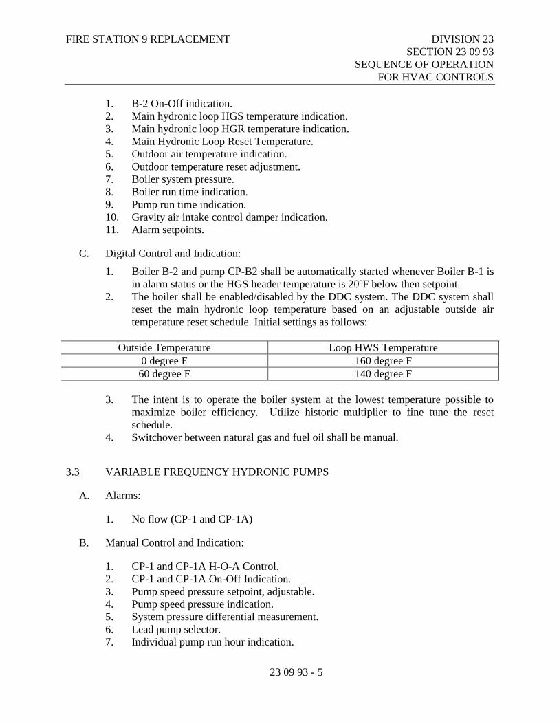
FIRE STATION 9 REPLACEMENT DIVISION 23
SECTION 23 09 93
SEQUENCE OF OPERATION
FOR HVAC CONTROLS
23 09 93 - 5
1. B-2 On-Off indication.
2. Main hydronic loop HGS temperature indication.
3. Main hydronic loop HGR temperature indication.
4. Main Hydronic Loop Reset Temperature.
5. Outdoor air temperature indication.
6. Outdoor temperature reset adjustment.
7. Boiler system pressure.
8. Boiler run time indication.
9. Pump run time indication.
10. Gravity air intake control damper indication.
11. Alarm setpoints.
C. Digital Control and Indication:
1. Boiler B-2 and pump CP-B2 shall be automatically started whenever Boiler B-1 is
in alarm status or the HGS header temperature is 20ºF below then setpoint.
2. The boiler shall be enabled/disabled by the DDC system. The DDC system shall
reset the main hydronic loop temperature based on an adjustable outside air
temperature reset schedule. Initial settings as follows:
Outside Temperature Loop HWS Temperature
0 degree F 160 degree F
60 degree F 140 degree F
3. The intent is to operate the boiler system at the lowest temperature possible to
maximize boiler efficiency. Utilize historic multiplier to fine tune the reset
schedule.
4. Switchover between natural gas and fuel oil shall be manual.
3.3 VARIABLE FREQUENCY HYDRONIC PUMPS
A. Alarms:
1. No flow (CP-1 and CP-1A)
B. Manual Control and Indication:
1. CP-1 and CP-1A H-O-A Control.
2. CP-1 and CP-1A On-Off Indication.
3. Pump speed pressure setpoint, adjustable.
4. Pump speed pressure indication.
5. System pressure differential measurement.
6. Lead pump selector.
7. Individual pump run hour indication.
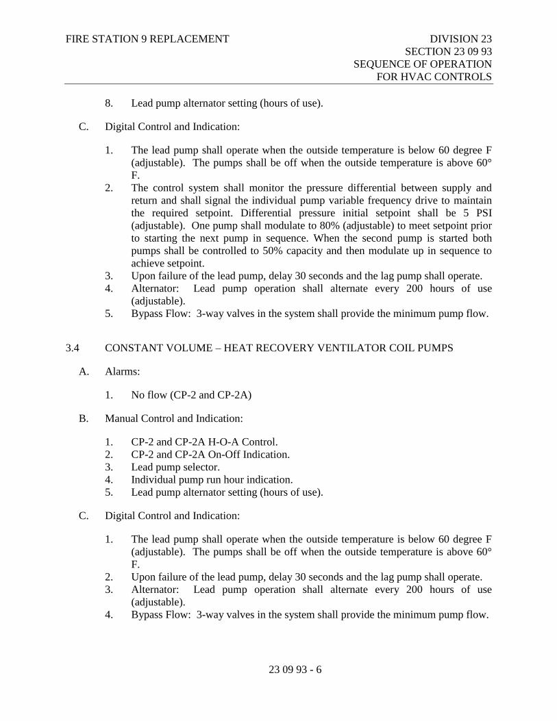
FIRE STATION 9 REPLACEMENT DIVISION 23
SECTION 23 09 93
SEQUENCE OF OPERATION
FOR HVAC CONTROLS
23 09 93 - 6
8. Lead pump alternator setting (hours of use).
C. Digital Control and Indication:
1. The lead pump shall operate when the outside temperature is below 60 degree F
(adjustable). The pumps shall be off when the outside temperature is above 60°
F.
2. The control system shall monitor the pressure differential between supply and
return and shall signal the individual pump variable frequency drive to maintain
the required setpoint. Differential pressure initial setpoint shall be 5 PSI
(adjustable). One pump shall modulate to 80% (adjustable) to meet setpoint prior
to starting the next pump in sequence. When the second pump is started both
pumps shall be controlled to 50% capacity and then modulate up in sequence to
achieve setpoint.
3. Upon failure of the lead pump, delay 30 seconds and the lag pump shall operate.
4. Alternator: Lead pump operation shall alternate every 200 hours of use
(adjustable).
5. Bypass Flow: 3-way valves in the system shall provide the minimum pump flow.
3.4 CONSTANT VOLUME – HEAT RECOVERY VENTILATOR COIL PUMPS
A. Alarms:
1. No flow (CP-2 and CP-2A)
B. Manual Control and Indication:
1. CP-2 and CP-2A H-O-A Control.
2. CP-2 and CP-2A On-Off Indication.
3. Lead pump selector.
4. Individual pump run hour indication.
5. Lead pump alternator setting (hours of use).
C. Digital Control and Indication:
1. The lead pump shall operate when the outside temperature is below 60 degree F
(adjustable). The pumps shall be off when the outside temperature is above 60°
F.
2. Upon failure of the lead pump, delay 30 seconds and the lag pump shall operate.
3. Alternator: Lead pump operation shall alternate every 200 hours of use
(adjustable).
4. Bypass Flow: 3-way valves in the system shall provide the minimum pump flow.
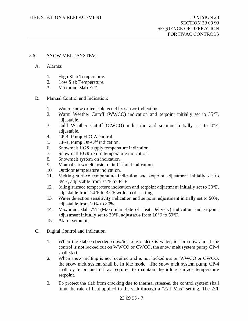
FIRE STATION 9 REPLACEMENT DIVISION 23
SECTION 23 09 93
SEQUENCE OF OPERATION
FOR HVAC CONTROLS
23 09 93 - 7
3.5 SNOW MELT SYSTEM
A. Alarms:
1. High Slab Temperature.
2. Low Slab Temperature.
3. Maximum slab T.
B. Manual Control and Indication:
1. Water, snow or ice is detected by sensor indication.
2. Warm Weather Cutoff (WWCO) indication and setpoint initially set to 35°F,
adjustable.
3. Cold Weather Cutoff (CWCO) indication and setpoint initially set to 0°F,
adjustable.
4. CP-4, Pump H-O-A control.
5. CP-4, Pump On-Off indication.
6. Snowmelt HGS supply temperature indication.
7. Snowmelt HGR return temperature indication.
8. Snowmelt system on indication.
9. Manual snowmelt system On-Off and indication.
10. Outdoor temperature indication.
11. Melting surface temperature indication and setpoint adjustment initially set to
39°F, adjustable from 34°F to 44°F
12. Idling surface temperature indication and setpoint adjustment initially set to 30°F,
adjustable from 24°F to 35°F with an off-setting.
13. Water detection sensitivity indication and setpoint adjustment initially set to 50%,
adjustable from 20% to 80%.
14. Maximum slab T (Maximum Rate of Heat Delivery) indication and setpoint
adjustment initially set to 30°F, adjustable from 10°F to 50°F.
15. Alarm setpoints.
C. Digital Control and Indication:
1. When the slab embedded snow/ice sensor detects water, ice or snow and if the
control is not locked out on WWCO or CWCO, the snow melt system pump CP-4
shall start.
2. When snow melting is not required and is not locked out on WWCO or CWCO,
the snow melt system shall be in idle mode. The snow melt system pump CP-4
shall cycle on and off as required to maintain the idling surface temperature
setpoint.
3. To protect the slab from cracking due to thermal stresses, the control system shall
limit the rate of heat applied to the slab through a "T Max" setting. The T
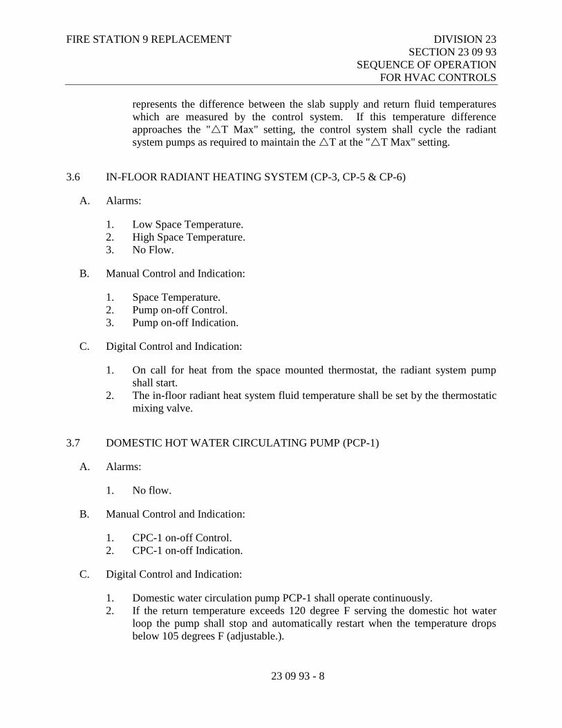
FIRE STATION 9 REPLACEMENT DIVISION 23
SECTION 23 09 93
SEQUENCE OF OPERATION
FOR HVAC CONTROLS
23 09 93 - 8
represents the difference between the slab supply and return fluid temperatures
which are measured by the control system. If this temperature difference
approaches the "T Max" setting, the control system shall cycle the radiant
system pumps as required to maintain the T at the "T Max" setting.
3.6 IN-FLOOR RADIANT HEATING SYSTEM (CP-3, CP-5 & CP-6)
A. Alarms:
1. Low Space Temperature.
2. High Space Temperature.
3. No Flow.
B. Manual Control and Indication:
1. Space Temperature.
2. Pump on-off Control.
3. Pump on-off Indication.
C. Digital Control and Indication:
1. On call for heat from the space mounted thermostat, the radiant system pump
shall start.
2. The in-floor radiant heat system fluid temperature shall be set by the thermostatic
mixing valve.
3.7 DOMESTIC HOT WATER CIRCULATING PUMP (PCP-1)
A. Alarms:
1. No flow.
B. Manual Control and Indication:
1. CPC-1 on-off Control.
2. CPC-1 on-off Indication.
C. Digital Control and Indication:
1. Domestic water circulation pump PCP-1 shall operate continuously.
2. If the return temperature exceeds 120 degree F serving the domestic hot water
loop the pump shall stop and automatically restart when the temperature drops
below 105 degrees F (adjustable.).
FIRE STATION 9 REPLACEMENT DIVISION 23
SECTION 23 09 93
SEQUENCE OF OPERATION
FOR HVAC CONTROLS
23 09 93 - 9
3.8 HEAT RECOVERY VENTILATOR (HRV-1)
A. Alarms:
1. Low S/A air temperature (50º F adjustable).
2. Return Filter high differential pressure.
3. Intake Filter high differential pressure.
4. Exhaust Fan Failure.
5. Supply Fan Failure.
6. Heat Recovery High Differential Pressure.
B. Digital Control and Indication:
1. On-off indication.
2. Outside temperature reset adjustment.
3. S/A temperature setpoint.
4. S/A temperature indication.
5. P/A temperature indication.
6. O/A temperature indication.
7. E/A temperature indication.
8. E/A temperature setpoint.
9. Bypass Damper Position.
10. Outside air Damper Position.
11. Exhaust Air Damper Position.
12. Preheat Coil Valve Position.
13. Heating Coil Valve Position.
14. DX Cooling Temperature Setpoint.
15. DX Cooling Temperature Indication.
16. Duct Static Pressure Indication.
17. Duct Static Pressure Setpoint.
18. Smoke Detection.
19. Alarm setpoints.
C. Digital Control and Indication:
1. Supply and Exhaust Fans shall operate continuously.
2. Heating Mode Operation:
a. The bypass damper shall modulate as required to maintain the exhaust air
temperature after the coil at 35°F.
b. The preheat coil shall modulate to maintain the preheat air temperature at
35°f.
c. The S/A desired temperature shall be reset based on adjustable outside
temperature. Initial settings as follows:
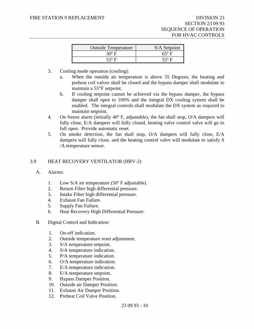
FIRE STATION 9 REPLACEMENT DIVISION 23
SECTION 23 09 93
SEQUENCE OF OPERATION
FOR HVAC CONTROLS
23 09 93 - 10
Outside Temperature S/A Setpoint
30º F 65º F
55º F 55º F
3. Cooling mode operation (cooling):
a. When the outside air temperature is above 55 Degrees, the heating and
preheat coil valves shall be closed and the bypass damper shall modulate to
maintain a 55°F setpoint.
b. If cooling setpoint cannot be achieved via the bypass damper, the bypass
damper shall open to 100% and the integral DX cooling system shall be
enabled. The integral controls shall modulate the DX system as required to
maintain setpoint.
4. On freeze alarm (initially 40º F, adjustable), the fan shall stop, O/A dampers will
fully close, E/A dampers will fully closed, heating valve control valve will go to
full open. Provide automatic reset.
5. On smoke detection, the fan shall stop, O/A dampers will fully close, E/A
dampers will fully close, and the heating control valve will modulate to satisfy S
/A temperature sensor.
3.9 HEAT RECOVERY VENTILATOR (HRV-2)
A. Alarms:
1. Low S/A air temperature (50º F adjustable).
2. Return Filter high differential pressure.
3. Intake Filter high differential pressure.
4. Exhaust Fan Failure.
5. Supply Fan Failure.
6. Heat Recovery High Differential Pressure.
B. Digital Control and Indication:
1. On-off indication.
2. Outside temperature reset adjustment.
3. S/A temperature setpoint.
4. S/A temperature indication.
5. P/A temperature indication.
6. O/A temperature indication.
7. E/A temperature indication.
8. E/A temperature setpoint.
9. Bypass Damper Position.
10. Outside air Damper Position.
11. Exhaust Air Damper Position.
12. Preheat Coil Valve Position.
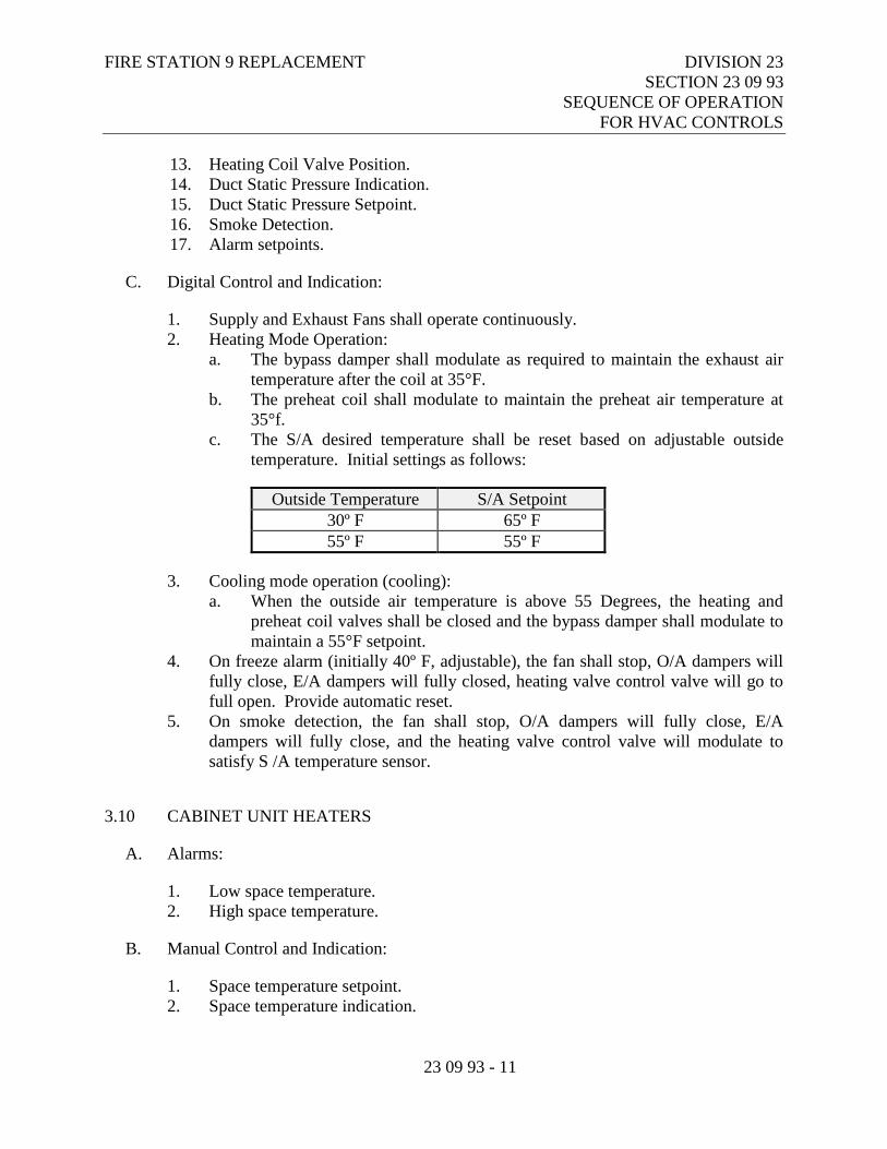
FIRE STATION 9 REPLACEMENT DIVISION 23
SECTION 23 09 93
SEQUENCE OF OPERATION
FOR HVAC CONTROLS
23 09 93 - 11
13. Heating Coil Valve Position.
14. Duct Static Pressure Indication.
15. Duct Static Pressure Setpoint.
16. Smoke Detection.
17. Alarm setpoints.
C. Digital Control and Indication:
1. Supply and Exhaust Fans shall operate continuously.
2. Heating Mode Operation:
a. The bypass damper shall modulate as required to maintain the exhaust air
temperature after the coil at 35°F.
b. The preheat coil shall modulate to maintain the preheat air temperature at
35°f.
c. The S/A desired temperature shall be reset based on adjustable outside
temperature. Initial settings as follows:
Outside Temperature S/A Setpoint
30º F 65º F
55º F 55º F
3. Cooling mode operation (cooling):
a. When the outside air temperature is above 55 Degrees, the heating and
preheat coil valves shall be closed and the bypass damper shall modulate to
maintain a 55°F setpoint.
4. On freeze alarm (initially 40º F, adjustable), the fan shall stop, O/A dampers will
fully close, E/A dampers will fully closed, heating valve control valve will go to
full open. Provide automatic reset.
5. On smoke detection, the fan shall stop, O/A dampers will fully close, E/A
dampers will fully close, and the heating valve control valve will modulate to
satisfy S /A temperature sensor.
3.10 CABINET UNIT HEATERS
A. Alarms:
1. Low space temperature.
2. High space temperature.
B. Manual Control and Indication:
1. Space temperature setpoint.
2. Space temperature indication.
FIRE STATION 9 REPLACEMENT DIVISION 23
SECTION 23 09 93
SEQUENCE OF OPERATION
FOR HVAC CONTROLS
23 09 93 - 12
C. Digital Control and Indication:
1. On a call for heat by a space mounted DDC temperature sensor, the fan shall start
and the 2-way motorized control valve shall modulate as required to maintain
setpoint, initially set to 70 degree F, adjustable.
3.11 HORIZONTAL UNIT HEATERS
A. Alarms:
1. Low space temperature.
2. High space temperature.
B. Manual Control and Indication:
1. Space temperature setpoint.
2. Space temperature indication.
C. Digital Control and Indication:
1. On a call for heat by a space mounted DDC temperature sensor, the fan shall start
and the 2-way motorized control valve shall modulate as required to maintain
setpoint, initially set to 68 degree F, adjustable.
3.12 VERTICAL UNIT HEATERS
A. Alarms:
1. Low space temperature.
2. High space temperature.
B. Manual Control and Indication:
1. Space temperature setpoint.
2. Space temperature indication.
C. Digital Control and Indication (3-Way Valve):
1. On a call for heat by a space mounted DDC temperature sensor, the fan shall start
and the 3-way motorized control valve shall modulate as required to maintain
setpoint, initially set to 70 degree F, adjustable.
D. Digital Control and Indication (2-Way Valve):
FIRE STATION 9 REPLACEMENT DIVISION 23
SECTION 23 09 93
SEQUENCE OF OPERATION
FOR HVAC CONTROLS
23 09 93 - 13
1. On a call for heat by a space mounted DDC temperature sensor, the fan shall start
and the 2-way motorized control valve shall modulate as required to maintain
setpoint, initially set to 70 degree F, adjustable.
3.13 FINTUBE RADIATION
A. Alarms:
1. Low space temperature.
2. High space temperature.
B. Manual Control and Indication:
1. Space temperature setpoint.
2. Space temperature indication.
C. Digital Control and Indication:
1. On a call for heat by a space mounted DDC temperature sensor, the fan shall start
and the 2-way motorized control valve shall modulate as required to maintain
setpoint, initially set to 70 degree F, adjustable.
3.14 GLYCOL FEED TANK (GT-1)
A. Alarms:
1. Low level.
B. Manual Control and Indication:
1. None.
C. Digital Control and Indication:
1. Packaged controls shall cycle the pump on and off as required to maintain system
pressure (Unit is normally turned off except at initial system fill and after
maintenance activities).
3.15 HOT WATER GENERATOR (HWG-1, P-6)
A. Alarms:
1. Low Supply Temperature.
2. High Supply temperature.
FIRE STATION 9 REPLACEMENT DIVISION 23
SECTION 23 09 93
SEQUENCE OF OPERATION
FOR HVAC CONTROLS
23 09 93 - 14
B. Manual Control and Indication:
1. None.
C. Digital Control and Indication:
1. On a call for heat by the packaged aquastat, way motorized control valve shall
open, pump CP-6 shall start. When setpoint is satisfied, pump CP-6 shall stop
and the 2-way motorized control valve shall close. Setpoint, initially set to 140
degree F, adjustable.
3.16 CEILING FANS (CF-1)
A. Alarms:
1. None
B. Manual Control and Indication:
1. On-Off Indication
C. Automated Control:
1. The ceiling fans shall be controlled by an on-off-variable speed controller.
3.17 BOILER ROOM VENTILATION FAN (VF-1)
A. Alarms:
1. Low space temperature (50º F adjustable).
B. Manual Control and Indication:
1. H-O-A control.
2. On-off indication.
3. Space temperature indication.
4. Outside air temperature indication.
5. Mixed air temperature setpoint.
6. Mixed air temperature indication.
7. Alarm setpoints.
C. Digital Control and Indication:
FIRE STATION 9 REPLACEMENT DIVISION 23
SECTION 23 09 93
SEQUENCE OF OPERATION
FOR HVAC CONTROLS
23 09 93 - 15
1. On call from the space mounted close-on-rise thermostat fan VF-1shall start and
the outside air and return air dampers shall modulate to maintain mixed air
setpoint initially set to 65ºF, (adjustable).
2. When the space mounted thermostat is stratified, the fan shall stop and the outside
air damper shall close and the return air damper shall open.
3.18 APPARATUS BAY VENTILATION FAN (EF-1)
A. Alarms
1. High CO concentration.
2. High N02 concentration.
B. Manual Control and Indication
1. On-off indication.
2. Visual Indication of high CO/ N02 concentration.
C. Automated Control
1. On call for ventilation either by a manually operated 0-30 minute spring wound
timer or the CO/N02 monitoring system the motorized damper on EF-1 shall open
or the fan shall stat.
D. Carbon monoxide/nitrogen dioxide sensor shall be a plug-in electromechanical sensing
element type sensor, a microprocessor, a dry output contact, and an audible alarm.
MSA model C485 controller and One (1) DS sensors or approved equal.
3.19 FITNESS ROOM EXHAUST FAN (EF-2)
A. Alarms:
1. None.
B. Manual Control and Indication:
1. On-off indication.
C. Automated Control:
1. On activation of a wall mounted 0-60 minute spring wound timer, the motorized
control damper shall open and the fan shall start. The motorized damper shall be
closed when the fan is off.
FIRE STATION 9 REPLACEMENT DIVISION 23
SECTION 23 09 93
SEQUENCE OF OPERATION
FOR HVAC CONTROLS
23 09 93 - 16
3.20 LAUNDRY ROOM EXHAUST FAN (EF-3)
A. Alarms:
1. None.
B. Manual Control and Indication:
1. On-off indication.
C. Automated Control:
1. On activation of a wall mounted 0-60 minute spring wound timer, the motorized
control damper shall open and the fan shall start. The motorized damper shall be
closed when the fan is off.
3.21 HOSE TOWER EXHAUST FAN (EF-4)
A. Alarms:
1. None.
B. Manual Control and Indication:
1. On-off indication.
C. Automated Control:
1. On activation of a wall mounted switch the motorized control inlet and exhaust air
dampers shall open and the fan shall start. The motorized dampers shall be closed
when the fan is off.
3.22 TOILET EXHAUST FANS (TEF-1)
A. Alarms:
1. None.
B. Manual Control and Indication:
1. On-off indication.
C. Automated Control:
FIRE STATION 9 REPLACEMENT DIVISION 23
SECTION 23 09 93
SEQUENCE OF OPERATION
FOR HVAC CONTROLS
23 09 93 - 17
1. On activation of the local lighting circuit the fan shall start. The lighting circuit is
controlled by a programmable timer, refer to electrical.
3.23 KITCHEN HOODS (KH-1)
A. Alarms:
1. None.
B. Manual Control and Indication:
1. On-off indication.
C. Automated Control:
1. Packaged controls shall cycle integral fan and lights on and off.
3.24 EMERGENCY BOILER SHUT-OFF
A. Boiler Room - Activation of a red emergency stop mushroom switch located at the exit
of the room shall shut down boilers B-1 and B-2, boiler circulation pumps shall remain
in operation.
END OF SECTION 23 09 93
FIRE STATION 9 REPLACEMENT DIVISION 23 SECTION 23 11 13 FACILITY FUEL-OIL PIPING
23 11 13 - 1
PART 1 - GENERAL
1.1 RELATED DOCUMENTS
A. Drawings and general provisions of the Contract, including Municipality of Anchorage Standard Specifications – Buildings (MASSB), General and Supplementary Conditions apply to this Section.
1.2 WORK INCLUDED
A. Section Includes:
1. Fuel Oil Piping - Buried. 2. Fuel Oil Piping - Above Ground. 3. Fuel Oil Underground Containment System. 4. Unions and Flanges. 5. Valves. 6. Pipe Hangers and Supports. 7. Relief Valves. 8. Strainers. 9. Flexible Connectors. 10. Tank Inventory and Leak Detection System. 11. Underground Pipe Markers. 12. Fuel Oil Dearator / Filter.
B. Related Sections:
1. Section 23 05 29 - Hangers and Supports for HVAC Piping and Equipment. 2. Section 23 05 53 - Identification for HVAC Piping and Equipment.
1.3 REFERENCES
A. American Society of Mechanical Engineers:
1. ASME B16.3 - Malleable Iron Threaded Fittings. 2. ASME B31.1 - Power Piping. 3. ASME B31.9 - Building Services Piping. 4. ASME B36.10M - Welded and Seamless Wrought Steel Pipe.
FIRE STATION 9 REPLACEMENT DIVISION 23 SECTION 23 11 13 FACILITY FUEL-OIL PIPING
23 11 13 - 2
5. ASME Section IX - Boiler and Pressure Vessel Code - Welding and Brazing Qualifications.
B. ASTM International:
1. ASTM A53/A53M - Standard Specification for Pipe, Steel, Black and Hot-Dipped, Zinc-Coated, Welded and Seamless.
2. ASTM F708 - Standard Practice for Design and Installation of Rigid Pipe Hang-ers.
C. American Welding Society:
1. AWS A5.8 - Specification for Filler Metals for Brazing and Braze Welding. 2. AWS D1.1 - Structural Welding Code - Steel.
D. National Fire Protection Association:
1. NFPA 30 - Flammable and Combustible Liquids Code. 2. NFPA 31 - Standard for the Installation of Oil-Burning Equipment.
E. Underwriters Laboratories Inc.:
1. UL 567 - Pipe Connectors for Flammable Liquids and Combustible Liquids and LP-Gas.
2. UL 842 - Valves for Flammable Fluids. 3. UL 913 - Intrinsically Safe Apparatus and Associated Apparatus for Use in Class
I, II, and III, Division 1, Hazardous Locations.
1.4 SUBMITTALS
A. Submittal Procedures under provisions of the Supplementary Conditions.
B. Product Data:
1. Piping: Submit data on pipe materials, fittings, and accessories. Submit manufac-turers catalog information.
2. Valves: Submit manufacturer’s catalog information with valve data and ratings for each service.
3. Hangers and Supports: Submit manufacturer’s catalog information including load capacity.
4. Fuel Piping Specialties: Submit manufacturer’s catalog information including ca-pacity, rough-in requirements, and service sizes.
5. Tank Inventory and Leak Detection System: Submit manufacturer’s catalog in-formation for controller, alarm unit, cable type, level sensors and detectors.
FIRE STATION 9 REPLACEMENT DIVISION 23 SECTION 23 11 13 FACILITY FUEL-OIL PIPING
23 11 13 - 3
C. Test Reports: Submit written test results for piping system pressure test.
D. Manufacturer's Installation Instructions: Submit piping system, piping accessories and Tank Inventory and Leak Detection System
1.5 CLOSEOUT SUBMITTALS
A. Execution and Closeout Requirements: Closeout procedures under provisions of Sup-plementary Conditions.
B. Project Record Documents: Record actual locations of valves, piping system, and sys-tem components.
C. Project Record Documents: Record actual locations of piping mains with invert eleva-tions, valves, manholes, and leak detection and location system.
D. Identify and describe unexpected variations to subsoil conditions or discovery of un-charted utilities.
E. Operation and Maintenance Data under provisions the Supplementary Conditions. Submit spare parts lists, exploded assembly views, for tank and inventory leak detec-tion.
F. Day Tank manual shall include the following as a minimum:
1. Registration certificate 2. Glossary 3. Equipment list 4. Detailed description of operation 5. Pump specifications 6. Installation instructions 7. Troubleshooting instructions 8. Maintenance instructions 9. Piping diagram 10. Electrical drawing 11. Exploded view parts drawing/parts list 12. Dimensional drawing 13. Warranty card
1.6 QUALITY ASSURANCE
A. Perform Work in accordance with NFPA 31.
B. Perform Work in accordance with authority having jurisdiction.
FIRE STATION 9 REPLACEMENT DIVISION 23 SECTION 23 11 13 FACILITY FUEL-OIL PIPING
23 11 13 - 4
C. Evaluate leak detection and location system by independent third party according to Third Party Procedures developed according to US EPS's "Standard Test Procedure for Evaluating Leak Detection Methods: Liquid-Phase Out-of-Tank Product Detectors." Evaluation results to verify system manufacturers claim regarding sensitivity, range and other performance data.
1.7 QUALIFICATIONS
A. Installer: Company specializing in performing work of this section with minimum three years documented experience or approved by manufacturer. And must be installed by a State of Alaska certified underground storage tank worker.
1.8 DELIVERY, STORAGE, AND HANDLING
A. Deliver, store and handle under the provisions of the Supplementary Conditions.
B. Accept valves on site in shipping containers with labeling in place. Inspect for damage.
C. Protect piping and fittings from soil and debris with temporary end caps and closures. Maintain in place until installation.
1.9 ENVIRONMENTAL REQUIREMENTS
A. Under the provisions of the Supplementary Conditions.
B. Do not install underground piping when bedding is wet or frozen.
1.10 FIELD MEASUREMENTS
A. Verify field measurements prior to fabrication.
1.11 COORDINATION
A. Under the provisions of the Supplementary Conditions.
B. Coordinate trenching, excavating, bedding, backfilling of buried piping systems with requirements of Division 31 - Earthwork.
1.12 WARRANTY
A. Under the provisions of the Supplementary Conditions.
FIRE STATION 9 REPLACEMENT DIVISION 23 SECTION 23 11 13 FACILITY FUEL-OIL PIPING
23 11 13 - 5
B. Furnish manufacturer warranty for leak detection and location system.
PART 2 - PRODUCTS
2.1 FUEL OIL PIPING - ABOVE GROUND
A. Steel Pipe: ASTM A53/A53M or ASME B36.10M Schedule 40 black.
1. Fittings: ASME B16.3, malleable iron, or ASTM A234/A234M wrought carbon steel and alloy steel welding type.
2. Joints: Welded. 3. Joints in Mechanical Room: Threaded for pipe 2 inch and smaller; welded for
pipe 2-1/2 inches and larger.
2.2 FLEXIBLE FUEL OIL PIPING SYSTEM
A. Manufacturers:
1. OPW FlexWorks.
2. Substitutions: Under the provisions of the Supplementary Conditions. 3.
2.3 FLEXIBLE FUEL OIL PIPING SYSTEM
A. Double-Wall Flexible Primary Piping: UL971 listed:
1. KYNAR™ PVDF outer jacket. 2. Braided fiber reinforcement. 3. Hydrologically stabilized fuel-grade polyurethane layer. 4. KYNAR PVDF core layer (Polyvinylidene Fluoride).
B. Primary and secondary pipe is tested for Type A & Type B external and internal fluids inside and out. Working Pressure: 75PSIG, 5 BAR Average, Burst Pressure: 600PSIG, 40 BAR, Temperature Rating: -20º to +120ºF, -29º to +49ºC, Minimum Bend Radius: 24 in., 600 mm.
C. Double Wall Flexible Access Piping: Crush and puncture-resistant flexible corrugated outer wall with smooth inner surface, rated for H-20 loading.
FIRE STATION 9 REPLACEMENT DIVISION 23 SECTION 23 11 13 FACILITY FUEL-OIL PIPING
23 11 13 - 6
D. Primary Pipe Fittings: Primary pipe fitting and couplings shall be of stainless steel con-struction specially designed for flexibility in installation of pipe. Brass couplings shall not be permitted.
E. Transition Piping Sumps: Constructed of one-piece polyethylene complete with water-resistant cover with cover gasket, handle and cover hold downs.
F. Tank Sumps: Two piece, filament wound with homogeneous vinyl ester resin con-struction with mechanically fastened water tight removable cover.
G. Pipe and conduit entry seals: Pipe and conduit entry seals shall have an exterior stud-ded compression ring encapsulated within rubber to protect it from corrosion. All studs shall be stainless steel and exposed only on the inside of the containment chamber.
2.4 UNIONS AND FLANGES
A. Unions for Pipe 2 inches and Smaller:
1. Ferrous Piping: Class 150, malleable iron, threaded. 2. Dielectric Connections: Union with galvanized or plated steel threaded end, cop-
per solder end, water impervious isolation barrier.
2.5 GATE VALVES
A. No allowed.
2.6 GLOBE VALVES
A. Not Allowed.
2.7 BALL VALVES
A. 1/4 inch to 1 inch: MSS SP 110, Class 125, two piece, threaded ends, bronze body; chrome plated bronze ball, reinforced Teflon seats, blow-out proof stem, lever handle, UL 842 listed for flammable liquids and LPG, full port.
2.8 CHECK VALVES
A. Swing Check Valves
1. 2 inches and Smaller: MSS SP 80, Class 150, bronze body and cap, bronze seat, Buna-N disc, threaded ends.
FIRE STATION 9 REPLACEMENT DIVISION 23 SECTION 23 11 13 FACILITY FUEL-OIL PIPING
23 11 13 - 7
B. Spring Loaded Check Valves:
1. 2 inches and Smaller: MSS SP 80, Class 150 bronze body, in-line spring lift check, silent closing, Buna-N disc, integral seat, threaded ends.
2.9 HANGERS AND SUPPORTS
A. Conform to NFPA 31.
B. Hangers for Pipe Sizes 1/2 to 1-1/2 inch: Malleable iron or Carbon steel, adjustable swivel, split ring.
2.10 RELIEF VALVES
A. ASME certified and labeled. Maximum working temperature: 450 degrees F. Body: Bronze. Seat: Viton or Monel. Stem and Springs: Stainless steel. Threaded ends. Auto-matic type, direct pressure actuated at maximum 60psi.
2.11 STRAINERS
A. Manufacturers:
1. Mueller Steam Specialty. 2. O.C. Keckley Company. 3. Spirax Sarco, Inc. 4. Substitutions: Under the provisions of the Supplementary Conditions.
B. 2 inch and Smaller: Y pattern, bronze body, threaded ends, Class 150, 1/32 inch stain-less steel perforated screen.
2.12 FLEXIBLE CONNECTORS
A. Manufacturers:
1. Flex-Hose Co., Inc. 2. Flex-Weld, Inc. 3. The Metraflex Company. 4. Substitutions: Under the provisions of the Supplementary Conditions.
B. 2 inches and Smaller: Corrugated Type 304 stainless steel inner hose with single layer of Type 304 stainless steel exterior braiding. Maximum working pressure 200 psig.
FIRE STATION 9 REPLACEMENT DIVISION 23 SECTION 23 11 13 FACILITY FUEL-OIL PIPING
23 11 13 - 8
2.13 TANK INVENTORY AND LEAK DETECTION SYSTEM
A. Acceptable Manufacturers:
1. VeederRoot Model TLS 450 2. No Substitutions.
B. Features and Options:
1. Low-Power/High-Power Compartments a. Universal sensor/probe interface module
1) 16 input module supports probes and sensors b. Universal input/output interface module
1) Five dry contact output relays/four low voltage dry contact inputs/five high voltage inputs (<=240Vac).
2) Supports PLLD and Pump Sense as well as standard functions c. Built-in relay
1) Supports tank overfill alarm 2. Communication Compartment
a. SiteFax™ interface module 1) Allows hookup to most remote facsimile or modem equipment
b. Ethernet interface module 1) Provides connectivity to local and wide area networks (LAN/WAN)
c. USB interface module 1) Supports Veeder-Root USB thumb drive
d. USB/ethernet dual interface module 1) Provides connectivity to local and wide area networks (LAN/WAN)
e. RS-232 dual interface module 1) Provides two 9-Pin female D-Connectors for data transmission to
P.O.S. terminal or computer f. RS-232/RS-485 dual interface module
1) Provides a 9-Pin female D-Connector and an 8-position RJ45 D-Connector for data transmission to P.O.S. terminal or computer
g. Single RS-232 interface module 1) Provides a 9-Pin female D-Connector for data transmission to P.O.S.
terminal or computer h. Operating temperature range - 32°F to 104°F (O°C to 40°C) i. Storage temperature range- 14°F to 158°F (-10°C to 70°C)
2.14 ISLAND CONTROLLER
A. Acceptable Manufacturers:
1. Assetworks FMS System.
FIRE STATION 9 REPLACEMENT DIVISION 23 SECTION 23 11 13 FACILITY FUEL-OIL PIPING
23 11 13 - 9
2. No Substitutions.
B. Features and Options:
1. Dimensions a. System Head: 15” W x 13” H x 13.6” D b. Height with Pedestal: 62” (157 cm)
2. Power Requirements a. 100 - 120 VAC
3. Environmental Requirements a. -50F to +130F •
4. Processor Speed a. 667 MHz•
5. Operating System a. Windows XP embedded•
6. Hose Control Capacity a. Two (2) hose model
7. Pulser Capacity a. Quantity (1:1, 10:1 250:1, 500:1, 1,000:1 ratios); b. Resolution to .001 gallon
8. Data Entry a. Magnetic Stripe insertion card reader b. 4 x 4 weatherproof metallic keypad c. 2 lines x 20 characters LCD display d. HID, AWID, Motorola Indala, GE Security, and other proximity card reader
support e. Radio Frequency data transmission for vehicles equipped with RF Vehicle
Box 9. Memory
a. 256K RAM, battery-backed 1GB Industrial Flash Disk 10. Clock
a. Real-time, battery-backed 11. Safeguards & Protection
a. Transient protection on AC power input b. AC and DC power fail detect c. Missing pulse detection d. Off the shelf UPS mounting bracket in pedestal
12. Diagnostics a. Built-in hardware and software diagnostics b. Built-in LED indicator lights c. Remote diagnostic software
13. Receipt Printer a. Optional, to be used with Paymentech Module Option
FIRE STATION 9 REPLACEMENT DIVISION 23 SECTION 23 11 13 FACILITY FUEL-OIL PIPING
23 11 13 - 10
2.15 ACCEPTABLE MANUFACTURER – DE-AERATOR / FILTER
A. Tigerholm.
B. Substitutions: None.
2.16 DE-AERATOR FUEL FILTERS
A. UL listed fuel oil de-aerator, converts single pipe supply to two-pipe system complete with fusible valve and integral fuel filter, Tigerholm Tigerloop Twin or approved equal.
2.17 FUEL OIL DAY TANK
A. Manufacturers:
1. Simplex. 2. Pryco. 3. Tramont. 4. Substitutions: Under the provisions of the Supplementary Conditions.
B. General: Provide a packaged design UL-142 double-wall secondary containment con-struction 25 PSIG day tank with on-board supply duplex pumps drawing from a remote main source tank. Day tank shall be complete in all respects in order to provide a relia-ble source of fuel. Day tank shall provide an automatic, self-refilling fuel supply sys-tem.
C. The day tank shall be designed and supplied as an engineered system by the manufac-turer. Each tank shall be of packaged design to include all inlet flow control devices, other valves, level controls, pump control, indicators, alarms and all other devices as re-quired to form an integrated, functional system such that field installation is restricted largely to external piping, wiring and such intermediate devices that are required by code and/or good engineering practice to interconnect the bulk source of supply to the day tank, the day tank to the prime mover and to provide for external vents as per local codes and UL142, NFPA31 and NFPA37.
D. The system shall be for use with fuel oil as described by NFPA321, “Basic Classifica-tion of Flammable and Combustible Liquids”. As defined by this standard, the fuel sup-ply system shall be for use with “combustible liquids”, those having a flash point at or above 100°F and further defined as class II or class III liquids. In no case shall a liquid defined as “flammable”, or as “class I” or as having a flash point less than 100°F be used. In every case, the system shall not be used or applied at a temperature in excess of the flash point of the contents. Electrical equipment used in the system shall be in ac-cordance with NFPA30, section 5-7, wherein it states “For areas where class II or class III liquids only are stored or handled at a temperature below their flash points, the elec-
FIRE STATION 9 REPLACEMENT DIVISION 23 SECTION 23 11 13 FACILITY FUEL-OIL PIPING
23 11 13 - 11
trical equipment may be installed in accordance with provisions of NFPA70, National Electric Code, for ordinary locations...”
E. The system shall be designed and installed in accordance with applicable sections of NFPA30, NFPA31, NFPA37, UL80 and UL142. The day tank shall bear the label of Underwriters Laboratories standard 142 and UL508.
F. Day tank construction:
1. All welded steel atmospheric tank of rectangular, double-wall secondary contain-ment, welded construction built in accordance with codes and standards noted above for indoor use with fuel oil
2. Pipe thread connections shall be provided for fuel oil supply from remote pump set, supply to prime mover, return from prime mover, overflow to main tank, vents, and drain with fire rated ball valve. A weatherproof, screened vent cap shall be provided as a loose item for field installation at the outdoor vent termination.
3. The tank shall be equipped with a welded steel channel base suitable for bolt at-tachment to a concrete pad
4. The tank shall have interior corrosion inhibitor to deter corrosion prior to installa-tion and use
5. The exterior of the day tank shall receive a heavy-duty industrial anti-corrosion coating and be finish painted.
6. All day tank system components shall be protected by a removable or hinged steel equipment cover.
7. Day tank shall be factory leak tested at 25 PSI. 8. The tank shall be steel double-wall secondary containment construction bearing
the UL 142 label. The containment shall be equipped with a leak detector that shall activate the “leak” alarm described below. A drain with fire rated ball valve is to be supplied. The containment shall be equipped with a separate e-vent as re-quired by UL 142.
G. Supply fire rated ball valves as follows:
1. Day tank drain 2. Secondary containment drain
H. Fuel delivery system: Provide installed upon the day tank, a duplex fuel oil pump and duplex pump controller with automatic alternator for supply of fuel from the main tank to the day tank.
I. Duplex pumps: 2.0 GPM at 1725 rpm, when operating with fuel oil having a viscosity of 32SSU.
1. Direct drive, motor driven pumps coupled via flexible coupling.
FIRE STATION 9 REPLACEMENT DIVISION 23 SECTION 23 11 13 FACILITY FUEL-OIL PIPING
23 11 13 - 12
2. Motors to be TEFC construction, HP as required for pump at 50 PSI NEMA type B, continuous duty at 40°C, 1725 RPM, 120V AC, 60 hertz, 1.15 service factor
3. Pumps to be directly driven, positive displacement, internal gear type with me-chanical shaft seal and cast iron body, machined steel gears.
4. Fire rated shutoff ball valves on pump inlets 5. Pump check valve, spring-type, cast iron construction 6. Flowswitch at each pump 7. Suction strainer, cast iron wye type fuel oil strainer on each pump suction 8. Provide a piston type, 0.1 gallon per stroke hand pump installed and piped and
equipped with fire-rated shutoff valves. 9. Inlet flow control solenoid valve each pump. Stainless steel construction, with
fire-rated bypass valve. 10. Supply an overflow return pump at 150% minimum capacity, of supply pump and
of identical construction. Add overflow return pump controller to paragraph 1.5 below.
J. Day tank level controller. A UL Listed, integrated design, digital level controller shall be supplied which provides differential level control for activation of pumps, duplex pump alternator, tank level indication, system alarms and manual operating controls. Level controller shall be self-contained as a unit within a NEMA4 enclosure integral with the day tank assembly.
1. PLC based with 6-inch, color, touch-panel operator interface 2. Dual level sensor input:
a. 4-20mA continuous sensor, analog-to-digital input b. Point sensing float switches: low, refill start, refill stop, high, checkpoint for
automatic cross check of sensors 3. Leak sensor 4. Spare I/O for options and design-build features 5. MODBUS and Ethernet network compatible 6. 4-20mA loop output for tank level 7. Operator touch-panel interface functions:
a. HOA switch b. Test c. Reset d. Alarm silence e. Numeric display of tank level in gallons (liters) f. Graphic condition display of tank level and pump/status/alarm condition g. Message indicators for status and alarm, including: h. Normal operation i. Pump running (fill, return, single or multiple pumps) j. Tank filling k. Loss of flow l. Low
FIRE STATION 9 REPLACEMENT DIVISION 23 SECTION 23 11 13 FACILITY FUEL-OIL PIPING
23 11 13 - 13
m. Critical low n. High o. Critical high p. Leak q. Not in auto r. Controller failure with specific message s. Other messages as determined by design-build option configuration
8. Relay dry contact outputs for the following (5A, SPDT): a. Low alarms b. High alarms c. Leak d. Not in auto
K. Day tank testing:
1. The day tank shall be supplied with manufacturers test certificates as below Tank test: pressure test, leak proof test and structural integrity/appearance test
2. Level controller: operational test of level sensors, level indicator, level control, alarms, backup devices
3. Pump: vacuum test, flow test, pressure test, leak proof test, ampere/voltage test, load test, overload test.
2.18 UNDERGROUND PIPE MARKERS
A. Plastic Ribbon Tape: Bright colored, continuously printed, minimum 6 inches wide by 4 mil thick, manufactured for direct burial service complete with trace wire.
2.19 BEDDING AND COVER MATERIALS
A. Refer to Division 31 - Earthwork.
PART 3 - EXECUTION
3.1 EXAMINATION
A. Verify excavations are to required grade, dry, and not over-excavated.
3.2 PREPARATION
A. Ream pipe and tube ends. Remove burrs. Bevel plain end ferrous pipe.
FIRE STATION 9 REPLACEMENT DIVISION 23 SECTION 23 11 13 FACILITY FUEL-OIL PIPING
23 11 13 - 14
B. Remove scale and dirt, on inside and outside, before assembly.
C. Prepare piping connections to equipment with flanges or unions.
3.3 INSTALLATION - INSERTS
A. Provide inserts for placement in concrete forms.
3.4 INSTALLATION - PIPE HANGERS AND SUPPORTS
A. Install hangers and supports in accordance with ASTM F708 and MSS SP 89.
B. Support horizontal piping hangers as scheduled.
C. Install hangers to provide minimum 1/2 inch space between finished covering and adja-cent work.
D. Place hangers within 12 inches of each horizontal elbow.
E. Install hangers to allow 1-1/2 inch minimum vertical adjustment. Design hangers for pipe movement without disengagement of supported pipe.
F. Where installing several pipes in parallel and at same elevation, provide multiple pipe hangers or trapeze hangers.
G. Provide clearance in hangers and from structure and other equipment for installation of insulation and access to valves and fittings.
3.5 INSTALLATION - BURIED PIPING SYSTEMS
A. Piping Trench and Pipe Burial Requirements: Buried fuel oil piping system must be in-stalled in accordance with all prevailing Federal, State, and Local codes and all applica-ble Manufacturers Installation Instructions.
B. Piping Trench Requirements: Piping trenches should be dug in such a manner that the trench width is equal to at least twice the width of all the flexible pipes contained with-in. All piping within the trench should be separated by the outside diameter of the pip-ing being installed with a required minimum of 2” (50 mm) of separation for all piping. Trench turns should be sweeping rather than sharp angles. The bottom of the trench should be compacted and as uniform as possible to eliminate high spots to insure an even layer of bedding material under the pipe. Remove all sharp rocks and debris from the trench bottom before bedding material is installed.
FIRE STATION 9 REPLACEMENT DIVISION 23 SECTION 23 11 13
FACILITY FUEL-OIL PIPING
23 11 13 - 15
C. Piping Burial Requirements - Unpaved Surfaces: If the surface is unpaved, then a min-imum of 18” (457mm) of approved backfill material should be installed between the top of all flexible piping and the top of the ground surface.
D. Piping Burial Requirements Paved Surfaces - If the surface is paved with either asphalt or concrete, the total amount of pavement plus approved backfill material shall be a minimum of 18” (457mm) between the top of either the flexible piping and the top of the paved surface.
E. Access Pipe Burial - Whether the surface is paved or unpaved with either asphalt or concrete then there shall be a minimum of 16” (406mm) between the top of the Access Pipe and the top of the paved or unpaved surface.
F. Approved Bedding & Backfill Materials - Approved bedding and backfill materials for OPW-FCS’s flexible piping sumps and Access piping shall meet the following specifi-cations:
1. Pea Gravel - Rounded Pea Gravel is permitted with a minimum diameter of 1/8”and a maximum diameter of 3/4”.
2. Crushed Stone - Crushed stone is permitted providing it shall be washed clean andbe of the free flowing type with an angular stone size between 1/8” and 1/2”.(Meets ASTM C-33 paragraph 9.1 requirements.).
3. Sand - Sand backfill is permitted providing it shall be washed clean and is freeflowing with a maximum content of 10% fines. When backfilling, make suresand is evenly distributed and fully compacted under and fully around the piping.
4. NOTE: A minimum of 6” (152mm) of approved bedding material shall be spreadand compacted evenly along the bottom of the piping trench. All bedding andbackfill material should be clean and free from ice and snow and debris. Usingmaterial other than those described above without written approval from OPWFueling Containment Systems will void the product warranty.
G. System Installation
1. FlexWorks retractable Fuel Oil Piping Systems consist of FlexWorks primarypipe fuel oil pipe runs installed in FlexWorks corrugated Access Pipe.
2. Retractable systems utilize Access Pipe to allow the primary pipe and couplingsto be removed in the future for inspection, repair, or replacement without excavat-ing or breaking concrete.
3. The Access Pipe is installed first between containment sumps or between a sumpand a Transition Assembly that is used when the pipe is run through a concreteslab. The primary pipe is then inserted through the Access Pipe.
4. FlexWorks Piping is shipped in continuous rolls and is typically measured and cutto length at the job site. Pipe must be protected from damage before and duringinstallation.
FIRE STATION 9 REPLACEMENT DIVISION 23 SECTION 23 11 13 FACILITY FUEL-OIL PIPING
23 11 13 - 16
H. Step #1 - Prepare Trenches
1. Prepare Trenches, in accordance with the requirements listed in the previous sec-tion.
I. Step #2 - Set Sumps
1. Set FlexWorks Tank Sumps and Above Grade/Below Grade Piping Transition Sumps as required. See typical installation diagrams (Refer to individual FlexWorks Tank Sump and Transition Sump Installation Instructions. a. FlexWorks Tank Sumps are mounted on top of underground storage tanks
to contain the pipe entries into the tank. Tank Sumps are available in vari-ous heights and are field adjustable to accommodate varying tank burial depths.
b. FlexWorks Transition Sumps are used to contain and maintain access to the pipe fittings where the pipe transitions between the flexible pipe below grade and rigid pipe above grade. Transition Assembly is also available for use where the pipe comes through a concrete slab. IMPORTANT: Support all sumps with adequate backfill up to the bottom of the pipe entry fittings. Make sure no voids are present under the sumps. Make sure 1/8” per foot minimum slope is maintained from the last dispenser sump in each piping run back to the tank.
J. Step #3 - Install Entry Fittings:
1. Install 4” FlexWorks Entry Fittings as required in FlexWorks Transition Sumps and Tank Sumps. (Refer to individual FlexWorks Entry Fitting Installation In-structions).
K. Step #4 - Install Pipe and Pipe Couplings:
1. Install FlexWorks piping according to the guidelines found in the OPW Fueling Containment Systems Flexible Underground Piping Manual (Publication UPM0001).
2. Cut the pipe using a FlexWorks Pipe Cutting Tool (PCT-1000). Be careful not to kink the pipe. Check each section for damage before installation.
L. Step #5 - Install Pipe Couplings:
1. Using the FlexWorks Coupling Machine (CME-0110), attach the pipe couplings to each end of each pipe section (Refer to individual Installation Instructions sup-plied with the Coupling Machine). a. When Coupling 3/4” and 1” pipe, use the following swage kits - CSK-
0075S (3/4” pipe) and CSK-0100S (1” pipe). b. Unscrew the shaft from the Coupling Machine (CME0110).
FIRE STATION 9 REPLACEMENT DIVISION 23 SECTION 23 11 13 FACILITY FUEL-OIL PIPING
23 11 13 - 17
c. Insert the shaft for either the 3/4” or 1” pipe. d. Place the 1.5” Swivel Faceplate (EG-CM-0170) on the Coupling Machine. e. Place the 3/4” or 1” Faceplate on top of the 1.5” Swivel Faceplate. f. Screw in the 3/4” or 1” Swage on the shaft. Follow the instructions in the
OPW Fueling Containment Systems Flexible Underground Piping Manual (Publication UPM-0001) for proper procedures for coupling the pipe.
M. Step #6 - Test the Access Pipe:
1. Connect a regulated air supply with a gauge to the air stem on the TBA-4175A. Carefully pressurize the Access Pipe through the air stem on the Test Boot TBA-4175). (2 psig is customary; do not exceed 5 psig). Leave each line pressurized for one hour. Loss of pressure signifies a leak in the line that must be corrected before proceeding.
N. Step #7 - Sump Testing:
1. After all connections are made, fill the sumps with water 1” above the highest penetration fitting. A drop in the water level within 1 hour indicates a leak that must be corrected before backfilling.
O. Step #8 - Backfilling:
1. Rounded pea gravel with a minimum diameter of 1/8” and a maximum diameter of 3/4” should be used for backfill around sumps.
2. IMPORTANT: If installing Transition sumps in high water table areas, use pea gravel inside transition sumps as ballast to prevent the sump from floating up. A slotted pipe can be installed in one corner of the sump to allow monitoring for and removal of contained liquid.
3.6 INSTALLATION - ABOVEGROUND PIPING
A. Install fuel oil piping in accordance with NFPA 31.
B. Provide non-conducting dielectric connections wherever jointing dissimilar metals. In-stall in accordance with NACE RP-01-69.
C. Route piping in orderly manner and maintain gradient.
D. Install piping to conserve building space and not interfere with use of space.
E. Group piping whenever practical at common elevations.
F. Install piping to allow for expansion and contraction without stressing pipe, joints, or connected equipment.
FIRE STATION 9 REPLACEMENT DIVISION 23 SECTION 23 11 13 FACILITY FUEL-OIL PIPING
23 11 13 - 18
G. Sleeve pipe passing through partitions, walls and floors.
H. Install fire stopping at fire rated construction perimeters and openings containing pene-trating sleeves and piping. Refer to Division 07 – Thermal and Moisture Protection.
I. Provide clearance for installation of insulation and access to valves and fittings.
J. Provide access where valves and fittings are not exposed.
K. Where pipe support members are welded to structural building framing, scrape, brush clean, weld, and apply one coat of zinc rich primer. Refer to Division 09 - Finishes.
L. Prepare pipe, fittings, supports, and accessories not pre-finished, ready for finish paint-ing. Refer to Division 09 - Finishes.
M. Install identification on piping systems including underground piping. Refer to Section 23 05 53 – Identification for HVAC Piping and Equipment.
N. Install valves with stems upright or horizontal, not inverted.
O. Protect piping systems from entry of foreign materials by temporary covers, completing sections of the Work, and isolating parts of completed system.
3.7 INSTALLATION – TANK INVENTORY LEAK DETECTION SYSTEM
A. Install in strict accordance with the manufacturer’s installation instructions.
END OF SECTION 23 11 13
FIRE STATION 9 REPLACEMENT DIVISION 23 SECTION 23 13 00
FACILITY FUEL-STORAGE TANKS
23 13 00 - 1
PART 1 - GENERAL
1.1 RELATED DOCUMENTS
A. Drawings and general provisions of the Contract, including Municipality of Anchorage Standard Specifications – Buildings (MASSB), General and Supplementary Conditions apply to this Section.
1.2 SECTION INCLUDES
A. Double-Wall FRP Tanks for Fuel Storage.
1.3 QUALITY ASSURANCE
A. Governing Standards, as applicable:
1. Underwriters Laboratories (UL) Standard for Safety 1316, File MH 9061 for storage of flammable liquids. A UL label shall be attached to each tank.
2. National Fire Protection Association (NFPA) Standards: 3. NFPA 30: Flammable and Combustible Liquids Code 4. NFPA 30A: Automotive and Marine Service Station Code 5. NFPA 31: Installation of Oil-Burning Equipment.
1.4 WARRANTY
A. Warranty shall be manufacturer's limited warranty for double-wall underground petroleum tanks in effect at time of purchase.
PART 2 - PRODUCTS
2.1 ACCEPTABLE MANUFACTURES - DOUBLE-WALL FRP TANKS FOR FUEL STORAGE
A. Xerxes
B. Substitutions: Under provisions of the Supplementary Conditions.
FIRE STATION 9 REPLACEMENT DIVISION 23 SECTION 23 13 00
FACILITY FUEL-STORAGE TANKS
23 13 00 - 2
2.2 DOUBLE-WALL FRP UNDERGROUND STORAGE TANKS
A. Loading Conditions – Tank shall meet the following design criteria:
1. Internal Load – Tank shall withstand a 5-psig air-pressure test with 5:1 safety factor. Contractor shall individually test tanks for leakage prior to installation. Maximum test pressure is 5 psig.
2. Vacuum Test – To verify structural integrity, every standard 10'-diameter tank and smaller shall be vacuum tested by the manufacturer at the factory to 11.5" of mercury.
3. Surface Loads – Tank shall withstand surface H-20 axle loads when properly installed according to manufacturer’s current Installation Manual and Operating Guidelines.
4. External Hydrostatic Pressure – Tank shall be capable of being buried in ground with 7' of overburden over the top of the tank, the hole fully flooded and a safety factor of 5:1 against general buckling.
5. Tank shall support accessory equipment – such as heating coils, drop tubes, submersible pumps and ladders – when installed according to tank manufacturer’s current Installation Manual and Operating Guidelines.
B. Product Storage
1. Tank shall be capable of storing petroleum products with specific gravity up to 1.1.
2. Tank shall be vented to atmospheric pressure. 3. Tank shall be capable of storing products identified in the manufacturer’s current
standard limited warranty.
C. Materials
1. Tank shall be manufactured with 100% resin and glass-fiber reinforcement. No sand fillers.
D. Interstitial Space
1. Tank shall have a space between the primary and secondary walls to allow for the free flow and containment of leaked product from the primary tank. The space also allows the insertion of a monitoring device through a monitoring fitting.
2.3 ACCESSORIES
A. Anchor Straps
1. Straps shall be FRP anchor straps as supplied by tank manufacturer.
FIRE STATION 9 REPLACEMENT DIVISION 23 SECTION 23 13 00
FACILITY FUEL-STORAGE TANKS
23 13 00 - 3
2. Number and location of straps shall be specified in current literature by tank manufacturer.
B. Manways
1. All manways shall be flanged and complete with UL-listed gaskets, bolts and covers.
2. Location is shown on tank drawings. 3. Manway extensions shall be FRP.
C. Optional Fill Tubes
1. Fill tubes shall be FRP, 4"-diameter, with a 6" x 4" double-tapped reducer bushing, and include a 6" NPT fitting. Tubes shall terminate a minimum of 4" from the bottom of tank (a minimum of 6" for a 12'-diameter tank).
D. Gauge Plates
1. Gauge plates shall be installed under each service fitting and manway opening.
E. NPT Threaded Fittings
1. All standard threaded fittings shall be half-couplings and shall be 4"- or 6"- diameter. Reducers are to be used for smaller sizes where shown and provided by contractor.
2. Strength – NPT fittings shall withstand a minimum of 150 foot-pounds of torque and 1,000 foot-pounds of bending, both with a 2:1 safety factor.
F. Monitor Fittings
1. Each monitor fitting shall consist of a 4" NPT fitting on the tank. Tanks with a hydrostatic monitoring system do not have a monitor fitting.
G. Foot Valves
1. Bronze body and poppet, galvanized screen, double poppet design, female NTP threaded connections.
H. Extractor Fittings
1. Zinc-plated cast iron body, bronze cap and suction stub adaptor, Buna-N gasket.
I. Expansion Compensators
1. Type 316 stainless steel, N.P.T. threads. Factory charged with dry nitrogen to 40 PSI. Precision Plumbing Products Model SS-750 or approved equal.
FIRE STATION 9 REPLACEMENT DIVISION 23 SECTION 23 13 00
FACILITY FUEL-STORAGE TANKS
23 13 00 - 4
J. Fill Limiting Valves
1. Cast aluminum body, nitrile rubber and closed cell foam float, Viton® seals, aluminum upper and lower tube, stainless steel hardware, acetal plastic parts. OPW model 61SO or approved equal.
PART 3 - INSTALLATION
3.1 TESTING
A. Tank shall be tested according to the Xerxes Installation Manual and Operating Guidelines for Single-Wall and Double-Wall Fiberglass Underground Storage Tanks in effect at time of installation.
3.2 INSTALLATION
A. Tank shall be installed according to the Xerxes Installation Manual and Operating Guidelines for Single-Wall and Double-Wall Fiberglass Underground Storage Tanks in effect at time of installation.
B. Installation contractor shall be trained and certified by the tank manufacturer.
END OF SECTION 23 13 00
FIRE STATION 9 REPLACEMENT DIVISION 23
SECTION 23 21 13
HYDRONIC PIPING
23 21 13 - 1
PART 1 - GENERAL
1.1 RELATED DOCUMENTS
A. Drawings and general provisions of the Contract, including Municipality of Anchorage
Standard Specifications – Buildings (MASSB), General and Supplementary Conditions
apply to this Section.
1.2 SECTION INCLUDES
A. Pipe and Pipe Fittings.
B. Valves.
1.3 RELATED WORK
A. Division 07 – Thermal and Moisture Protection: Penetration Firestopping
B. Division 09 – Finishes: Interior Painting.
C. Section 23 05 00 – Common Work Results for HVAC.
D. Section 23 05 16 - Expansion Fittings and Loops for HVAC Piping.
E. Section 23 05 29 – Hangers And Supports For HVAC Piping And Equipment.
F. Section 23 05 48 - Vibration and Seismic Control for HVAC Piping and Equipment.
G. Section 23 05 53 - Identification for HVAC Piping and Equipment.
H. Section 23 07 00 – HVAC Insulation.
I. Section 23 21 16 - Hydronic Piping Specialties.
1.4 REFERENCES
A. American Society of Mechanical Engineers:
1. ASME B16.3 - Malleable Iron Threaded Fittings.
FIRE STATION 9 REPLACEMENT DIVISION 23
SECTION 23 21 13
HYDRONIC PIPING
23 21 13 - 2
2. ASME B16.4 - Gray Iron Threaded Fittings.
3. ASME B16.18 - Cast Copper Alloy Solder Joint Pressure Fittings.
4. ASME B16.22 - Wrought Copper and Copper Alloy Solder Joint Pressure
Fittings.
5. ASME B16.26 - Cast Copper Alloy Fittings for Flared Copper Tubes.
6. ASME B31.1 - Power Piping.
7. ASME B31.9 - Building Services Piping.
8. ASME B36.10M - Welded and Seamless Wrought Steel Pipe.
9. ASME Section IX - Boiler and Pressure Vessel Code - Welding and Brazing
Qualifications.
B. ASTM International:
1. ASTM A53/A53M - Standard Specification for Pipe, Steel, Black and Hot-
Dipped, Zinc-Coated, Welded and Seamless.
2. ASTM A234/A234M - Standard Specification for Piping Fittings of Wrought
Carbon Steel and Alloy Steel for Moderate and High Temperature Service.
3. ASTM A395/A395M - Standard Specification for Ferritic Ductile Iron Pressure-
Retaining Castings for Use at Elevated Temperatures.
4. ASTM A536 - Standard Specification for Ductile Iron Castings.
5. ASTM B32 - Standard Specification for Solder Metal.
6. ASTM B68 - Standard Specification for Seamless Copper Tube, Bright Annealed.
7. ASTM B68M - Standard Specification for Seamless Copper Tube, Bright
Annealed (Metric).
8. ASTM B75 - Standard Specification for Seamless Copper Tube.
9. ASTM B88 - Standard Specification for Seamless Copper Water Tube.
10. ASTM B280 - Standard Specification for Seamless Copper Tube for Air
Conditioning and Refrigeration Field Service.
11. ASTM B584 - Standard Specification for Copper Alloy Sand Castings for
General Applications.
12. ASTM F1476 - Standard Specification for Performance of Gasketed Mechanical
Couplings for Use in Piping Applications.
C. American Welding Society:
1. AWS A5.8 - Specification for Filler Metals for Brazing and Braze Welding.
2. AWS D1.1 - Structural Welding Code - Steel.
D. National Fire Protection Association:
1. NFPA 30 - Flammable and Combustible Liquids Code.
2. NFPA 31 - Standard for the Installation of Oil-Burning Equipment.
a. NFPA 54 - National Fuel Gas Code.
FIRE STATION 9 REPLACEMENT DIVISION 23
SECTION 23 21 13
HYDRONIC PIPING
23 21 13 - 3
1.5 REGULATORY REQUIREMENTS
A. Conform to ASME B31.9.
1.6 QUALITY ASSURANCE
A. Valves: Manufacturer's name and pressure rating marked on valve body.
B. Welding Materials and Procedures: Conform to ASME Section IX, and applicable state
labor regulations.
C. Welders Certification: In accordance with ASME Section IX.
1.7 SUBMITTALS
A. Submit product data under provisions of the Supplementary Condition.
B. Include data on pipe materials, pipe fittings, valves, and accessories.
C. Include welder’s certification of compliance with ASME Section IX.
1.8 QUALIFICATIONS
A. Manufacturer: Company specializing in manufacturing products specified in this section
with minimum three years experience.
1.9 DELIVERY, STORAGE, AND HANDLING
A. Deliver, store and protect products to site under provisions of the Supplementary
Condition.
B. Deliver and store valves in shipping containers with labeling in place.
C. Provide temporary end caps and closure on piping and fittings. Maintain in place until
installation.
D. Protect piping from entry of foreign materials by temporary covers, completing sections
of the work, and isolating parts of the completed system.
FIRE STATION 9 REPLACEMENT DIVISION 23
SECTION 23 21 13
HYDRONIC PIPING
23 21 13 - 4
PART 2 - PRODUCTS
2.1 HEATING GLYCOL PIPING, ABOVE GRADE
A. Steel Pipe: ASTM A53, Schedule 40, black.
1. Fittings: ASTM B16.3, malleable iron or ASTM A234, steel welding type fittings.
2. Joints: Screwed, or AWS D1.1, welded.
B. Copper Tubing: ASTM B88, Type L, hard drawn.
1. Fittings: ASME B16.18 cast bronze of ASME B16.29 solder wrought copper.
2. Joints: AWS A5.8, BCuP silver braze; Flux: ASTM B813.
3. Viega ProPress System.
4. No grooved couplings allowed.
2.2 NATURAL GAS PIPING, BURIED WITHIN 5 FEET OF BUILDING
A. Steel Pipe: ASTM A53, Schedule 40 black. Fittings: ASTM A234, steel welding type,
with ANSI/AWWA C105 polyethylene jacket or double layer, half-lapped 10 mil
polyethylene tape. Joints: ANSI/AWS D1.1, welded.
B. Polyethylene Pipe: ASTM D2513, SDR 11.5. Fittings: ASTM D2683 or ASTM D2513
socket type. Joints: Fusion welded.
2.3 NATURAL GAS PIPING, ABOVE GRADE
A. Steel Pipe: ASTM A53, Schedule 40 black. Fittings: ANSI/ASME B16.3, malleable
iron, or ASTM A234, steel welding type. Joints: Screwed for pipe two inches and
under and if low pressure, or if medium pressure and outside building; ANSI/AWS
D1.1, welded, for pipe over two inches.
2.4 EQUIPMENT DRAINS AND OVERFLOWS
A. Steel Pipe: ASTM A53, Schedule 40 galvanized.
1. Fittings: Galvanized cast iron, or ASTM B16.3 malleable iron.
2. Joints: Screwed, or grooved mechanical couplings.
B. Copper Tubing: ASTM B88, Type L, hard drawn.
FIRE STATION 9 REPLACEMENT DIVISION 23
SECTION 23 21 13
HYDRONIC PIPING
23 21 13 - 5
1. Fittings: ASME B16.18 cast bronze, or ASME B16.29 solder wrought copper.
2. Joints: ASTM B32, solder, Grade 95TA or AWS A5.8, BCuP silver braze; Flux:
ASTM B813.
3. Viega ProPress System.
C. PVC Pipe: ASTM D1785, Schedule 40, and Schedule 80 for sizes 8 inch and larger, or
ASTM D2241, SDR 21 or 26.
1. Fittings: ASTM D2466 or D2467, PVC.
2. Joints: ASTM D2855, solvent weld.
2.5 FLANGES, UNIONS, AND COUPLINGS
A. Pipe Size 2 Inches and Under: 150 psig malleable iron unions for threaded ferrous
piping; bronze unions for copper pipe, brazed joints.
B. Pipe Size Over 2 Inches: 150 psig forged steel slip-on flanges for ferrous piping; bronze
flanges for copper piping.
C. Grooved and Shouldered Pipe End Couplings: Not allowed.
2.6 ACCEPTABLE MANUFACTURERS - ALL VALVE TYPES
A. Nibco.
B. Apollo.
C. FNW.
D. Substitutions: Under provisions of the Supplementary Condition.
2.7 GATE VALVES
A. 4 inches and over: Class 125 (iron) or 150 (steel), iron body, bronze trim, rising stem,
handwheel, OS&Y, single wedge, flanged ends. Provide chain operator when valve is
located 8’-0” or higher above finished floor level.
FIRE STATION 9 REPLACEMENT DIVISION 23
SECTION 23 21 13
HYDRONIC PIPING
23 21 13 - 6
2.8 GLOBE VALVES
A. Globe valves will not be permitted. Use ball or butterfly valves for throttling.
2.9 BALL VALVES
A. Up to 2 Inches: Bronze two piece body, full port, forged brass, chrome plated ball,
Teflon seats and stuffing box ring, lever handle, solder or threaded ends. Seat material
to be compatible with fluid handled.
B. Over 2 Inches: Cast steel, two piece body, full port chrome plated steel ball, Teflon seat
and stuffing box seals, lever handle or gear drive handwheel for sizes 10 inches and
over, flanged. Seat material to be compatible with liquid handled.
2.10 BUTTERFLY VALVES
A. Iron body, bronze disc, resilient replaceable seat for service to 250º F, lug ends,
extended neck, 10 position lever handle.
2.11 SWING CHECK VALVES
A. Up to 2 Inches: Bronze 45º swing disc, solder ends.
B. Over 2 Inches: Iron body, bronze trim, 45º swing disc, renewable disc and seat, flanged
ends.
2.12 SPRING LOADED CHECK VALVES
A. Iron body, bronze trim, stainless steel spring, renewable composition disc, screwed,
wafer or flanged ends.
2.13 DRAIN VALVES
A. Bronze body, chrome plated brass ball, RPTFE seals and stuffing box ring, stainless
steel handle with vinyl cover. 3/4” NPT x 3/4” Hose thread, with duct cover and chain,
sweat ends.
B. Apollo 78-100 Series or approved equal.
FIRE STATION 9 REPLACEMENT DIVISION 23
SECTION 23 21 13
HYDRONIC PIPING
23 21 13 - 7
2.14 ACCEPTABLE MANUFACTURERS – SEISMIC VALVES
A. KOSO VALVE.
B. Pacific Seismic,
C. Substitutions: Under provisions of the Supplementary Conditions.
2.15 SEISMIC VALVES
A. ASCE 25-06 and UL listed or AGA listed or International Association of Plumbing and
Mechanical Officials (IAPMO) listed. The valve may be either pendulum or ball
construction, soft seat construction for positive sealing with visual indicator and flanged
connections.
PART 3 - EXECUTION
3.1 ACCEPTABLE MANUFACTURERS – HEATING GLYCOL SYSTEM CLEANER
A. Hercules Chemical Company, Inc.
B. CH20.
C. Substitutions: Under provisions of the Supplementary Condition.
3.2 HEATING GLYCOL SYSTEM CLEANER
A. Physical Properties: Water soluble, 1.12 specific gravity, 212°F boiling point.
B. Appearance/color/odor: Yellow color liquid. Slight ammine odor.
PART 4 - EXECUTION
4.1 PREPARATION
A. Ream pipe and tube ends. Remove burrs. Bevel plain end ferrous pipe.
B. Remove scale and dirt on inside and outside before assembly.
FIRE STATION 9 REPLACEMENT DIVISION 23
SECTION 23 21 13
HYDRONIC PIPING
23 21 13 - 8
C. Prepare piping connections to equipment with flanges or unions.
D. After completion, fill, clean, and treat systems.
4.2 INSTALLATION
A. Route piping in orderly manner, plumb and parallel to building structure, and maintain
gradient.
B. Install piping to conserve building space, and not interfere with use of space and other
work.
C. Group piping whenever practical at common elevations.
D. Install piping to allow for expansion and contraction without stressing pipe, joints, or
connected equipment. Refer to Section 23 05 16 – Expansion Fittings and Loops for
HVAC Piping.
E. Provide clearance for installation of insulation, and access to valves and fittings.
F. Provide access where valves and fittings are not exposed.
G. Slope piping and arrange systems to drain at low points. Use eccentric reducers to
maintain top of pipe level.
H. Where pipe support members are welded to structural building framing, scrape, brush
clean, and apply one coat of zinc rich primer to welding.
I. Prepare pipe, fittings, supports, and accessories for finish painting. Refer to Division 09
- Finishes.
J. Install valves with stems upright or horizontal, not inverted.
4.3 APPLICATION
A. Use of grooved mechanical couplings and fasteners is limited to equipment drains and
overflows and only in accessible locations.
B. Install unions downstream of valves and at equipment or apparatus connections.
C. Install ball or butterfly valves for shut-off and to isolate equipment, part of systems, or
vertical risers.
D. Install ball or butterfly valves for throttling, bypass, or manual flow control services.
FIRE STATION 9 REPLACEMENT DIVISION 23
SECTION 23 21 13
HYDRONIC PIPING
23 21 13 - 9
E. Provide spring loaded check valves on discharge of pumps.
F. Provide ¾ inch ball drain valves at main shut-off valves, low points of piping, bases of
vertical risers, equipment and as indicated.
4.4 CLEANING OF THE HEATING GLYCOL PIPING SYSTEM
A. Prior to starting work, verify that the heating glycol piping systems are complete.
B. Fill the heating glycol piping systems system with the system cleaner, one (1) quart
hydronic system cleaner for every twenty (20) gallons of water in the hydronic system.
C. Circulate heating glycol piping systems system cleaning solution for a minimum of six
(6) hours. Let system cool completely.
D. Upon completion of boil out, completely flush system and drain all low points.
E. Fill system with appropriate glycol solution. See Specification Section 23 21 16 –
Hydronic Piping Specialties for procedures.
F. Submit a written and signed statement to the Owner that the above referenced cleaning
procedures have been completed.
4.5 TESTING
A. Test all heating water and glycol piping hydrostatically at 100 psig or 150 percent of
working pressure, whichever is greater, for a period of 4 hours. Observe piping during
this period and repair all leaks.
END OF SECTION 23 21 13
FIRE STATION 9 REPLACEMENT DIVISION 23
SECTION 23 21 16
HYDRONIC PIPING SPECIALTIES
23 21 16 - 1
PART 1 - GENERAL
1.1 RELATED DOCUMENTS
A. Drawings and general provisions of the Contract, including Municipality of Anchorage
Standard Specifications – Buildings (MASSB), General and Supplementary Conditions
apply to this Section.
1.2 SECTIONS INCLUDED
A. Diaphragm-Type Compression Tanks
B. Air Vents.
C. Hydraulic Separators.
D. Strainers.
E. Balance Valves.
F. Relief Valves.
G. Glycol System.
1.3 RELATED SECTIONS
A. Section 23 21 13 - Hydronic Piping.
1.4 REFERENCES
A. American Society of Mechanical Engineers:
1. ASME B40.1 - Gauges - Pressure Indicating Dial Type - Elastic Element.
2. ASME Section VIII - Boiler and Pressure Vessel Code - Pressure Vessels.
B. ASTM International:
1. ASTM E1 - Standard Specification for ASTM Thermometers.
FIRE STATION 9 REPLACEMENT DIVISION 23
SECTION 23 21 16
HYDRONIC PIPING SPECIALTIES
23 21 16 - 2
2. ASTM E77 - Standard Test Method for Inspection and Verification of
Thermometers.
C. American Water Works Association:
1. AWWA C700 - Cold-Water Meters - Displacement Type, Bronze Main Case.
2. AWWA C701 - Cold-Water Meters - Turbine Type, for Customer Service.
3. AWWA C702 - Cold-Water Meters - Compound Type.
4. AWWA C706 - Direct-Reading, Remote-Registration Systems for Cold-Water
Meters.
5. AWWA M6 - Water Meters - Selection, Installation, Testing, and Maintenance.
D. Underwriters Laboratories Inc.:
1. UL 393 - Indicating Pressure Gauges for Fire-Protection Service.
2. UL 404 - Gauges, Indicating Pressure, for Compressed Gas Service.
1.5 REGULATORY REQUIREMENTS
A. Conform to ASME Boilers and Pressure Vessels Code Section Vlll for manufacture of
tanks.
1.6 QUALITY ASSURANCE
A. Manufacturer: For each product specified, provide components by same manufacturer
throughout.
1.7 SUBMITTALS
A. Submit product data under provisions of the Supplementary Conditions.
1.8 OPERATION AND MAINTENANCE DATA
A. Submit operation and maintenance data under provisions of the Supplementary
Conditions.
B. Include installation instruction, assembly views, lubrication instructions, and
replacement parts list.
FIRE STATION 9 REPLACEMENT DIVISION 23
SECTION 23 21 16
HYDRONIC PIPING SPECIALTIES
23 21 16 - 3
PART 2 - PRODUCTS
2.1 ACCEPTABLE MANUFACTURERS - DIAPHRAGM-TYPE COMPRESSION
TANKS
A. Amtrol.
B. Taco.
C. Bell & Gossett.
D. Substitutions: Under provisions of the Supplementary Conditions.
2.2 DIAPHRAGM-TYPE COMPRESSION TANKS
A. Construction: Welded steel, rated for working pressure of 125 psig, with flexible EPDM
diaphragm sealed into tank, and steel saddles.
B. Accessories: Air-charging fitting, pre-charge to pressure as indicated.
2.3 ACCEPTABLE MANUFACTURERS - AIR VENTS
A. Spriotherm.
B. ITT Hoffman.
C. No Substitutions.
2.4 AIR VENTS
A. Float Type: Maintenance free solid brass construction, continuous air venting, 150 psig
standard working pressure, 270° F maximum temperature, 1⁄2 inch male tread at vent
point for pressure testing or remote venting, 1/2 inch female threaded connections.
Spirotherm Spirotop VTP, No Substitutions.
B. Manual Type: Disk type vent with built-in check valve for manual operation, discs
replaceable without draining system, 1/8 inch shank, rated at 50 psi; ITT Hoffman No.
508.
FIRE STATION 9 REPLACEMENT DIVISION 23
SECTION 23 21 16
HYDRONIC PIPING SPECIALTIES
23 21 16 - 4
2.5 ACCEPTABLE MANUFACTURERS - HYDRAULIC SEPARATORS
A. Spriotherm.
B. Caleffi.
C. Substitutions: Under provisions of the Supplementary Conditions.
2.6 HYDRAULIC SEPARATORS
A. Construction: Steel body, brass vent head, non-ferrous float, Viton seals and o-rings,
copper coalescing medium, 150 PSIG maximum working pressure, 270ºF maximum
operating temperature, ASME 150 pound flanged connection. Provide with capped
drain valve.
2.7 ACCEPTABLE MANUFACTURERS - STRAINERS
A. Bell & Gossett.
B. Taco.
C. Armstrong.
D. Substitutions: Under provisions of the Supplementary Conditions.
2.8 STRAINERS
A. Size 2 inch and Under: Screwed brass or iron body for 175 psig working pressure, Y
pattern with 1/32 inch stainless steel perforated screen.
B. Size 2-½ inch to 4 inch: Flanged iron body for 175 psig working pressure, Y pattern
with 3/64 inch stainless steel perforated screen.
C. Size 5 inch and Larger: Flanged iron body for 175 psig working pressure, basket pattern
with 1/8 inch stainless steel perforated screen.
2.9 ACCEPTABLE MANUFACTURERS - BALANCE VALVES
A. Bell & Gossett.
B. Armstrong.
FIRE STATION 9 REPLACEMENT DIVISION 23
SECTION 23 21 16
HYDRONIC PIPING SPECIALTIES
23 21 16 - 5
C. Taco.
D. Substitutions: Under provisions of the Supplementary Conditions.
2.10 BALANCE VALVES
A. Angle or straight pattern, inside screw globe valve for 125 psig working pressure, with
bronze body and integral union for screwed connections, renewable composition disc,
plastic wheel handle for shut-off service, and lockshield key cap for balancing service.
2.11 ACCEPTABLE MANUFACTURERS - RELIEF VALVES
A. Watts Regulator.
B. Bell & Gossett.
C. Taco.
D. Substitutions: Under provisions of the Supplementary Conditions.
2.12 RELIEF VALVES
A. Bronze body, Teflon seat, stainless steel stem and springs, automatic, direct pressure
actuated, capacities ASME certified and labeled.
2.13 ACCEPTABLE MANUFACTURERS – GLYCOL FEED TANK
A. Axiom.
B. No Substitutions.
2.14 GLYCOL FEED TANK
A. 17 U.S. gallon HDPE storage/mixing tank with cover; pump suction hose with inlet
strainer; pressure pump with thermal cut-out; integral pressure switch; integral check
valve; cord and plug; pre-charged accumulator tank with EPDM diaphragm; manual
diverter valve for purging air and agitating contents of storage tank; 5 to 55 psi pressure
adjustable regulating valve complete with pressure gauge; integral replaceable strainer;
built-in check valve; union connection; 36” long flexible connection hose with check
valve; low level pump cut-out. Pressure pump shall be capable of running dry without
damage. Unit shall be completely pre-assembled and certified by a recognized testing
agency to CSA standard C22.2 No 68.
FIRE STATION 9 REPLACEMENT DIVISION 23
SECTION 23 21 16
HYDRONIC PIPING SPECIALTIES
23 21 16 - 6
B. Glycol Solution Heating System: Inhibited propylene glycol and water solution factory
pre-mixed 40-60, suitable for operating temperatures of -23º F. The glycol shall be
delivered to site in sealed containers, color shall be bright red. DOWFROST HD as
manufactured by DOW Chemical Company or approved equal.
2.15 DIFFERENTIAL PRESSURE REGULATORS
A. Brass valve body with thermoplastic and stainless steel parts, EPDM diaphragm, 230
degree F maximum temperature, 85 PSI maximum working pressure, 0 to 17 PSI
regulating pressure range. Installation; requires no electrical hookup. Model D146 as
manufactured by Honeywell Braukman or approved equal.
PART 3 - EXECUTION
3.1 INSTALLATION AND APPLICATION
A. Install specialties in accordance with manufacturer's instructions to permit intended
performance.
B. Support tanks inside building from building structure, in accordance with
manufacturer's instructions.
C. Where large air quantities can accumulate, provide enlarged air collection standpipes.
D. Provide manual air vents at system high points and as indicated.
E. For automatic air vents, provide vent tubing to nearest drain or back to glycol tank if in
mechanical room. Where a drain is not available run discharge to a 12”x12”x6” high
galvanized, water tight pan located in an accessible location.
F. Provide hydraulic separator on suction side of system circulation pump and connect to
compression tank.
G. Provide valved drain and hose connection on strainer blow down connection.
H. Provide shutoff valves on water inlet to terminal heating units such as radiation, unit
heaters, and fan coil unit.
I. Provide balancing valves on water outlet from terminal heating units.
J. Select system relief valve capacity so that it is greater than make-up pressure reducing
valve capacity. Select equipment relief valve capacity to exceed rating of connected
equipment.
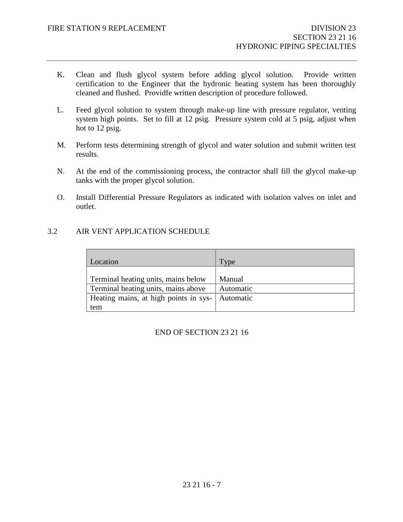
FIRE STATION 9 REPLACEMENT DIVISION 23
SECTION 23 21 16
HYDRONIC PIPING SPECIALTIES
23 21 16 - 7
K. Clean and flush glycol system before adding glycol solution. Provide written
certification to the Engineer that the hydronic heating system has been thoroughly
cleaned and flushed. Providfe written description of procedure followed.
L. Feed glycol solution to system through make-up line with pressure regulator, venting
system high points. Set to fill at 12 psig. Pressure system cold at 5 psig, adjust when
hot to 12 psig.
M. Perform tests determining strength of glycol and water solution and submit written test
results.
N. At the end of the commissioning process, the contractor shall fill the glycol make-up
tanks with the proper glycol solution.
O. Install Differential Pressure Regulators as indicated with isolation valves on inlet and
outlet.
3.2 AIR VENT APPLICATION SCHEDULE
Location Type
Terminal heating units, mains below Manual
Terminal heating units, mains above Automatic
Heating mains, at high points in sys-
tem
Automatic
END OF SECTION 23 21 16
FIRE STATION 9 REPLACEMENT DIVISION 23
SECTION 23 21 23
HYDRONIC PUMPS
23 21 23 - 1
PART 1 - GENERAL
1.1 RELATED DOCUMENTS
A. Drawings and general provisions of the Contract, including Municipality of Anchorage
Standard Specifications – Buildings (MASSB), General and Supplementary Conditions
apply to this Section.
1.2 SECTION INCLUDES
A. In-Line Circulators.
B. Vertical In-Line Pumps With Integral Variable Speed Drives.
1.3
A.
B.
C.
D.
RELATED SECTIONS
Section 23 05 13 - Common Motor Requirements for HVAC Equipment.
Section 23 05 48 - Vibration and Seismic Controls for HVAC Piping and Equipment.
Section 23 21 13 – Hydronic Piping
Section 23 21 16 - Hydronic Piping Specialties.
1.4 REFERENCES
A. National Electrical Manufacturers Association:
1. NEMA 250 - Enclosures for Electrical Equipment (1000 Volts Maximum).
B. Underwriters Laboratories Inc.:
1. UL 778 - Motor Operated Water Pumps.
FIRE STATION 9 REPLACEMENT DIVISION 23
SECTION 23 21 23
HYDRONIC PUMPS
23 21 23 - 2
1.5 QUALITY ASSURANCE
A. Manufacturer: Company specializing in manufacture, assembly, and field performance
of pumps with minimum three years experience.
B. Alignment: Base mounted pumps shall be aligned by qualified millwright and
alignment certified.
1.6 SUBMITTALS
A. Under provisions of the Supplementary Conditions.
B. Submit certified pump curves showing performance characteristics with pump and
system operating point plotted. Include NPSH curve when applicable.
1.7 OPERATION AND MAINTENANCE DATA
A. Submit operation and maintenance data under provisions of Supplementary Conditions.
B. Include installation instructions, assembly views, lubrication instructions, and
replacement parts list.
1.8 DELIVERY, STORAGE, AND HANDLING
A. Deliver, store. and protect products under the provisions of the Supplementary
Conditions.
1.9 EXTRA PARTS
A. Provide one extra set of mechanical seals for pumps where applicable.
PART 2 - PRODUCTS
2.1 ACCEPTABLE MANUFACTURERS - IN-LINE CIRCULATORS
A. Grundfos.
B. No Substitutions.
FIRE STATION 9 REPLACEMENT DIVISION 23
SECTION 23 21 23
HYDRONIC PUMPS
23 21 23 - 3
2.2 IN-LINE CIRCULATORS
A. Type: Maintenance free, self-lubricated, 3 speed industrial/commercial single stage, di-
rect drive circulator.
B. Casing: Cast iron.
C. Impeller: Type 304 stainless steel.
D. Bearings: Upper and lower radial bearings to be aluminum oxide ceramic, tungsten car-
bide shaft bearing surfaces.
E. Shaft: Stainless steel with type 430F.
2.3 VERTICAL IN-LINE PUMPS WITH INTEGRAL VARIABLE SPEED DRIVE
A. The pumps shall be of the single stage, in-line design with suction and discharge port
flanges of identical diameter.
B. The head-capacity curve shall have a steady rise in head from maximum to minimum
flow within the preferred operating region.
C. The pump housing shall have a stainless steel/teflon neck ring to minimize recirculation
and increase pump efficiency.
D. The impellers shall be laser welded stainless to obtain maximum efficiency. Cast impel-
lers and composite material shall not be acceptable. The impellers shall be secured to
the shaft with a split cone and a nut.
E. The suction and discharge flanges shall be tapped and drilled (1/4" NPT) to allow gauge
installation on the pump.
F. The pump shall have unbalanced mechanical seal. The mechanical seal shall be manu-
factured by the same manufacturer. The seal faces shall be tungsten carbide/carbon with
EPDM rubber bellows. ( For glycol applications reduced face o-ring seal with tungsten
carbide vs. tungsten carbide faces shall be used)
G. Pump Construction: Pump housing and motor stool - Cast iron EN-JL-1040; Impel-
lers, rotor can, rotor cladding - 304 Stainless Steel; Shaft - 431 Stainless Steel; Cou-
pling - Cast iron, 2 piece rigid coupling; Coupling guard - 304 stainless steel; Vent
screw - Brass.
H. For open loop applications pump housing and motor adapter shall be bronze.
FIRE STATION 9 REPLACEMENT DIVISION 23
SECTION 23 21 23
HYDRONIC PUMPS
23 21 23 - 4
I. All pumps shall be tested per ISO 9906 Annex A.
J. Pump housing and pump adapter shall be electro coated high corrosion resistance and
paint shall be cured at minimum 375 Degree F.
K. Motor: Each motor shall be of the asynchronous squirrel cage design and tested with the
pump as one unit by the same manufacturer. The motor enclosure shall be TEFC. The
motor insulation shall be Class F with temperature rise of Class B.
L. Integrated Variable Speed Drive: The VSD shall be designed and manufactured by the
same manufacturer as the pump. The VSD shall be factory installed on the motor. The
VSD enclosure class shall be IP44. The VSD shall have the human interface options of:
1. Control panel on the VSD face
2. Building Automation Systems Interface
3. The VSD shall be able controlled by the signals from a single sensor. The ac-
ceptable sensors signal is 4 to 20 mA. or 10-10 VDC signals.
4. VSD shall allow one digital input and one set point input.
PART 3 - EXECUTION
3.1 INSTALLATION
A. Install pumps in accordance with manufacturer's instructions.
B. The contractor shall field inspect, test, adjust, and balance the pump flows as per the
manufacturers’ instructions.
C. Provide access space around pumps for service. Provide no less than minimum as rec-
ommended by manufacturer.
D. Ensure pumps operate at specified system fluid temperatures without vapor binding and
cavitation, are non-overloading in parallel or individual operation, and operate within
25 percent of midpoint of published maximum efficiency curve.
E. Decrease from line size with long radius reducing elbows or reducers.
F. Support piping adjacent to pump such that no weight is carried on pump casings. In-
line pumps are supported by adjacent piping.
G. Bleed pump of air before start-up.
END OF SECTION 23 21 23
FIRE STATION 9 REPLACEMENT DIVISION 23
SECTION 23 31 00
HVAC DUCTS AND CASINGS
23 31 00 - 1
PART 1 - GENERAL
1.1 RELATED DOCUMENTS
A. Drawings and general provisions of the Contract, including Municipality of Anchorage
Standard Specifications – Buildings (MASSB), General and Supplementary Conditions
apply to this Section.
1.2 SECTION INCLUDES
A. Flexible Ductwork.
B. Low Pressure Ductwork.
1.3 RELATED WORK
A. Section 23 05 29 – Hanger and Supports for HVAC Piping and Equipment.
B. Section 23 05 93 - Testing, Adjusting and Balancing for HVAC.
C. Section 23 07 00 – HVAC Insulation.
D. Section 23 33 00 – Air Duct Accessories.
E. Section 23 37 00 - Air Outlets and Inlets.
1.4 REFERENCES
A. ASTM International:
1. ASTM A36/A36M - Standard Specification for Carbon Structural Steel.
2. ASTM A90/A90M - Standard Test Method for Weight Mass of Coating on Iron
and Steel Articles with Zinc or Zinc-Alloy Coatings.
3. ASTM A167 - Standard Specification for Stainless and Heat-Resisting
Chromium-Nickel Steel Plate, Sheet, and Strip.
4. ASTM A568/A568M - Standard Specification for Steel, Sheet, Carbon, and High-
Strength, Low-Alloy, Hot-Rolled and Cold-Rolled, General Requirements for.
5. ASTM A653/A653M - Standard Specification for Steel Sheet, Zinc-Coated
(Galvanized) or Zinc-Iron Alloy-Coated (Galvannealed) by the Hot-Dip Process.
FIRE STATION 9 REPLACEMENT DIVISION 23
SECTION 23 31 00
HVAC DUCTS AND CASINGS
23 31 00 - 2
6. ASTM A1008/A1008M - Standard Specification for Steel, Sheet, Cold-Rolled,
Carbon, Structural, High-Strength Low-Alloy and High-Strength Low-Alloy with
Improved Formability.
7. ASTM A1011/A1011M - Standard Specification for Steel, Sheet and Strip, Hot-
Rolled, Carbon, Structural, High-Strength Low-Alloy and High-Strength Low-
Alloy with Improved Formability.
8. ASTM B209 - Standard Specification for Aluminum and Aluminum-Alloy Sheet
and Plate.
9. ASTM E84 - Standard Test Method for Surface Burning Characteristics of
Building Materials.
B. National Fire Protection Association:
1. NFPA 90A - Standard for the Installation of Air Conditioning and Ventilating
Systems.
2. NFPA 90B - Standard for the Installation of Warm Air Heating and Air
Conditioning Systems.
3. NFPA 96 - Standard for Ventilation Control and Fire Protection of Commercial
Cooking Operations.
C. Sheet Metal and Air Conditioning Contractors:
1. SMACNA - HVAC Air Duct Leakage Test Manual.
2. SMACNA - HVAC Duct Construction Standard - Metal and Flexible.
D. Underwriters Laboratories Inc.:
1. UL 181 - Factory-Made Air Ducts and Connectors.
1.5 DEFINITIONS
A. Duct Sizes: Inside clear dimensions. For lined ducts, maintain sizes inside lining.
B. Low Pressure: Three pressure classifications: ½ inch WG positive or negative static
pressure and velocities less than 2,000 fpm; 1 inch WG positive or negative static
pressure and velocities less than 2,500 fpm and 2 inch WG positive or negative static
pressure and velocities less than 2,500 fpm.
1.6 REGULATORY REQUIREMENTS
A. Construct ductwork to NFPA 90A and NFPA 90B standards.
FIRE STATION 9 REPLACEMENT DIVISION 23
SECTION 23 31 00
HVAC DUCTS AND CASINGS
23 31 00 - 3
1.7 SUBMITTALS
A. Submit product data under the provisions of the Supplementary Conditions.
1.8 DELIVERY, STORAGE, AND HANDLING
A. Deliver products to site under provisions of the Supplementary Conditions.
B. Store and protect products under provisions of the Supplementary Conditions.
PART 2 - PRODUCTS
2.1 MATERIALS
A. General: Non-combustible or conforming to requirements for Class 1 air duct materials,
or UL 181.
B. Steel Ducts: ASTM A527 galvanized steel sheet, lock-forming quality, having zinc
coating of 1.25 oz. per sq. ft. for each side in conformance with ASTM A90.
C. Fasteners: Rivets, bolts, or sheet metal screws.
D. Sealant: Water based, Non-VOC, non-hardening, water resistant, fire resistive,
compatible with mating materials; liquid used alone or with tape.
E. Hanger Rod: Steel, galvanized; threaded both ends, threaded one end, or continuously
threaded.
2.2 FLEXIBLE DUCTWORK
A. Construction: Embedded fiberglass scrim vapor barrier between layers of polyester.
Perm rating of 0.04 (ASTM E96 Method “A”).
B. Surface Burning Characteristics: Flame/Smoke 25/50 - ASTM E84
C. Operating Temperature Range: -20 Degree F to 140 degree F continuous @ maximum
positive pressure. –20 degree F to 180 degree F intermittent @ 2 inches W.C. positive
pressure. -20 degree F to 250 degree F intermittent @ 0.5 inch W.C. positive pressure.
D. Core Rating: 10-inch W.C. positive, 1/2 inch W.C. negative pressure.
FIRE STATION 9 REPLACEMENT DIVISION 23
SECTION 23 31 00
HVAC DUCTS AND CASINGS
23 31 00 - 4
E. Approvals: UL 181, NFPA 90A and 90B.
2.3 LOW PRESSURE DUCTWORK
A. Fabricate and support in accordance with SMACNA HVAC Duct Construction
Standards and ASHRAE handbooks, except as indicated. Provide duct material,
gauges, reinforcing, and sealing for operating pressures indicated.
B. Size round ducts installed in place of rectangular ducts in accordance with ASHRAE
table of equivalent rectangular and round ducts. No variation of duct configuration or
sizes permitted except by written permission.
C. Construct T's, bends, and elbows with radius of not less than 1-½ times width of duct on
centerline. Where not possible and where rectangular elbows are used, provide air foil
turning vanes. Where acoustical lining is indicated, provide turning vanes of perforated
metal with glass fiber insulation.
D. Increase duct sizes gradually, not exceeding 15º divergence wherever possible.
Divergence upstream of equipment shall not exceed 30º; convergence downstream shall
not exceed 45º.
E. Provide easements where low pressure ductwork conflicts with piping and structure.
Where easements exceed 10 percent duct area, split into two ducts maintaining original
duct area.
F. Connect flexible ducts to metal ducts with draw bands.
G. Use crimp joints with or without bead for joining round duct sizes 12 inch and smaller
with crimp in direction of air flow.
H. Use double nuts and lock washers on threaded rod supports, provide acorn nut where
exposed in finished spaces.
PART 3 - EXECUTION
3.1 INSTALLATION
A. Provide openings in ductwork where required to accommodate thermometers and
controllers. Provide pitot tube openings where required for testing of systems, complete
with metal can with spring device or screw to ensure against air leakage. Where
openings are provided in insulated ductwork, install insulation material inside a metal
ring.
FIRE STATION 9 REPLACEMENT DIVISION 23
SECTION 23 31 00
HVAC DUCTS AND CASINGS
23 31 00 - 5
B. Locate ducts with sufficient space around equipment to allow normal operating and
maintenance activities.
C. Connect diffusers to low pressure ducts with five (5) feet maximum length of flexible
duct. Hold in place with strap or clamp.
D. During construction provide temporary closures of metal or taped polyethylene on open
ductwork to prevent construction dust from entering ductwork system.
E. Install pre-insulated flexible duct free of kinks and sharp turns (Minimum R=1.5xduct
Diameter).
3.2 DUCTWORK APPLICATION SCHEDULE
Air System Material
Low Pressure Supply Steel
Return and Relief Steel
General Exhaust Steel
Outside Air Intake Steel
Combustion Air Steel
END OF SECTION 23 31 00
FIRE STATION 9 REPLACEMENT DIVISION 23
SECTION 23 33 00
AIR DUCT ACCESSORIES
23 33 00 - 1
PART 1 - GENERAL
1.1 RELATED DOCUMENTS
A. Drawings and general provisions of the Contract, including Municipality of Anchorage
Standard Specifications – Buildings (MASSB), General and Supplementary Conditions
apply to this Section.
1.2 SECTION INCLUDES
A. Volume Control Dampers.
B. Control Dampers.
C. Backdraft Dampers.
D. Air Turning Devices.
E. Flexible Duct Connections.
F. Duct Access Doors.
G. Duct Test Holes.
H. Turning Vanes.
1.3 RELATED WORK
A. Section 23 05 48 – Vibration and Seismic Controls for HVAC.
B. Section 23 31 00 – HVAC Ducts and Casings.
1.4 REFERENCES
A. Air Movement and Control Association International, Inc.:
1. AMCA 500 - Test Methods for Louvers, Dampers, and Shutters.
2. ASTM International:
3. ASTM E1 - Standard Specification for ASTM Thermometers.
FIRE STATION 9 REPLACEMENT DIVISION 23
SECTION 23 33 00
AIR DUCT ACCESSORIES
23 33 00 - 2
B. National Fire Protection Association:
1. NFPA 90A - Standard for the Installation of Air Conditioning and Ventilating
Systems.
2. NFPA 92A - Recommended Practice for Smoke-Control Systems.
C. Sheet Metal and Air Conditioning Contractors:
1. SMACNA - HVAC Duct Construction Standard - Metal and Flexible.
D. Underwriters Laboratories Inc.:
1. UL 555 - Standard for Safety for Fire Dampers.
2. UL 555C - Standard for Safety for Ceiling Dampers.
1.5 SUBMITTALS
A. Submit product data under provisions of the Supplementary Conditions.
B. Submit manufacturer's installation instructions under provisions of the Supplementary
Conditions.
PART 2 - PRODUCTS
2.1 VOLUME CONTROL DAMPERS.
A. Fabricate in accordance with SMACNA HVAC Duct Construction Standards, and as
indicated.
B. Fabricate splitter dampers of material same gauge as duct to 24 inches size in either
direction, and two gauges heavier for sizes over 24 inches.
C. Fabricate splitter dampers of single thickness sheet metal to streamline shape. Secure
blade with continuous hinge or rod. Operate with minimum 1/4 inch diameter rod in
self aligning, universal joint action flanged bushing with set screw.
D. Fabricate single blade dampers for duct sizes to 9-1/2 x 30 inch.
E. Fabricate multi-blade damper of opposed blade pattern with maximum blade sizes 12 x
72 inch. Assemble center and edge crimped blades in prime coated or galvanized
channel frame with suitable hardware.
FIRE STATION 9 REPLACEMENT DIVISION 23
SECTION 23 33 00
AIR DUCT ACCESSORIES
23 33 00 - 3
F. Except in round ductwork 12 inches and smaller, provide end bearings. On multiple
blade dampers, provide oil-impregnated nylon or sintered bronze bearings.
G. On insulated ducts mount quadrant regulators on stand-off mounting brackets, bases, or
adapters.
2.2 ACCEPTABLE MANUFACTURERS – CONTROL DAMPERS
A. Ruskin.
B. Greenheck.
C. Louvers and Dampers, Inc.
D. Substitutions: Under provisions of the Supplementary Conditions.
2.3 CONTROL DAMPERS
A. Multi-blade, Opposed blade action, control dampers of extruded aluminum, with airfoil
type blades of maximum six inch width, blades positioned across short air opening
dimension, field replaceable extruded vinyl sealed edges, linked together in rattle-free
manner, non-corrosive molded synthetic bearings, square or hexagonal axles for
positive locking connection to blades and linkage, with documented leakage rate not to
exceed 6 CFM/sq. ft. at 4 inch W.G.
2.4 ACCEPTABLE MANUFACTURERS - BACKDRAFT DAMPERS
A. Ruskin.
B. Greenheck.
C. Substitutions: Under provisions of the Supplementary Conditions.
2.5 BACKDRAFT DAMPERS
A. Gravity backdraft dampers, size 18 x 18 inches or smaller, furnished with air moving
equipment, may be air moving equipment manufacturer’s standard construction.
B. Fabricate multi-blade, parallel action gravity balanced backdraft dampers of 16 gauge
galvanized steel, or extruded aluminum, with center pivoted blades of maximum 6 inch
width, with felt or flexible vinyl sealed edges, linked together in rattle-free manner with
FIRE STATION 9 REPLACEMENT DIVISION 23
SECTION 23 33 00
AIR DUCT ACCESSORIES
23 33 00 - 4
90 degree stop, steel ball bearings, and plated steel pivot pin; adjustment device to
permit setting for varying differential static pressure.
2.6 ACCEPTABLE MANUFACTURERS - AIR TURNING DEVICES
A. Duro-Dyne.
B. Substitutions: Under provisions of the Supplementary Conditions.
2.7 AIR TURNING DEVICES
A. Double Width: Air foil design double width galvanized turning vanes with 2 inch inside
radius.
B. Single Width: Single galvanized turning vane with 2 inch radius and minimum 1"
trailing straight leg.
C. Acoustical Vanes: Double width vanes with inner vane of perforated galvanized steel
with 3/32 inch holes on 5/32 inch spacing. Fill space between vanes with minimum
1.5 lb/cu ft glass fiber duct liner.
2.8 ACCEPTABLE MANUFACTURERS - FLEXIBLE DUCT CONNECTIONS
A. Duro-Dyne.
B. Substitutions: Under provisions of the Supplementary Conditions.
2.9 FLEXIBLE DUCT CONNECTIONS
A. Fabricate in accordance with SMACNA HVAC Duct Construction Standards, and as
indicated.
B. UL listed fire-retardant neoprene coated woven glass fiber fabric to NFPA 90A,
minimum density 20 oz. per sq. yd., approximately 3 inches wide, crimped into metal
edging strip.
C. Leaded vinyl sheet, minimum 0.55 inch thick, 0.87 lbs. per sq. ft., 10 dB attenuation in
10 to 10,000 Hz range.
2.10 ACCEPTABLE MANUFACTURERS - DUCT ACCESS DOORS
A. Ruskin.
FIRE STATION 9 REPLACEMENT DIVISION 23
SECTION 23 33 00
AIR DUCT ACCESSORIES
23 33 00 - 5
B. Greenheck.
C. Duro-Dyne.
D. Substitutions: Under provisions of the Supplementary Conditions.
2.11 DUCT ACCESS DOORS
A. Fabricate in accordance with SMACNA HVAC Duct Construction Standards and as
indicated.
B. Review locations prior to fabrication.
C. Fabricate rigid and close-fitting doors of galvanized steel with sealing gaskets and quick
fastening locking devices. For insulated ductwork, install minimum one inch thick
insulation with sheet metal cover.
D. Access doors smaller than 12 inches square may be secured with sash locks.
E. Provide two hinges and two sash locks for sizes up to 18 inches square, three hinges and
two compression latches with outside and inside handles for sizes up to 24 x 48 inches.
Provide an additional hinge for larger sizes.
F. Access doors with sheet metal screw fasteners are not acceptable.
2.12 DUCT TEST HOLES
A. Cut or drill temporary test holes in ducts as required. Cap with neat patches, neoprene
plugs, threaded plugs, or threaded or twist-on metal caps.
B. Permanent test holes shall be factory fabricated, air tight flanged fittings with screw
cap. Provide extended neck fittings to clear insulation.
PART 3 - EXECUTION
3.1 INSTALLATION
A. Install accessories in accordance with manufacturer's instructions.
B. Provide balancing dampers at points on low pressure supply, return, and exhaust
systems where branches are taken from larger ducts as required for air balancing. Use
splitter dampers only where indicated. Locate dampers a minimum 15 feet upstream of
all air inlets and outlets.
FIRE STATION 9 REPLACEMENT DIVISION 23
SECTION 23 33 00
AIR DUCT ACCESSORIES
23 33 00 - 6
C. Provide backdraft dampers on exhaust fans or exhaust ducts nearest to outside and
where indicated.
D. Provide flexible connections immediately adjacent to equipment in ducts associated
with fans and motorized equipment. Cover connections to medium and high pressure
fans with leaded vinyl sheet, held in place with metal straps.
E. Provide duct access doors for inspection and cleaning before and after filters, coils,
fans, automatic dampers, at fire dampers, and elsewhere as indicated. Provide
minimum 8 x 8 inch size for hand access, 18 x 18 inch size for shoulder access, and as
indicated.
F. Provide duct test holes where indicated and required for testing and balancing purposes.
G. Provide double width turning vanes at all constant cross-section rectangular duct elbows
at 2" spacing across elbow diagonal. Provide at rectangular reducing elbows single
width turning vanes with trailing edge sat 2" spacing across elbow diagonal.
H. Provide acoustical turning vanes at 2" spacing across elbow diagonal where indicated.
END OF SECTION 23 33 00
FIRE STATION 9 REPLACEMENT DIVISION 23
SECTION 23 34 13
AXIAL HVAC FANS
23 34 13 - 1
PART 1 - GENERAL
1.1 RELATED DOCUMENTS
A. Drawings and general provisions of the Contract, including Municipality of Anchorage
Standard Specifications – Buildings (MASSB), General and Supplementary Conditions
apply to this Section.
1.2 SECTION INCLUDES
A. Axial Fans.
1.3 RELATED WORK
A. Section 23 31 00 – HVAC Ducts and Casings.
B. Section 23 33 00 – Air Duct Accessories.
1.4 REFERENCES
A. Air Movement and Control Association International, Inc.:
1. AMCA 99 - Standards Handbook.
B. National Electrical Manufacturers Association:
1. NEMA MG 1 - Motors and Generators.
2. NEMA 250 - Enclosures for Electrical Equipment (1000 Volts Maximum).
1.5 QUALITY ASSURANCE
A. Performance Ratings: Conform to AMCA 210 and bear AMCA Certified Rating Seal.
B. Sound Ratings: AMCA 301, tested to AMCA 300, and bear AMCA Certified Sound
Rating Seal.
C. UL Compliance: UL listed and labeled, designed, manufactured, and tested in
accordance with UL 705.
FIRE STATION 9 REPLACEMENT DIVISION 23
SECTION 23 34 13
AXIAL HVAC FANS
23 34 13 - 2
1.6 SUBMITTALS
A. Submit product data under provisions of the Supplementary Conditions..
B. Provide product data on axial fans and accessories as required for the work.
C. Provide fan curves with specified operating point clearly plotted.
1.7 OPERATION AND MAINTENANCE DATA
A. Submit operation and maintenance data under provisions of the Supplementary
Conditions.
1.8 DELIVERY, STORAGE, AND HANDLING
A. Deliver products to site under provisions of the Supplementary Conditions..
B. Store and protect products under provisions of the Supplementary Conditions..
C. Protect motors, shafts, and bearings from weather and construction dust.
PART 2 - PRODUCTS
2.1 ACCEPTABLE MANUFACTURERS – AXIAL FANS
A. Cook.
B. Greenheck.
C. Acme.
D. Substitutions: Under provisions of the Supplementary Conditions.
2.2 AXIAL FANS
A. Construction: Fan shall be of bolted and welded construction utilizing corrosion
resistant fasteners. The motor shall be mounted on a 12 gauge steel wire guard. The
wire guard shall be bolted to a minimum 14 gauge wall panel with continuously welded
corners and an integral venturi. Unit shall bear an engraved aluminum nameplate.
Nameplate shall indicate design CFM and static pressure.
FIRE STATION 9 REPLACEMENT DIVISION 23
SECTION 23 34 13
AXIAL HVAC FANS
23 34 13 - 3
B. Coating: All steel fan components shall coated with an electrostatically applied, baked
polyester powder coating. Each component shall be subject to a five stage
environmentally friendly wash system, followed by a minimum 2 mil thick baked
powder finish. Paint must exceed 1,000 hour salt spray under ASTM B117 test method.
C. Motor shall be open drip proof type with permanently lubricated sealed bearings.
D. Propeller: Propeller shall have aluminum blades riveted to a painted steel hub. The
hub shall be securely fastened to the motor shaft utilizing two setscrews. Propeller shall
be balanced in accordance with AMCA Standard 204-96, Balance Quality and
Vibration Levels for Fans.
2.3 ACCEPTABLE MANUFACTURERS - COMMERCIAL CEILING FANS
A. Leading Edge
B. Substitutions: Under provisions of the Supplementary Conditions..
2.4 CEILING FANS
A. Impeller: Aerodynamically contoured aluminum blades. White epoxy enamel paint
over electrostatically applied epoxy powder primer. Heavy cast aluminum housing,
statically and dynamically balanced with blades.
B. Rotor/Stator: High grade cold-rolled carbon steel laminations, precision balanced,
varnished dipped. Self-aligning permanently-lubricated chrome steel ball bearings
affixed to shaft. U.L. required thermal protector, non-polar weatherproof encapsulated
PCB free capacitor.
C. Frame: Steel yoke, down-rod, locknut and pin with cover. Heavy duty upper shackle
with lock nuts and pins and rubber bushing.
D. Accessory: Solid state, U.L. listed on-off-variable speed controller.
E. Safety Devices:
1. Factory installed safety cable connected to motor shaft, minimum six feet
galvanized cable 3/8" 7x7 with rated breaking strength of 920 lbs. in compliance
with CSA Std. C22.2
2.5 EXECUTION
A. Install fans in accordance with manufacturer's instructions.

FIRE STATION 9 REPLACEMENT DIVISION 23
SECTION 23 34 13
AXIAL HVAC FANS
23 34 13 - 4
END OF SECTION 23 34 13
FIRE STATION 9 REPLACEMENT DIVISION 23
SECTION 23 34 23
HVAC POWER VENTILATORS
23 34 23 - 1
PART 1 - GENERAL
1.1 RELATED DOCUMENTS
A. Drawings and general provisions of the Contract, including Municipality of Anchorage
Standard Specifications – Buildings (MASSB), General and Supplementary Conditions
apply to this Section.
1.2 SECTION INCLUDES
A. Up-blast Centrifugal Exhaust Ventilators.
1.3 RELATED WORK
A. Section 23 05 48 - Vibration and Seismic Controls for HVAC Piping and Equipment.
B. Section 23 07 00 – HVAC Insulation.
C. Section 23 09 23 – Direct Digital Control System for HVAC.
D. Section 23 31 00 – HVAC Ducts and Casing.
E. Section 23 33 00 – Air Duct Accessories.
1.4 REFERENCES
A. American Bearing Manufacturers Association:
1. ABMA 9 - Load Ratings and Fatigue Life for Ball Bearings.
2. ABMA 11 - Load Ratings and Fatigue Life for Roller Bearings.
B. Air Movement and Control Association International, Inc.:
1. AMCA 99 - Standards Handbook.
2. AMCA 204 - Balance Quality and Vibration Levels for Fans.
3. AMCA 210 - Laboratory Methods of Testing Fans for Aerodynamic Performance
Rating.
4. AMCA 300 - Reverberant Room Method for Sound Testing of Fans.
FIRE STATION 9 REPLACEMENT DIVISION 23
SECTION 23 34 23
HVAC POWER VENTILATORS
23 34 23 - 2
5. AMCA 301 - Methods for Calculating Fan Sound Ratings from Laboratory Test
Data.
C. National Electrical Manufacturers Association:
1. NEMA MG 1 - Motors and Generators.
D. NEMA 250 - Enclosures for Electrical Equipment (1000 Volts Maximum).
1.5 QUALITY ASSURANCE
A. Performance Ratings: Conform to AMCA 210 and bear AMCA Certified Rating Seal.
B. Sound Ratings: AMCA 301, tested to AMCA 300, and bear AMCA Certified Sound
Rating Seal.
C. UL Compliance: UL listed and labeled, designed, manufactured, and tested in
accordance with UL 705.
1.6 SUBMITTALS
A. Submit product data under provisions of the Supplementary Conditions.
B. Provide product data on centrifugal fans and accessories as required for the work.
C. Provide fan curves with specified operating point clearly plotted.
D. Submit sound power levels for both fan inlet and outlet at rated capacity. Sound power
levels for the submitted product shall not exceed the sound power levels of the specified
equipment.
1.7 OPERATION AND MAINTENANCE DATA
A. Submit operation and maintenance data under provisions of the Supplementary
Conditions.
1.8 DELIVERY, STORAGE, AND HANDLING
A. Deliver products to site under provisions of the Supplementary Conditions.
B. Store and protect products under provisions of the Supplementary Conditions.
C. Protect motors, shafts, and bearings from weather and construction dust.
FIRE STATION 9 REPLACEMENT DIVISION 23
SECTION 23 34 23
HVAC POWER VENTILATORS
23 34 23 - 3
PART 2 - PRODUCTS
2.1 ACCEPTABLE MANUFACTURERS
A. Cook.
B. Greenheck
C. Acme.
D. Substitutions: Under provisions of the Supplementary Conditions.
2.2 UP-BLAST CENTRIFUGAL EXHAUST VENTILATORS.
A. Construction: The fan shall be of bolted and welded construction utilizing corrosion
resistant fasteners. The spun aluminum structural components shall be constructed of
minimum 16 gauge marine alloy aluminum, bolted to a rigid aluminum support
structure. The aluminum base shall have a one piece inlet spinning and continuously
welded curb cap corners for maximum leak protection. The windband shall have a
rolled bead for added strength. A two piece top cap shall have stainless steel quick
release latches to provide access into the motor compartment without the use of tools.
An integral conduit chase shall be provided into the motor compartment to facilitate
wiring connections. The motor, bearings and drives shall be mounted on a minimum 14
gauge steel power assembly, isolated from the unit structure with rubber vibration
isolators. These components shall be enclosed in a weather-tight compartment,
separated from the exhaust airstream. Lifting lugs shall be provided to help prevent
damage from improper lifting. Unit shall bear an engraved aluminum nameplate.
Nameplate shall indicate design CFM, static pressure, and maximum fan RPM.
B. Wheel: Wheel shall be centrifugal backward inclined, constructed of 100 percent
aluminum, including a precision machined cast aluminum hub. Wheel inlet shall
overlap an aerodynamic aluminum inlet cone to provide maximum performance and
efficiency. Wheel shall be balanced in accordance with AMCA Standard 204-96,
Balance Quality and Vibration Levels for Fans.
C. Motor: Motor shall be heavy duty type with permanently lubricated sealed ball bearings
and furnished at the specified voltage, phase and enclosure.
D. Bearings: Bearings shall be designed and individually tested specifically for use in air
handling applications. Construction shall be heavy duty re-greasable ball type in a cast
iron pillow block housing selected for a minimum L50 life in excess of 200,000 hours at
maximum cataloged operating speed.
FIRE STATION 9 REPLACEMENT DIVISION 23
SECTION 23 34 23
HVAC POWER VENTILATORS
23 34 23 - 4
E. Belts: Belts shall be oil and heat resistant, non-static, arctic grade.
F. Drives: Drives shall be precision machined cast iron type, keyed and securely attached
to the wheel and motor shafts. Drives shall be sized for 150 percent of the installed
motor horsepower. The variable pitch motor drive must be factory set to the specified
fan RPM.
PART 3 - EXECUTION
3.1 INSTALLATION
A. Provide insulated sheet metal curbs
B. Install fans in accordance with manufacturer's instructions.
END OF SECTION 23 34 23
FIRE STATION 9 REPLACEMENT DIVISION 23
SECTION 23 37 00
AIR OUTLETS AND INLETS
23 37 00 - 1
PART 1 - GENERAL
1.1 RELATED DOCUMENTS
A. Drawings and general provisions of the Contract, including Municipality of Anchorage
Standard Specifications – Buildings (MASSB), General and Supplementary Conditions
apply to this Section.
1.2 WORK INCLUDED
A. Diffusers.
B. Registers/Grilles.
C. Louvers.
1.3 REFERENCES
A. Air Movement and Control Association International, Inc.
B. AMCA 500 - Test Methods for Louvers, Dampers, and Shutters.
C. American Society of Heating, Refrigerating and Air-Conditioning Engineers:
D. ASHRAE 70 - Method of Testing for Rating the Performance of Air Outlets and Inlets.
E. Sheet Metal and Air Conditioning Contractors:
F. SMACNA - HVAC Duct Construction Standard - Metal and Flexible.
1.4 QUALITY ASSURANCE
A. Test and rate diffuser, register, and grille performance in accordance with ASHRAE 70.
B. Test and rate louver performance in accordance with AMCA 500.
FIRE STATION 9 REPLACEMENT DIVISION 23
SECTION 23 37 00
AIR OUTLETS AND INLETS
23 37 00 - 2
1.5 REGULATORY REQUIREMENTS
A. Conform to ANSI/NFPA 90A.
1.6 SUBMITTALS
A. Submit product data under provisions of the Supplementary Conditions.
B. Provide product data for items required for this project.
C. Review requirements of outlets and inlets as to size, finish, and type of mounting prior
to submitting product data.
PART 2 - PRODUCTS
2.1 ACCEPTABLE MANUFACTURERS – DIFFUSERS AND GRILLES
A. Titus.
B. Price.
C. American Aldes.
D. Substitutions: Under provisions of the Supplementary Conditions.
2.2 ROUND CONE (TYPE A)
A. Supply/Exhaust.
B. Fully adjustable for variable airflow capacity.
C. Rotating center-adjustment cone.
D. Durable white plastic (polypropylene co-polymer with HB UL rating).
2.3 SQUARE CEILING DIFFUSERS (TYPE B)
A. Construction: Fabricate of steel with rectangular, stamped, multi-cone type diffuser to
discharge air in 360 degree pattern, adjustable.
FIRE STATION 9 REPLACEMENT DIVISION 23
SECTION 23 37 00
AIR OUTLETS AND INLETS
23 37 00 - 3
B. Provide frame type to match ceiling construction. Provide with earthquake tabs for
seismic restraint for all lay-in ceiling installations.
C. Provide sectorizing baffles to adjust diffusion pattern as indicated.
D. Finish: Off-White.
E. Size: 24”x24” face.
2.4 ROUND CEILING DIFFUSERS (TYPE C)
A. The round ceiling diffuser shall have three round cones and round neck inlets of the
sizes and mounting types shown on the plans and outlet schedule. Two horizontal
discharge settings shall allow the diffuser to be field adjusted for different flow rate
conditions. The two inner cones must be easily removable as a unit using a spring lock
mechanism.
B. Round diffuser shall be constructed of 18 gauge steel. The finish shall be #26 white.
The finish shall be an anodic acrylic paint, baked at 315°F for 30 minutes. The pencil
hardness must be HB to H.
C. The paint must pass a 100-hour ASTM B117 Corrosive Environments Salt Spray Test
without creepage, blistering or deterioration of film. The paint must pass a 250-hour
ASTM D870 Water Immersion Test. The paint must also pass the ASTM D2794
Reverse Impact Cracking Test with a 50-inch pound force applied.
D. Finish: Off-White.
E. The diffuser shall be tested in accordance with ANSI/ASHRAE Standard 70-1991.
2.5 ROUND DUCT MOUNTED DIFFUSERS (TYPE D)
A. Heavy duty ring operated diffusers constructed of 18-gauge steel with a contoured outer
cone to guard against ceiling smudging and an inner vane assembly. The airflow
discharge pattern shall be field adjustable from horizontal to vertical by rotating a ring
operator to open (vertical discharge) or close (horizontal discharge) the inner vane
assembly. The inner vane assembly must be easily removable as a unit. The ring
operator shall be adjustable with a pole for remote access.
B. Finish: Off White.
FIRE STATION 9 REPLACEMENT DIVISION 23
SECTION 23 37 00
AIR OUTLETS AND INLETS
23 37 00 - 4
2.6 EGGCRATE RETURN/EXHAUST GRILL (TYPE E)
A. Construction: Eggcrate return grilles boarders shall be constructed of heavy extruded
aluminum with a thickness of 0.040-0.050 inch, the border width shall be 1-1/4 inches
on all sides and shall be interlocked at the four corners and mechanically staked to form
a rigid frame. The aluminum grid shall be 1/2 x 1/2 x 1/2 inch and must provide a free
area of at least 90%.
B. Provide frame type to match ceiling construction. Provide with earthquake tabs for
seismic restraint for all lay-in ceiling.
C. Finish: Off-White.
2.7 HEAVY DUTY BAR GRILLE (TYPE F)
A. Construction: Steel return bar grilles shall be constructed of steel with a 1-1/4-inch
border width on all sides and a minimum border gauge thickness of 16; bars shall be 14-
gauge steel. Bars shall be reinforced by perpendicular, steel support bars spaced on 6-
inch maximum centers. Corners shall be welded with full penetration welds and
reinforcing patch. Screw holes shall be countersunk.
B. Bar spacing shall be 1/2-inch spacing and 0° fixed deflection. The fixed deflection bars
shall be available parallel to the long or short dimension of the grille as indicated on the
plans.
C. Finish: Off-White.
2.8 ACCEPTABLE MANUFACTURERS - LOUVERS
A. Ruskin.
B. Greenheck.
C. Substitutions: Under provisions of the Supplementary Conditions.
2.9 LOUVERS
A. Construction:
1. Frame:
a. Material: Extruded aluminum, Alloy 6063-T5.
FIRE STATION 9 REPLACEMENT DIVISION 23
SECTION 23 37 00
AIR OUTLETS AND INLETS
23 37 00 - 5
b. Wall Thickness: 0.081 inch (2.1 mm), nominal.
c. Depth: 6 inches (152 mm).
d. Downspouts and caulking surfaces.
2. Blades:
a. Style: Drainable.
b. Material: Extruded aluminum, Alloy 6063-T5.
c. Wall Thickness: 0.081 inch (2.1 mm), nominal.
d. Angle: 37.5 degrees.
e. Centers: 5-29/32 inches (150 mm), nominal.
3. Bird Screen:
a. Material: Aluminum, 1/2 inch mesh x 0.063 inch.
b. Frame: Removable, rewireable.
c. Assembly: Factory assemble louver components. All welded construction.
4. Finish: Kynar 500 Fluoropolymer Coating, color selected by Architect.
PART 3 - EXECUTION
3.1 INSTALLATION
A. Install items in accordance with manufacturers' instructions.
B. Check location of outlets and inlets and make necessary adjustments in position to
conform with architectural features, symmetry, and lighting arrangement.
C. Install diffusers to ductwork with airtight connection.
D. Provide balancing dampers on duct take-off to diffusers, and grilles and registers,
regardless of whether dampers are specified as part of the diffuser, or grille and register
assembly.
E. Paint ductwork visible behind air outlets and inlets matte black.
F. Refer to architectural elevations when locating openings; strive to maintain an orderly
arrangement at all visible locations.
END OF SECTION 23 37 00
FIRE STATION 9 REPLACEMENT DIVISION 23
SECTION 23 51 00
BREECHINGS, CHIMNEYS, AND STACKS
23 51 00 - 1
PART 1 - GENERAL
1.1 RELATED DOCUMENTS
A. Drawings and general provisions of the Contract, including Municipality of Anchorage
Standard Specifications – Buildings (MASSB), General and Supplementary Conditions
apply to this Section.
1.2 SECTION INCLUDES
A. Insulated Positive Pressure Chimneys.
B. High Efficiency Condensing Boiler Chimneys.
1.3 RELATED SECTIONS
A. Section 23 05 00 – Common Work Results for HVAC.
B. Section 23 05 48 – Vibration and Seismic Controls for HVAC Piping and Equipment.
C. Section 23 52 16 - Condensing Boilers.
D. Section 23 52 23 - Cast Iron Boilers.
1.4 REFERENCES
A. ASTM International:
1. ASTM A167 - Standard Specification for Stainless and Heat-Resisting
Chromium-Nickel Steel Plate, Sheet, and Strip.
2. ASTM A653/A653M - Standard Specification for Steel Sheet, Zinc-Coated
(Galvanized) or Zinc-Iron Alloy-Coated (Galvannealed) by the Hot-Dip Process.
3. ASTM A924/A924M - Standard Specification for General Requirements for Steel
Sheet, Metallic-Coated by the Hot-Dip Process.
4. ASTM A1011/A1011M - Standard Specification for Steel, Sheet and Strip, Hot-
Rolled, Carbon, Structural, High-Strength Low-Alloy and High-Strength Low-
Alloy with Improved Formability.
5. ASTM C401 - Standard Classification of Alumina and Alumina-Silicate Castable
Refractories.
FIRE STATION 9 REPLACEMENT DIVISION 23
SECTION 23 51 00
BREECHINGS, CHIMNEYS, AND STACKS
23 51 00 - 2
B. National Fire Protection Association:
1. NFPA 31 - Standard for the Installation of Oil-Burning Equipment.
2. NFPA 54 - National Fuel Gas Code.
3. NFPA 82 - Standard on Incinerators and Waste and Linen Handling Systems and
Equipment.
4. NFPA 211 - Standard for Chimneys, Fireplaces, Vents, and Solid Fuel Burning
Appliances.
C. Sheet Metal and Air Conditioning Contractors:
1. SMACNA - Guide for Steel Stack Construction.
2. SMACNA - HVAC Duct Construction Standard - Metal and Flexible.
D. Underwriters Laboratories Inc.:
1. UL 103 - Factory-Built Chimneys for Residential Type and Building Heating
Appliances.
2. UL 127 - Factory-Built Fireplaces.
3. UL 378 - Draft Equipment.
4. UL 441 - Gas Vents.
5. UL 641 - Type L Low-Temperature Venting Systems.
6. UL 959 - Medium Heat Appliance Factory Built Chimneys.
1.5 DEFINITIONS
A. Breeching: Vent Connector.
B. Chimney: Primarily vertical shaft enclosing at least one vent for conducting flue gases
outdoors.
C. Smoke Pipe: Round, single wall vent connector.
D. Vent: That portion of a venting system designed to convey flue gases directly outdoors
from a vent connector or from an appliance when a vent connector is not used.
E. Vent Connector: That part of a venting system that conducts the flue gases from the
flue collar of an appliance to a chimney or vent, and may include a draft control device.
1.6 DESIGN REQUIREMENTS
A. Factory built vents and chimneys used for venting natural draft appliances shall comply
with NFPA 211 and be UL listed and labeled.
FIRE STATION 9 REPLACEMENT DIVISION 23
SECTION 23 51 00
BREECHINGS, CHIMNEYS, AND STACKS
23 51 00 - 3
B. Refer to Drawing S100.
1.7 QUALIFICATIONS
A. Manufacturer: Company specializing in the manufacture of products specified in this
Section with minimum three years documented experience.
1.8 REGULATORY REQUIREMENTS
A. Conform to NFPA 54 for installation of natural gas burning appliances and equipment.
B. Conform to NFPA 31 for installation of oil burning appliances and equipment.
1.9 SUBMITTALS
A. Submit product data under provisions of the Supplementary Conditions..
B. Shop Drawings: Indicate general construction, dimensions, weights, support and layout
of breeching. Submit layout drawings indicating plan view and elevations.
C. Product Data: Submit data indicating factory built chimneys, including dimensional
details of components and flue caps, dimensions and weights and connection
requirements.
D. Engineering Data: Submit stack sizing calculations confirming proper stack sizing for
the specific equipment used on this project.
E. Manufacturer's Installation Instructions: Submit assembly, support details, and
connection requirements.
F. Manufacturer's Certificate: Certify products meet or exceed specified requirements.
1.10 QUALITY ASSURANCE
A. Perform Work in accordance with Municipality of Anchorage standards.
B. Maintain one copy of each document on site.
C. Provide factory built vents and chimneys used for venting natural draft appliances
complying with NFPA 211 and UL listed and labeled.
FIRE STATION 9 REPLACEMENT DIVISION 23
SECTION 23 51 00
BREECHINGS, CHIMNEYS, AND STACKS
23 51 00 - 4
1.11 ENVIRONMENTAL REQUIREMENTS
A. Under the provisions of the Supplementary Conditions.
B. Maintain water integrity of roof during and after installation of chimney or vent.
1.12 FIELD MEASUREMENTS
A. Verify field measurements prior to fabrication.
PART 2 - PRODUCTS
2.1 MANUFACTURERS
A. Schebler Company.
B. Selkirk Metalbestos.
C. Substitutions: Under provisions of the Supplementary Conditions..
2.2 INSULATED POSITIVE PRESSURE CHIMNEYS
A. Double wall, metal stacks, tested to UL 103 and UL listed, for use with positive
pressure, forced draft building heating equipment, in compliance with NFPA 211.
B. Interior Chimney: Fabricate with 1 inch minimum insulation between inner and outer
jacket. Construct inner jacket of 20 gauge ANSI/ASTM A167 Type 316 stainless steel.
Construct outer jacket of .25” thick aluminized steel.
C. Exterior Chimney: Fabricate with 1 inch minimum insulation between inner and outer
jacket. Construct inner jacket of 20 gauge ANSI/ASTM A167 Type 316 stainless steel.
Construct outer jacket of 24 gauge ANSI/ASTM A167 Type 316 stainless steel.
D. Provide all accessories for a complete system each bearing factory applied UL label.
Including but not limited to supports, flashings, rain cap, etc.
E. Schebler P1 or approved equal.
FIRE STATION 9 REPLACEMENT DIVISION 23
SECTION 23 51 00
BREECHINGS, CHIMNEYS, AND STACKS
23 51 00 - 5
2.3 HIGH EFFICIENCY CONDENSING BOILER CHIMNEYS
A. Fabricate flue of AL29-4C or equivalent superferretic stainless steel, outer casing shall
be aluminized steel where concealed and type 304 stainless steel where exposed to the
exterior listed to UL 1738 and tested in compliance with UL 441.
B. Provide all accessories for a complete system each bearing factory applied UL label.
Including but not limited to supports, flashings, exit cone termination, etc.
C. Schebler eVent Series or approved equal.
PART 3 - EXECUTION
3.1 INSTALLATION
A. Install in accordance with manufacturer's instructions.
B. Provide double wall, insulated chimney continuous from appliance outlet to exterior
termination.
C. Install in accordance with recommendations of ASHRAE -Handbook, Equipment
Volume, Chapter "Chimney, Gas, Vent, and Fireplace Systems", and NFPA 54.
D. Install breechings with minimum of joints. Align accurately at connections, with
internal surfaces smooth.
E. Support breechings from building structure, rigidly with suitable ties, braces, hangers
and anchors to hold to shape and prevent buckling. Support vertical breechings,
chimneys, and stacks at 12 foot spacing, to adjacent structural surfaces, or at floor
penetrations. Refer to SMACNA HVAC Duct Construction Standards - Metal and
Flexible for equivalent duct support configuration and size.
F. Pitch breechings with positive slope up from fuel-fired equipment to chimney or stack.
G. Maintain UL listed minimum clearances from combustibles. Assemble pipe and
accessories as required for complete installation.
H. Assemble and install stack sections in accordance with NFPA 82, industry practices,
and in compliance with UL listing. Join sections with acid-resistant joint cement to
ANSI/ASTM C105. Connect base section to foundation using anchor lugs.
I. Level and plumb chimney and stacks.
FIRE STATION 9 REPLACEMENT DIVISION 23
SECTION 23 51 00
BREECHINGS, CHIMNEYS, AND STACKS
23 51 00 - 6
J. Clean breechings, chimneys, and stacks during installation, removing dust and debris.
K. At appliances, provide slip joints permitting removal of appliances without removal or
dismantling of breechings, chimneys, or stacks.
L. No single wall vent connectors or breechings are permitted.
END OF SECTION 23 51 00
FIRE STATION 9 REPLACEMENT DIVISION 23
SECTION 23 52 16
CONDENSING BOILERS
23 52 16 - 1
PART 1 - GENERAL
1.1 RELATED DOCUMENTS
A. Drawings and general provisions of the Contract, including Municipality of Anchorage
Standard Specifications – Buildings (MASSB), General and Supplementary Conditions
apply to this Section.
1.2 SECTION INCLUDES
A. High Efficiency Gas Boilers.
B. Controls and Boiler Trim.
C. PH Neutralizer.
1.3 RELATED SECTIONS
A. Section 23 05 48 - Vibration And Seismic Controls For HVAC.
B. Section 23 09 23 – Direct Digital Controls System for HVAC.
C. Section 23 09 93 – Sequence of Operation for HVAC Controls.
D. Section 22 21 13 – Hydronic Piping
E. Section 23 21 16 - Hydronic Piping Specialties.
F. Section 23 51 00 – Breechings Chimneys and Stacks
1.4 REFERENCES
A. American National Standards Institute:
1. ANSI Z21.13 - Gas-fired Low Pressure Steam and Hot Water Boilers.
B. American Society of Heating, Refrigerating and Air-Conditioning Engineers:
FIRE STATION 9 REPLACEMENT DIVISION 23
SECTION 23 52 16
CONDENSING BOILERS
23 52 16 - 2
1. ASHRAE 90.1 - Energy Standard for Buildings Except Low-Rise Residential
Buildings.
C. American Society of Mechanical Engineers:
1. ASME Section I - Boiler and Pressure Vessel Code - Power Boilers.
2. ASME Section IV - Boiler and Pressure Vessel Code - Heating Boilers.
3. ASME Section VIII - Boiler and Pressure Vessel Code - Pressure Vessels.
D. Hydronics Institute:
1. H.I. Heating Boiler Standard - Testing and Rating Standard for Heating Boilers.
E. National Electrical Manufacturers Association:
1. NEMA 250 - Enclosures for Electrical Equipment (1000 Volts Maximum).
F. National Fire Protection Association:
1. NFPA 54 - National Fuel Gas Code.
1.5 SUBMITTALS
A. Submit product data under provisions of the Supplementary Conditions.
B. Submit product data indicating gross input/output, I-B-R net rating, fuel type, electrical
requirements, accessories, trim, controls, general layout, dimensions, and size and
location of connections.
C. Test Reports: Indicate boilers meet or exceed specified performance and efficiency.
Submit results of combustion test.
D. Manufacturer's Installation Instructions: Submit assembly, support details, connection
requirements, and include start-up instructions.
E. Manufacturer's Certificate: Certify products meet or exceed specified requirements.
F. Manufacturers Field Reports: Indicate condition of equipment after start-up including
control settings and performance chart of control system.
G. Submit data showing boiler burner, controls and multiple boiler control panel.
FIRE STATION 9 REPLACEMENT DIVISION 23
SECTION 23 52 16
CONDENSING BOILERS
23 52 16 - 3
1.6 OPERATION AND MAINTENANCE DATA
A. Submit operation and maintenance data under provisions of the Supplementary
Conditions.
B. Include manufacturer's descriptive literature, operating instructions, cleaning
procedures, replacement parts list, and maintenance and repair data.
1.7 QUALITY ASSURANCE
A. Manufacturer: Company specializing in manufacturing the products specified in this
Section with minimum three years experience.
1.8 REGULATORY REQUIREMENTS
A. Conform to ANSI/NFPA 70 code for internal wiring of factory wired equipment.
B. Conform to ANSI/ASME SEC4 and SEC 8D for boiler construction.
C. Units: AGA certified. UL labeled.
1.9 DELIVERY, STORAGE, AND HANDLING
A. Deliver, store, and protect products to site under provisions of the Supplementary
Conditions.
B. Accept boilers and accessories on site in factory shipping packaging. Inspect for
damage.
C. Protect boilers from damage by leaving packing in place until installation
D. Protect units before, during, and after installation from damage to casing by leaving
factory shipping packaging in place until immediately prior to final acceptance.
1.10 WARRANTY
A. Provide one year warranty under provisions of the Supplementary Conditions.
B. Warranty: Include coverage for entire boiler.
FIRE STATION 9 REPLACEMENT DIVISION 23
SECTION 23 52 16
CONDENSING BOILERS
23 52 16 - 4
PART 2 - PRODUCTS
2.1 ACCEPTABLE MANUFACTURERS
A. AERCO.
B. Cleaver Brooks.
C. No Substitutions.
2.2 MANUFACTURED UNITS
A. Gas fired condensing boiler with suitable turndown range and positive pressure
discharge. Heat exchanger shall be helical fire tube or cast iron design and warranted to
withstand thermal shock. Heat exchanger shall be ASME rated to 150 PSI. Unit shall
have an ASME approved pressure relief valve sized for 50 PSI. Exhaust manifold shall
be corrosion resistant and include a gravity drain for elimination of condensation.
B. The flame monitoring system shall incorporate a UL recognized combustion safeguard
system utilizing interrupted spark ignition and rectification type flame sensor. Boiler
shall incorporate a electric probe type low water cutoff and dual over-temperature
protection including manual reset in accordance with ASME Section IV.
C. Electrical requirements: Provide single point connection for each unit for all 120v single
phase and 24V low voltage power requirements.
D. Boiler shall include integral factor wired operating controls. The controller shall have
the ability to vary the boiler input throughout its full range to maximize the condensing
capacity of the boiler.
2.3 PERFORMANCE
A. Performance rating shall be in accordance with HI-Testing and Rating Standard for Cast
Iron and Steel Heating Boilers.
2.4 VENTING
A. Unit venting shall be UL Listed for use with Category III and IV appliances. Vent
material shall be AL-294C stainless steel.
FIRE STATION 9 REPLACEMENT DIVISION 23
SECTION 23 52 16
CONDENSING BOILERS
23 52 16 - 5
2.5 PH NEUTRALIZER
A. PVC construction, PVC tubing and fitting, galvanized steel hardware. The PH
neutralizer shall be designed to elevate the PH level of the boiler and flue condensate to
a minimum of 3 PH above the boiler and flue condensate PH level or between 6.2 and
7.2 PH.
B. Neutralizer Agent: 1/2” to 3/4” aggregate calcium carbonate, provide initial fill and 20
lbs extra stock.
PART 3 - EXECUTION
3.1 INSTALLATION
A. Install in accordance with manufacturer's instructions.
B. Provide for connection to electrical service.
C. Provide connection of gas service in accordance with ANSI/AGA Z223.1.
D. Pipe relief valves to glycol tank.
E. The contractor shall supply all boilers and flue condensate drains with "P-traps" and
unions before the PH neutralizers. All piping shall be PVC and supplied/installed by the
contractor. Plastic tubing is an acceptable alternative when used with barbed fittings.
All PVC joints shall be glued in place and all barbed fittings shall be secured with tie
wraps.
F. The boiler and flue condensate drains shall not be combined into one neutralizer. All
piping shall be per manufactures piping diagrams and directions. PH neutralizers shall
be secured to the floor or wall so as not to be exposed to damage or within a normal
walkway. The contractor shall fill all "P-traps" and PH neutralizers with tap water
before the firing of any boiler
3.2 MANUFACTURER'S FIELD SERVICES
A. Prepare and start systems under provisions of the Supplementary Conditions.
B. Provide boiler set-up and adjustment before firing. Submit results of combustion test
prior to final acceptance, including: Over-fire and flue collar draft, CO, net stack
FIRE STATION 9 REPLACEMENT DIVISION 23
SECTION 23 52 16
CONDENSING BOILERS
23 52 16 - 6
temperature, smoke number, and percent efficiency. Tests are to be run by approved
technician specializing in boiler maintenance.
C. Submit written report after start-up including control settings and performance chart of
control system.
3.3 MANUFACTURER'S FIELD SERVICES
A. Prepare and start systems under provisions of the Supplementary Conditions.
B. Provide boiler set-up and adjustment before firing. Submit results of combustion test
prior to final acceptance, including: Overfire and flue collar draft, CO, net stack
temperature, smoke number, and percent efficiency. Tests are to be run by approved
technician specializing in boiler maintenance.
C. Submit written report after start-up including control settings and performance chart of
control system.
D. System start up shall include testing to determine lowest possible system temperature to
maintain adequate heating. Instruct us to adjust OSA rest to maximize boiler efficiency
while maintaining adequate interior temperatures.
END OF SECTION 23 52 16
FIRE STATION 9 REPLACEMENT DIVISION 23
SECTION 23 52 23
CAST IRON BOILERS
23 52 23 - 1
PART 1 - GENERAL
1.1 RELATED DOCUMENTS
A. Drawings and general provisions of the Contract, including Municipality of Anchorage
Standard Specifications – Buildings (MASSB), General and Supplementary Conditions
apply to this Section.
1.2 SECTION INCLUDES
A. Cast Iron Section Boiler
B. Controls and Boiler Trim.
C. Dual Fuel Burner
1.3 RELATED SECTIONS
A. Section 23 05 00 – Common Work Results for HVAC.
B. Section 23 05 29 – Hangars and Supports for HVAC Piping and Equipment.
C. Section 23 05 48 - Vibration and Seismic Controls for HVAC.
D. Section 23 05 53 – Identification for HVAC Piping and Equipment.
E. Section 23 05 93 – Testing, Adjusting and Balancing for HVAC.
F. Section 23 09 00 – Instrumentation and Control for HVAC.
G. Section 23 09 23 – Direct Digital Control System for HVAC.
H. Section 23 09 93 – Sequence of Operation for HVAC Controls.
I. Section 23 21 13 – Hydronic Piping
J. Section 23 21 16 – Hydronic Piping Specialties.
K. Section 23 51 00 – Breechings, Chimneys and Stacks.
FIRE STATION 9 REPLACEMENT DIVISION 23
SECTION 23 52 23
CAST IRON BOILERS
23 52 23 - 2
1.4 REFERENCES
A. American National Standards Institute:
1. ANSI Z21.13 - Gas-fired Low Pressure Steam and Hot Water Boilers.
B. American Society of Heating, Refrigerating and Air-Conditioning Engineers:
1. ASHRAE 90.1 - Energy Standard for Buildings Except Low-Rise Residential
Buildings.
C. American Society of Mechanical Engineers:
1. ASME Section I - Boiler and Pressure Vessel Code - Power Boilers.
2. ASME Section IV - Boiler and Pressure Vessel Code - Heating Boilers.
3. ASME Section VIII - Boiler and Pressure Vessel Code - Pressure Vessels.
D. Hydronics Institute:
1. H.I. Heating Boiler Standard - Testing and Rating Standard for Heating Boilers.
E. National Electrical Manufacturers Association:
1. NEMA 250 - Enclosures for Electrical Equipment (1000 Volts Maximum).
F. National Fire Protection Association:
1. NFPA 31 - Standard for the Installation of Oil-Burning Equipment.
2. NFPA 54 - National Fuel Gas Code.
3. NFPA 58 - Liquefied Petroleum Gas Code.
4. Underwriters Laboratories Inc.
5. UL 726 - Oil-Fired Boiler Assemblies.
1.5 SUBMITTALS
A. Submit product data under provisions of the Supplementary Conditions.
B. Submit product data indicating gross input/output, I-B-R net rating, fuel type, electrical
requirements, accessories, trim, controls, general layout, dimensions, and size and
location of connections
C. Test Reports: Indicate boilers meet or exceed specified performance and efficiency.
Submit results of combustion test.
FIRE STATION 9 REPLACEMENT DIVISION 23
SECTION 23 52 23
CAST IRON BOILERS
23 52 23 - 3
D. Manufacturer's Installation Instructions: Submit assembly, support details, connection
requirements, and include start-up instructions.
E. Manufacturer's Certificate: Certify products meet or exceed specified requirements.
F. Manufacturers Field Reports: Indicate condition of equipment after start-up including
control settings and performance chart of control system.
1.6 OPERATION AND MAINTENANCE DATA
A. Submit operation and maintenance data under provisions of the Supplementary
Conditions.
B. Include manufacturer's descriptive literature, operating instructions, cleaning
procedures, replacement parts list, and maintenance and repair data.
1.7 QUALITY ASSURANCE
A. Manufacturer: Company specializing in manufacturing the products specified in this
Section with minimum three years experience.
1.8 REGULATORY REQUIREMENTS
A. Conform to ANSI/NFPA 70 code for internal wiring of factory wired equipment.
B. Conform to ANSI/ASME SEC4 and SEC 8D for boiler construction.
C. Units: AGA certified. UL labeled.
1.9 DELIVERY, STORAGE, AND HANDLING
A. Deliver, store. and protect products to site under provisions of the Supplementary
Conditions.
B. Accept boilers and accessories on site in factory shipping packaging. Inspect for
damage.
C. Protect boilers from damage by leaving packing in place until installation
D. Protect units before, during, and after installation from damage to casing by leaving
factory shipping packaging in place until immediately prior to final acceptance.
FIRE STATION 9 REPLACEMENT DIVISION 23
SECTION 23 52 23
CAST IRON BOILERS
23 52 23 - 4
1.10 WARRANTY
A. Provide one year pro-rated warranty under provisions of the Supplementary Conditions.
B. Warranty: Include coverage for entire boiler.
PART 2 - PRODUCTS
2.1 ACCEPTABLE MANUFACTURERS - CAST IRON BOILERS
A. Weil McLain.
B. Burnham.
C. Substitutions: Under provisions of the General and Supplementary Conditions.
2.2 BOILER CONSTRUCTION
A. Boiler sections:
1. Assembled with short, individual draw rods.
2. Cast with sealing grooves for high temperature sealing rope to assure permanent
gas-tight seal.
3. Sealed water-tight by elastomer sealing rings. Each port opening is machined to
completely capture sealing ring between sections.
4. Must be hydro-wall design to provide completely water-cooled combustion
chamber.
5. Provided with sufficient tappings to install required controls.
6. Limited 10 year warranty against workmanship and defects to be in writing by
manufacturer.
B. Features and Accessories:
1. Provided with cast-in air elimination to separate air from circulating water.
2. Constructed to provide balanced water flow through entire section assembly using
single supply and return connections for water. No external headers are necessary
for water. Steam requires two supplies to an external header 24” minimum from
the waterline to the bottom of the header.
3. Furnished with insulated burner mounting plate having necessary holes and
tappings to mount burner. High temperature sealing rope is used to provide
permanent gas-tight seal between front section and plate.
4. Two observation ports (one in front and one in back) to allow visual inspection of
the flame.
FIRE STATION 9 REPLACEMENT DIVISION 23
SECTION 23 52 23
CAST IRON BOILERS
23 52 23 - 5
5. Cast iron flue collar with a built-in adjustable damper capable of being locked
into place after adjustment.
6. High temperature sealing rope used to provide permanent gas-tight seal between
hood and section assembly.
7. Heavy gauge steel cleanout plates to cover cleanout openings on the side of the
boiler(s).
8. Port openings must be of captured seal design – a machined groove assures
uniform compression of the sealing ring and protects the seal from contaminants.
Elastomer sealing rings are to be used to provide permanent water-tight seal
between sections.
9. Provided with flexible refractory blankets attached to back and floor of
combustion chamber.
10. Shipped with insulated heavy gauge steel jacket(s) with durable powdered paint
enamel finish. Jacket designed to be installed after connecting supply and return
piping.
C. Boiler foundation(s):
1. Provide level concrete housekeeping pad as indicated, refer to structural drawings.
D. All electrical components to be of high quality and third (3rd) party recognized.
E. Furnished Controls:
1. Combination low temperature limit (operating) and high temperature limit
control.
2. Low temperature limit set according to system design. High temperature limit set
at least 20 degree F higher than the low limit (240 degree F is the maximum
allowable water temperature).
3. Combination pressure-temperature gauge.
4. ASME certified pressure relief valve, set to relieve at 30 PSIG. Optional relief
valves available up to and including maximum allowable pressure. Side outlet
discharge type; contractor to pipe outlet to floor drain or near floor, avoiding any
area where freezing could occur.
5. Float type low water cut-off.
F. Burner construction, features and requirements:
1. Dual Fuel Burner fuel supply system and burner installation to conform to burner
manufacturer’s installation instructions and applicable codes, CSD-1 and FM.
2. Burner to have U.L. label(s) supplied by the burner manufacturer.
3. Burner designed to ensure high efficiency and good performance under forced
draft conditions with 0.1” W.C. positive pressure at the flue collar.
4. Burner to be adjusted to provide 9.5 to 10.0% CO2 for gas and/or 11.5 to 12%
CO2 with zero smoke for oil firing.
FIRE STATION 9 REPLACEMENT DIVISION 23
SECTION 23 52 23
CAST IRON BOILERS
23 52 23 - 6
5. Direct Spark Oil Ignition.
6. Modulating burner manufactured by Webster.
7. Control Panel Options:
a. Power on/fuel on light.
b. Call For Heat.
c. Ignition On.
d. Pilot Failure.
e. Low Water.
f. Flame Failure.
g. Silencing Switch.
h. Control Fuse and Holder.
i. Post Purge Timer.
PART 3 - EXECUTION
3.1 FACTORY TESTING
A. Boiler inspection shall include a hydrostatic test in the presence of an inspector having a
National Board Commission. He shall certify a Data Report which shall be delivered
with the boiler as evidence of ASME Code compliance. In addition to an ASME
symbol, the boiler shall bear a National Board Registration Number.
B. Proper operation of the boiler and all controls will be assured by filling with water and
test firing at the factory. Test firing will include adjusting all operating and safety
controls to the correct settings.
C. Hydrostatic test of boiler external piping shall be included with skid-mounted systems.
3.2 INSTALLATION
A. Install in accordance with manufacturer's instructions.
B. Provide for connection to electrical service. Refer to Division 26 - Electrical.
C. Provide connection of gas service in accordance with ANSI/AGA Z223.1.
3.3 MANUFACTURER'S FIELD SERVICES
A. Prepare and start systems under provisions the General and Supplementary Conditions.
Instruct operating personnel.
FIRE STATION 9 REPLACEMENT DIVISION 23
SECTION 23 52 23
CAST IRON BOILERS
23 52 23 - 7
B. Submit written report after start-up including control settings and performance chart of
control system.
C. Provide boiler set-up and adjustment before firing. Submit results of combustion test
prior to final acceptance, including: Over-fire and flue collar draft, CO2 (CO for gas),
net stack temperature, smoke number, and percent efficiency. Tests are to be run by
approved technician specializing in boiler maintenance.
END OF SECTION 23 52 23
FIRE STATION 9 REPLACEMENT DIVISION 23
SECTION 23 72 23
PACKAGED AIR-TO-AIR
ENERGY-RECOVERY UNITS
23 72 23 - 1
PART 1 - GENERAL
1.1 RELATED DOCUMENTS
A. Drawings and general provisions of the Contract, including Municipality of Anchorage
Standard Specifications – Buildings (MASSB), General and Supplementary Conditions
apply to this Section.
1.2 SECTION INCLUDES
A. Packaged Roof Top Heat Recovery Ventilators, (HRV).
1.3 RELATED WORK
A. Section 23 31 00 – HVAC Ducts and Casings.
B. Section 23 33 00 – Air Duct Accessories.
1.4 REFERENCES
A. AMCA 99 - Standards Handbook.
B. AMCA 210 - Laboratory Methods of Testing Fans for Rating Purposes.
C. AMCA 300 - Test Code for Sound Rating Air Moving Devices.
D. AMCA 301 - Method of Publishing Sound Ratings for Air Moving Devices.
E. ANSI/AFBMA 9 - Load Ratings and Fatigue Life for Ball Bearings.
F. ANSI/AFBMA 11 - Load Ratings and Fatigue Life for Roller Bearings.
G. ANSI/UL 900 - Test Performance of Air Filter Units.
H. ARI 410 - Forced-Circulation Air-Cooling and Air-Heating Coils.
I. ARI 435 - Standard for Application of Central-Station Air- Handling Units.
J. NFPA 90A - Installation of Air Conditioning and Ventilation Systems.
FIRE STATION 9 REPLACEMENT DIVISION 23
SECTION 23 72 23
PACKAGED AIR-TO-AIR
ENERGY-RECOVERY UNITS
23 72 23 - 2
K. SMACNA - Low Pressure Duct Construction Standards.
1.5 SUBMITTALS
A. Submit product data under provisions of the Supplementary Conditions.
B. Submit shop drawings and product data under provisions of the Supplementary
Conditions.
C. Shop drawings shall indicate assembly, unit dimensions, weight loading, required
clearances, construction details, and field connection details.
D. Product data shall indicate dimensions, weights, capacities, ratings, fan performance,
motor electrical characteristics, and gauges and finishes of materials.
E. Provide fan curves with specified operating point clearly plotted.
F. Submit sound power levels for both fan outlet and casing radiation at rated capacity.
G. Submit product data of filter media, filter performance data, filter assembly, and filter
frames.
H. Submit electrical requirements for power supply wiring including wiring diagrams for
interlock and control wiring, clearly indicating factory-installed and field-installed
wiring.
I. The roof curb mounted Heat Recovery Ventilators shall be factory painted, color
selected by architect, provide finish and color selection chart.
J. Submit manufacturer's installation instructions under provisions of the Supplementary
Conditions.
1.6 OPERATION AND MAINTENANCE DATA
A. Submit operation and maintenance data under provisions of the Supplementary
Conditions.
B. Include instructions for lubrication, filter replacement, motor and drive replacement,
spare parts lists, and wiring diagrams.
FIRE STATION 9 REPLACEMENT DIVISION 23
SECTION 23 72 23
PACKAGED AIR-TO-AIR
ENERGY-RECOVERY UNITS
23 72 23 - 3
1.7 DELIVERY, STORAGE, AND HANDLING
A. Deliver products to site under provisions of the Supplementary Conditions. Deliver to
site in factory-fabricated protective containers, with factory-installed shipping skids and
lifting lugs.
1.8 WARRANTY
A. Under the provisions of the Supplementary Conditions.
1.9 ENVIRONMENTAL REQUIREMENTS
A. Do not operate units for any purpose, temporary or permanent, until ductwork is clean,
filters are in place, bearings lubricated, and fan has been test run under observation.
PART 2 - PRODUCTS
2.1 ACCEPTABLE MANUFACTURERS - HEAT RECOVERY VENTILATORS
A. American Aldes.
B. Innovent, Inc.
C. Venmar CES.
D. Substitutions: Under provisions of the Supplementary Conditions.
2.2 GENERAL
A. HRV must include the following components:
1. fixed plate air-to-air heat recovery core
2. fresh air blower
3. exhaust air blower
4. filters ahead the core in both fresh and exhaust air circuits
5. insulated cabinet for indoor/outdoor installation
6. sensors and microprocessor controls for an autonomous operation.
B. The HRV must be capable of transferring sensible energy.
FIRE STATION 9 REPLACEMENT DIVISION 23
SECTION 23 72 23
PACKAGED AIR-TO-AIR
ENERGY-RECOVERY UNITS
23 72 23 - 4
C. The HRV must be designed to be used as a stand-alone unit or as a component in a
dedicated HVAC system or as complete ventilation/HVAC unit with optional heating
and cooling options.
D. The unit must be complete, fully assembled with gauges and controls, ready to be field
wired.
2.3 QUALITY ASSURANCE
A. The fixed plate heat recovery core must be AHRI certifies for the 1060 standard. Non
certified product will not be considered.
B. The unit must be tested as per ANSI/UL 1995 and CAN/CSA C22.2 No. 236, Fourth
Edition, October 14, 2011.
C. The unit must be ETL certified.
D. The insulation shall comply with NFPA 90A requirements for flame spread and smoke
generation.
E. Unit must be free of fabrication defect and maintain proper operation under normal use
for a period of two years from purchasing date.
F. Unit must be fully tested before delivery.
G. Unit shall be certified under UL 1812, Standard for Ducted Air to Air Heat Exchangers.
Specific UL-1812 Listing Standards for outdoor units including rain testing, UV
exposure testing, corrosion resistance and temperature extremes testing shall be
required for these models. Due to ongoing product offerings and upgrades, some models
and options are not included in UL Listing reports.
H. The heat recovery ventilator will be warranted to be free from defects in material and
workmanship for a period of two years from the purchase date. The heat recovery core
will be warranted to be free from defects in material and workmanship for a period of
ten years from the purchase date.
2.4 CABINET CONSTRUCTION
A. The cabinet must have a double wall construction with 2 inches thick fiberglass
insulation.
B. The floor must be insulated with 2 inches thick fiberglass insulation and protected under
the unit with a G90 galvanized steel 22 ga metal sheet.
FIRE STATION 9 REPLACEMENT DIVISION 23
SECTION 23 72 23
PACKAGED AIR-TO-AIR
ENERGY-RECOVERY UNITS
23 72 23 - 5
C. The exterior wall of the unit must be made of pre-painted steel, satin enamel paint
finish, 22 ga. The paint must be made of a silicone based polyurethane and withstand
150 rubs (back and forth) with methyl ethyl ketone (MEK) when tested as per ASTM-
D5402.
D. The interior wall of the unit must be made of G90 galvanized steel 22 ga.
E. The interior wall must be design to withstand the weight and loads of the cabinet.
F. The structural base of the unit must be made of formed galvanized steel 11 ga in the
form of a rail.
G. The structural base of the unit must have lifting holes.
H. The access doors must be made with the same material and thicknesses than the cabinet
and be equipped with luxury ¼ turn handles with integrated lock.
I. The access doors must be equipped with 180° hinges.
J. The cabinet must be constructed in a manner that there are no screw tips inside the unit.
K. Every joint must be sealed with polyurethane based high strength elastomeric sealant
that contains no solvents or isocyanates.
L. Drain connections if applicable will be 1” NPT. Drain Pan will be 18-gauge stainless
steel.
M. Motorized dampers on the fresh air exhaust air duct made of extruded aluminum
insulated and activated with an actuator. Dampers must be low leaks and have
integrated thermal breaks when specified in the project schedule.
2.5 AIR-TO-AIR FIXED PLATE HEAT RECOVERY CORE
A. The heat recovery section must be of the fixed plate air-to-air type.
B. The heat recovery fixed plated core must be made of polypropylene.
C. The fixed plate air-to-air heat recovery core must be easily cleanable.
2.6 FANS
A. Supply and exhaust fans must be double width double inlet with centrifugal forward
curved blades.
FIRE STATION 9 REPLACEMENT DIVISION 23
SECTION 23 72 23
PACKAGED AIR-TO-AIR
ENERGY-RECOVERY UNITS
23 72 23 - 6
B. Bearings must be sealed and permanently lubricated.
C. Fans must be statically and dynamically balanced.
D. The fan/motor/drive assembly must be mounted on a base made of 11 ga galvanized
steel.
E. The fan/motor/drive assembly must be mounted on spring vibration isolators with 1”
deflection.
F. The fan outlet must be connected to the unit’s casing with a flexible connector to
minimize vibration dispersion.
2.7 MOTORS
A. Motors must have an open enclosure, drip proof inverter rated 10:1 with a service factor
1.15.
B. Motors greater than 1.5 HP shall be Premium Efficiency as standard.
C. The motors must be mounted on an adjustable base to adjust the fan belt bending and
alignment.
D. The fan drive must be by pulley and trapezoidal belt with a fixed pitch driving pulley
and a variable pitch driven pulley.
E. The motor shall include permanently lubricated sealed bearings, and equipped with
automatic reset thermal overload protection.
F. The exhaust and supply air shall be delivered independently with its own single motor
and single blower.
2.8 FILTERS
A. Each air circuit must have 4 inches thick pleated and replaceable filters.
B. Filters must be installed ahead the heat recovery core in both air stream to protect the
core against dust and airborne contaminant that may reduce its efficiency.
C. Fresh air circuit filters must be MERV 13 rated when tested as per ASHRAE 52.2
standard.
D. Exhaust air circuit filters must be MERV8 rated when tested as per ASHRAE 52.2
standard.
FIRE STATION 9 REPLACEMENT DIVISION 23
SECTION 23 72 23
PACKAGED AIR-TO-AIR
ENERGY-RECOVERY UNITS
23 72 23 - 7
2.9 ELECTRICAL REQUIREMENT
A. The unit must have a single point power connection.
B. The unit must be equipped with a non-fused disconnect NEMA 4.
2.10 UNIT CONTROL
A. The unit shall be provided with factory mounted and factory wired microprocessor
control and sensors.
B. The unit shall be able to be controlled by optional BACnet Controller.
C. Unit must be able to provide a 24VAC 20VA power supply for external accessories.
D. Every component shall be properly protected against current overload.
E. Each motor must have its own magnetic contactor and thermal overload.
2.11 HOT WATER COILS
A. Hot water pre-heat coil.
B. Hot water post heat heating coil.
C. Water coil performances must be tested and certified as per AHRI 410 standard
requirements.
2.12 DX COOLING COIL.
A. Provide ARI rated coil with 0.02” thick seamless 5/8” diameter copper tubes and 0.006”
thick aluminum fins, galvanized casing, pressure tested and guaranteed for 250 psi
working pressure. Provide stainless steel IAQ drain pan under the coil extending past
the coil to ensure condensate retention. Coil shall be 1 circuit. Maximum face velocity
is 500 FPM. Stub suction line through unit casing.
2.13 DAMPERS
A. Motorized dampers: Motorized dampers on the fresh air exhaust air duct made of
extruded aluminum insulated and activated with an actuator. Dampers must be low
leaks and have integrated thermal breaks.
FIRE STATION 9 REPLACEMENT DIVISION 23
SECTION 23 72 23
PACKAGED AIR-TO-AIR
ENERGY-RECOVERY UNITS
23 72 23 - 8
B. Economizer cycle: Free Cooling management by temperature sensor on OA.
C. Face and Bypass Damper to provide free cooling
D. Terminal for OA and/or EA damper power and control (24 VAC, 10VA): included
when OA/EA damper selected
PART 3 - EXECUTION
3.1 INSTALLATION
A. Install in accordance with manufacturer's instructions.
END OF SECTION 23 72 23
FIRE STATION 9 REPLACEMENT DIVISION 23
SECTION 23 81 23
COMPUTER ROOM AIR CONDITIONERS
23 81 23 - 1
PART 1 - GENERAL
1.1 RELATED DOCUMENTS
A. Drawings and general provisions of the Contract, including Municipality of Anchorage
Standard Specifications – Buildings (MASSB), General and Supplementary Conditions
apply to this Section.
1.2 SECTION INCLUDES
A. Air Conditioning Units.
B. Controls and Control Panels.
1.3 PRODUCTS FURNISHED BUT NOT INSTALLED UNDER THIS SECTION
A. Section 26 05 03 - Equipment Wiring Connections.
1.4
A.
RELATED SECTIONS
Section 23 09 00 - Instrumentation and Control Devices for HVAC
1.5 REFERENCES
A. American Society of Heating, Refrigerating and Air-Conditioning Engineers:
1. ASHRAE 52.1 - Gravimetric and Dust-Spot Procedures for Testing Air-Cleaning
Devices Used in General Ventilation for Removing Particulate Matter.
B. American Society of Mechanical Engineers:
1. ASME Section VIII - Boiler and Pressure Vessel Code - Pressure Vessels.
C. National Electrical Manufacturers Association:
1. NEMA 250 - Enclosures for Electrical Equipment (1000 Volts Maximum).
FIRE STATION 9 REPLACEMENT DIVISION 23
SECTION 23 81 23
COMPUTER ROOM AIR CONDITIONERS
23 81 23 - 2
1.6 REGULATORY REQUIREMENTS
A. Conform to ANSI/NFPA 90A for the installation of computer room air conditioning
units.
1.7 SUBMITTALS
A. Submit product data under provisions of the Supplementary Conditions.
B. Submit product data for manufactured products and assemblies required for this project.
C. Indicate water, drain, electrical and refrigeration rough-in connections on product data.
D. Submit manufacturer's installation instructions under provisions of the General and
Supplementary Conditions.
1.8 OPERATION AND MAINTENANCE DATA
A. Submit operation and maintenance data under provisions of the Supplementary
Conditions.
B. Include manufacturer's descriptive literature, operating instructions, installation
instructions, and maintenance and repair data.
1.9 DELIVERY, STORAGE, AND HANDLING
A. Deliver, store and protect products to site under provisions of the Supplementary
Conditions.
1.10 WARRANTY
A. Provide manufacturer's warranty under provisions of the Supplementary Conditions.
1.11 EXTRA MATERIALS
A. Provide one sets of filters.
FIRE STATION 9 REPLACEMENT DIVISION 23
SECTION 23 81 23
COMPUTER ROOM AIR CONDITIONERS
23 81 23 - 3
PART 2 - PRODUCTS
2.1 ACCEPTABLE MANUFACTURERS - COMPUTER-ROOM AIR-CONDITIONERS
A. Mitsubishi.
B. Liebert.
C. Substitutions: Under provisions of the Supplementary Conditions.
2.2 EVAPORATOR CABINET AND FRAME CONSTRUCTION
A. The cabinet and chassis shall be constructed of heavy gauge, painted furniture steel. The
cabinet shall be designed for easy installation and service access from the front only.
2.3 AIR DISTRIBUTION
A. The air distribution system shall be constructed with a quiet, direct-drive fan assembly
equipped with multiple double-inlet blowers, self-aligning sleeve bearings, and lifetime
lubrication. Fan motor shall be permanent-split capacitor, high efficiency type,
equipped with two speeds for air flow modulation. Dehumidification shall utilize the
lower fan speed.
B. Air filters shall be the cleanable foam type. They shall be easily removable from the
front of the system by means of quarter-turn fasteners and shall not require system
shutdown for service.
2.4 MICROPROCESSOR CONTROL SYSTEM
A. The microprocessor based integral control system shall be factory assembled, wired into
the system cabinet and tested prior to shipment. Controls shall be easily accessible from
the front of the system display.
2.5 MONITORING
A. The LCD display shall provide an on/off indication, fan speed indication, operating
mode indication (cooling, heating and current day, time, temperature indication.
FIRE STATION 9 REPLACEMENT DIVISION 23
SECTION 23 81 23
COMPUTER ROOM AIR CONDITIONERS
23 81 23 - 4
2.6 PROGRAMMABILITY
A. The control shall be programmable on a daily basis or on a 5 day/2 day program
schedule. It shall be capable of accepting 2 programs per day.
B. The control shall include the capabilities to calibrate the temperature and humidity
sensors and adjust the sensor response delay time from 10 to 90 seconds.
C. The control shall be capable of displaying temperature values in °F or °C.
2.7 ALARMS
A. The control system shall monitor unit operation and activate an audible and visual alarm
for the following field adjustable conditions.
B. High Temperature (max 90°F, 32.2°C).
C. Low Temperature (min 35°F, 1.7°C).
D. The control shall be capable of disabling any alarm if required.
2.8 DIRECT EXPANSION COIL
A. The evaporator coil shall be constructed of copper tubes and aluminum fins.
Refrigerant flow shall be controlled by an externally equalized thermostatic expansion
valve. The coil shall be provided with a galvanized steel drain pan.
2.9 REFRIGERATION SYSTEM
A. The refrigeration system shall consist of a hermetic compressor with vibration isolating
springs, high pressure safety switch, liquid line filter/drier, and a compressor crankcase
heater. Refrigeration components shall be located in remote or close-coupled
condensing unit
2.10 AIR COOLED
A. The air cooled system shall consist of an evaporator section and a condensing unit
section.
FIRE STATION 9 REPLACEMENT DIVISION 23
SECTION 23 81 23
COMPUTER ROOM AIR CONDITIONERS
23 81 23 - 5
2.11 AXIAL FAN CONDENSING UNIT
A. The condenser coil shall be constructed of copper tubes and aluminum fins, with a
direct-drive axial type fan.
B. The condensing unit shall be factory tested, charged with refrigerant, sealed and be
capable of being connected to the evaporator section using pre-charged refrigerant line
sets. No piping, brazing, dehydration or charging shall be required.
2.12 CONDENSATE PUMP
A. The condensate pump shall be complete with integral float switch, pump, motor
assembly, check valve and reservoir.
PART 3 - EXECUTION
3.1 GENERAL
A. Install computer room Air Conditioning units in accordance with manufacturer’s
installation instructions. Install units plumb and level, firmly anchored in locations
indicated, and maintain manufacturer’s recommended clearances.
3.2 ELECTRICAL WIRING
A. Install and connect electrical devices furnished by manufacturer but not specified to be
factory mounted. Furnish copy of manufacturer’s electrical connection diagram
submittal to electrical contractor.
3.3 PIPING CONNECTIONS
A. Install and connect devices furnished by manufacturer but not specified to be factory
mounted. Furnish copy of manufacturer’s piping connection diagram submittal to
piping contractor.
3.4 CONDENSATE DRAIN PIPING
A. Connect condensate drain to air conditioning unit. Provide pitch and trap as
manufacturer’s instructions and local codes require.
FIRE STATION 9 REPLACEMENT DIVISION 23
SECTION 23 81 23
COMPUTER ROOM AIR CONDITIONERS
23 81 23 - 6
3.5 FIELD QUALITY CONTROL
A. Start up computer room air conditioning units in accordance with manufacturer’s start
up instructions. Test controls and demonstrate compliance with requirements.
END OF SECTION 23 81 23
FIRE STATION 9 REPLACEMENT DIVISION 23
SECTION 23 82 00
CONVECTION HEATING
AND COOLING UNITS
23 82 00 - 1
PART 1 - GENERAL
1.1 RELATED DOCUMENTS
A. Drawings and general provisions of the Contract, including Municipality of Anchorage
Standard Specifications – Buildings (MASSB), General and Supplementary Conditions
apply to this Section.
1.2 SECTION INCLUDES
A. Finned Tube Radiation.
B. Horizontal Serpentine Coil Unit Heaters.
C. Vertical Unit Heaters
D. Cabinet Unit Heaters.
1.3 RELATED SECTIONS
A. Section 23 05 13 - Common Motor Requirements for HVAC Equipment.
B. Section 23 09 23 – Direct Digital Control System for HVAC.
C. Section 23 21 13 – Hydronic Piping.
D. Section 23 21 16 - Hydronic Piping Specialties.
1.4 REFERENCES
A. ANSI/NFPA 70 - National Electrical Code.
1.5 SUBMITTALS
A. Submit product data under provisions of the General and Supplementary Conditions.
FIRE STATION 9 REPLACEMENT DIVISION 23
SECTION 23 82 00
CONVECTION HEATING
AND COOLING UNITS
23 82 00 - 2
B. Submit schedules of equipment and enclosures typically indicating length and number
of pieces of element and enclosure, and comparison of specified heat required to actual
heat output provided.
C. Indicate mechanical and electrical service locations and requirements, specifically
indicating deviations from indicated products.
1.6 PROJECT RECORD DOCUMENTS
A. Submit record documents under provisions of the Supplementary Conditions.
B. Accurately record actual locations of access doors in radiation cabinets required for
access to valves and or controls.
1.7 OPERATION AND MAINTENANCE DATA
A. Submit operation and maintenance data under provisions of the General and
Supplementary Conditions.
B. Include manufacturer’s descriptive literature, operating instructions, installation
instructions, maintenance and repair data, and parts listings.
1.8 QUALIFICATIONS
A. Manufacturer: Company specializing in manufacturing the products specified in this
Section with minimum three years experience.
1.9 REGULATORY REQUIREMENTS
A. Conform to applicable code for internal wiring of factory wired equipment.
1.10 DELIVERY, STORAGE AND HANDLING
A. Deliver products to site under provisions of the Supplementary Conditions.
B. Store and protect products under provisions of the Supplementary Conditions.
C. Protect units from physical damage by storing in protected areas and leaving factory
covers in place.
FIRE STATION 9 REPLACEMENT DIVISION 23
SECTION 23 82 00
CONVECTION HEATING
AND COOLING UNITS
23 82 00 - 3
1.11 SEQUENCING AND SCHEDULING
A. Install fintube radiation, convectors, fan-coil units, unit ventilators and radiant heaters
(equipment exposed to finished areas) after walls and ceiling are finished and painted.
Avoid damage.
1.12 WARRANTY
A. Provide one year manufacturer's warranty under provisions of the Supplementary
Conditions.
B. Warranty: Include coverage of motors.
PART 2 - PRODUCTS
2.1 ACCEPTABLE MANUFACTURERS – FINTUBE RADIATION, CABINET AND
UNIT HEATERS
A. Sterling
B. SlantFin.
C. Substitutions: Under provisions of the Supplementary Conditions.
2.2 FINNED TUBE RADIATION – FT-1
A. Heating Elements: 3/4 inch ID seamless copper tubing, 0.042 inches minimum wall
thickness, mechanically expanded into evenly spaced aluminum fins, suitable for
soldered fittings.
B. Element Hangers: Quiet operating, ball bearing cradle type providing unrestricted
longitudinal movement, on enclosure brackets.
C. Enclosures: 16 gauge steel. Provide easily jointed components, with male/female slip
joints and 14 gauge gussets, for wall to wall installation. Support rigidly, on wall or
floor mounted brackets.
D. Finish: Factory applied baked enamel on visible surfaces of enclosure or cabinet. Color
selected by architect.
FIRE STATION 9 REPLACEMENT DIVISION 23
SECTION 23 82 00
CONVECTION HEATING
AND COOLING UNITS
23 82 00 - 4
E. Damper: Where not thermostatically controlled, provide knob-operated internal damper
at enclosure air outlet.
F. Access Doors: For otherwise inaccessible valves, provide factory-made permanently
hinged access doors, 6 x 7 inch minimum size, and integral cabinet.
2.3 FINNED TUBE RADIATION – FT-2
A. Hydronic Floor Box Package includes floor box and grille plus 5 ft. heating element
with expansion cradles and two riser rings.
B. DIMENSIONS:
1. Enclosure 62-9/16” x 6-3/16 x 8-9/16” (ht.).
2. Grille: 65” x 8”
C. MATERIALS:
1. 18-gauge cold rolled steel enclosure.
2. 16-gauge cold rolled steel grille.
D. ELEMENT:
1. H-3, 3/4” copper with aluminum fins.
E. Grille Finish
1. Nu-White baked enamel
2.4 HORIZONTAL SERPENTINE COIL UNIT HEATERS
A. Coils: Serpentine Coil, seamless copper tubing, brazed to headers, and with evenly
spaced aluminum fins mechanically bonded to tubing, designed for 250 psi and 220º F.
B. Casing: 20 gauge minimum steel with threaded pipe connections for hanger rods.
C. Finish: Factory applied finish as selected on visible surfaces of enclosure.
D. Fan: Direct drive propeller type, statically and dynamically balanced, with OSHA fan
guard; horizontal models with permanently lubricated sleeve bearings; vertical models
with grease lubricated ball bearings.
E. Air Outlet: Horizontally, individually adjustable louvers.
FIRE STATION 9 REPLACEMENT DIVISION 23
SECTION 23 82 00
CONVECTION HEATING
AND COOLING UNITS
23 82 00 - 5
F. Motor: Horizontal models with permanently lubricated sleeve bearings; vertical models
with grease lubricated ball bearings.
G. Control: Local disconnect switch.
2.5 VERTICAL UNIT HEATERS
A. Coils: seamless copper tubing, brazed to headers, and with evenly spaced aluminum fins
mechanically bonded to tubing, designed for 250 psi and 220º F.
B. Casing: 20 gauge minimum steel with threaded pipe connections for hanger rods.
C. Finish: Factory applied finish as selected on visible surfaces of enclosure.
D. Fan: Direct drive propeller type, statically and dynamically balanced, with OSHA fan
guard; horizontal models with permanently lubricated sleeve bearings; vertical models
with grease lubricated ball bearings.
E. Air Outlet: Vertical four way adjustable airflow.
F. Motor: Vertical models with permanently lubricated sleeve bearings; vertical models
with grease lubricated ball bearings.
G. Control: Local disconnect switch.
2.6 CABINET UNIT HEATERS
A. Coils: Evenly spaced aluminum fins mechanically bonded to copper tubes, designed for
100 psi and 220º F.
B. Cabinet: 18 minimum gauge steel with exposed corners and edges rounded, easily
removed panels, glass fiber insulation and integral air outlet and inlet grilles.
C. Finish: Factory applied finish, color as selected by Architect on visible surfaces of
enclosure.
D. Fans: Centrifugal forward-curved, double width, statically and dynamically balanced,
direct driven.
E. All motors shall have integral thermal protection and start at 78 per cent of rated
voltage. All motors shall be of P.S.C. design and be capable of operating in high static
conditions. All motors shall be factory run-tested and assembled in unit prior to
shipping.
FIRE STATION 9 REPLACEMENT DIVISION 23
SECTION 23 82 00
CONVECTION HEATING
AND COOLING UNITS
23 82 00 - 6
F. Control: Local disconnect switch / multiple speed switch, factory wired, located in
cabinet.
G. Filter: Easily removable one inch thick glass fiber throw-away type, located to filter air
before coil.
PART 3 - EXECUTION
3.1 EXAMINATION
A. Verify that required utilities are available, in proper location, and ready for use.
B. Beginning of installation means installer accepts existing surfaces.
3.2 INSTALLATION
A. Install in accordance with manufacturer's instructions.
B. Coordinate installation of fintube radiation curtain wall with other trades.
C. Hang unit heaters from building structure, with pipe hangers anchored to building, not
from piping. Mount as high as possible to maintain greatest headroom unless otherwise
indicated.
D. Install cabinet unit heaters fan-coil units as indicated. Coordinate to assure correct
recess size for recessed units.
E. Protect units with protective covers during balance of construction.
F. Provide hydronic units with isolation valve on supply and isolation valve and balancing
valve on return piping. Provide float operated automatic air vents with isolation valve
as indicated on plans and details.
3.3 CLEANING
A. Clean work under provisions of the Supplementary Conditions.
B. After construction is completed, including painting, clean exposed surfaces of units.
Vacuum clean coils and inside of cabinets.
C. Touch-up marred or scratched surfaces of factory-finished cabinets, using finish
materials furnished by manufacturer.
END OF SECTION 23 82 00
FIRE STATION 9 REPLACEMENT DIVISION 23
SECTION 23 83 00
RADIANT HEATING UNITS
23 83 00 - 1
PART 1 - GENERAL
1.1 RELATED DOCUMENTS
A. Drawings and general provisions of the Contract, including Municipality of Anchorage
Standard Specifications – Buildings (MASSB), General and Supplementary Conditions
apply to this Section.
1.2 SECTION INCLUDES
A. Tubing.
B. Fittings.
C. Manifolds.
1.3 REGULATORY REQUIREMENTS
A. Tubing shall conform to ASTM F876 and F877, and manufactured using the T. Engle
process. Tubing oxygen permeation barrier shall conform to DIN 4726.
B. Installer’s Qualification: Installer’s shall be qualified in writing as either being certified
or certifiable prior to the commencement of the installation.
1.4 REFERENCES
A. ASTM F876 Standard specification for Cross-linked Polyethylene (PEX) Tubing.
1.5 SUBMITTALS
A. Submit product data under provisions of the Supplementary Conditions.
B. Provide submittals and shop drawings in accordance with the General Requirements
and as specified herein. Submit shop drawings indicating schematic layout of system,
including equipment, critical dimensions and tubing/slab penetration details and details
for protected exposed PEX tubing.
C. Submit manufacture’s technical instructions.
FIRE STATION 9 REPLACEMENT DIVISION 23
SECTION 23 83 00
RADIANT HEATING UNITS
23 83 00 - 2
D. Submit installers’ certification of training for installation of PEX floor heating systems.
E. Submit data indicating tube sizing and panel performance at tube spacing and warm
water temperatures selected.
F. Submit catalog data on all supports, tube guides, spacers and associated items necessary
for the installation of the tubing and manifolds.
G. Submit manufacturer approved Design Calculations Records.
1.6 OPERATION AND MAINTENANCE DATA
A. Submit operation and maintenance data under provisions the Supplementary
Conditions.
1.7 WARRANTY
A. Provide manufacturer's warranty under provisions of the Supplementary Conditions.
1.8 DELIVERY, STORAGE AND HANDLING
A. Deliver, store and protect products to site under provisions of the Supplementary
Conditions.
B. Deliver and store tubing and specialties in shipping containers with labeling in place.
Do not expose to ultra violet light for more than 90 days.
C. Protect tubing and specialties from entry of contaminating material by installing tape or
plugs in all open ends until installation and /or maintain tubing in the original shipping
boxes or packing until usage.
D. Unprotected tubes shall not be dragged across the ground or concrete surfaces, and shall
be stored on a flat surface with no sharp edges.
E. Tube shall be protected from oil, grease, direct sunlight and other elements as
recommended by manufacturer.
1.9 WARRANTY
A. The radiant floor system component manufacturer shall warrant the cross-linked
polyethylene tubing and all related water distribution components, except controls, to be
free from defects in material and workmanship for a period of twenty-five (25) years.
FIRE STATION 9 REPLACEMENT DIVISION 23
SECTION 23 83 00
RADIANT HEATING UNITS
23 83 00 - 3
Warranty shall be issued upon presentation of design calculation record forms, and
manufacturer approved site inspection reports (SIR).
PART 2 - PRODUCTS
2.1 ACCEPTABLE MANUFACTURERS
A. Mr. Pex.
B. Watts Radint.
C. Wirsbo.
D. Rehau.
E. Substitutions: Under provisions of the Supplementary Conditions.
2.2 TUBING
A. Material: All radiant floor heating tubing shall be high density cross-linked
polyethylene manufactured in accordance with ASTM F877. All tubing shall be fully
cross-linked to the specified standard prior to shipment from manufacture.
B. Temperature and Pressure Rating: Tubing shall be rated for not less than 180°F
working temperature and 100 psig working pressure.
C. Oxygen Diffusion Barrier: Tubing shall have a co-extruded oxygen diffusion barrier
capable of limiting oxygen diffusion through the tube to no greater that 0.10/gm³/day at
104°F water temperature.
D. Bend Radius: The minimum bend radius for cold bending of the tubing shall be not less
than five (5) times the outside diameter. Bends with a radius less than stated shall
require the use of a bending template as supplied by the tube manufacturer.
2.3 FITTINGS
A. Fittings shall be manufactured of brass and shall be supplied by the tubing manufacturer
as part of a proven cataloged system.
B. Tube couplings embedded within the thermal mass shall be brass compression type with
ribbed insert and compression sleeves as supplied by the tubing manufacturer.
FIRE STATION 9 REPLACEMENT DIVISION 23
SECTION 23 83 00
RADIANT HEATING UNITS
23 83 00 - 4
2.4 MANIFOLDS
A. Material: Distribution manifolds shall be a proven cataloged part of the manufacturer’s
system. Manifolds shall be equipped with balancing and isolation valves for each
circuit.
PART 3 - EXECUTION
3.1 PREPARATION
A. Cast-in-place concrete flooring structure must be clean and free from all construction
debris which could potentially damage the tube.
B. Preparing the Wall Cavity for Manifold Installation: See drawings to determine the
width of the wall cabinet and required wall opening dimensions. Mount the manifold
cabinet allowing space for the screed to fill up the front of the tube opening.
3.2 INSTALLATION
A. Install in accordance with manufacturer’s published technical manual.
B. Route tubing in orderly manner, according to layout and spacing shown in approved
submittal drawings. All notes on drawings shall be followed. At joints and fittings,
square and clean end of tube, using a plastic tube cutter and join immediately or cap
with tape to seal from contaminants. Where fittings are installed within the thermal
mass they shall be wrapped in chloride-free tape.
C. Remove all twists prior to securing tube. Fasten tubing at no more than 3 feet intervals,
being careful not to twist the tube. In thin concrete slabs it may be necessary to secure
tubing every 2 feet.
D. Tubing that must pass through expansion joints shall be sleeved 10” on each side of the
joint.
E. Where tubing exits the floor, a sleeve shall be placed around the tube, with the sleeve
extending a minimum of 10” into the floor and exiting by a minimum of 10”.
F. After laying each circuit, cap the end of the tube with tape and label the tube’s circuit
numbers (supply and return), or connect to associated manifold and label tube length for
balancing.
FIRE STATION 9 REPLACEMENT DIVISION 23
SECTION 23 83 00
RADIANT HEATING UNITS
23 83 00 - 5
G. The heating system should be put into operation after the poured concrete thermal mass
has cured a minimum of 28 days. If it is necessary to operate the heating system to
prevent freezing, a maximum flow temperature of 59° F must not be exceeded while the
thermal mass is curing. Gradually increase the flow temperature by 10° F each day
until it reaches the maximum operating temperature.
3.3 FIELD QUALITY CONTROL
A. Filling, Testing and Balancing: Tests of hydronic heating systems shall comply with
local codes, and, where required, should be witnessed by the building official.
1. Pressure gauges used must show pressure increments of 1 psig and should be
located at or near the lowest points in the distribution system.
2. Air Test: Charge the completed, yet unconcealed tubes with air. Do not exceed
100 psig.
a. Use liquid gas detector or soap to check for leakage at manifold
connections. Relieve air pressure.
3. Water Test: Charge the completed, yet unconcealed tubes with water. Purge all
air from tubes. Check system for leakage, especially at all tube joints. Take
necessary precautions to prevent water from freezing.
a. Perform a preliminary pressure test pressurizing the system to 1.5 times the
maximum operating pressure, or 100 psi, whichever is greater for 30
minutes. As the tubing expands, restore pressure, first at 10 minutes into
the test and again at 20 minutes. At the end of the 30 minute preliminary
test, pressure must not fall by more than 8 psig from the maximum, and
there shall be no leakage.
b. After performing the preliminary test, perform the main pressure test
immediately. The main pressure test shall last 2 hours. The test pressure
should be restored and must not fall more than 3 psig after 2 hours. No
leakage should be detected.
4. Pressure shall be maintained during installation of the thermal mass.
5. Complete all inspection and test reports as supplied by the manufacturer of the
system.
END OF SECTION 23 83 00
FIRE STATION 9 REPLACEMENT DIVISION 23
SECTION 23 83 05
RADIANT HEATING
SNOWMELT SYSTEMS
23 83 05 - 1
PART 1 - GENERAL
1.1 RELATED DOCUMENTS
A. Drawings and general provisions of the Contract, including Municipality of Anchorage
Standard Specifications – Buildings (MASSB), General and Supplementary Conditions
apply to this Section.
1.2 SECTION INCLUDES
A. Description: Furnish and install snow melt radiant tubing, distribution manifolds with
venting/air purge valve, manifold to tubing fittings, circuit isolation and balancing
valves, controls and installation specialties, supervision and field engineering required
for complete and proper function of the system.
1.3 REGULATORY REQUIREMENTS
A. Tubing shall conform to ASTM F876 and F877. Tubing oxygen permeation barrier
shall conform to DIN 4726.
B. Installer’s Qualification: Installer’s shall be qualified in writing as either being certified
or certifiable prior to the commencement of the installation.
1.4 REFERENCES
A. ASTM F876 Standard specification for Cross-linked Polyethylene (PEX) Tubing.
1.5 SUBMITTALS
A. Submit product data under provisions of the Supplementary Conditions.
B. Submit shop drawings indicating schematic layout of system, including equipment,
critical dimensions and tubing/slab penetration details and details for protected exposed
PEX tubing.
C. Submit manufacture’s technical instructions.
D. Submit installers’ certification of training for installation of PEX snowmelt systems.
FIRE STATION 9 REPLACEMENT DIVISION 23
SECTION 23 83 05
RADIANT HEATING
SNOWMELT SYSTEMS
23 83 05 - 2
E. Submit data indicating tube sizing and panel performance at tube spacing and warm
water temperatures selected.
F. Submit catalog data on all supports, tube guides, spacers and associated items necessary
for the installation of the tubing and manifolds.
G. Submit manufacturer approved Design Calculations Records.
1.6 DELIVERY, STORAGE AND HANDLING
A. Deliver and store tubing and specialties in shipping containers with labeling in place.
Do not expose to ultra violet light for more than 90 days.
B. Protect tubing and specialties from entry of contaminating material by installing tape or
plugs in all open ends until installation and /or maintain tubing in the original shipping
boxes or packing until usage.
C. Unprotected tubes shall not be dragged across the ground or concrete surfaces, and shall
be stored on a flat surface with no sharp edges.
D. Tube shall be protected from oil, grease, direct sunlight and other elements as
recommended by manufacturer.
1.7 WARRANTY
A. The snow melt system component manufacturer shall warrant the cross-linked
polyethylene tubing and all related water distribution components, except controls, to be
free from defects in material and workmanship for a period of twenty-five years.
Warranty shall be issued upon presentation of design calculation record forms, and
manufacturer approved site inspection reports (SIR).
PART 2 - PRODUCTS
2.1 ACCEPTABLE MANUFACTURER – SNOWMELT SYSTEM
A. Mr. Pex.
B. Watts Radiant.
C. Rehau.
D. Wirsbo.
FIRE STATION 9 REPLACEMENT DIVISION 23
SECTION 23 83 05
RADIANT HEATING
SNOWMELT SYSTEMS
23 83 05 - 3
E. Substitutions under the provisions of the Supplementary Conditions.
2.2 SNOWMELT SYSTEM
A. TUBING
1. Material: All snowmelt tubing shall be high density cross-linked polyethylene
manufactured in accordance with ASTM F877. All tubing shall be fully cross-
linked to the specified standard prior to shipment from manufacture.
2. Temperature and Pressure Rating: Tubing shall be rated for not less than 180°F
working temperature and 100 psig working pressure.
3. Oxygen Diffusion Barrier: Tubing shall have a co-extruded oxygen diffusion
barrier capable of limiting oxygen diffusion through the tube to no greater that
0.10/gm³/day at 104°F water temperature.
4. Bend Radius: The minimum bend radius for cold bending of the tubing shall be
not less than five (5) times the outside diameter. Bends with a radius less than
stated shall require the use of a bending template as supplied by the tube
manufacturer.
B. FITTINGS
1. Fittings shall be manufactured of brass and shall be supplied by the tubing
manufacturer as part of a proven cataloged system.
2. Tube couplings embedded within the thermal mass are not allowed.
C. MANIFOLDS
1. Material: Distribution manifolds shall be a proven cataloged part of the
manufacturer’s system.
2. Balancing Manifolds: Where required by the drawings, manifolds shall be
equipped with balancing and isolation valves for each circuit.
PART 3 - EXECUTION
3.1 PREPARATION
A. Concrete Slab or sidewalk: Subsoil should be compacted, flat and smooth to prevent
damage to the tube or insulation.
B. Preparing the Wall Cavity for Manifold Installation: See drawings to determine the
width of the wall cabinet and required wall opening dimensions. Mount the manifold
cabinet allowing space for the screed to fill up the front of the tube opening.
FIRE STATION 9 REPLACEMENT DIVISION 23
SECTION 23 83 05
RADIANT HEATING
SNOWMELT SYSTEMS
23 83 05 - 4
3.2 INSTALLATION
A. Install in accordance with manufacturer’s published technical manual.
B. Route tubing in orderly manner, according to layout and spacing shown in approved
submittal drawings. All notes on drawings shall be followed.
C. At joints and fittings, square and clean end of tube, using a plastic tube cutter and join
immediately or cap with tape to seal from contaminants. Where fittings are installed
within the thermal mass they shall be wrapped in chloride-free tape.
D. Remove all twists prior to securing tube. Fasten tubing at no more than 3 feet intervals,
being careful not to twist the tube. In thin concrete slabs it may be necessary to secure
tubing every 2 feet.
E. Tubing that must pass through expansion joints shall be sleeved 10” on each side of the
joint.
F. Where tubing exits the floor, a sleeve shall be placed around the tube, with the sleeve
extending a minimum of 10” into the floor and exiting by a minimum of 10”.
G. After laying each circuit, cap the end of the tube with tape and label the tube’s circuit
numbers (supply and return), or connect to associated manifold and label tube length for
balancing.
H. The snowmelt system should be put into operation after the poured concrete thermal
mass has cured a minimum of 28 days. If it is necessary to operate the heating system
to prevent freezing, a maximum flow temperature of 59° F must not be exceeded while
the thermal mass is curing. Gradually increase the flow temperature by 10° F each day
until it reaches the maximum operating temperature.
3.3 FIELD QUALITY CONTROL
A. Filling, Testing and Balancing: Tests of hydronic heating systems shall comply with
local codes, and, where required, should be witnessed by the building official.
B. Pressure gauges used must show pressure increments of 1 psig and should be located at
or near the lowest points in the distribution system.
C. Air Test: Charge the completed, yet unconcealed tubes with air. Do not exceed 100
psig.
FIRE STATION 9 REPLACEMENT DIVISION 23
SECTION 23 83 05
RADIANT HEATING
SNOWMELT SYSTEMS
23 83 05 - 5
D. Use liquid gas detector or soap to check for leakage at manifold connections. Relieve
air pressure.
E. Water Test: Charge the completed, yet unconcealed tubes with water. Purge all air from
tubes. Check system for leakage, especially at all tube joints. Take necessary
precautions to prevent water from freezing.
F. Perform a preliminary pressure test pressurizing the system to 1.5 times the maximum
operating pressure, or 100 psi, whichever is greater for 30 minutes. As the tubing
expands, restore pressure, first at 10 minutes into the test and again at 20 minutes. At
the end of the 30 minute preliminary test, pressure must not fall by more than 8 psig
from the maximum, and there shall be no leakage.
G. After performing the preliminary test, perform the main pressure test immediately. The
main pressure test shall last 2 hours. The test pressure should be restored and must not
fall more than 3 psig after 2 hours. No leakage should be detected.
H. Pressure shall be maintained during installation of the thermal mass.
I. Complete all inspection and test reports as supplied by the manufacturer of the system.
END OF SECTION 23 83 05
FIRE STATION 9 REPLACEMENT DIVISION 26
SECTION 26 01 26
MAINTENANCE TESTING
OF ELECTRICAL SYSTEMS
26 01 26 - 1
PART 1 - GENERAL
1.1 RELATED DOCUMENTS
A. Drawings and general provisions of the Contract, including Municipality of Anchorage
Standard Specifications – Buildings (MASSB), General and Supplementary Conditions
apply to this Section.
1.2 WORK INCLUDED
A. Feeder Megohm Testing.
B. Receptacle Branch Circuit Testing.
C. Ground Fault Circuit Interrupter Testing.
D. Electrical Service and Separately Derived System Ground Testing.
E. Ground Fault Protection Testing.
F. Phase Rotation.
G. Additional Testing and Maintenance requirements in individual equipment and system
Sections
1.3 REFERENCES
A. NETA ATS – Acceptance Testing Specifications for Electrical Power Distribution
Equipment and Systems.
B. ANSI/IEEE Std 81-1983 Guide for Measuring Earth Resistivity, Ground Impedance,
and Earth Surface Potentials of a Ground System.
C. ANSI/TIA/EIA – 568-B.1 and Addendums, General Cabling System Requirements
1.4 SUBMITTALS
A. General and Supplementary Conditions - Submittal Procedures: Requirements for
submittals and Section 26 05 00 – Common Work Results for Electrical.
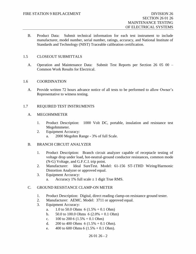
FIRE STATION 9 REPLACEMENT DIVISION 26
SECTION 26 01 26
MAINTENANCE TESTING
OF ELECTRICAL SYSTEMS
26 01 26 - 2
B. Product Data: Submit technical information for each test instrument to include
manufacturer, model number, serial number, ratings, accuracy, and National Institute of
Standards and Technology (NIST) Traceable calibration certification.
1.5 CLOSEOUT SUBMITTALS
A. Operation and Maintenance Data: Submit Test Reports per Section 26 05 00 –
Common Work Results for Electrical.
1.6 COORDINATION
A. Provide written 72 hours advance notice of all tests to be performed to allow Owner’s
Representative to witness testing.
1.7 REQUIRED TEST INSTRUMENTS
A. MEGOHMMETER
1. Product Description: 1000 Volt DC, portable, insulation and resistance test
Megohmmeter.
2. Equipment Accuracy:
a. 2000 Megohm Range - 3% of full Scale.
B. BRANCH CIRCUIT ANALYZER
1. Product Description: Branch circuit analyzer capable of receptacle testing of
voltage drop under load, hot-neutral-ground conductor resistances, common mode
(N-G) Voltage, and G.F.C.I. trip point.
2. Manufacturer: Ideal SureTest. Model: 61-156 ST-1THD Wiring/Harmonic
Distortion Analyzer or approved equal.
3. Equipment Accuracy:
a. Accuracy 1% full scale ± 1 digit True RMS.
C. GROUND RESISTANCE CLAMP-ON METER
1. Product Description: Digital, direct reading clamp-on resistance ground tester.
2. Manufacturer: AEMC. Model: 3711 or approved equal.
3. Equipment Accuracy:
a. 1.0 to 50.0 Ohms (1.5% + 0.1 Ohm)
b. 50.0 to 100.0 Ohms (2.0% + 0.1 Ohm)
c. 100 to 200 (1.5% + 0.1 Ohm)
d. 200 to 400 Ohms (1.5% + 0.1 Ohm).
e. 400 to 600 Ohms (1.5% + 0.1 Ohm).
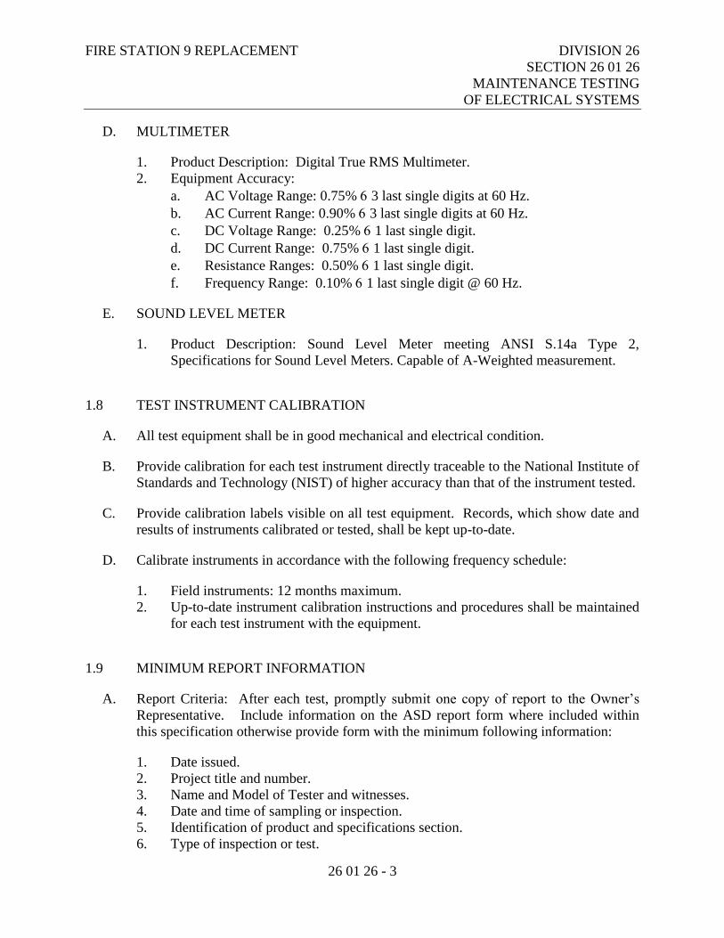
FIRE STATION 9 REPLACEMENT DIVISION 26
SECTION 26 01 26
MAINTENANCE TESTING
OF ELECTRICAL SYSTEMS
26 01 26 - 3
D. MULTIMETER
1. Product Description: Digital True RMS Multimeter.
2. Equipment Accuracy:
a. AC Voltage Range: 0.75% 3 last single digits at 60 Hz.
b. AC Current Range: 0.90% 3 last single digits at 60 Hz.
c. DC Voltage Range: 0.25% 1 last single digit.
d. DC Current Range: 0.75% 1 last single digit.
e. Resistance Ranges: 0.50% 1 last single digit.
f. Frequency Range: 0.10% 1 last single digit @ 60 Hz.
E. SOUND LEVEL METER
1. Product Description: Sound Level Meter meeting ANSI S.14a Type 2,
Specifications for Sound Level Meters. Capable of A-Weighted measurement.
1.8 TEST INSTRUMENT CALIBRATION
A. All test equipment shall be in good mechanical and electrical condition.
B. Provide calibration for each test instrument directly traceable to the National Institute of
Standards and Technology (NIST) of higher accuracy than that of the instrument tested.
C. Provide calibration labels visible on all test equipment. Records, which show date and
results of instruments calibrated or tested, shall be kept up-to-date.
D. Calibrate instruments in accordance with the following frequency schedule:
1. Field instruments: 12 months maximum.
2. Up-to-date instrument calibration instructions and procedures shall be maintained
for each test instrument with the equipment.
1.9 MINIMUM REPORT INFORMATION
A. Report Criteria: After each test, promptly submit one copy of report to the Owner’s
Representative. Include information on the ASD report form where included within
this specification otherwise provide form with the minimum following information:
1. Date issued.
2. Project title and number.
3. Name and Model of Tester and witnesses.
4. Date and time of sampling or inspection.
5. Identification of product and specifications section.
6. Type of inspection or test.

FIRE STATION 9 REPLACEMENT DIVISION 26
SECTION 26 01 26
MAINTENANCE TESTING
OF ELECTRICAL SYSTEMS
26 01 26 - 4
7. Date of test.
8. Results of tests.
9. Indicate compliance or non-compliance with Contract Documents.
10. Final adjustment setting values where applicable.
B. Submit copy of all tests performed in the O&M manual.
1.10 GENERAL REQUIREMENTS
A. Submit test results within 3 working days of each test and included in the O&M manual.
Submit all test data in hard copy and electronic format on CD-ROM or DVD-ROM.
B. Provide qualified personnel at site to perform all testing.
C. Perform specified testing of products in accordance with specified standards or as
denoted in this specification whichever is more stringent.
D. Promptly notify Owner’s Representative of irregularities or non-conformance of Work
or products.
E. Perform additional tests when test is performed incorrectly, deemed inaccurate, or
incorrectly documented.
F. The Contractor shall provide all forms, instrumentation and test equipment, loads, and
other consumables required to demonstrate the systems to Owner’s Representative
satisfaction.
G. Perform and submit all testing prior to substantial completion and system acceptance.
H. Retest all material, cables etc that are disturbed after testing.
I. Replace and retest all material installed which does not meet or exceed the minimum
acceptable limits set forth in this specification in accordance with the contract original
requirements at no additional charge to Contract Sum/Price.
J. Owner’s Representative shall be notified in writing at least 3 days prior to any testing
being performed.
PART 2 - PRODUCTS
Not Used
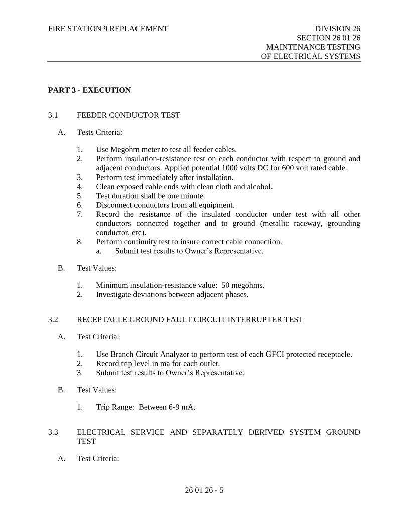
FIRE STATION 9 REPLACEMENT DIVISION 26
SECTION 26 01 26
MAINTENANCE TESTING
OF ELECTRICAL SYSTEMS
26 01 26 - 5
PART 3 - EXECUTION
3.1 FEEDER CONDUCTOR TEST
A. Tests Criteria:
1. Use Megohm meter to test all feeder cables.
2. Perform insulation-resistance test on each conductor with respect to ground and
adjacent conductors. Applied potential 1000 volts DC for 600 volt rated cable.
3. Perform test immediately after installation.
4. Clean exposed cable ends with clean cloth and alcohol.
5. Test duration shall be one minute.
6. Disconnect conductors from all equipment.
7. Record the resistance of the insulated conductor under test with all other
conductors connected together and to ground (metallic raceway, grounding
conductor, etc).
8. Perform continuity test to insure correct cable connection.
a. Submit test results to Owner’s Representative.
B. Test Values:
1. Minimum insulation-resistance value: 50 megohms.
2. Investigate deviations between adjacent phases.
3.2 RECEPTACLE GROUND FAULT CIRCUIT INTERRUPTER TEST
A. Test Criteria:
1. Use Branch Circuit Analyzer to perform test of each GFCI protected receptacle.
2. Record trip level in ma for each outlet.
3. Submit test results to Owner’s Representative.
B. Test Values:
1. Trip Range: Between 6-9 mA.
3.3 ELECTRICAL SERVICE AND SEPARATELY DERIVED SYSTEM GROUND
TEST
A. Test Criteria:
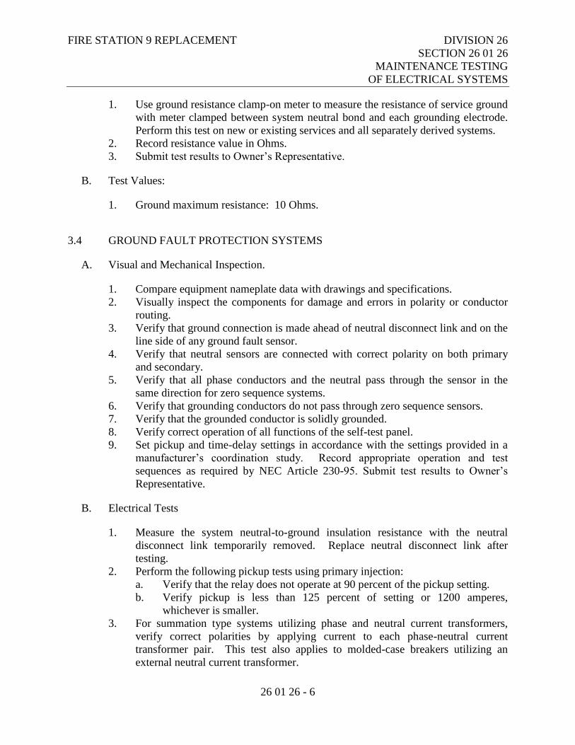
FIRE STATION 9 REPLACEMENT DIVISION 26
SECTION 26 01 26
MAINTENANCE TESTING
OF ELECTRICAL SYSTEMS
26 01 26 - 6
1. Use ground resistance clamp-on meter to measure the resistance of service ground
with meter clamped between system neutral bond and each grounding electrode.
Perform this test on new or existing services and all separately derived systems.
2. Record resistance value in Ohms.
3. Submit test results to Owner’s Representative.
B. Test Values:
1. Ground maximum resistance: 10 Ohms.
3.4 GROUND FAULT PROTECTION SYSTEMS
A. Visual and Mechanical Inspection.
1. Compare equipment nameplate data with drawings and specifications.
2. Visually inspect the components for damage and errors in polarity or conductor
routing.
3. Verify that ground connection is made ahead of neutral disconnect link and on the
line side of any ground fault sensor.
4. Verify that neutral sensors are connected with correct polarity on both primary
and secondary.
5. Verify that all phase conductors and the neutral pass through the sensor in the
same direction for zero sequence systems.
6. Verify that grounding conductors do not pass through zero sequence sensors.
7. Verify that the grounded conductor is solidly grounded.
8. Verify correct operation of all functions of the self-test panel.
9. Set pickup and time-delay settings in accordance with the settings provided in a
manufacturer’s coordination study. Record appropriate operation and test
sequences as required by NEC Article 230-95. Submit test results to Owner’s
Representative.
B. Electrical Tests
1. Measure the system neutral-to-ground insulation resistance with the neutral
disconnect link temporarily removed. Replace neutral disconnect link after
testing.
2. Perform the following pickup tests using primary injection:
a. Verify that the relay does not operate at 90 percent of the pickup setting.
b. Verify pickup is less than 125 percent of setting or 1200 amperes,
whichever is smaller.
3. For summation type systems utilizing phase and neutral current transformers,
verify correct polarities by applying current to each phase-neutral current
transformer pair. This test also applies to molded-case breakers utilizing an
external neutral current transformer.

FIRE STATION 9 REPLACEMENT DIVISION 26
SECTION 26 01 26
MAINTENANCE TESTING
OF ELECTRICAL SYSTEMS
26 01 26 - 7
a. The relay shall operate when current direction is the same relative to
polarity marks in the two current transformers.
b. The relay shall not operate when current direction is opposite relative to
polarity marks in the two current transformers.
4. Measure time delay of the relay at 150 percent or greater of pickup.
5. Verify reduced control voltage tripping capability: 55 percent for ac systems and
80 percent for dc systems.
6. Submit test results to Owner’s Representative.
C. Test Values:
1. Relay timing shall be in accordance with manufacturer’s specifications but shall
not exceed one second at 3000 amperes.
3.5 PHASE ROTATION TEST
A. Test each three phase circuit and feeder for consistent phase rotation for the entire
power system with a phase rotation meter.
B. Bump test each motor for proper rotation prior to use.
C. Correct conductor phase relationship to provide proper phase rotation.
D. Record the rotation sequence on each panelboard, MDP and Service circuit schedule.
E. Submit test results of each panelboard, MDP and Service to the Owner’s
Representative.
3.6 PHASE LOAD BALANCE TEST
A. After energizing building loads conduct a phase load balance test for each panelboard
with a clamp on ammeter.
B. Shift loads to provide current balance within 10% of the other phases. Revise circuit
directory to reflect any changes.
C. Notify Owner’s Representative at least 72 hours in advance before test.
END OF SECTION 26 01 26
FIRE STATION 9 REPLACEMENT DIVISION 26
SECTION 26 05 00
COMMON WORK RESULTS
FOR ELECTRICAL
26 05 00 - 1
PART 1 - GENERAL
1.1 RELATED DOCUMENTS
A. Drawings and general provisions of the Contract, including Municipality of Anchorage
Standard Specifications – Buildings (MASSB), General and Supplementary Conditions
apply to this Section.
1.2 SECTION INCLUDES
A. General Requirements specifically applicable to Division 26 - Electrical, in addition to
the General and Supplementary Conditions provisions.
B. The electrical system equipment and installation shall comply with all provisions and
requirements of this specification, as well as any and all applicable national, state and
local codes and standards.
1.3 WORK SEQUENCE
A. Construct Work in sequence under provisions of the General and Supplementary
Conditions.
1.4 COORDINATION
A. Coordinate the Work specified in this Division under provisions of the General and
Supplementary Conditions.
B. Prepare drawings showing proposed rearrangement of Work to meet job conditions,
including changes to Work specified under other Sections. Obtain permission of
Architect prior to proceeding.
1.5 REFERENCES
A. ANSI/NFPA 70 - National Electrical Code, latest adopted edition including all state and
local amendments.
B. NECA - Standard of Installation.
FIRE STATION 9 REPLACEMENT DIVISION 26
SECTION 26 05 00
COMMON WORK RESULTS
FOR ELECTRICAL
26 05 00 - 2
C. NETA ATS – Acceptance Testing Specifications for Electrical Power Distribution
Equipment and Systems.
D. Electrical Reference Symbols: The Electrical "Legend" on drawings is standardized
version for this project. All symbols shown may not be used on drawings. Use legend
as reference for symbols used on plans.
E. Electrical Drawings: Drawings are diagrammatic; complimentary to the Architectural
drawings; not intended to show all features of work. Install material not dimensioned
on drawings in a manner to provide a symmetrical appearance. Do not scale drawings
for exact equipment locations. Review Architectural, Structural, and Mechanical
Drawings and adjust work to conform to conditions shown thereon. Field verification of
dimensions, locations and levels is directed.
1.6 REGULATORY REQUIREMENTS
A. Conform to ANSI/NFPA 70.
B. Conform to the latest adopted edition of the International Building Code and the
International Fire Code including all state and local amendments thereto.
C. Obtain electrical permits, plan review, and inspections from authority having
jurisdiction.
1.7 SUBMITTALS
A. Submit inspection and permit certificates under provisions of the General and
Supplementary Conditions.
B. Include certificate of final inspection and acceptance from authority having jurisdiction.
C. Submittal review is for general design and arrangement only and does not relieve the
Contractor from any requirements of Contract Documents. Submittal not checked for
quantity, dimension, fit or proper operation. Where deviations of substitute product or
system performance have not been specifically noted in the submittal by the Contractor,
provisions of a complete and satisfactory working installation is the sole responsibility
of the Contractor.
D. In addition to requirements referenced in the General and Supplementary Conditions,
the following is required for work provided under this division of the specification.
1. Provide material and equipment submittals containing complete listings of
material and equipment shown on Electrical Drawings and specified herein,
bound in hard cover, loose-leaf binders separate from work furnished under other
FIRE STATION 9 REPLACEMENT DIVISION 26
SECTION 26 05 00
COMMON WORK RESULTS
FOR ELECTRICAL
26 05 00 - 3
divisions. Index and clearly identify all material and equipment by item, name or
designation used on drawings and in specifications.
2. Submit only pages which are pertinent; mark each copy of standard printed data
to identify pertinent products, referenced to Specification Section and Article
number. Show reference standards, performance characteristics, and capacities;
wiring diagrams and controls; component parts; finishes; dimensions; and
required clearances.
3. Modify manufacturer's standard schematic drawings and diagrams to supplement
standard information and to provide information specifically applicable to the
work. Delete information not applicable.
4. Review submittals prior to transmittal; determine and verify field measurements,
field construction criteria, manufacturer's catalog numbers, and conformance of
submittal with requirements of Contract Documents.
5. Coordinate submittals with requirements of work and of Contract Documents.
6. Sign or initial each sheet of shop drawings and product data, and each sample
label to certify compliance with requirements of Contract Documents. Notify
Architect/Engineer in writing at time of submittal, of any deviations from
requirements of Contract Documents.
7. Do not fabricate products or begin work which requires submittals until return of
submittal with Architect/Engineer acceptance.
8. Equipment scheduled by manufacturer's name and catalog designations,
manufacturer's published data and/or specification for that item, in effect on bid
date, are considered part of this specification. Approval of other manufacturer's
item proposed is contingent upon compliance therewith.
9. Submittals for Division 26 shall be complete and submitted at one time. Unless
given prior approval, partial submittals will be returned unreviewed.
1.8 SUBSTITUTIONS
A. In accordance with the General Conditions and the General Requirements, Substitution
and Product Options, all substitute items must fit in the available space, and be of equal
or better quality including efficiency performance, size, and weight, and must be
compatible with existing equipment.
1.9 PROJECT RECORD DRAWINGS
A. Maintain project record drawings in accordance with the General and Supplementary
Conditions.
B. In addition to the other requirements, mark up a clean set of drawings as the work
progresses to show the dimensioned location and routing of all electrical work which
will become permanently concealed. Show routing of work in permanently concealed
FIRE STATION 9 REPLACEMENT DIVISION 26
SECTION 26 05 00
COMMON WORK RESULTS
FOR ELECTRICAL
26 05 00 - 4
blind spaces within the building. Show complete routing and sizing of any significant
revisions to the systems shown.
C. Record drawing field mark-ups shall be maintained on-site and shall be available for
examination of the Owner’s Representative at all times.
1.10 OPERATION AND MAINTENANCE MANUALS
A. Provide operation and maintenance manuals for training of Owner's Representative in
operation and maintenance of systems and related equipment. In addition to
requirements referenced in the General and Supplementary Conditions, the following is
required for work provided under this section of the specifications.
B. Manuals shall be hard cover, loose-leaf binders with pages reinforced to prevent pullout
and shall be separate from work furnished under other divisions. Prepare a separate
chapter for instruction of each class of equipment or system. Index and clearly identify
each chapter and provide a table of contents.
C. Unless otherwise noted in the General and Supplementary Conditions, provide one copy
of all material for approval. After approval, provide five corrected approved copies.
D. The following is the suggested outline for operation and maintenance manuals and is
presented to indicate the extent of items required in manuals.
1. List chapters of information comprising the text. The following is a typical Table
of Contents:
a. Electrical power distribution
b. Lighting
c. Fire alarm
d. Television distribution system
e. Packaged generator
f. Fire Station Alert System
g. Other chapters as necessary
2. Provide the following items in sequence for each chapter shown in Table of
Contents:
a. Describe the procedures necessary for personnel to operate the system
including start-up, operation, emergency operation and shutdown.
1) Give complete instructions for energizing equipment and making
initial settings and adjustments whenever applicable.
2) Give step-by-step instructions for shutdown procedure if a particular
sequence is required.
3) Include test results of all tests required by this and other sections of
the specifications.
b. Maintenance Instructions:
FIRE STATION 9 REPLACEMENT DIVISION 26
SECTION 26 05 00
COMMON WORK RESULTS
FOR ELECTRICAL
26 05 00 - 5
1) Provide instructions and a schedule of preventive maintenance, in
tabular form, for all routine cleaning and inspection with
recommended lubricants if required for the following:
a) Lighting fixtures
b) Distribution equipment
c) Fire alarm and detection equipment
d) Television distribution system
e) Packaged generator
f) Fire Station Alert System systems
2) Provide instructions for minor repair or adjustments required for
preventive maintenance routines, limited to repairs and adjustments
which may be performed without special tools or test equipment and
which requires no special training or skills.
3) Provide manufacturers' descriptive literature including approved shop
drawings covering devices used in system, together with illustrations,
exploded views, etc. Also include special devices provided by the
Contractor.
4) Provide any information of a maintenance nature covering warranty
items, etc., which have not been discussed elsewhere.
5) Include list of all equipment furnished for project, where purchased,
technical representative if applicable and a local parts source with a
tabulation of descriptive data of all electrical-electronic spare parts
and all mechanical spare parts proposed for each type of equipment or
system. Properly identify each part by part number and manufacturer.
1.11 DEMONSTRATION OF ELECTRICAL SYSTEMS
A. During substantial completion inspection:
1. Conduct operating test for approval under provisions of the General and
Supplementary Conditions.
2. Demonstrate installation to operate satisfactorily in accordance with requirements
of Contract Documents.
3. Should any portion of installation fail to meet requirements of Contract
Documents, repair or replace items failing to meet requirements until items can be
demonstrated to comply.
4. Have instruments available for measuring light intensities, voltage and current
values, and for demonstration of continuity, grounds, or open circuit conditions.
5. Provide personnel to assist in taking measurements and making tests.
FIRE STATION 9 REPLACEMENT DIVISION 26
SECTION 26 05 00
COMMON WORK RESULTS
FOR ELECTRICAL
26 05 00 - 6
1.12 CERTIFICATE OF COMPLETION
A. Submit, at time of request for final inspection, a completed letter in the following
format:
I, NAME , of FIRM , certify that the electrical work is complete
in accordance with Contract Plans and Specifications, and authorized change orders
(copies attached) and will be ready for final inspection as of DATE . I further
certify that the following specification requirements have been fulfilled:
1. megger readings performed, copies of logs attached.
2. ground tests performed, copies of method used and results attached.
3. operating manuals completed, DATE .
SIGNED .
Owner's Representative
4. as-built drawings up-to-date and ready to deliver to Architect.
5. fire alarm system final connections, check out and start up completed on
DATE by:
SIGNED .
Factory Authorized and Trained Technician
6. security system final connections, check out and start up completed on
DATE by:
SIGNED .
Factory Authorized and Trained Technician
7. Instruction of operating personnel completed on DATE by:
SIGNED .
Owner's Representative
8. all other tests required by specifications have been performed.
9. all systems are fully operational.
SIGNED .
1.13 WARRANTY
A. In addition to the requirements of the General and Supplementary Conditions, warrant
all materials, installation and workmanship for one (1) year from date of acceptance.
B. Copies of manufacturer product warranties for all equipment shall be included in the
operation and installation manuals.
FIRE STATION 9 REPLACEMENT DIVISION 26
SECTION 26 05 00
COMMON WORK RESULTS
FOR ELECTRICAL
26 05 00 - 7
1.14 INSTRUCTION OF OPERATING PERSONNEL
A. In accordance with the requirements of the General and Supplementary Conditions and
this section provide services of qualified representative of supplier of each item or
system listed below to instruct designated personnel of Owner in operation and
maintenance of item or system.
B. Make instruction when system is complete, of number of hours indicated, and
performed at time mutually agreeable.
System or Equipment Hours of Instruction
Security system 4
Fire alarm system 4
Television distribution system 2
Lighting Control System 2
Standby power system 4
C. Certify that an Anchorage or Fairbanks based authorized service organization regularly
carries complete stock of repair parts for listed equipment or systems, that organization
is available and will furnish service within 48 hours after request. Include name,
address and telephone number of service organization.
D. Have approved operation and maintenance manuals and parts lists for all equipment on
hand at time of instruction.
PART 2 - PRODUCTS
2.1 MATERIALS AND EQUIPMENT
A. All Materials and Equipment shall be new and shall be listed by Underwriter’s
Laboratories or equivalent third party listing agency for the use intended.
B. Materials and Equipment shall be acceptable to the authority having jurisdiction as
suitable for the use intended when installed per listing and labeling instructions.
C. No materials or equipment containing asbestos in any form shall be used. Where
materials or equipment provided by this Contractor are found to contain asbestos such
items shall be removed and replaced with non-asbestos containing materials and
equipment at no cost to the Owner.
D. In describing the various items of equipment, in general, each item will be described
singularly, even though there may be numerous similar items.
FIRE STATION 9 REPLACEMENT DIVISION 26
SECTION 26 05 00
COMMON WORK RESULTS
FOR ELECTRICAL
26 05 00 - 8
PART 3 - EXECUTION
3.1 WORKMANSHIP
A. Install Work using procedures defined in NECA Standard of Installation and/or the
manufacturer’s installation instructions.
3.2 TESTS
A. Notify Contracting Officer at least 72 hours prior to conducting any tests.
B. Following completion of installation, test system ground in accordance with the
requirements of NETA ATS 7.13. and all feeders in accordance with NETA ATS 7.3.
Submit logs of values obtained, and nameplate data of instruments used prior to final
inspection. Include a copy of all data in the power distribution section of the Operation
and Maintenance Manuals.
C. Perform additional tests required under other sections of these specifications.
D. Perform all tests in the presence of the Owner’s authorized representative.
E. The Contractor shall provide written notification to the Owner’s authorized
representative and the State Electrical Inspector thirty days in advance of requests for
rough-in and substantial completion inspections.
END OF SECTION 26 05 00
FIRE STATION 9 REPLACEMENT DIVISION 26
SECTION 26 05 19
LOW-VOLTAGE ELECTRICAL
POWER CONDUCTORS AND CABLES
26 05 19 - 1
PART 1 - GENERAL
1.1 RELATED DOCUMENTS
A. Drawings and general provisions of the Contract, including Municipality of Anchorage
Standard Specifications – Buildings (MASSB), General and Supplementary Conditions
apply to this Section.
1.2 SECTION INCLUDES
A. Building wire.
B. Cable.
C. Wiring connections and terminations.
1.3 RELATED SECTIONS
A. Section 26 05 53 – Identification for Electrical Systems.
B. Division 31 – Earthwork.
1.4 REFERENCES
A. Federal Specification FS-A-A59544 – Cable and Wire, Electrical (Power, Fixed
Installation)
B. Federal Specification FS-J-C-30B – Cable Assembly, Power, Electrical
C. NEMA WC 5 - Thermoplastic-Insulated Wire and Cable for the Transmission and
Distribution of Electrical Energy.
D. NETA ATS – Acceptance testing specifications for Electrical Power Distribution and
Systems.
E. NFPA 70 – National Electrical Code.
F. NFPA 262 – Standard Method of test for flame travel and smoke of wires and cables for
use in air-handling spaces.
FIRE STATION 9 REPLACEMENT DIVISION 26
SECTION 26 05 19
LOW-VOLTAGE ELECTRICAL
POWER CONDUCTORS AND CABLES
26 05 19 - 2
G. UL 4 – Standard for Armored Cable.
H. UL 62 – Flexible Cords and Cables.
I. UL 83 – Thermoplastic Insulated Wire and Cable.
J. UL 1063 – Standard for Machine and Tool Wire and Cable.
K. UL 1424 – Standard for Cables for Power-Limited Fire Alarm.
L. UL 1479 – Standard for Fire Tests of Through Wall Penetration Fire Stops.
M. UL 1569 – Standard for Metal Clad Cable.
N. UL 1581 – Reference Standard for Electrical Wires, Cables and Flexible Cords.
1.5 QUALITY ASSURANCE
A. Provide wiring materials located in plenums with peak optical density not greater than
0.5, average optical density not greater than 0.15, and flame spread not greater than 5
feet (1.5m) when tested in accordance with NFPA 262.
PART 2 - PRODUCTS
2.1 BUILDING WIRE
A. Thermoplastic-insulated Building Wire: NEMA WC 5.
B. Feeders and Branch Circuits Larger Than 6 AWG: Copper, stranded conductor, 600 volt
insulation, THW, THHN/THWN or XHHW-2 as indicated.
C. Feeders and Branch Circuits 6 AWG and Smaller: Copper conductor, 600 volt
insulation, THHN/THWN or XHHW-2. 6 and 8 AWG, stranded conductor; smaller
than 8 AWG, solid conductor.
D. Branch Circuit Wire Color Code:
1. Color code wires by line or phase as follows:
a. Black, red, blue and white for 120/208V systems.
2. For conductors 8 AWG and smaller, insulation shall be colored. For conductors 6
AWG and larger, identify with colored phase tape at all terminals, splices, and
boxes.
FIRE STATION 9 REPLACEMENT DIVISION 26
SECTION 26 05 19
LOW-VOLTAGE ELECTRICAL
POWER CONDUCTORS AND CABLES
26 05 19 - 3
3. When two or more neutrals are installed in one conduit, identify each with the
proper circuit number in accordance with Section 26 05 53 – Identification for
Electrical Systems.
4. Grounding conductors 8 AWG and smaller shall have green colored insulation.
For 6 AWG and larger, use green tape at both ends and at all other visible points
in between, including pull and junction boxes.
E. Control Circuits: Copper, stranded conductor 600 volt insulation, THHN/THNN or
XHHW-2.
F. Fire Alarm Notification Appliance Circuits: Copper, solid or stranded conductor 600
volt insulation, THHN/THNN or XHHW-2.
2.2 METAL CLAD CABLE
A. UL 83, 1063, 1479, 1569, and 1581 listed, meets Federal Specification A-A-59544
(formerly J-C-30B). UL rated for installation in cable trays and environmental air
handling spaces. Fire wall rated for 1, 2, and 3-hour through penetrations.
B. Type MC Cable, Size 12 Through 10 AWG: Solid copper conductor, 600 volt
thermoplastic insulation, rated 90º C dry, 75º wet, insulated green grounding conductor,
and galvanized steel aluminum armor over mylar.
C. Fire Alarm/Control Type MC Cable, Size 18 through 12 AWG: UL 62, 83, 1063, 1424,
1479, 1569, and 1581 listed, solid copper conductor, 300 volt thermoplastic insulation,
rated 105º C, insulated green grounding conductor, red or red-striped galvanized steel
or aluminum armor over mylar. Conductor insulation shall be color-coded in
accordance with Section 28 31 00.
D. All metal clad cable shall be provided with color-coded insulation on all ungrounded
conductors in accordance with NEC 210.5(C) and Part 3 of this section.
2.3 REMOTE CONTROL AND SIGNAL CABLE
A. Control Cable for Class 1 Remote Control and Signal Circuits: Copper conductor, 600
volt insulation, rated 90º C, individual conductors twisted together, shielded, and
covered with an overall PVC jacket; UL listed.
B. Control Cable for Class 2 or Class 3 Remote Control and Signal Circuits: Copper
conductor, 300 volt insulation, rated 90º C, individual conductors twisted together,
shielded or unshielded (as required), and covered with a PVC jacket; UL listed.
C. Plenum Cable for Class 2 or Class 3 Remote Control and Signal Circuits: Copper
conductor, 300 volt insulation, rated 90º C, individual conductors twisted together,
FIRE STATION 9 REPLACEMENT DIVISION 26
SECTION 26 05 19
LOW-VOLTAGE ELECTRICAL
POWER CONDUCTORS AND CABLES
26 05 19 - 4
shielded or unshielded (as required), and covered with a nonmetallic jacket; UL listed
for use in air handling ducts, hollow spaces used as ducts, and plenums.
2.4 WIRING CONNECTIONS AND TERMINATIONS
A. For conductors 8 AWG and smaller:
1. Dry interior areas: Spring wire connectors, pre-insulated “twist-on” rated 105
degrees C per UL 468C. Where stranded conductors are terminated on screw type
terminals, install crimp insulated fork or ring terminals. Thomas & Betts Sta-Kon
or equal.
2. Motor connections: Spring wire connectors, pre-insulated “twist-on” rated 105
degrees C per UL 468C. Provide a minimum of 8 wraps of Scotch 33+ electrical
tape around conductors and connector to eliminate connector back off.
3. Wet or exterior: Spring wire connectors, pre-insulated “twist-on”, resin filled
rated for direct burial per UL 486D.
B. For conductors 6 AWG and larger:
1. Bus lugs and bolted connections: 600 V, 90 degrees C., two hole long barrel
irreversible compression copper tin plated. Thomas & Betts or approved equal.
2. Motor connection: 600 V, 90 degrees C., copper tin plated compression motor
pigtail connector, quick connect/disconnect, slip on insulator. Thomas & Betts or
approved equal.
3. Two way connector for splices or taps: 600 V, 90 degrees C., compression long
barrel, copper tin plated. Thomas & Betts or approved equal. Insulate with
Scotch 23 rubber insulating base covering and Scotch 33+ outer wrap.
PART 3 - EXECUTION
3.1 GENERAL WIRING METHODS
A. Use no wire smaller than 12 AWG for power and lighting circuits, and no smaller than
18 AWG for control wiring.
B. Use 10 AWG conductor for 20 ampere, 120 volt branch circuit home runs longer than
75 feet.
C. Splice only in junction or outlet boxes.
D. Neatly train and lace wiring inside boxes, equipment, and panelboards.
E. Make Conductor lengths for parallel circuits equal.
FIRE STATION 9 REPLACEMENT DIVISION 26
SECTION 26 05 19
LOW-VOLTAGE ELECTRICAL
POWER CONDUCTORS AND CABLES
26 05 19 - 5
F. Wiring in lighting fixture channels shall be rated for 90º C minimum.
G. Do not share neutral conductors. Provide a dedicated neutral conductor for each branch
circuit that requires a neutral.
3.2 WIRING INSTALLATION IN RACEWAYS
A. Pull all conductors into a raceway at the same time. Verify that raceway is complete
and properly supported prior to pulling conductors. Use UL listed wire pulling
lubricant for pulling 4 AWG and larger wires.
B. Install wire in raceway after interior of building has been physically protected from the
weather and all mechanical work likely to injure conductors has been completed.
C. Do not install XHHW-2 conductors when ambient temperatures are below –5 degrees C
and THHN/THWN conductors when ambient temperatures are below 0 degrees C.
D. Conductors shall be carefully inspected for insulation defects and protected from
damage as they are installed in the raceway. Where the insulation is defective or
damaged, the cable section shall be repaired or replaced at the discretion of the Owner
and at no additional cost to the Owner.
E. Place an equal number of conductors for each phase of a circuit in same raceway or
cable.
F. Route conductors from each system in independent raceway system and not intermix in
the same raceway, enclosure, junction box, wireway, or gutter as another system unless
otherwise shown on the plans.
G. No more than three current carrying conductors shall be installed in any homerun unless
otherwise indicated on the drawings.
H. Completely and thoroughly swab raceway system before installing conductors.
3.3 CABLE INSTALLATION
A. Provide protection for exposed cables where subject to damage.
B. Support cables above accessible ceilings; do not rest on ceiling tiles. Use spring metal
clips or cable ties to support cables from structure. Do not support cables from ceiling
suspension system. Include bridle rings or drive rings.
C. Use suitable cable fittings and connectors.
FIRE STATION 9 REPLACEMENT DIVISION 26
SECTION 26 05 19
LOW-VOLTAGE ELECTRICAL
POWER CONDUCTORS AND CABLES
26 05 19 - 6
D. Trench and backfill for direct buried cables per Division 31 - Earthwork. Install
warning tape along entire length of direct burial cables.
3.4 WIRING CONNECTIONS AND TERMINATIONS
A. Splice only in accessible junction boxes.
B. Thoroughly clean wires before installing lugs and connectors.
C. Make splices, taps and terminations to carry full ampacity of conductors without
perceptible temperature rise.
D. Terminate spare conductors with twist on connectors or heat shrink insulation to proper
voltage rating.
E. Control systems wiring in conjunction with mechanical or miscellaneous equipment,
including motor control center, switchboards, etc., to be identified in accordance with
wiring diagrams furnished with equipment.
F. Code sound and signal systems wiring and any special equipment in accordance with
manufacturer's diagrams or recommendations.
G. Do not exceed manufacturer's recommended pull tensions.
3.5 FIELD QUALITY CONTROL
A. Field inspection and testing will be performed under provisions of the General and
Supplementary Conditions.
B. Inspect wire and cable for physical damage and proper connection.
C. Torque conductor connections and terminations to manufacturer's recommended values.
D. Perform continuity test on all power and equipment branch circuit conductors. Verify
proper phasing connections.
3.6 WIRE AND CABLE INSTALLATION SCHEDULE
A. All Locations: Building wire and/or remote control and signal cable in raceways.
B. At the Contractor’s option Metal Clad cable may be used for branch circuit wiring other
than homeruns. Homeruns shall be building wire in raceway. Metal Clad cable used for
branch circuit wiring from a light switch to the light fixture shall include a spare
conductor for future use.
END OF SECTION 26 05 19
FIRE STATION 9 REPLACEMENT DIVISION 26
SECTION 26 05 26
GROUNDING AND BONDING
FOR ELECTRICAL SYSTEMS
26 05 26 - 1
PART 1 - GENERAL
1.1 RELATED DOCUMENTS
A. Drawings and general provisions of the Contract, including Municipality of Anchorage
Standard Specifications – Buildings (MASSB), General and Supplementary Conditions
apply to this Section.
1.2 SECTION INCLUDES
A. Power system grounding.
B. Telecommunications and Signal System Grounding.
C. Electrical equipment and raceway grounding and bonding.
1.3 RELATED SECTIONS
A. The Work under this section is subject to requirements of the Contract Documents
including the General Conditions, Supplementary Conditions, and sections under the
General and Supplementary Conditions and Section 26 05 00 – Common Work Results
for Electrical.
B. The General and Supplementary Conditions – Quality Requirements.
C. Section 26 05 00 – Common Work Results for Electrical.
D. Section 26 05 19 – Low-Voltage Electrical Power Conductors and Cables.
1.4 REFERENCE STANDARDS
A. ANSI/NEMA GR-1 – 2001, Ground Rod Electrodes and Ground Rod Electrode
Couplings.
B. ANSI/NFPA 70 – National Electrical Code.
C. ASTM B 3 – 2001 Standard Specification for Soft or Annealed Copper Wire.
FIRE STATION 9 REPLACEMENT DIVISION 26
SECTION 26 05 26
GROUNDING AND BONDING
FOR ELECTRICAL SYSTEMS
26 05 26 - 2
D. AWS A5.8/A5.8M – 1992; R2004 Specification for Filler Metals for Brazing and Braze
Welding.
E. IEEE Std 81 – 1983 Guide for Measuring Earth Resistivity, Ground Impedance, and
Earth Surface Potentials of a Ground System.
F. IEEE Std 142 – Recommended Practice for Grounding of Industrial and Commercial
Power System.
G. UL 467 – 2004 Standard for Grounding and Bonding Equipment.
1.5 SYSTEM DESCRIPTION
A. Provide a complete grounding system for services and equipment as required by State
Codes, NEC, applicable portions of other NFPA codes, TIA Standards and as indicated
herein.
1.6 SUBMITTALS
A. Product Data: Submit product data for all components provided, showing material type
and dimensions. Each catalog sheet should be clearly marked to indicate exact part
number provided, including all options and accessories.
1.7 CLOSEOUT SUBMITTALS
A. Project Record Drawings
1. Accurately indicate actual locations of main grounding bus, all grounding rods,
concrete encased electrodes, etc.
2. Show the actual installed routing of grounding electrode conductor, and size/type
of bonding conductors and termination locations of all major bonding connections
(water, piping, steel, fuel tanks, etc.).
B. Test Reports
1. The results of electrical ground resistance test, performed on the installed
grounding system shall be submitted in accordance with the paragraph entitled
“Field Quality Control” of this section.
2. Each test report shall include:
a. Date of test, soil moisture content, and soil temperature
b. Test operator
c. Instrument or other test equipment used
d. Electrode designation or location matching that shown on shop drawings
FIRE STATION 9 REPLACEMENT DIVISION 26
SECTION 26 05 26
GROUNDING AND BONDING
FOR ELECTRICAL SYSTEMS
26 05 26 - 3
e. Ground impedance in ohms
f. Assumptions made - if required
1.8 COORDINATIONS
A. The General and Supplementary Conditions – Administrative Requirements:
Requirements for Coordination.
B. Complete grounding and bonding of building reinforcing steel prior to concrete
placement.
PART 2 - PRODUCTS
2.1 MATERIALS
A. Solid Ground Rods: Copper-encased steel, ¾ inch diameter, minimum length 10 feet.
Ground rods shall be clean and smooth.
B. Bonding Conductors: Solid bare copper wire for sizes No. 8 AWG and smaller
diameter. Stranded bare copper wire for sizes No. 6 AWG and larger diameter.
Conductors may be insulated conductors if used provide green insulation.
C. Grounding Conductors: Copper conductor bare or green insulated.
D. Telecommunications Bonding Backbone: Bare copper, 2 AWG, stranded conductor.
E. Telecommunications Bonding Busbar: Wall-mounted, solid copper, 12 inch by 4 inch
by ¼ inch thick busbar with two insulators and standoff brackets. Chatsworth #40153-
012 or approved equal.
F. Mechanical Grounding and Bonding Connectors: Non-reversible crimp type lugs only.
Use factory made compression lug for all terminations.
G. Exothermic Grounding and Bonding Connectors: Exothermic welded type. Welding
procedure shall include the proper mold and powder charge and shall conform to the
manufacturer’s recommendations.
H. In external locations, clamping shall be used only where a disconnect type of
connection is required. Connection device may utilize threaded fasteners. Device shall
be constructed such that positive contact pressure shall be maintained at all times.
Machine bolts with tooth-type lock washers shall be used.
FIRE STATION 9 REPLACEMENT DIVISION 26
SECTION 26 05 26
GROUNDING AND BONDING
FOR ELECTRICAL SYSTEMS
26 05 26 - 4
PART 3 - EXECUTION
3.1 INSTALLATION
A. Provide a separate, insulated equipment-grounding conductor in all feeder and branch
circuits. Terminate each end on a grounding lug, bus, or bushing. Multiple conductors
on single lug not permitted. Each grounding conductor shall terminate on its own
terminal lug.
B. Connect grounding electrode conductors to metal water pipe using a suitable ground
clamp. Make connections to flanged piping at street side of flange. Provide bonding
jumper around water meter and back flow preventors.
C. Supplementary Grounding Electrode: Use driven ground rod on exterior of building in
main service equipment area. Use minimum of 20 feet No. 2 bare copper wire
embedded in concrete foundation.
D. Telecommunications Bonding Backbone: Terminate at the electrical service entrance
and at the ground bar or grounding lug on telecommunications backboard.
E. Provide grounding and bonding at Utility Company's metering equipment.
F. Bond together system neutrals, service equipment enclosures, exposed non-current
carrying metal parts of electrical equipment, metal raceway systems, grounding
conductor in raceways and cables, receptacle ground connectors, and plumbing systems.
G. Grounding conductors for branch circuits shall be sized in accordance with NEC, except
minimum size grounding conductor shall be No. 12 AWG.
H. Grounding conductor is in addition to neutral conductor and in no case shall neutral
conductor serve as grounding means.
I. Ground rods shall be installed so that the top of the rod is not less than 12 inches below
finished grade.
3.2 FIELD QUALITY CONTROL
A. Inspect grounding and bonding system conductors and connections for tightness and
proper installation.
B. Upon completion of the ground installation and before connection to the permanent
facility power the Contractor shall measure the ground resistance of the grounding
FIRE STATION 9 REPLACEMENT DIVISION 26
SECTION 26 05 26
GROUNDING AND BONDING
FOR ELECTRICAL SYSTEMS
26 05 26 - 5
electrode system. The testing shall utilize an earth resistance meter and be conducted in
accordance with the IEEE Standard for 3-point fall of potential method. The Contractor
shall notify the Owner’s representatives a minimum of 5 business days prior to the
scheduled ground testing date so they may be present at the time of testing. The
Contractor shall immediately notify the Owner’s representative if the measured ground
resistance is above 20 ohms. The Contractor shall submit a copy of the test report to the
Owner’s representative within 10 days after testing and before the ground system
becomes inaccessible.
C. Ground Isolation Test: Ground systems shall be tested for isolation from other ground
system.
D. Continuity Test: Continuity test shall be performed on all power receptacles to ensure
that the ground terminals are properly grounded to the facility ground system.
END OF SECTION 26 05 26
FIRE STATION 9 REPLACEMENT DIVISION 26
SECTION 26 05 29
HANGERS AND SUPPORTS
FOR ELECTRICAL SYSTEMS
26 05 29 - 1
PART 1 - GENERAL
1.1 RELATED DOCUMENTS
A. Drawings and general provisions of the Contract, including Municipality of Anchorage
Standard Specifications – Buildings (MASSB), General and Supplementary Conditions
apply to this Section.
1.2 SECTION INCLUDED
A. Conduit supports.
B. Formed steel channel.
C. Spring steel clips.
D. Sleeves.
E. Mechanical sleeve seals.
F. Firestopping relating to electrical work.
G. Firestopping accessories.
H. Equipment bases and supports.
1.3 RELATED WORK
A. The Work under this section is subject to requirements of the Contract Documents
including the General Conditions, Supplementary Conditions, and sections under the
General and Supplementary Conditions and Section 26 05 00 – Common Work Results
for Electrical.
B. Division 03 - Cast-In-Place Concrete: Product requirements for concrete for placement
by this section.
1.4 REFERENCES
A. International Building Code (IBC), Chapter 16 – Structural Design.
FIRE STATION 9 REPLACEMENT DIVISION 26
SECTION 26 05 29
HANGERS AND SUPPORTS
FOR ELECTRICAL SYSTEMS
26 05 29 - 2
B. ASTM International:
1. ASTM E84 - Standard Test Method for Surface Burning Characteristics of
Building Materials.
2. ASTM E119 - Standard Test Methods for Fire Tests of Building Construction and
Materials.
3. ASTM E814 - Standard Test Method for Fire Tests of Through-Penetration Fire
Stops.
4. ASTM E1966 - Standard Test Method for Fire-Resistive Joint Systems.
C. Underwriters Laboratories Inc.:
1. UL 263 - Fire Tests of Building Construction and Materials.
2. UL 723 - Tests for Surface Burning Characteristics of Building Materials.
3. UL 1479 - Fire Tests of Through-Penetration Firestops.
4. UL 2079 - Tests for Fire Resistance of Building Joint Systems.
5. UL - Fire Resistance Directory.
1.5 DEFINITIONS
A. Firestopping (Through-Penetration Protection System): Sealing or stuffing material or
assembly placed in spaces between and penetrations through building materials to arrest
movement of fire, smoke, heat, and hot gases through fire rated construction.
1.6 SYSTEM DESCRIPTION
A. Firestopping Materials: ASTM E814 and UL 1479 to achieve fire ratings as noted on
Drawings for adjacent construction, but not less than 1 hour fire rating.
1. Ratings may be 3-hours for firestopping in through-penetrations of 4-hour fire
rated assemblies unless otherwise required by applicable codes.
1.7 PERFORMANCE REQUIREMENTS
A. Firestopping: Conform to UL for fire resistance ratings and surface burning
characteristics.
B. Firestopping: Provide certificate of compliance from authority having jurisdiction
indicating approval of materials used.
FIRE STATION 9 REPLACEMENT DIVISION 26
SECTION 26 05 29
HANGERS AND SUPPORTS
FOR ELECTRICAL SYSTEMS
26 05 29 - 3
1.8 SUBMITTALS
A. The General and Supplementary Conditions: Requirements for submittals.
B. Product Data:
1. Firestopping: Submit data on product characteristics, performance and limitation
criteria.
C. Manufacturer's Installation Instructions:
1. Firestopping: Submit preparation and installation instructions.
D. Manufacturer's Certificate: Certify products meet or exceed specified requirements.
E. Seismic Restraint Calculations:
1. Provide structurally engineered shop drawings for seismic restraint of all
electrical equipment required by the International Building Code (IBC), Chapters
16, 17. Structural design shall be based on the Seismic Use Category and Seismic
Design Category as designated in these chapters.
2. Shop drawings shall be stamped by a professional engineer registered in the State
of Alaska.
1.9 COORDINATION
A. Coordinate size, shape and location of concrete pads with Division 03 - Concrete.
1.10 QUALITY ASSURANCE
A. Support systems shall be adequate for weight of equipment and conduit, including
wiring, which they carry.
B. Through Penetration Firestopping of Fire Rated Assemblies: UL 1479 or ASTM E814
with 0.10 inch water gage (24.9 Pa) minimum positive pressure differential to achieve
fire F-Ratings and temperature T-Ratings as indicated on Drawings, but not less than 1-
hour.
1. Wall Penetrations: Fire F-Ratings as indicated on Drawings, but not less than 1-
hour.
2. Floor and Roof Penetrations: Fire F-Ratings and temperature T-Ratings as
indicated on Drawings, but not less than 1-hour.
FIRE STATION 9 REPLACEMENT DIVISION 26
SECTION 26 05 29
HANGERS AND SUPPORTS
FOR ELECTRICAL SYSTEMS
26 05 29 - 4
3. Floor Penetrations Within Wall Cavities: T-Rating is not required.
1.11 ENVIRONMENTAL REQUIREMENTS
A. The General and Supplementary Conditions: Environmental conditions affecting
products on site.
B. Do not apply firestopping materials when temperature of substrate material and ambient
air is below 60 degrees F (15 degrees C).
C. Maintain this minimum temperature before, during, and for minimum 3 days after
installation of firestopping materials.
PART 2 - PRODUCTS
2.1 CONDUIT SUPPORTS
A. Manufacturers:
1. Allied Tube & Conduit Corp.
2. Minerallac Fastening Systems.
3. O-Z Gedney Co.
4. Substitutions: per the General and Supplementary Conditions.
B. Hanger Rods: Threaded high tensile strength galvanized carbon steel with free running
threads.
C. Beam Clamps: Malleable Iron, with tapered hole in base and back to accept either bolt
or hanger rod. Set screw: hardened steel.
D. Conduit clamps for trapeze hangers: Galvanized steel, notched to fit trapeze with single
bolt to tighten.
E. Conduit clamps - general purpose: One-hole malleable iron for surface mounted
conduits.
F. Cable Ties: High strength nylon temperature rated to 185 degrees F (85 degrees C). Self
locking.
2.2 FORMED STEEL CHANNEL
A. Manufacturers:
FIRE STATION 9 REPLACEMENT DIVISION 26
SECTION 26 05 29
HANGERS AND SUPPORTS
FOR ELECTRICAL SYSTEMS
26 05 29 - 5
1. B-Line Systems
2. Allied Tube & Conduit Corp.
3. Unistrut Corp.
4. Substitutions: per the General and Supplementary Conditions.
B. Product Description: Galvanized 12 gage (2.8 mm) thick steel. With holes 1-1/2 inches
(38 mm) on center.
2.3 SLEEVES
A. Sleeves Through Non-fire Rated Floors: 18 gage (1.2 mm) thick galvanized steel.
B. Sleeves Through Non-fire Rated Beams, Walls, Footings, and Potentially Wet Floors:
Steel pipe or 18 gage (1.2mm) thick galvanized steel.
C. Sleeves Through Fire Rated and Fire Resistive Floors and Walls, and Fire Proofing:
Prefabricated fire rated sleeves including seals, UL listed.
D. Fire-stopping Insulation: Glass fiber type, non-combustible.
2.4 MECHANICAL SLEEVE SEALS
A. Product Description: Modular mechanical type, consisting of interlocking synthetic
rubber links shaped to continuously fill annular space between object and sleeve,
connected with bolts and pressure plates causing rubber sealing elements to expand
when tightened, providing watertight seal and electrical insulation.
2.5 FIRE STOPPING
A. Manufacturers:
1. Dow Corning Corp.
2. 3M Fire Protection Products.
3. Fire Trak Corp.
4. Substitutions: per the General and Supplementary Conditions.
B. Product Description: Different types of products by multiple manufacturers are
acceptable as required to meet specified system description and performance
requirements; provide only one type for each similar application.
1. Silicone Firestopping Elastomeric Firestopping: Single component silicone
elastomeric compound and compatible silicone sealant.
2. Foam Firestopping Compounds: Single component foam compound.
FIRE STATION 9 REPLACEMENT DIVISION 26
SECTION 26 05 29
HANGERS AND SUPPORTS
FOR ELECTRICAL SYSTEMS
26 05 29 - 6
3. Formulated Firestopping Compound of Incombustible Fibers: Formulated
compound mixed with incombustible non-asbestos fibers.
4. Fiber Stuffing and Sealant Firestopping: Composite of mineral or ceramic fiber
stuffing insulation with silicone elastomer for smoke stopping.
5. Mechanical Firestopping Device with Fillers: Mechanical device with
incombustible fillers and silicone elastomer, covered with sheet stainless steel
jacket, joined with collars, penetration sealed with flanged stops.
6. Intumescent Firestopping: Intumescent putty compound which expands on
exposure to surface heat gain.
7. Firestop Pillows: Formed mineral fiber pillows.
2.6 FIRESTOPPING ACCESSORIES
A. Primer: Type recommended by firestopping manufacturer for specific substrate surfaces
and suitable for required fire ratings.
B. Installation Accessories: Provide clips, collars, fasteners, temporary stops or dams, and
other devices required to position and retain materials in place.
C. General:
1. Furnish UL listed products or products tested by independent testing laboratory.
2. Select products with rating not less than rating of wall or floor being penetrated.
D. Non-Rated Surfaces:
1. Stamped steel, chrome plated, hinged, split ring escutcheons or floor plates or
ceiling plates for covering openings in occupied areas where conduit is exposed.
2. For exterior wall openings below grade, furnish modular mechanical type seal
consisting of interlocking synthetic rubber links shaped to continuously fill
annular space between conduit and cored opening or water-stop type wall sleeve.
PART 3 - EXECUTION
3.1 EXAMINATION
A. The General and Supplementary Conditions: Verification of existing conditions before
starting work.
B. Verify openings are ready to receive sleeves.
C. Verify openings are ready to receive firestopping.
FIRE STATION 9 REPLACEMENT DIVISION 26
SECTION 26 05 29
HANGERS AND SUPPORTS
FOR ELECTRICAL SYSTEMS
26 05 29 - 7
3.2 PREPARATION
A. Clean substrate surfaces of dirt, dust, grease, oil, loose material, or other matter
affecting bond of firestopping material.
B. Remove incompatible materials affecting bond.
C. Install damming materials to arrest liquid material leakage.
D. Obtain permission from Owner’s Representative before using powder-actuated anchors.
E. Obtain permission from Owner’s Representative before drilling or cutting structural
members.
3.3 INSTALLATION - GENERAL
A. Fasten hanger rods, conduit clamps, and outlet and junction boxes to building structure
using precast insert system, expansion anchors, preset inserts, beam clamps, or spring
steel clips. Conduit support plates shall not be used to support conduits entering
junction or outlet boxes.
B. Use toggle bolts or hollow wall fasteners in hollow masonry partitions and walls;
expansion anchors or preset inserts in solid masonry walls; self-drilling anchors or
expansion anchor on concrete surfaces; sheet metal screws in sheet metal studs; and
wood screws in wood construction.
C. Do not support raceways, low voltage pathways, cables, telecommunication pathways
or boxes from ceiling suspension wires or suspended ceiling systems. Provide support
from building structure independently to allow ceiling removal and replacement without
removal of electrical system. If dedicated support wires are used, wires and wire clips
must be painted or color-coded. Exception: Outlet boxes for ceiling-mounted light
fixtures, speakers, motion sensors, and smoke detectors may be mounted in the ceiling
system.
D. Do not fasten supports to piping, ductwork, mechanical equipment, conduit, or ceiling
suspension system.
E. Do not penetrate by drilling or screwing into metal roof decking. All penetrations into
metal roof decking must be approved by the Project Manager in writing.
F. Fabricate supports from structural steel or steel channel, rigidly welded or bolted to
present a neat appearance. Use hexagon head bolts with spring lock washers under all
nuts.
FIRE STATION 9 REPLACEMENT DIVISION 26
SECTION 26 05 29
HANGERS AND SUPPORTS
FOR ELECTRICAL SYSTEMS
26 05 29 - 8
G. In wet locations install free-standing electrical equipment on concrete pads. Pad top
shall be a minimum of 3 ½” above the surrounding grade and shall be reinforced in
accordance with Division 3 of these specifications.
H. Install surface-mounted cabinets and panelboards with minimum of four anchors.
I. Bridge studs top and bottom with channels to support flush-mounted cabinets and
panelboards in stud walls.
J. Securely fasten fixtures and equipment to building structure in accordance with
manufacturer's recommendations and to provide necessary earthquake anchorage.
K. Provide wall attached fixtures and equipment weighing less than 50 pounds with
backing plates of at least 1/8" x 10" sheet steel or 2" x 10" fire retardant treated wood
securely built into the structural walls. Submit attachment details of heavier equipment
for approval.
L. Earthquake Anchorages:
1. Equipment weighing more than 50 pounds shall be adequately anchored to the
building structure to resist lateral earthquake forces.
2. Total lateral (earthquake) forces shall be 1.5 times the equipment weight acting
laterally in any direction through the equipment center of gravity. Provide
adequate backing at structural attachment points to accept the forces involved.
M. For light fixtures installed in exposed areas (i.e. with no ceiling system), provide safety
chains capable of supporting a minimum of 200 pounds. Attach safety chains to
building structure and to each end of the light fixtures so as to not allow fixture to drop
more than 6 inches upon primary fixture support failure.
N. Provide two minimum color-coded dedicated seismic support wires for each ceiling
mounted light fixture weighing less than 50 pounds. Attach support wires to building
structure independent from ceiling system and on opposing corners of the light fixtures
to not allow fixture to drop more than 6 inches upon ceiling failure. Secure each end
with three tight wraps within 1 inch at each end of the wire.
O. Attach the supporting cables for all pendant fixtures to both the building structure and to
the ceiling grid which they pass through.
P. Replace or repair any fireproofing damaged by the installation of supporting equipment
or devices.
Q. Power-driven fasteners are prohibited for tension load applications (such as supporting
luminaries or conduit racks from ceiling above). Use drilled-in expansion anchors, or
drilled and screw-in anchors such as Kwik-Con II or Tapcon.
FIRE STATION 9 REPLACEMENT DIVISION 26
SECTION 26 05 29
HANGERS AND SUPPORTS
FOR ELECTRICAL SYSTEMS
26 05 29 - 9
3.4 INSTALLATION - FIRESTOPPING
A. Install material at fire rated construction perimeters and openings containing penetrating
sleeves, piping, ductwork, conduit and other items, requiring firestopping.
B. Apply primer where recommended by manufacturer for type of firestopping material
and substrate involved, and as required for compliance with required fire ratings.
C. Apply firestopping material in sufficient thickness to achieve required fire and smoke
rating,to uniform density and texture.
D. Place intumescent coating in sufficient coats to achieve rating required.
E. Remove dam material after firestopping material has cured. Dam material to remain.
F. Fire Rated Surface:
1. Seal openings as follows:
a. Install sleeve through opening and extending beyond minimum of 1 inch
(25 mm) on both sides of building element.
b. Size sleeve allowing minimum of 1 inch (25 mm) void between sleeve and
building element.
c. Pack void with backing material.
d. Seal ends of sleeve with UL listed fire resistive silicone compound to meet
fire rating of structure penetrated.
G. Where conduit, wireway and trough penetrates fire rated surface, install firestopping
product in accordance with manufacturer's instructions.
H. Non-Rated Surfaces:
1. Seal openings through non-fire rated openings as follows:
a. Install sleeve through opening and extending beyond minimum of 1 inch
(25 mm) on both sides of building element.
b. Size sleeve allowing minimum of 1 inch (25 mm) void between sleeve and
building element.
c. Install type of firestopping material recommended by manufacturer.
I. Exterior wall openings below grade: Assemble rubber links of mechanical seal to size
of conduit and tighten in place, in accordance with manufacturer's instructions.
J. Interior partitions: Seal pipe penetrations at telecommunication rooms. Apply sealant to
both sides of penetration to completely fill annular space between sleeve and conduit.
FIRE STATION 9 REPLACEMENT DIVISION 26
SECTION 26 05 29
HANGERS AND SUPPORTS
FOR ELECTRICAL SYSTEMS
26 05 29 - 10
3.5 INSTALLATION - SLEEVES
A. Exterior watertight entries: Seal with adjustable interlocking rubber links.
B. Conduit penetrations not required to be watertight: Sleeve and fill with silicon foam.
C. Set sleeves in position in forms. Provide reinforcing around sleeves.
D. Size sleeves large enough to allow for movement due to expansion and contraction.
Provide for continuous insulation wrapping.
E. Extend sleeves through floors 1 inch (25 mm) above finished floor level. Caulk sleeves.
F. Where conduit or raceway penetrates floor, ceiling, or wall, close off space between
conduit or raceway and adjacent work with fire stopping insulation and caulk airtight.
Provide close fitting metal collar or escutcheon covers at both sides of penetration.
G. Install stainless steel escutcheons at finished surfaces.
3.6 FIELD QUALITY CONTROL
A. The General and Supplementary Conditions: Field inspecting, testing, adjusting, and
balancing.
B. Inspect installed firestopping for compliance with specifications and submitted
schedule.
3.7 CLEANING
A. The General and Supplementary Conditions: Requirements for cleaning.
B. Clean adjacent surfaces of firestopping materials.
3.8 PROTECTION OF FINISHED WORK
A. The General and Supplementary Conditions: Requirements for protecting finished
Work.
B. Protect adjacent surfaces from damage by material installation.
END OF SECTION 26 05 29
FIRE STATION 9 REPLACEMENT DIVISION 26
SECTION 26 05 33
RACEWAY AND BOXES
FOR ELECTRICAL SYSTEMS
26 05 33 - 1
PART 1 - GENERAL
1.1 RELATED DOCUMENTS
A. Drawings and general provisions of the Contract, including Municipality of Anchorage
Standard Specifications – Buildings (MASSB), General and Supplementary Conditions
apply to this Section.
1.2 SECTION INCLUDES
A. Section includes:
B. Metal conduit.
C. Flexible metal conduit.
D. Liquidtight metal conduit.
E. Electrical metallic tubing.
F. Surface Mounted Raceway.
G. Fittings and conduit bodies.
H. Wall and ceiling outlet boxes.
I. Pull and junction boxes.
1.3 RELATED SECTIONS
A. The Work under this section is subject to requirements of the Contract Documents
including the General Conditions, Supplementary Conditions,
B. The General and Supplementary Conditions.
C. Division 07 - Thermal and Moisture Protection.
D. Division 08 - Openings.
E. Section 26 05 00 – Common Work Results for Electrical.
FIRE STATION 9 REPLACEMENT DIVISION 26
SECTION 26 05 33
RACEWAY AND BOXES
FOR ELECTRICAL SYSTEMS
26 05 33 - 2
F. Section 26 05 19 – Low-Voltage Electrical Power Conductors and Cables.
G. Section 26 05 26 – Grounding and Bonding for Electrical Systems.
H. Section 26 05 29 – Hangers and Supports for Electrical Systems.
I. Section 26 05 53 – Identification for Electrical Systems.
J. Section 26 27 26 – Wiring Devices.
K. Section 27 10 00 – Structured Cabling.
1.4 REFERENCES
A. American National Standards Institute (ANSI):
1. ANSI C80.1 - Rigid Steel Conduit, Zinc Coated.
2. ANSI C80.3 - Electrical Metallic Tubing, Zinc Coated.
3. ANSI C80.5 - Rigid Aluminum Conduit.
B. American Society for Testing and Materials (ASTM):
1. ASTM A 123 – Specification for Zinc Coatings on Products Fabricated from
Rolled, Pressed, and Forged Steel Shapes, Plates, Bars and Strip.
C. National Electrical Manufacturers Association (NEMA):
1. NEMA FB 1 - Fittings, Cast Metal Boxes, and Conduit Bodies for Conduit and
Cable Assemblies.
2. NEMA OS 1 - Sheet-Steel Outlet Boxes, Device Boxes, Covers, and Box
Supports.
3. NEMA TC 7 - Smooth-Wall Coilable Polyethylene Electrical Plastic Conduit.
4. UL651B – Continuous Length HDPE Conduit.
5. NEMA 250 - Enclosures for Electrical Equipment (1000 Volts Maximum).
D. National Fire Protection Association (NFPA):
1. NFPA 70 - National Electrical Code.
E. Telecommunications Industry Association (TIA) and Electronics Industries Association
(EIA)
1. ANSI/TIA/EIA 568-B Commercial Building Telecommunications Cabling
Standard
FIRE STATION 9 REPLACEMENT DIVISION 26
SECTION 26 05 33
RACEWAY AND BOXES
FOR ELECTRICAL SYSTEMS
26 05 33 - 3
F. Building Industry Consulting Service International (BICSI):
1. BICSI Telecommunication Design Methods Manual
G. International Building Code (IBC):
1. IBC chapters 16 and 17 seismic requirements.
1.5 RACEWAY AND BOX INSTALLATION SCHEDULE
A. Raceway Minimum Size: All branch circuit conduits are sized on the drawings for
copper conductors with 600-Volt type XHHW insulation, unless otherwise noted. Size
all raceways not shown on the drawings to not exceed the percentage fill specified in
the NEC Table 1, Chapter 9 using the conduit dimensions of the NEC Table 4, Chapter
9 and conductor properties of the NEC Table 5, Chapter 9. Where specific cable is not
listed, use cable diameter provided by the manufacturer.
1. Below Grade: Provide 1 inch minimum, unless otherwise noted.
2. Above Grade or Slab on Grade: Provide 1/2 inch minimum. Raceway may be
reduced to ½ inch for final connection of raceway up to 6 feet for connection to
fixture or device where maximum conduit entry size is ½ inch.
B. Box Minimum Size: Provide all boxes sized and configured per NEC Article 370 and
as specified in this section.
C. Underground more than 5 feet from foundation wall:
1. Raceway: Provide rigid steel conduit or intermediate metal conduit or HDPE
conduit for telecommunication.
a. Provide detectable warning tape over all underground raceways per Section
26 05 53 – Identification for Electrical Systems.
b. Provide 3-inch minimum spacing between raceways.
c. Provide 3/4 inch minus material 6 inches above and below conduit.
Backfill remaining trench free of debris or rocks greater than 1 inch in
diameter.
2. Boxes and Enclosures: Provide concrete type 1A handhole.
D. Under or in concrete slab, or underground within 5 feet of foundation wall:
1. Raceway: Provide rigid steel conduit or intermediate metal conduit All conduit in
contact with concrete or block shall be rigid steel conduit half lapped wrapped
with pipe wrap or be plastic-coated conduit. Provide transition to rigid steel
conduit 12 inches prior to exit penetration through foundations, concrete walls, or
block walls. Provide transition to rigid steel conduit elbow and riser for
FIRE STATION 9 REPLACEMENT DIVISION 26
SECTION 26 05 33
RACEWAY AND BOXES
FOR ELECTRICAL SYSTEMS
26 05 33 - 4
penetration through slab. Arrange raceway so the curved portion of bend is not
visible above finished slab.
2. Boxes and Enclosures: Provide concrete tight cast and sheet metal steel metal
boxes.
E. In or through CMU walls:
1. Raceway: Provide rigid steel conduit or intermediate metal conduit. EMT
conduit may penetrate through CMU walls where the EMT is installed in a sleeve
and does not come in direct contact with the CMU. All conduit in contact with
concrete or block shall be rigid steel conduit half lapped wrapped with pipe wrap
or be plastic-coated conduit.
2. Boxes and Enclosures: Provide concrete tight cast and sheet metal steel metal
boxes.
F. Outdoor Above Grade, Damp or Wet Interior Locations:
1. Raceway: Provide rigid steel conduit or intermediate metal conduit.
2. Boxes and Enclosures: Provide weatherproof malleable iron for branch circuit
junction and outlet boxes. Provide weatherproof NEMA 3R sheet metal
enclosures for safety and disconnect switches and NEMA 4 sheet metal
enclosures with gaskets for motor controllers and control panels.
3. Fittings: Provide galvanized malleable iron with gaskets. Provide Myers
threaded hubs for all conduit entries into top and side of sheet metal enclosures.
G. Concealed Dry Locations:
1. Raceway: Provide rigid steel conduit, intermediate metal conduit, or electrical
metallic tubing.
2. Boxes and Enclosures: Provide sheet-metal boxes. Provide vapor barrier boxes in
exterior walls and the ceiling.
3. Fittings: Provide galvanized malleable iron and steel.
H. Exposed Dry Locations:
1. Raceway: Provide rigid steel conduit or intermediate metal conduit. EMT
conduit may be used where exposed conduit is allowed where it is not subject to
physical damage or where installed on the ceiling or a minimum of ten feet above
the floor.
2. Boxes and Enclosures: Provide sheet-metal boxes with raised steel covers.
3. Fittings: Provide galvanized malleable iron and steel.
4. Surface Raceway and Boxes. Where specifically noted on the Drawings, provide
surface raceway and boxes.
I. Telecommunication Grounding:
FIRE STATION 9 REPLACEMENT DIVISION 26
SECTION 26 05 33
RACEWAY AND BOXES
FOR ELECTRICAL SYSTEMS
26 05 33 - 5
1. Raceway: Provide aluminum or PVC conduit (non-ferrous) where the grounding
conductor is not concealed within the wall or ceiling; or if the grounding
conductor is exposed to physical damage.
2. Boxes and Enclosure: Provide non-ferrous as required.
3. Fittings: Provide non-ferrous as required.
J. Branch Circuits 60 Amperes or Larger and Feeders:
1. Raceway: Provide rigid steel conduit or intermediate metal conduit.
2. Boxes and Enclosures: Provide sheet-metal boxes.
3. Fittings: Provide galvanized malleable iron and steel.
K. Telecommunications Cable:
1. Raceway: Where portions of cabling system are installed in raceway, provide
rigid steel conduit, intermediate metal conduit, or electrical metallic tubing.
2. Boxes and Enclosures: Provide sheet metal boxes.
3. Fittings: Provide galvanized malleable iron and steel
L. Fire Alarm Cable:
1. Raceway: Provide fire alarm EMT in all interior locations. Where portions of
raceway are installed outdoors, in or under the slab, and in or through CMU walls,
comply with all other requirements of this section, as noted above.
2. Boxes and Enclosures: Provide sheet metal boxes.
3. Fittings: Provide galvanized malleable iron and steel
M. Hazardous Locations (Classified Wiring):
1. Raceway: Provide rigid steel conduit.
2. Boxes and Enclosures: Provide galvanized malleable iron rated Class 1 Division
1, NEMA FB1.
N. Equipment Connections: Provide short extensions (three feet maximum) of flexible
metal conduit for connections to light fixtures, motors, transformers, vibrating
equipment or equipment that requires removal for maintenance or replacement. Use
Liquidtight flexible conduit and fittings for motors and equipment in damp or wet
locations or subject to spilling of liquids as at pumps, kitchen equipment, in mechanical
rooms, boiler rooms, pump rooms, etc.
O. Liquidtight flexible nonmetallic conduit and electrical nonmetallic tubing are not
approved raceway systems for this project.
FIRE STATION 9 REPLACEMENT DIVISION 26
SECTION 26 05 33
RACEWAY AND BOXES
FOR ELECTRICAL SYSTEMS
26 05 33 - 6
1.6 DESIGN REQUIREMENTS
A. Seismic Support: Provide support in accordance with Section 26 05 29 – Hangers and
Supports for Electrical Systems.
B. ANSI/TIA/EIA - 568-B Commercial Building Telecommunications Cabling Standard
C. Telecommunication Pathways layout and configuration: BICSI Telecommunication
Design Methods Manual.
1.7 SUBMITTALS
A. The General and Supplementary Conditions - Submittals and Section 26 05 00 -
Electrical General Provisions.
B. Product Data: Submit data for products to be provided.
1.8 DELIVERY, STORAGE, AND HANDLING
A. Protect conduit from corrosion and entrance of debris by storing above grade. Provide
appropriate covering.
B. Protect PVC conduit from sunlight.
PART 2 - PRODUCTS
2.1 RIGID METAL CONDUIT (RMC)
A. Rigid Steel Conduit: ANSI C80.1, UL 6.
B. Rigid Aluminum Conduit: ANSI C80.5.
C. Fittings and Conduit Bodies: NEMA FB 1, UL 514B; Galvanized malleable iron with
threaded hubs for all conduit entries. Provide threaded connections and couplings only.
Set Screw and running thread fittings are not permitted. Provide copper free aluminum
fittings and conduit bodies with Aluminum Conduit.
D. Provide insulated throat bushings at all conduit terminations.
FIRE STATION 9 REPLACEMENT DIVISION 26
SECTION 26 05 33
RACEWAY AND BOXES
FOR ELECTRICAL SYSTEMS
26 05 33 - 7
2.2 PVC COATED RIGID METAL CONDUIT
A. Product Description: NEMA RN 1; rigid steel conduit with external 40-mil PVC
coating and internal galvanized surface.
B. Fittings and Conduit Bodies: NEMA FB 1; steel fittings with insulated throat bushings
and external PVC coating to match conduit.
2.3 INTERMEDIATE METAL CONDUIT (IMC)
A. Product Description: ANSI C80.6, UL 1242; Galvanized Steel Conduit.
B. Fittings and Conduit Bodies: NEMA FB 1, UL 514B; use fittings and conduit bodies
specified above for rigid steel conduit.
2.4 FLEXIBLE METAL CONDUIT (FMC)
A. Product Description: UL 1, FS WW-C-566; galvanized or zinc-coated flexible steel,
full-wall thickness. Reduced-wall flexible metal conduit is not acceptable.
B. Fittings and Conduit Bodies: ANSI/NEMA FB 1; steel or malleable iron with insulated
throat bushings. Die cast zinc or threaded inside throat fittings are not acceptable.
2.5 LIQUIDTIGHT FLEXIBLE METAL CONDUIT (LFMC)
A. Product Description: UL 360, flexible metal conduit with interlocked steel construction
and PVC jacket.
B. Fittings and Conduit Bodies: ANSI/NEMA FB 1; liquid tight steel or malleable iron
with insulated throat bushings. Die cast fittings are not acceptable.
2.6 ELECTRICAL METALLIC TUBING (EMT)
A. Product Description: ANSI C80.3, UL 797; galvanized steel tubing.
B. Fire Alarm EMT: Provide EMT with factory-applied red topcoating.
C. Fittings and Conduit Bodies: ANSI/NEMA FB 1; steel or malleable iron, compression
type with insulated throat bushings. Zinc die cast, set screw, or indentor fittings are not
acceptable.
FIRE STATION 9 REPLACEMENT DIVISION 26
SECTION 26 05 33
RACEWAY AND BOXES
FOR ELECTRICAL SYSTEMS
26 05 33 - 8
D. Maximum size shall be 2". Provide factory elbows on sizes 1-½" and larger.
2.7 RIGID NONMETALLIC CONDUIT (RNC)
A. Not approved for use on this project.
2.8 HIGH DENSITY POLYETHYLENE CONDUIT (HDPE)
A. Conduit: NEMA TC 7; HDPE conduit rated for 90º C cable. Provide Schedule 40
conduit for trade sizes up to 2” and Schedule 80 conduit for trade sizes above 2”.
B. Provide conduit with pullstring installed.
C. Fittings and Conduit Bodies: NEMA TC 7.
2.9 ELECTRICAL NONMETALLIC TUBING (ENT)
A. Not approved for use on this project.
2.10 FLEXIBLE NONMETALLIC OPTICAL FIBER RACEWAY
A. Product Description: UL2024 Plenum Rated; Indoor, corrugated, 1-inch in diameter.
Color Orange
B. Fittings: By same manufacturer as optical fiber raceway. Plenum Rated.
2.11 SURFACE METAL RACEWAY
A. Dual-Channel
1. Manufacturers:
a. Wiremold, V4000 series.
b. Mono Systems, SnapMark SMS4200-I series.
c. Hubbell, HBL4750 series.
d. Substitutions: Section 01 30 00 - Submittals.
2. Product Description: Dual-channel surface steel raceway with fitted snap on
cover and steel accessories, suitable for use as multi-outlet assembly. Keep data
and power conductors separate at all times. Provide radius fittings and
components. Inserts or limiting cable fill is not acceptable. Raceway covers with
knockouts for accessories or cable entries are not acceptable.
3. Size: 4-3/4 inches wide x 1-3/4 inches deep. Two equal compartments.
FIRE STATION 9 REPLACEMENT DIVISION 26
SECTION 26 05 33
RACEWAY AND BOXES
FOR ELECTRICAL SYSTEMS
26 05 33 - 9
4. Receptacles: Provide accessories to accept receptacles as specified in Section
26 27 26.
5. Telecommunication Outlets: As specified in Section 27 10 00 – Structured
Cabling.
6. Device Spacing: As indicated on drawings.
7. Channel Finish: Ivory.
8. Fittings: Furnish manufacturer's standard couplings, entrance fittings, elbows,
device brackets, end caps, seam covers, wire clips, device faceplates and
connectors.
a. Divided Entrance End Fitting: Wiremold #V4010DFO, #SnapMark
SMS4205-3-I, Hubbell #HBL4710DFOIV for power and telecom.
b. Internal Elbows: Wiremold #V4017FO, SnapMark #SMS4214FO-I,
Hubbell #4717DFOIV.
c. External Elbows: Wiremold #V4018FO, SnapMark #SMS4218FO-I,
Hubbell #4718DFOIV.
d. Flat Elbow: Wiremold #V4011FO, SnapMark #SMS4209FO-I, Hubbell
#4711DFOIV.
e. Divided TEE: Wiremold #V4015DFO, SnapMark #SMS4211FO-I,
Hubbell #4715DFOIV.
f. Blank End: Wiremold #4010B, SnapMark #SMS4204-I, Hubbell
#4710BIV.
g. Device Back Plate: Wiremold #V4007C-1R special order without adjacent
channel knock-out or #V4007C-1 where device will accommodate device
width, SnapMark #SMS4231-I, Hubbell #HBL4717BXIV.
h. Divider: Wiremold #G4000D and #G4001D, SnapMark #SMS4201 and
#SMS4207, Hubbell #HBL4750 DGY.
i. Wire Clip: Wiremold #G4000WC, SnapMark #SMS4206, Hubbell
#HBL4750WCGY
j. Couplings: Wiremold G4001, SnapMark #SMS4202, Hubbell
#HBL4751AC
9. Cuts: Perform all cuts with raceway base and cover shear specifically designed
for installed raceway system. Wiremold #640B and #640C, SnapMark #642-B
and #642-C, Hubbell #HBL640B and #HBL640C.
2.12 OUTLET BOXES
A. Sheet Metal Outlet Boxes: ANSI/NEMA OS 1, UL514A galvanized steel, with plaster
ring where applicable.
1. Minimum Size: 4 inches square or octagonal, 1-1/2 inches deep, unless otherwise
noted.
FIRE STATION 9 REPLACEMENT DIVISION 26
SECTION 26 05 33
RACEWAY AND BOXES
FOR ELECTRICAL SYSTEMS
26 05 33 - 10
2. Luminaire and Equipment Supporting Boxes: Rated for weight of equipment
supported; furnish 1/2 inch male fixture studs where required. Minimum Size: 4
inches square or octagonal, 2-1/8 inches deep.
3. Concrete and Masonry: Concrete type with field installed tape cover to prevent
concrete entry to raceway system. Minimum Size: 4 inches square, 2-1/8 inches
deep.
4. Telecommunications Outlets: Minimum size 4 inches square, 2-1/8 inches deep.
5. Residential Construction: Minimum size 3-3/4” x 2” x 2-9/16” deep or 4”
octagonal by 2-1/8” deep.
6. Cut-In Boxes: Minimum size 2” x 3” x 2-1/2” deep. Provide cut-in outlet boxes
where required for installation in existing walls.
B. Cast Boxes: NEMA FB 1, Type FD, galvanized malleable iron. Furnish gasketed
cover by box manufacturer. Furnish threaded hubs. “Bell” boxes are not acceptable.
C. Wall Plates: As specified in Section 26 27 26 – Wiring Devices.
2.13 PULL AND JUNCTION BOXES
A. Sheet Metal Pull and Junction Boxes: ANSI/NEMA OS 1, UL514A galvanized steel.
1. Minimum Size: 4 inches square or octagonal, 1-1/2 inches deep, unless otherwise
noted.
2. Residential Construction: Minimum size is same as sheet metal outlet boxes.
B. Sheet Metal Boxes Larger Than 12 Inches in Any Dimension: Hinged enclosure
Hoffman or approved equal.
C. Cast Metal Boxes for Outdoor and Wet Location Installations: NEMA 250, Type 4;
flat-flanged, surface mounted junction box, UL listed as raintight:
1. Material: Galvanized cast iron.
2. Cover: Furnish with ground flange, neoprene gasket, and stainless steel cover and
screws.
D. Cast Metal Boxes for Underground Installations: NEMA 250, Type 4; flat-flanged,
flush-mounted junction box, UL listed as raintight:
1. Material: Galvanized cast iron.
2. Cover: Furnish with outside flange, neoprene gasket, and recessed stainless steel
cover and screws.
E. Fiberglass Concrete composite Type 1A Handholes: Die-molded glass-fiber concrete
composite hand holes with pre-cut 6 x 6 inch cable entrance at center bottom of each
side:
FIRE STATION 9 REPLACEMENT DIVISION 26
SECTION 26 05 33
RACEWAY AND BOXES
FOR ELECTRICAL SYSTEMS
26 05 33 - 11
1. Cover: Glass-fiber concrete composite, weatherproof cover with non-skid finish.
2. Cover Legend: "ELECTRIC"
F. Polymer Concrete Junction Boxes for Underground Installations: Polymer concrete
consisting of sand and aggregate bound together with a polymer resin. Internal
reinforcement shall be provided by means of steel, fiberglass or a combination of the
two. The installed enclosure shall be rated for a minimum test load of 7500 pounds
distributed over a 10 inch by 10 inch area and used in occasional, non-deliberate
vehicular traffic or pedestrian traffic application. All hardware shall be stainless steel.
2.14 FLOOR BOXES
A. Floor Boxes for Installation in Cast-In-Place Concrete Floors: Full adjustable, cast iron,
or formed steel.
B. Concealed Floor Boxes for Concrete Installations: Multi-service steel floor box suitable
for use in concrete floors and meeting the UL scrub water exclusion requirements.
Provide large multi-gang floorbox for power, data and A/V with dividers as required to
install the devices shown on the Plans. Provide brushed aluminum carpet/tile flange
and coverplates as required to accommodate all installed devices. Wiremold #Evolution
series or approved equal.
2.15 EXPANSION FITTINGS
A. Galvanized malleable iron, galvanized with grounding bond jumper.
2.16 RACEWAY SEALING FITTINGS
A. Galvanized malleable iron, galvanized filled with sealing compound.
1. Class 1 Division 1 boundary lines and isolation of arcing devices use Class 1
Division 1 sealing compound.
2.17 BUSHINGS
A. Non-grounding: Threaded impact resistant plastic.
B. Grounding: Insulated galvanized malleable iron/steel with hardened screw bond to
raceway and conductor lug.
FIRE STATION 9 REPLACEMENT DIVISION 26
SECTION 26 05 33
RACEWAY AND BOXES
FOR ELECTRICAL SYSTEMS
26 05 33 - 12
2.18 LOCKNUTS
A. Threaded Electro Zinc Plated Steel designed to cut through protective coatings for
ground continuity.
2.19 WIREWAY
A. Product Description: General purpose type wireway. Size per NEC minimum fill
capacity required.
B. Knockouts: Field-installed, no factory knockouts acceptable.
C. Cover: Screw cover.
D. Fittings and Accessories: Include factory couplings, offsets, elbows, adapters and
support straps required for a complete system. Provide internal ground bonding jumper
bonded to each section.
PART 3 - EXECUTION
3.1 INSTALLATION
A. Ground and bond raceway and boxes in accordance with Section 26 05 26 – Grounding
and Bonding for Electrical Systems.
B. Provide seismic support and fasten raceway and box supports to structure and finishes
in accordance with Section 26 05 29 – Hangers and Supports for Electrical Systems.
C. Identify raceway and boxes with origin and destination in accordance with Section
26 05 53 – Identification for Electrical Systems.
D. Unless otherwise noted, do not inter-mix conductors from separate panelboards or any
other system in the same raceway system or junction boxes.
3.2 INSTALLATION - GENERAL RACEWAY
A. Install raceway for all systems, unless otherwise noted.
B. Install an equipment grounding conductor inside of all raceways containing line voltage
conductors.
FIRE STATION 9 REPLACEMENT DIVISION 26
SECTION 26 05 33
RACEWAY AND BOXES
FOR ELECTRICAL SYSTEMS
26 05 33 - 13
C. Provide raceways concealed in construction unless specifically noted otherwise, or
where installed at surface cabinets, motor and equipment connections and in
Mechanical and Electrical Equipment rooms. Do not route conduits on roofs, outside of
exterior walls, or along the surface of interior finished walls unless specifically noted on
the plans.
D. Raceway routing and boxes are shown in approximate locations unless dimensioned.
Where raceway routing is not denoted, field-coordinate to provide complete wiring
system.
E. Do not route raceways on floor. Arrange raceway and boxes to maintain a minimum of
6 feet 6 inches of headroom and present a neat appearance. Install raceways level and
square to a tolerance of 1/8” per 10 feet. Route exposed raceways and raceways above
accessible ceilings parallel and perpendicular to walls, ceiling, and adjacent piping.
F. Maintain minimum 6-inch clearance between raceway and mechanical and piping and
ductwork. Maintain 12-inch clearance between raceway and heat sources such as flues,
steam pipes, heating pipes, heating appliances, and other surfaces with temperatures
exceeding 104 degrees F.
G. Do not install raceway imbedded in spray applied fire proofing. Seal raceway
penetrations of fire-rated walls, ceilings, floors in accordance with the requirements of
Section 26 05 00 – Common Work Results for Electrical and Division 07 – Thermal
and Moisture Protection.
H. Route raceway through roof openings for piping and ductwork where possible;
otherwise, route through roof jack with pitch pocket. Coordinate all requirements with
Division 07 – Thermal and Moisture Protection of these specifications.
I. Where raceway penetrates fire-rated walls and floors, provide mechanical fire-stop
fittings with UL listed fire rating equal to wall or floor rating, seal opening around
conduit with UL listed firestop sealant or intumescent firestop, preserving the fire time
rating of the construction. Install in accordance with Section 07 84 46 - Fire Resistive
Joint Systems.
J. Raceways and boxes penetrating vapor barriers or penetrating areas from cold to warm
shall be taped and sealed with a non-hardening duct sealing compound to prevent the
accumulation of moisture, and shall include a vapor barrier on the outside.
K. Conduit embedded in concrete or solid masonry shall not be larger than 1/3 the
thickness of the wall or slab and shall be spaced not less than three diameters apart. No
cutting of reinforcing bars shall be permitted unless specifically approved. Should
structural members prevent the installation of conduit or equipment, notify the
Contracting Officer before proceeding.
FIRE STATION 9 REPLACEMENT DIVISION 26
SECTION 26 05 33
RACEWAY AND BOXES
FOR ELECTRICAL SYSTEMS
26 05 33 - 14
L. Route conduits in slabs to have 1 inch minimum cover. Conduits in slab shall not
compromise the structural integrity of the slab.
M. Field coordinate the installation of all conduit installed in or through concrete slabs
containing radiant heating piping to avoid conflict with the piping prior to the concrete
being poured. Core drilling of slabs with radiant heat piping installed is not allowed.
N. Arrange raceway supports to prevent misalignment during wiring installation. Support
raceway using coated steel or malleable iron straps, lay-in adjustable hangers, clevis
hangers, and split hangers.
O. Do not attach raceway to ceiling support wires or other piping systems and do not fasten
raceway with wire or perforated pipe straps. Remove all wire used for temporary
raceway support during construction, before conductors are pulled. Raceway shall be
installed to permit ready removal of equipment, piping, ductwork, or ceiling tiles.
P. Group raceway in parallel runs where practical and use conduit rack constructed of steel
channel with conduit straps or clamps, as specified in Section 26 05 29 – Hangers and
Supports for Electrical Systems. Provide space on each rack for 25 percent additional
raceway.
Q. Cut conduit square; de-burr cut ends. Bring conduit to the shoulder of fittings and
couplings and fasten securely. Where locknuts are used, install with one inside box and
one outside with dished part against box
R. Use threaded raintight conduit hubs for fastening conduit to cast boxes, and for
fastening conduit to sheet metal boxes in damp or wet locations. Sealing locknuts are
not acceptable.
S. Install no more than the equivalent of three 90-degree bends between boxes.
T. Install conduit bodies to make sharp changes in direction, such as around beams.
“Goosenecks” in conduits are not acceptable.
U. Use hydraulic one-shot conduit bender or factory elbows for bends in conduit larger
than 2 inch size.
V. Provide protective plastic bushings or insulated throat bushings at each raceway
termination not installed to an enclosure. Bushings shall be threaded to the raceway end
or connector.
W. Avoid moisture traps; install junction box with drain fitting at low points in raceway
system.
X. Install fittings and flexible metal conduit to accommodate 3-axis movements where
raceway crosses seismic joints
FIRE STATION 9 REPLACEMENT DIVISION 26
SECTION 26 05 33
RACEWAY AND BOXES
FOR ELECTRICAL SYSTEMS
26 05 33 - 15
Y. Install fittings designed and listed to accommodate expansion and contraction where
raceway crosses control and expansion joints.
Z. Stub a minimum of 2 inches above floor all raceways terminated beneath free standing
service equipment, pad mounted equipment, etc.
AA. Provide weatherhead on all raceway stub ups which are outdoors and do not terminate
into equipment
BB. Use cable sealing fittings forming a watertight non-slip connection to pass cords and
cables into conduit. Size cable sealing fitting for the conductor outside diameter. Use
Appleton CG series or equal cable sealing fittings.
CC. Use suitable caps to protect installed raceway against entrance of dirt and moisture.
DD. Provide nylon "jet-line" or approved equal pull string in empty raceway, except sleeves
and nipples.
EE. Paint all exposed conduit to match surface to which it is attached or crosses. Clean
greasy or dirty conduit prior to painting in accordance with paint manufacturer's
instructions. Where raceway penetrates non-rated ceilings, floors or walls, provide
patching, paint and trim to retain architectural aesthetics similar to surroundings
FF. Coat non-ferrous conduit threads prior to joining with conductive metallic grease
antioxidant.
GG. Join nonmetallic conduit using cement as recommended by manufacturer. Wipe
nonmetallic conduit dry and clean before joining. Apply full even coat of cement to
entire area that will be inserted into fitting. Let joint cure for 20 minutes minimum.
3.3 INSTALLATION – GENERAL BOXES
A. Provide electrical boxes as shown on Drawings, and as required for splices, taps, wire
pulling, equipment connections, and code compliance. All electrical box locations
shown on Drawings are approximate unless dimensioned.
B. Install pull boxes and junction boxes above accessible ceilings and in unfinished areas
only. Where installation is inaccessible, install outlet and junction boxes no more than
6 inches from ceiling access panel or from removable recessed luminaries. Coordinate
locations and sizes of required access doors with Division 08 - Openings.
C. Coordinate layout and installation of boxes to provide adequate headroom and working
clearance. Coordinate mounting heights and locations of outlets mounted above
counters, benches, and backsplashes.
FIRE STATION 9 REPLACEMENT DIVISION 26
SECTION 26 05 33
RACEWAY AND BOXES
FOR ELECTRICAL SYSTEMS
26 05 33 - 16
D. Align wall-mounted outlet boxes for switches, thermostats, and similar devices.
E. Use multiple-gang boxes where more than one device are mounted together; do not use
sectional boxes. Provide barriers to separate wiring of different voltage systems and
where normal and emergency power circuits occur in the same box.
F. Verify location of floor boxes in offices and work areas prior to rough-in. Set boxes
level and flush with finish flooring material.
G. Adjust box location up to 6 feet prior to rough-in to accommodate intended purpose.
H. Orient boxes to accommodate wiring devices oriented as specified in Section 26 27 26 –
Wiring Devices.
I. Unless otherwise specifically noted, locate outlet boxes for light switches within 6
inches of the door jamb on the latch side of the door.
J. Position outlets to locate luminaires as shown on reflected ceiling plans.
K. Locate and install boxes to maintain headroom and to present a neat appearance.
L. Locate flush-mounted box in masonry wall to require cutting of masonry unit corner
only. Coordinate masonry cutting to achieve neat opening.
M. Provide knockout closures for unused openings.
N. Install boxes in walls without damaging wall insulation or reducing its effectiveness.
O. Provide recessed outlet boxes in finished areas; secure boxes to interior wall and
partition studs, accurately positioning to allow for surface finish thickness. For outlet
boxes in walls with combustible finished surfaces such as wood paneling or fabric wall
coverings, position box to be flush with finished surface per NEC requirements.
P. Use stamped steel stud bridges for flush outlets in hollow stud wall, and adjustable steel
channel fasteners for flush ceiling outlet boxes. Accurately position bridges to allow for
surface finish thickness.
Q. Do not install flush mounted boxes back-to-back in walls; install with minimum 6
inches separation.
R. Install with minimum 24 inches separation in fire rated walls. Limit penetrations in fire
rated walls to 16 square inches each and a maximum total combined penetration area of
100 square inches in any given 100 square feet of wall. Where penetrations are in
excess of these requirements provided UL listed fire stop wrap acceptable to Authority
having Jurisdiction.
FIRE STATION 9 REPLACEMENT DIVISION 26
SECTION 26 05 33
RACEWAY AND BOXES
FOR ELECTRICAL SYSTEMS
26 05 33 - 17
S. Do not fasten boxes to ceiling support wires or other piping systems.
T. Support boxes independently of conduit.
U. Clean interior of boxes to remove dust, debris, and other material and clean exposed
surfaces and restore finish
V. Provide blank covers or plates for all boxes that do not contain devices.
3.4 INSTALLATION – SURFACE RACEWAY
A. Install flat-head screws, clips, and straps to fasten raceway channel to surfaces; mount
plumb and level. Install insulating bushings and inserts at connections to outlets and
corner fittings. Provide divider to keep power and data pathways separate at all times.
Bond each section together to provide electrically continuous system.
B. Close ends and unused openings in wireway and surface raceway.
C. Where wall surface is uneven, installer shall fur out wall section to match Surface
Raceway dimensions and Surface Boxes dimensions as required. Furring shall be
painted to match surface raceway.
D. Install Surface Raceway cover with no gaps, scratches, or deformities. Covers not
acceptable to Owner shall be replaced by the Contractor.
3.5 INSTALLATION – BURIED CONDUITS
A. Excavation and backfilling shall be in accordance with these specifications and the
applicable portions of Division 31 - Earthwork:
1. Excavate and backfill as necessary for proper installation or work.
2. Provide bracing and shoring as necessary or required.
3. Compact backfill under footings, floor slabs and paving using materials and
methods specified under Division 31, Earthwork.
4. All conduits outside the building perimeter shall be buried a minimum of 24
inches below grade. Bottom of trench shall be smoothed and all rocks and
cobbles 3 inches and larger shall be removed. Conduits shall be bedded in a
minimum of 2 inches of sand and shall have a cover of 2 inches minimum of
sand. Trench shall be backfilled with non-frost susceptible material and
compacted.
5. Conduits below slab on grade shall be installed in the top 6 inches of classified
material.
6. Damage to existing underground utilities shall be repaired immediately by the
Contractor at no cost to the Owner.
FIRE STATION 9 REPLACEMENT DIVISION 26
SECTION 26 05 33
RACEWAY AND BOXES
FOR ELECTRICAL SYSTEMS
26 05 33 - 18
3.6 INSTALLATION – TELECOMMUNICATION RACEWAYS AND SLEEVES
A. Provide continuous pathway system for all telecommunication cables. Provide cable
pathway support in accordance with Section 27 10 00 – Structured Cabling.
B. Provide separation clearances in accordance with Section 27 10 00 - Structured
Cabling.
C. Install the telecommunication pathways in accordance with requirements for Installation
of General Conduit and General Boxes above unless superceded by more stringent
requirements of this section or ANSI/EIA/TIA568-B and the latest published edition of
the BICSI Telecommunication Distribution Methods Manual guidelines and
recommendations.
D. Provide pathways for all telecommunication cables with Surface Raceway, Conduit,
Cable tray, J-hooks, and chases for the entire length of each cable. Provide pathway
capacity throughout entire system for each telecommunication outlet served sized to
accommodate a minimum of four 4-pair 100-Ohm UTP cables from each outlet location
to telecommunication room denoted on the plans.
E. Conduit Pathways:
1. Install pull boxes in continuous straight runs of conduit longer than 100 feet.
2. Maximum allowable continuous conduit section length of 100 feet between pull
boxes.
3. Contain no more than two 90-degree bends or de-rate conduit capacity 15% for up
to one additional 90-degree bend. Conduits less than 33 feet long, oversized one
trade size or with one of the 90-degree bends within 12 inches of a pull box may
have up to three 90 degree bends without de-rating.
4. Rate each offset as a 90-degree bend.
5. Bond each conduit to telecommunication ground system.
6. Condulets (LB fittings) shall not be installed in any telecommunications raceway.
7. Do not use flexible metal conduit unless specifically noted on the plans or
approved by the engineer where it is the only practical alternative. Increase
raceway one trade size above required size where flexible metal conduit is used.
8. Terminate conduits routed to cable trays within 6 inches of tray. Provide conduit
support to building structure within 24 inches of cable tray.
9. Terminate conduits and chases that protrude through floor in telecommunication
rooms to 3 inches above finished floor. Terminate conduits and chases that
protrude through finished ceiling or above within 12 inches of ladder rack,
distribution frame or cable organizer.
10. Provide bend radius of 6 times of the internal conduit diameter of conduits up to 2
inches; 10 times of the internal conduit diameter of conduits above 2 inches and
for all fiber optic raceways.
FIRE STATION 9 REPLACEMENT DIVISION 26
SECTION 26 05 33
RACEWAY AND BOXES
FOR ELECTRICAL SYSTEMS
26 05 33 - 19
11. Provide conduit pathways through walls with insulated bushings on each end for
all wall penetrations of cables.
12. Provide minimum conduit size of ¾ inch. Size all other conduits, sleeves and
chases according to the following table:
Conduit
Trade
size
Conduit Maximum Cable Capacity Based on two 90 degree bends and < 100 ft
(Inches OD of Cable)
(0.13”) (0.18”) (0.22”) (0.24”) (0.29”) (0.31”) (0.37”) (0.53”) (0.62”) (0.70”)
0.75” 6 5 4 3 2 2 1 0 0 0
1” 8 8 7 6 3 3 2 1 0 0
1.25” 16 14 12 10 6 4 3 1 1 1
1.5” 20 18 16 15 7 6 4 2 1 1
2” 30 26 22 20 14 12 7 4 3 2
2.5” 45 40 36 30 17 14 12 6 3 3
3” 70 60 50 40 20 20 17 7 6 6
3.5” 22 12 7 6
4” 30 14 12 7
F. Provide J-Hooks in accordance with Section 27 10 00 - Structured Cabling to provide
telecommunication pathway anywhere cable tray, conduit, or ladder rack is not denoted
on the plans and one or more telecommunication cables are routed.
G. Provide innerduct the entire length in conduits denoted to contain innerducts. Size
innerducts to use entire available capacity of the outer conduit.
H. Do not install innerduct and other cables in the same raceway.
3.7 INSTALLATION – TELECOMMUNICATION BOXES
A. Boxes:
1. All boxes shall be readily accessible.
2. Do not use boxes for angle pulls or change pathway direction. Locate pull boxes
in straight through sections of horizontal conduit pathways.
3. Provide pull boxes for 3/4-inch and 1-inch through pull for horizontal UTP
cabling. Provide all other boxes sized per the following table:
A. Maximum
Trade Size
Conduit
Minimum Size of Pull Box in Inches For each additional
conduit increase
width
in inches
Width Length
(direction of
conduit)
Depth
0.75” 4 12 3 2
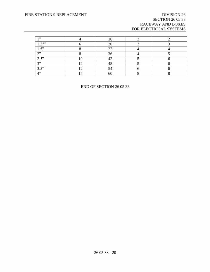
FIRE STATION 9 REPLACEMENT DIVISION 26
SECTION 26 05 33
RACEWAY AND BOXES
FOR ELECTRICAL SYSTEMS
26 05 33 - 20
1” 4 16 3 2
1.25” 6 20 3 3
1.5” 8 27 4 4
2” 8 36 4 5
2.5” 10 42 5 6
3” 12 48 5 6
3.5” 12 54 6 6
4” 15 60 8 8
END OF SECTION 26 05 33
FIRE STATION 9 REPLACEMENT DIVISION 26
SECTION 26 05 53
IDENTIFICATION FOR
ELECTRICAL SYSTEMS
26 05 53 - 1
PART 1 - GENERAL
1.1 RELATED DOCUMENTS
A. Drawings and general provisions of the Contract, including Municipality of Anchorage
Standard Specifications – Buildings (MASSB), General and Supplementary Conditions
apply to this Section.
1.2 WORK INCLUDED
A. Nameplates and tape labels.
B. Wire and cable markers.
C. Wire markers.
D. Conduit markers.
E. Underground warning tape.
F. Power one-line diagram and panel map.
G. Low-voltage one-line diagrams and system maps.
1.3 RELATED WORK
A. The Work under this section is subject to requirements of the Contract Documents
including the General Conditions, Supplementary Conditions, and sections under the
General and Supplementary Conditions and Section 26 05 00 – Common Work Results
for Electrical.
B. Section 26 05 19 – Low-Voltage Electrical Power Conductors and Cables.
C. Section 26 05 33 – Raceway and Boxes for Electrical Systems.
D. Section 26 24 16 – Panelboards
E. Section 26 27 26 – Wiring Devices
F. Section 27 10 00 – Structured Cabling.
FIRE STATION 9 REPLACEMENT DIVISION 26
SECTION 26 05 53
IDENTIFICATION FOR
ELECTRICAL SYSTEMS
26 05 53 - 2
G. Section 28 31 00 – Fire Detection and Alarm.
1.4 SUBMITTALS
A. The General and Supplementary Conditions and Section 26 05 00 – Common Work
Results for Electrical.
B. Product Data:
1. Submit manufacturer’s catalog literature for each product required.
2. Submit electrical identification schedule including list of wording, symbols, letter
size, color-coding, tag number, location, and function.
C. Manufacturer's Installation Instructions: Indicate installation instructions, special
procedures, and installation.
D. Prior to installation, submit power one-line diagram and panel map for review.
E. Prior to Substantial Completion, submit copies of all panel schedules for review by the
Owner. The Owner will note any changes to the room numbers/names and the
Contractor shall provide revised typed panel schedules to reflect all changes, at no
additional cost to the Owner.
F. Electrical One-Line Diagrams and Panel Maps: Provide electronically in AutoCAD
format, submitted with the O&M manuals.
1.5 ENVIRONMENTAL REQUIREMENTS
A. Install labels and nameplates only when ambient temperature and humidity conditions
for adhesive are within range recommended by manufacturer.
PART 2 - PRODUCTS
2.1 NAMEPLATES
A. Product Description: Laminated three-layer plastic with engraved white letters on black
background. Nameplate for service disconnect shall be engraved white letters on red
background.
B. Letter Size:
1. 1/4-inch high letters for identifying individual panel or equipment.
FIRE STATION 9 REPLACEMENT DIVISION 26
SECTION 26 05 53
IDENTIFICATION FOR
ELECTRICAL SYSTEMS
26 05 53 - 3
2. 1/8-inch high letters for remaining lines with 1/8 inch spacing between lines.
C. Minimum nameplate size: 1/8 inch thick with a consistent length and height for each
type of nameplate wherever installed on the project.
2.2 TAPE LABELS
A. Product Description: Adhesive tape labels, with 3/16 inch Bold Black letters on clear
background made using Dymo RhinoPro 5000 label printer or approved equal.
B. Embossed adhesive tape will not be permitted for any application.
2.3 WIRE MARKERS
A. Power and Lighting Description: Cloth tape type wire markers for all neutrals and
Phase conductors.
B. Low Voltage System Description: Self-adhesive machine printed label with unique
wire number that is shown on shop drawing for system.
C. Telecommunications Cable Markers: Self-laminating vinyl with translucent band and
minimum 1”W x .5”H printable area with matte white finish. Brady #B-427 series or
approved equal.
2.4 FIRE ALARM CONDUIT AND BOX IDENTIFICATION
A. Product Description: Red spray paint for fire alarm boxes.
B. Fire alarm conduit shall have red finish, as specified in Section 26 05 33 – Raceway and
Boxes.
2.5 UNDERGROUND WARNING TAPE
A. Product Description: Red, 6-inch wide, detectable.
B. Wording to read “Caution – Buried Electric Line Below”.
2.6 POWER DISTRIBUTION SYSTEM ONE-LINE DIAGRAM AND PANEL MAP
A. Product Description: One-line diagram and building floor plan panel map. One-line
diagram shall show the complete building power system for each MDP. Panel map
FIRE STATION 9 REPLACEMENT DIVISION 26
SECTION 26 05 53
IDENTIFICATION FOR
ELECTRICAL SYSTEMS
26 05 53 - 4
shall show the plan view location of all distribution panels and branch panelboards.
Minimum size shall be 11”x17” but larger maps are recommended. All text shall be
legible without magnification.
B. Install one-line and panel map behind a Plexiglas cover screwed to wall on four corners,
adjacent to each MDP.
2.7 LOW-VOLTAGE SYSTEMS ONE-LINE DIAGRAMS AND MAPS
A. Provide one-line diagrams and system maps for low-voltage and special systems, such
as fire, security, telecommunications, intercom, etc. Requirements are specified in
individual specification sections for each system.
PART 3 - EXECUTION
3.1 GENERAL INSTALLATION
A. Degrease and clean surfaces to receive nameplates and tape labels.
B. Install nameplates and tape labels parallel to equipment lines.
C. Underground Warning Tape Installation: Install underground warning tape along length
of each underground conduit, raceway, or cable 6 to 8 inches below finished grade,
directly above buried conduit, raceway, or cable.
3.2 NAMEPLATE INSTALLATION
A. Secure nameplates to equipment fronts using machine screws tapped and threaded into
panelboard, or using rivets. The use of adhesives is not acceptable. Machine screws to
not protrude more than 1/16 inch on back side.
B. Service Disconnect Nameplate: Provide nameplate on exterior service disconnect that
reads “SERVICE DISCONNECT”.
C. Distribution Panel Nameplates:
1. Provide overall equipment identification.
a. Line 1: Distribution panel name.
b. Line 2: Source which panelboard is fed.
c. Line 3: Voltage, phase and wire configuration.
d. Line 4: AIC rating of the panel.
e. Line 5: Where applicable, indicate that panel is series-rated.
FIRE STATION 9 REPLACEMENT DIVISION 26
SECTION 26 05 53
IDENTIFICATION FOR
ELECTRICAL SYSTEMS
26 05 53 - 5
2. Provide circuit breaker identification for each feeder breaker.
a. Line 1: Name of panelboard or equipment served.
b. Line 2: Location of served panelboard.
D. Branch Panelboard Nameplates:
1. Provide nameplate for each panelboard with the following information:
a. Line 1: Panelboard name.
b. Line 2: Source from which the panelboard is fed.
c. Line 3: Voltage, phase and wire configuration.
d. Line 4: AIC rating of the panelboard.
E. Disconnects, Starters, or Contactors:
1. Provide nameplate for each device with the following information:
a. Line 1: Load served.
b. Line 2: Panelboard and circuit number from which the device is fed.
c. Line 3: Fuse or Circuit amperage and poles. Where fused disconnect is in-
stalled, denote the maximum fuse size to be installed.
F. Control or Low Voltage System Panels:
1. Provide nameplate for each control panel with the following information:
a. Line 1: Unique panel name as shown on the shop drawings.
b. Line 2: System description such as Fire Alarm, Intercom, BAS, Security,
etc.
c. Line 3: Panelboard and circuit number from which the panel is fed if appli-
cable.
3.3 LABEL INSTALLATION
A. Conduit Feeder Labels - Provide conduit labels on all feeder raceways as follows:
1. Distribution Panels – “PANEL xxxx IN ROOM #xxx”.
2. Panelboards – “PANEL xxxx FED FROM MDP xxx”.
B. Spare Raceways: Provide raceway label on each individual raceway denoting the
source and termination point at each end.
C. Fire Alarm Device Labels: As specified in Section 28 31 00 – Addressable Fire Alarm
and Smoke Detection Systems.
D. Low-Voltage System Device Labels: Provide label on each device, denoting device ID
or address where applicable. Affix label to device faceplate for ceiling-mounted
FIRE STATION 9 REPLACEMENT DIVISION 26
SECTION 26 05 53
IDENTIFICATION FOR
ELECTRICAL SYSTEMS
26 05 53 - 6
devices or wall-mounted devices above 8’-0” AFF. Affix label inside backbox for
exterior devices.
3.4 WIRE IDENTIFICATION
A. Provide wire markers on each conductor in panelboard gutters, pull boxes, outlet and
junction boxes, and at load connection. Identification shall be as follows:
1. Markers shall be located within one inch of each cable end, except at panelboards,
where markers for branch circuit conductors shall be visible without removing
panel deadfront.
2. Each wire and cable shall carry the same labeled designation over its entire run,
regardless of intermediate terminations.
3. Color code phases, neutral, and ground per NEC requirements and Section
26 05 19 – Low Voltage Electrical Power Conductor and Cables.
4. Color-code all low-voltage system wires and cables in accordance with the
individual sections in which they are specified.
5. For power and lighting circuits, identify with branch circuit or feeder number.
6. Control Circuits: Control wire number as indicated on schematic and shop
drawings.
7. Fire Alarm Circuits: Provide cable markers showing NAC or SLC loop
identification number at all fire alarm junction boxes and pullboxes.
8. Provide cable markers on each cable, indicating device designation (e.g. “Camera
27”) for all security, intercom, door control, MATV, and CATV systems. Cables
shall be labeled at each end, as well as at any intermediate junction boxes or
pullboxes.
B. Provide pull string markers at each end of all pull strings. Marker shall identify the
location of the opposite end of the pull string.
3.5 JUNCTION BOX IDENTIFICATION
A. Fire Alarm: In accessible ceiling spaces, exposed ceiling spaces, mechanical/electrical
rooms, and other non-public spaces, paint fire alarm junction boxes and pullboxes with
red spray paint. In all finished spaces where fire alarm boxes are visible, they shall be
painted to match the surrounding finish. If there are any questions as to whether fire
alarm boxes shall be painted red in a specific area, the Contractor shall get clarification
from the Owner prior to painting.
B. Paint all junction boxes designated for future expansion with blue spray paint.
C. Label each lighting and power junction box with the panelboard name and circuit
number.
FIRE STATION 9 REPLACEMENT DIVISION 26
SECTION 26 05 53
IDENTIFICATION FOR
ELECTRICAL SYSTEMS
26 05 53 - 7
D. Label all junction boxes for door control, and CATV systems with the type of system
cables contained in the box.
E. For junction boxes above ceilings, mark the box cover with the circuit or system
designation using permanent black marker. For junction boxes in finished areas, mark
the inside of the cover with the circuit or system designation using permanent black
marker.
3.6 DEVICE PLATE IDENTIFICATION
A. Label each receptacle device plate or point of connection denoting the panelboard name
and circuit number.
B. Install adhesive label on the top of each plate.
3.7 PANELBOARD IDENTIFICATION
A. Provide panelboard circuit directories in accordance with Section 26 24 16 -
Panelboards.
B. Install one-line and panel map adjacent to each MDP.
3.8 LOW-VOLTAGE SYSTEM IDENTIFICATION
A. Install all labeling in accordance with the requirements of this section and of each
section where the individual systems are specified.
3.9 WORKING CLEARANCE STRIPING
A. Working clearance striping paint shall be applied in front of panels located in
mechanical rooms, electrical rooms, storage rooms, and other non-public areas with
exposed concrete floors.
B. Striping paint shall not be applied in front of panels located in corridors and other
public spaces, or spaces with finished floor surfaces (e.g., carpet, tile, vinyl, etc.).
END OF SECTION 26 05 53
FIRE STATION 9 REPLACEMENT DIVISION 26
SECTION 26 05 73
OVERCURRENT PROTECTIVE
DEVICE COORDINATION STUDY
26 05 73 - 1
PART 1 - GENERAL
1.1 RELATED DOCUMENTS
A. Drawings and general provisions of the Contract, including Municipality of Anchorage
Standard Specifications – Buildings (MASSB), General and Supplementary Conditions
apply to this Section.
1.2 SUMMARY
A. Section includes short circuit and protective device coordination study encompassing
portions of electrical distribution system from up to and including fuses in service main
disconnect(s), main breaker in sub-distribution panels, and main breaker in each
panelboard.
1.3 RELATED SECTIONS
A. Section 26 05 19 - Low-Voltage Electrical Power Conductors and Cables.
B. Section 26 24 16 – Panelboards.
C. Section 26 28 00 – Low-Voltage Circuit Protective Devices.
D. Section 26 29 13 - Enclosed Controllers.
E. Section 26 32 13 - Engine Generators.
F. Section 26 36 00 - Transfer Switches.
1.4 REFERENCES
A. Institute of Electrical and Electronics Engineers:
1. IEEE 242 - Recommended Practice for Protection and Coordination of Industrial
and Commercial Power Systems (Buff Book).
B. National Fire Protection Association:
1. NFPA 70 - National Electrical Code.
FIRE STATION 9 REPLACEMENT DIVISION 26
SECTION 26 05 73
OVERCURRENT PROTECTIVE
DEVICE COORDINATION STUDY
26 05 73 - 2
1.5 DESIGN REQUIREMENTS
A. Complete Short Circuit and Protective Device Coordination Study to meet requirements
of NFPA 70.
B. Report Preparation:
1. Preliminary study shall be prepared prior to ordering distribution equipment to
verify equipment ratings required.
2. Perform study with aid of computer software program "SKM System Analysis,
Inc.," Power Tools Electrical Engineering Software or approved equal.
3. Study shall be shall be conducted under the supervision and approval of a
Registered Professional Electrical Engineer.
4. Calculate short circuit interrupting and, when applicable, momentary duties for
assumed 3-phase bolted fault short circuit current and phase to ground fault short
circuit current at each of the following:
a. Automatic transfer switch.
b. Engine generator.
c. Low-voltage switchgear.
d. Distribution panelboards.
e. Branch circuit panelboards.
f. Busway.
g. Each other significant equipment location throughout system.
C. Report Contents:
1. Include the following:
a. One-line diagram.
b. Descriptions and scope of the study.
c. Tabulations of circuit breaker ratings versus calculated short circuit duties.
d. Time versus current coordination curves, tabulations of circuit breaker trip
unit settings, fuse selection.
e. Fault current calculations.
f. Recommendations.
1.6 SUBMITTALS
A. The General and Supplementary Conditions: Requirements for submittals.
B. Qualifications Data: Submit the following for review prior to starting study.
1. Submit qualifications of individual or individuals performing study and
Professional Engineer supervising and approving the study.
FIRE STATION 9 REPLACEMENT DIVISION 26
SECTION 26 05 73
OVERCURRENT PROTECTIVE
DEVICE COORDINATION STUDY
26 05 73 - 3
C. Software: Submit for review information on software proposed to be used in performing
study.
D. Product Data: Submit the following:
1. Report: Summarize results of study in report format including the following:
a. Descriptions, purpose, basis, and scope of study.
b. Tabulations of circuit breaker, fuse and other protective device ratings
versus calculated short-circuit duties, and commentary regarding same.
c. Protective device time versus current coordination curves, tabulations of
relay and circuit breaker trip settings, fuse selection, and commentary
regarding same.
d. Fault current calculations including definition of terms and guide for
interpretation of computer printout.
2. Submit copies of final report signed by professional engineer. Make additions or
changes required by review comments.
E. Electrical Distribution Gear and Equipment shall not be ordered until the study has been
approved and necessary adjustments have been made.
PART 2 - PRODUCT
NOT APPLICABLE
PART 3 - EXECUTION
3.1 FIELD QUALITY CONTROL
A. The General and Supplementary Conditions: Field inspecting, testing, adjusting, and
balancing.
B. Provide assistance to electrical distribution system equipment manufacturer during start
up of electrical system and equipment.
C. Select each primary protective device for delta-wye connected transformer so device’s
characteristic or operating band is within transformer characteristics, including point
equal to 58 percent of ANSI withstand point to provide secondary line-to-ground fault
protection.
D. Separate transformer primary protective device characteristic curves from associated
secondary device characteristics by 16 percent current margin to provide proper
coordination and protection in event of secondary line-to-line faults.

FIRE STATION 9 REPLACEMENT DIVISION 26
SECTION 26 05 73
OVERCURRENT PROTECTIVE
DEVICE COORDINATION STUDY
26 05 73 - 4
END OF SECTION 26 05 73
FIRE STATION 9 REPLACEMENT DIVISION 26
SECTION 26 05 83
WIRING CONNECTIONS
26 05 83 - 1
PART 1 - GENERAL
1.1 RELATED DOCUMENTS
A. Drawings and general provisions of the Contract, including Municipality of Anchorage
Standard Specifications – Buildings (MASSB), General and Supplementary Conditions
apply to this Section.
1.2 WORK INCLUDED
A. Electrical connections to equipment specified under other Sections or furnished by
Owner.
1.3 RELATED WORK
A. The General and Supplementary Conditions - Administrative Requirements; Summary:
Owner-furnished equipment.
B. Division 08 - Openings.
C. Division 10 - Specialties.
D. Division 11 - Equipment.
E. Division 21 – Fire Suppression Systems.
F. Division 22 – Plumbing.
G. Division 23 – Heating, Ventilating, and Air Conditioning (HVAC).
H. Section 26 05 19 - Low-Voltage Electrical Power Conductors and Cables.
I. Section 26 05 33 - Raceway and Boxes for Electrical Systems.
1.4 REFERENCES
A. FS W-C-596 - Electrical Power Connector, Plug, Receptacle, and Cable Outlet.
B. National Electrical Manufacturers Association:
FIRE STATION 9 REPLACEMENT DIVISION 26
SECTION 26 05 83
WIRING CONNECTIONS
26 05 83 - 2
1. NEMA WD 1 - General Purpose Wiring Devices.
2. NEMA WD 5 - Specific-Purpose Wiring Devices.
1.5 SUBMITTALS
A. The General and Supplementary Conditions – Submittal Procedures.
B. Product Data: Submit wiring device manufacturer’s catalog information showing
dimensions, configurations, and construction.
C. Manufacturer's installation instructions.
1.6 COORDINATION
A. The General and Supplementary Conditions - Administrative Requirements:
Coordination and project conditions.
B. Obtain and review shop drawings, product data, manufacturer’s wiring diagrams, and
manufacturer's instructions for equipment furnished under other sections.
C. Determine connection locations and requirements.
D. Sequence rough-in of electrical connections to coordinate with installation of
equipment.
E. Sequence electrical connections to coordinate with start-up of equipment.
PART 2 - PRODUCTS
2.1 CORDS AND CAPS
A. Straight-blade Attachment Plug: NEMA WD 1.
B. Locking-blade Attachment Plug: NEMA WD 5.
C. Attachment Plug Configuration: Match receptacle configuration at outlet provided for
equipment.
D. Cord Construction: Oil-resistant thermoset insulated Type SO multiconductor flexible
cord with identified equipment grounding conductor, suitable for extra hard usage in
damp locations.
FIRE STATION 9 REPLACEMENT DIVISION 26
SECTION 26 05 83
WIRING CONNECTIONS
26 05 83 - 3
E. Cord Size: Suitable for connected load of equipment and rating of branch circuit
overcurrent protection.
PART 3 - EXECUTION
3.1 INSPECTION
A. Verify that equipment is ready for electrical connection, wiring, and energization.
3.2 PREPARATION
A. Review equipment submittals prior to installation and electrical rough-in. Verify
location, size, and type of connections. Coordinate details of equipment connections
with supplier and installer.
3.3 EXISTING WORK
A. Remove exposed abandoned equipment wiring connections including abandoned
connections above accessible ceiling finishes.
B. Disconnect abandoned utilization equipment and remove wiring connections. Remove
abandoned components when connected raceway is abandoned and removed. Install
blank cover for abandoned boxes and enclosures not removed.
C. Extend existing equipment connections using materials and methods as specified.
3.4 INSTALLATION
A. Use wire and cable with insulation suitable for temperatures encountered in heat-
producing equipment.
B. Make conduit connections to equipment using flexible conduit. Use Liquidtight flexible
conduit in damp or wet locations.
C. Install pre-finished cord set where connection with attachment plug is indicated or
specified by the equipment manufacturer's installation instructions, or use attachment
plug with suitable strain-relief clamps.
D. Provide suitable strain-relief clamps for cord connections to outlet boxes and equipment
connection boxes.
FIRE STATION 9 REPLACEMENT DIVISION 26
SECTION 26 05 83
WIRING CONNECTIONS
26 05 83 - 4
E. Make wiring connections in control panel or in wiring compartment of pre-wired
equipment in accordance with manufacturer's instructions. Provide interconnecting
wiring where required.
F. Install disconnect switches, controllers, control stations, and control devices such as
limit switches and temperature switches and connect with conduit and wiring as
indicated in the equipment manufacturer's installation instructions.
3.5 ADJUSTING
A. Cooperate with utilization equipment installers and field service personnel during
checkout and starting of equipment to allow testing and balancing and other startup
operations. Provide personnel to operate electrical system and checkout wiring
connection components and configurations.
END OF SECTION 26 05 83
FIRE STATION 9 REPLACEMENT DIVISION 26
SECTION 26 09 26
LIGHTING CONTROL PANELBOARDS
26 09 26 - 1
PART 1 - GENERAL
1.1 RELATED DOCUMENTS
A. Drawings and general provisions of the Contract, including Municipality of Anchorage
Standard Specifications – Buildings (MASSB), General and Supplementary Conditions
apply to this Section.
1.2 WORK INCLUDED
A. A new low voltage lighting control system shall be provided to control the Lighting as
noted on the Plans. The system shall have the capability to be controlled locally via
intelligent lighting control switches.
B. Contractor’s work to include all labor, materials, tools, appliances, hardware, lighting
control panels, relays, sensors, wire, junction boxes, switches and equipment necessary
for and incidental to the delivery, installation and furnishing of a completely operational
lighting control system, as described herein.
1.3 RELATED WORK
A. Section 26 05 19 – Low-Voltage Electrical Conductors and Cables.
B. Section 26 05 33 – Raceway and Boxes for Electrical Systems.
C. Section 26 51 00 – Interior Lighting.
D. Section 26 56 00 – Exterior Lighting.
1.3 SUBMITTALS
A. Submit product data under provisions of the General and Supplementary Conditions.
B. Manufacturer shall substantiate conformance of this specification by supplying the
necessary catalog literature, documents, performance data and wiring diagrams. Any
deviations to this specification shall be clearly stated by letter and submitted.
FIRE STATION 9 REPLACEMENT DIVISION 26
SECTION 26 09 26
LIGHTING CONTROL PANELBOARDS
26 09 26 - 2
C. Submit a single line riser diagram of the control system showing interconnect wiring
between panels and devices including conductor type, quantity and size. Submit panel
diagrams or panel schedules indicating load controlled, circuit controlled, and connected
switches.
1.4 DELIVERY, STORAGE AND HANDLING
A. Deliver products to site, store and protect under provisions of the General and
Supplementary Conditions.
B. All lighting control equipment, wiring, etc. shall be stored in an enclosed area,
maintained at a minimum of 55 F and shall be protected from weather.
1.5 QUALIFICATIONS
A. Manufacturer: Company specializing in lighting control systems for a minimum of three
(3) years documented experience in Alaska.
B. All components and panels shall be UL listed, shall be manufactured by a UL listed
panel shop, offer a minimum three (3) year warranty and meet all state and local code
requirements.
C. Lighting control panels, components and assemblies shall be assembled and fully
factory tested prior to shipment and installation. Site assembled panels or components
shall not be allowed.
1.6 EXTRA MATERIALS
A. Furnish to the Owner the following extra materials for the lighting control system:
1. Eight (8) relays of each type.
1.7 WARRANTY
A. Warrant all materials and equipment to be new and free from defects in material and
workmanship for a period of one (1) year under provisions of the General and
Supplementary Conditions.
FIRE STATION 9 REPLACEMENT DIVISION 26
SECTION 26 09 26
LIGHTING CONTROL PANELBOARDS
26 09 26 - 3
1.8 PROJECT RECORD DRAWINGS
A. Submit documents under provisions of the General and Supplementary Conditions.
B. Provide contract size reproducible documents showing the as-built location of all new
control panels, existing momentary contact switches, any new conduit routing, and all
new junction box locations.
1.9 OPERATION AND MAINTENANCE MANUALS
A. Submit data under provisions of the General and Supplementary Conditions.
B. Provide operation and maintenance instructions including detail electronic schematic
drawings, detailed parts list and exploded view of all equipment, detailed
troubleshooting instructions and a reduced set of the project record drawings.
C. Provide lighting control operational summary sheet.
D. Provide programming record sheet.
PART 2 - PRODUCTS
2.1 ACCEPTABLE MANUFACTURERS
A. Watt Stopper, ‘LP Lighting Control Panel’
B. Intelligent Lighting Controls, Inc LightMaster Series.
C. Lithonia Lighting “Synergy” Lighting Control System.
D. Substitutions: Under provisions of the General and Supplementary Conditions.
2.2 PROGRAMMABLE LIGHTING CONTROLLER
A. Enclosure
1. UL listed NEMA 1 enclosure designed for wall mounting. Backbox must be
capable of being shipped ahead of controller chassis insert to allow for rough-in of
all electrical connections prior to receipt of the controller chassis insert.
2. Each programmable lighting controller shall be provided with a factory or field
installable controller chassis insert. Controller chassis insert shall contain all
FIRE STATION 9 REPLACEMENT DIVISION 26
SECTION 26 09 26
LIGHTING CONTROL PANELBOARDS
26 09 26 - 4
controller electronics, power supplies, relays, contactors and other required
components. Controller chassis inserts shall arrive at the project site completely
pre-wired and requiring only the connection of lighting circuits and control
devices.
3. Each programmable lighting controller shall be provided with a mechanical
barrier that separates all line voltage components and wiring from all control
voltage components and wiring. An additional barrier may be installed within the
line voltage section that shall provide isolation between normal and emergency
circuits where required.
4. Each programmable lighting controller shall be provided with a dead front screw-
held or hinged locking cover that is designed for either surface or flush mounting.
5. Controllers shall be available in sizes to accommodate up to 48 low voltage
switch inputs and 8 relay outputs. Controllers shall be available in either the
standard configuration in which the electronics are to the left of the voltage barrier
with the line voltage compartment on the right or with the electronics in the center
and two line/low voltage dividers with the lighting relays on the right and left
sides.
B. Electrical:
1. Controller Power Supply: Each programmable lighting controller shall be
provided with two dual-rated, UL listed Class 2 transformers capable of either 120
or 277 VAC primary (50 to 60 Hz).
2. Connections: All connections shall be made to clearly and permanently labeled
termination points.
C. Controller Electronics:
1. Controller CPU: Each programmable controller shall be provided with a CPU
(Central Processing Unit) that shall provide all the programming and control
functions for the entire controller. CPU shall be protected against loss of memory
during a power outage through nonvolatile RAM for a period of up to 10 years
without power of any type.
2. Real-Time Clock: Real-Time Clock shall be used to perform all time-controlled
functions. Clock accuracy shall be displayed to the second. Real-Time Clock
functions shall include time of day, day of week, date and automatic daylight
savings and leap year adjustments. Time clock shall be protected against loss of
time during a power outage for a period of up to 45 days without power of any
type.
3. I/O Controller: I/O (input/output) cards shall be provided to expand the controller
capability from 8 to 48 switch inputs and relay outputs in groups of 8. Electronics
shall feature surge protection and opto-isolation.

FIRE STATION 9 REPLACEMENT DIVISION 26
SECTION 26 09 26
LIGHTING CONTROL PANELBOARDS
26 09 26 - 5
4. Switch Input Characteristics: Each switch input shall be designed to be actuated
by dry contact from 2 or 3 wire momentary or maintained switches or their logical
equivalents (photo cell contacts, Building Automation System Outputs, Time
clocks etc.)
5. Input LEDs: For each input there shall be three LEDs: ON input contact status
(hardwired), OFF input contact status (hardwired) and Programmable Pilot
Output. The LEDs reflect the true status of the relay controlled by the switch
input. Normally this Pilot LEDs track with the status LED(s) of the affected
relays. (If the switch turns on relay output 5 for example, relay 5 output LED will
light.) However the user has the option of programming the LED to indicate the
status of any relay, group or preset.
6. Relay Output Characteristics: Each Relay Output shall control either a latching
lighting relay rated for 120 or 277 VAC @ 20 full load amps. or a dry contact
output that shall provide pulsed or maintained switching of the Class 2 circuits of
other devices such as two pole relays, contactors etc. Each output is equipped
with manual ON and OFF buttons that may be used to control the output
regardless of programming. In addition, each output has a status LED that
indicates the current status of the output.
7. Communications: The controller shall be equipped with a serial (RS232) port,
modem, and infrared transceiver for monitoring and programming purposes.
F. Programming: Programmable controllers shall be capable of being programmed,
monitored or controlled through any or all of the below methods. All programming
changes shall take effect
Immediately as they are programmed and shall not suspend or disable switches or other
system functions. The same functions shall be available for any of the connection types.
1. Local Key Pad and Display: The system user shall be able to program, monitor
and control any of the controller features and functions through the use of simple
menu-driven self-prompting user interface consisting of a 4-line 20-character
backlit LCD display and 6 selection keys that change function based on the
current operating mode.
G. Diagnostic Aids: Each programmable lighting controller shall be provided with an LED
that shall indicate that the main power supply is present and operational. Each relay
output shall have an LED pilot to indicate the current status of all controlled relay
outputs. In addition, the system user shall be able to monitor and control any
programmable lighting controller directly and in real time through any of the
programming methods listed above. System users shall be able to view the current status
of any or all relay outputs, force any relay output ON or OFF, and view the current
status of any or all switch inputs.
FIRE STATION 9 REPLACEMENT DIVISION 26
SECTION 26 09 26
LIGHTING CONTROL PANELBOARDS
26 09 26 - 6
H. Data Protection and Storage: All programmed data shall be stored in nonvolatile RAM
that shall protect all stored programming data from loss during a power outage for a
minimum period of 10 years without power of any type.
I. Power Failure and Power-Up Options: Each programmable lighting controller shall be
provided with circuitry that shall automatically shut down the controller whenever the
incoming power fails to be delivered to the controller within required limits. When
power is returned to the controller, one of the following power-up modes will be
implemented (user selectable) for each controlled relay output in the system.
1. No Action: Upon restoration of incoming control power, the controller
electronics shall be restarted and resume normal operations, and all circuits will
be maintained in the condition they were last in.
2. Forced ON: Controller will force the selected relay output to the ON state after
power-up. Time-scheduled events that were to take place during the power outage
will be ignored; however, all future scheduled events will be activated.
3. Forced OFF: Controller will force the selected relay output to the OFF state after
power-up. Time-scheduled events that were to take place during the power outage
will be ignored; however, all future scheduled events will be activated.
J. Manual Push Buttons: Each relay output shall be supplied with an ON and OFF manual
push-button with LED pilot that shall allow the system user to view the current status
and/or manually turn any relay output to the ON or OFF state.
K. True Relay Status Feedback: Each controller shall be provided with circuitry that shall
monitor the actual current status of each relay via a set of pilot contacts mechanically
linked to the relay main contacts.
L. Staggered or Instant Relay ON/OFF Activation: Programmable lighting controller shall
be support user selectable instantaneous or staggered (17 or 50 ms pulse duration) relay
activation.
M. Input Flexibility: Each switch input shall accept the logical equivalent of a dry contact
2- or 3-wire maintained or momentary switch.
N. Input to Output Programmability: Any switch input may be programmed to control any
or all of the controllers relay output(s) without limitations. Any switch input anywhere
in a control network can control any or all relay output(s).
O. Relay Groups: The controller also shall support the grouping of individual relay outputs
into 8 relay groups. These groups may be controlled by switch, or time based signals.
P. Switch Input Types: Each of the programmable lighting controller switch inputs shall
be programmable for one of the below listed switch types.
FIRE STATION 9 REPLACEMENT DIVISION 26
SECTION 26 09 26
LIGHTING CONTROL PANELBOARDS
26 09 26 - 7
1. Momentary ON/OFF: When momentary contact is made between the ON and
COM, relay outputs controlled by this input are turned ON. When momentary
contact is made between OFF and COM, relay outputs controlled by this input are
turned OFF.
2. Momentary Push-Button: When momentary contact is made between the ON and
COM, relay outputs controlled by this input are turned ON and OFF alternately,
based on current state, each time contact is made.
3. Maintained ON/OFF: When contact is made between the ON and COM, relay
outputs controlled by this input are turned ON. When contact is broken between
ON and COM, relay outputs controlled by this input are turned OFF.
4. Set Preset: When momentary contact is made between the ON and COM, the
selected preset scene will be activated. Controller shall provide 48 user definable
presets that can be activated by switch input or timer.
5. Two-Step Alternating Sequence: The first time the switch is activated, relay
outputs programmed as “Group A” are turned ON and relay outputs programmed
as “Group B” are turned OFF. The second time the switch is activated, “Group A”
relay outputs are turned OFF and “Group B” relay outputs are turned ON. The
third time the switch is activated, the pattern begins again at step one.
6. Timed ON: The timed ON input shall operate either from the input closure or
open. If programmed to operate from the closure, the relays turn ON when the
input closes and turn OFF after the timed duration. The relays do nothing when
the input opens. If programmed to operate from the open, the relays turn ON when
the input closes and remain ON. When the input opens, the relays turn OFF after
the timed ON duration.
7. Input Disable: When maintained contact is made between the ON and COM,
inputs programmed for disable from this switch input will be ignored.
8. Timer Disable: When maintained contact is made between the ON and COM,
timers programmed for disable from this switch input will be ignored.
9. Network Disable: When maintained contact is made between the ON and COM,
network commands sent to the controller via the control network are ignored.
10. Output Override: When maintained contact is made between the ON and COM,
relay outputs controlled by this input are either turned ON, OFF or HELD in their
current state until the input is released. All inputs, timers and network commands
are ignored for controlled relay outputs.
Q. Photo / Motion Sensor Inputs: Programmable lighting controllers shall be designed to
accept dry contact control inputs from photo or motion sensors and program them to
perform any of the available switch input functions.
R. Switch Enable/Disable: The system shall support the ability to enable/disable switch
inputs according to a user-defined set of times.
FIRE STATION 9 REPLACEMENT DIVISION 26
SECTION 26 09 26
LIGHTING CONTROL PANELBOARDS
26 09 26 - 8
T. Blink Alert: Each relay output within the programmable lighting controller can be
individually programmable to blink prior to being turned OFF. The blink alert function
shall blink each relay twice prior to turning OFF with a timer Off sweep to warn
occupants of the upcoming OFF event. If an ON command is received during the blink
alert time, relay output will be overridden and left ON for the override time. Override
times shall be adjustable from 5 to 999 minutes in 1-minute increments.
U. Astronomical Clock: Each controller shall contain an astronomical time clock that shall
calculate sunrise and sunset times based on the geographical positioning information
provided during the programming of the system. Sunrise and sunset times may be used
as activation times for any system timer. In addition to sunrise and sunset time
activation, the control shall be capable of programming activation time for the system
timer for before and after these times based on an offset of 1-999 minutes either before
or after the calculated sunrise or sunset event.
V. Open/Closed Time Control: The user shall also have the option of controlling relay
outputs in relation to the OPEN/CLOSED times of the facility. The open/closed times
may vary for different days per day of the week and may be programmed for each day of
the year.
W. Time-of-Day Scheduling: Each programmable lighting controller shall be provided
with a minimum of 48 available timers (scheduled events) for use in developing time-
of-day automated schedules. Each timer shall have the ability to turn any or all relay
outputs ON, OFF at any standard time in 1-minute increments or at times calculated by
the astronomical clock for sunrise and sunset with offset. Timers shall be day-of-week
selectable timers and may be programmed to activate on any combination of days of the
week (Sunday through Saturday), on all days, or to activate on a specific date only
(“Holiday Schedule”). Each non-holiday timer shall be capable of being programmed to
either halt operation on holidays or to ignore holidays and continue normal operations
on holidays.
X. OFF Sweeps: The system shall also support after hours OFF sweeps of selected relay
outputs at user defined one, two, or three hour intervals
Y. Pre-Sets: The lighting controller shall support up to 48 user-defined presets (ON/OFF
relay patterns). The presets may be invoked by switch or timer actuation.
Z. Descriptive Names: The system shall support the optional assignment of descriptive
names (up to 10 characters) to the lighting controller, relay outputs, relay groups, inputs,
timers, and presets.
AA. Password Protection: Each Programmable controller shall have a user definable 6-
number password, which will lock out the keypad programming functions.
FIRE STATION 9 REPLACEMENT DIVISION 26
SECTION 26 09 26
LIGHTING CONTROL PANELBOARDS
26 09 26 - 9
PART 3 - EXECUTION
3.1 INSTALLATION
A. The contractor shall locate, install, wire and program all lighting control panels as
directed in the contract drawings, specifications and in accordance with the
manufacturer’s installation and operation instructions.
B. The contractor shall provide, install and terminate interconnecting wiring between main
control panels, expansions panels, photocells, switches and other interconnecting
devices. Line voltage and class 2 (low voltage) wiring shall only be installed in the
respective section of the lighting control panels and devices.
C. The contractor shall arrange a pre-installation meeting with the manufacturer’s factory
authorized representative and Owner’s Representative, to review lighting schedules,
application, placement and installation criteria.
D. The contractor shall provide, at the Owner’s facility, the training necessary to
familiarize the Owner’s personnel with the operation, use, adjustment, programming,
and problem solving diagnosis of the lighting control system.
E. Lighting control system manufacturer shall provide all necessary technical phone
assistance to the contractor during installation of the lighting control system.
F. A wiring schedule directory card shall be installed on the back of the front cover of each
relay panel which identifies all circuits/relays/loads controlled.
3.2 INSTRUCTION OF OPERATION PERSONNEL
A. Provide the Owner’s authorized personnel with operation and maintenance instructions
for the lighting control system as specified in Section 26 05 00 – Common Work
Results for Electrical.
B. Conduct walking tour of project and briefly describe function, operation, and
maintenance of each component.
3.3 FIELD QUALITY CONTROL
A. The final connections, start-up, check-out and Owner instruction on the system shall be
done by a manufacturer’s certified and authorized technician.
FIRE STATION 9 REPLACEMENT DIVISION 26
SECTION 26 09 26
LIGHTING CONTROL PANELBOARDS
26 09 26 - 10
B. Under provisions of the General and Supplementary Conditions and Section 26 05 00 –
Common Work Results for Electrical, the manufacturer’s certified technician shall
make a thorough inspection of the complete installation including all components to
ensure the following:
1. The system is complete and functional and complies with all requirements of the
specifications.
2. All equipment meets Underwriter’s Laboratories requirements.
3. The system is installed in accordance with the manufacturer’s instructions.
4. Project record drawings are complete and up to date.
5. Make changes necessary to conform to Items 1, 2, 3 and 4 with technical
assistance from the manufacturer as required.
END OF SECTION 26 09 26
FIRE STATION 9 REPLACEMENT DIVISION 26
SECTION 26 24 16
PANELBOARDS
26 24 16 - 1
PART 1 - GENERAL
1.1 RELATED DOCUMENTS
A. Drawings and general provisions of the Contract, including Municipality of Anchorage
Standard Specifications – Buildings (MASSB), General and Supplementary Conditions
apply to this Section.
1.2 SECTION INCLUDES
A. Service and distribution panelboards.
B. Lighting and appliance branch circuit panelboards.
1.3 RELATED SECTIONS
A. The Work under this section is subject to requirements of the Contract Documents
including the General Conditions, Supplementary Conditions, and sections under the
General and Supplementary Conditions and Section 26 05 00 –Common Work Results
for Electrical.
B. Section 26 05 26 – Grounding and Bonding for Electrical Systems.
C. Section 26 05 53 – Identification for Electrical Systems.
1.4 REFERENCES
A. NEMA AB 1 - Molded Case Circuit Breakers.
B. NEMA PB 1 - Panelboards.
C. NEMA PB 1.1 - Instructions for Safe Installation, Operation and Maintenance of
Panelboards Rated 600 Volts or Less.
D. NEMA PB 2.2 - Application Guide for Ground-fault Protective Devices for Equipment.
E. UL 50 – Enclosures for Electrical Equipment
F. UL 67 – Panelboards
FIRE STATION 9 REPLACEMENT DIVISION 26
SECTION 26 24 16
PANELBOARDS
26 24 16 - 2
G. UL 489 – Molded Case Circuit Breakers and Circuit Breaker Enclosures
H. Federal Specification W-C-375B/Gen – Circuit Breakers, Molded Case, Branch Circuit
and Service
1.5 SUBMITTALS
A. Submit data under provisions of the General and Supplementary Conditions and Section
26 05 00 – Common Work Results for Electrical.
B. Product Data: Submit product data for all components provided which fall under this
section showing configurations, finishes, and dimensions. Each catalog sheet should be
clearly marked to indicate exact part number provided, including all options and
accessories.
C. Shop drawings: Submit shop drawings for each panelboard indicating features and
device arrangement and size. Include outline and support point dimensions, voltage,
main bus ampacity, and integrated short circuit ampere rating.
D. Submit final panel schedules in Microsoft Excel format with the O&M manuals.
1.6 DELIVERY, STORAGE AND HANDLING
A. Deliver products to site under provisions of the General and Supplementary Conditions.
B. Upon arrival at the site inspect equipment and report on any damage.
C. Handle carefully on site to avoid any damage to internal components, enclosures and
finishes.
D. Store in a clean, dry environment. Maintain factory packaging and provide an
additional heavy canvas or plastic cover to protect enclosures from dirt, water,
construction debris and traffic.
1.7 OPERATION AND MAINTENANCE MATERIALS
A. Submit data under provisions of the General and Supplementary Conditions and Section
26 05 00 – Common Work Results for Electrical.
B. Provide product data and shop drawing information including replacement parts list.
C. Provide installation, operation and maintenance information per manufacturer.
FIRE STATION 9 REPLACEMENT DIVISION 26
SECTION 26 24 16
PANELBOARDS
26 24 16 - 3
D. Project record data: Submit final record panel schedules as hardcopy and in Microsoft
Excel format.
1.8 WARRANTY
A. Manufacturer shall warrant specified equipment to be free of defects for a period of one
year from the date of installation.
1.9 SPARE PARTS
A. Keys: Furnish 2 each to Owner.
PART 2 - PRODUCTS
2.1 MANUFACTURERS - PANELBOARDS
A. Square D.
B. Cutler Hammer.
C. General Electric.
D. Siemens.
E. Substitutions: Under provisions of the General and Supplementary Conditions.
2.2 MAIN AND DISTRIBUTION CIRCUIT BREAKER PANELBOARDS
A. Panelboards: NEMA PB 1; circuit breaker type.
B. Enclosure: NEMA PB 1; Type 1 or 3R. As indicated on the drawings. Cabinet size:
6 inches deep; 24 inches wide minimum.
C. Provide cabinet front with door-in-door cover and hinged door with flush lock. Finish in
manufacturer's standard gray enamel.
D. Interior trim shall be dead-front construction to shield user from all energized parts.
E. Main circuit breaker and main lug interiors shall be field convertible for top or bottom
incoming feed.
FIRE STATION 9 REPLACEMENT DIVISION 26
SECTION 26 24 16
PANELBOARDS
26 24 16 - 4
F. Panelboard bussing shall be fully rated with sequential phase distribution. Bussing shall
be plated copper and the plating shall run the entire length of the busbar.
G. Provide UL Listed short circuit current ratings as indicated on the drawings. Minimum
short circuit rating shall be 10,000 amperes RMS symmetrical for 250 volt panelboards;
14,000 amperes RMS symmetrical for 600 volt panelboards.
H. A solidly bonded copper equipment ground bar shall be provided.
I. Solid neutral bus bars shall be provided. Neutral bus shall be of same material as the
phase busses. Solid neutral bars shall be equipped with a full capacity bonding strap for
service entrance applications. Gutter mounted neutrals will not be accepted.
J. Provide UL Listed panelboards with 200% rated neutrals as shown on the plans. 200%
neutral bars shall be copper neutral bus for non-linear load applications.
K. Panelboards shall have nameplates containing the following information:
1. Catalog number.
2. Factory order number.
3. UL Listed Label.
4. Short Circuit Current Rating.
5. Main Circuit Breaker or Main Lug Rating
6. System Voltage
L. Thermal Magnetic Molded Case Circuit Breakers: NEMA AB 1 and FS W-C-
375B/Gen; provide circuit breakers with integral thermal and instantaneous magnetic
trip in each pole. Provide circuit breakers UL listed as Type HACR for air conditioning
equipment branch circuits. Breaker ampacity and AIC rating shall be visible on breaker
without removing panel deadfront or cover.
M. The distribution gear shall be provided as integrated gear line-up with MDP, corner
piece and stacked branched paneboard. Basis of design is Square D MPS. The MPS
line-up is 9.5” deep.
2.3 BRANCH CIRCUIT PANELBOARDS
A. Lighting and Appliance Branch Circuit Panelboards: NEMA PB 1; circuit breaker type.
B. Enclosure: NEMA PB 1; Type 1 or 3R as indicated on Drawings. Boxes shall be
galvanized steel constructed in accordance with UL50 requirements. Interiors shall be
field convertible for top or bottom incoming feed. Main lug interiors up to 400 amperes
shall be field convertible to main breaker. Interior leveling provisions shall be provided
for flush mounted applications.
FIRE STATION 9 REPLACEMENT DIVISION 26
SECTION 26 24 16
PANELBOARDS
26 24 16 - 5
C. Cabinet Size: 6 inches deep; 20 inches wide minimum.
D. Provide flush or surface cabinet front as indicated on the Drawings with door-in-door
cover concealed trim clamps, concealed hinge and flush lock all keyed alike. Finish in
manufacturer's standard gray enamel.
E. Provide panelboards with copper bus, ratings as scheduled on Drawings. Provide one
continuous bus bar per phase each. Panelboards shall have sequentially phased branch
circuit connectors suitable for bolt-on branch circuit breakers. Bussing shall be fully
rated
F. Integrated Short Circuit Rating: Provide panelboards with short circuit ratings as shown
on the Drawings. Minimum ratings shall be 10,000 amperes RMS symmetrical for 250
volt panelboards; 14,000 amperes RMS symmetrical for 600 volt panelboards.
G. Main/Sub Feed Circuit Breakers: NEMA AB 1; Provide vertical mount main and/or sub
feed circuit breaker in panelboards as shown on the drawings.
1. Circuit breakers shall be operated by a toggle-type handle and shall have a quick-
make, quick-break over-center switching mechanism that is mechanically trip-
free. Automatic tripping of the breaker shall be clearly indicated by the handle
position. Contacts shall be nonwelding silver alloy and arc extinction shall be
accomplished by means of DE-ION arc chutes. A push-to-trip button on the front
of the circuit breaker shall provide a local manual means to exercise the trip
mechanism.
2. Lugs shall be UL Listed to accept copper and aluminum conductors and shall be
suitable for 90oC rated wire, sized according to the 75
oC temperature rating per
NEC Table 310-16. Lug body shall be bolted in place.
3. Main circuit breakers shall be UL listed for use with the following accessories:
a. Shunt Trip.
b. Under Voltage Trip.
c. Alarm Switch.
d. Mechanical Lug Kits.
e. Compression Lug Kits.
H. Branch Circuit Breakers: NEMA AB 1; Provide panelboards with bolt-on type thermal
magnetic trip circuit breakers.
1. Circuit breakers shall be operated by a toggle-type handle and shall have a quick-
make, quick-break over-center switching mechanism that is mechanically trip-free
with common trip handle for all poles.
2. Lugs shall be UL Listed to accept copper and aluminum conductors and shall be
suitable for 90oC rated wire, sized according to the 75
oC temperature rating per
NEC Table 310-16. Lug body shall be bolted in place.
3. Provide circuit breakers UL listed as Type SWD for lighting circuits.
FIRE STATION 9 REPLACEMENT DIVISION 26
SECTION 26 24 16
PANELBOARDS
26 24 16 - 6
4. Provide circuit breakers UL listed as type HACR for use with heating, air
conditioning and refrigeration equipment.
5. Provide UL Class A ground fault interrupter circuit breakers where scheduled on
Drawings.
2.4 PANELBOARD IDENTIFICATION
A. For each panelboard, provide typed schedule denoting each circuit load by the load type
and final name and room number actually in use in the facility. Schedule shall not be
typed with names shown on the Contract Drawings unless names are acceptable to the
Owner.
B. Provide panel schedule in O&M manual for every new panelboard.
C. All panelboards shall have signage for arc hazard installed. The marking shall be
located to be clearly visible to qualified personnel before examination, adjustment,
servicing or maintenance of the equipment. At a minimum the signage shall state the
following:
Warning
Arc Flash and Shock Hazard
Appropriate PPE Required
D. Provide electronic copies of all panel schedules in Microsoft Excel format, submitted
with the O&M manuals.
PART 3 - EXECUTION
3.1 INSTALLATION
A. Install panelboards plumb and flush with wall finishes, in conformance with NEMA PB
1.1.
B. Height: 6 feet, 6 inches to top of panelboard.
C. Provide filler plates for unused spaces in panelboards.
D. Panel Schedules: Revise schedules to reflect circuiting changes required to balance
phase loads.
FIRE STATION 9 REPLACEMENT DIVISION 26
SECTION 26 24 16
PANELBOARDS
26 24 16 - 7
E. Stub 5 empty one inch conduits to accessible location above ceiling out of each recessed
panelboard.
3.2 FIELD QUALITY CONTROL
A. Measure steady state load currents at each panelboard feeder. Should the difference at
any panelboard between phases exceed 20 percent, rearrange circuits in the panelboard
to balance the phase loads within 20 percent. Take care to maintain proper phasing for
multi-wire branch circuits
B. Visual and Mechanical Inspection: Inspect for physical damage, proper alignment,
anchorage, and grounding. Check proper installation and tightness of connections for
circuit breakers.
END OF SECTION 26 24 16
FIRE STATION 9 REPLACEMENT DIVISION 26
SECTION 26 27 26
WIRING DEVICES
26 27 26 - 1
PART 1 - GENERAL
1.1 RELATED DOCUMENTS
A. Drawings and general provisions of the Contract, including Municipality of Anchorage
Standard Specifications – Buildings (MASSB), General and Supplementary Conditions
apply to this Section.
1.2 SECTION INCLUDES
A. Wall switches.
B. Receptacles.
C. Occupancy sensors.
D. Device plates and box covers.
1.3 RELATED SECTIONS
A. The Work under this section is subject to requirements of the Contract Documents
including the General Conditions, Supplementary Conditions, and sections under the
General and Supplementary Conditions and Section 26 05 00 – Common Work Results
for Electrical.
B. Section 26 05 26 – Grounding and Bonding for Electrical Systems
C. Section 26 05 33 – Raceway and Boxes for Electrical Systems
D. Section 26 05 53 – Identification for Electrical Systems
1.4 REFERENCE STANDARDS
A. FS W-C-596 – Federal Specification for Electrical Power Connector, Plug, Receptacle,
and Cable Outlet.
B. FS W-S-896 – Federal Specification for Switches, Toggle (Toggle And Lock), Flush
Mounted.
FIRE STATION 9 REPLACEMENT DIVISION 26
SECTION 26 27 26
WIRING DEVICES
26 27 26 - 2
C. NEMA WD 1 - General Color Requirements for Wiring Devices
D. ANSI/NEMA WD 6 – Wiring Devices – Dimensional Requirement
E. UL 20 – General-Use Snap Switches
F. UL 498 - Attachment Plugs and Receptacles
G. UL 943 – Ground-Fault-Circuit-Interrupters
1.5 SUBMITTALS
A. Product Data: Submit product data for all components provided that are specified in this
section showing configurations, finishes, and dimensions. Each catalog sheet should be
clearly marked to indicate exact part number provided, including all options and
accessories.
B. Fixture Compatibility: Submitted occupancy sensors shall have wattage ratings to match
the circuits on which they are connected and shall be compatible with submitted lamps
and ballasts in the fixtures which they will control.
C. Submit scaled shop drawings of occupancy sensor layout, showing coverage areas and
any overlap areas. Shop drawings shall be prepared by occupancy sensor manufacturer.
The occupancy sensors on the Contract Drawings are shown in suggested locations.
The final quantity, locations, coverage areas, and aiming directions of all sensors shall
be determined by the occupancy sensor manufacturer and shown on the shop drawings.
Final sensor layout in the rooms shall be coordinated with air diffuser locations to avoid
false ON signals. Sensor layout shall also be coordinated with furniture and equipment
locations to avoid false OFF signals, due to obstruction of sensors. This coordination is
the responsibility of the Contractor.
1.6 CLOSEOUT SUBMITTALS
A. Project Record Drawings: Indicate actual locations and mounting heights of all wiring
devices on the project record drawings.
B. Operation and Maintenance Manuals: Submit manufacturer’s instructions for occupancy
sensor maintenance and adjustment.
1.7 SPARE PARTS
A. Keyed Light Switches: Provide Owner 2 keys to operate switches.
FIRE STATION 9 REPLACEMENT DIVISION 26
SECTION 26 27 26
WIRING DEVICES
26 27 26 - 3
PART 2 - PRODUCTS
2.1 ACCEPTABLE MANUFACTURERS - WALL SWITCHES.
A. Hubbell.
B. Leviton.
C. Pass & Seymour.
D. Arrow Hart.
E. Bryant.
F. Substitutions: Under provisions of the General and Supplementary Conditions.
2.2 WALL SWITCHES
A. Wall Switches for Lighting Circuits: UL 20; NEMA WD 1; and Federal Specification
FS W-S-896 AC industrial grade snap switch with toggle handle, rated 20 amperes and
120-277 volts AC. Handle: White nylon. Provide single-pole, 3-way, or 4-way
switches as indicated on Plans.
B. Pilot Light Type: UL 20; NEMA WD 1; and Federal Specification FS W-S-896 AC
industrial grade snap switch, rated 20 amperes and 120-277 volts AC. Handle: Red pilot
light toggle (illuminated when load is on). Provide single pole unless otherwise
indicated on Plans.
C. Keyed Switches for Lighting Circuits: UL 20; NEMA WD 1; and Federal Specification
FS W-S-896 AC industrial grade snap switch with keyed handle, rated 20 amperes and
120-277 volts AC. Handle: White nylon. Provide single-pole, 3-way, or 4-way
switches as indicated on Plans.
2.3 ACCEPTABLE MANUFACTURERS - RECEPTACLES
A. Hubbell.
B. Leviton.
C. Pass & Seymour.
D. Arrow Hart.
FIRE STATION 9 REPLACEMENT DIVISION 26
SECTION 26 27 26
WIRING DEVICES
26 27 26 - 4
E. Bryant.
F. Substitutions: Under provisions of the General and Supplementary Conditions.
2.4 RECEPTACLES
A. Convenience and Straight-blade Receptacles: UL 498, NEMA WD 1 and Federal
Specification FS W-C-596 industrial grade receptacle.
B. Locking-Blade Receptacles: NEMA WD 5.
C. Convenience Receptacle Configuration: NEMA WD 1; Type 5-20R, white nylon face.
D. Specific-use Receptacle Configuration: NEMA WD 1 or WD 5; type as indicated on
Drawings, black phenolic face.
E. GFCI Receptacles: 20A, duplex convenience receptacle with integral class ‘A’ ground
fault current interrupter, LED indicator lamp, and integral lockout function.
F. Tamper-Resistant Receptacles: Complying with the requirements of UL 498 (section
131) and NEC 406.11.
G. Weather-Resistant Receptacles: Listed to the weather-resistant supplement of UL498
and complying with the requirements of NEC 406.8.
2.5 ACCEPTABLE MANUFACTURERS – OCCUPANCY SENSORS
A. Hubbell.
B. Leviton.
C. Lithonia.
D. Novitas.
E. Wattstopper.
F. Substitutions: Under provisions of the General and Supplementary Conditions.
2.6 OCCUPANCY SENSORS
A. Ceiling-Mounted Dual-Tech Occupancy Sensor: Dual-technology PIR and ultrasonic
sensor with white housing, self-adjusting settings, automatic dual-mode operation, built-
in circadian calendar for testing, red/green LEDs for indication of PIR/ultrasonic
FIRE STATION 9 REPLACEMENT DIVISION 26
SECTION 26 27 26
WIRING DEVICES
26 27 26 - 5
motion, and non-volatile memory to retain automatic and manual settings during power
outages. Provide specific coverage area and either 180 or 360 coverage patterns, as
required in the space to prevent unintentional tripping in adjacent spaces. Sensor shall
have four selectable timer settings between 8 and 30 minutes. Sensor shall retain all
manually adjusted or “learned” settings in event of a power outage.
B. Single-Relay, Dual-Tech Occupancy Sensor Wall Switch: Decora style, dual-
technology, PIR and ultrasonic sensor with self-adjusting delayed-OFF time interval,
self-adjusting ambient light override, 180 adjustable field of view, “walk-through”
feature, manual ON/OFF pushbutton, LED indicator light to verify that detection is
active, and non-volatile memory to retain automatic and manual settings during power
outages. Sensor shall have four selectable timer settings between 4 and 30 minutes.
Device color shall match other switches. Fluorescent Ratings: 1800VA @120V,
4000VA @ 277V. Incandescent Ratings: 1800W @ 120V.
C. Dual-Relay, Dual-Tech Occupancy Sensor Wall Switch: Decora style dual-technology,
PIR and ultrasonic sensor suitable for switching two separate banks of lights from a
single unit. Sensor shall have self-adjusting delayed-OFF time interval, self-adjusting
ambient light override, 180 adjustable field of view, “walk-through” feature, two
manual ON/OFF pushbuttons, LED indicator light to verify that detection is active, and
non-volatile memory to retain automatic and manual settings during power outages.
Sensor shall have four selectable timer settings between 4 and 30 minutes. Device color
shall match other switches. Fluorescent Ratings: Primary Relay - 1200VA @120V,
2700VA @ 277V; Secondary Relay - 800VA @ 120V, 1200VA @ 277V. Incandescent
Ratings: Primary/Secondary Relay - 800W @ 120V.
D. Sensor Power Packs: Provide sensor power packs as recommended by the sensor
manufacturer and as required for all connected devices and the specified sequence of
operation. Note that control of fixtures with multi-level switching may require
additional power packs.
E. Sensor Masking: Infrared and dual-technology sensors shall include masking segments
for adjusting the coverage of the infrared sensor to avoid false-tripping. If masking is
not included with sensor, it shall be provided by Contractor at no additional cost to the
Owner.
2.7 ACCEPTABLE MANUFACTURERS – DEVICE PLATES
A. Hubbell.
B. Leviton.
C. Pass & Seymour.
FIRE STATION 9 REPLACEMENT DIVISION 26
SECTION 26 27 26
WIRING DEVICES
26 27 26 - 6
D. Mullberry.
E. Red Dot.
F. Raco.
G. Substitutions: Under provisions of the General and Supplementary Conditions.
2.8 DEVICE PLATES
A. Decorative Cover Plate: Smooth 430 or 302 stainless steel. with metal, counter sunk
screws to match device plate.
B. Weatherproof Cover Plate: UL listed, cast aluminum, hinged outlet cover/enclosure,
with gasket between the enclosure and the mounting surface, suitable for wet locations
while in use.
C. Exposed Work Cover Plate: ½ inch raised, square, pressed, galvanized or cadmium
plated steel cover plate supporting devices independent of the outlet box.
PART 3 - EXECUTION
3.1 INSTALLATION
A. Install wall switches 48 inches above floor, OFF position down.
B. Unless otherwise noted install wall switches within 6 inches of the door jamb on the
strike side.
C. Install wall dimmers 48 inches above floor; derate ganged dimmers as instructed by
manufacturer; do not use common neutral.
D. Install convenience receptacles 18 inches above floor, 4 inches above counters or
backsplash, grounding pole on bottom.
E. Dwelling Units: Install tamperproof receptacles at all locations as required by NEC
406.11.
F. Install specific-use receptacles at heights shown on Contract Drawings.
G. Unless otherwise noted, mounting heights are for finished floor to center line of outlet.
FIRE STATION 9 REPLACEMENT DIVISION 26
SECTION 26 27 26
WIRING DEVICES
26 27 26 - 7
H. Install decorative plates on switch, receptacle, and blank outlets in finished areas. Use
midsize or jumbo plates for outlets installed in masonry walls, where required to cover
up imperfections in the wall opening.
I. Install galvanized steel plates on outlet boxes and junction boxes in unfinished areas,
above accessible ceilings, and on surface-mounted outlets.
J. Install devices and wall plates flush and level.
K. Ground receptacles to boxes with a grounding wire. Grounding through the yoke or
screw contact is not an acceptable alternate to the ground wire.
L. Install circuit label on each receptacle and light switch in accordance with Section
26 05 53 – Identification for Electrical Systems.
3.2 OCCUPANCY SENSOR TESTING AND CALIBRATION
A. Set the “Delayed Off” time on all sensors to 30 minutes.
B. Do not activate the “Ambient Light Override” feature on any sensors.
C. Wall Sensors:
1. Provide masking on infrared lens to restrict field of view if necessary to prevent
unwanted switching from adjacent spaces such as hallways.
D. Ceiling Sensors:
1. Provide masking on infrared lens to restrict field of view if necessary to prevent
unwanted switching from adjacent spaces such as hallways.
2. Adjust range on sensor to match room size, as a percentage of total sensor
coverage. Example: For a 10’ x 10’ room, the maximum sensing distance in
front of the sensor (40’) is adjusted down to the minimum setting of 36%
coverage.
3. Adjust the PIR and ultrasonic sensitivity settings as required to avoid false
tripping due to air movement.
E. Immediately prior to the start of the Engineer/Owner inspection, the Contractor shall
ensure that all light switches are in the ON position in rooms where ceiling occupancy
sensors are installed. The intent is that the sensors are energized and ready for testing
during the inspection, without having to turn the light switches on and then wait for the
sensors to time out and turn the lights off.
END OF SECTION 26 27 26
FIRE STATION 9 REPLACEMENT DIVISION 26
SECTION 26 28 00
LOW-VOLTAGE CIRCUIT
PROTECTIVE DEVICES
26 28 00 - 1
PART 1 - GENERAL
1.1 RELATED DOCUMENTS
A. Drawings and general provisions of the Contract, including Municipality of Anchorage
Standard Specifications – Buildings (MASSB), General and Supplementary Conditions
apply to this Section.
1.2 SECTION INCLUDES
A. Disconnect switches.
B. Fuses.
C. Enclosures.
1.3 RELATED SECTIONS
A. The Work under this section is subject to requirements of the Contract Documents
including the General Conditions, Supplementary Conditions, and sections under the
General and Supplementary Conditions and Section 26 05 00 – Common Work Results
for Electrical.
B. The General and Supplementary Conditions.
C. Section 26 05 26 – Grounding and Bonding for Electrical Systems.
D. Section 26 05 29 – Hangers and Support for Electrical Systems.
E. Section 26 05 53 – Identification for Electrical Systems.
1.4 REFERENCE STANDARDS
A. ANSI/UL 198C - High-Intensity Capacity Fuses; Current Limiting Types.
B. ANSI/UL 198E - Class R Fuses.
C. ANSI/UL 98 Enclosed and Dead Front Switches.
FIRE STATION 9 REPLACEMENT DIVISION 26
SECTION 26 28 00
LOW-VOLTAGE CIRCUIT
PROTECTIVE DEVICES
26 28 00 - 2
D. NEMA KS 1 - Enclosed and Miscellaneous Distribution Equipment Switches (600
Volts Maximum).
E. NEMA FU 1 – Low Voltage Cartridge Fuses.
F. NETA ATS – Acceptance Testing Specifications for Electrical Power Distribution
Equipment and Systems.
1.5 SUBMITTALS
A. Product Data: Submit product data for all components provided, showing electrical
characteristics, material, and dimensions. Each catalog sheet should be clearly marked
to indicate exact part number provided, including all options and accessories.
B. Shop Drawings: Submit shop drawings include outline drawings with dimensions, and
equipment ratings for voltage, capacity, horsepower, and short circuit current
interrupting rating.
1.6 CLOSEOUT SUBMITTALS
A. Project Record Drawings: Accurately indicate actual location of enclosed switches and
ratings of actual installed fuses.
1.7 QUALITY ASSURANCE
A. Manufacturer: Company specializing in manufacturing products specified in this
section with minimum three years documented experience.
1.8 EXTRA STOCK
A. Provide extra stock under provisions of the General and Supplementary Conditions.
B. Fuses: Provide one set of 3 fuses of each size and type of fuse installed.
PART 2 - PRODUCTS
2.1 ACCEPTABLE MANUFACTURERS - ENCLOSED SWITCHES
A. Square D.
FIRE STATION 9 REPLACEMENT DIVISION 26
SECTION 26 28 00
LOW-VOLTAGE CIRCUIT
PROTECTIVE DEVICES
26 28 00 - 3
B. Siemens.
C. Cutler Hammer.
D. General Electric.
E. Substitutions: Under provisions of the General and Supplementary Conditions.
2.2 ENCLOSED SWITCHES
A. Fusible Switch Assemblies: NEMA KS 1; Heavy Duty type; quick-make, quick-break,
load interrupter enclosed knife switch with externally operable handle interlocked to
prevent opening front cover with switch in ON position. Handle lockable in OFF
position. Fuse Clips: Designed to accommodate Class R fuses and reject all other
classes of fuse.
B. Nonfusible Switch Assemblies: NEMA KS 1; Heavy Duty type; quick-make, quick-
break, load interrupter enclosed knife switch with externally operable handle
interlocked to prevent opening front cover with switch in ON position. Handle lockable
in OFF position.
C. Enclosures: NEMA KS 1; Type 1, 3R or 4 as indicated on Drawings.
2.3 ACCEPTABLE MANUFACTURERS - FUSES
A. Cooper-Bussmann.
B. Ferraz-Shawmut.
C. Economy.
D. Substitutions: Under provisions of the General and Supplementary Conditions.
2.4 FUSES
A. Fuses 600 Amperes and Less: ANSI/UL 198E, Class RK1; RK5; dual element, current
limiting, time delay, one-time fuse, 250 volt.
B. Interrupting Rating: 200,000 rms amperes.
FIRE STATION 9 REPLACEMENT DIVISION 26
SECTION 26 28 00
LOW-VOLTAGE CIRCUIT
PROTECTIVE DEVICES
26 28 00 - 4
PART 3 - EXECUTION
3.1 INSTALLATION
A. Install enclosed switches where indicated on Drawings, and where required for NEC
required disconnect of equipment specified under other divisions, but installed under
Division 26 - Electrical.
B. Install fuses in fusible disconnect switches.
C. All enclosed switches shall have signage for arc hazard installed. The marking shall be
located to be clearly visible to qualified personnel before examination, adjustment,
servicing or maintenance of the equipment. At a minimum the signage shall state the
following:
Warning
Arc Flash and Shock Hazard
Appropriate PPE Required
3.2 FIELD QUALITY CONTROL
A. Field inspecting, testing, adjusting and balancing.
B. Inspect and test in accordance with NETA ATS, exception Section 4.
C. Perform inspections and tests listed in NETA ATS, Section 7.5.
END OF SECTION 26 28 00
FIRE STATION 9 REPLACEMENT DIVISION 26
SECTION 26 29 13
ENCLOSED CONTROLLERS
26 29 13 - 1
PART 1 - GENERAL
1.1 RELATED DOCUMENTS
A. Drawings and general provisions of the Contract, including Municipality of Anchorage
Standard Specifications – Buildings (MASSB), General and Supplementary Conditions
apply to this Section.
1.2 WORK INCLUDED
A. Manual motor starters.
B. Magnetic motor starters.
C. Combination magnetic motor starters.
1.3 RELATED WORK
A. Division 21 – Fire Suppression.
B. Division 22 – Plumbing.
C. Division 23 – Heating, Ventilating, and Air Conditioning (HVAC).
D. Section 26 05 29 – Hangers and Supports for Electrical Systems.
E. Section 26 05 53 – Identification for Electrical Systems.
F. Section 26 28 00 – Low-Voltage Circuit Protective Devices.
1.4 REFERENCES
A. The Work under this section is subject to requirements of the Contract Documents
including the General Conditions, Supplementary Conditions, and sections under the
General and Supplementary Conditions.
B. ANSI/NEMA ICS 6 - Enclosures for Industrial Controls and Systems.
C. NEMA AB 1 - Molded Case Circuit Breakers.
FIRE STATION 9 REPLACEMENT DIVISION 26
SECTION 26 29 13
ENCLOSED CONTROLLERS
26 29 13 - 2
D. NEMA ICS 2 - Industrial Control Devices, Controllers, and Assemblies.
E. NEMA PB 1 - Panelboards.
F. NEMA PB 1.1 - Instructions for Safe Installation, Operation and Maintenance of
Panelboards Rated 600 Volts or Less.
1.5 SUBMITTALS
A. Submit shop drawings and product data under provisions of the General and
Supplementary Conditions.
B. Indicate on shop drawings, front and side views of motor control center enclosures with
overall dimensions. Include conduit entrance locations and requirements; nameplate
legends; size and number of bus bars per phase, neutral, and ground; electrical
characteristics including voltage, frame size and trip ratings, withstand ratings, and
time-current curves of all equipment and components.
C. Provide product data on motor starters and combination motor starters, relays, pilot
devices, and switching and overcurrent protective devices.
D. Submit manufacturers' instructions under provisions of the General and Supplementary
Conditions
1.6 OPERATION AND MAINTENANCE DATA
A. Submit operation and maintenance data under provisions of the General and
Supplementary Conditions.
B. Include spare parts data listing; source and current prices of replacement parts and
supplies; and recommended maintenance procedures and intervals.
1.7 DELIVERY, STORAGE, AND HANDLING
A. Deliver products to site under provisions of the General and Supplementary Conditions.
B. Store and protect products under provisions of the General and Supplementary
Conditions.
C. Store in a clean, dry space. Maintain factory wrapping or provide an additional heavy
canvas or heavy plastic cover to protect units from dirt, water, construction debris, and
traffic.
FIRE STATION 9 REPLACEMENT DIVISION 26
SECTION 26 29 13
ENCLOSED CONTROLLERS
26 29 13 - 3
D. Handle in accordance with manufacturer's written instructions. Lift only with lugs
provided for the purpose. Handle carefully to avoid damage to motor control center
components, enclosure, and finish.
1.8 SPARE PARTS
A. Keys: Furnish 2 each to Owner.
PART 2 - PRODUCTS
2.1 ACCEPTABLE MANUFACTURERS - MOTOR STARTERS
A. Square D.
B. Allen Bradley.
C. Siemens.
D. Cutler Hammer.
E. Substitutions: Under provisions of the General and Supplementary Conditions.
2.2 MANUAL MOTOR STARTERS
A. Fractional Horsepower Manual Starter: NEMA ICS 2; AC general-purpose Class A
manually operated, number of poles as required by the load served, full-voltage
controller for fractional horsepower induction motors, with thermal overload unit, red
pilot light, and toggle operator.
B. Enclosure: ANSI/NEMA ICS 6; Type 1, 3R or 4. As indicated on the Drawings.
2.3 MAGNETIC MOTOR STARTERS
A. Magnetic Motor Starters: NEMA ICS 2; AC general-purpose Class A magnetic
controller for induction motors rated in horsepower.
B. Full Voltage Starting: Non-reversing type.
C. Reduced Voltage Starting: Autotransformer type.
D. Coil Operating Voltage: 120 volts, 60 Hertz.
FIRE STATION 9 REPLACEMENT DIVISION 26
SECTION 26 29 13
ENCLOSED CONTROLLERS
26 29 13 - 4
E. Size: NEMA ICS 2; size as required by the load served.
F. Overload Relay: NEMA ICS 2; solid state, with 3 to 1 adjustment for trip current and
phase loss and unbalance protection.
G. Enclosure: NEMA ICS 6; Type 1 or 3R as shown on the drawings.
H. Combination Motor Starters: Combine motor starters with motor circuit protector
disconnect in common enclosure.
I. Auxiliary Contacts: NEMA ICS 2; two field convertible contacts in addition to seal-in
contact.
J. Pushbuttons: NEMA ICS 2; START/STOP in front cover.
K. Indicating Lights: NEMA ICS 2; RUN: red LED light in front cover.
L. Selector Switches: NEMA ICS 2; HAND/OFF/AUTO, in front cover.
M. Control Power Transformers: 120 volt secondary, VA capacity as required by the load
served in each motor starter.
N. Power Monitor: Include a three-phase power monitor in each magnetic starter
connected to shut down the motor on loss of any phase, phase reversal, or low voltage
on any phase. Power monitor shall automatically reset and restart motor when phase
and voltage conditions return to normal. Provide oversize starter enclosures as required
to install power monitor.
2.4 CONTROLLER OVERCURRENT PROTECTION AND DISCONNECTING MEANS
A. Motor Circuit Protector: NEMA AB 1; circuit breakers with integral instantaneous
magnetic trip in each pole.
PART 3 - EXECUTION
3.1 INSTALLATION
A. Install motor control equipment in accordance with manufacturer's instructions.
B. Select and install heater elements in motor starters to match installed motor
characteristics.
FIRE STATION 9 REPLACEMENT DIVISION 26
SECTION 26 29 13
ENCLOSED CONTROLLERS
26 29 13 - 5
C. Motor Data: Provide neatly typed label inside each motor starter enclosure door
identifying motor served, nameplate horsepower, full load amperes, code letter, service
factor, and voltage/phase rating.
D. After final connections are made, check and correct the rotation of all motors.
E. Field adjust the trip settings of all motor starter magnetic trip only circuit breakers to
approximately 11 times motor full load current. Determine full load current from motor
nameplate following installation.
F. Motor starting equipment shall be listed for use with the motors specified under
Division 21 – Fire Suppression System, Division 22 - Plumbing and Division 23 –
Heating, Ventilating, and Air Conditioning.
G. All motor control centers shall have signage for arc hazard installed. The marking shall
be located to be clearly visible to qualified personnel before examination, adjustment,
servicing or maintenance of the equipment. At a minimum the signage shall state the
following:
Warning
Arc Flash and Shock Hazard
Appropriate PPE Required
END OF SECTION 26 29 13
FIRE STATION 9 REPLACEMENT DIVISION 26
SECTION 26 32 13
ENGINE GENERATOR
26 32 13 - 1
PART 1 - GENERAL
1.1 RELATED DOCUMENTS
A. Drawings and general provisions of the Contract, including Municipality of Anchorage
Standard Specifications – Buildings (MASSB), General and Supplementary Conditions
apply to this Section.
1.2 SECTION INCLUDES
A. Packaged engine generator system.
B. Exhaust silencer and fittings.
C. Fuel fittings and day tank.
D. Battery and charger.
E. Day Tank package for automatic fill.
F. Weatherproof enclosure.
1.3 PRODUCTS FURNISHED BUT NOT INSTALLED UNDER THIS SECTION
A. Section 22 30 00 - Plumbing Equipment.
1.4 RELATED SECTIONS
A. Section 22 07 00 - Plumbing Insulation.
B. Section 23 05 48 - Vibration and Seismic Controls for HVAC.
C. Section 23 11 13 – Facility Fuel Oil Piping.
D. Section 23 31 00 – HVAC Ducts and Casings.
E. Section 23 33 00 – Air Duct Accessories.
F. Section 23 37 00 - Air Outlets and Inlets.
FIRE STATION 9 REPLACEMENT DIVISION 26
SECTION 26 32 13
ENGINE GENERATOR
26 32 13 - 2
G. Section 26 36 00 - Transfer Switches.
1.5 REFERENCES
A. ANSI/NEMA 250 - Enclosures for Electrical Equipment (1000 Volts Maximum).
B. ANSI/NEMA MG 1 - Motors and Generators.
C. ANSI/NFPA 70 - National Electrical Code.
D. ANSI/NFPA 110 – Emergency and Standby Power Systems. The generator set shall
meet all requirements for Level 1 systems. Level 1 prototype tests required by this
standard shall have been performed on a complete and functional unit. Component
level type tests will not substitute for this requirement.
E. ANSI/NEMA AB 1 - Molded Case Circuit Breakers.
F. UL 2200 - Standard for Stationary Engine Generator Assemblies: The genset shall be
listed to UL2200 or submitted to an independent third party certification process to
verify compliance as installed.
G. IEEE446 - Recommended Practice for Emergency and Standby Power Systems for
Commercial and Industrial Applications
H. International Building Code (IBC), Chapter 16 – Structural Design.
1.6 SYSTEM DESCRIPTION
A. Engine generator system to provide source of standby power.
B. System Capacity: 80 kW, 100 kVA at elevation of 1000 feet above sea level, and
ambient temperature between -40 and 104º F; standby rating using engine-mounted
radiator.
C. Operation: In accordance with ANSI/NFPA 110.
1.7 SUBMITTALS
A. Submit shop drawings and product data under provisions of the General and
Supplementary Conditions.
B. Submit shop drawings showing plan and elevation views with overall and
interconnection point dimensions, fuel consumption rate curves at various loads,
FIRE STATION 9 REPLACEMENT DIVISION 26
SECTION 26 32 13
ENGINE GENERATOR
26 32 13 - 3
ventilation and combustion air requirements, and electrical diagrams including
schematic and interconnection diagrams.
C. Submit product data showing dimensions, weights, ratings, interconnection points, and
internal wiring diagrams for engine, generator, control panel, battery, battery rack,
battery charger, exhaust silencer, vibration isolators, day tank, remote radiator, and
remote annunciator.
D. Provide structurally engineered shop drawings as specified in Section 26 05 29 –
Hangers and Supports for Electrical Systems for seismic restraint of all equipment
required by the 2000 IBC, Chapter 16 (1621). Equipment requiring structural shop
drawings includes, but is not limited to the following: Skid-mounted engine/generator,
sub-base fuel tank, concrete pad, and vibration isolators.
E. Submit manufacturer's installation instructions under provisions of the General and
Supplementary Conditions.
1.8 PROJECT RECORD DOCUMENTS
A. Submit record documents under provisions of the General and Supplementary
Conditions.
B. Accurately record location of engine generator and mechanical and electrical
connections.
1.9 OPERATION AND MAINTENANCE DATA
A. Submit operation and maintenance data under provisions of the General and
Supplementary Conditions.
B. Include instructions for the following:
1. Normal operation.
2. Routine maintenance requirements, including replacement of filters.
3. Starting battery inspection/maintenance.
4. System coolant and other fluid inspection and replacement.
5. Oil sampling and analysis for engine wear.
6. Emergency maintenance procedures.
C. Provide manufacturer’s service manuals for all equipment, including but not limited to
the following: Engine, generator, radiator, and fuel tank.
FIRE STATION 9 REPLACEMENT DIVISION 26
SECTION 26 32 13
ENGINE GENERATOR
26 32 13 - 4
1.10 QUALIFICATIONS
A. Manufacturer: Company specializing in packaged engine generator system with
minimum three years documented experience.
B. Supplier: Authorized distributor of engine generator manufacturer with service facilities
within 500 miles of project site.
1.11 DELIVERY, STORAGE, AND HANDLING
A. Deliver products to site under provisions of the General and Supplementary Conditions.
B. Store and protect products under provisions of the General and Supplementary
Conditions.
C. Accept packaged engine generator set and accessories on site in crates and verify
damage.
D. Protect equipment from dirt and moisture by securely wrapping in heavy plastic.
1.12 WARRANTY
A. Provide two year, 1500 hour warranty under provisions of the General and
Supplementary Conditions. The complete electrical power system (generator set,
controls, automatic transfer switch and associated switches and accessories) shall be
warranted by the manufacturer against defects in materials and workmanship for a
period of two years or 1500 hours, whichever occurs first from the date of beneficial
occupancy. Warranty shall include parts, labor, travel expenses and labor to
remove/reinstall equipment. There shall be no deductibles applied to the warranty.
1.13 MAINTENANCE SERVICE
A. Furnish service and maintenance of packaged engine generator system for one year
from Date of Substantial Completion. The maintenance service shall include two semi-
annual inspections and test run the engine to perform manufacturers recommended
preventative maintenance service on the equipment furnished.
FIRE STATION 9 REPLACEMENT DIVISION 26
SECTION 26 32 13
ENGINE GENERATOR
26 32 13 - 5
1.14 EXTRA MATERIALS
A. Submit maintenance materials under provisions of the General and Supplementary
Conditions.
B. Furnish one set of tools required for preventative maintenance of the engine generator
system. Package tools in adequately sized metal tool box.
C. Provide two additional sets of each fuel, oil, and air filter element required for the
engine generator system.
PART 2 - PRODUCTS
2.1 MANUFACTURERS
A. Cummins (Basis of Design).
B. Caterpillar.
C. Kohler.
D. Substitutions: Under provisions of the General and Supplementary Conditions.
2.2 ENGINE
A. Type: Water-cooled inline or V-type, four stroke cycle, compression ignition Diesel
internal combustion engine.
B. Rating: Sufficient to operate rated load at specified elevation and ambient limits.
C. Fuel System: Appropriate for use of No. 1 (Arctic grade) fuel oil.
D. Engine Speed: 1800 rpm.
E. Governor: Isochronous type to maintain engine speed within 0.5 percent, steady state,
and 5 percent, no load to full load, with recovery to steady state within 2 seconds
following sudden load changes.
F. Safety Devices: Engine shutdown on high water temperature, high lube oil temperature,
low oil pressure, overspeed, and engine overcrank. Limits as selected by manufacturer.
FIRE STATION 9 REPLACEMENT DIVISION 26
SECTION 26 32 13
ENGINE GENERATOR
26 32 13 - 6
G. Engine Starting: Electric DC starting system capable of three complete cranking cycles
without overheating. Starters shall have positive engagement, number and voltage of
starter motors in accordance with manufacturer's instructions. Include remote starting
control circuit, with MANUAL-OFF-REMOTE selector switch on engine-generator
control panel.
H. Engine Jacket Heater: UL499 listed and labeled thermal circulation type water heater
with integral thermostatic control, sized to maintain engine jacket water at 90º F, and
suitable for operation on 120 volts AC.
I. Radiator: Engine mounted radiator using 50/50 glycol coolant, with blower type fan,
sized to maintain safe engine temperature in ambient temperature of 104º F and freeze
protection to -50 ºF. Radiator Air Flow Restriction: 0.5 inches of water, maximum.
Rotating parts shall be guarded against accidental contact.
J. Engine Accessories:
1. Oil Pump: Positive displacement, mechanical, full pressure, lubrication oil pump.
2. Fuel Pump: An engine driven, mechanical, positive displacement fuel pump.
Include fuel priming pump.
3. Fuel filter with a replaceable spin-on canister element. Provide Racor #500FG or
approved equal pre-filter, with water shutdown sensor tied to control panel.
4. Replaceable dry element air cleaner with restriction indicator.
5. Water pump.
6. Lube oil cooler.
7. Lube Oil Drain: Extend the lube oil drain to the outside of the generator skid
using Areoequip fittings. Install a Nibco T - 113 shut off valve on the hose at an
accessible location of the unit and cap the end of the hose with a ¾” NPT cap.
K. Mounting: Provide unit with suitable spring-type vibration isolators and mount on
structural steel base.
2.3 GENERATOR
A. Generator: ANSI/NEMA MG 1; three phase, four pole, reconnectible brushless
synchronous generator with brushless exciter.
B. Rating: 80 kW, 100 kVA, at 0.8 power factor, 208Y/120 volts, 60Hz at 1800 rpm.
C. Insulation: ANSI/NEMA MG 1, Class F.
D. Temperature Rise: 130º C standby.
E. Enclosure: ANSI/NEMA MG 1; open drip proof.
FIRE STATION 9 REPLACEMENT DIVISION 26
SECTION 26 32 13
ENGINE GENERATOR
26 32 13 - 7
F. Digital Voltage Regulation: Include generator-mounted volts per Hertz exciter-regulator
to match engine and generator characteristics, with voltage regulation +/- one percent
from no load to full load. Include manual controls to adjust voltage drop +/- 5 percent
voltage level, and voltage gain.
G. Frequency Regulation: Isochronous from steady state no load to steady state rated load.
Random frequency variation with any steady load from no load to full load shall not
exceed plus or minus 0.25%.
H. The diesel engine-generator set shall be capable of single step load pick up of 100%
nameplate kW and power factor, less applicable derating factors, with the
engine-generator set at operating temperature.
I. The alternator shall produce a clean AC voltage waveform, with not more than 5% total
harmonic distortion at full linear load, when measured from line to neutral, and with not
more than 3% in any single harmonic.
J. Generator Leads: The generator leads shall be brought out and terminated on a unit-
mounted generator circuit breaker. The generator leads shall have sufficient length to
allow for any connection configuration.
2.4 ACCESSORIES
A. Sub-Base Tank: Double-wall, all-welded construction, base-mounted fuel tank with a
minimum capacity 24 hours capacity at full load rating of generator, suitable for use in
seismic zone 4. The tank outside dimensions shall not exceed the dimensions of the
generator framework. The tank shall have foundation to ground clearance for visual
secondary leak detection, shall have the structural integrity to support the engine-
generator set, shall be supplied by the engine-generator set manufacturer, and shall be
installed before shipment. The tank shall be UL 142 listed for both primary and
secondary containment and shall meet all of the requirements of NFPA for the intended
use. The tank shall have the following features; vent connections, tank-mounted fuel
gauge, flexible fuel line connections, check valve, high and low fuel level alarm
contacts and indicating lights, complete fuel tank gravity drainage capabilities, manual
overfill protection, lockable fill cap, and fuel level gauge. All appurtenances shall meet
all state and local codes. The tanks shall be provided with an automatic fill day tank
package with pumps, level sensors and level controller.
B. Exhaust Silencer: Nelson Special “400” or approved supercritical type silencer, with a
minimum overall attenuation level of 40 dB(A) and a maximum exhaust pressure drop
not to exceed the engine manufacturer’s recommendations at the rated engine exhaust
gas flow rate and temperature. Provide with ANSI 150# companion flanges and flexible
stainless steel exhaust fitting, suitable for vertical orientation side entry and end exit,
sized in accordance with engine manufacturer's instructions. Dual exhaust engines shall
FIRE STATION 9 REPLACEMENT DIVISION 26
SECTION 26 32 13
ENGINE GENERATOR
26 32 13 - 8
be provided with one silencer similar to the above combining the two exhaust outlets
into a single outlet
C. Batteries: Heavy duty, diesel starting type lead-acid storage batteries, sized as
recommended by the engine/generator set manufacturer for starting the set at -30F
ambient. Match battery voltage to starting system. Include necessary cables and
clamps.
D. Battery Tray: Non-metallic battery boxes with covers and hold-downs, treated for
electrolyte resistance and constructed to contain spillage of electrolyte. Provide with
seismic restraints to secure batteries during earthquakes. The battery housing shall be
mounted inside the engine/generator skid base
E. Battery Charger: Dual-rate, 10-Amp, current limiting type designed to float at 2.17 volts
per cell and equalize at 2.33 volts per cell. Provide overload protection, full wave
rectifier, DC voltmeter and ammeter, and 120 volts AC fused input. Provide wall-
mounted enclosure to meet ANSI/NEMA 250, Type 1 requirements. Operational
monitors shall provide visual output along with individual form C contacts rated at 4
amp, 120 VAC, 30 VDC for remote indication of:
1. Loss of AC power: Red light.
2. Low battery voltage: Red light.
3. High battery voltage: Red light.
4. Power on: Green light, no relay contact.
F. Line Circuit Breaker: NEMA AB 1 molded case circuit breaker on generator output
with integral thermal and instantaneous magnetic trip in each pole; number and rating as
indicated. Include battery-voltage operated shunt trip, connection to open circuit breaker
on engine failure. Mount unit in enclosure to meet ANSI/NEMA 250, Type 1
requirements.
G. Engine-Generator Control Panel: NEMA 250, Type 1 generator-mounted control panel
enclosure with UL508 listed and labeled microprocessor based control, designed to
provide automatic starting, monitoring and control functions. Include provision for
padlock and provide the following equipment and features:
1. 0 horn with silencing switch, red indicating light and reset switch.
H. Remote Annunciator Panel: Provide a flush mounted 20-light LED type remote alarm
annunciator panel with color painted finish and alarm horn, located as shown on the
Drawings. The remote annunciator shall provide all the audible and visual alarms
called for by NFPA Standard 110 for level 1 systems for the local generator control
panel. Annunciator shall be labeled with the specified functions. Alarm silence and
lamp test switches shall be provided. LED lamps shall be replaceable, and indicating
lamp color shall be capable of changes needed for specific application requirements.
FIRE STATION 9 REPLACEMENT DIVISION 26
SECTION 26 32 13
ENGINE GENERATOR
26 32 13 - 9
Spare lamps shall be provided to allow future addition of other alarm and status
functions to the annunciator. Alarm horn shall be switchable for all annunciation
points. Alarm horn (when switched on) shall sound for first fault, and all subsequent
faults, regardless of whether first fault has been cleared, in compliance with NFPA110
3-5.6.2. The interconnecting wiring between the annunciator and other system
components shall be monitored and failure of the interconnection between components
shall be displayed on the annunciator panel. Provide alarm horn, and indicators and
alarms as follows:
Condition Lamp Color Audible
Alarm
Genset Running Green No
Not in Auto Red (Flash-
ing)
Yes
High Battery Voltage Red Yes
Low Battery Voltage Red Yes
Charger AC Failure Red Yes
Fail to Start Red Yes
Low Engine Temperature Amber Yes
Pre-High Engine Temperature Amber Yes
High Engine Temperature Red Yes
Pre-Low Oil Pressure Amber Yes
Low Oil Pressure Red Yes
Overspeed Red Yes
Overcrank Red Yes
Emergency Stop Red Yes
Low Coolant Level Amber Yes
Low Fuel Level Amber Yes
Network OK Green Yes
(4) Spares Configurable Configurable
Low battery voltage lamp shall also be lighted for low cranking voltage or weak battery
alarm.
I. Heaters: Provide manufacturer’s recommended heaters with thermostatic controls to
keep engine oil pan, engine block, generator controls, and generator windings within
manufacturer’s recommended temperature. Provide immersion type coolant heater in
remote radiator to keep radiator within manufacturer’s recommended temperature at -
40oF.
J. Mounting: The complete engine/generator package shall be mounted on a common,
self-supporting, low profile, structural steel skid base with rubber in shear vibration
isolators between the engine and base and spring type vibration isolators with seismic
snubbers between the base and the module. The base shall extend from the rear end of
FIRE STATION 9 REPLACEMENT DIVISION 26
SECTION 26 32 13
ENGINE GENERATOR
26 32 13 - 10
the generator to the most forward point of the engine and shall be predrilled to accept a
4/0 AWG copper grounding conductor.
2.5 WEATHER-PROTECTIVE ENCLOSURE
A. The generator set shall be provided with a sound-attenuated housing which allows the
generator set to operate at full rated load in the ambient conditions previously specified.
The enclosure shall reduce the sound level of the generator set while operating at full
rated load to a maximum of 78 dBA at any location 7 meters from the generator set in a
free field environment. Housing configuration and materials used may be of any
suitable design which meets application needs, except that acoustical materials used
shall be oil and water resistant. No foam materials shall be used unless they can be
demonstrated to have the same durability and life as fiberglass.
B. The enclosure shall include hinged doors for access to both sides of the engine and
alternator, and the control equipment. Key-locking and padlockable door latches shall
be provided for all doors. Door hinges shall be stainless steel.
C. The enclosure shall be provided with an exhaust silencer, which is mounted inside of
the enclosure, and allows the generator set package to meet specified sound level
requirements. Silencer and exhaust shall include a raincap and rainshield.
D. The enclosure shall have a thermostatically-controlled modulating damper system to
maintain the temperature in the generator enclosure at a minimum of +40 degrees
Fahrenheit while the generator is running.
E. All sheetmetal shall be primed for corrosion protection and finish painted with the
manufacturers standard color. All surfaces of all metal parts shall be primed and
painted.
F. Painting of hoses, clamps, wiring harnesses, and other non-metallic service parts shall
not be acceptable. Fasteners used shall be corrosion resistant, and designed to minimize
marring of the painted surface when removed for normal installation or service work.
PART 3 - EXECUTION
3.1 EXAMINATION
A. Verify that surfaces are ready to receive work and field dimensions are as shown on
Drawings.
B. Verify that required utilities are available in proper location and ready for use.
FIRE STATION 9 REPLACEMENT DIVISION 26
SECTION 26 32 13
ENGINE GENERATOR
26 32 13 - 11
C. Beginning of installation means installer accepts existing conditions.
3.2 INSTALLATION
A. Install in accordance with manufacturer's instructions.
B. Ground and bond generator and other electrical system components in accordance with
NEC requirements.
3.3 FIELD QUALITY CONTROL
A. Field inspection and testing will be performed under provisions of the General and
Supplementary Conditions.
B. Provide two (2) hour load test utilizing a portable test bank. Simulate power failure
including operation of transfer switch, automatic starting cycle, and automatic
shutdown, and return to normal. Demonstrate all automatic features as directed by the
Owner’s Representative. Load bank testing shall be done as follows:
1. 30 minutes at 50% rated load.
2. 30 minutes at 75% rated load.
3. 60 minutes at 100% rated load.
C. During test, record the following at 20 minute intervals:
1. Kilowatts.
2. Amperes.
3. Voltage.
4. Coolant temperature.
5. Room temperature.
6. Frequency.
7. Oil pressure.
D. Test alarm and shutdown circuits by simulating conditions.
E. Upon completion of the load bank test, provide a test under full available (building)
load for 2 hours for witness by the Authority Having Jurisdiction and the Owner’s
Representative. Simulate power failures from ATS with load transfer and normal cool-
down cycle. Record voltage, current, and frequency during building load test. Note any
required adjustments. Furnish record of tests to the Owner.
FIRE STATION 9 REPLACEMENT DIVISION 26
SECTION 26 32 13
ENGINE GENERATOR
26 32 13 - 12
3.4 MANUFACTURER'S FIELD SERVICES
A. Prepare, start, test, and adjust systems under provisions of the General and
Supplementary Conditions.
3.5 ADJUSTING
A. Adjust work under provisions of the General and Supplementary Conditions.
B. Adjust generator output voltage and engine speed.
3.6 CLEANING
A. Clean work under provisions of the General and Supplementary Conditions.
B. Clean engine and generator surfaces. Replace oil and fuel filters.
3.7 DEMONSTRATION
A. Provide systems demonstration under provisions of the General and Supplementary
Conditions.
B. Describe loads connected to standby system and restrictions for future load additions.
C. Simulate power outage by interrupting normal source, and demonstrate that system
operates to provide standby power.
END OF SECTION 26 32 13
FIRE STATION 9 REPLACEMENT DIVISION 26
SECTION 26 36 00
TRANSFER SWITCHES
26 36 00 - 1
PART 1 - GENERAL
1.1 RELATED DOCUMENTS
A. Drawings and general provisions of the Contract, including Municipality of Anchorage
Standard Specifications – Buildings (MASSB), General and Supplementary Conditions
apply to this Section.
1.2 SECTION INCLUDES
A. Complete factory assembled automatic transfer switch (ATS).
1.3 RELATED SECTIONS
A. Section 26 05 53 - Identification for Electrical Systems.
B. Section 26 32 13 –Engine Generator.
1.4 REFERENCES
A. The Work under this section is subject to requirements of the Contract Documents
including the General Conditions, Supplementary Conditions, and sections under the
General and Supplementary Conditions and Section 26 05 00 – Common Work Results
for Electrical.
B. NFPA 70 - National Electrical Code.
C. NFPA 110 – Emergency and Standby Power Systems.
D. NEMA ICS 1 - General Standards for Industrial Control and Systems.
E. NEMA ICS 2 - Standards for Industrial Control Devices, Controllers, and Assemblies.
F. NEMA ICS 6 - Enclosures for Industrial Controls and Systems.
G. NEMA ICS 10 - Industrial Control and Systems: AC Transfer Switch Equipment.
H. NEMA 250 (National Electrical Manufacturers Association) - Enclosures for Electrical
Equipment (1000 Volts Maximum).
FIRE STATION 9 REPLACEMENT DIVISION 26
SECTION 26 36 00
TRANSFER SWITCHES
26 36 00 - 2
I. IEEE 446 – Recommended Practice for Emergency and Standby Power Systems for
Commercial and Industrial Applications.
J. IEC 947-6-1 Low-voltage Switchgear and Control gear; Multifunction equipment;
Automatic Transfer Switching Equipment.
K. NETA ATS - Acceptance Testing Specifications for Electrical Power Distribution
Equipment and Systems.
L. UL 891- According to UL standard the equipment shall be labeled “Suitable for use
only as service equipment”.
M. UL 508 - Industrial Control Equipment.
N. UL1008 - Standard for Transfer Switch Equipment.
1.5 SUBMITTALS
A. Product Data: Provide catalog sheets showing voltage, switch size, ratings and size of
switching devices, operating logic, short circuit ratings, dimensions, enclosure details
and all option provided.
B. Factory Test Report: Provide copy of factory operational test on the transfer switch
prior to shipping from the factory. A certified test report shall be included in the
packing list with the transfer switch. The test process shall include calibration of
voltage sensors.
1.6 CLOSEOUT SUBMITTALS
A. Project Record Drawings: Indicate actual locations and mounting heights of transfer
switches on the project record drawings.
B. O&M Manuals:
1. Provide project adjusted shop drawings indicating the final wiring and
terminations with the O&M manuals.
2. Provide printout or spreadsheet indicating final settings and adjusted values of the
transfer switch.
3. Include instructions for operating equipment. Include instructions for operating
equipment under emergency conditions when engine generator is running.
4. Include routine preventative maintenance and lubrication schedule. List special
tools, maintenance materials, and replacement parts.
FIRE STATION 9 REPLACEMENT DIVISION 26
SECTION 26 36 00
TRANSFER SWITCHES
26 36 00 - 3
1.7 QUALIFICATIONS
A. Manufacturer: Company specializing in manufacturing the Products specified in this
section with minimum three years documented experience. Manufacturer shall be
certified to ISO 9001 International Quality Standard and shall have third party
certification verifying quality assurance in design/development, production, installation
and service in accordance with ISO 9001.
B. Supplier: Authorized distributor of specified manufacturer with minimum three years
documented experience.
1.8 REGULATORY REQUIREMENTS
A. Conform to requirements of NFPA 70.
B. Conform to requirements of NFPA 110 for a Level 2 system.
C. Furnish products listed and classified by UL as suitable for purpose specified and
indicated.
1.9 DELIVERY, STORAGE, AND HANDLING
A. Store in a clean, dry space. Maintain factory wrapping or provide an additional heavy
canvas or heavy plastic cover to protect units from dirt, water, construction debris, and
traffic.
B. Handle in accordance with manufacturer's written instructions. Lift only with lugs
provided for the purpose. Handle carefully to avoid damage to internal components,
enclosure and finish.
1.10 FIELD MEASUREMENTS
A. Verify that field measurements are as instructed by manufacturer.
1.11 MAINTENANCE SERVICE
A. Furnish service and maintenance of transfer switch for one year from Date of
Substantial Completion.
FIRE STATION 9 REPLACEMENT DIVISION 26
SECTION 26 36 00
TRANSFER SWITCHES
26 36 00 - 4
1.12 WARRANTY
A. Provide three-year manufacturer warranty of all components, parts, and assemblies
against defects in materials and workmanship, with no deductible for all components.
PART 2 - PRODUCTS
2.1 MANUFACTURERS
A. Cummins/Onan (Basis of Design)
B. ASCO.
C. Kohler.
D. Caterpillar.
E. Substitutions: Under provisions of the General and Supplementary Conditions.
2.2 AUTOMATIC TRANSFER SWITCH
A. Description: NEMA ICS 2, UL 1008 listed automatic transfer switch.
B. Configuration: Double throw, electrically operated, electrically and mechanically
interlocked and mechanically held transfer switch. The transfer switch shall be
specifically designed so that it cannot stop in a neutral position.
C. Open Transition type.
2.3 SERVICE CONDITIONS
A. Service Conditions: NEMA ICS 1.
B. Operating Temperature: minus 40ºF to plus 140F.
C. Altitude: 1,000 feet.
2.4 RATINGS
A. Voltage: 208 volts, three phase, four wire, 60 Hz.
FIRE STATION 9 REPLACEMENT DIVISION 26
SECTION 26 36 00
TRANSFER SWITCHES
26 36 00 - 5
B. Switched Poles: 3 plus a neutral bus with lugs.
C. Load Inrush Rating: Combination load.
D. Continuous Rating: As noted on the Drawings.
E. Interrupting Capacity: 250 percent of continuous rating.
F. Withstand Current Rating: The switch shall be rated to withstand 48,000 Amps rms
symmetrical short circuit current for 3 cycles. Withstand ratings requiring special
breakers are not permitted.
2.5 PRODUCT OPTIONS AND FEATURES
A. ATS Controls: Microprocessor controls with digital display for status information.
B. Main switch contacts shall be high-pressure silver alloy. Contact assemblies shall have
arc chutes for positive arc extinguishing. Arc chutes shall have insulating covers to
prevent inter-phase flashover.
C. Transfer switch internal wiring shall be composed of pre-manufactured harnesses that
are permanently marked for source and destination. Harnesses shall be connected to the
control system by means of locking disconnect plug(s) to allow the control system to be
disconnected and service without disconnecting power from the transfer switch
mechanism.
D. Field control connections shall be made on a common terminal block that is clearly and
permanently labeled.
E. Transfer switch shall be provide with AL/CU mechanical lugs sized to accept the full
output rating of the switch or the number and size of conductors shown on the drawings,
whichever is larger.
F. Operator Panel: Provide with a control panel to allow the operator to view the status and
control the operation of the transfer switch. The operator panel shall be a sealed
membrane panel rated NEMA 3R that is permanently labeled for switch and control
functions. The operator panel shall be provided with the following features and
capabilities:
1. High intensity LED lamps to indicate the source that the load is connected to and
which sources are available. Source available LED indicators shall operate from
the control microprocessor to indicate the true condition of the sources as sensed
by the control.
FIRE STATION 9 REPLACEMENT DIVISION 26
SECTION 26 36 00
TRANSFER SWITCHES
26 36 00 - 6
2. High intensity LED lamps to indicate that the transfer switch in “Not in Auto” and
“Test/Exercise Active” to indicate that the control system is testing or exercising
the generator set.
3. “OVERIDE” pushbutton to cause the transfer switch to bypass any active time
delays for start, transfer, and retransfer and immediately proceed with its next
logical operation.
4. “TEST” pushbutton to initiate a preprogrammed test sequence for the generator
set and transfer switch. The transfer switch shall be programmable for test with
load or test without load.
5. “REST/LAMP TEST” pushbutton that will clear any faults present in the control
or simultaneously test all lamps on the panel by lighting them.
6. The control system shall continuously log information on the number of hours
each source has been connected to the load, the number of times transferred, and
the total number of times each source has failed. This information shall be
available via the operator display panel or a PC-based service tool.
7. Security key switch or controller password protection to allow the user to inhibit
adjustments, manual operation or testing of the transfer switch unless the ken is in
place and operated.
8. Analog AC meter display panel to display 3-phase AC Amps, 3-phase AC Volts,
Hz, kW load level, and load power factor. The display shall be color-coded with
green scale indicating normal or acceptable operating level, yellow indicating
conditions nearing a fault and red indicating operation in excess of rated
conditions for the transfer switch.
9. Vacuum fluorescent alphanumeric display panel with pushbutton navigation
switches [or LCD backlight panel with pushbutton navigation switches]. The
display shall be clearly visible in both bright (sunlight) and no light conditions. It
shall be visible over an angle of at least 120 degrees. The alphanumeric display
panel shall be capable of providing the following functions and capabilities:
a. Display source condition information, including AC voltage for each phase
of normal and emergency source, frequency of each source. Voltage for all
three phases shall be displayed on a single screen.
b. Display source status to indicate source is connected or not connected.
c. Display load data including 3-phase AC voltage, 3-phase AC current,
frequency, kW, kVA, and power factor. Voltage and current data for all
phases shall be displayed on a single screen.
d. The display panel shall allow the operator to view and make the following
adjustments in the control system after entering an access code:
1) Set nominal voltage and frequency for the transfer switch.
2) Adjust voltage and frequency sensor operation set points.
3) Set up time clock functions.
4) Set up load sequence functions.
5) Enable or disable control functions in the transfer switch, including
program transition.
FIRE STATION 9 REPLACEMENT DIVISION 26
SECTION 26 36 00
TRANSFER SWITCHES
26 36 00 - 7
6) Set up exercise and load test operation conditions, normal system time
delays for transfer time, time delay for start, stop transfer and
retransfer.
e. Display real time clock data, including date, and time in hours, minutes and
seconds. The real time clock shall incorporate provisions for automatic
daylight savings time and leap year adjustments. The control shall also log
total operating hours for the control system.
f. Display service history for the transfer switch. Display source connected
hours to indicate the total number of hours connected to each source.
Display number of times transferred and total number of times each source
has failed.
g. Display fault history on the transfer switch including condition, date and
time of fault. Faults shall include controller checksum error, low controller
DC voltage, ATS fail to close on transfer, ATS fail to close on retransfer,
network battery voltage low, network communications error.
G. Operator Panel: Provide with a control panel to allow the operator to view the status and
control the operation of the transfer switch. The operator panel shall be a sealed
membrane panel rated NEMA 3R that is permanently labeled for switch and control
functions. The operator panel shall be provided with the following features and
capabilities:
1. High intensity LED lamps to indicate the source that the load is connected to and
which sources are available.
2. “REST/LAMP TEST” pushbutton that will clear any faults present in the control
or simultaneously test all lamps on the panel by lighting them.
3. Security key switch to allow the user to inhibit adjustments, manual operation or
testing of the transfer switch unless the ken is in place and operated.
H. The transfer switch control system shall be configurable in the field for any operating
voltage level up to 600 VAC. Provide RMS voltage sensing and metering that is
accurate to within plus or minimum 1% of nominal voltage level. Frequency sensing
shall be accurate to within plus or minus 0.2%. Voltage sensing shall be monitored
based on the normal voltage at the site.
I. Transfer switch voltage sensors shall be close differential type providing source
availability information to the control system based on the following functions:
1. Monitoring all phases of the normal source for under voltage conditions
(adjustable for pickup in a range of 85 to 98% of the normal voltage leave and
dropout in a range of 75 to 98% of normal voltage level).
2. Monitoring all phases of the standby source for under voltage conditions
(adjustable for pickup in a range of 85 to 98% of the normal voltage leave and
dropout in a range of 75 to 98% of pickup voltage level).
3. Monitoring all phases of the normal and standby sources for voltage imbalance.
FIRE STATION 9 REPLACEMENT DIVISION 26
SECTION 26 36 00
TRANSFER SWITCHES
26 36 00 - 8
4. Monitoring all phases of the normal and standby sources for loss of a single
phase.
5. Monitoring all phases of the normal and standby sources for phase rotation.
6. Monitoring all phases of the normal and standby sources for over voltage
conditions (adjustable for dropout over a range of 105 to 135% or normal voltage
and pickup at 95 – 99% of dropout voltage level).
7. Monitoring of all phases of the normal and standby sources for over or under
frequency conditions.
8. Monitoring the neutral current flow in the load side of the transfer switch. The
control shall initiate an alarm when the neutral current exceeds a preset adjustable
value in the range of 100 – 150% (set at 125%) of rated phase current for more
than an adjustable time period of 10 to 60 seconds (set at 45 seconds).
J. All transfer switch sensing shall be configurable from a Window XP PC-based service
tool to allow setting of levels, and enabling or disabling of features and functions.
Selected functions including voltage sensing levels and time delays shall be
configurable using the operator panel. The transfer control shall incorporate a series of
diagnostic LED lamps.
K. The transfer switch shall incorporate adjustable time delays for generator set start
(adjustable in a range from 0 – 15 seconds, set at 5 seconds); transfer (adjustable in a
range from 0 – 120 seconds, set at 2 seconds); retransfer (adjustable in a range from 0 –
30 minutes, set at 5 minutes); and generator stop (cool down)(adjustable in a range of 0
– 30 minutes, set at 5 minutes).
L. The control shall have optically isolated logic inputs, high isolation transformers for AC
inputs, and relays on all outputs to provide optimum protection form line voltage
surges, RFI and EMI.
M. The transfer switch shall provide an isolated relay contact for starting of the generator
set. The relay shall be normally held open, and close to start the generator set. Output
contacts shall be form C.
N. Provide one set of Form C auxiliary contacts on both sides operated by transfer switch
position, rated 10 Amps, 250 VAC.
O. Generator set exercise (test) with load mode: The control system shall be configurable
to test the generator set under load. In this mode the transfer switch shall control the
generator set in the following sequence:
1. Transfer switch shall initiate the exercise sequence at a time indicated in the
exercise timer program or when manually initiated by the operator.
2. When the control system senses the generator set at rated voltage and frequency it
shall operate to connect the load to the generator set.
FIRE STATION 9 REPLACEMENT DIVISION 26
SECTION 26 36 00
TRANSFER SWITCHES
26 36 00 - 9
3. The generator set shall operate connected to the load for the duration of the
exercise period. If the generator set fails during this period the transfer switch
shall automatically reconnect the load to the normal source.
4. At the completion of the exercise period the transfer switch shall operate to
connect the load to the normal source.
5. The transfer switch shall operate the generator set unloaded for the programmed
cool down period and then remove the start signal from the generator set. If the
normal source fails at any time when the generator set is running the transfer
switch shall immediately connect the load to the generator set.
P. Generator set exercise (test) without load mode: The control system shall be
configurable to test the generator set without transfer switch load connected. In this
mode the transfer switch shall control the generator set in the following sequence:
1. Transfer switch shall initiate the exercise sequence at a time indicated in the
exercise timer program or when manually initiated by the operator.
2. When the control system senses the generator set at rated voltage and frequency it
shall operate the generator set unloaded for the duration of the exercise period.
3. At the completion of the exercise period the transfer switch shall remove the start
signal from the generator set and shut the generator down. If the normal source
fails at any time when the generator set is running the transfer switch shall
immediately connect the load to the generator set.
2.6 ENCLOSURE
A. Enclosure shall be ICS 10 and UL listed NEMA 3R. The enclosure shall provide wire
bend space in compliance to the latest version of NFPA 70. The cabinet door shall
include permanently mounted key type latches.
B. Manual operating handles and all control switches (other than key operated switches)
shall be accessible to authorized personnel only by opening the key locking cabinet
door.
C. Provide transfer switch with 125W strip heater properly designed and sized to prevent
condensation.
PART 3 - EXECUTION
3.1 EXAMINATION
A. Verify that surface is suitable for transfer switch installation.
FIRE STATION 9 REPLACEMENT DIVISION 26
SECTION 26 36 00
TRANSFER SWITCHES
26 36 00 - 10
3.2 INSTALLATION
A. Install transfer switches in accordance with manufacturer's instructions.
B. Provide engraved plastic nameplates under the provisions of Section 26 05 53 –
Identification for Electrical Systems.
C. Provide start-up control signal wiring between transfer switch and standby diesel
generator system to start generator upon local loss of power.
D. Provide reinforced concrete pad(s) for floor mounted transfer switches and combination
service entrance disconnect/transfer switch.
E. All transfer switches shall have signage for arc hazard installed. The marking shall be
located to be clearly visible to qualified personnel before examination, adjustment,
servicing or maintenance of the equipment. At a minimum the signage shall state the
following:
Warning
Arc Flash and Shock Hazard
Appropriate PPE Required
3.3 MANUFACTURER'S SERVICES
A. The transfer switch manufacturer shall perform a complete operational test on the
transfer switch prior to shipping from the factory. A certified test report shall be
included in the packing list with the transfer switch. The test process shall include
calibration of voltage sensors.
3.4 DEMONSTRATION
A. Visual and Mechanical Inspection:
1. Compare equipment nameplate data with drawings and specifications.
2. Inspect physical and mechanical condition.
3. Verify manual transfer warnings are attached and visible.
4. Verify tightness of control connections.
5. Verify tightness of accessible bolted electrical connections by calibrated torque-
wrench method in accordance with manufacturer's published data.
6. Perform manual transfer operation.
7. Verify positive mechanical interlocking between normal and alternative sources.
8. Inspect anchorage, alignment, grounding and required clearances.
FIRE STATION 9 REPLACEMENT DIVISION 26
SECTION 26 36 00
TRANSFER SWITCHES
26 36 00 - 11
B. Electrical Tests:
1. Measure contact-resistance.
2. Perform insulation-resistance tests, phase-to-phase and phase-to-ground, with
switch in both source positions. Test duration shall be one minute. Use a test
voltage in accordance with manufacturer’s published data. For control devices
that cannot tolerate test voltage follow manufacturer’s recommendation.
3. Verify settings and operation of control devices.
4. Calibrate and set relays and timers in accordance with manufacturer’s published
data.
5. Verify phase rotation, phasing and synchronized operation as required by the
application.
6. Perform automatic transfer tests:
a. Simulate loss of normal power.
b. Return to normal power.
c. Simulate loss of emergency power.
d. Simulate all forms of single-phase conditions.
7. Verify correct operation and timing of following functions:
a. Normal source voltage-sensing relays.
b. Engine start sequence.
c. Time delay upon transfer.
d. Alternate source voltage-sensing relays.
e. Automatic transfer operation.
f. Interlocks and limit switch function.
g. Time delay and retransfer upon normal power restoration.
h. Engine cool down and shutdown feature.
END OF SECTION 26 36 00
FIRE STATION 9 REPLACEMENT DIVISION 26
SECTION 26 51 00
INTERIOR LIGHTING
26 51 00 - 1
PART 1 - GENERAL
1.1 RELATED DOCUMENTS
A. Drawings and general provisions of the Contract, including Municipality of Anchorage
Standard Specifications – Buildings (MASSB), General and Supplementary Conditions
apply to this Section.
1.2 WORK INCLUDED
A. Interior Luminaires and Accessories.
B. Lamps.
C. Ballasts.
D. Fluorescent Luminaire Disconnect.
1.3 RELATED WORK
A. The Work under this section is subject to requirements of the Contract Documents
including the General Conditions, Supplementary Conditions, and sections under the
General and Supplementary Conditions and Section 26 05 00 – Common Work Results
for Electrical.
B. Division 09 – Finishes.
C. Section 26 05 26 - Grounding and Bonding for Electrical Systems.
D. Section 26 05 29 - Hangers And Supports for Electrical Systems.
E. Section 26 52 00 - Emergency Lighting.
F. Section 26 56 00 – Exterior Lighting.
1.4 REFERENCES
A. ANSI C62.41 – Specification for Surge Voltages in AC Power Circuits Rated up to
600V
FIRE STATION 9 REPLACEMENT DIVISION 26
SECTION 26 51 00
INTERIOR LIGHTING
26 51 00 - 2
B. ANSI C82.11 - Specification for High-Frequency Operation Of Fluorescent Lamp
Ballasts
C. USGBC LEED NC 2.2 – Leadership in Energy and Environmental Design.
D. UL 935 – Specification for Fluorescent-Lamp Ballasts
1.5 SUBMITTALS
A. Product Data: Submit the following:
1. Luminaires: Include manufacturer’s product data sheets and/or shop drawings
including outline drawings showing support points, weights, and accessory
information for each luminaire type.
2. Lamps: Submit manufacturer’s product data sheets for each lamp used on the
project. Indicate luminaire type where each lamp is used.
3. Ballasts: Submit manufacturer’s product data sheets for each different type of
ballasts used on the project. Indicate which luminaires each ballast is used in.
B. Interior Fixture Substitutions: Submit calculations to show that substitute interior
lighting fixtures meet or exceed the lighting levels, uniformity ratios, fixture electrical
load (less than or equal) to comply with designed energy efficiency per 2006 IECC.
1.6 CLOSEOUT SUBMITTALS
A. Project Record Drawings: Indicate actual locations and mounting heights of all lighting
fixtures and accessories on the project record drawings.
B. Operation and Maintenance Manuals:
1. Provide recommended luminaire cleaning and re-lamping schedule. If any
luminaire lenses require special lubricants for cleaning, include this in the
schedule.
2. Provide detailed bill of materials for all items purchased in this section including
distributor’s contact name, phone number and pertinent information.
3. Provide luminaire manufacturer’s installation instructions.
4. Include any specific warranty information provided by the manufacturer for
luminaires, lamps and ballasts.
1.7 DELIVERY, STORAGE, AND HANDLING
A. Deliver products to site, store and protect under provisions of the General and
Supplementary Conditions.
FIRE STATION 9 REPLACEMENT DIVISION 26
SECTION 26 51 00
INTERIOR LIGHTING
26 51 00 - 3
1.8 EXTRA STOCK
A. Provide spare parts under provisions of the General and Supplementary Conditions.
B. Lamps: Provide one carton (30 lamps) of each linear fluorescent lamps installed.
C. Lenses: Three percent of quantity furnished, minimum of one of each size and type.
D. Ballasts: One of each size and type installed.
PART 2 - PRODUCTS
2.1 INTERIOR LUMINAIRES AND ACCESSORIES
A. Luminaires: Provide UL listed luminaires as scheduled on the drawings or as approved
equal.
B. Listing: Luminaires shall be listed for use in the environment in which they are
installed. For example, luminaires installed in return air plenums, direct contact with
insulation, or in hazardous, wet, damp, or corrosive locations shall be UL listed for such
application.
C. Accessories: Provide all mounting kits, supports, interconnecting wiring, power
supplies, trim kits, gaskets, etc. for a complete installation.
2.2 ACCEPTABLE MANUFACTURERS - LAMPS
A. Phillips Lighting Company.
B. Osram Sylvania.
C. General Electric.
D. Venture Lighting International.
E. Substitutions: Under provisions of the General and Supplementary Conditions.
2.3 LAMPS - FLUORESCENT
A. All fluorescent lamp wattages and types shall be as scheduled on the Plans with a
configuration and pin base as required for installation in the specified light fixtures.
FIRE STATION 9 REPLACEMENT DIVISION 26
SECTION 26 51 00
INTERIOR LIGHTING
26 51 00 - 4
B. All fluorescent lamps shall be low-mercury type that passes the Toxicity Characteristic
Leaching Procedure (TCLP) test at end of life.
C. T8 Fluorescent Lamps (T8, T8HO): 3500 K, tri-phosphor, linear fluorescent lamp with
a minimum CRI of 85, and rated life of 24,000 hours (based on 3 hours per start using
programmed start ballast). Acceptable Manufacturer/Model: Philips “Alto Plus T8”,
Sylvania “Octron 800XP Ecologic”, GE “Startcoat Ecolux XL Extra-Life”, or approved
equal.
D. T5 Fluorescent Lamps (T5, T5HO): 3500 K, tri-phosphor, linear fluorescent lamps
with a minimum CRI of 85, and rated life of 20,000 hours (based on 3 hours per start).
Acceptable Manufacturer/Model: GE “Starcoat Ecolux”, Philips “Silhouette”, Sylvania
“Pentron”, or approved equal.
2.4 LAMPS – LED
A. Light Emitting Diode (LED): 3000 or 4100 K, with minimum 75CRI and a minimum
rated life of 50,000 hours at 75 degrees F average indoor ambient temperature.
2.5 ACCEPTABLE MANUFACTURERS - BALLASTS
A. Advance.
B. Osram/Sylvania.
C. Universal.
D. Substitutions: Under provisions of the General and Supplementary Conditions.
2.6 BALLASTS - FLUORESCENT
A. All fluorescent ballasts shall have the following minimum criteria:
1. Ballasts shall operate with no visible flicker (<3% flicker index) from 60 Hz input
source of 120 through 277 Volts, and sustain variations of ± 10% (Voltage &
Frequency) with no damage to the ballasts.
2. Ballast shall have Class “A” sound rating, a Power Factor greater than 98% when
used with primary lamp, and a Lamp Current Crest Factor (ratio of peak to RMS
current) of 1.7 or less in accordance with lamp manufacturer recommendation and
ANSI C82.11-1993.
3. Input current Total Harmonic Distortion shall not exceed 10% for the primary
lamp.
FIRE STATION 9 REPLACEMENT DIVISION 26
SECTION 26 51 00
INTERIOR LIGHTING
26 51 00 - 5
4. Ballasts shall comply with FCC Part 18 Non-Consumer Equipment for EMI
(power line conducted) and RFI (Radiated), shall provide transient immunity as
recommended by ANSI C62.41-1991, Location A2, and shall tolerate sustained
open circuit and short circuit output conditions without damage.
5. Ballasts shall be Underwriters Laboratory (UL 935) listed, Class P, Type 1
Outdoor, and CSA certified where applicable.
6. Ballasts shall have a five year warranty.
B. Programmed Start T8 Electronic Ballasts: Provide multi-volt (120-277V), programmed
start, high power factor type (above 95%), operating lamps at a frequency of 42 kHz or
higher with a ballast factor between 0.81 and 1.0. Ballast shall have a minimum start
temperature of 0F, a maximum ionization current (glow current) of 10mA during the
preheating interval and shall have a minimum Rh/Rc ratio (resistance measured hot vs.
room temperature) >4.00 to ensure proper lamp starting. Manufacturer/Model: Advance
“Optanium”, Universal “Accustart”, or Osram/Sylvania “Quicktronic Professional” or
approved equal.
C. T5/T5HO Electronic Ballasts: Provide multi-volt (120-277V), programmed start, high
power factor ballast (above 95%), operating lamps at a frequency of 42 kHz or higher
with a ballast factor between 0.81 and 1.0. Ballast shall contain a lamp End-Of-Life
(EOL) detection and shut down circuit in accordance with ANSI/IEC proposed
standards Ballast shall have a minimum start temperature of 0F, a maximum ionization
current (glow current) of 10mA during the preheating interval and shall have a
minimum Rh/Rc ratio (resistance measured hot vs. room temperature) >4.00 to ensure
proper lamp starting. Manufacturer/Model: Advance “Optanium”, Universal
“Accustart”, or Osram/Sylvania “Quicktronic Professional” or approved equal. Provide
ballasts rated to -20F in outdoor and cooler/freezer applications or where noted on the
Plans.
D. T5 Electronic Step-Dimming Ballasts: Provide multi-volt (120-277V), programmed
start, high power factor ballast (95% or above), operating lamps at a frequency of 42
kHz or higher with a ballast factor between 0.81 and 1.0. Ballast shall contain a lamp
End-Of-Life (EOL) detection and shut down circuit in accordance with ANSI/IEC
proposed standards Ballast shall have a minimum start temperature of 0F, a maximum
ionization current (glow current) of 10mA during the preheating interval and shall have
a minimum Rh/Rc ratio (resistance measured hot vs. room temperature) >4.00 to ensure
proper lamp starting. Ballast shall vary the light output of all connected lamps using
two pre-defined ballast factor control levels: 50% and 100% of the rated input power.
Basis of Design: Universal “Ballastar” system.
2.7 POWER SUPPLY – LED
A. Provide UL listed power supply as recommended by the LED fixture manufacturer for
operation of the specified LED lamps. Power supply shall be integral to the luminaire
FIRE STATION 9 REPLACEMENT DIVISION 26
SECTION 26 51 00
INTERIOR LIGHTING
26 51 00 - 6
unless otherwise noted on the Plans. Power supply shall operate at the supply voltage
indicated on the Plans and shall be listed for starting and operating the lamps at -40F
where installed outdoors.
2.8 FLUORESCENT LUMINAIRE DISCONNECT
A. UL listed, 4A, 600V, luminaire disconnect with tin-plated brass contacts, finger-safe
polycarbonate female housing, 105º C temperature rating, and two or three-pole
configuration to match load served. Ideal “PowerPlug” series or approved equal.
PART 3 - EXECUTION
3.1 INSTALLATION
A. Install lamps in luminaires and lampholders.
B. Unless otherwise noted on Plans, provide ballast integral to luminaires, pre-wired and
installed at the factory, suitable for use with the selected lamp.
C. Where remote ballasts are required on Plans, locate ballast to allow free air movement
in accordance with manufacturer’s installation instructions. Unless otherwise noted on
Plans, install ballasts on ¾” plywood backboard securely mounted to structure with
minimum 4 anchors. Locate backboard in mechanical, electrical, or utility room that
provides adequate sound dampening and install backboard in room to provide adequate
working clearance in front of equipment.
D. Step-Dimming Ballasts: All fluorescent lamps used with step-dimming ballasts shall be
burned-in for a minimum of 12 hours at 100% output prior to dimming.
E. Continuous Dimming Ballasts: All fluorescent lamps used with continuous dimming
ballasts shall be burned-in for a minimum of 100 hours at 100% output prior to
dimming.
F. Support surface-mounted luminaires directly from building structure.
G. Install recessed luminaires to permit removal from below. Use plaster frames in hard
ceilings.
H. Support luminaries in suspended ceilings from structure above using a minimum of (4)
anchors in accordance with Section 26 05 29 – Hangers and Supports for Electrical
Systems.
I. Rigidly align continuous rows of lighting fixtures for true in-line appearance.
FIRE STATION 9 REPLACEMENT DIVISION 26
SECTION 26 51 00
INTERIOR LIGHTING
26 51 00 - 7
J. Provide luminaire disconnecting means in ballast channel of each fluorescent fixture to
meet 2008 NEC 103.73.G requirements. Where the luminaire is fed from a multi-wire
branch circuit, provide multi-pole disconnect to simultaneously break all supply
conductors to the ballast, including the grounded conductor.
K. Mechanical Rooms: Lighting fixture locations shown on Plans in mechanical and
electrical equipment rooms are approximate. Coordinate mounting height and location
of lighting fixtures to clear mechanical, electrical and plumbing equipment and to
adequately illuminate meters, gauges and equipment. Support all lighting fixtures
independently of duct work or piping.
L. Tandem wiring: Provide factory harness for all tandem mounted light fixtures.
M. LED Power Supplies: Install power supplies to be readily accessible. Where power
supplies are installed in plenum areas, provide plenum rated listing.
3.2 RELAMPING
A. Re-lamp luminaires that have failed lamps at completion of Work.
3.3 ADJUSTING AND CLEANING
A. Align luminaires and clean lenses and diffusers at completion of Work. Clean paint
splatters, dirt, and debris from installed luminaires.
B. Touch up luminaire finish at completion of work.
END OF SECTION 26 51 00
FIRE STATION 9 REPLACEMENT DIVISION 26
SECTION 26 52 00
EMERGENCY LIGHTING
26 52 00 - 1
PART 1 - GENERAL
1.1 RELATED DOCUMENTS
A. Drawings and general provisions of the Contract, including Municipality of Anchorage
Standard Specifications – Buildings (MASSB), General and Supplementary Conditions
apply to this Section.
1.2 SECTION INCLUDES
A. Emergency exit signs.
B. Emergency fluorescent lamp power supplies.
C. Emergency lighting inverters.
1.3 RELATED SECTIONS
A. The Work under this section is subject to requirements of the Contract Documents
including the General Conditions, Supplementary Conditions, and sections under the
General and Supplementary Conditions and Section 26 05 00 – Common Work Results
for Electrical.
B. Section 26 05 19 – Low-Voltage Electrical Power Conductors and Cables.
C. Section 26 05 33 - Raceway and Boxes for Electrical Systems.
D. Section 26 05 53 – Identification for Electrical Systems.
E. Section 26 51 00 – Interior Lighting.
F. Section 26 56 00 – Exterior Lighting.
1.4 REFERENCE STANDARDS
A. NFPA 101 - Code for Safety to Life from Fire in Buildings and Structures.
B. NECA/IESNA 500 – Recommended Practice for Installation Indoor Commercial
Lighting System.
FIRE STATION 9 REPLACEMENT DIVISION 26
SECTION 26 52 00
EMERGENCY LIGHTING
26 52 00 - 2
C. UL 924 - Emergency Lighting and Power Equipment.
1.5 REGULATORY REQUIREMENTS
A. Conform to State and local building code and NFPA 101 for installation requirements.
B. Furnish emergency lighting units and exit signs that are UL 924 listed and labeled for
their indicated use and location on this project.
1.6 WARRANTY
A. Emergency Lighting Units: Submit a warranty, mutually executed by the manufacturer
and the installer, agreeing to replace emergency lighting units that fail in materials or
workmanship within five years, beginning on the date of manufacturer.
B. LED Exit Signs: Submit a warranty, mutually executed by the manufacturer and the
installed, agreeing to replace LED exit signs that fail in materials or workmanship
within five years, beginning on the date of substantial completion.
1.7 SUBMITTALS
A. Product Data: Submit product data under describing emergency lighting including data
substantiating that materials comply with specified requirements. Arrange data for
luminaires in the order of fixture designation.
B. Provide product data on emergency lighting units, exit signs, emergency ballasts,
emergency lighting inverters and emergency fluorescent lamp power supply units.
C. Performance Curves/Data: Submit certified photometric data for emergency lighting
units.
1.8 CLOSEOUT SUBMITTALS
A. Operation and Maintenance Manuals: Submit maintenance instructions for inclusion in
the operating and maintenance manuals.
PART 2 - PRODUCTS
2.1 EXIT SIGNS
A. Provide exit signs as scheduled on the Plans or approved equal.
FIRE STATION 9 REPLACEMENT DIVISION 26
SECTION 26 52 00
EMERGENCY LIGHTING
26 52 00 - 3
2.2 ACCEPTABLE MANUFACTURERS – FLUORESCENT EMERGENCY BALLASTS
A. Bodine.
B. Iota.
C. Lithonia.
D. Substitutions: Under provisions of the General and Supplementary Conditions.
2.3 FLUORESCENT EMERGENCY BALLAST
A. Standard T8 Unit: UL listed self-contained, with automatic transfer to battery supply on
power failure, including test switch, AC ON pilot light, fully-automatic two-rate
charger, End-Of-Life (EOL) detection, maintenance free nickel cadmium battery, and
Class P, 120/277V power supply capable of operating a F34T12 or an F32T8 lamp with
a minimum output of 1100 lumens for a minimum of 90 minutes. Bodine #B50 or
approved equal.
B. Low-Profile T5/T5HO Unit: UL listed self-contained, with automatic transfer to battery
supply on power failure, including test switch, AC ON pilot light, fully-automatic two-
rate charger, End-Of-Life (EOL) detection, maintenance free nickel cadmium battery,
and Class P, 120/277V power supply capable of operating one F28T5 or F54T5/HO
lamp with a minimum output of 1250 lumens for a minimum of 90 minutes. Bodine
#LP600 or approved equal.
C. Low-Profile T5 Unit in Step-Dimming Fixtures: UL listed self-contained, with
automatic transfer to battery supply on power failure, including test switch, AC ON
pilot light, fully-automatic two-rate charger, End-Of-Life (EOL) detection, maintenance
free nickel cadmium battery, and Class P, 120/277V power supply capable of operating
one F28T5 lamp with a minimum output of 1250 lumens for a minimum of 90 minutes.
Unit shall be compatible with step-dimming ballasts and shall be able to accurately
sense power failure in the fixture. Iota #I-320 or approved equal.
D. High Output Unit: UL listed self-testing, self-contained, remote-mounted, with
automatic transfer to battery supply on power failure, including test switch, AC ON
pilot light, fully-automatic two-rate charger, battery, and power supply capable of
operating two F32T8 lamps with a minimum output of 3000 lumens for a minimum of
90 minutes. Ballast shall automatically test emergency lighting for 30 seconds every 30
days and for 90 minutes once a year. Bodine #B35ST or approved equal. Unless
otherwise noted on the Plans, provide high output unit for emergency fixtures installed
in ceiling heights over 15 feet.
E. Test Switches:
FIRE STATION 9 REPLACEMENT DIVISION 26
SECTION 26 52 00
EMERGENCY LIGHTING
26 52 00 - 4
1. Standard and Low-Profile Units:
a. Recessed Linear Fluorescent Fixtures (T8): Mount test switch in ballast
channel so that it is accessible from below. In parabolic fixtures, mount test
switch so that it is visible and accessible through the louvers. Affix red
ballast identification label (supplied with ballast) to door trim on fixture to
denote location of emergency ballast.
b. Pendant Fixtures: Mount test switch in end cap of fixture, at end closest to
ballast. Affix red ballast identification label (supplied with ballast) to
bottom of fixture housing below test switch to denote location of emergency
ballast.
2. High Output Unit: Self-testing, as specified above.
3. Recessed Downlights: Mount test switch in ceiling, in recessed single-gang box
adjacent to downlight.
2.4 ACCEPTABLE MANUFACTURERS- EMERGENCY LIGHTING INVERTERS
A. Guth #GPCF series 18,32,100,,250W versions.
B. Iota #IIS series, 125W only.
C. Dual-lite #LG1 series, 120W only.
D. Bodine #ELI series, 100 or 250W.
E. Substitutions: Under provisions of the General and Supplementary Conditions.
2.5 EMERGENCY LIGHTING INVERTERS
A. UL 924 compliant, full output emergency lighting inverter capable of operating the
lamps at >90% lumen output for 90 minutes with field selectable 120 or 277 volt input
and output, maintenance free lead calcuium batteries, low voltage battery disconnect,
test button, LED indicators, white finish, self diagnostics with T-bar, recessed, or
surface mounting and minimum wattage as indicated on Plans.
B. The inverter unit shall allow for connected emergency fixture(s) to be normally on,
normally off, switched or dimmed without affecting lamp operation during a power
failure. Upon utility power loss, the inverter unit shall deliver 100% of its rated output
to the emergency fixtures regardless of the local switch or dimmer position, and shall
provide power to emergency fixtures at distances of up to 1000 feet.
FIRE STATION 9 REPLACEMENT DIVISION 26
SECTION 26 52 00
EMERGENCY LIGHTING
26 52 00 - 5
PART 3 - EXECUTION
3.1 INSTALLATION
A. Install units plumb and level.
B. Aim directional lampheads to illuminate the path of egress.
C. Install fluorescent emergency ballast {or single fixture emergency transfer device} in
the ballast channel of the fixtures indicated on the drawings. Provide an unswitched
source of power to the emergency ballast from the same circuit that powers the fixture
the ballast is installed in.
D. Provide connection from each exit sign to fire alarm system for flashing feature.
3.2 FIELD QUALITY CONTROL
A. Tests: Perform tests listed below according to manufacturer’s written instructions. Test
unit functions, operations, and protective features. Adjust to ensure operation complies
with Specifications. Perform tests required by NFPA 70, Articles 700 and 701.
Perform tests on completion of unit installation and after building circuits have been
energized. Provide instruments to permit accurate observation of tests. Include the
following tests:
1. Simulate power outage: Verify proper operation of each individual emergency
power supply.
2. Verify emergency supply duration.
3. Verify operation of remote test switches
4. Provide reports for load test conducted on individual batteries.
B. Retest: Correct deficiencies identified by tests and observations and retest until
specified requirements are met.
3.3 ADJUSTING
A. Aim lamp on wall-mounted emergency lighting units to obtain the following
illumination of egress pathway:
1. An average of 1 foot-candle.
2. A minimum at any point of 0.1 foot-candle measured along the path of egress at
floor level.
FIRE STATION 9 REPLACEMENT DIVISION 26
SECTION 26 52 00
EMERGENCY LIGHTING
26 52 00 - 6
3. Maximum-to-minimum illumination uniformity ratio of 40 to 1 shall not be
exceeded.
B. Test emergency lighting equipment in accordance with the manufacturer’s instructions
and NECA/IESNA 500.
3.4 CLEANING
A. On completion of installation, inspect unit components. Remove paint splatters and
other spots, dirt, and debris. Touch up scratches and abrasions in finish to match
original finish. Clean unit internally using methods and materials recommended by
manufacturer.
3.5 DEMONSTRATION
A. Walk owner’s representative through the emergency lighting system. Note how to
maintain, test and troubleshoot all units. Provide maintenance schedule for NFPA
required testing and note locations of remote test switches, and which units have self-
diagnostic features.
END OF SECTION 26 52 00
FIRE STATION 9 REPLACEMENT DIVISION 26
SECTION 26 56 00
EXTERIOR LIGHTING
26 56 00 - 1
PART 1 - GENERAL
1.1 RELATED DOCUMENTS
A. Drawings and general provisions of the Contract, including Municipality of Anchorage
Standard Specifications – Buildings (MASSB), General and Supplementary Conditions
apply to this Section.
1.2 WORK INCLUDED
A. Exterior luminaires and accessories.
B. Lamps.
C. Ballasts.
D. Poles.
1.3 RELATED WORK
A. The Work under this section is subject to requirements of the Contract Documents
including the General Conditions, Supplementary Conditions, and sections under the
General and Supplementary Conditions and Section 26 05 00 – Common Work Results
for Electrical.
B. Division 09 - Finishes.
C. Section 26 51 00 - Interior Lighting.
D. Section 26 52 00 - Emergency Lighting.
E. Division 32 – Exterior Improvements.
1.4 REFERENCES
A. ASTM D635 - Rate of Burning and/or Extent and Time of Burning of Self-Supporting
Plastics in a Horizontal Position.

FIRE STATION 9 REPLACEMENT DIVISION 26
SECTION 26 56 00
EXTERIOR LIGHTING
26 56 00 - 2
1.5 SUBMITTALS
A. Product Data: Submit the following:
1. Luminaires: Include manufacturer’s product data sheets and/or shop drawings
including outline drawings showing support points, weights, and accessory
information for each luminaire type.
2. Lamps: Submit manufacturer’s product data sheets for each lamp used on the
project. Indicate which luminaires each lamps is used in.
3. Ballasts: Submit manufacturer’s product data sheets for each different type of
ballasts used on the project. Indicate which luminaires each ballast is used in.
B. Calculations:
1. Submit calculations to substantiate pole selection.
2. Submit calculations to show that substitute parking lot lighting fixtures meet or
exceed the lighting levels and uniformity ratios shown on the drawings.
C. Exterior Fixture Substitutions: Submit calculations to show that substitute parking lot
lighting fixtures meet or exceed the lighting levels, uniformity ratios, fixture electrical
load (less than or equal) and LEED SS8 compliance, as shown on the drawings.
1.6 CLOSEOUT SUBMITTALS
A. Project Record Drawings: Indicate actual locations and mounting heights of all lighting
fixtures and accessories on the project record drawings.
B. Operation and Maintenance Manuals:
1. Provide recommended luminaire cleaning and re-lamping schedule. If any
luminaire lenses require special lubricants for cleaning, include this in the
schedule.
2. Provide detailed bill of materials for all items purchased in this section including
distributor’s contact name, phone number and pertinent information.
3. Provide luminaire manufacturer’s installation instructions.
4. Include any specific warranty information provided by the manufacturer for
luminaires, lamps and ballasts.
1.7 DELIVERY, STORAGE, AND HANDLING
A. Deliver products to site, store and protect under provisions of the General and
Supplementary Conditions.
FIRE STATION 9 REPLACEMENT DIVISION 26
SECTION 26 56 00
EXTERIOR LIGHTING
26 56 00 - 3
1.8 EXTRA STOCK
A. Provide spare parts under provisions of the General and Supplementary Conditions.
B. Lamps: Provide one carton (30 lamps) of T8 lamps and 10 of each size of compact
fluorescent lamps installed.
C. Lenses: Three percent of quantity furnished, minimum of one of each size and type.
D. Ballasts: One of each size and type installed.
PART 2 - PRODUCTS
2.1 EXTERIOR LUMINAIRES AND ACCESSORIES
A. Luminaires: Provide UL listed luminaires as scheduled on the drawings or as approved
equal.
B. Listing: Luminaires shall be listed for use in the environment in which they are
installed. For example, luminaires installed in return air plenums, direct contact with
insulation, or in hazardous, wet, damp, or corrosive locations shall be UL listed for such
application.
C. Accessories: Provide all mounting kits, supports, interconnecting wiring, power
supplies, trim kits, gaskets, etc. for a complete installation.
2.2 LAMPS
A. Provide lamps for luminaires in accordance with Specification Section 26 51 00 –
Interior Lighting.
2.3 BALLASTS
A. Provide ballasts for luminaires in accordance with Specification Section 26 51 00 –
Interior Lighting.
2.4 ACCEPTABLE MANUFACTURERS - POLES
A. Union Metal.
FIRE STATION 9 REPLACEMENT DIVISION 26
SECTION 26 56 00
EXTERIOR LIGHTING
26 56 00 - 4
B. Valmont.
C. General Electric.
D. Gardco.
E. Hubbell.
F. Substitutions: Under provisions of the General and Supplementary Conditions.
2.5 LIGHTING POLES
A. Metal Poles: Round tapered steel lighting pole with anchor base. Factory prime paint
and field finish under Division 09 - Finishes. Provide anodized finish.
B. Wind Load: 100 mph velocity with a gust factor of 1.3 per AASHTO standard
specifications for structural supports for highway signs, luminaries and traffic signals
with luminaries and brackets mounted.
C. Hand Hole: Drilled hand access hole at manufacturer's standard location. Provide
matching gasketed cover plate.
D. Anchor Bolts: As recommended by pole manufacturer. Provide template, flat washers,
lock washers, and hex nuts for each pole.
E. Pole Base Cover: Shall match pole finish and shall extend down to concrete cap over
pole base to completely cover anchor bolts and flange between pole and driven pile.
PART 3 - EXECUTION
3.1 INSTALLATION
A. Install lamps in luminaires and lampholders.
B. Unless otherwise noted on Plans, provide ballast integral to luminaires, pre-wired and
installed at the factory, suitable for use with the selected lamp.
C. Support surface-mounted luminaires directly from building structure.
D. Install recessed luminaires to permit removal from below. Use plaster frames in hard
ceilings.
E. Luminaire Pole Bases: Size and constructed as indicated on Drawings. Project anchor
bolts 2 inches minimum above base. Install poles on bases plumb; provide double nuts
FIRE STATION 9 REPLACEMENT DIVISION 26
SECTION 26 56 00
EXTERIOR LIGHTING
26 56 00 - 5
for adjustment and pole base covers. After adjusting of pole to be vertical, pack grout
under pole base to provide full contact with the foundation.
F. Use belt slings or non-chafing ropes to raise and set pre-finished luminaire poles.
G. Where remote ballasts are required on Plans, locate ballast to allow free air movement
in accordance with manufacturer’s installation instructions. Unless otherwise noted on
Plans, install ballasts on ¾” plywood backboard securely mounted to structure with
minimum 4 anchors. Locate backboard in mechanical, electrical, or utility room that
provides adequate sound dampening and install backboard in room to provide adequate
working clearance in front of equipment.
H. LED Power Supplies: Install power supplies to be readily accessible. Where power
supplies are installed outdoors, provide UL listed enclosures rated to -40F.
3.2 RELAMPING
A. Relamp luminaires which have failed lamps at completion of Work.
3.3 ADJUSTING AND CLEANING
A. Align luminaires and clean lenses and diffusers at completion of Work. Clean paint
splatters, dirt, and debris from installed luminaires.
B. Touch up luminaire and pole finish at completion of work.
END OF SECTION 26 56 00
FIRE STATION 9 REPLACEMENT DIVISION 27
SECTION 27 05 13
COMMUNICATIONS SERVICES
27 05 13 - 1
PART 1 - GENERAL
1.1 RELATED DOCUMENTS
A. Drawings and general provisions of the Contract, including Municipality of Anchorage
Standard Specifications – Buildings (MASSB), General and Supplementary Conditions
apply to this Section.
1.2 SECTION INCLUDED
A. Television distribution system.
1.3 RELATED SECTIONS
A. The Work under this section is subject to requirements of the Contract Documents
including the General Conditions, Supplementary Conditions, and sections under the
General and Supplementary Conditions and Section 26 05 00 – Common Work Results
for Electrical.
B. Section 26 05 26 – Grounding and Bonding for Electrical Systems.
C. Section 26 05 33 – Raceway and Boxes for Electrical Systems.
D. Section 26 27 26 – Wiring Devices.
1.4 REFERENCE STANDARDS
A. ANSI/NFPA 70 – 2008 National Electrical Code.
B. Applicable FCC Code of Regulations, Part 76, CATV Rules and Regulations, shall be
adhered to.
C. Applicable SCTE Standards shall be met, including but not limited to Testing Methods,
Procedures, and Single Mode Fiber Parameters, Fiber Cables, and Coaxial Cables.
D. UL 65 – Wired Cabinets.
E. UL 467 – Grounding and Bonding Equipment.
FIRE STATION 9 REPLACEMENT DIVISION 27
SECTION 27 05 13
COMMUNICATIONS SERVICES
27 05 13 - 2
1.5 SYSTEM DESCRIPTION
A. Provide complete television distribution system consisting of coaxial cables and
connecting hardware to transport television signals throughout building to user locations
as indicated.
B. System shall provide an operating signal level of plus 10 dBmV plus or minus 2 dB
over frequency range of 50 to 900 MHz at each outlet location.
1.6 SUBMITTALS
A. Product Data: Submit product data for all components provided, showing electrical
characteristics and connection requirements. Each catalog cut sheet should be clearly
marked exact part number provided, including all options and accessories
B. Shop Drawings: Submit shop drawings and manufacturer’s literatures for all
equipment, housing, cable, etc. proposed for used on this project. Shop drawings
including a complete list of equipment, material, and containing complete wiring and
schematic diagrams and other details required to demonstrate that the system has been
coordinated and will function properly as a system.
1.7 CLOSEOUT SUBMITTALS
A. Project Record Drawings: Provide contract size reproducible documents showing the
actual locations of all television distribution equipment, conduit routing, and all
junction box locations.
B. Operation and Maintenance Manuals: Provide operation and maintenance instructions
including detailed parts list and exploded view of all equipment, detailed
troubleshooting instructions and a reduced set of the project record drawings.
1.8 QUALITY ASSURANCE
A. Manufacturer: Company specializing in television distribution systems with a
minimum three years documented experience in Alaska.
1.9 DELIVERY, STORAGE, AND HANDLING
A. Deliver products to the site, store and protect under provisions of the General and
Supplementary Conditions.
FIRE STATION 9 REPLACEMENT DIVISION 27
SECTION 27 05 13
COMMUNICATIONS SERVICES
27 05 13 - 3
B. All television distribution equipment, wiring, etc. shall be stored in an enclosed area,
maintained at a minimum of 55º F and shall be protected from weather.
1.10 EXTRA MATERIALS
A. Furnish to the Owner the following extra materials for the television distribution
system:
5 Television outlets
500 Feet 75 Ohm television signal distribution cable
25 75 Ohm to 300 Ohm matching transformers for
connection to televisions
1.11 WARRANTY
A. Warrant all materials and equipment to be new and free from defects in material and
workmanship for a period of one year under provisions of the General and
Supplementary Conditions.
PART 2 - PRODUCTS
2.1 ACCEPTABLE MANUFACTURERS
A. Blonder-Tounge.
B. Substitutions: Under provisions of the General and Supplementary Conditions.
2.2 EQUIPMENT
A. Passive Components: Passive components, i.e. splitters, directional couplers, matching
networks, matching transformers, shall be 75 Ohm back matched variety with band pass
capability of 5 to 900 MHz. Directional Couplers shall be Blonder Tongue SRT-2 or
SRT-4 series or approved equal. Splitters shall be Blonder Tongue SXRX series or
equal.
B. Wall Plates: Only "back matched" "flat loss" 75 Ohm directional coupler wall plates
shall be used in distribution system and these shall meet following requirements:
1. Minimum frequency bandpass capacity of 5 to 900 MHz with output flatness of
plus or minus 0.5 dB or better for each unit over entire frequency range.
2. Cascading is not permitted. Homeruns only.
FIRE STATION 9 REPLACEMENT DIVISION 27
SECTION 27 05 13
COMMUNICATIONS SERVICES
27 05 13 - 4
3. Each unit shall have 20 dB return loss or greater over entire frequency range.
4. Each unit shall have 32 dB output to tap isolation or greater over entire frequency
range.
5. Each unit shall have 20 dB directivity or greater over entire frequency range.
C. Cable: Cable shall be RG-6, 75 Ohm, coaxial, 100 percent shielded including patch
cords from wall plate to receiver. Structural return loss to be 26 dB or greater in
installed position.
D. Cable selection shall be on basis of maximum permissible tilt incurred when providing
riser with maximum cascade of ten distribution terminal points with an operating signal
level of plus 10 dBmV plus or minus 2 dB over frequency range of 50 to 900 MHz at
each outlet location. Distribution system shall be set up for 2 dB forward output tilt at
input to each distribution riser between 50 and 900 MHz and cable type and lengths
shall be selected to comply with above.
E. Amplifiers: Meet or exceed the following specifications:
1. Frequency range - 50 to 900 MHz
2. Gain - 45 dB
3. Pass band flatness - plus or minus 0.5 dB
4. Input/Output impedance - 75 Ohms
5. Input/Output return loss (minimum) - 16 dB
6. Slope and gain - adjustable
7. Noise figure (maximum) - 12 dB
8. Hum modulation - minus 60 dB
9. Output level at 20-channel operation - plus 48 dBmV
10. Cross modulation ratio at 20-channel operation - -57 dB
11. Spurious and intermod signals at 20 channel operation - minus 60 dB
PART 3 - EXECUTION
3.1 INSTALLATION
A. Wiring shall be installed in conduit where installed in walls or above non-removable
ceilings. All conduit terminating in removable ceiling areas shall terminate with
smooth 90º right angle bend.
B. Install pullboxes in television conduit runs on not greater than 100 ft. centers, and in all
runs with more than two right angle bends.
C. Supply and install a polyethylene pull string in each empty television conduit run.
FIRE STATION 9 REPLACEMENT DIVISION 27
SECTION 27 05 13
COMMUNICATIONS SERVICES
27 05 13 - 5
D. Provide 4 ft. long, RG-59, 75 Ohm coaxial connector cable from wall plate to set for
each television system outlet installed. Terminate both ends of the cable with an “F”
type connector and provide a 75 Ohm to 300 Ohm matching transformer for each
television system outlet installed.
3.2 INSTRUCTION OF OPERATING PERSONNEL
A. Provide the Owner's authorized personnel with operation and maintenance instructions
for the television distribution system as specified in Section 26 01 26 – Testing and
Maintenance of Electrical Systems.
3.3 FIELD QUALITY CONTROL
A. Under provisions of the General and Supplementary Conditions and Section 26 05 00 –
Common Work Results for Electrical, the contractor shall make a thorough inspection
of the complete installation including all components to ensure the following:
1. The system is complete and functional and complies with all requirements of the
specifications.
2. All equipment meets Underwriter's Laboratories requirements.
3. The system is installed in accordance with the manufacturer's instructions.
4. Project record drawings are complete and up to date.
5. Make changes necessary to conform to Items 1, 2, 3 and 4 above as required.
END OF SECTION 27 05 13
FIRE STATION 9 REPLACEMENT DIVISION 27
SECTION 27 10 00
STRUCTURED CABLING
27 10 00 - 1
PART 1 - GENERAL
1.1 RELATED DOCUMENTS
A. Drawings and general provisions of the Contract, including Municipality of Anchorage
Standard Specifications – Buildings (MASSB), General and Supplementary Conditions
apply to this Section.
1.2 SECTION INCLUDES
A. Requirements for the design and installation of a telecommunications cabling system
including communications cable, equipment racks, patch panels, telecommunications
jacks, raceways, etc. as required for a complete and functional telecommunications
cabling system.
1.3 RELATED SECTIONS
A. Section 26 05 29 – Hangers and Supports for Electrical Systems.
B. Section 26 05 33 – Raceways and Boxes for Electrical Systems.
C. Section 26 05 53 –Identification for Electrical Systems.
1.4 PROJECT RECORD DOCUMENTS
A. Submit documents under the provisions of the General and Supplementary Conditions.
B. Accurately record location of jacks, pull boxes and equipment racks, routing of all
telecommunications raceways and cables, numbering scheme and identification number
of all cables and jacks.
C. Provide AutoCAD drawings of the facility on contract size sheets and on CD showing
the following:
1. On a separate layer show each telecommunication jack location and indicate each
jack and cable number by the jack location.
2. Show all cable counts at all cable junction boxes, sleeves, and J-hook
intersections.
FIRE STATION 9 REPLACEMENT DIVISION 27
SECTION 27 10 00
STRUCTURED CABLING
27 10 00 - 2
3. On a separate layer show the cable path from the telecommunications equipment
room to the end jack location.
D. Submit test results for all cables prior to Substantial Completion.
1.5 WARRANTY
A. A minimum fifteen (15) year manufacturer channel warranty shall be provided. This
warranty shall guarantee that the installed system:
1. Will be free from defects in materials, workmanship and installation labor
provided or carried out by the Certified Installer.
2. Will exceed applicable TIA/EIA and ISO/IEC specifications in force at the time
of installation and will comply with design and performance requirements for
recognized cabling media installed in the system.
3. Will support, at a minimum, 1000BaseT, 100Base-TX, 155 Mbps ATM, or any
other current or future application that is designed for transmission over a cabling
system as defined by the above referenced standards and manufacturers data sheet
in effect at the time of the installation.
B. Proof of pre-project warranty registration with manufacturer shall be provided. The
Contractor shall also provide proof of manufacturer’s acceptance of warranty after
completion of project.
1.6 LISTINGS AND STANDARDS
A. Furnish products listed and classified by Underwriters Laboratories, Inc. and suitable
for purpose specified and indicated.
B. Where a UL Standard is in effect equipment shall meet that standard and shall bear the
UL label.
1.7 REFERENCE CODES AND STANDARDS
A. The publications listed below form a part of the specification to the extent referenced.
The publications are referred to in the text by basic designation only, latest edition. The
reference codes and standards are minimum requirements:
1. ANSI/NFPA 70 2008 National Electrical Code
2. BICSI Telecommunications Distributions Methods Manual
3. TIA/EIA 568-B.1 Commercial Building Telecommunications Cable Standard,
Part 1: General Cabling System Requirements (including
Addendums).
FIRE STATION 9 REPLACEMENT DIVISION 27
SECTION 27 10 00
STRUCTURED CABLING
27 10 00 - 3
4. TIA/EIA 568-B.2 Commercial Building Telecommunications Cable Standard,
Part 2: Balanced Twisted-Pair Cabling Components (including
Addendums).
5. TIA/EIA-568-B.3 Optical Fiber Cabling Components Standard (including
Addendums).
6. TIA/EIA 455-61 Measurement of Fiber or Cable Attenuation Using an OTDR
7. TIA/EIA 569-A Commercial Building Standard for Telecommunications
Pathways and Spaces
8. TIA/EIA 606-A Administration Standards for the Telecommunications
Infrastructure of Commercial Buildings
9. TIA/EIA 607-A Commercial Building Grounding and Bonding Requirements
for Telecommunications
1.8 QUALITY ASSURANCE
A. Telephone Utility Company: Alaska Communications (previously Alaska
Communications System).
B. Install telephone service entrance in accordance with Telephone Utility Company’s
Rules and regulations.
C. Install all work in accordance with the above reference standards and codes. The
Owner reserves the right to reject all or a portion of the work performed either on
technical or aesthetic grounds.
D. All telecommunications cabling system layout and installation shall be overseen by a
BICSI-certified Registered Communications Distribution Designer (RCDD). The
installer shall either have an RCDD on permanent staff or shall have an RCDD on
contract for the duration of the project. The RCDD shall sign and attest to all cable
distribution design submittals and project record drawings and shall attest to the
completeness and accuracy of the system layout and installation.
E. All workmen employed for installation of equipment and cabling specified under this
section shall be specifically trained and certified in the installation of the specified
Category 6 UTP and fiber optic cabling systems, and shall have at least three years
experience installing, terminating, and testing Category 6 UTP and fiber optic cable on
this size and complexity of project.
F. The intended function of the telecommunications cable system is to transmit voice and
data signals from a central location to individual telecommunications outlet locations.
Upon completion of the work, the UTP cable system shall be capable of transmitting a
data signal that meets and exceeds the requirements of Category 6 and supports data
rates up to and including 1000BaseT, 1000Base-TX and 155 Mbps ATM. The
multimode fiber optic cable system shall be capable of transmitting signals with a

FIRE STATION 9 REPLACEMENT DIVISION 27
SECTION 27 10 00
STRUCTURED CABLING
27 10 00 - 4
minimum bandwidth of 160MHz at 850 nm and 500 Mhz at 1300 nm. The loss of each
strand of fiber shall not exceed 3.0/1.0 dB per kilometer at 850/1300 nm and the loss of
each connector shall not exceed .2 dB.
1.9 SUBMITTALS
A. Submit product data under provisions of the General and Supplementary Conditions
Provide factory test results for cables and connectors. Provide product data for the
following products:
1. Telecommunications rack and associated rack hardware
2. UTP Telecommunications Cable
3. UTP Telecommunications Jacks and Faceplates
4. UTP Modular Patch Panel
5. UTP Patch Cables
6. Cable Management Panels
7. UTP Telecommunications Cable Tester
8. UTP Sample Test Report (with all required testing parameters shown).
B. Submit certification for RCDD.
C. Submit qualifications and certifications to install the specified cabling system, including
proof of pre-project warranty registration.
D. Submit scaled drawings showing the locations of all telecommunications jacks,
equipment racks, telecommunications pullboxes, raceway and cable routing, and all
penetrations of fire-rated walls and ceilings. Drawings shall show jack labels and cable
counts. Submit elevations of each equipment rack. Provide a complete schedule of all
telecommunications jacks with their jack numbers and associated cable number. Shop
drawings shall be approved prior to installation of any portion of the
telecommunications system. Electronic AutoCAD drawings of the facility are
available upon request for preparation of the shop drawings.
1.10 LABELING SYSTEM
A. Labeling shall conform to ANSI/TIA/EIA-606 standards. In addition, provide the
following:
1. Labels on all outlets shall have minimum 3/16-in. high characters and shall be
installed behind recessed clear plastic covers on faceplate.
2. Provide labels on face of data patch panels and on inside cover of fiber connector
housings. Provide facility assignment records in a protective cover at the
telecommunications rack.
FIRE STATION 9 REPLACEMENT DIVISION 27
SECTION 27 10 00
STRUCTURED CABLING
27 10 00 - 5
3. Labels shall be machine-printed. Hand-lettered labels are not acceptable.
4. Label outlets with room number in which outlet is located (xxx), followed by a
single number to indicate the particular outlet within the room (Jx). Example:
161-J2.
5. Label patch panels with room number in which outlet is located (xxx), followed
by a single number to indicate the particular outlet within the room (Jx), followed
by a single number to indicate the particular connector in the outlet. Example:
161-J2-3.
6. Label telecommunications racks with telecom room designation (TRx), followed
by the rack designation in the closet (Rx). For example, in Telecommunications
Room 1, racks 1 and 2 would be labeled: TR1-R1 and TR1-R2.
7. Label fiber connector housings with rack designation at both ends of the backbone
cable. Example: TR1-R1 – TR6-R2.
8. Provide computer-generated Project Record Drawing drawings showing outlet
locations, type, and designation. Turn these drawings over to the Owner’s
Representative two (2) weeks prior to substantial completion, to allow the
Owner’s Personnel to connect and test Owner-provided equipment in a timely
fashion.
PART 2 - PRODUCTS
2.1 MANUFACTURERS
A. Throughout this specification, specific manufacturers and manufacturer’s catalog
numbers are cited. These citations are for the purpose of establishing quality and
performance criteria and are not intended to be proprietary. All products in the
structured cabling system shall be provided from one of the three approved systems
listed in each section, or an alternate system shall be substituted under the provisions of
the General and Supplementary Conditions. All decisions regarding approval of non-
specified manufacturers and products will be at the discretion of the Owner.
B. Structured Category 6 cabling systems shall include, but not be limited to, UTP
telecommunications cable, UTP jacks, faceplates, modular patch panels, and UTP patch
cables.
2.2 TELECOMMUNICATIONS BACKBOARD
A. Material: ACX Plywood.
B. Size: As indicated, ¾” thick.
C. Wall-mounted, solid copper, 12 inch by 4 inch by ¼ inch thick busbar with two
insulators and standoff brackets. Chatsworth #40153-012 or approved equal.
FIRE STATION 9 REPLACEMENT DIVISION 27
SECTION 27 10 00
STRUCTURED CABLING
27 10 00 - 6
D. Cable Support: Provide cable management rings and cable support straps for all cables
routed on backboard.
E. Wall-mounted equipment rack, as specified below.
2.3 TELEPHONE PUNCHDOWN BLOCKS
A. Wall-mounted type 66 block for cross-connect with incoming telephone utility cable:
50-pair capacity with cable management.
1. Siemon S66B3-50 with S20A cable management
B. Wall-mounted type 110 wiring block with 100-pair capacity and standoff legs for cross-
connect of intra-building telephone backbone cables. Use 5-pair connecting blocks.
1. CommScope Systimax #110AW2-100
2. Ortronics #OR-30200145
3. Leviton #41AW2-100
2.4 TELECOMMUNICATIONS EQUIPMENT RACKS
A. Floor Racks: Chatsworth #46353-503 or approved equal, seven-foot high, self-
supporting, floor mounted, pre-drilled and tapped, 19 inch, aluminum EIA equipment
rack with clear finish. The floor rack shall have the following features:
1. One Chatsworth #12096-503 or approved equal double-sided narrow vertical rack
cabling section with clear finish on each side of the rack.
2. One Chatsworth #10250-112 or approved equal steel cable runway with 12” wide
cross members welded at 12” intervals and gray finish. Provide cable runway
from telecommunications rack(s) to wall as indicated on the Drawings. Provide
Chatsworth #11421-112 or approved equal wall angle support kit and Chatsworth
#10595-112 or approved equal rack-to-runway mounting plate for cable runway.
3. Provide Chatsworth #10562-001 or approved equal universal earthquake bracing
kit, along with all associated hardware required to seismically brace racks to wall.
4. One Chatsworth #40108-519 or approved equal double-sided aluminum shelf
with clear finish, capable of supporting 50 pounds per side. Mount shelf at base
of rack for network server, as shown on the Drawings.
5. One Chatsworth #11245-519 or approved equal adjustable aluminum monitor
shelf with clear finish, capable of supporting 110 pounds. Mount shelf in top half
of rack for monitor, as shown on the Drawings.
6. One Chatsworth #12193-501 or approved equal 19” aluminum sliding keyboard
and mouse tray with clear finish, capable of holding a full-size keyboard. Mouse
tray shall be mounted at the front right corner of the keyboard tray and shall slide
forward.
FIRE STATION 9 REPLACEMENT DIVISION 27
SECTION 27 10 00
STRUCTURED CABLING
27 10 00 - 7
7. One Chatsworth #40074-500 or approved equal single-sided aluminum shelf with
clear finish, capable of supporting 50 pounds. Mount shelf as shown on the
Drawings.
8. One Chatsworth #10610-019 or approved equal 3/16” x 3/4” rack-mounted
copper grounding bar with 6 tapped ground mounting holes. Mount the
grounding bar at the top of the equipment rack.
9. One Leviton #5500-192 or approved equal 20-Amp rack-mounted surge
protective outlet strip with five rear-mounted duplex outlets, one front-mounted
duplex outlet, On/Off switch, 12-foot cord, and black housing. Outlet strip shall
have normal/common mode ratings of 33,000/26,000 mA peak, 50-60 dB. Mount
outlet strip at base of rack, as shown on the Drawings.
2.5 UTP TELECOMMUNICATIONS CABLE
A. Unless otherwise noted on the drawings provide and install plenum-rated CL2P and as
required by the space the cable is passing through, Category 6, 4 pair, 24 AWG, solid
copper conductor telecommunications cable from each telecommunications jack to the
corresponding patch panel.
1. CommScope Systimax #2071
2. Berk-Tek “LANmark 1000” CMP
3. Superior Essex “NextGain” #54-246-2B
2.6 UTP TELECOMMUNICATIONS JACKS
A. All UTP telecommunications jacks shall be type RJ-45, Category 6, T568A/B, 8P8C,
single, white finish, telecommunications jack with 45 exit for wall outlets and flush
exit for outlets in horizontal dual-channel surface raceway. Unless otherwise noted on
the drawings, install each telecommunications jack in a single gang faceplate at each
telecommunications outlet. The quantity of faceplate openings shall match the quantity
of jacks at each location. The Contractor shall verify the actual wiring configuration
(T568A or 568B) with the Owner prior to submittal.
B. UTP Jacks:
1. CommScope Systimax #MGS300BH-246 for T568A/B wiring.
2. Ortronics “TracJack Clarity 6” #OR-TJ600 for T568A/B wiring.
3. Leviton “eXtreme” #6110-RW6 for T568A/B wiring.
2.7 TELECOMMUNICATIONS OUTLET FACEPLATES
A. Unless otherwise noted, all faceplates shall be single-gang plastic faceplates with white
finish. The number of openings in each faceplate shall match the jack count of each
FIRE STATION 9 REPLACEMENT DIVISION 27
SECTION 27 10 00
STRUCTURED CABLING
27 10 00 - 8
outlet shown on the Drawings. (x in part numbers = designation for number of openings
in faceplate).
B. Faceplates For Wall Outlets:
1. CommScope Systimax #M1xL-246
2. Ortronics “TracJack” #OR-4030054x
3. Leviton #41080-xWP
C. Faceplates For Horizontal Dual-Channel Surface Raceway:
1. CommScope Systimax: Same as for wall outlets.
2. Ortronics: Same as for wall outlets.
3. Leviton: Same for wall outlets.
2.8 FACEPLATE ICONS
A. Color coded icons shall be provided to distinguish between designated telephone and
data outlets in all faceplates and patch panels as follows:
B. Designated telephone outlets in workstation faceplates: Red “telephone” icon.
1. CommScope Systimax #L2300-RD
2. Ortronics #OR40322100
3. Leviton: No icon available. Use red telecom jack
C. Designated telephone outlets in workstation faceplates: Blue “data” icon.
1. CommScope Systimax #L2300-BL
2. Ortronics #OR40326200
3. Leviton: No icon available. Use blue telecom jack
2.9 UTP MODULAR PATCH PANEL
A. Provide and install high-density 48 port, Category 6, modular patch panels in each
equipment rack. The front of the patch panels shall be equipped with RJ-45, T568A/B,
8P8C Category 6 compliant jacks (and integral wire management rings for CommScope
patch panels). The jacks shall be factory wired to a 110 type IDC connector. The
complete assembly shall exceed the requirements of TIA/EIA 568-B (Category 6), and
be factory tested to 1000 Mbps data rates. Install the number of patch panels in each
equipment rack as shown on the drawings or as required to terminate all UTP cables at
the rack plus 25% spare capacity. The Contractor shall verify the actual wiring
configuration (T568A or 568B) with the Owner prior to submittal.

FIRE STATION 9 REPLACEMENT DIVISION 27
SECTION 27 10 00
STRUCTURED CABLING
27 10 00 - 9
1. CommScope Systimax “Patchmax” #PM2160GS-48 for T568A/B wiring.
2. Ortronics “Clarity6” #OR-PHD66U48 for T568A/B wiring.
3. Leviton “eXtreme” #696586-U48 for T568A/B wiring.
2.10 UTP CABLE MANAGEMENT PANELS
A. Horizontal cable management panels shall have five metal horizontal cable rings. For
the Berk-Tek/Ortronics and Leviton structured cabling systems, install cable
management panels in the equipment rack. Unless otherwise noted on the drawings,
install one cable management panel between each patch panel and below the last patch
panel.
1. CommScope Systimax - Integral to patch panel.
2. Ortronics #OR-60400057
3. Leviton #4925C-BCM
B. Vertical cable management panels shall have four horizontal cable rings and four
vertical cable rings. Panels shall be installed in wall-mounted telecommunications
racks, as shown on the Drawings.
1. CommScope Systimax #1100D1-35-19
2. Ortronics #OR-808004410
3. Leviton: Not available. Use one of the products above.
2.11 UTP PATCH CABLES
A. All patch cables shall be factory manufactured to match the applicable
cable/connectivity solution (i.e. the Berk-Tek/Ortronics system shall use Ortronics
manufactured patch cords, etc.).
B. Telephone Cross-Connect: Provide 7-foot Category 6 patch cables with white or ivory
jacket for cross-connect between the telephone patch panel and the telecommunications
patch panels. Provide one patch cable for each port in all the telephone patch panels.
1. CommScope Systimax #CPC3312-05F007
2. Ortronics #OR-MC607-09
3. Leviton #6D460-07W
C. Network Equipment Connections: Provide Category 6 patch cables with blue jacket for
installation between network equipment in the rack and dedicated data ports in the
telecommunications patch panels. Provide one patch cable for each port in all the
telecommunications patch panels. Where the patch panels and switches are in the same
rack, provide 7’ cables. Where the patch panels and switches are in different racks,
provide 15’ (14’ for CommScope) cables. (xx in part numbers = cable length)
FIRE STATION 9 REPLACEMENT DIVISION 27
SECTION 27 10 00
STRUCTURED CABLING
27 10 00 - 10
1. CommScope Systimax #CPC3312-02F0xx
2. Ortronics #OR-MC6xx-06
3. Leviton #6D460-xxB
D. VoIP Connections: Provide 7-foot Category 6 patch cables with yellow jacket for
cross-connect between the VoIP switch ports and the telecommunications patch panels.
Provide ___ patch cables for each 48-port patch panel installed.
1. CommScope Systimax #CPC3312-09F007
2. Ortronics #OR-MC607-04
3. Leviton #6D460-07Y
E. Wireless Access Point Connections: Provide plenum-rated 7-foot Category 6 patch
cables with white or ivory jacket for connection to wireless access points. Provide one
patch cable for each access point location shown on the Drawings.
1. CommScope Systimax #CPC3312-05F007
2. Ortronics #OR-MC607-09
3. Leviton #6D460-07W
F. Computer Connections: Provide 10-foot (9-foot for Ortronics) long Category 6 patch
cable with white or ivory jacket for installation between the data jacks in each
telecommunications outlet and the Owner-provided computers. Provide one patch cable
for each data jack in all the telecommunications outlets, plus 25% additional cables for
future expansion or replacement cables.
1. CommScope Systimax #CPC3312-05F010
2. Ortronics #OR-MC609-09
3. Leviton #6D460-10W
2.12 VOICE BACKBONE CABLE
A. Unless otherwise noted on the drawings provide and install plenum-rated CL2P and as
required by the space the cable is passing through, Category 3, 24 AWG, solid copper
conductor multi-pair telephone backbone cable. (xx in part numbers = pair count, as
shown on Drawings)
1. CommScope Systimax #10100xxAGY
2. Berk-Tek #230xxx
3. Superior Essex #18-xxx-46
FIRE STATION 9 REPLACEMENT DIVISION 27
SECTION 27 10 00
STRUCTURED CABLING
27 10 00 - 11
2.13 CABLE SUPPORT
A. All cables not installed in conduit shall be supported using J-hooks, Caddy CableCat
series or approved equal, with a minimum J-hook size equivalent to Caddy #Cat32 or
approved equal. Size all J-hooks to support the quantity of cables installed, plus a
minimum of 25% spare capacity.
B. Cables shall be bundled using Velcro “One-Wrap” or approved equal reusable straps
with a minimum ¾ inch width. Plastic tie-wraps or cinch-straps are not allowed.
2.14 EXTRA MATERIALS
A. Furnish to the owner the following spares parts:
1. Five (5) percent of each type of UTP telecommunications jack.
2. Five (5) percent of each type of telecommunications faceplate.
3. Identification icons: Provide two spare bags (25 icons per bag) each of telephone
and data icons.
PART 3 - EXECUTION
3.1 EXAMINATION
A. Verify that surfaces are ready to receive work.
3.2 GENERAL INSTALLATION
A. Incoming outside plant telephone cable shall be terminated on punchdown blocks
located on the telecommunications backboard. One or more multi-pair cables shall be
routed from the cross-connect blocks to the telephone patch panel in the
telecommunications rack. Patch cords shall be used between the telephone and
telecommunications patch panels to connect a telephone line to a specific jack in the
building.
B. Follow cable manufacturer’s specification regarding handling methods,
retaining/support methods, bending radius and maximum pulling tension limitations.
Where manufacturer does not provide bending radius information, minimum bending
radius shall be 10 times the diameter of the cable. Use a tension-monitoring device to
ensure that the maximum pulling tension that may be applied to the cable to be pulled
FIRE STATION 9 REPLACEMENT DIVISION 27
SECTION 27 10 00
STRUCTURED CABLING
27 10 00 - 12
into a conduit section is not exceeded. Provide replacement cable if cable
manufacturer’s maximum pulling tension is exceeded at any time during a pull.
C. Cable shall be carefully inspected for sheath defects or other irregularities as it is paid
out from the reel. When defects are detected, pulling shall stop immediately and the
cable section shall be repaired or replaced at the discretion of the Contracting Agency.
A system of communications shall be maintained between pulling and feed locations so
that pulling can be stopped instantly, when required.
D. Adequate care shall be exercised when handling and storing reels of cable to prevent
damage to the cable. Cable with dents, flat spots, or other sheath distortions shall not be
installed.
E. Install termination backboards plumb, and attach securely at each corner.
F. Store a maximum of one foot of slack UTP cable for each UTP jack at each
telecommunications outlet.
G. In the telecommunications closet, ten feet of slack UTP cable shall be provided at the
racks. Route the service loop around the cable runway above the racks. No cables shall
encroach or interfere with rack equipment space. All cables shall be protected from
physical damage and should not be routed on the floor. Coiling the slack cable adjacent
to the rack is not acceptable. The intent of this installation method is to provide slack
cable for future work without causing increased inductance by coiling the cables.
H. In the telecommunications closet, a twenty-foot service loop for each fiber cable shall
be provided on the fiber storage ring adjacent to the rack. All incoming fiber cables
shall be stored on this ring to maintain the minimum bending radius of the fiber cable.
I. All cabling shall be run continuous with no splices from each telecommunications jack
to the cable connector at the patch panels. Telecommunications cables shall be
terminated at each end on their respective jack. No cable run shall exceed 90 meters
(295 feet) in length from the jack on the peripheral end to the patch panel.
J. All cable shall be routed in such a way as to minimize EMI and RFI interference.
Cables shall be routed to maintain the following minimum distances from noise
producing devices:
11 inches from power lines of 2 kVA or less.
18 inches from fluorescent and HID ballasts
42 inches from 5 kVA or greater power lines
46 inches from transformers and motors
FIRE STATION 9 REPLACEMENT DIVISION 27
SECTION 27 10 00
STRUCTURED CABLING
27 10 00 - 13
3.3 TERMINATIONS
A. The jacket of UTP cables shall be maintained to a point within one half inch of the
telecommunications jack. The twists on the individual pairs shall be maintained as
close as possible to the contacts of the termination points but shall in no case exceed 1/4
inch.
B. Pairs from each cable shall be terminated sequentially from left to right, top to bottom
starting with the lowest assigned number at the upper left-hand corner of the panel.
3.4 PATHWAYS AND RACEWAYS
A. Unless otherwise noted, all cables shall be installed in conduit or surface raceways from
the telecommunications jack to the space above the accessible ceiling, within 18” of the
J-hook pathway. Portions of cables not installed in conduit shall be supported in
accordance with TIA/EIA standards at intervals not exceeding four (4) feet in length
using J-hooks. The cable shall not be supported from ducts, pipes, conduits, ceiling grid
hangar wires, etc. At any point where the cable changes direction, slack shall be
provided to prevent rubbing or binding on the corner supports. Extreme care shall be
taken to ensure that the cable is not compressed, kinked or otherwise deformed during
installation. Any cable that is stretched, compressed, kinked or otherwise deformed
shall be replaced at no cost to the Owner.
B. Cables to be installed in raceway, cable tray, continuous cable support system or J-
hooks (as specified above) for the entire length of each cable. Provide raceway through
areas that will not be accessible for future cable replacement or additions.
C. Provide pathway capacity throughout entire system for each telecommunication outlet
served, sized to accommodate a minimum of four 4-pair cables from each outlet
location to the designated telecommunication room, as shown on the plans.
D. Telecommunication cables shall not be installed in the same raceway or pathway as
power cables.
E. Install polyethylene pulling string in each empty conduit containing a bend or over 10
feet in length.
F. Install all telecommunications outlets in outlet boxes under the provisions of Section
26 05 33 – Raceway and Boxes. Unless otherwise noted on the Drawings or in the
Specifications, outlets shall be mounted at 18 inches above floor, 4 inches above
counters or backsplash, with the jacks oriented in the standard “pins down” position.
G. Support raceways, outlet boxes, junction boxes and equipment racks under the
provisions of Section 26 05 29 – Hangers and Supports for Electrical Systems.
FIRE STATION 9 REPLACEMENT DIVISION 27
SECTION 27 10 00
STRUCTURED CABLING
27 10 00 - 14
3.5 LABELING
A. Label equipment racks as noted here-in and under the provisions of Section 26 05 53 –
Identification for Electrical Systems.
B. Furnish and install labels and documentation to identify all cables, jacks, and
connections in accordance with TIA/EIA standards, as shown on the Drawings, and
under the provisions of Section 26 05 53 – Identification for Electrical Systems. As a
minimum each jack in each faceplate shall have a unique identifier that matches the
identifier at the patch panel. Identifiers shall be installed on the front of the
telecommunications faceplate, on the cable behind the faceplate, and on the front of the
patch panel at the associated jack.
3.6 GROUNDING
A. Provide and install as indicated on the Drawings.
B. The TBB shall be routed along the telecom backbone pathway. In areas above
accessible ceilings, the TBB conductor may be routed exposed. In inaccessible areas,
the TBB conductor shall be routed in conduit and shall be bonded at both ends. All
grounding and bonding shall be done in accordance with TIA/EIA standards.
3.7 CABLE ACCEPTANCE TESTING
A. Prior to any cable testing, use the rack-mounted LAN static discharge unit to remove
static charges from all cables. Cable testers with built-in static discharge capability are
also acceptable.
B. Each UTP cable shall be tested for compliance with TIA/EIA 568B.2-1, Addendum 1
Category 6 standards after installation using a Fluke #DTX or approved equal tester. At
a minimum, the Contractor shall perform the following tests with the maximum
frequency of the tester set at 350MHz:
1. Signal Attenuation / Insertion Loss
2. Near End Cross Talk (NEXT)
3. Power Sum Near End Cross Talk (PS-NEXT)
4. Equal Level Far End Cross Talk (ELFEXT)
5. Power Sum Equal Level Far End Cross Talk (PS-ELFEXT)
6. Attenuation to Crosstalk Ratio (ACR)
7. Power Sum Attenuation to Crosstalk Ratio – Near End (PSACR-N)
8. Power Sum Attenuation to Crosstalk Ratio – Far End (PSACR-F)
9. Propagation Delay
10. Delay Skew
11. Return Loss
FIRE STATION 9 REPLACEMENT DIVISION 27
SECTION 27 10 00
STRUCTURED CABLING
27 10 00 - 15
12. Wiremap
13. Overall Cable Length
C. Test, analyze, and record compliance for the following network protocols:
1. 10 Base-T
2. 100 Base-T
3. 1000 Base-T
4. 155 Mbps ATM
D. The Contractor shall provide 100% testing for each “permanent link” (i.e. from the
work area outlet to the patch panel). Provide test results for all tests noted above in the
form of printouts from the test equipment and provide an electronic copy of the test data
for each cable on CD. If proprietary software is used, the submitted CD shall include
any necessary software required to view test results. If the results are delivered in a
standard format such as Excel or Access, the viewing software need not be provided.
At the front of the test report, the Contractor shall provide an index showing the
pass/fail results of each cable, along with the cable length and a corresponding cable
label.
E. Where any portion of the system does not meet the Specifications, the Contractor shall
correct the deviation and repeat any applicable testing at no additional cost to the
Owner.
F. Provide three working days advance notice of tests. The Owner’s Representative shall
reserve the right to be present during the testing of any or all cables in the system.
Submit a copy of the test report for each cable prior to substantial completion of the
project.
G. Acceptance of the telecommunications system shall be based on the results of the above
tests, functionality, and the receipt of documentation.
H. Prior to Substantial Completion, submit the measured values for the
telecommunications rack AC ground resistance and the voltage at the dedicated plug
strip on the telecommunications rack.
3.8 SYSTEM CROSS-CONNECT
A. Provide all labor and materials as required to cross-connect between the installed
telecommunications cabling system and the Owner’s telephone and computer systems.
This shall include the following:
1. Telephone System: Provide cross-connect between Owner’s telephone switch
and the telephone punchdown blocks or patch panel. The intent is to connect the
Owner’s telephone system to the installed telecommunications cabling system so
FIRE STATION 9 REPLACEMENT DIVISION 27
SECTION 27 10 00
STRUCTURED CABLING
27 10 00 - 16
that designated ports throughout the facility can be activated as telephone lines
with dial tone capability. All telephone system programming required for this
function shall be provided by the Owner under separate Contract. For bidding
purposes, assume a 50-pair cross-connect but coordinate with the Owner for the
exact requirements prior to installation.
2. Network System: Provide cross-connect between Owner’s network switches and
the installed fiber patch panels and horizontal patch panels. The intent is to assist
the Owner in activating designated computer ports throughout the facility. All
network programming required for this function shall be provided by the Owner
under separate Contract. For bidding purposes, assume a total of 50 cross-
connections between the network cabling system and the active equipment.
END OF SECTION 27 10 00
FIRE STATION 9 REPLACEMENT DIVISION 28
SECTION 28 10 00
ELECTRONIC ACCESS CONTROL
AND INTRUSION DETECTION
28 10 00 - 1
PART 1 - GENERAL
1.1 RELATED DOCUMENTS
A. Drawings and general provisions of the Contract, including Municipality of Anchorage
Standard Specifications – Buildings (MASSB), General and Supplementary Conditions
apply to this Section.
1.2 SECTION INCLUDES
A. Contractor designed and installed security control system.
B. Security system wire and cable.
C. Security system identification and labeling.
D. Security System Testing.
1.3 RELATED WORK
A. Section 08 71 00 – Door Hardware
B. Section 26 05 00 – Common Work Results for Electrical.
C. Section 26 05 19 – Low-Voltage Electrical Power Conductors and Cables.
D. Section 26 05 33 – Raceway and Boxes for Electrical Systems.
E. Section 26 05 53 – Identification for Electrical Systems.
F. Section 28 31 00 – Fire Detection and Alarm.
1.4 SUMMARY OF WORK
A. Provide all equipment, materials, labor, documentation and services necessary to
furnish, install, calibrate, adjust, and test a complete and operational Integrated Security
System, as required herein and as indicated on the Drawings. The system shall consist
FIRE STATION 9 REPLACEMENT DIVISION 28
SECTION 28 10 00
ELECTRONIC ACCESS CONTROL
AND INTRUSION DETECTION
28 10 00 - 2
of a fully automated and integrated Security System, including, but not limited to the
following functions and capabilities:
1. Security Alarm Monitoring and Reporting of alarm and trouble conditions
detected by individual devices in local and remote locations.
2. Access Control.
B. The system equipment and installation shall comply with all provisions and
requirements of this specification, as well as any and all applicable national, state and
local codes and standards.
C. The system must interface to the MOA city wide EBI/XBS system located at the
Loussac Library. Contractor shall sub-contract with Honeywell Building Solutions
(Doug Kadrich at 564-8124) for a complete system solution, integration and
interconnection.
1.5 SYSTEM DESCRIPTION
A. The System shall be Honeywell Integrated Security Access Control and Intrusion
Detection System. No substitutions as directed by MOA.
B. System Components: The basic components of the Security Access Control and
Intrusion detection system (SCP) System shall include:
1. Security System Control Unit.
2. Glassbreak Sensor (GB).
3. Return to Exit Device (RE): passive infrared or dual technology as required to
ensure detection of person approaching door to exit.
4. Card Reader (CR).
5. Other equipment as required for a complete integrated and listed system.
1.6 SEQUENCE OF OPERATION
A. Access Control:
1. Alarm: All field devices such as door contacts, motions sensors, and glassbreak
sensors shall interface with the SCP. Alarm signals and access requests shall be
transmitted to the Loussac Library Server via the WAN.
B. System Trouble:
1. Tamper: Activation of any of the tamper switches on the SCP enclosures shall
generate a “Security Trouble” alarm that is transmitted to the server via the WAN.
FIRE STATION 9 REPLACEMENT DIVISION 28
SECTION 28 10 00
ELECTRONIC ACCESS CONTROL
AND INTRUSION DETECTION
28 10 00 - 3
2. Power/Battery: Trouble signals shall also be generated for AC power failure, low
battery at the SCP. These signals shall be transmitted to the server via the WAN.
3. Field Devices: All individual field device circuits are supervised, using an end-
of-line (EOL) resistor. An “Open” or “Short” trouble condition on any field
device shall generate a “Security Trouble” alarm that is transmitted to the server
via the WAN.
1.7 REGULATORY REQUIREMENTS
A. All systems shall comply with applicable federal, state, and local building codes.
Conduit and wire installation shall comply with all of the provisions of Division 26 –
Electrical and Division 27 - Communications.
B. All equipment and assemblies shall be Underwriters Laboratories approved if
applicable. All of the equipment shall be listed by Underwriters Laboratories as
conforming to UL 1076 and UL 294.
1.8 QUALIFICATIONS
A. Honeywell Building Integration. No substitutions.
1.9 SUBMITTALS
A. Submit product data under provisions of the General and Supplementary Conditions.
B. Submit under provisions of the General and Supplementary Conditions and Division 26
– Electrical and Division 27 - Communications.
C. Provide manufacturer's data sheets on all equipment proposed for use on this project.
D. Manufacturer's Installation Instructions: Indicate application conditions and limitations
of use stipulated by Product testing agency. Include instructions for storage, handling,
protection, examination, preparation, installation, and starting of Product.
E. Electronic AutoCad drawings of the building floor plans are available upon request
for preparation of the shop drawings. All device locations shall be field verified by the
Contractor prior to completion of the shop drawings.
F. Provide contract-size shop drawings that include the following information:

FIRE STATION 9 REPLACEMENT DIVISION 28
SECTION 28 10 00
ELECTRONIC ACCESS CONTROL
AND INTRUSION DETECTION
28 10 00 - 4
1. Locations of all equipment and field devices, as well as routing of all cables with
the number and size of conductors in each run. Scale of floor plan shall match
Contract Drawings.
2. Minimum 1/4-inch enlarged plan of each equipment room. Plan must be large
enough to show actual equipment layouts and to show that all equipment will fit
in the intended space with no conflicts.
3. Locations and sizes of all raceways, sleeves, and penetrations. Fire rated
penetrations shall be specifically noted.
4. Provide a building zone map denoting the coverage areas as indicated on the
Drawings.
5. Provide a one-line diagram for each facility that shows the signal relationships of
all devices within the system.
6. Provide voltage drop calculations for all control panels, all field device circuits,
and all 12VDC power circuits. Provide battery calculations for all control panels,
including all connected devices. Calculations shall include estimated time system
will run without utility AC power in non-alarm state. All calculations shall be
shown on the Drawings.
7. For each major component, such as an control, show a typical detail of all wiring
connections to the equipment. This detail shall include all wire/cable color-
coding and all identification tags where applicable.
8. Indicate electrical characteristics and connection requirements, including line
voltage and low voltage wiring, and logic diagrams or block diagrams where
required. All text on the drawings shall be legible without magnification when
the shop drawings are reduced to 11” x 17”.
9. Provide details about integration with the Loussac Library Headend integration on
the shop drawings.
G. System Software Submittal
1. All room names, icon labels, and event descriptions on all graphic maps shall be
approved by the Owner. As part of the Software Submittal, the Contractor shall
submit the following:
a. An electronic copy of an I/O points table in Microsoft Excel spreadsheet
format. This table shall include all points controlled or monitored by the
system and the Owner’s Representatives shall assign meaningful names to
the points.
b. Provide 8.5” x 11” color printouts of all facility graphic maps and other
customized screens. Graphic maps shall clearly show samples of all colors
and positions of items such as alarm points that change color on the screen
when activated.
2. After the Engineer and Owner have completed the review, the Owner will provide
the Contractor with a list of modifications to the I/O Points Table, Event List, and
the graphic maps that are deemed appropriate for the proper operation of the
FIRE STATION 9 REPLACEMENT DIVISION 28
SECTION 28 10 00
ELECTRONIC ACCESS CONTROL
AND INTRUSION DETECTION
28 10 00 - 5
system. The Contractor shall make all modifications at no additional cost to the
Owner.
1.10 PROJECT RECORD DRAWINGS
A. Submit documents under provisions of the General and Supplementary Conditions.
B. Accurately indicate actual location of all security devices and controlling equipment,
power supplies, magnetic contacts, glassbreak sensors, relays, electric door strikes,
magnetic locks, etc. All field devices shall be shown with their actual device addresses.
C. Show the location and routing of all conduit and cables, including locations of major
pull and junction boxes.
D. Include a reduced set (11" x 17") set of the project record drawings in the Operation and
Maintenance Manual.
E. After review and approval of the Project Record Drawings by the Owner, the Contractor
shall provide the following documents;
1. One complete set of laminated 11” x 17” Project Record Drawings. Drawings
shall be bound in a 3-ring binder and hung from a wall hook adjacent to the main
control panel.
1.11 OPERATION AND MAINTENANCE MANUAL
A. Submit documents under provisions of the General and Supplementary Conditions.
B. Operation and Maintenance Data: Include bound copies of operating and maintenance
data with programming instructions.
C. Provide operation and maintenance instructions including detailed electronic schematic
drawings, detailed parts list and exploded view of all equipment, detailed
troubleshooting instructions and a reduced set of the project record drawings.
D. Provide completed copies of the System Test Reports.
E. Provide detailed instructions on system start-up, including instructions on re-starting the
file server after a system failure/lock-up.
F. Provide detailed instructions on downloading/uploading system software updates and on
replacement of defective components in the file server or workstation computer.
FIRE STATION 9 REPLACEMENT DIVISION 28
SECTION 28 10 00
ELECTRONIC ACCESS CONTROL
AND INTRUSION DETECTION
28 10 00 - 6
G. Program Documentation: Provide two electronic copies of the System Software
Program for each facility to aid in future maintenance, troubleshooting and modification
of the security system.
1.12 INSTRUCTION OF OPERATING PERSONNEL
A. Training sessions for the security system shall be conducted on-site by the
Manufacturer’s Representative.
1. Training session schedules shall conform to the requirements of the Owner.
2. Submit schedules to Owner for approval not less than two weeks prior to training
session.
1.13 COORDINATION
A. The necessity to coordinate this work with the Owner and the Contracting Agency is
emphasized. The Contractor shall be responsible for any omissions, delays and
additional cost due to lack of coordination or approval from the same.
B. Coordinate all work with lighting, power, ventilation, sprinklers and other systems in
the areas of work to avoid interferences.
1.14 QUALITY ASSURANCE
A. Provide complete testing of the security system in accordance with this section.
B. After installation, and before termination, all wiring shall be checked and tested to
ensure there are no grounds, opens, or shorts on any conductors or shields. The
Contractor shall maintain a complete log of all such quality assurance tests and make
them available for inspection by the Owner at any time during the construction phase.
At the completion of the installation all test results shall become part of the maintenance
documentation.
C. Inspection:
1. The Contractor shall carry out the inspection requirements of the Contract and
shall provide the Owner with documentation to the effect that off-site work is
being properly fabricated, and in accordance with the contract documents.
2. The Contractor shall notify the Owner sufficiently in advance of the time when
quality control tests are to be performed so that the Owner or their designee may
witness such tests, if desired. The presence or absence of the Owner from these
tests shall not relieve the Contractor from completing the tests in accordance with
FIRE STATION 9 REPLACEMENT DIVISION 28
SECTION 28 10 00
ELECTRONIC ACCESS CONTROL
AND INTRUSION DETECTION
28 10 00 - 7
the contract documents. Contractors QA documentation and practices shall be
subject to Engineer or Owner inspection at any time. The field-certified installer
must be present during final testing and calibration.
1.15 WARRANTY AND MAINTENANCE CONTRACT
A. Warrant all materials and equipment to be new and free from defects in material and
workmanship for a period of one year under provisions of the General and
Supplementary Conditions.
B. Thirty days prior to the expiration of the maintenance contract, the Security Systems
Integrator shall contact the Owner’s Representative to determine if any adjustments or
reprogramming are necessary to maintain proper operation of the security system. If any
adjustments or reprogramming are necessary, they shall be done at no cost to the Owner.
1.16 EXTRA MATERIALS
A. No spare parts are required.
PART 2 - PRODUCTS
2.1 MATERIALS AND MANUFACTURERS
A. Throughout this specification, specific manufacturers and manufacturer’s catalog
numbers are cited. All components of the Honeywell security access control and
intrusion system shall be as specified with no substitutions, in order that they can
properly interface with the existing system. Where products are listed as “or approved
equal”, these citations are for the purpose of establishing quality and performance
criteria and are not intended to be proprietary. All decisions regarding approval of non-
specified manufacturers and products will be at the discretion of the MOA Project
Manager.
B. Where no manufacturer is specified, provide products of manufacturers in compliance
with requirements. Any item of equipment or material not specifically addressed on the
drawings or in this document and required to provide a complete installation shall be
provided in a level of quality consistent with other specified items.
C. The Contractor shall provide the latest product model and software version available
from each manufacturer at the time of installation. No “beta version” or “test software”
products will be accepted. All proposed and provided equipment and/or products shall
FIRE STATION 9 REPLACEMENT DIVISION 28
SECTION 28 10 00
ELECTRONIC ACCESS CONTROL
AND INTRUSION DETECTION
28 10 00 - 8
be from the specified and approved manufacturers only, unless previously approved by
the Engineer and/or Owner.
D. All products and materials are to be new and free of defects, damage and corrosion. All
materials shall be in compliance to all applicable codes and designed specifically for the
function intended.
E. Quantity and location of all devices and equipment shall be as specified in Contract
Documents or as required for a complete and operable system.
2.2 SYSTEM SOFTWARE
A. The new system shall integrate with the existing Honeywell System located in the
Loussac Library.
2.3 SECURITY CONTROL UNIT (ACU)
A. Honeywell NexSentry II with MIRO units as required.
2.4 SECURITY INPUT DEVICES
A. Magnetic Contacts:
1. Unless otherwise noted on the Drawings, all door contacts shall be recessed type.
Where existing field conditions make it impossible to recess contacts in frame,
surface-mounted contacts may be used. Where wiring cannot be concealed, use
high-security door contacts with armored cable whip. Standard surface-mounted
door contacts may be used where wiring can be concealed and in other specific
locations approved by the MOA Representative prior to rough-in.
2. Recessed Contacts: GE Security 1078CW-N UL listed N.O. contacts with flame-
retardant white/natural ABS housing, hermetically sealed, potted magnetic reed
switch, 12-inch #22 AWG leads, and maximum gap distance (make) of 1 inch in
steel doors.
B. Acoustic Glassbreak Sensors: UL listed acoustic glassbreak sensor with 360 coverage
pattern, adjustable 25-foot maximum coverage radius, Form A contacts, 12VDC input,
and 2.75” x 4” rectangular white ABS housing designed to install on a single-gang box.
Honeywell FG625TAS or approved equal.
FIRE STATION 9 REPLACEMENT DIVISION 28
SECTION 28 10 00
ELECTRONIC ACCESS CONTROL
AND INTRUSION DETECTION
28 10 00 - 9
2.5 PROXIMITY CARD READER
A. HID ProxPro II 5455 125kHz wall switch proximity card reader.
2.6 RELEASE TO EXIT SENSOR
A. Honeywell IS-320.
2.7 SECURITY SYSTEM WIRE AND CABLE
A. Card Reader Communications Cable: Westpenn #253272B or approved equal plenum-
rated, 5-pair, 22 AWG, stranded tinned copper conductors, individually twisted pairs,
non-shileded, drain wire, 300-Volt insulation, rated 90º C, with an overall plenum
jacket.
B. Multi-Drop Power Cable: West Penn #25224 or approved equal plenum-rated, 1-pair,
18 AWG, stranded tinned copper conductors, unshielded twisted pair, 300-Volt
insulation, rated 90º C, with an overall plenum jacket.
C. Door Contact/Alarm Input Cable: West Penn #25222 or approved equal 1-pair, 20
AWG, twisted, unshielded, stranded tinned copper conductors, 300-Volt FEP insulation,
rated 90º C, with an overall plenum jacket.
D. Motion/Glassbreak Sensor Input Cable: West Penn #25244 or approved equal 4-
conductor, 18 AWG, stranded tinned copper conductors, 300-Volt FEP insulation, rated
90º C, with an overall plenum jacket.
E. Relay Output Cable: West Penn #25225 or approved equal 1-pair, 16 AWG, twisted,
unshielded, stranded tinned copper conductors, 300-Volt FEP insulation, rated 90º C,
with overall plenum jacket.
F. Interconnect Cable: Plenum-rated, 18 AWG, twisted, shielded or unshielded (as
required or recommended by manufacturer), stranded tinned copper conductors, 300-
Volt FEP insulation, rated 90º C, and plenum jacket. Pair count as required to provide
connections for all specified points between DDC and security system.
G. Electric Strike: #12 conductors, non-shielded.
2.8 SECURITY SYSTEM LABELING
A. Nameplates: Laminated 1/8-inch thick, three-layer plastic with engraved white letters
on black background. Letter size shall be 1/4-inch high letters for identifying individual
FIRE STATION 9 REPLACEMENT DIVISION 28
SECTION 28 10 00
ELECTRONIC ACCESS CONTROL
AND INTRUSION DETECTION
28 10 00 - 10
panel or equipment, 1/8-inch high letters for remaining lines with 1/8 inch spacing
between lines. Attach to equipment using threaded screws or pop-rivets.
B. Labels: Adhesive tape labels, with 3/16 inch Bold Black letters on clear background
made using Dymo RhinoPro label printer or approved equal.
C. Wire Markers: Self-adhesive machine-printed label with unique wire number that is
shown on security system shop drawings.
2.9 SECURITY SYSTEM TEST EQUIPMENT
A. LAPTOP COMPUTER
1. Specifications equal to or greater than required by software. Note that this
computer is for Contractor use in programming and shall not be turned over to the
Owner. The intent is that the Contractor uses a laptop computer on-site for
programming, instead of trying to program the system remotely via the WAN
connection.
2. The computer shall be configured for the MOA network. Coordinate with the
MOA IT Department for assistance with configuration and authorization of the
computer.
B. GLASSBREAK SENSOR TESTER
1. Product Description: Hand-held tester that generates glassbreak sounds to test
glassbreak sensors.
2. Manufacturer: Honeywell FG701 or approved equal.
2.10 SECURITY SYSTEM TEST REPORTS
A. Report Criteria: After each test, promptly submit one copy of report to MOA. Include
information on the report form where included within this specification otherwise
provide form with the minimum following information:
1. Date issued.
2. Project title and number.
3. Name and Model of Tester and witnesses.
4. Date and time of sampling or inspection.
5. Identification of product and specifications section.
6. Type of inspection or test.
7. Date of test.
8. Results of tests.
9. Indicate compliance or non-compliance with Contract Documents.
FIRE STATION 9 REPLACEMENT DIVISION 28
SECTION 28 10 00
ELECTRONIC ACCESS CONTROL
AND INTRUSION DETECTION
28 10 00 - 11
10. Final adjustment setting values where applicable.
PART 3 - EXECUTION
3.1 EXAMINATION
A. Prior to beginning equipment installation, examine areas to receive access control
equipment. Verify that all conditions are acceptable.
3.2 INSTALLATION
A. General:
1. Install all equipment in accordance with the manufacturer's instructions and
drawings. Coordinate locations of all sensors and magnetic contacts to provide
optimum performance in the associated area.
2. Keep up to date "As-built" record drawings at each job site detailing the layout
and field modifications to the Shop Drawings. Update the Shop Drawing
electronic copy with the field red-lined changes.
3. Unless otherwise noted on the Drawings, all RIMs, RRMs, ACUs, DACTs, and
other control equipment panels shall be mounted where they are accessible for
maintenance and testing. Panels shall not be mounted above accessible ceilings.
The maximum mounting height to the top of the enclosure shall be +8’-0” AFF or
6” below the ceiling, whichever is lower.
4. Pathway Separation Clearances:
a. Provide 3” minimum clearance from bottom of security system pathway to
ceiling tile and T-bar ceiling and 12 inches clear space above cable trays for
access.
b. Do not route security system cables adjacent and parallel to unshielded and
ungrounded power cabling.
5. Do not route raceways over or adjacent to boilers.
B. Environmental Conditions:
1. Components mounted in locations exposed to weather shall be housed in
corrosion resistant enclosures with appropriate environmental protection.
Component performance shall not degrade because of improper housing design.
Components in enclosures shall meet manufacturer's performance requirements
when exposed to the ambient conditions beyond manufacturer's limits. If
required, Contractor shall provide heaters in enclosures.
FIRE STATION 9 REPLACEMENT DIVISION 28
SECTION 28 10 00
ELECTRONIC ACCESS CONTROL
AND INTRUSION DETECTION
28 10 00 - 12
C. All work shall conform to the National Electrical Contractor's Association "Standard of
Installation".
D. Door Contacts: Secure the magnet side of recessed door contacts in the door, using
metal mounting brackets as required. Magnet shall not be mounted on a wood spacer
block to make it flush with the top of the door.
3.3 SYSTEM WIRING
A. No wiring other than that directly associated with Security Access Control System shall
be permitted in Security Access Control System conduits and pathways.
B. Cables to be installed in raceway, cable tray, continuous cable support system or
J-hooks the entire length of each cable. In all locations where devices are installed in
inaccessible ceilings or concealed in walls (i.e. door contacts, motion sensors), utilize
signal cable in raceway from the device to the area above the accessible grid ceiling.
C. Unless otherwise noted in the Contract Documents, install a dedicated cable to each
individual field device.
D. Install 1-foot cable service loop for all security system cable at the last J-hook nearest
the raceway down to the device, or as near as possible to the device when J-hooks are
not installed.
E. Wiring splices are to be avoided to the extent possible, and if needed they must be made
only in junction boxes and shall be crimp connected. Wire nut-type connections are not
acceptable.
3.4 SYSTEM LABELING
A. Install nameplates and labels parallel to equipment lines.
B. Secure nameplate with pop rivets or brass machine screws tapped and threaded to
cabinet. Machine screws shall not protrude more than 1/16 inch on back side.
1. Provide nameplate for each control panel with the following information:
a. Line 1: Unique control panel name as shown on the shop drawings.
b. Line 2: System description (Security).
c. Line 3: Panelboard and circuit number from which the control panel is fed
(if applicable).
FIRE STATION 9 REPLACEMENT DIVISION 28
SECTION 28 10 00
ELECTRONIC ACCESS CONTROL
AND INTRUSION DETECTION
28 10 00 - 13
C. Provide label on each security field device, denoting device address. Affix label to
device faceplate for ceiling-mounted devices or wall-mounted devices above 8’-0” AFF.
Affix label inside backbox for exterior devices.
D. Install wire marker for each cable at cabinets, pull boxes, junction boxes, and each load
connection. Wire ID number to match at each end.
3.5 EQUIPMENT CONNECTION AND CONFIGURATION
A. SCP: Connect the SCP to the MOA LAN/WAN via a port on the MOA Ethernet
switch. Coordinate with MOA Representative for exact switch connection point.
B. Glassbreak Sensors: Calibrate the glassbreak sensors for each space where they are
installed in accordance with manufacturer’s instructions. This shall include using the
glassbreak tester to first put the sensor into “calibrate” mode and then generating a
“plate” glassbreak sound from the four corners of the room. All glassbreak sensors shall
be left in the “unmasked” mode, regardless of the masked/unmasked condition of the
overall security system.
C. Request to Exit Motion Sensors: Install motion sensors as specified and initially
activate the “walk test” feature on each sensor. This feature shall remain active until
after the Final Completion Inspection. Adjust detector aim and masking pattern as
required to provide maximum coverage but eliminate false alarms.
3.6 FIELD QUALITY CONTROL AND TESTING
A. During the initial installation, testing, programming, and configuration of the security
system, all alarm, trouble and event signals, and any other outputs from the SCP shall be
routed separately from the normally monitored MOA alarms, events and troubles. The
Contractor shall review and clear the alarm log daily during testing and setup. The
intent is that the operation of the existing MOA-wide security system shall not be
impeded by any alarms, troubles and event signals generated during the initial
installation, testing, programming, and configuration process of the new security
system.
B. Perform a 100% Device Test on each device point and circuit for proper operation.
Confirm operation by observation in Honeywell client connected at building to MOA
LAN/WAN via a Contractor’s laptop computer.
1. Test each set of magnetic contacts for proper operation and contact closure.

FIRE STATION 9 REPLACEMENT DIVISION 28
SECTION 28 10 00
ELECTRONIC ACCESS CONTROL
AND INTRUSION DETECTION
28 10 00 - 14
2. Test field-of-view for each motion sensor and re-aim as necessary for intended
coverage area. Mask sensors or change lenses as necessary to prevent false
tripping from points outside the coverage area.
3. Test each glassbreak sensor with handheld tester to verify proper operation. Test
shall be performed with tester near actual windows. Relocate or add sensors
within room as necessary to obtain proper coverage area.
4. Test and toggle each industrial point for proper operation.
5. Test keypads and status panels for proper operation.
C. Verify that activation of all field devices noted above will properly annunciate at the
SCP (by checking the associated LED), trip the associated relay on the SCP, send an
alarm signal to the Loussac Library Headend. Record all results on the Honweywell
Security System Testing Form.
D. Provide a report from the Loussac Library Headend system that shows all devices tested.
Provide copies of report to the MOA Project Manager after the test.
E. If the building is occupied during the testing phase, provide initial basic training to fire
station staff, Contractor, and the MOA Project Manager. This training does not count
toward the formal Owner training specified in this section.
3.7 SYSTEM BREAK-IN PERIOD
A. After Substantial Completion, the Security Systems Integrator shall be the initial point
of contact for all alarm and trouble calls generated for a period of 7 days. The Security
Systems Integrator shall provide a contact phone number with 24-hour attendance and
shall respond to the project site within 30 minutes of being notified of an alarm or
trouble condition.
B. The Contractor shall provide a daily written summary to the MOA Project Manager of
the security system events from the previous evening including all arming, disarming,
alarms, troubles, and any other events generated by the security system.
C. Once the MOA Project Manager deems the system stable and operational, the
Contractor will be removed as the first responder and MOA will accept responsibility
for monitoring the system.
3.8 SYSTEM DEMONSTRATION
A. Demonstrate all perimeter doors and motion sensors are operable and not jumpered out.
B. Demonstrate system alarm reporting to the Loussac Library Headend.
FIRE STATION 9 REPLACEMENT DIVISION 28
SECTION 28 10 00
ELECTRONIC ACCESS CONTROL
AND INTRUSION DETECTION
28 10 00 - 15
C. Demonstrate proper operation of the reports. Generate sample Historical Reports using
Owner-provided printers.
D. Confirm security system operation under simulated utility power outage. Confirm
Loussac Library Headend receives alarms.
E. Demonstrate properly restricted operator privileges by logging in as an Operator and
demonstrating operation.
END OF SECTION 28 10 00
FIRE STATION 9 REPLACEMENT DIVISION 28
SECTION 28 31 00
FIRE DETECTION AND ALARM
28 31 00 - 1
PART 1 - GENERAL
1.1 RELATED DOCUMENTS
A. Drawings and general provisions of the Contract, including Municipality of Anchorage
Standard Specifications – Buildings (MASSB), General and Supplementary Conditions
apply to this Section.
1.2 SECTION INCLUDES
A. Contractor designed and installed addressable fire alarm and smoke detection system.
This is a performance type specification describing the minimum acceptable fire alarm
system. The Contractor shall design and install the fire alarm and smoke detection
system in accordance with the requirements of NFPA 72 and ADAG. The fire alarm
devices on the drawings are shown in suggested locations, the final number and location
of devices shall be solely determined by the Contractor and shall be in accordance with
NFPA 72 and ADAG.
1.3 RELATED SECTIONS
A. Division 08 - Openings.
B. Division 21 – Fire Suppression.
C. Section 26 05 19 – Low-Voltage Electrical Conductors and Cables.
D. Section 26 05 33 – Raceway and Boxes for Electrical Systems.
E. Section 26 05 53 – Identification for Electrical Systems.
1.4 REFERENCES
A. NFPA 72 - National Fire Alarm Code.
B. NFPA 101 - Life Safety Code.
C. International Mechanical Code (IMC).
D. Americans with Disabilities Act Guidelines (ADAG).
FIRE STATION 9 REPLACEMENT DIVISION 28
SECTION 28 31 00
FIRE DETECTION AND ALARM
28 31 00 - 2
E. ANSI S3.41 - Audible Emergency Evacuation Signals.
1.5 REGULATORY REQUIREMENTS
A. System: UL and FM listed.
B. Conform to requirements of NFPA 101.
C. Conform to requirements of ADAG.
D. Install system in accordance with NFPA 72.
E. Comply with the requirements of FM Global (MOA Insurance).
1.6 SYSTEM DESCRIPTION
A. Fire Alarm System: Contractor designed and installed, microprocessor controlled
manual and automatic fire alarm system with individually addressable initiating
devices. The Contractor shall design and install the fire alarm and smoke detection
system in accordance with the requirements of these specifications, NFPA 72, NFPA
101, and the ADAG. The fire alarm devices on the drawings are shown in suggested
locations however, all devices required by NFPA 72, NFPA 101 and the ADAG may
not be shown. At a minimum, the Contractor shall install the number of fire alarm
devices shown on the drawings however, the actual number and location of devices
required shall be determined solely by the Contractor to comply with the requirements
of these specifications and the above referenced codes. The Contractor shall modify the
fire alarm system device locations shown on the Drawings as required due to changes in
actual architectural, structural, or mechanical construction methods at no cost to the
Owner.
B. System Supervision: Provide electrically-supervised class B, addressable fire alarm
system with fault tolerant supervised signaling line circuits and notification appliance
circuits. Occurrence of single ground or open condition in signaling line circuit or
notification appliance circuit places circuit in TROUBLE mode. Component or power
supply failure places system in TROUBLE mode.
C. Alarm Sequence of Operation: Actuation of manual fire alarm station or automatic
initiating device causes system to enter ALARM, which includes the following
operations:
1. Sound and display local fire alarm notification appliances with ANSI S3.41
compliant temporal signal and synchronized flash.
2. Transmit alarm signal to activate the digital network equipment interface to notify
the main panel located in the Loussac Library.
FIRE STATION 9 REPLACEMENT DIVISION 28
SECTION 28 31 00
FIRE DETECTION AND ALARM
28 31 00 - 3
3. Indicate location and address of device in alarm on fire alarm control panel.
4. Record the time, date and location of the alarm in the fire alarm panels’ accessible
history database.
5. Transmit signal for closure of all fire/smoke dampers and shutdown of all
building supply and return air fans as indicated on the drawings.
6. Transmit non-coded signal to remote station equipment.
7. Transmit signal to release exit door electric locks through an adjustable 0-3
minute time delay with manual override.
D. Alarm Reset: Key-accessible RESET function resets alarm system out of ALARM if
alarm has cleared.
E. Trouble Sequence of Operation: System trouble, including grounding or open circuit of
signaling line or notification appliance circuits, or power or system failure causes
system to enter TROUBLE mode, including the following operations:
1. Activate visual and audible trouble alarm by device at the fire alarm panel.
2. Activate visual and audible trouble alarm by device at annunciator panel.
3. Manual ACKNOWLEDGE function at control panel silences audible trouble
alarm; visual alarm is displayed until initiating trouble is cleared.
4. Record the time, date and location of the trouble condition in the panel’s
accessible history database.
5. Transmit trouble signal to activate the digital network equipment interface to
notify the main panel located in the Loussac Library Security Office.
F. Drill Sequence of Operation: Manual DRILL function causes ALARM mode operation
to sound and display local fire alarm notification appliances.
G. Sprinkler System Water Flow Sequence of Operation: Water flow in sprinkler system
shall cause the fire alarm control panel to enter the alarm state.
H. Sprinkler System Valve Tamper Sequence of Operation: Activation of sprinkler valve
tamper switch shall cause the fire alarm control panel to display a supervisory trouble
indicator.
I. Lamp Test: Manual LAMP TEST function causes each indicator lamp/LED at the fire
alarm control panel to illuminate.
J. The system shall be 100% field programmable for additions and deletions, and shall be
capable of being expanded and field programmed at any time from the fire alarm
control panel with a plug-in programmer without returning the devices or operating
system to the factory for program change. System software and training shall be
provided to the Owner as part of this contract.
FIRE STATION 9 REPLACEMENT DIVISION 28
SECTION 28 31 00
FIRE DETECTION AND ALARM
28 31 00 - 4
K. The fire alarm control panel shall report and identify the failure of any device connected
to the system, a device removed from a signaling line or notification appliance circuit,
or a transmitting device component failure while all other line devices on the channel
shall continue to function. The control panel shall report failures by specific channel
and address number and permanently record the event including time and date on the
system database.
L. Addressable control relays connected to the system shall be continuously monitored for
proper state and position of contacts. Incorrect positions shall be automatically
corrected by command from the control panel. If control relay fails to respond to the
corrective command; the trouble signal shall sound, and the panel shall identify and
permanently record the location of the fault. The control panel shall also monitor
addressable control relays for proper state (position) after the system has commanded
the relay to operate. Failure of the control relay to operate (change state) shall cause the
panel to generate a trouble signal, identify and permanently record the location of the
fault.
1.7 QUALIFICATIONS
A. Manufacturer: Company specializing in addressable smoke detection and fire alarm
systems with five years documented experience.
B. Installer: Installation of the system shall be 100% field checked by a factory trained
and authorized NICET Level III technician certified in the Fire Alarm System Program.
The actual supervising technician must be approved prior to start of work.
C. System Certifier: Company specializing in smoke detection and fire alarm system
certified by UL as a fire alarm systems certifying agency.
1.8 SUBMITTALS
A. Submit product data under the provisions of the General and Supplementary Conditions.
B. Submit manufacturer's installation instructions.
C. Submit shop drawings prepared and signed by a NICET Level III technician certified in
fire alarm systems under the provisions of the General and Supplementary Conditions.
Shop drawings shall have the following requirements:
1. The Shop Drawings shall be reproduced electronically from a Master Copy
supplied in digital format. Electronic copy of the Contract Drawings will be
available at no charge to use as base plan for generation of electronic submittal.
Shop Drawings shall be printed at Contract Drawing size and scale of floor plans
on Shop Drawings shall match Contract Drawings.
FIRE STATION 9 REPLACEMENT DIVISION 28
SECTION 28 31 00
FIRE DETECTION AND ALARM
28 31 00 - 5
2. All text on the drawings shall be legible without magnification when the shop
drawings are reduced to 11” x 17”.
3. Provide minimum 1/8” scale floor plans with all new fire alarm control and
auxiliary panels, field devices, raceway and conductor routing, quantities and
connection requirements for every component.
4. Provide point-to-point system wiring diagrams showing interconnection of all
devices.
5. Provide a riser diagram showing all devices on each NAC, SLC, and auxiliary
circuit connected to the fire alarm control panel. Individual device addresses on
riser diagram are not required for initial shop drawing submittal but shall be
provided on the as-built drawings.
6. Provide calculations to support battery size selection. Provide voltage drop
calculations for each SLC and NAC circuit. Show the voltage drop at the furthest
notification appliance from the control panel. Show all formulas and acceptable
limits for all calculations. All calculations shall be shown on the shop drawings.
D. Submit shop drawings and product data to the local Fire Marshal for review and
approval. All shop drawings and product data shall be reviewed and approved by the
authority having jurisdiction prior to procurement and installation of materials or
devices for the system.
E. Device Names: All device names that are displayed on the LCD text annunciators in
the fire alarm panel shall be approved by the Owner. The Contractor shall submit an
electronic copy of a device list in Microsoft Excel spreadsheet format that includes
all addressable points controlled or monitored by the system, along with associated
room names and directional description (i.e. Classroom 123 South). The Owner’s
Representatives shall review this list and make any necessary revisions, which shall be
programmed into the system at no additional cost to the Owner.
1.9 PROJECT RECORD DRAWINGS
A. Submit documents under the provisions of the General and Supplementary Conditions.
B. Accurately indicate actual locations of notification appliances, initiating devices, fire
alarm control panel, annunciators, etc.
1.10 OPERATION AND MAINTENANCE DATA
A. Submit operating instructions and maintenance and repair procedures under the
provisions of the General and Supplementary Conditions.
B. Include manufacturer representative’s letter stating the system is operational.
FIRE STATION 9 REPLACEMENT DIVISION 28
SECTION 28 31 00
FIRE DETECTION AND ALARM
28 31 00 - 6
C. Include an 11” x 17” set of the fire alarm system project record drawings.
D. Include a completed copy of the NFPA 72 Inspection and Testing Form.
1.11 DELIVERY, STORAGE, AND HANDLING
A. Deliver products to site, store and protect, under provisions of the General and
Supplementary Conditions.
1.12 EXTRA MATERIALS
A. Provide spare parts under provisions of the General and Supplementary Conditions.
B. Provide two keys of each type.
C. Provide four addressable smoke detectors.
D. Provide two 135F addressable heat detectors.
E. Provide one fire alarm horn/strobe.
F. Provide two fire alarm strobe lights.
G. Provide one set of each type of fuse in the system.
PART 2 - PRODUCTS
2.1 MANUFACTURERS
A. Honeywell.
B. No other Substitutions as per MOA directive.
2.2 FIRE ALARM AND SMOKE DETECTION CONTROL PANEL
A. Control Panel: Microprocessor controlled, addressable panel with modular construction
and flush wall-mounted enclosure.
B. Power Supply: Adequate to serve control panel modules, initiating devices, notification
appliances, door holders, fire/smoke dampers, relays, duct smoke detectors, etc. plus 25
percent spare capacity to allow for future system load growth. Include battery-operated
emergency power supply with capacity for operating system in standby mode for 24
FIRE STATION 9 REPLACEMENT DIVISION 28
SECTION 28 31 00
FIRE DETECTION AND ALARM
28 31 00 - 7
hours followed by alarm mode for 5 minutes. Size battery capacity to allow for a 25
percent growth of the system load while complying with the above requirements.
C. Signaling Line Circuits: Class B, Style 4, signaling line circuit with capacity sufficient
for all initiating devices connected to the circuit plus 25 percent spare capacity to allow
for future load growth.
D. Notification Appliance Circuits: Class B, Style Y, notification appliance circuit
complying with ANSI S3.41 with capacity sufficient for all notification appliances
connected to the circuit plus 25 percent spare capacity to allow for future load growth.
E. Control Relays: Provide sufficient addressable control relays to provide accessory
functions specified and required by the drawings.
F. Provide TROUBLE ACKNOWLEDGE, DRILL, and ALARM SILENCE switch.
2.3 INITIATING DEVICES
A. Manual Station: Semi-flush mounted, double action addressable manual station. Provide
with high impact clear polycarbonate protective cover in gymnasium and multipurpose
rooms.
B. Ceiling Mounted Smoke Detector: Addressable, NFPA 72, photoelectric type with
adjustable sensitivity, plug-in base, and visual indication of detector actuation, suitable
for mounting on 4-inch outlet box.
C. Duct Mounted Smoke Detector: Addressable, NFPA 72, photoelectric type with
auxiliary SPDT relay contact, duct sampling tubes extending the width of duct, and
visual indication of detector activation, in duct-mounted housing. Provide with remote
visual indicator, test, and reset station.
D. Heat Detector: Addressable combination rate-of-rise and fixed temperature, rated 135
F, and temperature rate of rise of 15 F. Provide fixed temperature devices rated 200 F
where indicated.
E. Provide any specialized tools or interface equipment as required to program the
addressable devices. Turn over one of each type of tool to Owner at completion of
project.
2.4 CONTROL RELAY
A. A control relay/transponder shall be installed where building services (i.e. fan
shutdown, etc.) are to be automatically controlled by the fire alarm system during a fire
emergency. The control relay shall be of a type that only consumes power momentarily
FIRE STATION 9 REPLACEMENT DIVISION 28
SECTION 28 31 00
FIRE DETECTION AND ALARM
28 31 00 - 8
while transferring from the deenergized to the energized state or back again. The
command to change state shall come from the control panel in accordance with the
system program. The control relay shall be condition (deenergized or energized)
supervised, and its condition shall be confirmed and corrected, if necessary, during each
polling cycle. The control relay/transponder shall be capable of operating on the same
communication channel with initiating devices/transponders so that it can be located
within 3 feet of the building service device it is controlling as required by NFPA 101-
Life Safety Code while its integrity is being monitored from the control panel. The
address code of the control relay transponder shall be field selectable and changeable in
the same manner as for other transponders. The control relay/ transponder type code
shall be factory preset and not be field changeable.
2.5 NOTIFICATION APPLIANCES
A. Fire Alarm Bells: NFPA 72; electric vibrating, 10 inch bell with operating mechanism
behind dome. Sound Rating: 81dB at 10 feet. Provide weatherproof back box and
protective grid on exterior bells.
B. Fire Alarm Strobe Lights: NFPA 72 compliant, flush wall mounted, self-synchronizing,
xenon, fire alarm strobe lamp and flasher with flashrate of one flash per second,
complying with the requirements of ADAG. Provide red lettered FIRE on clear lens.
The strobe shall be field-selectable to provide 15, 30 75, or 110 candela synchronized
flash outputs. The settings of all strobes shall be determined by the Contractor during
the shop drawing process.
C. Fire Alarm Horn: ANSI S3.41 and NFPA 72 compliant, flush mounted fire alarm horn
with adjustable sound output level. Sound Rating: 87 dBA (reverberant) at 10 feet on
the “high” setting and 82 dBA (reverberant) at 10 feet on the “low” setting. Provide
minimum sound pressure level of 15 dBA above the average ambient sound level in
every occupied space within the building. Provide integral fire alarm strobe light as
specified above where indicated on the drawings.
D. Fire Alarm Mini-Horn: ANSI S3.41 and NFPA 72 compliant, flush mounted fire alarm
chime with adjustable sound output level. Sound Rating: 70 dBA (reverberant) at 10
feet on the maximum volume setting and 64 dBA (reverberant) at 10 feet on the
minimum volume setting. Provide minimum sound pressure level of 15 dBA above the
average ambient sound level in areas where mini-horns are used. Provide integral fire
alarm strobe light as specified above.
E. Digital Network Equipment Interface: Provide an electrically supervised, U.L. 864
listed digital network equipment interface module to be installed in or at the fire alarm
control cabinet. Interface shall be capable of transmitting an alarm condition, a trouble
condition, a supervisory alarm or a sprinkler system water flow alarm over MOA Wide
Area Network to the main fire alarm panel located in the Loussac Library. Interface
FIRE STATION 9 REPLACEMENT DIVISION 28
SECTION 28 31 00
FIRE DETECTION AND ALARM
28 31 00 - 9
shall be listed for use with the installed system at Loussac Library and this project.
Contractor shall coordinate with Honeywell for Integration of new system with existing
Loussac Library System.
F. Facility Map: Minimum 1/16” scale facility map in a frame with a clear acrylic cover.
Map shall be labeled to correspond to the information displayed on the LCD displays at
the fire alarm control panel. Submit a copy of the map for approval prior to installation.
2.6 FIRE ALARM WIRE AND CABLE
A. Fire Alarm System Power Branch Circuits: Building wire as specified in Section
26 05 03 – Equipment Wiring Connections.
B. Notification Appliance Circuits: Minimum #12 AWG copper building wire, as
specified in Section 26 05 03 – Equipment Wiring Connections.
C. Initiating and Signaling Line Circuits: Twisted, shielded or unshielded fire alarm cable
as recommended by the fire alarm system manufacturer. Minimum size #16 AWG.
PART 3 - EXECUTION
3.1 INSTALLATION
A. Install the fire alarm system in accordance with the manufacturer's instructions.
B. Install manual station with operating handle 48 inches above floor. Install notification
appliances 80 inches above floor or 6 inches below ceiling, whichever is lower.
C. Install all smoke detectors a minimum of three feet from any air supply, return, or
exhaust diffuser and a minimum of one foot from any light fixture.
D. Install all fire alarm system wiring in a dedicated conduit system separate from any
other system wiring. Provide minimum 8 inch wire tails at each device box and 50 inch
wire tails at the fire alarm control panel.
E. Make conduit and wiring connections to door release devices, sprinkler water flow
switches, sprinkler valve tamper switches, fire/smoke dampers, and other items as
shown on the drawings or required by NFPA 72. Note that the sprinkler system is a
design build system and not all valve tamper switches and flow switches may be shown
on the drawings. The Contractor is responsible to field coordinate all tamper and flow
switch locations and connect all switches to the fire alarm system.
FIRE STATION 9 REPLACEMENT DIVISION 28
SECTION 28 31 00
FIRE DETECTION AND ALARM
28 31 00 - 10
F. Install adhesive-backed, machine-printed device address labels on all addressable
devices, including smoke/heat detectors, control relays, monitor modules, etc. In public
spaces where devices are mounted below +80” on walls, install label on inside cover of
device. At all other locations, install label on exterior cover of device. Use Brother “P-
Touch” or approved equal label printer for all device labels.
G. The circuit disconnecting means for the fire alarm control panel circuit, remote power
booster supply, 120V door holders, or other control equipment circuits shall have a
painted red handle and handle lock. The circuit(s) shall be labeled “Fire Alarm
Circuit”. The circuit assignment and panel location shall be permanently identified on
all fire alarm control equipment.
H. The Contractor is responsible to field coordinate the final location of all initiating
devices and notification appliances to comply with the requirements of NFPA 72. Any
initiating devices or notification appliances that are not installed in accordance with
NFPA 72 shall be relocated to comply with the requirements of NFPA 72 at no cost to
the Owner.
I. Detectors shall not be installed until after the construction clean up of all trades is
complete and final. Protective dust covers shall be installed on all detectors prior to
final clean-up. Detectors that have been installed without dust covers prior to final
clean-up shall be replaced at no cost to the Owner.
J. Field locate remote visual indicators and test/reset stations for duct detectors and beam
detectors in an accessible location.
K. Where surface mounted devices are used, the Contractor shall install the manufacturer’s
approved surface mounting boxes and decorative skirts. The use of standard outlet
boxes as specified in Section 26 05 33- Raceway and Boxes is not acceptable.
L. Contractor shall coordinate with Honeywell for digital network equipment integration
into the existing Loussac Library Fire Alarm System Front End Equipment and
provision of digital link that meet the requirements of NFPA 72 and the Authority
Having Jurisdiction.
3.2 FIELD QUALITY CONTROL
A. Field inspection and testing will be performed under provisions of the General and
Supplementary Conditions.
B. Test in accordance with NFPA 72 and local fire department requirements. Provide a
completed NFPA 72 Inspection and Testing Form for inclusion in the Operation and
Maintenance manual at the completion of testing and commissioning the fire alarm
system.
FIRE STATION 9 REPLACEMENT DIVISION 28
SECTION 28 31 00
FIRE DETECTION AND ALARM
28 31 00 - 11
C. Provide all equipment, devices and manpower as necessary to test each and every
device in the fire alarm system both for function and supervision. Demonstrate that all
devices connected to the system function properly.
D. The facility will not be accepted as substantially complete until the fire alarm system
has been tested and demonstrated to the Owner's authorized representative as 100
percent complete and fully functional, a completed NFPA 72 Inspection and Testing
form is submitted.
3.3 MANUFACTURER'S FIELD SERVICES
A. Provide manufacturer's field services under provisions of the General and
Supplementary Conditions.
B. Include services of a certified technician to supervise installation, adjustments, final
connections, programming and system testing.
3.4 FIRE ALARM WIRE AND CABLE COLOR CODE
A. Provide fire alarm unit conductors with color coded insulation, or use color coded tape
at each conductor termination and in each junction box as follows:
1. Power Branch Circuit Conductors: Black, red, white.
2. Initiating Device Circuit: Black, red.
3. Detector Power Supply: Violet, brown.
4. Notification Appliance Circuit: Blue (positive), white (negative).
B. Identify all circuit conductors at all terminal and junction boxes per NEC 760.10. Use
the circuit designations (i.e. “NAC 1”, “SLC 1”, etc.), as indicated on the shop
drawings.
END OF SECTION 28 31 00
FIRE STATION 9 REPLACEMENT DIVISION 28
SECTION 28 39 13
FIRE STATION ALERTING SYSTEM
28 39 13 - 1
PART 1 - GENERAL
1.1 RELATED DOCUMENTS
A. Drawings and general provisions of the Contract, including Municipality of Anchorage
Standard Specifications – Buildings (MASSB), General and Supplementary Conditions
apply to this Section.
1.2 SECTION INCLUDES
A. Requirements for the design and installation of a Fire Station Alerting and wiring
system including communications cable, raceways, etc. as required for a complete and
functional alerting system.
1.3 RELATED SECTIONS
A. Section 26 05 19 – Low-Voltage Electrical Power Conductor and Cables.
B. Section 26 05 29 – Hangers and Supports for Electrical Systems.
C. Section 26 05 33 – Raceways and Boxes for Electrical Systems.
D. Section 26 05 53 – Identification for Electrical Systems.
E. Section 27 10 00 – Structured Cabling.
1.4 PROJECT RECORD DOCUMENTS
A. Submit documents under the provisions of the General and Supplementary Conditions.
B. Accurately record location of pull boxes and equipment, routing of all alert system
raceways and cables and numbering scheme.
C. Provide AutoCAD drawings of the facility on contract size sheets and on 3.5” diskette
showing the following:
1. On a separate layer show each equipment location.
2. On a separate layer show the cable path for the entire alerting system.
FIRE STATION 9 REPLACEMENT DIVISION 28
SECTION 28 39 13
FIRE STATION ALERTING SYSTEM
28 39 13 - 2
D. Submit test results for all cables prior to Substantial Completion.
1.5 LISTINGS AND STANDARDS
A. Furnish products listed and classified by Underwriters Laboratories, Inc. and suitable
for purpose specified and indicated.
B. Where a UL Standard is in effect equipment shall meet that standard and shall bear the
UL label.
1.6 REFERENCE CODES AND STANDARDS
A. The publications listed below form a part of the specification to the extent referenced.
The publications are referred to in the text by basic designation only, latest edition. The
reference codes and standards are minimum requirements:
1. ANSI/NFPA 70 National Electrical Code
2. BICSI Telecommunications Distributions Methods Manual
3. TIA/EIA 568-B.1 Commercial Building Telecommunications Cable Standard,
Part 1: General Cabling System Requirements
4. TIA/EIA 568-B.2 Commercial Building Telecommunications Cable Standard,
Part 2: Balanced Twisted-Pair Cabling Components
5. TIA/EIA 569-A Commercial Building Standard for Telecommunications
Pathways and Spaces
6. TIA/EIA 607 Commercial Building Grounding and Bonding Requirements for
Telecommunications
1.7 QUALITY ASSURANCE
A. Install in accordance with Manufacturer’s Installation requirements.
B. Install all work in accordance with the above reference standards and codes. The
Owner reserves the right to reject all or a portion of the work performed either on
technical or aesthetic grounds.
C. All alert cabling system layout and installation shall be overseen by a BICSI-certified
Registered Communications Distribution Designer (RCDD). The installer shall either
have an RCDD on permanent staff or shall have an RCDD on contract for the duration
of the project. The RCDD shall sign and attest to all cable distribution design
submittals and project record drawings and shall attest to the completeness and
accuracy of the system layout and installation.
FIRE STATION 9 REPLACEMENT DIVISION 28
SECTION 28 39 13
FIRE STATION ALERTING SYSTEM
28 39 13 - 3
D. All workmen employed for installation of equipment and wiring specified under this
section shall be specifically trained and certified in the installation of the specified
Category 5e UTP cabling systems, and shall have at least three years experience
installing, terminating, and testing Category 5e UTP cable on this size and complexity
of project.
E. The intended function of the alerting cable system is to transmit voice and data signals
from a central location to all equipment locations. Upon completion of the work, the
UTP cable system shall be capable of transmitting a data signal that meets and exceeds
the requirements of Category 5e and supports data rates up to and including 1000Base-
TX and 155 Mbps ATM.
1.8 SUBMITTALS
A. Throughout this specification, specific manufacturers and manufacturer’s catalog
numbers are cited. All decisions regarding approval of non-specified manufacturers and
products will be at the discretion of the Owner.
B. Submit product data under provisions of the General and Supplementary Conditions.
Provide factory test results for cables and connectors. Provide product data for the
following products:
1. Alert System Equipment.
2. UTP Telecommunications Cable.
3. UTP Cat 5e connectors.
4. UTP Patch Cables if used at the Master Control Unit.
5. UTP Telecommunications Cable Tester.
6. UTP Sample Test Report (with all required testing parameters shown).
C. Submit certification for RCDD.
D. Submit qualifications and certifications to install the specified cabling system.
1.9 LABELING SYSTEM
A. Labeling shall conform to following:
1. All cables shall be color marked as follows: Alert System Primary Loop: Yellow;
Alert System auxiliary lines: Green.
2. At the equipment locations, all cables shall be labeled to indentify incoming or
outgoing cable and shall be labeled with numbers per cable segment between
equipment locations.
FIRE STATION 9 REPLACEMENT DIVISION 28
SECTION 28 39 13
FIRE STATION ALERTING SYSTEM
28 39 13 - 4
3. Provide computer-generated Project Record Drawing drawings showing outlet
locations, type, and designation. Turn these drawings over to the Owner’s
Representative two (2) weeks prior to substantial completion, to allow the
Owner’s Personnel to connect and test Owner-provided equipment in a timely
fashion.
PART 2 – PRODUCTS
2.1 MANUFACTURERS
A. Alert System Category 5e cabling systems shall include, but not be limited to, UTP
telecommunications cable, and UTP patch cables. All products in the alert cabling
system shall be provided from one of the three approved systems listed in each section,
or an alternate system shall be substituted under the provisions of the General and
Supplementary Conditions.
B. Fire Station Alert System Equipment and pre-manufacturerd cables are to be purchased
from: Westnet Inc., 16752 Burke Lane, Huntington Beach, California 92647; Contact:
Richard K. Matheny at 1-800-843-9695
2.2 TELECOMMUNICATIONS BACKBOARD
A. Material: ACX Plywood.
B. Size: As indicated, ¾” thick.
C. Wall-mounted, solid copper, 10 inch by 4 inch by ¼ inch thick busbar with two
insulators and standoff brackets. Chatsworth #10622-010 or approved equal.
D. Cable Support: Provide cable management rings and cable support straps for all cables
routed on backboard.
2.3 ALERT SYSTEM EQUIPMENT
A. Floor Racks: Chatsworth #46353-703 or approved equal, seven-foot high, self-
supporting, floor mounted, pre-drilled and tapped, 19 inch, aluminum EIA equipment
rack with black finish. The floor rack shall have the following features:
1. One Chatsworth #12096-703 or approved equal double-sided narrow vertical rack
cabling section with black finish on each side of the rack.
FIRE STATION 9 REPLACEMENT DIVISION 28
SECTION 28 39 13
FIRE STATION ALERTING SYSTEM
28 39 13 - 5
2. One Chatsworth #10250-712 or approved equal steel cable runway with 12” wide
cross members welded at 12” intervals and black finish. Provide cable runway
from telecommunications rack(s) to wall as indicated on the Drawings. Provide
Chatsworth #11421-712 or approved equal wall angle support kit and Chatsworth
#10595-712 or approved equal rack-to-runway mounting plate for cable runway.
3. Provide Chatsworth #10562-001 or approved equal universal earthquake bracing
kit, along with all associated hardware required to seismically brace racks to wall.
4. Two Chatsworth #40074-700 or approved equal single-sided aluminum shelf with
black finish, capable of supporting 50 pounds. Mount shelf as shown on the
Drawings.
5. One Chatsworth #10610-019 or approved equal 3/16” x 3/4” rack-mounted copper
grounding bar with 6 tapped ground mounting holes. Mount the grounding bar at
the base of the equipment rack.
6. One Leviton #5500-192 or approved equal 20-Amp rack-mounted surge
protective outlet strip with five rear-mounted duplex outlets, one front-mounted
duplex outlet, On/Off switch, 12-foot cord, and black housing. Outlet strip shall
have normal/common mode ratings of 33,000/26,000 mA peak, 50-60 dB. Mount
outlet strip at base of rack, as shown on the Drawings.
7. One Westnet “MCU in rack” mounting kit. Suitable for installation of the Westnet
Master Control Unit (MCU).
8. Contractor furnished aluminum mounting base for and with Westnet Network
Interface Controller (NIC) and Westnet Station Paging Module (SPM) and
Westnet Testwsitch as indicated on the drawings.
9. Contractor furnished aluminum mounting base for and with Westnet Control
Remote (CR) and 66 Punch down block for termination of MCU auxiliary in- and
outputs as indicated on the drawings.
B. Provide and install all Westnet Alert system devices as indicated on the drawings and
connect.
2.4 UTP TELECOMMUNICATIONS CABLE
A. Unless otherwise noted on the drawings provide and install plenum-rated CL2P, as
noted on the drawings and as required by the space the cable is passing through,
Category 5e, 4 pair, 24 AWG, solid copper conductor telecommunications cable from
each telecommunications jack to the corresponding patch panel.
1. WestNet premanufactured cables
FIRE STATION 9 REPLACEMENT DIVISION 28
SECTION 28 39 13
FIRE STATION ALERTING SYSTEM
28 39 13 - 6
2.5 UTP PATCH CABLES
A. All patch cables shall be provided by WestNet..
B. Provide 7-foot Category 5e patch cables with yellow or green jacket for cross-connect
between master control unit, network interface controller and power module.
1. Ortronics “GigaMo” #OR-836GTP8007DE
2.6 VOICE BACKBONE CABLE
A. Unless otherwise noted on the drawings provide and install plenum-rated CL2P
Category 3, 4 pair, 24 AWG, solid copper conductor multi-pair telephone backbone
cable. (xx in part numbers = pair count, as shown on Drawings)
1. Berk-Tek #230xxx
2.7 CABLE SUPPORT
A. All cables not installed in conduit shall be supported using J-hooks, Caddy CableCat
series or approved equal, with a minimum J-hook size equivalent to Caddy #Cat32 or
approved equal. Size all J-hooks to support the quantity of cables installed, plus a
minimum of 25% spare capacity. Fiber optic cables shall be routed in 1” innerduct that
is supported on a separate J-hook above the J-hook supporting the copper cables.
B. Cables shall be bundled using Velcro “One-Wrap” or approved equal reusable straps
with a minimum ¾ inch width. Plastic tie-wraps or cinch-straps are not allowed.
PART 3 - EXECUTION
3.1 EXAMINATION
A. Verify that surfaces are ready to receive work.
3.2 INSTALLATION
A. Paint telecommunications backboard with intumescent flame-retardant base coating
over entire surface area. Add a finish coat of durable white or light gray enamel over
the entire surface area, under the provisions of Division 09 - Finishes. All painting
shall be done prior to installation of any telecommunications equipment.
FIRE STATION 9 REPLACEMENT DIVISION 28
SECTION 28 39 13
FIRE STATION ALERTING SYSTEM
28 39 13 - 7
B. Support raceways, backboard, and cabinets under the provisions of Section 26 05 33 –
Raceways and Boxes for Electrical Systems: Outlet boxes and conduit for
communications system.
C. Install termination backboards plumb, and attach securely at each corner.
D. Install polyethylene pulling string in each empty telephone conduit containing a bend or
over 10 feet in length.
E. Install all telecommunications outlets in outlet boxes under the provisions of Section
26 05 33 – Raceways and Boxes.
F. Support raceways, outlet boxes, junction boxes and equipment racks under the
provisions of Section 26 05 33 – Raceways and Boxes for Electrical Systems: Outlet
boxes and conduit for communications system.
G. Label cables as noted here in.
H. Store a maximum of six foot of slack UTP cable for each equipment location.
I. The jacket of UTP cables shall be maintained to a point within one half inch of the Cat
5e plug. The twists on the individual pairs shall be maintained as close as possible to
the contacts of the termination points but shall in no case exceed 1/4 inch.
J. Provide and install a #2 AWG, copper telecommunications bonding conductor (TBC)
from the grounding lug at the master control unit to the ground bus in the main
switchboard. In areas above accessible ceilings, the TBC conductor may be routed
exposed. In inaccessible areas, the TBC conductor shall be routed in conduit and shall
be bonded at both ends. All grounding and bonding shall be done in accordance with
TIA/EIA standards.
K. All cabling shall be run continuous with no splices from each Cat 5e plug to the Cat5e
plug at the following equipment location. No Alert system cable run shall exceed 90
meters (295 feet) in length.
L. Adhere to manufacturer’s published specifications for pulling tension, minimum bend
radius, and sidewall pressure when installing cables. Where manufacturer does not
provide bending radius information, minimum bending radius shall be 10 times the
diameter of the cable.
M. Use a tension-monitoring device to ensure that the maximum pulling tension that may
be applied to the cable to be pulled into a conduit section is not exceeded. Provide
replacement cable if cable manufacturer’s maximum pulling tension is exceeded at any
time during a pull.
FIRE STATION 9 REPLACEMENT DIVISION 28
SECTION 28 39 13
FIRE STATION ALERTING SYSTEM
28 39 13 - 8
N. Unless otherwise noted, all cables shall be installed in conduit from the wall mounted
equipment locations to the space above the accessible ceiling. Portions of cables not
installed in conduit shall be supported in accordance with TIA/EIA standards at
intervals not exceeding four (4) feet in length using J-hooks. The cable shall not be
supported from ducts, pipes, conduits, ceiling grid hangar wires, etc. At any point
where the cable changes direction, slack shall be provided to prevent rubbing or binding
on the corner supports. Extreme care shall be taken to ensure that the cable is not
compressed, kinked or otherwise deformed during installation. Any cable that is
stretched, compressed, kinked or otherwise deformed shall be replaced at no cost to the
Owner.
O. All cable shall be routed in such a way as to minimize EMI and RFI interference.
Cables shall be routed to maintain the following minimum distances from noise
producing devices:
5 inches from power lines of 2 kVA or less.
12 inches from fluorescent and HID ballasts.
36 inches from 5 kVA or greater power lines.
40 inches from transformers and motors.
3.3 CABLE ACCEPTANCE TESTING
A. Prior to any cable testing, use the rack-mounted LAN static discharge unit to remove
static charges from all cables. Cable testers with built-in static discharge capability are
also acceptable.
B. Each UTP cable shall be tested for compliance with TIA/EIA 568-B.1 and TIA/EIA
568B.2 Category 5e standards after installation using a Hewlett Packard Wirescope 350,
Microtest Omniscanner, Fluke DSP4100 or approved equal tester that is pre-approved
by the Engineer. At a minimum, the Contractor shall perform the following tests with
the maximum frequency of the tester set at 350MHz:
1. Signal Attenuation / Insertion Loss.
2. Near End Cross Talk (NEXT).
3. Power Sum Near End Cross Talk (PS-NEXT).
4. Equal Level Far End Cross Talk (ELFEXT).
5. Power Sum Equal Level Far End Cross Talk (PS-ELFEXT).
6. Attenuation to Crosstalk Ratio (ACR).
7. Power Sum Attenuation to Crosstalk Ration (PS-ACR).
8. Propagation Delay.
FIRE STATION 9 REPLACEMENT DIVISION 28
SECTION 28 39 13
FIRE STATION ALERTING SYSTEM
28 39 13 - 9
9. Delay Skew.
10. Return Loss.
11. Wiremap.
12. Overall Cable Length.
C. Test, analyze, and record compliance for the following network protocols:
1. 10 Base-T.
2. 100 Base-T.
3. 1000 Base-T.
4. 155 Mbps ATM.
D. The Contractor shall provide 100% testing for each “permanent link” (i.e. from the
work area outlet to the patch panel). Provide test results for all tests noted above in the
form of printouts from the test equipment and provide an electronic copy of the test data
for each cable on 3.5” diskette or CD. If proprietary software is used, the submitted
disk or CD shall include any necessary software required to view test results. If the
results are delivered in a standard format such as Excel or Access, the viewing software
need not be provided. At the front of the test report, the Contractor shall provide an
index showing the pass/fail results of each cable, along with the cable length and a
corresponding cable label.
E. Where any portion of the system does not meet the Specifications, the Contractor shall
correct the deviation and repeat any applicable testing at no additional cost to the
Owner.
F. Provide three working days advance notice of tests. The Owner’s Representative shall
reserve the right to be present during the testing of any or all cables in the system.
Submit a copy of the test report for each cable prior to substantial completion of the
project.
G. Acceptance of the telecommunications system shall be based on the results of the above
tests, functionality, and the receipt of documentation.
END OF SECTION 28 39 13

FIRE STATION 9 REPLACEMENT DIVISION 32 SECTION 32 12 43 POROUS FLEXIBLE PAVEMENT
32 12 43 - 1
PART 1 - GENERAL
1.1 RELATED DOCUMENTS
A. Drawings and general provisions of the Contract, including General and Supplementary Conditions, apply to this Section.
1.2 SUMMARY
A. This Section includes providing Permeable Pavement – Turf Grid systems and products including paver units, anchors, Topsoil and Seed.
Provide structural fill and base material as shown in the Drawings and required by manufacturer specifications for adequate support for project design loads.
The Permeable Pavement – Turf Grid work is included as an area of construction that demonstrates low impact development, best management practices. This demonstration area have been designated and designed in partnership with the Municipality of Anchorage Public Works Department, Division of Project Management and Engineering, Watershed Management Section.
1.3 RELATED WORK
A. Drawings and general provisions of the Contract, including the General and Supplementary Conditions, apply to this Section. 1. Section 32 91 13 “Soil Preparation” 2. Section 32 92 00 “Turf and Grasses”
1.4 SUBMITTALS
A. Product Data: For each Permeable Pavement – Turf Grid system provide data sheets, material descriptions, installation instructions, dimensions of components, manufacturer details, and maintenance and operation requirements.
B. Structural Calculation or Certification: For each Permeable Pavement – Turf Grid system provide structural analysis data signed and sealed by the qualified professional engineer responsible for their preparation certifying product meets structural loading capacity for fire and emergency apparatus.
C. Operation and Maintenance Data: To include in Operation and Maintenance Manual.
FIRE STATION 9 REPLACEMENT DIVISION 32 SECTION 32 12 43 POROUS FLEXIBLE PAVEMENT
32 12 43 - 2
D. Sample Warranty: Provide sample of Manufacturer special warranty.
1.5 QUALITY ASSURANCE
A. Installation is to be performed only by skilled workpeople with satisfactory record of performance on landscaping or paving projects of comparable size and quality.
1.6 SCHEDULE
A. Submit a schedule indicating dates for accomplishing work of this section including installation, seeding and maintenance. Provide for periodic updating and one-week minimum notice for inspections, observations, and testing dates.
1.7 DELIVERY, STORAGE, AND HANDLING
A. Protect Permeable Pavement – Turf Grid units from damage during delivery and store under tarp to protect from sunlight when time from delivery to installation exceeds one week.
1.8 MAINTENANCE PERIOD AND WARRANTY
A. Maintain Seeded areas of Permeable Pavement immediately after placement until final inspection and acceptance of the work in accordance with Section 32 92 00 “Turfs and Grasses”.
1.9 PROJECT CONDITIONS
A. Review installation procedures and coordinate Permeable Pavement work with other work affected. Generally, Permeable Pavement is installed at the same time as project grass installation, nearly the last site construction activity.
B. All hard surface paving adjacent to Permeable Pavement areas, including concrete walks and asphalt paving should be completed prior to installation of Permeable Pavement
C. Slopes for Permeable Pavement surfaces can vary from flat to 20% and is dependent on vehicle types to use the surface. Fire lanes, vehicle circulation areas and pedestrian circulation areas will generally require a slope less than 5%. Install Permeable Pavement to meet finish grades as shown in the Drawings.
D. Cold Weather:
FIRE STATION 9 REPLACEMENT DIVISION 32 SECTION 32 12 43 POROUS FLEXIBLE PAVEMENT
32 12 43 - 3
1. Do not use frozen materials or materials mixed or coated with ice or frost 2. Do not build on frozen work or wet, saturated or muddy subgrade.
E. Protect partially completed Permeable Pavement against damage from other construction activity when work is in progress and until Seeding has established. Any barricades constructed must still be accessible by emergency and fire equipment during and after installation.
F. Protect adjacent work from damage during Permeable Pavement installation.
PART 2 - PRODUCTS
2.1 AVAILABILITY
A. Approved Manufacturers: 1. NDS, Inc., 851 North Harvard Avenue, PO Box 339, Lindsay, California 93247.
Toll Free (800) 726-1994. Toll Free Fax (800) 726-1998. Phone (559) 562-9888. Fax (559) 562-4488. Website: www.ndspro.com. E-Mail [email protected]. a. Model: Tufftrack Grassroad Paver System
2. Invisible Structures, Inc., which is located at: 1600 Jackson St. Suite 310 ; Golden, CO 80401; Toll Free Tel: 800-233-1510; Tel: 303-233-8383; Email: request info ([email protected]); Web: www.invisiblestructures.com. a. Model: GrassPave2No Mow Seed Mixture. Apply 5 pounds per 1,000
square feet 3. Airfield Systems, which is located at: 8028 N. May Ave. Suite 201; Oklahoma
City, OK 73120; Tel: 405-359-3775; Email:request info ([email protected]); Web:www.airfieldsystems.com a. AirPave Geocell Grass Paving Units
B. Materials: 1. Structural Fill: Per the Drawings 2. Permeable Pavement – Turf Grid: Grass and Turf pavement materials provided by
one of the Approved Manufacturers listed above. Permeable Pavement must be plastic permeable product with a minimal open are of 40% (60% impervious) and designed with sufficient structure to regularly accommodate fire vehicle loading after installation. a. Tufftrack Grassroad Paver Grass Paving Unit (NDS, Inc.) b. GrassPave2 Porous Paving System (Invisible Structures, Inc) c. AirPave Geocell Grass Paving Units (Airfield Systems)
3. Topsoil: Fill Turf Grid per manufacturer specifications. 4. Seeding: Hydroseed per the Drawings.
FIRE STATION 9 REPLACEMENT DIVISION 32 SECTION 32 12 43 POROUS FLEXIBLE PAVEMENT
32 12 43 - 4
2.2 SOIL MATERIAL
A. Topsoil as specified in Section 32 91 13 “Soil Preparation”.
2.3 SEEDING
A. Schedule ‘A’ Seed Area (Lawn Seed) per Section 32 92 00 “Turf and Grasses”.
PART 3 - EXECUTION
3.1 INSPECTION
A. Examine sub-grade and base course installed conditions. Do not start Permeable Pavement installation until unsatisfactory conditions are corrected. Check for improperly compacted trenches, debris, and improper gradients.
B. Installation constitutes acceptance of existing conditions and responsibility for satisfactory performance. If existing conditions are found unsatisfactory, contact the Owners Representative, Civil Engineer and Landscape Architect for resolution.
3.2 PREPARATION
A. Place base course material over prepared sub base to grades shown on plans, in lifts not to exceed 6”, compacting each lift separately to 95% Modified Proctor. Leave a minimum 1” to 1-1/2” for Permeable Pavement unit and soil, per Manufacturer Instructions in order to fill to Final Grade.
3.3 INSTALLATION OF PERMEABLE PAVEMENT – TURF GRID UNITS
A. Install per Manufacturer specifications and instructions.
3.4 TOPSOIL AND SEEDING
A. Install Topsoil per Section 32 91 13 “Soil Preparation”.
B. Install Seeding per Section 32 92 00 “Turf and Grasses”. 1. Coverage must be uniform and complete. Following germination of the seed,
areas lacking germination larger than six-inches by six-inches must be reseeded immediately. Seeded areas must be fertilized and kept moist during development of the turf plants.
FIRE STATION 9 REPLACEMENT DIVISION 32 SECTION 32 12 43 POROUS FLEXIBLE PAVEMENT
32 12 43 - 5
2. A light dusting of Topsoil, not to exceed ½”, can be placed above the Permeable Pavement and Seeding to aid germination rates. Seeded areas must be fertilized and kept moist during development of the turf plants
3.5 PROTECTION
A. Seeded areas must be protected from any traffic, other than for emergency response purposes during construction, for a period of 4 to 6 weeks, or until the grass has been inspected and approved for adequate maturation to handle traffic.
3.6 CLEANUP
A. Remove and replace segments of Permeable Pavement units where one or more adjacent cells are broken or damaged, reinstalling as specified so no evidence of replacement is apparent.
B. Perform cleaning during the installation of work and upon completion of the work. Remove all excess materials, debris, and equipment from site. Repair any damage to adjacent materials and surfaces resulting from installation of this work.
3.7 MAINTENANCE
A. Provide one (1) year maintenance and warranty period for Seeding.
END OF SECTION 32 12 43
FIRE STATION 9 REPLACEMENT DIVISION 32 SECTION 32 31 19 DECORATIVE METAL FENCES AND GATES
32 31 19 - 1
PART 1 - GENERAL
1.1 RELATED DOCUMENTS
A. Drawings and general provisions of the Contract, including General and Supplementary Conditions, apply to this Section.
1.2 SUMMARY
A. Section Includes: 1. Utility Enclosure Gate.
B. Related Sections: 1. Section 03 30 00 ”Cast-In-Place Concrete” 2. Section 05 50 00 “Metal Fabrications
1.3 SUBMITTALS
A. Product Data: For each type of product indicated.
B. Shop Drawings: For utility enclosure gates. Include plans, elevations, sections, details, and attachments to other work.
C. Samples: For each utility enclosure gate material and for each color specified.
1. Provide Samples 6 inches in length for linear materials.
D. Welding certificates.
1.4 QUALITY ASSURANCE
A. Installer Qualifications: Fabricator of products.
B. Welding Qualifications: Qualify procedures and personnel according to AWS D1.1/D1.1M, "Structural Welding Code – Steel.
FIRE STATION 9 REPLACEMENT DIVISION 32 SECTION 32 31 19 DECORATIVE METAL FENCES AND GATES
32 31 19 - 2
PART 2 - PRODUCTS
2.1 STEEL AND IRON
A. Plates, Shapes, and Bars: ASTM A 36/A 36M.
B. Tubing: ASTM A 500, cold formed steel tubing.
2.2 UTILITY ENCLOSURE GATES
A. Utility Enclosure Gates: Shall include all equipment, labor and materials necessary to completely install galvanized steel and sealed wood slat utility enclosure gates as shown in the drawings.
B. Hinge Posts: 6” diameter schedule 40 steel pipe.
C. Slats: 1-1/4 inch by 6 inch Select Cedar, smooth finish. Seal slats with two coats of water-based clear sealant appropriate for exterior use. Secure slats to gate from back of frame through pre-drilled holes.
D. Fasteners: Tamperproof, corrosion-resistant, fasteners and washers to be hot-dip galvanized.
E. Gate Configuration: As shown in the Drawings.
F. Gate Frames: Fabricate frame with 2 inch by 2 inch by 3/16 hollow structural section steel tube. Cut, continuous weld and grind smooth all gate frame joints as shown in the Drawings. Pre-drill holes to receive fasteners for securing slats to front of frame. Hot-dip galvanize after fabrication.
G. Hardware: Provide Hinges with hardware for active swing and cane bolts with holds and receivers for inactive gates.
H. Hinges: Weld plate steel tabs and steel tube sized to receive hardware to Hinge Posts and Gate Frames as shown in the Drawings. Provide hinge bolt hardware to secure gates to hinge with washers to reduce friction. Provide lubrication specifically formulated for exterior applications and materials to minimize friction and corrosion.
I. Cane Bolts: Provide for inactive leaf of gates. Fabricated from 1-inch diameter, round steel rods, hot-dip galvanized after fabrication. Provide galvanized-steel pipe strikes to receive cane bolts in both open and closed positions, embedded into pavement and flush with finish grade surface.
FIRE STATION 9 REPLACEMENT DIVISION 32 SECTION 32 31 19 DECORATIVE METAL FENCES AND GATES
32 31 19 - 3
J. Galvanizing: For items other than hardware that are indicated to be galvanized, hot-dip galvanize to comply with ASTM A 123/A 123M unless otherwise indicated. For hardware items, hot-dip galvanize to comply with ASTM A 153/A 153M.
PART 3 - EXECUTION
3.1 EXAMINATION
A. Examine areas and conditions, with Installer present, for compliance with requirements for site clearing, earthwork, pavement work, construction layout, and other conditions affecting performance of the Work.
B. Do not begin installation before final grading is completed unless otherwise permitted by the Owner’s Representative.
C. Proceed with installation only after unsatisfactory conditions have been corrected.
3.2 PREPARATION
A. Stake or mark locations of Utility Enclosure Gates. Clearly indicate locations of adjacent utilities, underground structures, benchmarks, and property monuments.
3.3 GATE INSTALLATION
A. Post Setting: Embed posts in concrete footings per the Drawings.
B. Verify that posts and gate frames are set plumb, aligned, and at correct height and spacing, and hold in position during setting with mechanical devices.
C. Install gates level, plumb, and secure for full opening without interference. Install ground-set items in concrete for anchorage. Adjust hardware for smooth operation and lubricate where necessary.
3.4 ADJUSTING
A. Gates: Adjust gates to operate smoothly, easily, and quietly, free of binding, warp, excessive deflection, distortion, nonalignment, misplacement, disruption, or malfunction, throughout entire operational range. Confirm that cane bolts engage accurately and securely without forcing or binding.
FIRE STATION 9 REPLACEMENT DIVISION 32 SECTION 32 31 19 DECORATIVE METAL FENCES AND GATES
32 31 19 - 4
B. Lubricate hardware and all moving parts.
END OF SECTION 32 31 19
FIRE STATION 9 REPLACEMENT DIVISION 32 SECTION 32 91 13 SOIL PREPARATION
32 91 13 - 1
PART 1 - GENERAL
1.1 RELATED DOCUMENTS
A. Drawings and general provisions of the Contract, including General and Supplementary Conditions, apply to this Section.
1.2 SUMMARY
A. This Section includes topsoil for the following: 1. Subsoil grade for seeded areas shall be 4 inches, plus or minus 1 inch below finish
grade 2. Subsoil grade for planting bed areas shall be 18 inches, plus or minus 1 inch
below finish grade 3. Subsoil grade for Permeable Pavement – Turf Grid areas shall be per
manufacturer specifications and per Section 32 12 43 “Porous Flexible Pavement”
B. Related Sections include the following: 1. Section 32 12 43 “Porous Flexible Pavement” 2. Section 32 92 00 “Turf and Grasses” 3. Section 32 93 00 “Plants”
1.3 SUBMITTALS
A. Submit soil test report on soils proposed for use under this section. Include pH, nitrogen, phosphorus, and potassium; particle size and organic content by volume.
PART 2 - PRODUCTS
2.1 MATERIALS
A. Topsoil furnished shall consist of a natural friable surface soil without admixtures of undesirable subsoil, refuse, or foreign materials. It shall be free from roots, hard clay, coarse gravel, stones larger than 3/4 inch in diameter, noxious weeds, tall grasses, brush, sticks, stubble, and litter. Topsoil shall be free-draining and non-toxic.
B. Topsoil Composition:
1. Organic Materials: Not less than 40 percent or more than 60 percent by volume. 2. Silt: Not less than 20 percent by volume.
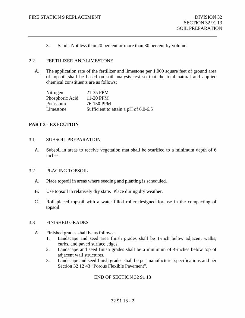
FIRE STATION 9 REPLACEMENT DIVISION 32 SECTION 32 91 13 SOIL PREPARATION
32 91 13 - 2
3. Sand: Not less than 20 percent or more than 30 percent by volume.
2.2 FERTILIZER AND LIMESTONE
A. The application rate of the fertilizer and limestone per 1,000 square feet of ground area of topsoil shall be based on soil analysis test so that the total natural and applied chemical constituents are as follows:
Nitrogen 21-35 PPM Phosphoric Acid 11-20 PPM Potassium 76-150 PPM Limestone Sufficient to attain a pH of 6.0-6.5
PART 3 - EXECUTION
3.1 SUBSOIL PREPARATION
A. Subsoil in areas to receive vegetation mat shall be scarified to a minimum depth of 6 inches.
3.2 PLACING TOPSOIL
A. Place topsoil in areas where seeding and planting is scheduled.
B. Use topsoil in relatively dry state. Place during dry weather.
C. Roll placed topsoil with a water-filled roller designed for use in the compacting of topsoil.
3.3 FINISHED GRADES
A. Finished grades shall be as follows: 1. Landscape and seed area finish grades shall be 1-inch below adjacent walks,
curbs, and paved surface edges. 2. Landscape and seed finish grades shall be a minimum of 4-inches below top of
adjacent wall structures. 3. Landscape and seed finish grades shall be per manufacturer specifications and per
Section 32 12 43 “Porous Flexible Pavement”.
END OF SECTION 32 91 13
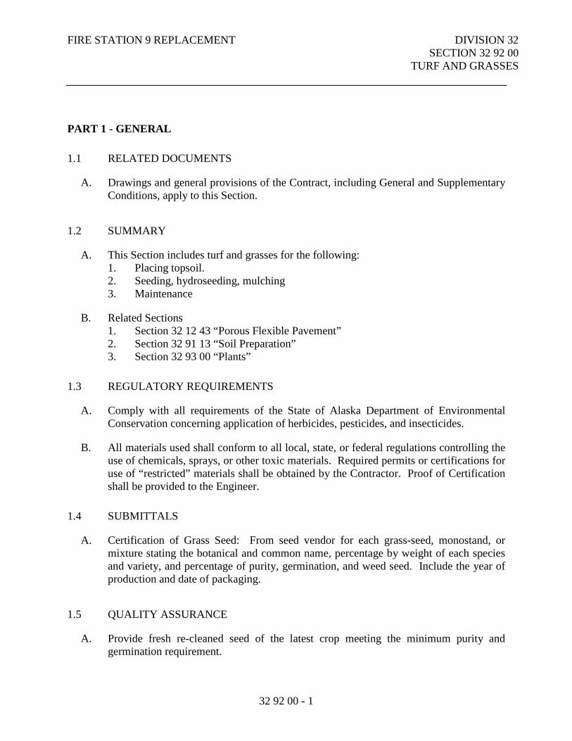
FIRE STATION 9 REPLACEMENT DIVISION 32 SECTION 32 92 00 TURF AND GRASSES
32 92 00 - 1
PART 1 - GENERAL
1.1 RELATED DOCUMENTS
A. Drawings and general provisions of the Contract, including General and Supplementary Conditions, apply to this Section.
1.2 SUMMARY
A. This Section includes turf and grasses for the following: 1. Placing topsoil. 2. Seeding, hydroseeding, mulching 3. Maintenance
B. Related Sections 1. Section 32 12 43 “Porous Flexible Pavement” 2. Section 32 91 13 “Soil Preparation” 3. Section 32 93 00 “Plants”
1.3 REGULATORY REQUIREMENTS
A. Comply with all requirements of the State of Alaska Department of Environmental Conservation concerning application of herbicides, pesticides, and insecticides.
B. All materials used shall conform to all local, state, or federal regulations controlling the use of chemicals, sprays, or other toxic materials. Required permits or certifications for use of “restricted” materials shall be obtained by the Contractor. Proof of Certification shall be provided to the Engineer.
1.4 SUBMITTALS
A. Certification of Grass Seed: From seed vendor for each grass-seed, monostand, or mixture stating the botanical and common name, percentage by weight of each species and variety, and percentage of purity, germination, and weed seed. Include the year of production and date of packaging.
1.5 QUALITY ASSURANCE
A. Provide fresh re-cleaned seed of the latest crop meeting the minimum purity and germination requirement.
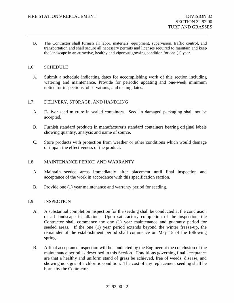
FIRE STATION 9 REPLACEMENT DIVISION 32 SECTION 32 92 00 TURF AND GRASSES
32 92 00 - 2
B. The Contractor shall furnish all labor, materials, equipment, supervision, traffic control, and transportation and shall secure all necessary permits and licenses required to maintain and keep the landscape in an attractive, healthy and vigorous growing condition for one (1) year.
1.6 SCHEDULE
A. Submit a schedule indicating dates for accomplishing work of this section including watering and maintenance. Provide for periodic updating and one-week minimum notice for inspections, observations, and testing dates.
1.7 DELIVERY, STORAGE, AND HANDLING
A. Deliver seed mixture in sealed containers. Seed in damaged packaging shall not be accepted.
B. Furnish standard products in manufacturer's standard containers bearing original labels showing quantity, analysis and name of source.
C. Store products with protection from weather or other conditions which would damage or impair the effectiveness of the product.
1.8 MAINTENANCE PERIOD AND WARRANTY
A. Maintain seeded areas immediately after placement until final inspection and acceptance of the work in accordance with this specification section.
B. Provide one (1) year maintenance and warranty period for seeding.
1.9 INSPECTION
A. A substantial completion inspection for the seeding shall be conducted at the conclusion of all landscape installation. Upon satisfactory completion of the inspection, the Contractor shall commence the one (1) year maintenance and guaranty period for seeded areas. If the one (1) year period extends beyond the winter freeze-up, the remainder of the establishment period shall commence on May 15 of the following spring.
B. A final acceptance inspection will be conducted by the Engineer at the conclusion of the maintenance period as described in this Section. Conditions governing final acceptance are that a healthy and uniform stand of grass be achieved, free of weeds, disease, and showing no signs of a chloritic condition. The cost of any replacement seeding shall be borne by the Contractor.
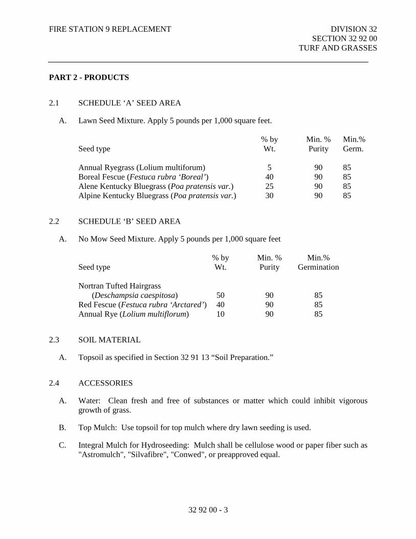
FIRE STATION 9 REPLACEMENT DIVISION 32 SECTION 32 92 00
TURF AND GRASSES
32 92 00 - 3
PART 2 - PRODUCTS
2.1 SCHEDULE ‘A’ SEED AREA
A. Lawn Seed Mixture. Apply 5 pounds per 1,000 square feet.
% by Min. % Min.% Seed type Wt. Purity Germ.
Annual Ryegrass (Lolium multiforum) 5 90 85 Boreal Fescue (Festuca rubra ‘Boreal’) 40 90 85 Alene Kentucky Bluegrass (Poa pratensis var.) 25 90 85 Alpine Kentucky Bluegrass (Poa pratensis var.) 30 90 85
2.2 SCHEDULE ‘B’ SEED AREA
A. No Mow Seed Mixture. Apply 5 pounds per 1,000 square feet
% by Min. % Min.% Seed type Wt. Purity Germination
Nortran Tufted Hairgrass (Deschampsia caespitosa) 50 90 85
Red Fescue (Festuca rubra ‘Arctared’) 40 90 85 Annual Rye (Lolium multiflorum) 10 90 85
2.3 SOIL MATERIAL
A. Topsoil as specified in Section 32 91 13 “Soil Preparation.”
2.4 ACCESSORIES
A. Water: Clean fresh and free of substances or matter which could inhibit vigorous growth of grass.
B. Top Mulch: Use topsoil for top mulch where dry lawn seeding is used.
C. Integral Mulch for Hydroseeding: Mulch shall be cellulose wood or paper fiber such as "Astromulch", "Silvafibre", "Conwed", or preapproved equal.
FIRE STATION 9 REPLACEMENT DIVISION 32 SECTION 32 92 00 TURF AND GRASSES
32 92 00 - 4
PART 3 - EXECUTION
3.1 INSPECTION
A. Engineer to verify that the topsoil base is placed and rolled to specified depth prior to seeding.
B. Beginning of installation means acceptance of existing site condition.
3.2 PLACING TOPSOIL
A. Spread topsoil to a minimum depth of 4 inches, after compaction, over all disturbed areas as noted on plans.
B. Grade to eliminate rough, low, or soft areas. Grades shall meet and blend naturally with existing, undisturbed areas. All grades shall produce positive drainage.
C. Loosen area 2 inches deep, dampen thoroughly, and cultivate to properly break up clods and lumps.
D. Remove all foreign materials, roots, stones larger than 3/4 inch in diameter, noxious weeds, or other litter while spreading material.
E. Place topsoil seven (7) days maximum prior to seeding.
F. After lawn areas have been prepared, take no heavy objects over them except lawn rollers.
G. After preparation of lawn areas and with top soil in semi-dry condition, roll lawn planting areas in two directions at approximately right angles with water ballast roller weighing between 100 and 150 lbs.
H. Rake or scarify and cut or fill irregularities that develop as required until area is true and uniform, free from lumps, depressions, and irregularities.
3.3 SEEDING TIME
A. Seed shall be installed between May 15 and August 15 for summer establishment; and after the first hard frost and before snow accumulation for dormant seeding in the fall. Dormant seeding in the fall is entirely at the Contractor’s risk. In the event that dormant seeding is unsuccessful, it shall be the Contractor’s responsibility to re-seed the following spring.
FIRE STATION 9 REPLACEMENT DIVISION 32 SECTION 32 92 00 TURF AND GRASSES
32 92 00 - 5
3.4 HAND SEEDING
A. Apply seed evenly, at specified rates, in two intersecting directions. Rake in lightly. Do not seed in excess of that which can be mulched on the same day.
B. Do not sow immediately following rain, when ground is too dry, or during windy periods.
C. Roll seeded area with roller not exceeding 150 lbs.
D. Immediately following seeding and compacting, apply top mulch to a thickness of 1/8 inch to 3/16 inch.
E. Apply water with a fine spray immediately after each area has been mulched. Saturate to 4 inches of soil.
3.5 HYDROSEEDING
A. Apply seeded slurry at rate of required seed mixture.
B. Integral mulch shall be applied to a thickness of approximately 1/8 inch. Maintain clear of shrubs, trees or other objects.
C. Apply water with a fine spray immediately after each area has been mulched. Saturate to 4 inches of soil, but do not allow puddling, slumping, or erosion of planted area. If hydraulic methods are used, apply spray mulch to attain a uniform cover over the seed bed to depth of 1/8-inch after seeding is complete.
3.6 SEED PROTECTION
A. Identify seeded areas with stakes, string, and fluorescent ribbon around area periphery. Set string height to 36 inches. Space stakes at maximum 60-inch intervals.
3.7 INSTALLATION CLEAN-UP
A. Project area shall be left clean and neat at the end of each working day.
B. Wash clean all building and paving surfaces that were affected by seed installation.
FIRE STATION 9 REPLACEMENT DIVISION 32 SECTION 32 92 00 TURF AND GRASSES
32 92 00 - 6
3.8 MAINTENANCE
A. Watering: All areas shall be watered at least once a week to maintain soil moisture throughout the root zone and shall be conducted regardless of natural rain fall unless approved in writing by the Owner’s Representative.
1. 3/4-inch of water is required weekly and shall be applied at rates to promote maximum penetration to root zone with minimal run-off.
2. New grass is to be kept moist at all times for the first six weeks after seeding.
B. Fertilization: Apply 1-1/2 pounds of actual nitrogen per 1,000 square feet, a minimum of two times per year. Suggested applications are every four to six weeks between May 1 and October 1. Seeded areas shall be fertilized for the full term of the one year maintenance period, however no fewer than a total of four applications shall be applied.
C. Limestone: Apply dolomitic limestone at rates to bring pH to 6.5 to 7.0 at the beginning of the growing season. An additional application may also be necessary to keep the pH level at 6.5 to 7.0.
D. Repair: Repair and replacement of all damaged or dead seeded areas shall occur upon request of the Owner’s Representative, regardless of cause prior to acceptance of seeded areas.
E. Diseases and Pests: An approved pesticide or herbicide shall be applied as necessary, after all other methods of control have been used, to maintain turf and seeded areas in a healthy and vigorous growing condition.
F. Weed Control: All seeded areas shall be kept free of weeds by hand weeding. Other methods may be employed upon Owner’s Representative approval.
3.9 INSPECTION
A. Progress Inspections: Maintenance shall be inspected by the Owner’s Representative on a regular basis. The Contractor shall perform maintenance activities at the request of the Owner’s Representative within 24 hours of notification that maintenance is required.
B. Final Inspection: At the conclusion of the maintenance period, a final inspection shall be conducted. The Contractor shall notify the Engineer in writing seven days in advance of the final inspection.
3.10 CLEAN-UP
A. The Contractor shall keep the project site clean and free of excess materials, and rubbish incidental to his work at all times. Clean-up will be one of the conditions to be met prior to all phases of acceptance.
END OF SECTION 32 92 00
FIRE STATION 9 REPLACEMENT DIVISION 32 SECTION 32 93 00 PLANTS
32 93 00 - 1
PART 1 - GENERAL
1.1 RELATED SECTIONS
A. Drawings and general provisions of the Contract, including the General and Supplementary Conditions, apply to this Section.
1. Section 32 91 13 “Soil Preparation” 2. Section 32 92 00 “Turf and Grasses”
1.2 DESCRIPTION OF WORK
A. Landscaping required for this contract is shown on the drawings and includes:
1. Placing of Topsoil 2. Planting of Trees and Shrubs 3. Planting of Perennials 4. Mulch 5. Landscape Edging 6. Boulders 7. Plant Maintenance
1.3 REGULATORY REQUIREMENTS
A. Comply with all requirements of the State of Alaska, Department of Environmental Conservation concerning application of herbicides, pesticides, and insecticides.
1.4 APPLICABLE PUBLICATIONS
A. All plant materials used shall be true to name and size and in conformity with the following standards:
1. ANSI Z60.1, current edition - American Standard for Nursery Stock
B. All planting, pruning and maintenance operations shall comply with the following standards:
1. ANSI Z133.1, current edition - American National Standard for Tree Care Operations
FIRE STATION 9 REPLACEMENT DIVISION 32 SECTION 32 93 00 PLANTS
32 93 00 - 2
2. ANSI A300-2001 - Tree Care Operations - Trees, Shrubs and Other Woody Plant Maintenance – Standard Practices
1.5 SUBMITTALS
A. Plant Material List: Include source, species, size and quantity.
B. Schedule: Submit a schedule indicating dates for accomplishing work of this section including watering and maintenance. Provide for periodic up-dating and adequate notice for inspections, observations, and testing dates.
C. Shredded Natural Bark One-pound bag of bark for Engineer’s approval.
1.6 PROJECT/SITE CONDITIONS
A. Planting Dates:
1. Plants shall be planted at a time that natural ground is not frozen.
1.7 INSPECTION
A. A substantial completion inspection for plant materials shall be conducted at the conclusion of all landscape installation. Contractor shall replace any material found not in compliance with these specifications.
1.8 QUALITY ASSURANCE
A. The Contractor shall be experienced in landscape installation and maintenance, preferably with an education in Horticulture, with an experienced work crew familiar with installing and maintaining plant materials in sub-arctic conditions.
1.9 MAINTENANCE PERIOD AND WARRANTY
B. Contractor to provide for all equipment for maintenance and warranty of the landscape installation, including all tree, shrub, perennial and groundcover plantings, for a period of one (1) year from the time the landscape installation has been completed, and Final Landscape Inspection has been approved by the Engineer. For those items not approved during the Final Landscape Inspection, the maintenance period will begin only after the Engineer has approved them.
C. The Contractor shall furnish all labor, materials, equipment, supervision, traffic control, and transportation and shall secure all necessary permits and licenses required to
FIRE STATION 9 REPLACEMENT DIVISION 32 SECTION 32 93 00 PLANTS
32 93 00 - 3
maintain and keep the landscape in an attractive, healthy and vigorous growing condition for one (1) year.
D. Maintenance of plant material shall be per PART 3.4 “MAINTENANCE”
1.10 PLANT SHIPMENT PREPARATION
A. Digging and preparation for shipment shall be done in a manner that will not cause shock or damage to branches, trunk, or root systems.
PART 2 - PRODUCTS
2.1 TREES AND SHRUBS
A. Quality: All plants shall be typical of their species or variety. All plants shall have normal, well-developed branches and vigorous root systems. They shall be sound, healthy, vigorous, free from defects, disfiguring knots, abrasions of the bark, sunscald injuries, plant diseases, insect eggs, borers and all other forms of infection. Plants which have been held in storage will be rejected if they show signs of growth or decline during storage. All plantings shall be “Nursery Grown” for a minimum period of two (2) years.
B. Size and Grading Standards: Size and grading standards shall conform to the "American Standard for Nursery Stock" ANSI Z60.1.
C. Ball and Burlap (B&B): All size and ratio shall be provided as recommended by ANSI Z60.1. The ball shall be of a diameter and depth to encompass enough fibrous and feeding root system necessary for the full recovery of the plant. Removal shall be accomplished by hand digging or mechanical devices. Center the plant stem or trunk in the ball and clean cut all roots at the ball surface. No roots shall be pulled from the ground. The root ball shall be completely wrapped with burlap or other suitable material and securely laced with twine.
D. Container Grown (C): Container size shall be provided as recommended by ANSI Z60.1. Plants shall be grown in a container sufficiently long for new fibrous roots to have developed and for root mass to retain its shape and hold together when removed from container. Container shall be sufficiently rigid to hold ball shape and protect root mass during shipping.
E. Delivery: All plants shall be packed, transported, and handled with utmost care to insure adequate protection against injury and desiccation. Plants coming from out-of-state certified growers and/or suppliers shall be certified by Federal authorities to be free from disease and infestation. Any inspection certificates required by law to this effect
FIRE STATION 9 REPLACEMENT DIVISION 32 SECTION 32 93 00 PLANTS
32 93 00 - 4
shall accompany each shipment invoiced or order of stock, and on arrival, the certificate shall be filed with the Engineer.
F. Inspection: No plant material shall be planted by the Contractor until it is inspected and approved by the Engineer. All rejected material shall be immediately removed from the site and replaced with acceptable material at no additional cost.
2.2 PERENNIALS:
A. Quality: Provide healthy, disease-free plants of species and variety shown or listed, with well-established root systems reaching to sides of the container to maintain a firm ball, but not with excessive root growth encircling the container. Provide only plants that are acclimated to outdoor conditions before delivery and that are in bud but not yet in bloom.
B. Delivery: All plants shall be packed, transported, and handled with utmost care to insure adequate protection against injury and desiccation. Plants coming from out-of-state certified growers and/or suppliers shall be certified by Federal authorities to be free from disease and infestation. Any inspection certificates required by law to this effect shall accompany each shipment invoiced or order of stock, and on arrival, the certificate shall be filed with the Engineer.
C. Inspection: No plant material shall be planted by the Contractor until it is inspected and approved by the Engineer. All rejected material shall be immediately removed from the site and replaced with acceptable material at no additional cost.
2.3 PLANTING MIX (TOPSOIL)
A. As specified in Section 32 91 13 “Soil Preparation.”
2.4 MULCH
A. Mulch shall consist of shredded bark mulch or rock mulch as specified on the drawings. Material shall be uniform in size, color, quality, and overall appearance. Mulch shall be free of material injurious to plant growth. Sources of mulch shall be free of weeds, invasive plant parts, seeds, sawdust, dirt, garbage, or other debris. 1. ROCK MULCH: Rock mulch shall be 2”-6” washed rounded rock, uniform in
size. All fines shall be screened from the aggregate with ¼” tolerance. Rock mulch shall be composed of round rocks and vary in color. Material shall be free of organic and inorganic debris and trash. Rock mulch shall be installed at 4” minimum depth unless otherwise noted in the Drawings.
2. BARK MULCH: Shredded bark mulch shall consist of shredded bark and wood. Maximum length of any individual component shall be two inches (2”) and a minimum of seventy-five percent (75%) of the mulch shall pass through a one-
FIRE STATION 9 REPLACEMENT DIVISION 32 SECTION 32 93 00 PLANTS
32 93 00 - 5
inch screen. Mulch shall be free of invasive weeds, seeds, or propagules. The bark mulch shall have the characteristics of retaining moisture, forming a mat not susceptible to spreading by wind or rain, and providing good growth medium for plants. Shredded bark mulch may contain up to fifty percent shredded wood material. Wood chips are not acceptable. Bark mulch containing shredded wood shall be aged a minimum of one year prior to installation. Bark mulch shall be free of soil, rocks, and weeds and installed at a minimum depth of 3” unless otherwise noted in the Drawings.
2.5 LANDSCAPE EDGING
A. Landscape Edging shall be black, aluminum, one-eighth inch thickness by four inch minimum depth with twelve-inch standard aluminum stakes. Landscape edging shall be Permaloc Aluminum Edging (www.permaloc.com) or preapproved substitute. Comparable products must be architecturally similar in size, type, and grading of materials, dimensions, finishes, texture, and manufactured for use in commercial applications.
2.6 BOULDERS
A. Contractor shall furnish boulders similar in size as shown on Drawings. Boulders excavated during construction may be re-used on site. No evidence of drilling, scrapes, flakes, cracks, or scars borne from machinery and equipment shall be visible after boulder is set in place.
2.7 FILTER FABRIC
A. Filter Fabric used in landscape planting areas shall be UV resistant, black polypropylene polyester blend with a permeability minimum of 12 gals/s.f./min. Filter Fabric shall be DeWitt Pro 5 Weed Barrier (1-800-325-0950) or approved equal.
PART 3 - EXECUTION
3.1 EXAMINATION
A. Examine areas to be landscaped and the details on the drawings for defects that will adversely affect the work and for deviations beyond allowable tolerances.
B. Start of work shall mean acceptance of interfacing surfaces as capable of producing an acceptable job.
FIRE STATION 9 REPLACEMENT DIVISION 32 SECTION 32 93 00 PLANTS
32 93 00 - 6
3.2 PREPARATION
A. Layout: Planting shall be located where it is shown on the Drawings except where obstructions overhead or below ground are encountered or where changes have been made in construction. Prior to the excavation of planting areas or plant pits, the Contractor shall ascertain the location of all utility lines, electric cables, and conduits so that proper precautions may be taken not to disturb or damage any subsurface improvements. Should obstructions be found, the Contractor shall promptly notify the Engineer who will arrange to relocate the plant material. Necessary adjustments shall be approved by the Engineer.
3.3 INSTALLATION
A. Setting Plants: Plants shall be set plumb and held in position until sufficient soil has been firmly placed around roots or ball. Plants shall be set in relation to surrounding grade so that they are even with the depth at which they were grown in the nursery, or container. Compact existing subgrade as shown on drawings and place planting beds above. Do not create “planting pits”.
B. Materials shall be removed that are metal, plastic, nylon or treated burlap, prior to backfilling. Balled and burlapped stock shall be backfilled with topsoil to approximately half the depth of the ball and the tamped and watered. Biodegradeable burlap and tying material shall be carefully opened and folded back. The backfill shall be completed, tamped and watered. A 4-inch high earth saucer shall be formed around individual plants.
C. Backfilling, backfill in maximum 6 inch layers with approved planting mix. Planting beds shall be backfilled carefully to fill all voids and to avoid breaking root ball or bruising roots. Tamp backfill firm to prevent settlement. When fill is nearly completed, water thoroughly and allow water to soak away. If settling of the backfill occurs after watering, add more backfill to bring to finish grade.
D. Shrubs: All shrubs shall be planted per Contract drawings. After preparation of the hole in the planting bed specified, the plant shall be placed in the center. Roots of bare rooted plants shall not be matted together, but arranged in their natural position with planting mix worked in among them. The hole shall be filled with planting mix and settled thoroughly by watering. Arrangement of shrubs must meet with the approval of the Engineer.
E. Watering: Thoroughly water each plant immediately following planting. Contractor shall follow the approved watering schedule and watering procedure throughout the duration of the planting and maintenance phases of the Contract.
FIRE STATION 9 REPLACEMENT DIVISION 32 SECTION 32 93 00 PLANTS
32 93 00 - 7
F. Pruning and Repair: All plants shall be neatly pruned and/or clipped to remove dead or diseased limbs in a manner that preserves the natural character of the plants. No plants shall be pruned or clipped prior to delivery. Broken or badly bruised branches shall be removed with a clean cut. All pruning shall be done with clean, sharp tools in accordance with standard nursery practice. All accidental damages to trees and shrubs occurring during the course of planting operations, which is not so great as to necessitate removal of a branch or replacement of a plant, shall promptly be treated as required in accordance with recognized horticultural practices. Pruning cuts shall not be painted.
G. Staking: Stake and guy trees in accordance with the drawings.
H. Mulch: All landscape planting beds shall be mulched at a minimum depth of 4” with Rock Mulch on top of Filter Fabric unless otherwise noted in the Drawings.
I. Landscape Edging: Landscape edging shall be installed per manufacturer’s specifications in all locations as shown in the Drawings.
J. Boulders: Contractor shall obtain approval from Landscape Architect or Owner’s Representative prior to backfilling to ensure desired face and orientation is achieved. Boulders shall be placed on site as directed. Contractor shall form a shallow pocket for boulder installation, ensuring the boulder is even and true in line, buried one-third to one-half of the boulder depth and in accordance with the Drawings. Boulders located in areas immediately adjacent or within concrete pavement areas will be placed on top of compacted gravel as shown in the Drawings to prevent frost heave.
3.4 MAINTENANCE
A. Watering: 1. The Contractor shall deepwater all Tree, Shrub and Perennial plantings, providing
water penetration throughout the root zone to depth of planting pits. Deep watering shall be done in accordance with the following schedule: a. Watering during Season of Installation: One week after the installation of
plant material. Deepwater all trees and vegetation mat areas each week (during periods of extended dry weather, watering shall occur twice weekly) continuing through the first hard frost, or October 15, whichever occurs first.
b. Watering during Season following installation: Beginning on May 1, deep water all trees and vegetation mat areas each week through the end of the maintenance period. Watering is not required between October 15 and May 1 unless specifically requested by the Owner’s Representative. Water application shall be applied at a rate that will permit maximum penetration providing moisture throughout the entire rootball with a minimal run-off.
FIRE STATION 9 REPLACEMENT DIVISION 32 SECTION 32 93 00 PLANTS
32 93 00 - 8
Owner’s Representative shall be notified 24 hours in advance of each water application.
B. Fertilization: 1. Fertilization of all trees shall be as follows:
a. Season of Installation: Only the initial application of fertilizer one month following planting is necessary. Contact the Owner’s Representative just prior to fertilization so inspection can be coordinated.
b. Final Season: Fertilization shall be per plant type specifications under this section.
c. Owner’s Representative shall be notified of specific times and dates for each fertilization application. Notice shall be at least 24 hours prior to application.
C. Pesticide: 1. An approved pesticide shall be applied only as necessary to maintain plant
materials in a healthy and vigorous growing condition. The Contractor shall supply for and receive a “permit to apply pesticide” from the State of Alaska, Department of Environment Conservation, or shall engage the services of a licensed pest control service qualified to be familiar with plants and appropriate pesticides. Pesticides shall not be used during the school year or when the school is in use.
2. The Owner’s Representative shall approve all pesticide application dates and methods prior to use of pesticides.
D. Pruning: 1. Tree Pruning shall only be at the request of the Owner’s Representative.
E. Plant Damage: In the event of damage to trees from a third party, including vandalism, moose, wind, and other events, the Owner’s Representative may direct the Contractor to replace trees at unit cost amounts to be agreed upon prior to installation. Such replacement to be made only upon written notice from the Owner’s Representative.
F. Weeding: 1. Planting beds and perennial planting areas shall be kept free of weeds and
invasive species for the duration of the maintenance period. Weekly weeding shall be performed on all planting areas.
2. Weeding shall be performed by hand pulling weeds including their root systems. Chemical or other means of weeding shall not be used. All other means of weeding shall be approved in writing by the Owner’s Representative prior to use of other methods. Use of weed whackers, fire or torches is not permitted. It is the Contractor’s responsibility to maintain beds in a weed-free condition. Relief from hand weeding shall not be the result of the Contractor’s failure to weed on a regular basis.
FIRE STATION 9 REPLACEMENT DIVISION 32 SECTION 32 93 00 PLANTS
32 93 00 - 9
G. Plant Replacement: 1. Plants shall be replaced by the Landscape Contractor within seven days of
notification by the Owner’s Representative. 2. All replacement plant materials shall match replaced plants as indicated on the
plant schedule unless a substitution request has been approved by the Owner’s Representative.
3.5 INSPECTIONS
A. PROGRESS INSPECTIONS 1. Maintenance shall be inspected by the Owner’s Representative on a regular basis.
The Contractor shall perform maintenance activities at the request of the Owner’s Representative within 24 hours of notification that maintenance is required.
2. The Contractor shall keep the project site clean and free of excess materials, and rubbish incidental to his work at all times. Clean-up will be one of the conditions to be met prior to all phases of planting acceptance.
B. FINAL INSPECTION 1. Condition of Plant Material: Prior to final inspection, the Contractor shall be
responsible for repairing third-party damage, watering and protecting planted areas, resetting any plants to an upright position, to proper grade or to proper position, and for removal and replacement of any dead plant material. The Contractor shall also re-stake trees and prune plants if necessary.
3.6 CLEAN-UP
A. Waste Materials: Quantities of subsoil, rock and other spoils resulting from excavation during planting shall be removed from planting sites and disposed of off-site.
B. The Contractor shall keep the project site clean and free of excess materials, and rubbish incidental to his work at all times. Clean-up will be one of the conditions to be met prior to all phases of planting acceptance.
C. Condition: All planting sites shall be left in an acceptable condition.
END OF SECTION 32 93 00
FIRE STATION 9 REPLACEMENT DIVISION 33
SECTION 33 71 73
ELECTRICAL UTILITY SERVICES
33 71 73 - 1
PART 1 - GENERAL
1.1 RELATED DOCUMENTS
A. Drawings and general provisions of the Contract, including Municipality of Anchorage
Standard Specifications – Buildings (MASSB), General and Supplementary Conditions
apply to this Section.
1.2 SECTION INCLUDES
A. Arrangement with Utility Company for permanent electric service including payment of
Utility Company charges for service.
B. Underground service entrance.
1.3 RELATED SECTIONS
A. The Work under this section is subject to requirements of the Contract Documents
including the General Conditions, Supplementary Conditions, and sections under the
General and Supplementary Conditions and Section 26 05 00 – Common Work Results
for Electrical.
B. Division 03 - Concrete.
C. Section 26 05 26 – Grounding and Bonding for Electrical Systems.
D. Section 26 05 29 – Hangers and Supports for Electrical Systems.
E. Section 26 05 33 – Raceway and Boxes for Electrical Systems.
F. Section 26 05 53 – Identifications for Electrical Systems.
G. Division 32 – Exterior Improvements.
1.4 REFERENCE STANDARDS
A. NEMA 250 – 2003 Enclosures for Electrical Equipment (1000 Volts Maximum).
FIRE STATION 9 REPLACEMENT DIVISION 33
SECTION 33 71 73
ELECTRICAL UTILITY SERVICES
33 71 73 - 2
B. UL 50 – 1995 Enclosures for Electrical Equipment.
C. UL 414 – 1999 Standard for Meter Sockets.
1.5 SYSTEM DESCRIPTION
A. System Voltage: 120/208V volts, three phase, four-wire, 60 Hertz.
B. Service Entrance: Underground.
1.6 SUBMITTALS
A. Product Data: Submit product data for all components provided, showing electrical
characteristics, material, finishes, and dimensions. Each catalog sheet should be clearly
marked to indicate exact part number provided, including all options and accessories.
B. Shop Drawings: Submit shop drawings and manufacturer’s literature for transformer
rated meter base and current transformer cabinet.
1.7 CLOSEOUT SUBMITTALS
A. Project Record Drawings: Indicate actual locations and mounting heights of service
entrance equipment on the project record drawings.
B. Operation and Maintenance Manuals: Submit manufacturer’s instructions for shunt trip
pushbutton operator maintenance.
1.8 QUALITY ASSURANCE
A. Utility Company: Chugach Electric Association (CEA).
B. Install service entrance in accordance with Utility Company's rules and regulations.
PART 2 - PRODUCTS
2.1 METERING EQUIPMENT
A. Meter: Furnished and installed by the Utility Company.
B. Transformer Rated Meter Base: NEMA 3R, 13-terminal, transformer rated 20 amperes,
600 volts with mounting provisions to accommodate a covered test switch with test
FIRE STATION 9 REPLACEMENT DIVISION 33
SECTION 33 71 73
ELECTRICAL UTILITY SERVICES
33 71 73 - 3
switch cover sealing provisions. The test switch mounting provisions shall accept a 10
pole covered test switch with a base dimension of 9.5 inches in width and a depth (the
dimension from the rear edge of the test switch base to the top of the cover sealing stud)
of no less than 3.375 inches. The lower cover of the meter socket shall seat fully with a
covered test switch in place. Meet requirements of NEMA standards for watthour meter
sockets-NEMA EI17-1978 (similar to EUSERC Drawing No. 339). The utility
company will furnish and install the test switch and CT wiring.
C. Current Transformer Cabinet: NEMA 3R, UL 414 listed, minimum size as shown on
the drawings. All current transformer cabinets and compartments shall have hinged
front cover access to the current transformers. The hinged front cover shall be lockable
and shall accept a padlock with a shackle diameter of not less than 5/16 inch. Current
transformer cabinets for services from 201 Amperes to 800 Amperes shall have ¼ x 20
mounting studs on the enclosure body spaced to accept a current transformer mounting
base. Current transformer cabinets for services from 801 Amperes to 2,500 Amperes
shall have side gutters sized as shown on the drawings and removable bus links.
D. Shunt Trip Switch: The shunt trip switch shall be a heavy duty, watertight/oiltight
maintained contact (non- momentary) pushbutton control station with die-cast NEMA 4
enclosure, normally open and normally close contact blocks with “Off” and “On”
clearly identified. (Square D Class 9001-KYK110 or approved equal). The “Off”
position must disconnect the power. The shunt trip shall be mounted on an equipment
mounting panel (Hoffman #A-8N8P or approved equal) inside NEMA 3R enclosure
with locking hasp and padlock (Hoffman #A-8R86HCR or approved equal) with white
engraved letters: "GENERATOR SHUNT TRIP - UTILITY".
E. Service Disconnect Switch: Per Section 26 28 19 – Enclosed Switches.
F. All removable covers for compartments containing un-metered conductors shall be
sealable or lockable with sealable latches, stud and wing-nuts, sealing screws, or slot
and tab devices. All top cover panels, side cover panels and rear cover panels providing
access to un-metered conductors shall be secured in place with devices that can not be
loosened from the outside, screws or bolts requiring special tools for installation or
removal are not acceptable alternates. No removable panel or cover requiring sealing or
locking shall be located behind other panels, covers or doors except for rain-tight
enclosures. Hinged cover panels shall be lockable on the side opposite the hinges.
Hinged panel covers shall accept a padlock with a shackle diameter of not less than 5/16
inch. Stud and wing-nut sealing assemblies shall consist of a ¼ inch x 20 (minimum)
stud and associated wing-nut, each drilled 0.0635 inch (minimum) for sealing purposes.
The stud shall be securely attached so as to not loosen or back out when being fastened.
Sealing screws shall be drilled 0.0635 inch (minimum) for sealing purposes. All
securing screws for removable panel covers shall be captive.
G. Current Transformer: Provided by Utility.
FIRE STATION 9 REPLACEMENT DIVISION 33
SECTION 33 71 73
ELECTRICAL UTILITY SERVICES
33 71 73 - 4
PART 3 - EXECUTION
3.1 INSTALLATION
A. Make arrangements with Utility Company to obtain permanent electric service to the
Project.
B. Underground: Install service entrance conduits from Utility Company's pad-mounted
transformer to building service entrance equipment. Utility Company will connect
service lateral conductors to service entrance conductors.
C. Install red engraved plastic nameplate on shunt trip disconnect on outside of box.
Install signage inside cover indicating location of main disconnect inside building.
D. Meter sockets shall be installed with the centerline of the socket opening no more than
72 inches and no less than 60 inches above finished grade. The meter socket shall be
installed with a minimum 10 inches of side clearance to each side of the socket. On
current transformer rated meter sockets, the conduit connecting the meter socket and the
current transformer cabinet shall be rigid steel or IMC and have a minimum diameter of
1 inch, shall not be longer than 25 feet, shall have no access points (junction boxes,
conduits, etc.), and shall connect to the meter socket at a factory supplied knockout
located below the test switch mounting provisions.
E. Wall mounted current transformer enclosures shall be mounted with the top of the
cabinet no more that 96 inches above grade and the bottom of the cabinet no less than
16 inches above grade.
F. Current transformer cabinets shall not be used as a junction point to service other
metered services or as a splicing chamber.
G. Install permanent label on main service disconnect indicating the maximum available
fault current, including the date of the calculation was performed per NEC 110.24 (A).
H. All service entrance equipment shall have signage for arc hazard installed. The marking
shall be located to be clearly visible to qualified personnel before examination,
adjustment, servicing or maintenance of the equipment. At a minimum the signage
shall state the following:
Warning
Arc Flash and Shock Hazard
Appropriate PPE Required
END OF SECTION 33 71 73