project manual - facilities & services
TRANSCRIPT
Project Manual
New Mexico State University
New Residence Hall
Las Cruces Campus, New Mexico
February 2018
PSC Project # 03891917
Volume I: Divisions 00 - 14
03891917 TABLE OF CONTENTS PAGE - 1
02/18
02/23/18
TABLE OF CONTENTS
DIVISION 00 - PROCUREMENT AND CONTRACTING REQUIREMENTS
00 00 00 Invitation to Bid (Separate document by NMSU)
00 31 32 Geotechnical Data
00 33 00 Stormwater Construction Permit
00 54 10 Weather Table
00 73 43 Wage Rate Requirements
DIVISION 01 - GENERAL REQUIREMENTS
01 10 00 Summary
01 20 00 Price and Payment Procedures
01 30 00 Administrative Requirements
01 33 00 Submittal Procedures
01 40 00 Quality Requirements
01 42 00 References
01 50 00 Temporary Facilities and Controls
01 57 23 Temporary Stormwater Pollution Control
01 60 00 Product Requirements
01 70 00 Execution and Closeout Requirements
01 74 19 Construction Waste Management and Disposal
01 78 23.30 Operation and Maintenance Commissioning Requirements
01 81 13 Sustainable Design Requirements
01 91 13 General Commissioning Requirements
01 91 13.10 Construction Checklists Commissioning Requirements
01 91 13.20 Functional Performance Testing Commissioning Requirements
01 91 13.30 Demonstration and Training Commissioning Requirements
DIVISION 02 - EXISTING CONDITIONS
Not Used
DIVISION 03 - CONCRETE
03 10 00 Concrete Forming and Accessories
03 20 00 Concrete Reinforcing
03 30 00 Cast-in-Place Concrete
03 39 00 Concrete Curing
03 54 13 Gypsum Cement Underlayment
DIVISION 04 - MASONRY
04 05 13 Masonry Mortaring
04 05 16 Masonry Grouting
04 20 00 Unit Masonry
03891917 TABLE OF CONTENTS PAGE - 2
02/18
02/23/18
DIVISION 05 - METALS
05 12 00 Structural Steel Framing
05 50 00 Metal Fabrications
05 52 13 Pipe and Tube Railings
DIVISION 06 - WOOD, PLASTICS, AND COMPOSITES
06 10 00 Rough Carpentry
06 15 00 Wood Decking
06 16 00 Sheathing
06 17 53 Shop-Fabricated Wood Trusses
06 18 00 Glued-Laminated Construction
06 41 16 Plastic-Laminate-Faced Architectural Cabinets
DIVISION 07 - THERMAL AND MOISTURE PROTECTION
07 21 00 Thermal Insulation
07 24 19 Water-Drainage Exterior Insulation and Finish System (EIFS)
07 27 26 Fluid-Applied Membrane Air Barriers
07 32 16 Concrete Roof Tiles
07 46 46 Fiber-Cement Siding
07 54 23 Thermoplastic Polyolefin (TPO) Roofing
07 62 00 Sheet Metal Flashing and Trim
07 71 29 Manufactured Roof Expansion Joints
07 72 00 Roof Accessories
07 72 33 Roof Hatches
07 84 13 Penetration Firestopping
07 84 43 Joint Firestopping
07 92 00 Joint Sealants
07 92 19 Acoustical Joint Sealants
07 95 13.13 Interior Expansion Joint Cover Assemblies
07 95 13.16 Exterior Expansion Joint Cover Assemblies
DIVISION 08 - OPENINGS
08 11 13 Hollow Metal Doors and Frames
08 12 13 Prefinished Steel Door Frames
08 14 16 Flush Wood Doors
08 31 13 Access Doors and Frames
08 41 13 Aluminum-Framed Entrances and Storefronts
08 53 13 Vinyl Windows
08 71 00 Door Hardware
08 80 00 Glazing
DIVISION 09 - FINISHES
09 21 16.23 Gypsum Board Shaft Wall Assemblies
09 29 00 Gypsum Board
09 30 13 Ceramic Tiling
09 51 13 Acoustical Panel Ceilings
03891917 TABLE OF CONTENTS PAGE - 3
02/18
02/23/18
09 65 13 Resilient Base and Accessories
09 65 19 Resilient Tile Flooring
09 68 13 Tile Carpeting
09 91 13 Exterior Painting
09 91 23 Interior Painting
09 93 00 Staining and Transparent Finishing
DIVISION 10 - SPECIALTIES
10 14 16 Plaques
10 14 23.16 Room-Identification Panel Signage
10 21 13.13 Metal Toilet Compartments
10 26 00 Wall and Door Protection
10 28 13 Toilet Accessories
10 28 19 Tub and Shower Doors
10 44 13 Fire Protection Cabinets
10 44 16 Fire Extinguishers
10 57 23 Wire Closet Shelving
10 82 13 Rooftop Equipment Screens
DIVISION 11 - EQUIPMENT
11 30 13 Residential Appliances
11 81 23.13 Window Washing Systems
DIVISION 12 - FURNISHINGS
12 24 13 Roller Window Shades
12 36 23.13 Plastic-Laminate-Clad Countertops
12 36 61.16 Solid Surfacing Countertops
12 48 16 Entrance Floor Grilles
DIVISION 13 - SPECIAL CONSTRUCTION
Not Used
DIVISION 14 - CONVEYING EQUIPMENT
14 24 00 Hydraulic Elevators
DIVISION 21 - FIRE SUPPRESSION
21 05 17 Sleeves and Sleeve Seals for Fire Suppression Piping
21 05 18 Escutcheons for Fire Suppression Piping
21 05 23 General Duty Valves for Fire Protection Piping
21 05 48 Vibration and Seismic Controls for Fire-Suppression Piping and Equipment
21 05 53 Identification for Fire Suppression Piping and Equipment
21 11 00 Facility Fire Suppression Water Service Piping
21 11 19 Fire Department Connections
21 13 13 Wet Pipe Sprinkler Systems
03891917 TABLE OF CONTENTS PAGE - 4
02/18
02/23/18
DIVISION 22 - PLUMBING
22 05 18 Escutcheons for Plumbing Piping
22 05 19 Meters and Gages for Plumbing Piping
22 05 23.12 Ball Valves for Plumbing Piping
22 05 23.14 Check Valves for Plumbing Piping
22 05 29 Hangers and Supports for Plumbing Piping and Equipment
22 05 53 Identification for Plumbing Piping and Equipment
22 07 16 Plumbing Equipment Insulation
22 07 19 Plumbing Piping insulation
22 11 16 Domestic Water Piping
22 11 19 Domestic Water Piping Specialties
22 11 23 Domestic Water Pumps
22 13 16 Sanitary Waste and Vent Piping
22 13 19 Sanitary Waste Piping Specialties
22 13 19.13 Sanitary Drains
22 14 13 Facility Storm Drainage Piping
22 14 23 Storm Drainage Piping Specialties
22 35 00 Domestic Water Heat Exchangers
22 41 00 Residential Plumbing Fixtures
22 42 13.13 Commercial Water Closets
22 42 13.16 Commercial Urinals
22 42 16.13 Commercial Lavatories
22 42 16.16 Commercial Sinks
22 42 23 Commercial Showers
22 47 16 Electric Water Coolers
DIVISION 23 - HEATING, VENTILATING, AND AIR-CONDITIONING (HVAC)
23 05 13 Common Motor Requirements for HVAC Equipment
23 05 16 Expansion Fittings and Expansion Loops for HVAC Piping
23 05 19 Meters and Gages for HVAC Piping
23 05 23.12 Ball Valves for HVAC Piping
23 05 23.13 Butterfly Valves for HVAC Piping
23 05 23.14 Check Valves for HVAC Piping
23 05 29 Hangers and Supports for HVAC Piping and Equipment
23 05 48.13 Vibration Controls for HVAC
23 05 53 Identification for HVAC Piping and Equipment
23 05 93 Testing, Adjusting, and Balancing for HVAC
23 07 13 Duct Insulation
23 07 16 HVAC Equipment Insulation
23 07 19 HVAC Piping Insulation
23 09 23 Direct Digital Control (DDC) System for HVAC
23 09 23.11 Control Valves
23 09 23.12 Control Dampers
23 09 24 Airflow Measurement Instruments
23 11 23 Facility Natural Gas Piping
23 21 13 Hydronic Piping
23 21 13.13 Underground Hydronic Piping
23 21 16 Hydronic Piping Specialties
03891917 TABLE OF CONTENTS PAGE - 5
02/18
02/23/18
23 21 23 Hydronic Pumps
23 22 13 Steam and Condensate Heating Piping
23 22 16 Steam and Condensate Heating Piping Specialties
23 22 23 Steam Condensate Pumps
23 25 13 Water Treatment for Closed-Loop Hydronic Systems
23 31 13 Metal Ducts
23 33 00 Air Ducts Accessories
23 33 46 Flexible Ducts
23 34 23 HVAC Power Ventilators
23 34 24 Industrial Commercial HVLS Ceiling Fans
23 37 13.13 Air Diffusers
23 37 13.23 Air Registers and Grilles
23 57 00 Heat Exchangers for HVAC
23 72 00 Energy Recovery Ventilators
23 81 26 Split-System Air-Conditioners
23 81 46 Water Source Unitary Heat Pumps
DIVISION 25 - INTEGRATED AUTOMATION
Not Used
DIVISION 26 - ELECTRICAL
26 00 00 Electrical General Provisions
26 05 03 Electrical Connections for Equipment
26 05 19 Wires and Cables
26 05 26 Grounding
26 05 29 Supporting Devices
26 05 33 Electrical Boxes and Fittings
26 05 35 Raceways
26 05 53 Electrical Identification
26 05 75 Short-Circuit Study / Arc-Flash Analysis
26 09 23 Lighting Controls
26 24 16 Panelboards
26 24 19 Motor and Circuit Disconnects
26 27 16 Cabinets and Enclosures
26 27 26 Wiring Devices
26 51 00 Interior Luminaires
26 56 00 Exterior Luminaires
DIVISION 27 - COMMUNICATIONS
27 51 23 Intercommunications System
DIVISION 28 - ELECTRONIC SAFETY AND SECURITY
28 31 00 Fire Alarm System
03891917 TABLE OF CONTENTS PAGE - 6
02/18
02/23/18
DIVISION 31 - EARTHWORK
31 05 13 Soils for Earthwork
31 10 00 Site Clearing
31 20 00 Earth Moving
31 23 16 Excavation
31 23 16.13 Trenching
31 23 23 Fill
31 41 10 Trench Safety System
31 50 00 Excavation Support and Protection
DIVISION 32 - EXTERIOR IMPROVEMENTS
32 12 16.10 Asphalt Paving Surfacing
32 13 73 Concrete Paving Joint Sealants
32 16 00 Concrete Curbs, Gutters, and Sidewalks
32 17 23 Pavement Markings
32 32 23 Segmental Retaining Wall
32 84 00 Planting Irrigation
32 91 13 Soil Preparation
32 92 00 Turf and Grasses
32 93 00 Plants
DIVISION 33 - UTILITIES
33 05 00 Common Work Results for Utilities
33 05 13 Manholes and Structures
33 12 00 Water Utility Distribution Equipment
33 13 00 Disinfecting of Water Utility Distribution
33 31 00 Sanitary Utility Sewerage Piping
33 41 00 Storm Utility Drainage Piping
DIVISIONS 34 - 49
Not Used
03891917 DOCUMENT RESPONSIBILITY PAGE - 1
02/18 AND PROJECT DIRECTORY
DOCUMENT RESPONSIBILITY AND PROJECT DIRECTORY
1.1 OWNER
New Mexico State University
Facility and Services
Project Development and Engineering
Mail Stop Code 3545
PO Box 300001
Las Cruces, New Mexico 88003
1.2 DESIGN PROFESSIONALS
A. Architect:
Parkhill, Smith & Cooper Inc.
115 W. Griggs
Las Cruces, New Mexico 88001
B. Civil Engineer:
Parkhill, Smith & Cooper Inc.
115 W. Griggs
Las Cruces, New Mexico 88001
C. Electrical Engineers:
RBM Engineering, Inc.
1065 S. Main, Building D, Suite A
Las Cruces, New Mexico 88005
D. Landscape Architect:
Parkhill, Smith & Cooper Inc.
115 W. Griggs
Las Cruces, New Mexico 88001
E. Plumbing/Mechanical Engineer:
RBM Engineering, Inc.
1065 S. Main, Building D, Suite A
Las Cruces, New Mexico 88005
F. Structural Engineers:
Stubbs Engineering, Inc.
277 E. Amador Ave., Suite 200
Las Cruses, New Mexico 88001
03891917 DESIGN PROFESSIONAL RESPONSIBILITY SMH - 1
02/18
DESIGN PROFESSIONAL RESPONSIBILITY
The Specification Sections authenticated by my seal and signature are limited to the following:
DIVISION 01 - GENERAL REQUIREMENTS
01 57 23 Temporary Stormwater Pollution Control
DIVISION 31 - EARTHWORK
31 10 00 Site Clearing
31 20 00 Earth Moving
31 23 16.13 Trenching
31 41 10 Trench Safety System
31 50 00 Excavation Support and Protection
DIVISION 32 - EXTERIOR IMPROVEMENTS
32 12 16.10 Asphalt Paving Surfacing
32 13 73 Concrete Paving Joint Sealants
32 16 00 Concrete Curbs, Gutters, and Sidewalks
32 17 23 Pavement Markings
DIVISION 33 - UTILITIES
33 05 00 Common Work Results for Utilities
33 05 13 Manholes and Structures
33 12 00 Water Utility Distribution Equipment
33 13 00 Disinfecting of Water Utility Distribution
33 31 00 Sanitary Utility Sewerage Piping
33 41 00 Storm Utility Drainage Piping
02/23/18
03891917 DESIGN PROFESSIONAL RESPONSIBILITY CJD - 1
02/18
DESIGN PROFESSIONAL RESPONSIBLITY
The Specification Sections authenticated by my seal and signature are limited to the following:
DIVISION 32 - EXTERIOR IMPROVEMENTS
32 84 00 Planting Irrigation
32 91 13 Soil Preparation
32 92 00 Turf and Grasses
32 93 00 Plants
02/23/18
03891917 GEOTECHNICAL DATA 00 31 32 - 1
02/18
SECTION 00 31 32 - GEOTECHNICAL DATA
PART 1 - GENERAL
1.1 SUMMARY
A. Related Requirements:
1. Section 00 00 00 "Invitation to Bid" for reference to Drawings and general provisions of
the Contract including General and Supplementary Conditions.
2. Division 01 Specification Sections apply to Work of this Section.
3. Section 01 81 13 "Sustainable Design Requirements" for LEED Sustainability
Requirements.
1.2 INFORMATION
A. Geotechnical Data:
1. An investigation of subsurface soil conditions at the building site was authorized by
Owner, and these investigations were made by:
Terracon Consultants, Inc.
4450 Bataan Memorial East
Las Cruces, New Mexico 88011-6000
575.527.1700
2. Logs of test borings are bound at the end of this Section.
3. Report is available for Contractor's information but is not a warranty of subsurface
conditions.
4. Complete report is available for Proposer's review in the office of the Architect from
8:00 a.m. to 5:00 p.m. Monday through Thursday and 8:00 a.m. to noon on Friday at the
following address:
Parkhill, Smith & Cooper, Inc.
115 W. Griggs
Las Cruces, New Mexico 88001
575.523.0915
1.3 RESPONSIBILITY
A. Proposers are expected to examine the geotechnical data reports and then determine for
themselves the validity of the information contained therein as it relates to this Project.
B. Architect and Owner do not guarantee continuity of conditions indicated at boring locations and
assume no responsibility for variations of subsoil quality or conditions.
PART 2 - PRODUCTS (Not Used)
PART 3 - EXECUTION (Not Used)
END OF SECTION

APPENDIX A
FIELD EXPLORATION
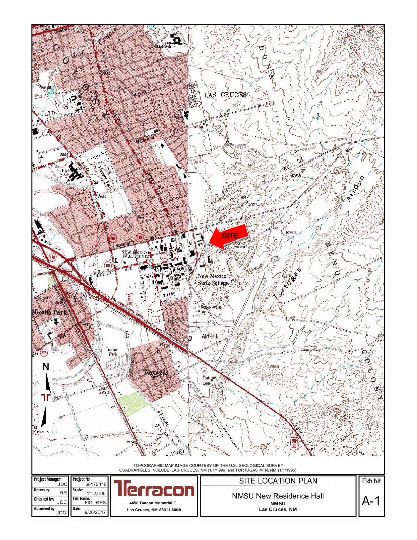
SITE LOCATION PLAN
NMSU New Residence HallNMSU
Las Cruces, NM
TOPOGRAPHIC MAP IMAGE COURTESY OF THE U.S. GEOLOGICAL SURVEYQUADRANGLES INCLUDE: LAS CRUCES, NM (1/1/1996) and TORTUGAS MTN, NM (1/1/1996).
4450 Bataan Memorial ELas Cruces, NM 88011-6000
68175118Project Manager:
Drawn by:
Checked by:
Approved by:
RR
JDC
JDC
1”=2,000’
FIGURES
9/26/2017
Project No.
Scale:
File Name:
Date:A-1
ExhibitJDC
SITE
APPROXIMATE BORING LOCATION
B-1
Imagery @2017 DigitalGlobe, Texas Orthoimagery Program, U.S. Geological Survey, Map data @2017 Google United States 50 ft
B-2
B-5
B-4
B-3
B-6
PERC-1
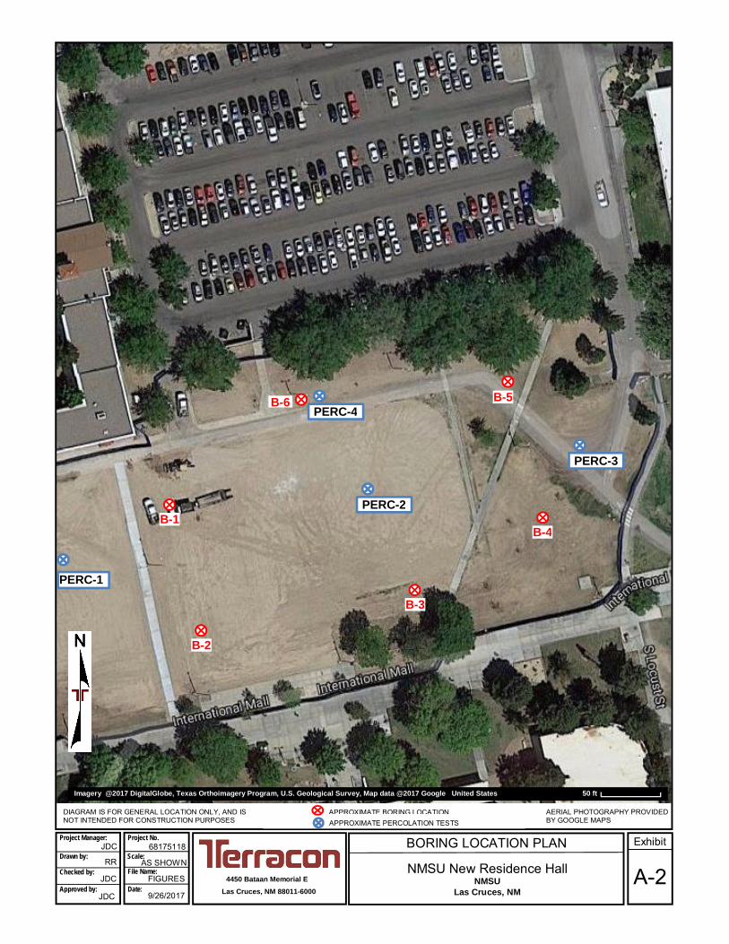
BORING LOCATION PLAN
NMSU New Residence HallNMSU
Las Cruces, NM4450 Bataan Memorial E
Las Cruces, NM 88011-6000
DIAGRAM IS FOR GENERAL LOCATION ONLY, AND ISNOT INTENDED FOR CONSTRUCTION PURPOSES
68175118
AERIAL PHOTOGRAPHY PROVIDEDBY GOOGLE MAPS
RR
JDC
JDC
AS SHOWN
FIGURES
9/26/2017
Scale:
A-2
ExhibitProject Manager:
Drawn by:
Checked by:
Approved by:
Project No.
File Name:
Date:
JDC
PERC-2
APPROXIMATE PERCOLATION TESTS
PERC-3
PERC-4
Geotechnical Engineering ReportNMSU New Residence Hall ■ Las Cruces, New Mexico
October 5, 2017 ■ Terracon Project No. 68175118
Responsive ■ Resourceful ■ Reliable Exhibit A-3
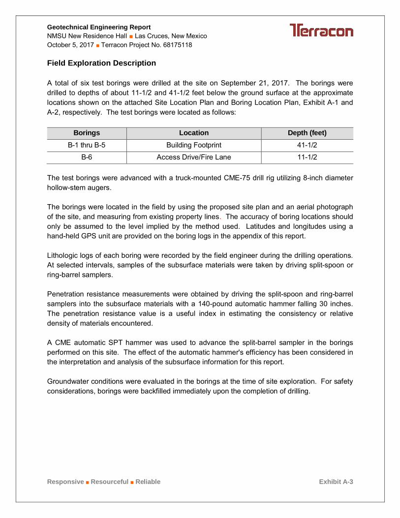
Field Exploration Description
A total of six test borings were drilled at the site on September 21, 2017. The borings were
drilled to depths of about 11-1/2 and 41-1/2 feet below the ground surface at the approximate
locations shown on the attached Site Location Plan and Boring Location Plan, Exhibit A-1 and
A-2, respectively. The test borings were located as follows:
Borings Location Depth (feet)B-1 thru B-5 Building Footprint 41-1/2
B-6 Access Drive/Fire Lane 11-1/2
The test borings were advanced with a truck-mounted CME-75 drill rig utilizing 8-inch diameter
hollow-stem augers.
The borings were located in the field by using the proposed site plan and an aerial photograph
of the site, and measuring from existing property lines. The accuracy of boring locations should
only be assumed to the level implied by the method used. Latitudes and longitudes using a
hand-held GPS unit are provided on the boring logs in the appendix of this report.
Lithologic logs of each boring were recorded by the field engineer during the drilling operations.
At selected intervals, samples of the subsurface materials were taken by driving split-spoon or
ring-barrel samplers.
Penetration resistance measurements were obtained by driving the split-spoon and ring-barrel
samplers into the subsurface materials with a 140-pound automatic hammer falling 30 inches.
The penetration resistance value is a useful index in estimating the consistency or relative
density of materials encountered.
A CME automatic SPT hammer was used to advance the split-barrel sampler in the borings
performed on this site. The effect of the automatic hammer's efficiency has been considered in
the interpretation and analysis of the subsurface information for this report.
Groundwater conditions were evaluated in the borings at the time of site exploration. For safety
considerations, borings were backfilled immediately upon the completion of drilling.
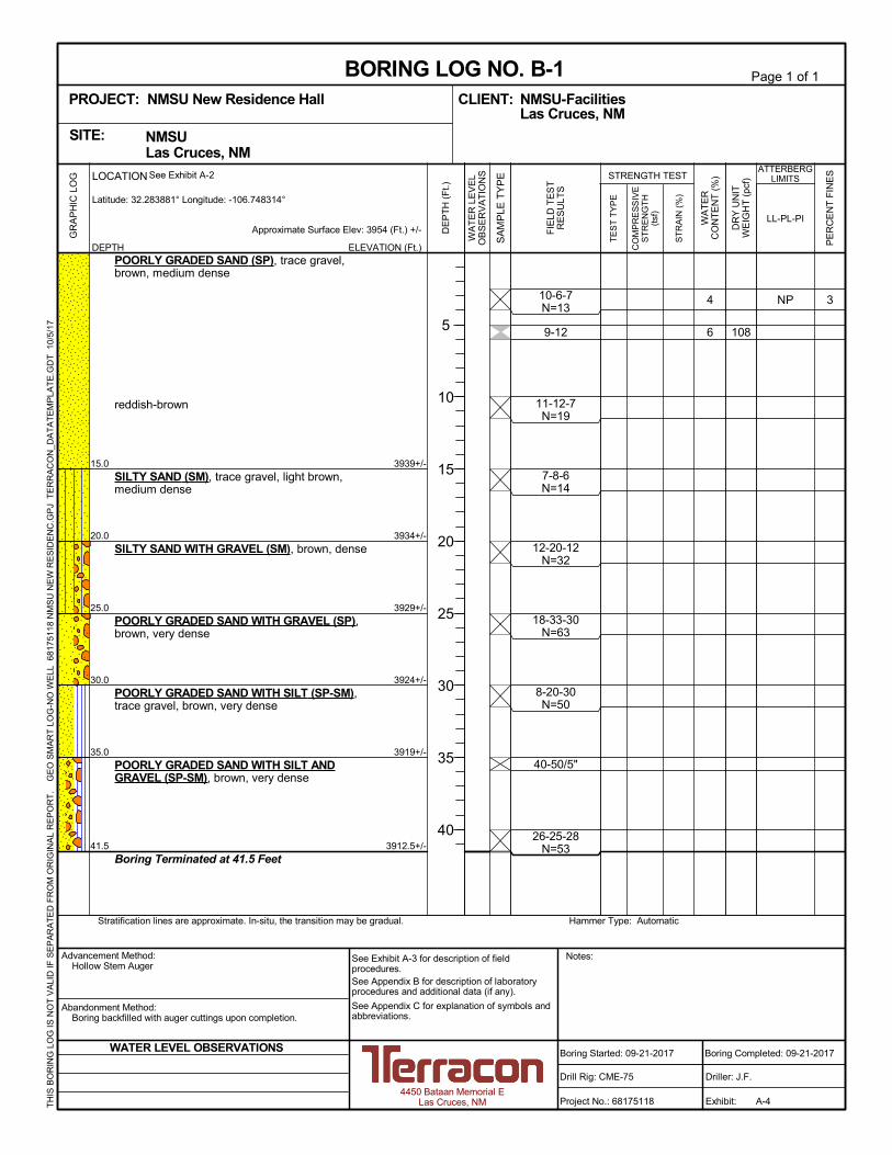
34
6 108
NP
3939+/-
3934+/-
3929+/-
3924+/-
3919+/-
3912.5+/-
10-6-7N=13
9-12
11-12-7N=19
7-8-6N=14
12-20-12N=32
18-33-30N=63
8-20-30N=50
40-50/5"
26-25-28N=53
15.0
20.0
25.0
30.0
35.0
41.5
POORLY GRADED SAND (SP), trace gravel,brown, medium dense
reddish-brown
SILTY SAND (SM), trace gravel, light brown,medium dense
SILTY SAND WITH GRAVEL (SM), brown, dense
POORLY GRADED SAND WITH GRAVEL (SP),brown, very dense
POORLY GRADED SAND WITH SILT (SP-SM),trace gravel, brown, very dense
POORLY GRADED SAND WITH SILT ANDGRAVEL (SP-SM), brown, very dense
Boring Terminated at 41.5 Feet
GR
AP
HIC
LO
G
Hammer Type: AutomaticStratification lines are approximate. In-situ, the transition may be gradual.
TH
IS B
OR
ING
LO
G IS
NO
T V
ALI
D IF
SE
PA
RA
TE
D F
RO
M O
RIG
INA
L R
EP
OR
T.
G
EO
SM
AR
T L
OG
-NO
WE
LL 6
817
511
8 N
MS
U N
EW
RE
SID
EN
C.G
PJ
TE
RR
AC
ON
_DA
TA
TE
MP
LAT
E.G
DT
10/
5/1
7
CO
MP
RE
SS
IVE
ST
RE
NG
TH
(tsf
)
ST
RA
IN (
%)
TE
ST
TY
PE
PE
RC
EN
T F
INE
S
WA
TE
RC
ON
TE
NT
(%
)
DR
Y U
NIT
WE
IGH
T (
pcf)
LL-PL-PI
ATTERBERGLIMITS
ELEVATION (Ft.)
Approximate Surface Elev: 3954 (Ft.) +/-
WA
TE
R L
EV
EL
OB
SE
RV
AT
ION
S
DE
PT
H (
Ft.)
5
10
15
20
25
30
35
40
SA
MP
LE T
YP
E STRENGTH TEST
FIE
LD T
ES
TR
ES
ULT
S
NMSU Las Cruces, NMSITE:
Page 1 of 1
Advancement Method:Hollow Stem Auger
Abandonment Method:Boring backfilled with auger cuttings upon completion.
Notes:
Project No.: 68175118
Drill Rig: CME-75
Boring Started: 09-21-2017
BORING LOG NO. B-1NMSU-FacilitiesCLIENT:Las Cruces, NM
Driller: J.F.
Boring Completed: 09-21-2017
Exhibit: A-4
See Exhibit A-3 for description of fieldprocedures.See Appendix B for description of laboratoryprocedures and additional data (if any).
See Appendix C for explanation of symbols andabbreviations.
PROJECT: NMSU New Residence Hall
4450 Bataan Memorial ELas Cruces, NM
WATER LEVEL OBSERVATIONS
DEPTH
LOCATION See Exhibit A-2
Latitude: 32.283881° Longitude: -106.748314°
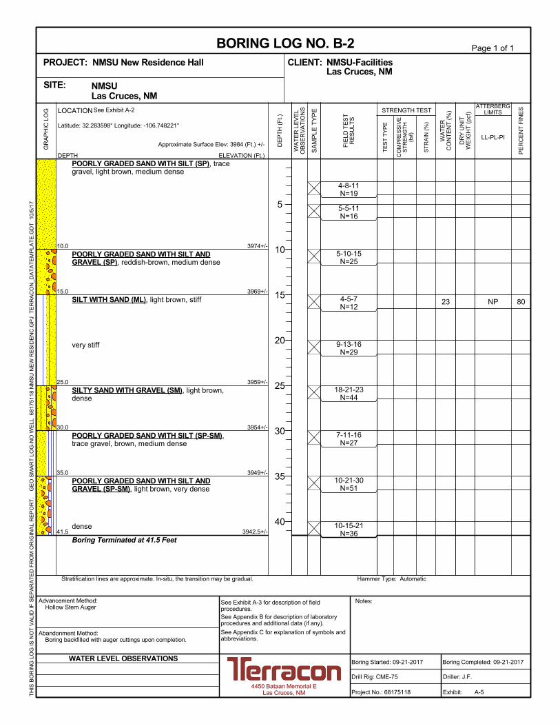
8023 NP
3974+/-
3969+/-
3959+/-
3954+/-
3949+/-
3942.5+/-
10.0
15.0
25.0
30.0
35.0
41.5
POORLY GRADED SAND WITH SILT (SP), tracegravel, light brown, medium dense
POORLY GRADED SAND WITH SILT ANDGRAVEL (SP), reddish-brown, medium dense
SILT WITH SAND (ML), light brown, stiff
very stiff
SILTY SAND WITH GRAVEL (SM), light brown,dense
POORLY GRADED SAND WITH SILT (SP-SM),trace gravel, brown, medium dense
POORLY GRADED SAND WITH SILT ANDGRAVEL (SP-SM), light brown, very dense
dense
Boring Terminated at 41.5 Feet
4-8-11N=19
5-5-11N=16
5-10-15N=25
4-5-7N=12
9-13-16N=29
18-21-23N=44
7-11-16N=27
10-21-30N=51
10-15-21N=36
GR
AP
HIC
LO
G
Hammer Type: AutomaticStratification lines are approximate. In-situ, the transition may be gradual.
TH
IS B
OR
ING
LO
G IS
NO
T V
ALI
D IF
SE
PA
RA
TE
D F
RO
M O
RIG
INA
L R
EP
OR
T.
G
EO
SM
AR
T L
OG
-NO
WE
LL 6
817
511
8 N
MS
U N
EW
RE
SID
EN
C.G
PJ
TE
RR
AC
ON
_DA
TA
TE
MP
LAT
E.G
DT
10/
5/1
7
CO
MP
RE
SS
IVE
ST
RE
NG
TH
(tsf
)
ST
RA
IN (
%)
TE
ST
TY
PE
PE
RC
EN
T F
INE
S
WA
TE
RC
ON
TE
NT
(%
)
DR
Y U
NIT
WE
IGH
T (
pcf)
LL-PL-PI
ATTERBERGLIMITS
ELEVATION (Ft.)
Approximate Surface Elev: 3984 (Ft.) +/-
WA
TE
R L
EV
EL
OB
SE
RV
AT
ION
S
WATER LEVEL OBSERVATIONS
DEPTH
LOCATION See Exhibit A-2
Latitude: 32.283598° Longitude: -106.748221°
DE
PT
H (
Ft.)
5
10
15
20
25
30
35
40
SA
MP
LE T
YP
E STRENGTH TEST
FIE
LD T
ES
TR
ES
ULT
S
NMSU Las Cruces, NMSITE:
Page 1 of 1
Advancement Method:Hollow Stem Auger
Abandonment Method:Boring backfilled with auger cuttings upon completion.
Notes:
Project No.: 68175118
Drill Rig: CME-75
Boring Started: 09-21-2017
BORING LOG NO. B-2NMSU-FacilitiesCLIENT:Las Cruces, NM
Driller: J.F.
Boring Completed: 09-21-2017
Exhibit: A-5
See Exhibit A-3 for description of fieldprocedures.See Appendix B for description of laboratoryprocedures and additional data (if any).
See Appendix C for explanation of symbols andabbreviations.
PROJECT: NMSU New Residence Hall
4450 Bataan Memorial ELas Cruces, NM
7 112
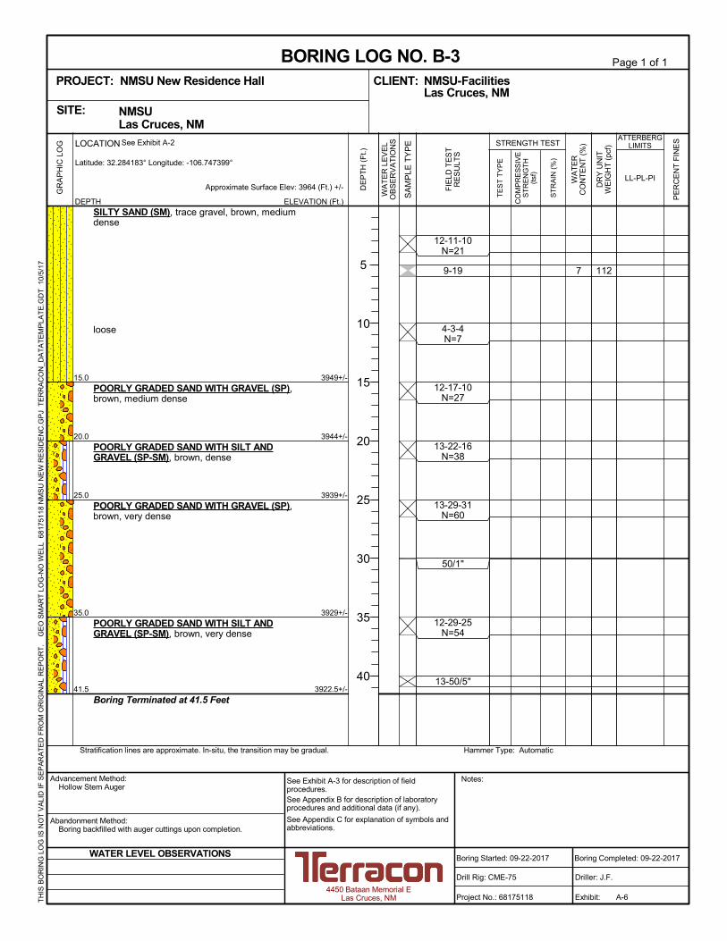
3949+/-
3944+/-
3939+/-
3929+/-
3922.5+/-
12-11-10N=21
9-19
4-3-4N=7
12-17-10N=27
13-22-16N=38
13-29-31N=60
50/1"
12-29-25N=54
13-50/5"
15.0
20.0
25.0
35.0
41.5
SILTY SAND (SM), trace gravel, brown, mediumdense
loose
POORLY GRADED SAND WITH GRAVEL (SP),brown, medium dense
POORLY GRADED SAND WITH SILT ANDGRAVEL (SP-SM), brown, dense
POORLY GRADED SAND WITH GRAVEL (SP),brown, very dense
POORLY GRADED SAND WITH SILT ANDGRAVEL (SP-SM), brown, very dense
Boring Terminated at 41.5 Feet
GR
AP
HIC
LO
G
Hammer Type: AutomaticStratification lines are approximate. In-situ, the transition may be gradual.
TH
IS B
OR
ING
LO
G IS
NO
T V
ALI
D IF
SE
PA
RA
TE
D F
RO
M O
RIG
INA
L R
EP
OR
T.
G
EO
SM
AR
T L
OG
-NO
WE
LL 6
817
511
8 N
MS
U N
EW
RE
SID
EN
C.G
PJ
TE
RR
AC
ON
_DA
TA
TE
MP
LAT
E.G
DT
10/
5/1
7
CO
MP
RE
SS
IVE
ST
RE
NG
TH
(tsf
)
ST
RA
IN (
%)
TE
ST
TY
PE
PE
RC
EN
T F
INE
S
WA
TE
RC
ON
TE
NT
(%
)
DR
Y U
NIT
WE
IGH
T (
pcf)
LL-PL-PI
ATTERBERGLIMITS
ELEVATION (Ft.)
Approximate Surface Elev: 3964 (Ft.) +/-
WA
TE
R L
EV
EL
OB
SE
RV
AT
ION
S
DE
PT
H (
Ft.)
5
10
15
20
25
30
35
40
SA
MP
LE T
YP
E STRENGTH TEST
FIE
LD T
ES
TR
ES
ULT
S
NMSU Las Cruces, NMSITE:
Page 1 of 1
Advancement Method:Hollow Stem Auger
Abandonment Method:Boring backfilled with auger cuttings upon completion.
Notes:
Project No.: 68175118
Drill Rig: CME-75
Boring Started: 09-22-2017
BORING LOG NO. B-3NMSU-FacilitiesCLIENT:Las Cruces, NM
Driller: J.F.
Boring Completed: 09-22-2017
Exhibit: A-6
See Exhibit A-3 for description of fieldprocedures.See Appendix B for description of laboratoryprocedures and additional data (if any).
See Appendix C for explanation of symbols andabbreviations.
PROJECT: NMSU New Residence Hall
4450 Bataan Memorial ELas Cruces, NM
WATER LEVEL OBSERVATIONS
DEPTH
LOCATION See Exhibit A-2
Latitude: 32.284183° Longitude: -106.747399°
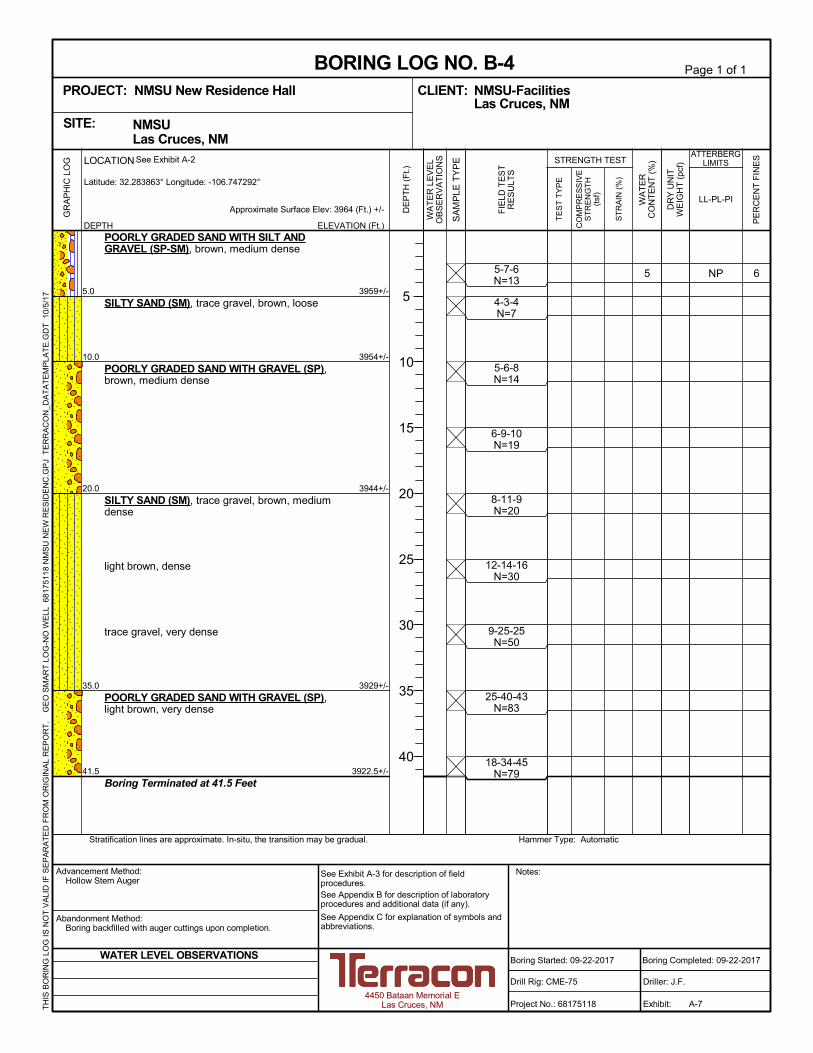
65 NP
3959+/-
3954+/-
3944+/-
3929+/-
3922.5+/-
5-7-6N=13
4-3-4N=7
5-6-8N=14
6-9-10N=19
8-11-9N=20
12-14-16N=30
9-25-25N=50
25-40-43N=83
18-34-45N=79
5.0
10.0
20.0
35.0
41.5
POORLY GRADED SAND WITH SILT ANDGRAVEL (SP-SM), brown, medium dense
SILTY SAND (SM), trace gravel, brown, loose
POORLY GRADED SAND WITH GRAVEL (SP),brown, medium dense
SILTY SAND (SM), trace gravel, brown, mediumdense
light brown, dense
trace gravel, very dense
POORLY GRADED SAND WITH GRAVEL (SP),light brown, very dense
Boring Terminated at 41.5 Feet
GR
AP
HIC
LO
G
Hammer Type: AutomaticStratification lines are approximate. In-situ, the transition may be gradual.
TH
IS B
OR
ING
LO
G IS
NO
T V
ALI
D IF
SE
PA
RA
TE
D F
RO
M O
RIG
INA
L R
EP
OR
T.
G
EO
SM
AR
T L
OG
-NO
WE
LL 6
817
511
8 N
MS
U N
EW
RE
SID
EN
C.G
PJ
TE
RR
AC
ON
_DA
TA
TE
MP
LAT
E.G
DT
10/
5/1
7
CO
MP
RE
SS
IVE
ST
RE
NG
TH
(tsf
)
ST
RA
IN (
%)
TE
ST
TY
PE
PE
RC
EN
T F
INE
S
WA
TE
RC
ON
TE
NT
(%
)
DR
Y U
NIT
WE
IGH
T (
pcf)
LL-PL-PI
ATTERBERGLIMITS
ELEVATION (Ft.)
Approximate Surface Elev: 3964 (Ft.) +/-
WA
TE
R L
EV
EL
OB
SE
RV
AT
ION
S
DE
PT
H (
Ft.)
5
10
15
20
25
30
35
40
SA
MP
LE T
YP
E STRENGTH TEST
FIE
LD T
ES
TR
ES
ULT
S
NMSU Las Cruces, NMSITE:
Page 1 of 1
Advancement Method:Hollow Stem Auger
Abandonment Method:Boring backfilled with auger cuttings upon completion.
Notes:
Project No.: 68175118
Drill Rig: CME-75
Boring Started: 09-22-2017
BORING LOG NO. B-4NMSU-FacilitiesCLIENT:Las Cruces, NM
Driller: J.F.
Boring Completed: 09-22-2017
Exhibit: A-7
See Exhibit A-3 for description of fieldprocedures.See Appendix B for description of laboratoryprocedures and additional data (if any).
See Appendix C for explanation of symbols andabbreviations.
PROJECT: NMSU New Residence Hall
4450 Bataan Memorial ELas Cruces, NM
WATER LEVEL OBSERVATIONS
DEPTH
LOCATION See Exhibit A-2
Latitude: 32.283863° Longitude: -106.747292°
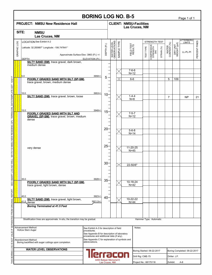
21
5
7
109
NP
3958+/-
3953+/-
3948+/-
3928+/-
3923+/-
3921.5+/-
7-6-6N=12
6-6
1-4-4N=8
7-5-7N=12
5-6-8N=14
11-20-25N=45
22-50/6"
10-18-24N=42
10-22-22N=44
5.0
10.0
15.0
35.0
40.0
41.5
SILTY SAND (SM), trace gravel, dark brown,medium dense
POORLY GRADED SAND WITH SILT (SP-SM),trace gravel, brown, medium dense
SILTY SAND (SM), trace gravel, brown, loose
POORLY GRADED SAND WITH SILT ANDGRAVEL (SP-SM), trace gravel, brown, mediumdense
very dense
POORLY GRADED SAND WITH SILT (SP-SM),trace gravel, light brown, dense
SILTY SAND (SM), trace gravel, light brown,denseBoring Terminated at 41.5 Feet
GR
AP
HIC
LO
G
Hammer Type: AutomaticStratification lines are approximate. In-situ, the transition may be gradual.
TH
IS B
OR
ING
LO
G IS
NO
T V
ALI
D IF
SE
PA
RA
TE
D F
RO
M O
RIG
INA
L R
EP
OR
T.
G
EO
SM
AR
T L
OG
-NO
WE
LL 6
817
511
8 N
MS
U N
EW
RE
SID
EN
C.G
PJ
TE
RR
AC
ON
_DA
TA
TE
MP
LAT
E.G
DT
10/
5/1
7
CO
MP
RE
SS
IVE
ST
RE
NG
TH
(tsf
)
ST
RA
IN (
%)
TE
ST
TY
PE
PE
RC
EN
T F
INE
S
WA
TE
RC
ON
TE
NT
(%
)
DR
Y U
NIT
WE
IGH
T (
pcf)
LL-PL-PI
ATTERBERGLIMITS
ELEVATION (Ft.)
Approximate Surface Elev: 3963 (Ft.) +/-
WA
TE
R L
EV
EL
OB
SE
RV
AT
ION
S
DE
PT
H (
Ft.)
5
10
15
20
25
30
35
40
SA
MP
LE T
YP
E STRENGTH TEST
FIE
LD T
ES
TR
ES
ULT
S
NMSU Las Cruces, NMSITE:
Page 1 of 1
Advancement Method:Hollow Stem Auger
Abandonment Method:Boring backfilled with auger cuttings upon completion.
Notes:
Project No.: 68175118
Drill Rig: CME-75
Boring Started: 09-22-2017
BORING LOG NO. B-5NMSU-FacilitiesCLIENT:Las Cruces, NM
Driller: J.F.
Boring Completed: 09-22-2017
Exhibit: A-8
See Exhibit A-3 for description of fieldprocedures.See Appendix B for description of laboratoryprocedures and additional data (if any).
See Appendix C for explanation of symbols andabbreviations.
PROJECT: NMSU New Residence Hall
4450 Bataan Memorial ELas Cruces, NM
WATER LEVEL OBSERVATIONS
DEPTH
LOCATION See Exhibit A-2
Latitude: 32.283687° Longitude: -106.747641°
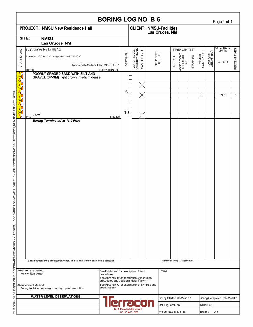
53 NP
3943.5+/-11.5
POORLY GRADED SAND WITH SILT ANDGRAVEL (SP-SM), light brown, medium dense
brown
Boring Terminated at 11.5 Feet
GR
AP
HIC
LO
G
Hammer Type: AutomaticStratification lines are approximate. In-situ, the transition may be gradual.
TH
IS B
OR
ING
LO
G IS
NO
T V
ALI
D IF
SE
PA
RA
TE
D F
RO
M O
RIG
INA
L R
EP
OR
T.
G
EO
SM
AR
T L
OG
-NO
WE
LL 6
817
511
8 N
MS
U N
EW
RE
SID
EN
C.G
PJ
TE
RR
AC
ON
_DA
TA
TE
MP
LAT
E.G
DT
10/
5/1
7
CO
MP
RE
SS
IVE
ST
RE
NG
TH
(tsf
)
ST
RA
IN (
%)
TE
ST
TY
PE
PE
RC
EN
T F
INE
S
WA
TE
RC
ON
TE
NT
(%
)
DR
Y U
NIT
WE
IGH
T (
pcf)
LL-PL-PI
ATTERBERGLIMITS
ELEVATION (Ft.)
Approximate Surface Elev: 3955 (Ft.) +/-
WA
TE
R L
EV
EL
OB
SE
RV
AT
ION
S
DE
PT
H (
Ft.)
5
10
SA
MP
LE T
YP
E STRENGTH TEST
FIE
LD T
ES
TR
ES
ULT
S
NMSU Las Cruces, NMSITE:
Page 1 of 1
Advancement Method:Hollow Stem Auger
Abandonment Method:Boring backfilled with auger cuttings upon completion.
Notes:
Project No.: 68175118
Drill Rig: CME-75
Boring Started: 09-22-2017
BORING LOG NO. B-6NMSU-FacilitiesCLIENT:Las Cruces, NM
Driller: J.F.
Boring Completed: 09-22-2017
Exhibit: A-9
See Exhibit A-3 for description of fieldprocedures.See Appendix B for description of laboratoryprocedures and additional data (if any).
See Appendix C for explanation of symbols andabbreviations.
PROJECT: NMSU New Residence Hall
4450 Bataan Memorial ELas Cruces, NM
WATER LEVEL OBSERVATIONS
DEPTH
LOCATION See Exhibit A-2
Latitude: 32.284102° Longitude: -106.747998°

APPENDIX B
LABORATORY TESTING
Geotechnical Engineering ReportNMSU New Residence Hall ■ Las Cruces, New Mexico
October 5, 2017 ■ Terracon Project No. 68175118
Responsive ■ Resourceful ■ Reliable Exhibit B-1
Laboratory Testing
Soil samples were tested in the laboratory to measure their dry unit weight and natural water
content. Grain size (ASTM D422), consolidation, pH (AWWA 4500 H), sulfate percentage
(AWWA 4500 E) and resistivity (ASTM G57) testing were also performed on selected samples.
The test results are provided on the boring logs and presented in Appendix B.
Descriptive classifications of the soils indicated on the boring logs are in accordance with the
enclosed General Notes and the Unified Soil Classification System. Also shown are estimated
Unified Soil Classification Symbols. A brief description of this classification system is attached
to this report in Appendix C. All classification was by visual/manual procedures, (ASTM D2487).
Selected samples were further classified using the results of Atterberg limit testing, (ASTM
D4318). The Atterberg limit test results are also provided on the boring logs.
Procedural standards noted above are for reference to methodology in general. In some cases,
variations to methods are applied as a result of local practice or professional judgment.
0
5
10
15
20
25
30
35
40
45
50
55
60
65
70
75
80
85
90
95
100
0.0010.010.1110100
30 40 501.5 2006 810 1441 3/4 1/2 60
GRAIN SIZE IN MILLIMETERS
PE
RC
EN
T F
INE
R B
Y W
EIG
HT
HYDROMETERU.S. SIEVE OPENING IN INCHES U.S. SIEVE NUMBERS
4 3/8 3 100 1403 2
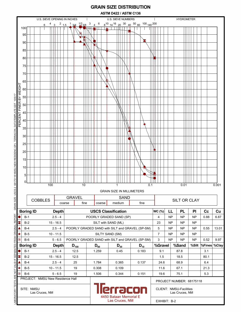
GRAIN SIZE DISTRIBUTIONASTM D422 / ASTM C136
6 16 20
PROJECT NUMBER: 68175118PROJECT: NMSU New Residence Hall
SITE: NMSU Las Cruces, NM
CLIENT: NMSU-Facilities Las Cruces, NM
EXHIBIT: B-24450 Bataan Memorial E
Las Cruces, NM
LAB
OR
AT
OR
Y T
ES
TS
AR
E N
OT
VA
LID
IF S
EP
AR
AT
ED
FR
OM
OR
IGIN
AL
RE
PO
RT
.
GR
AIN
SIZ
E: U
SC
S-2
681
751
18 N
MS
U N
EW
RE
SID
EN
C.G
PJ
TE
RR
AC
ON
_DA
TA
TE
MP
LAT
E.G
DT
10/
5/1
7
9.1
1.5
24.6
11.6
19.6
12.5
12.5
25
19
19
1.259
1.784
0.308
1.506
0.45
0.365
0.109
0.344
NP
NP
NP
NP
NP
B-1
B-2
B-4
B-5
B-6
LL PL PI
finefineSILT OR CLAY
%Sand%Gravel
COBBLESGRAVEL SAND
coarse medium
%Clay
3.1
80.1
6.4
21.3
5.3
%Silt %Fines
POORLY GRADED SAND (SP)
SILT with SAND (ML)
POORLY GRADED SAND with SILT and GRAVEL (SP-SM)
SILTY SAND (SM)
POORLY GRADED SAND with SILT and GRAVEL (SP-SM)
USCS Classification4
23
5
7
3
WC (%)
2.5 - 4
15 - 16.5
2.5 - 4
10 - 11.5
5 - 6.5
Boring ID Depth
Boring ID Depth
D60
87.8
18.5
68.9
67.1
75.1
2.5 - 4
15 - 16.5
2.5 - 4
10 - 11.5
5 - 6.5
D10D30
CuCc
D100
0.88
0.55
0.52
NP
NP
NP
NP
NP
NP
NP
NP
NP
NP
coarse
6.87
13.01
9.97
B-1
B-2
B-4
B-5
B-6
0.183
0.137
0.151
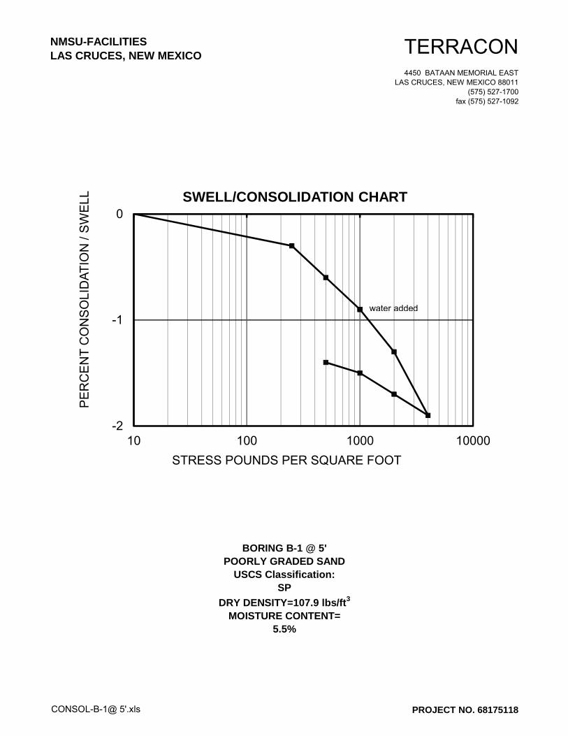
NMSU-FACILITIESLAS CRUCES, NEW MEXICO TERRACON
4450 BATAAN MEMORIAL EAST
LAS CRUCES, NEW MEXICO 88011
(575) 527-1700
fax (575) 527-1092
CONSOL-B-1@ 5'.xls
BORING B-1 @ 5'POORLY GRADED SAND
USCS Classification:SP
DRY DENSITY=107.9 lbs/ft3
MOISTURE CONTENT=5.5%
PROJECT NO. 68175118
-2
-1
0
10 100 1000 10000
PE
RC
EN
TC
ON
SO
LID
AT
ION
/S
WE
LL
STRESS POUNDS PER SQUARE FOOT
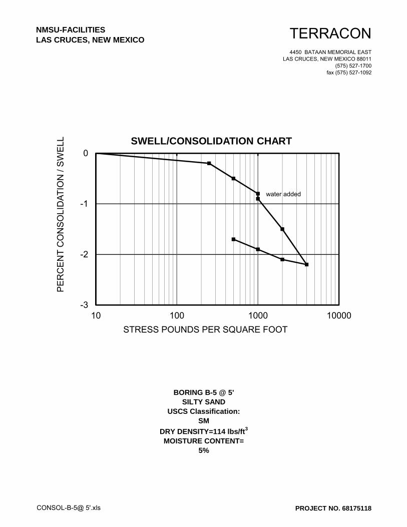
SWELL/CONSOLIDATION CHART
water added
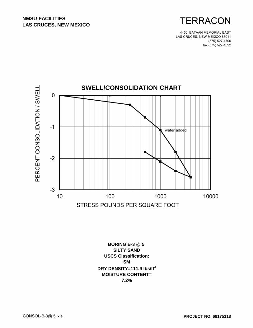
NMSU-FACILITIESLAS CRUCES, NEW MEXICO TERRACON
4450 BATAAN MEMORIAL EAST
LAS CRUCES, NEW MEXICO 88011
(575) 527-1700
fax (575) 527-1092
CONSOL-B-3@ 5'.xls
BORING B-3 @ 5'SILTY SAND
USCS Classification:SM
DRY DENSITY=111.9 lbs/ft3
MOISTURE CONTENT=7.2%
PROJECT NO. 68175118
-3
-2
-1
0
10 100 1000 10000
PE
RC
EN
TC
ON
SO
LID
AT
ION
/S
WE
LL
STRESS POUNDS PER SQUARE FOOT
SWELL/CONSOLIDATION CHART
water added
NMSU-FACILITIESLAS CRUCES, NEW MEXICO TERRACON
4450 BATAAN MEMORIAL EAST
LAS CRUCES, NEW MEXICO 88011
(575) 527-1700
fax (575) 527-1092
CONSOL-B-5@ 5'.xls
BORING B-5 @ 5'SILTY SAND
USCS Classification:SM
DRY DENSITY=114 lbs/ft3
MOISTURE CONTENT=5%
PROJECT NO. 68175118
-3
-2
-1
0
10 100 1000 10000
PE
RC
EN
TC
ON
SO
LID
AT
ION
/S
WE
LL
STRESS POUNDS PER SQUARE FOOT
SWELL/CONSOLIDATION CHART
water added
Project Number:
Service Date:
Report Date:
Task:
Client
Date Received:
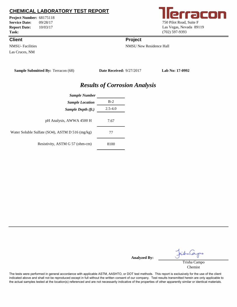
B-2
2.5-4.0
7.67
77
8100
Analyzed By:
The tests were performed in general accordance with applicable ASTM, AASHTO, or DOT test methods. This report is exclusively for the use of the client
indicated above and shall not be reproduced except in full without the written consent of our company. Test results transmitted herein are only applicable to
the actual samples tested at the location(s) referenced and are not necessarily indicative of the properties of other apparently similar or identical materials.
68175118
Terracon (68)Sample Submitted By: 9/27/2017
Results of Corrosion Analysis
Chemist
09/28/17
Las Cruces, NM
Lab No: 17-0992
Sample Number
Sample Location
Sample Depth (ft.)
10/03/17
750 Pilot Road, Suite F
Las Vegas, Nevada 89119
(702) 597-9393
Project
CHEMICAL LABORATORY TEST REPORT
Trisha Campo
pH Analysis, AWWA 4500 H
Water Soluble Sulfate (SO4), ASTM D 516 (mg/kg)
Resistivity, ASTM G 57 (ohm-cm)
NMSU- Facilities NMSU New Residence Hall

APPENDIX CSUPPORTING DOCUMENTS
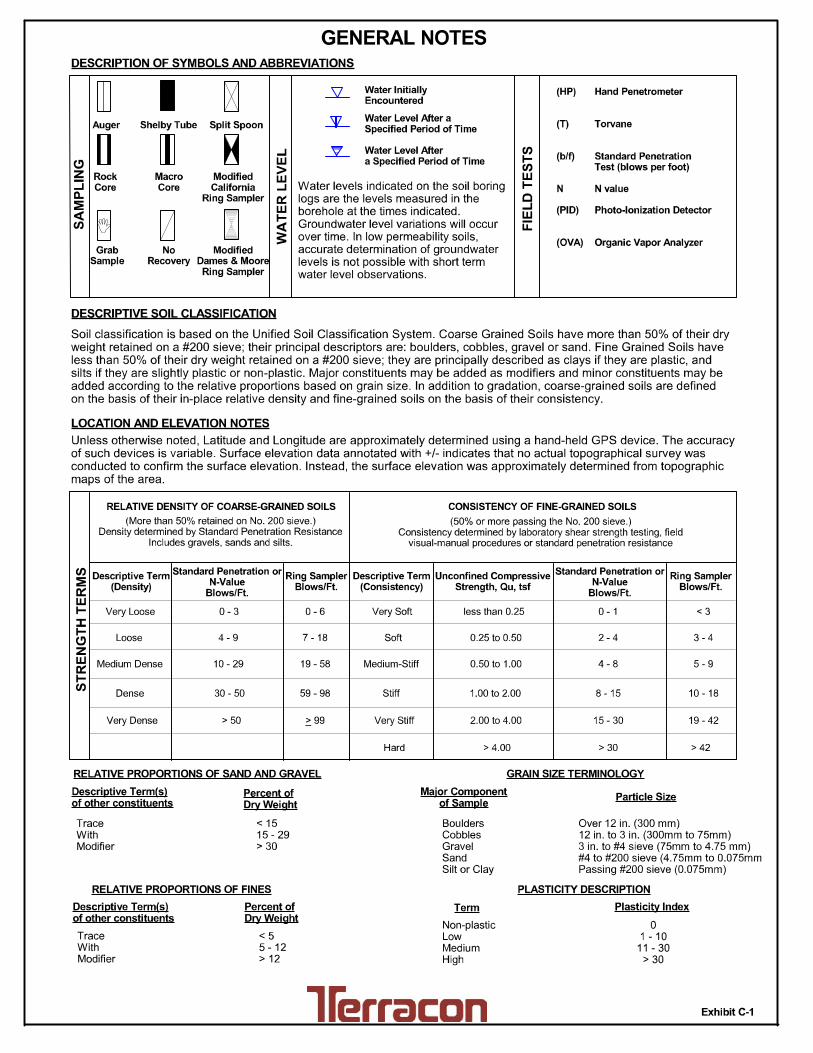
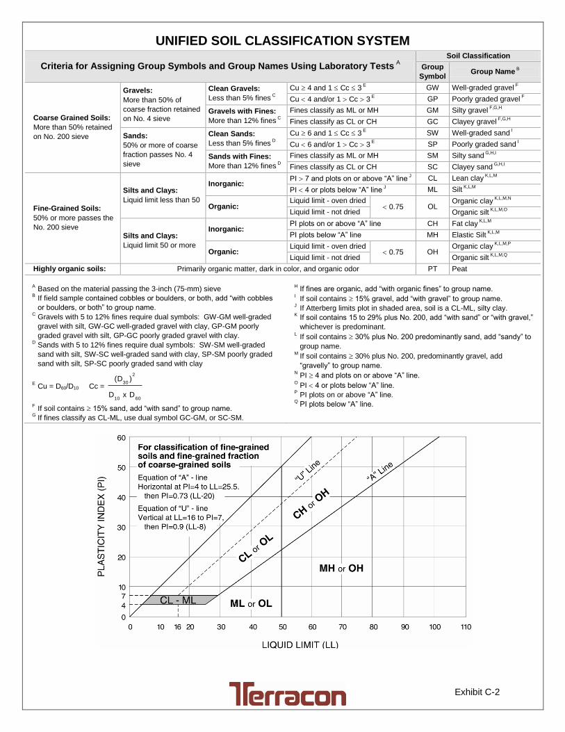
Exhibit C-2
UNIFIED SOIL CLASSIFICATION SYSTEM
Criteria for Assigning Group Symbols and Group Names Using Laboratory Tests A
Soil Classification
Group
Symbol Group Name
B
Coarse Grained Soils:
More than 50% retained
on No. 200 sieve
Gravels:
More than 50% of
coarse fraction retained
on No. 4 sieve
Clean Gravels:
Less than 5% fines C
Cu 4 and 1 Cc 3 E
GW Well-graded gravel F
Cu 4 and/or 1 Cc 3 E
GP Poorly graded gravel F
Gravels with Fines:
More than 12% fines C
Fines classify as ML or MH GM Silty gravel F,G,H
Fines classify as CL or CH GC Clayey gravel F,G,H
Sands:
50% or more of coarse
fraction passes No. 4
sieve
Clean Sands:
Less than 5% fines D
Cu 6 and 1 Cc 3 E
SW Well-graded sand I
Cu 6 and/or 1 Cc 3 E
SP Poorly graded sand I
Sands with Fines:
More than 12% fines D
Fines classify as ML or MH SM Silty sand G,H,I
Fines classify as CL or CH SC Clayey sand G,H,I
Fine-Grained Soils:
50% or more passes the
No. 200 sieve
Silts and Clays:
Liquid limit less than 50
Inorganic: PI 7 and plots on or above “A” line
J CL Lean clay
K,L,M
PI 4 or plots below “A” line J ML Silt
K,L,M
Organic: Liquid limit - oven dried
0.75 OL Organic clay
K,L,M,N
Liquid limit - not dried Organic silt K,L,M,O
Silts and Clays:
Liquid limit 50 or more
Inorganic: PI plots on or above “A” line CH Fat clay
K,L,M
PI plots below “A” line MH Elastic Silt K,L,M
Organic: Liquid limit - oven dried
0.75 OH Organic clay
K,L,M,P
Liquid limit - not dried Organic silt K,L,M,Q
Highly organic soils: Primarily organic matter, dark in color, and organic odor PT Peat
A Based on the material passing the 3-inch (75-mm) sieve
B If field sample contained cobbles or boulders, or both, add “with cobbles
or boulders, or both” to group name. C
Gravels with 5 to 12% fines require dual symbols: GW-GM well-graded
gravel with silt, GW-GC well-graded gravel with clay, GP-GM poorly
graded gravel with silt, GP-GC poorly graded gravel with clay. D
Sands with 5 to 12% fines require dual symbols: SW-SM well-graded
sand with silt, SW-SC well-graded sand with clay, SP-SM poorly graded
sand with silt, SP-SC poorly graded sand with clay
E Cu = D60/D10 Cc =
6010
2
30
DxD
)(D
F If soil contains 15% sand, add “with sand” to group name.
G If fines classify as CL-ML, use dual symbol GC-GM, or SC-SM.
H If fines are organic, add “with organic fines” to group name.
I If soil contains 15% gravel, add “with gravel” to group name.
J If Atterberg limits plot in shaded area, soil is a CL-ML, silty clay.
K If soil contains 15 to 29% plus No. 200, add “with sand” or “with gravel,”
whichever is predominant. L
If soil contains 30% plus No. 200 predominantly sand, add “sandy” to
group name. M
If soil contains 30% plus No. 200, predominantly gravel, add
“gravelly” to group name. N
PI 4 and plots on or above “A” line. O
PI 4 or plots below “A” line. P
PI plots on or above “A” line. Q
PI plots below “A” line.
03891917 STORMWATER CONSTRUCTION PERMIT 00 33 00 - 1
02/18
DOCUMENT 00 33 00 - STORMWATER CONSTRUCTION PERMIT
PART 1 - GENERAL
1.1 NOTIFICATION
A. The Clean Water Act and associated federal regulations (Title 40 of the Code of Federal
Regulations [CFR] 123.25(a)(9), 122.25(a), 122.26(b)(14)(x) and 122.26(b)(15) require nearly all
construction site operators engaged in clearing, grading, and excavating activities that disturb
one acre or more, including smaller sites in a larger common plan of development or sale,
to obtain coverage under a National Pollutant Discharge Elimination System (NPDES) permit for
their stormwater discharges.
B. Obtaining proper permits or making required notifications are the responsibility of the
Contractor at no additional cost to Owner.
C. Fines, fees, or any other financial damages assessed for failure to follow designated procedures
shall be paid by Contractor.
D. Monitoring and enforcement to ensure compliance of National Pollution Discharge
Elimination System (NPDES) will be conducted by the EPA Region 6 with the assistance of the
NM Environment Department.
1.2 SUMMARY
A. EPA Region 6 is the regulatory authority for the stormwater permitting program in New Mexico.
The Surface QUALITY Water Quality Bureau (SWQB) of the New Mexico Environment
Department assists the EPA in the regulation of stormwater discharges by performing inspections
on behalf of EPA and by serving as a local point of contact for providing information regarding
this federal regulatory program.
B. Related Requirements:
1. Division 00 00 00 "Invitation to Bid" for reference to Drawings and general
provisions of the Contract including General and Supplementary Conditions.
2. Division 01 Specification Sections apply to Work of this Section.
3. Division 01 81 13 "Sustainable Design Requirements" for LEED Sustainability
Requirements.
1.3 REQUIREMENTS
A. Contractor shall develop a Storm Water Pollution Prevention Plan (SWPPP) based on the
applicable requirements. More information regarding the permit can be found at the following
website: https://www.env.nm.gov/surface-water-quality/stormwater.
B. All elements of the accepted SWPPP and other activities required by the Construction
General Permit must be implemented and maintained until acceptance of Final Stabilization by
Owner.
C. Project requirements are found on the Erosion Control Plan in Drawings.
PART 2 - PRODUCTS (Not Used)
PART 3 - EXECUTION (Not Used)
END OF DOCUMENT
03891917 WEATHER TABLE 00 54 10 - 1
11/17 (EL PASO, NM)
DOCUMENT 00 54 10 - WEATHER TABLE
(EL PASO, TX)
APPLICABLE DOCUMENT
A. Sample Standard form of Agreement Between Regents of New Mexico State University
and Contractor.
DELAYS AND EXTENSION TIME
B. Anticipated Normal Weather Days: The time estimated by Contractor for completion of the
entire Work ready for use shall include the number of calendar days for anticipated delays
due to normal weather conditions. No time extension for delays due to weather will be
allowed until and unless such delays exceed the time included for normal weather delays.
In case of claims for extension of time because of abnormal inclement weather, such
extension of time shall be granted only because such abnormal inclement weather
prevented the execution of major items of work at NMSU Residence Hall on normal
working days.
C. For the purposes of this Contract, “abnormally inclement weather” will be interpreted as
the number of days in excess of the normal number of days on which rainfall exceeds 0.5
inch, or snow/ice pellets exceed 0.5 inch. Extensions of time to complete the Work will be
based on calendar days and granted by monthly account. No “rain days” unused for
previous months may be carried over or accountable for future periods of time.
D. A weather table reflecting the meteorological data from the El Paso, Texas area is to follow
and used to determine Contract Time extensions due to abnormally inclement weather.
END OF SECTION
03891917 WEATHER TABLE 00 54 10 - 2
02/18 (EL PASO, TX)
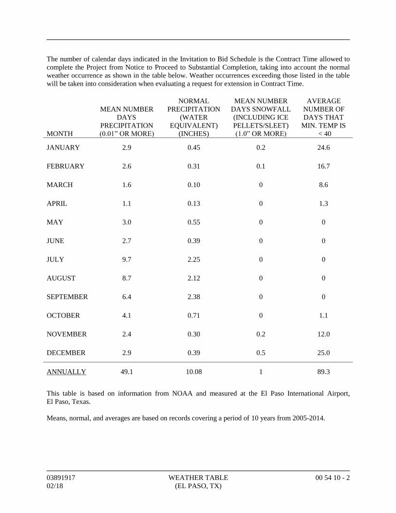
The number of calendar days indicated in the Invitation to Bid Schedule is the Contract Time allowed to
complete the Project from Notice to Proceed to Substantial Completion, taking into account the normal
weather occurrence as shown in the table below. Weather occurrences exceeding those listed in the table
will be taken into consideration when evaluating a request for extension in Contract Time.
This table is based on information from NOAA and measured at the El Paso International Airport,
El Paso, Texas.
Means, normal, and averages are based on records covering a period of 10 years from 2005-2014.
MONTH
MEAN NUMBER
DAYS
PRECIPITATION
(0.01” OR MORE)
NORMAL
PRECIPITATION
(WATER
EQUIVALENT)
(INCHES)
MEAN NUMBER
DAYS SNOWFALL
(INCLUDING ICE
PELLETS/SLEET)
(1.0” OR MORE)
AVERAGE
NUMBER OF
DAYS THAT
MIN. TEMP IS
< 40
JANUARY 2.9 0.45 0.2 24.6
FEBRUARY 2.6 0.31 0.1 16.7
MARCH 1.6 0.10 0 8.6
APRIL 1.1 0.13 0 1.3
MAY 3.0 0.55 0 0
JUNE 2.7 0.39 0 0
JULY 9.7 2.25 0 0
AUGUST 8.7 2.12 0 0
SEPTEMBER 6.4 2.38 0 0
OCTOBER 4.1 0.71 0 1.1
NOVEMBER 2.4 0.30 0.2 12.0
DECEMBER 2.9 0.39 0.5 25.0
ANNUALLY 49.1 10.08 1 89.3
03891917 WAGE RATE REQUIREMENTS 00 73 43 - 1
02/18
SECTION 00 73 43 - WAGE RATE REQUIREMENTS
PART 1 - GENERAL
1.1 WAGE RATE ESTABLISHMENT
A. For Contracts in excess of $60,000, minimum wages will be paid as determined by the
Department of Workforce Solutions in accordance with § 50-4-20 to § 50-4-30 NMSA 1978,
entitled “Minimum Wage Act.” Contractor and subcontractors shall deliver or mail copies of
the certified weekly payrolls, prepared in accordance with regulations, to the Labor
Commission and to Architect.
B. Contractor shall forfeit as a penalty to the Owner, $60.00 for each laborer, worker, or mechanic
employed for each calendar day, or portion thereof, such laborer, worker, or mechanic is paid
less than the said stipulated rates for any work done under this Contract by him, or by any
subcontractor under him.
C. Nothing herein contained, however, shall be construed to prohibit the payment of more than the
prevailing rate of wages to any laborer, worker, or mechanic employed on the Work.
D. Attention is called to the fact that there must be paid on this Project not less than the general
prevailing rates which have been established by Owner, and verified by Contractor as indicated
in the Schedule at the end of this document.
E. The General Prevailing Rate for overtime shall be 1-1/2 times the scheduled rate on an hourly
basis.
1.2 POSTING WAGE RATES
A. Minimum Wage Rates shall be posted on job site in a conspicuous place open for inspection by
all workers.
1.3 EMPLOYEE CLAIMS
A. Any employee who alleges that he has not been paid the minimum wage rate may file a written
claim with Owner.
1.4 PAYMENT OF EMPLOYEES AND PAYROLL RECORDS
A. Contractor and each subcontractor shall pay each of his employees engaged to perform Work
under this Contract in full (less mandatory legal deductions) not less than once a week.
B. Payment is to be in cash or check readily payable without discount. If payment is by cash,
obtain the signature of the employee verifying the payroll period, total hours worked, rate per
hour, total wages earned, and the date received.
C. Attach one copy of cash payment verification to payroll records.
D. Contractor and each subcontractor engaged at the site of the Work shall prepare and maintain
weekly payroll reports certified to be correct.
E. Payroll records shall contain the name, social security number, classification, rate per hour, and
hours worked each day, including regular hours and overtime hours.
03891917 WAGE RATE REQUIREMENTS 00 73 43 - 2
02/18
1.5 PAYROLL RECORDS
A. Payroll records shall be made available upon request for inspection by Architect or by a
designated representative of Owner to ascertain compliance with the minimum wage scale
provision of this Contract.
1.6 WAGE RATE SCHEDULE
A. See attached General Decision.
PART 2 - PRODUCTS (Not Used)
PART 3 - EXECUTION (Not Used)
END OF SECTION
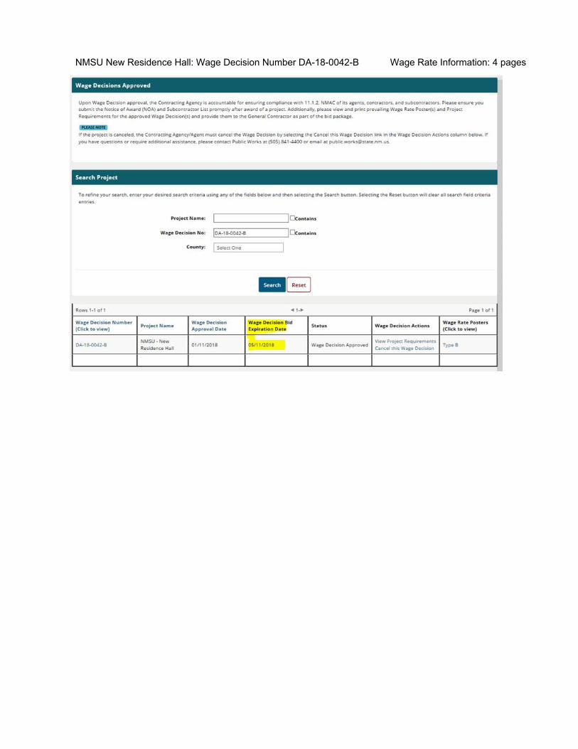
NMSU New Residence Hall: Wage Decision Number DA180042B Wage Rate Information: 4 pages

STATE OF NEW MEXICO NEW MEXICO DEPARTMENT OF WORKFORCE SOLUTIONS Labor Relations Division 121 Tijeras Ave NE, Suite 3000 Albuquerque, NM 87102 www.dws.state.nm.us
An Equal Opportunity Employer Page 1 of 2
PUBLIC WORKS PROJECT REQUIREMENTS
As a participant in a Public Works project valued at more than $60,000 in the State of New Mexico, the following list addresses many of the responsibilities that are defined by statute or regulation to each project stakeholder. Contracting Agency
Ensure that all Contractors wishing to bid on a Public Works project when the project is $60,000 or more are actively registered with the Public Works and Apprenticeship Application (PWAA) website: http://www.dws.state.nm.us/pwaa (Contractor Registration) prior to bidding.
Please submit Notice of Award (NOA) and Subcontractor List(s) to the PWAA website promptly after the project is awarded.
Please update the Subcontractor List(s) on the PWAA website whenever changes occur. All Sub-Contractors and tiers (excluding professional services) regardless of contract amount
must be listed on the Subcontractor List and must adhere to the Public Works Minimum Wage Act.
Ninety days after project completion please go into the PWAA system and close the project. Only Contracting Agencies are allowed to close the project. Agents or Contractors are not allowed to close projects.
General Contractor
Provide a complete Subcontractor List and Statements of Intent (SOI) to Pay Prevailing Wages for all Contractors, regardless of amount of work, to the Contracting Agency within 3 (three) days of award.
Ensure that all Subcontractors wishing to bid on a Public Works project have an active Contractor Registration with the Public Works and Apprenticeship Application (PWAA) website: http://www.dws.state.nm.us/pwaa prior to bidding when their bid will exceed $60,000.
Submit weekly certified payroll bi-weekly to the Contracting Agency. Make certain the Public Works Apprentice and Training Act contributions are paid either to
an approved Apprenticeship Program or to the Public Works Apprentice and Training Fund. Confirm the Wage Rate poster, provided in PWAA, is displayed at the job site in an easily
accessible place. Make sure, when a project has been completed, the Affidavits of Wages Paid (AWP) are sent
to the Contracting Agency.

STATE OF NEW MEXICO NEW MEXICO DEPARTMENT OF WORKFORCE SOLUTIONS Labor Relations Division 121 Tijeras Ave NE, Suite 3000 Albuquerque, NM 87102 www.dws.state.nm.us
An Equal Opportunity Employer Page 2 of 2
All Subcontractors and tiers (excluding professional services) regardless of contract amount must be listed on the Subcontractor List and must adhere to the Public Works Minimum Wage Act.
Subcontractor
Ensure that all Subcontractors wishing to bid on a Public Works project have an active Contractor Registration with the Public Works and Apprenticeship Application (PWAA) website: http://www.dws.state.nm.us/pwaa prior to bidding when their bid will exceed $60,000.
Submit weekly certified payroll bi-weekly to the General Contractor(s). Make certain the Public Works Apprentice and Training Act contributions are paid either to
an approved Apprenticeship Program or to the Public Works Apprentice and Training Fund. All Subcontractors and tiers (excluding professional services) regardless of contract amount
must be listed on the Subcontractor List and must adhere to the Public Works Minimum Wage Act.
Additional Information Reference material and forms may be found at New Mexico Department of Workforce Solutions Public Works web pages at: https://www.dws.state.nm.us/Labor-Relations/Labor-Information/Public-Works. CONTACT INFORMATION Contact the Labor Relations Division for any questions relating to Public Works projects by email at [email protected] or call (505) 841-4400.
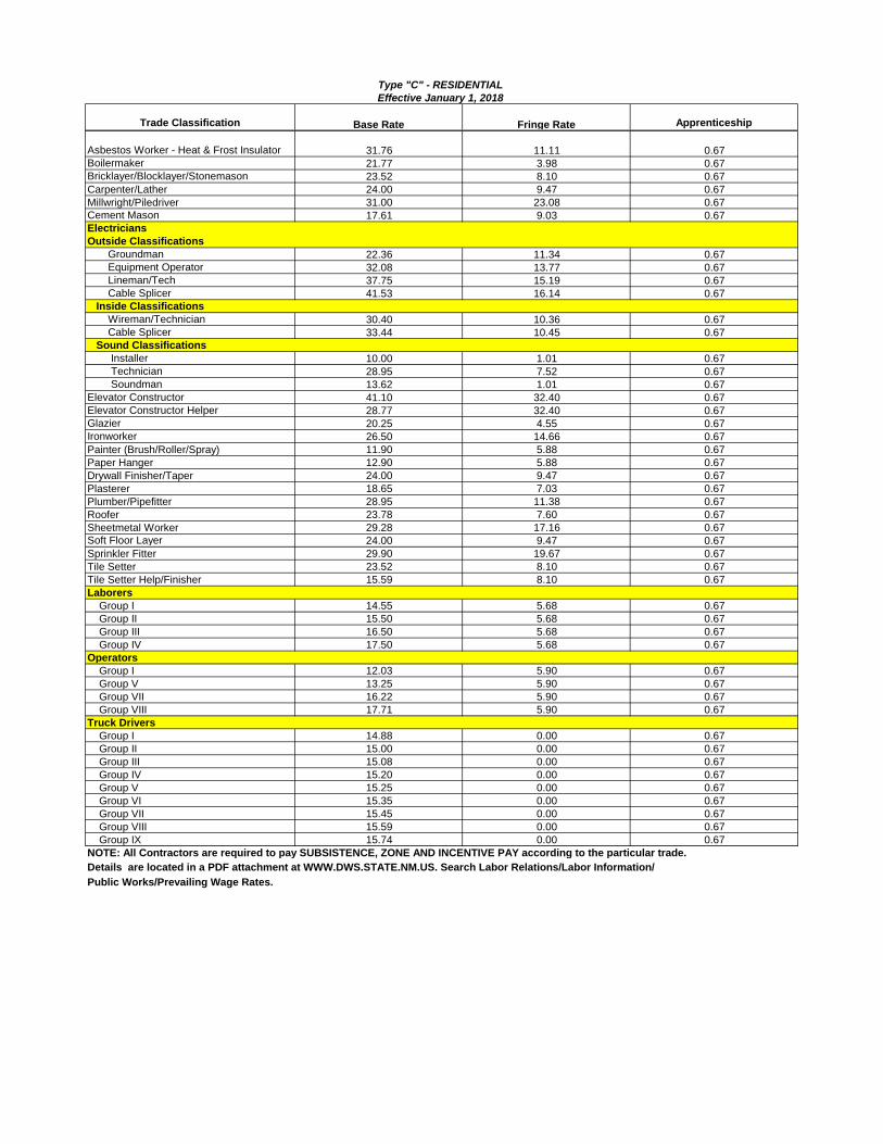
Trade Classification Base Rate Fringe Rate Apprenticeship
Asbestos Worker - Heat & Frost Insulator 31.76 11.11 0.67
Boilermaker 21.77 3.98 0.67
Bricklayer/Blocklayer/Stonemason 23.52 8.10 0.67
Carpenter/Lather 24.00 9.47 0.67
Millwright/Piledriver 31.00 23.08 0.67
Cement Mason 17.61 9.03 0.67
Electricians
Outside Classifications
Groundman 22.36 11.34 0.67
Equipment Operator 32.08 13.77 0.67
Lineman/Tech 37.75 15.19 0.67
Cable Splicer 41.53 16.14 0.67
Inside Classifications
Wireman/Technician 30.40 10.36 0.67
Cable Splicer 33.44 10.45 0.67
Sound Classifications
Installer 10.00 1.01 0.67
Technician 28.95 7.52 0.67
Soundman 13.62 1.01 0.67
Elevator Constructor 41.10 32.40 0.67
Elevator Constructor Helper 28.77 32.40 0.67
Glazier 20.25 4.55 0.67
Ironworker 26.50 14.66 0.67
Painter (Brush/Roller/Spray) 11.90 5.88 0.67
Paper Hanger 12.90 5.88 0.67
Drywall Finisher/Taper 24.00 9.47 0.67
Plasterer 18.65 7.03 0.67
Plumber/Pipefitter 28.95 11.38 0.67
Roofer 23.78 7.60 0.67
Sheetmetal Worker 29.28 17.16 0.67
Soft Floor Layer 24.00 9.47 0.67
Sprinkler Fitter 29.90 19.67 0.67
Tile Setter 23.52 8.10 0.67
Tile Setter Help/Finisher 15.59 8.10 0.67
Laborers
Group I 14.55 5.68 0.67
Group II 15.50 5.68 0.67
Group III 16.50 5.68 0.67
Group IV 17.50 5.68 0.67
Operators
Group I 12.03 5.90 0.67
Group V 13.25 5.90 0.67
Group VII 16.22 5.90 0.67
Group VIII 17.71 5.90 0.67
Truck Drivers
Group I 14.88 0.00 0.67
Group II 15.00 0.00 0.67
Group III 15.08 0.00 0.67
Group IV 15.20 0.00 0.67
Group V 15.25 0.00 0.67
Group VI 15.35 0.00 0.67
Group VII 15.45 0.00 0.67
Group VIII 15.59 0.00 0.67
Group IX 15.74 0.00 0.67
NOTE: All Contractors are required to pay SUBSISTENCE, ZONE AND INCENTIVE PAY according to the particular trade.
Details are located in a PDF attachment at WWW.DWS.STATE.NM.US. Search Labor Relations/Labor Information/
Public Works/Prevailing Wage Rates.
Type "C" - RESIDENTIAL
Effective January 1, 2018
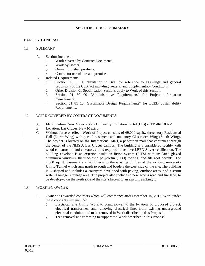
SECTION 01 10 00 - SUMMARY
GENERALPART 1 -
SUMMARY1.1
Section Includes:A.Work covered by Contract Documents.1.Work by Owner.2.Owner furnished products.3.Contractor use of site and premises.4.
Related Requirements:B.Section 00 00 00 "Invitation to Bid" for reference to Drawings and general1.provisions of the Contract including General and Supplementary Conditions.Other Division 01 Specification Sections apply to Work of this Section.2.Section 01 30 00 "Administrative Requirements" for Project information3.management.Section 01 81 13 "Sustainable Design Requirements" for LEED Sustainability4.Requirements.
WORK COVERED BY CONTRACT DOCUMENTS1.2
Identification: New Mexico State University Invitation to Bid (ITB) - ITB #R0189279.A.Location: Las Cruces, New Mexico.B.Without force or effect, Work of Project consists of 69,000 sq. ft., three-story ResidentialC.Hall (North Wing) with partial basement and one-story Classroom Wing (South Wing).The project is located on the International Mall, a pedestrian mall that continues throughthe center of the NMSU, Las Cruces campus. The building is a sprinklered facility withwood construction and elevator, and is required to achieve LEED Silver certification. Thebuilding envelope is an exterior insulation finish system (EIFS) with insulated glazedaluminum windows, thermoplastic polyolefin (TPO) roofing, and tile roof accents. The2,500 sq. ft. basement and will tie-in to the existing utilities at the existing universityUtility Tunnel which runs north to south and borders the west side of the site. The buildingis U-shaped and includes a courtyard developed with paving, outdoor areas, and a stormwater drainage retainage area. The project also includes a new access road and fire lane, tobe developed on the north side of the site adjacent to an existing parking lot.
WORK BY OWNER1.3
Owner has awarded contracts which will commence after December 15, 2017. Work underA.these contracts will include:
Electrical Site Utility Work to bring power to the location of proposed project,1.electrical transformer, and removing electrical lines from existing undergroundelectrical conduit noted to be removed in Work discribed in this Proposal.Tree removal and trimming to support the Work described in this Proposal.2.
0389191702/18
SUMMARY 01 10 00 - 1
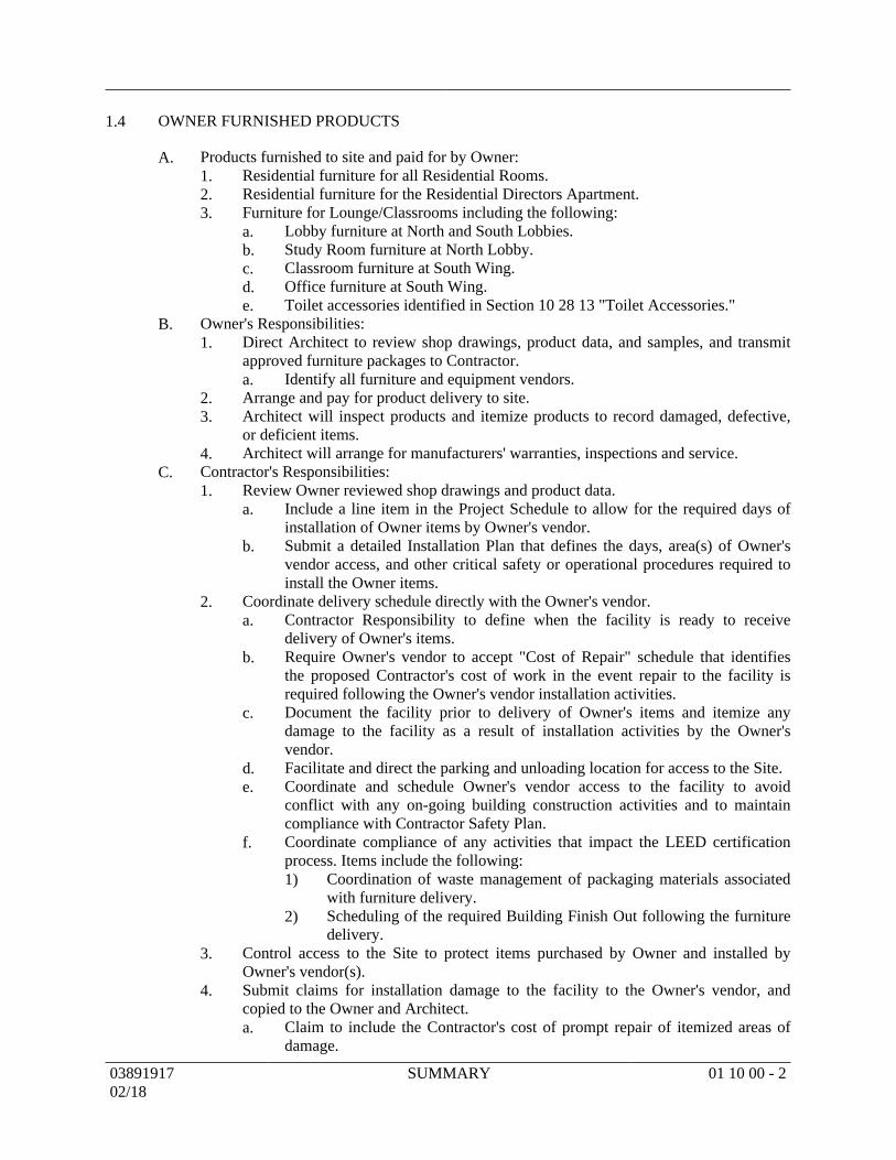
OWNER FURNISHED PRODUCTS1.4
Products furnished to site and paid for by Owner:A.Residential furniture for all Residential Rooms.1.Residential furniture for the Residential Directors Apartment.2.Furniture for Lounge/Classrooms including the following:3.
Lobby furniture at North and South Lobbies.a.Study Room furniture at North Lobby.b.Classroom furniture at South Wing.c.Office furniture at South Wing.d.Toilet accessories identified in Section 10 28 13 "Toilet Accessories."e.
Owner's Responsibilities:B.Direct Architect to review shop drawings, product data, and samples, and transmit1.approved furniture packages to Contractor.
Identify all furniture and equipment vendors.a.Arrange and pay for product delivery to site.2.Architect will inspect products and itemize products to record damaged, defective,3.or deficient items.Architect will arrange for manufacturers' warranties, inspections and service.4.
Contractor's Responsibilities:C.Review Owner reviewed shop drawings and product data.1.
Include a line item in the Project Schedule to allow for the required days ofa.installation of Owner items by Owner's vendor.Submit a detailed Installation Plan that defines the days, area(s) of Owner'sb.vendor access, and other critical safety or operational procedures required toinstall the Owner items.
Coordinate delivery schedule directly with the Owner's vendor.2.Contractor Responsibility to define when the facility is ready to receivea.delivery of Owner's items.Require Owner's vendor to accept "Cost of Repair" schedule that identifiesb.the proposed Contractor's cost of work in the event repair to the facility isrequired following the Owner's vendor installation activities.Document the facility prior to delivery of Owner's items and itemize anyc.damage to the facility as a result of installation activities by the Owner'svendor.Facilitate and direct the parking and unloading location for access to the Site.d.Coordinate and schedule Owner's vendor access to the facility to avoide.conflict with any on-going building construction activities and to maintaincompliance with Contractor Safety Plan.Coordinate compliance of any activities that impact the LEED certificationf.process. Items include the following:
Coordination of waste management of packaging materials associated1)with furniture delivery.Scheduling of the required Building Finish Out following the furniture2)delivery.
Control access to the Site to protect items purchased by Owner and installed by3.Owner's vendor(s).Submit claims for installation damage to the facility to the Owner's vendor, and4.copied to the Owner and Architect.
Claim to include the Contractor's cost of prompt repair of itemized areas ofa.damage.
0389191702/18
SUMMARY 01 10 00 - 2
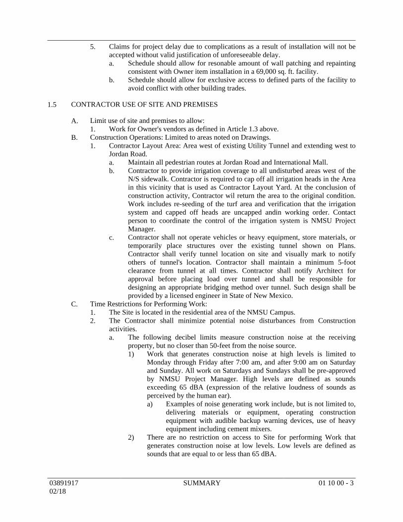
Claims for project delay due to complications as a result of installation will not be5.accepted without valid justification of unforeseeable delay.
Schedule should allow for resonable amount of wall patching and repaintinga.consistent with Owner item installation in a 69,000 sq. ft. facility.Schedule should allow for exclusive access to defined parts of the facility tob.avoid conflict with other building trades.
CONTRACTOR USE OF SITE AND PREMISES1.5
Limit use of site and premises to allow:A.Work for Owner's vendors as defined in Article 1.3 above.1.
Construction Operations: Limited to areas noted on Drawings.B.Contractor Layout Area: Area west of existing Utility Tunnel and extending west to1.Jordan Road.
Maintain all pedestrian routes at Jordan Road and International Mall.a.Contractor to provide irrigation coverage to all undisturbed areas west of theb.N/S sidewalk. Contractor is required to cap off all irrigation heads in the Areain this vicinity that is used as Contractor Layout Yard. At the conclusion ofconstruction activity, Contractor wil return the area to the original condition.Work includes re-seeding of the turf area and verification that the irrigationsystem and capped off heads are uncapped andin working order. Contactperson to coordinate the control of the irrigation system is NMSU ProjectManager.Contractor shall not operate vehicles or heavy equipment, store materials, orc.temporarily place structures over the existing tunnel shown on Plans.Contractor shall verify tunnel location on site and visually mark to notifyothers of tunnel's location. Contractor shall maintain a minimum 5-footclearance from tunnel at all times. Contractor shall notify Architect forapproval before placing load over tunnel and shall be responsible fordesigning an appropriate bridging method over tunnel. Such design shall beprovided by a licensed engineer in State of New Mexico.
Time Restrictions for Performing Work:C.The Site is located in the residential area of the NMSU Campus.1.The Contractor shall minimize potential noise disturbances from Construction2.activities.
The following decibel limits measure construction noise at the receivinga.property, but no closer than 50-feet from the noise source.
Work that generates construction noise at high levels is limited to1)Monday through Friday after 7:00 am, and after 9:00 am on Saturdayand Sunday. All work on Saturdays and Sundays shall be pre-approvedby NMSU Project Manager. High levels are defined as soundsexceeding 65 dBA (expression of the relative loudness of sounds asperceived by the human ear).
Examples of noise generating work include, but is not limited to,a)delivering materials or equipment, operating constructionequipment with audible backup warning devices, use of heavyequipment including cement mixers.
There are no restriction on access to Site for performing Work that2)generates construction noise at low levels. Low levels are defined assounds that are equal to or less than 65 dBA.
0389191702/18
SUMMARY 01 10 00 - 3
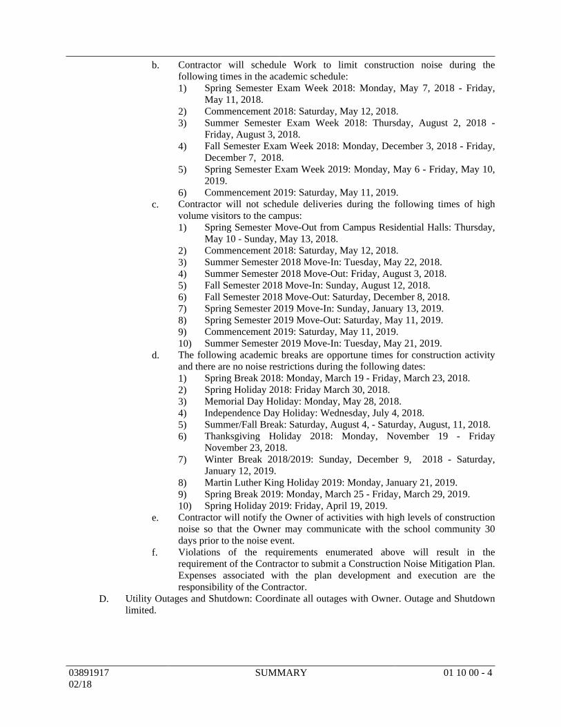
Contractor will schedule Work to limit construction noise during theb.following times in the academic schedule:
Spring Semester Exam Week 2018: Monday, May 7, 2018 - Friday,1)May 11, 2018.Commencement 2018: Saturday, May 12, 2018.2)Summer Semester Exam Week 2018: Thursday, August 2, 2018 -3)Friday, August 3, 2018.Fall Semester Exam Week 2018: Monday, December 3, 2018 - Friday,4)December 7, 2018.Spring Semester Exam Week 2019: Monday, May 6 - Friday, May 10,5)2019.Commencement 2019: Saturday, May 11, 2019.6)
Contractor will not schedule deliveries during the following times of highc.volume visitors to the campus:
Spring Semester Move-Out from Campus Residential Halls: Thursday,1)May 10 - Sunday, May 13, 2018.Commencement 2018: Saturday, May 12, 2018.2)Summer Semester 2018 Move-In: Tuesday, May 22, 2018.3)Summer Semester 2018 Move-Out: Friday, August 3, 2018.4)Fall Semester 2018 Move-In: Sunday, August 12, 2018.5)Fall Semester 2018 Move-Out: Saturday, December 8, 2018.6)Spring Semester 2019 Move-In: Sunday, January 13, 2019.7)Spring Semester 2019 Move-Out: Saturday, May 11, 2019.8)Commencement 2019: Saturday, May 11, 2019.9)Summer Semester 2019 Move-In: Tuesday, May 21, 2019.10)
The following academic breaks are opportune times for construction activityd.and there are no noise restrictions during the following dates:
Spring Break 2018: Monday, March 19 - Friday, March 23, 2018.1)Spring Holiday 2018: Friday March 30, 2018.2)Memorial Day Holiday: Monday, May 28, 2018.3)Independence Day Holiday: Wednesday, July 4, 2018.4)Summer/Fall Break: Saturday, August 4, - Saturday, August, 11, 2018.5)Thanksgiving Holiday 2018: Monday, November 19 - Friday6)November 23, 2018.Winter Break 2018/2019: Sunday, December 9, 2018 - Saturday,7)January 12, 2019.Martin Luther King Holiday 2019: Monday, January 21, 2019.8)Spring Break 2019: Monday, March 25 - Friday, March 29, 2019.9)Spring Holiday 2019: Friday, April 19, 2019.10)
Contractor will notify the Owner of activities with high levels of constructione.noise so that the Owner may communicate with the school community 30days prior to the noise event.Violations of the requirements enumerated above will result in thef.requirement of the Contractor to submit a Construction Noise Mitigation Plan.Expenses associated with the plan development and execution are theresponsibility of the Contractor.
Utility Outages and Shutdown: Coordinate all outages with Owner. Outage and ShutdownD.limited.
0389191702/18
SUMMARY 01 10 00 - 4

PRODUCTS (Not Used)PART 2 -
EXECUTION (Not Used)PART 3 -
END OF SECTION
0389191702/18
SUMMARY 01 10 00 - 5
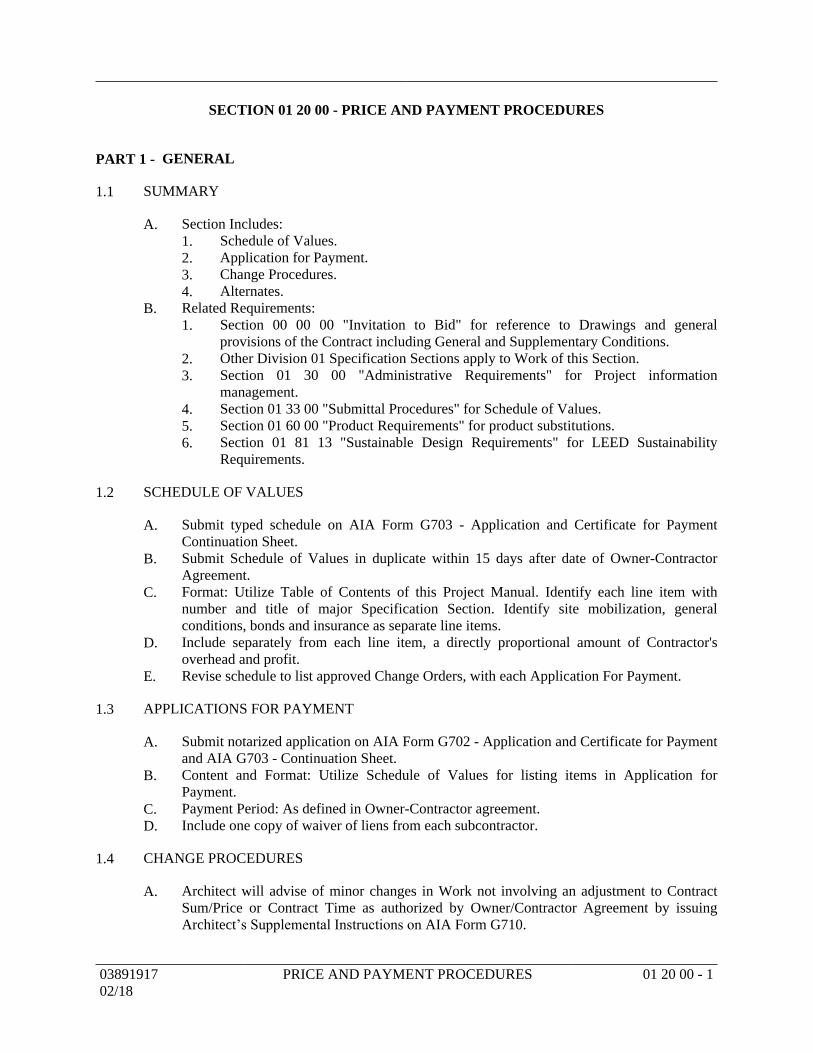
SECTION 01 20 00 - PRICE AND PAYMENT PROCEDURES
GENERALPART 1 -
SUMMARY1.1
Section Includes:A.Schedule of Values.1.Application for Payment.2.Change Procedures.3.Alternates.4.
Related Requirements:B.Section 00 00 00 "Invitation to Bid" for reference to Drawings and general1.provisions of the Contract including General and Supplementary Conditions.Other Division 01 Specification Sections apply to Work of this Section.2.Section 01 30 00 "Administrative Requirements" for Project information3.management.Section 01 33 00 "Submittal Procedures" for Schedule of Values.4.Section 01 60 00 "Product Requirements" for product substitutions.5.Section 01 81 13 "Sustainable Design Requirements" for LEED Sustainability6.Requirements.
SCHEDULE OF VALUES1.2
Submit typed schedule on AIA Form G703 - Application and Certificate for PaymentA.Continuation Sheet.Submit Schedule of Values in duplicate within 15 days after date of Owner-ContractorB.Agreement.Format: Utilize Table of Contents of this Project Manual. Identify each line item withC.number and title of major Specification Section. Identify site mobilization, generalconditions, bonds and insurance as separate line items.Include separately from each line item, a directly proportional amount of Contractor'sD.overhead and profit.Revise schedule to list approved Change Orders, with each Application For Payment.E.
APPLICATIONS FOR PAYMENT1.3
Submit notarized application on AIA Form G702 - Application and Certificate for PaymentA.and AIA G703 - Continuation Sheet.Content and Format: Utilize Schedule of Values for listing items in Application forB.Payment.Payment Period: As defined in Owner-Contractor agreement.C.Include one copy of waiver of liens from each subcontractor.D.
CHANGE PROCEDURES1.4
Architect will advise of minor changes in Work not involving an adjustment to ContractA.Sum/Price or Contract Time as authorized by Owner/Contractor Agreement by issuingArchitect’s Supplemental Instructions on AIA Form G710.
0389191702/18
PRICE AND PAYMENT PROCEDURES 01 20 00 - 1
Architect may issue a Construction Change Request which includes a detailed descriptionB.of a proposed change with supplementary or revised Drawings and specifications and achange in Contract Time for executing change. Contractor will prepare and submit anestimate within 7 days.Contractor may propose a change by submitting request for change to Architect. IncludeC.reason for change and effect on Contract Sum/Price, Contract Time, and subcontractors.Document requested substitutions in accordance with Section 01 60 00 "ProductRequirements."Stipulated Sum/Price Change Order: Based on Proposal Request and Contractor's fixedD.price quotation or Contractor's request for a Change Order as approved by Architect.Unit Price Change Order: For pre-determined unit prices and quantities, Change Order willE.be executed on a fixed unit price basis. For unit costs or quantities of units of work whichare not pre-determined, execute Work under a Construction Change Directive. Changes inContract Sum/Price or Contract Time will be computed as specified for Time and MaterialChange Order.Construction Change Directive: Architect may issue a directive, on AIA Form G713F.Construction Change Directive signed by Owner, instructing Contractor to proceed with achange in Work, for subsequent inclusion in a Change Order. Document will describechanges in Work, and designate method of determining any change in Contract Sum/Priceor Contract Time. Promptly execute change.Time and Material Change OrderG.
Submit itemized account and supporting data after completion of change, within1.time limits indicated in Conditions of the Contract.Architect will determine change allowable in Contract Sum/Price and Contract Time2.as provided in Contract Documents.Maintain detailed records of work done on Time and Material basis.3.Provide full information required for evaluation of proposed changes, and to4.substantiate costs for changes in Work.
Change Order Forms: AIA G701 Change Order.H.Execution of Change Orders: Architect will issue Change Orders for signatures of partiesI.as provided in Conditions of the Contract.Change Order: Furnish an itemized breakdown, in form acceptable to Architect of costsJ.and supporting information including but not limited to quantities and material prices. Tiersubcontracted work performed at labor rates, employer payments, and rental rates. Itemizebreakdown detail shall be same for subcontractor work. Provide complete supportinginformation for profit and overhead or markups used when requested. Consider thefollowing items a part of overhead or Contractor’s and sub-contractor’s mark-up and donot include as separate cost item: Labor for Superintendents, Assistant Superintendents,home office personnel, timekeepers and maintenance mechanics at any level ofcontracting; individual pieces of equipment, hand tools or instruments having a new valueof $500.00 or less, whether or not consumed by use; on site and main offices; modificationto record Contract Documents nor guarantee period costs.
ALTERNATES1.5
Alternates quoted on Proposal Forms will be reviewed and accepted or rejected by Owner.A.Accepted Alternates will be identified in Owner-Contractor Agreement.Coordinate related work and modify surrounding work as required.B.
0389191702/18
PRICE AND PAYMENT PROCEDURES 01 20 00 - 2
Schedule of Alternates:C.Alternate No. 1 - Waterproofing:1.
Waterproofing at residential suite bath area (integral to ceramic tiling).a.Sound mat at residential suite bath area (integral to gypsum cementb.underlayment).
Alternate No. 2 - Acoustical Panel Ceilings: Acoustical ceiling panel at north and2.south wing.Alternate No. 3 - Roof:3.
Roof Insulation: Increase tapered insulation to 3/8 inch per foot.a.Metal cap flashing at parapet (Base Bid is EIFS wrapped parapet).b.
Alternate No. 4 - Road Access:4.North Access Road: Asphalt paving.a.North Access Road: Concrete curb and gutter.b.North Access Road: Concrete sidewalk.c.
Alternate No. 5 - Towers and Arcade:5.North Wing: North tower.a.South Wing: Tower and arcade.b.
Alternate No. 6 - Doors and Hardware: Solid core doors and hardware upgrade at6.residential suite bath area.Alternate No. 7 - Sound Batt Insulation: South batt insulation between floors (LEED7.requirement).Alternate No. 8 - Aluminum-Framed Entrances and Storefronts:8.
South Wing: Aluminum storefront glazing at north elevation (doors in Basea.Bid).South Wing: Aluminum storefront glazing between classrooms and corridor.b.Shower door in lieu of shower rod and curtain.c.
Alternate No. 9 - EIFS System: Increase depth of rigid foam at windows and9.horizontal bands.Alternate No. 10 - Bike Racks: Two-tier storage, wall-mounted vertical storage, and10.covered outdoor system with bike racks.Alternate No. 11 - Entry Trellis: Entry trellis at north and south of north wing, and11.south side of south wing.Alternate No. 12 - Sidewalks:12.
Courtyard: Additional concrete sidewalk.a.Paved bike/pedestrian trail at east side of site.b.
Alternate No. 13 - South Wing Floor Finishes: Scheduled floor finishes at south13.wing in lieu of sealed concrete (scheduled floor base in Base Bid).Alternate No. 14 - Information and Communication Technology (ICT):14.
South Wing: Recessed IT station at each classroom.a.Alternate No. 15 - Rooftop Equipment Screens15.
South Wing: Rooftop equipment screens.a.Alternate No. 16 - Roller Window Shades:16.
North Wing: Residential window shades.a.South Wing: Commercial window shades and residential window shades.b.
Alternate No. 17 - Kitchen: Kitchen casework and appliances (LEED). Note17.mechanical and electrical are in Base Bid.Alternate No. 18 - Corridor Ceilings Upgrades: Corridor and lounge ceiling18.upgrades - gypsum board accent areas.Alternate No. 19 - French Drains: Vertical French drains at drainage retaining area.19.Alternate No. 20 - Landscaping:20.
Trees and associated irrigation system.a.Planting and associated irrigation system.b.
0389191702/18
PRICE AND PAYMENT PROCEDURES 01 20 00 - 3

PRODUCTS (Not Used)PART 2 -
EXECUTION (Not Used)PART 3 -
END OF SECTION
0389191702/18
PRICE AND PAYMENT PROCEDURES 01 20 00 - 4

SECTION 01 30 00 - ADMINISTRATIVE REQUIREMENTS
GENERALPART 1 -
SUMMARY1.1
Section Includes:A.Project Information Management.1.Coordination.2.Survey.3.Preconstruction meeting.4.Request for information.5.Site mobilization meeting.6.Progress meetings.7.Preinstallation meetings.8.Cutting and patching.9.
Related Requirements:B.Section 00 00 00 "Invitation to Bid" for reference to Drawings and general1.provisions of the Contract including General and Supplementary Conditions.Other Division 01 Specification Sections apply to Work of this Section.2.Section 01 81 13 "Sustainable Design Requirements" for LEED Sustainability3.Requirements.
PROJECT INFORMATION MANAGEMENT1.2
Project Website:A.Use Newforma Info Exchange; https://projects.team-psc.com/UserWeb/Login to1.send and receive project information.Contact Architect to setup a user name and password information.2.
Project information includes, but is not limited to, the following:B.Product Submittals.1.Requests for Information (RFI).2.Applications for Payment.3.Schedules.4.Construction Change Requests (CCRs).5.Close-out Documents.6.Construction Document Files:7.
Weather Days.a.Electronic File Requests.b.Correspondence.c.Test Reports.d.Meeting Minutes.e.Field Reports.f.
COORDINATION1.3
Coordinate scheduling, submittals, and Work to assure efficient and orderly sequence ofA.installation of construction elements.
0389191702/18
ADMINISTRATIVE REQUIREMENTS 01 30 00 - 1
Verify that utility requirements and characteristics of operating equipment are compatibleB.with building utilities. Coordinate work of various Sections having interdependentresponsibilities for installing, connecting to, and placing in service, such equipment.Coordinate space requirements and installation of mechanical and electrical work whichC.are indicated diagrammatically on Drawings. Follow routing shown for pipes, ducts, andconduit, as closely as practicable; place runs parallel with line of building. Utilize spacesefficiently to maximize accessibility for other installations, for maintenance, and forrepairs.In finished areas, except as otherwise indicated, conceal pipes, ducts, and wiring withinD.construction. Coordinate locations of fixtures and outlets with finish elements.Large Apparatus: Any large apparatus which is to be installed in any space and is too largeE.to permit access through windows, doorways, or shafts shall be provided before enclosingstructure is completed.Items which require electrical connections shall be coordinated with Division 26F."Electrical" for:
Voltage.1.Phase.2.Ampacity.3.Number and size of wires.4.Wiring diagrams.5.Starter size, details, and location.6.Control devices and details.7.
Coordinate completion and clean-up of Work of separate Sections in preparation forG.Substantial Completion.After Owner occupancy of premises, coordinate access to site with Owner for correction ofH.defective Work and Work not in accordance with Contract Documents, to minimizedisruption of Owner's activities.
SURVEY1.4
Use personnel experienced in surveying.A.Control datum for survey is that shown on Drawings.B.Verify set-backs and easements, confirm drawing dimensions and elevations.C.Provide field surveying services. Establish elevations, lines, and levels, utilizingD.recognized surveying practices.Submit registered site drawing and certificate signed by registered surveyor that elevationsE.and locations of Work are in conformance with Contract Documents.
PRECONSTRUCTION MEETING1.5
Owner will schedule a meeting after Notice to Proceed.A.Attendance Required:B.
Owner.1.Architect.2.Contractor.3.Major subcontractors.4.
Agenda:C.Submission of executed bonds and insurance certificates.1.Distribution of Contract Documents.2.Submission of list of subcontractors, list of products, Schedule of Values, and3.progress schedule.Designation of personnel representing each party in Contract and Architect.4.
0389191702/18
ADMINISTRATIVE REQUIREMENTS 01 30 00 - 2
Procedures and processing of field decisions, submittals, substitutions, applications5.for payments, proposal request, Change Orders, Request for Information (RFI), andContract closeout procedures.Review Notice to Proceed (NTP) and Substantial Completion Dates.6.Surface drainage requirements (SWPPP).7.Scheduling:8.
Owner's requirements for installation of Owner' items by Owner's vendors.a.Temporary utilities provided by Owner.b.Survey and building layout.c.Security and housekeeping procedures.d.Construction progress meetings.e.Procedures for testing.f.Procedures for maintaining record documents.g.Requirements for startup of equipment.h.Inspection and acceptance of equipment put into service during constructioni.period.
Scheduling activities of Construction Material Testing (CMT) lab.9.Record minutes and distribute copies within three days after meeting to participants withD.two copies to Architect and those affected by decisions made.
REQUEST FOR INFORMATION1.6
Request for information (RFI) requests from subcontractors or material suppliers will notA.be considered.Information indicated on RFI shall be complete before submission. If Architect determinesB.that request can be answered with information provided, Architect will assign an RFItracking number. Requests determined by Architect not to be an RFI will be returned toContractor electronically and deleted from Architect's electronic tracking software withoutbeing assigned an RFI tracking number. A transmittal document returning the denied RFIrequest will be provided with a response indicating action to be taken by Contractor.RFIs may contain more than 1 item when items are related issues. Otherwise, only 1 itemC.shall be addressed on each RFI request.Allow seven days for Architect's response to each RFI.D.Response to RFI will be issued to Contractor and Owner per Section 01 33 00 "SubmittalE.Procedures."Responses from Architect are not changes unless issued with a change per Section 01 20F.00 "Price and Payment Procedures."
SITE MOBILIZATION MEETING1.7
Schedule a meeting at site prior to Contractor occupancy.A.Attendance Required: Architect, special consultants, Contractor, Contractor'sB.superintendent, and major subcontractors.Agenda:C.
Use of premises by Owner and Contractor.1.Construction facilities and controls provided by Owner.2.Temporary utilities provided by Owner.3.Survey and building layout.4.Security and housekeeping procedures.5.Schedules.6.Procedures for testing.7.Procedures for maintaining record documents.8.
0389191702/18
ADMINISTRATIVE REQUIREMENTS 01 30 00 - 3
Requirements for startup of equipment.9.Inspection and acceptance of equipment put into service during construction period.10.
Record minutes and distribute copies within 3 days after meeting to participants withD.copies to Architect and those affected by decisions made.
PROGRESS MEETINGS1.8
Schedule and administer meetings throughout progress of Work at minimum bi-monthlyA.intervals.Make arrangements for meetings, prepare agenda with copies for participants, preside atB.meetings.Attendance Required:C.
Owner.1.Job superintendent.2.Major subcontractors.3.Suppliers.4. Architect as appropriate to agenda topics for each meeting.5.
Agenda:D.Review minutes of previous meetings.1.Review of Work progress.2.Field observations, problems, and decisions.3.Identification of problems which impede planned progress.4.Review of submittals schedule and status of submittals.5.Review of off-site fabrication and delivery schedules.6.Maintenance of progress schedule.7.Corrective measures to regain projected schedules.8.Planned progress during succeeding work period.9.Coordination of projected progress.10.Maintenance of quality and work standards.11.Effect of proposed changes on progress schedule and coordination.12.Other business relating to Work.13.
Record minutes, and distribute copies within three days to Architect, participants, andE.those affected by decisions made.
PREINSTALLATION MEETING1.9
When required in individual Specification Sections, convene a preinstallation meeting atA.site prior to installing Work.Require attendance of parties directly affecting, or affected by, Work.B.Notify Architect four days in advance of meeting date.C.Prepare agenda and preside at meeting.D.
Review conditions of installation, preparation and installation procedures.1.Review coordination with related work.2.
Record minutes, and distribute copies within three days after meeting to participants, withE.three copies to Architect.
0389191702/18
ADMINISTRATIVE REQUIREMENTS 01 30 00 - 4
PRODUCTSPART 2 -
EQUIPMENT ELECTRICAL CHARACTERISTICS AND COMPONENTS2.1
Motors: Specific motor type is specified in individual Specification Sections.A.Wiring Terminations: Provide terminal lugs to match branch circuit conductor quantities,B.sizes, and materials indicated. Size terminal lugs to NFPA 70, include lugs for terminalbox.Cord and Plug: Provide minimum 6 foot cord and plug including grounding connector forC.connection to electric wiring system. Cord of longer length is specified in individualSpecification Sections.
EXECUTIONPART 3 -
EXAMINATION3.1
Verify that existing site conditions and substrate surfaces are acceptable for subsequentA.Work. Beginning new Work means acceptance of existing conditions.Examine and verify specific conditions described in individual Specification Sections.B.Verify that utility services are available, of correct characteristics, and in correct location.C.
PREPARATION3.2
Clean substrate surfaces prior to applying next material or substance.A.Seal cracks or openings of substrate prior to applying next material or substance.B.Apply any manufacturer required or recommended substrate primer, sealer, or conditionerC.prior to applying any new material or substance in contact or bond.
CUTTING AND PATCHING3.3
Employ skilled and experienced installer to perform cutting and patching.A.Submit request in advance of cutting or altering elements which affects:B.
Structural integrity of element.1.Integrity of weather-exposed or moisture-resistant elements.2.Efficiency, maintenance, or safety of element.3.Visual qualities of sight-exposed elements.4.Work of Owner or separate contractor.5.
Execute cutting, fitting, and patching including excavation and fill, to complete Work, andC.to:
Fit several parts together, to integrate with other Work.1.Uncover Work to install or correct ill-timed Work.2.Remove and replace defective and non-conforming Work.3.Remove samples of installed Work for testing.4.Provide openings in elements of Work for penetrations of mechanical and electrical5.Work.
Execute work by methods which will avoid damage to other Work, and provide properD.surfaces to receive patching and finishing.Cut rigid materials using masonry saw or core drill.E.Restore Work with new products in accordance with requirements of Contract Documents.F.
0389191702/18
ADMINISTRATIVE REQUIREMENTS 01 30 00 - 5
Fit Work tight to pipes, sleeves, ducts, conduit, and other penetrations through surfaces.G.Maintain integrity of wall, ceiling, or floor construction; completely seal voids.H.Refinish surfaces to match adjacent finishes. For continuous surfaces, refinish to nearestI.intersection. For an assembly, refinish entire unit.Identify any hazardous substance or condition exposed during Work to Architect forJ.decision or remedy.
END OF SECTION
0389191702/18
ADMINISTRATIVE REQUIREMENTS 01 30 00 - 6
SECTION 01 33 00 - SUBMITTAL PROCEDURES
GENERALPART 1 -
SUMMARY1.1
Section Includes:A.Submittal procedures.1.Resubmittal requirements.2.Construction progress schedules.3.Shop drawings.4.Product data.5.Samples.6.Design data.7.Test reports.8.Certificates.9.Manufacturers' instructions.10.Manufacturers' field reports.11.Erection drawings.12.Construction photographs.13.
Related Requirements:B.Section 00 00 00 "Invitation to Bid" for reference to Drawings and general1.provisions of the Contract including General and Supplementary Conditions.Other Division 01 Specification Sections apply to Work of this Section.2.Section 01 20 00 "Price and Payment Procedures" for Schedule of Values;3.Inspecting and Testing Allowances.Section 01 30 00 "Administrative Requirements" for project information4.management.Section 01 40 00 "Quality Requirements" for Manufacturers' field services and5.reports; Testing Laboratory Services.Section 01 70 00 "Execution and Closeout Requirements" for Contract warranty,6.manufacturer's certificates and closeout submittals.Section 01 81 13 "Sustainable Design Requirements" for LEED Sustainability7.Requirements.
SUBMITTAL PROCEDURES1.2
Submit to Architect for review for limited purpose of checking for conformance withA.information given and design concept expressed in Contract Documents.Produce copies and distribute in accordance with this Article.B.Use project website to submit record documents as described in Section 01 70 00C."Execution and Closeout Requirements."Transmit each submittal separately with Contractor's standard transmittal letter includingD.Contractor's name, address, and phone number. Each submittal shall contain only oneSpecification Section.Sequentially number transmittal forms using Section number or Contractor's otherE.sequential numbering system.Identify Project, Contractor, subcontractor, or supplier; pertinent drawing sheet and detailF.number(s), and Specification Section number appropriate to submittal.
0389191702/18
SUBMITTAL PROCEDURES 01 33 00 - 1
Apply Contractor's stamp, signed or initialed certifying that review, verification ofG.products required, field dimensions, adjacent construction Work, and coordination ofinformation, is in accordance with requirements of Work and Contract Documents.Schedule submittals to expedite Project, and deliver to Architect. Coordinate submission ofH.related items.For each submittal for review, allow 15 days excluding delivery time to and fromI.Contractor.Identify variations from Contract Documents and product or system limitations which mayJ.be detrimental to successful performance of completed Work. Information, comments,field verifications, responses or other notations marked on submittals by Contractor shallbe done in blue or green colors only.Allow space on submittals for Contractor and Architect's review stamps.K.Distribute copies of reviewed submittals to concerned parties. Instruct parties to promptlyL.report any inability to comply with provisions.Submittals not requested will not be recognized or processed.M.Format:N.
Submit all submittals digitally using .PDF file extension. Each submittal shall be a1.single .PDF file including transmittal letter. Multiple files for same submittal willnot be accepted.Submittals in any other format, including .ZIP files, will be rejected.2.Hard copies will not be accepted.3.To ensure each page is legible, .PDF pages of drawings shall be same size/scale as a4.hard copy. Where applicable, scale symbols should be provided to indicate scale.Illegible submittals will be rejected.Uploaded submittals to project website.5.
Submittal procedures described in this Article applies to construction progress schedule,O.products list, shop drawings, product data, samples (actual samples and digital files ofsame), design data, test reports, certificates, manufacturer's instructions and field reports,erection drawings, and any other type of submittal submitted to Architect.
RESUBMITTAL REQUIREMENTS1.3
Revise and resubmit submittals, as required, and resubmit to meet requirements asA.specified and as noted on submittal reviews.Mark as RESUBMITTAL.B.Re-use original transmittal number and supplement with sequential alphabetical or numericC.suffix for each re-submittal.
CONSTRUCTION PROGRESS SCHEDULES1.4
Submit initial progress schedule for Architect's review within 15 days after date establishedA.in Notice to Proceed.Revise and resubmit as required.B.Submit revised schedule with each Application for Payment, identifying changes sinceC.previous version.Submit a horizontal bar chart with separate line for each section of Work, identifying firstD.work day of each week.
0389191702/18
SUBMITTAL PROCEDURES 01 33 00 - 2
Determine appropriate lead times to allow for manufacturing and delivery ofE.products/material for incorporation into Work. Indicate product/material manufacturer'slead-time for manufacturing and delivery to site. Include as a separate line for eachproduct/material. Failure to timely submit and process submittals, and ordering ofproducts/materials for delivery to site will not be grounds for approval of substitutions forother products/materials.Indicate delivery dates for Owner furnished products.F.Revisions to Schedules:G.
Indicate progress of each activity to date of submittal, and projected completion date1.of each activity.Identify activities modified since previous submittal, major changes in scope, and2.other identifiable changes.Prepare narrative report to define problem areas, anticipated delays, and impact on3.Schedule. Report corrective action taken, or proposed, and its effect including effectof changes on schedules of separate contractors.
SHOP DRAWINGS1.5
Indicate special utility and electrical characteristics, utility connection requirements, andA.location of utility outlets for service for functional equipment and appliances.Printable Image Size: Minimum 8-1/2 by 11 inches and maximum 30 by 42 inches.B.Draw details to a minimum scale of 1/2 inches equal to 1 foot.C.Draw site plans to same scale indicated on Contract Drawings.D.Draw other plans to a minimum scale of 1/8 inch equal to 1 foot.E.Construction Documents (electronic or paper format) issued by Architect cannot be used inF.any shape, form or fashion in creation and development of shop drawings, except thatelectronic files containing floor plans or site plans which have been purchased fromArchitect may be used as backgrounds for Contractor, subcontractors, sub-subcontractors,and material suppliers in shop drawing process.
Submittals that show obvious reproduction of the original Construction Documents1.will be rejected.
Electronic Files:G.Electronic AutoCAD drawing files are available for purchase from Architect upon1.request. Cost of files are indicated below plus applicable taxes.
1 - 3 Sheets: $100.00 per sheet.a.4 - 6 Sheets: $400.00 flat fee.b.7 - 9 Sheets: $500.00 flat fee.c.
Contractor or his subcontractors and sub-subcontractors may purchase an electronic2.file. An electronic file will be provided in software release currently used byArchitect. File will be provided via project website.Electronic Revit model files are available for purchase from Architect upon request.3.Cost of model files are $150.00 each plus applicable taxes. Only Contractor or hissubcontractors and sub-subcontractors may purchase an electronic file. An electronicfile will be provided in software release currently used by Architect. File will beprovided via project website.Prior to delivery of file, purchaser shall sign an Electronic File Transfer Release4.Form. Payment for an electronic file shall occur upon delivery of file to purchaser.Electronic file shall be used only for production of information required by this5.project and shall not be used in any other form (in whole or part).
0389191702/18
SUBMITTAL PROCEDURES 01 33 00 - 3
In creation and publication of shop drawings, under no circumstances shall6.Architect's seal or title block of drawing be reproduced. Shop drawings must beoriginal works from Contractor subcontractors, sub-subcontractors, and materialsuppliers.
PRODUCT DATA1.6
Mark each copy to identify applicable products, models, options, and other data.A.Supplement manufacturers' standard data to provide information unique to this Project.Include recommendations for application and use, and reference to compliance withB.specified standards of trade associations and testing agencies.Include notation of special coordination requirements for interfacing with adjacent workC.and building utilities where applicable.After review, distribute in accordance with titled "Submittal Procedures" Article above andD.provide copies for Record Documents described in Section 01 70 00 "Execution andCloseout Requirements."
SAMPLES1.7
Submit samples to illustrate functional and aesthetic characteristics of product, withA.integral parts and attachment devices. Accompany physical sample with color digitalimage (photo or scanned .PDF) of sample. Coordinate sample submittals for interfacingwork.Unless otherwise specified, submit samples of finishes from manufacturers' full range ofB.standard colors, textures, and patterns, for Architect's selection.Where variations in color, pattern or texture are inherent in material or product, submitC.multiple samples to indicate approximate range or variations.Include full Project information and identification of manufacturer, model number, type,D.style and color on each sample.Submit number of samples specified in individual Specification Sections; one of whichE.will be retained by Architect.Reviewed samples which may remain as part of Work are indicated in individualF.Specification Sections.Samples will not be used for testing purposes unless specifically stated in individualG.Specification Sections.
DESIGN DATA1.8
Submit for Architect's knowledge as contract administrator or for Owner.A.Submit for information for limited purpose of assessing conformance with informationB.given and design concept expressed in Contract Documents.
TEST REPORTS1.9
Submit for Architect's knowledge as contract administrator or for Owner.A.Submit test reports for information for limited purpose of assessing conformance withB.information given and design concept expressed in Contract Documents.
CERTIFICATES1.10
When specified in individual Specification Sections, submit certification by manufacturer,A.installation/application subcontractor, or Contractor to Architect.
0389191702/18
SUBMITTAL PROCEDURES 01 33 00 - 4
Indicate material or product conforms to or exceeds specified requirements. SubmitB.supporting reference data, affidavits, and certifications as appropriate.Certificates may be recent or previous test results on material or product, but must beC.acceptable to Architect.
MANUFACTURER'S INSTRUCTIONS1.11
When specified in individual Specification Sections, submit manufacturers' printedA.instructions for delivery, storage, assembly, installation, startup, adjusting, and finishing.Identify conflicts between manufacturers' instructions and Contract Documents.B.Indicate special procedures, conditions requiring special attention and specialC.environmental criteria required for application or installation.
MANUFACTURER'S FIELD REPORTS1.12
Submit reports for Architect's benefit as contract administrator or for Owner.A.Submit report within 30 days of observation to Architect for information.B.Submit for information for limited purpose of assessing conformance with informationC.given and design concept expressed in Contract Documents.
ERECTION DRAWINGS1.13
Submit drawings for Architect's benefit as contract administrator or for Owner.A.Submit for information for limited purpose of assessing conformance with informationB.given and design concept expressed in Contract Documents.Data indicating inappropriate or unacceptable Work may be subject to action by ArchitectC.or Owner.
CONSTRUCTION PHOTOGRAPHS1.14
Each month submit photographs to Architect.A.Photographs:B.
Format: JPEG file extension; color.1.Subject: Take two site photographs from differing directions and five interior2.photographs indicating relative progress of Work, five days maximum prior tosubmitting pay request.
Identify photographs with date, time, orientation, and Project identification.C.
PRODUCTS (Not Used)PART 2 -
EXECUTION (Not Used)PART 3 -
END OF SECTION
0389191702/18
SUBMITTAL PROCEDURES 01 33 00 - 5
SECTION 01 40 00 - QUALITY REQUIREMENTS
GENERALPART 1 -
SUMMARY1.1
Section Includes:A.Quality control and control of installation.1.Tolerances.2.References.3.Mockup requirements.4.Manufacturers' field services.5.Examination.6.Preparation.7.
Related Requirements:B.Section 00 00 00 "Invitation to Bid" for reference to Drawings and general1.provisions of the Contract including General and Supplementary Conditions.Other Division 01 Specification Sections apply to Work of this Section.2.Section 01 30 00 "Administrative Requirements" for Project information3.management.Section 01 33 00 "Submittal Procedures" for submission of Manufacturers'4.Instructions and Certificates.Section 01 60 00 "Product Requirements" for requirements for material and product5.quality.Section 01 81 13 "Sustainable Design Requirements" for LEED Sustainability6.Requirements.
QUALITY CONTROL AND CONTROL OF INSTALLATION1.2
Monitor quality control over suppliers, manufacturers, products, services, site conditions,A.and workmanship, to produce Work of specified quality.Comply with manufacturers' instructions, including each step in sequence.B.Should manufacturers' instructions conflict with Contract Documents, request clarificationC.from Architect before proceeding.Comply with specified standards as a minimum quality for Work except when moreD.stringent tolerances, codes, or specified requirements indicate higher standards or moreprecise workmanship.Perform work by persons qualified to produce workmanship of specified quality.E.Verify field measurements are as indicated on Shop Drawings or as instructed byF.manufacturer.Secure Products in place with positive anchorage devices designed and sized to withstandG.stresses, vibration, physical distortion or disfigurement.
TOLERANCES1.3
Monitor fabrication and installation tolerance control of products to produce acceptableA.Work. Do not permit tolerances to accumulate.Comply with manufacturers' tolerances. Should manufacturers' tolerances conflict withB.Contract Documents, request clarification from Architect before proceeding.Adjust products to appropriate dimensions; position before securing in place.C.
0389191702/18
QUALITY REQUIREMENTS 01 40 00 - 1
REFERENCES1.4
For products or workmanship specified by association, trade, or other consensus standards,A.comply with requirements of standard, except when more rigid requirements are specifiedor are required by applicable codes.Conform to reference standard by date of issue current on date of Contract Documents,B.except where a specific date is established by Code.Obtain copy of standards when required by Specification Section.C.Neither contractual relationship, duties nor responsibilities of parties in Contract nor thoseD.of Architect shall be altered from Contract Documents by mention or inference otherwisein any reference document.
MOCKUP REQUIREMENTS1.5
Tests will be performed under provisions identified in this Section and identified inA.respective product Specification Sections.Assemble and erect specified items, with specified attachment and anchorage devices,B.flashings, seals, and finishes.Accepted mockups shall be comparison standard for quality level for Work.C.Where mockup has been accepted by Architect and is specified in individual SpecificationD.Sections to be removed, remove mockup and clear area.
TESTING AND INSPECTION SERVICES1.6
Owner will appoint, employ, and pay for specified services of an independent firm toA.perform inspection and testing.The independent firm will perform inspections, tests, and other services specified inB.individual Specification Sections and as required by Architect.Testing, inspections and source quality control may occur on or off Project site. PerformC.off-site testing as required by Architect or Owner.Submit independent testing laboratory firm’s reports to Architect. Reports to includeD.observations and results of tests and will indicate compliance or non-compliance withContract Documents.Cooperate with independent firm; furnish samples of materials, design mix, equipment,E.tools, storage, provide safe access to project site, and provide assistance by incidental laboras requested.
Notify Architect and independent firm 48 hours prior to expected time for operations1.requiring services.Pay for additional samples and tests required for Contractor's use.2.
Employment of independent testing agency or laboratory does not relieve Contractor fromF.performing Work to contract requirements.Re-testing and/or re-inspection required because of non-conformance to specifiedG.requirements will be charged to Contractor by deducting re-testing and/or re-inspectioncharges from Contract Sum/Price.
MANUFACTURERS' FIELD SERVICES1.7
When specified in individual Specification Sections, require material or product suppliersA.or manufacturers to provide qualified staff personnel to observe site conditions, conditionsof surfaces and installation, quality of workmanship, startup of equipment, and test, adjust,and balance of equipment as applicable, and to initiate instructions when necessary.
0389191702/18
QUALITY REQUIREMENTS 01 40 00 - 2
Submit qualifications of observer to Architect 30 days in advance of required observations.B.Observer subject to approval of Architect.Report observations and site decisions or instructions given to applicators or installers thatC.are supplemental or contrary to manufacturers' written instructions.Refer to Section 01 33 00 "Submittal Procedures," Manufacturer's Field Reports Article.D.
PRODUCTS (Not Used)PART 2 -
EXECUTIONPART 3 -
EXAMINATION3.1
Verify site conditions and substrate surfaces are acceptable for subsequent Work.A.Beginning new Work means acceptance of existing conditions.Verify substrate is capable of structural support or attachment of new Work being appliedB.or attached.Examine and verify specific conditions described in individual Specification Sections.C.Verify utility services are available, of correct characteristics, and in correct locations.D.
PREPARATION3.2
Clean substrate surfaces prior to applying next material or substance.A.Seal cracks or openings of substrate prior to applying next material or substance.B.Apply manufacturer required or recommended substrate primer, sealer, or conditioner priorC.to applying new material or substance in contact or bond.
END OF SECTION
0389191702/18
QUALITY REQUIREMENTS 01 40 00 - 3
SECTION 01 42 00 - REFERENCES
GENERALPART 1 -
SUMMARY1.1
Related Requirements:A.Section 00 00 00 "Invitation to Bid" for reference to Drawings and general1.provisions of the Contract including General and Supplementary Conditions.Other Division 01 Specification Sections apply to Work of this Section.2.Section 01 81 13 "Sustainable Design Requirements" for LEED Sustainability3.Requirements.
DEFINITIONS1.2
General: Basic Contract definitions are included in the Conditions of the Contract.A."Approved": When used to convey Architect's action on Contractor's submittals,B.applications, and requests, "approved" is limited to Architect's duties and responsibilities asstated in the Conditions of the Contract."Directed": A command or instruction by Architect. Other terms including "requested,"C."authorized," "selected," "required," and "permitted" have the same meaning as "directed.""Indicated": Requirements expressed by graphic representations or in written form onD.Drawings, in Specifications, and in other Contract Documents. Other terms including"shown," "noted," "scheduled," and "specified" have the same meaning as "indicated.""Regulations": Laws, ordinances, statutes, and lawful orders issued by authorities havingE.jurisdiction, and rules, conventions, and agreements within the construction industry thatcontrol performance of the Work."Furnish": Supply and deliver to Project site, ready for unloading, unpacking, assembly,F.installation, and similar operations."Install": Unload, temporarily store, unpack, assemble, erect, place, anchor, apply, work toG.dimension, finish, cure, protect, clean, and similar operations at Project site."Provide": Furnish and install, complete and ready for the intended use.H."Project Site": Space available for performing construction activities. The extent of ProjectI.site is shown on Drawings and may or may not be identical with the description of the landon which Project is to be built."Owner' Vendor": The entity identified in an Agreement(s) between Owner and anJ.independent vendor to provide movable equipment or furniture, and to deliver and placeitems within the facility at precise locations defined by the Furniture and Equipment Plan.Facility access by the Owner's vendor is schedule by the Contractor.
INDUSTRY STANDARDS1.3
Applicability of Standards: Unless the Contract Documents include more stringentA.requirements, applicable construction industry standards have the same force and effect asif bound or copied directly into the Contract Documents to the extent referenced. Suchstandards are made a part of the Contract Documents by reference.Publication Dates: Comply with standards in effect as of date of the Contract DocumentsB.unless otherwise indicated.
0389191702/18
REFERENCES 01 42 00 - 1
Copies of Standards: Each entity engaged in construction on Project should be familiarC.with industry standards applicable to its construction activity. Copies of applicablestandards are not bound with the Contract Documents.
Where copies of standards are needed to perform a required construction activity,1.obtain copies directly from publication source.
ABBREVIATIONS AND ACRONYMS1.4
Industry Organizations: Where abbreviations and acronyms are used in Specifications orA.other Contract Documents, they shall mean the recognized name of the entities indicated inGale's "Encyclopedia of Associations: National Organizations of the U.S." or in ColumbiaBooks' "National Trade & Professional Associations of the United States."Industry Organizations: Where abbreviations and acronyms are used in Specifications orB.other Contract Documents, they shall mean the recognized name of the entities in thefollowing list. This information is subject to change and is believed to be accurate as of thedate of the Contract Documents.
AABC - Associated Air Balance Council; www.aabc.com.1.AAMA - American Architectural Manufacturers Association; www.aamanet.org.2.AAPFCO - Association of American Plant Food Control Officials; www.aapfco.org.3.AASHTO - American Association of State Highway and Transportation Officials;4.www.transportation.org.AATCC - American Association of Textile Chemists and Colorists; www.aatcc.org.5.ABMA - American Bearing Manufacturers Association;6.www.americanbearings.org.ABMA - American Boiler Manufacturers Association; www.abma.com.7.ACI - American Concrete Institute; (Formerly: ACI International); www.abma.com.8.ACPA - American Concrete Pipe Association; www.concrete-pipe.org.9.AEIC - Association of Edison Illuminating Companies, Inc. (The); www.aeic.org.10.AF&PA - American Forest & Paper Association; www.afandpa.org.11.AGA - American Gas Association; www.aga.org.12.AHAM - Association of Home Appliance Manufacturers; www.aham.org.13.AHRI - Air-Conditioning, Heating, and Refrigeration Institute (The);14.www.ahrinet.org.AI - Asphalt Institute; www.asphaltinstitute.org.15.AIA - American Institute of Architects (The); www.aia.org.16.AISC - American Institute of Steel Construction; www.aisc.org.17.AISI - American Iron and Steel Institute; www.steel.org.18.AITC - American Institute of Timber Construction; www.aitc-glulam.org.19.AMCA - Air Movement and Control Association International, Inc.; www.amca.org.20.ANSI - American National Standards Institute; www.ansi.org.21.AOSA - Association of Official Seed Analysts, Inc.; www.aosaseed.com.22.APA - APA - The Engineered Wood Association; www.apawood.org.23.APA - Architectural Precast Association; www.archprecast.org.24.API - American Petroleum Institute; www.api.org.25.ARI - Air-Conditioning & Refrigeration Institute; (See AHRI).26.ARI - American Refrigeration Institute; (See AHRI).27.ARMA - Asphalt Roofing Manufacturers Association; www.asphaltroofing.org.28.ASCE - American Society of Civil Engineers; www.asce.org.29.ASCE/SEI - American Society of Civil Engineers/Structural Engineering Institute;30.(See ASCE).ASHRAE - American Society of Heating, Refrigerating and Air-Conditioning31.Engineers; www.ashrae.org.
0389191702/18
REFERENCES 01 42 00 - 2
ASME - ASME International; (American Society of Mechanical Engineers);32.www.asme.org.ASSE - American Society of Safety Engineers (The); www.asse.org.33.ASSE - American Society of Sanitary Engineering; www.asse-plumbing.org.34.ASTM - ASTM International; www.astm.org.35.ATIS - Alliance for Telecommunications Industry Solutions; www.atis.org.36.AWEA - American Wind Energy Association; www.awea.org.37.AWI - Architectural Woodwork Institute; www.awinet.org.38.AWMAC - Architectural Woodwork Manufacturers Association of Canada;39.www.awmac.com.AWPA - American Wood Protection Association; www.awpa.com.40.AWS - American Welding Society; www.aws.org.41.AWWA - American Water Works Association; www.awwa.org.42.BHMA - Builders Hardware Manufacturers Association;43.www.buildershardware.com.BIA - Brick Industry Association (The); www.gobrick.com.44.BICSI - BICSI, Inc.; www.bicsi.org.45.BIFMA - BIFMA International; (Business and Institutional Furniture Manufacturer's46.Association); www.bifma.org.BISSC - Baking Industry Sanitation Standards Committee; www.bissc.org.47.BWF - Badminton World Federation; (Formerly: International Badminton48.Federation); www.bissc.org.CDA - Copper Development Association; www.copper.org.49.CEA - Canadian Electricity Association; www.electricity.ca.50.CEA - Consumer Electronics Association; www.ce.org.51.CFFA - Chemical Fabrics and Film Association, Inc.;52.www.chemicalfabricsandfilm.com.CFSEI - Cold-Formed Steel Engineers Institute; www.cfsei.org.53.CGA - Compressed Gas Association; www.cganet.com.54.CIMA - Cellulose Insulation Manufacturers Association; www.cellulose.org.55.CISCA - Ceilings & Interior Systems Construction Association; www.cisca.org.56.CISPI - Cast Iron Soil Pipe Institute; www.cispi.org.57.CLFMI - Chain Link Fence Manufacturers Institute; www.chainlinkinfo.org.58.CPA - Composite Panel Association; www.pbmdf.com.59.CRI - Carpet and Rug Institute (The); www.carpet-rug.org.60.CRRC - Cool Roof Rating Council; www.coolroofs.org.61.CRSI - Concrete Reinforcing Steel Institute; www.crsi.org.62.CSA - Canadian Standards Association; www.csa.ca.63.CSA - CSA International; (Formerly: IAS - International Approval Services);64.www.csa-international.org.CSI - Construction Specifications Institute (The); www.csinet.org.65.CSSB - Cedar Shake & Shingle Bureau; www.cedarbureau.org.66.CTI - Cooling Technology Institute; (Formerly: Cooling Tower Institute);67.www.cti.org.CWC - Composite Wood Council; (See CPA).68.DASMA - Door and Access Systems Manufacturers Association; www.dasma.com.69.DHI - Door and Hardware Institute; www.dhi.org.70.ECA - Electronic Components Association; (See ECIA).71.ECAMA - Electronic Components Assemblies & Materials Association; (See72.ECIA).ECIA - Electronic Components Industry Association; www.eciaonline.org.73.EIA - Electronic Industries Alliance; (See TIA).74.
0389191702/18
REFERENCES 01 42 00 - 3
EIMA - EIFS Industry Members Association; www.eima.com.75.EJMA - Expansion Joint Manufacturers Association, Inc.; www.ejma.org.76.ESD - ESD Association; (Electrostatic Discharge Association); www.esda.org.77.ESTA - Entertainment Services and Technology Association; (See PLASA).78.EVO - Efficiency Valuation Organization; www.evo-world.org.79.FCI - Fluid Controls Institute; www.fluidcontrolsinstitute.org.80.FIBA - Federation Internationale de Basketball; (The International Basketball81.Federation); www.fiba.com.FIVB - Federation Internationale de Volleyball; (The International Volleyball82.Federation); www.fivb.org.FM Approvals - FM Approvals LLC; www.fmglobal.com.83.FM Global - FM Global; (Formerly: FMG - FM Global); www.fmglobal.com.84.FRSA - Florida Roofing, Sheet Metal & Air Conditioning Contractors Association,85.Inc.; www.floridaroof.com.FSA - Fluid Sealing Association; www.fluidsealing.com.86.FSC - Forest Stewardship Council U.S.; www.fscus.org.87.GA - Gypsum Association; www.gypsum.org.88.GANA - Glass Association of North America; www.glasswebsite.com.89.GS - Green Seal; www.greenseal.org.90.HI - Hydraulic Institute; www.pumps.org.91.HI/GAMA - Hydronics Institute/Gas Appliance Manufacturers Association; (See92.AHRI).HMMA - Hollow Metal Manufacturers Association; (See NAAMM).93.HPVA - Hardwood Plywood & Veneer Association; www.hpva.org.94.HPW - H. P. White Laboratory, Inc.; www.hpwhite.com.95.IAPSC - International Association of Professional Security Consultants;96.www.iapsc.org.IAS - International Accreditation Service; www.iasonline.org.97.IAS - International Approval Services; (See CSA).98.ICBO - International Conference of Building Officials; (See ICC).99.ICC - International Code Council; www.iccsafe.org.100.ICEA - Insulated Cable Engineers Association, Inc.; www.icea.net.101.ICPA - International Cast Polymer Alliance; www.icpa-hq.org.102.ICRI - International Concrete Repair Institute, Inc.; www.icri.org.103.IEC - International Electrotechnical Commission; http://www.iec.ch.104.IEEE - Institute of Electrical and Electronics Engineers, Inc. (The); www.ieee.org.105.IES - Illuminating Engineering Society; (Formerly: Illuminating Engineering106.Society of North America); www.ies.org.IESNA - Illuminating Engineering Society of North America; (See IES).107.IEST - Institute of Environmental Sciences and Technology; www.iest.org.108.IGMA - Insulating Glass Manufacturers Alliance; www.igmaonline.org.109.IGSHPA - International Ground Source Heat Pump Association;110.www.igshpa.okstate.edu.ILI - Indiana Limestone Institute of America, Inc.; www.iliai.com.111.Intertek - Intertek Group; (Formerly: ETL SEMCO; Intertek Testing Service NA);112.www.intertek.com.ISA - International Society of Automation (The); (Formerly: Instrumentation,113.Systems, and Automation Society); www.isa.org.ISAS - Instrumentation, Systems, and Automation Society (The); (See ISA).114.ISFA - International Surface Fabricators Association; (Formerly: International Solid115.Surface Fabricators Association); www.isfanow.org.ISO - International Organization for Standardization; www.iso.org.116.
0389191702/18
REFERENCES 01 42 00 - 4
ISSFA - International Solid Surface Fabricators Association; (See ISFA).117.ITU - International Telecommunication Union; www.itu.int/home.118.KCMA - Kitchen Cabinet Manufacturers Association; www.kcma.org.119.LMA - Laminating Materials Association; (See CPA).120.LPI - Lightning Protection Institute; www.lightning.org.121.MBMA - Metal Building Manufacturers Association; www.mbma.com.122.MCA - Metal Construction Association; www.metalconstruction.org.123.MFMA - Maple Flooring Manufacturers Association, Inc.; www.maplefloor.org.124.MFMA - Metal Framing Manufacturers Association, Inc.;125.www.metalframingmfg.org.MHIA - Material Handling Industry of America; www.mhia.org.126.MIA - Marble Institute of America; www.marble-institute.com.127.MMPA - Moulding & Millwork Producers Association; www.wmmpa.com.128.MPI - Master Painters Institute; www.paintinfo.com.129.MSS - Manufacturers Standardization Society of The Valve and Fittings Industry130.Inc.; www.mss-hq.org.NAAMM - National Association of Architectural Metal Manufacturers;131.www.naamm.org.NACE - NACE International; (National Association of Corrosion Engineers132.International); www.nace.org.NADCA - National Air Duct Cleaners Association; www.nadca.com.133.NAIMA - North American Insulation Manufacturers Association; www.naima.org.134.NBGQA - National Building Granite Quarries Association, Inc.; www.nbgqa.com.135.NBI - New Buildings Institute; www.newbuildings.org.136.NCAA - National Collegiate Athletic Association (The); www.ncaa.org.137.NCMA - National Concrete Masonry Association; www.ncma.org.138.NEBB - National Environmental Balancing Bureau; www.nebb.org.139.NECA - National Electrical Contractors Association; www.necanet.org.140.NeLMA - Northeastern Lumber Manufacturers Association; www.nelma.org.141.NEMA - National Electrical Manufacturers Association; www.nema.org.142.NETA - InterNational Electrical Testing Association; www.netaworld.org.143.NFHS - National Federation of State High School Associations; www.nfhs.org.144.NFPA - National Fire Protection Association; www.nfpa.org.145.NFPA - NFPA International; (See NFPA).146.NFRC - National Fenestration Rating Council; www.nfrc.org.147.NHLA - National Hardwood Lumber Association; www.nhla.com.148.NLGA - National Lumber Grades Authority; www.nlga.org.149.NOFMA - National Oak Flooring Manufacturers Association; (See NWFA).150.NOMMA - National Ornamental & Miscellaneous Metals Association;151.www.nomma.org.NRCA - National Roofing Contractors Association; www.nrca.net.152.NRMCA - National Ready Mixed Concrete Association; www.nrmca.org.153.NSF - NSF International; www.nsf.org.154.NSPE - National Society of Professional Engineers; www.nspe.org.155.NSSGA - National Stone, Sand & Gravel Association; www.nssga.org.156.NTMA - National Terrazzo & Mosaic Association, Inc. (The); www.ntma.com.157.NWFA - National Wood Flooring Association; www.nwfa.org.158.PCI - Precast/Prestressed Concrete Institute; www.pci.org.159.PDI - Plumbing & Drainage Institute; www.pdionline.org.160.PLASA - PLASA; (Formerly: ESTA - Entertainment Services and Technology161.Association); www.plasa.org.RCSC - Research Council on Structural Connections; www.boltcouncil.org.162.
0389191702/18
REFERENCES 01 42 00 - 5
RFCI - Resilient Floor Covering Institute; www.rfci.com.163.RIS - Redwood Inspection Service; www.redwoodinspection.com.164.SAE - SAE International; www.sae.org.165.SCTE - Society of Cable Telecommunications Engineers; www.scte.org.166.SDI - Steel Deck Institute; www.sdi.org.167.SDI - Steel Door Institute; www.steeldoor.org.168.SEFA - Scientific Equipment and Furniture Association (The); www.sefalabs.com.169.SEI/ASCE - Structural Engineering Institute/American Society of Civil Engineers;170.(See ASCE).SIA - Security Industry Association; www.siaonline.org.171.SJI - Steel Joist Institute; www.steeljoist.org.172.SMA - Screen Manufacturers Association; www.smainfo.org.173.SMACNA - Sheet Metal and Air Conditioning Contractors' National Association;174.www.smacna.org.SMPTE - Society of Motion Picture and Television Engineers; www.smpte.org.175.SPFA - Spray Polyurethane Foam Alliance; www.sprayfoam.org.176.SPIB - Southern Pine Inspection Bureau; www.spib.org.177.SPRI - Single Ply Roofing Industry; www.spri.org.178.SRCC - Solar Rating & Certification Corporation; www.solar-rating.org.179.SSINA - Specialty Steel Industry of North America; www.ssina.com.180.SSPC - SSPC: The Society for Protective Coatings; www.sspc.org.181.STI - Steel Tank Institute; www.steeltank.com.182.SWI - Steel Window Institute; www.steelwindows.com.183.SWPA - Submersible Wastewater Pump Association; www.swpa.org.184.TCA - Tilt-Up Concrete Association; www.tilt-up.org.185.TCNA - Tile Council of North America, Inc.; www.tileusa.com.186.TEMA - Tubular Exchanger Manufacturers Association, Inc.; www.tema.org.187.TIA - Telecommunications Industry Association (The); (Formerly: TIA/EIA -188.Telecommunications Industry Association/Electronic Industries Alliance);www.tiaonline.org.TIA/EIA - Telecommunications Industry Association/Electronic Industries Alliance;189.(See TIA).TMS - The Masonry Society; www.masonrysociety.org.190.TPI - Truss Plate Institute; www.tpinst.org.191.TPI - Turfgrass Producers International; www.turfgrasssod.org.192.TRI - Tile Roofing Institute; www.tileroofing.org.193.UL - Underwriters Laboratories Inc.; www.ul.com.194.UNI - Uni-Bell PVC Pipe Association; www.uni-bell.org.195.USAV - USA Volleyball; www.usavolleyball.org.196.USGBC - U.S. Green Building Council; www.usgbc.org.197.USITT - United States Institute for Theatre Technology, Inc.; www.usitt.org.198.WASTEC - Waste Equipment Technology Association; www.wastec.org.199.WCLIB - West Coast Lumber Inspection Bureau; www.wclib.org.200.WCMA - Window Covering Manufacturers Association; www.wcmanet.org.201.WDMA - Window & Door Manufacturers Association; www.wdma.com.202.WI - Woodwork Institute; www.wicnet.org.203.WSRCA - Western States Roofing Contractors Association; www.wsrca.com.204.WWPA - Western Wood Products Association; www.wwpa.org.205.
0389191702/18
REFERENCES 01 42 00 - 6
Code Agencies: Where abbreviations and acronyms are used in Specifications or otherC.Contract Documents, they shall mean the recognized name of the entities in the followinglist. This information is believed to be accurate as of the date of the Contract Documents.
DIN - Deutsches Institut fur Normung e.V.; www.din.de.1.IAPMO - International Association of Plumbing and Mechanical Officials;2.www.iapmo.org.ICC - International Code Council; www.iccsafe.org.3.ICC-ES - ICC Evaluation Service, LLC; www.icc-es.org.4.
Federal Government Agencies: Where abbreviations and acronyms are used inD.Specifications or other Contract Documents, they shall mean the recognized name of theentities in the following list. Information is subject to change and is up to date as of thedate of the Contract Documents.
COE - Army Corps of Engineers; www.usace.army.mil.1.CPSC - Consumer Product Safety Commission; www.cpsc.gov.2.DOC - Department of Commerce; National Institute of Standards and Technology;3.www.nist.gov.DOD - Department of Defense; www.quicksearch.dla.mil.4.DOE - Department of Energy; www.energy.gov.5.EPA - Environmental Protection Agency; www.epa.gov.6.FAA - Federal Aviation Administration; www.faa.gov.7.FG - Federal Government Publications; www.gpo.gov/fdsys.8.GSA - General Services Administration; www.gsa.gov.9.HUD - Department of Housing and Urban Development; www.hud.gov.10.LBL - Lawrence Berkeley National Laboratory; Environmental Energy11.Technologies Division; www.eetd.lbl.gov.OSHA - Occupational Safety & Health Administration; www.osha.gov.12.SD - Department of State; www.state.gov.13.TRB - Transportation Research Board; National Cooperative Highway Research14.Program; The National Academies; www.trb.org.USDA - Department of Agriculture; Agriculture Research Service; U.S. Salinity15.Laboratory; www.ars.usda.gov.USDA - Department of Agriculture; Rural Utilities Service; www.usda.gov.16.USDOJ - Department of Justice; Office of Justice Programs; National Institute of17.Justice; www.ojp.usdoj.gov.USP - U.S. Pharmacopeial Convention; www.usp.org.18.USPS - United States Postal Service; www.usps.com.19.
Standards and Regulations: Where abbreviations and acronyms are used in SpecificationsE.or other Contract Documents, they shall mean the recognized name of the standards andregulations in the following list. This information is subject to change and is believed to beaccurate as of the date of the Contract Documents.
CFR - Code of Federal Regulations; Available from Government Printing Office;1.www.gpo.gov/fdsys.DOD - Department of Defense; Military Specifications and Standards; Available2.from DLA Document Services; www.quicksearch.dla.mil.DSCC - Defense Supply Center Columbus; (See FS).3.FED-STD - Federal Standard; (See FS).4.FS - Federal Specification; Available from DLA Document Services;5.www.quicksearch.dla.mil.
Available from Defense Standardization Program; www.dsp.dla.mil.a.Available from General Services Administration; www.gsa.gov.b.Available from National Institute of Building Sciences/Whole Buildingc.Design Guide; www.wbdg.org/ccb.
0389191702/18
REFERENCES 01 42 00 - 7
MILSPEC - Military Specification and Standards; (See DOD).6.USAB - United States Access Board; www.access-board.gov.7.USATBCB - U.S. Architectural & Transportation Barriers Compliance Board; (See8.USAB).
PRODUCTS (Not Used)PART 2 -
EXECUTION (Not Used)PART 3 -
END OF SECTION
0389191702/18
REFERENCES 01 42 00 - 8
SECTION 01 50 00 - TEMPORARY FACILITIES AND CONTROLS
GENERALPART 1 -
SUMMARY1.1
Section Includes:A.Temporary Utilities:1.
Electricity.a.Lighting.b.Heating.c.Cooling.d.Ventilation.e.Water.f.Sanitary.g.
Construction Facilities:2.Field offices.a.Vehicular access.b.Parking.c.Progress cleaning.d.Project identification.e.Traffic regulation.f.
Temporary Controls:3.Barriers.a.Fencing.b.Enclosures.c.Security.d.Water control.e.Dust control.f.Erosion and sediment control.g.Pollution control.h.Protection of Work.i.
Removal of utilities, facilities, and controls.4.Related Requirements:B.
Section 00 00 00 "Invitation to Bid" for reference to Drawings and general1.provisions of the Contract including General and Supplementary Conditions.Other Division 01 Specification Sections apply to Work of this Section.2.Section 01 70 00 "Execution and Closeout Requirements" for final cleaning.3.Section 01 81 13 "Sustainable Design Requirements" for LEED Sustainability4.Requirements.
TEMPORARY ELECTRICITY1.2
Electricity is provided by Owner. Coordinate connection to electric utility with Owner.A.
TEMPORARY LIGHTING FOR CONSTRUCTION PURPOSES1.3
Provide and maintain 1 watt/sq. ft. lighting to exterior staging and storage areas after darkA.for security purposes.
0389191702/18
TEMPORARY FACILITIES AND CONTROLS 01 50 00 - 1
Provide and maintain 0.25 watt/sq. ft. H.I.D. lighting to interior work areas after dark forB.security purposes.Provide branch wiring from power source to distribution boxes with lighting conductors,C.pigtails, and lamps as required.Maintain lighting and provide routine repairs.D.
TEMPORARY HEAT1.4
Provide heat devices as required to maintain specified conditions for constructionA.operations until new heating system is installed.Owner will pay cost of energy used. Exercise measures to conserve energy.B.
TEMPORARY COOLING1.5
Enclose building prior to activating temporary cooling in accordance with EnclosuresA.article in this Section.Maintain maximum ambient temperature of 80 degrees F in areas where construction is inB.progress, unless indicated otherwise in Specifications.
TEMPORARY VENTILATION1.6
Ventilate enclosed areas to assist cure of materials, to dissipate humidity, and to preventA.accumulation of dust, fumes, vapors, or gases.Provide temporary fan units as required to maintain clean air for construction operations.B.
TEMPORARY WATER SERVICE1.7
Connect to existing water source for construction operations. Extend and supplement withA.temporary devices as needed to maintain specified conditions for construction operations.Owner will pay cost of water used.B.
TEMPORARY SANITARY FACILITIES1.8
Provide and maintain required facilities and enclosures.A.Existing facilities shall not be used.B.
FIELD OFFICES1.9
Do not use existing facilities for field offices or for storage.A.Office:B.
Weathertight, with lighting, electrical outlets, heating, and ventilating equipment.1.Equip with sturdy furniture including drawing display table and conference table and2.chairs to accommodate six persons.Locate offices and sheds a minimum distance of 30 feet from new structures.3.
VEHICULAR ACCESS1.10
Location as approved by Architect.A.Provide unimpeded access for emergency vehicles. Maintain 20-foot-wide driveways withB.turning space between and around combustible materials.Provide and maintain access to fire hydrants and control valves free of obstructions.C.
0389191702/18
TEMPORARY FACILITIES AND CONTROLS 01 50 00 - 2
Provide means of removing mud from vehicle wheels before entering on site paved areasD.and public streets.See Drawings for required protection of existing below grade utility tunnel that separatesE.the suggested layout area from the building site.Coordinate use of on-site roads for construction traffic. Use of on-site roads requiresF.approval by Owner and may be subject to a defined access schedule.
PARKING1.11
When site space is not adequate, provide additional off-site parking.A.Use of existing parking facilities by construction personnel is not permitted.B.Do not allow vehicle parking on existing pavement.C.Permanent Pavements and Parking Facilities: Avoid traffic loading beyond paving designD.capacity. Tracked vehicles not allowed.Maintenance:E.
Maintain traffic and parking areas in sound condition free of excavated material,1.construction equipment, products, mud, snow, and ice.Maintain existing paved areas used for construction; promptly repair breaks,2.potholes, low areas, standing water, and other deficiencies, to maintain paving anddrainage in original, or specified, condition.
Removal, Repair:F.Remove temporary materials and construction before Substantial Completion.1.Repair existing facilities damaged by use, to original condition.2.
Mud from Site Vehicles: Provide means of removing mud from vehicle wheels beforeG.entering streets.
PROGRESS CLEANING1.12
Maintain areas free of waste materials, debris, and rubbish. Maintain site in a clean andA.orderly condition.Remove debris and rubbish from pipe chases, plenums, attics, crawl spaces, and otherB.closed or remote spaces, prior to enclosing space.Broom and vacuum clean interior areas prior to start of surface finishing, and continueC.cleaning to eliminate dust.Remove waste materials, debris, and rubbish from site and dispose off-site at intervals asD.required to maintain clean site.
PROJECT IDENTIFICATION1.13
Project Identification Sign:A.Size: Provide two, 8-foot wide by 4-foot high.1.Materials: 3/4-inch-thick exterior grade plywood and solid wood frame.2.Background Paint: Exterior quality, two coats; sign background of white. Total3.number of colors and placement per the Sign Elevation attached.Lettering: Pre-cut vinyl self-adhesive products, white. Colors and graphics per the4.Sign Elevation attached.Design: Design included as attachment to this Section.5.Content:6.
Project title, as indicated on Contract Documents.a.Owner’s name and logo.b.University Administration and Staff as identified on Sign Design Drawing.c.
0389191702/18
TEMPORARY FACILITIES AND CONTROLS 01 50 00 - 3
Names and titles of Architect and Consultants.d.Name of Prime Contractor.e.Name of major Subcontractors.f.Format per attached "Project Identification Sign" sketch at end of this Section.g.
Lettering: Series C of Standard Alphabet for Highway Signs, Public Roads7.Administration, Federal Works Agency.
Project Informational Signs:B.If required by other Documents or Sections of Project Manual, provide weather1.protected signs for site safety procedures, wage rates, and Storm Water PollutionPrevention Plan.Erect sign on or adjacent to field office, if required.2.
Design sign and structure to withstand 90 mph wind velocity.C.Installation:D.
Install Project identification sign within 15 days after date fixed by Notice to1.Proceed.Erect at location of high public visibility adjacent to main entrance to site.2.Erect supports and framing on secure foundation, rigidly braced and framed to resist3.wind loadings.Install sign surface plumb and level, with butt joints. Anchor securely.4.Paint exposed surfaces of sign supports and framing.5.
No other signs are allowed without Owner's permission except those required by law.E.Maintenance: Maintain signs and supports clean, repair deterioration and damage.F.Removal: Remove signs, framing, supports, and foundations at completion of Project andG.restore area.
TRAFFIC REGULATION1.14
Signs, Signals, and Devices:A.Post Mounted and Wall Mounted Traffic Control and Informational Signs: As1.approved by authority having jurisdiction.Traffic Cones and Drums: As approved by authority having jurisdiction.2.Flagperson Equipment: As required by authority having jurisdiction.3.
Flag Persons: Provide trained and equipped flag persons to regulate traffic whenB.construction operations or traffic encroach on public traffic lanes.Haul Routes:C.
Consult with authority having jurisdiction, establish public thoroughfares to be used1.for haul routes and site access.Confine construction traffic to designated haul routes.2.
Traffic Signs and Signals:D.Provide signs at approaches to site and on site, at crossroads, detours, parking areas,1.and elsewhere as needed to direct construction and affected public traffic.Provide, operate, and maintain traffic control signals to direct and maintain orderly2.flow of traffic in areas under Contractor's control, and areas affected by Contractor'soperations.Relocate as Work progresses, to maintain effective traffic control.3.
Removal:E.Remove equipment and devices when no longer required.1.Repair damage caused by installation.2.Remove post settings to depth of 2 feet.3.
0389191702/18
TEMPORARY FACILITIES AND CONTROLS 01 50 00 - 4
BARRIERS1.15
Provide barriers to prevent unauthorized entry to construction areas and to protect existingA.facilities and adjacent properties from damage from construction operations.Provide protection for the following items designated to remain. Replace damaged itemsB.condition to original condition:
Trees.1.Shrubbery.2.Lawns.3.
Protect site improvements including but not limited to pavements, walkways and drainageC.structures from damage. Replace damaged site improvements to original condition.Protect non-owned vehicular traffic and stored materials from damage.D.
TEMPORARY FENCING1.16
Construction: Commercial grade chain-link fence.A.Provide 6-foot-high fence around construction site and temporary materials storage area;B.equip with vehicular and pedestrian gates with locks.
TEMPORARY ENCLOSURES1.17
Exterior Enclosures: Provide temporary weathertight closure of exterior openings toA.accommodate acceptable working conditions and protection for products, to allow fortemporary heating, cooling, ventilation, and maintenance of required ambient temperaturesidentified in individual Specification Sections, and to prevent entry of unauthorizedpersons. Provide access doors with self-closing hardware and locks.
SECURITY1.18
Security Program:A.Protect Work from theft, vandalism, and unauthorized entry.1.Initiate program at Project mobilization.2.Maintain program throughout construction period until Owner occupancy.3.
Entry Control:B.Restrict entrance of persons and vehicles into Project site.1.Allow entrance only to authorized persons with proper identification.2.Maintain log of workers and visitors; make available to Owner on request.3.
WATER CONTROL1.19
Grade site to drain.A.Maintain excavations free of water.B.Provide, operate, and maintain pumping equipment.C.Protect site from puddling and running water. Provide water barriers as required to protectD.site from soil erosion.Provide water barriers as required to protect buildings from puddling, ponding or otherE.water accumulation that may damage foundations or other sub-surface construction.
0389191702/18
TEMPORARY FACILITIES AND CONTROLS 01 50 00 - 5
DUST CONTROL1.20
Execute Work by methods to minimize raising dust from construction operations.A.Provide positive means to prevent airborne dust from dispersing into atmosphere.B.
EROSION AND SEDIMENT CONTROL1.21
Plan and execute construction by methods to control surface drainage from cuts and fills,A.from borrow and waste disposal areas. Prevent erosion and sedimentation.Minimize surface area of bare soil exposed at one time.B.Provide temporary measures including berms, dikes, and drains, and other devices toC.prevent water flow that would result in erosion.Construct fill and waste areas by selective placement to avoid erosive surface silts or clays.D.Periodically inspect earthwork to detect evidence of erosion and sedimentation; promptlyE.apply corrective measures.
POLLUTION CONTROL1.22
Provide methods, means, and facilities to prevent contamination of soil, water, andA.atmosphere from discharge of noxious, toxic substances, and pollutants produced byconstruction operations.Comply with pollution and environmental control requirements of New Mexico StateB.University and/or the City of Las Cruces.Comply with LEED requirements as defined by the USGBC and the LEED Project goals.C.
PROTECTION OF INSTALLED WORK1.23
Protect installed Work and provide special protection where specified in individualA.Specification Sections.Provide temporary and removable protection for installed Products. Control activity inB.immediate work area to minimize damage.Provide protective coverings at openings in walls, roof, and soffits.C.Protect finished walkways, drives, and other surfaces from traffic, dirt, wear, damage, orD.movement of heavy objects, by protecting with durable sheet materials.Prohibit traffic or storage upon waterproofed or roofed surfaces. If traffic or activity isE.necessary, obtain recommendations for protection from waterproofing or roofing materialmanufacturer.Prohibit traffic from landscaped areas.F.
REMOVAL OF UTILITIES, FACILITIES, AND CONTROLS1.24
Remove temporary above grade utilities, equipment, facilities, and materials as soon asA.permanent facilities can be utilized.Remove underground utilities to a minimum depth of 2 feet and cap.B.Remove buried equipment, facilities, and materials to a minimum depth of 2 feet and cap.C.Backfill excavations as specified in other Sections and grade site as indicated.D.Clean and repair damage caused by installation or use of temporary work.E.Restore existing facilities used during construction to original condition. RestoreF.permanent facilities used during construction to specified condition.
0389191702/18
TEMPORARY FACILITIES AND CONTROLS 01 50 00 - 6
Remove the following when no longer needed:G.Office.1.Storage sheds.2.Enclosures.3.
PRODUCTS (Not Used)PART 2 -
EXECUTION (Not Used)PART 3 -
END OF SECTION
0389191702/18
TEMPORARY FACILITIES AND CONTROLS 01 50 00 - 7
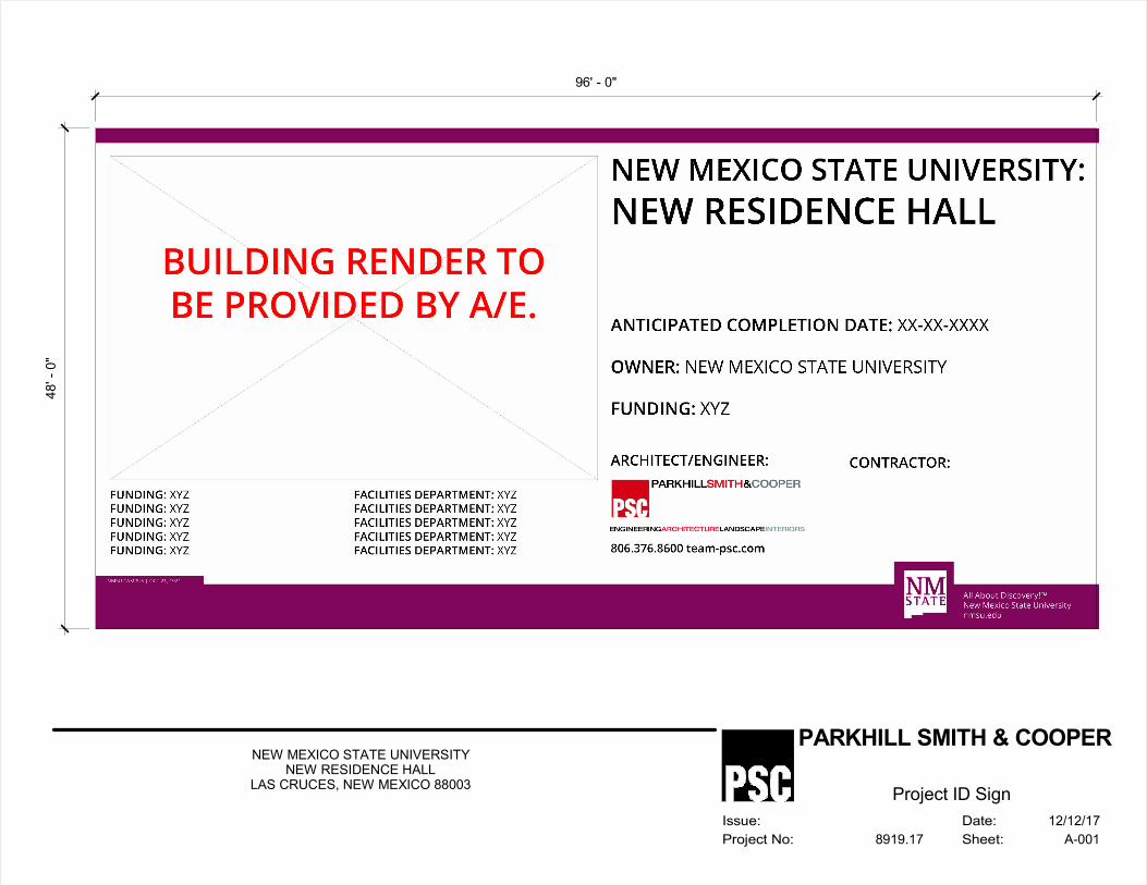
96' - 0"
48
' - 0
"
Date:
Sheet:
Issue:
Project No:
PARKHILL SMITH & COOPER
A-0018919.17
NEW MEXICO STATE UNIVERSITYNEW RESIDENCE HALL
LAS CRUCES, NEW MEXICO 88003
12/12/17
Project ID Sign
03891917 TEMPORARY STORMWATER POLLUTION CONTROL 01 57 23 - 1
02/18
SECTION 01 57 23 - TEMPORARY STORMWATER POLLUTION CONTROL
PART 1 - GENERAL
1.1 SUMMARY
A. Section Includes:
1. Contractor shall implement stormwater pollution prevention measures shown on the
Drawings. Contractor shall be responsible for any fines or penalties assessed by the
appropriate regulatory agency for failure to make required inspections, failure to
properly document those inspections, and/or failure to adequately implement and
adjust the stormwater pollution prevention measures where a Storm Water Pollution
Prevention Plan (SWPPP) is implemented.
B. Related Requirements:
1. Other Division 01 Specification Sections apply to Work of this Section.
1.2 SUBMITTALS
A. Inspection Reports.
1.3 EROSION AND SEDIMENT CONTROLS
A. General:
1. Structural measures shall be implemented to divert flows from exposed soils,
temporarily store flows, or otherwise limit run-off and the discharge of pollutants
from exposed areas of the site. Structural practices shall be implemented in a timely
manner during the construction process to minimize erosion and sediment run-off.
B. Stabilized Ingress/Egress:
1. Stabilized access to and from the construction site shall be installed as soon as
practical where a SWPPP is required.
2. In all cases, Contractor shall ensure that any soil tracked off-site is cleaned from
existing roads, alleys, and any adjacent properties as soon as possible. Contractor or
other responsible party shall check for any pollutants (mud, silt, sand, cement,
construction materials, etc.) tracked or washed off-site and perform necessary
clean-up measures at the end of each work day.
C. Silt Fences/Diversion Berms:
1. Where necessary, Contractor shall provide silt fences and/or diversion berms as a
temporary structural practice to minimize erosion and sediment runoff. Silt fences
and/or diversion berms shall be properly installed to effectively retain sediment
immediately after completing each phase of Work where erosion would occur in the
form of sheet and rill erosion (e.g., clearing and grubbing, excavation, embankment,
and grading).
D. Sand/Gravel Bags:
1. Contractor may provide sand/gravel bags as a temporary structural practice to
minimize erosion and sediment runoff. Bags shall be properly placed to effectively
retain sediment immediately after completing each phase of Work (e.g., clearing and
grubbing, excavation, embankment, and grading) in each independent runoff area
(e.g., after clearing and grubbing in an area between a ridge and drain, bags shall be
placed as Work progresses; bags shall be removed/replaced/relocated as needed for
Work to progress in the drainage area). Sand/gravel bags must remain in good
condition, or they shall be replaced.
03891917 TEMPORARY STORMWATER POLLUTION CONTROL 01 57 23 - 2
02/18
E. Site Stabilization:
1. Contractor shall disturb the least amount of site area as possible.
PART 2 - PRODUCTS (Not Used)
PART 3 - EXECUTION
3.1 STORM WATER POLLUTION PREVENTION PLAN
A. A SWPPP is required on this Project and shall be obtained by Construction Manager.
B. Contractor is responsible for meeting requirements by the New Mexico Environment
Department by implementing SWPPP measures.
C. A completed Construction Site Notice form in accordance with the requirements of the
state’s general permit for stormwater discharges from construction sites will be prepared
by Contractor.
D. The SWPPP shall be continually updated as necessary to reflect current and changing
conditions on site. Additional measures not specifically shown in the SWPPP may be used
to control erosion from leaving the site.
END OF SECTION
SECTION 01 60 00 - PRODUCT REQUIREMENTS
GENERALPART 1 -
SUMMARY1.1
Section Includes:A.Products.1.Product delivery, storage, and handling.2.Product options.3.Pre-approval procedures.4.Substitution procedures.5.
Related Requirements:B.Section 00 00 00 "Invitation to Bid" for reference to Drawings and general1.provisions of the Contract including General and Supplementary Conditions.Other Division 01 Specification Sections apply to Work of this Section.2.Section 01 30 00 "Administrative Requirements" for Project information3.management.Section 01 40 00 "Quality Requirements" for product quality monitoring.4.Section 01 42 00 "References."5.Section 01 81 13 "Sustainable Design Requirements" for LEED Sustainability6.Requirements.
PRODUCTS1.2
Products: Means new material, machinery, components, equipment, fixtures, and systemsA.forming Work and does not include machinery and equipment used for preparation,fabrication, conveying and erection of Work.Hazardous Materials: Products or material containing hazardous materials or substances,B.including but not limited to asbestos or polychlorinated biphenylshall (PCB) shall not beincluded in Work.Provide interchangeable components of same manufacturer, for similar components.C.Materials required to match existing work and not otherwise specified, shall be equal toD.existing work in quality, color, and finish. Workmanship and installation shall becomparable to adjacent existing work. Architect shall be authority in determination ofacceptable work.
PRODUCT DELIVERY, STORAGE AND HANDLING1.3
Delivery:A.Deliver materials, products and equipment to site in manufacturer's original,1.unopened containers or packaging, with identifying labels intact and legible.Promptly inspect shipments to assure that products comply with requirements,2.quantities are correct, and products are undamaged.Provide equipment and personnel to handle products by methods to prevent soiling,3.disfigurement, or damage.Arrange deliveries in accord with construction schedule and in ample time to4.facilitate inspection prior to installation to avoid unnecessary delays in constructionprocess.
0389191702/18
PRODUCT REQUIREMENTS 01 60 00 - 1
Storage:B.Store and protect products in accordance with manufacturer's instructions, with seals1.and labels intact and legible.Store sensitive products in weathertight, climate-controlled enclosures.2.For exterior storage of fabricated products, place on supports, above ground, sloped3.to drain water.Cover products subject to deterioration with impervious sheet covering. Provide4.ventilation to avoid condensation or potential degradation of products.Store loose granular materials on solid flat surfaces in a well-drained area. Prevent5.mixing with foreign matter.Provide equipment and personnel to store products by methods to prevent soiling,6.disfigurement, or damage.Arrange storage of products to permit access for inspection. Periodically inspect to7.verify products are undamaged and are maintained in acceptable condition.Materials, products, and equipment may be stored off site in a bonded and insured8.warehouse approved by Architect and Owner. Pay all costs incurred for off-sitestorage facilities. Products properly stored in off-site storage facilities may beincluded in progress pay requests with written approval of Architect.
Handling: Handle materials, products and equipment in a manner prescribed byC.manufacturer or specified to protect from damage during storage and installation.
PRODUCT OPTIONS1.4
Products Specified by Reference Standards or by Description Only: Any product meetingA.those standards or description.Products Specified by Naming One or More Manufacturers with a Provision forB.Substitutions: Submit a request for substitution for any manufacturer not named inaccordance with this Section.
PRE-APPROVAL1.5
Invitation to Bid specifies time restrictions for submitting requests for pre-approval duringA.proposal period to requirements specified in this Section.Pre-approval (during bidding period) may be considered when a product becomesB.unavailable through no fault of Contractor.Document each request with complete data substantiating compliance of proposedC.pre-approved product with Contract Documents.A request constitutes a representation that Proposer:D.
Has investigated proposed product and determined that it meets or exceeds quality1.level of specified product.Will provide same warranty for pre-approved product as for specified product.2.Will coordinate installation and make changes to other Work which may be required3.for Work to be complete with no additional cost to Owner.Waives claims for additional costs or time extension which may subsequently4.become apparent.Will reimburse Owner and Architect for review or redesign services associated with5.re-approval by authorities.
0389191702/18
PRODUCT REQUIREMENTS 01 60 00 - 2
Pre-Approval Submittal Procedure:E.Submit pre-approval request for consideration. Limit each request to one proposed1.product, system, material, or equipment.Requests shall include name of material or equipment to be pre-approved and a2.description of proposed pre-approved product including drawings, performance andtest data, and other information necessary for an evaluation.Submit item-by-item (line-by-line) comparison of each item listed in Specification3.compiled and submitted comparing specified material/product with proposedpre-approved product.Submit statement setting forth changes in other material, equipment, or other4.portions of Work including changes in work of other contracts that incorporation ofproposed pre-approved product would require shall be included.Submit shop drawings, product data, and certified test results for proposed product5.equivalence.Architect will notify all Bidders, in writing, of decision to accept or reject the6.pre-approval request.
SUBSTITUTIONS1.6
Invitation to Bid defines time restrictions for submitting requests for substitutions afterA.issue of Notice to Proceed.Substitutions (after proposal period) may be considered when a product becomesB.unavailable through no fault of Contractor.Document each request with complete data substantiating comlpiance of proposedC.substitution with Contract Documents.A request constitutes a representation that Proposer:D.
Has investigated proposed product and determined that it meets or exceeds quality1.level of specified product.Will provide same warranty for substitution as for specified product.2.Will coordinate installation and make changes to other Work which may be required3.for Work to be complete with no additional cost to Owner.Waives claims for additional costs or time extension which may subsequently4.become apparent.Will reimburse Owner and Architect for review or redesign services associated with5.re-approval by authorities.
Substitution Submittal Procedure:E.Submit request for substitution for consideration. Limit each request to one proposed1.substitution.Requests shall include name of material or equipment to be substituted and a2.description of proposed substitution product including drawings, performance andtest data, and other information necessary for an evaluation.Submit item-by-item (line-by-line) comparison of each item listed in Specification3.compiled and submitted comparing specified material/product with proposedsubstitution.Submit statement setting forth changes in other material, equipment, or other4.portions of Work including changes in work of other contracts that incorporation ofproposed substitution would require shall be included.Submit shop drawings, product data, and certified test results for proposed product5.equivalence.Architect will notify Contractor in writing, of decision to accept or reject request.6.
0389191702/18
PRODUCT REQUIREMENTS 01 60 00 - 3

PRODUCTS (Not Used)PART 2 -
EXECUTION (Not Used)PART 3 -
END OF SECTION
0389191702/18
PRODUCT REQUIREMENTS 01 60 00 - 4
SECTION 01 70 00 - EXECUTION AND CLOSEOUT REQUIREMENTS
GENERALPART 1 -
SUMMARY1.1
Section Includes:A.Closeout procedures.1.Final cleaning.2.Starting of systems.3.Demonstration and instructions.4.Testing, adjusting and balancing.5.Protecting installed construction.6.Project record documents.7.Operation and maintenance data.8.Manual for materials and finishes.9.Manual for equipment and systems.10.Spare parts and maintenance products.11.Product warranties and product bonds.12.Maintenance service.13.
Related Requirements:B.Section 00 00 00 "Invitation to Bid" for reference to Drawings and general1.provisions of the Contract including General and Supplementary Conditions.Other Division 01 Specification Sections apply to Work of this Section.2.Section 01 30 00 "Administrative Requirements" for project information3.management.Section 01 81 13 "Sustainable Design Requirements" for LEED Sustainability4.Requirements.Section 23 05 93 "Testing, Adjusting, and Balancing for HVAC" for testing,5.adjusting and balancing services.
CLOSEOUT PROCEDURES1.2
Submit written certification that Contract Documents have been reviewed, Work has beenA.inspected, and that Work is complete in accordance with Contract Documents and readyfor Architect's review.Provide submittals to Architect required by authority having jurisdiction.B.Submit final Application for Payment identifying total adjusted Contract Sum, previousC.payments, and sum remaining due.Closeout documents will be submitted electronically in OCR (Optical CharacterD.Recognition)/PDF format.At Owner’s request, Contractor shall provide a hard copy of Closeout Documents inE.three-ring binders.Owner will occupy all portions of building as specified in Section 01 10 00 "Summary."F.
0389191702/18
EXECUTION AND CLOSEOUT REQUIREMENTS 01 70 00 - 1
FINAL CLEANING1.3
Owner will provide final cleaning after final acceptance.A.Clean interior and exterior glass, surfaces exposed to view; remove temporary labels, stainsB.and foreign substances, polish transparent and glossy surfaces, vacuum carpeted and softsurfaces.Clean equipment and fixtures to sanitary condition with cleaning materials appropriate toC.surface and material being cleaned.Replace filters of operating equipment.D.Clean debris from roofs, gutters, downspouts, and drainage systems.E.Clean site; sweep paved areas, rake clean landscaped surfaces.F.Remove waste and surplus materials, rubbish, and construction facilities from site.G.
STARTING OF SYSTEMS1.4
Coordinate schedule for startup of various equipment and systems.A.Notify Owner seven days prior to startup of each item.B.Verify each piece of equipment or system has been checked for proper lubrication, driveC.rotation, belt tension, control sequence, and for conditions which may cause damage.Verify tests, meter readings, and specified electrical characteristics agree with thoseD.required by equipment or system manufacturer.Verify wiring and support components for equipment are complete and tested.E.Execute startup under supervision of applicable Contractors' personnel in accordance withF.manufacturers' instructions.When specified in individual Specification Sections, require manufacturer to provideG.authorized representative to be present at site to inspect, check, and approve equipment orsystem installation prior to startup, and to supervise placing equipment or system inoperation.Submit a written report in accordance with Section 01 33 00 "Submittal Procedures" thatH.equipment or system has been properly installed and is functioning correctly.
DEMONSTRATION AND INSTRUCTIONS1.5
Demonstrate operation and maintenance of products to Owner's personnel two weeks priorA.to date of Substantial Completion.For equipment or systems requiring seasonal operation, perform demonstration for otherB.season within six months.Utilize operation and maintenance manuals as basis for instruction. Review contents ofC.manual with Owner's personnel in detail to explain aspects of operation and maintenance.Demonstrate startup, operation, control, adjustment, trouble-shooting, servicing,D.maintenance, and shutdown of each item of equipment at scheduled time, at equipmentlocation.Prepare and insert additional data in operations and maintenance manuals when need forE.additional data becomes apparent during instruction.Required instruction time for each item of equipment and system is specified in individualF.Sections.
TESTING, ADJUSTING, AND BALANCING1.6
Testing, adjusting, and balancing will be performed in accordance with requirementsA.specified in Section 23 05 93 "Testing, Adjusting, and Balancing for HVAC."
0389191702/18
EXECUTION AND CLOSEOUT REQUIREMENTS 01 70 00 - 2
Owner will appoint, employ, and pay for services of independent firm to perform testing,B.adjusting, and balancing.Independent firm will perform services specified in Section 23 05 93 "Testing, Adjusting,C.and Balancing for HVAC."Reports will be submitted by independent firm to Architect indicating observations andD.results of tests and indicating compliance or non-compliance with requirements of ContractDocuments.
PROTECTING INSTALLED CONSTRUCTION1.7
Protect installed Work and provide special protection where specified in individualA.Specification Sections.Provide temporary and removable protection for installed products. Control activity inB.immediate work area to prevent damage.Provide protective coverings at walls, projections, jambs, sills, and soffits of openings.C.Protect finished floors, stairs, and other surfaces from traffic, dirt, wear, damage, orD.movement of heavy objects, by protecting with durable sheet materials.Prohibit traffic or storage upon waterproofed or roofed surfaces. When traffic or activity isE.necessary, obtain recommendations for protection from waterproofing or roofing materialmanufacturer.Prohibit traffic from landscaped areas.F.
HAZARDOUS MATERIALS AFFIDAVITS1.8
Provide notarized affidavits declaring that hazardous materials were not incorporated intoA.or delivered to site.Hazardous materials include asbestos, lead polychlorinated biphenyl (PCB), prohibitedB.termite eradication chemicals or any substance of any proportion determined or suspectedby an agency of federal or state government to create a health hazard.Provide table of contents listing affidavits in alphabetical order.C.Prepare cover page with printed title “AFFIDAVITS OF NON-INCORPORATEDD.HAZARDOUS MATERIALS”, Title of Project, Project Address, Owner’s Name, Addressand Phone and date of Construction Completion.Provide one complete set of aforementioned information in OCR (Optical CharacterE.Recognition)/PDF format.Submit prior to Application for Final Payment.F.
PROJECT RECORD DOCUMENTS1.9
Maintain on site one set of record documents; record actual revisions to Work:A.Drawings.1.Specifications.2.Addenda.3.Change Orders and other modifications to Contract.4.Reviewed Shop Drawings, Product Data, and Samples.5.Complete set of MSDS sheets for materials.6.Manufacturer's instruction for assembly, installation, and adjusting.7.
Ensure entries are complete and accurate, enabling future reference by Owner.B.Store record documents separate from documents used for construction.C.Record information concurrent with construction progress, not less than weekly.D.
0389191702/18
EXECUTION AND CLOSEOUT REQUIREMENTS 01 70 00 - 3
Specifications: Legibly mark and record at each product section description of productsE.installed, including following:
Manufacturer's name and product model and number.1.Product substitutions or alternates utilized.2.Changes made by Addenda, Change Orders, RFI responses, and other modifications.3.
Record Drawings and Shop Drawings: Legibly mark each item to record actualF.construction including:
Measured depths of foundations in relation to finish first floor datum.1.Measured horizontal and vertical locations of underground utilities and2.appurtenances, referenced to permanent surface improvements.Measured locations of internal utilities and appurtenances concealed in construction,3.referenced to visible and accessible features of Work.Field changes of dimension and detail.4.Details not on original Contract drawings.5.Changes made by Addenda, Change Order, RFI responses, and other modifications.6.Submit in OCR (Optical Character Recognition)/PDF format.7.Comply with most current requirements of the New Mexico Environment8.Department and by reference to the Asbestos National Emission Standard forHazardous Air Pollutants (NESHAP) 40 CFR 61 Subpart M.Submit MSDS on products used in construction of Project.9.Submit MSDS electronically in 8-1/2 x 11 inch format text pages.10.Prepare cover page with printed title “MATERIAL SAFETY DATA SHEETS11.(MSDS)”, Title of Project, Project Address, Owner’s Name, Address and Phone, andDate of Construction Completion.Internally subdivide contents with page dividers, organized into CSI format shown12.in Project Manual.Prepare a table of contents, listing each of Division headings and listing each13.material/product under each heading by manufacturer and material/product name.Submit complete set of aforementioned information in OCR (Optical Character14.Recognition)/PDF format.Submit information with Application for Final Payment and include MSDS for15.materials/products delivered or installed in Project.Failure to submit updated electronic MSDS documents will cause Application for16.Final Payment to be held by Architect (not submitted to Owner for processing) untilsuch time updated electronic MSDS documents are received and reviewed forcompliance by Architect.
Submit documents to Architect with claim for final Application for Payment.G.
OPERATION AND MAINTENANCE DATA1.10
Submit data electronically in 8-1/2 x 11 inch text pages, OCR (Optical CharacterA.Recognition)/PDF format.Prepare cover page with printed title "OPERATION AND MAINTENANCEB.INSTRUCTIONS", title of project.Internally subdivide contents with page dividers, logically organized as described below:C.
Drawings: Provide in OCR (Optical Character Recognition)/PDF format1.Contents: Prepare Table of Contents for each file (if multiple files), with each2.product or system description identified, in three parts as follows:
Part 1: Directory, listing names, addresses, and telephone numbers ofa.Architect, Contractor, Subcontractors, and major equipment suppliers.
0389191702/18
EXECUTION AND CLOSEOUT REQUIREMENTS 01 70 00 - 4
Part 2: Operation and maintenance instructions, arranged by system orb.process flow and subdivided by Specification Section. For each category,identify names, addresses, and telephone numbers of Subcontractors andsuppliers. Identify:
Significant design criteria.1)List of equipment.2)Parts list for each component.3)Operating instructions.4)Maintenance instructions for equipment and systems.5)Maintenance instructions for finishes, including recommended cleaning6)methods and materials, and special precautions identifying detrimentalagents.
Part 3: Project documents and certificates, including:c.Shop drawings and product data.1)Air and water balance reports.2)Certificates.3)Scanned copies of warranties and bonds in OCR (Optical Character4)Recognition)/PDF format.
Submit one complete set of aforementioned information in OCR (Optical CharacterD.Recognition)/PDF format.Submit documents with Application for Final Payment.E.
MANUAL FOR MATERIALS AND FINISHES1.11
Submit in OCR (Optical Character Recognition)/PDF format of preliminary draft orA.proposed formats and outlines of contents before start of Work. Architect will review draftand return electronic file with comments.For equipment, or component parts of equipment put into service during construction andB.operated by Owner, submit documents within ten days after acceptance.Submit one electronic copy of completed volumes 15 days prior to final inspection. DraftC.copy to be reviewed and returned after final inspection, with Architect comments. Revisecontent of electronic document set as required prior to final submission.Submit electronic documents of revised final volumes in final form within 10 days afterD.final inspection.Building Products, Applied Materials, and Finishes: Include product data, with catalogE.number, size, composition, and color and texture designations. Include information forre-ordering custom manufactured products.Instructions for Care and Maintenance: Include manufacturer's recommendations forF.cleaning agents and methods, precautions against detrimental agents and methods, andrecommended schedule for cleaning and maintenance.Moisture Protection and Weather Exposed Products: Include product data listing applicableG.reference standards, chemical composition, and details of installation. Includerecommendations for inspections, maintenance, and repair.Additional Requirements: As specified in individual product Specification Sections.H.Include listing in Table of Contents for design data, with fly sheet.I.
MANUAL FOR EQUIPMENT AND SYSTEMS1.12
Submit in OCR (Optical Character Recognition)/PDF format of preliminary draft orA.proposed formats and outlines of contents before start of Work. Architect will review draftand return with comments.
0389191702/18
EXECUTION AND CLOSEOUT REQUIREMENTS 01 70 00 - 5
For equipment, or component parts of equipment put into service during construction andB.operated by Owner, submit electronic documents within ten days after acceptance.Submit electronic copy of completed volume(s) 15 days prior to final inspection. DraftC.copy to be reviewed and returned after final inspection, with Architect comments. Revisecontent of electronic document set as required prior to final submission.Submit electronic documents in OCR (Optical Character Recognition)/PDF format ofD.revised final volumes in final form within 10 days after final inspection.Each Item of Equipment and Each System: Include description of unit or system, andE.component parts. Identify function, normal operating characteristics, and limitingconditions. Include performance curves, with engineering data and tests, and completenomenclature and model number of replaceable parts.Panelboard Circuit Directories: Provide electrical service characteristics, controls, andF.communications; by label machine.Include color coded wiring diagrams as installed.G.Operating Procedures: Include startup, break-in, and routine normal operating instructionsH.and sequences. Include regulation, control, stopping, shut-down, and emergencyinstructions. Include summer, winter, and special operating instructions.Maintenance Requirements: Include routine procedures and guide for preventativeI.maintenance and troubleshooting; disassembly, repair, and reassembly instructions; andalignment, adjusting, balancing, and checking instructions.Include servicing and lubrication schedule, and list of lubricants required.J.Include manufacturer's printed operation and maintenance instructions.K.Include sequence of operation by controls manufacturer.L.Include original manufacturer's parts list, illustrations, assembly drawings, and diagramsM.required for maintenance.Include control diagrams by controls manufacturer as installed.N.Include Contractor's coordination drawings, with color coded piping diagrams as installed.O.Include charts of valve tag numbers, with location and function of each valve, keyed toP.flow and control diagrams.Include list of original manufacturer's spare parts, current prices, and recommendedQ.quantities to be maintained in storage.Include test and balancing reports as specified in Section 01 40 00 "Quality Requirements."R.Additional Requirements: As specified in individual product Specification Sections.S.Include listing in Table of Contents for design data, with dividers.T.
SPARE PARTS AND MAINTENANCE PRODUCTS1.13
Furnish spare parts, maintenance, and extra products in quantities specified in individualA.Specification Sections.Deliver to Project site and place in location as directed by Owner; obtain receipt prior toB.final payment.Submit receipts signed by Owner or letter stating Contractor has delivered extra productsC.to Owner.
PRODUCT WARRANTIES AND PRODUCT BONDS1.14
Obtain warranties and bonds executed by responsible subcontractors, suppliers, andA.manufacturers, within 10 days after completion of applicable item of work.Execute and assemble transferable warranty documents and bonds from subcontractors,B.suppliers, and manufacturers.Verify documents are in proper form, contain full information, and are notarized.C.Co-execute submittals when required.D.
0389191702/18
EXECUTION AND CLOSEOUT REQUIREMENTS 01 70 00 - 6
Include Table of Contents.E.Submit one complete set of aforementioned information in OCR (Optical CharacterF.Recognition)/PDF format for review.Submit prior to Application for Final Payment.G.Time of Submittals:H.
For equipment or component parts of equipment put into service during construction1.with Owner's permission, submit documents within 10 days after acceptance.Make other submittals within 10 days after Date of Substantial Completion, prior to2.final Application for Payment.For items of Work for which acceptance is delayed beyond Date of Substantial3.Completion, submit within 10 days after acceptance, listing date of acceptance asbeginning of warranty or bond period.
MAINTENANCE SERVICE1.15
Furnish service and maintenance of components indicated in Specification Sections for oneA.year from date of Substantial Completion.Furnish service and maintenance of components indicated in Specification Sections.B.Examine system components at frequency consistent with reliable operation. Clean, adjust,C.and lubricate as required.Include systematic examination, adjustment, and lubrication of components. Repair orD.replace parts whenever required. Use parts produced by manufacturer of originalcomponent.Do not assign or transfer maintenance service to agent or Subcontractor without priorE.written consent of Owner.
PRODUCTS (Not Used)PART 2 -
EXECUTION (Not Used)PART 3 -
END OF SECTION
0389191702/18
EXECUTION AND CLOSEOUT REQUIREMENTS 01 70 00 - 7
SECTION 01 74 19 - CONSTRUCTION WASTE MANAGEMENT AND DISPOSAL
GENERALPART 1 -
SUMMARY1.1
Section includes administrative and procedural requirements for the following:A.Salvaging nonhazardous construction waste.1.Recycling nonhazardous construction waste.2.Disposing of nonhazardous demolition construction waste.3.
Related Requirements:B.Section 00 00 00 "Invitation to Bid" for reference to Drawings and general1.provisions of the Contract including General and Supplementary Conditions.Other Division 01 Specification Sections apply to Work of this Section.2.Section 01 81 13 "Sustainable Design Requirements" for LEED Sustainability3.Requirements.
DEFINITIONS1.2
Construction Waste: Building, structure, and site improvement materials and other solidA.waste resulting from construction, remodeling, renovation, or repair operations.Construction waste includes packaging.Demolition Waste: Building, structure, and site improvement materials resulting fromB.demolition operations.Disposal: Removal of demolition or construction waste and subsequent salvage, sale,C.recycling, or deposit in landfill, incinerator acceptable to authorities having jurisdiction, ordesignated spoil areas on Owner’s property.Recycle: Recovery of demolition or construction waste for subsequent processing inD.preparation for reuse.Salvage: Recovery of demolition or construction waste and subsequent sale or reuse inE.another facility.Salvage and Reuse: Recovery of demolition or construction waste and subsequentF.incorporation into the Work.
MATERIALS OWNERSHIP1.3
Unless otherwise indicated, demolition and construction waste becomes property ofA.Contractor.Historic items, relics, antiques, and similar objects including, but not limited to,B.cornerstones and their contents, commemorative plaques and tablets, and other items ofinterest or value to Owner that may be uncovered during demolition remain the property ofOwner.
Carefully salvage in a manner to prevent damage and promptly return to Owner.1.
ACTION SUBMITTALS1.4
Waste Management Plan: Submit plan within 14 days of date established for the Notice toA.Proceed.
0389191702/18
CONSTRUCTION WASTE MANAGEMENT AND DISPOSAL
01 74 19 - 1
INFORMATIONAL SUBMITTALS1.5
Waste Reduction Progress Reports: Concurrent with each Application for Payment, submitA.report. Use Form CWM-7 for construction waste. Include the following information:
Material category.1.Generation point of waste.2.Total quantity of waste in tons.3.Quantity of waste salvaged, both estimated and actual in tons.4.Quantity of waste recycled, both estimated and actual in tons.5.Total quantity of waste recovered (salvaged plus recycled) in tons.6.Total quantity of waste recovered (salvaged plus recycled) as a percentage of total7.waste.
Waste Reduction Calculations: Before request for Substantial Completion, submitB.calculated end-of-Project rates for salvage, recycling, and disposal as a percentage of totalwaste generated by the Work.Records of Donations: Indicate receipt and acceptance of salvageable waste donated toC.individuals and organizations. Indicate whether organization is tax exempt.Records of Sales: Indicate receipt and acceptance of salvageable waste sold to individualsD.and organizations. Indicate whether organization is tax exempt.Recycling and Processing Facility Records: Indicate receipt and acceptance of recyclableE.waste by recycling and processing facilities licensed to accept them. Include manifests,weight tickets, receipts, and invoices.Landfill and Incinerator Disposal Records: Indicate receipt and acceptance of waste byF.landfills and incinerator facilities licensed to accept them. Include manifests, weighttickets, receipts, and invoices.LEED Submittal: Submit documentation to USGBC, signed by Contractor, tabulating totalG.waste material, quantities diverted and means by which it is diverted, and statement thatrequirements for the credit have been met. Respond to questions and requests fromUSGBC regarding construction waste management and disposal until the USGBC hasmade its determination on the project's LEED certification application. Documentcorrespondence with USGBC as informational submittals.
QUALITY ASSURANCE1.6
Waste Management Coordinator Qualifications: Experienced firm, or individual employedA.and assigned by General Contractor, with a record of successful waste managementcoordination of projects with similar requirements. Superintendent may serve as WasteManagement Coordinator.
Waste management coordinator may also serve as LEED coordinator.1.Waste Management Conference(s): Conduct conference(s) at Project site to comply withB.requirements in Section 01 31 00 "Administrative Requirements." Review methods andprocedures related to waste management including, but not limited to, the following:
Review and discuss waste management plan including responsibilities of each1.contractor and waste management coordinator.Review requirements for documenting quantities of each type of waste and its2.disposition.Review and finalize procedures for materials separation and verify availability of3.containers and bins needed to avoid delays.Review procedures for periodic waste collection and transportation to recycling and4.disposal facilities.Review waste management requirements for each trade.5.
0389191702/18
CONSTRUCTION WASTE MANAGEMENT AND DISPOSAL
01 74 19 - 2
WASTE MANAGEMENT PLAN1.7
Waste Identification: Indicate anticipated types and quantities of site-clearing andA.construction waste generated by the Work. Use Form CWM-1 for construction waste.Include estimated quantities and assumptions for estimates.Waste Reduction Work Plan: List each type of waste and whether it will be salvaged,B.recycled, or disposed of in landfill or incinerator. Use Form CWM-3 for constructionwaste. Include points of waste generation, total quantity of each type of waste, quantity foreach means of recovery, and handling and transportation procedures.
Salvaged Materials for Sale: For materials that will be sold to individuals and1.organizations, include list of their names, addresses, and telephone numbers.Salvaged Materials for Donation: For materials that will be donated to individuals2.and organizations, include list of their names, addresses, and telephone numbers.Recycled Materials: Include list of local receivers and processors and type of3.recycled materials each will accept. Include names, addresses, and telephonenumbers.Disposed Materials: Indicate how and where materials will be disposed of. Include4.name, address, and telephone number of each landfill and incinerator facility.Handling and Transportation Procedures: Include method that will be used for5.separating recyclable waste including sizes of containers, container labeling, anddesignated location where materials separation will be performed.
Cost/Revenue Analysis: Indicate total cost of waste disposal as if there were no wasteC.management plan and net additional cost or net savings resulting from implementing wastemanagement plan. Use Form CWM-5 for construction waste. Include the following:
Total quantity of waste.1.Estimated cost of disposal (cost per unit). Include transportation and tipping fees and2.cost of collection containers and handling for each type of waste.Total cost of disposal (with no waste management).3.Revenue from salvaged materials.4.Revenue from recycled materials.5.Savings in transportation and tipping fees by donating materials.6.Savings in transportation and tipping fees that are avoided.7.Handling and transportation costs. Include cost of collection containers for each type8.of waste.Net additional cost or net savings from waste management plan.9.
PRODUCTSPART 2 -
PERFORMANCE REQUIREMENTS2.1
General: Achieve end-of-Project rates for salvage/recycling of 75 percent minimum, withA.95 percent preferred, by weight of total nonhazardous solid waste generated by the Work.Practice efficient waste management in the use of materials in the course of the Work. Useall reasonable means to divert construction and demolition waste from landfills andincinerators. Facilitate recycling and salvage of materials, including the following:
Construction Waste:1.Site demolition items including underground electrical and asphalt paving.a.Lumber.b.Wood sheet materials.c.Wood trim.d.
0389191702/18
CONSTRUCTION WASTE MANAGEMENT AND DISPOSAL
01 74 19 - 3
Metals.e.Roofing and concrete roof tile.f.Insulation.g.Gypsum board.h.Piping.i.Electrical conduit.j.Packaging: Regardless of salvage/recycle goal indicated in "General"k.Paragraph above, salvage or recycle 100 percent of the followinguncontaminated packaging materials:
Paper.1)Cardboard.2)Boxes.3)Plastic sheet and film.4)Polystyrene packaging.5)Wood crates.6)Wood pallets.7)Plastic pails.8)
Construction Office Waste: Regardless of salvage/recycle goal indicated inl."General" Paragraph above, salvage or recycle 100 percent of the followingconstruction office waste materials:
Paper.1)Aluminum cans.2)Glass containers.3)
EXECUTIONPART 3 -
PLAN IMPLEMENTATION3.1
General: Implement approved waste management plan. Provide handling, containers,A.storage, signage, transportation, and other items as required to implement wastemanagement plan during the entire duration of the Contract.
Comply with operation, termination, and removal requirements in Section 01 50 001."Temporary Facilities and Controls."
Waste Management Coordinator: Engage a waste management coordinator to beB.responsible for implementing, monitoring, and reporting status of waste management workplan.Training: Train workers, subcontractors, and suppliers on proper waste managementC.procedures, as appropriate for the Work.
Distribute waste management plan to everyone concerned within three days of1.submittal return.Distribute waste management plan to entities when they first begin work on-site.2.Review plan procedures and locations established for salvage, recycling, anddisposal.
Site Access and Temporary Controls: Conduct waste management operations to ensureD.minimum interference with roads, streets, walks, walkways, and other adjacent occupiedand used facilities.
Designate and label specific areas on Project site necessary for separating materials1.that are to be salvaged and recycled.Comply with Section 01 50 00 "Temporary Facilities and Controls" for controlling2.dust and dirt, environmental protection, and noise control.
0389191702/18
CONSTRUCTION WASTE MANAGEMENT AND DISPOSAL
01 74 19 - 4
RECYCLING CONSTRUCTION WASTE, GENERAL3.2
General: Recycle paper and beverage containers used by on-site workers.A.Recycling Incentives: Revenues, savings, rebates, tax credits, and other incentives receivedB.for recycling waste materials shall accrue to Contractor.Preparation of Waste: Prepare and maintain recyclable waste materials according toC.recycling or reuse facility requirements. Maintain materials free of dirt, adhesives,solvents, petroleum contamination, and other substances deleterious to the recyclingprocess.Procedures: Separate recyclable waste from other waste materials, trash, and debris.D.Separate recyclable waste by type at Project site to the maximum extent practical accordingto approved construction waste management plan.
Provide appropriately marked containers or bins for controlling recyclable waste1.until removed from Project site. Include list of acceptable and unacceptablematerials at each container and bin.
Inspect containers and bins for contamination and remove contaminateda.materials if found.
Stockpile processed materials on-site without intermixing with other materials.2.Place, grade, and shape stockpiles to drain surface water. Cover to preventwindblown dust.Stockpile materials away from construction area. Do not store within drip line of3.remaining trees.Store components off the ground and protect from the weather.4.Remove recyclable waste from Owner's property and transport to recycling receiver5.or processor as often as required to prevent overfilling bins.
RECYCLING CONSTRUCTION WASTE3.3
Packaging:A.Cardboard and Boxes: Break down packaging into flat sheets. Bundle and store in a1.dry location.Polystyrene Packaging: Separate and bag materials.2.Pallets: As much as possible, require deliveries using pallets to remove pallets from3.Project site. For pallets that remain on-site, break down pallets into component woodpieces and comply with requirements for recycling wood.Crates: Break down crates into component wood pieces and comply with4.requirements for recycling wood.
Wood Materials:B.Clean Cut-Offs of Lumber: Grind or chip into small pieces.1.Clean Sawdust: Bag sawdust that does not contain painted or treated wood.2.
Comply with requirements in Section 32 93 00 "Plants" for use of cleana.sawdust as organic mulch.
Gypsum Board: Stack large clean pieces on wood pallets or in container and store in a dryC.location.Paint: Seal containers and store by type.D.
0389191702/18
CONSTRUCTION WASTE MANAGEMENT AND DISPOSAL
01 74 19 - 5
DISPOSAL OF WASTE3.4
General: Except for items or materials to be salvaged or recycled, remove waste materialsA.from Project site and legally dispose of them in a landfill or incinerator acceptable toauthorities having jurisdiction.
Except as otherwise specified, do not allow waste materials that are to be disposed1.of accumulate on-site.Remove and transport debris in a manner that will prevent spillage on adjacent2.surfaces and areas.
Burning: Do not burn waste materials.B.Burning: Burning of waste materials is permitted only at designated areas on Owner'sC.property, provided required permits are obtained. Provide full-time monitoring for burningmaterials until fires are extinguished.
ATTACHMENTS3.5
Form CWM-1 for construction waste identification.A.Form CWM-3 for construction waste reduction work plan.B.Form CWM-5 for cost/revenue analysis of construction waste reduction work plan.C.Form CWM-7 for construction waste reduction progress report.D.
END OF SECTION
0389191702/18
CONSTRUCTION WASTE MANAGEMENT AND DISPOSAL
01 74 19 - 6
03891917 OPERATION AND MAINTENANCE COMMISSIONING 01 78 23.30 - 1
02/18 REQUIREMENTS
SECTION 01 78 23.30 - OPERATION AND MAINTENANCE
COMMISSIONING REQUIREMENTS
PART 1 - GENERAL
1.1 SUMMARY
A. Section Includes:
1. Compile Building Systems Manuals containing operations and maintenance
information submitted by installing contractors into a format that focuses on
equipment and components integral to a specific building system (e.g., air handler
systems).
2. Contractor shall obtain operations and maintenance information from subcontractors
and compile manuals as specified.
B. Related Requirements:
1. Section 00 00 00 "Invitation to Bid" for reference to Drawings and general
provisions of the Contract including General and Supplementary Conditions.
2. Other Division 01 Specification Sections apply to Work of this Section.
3. Section 01 33 00 "Submittal Procedures."
4. Section 01 81 13 "Sustainable Design Requirements" for LEED Sustainability
Requirements.
5. Section 01 91 13 "General Commissioning Requirements."
6. Section 01 91 13.10 "Construction Checklists Commissioning Requirements."
7. Section 01 91 13.20 "Functional Performance Testing Commissioning
Requirements."
8. Section 01 91 13.30 "Demonstration and Training Commissioning Requirements."
9. Individual Technical Specifications Sections: Specific requirements for operation
and maintenance data.
1.2 ACTION SUBMITTALS
A. Submit compiled Operation and Maintenance Manuals to Engineer and Commissioning
Authority (CxA). Once approved, they will be included in CxA's Systems Manual.
B. Manuals shall be in English language. Provide manuals in .pdf format on CD/DVD media.
Coordinate total number of copies with Owner and Engineer. Manuals shall use A4 Binder
size.
C. Within 90 days after Notice to Proceed, Contractor shall submit two copies of a proposed
detailed outline, an example of proposed format, sample of manual covers, and listing of
documents, data, and other information to be used in preparation of manuals. Review
comments will be provided to Contractor within 30 days of receipt of this submittal.
D. Two draft copies of manuals shall be submitted for approval no later than five months prior
to scheduled substantial completion date. Review comments will be provided to Contractor
within 30 calendar days of receipt of this submittal.
E. One final copy of manuals for facility shall be submitted for approval no later than
three months prior to scheduled substantial completion date. Review comments will be
provided to Contractor within 14 days of receipt of this submittal.
F. Six copies of final manuals, with all review comments addressed, shall be furnished to
Owner not less than 45 days prior to Owner acceptance of facilities. Any training required
to be performed by Contractor for Owner's maintenance staff shall utilize contents of
manual as classroom instructional material.
03891917 OPERATION AND MAINTENANCE COMMISSIONING 01 78 23.30 - 2
02/18 REQUIREMENTS
1.3 QUALITY ASSURANCE
A. Preparation of instructions and data shall be by personnel experienced in maintenance and
operation of equipment and systems incorporated into Project.
1.4 MANUAL FOR EQUIPMENT AND SYSTEMS
A. Prepare data in form of an instructional manual. Manuals shall be system specific.
B. Binders:
1. Commercial quality, 8-1/2 x 11 ring binders with durable covers.
2. Assemble O&M instructions in several volumes; no single volume shall be thicker
than 2 inches.
3. Parts 1 and 2 of system manual shall be combined into a separate binder(s) as a
primary reference for field operations and maintenance staff.
4. Parts 3 and 4 of systems manual shall be a separate binder providing additional
resource material that is not regularly required for day-to-day operations and
maintenance activities.
C. Cover: Identify each binder with typed or printed title OPERATION AND
MAINTENANCE INSTRUCTIONS; identify title of Project; identify subject matter of
contents.
D. Provide tabbed dividers for each separate product and system component, and typed
description of product and major component parts of equipment.
E. Text: Manufacturer's printed data, or typewritten data on bond paper.
F. Drawings: Provide with reinforced punched binder tab. Bind in with text; fold larger
drawings to size of text pages.
G. Contents: Prepare a Table of Contents for each volume, with each product or system
component description identified, in three parts as follows:
1. Part 1:
a. System Description.
b. System Design Narrative and Basis of Design: Provided by others. Provide a
Tab only.
c. Directory of system components, listing names, addresses and telephone
numbers and internet address of installing contractor, equipment supplier and
nearest authorized service and parts providers.
d. Sequence of Operations: Provide "As-Built" Sequence of Operations.
e. Building Automation System Setpoints: If system utilizes an independent
control module, provide pertinent set point values associated with control.
f. System Flow Diagrams: Include control sequences color-coded wiring
diagrams as installed, etc.
g. Illustrations:
1) Manual shall contain illustrations, drawings, or photographs necessary
to locate and identify components significant to operations and
maintenance staff.
2) Where necessary for clarity, illustrations shall show configuration and
removal and disassembly of parts. The following shall be included:
(a) Schematic diagrams which show arrangement of component
devices or parts.
(b) Wiring diagrams which show connections of circuit
arrangement.
(c) One-line diagrams of electrical power distribution systems and
communications type systems.
03891917 OPERATION AND MAINTENANCE COMMISSIONING 01 78 23.30 - 3
02/18 REQUIREMENTS
(d) Functional or block diagrams.
(e) Schematic piping diagrams which show interconnection of
components, of piping, tubing, or hose, and direction and
sequence of fluid flow, drawings, and photographs.
2. Part 2:
a. Operations and maintenance instructions arranged by specification system
(use title of specification section and not specification number in table of
contents and tabs).
b. Specification sections from all trades involved in installation of system shall
be incorporated. Each specification tab shall have a separate tab to address
each of following items as appropriate and applicable.
c. General product data that is not specific to or inapplicable to installation shall
not be included.
d. Notes, cautions, and warnings shall be used to emphasize important and
critical instructions where necessary. Notes, cautions, and warnings shall
immediately precede applicable instructions.
e. If manufacturer of equipment has detailed technical operation and
maintenance manuals, manufacturer's technical manuals shall be used in lieu
of providing following information.
f. Significant design criteria and nameplate data, including "fed by" information
identifying source and location of power.
g. Parts blowout diagrams and lists. Parts lists shall provide positive
identification of parts necessary for support of equipment and shall include
sufficient information to enable maintenance personnel to requisition
replacement parts. Critical parts that should be maintained in-stock shall be
identified.
h. Installation Instructions. Installation instructions shall include detailed step by
step procedures for installation and initial start-up of system components.
i. Operating instructions:
1) Include routine and emergency procedures (manual, automatic, local,
and remote), and safety precautions.
2) When equipment can be turned on-off from an operating console, limits
to be observed in starting, operating, stopping, or shutting down of
equipment or system shall be provided.
3) When equipment start-up procedures are complicated, a step-by-step
sequence for start-up shall be provided.
4) Adequate illustrative material shall be provided to identify and locate
operating controls and indicating devices. The function of each
operating control and indicating device shall be included.
5) Emergency operating instructions shall include alternate procedures to
be followed when normal operation is not possible because of
emergency conditions, such as power failure, control air failure,
lubricating oil failure, or partial failure of requirements. Emergency
operating instructions and procedures shall be located for quick and
ready references. Include summer, winter, and any special operating
instructions.
j. Preventive Maintenance: Preventive maintenance information shall be
provided. Use of special tools, materials, and test equipment shall be
specified, including model/type designation, as appropriate. The following
procedures shall be stressed, if applicable.
03891917 OPERATION AND MAINTENANCE COMMISSIONING 01 78 23.30 - 4
02/18 REQUIREMENTS
1) Cleaning and Lubrication: Periodic cleaning and lubrication
information, types of cleaning agents or lubricants required,
recommended intervals, such as monthly, quarterly, semiannually, or
hours of operation. Application points, type of lubricant and capacity
(required amounts) shall be identified. Pictorial format for lubrication is
desirable, cleaning and lubrication required during repair, replacement,
and reassembly shall also be covered.
2) Inspection: Instructions, including scheduling for inspection of
equipment for damages and wear shall be included. Tabular or chart
form is preferred and shall include, where applicable, allowable service
limits, wear, backlash, end play, length and depth of scoring, and
balance. These instructions shall be sufficiently complete to serve as
standards by which experienced technicians may determine when parts
may be continued in use and when they must be replaced.
3) Performance and Adjustment Verification: Instructions shall be
included for verification of accuracy of equipment measurement
devices needed to restore equipment to its original state. These
instructions shall provide complete step-by-step procedures that will
enable user to check accuracy of indications or readings. The location
of test connections and values expected at these points shall be
included, preferably in illustrated form. Adjustment of built-in self-test
features shall be included. Data shall include a list of additional
equipment required to accomplish verification, such as temperature,
vacuum, pressure, hydraulic, or pneumatic gages; voltmeters;
ammeters, or frequency meters. The listing shall show methods of use
or application, range scales, and specific minimum tolerances or
percentages of accuracy.
4) Recommended preventive maintenance task frequency.
k. Corrective Maintenance:
1) Instructions shall be included, but not limited to, all removal, repair
adjustment, and replacement procedures.
2) Exploded and sectional views giving details of assemblies shall be
provided, as necessary, to clarify test.
3) For mechanical items, dimensional information with tolerances,
clearances, wear limits, maximum bolt-down torques, and in-place
balancing or other means of reducing noise level, if required, shall be
supplied.
4) Requirements for cleaning and lubrication prior to reassembly shall be
included, if critical.
5) Information on use of special tools and test equipment supplied with
equipment, as well as any cautions or warnings which must be
observed to protect personnel and equipment, shall also be included.
l. Troubleshooting:
1) Failures that might occur during operation of equipment shall be listed.
2) Troubleshooting data and fault isolation techniques shall state:
(a) indication or symptom of trouble; (b) sequential instructions
necessary, including test hookups, to determine cause; (c) special tests
and test equipment; and (d) methods for returning equipment to
operating conditions. Information may be in chart form or in tabular
format with appropriate headings.
03891917 OPERATION AND MAINTENANCE COMMISSIONING 01 78 23.30 - 5
02/18 REQUIREMENTS
m. Maintenance instructions for special finishes, including recommended
cleaning methods and materials, and special precautions identifying
detrimental agents.
3. Part 3: Project documents and certificates, including the following.
a. Shop drawings and product data. Mark each sheet to clearly identify specific
products and component parts, and data applicable to installation. Delete
inapplicable information.
b. Air and water balance reports
c. Power Distribution Acceptance Test Record for equipment associated with
system.
d. Certificates.
e. Photocopies of original warranties.
4. Part 4: Commissioning Documentation. For building systems included in
commissioning program, include following information:
a. Construction and Startup Checklists (insert completed checklists)
b. Functional Performance Testing Documentation. (Provided by others. Provide
a Tab only.)
c. Master Deficiency/Issues Log highlighting any outstanding issues. (Provided
by others. Provide a Tab only.)
PART 2 - PRODUCTS (Not Used)
PART 3 - EXECUTION
3.1 COORDINATION RESPONSIBILITY
A. Contractor shall have overall coordination responsibility for compilation of Manuals.
B. Division Contractors responsible for provision of equipment, systems, materials or finishes
shall be responsible for obtaining required information from Subcontractors for
incorporation into manuals. Division Contractors shall be responsible for compiling
manuals and providing them to Contractor to allow submission of manuals in accordance
with submittal requirements.
3.2 MANUAL FOR EQUIPMENT AND SYSTEMS
A. The following Divisions shall utilize Manual for Equipment and Systems format:
1. Division 23 - Mechanical.
2. Division 26 - Electrical.
3. Division 28 - Electronic Safety and Security.
END OF SECTION
03891917 SUSTAINABLE DESIGN REQUIREMENTS 01 81 13 - 1
02/18
SECTION 01 81 13 - SUSTAINABLE DESIGN REQUIREMENTS
PART 1 - GENERAL
1.1 SUMMARY
A. Section includes general requirements and procedures for compliance with certain
prerequisites and credits needed for Project to obtain at a minimum "LEED Version 4 for
Building Design and Construction" (LEED v4 BD+C) Silver certification.
1. Some LEED prerequisites and credits needed to obtain LEED certification depend on
product selections and may not be specifically identified as LEED requirements.
Compliance with requirements needed to obtain LEED prerequisites and credits will
be used as one criterion to evaluate substitution requests and comparable product
requests.
2. Additional LEED prerequisites and credits needed to obtain the indicated LEED
certification are dependent on the Architect's design and other aspects of the Project
that are not part of the Work of the Contract.
3. Completion of LEED submittal templates, documentation and uploading to LEED
On-line for all contractor assigned credits are the responsibility of the Contractor.
B. Related Requirements:
1. Section 00 00 00 "Invitation to Bid" for reference to Drawings and general provisions
of the Contract including General and Supplementary Conditions.
2. Other Division 01 Specification Sections apply to Work of this Section.
3. Divisions 01 through 49 Sections for LEED requirements specific to the Work of each
of those Sections. These requirements may or may not include reference to LEED.
4. Section 01 81 13 "Sustainable Design Requirements" for LEED Sustainability
Requirements.
1.2 DEFINITIONS
A. LEED: USGBC's "LEED Version 4 for Building Design and Construction."
1. Definitions that are a part of "LEED Version 4 for Building Design and Construction"
apply to this Section.
B. Chain-of-Custody Certificates: Certificates signed by manufacturers certifying that wood
used to make products was obtained from forests certified by an FSC-accredited certification
body to comply with FSC STD-01-001. Certificates shall include evidence that manufacturer
is certified for chain of custody by an FSC-accredited certification body.
C. Regional Materials: Materials that have been extracted, harvested, or recovered, as well as
manufactured, within 100 miles of Project site. If only a fraction of a product or material is
extracted/harvested/recovered and manufactured locally, then only that percentage (by
weight) shall contribute to the regional value.
D. Recycled Content: The recycled content value of a material assembly shall be determined by
weight. The recycled fraction of the assembly is then multiplied by the cost of assembly to
determine the recycled content value.
1. "Postconsumer" material is defined as waste material generated by households or by
commercial, industrial, and institutional facilities in their role as end users of the
product, which can no longer be used for its intended purpose.
2. "Preconsumer" material is defined as material diverted from the waste stream during
the manufacturing process. Excluded is reutilization of materials, such as rework,
03891917 SUSTAINABLE DESIGN REQUIREMENTS 01 81 13 - 2
02/18
regrind, or scrap, generated in a process and capable of being reclaimed within the
same process that generated it.
1.3 PREINSTALLATION MEETINGS
A. Preinstallation Conference: Conduct conference at New Residence Hall job site. Review
LEED requirements and action plans for meeting requirements.
1.4 ADMINISTRATIVE REQUIREMENTS
A. Respond to questions and requests from Architect and USGBC regarding LEED credits that
are the responsibility of the Contractor, that depend on product selection or product qualities,
or that depend on Contractor's procedures until the USGBC has made its determination on
the Project's LEED certification application. Document responses as informational
submittals.
B. Submit documentation to USGBC and respond to questions and requests from USGBC
regarding LEED credits that are the responsibility of the Contractor, that depend on product
selection or product qualities, or that depend on Contractor's procedures until the USGBC
has made its determination on the Project's LEED certification application.
1. Document correspondence with USGBC as informational submittals
1.5 ACTION SUBMITTALS
A. General: Submit additional sustainable design submittals required by other Specification
Sections.
B. Sustainable design submittals are in addition to other submittals.
1. If submitted item is identical to that submitted to comply with other requirements,
include an additional copy with other submittal as a record copy of compliance with
indicated LEED requirements instead of separate sustainable design submittal. Mark
additional copy "Sustainable Design Submittal."
C. Sustainable Design Documentation Submittals:
1. Environmental Product Declarations complying with LEED requirements.
2. Documentation for products that comply with LEED requirements for multi-attribute
optimization.
a. Include documentation for regional materials, indicating location and distance
from Project of material manufacturer and point of extraction, harvest, or
recovery for each raw material and costs of regional materials.
3. Sustainability reports for products that comply with LEED requirements for raw
material and source extraction reporting.
4. Documentation for products that comply with LEED requirements for leadership
extraction practices. Include the following:
a. Product data and certification letter from product manufacturers, indicating
participation in an extended producer responsibility program and statement of
costs.
b. Product data and certification for bio-based materials, indicating that they
comply with requirements. Include statement of costs.
c. Product data and chain-of-custody certificates for products containing certified
wood. Include statement of costs.
d. Receipts for salvaged and refurbished materials used for Project, indicating
sources and costs.
03891917 SUSTAINABLE DESIGN REQUIREMENTS 01 81 13 - 3
02/18
e. Product data and certification letter from product manufacturers, indicating
percentages by weight of postconsumer and preconsumer recycled content for
products having recycled content. Include statement of costs.
f. Documentation for regional materials, indicating location and distance from
Project of material manufacturer and point of extraction, harvest, or recovery
for each raw material and costs of regional materials.
5. Material ingredient reports for products that comply with LEED requirements for
material ingredient reporting.
6. Documentation for products that comply with LEED requirements for material
ingredient optimization.
7. Documentation for products that comply with LEED requirements for product
manufacturer supply chain optimization.
a. Include documentation for regional materials, indicating location and distance
from Project of material manufacturer and point of extraction, harvest, or
recovery for each raw material and costs of regional materials.
8. Documentation complying with Section 01 74 19 "Construction Waste Management
and Disposal."
9. Product data for adhesives and sealants used inside the weatherproofing system,
indicating VOC content and laboratory test reports showing compliance with
requirements for low-emitting materials.
10. Product data for laminating adhesives and sealants for both shop and field applied for
composite wood and agrifiber assemblies indicating VOC content and laboratory test
reports showing compliance with requirements for low-emitting materials..
11. Product data for paints and coatings used inside the weatherproofing system,
indicating VOC content and laboratory test reports showing compliance with
requirements for low-emitting materials.
12. Laboratory test reports for flooring, indicating compliance with requirements for low-
emitting materials.
13. Laboratory test reports for products containing composite wood or agrifiber products
or wood glues, indicating compliance with requirements for low-emitting materials
both inside the weatherproofing system and at the factory.
14. Laboratory test reports for ceilings, walls, and thermal insulation, indicating
compliance with requirements for low-emitting materials.
15. Construction Indoor-Air-Quality (IAQ) Management:
a. Construction IAQ management plan.
b. Product data for temporary filtration media.
c. Product data for filtration media used during occupancy.
d. Construction Documentation: Six photographs at three different times during
the construction period, along with a brief description of the SMACNA
approach employed, documenting implementation of the IAQ management
measures, such as protection of ducts and on-site stored or installed absorptive
materials.
16. Prerequisite SS 1: Contractor shall create and implement an erosion and sedimentation
control plan for all construction activities associated with the project. The plan must
conform to the erosion and sedimentation requirements of the 2012 EPA General
Construction Permit OR local standards and codes, whichever is more stringent. The
plan must describe the measures implemented to accomplish the following objectives:
a. To prevent loss of soil during construction by stormwater runoff and/or wind
erosion, including protecting topsoil by stockpiling for reuse
b. To prevent sedimentation of storm sewers or receiving streams.
c. To prevent pollution of the air with dust and particulate matter.
03891917 SUSTAINABLE DESIGN REQUIREMENTS 01 81 13 - 4
02/18
17. IAQ Assessment:
a. Signed statement describing the building air flush-out procedures, including
temperature and relative humidity during flush-out, dates when flush-out was
begun and completed and statement that filtration media was replaced after
flush-out.
b. Product data for filtration media used during flush-out and occupancy.
c. Report from testing and inspecting agency indicating results of IAQ testing and
documentation showing compliance with IAQ testing procedures and
requirements.
1.6 INFORMATIONAL SUBMITTALS
A. Qualification Data: For LEED coordinator.
B. Project Materials Cost Data: Provide statement indicating total cost for materials used for
Project. Costs exclude labor. Include breakout of costs for the following categories of items:
1. Plumbing.
2. Mechanical.
3. Electrical.
4. Specialty items, such as elevators and equipment
C. Sustainable Design Action Plans: Provide preliminary submittals within thirty (30) days of
date established for the Notice to Proceed, indicating how the following requirements will
be met:
1. List of proposed products with Environmental Product Declarations.
2. List of proposed products complying with requirements for multi-attribute
optimization.
3. List of proposed products complying with requirements for raw material and source
extraction reporting.
4. List of proposed products complying with requirements for leadership extraction
practices.
5. List of proposed products complying with requirements for material ingredient
reporting.
6. List of proposed products complying with requirements for material ingredient
optimization.
7. List of proposed products complying with requirements for product manufacturer
supply chain optimization.
8. Waste management plan complying with Section 01 74 19 "Construction Waste
Management and Disposal."
9. Construction IAQ management plan.
D. Sustainable Design Progress Reports: Concurrent with each Application for Payment,
E. submit reports comparing actual construction and purchasing activities with sustainable
design action plans.
1.7 QUALITY ASSURANCE
A. LEED Coordinator: Engage an experienced LEED-accredited professional to coordinate
LEED requirements. LEED coordinator may also serve as waste management coordinator.
03891917 SUSTAINABLE DESIGN REQUIREMENTS 01 81 13 - 5
02/18
PART 2 - PRODUCTS
2.1 MATERIALS
A. Provide products and procedures necessary to obtain LEED credits required in this Section.
Although other Sections may specify some requirements that contribute to these LEED
credits, the Contractor shall provide additional materials and procedures necessary to obtain
LEED credits indicated.
B. At least 20 different products from at least five different manufacturers shall have
Environmental Product Declarations that comply with LEED requirements. Industry-wide
(generic) Environmental Product Declarations shall be valued as one-half of a product.
C. At least 50 percent, by cost, of the permanently installed products for the Project shall
comply with LEED requirements for multi-attribute optimization.
D. At least 20 different products from at least five different manufacturers shall have publically
released reports that comply with LEED requirements for raw material source and extraction
reporting. Self-declared reports by manufacturers shall be valued as one-half of a product.
E. At least 20 different products from at least five different manufacturers shall comply with
LEED requirements for material ingredient reporting.
F. At least 25 percent, by cost, of the permanently installed products for the Project shall
comply with LEED requirements for material ingredient optimization.
G. At least 25 percent, by cost, of the permanently installed products for the Project shall
comply with LEED requirements for product manufacturer supply chain optimization.
H. Not less than 25 percent of building materials, by cost, shall comply with LEED
requirements for leadership extraction practices.
1. Structure and enclosure materials shall not be more than 30 percent, by cost, of the
materials used to comply with this requirement.
I. Extended Producer Responsibility Program: Not less than 50 percent of building materials,
by cost, shall be manufactured by a participant in an extended producer responsibility
program.
J. Recycled Content: Building materials shall have recycled content such that postconsumer
recycled content plus one-half of preconsumer recycled content for Project constitutes a
minimum of 10 percent of cost of materials used for Project.
1. Cost of postconsumer recycled content plus one-half of preconsumer recycled content
of an item shall be determined by dividing weight of postconsumer recycled content
plus one-half of preconsumer recycled content in the item by total weight of the item
and multiplying by cost of the item.
2. Do not include plumbing, mechanical and electrical components, and specialty items,
such as elevators and equipment, in the calculation.
Certified Wood: Not less than 100 percent, by cost, of wood-based materials shall be
produced from wood obtained from forests certified by an FSC-accredited certification body
to comply with FSC STD-01-001.
2.2 LOW-EMITTING MATERIALS
A. Paints and Coatings: For field applications that are inside the weatherproofing system, paints
and coatings shall comply with VOC content limits of authorities having jurisdiction and the
following VOC content limits:
1. Flat Paints and Coatings: 50 g/L.
2. Nonflat Paints and Coatings: 50 g/L.
3. Dry-Fog Coatings: 150 g/L.
4. Primers, Sealers, and Undercoaters: 100 g/L.
03891917 SUSTAINABLE DESIGN REQUIREMENTS 01 81 13 - 6
02/18
5. Rust-Preventive Coatings: 100 g/L.
6. Zinc-Rich Industrial Maintenance Primers: 100 g/L.
7. Pretreatment Wash Primers: 420 g/L.
8. Clear Wood Finishes, Varnishes: 275 g/L.
9. Clear Wood Finishes, Lacquers: 275 g/L.
10. Floor Coatings: 50 g/L.
11. Shellacs, Clear: 730 g/L.
12. Shellacs, Pigmented: 550 g/L.
13. Stains: 100 g/L.
B. Paints and Coatings: For field applications that are inside the weatherproofing system,
90 percent of paints and coatings shall comply with the requirements of the California
Department of Public Health's "Standard Method for the Testing and Evaluation of Volatile
Organic Chemical Emissions from Indoor Sources Using Environmental Chambers."
C. Adhesives and Sealants: For field applications that are inside the weatherproofing system,
adhesives and sealants shall comply with VOC content limits of authorities having
jurisdiction and the following VOC content limits:
1. Wood Glues: 30 g/L.
2. Metal-to-Metal Adhesives: 30 g/L.
3. Adhesives for Porous Materials (Except Wood): 50 g/L.
4. Subfloor Adhesives: 50 g/L.
5. Plastic Foam Adhesives: 50 g/L.
6. Carpet Adhesives: 50 g/L.
7. Carpet Pad Adhesives: 50 g/L.
8. VCT and Asphalt Tile Adhesives: 50 g/L.
9. Cove Base Adhesives: 50 g/L.
10. Gypsum Board and Panel Adhesives: 50 g/L.
11. Rubber Floor Adhesives: 60 g/L.
12. Ceramic Tile Adhesives: 65 g/L.
13. Multipurpose Construction Adhesives: 70 g/L.
14. Fiberglass Adhesives: 80 g/L.
15. Contact Adhesives: 80 g/L.
16. Structural Glazing Adhesives: 100 g/L.
17. Wood Flooring Adhesives: 100 g/L.
18. Structural Wood Member Adhesives: 140 g/L.
19. Single-Ply Roof Membrane Adhesives: 250 g/L.
20. Special-Purpose Contact Adhesives (That Are Used to Bond Melamine-Covered
Board, Metal, Unsupported Vinyl, Rubber, or Wood Veneer 1/16 Inch or Less in
Thickness to Any Surface): 250 g/L.
21. Top and Trim Adhesives: 250 g/L.
22. Plastic Cement Welding Compounds: 250 g/L.
23. ABS Welding Compounds: 325 g/L.
24. CPVC Welding Compounds: 490 g/L.
25. PVC Welding Compounds: 510 g/L.
26. Adhesive Primer for Plastic: 550 g/L.
27. Sheet-Applied Rubber Lining Adhesives: 850 g/L.
28. Aerosol Adhesive, General-Purpose Mist Spray: 65 percent by weight.
29. Aerosol Adhesive, General-Purpose Web Spray: 55 percent by weight.
30. Special-Purpose Aerosol Adhesives (All Types): 70 percent by weight.
31. Other Adhesives: 250 g/L.
32. Architectural Sealants: 250 g/L.
33. Nonmembrane Roof Sealants: 300 g/L.
03891917 SUSTAINABLE DESIGN REQUIREMENTS 01 81 13 - 7
02/18
34. Single-Ply Roof Membrane Sealants: 450 g/L.
35. Other Sealants: 420 g/L.
36. Sealant Primers for Nonporous Substrates: 250 g/L.
37. Sealant Primers for Porous Substrates: 775 g/L.
38. Modified Bituminous Sealant Primers: 500 g/L.
39. Other Sealant Primers: 750 g/L.
D. Adhesives and Sealants: For field applications that are inside the weatherproofing system,
90 percent of adhesives and sealants shall comply with the requirements of the California
Department of Public Health's "Standard Method for the Testing and Evaluation of Volatile
Organic Chemical Emissions from Indoor Sources Using Environmental Chambers."
E. Flooring: Flooring shall comply with the requirements of the California Department of
Public Health's "Standard Method for the Testing and Evaluation of Volatile Organic
Chemical Emissions from Indoor Sources Using Environmental Chambers."
F. Composite Wood: Composite wood, agrifiber products, and adhesives shall be made using
ultra-low-emitting formaldehyde resins as defined in the California Air Resources Board's
"Airborne Toxic Control Measure to Reduce Formaldehyde Emissions from Composite
Wood Products" or shall be made with no added formaldehyde.
G. Ceilings, Walls, and Thermal Insulation: Ceilings, walls, and thermal insulation shall comply
with the requirements of the California Department of Public Health's "Standard Method for
the Testing and Evaluation of Volatile Organic Chemical Emissions from Indoor Sources
Using Environmental Chambers."
PART 3 - EXECUTION
3.1 NONSMOKING BUILDING
A. Smoking is not permitted within the building or within 25 feet of entrances, operable
windows, or outdoor-air intakes.
3.2 CONSTRUCTION WASTE MANAGEMENT
A. Comply with Section 01 74 19 "Construction Waste Management and Disposal."
3.3 CONSTRUCTION IAQ MANAGEMENT
A. Comply with SMACNA's "SMACNA IAQ Guideline for Occupied Buildings under
Construction."
1. If Owner authorizes use of permanent heating, cooling, and ventilating systems during
construction period as specified in Section 01 50 00 "Temporary Facilities and
Controls," install MERV 8 filter media at each return-air inlet for the air-handling
system used during construction.
2. Replace air filters immediately prior to occupancy.
3.4 IAQ ASSESSMENT
A. Flush-Out:
1. After construction ends, prior to occupancy and with all interior finishes and furniture
installed, perform a building flush-out by supplying a total volume of 14,000 cu. ft. of
outdoor air per sq. ft. of floor area (calculated on a per room basis) while maintaining
03891917 SUSTAINABLE DESIGN REQUIREMENTS 01 81 13 - 8
02/18
an internal temperature of at least 60 deg F and a relative humidity no higher than 60
percent.
B. Air-Quality Testing: Engage certified testing agency to perform the following:
1. Conduct baseline IAQ testing, after construction ends and prior to occupancy, using
testing protocols consistent with the EPA's "Compendium of Methods for the
Determination of Air Pollutants in Indoor Air," and as additionally detailed in the
USGBC's "LEED Reference Guide for Building Design and Construction."
2. Demonstrate that the contaminant maximum concentrations listed below are not
exceeded:
a. Formaldehyde: 27 ppb.
b. Particulates (PM10): 50 micrograms/cu. m.
c. Ozone: 0.075 ppm, according to ASTM D 5149.
d. Total Volatile Organic Compounds: 500 micrograms/cu. m.
e. 4-Phenylcyclohexene (4-PH): 6.5 micrograms/cu. m.
f. Carbon Monoxide: 9 ppm and no greater than 2 ppm above outdoor levels.
g. Target Chemicals in California Department of Public Health "Standard Method
for the Testing and Evaluation of Volatile Organic Chemical Emissions from
Indoor Sources Using Environmental Chambers," Table 4-1 (except
formaldehyde): Allowable concentrations in California Department of Public
Health "Standard Method for the Testing and Evaluation of Volatile Organic
Chemical Emissions from Indoor Sources Using Environmental Chambers,"
Table 4-1.
3. For each sampling point where the maximum concentration limits are exceeded, take
corrective action until requirements have been met.
4. Air-sample testing shall be conducted as follows:
a. All measurements shall be conducted prior to occupancy but during normal
occupied hours, and with building ventilation system starting at the normal
daily start time and operated at the minimum outside-air flow rate for the
occupied mode throughout the duration of the air testing.
b. Building shall have all interior finishes installed, including, but not limited to,
millwork, doors, paint, carpet, and acoustic tiles. Non-fixed furnishings, such
as desks, workstations and partitions, are required, to be in place for the testing.
c. Number of sampling locations varies depending on the size of building and
number of ventilation systems. For each portion of building served by a
separate ventilation system, the number of sampling points shall not be less
than one per 5,000 sq. ft. For large open spaces, one sampling point per
50,000 sq. ft. may be used.
d. Air samples shall be collected between 3 and 6 feet from the floor to represent
the breathing zone of occupants, and over a minimum four-hour period.
END OF SECTION
03891917 GENERAL COMMISSIONING REQUIREMENTS 01 91 13 - 1
02/18
SECTION 01 91 13 - GENERAL COMMISSIONING REQUIREMENTS
PART 1 - GENERAL
1.1 SUMMARY
A. Section Includes:
1. Commissioning Authority has been hired by Owner directly.
2. Contractor shall perform and assist in the commissioning process. Perform
commissioning in a systematic process to ensure that all building systems perform
interactively according to design intent and Owner’s operational needs. Commissioning
process shall encompass and coordinate separate functions of system documentation,
equipment startup, control system calibration, testing and balancing, performance
testing, and training.
3. Commissioning during construction phase is intended to achieve the following specific
objectives according to the Contract Documents:
a. Verify applicable equipment and systems are installed in accordance with
manufacturer’s recommendations and to industry accepted minimum standards
and that they receive adequate operational checkout by installing contractors.
b. Verify and document proper performance of equipment and systems.
c. Verify operation and maintenance documentation left on-site is complete.
d. Verify Owner’s operating personnel are adequately trained.
4. Commissioning process shall not take away from or reduce responsibility of Contractor
to provide finished and fully functioning product.
B. Related Requirements:
1. Section 00 00 00 "Invitation to Bid" for reference to Drawings and general provisions of
the Contract including General and Supplementary Conditions.
2. Other Division 01 Specification Sections apply to Work of this Section.
3. Section 01 33 00 "Submittal Procedures."
4. Section 01 70 00 "Execution and Closeout Requirements."
5. Section 01 78 23.30 "Operation and Maintenance Commissioning Requirements."
6. Section 01 81 13 "Sustainable Design Requirements" for LEED Sustainability
Requirements.
7. Section 01 91 13.10 "Construction Checklists Commissioning Requirements."
8. Section 01 91 13.20 "Functional Performance Testing Commissioning Requirements."
9. Section 01 91 13.30 "Demonstration and Training Commissioning Requirements."
1.2 DEFINITIONS
A. Acceptance Phase: Phase of construction after startup and initial checkout when functional
performance tests, operation and maintenance documentation review, and training occurs.
B. Approval: Acceptance that a piece of equipment or system has been properly installed and is
functioning in tested modes according to Contract Documents.
C. Architect/Engineer (A/E): Prime consultant and subconsultants who comprise design team,
generally HVAC mechanical designer/engineer and electrical designer/engineer.
D. Commissioning Authority: Commissioning Authority directs and coordinates day-to-day
commissioning activities. Commissioning Authority does not take an oversight role like
Construction Manager. Commissioning Authority is part of Construction Manager team or shall
report directly to Construction Manager.
03891917 GENERAL COMMISSIONING REQUIREMENTS 01 91 13 - 2
02/18
E. Commissioning Plan: an overall plan, developed before or after bidding, that provides structure,
schedule, and coordination planning for commissioning process.
F. Contractor: Provider of labor, materials, equipment, and services to complete the Work as
outlined in the Contract Documents.
G. Control System: Central building energy management control system.
H. Construction Checklist: A list of items to inspect and elementary component tests to conduct to
verify proper installation of equipment, provided by Commissioning Authority to subcontractor.
Construction checklists are primarily static inspections and procedures to prepare equipment or
system for initial operation (e.g., belt tension, oil levels OK, labels affixed, gages in place,
sensors calibrated, etc.). However, some construction checklist items entail simple testing of
function of a component, a piece of equipment or system (such as measuring voltage imbalance
on a three-phase motor). Construction checklists augment and are combined with
manufacturer’s startup checklist.
I. Construction Manager:
1. Owner’s representative in day-to-day activities of construction. In general, construction
management services contractor is hired by Owner to assist in overall management of
Project including supervising and on-site managing authority over a Project’s
construction. General Contractor reports to Construction Manager. Construction
Manager is Owner’s on-site representative.
2. When Commissioning Authority is hired by Contractor or A/E, Construction Manager
referred to in commissioning process is a member of Construction Manager team (staff
or independent contractor) who shall have direct significant mechanical engineering and
commissioning experience. That person designated from Construction Manager team is
Owner’s Representative verifying adequacy of commissioning process. In this case,
Construction Manager will be more involved in commissioning work and in witnessing
portions of process (selected startup and functional tests) and reviewing documents (test
approvals, etc.) than in following case.
3. When Commissioning Authority is hired by Construction Manager (on staff or as a
subcontractor), or directly by Owner, there may not need to be another Construction
Manager representative reviewing and approving work of Commissioning Authority,
other than schedule approvals and consultation during problem solving. In that case,
references to Construction Manager in these Specifications would actually mean
Commissioning Authority, except that Commissioning Authority progress reports would
go to Project Manager rather than Construction Manager.
J. Deferred Functional Tests: Functional tests that are performed later, after Substantial
Completion, due to partial occupancy, equipment, seasonal requirements, design or other site
conditions that disallow test from being performed.
K. Deficiency: A condition in installation or function of a component, piece of equipment, or
system that is not in compliance with Contract Documents (that is, does not perform properly or
is not complying with design intent).
L. Design Intent: A dynamic document that provides explanation of ideas, concepts and criteria
that are considered to be very important to owner. It is initially outcome of programming and
conceptual design phases.
M. Design Narrative or Design Documentation: Sections of either Design Intent or Basis of
Design.
N. Factory Testing: Testing of equipment on-site or at factory by factory personnel with Owner’s
Representative present.
O. Functional Performance Test: Test of dynamic function and operation of equipment and
systems using manual (direct observation) or monitoring methods. Functional testing is
dynamic testing of systems (rather than just components) under full operation (e.g., chiller
03891917 GENERAL COMMISSIONING REQUIREMENTS 01 91 13 - 3
02/18
pump is tested interactively with chiller functions to see if pump ramps up and down to
maintain differential pressure setpoint). Systems are tested under various modes, such as during
low cooling or heating loads, high loads, component failures, unoccupied, varying outside air
temperatures, fire alarm, power failure, etc. Systems are run through all control system’s
sequences of operation and components are verified to be responding as sequences state.
Traditional air or water test and balancing is not functional testing, in the commissioning sense
of the word. Testing and balancing contractor’s primary work is setting up system flows and
pressures as specified, while functional testing is verifying that which has already been set up.
Commissioning Authority develops functional test procedures in a sequential written form,
coordinates, oversees and documents actual testing, which is usually performed by installing
contractor or vendor. Functional tests are performed after construction checklists, and startup
are complete.
P. Indirect Indicators: Indicators of a response or condition, such as a reading from a control
system screen reporting a damper to be 100 percent closed.
Q. Manual Test: Using hand-held instruments, immediate control system readouts or direct
observation to verify performance (contrasted to analyzing monitored data taken over time to
make “observation”).
R. Monitoring: Recording of parameters (flow, current, status, pressure, etc.) of equipment
operation using data loggers or trending capabilities of control systems.
S. Noncompliance: See "Deficiency."
T. Nonconformance: See "Deficiency."
U. Overwritten Value: Writing over a sensor value in control system to see response of a system
(e.g., changing outside air temperature value from 50 to 75 degrees F to verify economizer
operation). See also “Simulated Signal.”
V. Owner-Contracted Tests: Tests paid for by Owner outside of the Agreement with Contractor
and for which Commissioning Authority does not oversee. Tests will not be repeated during
functional tests if properly documented.
W. Phased Commissioning: Commissioning that is completed in phases (by floors, for example)
due to size of structure or other scheduling issues, in order minimize total construction time.
X. Project Manager: Contracting and managing authority for Owner over design and/or
construction of Project, a staff position.
Y. Sampling: Functionally testing only a fraction of total number of identical or near identical
pieces of equipment. Refer to article “Functional Performance Testing” for additional details.
Z. Seasonal Performance Tests: Functional Tests that are deferred until system(s) will experience
conditions closer to their design conditions.
AA. Simulated Condition: Condition that is created for purpose of testing response of a system
(e.g., applying a hair blower to a space sensor to see response in a VAV box).
BB. Simulated Signal: Disconnecting a sensor and using a signal generator to send an amperage,
resistance, or pressure to transducer and DDC system to simulate a sensor value.
CC. Startup: Initial starting or activating of dynamic equipment, including executing construction
checklists.
DD. Subcontractors: Specialty contractors who hold contracts with Contractor to furnish and install
building components and systems.
EE. Test Procedures: Step-by-step process which must be executed to fulfill test requirements.
The test procedures are developed by Commissioning Authority.
FF. Test Requirements: Requirements specifying what modes and functions, etc., shall be tested.
The test requirements are not detailed test procedures. The test requirements are specified in
Contract Documents.
GG. Trending: Monitoring using building control system.
HH. Vendor: Supplier of equipment.
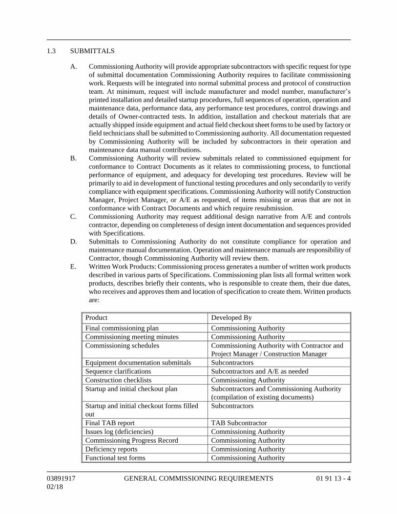
03891917 GENERAL COMMISSIONING REQUIREMENTS 01 91 13 - 4
02/18
1.3 SUBMITTALS
A. Commissioning Authority will provide appropriate subcontractors with specific request for type
of submittal documentation Commissioning Authority requires to facilitate commissioning
work. Requests will be integrated into normal submittal process and protocol of construction
team. At minimum, request will include manufacturer and model number, manufacturer’s
printed installation and detailed startup procedures, full sequences of operation, operation and
maintenance data, performance data, any performance test procedures, control drawings and
details of Owner-contracted tests. In addition, installation and checkout materials that are
actually shipped inside equipment and actual field checkout sheet forms to be used by factory or
field technicians shall be submitted to Commissioning authority. All documentation requested
by Commissioning Authority will be included by subcontractors in their operation and
maintenance data manual contributions.
B. Commissioning Authority will review submittals related to commissioned equipment for
conformance to Contract Documents as it relates to commissioning process, to functional
performance of equipment, and adequacy for developing test procedures. Review will be
primarily to aid in development of functional testing procedures and only secondarily to verify
compliance with equipment specifications. Commissioning Authority will notify Construction
Manager, Project Manager, or A/E as requested, of items missing or areas that are not in
conformance with Contract Documents and which require resubmission.
C. Commissioning Authority may request additional design narrative from A/E and controls
contractor, depending on completeness of design intent documentation and sequences provided
with Specifications.
D. Submittals to Commissioning Authority do not constitute compliance for operation and
maintenance manual documentation. Operation and maintenance manuals are responsibility of
Contractor, though Commissioning Authority will review them.
E. Written Work Products: Commissioning process generates a number of written work products
described in various parts of Specifications. Commissioning plan lists all formal written work
products, describes briefly their contents, who is responsible to create them, their due dates,
who receives and approves them and location of specification to create them. Written products
are:
Product Developed By
Final commissioning plan Commissioning Authority
Commissioning meeting minutes Commissioning Authority
Commissioning schedules Commissioning Authority with Contractor and
Project Manager / Construction Manager
Equipment documentation submittals Subcontractors
Sequence clarifications Subcontractors and A/E as needed
Construction checklists Commissioning Authority
Startup and initial checkout plan Subcontractors and Commissioning Authority
(compilation of existing documents)
Startup and initial checkout forms filled
out
Subcontractors
Final TAB report TAB Subcontractor
Issues log (deficiencies) Commissioning Authority
Commissioning Progress Record Commissioning Authority
Deficiency reports Commissioning Authority
Functional test forms Commissioning Authority
03891917 GENERAL COMMISSIONING REQUIREMENTS 01 91 13 - 5
02/18
Product Developed By
Filled out functional tests Commissioning Authority with Contractor
O&M manuals Subcontractors
Commissioning record book Commissioning Authority
Overall training plan Commissioning Authority and Construction
Manager
Specific training agendas Subcontractors
Final commissioning report Commissioning Authority
Misc. approvals Commissioning Authority
1.4 QUALITY ASSURANCE
A. Meetings:
1. Scoping Meeting: Within 14 days of commencement of construction, Commissioning
Authority will schedule, plan, and conduct a commissioning scoping meeting with entire
commissioning team in attendance. Meeting minutes will be distributed to all parties by
Commissioning Authority. Information gathered from this meeting will allow
Commissioning Authority to revise commissioning plan to its “final” version, which will
also be distributed to all parties.
2. Miscellaneous Meetings: Other meetings will be planned and conducted by
Commissioning Authority as construction progresses. Meetings will cover coordination,
deficiency resolution, and planning issues with particular subcontractors.
Commissioning Authority will plan meetings and will minimize unnecessary time being
spent by subcontractors. For large projects, meetings may be held monthly, until final
three months of construction when they may be held as frequently as one per week.
B. Coordination:
1. Members of commissioning team shall consist of Commissioning Authority, Project
Manager, designated representative of Owner’s Construction Management firm,
Contractor, Architect, and design engineers (particularly mechanical engineer),
mechanical subcontractor, electrical subcontractor, testing and balancing representative,
controls subcontractor, and other installing subcontractors or vendors. Owner’s building
or plant operator/engineer shall also be a member of commissioning team.
2. Management: Commissioning Authority has been hired by Owner directly.
Commissioning Authority shall direct and coordinate commissioning activities and
report to Owner. Members of commissioning team shall work together to fulfill their
contracted responsibilities and meet objectives of the Contract Documents.
Commissioning Authority’s responsibilities shall be same regardless of who employs
Commissioning Authority.
C. Reporting:
1. Commissioning Authority will provide regular reports to Construction Manager, Project
Manager, or Owner, depending on management structure, with increasing frequency as
construction and commissioning progresses. Standard forms are provided and referenced
in commissioning plan.
2. Commissioning Authority will regularly communicate with all members of
commissioning team, keeping them apprised of commissioning progress and scheduling
changes through memos, progress reports, etc.
3. Testing or review approvals and nonconformance and deficiency reports are made
regularly with review and testing as described in later Sections.
03891917 GENERAL COMMISSIONING REQUIREMENTS 01 91 13 - 6
02/18
4. Final summary report (approximately 4 to 6 pages, not including backup documentation)
by Commissioning Authority will be provided to Construction Manager, Project
Manager, or Owner, focusing on evaluating commissioning process issues and
identifying areas where process could be improved. Acquired documentation, logs,
minutes, reports, deficiency lists, communications, findings, unresolved issues, etc.,
will be compiled in appendices and provided with summary report. Construction
checklists, functional tests, and monitoring reports will not be part of final report, but
will be stored in Commissioning Record in operation and maintenance manuals.
1.5 ENGINEER’S RESPONSIBILITIES
A. Construction and Acceptance Phase:
1. Perform normal submittal review, construction observation, “as-built” Record Drawing
preparation, etc., as contracted. On-site observation shall be completed just prior to
system startup.
2. Provide design narrative and sequences documentation requested by Commissioning
Authority. Engineer shall assist (along with subcontractors) in clarifying operation and
control of commissioned equipment in areas where Specifications, control drawings, or
equipment documentation is not sufficient for writing detailed testing procedures.
3. Attend commissioning scoping meetings and other selected commissioning team
meetings.
4. Participate in resolution of system deficiencies identified during commissioning,
according to Contract Documents.
5. Prepare and submit final record “as-built” design intent and operating parameters
documentation for inclusion in operation and maintenance manuals. Review and approve
operation and maintenance manuals.
6. From Contractor’s red-line drawings, edit and update one-line diagrams developed as
part of design narrative documentation and those provided by vendor as Shop Drawings
for chilled water, condenser water, and steam and condensate systems.
7. Review construction checklists for major pieces of equipment for sufficiency prior to
their use.
8. Review functional test procedure forms for major pieces of equipment for sufficiency
prior to their use.
9. Witness testing of selected pieces of equipment and systems: for example, air handlers,
exhaust fans, controls systems, etc.
B. Warranty Period: Participate in resolution of noncompliance, nonconformance, and design
deficiencies identified during commissioning during warranty period commissioning.
C. Attend commissioning scoping meeting and additional meetings, as necessary.
D. Follow commissioning plan.
1.6 COMMISSIONING AUTHORITY’S RESPONSIBILITIES
A. Commissioning Authority shall not be responsible for design concept, design criteria,
compliance with codes, design or general construction scheduling, cost estimating, or
construction management. Commissioning Authority may assist with problem-solving,
nonconformance, or deficiencies. Primary role of Commissioning Authority shall be to develop
and coordinate execution of testing plan, observe, and document performance that systems are
functioning in accordance with documented design intent and in accordance with Contract
Documents. Contractor shall provide tools and labor to start, check-out and functionally test
equipment and systems.
03891917 GENERAL COMMISSIONING REQUIREMENTS 01 91 13 - 7
02/18
B. Construction and Acceptance Phase:
1. Coordinate and direct commissioning activities in a logical, sequential, and efficient
manner using consistent protocols and forms, centralized documentation, clear and
regular communications and consultations with necessary parties, frequently updated
timelines and schedules, and technical expertise.
2. Coordinate commissioning work and, with Contractor and Project/Construction
Manager, ensure that commissioning activities are being scheduled into master schedule.
3. Revise commissioning plan as necessary.
4. Plan and conduct commissioning scoping meeting and other commissioning meetings.
5. Request and review additional information required to perform commissioning tasks,
including operation and maintenance materials, Contractor startup, and checkout
procedures.
6. Before startup, gather and review current control sequences and interlocks and work with
subcontractors and design engineers until sufficient clarity has been obtained, in writing,
to be able to write detailed testing procedures.
7. Review Contractor submittals applicable to systems being commissioned for compliance
with commissioning needs, concurrent with A/E reviews.
8. Write and distribute construction checklists.
9. Perform site visits, as necessary, to observe component and system installations. Attend
selected planning and job-site meetings to obtain information on construction progress.
Review construction meeting minutes for revisions/substitutions relating to
commissioning process. Assist in resolving any discrepancies.
10. Notify Owner of pre-functional tests and construction checklist completion by reviewing
prefunctional checklist reports and by selected site observation and spot checking.
11. Notify Owner of systems startup by reviewing startup reports and by selected site
observation.
12. Review testing and balancing execution plan.
13. Before testing and balancing is executed, oversee sufficient functional testing of control
system and approve system to be used for testing and balancing.
14. Review air and water systems balancing by spot testing, by documenting completed
reports, and by selected site observation.
15. With necessary assistance and review from installing subcontractors, write functional
performance test procedures for equipment and systems. Test procedures may include
energy management control system trending, stand-alone data logger monitoring, or
manual functional testing. Submit to Owner for review, and for approval if required.
16. Analyze functional performance trend logs and monitoring data to verify performance.
17. Coordinate and witness functional performance tests performed by installing
subcontractors. Coordinate retesting as necessary until satisfactory performance is
achieved.
18. Maintain master deficiency and resolution log and separate testing record. Provide
Owner with written progress reports and test results with recommended actions.
19. Review equipment warranties to ensure that Owner’s responsibilities are clearly defined.
20. Oversee training of Owner’s operating personnel.
21. Compile and maintain commissioning record and building systems book(s).
22. Review operation and maintenance manuals.
23. Provide final commissioning report as specified below.
24. Develop commissioning record book in accordance with ASHRAE HVAC
Commissioning Guideline 0-2005.
03891917 GENERAL COMMISSIONING REQUIREMENTS 01 91 13 - 8
02/18
C. Warranty Period:
1. Coordinate and supervise required seasonal or deferred testing and deficiency
corrections.
2. Return to site at 10 months into the 12-month warranty period and review with facility
staff current building operation and condition of outstanding issues related to original
and seasonal commissioning. Identify areas that may come under warranty or under
original construction contract as a warranty period punch list.
3. Prepare and submit final Commission Record report to Owner.
D. Attend commissioning scoping meeting and additional meetings, as necessary.
E. Follow commissioning plan.
1.7 CONSTRUCTION MANAGER’S - OWNER’S REPRESENTATIVE’S RESPONSIBILITIES
A. Construction and Acceptance Phase:
1. Facilitate coordination of commissioning work by Commissioning Authority, and, with
Contractor and Commissioning Authority, ensure that commissioning activities are being
scheduled into master schedule.
2. Review and approve final commissioning plan.
3. Attend commissioning scoping meeting and other commissioning team meetings.
4. Perform normal review of Contractor submittals.
5. Furnish copy of construction documents, addenda, change orders and approved
submittals and Shop Drawings related to commissioned equipment to Commissioning
Authority.
6. Prior to testing, review and approve functional performance test procedures submitted by
Commissioning Authority.
7. When necessary, observe and witness construction checklists, startup and functional
testing of selected equipment.
8. Review commissioning progress and deficiency reports.
9. Coordinate resolution of noncompliance and design deficiencies identified in all phases
of commissioning.
10. Sign-off (final approval) on individual commissioning tests as completed and passing.
Recommend completion of commissioning process to Project Manager.
11. Assist Contractor in coordinating training of owner personnel.
B. Warranty period: Assist Commissioning Authority as necessary in seasonal or deferred testing
and deficiency corrections required by Specifications.
C. Attend commissioning scoping meeting and additional meetings, as necessary.
D. Follow commissioning plan.
1.8 OWNER’S PROJECT MANAGER’S RESPONSIBILITIES
A. Construction and Acceptance Phase:
1. Manage contract of A/E and of Contractor.
2. Arrange for facility operating and maintenance personnel to attend various field
commissioning activities and field training sessions according to commissioning plan -
construction phase.
3. Provide final approval for completion of commissioning work.
B. Warranty period: Ensure seasonal or deferred testing and deficiency issues are addressed.
C. Attend commissioning scoping meeting and additional meetings, as necessary.
D. Follow commissioning plan.
03891917 GENERAL COMMISSIONING REQUIREMENTS 01 91 13 - 9
02/18
1.9 CONTRACTOR’S RESPONSIBILITIES
A. Construction and Acceptance Phase:
1. Facilitate coordination of commissioning work by Commissioning Authority, and, with
Commissioning Authority, ensure that commissioning activities are being scheduled into
master schedule.
2. Include cost of commissioning in total Contract Price.
3. Furnish copy of construction documents, addenda, change orders and approved
submittals and Shop Drawings related to commissioned equipment to Commissioning
Authority.
4. In each Purchase Order or subcontract written, include requirements for submittal data,
operation and maintenance data, commissioning tasks and training.
5. Ensure subcontractors execute commissioning responsibilities according to Contract
Documents and schedule.
6. Representative shall attend commissioning scoping meeting and other necessary
meetings scheduled by Commissioning Authority to facilitate commissioning process.
7. Coordinate training of Owner’s personnel.
8. Prepare operation and maintenance manuals, according to Contract Documents,
including clarifying and updating original sequences of operation to record “as-built”
conditions.
B. Warranty Period:
1. Ensure subcontractors execute seasonal or deferred functional performance testing,
witnessed by Commissioning Authority, according to Contract Documents.
2. Ensure subcontractors correct deficiencies and make necessary adjustments to operation
and maintenance manuals and “as-built” Record Drawings for applicable issues
identified in seasonal testing.
C. Attend commissioning scoping meeting and additional meetings, as necessary.
D. Follow commissioning plan.
1.10 VENDOR’S RESPONSIBILITIES
A. Provide requested submittal data, including detailed startup procedures and specific
responsibilities of Owner to keep warranties in force.
B. Assist in equipment testing per agreements with subcontractors.
C. Include special tools and instruments (only available from vendor, specific to a piece of
equipment) required for testing equipment in accordance with Contract Documents in bid price,
except for standalone data logging equipment that may be used by Commissioning Authority.
D. Analyze specified products and verify that designer has specified newest most updated
equipment reasonable for Project’s scope and budget.
E. Provide information requested by Commissioning Authority regarding equipment sequence of
operation and testing procedures.
F. Review test procedures for equipment installed by manufacturer’s factory representatives.
G. Attend commissioning scoping meeting and additional meetings, as necessary.
H. Follow commissioning plan.
1.11 SCHEDULING
A. Commissioning Authority shall work with Owner and Contractor according to established
protocols to schedule commissioning activities. Commissioning Authority shall provide
sufficient notice to Owner and Contractor for scheduling commissioning activities. Contractor
03891917 GENERAL COMMISSIONING REQUIREMENTS 01 91 13 - 10
02/18
shall integrate commissioning activities into master schedule. Commissioning Authority,
Owner, and Contractor shall address scheduling problems and make necessary notifications in
timely manner in order to expedite commissioning process.
B. Commissioning Authority shall provide initial schedule of primary commissioning events at
commissioning scoping meeting. Commissioning plan shall provide format for schedule.
As construction progresses, more detailed schedules shall be developed by Commissioning
Authority. Commissioning plan shall also provide format for detailed schedules.
1.12 OWNER’S INSTRUCTION
A. Contractor shall be responsible for training coordination and scheduling and ultimately for
ensuring training is completed. Perform demonstration and training as specified in
Section 01 91 13.30.
PART 2 - PRODUCTS
2.1 TEST EQUIPMENT
A. Standard testing equipment required to perform startup and initial checkout and required
functional performance testing shall be provided by each contractor for equipment being tested.
For example, mechanical subcontractor shall ultimately be responsible for standard testing
equipment for HVAC system and controls system, except for equipment specific to and used by
testing and balancing contractor in their commissioning responsibilities. Two-way radios shall
be provided by Contractor for equipment being tested.
B. Special equipment, tools and instruments which are only available from vendor, specific to a
piece of equipment and required for testing equipment shall be provided, left on site, and shall
become property of Owner.
C. Testing equipment shall be of sufficient quality and accuracy to test and/or measure system
performance with tolerances specified. Refer to Section 01 91 13.20 for specific functional
performance testing requirements.
PART 3 - EXECUTION
3.1 COMMISSIONING PROCESS
A. Commissioning plan shall provide guidance in execution of commissioning process.
Immediately after initial commissioning scoping meeting, Commissioning Authority will update
plan submitted with Bid which is then considered “final” plan. Plan will continue to evolve and
expand as Project progresses.
B. Commissioning tasks and sequence:
1. Commissioning during construction shall begin with scoping meeting conducted by
Commissioning Authority to review commissioning process with commissioning team
members.
2. Additional meetings required during construction shall be scheduled by Commissioning
Authority with necessary parties attending, to plan, scope, coordinate, schedule future
activities and resolve problems.
3. Equipment documentation shall be submitted to Commissioning Authority during
normal submittals, including detailed startup procedures.
03891917 GENERAL COMMISSIONING REQUIREMENTS 01 91 13 - 11
02/18
4. Commissioning Authority shall work with subcontractors in developing startup plans
and startup documentation formats, including providing subcontractors with construction
checklists to be completed, during startup process.
5. Checkout and performance verification shall proceed from simple to complex; from
component level to equipment to systems and intersystem levels with construction
checklists being completed before functional testing.
6. Subcontractors shall execute and document construction checklists and perform startup
and initial checkout. Commissioning Authority shall document that checklists and
startup were completed according to approved plans. Commissioning Authority may
witness startup of selected equipment.
7. Commissioning Authority shall develop specific equipment and system functional
performance test procedures. Subcontractors shall review procedures.
8. Procedures shall be executed by subcontractors, under direction of, and documented by
Commissioning Authority.
9. Items of noncompliance in material, installation, or setup shall be corrected at
subcontractor’s expense and system shall be retested.
10. Commissioning Authority shall review operation and maintenance documentation for
completeness.
11. Commissioning shall be completed prior to Substantial Completion.
12. Commissioning Authority shall review, preapprove, and coordinate training provided by
subcontractors and verify that training was completed.
13. Deferred testing shall be conducted, as specified or required.
3.2 STARTUP, CONSTRUCTION CHECKLISTS, AND INITIAL CHECKOUT
A. Perform following procedures on equipment to be commissioned. Some systems that are not
comprised, e.g., electrical system power quality, may have very simplified construction
checklists and startup.
B. Construction checklists shall verify that equipment and systems are hooked up and operational.
It ensures that functional performance testing (in-depth system checkout) may proceed without
unnecessary delays. Each piece of equipment receives full checkout. No sampling strategies are
used. Prefunctional testing for a given system must be successfully completed prior to formal
functional performance testing of equipment or subsystems of given system. Refer to
Section 01 91 13.10 for construction checklist commissioning requirements.
3.3 FUNCTIONAL PERFORMANCE TESTING
A. List of equipment to be commissioned is found below. Refer to Section 01 91 13.20 for
functional performance testing requirements.
B. Functional performance testing shall demonstrate that each system is operating in accordance
with documented design intent and Contract Documents. Functional testing shall facilitate
bringing systems from state of Substantial Completion to full dynamic operation. During testing
process, areas of deficient performance shall be identified and corrected, improving operation
and functioning of systems.
C. Each system shall be operated through all modes of operation (seasonal, occupied, unoccupied,
warm-up, cool-down, part- and full-load) where there is a specified system response. Verify
each sequence in sequences of operation is required. Proper responses to such modes and
conditions as power failure, freeze condition, low oil pressure, no flow, equipment failure, etc.
shall also be tested. Development of test procedures: Before test procedures are written,
Commissioning Authority shall obtain all requested documentation and a current list of change
03891917 GENERAL COMMISSIONING REQUIREMENTS 01 91 13 - 12
02/18
orders affecting equipment or systems, including an updated points list, program code, control
sequences and parameters. Using testing parameters and requirements in Section 01 91 13.20,
Commissioning Authority shall develop specific test procedures and forms to verify and
document proper operation of each piece of equipment and system. Each subcontractor or
vendor responsible to execute a test shall provide limited assistance to Commissioning
Authority in developing procedures review (answering questions about equipment, operation,
sequences, etc.). Prior to execution, Commissioning Authority shall provide a copy of test
procedures to subcontractor(s) who shall review tests for feasibility, safety, equipment and
warranty protection. Commissioning Authority may submit tests to A/E for review, if requested.
D. Commissioning Authority shall review Owner-contracted, factory testing or required Owner
acceptance tests which Commissioning Authority is not responsible to oversee, including
documentation format, and shall determine what further testing or format changes may be
required to comply with Specifications. Redundancy of testing shall be minimized.
E. Purpose of specific test is to verify and document compliance with stated criteria of acceptance
given on test form.
3.4 PHASED COMMISSIONING
A. Startup and initial checkout may be executed in phases.
B. Phasing shall be planned and scheduled during coordination meeting of Commissioning
Authority, Construction Manager, Contractor and mechanical, testing and balancing, and
controls contractors.
C. Results shall be incorporated into master and commissioning schedule.
3.5 OPERATION AND MAINTENTANCE MANUALS
A. Standard operation and maintenance manuals: Specific content and format requirements for
standard operation and maintenance manuals shall be as specified in Section 01 78 23.30 for
operation and maintenance commissioning requirements.
B. Final report details: Final commissioning report shall include executive summary, list of
participants and roles, brief system description, overview of commissioning and testing scope
and a general description of testing and verification methods. For each piece of commissioned
equipment, report shall contain disposition of commissioning authority regarding adequacy of
equipment, documentation and training meeting Contract Documents in following areas:
1. Equipment meeting equipment specifications.
2. Equipment installation.
3. Functional performance and efficiency.
4. Equipment documentation and design intent.
5. Operator training.
C. Outstanding noncompliance items shall be specifically listed. Recommendations for
improvement to equipment or operations, future actions, commissioning process changes, etc.
shall also be listed.
D. Each noncompliance issue shall be referenced to specific functional test, inspection, trend log,
etc. where deficiency is documented.
E. Functional performance and efficiency section for each piece of equipment shall include brief
description of verification method used (manual testing, BAS trend logs, data loggers, etc.) and
include observations and conclusions from testing.
F. Other documentation will be retained by Commissioning Authority.
END OF SECTION
_____________________________________________________________________________________
03891917 CONSTRUCTION CHECKLISTS COMMISSIONING 01 91 13.10 - 1
02/18 REQUIREMENTS
SECTION 01 91 13.10 - CONSTRUCTION CHECKLISTS
COMMISSIONING REQUIREMENTS
PART 1 - GENERAL
1.1 SUMMARY
A. Section includes construction checklists for a given system shall be successfully completed
and approved prior to startup and formal performance testing of equipment or subsystems
of the given system.
B. Related Requirements:
1. Section 00 00 00 "Invitation to Bid" for reference to Drawings and general
provisions of the Contract including General and Supplementary Conditions.
2. Other Division 01 Specification Sections apply to Work of this Section.
3. Section 01 81 13 "Sustainable Design Requirements" for LEED Sustainability
Requirements.
1.2 STARTUP AND CHECKOUT PLAN
A. CxA shall assist the Project commissioning team members responsible for startup of any
equipment. The primary role of the CxA in this process is to ensure that there is written
documentation that each of the manufacturer-recommended procedures has been
completed by Contractor. Contractor shall submit manufacturer-provided construction
checklists to the CxA for review and approval. Startup shall be identified in the
commissioning scope meeting and on the checklist forms.
B. Construction checklists are provided in the Cx plan. These checklists indicate required
procedures to be executed as part of startup and initial checkout of the systems and the
party responsible for their execution.
C. Contractor shall determine which trade is responsible for executing and documenting each
of the line item tasks and route the checklists to the responsible subcontractors. Each form
may have more than one trade responsible for its execution.
D. Contractor/subcontractor, with assistance from the CxA, responsible for the purchase of the
equipment shall develop the full startup plan by combining the manufacturer's detailed
startup and checkout procedures and the construction checklists.
E. Contractor/subcontractor shall submit the full startup plan to the CxA for review and
approval.
F. CxA will review and approve the procedures and documentation format for reporting. The
CxA will return the procedures and the documentation format to the contractor, through the
CM.
G. Contractor will transmit the full startup plan to the subcontractors for their review and use.
1.3 SENSOR AND ACTUATOR CALIBRATION
A. All field-installed temperature, relative humidity, CO, CO2, refrigerant, O2, and/or
pressure sensors and gages, and all actuators (dampers and valves) on all equipment shall
be calibrated. Verify that all locations are appropriate and away from causes of erratic
operation. Submit to the CxA through the CM the calibration methods and results. All test
instruments shall have had a certified calibration within the last 6 months to NIST
traceable standards, and comply with all local, state, and/or federal requirements/
certifications, as required. Sensors installed in the unit at the factory with calibration
_____________________________________________________________________________________
03891917 CONSTRUCTION CHECKLISTS COMMISSIONING 01 91 13.10 - 2
02/18 REQUIREMENTS
certification provided need not be field calibrated. Provide bench testing as required at the
direction of the CxA.
B. Sensor Calibration Methods:
1. All Sensors: Verify that all sensor locations are appropriate and away from causes of
erratic operation. Verify that sensors with shielded cable are grounded at only one
end. For sensor pairs that are used to determine a temperature or pressure difference,
make sure they are reading within 0.2 degrees F of each other for temperature and
within a tolerance equal to 2 percent of the reading, of each other, for pressure.
Tolerances for critical applications may be tighter.
2. Sensors Without Transmitters, Standard Application: Make a reading with a
calibrated test instrument within 6 inches of the site sensor. Verify that the sensor
reading (via the permanent thermostat, gage or building automation system (BAS) is
within the tolerance limits. If not, install offset in BAS, calibrate, or replace sensor.
3. Sensors with Transmitters, Standard Application: Disconnect sensor. Connect a
signal generator in place of sensor. Connect ammeter in series between transmitter
and BAS control panel. Using manufacturer's resistance-temperature data, simulate
minimum desired temperature. Adjust transmitter potentiometer zero until 4 mA is
read by the ammeter. Repeat for the maximum temperature matching 20 mA to the
potentiometer span or maximum and verify at the BAS. Record all values and
recalibrated controller as necessary to conform with specified control ramps, reset
schedules, proportional relationship, reset relationship and P/I reaction. Reconnect
sensor. Make a reading with a calibrated test instrument within 6 inches of the site
sensor. Verify that the sensor reading is within the tolerance limits. If not, replace
sensor and repeat. For pressure sensors, perform a similar process with a suitable
signal generator.
4. Critical Applications: For critical applications, more rigorous calibration techniques
may be required for selected sensors. Describe any such methods used on an
attached sheet.
5. Valve and Damper Stroke Setup and Check EMS Readout: For all valve and damper
actuator positions checked, verify the actual position as seen in the field at the
device against the BAS readout. Set pumps or fans to normal operating mode.
Command valve or damper closed, visually verify that valve or damper is closed,
and adjust output zero signal as required. Command valve or damper open, verify
position is full open, and adjust output signal as required. Command valve or
damper to a few intermediate positions. If actual valve or damper position doesn't
reasonably correspond, replace actuator or add pilot positioner.
1.4 EXECUTION OF CONSTRUCTION CHECKLISTS AND STARTUP
A. Four weeks prior to the scheduled startup, Contractor shall coordinate startup and checkout
with the CM, Architect, and CxA. The execution and approval of the construction
checklists, startup, and checkout shall be directed and performed by Contractor,
subcontractor, or vendor. Signatures and dates are required of the applicable subcontractors
for verification of completion of their work.
B. Owner/CM, and Architect as necessary, shall observe, at minimum, the procedures for each
piece of primary equipment, unless there are multiple units, in which case a sampling
strategy may be used. CxA will observe all testing.
C. For lower-level components of equipment, (e.g., sensors, controllers), CxA shall observe a
sampling of the startup procedures.
_____________________________________________________________________________________
03891917 CONSTRUCTION CHECKLISTS COMMISSIONING 01 91 13.10 - 3
02/18 REQUIREMENTS
D. Subcontractors and vendors shall execute startup and provide CxA and Architect, through
Owner/CM, with a signed and dated copy of the completed startup and construction
checklists.
E. Only individuals of Contractor who have direct knowledge and witnessed that a line item
task on the construction checklist was actually performed shall check off that item. It is not
acceptable for witnessing supervisors to fill out these forms.
F. Deficiencies, nonconformance, and approval in checklists and startup (master issues log):
1. Contractor shall ensure that subcontractors clearly list any outstanding items of the
initial startup and construction checklist procedures that were not completed
successfully, on an attached sheet. The form and any outstanding deficiencies shall
be provided, through Owner/CM, to CxA within two days of test completion.
2. CxA will review the report and issue either a noncompliance report or an approval
form, through CM, to Contractor. The installing subcontractors or vendors shall
correct all areas that are deficient or incomplete in the checklists and tests in a timely
manner, shall notify Owner/CM as soon as outstanding items have been corrected,
and resubmit an updated startup report with a Statement of Correction on the
original noncompliance report. When satisfactorily completed, CxA will recommend
approval of the execution of the checklists and startup of each system.
3. Items left incomplete, which later cause deficiencies or delays during performance
may result in back-charges to Contractor.
G. Checklists:
1. Commissioning Plan contains sample representative Construction Checklists in a
form format. The Checklists are formatted by a specific system and intended to
include all system components that shall be checked by Contractor prior to the
Functional Performance Testing of the system.
2. Construction Checklist procedures displayed in a form format are intended to
provide Contractor with an example of a format and an indication of the rigor of the
required Checklists and documentation for various equipment types. These
checklists are general in nature and shall be provided in a more Project-specific
format after Contractor submittals are reviewed.
3. Checklists contain items for Divisions 01, 23, 26, and 28 contractors to perform. On
each checklist, a column is provided that shall be filled out by the designated
contractor assigned responsibility for that line item.
4. Those executing the checklists are responsible only to perform items that apply to
the specific application at hand. These checklists do not take the place of the
manufacturer's recommended checkout and startup procedures or report. Some
checklist procedures may be redundant with some checkout procedures that will be
documented on typical factory supplied field checkout sheets. Double documenting
is required in those cases. Additionally, copies of completed manufacturer checkout
and startup documentation shall be attached to the completed Checklists.
5. When a manufacturer's representative is responsible for the installation and startup
procedures exclusively (e.g., boilers, elevators, etc.) only a Construction Checklist
cover sheet shall be provided to Contractor, to which the completed manufacturer's
documentation shall be attached.
6. Refer to Section 01 91 13 "General Commissioning Requirements" for additional
requirements regarding installation verification checklists, startup, and initial
checkout. Items that do not apply should be noted along with the reasons on the
form. If this form is not used for documenting, one of similar rigor and clarity shall
be used.
_____________________________________________________________________________________
03891917 CONSTRUCTION CHECKLISTS COMMISSIONING 01 91 13.10 - 4
02/18 REQUIREMENTS
1.5 ACTION SUBMITTALS
A. Preconstruction Submittals: Startup and Checkout Plan.
B. Test Reports:
1. Sensor and Actuator Calibration.
2. Sensor Calibration Methods.
C. Closeout Submittals:
1. Construction Checklists.
2. Manufacturer’s Installation Checklists.
3. Execution of Construction Checklists and Startup.
PART 2 - PRODUCTS
2.1 CONSTRUCTION CHECKLISTS
A. Project-specific blank checklists shall be provided to Contractor in electronic file format
(Adobe PDF files) after approved equipment submittals and manufacturer provided
installation checklists are received by the CxA.
B. Specific equipment checklists shall be developed by the Commissioning Agent for the
systems and system/equipment components listed in the systems to be commissioned in
Section 01 91 13.
PART 3 - EXECUTION
3.1 SAMPLE CONSTRUCTION CHECKLISTS
A. Sample Construction Checklist procedures attached are shown in a form format and are
provided as an example of format and as an indication of rigor of required testing and
documentation for various equipment types. Construction Checklist procedures have not
been developed for this Project.
B. Following sample construction checklists are included for reference purposes only:
1. Air Handling Unit.
2. Lighting Control System.
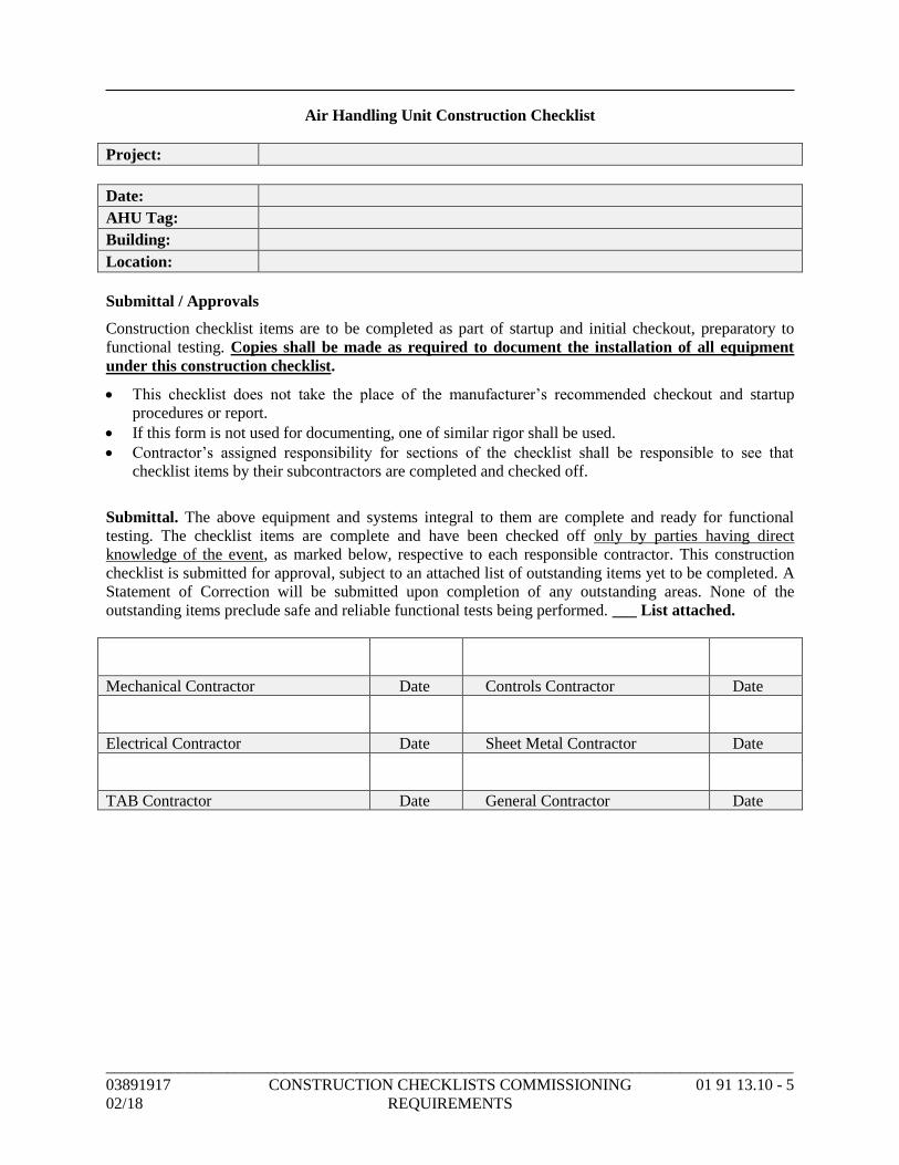
_____________________________________________________________________________________
03891917 CONSTRUCTION CHECKLISTS COMMISSIONING 01 91 13.10 - 5
02/18 REQUIREMENTS
Air Handling Unit Construction Checklist
Project:
Date:
AHU Tag:
Building:
Location:
Submittal / Approvals
Construction checklist items are to be completed as part of startup and initial checkout, preparatory to
functional testing. Copies shall be made as required to document the installation of all equipment
under this construction checklist.
• This checklist does not take the place of the manufacturer’s recommended checkout and startup
procedures or report.
• If this form is not used for documenting, one of similar rigor shall be used.
• Contractor’s assigned responsibility for sections of the checklist shall be responsible to see that
checklist items by their subcontractors are completed and checked off.
Submittal. The above equipment and systems integral to them are complete and ready for functional
testing. The checklist items are complete and have been checked off only by parties having direct
knowledge of the event, as marked below, respective to each responsible contractor. This construction
checklist is submitted for approval, subject to an attached list of outstanding items yet to be completed. A
Statement of Correction will be submitted upon completion of any outstanding areas. None of the
outstanding items preclude safe and reliable functional tests being performed. ___ List attached.
Mechanical Contractor Date Controls Contractor Date
Electrical Contractor Date Sheet Metal Contractor Date
TAB Contractor Date General Contractor Date
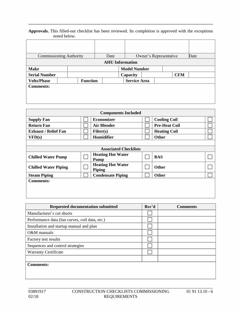
_____________________________________________________________________________________
03891917 CONSTRUCTION CHECKLISTS COMMISSIONING 01 91 13.10 - 6
02/18 REQUIREMENTS
Approvals. This filled-out checklist has been reviewed. Its completion is approved with the exceptions
noted below.
Commissioning Authority Date Owner’s Representative Date
AHU Information
Make Model Number
Serial Number Capacity CFM
Volts/Phase Function Service Area
Comments:
Components Included
Supply Fan Economizer Cooling Coil
Return Fan Air Blender Pre-Heat Coil
Exhaust / Relief Fan Filter(s) Heating Coil
VFD(s) Humidifier Other
Associated Checklists
Chilled Water Pump Heating Hot Water
Pump BAS
Chilled Water Piping Heating Hot Water
Piping Other
Steam Piping Condensate Piping Other
Comments:
Requested documentation submitted Rec’d Comments
Manufacturer’s cut sheets
Performance data (fan curves, coil data, etc.)
Installation and startup manual and plan
O&M manuals
Factory test results
Sequences and control strategies
Warranty Certificate
Comments:
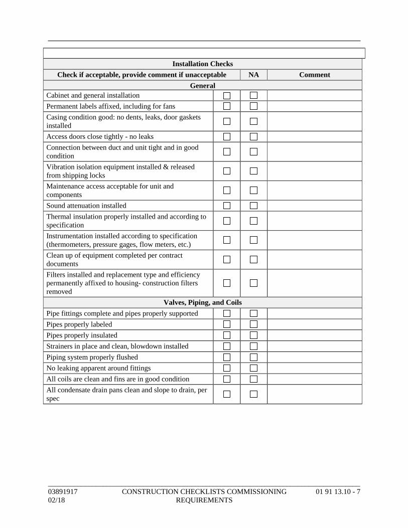
_____________________________________________________________________________________
03891917 CONSTRUCTION CHECKLISTS COMMISSIONING 01 91 13.10 - 7
02/18 REQUIREMENTS
Installation Checks
Check if acceptable, provide comment if unacceptable NA Comment
General
Cabinet and general installation
Permanent labels affixed, including for fans
Casing condition good: no dents, leaks, door gaskets
installed
Access doors close tightly - no leaks
Connection between duct and unit tight and in good
condition
Vibration isolation equipment installed & released
from shipping locks
Maintenance access acceptable for unit and
components
Sound attenuation installed
Thermal insulation properly installed and according to
specification
Instrumentation installed according to specification
(thermometers, pressure gages, flow meters, etc.)
Clean up of equipment completed per contract
documents
Filters installed and replacement type and efficiency
permanently affixed to housing- construction filters
removed
Valves, Piping, and Coils
Pipe fittings complete and pipes properly supported
Pipes properly labeled
Pipes properly insulated
Strainers in place and clean, blowdown installed
Piping system properly flushed
No leaking apparent around fittings
All coils are clean and fins are in good condition
All condensate drain pans clean and slope to drain, per
spec
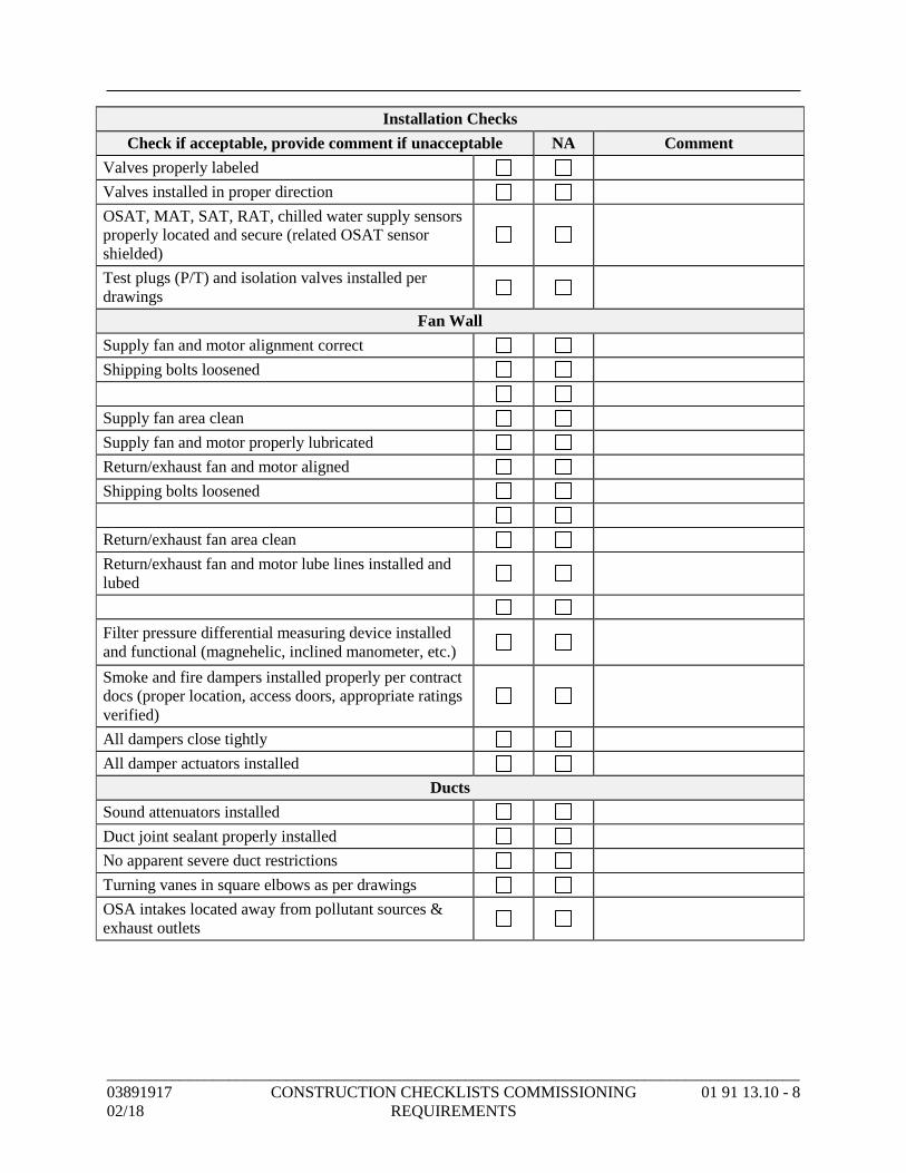
_____________________________________________________________________________________
03891917 CONSTRUCTION CHECKLISTS COMMISSIONING 01 91 13.10 - 8
02/18 REQUIREMENTS
Installation Checks
Check if acceptable, provide comment if unacceptable NA Comment
Valves properly labeled
Valves installed in proper direction
OSAT, MAT, SAT, RAT, chilled water supply sensors
properly located and secure (related OSAT sensor
shielded)
Test plugs (P/T) and isolation valves installed per
drawings
Fan Wall
Supply fan and motor alignment correct
Shipping bolts loosened
Supply fan area clean
Supply fan and motor properly lubricated
Return/exhaust fan and motor aligned
Shipping bolts loosened
Return/exhaust fan area clean
Return/exhaust fan and motor lube lines installed and
lubed
Filter pressure differential measuring device installed
and functional (magnehelic, inclined manometer, etc.)
Smoke and fire dampers installed properly per contract
docs (proper location, access doors, appropriate ratings
verified)
All dampers close tightly
All damper actuators installed
Ducts
Sound attenuators installed
Duct joint sealant properly installed
No apparent severe duct restrictions
Turning vanes in square elbows as per drawings
OSA intakes located away from pollutant sources &
exhaust outlets
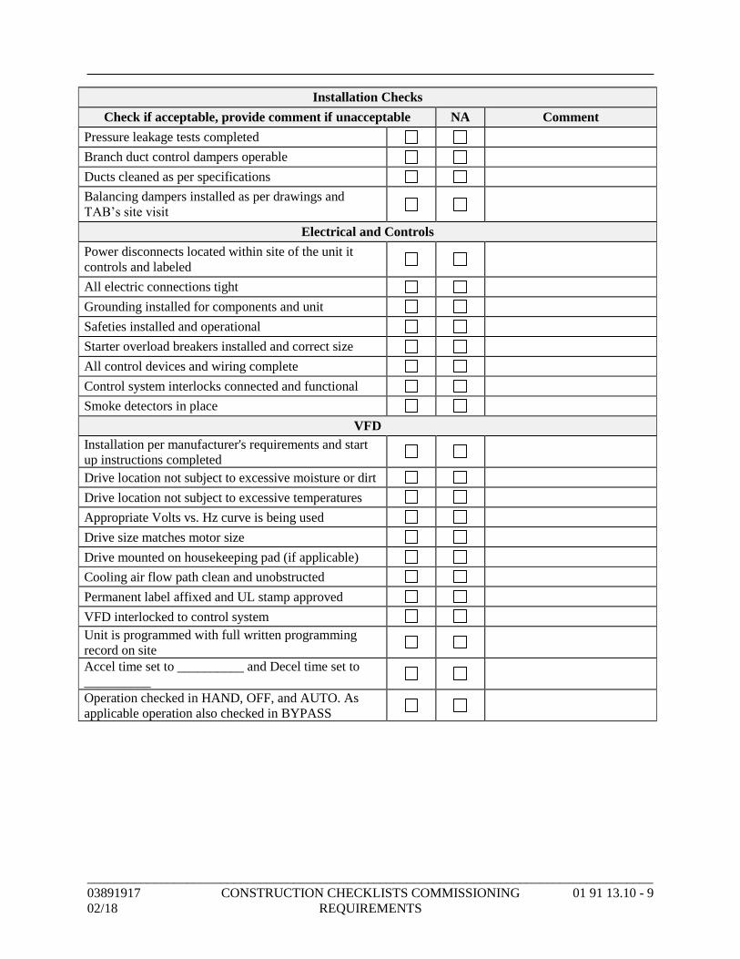
_____________________________________________________________________________________
03891917 CONSTRUCTION CHECKLISTS COMMISSIONING 01 91 13.10 - 9
02/18 REQUIREMENTS
Installation Checks
Check if acceptable, provide comment if unacceptable NA Comment
Pressure leakage tests completed
Branch duct control dampers operable
Ducts cleaned as per specifications
Balancing dampers installed as per drawings and
TAB’s site visit
Electrical and Controls
Power disconnects located within site of the unit it
controls and labeled
All electric connections tight
Grounding installed for components and unit
Safeties installed and operational
Starter overload breakers installed and correct size
All control devices and wiring complete
Control system interlocks connected and functional
Smoke detectors in place
VFD
Installation per manufacturer's requirements and start
up instructions completed
Drive location not subject to excessive moisture or dirt
Drive location not subject to excessive temperatures
Appropriate Volts vs. Hz curve is being used
Drive size matches motor size
Drive mounted on housekeeping pad (if applicable)
Cooling air flow path clean and unobstructed
Permanent label affixed and UL stamp approved
VFD interlocked to control system
Unit is programmed with full written programming
record on site
Accel time set to __________ and Decel time set to
__________
Operation checked in HAND, OFF, and AUTO. As
applicable operation also checked in BYPASS
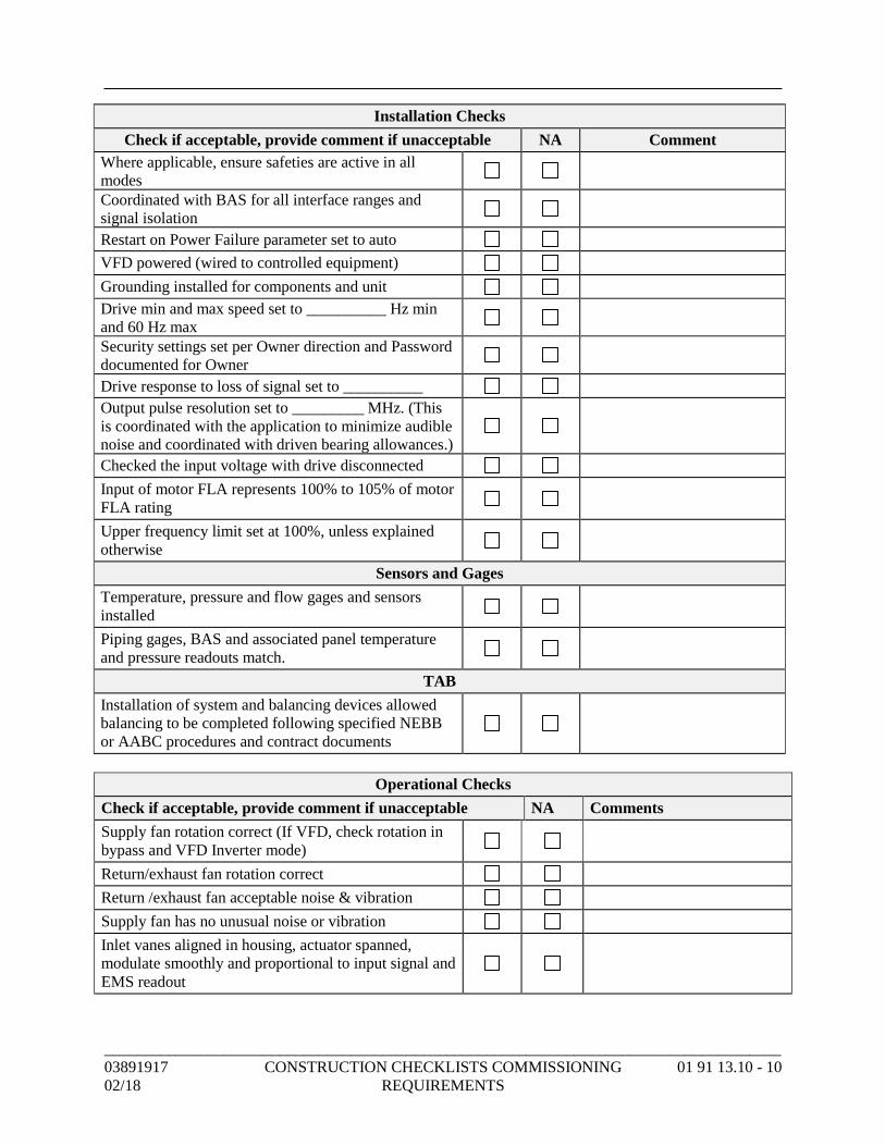
_____________________________________________________________________________________
03891917 CONSTRUCTION CHECKLISTS COMMISSIONING 01 91 13.10 - 10
02/18 REQUIREMENTS
Installation Checks
Check if acceptable, provide comment if unacceptable NA Comment
Where applicable, ensure safeties are active in all
modes
Coordinated with BAS for all interface ranges and
signal isolation
Restart on Power Failure parameter set to auto
VFD powered (wired to controlled equipment)
Grounding installed for components and unit
Drive min and max speed set to __________ Hz min
and 60 Hz max
Security settings set per Owner direction and Password
documented for Owner
Drive response to loss of signal set to __________
Output pulse resolution set to _________ MHz. (This
is coordinated with the application to minimize audible
noise and coordinated with driven bearing allowances.)
Checked the input voltage with drive disconnected
Input of motor FLA represents 100% to 105% of motor
FLA rating
Upper frequency limit set at 100%, unless explained
otherwise
Sensors and Gages
Temperature, pressure and flow gages and sensors
installed
Piping gages, BAS and associated panel temperature
and pressure readouts match.
TAB
Installation of system and balancing devices allowed
balancing to be completed following specified NEBB
or AABC procedures and contract documents
Operational Checks
Check if acceptable, provide comment if unacceptable NA Comments
Supply fan rotation correct (If VFD, check rotation in
bypass and VFD Inverter mode)
Return/exhaust fan rotation correct
Return /exhaust fan acceptable noise & vibration
Supply fan has no unusual noise or vibration
Inlet vanes aligned in housing, actuator spanned,
modulate smoothly and proportional to input signal and
EMS readout
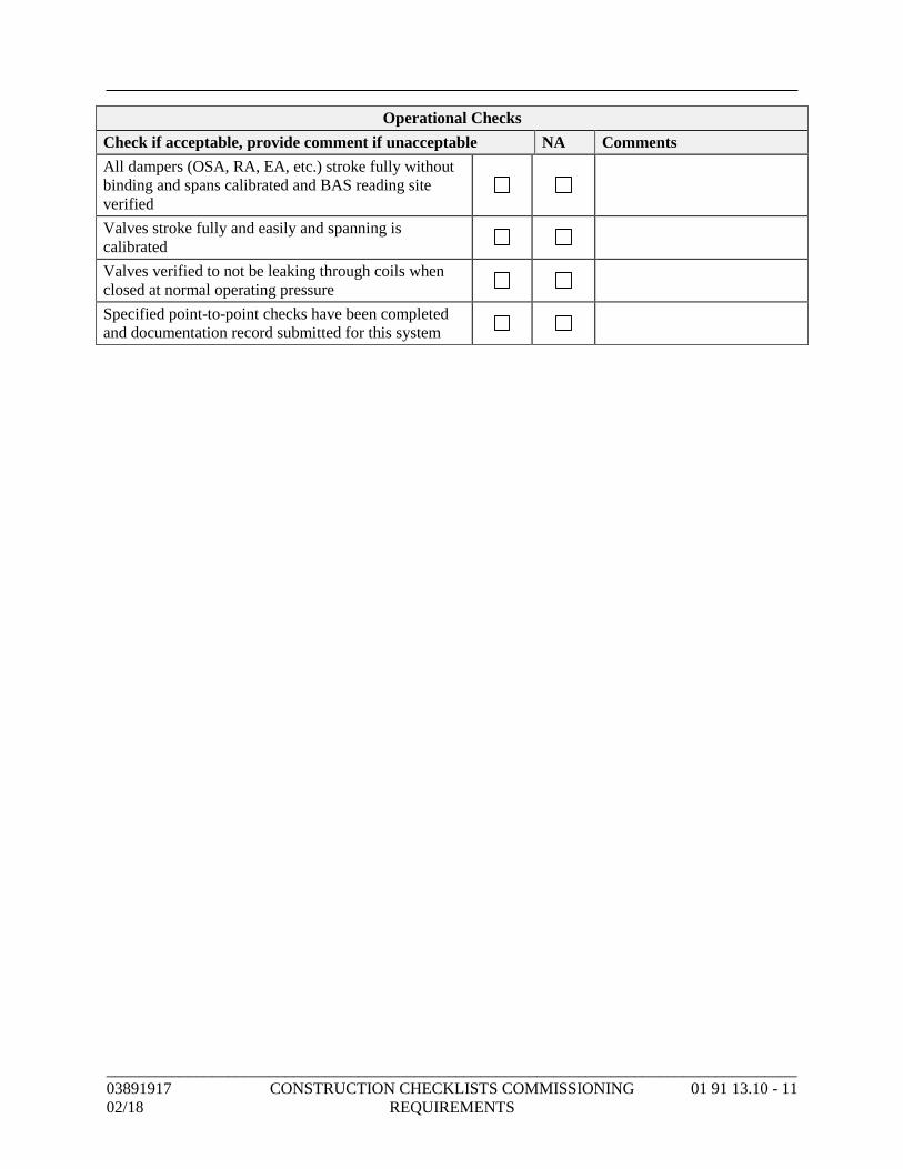
_____________________________________________________________________________________
03891917 CONSTRUCTION CHECKLISTS COMMISSIONING 01 91 13.10 - 11
02/18 REQUIREMENTS
Operational Checks
Check if acceptable, provide comment if unacceptable NA Comments
All dampers (OSA, RA, EA, etc.) stroke fully without
binding and spans calibrated and BAS reading site
verified
Valves stroke fully and easily and spanning is
calibrated
Valves verified to not be leaking through coils when
closed at normal operating pressure
Specified point-to-point checks have been completed
and documentation record submitted for this system
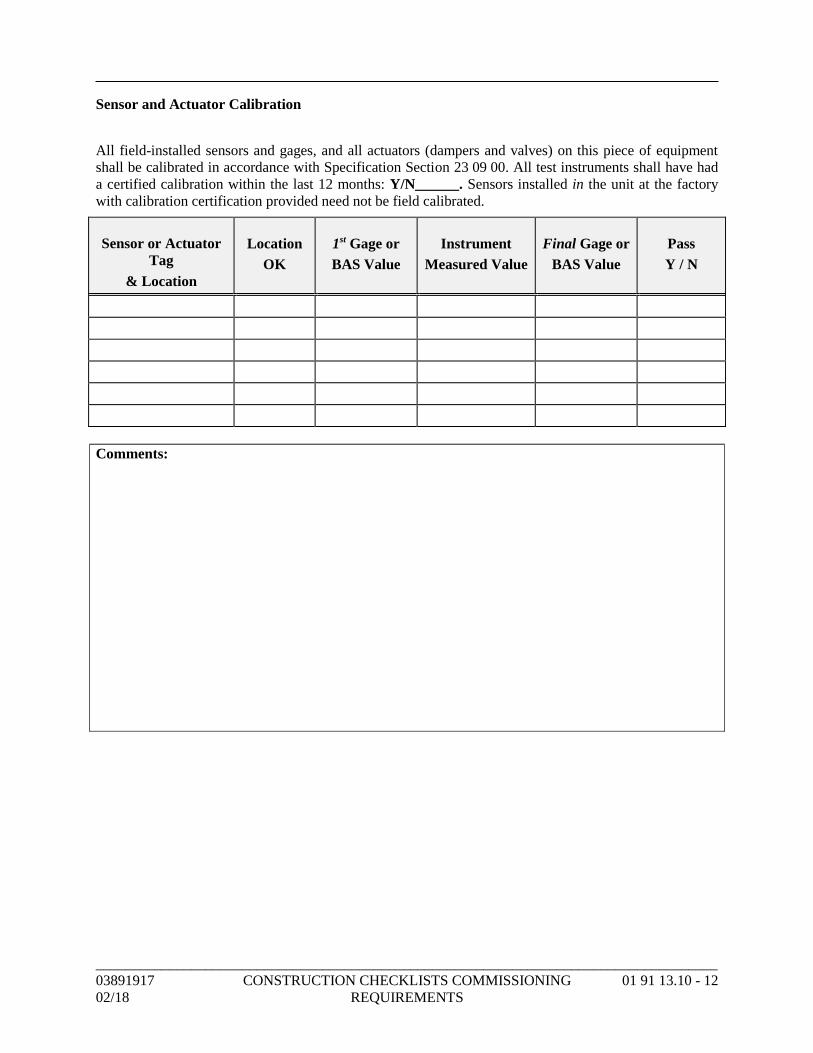
_____________________________________________________________________________________
03891917 CONSTRUCTION CHECKLISTS COMMISSIONING 01 91 13.10 - 12
02/18 REQUIREMENTS
Sensor and Actuator Calibration
All field-installed sensors and gages, and all actuators (dampers and valves) on this piece of equipment
shall be calibrated in accordance with Specification Section 23 09 00. All test instruments shall have had
a certified calibration within the last 12 months: Y/N______. Sensors installed in the unit at the factory
with calibration certification provided need not be field calibrated.
Sensor or Actuator
Tag
& Location
Location
OK
1st Gage or
BAS Value
Instrument
Measured Value
Final Gage or
BAS Value
Pass
Y / N
Comments:
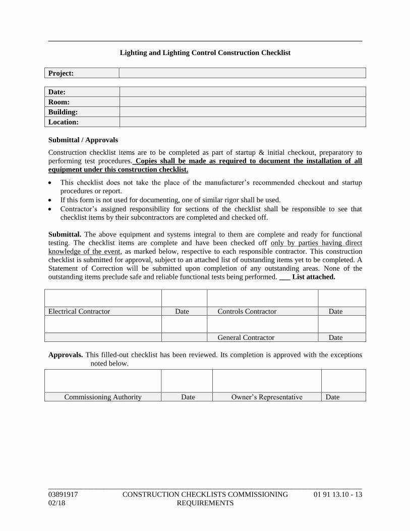
_____________________________________________________________________________________
03891917 CONSTRUCTION CHECKLISTS COMMISSIONING 01 91 13.10 - 13
02/18 REQUIREMENTS
Lighting and Lighting Control Construction Checklist
Project:
Date:
Room:
Building:
Location:
Submittal / Approvals
Construction checklist items are to be completed as part of startup & initial checkout, preparatory to
performing test procedures. Copies shall be made as required to document the installation of all
equipment under this construction checklist.
• This checklist does not take the place of the manufacturer’s recommended checkout and startup
procedures or report.
• If this form is not used for documenting, one of similar rigor shall be used.
• Contractor’s assigned responsibility for sections of the checklist shall be responsible to see that
checklist items by their subcontractors are completed and checked off.
Submittal. The above equipment and systems integral to them are complete and ready for functional
testing. The checklist items are complete and have been checked off only by parties having direct
knowledge of the event, as marked below, respective to each responsible contractor. This construction
checklist is submitted for approval, subject to an attached list of outstanding items yet to be completed. A
Statement of Correction will be submitted upon completion of any outstanding areas. None of the
outstanding items preclude safe and reliable functional tests being performed. ___ List attached.
Electrical Contractor Date Controls Contractor Date
General Contractor Date
Approvals. This filled-out checklist has been reviewed. Its completion is approved with the exceptions
noted below.
Commissioning Authority Date Owner’s Representative Date
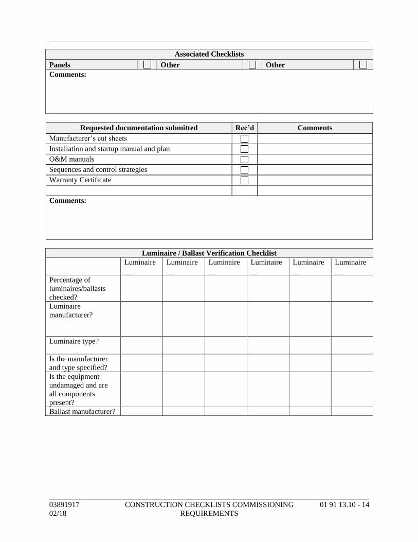
_____________________________________________________________________________________
03891917 CONSTRUCTION CHECKLISTS COMMISSIONING 01 91 13.10 - 14
02/18 REQUIREMENTS
Associated Checklists
Panels Other Other
Comments:
Requested documentation submitted Rec’d Comments
Manufacturer’s cut sheets
Installation and startup manual and plan
O&M manuals
Sequences and control strategies
Warranty Certificate
Comments:
Luminaire / Ballast Verification Checklist
Luminaire
__
Luminaire
__
Luminaire
__
Luminaire
__
Luminaire
__
Luminaire
__
Percentage of
luminaires/ballasts
checked?
Luminaire
manufacturer?
Luminaire type?
Is the manufacturer
and type specified?
Is the equipment
undamaged and are
all components
present?
Ballast manufacturer?
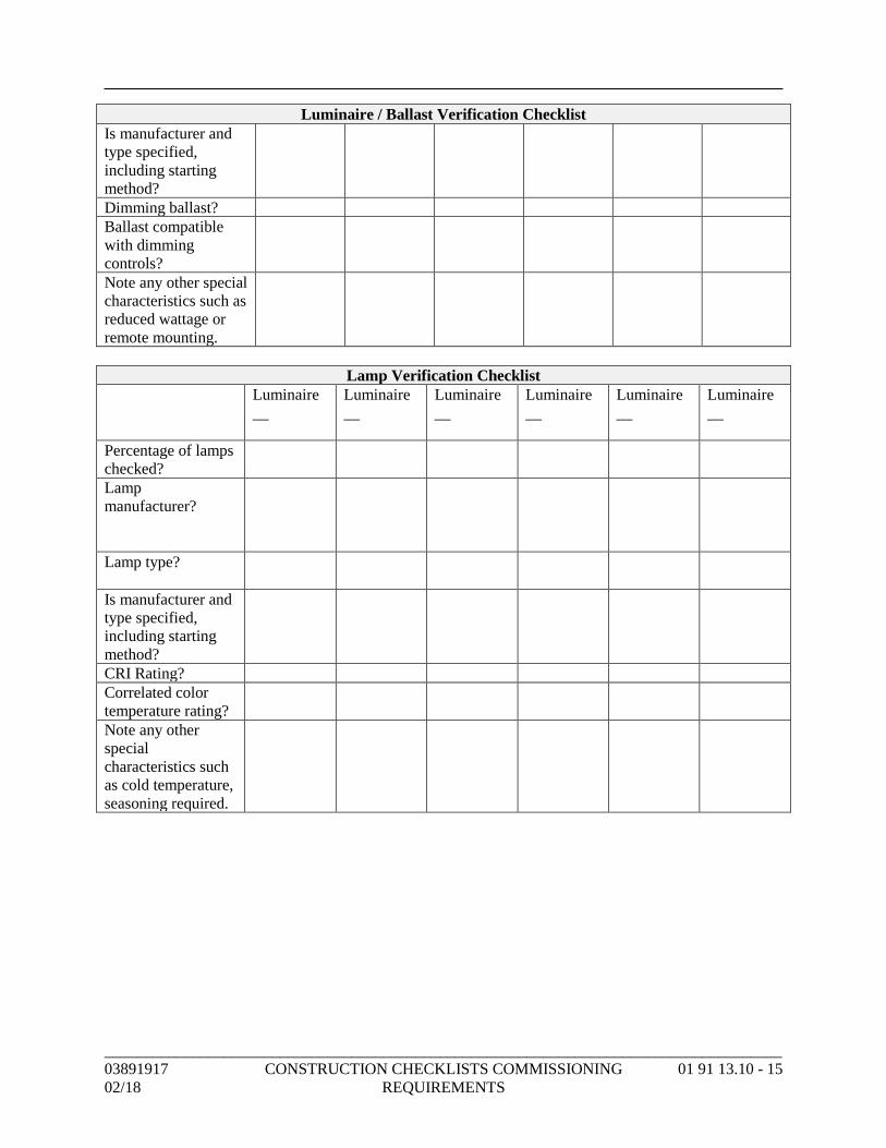
_____________________________________________________________________________________
03891917 CONSTRUCTION CHECKLISTS COMMISSIONING 01 91 13.10 - 15
02/18 REQUIREMENTS
Luminaire / Ballast Verification Checklist
Is manufacturer and
type specified,
including starting
method?
Dimming ballast?
Ballast compatible
with dimming
controls?
Note any other special
characteristics such as
reduced wattage or
remote mounting.
Lamp Verification Checklist
Luminaire
__
Luminaire
__
Luminaire
__
Luminaire
__
Luminaire
__
Luminaire
__
Percentage of lamps
checked?
Lamp
manufacturer?
Lamp type?
Is manufacturer and
type specified,
including starting
method?
CRI Rating?
Correlated color
temperature rating?
Note any other
special
characteristics such
as cold temperature,
seasoning required.
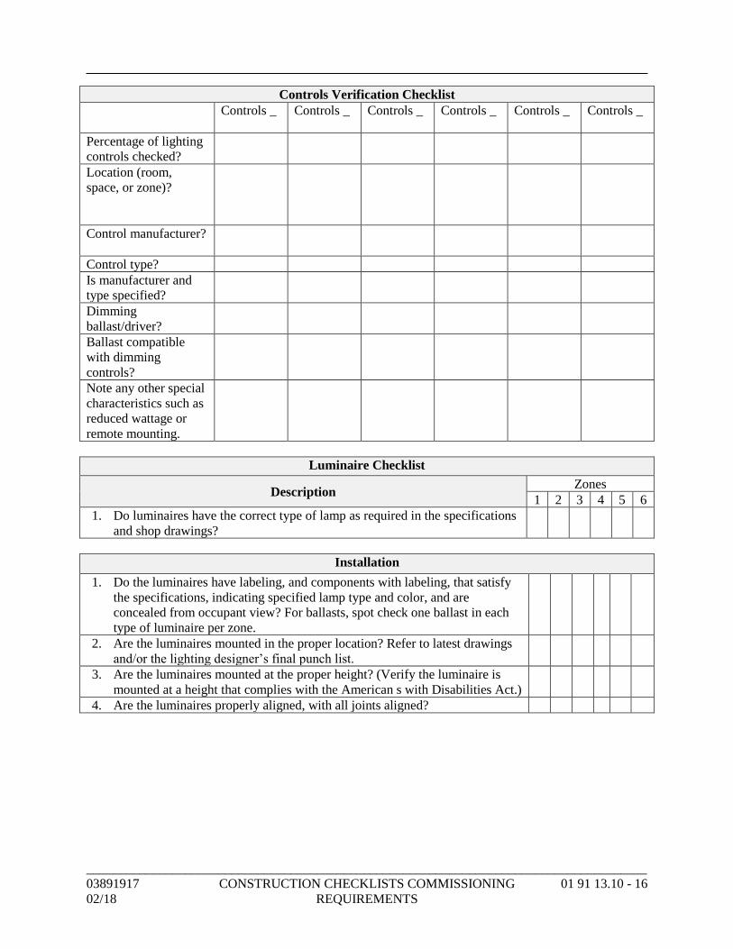
_____________________________________________________________________________________
03891917 CONSTRUCTION CHECKLISTS COMMISSIONING 01 91 13.10 - 16
02/18 REQUIREMENTS
Controls Verification Checklist
Controls _ Controls _ Controls _ Controls _ Controls _ Controls _
Percentage of lighting
controls checked?
Location (room,
space, or zone)?
Control manufacturer?
Control type?
Is manufacturer and
type specified?
Dimming
ballast/driver?
Ballast compatible
with dimming
controls?
Note any other special
characteristics such as
reduced wattage or
remote mounting.
Luminaire Checklist
Description Zones
1 2 3 4 5 6
1. Do luminaires have the correct type of lamp as required in the specifications
and shop drawings?
Installation
1. Do the luminaires have labeling, and components with labeling, that satisfy
the specifications, indicating specified lamp type and color, and are
concealed from occupant view? For ballasts, spot check one ballast in each
type of luminaire per zone.
2. Are the luminaires mounted in the proper location? Refer to latest drawings
and/or the lighting designer’s final punch list.
3. Are the luminaires mounted at the proper height? (Verify the luminaire is
mounted at a height that complies with the American s with Disabilities Act.)
4. Are the luminaires properly aligned, with all joints aligned?
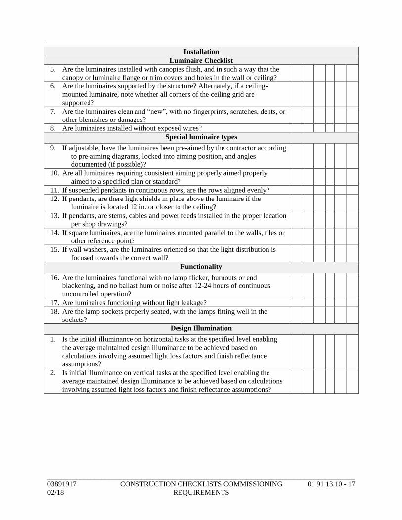
_____________________________________________________________________________________
03891917 CONSTRUCTION CHECKLISTS COMMISSIONING 01 91 13.10 - 17
02/18 REQUIREMENTS
Installation
Luminaire Checklist
5. Are the luminaires installed with canopies flush, and in such a way that the
canopy or luminaire flange or trim covers and holes in the wall or ceiling?
6. Are the luminaires supported by the structure? Alternately, if a ceiling-
mounted luminaire, note whether all corners of the ceiling grid are
supported?
7. Are the luminaires clean and “new”, with no fingerprints, scratches, dents, or
other blemishes or damages?
8. Are luminaires installed without exposed wires?
Special luminaire types
9. If adjustable, have the luminaires been pre-aimed by the contractor according
to pre-aiming diagrams, locked into aiming position, and angles
documented (if possible)?
10. Are all luminaires requiring consistent aiming properly aimed properly
aimed to a specified plan or standard?
11. If suspended pendants in continuous rows, are the rows aligned evenly?
12. If pendants, are there light shields in place above the luminaire if the
luminaire is located 12 in. or closer to the ceiling?
13. If pendants, are stems, cables and power feeds installed in the proper location
per shop drawings?
14. If square luminaires, are the luminaires mounted parallel to the walls, tiles or
other reference point?
15. If wall washers, are the luminaires oriented so that the light distribution is
focused towards the correct wall?
Functionality
16. Are the luminaires functional with no lamp flicker, burnouts or end
blackening, and no ballast hum or noise after 12-24 hours of continuous
uncontrolled operation?
17. Are luminaires functioning without light leakage?
18. Are the lamp sockets properly seated, with the lamps fitting well in the
sockets?
Design Illumination
1. Is the initial illuminance on horizontal tasks at the specified level enabling
the average maintained design illuminance to be achieved based on
calculations involving assumed light loss factors and finish reflectance
assumptions?
2. Is initial illuminance on vertical tasks at the specified level enabling the
average maintained design illuminance to be achieved based on calculations
involving assumed light loss factors and finish reflectance assumptions?
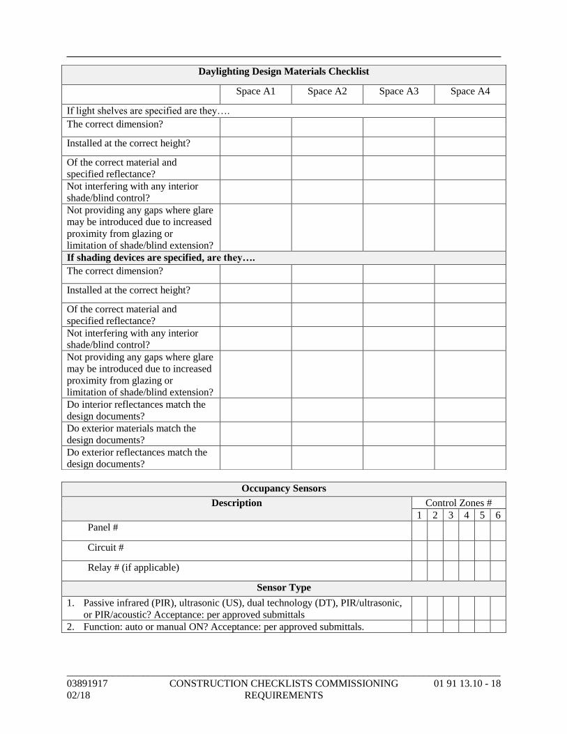
_____________________________________________________________________________________
03891917 CONSTRUCTION CHECKLISTS COMMISSIONING 01 91 13.10 - 18
02/18 REQUIREMENTS
Occupancy Sensors
Description Control Zones #
1 2 3 4 5 6
Panel #
Circuit #
Relay # (if applicable)
Sensor Type
1. Passive infrared (PIR), ultrasonic (US), dual technology (DT), PIR/ultrasonic,
or PIR/acoustic? Acceptance: per approved submittals
2. Function: auto or manual ON? Acceptance: per approved submittals.
Daylighting Design Materials Checklist
Space A1 Space A2 Space A3 Space A4
If light shelves are specified are they….
The correct dimension?
Installed at the correct height?
Of the correct material and
specified reflectance?
Not interfering with any interior
shade/blind control?
Not providing any gaps where glare
may be introduced due to increased
proximity from glazing or
limitation of shade/blind extension?
If shading devices are specified, are they….
The correct dimension?
Installed at the correct height?
Of the correct material and
specified reflectance?
Not interfering with any interior
shade/blind control?
Not providing any gaps where glare
may be introduced due to increased
proximity from glazing or
limitation of shade/blind extension?
Do interior reflectances match the
design documents?
Do exterior materials match the
design documents?
Do exterior reflectances match the
design documents?
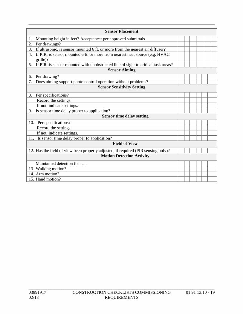
_____________________________________________________________________________________
03891917 CONSTRUCTION CHECKLISTS COMMISSIONING 01 91 13.10 - 19
02/18 REQUIREMENTS
Sensor Placement
1. Mounting height in feet? Acceptance: per approved submittals
2. Per drawings?
3. If ultrasonic, is sensor mounted 6 ft. or more from the nearest air diffuser?
4. If PIR, is sensor mounted 6 ft. or more from nearest heat source (e.g. HVAC
grille)?
5. If PIR, is sensor mounted with unobstructed line of sight to critical task areas?
Sensor Aiming
6. Per drawing?
7. Does aiming support photo control operation without problems?
Sensor Sensitivity Setting
8. Per specifications?
Record the settings.
If not, indicate settings.
9. Is sensor time delay proper to application?
Sensor time delay setting
10. Per specifications?
Record the settings.
If not, indicate settings.
11. Is sensor time delay proper to application?
Field of View
12. Has the field of view been properly adjusted, if required (PIR sensing only)?
Motion Detection Activity
Maintained detection for …..
13. Walking motion?
14. Arm motion?
15. Hand motion?
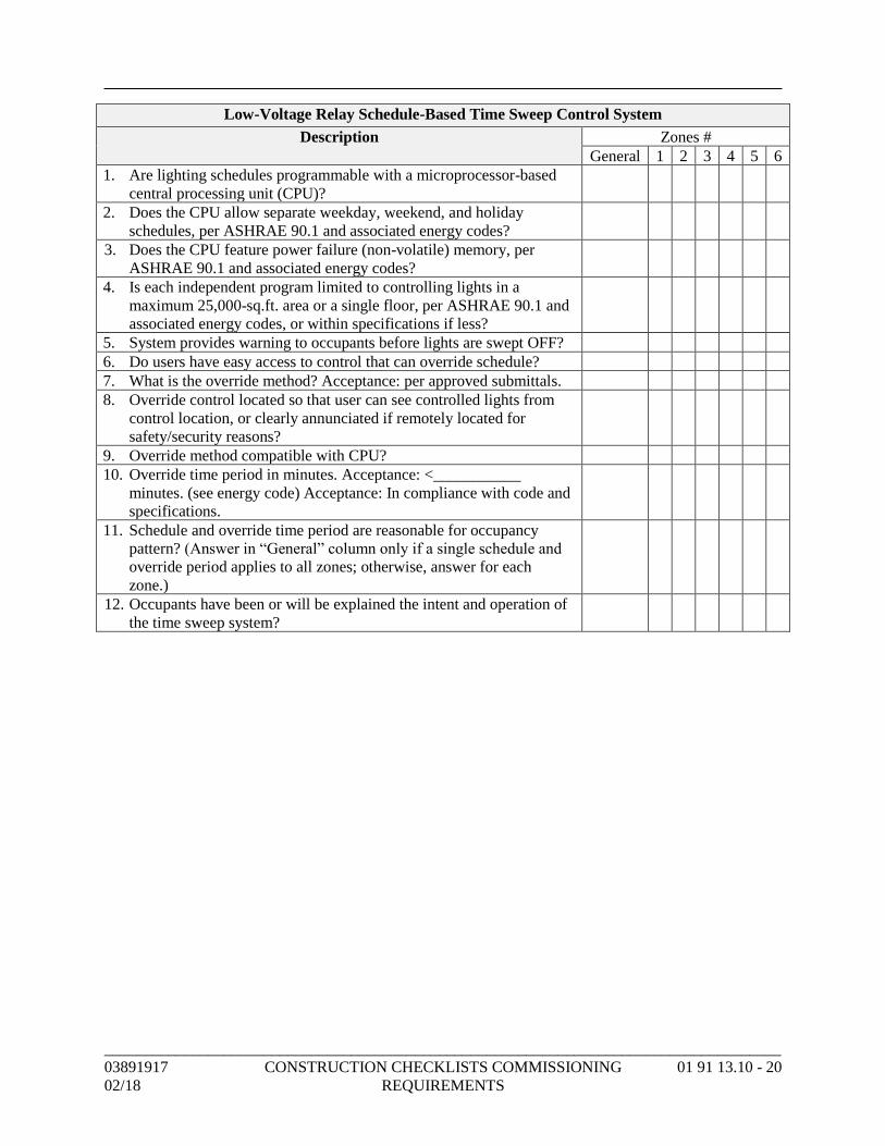
_____________________________________________________________________________________
03891917 CONSTRUCTION CHECKLISTS COMMISSIONING 01 91 13.10 - 20
02/18 REQUIREMENTS
Low-Voltage Relay Schedule-Based Time Sweep Control System
Description Zones #
General 1 2 3 4 5 6
1. Are lighting schedules programmable with a microprocessor-based
central processing unit (CPU)?
2. Does the CPU allow separate weekday, weekend, and holiday
schedules, per ASHRAE 90.1 and associated energy codes?
3. Does the CPU feature power failure (non-volatile) memory, per
ASHRAE 90.1 and associated energy codes?
4. Is each independent program limited to controlling lights in a
maximum 25,000-sq.ft. area or a single floor, per ASHRAE 90.1 and
associated energy codes, or within specifications if less?
5. System provides warning to occupants before lights are swept OFF?
6. Do users have easy access to control that can override schedule?
7. What is the override method? Acceptance: per approved submittals.
8. Override control located so that user can see controlled lights from
control location, or clearly annunciated if remotely located for
safety/security reasons?
9. Override method compatible with CPU?
10. Override time period in minutes. Acceptance: <___________
minutes. (see energy code) Acceptance: In compliance with code and
specifications.
11. Schedule and override time period are reasonable for occupancy
pattern? (Answer in “General” column only if a single schedule and
override period applies to all zones; otherwise, answer for each
zone.)
12. Occupants have been or will be explained the intent and operation of
the time sweep system?
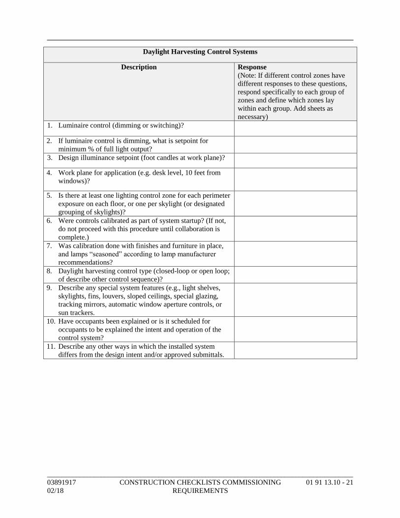
_____________________________________________________________________________________
03891917 CONSTRUCTION CHECKLISTS COMMISSIONING 01 91 13.10 - 21
02/18 REQUIREMENTS
Daylight Harvesting Control Systems
Description Response
(Note: If different control zones have
different responses to these questions,
respond specifically to each group of
zones and define which zones lay
within each group. Add sheets as
necessary)
1. Luminaire control (dimming or switching)?
2. If luminaire control is dimming, what is setpoint for
minimum % of full light output?
3. Design illuminance setpoint (foot candles at work plane)?
4. Work plane for application (e.g. desk level, 10 feet from
windows)?
5. Is there at least one lighting control zone for each perimeter
exposure on each floor, or one per skylight (or designated
grouping of skylights)?
6. Were controls calibrated as part of system startup? (If not,
do not proceed with this procedure until collaboration is
complete.)
7. Was calibration done with finishes and furniture in place,
and lamps “seasoned” according to lamp manufacturer
recommendations?
8. Daylight harvesting control type (closed-loop or open loop;
of describe other control sequence)?
9. Describe any special system features (e.g., light shelves,
skylights, fins, louvers, sloped ceilings, special glazing,
tracking mirrors, automatic window aperture controls, or
sun trackers.
10. Have occupants been explained or is it scheduled for
occupants to be explained the intent and operation of the
control system?
11. Describe any other ways in which the installed system
differs from the design intent and/or approved submittals.
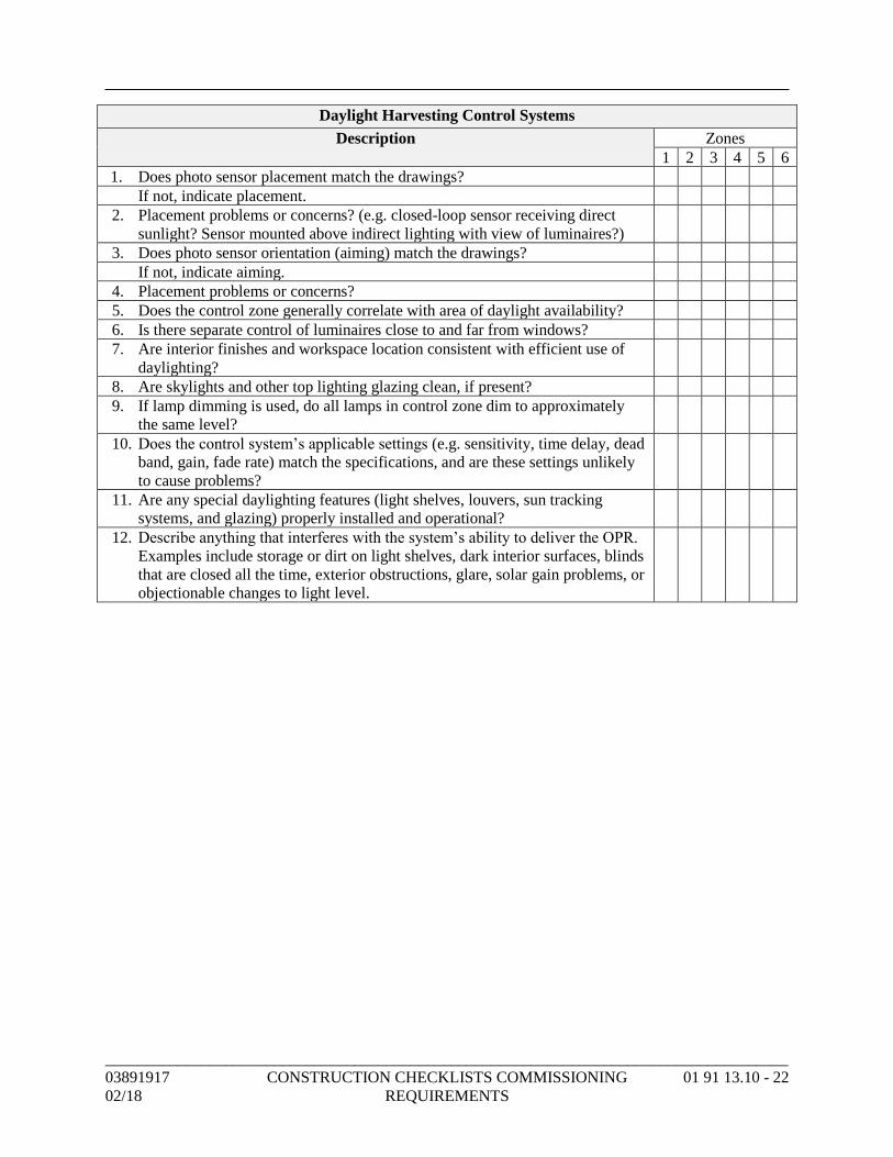
_____________________________________________________________________________________
03891917 CONSTRUCTION CHECKLISTS COMMISSIONING 01 91 13.10 - 22
02/18 REQUIREMENTS
Daylight Harvesting Control Systems
Description Zones
1 2 3 4 5 6
1. Does photo sensor placement match the drawings?
If not, indicate placement.
2. Placement problems or concerns? (e.g. closed-loop sensor receiving direct
sunlight? Sensor mounted above indirect lighting with view of luminaires?)
3. Does photo sensor orientation (aiming) match the drawings?
If not, indicate aiming.
4. Placement problems or concerns?
5. Does the control zone generally correlate with area of daylight availability?
6. Is there separate control of luminaires close to and far from windows?
7. Are interior finishes and workspace location consistent with efficient use of
daylighting?
8. Are skylights and other top lighting glazing clean, if present?
9. If lamp dimming is used, do all lamps in control zone dim to approximately
the same level?
10. Does the control system’s applicable settings (e.g. sensitivity, time delay, dead
band, gain, fade rate) match the specifications, and are these settings unlikely
to cause problems?
11. Are any special daylighting features (light shelves, louvers, sun tracking
systems, and glazing) properly installed and operational?
12. Describe anything that interferes with the system’s ability to deliver the OPR.
Examples include storage or dirt on light shelves, dark interior surfaces, blinds
that are closed all the time, exterior obstructions, glare, solar gain problems, or
objectionable changes to light level.
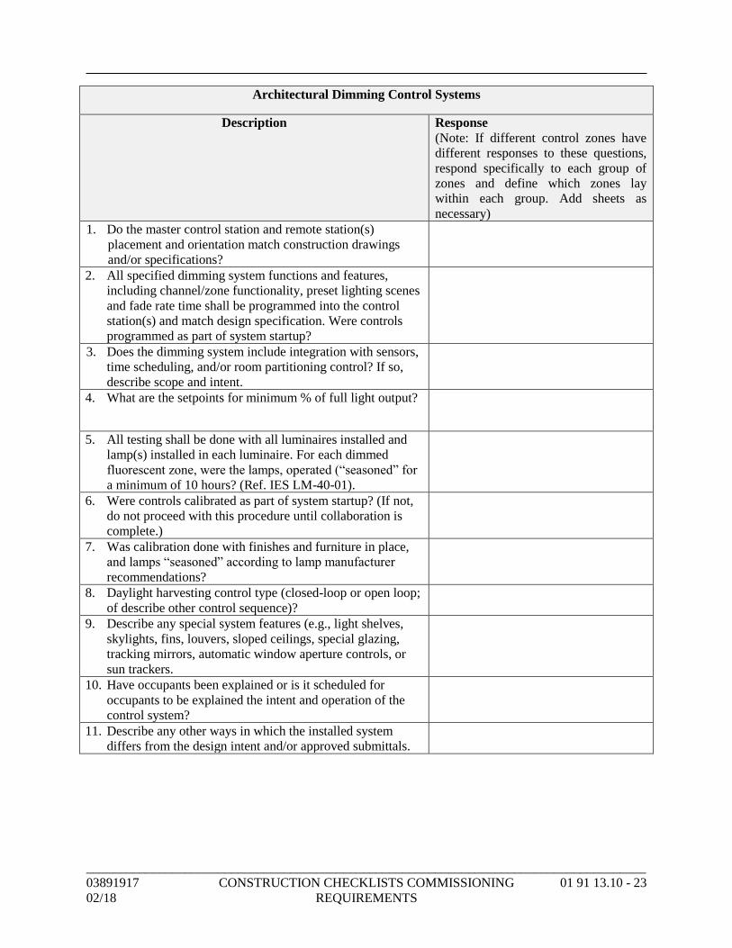
_____________________________________________________________________________________
03891917 CONSTRUCTION CHECKLISTS COMMISSIONING 01 91 13.10 - 23
02/18 REQUIREMENTS
Architectural Dimming Control Systems
Description Response
(Note: If different control zones have
different responses to these questions,
respond specifically to each group of
zones and define which zones lay
within each group. Add sheets as
necessary)
1. Do the master control station and remote station(s)
placement and orientation match construction drawings
and/or specifications?
2. All specified dimming system functions and features,
including channel/zone functionality, preset lighting scenes
and fade rate time shall be programmed into the control
station(s) and match design specification. Were controls
programmed as part of system startup?
3. Does the dimming system include integration with sensors,
time scheduling, and/or room partitioning control? If so,
describe scope and intent.
4. What are the setpoints for minimum % of full light output?
5. All testing shall be done with all luminaires installed and
lamp(s) installed in each luminaire. For each dimmed
fluorescent zone, were the lamps, operated (“seasoned” for
a minimum of 10 hours? (Ref. IES LM-40-01).
6. Were controls calibrated as part of system startup? (If not,
do not proceed with this procedure until collaboration is
complete.)
7. Was calibration done with finishes and furniture in place,
and lamps “seasoned” according to lamp manufacturer
recommendations?
8. Daylight harvesting control type (closed-loop or open loop;
of describe other control sequence)?
9. Describe any special system features (e.g., light shelves,
skylights, fins, louvers, sloped ceilings, special glazing,
tracking mirrors, automatic window aperture controls, or
sun trackers.
10. Have occupants been explained or is it scheduled for
occupants to be explained the intent and operation of the
control system?
11. Describe any other ways in which the installed system
differs from the design intent and/or approved submittals.
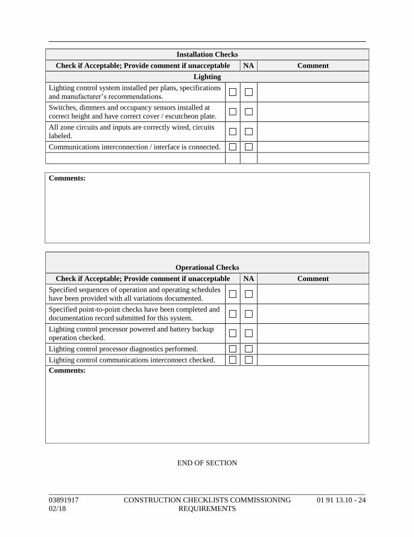
_____________________________________________________________________________________
03891917 CONSTRUCTION CHECKLISTS COMMISSIONING 01 91 13.10 - 24
02/18 REQUIREMENTS
Installation Checks
Check if Acceptable; Provide comment if unacceptable NA Comment
Lighting
Lighting control system installed per plans, specifications
and manufacturer’s recommendations.
Switches, dimmers and occupancy sensors installed at
correct height and have correct cover / escutcheon plate.
All zone circuits and inputs are correctly wired, circuits
labeled.
Communications interconnection / interface is connected.
Comments:
Operational Checks
Check if Acceptable; Provide comment if unacceptable NA Comment
Specified sequences of operation and operating schedules
have been provided with all variations documented.
Specified point-to-point checks have been completed and
documentation record submitted for this system.
Lighting control processor powered and battery backup
operation checked.
Lighting control processor diagnostics performed.
Lighting control communications interconnect checked.
Comments:
END OF SECTION
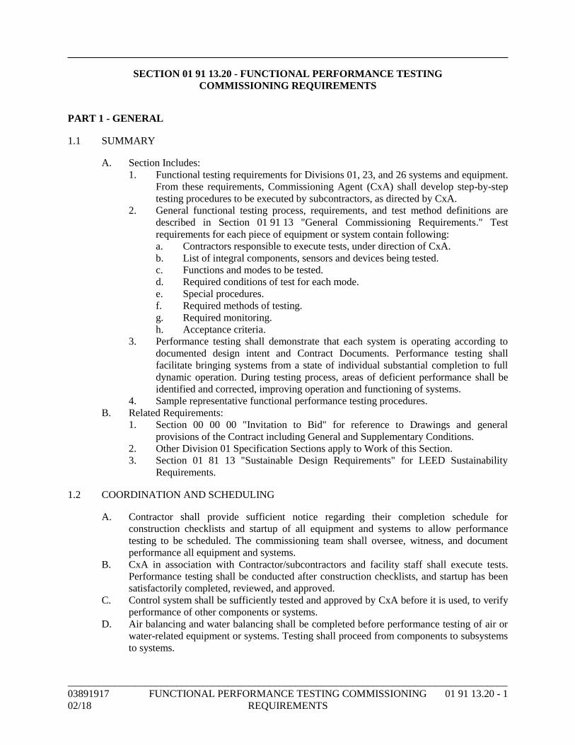
_____________________________________________________________________________________
03891917 FUNCTIONAL PERFORMANCE TESTING COMMISSIONING 01 91 13.20 - 1
02/18 REQUIREMENTS
SECTION 01 91 13.20 - FUNCTIONAL PERFORMANCE TESTING
COMMISSIONING REQUIREMENTS
PART 1 - GENERAL
1.1 SUMMARY
A. Section Includes:
1. Functional testing requirements for Divisions 01, 23, and 26 systems and equipment.
From these requirements, Commissioning Agent (CxA) shall develop step-by-step
testing procedures to be executed by subcontractors, as directed by CxA.
2. General functional testing process, requirements, and test method definitions are
described in Section 01 91 13 "General Commissioning Requirements." Test
requirements for each piece of equipment or system contain following:
a. Contractors responsible to execute tests, under direction of CxA.
b. List of integral components, sensors and devices being tested.
c. Functions and modes to be tested.
d. Required conditions of test for each mode.
e. Special procedures.
f. Required methods of testing.
g. Required monitoring.
h. Acceptance criteria.
3. Performance testing shall demonstrate that each system is operating according to
documented design intent and Contract Documents. Performance testing shall
facilitate bringing systems from a state of individual substantial completion to full
dynamic operation. During testing process, areas of deficient performance shall be
identified and corrected, improving operation and functioning of systems.
4. Sample representative functional performance testing procedures.
B. Related Requirements:
1. Section 00 00 00 "Invitation to Bid" for reference to Drawings and general
provisions of the Contract including General and Supplementary Conditions.
2. Other Division 01 Specification Sections apply to Work of this Section.
3. Section 01 81 13 "Sustainable Design Requirements" for LEED Sustainability
Requirements.
1.2 COORDINATION AND SCHEDULING
A. Contractor shall provide sufficient notice regarding their completion schedule for
construction checklists and startup of all equipment and systems to allow performance
testing to be scheduled. The commissioning team shall oversee, witness, and document
performance all equipment and systems.
B. CxA in association with Contractor/subcontractors and facility staff shall execute tests.
Performance testing shall be conducted after construction checklists, and startup has been
satisfactorily completed, reviewed, and approved.
C. Control system shall be sufficiently tested and approved by CxA before it is used, to verify
performance of other components or systems.
D. Air balancing and water balancing shall be completed before performance testing of air or
water-related equipment or systems. Testing shall proceed from components to subsystems
to systems.
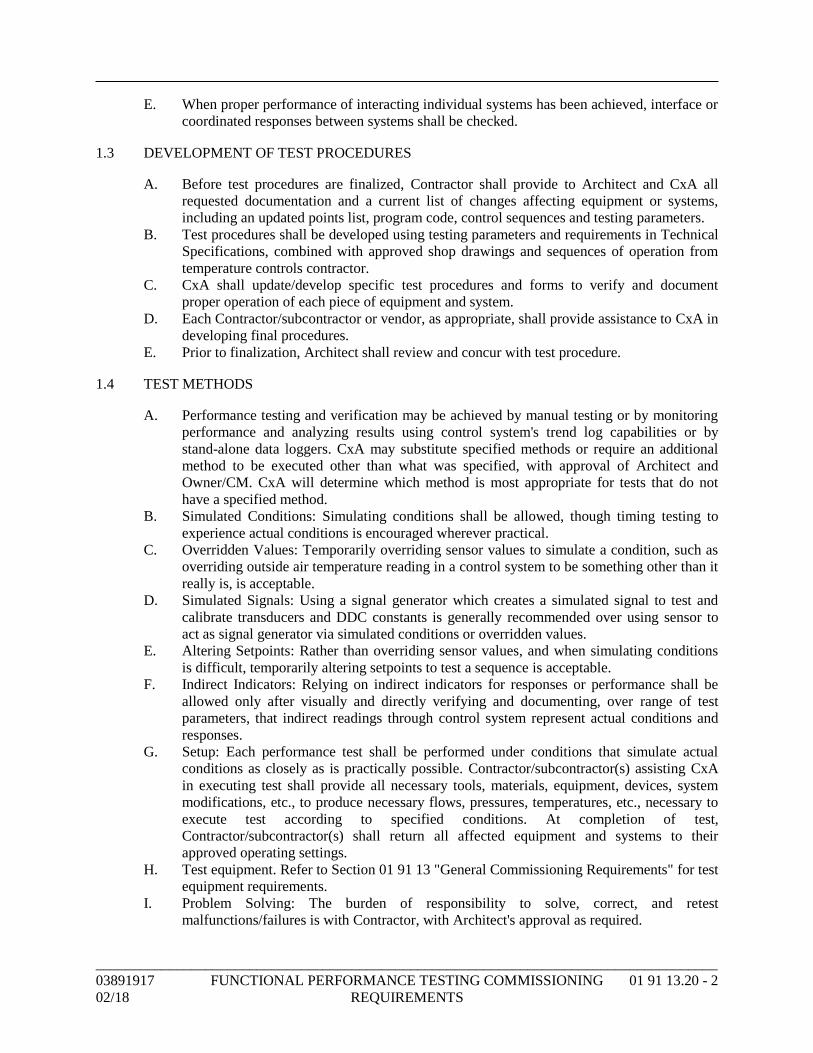
_____________________________________________________________________________________
03891917 FUNCTIONAL PERFORMANCE TESTING COMMISSIONING 01 91 13.20 - 2
02/18 REQUIREMENTS
E. When proper performance of interacting individual systems has been achieved, interface or
coordinated responses between systems shall be checked.
1.3 DEVELOPMENT OF TEST PROCEDURES
A. Before test procedures are finalized, Contractor shall provide to Architect and CxA all
requested documentation and a current list of changes affecting equipment or systems,
including an updated points list, program code, control sequences and testing parameters.
B. Test procedures shall be developed using testing parameters and requirements in Technical
Specifications, combined with approved shop drawings and sequences of operation from
temperature controls contractor.
C. CxA shall update/develop specific test procedures and forms to verify and document
proper operation of each piece of equipment and system.
D. Each Contractor/subcontractor or vendor, as appropriate, shall provide assistance to CxA in
developing final procedures.
E. Prior to finalization, Architect shall review and concur with test procedure.
1.4 TEST METHODS
A. Performance testing and verification may be achieved by manual testing or by monitoring
performance and analyzing results using control system's trend log capabilities or by
stand-alone data loggers. CxA may substitute specified methods or require an additional
method to be executed other than what was specified, with approval of Architect and
Owner/CM. CxA will determine which method is most appropriate for tests that do not
have a specified method.
B. Simulated Conditions: Simulating conditions shall be allowed, though timing testing to
experience actual conditions is encouraged wherever practical.
C. Overridden Values: Temporarily overriding sensor values to simulate a condition, such as
overriding outside air temperature reading in a control system to be something other than it
really is, is acceptable.
D. Simulated Signals: Using a signal generator which creates a simulated signal to test and
calibrate transducers and DDC constants is generally recommended over using sensor to
act as signal generator via simulated conditions or overridden values.
E. Altering Setpoints: Rather than overriding sensor values, and when simulating conditions
is difficult, temporarily altering setpoints to test a sequence is acceptable.
F. Indirect Indicators: Relying on indirect indicators for responses or performance shall be
allowed only after visually and directly verifying and documenting, over range of test
parameters, that indirect readings through control system represent actual conditions and
responses.
G. Setup: Each performance test shall be performed under conditions that simulate actual
conditions as closely as is practically possible. Contractor/subcontractor(s) assisting CxA
in executing test shall provide all necessary tools, materials, equipment, devices, system
modifications, etc., to produce necessary flows, pressures, temperatures, etc., necessary to
execute test according to specified conditions. At completion of test,
Contractor/subcontractor(s) shall return all affected equipment and systems to their
approved operating settings.
H. Test equipment. Refer to Section 01 91 13 "General Commissioning Requirements" for test
equipment requirements.
I. Problem Solving: The burden of responsibility to solve, correct, and retest
malfunctions/failures is with Contractor, with Architect's approval as required.
_____________________________________________________________________________________
03891917 FUNCTIONAL PERFORMANCE TESTING COMMISSIONING 01 91 13.20 - 3
02/18 REQUIREMENTS
J. Trend Logs: Upon completion of successful functional performance testing, Contractor
shall submit graphic trend logs to CxA.
1. Submit graphic trend log for each piece of controlled equipment showing each
controlled parameter.
2. Trend logs shall demonstrate successful performance for a seven-day period, unless
controlled process requires a longer timeline.
3. Trend log color printouts shall be submitted demonstrating successful seasonal
performance.
4. Trend logs shall be color graphic, with legend, submitted to CxA in printout form.
5. Graphical trend logs shall be readable and sufficiently labeled.
K. Documentation, Nonconformance, and Approval of Tests:
1. Documentation: CxA shall witness, verify, and document results of all performance
tests. CxA shall complete all documentation for performance testing.
2. Nonconformance:
a. Quick corrections of minor deficiencies identified may be made during tests at
discretion of CxA. In such cases deficiency and resolution will be
documented on procedure form or on an attached sheet, and in deficiency log.
b. As tests progress and a deficiency is identified, CxA shall discuss issue with
commissioning team, and Contractor.
1) When there is no dispute on deficiency and Contractor accepts
responsibility to correct it:
(a) CxA will document deficiency and Contractor's response and
intentions. After day's work, CxA will submit noncompliance
reports to CM. Contractor corrects deficiency, signs statement of
correction at bottom of noncompliance form certifying that
equipment is ready to be retested and sends it back to CxA.
(b) Contractor shall reschedule test; and test, or necessary portion of
overall system test, repeated.
2) If there is a dispute about a deficiency, regarding whether or not it is a
deficiency:
(a) Dispute shall be documented on noncompliance form with
Contractor's response.
(b) Resolutions are made at lowest management level possible.
Other parties are brought into discussions as needed. Final
interpretive authority is with Architect. Final acceptance
authority is with construction manager.
(c) CxA documents resolution process.
(d) Once interpretation and resolution have been decided, Contractor
corrects deficiency, signs statement of correction on
noncompliance form and provides it to CxA, through CM.
Contractor shall reschedule test and test repeated until
satisfactory performance is achieved.
3) Cost of retesting a functional performance test belongs to Contractor.
4) Contractor shall submit in writing to CM, at least as often as
commissioning meetings are being scheduled, status of each
outstanding discrepancy identified during commissioning. Discussion
shall cover explanations of any disagreement and proposals for their
resolutions.
(a) CxA retains original nonconformance forms until end of Project.
(b) Retesting shall not be considered a justified reason for a claim of
delay or for a time extension by Contractor.
_____________________________________________________________________________________
03891917 FUNCTIONAL PERFORMANCE TESTING COMMISSIONING 01 91 13.20 - 4
02/18 REQUIREMENTS
(c) Failure due to manufacturer defect: If 10 percent (or three,
whichever is greater) of identical pieces of equipment fail to
perform to Contract Documents (mechanically or substantively)
due to a manufacturing defect, not allowing it to meet its
submitted performance specification, all identical units may be
considered unacceptable by Architect or CxA. In such case,
Contractor shall provide Owner with following:
(1) Within one week of notification from Owner/CM,
Contractor, or manufacturer's representative shall examine
all other identical units making a record of findings. The
findings shall be provided to CM and CxA within
two weeks of original notice.
(2) Within two weeks of original notification, Contractor or
manufacturer shall provide a signed and dated, written
explanation of problem, cause of failures, etc., and all
proposed solutions. The proposed solutions shall not
significantly exceed specification requirements of original
installation.
(d) Architect will determine whether a replacement of all identical
units is required or a repair is acceptable.
(e) Two examples, where applicable, of proposed solution shall be
installed by Contractor and Architect shall be allowed to test
installations for up to one week, upon which Architect will
decide whether to accept solution.
(f) Upon acceptance, Contractor and/or manufacturer shall replace
or repair all identical items, at their expense. The replacement/
repair work shall proceed with reasonable speed beginning
within one week from when parts can be obtained.
3. Approval: CxA notes each satisfactorily demonstrated function on test form. Final
approval of performance test by Owner is made after review by CxA and CM,
following recommendations by Architect.
L. Deferred Testing, Unforeseen Deferred Tests:
1. If any check or test cannot be completed due to project completion level, required
occupancy condition, required weather conditions, or other deficiency, execution of
checklists and performance testing may be delayed upon approval of CxA and CM.
2. Tests shall be conducted in same manner as seasonal tests as soon as possible.
3. Services of necessary parties will be negotiated.
1.5 INCLUDED SYSTEMS AND EQUIPMENT
A. Commissioning plan shall contain a list of equipment and system test requirements
included in commissioning process for this Project.
1.6 PREREQUISITES
A. Prerequisite for start of functional performance testing is completion and acceptance of
Construction Checklists for each system and/or system component. Refer to
Section 01 91 13 "General Commissioning Requirements" and Section 01 91 13.10
"Construction Checklists Commissioning Requirements" for information regarding
Construction Checklists.
_____________________________________________________________________________________
03891917 FUNCTIONAL PERFORMANCE TESTING COMMISSIONING 01 91 13.20 - 5
02/18 REQUIREMENTS
B. Controls subcontractor shall also have trends set up as stated prior to start of functional
testing.
PART 2 - PRODUCTS (Not Used)
PART 3 - EXECUTION
3.1 FUNCTIONAL PERFORMANCE TESTING PROCEDURES
A. Procedures are detailed by specific building systems and include associated system
components.
B. Sample Functional Performance Test procedures attached are shown in a form format and
are provided as an example of format and as an indication of rigor of required testing and
documentation for various equipment types. Functional Test procedures have not been
developed for this Project. Functional test procedures shall be tailored to project specific
requirements by CxA after approved equipment and controls submittals for commissioned
equipment are received.
3.2 MONITORING
A. Perform monitoring as stand-alone method or to augment manual testing.
B. Points listed in required monitoring section of test requirements which are control system
monitored points shall be trended by controls contractor. Other points shall be monitored
by CxA using data loggers as necessary. At option of CxA, some control system
monitoring may be replaced with data logger monitoring. At CxA’s request, controls
contractor shall trend up to 20 percent more points than listed herein at no extra charge.
C. Hard copies of monitored data shall be in columnar format with time down left column and
at least five columns of point values on same page.
D. Provide graphical output for all output, if system can produce it. Provide equipment
manufacturer's authorized service representative to inspect and approve installation where
required in other Sections.
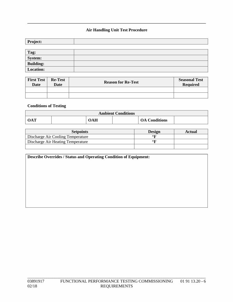
_____________________________________________________________________________________
03891917 FUNCTIONAL PERFORMANCE TESTING COMMISSIONING 01 91 13.20 - 6
02/18 REQUIREMENTS
Air Handling Unit Test Procedure
Project:
Tag:
System:
Building:
Location:
First Test
Date
Re-Test
Date Reason for Re-Test
Seasonal Test
Required
Conditions of Testing
Ambient Conditions
OAT OAH OA Conditions
Setpoints Design Actual
Discharge Air Cooling Temperature °F
Discharge Air Heating Temperature °F
Describe Overrides / Status and Operating Condition of Equipment:
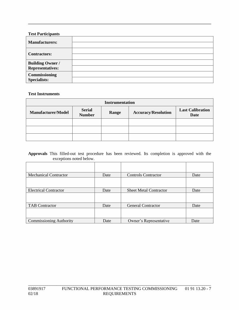
_____________________________________________________________________________________
03891917 FUNCTIONAL PERFORMANCE TESTING COMMISSIONING 01 91 13.20 - 7
02/18 REQUIREMENTS
Test Participants
Manufacturers:
Contractors:
Building Owner /
Representatives:
Commissioning
Specialists:
Test Instruments
Instrumentation
Manufacturer/Model Serial
Number Range Accuracy/Resolution
Last Calibration
Date
Approvals This filled-out test procedure has been reviewed. Its completion is approved with the
exceptions noted below.
Mechanical Contractor Date Controls Contractor Date
Electrical Contractor Date Sheet Metal Contractor Date
TAB Contractor Date General Contractor Date
Commissioning Authority Date Owner’s Representative Date
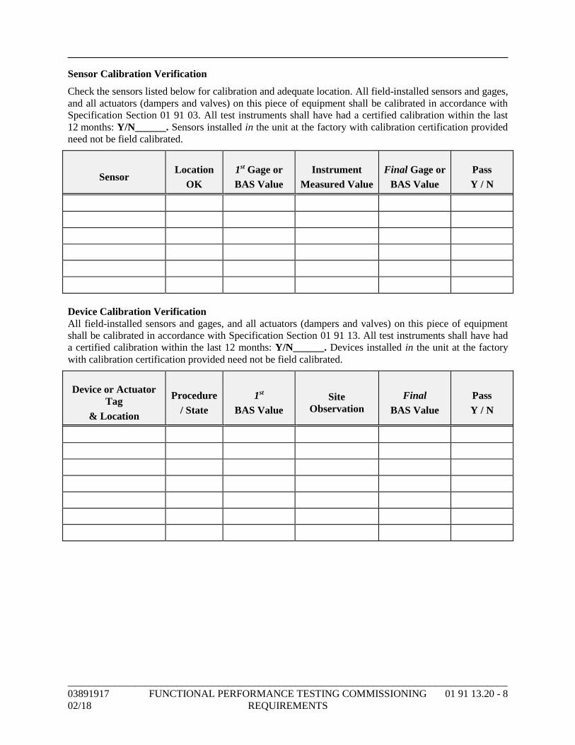
_____________________________________________________________________________________
03891917 FUNCTIONAL PERFORMANCE TESTING COMMISSIONING 01 91 13.20 - 8
02/18 REQUIREMENTS
Sensor Calibration Verification
Check the sensors listed below for calibration and adequate location. All field-installed sensors and gages,
and all actuators (dampers and valves) on this piece of equipment shall be calibrated in accordance with
Specification Section 01 91 03. All test instruments shall have had a certified calibration within the last
12 months: Y/N______. Sensors installed in the unit at the factory with calibration certification provided
need not be field calibrated.
Sensor
Location
OK
1st Gage or
BAS Value
Instrument
Measured Value
Final Gage or
BAS Value
Pass
Y / N
Device Calibration Verification
All field-installed sensors and gages, and all actuators (dampers and valves) on this piece of equipment
shall be calibrated in accordance with Specification Section 01 91 13. All test instruments shall have had
a certified calibration within the last 12 months: Y/N______. Devices installed in the unit at the factory
with calibration certification provided need not be field calibrated.
Device or Actuator
Tag
& Location
Procedure
/ State
1st
BAS Value
Site
Observation
Final
BAS Value
Pass
Y / N
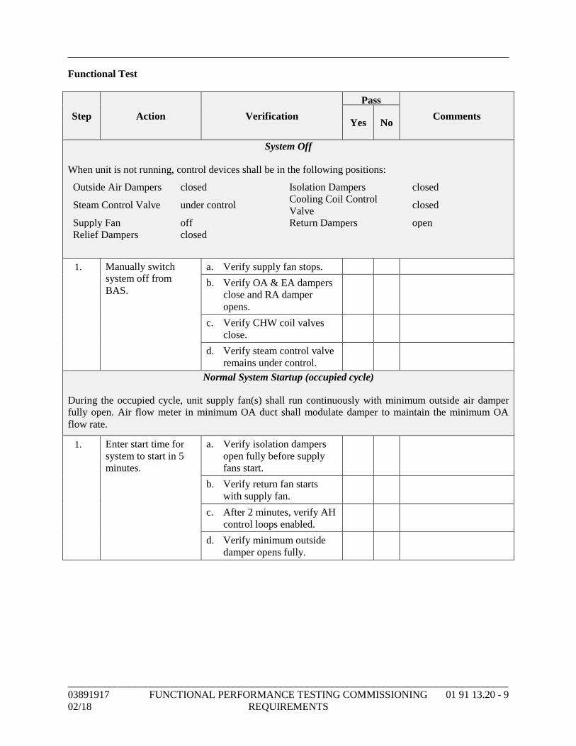
_____________________________________________________________________________________
03891917 FUNCTIONAL PERFORMANCE TESTING COMMISSIONING 01 91 13.20 - 9
02/18 REQUIREMENTS
Functional Test
Step Action Verification
Pass
Comments Yes No
System Off
When unit is not running, control devices shall be in the following positions:
Outside Air Dampers closed Isolation Dampers closed
Steam Control Valve under control Cooling Coil Control
Valve closed
Supply Fan off Return Dampers open
Relief Dampers closed
1. Manually switch
system off from
BAS.
a. Verify supply fan stops.
b. Verify OA & EA dampers
close and RA damper
opens.
c. Verify CHW coil valves
close.
d. Verify steam control valve
remains under control.
Normal System Startup (occupied cycle)
During the occupied cycle, unit supply fan(s) shall run continuously with minimum outside air damper
fully open. Air flow meter in minimum OA duct shall modulate damper to maintain the minimum OA
flow rate.
1. Enter start time for
system to start in 5
minutes.
a. Verify isolation dampers
open fully before supply
fans start.
b. Verify return fan starts
with supply fan.
c. After 2 minutes, verify AH
control loops enabled.
d. Verify minimum outside
damper opens fully.
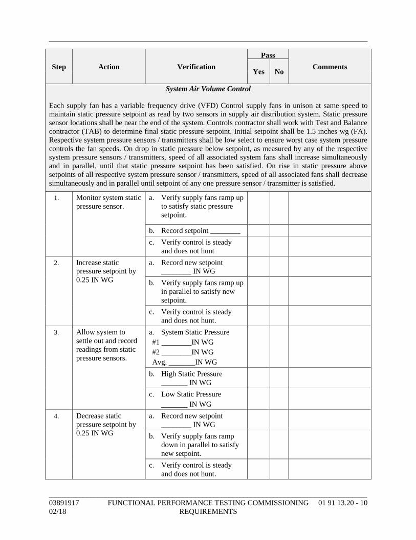
_____________________________________________________________________________________
03891917 FUNCTIONAL PERFORMANCE TESTING COMMISSIONING 01 91 13.20 - 10
02/18 REQUIREMENTS
Step Action Verification
Pass
Comments Yes No
System Air Volume Control
Each supply fan has a variable frequency drive (VFD) Control supply fans in unison at same speed to
maintain static pressure setpoint as read by two sensors in supply air distribution system. Static pressure
sensor locations shall be near the end of the system. Controls contractor shall work with Test and Balance
contractor (TAB) to determine final static pressure setpoint. Initial setpoint shall be 1.5 inches wg (FA).
Respective system pressure sensors / transmitters shall be low select to ensure worst case system pressure
controls the fan speeds. On drop in static pressure below setpoint, as measured by any of the respective
system pressure sensors / transmitters, speed of all associated system fans shall increase simultaneously
and in parallel, until that static pressure setpoint has been satisfied. On rise in static pressure above
setpoints of all respective system pressure sensor / transmitters, speed of all associated fans shall decrease
simultaneously and in parallel until setpoint of any one pressure sensor / transmitter is satisfied.
1. Monitor system static
pressure sensor.
a. Verify supply fans ramp up
to satisfy static pressure
setpoint.
b. Record setpoint ________
c. Verify control is steady
and does not hunt
2. Increase static
pressure setpoint by
0.25 IN WG
a. Record new setpoint
________ IN WG
b. Verify supply fans ramp up
in parallel to satisfy new
setpoint.
c. Verify control is steady
and does not hunt.
3. Allow system to
settle out and record
readings from static
pressure sensors.
a. System Static Pressure
#1 ________IN WG
#2 ________IN WG
Avg. _______IN WG
b. High Static Pressure
_______ IN WG
c. Low Static Pressure
_______ IN WG
4. Decrease static
pressure setpoint by
0.25 IN WG
a. Record new setpoint
________ IN WG
b. Verify supply fans ramp
down in parallel to satisfy
new setpoint.
c. Verify control is steady
and does not hunt.
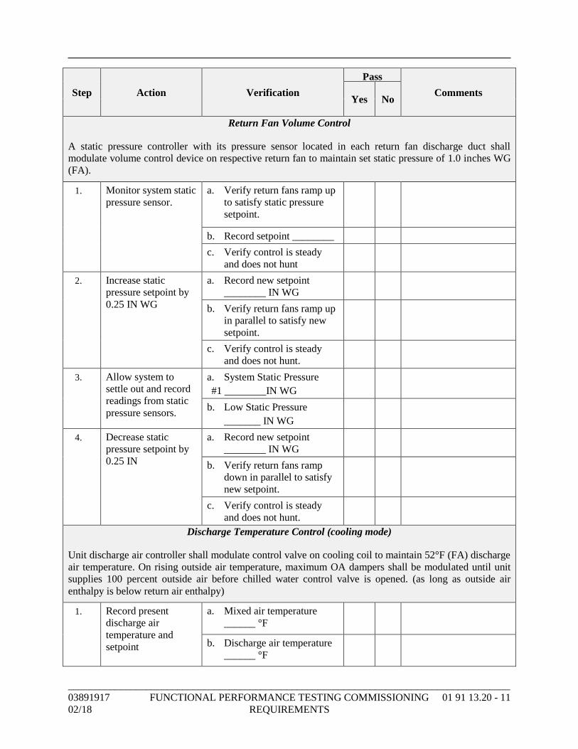
_____________________________________________________________________________________
03891917 FUNCTIONAL PERFORMANCE TESTING COMMISSIONING 01 91 13.20 - 11
02/18 REQUIREMENTS
Step Action Verification
Pass
Comments Yes No
Return Fan Volume Control
A static pressure controller with its pressure sensor located in each return fan discharge duct shall
modulate volume control device on respective return fan to maintain set static pressure of 1.0 inches WG
(FA).
1. Monitor system static
pressure sensor.
a. Verify return fans ramp up
to satisfy static pressure
setpoint.
b. Record setpoint ________
c. Verify control is steady
and does not hunt
2. Increase static
pressure setpoint by
0.25 IN WG
a. Record new setpoint
________ IN WG
b. Verify return fans ramp up
in parallel to satisfy new
setpoint.
c. Verify control is steady
and does not hunt.
3. Allow system to
settle out and record
readings from static
pressure sensors.
a. System Static Pressure
#1 ________IN WG
b. Low Static Pressure
_______ IN WG
4. Decrease static
pressure setpoint by
0.25 IN
a. Record new setpoint
________ IN WG
b. Verify return fans ramp
down in parallel to satisfy
new setpoint.
c. Verify control is steady
and does not hunt.
Discharge Temperature Control (cooling mode)
Unit discharge air controller shall modulate control valve on cooling coil to maintain 52°F (FA) discharge
air temperature. On rising outside air temperature, maximum OA dampers shall be modulated until unit
supplies 100 percent outside air before chilled water control valve is opened. (as long as outside air
enthalpy is below return air enthalpy)
1. Record present
discharge air
temperature and
setpoint
a. Mixed air temperature
______ °F
b. Discharge air temperature
______ °F
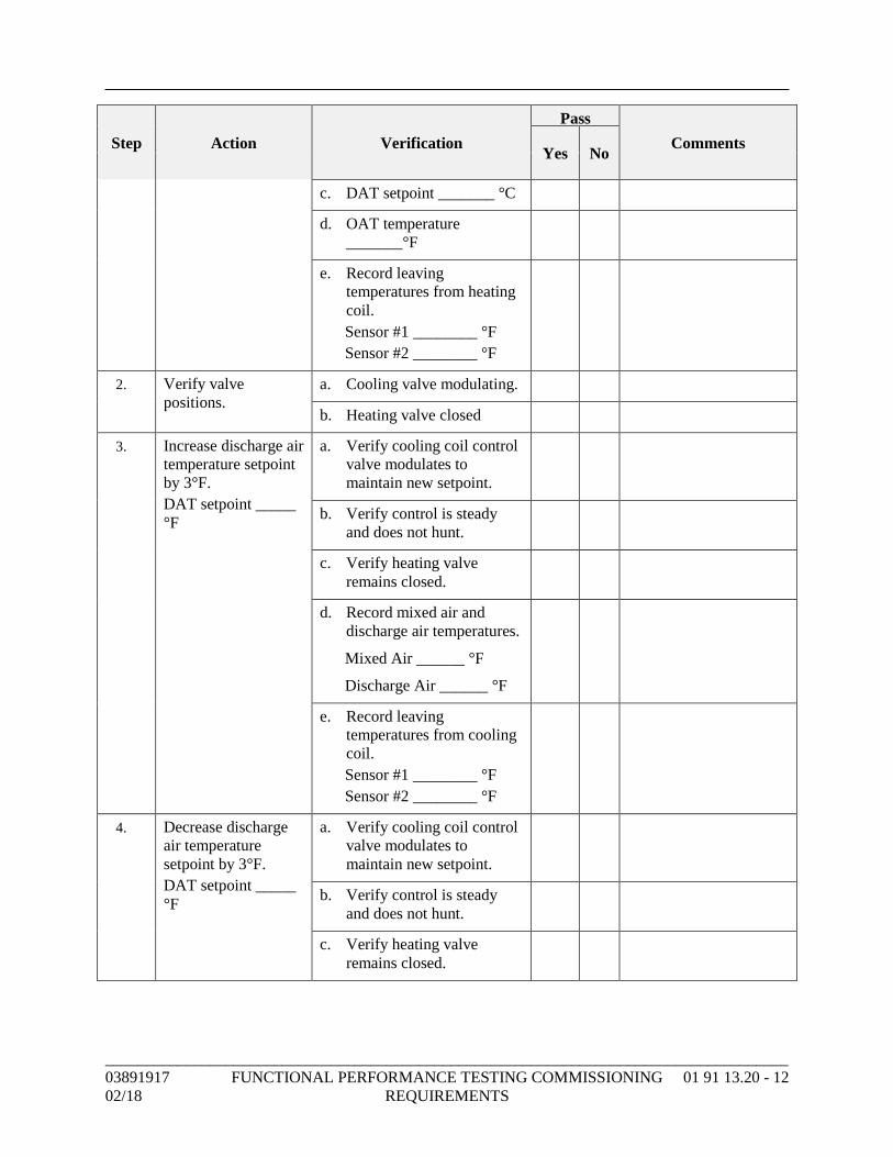
_____________________________________________________________________________________
03891917 FUNCTIONAL PERFORMANCE TESTING COMMISSIONING 01 91 13.20 - 12
02/18 REQUIREMENTS
Step Action Verification
Pass
Comments Yes No
c. DAT setpoint _______ °C
d. OAT temperature
_______°F
e. Record leaving
temperatures from heating
coil.
Sensor #1 ________ °F
Sensor #2 ________ °F
2. Verify valve
positions.
a. Cooling valve modulating.
b. Heating valve closed
3. Increase discharge air
temperature setpoint
by 3°F.
DAT setpoint _____
°F
a. Verify cooling coil control
valve modulates to
maintain new setpoint.
b. Verify control is steady
and does not hunt.
c. Verify heating valve
remains closed.
d. Record mixed air and
discharge air temperatures.
Mixed Air ______ °F
Discharge Air ______ °F
e. Record leaving
temperatures from cooling
coil.
Sensor #1 ________ °F
Sensor #2 ________ °F
4. Decrease discharge
air temperature
setpoint by 3°F.
DAT setpoint _____
°F
a. Verify cooling coil control
valve modulates to
maintain new setpoint.
b. Verify control is steady
and does not hunt.
c. Verify heating valve
remains closed.
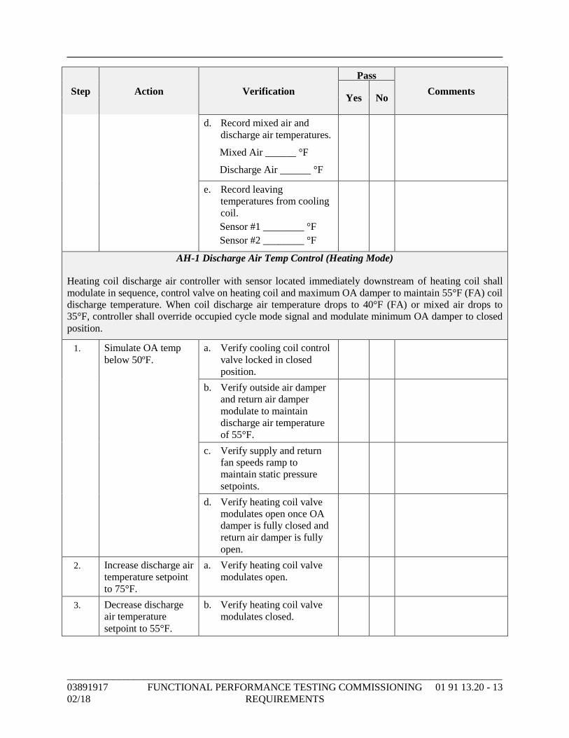
_____________________________________________________________________________________
03891917 FUNCTIONAL PERFORMANCE TESTING COMMISSIONING 01 91 13.20 - 13
02/18 REQUIREMENTS
Step Action Verification
Pass
Comments Yes No
d. Record mixed air and
discharge air temperatures.
Mixed Air ______ °F
Discharge Air ______ °F
e. Record leaving
temperatures from cooling
coil.
Sensor #1 ________ °F
Sensor #2 ________ °F
AH-1 Discharge Air Temp Control (Heating Mode)
Heating coil discharge air controller with sensor located immediately downstream of heating coil shall
modulate in sequence, control valve on heating coil and maximum OA damper to maintain 55°F (FA) coil
discharge temperature. When coil discharge air temperature drops to 40°F (FA) or mixed air drops to
35°F, controller shall override occupied cycle mode signal and modulate minimum OA damper to closed
position.
1. Simulate OA temp
below 50ºF.
a. Verify cooling coil control
valve locked in closed
position.
b. Verify outside air damper
and return air damper
modulate to maintain
discharge air temperature
of 55°F.
c. Verify supply and return
fan speeds ramp to
maintain static pressure
setpoints.
d. Verify heating coil valve
modulates open once OA
damper is fully closed and
return air damper is fully
open.
2. Increase discharge air
temperature setpoint
to 75°F.
a. Verify heating coil valve
modulates open.
3. Decrease discharge
air temperature
setpoint to 55°F.
b. Verify heating coil valve
modulates closed.
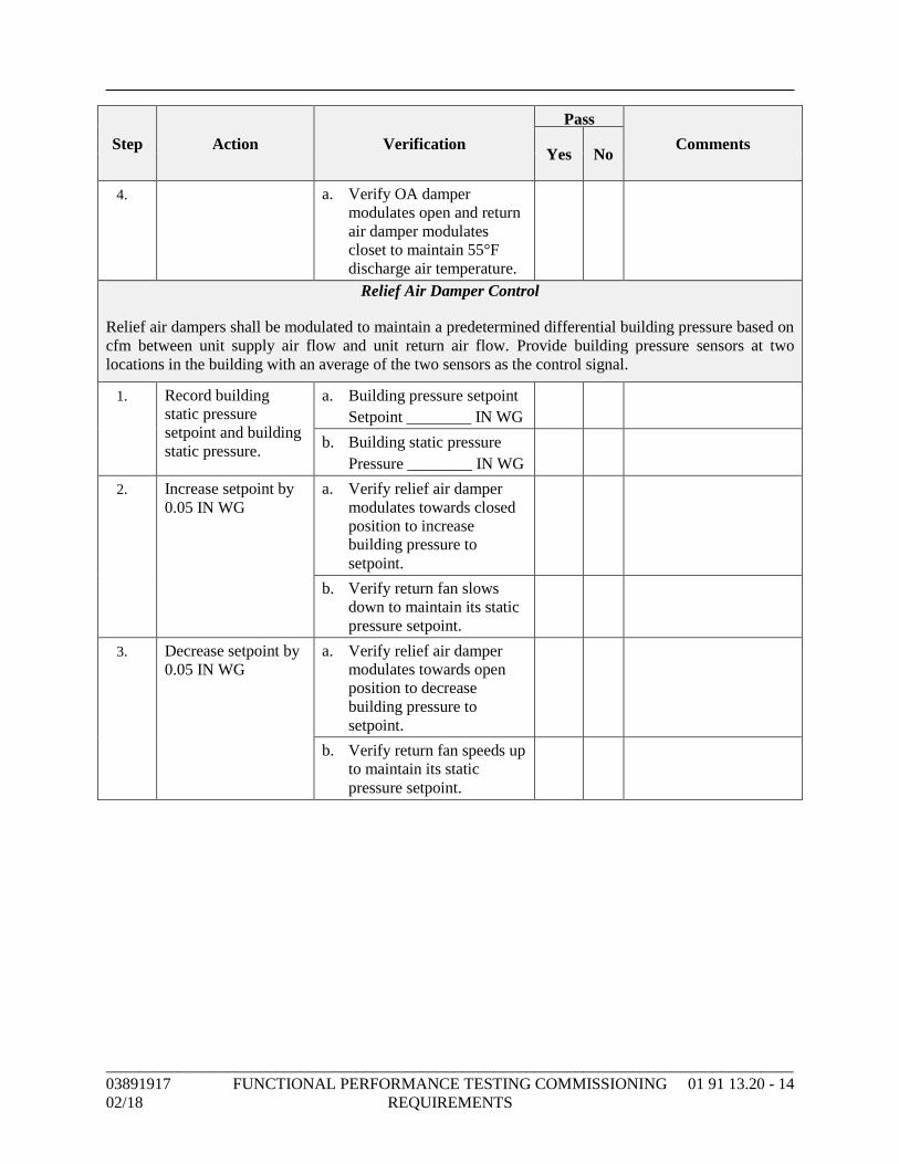
_____________________________________________________________________________________
03891917 FUNCTIONAL PERFORMANCE TESTING COMMISSIONING 01 91 13.20 - 14
02/18 REQUIREMENTS
Step Action Verification
Pass
Comments Yes No
4. a. Verify OA damper
modulates open and return
air damper modulates
closet to maintain 55°F
discharge air temperature.
Relief Air Damper Control
Relief air dampers shall be modulated to maintain a predetermined differential building pressure based on
cfm between unit supply air flow and unit return air flow. Provide building pressure sensors at two
locations in the building with an average of the two sensors as the control signal.
1. Record building
static pressure
setpoint and building
static pressure.
a. Building pressure setpoint
Setpoint ________ IN WG
b. Building static pressure
Pressure ________ IN WG
2. Increase setpoint by
0.05 IN WG
a. Verify relief air damper
modulates towards closed
position to increase
building pressure to
setpoint.
b. Verify return fan slows
down to maintain its static
pressure setpoint.
3. Decrease setpoint by
0.05 IN WG
a. Verify relief air damper
modulates towards open
position to decrease
building pressure to
setpoint.
b. Verify return fan speeds up
to maintain its static
pressure setpoint.
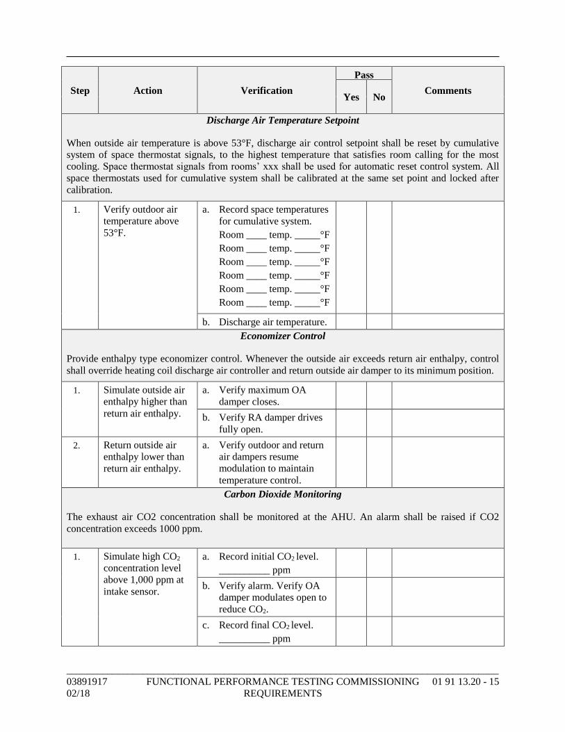
_____________________________________________________________________________________
03891917 FUNCTIONAL PERFORMANCE TESTING COMMISSIONING 01 91 13.20 - 15
02/18 REQUIREMENTS
Step Action Verification
Pass
Comments Yes No
Discharge Air Temperature Setpoint
When outside air temperature is above 53°F, discharge air control setpoint shall be reset by cumulative
system of space thermostat signals, to the highest temperature that satisfies room calling for the most
cooling. Space thermostat signals from rooms’ xxx shall be used for automatic reset control system. All
space thermostats used for cumulative system shall be calibrated at the same set point and locked after
calibration.
1. Verify outdoor air
temperature above
53°F.
a. Record space temperatures
for cumulative system.
Room ____ temp. _____°F
Room ____ temp. _____°F
Room ____ temp. _____°F
Room ____ temp. _____°F
Room ____ temp. _____°F
Room ____ temp. _____°F
b. Discharge air temperature.
Economizer Control
Provide enthalpy type economizer control. Whenever the outside air exceeds return air enthalpy, control
shall override heating coil discharge air controller and return outside air damper to its minimum position.
1. Simulate outside air
enthalpy higher than
return air enthalpy.
a. Verify maximum OA
damper closes.
b. Verify RA damper drives
fully open.
2. Return outside air
enthalpy lower than
return air enthalpy.
a. Verify outdoor and return
air dampers resume
modulation to maintain
temperature control.
Carbon Dioxide Monitoring
The exhaust air CO2 concentration shall be monitored at the AHU. An alarm shall be raised if CO2
concentration exceeds 1000 ppm.
1. Simulate high CO2
concentration level
above 1,000 ppm at
intake sensor.
a. Record initial CO2 level.
__________ ppm
b. Verify alarm. Verify OA
damper modulates open to
reduce CO2.
c. Record final CO2 level.
__________ ppm
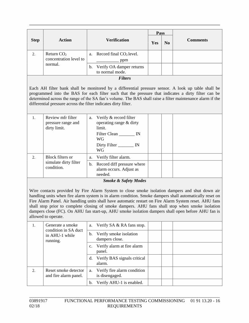
_____________________________________________________________________________________
03891917 FUNCTIONAL PERFORMANCE TESTING COMMISSIONING 01 91 13.20 - 16
02/18 REQUIREMENTS
Step Action Verification
Pass
Comments Yes No
2. Return CO2
concentration level to
normal.
a. Record final CO2 level.
__________ ppm
b. Verify OA damper returns
to normal mode.
Filters
Each AH filter bank shall be monitored by a differential pressure sensor. A look up table shall be
programmed into the BAS for each filter such that the pressure that indicates a dirty filter can be
determined across the range of the SA fan’s volume. The BAS shall raise a filter maintenance alarm if the
differential pressure across the filter indicates dirty filter.
1. Review mfr filter
pressure range and
dirty limit.
a. Verify & record filter
operating range & dirty
limit.
Filter Clean _______ IN
WG
Dirty Filter _______ IN
WG
2. Block filters or
simulate dirty filter
condition.
a. Verify filter alarm.
b. Record diff pressure where
alarm occurs. Adjust as
needed.
Smoke & Safety Modes
Wire contacts provided by Fire Alarm System to close smoke isolation dampers and shut down air
handling units when fire alarm system is in alarm condition. Smoke dampers shall automatically reset on
Fire Alarm Panel. Air handling units shall have automatic restart on Fire Alarm System reset. AHU fans
shall stop prior to complete closing of smoke dampers. AHU fans shall stop when smoke isolation
dampers close (FC). On AHU fan start-up, AHU smoke isolation dampers shall open before AHU fan is
allowed to operate.
1. Generate a smoke
condition in SA duct
in AHU-1 while
running.
a. Verify SA & RA fans stop.
b. Verify smoke isolation
dampers close.
c. Verify alarm at fire alarm
panel.
d. Verify BAS signals critical
alarm.
2. Reset smoke detector
and fire alarm panel.
a. Verify fire alarm condition
is disengaged.
b. Verify AHU-1 is enabled.
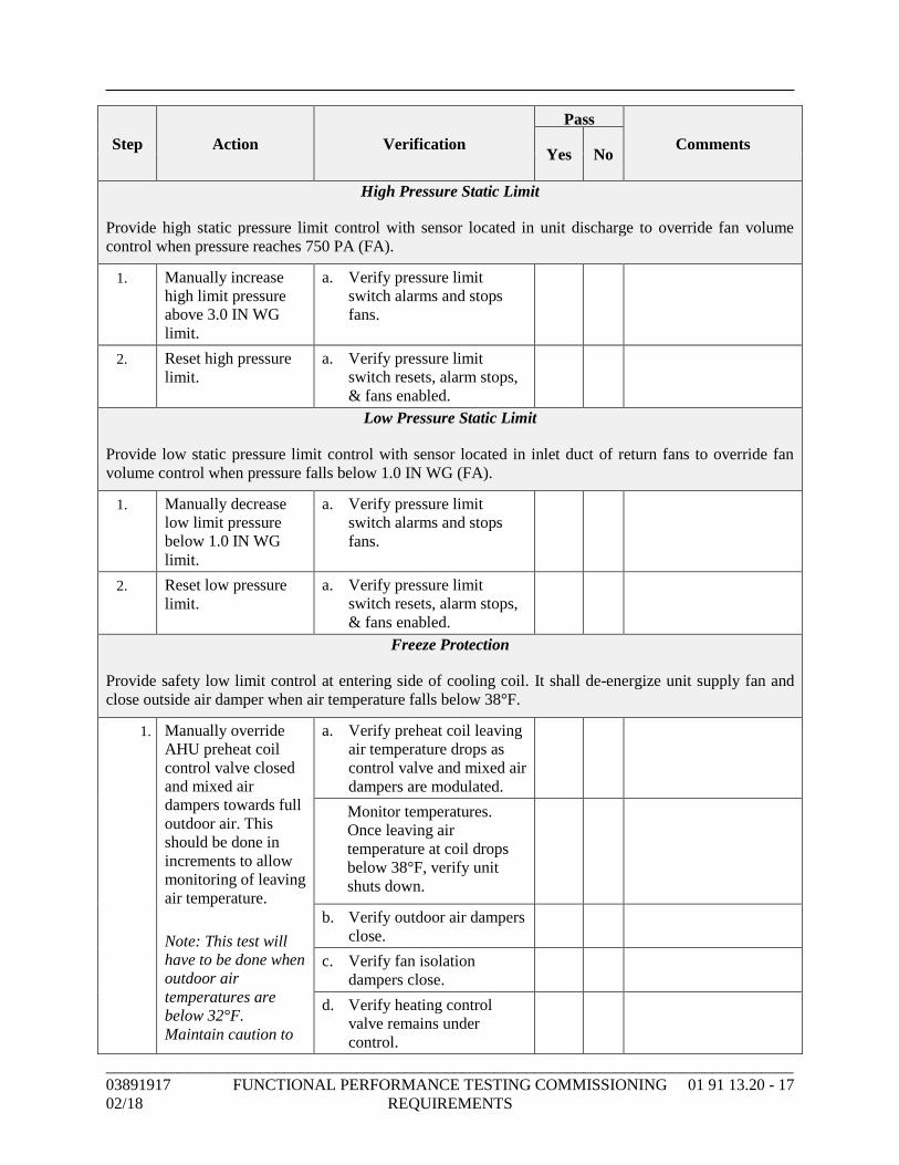
_____________________________________________________________________________________
03891917 FUNCTIONAL PERFORMANCE TESTING COMMISSIONING 01 91 13.20 - 17
02/18 REQUIREMENTS
Step Action Verification
Pass
Comments Yes No
High Pressure Static Limit
Provide high static pressure limit control with sensor located in unit discharge to override fan volume
control when pressure reaches 750 PA (FA).
1. Manually increase
high limit pressure
above 3.0 IN WG
limit.
a. Verify pressure limit
switch alarms and stops
fans.
2. Reset high pressure
limit.
a. Verify pressure limit
switch resets, alarm stops,
& fans enabled.
Low Pressure Static Limit
Provide low static pressure limit control with sensor located in inlet duct of return fans to override fan
volume control when pressure falls below 1.0 IN WG (FA).
1. Manually decrease
low limit pressure
below 1.0 IN WG
limit.
a. Verify pressure limit
switch alarms and stops
fans.
2. Reset low pressure
limit.
a. Verify pressure limit
switch resets, alarm stops,
& fans enabled.
Freeze Protection
Provide safety low limit control at entering side of cooling coil. It shall de-energize unit supply fan and
close outside air damper when air temperature falls below 38°F.
1. Manually override
AHU preheat coil
control valve closed
and mixed air
dampers towards full
outdoor air. This
should be done in
increments to allow
monitoring of leaving
air temperature.
Note: This test will
have to be done when
outdoor air
temperatures are
below 32°F.
Maintain caution to
a. Verify preheat coil leaving
air temperature drops as
control valve and mixed air
dampers are modulated.
Monitor temperatures.
Once leaving air
temperature at coil drops
below 38°F, verify unit
shuts down.
b. Verify outdoor air dampers
close.
c. Verify fan isolation
dampers close.
d. Verify heating control
valve remains under
control.
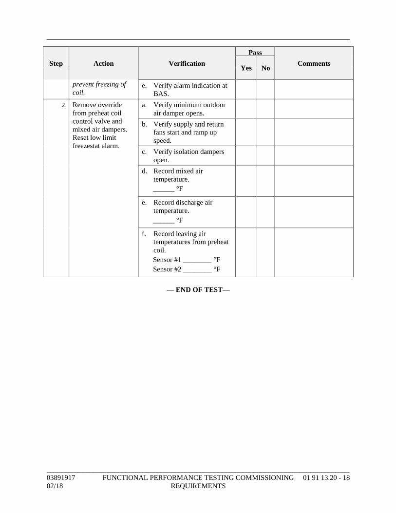
_____________________________________________________________________________________
03891917 FUNCTIONAL PERFORMANCE TESTING COMMISSIONING 01 91 13.20 - 18
02/18 REQUIREMENTS
Step Action Verification
Pass
Comments Yes No
prevent freezing of
coil. e. Verify alarm indication at
BAS.
2. Remove override
from preheat coil
control valve and
mixed air dampers.
Reset low limit
freezestat alarm.
a. Verify minimum outdoor
air damper opens.
b. Verify supply and return
fans start and ramp up
speed.
c. Verify isolation dampers
open.
d. Record mixed air
temperature.
______ °F
e. Record discharge air
temperature.
______ °F
f. Record leaving air
temperatures from preheat
coil.
Sensor #1 ________ °F
Sensor #2 ________ °F
— END OF TEST—
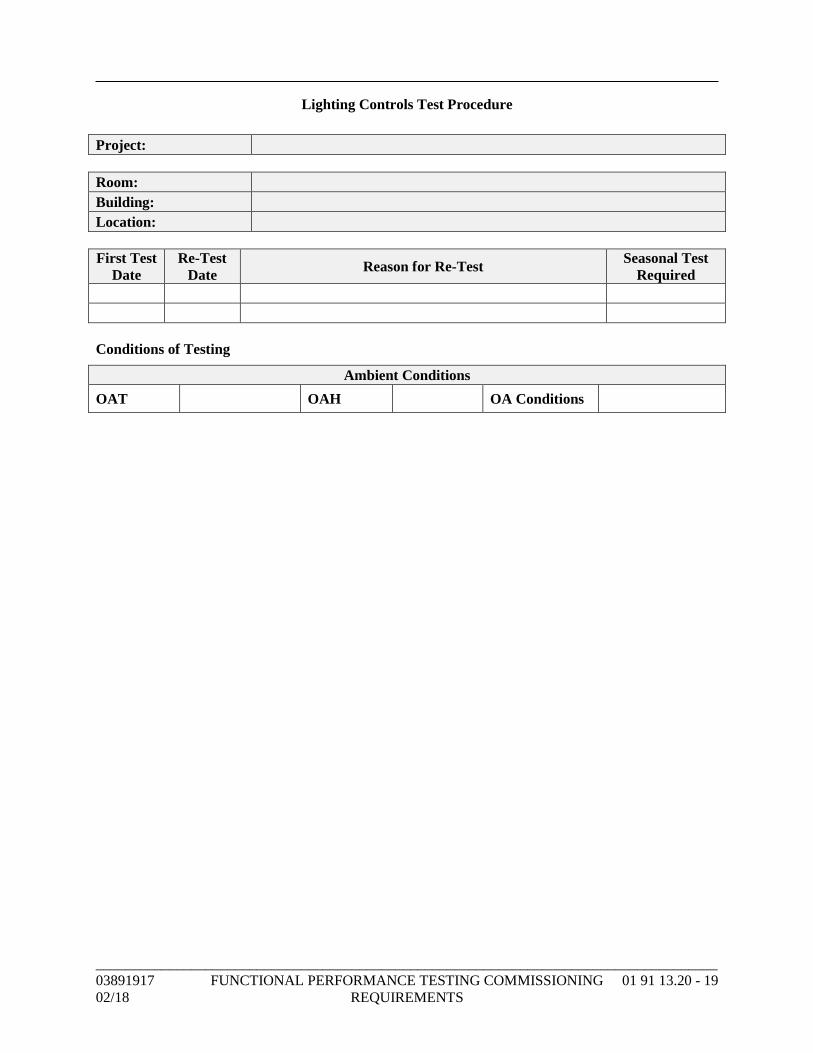
_____________________________________________________________________________________
03891917 FUNCTIONAL PERFORMANCE TESTING COMMISSIONING 01 91 13.20 - 19
02/18 REQUIREMENTS
Lighting Controls Test Procedure
Project:
Room:
Building:
Location:
First Test
Date
Re-Test
Date Reason for Re-Test
Seasonal Test
Required
Conditions of Testing
Ambient Conditions
OAT OAH OA Conditions
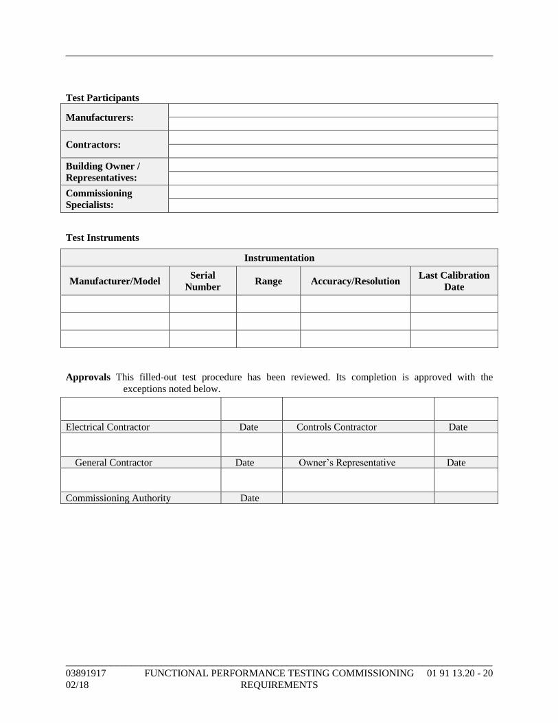
_____________________________________________________________________________________
03891917 FUNCTIONAL PERFORMANCE TESTING COMMISSIONING 01 91 13.20 - 20
02/18 REQUIREMENTS
Test Participants
Manufacturers:
Contractors:
Building Owner /
Representatives:
Commissioning
Specialists:
Test Instruments
Instrumentation
Manufacturer/Model Serial
Number Range Accuracy/Resolution
Last Calibration
Date
Approvals This filled-out test procedure has been reviewed. Its completion is approved with the
exceptions noted below.
Electrical Contractor Date Controls Contractor Date
General Contractor Date Owner’s Representative Date
Commissioning Authority Date
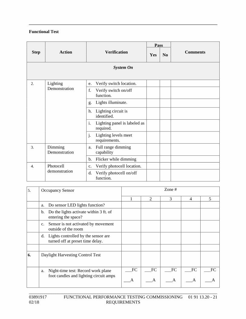
_____________________________________________________________________________________
03891917 FUNCTIONAL PERFORMANCE TESTING COMMISSIONING 01 91 13.20 - 21
02/18 REQUIREMENTS
Functional Test
1. Step Action Verification
Pass
Comments Yes No
System On
2. Lighting
Demonstration
e. Verify switch location.
f. Verify switch on/off
function.
g. Lights illuminate.
h. Lighting circuit is
identified.
i. Lighting panel is labeled as
required.
j. Lighting levels meet
requirements.
3. Dimming
Demonstration
a. Full range dimming
capability
b. Flicker while dimming
4. Photocell
demonstration
c. Verify photocell location.
d. Verify photocell on/off
function.
5. Occupancy Sensor Zone #
1 2 3 4 5
a. Do sensor LED lights function?
b. Do the lights activate within 3 ft. of
entering the space?
c. Sensor is not activated by movement
outside of the room
d. Lights controlled by the sensor are
turned off at preset time delay.
6. Daylight Harvesting Control Test
a. Night-time test: Record work plane
foot candles and lighting circuit amps
___FC
___A
___FC
___A
___FC
___A
___FC
___A
___FC
___A
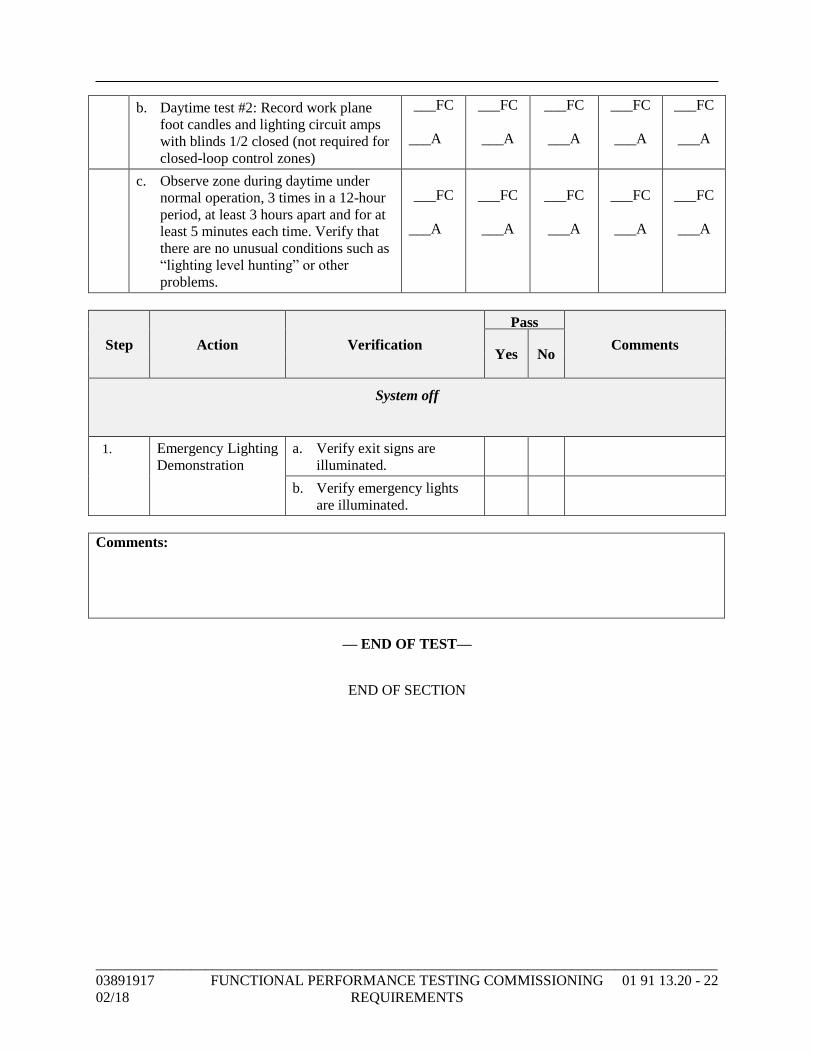
_____________________________________________________________________________________
03891917 FUNCTIONAL PERFORMANCE TESTING COMMISSIONING 01 91 13.20 - 22
02/18 REQUIREMENTS
b. Daytime test #2: Record work plane
foot candles and lighting circuit amps
with blinds 1/2 closed (not required for
closed-loop control zones)
___FC
___A
___FC
___A
___FC
___A
___FC
___A
___FC
___A
c. Observe zone during daytime under
normal operation, 3 times in a 12-hour
period, at least 3 hours apart and for at
least 5 minutes each time. Verify that
there are no unusual conditions such as
“lighting level hunting” or other
problems.
___FC
___A
___FC
___A
___FC
___A
___FC
___A
___FC
___A
2. Step Action Verification
Pass
Comments Yes No
System off
1. Emergency Lighting
Demonstration
a. Verify exit signs are
illuminated.
b. Verify emergency lights
are illuminated.
Comments:
— END OF TEST—
END OF SECTION
_____________________________________________________________________________________
03891917 DEMONSTRATION AND TRAINING COMMISSIONING 01 91 13.30 - 1
02/18 REQUIREMENTS
SECTION 01 91 13.30 - DEMONSTRATION AND TRAINING
COMMISSIONING REQUIREMENTS
PART 1 - GENERAL
1.1 SUMMARY
A. Section includes providing training and demonstrations to Owner's personnel. This Section
defines training plan and process for execution of training plan including following:
1. Development of systems manuals for use in training.
2. Provide qualified instructor(s) to address subject matter identified in training
agendas on date scheduled in training plan.
3. Delivery of both classroom and hands-on instructional sessions as specified.
4. Documentation of training sessions conducted
5. Delivery of training sessions to personnel as specified.
B. Related Requirements:
1. Section 00 00 00 "Invitation to Bid" for reference to Drawings and general
provisions of the Contract including General and Supplementary Conditions.
2. Other Division 01 Specification Sections apply to Work of this Section.
3. Section 01 78 23 "Operation and Maintenance Data."
4. Section 01 78 23.30 "Operation and Maintenance Data Commissioning
Requirements."
5. Section 01 79 00 "Demonstration and Training."
6. Section 01 81 13 "Sustainable Design Requirements" for LEED Sustainability
Requirements.
7. Section 01 91 13 "General Commissioning Requirements" for list of systems to be
included in training plan.
8. Technical Specifications defining hours of training.
1.2 CONTRACTOR AND SUBCONTRACTOR RESPONSIBILITIES
A. Review training schedule and coordinate scheduling of qualified instructor(s).
B. Deliver required hours of training as specified in Technical Sections.
C. Provide hands-on training, as specified, including creating various operational and
troubleshooting conditions to allow trainees to address these issues under supervision.
1.3 TRAINING PLAN
Training plan shall be developed by Owner and Contractor, detailing training requirements
as specified in the Technical Sections. Training plan shall include a training log
summarizing type and duration of training and trainees who will attend training. Training
plan shall include a four-section training agenda for each training session to include
following:
1. Section 1 - Audience and General Scope (Completed by Commissioning Agent and
Owner):
a. Trainees identified for training.
b. General objective and scope of training.
c. Preferred duration of training.
2. Section 2 - Instructors (Completed by Contractor responsible for training):
Contractor completes this section identifying name(s) and qualifications of
instructor(s)
_____________________________________________________________________________________
03891917 DEMONSTRATION AND TRAINING COMMISSIONING 01 91 13.30 - 2
02/18 REQUIREMENTS
3. Section 3 - Agenda (Reviewed by Commissioning Agent and approved by Owner):
a. Location of training.
b. Dates, start, and finish times.
c. Outline of information to be presented.
d. List of texts and other materials required to support training
4. Section 4 - Training Documentation (Completed by Contractor responsible for
training):
a. Date and duration of actual training.
b. Trainees participating in training.
c. Instructor(s) providing training.
1.4 QUALIFICATIONS OF TRAINER(S)
A. Individual delivering training shall have full knowledge on safe and proper operation,
maintenance, diagnosis, and repair of each piece of specific equipment. Trainer shall also
have experience in public speaking and providing similar instructional sessions in past.
Trainer shall have full knowledge of and utilize operation and maintenance information
provided with equipment in training. At a minimum, trainer shall have a background in
servicing of equipment and be able to appropriately address following:
1. Conceptual overview of how equipment works.
2. Names, addresses, numbers etc. of sources for information, tools, spare parts, etc.,
for equipment.
3. Details of warranty or guarantee.
4. Approved sequences of operation in all modes of operation.
5. Sources of utility support.
6. Routine operator tasks involving monitoring and operation covering all modes of
operation and mode switching as applicable.
7. Relevant health and safety practices/concerns.
8. Common problems and their diagnosis and repair.
9. Proper maintenance schedules, tasks and procedures with demonstrations.
10. Emergency response, documentation and recovery procedures.
1.5 MINIMUM TRAINING REQUIREMENTS
A. Training sessions should typically start and end in a classroom setting. Field
demonstrations will also typically be conducted to demonstrate hands-on aspects of
required tasks.
B. During hands-on session of instruction, trainer shall allow trainee to manipulate system and
troubleshoot problems simulated or created by trainer.
C. Training during any one work day shall not exceed four hours for any particular trade or
individual. Should more than four total hours of training be specified for a specific system,
piece of equipment or finish, then Contractor/vendor shall be responsible for scheduling
multiple sessions, where each session shall not exceed four hours. Every attempt shall be
made by Owner to schedule series of training over subsequent days to minimize time.
_____________________________________________________________________________________
03891917 DEMONSTRATION AND TRAINING COMMISSIONING 01 91 13.30 - 3
02/18 REQUIREMENTS
D. In general, training shall address following:
1. System overview: Describe overall system concepts and design intent.
a. Training shall be provided jointly by Architect and CxA for major building
systems and by Contractor or vendor representative for specialized
equipment.
b. High-Level Operations and Maintenance Training (By installing contractor):
Describe system components and general operations, maintenance and
troubleshooting.
2. Detailed Operations and Maintenance Training: When specified that training is to be
provided by manufacturer's representative, training shall detail specifics of
individual pieces of equipment, including operations, maintenance, and
troubleshooting.
E. Cost of trainer and any expenses incurred in delivery of training shall be responsibility of
Contractor and/or manufacturer.
F. In addition to verbal instructions outlined above, Contractor and manufacturer's
representatives shall furnish written basic instructions indicating proper operation of each
system and associated equipment. Each manufacturer shall also submit maintenance
guidelines, in a format defined by Owner and Commissioning Agent, on equipment
including instructions on operation, lubrication, recommended spare parts, and instruction
on preventive, routine, and corrective maintenance and equipment troubleshooting.
G. Written instructions and manufacturer's equipment maintenance guidelines shall be
provided at Contractor or manufacturer expense. A total of five sets of documentation shall
be made available for training session.
1.6 COORDINATION
A. Construction Manager or general contractor shall be responsible for coordinating training
provided by installation contractors and manufacturers.
B. Owner and Contractor shall provide Commissioning Agent (CxA) a copy of training plan
in sufficient time for CxA to review.
1.7 SCHEDULING
A. Owner will schedule training. Should scheduled date for training not be a date that
Contractor or manufacturer can provide training, then a mutually agreed to date shall be
scheduled.
B. Contractor shall be responsible for confirming with Owner one week in advance of a
scheduled training session that training shall be provided.
C. Should Contractor have to reschedule a training session due to unforeseen circumstances,
Contractor shall provide Owner a minimum 24-hour cancellation notice and coordinate
with Owner on rescheduling training.
PART 2 - PRODUCTS (Not Used)
PART 3 - EXECUTION
3.1 TRAINING REQUIREMENTS
A. Formal training, both classroom and hands-on, shall be recorded on DVDs by Contractor.
Two copies of each session shall be provided to Owner. Training shall be provided by a
_____________________________________________________________________________________
03891917 DEMONSTRATION AND TRAINING COMMISSIONING 01 91 13.30 - 4
02/18 REQUIREMENTS
professional trainer, completely versed, or assisted by someone who is completely versed,
in operation and maintenance requirements for each piece of equipment in subject system.
B. Should Contractor elect to utilize audio-visual presentation material in training sessions,
one copy of presentation material shall be provided to Owner for future training.
C. Training requirements are specified in specific Technical Specification Sections.
Contractor shall be responsible for complying with both this Section and Technical
Specification Section regarding training.
END OF SECTION
03891917 CONCRETE FORMING AND ACCESSORIES 03 10 00 - 1
02/18
SECTION 03 10 00 - CONCRETE FORMING AND ACCESSORIES
PART 1 - GENERAL
1.1 SUMMARY
A. Section Includes:
1. Formwork for cast-in-place concrete.
2. Shoring, bracing, and anchorage.
3. Architectural form liners.
4. Form accessories.
5. Form stripping.
B. Related Requirements:
1. Section 00 00 00 “Invitation to Bid” for reference to Drawings and general provisions of
the Contract including General and Supplementary Conditions.
2. Division 01 Specification Sections apply to Work of this Section.
3. Section 01 81 13 “Sustainable Design Requirements” for LEED Sustainability
Requirements.
1.2 SUBMITTALS
A. Product Data: Manufacturer information on void form materials and installation requirements.
B. Shop Drawings:
1. Formwork, shoring, and reshoring.
2. Pertinent dimensions, openings, methods of construction, types of connections, materials,
joint arrangement and details, ties and shores, location of framing, studding and bracing,
and temporary supports.
3. Means of leakage prevention for concrete exposed to view in finished construction.
4. Sequence and timing of erection and stripping, assumed compressive strength at time of
stripping, height of lift, and height of drop during placement.
5. Vertical, horizontal, and special loads according to ACI 347, and camber diagrams if
applicable.
6. Notes to formwork erector showing size and location of conduits and piping embedded in
concrete according to ACI 318.
7. Procedure and schedule for removal of shores and installation and removal of reshores.
C. Manufacturer's Certificate: Products meet or exceed specified requirements.
D. Delegated Design Submittals:
1. Submit signed and sealed Shop Drawings with design calculations and assumptions for
formwork and shoring.
2. Indicate loads transferred to structure during process of concreting, shoring, and
reshoring.
3. Include structural calculations to support design.
E. Field Quality-Control Submittals: Indicate results of Contractor-furnished tests and
inspections.
F. Qualifications Statement:
1. Qualifications for licensed professional.
1.3 QUALITY ASSURANCE
A. Perform Work according to ACI 31].
B. For wood products furnished for Work of this Section, comply with AF&PA.
03891917 CONCRETE FORMING AND ACCESSORIES 03 10 00 - 2
02/18
1.4 DELIVERY, STORAGE, AND HANDLING
A. Store materials off ground in ventilated and protected manner to prevent deterioration from
moisture.
PART 2 - PRODUCTS
2.1 PERFORMANCE AND DESIGN CRITERIA
A. Design, engineer, and construct formwork, shoring, and bracing according to ACI 318 to
conform to applicable code requirements to achieve concrete shape, line, and dimension as
indicated.
B. Vapor Retarder Permeance: Maximum 1 perm when tested according to ASTM E96, water
method.
2.2 FORMWORK ACCESSORIES
A. Form Ties:
1. Type: Snap off.
2. Material: Galvanized.
3. Length: Adjustable.
B. Form Release Agent:
1. Description: Colorless mineral oil that will not stain concrete or absorb moisture or
impair natural bonding or color characteristics of coating intended for use on concrete.
C. Corners:
1. Type: Chamfer.
2. Size: 3/4 inches.
3. Lengths: Maximum possible.
D. Vapor Retarder:
1. Description: Polyethylene sheet.
2. Thickness: 10 mils.
E. Bituminous Joint Filler: Comply with ASTM D1751.
F. Nails, Spikes, Lag Bolts, Through Bolts, Anchorages: Size, strength, and character to maintain
formwork in place while placing concrete.
PART 3 - EXECUTION
3.1 EXAMINATION
A. Verify lines, levels, and centers before proceeding with formwork.
B. Verify that dimensions agree with Shop Drawings.
C. If formwork is placed after reinforcement resulting in insufficient concrete cover over
reinforcement, request instructions from Architect/Engineer before proceeding.
3.2 INSTALLATION
A. Earth Forms:
1. Construct wood edge strips at top of each side of trench to secure reinforcing and to
prevent trench from sloughing.
03891917 CONCRETE FORMING AND ACCESSORIES 03 10 00 - 3
02/18
B. Formwork:
1. Provide top form for sloped surfaces steeper than 1.5 horizontal to 1 vertical to hold
shape of concrete during placement, unless it can be demonstrated that top forms can be
omitted.
2. Positioning:
a. Verify horizontal and vertical positions of forms.
b. Correct misaligned or misplaced forms before placing concrete.
3. Complete wedging and bracing before placing concrete.
4. Erect formwork, shoring, and bracing to achieve design requirements according to
ACI 318.
5. Stripping:
a. Arrange and assemble formwork to permit dismantling and stripping.
b. Permit removal of remaining principal shores.
6. Obtain approval of Architect/Engineer before framing openings in structural members not
indicated on Drawings.
7. Install void forms according to manufacturer instructions.
8. Do not patch formwork.
9. Leave forms in place for minimum number of days according to ACI 347.
C. Form Removal:
1. Do not remove forms or bracing until concrete has gained sufficient strength to carry its
own weight and imposed loads, and removal has been approved by Architect/Engineer.
2. Form Release Agent:
a. Apply according to manufacturer instructions.
b. Apply prior to placement of reinforcing steel, anchoring devices, and embedded
items.
c. Soak inside surfaces of untreated forms with clean water, and keep surfaces coated
prior to placement of concrete.
3. Form Cleaning:
a. Clean formed cavities of debris prior to placing concrete.
b. Flush with water or use compressed air to remove remaining foreign matter.
c. During cold weather, remove ice and snow from within forms without using de-icing
salts, and use compressed air or other dry method to remove foreign matter.
4. Reuse and Coating of Forms:
a. Thoroughly clean forms and reapply form coating before each reuse.
b. For exposed Work, do not reuse forms with damaged faces or edges.
c. Apply form coating to forms according to manufacturer instructions.
d. Do not coat forms for concrete indicated to receive "scored finish."
e. Apply form coatings before placing reinforcing steel.
D. Forms for Smooth Finish Concrete:
1. Use steel, plywood, or lined-board forms.
2. Install form lining with close-fitting square joints between separate sheets without
springing into place.
3. Use full-sized sheets of form liners and plywood wherever possible.
4. Tape joints to prevent protrusions in concrete.
5. Apply forming and strip wood forms in a manner to protect corners and edges.
6. Keep wood forms wet until stripped.
E. Architectural Form Liners:
1. Erect architectural side of formwork first.
2. Attach form liner to forms before installing form ties.
3. Seal form liner joints to prevent grout leaks.
4. Dress joints and edges to match form liner pattern and texture.
03891917 CONCRETE FORMING AND ACCESSORIES 03 10 00 - 4
02/18
F. Forms for Surfaces to Receive Membrane Waterproofing:
1. Use plywood or steel forms.
2. After erection of forms, tape form joints to prevent protrusions in concrete.
G. Form Anchors and Hangers:
1. Do not use anchors and hangers leaving exposed metal at concrete surface.
2. Symmetrically arrange hangers supporting forms from structural-steel members to
minimize twisting or rotation of member.
3. Penetration of structural-steel members is not permitted.
H. Inserts, Embedded Parts, and Openings:
1. Install formed openings for items to be embedded in or passing through concrete Work.
2. Locate and set in place items required to be cast directly into concrete.
3. Provide temporary ports or openings at bottom of formwork as required to facilitate
cleaning and inspection.
4. Close temporary openings with tight-fitting panels, flush with inside face of forms, and
neatly fitted such that joints will not be apparent in exposed concrete surfaces.
I. Form Ties:
1. Provide sufficient strength and quantity to prevent spreading of forms.
2. Leave inner rods in concrete when forms are stripped.
3. Space form ties equidistant, symmetrical, and aligned vertically and horizontally unless
indicated otherwise on Drawings.
J. Arrange formwork to allow proper erection sequence and to permit form removal without
damage to concrete.
K. Construction Joints:
1. Install surfaced pouring strip where construction joints intersect on exposed surfaces to
provide straight line at joints.
2. Just prior to subsequent concrete placement, remove strip and tighten forms to conceal
shrinkage.
3. Appearance:
a. Show no overlapping of construction joints.
b. Construct joints to present same appearance as butted plywood joints.
L. Embedded Items:
1. Make provisions for pipes, sleeves, anchors, inserts, reglets, anchor slots, nailers,
waterstops, and other features.
2. Do not embed wood or uncoated aluminum in concrete.
3. Obtain installation and setting information for embedded items furnished under other
Sections.
4. Securely anchor embedded items in correct location and alignment prior to placing
concrete.
5. Ensure that conduits and pipes, including those made of coated aluminum, meet
requirements of ACI 318 regarding size and location limitations.
M. Openings for Items Passing through Concrete:
1. Frame openings in concrete where indicated on Drawings.
2. Establish exact locations, sizes, and other conditions required for openings and
attachment of Work specified under other Sections.
3. Coordinate Work to avoid cutting and patching of concrete after placement.
4. Perform cutting and repairing of concrete required as result of failure to provide required
openings.
N. Screeds:
1. Set screeds and establish levels for tops of and finish on concrete slabs.
2. Slope slabs to drain as required or as indicated.
03891917 CONCRETE FORMING AND ACCESSORIES 03 10 00 - 5
02/18
O. Screed Supports:
1. For concrete over waterproof membranes and vapor retarder membranes, use cradle-,
pad-, or base-type screed supports that will not puncture membrane.
2. Staking through membrane is not permitted.
P. Cleanouts and Access Panels:
1. Provide removable cleanout sections or access panels at bottoms of forms to permit
inspection and effective cleaning of loose dirt, debris, and waste material.
2. Thoroughly blow out forms with compressed air just before concrete is placed.
3.3 TOLERANCES
A. Construct formwork to maintain tolerances according to ACI 318.
3.4 FIELD QUALITY CONTROL
A. Inspection:
1. Inspect erected formwork, shoring, and bracing to ensure that Work complies with
formwork design and that supports, fastenings, wedges, ties, and items are secure.
2. Notify Architect/Engineer after placement of reinforcing steel in forms but prior to
placing concrete.
3. Schedule concrete placement to permit formwork inspection before placing concrete.
END OF SECTION
03891917 CONCRETE REINFORCING 03 20 00 - 1
02/18
SECTION 03 20 00 - CONCRETE REINFORCING
PART 1 - GENERAL
1.1 SUMMARY
A. Section Includes:
1. Reinforcing bars.
2. Welded wire fabric.
3. Reinforcement accessories.
B. Related Requirements:
1. Section 00 00 00 “Invitation to Bid” for reference to Drawings and general provisions of
the Contract including General and Supplementary Conditions.
2. Division 01 Specification Sections apply to Work of this Section.
3. Section 01 81 13 “Sustainable Design Requirements” for LEED Sustainability
Requirements.
1.2 SUBMITTALS
A. Shop Drawings:
1. Bar sizes, spacings, locations, splice locations, and quantities of reinforcing steel and
welded wire fabric.
2. Bending and cutting schedules.
3. Supporting and spacing devices.
B. Manufacturer's Certificate: Products meet or exceed specified requirements.
C. Submit certified copies of mill test report of reinforcement materials analysis.
D. Welder Certificates: Certify welders and welding procedures employed on Work, verifying
AWS qualification within previous 12 months.
E. Source Quality-Control Submittals: Indicate results of factory tests and inspections.
F. Field Quality-Control Submittals: Indicate results of Contractor-furnished tests and
inspections.
G. Qualifications Statement:
1. Welders: Qualify procedures and personnel according to AWS D1.1.
1.3 QUALITY ASSURANCE
A. Perform Work according to ACI 318.
B. Prepare Shop Drawings according to ACI SP-66.
C. Welders: AWS qualified within previous 12 months for employed weld types.
1.4 DELIVERY, STORAGE, AND HANDLING
A. Store materials according to manufacturer instructions.
B. Protection:
1. Protect materials from moisture by storing in clean, dry location remote from
construction operations areas.
2. Provide additional protection according to manufacturer instructions.
03891917 CONCRETE REINFORCING 03 20 00 - 2
02/18
1.5 EXISTING CONDITIONS
A. Field Measurements:
1. Verify field measurements prior to fabrication.
2. Indicate field measurements on Shop Drawings.
PART 2 - PRODUCTS
2.1 REINFORCEMENT
A. Reinforcing Steel:
1. Comply with ASTM A615.
2. Yield Strength: 60 ksi.
3. Billet Bars: Deformed.
B. Welded Plain Wire Fabric:
1. Comply with ASTM A1064.
2. Configuration: Flat sheets or Coiled rolls.
2.2 FABRICATION
A. Fabricate concrete reinforcement according to ACI 318.
B. Form standard hooks for 180-degree bends, 90-degree bends, stirrups and tie hooks, and
seismic hooks as indicated.
C. Form reinforcement bends with minimum diameters according to ACI 318.
D. Fabricate column reinforcement with offset bends at reinforcement splices.
E. Weld reinforcement according to AWS D1.4.
F. Splicing:
1. If not indicated on Drawings, locate reinforcement splices at point of minimum stress.
2.3 ACCESSORY MATERIALS
A. Chairs, Bolsters, Bar Supports, and Spacers:
1. Size and Shape: To strengthen and support reinforcement during concrete placement
conditions.
2. Furnish load-bearing pad on bottom to prevent vapor retarder puncture.
B. Epoxy Coating Patching Material: Type as recommended by coating manufacturer.
2.4 SOURCE QUALITY CONTROL
A. Provide shop inspection and testing of completed assembly.
B. Certificate of Compliance:
1. If fabricator is approved by authorities having jurisdiction, submit certificate of
compliance indicating Work performed at fabricator's facility conforms to Contract
Documents.
2. Specified shop tests are not required for Work performed by approved fabricator.
03891917 CONCRETE REINFORCING 03 20 00 - 3
02/18
PART 3 - EXECUTION
3.1 INSTALLATION
A. Place, support, and secure reinforcement against displacement.
B. Do not weld crossing reinforcement bars for assembly except as permitted by
Architect/Engineer.
C. Spacing:
1. Space reinforcement bars with minimum clear spacing according to ACI 318.
2. If bars are indicated in multiple layers, place upper bars directly above lower bars.
D. Conform to applicable code for concrete cover over reinforcement.
E. Splice reinforcing where indicated on Drawings according to manufacturer instructions.
3.2 FIELD QUALITY CONTROL
A. Field inspection and testing will be performed by Owner's testing laboratory according to
ACI 318.
B. Provide unrestricted access to Work and cooperate with appointed inspection and testing firm.
C. Reinforcement Inspection:
1. Placement Acceptance: Inspect specified and ACI 318 material requirements and
specified placement tolerances.
2. Welding: Inspect welds according to AWS D1.1.
3. Periodic Placement Inspection: Inspect for correct materials, fabrication, sizes, locations,
spacing, concrete cover, and splicing.
4. Weldability Inspection: Inspect for reinforcement weldability if formed from steel other
than ASTM A706.
5. Continuous Weld Inspection: Inspect reinforcement according to ACI 318.
6. Periodic Weld Inspection: Inspect other welded connections.
END OF SECTION
03891917 CAST-IN-PLACE CONCRETE 03 30 00 - 1
02/18
SECTION 03 30 00 - CAST-IN-PLACE CONCRETE
PART 1 - GENERAL
1.1 SUMMARY
A. Section includes cast-in-place concrete for the following items:
1. Building frame members.
2. Beams, lintels, and columns.
3. Shear walls.
4. Elevator shaft walls.
5. Retaining walls.
6. Foundation walls.
7. Footings.
8. Supported slabs.
9. Slabs on grade.
10. Control, expansion, and contraction joint devices.
11. Equipment pads.
12. Light pole base.
13. Flagpole base.
14. Thrust blocks.
15. Manholes.
B. Related Requirements:
1. Section 00 00 00 “Invitation to Bid” for reference to Drawings and general provisions of
the Contract including General and Supplementary Conditions.
2. Division 01 Specification Sections apply to Work of this Section.
3. Section 01 81 13 “Sustainable Design Requirements” for LEED Sustainability
Requirements.
1.2 SUBMITTALS
A. Product Data: Submit data on joint devices, attachment accessories and admixtures.
B. Design Data:
1. Submit concrete mix design for each concrete strength.
2. Submit separate mix designs if admixtures are required for following:
a. Hot and cold weather concrete Work.
b. Air entrained concrete Work.
3. Identify mix ingredients and proportions, including admixtures.
4. Identify chloride content of admixtures and whether or not chlorides were added during
manufacture.
C. Manufacturer's Certificate: Products meet or exceed specified requirements.
D. Manufacturer Instructions: Submit installation procedures and interfacing required with
adjacent Work.
E. Field Quality-Control Submittals: Indicate results of Contractor-furnished tests and
inspections.
1.3 CLOSEOUT SUBMITTALS
A. Project Record Documents: Record actual locations of embedded utilities and components
concealed from view in finished construction.
03891917 CAST-IN-PLACE CONCRETE 03 30 00 - 2
02/18
1.4 QUALITY ASSURANCE
A. Perform Work according to ACI 318.
B. Comply with ACI 305R when pouring concrete during hot weather.
C. Comply with ACI 306.1 when pouring concrete during cold weather.
D. Acquire cement and aggregate from one source for Work.
PART 2 - PRODUCTS
2.1 MATERIALS
A. Admixtures:
1. Air Entrainment: Comply with ASTM C260.
2. Silica Fume: Comply with ASTM C1240.
3. Slag:
a. Description: Ground-granulated blast-furnace slag.
b. Comply with ASTM C989.
4. Plasticizing: Comply with ASTM C1017.
2.2 CONCRETE MIX
A. Select proportions for concrete according to ACI 318 trial mixtures and field test data.
B. Admixtures:
1. Include admixture types and quantities indicated in concrete mix designs only if approved
by Architect/Engineer.
2. Cold Weather:
a. Use accelerating admixtures in cold weather.
b. Use of admixtures will not relax cold-weather placement requirements.
3. Do not use calcium chloride or admixtures containing calcium chloride.
C. Average Compressive Strength Reduction: Permitted according to ACI 318.
D. Ready-Mixed Concrete: Mix and deliver concrete according to ASTM C94.
E. Site-Mixed Concrete: Mix concrete according to ACI 318.
PART 3 - EXECUTION
3.1 EXAMINATION
A. Verify requirements for concrete cover over reinforcement.
B. Verify that anchors, seats, plates, reinforcement, and other items to be cast into concrete are
accurately placed, positioned securely, and will not interfere with placing concrete.
3.2 PREPARATION
A. Previously Placed Concrete:
1. Prepare previously placed concrete by cleaning with steel brush and applying bonding
agent.
2. Remove laitance, coatings, and unsound materials.
B. In locations where new concrete is doweled to existing work, drill holes in existing concrete,
insert steel dowels, and pack solid with non-shrink grout.
C. Remove debris and ice from formwork, reinforcement, and concrete substrates.
D. Remove water from areas receiving concrete before concrete is placed.
03891917 CAST-IN-PLACE CONCRETE 03 30 00 - 3
02/18
3.3 INSTALLATION
A. Placing Concrete:
1. Place concrete according to ACI 318.
2. Notify testing laboratory and Architect/Engineer minimum 24 hours prior to
commencement of operations.
3. Ensure that reinforcement, inserts, embedded parts, formed expansion and contraction
joints, and are not disturbed during concrete placement.
4. Install vapor retarder under interior slabs on grade according to ASTM E1643.
5. Repairs:
a. Repair vapor retarder damaged during placement of concrete reinforcement.
6. Deposit concrete at final position, preventing segregation of mix.
7. Place concrete in continuous operation for each panel or section as determined by
predetermined joints.
8. Consolidate concrete.
9. Maintain records of concrete placement, including date, location, quantity, air
temperature, and test samples taken.
10. Place concrete continuously between predetermined expansion, control, and construction
joints.
11. Saw-Cut Joints:
a. Saw-cut joints within 12 hours after placing.
b. Cut into 1/4 depth of slab thickness.
B. Separate Floor Toppings:
1. Prior to placing floor topping, remove deleterious material roughen substrate concrete
surface, and broom and vacuum clean.
3.4 FIELD QUALITY CONTROL
A. Inspection and Testing: Performed by Owner's testing laboratory according to ACI 318.
B. Provide unrestricted access to Work and cooperate with appointed testing and inspection firm.
C. Submit proposed mix design of each class of concrete to inspection and testing firm for review
prior to commencement of Work.
D. Concrete Inspections:
1. Continuous Placement Inspection: Inspect for proper installation procedures.
2. Periodic Curing Inspection: Inspect for specified curing temperature and procedures.
E. Strength Test Samples:
1. Sampling Procedures: Comply with ASTM C172.
2. Cylinder Molding and Curing Procedures:
a. Comply with ASTM C31.
3. If volume of concrete for a class of concrete would provide less than five sets of
cylinders, take samples from five randomly selected batches, or from every batch if less
than five batches are used.
4. Make one additional cylinder during cold weather concreting and field cure.
F. Field Testing:
1. Slump Test Method: Comply with ASTM C143.
2. Air Content Test Method: Comply with ASTM C173.
3. Temperature Test Method: Comply with ASTM C1064.
4. Compressive Strength Concrete:
a. Measure slump and temperature for each sample.
b. Measure air content in air-entrained concrete for each sample.
03891917 CAST-IN-PLACE CONCRETE 03 30 00 - 4
02/18
G. Cylinder Compressive Strength Testing:
1. Test Method: Comply with ASTM C39.
2. Test Acceptance: According to ACI 318.
3. Retain one cylinder for 28 days for testing when requested by Architect/Engineer.
4. Dispose of remaining cylinders if testing is not required.
H. Core Compressive Strength Testing:
1. Sampling and Testing Procedures: Comply with ASTM C42.
2. Test Acceptance: According to ACI 318.
3. Drill three cores for each failed strength test from failed concrete.
I. Patching:
1. Allow Architect/Engineer to inspect concrete surfaces immediately upon removal of
forms.
2. Honeycombing or Embedded Debris in Concrete:
a. Not acceptable.
b. Notify Architect/Engineer upon discovery.
3. Patch imperfections as directed by Architect/Engineer.
J. Defective Concrete:
1. Description: Concrete not conforming to required lines, details, dimensions, tolerances,
or specified requirements.
2. Repair or replacement of defective concrete will be determined by Architect/Engineer.
3. Do not patch, fill, touch up, repair, or replace exposed concrete except upon express
direction of Architect/Engineer for each individual area.
END OF SECTION
03891917 CONCRETE CURING 03 39 00 - 1
02/18
SECTION 03 39 00 - CONCRETE CURING
PART 1 - GENERAL
1.1 SUMMARY
A. Section includes initial and final curing of horizontal and vertical concrete surfaces.
B. Related Requirements:
1. Section 00 00 00 “Invitation to Bid” for reference to Drawings and general provisions of
the Contract including General and Supplementary Conditions.
2. Division 01 Specification Sections apply to Work of this Section.
3. Section 01 81 13 “Sustainable Design Requirements” for LEED Sustainability
Requirements.
1.2 SUBMITTALS
A. Product Data: Curing compounds, compatibilities, and limitations.
1.3 QUALITY ASSURANCE
A. Perform Work according to ACI 318.
PART 2 - PRODUCTS (Not Used)
PART 3 - EXECUTION
3.1 INSTALLATION - HORIZONTAL SURFACES
A. Cure concrete according to ACI 308.1.
END OF SECTION
SECTION 03 54 13 - GYPSUM CEMENT UNDERLAYMENT
GENERALPART 1 -
SUMMARY1.1
Section includes self-leveling, gypsum cement underlayment for application below interiorA.floor coverings and sound mat for noise reduction.Related Requirements:B.
Section 00 00 00 "Invitation to Bid" for reference to Drawings and general1.provisions of the Contract including General and Supplementary Conditions.Division 01 Specification Sections apply to Work of this Section.2.Section 01 81 13 "Sustainable Design Requirements" for LEED Sustainability3.Requirements.
PREINSTALLATION MEETINGS1.2
Preinstallation Conference: Conduct conference at Project site.A.
ACTION SUBMITTALS1.3
Product Data: For each type of product.A.Sustainable Design Submittals:B.
Product Data: For coatings, indicating VOC content.1.Laboratory Test Reports: For coatings, indicating compliance with requirements for2.low-emitting materials.
Shop Drawings: Include plans indicating substrates, locations, and average depths ofC.underlayment based on survey of substrate conditions.
INFORMATIONAL SUBMITTALS1.4
Qualification Data: For Installer.A.
QUALITY ASSURANCE1.5
Installer Qualifications: Installer who is approved by manufacturer for application ofA.underlayment products required for this Project.Product Compatibility: Manufacturers of underlayment and floor-covering systems certifyB.in writing that products are compatible.Provide gypsum-cement underlayment and sound mat from a single manufacturer.C.
FIELD CONDITIONS1.6
Environmental Limitations: Comply with manufacturer's written instructions for substrateA.temperature, ventilation, ambient temperature and humidity, and other conditions affectingunderlayment performance.
Place gypsum cement underlayments only when ambient temperature and1.temperature of substrates are between 50 and 80 deg F.
0389191702/18
GYPSUM CEMENT UNDERLAYMENT 03 54 13 - 1
PRODUCTSPART 2 -
PERFORMANCE REQUIREMENTS2.1
Fire-Resistance Ratings: Comply with ASTM E 119; testing by a qualified testing agency.A.Identify products with appropriate markings of applicable testing agency.
Indicate design designations from UL's "Fire Resistance Directory" or from the1.listings of another qualified testing agency.
STC-Rated Assemblies: For STC-rated assemblies, provide materials and constructionB.identical to those tested in assembly indicated, according to ASTM E 90 and classifiedaccording to ASTM E 413 by an independent testing agency.IIC-Rated Assemblies: For IIC-rated assemblies, provide materials and constructionC.identical to those tested in assembly indicated, according to ASTM E 492 and classifiedaccording to ASTM E 989 by an independent testing agency.
GYPSUM CEMENT UNDERLAYMENTS2.2
Gypsum Cement Underlayment: Self-leveling, gypsum cement product that can be appliedA.in minimum uniform thickness of 1/8 inch and that can be feathered at edges to matchadjacent floor elevations.
Products: Subject to compliance with requirements, provide one of the following:1.Maxxon Corporation; Gyp-Crete 2000.a.United States Gypsum Company; Levelrock Ultra Armor Floorb.Underlayment.
Cement Binder: Gypsum or blended gypsum cement as defined by ASTM C 219.2.Compressive Strength: Not less than 2,000 psi at 28 days when tested according to3.ASTM C 472.
Water: Potable and at a temperature of not more than 70 deg F.B.Primer: Product of underlayment manufacturer recommended in writing for substrate,C.conditions, and application indicated.
Primer shall have a VOC content of 200 g/L or less when calculated according to 401.CFR 59, Subpart D.
ACCESSORIES2.3
Sound Mat:A.Products: Subject to compliance with requirements, provide one of the following:1.
United States Gypsum Company; Levelrock D20 PLUS Low Profile Sounda.Mat.
Location: Bath area of Residential Suite including room with shower and room with2.toilet.
EXECUTIONPART 3 -
EXAMINATION3.1
Examine substrates, with Installer present, for conditions affecting performance of theA.Work.Proceed with application only after unsatisfactory conditions have been corrected.B.
0389191702/18
GYPSUM CEMENT UNDERLAYMENT 03 54 13 - 2
PREPARATION3.2
General: Prepare and clean substrate according to manufacturer's written instructions.A.Treat nonmoving substrate cracks according to manufacturer's written instructions to1.prevent cracks from telegraphing (reflecting) through underlayment.Fill substrate voids to prevent underlayment from leaking.2.
Wood Substrates: Mechanically fasten loose boards and panels to eliminate substrateB.movement and squeaks. Sand to remove coatings that might impair underlayment bond andremove sanding dust.
Install underlayment reinforcement recommended in writing by manufacturer.1.Adhesion Tests: After substrate preparation, test substrate for adhesion with underlaymentC.according to manufacturer's written instructions.Sound Control Mat: Install sound control materials according to manufacturer's writtenD.instructions.
Do not install mechanical fasteners that penetrate through the sound control1.materials.
Coordination with finish flooring manufacturer: Coordinate level tolerance and meet theE.substrate requirement determined by the flooring manufacturer.
APPLICATION3.3
General: Mix and apply underlayment components according to manufacturer's writtenA.instructions.
Close areas to traffic during underlayment application and for time period after1.application recommended in writing by manufacturer.Coordinate application of components to provide optimum adhesion to substrate and2.between coats.At substrate expansion, isolation, and other moving joints, allow joint of same width3.to continue through underlayment.
Apply underlayment to produce uniform, level surface.B.Apply a final layer without aggregate to product surface.1.Feather edges to match adjacent floor elevations.2.
Cure underlayment according to manufacturer's written instructions. Prevent contaminationC.during application and curing processes.Do not install floor coverings over underlayment until after time period recommended inD.writing by underlayment manufacturer.Remove and replace underlayment areas that evidence lack of bond with substrate,E.including areas that emit a "hollow" sound when tapped.
PROTECTION3.4
Protect underlayment from concentrated and rolling loads for remainder of constructionA.period.
END OF SECTION
0389191702/18
GYPSUM CEMENT UNDERLAYMENT 03 54 13 - 3
03891917 MASONRY MORTARING 04 05 13 - 1
02/18
SECTION 04 05 13 - MASONRY MORTARING
PART 1 - GENERAL
1.1 SUMMARY
A. Section includes mortar for masonry.
B. Related Requirements:
1. Section 00 00 00 “Invitation to Bid” for reference to Drawings and general provisions of
the Contract including General and Supplementary Conditions.
2. Division 01 Specification Sections apply to Work of this Section.
3. Section 01 81 13 “Sustainable Design Requirements” for LEED Sustainability
Requirements.
1.2 SUBMITTALS
A. Samples: Two samples of mortar, illustrating mortar color and color range.
B. Manufacturer's Certificate: Products meet or exceed specified requirements.
C. Design Data: Submit required environmental conditions, admixture limitations, and design
mix if property specification of ASTM C270 is to be used.
D. Test and Evaluation Reports:
1. Indicate compliance of mortar to property requirements of ASTM C270.
E. Field Quality-Control Submittals: Indicate results of Contractor-furnished tests and
inspections.
F. Qualifications Statement: Qualifications for manufacturer.
1.3 QUALITY ASSURANCE
A. Comply with ACI 530/530.1.
B. Perform Work according to construction documents.
1.4 DELIVERY, STORAGE, AND HANDLING
A. Store materials according to manufacturer instructions.
B. Protection:
1. Protect materials from moisture and dust by storing in clean, dry location remote from
construction operations areas.
2. Provide additional protection according to manufacturer instructions.
1.5 AMBIENT CONDITIONS
A. Cold Weather Requirements: Comply with ACI 530/530.1 if ambient temperature or
temperature of masonry units is less than 40 degrees F.
B. Hot Weather Requirements: Comply with ACI 530/530.1 if ambient temperature is greater
than 100 degrees F or ambient temperature is greater than 90 degrees F with wind velocity
greater than 8 mph.
03891917 MASONRY MORTARING 04 05 13 - 2
02/18
PART 2 - PRODUCTS
2.1 MATERIALS
A. Furnish materials according to Construction Documents.
PART 3 - EXECUTION
3.1 PREPARATION
A. Apply bonding agent to existing concrete surfaces.
B. Mortar Mixing:
1. Thoroughly mix mortar ingredients according to ASTM C270 in quantities needed for
immediate use.
2. Achieve uniformly damp sand immediately before mixing process.
3. Add mortar color and admixtures to achieve uniform mix and coloration.
4. Retemper only within two hours of mixing.
3.2 INSTALLATION
A. According to ACI 530/530.1.
3.3 FIELD QUALITY CONTROL
A. Establish mortar mix according to ASTM C270.
END OF SECTION
03891917 MASONRY GROUTING 04 05 16 - 1
02/18
SECTION 04 05 16 - MASONRY GROUTING
PART 1 - GENERAL
1.1 SUMMARY
A. Section includes grout for masonry.
B. Related Requirements:
1. Section 00 00 00 “Invitation to Bid” for reference to Drawings and general provisions of
the Contract including General and Supplementary Conditions.
2. Division 01 Specification Sections apply to Work of this Section.
3. Section 01 81 13 “Sustainable Design Requirements” for LEED Sustainability
Requirements.
1.2 SUBMITTALS
A. Manufacturer's Certificate: Products meet or exceed specified requirements.
B. Test and Evaluation Reports: Indicate compliance with grout property requirements according
to ASTM C476.
C. Field Quality-Control Submittals: Indicate results of Contractor-furnished tests and
inspections.
1.3 QUALITY ASSURANCE
A. Perform Work according to ACI 530/530.1.
B. Perform Work according to construction documents.
1.4 DELIVERY, STORAGE, AND HANDLING
A. Store materials according to manufacturer instructions.
B. Protection:
1. Protect materials from moisture and dust by storing in clean, dry location remote from
construction operations areas.
2. Provide additional protection according to manufacturer instructions.
1.5 AMBIENT CONDITIONS
A. Cold Weather Requirements: According to ACI 530/530.1 if ambient temperature or
temperature of masonry units is less than 40 degrees F.
B. Hot Weather Requirements: According to ACI 530/530.1 if ambient temperature is greater
than 100 degrees F or if ambient temperature is greater than 90 degrees F with wind velocity
greater than 8 mph.
PART 2 - PRODUCTS
2.1 MATERIALS
A. Furnish materials according to Construction Documents.
03891917 MASONRY GROUTING 04 05 16 - 2
02/18
PART 3 - EXECUTION
3.1 EXAMINATION
A. Request inspection of spaces to be grouted.
3.2 INSTALLATION
A. Mixing: Mix grout according to ASTM C94, as modified to use ingredients complying with
ASTM C476.
B. Comply with ACI 530/530.1.
3.3 FIELD QUALITY CONTROL
A. Testing:
1. Mix: Comply with ASTM C1019 for compressive strength, and comply with
ASTM C143 for slump.
2. Compressive Strength of Mortar, Grout, and Masonry: Comply with ASTM C1314.
END OF SECTION
03891917 UNIT MASONRY 04 20 00 - 1
02/18
SECTION 04 20 00 - UNIT MASONRY
PART 1 - GENERAL
1.1 SUMMARY
A. Section includes concrete masonry units.
B. Related Requirements:
1. Section 00 00 00 "Invitation to Bid" for reference to Drawings and general
provisions of the Contract including General and Supplementary Conditions.
2. Division 01 Specification Sections apply to Work of this Section.
3. Section 01 81 13 "Sustainable Design Requirements" for LEED Sustainability
Requirements.
1.2 SUBMITTALS
A. Product Data:
1. Submit data for decorative masonry units fabricated wire reinforcement wall ties
anchors cavity insulation prefabricated core insulation inserts and other accessories.
2. Indicate initial rate of absorption for clay and shale brick.
B. Samples: Submit two full-size samples of decorative block units to illustrate color, texture,
and extremes of color range.
C. Manufacturer's Certificate: Certify that products meet or exceed specified requirements.
D. Source Quality-Control Submittals: Indicate results of shop tests and inspections.
E. Field Quality-Control Submittals: Indicate results of Contractor furnished tests and
inspections.
F. Qualifications Statements: Submit qualifications for installer.
1.3 QUALITY ASSURANCE
A. Perform Work according to ACI 530/530.1 - Building Code Requirements and
Specification for Masonry Structures and Related Commentaries.
B. Surface-Burning Characteristics: Foam Insulation: Maximum 75/450 flame-spread/
smoke-developed index when tested according to ASTM E 84.
C. Perform Work according to Construction Documents.
1.4 QUALIFICATIONS
A. Installer: Company specializing in performing Work of this Section with minimum
three years' documented experience.
1.5 DELIVERY, STORAGE, AND HANDLING
A. Inspection: Accept decorative units on-site. Inspect for damage.
1.6 AMBIENT CONDITIONS
A. Do not store reinforcing material directly on ground. Utilize blocking and other methods to
prevent rust on accessories prior to installation.
B. Cold-Weather Requirements: According to ACI 530.1 when ambient temperature or
temperature of masonry units is less than 40 degrees F.
03891917 UNIT MASONRY 04 20 00 - 2
02/18
C. Hot-Weather Requirements: According to ACI 530.1 when ambient temperature is greater
than 100 degrees F or ambient temperature is greater than 90 degrees F with wind velocity
greater than 8 mph.
1.7 EXISTING CONDITIONS
A. Field Measurements: Verify field measurements prior to fabrication. Indicate field
measurements on Shop Drawings.
PART 2 - PRODUCTS
2.1 PERFORMANCE AND DESIGN CRITERIA
A. Concrete Masonry Compressive Strength (f'm): 1,500 psi determined by unit strength
method.
2.2 UNIT MASONRY ASSEMBLIES
A. Regional Materials: CMUs shall be manufactured within 100 miles of Project site from
aggregates and cement that have been extracted, harvested, or recovered, as well as
manufactured, within 100 miles of Project site.
B. Furnish materials according to construction documents.
C. Shapes: Provide shapes indicated as follows, with exposed surfaces matching exposed
faces of adjacent units unless otherwise indicated.
1. Split Face Units:
a. Color: One color selected by Architect from manufacturer's standard color
range.
b. Size: Nominal 8-inch by 8-inch by 16-inch.
2. Column Cap:
a. Color: One color selected by Architect from manufacturer's standard color
range.
b. Size: Nominal 24-inch by 24-inch by 4-inch overall, cast in two pieces to
block-out for structural column.
2.3 MATERIALS
A. Solid Load-Bearing CMU: ASTM C 90; normal weight.
2.4 ACCESSORIES
A. Reinforcing Steel: As specified in Section 03 20 00 "Concrete Reinforcing."
2.5 SOURCE QUALITY CONTROL
A. Testing: Test brick efflorescence according to ASTM C 67. Brick rated greater than
"slightly effloresced" is not acceptable.
03891917 UNIT MASONRY 04 20 00 - 3
02/18
PART 3 - EXECUTION
3.1 EXAMINATION
A. Verify that:
1. Field conditions are acceptable and ready to receive Work.
2. Items provided by other Sections of Work are properly sized and located.
3. Built-in items are in proper location and ready for roughing into masonry Work.
3.2 PREPARATION
A. Direct and coordinate placement of metal anchors supplied to other Sections.
B. Furnish temporary bracing during installation of masonry Work. Maintain in place until
building structure provides permanent support.
C. Wet clay and shale brick before laying when initial rate of absorption is greater than 30 g
per min./30 sq. in. when tested according to ASTM C 67.
3.3 INSTALLATION
A. Establish lines, levels, and coursing indicated. Protect from displacement.
B. Maintain masonry courses to uniform dimension. Form bed and head joints of uniform
thickness.
C. Placing and Bonding:
1. Lay solid masonry units in full bed of mortar, with full head joints.
2. Lay hollow masonry units with face shell bedding on head and bed joints.
3. Buttering corners of joints or excessive furrowing of mortar joints are not permitted.
4. Remove excess mortar as Work progresses.
5. Interlock intersections and external corners.
6. Do not shift or tap masonry units after mortar has achieved initial set. Where
adjustment is required, remove mortar and replace.
7. Perform Site cutting of masonry units with proper tools to assure straight, clean,
unchipped edges. Prevent broken masonry unit corners or edges.
8. Isolate masonry from vertical structural framing members with movement joint as
indicated.
9. Isolate top of masonry from horizontal structural framing members and slabs or
decks with compressible joint filler.
D. Fire-Rated Masonry Construction: Install fire-rated masonry in compliance with
requirements of ASTM E 119 and with the hourly rating indicated on the Drawings.
E. Reinforced Masonry:
1. Lay masonry units with cells vertically aligned clear of mortar and unobstructed.
2. Place reinforcement bars as indicated.
3. Splice reinforcement as specified in Section 03 20 00 "Concrete Reinforcing."
4. Support and secure reinforcement from displacement.
5. Place and consolidate grout fill without displacing reinforcing.
6. Place grout according to ACI 530.1.
F. Control Joints:
1. Install control joints at the following maximum spacings, unless otherwise indicated
on Drawings:
a. Exterior Walls: 20 feet o.c. and within 24 inches on one side of each interior
and exterior corner.
b. Interior Walls: 30 feet o.c.
c. At changes in wall height.
03891917 UNIT MASONRY 04 20 00 - 4
02/18
2. Do not continue horizontal joint reinforcement through control joints.
3. Form control joint with sheet building paper bond breaker fitted to one side of
hollow contour end of block unit. Fill resultant core with grout fill. Rake joint at
exposed unit faces for placement of backer rod and sealant.
G. Cutting and Fitting:
1. Cut and fit for sleeves. Coordinate with other Sections of Work to provide correct
size, shape, and location.
2. Obtain Architect's approval prior to cutting or fitting masonry Work not indicated or
where appearance or strength of masonry Work may be impaired.
H. Installation Standards: Install Work according to construction documents.
3.4 FIELD QUALITY CONTROL
A. CMU: Test each type according to ASTM C 140.
B. Prism Tests: Test compressive strength of completed reinforced masonry according to
ASTM C 1314.
3.5 CLEANING
A. Clean soiled surfaces with cleaning solution.
3.6 PROTECTION
A. Protect exposed external corners subject to damage.
B. Protect base of walls from mud and mortar splatter.
C. Protect masonry and other items built into masonry walls from mortar droppings and
staining caused by mortar.
D. Protect tops of masonry Work with waterproof coverings secured in place without
damaging masonry. Provide coverings where masonry is exposed to weather when Work
is not in progress. Maintain protection on tops of completed exterior walls until installation
of permanent waterproof cap materials.
END OF SECTION
03891917 STRUCTURAL STEEL FRAMING 05 12 00 - 1
02/18
SECTION 05 12 00 - STRUCTURAL STEEL FRAMING
PART 1 - GENERAL
1.1 SUMMARY
A. Section Includes:
1. Structural shapes.
2. Channels and angles.
3. Hollow structural sections.
4. Structural pipe.
5. Structural plates and bars.
6. Floor plates.
7. Bolts, connectors, and anchors.
8. Grout.
B. Related Requirements:
1. Section 00 00 00 “Invitation to Bid” for reference to Drawings and general
provisions of the Contract including General and Supplementary Conditions.
2. Division 01 Specification Sections apply to Work of this Section.
3. Section 01 81 13 “Sustainable Design Requirements” for LEED Sustainability
Requirements.
1.2 SUBMITTALS
A. Shop Drawings:
1. Indicate profiles, sizes, spacing, locations of structural members, openings,
attachments and bolts.
2. Connections.
3. Indicate welded connections with AWS A2.4 welding symbols, and indicate net
weld lengths.
B. Manufacturer's Certificate: Certify that products meet or exceed specified requirements.
C. Welders Certificates: Certify welders employed on the Work, verifying AWS qualification
within previous 12 months.
D. Mill Test Reports: Submit indicating structural strength, destructive and non-destructive
test analysis.
E. Source Quality-Control Submittals: Indicate results of shop tests and inspections.
F. Field Quality-Control Submittals: Indicate results of Contractor-furnished tests and
inspections.
G. Qualifications Statements: Submit qualifications for fabricator, erector, shop painter, and
welders.
H. Perform Work according to following:
1. Structural Steel: AISC 360.
I. Fabricator: Company specializing in fabricating products specified in this Section with
minimum three years' documented experience with following current AISC Certification:
1. Standard Steel Building Structures (STD).
2. Conventional Steel Building Structures (SBD).
J. Erector: Company specializing in performing Work of this Section with minimum
three years' documented experience with following current AISC Certification:
1. Certified Steel Erector (CSE).
2. Advanced Certified Steel Erector (ACSE).
03891917 STRUCTURAL STEEL FRAMING 05 12 00 - 2
02/18
K. Shop Painter: Company specializing in performing Work of this Section with minimum
three years' documented experience with following current AISC Certification:
1. Sophisticated Paint Endorsement - Enclosed (P1).
2. Sophisticated Paint Endorsement - Covered (P2).
3. Sophisticated Paint Endorsement - Outside (P3).
L. Welders and Welding Procedures: AWS D1.1 qualified within previous 12 months.
PART 2 - PRODUCTS
2.1 STRUCTURAL STEEL
A. Rectangular, Hollow Structural Sections: ASTM A 500, Grade B.
B. Structural Plates and Bars: ASTM A 36.
2.2 BOLTS, CONNECTORS, AND ANCHORS
A. Nuts: ASTM A 563; heavy-hex type.
B. Washers: ASTM F 436.
C. Anchor Rods:
1. ASTM F 1554; Grade 36, weldable.
2. Shape: Straight.
3. Plate Washers: ASTM A 36.
2.3 WELDING MATERIALS
A. Welding Materials:
1. AWS D1.1.
2. Type required for materials being welded.
2.4 FABRICATION
A. Continuously seal joined members by continuous welds. Grind exposed welds smooth.
B. Fabricate connections for bolt, nut, and washer connectors.
2.5 FINISHES
A. Leave structural steel members unprimed.
2.6 ACCESSORIES
A. Grout:
1. Non-shrink type; premixed compound consisting of nonmetallic aggregate, cement,
water-reducing, and plasticizing additives.
2. Capable of developing minimum compressive strength of 5,000 psi at 28 days.
2.7 SOURCE QUALITY CONTROL
A. Testing: Test bolted and welded connections as specified in Part 3 for field quality control
tests.
03891917 STRUCTURAL STEEL FRAMING 05 12 00 - 3
02/18
B. Certificate of Compliance: When fabricator is approved by authorities having jurisdiction,
submit certificate of compliance indicating Work performed at fabricator's facility
conforms to Contract Documents.
1. Specified shop tests are not required for Work performed by approved fabricator.
PART 3 - EXECUTION
3.1 EXAMINATION
A. Verify that bearing surfaces are at correct elevation.
B. Verify that anchor rods are set in correct locations and arrangements, with correct exposure
for steel attachment.
3.2 PREPARATION
A. Furnish templates for installation of anchor rods and embedments in concrete and masonry
work.
3.3 ERECTION
A. Allow for erection loads and for sufficient temporary bracing to maintain structure safe,
plumb, and in alignment until completion of erection and installation of permanent bracing.
B. Field-weld components and shear connectors as indicated on Shop Drawings.
C. Field-connect members with threaded fasteners; torque to required resistance and
snug-tighten for bearing-type connections.
D. Do not field-cut or alter structural members without approval of Architect.
E. After erection, touch up welds and abrasions to match shop finishes.
3.4 GROUT INSTALLATION
A. Shim bearing plates and equipment supports to proper elevation, and snug-tighten anchor
bolts.
B. Fill void under bearing surface with grout; install and pack grout to remove air pockets.
C. Moist-cure grout.
D. Remove forms after grout is set; trim grout edges to form smooth surface, splayed
45 degrees.
E. Tighten anchor bolts after grout has cured for a minimum of three days.
3.5 FIELD QUALITY CONTROL
A. Bolted Connections: Inspect according to AISC 303.
1. Visually inspect all bolted connections.
2. Direct Tension Indicators: Comply with requirements of ASTM F 959, and verify
that gaps are less than gaps specified in Table 2.
B. Welding: Inspect welds according to AWS D1.1.
1. Use certified welders, and conduct inspections and tests as required. Record types
and locations of defects found in Work. Record work required and performed to
correct deficiencies.
2. Visually inspect all welds.
03891917 STRUCTURAL STEEL FRAMING 05 12 00 - 4
02/18
3. Ultrasonic Inspection: ASTM E 164; perform on each full-penetration weld.
4. Liquid Penetrant Inspection: ASTM E 165.
C. Correct defective bolted connections and welds.
END OF SECTION
SECTION 05 50 00 - METAL FABRICATIONS
GENERALPART 1 -
SUMMARY1.1
Section Includes:A.Miscellaneous steel framing and supports.1.Elevator machine hoist beams.2.Steel shapes for supporting elevator door sills.3.Shelf angles.4.Metal ladders.5.Metal bollards.6.
Related Requirements:B.Section 00 00 00 "Invitation to Bid" for reference to Drawings and general1.provisions of the Contract including General and Supplementary Conditions.Division 01 Specification Sections apply to Work of this Section.2.Section 01 81 13 "Sustainable Design Requirements" for LEED Sustainability3.Requirements.Section 07 72 33 "Roof Hatches."4.
COORDINATION1.2
Coordinate selection of shop primers with topcoats to be applied over them. Comply withA.paint and coating manufacturers' written recommendations to ensure that shop primers andtopcoats are compatible with one another.
ACTION SUBMITTALS1.3
Shop Drawings: Show fabrication and installation details. Include plans, elevations,A.sections, and details of metal fabrications and their connections. Show anchorage andaccessory items. Provide Shop Drawings for the following:
Steel framing and supports for mechanical and electrical equipment.1.Elevator machine beams, hoist beams, and divider beams.2.Steel shapes for supporting elevator door sills.3.Shelf angles.4.Metal ladders.5.Metal bollards.6.
FIELD CONDITIONS1.4
Field Measurements: Verify actual locations of walls and other construction contiguousA.with metal fabrications by field measurements before fabrication.
0389191702/18
METAL FABRICATIONS 05 50 00 - 1
PRODUCTSPART 2 -
PERFORMANCE REQUIREMENTS2.1
Thermal Movements: Allow for thermal movements from ambient and surface temperatureA.changes acting on exterior metal fabrications by preventing buckling, opening of joints,overstressing of components, failure of connections, and other detrimental effects.
Temperature Change: 120 deg F, ambient; 180 deg F, material surfaces.1.
METALS2.2
Metal Surfaces, General: Provide materials with smooth, flat surfaces unless otherwiseA.indicated. For metal fabrications exposed to view in the completed Work, providematerials without seam marks, roller marks, rolled trade names, or blemishes.Steel Plates, Shapes, and Bars: ASTM A 36/A 36M.B.Steel Pipe: ASTM A 53/A 53M, Standard Weight (Schedule 40) unless otherwiseC.indicated.
FASTENERS2.3
General: Unless otherwise indicated, provide Type 304 stainless-steel fasteners for exteriorA.use and zinc-plated fasteners with coating complying with ASTM B 633 or ASTM F 1941,Class Fe/Zn 5, at exterior walls. Select fasteners for type, grade, and class required.Steel Bolts and Nuts: Regular hexagon-head bolts, ASTM A 307, Grade A; with hex nuts,B.ASTM A 563; and, where indicated, flat washers.Steel Bolts and Nuts: Regular hexagon-head bolts, ASTM A 325, Type 3; with hex nuts,C.ASTM A 563, Grade C3; and, where indicated, flat washers.
MISCELLANEOUS MATERIALS2.4
Universal Shop Primer: Fast-curing, lead- and chromate-free, universal modified-alkydA.primer complying with MPI#79 and compatible with topcoat.Bituminous Paint: Cold-applied asphalt emulsion complying with ASTM D 1187/DB.1187M.
FABRICATION, GENERAL2.5
Shop Assembly: Preassemble items in the shop to greatest extent possible. DisassembleA.units only as necessary for shipping and handling limitations. Use connections thatmaintain structural value of joined pieces. Clearly mark units for reassembly andcoordinated installation.Cut, drill, and punch metals cleanly and accurately. Remove burrs and ease edges to aB.radius of approximately 1/32 inch unless otherwise indicated. Remove sharp or rough areason exposed surfaces.Weld corners and seams continuously to comply with the following:C.
Use materials and methods that minimize distortion and develop strength and1.corrosion resistance of base metals.Obtain fusion without undercut or overlap.2.Remove welding flux immediately.3.
0389191702/18
METAL FABRICATIONS 05 50 00 - 2
At exposed connections, finish exposed welds and surfaces smooth and blended so4.no roughness shows after finishing.
Form exposed connections with hairline joints, flush and smooth, using concealed fastenersD.or welds where possible. Where exposed fasteners are required, use Phillips flat-head(countersunk) fasteners unless otherwise indicated. Locate joints where least conspicuous.Fabricate seams and other connections that are exposed to weather in a manner to excludeE.water. Provide weep holes where water may accumulate.
MISCELLANEOUS FRAMING AND SUPPORTS2.6
General: Provide steel framing and supports not specified in other Sections as needed toA.complete the Work.Fabricate units from steel shapes, plates, and bars of welded construction unless otherwiseB.indicated. Fabricate to sizes, shapes, and profiles indicated and as necessary to receiveadjacent construction.Prime miscellaneous framing and supports with zinc-rich primer where indicated.C.
SHELF ANGLES2.7
Fabricate shelf angles from steel angles of sizes indicated and for attachment to concreteA.framing. Provide horizontally slotted holes to receive 3/4-inch bolts, spaced not more than6 inches from ends and 24 inches o.c., unless otherwise indicated.
METAL LADDERS2.8
General:A.Comply with ANSI A14.3.1.For elevator pit ladders, comply with ASME A17.1/CSA B44.2.
Steel Ladders:B.Fit rungs in centerline of siderails; plug-weld and grind smooth on outer rail faces.1.Provide platforms as indicated fabricated from welded or pressure-locked steel bar2.grating, supported by steel angles. Limit openings in gratings to no more than 1/2inch in least dimension.
METAL BOLLARDS2.9
Fabricate metal bollards from Schedule 40 steel pipe.A.Cap bollards with 1/4-inch-thick steel plate.1.
Fabricate sleeves for bollard anchorage from steel pipe with 1/4-inch- thick steel plateB.welded to bottom of sleeve. Make sleeves not less than 8 inches deep and 3/4 inch largerthan OD of bollard.Fabricate internal sleeves for removable bollards from Schedule 40 steel pipe or 1/4-inchC.wall-thickness steel tubing with an OD approximately 1/16 inch less than ID of bollards.Match drill sleeve and bollard for 3/4-inch steel machine bolt.
FINISHES, GENERAL2.10
Finish metal fabrications after assembly.A.Finish exposed surfaces to remove tool and die marks and stretch lines, and to blend intoB.surrounding surface.
0389191702/18
METAL FABRICATIONS 05 50 00 - 3
EXECUTIONPART 3 -
INSTALLATION, GENERAL3.1
Cutting, Fitting, and Placement: Perform cutting, drilling, and fitting required for installingA.metal fabrications. Set metal fabrications accurately in location, alignment, and elevation;with edges and surfaces level, plumb, true, and free of rack; and measured from establishedlines and levels.Fit exposed connections accurately together to form hairline joints. Weld connections thatB.are not to be left as exposed joints but cannot be shop welded because of shipping sizelimitations. Do not weld, cut, or abrade surfaces of exterior units that have been hot-dipgalvanized after fabrication and are for bolted or screwed field connections.Field Welding: Comply with the following requirements:C.
Use materials and methods that minimize distortion and develop strength and1.corrosion resistance of base metals.Obtain fusion without undercut or overlap.2.Remove welding flux immediately.3.At exposed connections, finish exposed welds and surfaces smooth and blended so4.no roughness shows after finishing and contour of welded surface matches that ofadjacent surface.
Fastening to In-Place Construction: Provide anchorage devices and fasteners where metalD.fabrications are required to be fastened to in-place construction. Provide threaded fastenersfor use with concrete and masonry inserts, toggle bolts, through bolts, lag screws, woodscrews, and other connectors.Provide temporary bracing or anchors in formwork for items that are to be built intoE.concrete, masonry, or similar construction.
INSTALLING MISCELLANEOUS FRAMING AND SUPPORTS3.2
General: Install framing and supports to comply with requirements of items beingA.supported, including manufacturers' written instructions and requirements indicated onShop Drawings.
INSTALLING METAL BOLLARDS3.3
Fill metal-capped bollards solidly with concrete and allow concrete to cure seven daysA.before installing.Anchor bollards in concrete with pipe sleeves preset and anchored into concrete. FillB.annular space around bollard solidly with nonshrink grout; mixed and placed to complywith grout manufacturer's written instructions. Slope grout up approximately 1/8 inchtoward bollard.Place removable bollards over internal sleeves and secure with 3/4-inch machine bolts andC.nuts. After tightening nuts, drill holes in bolts for inserting padlocks. Owner furnishespadlocks.Fill bollards solidly with concrete, mounding top surface to shed water.D.
Do not fill removable bollards with concrete.1.
0389191702/18
METAL FABRICATIONS 05 50 00 - 4
ADJUSTING AND CLEANING3.4
Touchup Painting: Immediately after erection, clean field welds, bolted connections, andA.abraded areas. Paint uncoated and abraded areas with the same material as used for shoppainting to comply with SSPC-PA 1 for touching up shop-painted surfaces.
Apply by brush or spray to provide a minimum 2.0-mil dry film thickness.1.
END OF SECTION
0389191702/18
METAL FABRICATIONS 05 50 00 - 5
SECTION 05 52 13 - PIPE AND TUBE RAILINGS
GENERALPART 1 -
SUMMARY1.1
Section includes steel tube railings.A.Related Requirements:B.
Section 00 00 00 "Invitation to Bid" for reference to Drawings and general1.provisions of the Contract including General and Supplementary Conditions.Division 01 Specification Sections apply to Work of this Section.2.Section 01 81 13 "Sustainable Design Requirements" for LEED Sustainability3.Requirements.
COORDINATION1.2
Coordinate selection of shop primers with topcoats to be applied over them. Comply withA.paint and coating manufacturers' written recommendations to ensure that shop primers andtopcoats are compatible with one another.Coordinate installation of anchorages for railings. Furnish setting drawings, templates, andB.directions for installing anchorages, including sleeves, concrete inserts, anchor bolts, anditems with integral anchors, that are to be embedded in concrete or masonry. Deliver suchitems to Project site in time for installation.Schedule installation so wall attachments are made only to completed walls. Do notC.support railings temporarily by any means that do not satisfy structural performancerequirements.
ACTION SUBMITTALS1.3
Product Data: For the following:A.Manufacturer's product lines of mechanically connected railings.1.Railing brackets.2.Grout, anchoring cement, and paint products.3.
Shop Drawings: Include plans, elevations, sections, details, and attachments to other work.B.
QUALITY ASSURANCE1.4
Welding Qualifications: Qualify procedures and personnel according to the following:A.AWS D1.1/D1.1M, "Structural Welding Code - Steel."1.AWS D1.2/D1.2M, "Structural Welding Code - Aluminum."2.AWS D1.6/D1.6M, "Structural Welding Code - Stainless Steel."3.
DELIVERY, STORAGE, AND HANDLING1.5
Protect mechanical finishes on exposed surfaces from damage by applying a strippable,A.temporary protective covering before shipping.
FIELD CONDITIONS1.6
Field Measurements: Verify actual locations of walls and other construction contiguousA.with metal fabrications by field measurements before fabrication.
0389191702/18
PIPE AND TUBE RAILINGS 05 52 13 - 1
PRODUCTSPART 2 -
MANUFACTURERS2.1
Steel Tube Railings:A.Manufacturers: Subject to compliance with requirements, available manufacturers1.offering products that may be incorporated into the Work include, but are not limitedto, the following:
Wagner, R & B, Inc.a.Source Limitations: Obtain each type of railing from single source from singleB.manufacturer.
PERFORMANCE REQUIREMENTS2.2
Delegated Design: Engage a qualified professional engineer, as defined in Section 01 40 00A."Quality Requirements," to design railings, including attachment to building construction.Structural Performance: Railings, including attachment to building construction, shallB.withstand the effects of gravity loads and the following loads and stresses within limits andunder conditions indicated:
Handrails and Top Rails of Guards:1.Uniform load of 50 lbf/ft. applied in any direction.a.Concentrated load of 200 lbf applied in any direction.b.Uniform and concentrated loads need not be assumed to act concurrently.c.
Infill of Guards:2.Concentrated load of 50 lbf applied horizontally on an area of 1 sq. ft.a.Infill load and other loads need not be assumed to act concurrently.b.
Thermal Movements: Allow for thermal movements from ambient and surface temperatureC.changes.
Temperature Change: 120 deg F, ambient; 180 deg F, material surfaces.1.
METALS, GENERAL2.3
Metal Surfaces, General: Provide materials with smooth surfaces, without seam marks,A.roller marks, rolled trade names, stains, discolorations, or blemishes.Brackets, Flanges, and Anchors: Cast or formed metal of same type of material and finishB.as supported rails unless otherwise indicated.
Provide type of bracket with flange tapped for concealed anchorage to threaded1.hanger bolt and that provides 1-1/2-inch clearance from inside face of handrail tofinished wall surface.
STEEL AND IRON2.4
Recycled Content of Steel Products: Postconsumer recycled content plus one-half ofA.preconsumer recycled content not less than 25 percent.Tubing: ASTM A 500 (cold formed).B.
0389191702/18
PIPE AND TUBE RAILINGS 05 52 13 - 2
MISCELLANEOUS MATERIALS2.5
Shop Primers: Provide primers that comply with Section 09 91 23 "Interior Painting."A.Nonshrink, Nonmetallic Grout: Factory-packaged, nonstaining, noncorrosive, nongaseousB.grout complying with ASTM C 1107/C 1107M. Provide grout specifically recommendedby manufacturer for interior and exterior applications.Anchoring Cement: Factory-packaged, nonshrink, nonstaining, hydraulic-controlledC.expansion cement formulation for mixing with water at Project site to create pourableanchoring, patching, and grouting compound.
FABRICATION2.6
General: Fabricate railings to comply with requirements indicated for design, dimensions,A.member sizes and spacing, details, finish, and anchorage.Shop assemble railings to greatest extent possible to minimize field splicing and assembly.B.Disassemble units only as necessary for shipping and handling limitations. Clearly markunits for reassembly and coordinated installation. Use connections that maintain structuralvalue of joined pieces.Cut, drill, and punch metals cleanly and accurately. Remove burrs and ease edges to aC.radius of approximately 1/32 inch unless otherwise indicated. Remove sharp or rough areason exposed surfaces.Form work true to line and level with accurate angles and surfaces.D.Fabricate connections that are exposed to weather in a manner that excludes water. ProvideE.weep holes where water may accumulate.Cut, reinforce, drill, and tap as indicated to receive finish hardware, screws, and similarF.items.Connections: Fabricate railings with welded connections unless otherwise indicated.G.Welded Connections: Cope components at connections to provide close fit, or use fittingsH.designed for this purpose. Weld all around at connections, including at fittings.
Use materials and methods that minimize distortion and develop strength and1.corrosion resistance of base metals.Obtain fusion without undercut or overlap.2.Remove flux immediately.3.At exposed connections, finish exposed surfaces smooth and blended so no4.roughness shows after finishing and welded surface matches contours of adjoiningsurfaces.
Nonwelded Connections: Connect members with concealed mechanical fasteners andI.fittings. Fabricate members and fittings to produce flush, smooth, rigid, hairline joints.
Fabricate splice joints for field connection using an epoxy structural adhesive if this1.is manufacturer's standard splicing method.
Form Changes in Direction as Follows:J.For changes in direction made by bending, use jigs to produce uniform curvature for1.each repetitive configuration required. Maintain cross section of member throughoutentire bend without buckling, twisting, cracking, or otherwise deforming exposedsurfaces of components.
Close exposed ends of railing members with prefabricated end fittings.K.Provide wall returns at ends of wall-mounted handrails unless otherwise indicated. CloseL.ends of returns unless clearance between end of rail and wall is 1/4 inch or less.
0389191702/18
PIPE AND TUBE RAILINGS 05 52 13 - 3
Brackets, Flanges, Fittings, and Anchors: Provide wall brackets, flanges, miscellaneousM.fittings, and anchors to interconnect railing members to other work unless otherwiseindicated.
At brackets and fittings fastened to plaster or gypsum board partitions, provide1.crush-resistant fillers or other means to transfer loads through wall finishes tostructural supports and prevent bracket or fitting rotation and crushing of substrate.
Provide inserts and other anchorage devices for connecting railings to concrete or masonryN.work. Fabricate anchorage devices capable of withstanding loads imposed by railings.Coordinate anchorage devices with supporting structure.For railing posts set in concrete, provide steel sleeves not less than 6 inches long withO.inside dimensions not less than 1/2 inch greater than outside dimensions of post, with metalplate forming bottom closure.
EXECUTIONPART 3 -
EXAMINATION3.1
Examine plaster and gypsum board assemblies, where reinforced to receive anchors, toA.verify that locations of concealed reinforcements are clearly marked for Installer. Locatereinforcements and mark locations if not already done.
INSTALLATION, GENERAL3.2
Fit exposed connections together to form tight, hairline joints.A.Perform cutting, drilling, and fitting required for installing railings. Set railings accuratelyB.in location, alignment, and elevation; measured from established lines and levels and freeof rack.
Do not weld, cut, or abrade surfaces of railing components that are coated or1.finished after fabrication and that are intended for field connection by mechanical orother means without further cutting or fitting.Set posts plumb within a tolerance of 1/16 inch in 3 feet.2.Align rails so variations from level for horizontal members and variations from3.parallel with rake of steps and ramps for sloping members do not exceed 1/4 inch in12 feet.
Control of Corrosion: Prevent galvanic action and other forms of corrosion by insulatingC.metals and other materials from direct contact with incompatible materials.
Coat, with a heavy coat of bituminous paint, concealed surfaces of aluminum that1.are in contact with grout, concrete, masonry, wood, or dissimilar metals.
Adjust railings before anchoring to ensure matching alignment at abutting joints.D.Fastening to In-Place Construction: Use anchorage devices and fasteners where necessaryE.for securing railings and for properly transferring loads to in-place construction.
RAILING CONNECTIONS3.3
Nonwelded Connections: Use mechanical or adhesive joints for permanently connectingA.railing components. Seal recessed holes of exposed locking screws using plastic cementfiller colored to match finish of railings.Welded Connections: Use fully welded joints for permanently connecting railingB.components. Comply with requirements for welded connections in "Fabrication" Articlewhether welding is performed in the shop or in the field.
0389191702/18
PIPE AND TUBE RAILINGS 05 52 13 - 4
Expansion Joints: Install expansion joints at locations indicated but not farther apart thanC.required to accommodate thermal movement. Provide slip-joint internal sleeve extending 2inches beyond joint on either side, fasten internal sleeve securely to one side, and locatejoint within 6 inches of post.
ANCHORING POSTS3.4
Use metal sleeves preset and anchored into concrete for installing posts. After posts areA.inserted into sleeves, fill annular space between post and sleeve with nonshrink,nonmetallic grout mixed and placed to comply with anchoring material manufacturer'swritten instructions.
ATTACHING RAILINGS3.5
Anchor railing ends at walls with round flanges anchored to wall construction and weldedA.to railing ends or connected to railing ends using nonwelded connections.Secure wall brackets and railing end flanges to building construction as follows:B.
For concrete and solid masonry anchorage, use drilled-in expansion shields and1.hanger or lag bolts.For hollow masonry anchorage, use toggle bolts.2.For wood stud partitions, use hanger or lag bolts set into studs or wood backing3.between studs. Coordinate with carpentry work to locate backing members.
ADJUSTING AND CLEANING3.6
Clean by washing thoroughly with clean water and soap and rinsing with clean water.A.Touchup Painting: Immediately after erection, clean field welds, bolted connections, andB.abraded areas of shop paint, and paint exposed areas with the same material as used forshop painting to comply with SSPC-PA 1 requirements for touching up shop-paintedsurfaces.
Apply by brush or spray to provide a minimum 2.0-mil dry film thickness.1.
PROTECTION3.7
Protect finishes of railings from damage during construction period with temporaryA.protective coverings approved by railing manufacturer. Remove protective coverings attime of Substantial Completion.
END OF SECTION
0389191702/18
PIPE AND TUBE RAILINGS 05 52 13 - 5
03891917 ROUGH CARPENTRY 06 10 00 - 1
02/18
SECTION 06 10 00 - ROUGH CARPENTRY
PART 1 - GENERAL
1.1 SUMMARY
A. Section Includes:
1. Structural floor, wall, and roof framing.
2. Built-up structural beams and columns.
3. Diaphragm trusses fabricated on Site.
4. Shear walls.
5. Floor, wall, and roof sheathing.
6. Preservative treatment of wood.
7. Fire-retardant treatment of wood.
8. Miscellaneous framing and sheathing.
B. Related Requirements:
1. Section 00 00 00 “Invitation to Bid” for reference to Drawings and general provisions of
the Contract including General and Supplementary Conditions.
2. Division 01 Specification Sections apply to Work of this Section.
3. Section 01 81 13 “Sustainable Design Requirements” for LEED Sustainability
Requirements.
1.2 SUBMITTALS
A. Product Data: Manufacturer information on insulated sheathing, wood preservative materials,
and application instructions.
B. Shop Drawings for Site-Fabricated Truss Frame: Dimensions, wood species and grades,
component profiles, drilled holes, fasteners, connectors, erection details, and sequence.
C. Manufacturer's Certificate: Products meet or exceed specified requirements.
1.3 QUALITY ASSURANCE
A. Perform Work according to:
1. Lumber Grading Agency: Certified by DOC PS 20.
2. Wood Structural Panel Grading Agency: Certified by APA - The Engineered Wood
Association.
3. Lumber: DOC PS 20.
4. Wood Structural Panels: DOC PS 1 or PS 2.
B. Fire-Rated Wall, Floor, Roof Construction:
1. Rating: As indicated in construction documents.
2. Tested Rating: Determined according to ASTM E119.
3. Prescriptive Rating:
a. Determined according to applicable code.
C. Surface-Burning Characteristics:
1. Fire-Retardant-Treated Materials: Maximum 25/450 flame-spread/smoke-developed
index when tested according to ASTM E84.
D. Apply label from agency approved by authority having jurisdiction to identify each
preservative-treated and fire-retardant-treated material.
E. Perform Work according to construction documents.
03891917 ROUGH CARPENTRY 06 10 00 - 2
02/18
1.4 DELIVERY, STORAGE, AND HANDLING
A. Store materials according to manufacturer instructions.
B. Protection: Protect trusses from warping or other distortion by stacking in vertical position and
bracing to resist movement.
PART 2 - PRODUCTS
2.1 ENGINEERED WOOD PRODUCTS
A. Engineered Wood Products:
1. Manufactured with an exterior-type adhesive according to ASTM D2559.
2. Evaluated and monitored according to ASTM D5456.
B. Types:
1. Parallel-Strand Lumber: Structural composite lumber made from wood strand elements
with grain primarily parallel to member lengths.
2. Laminated-Veneer Lumber: Structural composite lumber made from wood veneers with
grain primarily parallel to member lengths.
2.2 MATERIALS
A. Lumber: Provide materials according to construction documents.
B. Sheathing:
1. Wood Structural Panel Roof Sheathing:
a. Description: APA-rated, Structural I.
b. Span Rating: 24/16.
c. Exposure Durability: Exterior.
2. Wood Structural Panel Wall Sheathing:
a. Description: APA-rated , single floor.
b. Material: Structural I, plywood.
c. Span Rating: 24/16.
d. Exposure Durability: Exterior.
3. Gypsum Wall Sheathing:
a. Comply with ASTM C1396.
b. Thickness: 5/8 inch.
c. Faces: Water-repellent paper.
2.3 FACTORY WOOD TREATMENT
A. Wood Preservative (Pressure Treatment): AWPA U1, Commodity Specification A-Sawn
Products or F-Wood Composites, using waterborne preservative.
B. Wood Preservative (Surface Application):
1. Type: Clear.
C. Fire-Retardant Treatment:
1. Chemically treated and pressure impregnated.
2. Flame Spread: 25 or less when tested according to ASTM E84 and showing no evidence
of significant progressive combustion when test is continued for an additional 20
minutes.
3. Type: Interior.
03891917 ROUGH CARPENTRY 06 10 00 - 3
02/18
2.4 ACCESSORIES
A. Fasteners and Anchors:
1. Fasteners:
a. High-Humidity and Treated Wood Locations: ASTM A153, hot-dip galvanized
steel.
b. Elsewhere: Unfinished steel.
2. Nails and Staples: Comply with ASTM F1667.
3. Drywall Screws:
a. Description: Bugle head, hardened steel, power-driven.
b. Length: To achieve full penetration of sheathing substrate.
B. Die-Stamped Connectors:
1. Material: Hot-dipped galvanized steel.
C. Structural Framing Connectors:
1. Material: Hot-dipped galvanized steel.
2. Size: To suit framing conditions.
D. Sill Gasket on Top of Foundation Wall:
1. Material: Closed-cell polyethylene foam from continuous rolls.
2. Thickness: 2 inch.
3. Width: Plate width 8 inch.
PART 3 - EXECUTION
3.1 APPLICATION
A. Framing:
1. Fasten framing according to applicable code.
2. Place horizontal members crown side up.
3. Construct load-bearing framing and curb members full length without splices.
4. Openings:
a. Space short studs over and under opening to stud spacing.
5. Headers:
a. Construct double-joist headers at floor openings, ceiling openings, and under-wall
stud partitions parallel to floor joists.
b. Frame rigidly into joists.
6. Sill Gaskets:
a. Place directly on sill flashing.
b. Puncture gasket clean and fit tight to protruding foundation anchor bolts.
7. Roof Curbs:
a. Curb roof openings except where prefabricated curbs are provided.
b. Form corners by alternating lapping side members.
B. Sheathing:
1. Install gypsum sheathing according to ASTM C1280.
2. Fasten sheathing according to applicable code.
3. Secure roof sheathing with longer edge (strength axis) perpendicular to framing
members, with ends staggered and sheet ends over bearing.
4. Use sheathing clips between sheets between roof framing members.
5. Place building paper horizontally over wall sheathing and weather-lap edges and ends.
6. Secure wall sheathing with long dimension perpendicular to wall studs, with ends over
firm bearing and staggered.
03891917 ROUGH CARPENTRY 06 10 00 - 4
02/18
7. Subfloor Sheathing:
a. Secure subfloor sheathing with longer edge perpendicular to floor framing, with end
joints staggered and sheet ends over bearing.
b. Attach with drywall screws.
8. Install plywood two-span continuous.
9. Place building paper between floor underlayment and subflooring.
10. Underlayment:
a. Install flooring underlayment after dust- and dirt-generating activities have ceased
and prior to application of finished flooring.
b. Apply perpendicular to subflooring; stagger joints of underlayment.
c. Secure with deformed shank-type fasteners.
C. Fireblocking and Draftstopping:
1. Install fireblocking to cut off concealed draft openings.
2. Install fireblocking between:
a. Vertical walls and partitions.
b. Horizontal floor and roof framing.
c. Soffits, dropped ceilings, cove ceilings, and other horizontal concealed spaces.
d. Stair Stringers: Furnish at top and bottom of each rung.
3. Install draftstopping in floors and attics at locations indicated on Drawings.
a. Floors and Attics: In line with dwelling unit and sleeping unit separations.
D. Site-Applied Wood Treatment:
1. Brush-apply two coats of preservative treatment on wood in contact with cementitious
material and roofing and related metal flashings.
2. Treat Site-sawn cuts by applying preservative according to AWPA M4.
3. Allow preservative to dry prior to erecting members.
END OF SECTION
03891917 WOOD DECKING 06 15 00 - 1
02/18
SECTION 06 15 00 - WOOD DECKING
PART 1 - GENERAL
1.1 SUMMARY
A. Section Includes:
1. Plywood structural wood decking.
2. Preservative treatment of wood.
B. Related Requirements:
1. Section 00 00 00 “Invitation to Bid” for reference to Drawings and general provisions of
the Contract including General and Supplementary Conditions.
2. Division 01 Specification Sections apply to Work of this Section.
3. Section 01 81 13 “Sustainable Design Requirements” for LEED Sustainability
Requirements.
1.2 SUBMITTALS
A. Product Data: Submit manufacturer's technical data on wood preservative materials.
B. Shop Drawings: Indicate deck framing system, loads and cambers, bearing details, framed
openings, connections, fastening schedule.
C. Grade-stamp lumber and plywood.
D. Delegated Design Submittals: Submit signed and sealed Shop Drawings with design
calculations for Architect/Engineer's review.
E. Source Quality-Control Submittals: Indicate results of shop tests and inspections.
F. Qualifications Statements:
1. Submit qualifications for manufacturer, installer, and licensed professional.
2. Submit manufacturer's approval of installer.
1.3 QUALITY ASSURANCE
A. Perform Work according to following:
1. Lumber Grading Agency: Certified by NIST PS 20.
2. Wood Structural Panel Grading Agency: Certified by APA.
3. Lumber: APA PS 20.
4. Wood Structural Panels: APA PS 1 or APA PS 2.
B. Glued-Laminated Decking:
1. Comply with AITC 110, AITC 113, AITC 117, and AITC 119.
2. Fasteners: Use only fasteners that comply when tested according to ASTM D1761.
C. Perform Work according to ANSI A190.1.
D. Surface-Burning Characteristics:
1. Fire-Retardant-Treated Materials: Maximum 25/450 flame-spread/smoke-developed
index when tested according to ASTM E84.
E. Apply label from agency approved by authority having jurisdiction (AHJ) to identify each
preservative-treated and fire-retardant-treated material.
F. Perform Work according to construction documents.
G. Manufacturer: Company specializing in manufacturing products specified in this Section with
minimum three years' documented experience.
H. Installer: Company specializing in performing Work of this Section with minimum three
years' documented experience and approved by manufacturer.
03891917 WOOD DECKING 06 15 00 - 2
02/18
I. Licensed Professional: Professional engineer experienced in design of specified Work and
licensed at Project location.
1.4 DELIVERY, STORAGE, AND HANDLING
A. Deliver materials in manufacturer's water-resistant packaging; include installation instructions.
B. Storage:
1. Store materials according to manufacturer's instructions.
2. Do not store directly on ground or pavement.
3. Allow air circulation on all sides of bundles.
4. Store factory-finished wood decking in weather-protected storage.
5. Slit or puncture on lowest side of manufacturer's wrapping that is left in place during
storage to prevent moisture accumulation inside the wrapping.
C. Protect glued-laminated members according to AITC 111 requirements for unwrapped
materials.
PART 2 - PRODUCTS
2.1 WOOD DECKING
A. Performance and Design Criteria:
a. According to Construction Documents.
2.2 MATERIALS
A. Lumber Grading Rules: Comply with WWPA.
B. Plywood:
1. Comply with APA, Structural I.
2. Span Rating: 24/16.
3. Exposure Durability: 1.
2.3 WOOD TREATMENT
A. Fire-Retardant Treatment:
1. Chemically treated and pressure impregnated, having flame-spread of 25 or less when
tested according to ASTM E 84, and showing no evidence of significant progressive
combustion when test is continued for additional 20-minute period.
2. Type: Exterior.
B. Wood Preservative (Pressure Treatment): AWPA U1 using waterborne preservative.
C. Wood Preservative (Surface Application):
1. Clear.
2. Manufacturer's standard.
D. Moisture Content after Treatment: Kiln dried after treatment.
1. Lumber: Maximum 19 percent.
2. Structural Panels: Maximum 15 percent.
2.4 FINISHES
A. Factory-Applied Sealer: Manufacturer's standard acrylic-based clear sealer designed for
application of field finish as specified in Section 09 90 00 - Painting and Coating.
03891917 WOOD DECKING 06 15 00 - 3
02/18
2.5 ACCESSORIES
A. Fasteners and Anchors:
1. Fasteners:
a. High-Humidity and Treated-Wood Locations: Comply with ASTM A153 hot-dip
galvanized steel.
b. Other Locations: Unfinished steel.
2. Nails and Staples: Comply with ASTM F1667.
3. Wood Screws:
a. Comply with ASME B18.6.1.
b. Type: Bugle head, hardened steel.
c. Minimum Penetration into Main Member: Four times shank diameter, not including
length of tapered tip.
4. Drywall Screws:
a. Type: Bugle head, hardened steel, power driven.
b. Length: Sufficient to achieve full penetration of decking substrate.
5. Anchors:
a. Type: Toggle-bolt type for anchorage to hollow masonry.
B. Adhesive:
1. Type: Waterproof, air cure, cartridge dispensed.
2.6 SOURCE QUALITY CONTROL
A. Provide shop inspection and testing of completed assembly.
B. Certificate of Compliance: When manufacturer is approved by AHJ, submit certificate of
compliance indicating Work performed at manufacturer's facility conforms to Contract
Documents.
1. Specified shop tests are not required for Work performed by approved manufacturer.
PART 3 - EXECUTION
3.1 EXAMINATION
A. Verify that support framing is ready to receive decking.
3.2 PREPARATION
A. Coordinate placement of bearing items.
3.3 SITE-APPLIED WOOD TREATMENT
A. Brush-apply two coats of preservative treatment on wood in contact with cementitious
materials.
B. Treat Site-sawn cuts by applying preservative according to AWPA M4.
C. Allow preservative to dry prior to erecting members.
3.4 INSTALLATION
A. Plywood Decking:
1. Install decking perpendicular to framing members with ends staggered over firm bearing.
2. On sloped surfaces, lay decking with tongue upward.
3. Engage plywood tongue-and-groove edges.
03891917 WOOD DECKING 06 15 00 - 4
02/18
4. Allow expansion space at edges and ends.
5. Attach decking with adhesive and wood screws.
6. Use sheathing clips at unsupported edges of plywood between supporting framing
members.
7. Cut decking to accommodate roof drain and flange.
B. Installation Standards: Install Work according to construction documents.
3.5 PROTECTION
A. Do not permit traffic over unprotected floor surface.
B. Provide temporary waterproof covering to protect exposed decking before applying roofing.
END OF SECTION
SECTION 06 16 00 - SHEATHING
GENERALPART 1 -
SUMMARY1.1
Section Includes:A.Wall sheathing.1.Parapet sheathing.2.
Related Requirements:B.Section 00 00 00 "Invitation to Bid" for reference to Drawings and general1.provisions of the Contract including General and Supplementary Conditions.Division 01 Specification Sections apply to Work of this Section.2.Section 01 81 13 "Sustainable Design Requirements" for LEED Sustainability3.Requirements.Section 06 10 00 "Rough Carpentry" for plywood backing panels.4.Section 06 15 00 "Wood Decking" for plywood structural decking and preservative5.treatment of wood.Section 07 24 19 "Water-Drainage Exterior Insulation and Finish System (EIFS) for6.weather barrier and exterior finish applied over sheathing.Section 07 27 26 "Fluid-Applied Membrane Air Barriers" for barrier on applied to7.parapet sheathing.Section 07 54 23 "Thermoplastic Polyolefin (TPO) Roofing."8.
ACTION SUBMITTALS1.2
Product Data: For each type of process and factory-fabricated product. Indicate componentA.materials and dimensions and include construction and application details.
Qualification Statements:1.Submit qualifications for manufacturer, installer, and licensed professional.a.Submit manufacturer's approval of installer.b.
Include data for wood-preservative treatment from chemical treatment manufacturer2.and certification by treating plant that treated plywood complies with requirements.Indicate type of preservative used and net amount of preservative retained.Include data for fire-retardant treatment from chemical treatment manufacturer and3.certification by treating plant that treated plywood complies with requirements.Include physical properties of treated materials.For fire-retardant treatments, include physical properties of treated plywood both4.before and after exposure to elevated temperatures, based on testing by a qualifiedindependent testing agency according to ASTM D 5516.For products receiving waterborne treatment, include statement that moisture5.content of treated materials was reduced to levels specified before shipment toProject site.
DELIVERY, STORAGE, AND HANDLING1.3
Stack panels flat with spacers beneath and between each bundle to provide air circulation.A.Protect sheathing from weather by covering with waterproof sheeting, securely anchored.Provide for air circulation around stacks and under coverings.
0389191702/18
SHEATHING 06 16 00 - 1
PRODUCTSPART 2 -
WOOD PANEL PRODUCTS2.1
Emissions: Products shall meet the testing and product requirements of the CaliforniaA.Department of Public Health's "Standard Method for the Testing and Evaluation of VolatileOrganic Chemical Emissions from Indoor Sources Using Environmental Chambers."Thickness: As needed to comply with requirements specified, but not less than thicknessB.indicated.Factory mark panels to indicate compliance with applicable standard.C.
PRESERVATIVE-TREATED PLYWOOD2.2
Preservative Treatment by Pressure Process: AWPA U1; Use Category UC2.A.Preservative Chemicals: Acceptable to authorities having jurisdiction and containing1.no arsenic or chromium.
Mark plywood with appropriate classification marking of an inspection agency acceptableB.to authorities having jurisdiction.Application: Treat plywood in contact with masonry or concrete or used with roofing,C.flashing, vapor barriers, and waterproofing.
WALL SHEATHING2.3
Glass-Mat Gypsum Sheathing: ASTM C 1177/1177M.A.Products: Subject to compliance with requirements, available products that may be1.incorporated into the Work include, but are not limited to, the following:
CertainTeed Corporation; GlasRoc.a.Georgia-Pacific Building Products; Dens-Glass Gold.b.National Gypsum Company; Gold Bond eXP Extended Exposure Sheathing.c.Temple-Inland Building Products by Georgia-Pacific; GreenGlass Exteriord.Sheathing.United States Gypsum Co.; Securock.e.
Type and Thickness: Type X, 5/8 inch thick.2.Size: 48 by 96 inches for vertical installation.3.
PARAPET SHEATHING2.4
Plywood Sheathing: Exterior, Exposure 1 sheathing.A.Type and Thickness: Type X, 1/2-inch thick.1.Size: 48 by 96 inches for vertical installation.2.Span Rating: Not less than 24/16.3.
FASTENERS2.5
General: Provide fasteners of size and type indicated that comply with requirementsA.specified in this article for material and manufacture.
For parapet and wall sheathing, provide fasteners with hot-dip zinc coating1.complying with ASTM A 153/A 153M.
Screws for Fastening Sheathing to Wood Framing: ASTM C 1002.B.
0389191702/18
SHEATHING 06 16 00 - 2
MISCELLANEOUS MATERIALS2.6
Adhesives for Field Gluing Panels to Wood Framing: Formulation complying with APAA.AFG-01 that is approved for use with type of construction panel indicated bymanufacturers of both adhesives and panels.
EXECUTIONPART 3 -
INSTALLATION, GENERAL3.1
Do not use materials with defects that impair quality of sheathing or pieces that are tooA.small to use with minimum number of joints or optimum joint arrangement. Arrange jointsso that pieces do not span between fewer than three support members.Cut panels at penetrations, edges, and other obstructions of work; fit tightly againstB.abutting construction unless otherwise indicated.Securely attach to substrate by fastening as indicated, complying with the following:C.
Table 2304.9.1, "Fastening Schedule," in the ICC's International Building Code.1.Table R602.3(1), "Fastener Schedule for Structural Members," and Table R602.3(2),2."Alternate Attachments," in the ICC's International Residential Code for One- andTwo-Family Dwellings.ICC-ES evaluation report for fastener.3.
Use common wire nails unless otherwise indicated. Select fasteners of size that will notD.fully penetrate members where opposite side will be exposed to view or will receive finishmaterials. Make tight connections. Install fasteners without splitting wood.Coordinate wall and parapet sheathing installation with flashing and joint-sealantE.installation so these materials are installed in sequence and manner that prevent exteriormoisture from passing through completed assembly.Do not bridge building expansion joints; cut and space edges of panels to match spacing ofF.structural support elements.Coordinate sheathing installation with installation of materials installed over sheathing soG.sheathing is not exposed to precipitation or left exposed at end of the workday when rain isforecast.
GYPSUM SHEATHING INSTALLATION3.2
Comply with GA-253 and with manufacturer's written instructions.A.Fasten gypsum sheathing to wood framing with screws.1.
Apply fasteners so heads bear tightly against face of sheathing, but do not cut into facing.B.Horizontal Installation: Install sheathing with V-grooved edge down and tongue edge up.C.Interlock tongue with groove to bring long edges in contact with edges of adjacent panelswithout forcing. Abut ends over centers of studs, and stagger end joints of adjacent panelsnot less than one stud spacing. Attach at perimeter and within field of panel to each stud.
Space fasteners approximately 8 inches o.c. and set back a minimum of 3/8 inch1.from edges and ends of panels.For sheathing under stucco cladding, panels may be initially tacked in place with2.screws if overlying self-furring metal lath is screw-attached through sheathing tostuds immediately after sheathing is installed.
0389191702/18
SHEATHING 06 16 00 - 3
Vertical Installation: Install vertical edges centered over studs. Abut ends and edges withD.those of adjacent panels. Attach at perimeter and within field of panel to each stud.
Space fasteners approximately 8 inches o.c. and set back a minimum of 3/8 inch1.from edges and ends of panels.For sheathing under stucco cladding, panels may be initially tacked in place with2.screws if overlying self-furring metal lath is screw-attached through sheathing tostuds immediately after sheathing is installed.
Seal sheathing joints according to sheathing manufacturer's written instructions.E.Apply elastomeric sealant to joints and fasteners and trowel flat. Apply sufficient1.amount of sealant to completely cover joints and fasteners after troweling. Seal otherpenetrations and openings.Apply glass-fiber sheathing tape to glass-mat gypsum sheathing joints and apply and2.trowel sealant to embed entire face of tape in sealant. Apply sealant to exposedfasteners with a trowel so fasteners are completely covered. Seal other penetrationsand openings.
END OF SECTION
0389191702/18
SHEATHING 06 16 00 - 4
03891917 SHOP-FABRICATED WOOD TRUSSES 06 17 53 - 1
02/18
SECTION 06 17 53 - SHOP-FABRICATED WOOD TRUSSES
PART 1 - GENERAL
1.1 SUMMARY
A. Section Includes:
1. Shop-fabricated wood trusses for:
a. Roof and floor framing.
b. Bridging, bracing, and anchorage.
2. Preservative treatment of wood.
B. Related Requirements:
1. Section 00 00 00 “Invitation to Bid” for reference to Drawings and general provisions of
the Contract including General and Supplementary Conditions.
2. Division 01 Specification Sections apply to Work of this Section.
3. Section 01 81 13 “Sustainable Design Requirements” for LEED Sustainability
Requirements.
1.2 SUBMITTALS
A. Product Data: Submit truss plate connections, bearing plates, anchor connections, wind uplift
connections, bridging and bracing.
B. Shop Drawings: Indicate truss sizes, dimensions, spacing of trusses, associated components,
uplift connectors, web and chord sizes, plate sizes, fastener descriptions and spacings, loads
and truss cambers, framed openings.
C. Design Calculations: Indicate design loads, truss reactions, and member forces, deflections,
and stresses.
D. Manufacturer's/Fabricator's Certificate: Certify that products meet or exceed specified
requirements.
E. Delegated Design Submittals: Submit signed and sealed Shop Drawings with design
calculations and assumptions for sizes, dimensions, spacing of trusses, associated components,
uplift connectors, web and chord sizes, plate sizes, fastener descriptions and spacings, design
loads, truss cambers, framed openings.
F. Source Quality-Control Submittals: Indicate results of shop tests and inspections.
G. Qualifications Statements:
1. Submit qualifications for manufacturer/fabricator, erector, and licensed professional.
2. Submit manufacturer's/fabricator's approval of erector.
1.3 QUALITY ASSURANCE
A. Perform Work as follows:
1. Lumber Grading: Certified by DOC PS 20.
2. Plywood Grading Agency: Certified by APA/EWA.
3. Lumber: Comply with DOC PS 20.
4. Wood Structural Panels: DOC PS 1 or DOC PS 2.
B. Truss Design, Fabrication, and Installation: Comply with TPI BSCI, TPI DSB, and TPI 1.
C. Fire-Rated Floor AND Roof Construction:
1. Rating as indicated in construction documents.
2. Tested Rating: Determined according to ASTM E119.
3. Prescriptive Rating:
a. Determined according to applicable code.
03891917 SHOP-FABRICATED WOOD TRUSSES 06 17 53 - 2
02/18
D. Surface Burning Characteristics:
1. Fire-Retardant-Treated Materials: Maximum 25/450 flame-spread/smoke-developed
index when tested according to ASTM E84.
E. Apply label from agency approved by authority having jurisdiction to identify each
preservative-treated and fire-retardant-treated material.
F. Perform Work according to construction documents.
G. Manufacturer/Fabricator: Company specializing in manufacturing products specified in this
Section with three years' experience.
H. Erector: Company specializing in performing Work of this Section with three years'
experience and approved by manufacturer/fabricator.
I. Licensed Professional: Professional engineer experienced in design of specified Work and
licensed at Project location.
1.4 DELIVERY, STORAGE, AND HANDLING
A. Storage:
1. Do not lay trusses flat.
2. Store truss depth in vertical position resting on intermittent bearing pads.
1.5 EXISTING CONDITIONS
A. Field Measurements:
1. Verify field measurements prior to fabrication.
2. Indicate field measurements on Shop Drawings.
PART 2 - PRODUCTS
2.1 PERFORMANCE AND DESIGN CRITERIA
A. Design per specified criteria in Construction Drawings.
2.2 MATERIALS
A. Lumber Grading Rules: Comply with WWPA G-5.
B. Wood Members: Furnish according to Construction Documents.
C. Truss Bridging: Type, size, and spacing as recommended by truss manufacturer/fabricator.
2.3 FABRICATION
A. Fabricate trusses to achieve specified structural requirements.
B. Fabricate bottom and top chord extensions as indicated.
C. Frame special sized openings in web framing as indicated.
2.4 WOOD TREATMENT
A. Fire Retardant Treatment:
1. Chemically treated and pressure impregnated.
2. Flame Spread:
a. 25 or less when tested according to ASTM E84.
b. Showing no evidence of significant progressive combustion when test is continued
for additional 20 minutes.
3. Type: Exterior.
03891917 SHOP-FABRICATED WOOD TRUSSES 06 17 53 - 3
02/18
B. Wood Preservative by Pressure Treatment:
1. Comply with AWPA U1:
a. Commodity Specification A - Sawn Products.
C. Wood Preservative by Surface Application:
1. Color: Clear.
2.5 ACCESSORIES
A. Wood Blocking, Plating, Support Members, Framing for Openings:
1. Softwood Lumber:
a. S/P/F species.
b. Grade: Construction.
2. Moisture Content:
a. Maximum: 19 percent.
b. Minimum: 7 percent.
B. Fasteners and Anchors:
1. Material:
a. High Humidity and Treated Wood Locations: ASTM A153 (A153M), hot dipped
galvanized steel.
b. Elsewhere: Unfinished steel.
2. Nails and Staples: Comply with ASTM F1667.
2.6 SOURCE QUALITY CONTROL
A. Inspection: Inspect Work performed at manufacturer's/fabricator's facility to verify
conformance to Contract Documents.
B. Certificate of Compliance:
1. If manufacturer/fabricator is approved by authorities having jurisdiction, submit
certificate of compliance indicating Work performed at manufacturer's/fabricator's
facility conforms to Contract Documents.
2. Specified shop tests are not required for Work performed by approved
manufacturer/fabricator.
PART 3 - EXECUTION
3.1 EXAMINATION
A. Verify that supports and openings are ready to receive trusses.
3.2 PREPARATION
A. Coordinate placement of bearing items.
3.3 ERECTION
A. Make provisions for erection loads and sufficient temporary bracing to maintain plumb and
aligned structure until completion of erection and installation of permanent bracing.
B. Do not field cut or alter structural members without approval of Architect/Engineer.
C. Frame openings between trusses with lumber as specified in Section 06 10 00 - Rough
Carpentry.
D. After erection, touch up damaged surfaces with primer consistent with shop coat.
03891917 SHOP-FABRICATED WOOD TRUSSES 06 17 53 - 4
02/18
E. Site-Applied Wood Treatment:
1. Brush-apply two coats of preservative treatment on wood in contact with cementitious
materials.
2. Treat site-sawn cuts by applying preservative according to AWPA M4.
3. Allow preservative to dry prior to erecting members.
END OF SECTION
03891917 GLUED-LAMINATED CONSTRUCTION 06 18 00 - 1
02/18
SECTION 06 18 00 - GLUED-LAMINATED CONSTRUCTION
PART 1 - GENERAL
1.1 SUMMARY
A. Section Includes:
1. Glued-laminated timber beams and columns.
2. Preservative treatment of wood.
B. Related Requirements:
1. Section 00 00 00 “Invitation to Bid” for reference to Drawings and general provisions of
the Contract including General and Supplementary Conditions.
2. Division 01 Specification Sections apply to Work of this Section.
3. Section 01 81 13 “Sustainable Design Requirements” for LEED Sustainability
Requirements.
1.2 SUBMITTALS
A. Product Data: Submit technical data on wood preservative materials, application techniques,
and resultant performance information.
B. Shop Drawings: Indicate framing systems, connections, sizes and spacing of members, loads
and cambers, bearing and anchor details, bridging and bracing, framed openings.
C. Manufacturer's/Fabricator's Certificate: Products meet or exceed specified requirements.
D. Delegated Design Submittals:
1. Comply with AITC 117.
2. Submit signed and sealed Shop Drawings with design calculations and assumptions for
framing systems, sizes, connections, spacing of members, loads and cambers, bearing and
anchor details, bridging and bracing, and framed openings.
E. Source Quality-Control Submittals: Indicate results of shop tests and inspections.
F. Field Quality-Control Submittals: Indicate results of Contractor-furnished tests and
inspections.
G. Qualifications Statements:
1. Qualifications for manufacturer/fabricator, erector, and licensed professional.
1.3 QUALITY ASSURANCE
A. Perform Work as Follows:
1. Glued-Laminated Timber Fabrication: Comply with ANSI A190.1.
2. Connector Welding: Comply with AWS D1.1.
3. Preservative Treatment: Comply with AITC 109.
B. Glued-Laminated Timber Structural Capacities: Determine according to ASTM D3737.
C. Surface Burning Characteristics:
1. Fire-Retardant-Treated Materials: Maximum 25/450 flame-spread/smoke-developed
index when tested according to ASTM E84.
D. Apply label from agency approved by authority having jurisdiction to identify each
preservative-treated and fire-retardant-treated material.
E. Perform Work according to construction documents.
F. Manufacturer/Fabricator: Company specializing in manufacturing products specified in this
Section with three years' experience and certified by APA/EWA.
G. Erector: Company specializing in performing Work of this Section with three years'
experience.
03891917 GLUED-LAMINATED CONSTRUCTION 06 18 00 - 2
02/18
H. Licensed Professional: Professional engineer experienced in design of specified Work and
licensed in State of New Mexico.
1.4 DELIVERY, STORAGE, AND HANDLING
A. Storage:
1. Store materials according to manufacturer instructions.
2. Do not store directly on ground or pavement.
3. Allow air circulation on each side of wrapping and bundles.
B. Protection:
1. Slit or puncture lowest side of manufacturer wrapping that is left in place during storage
to prevent moisture accumulation inside wrapping.
2. Protect members according to AITC 111 for unwrapped materials.
3. Leave individual wrapping in place until materials receive finish coating.
1.5 EXISTING CONDITIONS
A. Field Measurements:
1. Verify field measurements prior to fabrication.
2. Indicate field measurements on Shop Drawings.
1.6 WARRANTY
A. Furnish lifetime manufacturer's warranty for material and workmanship defects, for
maintaining specified structural performance.
PART 2 - PRODUCTS
2.1 PERFORMANCE AND DESIGN CRITERIA
A. Design and laminate members according to AITC 117.
2.2 MATERIALS
A. Furnish materials according to Construction Documents.
2.3 WOOD TREATMENT
A. Fire Retardant Treatment:
1. Chemically treated and pressure impregnated.
2. Flame-Spread Index:
a. 25 or less when tested according to ASTM E84.
b. Showing no evidence of significant progressive combustion when test is continued
for additional 20 minutes.
3. Type: Exterior.
B. Wood Preservative by Pressure Treatment:
1. Comply with AWPA U1, Commodity Specification A - Sawn Products.
2. Type: Waterborne.
C. Wood Preservative by Surface Application:
1. Color: Clear.
03891917 GLUED-LAMINATED CONSTRUCTION 06 18 00 - 3
02/18
2.4 FABRICATION
A. Fabricate glued-laminated structural members according to AITC or APA/EWA.
B. Grade: Industrial.
C. Cut and fit members accurately to length to achieve tight joint fit.
D. Do not splice or join members without permission from authority having jurisdiction in
locations other than those indicated.
E. Fabricate steel hardware and connections with joints neatly fitted, welded, and ground smooth.
F. Sealer: After fabrication, apply one coat of manufacturer's standard penetrating clear sealer to
all surfaces according to AITC or APA/EWA requirements.
2.5 FINISHES
A. Field Finishing of Members: As specified in Division 09 - Painting and Coating.
B. Steel:
1. Galvanizing:
a. Comply with ASTM A123.
b. Hot-dip galvanize after fabrication.
2. Galvanizing for Nuts, Bolts, and Washers: Comply with ASTM A153.
2.6 SOURCE QUALITY CONTROL
A. Inspection: Inspect Work performed at manufacturer's/fabricator's facility to verify
conformance to Contract Documents.
B. Certificate of Compliance:
1. If manufacturer/fabricator is approved by authorities having jurisdiction, submit
certificate of compliance indicating Work performed at manufacturer's/fabricator's
facility conforms to Contract Documents.
2. Specified shop tests are not required for Work performed by approved
manufacturer/fabricator.
PART 3 - EXECUTION
3.1 EXAMINATION
A. Verify that supports are ready to receive units.
B. Verify that there is sufficient end bearing area.
3.2 ERECTION
A. Comply with AITC 111.
B. Lift members using protective straps to prevent visible damage.
C. Set structural members level, plumb, in correct positions, and sloped where indicated.
D. Install temporary bracing and anchorage to hold members in place until permanently secured.
E. Fit members together accurately without trimming, cutting, or other unauthorized
modification.
F. Swab and seal with primer interior wood surfaces of field-drilled holes in members.
3.3 FIELD QUALITY CONTROL
A. Inspect according to AWS D1.1.
03891917 GLUED-LAMINATED CONSTRUCTION 06 18 00 - 4
02/18
3.4 PROTECTION
A. Do not remove factory protective wrapping until after installation of roof deck and
water-resistant membrane.
END OF SECTION
SECTION 06 41 16 - PLASTIC-LAMINATE-FACED ARCHITECTURAL CABINETS
GENERALPART 1 -
SUMMARY1.1
Section includes plastic-laminate-faced architectural cabinets.A.Related Requirements:B.
Section 00 00 00 "Invitation to Bid" for reference to Drawings and general1.provisions of the Contract including General and Supplementary Conditions.Division 01 Specification Sections apply to Work of this Section.2.Section 01 81 13 "Sustainable Design Requirements" for LEED Sustainability3.Requirements.Section 06 10 00 "Rough Carpentry" for wood furring, blocking, shims, and hanging4.strips required for installing cabinets that are concealed within other constructionbefore cabinet installation.Section 12 36 23.13 "Plastic-Laminate-Clad Countertops."5.Section 12 36 61.16 "Solid Surfacing Countertops."6.
COORDINATION1.2
Coordinate sizes and locations of framing, blocking, furring, reinforcements, and otherA.related units of Work specified in other Sections to support loads imposed by installed andfully loaded cabinets.
ACTION SUBMITTALS1.3
Product Data: For each type of product.A.Shop Drawings: For plastic-laminate-faced architectural cabinets.B.
Include plans, elevations, sections, and attachment details.1.Show large-scale details.2.Show locations and sizes of furring, blocking, and hanging strips, including3.concealed blocking and reinforcement specified in other Sections.Show locations and sizes of cutouts and holes for items installed in plastic-laminate4.architectural cabinets.Apply AWI Quality Certification Program label to Shop Drawings.5.
Samples: For each exposed product and for each color and texture specified, inC.manufacturer's or fabricator's standard size.Samples for Initial Selection: For each type of exposed finish.D.Samples for Verification: For the following:E.
Plastic Laminates: 8 by 10 inches, for each type, color, pattern, and surface finish1.required.
Provide one sample applied to core material with specified edge materiala.applied to one edge.
Thermoset Decorative Panels: 8 by 10 inches, for each color, pattern, and surface2.finish.
Provide edge banding on one edge.a.
0389191702/18
PLASTIC-LAMINATE-CLAD ARCHITECTURAL CABINETS
06 41 16 - 1
Corner Pieces:3.Cabinet-front frame joints between stiles and rails and at exposed end pieces,a.18 inches high by 18 inches wide by 6 inches deep.Miter joints for standing trim.b.
Exposed Cabinet Hardware and Accessories: One full-size unit for each type and4.finish.
INFORMATIONAL SUBMITTALS1.4
Qualification Data: For fabricator.A.
QUALITY ASSURANCE1.5
Fabricator Qualifications: Shop that employs skilled workers who custom fabricateA.products similar to those required for this Project and whose products have a record ofsuccessful in-service performance.
Shop Certification: AWI's Quality Certification Program accredited participant.1.
DELIVERY, STORAGE, AND HANDLING1.6
Do not deliver cabinets until painting and similar finish operations that might damageA.architectural cabinets have been completed in installation areas. Store cabinets ininstallation areas or in areas where environmental conditions comply with requirementsspecified in "Field Conditions" Article.
FIELD CONDITIONS1.7
Environmental Limitations: Do not deliver or install cabinets until building is enclosed,A.wet-work is complete, and HVAC system is operating and maintaining temperature andrelative humidity at levels planned for building occupants during the remainder of theconstruction period.Field Measurements: Where cabinets are indicated to fit to other construction, verifyB.dimensions of other construction by field measurements before fabrication, and indicatemeasurements on Shop Drawings. Coordinate fabrication schedule with constructionprogress to avoid delaying the Work.
Locate concealed framing, blocking, and reinforcements that support cabinets by1.field measurements before being enclosed/concealed by construction, and indicatemeasurements on Shop Drawings.
Established Dimensions: Where cabinets are indicated to fit to other construction, establishC.dimensions for areas where cabinets are to fit. Provide allowance for trimming at site, andcoordinate construction to ensure that actual dimensions correspond to establisheddimensions.
0389191702/18
PLASTIC-LAMINATE-CLAD ARCHITECTURAL CABINETS
06 41 16 - 2
PRODUCTSPART 2 -
PLASTIC-LAMINATE-FACED ARCHITECTURAL CABINETS2.1
Quality Standard: Unless otherwise indicated, comply with the "Architectural WoodworkA.Standards" for grades of cabinets indicated for construction, finishes, installation, and otherrequirements.
Provide inspections of fabrication and installation together with labels and1.certificates from AWI certification program indicating that woodwork complies withrequirements of grades specified.The Contract Documents contain requirements that are more stringent than the2.referenced quality standard. Comply with requirements of Contract Documents inaddition to those of the referenced quality standard.
Grade: Custom.B.Type of Construction: Frameless.C.Door and Drawer-Front Style: Flush overlay.D.High-Pressure Decorative Laminate: NEMA LD 3, grades as indicated or if not indicated,E.as required by quality standard.Laminate Cladding for Exposed Surfaces:F.
Horizontal Surfaces: Grade HGS.1.Vertical Surfaces: Grade HGS.2.Edges: Grade HGS.3.
Materials for Semiexposed Surfaces:G.Surfaces Other Than Drawer Bodies: High-pressure decorative laminate, NEMA LD1.3, Grade VGS.
Edges of Plastic-Laminate Shelves:a.Shelves in Cabinets: PVC tape, 0.018-inch minimum thickness,1)matching laminate in color, pattern, and finish.Exposed Shelves: High-Pressure Decorative Laminate, NEMA LD3,2)same grade as door front.
For semiexposed backs of panels with exposed plastic-laminate surfaces,b.provide surface of high-pressure decorative laminate, NEMA LD 3, GradeVGS.
Drawer Sides and Backs: Thermoset decorative panels with PVC or polyester edge2.banding.Drawer Bottoms: Thermoset decorative panels.3.
Concealed Backs of Panels with Exposed Plastic-Laminate Surfaces: High-pressureH.decorative laminate, NEMA LD 3, Grade BKL.Drawer Construction: Fabricate with exposed fronts fastened to subfront with mountingI.screws from interior of body.
Join subfronts, backs, and sides with glued rabbeted joints supplemented by1.mechanical fasteners or glued dovetail joints.
Colors, Patterns, and Finishes: Provide materials and products that result in colors andJ.textures of exposed laminate surfaces complying with the following requirements:
As indicated by laminate manufacturer's designations on the Materials Schedule on1.Drawings.
0389191702/18
PLASTIC-LAMINATE-CLAD ARCHITECTURAL CABINETS
06 41 16 - 3
WOOD MATERIALS2.2
Wood Products: Provide materials that comply with requirements of referenced qualityA.standard for each type of architectural cabinet and quality grade specified unless otherwiseindicated.
Wood Moisture Content: 4 to 9 percent.1.Composite Wood and Agrifiber Products: Provide materials that comply with requirementsB.of referenced quality standard for each type of architectural cabinet and quality gradespecified unless otherwise indicated.Composite Wood Products:C.
Medium-Density Fiberboard (MDF): ANSI A208.2, Grade 130.1.Thermoset Decorative Panels: Particleboard or MDF finished with thermally fused,2.melamine-impregnated decorative paper and complying with requirements ofNEMA LD 3, Grade VGL, for Test Methods 3.3, 3.4, 3.6, 3.8, and 3.10.
CABINET HARDWARE AND ACCESSORIES2.3
General: Provide cabinet hardware and accessory materials associated with architecturalA.cabinets.
Manufacturers: Subject to compliance with requirements, available manufacturers1.offering products that may be incorporated into the Work include, but are not limitedto, the following:
Blum.a.Frameless Concealed Hinges (European Type): BHMA A156.9, B01602, 135 degrees ofB.opening, self-closing.Wire Pulls: Back mounted, solid metal, 4 inches long, 5/16 inch in diameter, 1 inchC.projection, and 5/16 inch in diameter.Adjustable Shelf Standards and Supports: BHMA A156.9, B04071; with shelf rests,D.B04081.Drawer Slides: BHMA A156.9.E.
Grade 1 and Grade 2: Side mounted.1.Type: Full extension.a.
Material: Epoxy-coated steel with polymer rollers.2.Grade 1HD-100 and Grade 1HD-200: Side mounted; full-extension type;3.zinc-plated-steel ball-bearing slides.For drawers more than 3 inches high, but not more than 6 inches high and not more4.than 24 inches wide, provide Grade 1.For drawers more than 6 inches high or more than 24 incheswide, provide Grade5.1HD-100.Grommets for Cable Passage: 2-inch OD, molded-plastic grommets and matching6.plastic caps with slot for wire passage.Color: Black.7.
Exposed Hardware Finishes: For exposed hardware, provide finish that complies withF.BHMA A156.18 for BHMA finish number indicated.
Satin Chromium Plated: BHMA 626 for brass or bronze base; BHMA 652 for steel1.base.
For concealed hardware, provide manufacturer's standard finish that complies with productG.class requirements in BHMA A156.9.
0389191702/18
PLASTIC-LAMINATE-CLAD ARCHITECTURAL CABINETS
06 41 16 - 4
MISCELLANEOUS MATERIALS2.4
Adhesives: Use adhesives that meet the testing and product requirements of the CaliforniaA.Department of Public Health's "Standard Method for the Testing and Evaluation of VolatileOrganic Chemical Emissions from Indoor Sources Using Environmental Chambers."
FABRICATION2.5
Fabricate architectural cabinets to dimensions, profiles, and details indicated.A.Complete fabrication, including assembly and hardware application, to maximum extentB.possible before shipment to Project site. Disassemble components only as necessary forshipment and installation. Where necessary for fitting at site, provide ample allowance forscribing, trimming, and fitting.
Notify Architect seven days in advance of the dates and times architectural cabinet1.fabrication will be complete.Trial fit assemblies at fabrication shop that cannot be shipped completely assembled.2.Install dowels, screws, bolted connectors, and other fastening devices that can beremoved after trial fitting. Verify that various parts fit as intended and checkmeasurements of assemblies against field measurements before disassembling forshipment.
Shop-cut openings to maximum extent possible to receive hardware, appliances, electricalC.work, and similar items. Locate openings accurately and use templates or roughing-indiagrams to produce accurately sized and shaped openings. Sand edges of cutouts toremove splinters and burrs.
EXECUTIONPART 3 -
PREPARATION3.1
Before installation, condition cabinets to humidity conditions in installation areas for notA.less than 72 hours.
INSTALLATION3.2
Grade: Install cabinets to comply with quality standard grade of item to be installed.A.Assemble cabinets and complete fabrication at Project site to extent that it was notB.completed in the shop.Anchor cabinets to anchors or blocking built in or directly attached to substrates. SecureC.with wafer-head cabinet installation screws.Install cabinets level, plumb, and true in line to a tolerance of 1/8 inch in 96 inches usingD.concealed shims.Scribe and cut cabinets to fit adjoining work, refinish cut surfaces, and repair damagedE.finish at cuts.Install cabinets without distortion so doors and drawers fit openings and are accuratelyF.aligned. Adjust hardware to center doors and drawers in openings and to provideunencumbered operation. Complete installation of hardware and accessory items asindicated.
Fasten wall cabinets through back, near top and bottom, and at ends not more than1.16 inches o.c. with No. 10 wafer-head screws sized for not less than 1-1/2-inchpenetration into wood framing, blocking, or hanging strips.
0389191702/18
PLASTIC-LAMINATE-CLAD ARCHITECTURAL CABINETS
06 41 16 - 5
ADJUSTING AND CLEANING3.3
Repair damaged and defective cabinets, where possible, to eliminate functional and visualA.defects. Where not possible to repair, replace architectural cabinets. Adjust joinery foruniform appearance.Clean, lubricate, and adjust hardware.B.Clean cabinets on exposed and semiexposed surfaces.C.
END OF SECTION
0389191702/18
PLASTIC-LAMINATE-CLAD ARCHITECTURAL CABINETS
06 41 16 - 6
SECTION 07 21 00 - THERMAL INSULATION
GENERALPART 1 -
SUMMARY1.1
Section includes glass-fiber (fiberglass) blanket insulation with thermal performance forA.wall and ceiling assemblies and spray foam insulation for gaps and cracks.Related Requirements:B.
Section 00 00 00 "Invitation to Bid" for reference to Drawings and general1.provisions of the Contract including General and Supplementary Conditions.Division 01 Specification Sections apply to Work of this Section.2.Section 01 81 13 "Sustainable Design Requirements" for LEED Sustainability3.Requirements.Section 07 54 23 "Thermoplastic Polyolefin (TPO) Roofing" for insulation specified4.as part of roofing construction.Section 09 29 00 "Gypsum Board" for sound attenuation blanket used as acoustic5.insulation.
ACTION SUBMITTALS1.2
Product Data: For each type of product.A.LEED Submittals:B.
Product Data for Credit MR 4: For products having recycled content, documentation1.indicating percentages by weight of postconsumer and preconsumer recycledcontent. Include statement indicating cost for each product having recycled content.
Low-emitting product certification.C.
INFORMATIONAL SUBMITTALS1.3
Product Test Reports: For each product, for tests performed by a qualified testing agency.A.Evaluation Reports: For foam-plastic insulation, from ICC-ES.B.
DELIVERY, STORAGE, AND HANDLING1.4
Protect insulation materials from physical damage and from deterioration due to moisture,A.soiling, and other sources. Store inside and in a dry location. Comply with manufacturer'swritten instructions for handling, storing, and protecting during installation.
PRODUCTSPART 2 -
GLASS-FIBER BLANKET2.1
Sustainability Requirements: Provide glass-fiber blanket insulation as follows:A.Free of Formaldehyde: Insulation manufactured with 100 percent acrylic binders and1.no formaldehyde.Low Emitting: Insulation tested according to ASTM D 5116 and shown to emit less2.than 0.05-ppm formaldehyde.
Recycled Content of Insulation: Postconsumer recycled content plus one-half ofB.preconsumer recycled content not less than 20 percent.
0389191702/18
THERMAL INSULATION 07 21 00 - 1
Glass-Fiber Blanket, Unfaced: ASTM C 665, Type I; with maximum flame-spread andC.smoke-developed indexes of 25 and 50, respectively, per ASTM E 84; passing ASTM E136 for combustion characteristics.
Basis-of-Design Product: Subject to compliance with requirements, provide1.comparable product by one of the following:
CertainTeed Corporation.a.Guardian Building Products, Inc.b.Johns Manville; a Berkshire Hathaway company.c.Knauf Insulation.d.Owens Corning.e.
Location:2.Ceiling/Floor Assembly at Outdoor E/W Passage H-100.a.R-value of 38 minimum.b.
Glass-Fiber Blanket, Kraft Faced: ASTM C 665, Type II (nonreflective faced), Class CD.(faced surface not rated for flame propagation); Category 1 (membrane is a vapor barrier).
Basis-of-Design Product: Subject to compliance with requirements, provide1.comparable product by one of the following:
CertainTeed Corporation.a.Guardian Building Products, Inc.b.Johns Manville; a Berkshire Hathaway company.c.Knauf Insulation.d.Owens Corning.e.
Location: Exterior walls.2.R-value of 19 minimum.3.
Glass-Fiber Blanket, Unfaced: ASTM C 665, Type I.E.Basis-of-Design Product: Subject to compliance with requirements, provide Owens1.Corning "EcoTouch" Sound Attenuation Batts or one of the following:
CertainTeed Corporation.a.Guardian Building Products, Inc.b.Johns Manville; a Berkshire Hathaway company.c.Knauf Insulation.d.
Location: As shown on Drawings.2.R-Value:3.
R-19 at 2x6 wood stud locations.a.R-11 at 2x4 wood stud locations.b.R-19 at ceiling locations.c.
Fire-Rated Assembly: UL File #BKNV 3576 for use in fire-rated assemblies.4.
EXECUTIONPART 3 -
PREPARATION3.1
Clean substrates of substances that are harmful to insulation, including removingA.projections capable of puncturing insulation or vapor retarders, or that interfere withinsulation attachment.
INSTALLATION, GENERAL3.2
Comply with insulation manufacturer's written instructions applicable to products andA.applications.
0389191702/18
THERMAL INSULATION 07 21 00 - 2
Install insulation that is undamaged, dry, and unsoiled and that has not been left exposed toB.ice, rain, or snow at any time.Extend insulation to envelop entire area to be insulated. Fit tightly around obstructions andC.fill voids with insulation. Remove projections that interfere with placement.Provide sizes to fit applications and selected from manufacturer's standard thicknesses,D.widths, and lengths. Apply single layer of insulation units unless multiple layers areotherwise shown or required to make up total thickness or to achieve R-value.
INSTALLATION OF INSULATION IN FRAMED CONSTRUCTION3.3
Blanket Insulation: Install in cavities formed by framing members according to theA.following requirements:
Use insulation widths and lengths that fill the cavities formed by framing members.1.If more than one length is required to fill the cavities, provide lengths that willproduce a snug fit between ends.Place insulation in cavities formed by framing members to produce a friction fit2.between edges of insulation and adjoining framing members.Maintain 3-inch clearance of insulation around recessed lighting fixtures not rated3.for or protected from contact with insulation.Attics: Install eave ventilation troughs between roof framing members in insulated4.attic spaces at vented eaves.For wood-framed construction, install blankets according to ASTM C 1320 and as5.follows:
With faced blankets having stapling flanges, lap blanket flange over flange ofa.adjacent blanket to maintain continuity of vapor retarder once finish materialis installed over it.Exterior Walls: Set units with facing placed toward interior of construction.b.
Miscellaneous Voids: Install insulation in miscellaneous voids and cavity spaces whereB.required to prevent gaps in insulation using the following materials:
Glass-Fiber Insulation: Compact to approximately 40 percent of normal maximum1.volume equaling a density of approximately 2.5 lb./cu. ft.Spray Polyurethane Insulation: Apply according to manufacturer's written2.instructions.
ACCESSORIES3.4
Penetration and Gap Filler:A.Spray polyurethane foam insulation for gaps within door and window frames and to1.ensure continuous insulation and control infiltration of air at junctures andtransitions between materials and assemblies.Basis of Design: Great Stuff Pro Gaps & Cracks and Great Stuff Pro Window &2.Door.
0389191702/18
THERMAL INSULATION 07 21 00 - 3
PROTECTION3.5
Protect installed insulation from damage due to harmful weather exposures, physical abuse,A.and other causes. Provide temporary coverings or enclosures where insulation is subject toabuse and cannot be concealed and protected by permanent construction immediately afterinstallation.
END OF SECTION
0389191702/18
THERMAL INSULATION 07 21 00 - 4
SECTION 07 24 19 - WATER-DRAINAGE EXTERIOR INSULATION AND FINISH SYSTEM(EIFS)
GENERALPART 1 -
SUMMARY1.1
Section Includes:A.EIFS-clad drainage-wall assemblies that are field applied over substrate.1.Water-resistive barrier coatings.2.EIFS insulation board above finished floor.3.
Related Requirements:B.Section 00 00 00 "Invitation to Bid" for reference to Drawings and general1.provisions of the Contract including General and Supplementary Conditions.Division 01 Specification Sections apply to Work of this Section.2.Section 01 81 13 "Sustainable Design Requirements" for LEED Sustainability3.Requirements.Section 06 16 00 "Sheathing" for sheathing behind EIFS-clad wall assemblies.4.Section 07 62 00 "Sheet Metal Flashing and Trim" for transition to roof systems.5.Section 07 92 00 "Joint Sealants" for sealing system at joints with dissimilar6.materials.
DEFINITIONS1.2
Definitions in ASTM E 2110 apply to Work of this Section.A.EIFS: Exterior insulation and finish system(s).B.IBC: International Building Code.C.
PREINSTALLATION MEETINGS1.3
Preinstallation Conference: Conduct conference at Project site.A.
ACTION SUBMITTALS1.4
Product Data: For each EIFS component, trim, and accessory, including water-resistiveA.barrier coatings.Sustainable Design Submittals:B.
Product Data: For adhesives, indicating VOC content.1.Laboratory Test Reports: For adhesives, indicating compliance with requirements2.for low-emitting materials.Product Data: For coatings, indicating VOC content.3.Laboratory Test Reports: For coatings, indicating compliance with requirements for4.low-emitting materials.
Shop Drawings:C.Include details for EIFS buildouts.1.Include details for parapet cap flashing.2.
Samples: Two 1-foot-square samples of EIFS finishes over cement board identical to theD.proposed installation in thickness, color, texture, insulation, and workmanship.
Include a typical control joint filled with sealant of color selected, as specified in1.Section 07 92 00 "Joint Sealants."
0389191702/18
WATER-DRAINAGE EXTERIOR INSULATION AND FINISH SYSTEM (EIFS)
07 24 19 - 1
INFORMATIONAL SUBMITTALS1.5
Test Reports and Manufacturer's Literature:Test Reports and Manufacturer's Literature:A.Manufacturer's literature and instructions for installation of the system. Include1.manufacturer's recommended details for corner treatment, sills, soffits, dentils,quoins, lintels, openings, and other special applications.Summary of test results by the Exterior Finish System manufacturer to substantiate2.comploiance with the specified performance requirements. Furnish complete testreports as required.Statement by Exterior Finish System manufacturer that all components of the system3.proposed for use on this Project are approved by that manufacturer.
Manufacturer Certificates: Signed by EIFS manufacturer, certifying the following:B.EIFS complies with requirements.1.Substrates to which EIFS is indicated to be attached are acceptable to EIFS2.manufacturer.Accessory products installed with EIFS, including joint sealants, flashing,3.water-resistive barrier coatings, and trim, whether or not furnished by EIFSmanufacturer and whether or not specified in this Section, are acceptable to EIFSmanufacturer.EIFS manufacturer's representative to visit Project site at preinstallation meeting and4.as requested periodically by Owner, Architect, Contractor, or EIFS Inspector.
CLOSEOUT SUBMITTALS1.6
Maintenance Data: For EIFS to include in maintenance manuals.A.
QUALITY ASSURANCE1.7
Installer Qualifications:A.An installer who is certified in writing by AWCI International as qualified to install1.Class PB EIFS using trained workers.Member in good standing of the EIFS Industry Members Asssociation (EIMA).2.Air/moisture barrier and IFS manufacturer for a minimum of 30 years.3.Manufacturing facilities ISO 9001: 2008 Certified Quality System and ISO 14001:4.2004 Certified Environmental Management System.
Contractor Requirements:B.Statement by Installer of the Exterior Finish System that they have a minimum of1.five years of exterpeice installing similar systems.
Furnish the names and locations of three projects if requested.a.Identify at least one project that is a minimum of three stories in height andb.with a wood structural system.
Knowledgeable in the proper use and handling of EIFS system materials.2.Employ skilled mechanics who are experienced and knowledgeable in air/moisture3.barrier and EIFS application, and familiar with the requirements of the specifiedwork.Provide the proper equipment, manpower, and supervision on the job site to install4.the system in compliance with EIFS system published specifications and details andthe Project Drawings and Specifications.
0389191702/18
WATER-DRAINAGE EXTERIOR INSULATION AND FINISH SYSTEM (EIFS)
07 24 19 - 2
EIFS Inspector: Contractor will engage a qualified EIFS Inspector to attend pre-installationC.meetings, inspect substrate conditions, review EIFS components, observe EIFS installation,and complete building envelope testing.
EIFS Inspector will submit reports to Owner.1.Work will correct deficiencies itemized in the EIFS Inspector's Report.2.Inspections will continue until the installation is determined to fully comply with3.requirements of the Work.
Insulation Board Manufacturer Requirements:D.EPS board listed by an approved agency.1.EPS board manufactured under EIFS system manufacturer licensing agreement and2.recognized the the EIFS manufacturer as being capable of producing EPS insulationboard to meet EIFS requirements.EPS board labeled with information required by the EIFS system manufacturer, the3.approved listing agency, and the applicable building code.
Mockups: Build mockups to verify selections made under Sample submittals, toE.demonstrate aesthetic effects, to set quality standards for materials and execution, and toset quality standards for fabrication and installation.
Build mockup of typical wall area as shown on Drawings.1.Include samples of aesthetic grooves as shown on the Drawings.a.Include sample of additional EPS insulation layers for aesthetic detail atb.windows.Include sample of EIFS Tile Look Accent Area.c.
Approval of mockups does not constitute approval of deviations from the Contract2.Documents contained in mockups unless Architect specifically approves suchdeviations in writing.Subject to compliance with requirements, approved mockups may become part of3.the completed Work if undisturbed at time of Substantial Completion.
DELIVERY, STORAGE, AND HANDLING1.8
Deliver materials in original, unopened packages with manufacturers' labels intact andA.clearly identifying products.Store materials inside and under cover; keep them dry and protected from weather, directB.sunlight, surface contamination, aging, corrosion, damaging temperatures, constructiontraffic, and other causes.
Stack insulation board flat and off the ground.1.Protect plastic insulation against ignition at all times. Do not deliver plastic2.insulating materials to Project site before installation time.Complete installation and concealment of plastic materials as rapidly as possible in3.each area of construction.
FIELD CONDITIONS1.9
Weather Limitations: Proceed with installation only when existing and forecasted weatherA.conditions and ambient outdoor air, humidity, and substrate temperatures permit EIFS tobe applied, dried, and cured according to manufacturers' written instructions and warrantyrequirements.
Proceed with installation of adhesives or coatings only when ambient temperatures1.have remained, or are forecast to remain, above 40 deg F for a minimum of 24 hoursbefore, during, and after application. Do not apply EIFS adhesives or coatingsduring rainfall.
0389191702/18
WATER-DRAINAGE EXTERIOR INSULATION AND FINISH SYSTEM (EIFS)
07 24 19 - 3
WARRANTY1.10
Manufacturer's Special Warranty: Manufacturer agrees to repair or replace components ofA.EIFS-clad drainage-wall assemblies that fail in materials or workmanship within specifiedwarranty period.
Failures include, but are not limited to, the following:1.Bond integrity and weathertightness.a.Deterioration of EIFS finishes and other EIFS materials beyond normalb.weathering.
Warranty coverage includes the following components of EIFS-clad drainage-wall2.assemblies:
EIFS finish, including base coats, finish coats, and reinforcing mesh.a.Insulation installed as part of EIFS including foam buildouts.b.Insulation adhesive.c.EIFS accessories, including trim components and flashing.d.Water-resistive barrier coatings.e.EIFS drainage components.f.
Warranty Period: 10 years from date of Substantial Completion.3.
PRODUCTSPART 2 -
MANUFACTURERS2.1
Manufacturers: Subject to compliance with requirements, available manufacturers offeringA.products that may be incorporated into the Work include, but are not limited to, thefollowing:
Dryvit Systems, Inc.1.Parex USA, Inc.2.Senergy; BASF Corp.3.Sto Corp.4.Source Limitations: Obtain EIFS from single source from single EIFS manufacturer5.and from sources approved by EIFS manufacturer as compatible with EIFScomponents.
PERFORMANCE REQUIREMENTS2.2
EIFS Performance: Comply with ASTM E 2568 and with the following:A.Weathertightness: Resistant to uncontrolled water penetration from exterior, with a1.means to drain water entering EIFS to the exterior.System Fire Performance: Fire-resistance rating of wall assembly.2.Structural Performance of Assembly and Components:3.
Wind Loads: Uniform pressure as indicated on Drawings.a.Impact Performance: ASTM E 2568, Ultra High impact resistance from base track to4.7.0 feet above finished floor.Abrasion Resistance of Finish Coat: Sample consisting of 1-inch- (25.4-mm-)thick5.EIFS mounted on 1/2-inch-thick gypsum board; cured for a minimum of 28 days andshows no cracking, checking, or loss of film integrity after exposure to 528 quarts ofsand when tested according to ASTM D 968, Method A.
0389191702/18
WATER-DRAINAGE EXTERIOR INSULATION AND FINISH SYSTEM (EIFS)
07 24 19 - 4
Mildew Resistance of Finish Coat: Sample applied to 2-by-2-inch clean glass6.substrate; cured for 28 days and shows no growth when tested according toASTM D 3273 and evaluated according to ASTM D 3274.Drainage Efficiency: 90 percent average minimum when tested according to7.ASTM E 2273.
EIFS MATERIALS2.3
Water-Resistive Barrier Coating: EIFS manufacturer's standard formulation andA.accessories for use as water-resistive barrier coating; compatible with substrate.
Water-Resistance: Comply with physical and performance criteria of1.ASTM E 2570/E 2570M.VOC Content: 100 g/L or less.2.Basis-of-Design: Sto Gold Coat with associated manufacturer's recommendation for3.coating at joints.
Coordination with required number of coats when applied to the specified sheathing perB.Section Flexible Membrane Flashing: Cold applied, self-adhering, self-healing, rubberizedasphalt and polyethylene film composite sheet or tape and primer; EIFS manufacterer'sstandard or product recommended in writing by EIFS manufacturer.Insulation Adhesive: EIFS manufacturer's standard formulation designed for indicated use;C.specifically formulated to be applied to back side of insulation in a manner that createsopen vertical channels designed to serve as an integral part of the water-drainage system ofthe EIFS-clad drainage-wall assembly; compatible with substrate; and complying with thefollowing:
Factory-blended dry formulation of portland cement, dry polymer admixture, and1.fillers specified for base coat.Factory-mixed noncementitious formulation designed for adhesive attachment of2.insulation to substrates of type indicated, as recommended by EIFS manufacturer.Adhesives shall have a VOC content of 50 g/L or less.3.Basis-of-Design: Sto BTS Plus.4.
Molded, (Expanded) Rigid Cellular Polystyrene Board Insulation: Comply withD.ASTM E 2430/E 2430M, unless otherwise noted, and the following:
Dimensions: Provide insulation boards of not more than 24 by 48 inches.1.Base Bid:2.
Overall board thickness of 1 inch.a.Joints at windows and feature areas as shown on Drawings.b.Base Bid provides joint and color change with no change in depth ofc.insulation board.Additional inches at entry areas as shown on Drawings.d.
Alternate:3.Additional 1 inch at base of building (water table).a.Additional inches at windows.b.Additional inches at decorative horizontal area between floors as shown onc.Drawings.Thermal Resistance:d.
R-value of 5 (LTTR) per inch.1)R-value takes precedence for product thickness.2)Total Continuous Insulation Performance Required: For Climate Zone3)3, Wood Framed - R-13 + R-3.8 ci. See Section 07 21 00 "ThermalInsulation."
Water Absorption: In accordance with ASTM D 2842, 0.3 percent by volumee.maximum.
0389191702/18
WATER-DRAINAGE EXTERIOR INSULATION AND FINISH SYSTEM (EIFS)
07 24 19 - 5
Compressive Strength: Minimum 15 psi.f.Board Edges: Square.g.
Foam Buildouts: Provide with profiles and dimensions indicated on Drawings.4.Premanufactured Quatrefoils: 32 by 32 inches.a.Premanufactured decorative accent parapet caps in curved profile shown onb.Drawings.Dimensional foam moulding at perimeter of accent areas as shown onc.Drawings.Custom Polystyrene shapes for brackets and other decorative details shown ond.Drawings.
Reinforcing Mesh: Balanced, alkali-resistant, open-weave, glass-fiber mesh treated forE.compatibility with other EIFS materials, made from continuous multiend strands withretained mesh tensile strength of not less than 120 lbf/in. according toASTM E 2098/E 2098M and the following:
Reinforcing Mesh for EIFS, General: Not less than weight required to comply with1.impact-performance level specified in "Performance Requirements" Article.Strip-Reinforcing Mesh: Not less than 3.75 oz./sq. yd.2.Detail-Reinforcing Mesh: Not less than 4.0 oz./sq. yd.3.Corner-Reinforcing Mesh: Not less than 7.2 oz./sq. yd.4.Standard Reinforcing Mesh below 7 feet (Above Grade): Achieve intermediate5.impact resistance with two layers of 4.5 oz./sq.yd. mesh.Standard Reinforcing Mesh above 7 feet (Above Grade): Achieve standard impact6.resistance with one layer of 4.5 oz./sq.yd. mesh.
Basis-of-Design: Sto 80920/90920.a.Parapet-Reinforcing Mesh: Not less than 15 oz./sq.yd. mesh extending below7.parapet accent for 4 inches, wrapping papapet completely and continue on back sideof parapet to system termination.
Base Coat: EIFS manufacturer's standard mixture complying with the following:F.Factory-blended dry formulation of portland cement, dry polymer admixture, and1.intert fillers to which only water is added at Project site; orFactory-mixed noncementitious formulation of polymer-emulsion adhesive and inert2.fillers that is ready to use without adding other materials.
Water-Resistant Base Coat: EIFS manufacturer's standard water-resistant formulationG.complying with the following:
Location: continuous at parapet conditions where decorative detail does not permit1.application of metal parapet cap flashing.Adhesives shall have a VOC content of 50 g/L or less.2.
Primer: EIFS maufacturer's standard factory-mixed, elastomerica-polymer primer forH.preparing base-coat surface for application of finish coat.Primer at Tile Look Accent Area: Primer formulated to withstand exposure to sunlight andI.approved by manufacturer in accent area application described below.
Basis of Design: StoPrime UV.1.Finish Coat: EIFS manufacturer's standard acrylic-based coating complying with theJ.following:
Factory-mixed formulation of polymer-emulsion binder, colorfast mineral pigments,1.sound stone particles, and fillers.Factory-mixed formulation of polymer-emulsion binder, colorfast mineral pigments,2.and fillers used with stone particles for embedding in finish coat to produce anapplied-aggregate finish.
0389191702/18
WATER-DRAINAGE EXTERIOR INSULATION AND FINISH SYSTEM (EIFS)
07 24 19 - 6
Colors:3.Three colors as shown on Drawings as Type A, B, and C.a.Color selected by Architect from manufacturer's range of southwestern colors.b.
Textures:4.Limestone - Field:a.
Basis-of-Design: Sto Limestone Finish.1)Linestone - Tile Look Accent Area: Achieved by applying the EIFS finishb.system in the following sequence:
Apply StoPrime UV - a clear primer that will look like a grount joint.1)Apply painter's tape in diagonal grid of 8 inches o.c. in area defined by2)decorative joints.Apply EIFS Type A color in limestone texture.3)Apply highlights to achieve visual effect with EFIS Type C color.4)Remove painter's tape.5)
Sealer: Manufacturer's waterproof, clear acrylic-based sealer for protecting finish coat.K.Water: Potable.L.Trim Accessories: Type as designated or required to suit conditions indicated and toM.comply with EIFS manufacturer's written instructions; manufactured from UV-stabilizedPVC; and complying with ASTM D 1784, manufacturer's standard cell class for useintended, and ASTM C 1063.
Expansion Joint: Closed-cell polyethylene backer rod and elastomeric sealant1.3/4-inch-minimum.Casing Bead: Prefabricated, one-piece type for attachments behind insulation, of2.depth required to suit thickness of coating and insulation, with face leg perforatedfor bonding to coating and back leg.Weep Screed/Track: Prefabricated, one-piece type for attachment behind insulation3.with perforated face leg extended to form a drip and weep holes in track bottom, ofdepth required to suit thickness of coating and insulation with face leg perforated forbonding to coating and back leg; designed to drain incidental moisture that gets intowall construction to the exterior at terminations of EIFS with drainage.Windowsill Flashing: Prefabricated type for both flashing and sloping sill over4.framing beneath windows; with end and back dams; designed to direct water toexterior.Parapet Cap Flashing: Type for both flashing and covering parapet top, with design5.complying with ASTM C 1397.Foundation Flashing: Type for above foundation insulation, with design complying6.wiht ASTM C 1397. Paint to match EIFS finish color above flashing.
MIXING2.4
Comply with EIFS manufacturer's requirements for combining and mixing materials. DoA.not introduce admixtures, water, or other materials, except as recommended by EIFSmanufacturer. Mix materials in clean containers. Use materials within time period specifiedby EIFS manufacturer or discard.
0389191702/18
WATER-DRAINAGE EXTERIOR INSULATION AND FINISH SYSTEM (EIFS)
07 24 19 - 7
EXECUTIONPART 3 -
EXAMINATION3.1
Examine substrates, areas, and conditions, with Installer present, for compliance withA.requirements for installation tolerances and other conditions affecting performance of theWork.Examine roof edges, wall framing, flashings, openings, substrates, and junctures at otherB.construction for suitable conditions where EIFS will be installed.Proceed with installation only after unsatisfactory conditions have been corrected.C.
Begin coating application only after surfaces are dry.1.Application of coating indicates acceptance of surfaces and conditions.2.
PREPARATION3.2
Protect contiguous work from moisture deterioration and soiling caused by application ofA.EIFS. Provide temporary covering and other protection needed to prevent spattering ofexterior finish coats on other work.Protect EIFS, substrates, and wall construction behind them from inclement weather duringB.installation. Prevent penetration of moisture behind drainage plane of EIFS anddeterioration of substrates.Prepare and clean substrates to comply with EIFS manufacturer's written instructions toC.obtain optimum bond between substrate and adhesive for insulation.
Concrete Substrates: Provide clean, dry, neutral-pH substrate for insulation1.installation. Verify suitability of substrate by performing bond and moisture testsrecommended by EIFS manufacturer.
EIFS INSTALLATION, GENERAL3.3
Comply with ASTM C 1397, ASTM E 2511, and EIFS manufacturer's written instructionsA.for installation of EIFS as applicable to each type of substrate indicated.
SUBSTRATE PROTECTION APPLICATION3.4
Water-Resistive Barrier Coating: Apply over sheathing to provide a water-resistive barrier.A.Tape and seal joints, exposed edges, terminations, and inside and outside corners of1.sheathing unless otherwise indicated by EIFS manufacturer's written instructions.Coordinate joint depth of substrate as required by EIFS manufacturer.2.
Flexible-Membrane Flashing: Install over water-resistive barrier coating, applied andB.lapped to shed water; seal at openings, penetrations, and terminations. Prime substrateswith flashing primer if required and install flashing.
TRIM INSTALLATION3.5
Trim: Apply trim accessories at perimeter of EIFS, at expansion joints, at windowsills, andA.elsewhere as indicated. Coordinate with installation of insulation.
Windowsill Flashing: Use at windows unless otherwise indicated.1.Expansion Joint: Use where indicated on Drawings.2.Parapet Cap Flashing: Use where indicated on Drawings.3.
0389191702/18
WATER-DRAINAGE EXTERIOR INSULATION AND FINISH SYSTEM (EIFS)
07 24 19 - 8
All decorative features applied to the building and indicated on Drawings including:4.Decorative chamfer.a.Foam moulding profiles.b.Quatrefoils.c.Decorative parapets.d.Window surrounds.e.Horizontal panels.f.Custom polystyrene shapes.g.
DRAINAGE MAT INSTALLATION3.6
Install EIFS manufacturer's integral system for drainage.A.
INSULATION INSTALLATION3.7
Board Insulation: Adhesively attach insulation to substrate in compliance withA.ASTM C 1397 and the following:
Apply adhesive to insulation by notched-trowel method, with notches oriented1.vertically to produce drainage channels that remain functional after the insulation isadhered to substrate.Apply adhesive to insulation by notched-trowel method in a manner that results in2.coating the entire surface of drainage mat with adhesive once insulation is adheredto drainage mat.Apply adhesive to ridges on back of channeled insulation by notched-trowel method3.in a manner that results in full adhesive contact over the entire surface of ridges,leaving channels free of adhesive once insulation is adhered to substrate.Press and slide insulation into place. Apply pressure over entire surface of insulation4.to accomplish uniform contact, high initial grab, and overall level surface.Allow adhered insulation to remain undisturbed for not less than 24 hours, before5.beginning rasping and sanding insulation or applying base coat and reinforcingmesh.Apply insulation over substrates in courses with long edges of boards oriented6.horizontally.Begin first course of insulation from a level base line and work upward.7.Begin first course of insulation from screed/track and work upward. Work from8.perimeter casing beads toward interior of panels if possible.Stagger vertical joints of insulation boards in successive courses to produce running9.bond pattern. Locate joints, so no piece of insulation is less than 12 inches wide or 6inches high. Offset joints not less than 6 inches from corners of window and dooropenings and not less than 4 inches from aesthetic reveals.
Adhesive Attachment: Offset joints of insulation not less than 6 inches froma.horizontal and 4 inches from vertical joints in sheathing.Mechanical Attachment: Offset joints of insulation from horizontal joints inb.sheathing.
Apply channeled insulation, with drainage channels aligned vertically.10.Interlock ends at internal and external corners.11.Abut insulation tightly at joints within and between each course to produce flush,12.continuously even surfaces without gaps or raised edges between boards. If gapsgreater than 1/16 inch occur, fill with insulation cut to fit gaps exactly; insertinsulation without using adhesive or other material.
0389191702/18
WATER-DRAINAGE EXTERIOR INSULATION AND FINISH SYSTEM (EIFS)
07 24 19 - 9
Cut insulation to fit openings, corners, and projections precisely and to produce13.edges and shapes complying with details indicated.Rasp or sand flush entire surface of insulation to remove irregularities projecting14.more than 1/16 inch from surface of insulation and to remove yellowed areas due tosun exposure; do not create depressions deeper than 1/16 inch. Prevent airbornedispersal and immediately collect insulation raspings or sandings.Cut aesthetic reveals in outside face of insulation with high-speed router and bit15.configured to produce grooves, rabbets, and other features that comply with profilesand locations indicated. Do not reduce insulation thickness at aesthetic reveals toless than 3/4 inch.Install foam buildouts and attach to structural substrate by adhesive.16.Interrupt insulation for expansion joints where indicated.17.Form joints for sealant application by leaving gaps between adjoining insulation18.edges and between insulation edges and dissimilar adjoining surfaces. Make gapswide enough to produce joint widths indicated after encapsulating joint substrateswith base coat and reinforcing mesh.Form joints for sealant application with back-to-back casing beads for joints within19.EIFS and with perimeter casing beads at dissimilar adjoining surfaces. Make gapsbetween casing beads and between perimeter casing beads and adjoining surfaces ofwidth indicated.Before installing insulation and before applying field-applied reinforcing mesh, fully20.wrap board edges. Cover edges of board and extend encapsulating mesh not lessthan 2-1/2 inches over front and back face unless otherwise indicated on Drawings.Treat exposed edges of insulation as follows:21.
Except for edges forming substrates of sealant joints, encapsulate with basea.coat, reinforcing mesh, and finish coat.Encapsulate edges forming substrates of sealant joints within EIFS or betweenb.EIFS and other work with base coat and reinforcing mesh.At edges trimmed by accessories, extend base coat, reinforcing mesh, andc.finish coat over face leg of accessories.
Coordinate installation of flashing and insulation to produce wall assembly that does22.not allow water to penetrate behind flashing and water-resistive barrier coating.
Expansion Joints: Install at locations indicated, where required by EIFS manufacturer, andB.as follows:
At expansion joints in substrates behind EIFS.1.Where EIFS adjoin dissimilar substrates, materials, and construction, including other2.EIFS.At floor lines in multilevel wood-framed construction.3.Where wall height or building shape changes.4.Where EIFS manufacturer requires joints in long continuous elevations.5.
Control Joints: Install at locations indicated, where required by EIF manufacturer, and asC.follows:
See Drawings for location of building control joints and surface control joints.1.Install joints as shown on Drawings at decorative details and change of color at2.windows, entry areas, and horizontal banding detail.
BASE-COAT APPLICATION3.8
Water-Resistant Base Coat: Apply full-thickness coverage to exposed insulation and toA.exposed surfaces of sloped shapes, window sills and to other surfaces indicated onDrawings.
0389191702/18
WATER-DRAINAGE EXTERIOR INSULATION AND FINISH SYSTEM (EIFS)
07 24 19 - 10
Base Coat: Apply full coverage to exposed insulation and foam build-outs with not lessB.than 1/16-inch dry-coat thickness.Reinforcing Mesh: Embed reinforcing mesh in wet base coat to produce wrinkle-freeC.installation with mesh continuous at corners, overlapped not less than 2-1/2 inches orotherwise treated at joints to comply with ASTM C 1397. Do not lap reinforcing meshwithin 8 inches of corners. Completely embed mesh, applying additional base-coat materialif necessary, so reinforcing-mesh color and pattern are invisible.Double-Layer Reinforcing-Mesh Application: Where indicated or required, apply secondD.base coat and second layer of reinforcing mesh, overlapped not less than 2-1/2 inches orotherwise treated at joints to comply with ASTM C 1397 in same manner as firstapplication. Do not apply until first base coat has cured.Additional Reinforcing Mesh: Apply strip-reinforcing mesh around openings, extending 4E.inches beyond perimeter. Apply additional 9-by-12-inch strip-reinforcing mesh diagonallyat corners of openings (re-entrant corners). Apply 8-inch- wide, strip-reinforcing mesh atboth inside and outside corners unless base layer of mesh is lapped not less than 4 incheson each side of corners.
At aesthetic reveals, apply strip-reinforcing mesh not less than 8 inches wide.1.Embed strip-reinforcing mesh in base coat before applying first layer of reinforcing2.mesh.
Foam Buildouts: Fully embed reinforcing mesh in base coat.F.Double Base-Coat Application: Where indicated, apply second base coat in same mannerG.and thickness as first application, except without reinforcing mesh. Do not apply until firstbase coat has cured.
FINISH-COAT APPLICATION3.9
Primer: Apply over dry base coat.A.Finish Coat: Apply full-thickness coverage over dry primed base coat, maintaining a wetB.edge at all times for uniform appearance, to produce a uniform finish of color and texturematching approved sample and free of cold joints, shadow lines, and texture variations.
Embed aggregate in finish coat to produce a uniform applied-aggregate finish of1.color and texture matching approved sample.
Sealer Coat: Apply over dry finish coat, in number of coats and thickness required by EIFSC.manufacturer.
EIFS TILE LOOK ACCENT AREA3.10
Primer: Apply over dry base coat.A.Accent Preparation: Apply painter's tape in 8-inch by 8-inch grid at 45 degree angle withinB.accent area defined by joints as shown on Drawings.Finish Coat: Apply full-thickness coverage over dry primed base coat, maintaining a wetC.edge at all times for uniform appearance, to produce a uniform finish of color and texturematching approved sample and free of cold joints, shadow lines, and texture variations.
Embed aggregate in finish coat to produce a uniform applied-aggregate finish of1.color and texture matching approved sample.Apply second color coat as highlight to achieve appearance of tile.2.Remove painter's tape.3.
Sealer Coat: Apply over dry finish coat, in number of coats and thickness required by EIFSD.manufacturer.
0389191702/18
WATER-DRAINAGE EXTERIOR INSULATION AND FINISH SYSTEM (EIFS)
07 24 19 - 11
CLEANING AND PROTECTION3.11
Remove temporary covering and protection of other work. Promptly remove coatingA.materials from window and door frames and other surfaces outside areas indicated toreceive EIFS coatings.
END OF SECTION
0389191702/18
WATER-DRAINAGE EXTERIOR INSULATION AND FINISH SYSTEM (EIFS)
07 24 19 - 12

SECTION 07 27 26 - FLUID-APPLIED MEMBRANE AIR BARRIERS
GENERALPART 1 -
SUMMARY1.1
Section includes vapor-retarding, fluid-applied air barriers as part of the back-of-parapetA.roofing system.Related Requirements:B.
Section 00 00 00 "Invitation to Bid" for reference to Drawings and general1.provisions of the Contract including General and Supplementary Conditions.Division 01 Specification Sections apply to Work of this Section.2.Section 01 81 13 "Sustainable Design Requirements" for LEED Sustainability3.Requirements.Section 06 16 00 "Sheathing" for wall sheathings and wall sheathing4.joint-and-penetration treatments.
DEFINITIONS1.2
Air-Barrier Material: A primary element that provides a continuous barrier to theA.movement of air.Air-Barrier Accessory: A transitional component of the air barrier that provides continuity.B.Air-Barrier Assembly: The collection of air-barrier materials and accessories applied to anC.opaque wall, including joints and junctions to abutting construction, to control airmovement through the wall.
PREINSTALLATION MEETINGS1.3
Preinstallation Conference: Conduct conference at Project site.A.Review air-barrier requirements and installation, special details, mockups,1.air-leakage and bond testing, air-barrier protection, and work scheduling that coversair barriers.
ACTION SUBMITTALS1.4
Product Data: For each type of product.A.Include manufacturer's written instructions for evaluating, preparing, and treating1.each substrate; technical data; dry film thickness; and tested physical andperformance properties of products.
INFORMATIONAL SUBMITTALS1.5
Field quality-control reports.A.
QUALITY ASSURANCE1.6
Installer Qualifications: An entity that employs installers and supervisors who are trainedA.and approved by manufacturer.
Installer shall be licensed by ABAA according to ABAA's Quality Assurance1.Program and shall employ ABAA-certified installers and supervisors on Project.
0389191702/18
FLUID-APPLIED MEMBRANE AIR BARRIERS 07 27 26 - 1
Mockups: Build mockups to set quality standards for materials and execution.B.Build integrated mockups of exterior wall assembly including parapet,1.back-of-parapet and roofing system.
Coordinate construction of mockups to permit inspection an dtestin gof aira.barrier before external finish system is installed.Include junction with roofing membrane, building corner condition, andb.foundation wall intersection.If Architect determines mockups do not comply with requirements,c.reconstruct mockups and apply air barrier until mockups are approved.
Approval of mockups does not constitute approval of deviations from the Contract2.Documents contained in mockups unless Architect specifically approves suchdeviations in writing.Subject to compliance with requirements, approved mockups may become part of3.the completed Work if undisturbed at time of Substantial Completion.
DELIVERY, STORAGE, AND HANDLING1.7
Remove and replace liquid materials that cannot be applied within their stated shelf life.A.Protect stored materials from direct sunlight.B.
FIELD CONDITIONS1.8
Environmental Limitations: Apply air barrier within the range of ambient and substrateA.temperatures recommended in writing by air-barrier manufacturer.
Protect substrates from environmental conditions that affect air-barrier performance.1.Do not apply air barrier to a damp or wet substrate or during snow, rain, fog, or mist.2.
PRODUCTSPART 2 -
MATERIALS2.1
Source Limitations: Obtain primary air-barrier materials and air-barrier accessories fromA.single source from single manufacturer.VOC Content: 100 g/L or less.B.Low-Emitting Materials: Products shall comply with the testing and product requirementsC.of the California Department of Public Health's "Standard Method for the Testing andEvaluation of Volatile Organic Chemical Emissions from Indoor Sources UsingEnvironmental Chambers."
PERFORMANCE REQUIREMENTS2.2
Air-Barrier Performance: Air-barrier assembly and seals with adjacent construction shallA.be capable of performing as a continuous air barrier. Air-barrier assemblies shall becapable of accommodating substrate movement and of sealing substrate expansion andcontrol joints, construction material changes, penetrations and transitions at perimeterconditions without deterioration and air leakage exceeding specified limits.Air-Barrier Assembly Air Leakage: Maximum 0.04 cfm/sq. ft. of surface area at 1.57B.lbf/sq. ft., when tested according to ASTM E 2357.
0389191702/18
FLUID-APPLIED MEMBRANE AIR BARRIERS 07 27 26 - 2
LOW-BUILD AIR BARRIERS, VAPOR RETARDING2.3
Low-Build, Vapor-Retarding Air Barrier: Synthetic polymer material with an installed dryA.film thickness, according to manufacturer's written instructions, of 6 to 15 mils oversmooth, void-free substrates.
Products: Subject to compliance with requirements, available products that may be1.incorporated into the Work include, but are not limited to, the following:
Polyguard Products, Inc.; Airloc Flex.a.Sto Corp; Sto Gold Coat.b.TK Products; TK-Airmax 2101 Non-Permeable.c.
Physical and Performance Properties:2.Air Permeance: Maximum 0.004 cfm/sq. ft. of surface area at 1.57-lbf/sq. ft.a.pressure difference; ASTM E 2178.Vapor Permeance: Maximum 0.1 perm; ASTM E 96/E 96M, Desiccantb.Method.Ultimate Elongation: Minimum 350 percent; ASTM D 412, Die C.c.Adhesion to Substrate: Minimum 16 lbf/sq. in. when tested according tod.ASTM D 4541.Fire Propagation Characteristics: Passes NFPA 285 testing as part of ane.approved assembly.UV Resistance: Can be exposed to sunlight for 90 days according tof.manufacturer's written instructions.
ACCESSORY MATERIALS2.4
Requirement: Provide primers, transition strips, termination strips, joint reinforcing fabricA.and strips, joint sealants, counterflashing strips, flashing sheets and metal termination bars,termination mastic, substrate patching materials, adhesives, tapes, foam sealants, lapsealants, and other accessory materials that are recommended in writing by air-barriermanufacturer to produce a complete air-barrier assembly and that are compatible withprimary air-barrier material and adjacent construction to which they may seal.Primer: Liquid waterborne primer recommended for substrate by air-barrier materialB.manufacturer.
EXECUTIONPART 3 -
EXAMINATION3.1
Examine substrates, areas, and conditions, with Installer present, for compliance withA.requirements and other conditions affecting performance of the Work.
Verify that substrates are sound and free of oil, grease, dirt, excess mortar, or other1.contaminants.Verify that substrates have cured and aged for minimum time recommended in2.writing by air-barrier manufacturer.Verify that substrates are visibly dry and free of moisture.Verify that masonry joints3.are flush and completely filled with mortar.
Proceed with installation only after unsatisfactory conditions have been corrected.B.
0389191702/18
FLUID-APPLIED MEMBRANE AIR BARRIERS 07 27 26 - 3
SURFACE PREPARATION3.2
Clean, prepare, treat, fill, and seal substrate and joints and cracks in substrate according toA.manufacturer's written instructions and details. Provide clean, dust-free, and dry substratefor air-barrier application.Mask off adjoining surfaces not covered by air barrier to prevent spillage and oversprayB.affecting other construction.Remove grease, oil, bitumen, form-release agents, paints, curing compounds, and otherC.penetrating contaminants or film-forming coatings from concrete.Remove fins, ridges, mortar, and other projections and fill honeycomb, aggregate pockets,D.holes, and other voids in concrete with substrate-patching material.Remove excess mortar from masonry ties, shelf angles, and other obstructions.E.At changes in substrate plane, apply sealant or termination mastic beads at sharp cornersF.and edges to form a smooth transition from one plane to another.Cover gaps in substrate plane and form a smooth transition from one substrate plane toG.another with stainless-steel sheet mechanically fastened to structural framing to providecontinuous support for air barrier.Bridge discontinuous wall-to-wall, deck-to-wall, and deck-to-deck joints with air-barrierH.accessory material that accommodates joint movement according to manufacturer's writteninstructions and details.
ACCESSORIES INSTALLATION3.3
Install accessory materials according to air-barrier manufacturer's written instructions andA.details to form a seal with adjacent construction and ensure continuity of air and waterbarrier.
Coordinate the installation of air barrier with installation of roofing membrane and1.base flashing to ensure continuity of air barrier with roofing membrane.Install transition strip on roofing membrane or base flashing so that a minimum of 32.inches of coverage is achieved over each substrate.Unless manufacturer recommends in writing against priming, apply primer to3.substrates at required rate and allow it to dry.Apply primer to substrates at required rate and allow it to dry. Limit priming to areas4.that will be covered by air-barrier material on same day. Reprime areas exposed formore than 24 hours.
Connect and seal exterior wall air-barrier material continuously to roofing-membrane airB.barrier, concrete below-grade structures, floor-to-floor construction, exterior glazing andwindow systems, glazed curtain-wall systems, storefront systems, exterior louvers, exteriordoor framing, and other construction used in exterior wall openings, using accessorymaterials.At end of each working day, seal top edge of strips and transition strips to substrate withC.termination mastic.Apply joint sealants forming part of air-barrier assembly within manufacturer'sD.recommended application temperature ranges. Consult manufacturer when sealant cannotbe applied within these temperature ranges.Wall Openings: Prime concealed, perimeter frame surfaces of windows, curtain walls,E.storefronts, and doors. Apply so that a minimum of 3 inches of coverage is achieved overeach substrate. Maintain 3 inches of full contact over firm bearing to perimeter frames,with not less than 1 inch of full contact.
Transition Strip: Roll firmly to enhance adhesion.1.
0389191702/18
FLUID-APPLIED MEMBRANE AIR BARRIERS 07 27 26 - 4
Fill gaps in perimeter frame surfaces of windows, curtain walls, storefronts, and doors, andF.miscellaneous penetrations of air-barrier material with foam sealant.Seal strips and transition strips around masonry reinforcing or ties and penetrations withG.termination mastic.Seal top of through-wall flashings to air barrier with an additional 6-inch- wide, transitionH.strip.Seal exposed edges of strips at seams, cuts, penetrations, and terminations not concealedI.by metal counterflashings or ending in reglets with termination mastic.Repair punctures, voids, and deficient lapped seams in strips and transition strips. Slit andJ.flatten fishmouths and blisters. Patch with transition strips extending 6 inches beyondrepaired areas in strip direction.
PRIMARY AIR-BARRIER MATERIAL INSTALLATION3.4
Apply air-barrier material to form a seal with strips and transition strips and to achieve aA.continuous air barrier according to air-barrier manufacturer's written instructions anddetails. Apply air-barrier material within manufacturer's recommended applicationtemperature ranges.
Unless manufacturer recommends in writing against priming, apply primer to1.substrates at required rate and allow it to dry.Limit priming to areas that will be covered by air-barrier material on same day.2.Reprime areas exposed for more than 24 hours.Where multiple prime coats are needed to achieve required bond, allow adequate3.drying time between coats.
Low-Build Air Barriers: Apply continuous unbroken air-barrier material to substratesB.according to the following thickness. Apply an increased thickness of air-barrier materialin full contact around protrusions such as masonry ties.
Vapor-Retarding, Low-Build Air Barrier: Total dry film thickness as recommended1.in writing by manufacturer to comply with performance requirements. Applyadditional material as needed to achieve void- and pinhole-free surface.
Do not cover air barrier until it has been tested and inspected by testing agency.C.Correct deficiencies in or remove air barrier that does not comply with requirements; repairD.substrates and reapply air-barrier components.
FIELD QUALITY CONTROL3.5
ABAA Quality Assurance Program: Perform examinations, preparation, installation,A.testing, and inspections under ABAA's Quality Assurance Program.Testing Agency: Engage a qualified testing agency to perform tests and inspections.B.Inspections: Air-barrier materials, accessories, and installation are subject to inspection forC.compliance with requirements. Inspections may include the following:
Continuity of air-barrier system has been achieved throughout the building envelope1.with no gaps or holes.Air-barrier dry film thickness.2.Continuous structural support of air-barrier system has been provided.3.Masonry and concrete surfaces are smooth, clean, and free of cavities, protrusions,4.and mortar droppings.Site conditions for application temperature and dryness of substrates have been5.maintained.Maximum exposure time of materials to UV deterioration has not been exceeded.6.Surfaces have been primed, if applicable.7.
0389191702/18
FLUID-APPLIED MEMBRANE AIR BARRIERS 07 27 26 - 5
Laps in strips and transition strips have complied with minimum requirements and8.have been shingled in the correct direction (or mastic has been applied on exposededges), with no fishmouths.Termination mastic has been applied on cut edges.9.Strips and transition strips have been firmly adhered to substrate.10.Compatible materials have been used.11.Transitions at changes in direction and structural support at gaps have been12.provided.Connections between assemblies (air-barrier and sealants) have complied with13.requirements for cleanliness, surface preparation and priming, structural support,integrity, and continuity of seal.All penetrations have been sealed.14.
Tests: As determined by testing agency from among the following tests:D.Air-Leakage-Location Testing: Air-barrier assemblies will be tested for evidence of1.air leakage according to ASTM E 1186, chamber pressurization or depressurizationwith smoke tracers.Air-Leakage-Volume Testing: Air-barrier assemblies will be tested for air-leakage2.rate according to ASTM E 783.Adhesion Testing: Air-barrier assemblies will be tested for required adhesion to3.substrate according to ASTM D 4541 for each 600 sq. ft.of installed air barrier orpart thereof.
Air barriers will be considered defective if they do not pass tests and inspections.E.Apply additional air-barrier material, according to manufacturer's written1.instructions, where inspection results indicate insufficient thickness.Remove and replace deficient air-barrier components for retesting as specified2.above.
Repair damage to air barriers caused by testing; follow manufacturer's written instructions.F.Prepare test and inspection reports.G.
CLEANING AND PROTECTION3.6
Protect air-barrier system from damage during application and remainder of constructionA.period, according to manufacturer's written instructions.
Protect air barrier from exposure to UV light and harmful weather exposure as1.recommended in writing by manufacturer. If exposed to these conditions for longerthan recommended, remove and replace air barrier or install additional,full-thickness, air-barrier application after repairing and preparing the overexposedmaterials according to air-barrier manufacturer's written instructions.Protect air barrier from contact with incompatible materials and sealants not2.approved by air-barrier manufacturer.
Clean spills, stains, and soiling from construction that would be exposed in the completedB.work using cleaning agents and procedures recommended in writing by manufacturer ofaffected construction.Remove masking materials after installation.C.
END OF SECTION
0389191702/18
FLUID-APPLIED MEMBRANE AIR BARRIERS 07 27 26 - 6
SECTION 07 32 16 - CONCRETE ROOF TILES
GENERALPART 1 -
SUMMARY1.1
Section Includes:A.Concrete roof tiles.1.Underlayment.2.
Related Requirements:B.Section 00 00 00 "Invitation to Bid" for reference to Drawings and general provision1.sof the Contract including General and Supplementary Conditions.Division 01 Specification Sections that apply to Work of this Section.2.Section 01 81 13 "Sustainable Design Requirements" for LEED Sustainability3.Requirements.Section 06 10 00 "Rough Carpentry" for treated wood nailers and blocking4.associated with tile roof installation.Section 06 15 00 "Wood Decking" for roof tile substrate.5.Section 07 46 46 "Fiber Cement Siding" for adjacent eave and trim.6.Section 07 62 00 "Sheet Metal Flashing and Trim" for flashing, gutters and7.downspouts.
DEFINITIONS1.2
Roofing Terminology: See ASTM D 1079, glossaries in TRI/WSRCA's "Concrete andA.Clay Roof Tile Design Criteria Installation Manual for Moderate Climate Regions," andNRCA's "NRCA Roofing and Waterproofing Manual" for definitions of terms related toroofing work in this Section.ASTM C1167 - Standard Specification for Concrete Roof Tile.B.
PREINSTALLATION MEETINGS1.3
Preinstallation Conference: Conduct conference at Project site.A.
ACTION SUBMITTALS1.4
Product Data: For each type of product.A.Samples: For each exposed product and for each color and texture specified.B.
Concrete Roof Tiles: Full size, showing full range of color values and blends.1.Accessory Tiles: Full size, each type.2.Metal Valley Flashing: 12 inches square.3.Ridge Vents: 12-inch-long Sample.4.Fastenings: Wire-tie system components, 12 inches long.5.
INFORMATIONAL SUBMITTALS1.5
Sample Warranty: Manufacturer's materials warranty.A.
0389191702/18
CONCRETE ROOF TILES 07 32 16 - 1
CLOSEOUT SUBMITTALS1.6
Maintenance Data: For roofing to include in maintenance manuals.A.
MAINTENANCE MATERIAL SUBMITTALS1.7
Furnish extra materials, from the same product run, that match products installed and thatA.are packaged with protective covering for storage and identified with labels describingcontents.
Concrete Roof Tiles: 100 sq. ft.of each type, in unbroken bundles.1.
QUALITY ASSURANCE1.8
Mockups: Build mockups to verify selections made under Sample submittals, toA.demonstrate aesthetic effects, and to set quality standards for materials and execution.
Build mockups for concrete roof tiles including related roofing materials.1.Size: 48 inches long x 48 inches wide.a.
Approval of mockups does not constitute approval of deviations from the Contract2.Documents contained in mockups unless Architect specifically approves suchdeviations in writing.Subject to compliance with requirements, approved mockups may become part of3.the completed Work if undisturbed at time of Substantial Completion.
Manufacturer Qualifications:B.Minimum 10 years of experience producing roofing systems of the size and1.complexity of this project.Production facilities capable of meeting the project schedule.2.Member of the Tile Roofing Institute (TRI).3.
Installer Qualifications:C.Minimum five years' dcoumented experience installing products specified in this1.Section.Supervision shall be performed by manufacturer's authorized installation2.representative.
DELIVERY, STORAGE, AND HANDLING1.9
Store underlayment rolls in a dry, well-ventilated location protected from weather,A.sunlight, and moisture according to manufacturer's written instructions.
Store on end, on pallets or other raised surfaces. Do not double stack rolls.1.Protect unused underlayment from weather, sunlight, and moisture when left overnight orB.when roofing work is not in progress.Handle, store, and place roofing materials in a manner to prevent damage to roof deck orC.structural supporting members.
FIELD CONDITIONS1.10
Environmental Limitations: Proceed with installation only when existing and forecastedA.weather conditions permit roofing to be installed according to manufacturer's writteninstructions and warranty requirements.
Install self-adhering sheet underlayment within the range of ambient and substrate1.temperatures recommended by manufacturer.
0389191702/18
CONCRETE ROOF TILES 07 32 16 - 2
WARRANTY1.11
Materials Warranty: Standard form in which manufacturer agrees to repair or replaceA.concrete roof tiles that fail in materials within specified warranty period.
Warranty Period: 50 years from date of Substantial Completion.1.Roofing Installer's Warranty: On warranty form at end of this Section, signed by Installer,B.in which Installer agrees to repair or replace components of concrete-tile roofing that fail inmaterials or workmanship within specified warranty period.
Warranty Period: Five years from date of Substantial Completion.1.
PRODUCTSPART 2 -
PERFORMANCE REQUIREMENTS2.1
Exterior Fire-Test Exposure: Provide concrete roof tiles and related roofing materialsA.identical to those of assemblies tested for Class B fire resistance according to ASTM E 108or UL 790 by UL or another testing and inspecting agency acceptable to authorities havingjurisdiction. Identify products with appropriate markings of applicable testing agency.Solar Reflectance Index (SRI): Three-year-aged SRI not less than 32 or initial SRI not lessB.than 39 when calculated according to ASTM E 1980, based on testing identical products bya qualified testing agency.
CONCRETE ROOF TILES2.2
Concrete Roof Tiles: ASTM C 1492, molded- or extruded-concrete roof tile units of shapeA.and configuration indicated, with integral color, and free of surface imperfections. Providewith fastening holes prepunched at factory.
Manufacturers: Subject to compliance with requirements, availablea.manufacturers offering products that may be incorporated into the Workinclude, but are not limited to, the following:Crown Roof Tile: 6018 S.W.Hwy. 72, Arcadia, FL 34266; 806.993.4004; www.crownrooftiles.com.
Tile: Mediterranean profile with high barrel.2.Accessory Tiles: Type IV, ridge ridge end hip and hip starter starter units.a.
Colors, Blends, and Patterns: As selected by Architect from manufacturer's full3.range.Regional Materials: Products shall be fabricated within 100 miles of Project site4.from materials that have been extracted, harvested, or recovered within 100 miles ofProject site.
0389191702/18
CONCRETE ROOF TILES 07 32 16 - 3
UNDERLAYMENT MATERIALS2.3
Self-Adhering Sheet Underlayment, High Temperature: Minimum of 40-mil- thick; withA.slip-resisting, polymer-film-reinforced or glass-reinforced top surface laminated to layer ofbutyl or SBS-modified-asphalt adhesive; with release backing; cold applied; and evaluatedand documented to be suitable for use for intended purpose under applicable codes by atesting and inspecting agency acceptable to authorities having jurisdiction.
Manufacturers: Subject to compliance with requirements, available manufacturers1.offering products that may be incorporated into the Work include, but are not limitedto, the following:
Carlisle Coatings & Waterproofing Inc.a.Grace Construction Products; W.R. Grace & Co. - Conn.b.Henry Company.c.Owens Corning.d.
ACCESSORIES2.4
Elastomeric Sealant: ASTM C 920, elastomeric joint sealant of type, grade, class, and useA.classifications required to seal joints in concrete-tile roofing and remain watertight.Mortar: ASTM C 270, Type M, with ASTM C 979/C 979M, pigmented mortar matchingB.the color of concrete roof tiles for exposed-to-view mortar, and natural color forconcealed-from-view mortar.Foam Adhesive: Two-component, polyurethane expanding adhesive recommended forC.application by concrete-roof-tile manufacturer.Eave Closure: Manufacturer's standard galvanized-steel eave closure formed to shape ofD.concrete roof tiles.Ridge Closure: Manufacturer's standard EPDM ridge closure, formed to shape of concreteE.roof tiles.Wood Nailers: Comply with requirements for pressure-preservative-treated wood inF.Section 06 10 00 "Rough Carpentry."
FASTENERS2.5
Roofing Nails: ASTM F 1667, hot-dip galvanized-steel, 0.120-inch-diameter shank,A.sharp-pointed, conventional roofing nails with barbed shanks; minimum 3/8-inch-diameterhead; of sufficient length to penetrate 3/4 inch into substrate or through thickness of thesheathing, whichever is less.
Where nails are in contact with metal flashing, use nails made from same metal as1.flashing.
Tile Locks: Hot-dip galvanized-steel, 0.1-inch-diameter wire device designed to secureB.butt edges of overlaid concrete roof tiles.
METAL FLASHING AND TRIM2.6
General: Comply with requirements in Section 07 62 00 "Sheet Metal Flashing and Trim."A.Fabricate sheet metal flashing and trim to comply with recommendations in SMACNA'sB."Architectural Sheet Metal Manual" for design, dimensions, metal, and othercharacteristics of the item.
Apron Flashings: Fabricate with lower flange extending a minimum of 6 inches 1.over and 4 inches beyond each side of downslope tile roofing and 6 inchesup thevertical surface.
0389191702/18
CONCRETE ROOF TILES 07 32 16 - 4
Valley Flashings: Fabricate in lengths not exceeding 10 feet , with 1-inch-high,2.inverted-V-profile water diverter at center of valley and with equal flange widths of12 inches.
EXECUTIONPART 3 -
EXAMINATION3.1
Examine substrates, areas, and conditions, with Installer present, for compliance withA.requirements for installation tolerances and other conditions affecting performance of theWork.
Examine roof sheathing to verify that sheathing joints are supported by framing and1.blocking or metal clips and that installation is within flatness tolerances.Verify that substrate is sound, dry, smooth, clean, sloped for drainage, and2.completely anchored and that provision has been made for flashings andpenetrations through roofing.
Prepare written report, endorsed by Installer, listing conditions detrimental to performanceB.of the Work.Proceed with installation only after unsatisfactory conditions have been corrected.C.
UNDERLAYMENT INSTALLATION3.2
General: Comply with concrete roof tile manufacturer's written instructions and withA.recommendations in NRCA's "NRCA Roofing Manual: Steep-Slope Roof Systems" unlessmore stringent requirements are indicated.
Cover ridge and hip wood nailers with underlayment strips.1.Self-Adhering Sheet Underlayment: Install wrinkle free; comply with low-temperatureB.installation restrictions of underlayment manufacturer if applicable. Install lapped indirection that sheds water. Lap sides not less than 3-1/2 inches. Lap ends not less than 6inches, staggered 24 inches between succeeding courses. Roll laps with roller. Coverunderlayment within seven days.
Prime concrete and masonry surfaces to receive self-adhering sheet underlayment.1.Extend self-adhering sheet underlayment over entire roof deck.2.Eaves: Extend from edges of eaves 24 inches beyond interior face of exterior wall.3.Rakes: Extend from edges of rakes 24 inches beyond interior face of exterior wall.4.Valleys: Extend from lowest to highest point 18 inches on each side.5.Hips: Extend 18 inches on each side.6.Ridges: Extend 36 inches on each side.7.Sidewalls: Extend 18 inches beyond sidewalls and return vertically against sidewalls8.not less than 6 inches.Dormers, Chimneys, Skylights, and Other Roof-Penetrating Elements: Extend 189.inches beyond penetrating elements and return vertically against penetratingelements not less than 4 inches.Roof-Slope Transitions: Extend 18 inches on each roof slope.10.
0389191702/18
CONCRETE ROOF TILES 07 32 16 - 5
METAL FLASHING INSTALLATION3.3
General: Install metal flashings and other sheet metal to comply with requirements inA.Section 07 62 00 "Sheet Metal Flashing and Trim."
Install metal flashings according to concrete roof tile manufacturer's written1.instructions and recommendations in NRCA's "NRCA Roofing Manual: Steep-SlopeRoof Systems."
Apron Flashings: Extend lower flange over and beyond each side of downslope tile roofingB.and up the vertical surface.Valley Flashings: Install centrally in valleys, lapping ends at least 8 inches in directionC.that sheds water. Fasten upper end of each length to roof deck beneath overlap.
Secure hemmed flange edges into metal cleats spaced 12 inches apart and fastened1.to roof deck.Adhere 9-inch-wide strips of self-adhering sheet underlayment to metal flanges and2.to roof-deck underlayment. Extend 4 inches over metal flanges.
Rake Drip Edges: Install over underlayment and fasten to roof deck.D.Eave Drip Edges: Install beneath underlayment and fasten to roof deck.E.Pipe Flashings: Form flashing around pipe penetrations and tile roofing. Fasten and seal toF.tile roofing.
WOOD NAILERS3.4
Install wood nailers securely fastened to roof deck at the following locations:A.Hips.1.Ridges.2.Rakes.3.
Install beveled wood cant at eaves and securely fasten to roof deck.B.Install nominal 1-by-2-inch wood battens horizontally in 48-inch lengths with endsC.separated by 1/2 inch, at spacing required by concrete roof tile manufacturer, and securelyfasten to roof deck.
Install nominal 1-by-2-inch wood counter battens vertically spaced 24 inches apart1.and securely fasten to roof deck.
CONCRETE ROOF TILE INSTALLATION3.5
General: Install concrete roof tiles according to manufacturer's written instructions andA.with recommendations in TRI/WSRCA's "Concrete and Clay Roof Tile Design CriteriaInstallation Manual for Moderate Climate Regions" and NRCA's "NRCA Roofing Manual:Steep-Slope Roof Systems" unless more stringent requirements are indicated.
Maintain uniform exposure and coursing of concrete roof tiles throughout roof.1.Extend tiles 2 inches over eave fasciae.2.Nail Fastening: Drive nails to clear the concrete roof tile so the tile hangs from the3.nail and is not drawn up.
Install wire through nail holes of cut tiles that cannot be nailed directly to roofa.deck, and fasten to nails driven into deck.
Wire-Tie Fastening: Install wire-tie systems and fasten concrete roof tiles according4.to manufacturer's written instructions.Mortar Setting: Install concrete roof tiles according to TRI/FRSA's "Concrete and5.Clay Roof Tile Installation Manual."Foam-Adhesive Setting: Install concrete roof tiles according to TRI/FRSA's6."Concrete and Clay Roof Tile Installation Manual."
0389191702/18
CONCRETE ROOF TILES 07 32 16 - 6
Tile Locks: Install to support and lock overlying tile butts to underlying tiles.7.Cut and fit concrete roof tiles neatly around roof vents, pipes, ventilators, and other8.projections through roof. Fill voids with mortar.Install concrete roof tiles with color blend approved by Architect.9.
High-Profile Concrete Roof Tile Installation:B.Install EPDM eave closure.1.Provide minimum 3-inch lap between succeeding courses of concrete roof tiles.2.Install rake tiles indicated.3.Install ridge tiles with laps facing away from prevailing wind. Seal laps with4.elastomeric sealant.
Open Valleys: Cut concrete roof tiles at open valleys to form straight lines. MaintainC.uniform width of exposed open valley1/8 inch in 12 inches from highest to lowest point.
Drill or notch cut valley tiles and wire-tie to fastener placed clear of valley metal1.flashings.Do not nail tiles to metal flashings.2.
Closed Valleys: Cut concrete roof tiles at closed valleys to form straight lines, trimmingD.upper concealed corners of tiles. Maintain uniform gap of 3/4 to 1 inch on either side of thewater diverter at centerline of valley.
Drill or notch cut valley tiles and wire-tie to fastener placed clear of valley metal1.flashings.Do not nail tiles to metal flashings.2.
ADJUSTING AND CLEANING3.6
Remove and replace damaged or broken concrete roof tiles.A.Remove excess concrete roof tiles and debris from Project site.B.
ROOFING INSTALLER'S WARRANTY3.7
WHEREAS <Insert name> of <Insert address>, herein called the "Roofing Installer," hasA.performed roofing and associated work ("the work") on the following project:
Owner: New Mexico State University.1.Address:Las Cruces Campus l2.Building Name/Type: New Residence Hall.3.Address: 1525 International Mall.4.Area of the Work: All Roofs on New Residence Hall.5.Acceptance Date: <Insert date>.6.Warranty Period: <Insert time>.7.Expiration Date: <Insert date>.8.
AND WHEREAS Roofing Installer has contracted (either directly with Owner or indirectlyB.as a subcontractor) to warrant the work against leaks and faulty or defective materials andworkmanship for designated Warranty Period,NOW THEREFORE Roofing Installer hereby warrants, subject to terms and conditionsC.herein set forth, that during Warranty Period he will, at his own cost and expense, make orcause to be made such repairs to or replacements of the work as are necessary to correctfaulty and defective work and as are necessary to maintain the work in a watertightcondition.This Warranty is made subject to the following terms and conditions:D.
Specifically excluded from this Warranty are damages to the work and other parts of1.the building, and to building contents, caused by:
Lightning;a.Peak gust wind speed exceeding <Insert wind speed> mph;b.
0389191702/18
CONCRETE ROOF TILES 07 32 16 - 7
Fire;c.Failure of roofing system substrate, including cracking, settlement, excessived.deflection, deterioration, and decomposition;Faulty construction of parapet walls, copings, chimneys, skylights, vents,e.equipment supports, and other edge conditions and penetrations of the work;Vapor condensation on bottom of roofing; andf.Activity on roofing by others, including construction contractors, maintenanceg.personnel, other persons, and animals, whether authorized or unauthorized byOwner.
When the work has been damaged by any of foregoing causes, Warranty shall be2.null and void until such damage has been repaired by Roofing Installer and until costand expense thereof have been paid by Owner or by another responsible party sodesignated.Roofing Installer is responsible for damage to the work covered by this Warranty but3.is not liable for consequential damages to building or building contents resultingfrom leaks or faults or defects of the work.During Warranty Period, if Owner allows alteration of the work by anyone other4.than Roofing Installer, including cutting, patching, and maintenance in connectionwith penetrations, attachment of other work, and positioning of anything on roof,this Warranty shall become null and void on date of the alterations, but only to theextent the alterations affect the work covered by this Warranty. If Owner engagesRoofing Installer to perform the alterations, Warranty shall not become null and voidunless Roofing Installer, before starting the alterations, notified Owner in writing,showing reasonable cause for claim, that the alterations would likely damage ordeteriorate the work, thereby reasonably justifying a limitation or termination of thisWarranty.During Warranty Period, if original use of roof is changed and it becomes used for,5.but was not originally specified for, a use or service more severe than originallyspecified, this Warranty shall become null and void on date of the change, but onlyto the extent the change affects the work covered by this Warranty.Owner shall promptly notify Roofing Installer of observed, known, or suspected6.leaks, defects, or deterioration and shall afford reasonable opportunity for RoofingInstaller to inspect the work and to examine evidence of such leaks, defects, ordeterioration.This Warranty is recognized to be the only warranty of Roofing Installer on the7.work and shall not operate to restrict or cut off Owner from other remedies andresources lawfully available to Owner in cases of roofing failure. Specifically, thisWarranty shall not operate to relieve Roofing Installer of responsibility forperformance of the work according to requirements of the Contract Documents,regardless of whether Contract was a contract directly with Owner or a subcontractwith Owner's General Contractor.
IN WITNESS THEREOF, this instrument has been duly executed this <Insert day> day ofE.<Insert month>, <Insert year>.
Authorized Signature: <Insert signature>.1.Name: <Insert name>.2.Title: <Insert title>.3.
END OF SECTION
0389191702/18
CONCRETE ROOF TILES 07 32 16 - 8
SECTION 07 46 46 - FIBER-CEMENT SIDING
GENERALPART 1 -
SUMMARY1.1
Section includes fiber-cement soffit.A.Related Requirements:B.
Section 00 00 00 "Invitation to Bid" for reference to Drawings and general1.provisions of the Contract including General and Supplementary Conditions.Division 01 Specification Sections apply to Work of this Section.2.Section 01 81 13 "Sustainable Design Requirements" for LEED Sustainability3.Requirements.Section 06 10 00 "Rough Carpentry" for wood furring, grounds, nailers, and4.blocking.Section 07 24 19 "Water-Drainage Exterior Insulatin and Finish System (EIFS)" for5.joint between wall and eave.
COORDINATION1.2
Coordinate siding installation with flashings and other adjoining construction to ensureA.proper sequencing.
ACTION SUBMITTALS1.3
Product Data: For each type of product.A.Samples for Initial Selection: For fiber-cement soffit including related accessories.B.Installation Instructions: For each type of product indicated.C.
INFORMATIONAL SUBMITTALS1.4
Product Test Reports: Based on evaluation of comprehensive tests performed by aA.qualified testing agency, for fiber-cement siding.
CLOSEOUT SUBMITTALS1.5
Maintenance Data: For each type of product, including related accessories, to include inA.maintenance manuals.
QUALITY ASSURANCE1.6
Mockups: Build mockups to verify selections made under Sample submittals and toA.demonstrate aesthetic effects and to set quality standards for fabrication and installation.
Build mockup of typical wall area as shown on Drawings.1.Build mockups for fiber-cement soffit including accessories.2.
Size: Soffit depth shown on Drawings by 6 feet.a.Approval of mockups does not constitute approval of deviations from the Contract3.Documents contained in mockups unless Architect specifically approves suchdeviations in writing.Subject to compliance with requirements, approved mockups may become part of4.the completed Work if undisturbed at time of Substantial Completion.
0389191702/18
FIBER-CEMENT SIDING 07 46 46 - 1
DELIVERY, STORAGE, AND HANDLING1.7
Deliver and store packaged materials in original containers with labels intact until time ofA.use.Store materials on elevated platforms, under cover, and in a dry location.B.
WARRANTY1.8
Special Warranty: Manufacturer agrees to repair or replace products that fail in materials orA.workmanship within specified warranty period.
Failures include, but are not limited to, the following:1.Structural failures including cracking and deforming.a.Deterioration of materials beyond normal weathering.b.
Warranty Period: 25 years from date of Substantial Completion.2.
PRODUCTSPART 2 -
MANUFACTURERS2.1
Source Limitations: Obtain products, including related accessories, from single sourceA.from single manufacturer.
FIBER-CEMENT SOFFIT2.2
General: ASTM C 1186, Type A, Grade II, fiber-cement board, noncombustible whenA.tested according to ASTM E 136; with a flame-spread index of 25 or less when testedaccording to ASTM E 84.
Manufacturers: Subject to compliance with requirements, available manufacturers1.offering products that may be incorporated into the Work include, but are not limitedto, the following:
CertainTeed Corporation.a.James Hardie Building Products, Inc.b.
Nominal Thickness: Not less than 5/16 inch.B.Pattern: 12-inch-wide sheets with wood-grain texture.C.Factory Priming: Manufacturer's standard acrylic primer.D.
ACCESSORIES2.3
Flashing: Provide flashing to adjacent materials with materials approved by the adjacentA.wall and roof systems. Provide flashing to adjacent gutter and downspout systems.Fasteners:B.
For fastening to wood, use siding nails of sufficient length to penetrate a minimum1.of 1 inch into substrate.For fastening fiber cement, use hot-dip galvanized fasteners.2.
Sealant/Caulking: Paintable elastomeric type, ASTM C920, Grade NS, Class 25 or higher.C.
0389191702/18
FIBER-CEMENT SIDING 07 46 46 - 2
EXECUTIONPART 3 -
EXAMINATION3.1
Examine substrates for compliance with requirements for installation tolerances and otherA.conditions affecting performance of fiber-cement soffit and related accessories.Proceed with installation only after unsatisfactory conditions have been corrected.B.
PREPARATION3.2
Clean substrates of projections and substances detrimental to application.A.
INSTALLATION3.3
General: Comply with manufacturer's written installation instructions applicable toA.products and applications indicated unless more stringent requirements apply.
Do not install damaged components.1.Use saw blades specifically designed to cut fiber-cement siding and trim. Do not2.allow dull blades to scorch cement fiber material.
Install fiber-cement siding and related accessories.B.Install fasteners no more than 24 inches o.c.1.Install siding by "blind nailing" method so that exposed nail heads are covered by2.subsequent siding panel.Install trim with counter-sunk finish nails. Prior to field painting, cover nail holes3.with sealant.Follow manufacturer's written instructions for setting depth of pneumatic nailers and4.distance from edge for placing nails.
Install joint sealants as specified in Section 92 00 "Joint Sealants" and to produce aC.weathertight installation.
ADJUSTING AND CLEANING3.4
Remove damaged, improperly installed, or otherwise defective materials and replace withA.new materials complying with specified requirements.Clean finished surfaces according to manufacturer's written instructions and maintain in aB.clean condition during construction.
END OF SECTION
0389191702/18
FIBER-CEMENT SIDING 07 46 46 - 3
SECTION 07 54 23 - THERMOPLASTIC POLYOLEFIN (TPO) ROOFING
GENERALPART 1 -
SUMMARY1.1
Section Includes:A.Adhered thermoplastic polyolefin (TPO) roofing system on a mechanically attached1.insulation package.Loosely laid and ballasted thermoplastic polyolefin (TPO) roofing system.2.Roof insulation.3.
Related Requirements:B.Section 00 00 00 "Invitation to Bid" for reference to Drawings and general1.provisions of the Contract including General and Supplementary Conditions.Division 01 Specification Sections apply to Work of this Section.2.Section 01 81 13 "Sustainable Design Requirements" for LEED Sustainability3.Requirements.Section 06 10 00 "Rough Carpentry" for wood nailers, curbs, and blocking; and for4.wood-based, structural-use roof deck panels.Section 06 16 00 "Sheathing" for wood-based, structural-use roof deck panels.5.Section 07 62 00 "Sheet Metal Flashing and Trim" for metal roof flashings and6.counterflashings.Section 07 71 29 "Manufactured Roof Expansion Joints" for proprietary7.manufactured roof expansion-joint assemblies.Section 07 92 00 "Joint Sealants" for joint sealants, joint fillers, and joint8.preparation.Section 22 14 23 "Storm Drainage Piping Specialties" for roof drains.9.
DEFINITIONS1.2
Roofing Terminology: Definitions in ASTM D 1079 and glossary in NRCA's "The NRCAA.Roofing and Waterproofing Manual" apply to Work of this Section.
PREINSTALLATION MEETINGS1.3
Preinstallation Roofing Conference: Conduct conference at Project site.A.Meet with Owner, Architect, Owner's insurer if applicable, testing and inspecting1.agency representative, roofing Installer, roofing system manufacturer'srepresentative, deck Installer, and installers whose work interfaces with or affectsroofing, including installers of roof accessories and roof-mounted equipment.Review methods and procedures related to roofing installation, including2.manufacturer's written instructions.Review and finalize construction schedule, and verify availability of materials,3.Installer's personnel, equipment, and facilities needed to make progress and avoiddelays.Examine deck substrate conditions and finishes for compliance with requirements,4.including flatness and fastening.Review base flashings, special roofing details, roof drainage, roof penetrations,5.equipment curbs, and condition of other construction that affects roofing system.
0389191702/18
THERMOPLASTIC POLYOLEFIN (TPO) ROOFING
07 54 23 - 1
Review governing regulations and requirements for insurance and certificates if6.applicable.
ACTION SUBMITTALS1.4
Product Data: For each type of product.A.LEED Submittals:B.
Product Data for SS Credit: Heat Island Reduction: For roof materials,1.documentation indicating that roof materials comply with Solar Reflectance Indexrequirement.
Shop Drawings: For roofing system. Include plans, elevations, sections, details, andC.attachments to other work, including:
Base flashings and membrane terminations.1.Tapered insulation, including slopes.2.Roof plan showing orientation of steel roof deck and orientation of roofing,3.fastening spacings, and patterns for mechanically fastened roofing.Insulation fastening patterns for corner, perimeter, and field-of-roof locations.4.
Samples for Verification: For the following products:D.Sheet roofing, of color required.1.Walkway pads or rolls, of color required.2.
CLOSEOUT SUBMITTALS1.5
Maintenance Data: For roofing system to include in maintenance manuals.A.
DELIVERY, STORAGE, AND HANDLING1.6
Deliver roofing materials to Project site in original containers with seals unbroken andA.labeled with manufacturer's name, product brand name and type, date of manufacture,approval or listing agency markings, and directions for storing and mixing with othercomponents.Store liquid materials in their original undamaged containers in a clean, dry, protectedB.location and within the temperature range required by roofing system manufacturer.Protect stored liquid material from direct sunlight.
Discard and legally dispose of liquid material that cannot be applied within its stated1.shelf life.
Protect roof insulation materials from physical damage and from deterioration by sunlight,C.moisture, soiling, and other sources. Store in a dry location. Comply with insulationmanufacturer's written instructions for handling, storing, and protecting during installation.Handle and store roofing materials, and place equipment in a manner to avoid permanentD.deflection of deck.
FIELD CONDITIONS1.7
Weather Limitations: Proceed with installation only when existing and forecasted weatherA.conditions permit roofing system to be installed according to manufacturer's writteninstructions and warranty requirements.
0389191702/18
THERMOPLASTIC POLYOLEFIN (TPO) ROOFING
07 54 23 - 2
WARRANTY1.8
Special Warranty: Manufacturer agrees to repair or replace components of roofing systemA.that fail in materials or workmanship within specified warranty period.
Special warranty includes roofing, base flashings, cover boards, roofing accessories,1.and other components of roofing system.Warranty Period: 15 years from date of Substantial Completion.2.
PRODUCTSPART 2 -
MANUFACTURERS2.1
Manufacturers: Subject to compliance with requirements, provide products by one of theA.following:
Carlisle SynTec Incorporated.1.Firestone Building Products.2.GAF Materials Corporation.3.Johns Manville.4.
Source Limitations: Obtain components including roof insulation and fasteners for roofingB.system from same manufacturer as membrane roofing or manufacturer approved bymembrane roofing manufacturer.
PERFORMANCE REQUIREMENTS2.2
General Performance: Installed roofing and base flashings shall withstand specified upliftA.pressures, thermally induced movement, and exposure to weather without failure due todefective manufacture, fabrication, installation, or other defects in construction. Roofingand base flashings shall remain watertight.
Accelerated Weathering: Roofing system shall withstand 2000 hours of exposure1.when tested according to ASTM G 152, ASTM G 154, or ASTM G 155.Impact Resistance: Roofing system shall resist impact damage when tested2.according to ASTM D 3746 or ASTM D 4272.
Material Compatibility: Roofing materials shall be compatible with one another andB.adjacent materials under conditions of service and application required, as demonstrated byroofing manufacturer based on testing and field experience.Roofing System Design: Tested by a qualified testing agency to resist the following upliftC.pressures. See Sheet S-101 for Wind Uplift Diagram for the following design values:
Corner uplift pressure.1.Perimeter uplift pressure.2.Field-of-roof uplift pressure.3.
Solar Reflectance Index: Not less than an initial SRI of 82, and a three-year aged SRI of 64D.when calculated according to ASTM E 1980, based on testing identical products by aqualified testing agency.Energy Star Listing: Roofing system shall be listed on the DOE's ENERGY STAR "RoofE.Products Qualified Product List" for low-slope roof products.Exterior Fire-Test Exposure: ASTM E 108 or UL 790, Class B; for application and roofF.slopes indicated; testing by a qualified testing agency. Identify products with appropriatemarkings of applicable testing agency.
0389191702/18
THERMOPLASTIC POLYOLEFIN (TPO) ROOFING
07 54 23 - 3
TPO ROOFING2.3
Fabric-Reinforced TPO Sheet: ASTM D 6878, internally fabric- or scrim-reinforced,A.uniform, flexible fabric-backed TPO sheet.
Thickness: 60 mils, nominal.1.Exposed Face Color: White.2.
AUXILIARY ROOFING MATERIALS2.4
General: Auxiliary materials recommended by roofing system manufacturer for intendedA.use and compatible with roofing.
Liquid-type auxiliary materials shall comply with VOC limits of authorities having1.jurisdiction.
Sheet Flashing: Manufacturer's standard unreinforced TPO sheet flashing, 55 mils thick,B.minimum, of same color as TPO sheet.Bonding Adhesive: Manufacturer's standard, water based.C.Metal Termination Bars: Manufacturer's standard, predrilled stainless-steel or aluminumD.bars, approximately 1 by 1/8 inch thick; with anchors.Fasteners: Factory-coated steel fasteners and metal or plastic plates complying withE.corrosion-resistance provisions in FM Global 4470, designed for fastening roofing tosubstrate, and acceptable to roofing system manufacturer.Miscellaneous Accessories: Provide pourable sealers, preformed cone and vent sheetF.flashings, preformed inside and outside corner sheet flashings, T-joint covers, lap sealants,termination reglets, and other accessories.
SUBSTRATE BOARDS2.5
Substrate Board: ASTM C 1177/C 1177M, glass-mat, water-resistant gypsum substrate,A.1/2 inch thick.
Products: Subject to compliance with requirements, available products that may be1.incorporated into the Work include, but are not limited to, the following:
Georgia-Pacific Corporation; Dens Deck Prime.a.Fasteners: Factory-coated steel fasteners and metal or plastic plates complying withB.corrosion-resistance provisions in FM Global 4470, designed for fastening substrate boardto roof deck.
ROOF INSULATION2.6
General: Preformed roof insulation boards manufactured or approved by TPO roofingA.manufacturer, selected from manufacturer's standard sizes suitable for application, ofthicknesses indicated.Extruded-Polystyrene Board Insulation: ASTM C 578, Type X, 1.3-lb./cu. ft. minimumB.density, square edged.
Manufacturers: Subject to compliance with requirements, available manufacturers1.offering products that may be incorporated into the Work include, but are not limitedto, the following:
DiversiFoam Products.a.Dow Chemical Company (The).b.Owens Corning.c.Pactiv Corporation.d.
0389191702/18
THERMOPLASTIC POLYOLEFIN (TPO) ROOFING
07 54 23 - 4
Tapered Insulation:C.Base Bid: Provide factory-tapered insulation boards fabricated to slope of 1/4 inch1.per 12 inches unless otherwise indicated.Alternate:2.
Provide factory-tapered insulation boards fabricated to slope 3/8 inch per 12a.inches unless otherwise indicated.Alternate price is the additional cost to increase slope from Base Bidb.requirement to the Alternate requirements.
Provide preformed saddles, crickets, tapered edge strips, and other insulation shapes whereD.indicated for sloping to drain. Fabricate to slopes indicated.
Fabricate crickets to twice the slope indicated (i.e., provide 1/2 inch per foot cricket1.for 1/4 per inch overall roof slope) or as otherwise approved by roofing systemmanufacturer to receive required system warranty.
INSULATION ACCESSORIES2.7
General: Roof insulation accessories recommended by insulation manufacturer forA.intended use and compatibility with roofing.Fasteners: Factory-coated steel fasteners and metal or plastic plates complying withB.corrosion-resistance provisions in FM Global 4470, designed for fastening roof insulationand cover boards to substrate, and acceptable to roofing system manufacturer.Cover Board: ASTM C 1177/C 1177M, glass-mat, water-resistant gypsum substrate, 1/2C.inch thick, factory primed.
Products: Subject to compliance with requirements, available products that may be1.incorporated into the Work include, but are not limited to, the following:
Georgia-Pacific Corporation; Dens Deck Prime.a.
WALKWAYS2.8
Flexible Walkways: Factory-formed, nonporous, heavy-duty, slip-resisting,A.surface-textured walkway rolls, approximately 3/16 inch thick and acceptable to roofingsystem manufacturer.
EXECUTIONPART 3 -
EXAMINATION3.1
Examine substrates, areas, and conditions, with Installer present, for compliance withA.requirements and other conditions affecting performance of the Work:
Verify that roof openings and penetrations are in place, curbs are set and braced, and1.roof-drain bodies are securely clamped in place.Verify that wood blocking, curbs, and nailers are securely anchored to roof deck at2.penetrations and terminations and that nailers match thicknesses of insulation.
Proceed with installation only after unsatisfactory conditions have been corrected.B.
PREPARATION3.2
Clean substrate of dust, debris, moisture, and other substances detrimental to roofingA.installation according to roofing system manufacturer's written instructions. Remove sharpprojections.
0389191702/18
THERMOPLASTIC POLYOLEFIN (TPO) ROOFING
07 54 23 - 5
Prevent materials from entering and clogging roof drains and conductors and from spillingB.or migrating onto surfaces of other construction. Remove roof-drain plugs when no work istaking place or when rain is forecast.
ROOFING INSTALLATION, GENERAL3.3
Install roofing system according to roofing system manufacturer's written instructions.A.Complete terminations and base flashings and provide temporary seals to prevent waterB.from entering completed sections of roofing system at the end of the workday or when rainis forecast. Remove and discard temporary seals before beginning work on adjoiningroofing.
SUBSTRATE BOARD INSTALLATION3.4
Install substrate board with long joints in continuous straight lines, perpendicular to roofA.slopes with end joints staggered between rows. Tightly butt substrate boards together.
INSULATION INSTALLATION3.5
Coordinate installing roofing system components so insulation is not exposed toA.precipitation or left exposed at the end of the workday.Comply with roofing system and insulation manufacturer's written instructions forB.installing roof insulation.Install tapered insulation under area of roofing to conform to slopes indicated.C.Install insulation under area of roofing to achieve required thickness. Where overallD.insulation thickness is 2.7 inches or greater, install two or more layers with joints of eachsucceeding layer staggered from joints of previous layer a minimum of 6 inches in eachdirection.Trim surface of insulation where necessary at roof drains so completed surface is flush andE.does not restrict flow of water.Install insulation with long joints of insulation in a continuous straight line with end jointsF.staggered between rows, abutting edges and ends between boards. Fill gaps exceeding 1/4inch with insulation.
Cut and fit insulation within 1/4 inch of nailers, projections, and penetrations.1.Mechanically Fastened Insulation: Install each layer of insulation and secure to deck usingG.mechanical fasteners specifically designed and sized for fastening specified board-typeroof insulation to deck type.
Mechanically fasten the R-25 insulation package to resist uplift pressure at corners,1.perimeter, and field of roof.
Install cover boards over insulation with long joints in continuous straight lines with endH.joints staggered between rows. Offset joints of insulation below a minimum of 6 inches ineach direction. Loosely butt cover boards together and fasten to roof deck.
Fasten cover boards to resist uplift pressure at corners, perimeter, and field of roof.1.Set cover board in a uniform coverage of full-spread insulation adhesive, firmly2.pressing and maintaining in place.
ADHERED ROOFING INSTALLATION3.6
Adhere roofing over area to receive roofing according to roofing system manufacturer'sA.written instructions. Unroll roofing and allow to relax before retaining.Accurately align roofing, and maintain uniform side and end laps of minimum dimensionsB.required by manufacturer. Stagger end laps.
0389191702/18
THERMOPLASTIC POLYOLEFIN (TPO) ROOFING
07 54 23 - 6
Bonding Adhesive: Apply to substrate and underside of roofing at rate required byC.manufacturer, and allow to partially dry before installing roofing. Do not apply to splicearea of roofing.Apply roofing with side laps shingled with slope of roof deck where possible.D.Seams: Clean seam areas, overlap roofing, and hot-air weld side and end laps of roofingE.and sheet flashings according to manufacturer's written instructions, to ensure a watertightseam installation.
Test lap edges with probe to verify seam weld continuity. Apply lap sealant to seal1.cut edges of sheet.Verify field strength of seams a minimum of twice daily, and repair seam sample2.areas.Repair tears, voids, and lapped seams in roofing that do not comply with3.requirements.
Spread sealant bed over deck-drain flange at roof drains, and securely seal roofing in placeF.with clamping ring.
BASE FLASHING INSTALLATION3.7
Install sheet flashings and preformed flashing accessories, and adhere to substratesA.according to roofing system manufacturer's written instructions.Apply bonding adhesive to substrate and underside of sheet flashing at required rate, andB.allow to partially dry. Do not apply to seam area of flashing.Flash penetrations and field-formed inside and outside corners with cured or uncured sheetC.flashing.Clean seam areas, overlap, and firmly roll sheet flashings into the adhesive. Hot-air weldD.side and end laps to ensure a watertight seam installation.Terminate and seal top of sheet flashings and mechanically anchor to substrate throughE.termination bars.
WALKWAY INSTALLATION3.8
Flexible Walkways: Install walkway products in locations indicated. Heat weld to substrateA.or adhere walkway products to substrate with compatible adhesive according to roofingsystem manufacturer's written instructions.
FIELD QUALITY CONTROL3.9
Testing Agency: Contractor will engage a qualified testing agency to inspect substrateA.conditions, surface preparation, membrane application, flashings, protection, and drainagecomponents, and to furnish reports to Architect.
Electric Field Vector Mapping (EFVM): Testing agency shall survey entire roof area1.for potential leaks using electric field vector mapping (EFVM).
Final Roof Inspection: Arrange for roofing system manufacturer's technical personnel toB.inspect roofing installation on completion.Repair or remove and replace components of roofing system where inspections indicateC.that they do not comply with specified requirements.Additional testing and inspecting, at Contractor's expense, will be performed to determineD.if replaced or additional work complies with specified requirements.
0389191702/18
THERMOPLASTIC POLYOLEFIN (TPO) ROOFING
07 54 23 - 7
PROTECTING AND CLEANING3.10
Protect roofing system from damage and wear during remainder of construction period.A.When remaining construction does not affect or endanger roofing, inspect roofing fordeterioration and damage, describing its nature and extent in a written report, with copiesto Architect and Owner.Correct deficiencies in or remove roofing system that does not comply with requirements,B.repair substrates, and repair or reinstall roofing system to a condition free of damage anddeterioration at time of Substantial Completion and according to warranty requirements.Clean overspray and spillage from adjacent construction using cleaning agents andC.procedures recommended by manufacturer of affected construction.
ROOFING INSTALLER'S WARRANTY3.11
WHEREAS _______________________________ of ___________________________,A.herein called the "Roofing Installer," has performed roofing and associated work ("work")on the following project:
Owner: NMSU Facilities & Services, Project Development & Engineering.1.Address: Mail Stop 3545, P.O. Box 30001, Las Cruces, NM 88003-8001.2.Building Name/Type: NMSU New Residence Hall.3.Address: NMSU - Las Cruces Campus.4.Area of Work: NMSU New Residence Hall.5.Acceptance Date: _________________.6.Warranty Period: 15 years.7.Expiration Date: __________________.8.
AND WHEREAS Roofing Installer has contracted (either directly with Owner or indirectlyB.as a subcontractor) to warrant said work against leaks and faulty or defective materials andworkmanship for designated Warranty Period,NOW THEREFORE Roofing Installer hereby warrants, subject to terms and conditionsC.herein set forth, that during Warranty Period he will, at his own cost and expense, make orcause to be made such repairs to or replacements of said work as are necessary to correctfaulty and defective work and as are necessary to maintain said work in a watertightcondition.This Warranty is made subject to the following terms and conditions:D.
Specifically excluded from this Warranty are damages to work and other parts of the1.building, and to building contents, caused by:
lightning;a.peak gust wind speed exceeding <Insert mph>;b.fire;c.failure of roofing system substrate, including cracking, settlement, excessived.deflection, deterioration, and decomposition;faulty construction of parapet walls, copings, chimneys, skylights, vents,e.equipment supports, and other edge conditions and penetrations of the work;vapor condensation on bottom of roofing; andf.activity on roofing by others, including construction contractors, maintenanceg.personnel, other persons, and animals, whether authorized or unauthorized byOwner.
0389191702/18
THERMOPLASTIC POLYOLEFIN (TPO) ROOFING
07 54 23 - 8
When work has been damaged by any of foregoing causes, Warranty shall be null2.and void until such damage has been repaired by Roofing Installer and until cost andexpense thereof have been paid by Owner or by another responsible party sodesignated.Roofing Installer is responsible for damage to work covered by this Warranty but is3.not liable for consequential damages to building or building contents resulting fromleaks or faults or defects of work.During Warranty Period, if Owner allows alteration of work by anyone other than4.Roofing Installer, including cutting, patching, and maintenance in connection withpenetrations, attachment of other work, and positioning of anything on roof, thisWarranty shall become null and void on date of said alterations, but only to theextent said alterations affect work covered by this Warranty. If Owner engagesRoofing Installer to perform said alterations, Warranty shall not become null andvoid unless Roofing Installer, before starting said work, shall have notified Owner inwriting, showing reasonable cause for claim, that said alterations would likelydamage or deteriorate work, thereby reasonably justifying a limitation or terminationof this Warranty.During Warranty Period, if original use of roof is changed and it becomes used for,5.but was not originally specified for, a promenade, work deck, spray-cooled surface,flooded basin, or other use or service more severe than originally specified, thisWarranty shall become null and void on date of said change, but only to the extentsaid change affects work covered by this Warranty.Owner shall promptly notify Roofing Installer of observed, known, or suspected6.leaks, defects, or deterioration and shall afford reasonable opportunity for RoofingInstaller to inspect work and to examine evidence of such leaks, defects, ordeterioration.This Warranty is recognized to be the only warranty of Roofing Installer on said7.work and shall not operate to restrict or cut off Owner from other remedies andresources lawfully available to Owner in cases of roofing failure. Specifically, thisWarranty shall not operate to relieve Roofing Installer of responsibility forperformance of original work according to requirements of the Contract Documents,regardless of whether Contract was a contract directly with Owner or a subcontractwith Owner's General Contractor.
IN WITNESS THEREOF, this instrument has been duly executed this ___________ day ofE.___________________, ________________.
Authorized Signature: _______________________________________.1.Name: ______________________________________.2.Title: _______________________________________.3.
END OF SECTION
0389191702/18
THERMOPLASTIC POLYOLEFIN (TPO) ROOFING
07 54 23 - 9
SECTION 07 62 00 - SHEET METAL FLASHING AND TRIM
GENERALPART 1 -
SUMMARY1.1
Section Includes:A.Manufactured through-wall flashing with snaplock receiver.1.Manufactured reglets with counterflashing.2.Field flashing related to mechanical work.3.Gutters, downspouts, and leader boxes.4.Scuppers.5.Factory fabricated and finished coping systems.6.
Related Requirements:B.Section 00 00 00 "Invitation to Bid" for reference to Drawings and general1.provisions of the Contract including General and Supplementary Conditions.Division 01 Specification Sections apply to Work of this Section.2.Section 01 81 13 "Sustainable Design Requirements" for LEED Sustainability3.Requirements.Section 07 24 19 "Water-Drainage Exterior Insulation and Finish System (EIFS)"4.for termination of EIFS at metal coping system.Section 07 32 16 "Concrete Roof Tiles" for flashing related to concrete tile roofs5.adjacent to parapets.Section 07 54 23 "Thermoplastic Polyolefin (TPO) Roofing" for flashing related to6.membrane roofing.Section 07 72 33 "Roof Hatches" for roof hatches.7.
COORDINATION1.2
Coordinate sheet metal flashing and trim layout and seams with sizes and locations ofA.penetrations to be flashed, and joints and seams in adjacent materials.Coordinate sheet metal flashing and trim installation with adjoining roofing and wallB.materials, joints, and seams to provide leakproof, secure, and noncorrosive installation.
ACTION SUBMITTALS1.3
Product Data: For each type of product.A.Include construction details, material descriptions, dimensions of individual1.components and profiles, and finishes for each manufactured product and accessory.
Sustainable Design Submittals:B.Product Data: For recycled content, indicating postconsumer and preconsumer1.recycled content and cost.
Shop Drawings: For sheet metal flashing and trim.C.Include plans, elevations, sections, and attachment details.1.Detail fabrication and installation layouts, expansion-joint locations, and keyed2.details. Distinguish between shop- and field-assembled work.Include identification of material, thickness, weight, and finish for each item and3.location in Project.Include details for forming, including profiles, shapes, seams, and dimensions.4.
0389191702/18
SHEET METAL FLASHING AND TRIM 07 62 00 - 1
Include details for joining, supporting, and securing, including layout and spacing of5.fasteners, cleats, clips, and other attachments. Include pattern of seams.Include details of expansion joints and expansion-joint covers, including showing6.direction of expansion and contraction from fixed points.Include details of roof-penetration flashing.7.Include details of edge conditions, including eaves, ridges, valleys, rakes, crickets,8.and counterflashings as applicable.Include details of connections to adjoining work.9.
Samples for Initial Selection: For each type of sheet metal and accessory indicated withD.factory-applied finishes.
QUALITY ASSURANCE1.4
High-performance coping shall be certified by coping manufacturer to meet performanceA.design criteria according to the following test standards:
ANSI/SPRI ES-1 Test RE-3 for Coping: The coping system shall be tested1.simultaneously on horizontal and vertical surfaces and shall exceed horizontal andvertical design wind pressure as calculated in accord with the ANSI/SPRI ERS-1Test RE-2. Use the current edition of ANSI/SPRI ES-1 Wind Design Standard forEdge Systems Used with Low Slope Roofing Systems.The coping product shall be listed in curent FM Approval Guide approved for FM2.1-90.The coping product shall be UL Classified by UL or other third-party verification of3.compliance with the ANSI/SPRI ES-1 Wind Design Standard.
DELIVERY, STORAGE, AND HANDLING1.5
Do not store sheet metal flashing and trim materials in contact with other materials thatA.might cause staining, denting, or other surface damage. Store sheet metal flashing and trimmaterials away from uncured concrete and masonry.Protect strippable protective covering on sheet metal flashing and trim from exposure toB.sunlight and high humidity, except to extent necessary for period of sheet metal flashingand trim installation.
PRODUCTSPART 2 -
PERFORMANCE REQUIREMENTS2.1
General: Sheet metal flashing and trim assemblies shall withstand wind loads, structuralA.movement, thermally induced movement, and exposure to weather without failure due todefective manufacture, fabrication, installation, or other defects in construction. Completedsheet metal flashing and trim shall not rattle, leak, or loosen, and shall remain watertight.SPRI Wind Design Standard: Manufacture and install roof edge flashings tested accordingB.to SPRI ES-1 and capable of resisting the following design pressure:
Design Pressure: As indicated on Drawings.1.Recycled Content: Postconsumer recycled content plus one-half of preconsumer recycledC.content not less than 50 percent.
0389191702/18
SHEET METAL FLASHING AND TRIM 07 62 00 - 2
Thermal Movements: Allow for thermal movements from ambient and surface temperatureD.changes to prevent buckling, opening of joints, overstressing of components, failure ofjoint sealants, failure of connections, and other detrimental effects. Base calculations onsurface temperatures of materials due to both solar heat gain and nighttime-sky heat loss.
Temperature Change: 120 deg F, ambient; 180 deg F, material surfaces.1.
SHEET METALS2.2
General: Protect mechanical and other finishes on exposed surfaces from damage byA.applying strippable, temporary protective film before shipping.Metallic-Coated Steel Sheet: Provide zinc-coated (galvanized) steel sheet according toB.ASTM A 653/A 653M, G90 coating designation; prepainted by coil-coating process tocomply with ASTM A 755/A 755M.
Surface: Smooth, flat.1.Exposed Coil-Coated Finish:2.
Siliconized Polyester: Epoxy primer and silicone-modified, polyester-enamela.topcoat; with dry film thickness of not less than 0.2 mil for primer and 0.8 milfor topcoat.
Color: As selected by Architect from manufacturer's full range.3.Concealed Finish: Pretreat with manufacturer's standard white or light-colored4.acrylic or polyester backer finish, consisting of prime coat and wash coat withminimum total dry film thickness of 0.5 mil.
PARAPET COPING SYSTEM2.3
Manufacturer:A.Subject to compliance with requirements, available manufacturers offering products1.that may be incorporated into the Work include, but are not limited to, the following:
W.P. Hickman Company, "Permasnap" snap-on coping system,a.www.wph.com.ATAS, "Rapid-Lok" snap-on coping system, www.atas.com.b.SAF, "Press-Loc" snap-on coping system, www.saf.com.c.
Snap-On Coping System: Metal coping cap with galvanized steel anchor cleats and gutterB.support chairs for capping any parapet wall. The system shall be watertight,maintenance-free, and not require exposede fasteners or sealant. Joints shall be butt typewith concealed splice plates.Performance Characteristics:C.
Coping sections shall expand and contract freely while mechanically locked in place1.on anchor cleats.Coping sections shall lock to anchor cleats by mechanical pressure from support2.chairs.All coping cover joints shall be underlayed with gutter/support chairs capable of3.draining water.
Metal: 22 gauge galvanized steel with Kynar coating.D.Coping Vertical Face and Back Leg: As shown on Drawings.E.Internal Splice Plates: Shall be concealed with matching finish to match coping cap.F.Fasteners: Shall be stainless steel screw type with a minimum pull-out resistance of 240G.pounds as supplied by manufacturer per substrate application. No exposed fasteners shallbe permitted.
0389191702/18
SHEET METAL FLASHING AND TRIM 07 62 00 - 3
Finishes: Standard precoated Kynar-500. Color to be selected by Architect fromH.manufacturer's standard color list.Accessories: Corners, end caps, pier caps, etc., shall be fabricated by coping manufacturer.I.
UNDERLAYMENT MATERIALS2.4
Felt: ASTM D 226/D 226M, Type II (No. 30), asphalt-saturated organic felt;A.nonperforated.Self-Adhering, High-Temperature Sheet: Minimum 30 mils thick, consisting of aB.slip-resistant polyethylene- or polypropylene-film top surface laminated to a layer of butyl-or SBS-modified asphalt adhesive, with release-paper backing; specifically designed towithstand high metal temperatures beneath metal roofing. Provide primer according towritten recommendations of underlayment manufacturer.
Products: Subject to compliance with requirements, available products that may be1.incorporated into the Work include, but are not limited to, the following:
Carlisle Coatings & Waterproofing Inc; CCW WIP 300HT.a.Grace Construction Products; W.R. Grace & Co. -- Conn.; Grace Vycor Plusb.Self-Adhered Flashing.Henry Company; Blueskin PE200 HT.c.Owens Corning; WeatherLock Metal High Temperature Underlayment.d.
Thermal Stability: ASTM D 1970; stable after testing at 240 deg F or higher.2.Low-Temperature Flexibility: ASTM D 1970; passes after testing at minus 20 deg F3.or lower.
MISCELLANEOUS MATERIALS2.5
General: Provide materials and types of fasteners, solder, protective coatings, sealants, andA.other miscellaneous items as required for complete sheet metal flashing and triminstallation and as recommended by manufacturer of primary sheet metal or manufactureditem unless otherwise indicated.Fasteners: Wood screws, annular threaded nails, self-tapping screws, self-locking rivetsB.and bolts, and other suitable fasteners designed to withstand design loads andrecommended by manufacturer of primary sheet metal or manufactured item.
General: Blind fasteners or self-drilling screws, gasketed, with hex-washer head.1.Exposed Fasteners: Heads matching color of sheet metal using plastic caps ora.factory-applied coating. Provide metal-backed EPDM or PVC sealingwashers under heads of exposed fasteners bearing on weather side of metal.Blind Fasteners: High-strength aluminum or stainless-steel rivets suitable forb.metal being fastened.
Fasteners for Zinc-Coated (Galvanized) Steel Sheet: Series 300 stainless steel or2.hot-dip galvanized steel according to ASTM A 153/A 153M or ASTM F 2329.
Solder:C.For Zinc-Coated (Galvanized) Steel: ASTM B 32, Grade Sn50, 50 percent tin and 501.percent lead or Grade Sn60, 60 percent tin and 40 percent lead.
Sealant Tape: Pressure-sensitive, 100 percent solids, polyisobutylene compound sealantD.tape with release-paper backing. Provide permanently elastic, nonsag, nontoxic,nonstaining tape 1/2 inch wide and 1/8 inch thick.Elastomeric Sealant: ASTM C 920, elastomeric polyurethane polymer sealant; of type,E.grade, class, and use classifications required to seal joints in sheet metal flashing and trimand remain watertight.
0389191702/18
SHEET METAL FLASHING AND TRIM 07 62 00 - 4
MANUFACTURED SHEET METAL FLASHING AND TRIM2.6
Reglets: Units of type, material, and profile required, formed to provide secure interlockingA.of separate reglet and counterflashing pieces, and compatible with flashing indicated.
Manufacturers: Subject to compliance with requirements, available manufacturers1.offering products that may be incorporated into the Work include, but are not limitedto, the following:
Fry Reglet Corporation.a.Hohmann & Barnard, Inc.b.Keystone Flashing Company, Inc.c.National Sheet Metal Systems, Inc.d.
Material: Galvanized steel, 0.022 inch thick.2.Surface-Mounted Type: Provide with slotted holes for fastening to substrate, with3.neoprene or other suitable weatherproofing washers, and with channel for sealant attop edge.Finish: With manufacturer's standard color coating.4.
FABRICATION, GENERAL2.7
General: Custom fabricate sheet metal flashing and trim to comply with details shown andA.recommendations in cited sheet metal standard that apply to design, dimensions, geometry,metal thickness, and other characteristics of item required. Fabricate sheet metal flashingand trim in shop to greatest extent possible.
Fabricate sheet metal flashing and trim in thickness or weight needed to comply with1.performance requirements, but not less than that specified for each application andmetal.Obtain field measurements for accurate fit before shop fabrication.2.Form sheet metal flashing and trim to fit substrates without excessive oil canning,3.buckling, and tool marks; true to line, levels, and slopes; and with exposed edgesfolded back to form hems.Conceal fasteners and expansion provisions where possible. Do not use exposed4.fasteners on faces exposed to view.
Fabrication Tolerances: Fabricate sheet metal flashing and trim that is capable ofB.installation to a tolerance of 1/4 inch in 20 feet on slope and location lines indicated onDrawings and within 1/8-inch offset of adjoining faces and of alignment of matchingprofiles.Fabrication Tolerances: Fabricate sheet metal flashing and trim that is capable ofC.installation to tolerances specified in MCA's "Guide Specification for Residential MetalRoofing."Expansion Provisions: Form metal for thermal expansion of exposed flashing and trim.D.
Form expansion joints of intermeshing hooked flanges, not less than 1 inch deep,1.filled with butyl sealant concealed within joints.Use lapped expansion joints only where indicated on Drawings.2.
Sealant Joints: Where movable, nonexpansion-type joints are required, form metal toE.provide for proper installation of elastomeric sealant according to cited sheet metalstandard.Fabricate cleats and attachment devices from same material as accessory being anchored orF.from compatible, noncorrosive metal.Fabricate cleats and attachment devices of sizes as recommended by cited sheet metalG.standard for application, but not less than thickness of metal being secured.
0389191702/18
SHEET METAL FLASHING AND TRIM 07 62 00 - 5

Seams: Fabricate nonmoving seams with flat-lock seams. Tin edges to be seamed, formH.seams, and solder.Seams: Fabricate nonmoving seams with flat-lock seams. Form seams and seal withI.elastomeric sealant unless otherwise recommended by sealant manufacturer for intendeduse. Rivet joints where necessary for strength.Do not use graphite pencils to mark metal surfaces.J.
ROOF-DRAINAGE SHEET METAL FABRICATIONS2.8
Hanging Gutters: Fabricate to cross section required, complete with end pieces, outletA.tubes, and other accessories as required. Fabricate in minimum 96-inch-long sections.Furnish flat-stock gutter brackets and flat-stock gutter spacers and straps fabricated fromsame metal as gutters, of size recommended by cited sheet metal standard but withthickness not less than twice the gutter thickness. Fabricate expansion joints,expansion-joint covers, gutter bead reinforcing bars, and gutter accessories from samemetal as gutters. Shop fabricate interior and exterior corners.
Gutter Profile: Manufactured half-round gutter according to cited sheet metal1.standard.Expansion Joints: Lap type.2.Accessories: Continuous, removable leaf screen with sheet metal frame and3.hardware cloth screen and wwire-ball downspout strainer.Gutters with Girth up to 15 Inches: Fabricate from the following materials:4.
Galvanized Steel: 0.022 inch thick.a.Downspouts: Fabricate round downspouts to dimensions indicated, complete with miteredB.elbows. Furnish with metal hangers from same material as downspouts and anchors. Shopfabricate elbows.
The following component type and design according to SMACNA's "Architectural1.Sheet Metal Manual."
Fabricated Hanger Style: Figure 1-35B.a.Scupper Design and Installation: Figure 1-27.b.Downspout-Gutter Connection: Figure 1-33D.c.
Parapet Scuppers: Fabricate scuppers to dimensions required, with closure flange trim toC.exterior, 4-inch-wide wall flanges to interior, and base extending 4 inches beyond cant ortapered strip into field of roof. Fabricate from the following materials:
Galvanized Steel: 0.028 inch thick.1.Conductor Heads: Fabricate conductor heads with flanged back and stiffened top edge andD.of dimensions and shape required, complete with outlet tubes, exterior flange trim, andbuilt-in overflows. Fabricate from the following materials:
Galvanized Steel: 0.028 inch thick.1.
LOW-SLOPE ROOF SHEET METAL FABRICATIONS2.9
Roof and Roof-to-Wall Transition Expansion-Joint Cover: Fabricate from the followingA.materials: Shop fabricate interior and exterior corners.
Galvanized Steel: 0.034 inch thick.1.Base Flashing: Shop fabricate interior and exterior corners. Fabricate from the followingB.materials:
Galvanized Steel: 0.028 inch thick.1.Counterflashing: Shop fabricate interior and exterior corners. Fabricate from the followingC.materials:
Galvanized Steel: 0.022 inch thick.1.
0389191702/18
SHEET METAL FLASHING AND TRIM 07 62 00 - 6
STEEP-SLOPE ROOF SHEET METAL FABRICATIONS2.10
Eave, Rake, Ridge, and Hip Flashing: Fabricate from the following materials:A.Galvanized Steel: 0.022 inch thick.1.
Counterflashing: Shop fabricate interior and exterior corners. Fabricate from the followingB.materials:
Galvanized Steel: 0.022 inch thick.1.
WALL SHEET METAL FABRICATIONS2.11
Through-Wall Flashing: Fabricate continuous flashings in minimum 96-inch-long, but notA.exceeding 12-foot-long, sections, under copings, and at shelf angles. Fabricatediscontinuous lintel, sill, and similar flashings to extend 6 inches beyond each side of wallopenings; and form with 2-inch-high end dams. Fabricate from the following materials:
Zinc: 0.032 inch thick.1.
EXECUTIONPART 3 -
EXAMINATION3.1
Examine substrates, areas, and conditions, with Installer present, for compliance withA.requirements for installation tolerances, substrate, and other conditions affectingperformance of the Work.
Verify compliance with requirements for installation tolerances of substrates.1.Verify that substrate is sound, dry, smooth, clean, sloped for drainage, and securely2.anchored.Verify that air- or water-resistant barriers have been installed over sheathing or3.backing substrate to prevent air infiltration or water penetration.
Proceed with installation only after unsatisfactory conditions have been corrected.B.
UNDERLAYMENT INSTALLATION3.2
Felt Underlayment: Install felt underlayment, wrinkle free, using adhesive to minimize useA.of mechanical fasteners under sheet metal flashing and trim. Apply in shingle fashion toshed water, with lapped joints of not less than 2 inches.Self-Adhering Sheet Underlayment: Install self-adhering sheet underlayment, wrinkle free.B.Prime substrate if recommended by underlayment manufacturer. Comply with temperaturerestrictions of underlayment manufacturer for installation; use primer for installingunderlayment at low temperatures. Apply in shingle fashion to shed water, with end laps ofnot less than 6 inches staggered 24 inches between courses. Overlap side edges not lessthan 3-1/2 inches. Roll laps and edges with roller. Cover underlayment within 14 days.
INSTALLATION, GENERAL3.3
General: Anchor sheet metal flashing and trim and other components of the Work securelyA.in place, with provisions for thermal and structural movement. Use fasteners, protectivecoatings, separators, sealants, and other miscellaneous items as required to complete sheetmetal flashing and trim system.
Install sheet metal flashing and trim true to line, levels, and slopes. Provide uniform,1.neat seams with minimum exposure of solder, welds, and sealant.
0389191702/18
SHEET METAL FLASHING AND TRIM 07 62 00 - 7
Install sheet metal flashing and trim to fit substrates and to result in watertight2.performance. Verify shapes and dimensions of surfaces to be covered beforefabricating sheet metal.Space cleats not more than 12 inches apart. Attach each cleat with at least two3.fasteners. Bend tabs over fasteners.Install exposed sheet metal flashing and trim with limited oil canning, and free of4.buckling and tool marks.Torch cutting of sheet metal flashing and trim is not permitted.5.Do not use graphite pencils to mark metal surfaces.6.
Metal Protection: Where dissimilar metals contact each other, or where metal contactsB.pressure-treated wood or other corrosive substrates, protect against galvanic action orcorrosion by painting contact surfaces with bituminous coating or by other permanentseparation as recommended by sheet metal manufacturer or cited sheet metal standard.
Underlayment: Where installing sheet metal flashing and trim directly on1.cementitious or wood substrates, install underlayment and cover with slip sheet.
Expansion Provisions: Provide for thermal expansion of exposed flashing and trim. SpaceC.movement joints at maximum of 10 feet with no joints within 24 inches of corner orintersection.
Form expansion joints of intermeshing hooked flanges, not less than 1 inch deep,1.filled with sealant concealed within joints.Use lapped expansion joints only where indicated on Drawings.2.
Fasteners: Use fastener sizes that penetrate wood blocking or sheathing not less than 1-1/4D.inches for nails and not less than 3/4 inch for wood screws.Conceal fasteners and expansion provisions where possible in exposed work and locate toE.minimize possibility of leakage. Cover and seal fasteners and anchors as required for atight installation.Seal joints as required for watertight construction.F.
Use sealant-filled joints unless otherwise indicated. Embed hooked flanges of joint1.members not less than 1 inch into sealant. Form joints to completely conceal sealant.When ambient temperature at time of installation is between 40 and 70 deg F, setjoint members for 50 percent movement each way. Adjust setting proportionately forinstallation at higher ambient temperatures. Do not install sealant-type joints attemperatures below 40 deg F.Prepare joints and apply sealants to comply with requirements in Section 07 92 002."Joint Sealants."
Rivets: Rivet joints in zinc where necessary for strength.G.
ROOF-DRAINAGE SYSTEM INSTALLATION3.4
General: Install sheet metal roof-drainage items to produce complete roof-drainage systemA.according to cited sheet metal standard unless otherwise indicated. Coordinate installationof roof perimeter flashing with installation of roof-drainage system.Hanging Gutters: Join sections with riveted and soldered joints. Provide for thermalB.expansion. Attach gutters at eave or fascia to firmly anchor them in position. Provide endclosures and seal watertight with sealant. Slope to downspouts.
Fasten gutter spacers to front and back of gutter.1.Anchor and loosely lock back edge of gutter to continuous cleat.2.Anchor gutter with gutter brackets spaced not more than 24 inches apart to roof3.deck, unless otherwise indicated, and loosely lock to front gutter bead.Install gutter with expansion joints at locations indicated, but not exceeding, 50 feet4.apart. Install expansion-joint caps.
0389191702/18
SHEET METAL FLASHING AND TRIM 07 62 00 - 8
Install continuous gutter screens on gutters with noncorrosive fasteners, hinged to5.swing open for cleaning gutters.
Downspouts: Join sections with 1-1/2-inch telescoping joints.C.Provide hangers with fasteners designed to hold downspouts securely to walls.1.Locate hangers at top and bottom and at approximately 60 inches o.c.Provide elbows at base of downspout to direct water away from building.2.
Splash Pans: Install where downspouts discharge on low-slope roofs. Set in elastomericD.sealant compatible with the substrate.Parapet Scuppers: Continuously support scupper, set to correct elevation, and seal flangesE.to interior wall face, over cants or tapered edge strips, and under roofing membrane.
Anchor scupper closure trim flange to exterior wall and seal with elastomeric sealant1.to scupper.Loosely lock front edge of scupper with conductor head.2.Seal with elastomeric sealant exterior wall scupper flanges into back of conductor3.head.
Conductor Heads: Anchor securely to wall, with elevation of conductor head rim atF.minimum of 1 inch below scupper discharge.Expansion-Joint Covers: Install expansion-joint covers at locations and of configurationG.indicated. Lap joints minimum of 4 inches in direction of water flow.
ROOF FLASHING INSTALLATION3.5
General: Install sheet metal flashing and trim to comply with performance requirementsA.and cited sheet metal standard. Provide concealed fasteners where possible, and set unitstrue to line, levels, and slopes. Install work with laps, joints, and seams that arepermanently watertight and weather resistant.Roof Edge Flashing: Anchor to resist uplift and outward forces according toB.recommendations in cited sheet metal standard unless otherwise indicated. Interlockbottom edge of roof edge flashing with continuous cleat anchored to substrate at staggered3-inch centers.Pipe or Post Counterflashing: Install counterflashing umbrella with close-fitting collar withC.top edge flared for elastomeric sealant, extending minimum of 4 inches over base flashing.Install stainless-steel draw band and tighten.Counterflashing: Coordinate installation of counterflashing with installation of baseD.flashing. Insert counterflashing in reglets or receivers and fit tightly to base flashing.Extend counterflashing 4 inches over base flashing. Lap counterflashing joints minimum of4 inches. Secure in waterproof manner by means of interlocking folded seam or blind rivetsand sealant unless otherwise indicated.Roof-Penetration Flashing: Coordinate installation of roof-penetration flashing withE.installation of roofing and other items penetrating roof. Seal with elastomeric sealant andclamp flashing to pipes that penetrate roof.
MISCELLANEOUS FLASHING INSTALLATION3.6
Equipment Support Flashing: Coordinate installation of equipment support flashing withA.installation of roofing and equipment. Weld or seal flashing with elastomeric sealant toequipment support member.Roof Coping:B.
Verify that substrate is dry, clean, and free of foreign matter.1.Verify as-built conditions of parapet and verify manufacturer's coping details for2.accuracy to fit the wall assembly prior to fabrication.Comply with coping manufacturer's installation guide.3.
0389191702/18
SHEET METAL FLASHING AND TRIM 07 62 00 - 9
ERECTION TOLERANCES3.7
Installation Tolerances: Shim and align sheet metal flashing and trim within installedA.tolerance of 1/4 inch in 20 feet on slope and location lines indicated on Drawings andwithin 1/8-inch offset of adjoining faces and of alignment of matching profiles.Installation Tolerances: Shim and align sheet metal flashing and trim within installedB.tolerances specified in MCA's "Guide Specification for Residential Metal Roofing."
CLEANING AND PROTECTION3.8
Clean exposed metal surfaces of substances that interfere with uniform oxidation andA.weathering.Clean off excess sealants.B.Remove temporary protective coverings and strippable films as sheet metal flashing andC.trim are installed unless otherwise indicated in manufacturer's written installationinstructions. On completion of sheet metal flashing and trim installation, remove unusedmaterials and clean finished surfaces as recommended by sheet metal flashing and trimmanufacturer. Maintain sheet metal flashing and trim in clean condition duringconstruction.Replace sheet metal flashing and trim that have been damaged or that have deterioratedD.beyond successful repair by finish touchup or similar minor repair procedures.
END OF SECTION
0389191702/18
SHEET METAL FLASHING AND TRIM 07 62 00 - 10
SECTION 07 71 29 - MANUFACTURED ROOF EXPANSION JOINTS
GENERALPART 1 -
SUMMARY1.1
Section includes flanged bellows-type roof expansion joints.A.Related Requirements:B.
Section 00 00 00 "Invitation to Bid" for reference to Drawings and general1.provisions of the Contract including General and Supplementary Conditions.Division 01 Specification Sections apply to Work of this Section.2.Section 01 81 13 "Sustainable Design Requirements" for LEED Sustainability3.Requirements.Section 06 10 00 "Rough Carpentry" for wooden curbs or cants for mounting roof4.expansion joints.Section 07 62 00 "Sheet Metal Flashing and Trim" for shop- and field-fabricated5.sheet metal expansion-joint systems, flashing, and other sheet metal items.
PREINSTALLATION MEETINGS1.2
Preinstallation Conference: Conduct conference at Project Site.A.
ACTION SUBMITTALS1.3
Product Data: For each type of product.A.Shop Drawings: For roof expansion joints.B.
Include plans, elevations, sections, and attachment details.1.Include details of splices, intersections, transitions, fittings, method of field2.assembly, and location and size of each field splice.Provide isometric drawings of intersections, terminations, changes in joint direction3.or planes, and transition to other expansion joint systems depicting how componentsinterconnect with each other and adjacent construction to allow movement andachieve waterproof continuity.
INFORMATIONAL SUBMITTALS1.4
Product Test Reports: For each fire-barrier provided as part of a roof-expansion-jointA.assembly, for tests performed by a qualified testing agency.
QUALITY ASSURANCE1.5
Installer Qualifications: Installer of roofing membrane.A.
WARRANTY1.6
Special Warranty: Manufacturer and Installer agree to repair or replace roof expansionA.joints and components that leak, deteriorate beyond normal weathering, or otherwise fail inmaterials or workmanship within specified warranty period.
Warranty Period: Two years from date of Substantial Completion.1.
0389191702/18
MANUFACTURED ROOF EXPANSION JOINTS 07 71 29 - 1
Special Warranty on Painted Finishes: Manufacturer's standard form in whichB.manufacturer agrees to repair finish or replace roof expansion joints that show evidence ofdeterioration of factory-applied finishes within specified warranty period.
Fluoropolymer Finish: Deterioration includes, but is not limited to, the following:1.Color fading more than five Hunter units when tested according toa.ASTM D 2244.Chalking in excess of a No. 8 rating when tested according to ASTM D 4214.b.Cracking, checking, peeling, or failure of paint to adhere to bare metal.c.
Warranty Period: 20 years from date of Substantial Completion.2.
PRODUCTSPART 2 -
PERFORMANCE REQUIREMENTS2.1
Thermal Movements: Allow for thermal movements from ambient and surface temperatureA.changes to prevent buckling, opening of joints, hole elongation, overstressing ofcomponents, failure of joint seals, failure of connections, and other detrimental effects.
Temperature Change: 120 deg F, ambient; 180 deg F, material surfaces.1.Fire-Resistance Rating: Comply with ASTM E 1966 or UL 2079; testing by a qualifiedB.testing agency to resist the spread of fire and to accommodate building thermal and seismicmovements without impairing its ability to resist the passage of fire and hot gases. Identifyproducts with appropriate markings of applicable testing agency.
Rating: Not less than fire-resistance rating of the roof assembly.1.
FLANGED BELLOWS-TYPE ROOF EXPANSION JOINTS2.2
Flanged Bellows-Type Roof Expansion Joint: Factory-fabricated, continuous, waterproof,A.joint cover consisting of exposed membrane bellows laminated to flexible, closed-cellsupport foam, and secured along each edge to 3- to 4-inch- wide metal flange.
Manufacturers: Subject to compliance with requirements, available manufacturers1.offering products that may be incorporated into the Work include, but are not limitedto, the following:
JointMaster/InPro Corporation; email: [email protected] Limitations: Obtain flanged bellows-type roof expansion joints approved by2.roofing manufacturer and that are part of roofing membrane warranty.Bellows: EPDM flexible membrane, with thickness shown on Drawings.3.Flanges:All flanges and adhesives shall be compible with the materials used in4.adjacent roofing systems.Configuration:5.
Roof-to-Roof at TPO Membrane.a.Roof-to-Wall at TPO Membrane.b.Wall-to-Wall at back of parpapet at TPO Membrane.c.Wall-to-Wall at back of parapet at EIFS-to-TPO transition area.d.Wall-to-Wall at Metal Coping to TPO transition area.e.Wall-to-Wall at EIFS System.f.
MISCELLANEOUS MATERIALS2.3
Adhesives: As recommended by roof-expansion-joint manufacturer.A.
0389191702/18
MANUFACTURED ROOF EXPANSION JOINTS 07 71 29 - 2
EXECUTIONPART 3 -
EXAMINATION3.1
Examine joint openings, substrates, and expansion-control joint systems that interface withA.roof expansion joints, for suitable conditions where roof expansion joints will be installed.Proceed with installation only after unsatisfactory conditions have been corrected.B.
INSTALLATION3.2
General: Comply with manufacturer's written instructions for handling and installing roofA.expansion joints.
Anchor roof expansion joints securely in place, with provisions for required1.movement. Use fasteners, protective coatings, sealants, and miscellaneous items asrequired to complete roof expansion joints.Install roof expansion joints true to line and elevation; and without warping, jogs in2.alignment, buckling, or tool marks.Provide for linear thermal expansion of roof expansion joint materials.3.Provide uniform profile of roof expansion joint throughout its length; do not stretch4.or squeeze membranes.Provide uniform, neat seams.5.Install roof expansion joints to fit substrates and to result in watertight performance.6.
Directional Changes: Install factory-fabricated units at directional changes to provideB.continuous, uninterrupted, and watertight joints.Transitions to Other Expansion-Control Joint Assemblies: Coordinate installation of roofC.expansion joints with other exterior expansion-control joint assemblies specified inSection 07 95 13.16 "Exterior Expansion Joint Cover Assemblies" to result in watertightperformance.Splices: Splice roof expansion joints to provide continuous, uninterrupted, and waterproofD.joints.
Install waterproof splices and prefabricated end dams to prevent leakage of1.secondary-seal membrane.
Metal Protection: Protect metals against galvanic action by separating dissimilar metalsE.from contact with each other or with corrosive substrates by painting contact surfaces withbituminous coating or by other permanent separation as recommended by manufacturer.
END OF SECTION
0389191702/18
MANUFACTURED ROOF EXPANSION JOINTS 07 71 29 - 3

SECTION 07 72 00 - ROOF ACCESSORIES
GENERALPART 1 -
SUMMARY1.1
Section includes roof curbs.A.Related Requirements:B.
Section 00 00 00 "Invitation to Bid" for reference to Drawings and general1.provisions of the Contract including General and Supplementary Conditions.Division 01 Specification Sections apply to Work of this Section.2.Section 01 81 13 "Sustainable Design Requirements" for LEED Sustainability3.Requirements.Section 07 54 23 "Thermoploastic Polyolefin (TPO) Roofing" for coordination with4.the roof membrane.
COORDINATION1.2
Coordinate layout and installation of roof accessories with roofing membrane and baseA.flashing and interfacing and adjoining construction to provide a leakproof, weathertight,secure, and noncorrosive installation.Coordinate dimensions with rough-in information or Shop Drawings of equipment to beB.supported.
ACTION SUBMITTALS1.3
Product Data: For each type of roof accessory.A.Include construction details, material descriptions, dimensions of individual1.components and profiles, and finishes.
INFORMATIONAL SUBMITTALS1.4
Sample Warranties: For manufacturer's special warranties.A.
CLOSEOUT SUBMITTALS1.5
Operation and Maintenance Data: For roof accessories to include in operation andA.maintenance manuals.
WARRANTY1.6
Special Warranty on Painted Finishes: Manufacturer's standard form in whichA.manufacturer agrees to repair finishes or replace roof accessories that show evidence ofdeterioration of factory-applied finishes within specified warranty period.
Fluoropolymer Finish: Deterioration includes, but is not limited to, the following:1.Color fading more than 5 Hunter units when tested according toa.ASTM D 2244.Chalking in excess of a No. 8 rating when tested according to ASTM D 4214.b.Cracking, checking, peeling, or failure of paint to adhere to bare metal.c.
Finish Warranty Period: 20 years from date of Substantial Completion.2.
0389191702/18
ROOF ACCESSORIES 07 72 00 - 1
PRODUCTSPART 2 -
PERFORMANCE REQUIREMENTS2.1
General Performance: Roof accessories shall withstand exposure to weather and resistA.thermally induced movement without failure, rattling, leaking, or fastener disengagementdue to defective manufacture, fabrication, installation, or other defects in construction.
ROOF CURBS2.2
Roof Curbs: Internally reinforced roof-curb units capable of supporting superimposed liveA.and dead loads, including equipment loads and other construction indicated on Drawings,bearing continuously on roof structure, and capable of meeting performance requirements;with welded or mechanically fastened and sealed corner joints, and integrally formeddeck-mounting flange at perimeter bottom.
Manufacturers: Subject to compliance with requirements, available manufacturers1.offering products that may be incorporated into the Work include, but are not limitedto, the following:
Curbs Plus, Inc.a.Custom Solution Roof and Metal Products.b.Greenheck Fan Corporation.c.KCC International Inc.d.Lloyd Industries, Inc.e.Roof Curb Systems.f.Roof Products and Systems (RPS); a division of Hart & Cooley, Inc.g.
Size: Coordinate dimensions with roughing-in information or Shop Drawings of equipmentB.to be supported.Material: Zinc-coated (galvanized) steel sheet, 0.079 inch thick.C.
Finish: Mill phosphatized.1.Color: As indicated by manufacturer's designations.2.
Construction:D.Curb Profile: Manufacturer's standard compatible with roofing system.1.On ribbed or fluted metal roofs, form deck-mounting flange at perimeter bottom to2.conform to roof profile.Fabricate curbs to minimum height of 12 inches above roofing surface unless3.otherwise indicated.Top Surface: Level top of curb, with roof slope accommodated by sloping4.deck-mounting flange.Insulation: Factory insulated with 1-1/2-inch-thick glass-fiber board insulation.5.Nailer: Factory-installed wood nailer under top flange on side of curb, continuous6.around curb perimeter.Metal Counterflashing: Manufacturer's standard, removable, fabricated of same7.metal and finish as curb.
MISCELLANEOUS MATERIALS2.3
General: Provide materials and types of fasteners, protective coatings, sealants, and otherA.miscellaneous items required by manufacturer for a complete installation.Glass-Fiber Board Insulation: ASTM C 726, nominal density of 3 lb./cu. ft., thermalB.resistivity of 4.3 deg F x h x sq. ft./Btu x in. at 75 deg F, thickness as indicated.
0389191702/18
ROOF ACCESSORIES 07 72 00 - 2
Wood Nailers: Softwood lumber, pressure treated with waterborne preservatives forC.aboveground use, acceptable to authorities having jurisdiction, containing no arsenic orchromium, and complying with AWPA C2; not less than 1-1/2 inches thick.Underlayment:D.
Felt: ASTM D 226/D 226M, Type II (No. 30), asphalt-saturated organic felt,1.nonperforated.Self-Adhering, High-Temperature Sheet: Minimum 30 to 40 mils thick, consisting2.of slip-resisting polyethylene-film top surface laminated to layer of butyl orSBS-modified asphalt adhesive, with release-paper backing; cold applied. Provideprimer when recommended by underlayment manufacturer.Fasteners: Roof accessory manufacturer's recommended fasteners suitable for3.application and metals being fastened. Match finish of exposed fasteners with finishof material being fastened. Provide nonremovable fastener heads to exterior exposedfasteners. Furnish the following unless otherwise indicated.
Gaskets: Manufacturer's standard tubular or fingered design of neoprene, EPDM, PVC, orE.silicone or a flat design of foam rubber, sponge neoprene, or cork.Elastomeric Sealant: ASTM C 920, elastomeric polyurethane silicone polymer sealant asF.recommended by roof accessory manufacturer for installation indicated; low modulus; oftype, grade, class, and use classifications required to seal joints and remain watertight.Butyl Sealant: ASTM C 1311, single-component, solvent-release butyl rubber sealant;G.polyisobutylene plasticized; heavy bodied for expansion joints with limited movement.
GENERAL FINISH REQUIREMENTS2.4
Comply with NAAMM's "Metal Finishes Manual for Architectural and Metal Products"A.for recommendations for applying and designating finishes.Appearance of Finished Work: Noticeable variations in same piece are not acceptable.B.Variations in appearance of adjoining components are acceptable if they are within therange of approved Samples and are assembled or installed to minimize contrast.
EXECUTIONPART 3 -
EXAMINATION3.1
Examine substrates, areas, and conditions, with Installer present, to verify actual locations,A.dimensions, and other conditions affecting performance of the Work.Verify that substrate is sound, dry, smooth, clean, sloped for drainage, and securelyB.anchored.Verify dimensions of roof openings for roof accessories.C.Proceed with installation only after unsatisfactory conditions have been corrected.D.
INSTALLATION3.2
General: Install roof accessories according to manufacturer's written instructions.A.Install roof accessories level; plumb; true to line and elevation; and without warping,1.jogs in alignment, buckling, or tool marks.Anchor roof accessories securely in place so they are capable of resisting indicated2.loads.Use fasteners, separators, sealants, and other miscellaneous items as required to3.complete installation of roof accessories and fit them to substrates.
0389191702/18
ROOF ACCESSORIES 07 72 00 - 3
Install roof accessories to resist exposure to weather without failing, rattling,4.leaking, or loosening of fasteners and seals.
Metal Protection: Protect metals against galvanic action by separating dissimilar metalsB.from contact with each other or with corrosive substrates by painting contact surfaces withbituminous coating or by other permanent separation as recommended by manufacturer.
Coat concealed side of uncoated aluminum roof accessories with bituminous coating1.where in contact with wood, ferrous metal, or cementitious construction.Underlayment: Where installing roof accessories directly on cementitious or wood2.substrates, install a course of underlayment and cover with manufacturer'srecommended slip sheet.Bed flanges in thick coat of asphalt roofing cement where required by manufacturers3.of roof accessories for waterproof performance.
Roof Curb Installation: Install each roof curb so top surface is level.C.
REPAIR AND CLEANING3.3
Galvanized Surfaces: Clean field welds, bolted connections, and abraded areas and repairA.galvanizing according to ASTM A 780/A 780M.Touch up factory-primed surfaces with compatible primer ready for field paintingB.according to Section 09 91 13 "Exterior Painting."Clean exposed surfaces according to manufacturer's written instructions.C.Clean off excess sealants.D.Replace roof accessories that have been damaged or that cannot be successfully repairedE.by finish touchup or similar minor repair procedures.
END OF SECTION
0389191702/18
ROOF ACCESSORIES 07 72 00 - 4
SECTION 07 72 33 - ROOF HATCHES
GENERALPART 1 -
SUMMARY1.1
Section Includes:A.Roof Hatches: Personnel Series II are standard stock size are metal, single door1.hatches used by personnel.Accessory Products for Roof Hatches:2.
Safety posts and for vertical ladder access roof hatches.a.Roof hatch safety railing system.b.
Related Requirements:B.Section 00 00 00 "Invitation to Bid" for reference to Drawings and general1.provisions of the Contract including General and Supplementary Conditions.Division 01 Specification Sections apply to Work of this Section.2.Section 01 81 13 "Sustainable Design Requirements" for LEED Sustainability3.Requirements.Section 07 54 23 "Thermoplastic Polyolefin (TPO) Roofing."4.Section 07 62 00 "Sheet Metal Flashing and Trim."5.
|COORDINATION1.2
Coordinate layout and installation of roof accessories with roofing membrane and baseA.flashing and interfacing and adjoining construction to provide a watertight installation.Coordinate dimensions with rough-in information or Shop Drawings of equipment to beB.supported.
SUBMITTALS1.3
Shop Drawings: Indicate configuration and dimension of components, adjacentA.construction, required clearances and tolerances, and other affected Work.
Hatch Units: Show types, elevations, thickness of metals, and full size profiles.1.Hardware: Show materials, finishes, locations of fasteners, types of fasteners,2.locations and types of operating hardware, and details of installation.General: Show connections of units and hardware to other Work. Include schedules3.showing location of each type and size of unit.
Product Data: Manufacturer's technical data for each type of hatch assembly, includingB.setting drawings, templates, finish requirements, and details of anchorage devices.
Include complete schedule, types, locations, construction details, finishes, latching1.or locking provisions, and other pertinent data.
Contract Closeout Submittals:C.Installation, Operating & Maintenance manuals.1.
DELIVERY, STORAGE, AND HANDLING1.4
Deliver materials to Project site ready use.A.Exercise proper care in handling of Work so as not to disrupt finished surfaces.B.Store materials under cover in a dry and clean location off the ground.C.
0389191702/18
ROOF HATCHES 07 72 33 - 1
WARRANTY1.5
Provide manufacturer's standard five-year warranty. Roof hatches shall be free fromA.manufacturing defects in materials and fabrication for a period of five years from the dateof shipment. Should a product fail to function in normal use within this period,manufacturer shall furnish a replacement or new part at Babcock-Davis's discretion.
PRODUCTSPART 2 -
MANUFACTURER2.1
Subject to compliance with requirements, available manufacturers offering products thatA.may be incorporated into the Work include, but are not limited to the following:
Babcock-Davis, 888.402.3726.1.The Bilco Company.2.
ROOF HATCH2.2
Roof Hatches:A.Basis-of-Design Product: Subject to compliance with requirements, provide1.Babcock-Davis; Personnel.Type and Size: Personnel II Stock standard size Single-leaf metal lid for ladder, ship2.stair, or alternating tread stair access, BG3636, 36 by 36 inches.
Hatch Material:a.Cover: 14 gauge galvanneal steel cover with 1 inch rigid insulation1)covered by 18 gauge, 0.040 inch aluminum cover.Curb: 14 gauge galvanneal steel with integral railing ready EZ tabbed2)counterflash. Mounting flange continuous around base of frame.
Fabricate curbs to minimum height of 12 inches above roofinga)surface unless otherwise indicated.
Finish: Mill finish.b.Insulation: 1 inch polyisocyanurate in curb and 1 inch polystyrene in cover.c.Hardware: Zinc plated steel.d.
Hinge Assembly: Pintle hinge with stainless steel hinge pin.1)Spring: Gas spring with integrated damper.2)Hold Open Device: Automatic zinc plated steel hold open arm with red3)vinyl grip handle.Latch: Zinc plated steel spring-type slam latch with inside and outside4)operating turn handles and padlock hasp provisions.Pull Handle: Interior pull down handle, powder coated safety yellow.5)Gasket: Extruded EPDM adhesive back seal, continuous around cover.6)
Ladder-Assist Post: Roof-hatch manufacturer's standard device for attachment toB.roof-access ladder.
Operation: Post locks in place on full extension; release mechanism returns post to1.closed position.Height: 42 inches above finished roof deck.2.Material: Steel tube.3.Post: 1-5/8 inch diameter pipe.4.Finish:5.
Color: As selected by Architect from manufacturer's full range.a.
0389191702/18
ROOF HATCHES 07 72 33 - 2
ACCESSORY PRODUCTS2.3
Safety Railing for Roof Hatch: Manufacturer's standard complete system including rails,A.fittings, fasteners, mounting brackets, safety barrier at railing opening and all accessoriesrequired for a complete installation.
Babcock-Davis model: BSRC.1.Size according to roof hatch inside curb size and application.2.Description: Railing mounting brackets designed to be bolted on exterior surfaces of3.curb counterflashing. Railing will provide protection of roof opening while roofhatch is open to comply with International Building Code and OSHA StandardsCFR 29 1910.23 and OSHA 29 CFR 1926.502:
Test Load; 200 pounds.a.Top Rail Height: 42 plus or minus 3 inches above finished roof deck.b.Mid Rail spaced to eliminate passage of 21-inch-diameter sphere.c.Upright post spacing of 8 feet maximum.d.Top rail, mid rail, and self-closing gate.e.Pipe: Galvanized, 1-1/4 inch ID, ASTM A53 seamed pipe.f.Fittings: Manufacturer's standard cast with set screw pipe mount.g.Counterflash Mounting Brackets; 3/16-inch flat bar galvanneal steel, zinch.plated with nut backing plate for easy bolt installation to counterflashing onroof hatch curb.Fasteners: Manufacturer's standard 3/8-16 x 0.75 zinc plated steel screws.i.Self-Closing Gate: Galvanized Steel Tubing, 1-1/2-inch nominal diameter, Uj.bolt with hinge attachment and galvanized mounting bolts and nut hardware.
Safety Post: Manufacture's standard system for mounting on fixed vertical ladders rungs.B.Babcock-Davis model.1.Description: Safety Post for installation on fixed vertical ladders mounted below2.hatch cover. Tubular post shall lock automatically when fully extended. Releaselever shall disengage the post to allow it to be returned to its lowered position.Materials: Post manufactured of high strength square tubing, 1-1/2-inch x 1-1/2-inch3.x 1/8-inch. A pull up loop shall be provided at the upper end of the post to facilitateraising the post.Balancing Spring: A stainless steel constant force balancing spring mechanism shall4.provide smooth, easy, controlled operation when raising and lowering the safetypost.Hardware: Shall be zinc plated steel. Attaches directly to the top two rungs of fixed5.vertical ladder.
EXECUTIONPART 3 -
EXAMINATION3.1
Verification of Conditions: Examine site conditions under which Work of this Section willA.be performed.
Identify conditions detrimental to providing proper quality and timely completions1.of work.Do not proceed with installation until detrimental conditions have been corrected.2.
0389191702/18
ROOF HATCHES 07 72 33 - 3
INSTALLATION3.2
Comply with manufacturer's recommendations.A.Securely anchor roof accessories in compliance with manufacturer's instructions.B.Set units plumb, level, and true to line without warp or rack.C.Incompatible Materials: Apply protective coating to separate aluminum from incompatibleD.materials.
ADJUSTING3.3
Adjust movable parts for smooth operation.A.Operational Units: Test-operate units with operable components. Clean and lubricate jointsB.and hardware. Adjust for proper operation.
CLEANING3.4
Clean exposed surfaces per manufacturer's written instructions. Touch up damaged metalA.coatings.
END OF SECTION
0389191702/18
ROOF HATCHES 07 72 33 - 4
SECTION 07 84 13 - PENETRATION FIRESTOPPING
GENERALPART 1 -
SUMMARY1.1
Section Includes:A.Penetrations in fire-resistance-rated walls.1.Penetrations in horizontal assemblies.2.
Related Requirements:B.Section 00 00 00 "Invitation to Bid" for reference to Drawings and general1.provisions of the Contract including General and Supplementary Condidtions.Division 01 Specification Sections apply to Work of this Section.2.Section 01 81 13 "Sustainable Design Requirements" for LEED Sustainability3.Requirements.Section 07 84 43 "Joint Firestopping" for joints in or between fire-resistance-rated4.construction.
ACTION SUBMITTALS1.2
Product Data: For each type of product indicated.A.
INFORMATIONAL SUBMITTALS1.3
Qualification Data: For qualified Installer.A.Installer Certificates: From Installer indicating penetration firestopping has been installedB.in compliance with requirements and manufacturer's written recommendations.Product Test Reports: Based on evaluation of comprehensive tests performed by aC.qualified testing agency, for penetration firestopping.
QUALITY ASSURANCE1.4
Installer Qualifications: A firm that has been approved by FM Global according to FMA.Global 4991, "Approval of Firestop Contractors," or been evaluated by UL and found tocomply with its "Qualified Firestop Contractor Program Requirements."Installer Qualifications: A firm experienced in installing penetration firestopping similar inB.material, design, and extent to that indicated for this Project, whose work has resulted inconstruction with a record of successful performance. Qualifications include having thenecessary experience, staff, and training to install manufacturer's products per specifiedrequirements. Manufacturer's willingness to sell its penetration firestopping products toContractor or to Installer engaged by Contractor does not in itself confer qualification onbuyer.Fire-Test-Response Characteristics: Penetration firestopping shall comply with theC.following requirements:
Penetration firestopping tests are performed by a qualified testing agency acceptable1.to authorities having jurisdiction.
0389191702/18
PENETRATION FIRESTOPPING 07 84 13 - 1
Penetration firestopping is identical to those tested per testing standard referenced in2."Penetration Firestopping" Article. Provide rated systems complying with thefollowing requirements:
Penetration firestopping products bear classification marking of qualifieda.testing and inspecting agency.Classification markings on penetration firestopping correspond tob.designations listed by the following:
UL in its "Fire Resistance Directory."1)Preinstallation Conference: Conduct conference at Project Site.D.
PROJECT CONDITIONS1.5
Environmental Limitations: Do not install penetration firestopping when ambient orA.substrate temperatures are outside limits permitted by penetration firestoppingmanufacturers or when substrates are wet because of rain, frost, condensation, or othercauses.Install and cure penetration firestopping per manufacturer's written instructions usingB.natural means of ventilations or, where this is inadequate, forced-air circulation.
COORDINATION1.6
Coordinate construction of openings and penetrating items to ensure that penetrationA.firestopping is installed according to specified requirements.Coordinate sizing of sleeves, openings, core-drilled holes, or cut openings to accommodateB.penetration firestopping.Notify Owner's testing agency at least seven days in advance of penetration firestoppingC.installations; confirm dates and times on day preceding each series of installations.
PRODUCTSPART 2 -
MANUFACTURERS2.1
Manufacturers: Subject to compliance with requirements, available manufacturers offeringA.products that may be incorporated into the Work include, but are not limited to, thefollowing:
Grace Construction Products.1.Hilti, Inc.2.3M Fire Protection Products.3.Tremco, Inc.; Tremco Fire Protection Systems Group.4.
PENETRATION FIRESTOPPING2.2
Provide penetration firestopping that is produced and installed to resist spread of fireA.according to requirements indicated, resist passage of smoke and other gases, and maintainoriginal fire-resistance rating of construction penetrated. Penetration firestopping systemsshall be compatible with one another, with the substrates forming openings, and withpenetrating items if any.
0389191702/18
PENETRATION FIRESTOPPING 07 84 13 - 2
Penetrations in Fire-Resistance-Rated Walls: Provide penetration firestopping with ratingsB.determined per ASTM E 814 or UL 1479, based on testing at a positive pressuredifferential of 0.01-inch wg.
Fire-resistance-rated walls include fire walls.1.F-Rating: Not less than the fire-resistance rating of constructions penetrated.2.
Penetrations in Horizontal Assemblies: Provide penetration firestopping with ratingsC.determined per ASTM E 814 or UL 1479, based on testing at a positive pressuredifferential of 0.01-inch wg.
Horizontal assemblies include floor/ceiling assemblies ceiling membranes of1.roof/ceiling assemblies.F-Rating: At least 1/2 hour, but not less than the fire-resistance rating of2.constructions penetrated.T-Rating: At least 1/2 hour, but not less than the fire-resistance rating of3.constructions penetrated except for floor penetrations within the cavity of a wall.
VOC Content: Penetration firestopping sealants and sealant primers shall comply with theD.following limits for VOC content when calculated according to 40 CFR 59, Subpart D(EPA Method 24):
Sealants: 250 g/L.1.Sealant Primers for Nonporous Substrates: 250 g/L.2.Sealant Primers for Porous Substrates: 775 g/L.3.
Accessories: Provide components for each penetration firestopping system that are neededE.to install fill materials and to maintain ratings required. Use only those componentsspecified by penetration firestopping manufacturer and approved by qualified testing andinspecting agency for firestopping indicated.
MIXING2.3
For those products requiring mixing before application, comply with penetrationA.firestopping manufacturer's written instructions for accurate proportioning of materials,water (if required), type of mixing equipment, selection of mixer speeds, mixingcontainers, mixing time, and other items or procedures needed to produce products ofuniform quality with optimum performance characteristics for application indicated.
EXECUTIONPART 3 -
EXAMINATION3.1
Examine substrates and conditions, with Installer present, for compliance withA.requirements for opening configurations, penetrating items, substrates, and otherconditions affecting performance of the Work.Proceed with installation only after unsatisfactory conditions have been corrected.B.
PREPARATION3.2
Surface Cleaning: Clean out openings immediately before installing penetrationA.firestopping to comply with manufacturer's written instructions and with the followingrequirements:
Remove from surfaces of opening substrates and from penetrating items foreign1.materials that could interfere with adhesion of penetration firestopping.
0389191702/18
PENETRATION FIRESTOPPING 07 84 13 - 3
Clean opening substrates and penetrating items to produce clean, sound surfaces2.capable of developing optimum bond with penetration firestopping. Remove looseparticles remaining from cleaning operation.Remove laitance and form-release agents from concrete.3.
Priming: Prime substrates where recommended in writing by manufacturer using thatB.manufacturer's recommended products and methods. Confine primers to areas of bond; donot allow spillage and migration onto exposed surfaces.Masking Tape: Use masking tape to prevent penetration firestopping from contactingC.adjoining surfaces that will remain exposed on completion of the Work and that wouldotherwise be permanently stained or damaged by such contact or by cleaning methods usedto remove stains. Remove tape as soon as possible without disturbing firestopping's sealwith substrates.
INSTALLATION3.3
General: Install penetration firestopping to comply with manufacturer's written installationA.instructions and published drawings for products and applications indicated.Install forming materials and other accessories of types required to support fill materialsB.during their application and in the position needed to produce cross-sectional shapes anddepths required to achieve fire ratings indicated.
After installing fill materials and allowing them to fully cure, remove combustible1.forming materials and other accessories not indicated as permanent components offirestopping.
Install fill materials for firestopping by proven techniques to produce the following results:C.Fill voids and cavities formed by openings, forming materials, accessories, and1.penetrating items as required to achieve fire-resistance ratings indicated.Apply materials so they contact and adhere to substrates formed by openings and2.penetrating items.For fill materials that will remain exposed after completing the Work, finish to3.produce smooth, uniform surfaces that are flush with adjoining finishes.
FIELD QUALITY CONTROL3.4
Owner will engage a qualified testing agency to perform tests and inspections.A.Where deficiencies are found or penetration firestopping is damaged or removed becauseB.of testing, repair or replace penetration firestopping to comply with requirements.Proceed with enclosing penetration firestopping with other construction only afterC.inspection reports are issued and installations comply with requirements.
CLEANING AND PROTECTION3.5
Provide final protection and maintain conditions during and after installation that ensureA.that penetration firestopping is without damage or deterioration at time of SubstantialCompletion. If, despite such protection, damage or deterioration occurs, immediately cutout and remove damaged or deteriorated penetration firestopping and install new materialsto produce systems complying with specified requirements.
PENETRATION FIRESTOPPING SCHEDULE3.6
Where UL-classified systems are indicated, they refer to system numbers in UL's "FireA.Resistance Directory" under product Category XHEZ.
0389191702/18
PENETRATION FIRESTOPPING 07 84 13 - 4
Fire stopping for Metallic Pipes, Conduit, or Tubing:B.UL-Classified Systems:1.
Floors: F-C-1059 or F-C-1009 for chase condition.a.Walls: W-L-1054.b.
Firestopping for Nonmetallic Pipe, Conduit, or Tubing:C.UL-Classified Systems:1.
Floors: F-C-2160, or F-C-12030 for chase condition.a.Walls: W-L-1054.b.
Firestopping for Electrical Cables:D.UL-Classified Systems:1.
Floors: F-C-3044, or F-C-3012 for chase condition.a.Walls: W-L-3065.b.
Firestopping for Fiberglass Insulated Pipes:E.UL-Classified Systems:1.Floors: F-C-5036.2.Walls: W-L-5029.3.
Firestopping for Miscellaneous Metal Ductwork:F.UL-Classified Systems:1.
Floors: F-C-7013 round duct.a.Walls: W-L-7155, rectangular duct.b.
END OF SECTION
0389191702/18
PENETRATION FIRESTOPPING 07 84 13 - 5
SECTION 07 84 43 - JOINT FIRESTOPPING
GENERALPART 1 -
SUMMARY1.1
Section includes joints in or between fire-resistance-rated constructions.A.Related Requirements:B.
Section 00 00 00 "Invitation to Bid" for reference to Drawings and general1.provisions of the Contract including General and Supplementary Conditions.Division 01 Specification Sections apply to Work of this Section.2.Section 01 81 13 "Sustainable Design Requirements" for LEED Sustainability3.Requirements.Section 07 84 13 "Penetration Firestopping" for penetrations in fire-resistance-rated4.walls, horizontal assemblies, and smoke barriers.Section 07 95 13.13 "Interior Expansion Joint Cover Assemblies" for fire-resistive5.manufactured expansion-joint cover assemblies for interior floors, walls, andceilings.
PREINSTALLATION MEETINGS1.2
Preinstallation Conference: Conduct conference at Project site.A.
ACTION SUBMITTALS1.3
Product Data: For each type of product.A.
INFORMATIONAL SUBMITTALS1.4
Product Test Reports: For each joint firestopping system, for tests performed by a qualifiedA.testing agency.
PROJECT CONDITIONS1.5
Environmental Limitations: Do not install joint firestopping systems when ambient orA.substrate temperatures are outside limits permitted by joint firestopping systemmanufacturers or when substrates are wet due to rain, frost, condensation, or other causes.Install and cure joint firestopping systems per manufacturer's written instructions usingB.natural means of ventilation or, where this is inadequate, forced-air circulation.
COORDINATION1.6
Coordinate construction of joints to ensure that joint firestopping systems can be installedA.according to specified firestopping system design.Coordinate sizing of joints to accommodate joint firestopping systems.B.
0389191702/18
JOINT FIRESTOPPING 07 84 43 - 1
PRODUCTSPART 2 -
JOINT FIRESTOPPING SYSTEMS2.1
Joint Firestopping Systems: Systems that resist spread of fire, passage of smoke and otherA.gases, and maintain original fire-resistance rating of assemblies in or between which jointfirestopping systems are installed. Joint firestopping systems shall accommodate buildingmovements without impairing their ability to resist the passage of fire and hot gases.Joints in or between Fire-Resistance-Rated Construction: Provide joint firestoppingB.systems with ratings determined per ASTM E 1966 or UL 2079.
Manufacturers: Subject to compliance with requirements, available manufacturers1.offering products that may be incorporated into the Work include, but are not limitedto, the following:
3M Fire Protection Products.a.A/D Fire Protection Systems Inc.b.Hilti, Inc.c.Nelson Firestop; a brand of Emerson Industrial Automation.d.NUCO Inc.e.Roxul Inc.f.Thermafiber, Inc.; an Owens Corning company.g.Tremco, Inc.h.
Fire-Resistance Rating: Equal to or exceeding the fire-resistance rating of the wall,2.floor, or roof in or between which it is installed.
EXAMINATION2.2
Examine substrates and conditions, with Installer present, for compliance withA.requirements for joint configurations, substrates, and other conditions affectingperformance of the Work.Proceed with installation only after unsatisfactory conditions have been corrected.B.
PREPARATION2.3
Surface Cleaning: Before installing fire-resistive joint systems, clean joints immediately toA.comply with fire-resistive joint system manufacturer's written instructions and thefollowing requirements:
Remove from surfaces of joint substrates foreign materials that could interfere with1.adhesion of elastomeric fill materials or compromise fire-resistive rating.Clean joint substrates to produce clean, sound surfaces capable of developing2.optimum bond with elastomeric fill materials. Remove loose particles remainingfrom cleaning operation.Remove laitance and form-release agents from concrete.3.
Prime substrates where recommended in writing by joint firestopping system manufacturerB.using that manufacturer's recommended products and methods. Confine primers to areas ofbond; do not allow spillage and migration onto exposed surfaces.
INSTALLATION2.4
General: Install fire-resistive joint systems to comply with manufacturer's writtenA.installation instructions and published drawings for products and applications indicated.
0389191702/18
JOINT FIRESTOPPING 07 84 43 - 2
Install forming materials and other accessories of types required to support elastomeric fillB.materials during their application and in position needed to produce cross-sectional shapesand depths required to achieve fire ratings indicated.
After installing elastomeric fill materials and allowing them to fully cure, remove1.combustible forming materials and other accessories not indicated as permanentcomponents of fire-resistive joint system.
Install elastomeric fill materials for fire-resistive joint systems by proven techniques toC.produce the following results:
Elastomeric fill voids and cavities formed by joints and forming materials as1.required to achieve fire-resistance ratings indicated.Apply elastomeric fill materials so they contact and adhere to substrates formed by2.joints.For elastomeric fill materials that will remain exposed after completing the Work,3.finish to produce smooth, uniform surfaces that are flush with adjoining finishes.
IDENTIFICATION2.5
Joint Identification: Identify joint firestopping systems with legible metal or plastic labels.A.Attach labels permanently to surfaces adjacent to and within 6 inches of joint edge solabels are visible to anyone seeking to remove or joint firestopping system. Use mechanicalfasteners or self-adhering-type labels with adhesives capable of permanently bondinglabels to surfaces on which labels are placed. Include the following information on labels:
The words "Warning - Joint Firestopping - Do Not Disturb. Notify Building1.Management of Any Damage."Contractor's name, address, and phone number.2.Designation of applicable testing agency.3.Date of installation.4.Manufacturer's name.5.Installer's name.6.
FIELD QUALITY CONTROL2.6
Inspecting Agency: Owner will engage a qualified testing agency to perform tests andA.inspections according to ASTM E 2393.Where deficiencies are found or joint firestopping systems are damaged or removed due toB.testing, repair or replace joint firestopping systems so they comply with requirements.Proceed with enclosing joint firestopping systems with other construction only afterC.inspection reports are issued and installations comply with requirements.
CLEANING AND PROTECTION2.7
Clean off excess elastomeric fill materials adjacent to joints as the Work progresses byA.methods and with cleaning materials that are approved in writing by joint firestoppingsystem manufacturers and that do not damage materials in which joints occur.Provide final protection and maintain conditions during and after installation that ensureB.joint firestopping systems are without damage or deterioration at time of SubstantialCompletion. If damage or deterioration occurs despite such protection, cut out and removedamaged or deteriorated fire-resistive joint systems immediately and install new materialsto produce fire-resistive joint systems complying with specified requirements.
END OF SECTION
0389191702/18
JOINT FIRESTOPPING 07 84 43 - 3
SECTION 07 92 00 - JOINT SEALANTS
GENERALPART 1 -
SUMMARY1.1
Section Includes:A.Nonstaining silicone joint sealants.1.Silicone joint sealants.2.Urethane joint sealants.3.Mildew-resistant joint sealants.4.Latex joint sealants.5.
Related Requirements:B.Section 00 00 00 "Invitation to Bid" for reference to Drawings and general1.provisions of the Contract including General and Supplementary Conditions.Division 01 Specification Sections apply to Work of this Section.2.Section 01 81 13 "Sustainable Design Requirements" for LEED Sustainability3.Requirements.Section 07 92 19 "Acoustical Joint Sealants" for sealing joints in sound-rated4.construction.
ACTION SUBMITTALS1.2
Product Data: For each joint-sealant product.A.
INFORMATIONAL SUBMITTALS1.3
Product Test Reports: For each kind of joint sealant, for tests performed by manufacturerA.and witnessed by a qualified testing agency.
QUALITY ASSURANCE1.4
Installer Qualifications: An authorized representative who is trained and approved byA.manufacturer.
FIELD CONDITIONS1.5
Do not proceed with installation of joint sealants under the following conditions:A.When ambient and substrate temperature conditions are outside limits permitted by1.joint-sealant manufacturer or are below 40 deg F.When joint substrates are wet.2.Where joint widths are less than those allowed by joint-sealant manufacturer for3.applications indicated.Where contaminants capable of interfering with adhesion have not yet been removed4.from joint substrates.
0389191702/18
JOINT SEALANTS 07 92 00 - 1
WARRANTY1.6
Special Installer's Warranty: Installer agrees to repair or replace joint sealants that do notA.comply with performance and other requirements specified in this Section within specifiedwarranty period.
Warranty Period: Two years from date of Substantial Completion.1.Special Manufacturer's Warranty: Manufacturer agrees to furnish joint sealants to repair orB.replace those joint sealants that do not comply with performance and other requirementsspecified in this Section within specified warranty period.
Warranty Period: Five years from date of Substantial Completion.1.Special warranties specified in this article exclude deterioration or failure of joint sealantsC.from the following:
Movement of the structure caused by stresses on the sealant exceeding sealant1.manufacturer's written specifications for sealant elongation and compression.Disintegration of joint substrates from causes exceeding design specifications.2.Mechanical damage caused by individuals, tools, or other outside agents.3.Changes in sealant appearance caused by accumulation of dirt or other atmospheric4.contaminants.
PRODUCTSPART 2 -
JOINT SEALANTS, GENERAL2.1
Compatibility: Provide joint sealants, backings, and other related materials that areA.compatible with one another and with joint substrates under conditions of service andapplication, as demonstrated by joint-sealant manufacturer, based on testing and fieldexperience.VOC Content of Interior Sealants: Sealants and sealant primers used inside theB.weatherproofing system shall comply with the following:
Architectural sealants shall have a VOC content of 250 g/L or less.1.Colors of Exposed Joint Sealants: As selected by Architect from manufacturer's standardC.range. Do not paint sealants to achieve color.
NONSTAINING SILICONE JOINT SEALANTS2.2
Nonstaining Joint Sealants: No staining of substrates when tested according to ASTM CA.1248.Silicone, Nonstaining, S, NS, 100/50, NT: Nonstaining, single-component, nonsag, plusB.100 percent and minus 50 percent movement capability, nontraffic-use, neutral-curingsilicone joint sealant; ASTM C 920, Type S, Grade NS, Class 100/50, Use NT.
Products: Subject to compliance with requirements, provide the following:1.May National Associates, Inc., a subsidiary of Sika Corporation U.S.;a.Bondaflex Sil 290 FPS-NB or Bondaflex Sil 290 NB.Pecora Corporation; 890FTS/TXTR or 890 NST.b.Tremco Incorporated; Spectrem 1.c.
0389191702/18
JOINT SEALANTS 07 92 00 - 2
Silicone, Nonstaining, S, NS, 50, NT: Nonstaining, single-component, nonsag, plus 50C.percent and minus 50 percent movement capability, nontraffic-use, neutral-curing siliconejoint sealant; ASTM C 920, Type S, Grade NS, Class 50, Use NT.
Products: Subject to compliance with requirements, provide the following:1.Dow Corning Corporation; 756 SMS or 795.a.GE Construction Sealants; Momentive Performance Materials Inc; SilPrufb.NB.May National Associates, Inc., a subsidiary of Sika Corporation U.S.;c.Bondaflex Sil 295 FPS NB.Pecora Corporation; 864NST, 895NST, or 898NST.d.Tremco Incorporated; Spectrem 2 or Spectrem 3.e.
URETHANE JOINT SEALANTS2.3
Urethane, S, NS, 25, NT: Single-component, nonsag, nontraffic-use, plus 25 percent andA.minus 25 percent movement capability, urethane joint sealant; ASTM C 920, Type S,Grade NS, Class 25, Use NT.
Products: Subject to compliance with requirements, provide the following:1.BASF Construction Chemicals - Building Systems; Sonalastic TX1.a.Bostik, Inc.; Chem-Calk GPS1, 900, 915, 916, or 2000.b.ER Systems, an ITW Company; Pacific Polymers Elasto-Thane 230 MP.c.Pecora Corporation; Dynatrol I-XL.d.Polymeric Systems, Inc.; Flexiprene 1000.e.Schnee-Morehead, Inc., an ITW company; Permathane SM7108.f.Sherwin-Williams Company (The); Stampede-1 or Stampede-TX.g.Sika Corporation U.S.; Sikaflex Textured Sealant.h.Tremco Incorporated; Dymonic.i.
Urethane, S, P, 35, T, NT: Single-component, pourable, plus 35 percent and minus 35B.percent movement capability, traffic- and nontraffic-use, urethane joint sealant; ASTM C920, Type S, Grade P, Class 35, Uses T and NT.
Products: Subject to compliance with requirements, provide the following:1.Bostik, Inc.; Chem-Calk 955-SL or Chem-Calk 955-SL.a.
MILDEW-RESISTANT JOINT SEALANTS2.4
Mildew-Resistant Joint Sealants: Formulated for prolonged exposure to humidity withA.fungicide to prevent mold and mildew growth.Silicone, Mildew Resistant, Acid Curing, S, NS, 25, NT: Mildew-resistant,B.single-component, nonsag, plus 25 percent and minus 25 percent movement capability,nontraffic-use, acid-curing silicone joint sealant; ASTM C 920, Type S, Grade NS, Class25, Use NT.
Products: Subject to compliance with requirements, provide the following:1.Dow Corning Corporation; 786-M White.a.GE Construction Sealants; Momentive Performance Materials Inc.; SCS1700b.Sanitary.May National Associates, Inc., a subsidiary of Sika Corporation U.S.;c.Bondaflex Sil 100 WF.Soudal USA; RTV GP.d.Tremco Incorporated; Tremsil 200.e.
0389191702/18
JOINT SEALANTS 07 92 00 - 3
LATEX JOINT SEALANTS2.5
Acrylic Latex: Acrylic latex or siliconized acrylic latex, ASTM C 834, Type OP, GradeA.NF.
Products: Subject to compliance with requirements, provide the following:1.BASF Construction Chemicals - Building Systems; Sonolac.a.May National Associates, Inc., a subsidiary of Sika Corporation U.S.;b.Bondaflex 600 or Bondaflex Sil-A 700.Pecora Corporation; AC-20.c.Sherwin-Williams Company (The); 850A, 950A, or PowerHouse.d.Tremco Incorporated; Tremflex 834.e.
JOINT-SEALANT BACKING2.6
Sealant Backing Material, General: Nonstaining; compatible with joint substrates, sealants,A.primers, and other joint fillers; and approved for applications indicated by sealantmanufacturer based on field experience and laboratory testing.
Manufacturers: Subject to compliance with requirements, available manufacturers1.offering products that may be incorporated into the Work include, but are not limitedto, the following:
BASF Construction Chemicals - Building Systems.a.Construction Foam Products, a division of Nomaco, Inc.b.
Cylindrical Sealant Backings: ASTM C 1330, Type C (closed-cell material with a surfaceB.skin) and of size and density to control sealant depth and otherwise contribute to producingoptimum sealant performance.Bond-Breaker Tape: Polyethylene tape or other plastic tape recommended by sealantC.manufacturer for preventing sealant from adhering to rigid, inflexible joint-filler materialsor joint surfaces at back of joint. Provide self-adhesive tape where applicable.
MISCELLANEOUS MATERIALS2.7
Primer: Material recommended by joint-sealant manufacturer where required for adhesionA.of sealant to joint substrates indicated, as determined from preconstructionjoint-sealant-substrate tests and field tests.Cleaners for Nonporous Surfaces: Chemical cleaners acceptable to manufacturers ofB.sealants and sealant backing materials, free of oily residues or other substances capable ofstaining or harming joint substrates and adjacent nonporous surfaces in any way, andformulated to promote optimum adhesion of sealants to joint substrates.Masking Tape: Nonstaining, nonabsorbent material compatible with joint sealants andC.surfaces adjacent to joints.
EXECUTIONPART 3 -
EXAMINATION3.1
Examine joints indicated to receive joint sealants, with Installer present, for complianceA.with requirements for joint configuration, installation tolerances, and other conditionsaffecting performance of the Work.Proceed with installation only after unsatisfactory conditions have been corrected.B.
0389191702/18
JOINT SEALANTS 07 92 00 - 4
PREPARATION3.2
Surface Cleaning of Joints: Clean out joints immediately before installing joint sealants toA.comply with joint-sealant manufacturer's written instructions and the followingrequirements:
Remove all foreign material from joint substrates that could interfere with adhesion1.of joint sealant, including dust, paints (except for permanent, protective coatingstested and approved for sealant adhesion and compatibility by sealant manufacturer),old joint sealants, oil, grease, waterproofing, water repellents, water, surface dirt,and frost.Clean porous joint substrate surfaces by brushing, grinding, mechanical abrading, or2.a combination of these methods to produce a clean, sound substrate capable ofdeveloping optimum bond with joint sealants. Remove loose particles remainingafter cleaning operations above by vacuuming or blowing out joints with oil-freecompressed air. Porous joint substrates include the following:
Concrete.a.Masonry.b.Unglazed surfaces of ceramic tile.c.Exterior insulation and finish systems.d.
Remove laitance and form-release agents from concrete.3.Clean nonporous joint substrate surfaces with chemical cleaners or other means that4.do not stain, harm substrates, or leave residues capable of interfering with adhesionof joint sealants. Nonporous joint substrates include the following:
Metal.a.Glass.b.Porcelain enamel.c.Glazed surfaces of ceramic tile.d.
Joint Priming: Prime joint substrates where recommended by joint-sealant manufacturer orB.as indicated by preconstruction joint-sealant-substrate tests or prior experience. Applyprimer to comply with joint-sealant manufacturer's written instructions. Confine primers toareas of joint-sealant bond; do not allow spillage or migration onto adjoining surfaces.Masking Tape: Use masking tape where required to prevent contact of sealant or primerC.with adjoining surfaces that otherwise would be permanently stained or damaged by suchcontact or by cleaning methods required to remove sealant smears. Remove tapeimmediately after tooling without disturbing joint seal.
INSTALLATION OF JOINT SEALANTS3.3
General: Comply with joint-sealant manufacturer's written installation instructions forA.products and applications indicated, unless more stringent requirements apply.Sealant Installation Standard: Comply with recommendations in ASTM C 1193 for use ofB.joint sealants as applicable to materials, applications, and conditions indicated.Install sealant backings of kind indicated to support sealants during application and atC.position required to produce cross-sectional shapes and depths of installed sealants relativeto joint widths that allow optimum sealant movement capability.
Do not leave gaps between ends of sealant backings.1.Do not stretch, twist, puncture, or tear sealant backings.2.Remove absorbent sealant backings that have become wet before sealant3.application, and replace them with dry materials.
Install bond-breaker tape behind sealants where sealant backings are not used betweenD.sealants and backs of joints.
0389191702/18
JOINT SEALANTS 07 92 00 - 5
Install sealants using proven techniques that comply with the following and at the sameE.time backings are installed:
Place sealants so they directly contact and fully wet joint substrates.1.Completely fill recesses in each joint configuration.2.Produce uniform, cross-sectional shapes and depths relative to joint widths that3.allow optimum sealant movement capability.
Tooling of Nonsag Sealants: Immediately after sealant application and before skinning orF.curing begins, tool sealants according to requirements specified in subparagraphs below toform smooth, uniform beads of configuration indicated; to eliminate air pockets; and toensure contact and adhesion of sealant with sides of joint.
Remove excess sealant from surfaces adjacent to joints.1.Use tooling agents that are approved in writing by sealant manufacturer and that do2.not discolor sealants or adjacent surfaces.Provide concave joint profile per Figure 8A in ASTM C 1193 unless otherwise3.indicated.
CLEANING3.4
Clean off excess sealant or sealant smears adjacent to joints as the Work progresses byA.methods and with cleaning materials approved in writing by manufacturers of joint sealantsand of products in which joints occur.
PROTECTION3.5
Protect joint sealants during and after curing period from contact with contaminatingA.substances and from damage resulting from construction operations or other causes sosealants are without deterioration or damage at time of Substantial Completion. If, despitesuch protection, damage or deterioration occurs, cut out, remove, and repair damaged ordeteriorated joint sealants immediately so installations with repaired areas areindistinguishable from original work.
JOINT-SEALANT SCHEDULE3.6
Joint-Sealant Application: Exterior joints in horizontal traffic surfaces.A.Joint Locations:1.
Isolation and contraction joints in cast-in-place concrete slabs.a.Joint Sealant:2.
Urethane, S, P, 35, T, NT.a.Joint-Sealant Color: As selected by Architect from manufacturer's full range of3.colors.
Joint-Sealant Application: Exterior joints in vertical surfaces and horizontal nontrafficB.surfaces.
Joint Locations:1.Joints in exterior insulation and finish systems.a.Joints between metal panels.b.Perimeter joints between materials listed above and frames of doors windowsc.and louvers.Control and expansion joints in ceilings and other overhead surfaces.d.
Joint Sealant:2.Silicone, nonstaining, S, NS, 50, NT.a.
Joint-Sealant Color: As selected by Architect from manufacturer's full range of3.colors.
0389191702/18
JOINT SEALANTS 07 92 00 - 6
Joint-Sealant Application: Interior joints in horizontal traffic surfaces.C.Joint Locations:1.
Isolation joints in cast-in-place concrete slabs.a.Control and expansion joints in tile flooring.b.
Joint Sealant:2.Urethane, S, P, 35, T, NT.a.
Joint-Sealant Color: As selected by Architect from manufacturer's full range of3.colors.
Joint-Sealant Application: Interior joints in vertical surfaces and horizontal nontrafficD.surfaces.
Joint Locations:1.Control and expansion joints on exposed interior surfaces of exterior walls.a.Tile control and expansion joints.b.
Joint Sealant:2.Silicone, nonstaining, S, NS, 100/50, NT.a.
Joint-Sealant Color: As selected by Architect from manufacturer's full range of3.colors.
Joint-Sealant Application: Mildew-resistant interior joints in vertical surfaces andE.horizontal nontraffic surfaces.
Joint Locations:1.Joints between plumbing fixtures and adjoining walls, floors, and counters.a.Tile control and expansion joints where indicated.b.
Joint Sealant:2.Silicone, mildew resistant, acid curing, S, NS, 25, NT.a.
Joint-Sealant Color: As selected by Architect from manufacturer's full range of3.colors.
Joint-Sealant Application: Interior joints in vertical surfaces and horizontal nontrafficF.surfaces not subject to significant movement JS06.
Joint Locations:1.Control joints on exposed interior surfaces of exterior walls.a.Perimeter joints between interior wall surfaces and frames of interior doors..b.
Joint Sealant: Acrylic Latex.2.Joint-Sealant Color: As selected by Architect from manufacturer's full range of3.colors.
END OF SECTION
0389191702/18
JOINT SEALANTS 07 92 00 - 7
SECTION 07 92 19 - ACOUSTICAL JOINT SEALANTS
GENERALPART 1 -
SUMMARY1.1
Section includes acoustical joint sealants and sound absorption material used in a soundA.absorption system.Related Requirements:B.
Section 00 00 00 "Invitation to Bid" for reference to Drawings and general1.provisions of the Contract including General and Supplementary Conditions.Division 01 Specification Sections apply to Work of this Section.2.Section 01 81 13 "Sustainable Design Requirements" for LEED Sustainability3.Requirements.Section 07 92 00 "Joint Sealants" for elastomeric, latex, and butyl-rubber-based joint4.sealants for nonacoustical applications.Section 09 29 00 "Gypsum Board" for sound control assembly using acoustical joint5.sealant and gypsum board.
ACTION SUBMITTALS1.2
Product Data: For each acoustical joint sealant.A.Samples for Initial Selection: Manufacturer's color charts consisting of strips of curedB.sealants showing the full range of colors available for each product exposed to view.
INFORMATIONAL SUBMITTALS1.3
Product Test Reports: For each kind of acoustical joint sealant, for tests performed by aA.qualified testing agency.
REFERENCES1.4
ASTM International (ASTM):A.ASTM E 84 - Standard Testing Method for Surface Burning Characteristics of1.Building Materials.ASTM E 90-02 - Standard Test Method for Laboratory Measurement of Airborne2.Sound Transmission Loss of Building Partitions.
QUALITY ASSURANCE1.5
Installer Qualificaitons: Utilize an installer with experience with installing acousticA.systems with gypsum board partitions.
WARRANTY1.6
Special Installer's Warranty: Installer agrees to repair or replace acoustical joint sealantsA.that do not comply with performance and other requirements specified in this Sectionwithin specified warranty period.
Warranty Period: Two years from date of Substantial Completion.1.
0389191702/18
ACOUSTICAL JOINT SEALANTS
07 92 19 - 1
PRODUCTSPART 2 -
PERFORMANCE REQUIREMENTS2.1
Provide acoustical joint-sealant products that effectively reduce airborne soundA.transmission through perimeter joints and openings in building construction, asdemonstrated by testing representative assemblies according to ASTM E 90.VOC Content of Interior Sealants: Sealants and sealant primers shall comply with theB.following:
Acoustical sealants and sealant primers shall have a VOC content of 250 g/L or less.1.
PRODUCTS - VISCOELASTIC DAMPING COMPOUND2.2
Subject to compliance with requirements, provide products by one of the following:A.Basis-of-Design: Green Glue Viscoelastic damping compound manufactured by the1.Green Glue Company; distributed by www.soundisolationcompany.com.
Physical Properties:B.Active Content: 68 percent plus or minus 5 percent.1.Working Time: 30 minutes at room temperature.2.Vixcosity: Light Paste 65,000 cpd.3.Color: Green.4.VOC: Greater than 2g/l.5.Flash Point: Greater than 200 degrees F.6.Application Temperature: 40 to 90 degrees F.7.
Fire-Related Properties:C.Product is able to be inserted into fire-rated assembly per the International Building1.Code.
ACOUSTICAL JOINT SEALANTS2.3
Acoustical Sealant for Exposed and concealed joints: Manufacturer's standard nonsag,A.paintable, nonstaining latex acoustical sealant complying with ASTM C843.
Products: Subject to compliance with requirements, availabel products that may be1.incorporated into the Work include, but are not limited to, the following:
GE Construction Sealants; RCS20 Acoustical.a.Pecora Corporation; AC-20 FTR.b.Serious Energy Inc.; QUiet Seal Pro.c.Tremco, Incorporated; Tremco Acoustical Sealant.d.USG Corporation; SHEETROCK Acoustical Sealant.e.
Colors of exposed Acoustical Joint Sealants: As selected by Architect from2.manufacturer's full range of colors.
MISCELLANEOUS MATERIALS2.4
Cleaners for Nonporous Surfaces: Chemical cleaners acceptable to manufacturers ofA.sealants and sealant backing materials, free of oily residues or other substances capable ofstaining or harming joint substrates and adjacent nonporous surfaces in any way, andformulated to promote optimum adhesion of sealants to joint substrates.
0389191702/18
ACOUSTICAL JOINT SEALANTS
07 92 19 - 2
EXECUTIONPART 3 -
EXAMINATION3.1
Examine joints indicated to receive acoustical joint sealants, with Installer present, forA.compliance with requirements for joint configuration, installation tolerances, and otherconditions affecting performance of the Work.Proceed with installation only after unsatisfactory conditions have been corrected.B.
PREPARATION3.2
Surface Cleaning of Joints: Clean out joints immediately before installing acoustical jointA.sealants to comply with joint-sealant manufacturer's written instructions.
INSTALLATION OF VISCOELASTIC DAMPING COMPOUND3.3
Refer to and comply with manufacturer's installation instructions.A.Follow manufacturer's requirements for installation with gypsum board wall assembly.B.
INSTALLATION OF ACOUSTICAL JOINT SEALANTS3.4
Comply with acoustical joint-sealant manufacturer's written installation instructions unlessA.more stringent requirements apply.STC-Rated Assemblies: Seal construction at perimeters, behind control joints, and atB.openings and penetrations with a continuous bead of acoustical joint sealant. Installacoustical joint sealants at both faces of partitions, at perimeters, and through penetrations.Comply with ASTM C 919, ASTM C 1193, and manufacturer's written recommendationsfor closing off sound-flanking paths around or through assemblies, including sealingpartitions to underside of floor slabs above acoustical ceilings.Acoustical Ceiling Areas: Apply acoustical joint sealant at perimeter edge moldings ofC.acoustical ceiling areas in a continuous ribbon concealed on back of vertical legs ofmoldings before they are installed.
CLEANING3.5
Clean off excess sealant or sealant smears adjacent to joints as the Work progresses byA.methods and with cleaning materials approved in writing by manufacturers of acousticaljoint sealants and of products in which joints occur.
PROTECTION3.6
Protect acoustical joint sealants during and after curing period from contact withA.contaminating substances and from damage resulting from construction operations or othercauses so sealants are without deterioration or damage at time of Substantial Completion.If, despite such protection, damage or deterioration occurs, cut out, remove, and repairdamaged or deteriorated acoustical joint sealants immediately so installations with repairedareas are indistinguishable from original work.
END OF SECTION
0389191702/18
ACOUSTICAL JOINT SEALANTS
07 92 19 - 3
SECTION 07 95 13.13 - INTERIOR EXPANSION JOINT COVER ASSEMBLIES
GENERALPART 1 -
SUMMARY1.1
Section Includes:A.Interior expansion joint cover assemblies.1.Fire blanket system between floors.2.
Related Requirements:B.Section 00 00 00 "Invitation to Bid" for reference to Drawings and general1.provisions of the Contract including General and Supplementary Conditions.Division 01 Specification Sections apply to Work of this Section.2.Section 01 81 13 "Sustainable Design Requirements" for LEED Sustainability3.Requirements.Section 07 92 00 "Joint Sealants" for sealing system at joints with dissimilar4.materials.Section 09 29 00 "Gypsum Board" for adjacent surfaces.5.Section 09 51 13 "Acoustical Panel Ceilings" for adjacent surfaces.6.
ACTION SUBMITTALS1.2
Product Data: For each type of product.A.Include construction details, material descriptions, dimensions of individual1.components and profiles, and finishes for expansion joint cover assemblies.
Shop Drawings: For each expansion joint cover assembly.B.Include plans, elevations, sections, details, splices, block-out requirement,1.attachments to other work, and line diagrams showing entire route of each expansionjoint.Where expansion joint cover assemblies change planes, provide isometric or clearly2.detailed drawing depicting how components interconnect.
Samples: For each expansion joint cover assembly and for each color and texture specified,C.full width by 6 inches long in size.
PRODUCTSPART 2 -
ASSEMBLY DESCRIPTION2.1
Furnish units in longest practicable lengths to minimize field splicing.A.Include factory-fabricated closure materials and transition pieces, T-joints, corners, curbs,B.cross-connections, and other accessories as required to provide continuous expansion jointcover assemblies.Designed to accommodate the expansion joint shown on Drawings.C.
0389191702/18
INTERIOR EXPANSION JOINT COVER ASSEMBLIES
07 95 13.13 - 1
FLOOR EXPANSION JOINT COVERS2.2
Metal-Plate Floor Joint Cover: Metal cover plate fixed on one side of joint gap and free toA.slide on other.
Manufacturers: Subject to compliance with requirements, available manufacturers1.offering products that may be incorporated into the Work include, but are not limitedto, the following:
InPro Corporation (IPC), Jointmaster Expansion Joint Systems, 806 Series,a.A01 (Floor to Floor) Hinged Cover Plate System. [email protected].
Application: Floor to floor.2.Fire Blanket System F520 coordinated with joint size and cover plate.3.Installation: Surface mounted.4.Fire-Resistance Rating: Not less than that indicated on Drawings.5.Cover-Plate Design: Plain.6.Exposed Metal:7.
Aluminum: ASTM B 221, alloy 6063-T6, 6005A-T61, and 5052-H32.a.Fasteners: Fasteners, accessories and other materials required for complete8.installation in accordance with the manufacturer's instructions.
Flat Head Concrete Sleeve Anchors.a.Fire Barrier: Mineral Wool & Self-leveling Sealant Fire Barrier.9.Location: Floor and window sills.10.
WALL EXPANSION JOINT COVERS2.3
Metal-Plate Wall Joint Cover: Metal cover plate fixed on one side of joint gap and free toA.slide on other.
Manufacturers: Subject to compliance with requirements, available manufacturers1.offering products that may be incorporated into the Work include, but are not limitedto, the following:
InPro Corporation (IPC), Jointmaster Expansion Joint Systems, 114-A07-100,a.(Wall to Wall). Email: [email protected].
Application: Wall to wall.2.Fire-Resistance Rating: Not less than that indicated on Drawings.3.Exposed Metal:4.
Aluminum: Manufacturer's standard.a.
CEILING EXPANSION JOINT COVERS2.4
Metal-Plate Ceiling Joint Cover: Metal cover plate fixed on one side of joint gap and freeA.to slide on other.
Manufacturers: Subject to compliance with requirements,available manufacturers1.offering products that may be incorporated into the Work include, but are not limitedto, the following:
InPro Corporation (IPC), Jointmaster Expansion Joint Systems, 114-A01-100,a.(Gypsum Board Ceiling to Gypsum Board Ceiling) & 112-A024-100(Acoustical Panel Lay-In Ceiling System to Acoustical Panel Lay-In CeilingSystem). Email: [email protected].
Application: Ceiling to ceiling.2.
0389191702/18
INTERIOR EXPANSION JOINT COVER ASSEMBLIES
07 95 13.13 - 2
Fire-Resistance Rating: Not less than that indicated on Drawings.3.Exposed Metal:4.
Aluminum: Manufacturer's standard.a.
EXECUTIONPART 3 -
EXAMINATION3.1
Examine surfaces where expansion joint cover assemblies will be installed for installationA.tolerances and other conditions affecting performance of the Work.Notify Architect where discrepancies occur that will affect proper expansion joint coverB.assembly installation and performance.Proceed with installation only after unsatisfactory conditions have been corrected.C.
PREPARATION3.2
Prepare substrates according to expansion joint cover assembly manufacturer's writtenA.instructions.Coordinate and furnish anchorages, setting drawings, and instructions for installingB.expansion joint cover assemblies. Provide fasteners of metal, type, and size to suit type ofconstruction indicated and to provide for secure attachment of expansion joint coverassemblies.
INSTALLATION3.3
Comply with manufacturer's written instructions for storing, handling, and installingA.expansion joint cover assemblies and materials unless more stringent requirements areindicated.Metal Frames: Perform cutting, drilling, and fitting required to install expansion joint coverB.assemblies.
Repair or grout block out as required for continuous frame support using1.nonmetallic, shrinkage-resistant grout.Install frames in continuous contact with adjacent surfaces.2.
Shimming is not permitted.a.Install in true alignment and proper relationship to joints and adjoining finished3.surfaces measured from established lines and levels.Adjust for differences between actual structural gap and nominal design gap due to4.ambient temperature at time of installation.Cut and fit ends to accommodate thermal expansion and contraction of metal5.without buckling of frames.Locate anchors at interval recommended by manufacturer, but not less than 3 inches6.from each end and not more than 24 inches o.c.
Install with hairline mitered corners where expansion joint cover assemblies changeC.direction or abut other materials.Terminate exposed ends of expansion joint cover assemblies with field- orD.factory-fabricated termination devices.Fire-Resistance-Rated Assemblies: Coordinate installation of expansion joint coverE.assembly materials and associated work so complete assemblies comply with performancerequirements.
0389191702/18
INTERIOR EXPANSION JOINT COVER ASSEMBLIES
07 95 13.13 - 3
PROTECTION3.4
Do not remove protective covering until finish work in adjacent areas is complete. WhenA.protective covering is removed, clean exposed metal surfaces to comply withmanufacturer's written instructions.Protect the installation from damage by Work of other Sections. Where necessary due toB.heavy construction traffic, remove and properly store cover plates or seals and installtemporary protection over expansion joint cover assemblies. Reinstall cover plates or sealsprior to Substantial Completion.
END OF SECTION
0389191702/18
INTERIOR EXPANSION JOINT COVER ASSEMBLIES
07 95 13.13 - 4
SECTION 07 95 13.16 - EXTERIOR EXPANSION JOINT COVER ASSEMBLIES
GENERALPART 1 -
SUMMARY1.1
Section includes exterior building expansion joint cover assemblies.A.Related Requirements:B.
Section 00 00 00 "Invitation to Bid" for reference to Drawings and general1.provisions of the Contract including General and Supplementary Conditions.Division 01 Specification Sections apply to Work of this Section.2.Section 01 81 13 "Sustainable Design Requirements" for LEED Sustainability3.Requirements.Section 07 24 19 "Water-Drainage Exterior Insulation and Finish System (EIFS)"4.for continuous weather barrier at joint.Section 07 71 29 "Manufactured Roof Expansion Joint Cover Assemblies" for5.continuuation of expansion joint through adjacent roof systems.
ACTION SUBMITTALS1.2
Product Data: For each type of product.A.Include construction details, material descriptions, dimensions of individual1.components and profiles, and finishes for expansion joint cover assemblies.
Shop Drawings: For each expansion joint cover assembly.B.Include plans, elevations, sections, details, splices, block-out requirement,1.attachments to other work, and line diagrams showing entire route of each expansionjoint.Where expansion joint cover assemblies change planes, provide isometric or clearly2.detailed drawing depicting how components interconnect.
Samples: For each exposed expansion joint cover assembly and for each color and textureC.specified, full width by 6 inches long in size.
INFORMATIONAL SUBMITTALS1.3
Product Test Reports: For each fire-resistance-rated expansion joint cover assembly, forA.tests performed by a qualified testing agency.
PRODUCTSPART 2 -
PERFORMANCE REQUIREMENTS2.1
Expansion Joint Design Criteria:A.Type of Movement:1.
Minimum Joint Width: 4-inch joint to accommodate movement of 2 inches.a.Type of Movement: Seismic.2.
Joint Movement: 2 inches.a.
0389191702/18
EXTERIOR EXPANSION JOINT COVER ASSEMBLIES
07 95 13.16 - 1
EXTERIOR EXPANSION JOINT COVERS2.2
Exterior Elastomeric-Seal Joint Cover: Assembly consisting of elastomeric seal anchoredA.to surface-mounted frames fixed to sides of joint gap.
Basis-of-Design Product: Subject to compliance with requirements, provide1.comparable product by one of the following:
InPro Corporation (IPC), #615-A07-100 exterior aluminum frame and seals,a.with integral backseal and moisture barrier.
Application: Wall to wall. 2.Installation: Recessed.3.Seal: Preformed elastomeric membrane or extrusion.4.
Color: As selected by Architect from manufacturer's full range.a.Bellows/Curb Flange Exterior Expansion Joint: Assembly includes black EPDM bellowsB.with galvanized flanges.
Basis-of-Design Product: Subject to compliance with requirements, provide1.comparable product by one of the following:
InPro Corporation (IPC), #674 Series, bent metal flanged bellows systema.suitable for various curb conditions.
Application:2.Roof-to-Roof: Install at framed curbs where expansion wall penetrates roofa.plane.
4-inch joint for 2-inch movement.1)Model #674-G01-100.2)
Roof-to-Wall: Install where expansion wall is parallel to parapet andb.penetrates the roof plane.
4-inch joint for 2-inch movement.1)Model #674-G02-100.2)Custom Accessories: Provide factory preformed transitions from3)horizontal to vertical.
MATERIALS2.3
Aluminum: ASTM B 221, Alloy 6063-T5 for extrusions; ASTM B 209, Alloy 6061-T6 forA.sheet and plate.
Apply manufacturer's standard protective coating on aluminum surfaces to be placed1.in contact with cementitious materials.
Elastomeric Seals: Manufacturer's standard preformed elastomeric membranes orB.extrusions to be installed in metal frames.
ACCESSORIES2.4
Moisture Barriers: Manufacturer's standard continuous, waterproof membrane within jointA.and attached to substrate on sides of joint.
Provide where indicated on Drawings.1.Manufacturer's standard attachment devices. Include anchors, clips, fasteners, set screws,B.spacers, and other accessories compatible with material in contact, as indicated or requiredfor complete installations.
0389191702/18
EXTERIOR EXPANSION JOINT COVER ASSEMBLIES
07 95 13.16 - 2
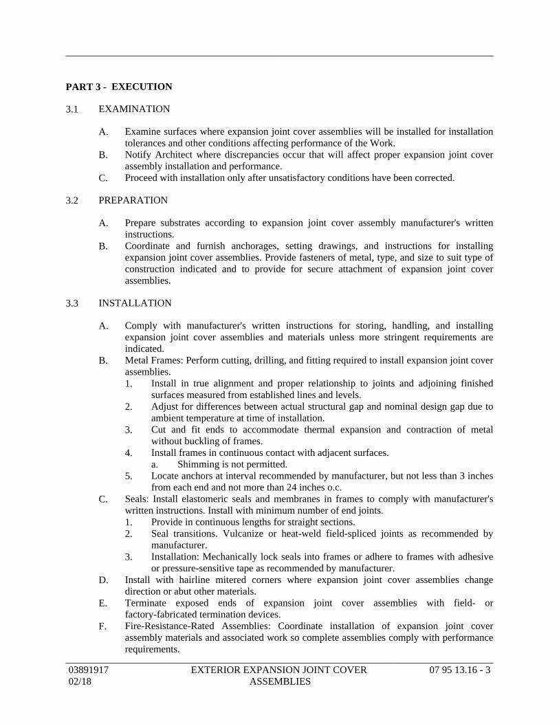
EXECUTIONPART 3 -
EXAMINATION3.1
Examine surfaces where expansion joint cover assemblies will be installed for installationA.tolerances and other conditions affecting performance of the Work.Notify Architect where discrepancies occur that will affect proper expansion joint coverB.assembly installation and performance.Proceed with installation only after unsatisfactory conditions have been corrected.C.
PREPARATION3.2
Prepare substrates according to expansion joint cover assembly manufacturer's writtenA.instructions.Coordinate and furnish anchorages, setting drawings, and instructions for installingB.expansion joint cover assemblies. Provide fasteners of metal, type, and size to suit type ofconstruction indicated and to provide for secure attachment of expansion joint coverassemblies.
INSTALLATION3.3
Comply with manufacturer's written instructions for storing, handling, and installingA.expansion joint cover assemblies and materials unless more stringent requirements areindicated.Metal Frames: Perform cutting, drilling, and fitting required to install expansion joint coverB.assemblies.
Install in true alignment and proper relationship to joints and adjoining finished1.surfaces measured from established lines and levels.Adjust for differences between actual structural gap and nominal design gap due to2.ambient temperature at time of installation.Cut and fit ends to accommodate thermal expansion and contraction of metal3.without buckling of frames.Install frames in continuous contact with adjacent surfaces.4.
Shimming is not permitted.a.Locate anchors at interval recommended by manufacturer, but not less than 3 inches5.from each end and not more than 24 inches o.c.
Seals: Install elastomeric seals and membranes in frames to comply with manufacturer'sC.written instructions. Install with minimum number of end joints.
Provide in continuous lengths for straight sections.1.Seal transitions. Vulcanize or heat-weld field-spliced joints as recommended by2.manufacturer.Installation: Mechanically lock seals into frames or adhere to frames with adhesive3.or pressure-sensitive tape as recommended by manufacturer.
Install with hairline mitered corners where expansion joint cover assemblies changeD.direction or abut other materials.Terminate exposed ends of expansion joint cover assemblies with field- orE.factory-fabricated termination devices.Fire-Resistance-Rated Assemblies: Coordinate installation of expansion joint coverF.assembly materials and associated work so complete assemblies comply with performancerequirements.
0389191702/18
EXTERIOR EXPANSION JOINT COVER ASSEMBLIES
07 95 13.16 - 3
CONNECTIONS3.4
Coordination with site manufactured systems at concrete roof tile system and TPOA.membrane system.
PROTECTION3.5
Do not remove protective covering until finish work in adjacent areas is complete. WhenA.protective covering is removed, clean exposed metal surfaces to comply withmanufacturer's written instructions.Protect the installation from damage by Work of other Sections.B.
END OF SECTION
0389191702/18
EXTERIOR EXPANSION JOINT COVER ASSEMBLIES
07 95 13.16 - 4
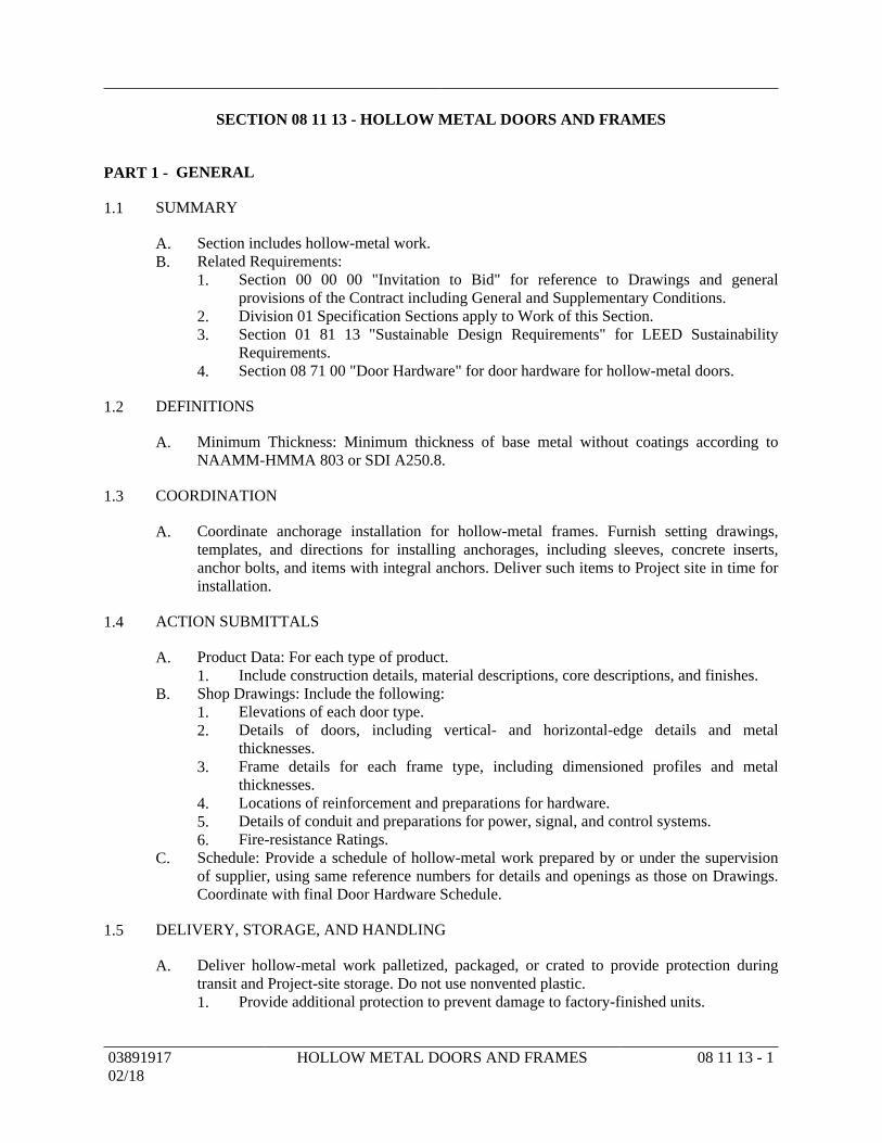
SECTION 08 11 13 - HOLLOW METAL DOORS AND FRAMES
GENERALPART 1 -
SUMMARY1.1
Section includes hollow-metal work.A.Related Requirements:B.
Section 00 00 00 "Invitation to Bid" for reference to Drawings and general1.provisions of the Contract including General and Supplementary Conditions.Division 01 Specification Sections apply to Work of this Section.2.Section 01 81 13 "Sustainable Design Requirements" for LEED Sustainability3.Requirements.Section 08 71 00 "Door Hardware" for door hardware for hollow-metal doors.4.
DEFINITIONS1.2
Minimum Thickness: Minimum thickness of base metal without coatings according toA.NAAMM-HMMA 803 or SDI A250.8.
COORDINATION1.3
Coordinate anchorage installation for hollow-metal frames. Furnish setting drawings,A.templates, and directions for installing anchorages, including sleeves, concrete inserts,anchor bolts, and items with integral anchors. Deliver such items to Project site in time forinstallation.
ACTION SUBMITTALS1.4
Product Data: For each type of product.A.Include construction details, material descriptions, core descriptions, and finishes.1.
Shop Drawings: Include the following:B.Elevations of each door type.1.Details of doors, including vertical- and horizontal-edge details and metal2.thicknesses.Frame details for each frame type, including dimensioned profiles and metal3.thicknesses.Locations of reinforcement and preparations for hardware.4.Details of conduit and preparations for power, signal, and control systems.5.Fire-resistance Ratings.6.
Schedule: Provide a schedule of hollow-metal work prepared by or under the supervisionC.of supplier, using same reference numbers for details and openings as those on Drawings.Coordinate with final Door Hardware Schedule.
DELIVERY, STORAGE, AND HANDLING1.5
Deliver hollow-metal work palletized, packaged, or crated to provide protection duringA.transit and Project-site storage. Do not use nonvented plastic.
Provide additional protection to prevent damage to factory-finished units.1.
0389191702/18
HOLLOW METAL DOORS AND FRAMES 08 11 13 - 1
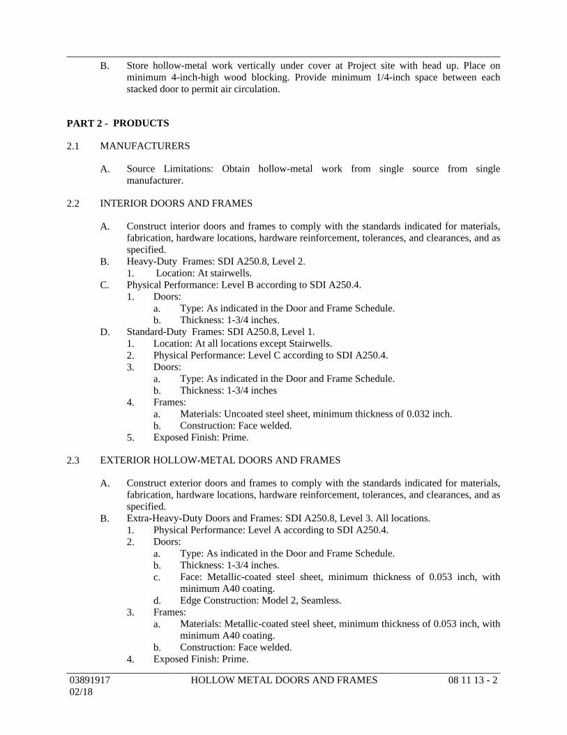
Store hollow-metal work vertically under cover at Project site with head up. Place onB.minimum 4-inch-high wood blocking. Provide minimum 1/4-inch space between eachstacked door to permit air circulation.
PRODUCTSPART 2 -
MANUFACTURERS2.1
Source Limitations: Obtain hollow-metal work from single source from singleA.manufacturer.
INTERIOR DOORS AND FRAMES2.2
Construct interior doors and frames to comply with the standards indicated for materials,A.fabrication, hardware locations, hardware reinforcement, tolerances, and clearances, and asspecified.Heavy-Duty Frames: SDI A250.8, Level 2.B.
Location: At stairwells.1.Physical Performance: Level B according to SDI A250.4.C.
Doors:1.Type: As indicated in the Door and Frame Schedule.a.Thickness: 1-3/4 inches.b.
Standard-Duty Frames: SDI A250.8, Level 1.D.Location: At all locations except Stairwells.1.Physical Performance: Level C according to SDI A250.4.2.Doors:3.
Type: As indicated in the Door and Frame Schedule.a.Thickness: 1-3/4 inchesb.
Frames:4.Materials: Uncoated steel sheet, minimum thickness of 0.032 inch.a.Construction: Face welded.b.
Exposed Finish: Prime.5.
EXTERIOR HOLLOW-METAL DOORS AND FRAMES2.3
Construct exterior doors and frames to comply with the standards indicated for materials,A.fabrication, hardware locations, hardware reinforcement, tolerances, and clearances, and asspecified.Extra-Heavy-Duty Doors and Frames: SDI A250.8, Level 3. All locations.B.
Physical Performance: Level A according to SDI A250.4.1.Doors:2.
Type: As indicated in the Door and Frame Schedule.a.Thickness: 1-3/4 inches.b.Face: Metallic-coated steel sheet, minimum thickness of 0.053 inch, withc.minimum A40 coating.Edge Construction: Model 2, Seamless.d.
Frames:3.Materials: Metallic-coated steel sheet, minimum thickness of 0.053 inch, witha.minimum A40 coating.Construction: Face welded.b.
Exposed Finish: Prime.4.
0389191702/18
HOLLOW METAL DOORS AND FRAMES 08 11 13 - 2
FRAME ANCHORS2.4
Jamb Anchors:A.Stud-Wall Type: Designed to engage stud, welded to back of frames; not less than1.0.042 inch thick.Postinstalled Expansion Type for In-Place Concrete or Masonry: Minimum2.3/8-inch-diameter bolts with expansion shields or inserts. Provide pipe spacer fromframe to wall, with throat reinforcement plate, welded to frame at each anchorlocation.
Floor Anchors: Formed from same material as frames, minimum thickness of 0.042 inch,B.and as follows:
Monolithic Concrete Slabs: Clip-type anchors, with two holes to receive fasteners.1.
MATERIALS2.5
Recycled Content of Steel Products: Postconsumer recycled content plus one-half ofA.preconsumer recycled content not less than 25 percent.Hot-Rolled Steel Sheet: ASTM A 1011/A 1011M, Commercial Steel (CS), Type B; free ofB.scale, pitting, or surface defects; pickled and oiled.Frame Anchors: ASTM A 879/A 879M, Commercial Steel (CS), 04Z coating designation;C.mill phosphatized.
For anchors built into exterior walls, steel sheet complying with ASTM A 1008/A1.1008M or ASTM A 1011/A 1011M, hot-dip galvanized according to ASTM A153/A 153M, Class B.
Inserts, Bolts, and Fasteners: Hot-dip galvanized according to ASTM A 153/A 153M.D.Mineral-Fiber Insulation: ASTM C 665, Type I (blankets without membrane facing);E.consisting of fibers manufactured from slag or rock wool; with maximum flame-spread andsmoke-developed indexes of 25 and 50, respectively; passing ASTM E 136 for combustioncharacteristics.
FABRICATION2.6
Fabricate hollow-metal work to be rigid and free of defects, warp, or buckle. AccuratelyA.form metal to required sizes and profiles, with minimum radius for metal thickness. Wherepractical, fit and assemble units in manufacturer's plant. To ensure proper assembly atProject site, clearly identify work that cannot be permanently factory assembled beforeshipment.Hollow-Metal Doors:B.
Steel-Stiffened Door Cores: Provide minimum thickness 0.026 inch, steel vertical1.stiffeners of same material as face sheets extending full-door height, with verticalwebs spaced not more than 6 inches apart. Spot weld to face sheets no more than 5inches o.c. Fill spaces between stiffeners with glass- or mineral-fiber insulation.Vertical Edges for Single-Acting Doors: Provide beveled or square edges at2.manufacturer's discretion.Top Edge Closures: Close top edges of doors with flush closures of same material as3.face sheets.Bottom Edge Closures: Close bottom edges of doors with end closures or channels4.of same material as face sheets.Exterior Doors: Provide weep-hole openings in bottoms of exterior doors to permit5.moisture to escape. Seal joints in top edges of doors against water penetration.
0389191702/18
HOLLOW METAL DOORS AND FRAMES 08 11 13 - 3
Hollow-Metal Frames: Where frames are fabricated in sections due to shipping or handlingC.limitations, provide alignment plates or angles at each joint, fabricated of same thicknessmetal as frames.
Frames: Provide closed tubular members with no visible face seams or joints,1.fabricated from same material as door frame. Fasten members at crossings and tojambs by butt welding.Provide countersunk, flat- or oval-head exposed screws and bolts for exposed2.fasteners unless otherwise indicated.Floor Anchors: Weld anchors to bottoms of jambs with at least four spot welds per3.anchor; however, for slip-on drywall frames, provide anchor clips or countersunkholes at bottoms of jambs.Jamb Anchors: Provide number and spacing of anchors as follows:4.
Stud-Wall Type: Locate anchors not more than 18 inches from top and bottoma.of frame. Space anchors not more than 32 inches o.c. and as follows:
Three anchors per jamb up to 60 inches high.1)Four anchors per jamb from 60 to 90 inches high.2)Five anchors per jamb from 90 to 96 inches high.3)Five anchors per jamb plus one additional anchor per jamb for each 244)inches or fraction thereof above 96 inches high.
Postinstalled Expansion Type: Locate anchors not more than 6 inches fromb.top and bottom of frame. Space anchors not more than 26 inches o.c.
Head Anchors: Two anchors per head for frames more than 42 inches wide and5.mounted in metal-stud partitions.Door Silencers: Drill stops to receive door silencers where specified in Section 08 716.00 "Door Hardware." Keep holes clear during construction.
Fabricate concealed stiffeners and edge channels from either cold- or hot-rolled steel sheet.D.Hardware Preparation: Factory prepare hollow-metal work to receive templated mortisedE.hardware; include cutouts, reinforcement, mortising, drilling, and tapping according to SDIA250.6, the Door Hardware Schedule, and templates.
Reinforce doors and frames to receive nontemplated, mortised, and surface-mounted1.door hardware.Comply with applicable requirements in SDI A250.6 and BHMA A156.115 for2.preparation of hollow-metal work for hardware.
STEEL FINISHES2.7
Prime Finish: Clean, pretreat, and apply manufacturer's standard primer.A.Shop Primer: Manufacturer's standard, fast-curing, lead- and chromate-free primer1.complying with SDI A250.10; recommended by primer manufacturer for substrate;compatible with substrate and field-applied coatings despite prolonged exposure.
EXECUTIONPART 3 -
EXAMINATION3.1
Examine substrates, areas, and conditions, with Installer present, for compliance withA.requirements for installation tolerances and other conditions affecting performance of theWork.Examine roughing-in for embedded and built-in anchors to verify actual locations beforeB.frame installation.
0389191702/18
HOLLOW METAL DOORS AND FRAMES 08 11 13 - 4
Prepare written report, endorsed by Installer, listing conditions detrimental to performanceC.of the Work.Proceed with installation only after unsatisfactory conditions have been corrected.D.
PREPARATION3.2
Drill and tap doors and frames to receive nontemplated, mortised, and surface-mountedA.door hardware.
INSTALLATION3.3
General: Install hollow-metal work plumb, rigid, properly aligned, and securely fastened inA.place. Comply with Drawings and manufacturer's written instructions.Hollow-Metal Frames: Install hollow-metal frames for doors, transoms, sidelites, borrowedB.lites, and other openings, of size and profile indicated. Comply with SDI A250.11 orNAAMM-HMMA 840 as required by standards specified.
Set frames accurately in position; plumbed, aligned, and braced securely until1.permanent anchors are set. After wall construction is complete, remove temporarybraces, leaving surfaces smooth and undamaged.
Where frames are fabricated in sections because of shipping or handlinga.limitations, field splice at approved locations by welding face jointcontinuously; grind, fill, dress, and make splice smooth, flush, and invisibleon exposed faces.Install frames with removable stops located on secure side of opening.b.Install door silencers in frames before grouting.c.Remove temporary braces necessary for installation only after frames haved.been properly set and secured.Check plumb, square, and twist of frames as walls are constructed. Shim ase.necessary to comply with installation tolerances.
Floor Anchors: Provide floor anchors for each jamb and mullion that extends to2.floor, and secure with postinstalled expansion anchors.Metal-Stud Partitions: Solidly pack mineral-fiber insulation inside frames.3.Concrete Walls: Solidly fill space between frames and concrete with mineral-fiber4.insulation.In-Place Concrete or Masonry Construction: Secure frames in place with5.postinstalled expansion anchors. Countersink anchors, and fill and make smooth,flush, and invisible on exposed faces.In-Place Metal or Wood-Stud Partitions: Secure slip-on drywall frames in place6.according to manufacturer's written instructions.Installation Tolerances: Adjust hollow-metal door frames for squareness, alignment,7.twist, and plumb to the following tolerances:
Squareness: Plus or minus 1/16 inch, measured at door rabbet on a line 90a.degrees from jamb perpendicular to frame head.Alignment: Plus or minus 1/16 inch, measured at jambs on a horizontal lineb.parallel to plane of wall.Twist: Plus or minus 1/16 inch, measured at opposite face corners of jambs onc.parallel lines, and perpendicular to plane of wall.Plumbness: Plus or minus 1/16 inch, measured at jambs at floor.d.
0389191702/18
HOLLOW METAL DOORS AND FRAMES 08 11 13 - 5

Hollow-Metal Doors: Fit hollow-metal doors accurately in frames, within clearancesC.specified below. Shim as necessary.
Non-Fire-Rated Steel Doors:1.Between Door and Frame Jambs and Head: 1/8 inch plus or minus 1/32 inch.a.Between Edges of Pairs of Doors: 1/8 inch to 1/4 inch plus or minus 1/32b.inch.At Bottom of Door: 5/8 inch plus or minus 1/32 inch.c.Between Door Face and Stop: 1/16 inch to 1/8 inch plus or minus 1/32 inch.d.
ADJUSTING AND CLEANING3.4
Final Adjustments: Check and readjust operating hardware items immediately before finalA.inspection. Leave work in complete and proper operating condition. Remove and replacedefective work, including hollow-metal work that is warped, bowed, or otherwiseunacceptable.Remove grout and other bonding material from hollow-metal work immediately afterB.installation.Prime-Coat Touchup: Immediately after erection, sand smooth rusted or damaged areas ofC.prime coat and apply touchup of compatible air-drying, rust-inhibitive primer.Metallic-Coated Surface Touchup: Clean abraded areas and repair with galvanizing repairD.paint according to manufacturer's written instructions.Touchup Painting: Cleaning and touchup painting of abraded areas of paint are specified inE.painting Sections.
END OF SECTION
0389191702/18
HOLLOW METAL DOORS AND FRAMES 08 11 13 - 6
03891917 PREFINISHED STEEL DOOR FRAMES 08 12 13 - 1
02/18
SECTION 08 12 13 - PREFINISHED STEEL DOOR FRAMES
PART 1 - GENERAL
1.1 SUMMARY
A. Section includes the furnishing of all items shown on the Drawings and as specified,
including but not limited to the following:
1. Knocked down, site assembled prefinished steel door frames at interior bath area
doors at all residential rooms, and at all interior doors at the residential apartment.
2. Bi-fold door openings (hardware not included).
B. Related Requirements:
1. Section 00 00 00 "Invitation to Bid" for reference to Drawings and general provisions
of the Contract including General and Supplementary Conditions.
2. Division 01 Specification Sections apply to Work of this Section.
3. Section 01 60 00 "Product Requirements."
4. Section 01 81 13 "Sustainable Design Requirements" for LEED Sustainability
Requirements.
5. Section 08 11 13 "Hollow Metal Doors and Frames" for door frames at corridor.
6. Section 08 14 16 "Flush Wood Doors" for hollow core and solid core doors at bath
area.
7. Section 08 71 00 "Door Hardware."
1.2 REFERENCES
A. ASTM A 653 - Standard for hot dipped galvanized steel material.
B. UBC 7-2-97, UBC 7-4-97 - Positive Pressure Fire Test Certification.
C. UL 10B - Fire test of Door Assemblies and UL10C Standard for Positive Pressure Fire
Tests of Door Assemblies.
D. NFPA 80 - Fire Doors and Windows (Latest Edition).
E. NFPA-101 - Life Safety Codes (Latest Edition).
F. ASTM D 2197 - Standard Test Method for Adhesion of Organic Coatings by Scrape
Adhesion.
G. ASTM D 2247 - Practice for Testing Water Resistance of Coatings in 100% Relative
Humidity.
H. ASTM D 2794 - Standard Test Method for Resistance of Organic Coatings to the Effects of
Rapid Deformation (Impact).
I. ASTM D 3361 - Standard Practice for Unfiltered Open-Flame Carbon-Arc exposures of
Paint and Related Coatings.
J. ASTM B 117 - Standard test for salt spray testing.
1.3 SUBMITTALS
A. Refer to Section 01 33 00 "Submittal Procedures."
B. Product Data: Indicate frame material, gauge, configuration and finishes.
C. Shop Drawings: Indicate frame elevations, details of frame anchorage, reinforcements
required, rough opening requirements, location of hardware embosses, and finishes. Detail
each floor of the building separately.
D. Samples: Submit one partial standard frame sample, illustrating factory finished frame
colors.
03891917 PREFINISHED STEEL DOOR FRAMES 08 12 13 - 2
02/18
E. Manufacturer's Installation Instructions: Provide installation instructions for all products
under this Section.
F. Manufacturer's Certificate of Warranty: Provide manufacturer’s standard warranty
certificate stating material is warranted for a period of one year from date of building
occupancy
G. LEED Qualification:
1. LEED Credit MR4.1, MR4.2: Post-consumer and Pre-consumer recycled material
content.
2. LEED Credit MR5.1: Location of manufacturer/proximity to Project.
3. EQc4.1: VOC - MSDS sheet for paint materials.
1.4 QUALITY ASSURANCE
A. Quality Standards:
1. Material free from defects in material and according to project specifications for
pre-engineered opening systems.
2. Proven durability of factory finishes allowing for bending and shaping of material
after finish is applied.
B. Fire Rated Frame Construction:
1. Conform to ASTM E 152, NFPA 252, and UL 10B and 10C.
C. Installed Frame Assembly: Conform to NFPA 80.
1. Use only installers familiar with installation of prefinished opening systems and
applied casing frame installation.
1.5 DELIVERY, STORAGE, AND HANDLING
A. Refer to Section 01 60 00 "Product Requirements" for transportation, handling, storing, and
protecting products in a dry area off the ground.
B. Accept frames on site in manufacturer's box packaging with identification labels intact.
Inspect for damage.
C. Do not open individual boxes until installation is to begin.
PART 2 - PRODUCTS
2.1 ACCEPTABLE MANUFACTURERS
A. Timely Industries, A Division of SDS Industries, Inc., 10241 Norris Avenue, Pacoima, CA
91331; Phone: 800.247.6242; Fax: 818.492.3530. Website: www.timelyframes.com.
B. Frames: Provide interior frames shown on Drawings and door schedule.
C. Substitutions: Refer to Section 01 60 00 "Product Requirements."
2.2 FRAMES
A. Frame Material: Hot dipped galvanized steel, for interior frames in normal atmospheric
exposures.
B. Frame Throat Opening: As shown on Plan details to suit finished wall thickness.
C. Frame Profile - Unequal Rabbet profile, standard with manufacturer:
1. “S” Series, 0.9 mm (20 gage) thick, room interior frames.
2. "S" Series, 0.9 mm (20 gage) thick, for bi-fold door.
03891917 PREFINISHED STEEL DOOR FRAMES 08 12 13 - 3
02/18
D. Casings:
1. Provide steel casings formed to be applied to heat treated clips on frame face after
frame is anchored to wall
2. Standard Steel - TA-8 with 6 mm (1/4 inch) reveal, on steel, stainless steel, and/or
brass frames. Fit factory assembled units with MiterGard corner alignment clips.
2.3 FABRICATION
A. Openings for single swing, pair, borrowed light and sidelight frames to be pre-cut, notched
and fabricated at the manufacturer’s facility. For fire rated and exterior openings, provide
kerf at stop for installation of smoke gasket or weatherstrip.
B. Provide minimum 14 gage hinge reinforcement plate tapped for machine screws supplied
with hinges. Hinge plate to be mechanically attached to hinge emboss on frame.
C. Casing Clips: Fabricate frames with factory applied, heat treated clips to ensure no deflection
in the clip upon application or removal of casing. Attachment clips may not be of same
material as frame.
D. Provide notches, tabs and/or stops for positive alignment of frame parts at all corners.
2.4 FINISHING
A. Frame Units: Prefinished with factory applied impact resistant, polyurethane baked enamel
finish or optional electrostatic applied water based paint system.
B. Frames for high humidity areas to be hot dipped galvanized. See 2.02.B for specific
locations.
C. Casing Finishes:
1. Steel: Prefinished with factory applied impact resistant, polyurethane baked enamel
finish.
2. PVC: Finished to match the frame color.
3. Primer: Hot Dipped Galvanized with 2 coats of white prime paint.
D. Colors: Color to be selected by Architect from manufacturer's selection of "standard finish"
colors.
PART 3 - EXECUTION
3.1 EXAMINATION
A. Verify acceptability of existing conditions before starting work.
B. Verify that opening sizes and wall thicknesses are within specified tolerances. Verify that all
finished walls are in plane to ensure proper door alignment.
3.2 INSTALLATION
A. Install frames in accordance with manufacturer’s requirements.
B. Anchor frames with screws located at every casing clip or every 11 inches as shown on
manufacturer’s instructions. Field verify quantity and location of fasteners prior to installing
casing.
C. Install prefinished frames near end of the project after wall painting and wall coverings.
D. Install frames using qualified installers familiar with installation of prefinished drywall
frames.
03891917 PREFINISHED STEEL DOOR FRAMES 08 12 13 - 4
02/18
E. Coordinate installation of frames with installation of hardware specified in Section 08 71 00
"Door Hardware."
F. Touch up blemishes on finished frames with factory-prepared touch-up paint.
END OF SECTION
SECTION 08 14 16 - FLUSH WOOD DOORS
GENERALPART 1 -
SUMMARY1.1
Section Includes:A.Solid-core doors with wood-veneer hardboard or MDF faces.1.Hollow-core doors with hardboard or MDF faces.2.Factory finishing flush wood doors.3.
Related Requirements:B.Section 00 00 00 "Invitation to Bid" for reference to Drawings and general1.provisions of the Contract including General and Supplementary Conditions.Division 01 Specification Sections apply to Work of this Section.2.Section 01 81 13 "Sustainable Design Requirements" for LEED Sustainability3.Requirements.Section 08 11 13 "Hollow Metal Doors and Frames" for rated doors.4.Section 08 12 13 "Prefinished Steel Door Frames" for interior residential suite doors.5.Section 08 71 00 "Door Hardware" for coordination with hardware.6.
PREINSTALLATION MEETINGS1.2
Preinstallation Conference: Conduct conference at Project site.A.
ACTION SUBMITTALS1.3
Product Data: For each type of door. Include details of core and edge construction, andA.trim for openings.Shop Drawings: Indicate location, size, and hand of each door; elevation of each kind ofB.door; construction details not covered in Product Data; and the following:
Dimensions and locations of mortises and holes for hardware.1.Dimensions and locations of cutoutsFire-protection ratings for fire-rated doors.2.
Samples for Initial Selection: For factory-finished doors.C.
QUALITY ASSURANCE1.4
Manufacturer Qualifications: A qualified manufacturer that is a licensee of WI's CertifiedA.Compliance Program.
DELIVERY, STORAGE, AND HANDLING1.5
Comply with requirements of referenced standard and manufacturer's written instructions.A.Package doors individually in plastic bags or cardboard cartons.B.Mark each door on bottom rail with opening number used on Shop Drawings.C.
0389191702/18
FLUSH WOOD DOORS 08 14 16 - 1
FIELD CONDITIONS1.6
Environmental Limitations: Do not deliver or install doors until spaces are enclosed andA.weathertight, wet work in spaces is complete and dry, and HVAC system is operating andmaintaining ambient temperature and humidity conditions at occupancy levels duringremainder of construction period.
WARRANTY1.7
Special Warranty: Manufacturer agrees to repair or replace doors that fail in materials orA.workmanship within specified warranty period.
Failures include, but are not limited to, the following:1.Warping (bow, cup, or twist) more than 1/4 inch in a 42-by-84-inch section.a.Telegraphing of core construction in face veneers exceeding 0.01 inch in ab.3-inch span.
Warranty shall also include installation and finishing that may be required due to2.repair or replacement of defective doors.Warranty Period for Solid-Core Interior Doors: Life of installation.3.Warranty Period for Hollow-Core Interior Doors: Five years from date of4.Substantial Completion.
PRODUCTSPART 2 -
MANUFACTURERS2.1
Manufacturers: Subject to compliance with requirements, available manufacturers offeringA.products that may be incorporated into the Work include, but are not limited to, thefollowing:
Algoma Hardwoods, Inc.1.Eggers Industries.2.Graham Wood Doors; an Assa Abloy Group company.3.Haley Brothers, Inc.4.Marlite.5.Marshfield Door Systems, Inc.6.Oshkosh Door Company.7.
Source Limitations: Obtain flush wood doors from single manufacturer.B.
FLUSH WOOD DOORS, GENERAL2.2
Quality Standard: In addition to requirements specified, comply with the following:A.Provide AWI Quality Certification Labels indicating that doors comply with1.requirements of grades specified.Contract Documents contain selections chosen from options in quality standard and2.additional requirements beyond those of quality standard. Comply with thoseselections and requirements in addition to quality standard.
Low-Emitting Materials: Fabricate doors with adhesives and composite wood products thatB.do not contain urea formaldehyde.
0389191702/18
FLUSH WOOD DOORS 08 14 16 - 2
Fire-Rated Wood Doors: Doors complying with NFPA 80 that are listed and labeled by aC.qualified testing agency, for fire-protection ratings indicated, based on testing at positivepressure according to NFPA 252.
Cores: Provide core specified or mineral core as needed to provide fire-protection1.rating indicated.Edge Construction: Provide edge construction with intumescent seals concealed by2.outer stile. Comply with specified requirements for exposed edges.Pairs: Provide fire-retardant stiles that are listed and labeled for applications3.indicated without formed-steel edges and astragals. Provide stiles with concealedintumescent seals. Comply with specified requirements for exposed edges.
Mineral-Core Doors:D.Core: Noncombustible mineral product complying with requirements of referenced1.quality standard and testing and inspecting agency for fire-protection ratingindicated.Blocking: Provide composite blocking with improved screw-holding capability2.approved for use in doors of fire-protection ratings indicated as needed to eliminatethrough-bolting hardware as follows:
5-inch top-rail blocking.a.5-inch bottom-rail blocking, in doors indicated to have protection plates.b.5-inch midrail blocking, in doors indicated to have armor plates.c.4-1/2-by-10-inch lock blocks, in doors indicated to have exit devices.d.
Edge Construction: At hinge stiles, provide laminated-edge construction with3.improved screw-holding capability and split resistance. Comply with specifiedrequirements for exposed edges.
Hollow-Core Doors:E.Construction: Standard hollow core.1.Blocking: Provide wood blocking with minimum dimensions as follows:2.
5-by-18-inch lock blocks at both stiles.a.5-inch top-rail blocking.b.
VENEER-FACED DOORS FOR TRANSPARENT FINISH2.3
Interior Solid-Core Doors:A.Grade: Custom (Grade B faces).1.Species: Select red birch.2.Cut: Rotary cut.3.Match between Veneer Leaves: Pleasing match.4.Assembly of Veneer Leaves on Door Faces: Balance match.5.Pair and Set Match: Provide for doors hung in same opening.6.Exposed Vertical and Top Edges: Compatible species.7.Core: Either glued wood stave or structural composite lumber.8.
Construction: Five or seven plies. Stiles and rails are bonded to core, then entire unit is abrasive2.4planed before veneering.DOORS FOR OPAQUE FINISH
Interior Solid-Core Doors:A.Grade: Custom.1.Faces: Hardboard or MDF.2.
Apply MDO to standard-thickness, closed-grain, hardwood face veneers ora.directly to high-density hardboard crossbands.
0389191702/18
FLUSH WOOD DOORS 08 14 16 - 3
Hardboard Faces: ANSI A135.4, Class 1 (tempered) or Class 2 (standard).b.MDF Faces: ANSI A208.2, Grade 150 or Grade 160.c.
Exposed Vertical and Top Edges: Any closed-grain hardwood.3.Core: Either glued wood stave or structural composite lumber.4.Construction: Five or seven plies. Stiles and rails are bonded to core, then entire unit5.is abrasive planed before veneering.Location: See Schedule of Alternates for location at interior suite locations.6.
Interior Hollow-Core Doors:B.Grade: Custom.1.Faces: Any closed-grain hardwood of mill option Hardboard or MDF.2.
Hardboard Faces: ANSI A135.4, Class 1 (tempered) or Class 2 (standard).a.MDF Faces: ANSI A208.2, Grade 150 or Grade 160.b.
Exposed Vertical and Top Edges: Any closed-grain hardwood.3.Construction: Three plies.4.WDMA IS.1-A Performance Grade: Standard Duty.5.
FABRICATION2.5
Factory machine doors for hardware that is not surface applied. Locate hardware to complyA.with DHI-WDHS-3. Comply with final hardware schedules, door frame Shop Drawings,BHMA-156.115-W, and hardware templates.
Metal Astragals: Factory machine astragals and formed-steel edges for hardware for1.pairs of fire-rated doors.
Openings: Factory cut and trim openings through doors.B.Light Openings: Trim openings with moldings of material and profile indicated.1.Glazing: Factory install glazing in doors indicated to be factory finished. Comply2.with applicable requirements in Section 08 80 00 "Glazing."Louvers: Factory install louvers in prepared openings.3.
FACTORY FINISHING2.6
General: Comply with referenced quality standard for factory finishing. CompleteA.fabrication, including fitting doors for openings and machining for hardware that is notsurface applied, before finishing.Opaque Finish:B.
Shop prime doors with one coat of wood primer specified in Section 09 91 231."Interior Painting." Seal all four edges, edges of cutouts, and mortises with primer.
EXECUTIONPART 3 -
EXAMINATION3.1
Examine doors and installed door frames, with Installer present, before hanging doors.A.Verify that installed frames comply with indicated requirements for type, size,1.location, and swing characteristics and have been installed with level heads andplumb jambs.Reject doors with defects.2.
Proceed with installation only after unsatisfactory conditions have been corrected.B.
0389191702/18
FLUSH WOOD DOORS 08 14 16 - 4
INSTALLATION3.2
Hardware: For installation, see Section 08 71 00 "Door Hardware."A.Installation Instructions: Install doors to comply with manufacturer's written instructionsB.and referenced quality standard, and as indicated.
Install fire-rated doors according to NFPA 80.1.Factory-Finished Doors: Restore finish before installation if fitting or machining isC.required at Project site.
ADJUSTING3.3
Operation: Rehang or replace doors that do not swing or operate freely.A.Finished Doors: Replace doors that are damaged or that do not comply with requirements.B.Doors may be repaired or refinished if Work complies with requirements and shows noevidence of repair or refinishing.
END OF SECTION
0389191702/18
FLUSH WOOD DOORS 08 14 16 - 5
SECTION 08 31 13 - ACCESS DOORS AND FRAMES
GENERALPART 1 -
SUMMARY1.1
Section includes access doors and frames for walls and ceilings.A.Related Requirements:B.
Section 00 00 00 "Invitation to Bid" for reference to Drawings and general1.provisions of the Contract including General and Supplementary Conditions.Division 01 Specification Sections apply to Work of this Section.2.Section 01 81 13 "Sustainable Design Requirements" for LEED Sustainability3.Requirements.Section 09 29 00 "Gypsum Board" for location coordination.4.
ACTION SUBMITTALS1.2
Product Data: For each type of product.A.Include construction details, material descriptions, dimensions of individual1.components and profiles, and finishes. Include latching/locking provisions pertinentto installation.
PRODUCTSPART 2 -
ACCESS DOORS AND FRAMES2.1
Flush Access Doors with Exposed Flanges:A.Manufacturers: Subject to compliance with requirements, available manufacturers1.offering products that may be incorporated into the Work include, but are not limitedto, the following:
Acudor Products, Inc.a.Babcock-Davis.b.Karp Associates, Inc.c.Williams Bros. Corporation of America (The).d.
Description: Face of door flush with frame, with exposed flange and concealed2.hinge.Locations: Wall and ceiling as shown on drawings.3.Door Size:4.
Wall: 12 inches by 12 inches.a.Ceiling: 18 inches by 18 inches.b.
Uncoated Steel Sheet for Door: Nominal 0.060 inch, 16 gage, factory primed.5.Frame Material: Same material, thickness, and finish as door.6.Latch and Lock: Latch bolt, key operated. Key all access doors within Project alike.7.
MATERIALS2.2
Steel Plates, Shapes, and Bars: ASTM A 36/A 36M.A.Steel Sheet: Uncoated or electrolytic zinc coated, ASTM A 879/A 879M, with cold-rolledB.steel sheet substrate complying with ASTM A 1008/A 1008M, Commercial Steel (CS),exposed.
0389191702/18
ACCESS DOORS AND FRAMES 08 31 13 - 1
Frame Anchors: Same material as door face.C.Inserts, Bolts, and Anchor Fasteners: Hot-dip galvanized steel according to ASTM A 153/D.A 153M or ASTM F 2329.
FABRICATION2.3
General: Provide access door and frame assemblies manufactured as integral units readyA.for installation.Metal Surfaces: For metal surfaces exposed to view in the completed Work, provideB.materials with smooth, flat surfaces without blemishes. Do not use materials with exposedpitting, seam marks, roller marks, rolled trade names, or roughness.Doors and Frames: Grind exposed welds smooth and flush with adjacent surfaces. FurnishC.mounting holes, attachment devices and fasteners of type required to secure access doors totypes of supports indicated.
For concealed flanges with drywall bead, provide edge trim for gypsum panels1.securely attached to perimeter of frames.For concealed flanges with plaster bead for full-bed plaster applications, provide2.zinc-coated expanded-metal lath and exposed casing bead welded to perimeter offrames.
Latch and Lock Hardware:D.Quantity: Furnish number of latches and locks required to hold doors tightly closed.1.Keys: Furnish two keys per lock and key all locks alike.2.
FINISHES2.4
Comply with NAAMM's "Metal Finishes Manual for Architectural and Metal Products"A.for recommendations for applying and designating finishes.Protect mechanical finishes on exposed surfaces from damage by applying a strippable,B.temporary protective covering before shipping.Painted Finishes: Comply with coating manufacturer's written instructions for cleaning,C.conversion coating, and applying and baking finish.
Factory Primed: Apply manufacturer's standard, lead- and chromate-free, universal1.primer immediately after surface preparation and pretreatment.
EXECUTIONPART 3 -
EXAMINATION3.1
Examine substrates for compliance with requirements for installation tolerances and otherA.conditions affecting performance of the Work.Proceed with installation only after unsatisfactory conditions have been corrected.B.
INSTALLATION3.2
Comply with manufacturer's written instructions for installing access doors and frames.A.
ADJUSTING3.3
Adjust doors and hardware, after installation, for proper operation.A.
END OF SECTION0389191702/18
ACCESS DOORS AND FRAMES 08 31 13 - 2
SECTION 08 41 13 - ALUMINUM-FRAMED ENTRANCES AND STOREFRONTS
GENERALPART 1 -
SUMMARY1.1
Section Includes:A.Interior storefront framing.1.Manual-swing entrance doors system.2.Fixed aluminum windows at South Wing.3.
Related Requirements:B.Section 00 00 00 "Invitation to Bid" for reference to Drawings and general1.provisions of the Contract including General and Supplementary Conditions.Division 01 Specification Sections apply to Work of this Section.2.Section 01 81 13 "Sustainable Design Requirements" for LEED Sustainability3.Requirements.Section 07 92 00 "Joint Sealants" for joints between dissimilar materials.4.Section 08 71 00 "Door Hardware" for hardware sets for all doors.5.
PREINSTALLATION MEETINGS1.2
Preinstallation Conference: Conduct conference at Project site.A.
ACTION SUBMITTALS1.3
Product Data: For each type of product.A.Include construction details, material descriptions, dimensions of individual1.components and profiles, and finishes.
Shop Drawings: For aluminum-framed entrances and storefronts. Include plans, elevations,B.sections, full-size details, and attachments to other work.
Include details of provisions for assembly expansion and contraction and for1.draining moisture occurring within the assembly to the exterior.Include full-size isometric details of each vertical-to-horizontal intersection of2.aluminum-framed entrances and storefronts, showing the following:
Joinery, including concealed welds.a.Anchorage.b.Expansion provisions.c.Glazing.d.Flashing and drainage.e.
Show connection to and continuity with adjacent thermal, weather, air, and vapor3.barriers.
Entrance Door Hardware Schedule: Prepared by or under supervision of supplier, detailingC.fabrication and assembly of entrance door hardware, as well as procedures and diagrams.Coordinate final entrance door hardware schedule with doors, frames, and related work toensure proper size, thickness, hand, function, and finish of entrance door hardware.
0389191702/18
ALUMINUM-FRAMED ENTRANCES AND STOREFRONTS
08 41 13 - 1
INFORMATIONAL SUBMITTALS1.4
Energy Performance Certificates: For aluminum-framed entrances and storefronts,A.accessories, and components, from manufacturer.
Basis for Certification: NFRC-certified energy performance values for each1.aluminum-framed entrance and storefront.
CLOSEOUT SUBMITTALS1.5
Maintenance Data: For aluminum-framed entrances and storefronts to include inA.maintenance manuals.
QUALITY ASSURANCE1.6
Installer Qualifications: An entity that employs installers and supervisors who are trainedA.and approved by manufacturer.
PRODUCTSPART 2 -
PERFORMANCE REQUIREMENTS2.1
General Performance: Comply with performance requirements specified, as determined byA.testing of aluminum-framed entrances and storefronts representing those indicated for thisProject without failure due to defective manufacture, fabrication, installation, or otherdefects in construction.
Aluminum-framed entrances and storefronts shall withstand movements of1.supporting structure including, but not limited to, story drift, twist, columnshortening, long-term creep, and deflection from uniformly distributed andconcentrated live loads.Failure also includes the following:2.
Thermal stresses transferring to building structure.a.Glass breakage.b.Noise or vibration created by wind and thermal and structural movements.c.Loosening or weakening of fasteners, attachments, and other components.d.Failure of operating units.e.
Structural Loads:B.Wind Loads: As indicated on Drawings.1.Other Design Loads: As indicated on Drawings.2.
Operable Units: Provide a minimum 1/16-inch clearance between framinga.members and operable units.
Cantilever Deflection: Where framing members overhang an anchor point, as3.follows:
Perpendicular to Plane of Wall: No greater than 1/240 of clear span plus 1/4a.inch for spans greater than 11 feet 8-1/4 inches or 1/175 times span, for spansless than 11 feet 8-1/4 inches.
Structural: Test according to ASTM E 330 as follows:C.When tested at positive and negative wind-load design pressures, assemblies do not1.evidence deflection exceeding specified limits.
0389191702/18
ALUMINUM-FRAMED ENTRANCES AND STOREFRONTS
08 41 13 - 2
Air Infiltration: Test according to ASTM E 283 for infiltration as follows:D.Fixed Framing and Glass Area:1.
Maximum air leakage of 0.06 cfm/sq. ft. at a static-air-pressure differential ofa.1.57 lbf/sq. ft.
Entrance Doors:2.Pair of Doors: Maximum air leakage of 1.0 cfm/sq. ft. at a static-air-pressurea.differential of 1.57 lbf/sq. ft.Single Doors: Maximum air leakage of 0.5 cfm/sq. ft. at a static-air-pressureb.differential of 1.57 lbf/sq. ft.
Water Penetration under Static Pressure: Test according to ASTM E 331 as follows:E.No evidence of water penetration through fixed glazing and framing areas when1.tested according to a minimum static-air-pressure differential of 20 percent ofpositive wind-load design pressure, but not less than 6.24 lbf/sq. ft.
Water Penetration under Dynamic Pressure: Test according to AAMA 501.1 as follows:F.No evidence of water penetration through fixed glazing and framing areas when1.tested at dynamic pressure equal to 20 percent of positive wind-load design pressure,but not less than 6.24 lbf/sq. ft.Maximum Water Leakage: No uncontrolled water penetrating assemblies or water2.appearing on assemblies' normally exposed interior surfaces from sources other thancondensation. Water leakage does not include water controlled by flashing andgutters, or water that is drained to exterior.
Energy Performance: Certify and label energy performance according to NFRC as follows:G.Thermal Transmittance (U-factor): Fixed glazing and framing areas shall have1.U-factor of not more than 0.45 Btu/sq. ft. x h x deg Fas determined according toNFRC 100.Solar Heat Gain Coefficient: Fixed glazing and framing areas shall have a solar heat2.gain coefficient of no greater than 0.35 as determined according to NFRC 200.Condensation Resistance: Fixed glazing and framing areas shall have an3.NFRC-certified condensation resistance rating of no less than 15as determinedaccording to NFRC 500.
Noise Reduction: Test according to ASTM E 90, with ratings determined by ASTM EH.1332, as follows.
Outdoor-Indoor Transmission Class: Minimum 26.1.Thermal Movements: Allow for thermal movements resulting from ambient and surfaceI.temperature changes:
Temperature Change: 120 deg F, ambient; 180 deg F, material surfaces.1.
MANUFACTURERS2.2
Basis-of-Design Product: Subject to compliance with requirements, provide KawneerA."Tri-fab 451" Series or equivalent product by one of the following:
Arcadia, Inc.1.Arch Aluminum & Glass Co., Inc.2.Kawneer North America.3.Tubelite.4.YKK AP America Inc.5.
Source Limitations: Obtain all components of aluminum-framed entrance and storefrontB.system, including framing and accessories, from single manufacturer.
0389191702/18
ALUMINUM-FRAMED ENTRANCES AND STOREFRONTS
08 41 13 - 3
FRAMING2.3
Framing Members: Manufacturer's extruded- or formed-aluminum framing members ofA.thickness required and reinforced as required to support imposed loads.
Construction: Thermally broken.1.Fabrication Method: Field-fabricated stick system.2.
Backer Plates: Manufacturer's standard, continuous backer plates for framing members, ifB.not integral, where framing abuts adjacent construction.Brackets and Reinforcements: Manufacturer's standard high-strength aluminum withC.nonstaining, nonferrous shims for aligning system components.Materials:D.
Aluminum: Alloy and temper recommended by manufacturer for type of use and1.finish indicated.
Sheet and Plate: ASTM B 209.a.Extruded Bars, Rods, Profiles, and Tubes: ASTM B 221.b.Extruded Structural Pipe and Tubes: ASTM B 429/B 429M.c.Structural Profiles: ASTM B 308/B 308M.d.
ENTRANCE DOOR SYSTEMS2.4
Entrance Doors: Manufacturer's standard glazed entrance doors for manual-swingA.operation.
ENTRANCE DOOR HARDWARE2.5
Entrance Door Hardware: Hardware not specified in this Section is specified in Section 08A.71 00 "Door Hardware."General: Provide entrance door hardware and entrance door hardware sets indicated inB."Entrance Door Hardware Sets" Article for each entrance door to comply withrequirements in this Section.
Entrance Door Hardware Sets: Provide quantity, item, size, finish or color indicated.1.Sequence of Operation: Provide electrified door hardware function, sequence of2.operation, and interface with other building control systems indicated.Opening-Force Requirements:3.
Egress Doors: Not more than 15 lbf to release the latch and not more than 30a.lbf to set the door in motion and not more than 15 lbf to open the door to itsminimum required width.Accessible Interior Doors: Not more than 5 lbf to fully open door.b.
Cylinders: As specified in Section 08 71 00 "Door Hardware."C.Keying: Keying Schedule per Section 08 71 00 "Door Hardware."1.
Weather Sweeps: Manufacturer's standard exterior-door bottom sweep with concealedD.fasteners on mounting strip.Silencers: BHMA A156.16, Grade 1.E.Thresholds: BHMA A156.21, raised thresholds beveled with a slope of not more than 1:2,F.with maximum height of 1/2 inch.
GLAZING2.6
Glazing: Comply with Section 08 80 00 "Glazing."A.Sealants used inside the weatherproofing system shall have a VOC content of 250 g/L.B.
0389191702/18
ALUMINUM-FRAMED ENTRANCES AND STOREFRONTS
08 41 13 - 4
ACCESSORIES2.7
Fasteners and Accessories: Manufacturer's standard corrosion-resistant, nonstaining,A.nonbleeding fasteners and accessories compatible with adjacent materials.
Use self-locking devices where fasteners are subject to loosening or turning out from1.thermal and structural movements, wind loads, or vibration.Reinforce members as required to receive fastener threads.2.Use exposed fasteners with countersunk Phillips screw heads, finished to match3.framing system.
Anchors: Three-way adjustable anchors with minimum adjustment of 1 inch thatB.accommodate fabrication and installation tolerances in material and finish compatible withadjoining materials and recommended by manufacturer.
Concrete and Masonry Inserts: Hot-dip galvanized cast-iron, malleable-iron, or steel1.inserts complying with ASTM A 123/A 123M or ASTM A 153/A 153Mrequirements.
Concealed Flashing: Manufacturer's standard corrosion-resistant, nonstaining, nonbleedingC.flashing compatible with adjacent materials.Bituminous Paint: Cold-applied asphalt-mastic paint complying with SSPC-Paint 12D.requirements except containing no asbestos, formulated for 30-milthickness per coat.
FABRICATION2.8
Form or extrude aluminum shapes before finishing.A.Fabricate components that, when assembled, have the following characteristics:B.
Profiles that are sharp, straight, and free of defects or deformations.1.Accurately fitted joints with ends coped or mitered.2.Physical and thermal isolation of glazing from framing members.3.Accommodations for thermal and mechanical movements of glazing and framing to4.maintain required glazing edge clearances.Provisions for field replacement of glazing from interior.5.Fasteners, anchors, and connection devices that are concealed from view to greatest6.extent possible.
Mechanically Glazed Framing Members: Fabricate for flush glazing without projectingC.stops.Structural-Sealant-Glazed Framing Members: Include accommodations for usingD.temporary support device to retain glazing in place while structural sealant cures.Storefront Framing: Fabricate components for assembly.E.Entrance Door Frames: Reinforce as required to support loads imposed by door operationF.and for installing entrance door hardware.Entrance Doors: Reinforce doors as required for installing entrance door hardware.G.
At exterior doors, provide weather sweeps applied to door bottoms.1.Entrance Door Hardware Installation: Factory install entrance door hardware. DisassembleH.as needed for shipping.After fabrication, clearly mark components to identify their locations in Project accordingI.to Shop Drawings.
ALUMINUM FINISHES2.9
Clear Anodic Finish: AAMA 611, AA-M12C22A31, Class II, 0.010 mm or thicker.A.
0389191702/18
ALUMINUM-FRAMED ENTRANCES AND STOREFRONTS
08 41 13 - 5
EXECUTIONPART 3 -
EXAMINATION3.1
Examine areas, with Installer present, for compliance with requirements for installationA.tolerances and other conditions affecting performance of the Work.Proceed with installation only after unsatisfactory conditions have been corrected.B.
INSTALLATION3.2
General:A.Comply with manufacturer's written instructions.1.Do not install damaged components.2.Fit joints to produce hairline joints free of burrs and distortion.3.Rigidly secure nonmovement joints.4.Install anchors with separators and isolators to prevent metal corrosion and5.electrolytic deterioration and to prevent impeding movement of moving joints.Seal perimeter and other joints watertight unless otherwise indicated.6.
Metal Protection:B.Where aluminum is in contact with dissimilar metals, protect against galvanic action1.by painting contact surfaces with materials recommended by manufacturer for thispurpose or by installing nonconductive spacers.Where aluminum is in contact with concrete or masonry, protect against corrosion2.by painting contact surfaces with bituminous paint.
Set continuous sill members and flashing in full sealant bed as specified in Section 07 92C.00 "Joint Sealants" to produce weathertight installation.Install components plumb and true in alignment with established lines and grades.D.Install operable units level and plumb, securely anchored, and without distortion. AdjustE.weather-stripping contact and hardware movement to produce proper operation.Install glazing as specified in Section 08 80 00 "Glazing."F.Entrance Doors: Install doors to produce smooth operation and tight fit at contact points.G.
Field-Installed Entrance Door Hardware: Install surface-mounted entrance door1.hardware according to entrance door hardware manufacturers' written instructionsusing concealed fasteners to greatest extent possible.
ERECTION TOLERANCES3.3
Erection Tolerances: Install aluminum-framed entrances and storefronts to comply with theA.following maximum tolerances:
Plumb: 1/8 inch in 10 feet; 1/4 inch in 40 feet.1.Level: 1/8 inch in 20 feet; 1/4 inch in 40 feet.2.Alignment:3.
Where surfaces abut in line or are separated by reveal or protruding elementa.up to 1/2 inch wide, limit offset from true alignment to 1/16 inch.Where surfaces are separated by reveal or protruding element from 1/2 to 1b.inch wide, limit offset from true alignment to 1/8 inch.Where surfaces are separated by reveal or protruding element of 1 inch widec.or more, limit offset from true alignment to 1/4 inch.
Location: Limit variation from plane to 1/8 inch in 12 feet; 1/2 inch over total4.length.
0389191702/18
ALUMINUM-FRAMED ENTRANCES AND STOREFRONTS
08 41 13 - 6
MAINTENANCE SERVICE3.4
Entrance Door Hardware:A.Maintenance Tools and Instructions: Furnish a complete set of specialized tools and1.maintenance instructions as needed for Owner's continued adjustment, maintenance,and removal and replacement of entrance door hardware.Initial Maintenance Service: Beginning at Substantial Completion, provide six2.months' full maintenance by skilled employees of entrance door hardware Installer.Include quarterly preventive maintenance, repair or replacement of worn ordefective components, lubrication, cleaning, and adjusting as required for properentrance door hardware operation at rated speed and capacity. Use parts and suppliesthat are the same as those used in the manufacture and installation of originalequipment.
END OF SECTION
0389191702/18
ALUMINUM-FRAMED ENTRANCES AND STOREFRONTS
08 41 13 - 7
SECTION 08 53 13 - VINYL WINDOWS
GENERALPART 1 -
SUMMARY1.1
Section includes vinyl-framed windows.A.Related Requirements:B.
Section 00 00 00 "Invitation for Bid" for reference to Drawings and general1.provisions of the Contract including General and Supplementary Conditions.Division 01 Specification Sections apply to Work of this Section.2.Section 01 81 13 "Sustainable Design Requirements" for LEED Sustainability3.Requirements.Section 06 16 00 "Sheathing" for sheathing behind EIFS-clad wall assemblies.4.Section 07 24 19 "Water-Drainage Exterior Insulation and Finish System (EIFS)."5.Section 07 62 00 "Sheet Metal Flashing and Trim" for transition to roof systems.6.Section 07 92 00 "Joint Sealants" for sealing system at joints with dissimilar7.materials.
PREINSTALLATION MEETINGS1.2
Preinstallation Conference: Conduct conference at Project site.A.Review and finalize construction schedule and verify availability of materials,1.Installer's personnel, equipment, and facilities needed to make progress and avoiddelays.Review, discuss, and coordinate the interrelationship of vinyl windows with other2.exterior wall components. Include provisions for anchoring, flashing, weeping,sealing perimeters, and protecting finishes.Review and discuss the sequence of work required to construct a watertight and3.weathertight exterior building envelope.Inspect and discuss the condition of substrate and other preparatory work performed4.by other trades.
ACTION SUBMITTALS1.3
Product Data: For each type of product.A.Include construction details, material descriptions, glazing and fabrication methods,1.dimensions of individual components and profiles, hardware, and finishes for vinylwindows.
Shop Drawings: For vinyl windows.B.Include plans, elevations, sections, hardware, accessories, insect screens, operational1.clearances, and details of installation, including anchor, flashing, and sealantinstallation.
Samples: For each exposed product and for each color specified, 6 inches square in size.C.Samples for Initial Selection: For units with factory-applied finishes.D.
Include Samples of hardware and accessories involving color selection.1.
0389191702/18
VINYL WINDOWS 08 53 13 - 1
Samples for Verification: For vinyl windows and components required, prepared onE.Samples of size indicated below:
Exposed Finishes: 6 inches square.1.Exposed Hardware: Full-size units.2.
Product Schedule: For vinyl windows. Use same designations indicated on Drawings.F.
INFORMATIONAL SUBMITTALS1.4
Qualification Data: For manufacturer and Installer.A.Product Test Reports: For each type of vinyl window, for tests performed by a qualifiedB.testing agency.Sample Warranties: For manufacturer's warranties.C.
QUALITY ASSURANCE1.5
Manufacturer Qualifications: A manufacturer capable of fabricating vinyl windows thatA.meet or exceed performance requirements indicated and of documenting this performanceby test reports and calculations.
Minimum 10 years' experience producing vinyl (PVC) windows.1.Capable of sending an authorized representative to the Project site for field2.measurements and periodic installation inspections. A minimum of three site visits isrequired.
Installer Qualifications: An installer acceptable to vinyl window manufacturer forB.installation of units required for this Project.Mockups: Build mockups to verify selections made under Sample submittals, toC.demonstrate aesthetic effects, and to set quality standards for materials and execution.
Build mockup of typical wall area as shown on Drawings.1.Approval of mockups does not constitute approval of deviations from the Contract2.Documents contained in mockups unless Architect specifically approves suchdeviations in writing.Subject to compliance with requirements, approved mockups may become part of3.the completed Work if undisturbed at time of Substantial Completion.Owner will engage, at their option, a window inspector to conduct a "Field Window4.Test" for air and water infiltration.
WARRANTY1.6
Manufacturer's Warranty: Manufacturer agrees to repair or replace vinyl windows that failA.in materials or workmanship within specified warranty period.
Failures include, but are not limited to, the following:1.Failure to meet performance requirements.a.Structural failures including excessive deflection, water leakage, and airb.infiltration.Faulty operation of movable sash and hardware.c.Deterioration of materials and finishes beyond normal weathering.d.Failure of insulating glass.e.
Warranty Period:2.Window: 10 years from date of Substantial Completion.a.
0389191702/18
VINYL WINDOWS 08 53 13 - 2
PRODUCTSPART 2 -
MANUFACTURERS2.1
Source Limitations: Obtain vinyl windows from single source from single manufacturer.A.
WINDOW PERFORMANCE REQUIREMENTS2.2
Product Standard: Comply with AAMA/WDMA/CSA 101/I.S.2/A440 for definitions andA.minimum standards of performance, materials, components, accessories, and fabricationunless more stringent requirements are indicated.
Window Certification: WDMA certified with label attached to each window.1.Performance Class and Grade: AAMA/WDMA/CSA 101/I.S.2/A440 as follows:B.
Minimum Performance Class: R.1.Minimum Performance Grade: 15.2.
Thermal Transmittance: NFRC 100 maximum whole-window U-factor of 0.35 Btu/sq. ft.C.x h x deg F.Solar Heat-Gain Coefficient (SHGC): NFRC 200 maximum whole-window SHGC of 0.30.D.
VINYL WINDOWS2.3
Manufacturers: Subject to compliance with requirements, available manufacturers offeringA.products that may be incorporated into the Work include, but are not limited to, thefollowing:
Basis of Design: Fairfield 80 Series, manufactured by Alside, P.O. Box 2010,1.Akron, OH 44309, www.alside.com.Jeld-Wen, Inc.2.
Operating Types: Provide the following operating types in locations indicated onB.Drawings:
Fixed.1.Frames and Sashes: Impact-resistant, UV-stabilized PVC complying withC.AAMA/WDMA/CSA 101/I.S.2/A440.
Finish: Integral color, white.1.Insulating-Glass Units: ASTM E 2190.D.
Glass: ASTM C 1036, Type 1, Class 1, q3.1.Tint: Clear.a.NFRC Glass Strength: Double Strenth: 13/16 inch.b.
Lites: As shown on the Drawings.2.Filling: Fill space between glass lites with air.3.Low-E Coating: Pyrolytic on second surface.4.
Performance:E.U-Factor: 0.281.Condensation Resistance (CR): 552.Solar Heat Gain Coefficient (SHGC): 0.223.Visible Transmittance (VT): 0.54.NRFR Certified Product Directory (CPD): ASO-A-99-02134-00002.5.
Product certified by NFRC to meet performance requirements per NFRC 706.a.GlazingSystem: Manufacturer's standard factory-glazing system that produces weathertightF.seal.
0389191702/18
VINYL WINDOWS 08 53 13 - 3
Weather Stripping: Provide full-perimeter weather stripping for each operable sash unlessG.otherwise indicated.Fasteners: Noncorrosive and compatible with window members, trim, hardware, anchors,H.and other components.
Exposed Fasteners: Do not use exposed fasteners to greatest extent possible. For1.application of hardware, use fasteners that match finish hardware being fastened.
ACCESSORIES2.4
Dividers (False Muntins): Provide divider grilles in designs indicated for each sash lite.A.Quantity and Type: One permanently located between insulating-glass lites.1.Material: Manufacturer's standard.2.Pattern: As indicated on Drawings.3.Profile: As selected by Architect from manufacturer's full range. Price based upon4."Colonial" style.Color: As selected by Architect from manufacturer's full range.5.
Frame Accessories:B.Provide extension clips as required to complete weathertight installation in an EIFS1.building system.Integral nail fins.2.
FABRICATION2.5
Fabricate vinyl windows in sizes indicated. Include a complete system for installing andA.anchoring windows.Glaze vinyl windows in the factory.B.Weather strip each operable sash to provide weathertight installation.C.Complete fabrication, assembly, finishing, hardware application, and other work in theD.factory to greatest extent possible. Disassemble components only as necessary forshipment and installation. Allow for scribing, trimming, and fitting at Project site.
EXECUTIONPART 3 -
EXAMINATION3.1
Examine openings, substrates, structural support, anchorage, and conditions, with InstallerA.present, for compliance with requirements for installation tolerances and other conditionsaffecting performance of the Work.Verify rough opening dimensions, levelness of sill plate, and operational clearances.B.Examine wall flashings, vapor retarders, water and weather barriers, and other built-inC.components to ensure weathertight window installation.Proceed with installation only after unsatisfactory conditions have been corrected.D.
INSTALLATION3.2
Comply with manufacturer's written instructions for installing windows, hardware,A.accessories, and other components. For installation procedures and requirements notaddressed in manufacturer's written instructions, comply with installation requirements inASTM E 2112.
0389191702/18
VINYL WINDOWS 08 53 13 - 4
Install windows level, plumb, square, true to line, without distortion, anchored securely inB.place to structural support, and in proper relation to wall flashing and other adjacentconstruction to produce weathertight construction.
ADJUSTING, CLEANING, AND PROTECTION3.3
Adjust operating sashes and hardware for a tight fit at contact points and weather strippingA.for smooth operation and weathertight closure.Clean exposed surfaces immediately after installing windows. Remove excess sealants,B.glazing materials, dirt, and other substances.
Keep protective films and coverings in place until final cleaning.1.Remove and replace sashes if glass has been broken, chipped, cracked, abraded, orC.damaged during construction period.Protect window surfaces from contact with contaminating substances resulting fromD.construction operations. If contaminating substances do contact window surfaces, removecontaminants immediately according to manufacturer's written instructions.
END OF SECTION
0389191702/18
VINYL WINDOWS 08 53 13 - 5
03891917 DOOR HARDWARE 08 71 00 - 1
02/18
SECTION 08 71 00 - DOOR HARDWARE
PART 1 - GENERAL
1.1 SUMMARY
A. Section includes commercial door hardware for the following:
1. Swinging doors.
2. Other doors to the extent indicated.
B. Door hardware includes, but is not necessarily limited to, the following:
1. Mechanical door hardware.
2. Electromechanical door hardware.
3. Automatic operators.
4. Cylinders specified for doors in other Sections.
C. Related Requirements:
1. Section 00 00 00 "Invitation to Bid" for reference to Drawings and general
provisions of the Contract including General and Supplementary Conditions.
2. Division 01 Specification Sections apply to Work of this Section.
3. Section 01 81 13 "Sustainable Design Requirements" for LEED Sustainability
Requirements.
4. Section 08 11 13 “Hollow Metal Doors and Frames.”
5. Section 08 14 16 “Flush Wood Doors.”
6. Section 08 71 00.10 “Door Hardware Schedule.”
D. Codes and References: Comply with the version year adopted by the Authority Having
Jurisdiction.
1. ANSI A117.1 - Accessible and Usable Buildings and Facilities.
2. ICC/IBC - International Building Code.
3. NFPA 70 - National Electrical Code.
4. NFPA 80 - Fire Doors and Windows.
5. NFPA 101 - Life Safety Code.
6. NFPA 105 - Installation of Smoke Door Assemblies.
7. UL/ULC and CSA C22.2 - Standards for Automatic Door Operators Used on Fire and
Smoke Barrier Doors and Systems of Doors.
8. State Building Codes, Local Amendments.
E. Standards: All hardware specified herein shall comply with the following industry
standards:
1. ANSI/BHMA Certified Product Standards - A156 Series.
2. UL-10C - Positive Pressure Fire Tests of Door Assemblies.
1.2 SUBMITTALS
A. Product Data: Manufacturer's product data sheets including installation details, material
descriptions, dimensions of individual components and profiles, operational descriptions,
and finishes.
03891917 DOOR HARDWARE 08 71 00 - 2
02/18
B. Door Hardware Schedule: Prepared by or under the supervision of supplier, detailing
fabrication and assembly of door hardware, as well as procedures and diagrams.
Coordinate the final Door Hardware Schedule with doors, frames, and related work to
ensure proper size, thickness, hand, function, and finish of door hardware.
1. Format: Comply with scheduling sequence and vertical format in DHI's "Sequence
and Format for the Hardware Schedule."
2. Organization: Organize the Door Hardware Schedule into door hardware sets
indicating complete designations of every item required for each door or opening.
Organize door hardware sets in same order as in the Door Hardware Sets at the end
of Part 3. Submittals that do not follow the same format and order as the Door
Hardware Sets will be rejected and subject to resubmission.
3. Content: Include the following information:
a. Type, style, function, size, label, hand, and finish of each door hardware item.
b. Manufacturer of each item.
c. Fastenings and other pertinent information.
d. Location of door hardware set, cross-referenced to Drawings, both on floor
plans and in door and frame schedule.
e. Explanation of abbreviations, symbols, and codes contained in schedule.
f. Mounting locations for door hardware.
g. Door and frame sizes and materials.
h. Warranty information for each product.
4. Submittal Sequence: Submit the final Door Hardware Schedule at earliest possible
date, particularly where approval of the Door Hardware Schedule must precede
fabrication of other work that is critical in the Project construction schedule. Include
Product Data, Samples, Shop Drawings of other work affected by door hardware,
and other information essential to the coordinated review of the Door Hardware
Schedule.
C. Shop Drawings: Details of electrified access control hardware indicating the following:
1. Wiring Diagrams: Upon receipt of approved schedules, submit detailed system
wiring diagrams for power, signaling, monitoring, communication, and control of
the access control system electrified hardware. Differentiate between manufacturer-
installed and field-installed wiring. Include the following:
a. Elevation diagram of each unique access controlled opening showing location
and interconnection of major system components with respect to their
placement in the respective door openings.
b. Complete (risers, point-to-point) access control system block wiring
diagrams.
c. Wiring instructions for each electronic component scheduled herein.
2. Electrical Coordination: Coordinate with related Sections the voltages and wiring
details required at electrically controlled and operated hardware openings.
D. Keying Schedule: After a keying meeting with Owner has taken place, prepare a separate
keying schedule detailing final instructions. Submit the keying schedule in electronic
format. Include keying system explanation, door numbers, key set symbols, hardware set
numbers, and special instructions. Owner must approve submitted keying schedule prior to
the ordering of permanent cylinders/cores.
E. Informational Submittals:
1. Product Test Reports: Indicating compliance with cycle testing requirements, based
on evaluation of comprehensive tests performed by manufacturer and witnessed by a
qualified independent testing agency.
03891917 DOOR HARDWARE 08 71 00 - 3
02/18
F. Operating and Maintenance Manuals: Provide manufacturer operating and maintenance
manuals for each item comprising the complete door hardware installation in quantity as
required in Section 01 70 00 "Execution and Closeout Requirements."
1.3 QUALITY ASSURANCE
A. Manufacturers Qualifications: Engage qualified manufacturers with a minimum five years
of documented experience in producing hardware and equipment similar to that indicated
for this Project and that have a proven record of successful in-service performance.
B. Installer Qualifications: A minimum three years' documented experience installing both
standard and electrified door hardware similar in material, design, and extent to that
indicated for this Project and whose work has resulted in construction with a record of
successful in-service performance.
C. Door Hardware Supplier Qualifications: Experienced commercial door hardware
distributors with a minimum five years' documented experience supplying both mechanical
and electromechanical hardware installations comparable in material, design, and extent to
that indicated for this Project. Supplier recognized as a factory direct distributor by
manufacturers of the primary materials with a warehousing facility in Project's vicinity.
Supplier to have on staff a certified Architectural Hardware Consultant (AHC) available
during the course of the Work to consult with Contractor, Architect, and Owner concerning
both standard and electromechanical door hardware and keying.
D. Source Limitations: Obtain each type and variety of door hardware specified in this Section
from a single source unless otherwise indicated.
1. Electrified modifications or enhancements made to a source manufacturer's product
line by a secondary or third-party source will not be accepted.
2. Provide electromechanical door hardware from the same manufacturer as
mechanical door hardware, unless otherwise indicated.
E. Each unit to bear third party permanent label demonstrating compliance with the
referenced standards.
F. Keying Conference: Conduct conference to comply with requirements in Section 01 30 00
"Administrative Requirements." Keying conference to incorporate the following criteria
into the final keying schedule document:
1. Function of building, purpose of each area and degree of security required.
2. Plans for existing and future key system expansion.
3. Requirements for key control storage and software.
4. Installation of permanent keys, cylinder cores and software.
5. Address and requirements for delivery of keys.
G. Pre-Submittal Conference: Conduct coordination conference in compliance with
requirements in Section 01 30 00 "Administrative Requirements" with attendance by
representatives of Supplier(s), Installer(s), and Contractor(s) to review proper methods and
the procedures for receiving, handling, and installing door hardware.
1. Prior to installation of door hardware, conduct a Project-specific training meeting to
instruct the installing contractors' personnel on the proper installation and
adjustment of their respective products. Product training to be attended by installers
of door hardware (including electromechanical hardware) for aluminum, hollow
metal, and wood doors. Training will include the use of installation manuals,
hardware schedules, templates, and physical product samples as required.
2. Inspect and discuss electrical roughing-in, power supply connections, and other
preparatory work performed by other trades.
3. Review sequence of operation narratives for each unique access controlled opening.
4. Review and finalize construction schedule and verify availability of materials.
03891917 DOOR HARDWARE 08 71 00 - 4
02/18
5. Review the required inspecting, testing, commissioning, and demonstration
procedures.
H. At completion of installation, provide written documentation that components were applied
to manufacturer's instructions and recommendations and according to approved schedule.
1.4 DELIVERY, STORAGE, AND HANDLING
A. Inventory door hardware on receipt and provide secure lock-up and shelving for door
hardware delivered to Project site. Do not store electronic access control hardware,
software, or accessories at Project site without prior authorization.
B. Tag each item or package separately with identification related to the final Door Hardware
Schedule, and include basic installation instructions with each item or package.
C. Deliver, as applicable, permanent keys, cylinders, cores, access control credentials,
software and related accessories directly to Owner via registered mail or overnight package
service. Instructions for delivery to Owner shall be established at the "Keying Conference."
1.5 COORDINATION
A. Templates: Obtain and distribute to the parties involved templates for doors, frames, and
other work specified to be factory prepared for installing standard and electrified hardware.
Check Shop Drawings of other work to confirm that adequate provisions are made for
locating and installing hardware to comply with indicated requirements.
B. Door Hardware and Electrical Connections: Coordinate the layout and installation of
scheduled electrified door hardware and related access control equipment with required
connections to source power junction boxes, low voltage power supplies, detection and
monitoring hardware, and fire and detection alarm systems.
C. Door and Frame Preparation: Doors and corresponding frames are to be prepared,
reinforced, and pre-wired (if applicable) to receive the installation of the specified
electrified, monitoring, signaling, and access control system hardware without additional
in-field modifications.
1.6 WARRANTY
A. General Warranty: Reference Division 01, General Requirements. Special warranties
specified in this Article shall not deprive Owner of other rights Owner may have under
other provisions of the Contract Documents and shall be in addition to, and run concurrent
with, other warranties made by Contractor under requirements of the Contract Documents.
B. Warranty Period: Written warranty, executed by manufacturer(s), agreeing to repair or
replace components of standard and electrified door hardware that fails in materials or
workmanship within specified warranty period after final acceptance by Owner. Failures
include, but are not limited to, the following:
1. Structural failures including excessive deflection, cracking, or breakage.
2. Faulty operation of the hardware.
3. Deterioration of metals, metal finishes, and other materials beyond normal
weathering.
4. Electrical component defects and failures within the systems operation.
C. Standard Warranty Period: One year from date of Substantial Completion, unless otherwise
indicated.
D. Special Warranty Periods:
1. Seven years for heavy duty cylindrical (bored) locks and latches.
2. Five years for exit hardware.
03891917 DOOR HARDWARE 08 71 00 - 5
02/18
3. 25 years for manual surface door closer bodies.
4. Two years for electromechanical door hardware.
1.7 MAINTENANCE SERVICE
A. Maintenance Tools and Instructions: Furnish a complete set of specialized tools and
maintenance instructions as needed for Owner's continued adjustment, maintenance, and
removal and replacement of door hardware.
PART 2 - PRODUCTS
2.1 SCHEDULED DOOR HARDWARE
A. General: Provide door hardware for each door to comply with requirements in Door
Hardware Sets and each referenced Section that products are to be supplied under.
B. Designations: Requirements for quantity, item, size, finish or color, grade, function, and
other distinctive qualities of each type of door hardware are indicated in the Door
Hardware Sets at the end of Part 3. Products are identified by using door hardware
designations, as follows:
1. Named Manufacturer's Products: Product designation and manufacturer are listed for
each door hardware type required for the purpose of establishing requirements.
Manufacturers' names are abbreviated in the Door Hardware Schedule.
C. Substitutions: Requests for substitution and product approval for inclusive mechanical and
electromechanical door hardware in compliance with the Specifications must be submitted
in writing and in accordance with the procedures and time frames outlined in Division 01,
Substitution Procedures. Approval of requests is at the discretion of Architect, Owner, and
their designated consultants.
2.2 HANGING DEVICES
A. Hinges: ANSI/BHMA A156.1 certified butt hinges with number of hinge knuckles as
specified in the Door Hardware Sets.
1. Quantity: Provide the following hinge quantity, unless otherwise indicated:
a. Two Hinges: For doors with heights up to 60 inches.
b. Three Hinges: For doors with heights 61 to 90 inches.
c. Four Hinges: For doors with heights 91 to 120 inches.
d. For doors with heights more than 120 inches, provide four hinges, plus
one hinge for every 30 inches of door height greater than 120 inches.
2. Hinge Size: Provide the following, unless otherwise indicated, with hinge widths
sized for door thickness and clearances required:
a. Widths up to 3 feet, 0 inches: 4-1/2-inch standard or heavy weight as
specified.
b. Sizes from 3 feet, 1 inch to 4 feet, 0 inches: 5-inch standard or heavy weight
as specified.
3. Hinge Weight and Base Material: Unless otherwise indicated, provide the following:
a. Exterior Doors: Heavy weight, non-ferrous, ball bearing or oil impregnated
bearing hinges unless Hardware Sets indicate standard weight.
b. Interior Doors: Standard weight, steel, ball bearing or oil impregnated bearing
hinges unless Hardware Sets indicate heavy weight.
03891917 DOOR HARDWARE 08 71 00 - 6
02/18
4. Hinge Options: Comply with the following:
a. Non-removable Pins: Provide set screw in hinge barrel that, when tightened
into a groove in hinge pin, prevents removal of pin while door is closed; for
the all out-swinging lockable doors.
5. Acceptable Manufacturers:
a. Hager Companies (HA).
b. McKinney Products; ASSA ABLOY Architectural Door Accessories (MK).
B. Continuous Geared Hinges: ANSI/BHMA A156.26 Grade 1-600 certified continuous
geared hinge. with minimum 0.120-inch thick extruded 6060 T6 aluminum alloy hinge
leaves and a minimum overall width of 4 inches. Hinges are non-handed, reversible, and
fabricated to template screw locations. Factory trim hinges to suit door height and prepare
for electrical cut-outs.
1. Acceptable Manufacturers:
a. Bommer Industries (BO).
b. McKinney Products; ASSA ABLOY Architectural Door Accessories (MK).
c. Pemko Products; ASSA ABLOY Architectural Door Accessories (PE).
C. Sliding and Folding Door Hardware: Hardware is to be of type and design as specified and
should comply with ANSI/BHMA A156.14.
1. Sliding Bi-Passing Pocket Door Hardware: Provide complete sets consisting of
track, hangers, stops, bumpers, floor channel, guides, and accessories indicated.
2. Bi-folding Door Hardware: Rated for door panels weighing up to 125 lb.
3. Pocket Sliding Door Hardware: Rated for doors weighing up to 200 lb.
4. Acceptable Manufacturers:
a. Hafele Manufacturing (HF).
b. Johnson Hardware (JO).
c. Pemko Products; ASSA ABLOY Architectural Door Accessories (PE).
2.3 POWER TRANSFER DEVICES
A. Concealed Quick Connect Electric Power Transfers: Provide concealed wiring pathway
housing mortised into the door and frame for low voltage electrified door hardware.
Furnish with Molex™ standardized plug connectors and sufficient number of concealed
wires (up to 12) to accommodate the electrified functions specified in the Door Hardware
Sets. Connectors plug directly to through-door wiring harnesses for connection to electric
locking devices and power supplies. Wire nut connections are not acceptable.
1. Acceptable Manufacturers:
a. Adams Rite (AD) - 4612 Series.
b. Securitron (SU) - EL-EPT Series.
B. Electric Door Wire Harnesses: Provide electric/data transfer wiring harnesses with
standardized plug connectors to accommodate up to 12 wires. Connectors plug directly to
through-door wiring harnesses for connection to electric locking devices and power
supplies. Provide sufficient number and type of concealed wires to accommodate electric
function of specified hardware. Provide a connector for through-door electronic locking
devices and from hinge to junction box above the opening. Wire nut connections are not
acceptable. Determine the length required for each electrified hardware component for the
door type, size and construction, minimum of two per electrified opening.
1. Provide one each of the following tools as part of the base bid contract:
a. McKinney Products; ASSA ABLOY Architectural Door Accessories (MK) -
Electrical Connecting Kit: QC-R001.
b. McKinney Products; ASSA ABLOY Architectural Door Accessories (MK) -
Connector Hand Tool: QC-R003.
03891917 DOOR HARDWARE 08 71 00 - 7
02/18
2. Acceptable Manufacturers:
a. McKinney Products; ASSA ABLOY Architectural Door Accessories (MK) -
QC-C Series.
2.4 DOOR OPERATING TRIM
A. Flush Bolts and Surface Bolts: ANSI/BHMA A156.3 and A156.16, Grade 1, certified.
1. Flush bolts to be furnished with top rod of sufficient length to allow bolt retraction
device location approximately six feet from the floor.
2. Furnish dust proof strikes for bottom bolts.
3. Surface bolts to be minimum 8” in length and UL listed for labeled fire doors and
UL listed for windstorm components where applicable.
4. Provide related accessories (mounting brackets, strikes, coordinators, etc.) as
required for appropriate installation and operation.
5. Acceptable Manufacturers:
a. Burns Manufacturing (BU).
b. Door Controls International (DC).
c. Rockwood Products; ASSA ABLOY Architectural Door Accessories (RO).
B. Coordinators: ANSI/BHMA A156.3 certified door coordinators consisting of active-leaf,
hold-open lever and inactive-leaf release trigger. Model as indicated in hardware sets.
1. Acceptable Manufacturers:
a. Door Controls International (DC).
b. Rockwood Products; ASSA ABLOY Architectural Door Accessories (RO).
C. Door Push Plates and Pulls: ANSI/BHMA A156.6 certified door pushes and pulls of type
and design specified in the Hardware Sets. Coordinate and provide proper width and height
as required where conflicting hardware dictates.
1. Push/Pull Plates: Minimum 0.050 inch thick, size as indicated in hardware sets, with
beveled edges, secured with exposed screws unless otherwise indicated.
2. Door Pull and Push Bar Design: Size, shape, and material as indicated in the
hardware sets. Minimum clearance of 2-1/2-inches from face of door unless
otherwise indicated.
3. Offset Pull Design: Size, shape, and material as indicated in the hardware sets.
Minimum clearance of 2-1/2-inches from face of door and offset of 90 degrees
unless otherwise indicated.
4. Fasteners: Provide manufacturer's designated fastener type as indicated in Hardware
Sets.
5. Acceptable Manufacturers:
a. Burns Manufacturing (BU).
b. Hiawatha, Inc. (HI).
c. Rockwood Products; ASSA ABLOY Architectural Door Accessories (RO).
2.5 CYLINDERS AND KEYING
A. General: Cylinder manufacturer to have minimum 10 years' experience designing secured
master key systems and have on record a published security keying system policy.
B. Source Limitations: Obtain each type of keyed cylinder and keys from the same source
manufacturer as locksets and exit devices, unless otherwise indicated.
C. Cylinders: Original manufacturer cylinders complying with the following:
1. Mortise Type: Threaded cylinders with rings and cams to suit hardware application.
2. Rim Type: Cylinders with back plate, flat-type vertical or horizontal tailpiece, and
raised trim ring.
03891917 DOOR HARDWARE 08 71 00 - 8
02/18
3. Bored-Lock Type: Cylinders with tailpieces to suit locks.
4. Mortise and rim cylinder collars to be solid and recessed to allow the cylinder face
to be flush and be free spinning with matching finishes.
5. Keyway: Match Facility Standard. Match Facility Restricted Keyway.
D. Keying System: Each type of lock and cylinders to be factory keyed.
1. Conduct specified "Keying Conference" to define and document keying system
instructions and requirements.
2. Furnish factory cut, nickel-silver large bow permanently inscribed with a visual key
control number as directed by Owner.
3. New System: Key locks to a new key system as directed by Owner.
E. Key Quantity: Provide the following minimum number of keys:
1. Change Keys per Cylinder: Two.
2. Master Keys (per Master Key Level/Group): Five.
3. Construction Keys (where required): 10.
F. Construction Keying: Provide construction master keyed cylinders.
G. Key Registration List (Bitting List):
1. Provide keying transcript list to Owner's representative in the proper format for
importing into key control software.
2. Provide transcript list in writing or electronic file as directed by Owner.
2.6 MECHANICAL LOCKS AND LATCHING DEVICES
A. Cylindrical Locksets, Grade 1 (Heavy Duty): ANSI/BHMA A156.2, Series 4000, Grade 1
certified.
1. Furnish with solid cast levers, standard 2-3/4-inch backset, and 1/2-inch (3/4-inch at
rated paired openings) throw brass or stainless steel latchbolt.
2. Locks are to be non-handed and fully field reversible.
3. Acceptable Manufacturers:
a. Yale Locks and Hardware (YA) 5400LN Series.
b. No Substitution.
B. Base Bid: Cylindrical Locksets, Grade 2 (Residential Duty): ANSI/BHMA A156.2, Series
4000, Grade 2 certified.
1. Locks are to be non-handed and fully field reversible.
2. Acceptable Manufacturers:
a. Marks Hardware (MX) - 75 Line Series.
b. No Substitution (unless upgrade via award of Alternate)
3. Hardware sets are written for 95 Line Series. Include equivalent 75 Line Series
lockset in Base Bid price for Hardware Sets 25, 26, 27, and 28.
C. Alternate: Cylindrical Locksets, Grade 1 (Commercial Duty): ANSI/BHMA A156.2,
Series 4000, Grade 1 certified.
1. Locks are to be non-handed and fully field reversible.
2. Acceptable Manufacturers:
a. Marks Hardware (MX) - 95 Line Series from 75 Line Series to 95 Line Series.
b. No Substitution.
3. Alternate is the additional price to upgrade locksets.
4. Hardware sets are written for 95 Line Series.
03891917 DOOR HARDWARE 08 71 00 - 9
02/18
2.7 LOCK AND LATCH STRIKES
A. Strikes: Provide manufacturer's standard strike with strike box for each latch or lock bolt,
with curved lip extended to protect frame, finished to match door hardware set, unless
otherwise indicated, and as follows:
1. Flat-Lip Strikes: For locks with three-piece antifriction latchbolts, as recommended
by manufacturer.
2. Extra-Long-Lip Strikes: For locks used on frames with applied wood casing trim.
3. Aluminum-Frame Strike Box: Provide manufacturer's special strike box fabricated
for aluminum framing.
4. Double-lipped strikes: For locks at double acting doors. Furnish with retractable stop
for rescue hardware applications.
B. Standards: Comply with the following:
1. Strikes for Mortise Locks and Latches: BHMA A156.13.
2. Strikes for Bored Locks and Latches: BHMA A156.2.
3. Strikes for Auxiliary Deadlocks: BHMA A156.36.
4. Dustproof Strikes: BHMA A156.16.
2.8 CONVENTIONAL EXIT DEVICES
A. General Requirements: All exit devices specified herein shall meet or exceed the following
criteria:
1. At doors not requiring a fire rating, provide devices complying with NFPA 101 and
listed and labeled for "Panic Hardware" according to UL-305. Provide proper
fasteners as required by manufacturer including sex nuts and bolts at openings
specified in the Hardware Sets.
2. Where exit devices are required on fire rated doors, provide devices complying with
NFPA 80 and with UL labeling indicating "Fire Exit Hardware." Provide devices
with the proper fasteners for installation as tested and listed by UL. Consult
manufacturer’s catalog and template book for specific requirements.
3. Except on fire rated doors, provide exit devices with hex key dogging device to hold
the pushbar and latch in a retracted position. Provide optional keyed cylinder
dogging on devices where specified in Hardware Sets.
4. Devices must fit flat against the door face with no gap that permits unauthorized
dogging of the push bar. The addition of filler strips is required in any case where
the door light extends behind the device as in a full glass configuration.
5. Lever Operating Trim: Where exit devices require lever trim, furnish manufacturer's
heavy-duty escutcheon trim with threaded studs for through-bolts.
a. Lock Trim Design: As indicated in Hardware Sets, provide finishes and
designs to match that of the specified locksets.
b. Where function of exit device requires a cylinder, provide a cylinder (Rim or
Mortise) as specified in Hardware Sets.
6. Vertical Rod Exit Devices: Where surface or concealed vertical rod exit devices are
used at interior openings, provide as less bottom rod (LBR) unless otherwise
indicated. Provide dust proof strikes where thermal pins are required to project into
the floor.
7. Narrow Stile Applications: At doors constructed with narrow stiles, or as specified
in Hardware Sets, provide devices designed for maximum 2-inch-wide stiles.
8. Dummy Push Bar: Nonfunctioning push bar matching functional push bar.
9. Rail Sizing: Provide exit device rails factory sized for proper door width application.
03891917 DOOR HARDWARE 08 71 00 - 10
02/18
10. Through Bolt Installation: For exit devices and trim as indicated in Door Hardware
Sets.
B. Conventional Push Rail Exit Devices (Heavy Duty): ANSI/BHMA A156.3, Grade 1
certified panic and fire exit hardware devices furnished in the functions specified in the
Hardware Sets. Exit device latch to be stainless steel, pullman type, with deadlock feature.
1. Acceptable Manufacturers:
a. Von Duprin (VD) - 35A/98 XP Series.
2.9 DOOR CLOSERS
A. All door closers specified herein shall meet or exceed the following criteria:
1. General: Door closers to be from one manufacturer, matching in design and style,
with the same type door preparations and templates regardless of application or
spring size. Closers to be non-handed with full sized covers including installation
and adjusting information on inside of cover.
2. Standards: Closers to comply with UL-10C for Positive Pressure Fire Test and be
UL listed for use of fire rated doors.
3. Cycle Testing: Provide closers which have surpassed 15 million cycles in a test
witnessed and verified by UL.
4. Size of Units: Comply with manufacturer's written recommendations for sizing of
door closers depending on size of door, exposure to weather, and anticipated
frequency of use. Where closers are indicated for doors required to be accessible to
the physically handicapped, provide units complying with ANSI ICC/A117.1.
5. Closer Arms: Provide heavy duty, forged steel closer arms unless otherwise
indicated in Hardware Sets.
6. Closers shall not be installed on exterior or corridor side of doors; where possible
install closers on door for optimum aesthetics.
7. Closer Accessories: Provide door closer accessories including custom templates,
special mounting brackets, spacers and drop plates as required for proper
installation. Provide through-bolt and security type fasteners as specified in the
hardware sets.
B. Door Closers, Surface Mounted (Commercial Duty): ANSI/BHMA 156.4, Grade 1
certified surface mounted, institutional grade door closers with complete spring power
adjustment, sizes 1 through 6; and fully operational adjustable according to door size,
frequency of use, and opening force. Closers to be rack and pinion type, one piece cast iron
or aluminum alloy body construction, with adjustable backcheck, closing sweep, and latch
speed control valves. Provide non-handed units standard.
1. Acceptable Manufacturers:
a. LCN Closers (LC) - 1460 Series.
b. No Substitution.
2.10 ELECTROHYDRAULIC DOOR OPERATORS
A. General: Provide low energy operators of size recommended by manufacturer for door
size, weight, and movement; for condition of exposure; and for compliance with UL-325.
Coordinate operator mechanisms with door operation, hinges, and activation devices.
1. Fire-Rated Doors: Provide door operators for fire-rated door assemblies that comply
with NFPA 80 for fire-rated door components and are listed and labeled by a
qualified testing agency.
B. Standard: Certified ANSI/BHMA A156.19.
03891917 DOOR HARDWARE 08 71 00 - 11
02/18
C. Performance Requirements:
1. Opening Force if Power Fails: Not more than 15 lbf required to release a latch if
provided, not more than 30 lbf required to manually set door in motion, and not
more than 15 lbf required to fully open door.
2. Entrapment Protection: Not more than 15 lbf required to prevent stopped door from
closing or opening.
D. Configuration: Surface mounted or in-ground as required. Door operators to control single
swinging and pair of swinging doors.
E. Operation: Power opening and spring closing operation capable of meeting ANSI A117.1
accessibility guideline. Provide time delay for door to remain open before initiating closing
cycle as required by ANSI/BHMA A156.19. When not in automatic mode, door operator
to function as manual door closer with fully adjustable opening and closing forces, with or
without electrical power.
F. Features: Operator units to have full feature adjustments for door opening and closing force
and speed, backcheck, motor assist acceleration from 0 to 30 seconds, time delay, vestibule
interface delay, obstruction recycle, and hold open time from 0 up to 30 seconds.
G. Provide outputs and relays on board the operator to allow for coordination of exit device
latch retraction, electric strikes, magnetic locks, card readers, safety and motion sensors
and specified auxiliary contacts.
H. Brackets and Reinforcements: Manufacturer's standard, fabricated from aluminum with
nonferrous shims for aligning system components.
I. Acceptable Manufacturers: Subject to compliance with requirements, provide products by
the following:
1. Norton Door Controls (NO) - 6000 Series.
2.11 ARCHITECTURAL TRIM
A. Door Protective Trim:
1. General: Door protective trim units to be of type and design as specified below or in
the Hardware Sets.
2. Size: Fabricate protection plates (kick, armor, or mop) not more than 2 inches less
than door width (LDW) on stop side of single doors and 1 inch LDW on stop side of
pairs of doors, and not more than 1 inch less than door width on pull side.
Coordinate and provide proper width and height as required where conflicting
hardware dictates. Height to be as specified in the Hardware Sets.
3. Where plates are applied to fire rated doors with the top of the plate more than
16 inches above the bottom of the door, provide plates complying with NFPA 80.
Consult manufacturer’s catalog and template book for specific requirements for size
and applications.
4. Protection Plates: ANSI/BHMA A156.6 certified protection plates (kick, armor, or
mop), fabricated from the following:
a. Stainless Steel: 300 grade, 050-inch thick.
5. Options and fasteners: Provide manufacturer's designated fastener type as specified
in the Hardware Sets. Provide countersunk screw holes.
6. Acceptable Manufacturers:
a. Burns Manufacturing (BU).
b. Hiawatha, Inc. (HI).
c. Rockwood Products; ASSA ABLOY Architectural Door Accessories (RO).
03891917 DOOR HARDWARE 08 71 00 - 12
02/18
2.12 DOOR STOPS AND HOLDERS
A. General: Door stops and holders to be of type and design as specified below or in the
Hardware Sets.
B. Door Stops and Bumpers: ANSI/BHMA A156.16, Grade 1 certified door stops and wall
bumpers. Provide wall bumpers, either convex or concave types with anchorage as
indicated, unless floor or other types of door stops are specified in Hardware Sets. Do not
mount floor stops where they will impede traffic. Where floor or wall bumpers are not
appropriate, provide overhead type stops and holders.
1. Acceptable Manufacturers:
a. Burns Manufacturing (BU).
b. Hiawatha, Inc. (HI).
c. Rockwood Products; ASSA ABLOY Architectural Door Accessories (RO).
C. Overhead Door Stops and Holders: ANSI/BHMA A156.6, Grade 1 certified overhead stops
and holders to be surface or concealed types as indicated in Hardware Sets. Track, slide,
arm, and jamb bracket to be constructed of extruded bronze and shock absorber spring of
heavy-tempered steel. Provide non-handed design with mounting brackets as required for
proper operation and function.
1. Acceptable Manufacturers:
a. Rixson Door Controls (RF).
b. Rockwood Products; ASSA ABLOY Architectural Door Accessories (RO).
c. Sargent Manufacturing (SA).
2.13 ARCHITECTURAL SEALS
A. General: Thresholds, weatherstripping, and gasket seals to be of type and design as
specified below or in the Hardware Sets. Provide continuous weatherstrip gasketing on
exterior doors and provide smoke, light, or sound gasketing on interior doors where
indicated. At exterior applications provide non-corrosive fasteners and elsewhere where
indicated.
B. Smoke Labeled Gasketing: Assemblies complying with NFPA 105 that are listed and
labeled by a testing and inspecting agency acceptable to authorities having jurisdiction, for
smoke control ratings indicated, based on testing according to UL-1784.
1. Provide smoke labeled perimeter gasketing at all smoke labeled openings.
C. Fire Labeled Gasketing: Assemblies complying with NFPA 80 that are listed and labeled
by a testing and inspecting agency acceptable to authorities having jurisdiction, for fire
ratings indicated, based on testing according to UL-10C.
1. Provide intumescent seals as indicated to meet UL-10C Standard for Positive
Pressure Fire Tests of Door Assemblies, and NPFA 252, Standard Methods of Fire
Tests of Door Assemblies.
D. Sound-Rated Gasketing: Assemblies that are listed and labeled by a testing and inspecting
agency, for sound ratings indicated.
E. Replaceable Seal Strips: Provide only those units where resilient or flexible seal strips are
easily replaceable and readily available from stocks maintained by manufacturer.
F. Acceptable Manufacturers:
1. National Guard Products (NG).
2. Pemko Products; ASSA ABLOY Architectural Door Accessories (PE).
3. Reese Enterprises, Inc. (RE).
03891917 DOOR HARDWARE 08 71 00 - 13
02/18
2.14 ELECTRONIC ACCESSORIES
A. Door Position Switches: Door position magnetic reed contact switches specifically
designed for use in commercial door applications. On recessed models, the contact and
magnetic housing snap-lock into a 1-inch-diameter hole. Surface mounted models include
wide gap distance design complete with armored flex cabling. Provide SPDT, N/O
switches with optional Rare Earth Magnet installation on steel doors with flush top
channels.
1. Acceptable Manufacturers:
a. Sargent Manufacturing (SA) - 3280 Series.
b. Securitron (SU) - DPS Series.
2.15 FABRICATION
A. Fasteners: Provide door hardware manufactured to comply with published templates
generally prepared for machine, wood, and sheet metal screws. Provide screws according
to manufacturer's recognized installation standards for application intended.
2.16 FINISHES
A. Standard: Designations used in the Hardware Sets and elsewhere indicate hardware
finishes complying with ANSI/BHMA A156.18, including coordination with traditional
U.S. finishes indicated by certain manufacturers for their products.
B. Provide quality of finish, including thickness of plating or coating (if any), composition,
hardness, and other qualities complying with manufacturer's standards, but in no case less
than specified by referenced standards for the applicable units of hardware.
C. Protect mechanical finishes on exposed surfaces from damage by applying a strippable,
temporary protective covering before shipping.
PART 3 - EXECUTION
3.1 EXAMINATION
A. Examine scheduled openings, with Installer present, for compliance with requirements for
installation tolerances, labeled fire door assembly construction, wall and floor construction,
and other conditions affecting performance.
B. Notify Architect of any discrepancies or conflicts between the door schedule, door types,
Drawings, and scheduled hardware. Proceed only after such discrepancies or conflicts have
been resolved in writing.
3.2 PREPARATION
A. Hollow Metal Doors and Frames: Comply with ANSI/DHI A115 series.
B. Wood Doors: Comply with ANSI/DHI A115-W series.
03891917 DOOR HARDWARE 08 71 00 - 14
02/18
3.3 INSTALLATION
A. Install each item of mechanical and electromechanical hardware and access control
equipment to comply with manufacturer's written instructions and according to
specifications.
1. Installers are to be trained and certified by manufacturer on the proper installation
and adjustment of fire, life safety, and security products including: hanging devices;
locking devices; closing devices; and seals.
B. Mounting Heights: Mount door hardware units at heights indicated in following applicable
publications, unless specifically indicated or required to comply with governing
regulations:
1. Standard Steel Doors and Frames: DHI's "Recommended Locations for
Architectural Hardware for Standard Steel Doors and Frames."
2. Wood Doors: DHI WDHS.3, "Recommended Locations for Architectural Hardware
for Wood Flush Doors."
3. Where indicated to comply with accessibility requirements, comply with
ANSI A117.1 "Accessibility Guidelines for Buildings and Facilities."
4. Provide blocking in drywall partitions where wall stops or other wall mounted
hardware is located.
C. Retrofitting: Install door hardware to comply with manufacturer's published templates and
written instructions. Where cutting and fitting are required to install door hardware onto or
into surfaces that are later to be painted or finished in another way, coordinate removal,
storage, and reinstallation of surface protective trim units with finishing work specified in
Division 09 Sections. Do not install surface-mounted items until finishes have been
completed on substrates involved.
D. Thresholds: Set thresholds for exterior and acoustical doors in full bed of sealant
complying with requirements specified in Section 07 92 00 "Joint Sealants."
E. Storage: Provide a secure lock up for hardware delivered to the project but not yet
installed. Control the handling and installation of hardware items so that the completion of
the work will not be delayed by hardware losses before and after installation.
3.4 FIELD QUALITY CONTROL
A. Field Inspection: Supplier will perform a final inspection of installed door hardware and
state in report whether work complies with or deviates from requirements, including
whether door hardware is properly installed, operating and adjusted.
3.5 ADJUSTING
A. Initial Adjustment: Adjust and check each operating item of door hardware and each door
to ensure proper operation or function of every unit. Replace units that cannot be adjusted
to operate as intended. Adjust door control devices to compensate for final operation of
heating and ventilating equipment and to comply with referenced accessibility
requirements.
3.6 CLEANING AND PROTECTION
A. Protect all hardware stored on construction site in a covered and dry place. Protect exposed
hardware installed on doors during the construction phase. Install any and all hardware at
the latest possible time frame.
B. Clean adjacent surfaces soiled by door hardware installation.
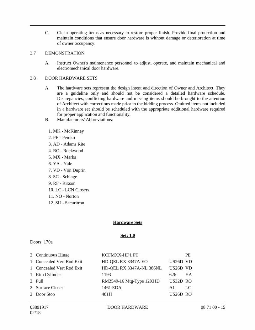
03891917 DOOR HARDWARE 08 71 00 - 15
02/18
C. Clean operating items as necessary to restore proper finish. Provide final protection and
maintain conditions that ensure door hardware is without damage or deterioration at time
of owner occupancy.
3.7 DEMONSTRATION
A. Instruct Owner's maintenance personnel to adjust, operate, and maintain mechanical and
electromechanical door hardware.
3.8 DOOR HARDWARE SETS
A. The hardware sets represent the design intent and direction of Owner and Architect. They
are a guideline only and should not be considered a detailed hardware schedule.
Discrepancies, conflicting hardware and missing items should be brought to the attention
of Architect with corrections made prior to the bidding process. Omitted items not included
in a hardware set should be scheduled with the appropriate additional hardware required
for proper application and functionality.
B. Manufacturers' Abbreviations:
1. MK - McKinney
2. PE - Pemko
3. AD - Adams Rite
4. RO - Rockwood
5. MX - Marks
6. YA - Yale
7. VD - Von Duprin
8. SC - Schlage
9. RF - Rixson
10. LC - LCN Closers
11. NO - Norton
12. SU - Securitron
Hardware Sets
Set: 1.0
Doors: 170a
2 Continuous Hinge KCFMXX-HD1 PT PE
1 Concealed Vert Rod Exit HD-QEL RX 3347A-EO US26D VD
1 Concealed Vert Rod Exit HD-QEL RX 3347A-NL 386NL US26D VD
1 Rim Cylinder 1193 626 YA
2 Pull RM2540-16 Mtg-Type 12XHD US32D RO
2 Surface Closer 1461 EDA AL LC
2 Door Stop 481H US26D RO
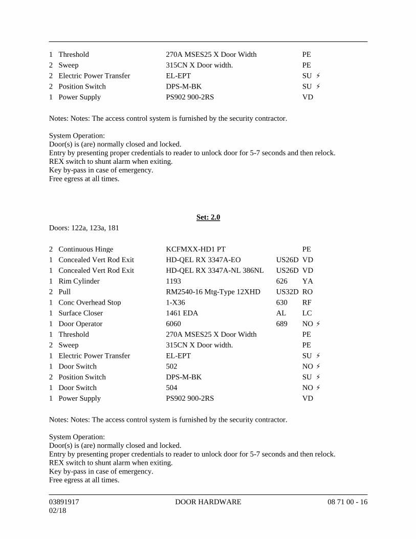
03891917 DOOR HARDWARE 08 71 00 - 16
02/18
1 Threshold 270A MSES25 X Door Width PE
2 Sweep 315CN X Door width. PE
2 Electric Power Transfer EL-EPT SU ⚡
2 Position Switch DPS-M-BK SU ⚡
1 Power Supply PS902 900-2RS VD
Notes: Notes: The access control system is furnished by the security contractor.
System Operation:
Door(s) is (are) normally closed and locked.
Entry by presenting proper credentials to reader to unlock door for 5-7 seconds and then relock.
REX switch to shunt alarm when exiting.
Key by-pass in case of emergency.
Free egress at all times.
Set: 2.0
Doors: 122a, 123a, 181
2 Continuous Hinge KCFMXX-HD1 PT PE
1 Concealed Vert Rod Exit HD-QEL RX 3347A-EO US26D VD
1 Concealed Vert Rod Exit HD-QEL RX 3347A-NL 386NL US26D VD
1 Rim Cylinder 1193 626 YA
2 Pull RM2540-16 Mtg-Type 12XHD US32D RO
1 Conc Overhead Stop 1-X36 630 RF
1 Surface Closer 1461 EDA AL LC
1 Door Operator 6060 689 NO ⚡
1 Threshold 270A MSES25 X Door Width PE
2 Sweep 315CN X Door width. PE
1 Electric Power Transfer EL-EPT SU ⚡
1 Door Switch 502 NO ⚡
2 Position Switch DPS-M-BK SU ⚡
1 Door Switch 504 NO ⚡
1 Power Supply PS902 900-2RS VD
Notes: Notes: The access control system is furnished by the security contractor.
System Operation:
Door(s) is (are) normally closed and locked.
Entry by presenting proper credentials to reader to unlock door for 5-7 seconds and then relock.
REX switch to shunt alarm when exiting.
Key by-pass in case of emergency.
Free egress at all times.
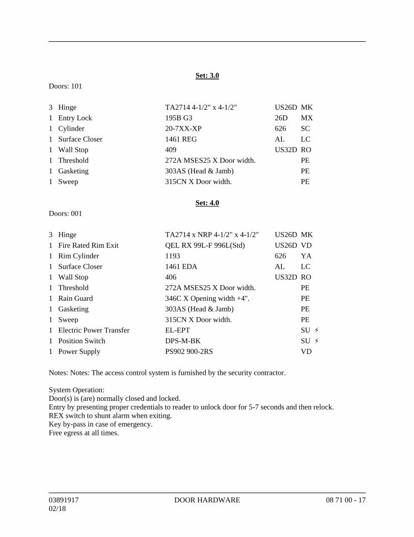
03891917 DOOR HARDWARE 08 71 00 - 17
02/18
Set: 3.0
Doors: 101
3 Hinge TA2714 4-1/2" x 4-1/2" US26D MK
1 Entry Lock 195B G3 26D MX
1 Cylinder 20-7XX-XP 626 SC
1 Surface Closer 1461 REG AL LC
1 Wall Stop 409 US32D RO
1 Threshold 272A MSES25 X Door width. PE
1 Gasketing 303AS (Head & Jamb) PE
1 Sweep 315CN X Door width. PE
Set: 4.0
Doors: 001
3 Hinge TA2714 x NRP 4-1/2" x 4-1/2" US26D MK
1 Fire Rated Rim Exit QEL RX 99L-F 996L(Std) US26D VD
1 Rim Cylinder 1193 626 YA
1 Surface Closer 1461 EDA AL LC
1 Wall Stop 406 US32D RO
1 Threshold 272A MSES25 X Door width. PE
1 Rain Guard 346C X Opening width +4". PE
1 Gasketing 303AS (Head & Jamb) PE
1 Sweep 315CN X Door width. PE
1 Electric Power Transfer EL-EPT SU ⚡
1 Position Switch DPS-M-BK SU ⚡
1 Power Supply PS902 900-2RS VD
Notes: Notes: The access control system is furnished by the security contractor.
System Operation:
Door(s) is (are) normally closed and locked.
Entry by presenting proper credentials to reader to unlock door for 5-7 seconds and then relock.
REX switch to shunt alarm when exiting.
Key by-pass in case of emergency.
Free egress at all times.
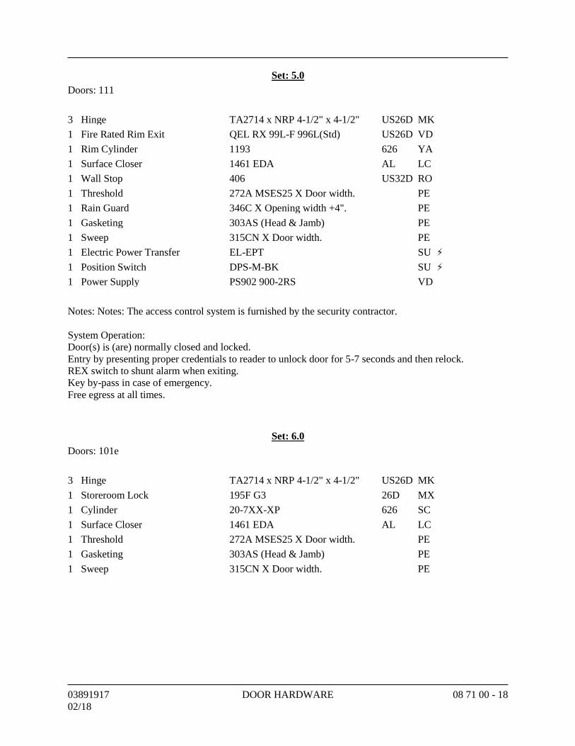
03891917 DOOR HARDWARE 08 71 00 - 18
02/18
Set: 5.0
Doors: 111
3 Hinge TA2714 x NRP 4-1/2" x 4-1/2" US26D MK
1 Fire Rated Rim Exit QEL RX 99L-F 996L(Std) US26D VD
1 Rim Cylinder 1193 626 YA
1 Surface Closer 1461 EDA AL LC
1 Wall Stop 406 US32D RO
1 Threshold 272A MSES25 X Door width. PE
1 Rain Guard 346C X Opening width +4". PE
1 Gasketing 303AS (Head & Jamb) PE
1 Sweep 315CN X Door width. PE
1 Electric Power Transfer EL-EPT SU ⚡
1 Position Switch DPS-M-BK SU ⚡
1 Power Supply PS902 900-2RS VD
Notes: Notes: The access control system is furnished by the security contractor.
System Operation:
Door(s) is (are) normally closed and locked.
Entry by presenting proper credentials to reader to unlock door for 5-7 seconds and then relock.
REX switch to shunt alarm when exiting.
Key by-pass in case of emergency.
Free egress at all times.
Set: 6.0
Doors: 101e
3 Hinge TA2714 x NRP 4-1/2" x 4-1/2" US26D MK
1 Storeroom Lock 195F G3 26D MX
1 Cylinder 20-7XX-XP 626 SC
1 Surface Closer 1461 EDA AL LC
1 Threshold 272A MSES25 X Door width. PE
1 Gasketing 303AS (Head & Jamb) PE
1 Sweep 315CN X Door width. PE
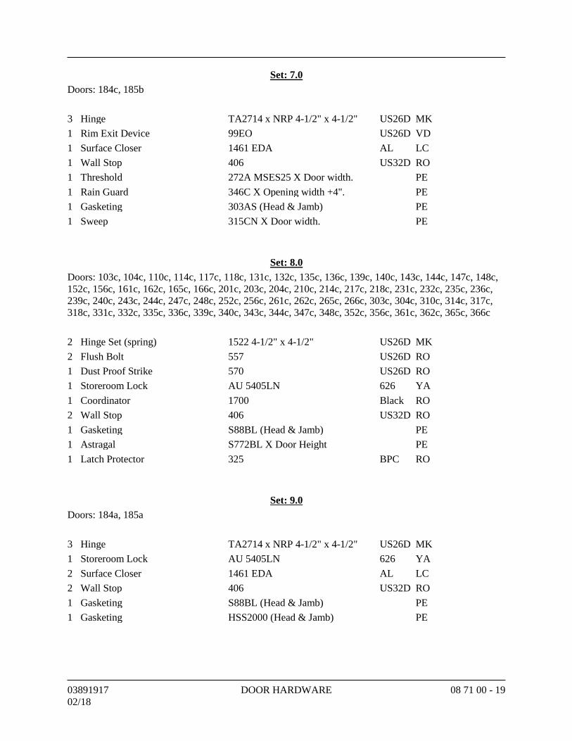
03891917 DOOR HARDWARE 08 71 00 - 19
02/18
Set: 7.0
Doors: 184c, 185b
3 Hinge TA2714 x NRP 4-1/2" x 4-1/2" US26D MK
1 Rim Exit Device 99EO US26D VD
1 Surface Closer 1461 EDA AL LC
1 Wall Stop 406 US32D RO
1 Threshold 272A MSES25 X Door width. PE
1 Rain Guard 346C X Opening width +4". PE
1 Gasketing 303AS (Head & Jamb) PE
1 Sweep 315CN X Door width. PE
Set: 8.0
Doors: 103c, 104c, 110c, 114c, 117c, 118c, 131c, 132c, 135c, 136c, 139c, 140c, 143c, 144c, 147c, 148c,
152c, 156c, 161c, 162c, 165c, 166c, 201c, 203c, 204c, 210c, 214c, 217c, 218c, 231c, 232c, 235c, 236c,
239c, 240c, 243c, 244c, 247c, 248c, 252c, 256c, 261c, 262c, 265c, 266c, 303c, 304c, 310c, 314c, 317c,
318c, 331c, 332c, 335c, 336c, 339c, 340c, 343c, 344c, 347c, 348c, 352c, 356c, 361c, 362c, 365c, 366c
2 Hinge Set (spring) 1522 4-1/2" x 4-1/2" US26D MK
2 Flush Bolt 557 US26D RO
1 Dust Proof Strike 570 US26D RO
1 Storeroom Lock AU 5405LN 626 YA
1 Coordinator 1700 Black RO
2 Wall Stop 406 US32D RO
1 Gasketing S88BL (Head & Jamb) PE
1 Astragal S772BL X Door Height PE
1 Latch Protector 325 BPC RO
Set: 9.0
Doors: 184a, 185a
3 Hinge TA2714 x NRP 4-1/2" x 4-1/2" US26D MK
1 Storeroom Lock AU 5405LN 626 YA
2 Surface Closer 1461 EDA AL LC
2 Wall Stop 406 US32D RO
1 Gasketing S88BL (Head & Jamb) PE
1 Gasketing HSS2000 (Head & Jamb) PE
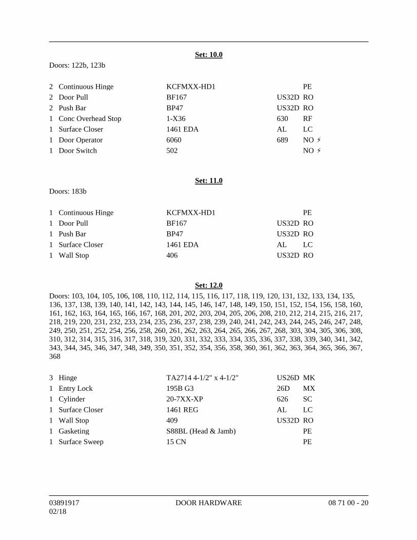
03891917 DOOR HARDWARE 08 71 00 - 20
02/18
Set: 10.0
Doors: 122b, 123b
2 Continuous Hinge KCFMXX-HD1 PE
2 Door Pull BF167 US32D RO
2 Push Bar BP47 US32D RO
1 Conc Overhead Stop 1-X36 630 RF
1 Surface Closer 1461 EDA AL LC
1 Door Operator 6060 689 NO ⚡
1 Door Switch 502 NO ⚡
Set: 11.0
Doors: 183b
1 Continuous Hinge KCFMXX-HD1 PE
1 Door Pull BF167 US32D RO
1 Push Bar BP47 US32D RO
1 Surface Closer 1461 EDA AL LC
1 Wall Stop 406 US32D RO
Set: 12.0
Doors: 103, 104, 105, 106, 108, 110, 112, 114, 115, 116, 117, 118, 119, 120, 131, 132, 133, 134, 135,
136, 137, 138, 139, 140, 141, 142, 143, 144, 145, 146, 147, 148, 149, 150, 151, 152, 154, 156, 158, 160,
161, 162, 163, 164, 165, 166, 167, 168, 201, 202, 203, 204, 205, 206, 208, 210, 212, 214, 215, 216, 217,
218, 219, 220, 231, 232, 233, 234, 235, 236, 237, 238, 239, 240, 241, 242, 243, 244, 245, 246, 247, 248,
249, 250, 251, 252, 254, 256, 258, 260, 261, 262, 263, 264, 265, 266, 267, 268, 303, 304, 305, 306, 308,
310, 312, 314, 315, 316, 317, 318, 319, 320, 331, 332, 333, 334, 335, 336, 337, 338, 339, 340, 341, 342,
343, 344, 345, 346, 347, 348, 349, 350, 351, 352, 354, 356, 358, 360, 361, 362, 363, 364, 365, 366, 367,
368
3 Hinge TA2714 4-1/2" x 4-1/2" US26D MK
1 Entry Lock 195B G3 26D MX
1 Cylinder 20-7XX-XP 626 SC
1 Surface Closer 1461 REG AL LC
1 Wall Stop 409 US32D RO
1 Gasketing S88BL (Head & Jamb) PE
1 Surface Sweep 15 CN PE
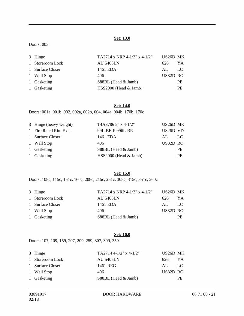
03891917 DOOR HARDWARE 08 71 00 - 21
02/18
Set: 13.0
Doors: 003
3 Hinge TA2714 x NRP 4-1/2" x 4-1/2" US26D MK
1 Storeroom Lock AU 5405LN 626 YA
1 Surface Closer 1461 EDA AL LC
1 Wall Stop 406 US32D RO
1 Gasketing S88BL (Head & Jamb) PE
1 Gasketing HSS2000 (Head & Jamb) PE
Set: 14.0
Doors: 001a, 001b, 002, 002a, 002b, 004, 004a, 004b, 170b, 170c
3 Hinge (heavy weight) T4A3786 5" x 4-1/2" US26D MK
1 Fire Rated Rim Exit 99L-BE-F 996L-BE US26D VD
1 Surface Closer 1461 EDA AL LC
1 Wall Stop 406 US32D RO
1 Gasketing S88BL (Head & Jamb) PE
1 Gasketing HSS2000 (Head & Jamb) PE
Set: 15.0
Doors: 108c, 115c, 151c, 160c, 208c, 215c, 251c, 308c, 315c, 351c, 360c
3 Hinge TA2714 x NRP 4-1/2" x 4-1/2" US26D MK
1 Storeroom Lock AU 5405LN 626 YA
1 Surface Closer 1461 EDA AL LC
1 Wall Stop 406 US32D RO
1 Gasketing S88BL (Head & Jamb) PE
Set: 16.0
Doors: 107, 109, 159, 207, 209, 259, 307, 309, 359
3 Hinge TA2714 4-1/2" x 4-1/2" US26D MK
1 Storeroom Lock AU 5405LN 626 YA
1 Surface Closer 1461 REG AL LC
1 Wall Stop 406 US32D RO
1 Gasketing S88BL (Head & Jamb) PE
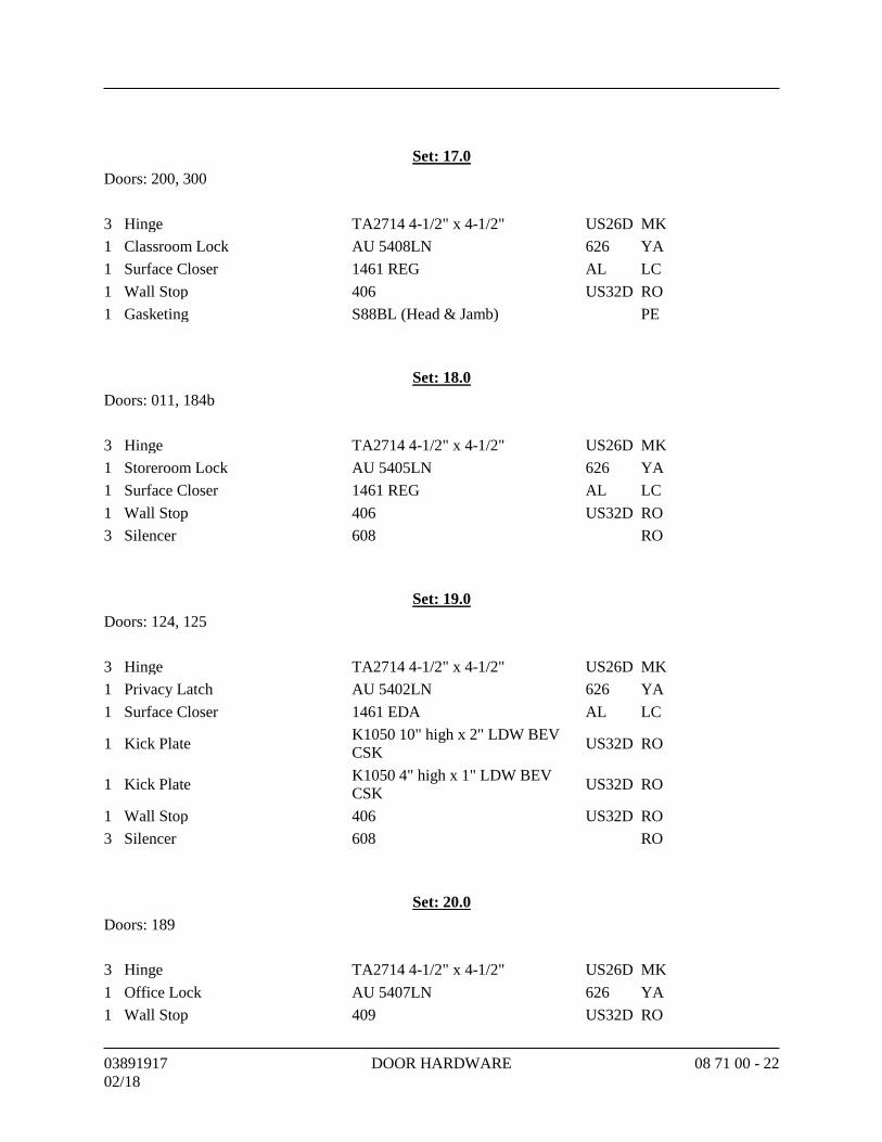
03891917 DOOR HARDWARE 08 71 00 - 22
02/18
Set: 17.0
Doors: 200, 300
3 Hinge TA2714 4-1/2" x 4-1/2" US26D MK
1 Classroom Lock AU 5408LN 626 YA
1 Surface Closer 1461 REG AL LC
1 Wall Stop 406 US32D RO
1 Gasketing S88BL (Head & Jamb) PE
Set: 18.0
Doors: 011, 184b
3 Hinge TA2714 4-1/2" x 4-1/2" US26D MK
1 Storeroom Lock AU 5405LN 626 YA
1 Surface Closer 1461 REG AL LC
1 Wall Stop 406 US32D RO
3 Silencer 608 RO
Set: 19.0
Doors: 124, 125
3 Hinge TA2714 4-1/2" x 4-1/2" US26D MK
1 Privacy Latch AU 5402LN 626 YA
1 Surface Closer 1461 EDA AL LC
1 Kick Plate K1050 10" high x 2" LDW BEV
CSK US32D RO
1 Kick Plate K1050 4" high x 1" LDW BEV
CSK US32D RO
1 Wall Stop 406 US32D RO
3 Silencer 608 RO
Set: 20.0
Doors: 189
3 Hinge TA2714 4-1/2" x 4-1/2" US26D MK
1 Office Lock AU 5407LN 626 YA
1 Wall Stop 409 US32D RO
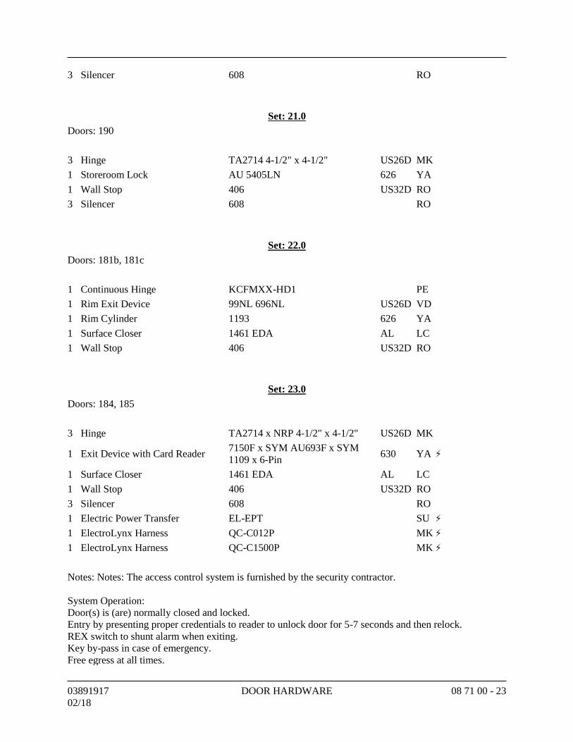
03891917 DOOR HARDWARE 08 71 00 - 23
02/18
3 Silencer 608 RO
Set: 21.0
Doors: 190
3 Hinge TA2714 4-1/2" x 4-1/2" US26D MK
1 Storeroom Lock AU 5405LN 626 YA
1 Wall Stop 406 US32D RO
3 Silencer 608 RO
Set: 22.0
Doors: 181b, 181c
1 Continuous Hinge KCFMXX-HD1 PE
1 Rim Exit Device 99NL 696NL US26D VD
1 Rim Cylinder 1193 626 YA
1 Surface Closer 1461 EDA AL LC
1 Wall Stop 406 US32D RO
Set: 23.0
Doors: 184, 185
3 Hinge TA2714 x NRP 4-1/2" x 4-1/2" US26D MK
1 Exit Device with Card Reader 7150F x SYM AU693F x SYM
1109 x 6-Pin 630 YA ⚡
1 Surface Closer 1461 EDA AL LC
1 Wall Stop 406 US32D RO
3 Silencer 608 RO
1 Electric Power Transfer EL-EPT SU ⚡
1 ElectroLynx Harness QC-C012P MK ⚡
1 ElectroLynx Harness QC-C1500P MK ⚡
Notes: Notes: The access control system is furnished by the security contractor.
System Operation:
Door(s) is (are) normally closed and locked.
Entry by presenting proper credentials to reader to unlock door for 5-7 seconds and then relock.
REX switch to shunt alarm when exiting.
Key by-pass in case of emergency.
Free egress at all times.
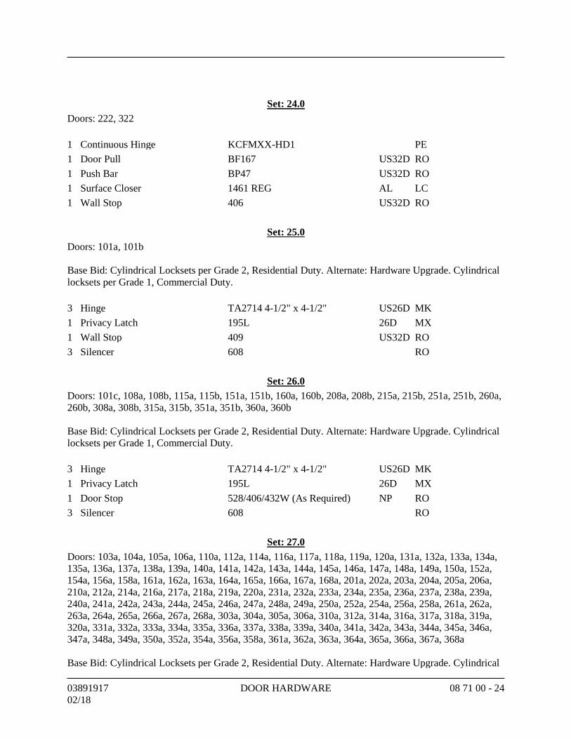
03891917 DOOR HARDWARE 08 71 00 - 24
02/18
Set: 24.0
Doors: 222, 322
1 Continuous Hinge KCFMXX-HD1 PE
1 Door Pull BF167 US32D RO
1 Push Bar BP47 US32D RO
1 Surface Closer 1461 REG AL LC
1 Wall Stop 406 US32D RO
Set: 25.0
Doors: 101a, 101b
Base Bid: Cylindrical Locksets per Grade 2, Residential Duty. Alternate: Hardware Upgrade. Cylindrical
locksets per Grade 1, Commercial Duty.
3 Hinge TA2714 4-1/2" x 4-1/2" US26D MK
1 Privacy Latch 195L 26D MX
1 Wall Stop 409 US32D RO
3 Silencer 608 RO
Set: 26.0
Doors: 101c, 108a, 108b, 115a, 115b, 151a, 151b, 160a, 160b, 208a, 208b, 215a, 215b, 251a, 251b, 260a,
260b, 308a, 308b, 315a, 315b, 351a, 351b, 360a, 360b
Base Bid: Cylindrical Locksets per Grade 2, Residential Duty. Alternate: Hardware Upgrade. Cylindrical
locksets per Grade 1, Commercial Duty.
3 Hinge TA2714 4-1/2" x 4-1/2" US26D MK
1 Privacy Latch 195L 26D MX
1 Door Stop 528/406/432W (As Required) NP RO
3 Silencer 608 RO
Set: 27.0
Doors: 103a, 104a, 105a, 106a, 110a, 112a, 114a, 116a, 117a, 118a, 119a, 120a, 131a, 132a, 133a, 134a,
135a, 136a, 137a, 138a, 139a, 140a, 141a, 142a, 143a, 144a, 145a, 146a, 147a, 148a, 149a, 150a, 152a,
154a, 156a, 158a, 161a, 162a, 163a, 164a, 165a, 166a, 167a, 168a, 201a, 202a, 203a, 204a, 205a, 206a,
210a, 212a, 214a, 216a, 217a, 218a, 219a, 220a, 231a, 232a, 233a, 234a, 235a, 236a, 237a, 238a, 239a,
240a, 241a, 242a, 243a, 244a, 245a, 246a, 247a, 248a, 249a, 250a, 252a, 254a, 256a, 258a, 261a, 262a,
263a, 264a, 265a, 266a, 267a, 268a, 303a, 304a, 305a, 306a, 310a, 312a, 314a, 316a, 317a, 318a, 319a,
320a, 331a, 332a, 333a, 334a, 335a, 336a, 337a, 338a, 339a, 340a, 341a, 342a, 343a, 344a, 345a, 346a,
347a, 348a, 349a, 350a, 352a, 354a, 356a, 358a, 361a, 362a, 363a, 364a, 365a, 366a, 367a, 368a
Base Bid: Cylindrical Locksets per Grade 2, Residential Duty. Alternate: Hardware Upgrade. Cylindrical
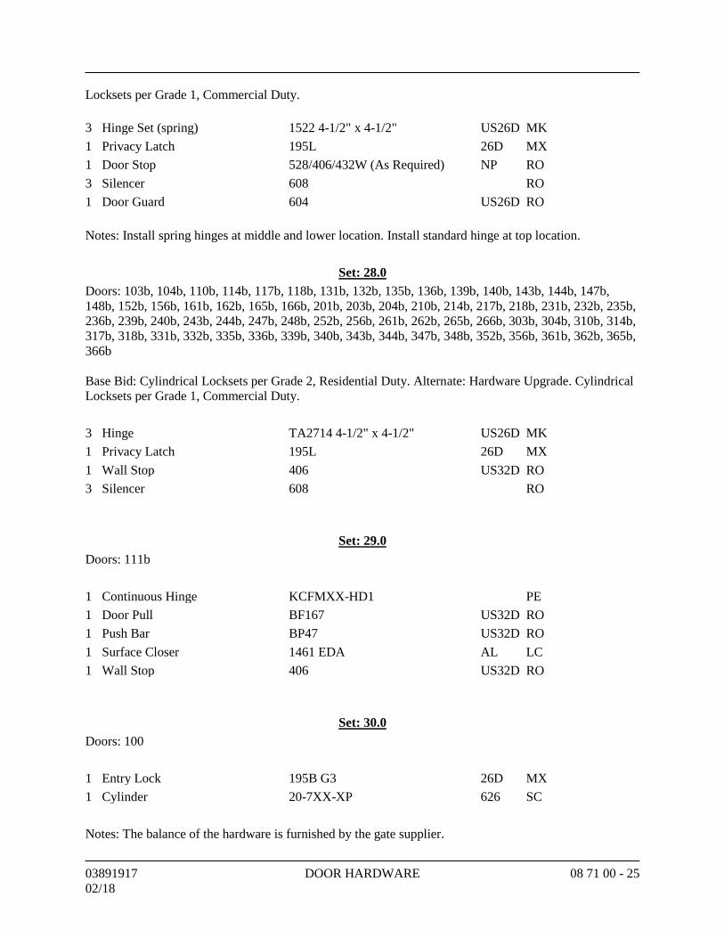
03891917 DOOR HARDWARE 08 71 00 - 25
02/18
Locksets per Grade 1, Commercial Duty.
3 Hinge Set (spring) 1522 4-1/2" x 4-1/2" US26D MK
1 Privacy Latch 195L 26D MX
1 Door Stop 528/406/432W (As Required) NP RO
3 Silencer 608 RO
1 Door Guard 604 US26D RO
Notes: Install spring hinges at middle and lower location. Install standard hinge at top location.
Set: 28.0
Doors: 103b, 104b, 110b, 114b, 117b, 118b, 131b, 132b, 135b, 136b, 139b, 140b, 143b, 144b, 147b,
148b, 152b, 156b, 161b, 162b, 165b, 166b, 201b, 203b, 204b, 210b, 214b, 217b, 218b, 231b, 232b, 235b,
236b, 239b, 240b, 243b, 244b, 247b, 248b, 252b, 256b, 261b, 262b, 265b, 266b, 303b, 304b, 310b, 314b,
317b, 318b, 331b, 332b, 335b, 336b, 339b, 340b, 343b, 344b, 347b, 348b, 352b, 356b, 361b, 362b, 365b,
366b
Base Bid: Cylindrical Locksets per Grade 2, Residential Duty. Alternate: Hardware Upgrade. Cylindrical
Locksets per Grade 1, Commercial Duty.
3 Hinge TA2714 4-1/2" x 4-1/2" US26D MK
1 Privacy Latch 195L 26D MX
1 Wall Stop 406 US32D RO
3 Silencer 608 RO
Set: 29.0
Doors: 111b
1 Continuous Hinge KCFMXX-HD1 PE
1 Door Pull BF167 US32D RO
1 Push Bar BP47 US32D RO
1 Surface Closer 1461 EDA AL LC
1 Wall Stop 406 US32D RO
Set: 30.0
Doors: 100
1 Entry Lock 195B G3 26D MX
1 Cylinder 20-7XX-XP 626 SC
Notes: The balance of the hardware is furnished by the gate supplier.
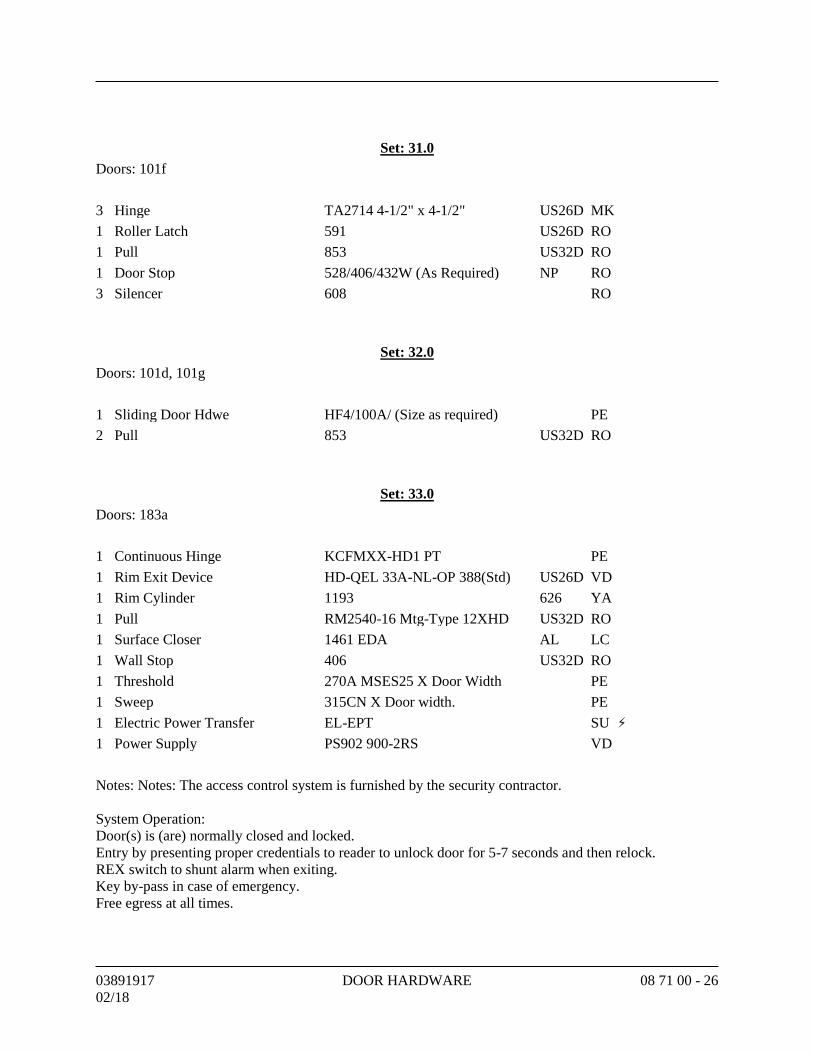
03891917 DOOR HARDWARE 08 71 00 - 26
02/18
Set: 31.0
Doors: 101f
3 Hinge TA2714 4-1/2" x 4-1/2" US26D MK
1 Roller Latch 591 US26D RO
1 Pull 853 US32D RO
1 Door Stop 528/406/432W (As Required) NP RO
3 Silencer 608 RO
Set: 32.0
Doors: 101d, 101g
1 Sliding Door Hdwe HF4/100A/ (Size as required) PE
2 Pull 853 US32D RO
Set: 33.0
Doors: 183a
1 Continuous Hinge KCFMXX-HD1 PT PE
1 Rim Exit Device HD-QEL 33A-NL-OP 388(Std) US26D VD
1 Rim Cylinder 1193 626 YA
1 Pull RM2540-16 Mtg-Type 12XHD US32D RO
1 Surface Closer 1461 EDA AL LC
1 Wall Stop 406 US32D RO
1 Threshold 270A MSES25 X Door Width PE
1 Sweep 315CN X Door width. PE
1 Electric Power Transfer EL-EPT SU ⚡
1 Power Supply PS902 900-2RS VD
Notes: Notes: The access control system is furnished by the security contractor.
System Operation:
Door(s) is (are) normally closed and locked.
Entry by presenting proper credentials to reader to unlock door for 5-7 seconds and then relock.
REX switch to shunt alarm when exiting.
Key by-pass in case of emergency.
Free egress at all times.
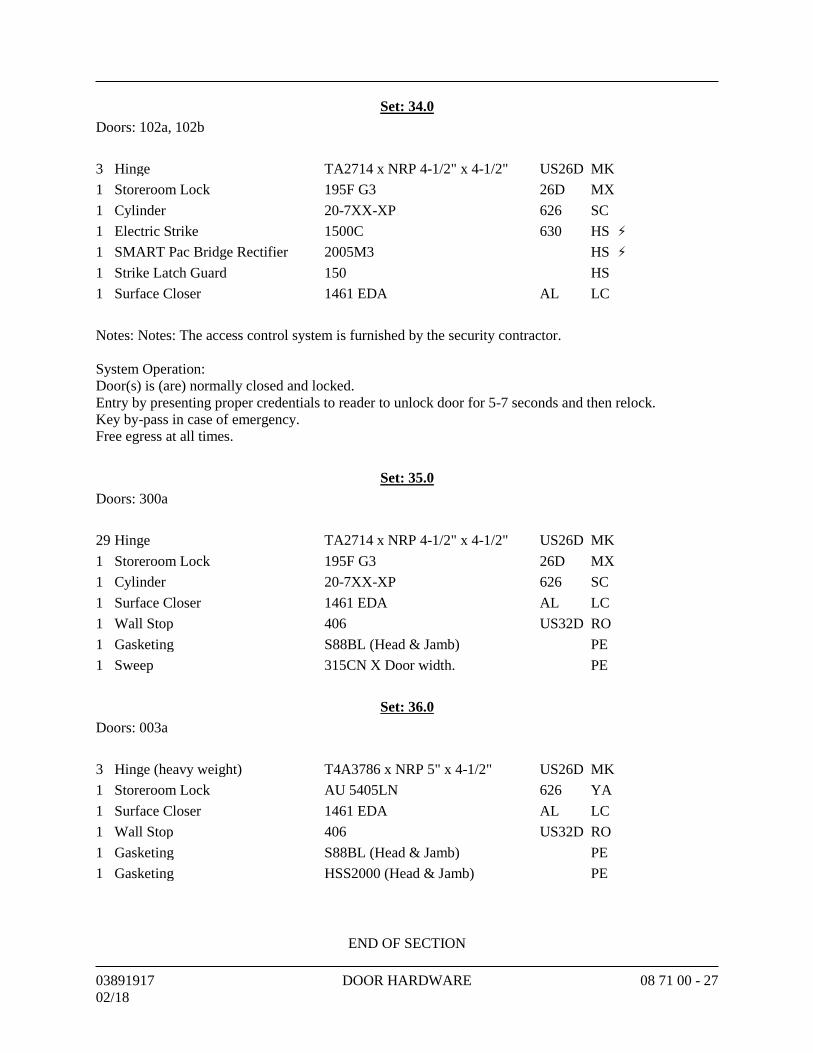
03891917 DOOR HARDWARE 08 71 00 - 27
02/18
Set: 34.0
Doors: 102a, 102b
3 Hinge TA2714 x NRP 4-1/2" x 4-1/2" US26D MK
1 Storeroom Lock 195F G3 26D MX
1 Cylinder 20-7XX-XP 626 SC
1 Electric Strike 1500C 630 HS ⚡
1 SMART Pac Bridge Rectifier 2005M3 HS ⚡
1 Strike Latch Guard 150 HS
1 Surface Closer 1461 EDA AL LC
Notes: Notes: The access control system is furnished by the security contractor.
System Operation:
Door(s) is (are) normally closed and locked.
Entry by presenting proper credentials to reader to unlock door for 5-7 seconds and then relock.
Key by-pass in case of emergency.
Free egress at all times.
Set: 35.0
Doors: 300a
29 Hinge TA2714 x NRP 4-1/2" x 4-1/2" US26D MK
1 Storeroom Lock 195F G3 26D MX
1 Cylinder 20-7XX-XP 626 SC
1 Surface Closer 1461 EDA AL LC
1 Wall Stop 406 US32D RO
1 Gasketing S88BL (Head & Jamb) PE
1 Sweep 315CN X Door width. PE
Set: 36.0
Doors: 003a
3 Hinge (heavy weight) T4A3786 x NRP 5" x 4-1/2" US26D MK
1 Storeroom Lock AU 5405LN 626 YA
1 Surface Closer 1461 EDA AL LC
1 Wall Stop 406 US32D RO
1 Gasketing S88BL (Head & Jamb) PE
1 Gasketing HSS2000 (Head & Jamb) PE
END OF SECTION
SECTION 08 80 00 - GLAZING
GENERALPART 1 -
SUMMARY1.1
Section Includes:A.Glass for:1.
Windows.a.Doors.b.Storefront framing.c.
Glazing sealants and accessories.2.Related Requirements:B.
Section 00 00 00 "Invitation to Bid" for reference to Drawings and general1.provisions of the Contract including General and Supplementary Conditions.Division 01 Specification Sections apply to Work of this Section.2.Section 01 81 13 "Sustainable Design Requirements" for LEED Sustainability3.Requirements.Section 08 41 13 "Aluminum-Framed Entrances and Storefronts."4.
DEFINITIONS1.2
Glass Manufacturers: Firms that produce primary glass, fabricated glass, or both, asA.defined in referenced glazing publications.Glass Thicknesses: Indicated by thickness designations in millimeters according to ASTMB.C 1036.IBC: International Building Code.C.Interspace: Space between lites of an insulating-glass unit.D.
COORDINATION1.3
Coordinate glazing channel dimensions to provide necessary bite on glass, minimum edgeA.and face clearances, and adequate sealant thicknesses, with reasonable tolerances.
PREINSTALLATION MEETINGS1.4
Preinstallation Conference: Conduct conference at Project site.A.Review and finalize construction schedule and verify availability of materials,1.Installer's personnel, equipment, and facilities needed to make progress and avoiddelays.Review temporary protection requirements for glazing during and after installation.2.
ACTION SUBMITTALS1.5
Product Data: For each type of product.A.LEED Submittals:B.
Product Data for Credit IEQ 4.1: For field-applied glazing sealants, documentation1.including printed statement of VOC content.
0389191702/18
GLAZING 08 80 00 - 1
Glass Samples: For each type of the following products; 12 inches square.C.Coated glass.1.Insulating glass.2.Insulating glass with muntin grid between the glass.3.
Glazing Accessory Samples: For sealants and colored spacers, in 12-inch lengths.D.Glazing Schedule: List glass types and thicknesses for each size opening and location. UseE.same designations indicated on Drawings.
INFORMATIONAL SUBMITTALS1.6
Qualification Data:A.Installer.1.Manufacturers of insulating-glass units with sputter-coated, low-E coatings.2.Glass testing agency.3.
Product Certificates: For glass.B.Product Test Reports: For insulating glass and glazing sealants, for tests performed by aC.qualified testing agency.
For glazing sealants, provide test reports based on testing current sealant1.formulations within previous 36-month period.
Preconstruction adhesion and compatibility test report.D.Sample Warranties: For special warranties.E.
QUALITY ASSURANCE1.7
Manufacturer Qualifications for Insulating-Glass Units with Sputter-Coated, Low-EA.Coatings: A qualified insulating-glass manufacturer who is approved and certified bycoated-glass manufacturer.Installer Qualifications: A qualified installer who employs glass installers for this ProjectB.who are certified under the National Glass Association's Certified Glass Installer Program.Glass Testing Agency Qualifications: A qualified independent testing agency accreditedC.according to the NFRC CAP 1 Certification Agency Program.Sealant Testing Agency Qualifications: An independent testing agency qualified accordingD.to ASTM C 1021 to conduct the testing indicated.Mockups: Build mockups to demonstrate aesthetic effects and to set quality standards forE.materials and execution.
Install glazing in mockups specified in Section 08 41 13 "Aluminum-Framed1.Entrances and Storefronts" to match glazing systems required for Project, includingglazing methods.Subject to compliance with requirements, approved mockups may become part of2.the completed Work if undisturbed at time of Substantial Completion.
PRECONSTRUCTION TESTING1.8
Preconstruction Adhesion and Compatibility Testing: Test each glass product, tape sealant,A.gasket, glazing accessory, and glass-framing member for adhesion to and compatibilitywith elastomeric glazing sealants.
Testing is not required if data are submitted based on previous testing of current1.sealant products and glazing materials matching those submitted.
0389191702/18
GLAZING 08 80 00 - 2
DELIVERY, STORAGE, AND HANDLING1.9
Protect glazing materials according to manufacturer's written instructions. Prevent damageA.to glass and glazing materials from condensation, temperature changes, direct exposure tosun, or other causes.
FIELD CONDITIONS1.10
Environmental Limitations: Do not proceed with glazing when ambient and substrateA.temperature conditions are outside limits permitted by glazing material manufacturers andwhen glazing channel substrates are wet from rain, frost, condensation, or other causes.
Do not install glazing sealants when ambient and substrate temperature conditions1.are outside limits permitted by sealant manufacturer or are below 40 deg F.
WARRANTY1.11
Manufacturer's Special Warranty for Coated-Glass Products: Manufacturer agrees toA.replace coated-glass units that deteriorate within specified warranty period. Deteriorationof coated glass is defined as defects developed from normal use that are not attributed toglass breakage or to maintaining and cleaning coated glass contrary to manufacturer'swritten instructions. Defects include peeling, cracking, and other indications ofdeterioration in coating.
Warranty Period: 10 years from date of Substantial Completion.1.Manufacturer's Special Warranty for Insulating Glass: Manufacturer agrees to replaceB.insulating-glass units that deteriorate within specified warranty period. Deterioration ofinsulating glass is defined as failure of hermetic seal under normal use that is not attributedto glass breakage or to maintaining and cleaning insulating glass contrary to manufacturer'swritten instructions. Evidence of failure is the obstruction of vision by dust, moisture, orfilm on interior surfaces of glass.
Warranty Period: 10 years from date of Substantial Completion.1.
PRODUCTSPART 2 -
MANUFACTURERS2.1
Basis-of-Design Glass Product: Subject to compliance with requirements, provide productA.indicated in glass schedules or comparable product by one of the following:
PPG Industries, Inc.1.SaftiFirst/O'Keefe's Inc.2.Viracon, Inc.3.
Source Limitations for Glass: Obtain from single source from single manufacturer for eachB.glass type.
Obtain tinted glass from single source from single manufacturer.1.Obtain reflective-coated glass from single source from single manufacturer.2.
Source Limitations for Glazing Accessories: Obtain from single source from singleC.manufacturer for each product and installation method.
0389191702/18
GLAZING 08 80 00 - 3
PERFORMANCE REQUIREMENTS2.2
General: Installed glazing systems shall withstand normal thermal movement and wind andA.impact loads (where applicable) without failure, including loss or glass breakageattributable to the following: defective manufacture, fabrication, or installation; failure ofsealants or gaskets to remain watertight and airtight; deterioration of glazing materials; orother defects in construction.Structural Performance: Glazing shall withstand the following design loads within limitsB.and under conditions indicated determined according to the IBC and ASTM E 1300.
Design Wind Pressures: As indicated on Drawings.1.Safety Glazing: Where safety glazing is indicated, provide glazing that complies with 16C.CFR 1201, Category II.Thermal and Optical Performance Properties: Provide glass with performance propertiesD.specified, as indicated in manufacturer's published test data, based on procedures indicatedbelow:
For monolithic-glass lites, properties are based on units with lites 6 mm thick.1.For insulating-glass units, properties are based on units of thickness indicated for2.overall unit and for each lite.U-Factors: Center-of-glazing values, according to NFRC 100 and based on LBL's3.WINDOW 5.2 computer program, expressed as Btu/sq. ft. x h x deg F.Solar Heat-Gain Coefficient and Visible Transmittance: Center-of-glazing values,4.according to NFRC 200 and based on LBL's WINDOW 5.2 computer program.Visible Reflectance: Center-of-glazing values, according to NFRC 300.5.
GLASS PRODUCTS, GENERAL2.3
Glazing Publications: Comply with published recommendations of glass productA.manufacturers and organizations below unless more stringent requirements are indicated.See these publications for glazing terms not otherwise defined in this Section or inreferenced standards.
GANA Publications: "Laminated Glazing Reference Manual" and "Glazing1.Manual."AAMA Publications: AAMA GDSG-1, "Glass Design for Sloped Glazing," and2.AAMA TIR A7, "Sloped Glazing Guidelines."IGMA Publication for Sloped Glazing: IGMA TB-3001, "Guidelines for Sloped3.Glazing."IGMA Publication for Insulating Glass: SIGMA TM-3000, "North American4.Glazing Guidelines for Sealed Insulating Glass Units for Commercial andResidential Use."
Safety Glazing Labeling: Where safety glazing is indicated, permanently mark glazingB.with certification label of manufacturer. Label shall indicate manufacturer's name, type ofglass, thickness, and safety glazing standard with which glass complies.Insulating-Glass Certification Program: Permanently marked either on spacers or on atC.least one component lite of units with appropriate certification label of IGCC.Thickness: Where glass thickness is indicated, it is a minimum.D.Strength: Where annealed float glass is indicated, provide annealed float glass,E.heat-strengthened float glass, or fully tempered float glass as needed to comply with"Performance Requirements" Article. Where heat-strengthened float glass is indicated,provide heat-strengthened float glass or fully tempered float glass as needed to complywith "Performance Requirements" Article. Where fully tempered float glass is indicated,provide fully tempered float glass.
0389191702/18
GLAZING 08 80 00 - 4
GLASS PRODUCTS2.4
Clear Annealed Float Glass: ASTM C 1036, Type I, Class 1 (clear), Quality-Q3.A.Fully Tempered Float Glass: ASTM C 1048, Kind FT (fully tempered), Condition AB.(uncoated) unless otherwise indicated, Type I, Class 1 (clear) or Class 2 (tinted) asindicated, Quality-Q3.
Fabrication Process: By horizontal (roller-hearth) process with roll-wave distortion1.parallel to bottom edge of glass as installed unless otherwise indicated.
Heat-Strengthened Float Glass: ASTM C 1048, Kind HS (heat strengthened), Type I,C.Condition A (uncoated) unless otherwise indicated, Type I, Class 1 (clear) or Class 2(tinted) as indicated, Quality-Q3.
Fabrication Process: By horizontal (roller-hearth) process with roll-wave distortion1.parallel to bottom edge of glass as installed unless otherwise indicated.
Pyrolytic-Coated, Low-Maintenance Glass: Clear float glass with a coating on first surfaceD.having both photocatalytic and hydrophilic properties that act to loosen dirt and to causewater to sheet evenly over the glass instead of beading.
Basis-of-Design Product: Solarban 70XL Solar Control Low-E Glass, manufactured1.by PPG Industries.
Specialty Fire Protective Glazing: Specialty fire protective glazing and complying with 16E.CFR 1201, Category I.
Basis-of-Design Product: Subject to compliance with requirements, provide SAFTI1.FIRST Fire Rated Glazing Solutions; Superlite X-90, or comparable product.
INSULATING GLASS2.5
Insulating-Glass Units: Factory-assembled units consisting of sealed lites of glassA.separated by a dehydrated interspace, qualified according to ASTM E 2190.
Sealing System: Dual seal, with manufacturer's standard primary and secondary1.sealants.Spacer: Manufacturer's standard spacer material and construction.2.Desiccant: Molecular sieve or silica gel, or a blend of both.3.
GASKET GLAZING2.6
Provide preformed gaskets for aluminum framing.A.ASTM C864 resilient type as recommended by glazing manufacturer for framing systemB.furnished with extruded shape to suit glazing channel retaining slot.Color selected by Architect from manufacturer's standard range of colors.C.
GLAZING SEALANTS2.7
General:A.Provide glazing sealants for exterior non-aluminum doors and frames.1.Compatibility: Compatible with one another and with other materials they contact,2.including glass products, seals of insulating-glass units, and glazing channelsubstrates, under conditions of service and application, as demonstrated by sealantmanufacturer based on testing and field experience.Suitability: Comply with sealant and glass manufacturers' written instructions for3.selecting glazing sealants suitable for applications indicated and for conditionsexisting at time of installation.Field-applied sealants shall have a VOC content of not more than 250 g/L.4.
0389191702/18
GLAZING 08 80 00 - 5
Colors of Exposed Glazing Sealants: As selected by Architect from manufacturer's5.full range.
Glazing Sealant: Neutral-curing silicone glazing sealant complying with ASTM C 920,B.Type S, Grade NS, Class 100/50, Use NT.
Products: Subject to compliance with requirements, provide one of the following:1.Dow Corning Corporation; 790.a.GE Construction Sealants; Momentive Performance Materials Inc; SilPrufb.LM SCS2700.May National Associates, Inc.; Bondaflex Sil 290.c.Pecora Corporation; 890NST.d.Sika Corporation; Sikasil WS-290.e.
Applications: Fixed glazing units in window application; operable doors in2.storefront system, and fixed glazed units adjacent to the operable doors in a store.
GLAZING TAPES2.8
General: Provide glazing tape for interior hollow metal and wood doors and frames.A.Back-Bedding Mastic Glazing Tapes: Preformed, butyl-based, 100 percent solidsB.elastomeric tape; nonstaining and nonmigrating in contact with nonporous surfaces; with orwithout spacer rod as recommended in writing by tape and glass manufacturers forapplication indicated; and complying with ASTM C 1281 and AAMA 800 for productsindicated below:
AAMA 806.3 tape, for glazing applications in which tape is subject to continuous1.pressure.AAMA 807.3 tape, for glazing applications in which tape is not subject to2.continuous pressure.
Expanded Cellular Glazing Tapes: Closed-cell, PVC foam tapes; factory coated withC.adhesive on both surfaces; and complying with AAMA 800 for the following types:
AAMA 810.1, Type 2, for glazing applications in which tape is used in combination1.with a full bead of liquid sealant.
MUNTIN TYPE AND PATTERN2.9
Muntin: Custom pattern and number of lites. Refer to Drawings.A.Location: Plastic grid located between the glass.B.
Secured as required to withstand full temperature range.1.Material per manufacturer's standard to withstand full temperature range.2.Face Dimension: 1 inch visible from exterior and interior and all muntins equal.3.
MISCELLANEOUS GLAZING MATERIALS2.10
General: Provide products of material, size, and shape complying with referenced glazingA.standard, with requirements of manufacturers of glass and other glazing materials forapplication indicated, and with a proven record of compatibility with surfaces contacted ininstallation.Cleaners, Primers, and Sealers: Types recommended by sealant or gasket manufacturer.B.Setting Blocks: Elastomeric material with a Shore, Type A durometer hardness of 85, plusC.or minus 5.Spacers: Elastomeric blocks or continuous extrusions of hardness required by glassD.manufacturer to maintain glass lites in place for installation indicated.Edge Blocks: Elastomeric material of hardness needed to limit glass lateral movementE.(side walking).
0389191702/18
GLAZING 08 80 00 - 6
FABRICATION OF GLAZING UNITS2.11
Fabricate glazing units in sizes required to fit openings indicated for Project, with edge andA.face clearances, edge and surface conditions, and bite complying with written instructionsof product manufacturer and referenced glazing publications, to comply with systemperformance requirements.
Allow for thermal movements from ambient and surface temperature changes acting1.on glass framing members and glazing components.
Temperature Change: 120 deg F, ambient; 180 deg F, material surfaces.a.Clean-cut or flat-grind vertical edges of butt-glazed monolithic lites to produce squareB.edges with slight chamfers at junctions of edges and faces.Grind smooth and polish exposed glass edges and corners.C.
EXECUTIONPART 3 -
EXAMINATION3.1
Examine framing, glazing channels, and stops, with Installer present, for compliance withA.the following:
Manufacturing and installation tolerances, including those for size, squareness, and1.offsets at corners.Presence and functioning of weep systems.2.Minimum required face and edge clearances.3.Effective sealing between joints of glass-framing members.4.
Proceed with installation only after unsatisfactory conditions have been corrected.B.
PREPARATION3.2
Clean glazing channels and other framing members receiving glass immediately beforeA.glazing. Remove coatings not firmly bonded to substrates.Examine glazing units to locate exterior and interior surfaces. Label or mark units asB.needed so that exterior and interior surfaces are readily identifiable. Do not use materialsthat leave visible marks in the completed Work.
GLAZING, GENERAL3.3
Comply with combined written instructions of manufacturers of glass, sealants, gaskets,A.and other glazing materials, unless more stringent requirements are indicated, includingthose in referenced glazing publications.Protect glass edges from damage during handling and installation. Remove damaged glassB.from Project site and legally dispose of off Project site. Damaged glass includes glass withedge damage or other imperfections that, when installed, could weaken glass, impairperformance, or impair appearance.Apply primers to joint surfaces where required for adhesion of sealants, as determined byC.preconstruction testing.Install setting blocks in sill rabbets, sized and located to comply with referenced glazingD.publications, unless otherwise required by glass manufacturer. Set blocks in thin course ofcompatible sealant suitable for heel bead.Do not exceed edge pressures stipulated by glass manufacturers for installing glass lites.E.
0389191702/18
GLAZING 08 80 00 - 7
Provide spacers for glass lites where length plus width is larger than 50 inches.F.Locate spacers directly opposite each other on both inside and outside faces of glass.1.Install correct size and spacing to preserve required face clearances, unless gasketsand glazing tapes are used that have demonstrated ability to maintain required faceclearances and to comply with system performance requirements.Provide 1/8-inch minimum bite of spacers on glass and use thickness equal to2.sealant width. With glazing tape, use thickness slightly less than final compressedthickness of tape.
Provide edge blocking where indicated or needed to prevent glass lites from movingG.sideways in glazing channel, as recommended in writing by glass manufacturer andaccording to requirements in referenced glazing publications.Set glass lites in each series with uniform pattern, draw, bow, and similar characteristics.H.Set glass lites with proper orientation so that coatings face exterior or interior as specified.I.Square cut wedge-shaped gaskets at corners and install gaskets in a manner recommendedJ.by gasket manufacturer to prevent corners from pulling away; seal corner joints and buttjoints with sealant recommended by gasket manufacturer.
TAPE GLAZING3.4
Position tapes on fixed stops so that, when compressed by glass, their exposed edges areA.flush with or protrude slightly above sightline of stops.Install tapes continuously, but not necessarily in one continuous length. Do not stretchB.tapes to make them fit opening.Cover vertical framing joints by applying tapes to heads and sills first, then to jambs.C.Cover horizontal framing joints by applying tapes to jambs, then to heads and sills.Place joints in tapes at corners of opening with adjoining lengths butted together, notD.lapped. Seal joints in tapes with compatible sealant approved by tape manufacturer.Do not remove release paper from tape until right before each glazing unit is installed.E.Apply heel bead of elastomeric sealant.F.Center glass lites in openings on setting blocks, and press firmly against tape by insertingG.dense compression gaskets formed and installed to lock in place against faces of removablestops. Start gasket applications at corners and work toward centers of openings.Apply cap bead of elastomeric sealant over exposed edge of tape.H.
GASKET GLAZING (DRY)3.5
Cut compression gaskets to lengths recommended by gasket manufacturer to fit openingsA.exactly, with allowance for stretch during installation.Insert soft compression gasket between glass and frame or fixed stop so it is securely inB.place with joints miter cut and bonded together at corners.Installation with Drive-in Wedge Gaskets: Center glass lites in openings on setting blocks,C.and press firmly against soft compression gasket by inserting dense compression gasketsformed and installed to lock in place against faces of removable stops. Start gasketapplications at corners and work toward centers of openings. Compress gaskets to producea weathertight seal without developing bending stresses in glass. Seal gasket joints withsealant recommended by gasket manufacturer.Installation with Pressure-Glazing Stops: Center glass lites in openings on setting blocks,D.and press firmly against soft compression gasket. Install dense compression gaskets andpressure-glazing stops, applying pressure uniformly to compression gaskets. Compressgaskets to produce a weathertight seal without developing bending stresses in glass. Sealgasket joints with sealant recommended by gasket manufacturer.Install gaskets so they protrude past face of glazing stops.E.
0389191702/18
GLAZING 08 80 00 - 8
SEALANT GLAZING (WET)3.6
Install continuous spacers, or spacers combined with cylindrical sealant backing, betweenA.glass lites and glazing stops to maintain glass face clearances and to prevent sealant fromextruding into glass channel and blocking weep systems until sealants cure. Secure spacersor spacers and backings in place and in position to control depth of installed sealantrelative to edge clearance for optimum sealant performance.Force sealants into glazing channels to eliminate voids and to ensure complete wetting orB.bond of sealant to glass and channel surfaces.Tool exposed surfaces of sealants to provide a substantial wash away from glass.C.
CLEANING AND PROTECTION3.7
Immediately after installation remove nonpermanent labels and clean surfaces.A.Protect glass from contact with contaminating substances resulting from constructionB.operations. Examine glass surfaces adjacent to or below exterior concrete and othermasonry surfaces at frequent intervals during construction, but not less than once a month,for buildup of dirt, scum, alkaline deposits, or stains.
If, despite such protection, contaminating substances do come into contact with1.glass, remove substances immediately as recommended in writing by glassmanufacturer. Remove and replace glass that cannot be cleaned without damage tocoatings.
Remove and replace glass that is damaged during construction period.C.Wash glass on both exposed surfaces not more than four days before date scheduled forD.inspections that establish date of Substantial Completion. Wash glass as recommended inwriting by glass manufacturer.
MONOLITHIC GLASS SCHEDULE3.8
Glass Type G01: Clear annealed float glass.A.Minimum Thickness: 6 mm.1.
Glass Type G02: Clear fully tempered float glass.B.Minimum Thickness: 6 mm.1.Safety glazing required.2.
Glass Type G03:C.Clear annealed flat glass.1.
Basis-of-Design Product: SuperLite X-90 manufactured by SaftiFirst,a.Division of O'Keefe's, Inc.Minimum Thickness: 3/4 inch.b.Fire and safety glazing.c.
INSULATING GLASS SCHEDULE3.9
Glass Type G10: Low-E-coated, clear insulating glass.A.Basis-of-Design Product: Solarban 70XL Solar Control Low-E Glass, manufactured1.by PPG Industries.Overall Unit Thickness: 1 inch.2.Minimum Thickness of Each Glass Lite: 6 mm.3.Outdoor Lite: Fully tempered float glass.4.Interspace Content: Air.5.Indoor Lite: Fully tempered float glass.6.
0389191702/18
GLAZING 08 80 00 - 9
Low-E Coating: Pyrolytic or sputtered on second or third surface.7.Winter Nighttime U-Factor: 0.26 maximum.8.Summer Daytime U-Factor: 0.28 maximum.9.Visible Light Transmittance: 64 percent minimum.10.Solar Heat Gain Coefficient: 0.25 maximum.11.Safety glazing required.12.
Glass Type G12: Low-E coated clear insulating glass (not tempered).B.Basis-of-Design Product: Solarban 70XL Solar Control Low-E Glass, manufactured1.by PPG Industries.Overall Unit Thickness: 1 inch.2.Minimum Thickness of Each Glass Lite: 6 mm.3.Outdoor Lite: Annealed.4.Interspace Content: Air.5.Indoor Lite: Annealed flat glass.6.Low-E Coating: Pyrolytic or sputtered on second or third surface.7.
END OF SECTION
0389191702/18
GLAZING 08 80 00 - 10
SECTION 09 21 16.23 - GYPSUM BOARD SHAFT WALL ASSEMBLIES
GENERALPART 1 -
SUMMARY1.1
Section includes gypsum board shaft wall assemblies.A.Related Requirements:B.
Section 00 00 00 "Invitation to Bid" for reference to Drawings and general1.provisions of the Contract including General and Supplementary Conditions.Division 01 Specification Sections apply to Work of this Section.2.Section 01 81 13 "Sustainable Design Requirements" for LEED Sustainability3.Requirements.
ACTION SUBMITTALS1.2
Product Data: For each component of gypsum board shaft wall assembly.A.
DELIVERY, STORAGE, AND HANDLING1.3
Store materials inside under cover and keep them dry and protected against weather,A.condensation, direct sunlight, construction traffic, and other potential causes of damage.Stack panels flat and support them on risers on a flat platform to prevent sagging.
FIELD CONDITIONS1.4
Environmental Limitations: Comply with gypsum-shaftliner-board manufacturer's writtenA.instructions.Do not install finish panels until installation areas are enclosed and conditioned.B.Do not install panels that are wet, moisture damaged, or mold damaged.C.
Indications that panels are wet or moisture damaged include, but are not limited to,1.discoloration, sagging, and irregular shape.Indications that panels are mold damaged include, but are not limited to, fuzzy or2.splotchy surface contamination and discoloration.
PRODUCTSPART 2 -
PERFORMANCE REQUIREMENTS2.1
Fire-Resistance-Rated Assemblies: For fire-resistance-rated assemblies, provide materialsA.and construction identical to those tested in assembly indicated according to ASTM E 119by an independent testing agency.Recycled Content of Steel Products: Postconsumer recycled content plus one-half ofB.preconsumer recycled content not less than 25 percent.
0389191702/18
GYPSUM BOARD SHAFT WALL ASSEMBLIES 09 21 16.23 - 1
GYPSUM BOARD SHAFT WALL ASSEMBLIES2.2
Fire-Resistance Rating: One hour.A.Studs: Manufacturer's standard profile for repetitive, corner, and end members as follows:B.
Depth: 2-1/2 inches.1.Finish Panels: Gypsum board as specified in Section 09 29 00 "Gypsum Board."C.
EXECUTIONPART 3 -
EXAMINATION3.1
Examine substrates and conditions, with Installer present, for compliance withA.requirements for installation tolerances and other conditions affecting performance of theWork.Examine panels before installation. Reject panels that are wet, moisture damaged, or moldB.damaged.Proceed with installation only after unsatisfactory conditions have been corrected.C.
INSTALLATION3.2
General: Install gypsum board shaft wall assemblies to comply with requirements ofA.fire-resistance-rated assemblies indicated and manufacturer's written installationinstructions.Do not bridge building expansion joints with shaft wall assemblies; frame both sides ofB.expansion joints with furring and other support.Install supplementary framing in gypsum board shaft wall assemblies around openings andC.as required for blocking, bracing, and support of gravity and pullout loads of fixtures,equipment, services, heavy trim, furnishings, wall-mounted door stops, and similar itemsthat cannot be supported directly by shaft wall assembly framing.
Elevator Hoistway: At elevator hoistway-entrance door frames, provide jamb struts1.on each side of door frame.
Penetrations: At penetrations in shaft wall, maintain fire-resistance rating of shaft wallD.assembly by installing supplementary steel framing around perimeter of penetration andfire protection behind boxes containing wiring devices, elevator call buttons and floorindicators, and similar items.Isolate perimeter of gypsum panels from building structure to prevent cracking of panelsE.while maintaining continuity of fire-rated construction.Control Joints: Install control joints according to ASTM C 840 and in specific locationsF.approved by Architect while maintaining fire-resistance rating of gypsum board shaft wallassemblies.Sound-Rated Shaft Wall Assemblies: Seal gypsum board shaft walls with acousticalG.sealant at perimeter of each assembly where it abuts other work and at joints andpenetrations within each assembly.Installation Tolerance: Install each framing member so fastening surfaces vary not moreH.than 1/8 inch from the plane formed by faces of adjacent framing.
PROTECTION3.3
Protect installed products from damage from weather, condensation, direct sunlight,A.construction, and other causes during remainder of the construction period.
0389191702/18
GYPSUM BOARD SHAFT WALL ASSEMBLIES 09 21 16.23 - 2
Remove and replace panels that are wet, moisture damaged, or mold damaged.B.Indications that panels are wet or moisture damaged include, but are not limited to,1.discoloration, sagging, and irregular shape.Indications that panels are mold damaged include, but are not limited to, fuzzy or2.splotchy surface contamination and discoloration.
END OF SECTION
0389191702/18
GYPSUM BOARD SHAFT WALL ASSEMBLIES 09 21 16.23 - 3
SECTION 09 29 00 - GYPSUM BOARD
GENERALPART 1 -
SUMMARY1.1
Section Includes:A.Interior gypsum board.1.Tile backing panels.2.Texture finishes.3.
Related Requirements:B.Section 00 00 00 "Invitation to Bid" for reference to Drawings and general1.provisions of the Contract including General and Supplementary Conditions.Division 01 Specification Sections apply to Work of this Section.2.Section 01 81 13 "Sustainable Design Requirements" for LEED Sustainability3.Requirements.Section 06 16 00 "Sheathing" for gypsum sheathing for exterior walls.4.Section 07 92 19 "Acoustical Joint Sealants" for acoustic decoupling required5.between layers of gypsum board.
ACTION SUBMITTALS1.2
Product Data: For each type of product.A.
DELIVERY, STORAGE AND HANDLING1.3
Store materials inside under cover and keep them dry and protected against weather,A.condensation, direct sunlight, construction traffic, and other potential causes of damage.Stack panels flat and supported on risers on a flat platform to prevent sagging.
FIELD CONDITIONS1.4
Environmental Limitations: Comply with ASTM C 840 requirements or gypsum boardA.manufacturer's written instructions, whichever are more stringent.Do not install paper-faced gypsum panels until installation areas are enclosed andB.conditioned.Do not install panels that are wet, moisture damaged, and mold damaged.C.
Indications that panels are wet or moisture damaged include, but are not limited to,1.discoloration, sagging, or irregular shape.Indications that panels are mold damaged include, but are not limited to, fuzzy or2.splotchy surface contamination and discoloration.
PRODUCTSPART 2 -
PERFORMANCE REQUIREMENTS2.1
Fire-Resistance-Rated Assemblies: For fire-resistance-rated assemblies, provide materialsA.and construction identical to those tested in assembly indicated according to ASTM E 119by an independent testing agency.
0389191702/18
GYPSUM BOARD 09 29 00 - 1
Ceiling and wall materials shall comply with the requirements of the CaliforniaB.Department of Public Health's "Standard Method for the Testing and Evaluation of VolatileOrganic Chemical Emissions from Indoor Sources Using Environmental Chambers."
GYPSUM BOARD, GENERAL2.2
Size: Provide maximum lengths and widths available that will minimize joints in each areaA.and that correspond with support system indicated.
INTERIOR GYPSUM BOARD2.3
Gypsum Wallboard: ASTM C 1396/C 1396M.A.Manufacturers: Subject to compliance with requirements, provide products by one of1.the following:
Georgia-Pacific Building Products.a.National Gypsum Company.b.USG Corporation.c.
Thickness: 5/8 inch.2.Long Edges: Tapered.3.
Gypsum Board, Type X: ASTM C 1396/C 1396M.B.Manufacturers: Subject to compliance with requirements, provide products by one of1.the following:
Georgia-Pacific Building Products.a.National Gypsum Company.b.USG Corporation.c.
Thickness: 1/2 inch, 5/8 inch, and 1 inch as shown on Drawings to achieve required2.fire resistance assemblies.Long Edges: Tapered.3.
Mold-Resistant Gypsum Board: ASTM C 1396/C 1396M. With moisture- andC.mold-resistant core and paper surfaces.
Core: Moisture resistant.1.Long Edges: Tapered.2.
TRIM ACCESSORIES2.4
Interior Trim: ASTM C 1047.A.Material: Galvanized or aluminum-coated steel sheet, rolled zinc, plastic, or1.paper-faced galvanized-steel sheet.Shapes:2.
Cornerbead.a.U-Bead: J-shaped; exposed short flange does not receive joint compound.b.Expansion (control) joint.c.
JOINT TREATMENT MATERIALS2.5
General: Comply with ASTM C 475/C 475M.A.Joint Tape:B.
Interior Gypsum Board: Paper.1.Tile Backing Panels: As recommended by panel manufacturer.2.
0389191702/18
GYPSUM BOARD 09 29 00 - 2
Joint Compound for Interior Gypsum Board: For each coat, use formulation that isC.compatible with other compounds applied on previous or for successive coats.
Prefilling: At open joints, rounded or beveled panel edges, and damaged surface1.areas, use setting-type taping compound.Embedding and First Coat: For embedding tape and first coat on joints, fasteners,2.and trim flanges, use setting-type taping compound.
Use setting-type compound for installing paper-faced metal trim accessories.a.Fill Coat: For second coat, use setting-type, sandable topping compound.3.Finish Coat: For third coat, use drying-type, all-purpose compound.4.
Joint Compound for Tile Backing Panels:D.Water-Resistant Gypsum Backing Board: Use setting-type taping compound and1.setting-type, sandable topping compound.
AUXILIARY MATERIALS2.6
General: Provide auxiliary materials that comply with referenced installation standards andA.manufacturer's written instructions.Steel Drill Screws: ASTM C 1002 unless otherwise indicated.B.
Use screws complying with ASTM C 954 for fastening panels to steel members1.from 0.033 to 0.112 inch thick.
Thermal Insulation: As specified in Section 07 21 00 "Thermal Insulation."C.Acoustic Products: As specified in Section 07 92 19 "Acoustical Joint Sealants."D.Resilient Channel:E.
Basis-of-Design: Subject to compliance with requirements, available manufacturers1.include, but are not limited to:
ClarkDietrich:a.RC-2 Resilient Channel, 18 mils, 25 gauge, 2-1/2-inch by 1/2-inch1)deep.ASTM C 645.2)
Location: As shown on Drawings at ceilings.b.
TEXTURE FINISHES2.7
Primer: As recommended by textured finish manufacturer.A.
EXECUTIONPART 3 -
EXAMINATION3.1
Examine areas and substrates including welded hollow-metal frames and support framing,A.with Installer present, for compliance with requirements and other conditions affectingperformance of the Work.Examine panels before installation. Reject panels that are wet, moisture damaged, andB.mold damaged.Proceed with installation only after unsatisfactory conditions have been corrected.C.
0389191702/18
GYPSUM BOARD 09 29 00 - 3
APPLYING AND FINISHING PANELS, GENERAL3.2
Comply with ASTM C 840.A.Install ceiling panels across framing to minimize the number of abutting end joints and toB.avoid abutting end joints in central area of each ceiling. Stagger abutting end joints ofadjacent panels not less than one framing member.Install panels with face side out. Butt panels together for a light contact at edges and endsC.with not more than 1/16 inch of open space between panels. Do not force into place.Locate edge and end joints over supports, except in ceiling applications where intermediateD.supports or gypsum board back-blocking is provided behind end joints. Do not placetapered edges against cut edges or ends. Stagger vertical joints on opposite sides ofpartitions. Do not make joints other than control joints at corners of framed openings.Form control and expansion joints with space between edges of adjoining gypsum panels.E.Cover both faces of support framing with gypsum panels in concealed spaces (aboveF.ceilings, etc.), except in chases braced internally.
Unless concealed application is indicated or required for sound, fire, air, or smoke1.ratings, coverage may be accomplished with scraps of not less than 8 sq. ft. in area.Fit gypsum panels around ducts, pipes, and conduits.2.Where partitions intersect structural members projecting below underside of3.floor/roof slabs and decks, cut gypsum panels to fit profile formed by structuralmembers; allow 1/4- to 3/8-inch-wide joints to install sealant.
Isolate perimeter of gypsum board applied to non-load-bearing partitions at structuralG.abutments. Provide 1/4- to 1/2-inch-wide spaces at these locations and trim edges withedge trim where edges of panels are exposed. Seal joints between edges and abuttingstructural surfaces with acoustical sealant.Attachment to Steel Framing: Attach panels so leading edge or end of each panel isH.attached to open (unsupported) edges of stud flanges first.
APPLYING INTERIOR GYPSUM BOARD3.3
Install interior gypsum board in the following locations:A.Wallboard Type: Vertical surfaces unless otherwise indicated.1.Type X: Where required for fire-resistance-rated assembly.2.Mold-Resistant Type: Locate at all "Bath" areas including room with shower and3.room.
Single-Layer Application:B.On partitions/walls, apply gypsum panels unless otherwise indicated or required by1.fire-resistance-rated assembly, and minimize end joints.
Stagger abutting end joints not less than one framing member in alternatea.courses of panels.
On Z-shaped furring members, apply gypsum panels vertically (parallel to framing)2.with no end joints. Locate edge joints over furring members.Fastening Methods: Apply gypsum panels to supports with steel drill screws.3.
Multilayer Application:C.On partitions/walls, apply gypsum board indicated for base layers and face layers1.vertically (parallel to framing) with joints of base layers located over stud or furringmember and face-layer joints offset at least one stud or furring member withbase-layer joints unless otherwise indicated or required by fire-resistance-ratedassembly. Stagger joints on opposite sides of partitions.
Coordinate installation with acoustical sealants per Section 07 92 19a."Acoustical Joint Sealants."
0389191702/18
GYPSUM BOARD 09 29 00 - 4
On Z-shaped furring members, apply base layer vertically (parallel to framing) and2.face layer either vertically (parallel to framing) or horizontally (perpendicular toframing) with vertical joints offset at least one furring member. Locate edge joints ofbase layer over furring members.Fastening Methods: Fasten base layers with screws; fasten face layers with adhesive3.and supplementary fasteners.
INSTALLING TRIM ACCESSORIES3.4
General: For trim with back flanges intended for fasteners, attach to framing with sameA.fasteners used for panels. Otherwise, attach trim according to manufacturer's writteninstructions.Control Joints: Install control joints according to ASTM C 840 and in specific locationsB.approved by Architect for visual effect.Interior Trim: Install in the following locations:C.
Cornerbead: Use at outside corners.1.U-Bead: Use at exposed panel edges.2.
FINISHING GYPSUM BOARD3.5
General: Treat gypsum board joints, interior angles, edge trim, control joints, penetrations,A.fastener heads, surface defects, and elsewhere as required to prepare gypsum boardsurfaces for decoration. Promptly remove residual joint compound from adjacent surfaces.Prefill open joints, rounded or beveled edges, and damaged surface areas.B.Apply joint tape over gypsum board joints, except for trim products specifically indicatedC.as not intended to receive tape.Gypsum Board Finish Levels: Finish panels to levels indicated below and according toD.ASTM C 840:
Level 1: Ceiling plenum areas, concealed areas, and where indicated.1.Level 2: Panels that are substrate for tile.2.Level 4: At panel surfaces that will be exposed to view unless otherwise indicated.3.
Primer and its application to surfaces are specified in Section 09 91 23a."Interior Painting."
APPLYING TEXTURE FINISHES3.6
Surface Preparation and Primer: Prepare and apply primer to gypsum panels and otherA.surfaces receiving texture finishes. Apply primer to surfaces that are clean, dry, andsmooth.Texture Finish Application: Mix and apply finish using powered spray equipment, toB.produce a uniform texture free of starved spots or other evidence of thin application or ofapplication patterns.Prevent texture finishes from coming into contact with surfaces not indicated to receiveC.texture finish by covering them with masking agents, polyethylene film, or other means. If,despite these precautions, texture finishes contact these surfaces, immediately removedroppings and overspray to prevent damage according to texture-finish manufacturer'swritten instructions.
0389191702/18
GYPSUM BOARD 09 29 00 - 5
PROTECTION3.7
Protect adjacent surfaces from drywall compound and promptly remove from floors andA.other non-drywall surfaces. Repair surfaces stained, marred, or otherwise damaged duringdrywall application.Protect installed products from damage from weather, condensation, direct sunlight,B.construction, and other causes during remainder of the construction period.Remove and replace panels that are wet, moisture damaged, and mold damaged.C.
Indications that panels are wet or moisture damaged include, but are not limited to,1.discoloration, sagging, or irregular shape.Indications that panels are mold damaged include, but are not limited to, fuzzy or2.splotchy surface contamination and discoloration.
END OF SECTION
0389191702/18
GYPSUM BOARD 09 29 00 - 6
SECTION 09 30 13 - CERAMIC TILING
GENERALPART 1 -
SUMMARY1.1
Section Includes:A.Ceramic mosaic tile.1.Waterproof membrane for thinset applications.2.Marble threshold.3.Engineered stone thresholds.4.
Related Requirements:B.Section 00 00 00 "Invitation to Bid" for reference to Drawings and general1.provisions of the Contract including General and Supplementary Conditions.Division 01 Specification Sections apply to Work of this Section.2.Section 01 81 13 "Sustainable Design Requirements" for LEED Sustainability3.Requirements.Section 03 54 13 "Gypsum Cement Underlayment" for coordination of slope4.required as substrate for ceramic tile system.
ACTION SUBMITTALS1.2
Product Data: For each type of product.A.Sustainable Design Submittals:B.
Product Data: For adhesives, indicating VOC content.1.Laboratory Test Reports: For adhesives, indicating compliance with requirements2.for low-emitting materials.Laboratory Test Reports: For sealers, indicating compliance with requirements for3.low-emitting materials.
Samples:C.Each type and composition of tile and for each color and finish required. For1.ceramic mosaic tile in color blend patterns, provide samples of each color blend.Assembled samples mounted on a rigid panel, with grouted joints, for each type and2.composition of tile and for each color and finish required.Stone thresholds.3.
INFORMATIONAL SUBMITTALS1.3
Qualification Data: For Installer.A.
MAINTENANCE MATERIAL SUBMITTALS1.4
Furnish extra materials that match and are from same production runs as products installedA.and that are packaged with protective covering for storage and identified with labelsdescribing contents.
Tile and Trim Units: Furnish quantity of full-size units equal to 3 percent of amount1.installed for each type, composition, color, pattern, and size indicated.
0389191702/18
CERAMIC TILING 09 30 13 - 1
QUALITY ASSURANCE1.5
Installer Qualifications:A.Installer is a five-star member of the National Tile Contractors Association or a1.Trowel of Excellence member of the Tile Contractors' Association of America.Installer's supervisor for Project holds the International Masonry Institute's Foreman2.Certification.Installer employs Ceramic Tile Education Foundation Certified Installers or3.installers recognized by the U.S. Department of Labor as Journeyman Tile Layers.
Mockups: Build mockups to verify selections made under Sample submittals and toB.demonstrate aesthetic effects and set quality standards for materials and execution.
Build mockup of each type of floor tile installation.1.Subject to compliance with requirements, approved mockups may become part of2.the completed Work if undisturbed at time of Substantial Completion.
PRODUCTSPART 2 -
PRODUCTS, GENERAL2.1
ANSI Ceramic Tile Standard: Provide Standard-grade tile that complies with ANSI A137.1A.for types, compositions, and other characteristics indicated.ANSI Standards for Tile Installation Materials: Provide materials complying withB.ANSI A108.02, ANSI standards referenced in other Part 2 articles, ANSI standardsreferenced by TCNA installation methods specified in tile installation schedules, and otherrequirements specified.
TILE PRODUCTS2.2
Ceramic Mosaic Tile:A.Basis-of-Design Product: Subject to compliance with requirements, provide Daltile |1.Heathland ceramic tile, or comparable product by one of the following:
American Marazzi Tile, Inc.a.American Olean; a division of Dal-Tile Corporation.b.Crossville, Inc.c.Deutsche Steinzeug America, Inc.d.Grupo Porcelanite.e.Interceramic.f.Jeffrey Court Inc.g.Lone Star Ceramics; Elgin Butler.h.Portobello America, Inc.i.Seneca Tiles, Inc.j.
Composition: Glazed ceramic tile.2.Module Size: 12 by 12 inches.3.Thickness: 1/4 inch.4.Face: Pattern of design indicated, with cushion edges.5.Dynamic Coefficient of Friction: Not less than 0.42.6.Tile Color and Pattern: Refer to Material Legend.7.Grout Color: Refer to Material Legend, Construction Documents.8.
0389191702/18
CERAMIC TILING 09 30 13 - 2
Trim Units: Coordinated with sizes and coursing of adjoining flat tile where9.applicable and matching characteristics of adjoining flat tile. Provide shapes asfollows, selected from manufacturer's standard shapes:
Base Cove: 6 inches by 12 inches with integral cove base and bullnose top.a.Base Cap: Bullnose, module size 1 by 1 inch.b.External Corners for Thinset Mortar Installations: Bead, module size 1 by 1c.inch. Bead, from manufacturer's standard trim for the Heathland series.Internal Corners: Cove, from manufacturer's standard trim for the Heathlandd.series, module size 1 by 1 inch.Tapered Transition Tile: Coordinate tile with adjacent marble threshold.e.Shape designed to effect transition between thickness of tile floor andadjoining floor finishes of different thickness, tapered to provide reduction inthickness from 1/2 to 1/4 inch across nominal 4-inch dimension.
THRESHOLDS2.3
General: Fabricate to sizes and profiles indicated or required to provide transition betweenA.adjacent floor finishes.
Bevel edges at 1:2 slope, with lower edge of bevel aligned with or up to 1/16 inch1.above adjacent floor surface. Finish bevel to match top surface of threshold. Limitheight of threshold to 1/2 inch or less above adjacent floor surface.
Marble Thresholds: ASTM C 503/C 503M, with a minimum abrasion resistance of 10B.according to ASTM C 1353 or ASTM C 241/C 241M and with honed finish.
Description: Uniform, fine- to medium-grained white stone with gray veining.1.Contractor Option: Engineered Stone, in white color and meeting equivalent2.hardness and abrasion resistance as marble, as defined in ASTM C 616/C 616M-15.Dimensions: Overall threshold as shown on Drawings.3.
WATERPROOF MEMBRANE2.4
General: Manufacturer's standard product, selected from the following, that complies withA.ANSI A118.10 and is recmomended by manufacturer for the application indicated. Includereinforcement and accessories recommended by manufacturer.
SETTING MATERIALS2.5
Portland Cement Mortar (Thickset) Installation Materials: ANSI A108.02.A.Standard Dry-Set Mortar (Thinset): ANSI A118.1.B.
Manufacturers: Subject to compliance with requirements, available manufacturers1.offering products that may be incorporated into the Work include, but are not limitedto, the following:
Boiardi Products Corporation; a QEP company.a.Bonsal American, an Oldcastle company.b.Bostik, Inc.c.C-Cure.d.Custom Building Products.e.Jamo Inc.f.LATICRETE SUPERCAP, LLC.g.MAPEI Corporation.h.Southern Grouts & Mortars, Inc.i.
0389191702/18
CERAMIC TILING 09 30 13 - 3
Summitville Tiles, Inc.j.TEC / H.B. Fuller Construction Products Inc.k.
For wall applications, provide nonsagging mortar.C.
GROUT MATERIALS2.6
Water-Cleanable Epoxy Grout: ANSI A118.3, with a VOC content of 65 g/L or less.A.Manufacturers: Subject to compliance with requirements, available manufacturers1.offering products that may be incorporated into the Work include, but are not limitedto, the following:
ARDEX Americas.a.Atlas Minerals & Chemicals, Inc.b.Boiardi Products Corporation; a QEP company.c.Bonsal American, an Oldcastle company.d.Bostik, Inc.e.C-Cure.f.Custom Building Products.g.Jamo Inc.h.LATICRETE SUPERCAP, LLC.i.MAPEI Corporation.j.Merkrete by Parex USA, Inc.k.Sauereisen.l.Southern Grouts & Mortars, Inc.m.Summitville Tiles, Inc.n.
TEC / H.B. Fuller Construction Products Inc.B.
MISCELLANEOUS MATERIALS2.7
Trowelable Underlayments and Patching Compounds: Latex-modified, portlandA.cement-based formulation provided or approved by manufacturer of tile-setting materialsfor installations indicated.Metal Edge Strips: Angle or L-shape, height to match tile and setting-bed thickness,B.metallic or combination of metal and PVC or neoprene base, designed specifically forflooring applications; nickel silver exposed-edge material.
Manufacturers: Subject to compliance with requirements, available manufacturers1.offering products that may be incorporated into the Work include, but are not limitedto, the following:
Blanke Corporation.a.Ceramic Tool Company, Inc.b.Schluter Systems L.P.c.
Floor Sealer: Manufacturer's standard product for sealing grout joints and that does notC.change color or appearance of grout.
Manufacturers: Subject to compliance with requirements, available manufacturers1.offering products that may be incorporated into the Work include, but are not limitedto, the following:
Bonsal American, an Oldcastle company.a.Custom Building Products.b.Jamo Inc.c.Southern Grouts & Mortars, Inc.d.Summitville Tiles, Inc.e.
0389191702/18
CERAMIC TILING 09 30 13 - 4
Products shall comply with the requirements of the California Department of PublicD.Health's "Standard Method for the Testing and Evaluation of Volatile Organic ChemicalEmissions from Indoor Sources Using Environmental Chambers."
EXECUTIONPART 3 -
EXAMINATION3.1
Examine substrates, areas, and conditions where tile will be installed, with InstallerA.present, for compliance with requirements for installation tolerances and other conditionsaffecting performance of the Work.
Verify that substrates for setting tile are firm; dry; clean; free of coatings that are1.incompatible with tile-setting materials, including curing compounds and othersubstances that contain soap, wax, oil, or silicone; and comply with flatnesstolerances required by ANSI A108.01 for installations indicated.Verify that concrete substrates for tile floors installed with bonded mortar bed or2.thinset mortar comply with surface finish requirements in ANSI A108.01 forinstallations indicated.
Proceed with installation only after unsatisfactory conditions have been corrected.B.
PREPARATION3.2
Fill cracks, holes, and depressions in concrete substrates for tile floors installed withA.adhesives or thinset mortar with trowelable leveling and patching compound specificallyrecommended by tile-setting material manufacturer.Where indicated, prepare substrates to receive waterproofing by applying a reinforcedB.mortar bed that complies with ANSI A108.1A and is sloped 1/4 inch per foot towarddrains.Blending: For tile exhibiting color variations, verify that tile has been factory blended andC.packaged so tile units taken from one package show same range of colors as those takenfrom other packages and match approved Samples. If not factory blended, either return tomanufacturer or blend tiles at Project site before installing.
CERAMIC TILE INSTALLATION3.3
Comply with TCNA's "Handbook for Ceramic, Glass, and Stone Tile Installation" forA.TCNA installation methods specified in tile installation schedules. Comply with parts ofthe ANSI A108 series "Specifications for Installation of Ceramic Tile" that are referencedin TCNA installation methods, specified in tile installation schedules, and apply to types ofsetting and grouting materials used.
For the following installations, follow procedures in the ANSI A108 series of tile1.installation standards for providing 95 percent mortar coverage:
Exterior tile floors.a.Tile floors in wet areas.b.Tile swimming pool decks.c.Tile floors in laundries.d.Tile floors consisting of tiles 8 by 8 inches or larger.e.Tile floors consisting of rib-backed tiles.f.
Extend tile work into recesses and under or behind equipment and fixtures to formB.complete covering without interruptions unless otherwise indicated. Terminate work neatlyat obstructions, edges, and corners without disrupting pattern or joint alignments.
0389191702/18
CERAMIC TILING 09 30 13 - 5
Accurately form intersections and returns. Perform cutting and drilling of tile withoutC.marring visible surfaces. Carefully grind cut edges of tile abutting trim, finish, or built-initems for straight aligned joints. Fit tile closely to electrical outlets, piping, fixtures, andother penetrations so plates, collars, or covers overlap tile.Provide manufacturer's standard trim shapes where necessary to eliminate exposed tileD.edges.Where accent tile differs in thickness from field tile, vary setting bed thickness so that tilesE.are flush.Jointing Pattern: Lay tile in grid pattern unless otherwise indicated. Lay out tile work andF.center tile fields in both directions in each space or on each wall area. Lay out tile work tominimize the use of pieces that are less than half of a tile. Provide uniform joint widthsunless otherwise indicated.Joint Widths: As indicated.G.Expansion Joints: Provide expansion joints and other sealant-filled joints, includingH.control, contraction, and isolation joints, where indicated. Form joints during installation ofsetting materials, mortar beds, and tile. Do not saw-cut joints after installing tiles.
Where joints occur in concrete substrates, locate joints in tile surfaces directly above1.them.
Stone Thresholds: Install stone thresholds in same type of setting bed as adjacent floorI.unless otherwise indicated.
At locations where mortar bed (thickset) would otherwise be exposed above1.adjacent floor finishes, set thresholds in modified dry-set or improved modified drysetmortar (thinset).Do not extend cleavage membrane, waterproofing, or crack isolation membrane2.under thresholds set in standard dry-set, modified dry-set, or improved modifieddry-set mortar. Fill joints between such thresholds and adjoining tile set on cleavagemembrane, waterproofing, or crack isolation membrane with elastomeric sealant.
Metal Edge Strips: Install at locations indicated.J.Floor Sealer: Apply floor sealer to cementitious grout joints in tile floors according toK.floor-sealer manufacturer's written instructions. As soon as floor sealer has penetratedgrout joints, remove excess sealer and sealer from tile faces by wiping with soft cloth.Install tile backing panels and treat joints according to ANSI A108.11 and manufacturer'sL.written instructions for type of application indicated. Use modified dry-set mortar forbonding material unless otherwise directed in manufacturer's written instructions.Install waterproofing to comply with ANSI A108.13 and manufacturer's writtenM.instructions to produce waterproof membrane of uniform thickness that is bonded securelyto substrate.Install crack isolation membrane to comply with ANSI A108.17 and manufacturer's writtenN.instructions to produce membrane of uniform thickness that is bonded securely tosubstrate.
END OF SECTION
0389191702/18
CERAMIC TILING 09 30 13 - 6
SECTION 09 51 13 - ACOUSTICAL PANEL CEILINGS
GENERALPART 1 -
SUMMARY1.1
Section includes acoustical panels and exposed suspension systems for interior ceilings.A.Products furnished, but not installed under this Section, include anchors, clips, and otherB.ceiling attachment devices to be cast in concrete.Related Requirements:C.
Section 00 00 00 "Invitation to Bid" for reference to Drawings and general1.provisions of the Contract including General and Supplementary Conditions.Division 01 Specification Sections apply to Work of this Section.2.Section 01 81 13 "Sustainable Design Requirements" for LEED Sustainability3.Requirements.
PREINSTALLATION MEETINGS1.2
Preinstallation Conference: Conduct conference at Project Site.A.
ACTION SUBMITTALS1.3
Product Data: For each type of product.A.Sustainable Design Submittals:B.
Product Data: For recycled content, indicating postconsumer and preconsumer1.recycled content and cost.Laboratory Test Reports: For ceiling products, indicating compliance with2.requirements for low-emitting materials.
Samples: For each exposed product and for each color and texture specified, 6 inches inC.size.
INFORMATIONAL SUBMITTALS1.4
Product Test Reports: For each acoustical panel ceiling, for tests performed by a qualifiedA.testing agency.
CLOSEOUT SUBMITTALS1.5
Maintenance Data: For finishes to include in maintenance manuals.A.
MAINTENANCE MATERIAL SUBMITTALS1.6
Furnish extra material, from the same product run, that match products installed and thatA.are packaged with protective covering for storage and identified with labels describingcontents.
Acoustical Ceiling Units: Full-size panels equal to 2 percent of quantity installed.1.Suspension-System Components: Quantity of each exposed component equal to 22.percent of quantity installed.Hold-Down Clips: Equal to 2 percent of quantity installed.3.Impact Clips: Equal to 2 percent of quantity installed.4.
0389191702/18
ACOUSTICAL PANEL CEILINGS
09 51 13 - 1
DELIVERY, STORAGE, AND HANDLING1.7
Deliver acoustical panels, suspension-system components, and accessories to Project siteA.and store them in a fully enclosed, conditioned space where they will be protected againstdamage from moisture, humidity, temperature extremes, direct sunlight, surfacecontamination, and other causes.Before installing acoustical panels, permit them to reach room temperature and a stabilizedB.moisture content.
FIELD CONDITIONS1.8
Environmental Limitations: Do not install acoustical panel ceilings until spaces areA.enclosed and weathertight, wet-work in spaces is complete and dry, work above ceilings iscomplete, and ambient temperature and humidity conditions are maintained at the levelsindicated for Project when occupied for its intended use.
Pressurized Plenums: Operate ventilation system for not less than 48 hours before1.beginning acoustical panel ceiling installation.
PRODUCTSPART 2 -
ACOUSTICAL PANELS2.1
Manufacturers: Subject to compliance with requirements, available manufacturers offeringA.products that may be incorporated into the Work include, but are not limited to, thefollowing:
Armstrong World Industries, Inc.1.Chicago Metallic Corporation.2.United States Gypsum Company.3.
Recycled Content: Postconsumer recycled content plus one-half of preconsumer recycledB.content not less than 25 percent.Classification: Provide panels as follows:C.
Type and Form: Type III, mineral base with painted finish.1.Pattern: D (fissured).2.Style: School Zone Fine Fissured, #1810.3.
Color: White.D.Light Reflectance (LR): Not less than 0.85.E.Ceiling Attenuation Class (CAC): Not less than 40.F.Noise Reduction Coefficient (NRC): Not less than 0.85.G.Edge/Joint Detail: Square.H.Thickness: 3/4 inch.I.Modular Size: 24 by 24 inches.J.Antimicrobial Treatment: Manufacturer's standard broad spectrum, antimicrobialK.formulation that inhibits fungus, mold, mildew, and gram-positive and gram-negativebacteria and showing no mold, mildew, or bacterial growth when tested according toASTM D 3273, ASTM D 3274, or ASTM G 21 and evaluated according to ASTM D 3274or ASTM G 21.
0389191702/18
ACOUSTICAL PANEL CEILINGS
09 51 13 - 2
METAL SUSPENSION SYSTEM2.2
Manufacturers: Subject to compliance with requirements, available manufacturers offeringA.products that may be incorporated into the Work include, but are not limited to, thefollowing:
Armstrong World Industries, Inc.1.Chicago Metallic Corporation.2.United States Gypsum Company.3.
Metal Suspension-System Standard: Provide manufacturer's standard, direct-hung, metalB.suspension system and accessories according to ASTM C 635/C 635M and designated bytype, structural classification, and finish indicated.
High-Humidity Finish: Where indicated, provide coating tested and classified for1."severe environment performance" according to ASTM C 635/C 635M.
Attachment Devices: Size for five times the design load indicated in ASTM C635/C635MC.Table 1, "Direct Hung," unless otherwise indicated. Comply with seismic designrequirements.Recycled Content: Postconsumer recycled content plus one-half of preconsumer recycledD.content not less than 25 percent.Wide-Face, Capped, Double-Web, Steel Suspension System: Main and cross runners rollE.formed from cold-rolled steel sheet; prepainted, electrolytically zinc coated, or hot-dipgalvanized, G30 coating designation; with prefinished 15/16-inch-wide metal caps onflanges.
Structural Classification: Intermediate-duty system.1.End Condition of Cross Runners: Override (stepped) type.2.Face Design: Flat, flush.3.Cap Material: Cold-rolled steel or aluminum.4.Cap Finish: Painted white.5.
ACCESSORIES2.3
Attachment Devices: Size for five times the design load indicated in ASTM C 635/CA.635M, Table 1, "Direct Hung," unless otherwise indicated. Comply with seismic designrequirements.Wire Hangers, Braces, and Ties: Provide wires as follows:B.
Zinc-Coated, Carbon-Steel Wire: ASTM A 641/A 641M, Class 1 zinc coating, soft1.temper.Size: Wire diameter sufficient for its stress at three times hanger design load (ASTM2.C 635/C 635M, Table 1, "Direct Hung") will be less than yield stress of wire, but notless than 0.106-inch-diameter wire.
Hold-Down Clips: Manufacturer's standard hold-down.C.
EXECUTIONPART 3 -
EXAMINATION3.1
Examine substrates, areas, and conditions, including structural framing to which acousticalA.panel ceilings attach or abut, with Installer present, for compliance with requirementsspecified in this and other Sections that affect ceiling installation and anchorage and withrequirements for installation tolerances and other conditions affecting performance ofacoustical panel ceilings.
0389191702/18
ACOUSTICAL PANEL CEILINGS
09 51 13 - 3
Examine acoustical panels before installation. Reject acoustical panels that are wet,B.moisture damaged, or mold damaged.Proceed with installation only after unsatisfactory conditions have been corrected.C.
PREPARATION3.2
Measure each ceiling area and establish layout of acoustical panels to balance borderA.widths at opposite edges of each ceiling. Avoid using less-than-half-width panels atborders unless otherwise indicated, and comply with layout shown on reflected ceilingplans.Layout openings for penetrations centered on the penetrating items.B.
INSTALLATION3.3
Install acoustical panel ceilings according to ASTM C 636/C 636M, seismic designA.requirements, and manufacturer's written instructions.
Fire-Rated Assembly: Install fire-rated ceiling systems according to tested fire-rated1.design.
Suspend ceiling hangers from building's structural members and as follows:B.Install hangers plumb and free from contact with insulation or other objects within1.ceiling plenum that are not part of supporting structure or of ceiling suspensionsystem.Splay hangers only where required to miss obstructions; offset resulting horizontal2.forces by bracing, countersplaying, or other equally effective means.Where width of ducts and other construction within ceiling plenum produces hanger3.spacings that interfere with location of hangers at spacings required to supportstandard suspension-system members, install supplemental suspension members andhangers in form of trapezes or equivalent devices.Secure wire hangers to ceiling-suspension members and to supports above with a4.minimum of three tight turns. Connect hangers directly to structure or to inserts, eyescrews, or other devices that are secure and appropriate for substrate and that willnot deteriorate or otherwise fail due to age, corrosion, or elevated temperatures.Secure flat, angle, channel, and rod hangers to structure, including intermediate5.framing members, by attaching to inserts, eye screws, or other devices that aresecure and appropriate for both the structure to which hangers are attached and thetype of hanger involved. Install hangers in a manner that will not cause them todeteriorate or fail due to age, corrosion, or elevated temperatures.Do not support ceilings directly from permanent metal forms or floor deck. Fasten6.hangers to cast-in-place hanger inserts, postinstalled mechanical or adhesiveanchors, or power-actuated fasteners that extend through forms into concrete.When steel framing does not permit installation of hanger wires at spacing required,7.install carrying channels or other supplemental support for attachment of hangerwires.Do not attach hangers to steel deck tabs.8.Do not attach hangers to steel roof deck. Attach hangers to structural members.9.Space hangers not more than 48 inches o.c. along each member supported directly10.from hangers unless otherwise indicated; provide hangers not more than 8 inchesfrom ends of each member.Size supplemental suspension members and hangers to support ceiling loads within11.performance limits established by referenced standards.
0389191702/18
ACOUSTICAL PANEL CEILINGS
09 51 13 - 4
Secure bracing wires to ceiling suspension members and to supports with a minimum ofC.four tight turns. Suspend bracing from building's structural members as required forhangers, without attaching to permanent metal forms, steel deck, or steel deck tabs. Fastenbracing wires into concrete with cast-in-place or postinstalled anchors.Install edge moldings and trim of type indicated at perimeter of acoustical ceiling area andD.where necessary to conceal edges of acoustical panels.
Apply acoustical sealant in a continuous ribbon concealed on back of vertical legs of1.moldings before they are installed.Screw attach moldings to substrate at intervals not more than 16 inches o.c. and not2.more than 3 inches from ends. Miter corners accurately and connect securely.Do not use exposed fasteners, including pop rivets, on moldings and trim.3.
Install suspension-system runners so they are square and securely interlocked with oneE.another. Remove and replace dented, bent, or kinked members.Install acoustical panels with undamaged edges and fit accurately into suspension-systemF.runners and edge moldings. Scribe and cut panels at borders and penetrations to provideprecise fit.
Arrange directionally patterned acoustical panels as follows:1.As indicated on reflected ceiling plans.a.Install panels with pattern running in one direction parallel to long axis ofb.space.Install panels in a basket-weave pattern.c.
For square-edged panels, install panels with edges fully hidden from view by flanges2.of suspension-system runners and moldings.For reveal-edged panels on suspension-system runners, install panels with bottom of3.reveal in firm contact with top surface of runner flanges.For reveal-edged panels on suspension-system members with box-shaped flanges,4.install panels with reveal surfaces in firm contact with suspension-system surfacesand panel faces flush with bottom face of runners.Paint cut edges of panel remaining exposed after installation; match color of5.exposed panel surfaces using coating recommended in writing for this purpose byacoustical panel manufacturer.Install hold-down clips in areas indicated; space according to panel manufacturer's6.written instructions unless otherwise indicated.
Hold-Down Clips: Space o.c. on all cross runners.a.Install clean-room gasket system in areas indicated, sealing each panel and fixture as7.recommended by panel manufacturer's written instructions.Protect lighting fixtures and air ducts according to requirements indicated for8.fire-resistance-rated assembly.
ERECTION TOLERANCES3.4
Suspended Ceilings: Install main and cross runners level to a tolerance of 1/8 inch in 12A.feet, non-cumulative.Moldings and Trim: Install moldings and trim to substrate and level with ceilingB.suspension system to a tolerance of 1/8 inch in 12 feet, non-cumulative.
FIELD QUALITY CONTROL3.5
Acoustical panel ceiling hangers, anchors, and fasteners will be considered defective ifA.they do not pass tests and inspections.Prepare test and inspection reports.B.
0389191702/18
ACOUSTICAL PANEL CEILINGS
09 51 13 - 5
CLEANING3.6
Clean exposed surfaces of acoustical panel ceilings, including trim, edge moldings, andA.suspension-system members. Comply with manufacturer's written instructions for cleaningand touchup of minor finish damage.Remove and replace ceiling components that cannot be successfully cleaned and repairedB.to permanently eliminate evidence of damage.
END OF SECTION
0389191702/18
ACOUSTICAL PANEL CEILINGS
09 51 13 - 6
03891917 RESILIENT BASE AND ACCESSORIES 09 65 13 - 1
02/18
SECTION 09 65 13 - RESILIENT BASE AND ACCESSORIES
PART 1 - GENERAL
1.1 SUMMARY
A. Section Includes:
1. Resilient base.
2. Resilient molding accessories.
B. Related Requirements:
1. Section 00 00 00 "Invitation to Bid" for reference to Drawings and general
provisions of the Contract including General and Supplementary Conditions.
2. Division 01 Specification Sections apply to Work of this Section.
3. Section 01 81 13 "Sustainable Design Requirements" for LEED Sustainability
Requirements.
1.2 ACTION SUBMITTALS
A. Product Data: For each type of product.
B. Samples: For each exposed product and for each color and texture specified, not less than
12 inches long.
PART 2 - PRODUCTS
2.1 VINYL BASE
A. Manufacturers: Subject to compliance with requirements, provide products by one of the
following:
1. Armstrong World Industries Inc.
2. Burke Mercer Flooring Products, Division of Burke Industries Inc.
3. Flexco.
4. Johnsonite; A Tarkett Company.
5. Roppe Corporation USA.
6. VPI LLC, Floor Products Division.
B. Product Standard: ASTM F 1861, Type TV (vinyl, thermoplastic).
1. Group: I (solid, homogeneous).
2. Style and Location:
a. Style B, Cove: Provide in areas with resilient flooring.
C. Minimum Thickness: 0.125 inch.
D. Height: 4 inches.
E. Lengths: Coils in manufacturer's standard length.
F. Outside Corners: Job formed.
G. Inside Corners: Job formed.
H. Colors and Patterns: As selected by Architect from full range of industry standard colors.
03891917 RESILIENT BASE AND ACCESSORIES 09 65 13 - 2
02/18
2.2 VINYL MOLDING ACCESSORY
A. Manufacturers: Subject to compliance with requirements, available manufacturers offering
products that may be incorporated into the Work include, but are not limited to, the
following:
1. Armstrong World Industries Inc.
2. Burke Mercer Flooring Products, Division of Burke Industries, Inc.
3. Flexco.
4. Johnsonite; A Tarkett Company.
5. Musson Rubber Company.
6. Roppe Corporation USA.
B. Description: Vinyl carpet edge for glue-down applications, nosing for carpet, nosing for
resilient flooring, reducer strip for resilient flooring, joiner for tile and carpet, and
transition strips.
C. Profile and Dimensions: Refer to Material Legend.
D. Locations: Provide vinyl molding accessories in areas indicated and changes in flooring
materials.
E. Colors and Patterns: As selected by Architect from full range of industry standard colors.
2.3 INSTALLATION MATERIALS
A. Trowelable Leveling and Patching Compounds: Latex-modified, portland cement based or
blended hydraulic-cement-based formulation provided or approved by resilient-product
manufacturer for applications indicated.
B. Adhesives: Water-resistant type recommended by resilient-product manufacturer for
resilient products and substrate conditions indicated.
1. Adhesives shall have a VOC content of 50 g/L or less.
C. Floor Polish: Provide protective, liquid floor-polish products recommended by resilient
stair-tread manufacturer. Omit if none recommended.
PART 3 - EXECUTION
3.1 PREPARATION
A. Prepare substrates according to manufacturer's written instructions to ensure adhesion of
resilient products.
B. Concrete Substrates for Resilient Stair Accessories: Prepare horizontal surfaces according
to ASTM F 710.
1. Verify that substrates are dry and free of curing compounds, sealers, and hardeners.
2. Remove substrate coatings and other substances that are incompatible with
adhesives and that contain soap, wax, oil, or silicone, using mechanical methods
recommended by manufacturer. Do not use solvents.
3. Alkalinity and Adhesion Testing: Perform tests recommended by manufacturer.
Proceed with installation only after substrate alkalinity falls within range on
pH scale recommended by manufacturer in writing, but not less than 5 or more than
9 pH.
03891917 RESILIENT BASE AND ACCESSORIES 09 65 13 - 3
02/18
4. Moisture Testing: Proceed with installation only after substrates pass testing
according to manufacturer's written recommendations, but not less stringent than the
following:
a. Perform anhydrous calcium chloride test according to ASTM F 1869. Proceed
with installation only after substrates have maximum moisture-vapor-
emission rate of 3 lb. of water/1,000 sq. ft. in 24 hours.
b. Perform relative humidity test using in situ probes according to
ASTM F 2170. Proceed with installation only after substrates have maximum
75 percent relative humidity level.
C. Fill cracks, holes, and depressions in substrates with trowelable leveling and patching
compound; remove bumps and ridges to produce a uniform and smooth substrate.
D. Do not install resilient products until they are the same temperature as the space where they
are to be installed.
E. Immediately before installation, sweep and vacuum clean substrates to be covered by
resilient products.
3.2 RESILIENT BASE INSTALLATION
A. Comply with manufacturer's written instructions for installing resilient base.
B. Apply resilient base to walls, columns, pilasters, casework and cabinets in toe spaces, and
other permanent fixtures in rooms and areas where base is required.
C. Install resilient base in lengths as long as practical without gaps at seams and with tops of
adjacent pieces aligned.
D. Tightly adhere resilient base to substrate throughout length of each piece, with base in
continuous contact with horizontal and vertical substrates.
E. Do not stretch resilient base during installation.
F. On masonry surfaces or other similar irregular substrates, fill voids along top edge of
resilient base with manufacturer's recommended adhesive filler material.
G. Preformed Corners: Install preformed corners before installing straight pieces.
H. Job-Formed Corners:
1. Outside Corners: Not permitted.
2. Inside Corners: Use straight pieces of maximum lengths possible and form with
returns not less than 6 inches in length.
a. Cope corners to minimize open joints.
3.3 RESILIENT ACCESSORY INSTALLATION
A. Comply with manufacturer's written instructions for installing resilient accessories.
B. Resilient Molding Accessories: Butt to adjacent materials and tightly adhere to substrates
throughout length of each piece. Install reducer strips at edges of floor covering that would
otherwise be exposed.
3.4 CLEANING AND PROTECTION
A. Comply with manufacturer's written instructions for cleaning and protecting resilient
products.
B. Floor Polish: Where recommended by manufacturer, remove soil, visible adhesive, and
surface blemishes from resilient stair treads before applying liquid floor polish.
1. Apply two coats.
C. Cover resilient products subject to wear and foot traffic until Substantial Completion.
END OF SECTION
SECTION 09 65 19 - RESILIENT TILE FLOORING
GENERALPART 1 -
SUMMARY1.1
Section includes luxury vinyl tile.A.Related Requirements:B.
Section 00 00 00 "Invitation to Bid" for reference to Drawings and general1.provisions of the Contract including General and Supplementary Conditions.Division 01 Specification Sections apply to Work of this Section.2.Section 01 81 13 "Sustainable Design Requirements" for LEED Sustainability3.Requirements.
ACTION SUBMITTALS1.2
Product Data: For each type of product.A.Sustainable Design Submittals:B.
Product Data: For adhesives, indicating VOC content.1.Laboratory Test Reports: For adhesives, indicating compliance with requirements2.for low-emitting materials.Product Data: For chemical-bonding compounds, indicating VOC content.3.Laboratory Test Reports: For chemical-bonding compounds, indicating compliance4.with requirements for low-emitting materials.Product Data: For sealants, indicating VOC content.5.Laboratory Test Reports: For sealants, indicating compliance with requirements for6.low-emitting materials.Laboratory Test Reports: For flooring products, indicating compliance with7.requirements for low-emitting materials.Environmental Product Declaration: For each product.8.Health Product Declaration: For each product.9.Sourcing of Raw Materials: Corporate sustainability report for each manufacturer.10.
Samples: For each exposed product and for each color and pattern specified.C.
CLOSEOUT SUBMITTALS1.3
Maintenance data.A.
QUALITY ASSURANCE1.4
Installer Qualifications: An entity that employs installers and supervisors who areA.competent in techniques required by manufacturer for floor tile installation.
PRODUCTSPART 2 -
PERFORMANCE REQUIREMENTS2.1
Fire-Test-Response Characteristics: For resilient floor tile, as determined by testingA.identical products according to ASTM E 648 or NFPA 253 by a qualified testing agency.
Critical Radiant Flux Classification: Class I, not less than 0.45 W/sq. cm.1.0389191702/18
RESILIENT TILE FLOORING 09 65 19 - 1
Flooring products shall comply with the requirements of the California Department ofB.Public Health's "Standard Method for the Testing and Evaluation of Volatile OrganicChemical Emissions from Indoor Sources Using Environmental Chambers."
LUXURY VINYL TILE2.2
Basis-of-Design Product: Subject to compliance with requirements, provide Interface |A.Level Set, Woodgrains, or comparable product by one of the following:
American Biltrite.1.Armstrong World Industries, Inc.2.Congoleum Corporation.3.Johnsonite; A Tarkett Company.4.Mannington Mills, Inc.5.
Tile Standard: ASTM F 1066, Class 3, surface pattern.B.Wearing Surface: Embossed.C.Thickness: 4.4 mm.D.Size: 25 by 100 cm.E.Colors and Patterns: Refer to Material Legend.F.
INSTALLATION MATERIALS2.3
Trowelable Leveling and Patching Compounds: Latex-modified, portland-cement-based orA.blended hydraulic-cement-based formulation provided or approved by floor tilemanufacturer for applications indicated.Adhesives: Water-resistant type recommended by floor tile and adhesive manufacturers toB.suit floor tile and substrate conditions indicated.
Adhesives shall have a VOC content of 50 g/L or less.1.Adhesive shall comply with the testing and product requirements of the California2.Department of Public Health's "Standard Method for the Testing and Evaluation ofVolatile Organic Chemical Emissions from Indoor Sources Using EnvironmentalChambers."
Floor Polish: Provide protective, liquid floor-polish products recommended by floor tileC.manufacturer.
EXECUTIONPART 3 -
PREPARATION3.1
Prepare substrates according to floor tile manufacturer's written instructions to ensureA.adhesion of resilient products.Concrete Substrates: Prepare according to ASTM F 710.B.
Verify that substrates are dry and free of curing compounds, sealers, and hardeners.1.Remove substrate coatings and other substances that are incompatible with2.adhesives and that contain soap, wax, oil, or silicone, using mechanical methodsrecommended by floor tile manufacturer. Do not use solvents.Alkalinity and Adhesion Testing: Perform tests recommended by floor tile3.manufacturer. Proceed with installation only after substrate alkalinity falls withinrange on pH scale recommended by manufacturer in writing, but not less than 5 ormore than 9 pH.
0389191702/18
RESILIENT TILE FLOORING 09 65 19 - 2
Moisture Testing: Perform tests so that each test area does not exceed 1,000 sq. ft.,4.and perform no fewer than three tests in each installation area and with test areasevenly spaced in installation areas.
Anhydrous Calcium Chloride Test: ASTM F 1869. Proceed with installationa.only after substrates have maximum moisture-vapor-emission rate of 3 lb. ofwater/1,000 sq. ft. in 24 hours.Relative Humidity Test: Using in-situ probes, ASTM F 2170. Proceed withb.installation only after substrates have a maximum 75 percent relativehumidity level measurement.
Access Flooring Panels: Remove protective film of oil or other coating using methodC.recommended by access flooring manufacturer.Fill cracks, holes, and depressions in substrates with trowelable leveling and patchingD.compound; remove bumps and ridges to produce a uniform and smooth substrate.Do not install floor tiles until materials are the same temperature as space where they are toE.be installed.
At least 48 hours in advance of installation, move resilient floor tile and installation1.materials into spaces where they will be installed.
Immediately before installation, sweep and vacuum clean substrates to be covered byF.resilient floor tile.
FLOOR TILE INSTALLATION3.2
Comply with manufacturer's written instructions for installing floor tile.A.Lay out floor tiles from center marks established with principal walls, discounting minorB.offsets, so tiles at opposite edges of room are of equal width. Adjust as necessary to avoidusing cut widths that equal less than one-half tile at perimeter.
Lay tiles in pattern indicated.1.Match floor tiles for color and pattern by selecting tiles from cartons in the same sequenceC.as manufactured and packaged, if so numbered. Discard broken, cracked, chipped, ordeformed tiles.
Lay tiles with grain running in one direction.1.Scribe, cut, and fit floor tiles to butt neatly and tightly to vertical surfaces and permanentD.fixtures including built-in furniture, cabinets, pipes, outlets, and door frames.Extend floor tiles into toe spaces, door reveals, closets, and similar openings. Extend floorE.tiles to center of door openings.Maintain reference markers, holes, and openings that are in place or marked for futureF.cutting by repeating on floor tiles as marked on substrates. Use chalk or othernonpermanent marking device.Install floor tiles on covers for telephone and electrical ducts, building expansion-jointG.covers, and similar items in installation areas. Maintain overall continuity of color andpattern between pieces of tile installed on covers and adjoining tiles. Tightly adhere tileedges to substrates that abut covers and to cover perimeters.Adhere floor tiles to substrates using a full spread of adhesive applied to substrate toH.produce a completed installation without open cracks, voids, raising and puckering atjoints, telegraphing of adhesive spreader marks, and other surface imperfections.Floor Polish: Remove soil, adhesive, and blemishes from floor tile surfaces beforeI.applying liquid floor polish.
Apply coat(s) as required by manufacturer.1.
END OF SECTION
0389191702/18
RESILIENT TILE FLOORING 09 65 19 - 3
SECTION 09 68 13 - TILE CARPETING
GENERALPART 1 -
SUMMARY1.1
Section includes modular carpet tile.A.Related Requirements:B.
Section 00 00 00 "Invitation to Bid" for reference to Drawings and general1.provisions of the Contract including General and Supplementary Conditions.Division 01 Specification Sections apply to Work of this Section.2.Section 01 81 13 "Sustainable Design Requirements" for LEED Sustainability3.Requirements.
PREINSTALLATION MEETINGS1.2
Preinstallation Conference: Conduct conference at Project site.A.
ACTION SUBMITTALS1.3
Product Data: For each type of product.A.Sustainable Design Submittals:B.
Product Data: For adhesives, indicating VOC content.1.Laboratory Test Reports: For adhesives, indicating compliance with requirements2.for low-emitting materials.Laboratory Test Reports: For flooring products, indicating compliance with3.requirements for low-emitting materials.
Shop Drawings: For carpet tile installation, plans showing the following:C.Columns, doorways, enclosing walls or partitions, built-in cabinets, and locations1.where cutouts are required in carpet tiles.Carpet tile type, color, and dye lot.2.Type of subfloor.3.Type of installation.4.Pattern of installation.5.Pattern type, location, and direction.6.Pile direction.7.Type, color, and location of insets and borders.8.Type, color, and location of edge, transition, and other accessory strips.9.Transition details to other flooring materials.10.
Samples: For each exposed product and for each color and texture required.D.
INFORMATIONAL SUBMITTALS1.4
Product test reports.A.Sample warranty.B.
CLOSEOUT SUBMITTALS1.5
Maintenance data.A.
0389191702/18
TILE CARPETING 09 68 13 - 1
QUALITY ASSURANCE1.6
Installer Qualifications: Certified by the International Certified Floorcovering InstallersA.Association at the Commercial II certification level.
WARRANTY1.7
Special Warranty for Carpet Tiles: Manufacturer agrees to repair or replace components ofA.carpet tile installation that fail in materials or workmanship within specified warrantyperiod.
Warranty Period: 10 years from date of Substantial Completion.1.
PRODUCTSPART 2 -
CARPET TILE2.1
Basis-of-Design Product: Subject to compliance with requirements, provide Interface |A.Square Off Collection and Pattern Library, or comparable product by one of the following:
Atlas Carpet Mills, Inc.1.J&J Invision; J&J Industries, Inc.2.Mannington Mills, Inc.3.Milliken & Company.4.Mohawk Group (The); Mohawk Carpet, LLC.5.Patcraft; a division of Shaw Industries, Inc.6.Shaw Contract Group; a Berkshire Hathaway company.7.Tandus; a Tarkett company.8.
Color: Refer to Material Legend, Construction Documents.B.Pattern: Refer to Material Legend.C.Fiber Content: 100 percent nylon 6, 6.D.Fiber Type: Nylon.E.Pile Characteristic: Tufted textured loop pile.F.Density: 6.706 oz./cu. yd.G.Pile Thickness: 2.5 mm for finished carpet tile according to ASTM D 6859.H.Total Weight: 20 oz./sq. yd. for finished carpet tile.I.Primary Backing/Backcoating: Manufacturer's standard composite materials.J.Secondary Backing: Manufacturer's standard material.K.Size: 50 by 50 cm.L.Applied Treatments:M.
Soil-Resistance Treatment: Manufacturer's standard treatment.1.Antimicrobial Treatment: Manufacturer's standard treatment that protects carpet tiles2.as follows:
Antimicrobial Activity: Not less than 2-mm halo of inhibition fora.gram-positive bacteria, not less than 1-mm halo of inhibition forgram-negative bacteria, and no fungal growth, according to AATCC 174.
Sustainable Design Requirements:N.Sustainable Product Certification: Platinum level certification according to1.ANSI/NSF 140.Flooring products shall comply with the requirements of the California Department2.of Public Health's "Standard Method for the Testing and Evaluation of VolatileOrganic Chemical Emissions from Indoor Sources Using Environmental Chambers."
0389191702/18
TILE CARPETING 09 68 13 - 2
Performance Characteristics:O.Appearance Retention Rating: Heavy traffic, 3.0 minimum according to1.ASTM D 7330.Critical Radiant Flux Classification: Not less than 0.45 W/sq. cm according to2.NFPA 253.Dry Breaking Strength: Not less than 100 lbf according to ASTM D 2646.3.Tuft Bind: Not less than 5 lbf according to ASTM D 1335.4.Delamination: Not less than 3.5 lbf/in. according to ASTM D 3936.5.Dimensional Tolerance: Within 1/32 inch of specified size dimensions, as6.determined by physical measurement.Dimensional Stability: 0.2 percent or less according to ISO 2551 (Aachen Test).7.Noise Reduction Coefficient (NRC): According to ASTM C 423.8.Colorfastness to Crocking: Not less than 4, wet and dry, according to AATCC 165.9.Colorfastness to Light: Not less than 4 after 40 AFU (AATCC fading units)10.according to AATCC 16, Option E.Electrostatic Propensity: Less than 3.5 kV according to AATCC 134.11.
INSTALLATION ACCESSORIES2.2
Trowelable Leveling and Patching Compounds: Latex-modified, hydraulic-cement-basedA.formulation provided or recommended by carpet tile manufacturer.Adhesives: Water-resistant, mildew-resistant, nonstaining, pressure-sensitive type to suitB.products and subfloor conditions indicated, that comply with flammability requirements forinstalled carpet tile, and are recommended by carpet tile manufacturer for releasableinstallation.
Adhesives shall have a VOC content of 50 g/L or less.1.Adhesive shall comply with the testing and product requirements of the California2.Department of Public Health's "Standard Method for the Testing and Evaluation ofVolatile Organic Chemical Emissions from Indoor Sources Using EnvironmentalChambers."
EXECUTIONPART 3 -
EXAMINATION3.1
Concrete Slabs:A.Moisture Testing: Perform tests so that each test area does not exceed 1,000 sq. ft.,1.and perform no fewer than three tests in each installation area and with test areasevenly spaced in installation areas.
Anhydrous Calcium Chloride Test: ASTM F 1869. Proceed with installationa.only after substrates have maximum moisture-vapor-emission rate of 3 lb. ofwater/1,000 sq. ft. in 24 hours.Relative Humidity Test: Using in situ probes, ASTM F 2170. Proceed withb.installation only after substrates have a maximum 75 percent relativehumidity level measurement.Perform additional moisture tests recommended in writing by adhesive andc.carpet tile manufacturers. Proceed with installation only after substrates passtesting.
Wood Subfloors: Verify that underlayment surface is free of irregularities and substancesB.that may interfere with adhesive bond or show through surface.
0389191702/18
TILE CARPETING 09 68 13 - 3
Metal Subfloors: Verify that underlayment surface is free of irregularities and substancesC.that may interfere with adhesive bond or show through surface.Painted Subfloors: Perform bond test recommended in writing by adhesive manufacturer.D.
Access Flooring Systems: Verify access floor substrate is compatible with carpet tile1.and adhesive, if any, and underlayment surface is gaps greater than 1/8 inch andprotrusions more than 1/32 inch.
PREPARATION3.2
General: Comply with CRI's "CRI Carpet Installation Standards" and with carpet tileA.manufacturer's written installation instructions for preparing substrates indicated to receivecarpet tile.Use trowelable leveling and patching compounds, according to manufacturer's writtenB.instructions, to fill cracks, holes, depressions, and protrusions in substrates. Fill or levelcracks, holes and depressions 1/8 inch wide or wider, and protrusions more than 1/32 inchunless more stringent requirements are required by manufacturer's written instructions.Concrete Substrates: Remove coatings, including curing compounds, and other substancesC.that are incompatible with adhesives and that contain soap, wax, oil, or silicone, withoutusing solvents. Use mechanical methods recommended in writing by adhesive and carpettile manufacturers.Metal Substrates: Clean grease, oil, soil and rust, and prime if recommended in writing byD.adhesive manufacturer. Rough sand painted metal surfaces and remove loose paint. Sandaluminum surfaces, to remove metal oxides, immediately before applying adhesive.Broom and vacuum clean substrates to be covered immediately before installing carpet tile.E.
INSTALLATION3.3
General: Comply with CRI's "CRI Carpet Installation Standard," Section 18, "ModularA.Carpet" and with carpet tile manufacturer's written installation instructions.Installation Method: As recommended in writing by carpet tile manufacturer.B.Maintain dye-lot integrity. Do not mix dye lots in same area.C.Maintain pile-direction patterns indicated on Drawings and recommended in writing byD.carpet tile manufacturer.Cut and fit carpet tile to butt tightly to vertical surfaces, permanent fixtures, and built-inE.furniture including cabinets, pipes, outlets, edgings, thresholds, and nosings. Bind or sealcut edges as recommended by carpet tile manufacturer.Extend carpet tile into toe spaces, door reveals, closets, open-bottomed obstructions,F.removable flanges, alcoves, and similar openings.Maintain reference markers, holes, and openings that are in place or marked for futureG.cutting by repeating on carpet tile as marked on subfloor. Use nonpermanent, nonstainingmarking device.Install pattern parallel to walls and borders.H.Access Flooring: Stagger joints of carpet tiles so carpet tile grid is offset from accessI.flooring panel grid. Do not fill seams of access flooring panels with carpet adhesive; keepseams free of adhesive.Protect carpet tile against damage from construction operations and placement ofJ.equipment and fixtures during the remainder of construction period. Use protectionmethods indicated or recommended in writing by carpet tile manufacturer.
END OF SECTION
0389191702/18
TILE CARPETING 09 68 13 - 4
SECTION 09 91 13 - EXTERIOR PAINTING
GENERALPART 1 -
SUMMARY1.1
Section includes surface preparation and the application of paint systems on the followingA.exterior substrates:
Concrete.1.Steel.2.Galvanized metal.3.Wood Structure.4.Exterior gypsum board.5.
Related Requirements:B.Section 00 00 00 "Invitation to Bid" for reference to Drawings and general1.provisions of the Contract including General and Supplementary Conditions.Division 01 Specification Sections apply to Work of this Section.2.Section 01 81 13 "Sustainable Design Requirements" for LEED Sustainability3.Requirements.Section 09 91 23 "Interior Painting" for surface preparation and the application of4.paint systems on interior substrates.Section 09 93 00 "Staining and Transparent Finishing" for surface preparation and5.the application of wood stains and transparent finishes on exterior wood substrates.
DEFINITIONS1.2
Gloss Level 1: Not more than 5 units at 60 degrees and 10 units at 85 degrees, according toA.ASTM D 523, a matte flat finish.Gloss Level 2: Not more than 10 units at 60 degrees and 10 to 35 units at 85 degrees,B.according to ASTM D 523, a high-side sheen flat, velvet-like finish.Gloss Level 3: 10 to 25 units at 60 degrees and 10 to 35 units at 85 degrees, according toC.ASTM D 523, an eggshell finish.Gloss Level 4: 20 to 35 units at 60 degrees and not less than 35 units at 85 degrees,D.according to ASTM D 523, a satin-like finish.Gloss Level 5: 35 to 70 units at 60 degrees, according to ASTM D 523, a semi-gloss finish.E.Gloss Level 6: 70 to 85 units at 60 degrees, according to ASTM D 523, a gloss finish.F.
ACTION SUBMITTALS1.3
Product Data: For each type of product. Include preparation requirements and applicationA.instructions.Product List: For each product indicated, include the following:B.
Cross-reference to paint system and locations of application areas. Use same1.designations indicated on Drawings and in schedules.VOC content.2.
0389191702/18
EXTERIOR PAINTING 09 91 13 - 1
CLOSEOUT SUBMITTALS1.4
Coating Maintenance Manual: Provide coating maintenance manual including areaA.summary with finish schedule, area detail designating location where eachproduct/color/finish was used, product data pages, material safety data sheets, care andcleaning instructions, touch-up procedures, and color samples of each color and finishused.
DELIVERY, STORAGE, AND HANDLING1.5
Delivery and Handling: Deliver products to Project site in an undamaged condition inA.manufacturer's original sealed containers, complete with labels and instructions forhandling, storing, unpacking, protecting, and installing. Packaging shall bear themanufacture's label with the following information:
Product name and type (description).1.Batch date.2.Color number.3.VOC content.4.Environmental handling requirements.5.Surface preparation requirements.6.Application instructions.7.
Store materials not in use in tightly covered containers in well-ventilated areas withB.ambient temperatures continuously maintained at not less than 45 deg F.
Maintain containers in clean condition, free of foreign materials and residue.1.Remove rags and waste from storage areas daily.2.
FIELD CONDITIONS1.6
Apply paints only when temperature of surfaces to be painted and ambient air temperaturesA.are between 50 and 95 deg F.Do not apply paints in snow, rain, fog, or mist; when relative humidity exceeds 85 percent;B.at temperatures less than 5 deg F above the dew point; or to damp or wet surfaces.
PRODUCTSPART 2 -
MANUFACTURERS2.1
Basis-of-Design Product: Subject to compliance with requirements, provideA.Sherwin-Williams Company products indicated or comparable product from one of thefollowing:
Benjamin Moore & Co.1.Kwal, Division of Sherwin-Williams.2.Glidden Professional, Division of PPG Architectural Finishes, Inc.3.PPG Architectural Finishes, Inc.4.Kelly Moore.5.Dunn Edwards.6.
Source Limitations: Obtain paint materials from single source from single listedB.manufacturer.
Manufacturer's designations listed on a separate color schedule are for color1.reference only and do not indicate prior approval.
0389191702/18
EXTERIOR PAINTING 09 91 13 - 2
PAINT, GENERAL2.2
Standards: Provide products that comply with Manufacture's Premium 1st Quality standardsA.indicated and like VOC limits.Material Compatibility:B.
Provide materials for use within each paint system that are compatible with one1.another and substrates indicated, under conditions of service and application asdemonstrated by manufacturer, based on testing and field experience.For each coat in a paint system, provide products recommended in writing by2.manufacturers of topcoat for use in paint system and on substrate indicated.
VOC Content: Provide materials that comply with VOC limits of authorities havingC.jurisdiction.Colors: As indicated in a color schedule.D.
EXECUTIONPART 3 -
EXAMINATION3.1
Examine substrates and conditions, with Applicator present, for compliance withA.requirements for maximum moisture content and other conditions affecting performance ofthe Work. Verify suitability of substrates, including surface conditions and compatibilitywith existing finishes and primers. Where acceptability of substrate conditions is inquestion, apply samples and perform in-situ testing to verify compatibility, adhesion, andfilm integrity of new paint application.
Report, in writing, conditions that may affect application, appearance, or1.performance of paint.
Substrate Conditions:B.Maximum Moisture Content of Substrates: When measured with an electronic1.moisture meter as follows:
Concrete: 12 percent.a.Masonry (Clay and CMU): 12 percent.b.Wood: 15 percent.c.Portland Cement Plaster: 12 percent.d.Gypsum Board: 12 percent.e.
Portland Cement Plaster Substrates: Verify that plaster is fully cured.2.Exterior Gypsum Board Substrates: Verify that finishing compound is sanded3.smooth.
Proceed with coating application only after unsatisfactory conditions have been corrected;C.application of coating indicates acceptance of surfaces and conditions.
PREPARATION3.2
Comply with manufacturer's written instructions and recommendations in "MPI Manual"A.applicable to substrates and paint systems indicated.Remove hardware, covers, plates, and similar items already in place that are removable andB.are not to be painted. If removal is impractical or impossible because of size or weight ofitem, provide surface-applied protection before surface preparation and painting.
After completing painting operations, use workers skilled in the trades involved to1.reinstall items that were removed. Remove surface-applied protection.
0389191702/18
EXTERIOR PAINTING 09 91 13 - 3
Clean substrates of substances that could impair bond of paints, including dust, dirt, oil,C.grease, and incompatible paints and encapsulants.
Remove incompatible primers and reprime substrate with compatible primers or1.apply tie coat as required to produce paint systems indicated.
Concrete Substrates: Remove release agents, curing compounds, efflorescence, and chalk.D.Do not paint surfaces if moisture content or alkalinity of surfaces to be painted exceeds thatpermitted in manufacturer's written instructions.Shop-Primed Steel Substrates: Clean field welds, bolted connections, and abraded areas ofE.shop paint, and paint exposed areas with the same material as used for shop priming tocomply with SSPC-PA 1 for touching up shop-primed surfaces.Galvanized-Metal Substrates: Remove grease and oil residue from galvanized sheet metalF.by mechanical methods to produce clean, lightly etched surfaces that promote adhesion ofsubsequently applied paints.Aluminum Substrates: Remove loose surface oxidation.G.
APPLICATION3.3
Apply paints according to manufacturer's written instructions and recommendations inA."MPI Manual."
Use applicators and techniques suited for paint and substrate indicated.1.Paint surfaces behind movable items same as similar exposed surfaces. Before final2.installation, paint surfaces behind permanently fixed items with prime coat only.Paint both sides and edges of exterior doors and entire exposed surface of exterior3.door frames.Paint entire exposed surface of window frames and sashes.4.Do not paint over labels of independent testing agencies or equipment name,5.identification, performance rating, or nomenclature plates.Primers specified in painting schedules may be omitted on items that are factory6.primed or factory finished if acceptable to topcoat manufacturers.
Tint undercoats same color as topcoat, but tint each undercoat a lighter shade to facilitateB.identification of each coat if multiple coats of same material are to be applied. Providesufficient difference in shade of undercoats to distinguish each separate coat.If undercoats or other conditions show through topcoat, apply additional coats until curedC.film has a uniform paint finish, color, and appearance.Apply paints to produce surface films without cloudiness, spotting, holidays, laps, brushD.marks, roller tracking, runs, sags, ropiness, or other surface imperfections. Cut in sharplines and color breaks.Painting Fire Suppression, Plumbing, HVAC, Electrical, Communication, and ElectronicE.Safety and Security Work:
Paint the following work where exposed to view:1.Equipment, including panelboards.a.Uninsulated metal piping.b.Uninsulated plastic piping.c.Pipe hangers and supports.d.Metal conduit.e.Plastic conduit.f.
0389191702/18
EXTERIOR PAINTING 09 91 13 - 4
FIELD QUALITY CONTROL3.4
Dry Film Thickness Testing: Owner may engage the services of a qualified testing andA.inspecting agency to inspect and test paint for dry film thickness.
Contractor shall touch up and restore painted surfaces damaged by testing.1.If test results show that dry film thickness of applied paint does not comply with2.paint manufacturer's written recommendations, Contractor shall pay for testing andapply additional coats as needed to provide dry film thickness that complies withpaint manufacturer's written recommendations.
CLEANING AND PROTECTION3.5
At end of each workday, remove rubbish, empty cans, rags, and other discarded materialsA.from Project site.After completing paint application, clean spattered surfaces. Remove spattered paints byB.washing, scraping, or other methods. Do not scratch or damage adjacent finished surfaces.Protect work of other trades against damage from paint application. Correct damage toC.work of other trades by cleaning, repairing, replacing, and refinishing, as approved byArchitect, and leave in an undamaged condition.At completion of construction activities of other trades, touch up and restore damaged orD.defaced painted surfaces.
EXTERIOR PAINTING SCHEDULE3.6
Concrete Substrates, Pedestrian Traffic Surfaces:A.Latex Floor Paint System:1.
First Coat: Floor paint, latex, slip-resistant, matching topcoat.a.Topcoat: Floor paint, latex, slip-resistant, low gloss (maximum Gloss Levelb.3): S-W ArmorSeal Tread-Plex, B90 Series, at 1.5 to 2.0 mils dry per coat.
Concrete Stain System (Water-based) for Vertical Surfaces:2.First Coat: Low-luster opaque finish matching top coat.a.Topcoat: Low-luster opaque finish: S-W H&C Concrete Stain Solid Colorb.Water Based, at 50 to 250 sq. ft. per gal.
Ferrous Metal, Galvanized-Metal, and Aluminum Substrates:B.Water-Based Light Industrial Coating System:1.
Prime Coat: Primer, water-based, anti-corrosive for metal: S-W Pro Industriala.Pro-Cryl Universal Primer, B66-310 Series, 5.0 to 10.0 mils wet, 2.0 to 4.0mils dry.Prime Coat: Shop primer specified in Section where substrate is specified.b.Intermediate Coat: Light industrial coating, exterior, water based, matchingc.topcoat.Topcoat: Light industrial coating, exterior, water based, eggshell (Gloss Leveld.3): S-W Pro Industrial Eg-Shel Acrylic B66-660 Series, at 2.5 to 4.0 mils dry,per coat.Topcoat: Light industrial coating, exterior, water based, semi-gloss (Glosse.Level 5): S-W Pro Industrial Acrylic Semi-Gloss Coating, B66-650 Series, at2.5 to 4.0 mils dry, per coat.
0389191702/18
EXTERIOR PAINTING 09 91 13 - 5
Exterior Gypsum Board Substrates:C.Latex System:1.
Prime Coat: Primer: S-W Exterior Latex Wood Primer B42W8041.a.Intermediate Coat: Latex, exterior, matching topcoat.b.Topcoat: Latex, exterior, SW A-100 Exterior Latex Satin, A82 series, <50c.g/L.
Exterior Wood Frame including Structure and Roof Deck:D.Latex System:1.
Prime Coat: Primer: S-W Exterior Latex Wood Primer B42W8041.a.Intermediate Coat: Latex, exterior, matching topcoat.b.Topcoat: Latex, exterior, SW A-100 Exterior Latex Satin, A82 series, <50c.g/L.
END OF SECTION
0389191702/18
EXTERIOR PAINTING 09 91 13 - 6
SECTION 09 91 23 - INTERIOR PAINTING
GENERALPART 1 -
SUMMARY1.1
Section Includes:A.Surface preparation and the application of paint systems on the following interior1.substrates:
Gypsum board.a.Fire and smoke assembly identification.2.
Related Requirements:B.Section 00 00 00 "Invitation to Bid" for reference to Drawings and general1.provisions of the Contract including General and Supplementary Conditions.Division 01 Specification Sections apply to Work of this Section.2.Section 01 81 13 "Sustainable Design Requirements" for LEED Sustainability3.Requirements.Section 09 93 00 "Staining and Transparent Finishing" for surface preparation and4.the application of wood stains and transparent finishes on interior wood substrates.
DEFINITIONS1.2
Gloss Level 1: Not more than 5 units at 60 degrees and 10 units at 85 degrees, according toA.ASTM D 523, a matte flat finish.Gloss Level 2: Not more than 10 units at 60 degrees and 10 to 35 units at 85 degrees,B.according to ASTM D 523, a high-side sheen flat, velvet-like finish.Gloss Level 3: 10 to 25 units at 60 degrees and 10 to 35 units at 85 degrees, according toC.ASTM D 523, an eggshell finish.Gloss Level 4: 20 to 35 units at 60 degrees and not less than 35 units at 85 degrees,D.according to ASTM D 523, a satin-like finish.Gloss Level 5: 35 to 70 units at 60 degrees, according to ASTM D 523, a semi-gloss finish.E.Gloss Level 6: 70 to 85 units at 60 degrees, according to ASTM D 523, a gloss finish.F.
ACTION SUBMITTALS1.3
Product Data: For each type of product. Include preparation requirements and applicationA.instructions.Product List: For each product indicated, include the following:B.
Cross-reference to paint system and locations of application areas. Use same1.designations indicated on Drawings and in schedules.VOC content.2.
STORAGE, AND HANDLING1.4
Delivery and Handling: Deliver products to Project site in an undamaged condition inA.manufacturer's original sealed containers, complete with labels and instructions forhandling, storing, unpacking, protecting, and installing. Packaging shall bear themanufacturer’s label with the following information:
Product name and type (description).1.Batch date.2.
0389191702/18
INTERIOR PAINTING 09 91 23 - 1
Color number.3.VOC content.4.Environmental handling requirements.5.Surface preparation requirements.6.Application instructions.7.
Store materials not in use in tightly covered containers in well-ventilated areas withB.ambient temperatures continuously maintained at not less than 45 deg F.
Maintain containers in clean condition, free of foreign materials and residue.1.Remove rags and waste from storage areas daily.2.
FIELD CONDITIONS1.5
Apply paints only when temperature of surfaces to be painted and ambient air temperaturesA.are between 50 and 95 deg F.Do not apply paints when relative humidity exceeds 85 percent; at temperatures less than 5B.deg F above the dew point; or to damp or wet surfaces.
PRODUCTSPART 2 -
MANUFACTURERS2.1
Basis-of-Design Product: Subject to compliance with requirements, provideA.Sherwin-Williams Company products indicated or comparable product from one of thefollowing:
Benjamin Moore & Co.1.Kwal, Division of Sherwin-Williams.2.Glidden Professional, Division of PPG Architectural Finishes, Inc.3.PPG Architectural Finishes, Inc.4.Kelly Moore.5.Dunn Edwards.6.
Source Limitations: Obtain paint materials from single source from single listedB.manufacturer.
Manufacturer's designations listed on a separate color schedule are for color1.reference only and do not indicate prior approval.
PAINT, GENERAL2.2
Standards: Provide products that comply with Manufacture’s Premium 1st QualityA.standards indicated and like VOC limits.Material Compatibility:B.
Provide materials for use within each paint system that are compatible with one1.another and substrates indicated, under conditions of service and application asdemonstrated by manufacturer, based on testing and field experience.For each coat in a paint system, provide products recommended in writing by2.manufacturers of topcoat for use in paint system and on substrate indicated.
Colors: As indicated in a color schedule.C.
0389191702/18
INTERIOR PAINTING 09 91 23 - 2
EXECUTIONPART 3 -
EXAMINATION3.1
Examine substrates and conditions, with Applicator present, for compliance withA.requirements for maximum moisture content and other conditions affecting performance ofthe Work. Verify suitability of substrates, including surface conditions and compatibilitywith existing finishes and primers. Where acceptability of substrate conditions is inquestion, apply samples and perform in-situ testing to verify compatibility, adhesion, andfilm integrity of new paint application.
Report, in writing, conditions that may affect application, appearance, or1.performance of paint.
Substrate Conditions:B.Maximum Moisture Content of Substrates: When measured with an electronic1.moisture meter as follows:
Concrete: 12 percent.a.Masonry (Clay and CMU): 12 percent.b.Wood: 15 percent.c.Gypsum Board: 12 percent.d.Plaster: 12 percent.e.
Gypsum Board Substrates: Verify that finishing compound is sanded smooth.2.Plaster Substrates: Verify that plaster is fully cured.3.Spray-Textured Ceiling Substrates: Verify that surfaces are dry.4.
Proceed with coating application only after unsatisfactory conditions have been corrected;C.application of coating indicates acceptance of surfaces and conditions.
PREPARATION3.2
Comply with manufacturer's written instructions and recommendations in "MPI Manual"A.applicable to substrates indicated.Remove hardware, covers, plates, and similar items already in place that are removable andB.are not to be painted. If removal is impractical or impossible because of size or weight ofitem, provide surface-applied protection before surface preparation and painting.
After completing painting operations, use workers skilled in the trades involved to1.reinstall items that were removed. Remove surface-applied protection if any.
Clean substrates of substances that could impair bond of paints, including dust, dirt, oil,C.grease, and incompatible paints and encapsulants.
Remove incompatible primers and reprime substrate with compatible primers or1.apply tie coat as required to produce paint systems indicated.
APPLICATION3.3
Apply paints according to manufacturer's written instructions and to recommendations inA."MPI Manual."
Use applicators and techniques suited for paint and substrate indicated.1.Paint surfaces behind movable equipment and furniture same as similar exposed2.surfaces. Before final installation, paint surfaces behind permanently fixedequipment or furniture with prime coat only.Paint front and backsides of access panels, removable or hinged covers, and similar3.hinged items to match exposed surfaces.
0389191702/18
INTERIOR PAINTING 09 91 23 - 3
Do not paint over labels of independent testing agencies or equipment name,4.identification, performance rating, or nomenclature plates.Primers specified in painting schedules may be omitted on items that are factory5.primed or factory finished if acceptable to topcoat manufacturers.
Tint each undercoat a lighter shade to facilitate identification of each coat if multiple coatsB.of same material are to be applied. Tint undercoats to match color of topcoat, but providesufficient difference in shade of undercoats to distinguish each separate coat.If undercoats or other conditions show through topcoat, apply additional coats until curedC.film has a uniform paint finish, color, and appearance.Apply paints to produce surface films without cloudiness, spotting, holidays, laps, brushD.marks, roller tracking, runs, sags, ropiness, or other surface imperfections. Cut in sharplines and color breaks.Painting Fire Suppression, Plumbing, HVAC, Electrical, Communication, and ElectronicE.Safety and Security Work:
Paint the following work where exposed in equipment rooms:1.Equipment, including panelboards.a.Uninsulated metal piping.b.Uninsulated plastic piping.c.Pipe hangers and supports.d.Metal conduit.e.Plastic conduit.f.
Paint the following work where exposed in occupied spaces:2.Equipment, including panelboards.a.Uninsulated metal piping.b.Uninsulated plastic piping.c.Pipe hangers and supports.d.Metal conduit.e.Plastic conduit.f.Other items as directed by Architect.g.
Paint portions of internal surfaces of metal ducts, without liner, behind air inlets and3.outlets that are visible from occupied spaces.
Fire and Smoke Assembly Identification: Where assembly types are identified inF.Drawings, provide stenciled identification in accessible concealed spaces.
Assembly Types Requiring Identification: Fire walls, fire barriers, fire partitions,1.smoke barriers, and smoke partitions.Accessible concealed spaces include below accessible floors, above ceilings, and2.attic spaces.Locate at intervals not exceeding 30 feet measured horizontally.3.Lettering not less than 3 inches in height with a minimum 3/8-inch stroke in a4.contrasting color.Wording: "Fire and/or smoke barrier - Protect all openings."5.
FIELD QUALITY CONTROL3.4
Dry Film Thickness Testing: Owner may engage the services of a qualified testing andA.inspecting agency to inspect and test paint for dry film thickness.
Contractor shall touch up and restore painted surfaces damaged by testing.1.If test results show that dry film thickness of applied paint does not comply with2.paint manufacturer's written recommendations, Contractor shall pay for testing andapply additional coats as needed to provide dry film thickness that complies withpaint manufacturer's written recommendations.
0389191702/18
INTERIOR PAINTING 09 91 23 - 4
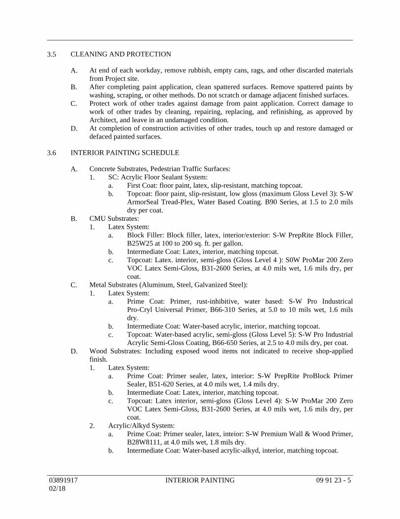
CLEANING AND PROTECTION3.5
At end of each workday, remove rubbish, empty cans, rags, and other discarded materialsA.from Project site.After completing paint application, clean spattered surfaces. Remove spattered paints byB.washing, scraping, or other methods. Do not scratch or damage adjacent finished surfaces.Protect work of other trades against damage from paint application. Correct damage toC.work of other trades by cleaning, repairing, replacing, and refinishing, as approved byArchitect, and leave in an undamaged condition.At completion of construction activities of other trades, touch up and restore damaged orD.defaced painted surfaces.
INTERIOR PAINTING SCHEDULE3.6
Concrete Substrates, Pedestrian Traffic Surfaces:A.SC: Acrylic Floor Sealant System:1.
First Coat: floor paint, latex, slip-resistant, matching topcoat.a.Topcoat: floor paint, slip-resistant, low gloss (maximum Gloss Level 3): S-Wb.ArmorSeal Tread-Plex, Water Based Coating. B90 Series, at 1.5 to 2.0 milsdry per coat.
CMU Substrates:B.Latex System:1.
Block Filler: Block filler, latex, interior/exterior: S-W PrepRite Block Filler,a.B25W25 at 100 to 200 sq. ft. per gallon.Intermediate Coat: Latex, interior, matching topcoat.b.Topcoat: Latex. interior, semi-gloss (Gloss Level 4 ): S0W ProMar 200 Zeroc.VOC Latex Semi-Gloss, B31-2600 Series, at 4.0 mils wet, 1.6 mils dry, percoat.
Metal Substrates (Aluminum, Steel, Galvanized Steel):C.Latex System:1.
Prime Coat: Primer, rust-inhibitive, water based: S-W Pro Industricala.Pro-Cryl Universal Primer, B66-310 Series, at 5.0 to 10 mils wet, 1.6 milsdry.Intermediate Coat: Water-based acrylic, interior, matching topcoat.b.Topcoat: Water-based acrylic, semi-gloss (Gloss Level 5): S-W Pro Industrialc.Acrylic Semi-Gloss Coating, B66-650 Series, at 2.5 to 4.0 mils dry, per coat.
Wood Substrates: Including exposed wood items not indicated to receive shop-appliedD.finish.
Latex System:1.Prime Coat: Primer sealer, latex, interior: S-W PrepRite ProBlock Primera.Sealer, B51-620 Series, at 4.0 mils wet, 1.4 mils dry.Intermediate Coat: Latex, interior, matching topcoat.b.Topcoat: Latex interior, semi-gloss (Gloss Level 4): S-W ProMar 200 Zeroc.VOC Latex Semi-Gloss, B31-2600 Series, at 4.0 mils wet, 1.6 mils dry, percoat.
Acrylic/Alkyd System:2.Prime Coat: Primer sealer, latex, inteior: S-W Premium Wall & Wood Primer,a.B28W8111, at 4.0 mils wet, 1.8 mils dry.Intermediate Coat: Water-based acrylic-alkyd, interior, matching topcoat.b.
0389191702/18
INTERIOR PAINTING 09 91 23 - 5
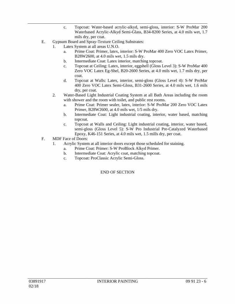
Topcoat: Water-based acrylic-alkyd, semi-gloss, interior: S-W ProMar 200c.Waterbased Acrylic-Alkyd Semi-Glass, B34-8200 Series, at 4.0 mils wet, 1.7mils dry, per coat.
Gypsum Board and Spray-Texture Ceiling Substrates:E.Latex System at all areas U.N.O.1.
Prime Coat: Primer, latex, interior: S-W ProMar 400 Zero VOC Latex Primer,a.B28W2600, at 4.0 mils wet, 1.5 mils dry.Intermediate Coat: Latex interior, matching topcoat.b.Topcoat at Ceiling: Latex, interior, eggshell (Gloss Level 3): S-W ProMar 400c.Zero VOC Latex Eg-Shel, B20-2600 Series, at 4.0 mils wet, 1.7 mils dry, percoat.Topcoat at Walls: Latex, interior, semi-gloss (Gloss Level 4): S-W ProMard.400 Zero VOC Latex Semi-Gloss, B31-2600 Series, at 4.0 mils wet, 1.6 milsdry, per coat.
Water-Based Light Industrial Coating System at all Bath Areas including the room2.with shower and the room with toilet, and public rest rooms.
Prime Coat: Primer sealer, latex, interior: S-W ProMar 200 Zero VOC Latexa.Primer, B28W2600, at 4.0 mils wet, 1/5 mils dry.Intermediate Coat: Light industrial coating, interior, water based, matchingb.topcoat.Topcoat at Walls and Ceiling: Light industrial coating, interior, water based,c.semi-gloss (Gloss Level 5): S-W Pro Industrial Pre-Catalyzed WaterbasedEpoxy, K46-151 Series, at 4.0 mils wet, 1.5 mills dry, per coat.
MDF Face of Doors:F.Acrylic System at all interior doors except those scheduled for staining.1.
Prime Coat: Primer: S-W ProBlock Alkyd Primer.a.Intermediate Coat: Acrylic coat, matching topcoat.b.Topcoat: ProClassic Acrylic Semi-Gloss.c.
END OF SECTION
0389191702/18
INTERIOR PAINTING 09 91 23 - 6
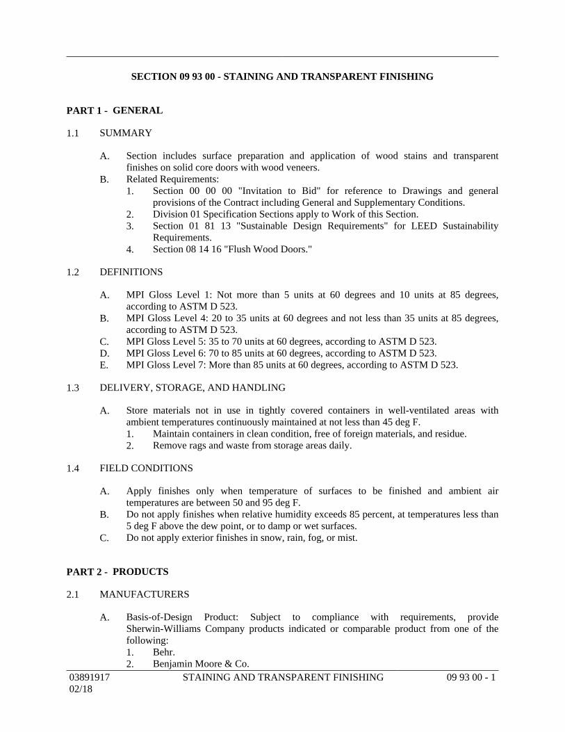
SECTION 09 93 00 - STAINING AND TRANSPARENT FINISHING
GENERALPART 1 -
SUMMARY1.1
Section includes surface preparation and application of wood stains and transparentA.finishes on solid core doors with wood veneers.Related Requirements:B.
Section 00 00 00 "Invitation to Bid" for reference to Drawings and general1.provisions of the Contract including General and Supplementary Conditions.Division 01 Specification Sections apply to Work of this Section.2.Section 01 81 13 "Sustainable Design Requirements" for LEED Sustainability3.Requirements.Section 08 14 16 "Flush Wood Doors."4.
DEFINITIONS1.2
MPI Gloss Level 1: Not more than 5 units at 60 degrees and 10 units at 85 degrees,A.according to ASTM D 523.MPI Gloss Level 4: 20 to 35 units at 60 degrees and not less than 35 units at 85 degrees,B.according to ASTM D 523.MPI Gloss Level 5: 35 to 70 units at 60 degrees, according to ASTM D 523.C.MPI Gloss Level 6: 70 to 85 units at 60 degrees, according to ASTM D 523.D.MPI Gloss Level 7: More than 85 units at 60 degrees, according to ASTM D 523.E.
DELIVERY, STORAGE, AND HANDLING1.3
Store materials not in use in tightly covered containers in well-ventilated areas withA.ambient temperatures continuously maintained at not less than 45 deg F.
Maintain containers in clean condition, free of foreign materials, and residue.1.Remove rags and waste from storage areas daily.2.
FIELD CONDITIONS1.4
Apply finishes only when temperature of surfaces to be finished and ambient airA.temperatures are between 50 and 95 deg F.Do not apply finishes when relative humidity exceeds 85 percent, at temperatures less thanB.5 deg F above the dew point, or to damp or wet surfaces.Do not apply exterior finishes in snow, rain, fog, or mist.C.
PRODUCTSPART 2 -
MANUFACTURERS2.1
Basis-of-Design Product: Subject to compliance with requirements, provideA.Sherwin-Williams Company products indicated or comparable product from one of thefollowing:
Behr.1.Benjamin Moore & Co.2.
0389191702/18
STAINING AND TRANSPARENT FINISHING 09 93 00 - 1
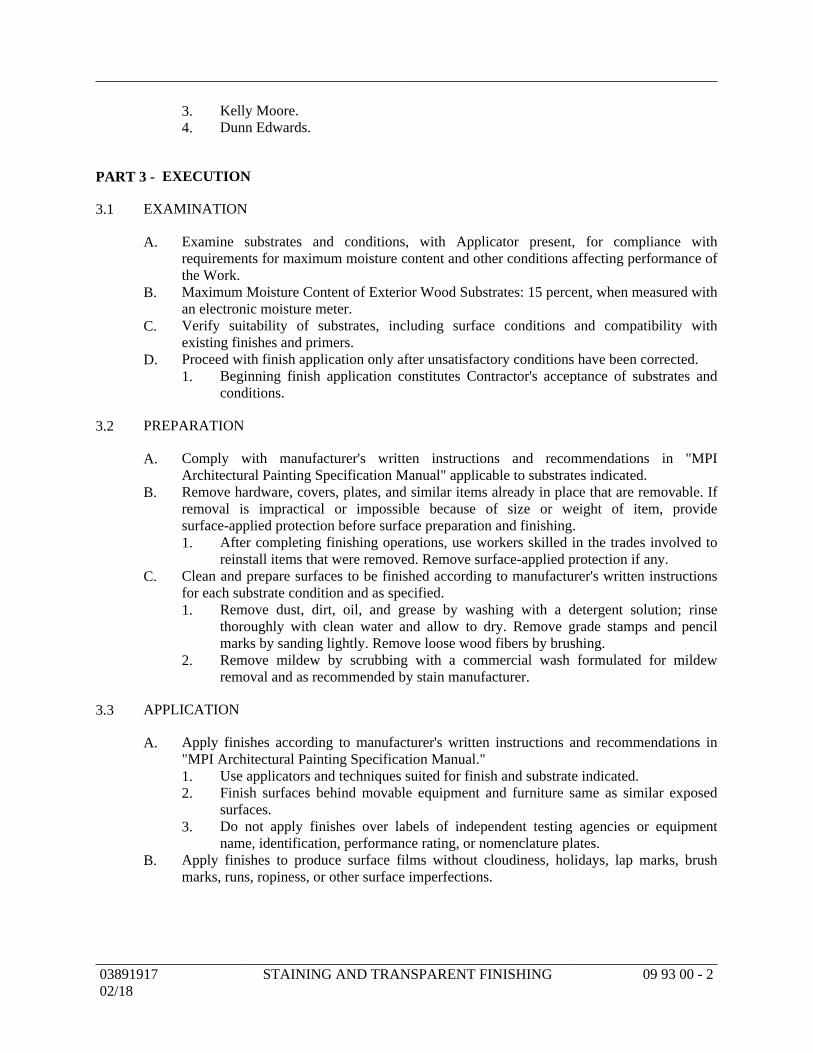
Kelly Moore.3.Dunn Edwards.4.
EXECUTIONPART 3 -
EXAMINATION3.1
Examine substrates and conditions, with Applicator present, for compliance withA.requirements for maximum moisture content and other conditions affecting performance ofthe Work.Maximum Moisture Content of Exterior Wood Substrates: 15 percent, when measured withB.an electronic moisture meter.Verify suitability of substrates, including surface conditions and compatibility withC.existing finishes and primers.Proceed with finish application only after unsatisfactory conditions have been corrected.D.
Beginning finish application constitutes Contractor's acceptance of substrates and1.conditions.
PREPARATION3.2
Comply with manufacturer's written instructions and recommendations in "MPIA.Architectural Painting Specification Manual" applicable to substrates indicated.Remove hardware, covers, plates, and similar items already in place that are removable. IfB.removal is impractical or impossible because of size or weight of item, providesurface-applied protection before surface preparation and finishing.
After completing finishing operations, use workers skilled in the trades involved to1.reinstall items that were removed. Remove surface-applied protection if any.
Clean and prepare surfaces to be finished according to manufacturer's written instructionsC.for each substrate condition and as specified.
Remove dust, dirt, oil, and grease by washing with a detergent solution; rinse1.thoroughly with clean water and allow to dry. Remove grade stamps and pencilmarks by sanding lightly. Remove loose wood fibers by brushing.Remove mildew by scrubbing with a commercial wash formulated for mildew2.removal and as recommended by stain manufacturer.
APPLICATION3.3
Apply finishes according to manufacturer's written instructions and recommendations inA."MPI Architectural Painting Specification Manual."
Use applicators and techniques suited for finish and substrate indicated.1.Finish surfaces behind movable equipment and furniture same as similar exposed2.surfaces.Do not apply finishes over labels of independent testing agencies or equipment3.name, identification, performance rating, or nomenclature plates.
Apply finishes to produce surface films without cloudiness, holidays, lap marks, brushB.marks, runs, ropiness, or other surface imperfections.
0389191702/18
STAINING AND TRANSPARENT FINISHING 09 93 00 - 2
CLEANING AND PROTECTION3.4
At end of each workday, remove rubbish, empty cans, rags, and other discarded materialsA.from Project site.After completing finish application, clean spattered surfaces. Remove spattered materialsB.by washing, scraping, or other methods. Do not scratch or damage adjacent finishedsurfaces.Protect work of other trades against damage from finish application. Correct damage byC.cleaning, repairing, replacing, and refinishing, as approved by Architect, and leave in anundamaged condition.At completion of construction activities of other trades, touch up and restore damaged orD.defaced finished wood surfaces.
INTERIOR WOOD - FINISH-SYSTEM SCHEDULE3.5
Wood Veneer Doors: Stained Finish.A.1st Coat: S-W Sherwood BAC Wiping Stain.1.
Color to be selected by Architect from manufacturer's standard range.a.2nd Coat: S-W Sherwood Fast Dry Vinyl Sealer.2.3rd and 4th Coat: S-W Sherwood PreCoat HB Lacquer Dull Rubbed Effect..3.
END OF SECTION
0389191702/18
STAINING AND TRANSPARENT FINISHING 09 93 00 - 3
SECTION 10 14 16 - PLAQUES
GENERALPART 1 -
SUMMARY1.1
Section includes metal plaques.A.Related Requirements:B.
Section 00 00 00 "Invitation to Bid" for reference to Drawings and general1.provisions of the Contract including General and Supplementary Conditions.Division 01 Specification Sections apply to Work of this Section.2.Section 01 81 13 "Sustainable Design Requirements" for LEED Sustainability3.Requirements.Section 10 14 23.16 "Room-Identification Panel Signage" for plaques or signs4.similar to metal plaques, with or without frames, except that they are made ofmaterials other than solid metal.
DEFINITIONS1.2
Accessible: In accordance with the accessibility standard.A.
ACTION SUBMITTALS1.3
Product Data: For each type of product.A.Shop Drawings: For plaques.B.
Include fabrication and installation details and attachments to other work.1.Show plaque mounting heights, locations of supplementary supports to be provided2.by other installers, and accessories.Show message list, typestyles, graphic elements, and layout for each plaque at least3.half size.
Samples for Initial Selection: For each type of plaque, exposed component, and exposedC.finish.
Include representative Samples of available finishes and border styles.1.
WARRANTY1.4
Sample Warranty: Manufacturer agrees to repair or replace components of plaques that failA.in materials or workmanship within specified warranty period.
Failures include, but are not limited to, the following:1.Deterioration of finishes beyond normal weathering.a.Deterioration of embedded graphic image.b.
Warranty Period: Five years from date of Substantial Completion.2.
PRODUCTSPART 2 -
PERFORMANCE REQUIREMENTS2.1
Accessibility Standard: Comply with applicable provisions in the USDOJ's "2010 ADAA.Standards for Accessible Design" and ICC A117.1.
0389191702/18
PLAQUES 10 14 16 - 1
PLAQUES2.2
Cast Plaque: Cast-metal plaque with background texture, border, and characters havingA.uniform faces, sharp corners, and precisely formed lines and profiles; and as follows:
Manufacturers: Subject to compliance with requirements, available manufacturers1.offering products that may be incorporated into the Work include, but are not limitedto, the following:
A.R.K. Ramos.a.ACE Sign Systems, Inc..b.Gemini Incorporated.c.Matthews International Corporation; Bronze Division.d.Metal Arts.e.Metallic Arts.f.
Plaque Material: Cast bronze.2.Plaque Thickness: 0.153 inch.3.Finishes:4.
Integral Metal Finish: Mill finish raised surface with dark oxidizeda.background.
Background Texture: Leatherette.5.Mounting: Concealed studs.6.Text and Typeface: Per Plaque Schedule attached.7.
MATERIALS2.3
Bronze Castings: ASTM B 584, alloy recommended by manufacturer and finisher forA.finish indicated.Bronze Plate: ASTM B 36/B 36M, alloy recommended by manufacturer and finisher forB.finish indicated.
ACCESSORIES2.4
Fasteners and Anchors: Manufacturer's standard as required for secure anchorage ofA.plaques, noncorrosive and compatible with each material joined, and complying with thefollowing:
Use concealed fasteners and anchors unless indicated to be exposed.1.For exterior exposure, furnish nonferrous-metal or hot-dip galvanized devices unless2.otherwise indicated.Plaque Mounting Fasteners:3.
Concealed Studs: Concealed (blind), threaded studs welded or brazed to backa.of plaque, screwed into back of plaque, or screwed into tapped lugs castintegrally into back of plaque unless otherwise indicated.
FABRICATION2.5
General: Provide manufacturer's standard plaques according to requirements indicated.A.Preassemble plaques in the shop to greatest extent possible. Disassemble plaques1.only as necessary for shipping and handling limitations. Clearly mark units forreassembly and installation; apply markings in locations concealed from view afterfinal assembly.Mill joints to a tight, hairline fit. Form assemblies and joints exposed to weather to2.resist water penetration and retention.
0389191702/18
PLAQUES 10 14 16 - 2
Comply with AWS for recommended practices in welding and brazing. Provide3.welds and brazes behind finished surfaces without distorting or discoloring exposedside. Clean exposed welded and brazed connections of flux, and dress exposed andcontact surfaces.Conceal connections if possible; otherwise, locate connections where they are4.inconspicuous.Provide rabbets, lugs, and tabs necessary to assemble components and to attach to5.existing work. Drill and tap for required fasteners. Use concealed fasteners wherepossible; use exposed fasteners that match plaque finish.Castings: Fabricate castings free of warp, cracks, blowholes, pits, scale, sand holes,6.and other defects that impair appearance or strength. Grind, wire brush, sandblast,and buff castings to remove seams, gate marks, casting flash, and other castingmarks before finishing.
Surface-Engraved Graphics: Machine-engrave characters and other graphic devices intoB.indicated plaque surface to produce precisely formed copy, incised to uniform depth.
Engraved Metal: Fill engraved graphics with manufacturer's standard baked enamel.1.Brackets: Fabricate brackets, fittings, and hardware for bracket-mounted plaques to suitC.plaque construction and mounting conditions indicated. Modify manufacturer's standardbrackets as required.
GENERAL FINISH REQUIREMENTS2.6
Protect mechanical finishes on exposed surfaces from damage by applying a strippable,A.temporary protective covering before shipping.Appearance of Finished Work: Noticeable variations in same piece are not acceptable.B.Variations in appearance of adjoining components are acceptable if they are within therange of approved Samples and are assembled or installed to minimize contrast.Directional Finishes: Run grain with long dimension of each piece and perpendicular toC.long dimension of finished trim or border surface unless otherwise indicated.Organic, Anodic, and Chemically Produced Finishes: Apply to formed metal afterD.fabrication but before applying contrasting polished finishes on raised features unlessotherwise indicated.
CLEAR ORGANIC COATING FOR COPPER-ALLOY FINISHES2.7
Clear Organic Coating: Clear, waterborne, air-drying, acrylic lacquer called "Incralac";A.specially developed for coating copper-alloy products; consisting of a solution of methylmethacrylate copolymer with benzotriazole to prevent breakdown of the film in UV light;shop applied in two uniform coats according to manufacturer's written instructions, withinterim drying between coats and without runs or other surface imperfections, to a total dryfilm thickness of 1 mil.
EXECUTIONPART 3 -
EXAMINATION3.1
Examine substrates, areas, and conditions, with Installer present, for compliance withA.requirements for installation tolerances and other conditions affecting performance.
0389191702/18
PLAQUES 10 14 16 - 3
Verify that plaque-support surfaces are within tolerances to accommodate plaques withoutB.gaps or irregularities between backs of plaques and support surfaces unless otherwiseindicated.Proceed with installation only after unsatisfactory conditions have been corrected.C.
INSTALLATION3.2
General: Install plaques using mounting methods indicated and according to manufacturer'sA.written instructions.
Install plaques level, plumb, true to line, and at locations and heights indicated, with1.plaque surfaces free of distortion and other defects in appearance.Install plaques so they do not protrude or obstruct according to the accessibility2.standard.Before installation, verify that plaque surfaces are clean and free of materials or3.debris that would impair installation.Corrosion Protection: Coat concealed surfaces of exterior aluminum in contact with4.grout, concrete, masonry, wood, or dissimilar metals, with a heavy coat ofbituminous paint.
Plaques Used for Room Identification: Install in locations on walls.B.Mounting Methods:C.
Concealed Studs: Using a template, drill holes in substrate aligning with studs on1.back of plaque. Remove loose debris from hole and substrate surface.
Masonry Substrates: Fill holes with adhesive. Leave recess space in hole fora.displaced adhesive. Place plaque in position and push until flush to surface,embedding studs in holes. Temporarily support plaque in position untiladhesive fully sets.Thin or Hollow Surfaces: Place plaque in position and flush to surface, installb.washers and nuts on studs projecting through opposite side of surface, andtighten.
ADJUSTING AND CLEANING3.3
Remove and replace damaged or deformed plaques and plaques that do not comply withA.specified requirements. Replace plaques with damaged or deteriorated finishes orcomponents that cannot be successfully repaired by finish touchup or similar minor repairprocedures.Remove temporary protective coverings and strippable films as plaques are installed.B.On completion of installation, clean exposed surfaces of plaques according toC.manufacturer's written instructions, and touch up minor nicks and abrasions in finish.Maintain plaques in a clean condition during construction and protect from damage untilacceptance by Owner.
PLAQUE SCHEDULE3.4
Attached Plaque Schedule.A.
END OF SECTION
0389191702/18
PLAQUES 10 14 16 - 4
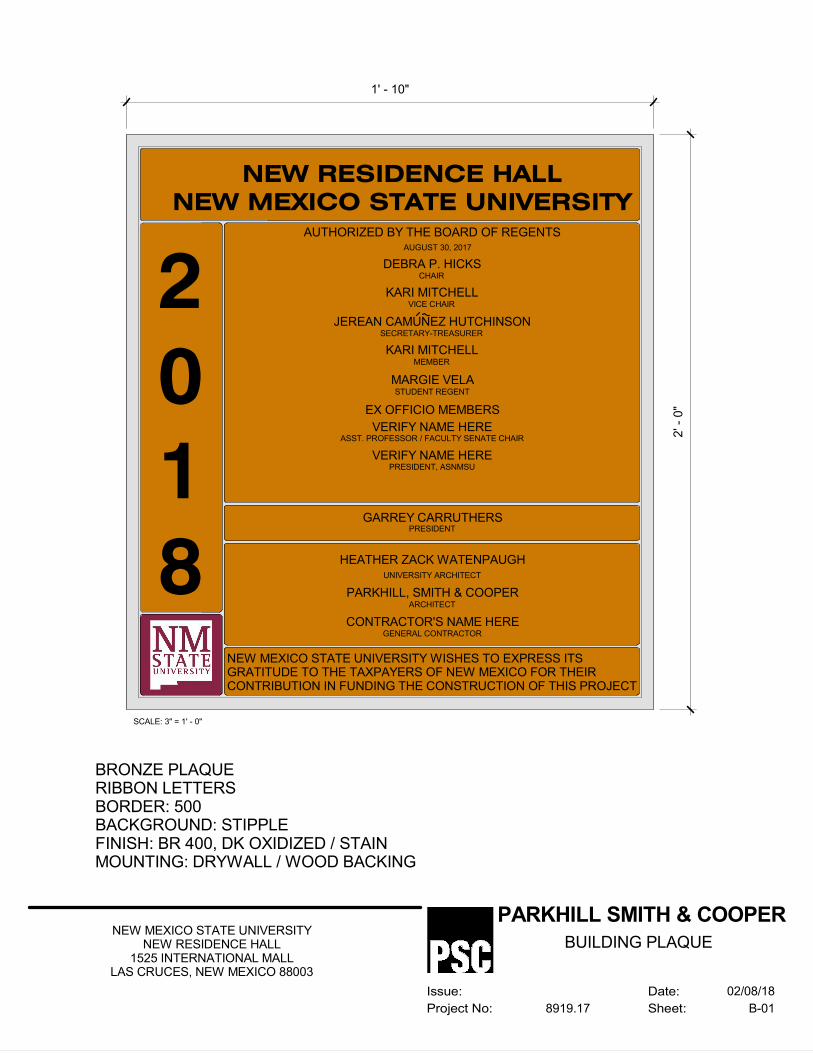
2
0
1
8
NEW RESIDENCE HALL
NEW MEXICO STATE UNIVERSITYAUTHORIZED BY THE BOARD OF REGENTS
1' - 10"
2' -
0"
DEBRA P. HICKS
AUGUST 30, 2017
CHAIR
KARI MITCHELLVICE CHAIR
JEREAN CAMUNEZ HUTCHINSONSECRETARY-TREASURER
KARI MITCHELLMEMBER
MARGIE VELASTUDENT REGENT
NEW MEXICO STATE UNIVERSITY WISHES TO EXPRESS ITSGRATITUDE TO THE TAXPAYERS OF NEW MEXICO FOR THEIRCONTRIBUTION IN FUNDING THE CONSTRUCTION OF THIS PROJECT
HEATHER ZACK WATENPAUGH
PARKHILL, SMITH & COOPER
CONTRACTOR'S NAME HERE
UNIVERSITY ARCHITECT
ARCHITECT
GENERAL CONTRACTOR
GARREY CARRUTHERSPRESIDENT
EX OFFICIO MEMBERS
VERIFY NAME HEREASST. PROFESSOR / FACULTY SENATE CHAIR
VERIFY NAME HEREPRESIDENT, ASNMSU
Date:
Sheet:
Issue:
Project No:
PARKHILL SMITH & COOPER
B-018919.17
NEW MEXICO STATE UNIVERSITYNEW RESIDENCE HALL
1525 INTERNATIONAL MALLLAS CRUCES, NEW MEXICO 88003
02/08/18
BUILDING PLAQUE
BRONZE PLAQUERIBBON LETTERSBORDER: 500BACKGROUND: STIPPLEFINISH: BR 400, DK OXIDIZED / STAINMOUNTING: DRYWALL / WOOD BACKING
SCALE: 3" = 1' - 0"
SECTION 10 14 23.16 - ROOM-IDENTIFICATION PANEL SIGNAGE
GENERALPART 1 -
SUMMARY1.1
Section includes room-identification signs that are directly attached to the building.A.Related Requirements:B.
Section 00 00 00 "Invitation to Bid" for reference to Drawings and general1.provisions of the Contract including General and Supplementary Conditions.Division 01 Specification Sections apply to Work of this Section.2.Section 01 81 13 "Sustainable Design Requirements" for LEED Sustainability3.Requirements.Section 10 14 16 "Plaques" for one-piece, solid metal signs, with or without frames,4.that are used for high-end room-identification.
DEFINITIONS1.2
Accessible: In accordance with the accessibility standard.A.
COORDINATION1.3
Furnish templates for placement of sign-anchorage devices embedded in permanentA.construction by other installers.Furnish templates for placement of electrical service embedded in permanent constructionB.by other installers.
ACTION SUBMITTALS1.4
Product Data: For each type of product.A.Shop Drawings: For room-identification signs.B.
Include fabrication and installation details and attachments to other work.1.Show sign mounting heights, locations of supplementary supports to be provided by2.other installers, and accessories.Show message list, typestyles, graphic elements, including raised characters and3.Braille, and layout for each sign at least half size.
Samples for Initial Selection: For each type of sign assembly, exposed component, andC.exposed finish.
Include representative Samples of available typestyles and graphic symbols.1.Full-size Sample.2.Color samples of each color per Signage Schedule.3.
FIELD CONDITIONS1.5
Field Measurements: Verify locations of anchorage devices embedded in permanentA.construction by other installers by field measurements before fabrication, and indicatemeasurements on Shop Drawings.
0389191702/18
ROOM-IDENTIFICATION PANEL SIGNAGE 10 14 23.16 - 1
WARRANTY1.6
Special Warranty: Manufacturer agrees to repair or replace components of signs that fail inA.materials or workmanship within specified warranty period.
Failures include, but are not limited to, the following:1.Deterioration of finishes beyond normal weathering.a.Deterioration of embedded graphic image.b.Separation or delamination of sheet materials and components.c.
Warranty Period: Five years from date of Substantial Completion.2.
PRODUCTSPART 2 -
PERFORMANCE REQUIREMENTS2.1
Accessibility Standard: Comply with applicable provisions in the USDOJ's "2010 ADAA.Standards for Accessible Design"and ICC A117.1.
ROOM-IDENTIFICATION SIGNS2.2
Room-Identification Sign: Sign system with smooth, uniform surfaces; with message andA.characters having uniform faces, sharp corners, and precisely formed lines and profiles;and as follows:
Manufacturers: Subject to compliance with requirements, available manufacturers1.offering products that may be incorporated into the Work include, but are not limitedto, the following:
ACE Sign Systems, Inc.a.Advance Corporation.b.Allen Industries Architectural Signage.c.APCO Graphics, Inc.d.ASE, Inc.e.ASI Sign Systems, Inc.f.Best Sign Systems, Inc.g.InPro Corporation (IPC).h.Mohawk Sign Systems.i.Signature Signs, Inc.j.Stamprite Supersine; a division of Stamp Rite Inc.k.Vista System.l.Century Sign Builders.m.
Laminated-Sheet Sign: Injection-molded polycarbonate, acrylic, or other2.integral-color polymer face sheet with raised graphics laminated.
Composite-Sheet Thickness: Manufacturer's standard for size of sign.a.Surface-Applied Graphics: Applied Raised letters and numbers to a raisedb.thickness of 1/16 inch above face of signage.Color(s): As indicated on attached Signage Schedule and Elevations.c.
Sign-Panel Perimeter: Finish edges smooth.3.Edge Condition at Horizontal Edges: Square cut.a.Corner Condition in Elevation: Square.b.
Mounting: Surface mounted to wall with two-face tape.4.Text and Typeface: As indicated on attached Signage Schedule and Elevations.5.
0389191702/18
ROOM-IDENTIFICATION PANEL SIGNAGE 10 14 23.16 - 2
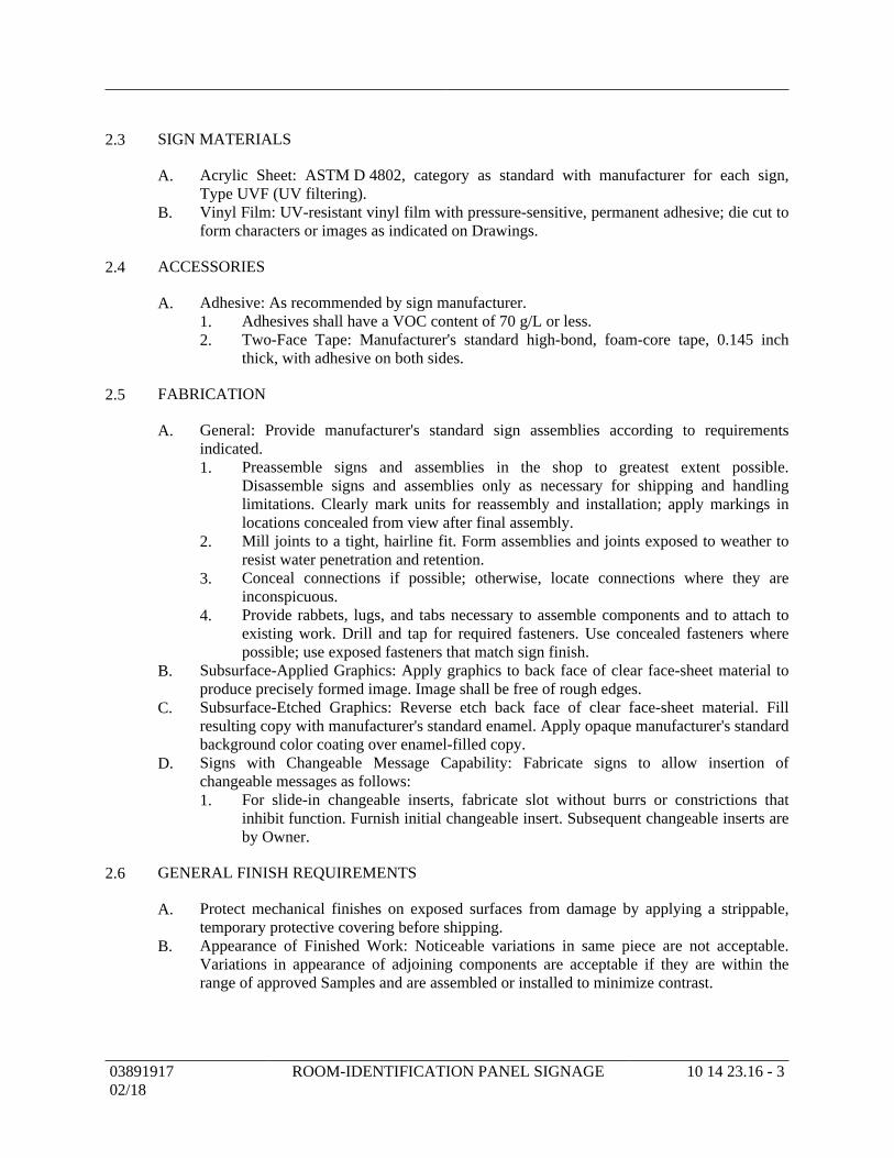
SIGN MATERIALS2.3
Acrylic Sheet: ASTM D 4802, category as standard with manufacturer for each sign,A.Type UVF (UV filtering).Vinyl Film: UV-resistant vinyl film with pressure-sensitive, permanent adhesive; die cut toB.form characters or images as indicated on Drawings.
ACCESSORIES2.4
Adhesive: As recommended by sign manufacturer.A.Adhesives shall have a VOC content of 70 g/L or less.1.Two-Face Tape: Manufacturer's standard high-bond, foam-core tape, 0.145 inch2.thick, with adhesive on both sides.
FABRICATION2.5
General: Provide manufacturer's standard sign assemblies according to requirementsA.indicated.
Preassemble signs and assemblies in the shop to greatest extent possible.1.Disassemble signs and assemblies only as necessary for shipping and handlinglimitations. Clearly mark units for reassembly and installation; apply markings inlocations concealed from view after final assembly.Mill joints to a tight, hairline fit. Form assemblies and joints exposed to weather to2.resist water penetration and retention.Conceal connections if possible; otherwise, locate connections where they are3.inconspicuous.Provide rabbets, lugs, and tabs necessary to assemble components and to attach to4.existing work. Drill and tap for required fasteners. Use concealed fasteners wherepossible; use exposed fasteners that match sign finish.
Subsurface-Applied Graphics: Apply graphics to back face of clear face-sheet material toB.produce precisely formed image. Image shall be free of rough edges.Subsurface-Etched Graphics: Reverse etch back face of clear face-sheet material. FillC.resulting copy with manufacturer's standard enamel. Apply opaque manufacturer's standardbackground color coating over enamel-filled copy.Signs with Changeable Message Capability: Fabricate signs to allow insertion ofD.changeable messages as follows:
For slide-in changeable inserts, fabricate slot without burrs or constrictions that1.inhibit function. Furnish initial changeable insert. Subsequent changeable inserts areby Owner.
GENERAL FINISH REQUIREMENTS2.6
Protect mechanical finishes on exposed surfaces from damage by applying a strippable,A.temporary protective covering before shipping.Appearance of Finished Work: Noticeable variations in same piece are not acceptable.B.Variations in appearance of adjoining components are acceptable if they are within therange of approved Samples and are assembled or installed to minimize contrast.
0389191702/18
ROOM-IDENTIFICATION PANEL SIGNAGE 10 14 23.16 - 3
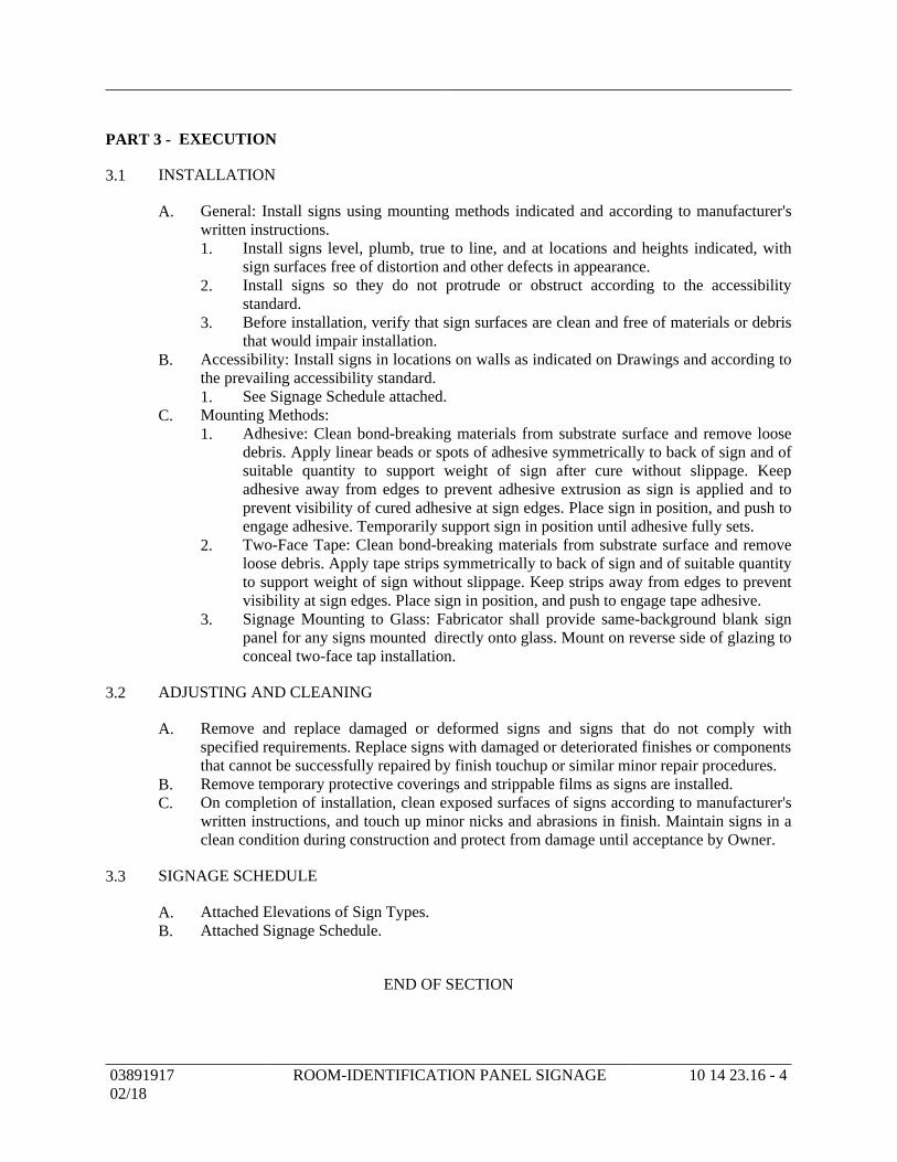
EXECUTIONPART 3 -
INSTALLATION3.1
General: Install signs using mounting methods indicated and according to manufacturer'sA.written instructions.
Install signs level, plumb, true to line, and at locations and heights indicated, with1.sign surfaces free of distortion and other defects in appearance.Install signs so they do not protrude or obstruct according to the accessibility2.standard.Before installation, verify that sign surfaces are clean and free of materials or debris3.that would impair installation.
Accessibility: Install signs in locations on walls as indicated on Drawings and according toB.the prevailing accessibility standard.
See Signage Schedule attached.1.Mounting Methods:C.
Adhesive: Clean bond-breaking materials from substrate surface and remove loose1.debris. Apply linear beads or spots of adhesive symmetrically to back of sign and ofsuitable quantity to support weight of sign after cure without slippage. Keepadhesive away from edges to prevent adhesive extrusion as sign is applied and toprevent visibility of cured adhesive at sign edges. Place sign in position, and push toengage adhesive. Temporarily support sign in position until adhesive fully sets.Two-Face Tape: Clean bond-breaking materials from substrate surface and remove2.loose debris. Apply tape strips symmetrically to back of sign and of suitable quantityto support weight of sign without slippage. Keep strips away from edges to preventvisibility at sign edges. Place sign in position, and push to engage tape adhesive.Signage Mounting to Glass: Fabricator shall provide same-background blank sign3.panel for any signs mounted directly onto glass. Mount on reverse side of glazing toconceal two-face tap installation.
ADJUSTING AND CLEANING3.2
Remove and replace damaged or deformed signs and signs that do not comply withA.specified requirements. Replace signs with damaged or deteriorated finishes or componentsthat cannot be successfully repaired by finish touchup or similar minor repair procedures.Remove temporary protective coverings and strippable films as signs are installed.B.On completion of installation, clean exposed surfaces of signs according to manufacturer'sC.written instructions, and touch up minor nicks and abrasions in finish. Maintain signs in aclean condition during construction and protect from damage until acceptance by Owner.
SIGNAGE SCHEDULE3.3
Attached Elevations of Sign Types.A.Attached Signage Schedule.B.
END OF SECTION
0389191702/18
ROOM-IDENTIFICATION PANEL SIGNAGE 10 14 23.16 - 4
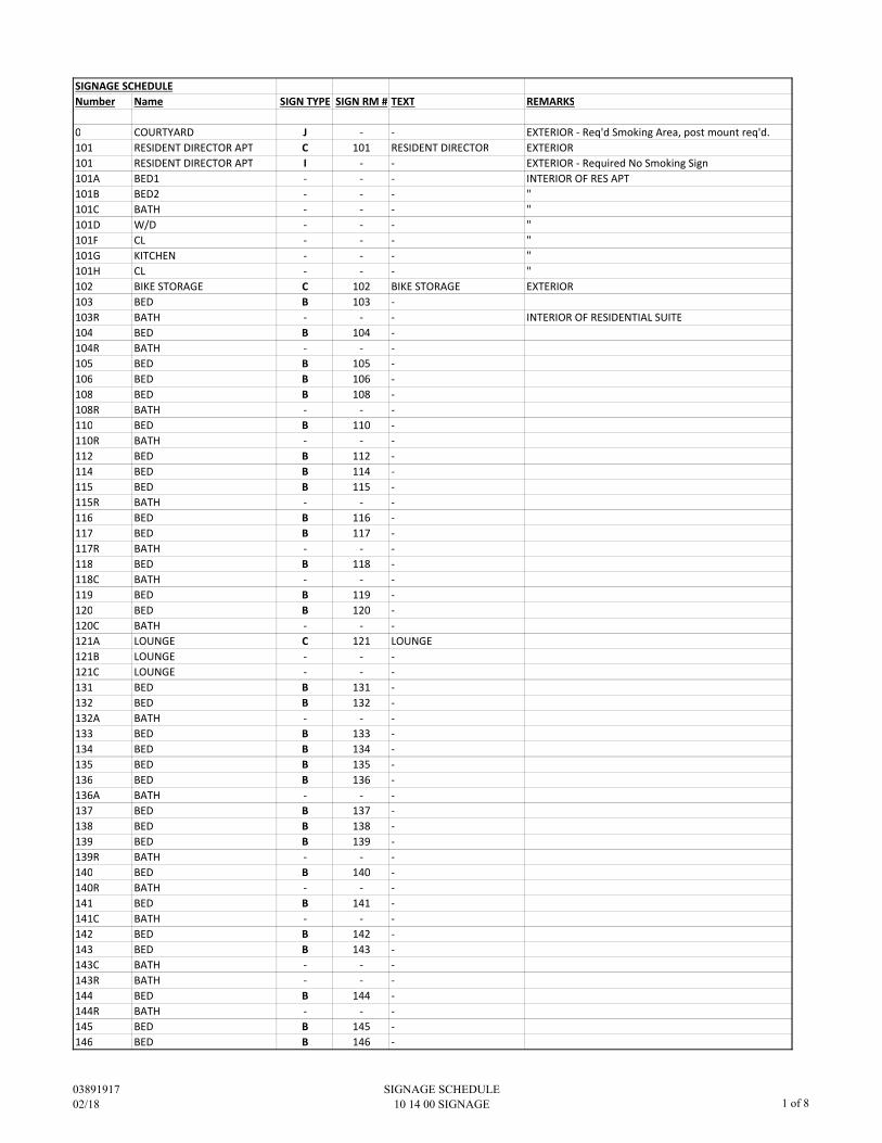
SIGNAGE SCHEDULE
Number Name SIGN TYPE SIGN RM # TEXT REMARKS
0 COURTYARD J - - EXTERIOR - Req'd Smoking Area, post mount req'd.
101 RESIDENT DIRECTOR APT C 101 RESIDENT DIRECTOR EXTERIOR
101 RESIDENT DIRECTOR APT I - - EXTERIOR - Required No Smoking Sign
101A BED1 - - - INTERIOR OF RES APT
101B BED2 - - - "
101C BATH - - - "
101D W/D - - - "
101F CL - - - "
101G KITCHEN - - - "
101H CL - - - "
102 BIKE STORAGE C 102 BIKE STORAGE EXTERIOR
103 BED B 103 -
103R BATH - - - INTERIOR OF RESIDENTIAL SUITE
104 BED B 104 -
104R BATH - - -
105 BED B 105 -
106 BED B 106 -
108 BED B 108 -
108R BATH - - -
110 BED B 110 -
110R BATH - - -
112 BED B 112 -
114 BED B 114 -
115 BED B 115 -
115R BATH - - -
116 BED B 116 -
117 BED B 117 -
117R BATH - - -
118 BED B 118 -
118C BATH - - -
119 BED B 119 -
120 BED B 120 -
120C BATH - - -
121A LOUNGE C 121 LOUNGE
121B LOUNGE - - -
121C LOUNGE - - -
131 BED B 131 -
132 BED B 132 -
132A BATH - - -
133 BED B 133 -
134 BED B 134 -
135 BED B 135 -
136 BED B 136 -
136A BATH - - -
137 BED B 137 -
138 BED B 138 -
139 BED B 139 -
139R BATH - - -
140 BED B 140 -
140R BATH - - -
141 BED B 141 -
141C BATH - - -
142 BED B 142 -
143 BED B 143 -
143C BATH - - -
143R BATH - - -
144 BED B 144 -
144R BATH - - -
145 BED B 145 -
146 BED B 146 -
03891917
02/18
SIGNAGE SCHEDULE
10 14 00 SIGNAGE 1 of 8
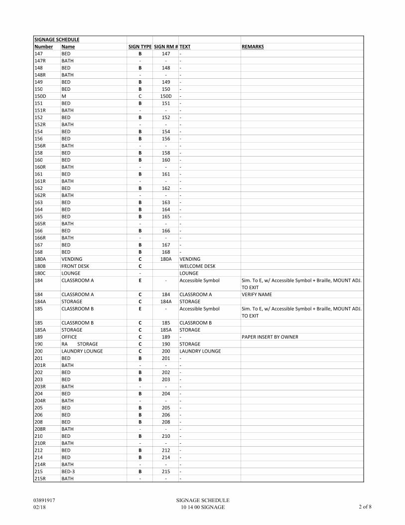
SIGNAGE SCHEDULE
Number Name SIGN TYPE SIGN RM # TEXT REMARKS
147 BED B 147 -
147R BATH - - -
148 BED B 148 -
148R BATH - - -
149 BED B 149 -
150 BED B 150 -
150D M C 150D -
151 BED B 151 -
151R BATH - - -
152 BED B 152 -
152R BATH - - -
154 BED B 154 -
156 BED B 156 -
156R BATH - - -
158 BED B 158 -
160 BED B 160 -
160R BATH - - -
161 BED B 161 -
161R BATH - - -
162 BED B 162 -
162R BATH - - -
163 BED B 163 -
164 BED B 164 -
165 BED B 165 -
165R BATH - - -
166 BED B 166 -
166R BATH - - -
167 BED B 167 -
168 BED B 168 -
180A VENDING C 180A VENDING
180B FRONT DESK C WELCOME DESK
180C LOUNGE - LOUNGE
184 CLASSROOM A E - Accessible Symbol Sim. To E, w/ Accessible Symbol + Braille, MOUNT ADJ.
TO EXIT
184 CLASSROOM A C 184 CLASSROOM A VERIFY NAME
184A STORAGE C 184A STORAGE
185 CLASSROOM B E - Accessible Symbol Sim. To E, w/ Accessible Symbol + Braille, MOUNT ADJ.
TO EXIT
185 CLASSROOM B C 185 CLASSROOM B
185A STORAGE C 185A STORAGE
189 OFFICE C 189 - PAPER INSERT BY OWNER
190 RA STORAGE C 190 STORAGE
200 LAUNDRY LOUNGE C 200 LAUNDRY LOUNGE
201 BED B 201 -
201R BATH - - -
202 BED B 202 -
203 BED B 203 -
203R BATH - - -
204 BED B 204 -
204R BATH - - -
205 BED B 205 -
206 BED B 206 -
208 BED B 208 -
208R BATH - - -
210 BED B 210 -
210R BATH - - -
212 BED B 212 -
214 BED B 214 -
214R BATH - - -
215 BED-3 B 215 -
215R BATH - - -
03891917
02/18
SIGNAGE SCHEDULE
10 14 00 SIGNAGE 2 of 8
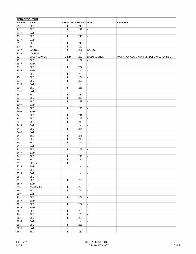
SIGNAGE SCHEDULE
Number Name SIGN TYPE SIGN RM # TEXT REMARKS
216 BED B 216 -
217 BED B 217 -
217R BATH - - -
218 BED B 218 -
218R BATH - - -
219 BED B 219 -
220 BED B 220 -
221A LOUNGE C 221 LOUNGE
221B LOUNGE - - -
222 STUDY LOUNGE C & D 222 STUDY LOUNGE MOUNT ON GLASS: C @ RM SIDE; D @ LOBBY SIDE
231 BED B 231 -
231R BATH - - -
232 BED B 232 -
232R BATH - - -
233 BED B 233 -
234 BED B 234 -
235 BED B 235 -
235R BATH - - -
236 BED B 236 -
236R BATH - - -
237 BED B 237 -
238 BED B 238 -
239 BED B 239 -
239R BATH - - -
240 BED B 240 -
240R BATH - - -
241 BED B 241 -
242 BED B 242 -
243 BED B 243 -
243R BATH - - -
244 BED B 244 -
244R BATH - - -
245 BED B 245 -
246 BED B 246 -
247 BED B 247 -
247R BATH - - -
248 BED B 248 -
248R BATH - - -
249 BED B 249 -
250 BED B 250 -
251 BED - 4 B -
251R BATH - - -
252 BED - -
252R BATH - - -
254 BED - -
256 BED B 256 -
256R BATH - - -
258 ACCESS BED B 258 -
260 BED B 260 -
260R BATH - - -
261 BED B 261 -
261R BATH - - -
262 BED B 262 -
262R BATH - - -
263 BED B 263 -
264 BED B 264 -
265 BED B 265 -
265R BATH - - -
266 BED B 266 -
266R BATH - - -
267 BED B 267 -
03891917
02/18
SIGNAGE SCHEDULE
10 14 00 SIGNAGE 3 of 8
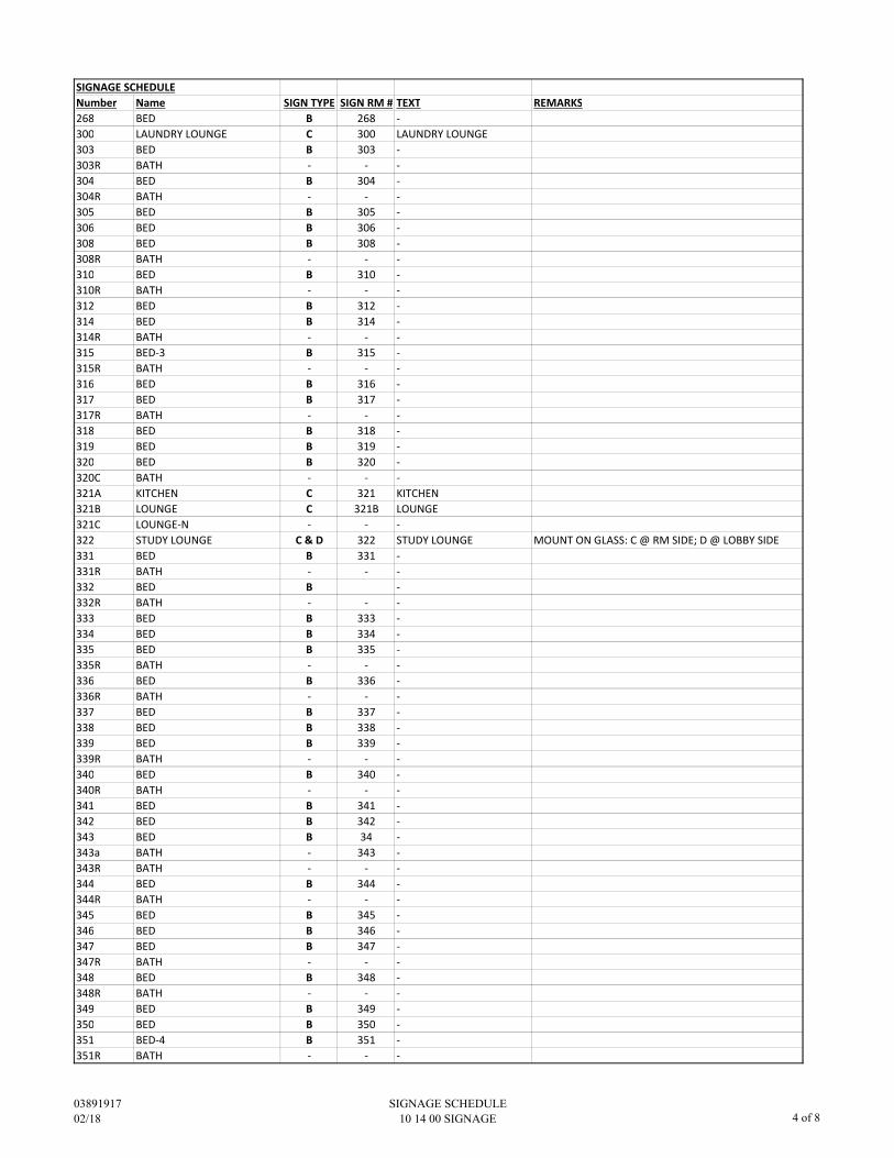
SIGNAGE SCHEDULE
Number Name SIGN TYPE SIGN RM # TEXT REMARKS
268 BED B 268 -
300 LAUNDRY LOUNGE C 300 LAUNDRY LOUNGE
303 BED B 303 -
303R BATH - - -
304 BED B 304 -
304R BATH - - -
305 BED B 305 -
306 BED B 306 -
308 BED B 308 -
308R BATH - - -
310 BED B 310 -
310R BATH - - -
312 BED B 312 -
314 BED B 314 -
314R BATH - - -
315 BED-3 B 315 -
315R BATH - - -
316 BED B 316 -
317 BED B 317 -
317R BATH - - -
318 BED B 318 -
319 BED B 319 -
320 BED B 320 -
320C BATH - - -
321A KITCHEN C 321 KITCHEN
321B LOUNGE C 321B LOUNGE
321C LOUNGE-N - - -
322 STUDY LOUNGE C & D 322 STUDY LOUNGE MOUNT ON GLASS: C @ RM SIDE; D @ LOBBY SIDE
331 BED B 331 -
331R BATH - - -
332 BED B -
332R BATH - - -
333 BED B 333 -
334 BED B 334 -
335 BED B 335 -
335R BATH - - -
336 BED B 336 -
336R BATH - - -
337 BED B 337 -
338 BED B 338 -
339 BED B 339 -
339R BATH - - -
340 BED B 340 -
340R BATH - - -
341 BED B 341 -
342 BED B 342 -
343 BED B 34 -
343a BATH - 343 -
343R BATH - - -
344 BED B 344 -
344R BATH - - -
345 BED B 345 -
346 BED B 346 -
347 BED B 347 -
347R BATH - - -
348 BED B 348 -
348R BATH - - -
349 BED B 349 -
350 BED B 350 -
351 BED-4 B 351 -
351R BATH - - -
03891917
02/18
SIGNAGE SCHEDULE
10 14 00 SIGNAGE 4 of 8
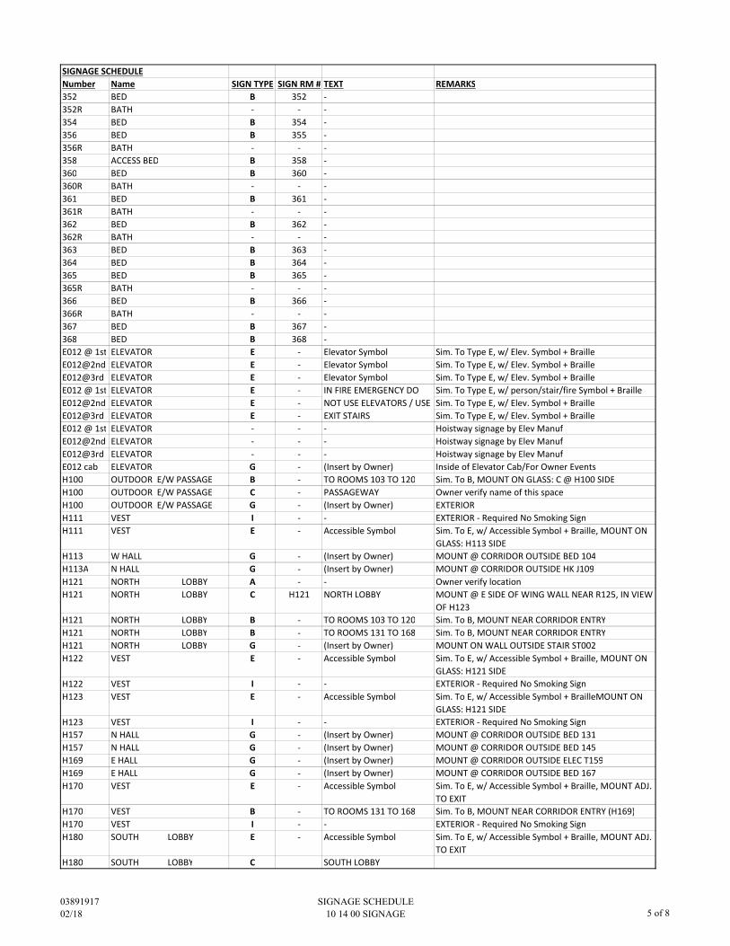
SIGNAGE SCHEDULE
Number Name SIGN TYPE SIGN RM # TEXT REMARKS
352 BED B 352 -
352R BATH - - -
354 BED B 354 -
356 BED B 355 -
356R BATH - - -
358 ACCESS BED B 358 -
360 BED B 360 -
360R BATH - - -
361 BED B 361 -
361R BATH - - -
362 BED B 362 -
362R BATH - - -
363 BED B 363 -
364 BED B 364 -
365 BED B 365 -
365R BATH - - -
366 BED B 366 -
366R BATH - - -
367 BED B 367 -
368 BED B 368 -
E012 @ 1st ELEVATOR E - Elevator Symbol Sim. To Type E, w/ Elev. Symbol + Braille
E012@2nd ELEVATOR E - Elevator Symbol Sim. To Type E, w/ Elev. Symbol + Braille
E012@3rd ELEVATOR E - Elevator Symbol Sim. To Type E, w/ Elev. Symbol + Braille
E012 @ 1st ELEVATOR E - Sim. To Type E, w/ person/stair/fire Symbol + Braille
E012@2nd ELEVATOR E - Sim. To Type E, w/ Elev. Symbol + Braille
E012@3rd ELEVATOR E - Sim. To Type E, w/ Elev. Symbol + Braille
E012 @ 1st ELEVATOR - - - Hoistway signage by Elev Manuf
E012@2nd ELEVATOR - - - Hoistway signage by Elev Manuf
E012@3rd ELEVATOR - - - Hoistway signage by Elev Manuf
E012 cab ELEVATOR G - (Insert by Owner) Inside of Elevator Cab/For Owner Events
H100 OUTDOOR E/W PASSAGE B - TO ROOMS 103 TO 120 Sim. To B, MOUNT ON GLASS: C @ H100 SIDE
H100 OUTDOOR E/W PASSAGE C - PASSAGEWAY Owner verify name of this space
H100 OUTDOOR E/W PASSAGE G - (Insert by Owner) EXTERIOR
H111 VEST I - - EXTERIOR - Required No Smoking Sign
H111 VEST E - Accessible Symbol Sim. To E, w/ Accessible Symbol + Braille, MOUNT ON
GLASS: H113 SIDE
H113 W HALL G - (Insert by Owner) MOUNT @ CORRIDOR OUTSIDE BED 104
H113A N HALL G - (Insert by Owner) MOUNT @ CORRIDOR OUTSIDE HK J109
H121 NORTH LOBBY A - - Owner verify location
H121 NORTH LOBBY C H121 NORTH LOBBY MOUNT @ E SIDE OF WING WALL NEAR R125, IN VIEW
OF H123
H121 NORTH LOBBY B - TO ROOMS 103 TO 120 Sim. To B, MOUNT NEAR CORRIDOR ENTRY
H121 NORTH LOBBY B - TO ROOMS 131 TO 168 Sim. To B, MOUNT NEAR CORRIDOR ENTRY
H121 NORTH LOBBY G - (Insert by Owner) MOUNT ON WALL OUTSIDE STAIR ST002
H122 VEST E - Accessible Symbol Sim. To E, w/ Accessible Symbol + Braille, MOUNT ON
GLASS: H121 SIDE
H122 VEST I - - EXTERIOR - Required No Smoking Sign
H123 VEST E - Accessible Symbol Sim. To E, w/ Accessible Symbol + BrailleMOUNT ON
GLASS: H121 SIDE
H123 VEST I - - EXTERIOR - Required No Smoking Sign
H157 N HALL G - (Insert by Owner) MOUNT @ CORRIDOR OUTSIDE BED 131
H157 N HALL G - (Insert by Owner) MOUNT @ CORRIDOR OUTSIDE BED 145
H169 E HALL G - (Insert by Owner) MOUNT @ CORRIDOR OUTSIDE ELEC T159
H169 E HALL G - (Insert by Owner) MOUNT @ CORRIDOR OUTSIDE BED 167
H170 VEST E - Accessible Symbol Sim. To E, w/ Accessible Symbol + Braille, MOUNT ADJ.
TO EXIT
H170 VEST B - TO ROOMS 131 TO 168 Sim. To B, MOUNT NEAR CORRIDOR ENTRY (H169)
H170 VEST I - - EXTERIOR - Required No Smoking Sign
H180 SOUTH LOBBY E - Accessible Symbol Sim. To E, w/ Accessible Symbol + Braille, MOUNT ADJ.
TO EXIT
H180 SOUTH LOBBY C SOUTH LOBBY
IN FIRE EMERGENCY DO
NOT USE ELEVATORS / USE
EXIT STAIRS
03891917
02/18
SIGNAGE SCHEDULE
10 14 00 SIGNAGE 5 of 8
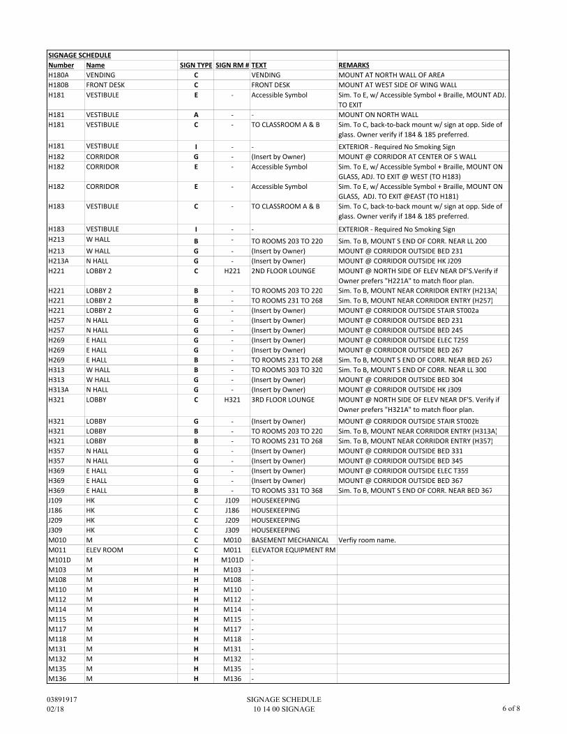
SIGNAGE SCHEDULE
Number Name SIGN TYPE SIGN RM # TEXT REMARKS
H180A VENDING C VENDING MOUNT AT NORTH WALL OF AREA
H180B FRONT DESK C FRONT DESK MOUNT AT WEST SIDE OF WING WALL
H181 VESTIBULE E - Accessible Symbol Sim. To E, w/ Accessible Symbol + Braille, MOUNT ADJ.
TO EXIT
H181 VESTIBULE A - - MOUNT ON NORTH WALL
H181 VESTIBULE C - TO CLASSROOM A & B Sim. To C, back-to-back mount w/ sign at opp. Side of
glass. Owner verify if 184 & 185 preferred.
H181 VESTIBULE I - - EXTERIOR - Required No Smoking Sign
H182 CORRIDOR G - (Insert by Owner) MOUNT @ CORRIDOR AT CENTER OF S WALL
H182 CORRIDOR E - Accessible Symbol Sim. To E, w/ Accessible Symbol + Braille, MOUNT ON
GLASS, ADJ. TO EXIT @ WEST (TO H183)
H182 CORRIDOR E - Accessible Symbol Sim. To E, w/ Accessible Symbol + Braille, MOUNT ON
GLASS, ADJ. TO EXIT @EAST (TO H181)
H183 VESTIBULE C - TO CLASSROOM A & B Sim. To C, back-to-back mount w/ sign at opp. Side of
glass. Owner verify if 184 & 185 preferred.
H183 VESTIBULE I - - EXTERIOR - Required No Smoking Sign
H213 W HALL B - TO ROOMS 203 TO 220 Sim. To B, MOUNT S END OF CORR. NEAR LL 200
H213 W HALL G - (Insert by Owner) MOUNT @ CORRIDOR OUTSIDE BED 231
H213A N HALL G - (Insert by Owner) MOUNT @ CORRIDOR OUTSIDE HK J209
H221 LOBBY 2 C H221 2ND FLOOR LOUNGE MOUNT @ NORTH SIDE OF ELEV NEAR DF'S.Verify if
Owner prefers "H221A" to match floor plan.
H221 LOBBY 2 B - TO ROOMS 203 TO 220 Sim. To B, MOUNT NEAR CORRIDOR ENTRY (H213A)
H221 LOBBY 2 B - TO ROOMS 231 TO 268 Sim. To B, MOUNT NEAR CORRIDOR ENTRY (H257)
H221 LOBBY 2 G - (Insert by Owner) MOUNT @ CORRIDOR OUTSIDE STAIR ST002a
H257 N HALL G - (Insert by Owner) MOUNT @ CORRIDOR OUTSIDE BED 231
H257 N HALL G - (Insert by Owner) MOUNT @ CORRIDOR OUTSIDE BED 245
H269 E HALL G - (Insert by Owner) MOUNT @ CORRIDOR OUTSIDE ELEC T259
H269 E HALL G - (Insert by Owner) MOUNT @ CORRIDOR OUTSIDE BED 267
H269 E HALL B - TO ROOMS 231 TO 268 Sim. To B, MOUNT S END OF CORR. NEAR BED 267
H313 W HALL B - TO ROOMS 303 TO 320 Sim. To B, MOUNT S END OF CORR. NEAR LL 300
H313 W HALL G - (Insert by Owner) MOUNT @ CORRIDOR OUTSIDE BED 304
H313A N HALL G - (Insert by Owner) MOUNT @ CORRIDOR OUTSIDE HK J309
H321 LOBBY C H321 3RD FLOOR LOUNGE MOUNT @ NORTH SIDE OF ELEV NEAR DF'S. Verify if
Owner prefers "H321A" to match floor plan.
H321 LOBBY G - (Insert by Owner) MOUNT @ CORRIDOR OUTSIDE STAIR ST002b
H321 LOBBY B - TO ROOMS 203 TO 220 Sim. To B, MOUNT NEAR CORRIDOR ENTRY (H313A)
H321 LOBBY B - TO ROOMS 231 TO 268 Sim. To B, MOUNT NEAR CORRIDOR ENTRY (H357)
H357 N HALL G - (Insert by Owner) MOUNT @ CORRIDOR OUTSIDE BED 331
H357 N HALL G - (Insert by Owner) MOUNT @ CORRIDOR OUTSIDE BED 345
H369 E HALL G - (Insert by Owner) MOUNT @ CORRIDOR OUTSIDE ELEC T359
H369 E HALL G - (Insert by Owner) MOUNT @ CORRIDOR OUTSIDE BED 367
H369 E HALL B - TO ROOMS 331 TO 368 Sim. To B, MOUNT S END OF CORR. NEAR BED 367
J109 HK C J109 HOUSEKEEPING
J186 HK C J186 HOUSEKEEPING
J209 HK C J209 HOUSEKEEPING
J309 HK C J309 HOUSEKEEPING
M010 M C M010 BASEMENT MECHANICAL Verfiy room name.
M011 ELEV ROOM C M011 ELEVATOR EQUIPMENT RM
M101D M H M101D -
M103 M H M103 -
M108 M H M108 -
M110 M H M110 -
M112 M H M112 -
M114 M H M114 -
M115 M H M115 -
M117 M H M117 -
M118 M H M118 -
M131 M H M131 -
M132 M H M132 -
M135 M H M135 -
M136 M H M136 -
03891917
02/18
SIGNAGE SCHEDULE
10 14 00 SIGNAGE 6 of 8
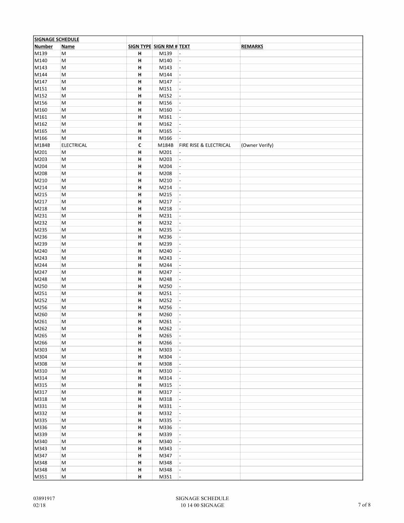
SIGNAGE SCHEDULE
Number Name SIGN TYPE SIGN RM # TEXT REMARKS
M139 M H M139 -
M140 M H M140 -
M143 M H M143 -
M144 M H M144 -
M147 M H M147 -
M151 M H M151 -
M152 M H M152 -
M156 M H M156 -
M160 M H M160 -
M161 M H M161 -
M162 M H M162 -
M165 M H M165 -
M166 M H M166 -
M184B ELECTRICAL C M184B FIRE RISE & ELECTRICAL (Owner Verify)
M201 M H M201 -
M203 M H M203 -
M204 M H M204 -
M208 M H M208 -
M210 M H M210 -
M214 M H M214 -
M215 M H M215 -
M217 M H M217 -
M218 M H M218 -
M231 M H M231 -
M232 M H M232 -
M235 M H M235 -
M236 M H M236 -
M239 M H M239 -
M240 M H M240 -
M243 M H M243 -
M244 M H M244 -
M247 M H M247 -
M248 M H M248 -
M250 M H M250 -
M251 M H M251 -
M252 M H M252 -
M256 M H M256 -
M260 M H M260 -
M261 M H M261 -
M262 M H M262 -
M265 M H M265 -
M266 M H M266 -
M303 M H M303 -
M304 M H M304 -
M308 M H M308 -
M310 M H M310 -
M314 M H M314 -
M315 M H M315 -
M317 M H M317 -
M318 M H M318 -
M331 M H M331 -
M332 M H M332 -
M335 M H M335 -
M336 M H M336 -
M339 M H M339 -
M340 M H M340 -
M343 M H M343 -
M347 M H M347 -
M348 M H M348 -
M348 M H M348 -
M351 M H M351 -
03891917
02/18
SIGNAGE SCHEDULE
10 14 00 SIGNAGE 7 of 8
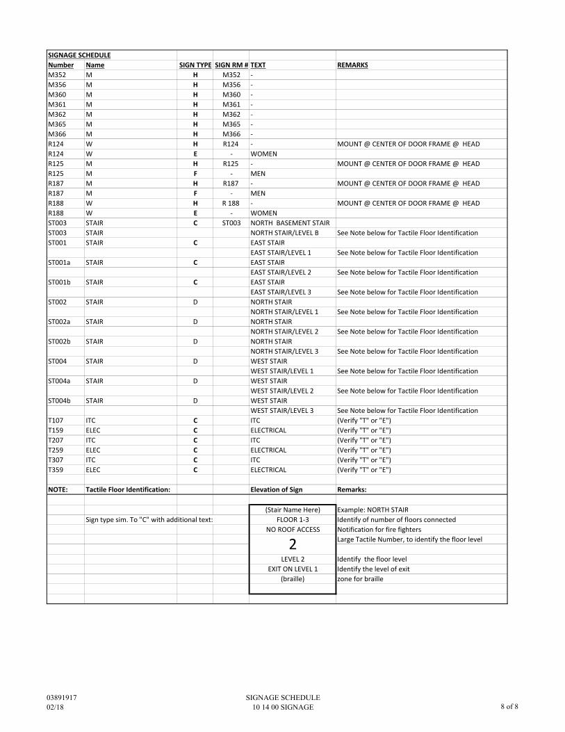
SIGNAGE SCHEDULE
Number Name SIGN TYPE SIGN RM # TEXT REMARKS
M352 M H M352 -
M356 M H M356 -
M360 M H M360 -
M361 M H M361 -
M362 M H M362 -
M365 M H M365 -
M366 M H M366 -
R124 W H R124 - MOUNT @ CENTER OF DOOR FRAME @ HEAD
R124 W E - WOMEN
R125 M H R125 - MOUNT @ CENTER OF DOOR FRAME @ HEAD
R125 M F - MEN
R187 M H R187 - MOUNT @ CENTER OF DOOR FRAME @ HEAD
R187 M F - MEN
R188 W H R 188 - MOUNT @ CENTER OF DOOR FRAME @ HEAD
R188 W E - WOMEN
ST003 STAIR C ST003 NORTH BASEMENT STAIR
ST003 STAIR NORTH STAIR/LEVEL B See Note below for Tactile Floor Identification
ST001 STAIR C EAST STAIR
EAST STAIR/LEVEL 1 See Note below for Tactile Floor Identification
ST001a STAIR C EAST STAIR
EAST STAIR/LEVEL 2 See Note below for Tactile Floor Identification
ST001b STAIR C EAST STAIR
EAST STAIR/LEVEL 3 See Note below for Tactile Floor Identification
ST002 STAIR D NORTH STAIR
NORTH STAIR/LEVEL 1 See Note below for Tactile Floor Identification
ST002a STAIR D NORTH STAIR
NORTH STAIR/LEVEL 2 See Note below for Tactile Floor Identification
ST002b STAIR D NORTH STAIR
NORTH STAIR/LEVEL 3 See Note below for Tactile Floor Identification
ST004 STAIR D WEST STAIR
WEST STAIR/LEVEL 1 See Note below for Tactile Floor Identification
ST004a STAIR D WEST STAIR
WEST STAIR/LEVEL 2 See Note below for Tactile Floor Identification
ST004b STAIR D WEST STAIR
WEST STAIR/LEVEL 3 See Note below for Tactile Floor Identification
T107 ITC C ITC (Verify "T" or "E")
T159 ELEC C ELECTRICAL (Verify "T" or "E")
T207 ITC C ITC (Verify "T" or "E")
T259 ELEC C ELECTRICAL (Verify "T" or "E")
T307 ITC C ITC (Verify "T" or "E")
T359 ELEC C ELECTRICAL (Verify "T" or "E")
NOTE: Tactile Floor Identification: Elevation of Sign Remarks:
(Stair Name Here) Example: NORTH STAIR
Sign type sim. To "C" with additional text: FLOOR 1-3 Identify of number of floors connected
NO ROOF ACCESS Notification for fire fighters
Large Tactile Number, to identify the floor level
LEVEL 2 Identify the floor level
EXIT ON LEVEL 1 Identify the level of exit
(braille) zone for braille
2
03891917
02/18
SIGNAGE SCHEDULE
10 14 00 SIGNAGE 8 of 8
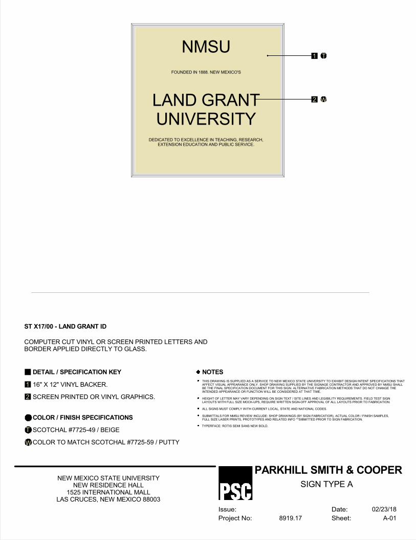
DETAIL / SPECIFICATION KEY
16" X 12" VINYL BACKER.
SCREEN PRINTED OR VINYL GRAPHICS.
COLOR / FINISH SPECIFICATIONS
SCOTCHAL #7725-49 / BEIGE
COLOR TO MATCH SCOTCHAL #7725-59 / PUTTY
NOTES
THIS DRAWING IS SUPPLIED AS A SERVICE TO NEW MEXICO STATE UNIVERSITY TO EXHIBIT DESIGN INTENT SPECIFICATIONS THATAFFECT VISUAL APPEARANCE ONLY. SHOP DRAWING SUPPLIED BY THE SIGNAGE CONTRACTOR AND APPROVED BY NMSU SHALLBE THE FINAL SPECIFICATION DOCUMENT FOR THIS SIGN. ALTERNATIVE FABRICATION METHODS THAT DO NOT CHANGE THEINTENDED APPEARANCE OR FUNCTION WILL BE CONSIDERED AT THAT TIME.
HEIGHT OF LETTER MAY VARY DEPENDING ON SIGN TEXT / SITE LINES AND LEGIBILITY REQUIREMENTS. FIELD TEST SIGNLAYOUTS WITH FULL SIZE MOCK-UPS, REQUIRE WRITTEN SIGN-OFF APPROVAL OF ALL LAYOUTS PRIOR TO FABRICATION.
ALL SIGNS MUST COMPLY WITH CURRENT LOCAL, STATE AND NATIONAL CODES.
SUBMITTALS FOR NMSU REVIEW INCLUDE: SHOP DRAWINGS (BY SIGN FABRICATIOR), ACTUAL COLOR / FINISH SAMPLES,FULL SIZE LASER PRINTS, PROTOTYPES AND RELATED INFO **SIBMITTED PRIOR TO SIGN FABRICATION.
TYPERFACE: ROTIS SEMI SANS NEW BOLD.
ST X17/00 - LAND GRANT ID
COMPUTER CUT VINYL OR SCREEN PRINTED LETTERS ANDBORDER APPLIED DIRECTLY TO GLASS.
1
2
T
W
1 T
2 W
NMSU
LAND GRANTUNIVERSITY
FOUNDED IN 1888. NEW MEXICO'S
DEDICATED TO EXCELLENCE IN TEACHING, RESEARCH,EXTENSION EDUCATION AND PUBLIC SERVICE.
Date:
Sheet:
Issue:
Project No:
PARKHILL SMITH & COOPER
A-018919.17
NEW MEXICO STATE UNIVERSITYNEW RESIDENCE HALL
1525 INTERNATIONAL MALLLAS CRUCES, NEW MEXICO 88003
02/23/18
SIGN TYPE A
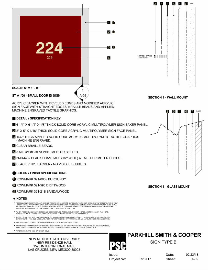
DETAIL / SPECIFICATION KEY
6 1/4" X 6 1/4" X 1/8" THICK SOLID CORE ACRYLIC MULTIPOLYMER SIGN BAKER PANEL.
5" X 5" X 1/16" THICK SOLID CORE ACRYLIC MULTIPOLYMER SIGN FACE PANEL.
1/32" THICK APPLIED SOLID CORE ACRYLIC MULTIPOLYMER TACTILE GRAPHICS(MACHINE ENGRAVED.
CLEAR BRAILLE BEADS.
5 MIL 3M #F-9473 VHB TAPE; OR BETTER
3M #4432 BLACK FOAM TAPE (1/2" WIDE) AT ALL PERIMETER EDGES.
BLACK VINYL BACKER - NO VISIBLE BUBBLES.
COLOR / FINISH SPECIFICATIONS
ROWMARK 321-803 / BURGUNDY
ROWMARK 321-595 DRIFTWOOD
NOTES
THIS DRAWING IS SUPPLIED AS A SERVICE TO NEW MEXICO STATE UNIVERSITY TO EXHIBIT DESIGN INTENT SPECIFICATIONS THATAFFECT VISUAL APPEARANCE ONLY. SHOP DRAWING SUPPLIED BY THE SIGNAGE CONTRACTOR AND APPROVED BY NMSU SHALLBE THE FINAL SPECIFICATION DOCUMENT FOR THIS SIGN. ALTERNATIVE FABRICATION METHODS THAT DO NOT CHANGE THEINTENDED APPEARANCE OR FUNCTION WILL BE CONSIDERED AT THAT TIME.
WHEN POSSIBLE, ALL FASTENERS SHALL BE CONCEALED. WHEN VISIBLE SCREW HEADS ARE NECESSARY, FLAT HEAD,COUNTERSUNK ALLAN SCREWS, PAINTED TO MATCH COMPONENT COLOR ARE PREFERRED.
HEIGHT OF LETTER MAY VARY DEPENDING ON SIGN TEXT / SITE LINES AND LEGIBILITY REQUIREMENTS. FIELD TEST SIGNLAYOUTS WITH FULL SIZE MOCK-UPS, REQUIRE WRITTEN SIGN-OFF APPROVAL OF ALL LAYOUTS PRIOR TO FABRICATION.
ALL SIGNS MUST COMPLY WITH CURRENT LOCAL, STATE AND NATIONAL CODES.
SUBMITTALS FOR NMSU REVIEW INCLUDE: SHOP DRAWINGS (BY SIGN FABRICATIOR), ACTUAL COLOR / FINISH SAMPLES,FULL SIZE LASER PRINTS, PROTOTYPES AND RELATED INFO **SIBMITTED PRIOR TO SIGN FABRICATION.
TYPERFACE: ROTIS SEMI SANS NEW BOLD.
ST A1/00 - SMALL DOOR ID SIGN
ACRYLIC BACKER WITH BEVELED EDGES AND MODIFIED ACRYLICSIGN FACE WITH STRAIGHT EDGES. BRAILLE BEADS AND APPLIEDMACHINE ENGRAVED TACTILE GRAPHICS.
1
2
3
4
5
6
7
Q
R
ROWMARK 321-21B SANDALWOODS
1 R
2 Q
3 S
4GRADE 2 BRAILLE1/32" HEIGHT
G WALL15253
SECTION 1 - WALL MOUNT
6 GLASS152
SECTION 1 - GLASS MOUNT
7
-
---
1
A-02
224
224
SCALE: 6" = 1' - 0"
Date:
Sheet:
Issue:
Project No:
PARKHILL SMITH & COOPER
A-028919.17
NEW MEXICO STATE UNIVERSITYNEW RESIDENCE HALL
1525 INTERNATIONAL MALLLAS CRUCES, NEW MEXICO 88003
02/23/18
SIGN TYPE B
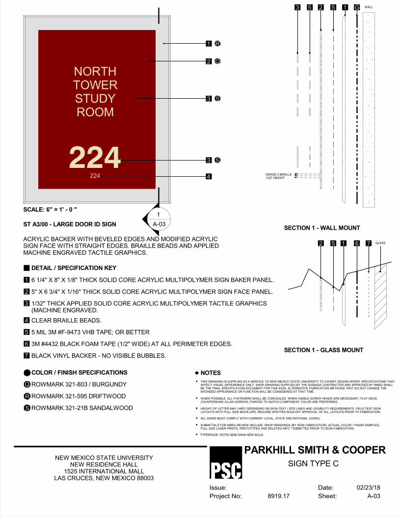
224
DETAIL / SPECIFICATION KEY
6 1/4" X 8" X 1/8" THICK SOLID CORE ACRYLIC MULTIPOLYMER SIGN BAKER PANEL.
5" X 6 3/4" X 1/16" THICK SOLID CORE ACRYLIC MULTIPOLYMER SIGN FACE PANEL.
1/32" THICK APPLIED SOLID CORE ACRYLIC MULTIPOLYMER TACTILE GRAPHICS(MACHINE ENGRAVED.
CLEAR BRAILLE BEADS.
5 MIL 3M #F-9473 VHB TAPE; OR BETTER
3M #4432 BLACK FOAM TAPE (1/2" WIDE) AT ALL PERIMETER EDGES.
BLACK VINYL BACKER - NO VISIBLE BUBBLES.
COLOR / FINISH SPECIFICATIONS
ROWMARK 321-803 / BURGUNDY
ROWMARK 321-595 DRIFTWOOD
NOTES
THIS DRAWING IS SUPPLIED AS A SERVICE TO NEW MEXICO STATE UNIVERSITY TO EXHIBIT DESIGN INTENT SPECIFICATIONS THATAFFECT VISUAL APPEARANCE ONLY. SHOP DRAWING SUPPLIED BY THE SIGNAGE CONTRACTOR AND APPROVED BY NMSU SHALLBE THE FINAL SPECIFICATION DOCUMENT FOR THIS SIGN. ALTERNATIVE FABRICATION METHODS THAT DO NOT CHANGE THEINTENDED APPEARANCE OR FUNCTION WILL BE CONSIDERED AT THAT TIME.
WHEN POSSIBLE, ALL FASTENERS SHALL BE CONCEALED. WHEN VISIBLE SCREW HEADS ARE NECESSARY, FLAT HEAD,COUNTERSUNK ALLAN SCREWS, PAINTED TO MATCH COMPONENT COLOR ARE PREFERRED.
HEIGHT OF LETTER MAY VARY DEPENDING ON SIGN TEXT / SITE LINES AND LEGIBILITY REQUIREMENTS. FIELD TEST SIGNLAYOUTS WITH FULL SIZE MOCK-UPS, REQUIRE WRITTEN SIGN-OFF APPROVAL OF ALL LAYOUTS PRIOR TO FABRICATION.
ALL SIGNS MUST COMPLY WITH CURRENT LOCAL, STATE AND NATIONAL CODES.
SUBMITTALS FOR NMSU REVIEW INCLUDE: SHOP DRAWINGS (BY SIGN FABRICATIOR), ACTUAL COLOR / FINISH SAMPLES,FULL SIZE LASER PRINTS, PROTOTYPES AND RELATED INFO **SIBMITTED PRIOR TO SIGN FABRICATION.
TYPERFACE: ROTIS SEMI SANS NEW BOLD.
ST A3/00 - LARGE DOOR ID SIGN
ACRYLIC BACKER WITH BEVELED EDGES AND MODIFIED ACRYLICSIGN FACE WITH STRAIGHT EDGES. BRAILLE BEADS AND APPLIEDMACHINE ENGRAVED TACTILE GRAPHICS.
1
2
3
4
5
6
7
Q
R
ROWMARK 321-21B SANDALWOODS
1 R
2 Q
3 S
4GRADE 2 BRAILLE1/32" HEIGHT
G WALL15253
SECTION 1 - WALL MOUNT
6 GLASS152
SECTION 1 - GLASS MOUNT
7
-
---
1
A-03
NORTHTOWERSTUDYROOM
224 3 S
SCALE: 6" = 1' - 0 "
Date:
Sheet:
Issue:
Project No:
PARKHILL SMITH & COOPER
A-038919.17
NEW MEXICO STATE UNIVERSITYNEW RESIDENCE HALL
1525 INTERNATIONAL MALLLAS CRUCES, NEW MEXICO 88003
02/23/18
SIGN TYPE C
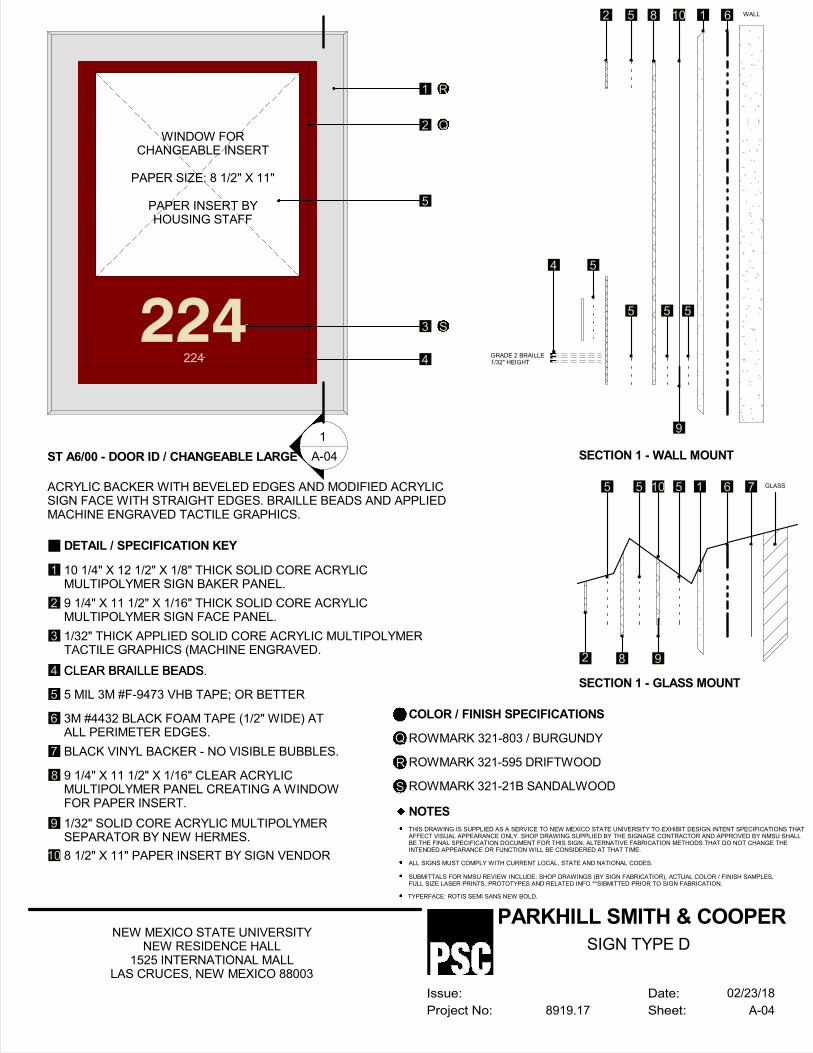
224
DETAIL / SPECIFICATION KEY
10 1/4" X 12 1/2" X 1/8" THICK SOLID CORE ACRYLICMULTIPOLYMER SIGN BAKER PANEL.
9 1/4" X 11 1/2" X 1/16" THICK SOLID CORE ACRYLICMULTIPOLYMER SIGN FACE PANEL.
1/32" THICK APPLIED SOLID CORE ACRYLIC MULTIPOLYMERTACTILE GRAPHICS (MACHINE ENGRAVED.
CLEAR BRAILLE BEADS.
9 1/4" X 11 1/2" X 1/16" CLEAR ACRYLICMULTIPOLYMER PANEL CREATING A WINDOWFOR PAPER INSERT.
3M #4432 BLACK FOAM TAPE (1/2" WIDE) ATALL PERIMETER EDGES.
BLACK VINYL BACKER - NO VISIBLE BUBBLES.
COLOR / FINISH SPECIFICATIONS
ROWMARK 321-803 / BURGUNDY
ROWMARK 321-595 DRIFTWOOD
NOTES
THIS DRAWING IS SUPPLIED AS A SERVICE TO NEW MEXICO STATE UNIVERSITY TO EXHIBIT DESIGN INTENT SPECIFICATIONS THATAFFECT VISUAL APPEARANCE ONLY. SHOP DRAWING SUPPLIED BY THE SIGNAGE CONTRACTOR AND APPROVED BY NMSU SHALLBE THE FINAL SPECIFICATION DOCUMENT FOR THIS SIGN. ALTERNATIVE FABRICATION METHODS THAT DO NOT CHANGE THEINTENDED APPEARANCE OR FUNCTION WILL BE CONSIDERED AT THAT TIME.
ALL SIGNS MUST COMPLY WITH CURRENT LOCAL, STATE AND NATIONAL CODES.
SUBMITTALS FOR NMSU REVIEW INCLUDE: SHOP DRAWINGS (BY SIGN FABRICATIOR), ACTUAL COLOR / FINISH SAMPLES,FULL SIZE LASER PRINTS, PROTOTYPES AND RELATED INFO **SIBMITTED PRIOR TO SIGN FABRICATION.
TYPERFACE: ROTIS SEMI SANS NEW BOLD.
ST A6/00 - DOOR ID / CHANGEABLE LARGE
ACRYLIC BACKER WITH BEVELED EDGES AND MODIFIED ACRYLICSIGN FACE WITH STRAIGHT EDGES. BRAILLE BEADS AND APPLIEDMACHINE ENGRAVED TACTILE GRAPHICS.
1
2
3
4
8
9
10
Q
R
ROWMARK 321-21B SANDALWOODS
1 R
2 Q
5
4GRADE 2 BRAILLE1/32" HEIGHT
6 WALL110852
SECTION 1 - WALL MOUNT
6 GLASS1510
SECTION 1 - GLASS MOUNT
7
-
---
1
A-04
224 3 S
7
6
5 MIL 3M #F-9473 VHB TAPE; OR BETTER5
1/32" SOLID CORE ACRYLIC MULTIPOLYMERSEPARATOR BY NEW HERMES.
8 1/2" X 11" PAPER INSERT BY SIGN VENDOR
5 5 5
9
54
55
8 92
Date:
Sheet:
Issue:
Project No:
PARKHILL SMITH & COOPER
A-048919.17
NEW MEXICO STATE UNIVERSITYNEW RESIDENCE HALL
1525 INTERNATIONAL MALLLAS CRUCES, NEW MEXICO 88003
02/23/18
SIGN TYPE D
CLEAR BRAILLE BEADS
WINDOW FORCHANGEABLE INSERT
PAPER SIZE: 8 1/2" X 11"
PAPER INSERT BYHOUSING STAFF

WOMEN
DETAIL / SPECIFICATION KEY
6 1/4" X 8" X 1/8" THICK SOLID CORE ACRYLIC MULTIPOLYMER SIGN BAKER PANEL.
5" X 6 3/4" X 1/16" THICK SOLID CORE ACRYLIC MULTIPOLYMER SIGN FACE PANEL.
1/32" THICK APPLIED SOLID CORE ACRYLIC MULTIPOLYMER TACTILE GRAPHICS (MACHINE ENGRAVED.
CLEAR BRAILLE BEADS.
5 MIL 3M #F-9473 VHB TAPE; OR BETTER
3M #4432 BLACK FOAM TAPE (1/2" WIDE) AT ALL PERIMETER EDGES.
COLOR / FINISH SPECIFICATIONS
ROWMARK 321-803 / BURGUNDY
ROWMARK 321-595 DRIFTWOOD
NOTES
THIS DRAWING IS SUPPLIED AS A SERVICE TO NEW MEXICO STATE UNIVERSITY TO EXHIBIT DESIGN INTENT SPECIFICATIONS THATAFFECT VISUAL APPEARANCE ONLY. SHOP DRAWING SUPPLIED BY THE SIGNAGE CONTRACTOR AND APPROVED BY NMSU SHALLBE THE FINAL SPECIFICATION DOCUMENT FOR THIS SIGN. ALTERNATIVE FABRICATION METHODS THAT DO NOT CHANGE THEINTENDED APPEARANCE OR FUNCTION WILL BE CONSIDERED AT THAT TIME.
WHEN POSSIBLE, ALL FASTENERS SHALL BE CONCEALED. WHEN VISIBLE SCREW HEADS ARE NECESSARY, FLAT HEAD,COUNTERSUNK ALLAN SCREWS, PAINTED TO MATCH COMPONENT COLOR ARE PREFERRED.
HEIGHT OF LETTER MAY VARY DEPENDING ON SIGN TEXT / SITE LINES AND LEGIBILITY REQUIREMENTS. FIELD TEST SIGNLAYOUTS WITH FULL SIZE MOCK-UPS, REQUIRE WRITTEN SIGN-OFF APPROVAL OF ALL LAYOUTS PRIOR TO FABRICATION.
ALL SIGNS MUST COMPLY WITH CURRENT LOCAL, STATE AND NATIONAL CODES.
SUBMITTALS FOR NMSU REVIEW INCLUDE: SHOP DRAWINGS (BY SIGN FABRICATIOR), ACTUAL COLOR / FINISH SAMPLES,FULL SIZE LASER PRINTS, PROTOTYPES AND RELATED INFO **SIBMITTED PRIOR TO SIGN FABRICATION.
TYPERFACE: ROTIS SEMI SANS NEW BOLD.
ST A7/00 - RESTROOM ID / WOMEN
ACRYLIC BACKER WITH BEVELED EDGES AND MODIFIED ACRYLICSIGN FACE WITH STRAIGHT EDGES. BRAILLE BEADS AND APPLIEDMACHINE ENGRAVED TACTILE GRAPHICS.
1
2
3
4
5
6
Q
R
ROWMARK 321-21B SANDALWOODS
1 R
2 Q
3 S
4GRADE 2 BRAILLE1/32" HEIGHT
G WALL15253
SECTION 1 - WALL MOUNT
-
---
1
A-05
WOMEN 3 S
SCALE: 6" = 1' - 0 "
W
TAPE PLACED 1/2" INSIDEALL PERIMETER EDGES
Date:
Sheet:
Issue:
Project No:
PARKHILL SMITH & COOPER
A-058919.17
NEW MEXICO STATE UNIVERSITYNEW RESIDENCE HALL
1525 INTERNATIONAL MALLLAS CRUCES, NEW MEXICO 88003
02/23/18
SIGN TYPE E
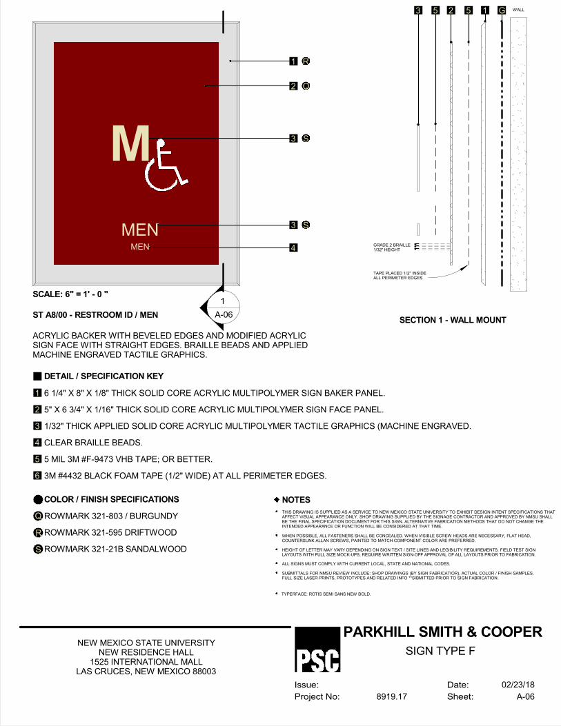
MEN
DETAIL / SPECIFICATION KEY
6 1/4" X 8" X 1/8" THICK SOLID CORE ACRYLIC MULTIPOLYMER SIGN BAKER PANEL.
5" X 6 3/4" X 1/16" THICK SOLID CORE ACRYLIC MULTIPOLYMER SIGN FACE PANEL.
1/32" THICK APPLIED SOLID CORE ACRYLIC MULTIPOLYMER TACTILE GRAPHICS (MACHINE ENGRAVED.
CLEAR BRAILLE BEADS.
5 MIL 3M #F-9473 VHB TAPE; OR BETTER.
3M #4432 BLACK FOAM TAPE (1/2" WIDE) AT ALL PERIMETER EDGES.
COLOR / FINISH SPECIFICATIONS
ROWMARK 321-803 / BURGUNDY
ROWMARK 321-595 DRIFTWOOD
NOTES
THIS DRAWING IS SUPPLIED AS A SERVICE TO NEW MEXICO STATE UNIVERSITY TO EXHIBIT DESIGN INTENT SPECIFICATIONS THATAFFECT VISUAL APPEARANCE ONLY. SHOP DRAWING SUPPLIED BY THE SIGNAGE CONTRACTOR AND APPROVED BY NMSU SHALLBE THE FINAL SPECIFICATION DOCUMENT FOR THIS SIGN. ALTERNATIVE FABRICATION METHODS THAT DO NOT CHANGE THEINTENDED APPEARANCE OR FUNCTION WILL BE CONSIDERED AT THAT TIME.
WHEN POSSIBLE, ALL FASTENERS SHALL BE CONCEALED. WHEN VISIBLE SCREW HEADS ARE NECESSARY, FLAT HEAD,COUNTERSUNK ALLAN SCREWS, PAINTED TO MATCH COMPONENT COLOR ARE PREFERRED.
HEIGHT OF LETTER MAY VARY DEPENDING ON SIGN TEXT / SITE LINES AND LEGIBILITY REQUIREMENTS. FIELD TEST SIGNLAYOUTS WITH FULL SIZE MOCK-UPS, REQUIRE WRITTEN SIGN-OFF APPROVAL OF ALL LAYOUTS PRIOR TO FABRICATION.
ALL SIGNS MUST COMPLY WITH CURRENT LOCAL, STATE AND NATIONAL CODES.
SUBMITTALS FOR NMSU REVIEW INCLUDE: SHOP DRAWINGS (BY SIGN FABRICATIOR), ACTUAL COLOR / FINISH SAMPLES,FULL SIZE LASER PRINTS, PROTOTYPES AND RELATED INFO **SIBMITTED PRIOR TO SIGN FABRICATION.
TYPERFACE: ROTIS SEMI SANS NEW BOLD.
ST A8/00 - RESTROOM ID / MEN
ACRYLIC BACKER WITH BEVELED EDGES AND MODIFIED ACRYLICSIGN FACE WITH STRAIGHT EDGES. BRAILLE BEADS AND APPLIEDMACHINE ENGRAVED TACTILE GRAPHICS.
1
2
3
4
5
6
Q
R
ROWMARK 321-21B SANDALWOODS
1 R
2 Q
3 S
4GRADE 2 BRAILLE1/32" HEIGHT
G WALL15253
SECTION 1 - WALL MOUNT
-
---
1
A-06
MEN 3 S
SCALE: 6" = 1' - 0 "
M
TAPE PLACED 1/2" INSIDEALL PERIMETER EDGES
Date:
Sheet:
Issue:
Project No:
PARKHILL SMITH & COOPER
A-068919.17
NEW MEXICO STATE UNIVERSITYNEW RESIDENCE HALL
1525 INTERNATIONAL MALLLAS CRUCES, NEW MEXICO 88003
02/23/18
SIGN TYPE F

DETAIL / SPECIFICATION KEY
13 1/4" X 18 7/8" X 1/8" THICK SOLID COREACRYLIC MULTIPOLYMER SIGN BAKER PANEL.
12" X 17 5/8" X 1/32" THICK SOLID CORE ACRYLICMULTIPOLYMER SIGN FACE PANEL.
12" X 17 5/8" X 1/8" CLEAR ACRYLICMULTIPOLYMER PANEL CREATING A WINDOWFOR PAPER INSERT.
3M #4432 BLACK FOAM TAPE (1/2" WIDE) ATALL PERIMETER EDGES.
COLOR / FINISH SPECIFICATIONS
ROWMARK 321-803 / BURGUNDY
ROWMARK 321-595 DRIFTWOOD
NOTES
THIS DRAWING IS SUPPLIED AS A SERVICE TO NEW MEXICO STATE UNIVERSITY TO EXHIBIT DESIGN INTENT SPECIFICATIONS THATAFFECT VISUAL APPEARANCE ONLY. SHOP DRAWING SUPPLIED BY THE SIGNAGE CONTRACTOR AND APPROVED BY NMSU SHALLBE THE FINAL SPECIFICATION DOCUMENT FOR THIS SIGN. ALTERNATIVE FABRICATION METHODS THAT DO NOT CHANGE THEINTENDED APPEARANCE OR FUNCTION WILL BE CONSIDERED AT THAT TIME.
ALL SIGNS MUST COMPLY WITH CURRENT LOCAL, STATE AND NATIONAL CODES.
SUBMITTALS FOR NMSU REVIEW INCLUDE: SHOP DRAWINGS (BY SIGN FABRICATIOR), ACTUAL COLOR / FINISH SAMPLES,FULL SIZE LASER PRINTS, PROTOTYPES AND RELATED INFO **SIBMITTED PRIOR TO SIGN FABRICATION.
TYPERFACE: ROTIS SEMI SANS NEW BOLD.
ST A10/00 - EVACUATION MAP
ACRYLIC BACKER WITH BEVELED EDGES AND MODIFIED ACRYLICSIGN FACE WITH STRAIGHT EDGES. BRAILLE BEADS AND APPLIEDMACHINE ENGRAVED TACTILE GRAPHICS.
1
2
3
4
Q
R
1 R
2 Q
5
4 WALL17532
SECTION 1 - WALL MOUNT
-
---
1
A-07
7
7
6
5 MIL 3M #F-9473 VHB TAPE; OR BETTER
5
1/32" SOLID CORE ACRYLIC MULTIPOLYMERSEPARATOR BY NEW HERMES.
11" X 17" DIGITAL MAP INSERT BY SIGN VENDOR.
3 3 3
6
WINDOW FORCHANGEABLE INSERT
PAPER SIZE: 11" X 17"
PAPER INSERT BYSIGN CONTRACTOR
Date:
Sheet:
Issue:
Project No:
PARKHILL SMITH & COOPER
A-078919.17
NEW MEXICO STATE UNIVERSITYNEW RESIDENCE HALL
1525 INTERNATIONAL MALLLAS CRUCES, NEW MEXICO 88003
02/23/18
SIGN TYPE G

1 R
2 QM260
DETAIL / SPECIFICATION KEY
16" X 12" VINYL BACKER.
SCREEN PRINTED OR VINYL GRAPHICS.
COLOR / FINISH SPECIFICATIONS
ROWMARK 321-803 / BURGUNDY
ROWMARK 321-21B SANDALWOOD
1
2
R
Q
SCALE: 12" = 1' - 0"
OWNER OPTION: REVERSE Q & R
Date:
Sheet:
Issue:
Project No:
PARKHILL SMITH & COOPER
A-098919.17
NEW MEXICO STATE UNIVERSITYNEW RESIDENCE HALL
1525 INTERNATIONAL MALLLAS CRUCES, NEW MEXICO 88003
02/23/18
SIGN TYPE H

DETAIL / SPECIFICATION KEY
6 1/4" X 8" X 1/8" THICK SOLID CORE ACRYLIC MULTIPOLYMER SIGN BAKER PANEL.
5" X 6 3/4" X 1/16" THICK SOLID CORE ACRYLIC MULTIPOLYMER SIGN FACE PANEL.
1/32" THICK APPLIED SOLID CORE ACRYLIC MULTIPOLYMER TACTILE GRAPHICS(MACHINE ENGRAVED.
CLEAR BRAILLE BEADS.
5 MIL 3M #F-9473 VHB TAPE; OR BETTER
3M #4432 BLACK FOAM TAPE (1/2" WIDE) AT ALL PERIMETER EDGES.
BLACK VINYL BACKER - NO VISIBLE BUBBLES.
COLOR / FINISH SPECIFICATIONS
ROWMARK 321-803 / BURGUNDY
ROWMARK 321-595 DRIFTWOOD
NOTES
THIS DRAWING IS SUPPLIED AS A SERVICE TO NEW MEXICO STATE UNIVERSITY TO EXHIBIT DESIGN INTENT SPECIFICATIONS THATAFFECT VISUAL APPEARANCE ONLY. SHOP DRAWING SUPPLIED BY THE SIGNAGE CONTRACTOR AND APPROVED BY NMSU SHALLBE THE FINAL SPECIFICATION DOCUMENT FOR THIS SIGN. ALTERNATIVE FABRICATION METHODS THAT DO NOT CHANGE THEINTENDED APPEARANCE OR FUNCTION WILL BE CONSIDERED AT THAT TIME.
WHEN POSSIBLE, ALL FASTENERS SHALL BE CONCEALED. WHEN VISIBLE SCREW HEADS ARE NECESSARY, FLAT HEAD,COUNTERSUNK ALLAN SCREWS, PAINTED TO MATCH COMPONENT COLOR ARE PREFERRED.
HEIGHT OF LETTER MAY VARY DEPENDING ON SIGN TEXT / SITE LINES AND LEGIBILITY REQUIREMENTS. FIELD TEST SIGNLAYOUTS WITH FULL SIZE MOCK-UPS, REQUIRE WRITTEN SIGN-OFF APPROVAL OF ALL LAYOUTS PRIOR TO FABRICATION.
ALL SIGNS MUST COMPLY WITH CURRENT LOCAL, STATE AND NATIONAL CODES.
SUBMITTALS FOR NMSU REVIEW INCLUDE: SHOP DRAWINGS (BY SIGN FABRICATIOR), ACTUAL COLOR / FINISH SAMPLES,FULL SIZE LASER PRINTS, PROTOTYPES AND RELATED INFO **SIBMITTED PRIOR TO SIGN FABRICATION.
TYPERFACE: ROTIS SEMI SANS NEW BOLD.
ST A3/00 - NO SMOKING SIGN
ACRYLIC BACKER WITH BEVELED EDGES AND MODIFIED ACRYLICSIGN FACE WITH STRAIGHT EDGES. BRAILLE BEADS AND APPLIEDMACHINE ENGRAVED TACTILE GRAPHICS.
1
2
3
4
5
6
7
Q
R
ROWMARK 321-21B SANDALWOODS
1 R
2 Q
3 S
6 WALL15253
SECTION 1 - WALL MOUNT
6 GLASS152
SECTION 1 - GLASS MOUNT
7
-
---
1
A-03
THIS IS ASMOKE FREE
FACILITY
SCALE: 6" = 1' - 0 "
NO SMOKING SYMBOL
YOUR COOPERATIONIS APPRECIATED
Date:
Sheet:
Issue:
Project No:
PARKHILL SMITH & COOPER
A-108919.17
NEW MEXICO STATE UNIVERSITYNEW RESIDENCE HALL
1525 INTERNATIONAL MALLLAS CRUCES, NEW MEXICO 88003
02/23/18
SIGN TYPE I
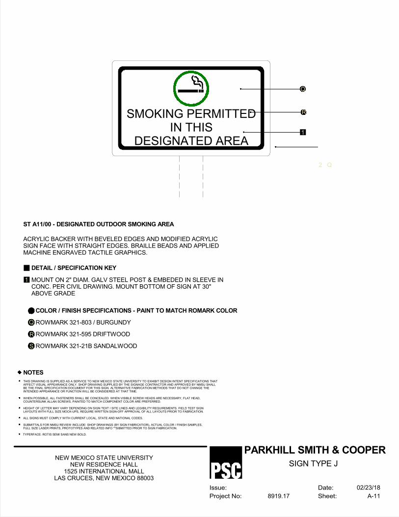
DETAIL / SPECIFICATION KEY
MOUNT ON 2" DIAM. GALV STEEL POST & EMBEDED IN SLEEVE INCONC. PER CIVIL DRAWING. MOUNT BOTTOM OF SIGN AT 30"ABOVE GRADE
NOTES
THIS DRAWING IS SUPPLIED AS A SERVICE TO NEW MEXICO STATE UNIVERSITY TO EXHIBIT DESIGN INTENT SPECIFICATIONS THATAFFECT VISUAL APPEARANCE ONLY. SHOP DRAWING SUPPLIED BY THE SIGNAGE CONTRACTOR AND APPROVED BY NMSU SHALLBE THE FINAL SPECIFICATION DOCUMENT FOR THIS SIGN. ALTERNATIVE FABRICATION METHODS THAT DO NOT CHANGE THEINTENDED APPEARANCE OR FUNCTION WILL BE CONSIDERED AT THAT TIME.
WHEN POSSIBLE, ALL FASTENERS SHALL BE CONCEALED. WHEN VISIBLE SCREW HEADS ARE NECESSARY, FLAT HEAD,COUNTERSUNK ALLAN SCREWS, PAINTED TO MATCH COMPONENT COLOR ARE PREFERRED.
HEIGHT OF LETTER MAY VARY DEPENDING ON SIGN TEXT / SITE LINES AND LEGIBILITY REQUIREMENTS. FIELD TEST SIGNLAYOUTS WITH FULL SIZE MOCK-UPS, REQUIRE WRITTEN SIGN-OFF APPROVAL OF ALL LAYOUTS PRIOR TO FABRICATION.
ALL SIGNS MUST COMPLY WITH CURRENT LOCAL, STATE AND NATIONAL CODES.
SUBMITTALS FOR NMSU REVIEW INCLUDE: SHOP DRAWINGS (BY SIGN FABRICATIOR), ACTUAL COLOR / FINISH SAMPLES,FULL SIZE LASER PRINTS, PROTOTYPES AND RELATED INFO **SIBMITTED PRIOR TO SIGN FABRICATION.
TYPERFACE: ROTIS SEMI SANS NEW BOLD.
ST A11/00 - DESIGNATED OUTDOOR SMOKING AREA
ACRYLIC BACKER WITH BEVELED EDGES AND MODIFIED ACRYLICSIGN FACE WITH STRAIGHT EDGES. BRAILLE BEADS AND APPLIEDMACHINE ENGRAVED TACTILE GRAPHICS.
1
SMOKING PERMITTEDIN THIS
DESIGNATED AREA1
COLOR / FINISH SPECIFICATIONS - PAINT TO MATCH ROMARK COLOR
ROWMARK 321-803 / BURGUNDY
ROWMARK 321-595 DRIFTWOOD
Q
R
ROWMARK 321-21B SANDALWOODS
Q
R
2 Q
Date:
Sheet:
Issue:
Project No:
PARKHILL SMITH & COOPER
A-118919.17
NEW MEXICO STATE UNIVERSITYNEW RESIDENCE HALL
1525 INTERNATIONAL MALLLAS CRUCES, NEW MEXICO 88003
02/23/18
SIGN TYPE J
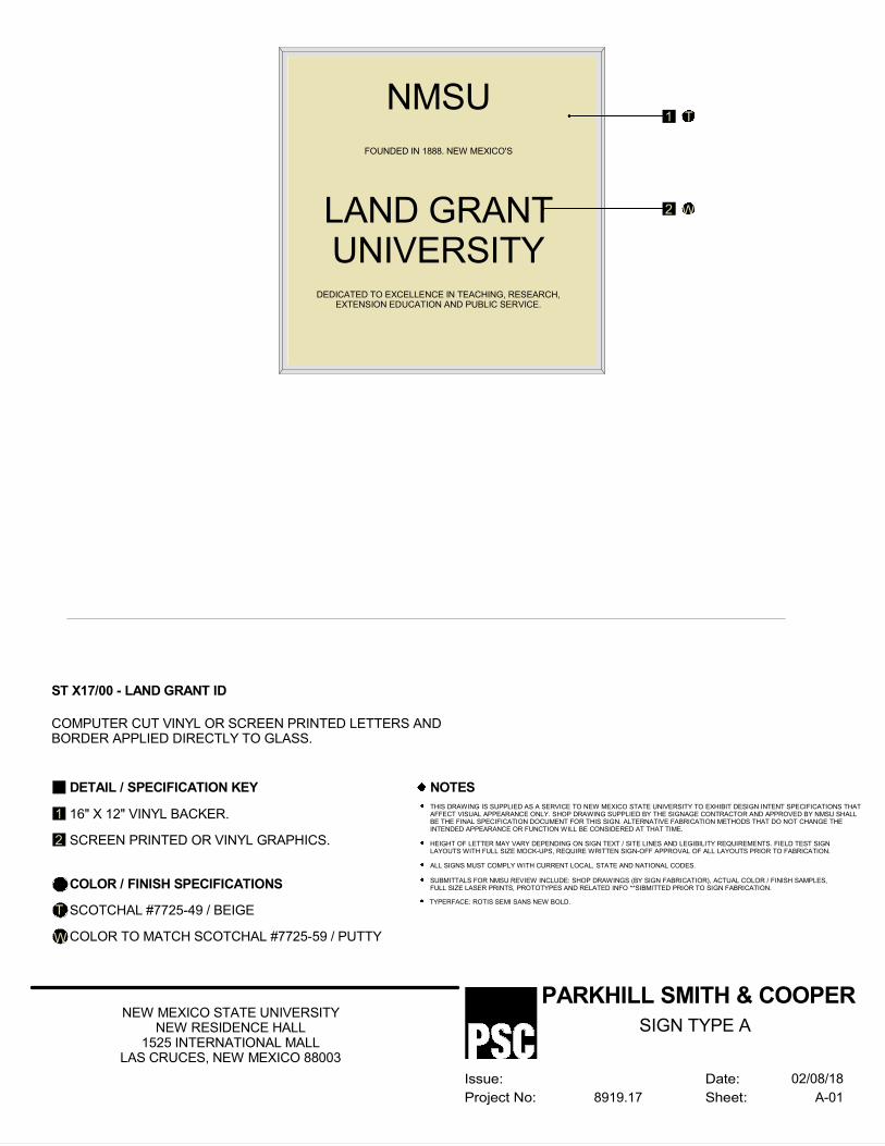
DETAIL / SPECIFICATION KEY
16" X 12" VINYL BACKER.
SCREEN PRINTED OR VINYL GRAPHICS.
COLOR / FINISH SPECIFICATIONS
SCOTCHAL #7725-49 / BEIGE
COLOR TO MATCH SCOTCHAL #7725-59 / PUTTY
NOTES
THIS DRAWING IS SUPPLIED AS A SERVICE TO NEW MEXICO STATE UNIVERSITY TO EXHIBIT DESIGN INTENT SPECIFICATIONS THATAFFECT VISUAL APPEARANCE ONLY. SHOP DRAWING SUPPLIED BY THE SIGNAGE CONTRACTOR AND APPROVED BY NMSU SHALLBE THE FINAL SPECIFICATION DOCUMENT FOR THIS SIGN. ALTERNATIVE FABRICATION METHODS THAT DO NOT CHANGE THEINTENDED APPEARANCE OR FUNCTION WILL BE CONSIDERED AT THAT TIME.
HEIGHT OF LETTER MAY VARY DEPENDING ON SIGN TEXT / SITE LINES AND LEGIBILITY REQUIREMENTS. FIELD TEST SIGNLAYOUTS WITH FULL SIZE MOCK-UPS, REQUIRE WRITTEN SIGN-OFF APPROVAL OF ALL LAYOUTS PRIOR TO FABRICATION.
ALL SIGNS MUST COMPLY WITH CURRENT LOCAL, STATE AND NATIONAL CODES.
SUBMITTALS FOR NMSU REVIEW INCLUDE: SHOP DRAWINGS (BY SIGN FABRICATIOR), ACTUAL COLOR / FINISH SAMPLES,FULL SIZE LASER PRINTS, PROTOTYPES AND RELATED INFO **SIBMITTED PRIOR TO SIGN FABRICATION.
TYPERFACE: ROTIS SEMI SANS NEW BOLD.
ST X17/00 - LAND GRANT ID
COMPUTER CUT VINYL OR SCREEN PRINTED LETTERS ANDBORDER APPLIED DIRECTLY TO GLASS.
1
2
T
W
1 T
2 W
NMSU
LAND GRANTUNIVERSITY
FOUNDED IN 1888. NEW MEXICO'S
DEDICATED TO EXCELLENCE IN TEACHING, RESEARCH,EXTENSION EDUCATION AND PUBLIC SERVICE.
Date:
Sheet:
Issue:
Project No:
PARKHILL SMITH & COOPER
A-018919.17
NEW MEXICO STATE UNIVERSITYNEW RESIDENCE HALL
1525 INTERNATIONAL MALLLAS CRUCES, NEW MEXICO 88003
02/08/18
SIGN TYPE A
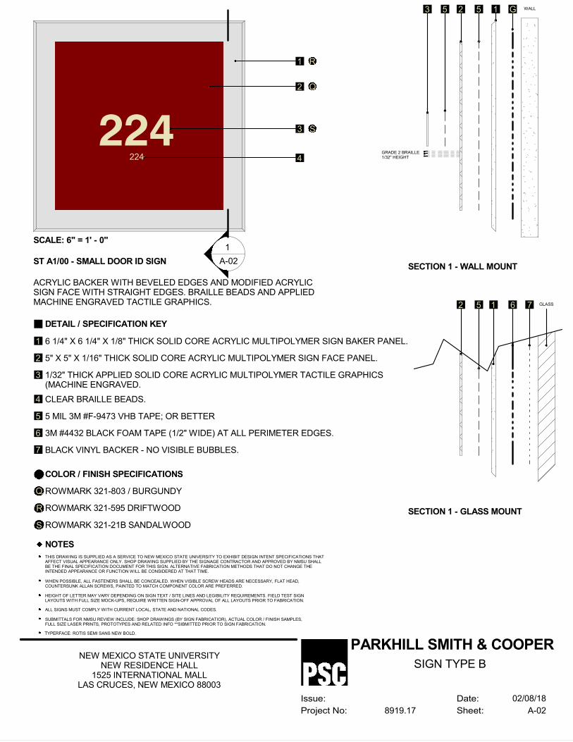
DETAIL / SPECIFICATION KEY
6 1/4" X 6 1/4" X 1/8" THICK SOLID CORE ACRYLIC MULTIPOLYMER SIGN BAKER PANEL.
5" X 5" X 1/16" THICK SOLID CORE ACRYLIC MULTIPOLYMER SIGN FACE PANEL.
1/32" THICK APPLIED SOLID CORE ACRYLIC MULTIPOLYMER TACTILE GRAPHICS(MACHINE ENGRAVED.
CLEAR BRAILLE BEADS.
5 MIL 3M #F-9473 VHB TAPE; OR BETTER
3M #4432 BLACK FOAM TAPE (1/2" WIDE) AT ALL PERIMETER EDGES.
BLACK VINYL BACKER - NO VISIBLE BUBBLES.
COLOR / FINISH SPECIFICATIONS
ROWMARK 321-803 / BURGUNDY
ROWMARK 321-595 DRIFTWOOD
NOTES
THIS DRAWING IS SUPPLIED AS A SERVICE TO NEW MEXICO STATE UNIVERSITY TO EXHIBIT DESIGN INTENT SPECIFICATIONS THATAFFECT VISUAL APPEARANCE ONLY. SHOP DRAWING SUPPLIED BY THE SIGNAGE CONTRACTOR AND APPROVED BY NMSU SHALLBE THE FINAL SPECIFICATION DOCUMENT FOR THIS SIGN. ALTERNATIVE FABRICATION METHODS THAT DO NOT CHANGE THEINTENDED APPEARANCE OR FUNCTION WILL BE CONSIDERED AT THAT TIME.
WHEN POSSIBLE, ALL FASTENERS SHALL BE CONCEALED. WHEN VISIBLE SCREW HEADS ARE NECESSARY, FLAT HEAD,COUNTERSUNK ALLAN SCREWS, PAINTED TO MATCH COMPONENT COLOR ARE PREFERRED.
HEIGHT OF LETTER MAY VARY DEPENDING ON SIGN TEXT / SITE LINES AND LEGIBILITY REQUIREMENTS. FIELD TEST SIGNLAYOUTS WITH FULL SIZE MOCK-UPS, REQUIRE WRITTEN SIGN-OFF APPROVAL OF ALL LAYOUTS PRIOR TO FABRICATION.
ALL SIGNS MUST COMPLY WITH CURRENT LOCAL, STATE AND NATIONAL CODES.
SUBMITTALS FOR NMSU REVIEW INCLUDE: SHOP DRAWINGS (BY SIGN FABRICATIOR), ACTUAL COLOR / FINISH SAMPLES,FULL SIZE LASER PRINTS, PROTOTYPES AND RELATED INFO **SIBMITTED PRIOR TO SIGN FABRICATION.
TYPERFACE: ROTIS SEMI SANS NEW BOLD.
ST A1/00 - SMALL DOOR ID SIGN
ACRYLIC BACKER WITH BEVELED EDGES AND MODIFIED ACRYLICSIGN FACE WITH STRAIGHT EDGES. BRAILLE BEADS AND APPLIEDMACHINE ENGRAVED TACTILE GRAPHICS.
1
2
3
4
5
6
7
Q
R
ROWMARK 321-21B SANDALWOODS
1 R
2 Q
3 S
4GRADE 2 BRAILLE1/32" HEIGHT
G WALL15253
SECTION 1 - WALL MOUNT
6 GLASS152
SECTION 1 - GLASS MOUNT
7
-
---
1
A-02
224
224
SCALE: 6" = 1' - 0"
Date:
Sheet:
Issue:
Project No:
PARKHILL SMITH & COOPER
A-028919.17
NEW MEXICO STATE UNIVERSITYNEW RESIDENCE HALL
1525 INTERNATIONAL MALLLAS CRUCES, NEW MEXICO 88003
02/08/18
SIGN TYPE B

224
DETAIL / SPECIFICATION KEY
6 1/4" X 8" X 1/8" THICK SOLID CORE ACRYLIC MULTIPOLYMER SIGN BAKER PANEL.
5" X 6 3/4" X 1/16" THICK SOLID CORE ACRYLIC MULTIPOLYMER SIGN FACE PANEL.
1/32" THICK APPLIED SOLID CORE ACRYLIC MULTIPOLYMER TACTILE GRAPHICS(MACHINE ENGRAVED.
CLEAR BRAILLE BEADS.
5 MIL 3M #F-9473 VHB TAPE; OR BETTER
3M #4432 BLACK FOAM TAPE (1/2" WIDE) AT ALL PERIMETER EDGES.
BLACK VINYL BACKER - NO VISIBLE BUBBLES.
COLOR / FINISH SPECIFICATIONS
ROWMARK 321-803 / BURGUNDY
ROWMARK 321-595 DRIFTWOOD
NOTES
THIS DRAWING IS SUPPLIED AS A SERVICE TO NEW MEXICO STATE UNIVERSITY TO EXHIBIT DESIGN INTENT SPECIFICATIONS THATAFFECT VISUAL APPEARANCE ONLY. SHOP DRAWING SUPPLIED BY THE SIGNAGE CONTRACTOR AND APPROVED BY NMSU SHALLBE THE FINAL SPECIFICATION DOCUMENT FOR THIS SIGN. ALTERNATIVE FABRICATION METHODS THAT DO NOT CHANGE THEINTENDED APPEARANCE OR FUNCTION WILL BE CONSIDERED AT THAT TIME.
WHEN POSSIBLE, ALL FASTENERS SHALL BE CONCEALED. WHEN VISIBLE SCREW HEADS ARE NECESSARY, FLAT HEAD,COUNTERSUNK ALLAN SCREWS, PAINTED TO MATCH COMPONENT COLOR ARE PREFERRED.
HEIGHT OF LETTER MAY VARY DEPENDING ON SIGN TEXT / SITE LINES AND LEGIBILITY REQUIREMENTS. FIELD TEST SIGNLAYOUTS WITH FULL SIZE MOCK-UPS, REQUIRE WRITTEN SIGN-OFF APPROVAL OF ALL LAYOUTS PRIOR TO FABRICATION.
ALL SIGNS MUST COMPLY WITH CURRENT LOCAL, STATE AND NATIONAL CODES.
SUBMITTALS FOR NMSU REVIEW INCLUDE: SHOP DRAWINGS (BY SIGN FABRICATIOR), ACTUAL COLOR / FINISH SAMPLES,FULL SIZE LASER PRINTS, PROTOTYPES AND RELATED INFO **SIBMITTED PRIOR TO SIGN FABRICATION.
TYPERFACE: ROTIS SEMI SANS NEW BOLD.
ST A3/00 - LARGE DOOR ID SIGN
ACRYLIC BACKER WITH BEVELED EDGES AND MODIFIED ACRYLICSIGN FACE WITH STRAIGHT EDGES. BRAILLE BEADS AND APPLIEDMACHINE ENGRAVED TACTILE GRAPHICS.
1
2
3
4
5
6
7
Q
R
ROWMARK 321-21B SANDALWOODS
1 R
2 Q
3 S
4GRADE 2 BRAILLE1/32" HEIGHT
G WALL15253
SECTION 1 - WALL MOUNT
6 GLASS152
SECTION 1 - GLASS MOUNT
7
-
---
1
A-03
LIBRARYADMINISTRATION
&CONFERENCE
ROOM
224 3 S
SCALE: 6" = 1' - 0 "
Date:
Sheet:
Issue:
Project No:
PARKHILL SMITH & COOPER
A-038919.17
NEW MEXICO STATE UNIVERSITYNEW RESIDENCE HALL
1525 INTERNATIONAL MALLLAS CRUCES, NEW MEXICO 88003
02/08/18
SIGN TYPE C

224
DETAIL / SPECIFICATION KEY
10 1/4" X 12 1/2" X 1/8" THICK SOLID CORE ACRYLICMULTIPOLYMER SIGN BAKER PANEL.
9 1/4" X 11 1/2" X 1/16" THICK SOLID CORE ACRYLICMULTIPOLYMER SIGN FACE PANEL.
1/32" THICK APPLIED SOLID CORE ACRYLIC MULTIPOLYMERTACTILE GRAPHICS (MACHINE ENGRAVED.
CLEAR BRAILLE BEADS.
9 1/4" X 11 1/2" X 1/16" CLEAR ACRYLICMULTIPOLYMER PANEL CREATING A WINDOWFOR PAPER INSERT.
3M #4432 BLACK FOAM TAPE (1/2" WIDE) ATALL PERIMETER EDGES.
BLACK VINYL BACKER - NO VISIBLE BUBBLES.
COLOR / FINISH SPECIFICATIONS
ROWMARK 321-803 / BURGUNDY
ROWMARK 321-595 DRIFTWOOD
NOTES
THIS DRAWING IS SUPPLIED AS A SERVICE TO NEW MEXICO STATE UNIVERSITY TO EXHIBIT DESIGN INTENT SPECIFICATIONS THATAFFECT VISUAL APPEARANCE ONLY. SHOP DRAWING SUPPLIED BY THE SIGNAGE CONTRACTOR AND APPROVED BY NMSU SHALLBE THE FINAL SPECIFICATION DOCUMENT FOR THIS SIGN. ALTERNATIVE FABRICATION METHODS THAT DO NOT CHANGE THEINTENDED APPEARANCE OR FUNCTION WILL BE CONSIDERED AT THAT TIME.
ALL SIGNS MUST COMPLY WITH CURRENT LOCAL, STATE AND NATIONAL CODES.
SUBMITTALS FOR NMSU REVIEW INCLUDE: SHOP DRAWINGS (BY SIGN FABRICATIOR), ACTUAL COLOR / FINISH SAMPLES,FULL SIZE LASER PRINTS, PROTOTYPES AND RELATED INFO **SIBMITTED PRIOR TO SIGN FABRICATION.
TYPERFACE: ROTIS SEMI SANS NEW BOLD.
ST A6/00 - DOOR ID / CHANGEABLE LARGE
ACRYLIC BACKER WITH BEVELED EDGES AND MODIFIED ACRYLICSIGN FACE WITH STRAIGHT EDGES. BRAILLE BEADS AND APPLIEDMACHINE ENGRAVED TACTILE GRAPHICS.
1
2
3
4
8
9
10
Q
R
ROWMARK 321-21B SANDALWOODS
1 R
2 Q
5
4GRADE 2 BRAILLE1/32" HEIGHT
6 WALL110852
SECTION 1 - WALL MOUNT
6 GLASS1510
SECTION 1 - GLASS MOUNT
7
-
---
1
A-04
224 3 S
7
6
5 MIL 3M #F-9473 VHB TAPE; OR BETTER5
1/32" SOLID CORE ACRYLIC MULTIPOLYMERSEPARATOR BY NEW HERMES.
8 1/2" X 11" PAPER INSERT BY SIGN VENDOR
5 5 5
9
54
55
8 92
Date:
Sheet:
Issue:
Project No:
PARKHILL SMITH & COOPER
A-048919.17
NEW MEXICO STATE UNIVERSITYNEW RESIDENCE HALL
1525 INTERNATIONAL MALLLAS CRUCES, NEW MEXICO 88003
02/08/18
SIGN TYPE D
CLEAR BRAILLE BEADS
WINDOW FORCHANGEABLE INSERT
PAPER SIZE: 8 1/2" X 11"
PAPER INSERT BYLIBRARY STAFF
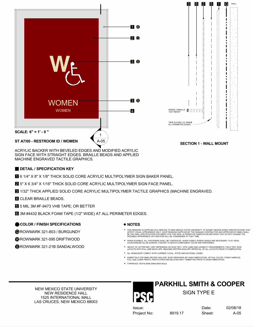
WOMEN
DETAIL / SPECIFICATION KEY
6 1/4" X 8" X 1/8" THICK SOLID CORE ACRYLIC MULTIPOLYMER SIGN BAKER PANEL.
5" X 6 3/4" X 1/16" THICK SOLID CORE ACRYLIC MULTIPOLYMER SIGN FACE PANEL.
1/32" THICK APPLIED SOLID CORE ACRYLIC MULTIPOLYMER TACTILE GRAPHICS (MACHINE ENGRAVED.
CLEAR BRAILLE BEADS.
5 MIL 3M #F-9473 VHB TAPE; OR BETTER
3M #4432 BLACK FOAM TAPE (1/2" WIDE) AT ALL PERIMETER EDGES.
COLOR / FINISH SPECIFICATIONS
ROWMARK 321-803 / BURGUNDY
ROWMARK 321-595 DRIFTWOOD
NOTES
THIS DRAWING IS SUPPLIED AS A SERVICE TO NEW MEXICO STATE UNIVERSITY TO EXHIBIT DESIGN INTENT SPECIFICATIONS THATAFFECT VISUAL APPEARANCE ONLY. SHOP DRAWING SUPPLIED BY THE SIGNAGE CONTRACTOR AND APPROVED BY NMSU SHALLBE THE FINAL SPECIFICATION DOCUMENT FOR THIS SIGN. ALTERNATIVE FABRICATION METHODS THAT DO NOT CHANGE THEINTENDED APPEARANCE OR FUNCTION WILL BE CONSIDERED AT THAT TIME.
WHEN POSSIBLE, ALL FASTENERS SHALL BE CONCEALED. WHEN VISIBLE SCREW HEADS ARE NECESSARY, FLAT HEAD,COUNTERSUNK ALLAN SCREWS, PAINTED TO MATCH COMPONENT COLOR ARE PREFERRED.
HEIGHT OF LETTER MAY VARY DEPENDING ON SIGN TEXT / SITE LINES AND LEGIBILITY REQUIREMENTS. FIELD TEST SIGNLAYOUTS WITH FULL SIZE MOCK-UPS, REQUIRE WRITTEN SIGN-OFF APPROVAL OF ALL LAYOUTS PRIOR TO FABRICATION.
ALL SIGNS MUST COMPLY WITH CURRENT LOCAL, STATE AND NATIONAL CODES.
SUBMITTALS FOR NMSU REVIEW INCLUDE: SHOP DRAWINGS (BY SIGN FABRICATIOR), ACTUAL COLOR / FINISH SAMPLES,FULL SIZE LASER PRINTS, PROTOTYPES AND RELATED INFO **SIBMITTED PRIOR TO SIGN FABRICATION.
TYPERFACE: ROTIS SEMI SANS NEW BOLD.
ST A7/00 - RESTROOM ID / WOMEN
ACRYLIC BACKER WITH BEVELED EDGES AND MODIFIED ACRYLICSIGN FACE WITH STRAIGHT EDGES. BRAILLE BEADS AND APPLIEDMACHINE ENGRAVED TACTILE GRAPHICS.
1
2
3
4
5
6
Q
R
ROWMARK 321-21B SANDALWOODS
1 R
2 Q
3 S
4GRADE 2 BRAILLE1/32" HEIGHT
G WALL15253
SECTION 1 - WALL MOUNT
-
---
1
A-05
WOMEN 3 S
SCALE: 6" = 1' - 0 "
W
TAPE PLACED 1/2" INSIDEALL PERIMETER EDGES
Date:
Sheet:
Issue:
Project No:
PARKHILL SMITH & COOPER
A-058919.17
NEW MEXICO STATE UNIVERSITYNEW RESIDENCE HALL
1525 INTERNATIONAL MALLLAS CRUCES, NEW MEXICO 88003
02/08/18
SIGN TYPE E

MEN
DETAIL / SPECIFICATION KEY
6 1/4" X 8" X 1/8" THICK SOLID CORE ACRYLIC MULTIPOLYMER SIGN BAKER PANEL.
5" X 6 3/4" X 1/16" THICK SOLID CORE ACRYLIC MULTIPOLYMER SIGN FACE PANEL.
1/32" THICK APPLIED SOLID CORE ACRYLIC MULTIPOLYMER TACTILE GRAPHICS (MACHINE ENGRAVED.
CLEAR BRAILLE BEADS.
5 MIL 3M #F-9473 VHB TAPE; OR BETTER.
3M #4432 BLACK FOAM TAPE (1/2" WIDE) AT ALL PERIMETER EDGES.
COLOR / FINISH SPECIFICATIONS
ROWMARK 321-803 / BURGUNDY
ROWMARK 321-595 DRIFTWOOD
NOTES
THIS DRAWING IS SUPPLIED AS A SERVICE TO NEW MEXICO STATE UNIVERSITY TO EXHIBIT DESIGN INTENT SPECIFICATIONS THATAFFECT VISUAL APPEARANCE ONLY. SHOP DRAWING SUPPLIED BY THE SIGNAGE CONTRACTOR AND APPROVED BY NMSU SHALLBE THE FINAL SPECIFICATION DOCUMENT FOR THIS SIGN. ALTERNATIVE FABRICATION METHODS THAT DO NOT CHANGE THEINTENDED APPEARANCE OR FUNCTION WILL BE CONSIDERED AT THAT TIME.
WHEN POSSIBLE, ALL FASTENERS SHALL BE CONCEALED. WHEN VISIBLE SCREW HEADS ARE NECESSARY, FLAT HEAD,COUNTERSUNK ALLAN SCREWS, PAINTED TO MATCH COMPONENT COLOR ARE PREFERRED.
HEIGHT OF LETTER MAY VARY DEPENDING ON SIGN TEXT / SITE LINES AND LEGIBILITY REQUIREMENTS. FIELD TEST SIGNLAYOUTS WITH FULL SIZE MOCK-UPS, REQUIRE WRITTEN SIGN-OFF APPROVAL OF ALL LAYOUTS PRIOR TO FABRICATION.
ALL SIGNS MUST COMPLY WITH CURRENT LOCAL, STATE AND NATIONAL CODES.
SUBMITTALS FOR NMSU REVIEW INCLUDE: SHOP DRAWINGS (BY SIGN FABRICATIOR), ACTUAL COLOR / FINISH SAMPLES,FULL SIZE LASER PRINTS, PROTOTYPES AND RELATED INFO **SIBMITTED PRIOR TO SIGN FABRICATION.
TYPERFACE: ROTIS SEMI SANS NEW BOLD.
ST A8/00 - RESTROOM ID / MEN
ACRYLIC BACKER WITH BEVELED EDGES AND MODIFIED ACRYLICSIGN FACE WITH STRAIGHT EDGES. BRAILLE BEADS AND APPLIEDMACHINE ENGRAVED TACTILE GRAPHICS.
1
2
3
4
5
6
Q
R
ROWMARK 321-21B SANDALWOODS
1 R
2 Q
3 S
4GRADE 2 BRAILLE1/32" HEIGHT
G WALL15253
SECTION 1 - WALL MOUNT
-
---
1
A-06
MEN 3 S
SCALE: 6" = 1' - 0 "
M
TAPE PLACED 1/2" INSIDEALL PERIMETER EDGES
Date:
Sheet:
Issue:
Project No:
PARKHILL SMITH & COOPER
A-068919.17
NEW MEXICO STATE UNIVERSITYNEW RESIDENCE HALL
1525 INTERNATIONAL MALLLAS CRUCES, NEW MEXICO 88003
02/08/18
SIGN TYPE F
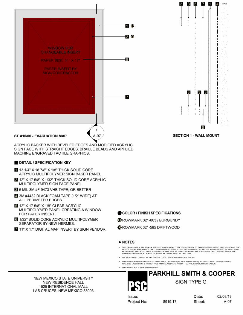
DETAIL / SPECIFICATION KEY
13 1/4" X 18 7/8" X 1/8" THICK SOLID COREACRYLIC MULTIPOLYMER SIGN BAKER PANEL.
12" X 17 5/8" X 1/32" THICK SOLID CORE ACRYLICMULTIPOLYMER SIGN FACE PANEL.
12" X 17 5/8" X 1/8" CLEAR ACRYLICMULTIPOLYMER PANEL CREATING A WINDOWFOR PAPER INSERT.
3M #4432 BLACK FOAM TAPE (1/2" WIDE) ATALL PERIMETER EDGES.
COLOR / FINISH SPECIFICATIONS
ROWMARK 321-803 / BURGUNDY
ROWMARK 321-595 DRIFTWOOD
NOTES
THIS DRAWING IS SUPPLIED AS A SERVICE TO NEW MEXICO STATE UNIVERSITY TO EXHIBIT DESIGN INTENT SPECIFICATIONS THATAFFECT VISUAL APPEARANCE ONLY. SHOP DRAWING SUPPLIED BY THE SIGNAGE CONTRACTOR AND APPROVED BY NMSU SHALLBE THE FINAL SPECIFICATION DOCUMENT FOR THIS SIGN. ALTERNATIVE FABRICATION METHODS THAT DO NOT CHANGE THEINTENDED APPEARANCE OR FUNCTION WILL BE CONSIDERED AT THAT TIME.
ALL SIGNS MUST COMPLY WITH CURRENT LOCAL, STATE AND NATIONAL CODES.
SUBMITTALS FOR NMSU REVIEW INCLUDE: SHOP DRAWINGS (BY SIGN FABRICATIOR), ACTUAL COLOR / FINISH SAMPLES,FULL SIZE LASER PRINTS, PROTOTYPES AND RELATED INFO **SIBMITTED PRIOR TO SIGN FABRICATION.
TYPERFACE: ROTIS SEMI SANS NEW BOLD.
ST A10/00 - EVACUATION MAP
ACRYLIC BACKER WITH BEVELED EDGES AND MODIFIED ACRYLICSIGN FACE WITH STRAIGHT EDGES. BRAILLE BEADS AND APPLIEDMACHINE ENGRAVED TACTILE GRAPHICS.
1
2
3
4
Q
R
1 R
2 Q
5
4 WALL17532
SECTION 1 - WALL MOUNT
-
---
1
A-07
7
7
6
5 MIL 3M #F-9473 VHB TAPE; OR BETTER
5
1/32" SOLID CORE ACRYLIC MULTIPOLYMERSEPARATOR BY NEW HERMES.
11" X 17" DIGITAL MAP INSERT BY SIGN VENDOR.
3 3 3
6
WINDOW FORCHANGEABLE INSERT
PAPER SIZE: 11" X 17"
PAPER INSERT BYSIGN CONTRACTOR
Date:
Sheet:
Issue:
Project No:
PARKHILL SMITH & COOPER
A-078919.17
NEW MEXICO STATE UNIVERSITYNEW RESIDENCE HALL
1525 INTERNATIONAL MALLLAS CRUCES, NEW MEXICO 88003
02/08/18
SIGN TYPE G
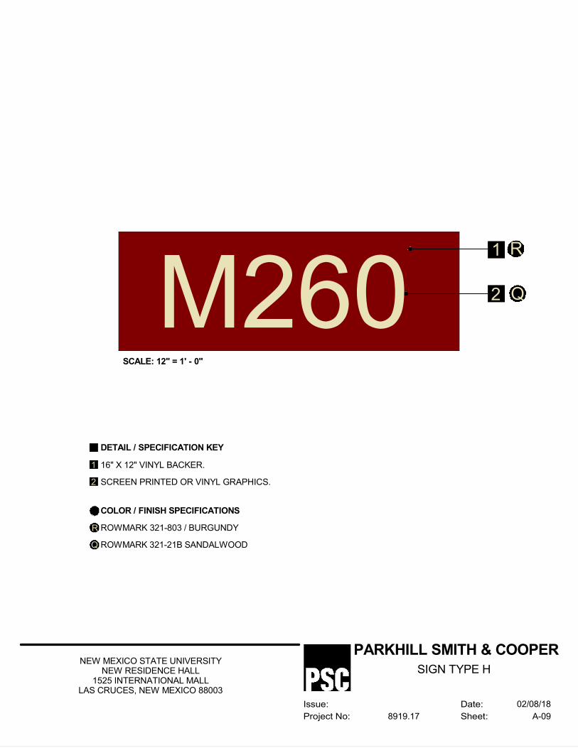
1 R
2 QM260
DETAIL / SPECIFICATION KEY
16" X 12" VINYL BACKER.
SCREEN PRINTED OR VINYL GRAPHICS.
COLOR / FINISH SPECIFICATIONS
ROWMARK 321-803 / BURGUNDY
ROWMARK 321-21B SANDALWOOD
1
2
R
Q
SCALE: 12" = 1' - 0"
Date:
Sheet:
Issue:
Project No:
PARKHILL SMITH & COOPER
A-098919.17
NEW MEXICO STATE UNIVERSITYNEW RESIDENCE HALL
1525 INTERNATIONAL MALLLAS CRUCES, NEW MEXICO 88003
02/08/18
SIGN TYPE H
SECTION 10 21 13.13 - METAL TOILET COMPARTMENTS
GENERALPART 1 -
SUMMARY1.1
Section includes painted steel toilet compartments configured as toilet enclosures entranceA.screens urinal screens.Related Requirements:B.
Section 00 00 00 "Invitation to Bid" for reference to Drawings and general1.provisions of the Contract including General and Supplementary Conditions.Division 01 Specification Sections apply to Work of this Section.2.Section 01 81 13 "Sustainable Design Requirements" for LEED Sustainability3.Requirements.Section 06 10 00 "Rough Carpentry" for blocking.4.Section 10 28 13 "Toilet Accessories" for toilet tissue dispensers, grab bars, purse5.shelves, and similar accessories mounted on toilet compartments.
ACTION SUBMITTALS1.2
Product Data: For each type of product.A.Include construction details, material descriptions, dimensions of individual1.components and profiles, and finishes for toilet compartments.
Shop Drawings: For toilet compartments.B.Include plans, elevations, sections, and attachment details.1.Show locations of reinforcements for compartment-mounted grab bars and locations2.of blocking for surface-mounted toilet accessories.Show locations of centerlines of toilet fixtures.3.Show locations of floor drains.4.
Samples for Initial Selection: For each type of toilet compartment material indicated.C.Include Samples of hardware and accessories involving material and color selection.1.
CLOSEOUT SUBMITTALS1.3
Maintenance Data: For toilet compartments to include in maintenance manuals.A.
PROJECT CONDITIONS1.4
Field Measurements: Verify actual locations of toilet fixtures, walls, columns, ceilings, andA.other construction contiguous with toilet compartments by field measurements beforefabrication.
PRODUCTSPART 2 -
PERFORMANCE REQUIREMENTS2.1
Recycled Content of Metal Components: Postconsumer recycled content plus one-half ofA.preconsumer recycled content not less than 25 percent.Regulatory Requirements: Comply with applicable provisions in ICC A117.1 for toiletB.compartments designated as accessible.
0389191702/18
METAL TOILET COMPARTMENTS 10 21 13.13 - 1
PAINTED STEEL TOILET COMPARTMENTS2.2
Manufacturers: Subject to compliance with requirements, available manufacturers offeringA.products that may be incorporated into the Work include, but are not limited to, thefollowing:
Accurate Partitions Corporation.1.All American Metal Corp.2.American Sanitary Partition Corporation.3.Ampco, Inc.4.Bradley Corporation; Mills Partitions.5.Flush Metal Partition Corp.6.General Partitions Mfg. Corp.7.Global Steel Products Corp.8.Hadrian Manufacturing Inc.9.Knickerbocker Partition Corporation.10.Marlite.11.Metpar Corp.12.Shanahan's Limited.13.
Toilet-Enclosure Style: Floor anchored.B.Entrance-Screen Style: Floor anchored.C.Urinal-Screen Style: Floor anchored.D.Door, Panel, and Pilaster Construction: Seamless, metal facing sheets pressure laminated toE.core material; with continuous, interlocking molding strip or lapped-and-formed edgeclosures; corners secured by welding or clips and exposed welds ground smooth. Providewith no-sightline system. Exposed surfaces shall be free of pitting, seam marks, rollermarks, stains, discolorations, telegraphing of core material, or other imperfections.
Core Material: Manufacturer's standard sound-deadening honeycomb of1.resin-impregnated kraft paper in thickness required to provide finished thickness of1 inch for doors and panels and 1-1/4 inches for pilasters.Grab-Bar Reinforcement: Provide concealed internal reinforcement for grab bars2.mounted on units of size and material adequate for panel to withstand applieddownward load on grab bar of at least 250 lbf, when tested according to ASTM F446, without deformation of panel.Tapping Reinforcement: Provide concealed reinforcement for tapping (threading) at3.locations where machine screws are used for attaching items to units.
Facing Sheets and Closures: Electrolytically coated steel sheet with nominal base-metalF.(uncoated) thicknesses as follows:
Pilasters, Unbraced at One End: Manufacturer's standard thickness, but not less than1.0.048 inch.Panels: Manufacturer's standard thickness, but not less than 0.030 inch.2.Doors: Manufacturer's standard thickness, but not less than 0.030 inch.3.
Urinal-Screen Post: Manufacturer's standard post design of material matching the thicknessG.and construction of pilasters; with shoe matching that on the pilaster.Brackets (Fittings):H.
Stirrup Type: Ear or U-brackets; chrome-plated zamac.1.Steel Sheet Finish: Immediately after cleaning and pretreating, apply manufacturer'sI.standard baked-on finish, including thermosetting, electrostatically applied, and powdercoatings. Comply with coating manufacturer's written instructions for applying and baking.
Color: As selected by Architect from manufacturer's standard range.1.Allow for application of one color in each room.a.
0389191702/18
METAL TOILET COMPARTMENTS 10 21 13.13 - 2
HARDWARE AND ACCESSORIES2.3
Hardware and Accessories: Manufacturer's standard operating hardware and accessories.A.Material: Chrome-plated zamac.1.Hinges: Manufacturer's standard continuous, cam type that swings to a closed or2.partially open position, allowing emergency access by lifting door.Latch and Keeper: Manufacturer's standard surface-mounted latch unit designed for3.emergency access and with combination rubber-faced door strike and keeper.Provide units that comply with regulatory requirements for accessibility atcompartments designated as accessible.Door Pull: Manufacturer's standard unit at out-swinging doors that complies with4.regulatory requirements for accessibility. Provide units on both sides of doors atcompartments designated as accessible.
MATERIALS2.4
Steel Sheet: Commercial steel sheet for exposed applications; mill phosphatized andA.selected for smoothness.
Electrolytically Zinc Coated: ASTM A 879/A 879M, 01Z.1.Zamac: ASTM B 86, commercial zinc-alloy die castings, chrome plated.B.
FABRICATION2.5
Fabrication, General: Fabricate toilet compartment components to sizes indicated.A.Coordinate requirements and provide cutouts for through-partition toilet accessories, andsolid blocking within panel where required for attachment of toilet accessories.Floor-Anchored Units: Provide manufacturer's standard corrosion-resistant anchoringB.assemblies with leveling adjustment nuts at pilasters for structural connection to floor.Provide shoes at pilasters to conceal anchorage.Urinal-Screen Posts: Provide manufacturer's standard corrosion-resistant anchoringC.assemblies with leveling adjustment at bottoms of posts. Provide shoes at posts to concealanchorage.Door Size and Swings: Unless otherwise indicated, provide 24-inch-wide, in-swingingD.doors for standard toilet compartments and 36-inch-wide, out-swinging doors with aminimum 32-inch-wide, clear opening for compartments designated as accessible.
EXECUTIONPART 3 -
EXAMINATION3.1
Examine substrates, areas and conditions, with Installer present, for compliance withA.requirements for fastening, support, alignment, operating clearances, and other conditionsaffecting performance of the Work.
Confirm location and adequacy of blocking and supports required for installation.1.Proceed with installation only after unsatisfactory conditions have been corrected.B.Coordinate layout and installation of supports, inserts, and anchors built into other units ofC.work for toilet compartment anchorage.
0389191702/18
METAL TOILET COMPARTMENTS 10 21 13.13 - 3
INSTALLATION3.2
General: Comply with manufacturer's written installation instructions. Install units rigid,A.straight, level, and plumb. Secure units in position indicated with manufacturer'srecommended anchoring devices.
Maximum Clearances:1.Pilasters and Panels: 1/2 inch.a.Panels and Walls: 1 inch.b.
Stirrup Brackets: Secure panels to walls and to pilasters with no fewer than three2.brackets attached at midpoint and near top and bottom of panel.
Locate wall brackets so holes for wall anchors occur in masonry or tile joints.a.Align brackets at pilasters with brackets at walls.b.
Floor-Anchored Units: Set pilasters with anchors penetrating not less than 2 inches intoB.structural floor unless otherwise indicated in manufacturer's written instructions. Level,plumb, and tighten pilasters. Hang doors and adjust so tops of doors are level with tops ofpilasters when doors are in closed position.Urinal Screens: Attach with anchoring devices to suit supporting structure. Set units levelC.and plumb, rigid, and secured to resist lateral impact.
END OF SECTION
0389191702/18
METAL TOILET COMPARTMENTS 10 21 13.13 - 4
SECTION 10 26 00 - WALL AND DOOR PROTECTION
GENERALPART 1 -
SUMMARY1.1
Section includes corner guards.A.Related Requirements:B.
Section 00 00 00 "Invitation to Bid" for reference to Drawings and general1.provisions of the Contract including General and Supplementary Conditions.Division 01 Specification Sections apply to Work of this Section.2.Section 01 81 13 "Sustainable Design Requirements" for LEED Sustainability3.Requirements.
ACTION SUBMITTALS1.2
Product Data: For each type of product indicated.A.LEED Submittals:B.
Product Data for Credit IEQ 4.1: For adhesives, documentation including printed1.statement of VOC content.Laboratory Test Reports for Credit IEQ 4: For adhesives, documentation indicating2.that products comply with the testing and product requirements of the CaliforniaDepartment of Health Services' "Standard Practice for the Testing of VolatileOrganic Emissions from Various Sources Using Small-Scale EnvironmentalChambers."
Shop Drawings: For each impact-resistant wall protection unit. Include sections, details,C.and attachments to other work.
For installed products indicated to comply with design loads, include structural1.analysis data signed and sealed by the qualified professional engineer responsiblefor their preparation.
Samples: For each exposed product and for each color and texture specified, 12 inchesD.long.
INFORMATIONAL SUBMITTALS1.3
Material certificates.A.Material test reports.B.Warranty: Sample of special warranty.C.
CLOSEOUT SUBMITTALS1.4
Maintenance data.A.
QUALITY ASSURANCE1.5
Installer Qualifications: An employer of workers trained and approved by manufacturer.A.Surface-Burning Characteristics: As determined by testing identical products per ASTM EB.84, NFPA 255, or UL 723 by UL or another qualified testing agency.Regulatory Requirements: Comply with applicable provisions in the U.S. Architectural &C.Transportation Barriers Compliance Board's ADA-ABA Accessibility Guidelines.
0389191702/18
WALL AND DOOR PROTECTION 10 26 00 - 1
WARRANTY1.6
Special Warranty: Manufacturer's standard form in which manufacturer agrees to repair orA.replace components of impact-resistant wall protection units that fail in materials orworkmanship within specified warranty period.
Failures include, but are not limited to, the following:1.Structural failures.a.Deterioration of plastic and other materials beyond normal use.b.
Warranty Period: Five years from date of Substantial Completion.B.
PRODUCTSPART 2 -
MATERIALS2.1
PVC Plastic: ASTM D 1784, Class 1, textured, chemical- and stain-resistant,A.high-impact-resistant PVC or acrylic-modified vinyl plastic with integral color throughout.
Impact Resistance: Minimum 25.4 ft-lbf/in. of notch when tested according to1.ASTM D 256, Test Method A.Chemical and Stain Resistance: Tested according to ASTM D 543 and ASTM D2.1308.Self-extinguishing when tested according to ASTM D 635.3.Flame-Spread Index: 25 or less.4.Smoke-Developed Index: 450 or less.5.
Polycarbonate Plastic Sheet: ASTM D 6098, S-PC01, Class 1 or 2, abrasion resistant; withB.a minimum impact-resistance rating of 15 ft-lbf/in. of notch when tested according toASTM D 256, Test Method A.Fasteners: Aluminum, nonmagnetic stainless-steel, or other noncorrosive metal screws,C.bolts, and other fasteners compatible with items being fastened. Use security-type fastenerswhere exposed to view.Adhesive: As recommended by impact-resistant plastic wall protection manufacturer andD.with a VOC content of 70 g/L or less when calculated according to 40 CFR 59, Subpart D(EPA Method 24).Adhesive: As recommended by impact-resistant plastic wall protection manufacturer andE.that complies with the testing and product requirements of the California Department ofHealth Services' "Standard Practice for the Testing of Volatile Organic Emissions fromVarious Sources Using Small-Scale Environmental Chambers."
CORNER GUARDS2.2
Surface-Mounted, Resilient, Plastic Corner Guards: Assembly consisting of snap-on plasticA.cover installed over continuous retainer; including mounting hardware; fabricated with 90-or 135-degree turn to match wall condition.
Basis-of-Design Product: Subject to compliance with requirements, provide Inpro |1.Flexible Clear Corner Guards, or comparable product by one of the following:
American Floor Products Co., Inc.a.Arden Architectural Specialties, Inc.b.Balco, Inc.c.Construction Specialties, Inc.d.IPC Door and Wall Protection Systems; Division of InPro Corporation.e.
0389191702/18
WALL AND DOOR PROTECTION 10 26 00 - 2
Korogard Wall Protection Systems; a division of RJF Internationalf.Corporation.Musson Rubber Company.g.Pawling Corporation.h.Tepromark International, Inc.i.WallGuard.com.j.
Cover: Extruded rigid plastic, minimum 0.045-inch wall thickness; in dimensions2.and profiles indicated on Drawings.
Color and Texture: Clear.a.Size: 1 inch by 1 inch by 4 foot.3.Installation: Peel-n-stick adhesive with six small screws installed equally. Provide4.mockup for a final approval.
EXECUTIONPART 3 -
INSTALLATION3.1
General: Install impact-resistant wall protection units level, plumb, and true to line withoutA.distortions. Do not use materials with chips, cracks, voids, stains, or other defects thatmight be visible in the finished Work.
Provide splices, mounting hardware, anchors, and other accessories required for a1.complete installation.
Provide anchoring devices to withstand imposed loads.a.Adjust end and top caps as required to ensure tight seams.b.
Immediately after completion of installation, clean plastic covers and accessories using aB.standard, ammonia-based, household cleaning agent.Remove excess adhesive using methods and materials recommended in writing byC.manufacturer.
END OF SECTION
0389191702/18
WALL AND DOOR PROTECTION 10 26 00 - 3
SECTION 10 28 13 - TOILET ACCESSORIES
GENERALPART 1 -
SUMMARY1.1
Section Includes:A.Public-use washroom accessories.1.Residential bath accessories for toilet, shower room and vanity areas.2.Custodial accessories.3.
Related Requirements:B.Section 00 00 00 "Invitation to Bid" for reference to Drawings and general1.provisions of the Contract including General and Supplementary Conditions.Division 01 Specification Sections apply to Work of this Section.2.Section 01 81 13 "Sustainable Design Requirements" for LEED Sustainability3.Requirements.Section 06 10 00 "Rough Carpentry" for blocking required to support accessories4.and for required blocking for "future" grab bars as required for accessibilitycompliance.Section 22 41 00 "Residential Plumbing Fixtures" for folding shower seat provided5.in pre-manufactured shower enclosure package.
COORDINATION1.2
Coordinate accessory locations with other work to prevent interference with clearancesA.required for access by people with disabilities, and for proper installation, adjustment,operation, cleaning, and servicing of accessories.Deliver inserts and anchoring devices set into concrete or masonry as required to preventB.delaying the Work.
ACTION SUBMITTALS1.3
Product Data: For each type of product.A.Include construction details, material descriptions, dimensions of individual1.components and profiles, and finishes.Include anchoring and mounting requirements, including requirements for cutouts in2.other work and substrate preparation.Include electrical characteristics.3.
CLOSEOUT SUBMITTALS1.4
Maintenance Data: For accessories to include in maintenance manuals.A.
PRODUCTSPART 2 -
OWNER-FURNISHED MATERIALS2.1
Owner-Furnished Materials at Public Restrooms:A.Toilet Paper Dispensers.1.Paper Towel Dispensers.2.
0389191702/18
TOILET ACCESSORIES 10 28 13 - 1
Soap Dispensers.3.Waste Containers for Paper Towel.4.
PUBLIC-USE WASHROOM ACCESSORIES2.2
Source Limitations: Obtain public-use washroom accessories from single source fromA.single manufacturer.Grab Bar:B.
Manufacturers: Subject to compliance with requirements, available manufacturers1.offering products that may be incorporated into the Work include, but are not limitedto, the following:
A&J Washroom Accessories, Inc.a.American Specialties, Inc.; ASI Group.b.Bobrick Washroom Equipment, Inc.c.Bradley Corporation.d.Brey-Krause Manufacturing Co.e.GAMCO Specialty Accessories; a division of Bobrick.f.Tubular Specialties Manufacturing, Inc.g.
Mounting: Flanges with concealed fasteners.2.Material: Stainless steel, 0.05 inch thick.3.
Finish: Smooth, No. 4 finish (satin).a.Outside Diameter: 1-1/2 inches.4.Configuration and Length:5.
42 inch, mounted horizontally at the side of toilet, as indicated on Drawings.a.36 inch, mounted horizontally at the rear of toilet, as indicated on Drawings.b.18 inch, mounted vertically at the side of the toilet, as indicated on Drawings.c.
Sanitary-Napkin Disposal Unit:C.Basis-of-Design Product: Subject to compliance with requirements, provide Bobrick1.Corporation Model B-5270 Matrix Series, surface mounted or comparable productby one of the following:
A&J Washroom Accessories, Inc.a.American Specialties, Inc.; ASI Group.b.Bobrick Washroom Equipment, Inc.c.Bradley Corporation.d.Brey-Krause Manufacturing Co.e.GAMCO Specialty Accessories; a division of Bobrick.f.Seachrome Corporation.g.Tubular Specialties Manufacturing, Inc.h.
Mounting: Surface mounted.2.Door or Cover: Self-closing, disposal-opening cover.3.Receptacle: Removable.4.Material and Finish: ABS Plastic, grey color.5.
Recessed Waste Receptacle:D.Basis-of-Design Product: Subject to compliance with requirements, provide Bobrick1.Model B-1658 2436 Tempered Glass Channel Frame or comparable product by oneof the following:
A&J Washroom Accessories, Inc.a.American Specialties, Inc.; ASI Group.b.Bobrick Washroom Equipment, Inc.c.Bradley Corporation.d.Brey-Krause Manufacturing Co.e.GAMCO Specialty Accessories; a division of Bobrick.f.
0389191702/18
TOILET ACCESSORIES 10 28 13 - 2
Seachrome Corporation.g.Tubular Specialties Manufacturing, Inc.h.
Mounting: Recessed with projection less than 4 inches.2.Door or Cover: Removable front panel for easy cleaning.3.Receptacle: Removeable and secured to cabinet with key.4.Liner: Heavy-duty stitched vinyl-coated nylon.5.Materials and Finish: 22 gauge Satin-finish Stainless Steel.6.Overall Dimensions: 17-1/8 inches wide by 30-5/8 inches high by 8-3/4 inches deep.7.
Mirror Unit:E.Basis-of-Design Product: Subject to compliance with requirements, provide Bobrick1.Model B-1658 2436 Tempered Glass Channel Frame or comparable product by oneof the following:
A&J Washroom Accessories, Inc.a.American Specialties, Inc.; ASI Group.b.Bobrick Washroom Equipment, Inc.c.Bradley Corporation.d.Brey-Krause Manufacturing Co.e.GAMCO Specialty Accessories; a division of Bobrick.f.Tubular Specialties Manufacturing, Inc.g.
Frame: Stainless-steel channel.2.Corners: Manufacturer's standard.a.
Hangers: Produce rigid, tamper- and theft-resistant installation, using method3.indicated below.
One-piece, galvanized-steel, wall-hanger device with spring-action lockinga.mechanism to hold mirror unit in position with no exposed screws or bolts.Wall bracket of galvanized steel, equipped with concealed locking devicesb.requiring a special tool to remove.
Size: 24 inches wide by 36 inches high.4.
RESIDENTIAL BATH AREA ACCESSORIES2.3
Source Limitations: There is no source limitation for residential bath area accessories.A.Toilet Paper Holder:B.
Manufacturers: Subject to compliance with requirements, available manufacturers1.offering products that may be incorporated into the Work include, but are not limitedto, the following:Basis-of-Design: Subject to compliance with requirements, provide Moen Donner2.Double Post Toilet Paper Holder.
Material: Zinc.a.Finish: Chrome.b.Capacity: Single Role.c.Fasteners: Concealed.d.
Towel Ring:C.Basis-of-Design: Subject to compliance with requirements, provide Moen1.Contemporary Towel Ring.
Material: Zinc.a.Finish: Chrome.b.Capacity: 22 pounds.c.Fasteners: Concealed.d.Quantity: Total of two at vanity and mounted one on each side of sink.e.
0389191702/18
TOILET ACCESSORIES 10 28 13 - 3
Shower Curtain Rod:D.Basis-of-Design Product: Subject to compliance with requirements, provide Moen1.63-5-HD Donner Commercial Shower Rod with 63-F Shower Rod Flanges, orcomparable product by the following:
Project Source.a.Description: 1-inch OD; fabricated from stainless steel.2.Mounting Flanges: same as shower rod with exposed fasteners.3.Finish: Stainless Steel.4.
Shower Curtain:F.Basis-of-Design Product: Subject to compliance with requirements, provide Peva1.medium 5 gauge shower curtain manufactured by Glacier Bay, or comparableproduct by one of the following:
Style Selections.a.Size: Minimum 6 inches wider than opening by 72 inches high.2.Material: Peva, medium 5 gauge, mold and mildew resistant.3.Color: Frosted clear.4.Grommets: Corrosion resistant at minimum 6 inches o.c. through top hem.5.Shower Curtain Hooks: Chrome-plated or stainless-steel, spring wire curtain hooks6.with snap fasteners, sized to accommodate specified curtain rod. Provide one hookper curtain grommet.
Residential Mirror (M1):G.Basis-of-Design: Subject to compliance with requirements, provide Frameless1.Round Wall Mirror manufactured by The Better Bevel (distributed bywww.hayneedle.com).
Dimension: 28-inch diameter.a.Finish: Chrome.b.Edge: Beveled.c.Glass Type: Tempered.d.
Residential Mirror (M2):H.Fabricated mirror at Accessible Rooms and Residential Apartment.1.
Dimensions: 28 inches wide by 30 inches high with 28-inch rounded arch topa.to match mirror type M1.Mounting required with vision surface at 40 inches above floor minimum.b.Finish: Chrome.c.Edge: Beveled.d.Glass Type: Tempered.e.
Folding Shower Seat:I.Seat is provided as part of the pre-manufactured shower enclosure. See residential1.plumbing fixtures on Drawings, on the Plumbing Fixture Schedule.
Robe Hook:J.Basis-of-Design Product: Subject to compliance with requirements, provide Hang1.Safe Hooks, 165 E. Hwy CC - Nixa, MO, 888.803.7403, [email protected]:2.
Hooks: Polycarbonate plastic (rounded ends, eased edges, polished), mounteda.with #14 x 2-inch stainless Philips oval head screws and finishing washers.Quantity of four hooks.Mounting Board: "Hang Safe Vibrant Rack" recycled high densityb.polyethelene, 1-1/2 inches deep by 3-1/2 inches tall by 32 inches long (sizedto hold four hooks at 8 inches on center).Mounting Board Color: Selected from manufacturer's standard range.c.
0389191702/18
TOILET ACCESSORIES 10 28 13 - 4
CUSTODIAL ACCESSORIES2.4
Source Limitations: Obtain custodial accessories from single source from singleA.manufacturer.Mop and Broom Holder:B.
Basis-of-Design Product: Subject to compliance with requirements, provide Bobrick1.B-223 x 36 or comparable product by one of the following:
A&J Washroom Accessories, Inc.a.American Specialties, Inc.; ASI Group.b.Bobrick Washroom Equipment, Inc.c.Bradley Corporation.d.Brey-Krause Manufacturing Co.e.GAMCO Specialty Accessories; a division of Bobrick.f.Tubular Specialties Manufacturing, Inc.g.
Description: Anti-slip mop holders with spring-loaded rubber cam that grips handles2.7/16 inches to 1-1/4 inches in diameter and holds three mops.Length: 36 inches.3.Hooks: Three.4.Mop/Broom Holders: Three, spring-loaded, rubber hat, cam type.5.Material and Finish: Stainless steel, No. 4 finish (satin).6.
Shelf: Not less than nominal 0.05-inch-thick stainless steel.a.Rod: Approximately 1/4-inch-diameter stainless steel.b.
MATERIALS2.5
Stainless Steel: ASTM A 666, Type 304, 0.031-inch minimum nominal thickness unlessA.otherwise indicated.Galvanized-Steel Sheet: ASTM A 653/A 653M, with G60 hot-dip zinc coating.B.Galvanized-Steel Mounting Devices: ASTM A 153/A 153M, hot-dip galvanized afterC.fabrication.Fasteners: Screws, bolts, and other devices of same material as accessory unit andD.tamper-and-theft resistant where exposed, and of galvanized steel where concealed.Mirrors: ASTM C 1503, Mirror Glazing Quality, clear-glass mirrors, nominal 6.0 mmE.thick.
FABRICATION2.6
General: Fabricate units with tight seams and joints, and exposed edges rolled. Hang doorsA.and access panels with full-length, continuous hinges. Equip units for concealed anchorageand with corrosion-resistant backing plates.
EXECUTIONPART 3 -
INSTALLATION3.1
Install accessories according to manufacturers' written instructions, using fastenersA.appropriate to substrate indicated and recommended by unit manufacturer. Install unitslevel, plumb, and firmly anchored in locations and at heights indicated.Grab Bars: Install to withstand a downward load of at least 250 lbf, when tested accordingB.to ASTM F 446.
0389191702/18
TOILET ACCESSORIES 10 28 13 - 5

ADJUSTING AND CLEANING3.2
Adjust accessories for unencumbered, smooth operation. Replace damaged or defectiveA.items.Remove temporary labels and protective coatings.B.Clean and polish exposed surfaces according to manufacturer's written instructions.C.
END OF SECTION
0389191702/18
TOILET ACCESSORIES 10 28 13 - 6
SECTION 10 28 19 - TUB AND SHOWER ENCLOSURES
GENERALPART 1 -
SUMMARY1.1
Section includes framed shower doors and enclosures.A.Related Requirements:B.
Section 00 00 00 "Invitation to Bid" for reference to Drawings and general1.provisions of the Contract including General and Supplementary Conditions.Division 01 Specification Sections apply to Work of this Section.2.Section 01 81 13 "Sustainable Design Requirements" for LEED Sustainability3.Requirements.
ACTION SUBMITTALS1.2
Product Data: For each type of product.A.Include construction details, material descriptions, dimensions of individual1.components and profiles, and finishes for shower doors and enclosures.
Sustainable Design Submittals:B.Product Data: For sealants, indicating VOC content.1.Laboratory Test Reports: For sealants, indicating compliance with requirements for2.low-emitting materials.
Shop Drawings: For shower doors and enclosures.C.Include plans, elevations, sections, and attachment details.1.
Samples for Initial Selection: For each type of exposed finish.D.Samples for Verification: For tub and shower doors and enclosures.E.
Each type of mounting and operating hardware; full size.1.Glass and glazing; 12 inches square.2.Trim; 12-inch lengths.3.
INFORMATIONAL SUBMITTALS1.3
Sample Warranty: For manufacturer's special warranty.A.
CLOSEOUT SUBMITTALS1.4
Maintenance Data: For tub and shower doors and enclosures to include in maintenanceA.manuals.
QUALITY ASSURANCE1.5
Mockups: Build mockups to demonstrate aesthetic effects and to set quality standards forA.fabrication and installation.
Build mockup of tub and shower doors and enclosure as shown on Drawings.1.Approval of mockups does not constitute approval of deviations from the Contract2.Documents contained in mockups unless Architect specifically approves suchdeviations in writing.Subject to compliance with requirements, approved mockups may become part of3.the completed Work if undisturbed at time of Substantial Completion.
0389191702/18
TUB AND SHOWER DOORS 10 28 19 - 1
FIELD CONDITIONS1.6
Verify dimensions by field measurements before fabrication and indicate on ShopA.Drawings.
WARRANTY1.7
Special Warranty: Manufacturer agrees to repair or replace components of tub and showerA.doors and enclosures that fail in materials or workmanship within specified warrantyperiod, without monetary limitation.
Failures include, but are not limited to, the following:1.Structural failures including excessive deflection.a.Deterioration of metals, metal finishes, and other materials beyond normalb.use.
Warranty Period: Three years from date of Substantial Completion.2.
PRODUCTSPART 2 -
FRAMED ENCLOSURES2.1
Glass panels with full perimeter frames of extruded aluminum with screw-fastened corners.A.Minimum 3/8-inchpenetration of glass into frame. Framing members of thickness requiredto support imposed loads.
Manufacturers: Subject to compliance with requirements, available manufacturers1.offering products that may be incorporated into the Work include, but are not limitedto, the following:
Alumax Bath Enclosures.a.American Shower Door.b.Artistcraft Shower Doors.c.Basco, Inc.d.Cardinal Shower Enclosures; Hoskin & Muir, Inc.e.Century Bathworks.f.Fleurco Shower Doors.g.Hartung Glass Industries.h.Southeastern Aluminum Products, Inc.i.
Frames, Hardware, and Trim: Manufacturer's standard units as indicated and as requiredB.for a complete installation.
Materials: Aluminum; ASTM B 221.1.Finish: Clear anodic.2.
Swinging Doors: Full-height piano hinge. Manufacturer's standard pulls and latch.C.Glazing: Safety glazing materials complying with 16 CFR 1201, Category II, withD.permanently etched identification acceptable to authorities having jurisdiction.
Glass Nominal Thickness: 6 mm.1.Patterned Glass: ASTM C 1048, Kind FT (fully tempered), Type II, Class 1 (clear),2.Form 3; Quality-Q6, Finish F1 (patterned, one side).
Pattern: Fluted. Manufacturer's standard.a.Protective, Self-Cleaning, Glass Coating: Clear float glass with a coating on first3.surface having both photocatalytic and hydrophilic properties that act to loosen dirtand to cause water to sheet evenly over the glass instead of beading.
Fasteners: Manufacturer's standard stainless-steel or other noncorrosive fasteners.E.
0389191702/18
TUB AND SHOWER DOORS 10 28 19 - 2
Sealant: Mildew-resistant, single-component, nonsag, neutral-curing silicone joint sealant;F.ASTM C 920, Type S, Grade NS, Class 25, for Use NT.
Sealant shall have a VOC content of 250 g/L or less.1.Sealant shall comply with the testing and product requirements of the California2.Department of Public Health's "Standard Method for the Testing and Evaluation ofVolatile Organic Chemical Emissions from Indoor Sources Using EnvironmentalChambers."
EXECUTIONPART 3 -
INSTALLATION3.1
Prepare and install per manufacturer's written instructions unless more stringentA.requirements are contained in GANA's "Glazing Manual."Clean substrates, removing projections, filling voids, and sealing joints.B.Set units level, plumb, and true to line, without warp or rack of frames and panels, andC.anchor securely in place.Fasten components securely in place, with provisions for thermal movement. Install withD.concealed fasteners unless otherwise indicated.Install components to drain and return water to tub or shower.E.Install doors to produce smooth operation and tight fit at contact points.F.Repair, refinish, or replace components damaged during installation.G.Installation is required to be "reversible" and allow Owner to remove the shower door inH.the future.
ADJUSTING AND CLEANING3.2
Adjust operating parts and hardware for smooth, quiet operation and watertight closure.A.Lubricate hardware and moving parts.Remove nonpermanent labels, and clean surfaces immediately after installation.B.
END OF SECTION
0389191702/18
TUB AND SHOWER DOORS 10 28 19 - 3
SECTION 10 44 13 - FIRE PROTECTION CABINETS
GENERALPART 1 -
SUMMARY1.1
Section includes fire-protection cabinets for portable fire extinguishers.A.Related Requirements:B.
Section 00 00 00 "Invitation to Bid" for reference to Drawings and general1.provisions of the Contract including General and Supplementary Conditions.Division 01 Specification Sections apply to Work of this Section.2.Section 01 81 13 "Sustainable Design Requirements" for LEED Sustainability3.Requirements.Section 10 44 16 "Fire Extinguishers."4.
ACTION SUBMITTALS1.2
Product Data: For each type of product. Show door hardware, cabinet type, trim style, andA.panel style. Include roughing-in dimensions and details showing recessed-, semirecessed-,or surface-mounting method and relationships of box and trim to surrounding construction.Product Schedule: For fire-protection cabinets. Indicate whether recessed, semirecessed, orB.surface mounted. Coordinate final fire-protection cabinet schedule with fire-extinguisherschedule to ensure proper fit and function.
CLOSEOUT SUBMITTALS1.3
Maintenance Data: For fire-protection cabinets to include in maintenance manuals.A.
COORDINATION1.4
Coordinate size of fire-protection cabinets to ensure that type and capacity of fireA.extinguishers indicated are accommodated.Coordinate sizes and locations of fire-protection cabinets with wall depths.B.
PRODUCTSPART 2 -
PERFORMANCE REQUIREMENTS2.1
Fire-Rated Fire-Protection Cabinets: Listed and labeled to comply with requirements inA.ASTM E 814 for fire-resistance rating of walls where they are installed.
FIRE-PROTECTION CABINET (FEC)2.2
Cabinet Type: Suitable for fire extinguisher.A.Products: Subject to compliance with requirements, provide one of the following:1.
JL Industries, Inc.; a division of the Activar Construction Products Group.a.Larsens Manufacturing Company.b.Potter Roemer LLC.c.
0389191702/18
FIRE PROTECTION CABINETS 10 44 13 - 1
Cabinet Construction: Nonrated and one-hour or less fire rated. Refer to Drawings for fireB.ratings.
Fire-Rated Cabinets: Construct fire-rated cabinets with double walls fabricated from1.0.043-inch-thick cold-rolled steel sheet lined with minimum 5/8-inch-thickfire-barrier material. Provide factory-drilled mounting holes.
Cabinet Material: Cold-rolled steel sheet.C.Shelf: Same metal and finish as cabinet.1.
Semirecessed Cabinet: One-piece combination trim and perimeter door frame overlappingD.surrounding wall surface with exposed trim face and wall return at outer edge (backbend).
Square-Edge Trim: 1-1/4- to 1-1/2-inch backbend depth.1.Cabinet Trim Material: Same material and finish as door.E.Door Material: Steel sheet.F.Door Style: Fully glazed panel with frame.G.Door Glazing: Tempered float glass (clear).H.Door Hardware: Manufacturer's standard door-operating hardware of proper type forI.cabinet type, trim style, and door material and style indicated.
Provide manufacturer's theft-deterrent feature with keyed cylinder lock. A plastic1.cam lock installed causes the cabinet to appear to be locked, but the door can beopened with a sharp pull which breaks the replaceable plastic cam. Coordinatelocation to meet accessibility requirements.
Basis-Of-Design: Saf-T-Lock, manufactured by JL Industries;[email protected]; www.activarcpg.com.
Provide ADA recessed pull.2.Provide manufacturer's standard hinge permitting door to open 180 degrees.3.
Accessories:J.Mounting Bracket: Manufacturer's standard steel, designed to secure fire1.extinguisher to fire protection cabinet, of sizes required for types and capacities offire extinguishers indicated, with plated or baked -enamel finish.Identification: Lettering complying with aurhorities having jurisdiction for letter2.style, size, spacing and location.
Identify fire extinguisher in fire protection cabinet with the words "FIREa.EXTINGUISHER".
Location: Applied to cabinet door.1)Application Process: Pressure-sensitive vinyl letters.2)Lettering Color: Red.3)Orientation: Vertical.4)
Materials:K.Cold-Rolled Steel: ASTM A 1008/A 1008M, Commercial Steel (CS), Type B.1.
Finish: Baked enamel or powder coat.a.Color: As selected by Architect from full range of industry colors and colorb.densities.
FABRICATION2.3
Fire-Protection Cabinets: Provide manufacturer's standard box (tub) with trim, frame, door,A.and hardware to suit cabinet type, trim style, and door style indicated.
Weld joints and grind smooth.1.Provide factory-drilled mounting holes.2.Prepare doors and frames to receive locks.3.Install door locks at factory.4.
0389191702/18
FIRE PROTECTION CABINETS 10 44 13 - 2
Cabinet Doors: Fabricate doors according to manufacturer's standards, from materialsB.indicated and coordinated with cabinet types and trim styles.
Fabricate door frames with tubular stiles and rails and hollow-metal design,1.minimum 1/2 inch thick.Miter and weld perimeter door frames.2.
Cabinet Trim: Fabricate cabinet trim in one piece with corners mitered, welded, andC.ground smooth.
GENERAL FINISH REQUIREMENTS2.4
Comply with NAAMM's AMP 500, "Metal Finishes Manual for Architectural and MetalA.Products," for recommendations for applying and designating finishes.Protect mechanical finishes on exposed surfaces of fire-protection cabinets from damageB.by applying a strippable, temporary protective covering before shipping.Finish fire-protection cabinets after assembly.C.Appearance of Finished Work: Noticeable variations in same piece are not acceptable.D.Variations in appearance of adjoining components are acceptable if they are within therange of approved Samples and are assembled or installed to minimize contrast.
EXECUTIONPART 3 -
EXAMINATION3.1
Examine walls and partitions for suitable framing depth and blocking where semirecessedA.cabinets will be installed.Proceed with installation only after unsatisfactory conditions have been corrected.B.
PREPARATION3.2
Prepare recesses for semirecessed fire-protection cabinets as required by type and size ofA.cabinet and trim style.
INSTALLATION3.3
General: Install fire-protection cabinets in locations and at mounting heights indicated or, ifA.not indicated, at heights indicated below:
Fire Extinguishers Weighing 40 Pounds or Less: 54 inches above finished floor to1.top of cabinet.Fire Extinguishers Weighing More than 40 Pounds: 42 inches above finished floor2.to top of cabinet.
Fire-Protection Cabinets: Fasten cabinets to structure, square and plumb.B.Provide inside latch and lock for break-glass panels.1.
ADJUSTING AND CLEANING3.4
Remove temporary protective coverings and strippable films, if any, as fire-protectionA.cabinets are installed unless otherwise indicated in manufacturer's written installationinstructions.Adjust fire-protection cabinet doors to operate easily without binding. Verify that integralB.locking devices operate properly.
0389191702/18
FIRE PROTECTION CABINETS 10 44 13 - 3
On completion of fire-protection cabinet installation, clean interior and exterior surfaces asC.recommended by manufacturer.Touch up marred finishes, or replace fire-protection cabinets that cannot be restored toD.factory-finished appearance. Use only materials and procedures recommended or furnishedby fire-protection cabinet and mounting bracket manufacturers.Replace fire-protection cabinets that have been damaged or have deteriorated beyondE.successful repair by finish touchup or similar minor repair procedures.
END OF SECTION
0389191702/18
FIRE PROTECTION CABINETS 10 44 13 - 4
SECTION 10 44 16 - FIRE EXTINGUISHERS
GENERALPART 1 -
SUMMARY1.1
Section includes portable, hand-carried fire extinguishers.A.Related Requirements:B.
Section 00 00 00 "Invitation to Bid" for reference to Drawings and general1.provisions of the Contract including General and Supplementary Conditions.Division 01 Specification Sections apply to Work of this Section.2.Section 01 81 13 "Sustainable Design Requirements" for LEED Sustainability3.Requirements.Section 10 44 13 "Fire Protection Cabinets."4.
ACTION SUBMITTALS1.2
Product Data: For each type of product. Include rating and classification, materialA.descriptions, dimensions of individual components and profiles, and finishes for fireextinguisher.
WARRANTY1.3
Warranty: Sample of special warranty.A.Manufacturer agrees to repair or replace fire extinguishers that fail in materials or1.workmanship within specified warranty period.
Failure of hydrostatic test according to NFPA 10.a.Faulty operation of valves or release levers.b.
Warranty Period: Six years from date of Substantial Completion.2.
CLOSEOUT SUBMITTALS1.4
Operation and Maintenance Data: For fire extinguishers to include in maintenanceA.manuals.
PRODUCTSPART 2 -
PERFORMANCE REQUIREMENTS2.1
NFPA Compliance: Fabricate and label fire extinguishers to comply with NFPA 10,A."Portable Fire Extinguishers."Fire Extinguishers: Listed and labeled for type, rating, and classification by an independentB.testing agency acceptable to authorities having jurisdiction.
0389191702/18
FIRE EXTINGUISHERS 10 44 16 - 1
PORTABLE, HAND-CARRIED FIRE EXTINGUISHERS2.2
Fire Extinguishers: Type, size, and capacity for each indicated.A.Manufacturers: Subject to compliance with requirements, provide products by one of1.the following:
JL Industries, Inc.; a division of the Activar Construction Products Group.a.Larsens Manufacturing Company.b.Potter Roemer LLC.c.
Handles and Levers: Manufacturer's standard.2.Multipurpose Dry-Chemical Type in Steel Container: UL-rated 4-A:60-B:C, 10-lb.B.nominal capacity, with monoammonium phosphate-based dry chemical in enameled-steelcontainer.
EXECUTIONPART 3 -
EXAMINATION3.1
Examine fire extinguishers for proper charging and tagging.A.Remove and replace damaged, defective, or undercharged fire extinguishers.1.
Proceed with installation only after unsatisfactory conditions have been corrected.B.
INSTALLATION3.2
General: Install fire extinguishers in locations indicated and in compliance withA.requirements of authorities having jurisdiction.
END OF SECTION
0389191702/18
FIRE EXTINGUISHERS 10 44 16 - 2
03891917 WIRE CLOSET SHELVING 10 57 23 - 1
02/18
SECTION 10 57 23 - WIRE CLOSET SHELVING
PART 1 - GENERAL
1.1 SUMMARY
A. Section includes pre-finished wire shelving and attachment accessories.
B. Related Requirements:
1. Section 00 00 00 "Invitation to Bid" for reference to Drawings and general
provisions of the Contract including General and Supplementary Conditions.
2. Division 01 Specification Sections apply to Work of this Section.
3. Section 01 81 13 "Sustainable Design Requirements" for LEED Sustainability
Requirements.
1.2 SUBMITTALS
A. Product Data: Submit applicable reference standards, performance and test data, and
application recommendations and limitations.
B. Shop Drawings: Submit design and installation drawings showing product components in
assembly with adjacent materials and products.
PART 2 - PRODUCTS
2.1 MATERIALS
A. Description: 12-inch-deep, heavy-duty white vinyl coated Grade C-1006 drawn steel wire
with 5/8- to 1-inch wire spacing. ClosetMaid Corp. “Total Slide” or approved equivalent
shelves with wire rod supported clothes hanger rod that allows full slide of clothes hangers.
B. Accessories: Provide manufacturer's standard support bracket, pre-loaded sidewall bracket,
and wall clip to anchor and support shelving.
PART 3 - EXECUTION
3.1 INSTALLATION
A. Install shelving at locations indicated using manufacturer provided hardware. Where possible,
install support brackets and clips into wood blocking with screws of sufficient length to
penetrate blocking 3/4 inch. Where blocking is not available, use expansion anchors
designed for drywall applications.
END OF SECTION
03891917 ROOFTOP EQUIPMENT SCREENS 10 82 13 - 1
02/18
SECTION 10 82 13 - ROOFTOP EQUIPMENT SCREENS
PART 1 - GENERAL
1.1 SUMMARY
A. Section Includes:
1. Pre-formed thermoplastic panel for enclosing roof top mechanical equipment.
2. Aluminum assembly framing for direct attachment of screening panels to mechanical
equipment; no base or curb required unless shown otherwise on drawings.
3. Sliding panels to permit easy access to mechanical equipment for servicing.
B. Products Not Installed or Furnished in This Section:
1. Touch-up painting required for scratches and screw heads.
2. Field painting of prime painted screens
C. Related Requirements:
1. Section 00 00 00 "Invitation to Bid" for reference to Drawings and general provisions
of the Contract including General and Supplementary Conditions.
2. Division 01 Specification Sections apply to Work of this Section.
3. Section 01 20 00 “Price and Payment Procedures” for Schedule of Alternates and
direction regarding bidding of equipment screens as alternates.
4. Section 01 81 13 "Sustainable Design Requirements" for LEED Sustainability
Requirements.
1.2 REFERENCES
A. ASTM International:
1. ASTM B 221-96 - Aluminum and Aluminum Alloy Extruded Bars, Rods, Wire
Profiles, and Tubes.
B. The Aluminum Association, Inc.:
1. AA ADM-1516166 (1994) - Aluminum Design Manual.
C. American Society of Civil Engineers:
1. ASCE 7-95 - Minimum Design Loads for Buildings and Other Structures.
1.3 SYSTEM DESCRIPTION
A. Design Criteria:
1. Manufacturer is responsible for the structural design of all materials, assembly, and
attachments to resist snow, wind, suction, and uplift loading at any point without
damage or permanent set.
2. Framing shall be designed in accordance with the Aluminum Design Manual to resist
the following loading:
a. ASCE 7-95 - Minimum Design Loads for Buildings and Other Structures;
American Society of Civil Engineers.
1.4 SUBMITTALS
A. Product Data: Submit manufacturer's catalog data, detail sheets, specification, and other data
sufficient to indicate compliance with these Specifications.
03891917 ROOFTOP EQUIPMENT SCREENS 10 82 13 - 2
02/18
B. Shop Drawings: Indicate layouts heights, component connection details, and details of
interface with adjacent construction. Mark data to indicate:
1. Roof top mechanical equipment to be enclosed.
C. Samples:
1. Samples of Materials: Thermoplastic.
2. Color Selection: Submit paint chart with full range of colors available for Architect's
selection.
D. Certification: Manufacturer's Certificate of Compliance certifying that thermoplastic panels
supplied meet or exceed requirements specified.
E. Closeout Submittals: Warranty documents, issued and executed by manufacturer,
countersigned by Contractor.
1.5 QUALITY ASSURANCE
A. Regulatory Requirements: Comply with requirements of building authorities having
jurisdiction in Project location.
B. Manufacturer Qualifications: Minimum five years' documented experience producing
systems specified in this Section.
C. Pre-Installation Meeting:
1. Convene at job site seven calendar days prior to scheduled beginning of construction
activities of this Section to review requirements of this Section.
2. Require attendance by representatives of the installing subcontractor (who will
represent the system manufacturer) and other entities directly affected by construction
activities of this Section.
3. Notify Architect four calendar days in advance of scheduled meeting date.
1.6 DELIVERY, STORAGE, AND HANDLING
A. Delivery: Deliver materials to site in manufacturer's original, unopened containers and
packaging, with labels clearly indicating manufacturer and material.
B. Storage and Handling: Protect materials and finishes during handling and installation to
prevent damage.
1.7 PROJECT CONDITIONS
A. Field Measurements: Take measurements of actual roof top unit for fit without gaps. Indicate
measurements on shop drawings fully documenting any field condition that may interfere
with the screen system installation.
1.8 COORDINATION
A. Installer for Work under this Section shall be responsible for coordination of panel and
framing sizes and required options with Contractor's requirements.
1. Request information on sizes and options required from Contractor.
B. Submit shop drawings to Contractor and obtain written approval of shop drawing from
Contractor prior to fabrication.
1.9 WARRANTY
A. If any part of the rooftop equipment screen fails because of a manufacturing defect within
one year from the date of Substantial Completion, manufacturer will furnish without charge
03891917 ROOFTOP EQUIPMENT SCREENS 10 82 13 - 3
02/18
the required replacement part(s). Any local transportation, related service labor or diagnostic
call charges are not included.
B. This warranty does not cover failure of your rooftop equipment screen if it is damaged by
Owner, or if the failure is caused by improper installation. In no event shall Warrantor be
liable for incidental or consequential damages.
PART 2 - PRODUCTS
2.1 MANUFACTURERS
A. Acceptable Products: Envisor Screening System by CityScapes Incorporated, 4200 Lyman
Ct. Hilliard, OH 43026; 1.877.727.3367; www.cityscapesinc.com.
B. Pre-Approval and Substitutions: See Section 01 60 00 “Product Requirements” for
Pre-Approval and Substitution procedures.
C. Manufacturer’s Quotation: Preliminary discussion of the required screening system
2.2 MATERIALS
A. Thermoformed Plastic Panels: Fabricated from rigid medium impact thermo-formed ABS
(Acrylic Butylene Styrene) sheets.
1. Minimum Thickness: 3/16 inch.
B. Painted Metal Panels: Fabricated from rigid aluminum panels in multiple thicknesses.
1. Minimum Thickness: 0.063 inch.
C. Framing: Aluminum Plate, Shapes and Bar: ASTM B 221, alloy 6061-T5 or 6063-T5.
D. Threaded Fasteners: All screws, bolts, nut and washers shall be stainless steel.
1. Corner assembly fasteners shall be #10-16 x stainless steel TEK screws. Length as
required to develop full holding capacity of screw when fastened to Mechanical
Equipment.
2. Provide lock washer or other locking device at all bolted connections.
2.3 FABRICATION
A. Provide factory-formed panel systems with continuous interlocking panel connections and
indicated or necessary components: Form all components true to shape, accurate in size,
square, and free from distortion or defects. Cut panels to precise lengths indicated on
approved shop drawings.
B. Fabricate all panels to slide horizontally to allow access to unit access panels behind.
C. Panel Design, Style, Trim:
1. Pan Style.
2. Panel Design: AcryliCap: Pan.
3. Decorative Top Trim Profile: Cove.
D. Trim and Closures: Fabricated from 24 gage metal, and finished with manufacturer's standard
coating system, unless shown otherwise on Drawings.
E. Framing: Fabricate and assemble components in largest practical sizes, for delivery to the
site. 1. Construct corner assemblies to required shape with joints tightly fitted. 2. Supply components required for anchorage of framing. Fabricate anchors and related
components of material and finish as required, or as specifically noted.
03891917 ROOFTOP EQUIPMENT SCREENS 10 82 13 - 4
02/18
2.4 FINISHES
A. Aluminum Framing: Mill finish.
B. Panel Coating: Manufacturer's standard coating system, factory-applied.
1. Color: Selected from full range of manufacturer's standard colors.
PART 3 - EXECUTION
3.1 EXAMINATION
A. Installer's Examination: Examine conditions under which construction activities of this
Section are to be performed.
1. Submit written notification to Architect and screen manufacturer if such conditions are
unacceptable.
2. Beginning erection constitutes installer's acceptance of conditions.
3.2 INSTALLATION
A. Install units in accordance with the manufacturer's instructions and approved shop drawings.
Keep perimeter lines straight, plumb, and level. Provide brackets, anchors and accessories
necessary for a complete installation.
B. Fasten structural supports to HVAC units without damaging operation of the unit.
1. Provide corner and mid-span assemblies as required by approved shop drawings so
that the panels are supported uniformly.
2. Fastening bottom rail using bolts to permit ease of access to HVAC units.
C. Insert thermoplastic panels into structural supports, except where fixed attachment points are
indicated. Butt thermoplastic panels to adjacent panels for uniform fit. Fasten fixed panels in
accordance with the shop drawings.
D. Metal Separation: Where aluminum materials would contact dissimilar materials, insert
rubber grommets at attachment points, thus eliminating where dissimilar metals would
otherwise be in contact.
E. Do not cut or abrade finishes which cannot be restored. Return items with such finishes to
shop for required alterations.
3.3 ERECTION TOLERANCES
A. Maximum Misalignment from True Position: 1/4 inch.
3.4 CLEANING AND PROTECTION
A. Remove all protective masking from material immediately after installation.
B. Protection:
1. Ensure that finishes and structure of installed systems are not damaged by subsequent
construction activities.
2. If minor damage to finishes occurs, repair damage in accordance with manufacturer's
recommendations; provide replacement components if repaired finishes are
unacceptable to Architect.
03891917 ROOFTOP EQUIPMENT SCREENS 10 82 13 - 5
02/18
C. Prior to Substantial Completion: Remove dust or other foreign matter from component
surfaces; clean finishes in accordance with manufacturer's instructions.
1. Clean units in accordance with manufacturer's instructions.
END OF SECTION
SECTION 11 30 13 - RESIDENTIAL APPLIANCES
GENERALPART 1 -
SUMMARY1.1
Section Includes:A.Cooking appliances.1.Kitchen exhaust ventilation.2.Refrigeration appliances.3.Cleaning appliances.4.Clothes washer and dryer.5.
Related Requirements:B.Section 00 00 00 "Invitation to Bid" for reference to Drawings and general1.provisions of the Contract including General and Supplementary Conditions.Division 01 Specification Sections apply to Work of this Section.2.Section 01 81 13 "Sustainable Design Requirements" for LEED Sustainability3.Requirements.Section 06 41 16 "Plastic-Laminate-Clad Architectural Cabinets" for coordination of4.appliances with millwork.Section 12 36 61.16 "Solid Surfacing Countertops" for coordination with5.countertops.Section 22 41 00 "Residential Plumbing Fixtures" for kitchen sinks, dishwasher6.air-gap fittings, and waste (garbage) disposers.
ACTION SUBMITTALS1.2
Product Data: For each type of product.A.Include installation details, material descriptions, dimensions of individual1.components, and finishes for each appliance.Include rated capacities, operating characteristics, electrical characteristics, and2.furnished accessories.
Sustainable Design Submittals:B.Product Data: For indicated products, indicating compliance with requirements for1.ENERGY STAR product labeling.
PRODUCTSPART 2 -
MANUFACTURERS2.1
Source Limitations: Obtain residential appliances from single source, unless notedA.otherwise.
PERFORMANCE REQUIREMENTS2.2
Electrical Appliances: Listed and labeled as defined in NFPA 70, by a qualified testingA.agency, and marked for intended location and application.Accessibility: Where residential appliances are indicated to comply with accessibilityB.requirements, comply with applicable provisions in the DOJ's 2010 ADA Standards forAccessible Design and ICC A117.1.
0389191702/18
RESIDENTIAL APPLIANCES 11 30 13 - 1
COOKTOPS2.3
Electric Cooktop (Cook):A.Manufacturers: Subject to compliance with requirements, available manufacturers1.offering products that may be incorporated into the Work include, but are not limitedto, the following:
General Electric Company (GE Appliances).a.Basis-of-Design: GE CAFE SERIES 30" Built-In Touch Control Induction Cooktop.2.
Model: CHP9530SJSS.a.Dimensions: Approximate dimensions are 29-3/4 inches long by 20-7/8 inches wide3.by 4-5/8 inches high.Controls: Touch controls located in cooktop surface at the center and front of the4.surface.Accessibility Requirements:5.
Unit installed to provide knee and toe clearance beneath the element.a.Coordinate installation with millwork.b.
Exhaust Hood Ventilation: Coordinate location of domestic range hood per6.Mechanical Drawings.Electric Power Supply: As indicated on Drawings.7.Top Material: Manufacturer's standard.8.
Color/Finish: Black.a.Location: Kitchen.9.
RANGES2.4
Electric Range (Range): Freestanding and complying with AHAM ER-1.A.Manufacturers: Subject to compliance with requirements, available manufacturers1.offering products that may be incorporated into the Work include, but are not limitedto, the following:
General Electric Company (GE Appliances).a.Basis-Of-Design: GE 30-inch Free-Standing Electric Range.2.
Model: JBS10DFWW.a.Width: 30 inches.3.Oven Features:4.
Capacity: 5 cu. ft.a.Operation: Baking and pyrolytic self-cleaning.b.Broiler: Located in top of oven.c.Oven Door(s): Counterbalanced, removable, with observation window andd.full-width handle.Electric Power Rating:e.
Oven: Manufacturer's standard.1)Broiler: Manufacturer's standard.2)
Controls: Knob control, located on front.5.Accessibility Requirements: Controls within reach range.6.Electric Power Supply: As indicated on Drawings.7.Material: Porcelain-enameled.8.
Color/Finish: White.a.Location: Residential Apartment.9.
0389191702/18
RESIDENTIAL APPLIANCES 11 30 13 - 2
WALL OVENS2.5
Electric Wall Oven (Oven): One-oven unit.A.Manufacturers: Subject to compliance with requirements, available manufacturers1.offering products that may be incorporated into the Work include, but are not limitedto, the following:
General Electric Company (GE Appliances).a.Basis-Of-Design: GE Cafe Series 30-inch Built-In Single Convection Wall Oven.2.
Model: CT9050SHSS.a.Mounting: Built-in undercounter.3.
Coordinate installation with adjacent undercounter appliances and maintaina.manufacturer's required clearance between appliances.
Capacity: 3.3 cu. ft.4.Operation: Baking, convection pyrolytic self-cleaning.5.Broiler: Located in top of oven.6.Oven Door(s): Counterbalanced, removable, with observation window and7.full-width handle.Electric Power Rating:8.
Oven(s): Manufacturer's standard.a.Broiler: Manufacturer's standard.b.
Electric Power Supply: As indicated on Drawings.9.Controls: Digital panel controls and timer display.10.Accessibility Requirements: Mounted within reach range.11.Material: Stainless steel.12.Location: Kitchen.13.
MICROWAVE OVENS2.6
Microwave Oven (Micro):A.Manufacturers: Subject to compliance with requirements, available manufacturers1.offering products that may be incorporated into the Work include, but are not limitedto, the following:
General Electric Company (GE Appliances).a.Mounting: Built-in undercounter.2.
Coordinate installation with adjacent undercounter appliances and maintaina.manufacturer's required clearance between applicances.
Type: Convection.3.Dimensions:4.
Width: 29-7/8 inches.a.Depth: 21-1/2 inches.b.Height: 19-1/8 inches.c.
Capacity: 1.7 cu. ft.5.Oven Door: Door with observation window and pull handle.6.Microwave Power Rating: 975 microwave watts.7.
Convection Element Power Rating: 1,500 convection watts.a.Electric Power Supply: As indicated on Drawings.8.Controls: Digital panel controls and timer display.9.Accessibility Requirements: Mounted within reach range.10.Material: Stainless steel.11.Location: Kitchen.12.
0389191702/18
RESIDENTIAL APPLIANCES 11 30 13 - 3
KITCHEN EXHAUST VENTILATION2.7
Overhead Exhaust Hood (Hood):A.Manufacturers: See "Domestic Range Hood Schedule" on Mechanical Drawings.1.Location: One each at Kitchen and Residential Apartment.2.
REFRIGERATOR/FREEZERS2.8
Refrigerator/Freezer (R): Two-door refrigerator/freezer with freezer on bottom andA.complying with AHAM HRF-1.
Manufacturers: Subject to compliance with requirements, available manufacturers1.offering products that may be incorporated into the Work include, but are not limitedto, the following:
General Electric Company (GE Appliances).a.Basis-of-Design:2.
Model: GDE25ESKSS.a.Type: Freestanding.3.Dimensions:4.
Width: 32-3/4 inches.a.Depth: 35 inches without handle.b.Height: 69-7/8 inches.c.
Storage Capacity:5.Refrigeration Compartment Volume: 17.6 cu. ft.a.Freezer Volume: 7.3 cu. ft.b.Shelf Area: Two adjustable and two full-width, for a total of three glassc.shelves.One clear snack drawer and two humidity controlled drawers, for a total ofd.three drawers.Two adjustable and two full width door bins, for a total of four clear doore.bins.
General Features:6.Door Configuration: Overlay.a.Ice maker with water filtration system and water filter indicator light.b.Built-in water-filtration system.c.Install with hinge on left.d.Digital temperature display with multiflow air system with electronic sensorse.and turbo cool setting.
Refrigerator Features:7.Interior light in refrigeration compartment.a.Temperature-controlled bins.b.
Freezer Features:8.Automatic defrost.a.Interior light in freezer compartment.b.Automatic icemaker and storage bin.c.
ENERGY STAR: Provide appliances that qualify for the EPA/DOE ENERGY9.STAR product-labeling program.Front Panel(s): Stainless steel.10.Appliance Color/Finish: Stainless steel.11.Location: Kitchen.12.
0389191702/18
RESIDENTIAL APPLIANCES 11 30 13 - 4
Refrigerator/Freezer (R): Two-door refrigerator/freezer with freezer on top and complyingB.with AHAM HRF-1.
Manufacturers: Subject to compliance with requirements, available manufacturers1.offering products that may be incorporated into the Work include, but are not limitedto, the following:
General Electric Company (GE Appliances).a.Basis-of-Design:2.
Model: GTE18LGHWW.a.Type: Freestanding.3.Dimensions:4.
Width: 28- inches.a.Depth: 30-1/2 inches without handle.b.Height: 67-3/8 inches.c.
Storage Capacity:5.Refrigeration Compartment Volume: 13.5 cu. ft (0.44 cu. m).a.Freezer Volume: 4 cu. ft (0.15 cu. m).b.Shelf Area: Two adjustable and two full-width, for a total of three glassc.shelves.One clear snack drawer and two humidity controlled drawers, for a total ofd.three drawers.Dairy compartment and Gallon Storage.e.
General Features:6.Door Configuration: Overlay.a.Ice maker.b.Built-in water-filtration system.c.Install with hinge on left.d.Air Tower temperature management.e.
Refrigerator Features:7.Interior light in refrigeration compartment.a.Upfront temperature controls.b.
Freezer Features:8.Automatic defrost.a.Interior light in freezer compartment.b.Automatic icemaker and storage bin.c.
ENERGY STAR: Provide appliances that qualify for the EPA/DOE ENERGY9.STAR product-labeling program.Front Panel(s): Stainless steel.10.Appliance Color/Finish: Stainless steel.11.Location: Residential Apartment.12.
DISHWASHERS2.9
Dishwasher (DW): Complying with AHAM DW-1.A.Manufacturers: Subject to compliance with requirements, available manufacturers1.offering products that may be incorporated into the Work include, but are not limitedto, the following:
General Electric Company (GE Appliances).a.Basis-Of-Design: GE Profile Stainless Steel Interior Dishwasher with Front2.Controls.
Model: PDF820SSJSS.a.Type: Built-in undercounter.3.
0389191702/18
RESIDENTIAL APPLIANCES 11 30 13 - 5
Dimensions:4.Width: 24 inches.a.Depth: 24 inches.b.Height: 34 inches.c.
Sound Level: Maximum 45 dB.5.Tub and Door Liner: Stainless steel with sealed detergent and automatic rinsing-aid6.dispensers.Rack System: Nylon, with removable cutlery basket.7.Controls: Touch-pad, front controls with four wash cycles and hot-air and heat-off8.drying cycle options.Features:9.
Waste food disposer.a.Self-cleaning food-filter system.b.Hot-water booster heater for 140 deg F wash water with incoming water atc.100 deg F.
ENERGY STAR: Provide appliances that qualify for the EPA/DOE ENERGY10.STAR product-labeling program.Front Panel: Stainless steel.11.Appliance Color/Finish: Stainless steel.12.Location: Kitchen.13.
Dishwasher (DW): Complying with AHAM DW-1.B.Manufacturers: Subject to compliance with requirements, available manufacturers1.offering products that may be incorporated into the Work include, but are not limitedto, the following:
General Electric Company (GE Appliances).a.Basis-Of-Design: GE Built-in Dishwasher.2.
Model: GSD2100VWW.a.Type: Built-in undercounter.3.Dimensions:4.
Width: 24 inches.a.Depth: 24 inches.b.Height: 34 inches.c.
Sound Level: Maximum 45 dB.5.Tub and Door Liner: Permatuf plastic.6.Rack System: Manufacturer's standard, with removable cutlery basket.7.Controls: Touch-pad, front controls with four wash cycles and hot-air and heat-off8.drying cycle options.Features:9.
Waste food disposer.a.Self-cleaning food-filter system.b.Hot-water booster heater for 140 deg F wash water with incoming water atc.100 deg F.
ENERGY STAR: Provide appliances that qualify for the EPA/DOE ENERGY10.STAR product-labeling program.Front Panel: Manufacturer's standard.11.Appliance Color/Finish: White.12.Location: Residential Apartment.13.
0389191702/18
RESIDENTIAL APPLIANCES 11 30 13 - 6
CLOTHES WASHER2.10
Manufacturers: Subject to compliance with requirements, available manufacturers offeringA.products that may be incorporated into the Work include, but are not limited to, thefollowing:
General Electric Company (GE Appliances).1.Basis of Design:B.
Model Wcvh4800KWWL.1.Type: Frontload washer.C.Dimensions:D.
Width: 23-1/2 inches.1.Depth: 26-5/8 inches.2.Height: 33-5/16 inches.3.
Features:E.Capacity: 2.2 cu. ft.1.Wash Basket Type: Stainless steel.2.Door Style: See-thru glass.3.Color: White.4.
Location: Residential Apartment.F.
CLOTHES DRYER2.11
Manufacturers: Subject to compliance with requirements, available manufacturers offeringA.products that may be incorporated into the Work include, but are not limited to, thefollowing:
General Electric Company (GE Appliances).1.Basis of Design:B.
Model GTD33EASK.1.Type: Freestanding and electric.C.Dimensions:D.
Width: 27 inches.1.Depth: 29-1/2 inches.2.Height: 44 inches.3.
Features:E.Capacity: 7.2 cu. ft.1.Drum Type: Aluminized alloy.2.Exhaust Options: 4-way (rear, right, left, and bottom).3.Door: Reversable.4.Color: White.5.Fuel Type: Electric.6.
Location: Residential Apartment.F.
EXECUTIONPART 3 -
EXAMINATION3.1
Examine substrates, areas, and conditions, with Installer present, for compliance withA.requirements for installation tolerances, power connections, and other conditions affectinginstallation and performance of residential appliances.
0389191702/18
RESIDENTIAL APPLIANCES 11 30 13 - 7
Examine roughing-in for piping systems to verify actual locations of piping connectionsB.before appliance installation.Examine walls, ceilings, and roofs for suitable conditions where overhead exhaust hoodsC.will be installed.Prepare written report, endorsed by Installer, listing conditions detrimental to performanceD.of the Work.Proceed with installation only after unsatisfactory conditions have been corrected.E.
INSTALLATION3.2
Install appliances according to manufacturer's written instructions.A.Built-in Equipment: Securely anchor units to supporting cabinets or countertops withB.concealed fasteners. Verify that clearances are adequate for proper functioning and thatrough openings are completely concealed.Freestanding Equipment: Place units in final locations after finishes have been completedC.in each area. Verify that clearances are adequate to properly operate equipment.
FIELD QUALITY CONTROL3.3
Perform the following tests and inspections with the assistance of a factory-authorizedA.service representative:
Perform visual, mechanical, and electrical inspection and testing for each appliance1.according to manufacturers' written recommendations. Certify compliance with eachmanufacturer's appliance-performance parameters.Leak Test: After installation, test for leaks. Repair leaks and retest until no leaks2.exist.Operational Test: After installation, start units to confirm proper operation.3.Test and adjust controls and safeties. Replace damaged and malfunctioning controls4.and components.
An appliance will be considered defective if it does not pass tests and inspections.B.Prepare test and inspection reports.C.
DEMONSTRATION3.4
Engage a factory-authorized service representative to train Owner's maintenance personnelA.to adjust, operate, and maintain residential appliances.
END OF SECTION
0389191702/18
RESIDENTIAL APPLIANCES 11 30 13 - 8
03891917 WINDOW WASHING SYSTEMS 11 81 23.13 - 1
02/18
SECTION 11 81 23.13 - WINDOW WASHING SYSTEMS
PART 1 - GENERAL
1.1 SUMMARY
A. Section Includes:
1. Roof tie-down anchor for roof maintenance.
2. Note: No window washing components in this Project.
B. Related Requirements:
1. Section 00 00 00 “Invitation to Bid” for reference to Drawings nd general provisions
of the Contract including General and Supplementary Conditions.
2. Division 01 Specification Sections apply to Work of this Section.
3. Section 01 81 13 “Sustainable Design Requirements” for LEED Sustainability
Requirements.
4. Section 07 54 23 “Thermoplastic Polyolefin (TPO) Roofing” for flashing and
penetrations through the roof membrane.
1.2 REFERENCES
A. American Institute of Steel Construction (AISC):
1. AISC S342L (1993) - Load and Resistance Factor Design Specification for
Structural Steel Buildings (including Supplement No.1).
B. Aluminum Association (AA):
1. AA DAF 45 - Designation System for Aluminum Finishes.
2. AA ADM-1 (2000) - Aluminum Design Manual.
C. American Society of Mechanical Engineers (AMSE):
1. ASME A120.1 (2006) - Safety Requirements for Powered Platforms and Traveling
Ladders and Gantries for Building Maintenance.
D. American National Standards Institute / International Window Cleaning Association
(ANSI/IWCA):
1. ANSI/IWCA I-14.1 (2006) - Window Cleaning Safety Standard.
E. American Welding Society (AWS):
1. AWS D1.2/D1.2M (2003) - Structural Welding Code - Aluminum.
2. AWS D1.1/D1.1M (2006) - Structural Welding Code - Steel.
F. ASTM International (ASTM):
1. ASTM A 123/A 123M (2002) - Standard Specification for Zinc (Hot-Dip
Galvanized) Coatings on Iron and Steel Products.
2. ASTM A 167 (1999, 2004) - Specification for Stainless and Heat Resisting
Chromium Nickel Steel Plate, Sheet and Strip.
3. ASTM A 276 (2006) - Standard Specification for Stainless Steel Bars and Shapes.
4. ASTM A 492 (1995, 2004) - Standard Specification for Stainless Steel Rope.
5. ASTM B 221 (2006) - Standard Specification for Aluminum and Aluminum-Alloy
Extruded Bars, Rods, Wire, Profiles, and Tubes.
G. International Code Council (ICC):
1. International Building Code.
H. Occupational Safety and Health Administration (OSHA):
1. OSHA 1910, Subpart D - Walking and Work Surfaces.
2. OSHA 1910, Subpart F, Appendix C - Personal Fall Arrest Systems.
3. OSHA Ruling on Window Cleaning by Bosun’s Chair.
4. OSHA 1910.66 Subpart F - Powered Platforms.
03891917 WINDOW WASHING SYSTEMS 11 81 23.13 - 2
02/18
1.3 ACTION SUBMITTALS
A. Shop Drawings: Indicate information on shop drawings as follows:
1. Submit shop drawings showing complete layout and configuration anchorage
component.
2. Submit design detail sealed by a licensed Structural Engineer in the State of
New Mexico and showing the installation of the anchor component in the structural
system described in the Drawings.
B. Submit product data, including manufacturer’s technical data sheet, for specified products.
1.4 INFORMATION SUBMITTALS
A. Quality Assurance:
1. Test Reports: Certified test reports showing compliance with specified performance
characteristics and physical properties.
2. Certificates: Product certificates signed by manufacturer certifying materials comply
with specified performance characteristics and criteria and physical requirements.
3. Manufacturer’s installation instructions.
1.5 CLOSEOUT SUBMITTALS
A. Submit one-year standard manufacturer warranty documents specified.
B. Operation and Maintenance Data: Submit Operation and Maintenance data for installed
products.
1. Include manufacturer’s instructions covering maintenance requirements and parts
catalog giving complete list of repair and replacement parts with cuts and identifying
numbers.
1.6 DELIVERY, STORAGE, AND HANDLING
A. Ordering: Comply with manufacturer’s ordering instructions and lead time requirements to
avoid construction delays.
B. Delivery: Deliver materials in manufacturer’s original packaging with identification labels
intact and in sizes to suit Project.
C. Storage and Protection: Store materials protected from exposure to harmful weather
conditions and at temperature conditions recommended by manufacturer.
1.7 WARRANTY
A. Project Warranty: Refer to Contract Conditions for additional project warranty provisions.
B. Manufacturer’s Warranty: Submit, for Owner’s acceptance, manufacturer’s standard
warranty document executed by authorized company official. Manufacturer’s warranty is
in addition to, and does not limit, other rights Owner may have under Contract Documents.
C. Warranty: Commencing on date of substantial completion.
03891917 WINDOW WASHING SYSTEMS 11 81 23.13 - 3
02/18
PART 2 - PRODUCTS
2.1 MANUFACTURERS
A. Ensure manufacturer has minimum five years' experience in manufacturing window
washing and suspended maintenance system components similar to or exceeding
requirements of Project.
B. Manufacturer’s Insurance: Ensure manufacturer carries liability insurance to protect
against product and system failure in amount of $5,000,000.00 minimum.
2.2 PROPRIETARY PRODUCTS AND SYSTEMS
A. Manufacturer: Pro-Bel Group of Companies; Phone: 905.427.0616, USA Toll Free:
800.461.0575, Fax: 905.427.2545; E-mail: [email protected]; Internet URL:
http://www.pro-belgroup.com.
2.3 DESIGN PERFORMANCE REQUIREMENTS
A. Design window cleaning and suspended maintenance system to suit Project requirements
to AISC S342L.
B. Locate anchorages as shown on Drawings.
C. Design anchor components for cleaning and suspended maintenance equipment to
ASME A120.1.
1. Ensure compatibility with industry standard equipment.
2. Anchorage and anchor components: Designed by Engineer qualified in design of
window cleaning and suspended maintenance equipment and licensed in State of
New Mexico.
D. Design system fall arrest safety anchors and equipment supports to AISC S342L, including
supplement No.1, and ANSI/IWCA I-14.1, and as follows:
1. Comply with OSHA 1910, Subpart F, Appendix C.
2. Fall Arrest Safety Anchors:
a. Fall arresting force safety factor of 2 to 1 without permanent deformation:
1,800 lbs. minimum.
2.4 ANCHORS
A. Safety U-bars: Stainless steel to ASTM A 276, Type 304 with 240 MPa minimum yield
strength.
1. U-bar: 0.75 inches minimum diameter material with 1.5 inches eye opening.
B. Plate and Other Sections: Mild steel, Type 300W with 300 MPa minimum yield strength,
hot dipped galvanized to ASTM A123/A123M.
1. Wall thickness to suit application.
C. Seamless Spun Aluminum Flashing (for Roof Anchors): To AA ADM-1 Type 6061-T6
alloy and to ASTM B 221.
1. Basis-of-Design: PEB-WOOD Roof Anchor, manufactured by Pro-Bel.
2. Deck Flange Flashing: In accordance with Section 07 54 23 "Thermoplastic
Polyolefin (TPO) Roofing" and 07 62 00 "Sheet Metal Flashing and Trim."
3. Acceptable material: Pro-Bel Group, Aluminum Deck Flange Flashing.
D. Miscellaneous Bolts, Nuts and Washers: Stainless steel to ASTM A 276, Type 304 with
240 MPa minimum yield strength.
03891917 WINDOW WASHING SYSTEMS 11 81 23.13 - 4
02/18
PART 3 - EXECUTION
3.1 INSTALLERS
A. Provide experienced and qualified technicians to carry out installation of roof anchor.
B. Do steel welding to AWS D1.2/D1.2M.
C. Do aluminum welding to AWS D1.1/D1.1M.
3.2 MANUFACTURERS INSTRUCTIONS
A. Compliance: Comply with manufacturer’s written data, including product technical
bulletins, product catalog installation instructions, and Pro-Bel Group technical data sheets.
3.3 EXAMINATION
A. Site Verification of Conditions:
1. Verify that substrate conditions which have been previously installed under other
Sections or contracts, are acceptable for product installation in accordance with
manufacturer’s instructions prior to installation of window washing equipment.
2. Inform Architect of unacceptable conditions immediately upon discovery.
3. Proceed with installation only after unacceptable conditions have been remedied.
3.4 PREPARATION
A. Ensure structure or substrate is adequate to support proposed anchor system.
3.5 INSTALLATION
A. Coordinate window washing equipment work with work of other trades, for proper time
and sequence to avoid construction delays.
B. Coordinate work to comply with roof warranty requirements.
C. Mechanically fasten anchors in accordance with manufacturer’s recommendations.
D. Accurately fit and align, securely fasten, and install free from distortion or defects.
E. Deform threads of tail end of anchor studs after nuts have been tightened to prevent
accidental removal and vandalism.
3.6 FIELD QUALITY CONTROL
A. When necessary have the manufacture assist in installation.
B. Testing: Test on site 100 percent of anchors relying upon chemical adhesive fasteners
using load cell test apparatus in accordance with manufacturer's written recommendations.
3.7 ADJUSTMENT
A. Lubricate moving parts to operate smoothly and fit accurately.
B. Complete "Initial Inspection - Certification for Use" form included in Equipment Manual
and Inspection Log Book provided by manufacturer.
3.8 PROTECTION
A. Protect installed product from damage during construction.
END OF SECTION
SECTION 12 24 13 - ROLLER WINDOW SHADES
GENERALPART 1 -
SUMMARY1.1
Section includes manually operated residential roller shades and commercial roller shadesA.with single rollers.Related Requirements:B.
Section 00 00 00 "Invitation to Bid" for reference to Drawings and general1.provisions of the Contract including General and Supplementary Conditions.Division 01 Specification Sections apply to Work of this Section.2.Section 01 81 13 "Sustainable Design Requirements" for LEED Sustainability3.Requirements.
ACTION SUBMITTALS1.2
Product Data: For each type of product.A.Include construction details, material descriptions, dimensions of individual1.components and profiles, features, finishes, and operating instructions for rollershades.
Shop Drawings: Show fabrication and installation details for roller shades, includingB.shadeband materials, their orientation to rollers, and their seam and batten locations.
Motor-Operated Shades: Include details of installation and diagrams for power,1.signal, and control wiring.
Samples: For each exposed product and for each color and texture specified, 10 inchesC.long.
MAINTENANCE MATERIAL SUBMITTALS1.3
Furnish extra materials that match products installed and that are packaged with protectiveA.covering for storage and identified with labels describing contents.
Roller Shades: Full-size units equal to 5 percent of quantity installed for each size,1.color, and shadeband material indicated, but no fewer than 10 units.
DELIVERY, STORAGE, AND HANDLING1.4
Deliver roller shades in factory packages, marked with manufacturer, product name, andA.location of installation using same designations indicated on Drawings.
FIELD CONDITIONS1.5
Environmental Limitations: Do not install roller shades until construction and finish workA.in spaces, including painting, is complete and dry and ambient temperature and humidityconditions are maintained at the levels indicated for Project when occupied for its intendeduse.
0389191702/18
ROLLER WINDOW SHADES 12 24 13 - 1
Field Measurements: Where roller shades are indicated to fit to other construction, verifyB.dimensions of other construction by field measurements before fabrication and indicatemeasurements on Shop Drawings. Allow clearances for operating hardware of operableglazed units through entire operating range. Notify Architect of installation conditions thatvary from Drawings. Coordinate fabrication schedule with construction progress to avoiddelaying the Work.
PRODUCTSPART 2 -
MANUALLY OPERATED SHADES WITH SINGLE ROLLERS AT VINYL WINDOW2.1LOCATIONS
Operating Mechanisms: Spring roller controlled manually by pulling bottom hem.A.Rollers: Corrosion-resistant steel, extruded-aluminum or wood tubes of diameters1.and wall thicknesses required to accommodate operating mechanisms and weightsand widths of shadebands indicated without deflection.Direction of Shadeband Roll: Regular, from back (exterior face) of roller.2.Shadeband-to-Roller Attachment: Manufacturer's standard method.3.Hem Type: Plain Hem.4.
Mounting Hardware: Brackets or endcaps, corrosion resistant and compatible with rollerB.assembly, operating mechanism, installation accessories, and mounting location andconditions indicated.
Top or side mounted per manufacturer's recommendation.1.Roller Operation: Spring Roller (cordless).2.
SHADEBAND MATERIALS AT VINYL WINDOW LOCATIONS2.2
Light-Blocking Fabric: Opaque fabric, stain and fade resistant.A.Source: Roller shade manufacturer.1.Type: Four-ply blackout vinyl in color to be selected by Architect from standard2.product colors. Color visible to outside: White.Roll Width: As shown on Drawings - interior gypsum board opening at each3.window.Features: Washable.4.Location: All vinyl window at "Bed," "Bath," and "Residential Apartment"5.locations.
Light-Filtering Fabric:B.Source: Roller shade manufacturer.1.Type: PVC-free polyester yards with an opaque acrylic backing.2.Color: As selected by Architect from manufacturer's full range of color.3.Roll Width: As shown on Drawings; interior gypsum board opening at each window.4.Features: Washable.5.Location: All vinyl window locations that are not either a "Bed," "Bath," or6."Residential Apartment" location.
0389191702/18
ROLLER WINDOW SHADES 12 24 13 - 2
ROLLER SHADE FABRICATION2.3
Unit Sizes: Fabricate units in sizes to fill window and other openings as follows, measuredA.at 74 deg F:
Between (Inside) Jamb Installation: Width equal to jamb-to-jamb dimension of1.opening in which shade is installed less 1/4 inch per side or 1/2-inch total, plus orminus 1/8 inch. Length equal to head-to-sill or -floor dimension of opening in whichshade is installed less 1/4 inch, plus or minus 1/8 inch.Overall shadeband width shall be maximized to reduce light gap width at sides.2.
DOUBLE-ROLLER SHADES AT ALUMINUM STOREFRONT SYSTEMS2.4
Manufacturers: Subject to compliance with requirements, provide the following:A.MechoShade Systems, Inc.1.
Manual Operating System: Provide factory-assembled shade system with features,B.characteristics, and accessories suitable for conditions indicated, complete with manualchain for shade operation.Rollers: Corrosion-resistant steel or extruded-aluminum tubes of diameters and wallC.thickness required to accommodate operating mechanisms and weights and widths ofshadebands indicated without deflection.
Double Roller Mounting Configuration: Offset, outside shade over and inside shade1.under.Inside Roller:2.
Drive-End Location: Right side of interior face of shade.a.Direction of Shadeband Roll: Regular, from back (exterior face) of roller.b.
Outside Roller:3.Drive-End Location: Right side of interior face of shade.a.Direction of Shadeband Roll: Regular, from back (Exterior face) of roller.b.
Shadeband-to-Roller Attachment: Manufacturer's standard method.4.Mounting Hardware: Brackets or endcaps, corrosion resistant and compatible with rollerD.assembly, operating mechanism, installation accessories, and mounting location andconditions indicated.Inside Shadebands:E.
Shadeband Material: Light-filtering fabric.1.Shadeband Bottom(Hem) Bar: Steel or extruded aluminum.2.
Type: Enclosed in sealed pocket of shadeband material.a.Color and Finish: As selected by Architect from manufacturer's full range ofb.color and as indicated on Material Legend in Drawings.
Outside Shadebands:F.Shadeband Material: Light-blocking fabric.1.Shadeband Bottom (Hem) Bar: Steel or extruded aluminum.2.
Type: Enclosed in sealed pocket of shadeband material.a.
SHADEBAND MATERIALS AT ALUMINUM STOREFRONT SYSTEMS2.5
Shadeband Material Flame-Resistance Rating: Comply with NFPA 701. Testing by aA.qualified testing agency. Identify products with appropriate markings of applicable testingagency.Light-Filtering Fabric: Woven fabric, stain and fade resistant.B.
ThermoVeil: Reversible Satin Weave 3000 Series.1.Type: PVC-coated polyester.2.
0389191702/18
ROLLER WINDOW SHADES 12 24 13 - 3
Weave: Satin Weave.3.Roll Width: 72 inches and 96 inches.4.Orientation on Shadeband: Up the bolt.5.Openness Factor: 1-2 percent.6.Flame Resistance: NFPA 701-2004, pass.7.Color: As selected by Architect from manufacturer's full range of color and as8.indicated on Material Legend in Drawings.
Light-Blocking Fabric: Opaque fabric, stain and fade resistant.C.Source: Midnite Blackout 0200 Series (opaque).1.Type: PVC-free polyester yarns with an opaque acrylic backing.2.Roll Width: 126 inches.3.Orientation on Shadeband: Up the bolt.4.Flame Resistance: NFPA 701-2004, pass.5.Color: As selected by Architect from manufacturer's full range of color and as6.indicated on Material Legend in Drawings.
ROLLER SHADE FABRICATION AT ALUMINUM STOREFRONT SYSTEMS2.6
Product Safety Standard: Fabricate roller shades to comply with WCMA A 100.1,A.including requirements for flexible, chain-loop devices; lead content of components; andwarning labels.Unit Sizes: Fabricate units in sizes to fill window and other openings as follows, measuredB.at 74 deg F:
Between (Inside) Jamb Installation: Width equal to jamb-to-jamb dimension of1.opening in which shade is installed less 1/4 inch per side, or 1/2 inch total, plus orminus 1/8 inch. Length equal to head-to-sill or -floor dimension of opening in whichshade is installed less 1/4 inch, plus or minus 1/8 inch.
Fabricate units to completely fill existing openings from head to sill and jamb-to-jambC.unless specifically indicated otherwise.Fabricate shadecloth to hang flat without buckling or distortion. Fabricate with heat-sealedD.trimmed edges to hang straight without curling or raveling. Fabricate unguided shadeclothto roll true and straight without shifting sideways more than 1/8 inch in either direction per8 feet or shade height due to warp distortion or weave design.Provide battens in standard shades as required to assure proper tracking and uniformE.rolling shadebands. Contractor shall be responsible for assuring the width-to-height (W:H)ratios shall not exceed manufacturer's standards or, in absence of such standards, shall beresponsible for establishing appropriate standards to assure proper tracking and rolling ofthe shadecloth within specified standards. Battens shall be roll-formed stainless steel ortempered steel, as required.Seams shall be properly located. Furnish battens in place of plain seams when the width,F.height, or weight of the shade exceeds manufacturer's standards. In absence of suchstandards, assure proper use of seams or battens as required, and assure the proper trackingof the shadebands.
COMPONENTS AT ALUMINUM STOREFRONT SYSTEMS2.7
Access and Material Requirements:A.Provide shade hardware allowing for the removal of shade roller tube from brackets1.without removing hardware from opening and without requiring end or centersupports to be removed.Provide shade hardware that allows for removal and re-mounting of the shadebands2.without having to remove the shade tube, drive, or operating support brackets.
0389191702/18
ROLLER WINDOW SHADES 12 24 13 - 4
Use on Delrin engineered plastics by DuPont for all plastic components of shade3.hardware. Styrene based plastics, and/or polyester or reinforced polyester, will notbe acceptable.
EXECUTIONPART 3 -
EXAMINATION3.1
Examine substrates, areas, and conditions, with Installer present, for compliance withA.requirements for installation tolerances, operational clearances, and other conditionsaffecting performance of the Work.Proceed with installation only after unsatisfactory conditions have been corrected.B.
ROLLER SHADE INSTALLATION3.2
Install roller shades level, plumb, and aligned with adjacent units according toA.manufacturer's written instructions.
Opaque Shadebands: Located so shadeband is not closer than 2 inches to interior1.face of glass. Allow clearances for window operation hardware.
Single Roller Shade Locations: At all vinyl window locations.B.Double Roller Shade Locations: At all aluminum storefront systems.C.
ADJUSTING3.3
Adjust and balance roller shades to operate smoothly, easily, safely, and free from bindingA.or malfunction throughout entire operational range.
CLEANING AND PROTECTION3.4
Clean roller shade surfaces, after installation, according to manufacturer's writtenA.instructions.Provide final protection and maintain conditions, in a manner acceptable to manufacturerB.and Installer, that ensure that roller shades are without damage or deterioration at time ofSubstantial Completion.Replace damaged roller shades that cannot be repaired, in a manner approved by Architect,C.before time of Substantial Completion.
DEMONSTRATION3.5
Engage a factory-authorized service representative to train Owner's maintenance personnelA.to adjust, operate, and maintain motor-operated roller shades.
END OF SECTION
0389191702/18
ROLLER WINDOW SHADES 12 24 13 - 5
SECTION 12 36 23.13 - PLASTIC-LAMINATE-CLAD COUNTERTOPS
GENERALPART 1 -
SUMMARY1.1
Section includes plastic-laminate countertops with sinks, countertops without sinks, andA.wall mounted shelves.Related Requirements:B.
Section 00 00 00 "Invitation to Bid" for reference to Drawings and general1.provisions of the Contract including General and Supplementary Conditions.Division 01 Specification Sections apply to Work of this Section.2.Section 01 81 13 "Sustainable Design Requirements" for LEED Sustainability3.Requirements.
ACTION SUBMITTALS1.2
Product Data: For each type of product.A.Shop Drawings: Show location of each item, dimensioned plans and elevations,1.large-scale details, attachment devices, and other components.Show locations and sizes of cutouts and holes for plumbing fixtures installed in2.plastic-laminate countertops.Apply AWI Quality Certification Program label to Shop Drawings.4.
Samples for Initial Selection: Plastic laminates.B.
INFORMATIONAL SUBMITTALS1.3
Qualification Data: For fabricator.A.Woodwork Quality Standard Compliance Certificates: AWI Quality Certification ProgramB.certificates.
QUALITY ASSURANCE1.4
Fabricator Qualifications: Shop that employs skilled workers who custom fabricateA.products similar to those required for this Project and whose products have a record ofsuccessful in-service performance. Shop is a certified participant in AWI's QualityCertification Program.Installer Qualifications: Certified participant in AWI's Quality Certification Program.B.Testing Agency Qualifications: For testing agency providing classification marking forC.fire-retardant-treated material, an inspection agency acceptable to authorities havingjurisdiction that periodically performs inspections to verify that the material bearing theclassification marking is representative of the material tested.
DELIVERY, STORAGE, AND HANDLING1.5
Do not deliver countertops until painting and similar operations that could damageA.countertops have been completed in installation areas. If countertops must be stored inother than installation areas, store only in areas where environmental conditions complywith requirements specified in "Field Conditions" Article.
0389191702/18
PLASTIC-LAMINATE-CLAD COUNTERTOPS 12 36 23.13 - 1
FIELD CONDITIONS1.6
Environmental Limitations: Do not deliver or install countertops until building is enclosed,A.wet work is complete, and HVAC system is operating and maintaining temperature andrelative humidity at occupancy levels during the remainder of the construction period.Environmental Limitations: Do not deliver or install countertops until building is enclosed,B.wet work is complete, and HVAC system is operating and maintaining temperaturebetween 60 and 90 deg F and relative humidity between 17 and 50 percent during theremainder of the construction period.Field Measurements: Where countertops are indicated to fit to other construction, verifyC.dimensions of other construction by field measurements before fabrication, and indicatemeasurements on Shop Drawings. Coordinate fabrication schedule with constructionprogress to avoid delaying the Work.Established Dimensions: Where countertops are indicated to fit to other construction,D.establish dimensions for areas where countertops are to fit. Provide allowance for trimmingat site, and coordinate construction to ensure that actual dimensions correspond toestablished dimensions.
PRODUCTSPART 2 -
PLASTIC-LAMINATE COUNTERTOPS2.1
Quality Standard: Unless otherwise indicated, comply with the "Architectural WoodworkA.Standards" for grades indicated for construction, installation, and other requirements.
Provide certificates from AWI certification program indicating that countertops1.comply with requirements of grades specified.
Grade: Premium.B.High-Pressure Decorative Laminate: NEMA LD 3, Grade HGS.C.
Manufacturers: Subject to compliance with requirements,available manufacturers1.offering products that may be incorporated into the Work include, but are not limitedto, the following:
Formica Corporation.a.Wilsonart International Holdings, Inc.b.Nevamar Corporation.c.
Colors, Patterns, and Finishes: Provide materials and products that result in colors andD.textures of exposed laminate surfaces complying with the following requirements:
As shown on Drawings.1.Grain Direction: Parallel to cabinet fronts.2.
Edge Treatment: Same as laminate cladding on horizontal surfaces.E.Core Material: Particleboard or medium-density fiberboard.F.Core Material at Sinks: Particleboard made with exterior glue.G.Core Thickness: 1-1/8 inch.H.
Build up countertop thickness to 1-1/2 inches at front, back, and ends with additional1.layers of core material laminated to top.
Backer Sheet: Provide plastic-laminate backer sheet, NEMA LD 3, Grade BKL, onI.underside of countertop substrate.Plastic-Laminate shelves: At free-standing shelf locations, provide decorativeJ.plastic-laminate on all five exposed surfaces of the shelf and backer sheet at sixth sidemounted to wall.
0389191702/18
PLASTIC-LAMINATE-CLAD COUNTERTOPS 12 36 23.13 - 2
WOOD MATERIALS2.2
Composite Wood and Agrifiber Products: Provide materials that comply with requirementsA.of referenced quality standard for each type of woodwork and quality grade specifiedunless otherwise indicated.
Recycled Content of Medium-Density Fiberboard and Particleboard: Postconsumer1.recycled content plus one-half of preconsumer recycled content not less than 45percent.Medium-Density Fiberboard: ANSI A208.2, Grade 130, made with binder2.containing no urea formaldehyde.
Particleboard: ANSI A208.1, .2.3
MISCELLANEOUS MATERIALS2.4
VOC Limits for Installation Adhesives and Sealants: Use products that comply with theA.following limits for VOC content when calculated according to 40 CFR 59, Subpart D(EPA Method 24):
Wood Glues: 30 g/L.1.Multipurpose Construction Adhesives: 70 g/L.2.Structural Wood Member Adhesive: 140 g/L.3.Architectural Sealants: 250 g/L.4.
FABRICATION2.5
Fabricate countertops to dimensions, profiles, and details indicated. Provide front and endA.overhang of 1 inch over base cabinets. Ease edges to radius indicated for the following:
Solid-Wood (Lumber) Members: 1/16 inch unless otherwise indicated.1.Complete fabrication, including assembly, to maximum extent possible before shipment toB.Project site. Disassemble components only as necessary for shipment and installation.Where necessary for fitting at site, provide ample allowance for scribing, trimming, andfitting.
Notify Architect seven days in advance of the dates and times woodwork fabrication1.will be complete.Trial fit assemblies at fabrication shop that cannot be shipped completely assembled.2.Install dowels, screws, bolted connectors, and other fastening devices that can beremoved after trial fitting. Verify that various parts fit as intended and checkmeasurements of assemblies against field measurements before disassembling forshipment.
Shop cut openings to maximum extent possible to receive appliances, plumbing fixtures,C.electrical work, and similar items. Locate openings accurately and use templates orroughing-in diagrams to produce accurately sized and shaped openings. Sand edges ofcutouts to remove splinters and burrs.
Seal edges of openings in countertops with a coat of varnish.1.
0389191702/18
PLASTIC-LAMINATE-CLAD COUNTERTOPS 12 36 23.13 - 3
EXECUTIONPART 3 -
PREPARATION3.1
Before installation, condition countertops to average prevailing humidity conditions inA.installation areas.Before installing countertops, examine shop-fabricated work for completion and completeB.work as required, including removal of packing and backpriming.
INSTALLATION3.2
Grade: Install countertops to comply with same grade as item to be installed.A.Assemble countertops and complete fabrication at Project site to the extent that it was notB.completed in the shop.
Provide cutouts for appliances, plumbing fixtures, electrical work, and similar items.1.Field Jointing: Where possible, make in the same manner as shop jointing, using dowels,C.splines, adhesives, and fasteners recommended by manufacturer. Prepare edges to bejoined in shop so Project-site processing of top and edge surfaces is not required. Locatefield joints where shown on Shop Drawings.
Secure field joints in plastic-laminate countertops with concealed clamping devices1.located within 6 inches of front and back edges and at intervals not exceeding 24inches. Tighten according to manufacturer's written instructions to exert a constant,heavy-clamping pressure at joints.
Install countertops level, plumb, true, and straight. Shim as required with concealed shims.D.Install level and plumb to a tolerance of 1/8 inch in 96 inches.Scribe and cut countertops to fit adjoining work, refinish cut surfaces, and repair damagedE.finish at cuts.Countertops: Anchor securely by screwing through corner blocks of base cabinets or otherF.supports into underside of countertop.
Install countertops with no more than 1/8 inch in 96-inch sag, bow, or other1.variation from a straight line.Seal junctures of tops, splashes, and walls with mildew-resistant silicone sealant or2.another permanently elastic sealing compound recommended by countertop materialmanufacturer.
ADJUSTING AND CLEANING3.3
Repair damaged and defective countertops, where possible, to eliminate functional andA.visual defects; where not possible to repair, replace woodwork. Adjust joinery for uniformappearance.Clean countertops on exposed and semiexposed surfaces. Touch up shop-applied finishesB.to restore damaged or soiled areas.
END OF SECTION
0389191702/18
PLASTIC-LAMINATE-CLAD COUNTERTOPS 12 36 23.13 - 4
SECTION 12 36 61.16 - SOLID SURFACING COUNTERTOPS
GENERALPART 1 -
SUMMARY1.1
Section Includes:A.Solid surface material countertops.1.Solid surface material backsplashes.2.Solid surface material end splashes.3.Solid surface material apron fronts.4.
Related Requirements:B.Section 00 00 00 "Invitation to Bid" for reference to Drawings and general1.provisions of the Contract including General and Supplementary Conditions.Division 01 Specification Sections apply to Work of this Section.2.Section 01 81 13 "Sustainable Design Requirements" for LEED Sustainability3.Requirements.[Section 07 92 00 "Joint Sealants" for joints between countertop and plumbing4.fixtures and walls.Drawings for Plumbing Fixture Schedule.5.
ACTION SUBMITTALS1.2
Product Data: For countertop materials.A.Shop Drawings: For countertops. Show materials, finishes, edge and backsplash profiles,B.methods of joining, and cutouts for plumbing fixtures.
Show locations and details of joints.1.Samples for Initial Selection: For each type of material exposed to view.C.
INFORMATIONAL SUBMITTALS1.3
Qualification Data: For fabricator.A.
CLOSEOUT SUBMITTALS1.4
Maintenance Data: For solid surface material countertops to include in maintenanceA.manuals. Include Product Data for care products used or recommended by Installer andnames, addresses, and telephone numbers of local sources for products.
QUALITY ASSURANCE1.5
Fabricator Qualifications: Shop that employs skilled workers who custom-fabricateA.countertops similar to that required for this Project, and whose products have a record ofsuccessful in-service performance.Mockups: Build mockups to demonstrate aesthetic effects and to set quality standards forB.fabrication and execution.
Build mockup of typical countertop as shown on Drawings.1.Subject to compliance with requirements, approved mockups may become part of2.the completed Work if undisturbed at time of Substantial Completion.
0389191702/18
SOLID SURFACING COUNTERTOPS 12 36 61.16 - 1
FIELD CONDITIONS1.6
Field Measurements: Verify dimensions of countertops by field measurements beforeA.countertop fabrication is complete.
COORDINATION1.7
Coordinate locations of utilities that will penetrate countertops or backsplashes.A.
PRODUCTSPART 2 -
SOLID SURFACE COUNTERTOP MATERIALS2.1
Solid Surface Material: Homogeneous-filled plastic resin complying with ICPA SS-1.A.Manufacturers: Subject to compliance with requirements, available manufacturers1.offering products that may be incorporated into the Work include, but are not limitedto, the following:Basis-of-Design Product: Subject to compliance with requirements, provide2.comparable product by one of the following:
Avonite Surfaces.a.E. I. du Pont de Nemours and Company.b.Formica Corporation.c.Wilsonart International Holdings, Inc.d.
Colors and Patterns: As selected by Architect and as shown on Drawings.3.
COUNTERTOP FABRICATION2.2
Fabricate countertops according to solid surface material manufacturer's writtenA.instructions and to the AWI/AWMAC/WI's "Architectural Woodwork Standards."
Grade: Custom.1.Configuration:B.
Front: Radius edge with apron, 4 inches high with 3/8-inch radius.1.Backsplash:2.
Cove radius at inside corner with 3/8-inch radius.a.Radius edge with 3/8-inch radius.b.
Side Splash: Matching backsplash.3.Countertops: 3/4-inch-thick, solid surface material with front edge built up with sameC.material.Backsplashes: 1/2-inch-thick, solid surface material.D.Fabricate tops with shop-applied edges and backsplashes unless otherwise indicated.E.Comply with solid surface material manufacturer's written instructions for adhesives,sealers, fabrication, and finishing.Joints: Fabricate countertops without joints.F.Cutouts and Holes:G.
Counter-Mounted Plumbing Fixtures: Prepare countertops in shop for field cutting1.openings for counter-mounted fixtures. Mark tops for cutouts and drill holes atcorners of cutout locations. Make corner holes of largest radius practical.
0389191702/18
SOLID SURFACING COUNTERTOPS 12 36 61.16 - 2
INSTALLATION MATERIALS2.3
Adhesive: Product recommended by solid surface material manufacturer.A.Adhesives shall have a VOC content of 70 g/L or less.1.
Sealant for Countertops: Comply with applicable requirements in Section 07 92 00 "JointB.Sealants."
EXECUTIONPART 3 -
EXAMINATION3.1
Examine substrates to receive solid surface material countertops and conditions underA.which countertops will be installed, with Installer present, for compliance withrequirements for installation tolerances and other conditions affecting performance ofcountertops.Proceed with installation only after unsatisfactory conditions have been corrected.B.
INSTALLATION3.2
Install countertops level to a tolerance of 1/16 inch in 8 feet, 1/8inch maximum. Do notA.exceed 1/64-inch difference between planes of adjacent units.Fasten countertops by screwing through corner blocks of base units into underside ofB.countertop. Predrill holes for screws as recommended by manufacturer. Align adjacentsurfaces and, using adhesive in color to match countertop, form seams to comply withmanufacturer's written instructions. Carefully dress joints smooth, remove surfacescratches, and clean entire surface.Fasten subtops to cabinets by screwing through subtops into cornerblocks of base cabinets.C.Shim as needed to align subtops in a level plane.Secure countertops to subtops with adhesive according to solid surface materialD.manufacturer's written instructions. Align adjacent surfaces and, using adhesive in color tomatch countertop, form seams to comply with manufacturer's written instructions.Carefully dress joints smooth, remove surface scratches, and clean entire surface.Bond joints with adhesive and draw tight as countertops are set. Mask areas of countertopsE.adjacent to joints to prevent adhesive smears.
Install metal splines in kerfs in countertop edges at joints. Fill kerfs with adhesive1.before inserting splines and remove excess immediately after adjoining units aredrawn into position.Clamp units to temporary bracing, supports, or each other to ensure that countertops2.are properly aligned and joints are of specified width.
Install backsplashes and end splashes by adhering to wall and countertops with adhesive.F.Mask areas of countertops and splashes adjacent to joints to prevent adhesive smears.Install aprons to backing and countertops with adhesive. Mask areas of countertops andG.splashes adjacent to joints to prevent adhesive smears. Fasten by screwing throughbacking. Predrill holes for screws as recommended by manufacturer.
0389191702/18
SOLID SURFACING COUNTERTOPS 12 36 61.16 - 3
Complete cutouts not finished in shop. Mask areas of countertops adjacent to cutouts toH.prevent damage while cutting. Make cutouts to accurately fit items to be installed, and atright angles to finished surfaces unless beveling is required for clearance. Ease edgesslightly to prevent snipping.
Seal edges of cutouts in particleboard subtops by saturating with varnish.1.Apply sealant to gaps at walls; comply with Section 07 92 00 "Joint Sealants."I.
END OF SECTION
0389191702/18
SOLID SURFACING COUNTERTOPS 12 36 61.16 - 4
SECTION 12 48 16 - ENTRANCE FLOOR GRILLES
GENERALPART 1 -
SUMMARY1.1
Section includes recessed floor grilles and frames.A.Related Requirements:B.
Section 00 00 00 "Invitation to Bid" for reference to Drawings and general1.provisions of the Contract including General and Supplementary Conditions.Division 01 Specification Sections apply to Work of this Section.2.Section 01 81 13 "Sustainable Design Requirements" for LEED Sustainability3.Requirements.Section 03 30 00 "Cast-in-Place Concrete" for coordination with recessed depth for4.the entrance grille system.
COORDINATION1.2
Coordinate size and location of recesses in concrete to receive floor grilles and frames.A.
ACTION SUBMITTALS1.3
Product Data: For each type of product.A.Include construction details, material descriptions, dimensions of individual1.components and profiles, and finishes for entrance floor grilles and frames.
Shop Drawings:B.Items penetrating floor grilles and frames, including door control devices.1.Divisions between grille sections.2.Perimeter floor moldings.3.
Samples: For the following products, in manufacturer's standard sizes:C.Floor Grille: Assembled section of floor grille.1.Frame Members: Sample of each type and color.2.
CLOSEOUT SUBMITTALS1.4
Maintenance Data: For floor grilles and frames to include in maintenance manuals.A.
FIELD CONDITIONS1.5
Field Measurements: Indicate measurements on Shop Drawings.A.
PRODUCTSPART 2 -
MANUFACTURERS2.1
Basis-of-Design Product: Subject to compliance with requirements, provide AdvancedA.Track Entry Grille System with AD Angle Frame manufactured by Mats Incorporated,www.matsinc.com, or comparable product by one of the following:
Babcock-Davis.1.Balco, Inc.2.
0389191702/18
ENTRANCE FLOOR GRILLES 12 48 16 - 1
C/S Group.3.JL Industries, Inc.; a division of the Activar Construction Products Group.4.Mats Incorporated.5.McGill Architectural Products.6.ProSpec; an Oldcastle company.7.
ENTRANCE FLOOR GRILLES, GENERAL2.2
Structural Performance: Provide floor grilles and frames capable of withstanding theA.following loads and stresses within limits and under conditions indicated:
Uniform floor load of 300 lbf/sq. ft.1.Wheel load of 350 lb. per wheel.2.
Accessibility Standard: Comply with applicable provisions in the DOJ's "2010 ADAB.Standards for Accessible Design" and ICC A117.1.
FLOOR GRILLES2.3
General: Provide manufacturer's standard floor-grille assemblies consisting of treads ofA.type and profile indicated, interlocked or joined together by cross members, and withsupport legs (if any) and other components needed to produce a complete installation.Aluminum Floor Grilles: Provide manufacturer's standard floor grilles with extrudedB.members, top-surfaced tread rails, and as follows:
Tread Rails: Extruded-aluminum tread rails.1.Aluminum Color: Mill finish.a.
Drying Insert: Nylon.2.Dimension: Grille depth to be 1-1/2 inch, with frame depth of 1-5/8 inch.3.Panel Size: Foot Grille to be supplied in panels not to exceed 48 inches by 424.inches. One piece design not allowed. All grille panels to be supplied withindividual, pre-fabricated factory-assembled frames.
Provide a mechanical joint For sections larger than 6 feet by 8 feet.a.Recessed Pan: 20 gauge aluminum.5.Recycled Content: Minimum of 58.62 percent pre-consumer and a minimum of 15.56.percent post-consumer recycled content.Entryway Depth: Submit documentation substantiating that the project has a7.permanent entryway system at least ten feet in length that is maintained on a weeklybasis.Accessories: Stainless-steel hinges, galvanized steel key-lock downs (GB-46)8.attached to each grid section, and galvanized steel keyless-lock downs attached toeach grid section.
MATERIALS2.4
Extruded Aluminum: ASTM B 221 , Alloy 6061-T6 or Alloy 6063-T5, T6, or T52 asA.standard with manufacturer.
FABRICATION2.5
Shop fabricate floor grilles to greatest extent possible in sizes as indicated. UnlessA.otherwise indicated, provide each grille as a single unit; do not exceed manufacturer'srecommended maximum sizes for units that are removed for maintenance and cleaning.Where joints in grilles are necessary, space symmetrically and away from normal trafficlanes.
0389191702/18
ENTRANCE FLOOR GRILLES 12 48 16 - 2
Fabricate frame members in single lengths or, where frame dimensions exceed maximumB.available lengths, provide minimum number of pieces possible, with hairline joints equallyspaced and pieces spliced together by straight connecting pins.Coat surface of aluminum in contact with cementitious materials with manufacturer'sC.standard protective coating.
EXECUTIONPART 3 -
EXAMINATION3.1
Examine substrates and floor conditions for compliance with requirements for location,A.size, minimum recess depth, and other conditions affecting installation of floor grilles andframes.Examine roughing-in for drainage piping systems to verify actual locations of pipingB.connections before floor grille and frame and drain pan installation.Proceed with installation only after unsatisfactory conditions have been corrected.C.
INSTALLATION3.2
Install recessed floor grilles and frames and drain pans to comply with manufacturer'sA.written instructions at locations indicated and with top of floor grilles and frames inrelationship to one another and to adjoining finished flooring as recommended bymanufacturer. Set floor-grille tops at height for most effective cleaning action. Coordinatetop of floor-grille surfaces with doors that swing across grilles to provide clearance underdoor.Verify that finished surface does not exceed tolerances defined by accessibilityB.requirements due to flexure of the aluminum bars. Mechanically secure and adjust adjacentgrille system sections.
PROTECTION3.3
After completing frame installations, provide temporary filler of plywood or fiberboard inA.floor-grille recesses and cover frames with plywood protective flooring. Maintainprotection until construction traffic has ended and Project is near Substantial Completion.
END OF SECTION
0389191702/18
ENTRANCE FLOOR GRILLES 12 48 16 - 3
SECTION 14 24 00 - HYDRAULIC ELEVATORS
GENERALPART 1 -
SUMMARY1.1
Section includes hydraulic passenger elevators.A.Related Requirements:B.
Section 00 00 00 "Invitation to Bid" for reference to Drawings and general1.provisions of the Contract including General and Supplementary Conditions.Division 01 Specification Sections apply to Work of this Section.2.Section 01 81 13 "Sustainable Design Requirements" for LEED Sustainability3.Requirements.Section 04 20 00 "Unit Masonry" for setting sleeves, inserts, and anchoring devices4.in masonry and for grouting elevator entrance frames installed in masonry walls.Section 22 11 23 "Domestic Water Pumps" for sump pumps, sumps, and sump5.covers in elevator pits.Section 28 31 00 "Fire Alarm Systems" for smoke detectors in elevator lobbies to6.initiate emergency recall operation and heat detectors in shafts and machine roomsto disconnect power from elevator equipment before sprinkler activation and forconnection to elevator controllers.
DEFINITIONS1.2
Definitions in ASME A17.1/CSA B44 apply to Work of this Section.A.Service Elevator: A passenger elevator that is also used to carry freight.B.
ACTION SUBMITTALS1.3
Product Data: Include capacities, sizes, performances, operations, safety features, finishes,A.and similar information. Include product data for car enclosures; hoistway entrances; andoperation, control, and signal systems.Shop Drawings:B.
Include plans, elevations, sections, and large-scale details indicating service at each1.landing; machine room layout; coordination with building structure; relationshipswith other construction; and locations of equipment.Include large-scale layout of car-control station.2.Indicate maximum dynamic and static loads imposed on building structure at points3.of support as well as maximum and average power demands.
Samples for Initial Selection: For finishes involving color selection.C.
INFORMATIONAL SUBMITTALS1.4
Qualification Data: For Installer.A.Manufacturer Certificates: Signed by elevator manufacturer, certifying that hoistway, pit,B.and machine room layout and dimensions, as shown on Drawings, and electrical service, asshown and specified, are adequate for elevator system being provided.Sample Warranty: For special warranty.C.
0389191702/18
HYDRAULIC ELEVATORS 14 24 00 - 1
CLOSEOUT SUBMITTALS1.5
Operation and Maintenance Data: For elevators to include in emergency, operation, andA.maintenance manuals.
Submit manufacturer's/installer's standard operation and maintenance manual, in1.accordance with ASME A17.1/CSA B44 including diagnostic and repairinformation available to manufacturer's and Installer's maintenance personnel.
Inspection and Acceptance Certificates and Operating Permits: As required by authoritiesB.having jurisdiction for normal, unrestricted elevator use.
QUALITY ASSURANCE1.6
Manufacturer Qualifications: An approved manufacturer with minimum fifteen yearsA.experience in manufacturing, installing, and servicing elevators of the type required for theProject.
Must be the manufacturer of the power unit, controller, signal fixtures, door1.operators, cab entrances, and all other major parts of the elevator operatingequipment.The major parts of the elevator equipoment shall be manufactured in the United2.States, and not be an assembled system.The manufacturer shall have a documented, ongoing quality assurance program.3.ISO-9001: 2000 Manufacturer Certified.4.ISO-14001: 2004 Environmental Management System Certified.5.
Installer Qualifications: Elevator manufacturer or an authorized representative who isB.trained and approved by manufacturer, with not less than 15 years of satisfactoryexperience installing elevators equal in character and performance to the Project elevators.Regulatory Requirements:C.
ASME/ANSI A17.1 - Safety Code for Elevators and Escalators, latest edition or as1.required by the local building code.NFPA 70 - National Electrical Code.2.NFPA 80 - Fire Doors and Windows.3.Americans with Disabilities Act Accessibility Guidelines (ADAAG).4.
Inspection and Testing: Elevator installer shall obtain and pay for all requiredD.inspections,test, permits, and fees for elevator installation.
Arrange for inspections and make required tests.1.Deliver to Owner upon completion and acceptance of elevator work.2.
DELIVERY, STORAGE, AND HANDLING1.7
Deliver, store, and handle materials, components, and equipment in manufacturer'sA.protective packaging. Store materials, components, and equipment off of ground, undercover, and in a dry location.
COORDINATION1.8
Coordinate installation of sleeves, block outs, elevator equipment with integral anchors,A.and other items that are embedded in concrete or masonry for elevator equipment. Furnishtemplates, sleeves, elevator equipment with integral anchors, and installation instructionsand deliver to Project site in time for installation.Furnish well casing and coordinate delivery with related excavation work.B.
0389191702/18
HYDRAULIC ELEVATORS 14 24 00 - 2
Coordinate locations and dimensions of other Work specified in other Sections that relatesC.to hydraulic elevators, including pit ladders; sumps and floor drains in pits; entrancesubsills; electrical service; and electrical outlets, lights, and switches in hoistways, pits, andmachine rooms.
PROJECT CONDITIONS:1.9
Prohibited Use: Elevators shall not be used for temporary service or for any other purposeA.during the construction period before Substantial Completion and acceptance by purchaserunless agreed upon by Elevator Contractor and General Contractor with signed temporaryagreement.
WARRANTY1.10
Manufacturer's Special Warranty: Manufacturer agrees to repair, restore, or replaceA.elevator work that fails in materials or workmanship within specified warranty period.
Failures include, but are not limited to, operation or control system failure, including1.excessive malfunctions; performances below specified ratings; excessive wear;unusual deterioration or aging of materials or finishes; unsafe conditions; need forexcessive maintenance; abnormal noise or vibration; and similar unusual,unexpected, and unsatisfactory conditions.Warranty Period: One year from date of Substantial Completion.2.
MAINTENANCE1.11
Furnish maintenance and call back service for a period of 12 months for each elevator fromA.date of Substantial Completion during normal working hours, excluding callbacks. Serviceshall consist of periodic examination of the equipment, adjustment, lubrication, cleaning,supplies and parts to keep the elevators in proper operation.
Manufacturer shall have a service office and full time service personnel within a1.50-mile radius of the Project site.
PRODUCTSPART 2 -
HYDRAULIC ELEVATOR MANUFACTURERS2.1
Manufacturers: Subject to compliance with requirements, available manufacturers offeringA.products that may be incorporated into the Work include, but are not limited to, thefollowing:
ThyssenKrupp Elevator.1.Contact: Liesje Gebler, 505.858.2168 or [email protected].
PERFORMANCE REQUIREMENTS2.2
Regulatory Requirements: Comply with ASME A17.1/CSA B44.A.Accessibility Requirements: Comply with Section 407 in the United States Access Board'sB.ADA-ABA Accessibility Guidelines and with ICC A117.1.
0389191702/18
HYDRAULIC ELEVATORS 14 24 00 - 3
Seismic Performance: Elevator system shall withstand the effects of earthquake motionsC.determined according to AISC 341-10 and shall comply with elevator seismic requirementsin ASME A17.1/CSA B44.
The term "withstand" means "the system will remain in place without separation of1.any parts when subjected to the seismic forces specified."Project Seismic Design Category: B.2.Elevator Component Importance Factor: 1.0.3.Design earthquake spectral response acceleration short period (Sds) for Project is4.0.125.Provide earthquake equipment required by ASME A17.1/CSA B44.5.Provide seismic switch required by ASCE/SEI 7.6.
ELEVATORS2.3
Elevator System, General: Manufacturer's standard elevator systems. Unless otherwiseA.indicated, manufacturers' standard components shall be used, as included in standardelevator systems and as required for complete system.Elevator Description:B.
Basis-of-Design: Endura 35A Twinpost Telescopic 3-stage manufactured by1.ThyssenKrupp Elevator.Rated Load: 3,500 lb.2.Rated Speed: 125 fpm.3.Operation System: Single automatic operation.4.Car Enclosures:5.
Inside Width: 80 inches from side wall to side wall.a.Inside Depth: 66 inches from back wall to front wall (return panels).b.Inside Height: Not less than Insert dimension to underside of ceiling.c.Side and Rear Wall Panels: Enameled or powder-coated steel.d.Reveals: Enameled or powder-coated steel.e.Door Faces (Interior): Enameled or powder-coated steel.f.Door Sills: Aluminum.g.Ceiling: Enameled or powder-coated steel.h.Floor prepared to receive carpet tile.i.
Hoistway Entrances:6.Width: 42 inches.a.Height: 84 inches.b.Type: Single-speed side sliding and able to accommodate ambulancec.stretcher.Frames at First Floors: Enameled or powder-coated steel.d.Doors: Enameled or powder-coated steel.e.Sills: Aluminum.f.
Landings: Three total - first, second, and third floors.7.Hall Fixtures: Satin stainless steel, No. 4 finish.8.
SYSTEMS AND COMPONENTS2.4
Hydraulic Fluid:A.Elevator manufacturer's standard fire-resistant fluid with additives as needed to1.prevent oxidation of fluid, corrosion of cylinder and other components, and otheradverse effects.Vegetable-based oil.2.
0389191702/18
HYDRAULIC ELEVATORS 14 24 00 - 4
Guides: sliding guides with guide-rail lubricators. Provide guides at top and bottom of carB.frame.
DOOR-REOPENING DEVICES2.5
Infrared Array: Provide door-reopening device with uniform array of 36 or moreA.microprocessor-controlled, infrared light beams projecting across car entrance. Interruptionof one or more light beams shall cause doors to stop and reopen.
CAR ENCLOSURES2.6
Materials and Finishes: Manufacturer's standards, but not less than the following:A.Floor Finish: subfloor prepared to receive carpet tile shown on Drawings in1.circulation area adjacent to elevator.Metal Ceiling: LED downlight fixture in ceiling in metal pan with powder coat2.finish.Light Fixture Efficiency: Not less than 35 lumens/W.3.Ventilation Fan Efficiency: Not less than 3.0 cfm/W. Manufacturer's standard4.exhaust fan, mounted on the car top.Handrail: Provide 1.5-inch-diameter cylindrical metal on rear wall only. Handrails5.shall have a stainless steel, No. 4 brushed finish.Cab Protection: Provide cab pads buttons and one full set of protection pads.6.
HOISTWAY ENTRANCES2.7
Fire-Rated Hoistway Entrance Assemblies: Door-and-frame assemblies shall comply withA.NFPA 80 and be listed and labeled by a testing and inspecting agency acceptable toauthorities having jurisdiction based on testing at as close-to-neutral pressure as possibleaccording to UL 10B.
Fire-Protection Rating: 1-1/2 hours.1.Materials and Fabrication: Manufacturer's standards, but not less than the following:B.
Enameled- or Powder-Coated-Steel Frames: Formed from cold- or hot-rolled steel1.sheet. Provide with factory-applied enamel or powder-coat finish; colors as selectedby Architect from manufacturer's full range.Enameled- or Powder-Coated-Steel Doors: Flush, hollow-metal construction;2.fabricated from cold-rolled steel sheet. Provide with factory-applied enamel orpowder-coat finish; colors as selected by Architect from manufacturer's full range.
SIGNAL EQUIPMENT2.8
Car-Control Stations: Provide manufacturer's standard recessed car-control stations. MountA.in return panel adjacent to car door unless otherwise indicated.
Mark buttons and switches for required use or function. Use both tactile symbols1.and Braille.Provide "No Smoking" sign matching car-control station, either integral with2.car-control station or mounted adjacent to it, with text and graphics as required byauthorities having jurisdiction.
Car Top Inspection: Provide a car top inspection station with an "auto-inspection" switch,B.an "emergency stop" switch, and constant pressure "up and down" direction and safetybuttons to make the normal operating devices inoperative. The station will give theinspector complete control of the elevator. The car top inspection station shall be mountedin the door operator assembly.
0389191702/18
HYDRAULIC ELEVATORS 14 24 00 - 5
Emergency Communication System: Two-way voice communication system, with visibleC.signal, which dials preprogrammed number of monitoring station and does not requirehandset use. System is contained in flush-mounted cabinet, with identification, instructionsfor use, and battery backup power supply.Car Position Indicator: Provide illuminated, digital-type car position indicator, locatedD.above car door or above car-control station. Also, provide audible signal to indicate topassengers that car is either stopping at or passing each of the floors served. Include traveldirection arrows if not provided in car-control station.Hall Push-Button Stations: Provide one hall push-button station at each landing.E.
Provide units with flat faceplate for mounting with body of unit recessed in wall.1.Equip units with buttons for calling elevator and for indicating applicable direction2.of travel.Phase 1 firefighter's service key switch, with instructions, shall be incorporated into3.the hall station at the designated level.
Hall Lanterns: Units with illuminated arrows; however, provide single arrow at terminalF.landings. Provide one of the following:
Manufacturer's standard wall-mounted units, for mounting above entrance frames.1.Units with flat faceplate for mounting with body of unit recessed in wall and with2.illuminated elements projecting from faceplate for ease of angular viewing.Floor Identification Pads: Provide door jamb pads at each floor. Jamb pads shall3.comply with Americans with Disabilities Act (ADA) requirements.
Hall Annunciator: With each hall lantern, provide audible signals indicating car arrival andG.direction of travel. Signals sound once for up and twice for down.
At manufacturer's option, audible signals may be placed on cars.1.Elevator Signage:H.
Provide written/visual sign on plastic sign material noting Fire Department elevator1.operation and "IN CASE OF FIRE, USE NEAREST STAIRWAY - DO NOT USEELEVATOR". The signage will be posted in a conspicuous location. Signage willnot be placed near or under bulletin boards or in other areas where hanging materialswill obscure the signage. All fire rated doors will have the appropriate signage(provided by the manufacturer) indicating its fire rating. This signage will be in theway of a metal placard, attached to the side of the door. The placard will not becovered/painted or otherwise obscured.
FINISH MATERIALS2.9
Cold-Rolled Steel Sheet: ASTM A 1008/A 1008M, commercial steel, Type B, exposed,A.matte finish.Hot-Rolled Steel Sheet: ASTM A 1011/A 1011M, commercial steel, Type B, pickled.B.Stainless-Steel Sheet: ASTM A 240/A 240M, Type 304.C.Stainless-Steel Bars: ASTM A 276, Type 304.D.Stainless-Steel Tubing: ASTM A 554, Grade MT 304.E.Aluminum Extrusions: ASTM B 221, Alloy 6063.F.
0389191702/18
HYDRAULIC ELEVATORS 14 24 00 - 6
EXECUTIONPART 3 -
EXAMINATION3.1
Examine elevator areas, with Installer present, for compliance with requirements forA.installation tolerances and other conditions affecting performance of the Work. Verifycritical dimensions and examine supporting structure and other conditions under whichelevator work is to be installed.Prepare written report, endorsed by Installer, listing conditions detrimental to performanceB.of the Work.Proceed with installation only after unsatisfactory conditions have been corrected.C.
INSTALLATION3.2
Install elevator systems components and coordinate installation of hoistway wallA.construction.
Work shall be performed by competent elevator installation personnel in accordance1.with ASME A17.1, manufacturer's installation instructions and approved shopdrawings.Comply with the National Electrical Code for electrical work required during2.installation.
Excavation for Cylinder: Drill well hole in elevator pit to accommodate installation ofB.cylinder; comply with applicable requirements in Section 31 20 00 "Earth Moving."Provide well casing as necessary to retain well-hole walls.C.Install cylinder in protective casing within well hole. Before installing protective casing,D.remove water and debris from well hole and provide permanent waterproof seal at bottomof well casing.
Fill void space between protective casing and cylinder with corrosion-protective1.filler.Align cylinder and fill space around protective casing with fine sand.2.
Install cylinder plumb and accurately centered for elevator car position and travel. AnchorE.securely in place, supported at pit floor. Seal between protective casing and pit floor with 4inches of nonshrink, nonmetallic grout.Install cylinder plumb and accurately centered for elevator car position and travel. AnchorF.securely in place, supported at pit floor and braced at intervals as needed to maintainalignment. Anchor cylinder guides at spacing needed to maintain alignment and avoidoverstressing guides.Welded Construction: Provide welded connections for installing elevator work whereG.bolted connections are not required for subsequent removal or for normal operation,adjustment, inspection, maintenance, and replacement of worn parts. Comply with AWSworkmanship and welding operator qualification standards.Sound Isolation: Mount rotating and vibrating equipment on vibration-isolating mounts toH.minimize vibration transmission to structure and structure-borne noise due to elevatorsystem.Install piping above the floor, where possible. Install underground piping in casing.I.
Excavate for piping and backfill encased piping according to applicable1.requirements in Section 31 20 00 "Earth Moving."
Lubricate operating parts of systems as recommended by manufacturers.J.
0389191702/18
HYDRAULIC ELEVATORS 14 24 00 - 7
Alignment: Coordinate installation of hoistway entrances with installation of elevatorK.guide rails for accurate alignment of entrances with car. Where possible, delay installationof sills and frames until car is operable in shaft. Reduce clearances to minimum, safe,workable dimension at each landing.Leveling Tolerance: 1/4 inch, up or down, regardless of load and travel direction.L.Set sills flush with finished floor surface at landing. Fill space under sill solidly withM.nonshrink, nonmetallic grout.Locate hall signal equipment for elevators as follows unless otherwise indicated:N.
Mount hall lanterns at a minimum of 72 inches above finished floor.1.
FIELD QUALITY CONTROL3.3
Acceptance Testing: On completion of elevator installation and before permitting elevatorA.use (either temporary or permanent), perform acceptance tests as required andrecommended by ASME A17.1/CSA B44 and by governing regulations and agencies.
Complete a full elevator load test per NMSU requirements.1.Advise Owner, Architect, and authorities having jurisdiction in advance of dates and timesB.that tests are to be performed on elevators.
PROTECTION3.4
Temporary Use: Limit temporary use for construction purposes. Comply with theA.following requirements if elevator used for construction purposes:
Provide car with temporary enclosure, either within finished car or in place of1.finished car, to protect finishes from damage.Provide other protective coverings, barriers, devices, signs, and procedures as2.needed to protect elevator and elevator equipment.Do not load elevators beyond their rated weight capacity.3.Engage elevator Installer to provide full maintenance service. Include preventive4.maintenance, repair or replacement of worn or defective components, lubrication,cleanup, and adjustment as necessary for proper elevator operation at rated speedand capacity. Provide parts and supplies same as those used in the manufacture andinstallation of original equipment.Engage elevator Installer to restore damaged work, if any, so no evidence remains of5.correction. Return items that cannot be refinished in the field to the shop, makerequired repairs and refinish entire unit, or provide new units as required.
DEMONSTRATION3.5
Engage a factory-authorized service representative to train Owner's maintenance personnelA.to operate elevator.Transfer the elevator emergency access key (tool) to be included in the closeout package.B.Check operation of elevator with Owner's personnel present before date of SubstantialC.Completion and again not more than one month before end of warranty period. Determinethat operation systems and devices are functioning properly.
0389191702/18
HYDRAULIC ELEVATORS 14 24 00 - 8
MAINTENANCE3.6
Initial Maintenance Service: Beginning at Substantial Completion, maintenance serviceA.shall include twelve months' full maintenance by skilled employees of elevator Installer.Include monthly preventive maintenance, repair or replacement of worn or defectivecomponents, lubrication, cleaning, and adjusting as required for proper elevator operation.Parts and supplies shall be manufacturer's authorized replacement parts and supplies.
Include 24-hour-per-day, seven-day-per-week emergency callback service with1.response time of one hour or less.
END OF SECTION
0389191702/18
HYDRAULIC ELEVATORS 14 24 00 - 9