project manual - solar decathlon
TRANSCRIPT

Project ManualAs-Built Document
U.S. DEPARTMENT OF ENERGY SOLAR DECATHLON 2013August 22, 2013
1051 North Bishop Avenue116 Kummer Student Design Center
Rolla, Missouri 65409
(573) 341-7546


.


adhesive where required to hold material in place.

ASTM International (ASTM):


ASTM International (ASTM):


℉ ℉ ℃ ℃


c.


√
√

√
√
√
√

2.
THHinc
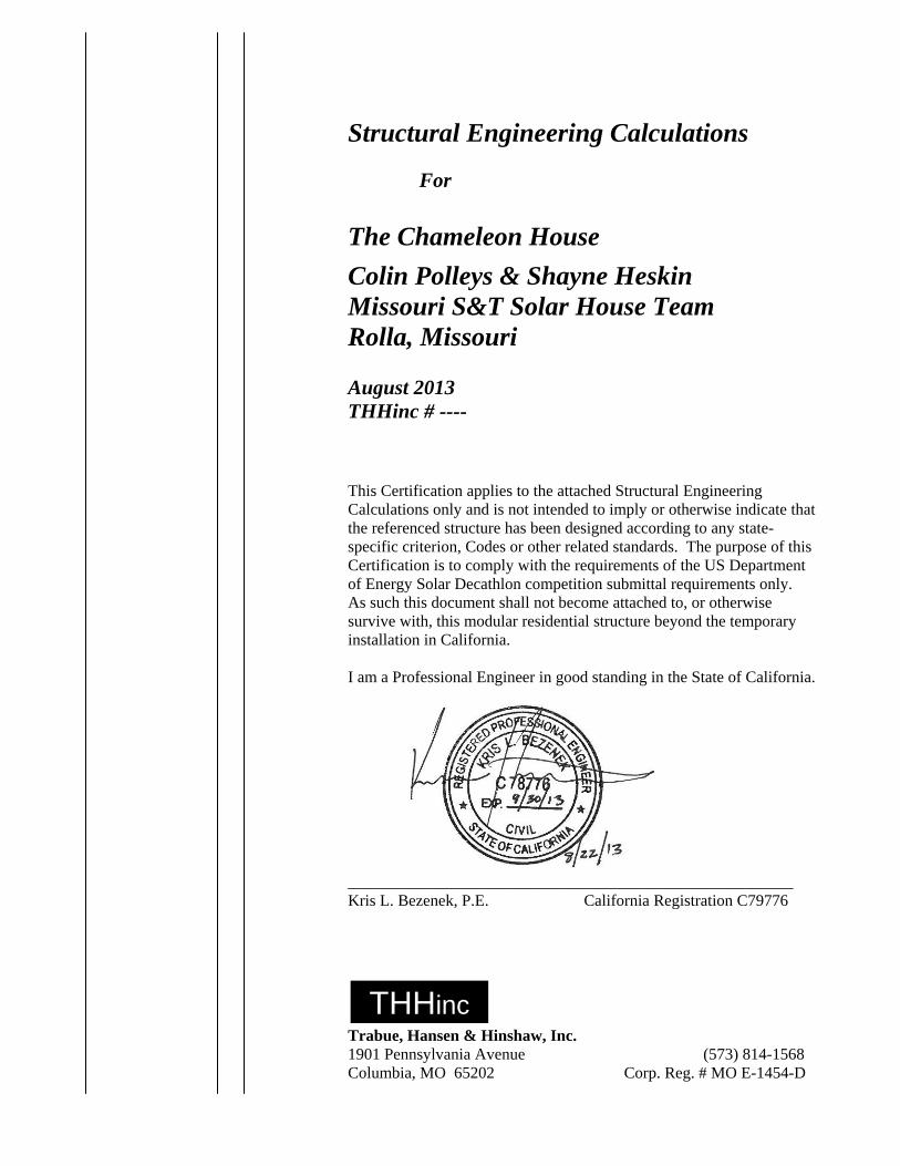
Structural Engineering Calculations For
The Chameleon House
Colin Polleys & Shayne Heskin Missouri S&T Solar House Team Rolla, Missouri August 2013 THHinc # ----
This Certification applies to the attached Structural Engineering Calculations only and is not intended to imply or otherwise indicate that the referenced structure has been designed according to any state-specific criterion, Codes or other related standards. The purpose of this Certification is to comply with the requirements of the US Department of Energy Solar Decathlon competition submittal requirements only. As such this document shall not become attached to, or otherwise survive with, this modular residential structure beyond the temporary installation in California. I am a Professional Engineer in good standing in the State of California. _______________________________________________________ Kris L. Bezenek, P.E. California Registration C79776
Trabue, Hansen & Hinshaw, Inc. 1901 Pennsylvania Avenue (573) 814-1568 Columbia, MO 65202 Corp. Reg. # MO E-1454-D
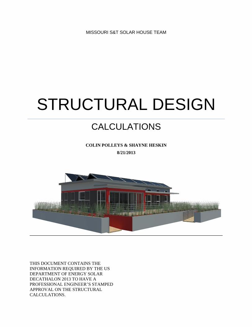
MISSOURI S&T SOLAR HOUSE TEAM
STRUCTURAL DESIGN CALCULATIONS
COLIN POLLEYS & SHAYNE HESKIN
8/21/2013
THIS DOCUMENT CONTAINS THE
INFORMATION REQUIRED BY THE US
DEPARTMENT OF ENERGY SOLAR
DECATHALON 2013 TO HAVE A
PROFESSIONAL ENGINEER’S STAMPED
APPROVAL ON THE STRUCTURAL
CALCULATIONS.
JOB_______________________________________ SHEET NO._______________OF________________ CALC. BY________________DATE______________ CHECKED BY____________ _DATE______________
MISSOURI S&T SOLAR HOUSE TEAM | Chameleon House 1
TABLE OF CONTENTS
1. GENERAL ................................................................................................................................................ 4
1.1 - ARCHITECTURE ........................................................................................................................... 4
1.1.1 ISOMETRIC VIEW ....................................................................................................... 4
1.1.2 FLOOR PLAN ............................................................................................................... 4
1.1.4 NORTH ELEVATION .................................................................................................. 5
1.1.6 SOUTH ELEVATION ................................................................................................... 6
1.2.1 ITEM WEIGHTS ........................................................................................................... 8
1.2.2 GRAVITY LOADS ....................................................................................................... 9
1.2.2.1 BEDROOM .............................................................................................. 9
1.2.2.2 LIVING ROOM ...................................................................................... 11
1.2.2.3 BATHROOM ......................................................................................... 13
1.2.2.4 SOLARIUM ........................................................................................... 14
1.2.3 LATERAL ................................................................................................................... 15
1.2.3.1 EARTHQUAKE ..................................................................................... 15
1.2.3.2 WIND ..................................................................................................... 17
2. SPECIFIC DESIGN ITEMS ................................................................................................................... 18
2.1 SOLAR PANELS ............................................................................................................................ 18
2.2 DROP CEILING .............................................................................................................................. 18
2.3 - WIND ............................................................................................................................................ 19
2.3.1 SUMMARY ....................................................................................................................... 19
2.4- STRUCTURALLY INSULATED PANELS (SIPS) ...................................................................... 20
2.4.1 SPECIFICATIONS ...................................................................................................... 20
2.5 – LATERAL SEISMIC DESIGN CHECK ...................................................................................... 20
2.5.1 SIPS ............................................................................................................................. 20
2.5.2 DIAPHRAM ................................................................................................................ 20
2.6 – STEEL FLOOR JOIST SYSTEM ................................................................................................ 21
2.6.1 MEMBER SPECIFICATION ...................................................................................... 21
2.6.2 LOAD SUMMARY ..................................................................................................... 21
2.6.3 DEFLECTION ............................................................................................................. 21
JOB_______________________________________ SHEET NO._______________OF________________ CALC. BY________________DATE______________ CHECKED BY____________ _DATE______________
MISSOURI S&T SOLAR HOUSE TEAM | Chameleon House 2
2.6.4 STRENGTH ................................................................................................................. 21
2.6.5 DESIGN ....................................................................................................................... 21
2.6.6 CONNECTION DETAIL ............................................................................................ 23
2.6.7 CALCULATIONS AND CODE ............................................................ 31
2.6.8 - STEEL CHECKS FOR CRANING ............................................................................................ 36
2.6.8.1 LOADS ........................................................................................................................ 36
2.6.8.2 DEFLECTION ............................................................................................................. 37
2.6.8.3 STRENGTH ................................................................................................................. 41
2.6.9 - STEEL CHECKS FOR TRUCK ................................................................................................ 45
2.6.9.1 LOADS ........................................................................................................................ 45
2.6.9.2 DEFLECTION ............................................................................................................. 46
2.6.9.3 STRENGTH ................................................................................................................. 50
2.7 – FOOTING CONSTRUCTION AND COMPETITION DESIGN ..................................................... 53
2.7.1 DRAWING .................................................................................................................. 53
2.7.2 SIZING CALCULATIONS ......................................................................................... 54
2.7.3 GRAVITY FOOTINGS ...................................................................................................... 58
2.7.3.1 SIZE ............................................................................................................................. 58
2.7.3.2 MATERIAL SPECIFICATION .................................................................................. 58
2.7.3.3 DESIGN ....................................................................................................................... 58
2.7.3.4 SIZE ................................................................................ Error! Bookmark not defined.
2.7.3.5 LATERAL CHECK ......................................................................................................... 59
2.7.4 SEISMIC FOOTINGS ........................................................................................................ 64
2.7.4.1 MATERIAL SPECIFICATION .................................................................................. 64
2.7.4.2 DESIGN ....................................................................................................................... 64
2.8 - TIE DOWNS ................................................................................................................................. 66
2.8.1 MATERIALS AND SPECIFICATIONS .................................................................... 66
2.8.2 DRAWINGS ................................................................................................................ 68
2.9 DECK ........................................................................................................................................... 68
2.10- BIFACIAL RACKING ...................................................................................................................... 72
3 CRANING ............................................................................................................................................... 75
3.1 - WEIGHT CALCULATIONS ........................................................................................................ 75
JOB_______________________________________ SHEET NO._______________OF________________ CALC. BY________________DATE______________ CHECKED BY____________ _DATE______________
MISSOURI S&T SOLAR HOUSE TEAM | Chameleon House 3
3.1.2 - LIFT POINTS ............................................................................................................................. 79
3.1.2.1 SPECIFICATIONS ...................................................................................................... 79
3.1.2.2 LOADS ........................................................................................................................ 79
3.1.2.3 DIAGRAM .................................................................................................................. 79
4. TRUCKING ............................................................................................................................................ 80
4.1 - SECTION DIAGRAM ....................................................................................................................... 80
5.4 - TIE DOWNS ................................................................................................................................. 83
6. APPENDICIES ....................................................................................................................................... 84
JOB_______________________________________ SHEET NO._______________OF________________ CALC. BY________________DATE______________ CHECKED BY____________ _DATE______________
MISSOURI S&T SOLAR HOUSE TEAM | Chameleon House 4
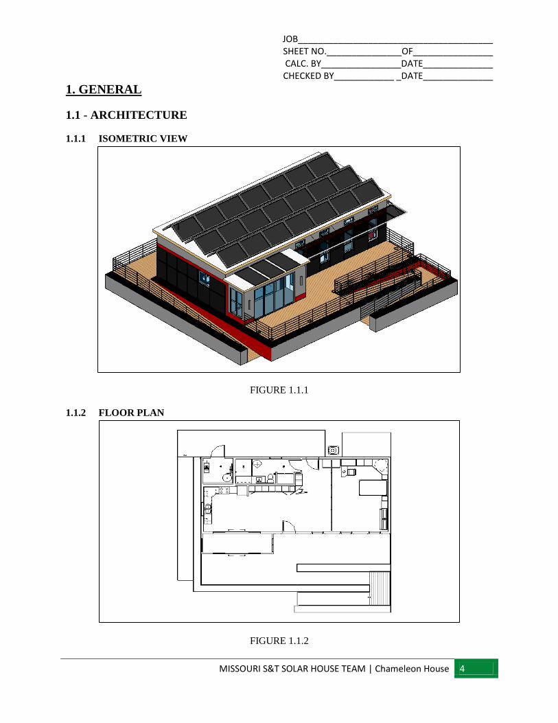
1. GENERAL
1.1 - ARCHITECTURE
1.1.1 ISOMETRIC VIEW
FIGURE 1.1.1
1.1.2 FLOOR PLAN
FIGURE 1.1.2
JOB_______________________________________ SHEET NO._______________OF________________ CALC. BY________________DATE______________ CHECKED BY____________ _DATE______________
MISSOURI S&T SOLAR HOUSE TEAM | Chameleon House 5
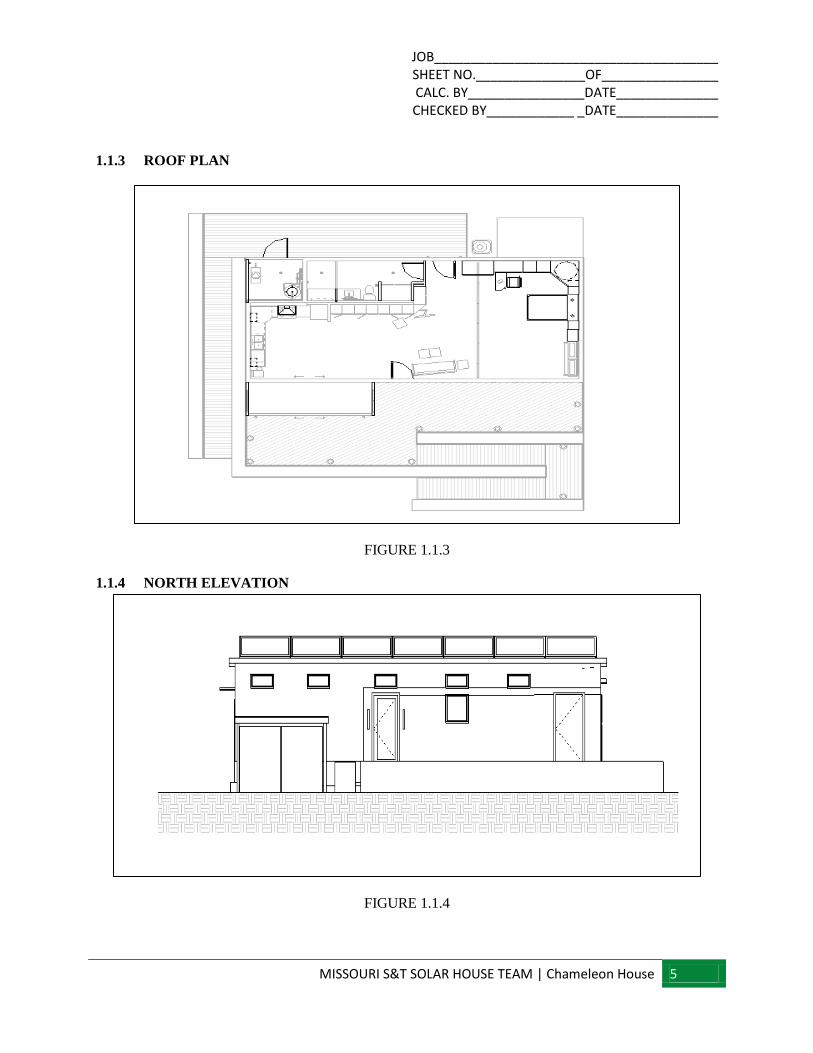
1.1.3 ROOF PLAN
FIGURE 1.1.3
1.1.4 NORTH ELEVATION
FIGURE 1.1.4
JOB_______________________________________ SHEET NO._______________OF________________ CALC. BY________________DATE______________ CHECKED BY____________ _DATE______________
MISSOURI S&T SOLAR HOUSE TEAM | Chameleon House 6
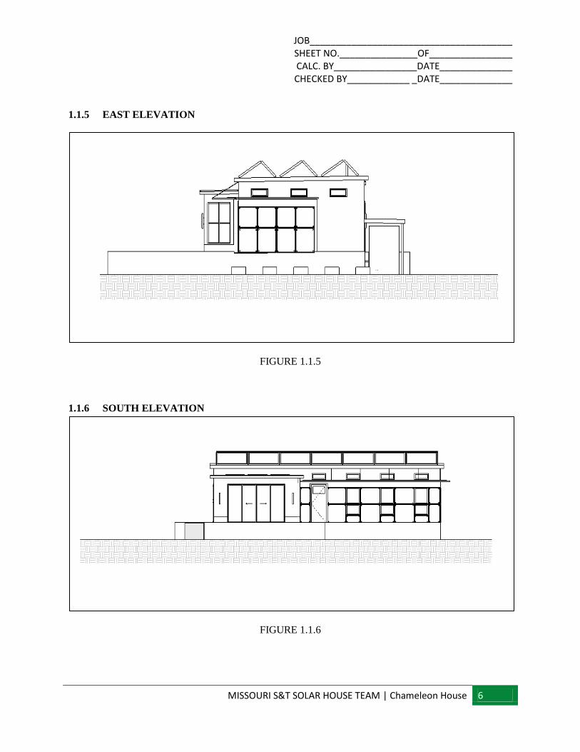
1.1.5 EAST ELEVATION
FIGURE 1.1.5
1.1.6 SOUTH ELEVATION
FIGURE 1.1.6
JOB_______________________________________ SHEET NO._______________OF________________ CALC. BY________________DATE______________ CHECKED BY____________ _DATE______________
MISSOURI S&T SOLAR HOUSE TEAM | Chameleon House 7
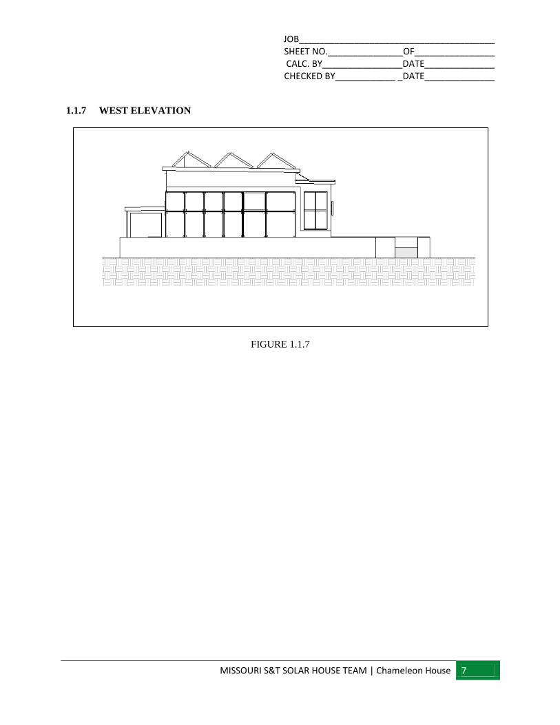
1.1.7 WEST ELEVATION
FIGURE 1.1.7
JOB_______________________________________ SHEET NO._______________OF________________ CALC. BY________________DATE______________ CHECKED BY____________ _DATE______________
MISSOURI S&T SOLAR HOUSE TEAM | Chameleon House 8
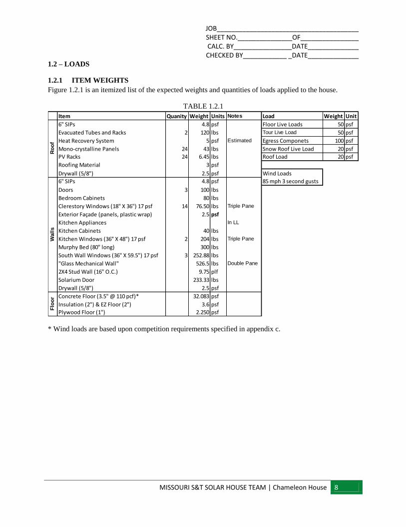
1.2 – LOADS
1.2.1 ITEM WEIGHTS
Figure 1.2.1 is an itemized list of the expected weights and quantities of loads applied to the house.
TABLE 1.2.1
* Wind loads are based upon competition requirements specified in appendix c.
Item Quanity Weight Units Notes Load Weight Unit
6" SIPs 4.8 psf Floor Live Loads 50 psf
Evacuated Tubes and Racks 2 120 lbs Tour Live Load 50 psf
Heat Recovery System 5 psf Estimated Egress Componets 100 psf
Mono-crystalline Panels 24 43 lbs Snow Roof Live Load 20 psf
PV Racks 24 6.45 lbs Roof Load 20 psf
Roofing Material 3 psf
Drywall (5/8") 2.5 psf Wind Loads
6" SIPs 4.8 psf 85 mph 3 second gusts
Doors 3 100 lbs
Bedroom Cabinets 80 lbs
Clerestory Windows (18" X 36") 17 psf 14 76.50 lbs Triple Pane
Exterior Façade (panels, plastic wrap) 2.5 psf
Kitchen Appliances In LL
Kitchen Cabinets 40 lbs
Kitchen Windows (36" X 48") 17 psf 2 204 lbs Triple Pane
Murphy Bed (80" long) 300 lbs
South Wall Windows (36" X 59.5") 17 psf 3 252.88 lbs
"Glass Mechanical Wall" 526.5 lbs Double Pane
2X4 Stud Wall (16" O.C.) 9.75 plf
Solarium Door 233.33 lbs
Drywall (5/8") 2.5 psf
Concrete Floor (3.5" @ 110 pcf)* 32.083 psf
Insulation (2") & EZ Floor (2") 3.6 psf
Plywood Floor (1") 2.250 psf
Ro
of
Wall
sF
loo
r
JOB_______________________________________ SHEET NO._______________OF________________ CALC. BY________________DATE______________ CHECKED BY____________ _DATE______________
MISSOURI S&T SOLAR HOUSE TEAM | Chameleon House 9
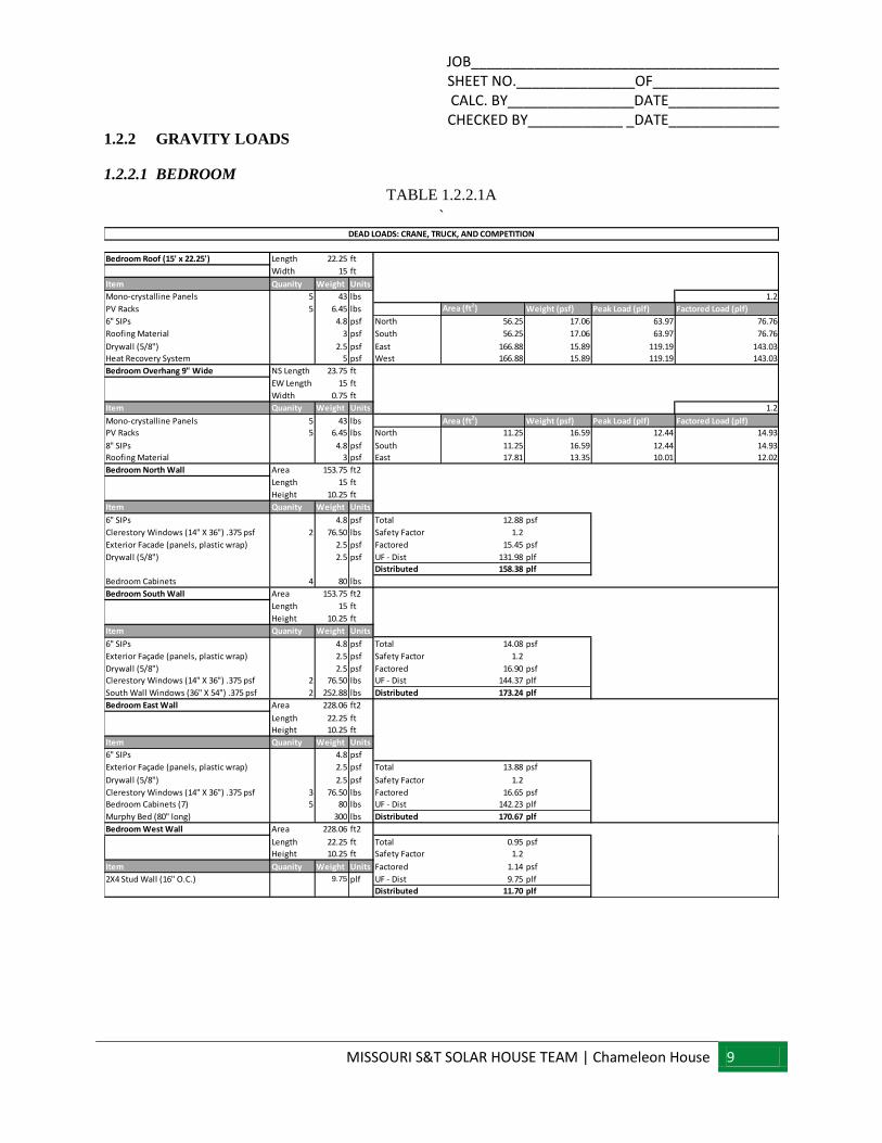
1.2.2 GRAVITY LOADS
1.2.2.1 BEDROOM
TABLE 1.2.2.1A
`
Bedroom Roof (15' x 22.25') Length 22.25 ft
Width 15 ft
Item Quanity Weight Units
Mono-crystalline Panels 5 43 lbs 1.2
PV Racks 5 6.45 lbs Area (ft2) Weight (psf) Peak Load (plf) Factored Load (plf)
6" SIPs 4.8 psf North 56.25 17.06 63.97 76.76
Roofing Material 3 psf South 56.25 17.06 63.97 76.76
Drywall (5/8") 2.5 psf East 166.88 15.89 119.19 143.03
Heat Recovery System 5 psf West 166.88 15.89 119.19 143.03
Bedroom Overhang 9" Wide NS Length 23.75 ft
EW Length 15 ft
Width 0.75 ft
Item Quanity Weight Units 1.2
Mono-crystalline Panels 5 43 lbs Area (ft2) Weight (psf) Peak Load (plf) Factored Load (plf)
PV Racks 5 6.45 lbs North 11.25 16.59 12.44 14.93
8" SIPs 4.8 psf South 11.25 16.59 12.44 14.93
Roofing Material 3 psf East 17.81 13.35 10.01 12.02
Bedroom North Wall Area 153.75 ft2
Length 15 ft
Height 10.25 ft
Item Quanity Weight Units
6" SIPs 4.8 psf Total 12.88 psf
Clerestory Windows (14" X 36") .375 psf 2 76.50 lbs Safety Factor 1.2
Exterior Facade (panels, plastic wrap) 2.5 psf Factored 15.45 psf
Drywall (5/8") 2.5 psf UF - Dist 131.98 plf
Distributed 158.38 plf
Bedroom Cabinets 4 80 lbs
Bedroom South Wall Area 153.75 ft2
Length 15 ft
Height 10.25 ft
Item Quanity Weight Units
6" SIPs 4.8 psf Total 14.08 psf
Exterior Façade (panels, plastic wrap) 2.5 psf Safety Factor 1.2
Drywall (5/8") 2.5 psf Factored 16.90 psf
Clerestory Windows (14" X 36") .375 psf 2 76.50 lbs UF - Dist 144.37 plf
South Wall Windows (36" X 54") .375 psf 2 252.88 lbs Distributed 173.24 plf
Bedroom East Wall Area 228.06 ft2
Length 22.25 ft
Height 10.25 ft
Item Quanity Weight Units
6" SIPs 4.8 psf
Exterior Façade (panels, plastic wrap) 2.5 psf Total 13.88 psf
Drywall (5/8") 2.5 psf Safety Factor 1.2
Clerestory Windows (14" X 36") .375 psf 3 76.50 lbs Factored 16.65 psf
Bedroom Cabinets (7) 5 80 lbs UF - Dist 142.23 plf
Murphy Bed (80" long) 300 lbs Distributed 170.67 plf
Bedroom West Wall Area 228.06 ft2
Length 22.25 ft Total 0.95 psf
Height 10.25 ft Safety Factor 1.2
Item Quanity Weight Units Factored 1.14 psf
2X4 Stud Wall (16" O.C.) 9.75 plf UF - Dist 9.75 plf
Distributed 11.70 plf
DEAD LOADS: CRANE, TRUCK, AND COMPETITION
JOB_______________________________________ SHEET NO._______________OF________________ CALC. BY________________DATE______________ CHECKED BY____________ _DATE______________
MISSOURI S&T SOLAR HOUSE TEAM | Chameleon House 10
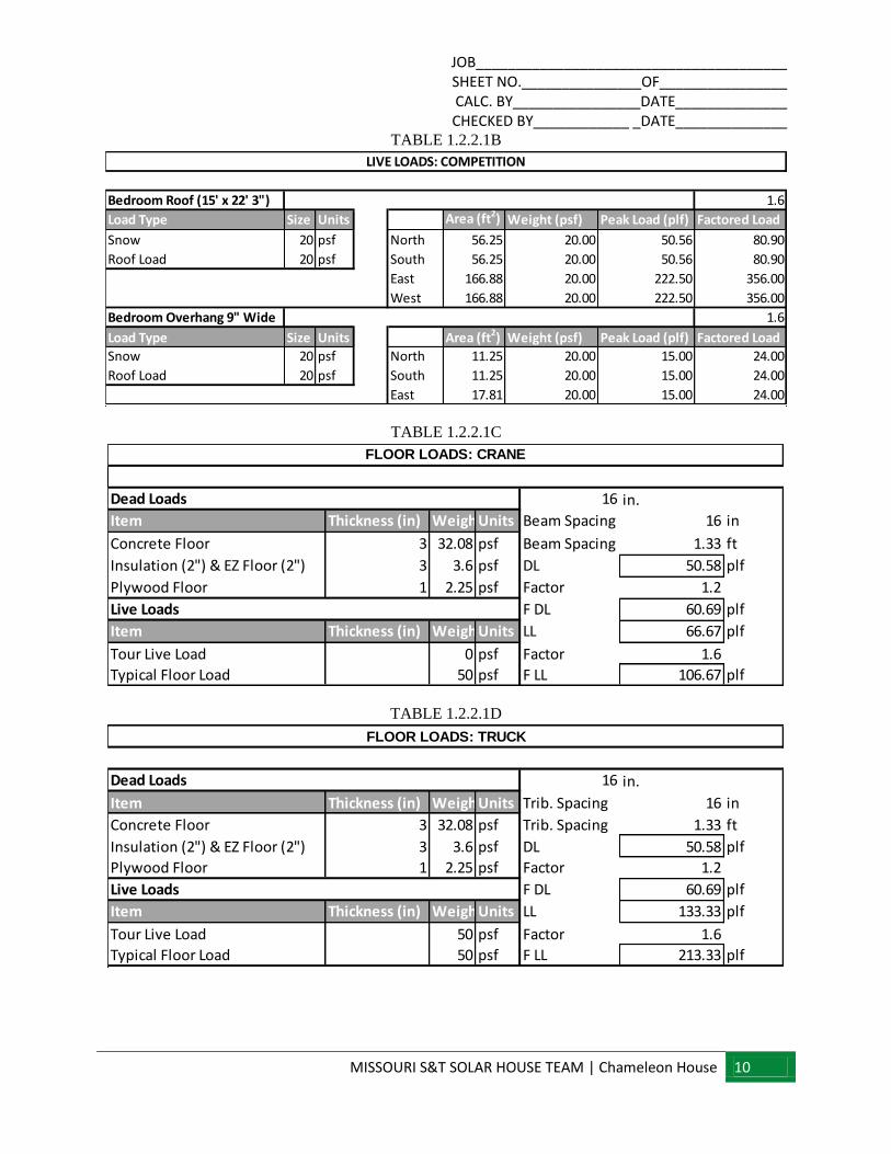
TABLE 1.2.2.1B
TABLE 1.2.2.1C
TABLE 1.2.2.1D
Bedroom Roof (15' x 22' 3") 1.6
Load Type Size Units Area (ft2) Weight (psf) Peak Load (plf) Factored Load
Snow 20 psf North 56.25 20.00 50.56 80.90
Roof Load 20 psf South 56.25 20.00 50.56 80.90
East 166.88 20.00 222.50 356.00
West 166.88 20.00 222.50 356.00
Bedroom Overhang 9" Wide 1.6
Load Type Size Units Area (ft2) Weight (psf) Peak Load (plf) Factored Load
Snow 20 psf North 11.25 20.00 15.00 24.00
Roof Load 20 psf South 11.25 20.00 15.00 24.00
East 17.81 20.00 15.00 24.00
LIVE LOADS: COMPETITION
16 in.
Item Thickness (in) WeightUnits Beam Spacing 16 in
Concrete Floor 3 32.08 psf Beam Spacing 1.33 ft
Insulation (2") & EZ Floor (2") 3 3.6 psf DL 50.58 plf
Plywood Floor 1 2.25 psf Factor 1.2
F DL 60.69 plf
Item Thickness (in) WeightUnits LL 66.67 plf
Tour Live Load 0 psf Factor 1.6
Typical Floor Load 50 psf F LL 106.67 plf
Live Loads
Dead Loads
FLOOR LOADS: CRANE
16 in.
Item Thickness (in) WeightUnits Trib. Spacing 16 in
Concrete Floor 3 32.08 psf Trib. Spacing 1.33 ft
Insulation (2") & EZ Floor (2") 3 3.6 psf DL 50.58 plf
Plywood Floor 1 2.25 psf Factor 1.2
F DL 60.69 plf
Item Thickness (in) WeightUnits LL 133.33 plf
Tour Live Load 50 psf Factor 1.6
Typical Floor Load 50 psf F LL 213.33 plf
Live Loads
Dead Loads
FLOOR LOADS: TRUCK
JOB_______________________________________ SHEET NO._______________OF________________ CALC. BY________________DATE______________ CHECKED BY____________ _DATE______________
MISSOURI S&T SOLAR HOUSE TEAM | Chameleon House 11
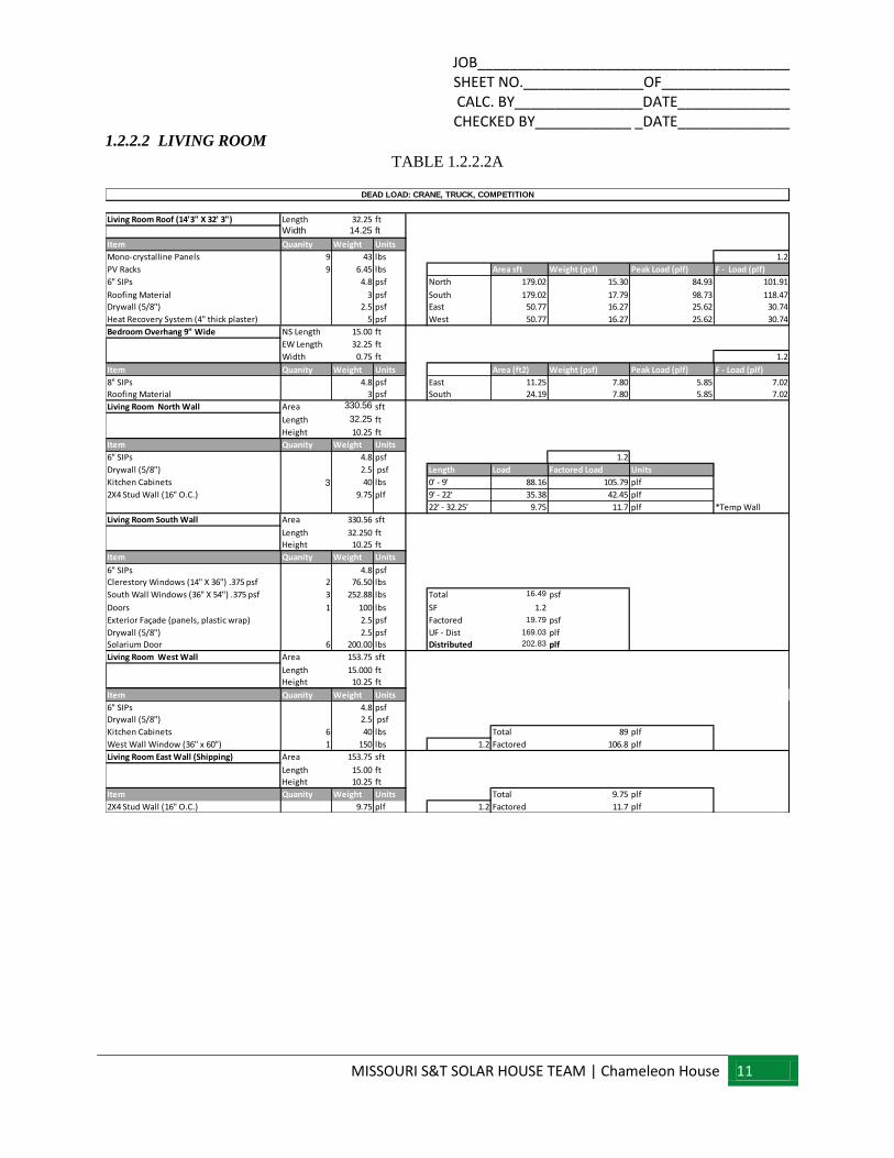
1.2.2.2 LIVING ROOM
TABLE 1.2.2.2A
Living Room Roof (14'3" X 32' 3") Length 32.25 ftWidth 14.25 ft
Item Quanity Weight Units
Mono-crystalline Panels 9 43 lbs 1.2
PV Racks 9 6.45 lbs Area sft Weight (psf) Peak Load (plf) F - Load (plf)
6" SIPs 4.8 psf North 179.02 15.30 84.93 101.91
Roofing Material 3 psf South 179.02 17.79 98.73 118.47
Drywall (5/8") 2.5 psf East 50.77 16.27 25.62 30.74
Heat Recovery System (4" thick plaster) 5 psf West 50.77 16.27 25.62 30.74
Bedroom Overhang 9" Wide NS Length 15.00 ft
EW Length 32.25 ft
Width 0.75 ft 1.2
Item Quanity Weight Units Area (ft2) Weight (psf) Peak Load (plf) F - Load (plf)
8" SIPs 4.8 psf East 11.25 7.80 5.85 7.02
Roofing Material 3 psf South 24.19 7.80 5.85 7.02
Living Room North Wall Area 330.56 sft
Length 32.25 ft
Height 10.25 ft
Item Quanity Weight Units
6" SIPs 4.8 psf 1.2
Drywall (5/8") 2.5 psf Length Load Factored Load Units
Kitchen Cabinets 3 40 lbs 0' - 9' 88.16 105.79 plf
2X4 Stud Wall (16" O.C.) 9.75 plf 9' - 22' 35.38 42.45 plf
22' - 32.25' 9.75 11.7 plf *Temp Wall
Living Room South Wall Area 330.56 sft
Length 32.250 ft
Height 10.25 ft
Item Quanity Weight Units
6" SIPs 4.8 psf
Clerestory Windows (14" X 36") .375 psf 2 76.50 lbs
South Wall Windows (36" X 54") .375 psf 3 252.88 lbs Total 16.49 psf
Doors 1 100 lbs SF 1.2
Exterior Façade (panels, plastic wrap) 2.5 psf Factored 19.79 psf
Drywall (5/8") 2.5 psf UF - Dist 169.03 plf
Solarium Door 6 200.00 lbs Distributed 202.83 plf
Living Room West Wall Area 153.75 sft
Length 15.000 ft
Height 10.25 ft
Item Quanity Weight Units
6" SIPs 4.8 psf
Drywall (5/8") 2.5 psf
Kitchen Cabinets 6 40 lbs Total 89 plf
West Wall Window (36" x 60") 1 150 lbs 1.2 Factored 106.8 plf
Living Room East Wall (Shipping) Area 153.75 sft
Length 15.00 ft
Height 10.25 ft
Item Quanity Weight Units Total 9.75 plf
2X4 Stud Wall (16" O.C.) 9.75 plf 1.2 Factored 11.7 plf
DEAD LOAD: CRANE, TRUCK, COMPETITION
JOB_______________________________________ SHEET NO._______________OF________________ CALC. BY________________DATE______________ CHECKED BY____________ _DATE______________
MISSOURI S&T SOLAR HOUSE TEAM | Chameleon House 12
TABLE 1.2.2.2B
TABLE 1.2.2.2C
TABLE 1.2.2.2D
Length 32.25 ft 1.6
Width 14.25 ft Area sft Weight (psf) Peak Load (plf) Factored Load
Load Type Weight Units North 179.02 20.00 111.02 177.63
Snow 20 psf South 179.02 20.00 111.02 177.63
Roof Load 20 psf East 50.77 20.00 71.25 114.00
West 50.77 20.00 71.25 114.00
East Overhang 11.25 20.00 6.98 11.16
South Overhang 24.19 20.00 15.00 24.00
Living Room Roof (15' x 32.33')
LIVE LOAD: COMPETITION
Trib. Spacing 16 in
Item Thickness (in) Weight Units Trib. Spacing 1.33 ft
Concrete Floor (3" @ 110 pcf) 3 32.08 psf DL 50.58 plf
Insulation (3") 3 3.60 psf Factor 1.2
Plywood Floor (1") 1 2.25 psf F DL 60.69 plf
LL 66.67 plf
Item Thickness (in) Weight Units Factor 1.6
Floor Load (Competition) 0 psf F LL 106.67 plf
Typical Floor Load 50 psf
Dead Loads
FLOOR LOADS: CRANE
Live Loads
Trib. Spacing 16 in
Item Thickness (in) Weight Units Trib. Spacing 1.33 ft
Concrete Floor (3" @ 110 pcf) 3 32.08 psf DL 50.58 plf
Insulation (3") 3 3.60 psf Factor 1.2
Plywood Floor (1") 1 2.25 psf F DL 60.69 plf
LL 133.33 plf
Item Thickness (in) Weight Units Factor 1.6
Floor Load (Competition) 50 psf F LL 213.33 plf
Typical Floor Load 50 psf
Live Loads
Dead Loads
FLOOR LOADS: TRUCK
JOB_______________________________________ SHEET NO._______________OF________________ CALC. BY________________DATE______________ CHECKED BY____________ _DATE______________
MISSOURI S&T SOLAR HOUSE TEAM | Chameleon House 13
1.2.2.3 BATHROOM
TABLE 1.2.2.3A
Bathroom Roof (8' X 32' 3") Length 8 ft
Width 32.25 ft
Overhang Width 0.75 ft
Item Quanity Weight Units
Mono-crystalline Panels 5 43 lbs
PV Racks 5 6.45 lbs 1.2
6" SIPs 4.8 psf Area sft Weight (psf) Peak Load (plf) Factored Load (plf)
Roofing Material 3 psf North 129.00 12.19 48.75 58.51
Drywall (5/8") 2.5 psf South 129.00 12.19 48.75 58.51
Evacuated Tubes and Racks 2 120 lbs North Overhang 24.19 7.80 251.55 301.86
Bathroom North Wall Area 330.5625 sft
Length 32.25 ft
Height 10.25 ft
Item Quanity Weight Units
6" SIPs 4.8 psf
Drywall (5/8") 2.5 psf
Exterior Façade (panels, plastic wrap) 2.5 psf 1.2
Mechanical Door 1 150 lbs Area sft Weight (psf) Peak Load (plf) Factored Load (plf)
Clerestory Windows 3 76.50 lbs 0-8 0 0
Door 1 100 lbs 8-32.25 9.8 100.45 120.54
Bathroom South Wall Area 330.5625 sft
Length 32.25 ft
Height 10.25 ft
Item Quanity Weight Units
6" SIPs 4.8 psf
Drywall (5/8") 2.5 psf Area sft Weight (psf) Peak Load (plf) Factored Load (plf)
Interior Finish 2.5 psf 0 to 9 9.8 100.45 120.54
Doors 1 100 lbs 9 to 26 5.951219512 61 73.2
2X4 Stud Wall (16" O.C.) 9.75 plf 26 to 32.25 0 9.75 11.7
BathRoom West Wall (Mechanical Room) Area 82 sft
Length 8.000 ft
Height 10.25 ft
Item Quanity Weight Units
2X4 Stud Wall (16" O.C.) 9.75 plf Total 3.25 plf
Exterior Façade (panels, plastic wrap) 2.5 psf 1.2 Factored 3.9 plf
BathRoom West Wall (SIP Wall) Area 82 sft
Length 8.000 ft
Height 10.25 ft
Item Quanity Weight Units
6" SIPs 4.8 psf Total 9.125 plf
Drywall (5/8") 2.5 psf 1.2 Factored 10.95 plf
BathRoom EastWall (Shipping) Area 82 sft
Length 8.000 ft
Height 10.25 ft
Item Quanity Weight Units Total 9.75 plf
2X4 Stud Wall (16" O.C.) 9.75 plf 1.2 Factored 11.7 plf
DEAD LOAD: CRANE, TRUCK, COMPETITION
JOB_______________________________________ SHEET NO._______________OF________________ CALC. BY________________DATE______________ CHECKED BY____________ _DATE______________
MISSOURI S&T SOLAR HOUSE TEAM | Chameleon House 14
TABLE 1.2.2.3B
TABLE 1.2.2.3C
TABLE 1.2.2.3D
1.2.2.4 SOLARIUM
An engineering judgment was made that the solarium roof, wall, and floor loads are similar enough to the
living room section that as long as the structure system was similar the smaller area, and smaller joist
spacing would be more than enough.
Length 8 ft
Width 32.25 ft 1.6Overhang Length 40.25 ft Area sft Weight (psf) Peak Load (plf) Factored Load (plf)
Load Type Size Units North 129.00 20.000 80.000 128.000
Snow 20 psf South 129.00 20.000 80.000 128.000
Roof Load 20 psf North Overhang 24.19 20.000 12.019 19.230
Living Room Roof (15' x 32.33')
LIVE LOAD: COMPETITION
Trib. Spacing 16 in
Item Thickness (in) Weight Units Trib. Spacing 1.333 ft
Concrete Floor (3" @ 110 pcf) 3.5 32.08 psf DL 50.578 plf
Insulation (4") 4 3.6 psf Factor 1.2
Plywood Floor (0.75") 1 2.25 psf F DL 60.693 plf
LL 133.333 plf
Item Thickness (in) Weight Units Factor 1.6
Floor Load (Competition) 50 psf F LL 213.333 plf
Typical Floor Load 50 psf
FLOOR LOADS: CRANE
Live Loads
Dead Loads
Trib. Spacing 16 in
Item Thickness (in) Weight Units Trib. Spacing 1.33 ft
Concrete Floor (3" @ 110 pcf) 3 32.08 psf DL 50.58 plf
Insulation (3") 3 3.6 psf Factor 1.2
Plywood Floor (1") 1 2.25 psf F DL 60.69 plf
LL 133.333 plf
Item Thickness (in) Weight Units Factor 1.6
Floor Load (Competition) 50 psf F LL 213.333 plf
Typical Floor Load 50 psf
Live Loads
Dead Loads
FLOOR LOADS: TRUCK
JOB_______________________________________ SHEET NO._______________OF________________ CALC. BY________________DATE______________ CHECKED BY____________ _DATE______________
MISSOURI S&T SOLAR HOUSE TEAM | Chameleon House 15
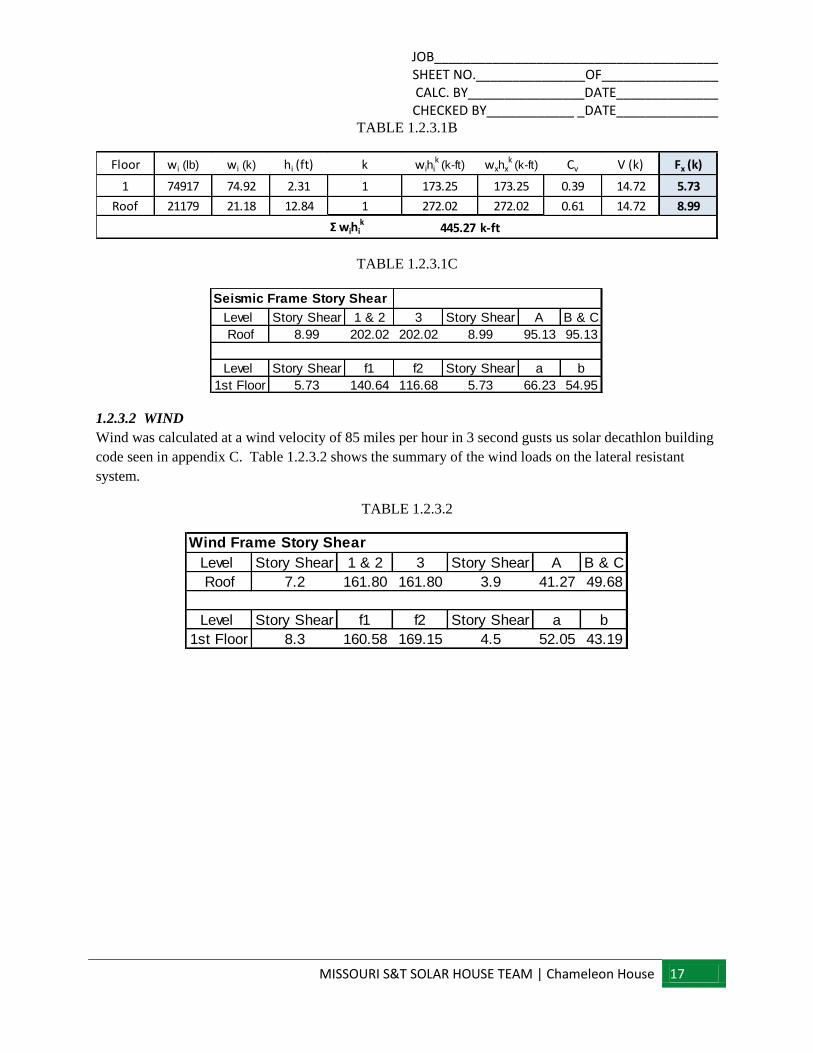
1.2.3 LATERAL
1.2.3.1 EARTHQUAKE
Table 1.2.3.1a illustrates the seismic weights based on the dead loads of each section. Figure 1.2.3.1
illustrates the variables used in determining the ground lateral load based on ASCE 7-10. Table 1.2.3.1b
illustrates the distribution the lateral load to the levels of the house. Table 1.2.3.1c shows the summary of
the earthquake loads dispersed to the lateral support system. Seismic concerns were based off of appendix
C, calling for a design that meets all code requirements for a seismic design category D2 based upon the
IRC.
TABLE 1.2.3.1A
Floor Area (SF) Weight (lbs)
1 333.75 First Floor 21492.26
Roof 333.75 Roof 7834.36
W= 29327 lb
W= 29.33 k
Floor Area (SF) Weight (lbs)
1 459.56 First Floor 26976.85
Roof 459.56 Roof 7851.67
W= 34829 lb
W= 34.83 k
Floor Area (SF) Weight (lbs)
1 258 First Floor 18863.19
Roof 258 Roof 3333.31
W= 22197 lb
W= 22.20 k
Floor Area (SF) Weight (lbs)
1 108 First Floor 7584.80
Roof 108 Roof 2160.00
W= 9745 lb
W= 9.74 k
*Estimated based on 2, 14' glass windows, and 2X4
walls on edge with typical flooring based on house
Estimated Solarium Room
Bedroom Section
Living Room Section
Bathroom Section
Seismic Weight Calculations
Total Building Weight
Total Building Weight
Total Building Weight
Total Building Weight

JOB_______________________________________ SHEET NO._______________OF________________ CALC. BY________________DATE______________ CHECKED BY____________ _DATE______________
MISSOURI S&T SOLAR HOUSE TEAM | Chameleon House 16
FIGURE 1.2.3.1
Seismic Forces
ASCE 7-10 Seismic Design
Site Spectrum
Code Reference
SS = 1.493 g 11.4.1
S1 = 0.554 g 11.4.1
Site Class Class = D Table 1: Site Parameters
Fa = 1.00 Table 11.4-1
Fv = 1.50 Table 11.4-2
SMS = 1.493 g 11.4.3
SM1 = 0.831 g 11.4.3
SDS = 0.995 g 11.4.4
SD1 = 0.554 g 11.4.4
All Other Structural Systems
R = 6.5 Table 12.2-1
ΩO = 3.0 Table 12.2-1
Cd = 4.0 Table 12.2-1
Category = II Table 1-1
Ct = 0.02 Table 12.8-2
x = 0.75 Table 12.8-2
TL = 8.00 sec. Figure 22-12
hn = 13.1 ft. 12.8.2.1
Cat. = D 11.6 & Tables 11.6-1 & 11.6-2
I = 1.0 11.5.1 & Table 11.5-1
CU = 1.40 Table 12.8-1
Ta = 0.138 sec. 12.8.2.1
TLIM = 0.193 sec. 12.8.2
Period To TO = 0.111 sec. 11.4.4
Period Ts TS = 0.557 sec. 11.4.5
T = 0.557 sec. 12.8.2
CS = N/A 12.8-2
CS = 0.153 12.8-3
CS = N/A 12.8-4
CS, min_Allowable = 0.01 12.8-5
CS, min_Allowable = N/A 12.8-6
CS = 0.153
CS = 0.153 *W 12.8-1
W = 96.10 k
V = 14.72 k
Value of Coefficients based on SPA periods:
Input values below from map or CD:
Spectral Response Acceleration, Short Period
Spectral Response Acceleration, 1-Sec. Period
Input value below from soils report:
Response Modification Factor
Site Coefficient for Short Period
Site Coefficient for 1-sec. Period
Determine Maximum Considered Earthquake (MCE) Parameters:
MCE Spectral Response Acceleration, Short T
MCE Spectral Response Acceleration, 1-Sec. T
Determine Design Base Earthquake (DBE) parameters:
DBE Spectral Response Acceleration, Short T
DBE Spectral Response Acceleration, 1-Sec. T
Input Building Properties:
Structure Type
Building Response
Coefficient for Upper Limit on Calculated Period
System Overstrength Factor
Deflection Amplification Factor
Occupancy Category
Period Parameters
Period Parameters
Long Period Transistion Period
Effective Height
Determine Period for Base Shear:
Seismic Design Category
Occupancy Importance Factor
Seismic Response Coefficient T>TL
Min. Allowable Seismic Response Coefficient
Seismic Base Shear (Equivalent Lateral Force Procedure)
Approximate Fundamental Period
Design Fundamental Period Limit
Design Period
Determine Base Shear:
Seismic Response Coefficient To<T<Ts
Seismic Response Coefficient T<TL
JOB_______________________________________ SHEET NO._______________OF________________ CALC. BY________________DATE______________ CHECKED BY____________ _DATE______________
MISSOURI S&T SOLAR HOUSE TEAM | Chameleon House 17
TABLE 1.2.3.1B
TABLE 1.2.3.1C
1.2.3.2 WIND
Wind was calculated at a wind velocity of 85 miles per hour in 3 second gusts us solar decathlon building
code seen in appendix C. Table 1.2.3.2 shows the summary of the wind loads on the lateral resistant
system.
TABLE 1.2.3.2
Floor wi (lb) wi (k) hi (ft) k wihik (k-ft) wxhx
k (k-ft) Cv V (k) Fx (k)
1 74917 74.92 2.31 1 173.25 173.25 0.39 14.72 5.73
Roof 21179 21.18 12.84 1 272.02 272.02 0.61 14.72 8.99
Σ wihik
445.27 k-ft
Level Story Shear 1 & 2 3 Story Shear A B & C
Roof 8.99 202.02 202.02 8.99 95.13 95.13
Level Story Shear f1 f2 Story Shear a b
1st Floor 5.73 140.64 116.68 5.73 66.23 54.95
Seismic Frame Story Shear
Level Story Shear 1 & 2 3 Story Shear A B & C
Roof 7.2 161.80 161.80 3.9 41.27 49.68
Level Story Shear f1 f2 Story Shear a b
1st Floor 8.3 160.58 169.15 4.5 52.05 43.19
Wind Frame Story Shear

JOB_______________________________________ SHEET NO._______________OF________________ CALC. BY________________DATE______________ CHECKED BY____________ _DATE______________
MISSOURI S&T SOLAR HOUSE TEAM | Chameleon House 18
2. SPECIFIC DESIGN ITEMS
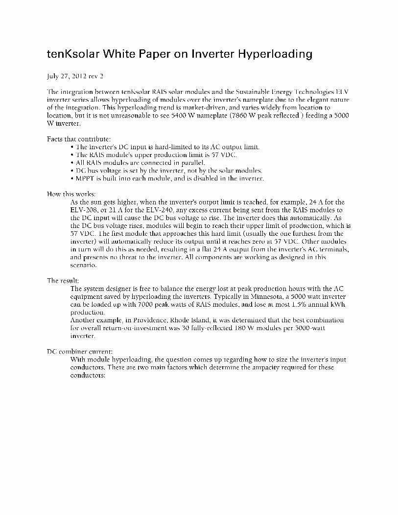
2.1 SOLAR PANELS
Manufacturer: tenK solar
product: wave system
Watts: 410w panels, 3 rows of 7 panels
Angle of panel: 26˚
Angle of reflector: 45˚
A PE stamp is necessary ensure the ballast weight applied to this solar system is adequate in weight.
Appendix e and f provide testing date from tenK solar to facilitate the wind uplift. Appendix g shows
provided drawings from tenK solar regarding dimensions and angles.
2.2 DROP CEILING
A drop ceiling is incorporated with the design. The ceiling provides a significant danger to occupants
during a seismic event and thus must be designed according to specific codes.
The ceiling is designed to comply with e580 for seismic design categories d,e, and f. All
Vertical support will be provided by 12 gauge hanger wire.
At locations requiring both lateral and vertical support, vertical support will be provided by two separate
members. Typical vertical support (tension) will be provided by hanger wire just as in a plain vertical
support. Additional vertical support (compression or resistance to uplift) will be provided by a 1/2"
diameter electrical metal tubing compression post.
Lateral support will be provided by four separate 12 gauge hanger wires splayed 90° from each other
(when measured in plan view) and each oriented at an angle not more than 45° upward (measured from
the ceiling plane).
Hanger wires (vertical supports) must be positioned every 4'. Compression posts must be positioned every
12'. Splay wires (lateral supports) must be positioned every 12'.
Figure 7.0a shows the design of the support ceiling and figure 7.0b shows a cross-section of a lateral
support.
JOB_______________________________________ SHEET NO._______________OF________________ CALC. BY________________DATE______________ CHECKED BY____________ _DATE______________
MISSOURI S&T SOLAR HOUSE TEAM | Chameleon House 19
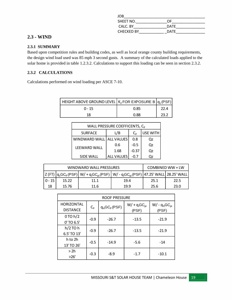
2.3 - WIND
2.3.1 SUMMARY
Based upon competition rules and building codes, as well as local orange county building requirements,
the design wind load used was 85 mph 3 second gusts. A summary of the calculated loads applied to the
solar home is provided in table 1.2.3.2. Calculations to support this loading can be seen in section 2.3.2.
2.3.2 CALCULATIONS
Calculations performed on wind loading per ASCE 7-10.
HEIGHT ABOVE GROUND LEVEL KZ FOR EXPOSURE B qz (PSF)
0 - 15 0.85 22.4
18 0.88 23.2
SURFACE L/B CP USE WITH
WINDWARD WALL ALL VALUES 0.8 Qz
0.6 -0.5 Qz
1.68 -0.37 Qz
SIDE WALL ALL VALUES -0.7 Qz
LEEWARD WALL
WALL PRESSURE COEFFICENTS, CP
Z (FT) qzGCP (PSF) W/ + qiGCpi (PSF) W/ - qiGCpi (PSF) 47.25' WALL 28.25' WALL
0 - 15 15.22 11.1 19.4 25.1 22.5
18 15.76 11.6 19.9 25.6 23.0
WINDWARD WALL PRESSURES COMBINED WW + LW
0 TO h/2
0' TO 6.5'
h/2 TO h
6.5' TO 13'
h to 2h
13' TO 26'
> 2h
>26'
-0.5
-0.9
ROOF PRESSURE
-14.9 -5.6 -14
-0.3 -8.9 -1.7 -10.1
-26.7 -13.5 -21.9
-0.9 -26.7 -13.5 -21.9
HORIZONTAL
DISTANCECP qHGCP (PSF)
W/ + qiGCpi
(PSF)
W/ - qHGCpi
(PSF)
JOB_______________________________________ SHEET NO._______________OF________________ CALC. BY________________DATE______________ CHECKED BY____________ _DATE______________
MISSOURI S&T SOLAR HOUSE TEAM | Chameleon House 20
2.4- STRUCTURALLY INSULATED PANELS (SIPS)
2.4.1 SPECIFICATIONS
Energy panel systems will engineer and design the wall panel system. See appendix A for the product
specs, appendix D for the complete design, and appendix D for the calculations.
2.5 – LATERAL SEISMIC DESIGN CHECK
2.5.1 SIPS
See appendix D for energy panel solutions lateral seismic design checks.
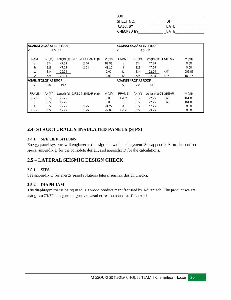
2.5.2 DIAPHRAM
The diaphragm that is being used is a wood product manufactured by Advantech. The product we are
using is a 23/32” tongue and groove, weather resistant and stiff material.
V 4.5 KIP V 8.3 KIP
FRAME AT (ft2) Length (ft) DIRECT SHEAR (kip) V (plf) FRAME AT (ft
2) Length (ft)DIRECT SHEAR (kip) V (plf)
a 634 47.25 2.46 52.05 a 634 47.25 0.00
b 526 47.25 2.04 43.19 b 526 47.25 0.00
f1 634 22.25 0.00 f1 634 22.25 4.54 203.88
f2 526 22.25 0.00 f2 526 22.25 3.76 169.15
V 3.9 KIP V 7.2 KIP
FRAME AT (ft2) Length (ft) DIRECT SHEAR (kip) V (plf) FRAME AT (ft
2) Length (ft)DIRECT SHEAR (kip) V (plf)
1 & 2 579 22.25 0.00 1 & 2 579 22.25 3.60 161.80
3 579 22.25 0.00 3 579 22.25 3.60 161.80
A 579 47.25 1.95 41.27 A 579 47.25 0.00
B & C 579 39.25 1.95 49.68 B & C 579 39.25 0.00
AGAINST 28.25' AT 1ST FLOOR
AGAINST 28.25' AT ROOF
AGAINST 47.25' AT 1ST FLOOR
AGAINST 47.25' AT ROOF
JOB_______________________________________ SHEET NO._______________OF________________ CALC. BY________________DATE______________ CHECKED BY____________ _DATE______________
MISSOURI S&T SOLAR HOUSE TEAM | Chameleon House 21
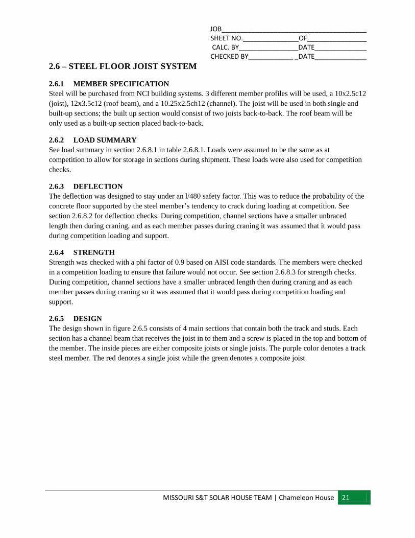
2.6 – STEEL FLOOR JOIST SYSTEM
2.6.1 MEMBER SPECIFICATION
Steel will be purchased from NCI building systems. 3 different member profiles will be used, a 10x2.5c12
(joist), 12x3.5c12 (roof beam), and a 10.25x2.5ch12 (channel). The joist will be used in both single and
built-up sections; the built up section would consist of two joists back-to-back. The roof beam will be
only used as a built-up section placed back-to-back.
2.6.2 LOAD SUMMARY
See load summary in section 2.6.8.1 in table 2.6.8.1. Loads were assumed to be the same as at
competition to allow for storage in sections during shipment. These loads were also used for competition
checks.
2.6.3 DEFLECTION
The deflection was designed to stay under an l/480 safety factor. This was to reduce the probability of the
concrete floor supported by the steel member’s tendency to crack during loading at competition. See
section 2.6.8.2 for deflection checks. During competition, channel sections have a smaller unbraced
length then during craning, and as each member passes during craning it was assumed that it would pass
during competition loading and support.
2.6.4 STRENGTH
Strength was checked with a phi factor of 0.9 based on AISI code standards. The members were checked
in a competition loading to ensure that failure would not occur. See section 2.6.8.3 for strength checks.
During competition, channel sections have a smaller unbraced length then during craning and as each
member passes during craning so it was assumed that it would pass during competition loading and
support.
2.6.5 DESIGN
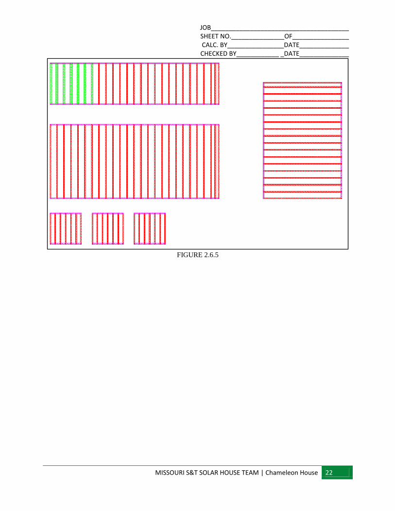
The design shown in figure 2.6.5 consists of 4 main sections that contain both the track and studs. Each
section has a channel beam that receives the joist in to them and a screw is placed in the top and bottom of
the member. The inside pieces are either composite joists or single joists. The purple color denotes a track
steel member. The red denotes a single joist while the green denotes a composite joist.
JOB_______________________________________ SHEET NO._______________OF________________ CALC. BY________________DATE______________ CHECKED BY____________ _DATE______________
MISSOURI S&T SOLAR HOUSE TEAM | Chameleon House 22
FIGURE 2.6.5
JOB_______________________________________ SHEET NO._______________OF________________ CALC. BY________________DATE______________ CHECKED BY____________ _DATE______________
MISSOURI S&T SOLAR HOUSE TEAM | Chameleon House 23
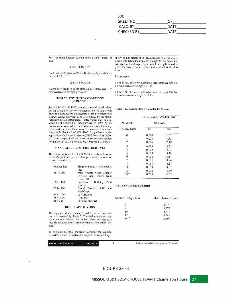
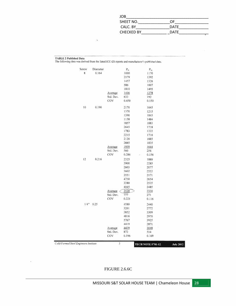
2.6.6 CONNECTION DETAIL
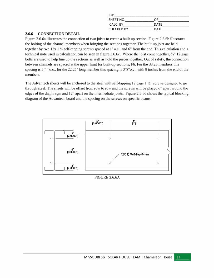
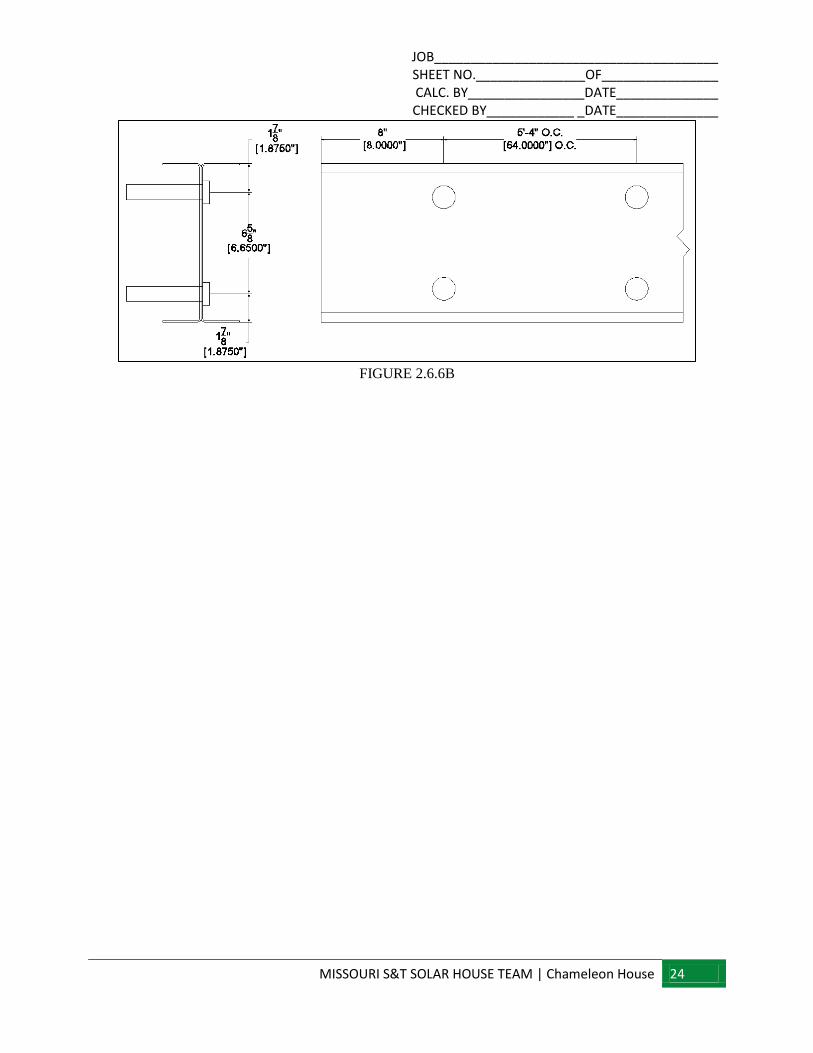
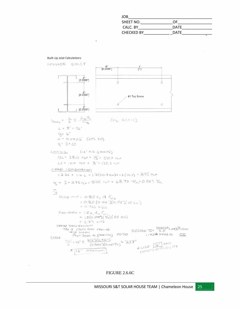
Figure 2.6.6a illustrates the connection of two joists to create a built up section. Figure 2.6.6b illustrates
the bolting of the channel members when bringing the sections together. The built-up joist are held
together by two 12x 1 ¼ self-tapping screws spaced at 1’ o.c., and 6” from the end. This calculation and a
technical note used in calculation can be seen in figure 2.6.6c. Where the joist come together, ¾” 12 gage
bolts are used to help line up the sections as well as hold the pieces together. Out of safety, the connection
between channels are spaced at the upper limit for built-up sections, l/6. For the 33.25 members this
spacing is 5’4” o.c., for the 22.25’ long member this spacing is 3’8”o.c., with 8 inches from the end of the
members.
The Advantech sheets will be anchored to the steel with self-tapping 12 gage 1 ½” screws designed to go
through steel. The sheets will be offset from row to row and the screws will be placed 6” apart around the
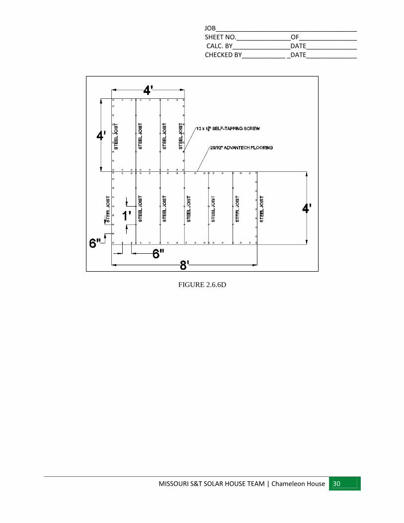
edges of the diaphragm and 12” apart on the intermediate joists. Figure 2.6.6d shows the typical blocking
diagram of the Advantech board and the spacing on the screws on specific beams.
FIGURE 2.6.6A
JOB_______________________________________ SHEET NO._______________OF________________ CALC. BY________________DATE______________ CHECKED BY____________ _DATE______________
MISSOURI S&T SOLAR HOUSE TEAM | Chameleon House 24
FIGURE 2.6.6B
JOB_______________________________________ SHEET NO._______________OF________________ CALC. BY________________DATE______________ CHECKED BY____________ _DATE______________
MISSOURI S&T SOLAR HOUSE TEAM | Chameleon House 25
FIGURE 2.6.6C

JOB_______________________________________ SHEET NO._______________OF________________ CALC. BY________________DATE______________ CHECKED BY____________ _DATE______________
MISSOURI S&T SOLAR HOUSE TEAM | Chameleon House 26
FIGURE 2.6.6C
JOB_______________________________________ SHEET NO._______________OF________________ CALC. BY________________DATE______________ CHECKED BY____________ _DATE______________
MISSOURI S&T SOLAR HOUSE TEAM | Chameleon House 27
FIGURE 2.6.6C
JOB_______________________________________ SHEET NO._______________OF________________ CALC. BY________________DATE______________ CHECKED BY____________ _DATE______________
MISSOURI S&T SOLAR HOUSE TEAM | Chameleon House 28
FIGURE 2.6.6C

JOB_______________________________________ SHEET NO._______________OF________________ CALC. BY________________DATE______________ CHECKED BY____________ _DATE______________
MISSOURI S&T SOLAR HOUSE TEAM | Chameleon House 29
FIGURE 2.6.6C
JOB_______________________________________ SHEET NO._______________OF________________ CALC. BY________________DATE______________ CHECKED BY____________ _DATE______________
MISSOURI S&T SOLAR HOUSE TEAM | Chameleon House 30
FIGURE 2.6.6D
JOB_______________________________________ SHEET NO._______________OF________________ CALC. BY________________DATE______________ CHECKED BY____________ _DATE______________
MISSOURI S&T SOLAR HOUSE TEAM | Chameleon House 31
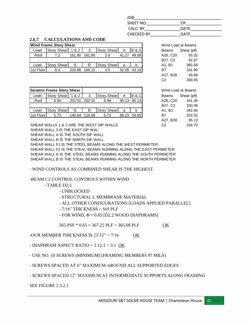
2.6.7 CALCULATIONS AND CODE
- WIND CONTROLS AS COMBINED SHEAR IS THE HIGHEST.
-BEAM C2 CONTROL CONTROLS WITHIN WIND
- TABLE D2-1
- UNBLOCKED
- STRUCTURAL L MEMBRANE MATERIAL
- ALL OTHER CONFIGURATIONS [LOADS APPLIED PARALLEL]
- 7/16” THICKNESS = 565 PLF
- FOR WIND, Φ = 0.65 [D2.2 WOOD DIAPHRAMS]
565 PSF * 0.65 = 367.25 PLF > 365.68 PLF OK
-OUR MEMBER THICKNESS IS 23/32” > 7/16 OK
- DIAPHRAM ASPECT RATIO = 2.12:1 < 3:1 OK
- USE NO. 10 SCREWS (MINIMUM) [FRAMING MEMBERS 97 MILS]
- SCREWS SPACED AT 6” MAXIMUM AROUND ALL SUPPORTED EDGES
- SCREWS SPACED 12” MAXIMUM AT INTERMEDIATE SUPPORTS ALONG FRAMING
SEE FIGURE 2.3.2.1
Level Story Shear 1 & 2 3 Story Shear A B & C Beams Shear (plf)
Roof 7.2 161.80 161.80 3.9 41.27 49.68 A26, C20 93.32
B27, C3 92.87
Level Story Shear f1 f2 Story Shear a b A1, B1 365.68
1st Floor 8.3 203.88 169.15 4.5 52.05 43.19 B7 161.80
A27, B28 49.68
C2 330.95
Level Story Shear 1 & 2 3 Story Shear A B & C Beams Shear (plf)
Roof 8.99 202.02 202.02 8.99 95.13 95.13 A26, C20 161.36
B27, C3 150.08
Level Story Shear f1 f2 Story Shear a b A1, B1 342.66
1st Floor 5.73 140.64 116.68 5.73 66.23 54.95 B7 202.02
A27, B28 95.13
SHEAR WALLS 1 & 2 ARE THE WEST SIP WALLS C2 318.70
SHEAR WALL 3 IS THE EAST SIP WAL
SHEAR WALL A IS THE SOUTH SIP WALL
SHEAR WALL B IS THE NORTH SIP WALL
SHEAR WALL F1 IS THE STEEL BEAMS ALONG THE WEST PERIMETER
SHEAR WALL F2 IS THE STEAL BEAMS RUNNING ALONG THE EAST PERIMETER
SHEAR WALL A IS THE STEEL BEAMS RUNNING ALONG THE SOUTH PERIMETER
SHEAR WALL B IS THE STEAL BEAMS RUNNING ALONG THE NORTH PERIMETER
Wind Load at Beams
Wind Frame Story Shear
Seismic Frame Story Shear
Wind Load at Beams
JOB_______________________________________ SHEET NO._______________OF________________ CALC. BY________________DATE______________ CHECKED BY____________ _DATE______________
MISSOURI S&T SOLAR HOUSE TEAM | Chameleon House 32
JOB_______________________________________ SHEET NO._______________OF________________ CALC. BY________________DATE______________ CHECKED BY____________ _DATE______________
MISSOURI S&T SOLAR HOUSE TEAM | Chameleon House 33
JOB_______________________________________ SHEET NO._______________OF________________ CALC. BY________________DATE______________ CHECKED BY____________ _DATE______________
MISSOURI S&T SOLAR HOUSE TEAM | Chameleon House 34
JOB_______________________________________ SHEET NO._______________OF________________ CALC. BY________________DATE______________ CHECKED BY____________ _DATE______________
MISSOURI S&T SOLAR HOUSE TEAM | Chameleon House 35
JOB_______________________________________ SHEET NO._______________OF________________ CALC. BY________________DATE______________ CHECKED BY____________ _DATE______________
MISSOURI S&T SOLAR HOUSE TEAM | Chameleon House 36
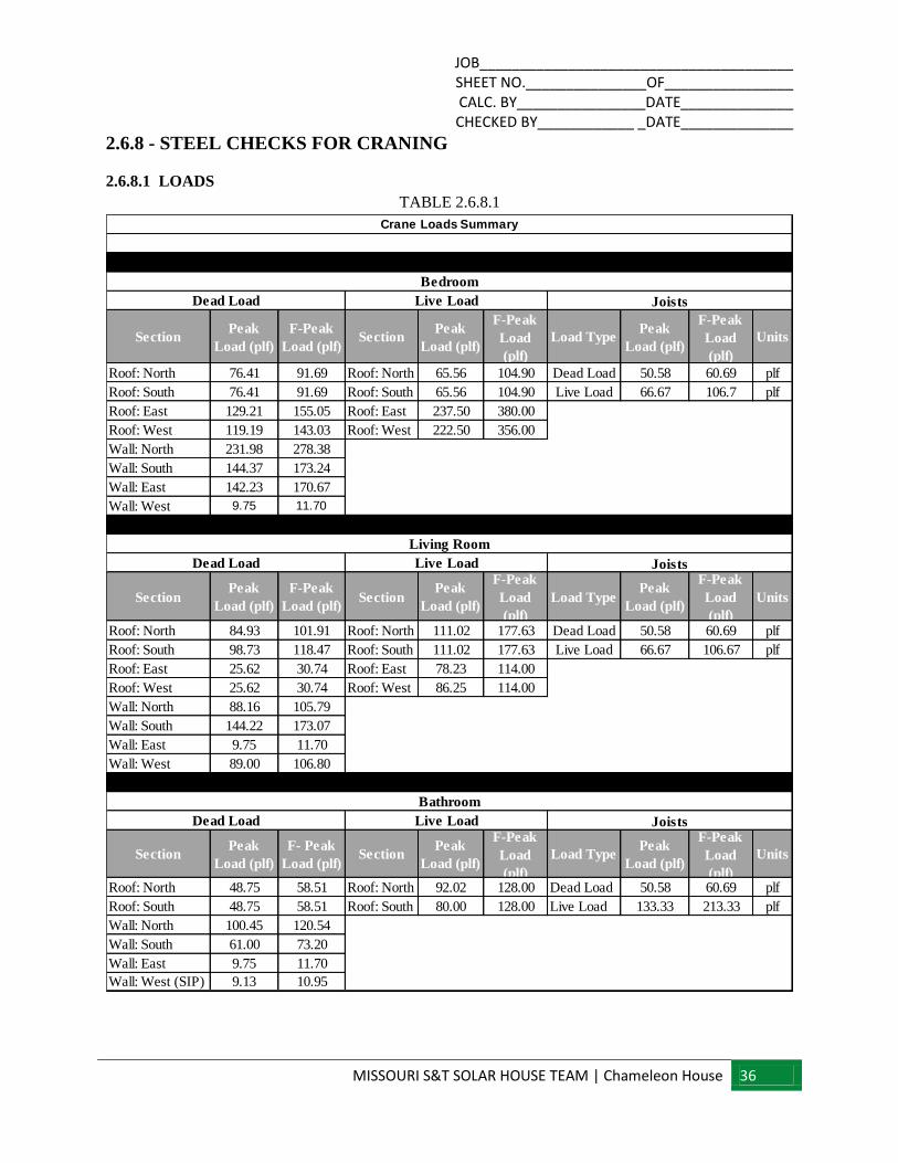
2.6.8 - STEEL CHECKS FOR CRANING
2.6.8.1 LOADS
TABLE 2.6.8.1
SectionPeak
Load (plf)
F-Peak
Load (plf)Section
Peak
Load (plf)
F-Peak
Load
(plf)
Load TypePeak
Load (plf)
F-Peak
Load
(plf)
Units
Roof: North 76.41 91.69 Roof: North 65.56 104.90 Dead Load 50.58 60.69 plf
Roof: South 76.41 91.69 Roof: South 65.56 104.90 Live Load 66.67 106.7 plf
Roof: East 129.21 155.05 Roof: East 237.50 380.00
Roof: West 119.19 143.03 Roof: West 222.50 356.00
Wall: North 231.98 278.38
Wall: South 144.37 173.24
Wall: East 142.23 170.67
Wall: West 9.75 11.70
SectionPeak
Load (plf)
F-Peak
Load (plf)Section
Peak
Load (plf)
F-Peak
Load
(plf)
Load TypePeak
Load (plf)
F-Peak
Load
(plf)
Units
Roof: North 84.93 101.91 Roof: North 111.02 177.63 Dead Load 50.58 60.69 plf
Roof: South 98.73 118.47 Roof: South 111.02 177.63 Live Load 66.67 106.67 plf
Roof: East 25.62 30.74 Roof: East 78.23 114.00
Roof: West 25.62 30.74 Roof: West 86.25 114.00
Wall: North 88.16 105.79
Wall: South 144.22 173.07
Wall: East 9.75 11.70
Wall: West 89.00 106.80
SectionPeak
Load (plf)
F- Peak
Load (plf)Section
Peak
Load (plf)
F-Peak
Load
(plf)
Load TypePeak
Load (plf)
F-Peak
Load
(plf)
Units
Roof: North 48.75 58.51 Roof: North 92.02 128.00 Dead Load 50.58 60.69 plf
Roof: South 48.75 58.51 Roof: South 80.00 128.00 Live Load 133.33 213.33 plf
Wall: North 100.45 120.54
Wall: South 61.00 73.20
Wall: East 9.75 11.70
Wall: West (SIP) 9.13 10.95
Crane Loads Summary
Dead Load Live Load Joists
Bathroom
Dead Load Live Load Joists
Living Room
Bedroom
Dead Load Live Load Joists
JOB_______________________________________ SHEET NO._______________OF________________ CALC. BY________________DATE______________ CHECKED BY____________ _DATE______________
MISSOURI S&T SOLAR HOUSE TEAM | Chameleon House 37
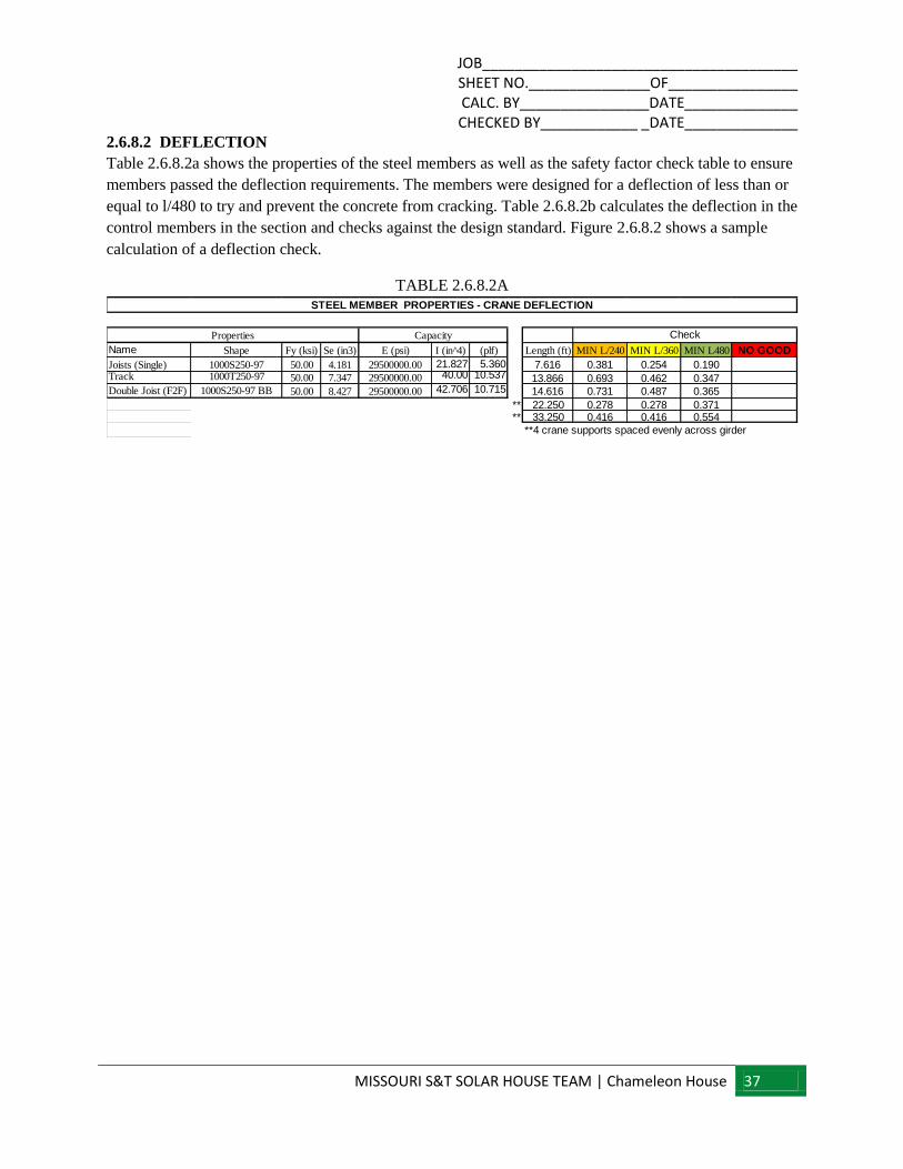
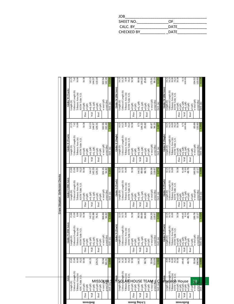
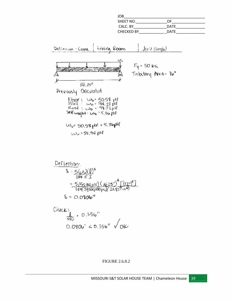
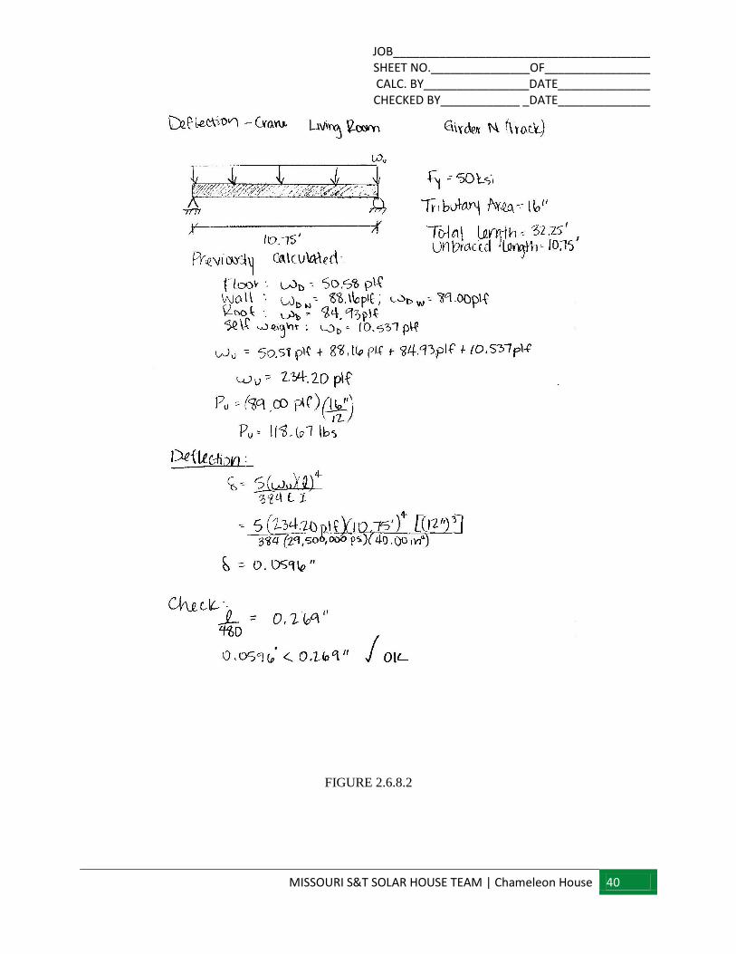
2.6.8.2 DEFLECTION
Table 2.6.8.2a shows the properties of the steel members as well as the safety factor check table to ensure
members passed the deflection requirements. The members were designed for a deflection of less than or
equal to l/480 to try and prevent the concrete from cracking. Table 2.6.8.2b calculates the deflection in the
control members in the section and checks against the design standard. Figure 2.6.8.2 shows a sample
calculation of a deflection check.
TABLE 2.6.8.2A
Name Shape Fy (ksi) Se (in3) E (psi) I (in^4) (plf) Length (ft) MIN L/240 MIN L/360 MIN L480 NO GOOD
Joists (Single) 1000S250-97 50.00 4.181 29500000.00 21.827 5.360 7.616 0.381 0.254 0.190Track 1000T250-97 50.00 7.347 29500000.00 40.00 10.537 13.866 0.693 0.462 0.347Double Joist (F2F) 1000S250-97 BB 50.00 8.427 29500000.00 42.706 10.715 14.616 0.731 0.487 0.365
** 22.250 0.278 0.278 0.371** 33.250 0.416 0.416 0.554
**4 crane supports spaced evenly across girder
STEEL MEMBER PROPERTIES - CRANE DEFLECTION
Properties Capacity Check
JOB_______________________________________ SHEET NO._______________OF________________ CALC. BY________________DATE______________ CHECKED BY____________ _DATE______________
MISSOURI S&T SOLAR HOUSE TEAM | Chameleon House 38
TABLE 2.6.8.2B
Length
(ft
)15.0
0L
ength
(ft
)15.0
0L
ength
(ft
)15.0
0L
ength
(ft
)22.2
5L
ength
(ft
)22.2
5
Unbra
ced L
ength
(ft
)15.0
0U
nbra
ced L
ength
(ft
)15.0
0U
nbra
ced L
ength
(ft
)15.0
0U
nbra
ced L
ength
(ft
)7.4
2U
nbra
ced L
ength
(ft
)7.4
2
Tri
buta
ry A
rea (
in)
16.0
0T
ributa
ry A
rea (
in)
8.0
0T
ributa
ry A
rea (
in)
8.0
0T
ributa
ry A
rea (
in)
16.0
0T
ributa
ry A
rea (
in)
16.0
0
AIS
C T
able
3-2
3.
19,2
2A
ST
M T
able
3-2
3.
19,2
2A
ST
M T
able
3-2
3.
19,2
2A
ST
M T
able
3-2
3.
AS
TM
Table
3-2
3.
wd (
plf
)50.5
8w
d (
plf
)50.5
8w
d (
plf
)50.5
8w
d (
plf
)50.5
8w
d (
plf
)50.5
8
wl (p
lf)
wl (p
lf)
wl (p
lf)
wl (p
lf)
wl (p
lf)
wd (
plf
)142.2
3w
dE (
plf
)142.2
3w
dS (
plf
)144.3
7w
dE (
plf
)142.2
3w
dE (
plf
)142.2
3
wl (p
lf)
wd
N (
plf
)231.9
8w
dE (
plf
)142.2
3w
dS (
plf
)144.3
7w
dS (
plf
)144.3
7
wd (
plf
)129.2
1w
d (
plf
)76.4
1w
d (
plf
)129.2
1w
d (
plf
)129.2
1w
d (
plf
)119.1
9
wl (p
lf)
wl (p
lf)
wl (p
lf)
wl (p
lf)
wl (p
lf)
w t
ota
l (p
lf)
55.9
4w
tota
l (p
lf)
369.6
9w
tota
l (p
lf)
324.1
5w
tota
l (p
lf)
332.5
5w
tota
l (p
lf)
322.5
4
p t
ota
l (l
bs)
361.9
1p t
ota
l (l
bs)
94.8
2p t
ota
l (l
bs)
94.8
2p t
ota
l (l
bs)
192.4
9p t
ota
l (l
bs)
192.4
9
Defl
. (i
n)
0.0
990
Defl
. (i
n)
0.3
343
Defl
. (i
n)
0.2
931
Defl
. (i
n)
0.0
192
Defl
. (i
n)
0.0
186
Length
(ft
)14.2
5L
ength
(ft
)32.2
5L
ength
(ft
)32.2
5L
ength
(ft
)14.2
5L
ength
(ft
)14.2
5
Unbra
ced L
ength
(ft
)14.2
5U
nbra
ced L
ength
(ft
)10.7
5U
nbra
ced L
ength
(ft
)10.7
5U
nbra
ced L
ength
(ft
)14.2
5U
nbra
ced L
ength
(ft
)14.2
5
Tri
buta
ry A
rea (
in)
16.0
0T
ributa
ry A
rea (
in)
16.0
0T
ributa
ry A
rea (
in)
16.0
0T
ributa
ry A
rea (
in)
8.0
0T
ributa
ry A
rea (
in)
8.0
0
AS
TM
Table
3-2
3.
19,2
2A
ST
M T
able
3-2
3.
AS
TM
Table
3-2
3.
AS
TM
Table
3-2
3.
19,2
2A
ST
M T
able
3-2
3.
19,2
2
wd (
plf
)50.5
8w
d (
plf
)50.5
8w
d (
plf
)50.5
8w
d (
plf
)50.5
8w
d (
plf
)50.5
8
wl (p
lf)
wl (p
lf)
wl (p
lf)
wl (p
lf)
wl (p
lf)
wd (
plf
)144.2
2w
dN (
plf
)88.1
6w
dS (
plf
)144.2
2w
dE (
plf
)9.7
5w
dW
(plf
)89.0
0
wl (p
lf)
wd
W (
plf
)89.0
0w
dW
(plf
)89.0
0w
dS (
plf
)144.2
2w
dS (
plf
)144.2
2
wd (
plf
)98.7
3w
d (
plf
)84.9
3w
d (
plf
)98.7
3w
d (
plf
)25.6
2w
d (
plf
)25.6
2
wl (p
lf)
wl (p
lf)
wl (p
lf)
wl (p
lf)
wl (p
lf)
w t
ota
l (p
lf)
55.9
4w
tota
l (p
lf)
234.2
0w
tota
l (p
lf)
304.0
6w
tota
l (p
lf)
60.8
7w
tota
l (p
lf)
175.9
1
p t
ota
l (l
bs)
323.9
3p t
ota
l (l
bs)
118.6
7p t
ota
l (l
bs)
118.6
7p t
ota
l (l
bs)
96.1
5p t
ota
l (l
bs)
96.1
5
Defl
. (i
n)
0.0
806
Defl
. (i
n)
0.0
596
Defl
. (i
n)
0.0
774
Defl
. (i
n)
0.0
877
Defl
. (i
n)
0.1
295
Length
(ft
)8.0
0L
ength
(ft
)32.2
5L
ength
(ft
)32.2
5L
ength
(ft
)14.2
5L
ength
(ft
)14.2
5U
nbra
ced L
ength
(ft
)8.0
0U
nbra
ced L
ength
(ft
)10.7
5U
nbra
ced L
ength
(ft
)10.7
5U
nbra
ced L
ength
(ft
)14.2
5U
nbra
ced L
ength
(ft
)14.2
5T
ributa
ry A
rea (
in)
16.0
0T
ributa
ry A
rea (
in)
16.0
0T
ributa
ry A
rea (
in)
16.0
0T
ributa
ry A
rea (
in)
16.0
0T
ributa
ry A
rea (
in)
16.0
0A
ST
M T
able
3-2
3.
19,2
2A
ST
M T
able
3-2
3.
AS
TM
Table
3-2
3.
AS
TM
Table
3-2
3.
19,2
2A
ST
M T
able
3-2
3.
19,2
2w
d (
plf
)50.5
8w
d (
plf
)50.5
8w
d (
plf
)50.5
8w
d (
plf
)50.5
8w
d (
plf
)50.5
8w
l (p
lf)
wl (p
lf)
wl (p
lf)
wl (p
lf)
wl (p
lf)
wd (
plf
)100.4
5w
dN (
plf
)100.4
5w
dS (
plf
)61.0
0w
dE (
plf
)9.7
5w
dW
(plf
)9.1
3w
l (p
lf)
wd
W (
plf
)9.1
3w
dW
(plf
)9.1
3w
dN (
plf
)100.4
5w
dN (
plf
)100.4
5
wd (
plf
)48.7
5w
d (
plf
)48.7
5w
d (
plf
)48.7
5w
d (
plf
)w
d (
plf
)
wl (p
lf)
wl (p
lf)
wl (p
lf)
wl (p
lf)
wl (p
lf)
w t
ota
l (p
lf)
55.9
4w
tota
l (p
lf)
199.7
8w
tota
l (p
lf)
160.3
3w
tota
l (p
lf)
65.6
9w
tota
l (p
lf)
154.5
2
p t
ota
l (l
bs)
198.9
4p t
ota
l (l
bs)
12.1
7p t
ota
l (l
bs)
12.1
7p t
ota
l (l
bs)
133.9
3p t
ota
l (l
bs)
133.9
3
Defl
. (i
n)
0.0
080
Defl
. (i
n)
0.0
509
Defl
. (i
n)
0.0
408
Defl
. (i
n)
0.0
946
Defl
. (i
n)
0.1
138
Wall
Wall
Wall
Roof
Roof
Roof
Jo
ists
Gir
de
r N
(T
rack
)G
ird
er
S (
Tra
ck
)
Flo
or
Flo
or
Flo
or
Roof
Roof
Wall
Wall
Wall
Roof
Roof
Roof
Flo
or
Flo
or
Flo
or
BathroomLiving RoomBedroom
Gir
de
r W
(T
rack
)
Gir
de
r W
(D
bl
Jo
ist)
Gir
de
r W
(D
bl
Jo
ist)
Gir
de
r E
(S
ing
le)
Gir
de
r E
(S
ing
le)
Gir
de
r E
(T
rack
)
Wall
Wall
Wall
Flo
or
Flo
or
Flo
or
Roof
Roof
Wall
Flo
or
Cra
ne
Sit
uati
on
- D
efl
ecto
in C
he
cks
Jo
ists
Gir
de
r N
(D
bl
Jo
ist)
Gir
de
r S
(D
bl
Jo
ist)
DEMAND
Jo
ists
Gir
de
r N
(T
rack
)G
ird
er
S (
Tra
ck
)
Roof
Wall
Flo
or
Roof
Wall
Flo
or
Roof
Wall
Flo
or
Roof
Wall
Flo
or
Roof
Wall
Flo
or
JOB_______________________________________ SHEET NO._______________OF________________ CALC. BY________________DATE______________ CHECKED BY____________ _DATE______________
MISSOURI S&T SOLAR HOUSE TEAM | Chameleon House 39
FIGURE 2.6.8.2
JOB_______________________________________ SHEET NO._______________OF________________ CALC. BY________________DATE______________ CHECKED BY____________ _DATE______________
MISSOURI S&T SOLAR HOUSE TEAM | Chameleon House 40
FIGURE 2.6.8.2
JOB_______________________________________ SHEET NO._______________OF________________ CALC. BY________________DATE______________ CHECKED BY____________ _DATE______________
MISSOURI S&T SOLAR HOUSE TEAM | Chameleon House 41
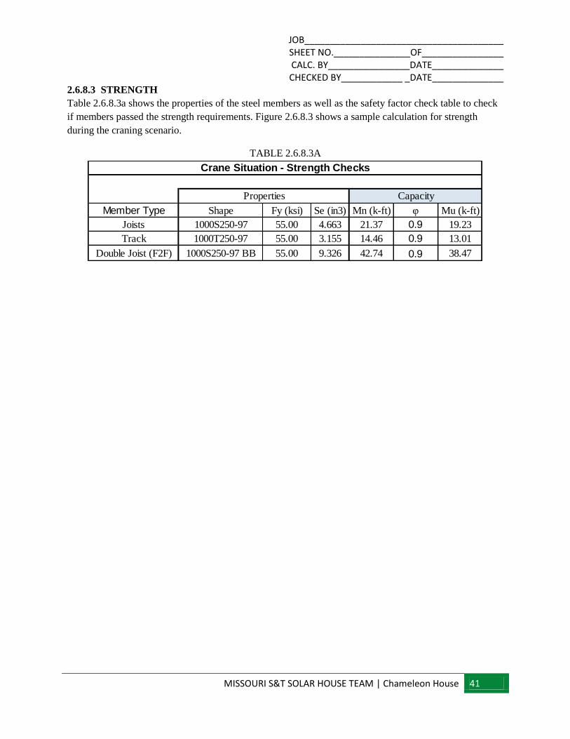
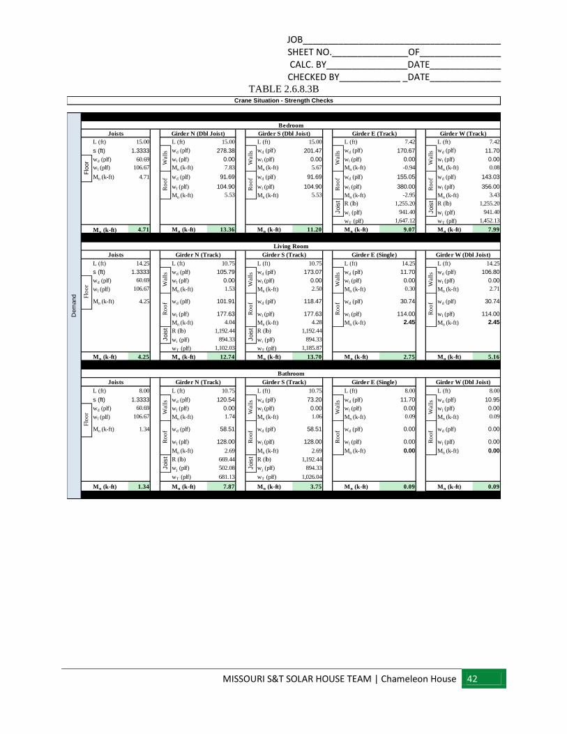
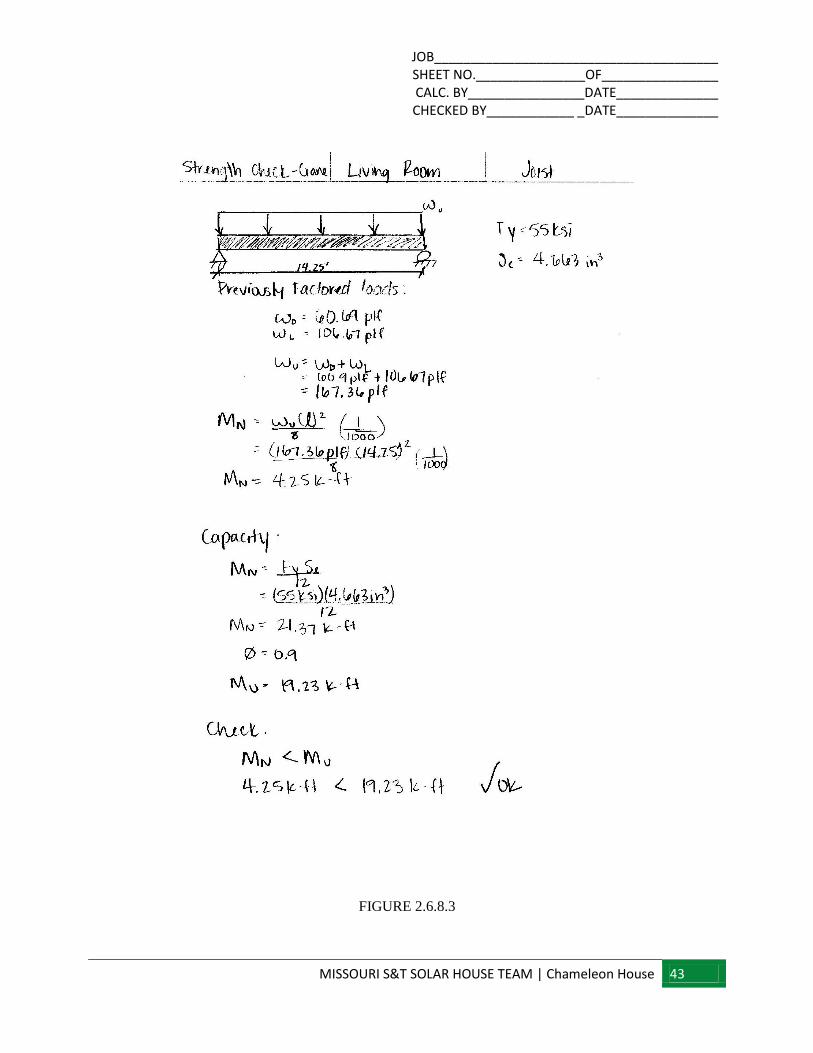
2.6.8.3 STRENGTH
Table 2.6.8.3a shows the properties of the steel members as well as the safety factor check table to check
if members passed the strength requirements. Figure 2.6.8.3 shows a sample calculation for strength
during the craning scenario.
TABLE 2.6.8.3A
Member Type Shape Fy (ksi) Se (in3) Mn (k-ft) φ Mu (k-ft)
Joists 1000S250-97 55.00 4.663 21.37 0.9 19.23
Track 1000T250-97 55.00 3.155 14.46 0.9 13.01
Double Joist (F2F) 1000S250-97 BB 55.00 9.326 42.74 0.9 38.47
Crane Situation - Strength Checks
Properties Capacity
JOB_______________________________________ SHEET NO._______________OF________________ CALC. BY________________DATE______________ CHECKED BY____________ _DATE______________
MISSOURI S&T SOLAR HOUSE TEAM | Chameleon House 42
TABLE 2.6.8.3B
L (ft) 15.00 L (ft) 15.00 L (ft) 15.00 L (ft) 7.42 L (ft) 7.42
s (ft) 1.3333 wd (plf) 278.38 wd (plf) 201.47 wd (plf) 170.67 wd (plf) 11.70
wd (plf) 60.69 wl (plf) 0.00 wl (plf) 0.00 wl (plf) 0.00 wl (plf) 0.00
wl (plf) 106.67 Mn (k-ft) 7.83 Mn (k-ft) 5.67 Mn (k-ft) -0.94 Mn (k-ft) 0.08
Mn (k-ft) 4.71 wd (plf) 91.69 wd (plf) 91.69 wd (plf) 155.05 wd (plf) 143.03
wl (plf) 104.90 wl (plf) 104.90 wl (plf) 380.00 wl (plf) 356.00
Mn (k-ft) 5.53 Mn (k-ft) 5.53 Mn (k-ft) -2.95 Mn (k-ft) 3.43
R (lb) 1,255.20 R (lb) 1,255.20
wj (plf) 941.40 wj (plf) 941.40
wT (plf) 1,647.12 wT (plf) 1,452.13
Mn (k-ft) 4.71 Mn (k-ft) 13.36 Mn (k-ft) 11.20 Mn (k-ft) 9.07 Mn (k-ft) 7.99
L (ft) 14.25 L (ft) 10.75 L (ft) 10.75 L (ft) 14.25 L (ft) 14.25
s (ft) 1.3333 wd (plf) 105.79 wd (plf) 173.07 wd (plf) 11.70 wd (plf) 106.80
wd (plf) 60.69 wl (plf) 0.00 wl (plf) 0.00 wl (plf) 0.00 wl (plf) 0.00
wl (plf) 106.67 Mn (k-ft) 1.53 Mn (k-ft) 2.50 Mn (k-ft) 0.30 Mn (k-ft) 2.71
Mn (k-ft) 4.25 wd (plf) 101.91 wd (plf) 118.47 wd (plf) 30.74 wd (plf) 30.74
wl (plf) 177.63 wl (plf) 177.63 wl (plf) 114.00 wl (plf) 114.00
Mn (k-ft) 4.04 Mn (k-ft) 4.28 Mn (k-ft) 2.45 Mn (k-ft) 2.45
R (lb) 1,192.44 R (lb) 1,192.44
wj (plf) 894.33 wj (plf) 894.33
wT (plf) 1,102.03 wT (plf) 1,185.87
Mn (k-ft) 4.25 Mn (k-ft) 12.74 Mn (k-ft) 13.70 Mn (k-ft) 2.75 Mn (k-ft) 5.16
L (ft) 8.00 L (ft) 10.75 L (ft) 10.75 L (ft) 8.00 L (ft) 8.00
s (ft) 1.3333 wd (plf) 120.54 wd (plf) 73.20 wd (plf) 11.70 wd (plf) 10.95
wd (plf) 60.69 wl (plf) 0.00 wl (plf) 0.00 wl (plf) 0.00 wl (plf) 0.00
wl (plf) 106.67 Mn (k-ft) 1.74 Mn (k-ft) 1.06 Mn (k-ft) 0.09 Mn (k-ft) 0.09
Mn (k-ft) 1.34 wd (plf) 58.51 wd (plf) 58.51 wd (plf) 0.00 wd (plf) 0.00
wl (plf) 128.00 wl (plf) 128.00 wl (plf) 0.00 wl (plf) 0.00
Mn (k-ft) 2.69 Mn (k-ft) 2.69 Mn (k-ft) 0.00 Mn (k-ft) 0.00
R (lb) 669.44 R (lb) 1,192.44
wj (plf) 502.08 wj (plf) 894.33
wT (plf) 681.13 wT (plf) 1,026.04
Mn (k-ft) 1.34 Mn (k-ft) 7.87 Mn (k-ft) 3.75 Mn (k-ft) 0.09 Mn (k-ft) 0.09
Girder W (Track)
Flo
or
Ro
of
Ro
of
Ro
of
Wall
s
Wall
s
Wall
s
Wall
s
Girder S (Track)
Bathroom
Flo
or
Ro
of
Ro
of
Jois
t
Jois
t
Jois
tW
all
s
Wall
s
Jois
t
Jois
t
Wall
s
Wall
s
Girder E (Single) Girder W (Dbl Joist)Joists Girder N (Track)
Ro
of
Wall
s
Ro
of
Ro
of
Ro
of
Ro
of
Wall
s
Girder N (Track) Girder S (Track)Joists Girder E (Single) Girder W (Dbl Joist)R
oo
f
Ro
of
Dem
and
Crane Situation - Strength Checks
Living Room
Flo
or
Jois
t
Wall
s
Wall
s
Bedroom
Girder N (Dbl Joist)Joists Girder S (Dbl Joist) Girder E (Track)
JOB_______________________________________ SHEET NO._______________OF________________ CALC. BY________________DATE______________ CHECKED BY____________ _DATE______________
MISSOURI S&T SOLAR HOUSE TEAM | Chameleon House 43
FIGURE 2.6.8.3

JOB_______________________________________ SHEET NO._______________OF________________ CALC. BY________________DATE______________ CHECKED BY____________ _DATE______________
MISSOURI S&T SOLAR HOUSE TEAM | Chameleon House 44
FIRGURE 2.6.8.3
JOB_______________________________________ SHEET NO._______________OF________________ CALC. BY________________DATE______________ CHECKED BY____________ _DATE______________
MISSOURI S&T SOLAR HOUSE TEAM | Chameleon House 45
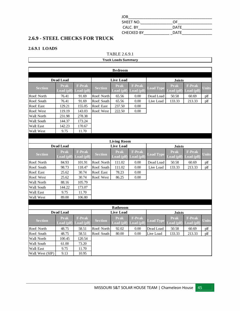
2.6.9 - STEEL CHECKS FOR TRUCK
2.6.9.1 LOADS
TABLE 2.6.9.1
SectionPeak
Load (plf)
F-Peak
Load (plf)Section
Peak
Load (plf)
F-Peak
Load (plf)Load Type
Peak
Load (plf)
F-Peak
Load (plf)Units
Roof: North 76.41 91.69 Roof: North 65.56 0.00 Dead Load 50.58 60.69 plf
Roof: South 76.41 91.69 Roof: South 65.56 0.00 Live Load 133.33 213.33 plf
Roof: East 129.21 155.05 Roof: East 237.50 0.00
Roof: West 119.19 143.03 Roof: West 222.50 0.00
Wall: North 231.98 278.38
Wall: South 144.37 173.24
Wall: East 142.23 170.67
Wall: West 9.75 11.70
SectionPeak
Load (plf)
F-Peak
Load (plf)Section
Peak
Load (plf)
F-Peak
Load (plf)Load Type
Peak
Load (plf)
F-Peak
Load (plf)Units
Roof: North 84.93 101.91 Roof: North 111.02 0.00 Dead Load 50.58 60.69 plf
Roof: South 98.73 118.47 Roof: South 111.02 0.00 Live Load 133.33 213.33 plf
Roof: East 25.62 30.74 Roof: East 78.23 0.00
Roof: West 25.62 30.74 Roof: West 86.25 0.00
Wall: North 88.16 105.79
Wall: South 144.22 173.07
Wall: East 9.75 11.70
Wall: West 89.00 106.80
SectionPeak
Load (plf)
F-Peak
Load (plf)Section
Peak
Load (plf)
F-Peak
Load (plf)Load Type
Peak
Load (plf)
F-Peak
Load (plf)Units
Roof: North 48.75 58.51 Roof: North 92.02 0.00 Dead Load 50.58 60.69 plf
Roof: South 48.75 58.51 Roof: South 80.00 0.00 Live Load 133.33 213.33 plf
Wall: North 100.45 120.54
Wall: South 61.00 73.20
Wall: East 9.75 11.70
Wall: West (SIP) 9.13 10.95
Truck Loads Summary
Living Room
Bedroom
Dead Load Live Load Joists
Dead Load Live Load Joists
Bathroom
Dead Load Live Load Joists
JOB_______________________________________ SHEET NO._______________OF________________ CALC. BY________________DATE______________ CHECKED BY____________ _DATE______________
MISSOURI S&T SOLAR HOUSE TEAM | Chameleon House 46
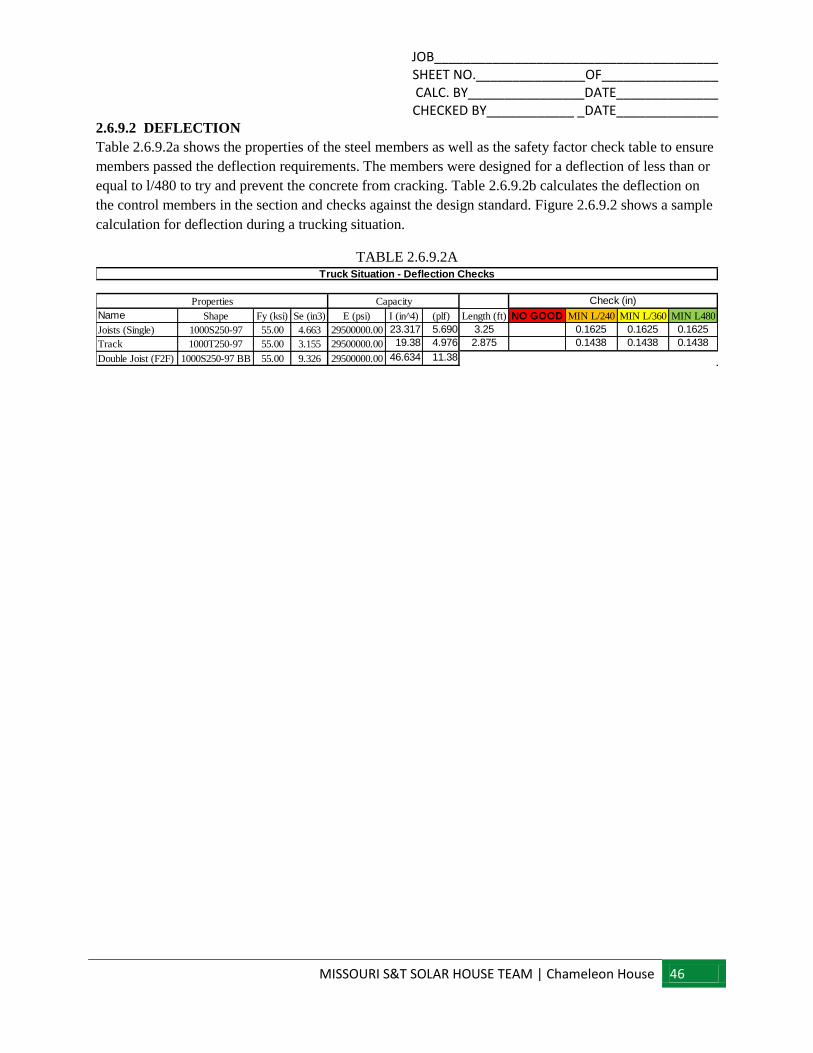
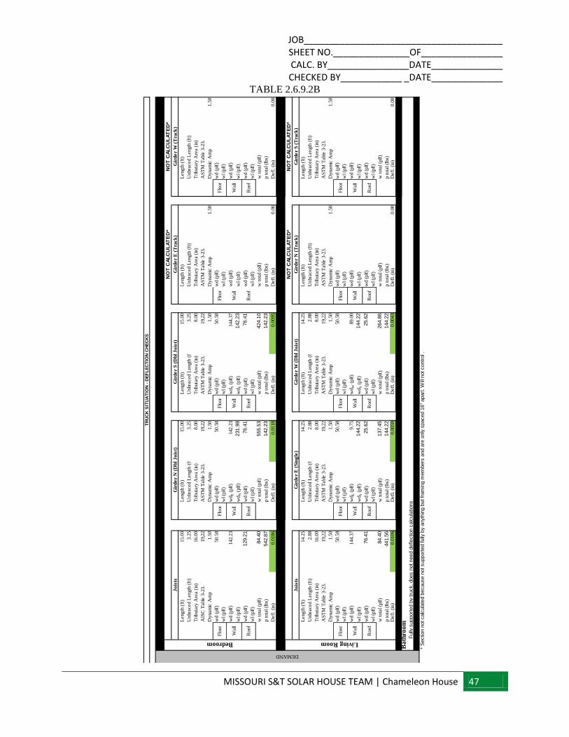
2.6.9.2 DEFLECTION
Table 2.6.9.2a shows the properties of the steel members as well as the safety factor check table to ensure
members passed the deflection requirements. The members were designed for a deflection of less than or
equal to l/480 to try and prevent the concrete from cracking. Table 2.6.9.2b calculates the deflection on
the control members in the section and checks against the design standard. Figure 2.6.9.2 shows a sample
calculation for deflection during a trucking situation.
TABLE 2.6.9.2A
Name Shape Fy (ksi) Se (in3) E (psi) I (in^4) (plf) Length (ft) NO GOOD MIN L/240 MIN L/360 MIN L480
Joists (Single) 1000S250-97 55.00 4.663 29500000.00 23.317 5.690 3.25 0.1625 0.1625 0.1625
Track 1000T250-97 55.00 3.155 29500000.00 19.38 4.976 2.875 0.1438 0.1438 0.1438
Double Joist (F2F) 1000S250-97 BB 55.00 9.326 29500000.00 46.634 11.38
Truck Situation - Deflection Checks
Properties Capacity Check (in)
JOB_______________________________________ SHEET NO._______________OF________________ CALC. BY________________DATE______________ CHECKED BY____________ _DATE______________
MISSOURI S&T SOLAR HOUSE TEAM | Chameleon House 47
TABLE 2.6.9.2B
Length
(ft
)15.0
0L
ength
(ft
)15.0
0L
ength
(ft
)15.0
0L
ength
(ft
)L
ength
(ft
)
Unbra
ced L
ength
(ft
)3.2
5U
nbra
ced L
ength
(ft
)3.2
5U
nbra
ced L
ength
(ft
)3.2
5U
nbra
ced L
ength
(ft
)U
nbra
ced L
ength
(ft
)
Tri
buta
ry A
rea (
in)
16.0
0T
ributa
ry A
rea (
in)
8.0
0T
ributa
ry A
rea (
in)
8.0
0T
ributa
ry A
rea (
in)
Tri
buta
ry A
rea (
in)
AIS
C T
able
3-2
3.
19,2
2A
ST
M T
able
3-2
3.
19,2
2A
ST
M T
able
3-2
3.
19,2
2A
ST
M T
able
3-2
3.
AS
TM
Table
3-2
3.
Dynam
ic A
mp
1.5
0D
ynam
ic A
mp
1.5
0D
ynam
ic A
mp
1.5
0D
ynam
ic A
mp
1.5
0D
ynam
ic A
mp
1.5
0
wd (
plf
)50.5
8w
d (
plf
)50.5
8w
d (
plf
)50.5
8w
d (
plf
)w
d (
plf
)
wl (p
lf)
wl (p
lf)
wl (p
lf)
wl (p
lf)
wl (p
lf)
wd (
plf
)142.2
3w
dE (
plf
)142.2
3w
dS (
plf
)144.3
7w
d (
plf
)w
d (
plf
)
wl (p
lf)
wd
N (
plf
)231.9
8w
dE (
plf
)142.2
3w
l (p
lf)
wl (p
lf)
wd (
plf
)129.2
1w
d (
plf
)76.4
1w
d (
plf
)76.4
1w
d (
plf
)w
d (
plf
)
wl (p
lf)
wl (p
lf)
wl (p
lf)
wl (p
lf)
wl (p
lf)
w t
ota
l (p
lf)
84.4
0w
tota
l (p
lf)
555.5
3w
tota
l (p
lf)
424.1
0w
tota
l (p
lf)
w t
ota
l (p
lf)
p t
ota
l (l
bs)
542.8
7p t
ota
l (l
bs)
142.2
3p t
ota
l (l
bs)
142.2
3p t
ota
l (l
bs)
p t
ota
l (l
bs)
Defl
. (i
n)
0.0
186
Defl
. (i
n)
0.0
118
Defl
. (i
n)
0.0
095
Defl
. (i
n)
0.0
0D
efl
. (i
n)
0.0
0
Length
(ft
)14.2
5L
ength
(ft
)14.2
5L
ength
(ft
)14.2
5L
ength
(ft
)L
ength
(ft
)
Unbra
ced L
ength
(ft
)2.8
8U
nbra
ced L
ength
(ft
)2.8
8U
nbra
ced L
ength
(ft
)2.8
8U
nbra
ced L
ength
(ft
)U
nbra
ced L
ength
(ft
)
Tri
buta
ry A
rea (
in)
16.0
0T
ributa
ry A
rea (
in)
8.0
0T
ributa
ry A
rea (
in)
8.0
0T
ributa
ry A
rea (
in)
Tri
buta
ry A
rea (
in)
AS
TM
Table
3-2
3.
19,2
2A
ST
M T
able
3-2
3.
19,2
2A
ST
M T
able
3-2
3.
19,2
2A
ST
M T
able
3-2
3.
AS
TM
Table
3-2
3.
Dynam
ic A
mp
1.5
0D
ynam
ic A
mp
1.5
0D
ynam
ic A
mp
1.5
0D
ynam
ic A
mp
1.5
0D
ynam
ic A
mp
1.5
0
wd (
plf
)50.5
8w
d (
plf
)50.5
8w
d (
plf
)50.5
8w
d (
plf
)w
d (
plf
)
wl (p
lf)
wl (p
lf)
wl (p
lf)
wl (p
lf)
wl (p
lf)
wd (
plf
)144.3
7w
dE (
plf
)9.7
5w
dW
(plf
)89.0
0w
d (
plf
)w
d (
plf
)
wl (p
lf)
wd
S (
plf
)144.2
2w
dS (
plf
)144.2
2w
l (p
lf)
wl (p
lf)
wd (
plf
)76.4
1w
d (
plf
)25.6
2w
d (
plf
)25.6
2w
d (
plf
)w
d (
plf
)
wl (p
lf)
wl (p
lf)
wl (p
lf)
wl (p
lf)
wl (p
lf)
w t
ota
l (p
lf)
84.4
0w
tota
l (p
lf)
137.4
5w
tota
l (p
lf)
264.8
6w
tota
l (p
lf)
w t
ota
l (p
lf)
p t
ota
l (l
bs)
441.5
6p t
ota
l (l
bs)
144.2
2p t
ota
l (l
bs)
144.2
2p t
ota
l (l
bs)
p t
ota
l (l
bs)
Defl
. (i
n)
0.0
106
Defl
. (i
n)
0.0
059
Defl
. (i
n)
0.0
043
Defl
. (i
n)
0.0
0D
efl
. (i
n)
0.0
0
Ba
thro
om
Fully
support
ed b
y tr
uck,
does n
ot need d
efle
ctio
n c
alc
ula
tions
Wall
Roof
Flo
or
Wall
Roof
Wall
Roof
Roof
Flo
or
Wall
Jo
ists
Wall
Gir
de
r S
(T
rack
)G
ird
er
N (
Tra
ck
)
NO
T C
AL
CU
LA
TE
D*
NO
T C
AL
CU
LA
TE
D*
Roof
Wall
Flo
or
Roof
Flo
or
Roof
Wall
Flo
or
TR
UC
K S
ITU
AT
ION
- D
EF
LE
CT
ION
CH
EC
KS
Wall
Flo
or
Flo
or
Flo
or
Wall
NO
T C
AL
CU
LA
TE
D*
NO
T C
AL
CU
LA
TE
D*
Gir
de
r W
(T
rack
)
Gir
de
r W
(D
bl
Jo
ist)
Gir
de
r E
(S
ing
le)
Gir
de
r E
(T
rack
)
Flo
or
* S
ectio
n n
ot calc
ula
ted b
ecause n
ot support
ed fully
by
anyt
hin
g b
ut fr
am
ing m
em
bers
and a
re o
nly
spaced 1
6"
apart
. W
ill n
ot contr
ol .
Flo
or
Roof
Wall
Roof
Roof
Jo
ists
Gir
de
r N
(D
bl
Jo
ist)
DEMAND
Living RoomBedroom
Gir
de
r S
(D
bl
Jo
ist)
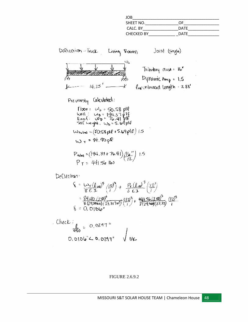
JOB_______________________________________ SHEET NO._______________OF________________ CALC. BY________________DATE______________ CHECKED BY____________ _DATE______________
MISSOURI S&T SOLAR HOUSE TEAM | Chameleon House 48
FIGURE 2.6.9.2
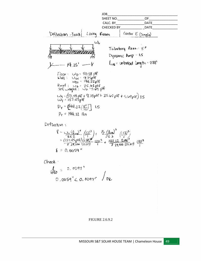
JOB_______________________________________ SHEET NO._______________OF________________ CALC. BY________________DATE______________ CHECKED BY____________ _DATE______________
MISSOURI S&T SOLAR HOUSE TEAM | Chameleon House 49
FIGURE 2.6.9.2
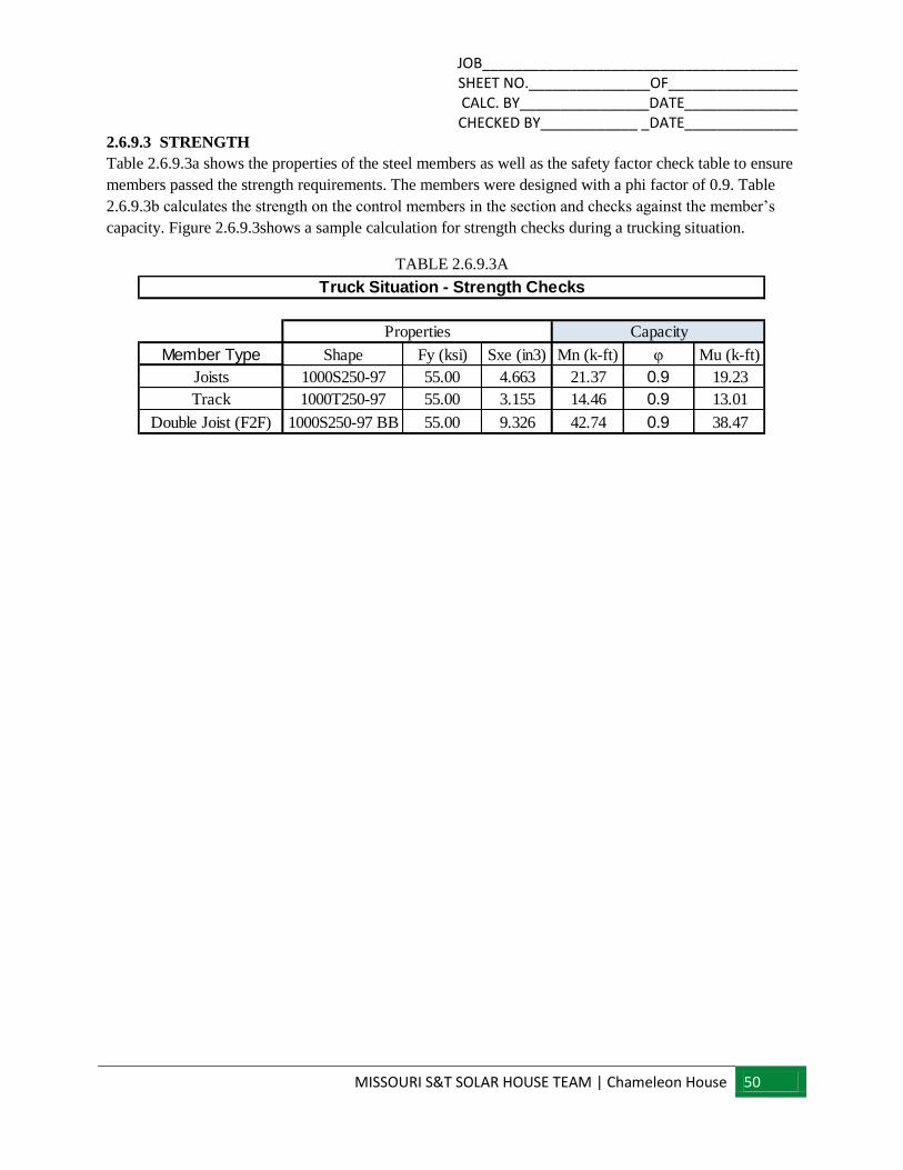
JOB_______________________________________ SHEET NO._______________OF________________ CALC. BY________________DATE______________ CHECKED BY____________ _DATE______________
MISSOURI S&T SOLAR HOUSE TEAM | Chameleon House 50
2.6.9.3 STRENGTH
Table 2.6.9.3a shows the properties of the steel members as well as the safety factor check table to ensure
members passed the strength requirements. The members were designed with a phi factor of 0.9. Table
2.6.9.3b calculates the strength on the control members in the section and checks against the member’s
capacity. Figure 2.6.9.3shows a sample calculation for strength checks during a trucking situation.
TABLE 2.6.9.3A
Member Type Shape Fy (ksi) Sxe (in3) Mn (k-ft) φ Mu (k-ft)
Joists 1000S250-97 55.00 4.663 21.37 0.9 19.23
Track 1000T250-97 55.00 3.155 14.46 0.9 13.01
Double Joist (F2F) 1000S250-97 BB 55.00 9.326 42.74 0.9 38.47
Properties Capacity
Truck Situation - Strength Checks
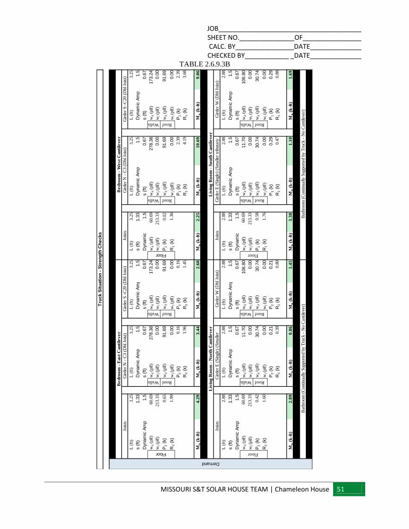
JOB_______________________________________ SHEET NO._______________OF________________ CALC. BY________________DATE______________ CHECKED BY____________ _DATE______________
MISSOURI S&T SOLAR HOUSE TEAM | Chameleon House 51
TABLE 2.6.9.3B
L (
ft)
3.2
5L
(ft
)3.2
5L
(ft
)3.2
5L
(ft
)3.2
5L
(ft
)3.2
5L
(ft
)3.2
5
s (
ft)
1.3
3D
ynam
ic A
mp
1.5
Dyn
am
ic A
mp
1.5
s (
ft)
1.3
3D
ynam
ic A
mp
1.5
Dyn
am
ic A
mp
1.5
Dyn
am
ic A
mp
1.5
s (
ft)
0.6
7s (
ft)
0.6
7D
ynam
ic A
mp
1.5
s (
ft)
0.6
7s (
ft)
0.6
7
wd (
plf
)60.6
9w
d (
plf
)278.3
8w
d (
plf
)173.2
4w
d (
plf
)60.6
9w
d (
plf
)278.3
8w
d (
plf
)173.2
4
wl (p
lf)
213.3
3w
l (p
lf)
0.0
0w
l (p
lf)
0.0
0w
l (p
lf)
213.3
3w
l (p
lf)
0.0
0w
l (p
lf)
0.0
0
P2 (
k)0.6
5w
d (
plf
)91.6
9w
d (
plf
)91.6
9P
1 (
k)0.0
2w
d (
plf
)91.6
9w
d (
plf
)91.6
9
R2 (
k)1.9
9w
l (p
lf)
0.0
0w
l (p
lf)
0.0
0R
1 (
k)1.3
6w
l (p
lf)
0.0
0w
l (p
lf)
0.0
0
P2 (
k)0.1
6P
2 (
k)0.1
6P
1 (
k)2.3
9P
1 (
k)2.3
9
R2 (
k)1.9
6R
2 (
k)1.4
5R
1 (
k)4.1
9R
1 (
k)3.6
8
Mn (
k-f
t)4
.29
Mn (
k-f
t)3
.44
Mn (
k-f
t)2
.60
Mn (
k-f
t)2
.25
Mn (
k-f
t)1
0.6
9M
n (
k-f
t)9
.86
L (
ft)
2.8
8L
(ft
)2.8
8L
(ft
)2.8
8L
(ft
)2.8
8L
(ft
)2.8
8L
(ft
)2.8
8
s (
ft)
1.3
3D
ynam
ic A
mp
1.5
Dyn
am
ic A
mp
1.5
s (
ft)
1.3
3D
ynam
ic A
mp
1.5
Dyn
am
ic A
mp
1.5
Dyn
am
ic A
mp
1.5
s (
ft)
0.6
7s (
ft)
0.6
7D
ynam
ic A
mp
1.5
s (
ft)
0.6
7s (
ft)
0.6
7
wd (
plf
)60.6
9w
d (
plf
)11.7
0w
d (
plf
)106.8
0w
d (
plf
)60.6
9w
d (
plf
)11.7
0w
d (
plf
)106.8
0
wl (p
lf)
213.3
3w
l (p
lf)
0.0
0w
l (p
lf)
0.0
0w
l (p
lf)
213.3
3w
l (p
lf)
0.0
0w
l (p
lf)
0.0
0
P2 (
k)0.4
2w
d (
plf
)30.7
4w
d (
plf
)30.7
4P
1 (
k)0.5
8w
d (
plf
)30.7
4w
d (
plf
)30.7
4
R2 (
k)1.6
0w
l (p
lf)
0.0
0w
l (p
lf)
0.0
0R
1 (
k)1.7
6w
l (p
lf)
0.0
0w
l (p
lf)
0.0
0
P2 (
k)0.2
1P
2 (
k)0.2
1P
1 (
k)0.2
9P
1 (
k)0.2
9
R2 (
k)0.3
9R
2 (
k)0.8
0R
1 (
k)0.4
7R
1 (
k)0.8
8
Mn (
k-f
t)2
.89
Mn (
k-f
t)0
.86
Mn (
k-f
t)1
.45
Mn (
k-f
t)3
.38
Mn (
k-f
t)1
.10
Mn (
k-f
t)1
.69
Be
dro
om
- E
ast
Can
tile
ve
r
Demand
Jois
tsG
irder
N -
C3 (
Dbl Jo
ist)
Gir
der
S -
C20 (
Dbl Jo
ist)
Floor
Gir
der
E (
Sin
gle
) (S
malle
r G
irder
W (
Dbl Jo
ist)
Walls Roof
Liv
ing
Ro
om
- N
ort
h C
an
tile
ve
r
Jois
ts
Floor
Walls Roof
RoofWalls
Bath
room
(C
ontinually
Support
ed b
y T
ruck -
No C
antile
ver)
Be
dro
om
- W
est
Can
tile
ve
r
Jois
tsG
irder
N -
C3 (
Dbl Jo
ist)
Gir
der
S -
C20 (
Dbl Jo
ist)
Jois
tsG
irder
E (
Sin
gle
) (S
malle
r tr
ibuta
ry
Gir
der
W (
Dbl Jo
ist)
Bath
room
(C
ontinually
Support
ed b
y T
ruck -
No C
antile
ver)
Walls Roof
Floor
Walls Roof
Tru
ck S
itu
ati
on
- S
tre
ng
th C
he
cks
Liv
ing
Ro
om
- S
ou
th C
an
tile
ve
r
Walls Roof
Walls Roof
Floor
RoofWalls
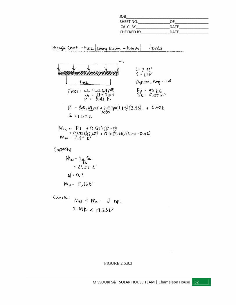
JOB_______________________________________ SHEET NO._______________OF________________ CALC. BY________________DATE______________ CHECKED BY____________ _DATE______________
MISSOURI S&T SOLAR HOUSE TEAM | Chameleon House 52
FIGURE 2.6.9.3
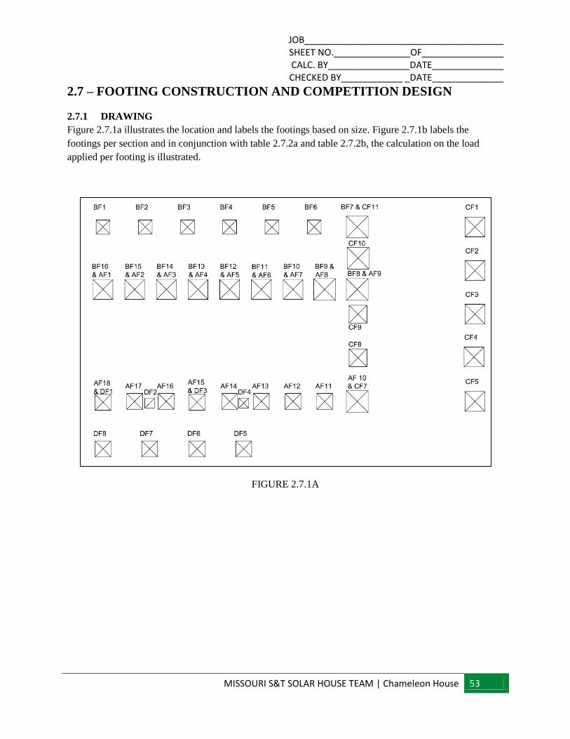
JOB_______________________________________ SHEET NO._______________OF________________ CALC. BY________________DATE______________ CHECKED BY____________ _DATE______________
MISSOURI S&T SOLAR HOUSE TEAM | Chameleon House 53
2.7 – FOOTING CONSTRUCTION AND COMPETITION DESIGN
2.7.1 DRAWING
Figure 2.7.1a illustrates the location and labels the footings based on size. Figure 2.7.1b labels the
footings per section and in conjunction with table 2.7.2a and table 2.7.2b, the calculation on the load
applied per footing is illustrated.
FIGURE 2.7.1A
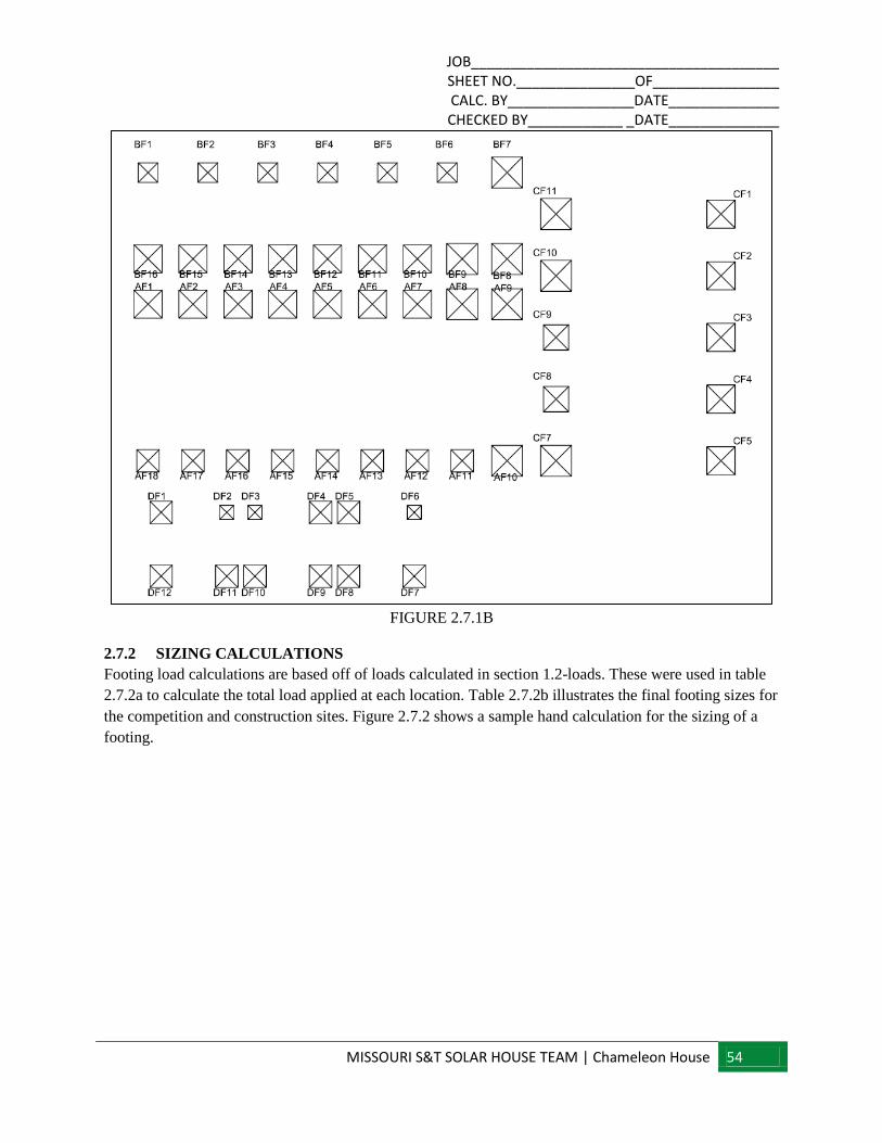
JOB_______________________________________ SHEET NO._______________OF________________ CALC. BY________________DATE______________ CHECKED BY____________ _DATE______________
MISSOURI S&T SOLAR HOUSE TEAM | Chameleon House 54
FIGURE 2.7.1B
2.7.2 SIZING CALCULATIONS
Footing load calculations are based off of loads calculated in section 1.2-loads. These were used in table
2.7.2a to calculate the total load applied at each location. Table 2.7.2b illustrates the final footing sizes for
the competition and construction sites. Figure 2.7.2 shows a sample hand calculation for the sizing of a
footing.
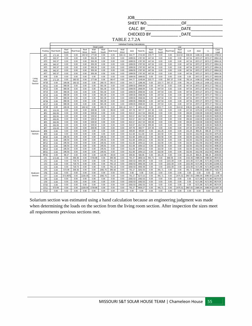
JOB_______________________________________ SHEET NO._______________OF________________ CALC. BY________________DATE______________ CHECKED BY____________ _DATE______________
MISSOURI S&T SOLAR HOUSE TEAM | Chameleon House 55
TABLE 2.7.2A
Solarium section was estimated using a hand calculation because an engineering judgment was made
when determining the loads on the section from the living room section. After inspection the sizes meet
all requirements previous sections met.
Footing Roof NorthRoof
SouthRoof East
Roof
West
Wall
North
Wall
SouthWall East
Wall
WestJoist Total DL
Roof
North
Roof
SouthRoof East
Roof
WestLLR Joist LL
Case
Load
AF1 171.18 0.00 0.00 182.52 177.69 0.00 0.00 634.13 544.77 1710.30 223.77 0.00 0.00 614.53 838.30 1436.13 1436.13 4769.32
AF2 342.37 0.00 0.00 0.00 355.39 0.00 0.00 0.00 1089.55 1787.30 447.54 0.00 0.00 0.00 447.54 2872.27 2872.27 6964.16
AF3 342.37 0.00 0.00 0.00 355.39 0.00 0.00 0.00 1089.55 1787.30 447.54 0.00 0.00 0.00 447.54 2872.27 2872.27 6964.16
AF4 342.37 0.00 0.00 0.00 355.39 0.00 0.00 0.00 1089.55 1787.30 447.54 0.00 0.00 0.00 447.54 2872.27 2872.27 6964.16
AF5 342.37 0.00 0.00 0.00 355.39 0.00 0.00 0.00 1089.55 1787.30 447.54 0.00 0.00 0.00 447.54 2872.27 2872.27 6964.16
AF6 342.37 0.00 0.00 0.00 355.39 0.00 0.00 0.00 1089.55 1787.30 447.54 0.00 0.00 0.00 447.54 2872.27 2872.27 6964.16
AF7 342.37 0.00 0.00 0.00 355.39 0.00 0.00 0.00 1089.55 1787.30 447.54 0.00 0.00 0.00 447.54 2872.27 2872.27 6964.16
AF8 0.00 0.00 0.00 0.00 0.00 0.00 0.00 0.00 1089.55 1089.55 0.00 0.00 0.00 0.00 0.00 2872.27 2872.27 5903.08
AF9 171.18 0.00 182.52 0.00 177.69 0.00 69.47 0.00 544.77 1145.64 223.77 0.00 557.37 0.00 781.14 1436.13 1436.13 4063.15
AF10 0.00 199.00 182.52 0.00 0.00 290.70 69.47 0.00 544.77 1286.46 0.00 223.77 557.37 0.00 781.14 1436.13 1436.13 4232.13
AF11 0.00 398.00 0.00 0.00 0.00 581.39 0.00 0.00 1089.55 2068.94 0.00 447.54 0.00 0.00 447.54 2872.27 2872.27 7302.12
AF12 0.00 398.00 0.00 0.00 0.00 581.39 0.00 0.00 1089.55 2068.94 0.00 447.54 0.00 0.00 447.54 2872.27 2872.27 7302.12
AF13 0.00 398.00 0.00 0.00 0.00 581.39 0.00 0.00 1089.55 2068.94 0.00 447.54 0.00 0.00 447.54 2872.27 2872.27 7302.12
AF14 0.00 398.00 0.00 0.00 0.00 581.39 0.00 0.00 1089.55 2068.94 0.00 447.54 0.00 0.00 447.54 2872.27 2872.27 7302.12
AF15 0.00 398.00 0.00 0.00 0.00 581.39 0.00 0.00 1089.55 2068.94 0.00 447.54 0.00 0.00 447.54 2872.27 2872.27 7302.12
AF16 0.00 398.00 0.00 0.00 0.00 581.39 0.00 0.00 1089.55 2068.94 0.00 447.54 0.00 0.00 447.54 2872.27 2872.27 7302.12
AF17 0.00 398.00 0.00 0.00 0.00 581.39 0.00 0.00 1089.55 2068.94 0.00 447.54 0.00 0.00 447.54 2872.27 2872.27 7302.12
AF18 0.00 199.00 0.00 182.52 0.00 290.70 0.00 634.13 544.77 1851.12 0.00 223.77 0.00 614.53 838.30 1436.13 1436.13 4938.30
BF1 131.03 0.00 0.00 0.00 269.96 0.00 39.00 0.00 407.78 847.77 247.30 0.00 0.00 0.00 247.30 1075.00 1075.00 2860.97
BF2 262.05 0.00 0.00 0.00 539.92 0.00 0.00 0.00 815.57 1617.54 494.60 0.00 0.00 0.00 494.60 2150.00 2150.00 5628.35
BF3 262.05 0.00 0.00 0.00 539.92 0.00 0.00 0.00 815.57 1617.54 494.60 0.00 0.00 0.00 494.60 2150.00 2150.00 5628.35
BF4 262.05 0.00 0.00 0.00 539.92 0.00 0.00 0.00 815.57 1617.54 494.60 0.00 0.00 0.00 494.60 2150.00 2150.00 5628.35
BF5 262.05 0.00 0.00 0.00 539.92 0.00 0.00 0.00 815.57 1617.54 494.60 0.00 0.00 0.00 494.60 2150.00 2150.00 5628.35
BF6 262.05 0.00 0.00 0.00 539.92 0.00 0.00 0.00 815.57 1617.54 494.60 0.00 0.00 0.00 494.60 2150.00 2150.00 5628.35
BF7 131.03 0.00 0.00 0.00 269.96 0.00 0.00 0.00 407.78 808.77 247.30 0.00 0.00 0.00 247.30 1075.00 1075.00 2814.17
BF8 0.00 0.00 0.00 0.00 0.00 0.00 0.00 0.00 305.84 305.84 0.00 161.25 0.00 0.00 161.25 806.25 806.25 1737.63
BF9 0.00 0.00 0.00 0.00 0.00 0.00 0.00 0.00 611.68 611.68 0.00 322.50 0.00 0.00 322.50 1612.50 1612.50 3475.26
BF10 0.00 196.54 0.00 0.00 0.00 245.91 0.00 0.00 611.68 1054.12 0.00 322.50 0.00 0.00 322.50 1612.50 1612.50 4006.20
BF11 0.00 196.54 0.00 0.00 0.00 245.91 0.00 0.00 611.68 1054.12 0.00 322.50 0.00 0.00 322.50 1612.50 1612.50 4006.20
BF12 0.00 196.54 0.00 0.00 0.00 245.91 0.00 0.00 611.68 1054.12 0.00 322.50 0.00 0.00 322.50 1612.50 1612.50 4006.20
BF13 0.00 196.54 0.00 0.00 0.00 245.91 0.00 0.00 611.68 1054.12 0.00 322.50 0.00 0.00 322.50 1612.50 1612.50 4006.20
BF14 0.00 196.54 0.00 0.00 0.00 245.91 0.00 0.00 611.68 1054.12 0.00 322.50 0.00 0.00 322.50 1612.50 1612.50 4006.20
BF15 0.00 196.54 0.00 0.00 0.00 245.91 0.00 0.00 611.68 1054.12 0.00 322.50 0.00 0.00 322.50 1612.50 1612.50 4006.20
BF16 0.00 98.27 0.00 0.00 0.00 122.95 39.00 0.00 305.84 566.06 0.00 161.25 0.00 0.00 161.25 806.25 806.25 2049.90
CF1 573.09 0.00 359.36 0.00 1739.88 0.00 395.56 0.00 791.27 3859.16 491.71 0.00 660.55 0.00 1152.26 2085.94 2085.94 8544.62
CF2 0.00 0.00 718.73 0.00 0.00 0.00 791.13 0.00 1582.53 3092.39 0.00 0.00 1321.09 0.00 1321.09 4171.88 4171.88 11046.41
CF3 0.00 0.00 718.73 0.00 0.00 0.00 791.13 0.00 1582.53 3092.39 0.00 0.00 1321.09 0.00 1321.09 4171.88 4171.88 11046.41
CF4 0.00 0.00 718.73 0.00 0.00 0.00 791.13 0.00 1582.53 3092.39 0.00 0.00 1321.09 0.00 1321.09 4171.88 4171.88 11046.41
CF5 0.00 573.09 359.36 0.00 0.00 1082.75 395.56 0.00 791.27 3202.03 0.00 491.71 0.00 0.00 491.71 2085.94 2085.94 7425.79
CF6 0.00 0.00 0.00 0.00 0.00 0.00 0.00 0.00 0.00 0.00 0.00 0.00 0.00 0.00 0.00 0.00 0.00 0.00
CF7 0.00 573.0875 0.00 1326.04 0.00 1082.75 0.00 0.00 791.27 5273.15 0.00 491.71 0.00 2475.31 2967.03 2085.94 2085.94 11148.79
CF8 0.00 0.00 0.00 0.00 0.00 0.00 0.00 0.00 1582.53 1582.53 0.00 0.00 0.00 0.00 0.00 4171.88 4171.88 8574.04
CF9 0.00 0.00 0.00 0.00 0.00 0.00 0.00 0.00 1582.53 1582.53 0.00 0.00 0.00 0.00 0.00 4171.88 4171.88 8574.04
CF10 0.00 0.00 0.00 0.00 0.00 0.00 0.00 0.00 1582.53 1582.53 0.00 0.00 0.00 0.00 0.00 4171.88 4171.88 8574.04
CF11 573.09 0.00 0.00 1326.04 1739.88 0.00 0.00 0.00 791.27 5930.27 0.00 491.71 0.00 2475.31 2967.03 2085.94 2085.94 11937.34
CF12 0.00 0.00 0.00 0.00 0.00 0.00 0.00 0.00 0.00 0.00 0.00 0.00 0.00 0.00 0.00 0.00 0.00 0.00
Living
Room
Section
Bathroom
Section
Bedroom
Section
Individual Footing Calculations
Dead Loads Live
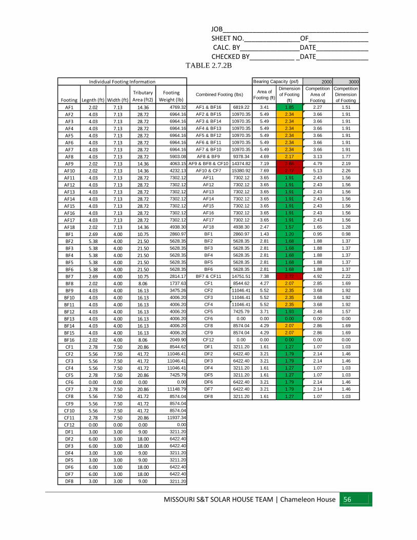
JOB_______________________________________ SHEET NO._______________OF________________ CALC. BY________________DATE______________ CHECKED BY____________ _DATE______________
MISSOURI S&T SOLAR HOUSE TEAM | Chameleon House 56
TABLE 2.7.2B
2000 3000
Footing Legnth (ft) Width (ft)
Tributary
Area (ft2)
Footing
Weight (lb)
Area of
Footing (ft)
Dimension
of Footing
(ft)
Competition
Area of
Footing
Competition
Dimension
of Footing
AF1 2.02 7.13 14.36 4769.32 AF1 & BF16 6819.22 3.41 1.85 2.27 1.51
AF2 4.03 7.13 28.72 6964.16 AF2 & BF15 10970.35 5.49 2.34 3.66 1.91
AF3 4.03 7.13 28.72 6964.16 AF3 & BF14 10970.35 5.49 2.34 3.66 1.91
AF4 4.03 7.13 28.72 6964.16 AF4 & BF13 10970.35 5.49 2.34 3.66 1.91
AF5 4.03 7.13 28.72 6964.16 AF5 & BF12 10970.35 5.49 2.34 3.66 1.91
AF6 4.03 7.13 28.72 6964.16 AF6 & BF11 10970.35 5.49 2.34 3.66 1.91
AF7 4.03 7.13 28.72 6964.16 AF7 & BF10 10970.35 5.49 2.34 3.66 1.91
AF8 4.03 7.13 28.72 5903.08 AF8 & BF9 9378.34 4.69 2.17 3.13 1.77
AF9 2.02 7.13 14.36 4063.15 AF9 & BF8 & CF10 14374.82 7.19 2.68 4.79 2.19
AF10 2.02 7.13 14.36 4232.13 AF10 & CF7 15380.92 7.69 2.77 5.13 2.26
AF11 4.03 7.13 28.72 7302.12 AF11 7302.12 3.65 1.91 2.43 1.56
AF12 4.03 7.13 28.72 7302.12 AF12 7302.12 3.65 1.91 2.43 1.56
AF13 4.03 7.13 28.72 7302.12 AF13 7302.12 3.65 1.91 2.43 1.56
AF14 4.03 7.13 28.72 7302.12 AF14 7302.12 3.65 1.91 2.43 1.56
AF15 4.03 7.13 28.72 7302.12 AF15 7302.12 3.65 1.91 2.43 1.56
AF16 4.03 7.13 28.72 7302.12 AF16 7302.12 3.65 1.91 2.43 1.56
AF17 4.03 7.13 28.72 7302.12 AF17 7302.12 3.65 1.91 2.43 1.56
AF18 2.02 7.13 14.36 4938.30 AF18 4938.30 2.47 1.57 1.65 1.28
BF1 2.69 4.00 10.75 2860.97 BF1 2860.97 1.43 1.20 0.95 0.98
BF2 5.38 4.00 21.50 5628.35 BF2 5628.35 2.81 1.68 1.88 1.37
BF3 5.38 4.00 21.50 5628.35 BF3 5628.35 2.81 1.68 1.88 1.37
BF4 5.38 4.00 21.50 5628.35 BF4 5628.35 2.81 1.68 1.88 1.37
BF5 5.38 4.00 21.50 5628.35 BF5 5628.35 2.81 1.68 1.88 1.37
BF6 5.38 4.00 21.50 5628.35 BF6 5628.35 2.81 1.68 1.88 1.37
BF7 2.69 4.00 10.75 2814.17 BF7 & CF11 14751.51 7.38 2.72 4.92 2.22
BF8 2.02 4.00 8.06 1737.63 CF1 8544.62 4.27 2.07 2.85 1.69
BF9 4.03 4.00 16.13 3475.26 CF2 11046.41 5.52 2.35 3.68 1.92
BF10 4.03 4.00 16.13 4006.20 CF3 11046.41 5.52 2.35 3.68 1.92
BF11 4.03 4.00 16.13 4006.20 CF4 11046.41 5.52 2.35 3.68 1.92
BF12 4.03 4.00 16.13 4006.20 CF5 7425.79 3.71 1.93 2.48 1.57
BF13 4.03 4.00 16.13 4006.20 CF6 0.00 0.00 0.00 0.00 0.00
BF14 4.03 4.00 16.13 4006.20 CF8 8574.04 4.29 2.07 2.86 1.69
BF15 4.03 4.00 16.13 4006.20 CF9 8574.04 4.29 2.07 2.86 1.69
BF16 2.02 4.00 8.06 2049.90 CF12 0.00 0.00 0.00 0.00 0.00
CF1 2.78 7.50 20.86 8544.62 DF1 3211.20 1.61 1.27 1.07 1.03
CF2 5.56 7.50 41.72 11046.41 DF2 6422.40 3.21 1.79 2.14 1.46
CF3 5.56 7.50 41.72 11046.41 DF3 6422.40 3.21 1.79 2.14 1.46
CF4 5.56 7.50 41.72 11046.41 DF4 3211.20 1.61 1.27 1.07 1.03
CF5 2.78 7.50 20.86 7425.79 DF5 3211.20 1.61 1.27 1.07 1.03
CF6 0.00 0.00 0.00 0.00 DF6 6422.40 3.21 1.79 2.14 1.46
CF7 2.78 7.50 20.86 11148.79 DF7 6422.40 3.21 1.79 2.14 1.46
CF8 5.56 7.50 41.72 8574.04 DF8 3211.20 1.61 1.27 1.07 1.03
CF9 5.56 7.50 41.72 8574.04
CF10 5.56 7.50 41.72 8574.04
CF11 2.78 7.50 20.86 11937.34
CF12 0.00 0.00 0.00 0.00
DF1 3.00 3.00 9.00 3211.20
DF2 6.00 3.00 18.00 6422.40
DF3 6.00 3.00 18.00 6422.40
DF4 3.00 3.00 9.00 3211.20
DF5 3.00 3.00 9.00 3211.20
DF6 6.00 3.00 18.00 6422.40
DF7 6.00 3.00 18.00 6422.40
DF8 3.00 3.00 9.00 3211.20
Combined Footing (lbs)
Individual Footing Information Bearing Capacity (psf)

JOB_______________________________________ SHEET NO._______________OF________________ CALC. BY________________DATE______________ CHECKED BY____________ _DATE______________
MISSOURI S&T SOLAR HOUSE TEAM | Chameleon House 57
TRIBUTARY AREA
AT = (2.02 FT) (7.13 FT) = 14.40 FT2
DEAD LOADS
ROOF WEST – 25.62 LB/FT.
DEAD ROOF WEST= (25.62 LB/FT)*(7.13 FT) = 182.67 LB
ROOF NORTH – 84.93 LB/FT
DEAD ROOF NORTH = (84.93 LB/FT)*(2.02 FT) = 171.56 LB
WALL NORTH– 88.16 LB/FT
DEAD WALL NORTH = (88.16 LB/FT)*(2.02FT) = 178.08 LB
WALL WEST – 89.00 LB/FT
DEAD WALL WEST = (89.00LB/FT)*(7.13FT) = 634.57 LB
JOIST – 37.93 LB/FT2
DEAD JOIST = (37.93 LB/FT2)*(14.40 FT
2) = 546.19 LB
DEAD LOAD TOTAL (DL) =1553.07 LB
LIVE LOAD
ROOF NORTH – 111.02 LB/FT
LIVE ROOF NORTH = (111.02LB/FT)*(2.02FT) = 224.26 LB
ROOF WEST – 86.25 LB/FT
LIVE ROOF WEST = (86.25 LB/FT)*(7.13FT) = 614.96 LB
TOTAL LIVE LOAD ROOF (LLR) = 839.22 LB
JOIST- 100.00 LB/FT2
LIVE JOIST = (100.00 LB/FT2)*(14.40 FT
2) = 1440 LB
TOTAL LIVE LOAD (LL) = 1440 LB
LOAD CASE
1.2(DL) + 1.6(LL) + 0.5(LLR)
1.2(1553.07 LB) + 1.6(1440 LB) +0.5(839.22 LB) = 4587.29 LB
FIGURE 2.7.2 SAMPLE CALCULATION
LIVING ROOM SECTION (SECTION A)
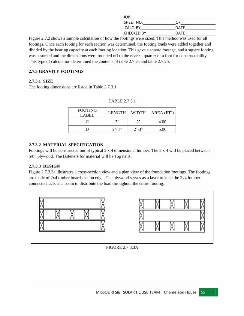
JOB_______________________________________ SHEET NO._______________OF________________ CALC. BY________________DATE______________ CHECKED BY____________ _DATE______________
MISSOURI S&T SOLAR HOUSE TEAM | Chameleon House 58
Figure 2.7.2 shows a sample calculation of how the footings were sized. This method was used for all
footings. Once each footing for each section was determined, the footing loads were added together and
divided by the bearing capacity at each footing location. This gave a square footage, and a square footing
was assumed and the dimensions were rounded off to the nearest quarter of a foot for constructability.
This type of calculation determined the contents of table 2.7.2a and table 2.7.2b.
2.7.3 GRAVITY FOOTINGS
2.7.3.1 SIZE
The footing dimensions are listed in Table 2.7.3.1.
TABLE 2.7.3.1
FOOTING
LABEL LENGTH WIDTH AREA (FT
2)
C 2’ 2’ 4.00
D 2’-3” 2’-3” 5.06
2.7.3.2 MATERIAL SPECIFICATION
Footings will be constructed out of typical 2 x 4 dimensional lumber. The 2 x 4 will be placed between
5/8” plywood. The fasteners for material will be 16p nails.
2.7.3.3 DESIGN
Figure 2.7.3.3a illustrates a cross-section view and a plan view of the foundation footings. The footings
are made of 2x4 timber boards set on edge. The plywood serves as a layer to keep the 2x4 lumber
connected, acts as a beam to distribute the load throughout the entire footing.
FIGURE 2.7.3.3A
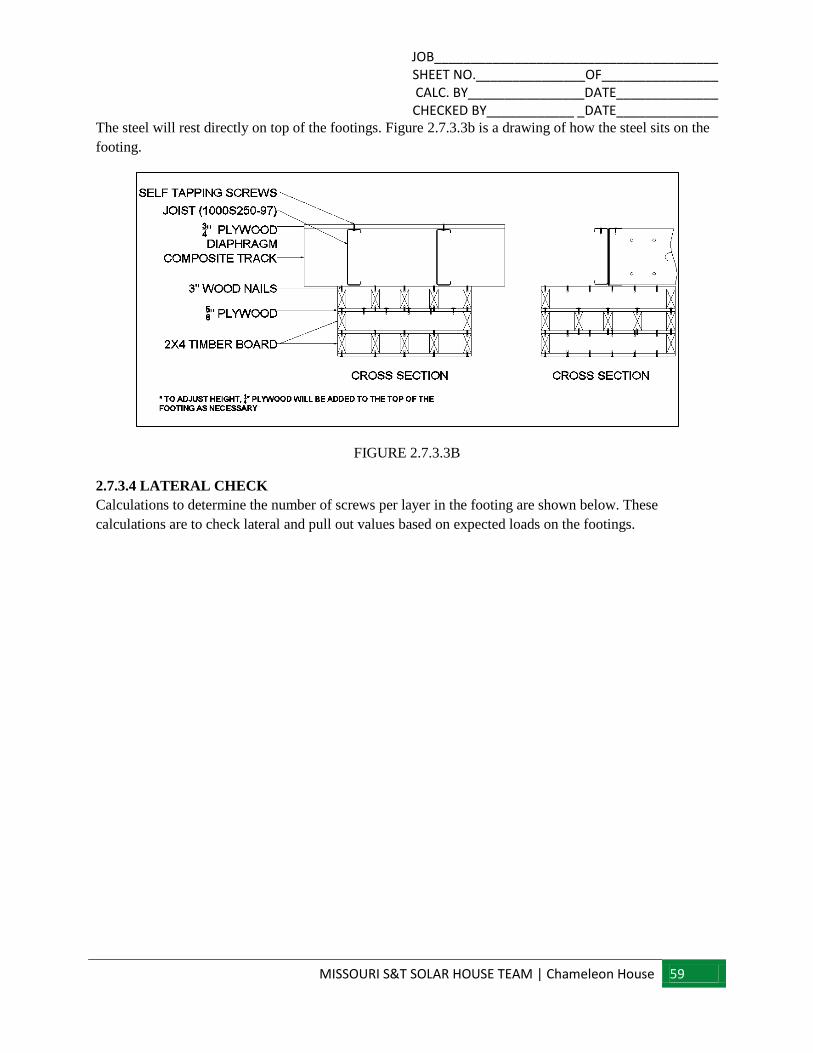
JOB_______________________________________ SHEET NO._______________OF________________ CALC. BY________________DATE______________ CHECKED BY____________ _DATE______________
MISSOURI S&T SOLAR HOUSE TEAM | Chameleon House 59
The steel will rest directly on top of the footings. Figure 2.7.3.3b is a drawing of how the steel sits on the
footing.
FIGURE 2.7.3.3B
2.7.3.4 LATERAL CHECK
Calculations to determine the number of screws per layer in the footing are shown below. These
calculations are to check lateral and pull out values based on expected loads on the footings.
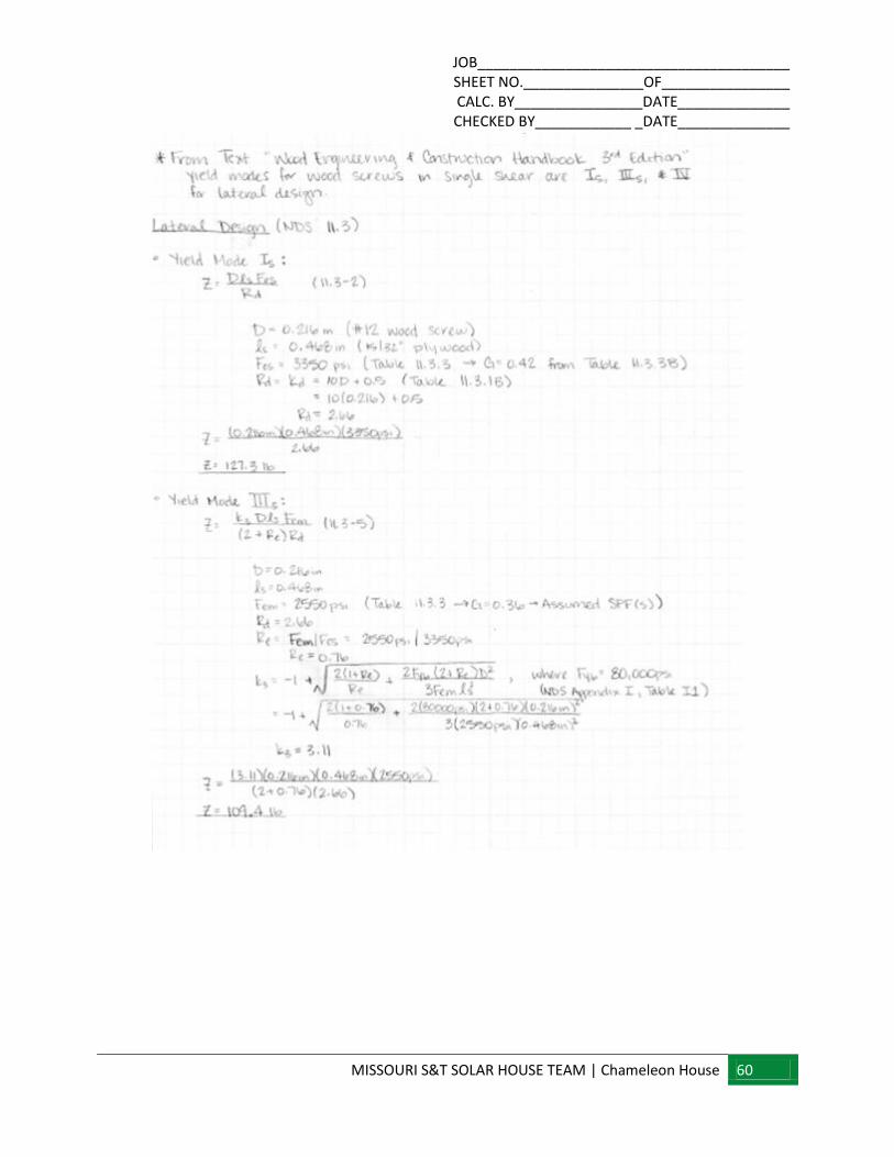
JOB_______________________________________ SHEET NO._______________OF________________ CALC. BY________________DATE______________ CHECKED BY____________ _DATE______________
MISSOURI S&T SOLAR HOUSE TEAM | Chameleon House 60
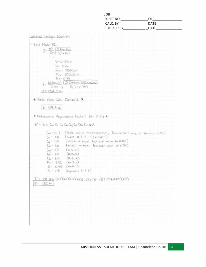
JOB_______________________________________ SHEET NO._______________OF________________ CALC. BY________________DATE______________ CHECKED BY____________ _DATE______________
MISSOURI S&T SOLAR HOUSE TEAM | Chameleon House 61
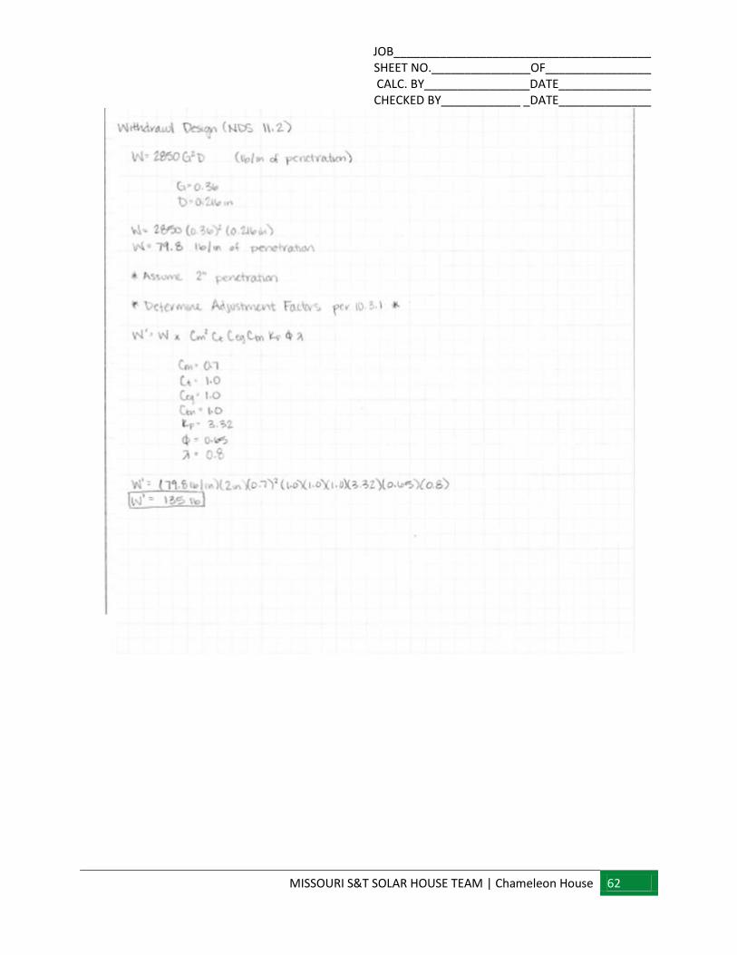
JOB_______________________________________ SHEET NO._______________OF________________ CALC. BY________________DATE______________ CHECKED BY____________ _DATE______________
MISSOURI S&T SOLAR HOUSE TEAM | Chameleon House 62
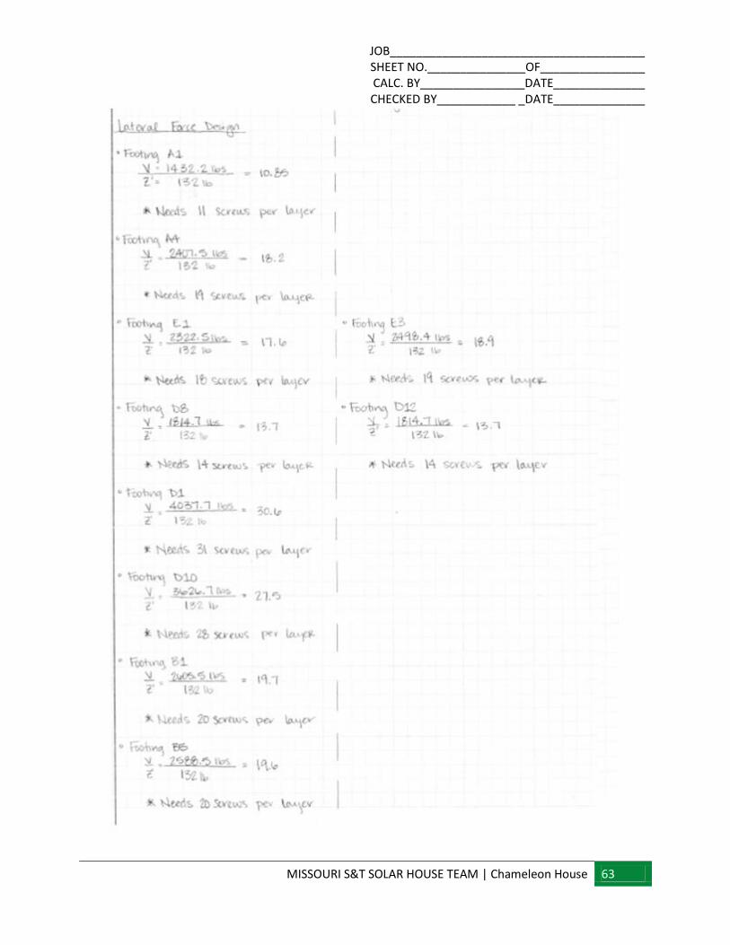
JOB_______________________________________ SHEET NO._______________OF________________ CALC. BY________________DATE______________ CHECKED BY____________ _DATE______________
MISSOURI S&T SOLAR HOUSE TEAM | Chameleon House 63
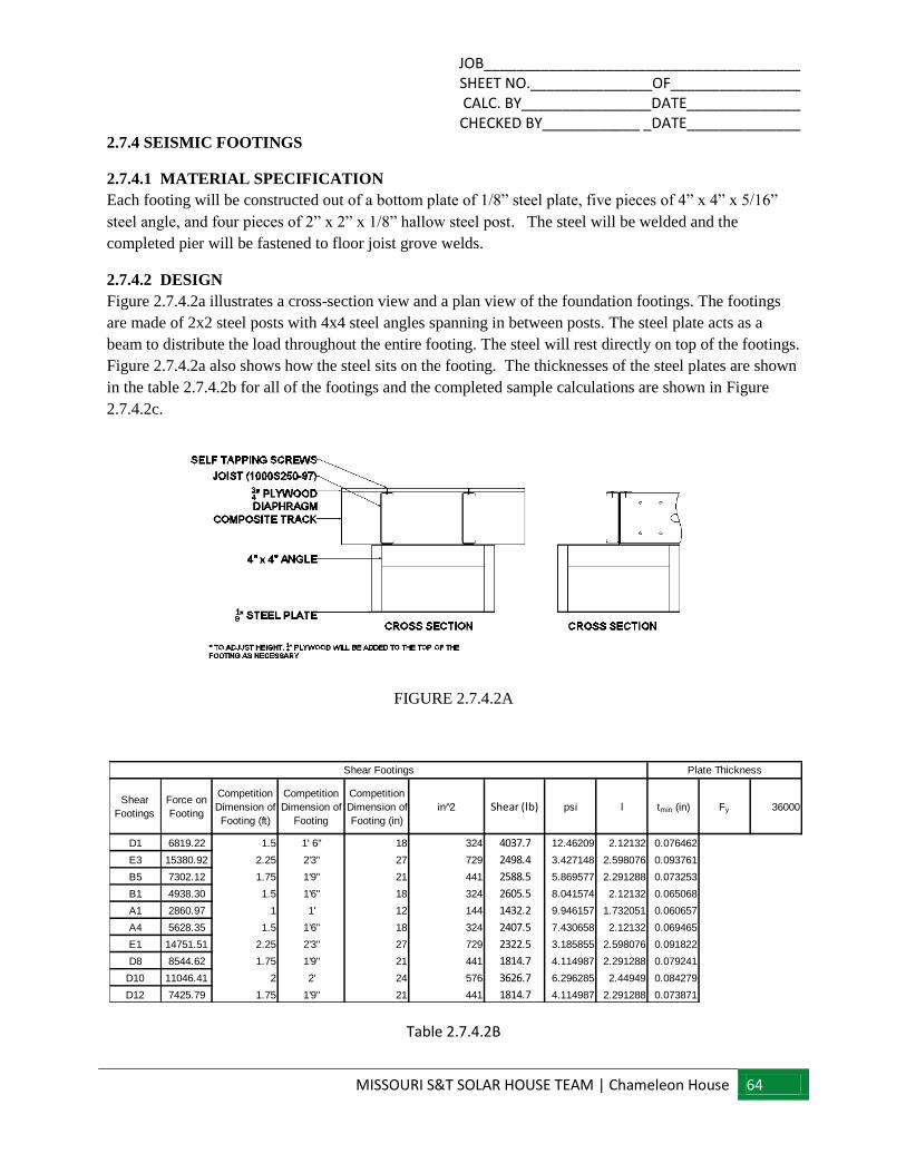
JOB_______________________________________ SHEET NO._______________OF________________ CALC. BY________________DATE______________ CHECKED BY____________ _DATE______________
MISSOURI S&T SOLAR HOUSE TEAM | Chameleon House 64
2.7.4 SEISMIC FOOTINGS
2.7.4.1 MATERIAL SPECIFICATION
Each footing will be constructed out of a bottom plate of 1/8” steel plate, five pieces of 4” x 4” x 5/16”
steel angle, and four pieces of 2” x 2” x 1/8” hallow steel post. The steel will be welded and the
completed pier will be fastened to floor joist grove welds.
2.7.4.2 DESIGN
Figure 2.7.4.2a illustrates a cross-section view and a plan view of the foundation footings. The footings
are made of 2x2 steel posts with 4x4 steel angles spanning in between posts. The steel plate acts as a
beam to distribute the load throughout the entire footing. The steel will rest directly on top of the footings.
Figure 2.7.4.2a also shows how the steel sits on the footing. The thicknesses of the steel plates are shown
in the table 2.7.4.2b for all of the footings and the completed sample calculations are shown in Figure
2.7.4.2c.
FIGURE 2.7.4.2A
Table 2.7.4.2B
Shear
Footings
Force on
Footing
Competition
Dimension of
Footing (ft)
Competition
Dimension of
Footing
Competition
Dimension of
Footing (in)
in 2̂ Shear (lb) psi l tmin (in) Fy 36000
D1 6819.22 1.5 1' 6" 18 324 4037.7 12.46209 2.12132 0.076462
E3 15380.92 2.25 2'3" 27 729 2498.4 3.427148 2.598076 0.093761
B5 7302.12 1.75 1'9" 21 441 2588.5 5.869577 2.291288 0.073253
B1 4938.30 1.5 1'6" 18 324 2605.5 8.041574 2.12132 0.065068
A1 2860.97 1 1' 12 144 1432.2 9.946157 1.732051 0.060657
A4 5628.35 1.5 1'6" 18 324 2407.5 7.430658 2.12132 0.069465
E1 14751.51 2.25 2'3" 27 729 2322.5 3.185855 2.598076 0.091822
D8 8544.62 1.75 1'9" 21 441 1814.7 4.114987 2.291288 0.079241
D10 11046.41 2 2' 24 576 3626.7 6.296285 2.44949 0.084279
D12 7425.79 1.75 1'9" 21 441 1814.7 4.114987 2.291288 0.073871
Plate ThicknessShear Footings
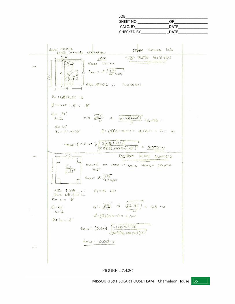
JOB_______________________________________ SHEET NO._______________OF________________ CALC. BY________________DATE______________ CHECKED BY____________ _DATE______________
MISSOURI S&T SOLAR HOUSE TEAM | Chameleon House 65
FIGURE 2.7.4.2C
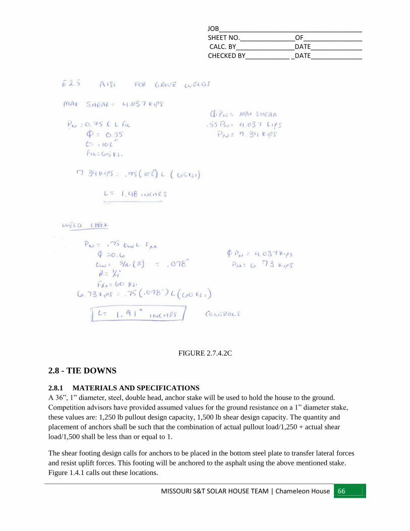
JOB_______________________________________ SHEET NO._______________OF________________ CALC. BY________________DATE______________ CHECKED BY____________ _DATE______________
MISSOURI S&T SOLAR HOUSE TEAM | Chameleon House 66
FIGURE 2.7.4.2C
2.8 - TIE DOWNS
2.8.1 MATERIALS AND SPECIFICATIONS
A 36”, 1” diameter, steel, double head, anchor stake will be used to hold the house to the ground.
Competition advisors have provided assumed values for the ground resistance on a 1” diameter stake,
these values are: 1,250 lb pullout design capacity, 1,500 lb shear design capacity. The quantity and
placement of anchors shall be such that the combination of actual pullout load/1,250 + actual shear
load/1,500 shall be less than or equal to 1.
The shear footing design calls for anchors to be placed in the bottom steel plate to transfer lateral forces
and resist uplift forces. This footing will be anchored to the asphalt using the above mentioned stake.
Figure 1.4.1 calls out these locations.
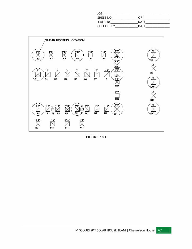
JOB_______________________________________ SHEET NO._______________OF________________ CALC. BY________________DATE______________ CHECKED BY____________ _DATE______________
MISSOURI S&T SOLAR HOUSE TEAM | Chameleon House 67
FIGURE 2.8.1
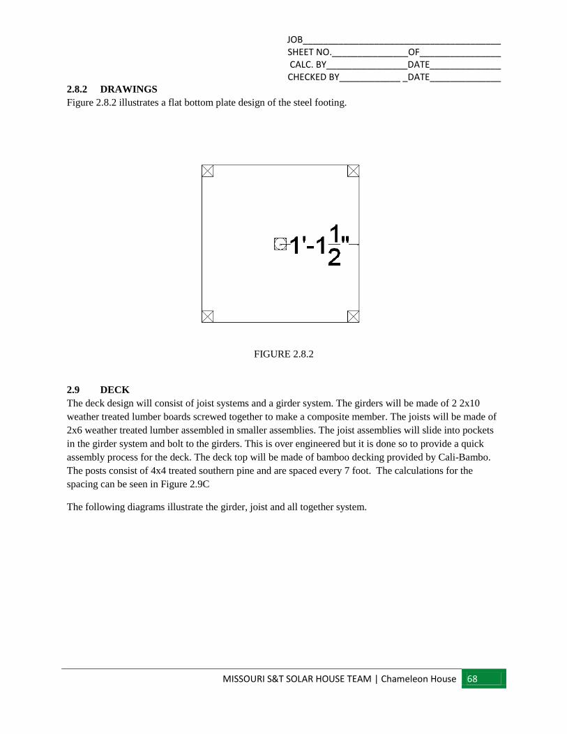
JOB_______________________________________ SHEET NO._______________OF________________ CALC. BY________________DATE______________ CHECKED BY____________ _DATE______________
MISSOURI S&T SOLAR HOUSE TEAM | Chameleon House 68
2.8.2 DRAWINGS
Figure 2.8.2 illustrates a flat bottom plate design of the steel footing.
FIGURE 2.8.2
2.9 DECK
The deck design will consist of joist systems and a girder system. The girders will be made of 2 2x10
weather treated lumber boards screwed together to make a composite member. The joists will be made of
2x6 weather treated lumber assembled in smaller assemblies. The joist assemblies will slide into pockets
in the girder system and bolt to the girders. This is over engineered but it is done so to provide a quick
assembly process for the deck. The deck top will be made of bamboo decking provided by Cali-Bambo.
The posts consist of 4x4 treated southern pine and are spaced every 7 foot. The calculations for the
spacing can be seen in Figure 2.9C
The following diagrams illustrate the girder, joist and all together system.
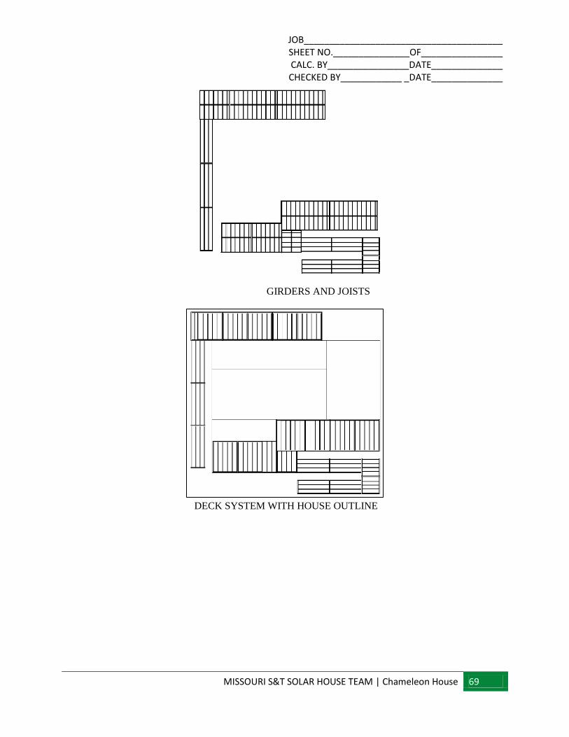
JOB_______________________________________ SHEET NO._______________OF________________ CALC. BY________________DATE______________ CHECKED BY____________ _DATE______________
MISSOURI S&T SOLAR HOUSE TEAM | Chameleon House 69
GIRDERS AND JOISTS
DECK SYSTEM WITH HOUSE OUTLINE
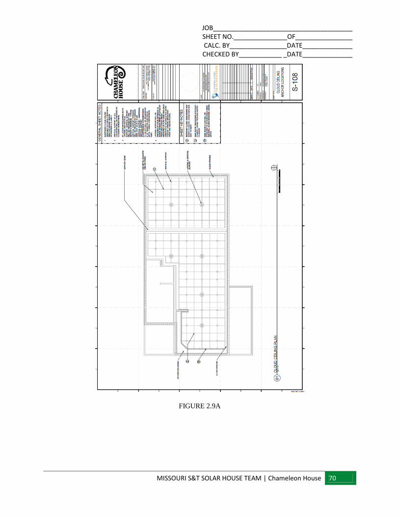
JOB_______________________________________ SHEET NO._______________OF________________ CALC. BY________________DATE______________ CHECKED BY____________ _DATE______________
MISSOURI S&T SOLAR HOUSE TEAM | Chameleon House 70
FIGURE 2.9A
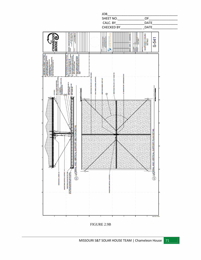
JOB_______________________________________ SHEET NO._______________OF________________ CALC. BY________________DATE______________ CHECKED BY____________ _DATE______________
MISSOURI S&T SOLAR HOUSE TEAM | Chameleon House 71
FIGURE 2.9B

JOB_______________________________________ SHEET NO._______________OF________________ CALC. BY________________DATE______________ CHECKED BY____________ _DATE______________
MISSOURI S&T SOLAR HOUSE TEAM | Chameleon House 72
FIGURE 2.9C
2.10- BIFACIAL RACKING
The Bifacial racking system consists of an outside frame constructed of 2x8 treated southern pine and
the inside supports are constructed of 2x6 treated southern pine. The posts supporting the structure
are 4x4 treated southern pine and are spaced every 12 foot. The calculations can be found in Figure
2.10a. Figure 2.10b shows both the plan and profile views of the structure.
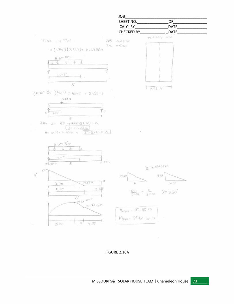
JOB_______________________________________ SHEET NO._______________OF________________ CALC. BY________________DATE______________ CHECKED BY____________ _DATE______________
MISSOURI S&T SOLAR HOUSE TEAM | Chameleon House 73
FIGURE 2.10A
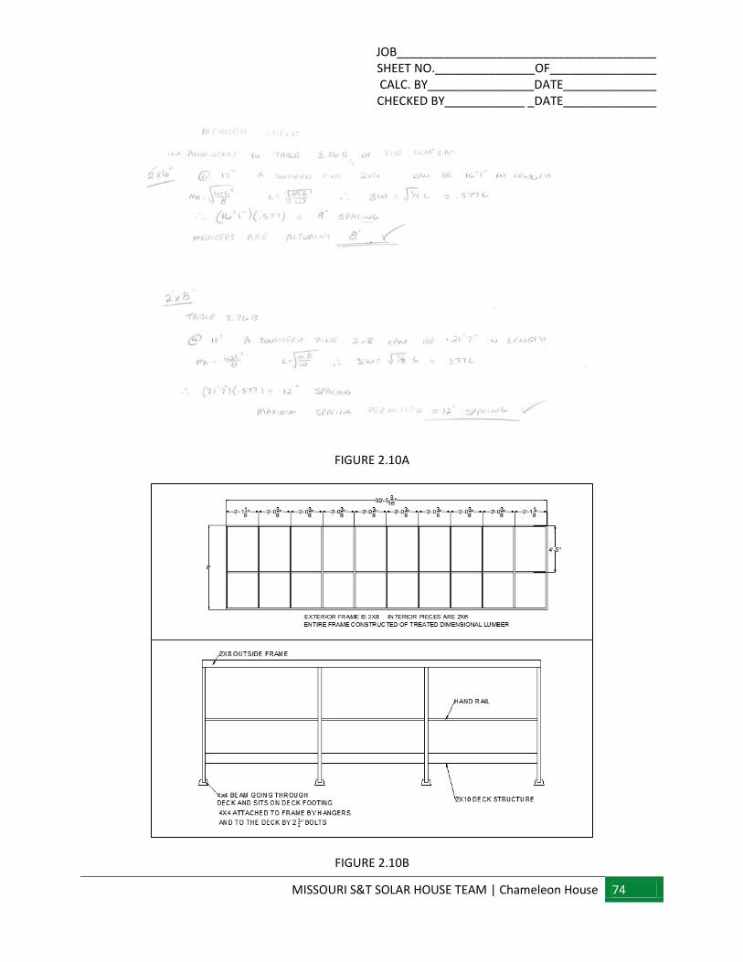
JOB_______________________________________ SHEET NO._______________OF________________ CALC. BY________________DATE______________ CHECKED BY____________ _DATE______________
MISSOURI S&T SOLAR HOUSE TEAM | Chameleon House 74
FIGURE 2.10A
FIGURE 2.10B
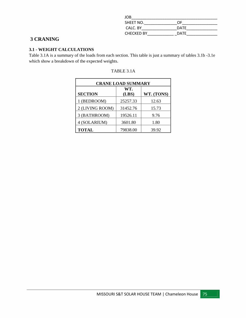
JOB_______________________________________ SHEET NO._______________OF________________ CALC. BY________________DATE______________ CHECKED BY____________ _DATE______________
MISSOURI S&T SOLAR HOUSE TEAM | Chameleon House 75
3 CRANING
3.1 - WEIGHT CALCULATIONS Table 3.1A is a summary of the loads from each section. This table is just a summary of tables 3.1b -3.1e
which show a breakdown of the expected weights.
TABLE 3.1A
CRANE LOAD SUMMARY
SECTION
WT.
(LBS) WT. (TONS)
1 (BEDROOM) 25257.33 12.63
2 (LIVING ROOM) 31452.76 15.73
3 (BATHROOM) 19526.11 9.76
4 (SOLARIUM) 3601.80 1.80
TOTAL 79838.00 39.92
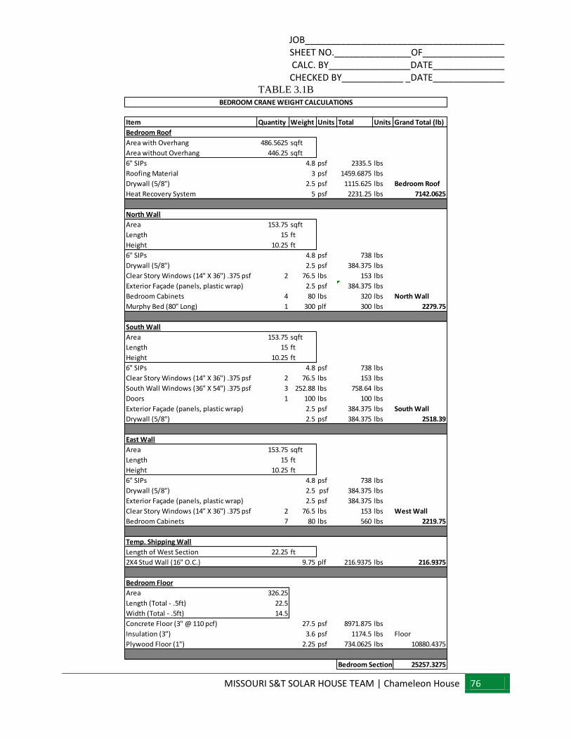
JOB_______________________________________ SHEET NO._______________OF________________ CALC. BY________________DATE______________ CHECKED BY____________ _DATE______________
MISSOURI S&T SOLAR HOUSE TEAM | Chameleon House 76
TABLE 3.1B
Item Quantity Weight Units Total Units Grand Total (lb)
Bedroom Roof
Area with Overhang 486.5625 sqft
Area without Overhang 446.25 sqft
6" SIPs 4.8 psf 2335.5 lbs
Roofing Material 3 psf 1459.6875 lbs
Drywall (5/8") 2.5 psf 1115.625 lbs Bedroom Roof
Heat Recovery System 5 psf 2231.25 lbs 7142.0625
North Wall
Area 153.75 sqft
Length 15 ft
Height 10.25 ft
6" SIPs 4.8 psf 738 lbs
Drywall (5/8") 2.5 psf 384.375 lbs
Clear Story Windows (14" X 36") .375 psf 2 76.5 lbs 153 lbs
Exterior Façade (panels, plastic wrap) 2.5 psf 384.375 lbs
Bedroom Cabinets 4 80 lbs 320 lbs North Wall
Murphy Bed (80" Long) 1 300 plf 300 lbs 2279.75
South Wall
Area 153.75 sqft
Length 15 ft
Height 10.25 ft
6" SIPs 4.8 psf 738 lbs
Clear Story Windows (14" X 36") .375 psf 2 76.5 lbs 153 lbs
South Wall Windows (36" X 54") .375 psf 3 252.88 lbs 758.64 lbs
Doors 1 100 lbs 100 lbs
Exterior Façade (panels, plastic wrap) 2.5 psf 384.375 lbs South Wall
Drywall (5/8") 2.5 psf 384.375 lbs 2518.39
East Wall
Area 153.75 sqft
Length 15 ft
Height 10.25 ft
6" SIPs 4.8 psf 738 lbs
Drywall (5/8") 2.5 psf 384.375 lbs
Exterior Façade (panels, plastic wrap) 2.5 psf 384.375 lbs
Clear Story Windows (14" X 36") .375 psf 2 76.5 lbs 153 lbs West Wall
Bedroom Cabinets 7 80 lbs 560 lbs 2219.75
Temp. Shipping Wall
Length of West Section 22.25 ft
2X4 Stud Wall (16" O.C.) 9.75 plf 216.9375 lbs 216.9375
Bedroom Floor
Area 326.25
Length (Total - .5ft) 22.5
Width (Total - .5ft) 14.5
Concrete Floor (3" @ 110 pcf) 27.5 psf 8971.875 lbs
Insulation (3") 3.6 psf 1174.5 lbs Floor
Plywood Floor (1") 2.25 psf 734.0625 lbs 10880.4375
25257.3275Bedroom Section
BEDROOM CRANE WEIGHT CALCULATIONS
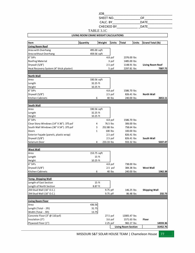
JOB_______________________________________ SHEET NO._______________OF________________ CALC. BY________________DATE______________ CHECKED BY____________ _DATE______________
MISSOURI S&T SOLAR HOUSE TEAM | Chameleon House 77
TABLE 3.1C
Item Quantity Weight Units Total Units Grand Total (lb)
Living Room Roof
Area with Overhang 495.00 sqft
Area without Overhang 459.56 sqft
6" SIPs 4.8 psf 2376.00 lbs
Roofing Material 3 psf 1485.00 lbs
Drywall (5/8") 2.5 psf 1148.91 lbs Living Room Roof
Heat Recovery System (4" thick plaster) 5 psf 2297.81 lbs 7307.72
North Wall
Area 330.56 sqft
Length 32.25 ft
Height 10.25 ft
6" SIPs 4.8 psf 1586.70 lbs
Drywall (5/8") 2.5 psf 826.41 lbs North Wall
Kitchen Cabinets 6 40 lbs 240.00 lbs 2653.11
South Wall
Area 330.56 sqft
Length 32.25 ftHeight 10.25 ft
6" SIPs 4.8 psf 1586.70 lbs
Clear Story Windows (14" X 36") .375 psf 4 76.5 lbs 306.00 lbs
South Wall Windows (36" X 54") .375 psf 3 252.88 lbs 758.64 lbs
Doors 1 100 lbs 100.00 lbs
Exterior Façade (panels, plastic wrap) 2.5 psf 826.41 lbs
Drywall (5/8") 2.5 psf 826.41 lbs South Wall
Solarium Door 4 233.33 lbs 933.32 lbs 5337.47
West Wall
Area 153.75 sqft
Length 15 ft
Height 10.25 ft
6" SIPs 4.8 psf 738.00 lbs
Drywall (5/8") 2.5 psf 384.38 lbs West Wall
Kitchen Cabinets 6 40 lbs 240.00 lbs 1362.38
Temp. Shipping Wall
Length of East Section 15 ft
Length of North Section 8.87 ft
2X4 Stud Wall (16" O.C.) 9.75 plf 146.25 lbs Shipping Wall
2X4 Stud Wall (16" O.C.) 9.75 plf 86.48 lbs 232.73
Living Room Floor
Area 436.56
Length (Total - .5ft) 31.75
Width (Total - .5ft) 13.75
Concrete Floor (3" @ 110 pcf) 27.5 psf 12005.47 lbs
Insulation (3") 3.6 psf 1571.63 lbs Floor
Plywood Floor (1") 2.25 psf 982.27 lbs 14559.36
31452.76Living Room Section
LIVING ROOM CRANE WEIGHT CALCULATIONS
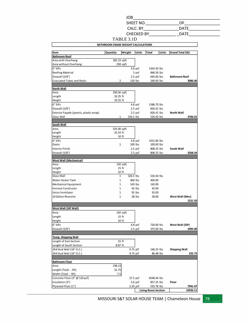
JOB_______________________________________ SHEET NO._______________OF________________ CALC. BY________________DATE______________ CHECKED BY____________ _DATE______________
MISSOURI S&T SOLAR HOUSE TEAM | Chameleon House 78
TABLE 3.1D
Item Quantity Weight Units Total Units Grand Total (lb)
Bathroom Roof
Area with Overhang 282.19 sqft
Area without Overhang 258 sqft
6" SIPs 4.8 psf 1354.50 lbs
Roofing Material 3 psf 846.56 lbs
Drywall (5/8") 2.5 psf 645.00 lbs Bathroom Roof
Evacuated Tubes and Racks 2 120 lbs 240.00 lbs 3086.06
North Wall
Area 330.56 sqft
Length 32.25 ft
Height 10.25 ft
6" SIPs 4.8 psf 1586.70 lbs
Drywall (5/8") 2.5 psf 826.41 lbs
Exterior Façade (panels, plastic wrap) 2.5 psf 826.41 lbs North Wall
Glass Wall 1 526.5 lbs 526.50 lbs 3766.01
South Wall
Area 323.30 sqftLength 32.33 ft
Height 10 ft
6" SIPs 4.8 psf 1551.84 lbsDoors 1 100 lbs 100.00 lbs
Interior Finish 2.5 psf 808.25 lbs South Wall
Drywall (5/8") 2.5 psf 808.25 lbs 3268.34
West Wall (Mechanical)
Area 150 sqft
Length 15 ft
Height 10 ft
Glass Wall 1 526.5 lbs 526.50 lbs
Water Heater Tank 1 400 lbs 400.00
Mechanical Equipment 1 143 lbs 143.00
Venmar Constructo 1 42 lbs 42.00
Unico Ventilator 1 92 lbs 92.00
10 Gallon Resevior 1 28 lbs 28.00 West Wall (Mec)
1231.50
West Wall (SIP Wall)
Area 150 sqft
Length 15 ft
Height 10 ft
6" SIPs 4.8 psf 720.00 lbs West Wall (SIP)
Drywall (5/8") 2.5 psf 375.00 lbs 1095.00
Temp. Shipping Wall
Length of East Section 15 ft
Length of South Section 8.87 ft
2X4 Stud Wall (16" O.C.) 9.75 plf 146.25 lbs Shipping Wall
2X4 Stud Wall (16" O.C.) 9.75 plf 86.48 lbs 232.73
Bathroom Floor
Area 238.13
Length (Total - .5ft) 31.75
Width (Total - .5ft) 7.5
Concrete Floor (3" @ 110 pcf) 27.5 psf 6548.44 lbs
Insulation (3") 3.6 psf 857.25 lbs Floor
Plywood Floor (1") 2.25 psf 535.78 lbs 7941.47
19526.11Living Room Section
BATHROOM CRANE WEIGHT CALCULATIONS
JOB_______________________________________ SHEET NO._______________OF________________ CALC. BY________________DATE______________ CHECKED BY____________ _DATE______________
MISSOURI S&T SOLAR HOUSE TEAM | Chameleon House 79
TABLE 3.1E
3.1.2 - LIFT POINTS
3.1.2.1 SPECIFICATIONS
The house will be lifted in sections by using straps specified by the craning company. These straps will
span underneath each section along the steel floor joists to prevent buckling.
3.1.2.2 LOADS
Table 3.1A shows the expected loads for each section. Each section will be picked up with two to three
craning straps. These straps will then connect to the cables. As is noticeable from the table, the largest
expected load at any section is 15.73 tons. This is the design load we will use sizing the craning straps.
3.1.2.3 DIAGRAM
FIGURE 3.1.2.3A
Item Quantity Weight Units Total Units Grand Total
Solarium Floor
Area 108 sqft
Length 18 ft
Width 6 ft
Concrete Floor (3" @ 110 pcf) 27.5 psf 2970 lbs
Insulation (3") 3.6 psf 388.8 lbs Solarium Floor
Plywood Floor (1") 2.25 psf 243 lbs 3601.80
3601.80
1200.6
*Solarium breaks into three equal sections
Solarium*
Solarium Section*
SOLARIUM CRANE WEIGHT CALCULATIONS
JOB_______________________________________ SHEET NO._______________OF________________ CALC. BY________________DATE______________ CHECKED BY____________ _DATE______________
MISSOURI S&T SOLAR HOUSE TEAM | Chameleon House 80
4. TRUCKING
4.1 - SECTION DIAGRAM
LIVING ROOM SECTION
TABLE 4.1A
JOB_______________________________________ SHEET NO._______________OF________________ CALC. BY________________DATE______________ CHECKED BY____________ _DATE______________
MISSOURI S&T SOLAR HOUSE TEAM | Chameleon House 81
BATHROOM SECTION
TABLE 4.1B
JOB_______________________________________ SHEET NO._______________OF________________ CALC. BY________________DATE______________ CHECKED BY____________ _DATE______________
MISSOURI S&T SOLAR HOUSE TEAM | Chameleon House 82
BEDROOM SECTION
TABLE 4.1C
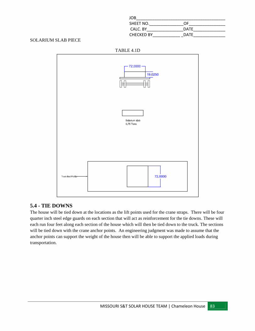
JOB_______________________________________ SHEET NO._______________OF________________ CALC. BY________________DATE______________ CHECKED BY____________ _DATE______________
MISSOURI S&T SOLAR HOUSE TEAM | Chameleon House 83
SOLARIUM SLAB PIECE
TABLE 4.1D
5.4 - TIE DOWNS
The house will be tied down at the locations as the lift points used for the crane straps. There will be four
quarter inch steel edge guards on each section that will act as reinforcement for the tie downs. These will
each run four feet along each section of the house which will then be tied down to the truck. The sections
will be tied down with the crane anchor points. An engineering judgment was made to assume that the
anchor points can support the weight of the house then will be able to support the applied loads during
transportation.

JOB_______________________________________ SHEET NO._______________OF________________ CALC. BY________________DATE______________ CHECKED BY____________ _DATE______________
MISSOURI S&T SOLAR HOUSE TEAM | Chameleon House 84
6. APPENDICIES
A. ENERGY PANEL SOLUTIONS’ NTA LISTING REPORT
B. US SOLAR DECATHALON 2013 RULES
C. US SOLAR DECATHALON BUILDING CODE
D. ENERGY PANEL SOLUTIONS’ DESIGN REPORT AND CALCULATIONS
E. SUMMARY OF TENK SOLAR WIND TUNNEL FORCE COEFFICIENTS
F. SCALING WIND TUNNEL RESULTS FROM JUPITER TO NEPTUNE
G. TENK SOLAR PANEL DIMENSIONS AND ANGLES
H. SEISMIC FOOTING CALCULATIONS
I. STEEL STRAPPING CALCULATIONS
J. GABRIEL CRANE INFORMATION
K. WOOD FRAME CONSTRUCTION MANUAL REFERNCE
JOB_______________________________________ SHEET NO._______________OF________________ CALC. BY________________DATE______________ CHECKED BY____________ _DATE______________
MISSOURI S&T SOLAR HOUSE TEAM | Chameleon House 85
A. ENERGY PANEL SOLUTIONS’ NTA LISTING REPORT

Listing Report: EPS102108-21
This listing report is intended to indicate that NTA Inc. has evaluated product described and has found it to be eligible for labeling. Product not labeled as specified herein is not covered by this report. NTA Inc. makes no warranty, either expressed or implied, regarding the product covered by this report.
NTA, INC. • 305 NORTH OAKLAND AVENUE • P.O. BOX 490 • NAPPANEE, INDIANA 46550 PHONE: 574-773-7975 WEB: WWW.NTAINC.COM FAX: 574-773-2260 EPS102108-21 Listing Report 2012-04-05 Issue/Revision Date: 04/05/2012 This report is subject to annual renewal. Page 1 of 10 NTA FORM ISQA 3.2n Listing Report Template 2012-03-21
CSI 06 12 16
PRODUCT: Structural Insulated Panels (SIPs) DIVISION: Wood and Plastics (06) SECTION: Structural Panels (06 12 16) Report Holder Structural Insulated Panel Association (SIPA) PO Box 1699 Gig Harbor, WA 98335
Manufacturing Locations Energy Panel Structures, Inc. (NTA Plant #549) 102 East Industrial Park Graettinger, IA 51342 1. SUBJECT
Energy Panel Structures Structural Insulated Panels. Wall and Roof Panels 8 ft. to 20 ft. long, 4-5/8 in. to 12-1/4 in. thick.
2. SCOPE
2.1. NTA, Inc. has evaluated the above product(s) for compliance with the applicable sections of the following codes: 2.1.1. 2006, 2009 International Building Code (IBC) 2.1.2. 2006, 2009 International Residential Code (IRC)
2.2. NTA, Inc. has evaluated the above product(s) in
accordance with: 2.2.1. NTA IM 014 Structural Insulated Panel Evaluation 2.2.2. NTA IM 036 Quality System Requirements
2.3. NTA, Inc. has evaluated the following properties of
the above product(s): 2.3.1. Structural performance under axial, transverse and
racking loads.
To obtain the most current NTA Listing Report visit www.ntainc.com/product-certification/.
3. USES
3.1. General. Energy Panel Structures Structural Insulated Panels are used as structural insulated roof and wall panels capable of resisting transverse, axial and in-plane shear loads.
3.2. Construction Types. Energy Panel Structures Structural Insulated Panels shall be considered combustible building elements when determining the Type of Construction in accordance with 2009 IBC Chapter 6. (IM
014 NACU1)
3.3. Fire Resistive Assemblies. Energy Panel Structures Structural Insulated Panels shall not be used as part of a fire-rated assembly unless suitable evidence and details are submitted and approved by the authority having jurisdiction. (IM 014 ACU14)
4. DESCRIPTION
4.1. General. Energy Panel Structures Structural Insulated Panels are factory-assembled, engineered-wood-faced, structural insulated panels (SIPs) with an expanded polystyrene (EPS) foam core. The panels are intended for use as load-bearing or non-load bearing wall and roof panels. Panels are available in 4-5/8 in. through 12-1/4 in. overall thicknesses. The panels are custom made to the specifications for each use and are assembled under factory-controlled conditions. The maximum panel size is 8 ft. wide and up to 20 ft. in length.
4.2. Materials 4.2.1. Facing. The facing consists of two single-ply oriented strand board (OSB) facings a minimum of 7/16 in. thick conforming to 2009 IRC Table 613.3.2 and DOC PS 2-04, Exposure 1, Rated Sheathing with a span index of 24/16. Panels may be manufactured with the facing strength axis oriented in either direction with respect to the direction of SIP bending provided the appropriate strength values are used. 4.2.2. Core. The core material is EPS Foam conforming to the Type I specification defined in ASTM C578. The foam core, up to 11-3/8 in. thickness, has a flame spread rating not exceeding 75 and a smoke-developed rating not exceeding 450 in compliance with 2009 IBC Section 2603.3 Exception 4. 4.2.3. Adhesive. Facing materials are adhered to the core material using a structural adhesive. The adhesive is applied during the lamination process in accordance with the in-plant quality system documentation.

Listing Report: EPS102108-21
This listing report is intended to indicate that NTA Inc. has evaluated product described and has found it to be eligible for labeling. Product not labeled as specified herein is not covered by this report. NTA Inc. makes no warranty, either expressed or implied, regarding the product covered by this report.
NTA, INC. • 305 NORTH OAKLAND AVENUE • P.O. BOX 490 • NAPPANEE, INDIANA 46550 PHONE: 574-773-7975 WEB: WWW.NTAINC.COM FAX: 574-773-2260 EPS102108-21 Listing Report 2012-04-05 Issue/Revision Date: 04/05/2012 This report is subject to annual renewal. Page 2 of 10 NTA FORM ISQA 3.2n Listing Report Template 2012-03-21
CSI 06 12 16
4.2.4. Material Sources. The facing, core and adhesive used in the construction of Energy Panel Structures Structural Insulated Panels shall be composed only of materials from approved sources as identified in the in-plant quality system documentation. A list of material suppliers is provided in Table 9. 4.2.5. Splines. Energy Panel Structures Structural Insulated Panels are interconnected with surface splines or block splines (Figure 1). Connections using dimensional lumber splines or engineered structural splines are not specifically addressed in this report and must be designed in accordance with accepted engineering practice to meet applicable code requirements. (IM 014 ACU 20) 4.2.5.1. Surface Splines. Surface splines (Figure 1) consist of 3 in. wide by 7/16 in. thick or thicker OSB. At each panel joint, one surface spline is inserted into each of two tight-fitting slots in the core. The slots in the core are located just inside the facing. 4.2.5.2. Block Splines. Block splines (Figure 1) are manufactured in the same manner as the SIP except with an overall thickness that is 1 in. less than the overall thickness of the panel to be joined.
5. DESIGN
5.1. Overall Structural System. The scope of this report is limited to the evaluation of the SIP component. Panel connections and other details related to incorporation of the panel into the overall structural system of a building are beyond the scope of this report. (IM 014 NACU3) 5.2. Design Approval. Where required by the authority having jurisdiction, structures using Energy Panel Structures Structural Insulated Panels shall be designed by a registered design professional. Construction documents, including engineering calculations and drawings providing floor plans, window details, door details and connector details, shall be submitted to the code official when application is made for a permit. The individual preparing such documents shall possess the necessary qualifications as required by the applicable code and the professional registration laws of the state where the construction is undertaken. Approved construction documents shall be available at all times on the jobsite during installation.(IM 014 NACU4)
5.3. Design Loads. Design loads to be resisted by the SIPs shall be as required under the applicable building code. Loads on the panels shall not exceed the loads noted in this report. 5.4. Allowable Loads. Allowable axial, transverse, and racking loads may be calculated using the panel properties provided in Tables 1 and 2 or may be selected from Tables 3 through 7. Maximum and minimum panel heights, spans and thicknesses are limited as provided in Table 2 through 7. Unless otherwise noted, all properties and allowable loads apply to panels joined with surface or block splines. Allowable loads for reinforced panel capacities shall be designed by a registered professional. Calculations demonstrating that the loads applied are less than the allowable loads described in this report shall be submitted to the code official for approval.(IM 014 NACU5) For loading conditions not specifically addressed herein, structural members designed in accordance with accepted engineering practice shall be provided to meet applicable code requirements. 5.5. Concentrated Loads. Axial loads shall be applied to the SIP through continuous members such as structural insulated roof or floor panels or repetitive members such as joists, trusses or rafters spaced at regular intervals of 24 in. on center or less. Such members shall be fastened to a rim board or similar member to distribute the load to the SIP. For other loading conditions, reinforcement shall be provided. This reinforcement shall be designed in accordance with accepted engineering practice. (IM 014
ACU12) 5.6. Eccentric and Side Loads. Axial loads shall be applied concentrically to the top of the SIP. Loads shall not be applied eccentrically or through framing attached to one side of the panel (such as balloon framing) except where additional engineering documentation is provided. (IM 014 ACU13) 5.7. Openings. Openings in panels shall be reinforced with wood or steel designed in accordance with accepted engineering practice to resist all loads applied to the opening as required by the adopted code. Details for door and window openings shall be provided to clarify the manner of supporting axial, transverse and/or racking shear loads at openings. Such details shall be shown on approved design documents and subject to approval by the local authority having jurisdiction. (IM 014 ACU8)

Listing Report: EPS102108-21
This listing report is intended to indicate that NTA Inc. has evaluated product described and has found it to be eligible for labeling. Product not labeled as specified herein is not covered by this report. NTA Inc. makes no warranty, either expressed or implied, regarding the product covered by this report.
NTA, INC. • 305 NORTH OAKLAND AVENUE • P.O. BOX 490 • NAPPANEE, INDIANA 46550 PHONE: 574-773-7975 WEB: WWW.NTAINC.COM FAX: 574-773-2260 EPS102108-21 Listing Report 2012-04-05 Issue/Revision Date: 04/05/2012 This report is subject to annual renewal. Page 3 of 10 NTA FORM ISQA 3.2n Listing Report Template 2012-03-21
CSI 06 12 16
5.8. In-Plane Shear Design. Shear walls utilizing block or surface splines shall be sized to resist all code required wind and seismic loads without exceeding the allowable loads provided in Tables 6 and 7. Shear wall chords, hold-downs and connections to transfer shear forces between the wall and surrounding structure shall be designed in accordance with accepted engineering practice. Allowable strengths for shear walls with structural splines along each panel edge shall be designed in accordance with accepted engineering practice and subject to the limitations for wood sheathed shear walls.
5.8.1. Seismic Design Categories A, B and C. The use of the shear wall configurations in Table 6 is limited to structures in Seismic Design Categories A, B and C. Where SIPs are used to resist seismic forces the following factors shall be used for design: Response Modification Coefficient, R = 2.0; System Overstrength Factor, �0 = 2.5; Deflection Amplification Factor, Cd = 2.0. (IM 014 ACU16)
The maximum panel height-to-width ratio shall be 2:1. (IM
014 ACU17) 5.8.2. Seismic Design Categories D, E, and F. The shear wall configurations in Table 7 are permitted in Seismic Design Categories D, E and F. Such walls shall be designed using the seismic design coefficients and limitations provided in ASCE 7-05 for light-framed walls sheathed with wood structural panels rated for shear resistance (SFRS A13). These SIPs shall use the following factors for design: Response Modification Coefficient, R = 6.5; System Overstrength Factor, �0 = 3.0; Deflection Amplification Factor, Cd = 4.0.(IM 014 ACU16)
The maximum panel height-to-width ratio shall be 1:1. (IM
014 ACU17) 5.8.3. Adhesives and Sealants. Adhesives and sealants shall not be applied at wood-to-wood or spline-to-facing interfaces in shear walls in Seismic Design Categories D, E and F(IM 014 NACU10). Adhesives and sealants may be applied to wood-to-foam or facing-to-foam interfaces. Flexible SIP tape may be applied over panel joints. 5.9. Horizontal Diaphragms. Horizontal diaphragms shall be sized to resist all code required wind and seismic loads without exceeding the allowable loads provided in Table 8. Diaphragm chords and connections to transfer shear forces between the diaphragm and surrounding structure shall be designed in accordance with accepted engineering practice. The maximum diaphragm length-to-width ratio shall not exceed 3:1. (IM 014 ACU18)
5.10. Combined Loads. Panels subjected to any combination of transverse, axial or in-plane shear loads shall be analyzed utilizing a straight line interaction in accordance with NTA IM014 TIP 01 SIP Design Guide.
6. INSTALLATION
6.1. General. Energy Panel Structures Structural Insulated Panels shall be fabricated, identified and erected in accordance with this report, the approved construction documents and the applicable code. In the event of a conflict between the manufacturer’s published installation instructions and this report, this report shall govern. Approved construction documents shall be available at all times on the jobsite during installation. (IM 014 NACU7) 6.2. Splines. Energy Panel Structures Structural Insulated Panels are interconnected at the panel edges through the use of a spline. The spline type may be of any configuration listed in Section 4.2.5 as required by the specific design. The spline shall be secured in place with not less than 0.131 in. x 2-1/2 in. nails, spaced 6 in. on center on both sides of the panel, or an approved equivalent fastener. All joints shall be sealed in accordance with the SIP manufacturer’s installation instructions. Alternate spline connections may be required for panels subjected to in-plane racking forces. Such panels shall be interconnected exactly as required in Table 6 or 7 or as directed by the designer. 6.3. Plates. The top and bottom plates of the panels shall be dimensional or engineered lumber sized to match the core thickness of the panel. The plates shall be secured using not less than 0.131 in. x 2-1/2 in. nails, spaced 6 in. on center on both sides of the panel, or an approved equivalent fastener. A second plate composed of 1-1/8 in. minimum thickness dimensional or engineered lumber with a specific gravity of 0.42 that is cut to the full thickness of the panel shall be secured to the first top plate using 0.131 in. x 3 in. nails or an approved equivalent fastener. 6.4. Cutting and Notching. No field cutting or routing of the panels shall be permitted except as shown on approved drawings. (IM 014 NACU6) 6.5. Protection from Decay. SIPs that rest on exterior foundation walls shall not be located within 8 in. of exposed earth. SIPs supported by concrete or masonry that is in direct contact with earth shall be protected from the concrete or masonry by a moisture barrier. (IM 014 ACU6)

Listing Report: EPS102108-21
This listing report is intended to indicate that NTA Inc. has evaluated product described and has found it to be eligible for labeling. Product not labeled as specified herein is not covered by this report. NTA Inc. makes no warranty, either expressed or implied, regarding the product covered by this report.
NTA, INC. • 305 NORTH OAKLAND AVENUE • P.O. BOX 490 • NAPPANEE, INDIANA 46550 PHONE: 574-773-7975 WEB: WWW.NTAINC.COM FAX: 574-773-2260 EPS102108-21 Listing Report 2012-04-05 Issue/Revision Date: 04/05/2012 This report is subject to annual renewal. Page 4 of 10 NTA FORM ISQA 3.2n Listing Report Template 2012-03-21
CSI 06 12 16
6.6. Protection from Termites. In areas subject to damage from termites, SIPs shall be protected from termites using an approved method. Panels shall not be installed below grade or in contact with earth. (IM 014 ACU7) 6.7. Heat-Producing Fixtures. Heat-producing fixtures shall not be installed in the panels unless protected by a method approved by the code official or documented in test reports. This limitation shall not be interpreted to prohibit heat-producing elements with suitable protection. (IM 014 NACU9) 6.8. Voids and Holes 6.8.1 Voids in Core. In lieu of openings designed in accordance with section 5.7, the following voids are permitted. Voids may be provided in the panel core during fabrication at predetermined locations only. Voids parallel to the panel span shall be limited to a single 1 in. maximum diameter hole. Such voids shall be spaced a minimum of 4 ft. on center measured perpendicular to the panel span. Two 1/2 in. diameter holes may be substituted for the single 1 in. hole provided they are maintained parallel and within 2 in. of each other. (IM 014 ACU11) Voids perpendicular to the panel span shall be limited to a single 1 in. maximum diameter hole placed not closer than 16 in. from the support. Additional voids in the same direction shall be spaced not less than 28 in. on center. 6.8.2 Holes in Panels. Holes may be placed in panels during fabrication at predetermined locations only. Holes shall be limited to 4 in. x 4 in. square. The minimum distance between holes shall not be less than 4 ft. on center measured perpendicular to the panel span and 24 in. on center measured parallel to the panel span. Not more than three holes shall be permitted in a single line parallel to the panel span. The holes may intersect voids permitted elsewhere in this report. (IM 014 ACU15) 6.9. Panel Cladding 6.9.1 Roof Covering. The roof covering, underlayment and flashing shall comply with the applicable code(s). All roofing materials must be installed in accordance with the manufacturer’s installation instructions. The use of roof coverings requiring the application of heat during installation shall be reviewed and approved by a registered design professional.
6.9.2 Exterior Wall Covering. Panels shall be covered on the exterior by a water-resistive barrier as required by the applicable code. The water-resistive barrier shall be attached with flashing in such a manner as to provide a continuous water-resistive barrier behind the exterior wall veneer. (IM 014 ACU9) The exterior facing of the SIP wall shall be covered with weather protection as required by the adopted building code or other approved materials. (IM 014
ACU10) 6.9.3 Interior Finish. The SIP foam plastic core shall be separated from the interior of the building by an approved thermal barrier of 1/2 in. gypsum wallboard or equivalent thermal barrier where required by 2009 IBC Section 2603.4.
7. CONDITIONS OF USE
Energy Panel Structures Structural Insulated Panels as described in this report comply with the codes listed in Section 2.0, subject to the following conditions: 7.1. Installation complies with this report and the
approved construction documents. 7.2. This report applies only to the panel thicknesses
specifically listed herein. (IM 014 ACU3) 7.3. In-use panel heights/spans shall not exceed the
values listed herein. Extrapolation beyond the values listed herein is not permitted. (IM 014 ACU2)
7.4. The panels are manufactured in the production facilities noted in this report. (IM 014 NACU8)

Listing Report: EPS102108-21
This listing report is intended to indicate that NTA Inc. has evaluated product described and has found it to be eligible for labeling. Product not labeled as specified herein is not covered by this report. NTA Inc. makes no warranty, either expressed or implied, regarding the product covered by this report.
NTA, INC. • 305 NORTH OAKLAND AVENUE • P.O. BOX 490 • NAPPANEE, INDIANA 46550 PHONE: 574-773-7975 WEB: WWW.NTAINC.COM FAX: 574-773-2260 EPS102108-21 Listing Report 2012-04-05 Issue/Revision Date: 04/05/2012 This report is subject to annual renewal. Page 5 of 10 NTA FORM ISQA 3.2n Listing Report Template 2012-03-21
CSI 06 12 16
8. EVIDENCE SUBMITTED NTA, Inc. has examined the following evidence to evaluate this product: 8.1. Review of each manufacturing facility’s quality
system documentation for conformance to NTA IM 036.
8.2. Qualification test data in accordance with NTA IM 14 Standard Evaluation Plan 01 (IM 014 SEP 01).
8.3. Periodic quality system audits of the production facilities.
8.4. Periodic testing in accordance with NTA IM 014. Evaluation evidence and data are on file with NTA, Inc. NTA, Inc. is accredited by the International Accreditation Service (IAS) as follows: ISO17020 Inspection Agency (AA-682) ISO17025 Testing Laboratory (TL-259) ISO Guide 65 Product Certification Agency (PCA-102)
The scope of accreditation related to testing, inspection or product certification pertain only to the test methods and/or standard referenced therein. Design parameters and the application of building code requirements, such as special inspection, have not been reviewed by IAS and are not covered in the accreditation. Product evaluations are performed under the direct supervision of Professional Engineers licensed in all jurisdictions within the United States as required by the building code and state engineering board rules.
9. FINDINGS All products referenced herein are manufactured under an in-plant quality assurance program to insure that the production quality meets or exceeds the requirements of the codes noted herein and the criteria as established by NTA, Inc. Furthermore, panels must comply with the conditions of this report. This report is subject to annual renewal.
10. IDENTIFICATION
Each eligible panel shall be permanently marked to provide the following information:
a) The NTA, Inc. listing mark, shown below b) NTA’s Listing No. EPS102108-21 c) In-plant quality assurance stamp d) Identifier for production facility e) Project or batch number.
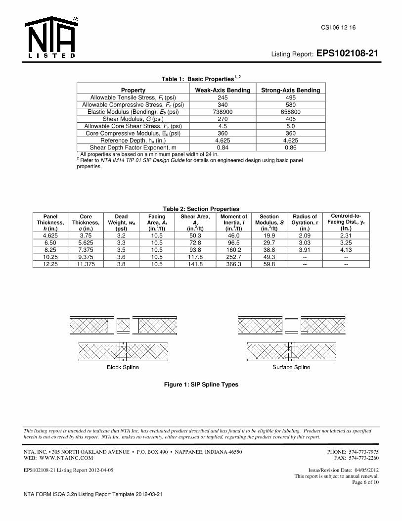
Listing Report: EPS102108-21
This listing report is intended to indicate that NTA Inc. has evaluated product described and has found it to be eligible for labeling. Product not labeled as specified herein is not covered by this report. NTA Inc. makes no warranty, either expressed or implied, regarding the product covered by this report.
NTA, INC. • 305 NORTH OAKLAND AVENUE • P.O. BOX 490 • NAPPANEE, INDIANA 46550 PHONE: 574-773-7975 WEB: WWW.NTAINC.COM FAX: 574-773-2260 EPS102108-21 Listing Report 2012-04-05 Issue/Revision Date: 04/05/2012 This report is subject to annual renewal. Page 6 of 10 NTA FORM ISQA 3.2n Listing Report Template 2012-03-21
CSI 06 12 16
Table 1: Basic Properties1, 2
Property Weak-Axis Bending Strong-Axis Bending Allowable Tensile Stress, Ft (psi) 245 495
Allowable Compressive Stress, Fc (psi) 340 580 Elastic Modulus (Bending), Eb (psi) 738900 658800
Shear Modulus, G (psi) 270 405 Allowable Core Shear Stress, Fv (psi) 4.5 5.0 Core Compressive Modulus, Ec (psi) 360 360
Reference Depth, ho (in.) 4.625 4.625 Shear Depth Factor Exponent, m 0.84 0.86
1 All properties are based on a minimum panel width of 24 in. 2 Refer to NTA IM14 TIP 01 SIP Design Guide for details on engineered design using basic panel properties.
Table 2: Section Properties Panel
Thickness, h (in.)
Core Thickness,
c (in.)
Dead Weight, wd
(psf)
Facing Area, Af (in.2/ft)
Shear Area, Av
(in.2/ft)
Moment of Inertia, I (in.4/ft)
Section Modulus, S
(in.3/ft)
Radius of Gyration, r
(in.)
Centroid-to-Facing Dist., yc
(in.) 4.625 3.75 3.2 10.5 50.3 46.0 19.9 2.09 2.31 6.50 5.625 3.3 10.5 72.8 96.5 29.7 3.03 3.25 8.25 7.375 3.5 10.5 93.8 160.2 38.8 3.91 4.13
10.25 9.375 3.6 10.5 117.8 252.7 49.3 -- -- 12.25 11.375 3.8 10.5 141.8 366.3 59.8 -- --
Figure 1: SIP Spline Types
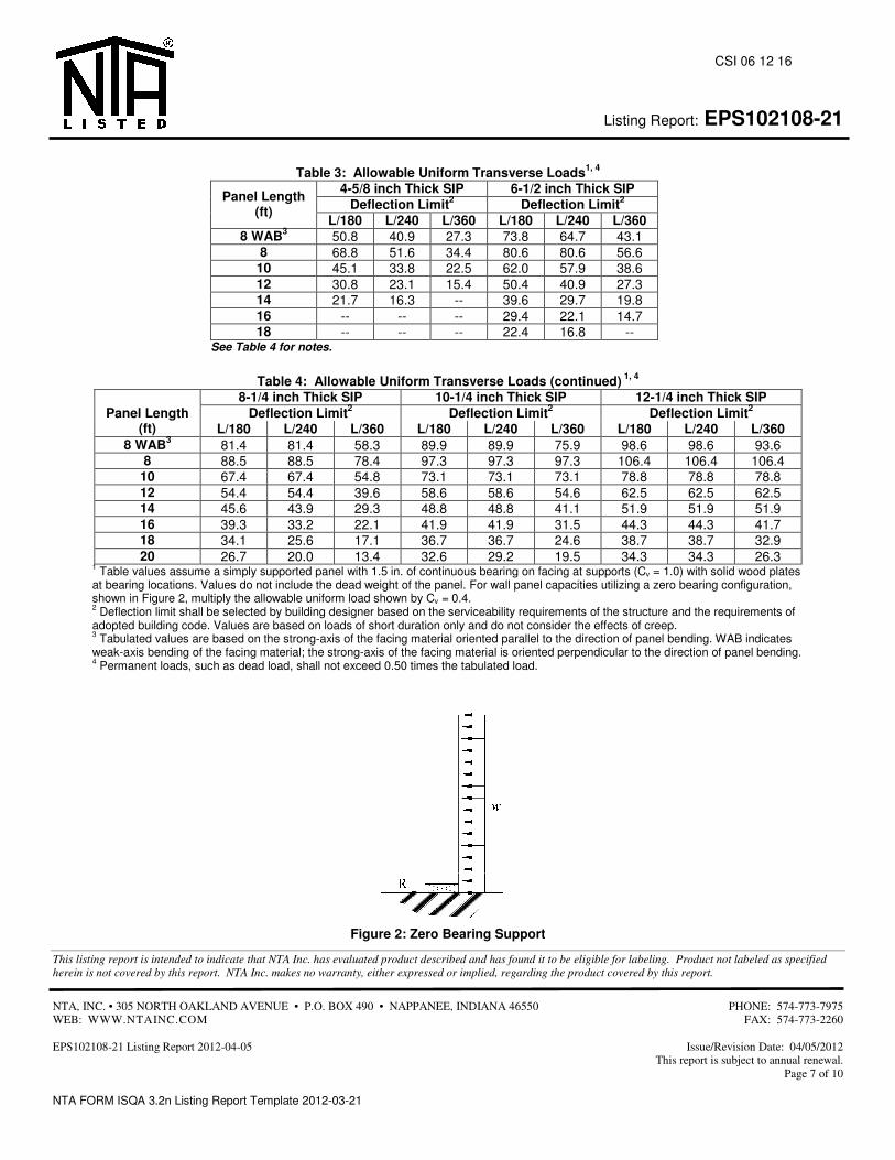
Listing Report: EPS102108-21
This listing report is intended to indicate that NTA Inc. has evaluated product described and has found it to be eligible for labeling. Product not labeled as specified herein is not covered by this report. NTA Inc. makes no warranty, either expressed or implied, regarding the product covered by this report.
NTA, INC. • 305 NORTH OAKLAND AVENUE • P.O. BOX 490 • NAPPANEE, INDIANA 46550 PHONE: 574-773-7975 WEB: WWW.NTAINC.COM FAX: 574-773-2260 EPS102108-21 Listing Report 2012-04-05 Issue/Revision Date: 04/05/2012 This report is subject to annual renewal. Page 7 of 10 NTA FORM ISQA 3.2n Listing Report Template 2012-03-21
CSI 06 12 16
Table 3: Allowable Uniform Transverse Loads1, 4
4-5/8 inch Thick SIP 6-1/2 inch Thick SIP Deflection Limit2 Deflection Limit2 Panel Length
(ft) L/180 L/240 L/360 L/180 L/240 L/360
8 WAB3 50.8 40.9 27.3 73.8 64.7 43.1 8 68.8 51.6 34.4 80.6 80.6 56.6
10 45.1 33.8 22.5 62.0 57.9 38.6 12 30.8 23.1 15.4 50.4 40.9 27.3 14 21.7 16.3 -- 39.6 29.7 19.8 16 -- -- -- 29.4 22.1 14.7 18 -- -- -- 22.4 16.8 --
See Table 4 for notes.
Table 4: Allowable Uniform Transverse Loads (continued) 1, 4 8-1/4 inch Thick SIP 10-1/4 inch Thick SIP 12-1/4 inch Thick SIP
Deflection Limit2 Deflection Limit2 Deflection Limit2 Panel Length (ft) L/180 L/240 L/360 L/180 L/240 L/360 L/180 L/240 L/360
8 WAB3 81.4 81.4 58.3 89.9 89.9 75.9 98.6 98.6 93.6 8 88.5 88.5 78.4 97.3 97.3 97.3 106.4 106.4 106.4
10 67.4 67.4 54.8 73.1 73.1 73.1 78.8 78.8 78.8 12 54.4 54.4 39.6 58.6 58.6 54.6 62.5 62.5 62.5 14 45.6 43.9 29.3 48.8 48.8 41.1 51.9 51.9 51.9 16 39.3 33.2 22.1 41.9 41.9 31.5 44.3 44.3 41.7 18 34.1 25.6 17.1 36.7 36.7 24.6 38.7 38.7 32.9 20 26.7 20.0 13.4 32.6 29.2 19.5 34.3 34.3 26.3
1 Table values assume a simply supported panel with 1.5 in. of continuous bearing on facing at supports (Cv = 1.0) with solid wood plates at bearing locations. Values do not include the dead weight of the panel. For wall panel capacities utilizing a zero bearing configuration, shown in Figure 2, multiply the allowable uniform load shown by Cv = 0.4. 2 Deflection limit shall be selected by building designer based on the serviceability requirements of the structure and the requirements of adopted building code. Values are based on loads of short duration only and do not consider the effects of creep. 3 Tabulated values are based on the strong-axis of the facing material oriented parallel to the direction of panel bending. WAB indicates weak-axis bending of the facing material; the strong-axis of the facing material is oriented perpendicular to the direction of panel bending. 4 Permanent loads, such as dead load, shall not exceed 0.50 times the tabulated load.
Figure 2: Zero Bearing Support
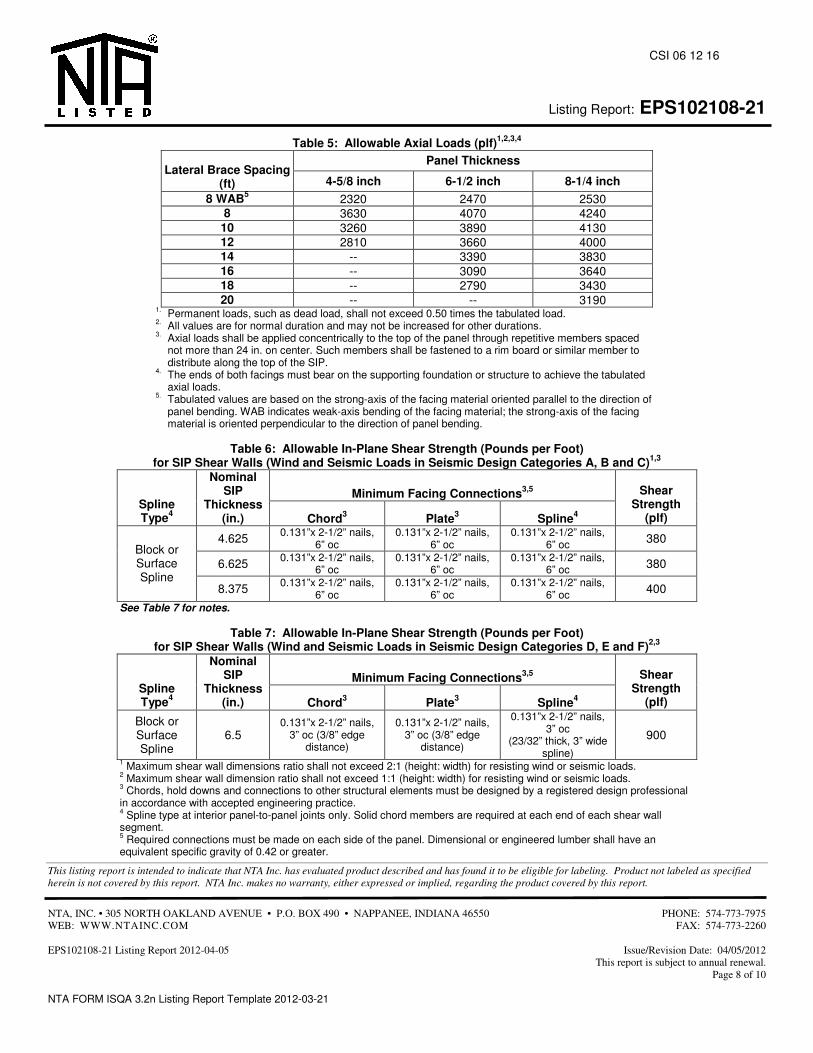
Listing Report: EPS102108-21
This listing report is intended to indicate that NTA Inc. has evaluated product described and has found it to be eligible for labeling. Product not labeled as specified herein is not covered by this report. NTA Inc. makes no warranty, either expressed or implied, regarding the product covered by this report.
NTA, INC. • 305 NORTH OAKLAND AVENUE • P.O. BOX 490 • NAPPANEE, INDIANA 46550 PHONE: 574-773-7975 WEB: WWW.NTAINC.COM FAX: 574-773-2260 EPS102108-21 Listing Report 2012-04-05 Issue/Revision Date: 04/05/2012 This report is subject to annual renewal. Page 8 of 10 NTA FORM ISQA 3.2n Listing Report Template 2012-03-21
CSI 06 12 16
Table 5: Allowable Axial Loads (plf)1,2,3,4
Panel Thickness Lateral Brace Spacing
(ft) 4-5/8 inch 6-1/2 inch 8-1/4 inch 8 WAB5 2320 2470 2530
8 3630 4070 4240 10 3260 3890 4130 12 2810 3660 4000 14 -- 3390 3830 16 -- 3090 3640 18 -- 2790 3430 20 -- -- 3190
1. Permanent loads, such as dead load, shall not exceed 0.50 times the tabulated load. 2. All values are for normal duration and may not be increased for other durations. 3. Axial loads shall be applied concentrically to the top of the panel through repetitive members spaced
not more than 24 in. on center. Such members shall be fastened to a rim board or similar member to distribute along the top of the SIP.
4. The ends of both facings must bear on the supporting foundation or structure to achieve the tabulated axial loads.
5. Tabulated values are based on the strong-axis of the facing material oriented parallel to the direction of panel bending. WAB indicates weak-axis bending of the facing material; the strong-axis of the facing material is oriented perpendicular to the direction of panel bending.
Table 6: Allowable In-Plane Shear Strength (Pounds per Foot)
for SIP Shear Walls (Wind and Seismic Loads in Seismic Design Categories A, B and C)1,3
Minimum Facing Connections3,5 Spline Type4
Nominal SIP
Thickness (in.) Chord3 Plate3 Spline4
Shear Strength
(plf)
4.625 0.131”x 2-1/2” nails, 6” oc
0.131”x 2-1/2” nails, 6” oc
0.131”x 2-1/2” nails, 6” oc 380
6.625 0.131”x 2-1/2” nails, 6” oc
0.131”x 2-1/2” nails, 6” oc
0.131”x 2-1/2” nails, 6” oc 380
Block or Surface Spline
8.375 0.131”x 2-1/2” nails, 6” oc
0.131”x 2-1/2” nails, 6” oc
0.131”x 2-1/2” nails, 6” oc 400
See Table 7 for notes.
Table 7: Allowable In-Plane Shear Strength (Pounds per Foot) for SIP Shear Walls (Wind and Seismic Loads in Seismic Design Categories D, E and F)2,3
Minimum Facing Connections3,5 Spline Type4
Nominal SIP
Thickness (in.) Chord3 Plate3 Spline4
Shear Strength
(plf)
Block or Surface Spline
6.5 0.131”x 2-1/2” nails,
3” oc (3/8” edge distance)
0.131”x 2-1/2” nails, 3” oc (3/8” edge
distance)
0.131”x 2-1/2” nails, 3” oc
(23/32” thick, 3” wide spline)
900
1 Maximum shear wall dimensions ratio shall not exceed 2:1 (height: width) for resisting wind or seismic loads. 2 Maximum shear wall dimension ratio shall not exceed 1:1 (height: width) for resisting wind or seismic loads. 3 Chords, hold downs and connections to other structural elements must be designed by a registered design professional in accordance with accepted engineering practice. 4 Spline type at interior panel-to-panel joints only. Solid chord members are required at each end of each shear wall segment. 5 Required connections must be made on each side of the panel. Dimensional or engineered lumber shall have an equivalent specific gravity of 0.42 or greater.
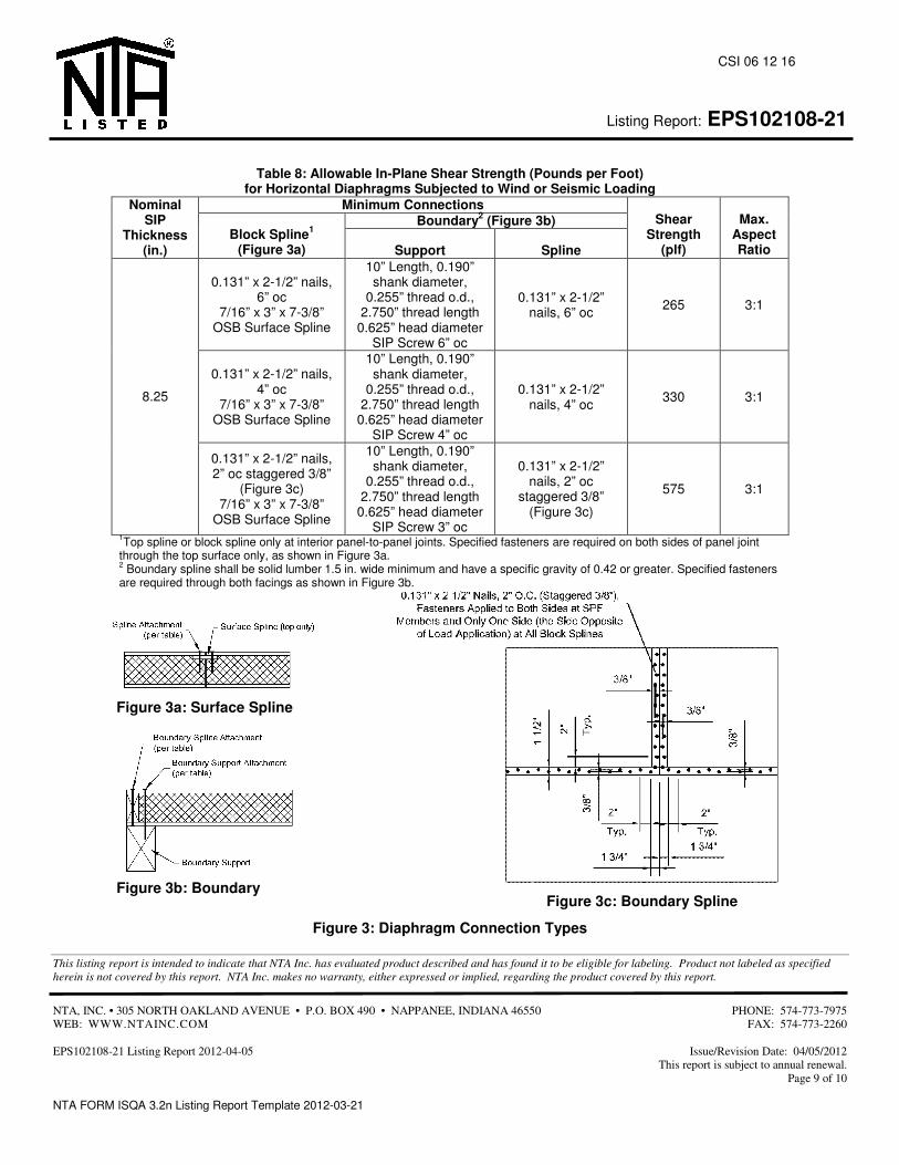
Listing Report: EPS102108-21
This listing report is intended to indicate that NTA Inc. has evaluated product described and has found it to be eligible for labeling. Product not labeled as specified herein is not covered by this report. NTA Inc. makes no warranty, either expressed or implied, regarding the product covered by this report.
NTA, INC. • 305 NORTH OAKLAND AVENUE • P.O. BOX 490 • NAPPANEE, INDIANA 46550 PHONE: 574-773-7975 WEB: WWW.NTAINC.COM FAX: 574-773-2260 EPS102108-21 Listing Report 2012-04-05 Issue/Revision Date: 04/05/2012 This report is subject to annual renewal. Page 9 of 10 NTA FORM ISQA 3.2n Listing Report Template 2012-03-21
CSI 06 12 16
Table 8: Allowable In-Plane Shear Strength (Pounds per Foot)
for Horizontal Diaphragms Subjected to Wind or Seismic Loading Minimum Connections
Boundary2 (Figure 3b) Nominal
SIP Thickness
(in.) Block Spline1
(Figure 3a) Support Spline
Shear Strength
(plf)
Max. Aspect Ratio
0.131” x 2-1/2” nails, 6” oc
7/16” x 3” x 7-3/8” OSB Surface Spline
10” Length, 0.190” shank diameter,
0.255” thread o.d., 2.750” thread length
0.625” head diameter SIP Screw 6” oc
0.131” x 2-1/2” nails, 6” oc 265 3:1
0.131” x 2-1/2” nails, 4” oc
7/16” x 3” x 7-3/8” OSB Surface Spline
10” Length, 0.190” shank diameter,
0.255” thread o.d., 2.750” thread length
0.625” head diameter SIP Screw 4” oc
0.131” x 2-1/2” nails, 4” oc 330 3:1 8.25
0.131” x 2-1/2” nails, 2” oc staggered 3/8”
(Figure 3c) 7/16” x 3” x 7-3/8”
OSB Surface Spline
10” Length, 0.190” shank diameter,
0.255” thread o.d., 2.750” thread length
0.625” head diameter SIP Screw 3” oc
0.131” x 2-1/2” nails, 2” oc
staggered 3/8” (Figure 3c)
575 3:1
1Top spline or block spline only at interior panel-to-panel joints. Specified fasteners are required on both sides of panel joint through the top surface only, as shown in Figure 3a. 2 Boundary spline shall be solid lumber 1.5 in. wide minimum and have a specific gravity of 0.42 or greater. Specified fasteners are required through both facings as shown in Figure 3b.
Figure 3: Diaphragm Connection Types
Figure 3a: Surface Spline
Figure 3b: Boundary Figure 3c: Boundary Spline
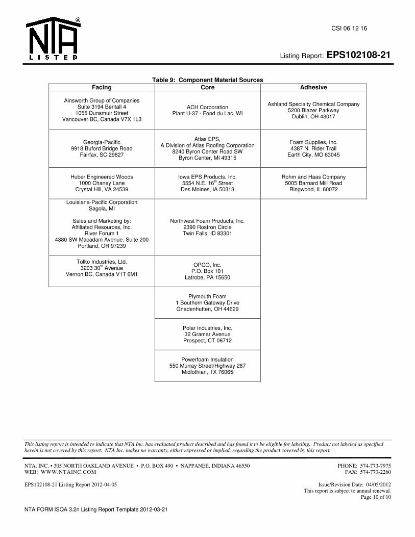
Listing Report: EPS102108-21
This listing report is intended to indicate that NTA Inc. has evaluated product described and has found it to be eligible for labeling. Product not labeled as specified herein is not covered by this report. NTA Inc. makes no warranty, either expressed or implied, regarding the product covered by this report.
NTA, INC. • 305 NORTH OAKLAND AVENUE • P.O. BOX 490 • NAPPANEE, INDIANA 46550 PHONE: 574-773-7975 WEB: WWW.NTAINC.COM FAX: 574-773-2260 EPS102108-21 Listing Report 2012-04-05 Issue/Revision Date: 04/05/2012 This report is subject to annual renewal. Page 10 of 10 NTA FORM ISQA 3.2n Listing Report Template 2012-03-21
CSI 06 12 16
Table 9: Component Material Sources
Facing Core Adhesive
Ainsworth Group of Companies Suite 3194 Bentall 4
1055 Dunsmuir Street Vancouver BC, Canada V7X 1L3
ACH Corporation Plant U-37 - Fond du Lac, WI
Ashland Specialty Chemical Company 5200 Blazer Parkway
Dublin, OH 43017
Georgia-Pacific 9918 Buford Bridge Road
Fairfax, SC 29827
Atlas EPS,
A Division of Atlas Roofing Corporation 8240 Byron Center Road SW
Byron Center, MI 49315
Foam Supplies, Inc. 4387 N. Rider Trail
Earth City, MO 63045
Huber Engineered Woods 1000 Chaney Lane
Crystal Hill, VA 24539
Iowa EPS Products, Inc.
5554 N.E. 16th Street Des Moines, IA 50313
Rohm and Haas Company 5005 Barnard Mill Road
Ringwood, IL 60072
Louisiana-Pacific Corporation Sagola, MI
Sales and Marketing by: Affiliated Resources, Inc.
River Forum 1 4380 SW Macadam Avenue, Suite 200
Portland, OR 97239
Northwest Foam Products, Inc. 2390 Rostron Circle Twin Falls, ID 83301
Tolko Industries, Ltd. 3203 30th Avenue
Vernon BC, Canada V1T 6M1
OPCO, Inc.
P.O. Box 101 Latrobe, PA 15650
Plymouth Foam
1 Southern Gateway Drive Gnadenhutten, OH 44629
Polar Industries, Inc. 32 Gramar Avenue Prospect, CT 06712
Powerfoam Insulation
550 Murray Street/Highway 287 Midlothian, TX 76065

JOB_______________________________________ SHEET NO._______________OF________________ CALC. BY________________DATE______________ CHECKED BY____________ _DATE______________
MISSOURI S&T SOLAR HOUSE TEAM | Chameleon House 86
B. US DEPARTMENT OF ENERGY SOLAR DECATHALON 2013 RULES

RULES
Last Updated: September 24, 2012

U.S. Department of Energy Solar Decathlon 2013 Rules i September 24, 2012
Contents
SECTION I: DEFINITIONS ........................................................................................................................................1
SECTION II: GENERAL RULES ..................................................................................................................................5
Rule 1. Authority ................................................................................................................................................................ ............. 5 1-1. Director ................................................................................................................................................................ ................ 5 1-2. Competition Manager .................................................................................................................................................... 5 1-3. Rules Officials .................................................................................................................................................................... 5 1-4. Organizers ................................................................................................................................................................ .......... 5 1-5. Staff........................................................................................................................................................................................ 5
Rule 2. Administration ................................................................................................................................................................ . 5 2-1. Precedence ......................................................................................................................................................................... 5 2-2. Violations of Intent ......................................................................................................................................................... 5 2-3. Effective Date .................................................................................................................................................................... 5 2-4. Official Communications .............................................................................................................................................. 5 2-5. Decisions on the Rules ................................................................................................................................................... 6 2-6. Self-Reporting ................................................................................................................................................................ ... 6 2-7. Penalties .............................................................................................................................................................................. 6 2-8. Protests ................................................................................................................................................................ ................ 7
Rule 3. Participation ................................................................................................................................................................ ...... 8 3-1. Entry ................................................................................................................................................................ ..................... 8 3-2. Contact Information ....................................................................................................................................................... 8 3-3. Safety ................................................................................................................................................................ .................... 9 3-4. Conduct ................................................................................................................................................................ ................ 9 3-5. Use of Likeness, Content, and Images ..................................................................................................................... 9 3-6. Withdrawals ................................................................................................................................................................ ...... 9
Rule 4. Site Operations ................................................................................................................................................................ . 9 4-1. Damage Liability .............................................................................................................................................................. 9 4-2. Construction Equipment ............................................................................................................................................ 10 4-3. Ground Penetration ...................................................................................................................................................... 10 4-4. Impact on the Competition Site ............................................................................................................................... 10 4-5. Generators ................................................................................................................................................................ ........ 10 4-6. Spill Containment .......................................................................................................................................................... 10 4-7. Lot Conditions ................................................................................................................................................................ . 10 4-8. Electric Vehicles ............................................................................................................................................................. 10
Rule 5. The Solar Envelope ....................................................................................................................................................... 11 5-1. Lot Size ................................................................................................................................................................ ............... 11 5-2. Solar Envelope Dimensions ....................................................................................................................................... 11
Rule 6. The House ................................................................................................................................................................ ......... 12 6-1. Structural Design Approval ....................................................................................................................................... 12 6-2. Finished Square Footage ............................................................................................................................................ 12 6-3. Entrance and Exit Routes ........................................................................................................................................... 12 6-4. Competition Prototype Alternates ......................................................................................................................... 12
Rule 7. Vegetation ................................................................................................................................................................ ......... 13 7-1. Placement ................................................................................................................................................................ ......... 13 7-2. Watering Restrictions .................................................................................................................................................. 13
Rule 8. Energy ................................................................................................................................................................ ................ 13 8-1. PV Technology Limitations ........................................................................................................................................ 13 8-2. Energy Sources ............................................................................................................................................................... 13 8-3. Batteries ............................................................................................................................................................................ 13
U.S. Department of Energy Solar Decathlon 2013 Rules ii September 24, 2012
8-4. Desiccant Systems ......................................................................................................................................................... 14 8-5. Village Grid ....................................................................................................................................................................... 14 8-6. Net Metering Rules ....................................................................................................................................................... 14
Rule 9. Liquids ................................................................................................................................................................ ............... 14 9-1. Container Locations ..................................................................................................................................................... 14 9-2. Team-Provided Liquids .............................................................................................................................................. 14 9-3. Greywater Reuse ........................................................................................................................................................... 15 9-4. Rainwater Collection.................................................................................................................................................... 15 9-5. Evaporation ................................................................................................................................................................ ..... 15 9-6. Thermal Mass ................................................................................................................................................................ .. 15 9-7. Greywater Heat Recovery .......................................................................................................................................... 15 9-8. Water Delivery ............................................................................................................................................................... 15 9-9. Water Removal ............................................................................................................................................................... 16
Rule 10. The Event ................................................................................................................................................................ ..... 16 10-1. Registration ................................................................................................................................................................ 16 10-2. Event Sponsor Recognition .................................................................................................................................. 16 10-3. Team Sponsor Recognition .................................................................................................................................. 17 10-4. Logistics ................................................................................................................................................................ ........ 17 10-5. Inspections ................................................................................................................................................................ .. 17 10-6. Communications Materials ................................................................................................................................... 18
Rule 11. Contest Week ............................................................................................................................................................. 18 11-1. House Occupancy ..................................................................................................................................................... 18 11-2. House Operators ....................................................................................................................................................... 18 11-3. Late Design Changes ............................................................................................................................................... 18 11-4. Public Exhibit ............................................................................................................................................................. 18 11-5. Team Uniforms .......................................................................................................................................................... 19 11-6. Impound ................................................................................................................................................................ ....... 19
SECTION III: CONTEST CRITERIA ......................................................................................................................... 21
Contest 1. Architecture ........................................................................................................................................................... 22 Contest 2. Market Appeal ....................................................................................................................................................... 22 Contest 3. Engineering ............................................................................................................................................................ 23 Contest 4. Communications .................................................................................................................................................. 24 Contest 5. Affordability ........................................................................................................................................................... 25 Contest 6. Comfort Zone ......................................................................................................................................................... 26
6-1. Temperature ................................................................................................................................................................... 26 6-2. Humidity ................................................................................................................................................................ ........... 26
Contest 7. Hot Water ................................................................................................................................................................ 26 Contest 8. Appliances .............................................................................................................................................................. 27
8-1. Refrigerator ................................................................................................................................................................ ..... 27 8-2. Freezer ................................................................................................................................................................ ............... 28 8-3. Clothes Washer .............................................................................................................................................................. 28 8-4. Clothes Dryer .................................................................................................................................................................. 28 8-5. Dishwasher ................................................................................................................................................................ ...... 29
Contest 9. Home Entertainment ......................................................................................................................................... 29 9-1. Lighting ................................................................................................................................................................ .............. 29 9-2. Cooking ................................................................................................................................................................ .............. 30 9-3. Dinner Party ................................................................................................................................................................ .... 30 9-4. Home Electronics .......................................................................................................................................................... 31 9-5. Movie Night ................................................................................................................................................................ ...... 32
Contest 10. Energy Balance ..................................................................................................................................................... 32
APPENDIX A EVENT SCHEDULES .......................................................................................................................... 33
U.S. Department of Energy Solar Decathlon 2013 Rules iii September 24, 2012
A-1. Overview Event Calendar ............................................................................................................................................... 33 A-2. Scoring Chronology ........................................................................................................................................................... 34 A-3. Detailed Event Schedule .................................................................................................................................................. 35
APPENDIX B JURIED SUBCONTEST GUIDELINES ............................................................................................ 41
B-1. Juror Guidelines ................................................................................................................................................................ .. 41 B-2. Team Guidelines ................................................................................................................................................................ . 42 B-3. Public Exhibit Requirements ......................................................................................................................................... 43
APPENDIX C MEASURED SUBCONTEST GUIDELINES .................................................................................... 45
C-1. Monitored Performance Subcontests ........................................................................................................................ 45 C-2. Task Completion Subcontests ....................................................................................................................................... 46
APPENDIX D COMPETITION DELIVERABLES ................................................................................................... 47
D-1. Schematic Design Summary ........................................................................................................................................... 47 D-2. Computer-Animated Walkthrough and Computer-Generated Renderings ............................................... 49 D-3. Building Information Model .......................................................................................................................................... 49 D-4. Drawings ................................................................................................................................................................................ 50 D-5. Project Manual ................................................................................................................................................................ ..... 50 D-6. Jury Narratives ................................................................................................................................................................ .... 53 D-7. Audiovisual Presentation ................................................................................................................................................ 53 D-8. Website ................................................................................................................................................................ ................... 54 D-9. Project Summary ................................................................................................................................................................ 54 D-10. Public Exhibit Materials .............................................................................................................................................. 56 D-11. Final Report ................................................................................................................................................................ ..... 56
APPENDIX E HEALTH AND SAFETY PLAN ......................................................................................................... 59
E-1. Plan Development .............................................................................................................................................................. 59 E-2. Required Training .............................................................................................................................................................. 59 E-3. Submission and Approval ............................................................................................................................................... 59
APPENDIX F DELIVERABLE SUBMISSION INSTRUCTIONS .......................................................................... 61
F-1. Website URL ................................................................................................................................................................ ......... 61 F-2. PDF Requirements ............................................................................................................................................................. 61 F-3. Electronic File-Naming Instructions .......................................................................................................................... 61 F-4. Electronic File Submission Options ............................................................................................................................ 62
U.S. Department of Energy Solar Decathlon 2013 Rules 1 September 24, 2012
SECTION I: DEFINITIONS
Assembly The period of time between the arrival of trucks and the beginning of the contests on the competition site
Communications manager The organizer responsible for the project’s public outreach and communications activities
Communications materials All printed or electronic publications designed to convey information to the public
Competition All aspects of the Solar Decathlon related to the contests and the scoring of those contests
Competition manager The organizer responsible for writing and enforcing the rules and conducting a fair and compelling competition
Competition prototype The complete assembly of physical components installed within the solar envelope
Competition site The area provided by the organizers containing all solar envelopes, pedestrian walkways, and associated organizer equipment, structures, and infrastructure
Contest The Solar Decathlon competition consists of 10 separately scored contests, each containing one or more subcontests
Contest official An individual selected by the competition manager to officiate one or more of the contests; a contest official is only authorized to interpret the rules of the contest(s) to which he or she is assigned
Contest week The 9-day period on the competition site when some or all contests are in progress
Decathlete A team member who meets the decathlete eligibility rules outlined in the file posted in the "/Files/Rules" folder on the Yahoo Group
Decision The rules officials’ interpretation or clarification of a rule
Decisions on the Solar Decathlon Rules The compilation of all decisions made by the rules officials during the project
Director The organizer representing the U.S. Department of Energy with final decision-making authority regarding all aspects of the project
Disassembly The period of time between the closing of the public exhibit and the completion of competition site cleanup; Rule 8-2 does not apply during disassembly
Event The activities that take place on the competition site including, but not limited to, registration, assembly, inspections, contests, special events, public exhibits, and disassembly

U.S. Department of Energy Solar Decathlon 2013 Rules 2 September 24, 2012
Event production manager The organizer responsible for the project’s special events and volunteer activities
Event sponsor An entity selected by the director to support the Solar Decathlon—a project of the U.S. Department of Energy (DOE), which partners with other institutions, such as its National Renewable Energy Laboratory (NREL), to help ensure the success of the project
Faculty advisor A team member who is the lead faculty member and primary representative of a participating school in the project; also provides guidance to the team on an as-needed basis throughout the project
Grid-tie assembly The period of time during assembly after the house has been connected to the village grid (interconnected); Rule 8-2 applies during grid-tie assembly
Interconnection application Submitted in the project manual by the team’s electrical engineer, this form provides the technical details needed to determine the suitability of the team’s electrical system for interconnection to the village grid
Juried subcontest A subcontest based on a jury evaluation
Juror An individual selected by the organizers to make subjective evaluations of the projects
Jury A group of jurors evaluating a specific aspect of each team’s competition prototype
Measured subcontest A subcontest based on task completion or monitored performance
Observer Assigned by the competition manager to observe team activities during contest week, an observer reports observed rules infractions to the rules officials and records the results of specific contest tasks, but does not provide interpretations of the Solar Decathlon Rules
Organizer A DOE or NREL employee, subcontractor, or observer working on the project and having the authority described in Rule 1-4
Project All activities related to the U.S. Department of Energy Solar Decathlon 2013—from the issuance of the request for proposals through the closing of subcontracts
Protest resolution committee A group of individuals selected by the organizers to resolve team protests during the competition
Public exhibit Areas of the competition site open to the public during designated hours
Rule A principle or regulation governing conduct, action, procedure, arrangement, etc., for the duration of the project
Rules official An organizer authorized to interpret the rules; the competition manager is the lead rules official
U.S. Department of Energy Solar Decathlon 2013 Rules 3 September 24, 2012
Safety officer An organizer whose primary responsibilities are to evaluate the teams’ construction documents and the teams’ competition site activities for compliance with Rule 3-3
Scored period Any 15-minute period beginning at 0, 15, 30, or 45 minutes after the hour, during which a particular monitored contest is in progress
Scorekeeper The individual selected by the organizers to operate the scoring server during the competition
Scoring server A server that collects data from the central datalogger server; includes forms for manually entering juried and task-based measured contest results, and calculates composite scores
Site operations manager The organizer responsible for all event site operations except those listed as responsibilities of the competition manager and event production manager
Solar Decathlon Building Code A set of design and construction standards set forth and enforced by the Solar Decathlon building official for the protection of public health and safety during the event
Solar Decathlon building official The rules official responsible for writing, interpreting, and enforcing the Solar Decathlon Building Code
Solar envelope The area, as defined by Rule 5, containing the competition prototype
Stand-alone assembly The period of time during assembly before the house has been interconnected to the village grid; Rule 8-2 does not apply during stand-alone assembly
Staff Individuals working for the organizers on the project, including volunteers
Subcontest An individually scored element within a contest
Team The combination of team members, including team crew and decathletes, representing a single entry to the competition
Team crew A person who is integrally involved with a team’s project but is unaffiliated with a participating school; contractors, volunteers, team media, and sponsors represent team crew examples
Team member An enrolled student, recent graduate, faculty member, or other person who is affiliated with one of the participating schools and is integrally involved with a team’s project activities; decathletes, faculty advisors, and involved staff from a participating school are all considered team members
Village grid The bi-directional, AC electrical network on the competition site to which each house has an individually metered connection
Yahoo Group A community website that includes official communications suitable for viewing by all teams and organizers
U.S. Department of Energy Solar Decathlon 2013 Rules 5 September 24, 2012
SECTION II: GENERAL RULES
Rule 1. Authority
1-1. Director The director represents the U.S. Department of Energy and has the final decision-making authority in all aspects of the project.
1-2. Competition Manager The competition manager is the only rules official authorized to write and modify the rules.
1-3. Rules Officials The rules officials are the only organizers authorized to interpret the rules. a. If there is any doubt or ambiguity as to the wording or intent of these rules, the decision of the rules officials
shall prevail. b. Printed, electronic, and verbal communications from the rules officials shall be considered part of, and shall
have the same validity as, these rules.
1-4. Organizers Occasionally, a rules official may not be immediately available to make an extremely time-sensitive decision. In these rare cases, organizers are authorized to revise the project schedule, change a team’s score, or enforce the rules in any manner that is, in their sole judgment, required for the fair and efficient operation or safety of the competition.
1-5. Staff Solar Decathlon staff are not authorized to revise the project schedule, change a team’s score, or enforce the rules under any circumstances.
Rule 2. Administration
2-1. Precedence If there is a conflict between two or more rules, the rule having the later date takes precedence.
2-2. Violations of Intent A violation of the intent of a rule is considered a violation of the rule itself.
2-3. Effective Date The latest version of the Rules posted in the “/Files/Rules” folder on the Yahoo Group1 and dated for the year of the event represents the Rules in effect.
2-4. Official Communications It is the team’s responsibility to stay current with official project communications. Official communications between the teams and the organizers occur through, but are not limited to, one or more of the following: a. Yahoo Group (http://groups.yahoo.com/group/SD2013): Official communications suitable for viewing by
all teams and organizers are posted on the Yahoo Group message board. The Yahoo Group includes a section
1 Members of the public without access to the Yahoo Group who are interested in receiving this information may email a request to the competition manager at [email protected].
U.S. Department of Energy Solar Decathlon 2013 Rules 6 September 24, 2012
for posting files. If files are too large for the Yahoo Group, they are posted on the FTP site or in the dropbox, and the teams are notified of the exact location of file(s) via the Yahoo Group. Other Yahoo Group features are used for various purposes. Instructions for joining the Yahoo Group are provided to each team immediately following the selection of teams.
b. Competition manager’s email ([email protected]): For confidential communications or the transfer of small (<5 MB), confidential files, teams may email the competition manager. The content of communications sent to this email address remains confidential, unless the team grants permission to the competition manager to divulge the content of these communications to the other teams. See the exception in Rule 2-5 for more information about confidentiality.
c. Dropbox (http://dropbox.yousendit.com/SolarDecathlon): The dropbox is used by the organizers and teams to transfer large or confidential files. Notification of or requests for file transfers are made via the Yahoo Group or email.
d. Conference calls: Teams are strongly encouraged to participate in regularly scheduled conference calls with the organizers. Invitations and instructions for participation in conference calls are provided via the Yahoo Group.
e. Meetings: Before the event, the teams and organizers have one or more in-person meetings. Notification of the date(s) and agenda(s) for these meetings is made via the Yahoo Group. A meeting is held the day before assembly begins. Meetings are also held on a daily basis throughout the event.
f. Email: For expediency and to protect confidentiality, the organizers may choose to communicate with teams via team members’ email addresses listed in the Yahoo Group database. However, most official communication occurs via the Yahoo Group message board.
2-5. Decisions on the Rules The Decisions on the Rules offers interpretations of the rules contained in this document, the Solar Decathlon Rules. After the rules officials make a decision that may, in their opinion, directly or indirectly affect the strategies of all teams, the rules officials add the decision to the Decisions on the Rules and notify the teams of the addition via the Yahoo Group. Exception: If such a notification would unfairly reveal the strategies of one or more individual teams, the organizers may, depending on the circumstances, refrain from notifying all teams of the decision.
2-6. Self-Reporting Teams shall self-report obvious or suspected rules infractions that have occurred or may occur. a. The Solar Decathlon Rules do not address every possible scenario that may arise during the competition.
Therefore, a team considering an action that is not explicitly permitted by the rules should ask the rules officials for a decision before proceeding with the action. If the team does not ask for an official decision, it puts itself at risk of incurring a penalty.
b. The rules officials and director exercise discretion when determining the penalty for a rules infraction. Rules infractions observed by rules officials, organizers, or other teams, i.e., not self-reported by the team committing the infraction, may be subject to more severe penalties than self-reported rules infractions.
2-7. Penalties Teams committing rules infractions are subject to one or more of the following penalties, depending on the severity of the infraction: 1) point penalty applied to one or more contests; 2) disqualification from part, or all, of one or more subcontests; or 3) disqualification from the competition. a. The rules officials shall determine the severity of rules infractions and classify them as minor or major. b. The rules officials are authorized to apply point penalties and disqualify a team from part, or all, of one or
more subcontests as a consequence of minor rules infractions.
U.S. Department of Energy Solar Decathlon 2013 Rules 7 September 24, 2012
c. The rules officials shall report to the director all major rules infractions. The director is solely authorized to apply point penalties or disqualify a team from the competition or from part, or all, of one or more subcontests for major rules infractions.
d. Disqualification from the competition requires prior notice to the team and an opportunity for the team to make an oral or written statement on its behalf.
e. The competition manager shall notify all teams via the scoring server when a penalty has been assessed against any team. The notification shall include the identity of the team receiving the penalty; a brief description of the infraction, including its severity, i.e., minor or major; and a brief description of the penalty.
2-8. Protests Official written protests may be filed by a team for any reason during the contest week. A filing fee of up to 10 points may be assessed to the team filing the protest if the protest is deemed by the protest resolution committee to be frivolous. a. Teams are encouraged to communicate with the rules officials to resolve issues and complaints before
resorting to the protest process. Protests should be filed only if a) the team and the rules officials are unable to resolve the dispute themselves; or b) the team or the rules officials are too busy to engage in discussions that may result in resolution of the dispute without a protest.
b. Protests shall be submitted between 8 a.m. and 6 p.m., and within 24 hours of the action being protested. The final opportunity to file a protest is 5 minutes following the conclusion of the final subcontest on the final day of contest week. Exception: The results of one or more subcontests may be announced during the final awards ceremony. The results of contests or subcontests announced during the final awards ceremony may not be protested.
c. The protest shall be submitted to the competition manager in a sealed envelope. It shall include the name and signature of a decathlete, the date of the protest submission, an acknowledgment that a 10-point filing fee may be assessed, and a clear description of the action being protested.
d. Following the receipt of a protest, the protest resolution procedure will occur as follows: (i). The competition manager convenes the protest resolution committee. (ii). The competition manager submits the sealed envelope containing the team’s written protest to the
committee. Unless the competition manager is called by the committee to testify, the competition manager is not permitted to read the protest until after the protest resolution committee has submitted its written decision.
(iii). The committee opens the envelope and reads the protest in private. No appearance by organizers or team members is authorized during the committee’s private deliberations. No right to counsel by organizers or team members is authorized.
(iv). The committee notifies the competition manager if it would like to call any individuals for testimony. The competition manager notifies individuals called for testimony. The committee may call the competition manager for testimony.
(v). Testimony is provided by individuals called by the committee. (vi). The committee notifies the competition manager of its decision in writing and indicates how many
points shall be assessed as a filing fee. The decision of the committee is final and no further appeals are allowed.
(vii). If the decision involves changes to a team’s score or the assessment of a filing fee, the competition manager notifies the scorekeeper of the changes, and the scorekeeper applies the changes to the scoring server.
(viii). The competition manager posts a copy of the written protest and decision on the Yahoo Group.
U.S. Department of Energy Solar Decathlon 2013 Rules 8 September 24, 2012
Rule 3. Participation
3-1. Entry The project is open to colleges, universities, and other post-secondary educational institutions. Entry is determined through a proposal process. All proposals are reviewed, scored, and ranked. Subject to the quantity and quality of proposals, a limited number of teams will be selected for entry.
3-2. Contact Information Each team shall provide contact information for the team officers listed in Table 1 and shall keep the contact information current for the duration of the project. a. If a team’s internal officer titles do not exactly match those listed in Table 1, each team shall still provide the
contact information for the person fulfilling each of the areas of responsibility described in the second column.
b. Teams shall provide the contact information for one and only one person in each officer position; these individuals are responsible for forwarding information to any “co-officers,” as necessary.
c. An individual may have multiple officer titles, however the same individual may not fulfill the project manager, construction manager, or health and safety officer roles.
d. Teams shall enter required contact information into the “Team Officer Contact Info” Yahoo Group database. e. Faculty members are only eligible to fill the “faculty advisor” team officer position. Eligible decathletes must
fill all other team officer positions.
Table 1: Team officers
Title Responsibilities
Primary student contact Ensures that official communications from the organizers are routed to the appropriate team member(s)
Project manager Responsible for planning and executing the project and ultimately responsible for the overall health and safety of the project
Public relations contact Works in conjunction with DOE’s Public Affairs office to coordinate the team’s interactions with the media
Construction manager
Responsible for planning and executing the construction, transport, assembly, and disassembly of the house, including providing the necessary oversight on construction activities to ensure that construction work is performed in compliance with the Health and Safety Plan
Architecture project manager Responsible for the architectural design effort; license not required Project engineer Responsible for the engineering design effort; license not required
Measured contest captain Serves as the primary strategist and coordinator of tasks in Contests 6 through 10; is responsible for demonstrating the compliance of appliances with the Rules
Health and safety officer Responsible for developing the team’s Health and Safety Plan, for providing health and safety oversight to the project and advising the project manager and construction manager, as necessary, on project health and safety issues
Life safety captain Responsible for the team’s life safety during the event, including the fire watch, public safety within the team’s solar envelope, and evacuation procedures
Instrumentation contact Collaborates with the organizers’ instrumentation team and the team’s construction manager to accommodate the organizer’s equipment
Electrical engineer Completes the Interconnection Application and works in conjunction with the site operations manager to interconnect the house to the micro-grid on the competition site; license not required
Faculty advisor Serves as the lead faculty member and primary representative of a participating school in the project; also provides guidance to the team throughout the project
Sponsorship manager Responsible for recruiting team sponsors and for team compliance with Rule 10-3
U.S. Department of Energy Solar Decathlon 2013 Rules 9 September 24, 2012
3-3. Safety Each team is responsible for the safety of its operations. a. Each team member and team crew member shall work in a safe manner at all times during the project in
accordance with the requirements identified in the rules and approved team Health and Safety Plan. b. Each team shall supply all necessary personal protective equipment (PPE) and safety equipment for all of the
team’s workers during the project. c. During assembly and disassembly, a minimum level of PPE—hard hat (ANSI Z89.1 or equivalent, Type I,
Class G or better), safety glasses with side shields (ANSI Z87.1 or equivalent), shirt with sleeves at least 3 in. (7.6 cm) long, long pants (the bottoms of the pant legs shall, at a minimum, touch the top of the boots when standing), and safety boots (ANSI Z41 PT99 or equivalent) with ankle support—shall be used by each team member and team crew member. Additional PPE or safety equipment shall be used if required for the task being performed.
d. Children under the age of 18 are not permitted to be on the competition site during assembly and disassembly.
e. Smoking is not permitted within the competition site at any time during assembly or disassembly. f. Pets and other animals are not permitted on the competition site during assembly or disassembly with the
exception of registered service animals. g. Organizers may issue a stop work order at any time during the project if a hazardous condition is identified. h. Failure to follow the procedures and requirements outlined in each team’s Health and Safety Plan is
considered a rule violation subject to Rule 2-7.All electrical work on the competition site shall meet electrical lockout/tagout requirements indicated in each team’s approved Health and Safety Plan.
3-4. Conduct Improper conduct or the use of alcohol or illegal substances will not be tolerated. Improper conduct may include, but is not limited to, improper language, unsportsmanlike conduct, unsafe behavior, distribution of inappropriate media, or cheating.
3-5. Use of Likeness, Content, and Images Team members and crew agree to the use of their names, likenesses, content, graphics, and photos in any communications materials issued by the organizers and event sponsors. a. Content and images (graphics and photos), and any publications in which the content and images appear,
may be viewable and made available to the general public via DOE’s, NREL’s, and the event sponsors’ websites with unrestricted use.
b. The organizers and event sponsors will make all reasonable efforts to credit the sources of content and images, although they may be published without credit. To ensure proper usage of and credit for images, teams should submit photos and graphics by following the instructions for submitting images located in Appendix F.
Exception: The deliverable status sheet posted in the “/Files/Deliverable Status Sheet” folder on the Yahoo Group indicates which deliverables will remain confidential through the completion of the project. All other competition and contract deliverables may be made publicly available any time after their receipt by the organizers.
3-6. Withdrawals Any team wishing to withdraw from the project must notify the competition manager in writing. All written withdrawals signed by a faculty advisor are final.
Rule 4. Site Operations
4-1. Damage Liability Each team is financially responsible for any damage it causes to the competition site.
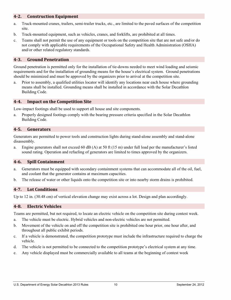
U.S. Department of Energy Solar Decathlon 2013 Rules 10 September 24, 2012
4-2. Construction Equipment a. Truck-mounted cranes, trailers, semi-trailer trucks, etc., are limited to the paved surfaces of the competition
site. b. Track-mounted equipment, such as vehicles, cranes, and forklifts, are prohibited at all times. c. Teams shall not permit the use of any equipment or tools on the competition site that are not safe and/or do
not comply with applicable requirements of the Occupational Safety and Health Administration (OSHA) and/or other related regulatory standards.
4-3. Ground Penetration Ground penetration is permitted only for the installation of tie-downs needed to meet wind loading and seismic requirements and for the installation of grounding means for the house’s electrical system. Ground penetrations should be minimized and must be approved by the organizers prior to arrival at the competition site. a. Prior to assembly, a qualified utilities locator will identify any locations near each house where grounding
means shall be installed. Grounding means shall be installed in accordance with the Solar Decathlon Building Code.
4-4. Impact on the Competition Site Low-impact footings shall be used to support all house and site components. a. Properly designed footings comply with the bearing pressure criteria specified in the Solar Decathlon
Building Code.
4-5. Generators Generators are permitted to power tools and construction lights during stand-alone assembly and stand-alone disassembly. a. Engine generators shall not exceed 60 dB (A) at 50 ft (15 m) under full load per the manufacturer’s listed
sound rating. Operation and refueling of generators are limited to times approved by the organizers.
4-6. Spill Containment a. Generators must be equipped with secondary containment systems that can accommodate all of the oil, fuel,
and coolant that the generator contains at maximum capacities. b. The release of water or other liquids onto the competition site or into nearby storm drains is prohibited.
4-7. Lot Conditions Up to 12 in. (30.48 cm) of vertical elevation change may exist across a lot. Design and plan accordingly.
4-8. Electric Vehicles Teams are permitted, but not required, to locate an electric vehicle on the competition site during contest week. a. The vehicle must be electric. Hybrid vehicles and non-electric vehicles are not permitted. b. Movement of the vehicle on and off the competition site is prohibited one hour prior, one hour after, and
throughout all public exhibit periods. c. If a vehicle is demonstrated, the competition prototype must include the infrastructure required to charge the
vehicle. d. The vehicle is not permitted to be connected to the competition prototype’s electrical system at any time. e. Any vehicle displayed must be commercially available to all teams at the beginning of contest week
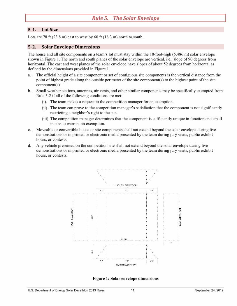
U.S. Department of Energy Solar Decathlon 2013 Rules 11 September 24, 2012
Rule 5. The Solar Envelope
5-1. Lot Size Lots are 78 ft (23.8 m) east to west by 60 ft (18.3 m) north to south.
5-2. Solar Envelope Dimensions The house and all site components on a team’s lot must stay within the 18-foot-high (5.486 m) solar envelope shown in Figure 1. The north and south planes of the solar envelope are vertical, i.e., slope of 90 degrees from horizontal. The east and west planes of the solar envelope have slopes of about 52 degrees from horizontal as defined by the dimensions provided in Figure 1. a. The official height of a site component or set of contiguous site components is the vertical distance from the
point of highest grade along the outside perimeter of the site component(s) to the highest point of the site component(s).
b. Small weather stations, antennas, air vents, and other similar components may be specifically exempted from Rule 5-2 if all of the following conditions are met:
(i). The team makes a request to the competition manager for an exemption. (ii). The team can prove to the competition manager’s satisfaction that the component is not significantly
restricting a neighbor’s right to the sun. (iii). The competition manager determines that the component is sufficiently unique in function and small
in size to warrant an exemption. c. Moveable or convertible house or site components shall not extend beyond the solar envelope during live
demonstrations or in printed or electronic media presented by the team during jury visits, public exhibit hours, or contests.
d. Any vehicle presented on the competition site shall not extend beyond the solar envelope during live demonstrations or in printed or electronic media presented by the team during jury visits, public exhibit hours, or contests.
Figure 1: Solar envelope dimensions
U.S. Department of Energy Solar Decathlon 2013 Rules 12 September 24, 2012
Rule 6. The House
6-1. Structural Design Approval Each team shall submit structural drawings and calculations that have been stamped by a qualified, licensed design professional registered in the State of California or be eligible for California registration reciprocity. a. By stamping the structural drawings and calculations, the licensed professional certifies that the structural
provisions of the Solar Decathlon Building Code have been met by the design, and that the structure is safe for the public to enter if it has been built as designed.
b. The licensed professional shall stamp the structural drawings and calculations of the house and all site components that might pose a threat to public safety if they fail.
6-2. Finished Square Footage The finished square footage, as defined by ANSI Z765-2003, “Square Footage—Method for Calculating,” shall be at least 600 ft2 (55.7 m2), but shall not exceed 1000 ft2 (92.9 m2). a. If the building has convertible or moveable components, the maximum and minimum square footages
observed during live demonstrations or shown in printed or electronic media presented by the team during jury visits, public exhibit hours, or contests count as the maximum and minimum square footages of record, respectively.
6-3. Entrance and Exit Routes a. The main house entrance may be placed on any side of the house. However, an accessible route leading from
the main street of the solar village to the main house entrance shall be provided. b. The house exit route shall lead from the main house exit to the main street of the solar village or to the
east/west side of the solar envelope accessible to the public. c. Teams shall clearly illustrate and label the entrance and exit routes between solar envelope “property lines”
and house entrance/exit in the construction drawings.
6-4. Competition Prototype Alternates Alternates to the competition prototype shall not be proposed in materials intended for consideration by the Architecture, Market Appeal, and Engineering juries. Team websites and public exhibit communications materials, including signage, handouts and public display information, are not subject to this rule. a. Renderings and other graphical representations may only show the competition prototype house and the
associated competition prototype site components on a featureless 78 ft (23.8 m) east to west by 60 ft (18.3 m) north to south lot. The featureless lot has a flat, uniform ground covering to be specified by the team.
b. Natural and man-made features, including adjacent competition prototypes, located near the target client's site may be depicted, as long as the depicted features are located outside of the solar envelope.
c. Teams shall not propose alternates to address local building code provisions and site restrictions at the target client’s site. The juries will be instructed to assume that the Solar Decathlon Rules and Building Code also apply at the target client’s site.
d. Public exhibit communications materials are not considered part of the competition prototype and, therefore, shall not be shown in renderings and other graphical representations.
Exception: The cost estimator and juries will disregard all containers and associated equipment, such as pressure pumps, that would be unnecessary if city water and sewer services were available on the competition site. Therefore, these components shall be noted as “Temporary for Competition Purposes” in drawings and other graphical representations. Note that all structures and surfaces that surround the containers will be evaluated by the cost estimator and juries. The cost estimator and juries will disregard any vehicle on display on the competition site. Note that any infrastructure provided to support the vehicle will be evaluated by the cost estimator and juries.
U.S. Department of Energy Solar Decathlon 2013 Rules 13 September 24, 2012
Rule 7. Vegetation
The use of potted vegetation is permitted. All potted vegetation shall comply with Rules 4-4 and 4-6.
7-1. Placement Vegetation may be moved around the solar envelope until the beginning of contest week, after which it shall remain stationary until the conclusion of contest week unless the drawings clearly show how some or all vegetation is designed to be moved as part of an integrated system.
7-2. Watering Restrictions Greywater that may possibly contain organisms that could go septic shall not be used to water vegetation.
Rule 8. Energy
8-1. PV Technology Limitations a. Bare photovoltaic cells and encapsulated photovoltaic modules must be commercially available to all teams
by the beginning of the event. b. Substantial modification of the crystal structure, junction, or metallization constitutes manufacture of a new
cell and is not allowed.
8-2. Energy Sources After the conclusion of stand-alone assembly (see Rule 8-5c for details) and until the conclusion of the Energy Balance Contest (see Appendix A for the detailed event schedule), global solar radiation incident upon the lot and the energy in small primary batteries (see Rule 8-3 for limitations) are the only sources of energy that may be consumed in the operation of the house without the requirement of subsequent energy offsets. Exception: Teams may use organizer-supplied microgrid power that is exempt from the Energy Balance Contest during grid-tie assembly for construction equipment, site lighting, and task lighting located outside the finished square footage only. Teams may use generators during grid-tie assembly for nighttime construction lighting only. a. All other energy sources, such as AC grid energy, consumed in the operation of the house must be offset by
an equal or greater amount of energy produced, or “regenerated,” by the house. b. Fireplaces, fire pits, candles, and other devices using non-solar fuels are not permitted in the designs.
Exception: The limited use of batteries is permitted by Rule 8-3.
8-3. Batteries Hard-wired battery banks and large plug-in uninterruptable power supplies (UPS) are not permitted. a. The use of primary (non-rechargeable) batteries (no larger than “9V” size) is limited to smoke detectors,
remote controls, thermostats, alarm clock backups, and other small devices that typically use small primary batteries.
b. “Plug-in” (non-hard-wired) devices with small secondary (rechargeable) batteries that are designed to be recharged by the house’s electrical system (e.g., a laptop computer), shall be connected, or “plugged into,” the house’s electrical system whenever the devices are located in the house or within the solar envelope. Exception: If not used in the operation of the house at any time during contest week, portable electronic devices used for mobile communications, such as cell phones and PDAs, are permitted within the solar envelope without having to be plugged into the house’s electrical system. Electric vehicles with integrated batteries are permitted to be located within the solar envelope, but may not be connected to the competition prototype’s electrical system at any time.
c. Stand-alone, PV-powered devices with small secondary batteries are permitted, but the aggregate battery capacity of these devices may not exceed 100 Wh.
U.S. Department of Energy Solar Decathlon 2013 Rules 14 September 24, 2012
d. Batteries include most commercially available energy storage devices, such as electrochemical batteries and capacitors.
8-4. Desiccant Systems If a desiccant system is used, it must be regenerative. a. To ensure that the desiccant has been fully regenerated by the conclusion of the Energy Balance Contest, the
desiccant material or device must be easily measurable. b. In most cases, the material or device will be measured prior to and at the conclusion of the Energy Balance
Contest. In some cases, a measurement at the conclusion of the Energy Balance Contest may not be necessary.
c. At the conclusion of the Energy Balance Contest, the weight of the desiccant material or device shall be less than or equal to its initial weight.
d. Some desiccant systems with very low moisture storage capacities may be exempt from this requirement. Exemptions will be granted on a case-by-case basis by the competition manager.
8-5. Village Grid The organizers shall provide the village with an electric power grid that provides AC power to and accepts AC power from the houses. a. The organizers shall provide the necessary service conductors and connect the conductors at the utility
intertie point. b. A team shall notify the organizers if its house operates with an AC service other than 60 Hz, 120/240V split-
phase with neutral. c. At a date and time specified in Appendix A, teams have the option to switch from stand-alone assembly to
grid-tie assembly if all relevant inspections have been passed and the village grid is available. Teams shall not switch back to stand-alone assembly after switching to grid-tie assembly. At a later date and time specified in Appendix A, all teams shall have switched to grid-tie assembly.
8-6. Net Metering Rules a. When a team switches from stand-alone assembly to grid-tie assembly, its bidirectional meter resets to zero. b. If the meter reading indicates net energy production at the start of the Energy Balance Contest, the meter is
reset to zero. If the meter reading indicates net energy consumption at the start of the Energy Balance Contest, the meter is not reset and the team begins the Energy Balance Contest with an energy deficit.
Rule 9. Liquids
9-1. Container Locations a. Primary supply water and greywater containers shall be located outside of the finished square footage as
defined by Rule 6-2. These containers may not be located below the finished square footage. Exception: Teams may utilize one or more small tanks to accept wastewater discharge in preparation for delivery to the main wastewater tank(s) up to a maximum aggregate volume of 20 gallons.
b. Solar storage, hot water, or other thermal storage containers may be located within the finished square footage.
c. The primary supply water tank(s) shall be fully shaded from direct solar radiation between 9 a.m. and 5 p.m. Pacific Daylight Time (PDT) or between 8 a.m. and 4 p.m. solar time on October 1.
9-2. Team-Provided Liquids A team may provide its own liquids for the following purposes: a. Personal hydration b. Irrigation [one-time delivery before water delivery day, 50 gallon (189 L) limit, water only]
U.S. Department of Energy Solar Decathlon 2013 Rules 15 September 24, 2012
c. Thermal mass (quantity limited by bearing pressure limit and Rule 4-4; see Rule 9-6 for restrictions) d. Food preparation e. Hydronic system pressure testing2 f. Small volumes of glycol, deionized water, or other working fluids for thermodynamic systems using working
fluids other than non-potable water g. Assembly (e.g., hydraulic fluid), finishing (e.g., paint), and cleaning (e.g., mineral spirits).
9-3. Greywater Reuse A team may reuse greywater for irrigation only. a. Greywater reuse systems shall comply with Rule 7-2.
9-4. Rainwater Collection A team may collect rainwater that falls on its site and use it in, or as, any of the following: a. Irrigation source b. Water feature c. Heat sink or heat source
9-5. Evaporation Water may be used for evaporation purposes.
9-6. Thermal Mass Teams may use liquids as thermal mass. a. The thermal storage containers shall be filled and sealed before their arrival on the competition site and shall
remain sealed until they are removed from the competition site by the teams. b. The thermal storage containers shall be isolated, i.e., the contained liquid shall not circulate to other
containers or systems.
9-7. Greywater Heat Recovery Heat may be recovered from greywater as it flows from the drain to the waste tank. a. “Batch”-type greywater heat recovery is prohibited.
9-8. Water Delivery A team may request up to 1500 gallons of water from the organizers in its detailed water budget.3 The procedure and associated requirements for water delivery follow. a. On water delivery day, two water trucks begin at the southeast and northwest corners of the competition site
in the morning and proceed to service each house. Each truck will be equipped with a pump to aid in water supply.
b. Teams shall provide a minimum of six people, on command, to help move the water hose to their house from the previously serviced house.
c. After the two trucks have serviced all houses once, they will circle the village again to service any house needing additional water.
d. Teams that delay the water supply process or request additional water after the trucks complete their second circle around the village are subject to a penalty and a delay in receiving their water. Instead of or in addition to a penalty, these teams may be required to pay for their own water. Teams required to pay for their own water supply shall use a company approved by the organizers.
2 The water may only fill isolated loops; it shall not enter tanks. 3 The detailed water budget shall be included in the Project Manual (see Content Requirements in Appendix D-5).
U.S. Department of Energy Solar Decathlon 2013 Rules 16 September 24, 2012
e. The design deliverables shall clearly indicate the fill location(s), quantity of water requested at each fill location, container dimensions, diameter of the opening(s) (minimum 4 in., or 10 cm), and clearance above the container(s) fill location(s) (minimum 12 in., or 30.48 cm). All openings shall be easily accessible.
f. Teams are responsible for distributing water within their houses. This includes all necessary pumps, containers, lines, valves, etc. All pumping power to distribute water must be delivered by an AC circuit.
9-9. Water Removal The procedure and associated requirements for water removal follow. a. On water removal day, two water trucks begin at the middle of the village and proceed toward the northwest
and southeast to service each house. Each truck will be equipped with a pump to aid in water removal. b. Teams shall supply a minimum of six people, on command, to help move the water hose to their house from
the previously serviced house. c. After the two trucks have serviced all houses once, they will circle the village again to service any house
needing remaining water removed. d. Teams that delay the water removal process may be required to pay for their own water removal. Teams
required to pay for their own water removal shall use a company approved by the organizers. e. The design deliverables shall clearly indicate the removal location(s), quantity of water to be removed from
each removal location, container dimensions, diameter of the opening(s) (minimum 4 in., or 10 cm), and clearance above the container(s) fill location(s) (minimum 12 in., or 30.48 cm). All openings shall be easily accessible.
f. Teams are responsible for either removing remaining water from the site or moving remaining water to the designated removal locations.
Rule 10. The Event
10-1. Registration All Solar Decathlon event participants must register either through the online registration site, which will be available closer to the event, or on the competition site. a. The following rules apply to all registrants:
(i). Each event participant must register individually. Group registrations are not allowed. (ii). Online registration is encouraged for all event participants, because on-site registration could cause
delays in gaining event access. (iii). When registering, event participants must complete all required information and forms before access
to the event is allowed. b. Organizers, team members, jurors, and staff are required to provide a photo that will be kept on file and
used for security purposes. Participants should use the online registration site to submit completed forms, information, and photos prior to the event. Once all information, forms, and photos are received, the organizers will issue an event security ID that must be visible at all times while on the competition site.
c. Team crew members are not required to submit a photo. Due to safety concerns, site access for team crew members may be restricted.
d. Visiting media will not be required to submit forms or photos, but must check in at event headquarters. Due to safety concerns, site access for visiting media may be restricted.
10-2. Event Sponsor Recognition All communications materials produced by the teams concerning or referring to the project (including team websites) shall refer prominently to the project as the “U.S. Department of Energy Solar Decathlon.” a. Teams are required to use the Solar Decathlon logo, the DOE wordmark, and the NREL logo on all
communications materials visible at the Orange County Great Park. The DOE wordmark and NREL logo
U.S. Department of Energy Solar Decathlon 2013 Rules 17 September 24, 2012
shall be a maximum of one-third the size of the Solar Decathlon logo as outlined in the Solar Decathlon identity guidelines4.
b. The Solar Decathlon logo, the DOE wordmark, and NREL logo are the only required graphic elements teams must use.
c. Team websites shall comply with Rule 10-2 with the exception of the one-third size rule for team sponsor text and logos.
d. Team uniforms are exempt from Rule 10-2. See Rule 11-5 for specifics.
10-3. Team Sponsor Recognition Team sponsors may be recognized with text, logos, or both, but the text and logos must appear in conjunction with the Solar Decathlon text and logo and be a maximum of one-third of the size of the Solar Decathlon text and logo, as outlined in the Solar Decathlon identity guidelines. a. Team websites shall comply with Rules 10-2 and 10-3, with the exception of the one-third size rule for team
sponsor text and logos. b. Rule 10-3 applies but is not limited to all communications materials that will be on display or distributed on
the competition site. c. Communications materials or other products that exist largely for the recognition of sponsors are limited to
10 square feet (0.93 square meters), in aggregate within the solar envelope. “Other products” include but are not limited to signs, exhibits, posters, plaques, photos, wall art, and furnishings.
d. For multimedia or audio presentations shown on the competition site, no more than 20% of the total time, 1 minute, or whichever is less may be dedicated to recognition of team sponsors.
e. Off-the-shelf components that feature a built-in manufacturer’s logo are acceptable and need not be accompanied by the Solar Decathlon text and logo.
f. Team uniforms are exempt from Rule 10-3. See Rule 11-5 for specifics.
10-4. Logistics a. Each team is responsible for the transport of its house, the house’s contents, and all necessary tools and
equipment, and shall be responsible for any damage to or loss of such items. b. Each team is responsible for procuring all necessary equipment, tools, and supplies. c. Each team is responsible for transportation, accommodations, lodging, food, and beverages
(i). The organizers will make drinking water available on the competition site to all team members for the duration of the event.
d. Each team is responsible for making its own reservations and arrangements and for covering all necessary costs.
10-5. Inspections Each project shall be inspected for compliance with the Solar Decathlon Rules and the Solar Decathlon Building Code. a. A team shall notify the appropriate inspector when it is ready for an inspection. When two or more teams
request an inspection simultaneously, the order of inspections shall be determined in a drawing. b. Additional random inspections for compliance shall take place throughout contest week. c. The competition manager shall check each team’s inspection status, as indicated on the team’s official
inspection card, to determine which houses are eligible to participate in the contests. All final inspections shall be passed by the conclusion of last-chance final inspections. Failure to pass inspections by the required deadline will be considered a rules violation. A team must have passed inspections by the conclusion of the inspector’s work day for a team to be eligible to participate in the following day’s contests, which officially start at midnight.
4 Solar Decathlon identity guidelines are available at: http://www.solardecathlon.gov/commstandards.
U.S. Department of Energy Solar Decathlon 2013 Rules 18 September 24, 2012
Exception: Jury visits will proceed as scheduled regardless of a team’s inspection status. However, jurors will be made aware of the team’s inspection status and may consider it in their evaluations.
d. Because open, partially functioning houses are preferable to closed, fully functioning houses, the organizers will direct the inspectors to require that an unsafe condition be corrected so that public visits can occur—even if, as a consequence, the house is ineligible for participation in one or more contests.
10-6. Communications Materials All communications materials shall support the goal of Contest 4: Communications, which is to educate consumers about the project and topics relevant to the project.
Rule 11. Contest Week
11-1. House Occupancy Under normal circumstances, no more than six people may be located in the house at any one time. a. Toward the end of each day of contest week, the competition manager shall post a message on the Yahoo
Group message board indicating the hours during which rule 11-1 is in effect the following day. b. Rule 11-1 is automatically suspended whenever the Comfort Zone Contest measurements are suspended. See
Appendix A-3 for the Comfort Zone Contest schedule. c. Jurors, observers, official organizer-provided competition photographers, media, writers, and others with
authority to enter a house as an organizer are not counted toward the number of house occupants. d. Up to 10 people may be located in the house during dinner parties. At least six of the people in the house
during dinner parties shall be the two decathletes from each of the three guest teams. No more than two of the remaining people in the house may be VIP guests.
11-2. House Operators Only decathletes are permitted to operate the house and participate in the contests during contest week. a. All competition-related communications on the competition site shall be between the organizers and
decathletes. Non-decathlete team members and team crew are not permitted to participate in or listen to competition-related communications.
11-3. Late Design Changes The final project assembled on the competition site shall be consistent with the design and specifications presented in the as-built drawings and project manual. a. If there are known inconsistencies between the final project and the as-built drawings and project manual, the
team shall document these inconsistencies and submit the documentation to the competition manager as soon as possible after the inconsistency is known. The competition manager will then submit this documentation or a summary of the documented inconsistencies to the respective juries and inspectors at the appropriate time.
b. The competition manager will compile a summary of all undocumented inconsistencies discovered during the inspections process and submit the summary to the respective juries at the appropriate time.
11-4. Public Exhibit a. Teams are required to provide an accessible route to all areas of the house and site that are available to the
public during exhibit hours. b. Teams are permitted to produce and distribute only one informational brochure or handout on the
competition site. c. Teams shall develop signage that complements public exhibit tours by informing visitors about the team
project and engaging visitors waiting in line. d. Teams are prohibited from selling items to the general public on the competition site.
U.S. Department of Energy Solar Decathlon 2013 Rules 19 September 24, 2012
e. Only organizer-approved vendors may provide food and beverage to the general public on the competition site.
11-5. Team Uniforms a. During contest week and special events specified by the organizers, all team members present on the
competition site or the site of a special event shall wear uniforms representing their team. b. Team uniforms are exempt from Rules 10-2 and 10-3. c. Team sponsor logos are approved to be visible ONLY on the back of the team uniform (jacket, shirt, hat, or
other wearable item). d. The only information or graphics that are approved to be visible from the front of the team uniform (jacket,
shirt, hat, or other wearable item) shall be the institution and its logo, the team name and logo, the Solar Decathlon logo, and event sponsor logos.
e. A built-in clothing manufacturer logo may be visible on the front or back of the team uniform, or both.
11-6. Impound Each house shall be impounded on specified nights as indicated in Appendix A under the direct supervision of the organizers or staff. Team members and team crew shall not occupy the competition site during impound hours. There is a 10-minute impound grace period.

U.S. Department of Energy Solar Decathlon 2013 Rules 20 September 24, 2012
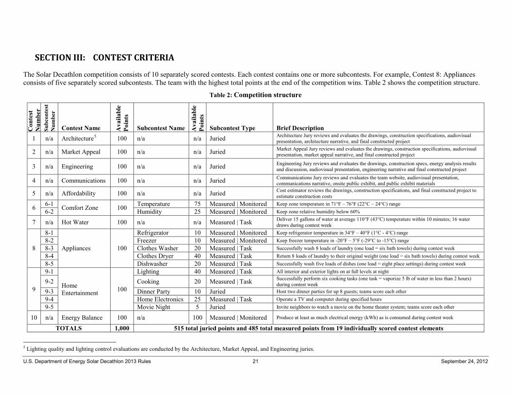
U.S. Department of Energy Solar Decathlon 2013 Rules 21 September 24, 2012
SECTION III: CONTEST CRITERIA
The Solar Decathlon competition consists of 10 separately scored contests. Each contest contains one or more subcontests. For example, Contest 8: Appliances consists of five separately scored subcontests. The team with the highest total points at the end of the competition wins. Table 2 shows the competition structure.
Table 2: Competition structure
Con
test
N
umbe
r Su
bcon
test
N
umbe
r
Contest Name Ava
ilabl
e Po
ints
Subcontest Name A
vaila
ble
Poin
ts
Subcontest Type Brief Description 1 n/a Architecture5 100 n/a n/a Juried Architecture Jury reviews and evaluates the drawings, construction specifications, audiovisual
presentation, architecture narrative, and final constructed project
2 n/a Market Appeal 100 n/a n/a Juried Market Appeal Jury reviews and evaluates the drawings, construction specifications, audiovisual presentation, market appeal narrative, and final constructed project
3 n/a Engineering 100 n/a n/a Juried Engineering Jury reviews and evaluates the drawings, construction specs, energy analysis results and discussion, audiovisual presentation, engineering narrative and final constructed project
4 n/a Communications 100 n/a n/a Juried Communications Jury reviews and evaluates the team website, audiovisual presentation, communications narrative, onsite public exhibit, and public exhibit materials
5 n/a Affordability 100 n/a n/a Juried Cost estimator reviews the drawings, construction specifications, and final constructed project to estimate construction costs
6 6-1 Comfort Zone 100 Temperature 75 Measured | Monitored Keep zone temperature in 71°F – 76°F (22°C – 24°C) range 6-2 Humidity 25 Measured | Monitored Keep zone relative humidity below 60%
7 n/a Hot Water 100 n/a n/a Measured | Task Deliver 15 gallons of water at average 110°F (43°C) temperature within 10 minutes; 16 water draws during contest week
8
8-1
Appliances 100
Refrigerator 10 Measured | Monitored Keep refrigerator temperature in 34°F – 40°F (1°C - 4°C) range 8-2 Freezer 10 Measured | Monitored Keep freezer temperature in -20°F – 5°F (-29°C to -15°C) range 8-3 Clothes Washer 20 Measured | Task Successfully wash 8 loads of laundry (one load = six bath towels) during contest week 8-4 Clothes Dryer 40 Measured | Task Return 8 loads of laundry to their original weight (one load = six bath towels) during contest week 8-5 Dishwasher 20 Measured | Task Successfully wash five loads of dishes (one load = eight place settings) during contest week
9
9-1
Home Entertainment 100
Lighting 40 Measured | Task All interior and exterior lights on at full levels at night
9-2 Cooking 20 Measured | Task Successfully perform six cooking tasks (one task = vaporize 5 lb of water in less than 2 hours) during contest week
9-3 Dinner Party 10 Juried Host two dinner parties for up 8 guests; teams score each other 9-4 Home Electronics 25 Measured | Task Operate a TV and computer during specified hours 9-5 Movie Night 5 Juried Invite neighbors to watch a movie on the home theater system; teams score each other
10 n/a Energy Balance 100 n/a 100 Measured | Monitored Produce at least as much electrical energy (kWh) as is consumed during contest week
TOTALS 1,000 515 total juried points and 485 total measured points from 19 individually scored contest elements
5 Lighting quality and lighting control evaluations are conducted by the Architecture, Market Appeal, and Engineering juries.

U.S. Department of Energy Solar Decathlon 2013 Rules 22 September 24, 2012
There are three ways to earn points: • Task completion • Monitored performance • Jury evaluation. Subcontests based on task completion or monitored performance are called measured subcontests; subcontests based on a jury evaluation are called juried subcontests. Points for task completion are awarded as a function of “closeness to completion.” Points for measured performance are either awarded at the end of each scored period throughout contest week or at the conclusion of contest week when performance requirements are met or partially met. The scoring of the juried subcontests is more flexible than the scoring of the measured subcontests described above. However, for the sake of fairness, consistency is important. To increase the consistency of the scoring in juried subcontests, the jurors shall use the evaluation method described in Appendix B-1.
Contest 1. Architecture
A jury of architects shall assign an overall score for the design’s architectural merit and implementation by reviewing the team’s drawings, construction specifications, audiovisual presentation, and architecture narrative (see Appendix D), and by performing an on-site evaluation of the competition prototype (see Appendix B). The jury shall consider the following specific criteria in its evaluation:
Design and implementation • Was the team effective in its use of architectural elements including, but not limited to: scale and proportion
of room and facade features, indoor/outdoor connections, composition, and linking of various house elements?
• Did the team create a holistic design that will be comfortable for occupants and compatible with the surrounding environment?
• Are the lighted spaces rich and varied? Do they have adequate light for tasks? Do they have good color rendition? Do the luminaires properly distribute light? Is the admission of direct and diffuse sunlight effectively controlled?
• Will the overall architectural design offer a sense of inspiration and delight to Solar Decathlon visitors? • Did the competition prototype demonstrate quality design, detailing, and architectural implementation?
Documentation • Did the drawings, construction specifications, audiovisual presentation, and architecture narrative enable the
jury to conduct a preliminary evaluation of the design prior to its arrival at the competition site? • Did the drawings, construction specifications, and audiovisual presentation accurately reflect the constructed
project as assembled on the competition site?
Contest 2. Market Appeal
A jury of professionals from the homebuilding industry shall assign an overall score for the house’s market appeal by reviewing the team’s drawings, construction specifications, audiovisual presentation, and market appeal narrative (see Appendix D), and by performing an on-site evaluation of the competition prototype (see Appendix B). The jury shall consider the following specific criteria in its evaluation of the responsiveness of the design to the characteristics and requirements of a team-defined target client (see Table 3 for examples of target client characteristics and requirements, which shall be included in the project manual).
Livability • Does the design offer the occupant(s) a safe, functional, convenient, comfortable, and enjoyable place to live?
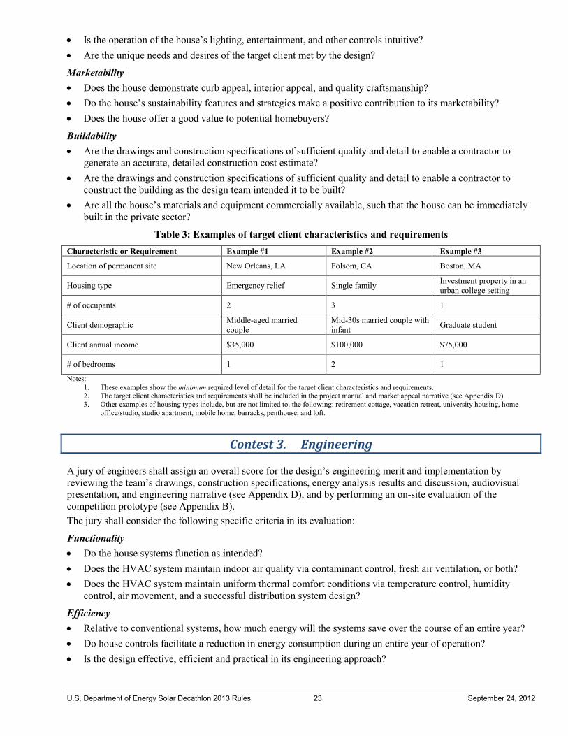
U.S. Department of Energy Solar Decathlon 2013 Rules 23 September 24, 2012
• Is the operation of the house’s lighting, entertainment, and other controls intuitive? • Are the unique needs and desires of the target client met by the design?
Marketability • Does the house demonstrate curb appeal, interior appeal, and quality craftsmanship? • Do the house’s sustainability features and strategies make a positive contribution to its marketability? • Does the house offer a good value to potential homebuyers?
Buildability • Are the drawings and construction specifications of sufficient quality and detail to enable a contractor to
generate an accurate, detailed construction cost estimate? • Are the drawings and construction specifications of sufficient quality and detail to enable a contractor to
construct the building as the design team intended it to be built? • Are all the house’s materials and equipment commercially available, such that the house can be immediately
built in the private sector?
Table 3: Examples of target client characteristics and requirements Characteristic or Requirement Example #1 Example #2 Example #3
Location of permanent site New Orleans, LA Folsom, CA Boston, MA
Housing type Emergency relief Single family Investment property in an urban college setting
# of occupants 2 3 1
Client demographic Middle-aged married couple
Mid-30s married couple with infant Graduate student
Client annual income $35,000 $100,000 $75,000
# of bedrooms 1 2 1
Notes: 1. These examples show the minimum required level of detail for the target client characteristics and requirements. 2. The target client characteristics and requirements shall be included in the project manual and market appeal narrative (see Appendix D). 3. Other examples of housing types include, but are not limited to, the following: retirement cottage, vacation retreat, university housing, home
office/studio, studio apartment, mobile home, barracks, penthouse, and loft.
Contest 3. Engineering
A jury of engineers shall assign an overall score for the design’s engineering merit and implementation by reviewing the team’s drawings, construction specifications, energy analysis results and discussion, audiovisual presentation, and engineering narrative (see Appendix D), and by performing an on-site evaluation of the competition prototype (see Appendix B). The jury shall consider the following specific criteria in its evaluation:
Functionality • Do the house systems function as intended? • Does the HVAC system maintain indoor air quality via contaminant control, fresh air ventilation, or both? • Does the HVAC system maintain uniform thermal comfort conditions via temperature control, humidity
control, air movement, and a successful distribution system design?
Efficiency • Relative to conventional systems, how much energy will the systems save over the course of an entire year? • Do house controls facilitate a reduction in energy consumption during an entire year of operation? • Is the design effective, efficient and practical in its engineering approach?

U.S. Department of Energy Solar Decathlon 2013 Rules 24 September 24, 2012
Innovation • Were any unique approaches used to solve engineering design challenges? • Do the proposed innovations have true market potential?
Reliability • How long are the systems expected to operate at a high level of performance? • How much maintenance is required to keep them operating at a high level?
Documentation • Did the drawings, construction specifications, energy analysis results and discussion, and audiovisual
engineering presentation enable the jury to conduct a preliminary evaluation of the design prior to its arrival at the competition site?
• Did the drawings, construction specifications, energy analysis results and discussion, and audiovisual engineering presentation accurately reflect the constructed project as assembled on the competition site?
Contest 4. Communications
A jury of communications professionals will evaluate and assign an overall score for the team’s communications by reviewing the team’s final website, public exhibit materials, communications narrative, audiovisual presentations (see Appendix D), and by evaluating the public exhibit presentations and communications summary presentation onsite (see Appendix B). For each product evaluated, the jury will consider the following specific criteria:
Final website • Was the website submitted by the deadline? • Is the design appealing (graphics, photos, colors, and typography)? • Is the information architecture easy to use, consistent, and comprehensible? Does it present a logical hierarchy
of information? • Are graphical elements easy to use, consistent, and well integrated with content and design? • Does the website meet minimum coding requirements? • Is the website usable by people of all abilities? • Does the team communicate its messages appropriately to online audiences? • Does the team employ original and creative methods to capture users’ interests and engage online visitors? • Does the website comply with Rules 10-2 and 10-3? • Does the team employ a comprehensive and successful social media strategy?
Public exhibit materials • Does the on-site signage comply with Rules 10-2 and 10-3? • Does the team handout comply with Rules 10-2 and 10-3? • Do the on-site communications materials follow the team’s communications strategy? • Are messages communicated successfully? • Do materials use correct spelling and grammar? • Does the handout demonstrate originality? • Does the signage demonstrate originality? • Are the materials educational?
Public exhibit presentation • Did the team present a 10-minute comprehensive, personalized “tour” appropriate for times when visitors are
sparse?
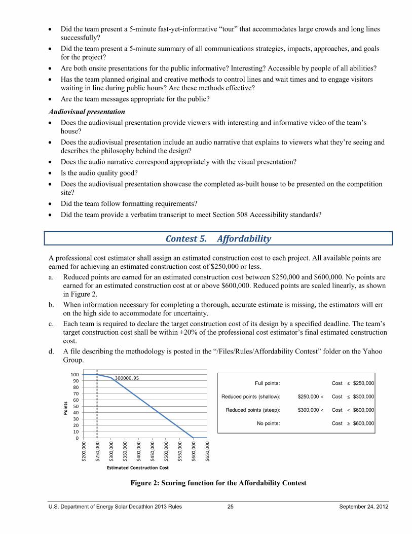
U.S. Department of Energy Solar Decathlon 2013 Rules 25 September 24, 2012
• Did the team present a 5-minute fast-yet-informative “tour” that accommodates large crowds and long lines successfully?
• Did the team present a 5-minute summary of all communications strategies, impacts, approaches, and goals for the project?
• Are both onsite presentations for the public informative? Interesting? Accessible by people of all abilities? • Has the team planned original and creative methods to control lines and wait times and to engage visitors
waiting in line during public hours? Are these methods effective? • Are the team messages appropriate for the public?
Audiovisual presentation • Does the audiovisual presentation provide viewers with interesting and informative video of the team’s
house? • Does the audiovisual presentation include an audio narrative that explains to viewers what they’re seeing and
describes the philosophy behind the design? • Does the audio narrative correspond appropriately with the visual presentation? • Is the audio quality good? • Does the audiovisual presentation showcase the completed as-built house to be presented on the competition
site? • Did the team follow formatting requirements? • Did the team provide a verbatim transcript to meet Section 508 Accessibility standards?
Contest 5. Affordability
A professional cost estimator shall assign an estimated construction cost to each project. All available points are earned for achieving an estimated construction cost of $250,000 or less. a. Reduced points are earned for an estimated construction cost between $250,000 and $600,000. No points are
earned for an estimated construction cost at or above $600,000. Reduced points are scaled linearly, as shown in Figure 2.
b. When information necessary for completing a thorough, accurate estimate is missing, the estimators will err on the high side to accommodate for uncertainty.
c. Each team is required to declare the target construction cost of its design by a specified deadline. The team’s target construction cost shall be within ±20% of the professional cost estimator’s final estimated construction cost.
d. A file describing the methodology is posted in the “/Files/Rules/Affordability Contest” folder on the Yahoo Group.
Figure 2: Scoring function for the Affordability Contest
Full points: Cost ≤ $250,000
Reduced points (shallow): $250,000 < Cost ≤ $300,000
Reduced points (steep): $300,000 < Cost < $600,000
No points: Cost ≥ $600,000
300000, 95
0102030405060708090
100
$200
,000
$250
,000
$300
,000
$350
,000
$400
,000
$450
,000
$500
,000
$550
,000
$600
,000
$650
,000
Poin
ts
Estimated Construction Cost
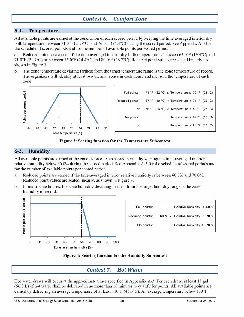
U.S. Department of Energy Solar Decathlon 2013 Rules 26 September 24, 2012
Contest 6. Comfort Zone
6-1. Temperature All available points are earned at the conclusion of each scored period by keeping the time-averaged interior dry-bulb temperature between 71.0°F (21.7°C) and 76.0°F (24.4°C) during the scored period. See Appendix A-3 for the schedule of scored periods and for the number of available points per scored period. a. Reduced points are earned if the time-averaged interior dry-bulb temperature is between 67.0°F (19.4°C) and 71.0°F (21.7°C) or between 76.0°F (24.4°C) and 80.0°F (26.7°C). Reduced point values are scaled linearly, as shown in Figure 3. b. The zone temperature deviating farthest from the target temperature range is the zone temperature of record.
The organizers will identify at least two thermal zones in each house and measure the temperature of each zone.
Figure 3: Scoring function for the Temperature Subcontest
6-2. Humidity All available points are earned at the conclusion of each scored period by keeping the time-averaged interior relative humidity below 60.0% during the scored period. See Appendix A-3 for the schedule of scored periods and for the number of available points per scored period. a. Reduced points are earned if the time-averaged interior relative humidity is between 60.0% and 70.0%.
Reduced point values are scaled linearly, as shown in Figure 4. b. In multi-zone houses, the zone humidity deviating farthest from the target humidity range is the zone
humidity of record.
Figure 4: Scoring function for the Humidity Subcontest
Contest 7. Hot Water
Hot water draws will occur at the approximate times specified in Appendix A-3. For each draw, at least 15 gal (56.8 L) of hot water shall be delivered in no more than 10 minutes to qualify for points. All available points are earned by delivering an average temperature of at least 110°F (43.3°C). An average temperature below 100°F
Full points: 71 °F (22 °C) ≤ Temperature ≤ 76 °F (24 °C)
Reduced points: 67 °F (19 °C) < Temperature < 71 °F (22 °C)
or 76 °F (24 °C) < Temperature < 80 °F (27 °C)
No points: Temperature ≤ 67 °F (19 °C)
or Temperature ≥ 80 °F (27 °C)64 66 68 70 72 74 76 78 80 82
Poin
ts p
er sc
ored
per
iod
Zone temperature (°F)
Full points: Relative humidity ≤ 60 %
Reduced points: 60 % < Relative humidity < 70 %
No points: Relative humidity ≥ 70 %
0 10 20 30 40 50 60 70 80 90 100
Poin
ts p
er sc
ored
per
iod
Zone relative humidity (%)
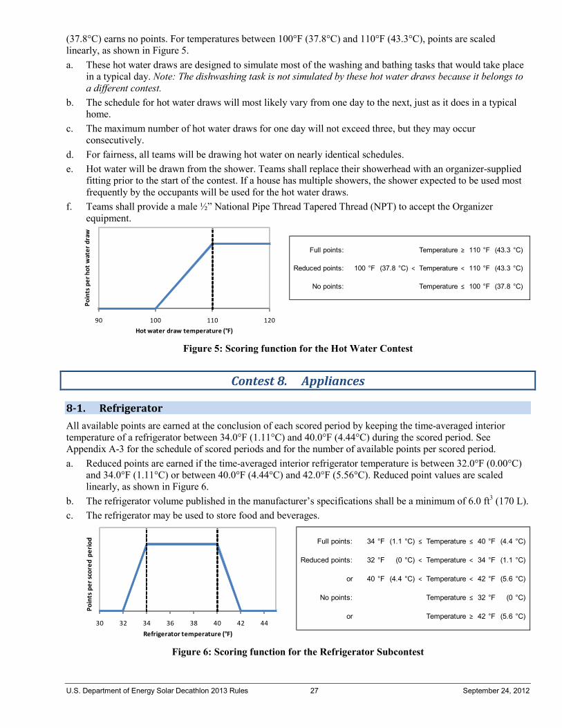
U.S. Department of Energy Solar Decathlon 2013 Rules 27 September 24, 2012
(37.8°C) earns no points. For temperatures between 100°F (37.8°C) and 110°F (43.3°C), points are scaled linearly, as shown in Figure 5. a. These hot water draws are designed to simulate most of the washing and bathing tasks that would take place
in a typical day. Note: The dishwashing task is not simulated by these hot water draws because it belongs to a different contest.
b. The schedule for hot water draws will most likely vary from one day to the next, just as it does in a typical home.
c. The maximum number of hot water draws for one day will not exceed three, but they may occur consecutively.
d. For fairness, all teams will be drawing hot water on nearly identical schedules. e. Hot water will be drawn from the shower. Teams shall replace their showerhead with an organizer-supplied
fitting prior to the start of the contest. If a house has multiple showers, the shower expected to be used most frequently by the occupants will be used for the hot water draws.
f. Teams shall provide a male ½” National Pipe Thread Tapered Thread (NPT) to accept the Organizer equipment.
Figure 5: Scoring function for the Hot Water Contest
Contest 8. Appliances
8-1. Refrigerator All available points are earned at the conclusion of each scored period by keeping the time-averaged interior temperature of a refrigerator between 34.0°F (1.11°C) and 40.0°F (4.44°C) during the scored period. See Appendix A-3 for the schedule of scored periods and for the number of available points per scored period. a. Reduced points are earned if the time-averaged interior refrigerator temperature is between 32.0°F (0.00°C)
and 34.0°F (1.11°C) or between 40.0°F (4.44°C) and 42.0°F (5.56°C). Reduced point values are scaled linearly, as shown in Figure 6.
b. The refrigerator volume published in the manufacturer’s specifications shall be a minimum of 6.0 ft3 (170 L). c. The refrigerator may be used to store food and beverages.
Figure 6: Scoring function for the Refrigerator Subcontest
Full points: Temperature ≥ 110 °F (43.3 °C)
Reduced points: 100 °F (37.8 °C) < Temperature < 110 °F (43.3 °C)
No points: Temperature ≤ 100 °F (37.8 °C)
90 100 110 120
Poin
ts p
er h
ot w
ater
dra
w
Hot water draw temperature (°F)
Full points: 34 °F (1.1 °C) ≤ Temperature ≤ 40 °F (4.4 °C)
Reduced points: 32 °F (0 °C) < Temperature < 34 °F (1.1 °C)
or 40 °F (4.4 °C) < Temperature < 42 °F (5.6 °C)
No points: Temperature ≤ 32 °F (0 °C)
or Temperature ≥ 42 °F (5.6 °C)30 32 34 36 38 40 42 44
Poin
ts p
er sc
ored
per
iod
Refrigerator temperature (°F)
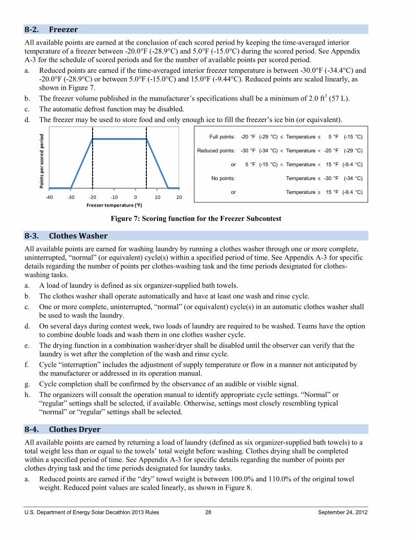
U.S. Department of Energy Solar Decathlon 2013 Rules 28 September 24, 2012
8-2. Freezer All available points are earned at the conclusion of each scored period by keeping the time-averaged interior temperature of a freezer between -20.0°F (-28.9°C) and 5.0°F (-15.0°C) during the scored period. See Appendix A-3 for the schedule of scored periods and for the number of available points per scored period. a. Reduced points are earned if the time-averaged interior freezer temperature is between -30.0°F (-34.4°C) and
-20.0°F (-28.9°C) or between 5.0°F (-15.0°C) and 15.0°F (-9.44°C). Reduced points are scaled linearly, as shown in Figure 7.
b. The freezer volume published in the manufacturer’s specifications shall be a minimum of 2.0 ft3 (57 L). c. The automatic defrost function may be disabled. d. The freezer may be used to store food and only enough ice to fill the freezer’s ice bin (or equivalent).
Figure 7: Scoring function for the Freezer Subcontest
8-3. Clothes Washer All available points are earned for washing laundry by running a clothes washer through one or more complete, uninterrupted, “normal” (or equivalent) cycle(s) within a specified period of time. See Appendix A-3 for specific details regarding the number of points per clothes-washing task and the time periods designated for clothes-washing tasks. a. A load of laundry is defined as six organizer-supplied bath towels. b. The clothes washer shall operate automatically and have at least one wash and rinse cycle. c. One or more complete, uninterrupted, “normal” (or equivalent) cycle(s) in an automatic clothes washer shall
be used to wash the laundry. d. On several days during contest week, two loads of laundry are required to be washed. Teams have the option
to combine double loads and wash them in one clothes washer cycle. e. The drying function in a combination washer/dryer shall be disabled until the observer can verify that the
laundry is wet after the completion of the wash and rinse cycle. f. Cycle “interruption” includes the adjustment of supply temperature or flow in a manner not anticipated by
the manufacturer or addressed in its operation manual. g. Cycle completion shall be confirmed by the observance of an audible or visible signal. h. The organizers will consult the operation manual to identify appropriate cycle settings. “Normal” or
“regular” settings shall be selected, if available. Otherwise, settings most closely resembling typical “normal” or “regular” settings shall be selected.
8-4. Clothes Dryer All available points are earned by returning a load of laundry (defined as six organizer-supplied bath towels) to a total weight less than or equal to the towels’ total weight before washing. Clothes drying shall be completed within a specified period of time. See Appendix A-3 for specific details regarding the number of points per clothes drying task and the time periods designated for laundry tasks. a. Reduced points are earned if the “dry” towel weight is between 100.0% and 110.0% of the original towel
weight. Reduced point values are scaled linearly, as shown in Figure 8.
Full points: -20 °F (-29 °C) ≤ Temperature ≤ 5 °F (-15 °C)
Reduced points: -30 °F (-34 °C) < Temperature < -20 °F (-29 °C)
or 5 °F (-15 °C) < Temperature < 15 °F (-9.4 °C)
No points: Temperature ≤ -30 °F (-34 °C)
or Temperature ≥ 15 °F (-9.4 °C)-40 -30 -20 -10 0 10 20
Poin
ts p
er sc
ored
per
iod
Freezer temperature (°F)
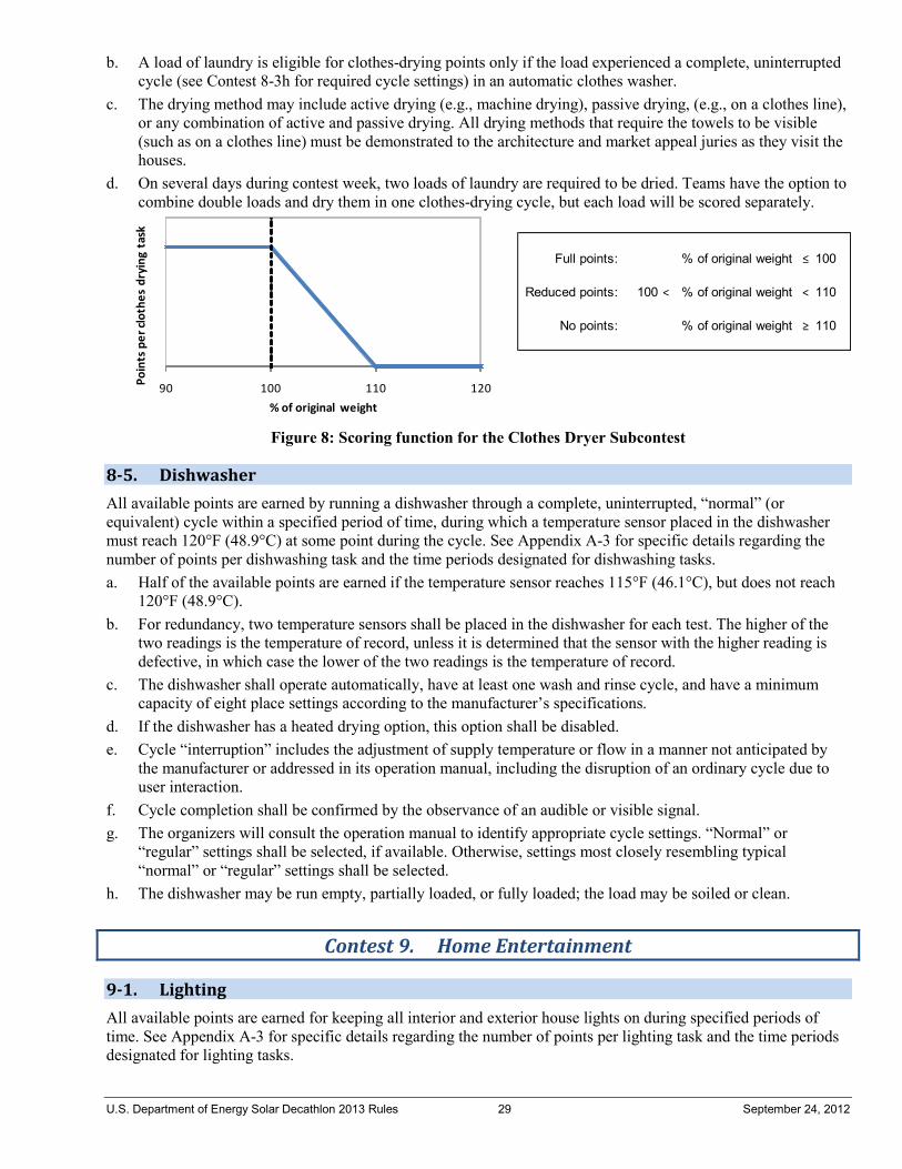
U.S. Department of Energy Solar Decathlon 2013 Rules 29 September 24, 2012
b. A load of laundry is eligible for clothes-drying points only if the load experienced a complete, uninterrupted cycle (see Contest 8-3h for required cycle settings) in an automatic clothes washer.
c. The drying method may include active drying (e.g., machine drying), passive drying, (e.g., on a clothes line), or any combination of active and passive drying. All drying methods that require the towels to be visible (such as on a clothes line) must be demonstrated to the architecture and market appeal juries as they visit the houses.
d. On several days during contest week, two loads of laundry are required to be dried. Teams have the option to combine double loads and dry them in one clothes-drying cycle, but each load will be scored separately.
Figure 8: Scoring function for the Clothes Dryer Subcontest
8-5. Dishwasher All available points are earned by running a dishwasher through a complete, uninterrupted, “normal” (or equivalent) cycle within a specified period of time, during which a temperature sensor placed in the dishwasher must reach 120°F (48.9°C) at some point during the cycle. See Appendix A-3 for specific details regarding the number of points per dishwashing task and the time periods designated for dishwashing tasks. a. Half of the available points are earned if the temperature sensor reaches 115°F (46.1°C), but does not reach
120°F (48.9°C). b. For redundancy, two temperature sensors shall be placed in the dishwasher for each test. The higher of the
two readings is the temperature of record, unless it is determined that the sensor with the higher reading is defective, in which case the lower of the two readings is the temperature of record.
c. The dishwasher shall operate automatically, have at least one wash and rinse cycle, and have a minimum capacity of eight place settings according to the manufacturer’s specifications.
d. If the dishwasher has a heated drying option, this option shall be disabled. e. Cycle “interruption” includes the adjustment of supply temperature or flow in a manner not anticipated by
the manufacturer or addressed in its operation manual, including the disruption of an ordinary cycle due to user interaction.
f. Cycle completion shall be confirmed by the observance of an audible or visible signal. g. The organizers will consult the operation manual to identify appropriate cycle settings. “Normal” or
“regular” settings shall be selected, if available. Otherwise, settings most closely resembling typical “normal” or “regular” settings shall be selected.
h. The dishwasher may be run empty, partially loaded, or fully loaded; the load may be soiled or clean.
Contest 9. Home Entertainment
9-1. Lighting All available points are earned for keeping all interior and exterior house lights on during specified periods of time. See Appendix A-3 for specific details regarding the number of points per lighting task and the time periods designated for lighting tasks.
Full points: % of original weight ≤ 100
Reduced points: 100 < % of original weight < 110
No points: % of original weight ≥ 110
90 100 110 120Poin
ts p
er cl
othe
s dr
ying
tas
k
% of original weight
U.S. Department of Energy Solar Decathlon 2013 Rules 30 September 24, 2012
Exception: Lights located within manufactured residential appliances such as a refrigerator, clothes dryer, microwave, and oven that are intended to illuminate the interior of the appliance are not required to be illuminated. Lights that are not designed to be connected to the house electrical system are not required to be illuminated. a. All dimmers shall be adjusted to their highest positions and all other lighting control equipment shall be
disabled or overridden so that the controlled lamps are fully and continuously on during the specified periods.
b. Partial credit will be awarded for partial compliance.
9-2. Cooking All available points are earned by using a kitchen appliance to vaporize 5.000 lb (80.00 oz or 2.268 kg) of water within a specified period of time. See Appendix A-3 for specific details regarding the number of points per cooking task and the time periods designated for cooking tasks. a. Reduced points are earned if between 1.000 lb (16.00 oz or 0.454 kg) and 5.000 lb (80.00 oz or 2.268 kg) are
vaporized. Reduced point values are scaled linearly, as shown in Figure 9. b. Any kitchen appliance may be used, but it must operate in its normal configuration as it is vaporizing the
water. c. The water shall be vaporized in a single container and the starting water weight shall be at least 96.00 oz
(2.721 kg).
Figure 9: Scoring function for the Cooking Subcontest
9-3. Dinner Party Each team shall host two dinner parties for its neighbors during contest week. See Appendix A-3 for the dinner party schedule and the number of available points per dinner party. Dinner parties will feature a pair of guest decathletes from each of three competing teams, and each pair of guest decathletes shall assign a score to the host team after each dinner party. The quality of the meal, ambiance, and overall experience shall be considered in the evaluation. a. To maintain consistency among the juried contests and subcontests, guest teams shall use the scoring
methodology described in the “Phase 3: Deliberation” section of Appendix B-1. Each of the three pairs of guest decathletes shall submit three percentage integer scores, i.e., one score for quality of the meal, one score for ambiance, and one score for overall experience, to the contest officials by 11 p.m. These nine scores will be averaged and multiplied by the maximum available points in the scoring server to generate a final score for each dinner party. Percentage integer scores may range from 0% (lowest possible score) to 100% (highest possible score).
b. The village will be organized into five small “neighborhoods.” Each neighborhood consists of four neighboring houses. The guest list for the dinner party shall be limited to eight people—two people from each of the three neighboring houses and up to two VIP guests. VIP guests may include organizers, media, government employees, family members, or other individuals approved by the organizers to attend the dinner parties.
c. See Rule 11-1d for house occupancy rules during the dinner party.
Full points: Weight ≥ 80 oz (2300 g)
Reduced points: 16 oz (450 g) < Weight < 80 oz (2300 g)
No points: Weight ≤ 16 oz (450 g)
0 10 20 30 40 50 60 70 80 90 100
Poin
ts p
er co
okin
g ta
sk
Weight of vaporized water (oz)
U.S. Department of Energy Solar Decathlon 2013 Rules 31 September 24, 2012
d. Each host team shall prepare dinner for exactly eight people—six decathlete guests and two host team members or VIP guests. Guest decathletes are encouraged to deduct points if too much or too little food is prepared. Teams are not permitted to serve the same meal at each dinner party.
e. Host team decathletes in the house during the dinner party must be performing one or more of the following three functions: 1) eating the meal; 2) cooking/preparing the food; 3) operating the house during scheduled Contest 7, 8, or 9 activities.
f. Non-decathletes are prohibited from preparing the meal or instructing decathletes in any way on the competition site.
g. Teams shall prepare and cook all food and beverages in the house during the period of time indicated in Appendix A-3. A file describing eligible and ineligible ingredients is posted in the “/Files/Rules/Dinner Party” folder on the Yahoo Group.
h. The meal shall be served and eaten in the finished square footage at the eating area designated in the drawings.
i. Before and after the dinner portion of the party, the host team is permitted, but not required, to serve hors d’oeuvres and/or beverages, which may be served outside.
j. Teams are required to submit detailed dinner party menus, recipes, and ingredient lists to the organizers. (i). Guest decathletes are encouraged to deduct points for inconsistencies between the meal served for
each dinner party and the dinner party information submitted prior to contest week. k. Teams hosting dinner parties shall comply with the following safety requirements:
(i). The use of flames, including candle flames, is prohibited during contest week (see Rule 8-2b). (ii). No alcoholic beverages may be stored in the house, used in meal preparation, served, or part of a
meal in any way. (iii). All water used for cooking and drinking shall be drinking water purchased in sealed containers. (iv). All dishes and cookware shall be washed with hot water and soap and rinsed prior to use. (v). Normal domestic wastewater may go into the wastewater tank. (vi). All beverages and food must be stored properly and according to the instructions on the packaging,
e.g., beverages and foods marked “refrigerate after opening” must be refrigerated appropriately after opening.
(vii). To help prevent allergic reactions among dinner party guests, teams shall create a list of ingredients for each of the items being served at each meal. Common food allergies include milk/dairy products, eggs, peanuts, tree nuts (walnuts, cashews, pecans), fish, shellfish, soy, and wheat.
(viii). Outdoor cooking and grilling equipment may be incorporated into the competition prototype, but the use of such equipment is prohibited on the competition site.
(ix). The use of coolers to store food, beverages, or ice associated with the dinner party on site is not permitted. Coolers may be used for transporting food to the competition site only.
9-4. Home Electronics All available points are earned for operating a television (TV) and computer during specified periods of time. See Appendix A-3 for specific details regarding the number of points per home electronics task and the time periods designated for home electronics tasks. a. The TV display shall be a minimum of 27 in. (68.6 cm) according to the manufacturer’s stated display size.
The computer display shall be a minimum of 15 in. (38.1 cm) according to the manufacturer’s stated display size. The computer may be a laptop or desktop computer. The TV and computer displays shall be able to be operated simultaneously and controlled independently of each other.
b. The organizers will supply content that must be shown on the TV display during the home electronics tasks. There is no required volume setting, but the brightness of the display shall be set to at least 75% of maximum. Observers will conduct spot checks to verify that the TV is showing the supplied content and that the brightness is at the required level.
c. The organizers will supply content that must be shown on the computer display during the scored periods. A decathlete may temporarily suspend the supplied content to use the computer for other practical purposes, but
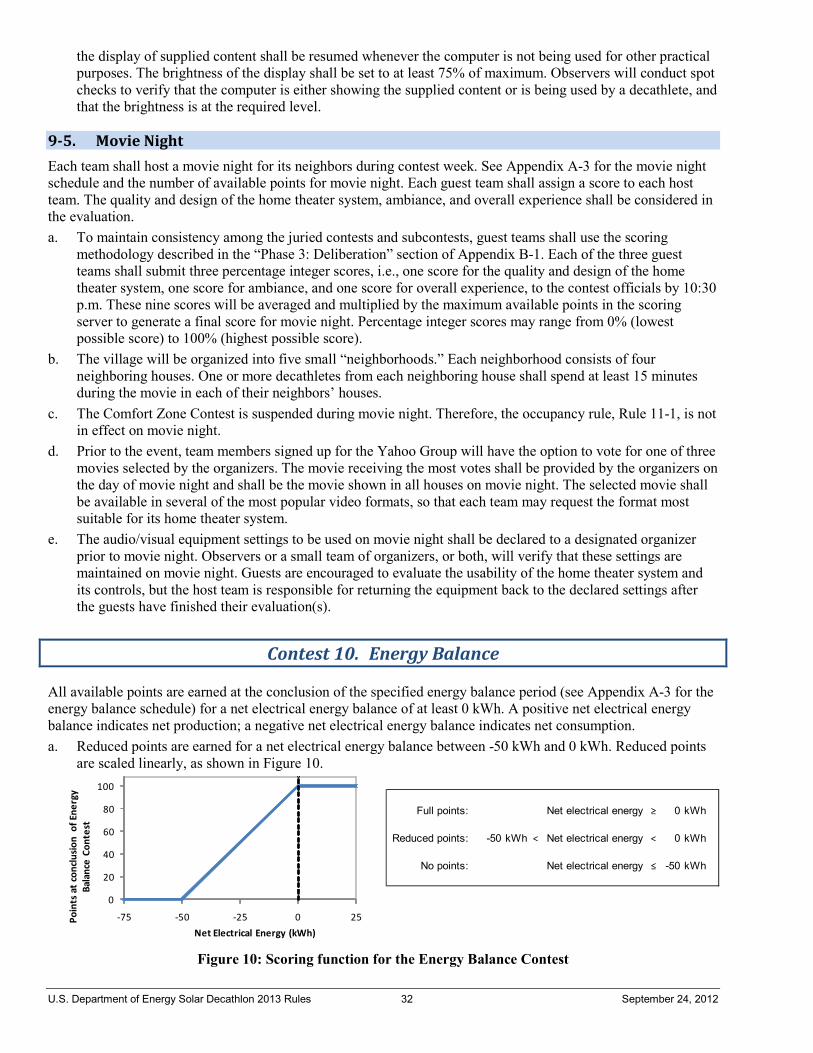
U.S. Department of Energy Solar Decathlon 2013 Rules 32 September 24, 2012
the display of supplied content shall be resumed whenever the computer is not being used for other practical purposes. The brightness of the display shall be set to at least 75% of maximum. Observers will conduct spot checks to verify that the computer is either showing the supplied content or is being used by a decathlete, and that the brightness is at the required level.
9-5. Movie Night Each team shall host a movie night for its neighbors during contest week. See Appendix A-3 for the movie night schedule and the number of available points for movie night. Each guest team shall assign a score to each host team. The quality and design of the home theater system, ambiance, and overall experience shall be considered in the evaluation. a. To maintain consistency among the juried contests and subcontests, guest teams shall use the scoring
methodology described in the “Phase 3: Deliberation” section of Appendix B-1. Each of the three guest teams shall submit three percentage integer scores, i.e., one score for the quality and design of the home theater system, one score for ambiance, and one score for overall experience, to the contest officials by 10:30 p.m. These nine scores will be averaged and multiplied by the maximum available points in the scoring server to generate a final score for movie night. Percentage integer scores may range from 0% (lowest possible score) to 100% (highest possible score).
b. The village will be organized into five small “neighborhoods.” Each neighborhood consists of four neighboring houses. One or more decathletes from each neighboring house shall spend at least 15 minutes during the movie in each of their neighbors’ houses.
c. The Comfort Zone Contest is suspended during movie night. Therefore, the occupancy rule, Rule 11-1, is not in effect on movie night.
d. Prior to the event, team members signed up for the Yahoo Group will have the option to vote for one of three movies selected by the organizers. The movie receiving the most votes shall be provided by the organizers on the day of movie night and shall be the movie shown in all houses on movie night. The selected movie shall be available in several of the most popular video formats, so that each team may request the format most suitable for its home theater system.
e. The audio/visual equipment settings to be used on movie night shall be declared to a designated organizer prior to movie night. Observers or a small team of organizers, or both, will verify that these settings are maintained on movie night. Guests are encouraged to evaluate the usability of the home theater system and its controls, but the host team is responsible for returning the equipment back to the declared settings after the guests have finished their evaluation(s).
Contest 10. Energy Balance
All available points are earned at the conclusion of the specified energy balance period (see Appendix A-3 for the energy balance schedule) for a net electrical energy balance of at least 0 kWh. A positive net electrical energy balance indicates net production; a negative net electrical energy balance indicates net consumption. a. Reduced points are earned for a net electrical energy balance between -50 kWh and 0 kWh. Reduced points
are scaled linearly, as shown in Figure 10.
Figure 10: Scoring function for the Energy Balance Contest
Full points: Net electrical energy ≥ 0 kWh
Reduced points: -50 kWh < Net electrical energy < 0 kWh
No points: Net electrical energy ≤ -50 kWh
0
20
40
60
80
100
-75 -50 -25 0 25Poin
ts a
t con
clusio
n of
Ene
rgy
Bala
nce
Cont
est
Net Electrical Energy (kWh)
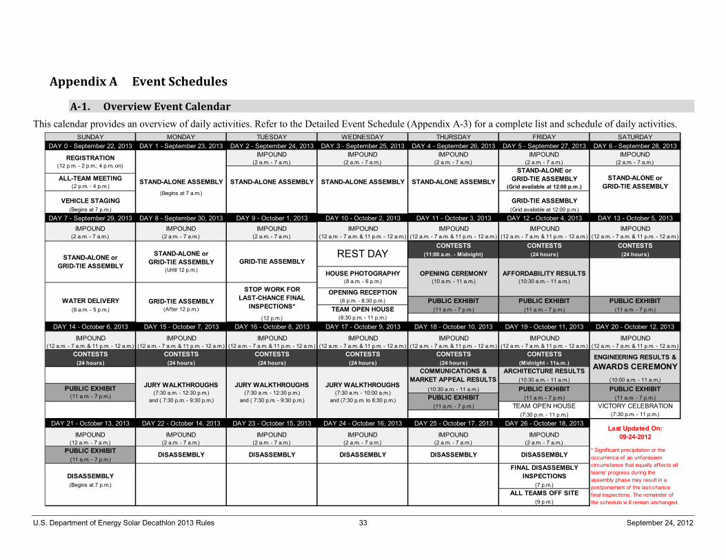
U.S. Department of Energy Solar Decathlon 2013 Rules 33 September 24, 2012
Appendix A Event Schedules
A-1. Overview Event Calendar This calendar provides an overview of daily activities. Refer to the Detailed Event Schedule (Appendix A-3) for a complete list and schedule of daily activities.
SUNDAY MONDAY TUESDAY WEDNESDAY THURSDAY FRIDAY SATURDAYDAY 0 - September 22, 2013 DAY 1 - September 23, 2013 DAY 2 - September 24, 2013 DAY 3 - September 25, 2013 DAY 4 - September 26, 2013 DAY 5 - September 27, 2013 DAY 6 - September 28, 2013
IMPOUND (2 a.m. - 7 a.m.)
IMPOUND (2 a.m. - 7 a.m.)
IMPOUND (2 a.m. - 7 a.m.)
IMPOUND (2 a.m. - 7 a.m.)
IMPOUND (2 a.m. - 7 a.m.)
(Begins at 7 a.m.)VEHICLE STAGING GRID-TIE ASSEMBLY
(Begins at 7 p.m.) (Grid available at 12:00 p.m.)DAY 7 - September 29, 2013 DAY 8 - September 30, 2013 DAY 9 - October 1, 2013 DAY 10 - October 2, 2013 DAY 11 - October 3, 2013 DAY 12 - October 4, 2013 DAY 13 - October 5, 2013
IMPOUND (2 a.m. - 7 a.m.)
IMPOUND (2 a.m. - 7 a.m.)
IMPOUND (2 a.m. - 7 a.m.)
IMPOUND (12 a.m. - 7 a.m. & 11 p.m. - 12 a.m.)
IMPOUND (12 a.m. - 7 a.m. & 11 p.m. - 12 a.m.)
IMPOUND (12 a.m. - 7 a.m. & 11 p.m. - 12 a.m.)
IMPOUND (12 a.m. - 7 a.m. & 11 p.m. - 12 a.m.)
CONTESTS CONTESTS CONTESTS(11:00 a.m. - Midnight) (24 hours) (24 hours)
OPENING RECEPTIONWATER DELIVERY (6 p.m. - 8:30 p.m.) PUBLIC EXHIBIT PUBLIC EXHIBIT PUBLIC EXHIBIT
(8 a.m. - 5 p.m.) TEAM OPEN HOUSE (11 a.m. - 7 p.m.) (11 a.m. - 7 p.m.) (11 a.m. - 7 p.m.)(12 p.m.) (8:30 p.m. - 11 p.m.)
DAY 14 - October 6, 2013 DAY 15 - October 7, 2013 DAY 16 - October 8, 2013 DAY 17 - October 9, 2013 DAY 18 - October 10, 2013 DAY 19 - October 11, 2013 DAY 20 - October 12, 2013
IMPOUND (12 a.m. - 7 a.m. & 11 p.m. - 12 a.m.)
IMPOUND (12 a.m. - 7 a.m. & 11 p.m. - 12 a.m.)
IMPOUND (12 a.m. - 7 a.m. & 11 p.m. - 12 a.m.)
IMPOUND (12 a.m. - 7 a.m. & 11 p.m. - 12 a.m.)
IMPOUND (12 a.m. - 7 a.m. & 11 p.m. - 12 a.m.)
IMPOUND (12 a.m. - 7 a.m. & 11 p.m. - 12 a.m.)
IMPOUND (12 a.m. - 7 a.m. & 11 p.m. - 12 a.m.)
CONTESTS CONTESTS CONTESTS CONTESTS CONTESTS CONTESTS(24 hours) (24 hours) (24 hours) (24 hours) (24 hours) (Midnight - 11a.m.)
ARCHITECTURE RESULTS(10:30 a.m. - 11 a.m.) (10:00 a.m. - 11 a.m.)
(10:30 a.m. - 11 a.m.) PUBLIC EXHIBIT PUBLIC EXHIBITPUBLIC EXHIBIT (11 a.m. - 7 p.m.) (11 a.m. - 7 p.m.)
(11 a.m. - 7 p.m.) TEAM OPEN HOUSE VICTORY CELEBRATION(7:30 p.m. - 11 p.m.) (7:30 p.m. - 11 p.m.)
DAY 21 - October 13, 2013 DAY 22 - October 14, 2013 DAY 23 - October 15, 2013 DAY 24 - October 16, 2013 DAY 25 - October 17, 2013 DAY 26 - October 18, 2013
IMPOUND (12 a.m. - 7 a.m.)
IMPOUND (2 a.m. - 7 a.m.)
IMPOUND (2 a.m. - 7 a.m.)
IMPOUND (2 a.m. - 7 a.m.)
IMPOUND (2 a.m. - 7 a.m.)
IMPOUND (2 a.m. - 7 a.m.)
PUBLIC EXHIBIT(11 a.m. - 7 p.m.)
DISASSEMBLYFINAL DISASSEMBLY
INSPECTIONS(Begins at 7 p.m.) (7 p.m.)
ALL TEAMS OFF SITE(9 p.m.)
HOUSE PHOTOGRAPHY(8 a.m. - 6 p.m.)
STAND-ALONE ASSEMBLY STAND-ALONE ASSEMBLY
GRID-TIE ASSEMBLY
STAND-ALONE or GRID-TIE ASSEMBLY
REST DAY
STOP WORK FOR LAST-CHANCE FINAL
INSPECTIONS*
STAND-ALONE or GRID-TIE ASSEMBLY
(Grid available at 12:00 p.m.)
AFFORDABILITY RESULTS(10:30 a.m. - 11 a.m.)
OPENING CEREMONY(10 a.m. - 11 a.m.)
STAND-ALONE ASSEMBLY
REGISTRATION(12 p.m. - 2 p.m.; 4 p.m. on)
ALL-TEAM MEETING(2 p.m. - 4 p.m.)
STAND-ALONE or GRID-TIE ASSEMBLY
STAND-ALONE or GRID-TIE ASSEMBLY
(Until 12 p.m.)
GRID-TIE ASSEMBLY(After 12 p.m.)
STAND-ALONE ASSEMBLY
* Signif icant precipitation or the occurrence of an unforeseen circumstance that equally affects all teams' progress during the assembly phase may result in a postponement of the last-chance f inal inspections. The remainder of the schedule w ill remain unchanged.
Last Updated On: 09-24-2012
ENGINEERING RESULTS & AWARDS CEREMONYCOMMUNICATIONS &
MARKET APPEAL RESULTSPUBLIC EXHIBIT
(11 a.m. - 7 p.m.)
DISASSEMBLY DISASSEMBLYDISASSEMBLY DISASSEMBLY DISASSEMBLY
JURY WALKTHROUGHS(7:30 a.m. - 12:30 p.m.)
and ( 7:30 p.m. - 9:30 p.m.)
JURY WALKTHROUGHS(7:30 a.m. - 10:00 a.m.)
and (7:30 p.m. to 8:30 p.m.)
JURY WALKTHROUGHS(7:30 a.m. - 12:30 p.m.)
and ( 7:30 p.m. - 9:30 p.m.)
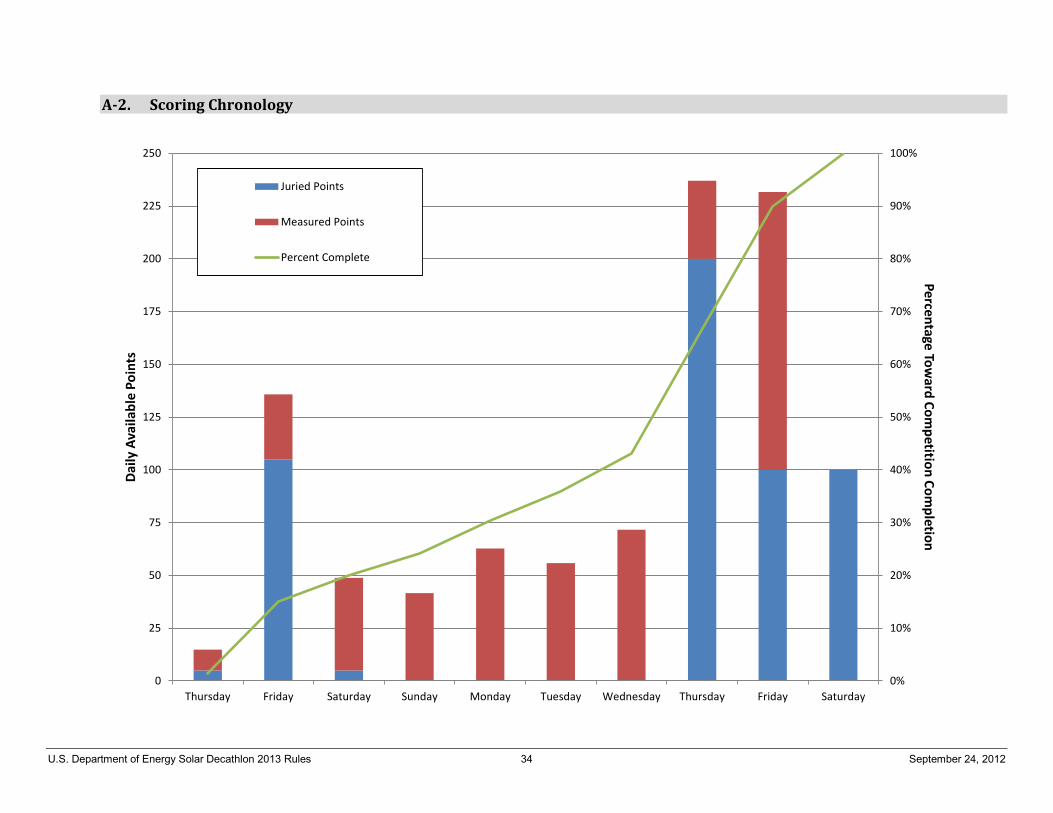
U.S. Department of Energy Solar Decathlon 2013 Rules 34 September 24, 2012
A-2. Scoring Chronology
0%
10%
20%
30%
40%
50%
60%
70%
80%
90%
100%
0
25
50
75
100
125
150
175
200
225
250
Thursday Friday Saturday Sunday Monday Tuesday Wednesday Thursday Friday Saturday
Percentage Toward Com
petition Completion
Daily
Ava
ilabl
e Po
ints
Juried Points
Measured Points
Percent Complete
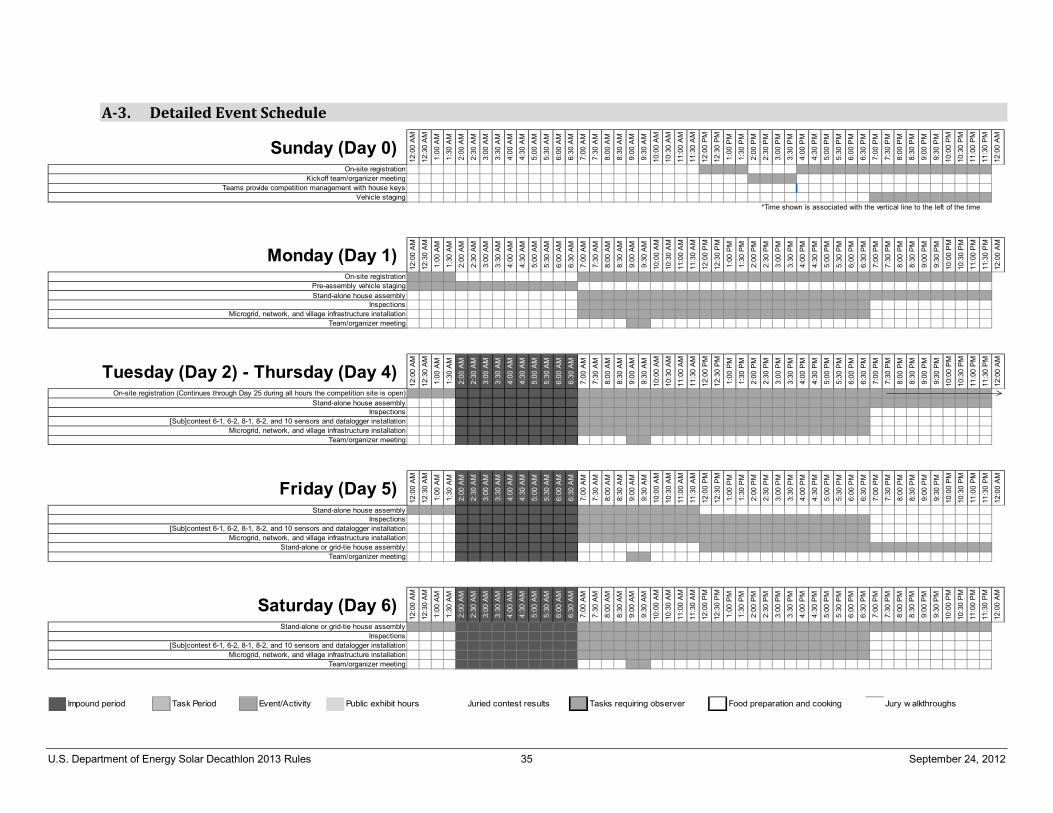
U.S. Department of Energy Solar Decathlon 2013 Rules 35 September 24, 2012
A-3. Detailed Event Schedule
12:0
0 A
M
12:3
0 A
M
1:00
AM
1:30
AM
2:00
AM
2:30
AM
3:00
AM
3:30
AM
4:00
AM
4:30
AM
5:00
AM
5:30
AM
6:00
AM
6:30
AM
7:00
AM
7:30
AM
8:00
AM
8:30
AM
9:00
AM
9:30
AM
10:0
0 A
M
10:3
0 A
M
11:0
0 A
M
11:3
0 A
M
12:0
0 P
M
12:3
0 P
M
1:00
PM
1:30
PM
2:00
PM
2:30
PM
3:00
PM
3:30
PM
4:00
PM
4:30
PM
5:00
PM
5:30
PM
6:00
PM
6:30
PM
7:00
PM
7:30
PM
8:00
PM
8:30
PM
9:00
PM
9:30
PM
10:0
0 P
M
10:3
0 P
M
11:0
0 P
M
11:3
0 P
M
12:0
0 A
M
*Time shown is associated with the vertical line to the left of the time
Sunday (Day 0)On-site registration
Kickoff team/organizer meetingTeams provide competition management with house keys
Vehicle staging
12:0
0 A
M
12:3
0 A
M
1:00
AM
1:30
AM
2:00
AM
2:30
AM
3:00
AM
3:30
AM
4:00
AM
4:30
AM
5:00
AM
5:30
AM
6:00
AM
6:30
AM
7:00
AM
7:30
AM
8:00
AM
8:30
AM
9:00
AM
9:30
AM
10:0
0 A
M
10:3
0 A
M
11:0
0 A
M
11:3
0 A
M
12:0
0 P
M
12:3
0 P
M
1:00
PM
1:30
PM
2:00
PM
2:30
PM
3:00
PM
3:30
PM
4:00
PM
4:30
PM
5:00
PM
5:30
PM
6:00
PM
6:30
PM
7:00
PM
7:30
PM
8:00
PM
8:30
PM
9:00
PM
9:30
PM
10:0
0 P
M
10:3
0 P
M
11:0
0 P
M
11:3
0 P
M
12:0
0 A
M
Stand-alone house assembly
Microgrid, network, and village infrastructure installationTeam/organizer meeting
Monday (Day 1)Pre-assembly vehicle staging
Inspections
On-site registration
12:0
0 A
M
12:3
0 A
M
1:00
AM
1:30
AM
2:00
AM
2:30
AM
3:00
AM
3:30
AM
4:00
AM
4:30
AM
5:00
AM
5:30
AM
6:00
AM
6:30
AM
7:00
AM
7:30
AM
8:00
AM
8:30
AM
9:00
AM
9:30
AM
10:0
0 A
M
10:3
0 A
M
11:0
0 A
M
11:3
0 A
M
12:0
0 P
M
12:3
0 P
M
1:00
PM
1:30
PM
2:00
PM
2:30
PM
3:00
PM
3:30
PM
4:00
PM
4:30
PM
5:00
PM
5:30
PM
6:00
PM
6:30
PM
7:00
PM
7:30
PM
8:00
PM
8:30
PM
9:00
PM
9:30
PM
10:0
0 P
M
10:3
0 P
M
11:0
0 P
M
11:3
0 P
M
12:0
0 A
M
Stand-alone house assembly
Tuesday (Day 2) - Thursday (Day 4)On-site registration (Continues through Day 25 during all hours the competition site is open)
Inspections
Microgrid, network, and village infrastructure installationTeam/organizer meeting
[Sub]contest 6-1, 6-2, 8-1, 8-2, and 10 sensors and datalogger installation12
:00
AM
12:3
0 A
M
1:00
AM
1:30
AM
2:00
AM
2:30
AM
3:00
AM
3:30
AM
4:00
AM
4:30
AM
5:00
AM
5:30
AM
6:00
AM
6:30
AM
7:00
AM
7:30
AM
8:00
AM
8:30
AM
9:00
AM
9:30
AM
10:0
0 A
M
10:3
0 A
M
11:0
0 A
M
11:3
0 A
M
12:0
0 P
M
12:3
0 P
M
1:00
PM
1:30
PM
2:00
PM
2:30
PM
3:00
PM
3:30
PM
4:00
PM
4:30
PM
5:00
PM
5:30
PM
6:00
PM
6:30
PM
7:00
PM
7:30
PM
8:00
PM
8:30
PM
9:00
PM
9:30
PM
10:0
0 P
M
10:3
0 P
M
11:0
0 P
M
11:3
0 P
M
12:0
0 A
M
Stand-alone house assembly
Friday (Day 5)Inspections
[Sub]contest 6-1, 6-2, 8-1, 8-2, and 10 sensors and datalogger installationMicrogrid, network, and village infrastructure installation
Team/organizer meetingStand-alone or grid-tie house assembly
12:0
0 A
M
12:3
0 A
M
1:00
AM
1:30
AM
2:00
AM
2:30
AM
3:00
AM
3:30
AM
4:00
AM
4:30
AM
5:00
AM
5:30
AM
6:00
AM
6:30
AM
7:00
AM
7:30
AM
8:00
AM
8:30
AM
9:00
AM
9:30
AM
10:0
0 A
M
10:3
0 A
M
11:0
0 A
M
11:3
0 A
M
12:0
0 P
M
12:3
0 P
M
1:00
PM
1:30
PM
2:00
PM
2:30
PM
3:00
PM
3:30
PM
4:00
PM
4:30
PM
5:00
PM
5:30
PM
6:00
PM
6:30
PM
7:00
PM
7:30
PM
8:00
PM
8:30
PM
9:00
PM
9:30
PM
10:0
0 P
M
10:3
0 P
M
11:0
0 P
M
11:3
0 P
M
12:0
0 A
M
Team/organizer meeting
Stand-alone or grid-tie house assembly
Microgrid, network, and village infrastructure installation
Inspections
Saturday (Day 6)
[Sub]contest 6-1, 6-2, 8-1, 8-2, and 10 sensors and datalogger installation
Impound period Task Period Event/Activity Public exhibit hours Juried contest results Tasks requiring observer Food preparation and cooking Jury w alkthroughs
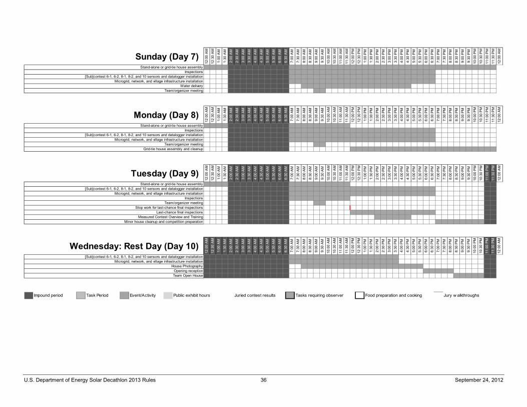
U.S. Department of Energy Solar Decathlon 2013 Rules 36 September 24, 2012
12:0
0 A
M
12:3
0 A
M
1:00
AM
1:30
AM
2:00
AM
2:30
AM
3:00
AM
3:30
AM
4:00
AM
4:30
AM
5:00
AM
5:30
AM
6:00
AM
6:30
AM
7:00
AM
7:30
AM
8:00
AM
8:30
AM
9:00
AM
9:30
AM
10:0
0 A
M
10:3
0 A
M
11:0
0 A
M
11:3
0 A
M
12:0
0 P
M
12:3
0 P
M
1:00
PM
1:30
PM
2:00
PM
2:30
PM
3:00
PM
3:30
PM
4:00
PM
4:30
PM
5:00
PM
5:30
PM
6:00
PM
6:30
PM
7:00
PM
7:30
PM
8:00
PM
8:30
PM
9:00
PM
9:30
PM
10:0
0 P
M
10:3
0 P
M
11:0
0 P
M
11:3
0 P
M
12:0
0 A
M
Sunday (Day 7)Stand-alone or grid-tie house assembly
Inspections[Sub]contest 6-1, 6-2, 8-1, 8-2, and 10 sensors and datalogger installation
Microgrid, network, and village infrastructure installation
Team/organizer meetingWater delivery
12:0
0 A
M
12:3
0 A
M
1:00
AM
1:30
AM
2:00
AM
2:30
AM
3:00
AM
3:30
AM
4:00
AM
4:30
AM
5:00
AM
5:30
AM
6:00
AM
6:30
AM
7:00
AM
7:30
AM
8:00
AM
8:30
AM
9:00
AM
9:30
AM
10:0
0 A
M
10:3
0 A
M
11:0
0 A
M
11:3
0 A
M
12:0
0 P
M
12:3
0 P
M
1:00
PM
1:30
PM
2:00
PM
2:30
PM
3:00
PM
3:30
PM
4:00
PM
4:30
PM
5:00
PM
5:30
PM
6:00
PM
6:30
PM
7:00
PM
7:30
PM
8:00
PM
8:30
PM
9:00
PM
9:30
PM
10:0
0 P
M
10:3
0 P
M
11:0
0 P
M
11:3
0 P
M
12:0
0 A
M
[Sub]contest 6-1, 6-2, 8-1, 8-2, and 10 sensors and datalogger installationMicrogrid, network, and village infrastructure installation
Stand-alone or grid-tie house assemblyInspections
Team/organizer meeting
Monday (Day 8)
Grid-tie house assembly and cleanup
12:0
0 A
M
12:3
0 A
M
1:00
AM
1:30
AM
2:00
AM
2:30
AM
3:00
AM
3:30
AM
4:00
AM
4:30
AM
5:00
AM
5:30
AM
6:00
AM
6:30
AM
7:00
AM
7:30
AM
8:00
AM
8:30
AM
9:00
AM
9:30
AM
10:0
0 A
M
10:3
0 A
M
11:0
0 A
M
11:3
0 A
M
12:0
0 P
M
12:3
0 P
M
1:00
PM
1:30
PM
2:00
PM
2:30
PM
3:00
PM
3:30
PM
4:00
PM
4:30
PM
5:00
PM
5:30
PM
6:00
PM
6:30
PM
7:00
PM
7:30
PM
8:00
PM
8:30
PM
9:00
PM
9:30
PM
10:0
0 P
M
10:3
0 P
M
11:0
0 P
M
11:3
0 P
M
12:0
0 A
M
Tuesday (Day 9)Stand-alone or grid-tie house assembly
Inspections
Stop work for last-chance final inspections
Measured Contest Overview and TrainingMinor house cleanup and competition preparation
Microgrid, network, and village infrastructure installation[Sub]contest 6-1, 6-2, 8-1, 8-2, and 10 sensors and datalogger installation
Last-chance final inspections
Team/organizer meeting12
:00
AM
12:3
0 A
M
1:00
AM
1:30
AM
2:00
AM
2:30
AM
3:00
AM
3:30
AM
4:00
AM
4:30
AM
5:00
AM
5:30
AM
6:00
AM
6:30
AM
7:00
AM
7:30
AM
8:00
AM
8:30
AM
9:00
AM
9:30
AM
10:0
0 A
M
10:3
0 A
M
11:0
0 A
M
11:3
0 A
M
12:0
0 P
M
12:3
0 P
M
1:00
PM
1:30
PM
2:00
PM
2:30
PM
3:00
PM
3:30
PM
4:00
PM
4:30
PM
5:00
PM
5:30
PM
6:00
PM
6:30
PM
7:00
PM
7:30
PM
8:00
PM
8:30
PM
9:00
PM
9:30
PM
10:0
0 P
M
10:3
0 P
M
11:0
0 P
M
11:3
0 P
M
12:0
0 A
M
Microgrid, network, and village infrastructure installation[Sub]contest 6-1, 6-2, 8-1, 8-2, and 10 sensors and datalogger installation
Wednesday: Rest Day (Day 10)
House PhotographyOpening receptionTeam Open House
Impound period Task Period Event/Activity Public exhibit hours Juried contest results Tasks requiring observer Food preparation and cooking Jury w alkthroughs
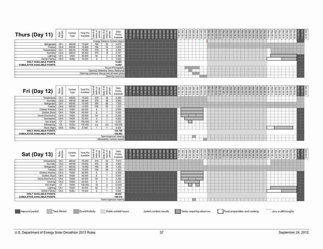
U.S. Department of Energy Solar Decathlon 2013 Rules 37 September 24, 2012
Thurs (Day 11) Rul
es
Sec
tion
Contest Type
Total PtsAvailable
Tota
l # o
f ta
sks
orpe
riods
Dai
ly #
of
task
s or
perio
ds DailyPoints
Available 12:0
0 A
M
12:3
0 A
M
1:00
AM
1:30
AM
2:00
AM
2:30
AM
3:00
AM
3:30
AM
4:00
AM
4:30
AM
5:00
AM
5:30
AM
6:00
AM
6:30
AM
7:00
AM
7:30
AM
8:00
AM
8:30
AM
9:00
AM
9:30
AM
10:0
0 A
M
10:3
0 A
M
11:0
0 A
M
11:3
0 A
M
12:0
0 P
M
12:3
0 P
M
1:00
PM
1:30
PM
2:00
PM
2:30
PM
3:00
PM
3:30
PM
4:00
PM
4:30
PM
5:00
PM
5:30
PM
6:00
PM
6:30
PM
7:00
PM
7:30
PM
8:00
PM
8:30
PM
9:00
PM
9:30
PM
10:0
0 P
M
10:3
0 P
M
11:0
0 P
M
11:3
0 P
M
12:0
0 A
M
Refrigerator C8-1 MEAS 10.000 766 52 0.679 ## ## ## ## ## ## ## ## ## ## ## ## ## ## ## ## ## ## ## ## ## ## ## ## ## ##
Freezer C8-2 MEAS 10.000 766 52 0.679 ## ## ## ## ## ## ## ## ## ## ## ## ## ## ## ## ## ## ## ## ## ## ## ## ## ##Temperature C6-1 MEAS 75.000 576 18 2.344 ## ## ## ## ## ## ## ## ##
Humidity C6-2 MEAS 25.000 576 18 0.781 ## ## ## ## ## ## ## ## ##Lighting C9-1 TASK 40.000 52 7 5.385 ## ## ## ## ## ## ##
Dinner Parties C9-3 SUBJ 10.000 2 1 5.000 ## ## ## ##DAILY AVAILABLE POINTS 14.867
CUMULATIVE AVAILABLE POINTS 14.867`
Opening Ceremony Dress RehearsalHouse Photography
Energy Balance Contest begins
Opening ceremony line-up and all-team photoOpening ceremony
Fri (Day 12) Rul
es
Sec
tion
Contest Type
Total PtsAvailable
Tota
l # o
f ta
sks
orpe
riods
Dai
ly #
of
task
s or
perio
ds DailyPoints
Available 12:0
0 A
M
12:3
0 A
M
1:00
AM
1:30
AM
2:00
AM
2:30
AM
3:00
AM
3:30
AM
4:00
AM
4:30
AM
5:00
AM
5:30
AM
6:00
AM
6:30
AM
7:00
AM
7:30
AM
8:00
AM
8:30
AM
9:00
AM
9:30
AM
10:0
0 A
M
10:3
0 A
M
11:0
0 A
M
11:3
0 A
M
12:0
0 P
M
12:3
0 P
M
1:00
PM
1:30
PM
2:00
PM
2:30
PM
3:00
PM
3:30
PM
4:00
PM
4:30
PM
5:00
PM
5:30
PM
6:00
PM
6:30
PM
7:00
PM
7:30
PM
8:00
PM
8:30
PM
9:00
PM
9:30
PM
10:0
0 P
M
10:3
0 P
M
11:0
0 P
M
11:3
0 P
M
12:0
0 A
M
Temperature C6-1 MEAS 75.000 576 48 6.250 ## ## ## ## ## ## ## ## ## ## ## ## ## ## ## ## ## ## ## ## ## ## ## ##Humidity C6-2 MEAS 25.000 576 48 2.083 ## ## ## ## ## ## ## ## ## ## ## ## ## ## ## ## ## ## ## ## ## ## ## ##
Refrigerator C8-1 MEAS 10.000 766 96 1.253 ## ## ## ## ## ## ## ## ## ## ## ## ## ## ## ## ## ## ## ## ## ## ## ## ## ## ## ## ## ## ## ## ## ## ## ## ## ## ## ## ## ## ## ## ## ## ## ##Freezer C8-2 MEAS 10.000 766 96 1.253 ## ## ## ## ## ## ## ## ## ## ## ## ## ## ## ## ## ## ## ## ## ## ## ## ## ## ## ## ## ## ## ## ## ## ## ## ## ## ## ## ## ## ## ## ## ## ## ##
Clothes Washer C8-3 TASK 20.000 8 1 2.500 ## ## ## ## ## ##Clothes Dryer C8-4 TASK 40.000 8 1 5.000 ## ## ## ## ## ##
Home Electronics C9-4 TASK 25.000 34 3 2.206Dishwasher C8-5 TASK 20.000 5 1 4.000 ## ## ## ## ##
Hot Water C7 TASK 100.000 16 1 6.250 ##Affordability C5 SUBJ 100.000 n/a n/a 100.000Movie Night C9-5 SUBJ 5.000 1 1 5.000 ## ## ## ## ##
DAILY AVAILABLE POINTS 135.796CUMULATIVE AVAILABLE POINTS 150.663
Affordability contest awards
#####
Team/organizer meeting
##########
Sat (Day 13) Rul
es
Sec
tion
Contest Type
Total PtsAvailable
Tota
l # o
f ta
sks
orpe
riods
Dai
ly #
of
task
s or
perio
ds DailyPoints
Available 12:0
0 A
M
12:3
0 A
M
1:00
AM
1:30
AM
2:00
AM
2:30
AM
3:00
AM
3:30
AM
4:00
AM
4:30
AM
5:00
AM
5:30
AM
6:00
AM
6:30
AM
7:00
AM
7:30
AM
8:00
AM
8:30
AM
9:00
AM
9:30
AM
10:0
0 A
M
10:3
0 A
M
11:0
0 A
M
11:3
0 A
M
12:0
0 P
M
12:3
0 P
M
1:00
PM
1:30
PM
2:00
PM
2:30
PM
3:00
PM
3:30
PM
4:00
PM
4:30
PM
5:00
PM
5:30
PM
6:00
PM
6:30
PM
7:00
PM
7:30
PM
8:00
PM
8:30
PM
9:00
PM
9:30
PM
10:0
0 P
M
10:3
0 P
M
11:0
0 P
M
11:3
0 P
M
12:0
0 A
M
Temperature C6-1 MEAS 75.000 576 60 7.813 ## ## ## ## ## ## ## ## ## ## ## ## ## ## ## ## ## ## ## ## ## ## ## ## ## ## ## ## ## ##Humidity C6-2 MEAS 25.000 576 60 2.604 ## ## ## ## ## ## ## ## ## ## ## ## ## ## ## ## ## ## ## ## ## ## ## ## ## ## ## ## ## ##
Refrigerator C8-1 MEAS 10.000 766 96 1.253 ## ## ## ## ## ## ## ## ## ## ## ## ## ## ## ## ## ## ## ## ## ## ## ## ## ## ## ## ## ## ## ## ## ## ## ## ## ## ## ## ## ## ## ## ## ## ## ##Freezer C8-2 MEAS 10.000 766 96 1.253 ## ## ## ## ## ## ## ## ## ## ## ## ## ## ## ## ## ## ## ## ## ## ## ## ## ## ## ## ## ## ## ## ## ## ## ## ## ## ## ## ## ## ## ## ## ## ## ##
Clothes Washer C8-3 TASK 20.000 8 1 2.500 ## ## ## ## ## ##Clothes Dryer C8-4 TASK 40.000 8 1 5.000 ## ## ## ## ## ##
Home Electronics C9-4 TASK 25.000 34 3 2.206Cooking C9-2 TASK 20.000 6 1 3.333 ## ## ## ##
Hot Water C7 TASK 100.000 16 2 12.500 ## ##Lighting C9-1 TASK 40.000 52 7 5.385 ## ## ## ## ## ## ##
Dinner Parties C9-3 SUBJ 10.000 2 1 5.000 ## ## ## ##DAILY AVAILABLE POINTS 48.847
CUMULATIVE AVAILABLE POINTS 199.510
########## #####
Team/organizer meeting
Impound period Task Period Event/Activity Public exhibit hours Juried contest results Tasks requiring observer Food preparation and cooking Jury w alkthroughs
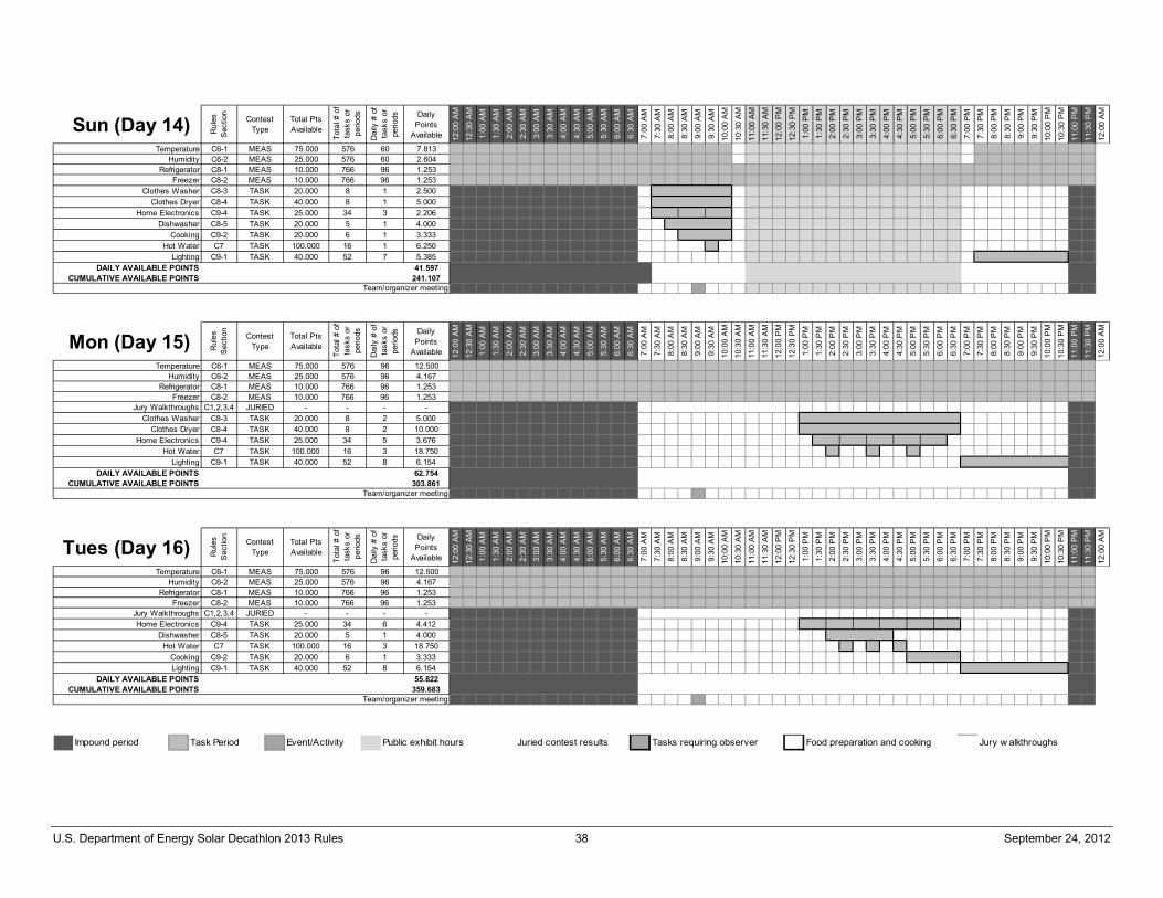
U.S. Department of Energy Solar Decathlon 2013 Rules 38 September 24, 2012
Sun (Day 14) Rul
es
Sec
tion
Contest Type
Total PtsAvailable
Tota
l # o
f ta
sks
orpe
riods
Dai
ly #
of
task
s or
perio
ds DailyPoints
Available 12:0
0 A
M
12:3
0 A
M
1:00
AM
1:30
AM
2:00
AM
2:30
AM
3:00
AM
3:30
AM
4:00
AM
4:30
AM
5:00
AM
5:30
AM
6:00
AM
6:30
AM
7:00
AM
7:30
AM
8:00
AM
8:30
AM
9:00
AM
9:30
AM
10:0
0 A
M
10:3
0 A
M
11:0
0 A
M
11:3
0 A
M
12:0
0 P
M
12:3
0 P
M
1:00
PM
1:30
PM
2:00
PM
2:30
PM
3:00
PM
3:30
PM
4:00
PM
4:30
PM
5:00
PM
5:30
PM
6:00
PM
6:30
PM
7:00
PM
7:30
PM
8:00
PM
8:30
PM
9:00
PM
9:30
PM
10:0
0 P
M
10:3
0 P
M
11:0
0 P
M
11:3
0 P
M
12:0
0 A
M
Temperature C6-1 MEAS 75.000 576 60 7.813 ## ## ## ## ## ## ## ## ## ## ## ## ## ## ## ## ## ## ## ## ## ## ## ## ## ## ## ## ## ##Humidity C6-2 MEAS 25.000 576 60 2.604 ## ## ## ## ## ## ## ## ## ## ## ## ## ## ## ## ## ## ## ## ## ## ## ## ## ## ## ## ## ##
Refrigerator C8-1 MEAS 10.000 766 96 1.253 ## ## ## ## ## ## ## ## ## ## ## ## ## ## ## ## ## ## ## ## ## ## ## ## ## ## ## ## ## ## ## ## ## ## ## ## ## ## ## ## ## ## ## ## ## ## ## ##Freezer C8-2 MEAS 10.000 766 96 1.253 ## ## ## ## ## ## ## ## ## ## ## ## ## ## ## ## ## ## ## ## ## ## ## ## ## ## ## ## ## ## ## ## ## ## ## ## ## ## ## ## ## ## ## ## ## ## ## ##
Clothes Washer C8-3 TASK 20.000 8 1 2.500 ## ## ## ## ## ##Clothes Dryer C8-4 TASK 40.000 8 1 5.000 ## ## ## ## ## ##
Home Electronics C9-4 TASK 25.000 34 3 2.206Dishwasher C8-5 TASK 20.000 5 1 4.000 ## ## ## ## ##
Cooking C9-2 TASK 20.000 6 1 3.333 ## ## ## ##Hot Water C7 TASK 100.000 16 1 6.250 ##
Lighting C9-1 TASK 40.000 52 7 5.385 ## ## ## ## ## ## ##DAILY AVAILABLE POINTS 41.597
CUMULATIVE AVAILABLE POINTS 241.107
##### ##### #####
Team/organizer meeting
Mon (Day 15) Rul
es
Sec
tion
Contest Type
Total PtsAvailable
Tota
l # o
f ta
sks
orpe
riods
Dai
ly #
of
task
s or
perio
ds DailyPoints
Available 12:0
0 A
M
12:3
0 A
M
1:00
AM
1:30
AM
2:00
AM
2:30
AM
3:00
AM
3:30
AM
4:00
AM
4:30
AM
5:00
AM
5:30
AM
6:00
AM
6:30
AM
7:00
AM
7:30
AM
8:00
AM
8:30
AM
9:00
AM
9:30
AM
10:0
0 A
M
10:3
0 A
M
11:0
0 A
M
11:3
0 A
M
12:0
0 P
M
12:3
0 P
M
1:00
PM
1:30
PM
2:00
PM
2:30
PM
3:00
PM
3:30
PM
4:00
PM
4:30
PM
5:00
PM
5:30
PM
6:00
PM
6:30
PM
7:00
PM
7:30
PM
8:00
PM
8:30
PM
9:00
PM
9:30
PM
10:0
0 P
M
10:3
0 P
M
11:0
0 P
M
11:3
0 P
M
12:0
0 A
M
Temperature C6-1 MEAS 75.000 576 96 12.500 ## ## ## ## ## ## ## ## ## ## ## ## ## ## ## ## ## ## ## ## ## ## ## ## ## ## ## ## ## ## ## ## ## ## ## ## ## ## ## ## ## ## ## ## ## ## ## ##Humidity C6-2 MEAS 25.000 576 96 4.167 ## ## ## ## ## ## ## ## ## ## ## ## ## ## ## ## ## ## ## ## ## ## ## ## ## ## ## ## ## ## ## ## ## ## ## ## ## ## ## ## ## ## ## ## ## ## ## ##
Refrigerator C8-1 MEAS 10.000 766 96 1.253 ## ## ## ## ## ## ## ## ## ## ## ## ## ## ## ## ## ## ## ## ## ## ## ## ## ## ## ## ## ## ## ## ## ## ## ## ## ## ## ## ## ## ## ## ## ## ## ##Freezer C8-2 MEAS 10.000 766 96 1.253 ## ## ## ## ## ## ## ## ## ## ## ## ## ## ## ## ## ## ## ## ## ## ## ## ## ## ## ## ## ## ## ## ## ## ## ## ## ## ## ## ## ## ## ## ## ## ## ##
Jury Walkthroughs C1,2,3,4 JURIED - - - -Clothes Washer C8-3 TASK 20.000 8 2 5.000 ## ## ## ## ## ## ## ## ## ## ## ##
Clothes Dryer C8-4 TASK 40.000 8 2 10.000 ## ## ## ## ## ## ## ## ## ## ## ##Home Electronics C9-4 TASK 25.000 34 5 3.676
Hot Water C7 TASK 100.000 16 3 18.750 ## ## ##Lighting C9-1 TASK 40.000 52 8 6.154 ## ## ## ## ## ## ## ##
DAILY AVAILABLE POINTS 62.754CUMULATIVE AVAILABLE POINTS 303.861
##### ##### ##### ##########
Team/organizer meeting
Tues (Day 16) Rul
es
Sec
tion
Contest Type
Total PtsAvailable
Tota
l # o
f ta
sks
orpe
riods
Dai
ly #
of
task
s or
perio
ds DailyPoints
Available 12:0
0 A
M
12:3
0 A
M
1:00
AM
1:30
AM
2:00
AM
2:30
AM
3:00
AM
3:30
AM
4:00
AM
4:30
AM
5:00
AM
5:30
AM
6:00
AM
6:30
AM
7:00
AM
7:30
AM
8:00
AM
8:30
AM
9:00
AM
9:30
AM
10:0
0 A
M
10:3
0 A
M
11:0
0 A
M
11:3
0 A
M
12:0
0 P
M
12:3
0 P
M
1:00
PM
1:30
PM
2:00
PM
2:30
PM
3:00
PM
3:30
PM
4:00
PM
4:30
PM
5:00
PM
5:30
PM
6:00
PM
6:30
PM
7:00
PM
7:30
PM
8:00
PM
8:30
PM
9:00
PM
9:30
PM
10:0
0 P
M
10:3
0 P
M
11:0
0 P
M
11:3
0 P
M
12:0
0 A
M
Temperature C6-1 MEAS 75.000 576 96 12.500 ## ## ## ## ## ## ## ## ## ## ## ## ## ## ## ## ## ## ## ## ## ## ## ## ## ## ## ## ## ## ## ## ## ## ## ## ## ## ## ## ## ## ## ## ## ## ## ##Humidity C6-2 MEAS 25.000 576 96 4.167 ## ## ## ## ## ## ## ## ## ## ## ## ## ## ## ## ## ## ## ## ## ## ## ## ## ## ## ## ## ## ## ## ## ## ## ## ## ## ## ## ## ## ## ## ## ## ## ##
Refrigerator C8-1 MEAS 10.000 766 96 1.253 ## ## ## ## ## ## ## ## ## ## ## ## ## ## ## ## ## ## ## ## ## ## ## ## ## ## ## ## ## ## ## ## ## ## ## ## ## ## ## ## ## ## ## ## ## ## ## ##Freezer C8-2 MEAS 10.000 766 96 1.253 ## ## ## ## ## ## ## ## ## ## ## ## ## ## ## ## ## ## ## ## ## ## ## ## ## ## ## ## ## ## ## ## ## ## ## ## ## ## ## ## ## ## ## ## ## ## ## ##
Jury Walkthroughs C1,2,3,4 JURIED - - - -Home Electronics C9-4 TASK 25.000 34 6 4.412
Dishwasher C8-5 TASK 20.000 5 1 4.000 ## ## ## ## ##Hot Water C7 TASK 100.000 16 3 18.750 ## ## ##
Cooking C9-2 TASK 20.000 6 1 3.333 ## ## ## ##Lighting C9-1 TASK 40.000 52 8 6.154 ## ## ## ## ## ## ## ##
DAILY AVAILABLE POINTS 55.822CUMULATIVE AVAILABLE POINTS 359.683
##############################
Team/organizer meeting
Impound period Task Period Event/Activity Public exhibit hours Juried contest results Tasks requiring observer Food preparation and cooking Jury w alkthroughs
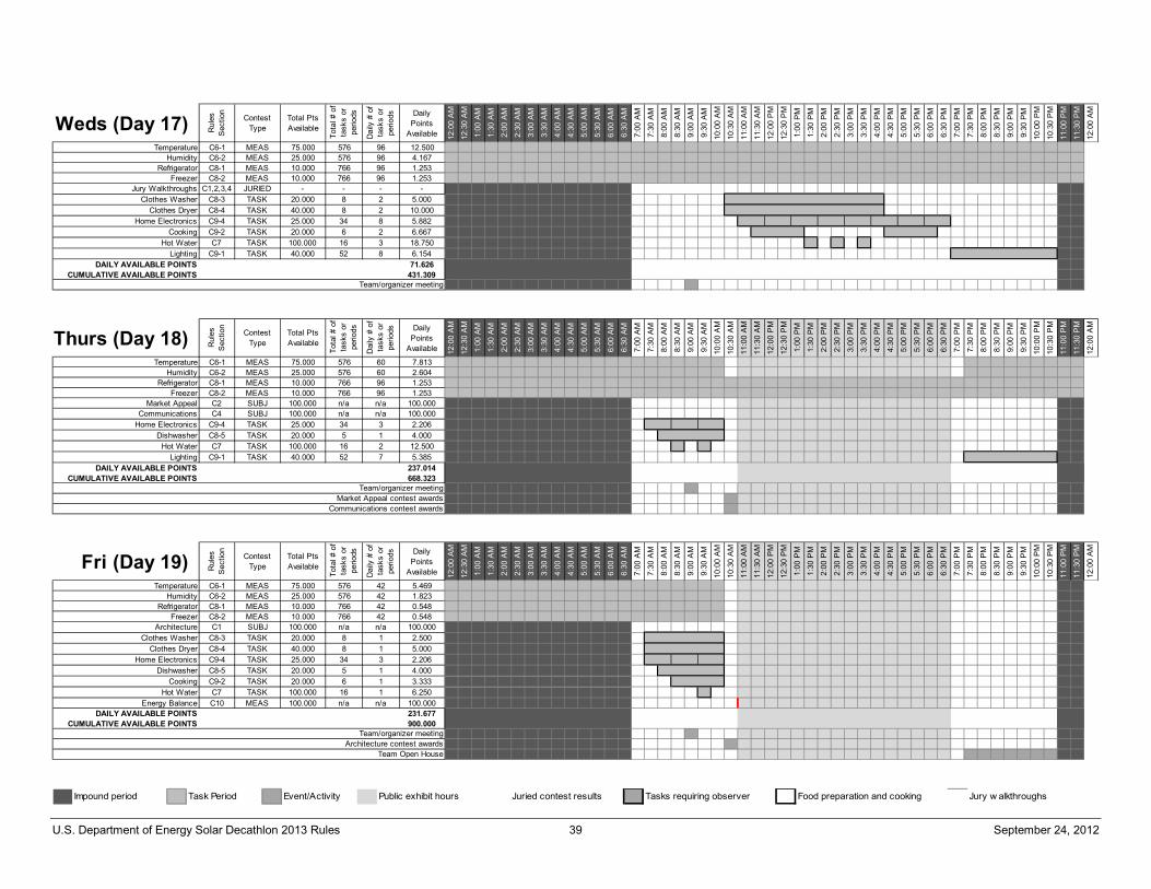
U.S. Department of Energy Solar Decathlon 2013 Rules 39 September 24, 2012
Weds (Day 17) Rul
es
Sec
tion
Contest Type
Total PtsAvailable
Tota
l # o
f ta
sks
orpe
riods
Dai
ly #
of
task
s or
perio
ds DailyPoints
Available 12:0
0 A
M
12:3
0 A
M
1:00
AM
1:30
AM
2:00
AM
2:30
AM
3:00
AM
3:30
AM
4:00
AM
4:30
AM
5:00
AM
5:30
AM
6:00
AM
6:30
AM
7:00
AM
7:30
AM
8:00
AM
8:30
AM
9:00
AM
9:30
AM
10:0
0 A
M
10:3
0 A
M
11:0
0 A
M
11:3
0 A
M
12:0
0 P
M
12:3
0 P
M
1:00
PM
1:30
PM
2:00
PM
2:30
PM
3:00
PM
3:30
PM
4:00
PM
4:30
PM
5:00
PM
5:30
PM
6:00
PM
6:30
PM
7:00
PM
7:30
PM
8:00
PM
8:30
PM
9:00
PM
9:30
PM
10:0
0 P
M
10:3
0 P
M
11:0
0 P
M
11:3
0 P
M
12:0
0 A
M
Temperature C6-1 MEAS 75.000 576 96 12.500 ## ## ## ## ## ## ## ## ## ## ## ## ## ## ## ## ## ## ## ## ## ## ## ## ## ## ## ## ## ## ## ## ## ## ## ## ## ## ## ## ## ## ## ## ## ## ## ##Humidity C6-2 MEAS 25.000 576 96 4.167 ## ## ## ## ## ## ## ## ## ## ## ## ## ## ## ## ## ## ## ## ## ## ## ## ## ## ## ## ## ## ## ## ## ## ## ## ## ## ## ## ## ## ## ## ## ## ## ##
Refrigerator C8-1 MEAS 10.000 766 96 1.253 ## ## ## ## ## ## ## ## ## ## ## ## ## ## ## ## ## ## ## ## ## ## ## ## ## ## ## ## ## ## ## ## ## ## ## ## ## ## ## ## ## ## ## ## ## ## ## ##Freezer C8-2 MEAS 10.000 766 96 1.253 ## ## ## ## ## ## ## ## ## ## ## ## ## ## ## ## ## ## ## ## ## ## ## ## ## ## ## ## ## ## ## ## ## ## ## ## ## ## ## ## ## ## ## ## ## ## ## ##
Jury Walkthroughs C1,2,3,4 JURIED - - - -Clothes Washer C8-3 TASK 20.000 8 2 5.000 ## ## ## ## ## ## ## ## ## ## ## ##
Clothes Dryer C8-4 TASK 40.000 8 2 10.000 ## ## ## ## ## ## ## ## ## ## ## ##Home Electronics C9-4 TASK 25.000 34 8 5.882
Cooking C9-2 TASK 20.000 6 2 6.667 ## ## ## ## ## ## ## ##Hot Water C7 TASK 100.000 16 3 18.750 ## ## ##
Lighting C9-1 TASK 40.000 52 8 6.154 ## ## ## ## ## ## ## ##DAILY AVAILABLE POINTS 71.626
CUMULATIVE AVAILABLE POINTS 431.309
##### ##### ##### #####
Team/organizer meeting
########## ##########
Thurs (Day 18) Rul
es
Sec
tion
Contest Type
Total PtsAvailable
Tota
l # o
f ta
sks
orpe
riods
Dai
ly #
of
task
s or
perio
ds DailyPoints
Available 12:0
0 A
M
12:3
0 A
M
1:00
AM
1:30
AM
2:00
AM
2:30
AM
3:00
AM
3:30
AM
4:00
AM
4:30
AM
5:00
AM
5:30
AM
6:00
AM
6:30
AM
7:00
AM
7:30
AM
8:00
AM
8:30
AM
9:00
AM
9:30
AM
10:0
0 A
M
10:3
0 A
M
11:0
0 A
M
11:3
0 A
M
12:0
0 P
M
12:3
0 P
M
1:00
PM
1:30
PM
2:00
PM
2:30
PM
3:00
PM
3:30
PM
4:00
PM
4:30
PM
5:00
PM
5:30
PM
6:00
PM
6:30
PM
7:00
PM
7:30
PM
8:00
PM
8:30
PM
9:00
PM
9:30
PM
10:0
0 P
M
10:3
0 P
M
11:0
0 P
M
11:3
0 P
M
12:0
0 A
M
Temperature C6-1 MEAS 75.000 576 60 7.813 ## ## ## ## ## ## ## ## ## ## ## ## ## ## ## ## ## ## ## ## ## ## ## ## ## ## ## ## ## ##Humidity C6-2 MEAS 25.000 576 60 2.604 ## ## ## ## ## ## ## ## ## ## ## ## ## ## ## ## ## ## ## ## ## ## ## ## ## ## ## ## ## ##
Refrigerator C8-1 MEAS 10.000 766 96 1.253 ## ## ## ## ## ## ## ## ## ## ## ## ## ## ## ## ## ## ## ## ## ## ## ## ## ## ## ## ## ## ## ## ## ## ## ## ## ## ## ## ## ## ## ## ## ## ## ##Freezer C8-2 MEAS 10.000 766 96 1.253 ## ## ## ## ## ## ## ## ## ## ## ## ## ## ## ## ## ## ## ## ## ## ## ## ## ## ## ## ## ## ## ## ## ## ## ## ## ## ## ## ## ## ## ## ## ## ## ##
Market Appeal C2 SUBJ 100.000 n/a n/a 100.000Communications C4 SUBJ 100.000 n/a n/a 100.000
Home Electronics C9-4 TASK 25.000 34 3 2.206Dishwasher C8-5 TASK 20.000 5 1 4.000 ## ## ## ## ##
Hot Water C7 TASK 100.000 16 2 12.500 ## ##Lighting C9-1 TASK 40.000 52 7 5.385 ## ## ## ## ## ## ##
DAILY AVAILABLE POINTS 237.014CUMULATIVE AVAILABLE POINTS 668.323
Communications contest awardsMarket Appeal contest awards
Team/organizer meeting
##### ##### #####
Fri (Day 19) Rul
es
Sec
tion
Contest Type
Total PtsAvailable
Tota
l # o
f ta
sks
orpe
riods
Dai
ly #
of
task
s or
perio
ds DailyPoints
Available 12:0
0 A
M
12:3
0 A
M
1:00
AM
1:30
AM
2:00
AM
2:30
AM
3:00
AM
3:30
AM
4:00
AM
4:30
AM
5:00
AM
5:30
AM
6:00
AM
6:30
AM
7:00
AM
7:30
AM
8:00
AM
8:30
AM
9:00
AM
9:30
AM
10:0
0 A
M
10:3
0 A
M
11:0
0 A
M
11:3
0 A
M
12:0
0 P
M
12:3
0 P
M
1:00
PM
1:30
PM
2:00
PM
2:30
PM
3:00
PM
3:30
PM
4:00
PM
4:30
PM
5:00
PM
5:30
PM
6:00
PM
6:30
PM
7:00
PM
7:30
PM
8:00
PM
8:30
PM
9:00
PM
9:30
PM
10:0
0 P
M
10:3
0 P
M
11:0
0 P
M
11:3
0 P
M
12:0
0 A
M
Temperature C6-1 MEAS 75.000 576 42 5.469 ## ## ## ## ## ## ## ## ## ## ## ## ## ## ## ## ## ## ## ## ##Humidity C6-2 MEAS 25.000 576 42 1.823 ## ## ## ## ## ## ## ## ## ## ## ## ## ## ## ## ## ## ## ## ##
Refrigerator C8-1 MEAS 10.000 766 42 0.548 ## ## ## ## ## ## ## ## ## ## ## ## ## ## ## ## ## ## ## ## ##Freezer C8-2 MEAS 10.000 766 42 0.548 ## ## ## ## ## ## ## ## ## ## ## ## ## ## ## ## ## ## ## ## ##
Architecture C1 SUBJ 100.000 n/a n/a 100.000Clothes Washer C8-3 TASK 20.000 8 1 2.500 ## ## ## ## ## ##
Clothes Dryer C8-4 TASK 40.000 8 1 5.000 ## ## ## ## ## ##Home Electronics C9-4 TASK 25.000 34 3 2.206
Dishwasher C8-5 TASK 20.000 5 1 4.000 ## ## ## ## ##Cooking C9-2 TASK 20.000 6 1 3.333 ## ## ## ##
Hot Water C7 TASK 100.000 16 1 6.250 ##Energy Balance C10 MEAS 100.000 n/a n/a 100.000
DAILY AVAILABLE POINTS 231.677CUMULATIVE AVAILABLE POINTS 900.000
Team Open House
##### ##### #####
Team/organizer meetingArchitecture contest awards
Impound period Task Period Event/Activity Public exhibit hours Juried contest results Tasks requiring observer Food preparation and cooking Jury w alkthroughs
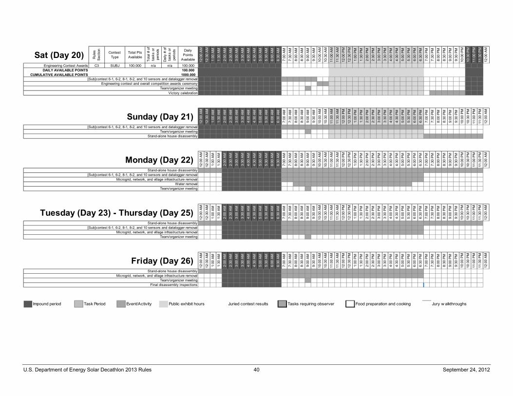
U.S. Department of Energy Solar Decathlon 2013 Rules 40 September 24, 2012
Sat (Day 20) Rul
es
Sec
tion
Contest Type
Total PtsAvailable
Tota
l # o
f ta
sks
orpe
riods
Dai
ly #
of
task
s or
perio
ds DailyPoints
Available 12:0
0 A
M
12:3
0 A
M
1:00
AM
1:30
AM
2:00
AM
2:30
AM
3:00
AM
3:30
AM
4:00
AM
4:30
AM
5:00
AM
5:30
AM
6:00
AM
6:30
AM
7:00
AM
7:30
AM
8:00
AM
8:30
AM
9:00
AM
9:30
AM
10:0
0 A
M
10:3
0 A
M
11:0
0 A
M
11:3
0 A
M
12:0
0 P
M
12:3
0 P
M
1:00
PM
1:30
PM
2:00
PM
2:30
PM
3:00
PM
3:30
PM
4:00
PM
4:30
PM
5:00
PM
5:30
PM
6:00
PM
6:30
PM
7:00
PM
7:30
PM
8:00
PM
8:30
PM
9:00
PM
9:30
PM
10:0
0 P
M
10:3
0 P
M
11:0
0 P
M
11:3
0 P
M
12:0
0 A
M
Engineering Contest Awards C3 SUBJ 100.000 n/a n/a 100.000DAILY AVAILABLE POINTS 100.000
CUMULATIVE AVAILABLE POINTS 1000.000[Sub]contest 6-1, 6-2, 8-1, 8-2, and 10 sensors and datalogger removal
Victory celebrationTeam/organizer meeting
Engineering contest and overall competition awards ceremony
12:0
0 A
M
12:3
0 A
M
1:00
AM
1:30
AM
2:00
AM
2:30
AM
3:00
AM
3:30
AM
4:00
AM
4:30
AM
5:00
AM
5:30
AM
6:00
AM
6:30
AM
7:00
AM
7:30
AM
8:00
AM
8:30
AM
9:00
AM
9:30
AM
10:0
0 A
M
10:3
0 A
M
11:0
0 A
M
11:3
0 A
M
12:0
0 P
M
12:3
0 P
M
1:00
PM
1:30
PM
2:00
PM
2:30
PM
3:00
PM
3:30
PM
4:00
PM
4:30
PM
5:00
PM
5:30
PM
6:00
PM
6:30
PM
7:00
PM
7:30
PM
8:00
PM
8:30
PM
9:00
PM
9:30
PM
10:0
0 P
M
10:3
0 P
M
11:0
0 P
M
11:3
0 P
M
12:0
0 A
M
Sunday (Day 21)[Sub]contest 6-1, 6-2, 8-1, 8-2, and 10 sensors and datalogger removal
Team/organizer meetingStand-alone house disassembly
12:0
0 A
M
12:3
0 A
M
1:00
AM
1:30
AM
2:00
AM
2:30
AM
3:00
AM
3:30
AM
4:00
AM
4:30
AM
5:00
AM
5:30
AM
6:00
AM
6:30
AM
7:00
AM
7:30
AM
8:00
AM
8:30
AM
9:00
AM
9:30
AM
10:0
0 A
M
10:3
0 A
M
11:0
0 A
M
11:3
0 A
M
12:0
0 P
M
12:3
0 P
M
1:00
PM
1:30
PM
2:00
PM
2:30
PM
3:00
PM
3:30
PM
4:00
PM
4:30
PM
5:00
PM
5:30
PM
6:00
PM
6:30
PM
7:00
PM
7:30
PM
8:00
PM
8:30
PM
9:00
PM
9:30
PM
10:0
0 P
M
10:3
0 P
M
11:0
0 P
M
11:3
0 P
M
12:0
0 A
M
Microgrid, network, and village infrastructure removal
Team/organizer meeting
[Sub]contest 6-1, 6-2, 8-1, 8-2, and 10 sensors and datalogger removal
Monday (Day 22)Stand-alone house disassembly
Water removal
12:0
0 A
M
12:3
0 A
M
1:00
AM
1:30
AM
2:00
AM
2:30
AM
3:00
AM
3:30
AM
4:00
AM
4:30
AM
5:00
AM
5:30
AM
6:00
AM
6:30
AM
7:00
AM
7:30
AM
8:00
AM
8:30
AM
9:00
AM
9:30
AM
10:0
0 A
M
10:3
0 A
M
11:0
0 A
M
11:3
0 A
M
12:0
0 P
M
12:3
0 P
M
1:00
PM
1:30
PM
2:00
PM
2:30
PM
3:00
PM
3:30
PM
4:00
PM
4:30
PM
5:00
PM
5:30
PM
6:00
PM
6:30
PM
7:00
PM
7:30
PM
8:00
PM
8:30
PM
9:00
PM
9:30
PM
10:0
0 P
M
10:3
0 P
M
11:0
0 P
M
11:3
0 P
M
12:0
0 A
M
Microgrid, network, and village infrastructure removalTeam/organizer meeting
Tuesday (Day 23) - Thursday (Day 25)Stand-alone house disassembly
[Sub]contest 6-1, 6-2, 8-1, 8-2, and 10 sensors and datalogger removal
12:0
0 A
M
12:3
0 A
M
1:00
AM
1:30
AM
2:00
AM
2:30
AM
3:00
AM
3:30
AM
4:00
AM
4:30
AM
5:00
AM
5:30
AM
6:00
AM
6:30
AM
7:00
AM
7:30
AM
8:00
AM
8:30
AM
9:00
AM
9:30
AM
10:0
0 A
M
10:3
0 A
M
11:0
0 A
M
11:3
0 A
M
12:0
0 P
M
12:3
0 P
M
1:00
PM
1:30
PM
2:00
PM
2:30
PM
3:00
PM
3:30
PM
4:00
PM
4:30
PM
5:00
PM
5:30
PM
6:00
PM
6:30
PM
7:00
PM
7:30
PM
8:00
PM
8:30
PM
9:00
PM
9:30
PM
10:0
0 P
M
10:3
0 P
M
11:0
0 P
M
11:3
0 P
M
12:0
0 A
M
Final disassembly inspections
Microgrid, network, and village infrastructure removalTeam/organizer meeting
Friday (Day 26)Stand-alone house disassembly
Impound period Task Period Event/Activity Public exhibit hours Juried contest results Tasks requiring observer Food preparation and cooking Jury w alkthroughs
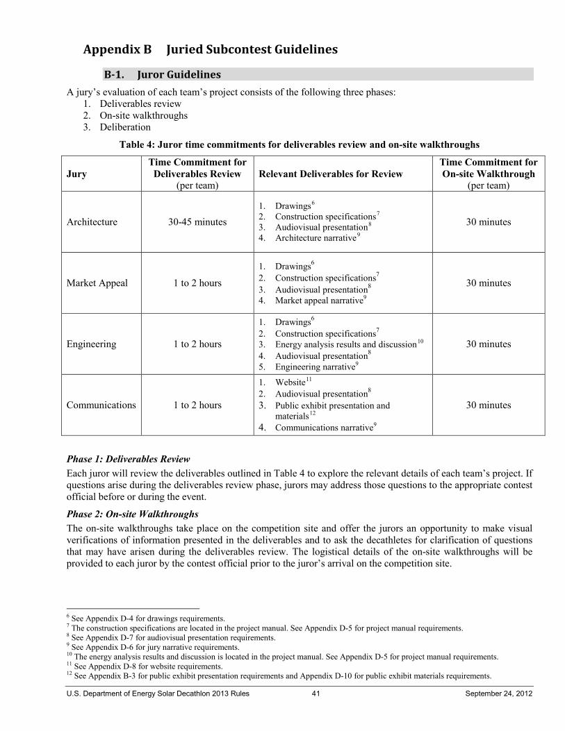
U.S. Department of Energy Solar Decathlon 2013 Rules 41 September 24, 2012
Appendix B Juried Subcontest Guidelines
B-1. Juror Guidelines A jury’s evaluation of each team’s project consists of the following three phases:
1. Deliverables review 2. On-site walkthroughs 3. Deliberation
Table 4: Juror time commitments for deliverables review and on-site walkthroughs
Jury Time Commitment for
Deliverables Review (per team)
Relevant Deliverables for Review Time Commitment for On-site Walkthrough
(per team)
Architecture 30-45 minutes 1. Drawings6 2. Construction specifications7 3. Audiovisual presentation8 4. Architecture narrative9
30 minutes
Market Appeal 1 to 2 hours
1. Drawings6 2. Construction specifications7 3. Audiovisual presentation8 4. Market appeal narrative9
30 minutes
Engineering 1 to 2 hours
1. Drawings6 2. Construction specifications7 3. Energy analysis results and discussion10 4. Audiovisual presentation8 5. Engineering narrative9
30 minutes
Communications 1 to 2 hours
1. Website11 2. Audiovisual presentation8 3. Public exhibit presentation and
materials12 4. Communications narrative9
30 minutes
Phase 1: Deliverables Review Each juror will review the deliverables outlined in Table 4 to explore the relevant details of each team’s project. If questions arise during the deliverables review phase, jurors may address those questions to the appropriate contest official before or during the event.
Phase 2: On-site Walkthroughs The on-site walkthroughs take place on the competition site and offer the jurors an opportunity to make visual verifications of information presented in the deliverables and to ask the decathletes for clarification of questions that may have arisen during the deliverables review. The logistical details of the on-site walkthroughs will be provided to each juror by the contest official prior to the juror’s arrival on the competition site.
6 See Appendix D-4 for drawings requirements. 7 The construction specifications are located in the project manual. See Appendix D-5 for project manual requirements. 8 See Appendix D-7 for audiovisual presentation requirements. 9 See Appendix D-6 for jury narrative requirements. 10 The energy analysis results and discussion is located in the project manual. See Appendix D-5 for project manual requirements. 11 See Appendix D-8 for website requirements. 12 See Appendix B-3 for public exhibit presentation requirements and Appendix D-10 for public exhibit materials requirements.
U.S. Department of Energy Solar Decathlon 2013 Rules 42 September 24, 2012
Phase 3: Deliberation
STEP #1 During the deliberation phase, which takes place after the completion of on-site walkthroughs, the jury is encouraged to place each team into one of four classes based on each team’s performance relative to the contest criteria. The four classes are:
Class #1: ECLIPSES contest criteria 91% – 100% of available points Class #2: EXCEEDS contest criteria 81% – 90% of available points Class #3: EQUALS contest criteria 61% – 80% of available points
Class #4: APPROACHES contest criteria 0% – 60% of available points Juries are not required to place a uniform number of teams in all classes or to place at least one team in every class. For example, if a jury determines that no teams are worthy of Class #1, there would be no teams with scores greater than 90%. Note that placing teams into classes (as a first step toward assigning an eventual percentage integer) is encouraged to ease the process of evaluating so many teams at one time. If it is possible to further separate teams within a particular class, assigning different percentage integers within the allowed range of the particular class is encouraged. The assigned percentage integer may fall anywhere within the range associated with the class. If it is not possible to further separate teams within a particular class, it may be appropriate to assign each team in a particular class the same percentage integer.
STEP #2 After assigning each team a percentage integer from 0% to 100%, the jury shall submit its percentage integers to the contest official. The contest official will then submit the percentages to the competition manager, who will convert them into a score based on the total number of available points for the contest being judged. The competition manager will round off any noninteger percentage scores to the nearest integer. Prior to posting scores in the scoring server, the scorekeeper will apply any applicable penalties that may have been incurred.
STEP #3 The three highest-scoring teams (plus ties) will be given awards during a scheduled media announcement during contest week (see Appendix A for announcement schedule). Pending the jurors’ availability, the organizers will invite the jurors to make the announcement. The scores for all of the teams will be posted immediately following the announcement.
STEP #4 The jury shall submit written or recorded scoring justifications for each team to the contest official. The jury’s scoring justifications will be provided as feedback to each team so it might better understand why the jury evaluated the team as it did. The justifications may be posted on the Solar Decathlon website.
B-2. Team Guidelines a. It is ultimately the team’s responsibility to be ready for the arrival of juries at the times indicated in the jury
walkthrough schedule, which is available in the “/Files/Rules/Rules Reference Documents” folder on the Yahoo Group. A Solar Decathlon organizer or staff person called a “runner” will deliver a warning 30 to 60 minutes prior to the arrival of the jury.
b. Teams shall show all possible configurations of the house during the walkthroughs of the Architecture, Market Appeal, and Engineering juries. House configurations that could affect the outcome of contests and that were not demonstrated to the juries are prohibited during contest week. Some examples of reconfigurable features include: • A significant moveable component, such as a room, wall, or bed (safety plan must also be in place) • Significant shading devices, such as retractable awnings or operable shutters • Towel-drying locations • Window coverings that may obstruct views or reduce light levels.
U.S. Department of Energy Solar Decathlon 2013 Rules 43 September 24, 2012
If a team does not have time to do a live reconfiguration during the jury walkthroughs, the team must use some other method, such as photographs or video, to show all reconfigurable features in their various configurations. If a team is not planning to actually reconfigure qualifying features at any time during contest week and has not shown or described the reconfiguration in the drawings, project manual, audiovisual presentation, or video walkthrough, that team does not have to show the reconfiguration to the juries. All plug-in or portable appliances that may be used during contest week must be in their fully deployed locations and configurations during the Architecture, Engineering, or Market Appeal jury walkthroughs. Also be aware that the Architecture, Engineering or Market Appeal juries may request plug-in, portable, or hard-wired appliances to be turned on so they can evaluate noise levels or other characteristics of the appliances that may not be apparent when the appliances are off.
c. Rule 11-1, “House Occupancy,” applies during jury walkthroughs. Non-decathlete team members and team crew shall not be present during the walkthroughs.
d. The jury walkthroughs will be held to a very strict schedule for each of the houses. The importance of following this schedule is twofold: 1) To ensure each team receives equal visitation time by the juries to maintain a sense of fairness among all the teams; and 2) Any deviation from the schedule will have an immediate effect on other events planned during the days the juries will be evaluating houses. A small deviation in the defined schedule for the juries could result in a very difficult situation to resolve in another component of the competition. If a team is not ready for a jury to begin its evaluation at the scheduled time, then the total time the jury spends in that team’s house will be reduced.
e. During daytime jury walkthroughs, the jury will have 30 minutes to visit each house, followed by a 5-minute period to travel to the next house. During the 30-minute walkthrough, 20 minutes will be allocated for the team to lead the jury through the house and answer any questions the jury may have. After 20 minutes, the team shall leave the house so that the jury can hold a private, 10-minute discussion about the house it has just visited.
f. The Architecture Jury will visit each house a second time at night. During the nighttime walkthrough, the Architecture Jury will have 10 minutes to visit each house followed by a 5-minute period to travel to the next house. During the 10-minute walkthrough, 5 minutes will be allocated for the team to answer any questions the jury may have. Teams are permitted to adjust the house lighting during the Architecture Jury visit without consequence on the score for the Lighting Subcontest. After 5 minutes, the team shall leave the house so that the jury can hold a private, 5-minute discussion about the house it has just visited.
g. Presentation boards or other visual media summarizing information in the “Relevant Deliverables” (see the third column in Table 4) are permitted to be on display during jury walkthroughs. The team website, public exhibit handout, and public exhibit materials may only be viewed by the Communications Jury.
h. One or more of the eligible house occupants (see Rule 11-1 and item c above) may audiotape or videotape the jury walkthrough as it is happening, but taping of the private jury discussion period is prohibited.
i. Areas of the house excluded from the accessible exhibit route may be accessed by the juries and considered in their evaluations.
j. The organizers will provide all juries with summaries of important rule and code violations for each team so that juries are aware of violations before giving credit for aspects of the project that are not in compliance.
k. The organizers may provide juries with contents of the organizers’ reviews of relevant deliverables.
B-3. Public Exhibit Requirements The team shall present two versions of its public tour. Both versions will be evaluated by the Communications Jury.
Version #1: 10-Minute Personalized Tour • The personalized tour is a comprehensive tour that addresses individual visitors’ needs and questions and
is appropriate for times when wait lines are short or nonexistent. • Each team will be allowed 10 minutes to present the personalized tour to the Communications Jury. • The version of the personalized tour presented to the Communications Jury must represent the
personalized tour presented to the public throughout the competition week.

U.S. Department of Energy Solar Decathlon 2013 Rules 44 September 24, 2012
Version #2: 5-Minute Fast Tour • The 5-minute fast tour is a fast-yet-informative tour that allows visitors to move through the house on
their own and accommodates large crowds and long lines. • Each team will be allowed 5 minutes to present the fast-yet-informative tour to the Communications Jury. • The version of the fast tour presented to the Communications Jury must represent the fast tour presented
to the public throughout the competition week.
Common Requirements • Both versions of the public tours shall be informative, interesting, and accessible by people of all abilities. • In addition to the two tours described above, teams will be allowed 5 minutes to present the team
communications strategy to the Communications Jury. • Teams are encouraged to employ effective and creative methods to control wait times and engage visitors
waiting in line during public hours. • Power-consuming devices, such as LCD displays, house lighting, mobile electronics, etc., shall not be
used during the fast tour presented to the Communication Jury. Any power-consuming devices used during the personalized tour must be plugged into the house at all times when not in use.
• For additional information, see Rule 11-4.
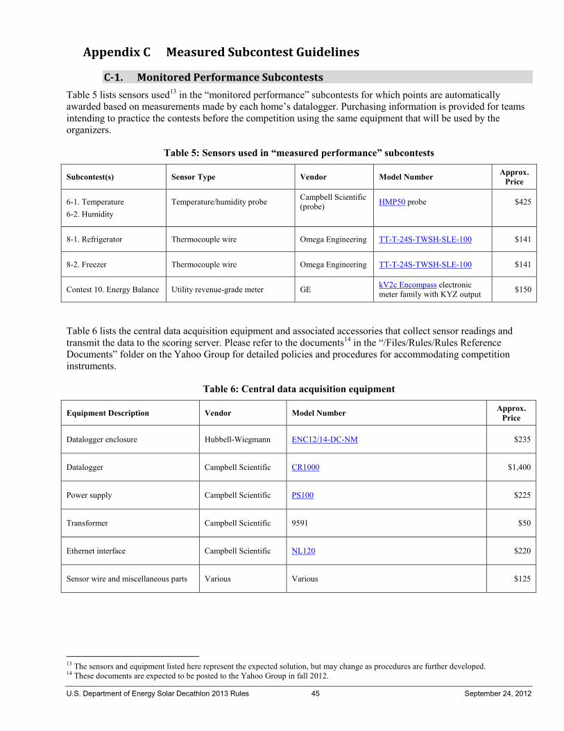
U.S. Department of Energy Solar Decathlon 2013 Rules 45 September 24, 2012
Appendix C Measured Subcontest Guidelines
C-1. Monitored Performance Subcontests Table 5 lists sensors used13 in the “monitored performance” subcontests for which points are automatically awarded based on measurements made by each home’s datalogger. Purchasing information is provided for teams intending to practice the contests before the competition using the same equipment that will be used by the organizers.
Table 5: Sensors used in “measured performance” subcontests
Subcontest(s) Sensor Type Vendor Model Number Approx. Price
6-1. Temperature 6-2. Humidity
Temperature/humidity probe
Campbell Scientific (probe)
HMP50 probe
$425
8-1. Refrigerator Thermocouple wire Omega Engineering TT-T-24S-TWSH-SLE-100 $141
8-2. Freezer Thermocouple wire Omega Engineering TT-T-24S-TWSH-SLE-100 $141
Contest 10. Energy Balance Utility revenue-grade meter GE kV2c Encompass electronic meter family with KYZ output $150
Table 6 lists the central data acquisition equipment and associated accessories that collect sensor readings and transmit the data to the scoring server. Please refer to the documents14 in the “/Files/Rules/Rules Reference Documents” folder on the Yahoo Group for detailed policies and procedures for accommodating competition instruments.
Table 6: Central data acquisition equipment
Equipment Description Vendor Model Number Approx. Price
Datalogger enclosure Hubbell-Wiegmann ENC12/14-DC-NM $235
Datalogger Campbell Scientific CR1000 $1,400
Power supply Campbell Scientific PS100 $225
Transformer Campbell Scientific 9591 $50
Ethernet interface Campbell Scientific NL120 $220
Sensor wire and miscellaneous parts Various Various $125
13 The sensors and equipment listed here represent the expected solution, but may change as procedures are further developed. 14 These documents are expected to be posted to the Yahoo Group in fall 2012.

U.S. Department of Energy Solar Decathlon 2013 Rules 46 September 24, 2012
C-2. Task Completion Subcontests The “task completion” subcontests listed in Table 7 are classified as such because teams earn points by successfully completing a task that is observed by, and the results of which are recorded by, an observer in the “observer logs”:
Table 7: Instruments and sensors used in “task completion” subcontests
Subcontest(s) Instrument or Sensor Type Vendor Model Number Approx. Price
Contest 7. Hot Water Multiple Components15 Constructed None $600
8-3. Clothes Washer Visual/audible inspection n/a n/a n/a
8-4. Clothes Dryer Scale Acculab SVI-50C $350
8-5. Dishwasher Nonreversible temperature label Omega TL-5-105-10 $10 (pkg of 10)
9-1. Lighting Visual inspection n/a n/a n/a
9-2. Cooking Kitchen scale Salton 1008 $50
9-4. Home Electronics Visual inspection n/a n/a n/a
Please refer to the “Measured Contest Procedures” slideshow16 in the “/Files/Rules/Rules Reference Documents” folder on the Yahoo Group for detailed task completion subcontest policies and procedures as well as examples of observer logs.
15 A detailed component list is expected to be posted to the Yahoo Group in spring 2013. 16 This slideshow is expected to be posted in spring 2013.
U.S. Department of Energy Solar Decathlon 2013 Rules 47 September 24, 2012
Appendix D Competition Deliverables
The design deliverables consist of the schematic design summary, building information model, drawings, project manual, and audiovisual presentations. These design deliverables serve the following important functions:
• In its schematic design summary, the team shall disclose to the organizers all non-standard design features, communications strategies, site operations plans, and health and safety considerations that require further review prior to the continuation of the project into the design development phase.
• All the drawings shall be generated in an Autodesk Revit building information model compatible format.
• The drawings and project manual shall demonstrate compliance with the Solar Decathlon Building Code and the Solar Decathlon Rules so that the inspectors will be able to grant final on-site approval by verifying that the constructed project on the competition site was accurately represented by the approved drawings and project manual.
• The drawings and project manual shall clearly describe a team’s proposed assembly and disassembly procedures. The site operations manager will review the teams’ procedures to identify and address potential conflicts among the teams. Each team is encouraged to consult with the site operations manager as the relevant sections of the drawings and project manual are being developed.
• The drawings and project manual shall provide a residential contractor with all the information needed to generate an accurate, detailed cost estimate and to efficiently construct the building as the design team intended it to be built. The drawings and project manual must be comprehensive because the design team shall assume that the contractor has had no prior communication with the design team, has no prior knowledge of the design, and has little or no experience building high-performance residences.
• Because the juries have a very limited opportunity to evaluate the constructed projects on the competition site, the drawings, project manual, audiovisual presentation, and jury narratives provide the only means for a team to provide a detailed presentation of its project to the juries. In the weeks leading up to contest week, each juror shall evaluate the audiovisual presentation and sections of the teams’ drawings and project manual relevant to the juror’s respective area of expertise. The primary purpose of the juries’ walkthroughs on the competition site is twofold: 1) to verify that the project, as assembled on the competition site, was accurately represented in the drawings, project manual, audiovisual presentations and narratives; and 2) to ask the decathletes any clarifying questions that arose during the evaluation of the design via the drawings, project manual, and audiovisual presentations.
Additional competition deliverables provided the information required to allow the organizers, juries, and public to develop a comprehensive understanding of each team’s competition prototype.
D-1. Schematic Design Summary The schematic design proposal will be reviewed by the organizers and discussed in detail during the schematic design review. It will not be reviewed by any juries and will not be made publicly available until after the completion of the competition.

U.S. Department of Energy Solar Decathlon 2013 Rules 48 September 24, 2012
Format Requirements
Packaged into a single, bookmarked PDF file (see Appendix F for PDF formatting and file-naming requirements)
Intent of figures shouldn’t be lost if printed in black & white ANSI “A” (8.5 in. X 11 in.) sheet size and ANSI “D” (22 in. X 34 in.) sheet size 20 to 30 pages, including figures and tables; cover sheet, table of contents, and appendices do not count
toward page limit 11-point body text Maximum 14-point heading text One-inch margins on top, bottom, left, and right Include page numbers and numbered captions for figures and tables for easy navigation through document
Content Requirements
Team mission statement (1 paragraph) Detailed strategy for winning the competition including a realistic contest-by-contest breakdown of points
the team expects to earn (2 to 3 pages) Narrative describing the architectural and engineering design approaches (1 to 2 pages) Design drawings and written description of the following systems and components, with a focus on unique
systems and components that may not be addressed by model building codes (12 to 17 pages): • Temporary foundations and anchors • Exterior building structures, such as including decks, outbuildings, overhead structures, etc. • Ramps, railings, and guards • Glazing types and location • Interior finishes • Fire protection • DC electrical • AC electrical • Water storage/service • Plumbing • Mechanical (includes HVAC) • Solar mechanical
Description of and proposed location(s) for utility meter and organizer dataloggers (1 to 2 pages) Description of public exhibit, communications, and outreach strategy (1 to 2 pages) Drawings showing proposed interior and exterior accessible tour routes (2 to 3 pages) Computer-generated renderings of competition prototype (5-6 pages, images to be minimum 3000 px by
2400 px Health and Safety Plan outline including approach to meeting OSHA training requirement (1 to 2 pages) Identification of and summary of qualifications for the licensed design professional who will be stamping the
structural drawings and calculations (1 page)

U.S. Department of Energy Solar Decathlon 2013 Rules 49 September 24, 2012
D-2. Computer-Animated Walkthrough and Computer-Generated Renderings
Computer-Animated Walkthrough Each team shall provide a computer-animated walkthrough of its house for the following purposes:
1. To be included in a compilation video of all Solar Decathlon 2013 walkthroughs that will be presented to the public and used in marketing materials associated with the project.
2. To be posted on the Solar Decathlon website as an introduction to each house.
Format Requirements
Packaged into a single Quicktime .mov or H.264 compressed MP4 (MPEG-4) file type using 720 x 480 resolution and 16:9 aspect ratio
Runtime between 3 and 3.5 minutes Shall be accompanied by a verbatim transcript in a Microsoft Word-compatible format to meet Section 508
Accessibility standards.
Content Requirements
Composed of animated computer renderings that demonstrate all aspects of the house Includes an audio narrative that explains to viewers what they’re seeing and describes the philosophy behind
the design Does not include elements that are inherently inaccessible to those with visual disabilities Does not contain background music that violates U.S. copyright laws. All incorporated music must be an
original or royalty-free composition. Proof of licensing shall be submitted with the final file and transcript.
Computer-Generated Renderings The computer-generated renderings will be posted to the Solar Decathlon website and used in various communications materials to introduce the public to each competition prototype.
Format Requirements
Minimum resolution of each image shall be 3000 px wide by 2400 px Composed of image files (JPEG, TIFF, etc.) packaged as one Zip (.zip) file
Content Requirements
Includes, at a minimum: • Two (2) elevation views of the competition prototype • One (1) Birds-eye perspective views of the competition prototype • Two (2) Interior views of the competition prototype
D-3. Building Information Model The BIM is a contractual deliverable that is due at the conclusion of the design development phase, at the conclusion of the construction documentation phase, and again just prior to the competition. Each iteration of the BIM shall include an increasing level of detail and refinement as the project progresses. It will be used by the organizers for several purposes outlined in the Appendix D introduction above. The BIM will not be reviewed by any juries and may be made publicly available following each submission.
Format Requirements
One (1) Autodesk Revit (.rvt)-compatible file or one (1) Autodesk Revit Architecture (.rvt)-compatible file with relative references to additional Revit (.rvt)-compatible files as required. If multiple Autodesk Revit-compatible files are submitted, they should be packaged as one Zip (.zip) file.

U.S. Department of Energy Solar Decathlon 2013 Rules 50 September 24, 2012
Extensive use of the Revit template (.rte) file17 available for download in the “/Files/Rules/Resources” folder on the Yahoo Group; limited minor modifications to the template are allowed, but must be approved by competition management
Content Requirements
House model Site model including all exterior site components Drawing set sheet views matching submitted drawings
Notes: 1) Shop drawings submitted by subcontractors need not be recreated from scratch in the BIM unless they contain information that is required to make the BIM complete 2) Even if shop drawings aren’t recreated in the BIM, they shall be imported into the BIM file and included in sheet views for inclusion in the drawing set.
Sufficient detail to enable the organizers to develop detailed cost estimates and a product directory using only the information included in the BIM; the sample BIM18 posted for download in the “/Files/Rules/Resources” folder on the Yahoo Group includes the minimum required level of detail
D-4. Drawings The drawings shall be generated from sheet views in the BIM file. Each iteration of the drawings shall include an increasing level of detail and refinement as the project progresses. The drawings may be made publicly available after each submission.
Format Requirements
Packaged into a single, bookmarked PDF file (see Appendix F for PDF formatting and file-naming requirements) using NCSv4-compliant order and formatting.
Compliant with United States National CAD Standard® – Version 5.0 EXCEPTION: The use of keynotes is not required.
ANSI “D” (22 in. X 34 in.) sheet size Graphic scales included to allow users to reduce or enlarge printed sheets Very similar formatting as the sample drawings19 generated from the sample BIM; limited minor
modifications to the sample drawings format are allowed, but must be approved by competition management
Content Requirements
Sufficient detail to enable the organizers to develop detailed cost estimates and a product directory using only the information included in the drawings and project manual; sample drawings posted19 for download in the “/Files/Rules/Resources” folder on the Yahoo Group include the minimum required level of detail
D-5. Project Manual The project manual is a contractual and competition deliverable that is due at the conclusion of the design development phase, at the conclusion of the construction documentation phase, and again just prior to the competition. Each iteration of the project manual shall include an increasing level of detail and refinement as the project progresses. The project manual may be made publicly available following each submission.
17 The Revit template was posted in summer 2012 18 A first version of the sample BIM was posted for download in summer 2012. 19 A first version of the sample drawings was posted for download in summer 2012.
U.S. Department of Energy Solar Decathlon 2013 Rules 51 September 24, 2012
Format Requirements
ANSI “A” (8.5 in. X 11 in.) sheet size Organization and formatting of construction specifications in compliance with the Construction
Specifications Institute’s MasterFormat 2004 Edition, SectionFormat, and PageFormat standards Packaged into a single, bookmarked PDF file (see Appendix F for PDF formatting and file-naming
requirements) Extensive use of the Word template (.dotx) file20 available for download in the “/Files/Rules/Resources”
folder on the Yahoo Group; limited minor modifications to the template are allowed, but must be approved by competition management
Content Requirements
Content Requirements for Rules Compliance Checklist
Rule # Rule Description Content Requirement(s)
4-2 Construction Equipment Drawing(s) showing the assembly and disassembly sequences and the movement of heavy machinery on the competition site
4-2 Construction Equipment Specifications for heavy machinery
4-3 Ground Penetration Drawing(s) showing the locations and depths of all ground penetrations on the competition site
4-4 Impact within the Solar Envelope
Drawing(s) showing the location, contact area, and bearing pressure of every component resting directly within the solar envelope
4-5 Generators Specifications for generators (including sound rating)
4-6 Spill Containment Drawing(s) showing the locations of all equipment, containers, and pipes that will contain liquids at any point during the event
4-6 Spill Containment Specifications for all equipment, containers, and pipes that will contain liquids at any point during the event
4-7 Lot Conditions Calculations showing that the structural design remains compliant even if 12 in. (30.48 cm) of vertical elevation change exists
4-7 Lot Conditions Drawing(s) showing shimming methods and materials to be used if 12 in. (30.48 cm) of vertical elevation change exists on the lot
5-2 Solar Envelope Dimensions
Drawing(s) showing the location of all house and site components relative to the solar envelope
5-2 Solar Envelope Dimensions
List of solar envelope exemption requests accompanied by justifications and drawing references
6-1 Structural Design Approval
List of, or marking on, all drawing and project manual sheets that have been or will be stamped by the qualified, licensed design professional in the stamped structural submission; the stamped submission shall consist entirely of sheets that also appear in the drawings and project manual
20 A first version of the project manual template was posted for download in summer 2012. 21 A template version of the rules compliance checklist was included in the project manual template.
Complete set of construction specifications (including links to manufacturers’ data sheets) Rules compliance checklist21 (see content requirements below) Structural calculations Detailed water budget Summary of unlisted electrical components Summary of reconfigurable features (see Appendix B-2b) Interconnection application form Complete quantity take-offs of entire competition prototype
U.S. Department of Energy Solar Decathlon 2013 Rules 52 September 24, 2012
Rule # Rule Description Content Requirement(s)
6-2 Finished Square Footage Drawing(s) showing all information needed by the rules officials to measure the finished square footage electronically
6-2 Finished Square Footage Drawing(s) showing all movable components that may increase the finished square footage if operated during contest week
6-3 Entrance and Exit Routes Drawing(s) showing the accessible public tour route
7-1 Placement Drawing(s) showing the location of all vegetation and, if applicable, the movement of vegetation designed as part of an integrated mobile system
7-2 Watering Restrictions Drawing(s) showing the layout and operation of greywater irrigation systems
8-1 PV Technology Limitations Specifications for photovoltaic components
8-3 Batteries Drawing(s) showing the location(s) and quantity of all primary and secondary batteries and stand-alone, PV-powered devices
8-3 Batteries Specifications for all primary and secondary batteries and stand-alone, PV-powered devices
8-4 Desiccant Systems Drawing(s) describing the operation of the desiccant system 8-4 Desiccant Systems Specifications for desiccant system components 8-5 Village Grid Completed interconnection application form
8-5 Village Grid Drawing(s) showing the locations of the photovoltaics, inverter(s), terminal box, meter housing, service equipment, and grounding means
8-5 Village Grid Specifications for the photovoltaics, inverter(s), terminal box, meter housing, service equipment, and grounding means
8-5 Village Grid One-line electrical diagram 8-5 Village Grid Calculation of service/feeder net computed load per NEC 220 8-5 Village Grid Site plan showing the house, decks, ramps, tour paths, and terminal box
8-5 Village Grid Elevation(s) showing the meter housing, main utility disconnect, and other service equipment
9-1 Container Locations Drawing(s) showing the location of all liquid containers relative to the finished square footage
9-1 Container Locations Drawing(s) demonstrating that the primary supply water tank(s) is fully shaded from direct solar radiation between 9 a.m. and 5 p.m. PDT or between 8 a.m. and 4 p.m. solar time on October 1
9-2 Team-Provided Liquids Quantity, characteristics, and delivery date(s) of all team-provided liquids for irrigation, thermal mass, hydronic system pressure testing, and thermodynamic system operation
9-3 Greywater Reuse Drawing(s) showing the layout and operation of greywater reuse systems
9-4 Rainwater Collection Drawing(s) showing the layout and operation of rainwater collection systems
9-6 Thermal Mass Drawing(s) showing the locations of liquid-based thermal mass systems 9-6 Thermal Mass Specifications for components of liquid-based thermal mass systems
9-7 Greywater Heat Recovery Drawing(s) showing the layout and operation of greywater heat recovery systems
9-8 Water Delivery Drawing(s) showing the complete sequence of water delivery and distribution events
9-8 Water Delivery Specifications for the containers to which water will be delivered
9-9 Water Removal Drawing(s) showing the complete sequence of water consolidation and removal events
9-9 Water Removal Specifications for the containers from which water will be removed 11-4 Public Exhibit Interior and exterior plans showing entire accessible tour route
U.S. Department of Energy Solar Decathlon 2013 Rules 53 September 24, 2012
D-6. Jury Narratives The jury narratives are written documents that provide a summary of each team’s approach to meeting the contest requirements for the Architecture, Market Appeal, Engineering, and Communications contests. The narratives will be reviewed by the respective jury prior to the competition in accordance with Table 4. The narratives will not be made public prior to the release of the respective contest results.
Format Requirements
ANSI “A” (8.5 in. X 11 in.) sheet size Packaged into a single, bookmarked PDF file (see Appendix F for PDF formatting and file-naming
requirements)
Content Requirements
D-7. Audiovisual Presentation The audiovisual presentation is a competition deliverable that is due just prior to the competition. The juries will review the audiovisual presentation prior to the competition in accordance with Table 4. The presentation will be made publicly available soon after the submission as an update to the Computer-Animated Walkthrough.
Format Requirements
The format requirements for the audiovisual presentation are outlined below. • .MOV or H.264 compressed.MP4 (MPEG-4) file type • 3–3.5 minute runtime • 16:9 aspect ratio • 720 x 480 resolution • Accompanied by a verbatim transcript of the audio narrative to meet Section 508 Accessibility standards.
Transcript should be submitted in a Microsoft Word-compatible format. For an example of a text version script, see the Wind Power Animation (Text Version).
Content Requirements
Must include video footage of the actual constructed house May contain still photos and graphics Gives the jurors a realistic preview of what they will experience during the on-site walkthroughs Explains how the project meets the criteria22 listed in the relevant contest section of the rules Includes an audio narrative that explains to viewers what they’re seeing and describes the underlying
philosophy Contains only originally created or properly credited work that does not violate U.S. copyright laws Does not contain background music that violates U.S. copyright laws. All incorporated music must be an
original or royalty-free composition. Proof of licensing shall be submitted with the final file and transcript. 22 The audiovisual presentation shall address the design and implementation criteria for architecture; the livability and marketability criteria for market appeal; and the functionality, efficiency, innovation, and reliability criteria for engineering.
Architecture Narrative (5 pages, maximum) Market Appeal Narrative (5 pages, maximum) Engineering Narrative (5 pages, maximum) Communications Narrative (2 pages, maximum)
The narrative should present the team’s communications goals, objectives, 2-3 high-level strategies/tactics for meeting these goals and objectives, target audiences, key messages, and metrics for success (e.g., how will the team know if its communications succeeded?).

U.S. Department of Energy Solar Decathlon 2013 Rules 54 September 24, 2012
Follows guidelines for logos as described in Rules 10-2 and 10-3 Does not contain interactive elements that are inherently inaccessible to those with visual disabilities
D-8. Website The website is a contractual and competition deliverable that is due near the beginning of the project as a preliminary website and again just prior to the competition. The website serves as part of each team’s communications strategy and will be reviewed by the communications jury in accordance with Table 4. Preliminary Website A preliminary website consisting of at least three pages shall be evaluated by communications professionals at NREL to ensure compliance with the Minimum Website Coding Standards document available on the Yahoo Group23. Final Website The final website shall be evaluated by the Communications Jury. The final website shall consist of considerably more content than the preliminary website. Each team may request up to two courtesy reviews of the final website prior to submission. Teams shall request a courtesy review by contacting [email protected]. After each courtesy review, each team shall be notified of required changes it should make to achieve compliance. The Communications Jury shall begin evaluations of team websites at the same time as the as-built deliverable submission. Communications professionals at NREL will also evaluate each final website for compliance with the Minimum Website Coding Standards document posted in the Yahoo Group. The organizers will provide the Communications Jury with a summary of aspects that are not in compliance for each team so that the jury is aware of any violations. The Communications Jury will re-evaluate the website following the on-site walkthrough to determine effective use of project updates, photographs, social media, and other communications efforts.
D-9. Project Summary Important to many communications-related aspects of the Solar Decathlon, project summaries: • Provide essential content for the organizers to use while developing various event materials (e.g., the website,
event program, media kit, and village signage) • Prepare teams to answer questions from visitors to their construction sites and to the competition site at
Orange County Great Park. • Help organizers and teams respond effectively to media inquiries.
All project summary materials (narrative, photograph, computer-generated house rendering, and logos) shall be saved in the formats indicated and submitted to organizers packaged as a single .zip file.
Overview Format Requirements
Packaged into a single, bookmarked PDF file (see Appendix F for PDF formatting and file-naming requirements)
10 pages maximum 11-pt. type, double spaced, 1-in. (or metric equivalent) margins
Content Requirements
A 100-word or less description of your team house. (1 paragraph) Design philosophy and house design. What is the team trying to portray or accomplish with this design?
What will the house look like? What are some of the key features? (1 page)
23 The Minimum Website Coding Standards document was posted for download in spring 2012
U.S. Department of Energy Solar Decathlon 2013 Rules 55 September 24, 2012
Unique house features. What makes the house unlike any other? (1 page) Technological innovations. Summarize the unique or unusual technologies incorporated into your house. (1-
2 pages) Define the target client for the team house. How does the design accommodate the needs and desires of this
client? (1 paragraph) Team organization and contacts. Indicate how your team is organized and approximately how many
students, faculty, and others (e.g., sponsors, volunteers, family members) are involved in the project. (1 page)
Future plans for your house, if known. Where will it go after the competition? (1 paragraph)
Team Photograph For use in the event program, media kit, and Solar Decathlon website, the team photo is an important conveyance of your team’s personality.
Format Requirements
Native format of the camera, such as JPEG or RAW, if available 2048 × 1080 minimum pixel dimensions RGB, 8-bit color, not black and white
Content Requirements
Include all team members (if possible) and strive for creativity. For examples of past team photos, visit the History section of the Solar Decathlon website.
For a photograph to be properly credited, the following information shall be included in a Microsoft Word-compatible text file accompanying the photograph file:
• Name, phone number, and email of person submitting the photograph • Photograph date and location • Photographer’s name and affiliation.
Team Logo The team logo is used by organizers in village signage, the event program, media kit, and Solar Decathlon website.
Format Requirements
Submit two versions of your logo: • One for Web (GIF or JPG, at least 200 px wide). GIF is preferred for simple flat-color logos. JPG is
preferred for complex logos. • One for print (high-resolution or vector format; EPS preferred).
Content Requirements
Include a text file containing the following additional information: • Name, phone number, and email of person submitting the logo • A list of all Pantone (PMS) or CMYK numbers used in the logo. Please consult the graphic designer
of your logo if you need help providing these specific color requirements.
Computer-Generated Renderings The computer-generated renderings will be posted to the Solar Decathlon website and used in various communications materials to introduce the public to each competition prototype.
Format Requirements
U.S. Department of Energy Solar Decathlon 2013 Rules 56 September 24, 2012
Minimum resolution of each image shall be 3000 px wide by 2400 px Composed of image files (JPEG, TIFF, etc.) packaged as one Zip (.zip) file
Content Requirements
Includes, at a minimum: • North Elevation View of the competition prototype • South Elevation View of the competition prototype • East Elevation View of the competition prototype • West Elevation View of the competition prototype • Two (2) Birds-eye perspective views of the competition prototype • Four (4) Interior views of the competition prototype
Dinner Party Menus and Recipes The dinner party information will be provided to visiting teams for review prior to participation in the dinner party subcontest and will be posted to the Solar Decathlon website.
Format Requirements
Packaged into a single, bookmarked PDF file (see Appendix F for PDF formatting and file-naming requirements)
Content Requirements
Restaurant-style dinner party menu for each dinner party Cookbook-style recipes for all components of dinner party Comprehensive ingredient list for each dinner party
D-10. Public Exhibit Materials All team communications materials on the competition site shall support the goal of Contest 4: Communications, which is to educate consumers about the project and topics relevant to the project. • Teams shall submit all public exhibit materials to organizers for review. Organizers will determine whether
materials meet competition guidelines. • Public exhibit materials shall be evaluated by Communications Jury members.
Format Requirements
Packaged into a single, bookmarked PDF file (see Appendix F for PDF formatting and file-naming requirements)
Each public exhibit material shall be represented at its full scale within the PDF. Therefore, it is expected that the PDF may contain sheets at several different scales.
Content Requirements
Team handout (shall abide by Rules 10-2, 10-3, and 11-4b) Signage (shall abide by Rules 10-2, 10-3, and 11-4c) Team uniform design (shall abide by Rule 11-5) Plan drawing of team site depicting public exhibit material locations and tour route at 1:48 scale
D-11. Final Report The Final Report shall reflect the results of the team’s Solar Decathlon project.
Format Requirements
U.S. Department of Energy Solar Decathlon 2013 Rules 57 September 24, 2012
Packaged into a single PDF file (see Appendix F for PDF formatting and file-naming requirements) Intent of figures shouldn’t be lost if printed in black & white ANSI “A” (8.5 in. X 11 in.) sheet size 20 pages maximum, including figures, tables, and appendices; cover sheet and table of contents do not count
toward page limit 11-point body text minimum, maximum 14-point heading text One-inch margins on top, bottom, left, and right Include page numbers and numbered captions for figures and tables for easy navigation through document
Content Requirements
Results of fundraising activities—final quantity of contributions (cash and in-kind); final project budget and accounting; lessons learned—what went well, what didn’t, and what you would do differently.
Results of media-outreach activities—include statistics. Results of on-site exhibition activities—estimates of the number of visitors to the house (justify estimates);
assessment of visitor experiences (include qualitative data); and lessons learned—what went well, what didn’t, and what you would do differently.
Evaluation of the team’s website—number of hits, unique visits, and any other user statistics; lessons learned—what went well, what didn’t, and what you would do differently.
Team perspective on the effectiveness of the organizers’ communications efforts with both the teams and the public.
Description of future plans for the house, including a statement indicating whether the participating institution(s) would be interested in partnering with NREL to use the house for follow-up collaborative research and outreach projects.
Short description of each team officer’s future plans for employment, continued study, or other endeavors. NREL requests this information for possible inclusion in publications and presentations describing how the Solar Decathlon serves as an effective workforce development and university research project.
Suggested competition improvements. Any other information you feel would be helpful to the organizers or future teams.

U.S. Department of Energy Solar Decathlon 2013 Rules 59 September 24, 2012
Appendix E Health and Safety Plan
The overall success of the Solar Decathlon competition is dependent on the health and safety of all members, volunteers, organizers, and the public. To achieve this objective, each team is required to submit a Health and Safety Plan that identifies the following elements:
• How you will be minimizing risk • How you will address major hazards that may be encountered during assembly and disassembly activities
on the competition site • How you will control these hazards to prevent injury to team members, volunteers, organizers and the
public. • Areas of high risk such as electrical safety, working at elevated heights/fall protection, hoisting and
rigging activities and safe equipment operations shall include the necessary level of detail to ensure the health and safety of all site personnel.
• How you will ensure that you are in compliance with applicable regulations. • The roles and responsibilities for the health and safety officer(s) throughout the event.
E-1. Plan Development A Health and Safety Plan template is available in the “/Files/Site Ops and Safety” 24 folder of the Yahoo Group. The template identifies major topics to address, the level of detail required, performance expectations, and requirements such as minimum levels of training needed for various team positions. The format of each team’s submitted plan can deviate slightly from the recommended template as long as the information and level of detail is equivalent. Teams are encouraged to work or consult with your school’s environment, safety and health department during the development process. They can be an excellent resource when developing your Health and Safety Plans, while also ensuring that school-specific requirements are addressed.
E-2. Required Training To ensure a minimum knowledge base regarding health and safety issues during construction activities, the team’s project manager, construction manager, and health and safety officer are required to complete the OSHA 30-hour Construction Safety Training course. Each role must be filled by a different individual. Proof of course completion for the OSHA 30-hour Construction Safety Training shall be included in the final Health and Safety Plan.
E-3. Submission and Approval Teams are required to submit their Health and Safety Plan to NREL for acceptance. Teams are responsible to update the Health and Safety Plans, both before and after acceptance, to reflect changes in construction parameters. For example, if a team did not plan to use a crane to place their house when the plan was submitted but later decide that a crane will be necessary, then the team is required to update the plan accordingly. During the event, a current copy of each team’s Health and Safety Plan shall be posted on their site in a prominent location. Individuals working on your site shall be briefed on the final, approved plan and should know the expectations regarding safety, hazards, and controls.
24 The template was posted to the Yahoo Group in spring 2012
U.S. Department of Energy Solar Decathlon 2013 Rules 61 September 24, 2012
Appendix F Deliverable Submission Instructions
Deliverables are considered to be on time if they are received by the competition manager by 5 p.m. Mountain time on the respective due date. Refer to the “Deliverable Status Sheet” in the “/Files/Deliverable status sheets” folder on the Yahoo Group for deliverable due dates and required file formats for each of the respective deliverables.
F-1. Website URL Website URLs shall be emailed to the competition manager at [email protected].
F-2. PDF Requirements a. Files submitted as a PDF shall meet the following criteria:
(i). Embed all fonts. (ii). Maintain a minimum resolution of 300 dpi.
b. If an application does not support a direct-to-PDF function, create a postscript file by printing to a postscript printer with the “print to file” option selected. Use this postscript (.ps or .prn) file to create a PDF using Acrobat Distiller’s high-resolution job settings.
(i). Creating a PDF from scans, or by outputting the content into a raster image format (.jpg, .tiff, .png, .gif, etc.) and then creating a PDF from the images, is NOT ACCEPTABLE.
(ii). All-raster PDFs are large files at 300dpi, are of unacceptable quality at lower resolutions, and are not scalable without degradation.
F-3. Electronic File-Naming Instructions The required file-naming convention for all electronic files follows:
[TEAM ABBREVIATION]_[DELIVERABLE ABBREVIATION]_[SUBMISSION DATE (YYYY-MM-DD)].[EXTENSION]
See Table 8 for a list of team name and deliverable abbreviations.
Example: A building information model submitted by West Virginia on April 5, 2013 would have the following file name: WVU_BIM_2013-04-05.rvt

U.S. Department of Energy Solar Decathlon 2013 Rules 62 September 24, 2012
Table 8: Team and deliverable abbreviations
Team Name TEAM ABBREVIATION Deliverable Name DELIVERABLE
ABBREVIATION25
AZ State/New Mexico ASUNM Schematic Design Summary SCHEMATIC
Czech Republic CTU Building Information Model BIM
Kentucky/Indiana KEN Project Manual MANUAL
Las Vegas UNLV Health and Safety Plan SAFETY
Middlebury College MIDD Computer-Animated Walkthrough ANIMATION
Missouri S&T MST Stamped Structural Drawings DRAWINGS
North Carolina UNCC Stamped Structural Calculations CALCS
Norwich NU Project Summary ZIP file SUMMARY
Santa Clara SCU Jury Narratives NARRATIVE
SCI-Arc/Caltech SCICAL Audiovisual Presentation AV
Stanford SU Overview OVERVIEW
Stevens SIT Team Photograph PHOTO
Team Alberta CALG Team logo LOGO
Team Austria VUT Computer-Generated Renderings RENDER
Team Capitol DC DC Dinner Party Menus and Recipes DINNER
Team Ontario ONT Public Exhibit Materials EXHIBIT
Team Texas TEX Final Report FINALREPORT
Tidewater Virginia VA
U of So Cal USC
West Virginia WVU
F-4. Electronic File Submission Options All electronic files shall be uploaded to the Solar Decathlon dropbox. Teams wishing to reduce file upload times may archive electronic files in ZIP files. Please verify that files in ZIP archives can be extracted using WinZip.
25 Accompanying files, such as text transcripts for videos and metadata files for photos and logos, should also use the appropriate abbreviation from this list.

JOB_______________________________________ SHEET NO._______________OF________________ CALC. BY________________DATE______________ CHECKED BY____________ _DATE______________
MISSOURI S&T SOLAR HOUSE TEAM | Chameleon House 87
C. US SOLAR DECATHALON BUILDING CODE

DRAFT BUILDING CODE
Last Updated: March 8, 2012

U.S. Department of Energy Solar Decathlon 2013 Draft Building Code i March 8, 2012
Contents Section 1. Introduction ............................................................................................................................................................. 1 Section 2. Adopted Codes ........................................................................................................................................................ 1 Section 3. Building Planning and Construction .............................................................................................................. 1
3-1. Fire Protection and Prevention ................................................................................................................................. 1 3-2. Means of Egress ................................................................................................................................................................ 1 3-3. Interior Finishes............................................................................................................................................................... 2 3-4. Glazing .................................................................................................................................................................................. 2 3-5. Roofing ................................................................................................................................................................ ................. 2 3-6. Foam Plastic Insulation ................................................................................................................................................. 2 3-7. Exterior Envelope ............................................................................................................................................................ 2 3-8. Ceiling Height ................................................................................................................................................................ .... 3 3-9. Skylights .............................................................................................................................................................................. 3 3-10. Energy Conservation ................................................................................................................................................. 3 3-11. Fire Sprinkler System ............................................................................................................................................... 3
Section 4. Accessibility ............................................................................................................................................................. 3 4-1. Accessible Route – Interior ......................................................................................................................................... 3 4-2. Accessibility – Habitable Roof Deck and Interior Second Floor/Loft Levels .......................................... 3 4-3. Accessibility – Ramps .................................................................................................................................................... 4 4-4. Changes in Elevation ...................................................................................................................................................... 4 4-5. Doors and Door Approaches ....................................................................................................................................... 4
Section 5. Structural .................................................................................................................................................................. 4 5-1. Prescriptive Requirements .......................................................................................................................................... 5 5-2. Design Loads ................................................................................................................................................................ ..... 5 5-3. Exterior Construction .................................................................................................................................................... 5 5-4. Specific Point Loads ........................................................................................................................................................ 5 5-5. Foundation ................................................................................................................................................................ ......... 6 5-6. Alternate Materials ......................................................................................................................................................... 6 5-7. Structural Steel ................................................................................................................................................................ . 6
Section 6. Electrical ................................................................................................................................................................ .... 7 6-1. Governing Code ................................................................................................................................................................ 7 6-2. Drawing Requirements ................................................................................................................................................. 7 6-3. Tamper-Resistant Receptacles .................................................................................................................................. 7 6-4. Outdoor Receptacles ...................................................................................................................................................... 7 6-5. Arc-Fault Circuit Protection ........................................................................................................................................ 8 6-6. Ground-Fault Circuit Protection ................................................................................................................................ 8 6-7. Equipment Listings ......................................................................................................................................................... 9 6-8. Photovoltaics ................................................................................................................................................................ ..... 9 6-9. Grounding ................................................................................................................................................................ ......... 10
Section 7. Mechanical .............................................................................................................................................................. 10 7-1. Drawing Requirements ............................................................................................................................................... 10 7-2. Return Air ................................................................................................................................................................ ......... 10 7-3. Outside and Exhaust Air ............................................................................................................................................. 10 7-4. Bathroom Ventilation .................................................................................................................................................. 10
Section 8. Solar Mechanical .................................................................................................................................................. 10 8-1. Drawing Requirements ............................................................................................................................................... 10 8-2. Cross Connection ........................................................................................................................................................... 10 8-3. Access ................................................................................................................................................................................. 10 8-4. Roof-Mounted Collectors ........................................................................................................................................... 11 8-5. Pressure and Temperature Relief ........................................................................................................................... 11 8-6. Vacuum Relief ................................................................................................................................................................ . 11 8-7. Expansion Tanks ............................................................................................................................................................ 11
U.S. Department of Energy Solar Decathlon 2013 Draft Building Code ii March 8, 2012
8-8. Solar Loop Isolation ..................................................................................................................................................... 11 8-9. Maximum Temperature Limitation ....................................................................................................................... 11 8-10. Collector and Thermal Storage Unit Labeling .............................................................................................. 11 8-11. Prohibited Heat-Transfer Media ........................................................................................................................ 11 8-12. Backflow Prevention ............................................................................................................................................... 11 8-13. Pressure Test .............................................................................................................................................................. 12
Section 9. Plumbing ................................................................................................................................................................. 12 9-1. Drawing Requirements ............................................................................................................................................... 12 9-2. Water Closet Demonstration .................................................................................................................................... 12 9-3. Plumbing Wall – Structural ....................................................................................................................................... 12 9-4. Shower Mixing Valves ................................................................................................................................................. 12 9-5. Backflow Prevention .................................................................................................................................................... 12 9-6. Water Heater and Heated Storage Vessel Seismic Support ......................................................................... 12 9-7. Supply ................................................................................................................................................................ ................ 12 9-8. Waste .................................................................................................................................................................................. 13 9-9. Water Feature Safety ................................................................................................................................................... 13
Section 10. Material Safety ...................................................................................................................................................... 13 10-1. Thermal Storage ....................................................................................................................................................... 13 10-2. Paint Disposal ............................................................................................................................................................ 13 10-3. Material Safety Data Sheets (MSDS) ................................................................................................................. 13
Section 11. Moveable Features .............................................................................................................................................. 13
U.S. Department of Energy Solar Decathlon 2013 Draft Building Code 1 March 8, 2012
Section 1. Introduction
Although there is some degree of overlap between the two, it is important to note some crucial distinctions between the Solar Decathlon Rules and the Solar Decathlon Building Code. The Rules exist primarily to promote a fair and interesting competition. The Building Code exists primarily to protect public health and ensure safety. Failure to comply with the Rules may result in official warnings, point penalties, or disqualification from the competition. Failure to comply with the Building Code may prohibit the participation of your house in any aspect of the overall competition. Therefore, compliance with the Building Code is a prerequisite for participation in the competition.
Section 2. Adopted Codes
The 2012 International Residential Code (IRC) of the International Code Council with amendments and the 2011 National Electric Code (NEC) of the National Fire Protection Agency (NFPA) have been adopted by reference as the Solar Decathlon Building Code and have the same force and effect as though fully set forth in the Solar Decathlon Rules, except as specifically amended by provisions that follow.
Section 3. Building Planning and Construction
The building is intended to be representative of a single-family dwelling constructed in accordance with the provisions contained in the IRC. Because portions of the building will be open to viewing by the general public, the IRC is amended with specific provisions of the International Building Code (IBC) and the Architectural Barriers Act as appropriate.
3-1. Fire Protection and Prevention
a. Fire Protection Plan Each team shall provide a fire protection plan. This plan should indicate the location of fire extinguishers, how egress will be made from the unit, and who will be responsible for public tour life safety (the team’s “life-safety captain”) during the event. Include a written operations plan for orderly and quick evacuation and fire mitigation. Successful demonstration of the plan will be required before any public tour of the building will be permitted. b. Each house will be required to have smoke alarms per IRC requirements and a fire extinguisher with a
minimum Underwriters Laboratory (UL) rating of 2A-10BC. Smoke alarms shall be connected to the AC voltage side of the inverter and provided with independent, e.g., integral with the alarm, battery backup. All alarms shall be interconnected and all shall sound when one is activated (IRC, Sec. R314).
3-2. Means of Egress
The following means of egress components accessible to the public shall comply with Chapter 10 of the International Building Code.
a. Stairs Exterior stairs are prohibited. All changes in elevation used as part of the public tour, accessible route, or means of egress shall be provided with sloped walking surfaces or ramps. Demonstration or mechanical equipment access stairs located within the interior of the dwelling and excluded from use by the public or any other individual during the public tours may be provided in accordance with IRC Section 311.4. Ladders or stairs that are not IRC compliant may be provided as “demonstrators” but the design team should be aware that United States building codes typically do not permit their use for access to habitable spaces. b. Handrails Handrails shall be provided on both sides of ramps (sloped walking surfaces in excess of 5% in the direction of travel) used by the public during the display. All handrails shall be designed in accordance with ICC-A117.1 2009 Section 505
U.S. Department of Energy Solar Decathlon 2013 Draft Building Code 2 March 8, 2012
3-3. Interior Finishes
Interior finishes must comply with IRC Section R302.9.
3-4. Glazing
The following hazardous locations are subject to human impact and require safety glazing. See IRC Section 308 for specific details and exceptions.
a. Photovoltaic modules containing glazing materials and placed within any of the locations listed in Items b through g below
b. Glazing in doors c. Glazing in doors, surrounds, and walls enclosing or facing bathtubs or showers where not located more
than 60 inches (152cm) above the finished floor. d. Glazing in windows within a 24 in. (61.0 cm) arc of either vertical edge of a door and less than 60 in.
(152.4 cm) above the floor e. Glazing within 36 in. (91.4 cm) of stairways and/or within 60 in. (152.4 cm) of the bottom edge of stair
treads when the bottom edge of the glazing is less than 60 in. (152.4 cm) above a walking surface f. Glazing in overhead panels (including skylights and glazed solar panels) placed where glazing is not
separated from the occupants by a solid surface such as a roof g. Glazing in panels located with all the following conditions present:
(i). Pane of glazing is greater than 9 ft2 (0.836 m2) (ii). Bottom edge of glazing is less than 18 in. (45.7 cm) above the floor (iii). Top edge of glazing is greater than 36 in. (91.4 cm) above the floor (iv). Walking surface is located within 36 in. (91.4 cm) of the glazing (IRC, Sec. 308.4).
3-5. Roofing
All roofing materials shall comply with IRC Chapter 9. Photovoltaic modules and shingles modules must be evaluated in accordance with UL 1703 and be designed for design wind loads.
3-6. Foam Plastic Insulation
Foam plastics used for building construction shall only be permitted if the foam plastic is isolated from the interior of the building with gypsum board 0.5 in. (1.3 cm) thick. This applies to foams typically used in structural insulated panel wall, floor, and roof systems. Provide documentation to demonstrate compliance (IRC, Sec. R316).
a. Gypsum board containing phase-change materials and other flammable performance enhancements may not qualify as the required thermal barrier unless specifically approved.
b. The thermal barrier specified in Section R316.4 is not required to be installed on the walking surface of a structural floor system that contains foam plastic insulation where the foam plastic is covered by a minimum nominal 0.5 inch (1.3 cm) thick wood structural panel or equivalent.
c. Exposed foam plastic located in attics or crawlspaces (interstitial space between the floor assembly and the competition site surface) shall be covered with an ignition barrier consisting of 1.5 in. (3.81 cm) thick mineral fiber insulation, 0.25 in. (0.64 cm) thick wood structural panels, 0.375 in. (0.95 cm) thick particleboard, 0.25 in. (0.64 cm) hardboard, 0.375 in. (0.95 cm) gypsum board, or corrosion-resistant steel having a base metal thickness of 0.016 inch (0.41 mm).
3-7. Exterior Envelope
Provide section details of proposed wall assembly showing framing, sheathing, water-resistive barrier, flashing, and exterior cladding as applicable (IRC, Sec. R703).
U.S. Department of Energy Solar Decathlon 2013 Draft Building Code 3 March 8, 2012
3-8. Ceiling Height
Ceiling height shall provide a minimum of 7 ft (213.4 cm) of headroom (IRC, Sec. R305).
3-9. Skylights
IRC Section R308.6 regulates skylight glazing. Glazing is limited to certain types, and screening under the glazing may be required. Indicate which glazing products are to be used and provide sufficient details in the submitted plans to ensure compliance (IRC, Sec. 308.6). Glass PV or hydronic solar collectors used overhead without a solid surface underneath (such as a roof) will be regulated as skylights.
3-10. Energy Conservation
Design and construction for energy conservation shall be in accordance with the 2012 International Residential Code. Buildings shall be designed using the Climate Zone specified at the final location for the structure following the public exhibit in Irvine, California at the Orange County Great Park. For areas outside of the United States, determination of climate zone equivalency shall be provided in accordance with IRC Section N1101.10. Teams will be required to demonstrate compliance by using either the prescriptive method, UA Trade Off approach, or by performance modeling using RESNET or other approved software.
3-11. Fire Sprinkler System
2012 IRC Section R313 requires fire suppression sprinkler systems in all single-family dwellings. All buildings shall be provided with fire sprinklers designed in accordance with IRC Section P2904 or NFPA 13D. Such systems shall be fully operational during the public exhibit and competition. Each dwelling will be individually required to provide site-stored fire water for sprinkler operations based on the design demand. Each dwelling’s sprinkler will be required to be provided with a pump capable of the pressure and volume required for the fire sprinkler design.
Section 4. Accessibility
4-1. Accessible Route – Interior
An accessible route shall be provided within the unit to all spaces accessible to the public as part of the tour. Other accessible features may be included in rooms such as kitchens and bathrooms at the discretion of the designers. If any of the features are intended for use by the public, they shall be accessible in accordance with 2012 IBC Chapter 11 and ICC/ANSI A117.1-2009 for the level of accessibility desired.
4-2. Accessibility – Habitable Roof Deck and Interior Second Floor/Loft Levels
Solar Decathlon competition houses are intended to demonstrate single-family dwellings that would not normally be regulated by federal accessibility standards. However, these buildings are open to the public for educational purposes and must be accessible in all primary function areas. Therefore, any portion of the building where the public is permitted must provide an accessible route.
a. The Americans with Disabilities Act (ADA) requires an elevator to be installed in buildings (funded pursuant to Title II) where an accessible route is required to stories above the first floor (such as the roof deck, second floor, or loft). The 3,000 ft2 (278.7 m2) exception located in IBC Section 1104.4 Exc. 1 is superseded by this Federal regulation.
b. The ADA Technical Assistance Center has stated that it is acceptable to “demonstrate” a roof deck, loft, or upper level accessed via stairs, or other means of inaccessible access, as long as no member of the public, organizers, or competing teams is allowed to access the space during public exhibit periods. Any provided means of access shall be fully gated or cordoned off to inhibit entry. Adherence to these guidelines should remove any perception that the upper level is being used as a primary function and therefore subject to the accessibility provisions of the ADA.
c. Please note that the construction of buildings using U.S. Federal Funds requires compliance with the Architectural Barriers Act. Scoping and technical criteria can be found in the ADA-ABA Accessibility
U.S. Department of Energy Solar Decathlon 2013 Draft Building Code 4 March 8, 2012
Guidelines: http://www.access-board.gov/ada-aba/final.cfm. Technical provisions in the Guidelines are similar to those contained in ICC A117.1-2009.
4-3. Accessibility – Ramps
The following are the most important regulations regarding ramps: a. A “ramp” is any sloping surface used as part of the circulation path that has a slope in excess of 1:20.
Sloping surfaces less than 1:20 shall comply with ICC A117.1-2009 and ADA-ABA Accessibility Guidelines Section 403.
b. The slope of a ramp cannot exceed 1:12. c. At the top and bottom of any ramp, a landing 60 in. (152.4 cm) long is required. d. A 60 in. by 60 in. (152.4 cm by 152.4 cm) landing is required at any point where a ramp changes
directions. e. Handrails are required if the ramp’s rise exceeds 6 in. (15 cm) ADA-ABA Accessibility Guidelines, and
ICC A117.1-2003 Section 405). f. Teams must design and provide a metal plate transition component between the access ramp and the
walking surface of the competition site. Such plate shall be no greater than 1/2 inch (12.7mm) thick at the edge contacting the walking surface of the competition site. If the edge exceeds 1/4 inch (6.3mm) thickness, it shall be provided with a 1:2 bevel. If the connected ramp exceeds 5% slope, the transition plate and the ramp must be provided with handrails and edge protection. Both shall extend onto the transition plate with the handrails extending 12 inches (305mm) beyond the termination of the transition plate.
4-4. Changes in Elevation
All changes in elevation (including even minor changes in areas such as door thresholds) must be considered along an accessible route. Changes not exceeding 0.25 in. (0.64 cm) are acceptable.
a. Elevation changes between 0.25 in. and 0.5 in. (0.64 cm and 1.3 cm) shall be beveled at a maximum of 1:2 slope
b. Any change in elevation exceeding 0.5 in. (1.3 cm) shall be by a ramp with a maximum slope of 1:12 (ADA-ABA Accessibility Guidelines and ICC A117.1 Section 405).
c. Sloped walking surfaces complying with ADA-ABA Accessibility Guidelines and ICC A117.1 Section 403 shall be permitted.
4-5. Doors and Door Approaches
All doors shall comply with ADA-ABA Accessibility Guidelines and ANSI A117.1-2003 Section 404. a. Doors that can be fixed in an open position may be accepted as part of the accessible route if 32 in.
(81.3 cm) minimum clearance is provided through the door opening with the door secured in the fully open position.
b. Doors without required maneuvering clearances that are intended to remain open during the public tour must be clearly identified on the plans and approved by the Solar Decathlon Building Official.
Section 5. Structural
The structural drawings and calculations shall be stamped by a qualified, licensed professional engineer. Such engineer shall be registered in the State of California or be eligible for California registration reciprocity. Obtaining the stamp is the responsibility of the teams, not the organizers. The organizers will submit stamped structural drawings and calculations to the City of Irvine, California for final approval. It is strongly recommended that teams involve a qualified, licensed professional throughout the design process because he or she could require structural design changes that could affect other aspects of the house. In addition to meeting applicable IRC requirements, special attention must be given to the structural design challenges unique to the temporary exhibit. These challenges include, but are not limited to, the following:
U.S. Department of Energy Solar Decathlon 2013 Draft Building Code 5 March 8, 2012
a. Increased live loads because of public access to houses b. Necessity for non-earth-embedded foundations employing post installed concrete anchor embedment
tie-down because of the lack of a permanent foundation Unique wind-loading conditions because of roof-mounted solar systems
c. Increased dead loads because of unusual or concentrated mechanical and electrical equipment.
5-1. Prescriptive Requirements
a. Structural systems shall be designed in accordance with the appropriate prescriptive provisions of the IRC where practical. Engineered design may be employed using accepted engineering practice in accordance with the International Building Code. Alternate materials and methods shall comply with IRC Section 104.11 and Sec. CC2.6.
b. Structural framing: A detailed one-line structural plan view drawing is required at a minimum. Successive plan sheets shall be provided and shall include foundation footings, anchorage details, floor framing, wall locations, and roof framing. All structural components shall be listed including sizes, species and grade, orientation of the structural components, and repetitive spacing (on-center distances). Include details on connections between joists and beams, floor systems and foundations, walls and floors, rafters and beams, etc. Specify proprietary hangers or other mechanical connections (IRC, Sec. R301.1).
5-2. Design Loads
The following minimum loads must be used in the structural design: a. Wind: 85 mph (38.0 m/s) (3-second gust), exposure category C (if anchorage design is not employed,
the design must show that there is no overturning, uplifting, or sliding with a safety factor of 2) b. Seismic: IRC Seismic Design Category (SDC) D2 See IRC Section R301.2.2 c. Railings: 200 lb (890 N) concentrated load applied in any direction at any point at the top of the rail d. Interior floor, decks, ramps: 50 psf (2.39 kPa) live load e. Exterior floor, decks, ramps used for tour staging and egress purposes: 100psf (4.79 kPa) live load f. Roof: 20 psf (0.958 kPa) live load g. Temporary Paved Surface: 6,000 psf (287 kPa) maximum load-bearing pressure Additional structural
design requirements at the post-event house location (to be determined by the licensed professional of record).
Structural plans shall indicate the design live loads [e.g., 40 psf (1.92 kPa) floors, 100 psf (4.79 kPa) means of egress components (ramps), 20 psf (0.958 kPa) snow roof live load] and the location, size, and weight of special loads such as liquid storage tanks and mass or trombe walls. These loads are considered minimums for the temporary event competition. Higher design loads may be mandated by the local authority having jurisdiction in the location where the house will be permanently sited. The design should accommodate the higher of the design values required by the Solar Decathlon Building Code or the local Authority Having Jurisdiction (AHJ).
5-3. Exterior Construction
Structural plans shall include design details for any exterior appurtenances such as decks, stairs, ramps, awnings, canopies, and roof projections (IRC, Sec. R301.1). Deck structural framing shall include full details for house ledger connections, joist-to-beam connections, and beam-to-column/footing connections. Special design attention shall be paid to load path for deck foundation systems for concealed footing systems.
5-4. Specific Point Loads
Provide wind-analysis calculations for point-load connections demonstrating the components’ abilities to withstand 85 mph (38.0 m/s) (3 second gust), exposure category C wind conditions. Provide point-load connection details for all solar panel connections to demonstrate that the connections will resist uplift (IRC, Sec. R301.1 and R905.16).

U.S. Department of Energy Solar Decathlon 2013 Draft Building Code 6 March 8, 2012
5-5. Foundation
Provide a foundation plan for temporary setup on the competition site. Plans shall include location and size of all pad footings and required tie-down anchors (e.g., type, number, and installation configuration) to prevent wind uplift or overturning (IRC, Sec. R401.1 and R401.2) and to provide adequate lateral load transference for SDC D2 design seismic forces. Please provide consideration for sloping or variable site conditions. General Requirements
a. All houses, decks, and other structures shall be provided with foundations sufficient to safely transmit gravity, lateral, and uplift loads. For purposes of design, the presumptive paved surface bearing capacity shall be 6,000 psf (287 kPa). Design wind speed shall be 85 mph (38.0 m/s) (3-second gust) with a C exposure. Uplift Design
b. Uplift design may employ uplift anchorage, dead-load analysis, or a combination of both. Anchorage embedment in the site concrete will be limited to the 6” of reported concrete depth for post installed embedment anchors. Through concrete earth anchor design values must be approved by the Solar Decathlon Building Official. Teams are encouraged to configure their structures to take advantage of dead loads to resist wind uplift, and seismic and wind generated overturning, and sliding. All designs shall be supported by calculations demonstrating the efficacy of the system. Foundation designs and calculations shall be approved prior to placement of the structure on the Orange County Great Park competition site in Irvine, California.
5-6. Alternate Materials
Alternate materials are permitted as follows. a. Engineered lumber (e.g., TJIs, LPIs, and BCIs) pursuant to specific manufacturer’s design data. The
product selected must carry a current ICC Evaluation Services report. See http://www.icc-es.org/. b. Structurally insulated panel systems pursuant to specific manufacturer’s design data. The product
selected must carry a current ICC Evaluation Services report. Also be advised that foam plastics must be thermally isolated from the interior of the dwelling (see Section 3-6 for more details).
c. Engineered trusses (floor or roof) must be designed in accordance with IRC Sections R502.11 or R802.10 as appropriate. Individual truss reports shall be provided for review and shall bear the seal of a registered design professional.
d. Alternate materials may be permitted if approved pursuant to approval by written request under IRC Section 104.11. It is the responsibility of the applicant to provide adequate proof to document the alternate as meeting the intent of the prescriptive code requirements. The organizers reserve the right to deny any alternate for failure to clearly demonstrate code equivalence.
e. Phase-change materials included within building components must be identified on the plans. Specifications for the material composition must be provided with fire-performance testing data. Be advised that phase-change embedment in gypsum board or interior wall or ceiling finishes may affect the ability of these materials to pass IRC required fire tests.
f. Unlisted electrical components intended to be used must be fully disclosed no later than 12 months prior to the start of the competition. Such unlisted components will be limited to 60 volts. Such components shall be fully described in a written proposal format with competent technical substantiation provided. The proposal is subject to approval by the event organizers subject to stipulated minimum testing to ensure safe operation during the public event.
5-7. Structural Steel
Provide structural details for load-carrying structural steel assemblies. Include welded or bolted connections within the assembly and where attached to other structures (IRC, Sec. R301.1.3).

U.S. Department of Energy Solar Decathlon 2013 Draft Building Code 7 March 8, 2012
Section 6. Electrical
6-1. Governing Code
The provisions of the 2011 NEC supersede the limited prescriptive electrical requirements contained in Chapters 33-42 of the IRC. Exception: Electrical system design methods required by non-US entrants for compliance in the jurisdiction of final placement may be permitted following review and approval by the Solar Decathlon Building Code Official. Such approval will require compliance with an approved national or international electrical code or standard. Teams seeking approval must submit two copies of the referenced code for evaluation prior to approval. If approved, such teams will be required to provide special inspection of the electrical system prior to placement of the structure in Irvine, California. Solar Decathlon temporary site final inspections of the visible electrical system will be performed by Solar Decathlon electrical inspectors using team supplied electrical test equipment suitable for the approved NEC-alternate electrical system.
6-2. Drawing Requirements
a. Electrical plan(s) must include layouts of proposed receptacles, switches, light fixtures, smoke alarms, ceiling fans, etc.
b. Provide details on the proposed PV system along with a key for symbols used in the drawings. Such details shall include information on the photovoltaic panels, distribution (e.g., wiring, inverters, switch gear, and over-current protection), and storage equipment (IRC, Sec. R106.1.1).
c. Provide a key for electrical symbols used in the electrical plans (IRC, Sec. R106.1.1).
6-3. Tamper-Resistant Receptacles
Figure 1: NEC excerpt regarding tamper-resistant receptacles
6-4. Outdoor Receptacles
Any receptacles used on the exterior of the building must be protected with ground fault circuit interrupters (GFCI). Enclosures provided must be suitable for damp locations (IRC, Sec. E3802.3).
406.11 Tamper-Resistant Receptacles in Dwelling Units. In all areas specified in NEC Article 210.52, all 125-volt, 15- and 20-ampere receptacles shall be listed tamper-resistant receptacles.
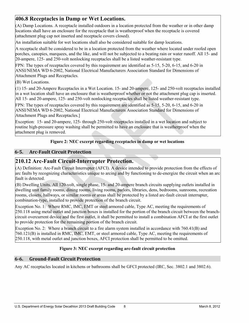
U.S. Department of Energy Solar Decathlon 2013 Draft Building Code 8 March 8, 2012
Figure 2: NEC excerpt regarding receptacles in damp or wet locations
6-5. Arc-Fault Circuit Protection
Figure 3: NEC excerpt regarding arc-fault circuit protection
6-6. Ground-Fault Circuit Protection
Any AC receptacles located in kitchens or bathrooms shall be GFCI protected (IRC, Sec. 3802.1 and 3802.6).
406.8 Receptacles in Damp or Wet Locations. (A) Damp Locations. A receptacle installed outdoors in a location protected from the weather or in other damp locations shall have an enclosure for the receptacle that is weatherproof when the receptacle is covered (attachment plug cap not inserted and receptacle covers closed). An installation suitable for wet locations shall also be considered suitable for damp locations. A receptacle shall be considered to be in a location protected from the weather where located under roofed open porches, canopies, marquees, and the like, and will not be subjected to a beating rain or water runoff. All 15- and 20-ampere, 125- and 250-volt nonlocking receptacles shall be a listed weather-resistant type. FPN: The types of receptacles covered by this requirement are identified as 5-15, 5-20, 6-15, and 6-20 in ANSI/NEMA WD 6-2002, National Electrical Manufacturers Association Standard for Dimensions of Attachment Plugs and Receptacles. (B) Wet Locations. (1) 15- and 20-Ampere Receptacles in a Wet Location. 15- and 20-ampere, 125- and 250-volt receptacles installed in a wet location shall have an enclosure that is weatherproof whether or not the attachment plug cap is inserted. All 15- and 20-ampere, 125- and 250-volt nonlocking receptacles shall be listed weather-resistant type. FPN: The types of receptacles covered by this requirement are identified as 5-15, 5-20, 6-15, and 6-20 in ANSI/NEMA WD 6-2002, National Electrical Manufacturers Association Standard for Dimensions of Attachment Plugs and Receptacles.] Exception: 15- and 20-ampere, 125- through 250-volt receptacles installed in a wet location and subject to routine high-pressure spray washing shall be permitted to have an enclosure that is weatherproof when the attachment plug is removed.
210.12 Arc-Fault Circuit-Interrupter Protection. (A) Definition: Arc-Fault Circuit Interrupter (AFCI). A device intended to provide protection from the effects of arc faults by recognizing characteristics unique to arcing and by functioning to de-energize the circuit when an arc fault is detected. (B) Dwelling Units. All 120-volt, single phase, 15- and 20-ampere branch circuits supplying outlets installed in dwelling unit family rooms, dining rooms, living rooms, parlors, libraries, dens, bedrooms, sunrooms, recreation rooms, closets, hallways, or similar rooms or areas shall be protected by a listed arc-fault circuit interrupter, combination-type, installed to provide protection of the branch circuit. Exception No. 1: Where RMC, IMC, EMT or steel armored cable, Type AC, meeting the requirements of 250.118 using metal outlet and junction boxes is installed for the portion of the branch circuit between the branch-circuit overcurrent device and the first outlet, it shall be permitted to install a combination AFCI at the first outlet to provide protection for the remaining portion of the branch circuit. Exception No. 2: Where a branch circuit to a fire alarm system installed in accordance with 760.41(B) and 760.121(B) is installed in RMC, IMC, EMT, or steel armored cable, Type AC, meeting the requirements of 250.118, with metal outlet and junction boxes, AFCI protection shall be permitted to be omitted.
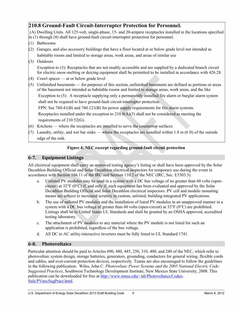
U.S. Department of Energy Solar Decathlon 2013 Draft Building Code 9 March 8, 2012
Figure 4: NEC excerpt regarding ground-fault circuit protection
6-7. Equipment Listings
All electrical equipment shall carry an approved testing agency’s listing or shall have been approved by the Solar Decathlon Building Official and Solar Decathlon electrical inspectors for temporary use during the event in accordance with Section 104.11 of the IRC and Section 110.2 of the NEC (IRC, Sec. E3303.3).
a. Unlisted PV modules may be used in a system with a DC bus voltage of no greater than 60 volts (open-circuit) at 32°F (0°C) if, and only if, such equipment has been evaluated and approved by the Solar Decathlon Building Official and Solar Decathlon electrical inspectors. PV cell and module mounting means are subject to increased scrutiny in custom, unlisted, building-integrated PV applications.
b. The use of unlisted PV modules and the installation of listed PV modules in an unapproved manner in a system with a DC bus voltage of greater than 60 volts (open-circuit) at 32°F (0°C) are prohibited. Listings shall be to United States UL Standards and shall be granted by an OSHA approved, accredited testing laboratory.
c. The attachment of PV modules to any material where the PV module is not listed for such an application is prohibited, regardless of the bus voltage.
d. All DC to AC utility-interactive inverters must be fully listed to UL Standard 1741.
6-8. Photovoltaics
Particular attention should be paid to Articles 690, 480, 445, 250, 310, 400, and 240 of the NEC, which refer to photovoltaic system design, storage batteries, generators, grounding, conductors for general wiring, flexible cords and cables, and over-current protection devices, respectively. Teams are also encouraged to follow the guidelines in the following publication: Wiles, John C. Photovoltaic Power Systems and the 2005 National Electric Code: Suggested Practices, Southwest Technology Development Institute, New Mexico State University, 2008. This publication can be downloaded for free at http://www.nmsu.edu/~tdi/Photovoltaics/Codes-Stds/PVnecSugPract.html.
210.8 Ground-Fault Circuit-Interrupter Protection for Personnel. (A) Dwelling Units. All 125-volt, single-phase, 15- and 20-ampere receptacles installed in the locations specified in (1) through (8) shall have ground-fault circuit-interrupter protection for personnel. (1) Bathrooms (2) Garages, and also accessory buildings that have a floor located at or below grade level not intended as habitable rooms and limited to storage areas, work areas, and areas of similar use (3) Outdoors Exception to (3): Receptacles that are not readily accessible and are supplied by a dedicated branch circuit
for electric snow-melting or deicing equipment shall be permitted to be installed in accordance with 426.28. (4) Crawl spaces — at or below grade level (5) Unfinished basements — for purposes of this section, unfinished basements are defined as portions or areas
of the basement not intended as habitable rooms and limited to storage areas, work areas, and the like Exception to (5): A receptacle supplying only a permanently installed fire alarm or burglar alarm system shall not be required to have ground-fault circuit-interrupter protection. FPN: See 760.41(B) and 760.121(B) for power supply requirements for fire alarm systems. Receptacles installed under the exception to 210.8(A)(5) shall not be considered as meeting the requirements of 210.52(G). (6) Kitchens — where the receptacles are installed to serve the countertop surfaces (7) Laundry, utility, and wet bar sinks — where the receptacles are installed within 1.8 m (6 ft) of the outside edge of the sink.

U.S. Department of Energy Solar Decathlon 2013 Draft Building Code 10 March 8, 2012
6-9. Grounding
Each dwelling shall be provided with grounding electrodes in accordance with IRC E3608.1.4 Rod and pipe electrodes. The length of the ground rod shall be exactly 8 feet (2438 mm) in length.
Section 7. Mechanical
7-1. Drawing Requirements
Provide a key for symbols used in the drawings (IRC, Sec. R106.1.1).
7-2. Return Air
Return air shall not be taken from a bathroom, kitchen, mechanical, or furnace room. (IRC, Sec. M1602.2).
7-3. Outside and Exhaust Air
a. Outside Air Outside air shall not be taken closer than 10 ft (304.8 cm) from an appliance or plumbing vent, or discharge outlet of an exhaust fan [unless the intake is located at least 3 ft (91.4 cm) below the vent or fan discharge] (IRC, Sec. M1602.2, Item 1). b. Screens Outside air inlets shall be equipped with a screen with openings 0.25 in. to 0.5 in. (0.64 cm to 1.3 cm) (IRC, Sec. M1602.3). c. Exhaust hood systems capable of exhausting in excess of 400 cubic feet per minute (0.19 m3/s) shall be
provided with makeup air at a rate approximately equal to the exhaust air rate. Such makeup air systems shall be equipped with a means of closure and shall be automatically controlled to start and operate simultaneously with the exhaust system. (IRC Sec. M1503.4)
7-4. Bathroom Ventilation
Bathrooms shall be provided with mechanical ventilation systems capable of providing 50 cfm (23.6 L/s) for intermittent ventilation or 20 cfm (9.4 L/s) for continuous ventilation, or with windows allowing a 1.5 ft2 (0.14 m2) opening for natural ventilation (IRC, Sec. R303.3).
Section 8. Solar Mechanical
8-1. Drawing Requirements
Provide plan details for any proposed solar mechanical systems. Provide details on collectors, fluid distribution, heat exchangers, etc., along with a key for symbols used in the drawings (IRC, Sec. 106.1.1). Plans should emphasize compliance with IRC M2301.
8-2. Cross Connection
Provide details for the solar hot-water system. Provide details indicating if potable water or other heat transfer liquids will be employed. If other than potable water is used, an approved heat exchanger shall be employed to isolate potable water from transfer fluids (IRC Section R106.1.1).
8-3. Access
Solar collectors, controls, dampers, fans, and pumps shall be accessible for inspection, maintenance, repair, and replacement (IRC, Sec. M2301.2.1).
U.S. Department of Energy Solar Decathlon 2013 Draft Building Code 11 March 8, 2012
8-4. Roof-Mounted Collectors
The roof shall be constructed to support all loads imposed by the collectors. If collectors are intended to serve as the roof covering, documentation shall be provided to determine compliance with the roofing provisions in IRC, Chapter 9. If the collectors will be placed over the roof covering, the collectors and supporting structure shall be constructed of noncombustible material or fire-retardant-treated wood equivalent to that required for the roof covering (IRC, Sec. M2301.2.2).
8-5. Pressure and Temperature Relief
Pressure- and temperature-relief valves shall be provided for components under pressure. Relief devices shall be installed in sections of the system so that a section cannot be valved off or isolated from a relief device (IRC, Sec. M2301.2.3). Pressure and temperature relief devices shall have the capacity to be removed and capped prior to inspection to accommodate the required 100 psi (690 kPa) system pressure test required by Section 8-13.
8-6. Vacuum Relief
A vacuum relief valve shall protect system components that might be subjected to pressure drops below atmospheric pressure during operation or shutdown. Plans shall indicate if this system is subject to vacuum conditions (IRC, Sec. M2301.2.4).
8-7. Expansion Tanks
Expansion tanks in solar systems shall be installed in accordance with IRC, Section M2301 in closed-fluid loops that contain heat-transfer fluid (IRC, Sec. M2301.2.6).
8-8. Solar Loop Isolation
Valves shall be installed to allow isolation of the solar collectors from the remainder of the system (IRC, Sec. M2301.2.8).
8-9. Maximum Temperature Limitation
Systems shall be equipped with means to limit the maximum water temperature of the system fluid entering or exchanging heat with any pressurized vessel inside the dwelling to 180°F (82°C). This protection is required in addition to required temperature and pressure relief valves stated in IRC, Section M2301.2.3 (IRC, Sec. M2301.2.9).
8-10. Collector and Thermal Storage Unit Labeling
a. Collectors and storage units shall be listed and labeled to show the manufacturer’s name, model number, serial number, collector weight, collector maximum allowable temperatures and pressures, and the type of heat transfer fluids that are compatible with the collector and storage units (IRC, Sec. 2301.3).
b. Identification of system components. All components of the solar hydronic system shall be identified with permanent identification labels. Such labels shall indicate the function of the component (i.e. panel loop supply or return, heat exchanger, domestic loop, etc.) and flow direction.
Exception: Domestic plumbing fixture supply and in-floor radiant heat loops.
8-11. Prohibited Heat-Transfer Media
Flammable gasses and liquids shall not be used as heat-transfer fluids (IRC, Sec. M2301.4).
8-12. Backflow Prevention
All connections from the potable water supply to solar systems shall comply with IRC, Section P2902.4.5 (IRC, Sec.M2301.5).
U.S. Department of Energy Solar Decathlon 2013 Draft Building Code 12 March 8, 2012
8-13. Pressure Test
All solar hydronic piping shall be tested hydrostatically at a pressure of not less than 100 psi (690 kPa) for no fewer than 15 minutes. Temperature and pressure relief devices that operate at or less than 100 psi (690 kPa) shall be isolated during the test by removal and capping. Exception: Systems designed for pressures under 100pst (690kPa) may be tested at lower pressures when approved by the Solar Decathlon Building Official. Such testing must be approved prior to transportation of the structure to the competition site.
Section 9. Plumbing
9-1. Drawing Requirements
a. Provide a labeled isometric diagram of the proposed plumbing system for review. Clearly indicate waste lines, vent lines, potable water supply, heat exchange equipment, and the type of any heat transferring fluid used other than potable water.
b. Provide a key for symbols used in the drawings (IRC, Sec. 106.1.1).
9-2. Water Closet Demonstration
Water closets are installed for demonstration only and shall not be connected to any portion of the sewage disposal system. The water closet shall be attached to a PVC or ABS 4 in. to 3 in. (10.2 cm to 7.7 cm) water-closet flange provided with a capped end. The cap shall be located as close as possible to the flange fitting. No structural member shall be cut or otherwise damaged to accommodate the water-closet flange assembly. No water supply shall be extended to the water closet unless otherwise approved by the Solar Decathlon Building Official.
9-3. Plumbing Wall – Structural
Recommendation: Create a dedicated plumbing wall with thickness sufficient to allow pipe penetrations within the studs not exceeding 60% of the stud width in nonbearing walls (IRC, Sec. 602.6).
9-4. Shower Mixing Valves
Shower mixing valves shall be pressure balanced, thermostatic mixing, or a combination of the two, with the high limit set at 120°F (48.9°C) to prevent scalding (IRC, Sec. P2708.3).
9-5. Backflow Prevention
Backflow prevention is required to isolate the potable water supply from the solar systems. See IRC Section P2902.2 for permissible devices. Because this project uses supply tanks for potable water, the use of a separate and isolated fill system for the solar component may be deemed acceptable backflow prevention (IRC, Sec. P2902.2).
9-6. Water Heater and Heated Storage Vessel Seismic Support
Water heaters and other heated fluid storage vessels shall be anchored or strapped in the upper one-third and in the lower one-third of the appliance to resist a horizontal force equal to one-third of the operating weight of the water heater, acting in any horizontal direction, or in accordance with the appliance manufacturer’s recommendations.
9-7. Supply
No additives of any kind may be added to the water in the team’s supply tank. This water is not for consumption at any time. Teams will be required to provide the tank and support this tank so that it does not damage the competition site turf.

U.S. Department of Energy Solar Decathlon 2013 Draft Building Code 13 March 8, 2012
9-8. Waste
All substances used in combination with water to clean the house, dishes, utensils, etc., must be nontoxic and preferably biodegradable. Teams may incur a point penalty for any toxic substances that are found in the wastewater tank.
9-9. Water Feature Safety
a. Water features shall not exceed a depth of 2 ft (61 cm). b. For water features >1 ft but <2 ft (>30.5 cm but <61 cm), there shall be a representative from the team
positioned at the water feature when open to the public to monitor the area and act as a lifeguard if necessary. During times when the area is not open to the public, the water feature shall be covered or guarded in a manner to prevent access.
c. To ensure safe access, a 44 in. (111.8 cm) accessible surface shall be maintained all around the water feature.
d. Visitor flow patterns shall be considered in the placement of the water feature. e. The water feature should have sufficient circulation/treatment/measures taken to ensure the water does
not become stagnant and a nuisance hazard.
Section 10. Material Safety
10-1. Thermal Storage
All thermal storage devices (“mass”) must be made of stable, nontoxic materials. For all heat-transfer fluids, Material Safety Data Sheets (MSDS) must be submitted for approval. All liquid-based thermal storage systems must be marked with the NFPA’s hazard warning diamond appropriate to the technology.
10-2. Paint Disposal
Teams are not permitted to dispose of paint on the competition site. Teams may either take unused paint home or find a local facility that disposes of or recycles paint.
10-3. Material Safety Data Sheets (MSDS)
MSDS are required for all potentially hazardous materials to be used at the event, such as cleaning solvents, glycol, rubber cement, rubbing alcohol, etc.
Section 11. Moveable Features
Teams planning to move or transform major components of their houses beyond the assembly and disassembly phases are required to obtain special approval from a Solar Decathlon safety officer. Possible design features meeting this description include large, unusual, and potentially dangerous features such as moveable rooms and walls, changeable façades, collapsible spaces, and folding beds. This requirement does not apply to smaller, more typical house features that may be reconfigured, such as awnings, operable windows and window coverings, and doors. The following rules apply to qualifying features:
a. After the houses are assembled on the competition site, the safety officer will inspect every house and inform each team whether it has any qualifying features.
b. Teams wanting to determine before the event whether their house has any qualifying features should contact [email protected].
c. The safety officer cannot thoroughly evaluate the safety of a particular house feature until it is seen in operation; however, the safety officer will try to indicate with a reasonable degree of confidence whether certain features are subject to these rules.
d. Qualifying features shall not be reconfigured during impound.

U.S. Department of Energy Solar Decathlon 2013 Draft Building Code 14 March 8, 2012
e. Qualifying features shall not be reconfigured during public exhibit hours unless approved by the Solar Decathlon safety officer. To receive approval, a team must:
(i). Include in its Health and Safety Plan an explanation of how it will ensure safety during the movement of qualifying features
(ii). Demonstrate the successful execution of the safety plan for qualifying features at some point before public exhibit hours begin
(iii). Continue to demonstrate the successful execution of the safety plan for qualifying features during public exhibit hours.
f. If, at any time, the safety officer witnesses unsafe conditions, the movement of qualifying features during public tours may be prohibited for the duration of the event.

JOB_______________________________________ SHEET NO._______________OF________________ CALC. BY________________DATE______________ CHECKED BY____________ _DATE______________
MISSOURI S&T SOLAR HOUSE TEAM | Chameleon House 88
D. ENERGY PANEL SOLUTIONS’ DESIGN REPORT AND CALCULATIONS

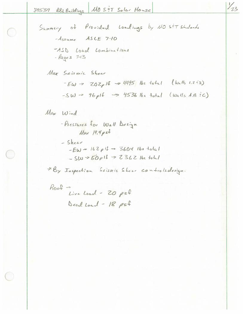
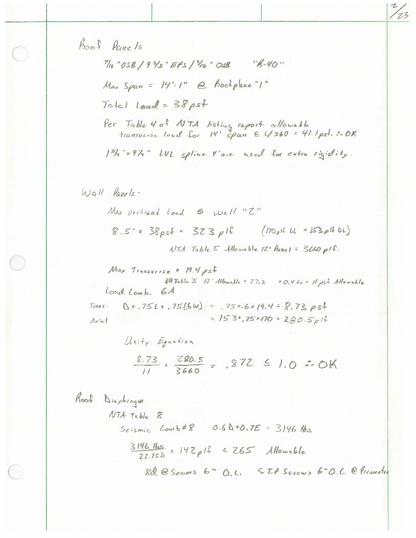
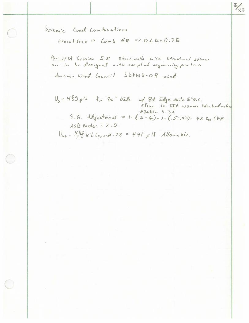
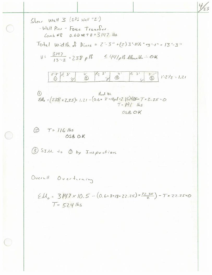
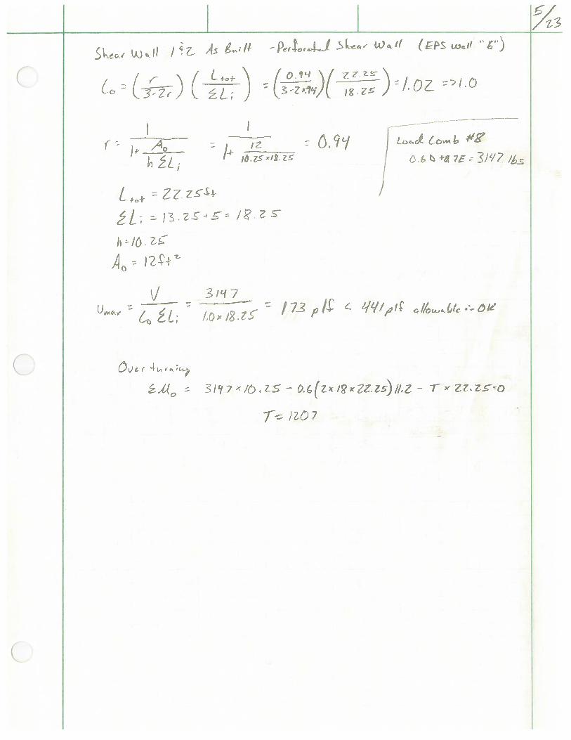
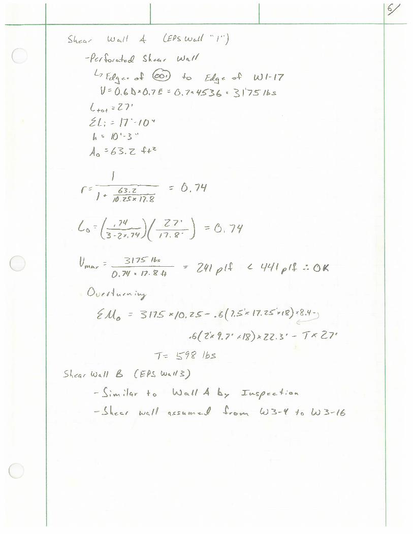
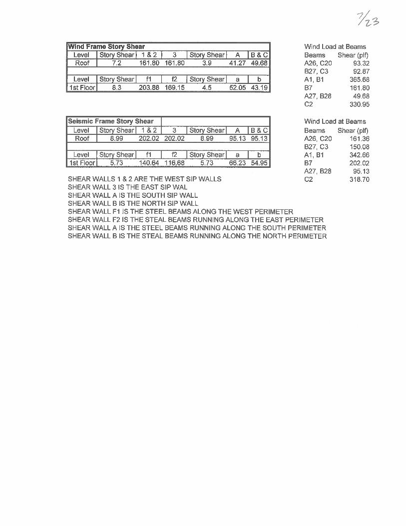
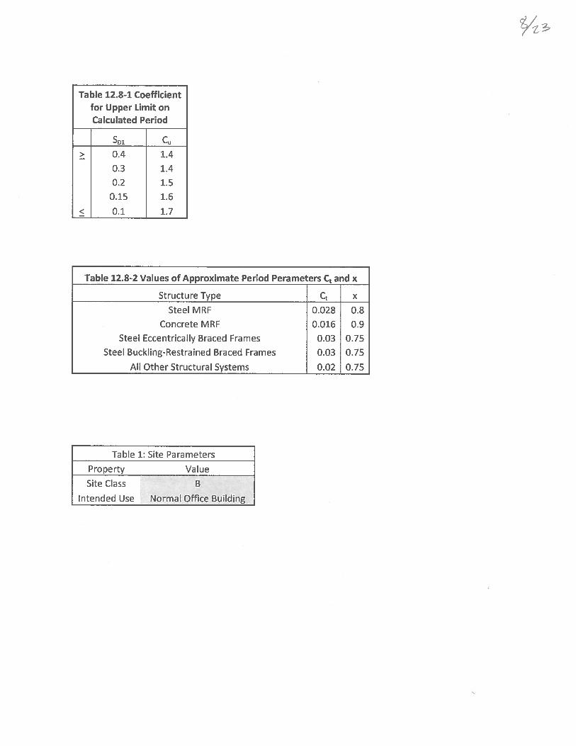
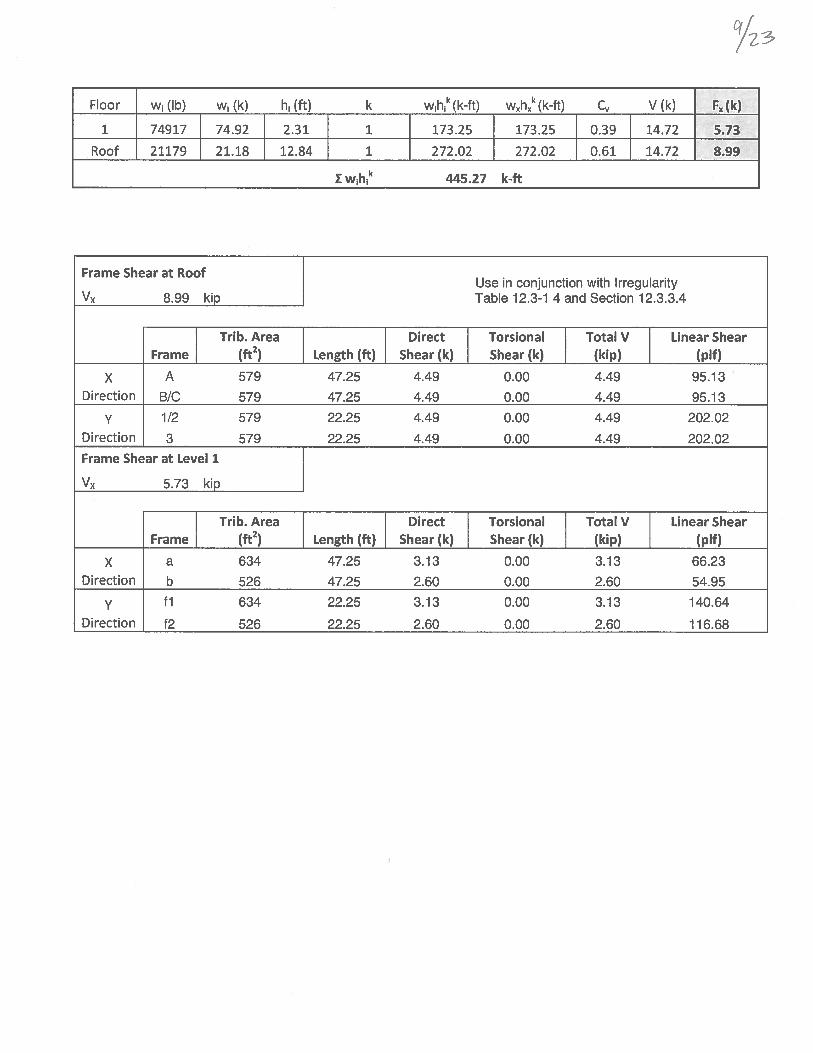

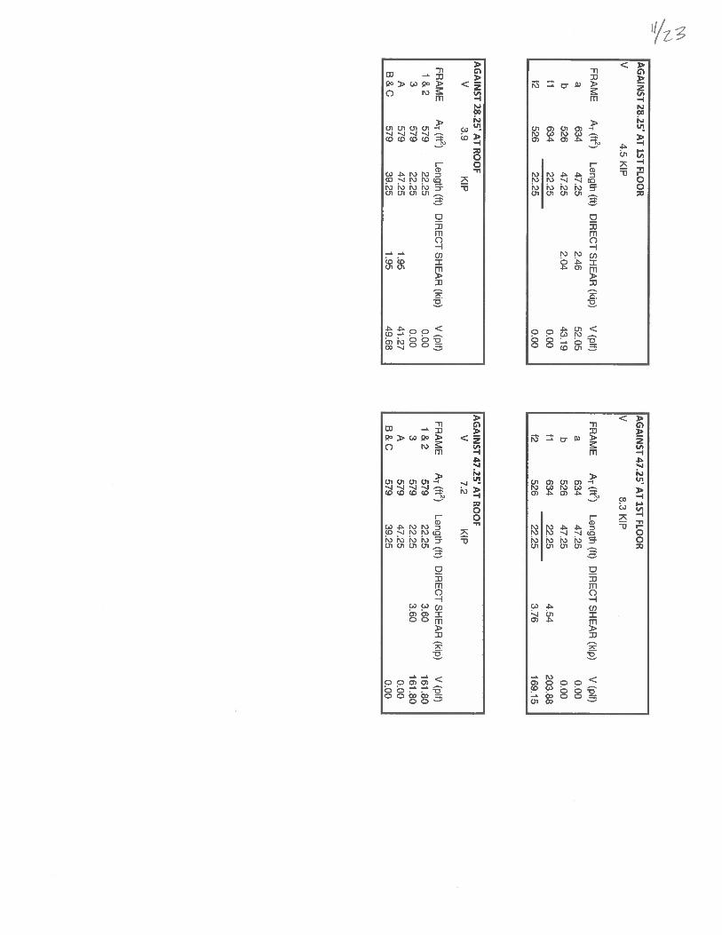
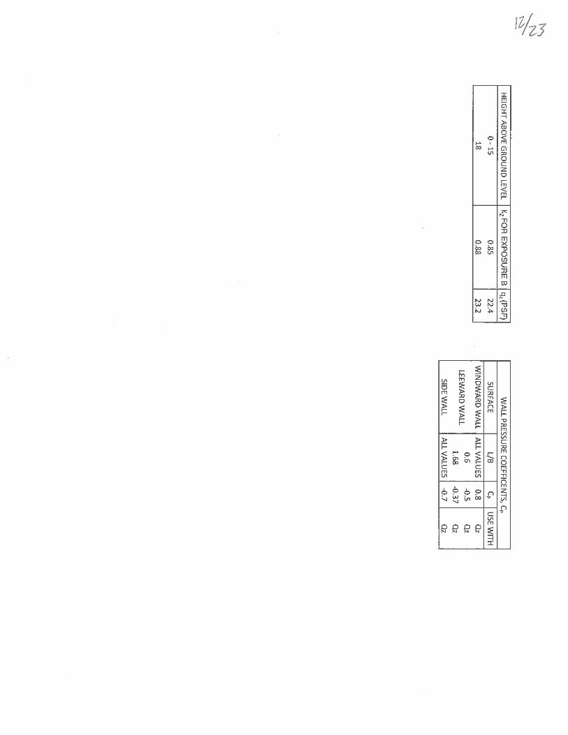


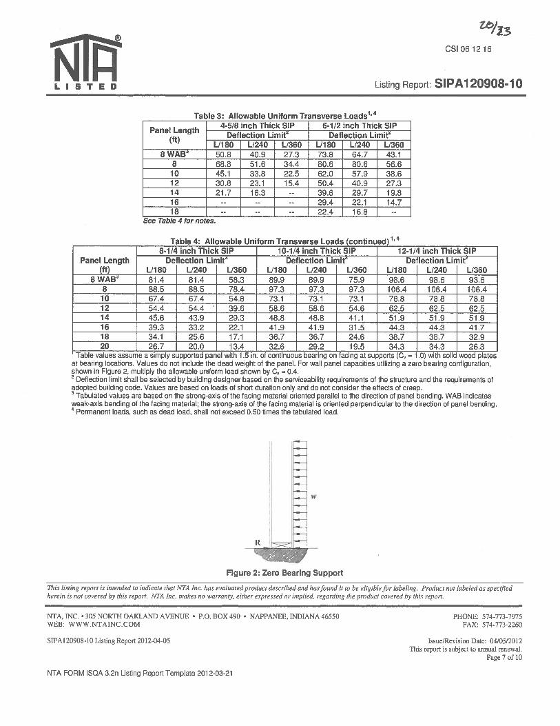
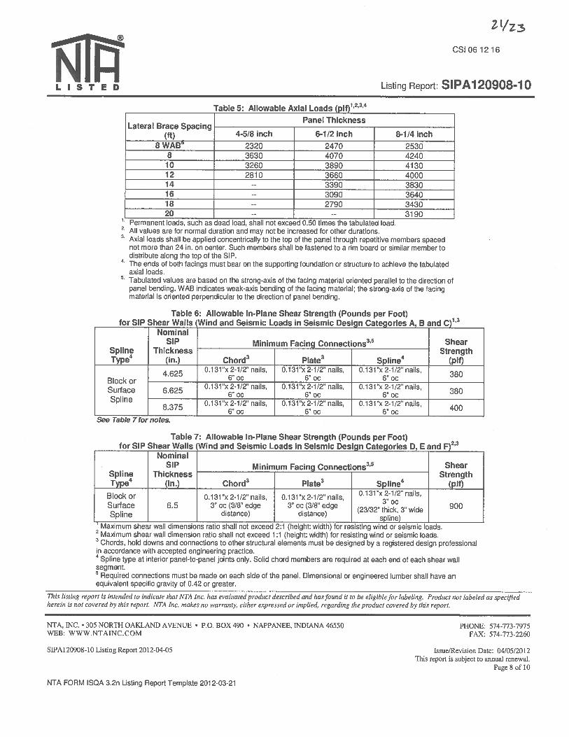
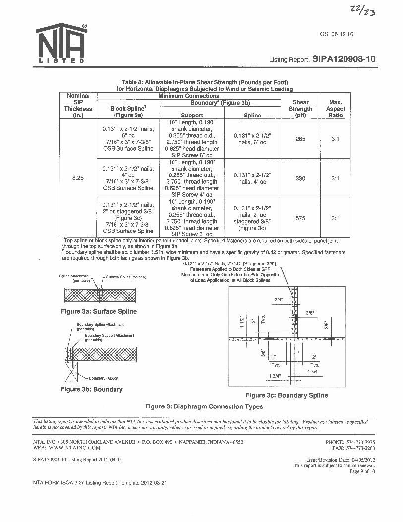
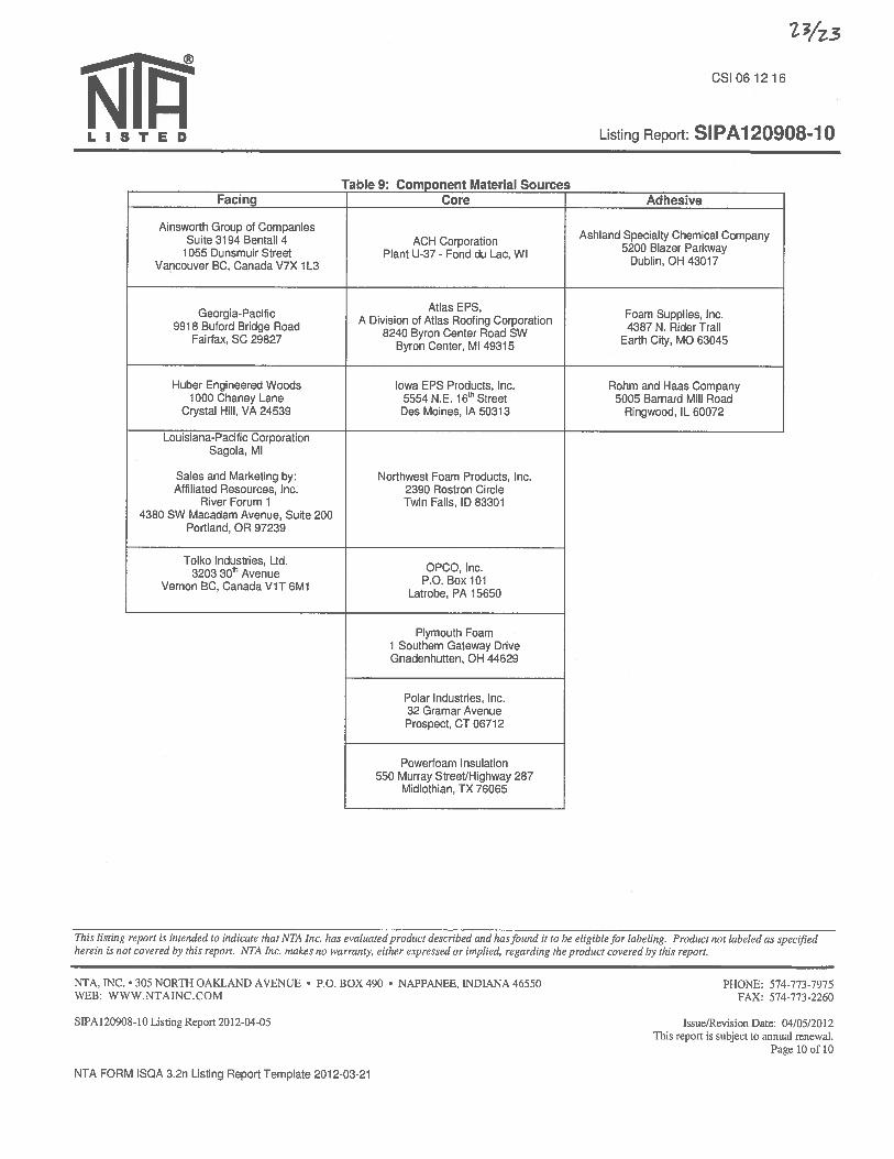

JOB_______________________________________ SHEET NO._______________OF________________ CALC. BY________________DATE______________ CHECKED BY____________ _DATE______________
MISSOURI S&T SOLAR HOUSE TEAM | Chameleon House 89
E. SUMMARY OF TENK SOLAR WIND TUNNEL FORCE COEFFICIENTS

Summary of tenKsolar wind tunnel force coefficients
Lowell Berg, 5/3/2012
Summary
Structural loading from wind is governed by applicable standards, but all are based on the same
basic physics. Wind tunnel testing may be used for photovoltaic arrays to measure wind force
coefficients. The measured wind force coefficients are much smaller than what one would get
from assuming the array is a standard building. The resulting smaller estimated wind forces put
significantly less wind force on the supporting building.
Background
TenKsolar photovoltaic arrays are unique in their ability to gather more energy from the sun than
what falls directly on the photovoltaic module. The reflector directs additional light onto the
photovoltaic module. The result is that more solar radiation is converted to electricity than
without the reflector.
The reflector also serves to “close” the array so the south end (all references here are for the
northern hemisphere) with a photovoltaic module on it and the north end have approximately the
same wind profile. The resulting unique “wave” structure has very good wind load
characteristics compared to some of the approximation that can be made using standard wind
load prediction tools.
Array Design Requirements
In North America, ASCE 7 (Minimum Design Loads for Buildings and Other Structures,
published by ASCE) specifies loads on structures, and Chapter 6 specifies how to estimate wind
loads on typical structures. In Europe, Eurocode (Eurocode 1: Actions on Structures – General
Actions – Part 1-4: Wind Actions) provides similar directions on estimating wind loads on
structures. The two codes are very similar in intent and content. This should come as no
surprise as neither the basic physics nor the wind recognizes geographic boundaries.
Both ASCE 7 and Eurocode provide for the use of wind tunnel testing for buildings or structures
having unusual shapes. ASCE 7 specifies the characteristics the flow in the wind tunnel must
meet to make valid measurements. Eurocode defers to the “appropriate Authority” but does
specify that one must use appropriate models of the natural wind.
ASCE 7 specifies the wind conditions to use in all parts of the United States and its territories.
Eurocode, provides a unified calculation procedure across all participating countries but defers to
a “country annex” where country-specific parameters like design wind speed are documented.

In Romania, the appropriate authorities have published a document that specifies how to estimate
wind loads. This document refers to best practices adopted from both ASCE 7 and Eurocode,
and provides all the information for Romania that would be in a Eurocode country annex.
Wind Tunnel Testing
TenKsolar sponsored wind tunnel testing of scale models of tenKsolar’s roof-mounted arrays.
Tests were conducted in the atmospheric boundary layer wind tunnel at the University of
Minnesota’s St. Anthony Falls Lab. Wind speeds and profiles were adjusted to match the
conditions of turbulent flow in urban and suburban areas or other wooded areas (exposure B in
ASCE 7, section 6.5.6.2, corresponding to 30% turbulence intensity). This high turbulence
intensity is very difficult to achieve, so most of the data is for very low turbulence “smooth” flow
and a multiplier is used on the data to account for the additional forces due to correlated and
uncorrelated turbulence. The smooth flow forces are multiplied by 1.09 to account for the
influence of turbulence. See Appendix 1 for more details.
For sharp-edged bodies (like photovoltaic modules or reflectors), the forces are proportional to
the square of the wind speed. This was confirmed in the wind tunnel for scale models of
tenKsolar arrays. This means we can use results at one wind tunnel speed to estimate forces at
other speeds.
More importantly, this means we can use the results at one wind tunnel speed and accurately
estimate the result on full-size structures at other speeds. In particular, we can use the same wind
tunnel results in places with different basic wind speed requirements.
The wind tunnel measurements are forces. The scale models are one eighth the size of the real
hardware, so the forces measured in the wind tunnel are multiplied by 64 to get estimates of the
forces on the full-sized hardware. Further, the forces are then multiplied by 1.09 to account for
the effect of turbulence.
In wind loading codes it is typical to estimate wind reference pressure
2*constant Velocitypref
The constant is usually half of the air density. The resulting pressure is known as the stagnation
pressure. The reference pressure is multiplied by several factors to account for height, local
topography, wind direction variability, and the function of the structure. This gives the design
pressure
refdesign pfactorsp *
The forces on a structure come from the design pressure times the structure’s area times a form
factor, C
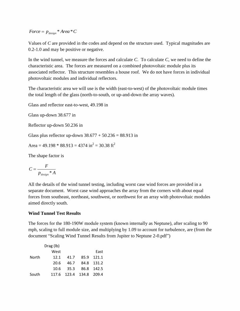
CAreapForce design **
Values of C are provided in the codes and depend on the structure used. Typical magnitudes are
0.2-1.0 and may be positive or negative.
In the wind tunnel, we measure the forces and calculate C. To calculate C, we need to define the
characteristic area. The forces are measured on a combined photovoltaic module plus its
associated reflector. This structure resembles a house roof. We do not have forces in individual
photovoltaic modules and individual reflectors.
The characteristic area we will use is the width (east-to-west) of the photovoltaic module times
the total length of the glass (north-to-south, or up-and-down the array waves).
Glass and reflector east-to-west, 49.198 in
Glass up-down 38.677 in
Reflector up-down 50.236 in
Glass plus reflector up-down 38.677 + 50.236 = 88.913 in
Area = 49.198 * 88.913 = 4374 in2 = 30.38 ft
2
The shape factor is
Ap
FC
design *
All the details of the wind tunnel testing, including worst case wind forces are provided in a
separate document. Worst case wind approaches the array from the corners with about equal
forces from southeast, northeast, southwest, or northwest for an array with photovoltaic modules
aimed directly south.
Wind Tunnel Test Results
The forces for the 180-190W module system (known internally as Neptune), after scaling to 90
mph, scaling to full module size, and multiplying by 1.09 to account for turbulence, are (from the
document “Scaling Wind Tunnel Results from Jupiter to Neptune 2-0.pdf”)
Drag (lb)
West East
North 12.1 41.7 85.9 121.1
20.6 46.7 84.8 131.2
10.6 35.3 86.8 142.5
South 117.6 123.4 134.8 209.4
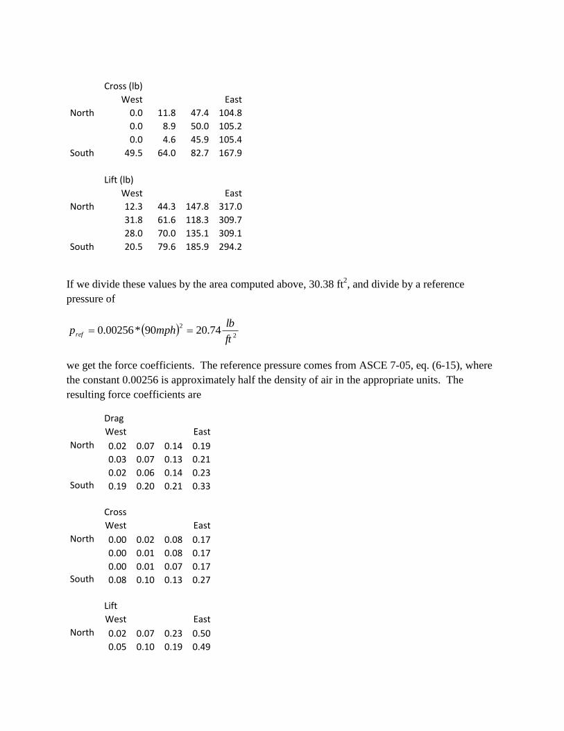
Cross (lb)
West East
North 0.0 11.8 47.4 104.8
0.0 8.9 50.0 105.2
0.0 4.6 45.9 105.4
South 49.5 64.0 82.7 167.9
Lift (lb)
West East
North 12.3 44.3 147.8 317.0
31.8 61.6 118.3 309.7
28.0 70.0 135.1 309.1
South 20.5 79.6 185.9 294.2
If we divide these values by the area computed above, 30.38 ft2, and divide by a reference
pressure of
2
274.2090*00256.0
ft
lbmphpref
we get the force coefficients. The reference pressure comes from ASCE 7-05, eq. (6-15), where
the constant 0.00256 is approximately half the density of air in the appropriate units. The
resulting force coefficients are
Drag
West East
North 0.02 0.07 0.14 0.19 0.03 0.07 0.13 0.21 0.02 0.06 0.14 0.23 South 0.19 0.20 0.21 0.33
Cross
West East
North 0.00 0.02 0.08 0.17 0.00 0.01 0.08 0.17 0.00 0.01 0.07 0.17 South 0.08 0.10 0.13 0.27
Lift
West East
North 0.02 0.07 0.23 0.50 0.05 0.10 0.19 0.49

0.04 0.11 0.21 0.49 South 0.03 0.13 0.30 0.47
There are several important things to note about these values.
The largest coefficients are generally in the bottom right corner. The wind blows from
bottom right to top left (a wind from the southeast to the northwest is a southeast wind).
As one moves from east to west, the coefficients decrease in size.
As one moves from south to north, some of the coefficients decrease while others don’t
change much.
It is interesting to compare these coefficients with those for other structures. For a closed
building with a simple two-plane, sloped roof, the coefficients are -1.0 (downwind, forces away
from roof) and +0.9 (upwind, forces toward roof). (These are from ASCE 7-05, Figure 6-11D
for 27-45 deg roof. Similar results can be found in Eurocode, -0.8 to +0.6 for 45 deg roofs.) For
the array, the net force is upward (positive lift), but the worst case coefficient is about 0.5 and the
coefficient reduce to 0.02 toward the middle of the array.
This means that one will predict significantly larger forces if one assumes the array is a closely
packed group of “houses”. Further, large forces will be predicted if one does not account for the
variation of force through the array.
This demonstrates the intent of both Eurocode and ASCE 7 (as well as derivative documents) in
allowing wind tunnel data to estimate force coefficients.
Because all the photovoltaic modules and reflectors are structurally coupled together through the
rails, forces can be transmitted through the array. It is not necessary to react to all the wind force
at a single photovoltaic module. Instead, one can usually ballast or tie down corners of small
arrays and use occasional tie downs on the edges of larger arrays.
The middle of large arrays has very small wind forces that can easily be reacted with friction
forces.
Summary
Structural loading from wind is governed by applicable standards, but all are based on the same
basic physics. Wind tunnel testing may be used for photovoltaic arrays to measure wind force
coefficients. The measured wind force coefficients are much smaller than what one would get
from assuming the array is a standard building. The resulting smaller estimated wind forces put
significantly less wind force on the supporting building.
Appendix 1: Including the effects of turbulence on forces
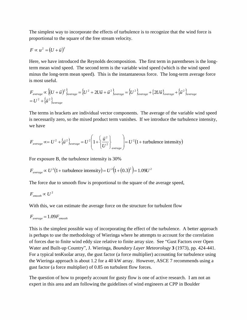
The simplest way to incorporate the effects of turbulence is to recognize that the wind force is
proportional to the square of the free stream velocity.
22 uUuF
Here, we have introduced the Reynolds decomposition. The first term in parentheses is the long-
term mean wind speed. The second term is the variable wind speed (which is the wind speed
minus the long-term mean speed). This is the instantaneous force. The long-term average force
is most useful.
average
averageaverageaverageaverageaverageaverage
uU
uuUUuuUUuUF
22
2222222
The terms in brackets are individual vector components. The average of the variable wind speed
is necessarily zero, so the mixed product term vanishes. If we introduce the turbulence intensity,
we have
intensityturbulence11 2
2
2222
UU
uUuUF
average
averageaverage
For exposure B, the turbulence intensity is 30%
2222 09.13.01intensityturbulence1 UUUFaverage
The force due to smooth flow is proportional to the square of the average speed,
2UFsmooth
With this, we can estimate the average force on the structure for turbulent flow
smoothaverage FF 09.1
This is the simplest possible way of incorporating the effect of the turbulence. A better approach
is perhaps to use the methodology of Wieringa where he attempts to account for the correlation
of forces due to finite wind eddy size relative to finite array size. See “Gust Factors over Open
Water and Built-up Country”, J. Wieringa, Boundary Layer Meteorology 3 (1973), pp. 424-441.
For a typical tenKsolar array, the gust factor (a force multiplier) accounting for turbulence using
the Wieringa approach is about 1.2 for a 40 kW array. However, ASCE 7 recommends using a
gust factor (a force multiplier) of 0.85 on turbulent flow forces.
The question of how to properly account for gusty flow is one of active research. I am not an
expert in this area and am following the guidelines of wind engineers at CPP in Boulder

Colorado. I have been using ASCE 7-05. I understand that a newer version of ASCE 7 may
account for gustiness more like Wierings suggests.
What does this mean? My multiplier is 1.09. Wieringa’s approach would suggest 1.2 for a 40
kW array, <1.1 for a much larger array, and 1.5 for a 5kW array. It would seem this is the level
of uncertainty typical in wind engineering, and is not really surprising given that in all wind
loading codes, force coefficients are only given to one decimal place.
I would use the 1.09 multiplier on smooth flow results and a healthy factor of safety of 1.5 on
wind loads.
The wind speed variability adds even more complexity. If one measures the instantaneous wind
speed, one can develop a histogram of speeds and assign a probability that the wind speed is
above a certain speed. Further, one can estimate the time the wind speed is above that speed.
The approach taken in ASCE 7 is to use the 3 second wind burst as the basic design wind speed.
For much of the United States, the design requirement is a 3 second wind burst at 40 m/s. This is
equivalent (using the appropriate wind speed probability curve, the so-called Durst curve) to a
3600 second “burst” at about 27 m/s. Clearly using steady state smooth flow wind speeds
corresponding to 40 m/s is conservative, and erases any distinction between the multiplier 1.09
and some other approximation for turbulence.
Wind engineering is a complex business and is an area of active academic and commercial
research.

JOB_______________________________________ SHEET NO._______________OF________________ CALC. BY________________DATE______________ CHECKED BY____________ _DATE______________
MISSOURI S&T SOLAR HOUSE TEAM | Chameleon House 90
F. SCALING WIND TUNNEL RESULTS FROM JUPITER TO NEPTUNE
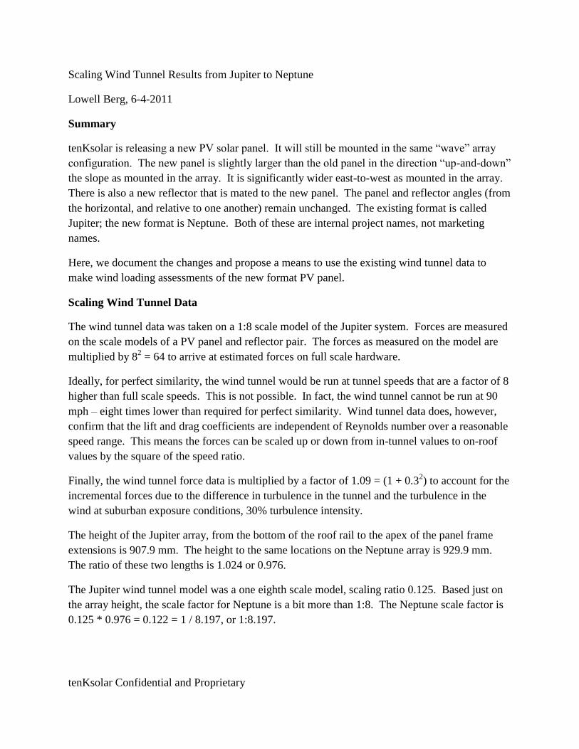
tenKsolar Confidential and Proprietary
Scaling Wind Tunnel Results from Jupiter to Neptune
Lowell Berg, 6-4-2011
Summary
tenKsolar is releasing a new PV solar panel. It will still be mounted in the same “wave” array
configuration. The new panel is slightly larger than the old panel in the direction “up-and-down”
the slope as mounted in the array. It is significantly wider east-to-west as mounted in the array.
There is also a new reflector that is mated to the new panel. The panel and reflector angles (from
the horizontal, and relative to one another) remain unchanged. The existing format is called
Jupiter; the new format is Neptune. Both of these are internal project names, not marketing
names.
Here, we document the changes and propose a means to use the existing wind tunnel data to
make wind loading assessments of the new format PV panel.
Scaling Wind Tunnel Data
The wind tunnel data was taken on a 1:8 scale model of the Jupiter system. Forces are measured
on the scale models of a PV panel and reflector pair. The forces as measured on the model are
multiplied by 82 = 64 to arrive at estimated forces on full scale hardware.
Ideally, for perfect similarity, the wind tunnel would be run at tunnel speeds that are a factor of 8
higher than full scale speeds. This is not possible. In fact, the wind tunnel cannot be run at 90
mph – eight times lower than required for perfect similarity. Wind tunnel data does, however,
confirm that the lift and drag coefficients are independent of Reynolds number over a reasonable
speed range. This means the forces can be scaled up or down from in-tunnel values to on-roof
values by the square of the speed ratio.
Finally, the wind tunnel force data is multiplied by a factor of 1.09 = (1 + 0.32) to account for the
incremental forces due to the difference in turbulence in the tunnel and the turbulence in the
wind at suburban exposure conditions, 30% turbulence intensity.
The height of the Jupiter array, from the bottom of the roof rail to the apex of the panel frame
extensions is 907.9 mm. The height to the same locations on the Neptune array is 929.9 mm.
The ratio of these two lengths is 1.024 or 0.976.
The Jupiter wind tunnel model was a one eighth scale model, scaling ratio 0.125. Based just on
the array height, the scale factor for Neptune is a bit more than 1:8. The Neptune scale factor is
0.125 * 0.976 = 0.122 = 1 / 8.197, or 1:8.197.
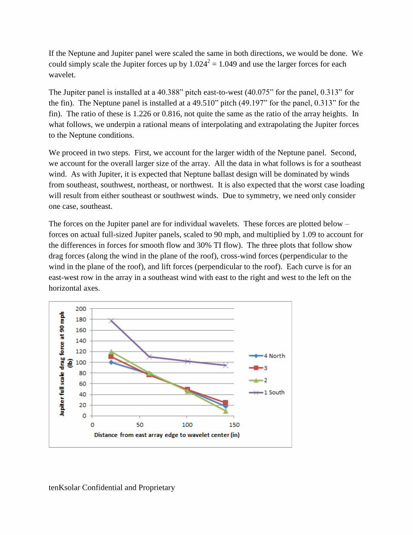
tenKsolar Confidential and Proprietary
If the Neptune and Jupiter panel were scaled the same in both directions, we would be done. We
could simply scale the Jupiter forces up by 1.0242 = 1.049 and use the larger forces for each
wavelet.
The Jupiter panel is installed at a 40.388” pitch east-to-west (40.075” for the panel, 0.313” for
the fin). The Neptune panel is installed at a 49.510” pitch (49.197” for the panel, 0.313” for the
fin). The ratio of these is 1.226 or 0.816, not quite the same as the ratio of the array heights. In
what follows, we underpin a rational means of interpolating and extrapolating the Jupiter forces
to the Neptune conditions.
We proceed in two steps. First, we account for the larger width of the Neptune panel. Second,
we account for the overall larger size of the array. All the data in what follows is for a southeast
wind. As with Jupiter, it is expected that Neptune ballast design will be dominated by winds
from southeast, southwest, northeast, or northwest. It is also expected that the worst case loading
will result from either southeast or southwest winds. Due to symmetry, we need only consider
one case, southeast.
The forces on the Jupiter panel are for individual wavelets. These forces are plotted below –
forces on actual full-sized Jupiter panels, scaled to 90 mph, and multiplied by 1.09 to account for
the differences in forces for smooth flow and 30% TI flow). The three plots that follow show
drag forces (along the wind in the plane of the roof), cross-wind forces (perpendicular to the
wind in the plane of the roof), and lift forces (perpendicular to the roof). Each curve is for an
east-west row in the array in a southeast wind with east to the right and west to the left on the
horizontal axes.
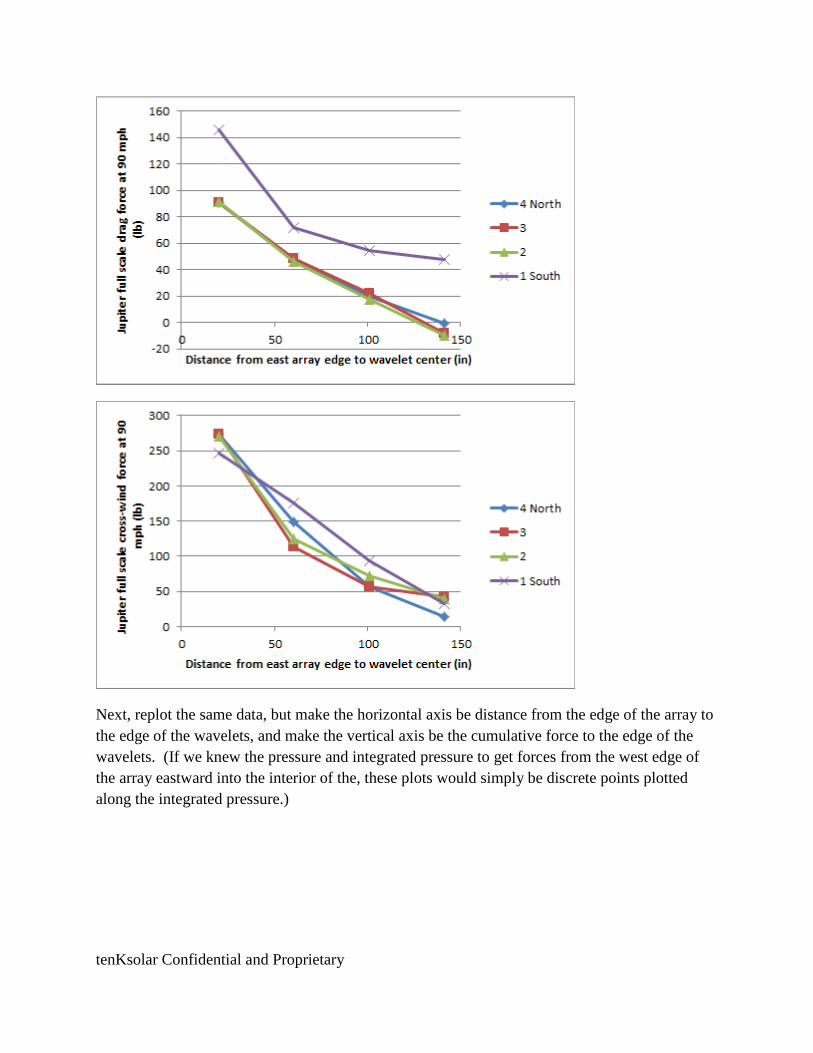
tenKsolar Confidential and Proprietary
Next, replot the same data, but make the horizontal axis be distance from the edge of the array to
the edge of the wavelets, and make the vertical axis be the cumulative force to the edge of the
wavelets. (If we knew the pressure and integrated pressure to get forces from the west edge of
the array eastward into the interior of the, these plots would simply be discrete points plotted
along the integrated pressure.)

tenKsolar Confidential and Proprietary
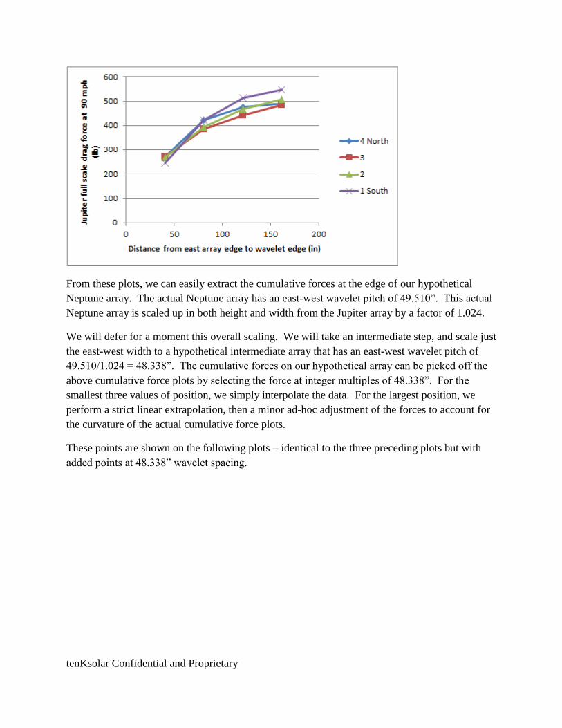
tenKsolar Confidential and Proprietary
From these plots, we can easily extract the cumulative forces at the edge of our hypothetical
Neptune array. The actual Neptune array has an east-west wavelet pitch of 49.510”. This actual
Neptune array is scaled up in both height and width from the Jupiter array by a factor of 1.024.
We will defer for a moment this overall scaling. We will take an intermediate step, and scale just
the east-west width to a hypothetical intermediate array that has an east-west wavelet pitch of
49.510/1.024 = 48.338”. The cumulative forces on our hypothetical array can be picked off the
above cumulative force plots by selecting the force at integer multiples of 48.338”. For the
smallest three values of position, we simply interpolate the data. For the largest position, we
perform a strict linear extrapolation, then a minor ad-hoc adjustment of the forces to account for
the curvature of the actual cumulative force plots.
These points are shown on the following plots – identical to the three preceding plots but with
added points at 48.338” wavelet spacing.
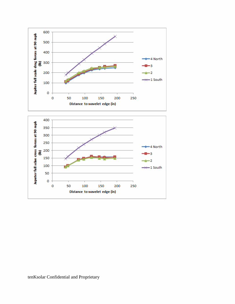
tenKsolar Confidential and Proprietary
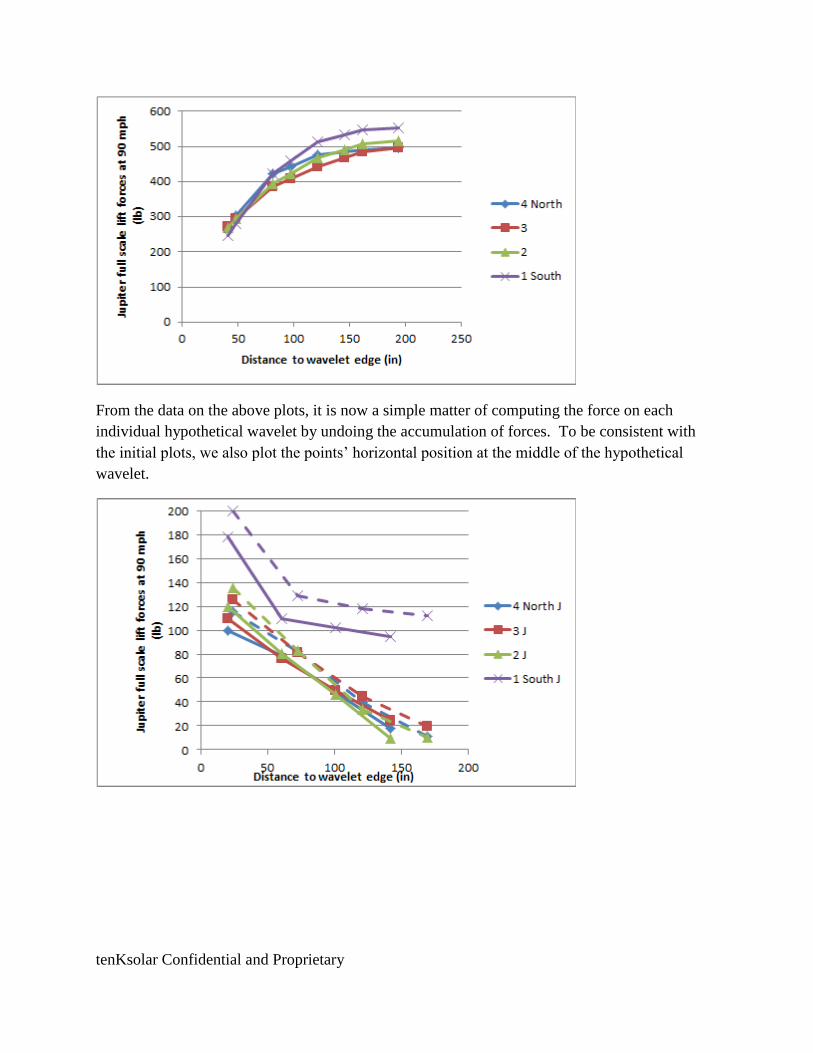
tenKsolar Confidential and Proprietary
From the data on the above plots, it is now a simple matter of computing the force on each
individual hypothetical wavelet by undoing the accumulation of forces. To be consistent with
the initial plots, we also plot the points’ horizontal position at the middle of the hypothetical
wavelet.
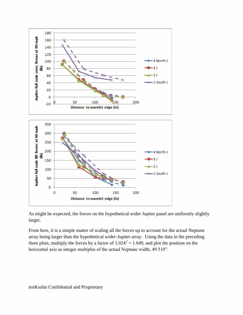
tenKsolar Confidential and Proprietary
As might be expected, the forces on the hypothetical wider Jupiter panel are uniformly slightly
larger.
From here, it is a simple matter of scaling all the forces up to account for the actual Neptune
array being larger than the hypothetical wider-Jupiter array. Using the data in the preceding
three plots, multiply the forces by a factor of 1.0242 = 1.049, and plot the position on the
horizontal axis as integer multiples of the actual Neptune width, 49.510”.
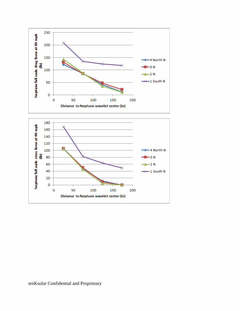
tenKsolar Confidential and Proprietary

tenKsolar Confidential and Proprietary
Numerical values of all these data are in the following tables
Drag (lb)
Position (in) 173.3 123.8 74.3 24.8
4 North N 12.1 41.7 85.9 121.1
3 N 20.6 46.7 84.8 131.2
2 N 10.6 35.3 86.8 142.5
1 South N 117.6 123.4 134.8 209.4
Cross (lb)
Position (in) 173.3 123.8 74.3 24.8
4 North N 0.0 11.8 47.4 104.8
3 N 0.0 8.9 50.0 105.2
2 N 0.0 4.6 45.9 105.4
1 South N 49.5 64.0 82.7 167.9
Lift (lb)
Position 173.3 123.8 74.3 24.8
4 North N 12.3 44.3 147.8 317.0
3 N 31.8 61.6 118.3 309.7
2 N 28.0 70.0 135.1 309.1
1 South N 20.5 79.6 185.9 294.2

JOB_______________________________________ SHEET NO._______________OF________________ CALC. BY________________DATE______________ CHECKED BY____________ _DATE______________
MISSOURI S&T SOLAR HOUSE TEAM | Chameleon House 91
G. TENK SOLAR PANEL DIMENSIONS AND ANGLES
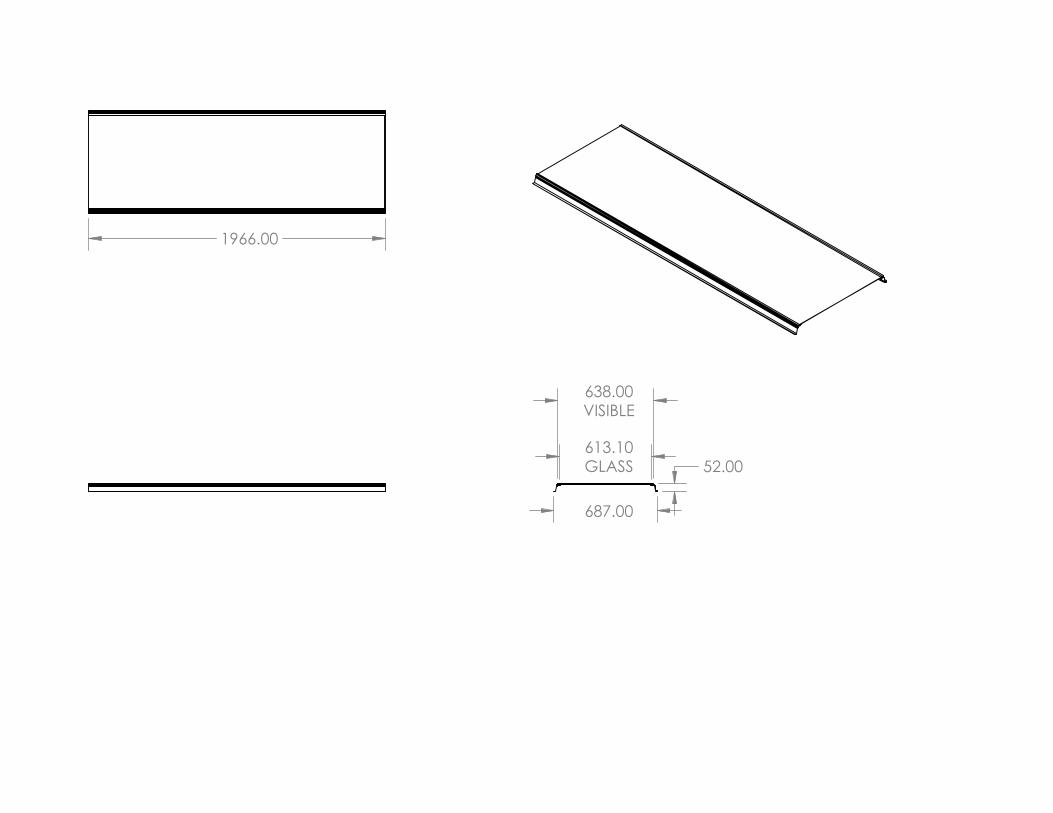
1966.00
687.00
638.00VISIBLE
613.10GLASS 52.00
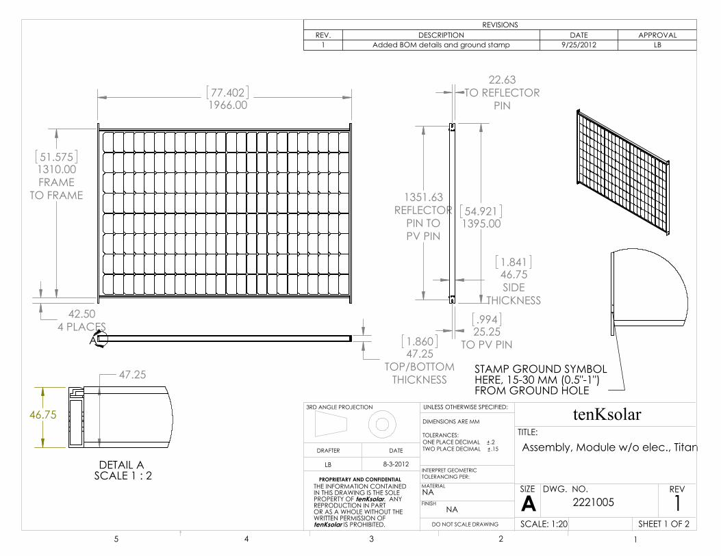
77.4021966.00
51.5751310.00FRAME
TO FRAME
42.504 PLACES
1.86047.25
TOP/BOTTOMTHICKNESS
A
54.9211395.00
1351.63REFLECTOR
PIN TOPV PIN
.99425.25
TO PV PIN
22.63TO REFLECTOR
PIN
1.84146.75SIDE
THICKNESS
46.75
47.25
DETAIL A SCALE 1 : 2
STAMP GROUND SYMBOLHERE, 15-30 MM (0.5"-1")FROM GROUND HOLE
REVISIONSREV. DESCRIPTION DATE APPROVAL
1 Added BOM details and ground stamp 9/25/2012 LB
5 4 3 2 1
THE INFORMATION CONTAINED IN THIS DRAWING IS THE SOLE PROPERTY OF tenKsolar. ANY REPRODUCTION IN PARTOR AS A WHOLE WITHOUT THE WRITTEN PERMISSION OF tenKsolar IS PROHIBITED.
PROPRIETARY AND CONFIDENTIAL
DIMENSIONS ARE MM
TOLERANCES:ONE PLACE DECIMAL .2TWO PLACE DECIMAL .15
INTERPRET GEOMETRICTOLERANCING PER:
MATERIAL
FINISH
NA
NA
DRAFTER DATE
tenKsolarTITLE:
SIZE
ADWG. NO. REV
SCALE: 1:20
UNLESS OTHERWISE SPECIFIED:
1
LB 8-3-2012
SHEET 1 OF 2DO NOT SCALE DRAWING
2221005
Assembly, Module w/o elec., Titan
3RD ANGLE PROJECTION
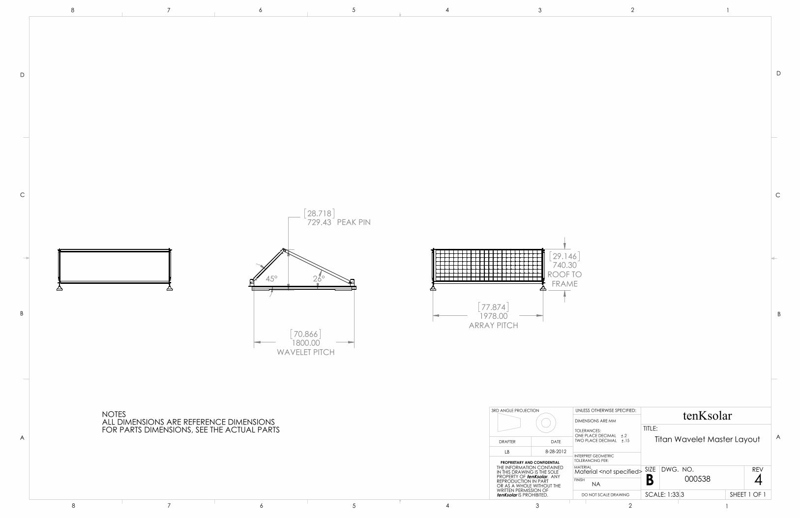
70.8661800.00
WAVELET PITCH
26° 45°
28.718729.43 PEAK PIN
77.8741978.00
ARRAY PITCH
29.146740.30
ROOF TOFRAME
NOTESALL DIMENSIONS ARE REFERENCE DIMENSIONSFOR PARTS DIMENSIONS, SEE THE ACTUAL PARTS
D
C
B
AA
B
C
D
12345678
8 7 6 5 4 3 2 1
THE INFORMATION CONTAINED IN THIS DRAWING IS THE SOLE PROPERTY OF tenKsolar. ANY REPRODUCTION IN PARTOR AS A WHOLE WITHOUT THE WRITTEN PERMISSION OF tenKsolar IS PROHIBITED.
PROPRIETARY AND CONFIDENTIAL
DIMENSIONS ARE MM
TOLERANCES:ONE PLACE DECIMAL .2TWO PLACE DECIMAL .15
INTERPRET GEOMETRICTOLERANCING PER:
MATERIAL
FINISH
Material <not specified>
NA
DRAFTER DATE
tenKsolarTITLE:
SIZE
BDWG. NO. REV
SCALE: 1:33.3
UNLESS OTHERWISE SPECIFIED:
4
LB 8-28-2012
SHEET 1 OF 1DO NOT SCALE DRAWING
000538
Titan Wavelet Master Layout
3RD ANGLE PROJECTION
JOB_______________________________________ SHEET NO._______________OF________________ CALC. BY________________DATE______________ CHECKED BY____________ _DATE______________
MISSOURI S&T SOLAR HOUSE TEAM | Chameleon House 92
H. SEISMIC FOOTING CALCULATIONS
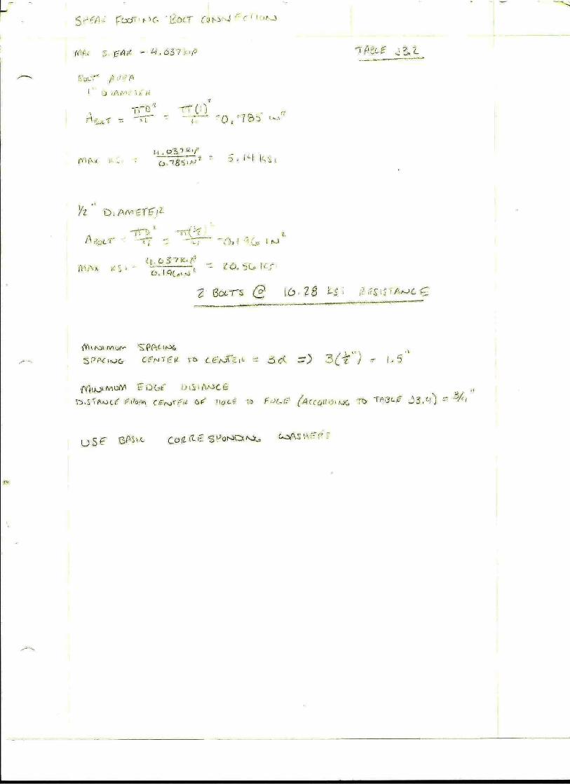
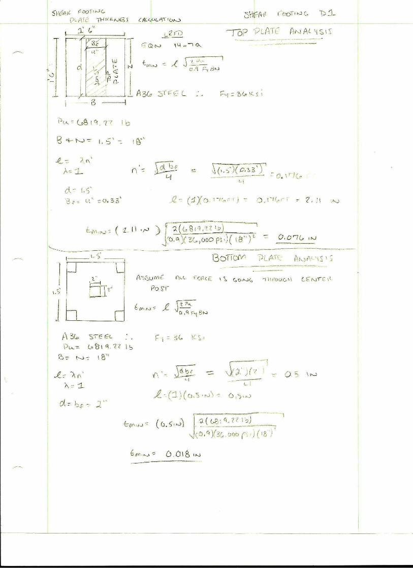
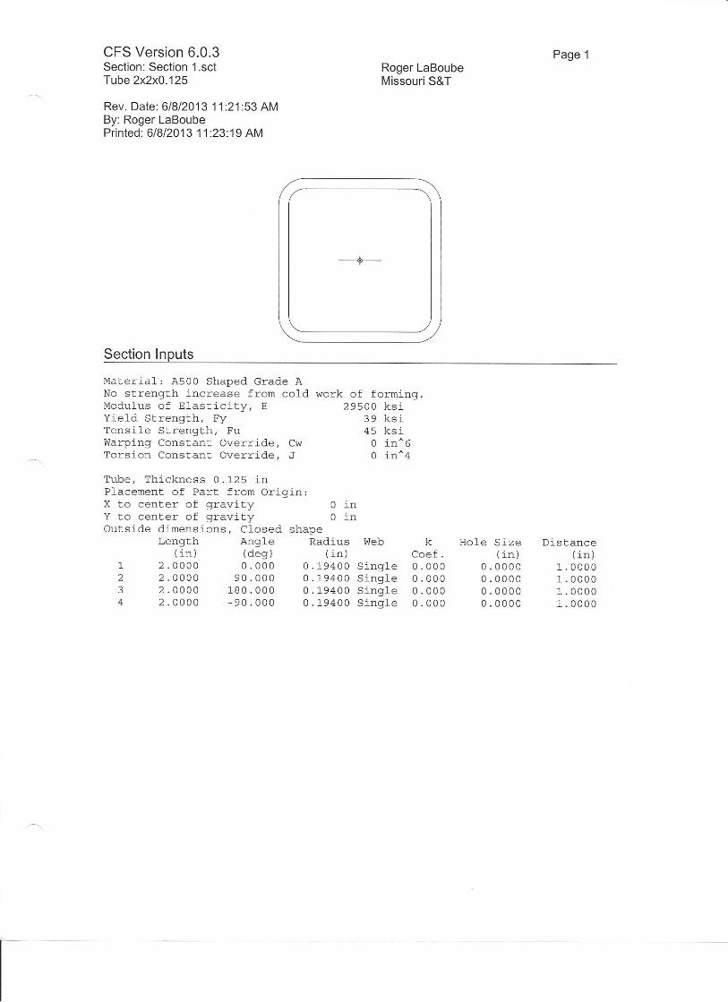
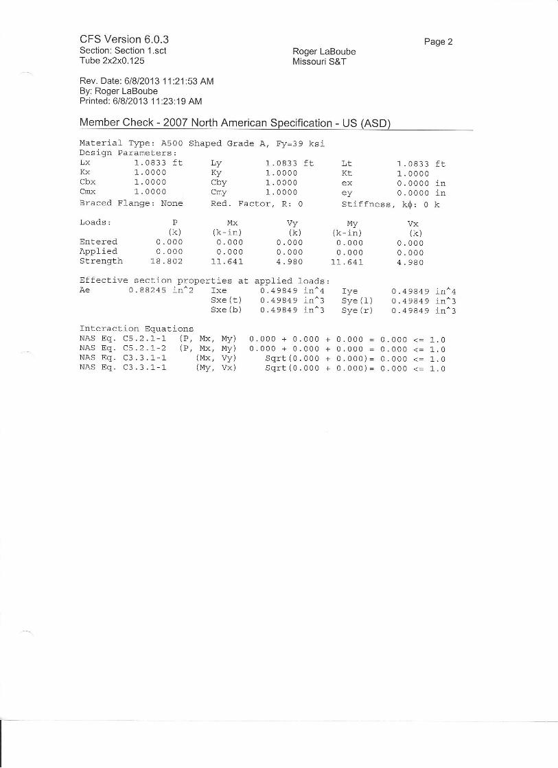
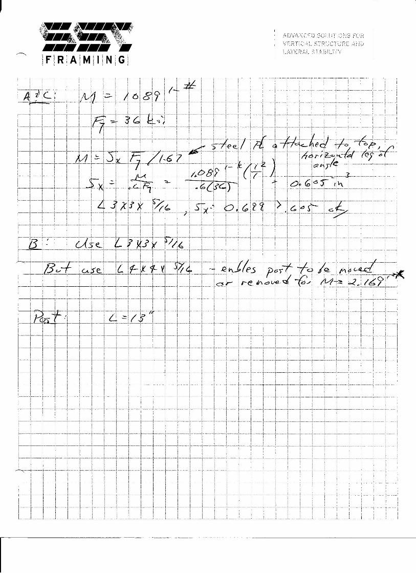

JOB_______________________________________ SHEET NO._______________OF________________ CALC. BY________________DATE______________ CHECKED BY____________ _DATE______________
MISSOURI S&T SOLAR HOUSE TEAM | Chameleon House 93
I. STEEL STRAPPING CALCULATIONS
--- t'li
I
i
aaQtu uJ uJEETf{{d-l=liiiosoSU}AAJlr)totoEltrl
@aaaFFFFlil M! UJlrl tIJ UJ UJ:E-=Iq@aqooootooooF ol (\llrttlO(Ol-t\cf, cf) (f) (f)Gl 6d (\l r99??CD CO CD CO
wls =4Y
21.20;
\2,s4' = x
i q*\i r?,*tl7t 3\+
,=- (w\r,L"*-l.._--,B:"r",g:jia**r_l
* Skarys \ tlu\ivvp vtru*)F lau ti - \u !tu tt;irrl i!,i,, '
l( Stte\ 1,,,,,:i',:. r+ \\ti',\ i;{:lK \uv urr + t ;ritg.p-v iv i ?-r; \ .,
\r'{,u!! r';
'I tt. r- - . -''
;3-:.,; j t,iru r it tv).4.
i'u'
i"" 7r-r\\- Ou,t-
'i'i ':,.,',ir #) 'Lu
+v
a@u)ul trJ uJtftr(f(({--\-aE-, -) -) t.tasa=AU)AJlololo8tttt
ur@qaI-FFFuJ uJ uJ utuJ [rJ l.ll lrtI:trI:taa@aoooorooooF (\l ol
ltlllO@t*t-c) c) (f, cDGt Gt (\t ro<)oottttco(f)(f)(o
Sb'-ar*
5"b$ toog
-v -^Aq - u."\
O.Of: ,mz
o'\4L t^z
$' P.l*i
= O'Ot, ,^t'
* O'Ab1 t*u
[{,-}/l*U C i {,r-',: i f f i..i
ut
=oo
t .Ten':t.:* Strr ,{r ( ++?yr'n,* lx A - (, ?1(^) \'ufri;:
,[flou-' r'ri:'ri:;j
,., * el,r - -(c,,qYtz') =F{Ai l-'rt --, ," r 1 ?i)\-bi
r\ -r'' ' '2:-4J?,2*: =Nn = :*:-!')*- !!' i,1 i*tt.i
'"i ?TY ': yt sechorV \in : f\. h*
P*'$F = to-'"1+tr1'?t')Fi{ tpbV-ti
A^. +F " t{r=}"Z:)ffi 4-a\r*'
& ',Jtr tlz " , *' lira-y f*-
7[1wood
?, \bbb\ \uL -- z,Lt* WV.l-- Z,av W
lk one " Ne^1 Ac*1 an 'lk
v.i = l?3*i,lb_ _b\lV"S(z,zv ++1L
Bearns AeC : Ar' (t,\b?+la){?-.Ltak) = \,Lbl\Lbe*+* &'. Ar ' ( t, t,fu X z, zv tt\ = 2,%e+L
Searn* A+c,
1
Ituw
I
cnaa[lJulutr(f(E({{*h-qr
-, -, -, t.taaa=U'AA)J
rO ro rO tLttrtcncr@aFFFFuJuJu[!trj trj uJ Lu----CDAU>O<)oooroooo
- (\l OlttttIO(oNF(r) cD (f) (")(\t (\t (\t roooo
lttt(oc)cD(o = \-10? ru I 9+
(z
UJ
=oo
v,= v2 = 4 lz -- ( t-to:i \u i t+'X Z.f.r,h) = \\1f tv.2-
[4 = #e ' (trcn tr"Lf*)Cz'euft) = tDAq P+-ruwbWey"\ S:
rtv= (r^u r.+)(z.re+-ta = 3bn1 \\,\tt2,Lt@ 4+
= loml vlw\z.u"ft)+
( azqr i"lnY e,eutfl4b
4(3ffi1 toltil(r.tattYtLb
G31t rvlk\(.r.t3WYb
= ttt4 tl,
= 3h34 tv
3W h-tU
64L k-ru
Ell,;li
l"l lc.'l'l-j
MN*t*, I, t uu
Vf-Va= vOel"1+
Vt- wol,lz
H,=WMz= #':'
fuNvts I *Z:It\Q tu
]'til,h= Ez = (t4\4 ru)f2 = 4\oO t't
M = V -* (tqtq rPYz,?rrn) = LW+ ft- tU'-r* 4 +
D^= (aoit rEl\.t,zgt+)z-zt' t+
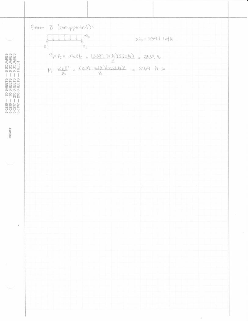
Bmryr "b (W,S",g1,*. *Cr\),
I i i -l'. i itfi* N*' 3341 tirli*
Vr Vt' rxisAl.z : {::4-t tu.I{tYz.,?bk}- = Affiq i'bI
hn- Lr:g.tr - (3"4riul{tX+"rLi''iti 7Wq ii-l*It-. b a
aaa[rJ [rJ tIJ(f,tfTE{((-lfll*ooo:cnc)aJororoElttt
@aaaI-FFFuuJ[!uTU IJJ TIJ tI,J:EII-ACDA@ooooro(>oor (\l Olltrttr)(ol'..NCD (f' <D Cf'f,l G.l Al r9999c0 co (f) cf,
qJ
=o()

JOB_______________________________________ SHEET NO._______________OF________________ CALC. BY________________DATE______________ CHECKED BY____________ _DATE______________
MISSOURI S&T SOLAR HOUSE TEAM | Chameleon House 94
J. GABRIEL CRANE INFORMATION
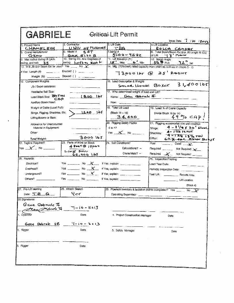
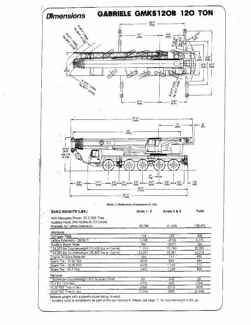
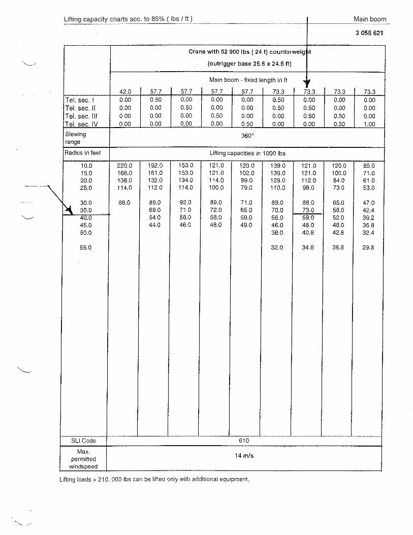
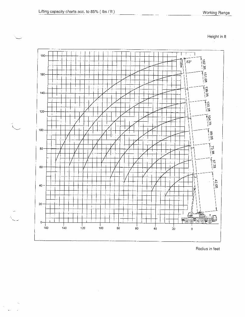
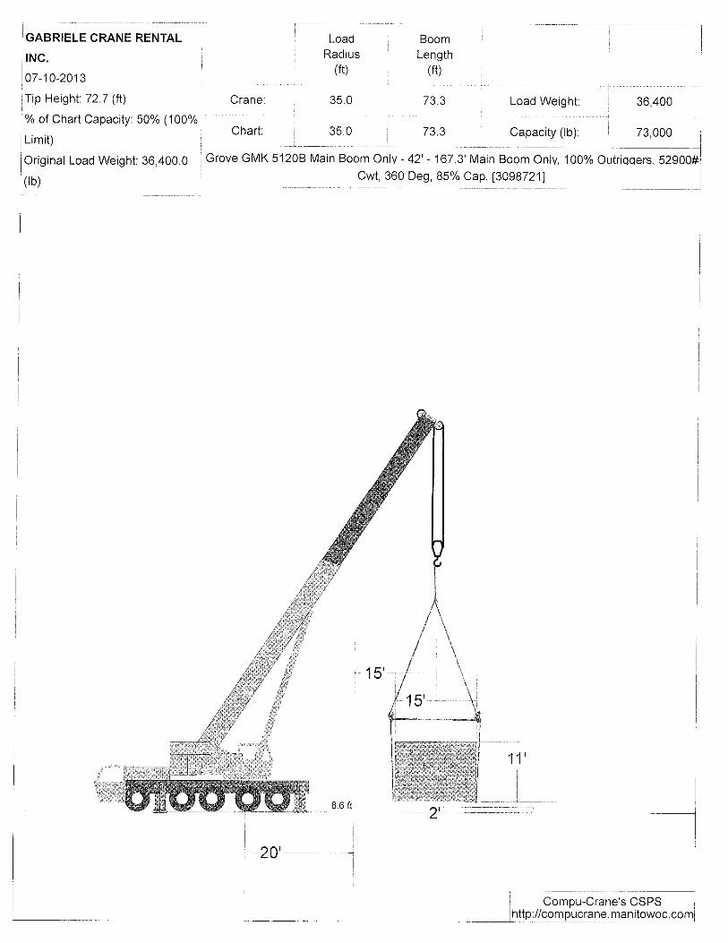

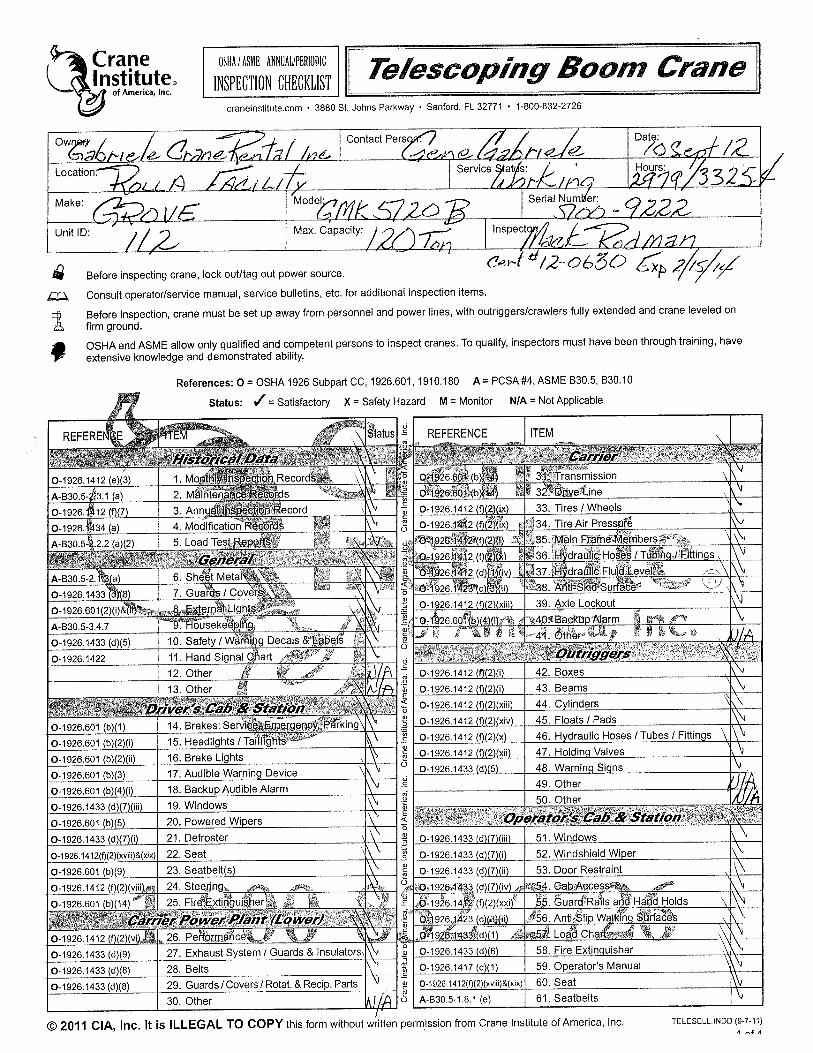
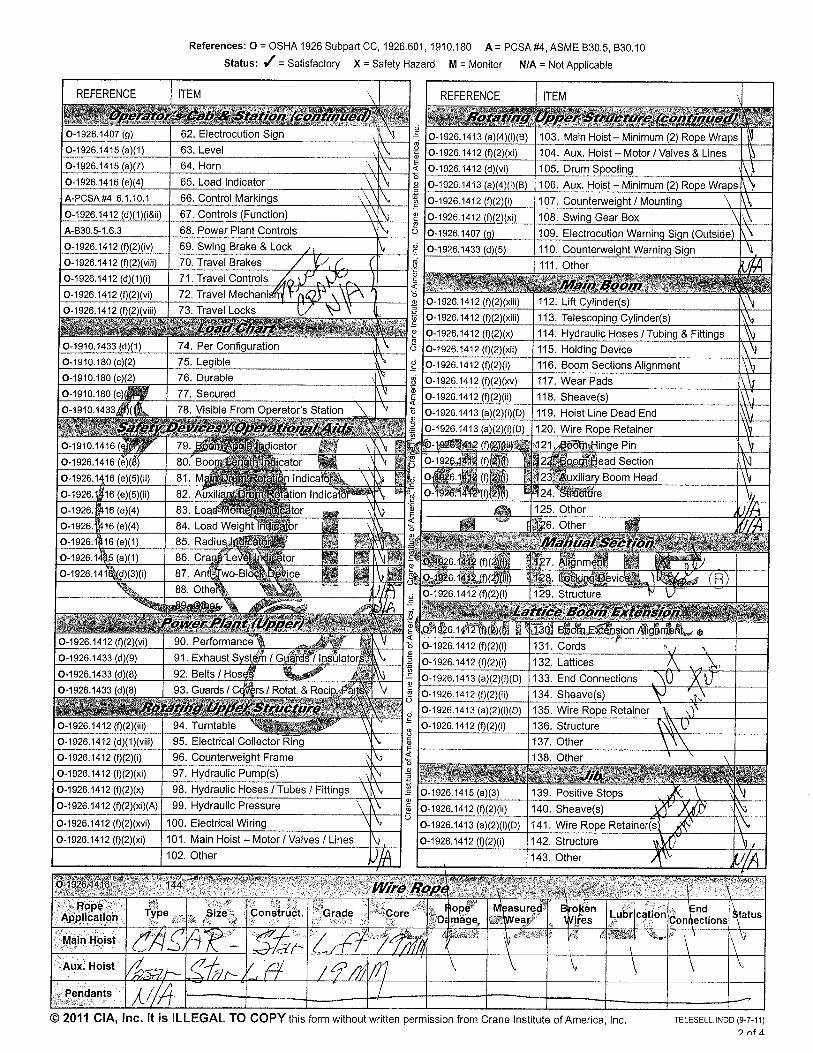


JOB_______________________________________ SHEET NO._______________OF________________ CALC. BY________________DATE______________ CHECKED BY____________ _DATE______________
MISSOURI S&T SOLAR HOUSE TEAM | Chameleon House 95
K. WOOD FRAME CONSTRUCTION MANUAL REFERENCE

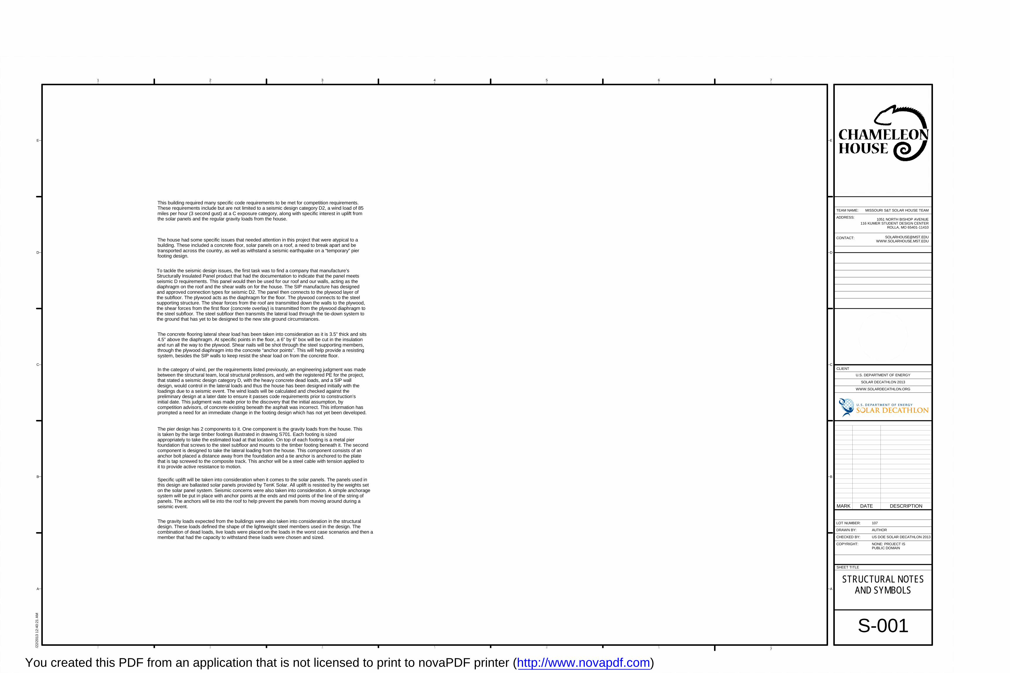
1 2 3 4 5 6 7
A
B
C
D
E
1 2 3 4 5 6 7
A
B
C
D
E
SHEET TITLE
LOT NUMBER:
DRAWN BY:
CHECKED BY:
COPYRIGHT:
CLIENT
U.S. DEPARTMENT OF ENERGY
SOLAR DECATHLON 2013
WWW.SOLARDECATHLON.ORG
TEAM NAME:
ADDRESS:
CONTACT:
NONE: PROJECT ISPUBLIC DOMAIN
1051 NORTH BISHOP AVENUE116 KUMER STUDENT DESIGN CENTER
ROLLA, MO 65401-11410
US DOE SOLAR DECATHLON 2013
8/22
/201
3 1
2:40
:21
AM
S-001
STRUCTURAL NOTESAND SYMBOLS
107
AUTHOR
MISSOURI S&T SOLAR HOUSE TEAM
This building required many specific code requirements to be met for competition requirements.These requirements include but are not limited to a seismic design category D2, a wind load of 85miles per hour (3 second gust) at a C exposure category, along with specific interest in uplift fromthe solar panels and the regular gravity loads from the house.
The house had some specific issues that needed attention in this project that were atypical to abuilding. These included a concrete floor, solar panels on a roof, a need to break apart and betransported across the country, as well as withstand a seismic earthquake on a “temporary” pierfooting design.
To tackle the seismic design issues, the first task was to find a company that manufacture’sStructurally Insulated Panel product that had the documentation to indicate that the panel meetsseismic D requirements. This panel would then be used for our roof and our walls, acting as thediaphragm on the roof and the shear walls on for the house. The SIP manufacture has designedand approved connection types for seismic D2. The panel then connects to the plywood layer ofthe subfloor. The plywood acts as the diaphragm for the floor. The plywood connects to the steelsupporting structure. The shear forces from the roof are transmitted down the walls to the plywood,the shear forces from the first floor (concrete overlay) is transmitted from the plywood diaphragm tothe steel subfloor. The steel subfloor then transmits the lateral load through the tie-down system tothe ground that has yet to be designed to the new site ground circumstances.
The concrete flooring lateral shear load has been taken into consideration as it is 3.5” thick and sits4.5” above the diaphragm. At specific points in the floor, a 6” by 6” box will be cut in the insulationand run all the way to the plywood. Shear nails will be shot through the steel supporting members,through the plywood diaphragm into the concrete “anchor points”. This will help provide a resistingsystem, besides the SIP walls to keep resist the shear load on from the concrete floor.
In the category of wind, per the requirements listed previously, an engineering judgment was madebetween the structural team, local structural professors, and with the registered PE for the project,that stated a seismic design category D, with the heavy concrete dead loads, and a SIP walldesign, would control in the lateral loads and thus the house has been designed initially with theloadings due to a seismic event. The wind loads will be calculated and checked against thepreliminary design at a later date to ensure it passes code requirements prior to construction’sinitial date. This judgment was made prior to the discovery that the initial assumption, bycompetition advisors, of concrete existing beneath the asphalt was incorrect. This information hasprompted a need for an immediate change in the footing design which has not yet been developed.
The pier design has 2 components to it. One component is the gravity loads from the house. Thisis taken by the large timber footings illustrated in drawing S701. Each footing is sizedappropriately to take the estimated load at that location. On top of each footing is a metal pierfoundation that screws to the steel subfloor and mounts to the timber footing beneath it. The secondcomponent is designed to take the lateral loading from the house. This component consists of ananchor bolt placed a distance away from the foundation and a tie anchor is anchored to the platethat is tap screwed to the composite track. This anchor will be a steel cable with tension applied toit to provide active resistance to motion.
Specific uplift will be taken into consideration when it comes to the solar panels. The panels used inthis design are ballasted solar panels provided by TenK Solar. All uplift is resisted by the weights seton the solar panel system. Seismic concerns were also taken into consideration. A simple anchoragesystem will be put in place with anchor points at the ends and mid points of the line of the string ofpanels. The anchors will tie into the roof to help prevent the panels from moving around during aseismic event.
The gravity loads expected from the buildings were also taken into consideration in the structuraldesign. These loads defined the shape of the lightweight steel members used in the design. Thecombination of dead loads, live loads were placed on the loads in the worst case scenarios and then amember that had the capacity to withstand these loads were chosen and sized.
MARK DATE DESCRIPTION
You created this PDF from an application that is not licensed to print to novaPDF printer (http://www.novapdf.com)
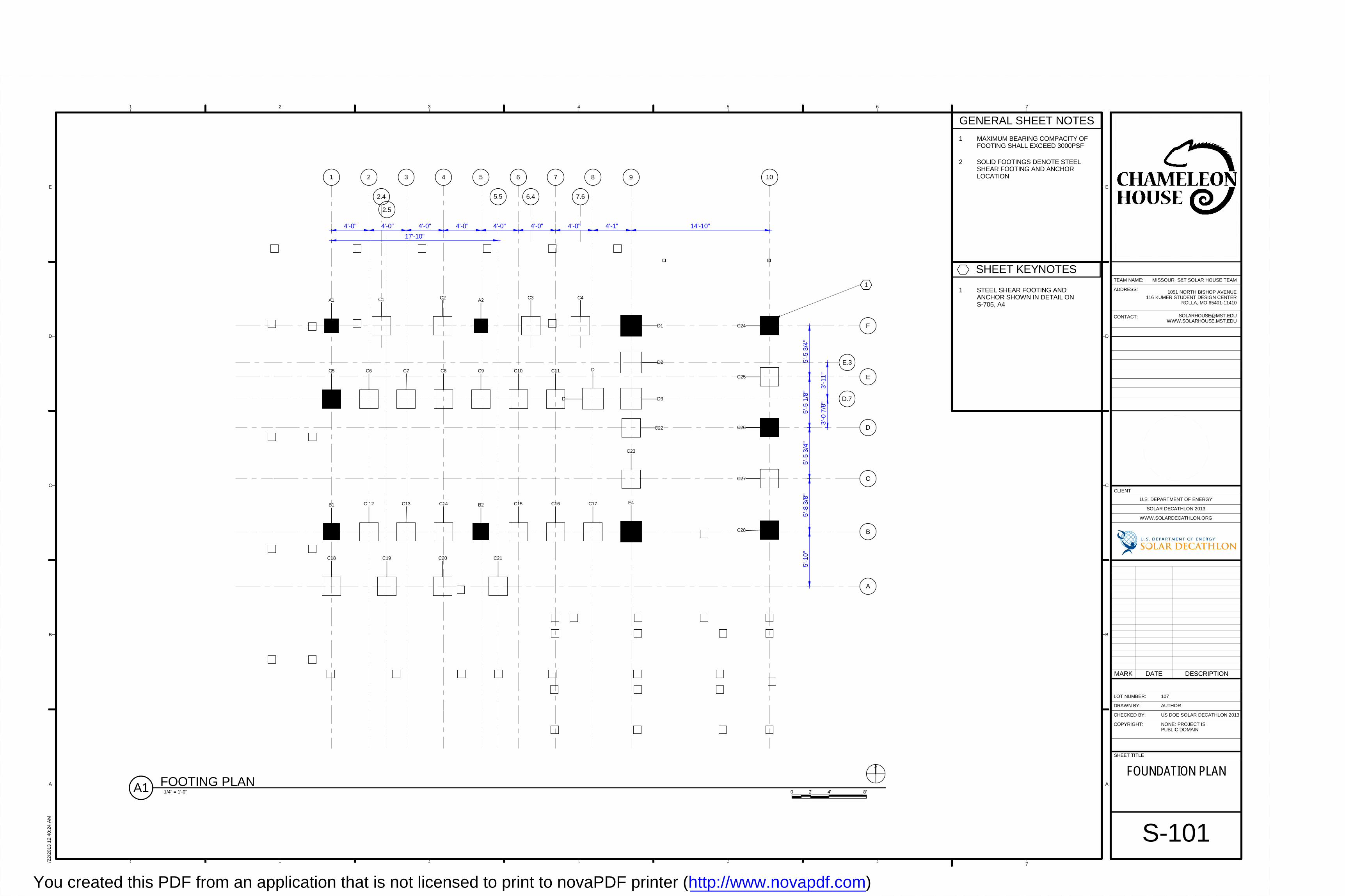
1 2 3 5 10
5.5
B
C
D
E
F
A
D.7
6 7 8 9
7.66.42.4
4
17'-10"
4'-0" 4'-0" 4'-0" 4'-0" 4'-0" 4'-0" 4'-0" 4'-1" 14'-10"
5'-5
3/4
"5'
-5 1
/8"
5'-5
3/4
"5'
-8 3
/8"
5'-1
0"
3'-0
7/8
"
E.3
3'-1
1"
2.5
1
C4C1
C6 C7 C8 C9 C10 C11
D
C22
C25
C23
C16C15C14C13C`12
D1
D3
D2
C26
C24
C27
C28
A1 C2 A2 C3
C5
B2B1 C17
D
C18 C19 C20 C21
E4
1 2 3 4 5 6 7
A
B
C
D
E
1 2 3 4 5 6 7
A
B
C
D
E
SHEET TITLE
LOT NUMBER:
DRAWN BY:
CHECKED BY:
COPYRIGHT:
CLIENT
U.S. DEPARTMENT OF ENERGY
SOLAR DECATHLON 2013
WWW.SOLARDECATHLON.ORG
TEAM NAME:
ADDRESS:
CONTACT:
NONE: PROJECT ISPUBLIC DOMAIN
1051 NORTH BISHOP AVENUE116 KUMER STUDENT DESIGN CENTER
ROLLA, MO 65401-11410
US DOE SOLAR DECATHLON 2013
8/22
/201
3 1
2:40
:24
AM
S-101
FOUNDATION PLAN
107
AUTHOR
MISSOURI S&T SOLAR HOUSE TEAM
1/4" = 1'-0"A1 FOOTING PLAN0 2' 4' 8'
GENERAL SHEET NOTES
1 MAXIMUM BEARING COMPACITY OFFOOTING SHALL EXCEED 3000PSF
2 SOLID FOOTINGS DENOTE STEELSHEAR FOOTING AND ANCHORLOCATION
MARK DATE DESCRIPTION
SHEET KEYNOTES
1 STEEL SHEAR FOOTING ANDANCHOR SHOWN IN DETAIL ONS-705, A4
You created this PDF from an application that is not licensed to print to novaPDF printer (http://www.novapdf.com)
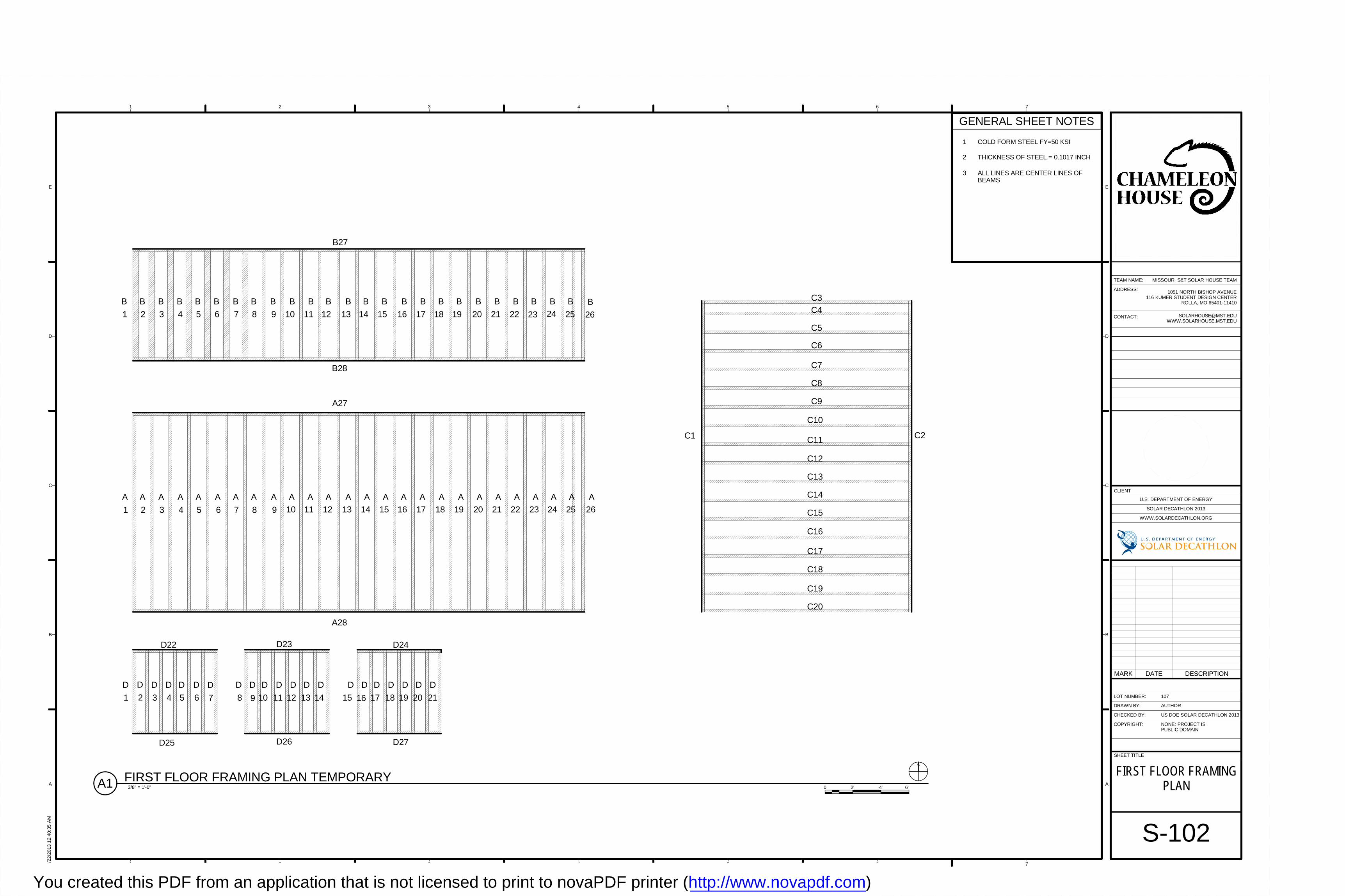
A A
10
A A A A A A A A A A A A A A A
11 12 13 14 15 16 17 18 19 20 21 22 23 24 259
A
8
A
7
A
6
A
5
A
4
A
3
A
2
A
1
A
26
B
1
B
2
B
3
B
4
B
5
B
6
B
7
B
8
B
9
B
10
B
11
B
12
B
13
B
14
B
15
B
16
B
17
B
18
B
19
B
20
B
21
B
22
B
23
B
24
B
25
B
26
C3
C4
C5
C6
C7
C8
C9
C10
C11
C12
C13
C14
C15
C16
C17
C18
C19
C20
D
1
D
2
D
3 4 5 6 7 8 9 10 11 12
D D D D D D D D D
13 14
D D
15 16 17 18 19
D D D D D
20 21
D D
D22 D23 D24
D27D26D25
A27
A28
B28
B27
C1 C2
1 2 3 4 5 6 7
A
B
C
D
E
1 2 3 4 5 6 7
A
B
C
D
E
SHEET TITLE
LOT NUMBER:
DRAWN BY:
CHECKED BY:
COPYRIGHT:
CLIENT
U.S. DEPARTMENT OF ENERGY
SOLAR DECATHLON 2013
WWW.SOLARDECATHLON.ORG
TEAM NAME:
ADDRESS:
CONTACT:
NONE: PROJECT ISPUBLIC DOMAIN
1051 NORTH BISHOP AVENUE116 KUMER STUDENT DESIGN CENTER
ROLLA, MO 65401-11410
US DOE SOLAR DECATHLON 2013
8/22
/201
3 1
2:40
:35
AM
S-102
FIRST FLOOR FRAMINGPLAN
107
AUTHOR
MISSOURI S&T SOLAR HOUSE TEAM
GENERAL SHEET NOTES
1 COLD FORM STEEL FY=50 KSI
2 THICKNESS OF STEEL = 0.1017 INCH
3 ALL LINES ARE CENTER LINES OFBEAMS
MARK DATE DESCRIPTION
3/8" = 1'-0"A1 FIRST FLOOR FRAMING PLAN TEMPORARY0 4' 6'2'
You created this PDF from an application that is not licensed to print to novaPDF printer (http://www.novapdf.com)
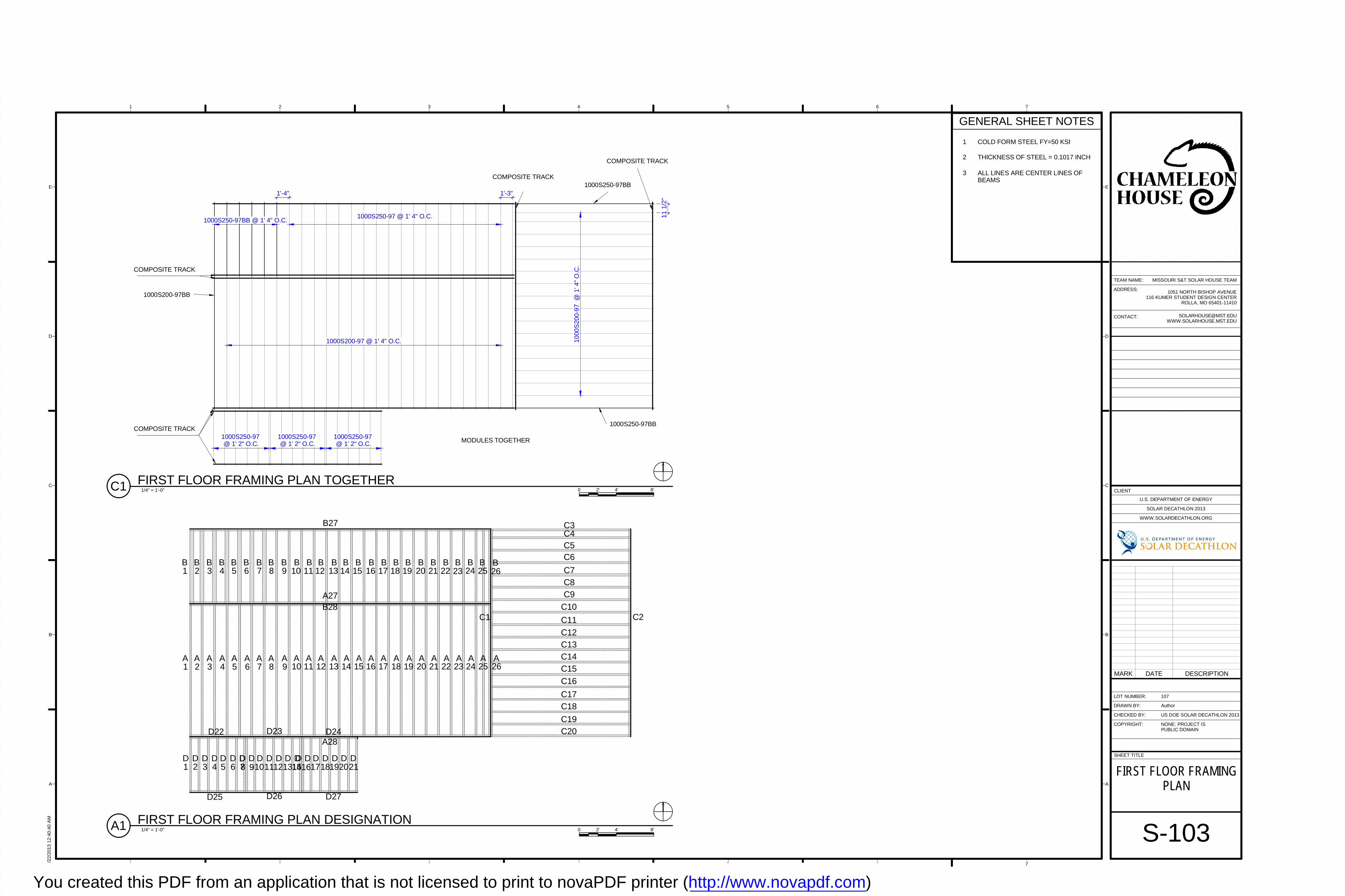
MODULES TOGETHER
1000S250-97BB @ 1' 4" O.C.1000S250-97 @ 1' 4" O.C.
1'-4" 1'-3"
11
1/2
"
1000S200-97 @ 1' 4" O.C. 10
00S
200
-97
@ 1
' 4"
O.C
.
1000S250-97 @ 1' 2" O.C.
1000S250-97 @ 1' 2" O.C.
1000S250-97 @ 1' 2" O.C.
1000S200-97BB
1000S250-97BB
1000S250-97BB
COMPOSITE TRACK
COMPOSITE TRACK
COMPOSITE TRACK
COMPOSITE TRACK
A A10
A A A A A A A A A A A A A A A11 12 13 14 15 16 17 18 19 20 21 22 23 24 259
A8
A7
A6
A5
A4
A3
A2
A1
A26
B1
B2
B3
B4
B5
B6
B7
B8
B9
B10
B11
B12
B13
B14
B15
B16
B17
B18
B19
B20
B21
B22
B23
B24
B25
B26
C3C4C5C6
C7C8C9
C10
C11
C12C13C14C15
C16
C17C18
C19C20
D1
D2
D3 4 5 6 78 9101112
D D D DD D D D D1314D D
1516171819D D D D D
2021D D
D22 D23 D24
D27D26D25
A27
A28
B28
B27
C1 C2
1 2 3 4 5 6 7
A
B
C
D
E
1 2 3 4 5 6 7
A
B
C
D
E
SHEET TITLE
LOT NUMBER:
DRAWN BY:
CHECKED BY:
COPYRIGHT:
CLIENT
U.S. DEPARTMENT OF ENERGY
SOLAR DECATHLON 2013
WWW.SOLARDECATHLON.ORG
TEAM NAME:
ADDRESS:
CONTACT:
NONE: PROJECT ISPUBLIC DOMAIN
1051 NORTH BISHOP AVENUE116 KUMER STUDENT DESIGN CENTER
ROLLA, MO 65401-11410
US DOE SOLAR DECATHLON 2013
8/22
/201
3 1
2:40
:40
AM
S-103
FIRST FLOOR FRAMINGPLAN
107
Author
MISSOURI S&T SOLAR HOUSE TEAM
GENERAL SHEET NOTES
1 COLD FORM STEEL FY=50 KSI
2 THICKNESS OF STEEL = 0.1017 INCH
3 ALL LINES ARE CENTER LINES OFBEAMS
MARK DATE DESCRIPTION
1/4" = 1'-0"C1 FIRST FLOOR FRAMING PLAN TOGETHER
1/4" = 1'-0"A1 FIRST FLOOR FRAMING PLAN DESIGNATION
0 2' 4' 8'
0 2' 4' 8'
You created this PDF from an application that is not licensed to print to novaPDF printer (http://www.novapdf.com)
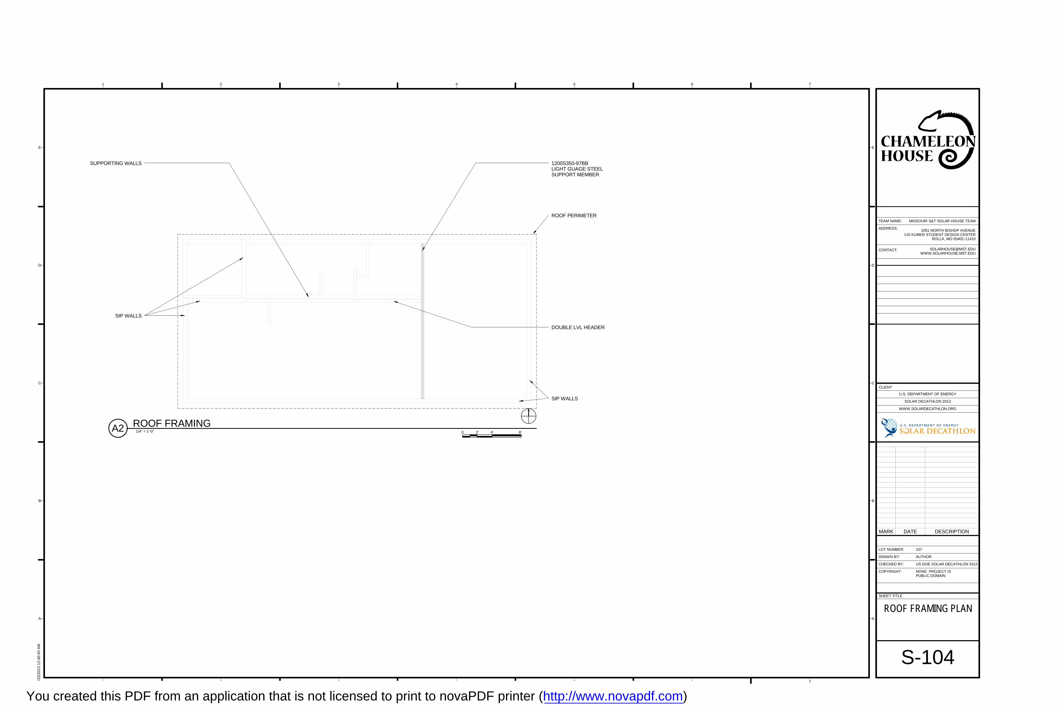
1200S350-97BBLIGHT GUAGE STEELSUPPORT MEMBER
SUPPORTING WALLS
ROOF PERIMETER
SIP WALLS
SIP WALLS
DOUBLE LVL HEADER
1 2 3 4 5 6 7
A
B
C
D
E
1 2 3 4 5 6 7
A
B
C
D
E
SHEET TITLE
LOT NUMBER:
DRAWN BY:
CHECKED BY:
COPYRIGHT:
CLIENT
U.S. DEPARTMENT OF ENERGY
SOLAR DECATHLON 2013
WWW.SOLARDECATHLON.ORG
TEAM NAME:
ADDRESS:
CONTACT:
NONE: PROJECT ISPUBLIC DOMAIN
1051 NORTH BISHOP AVENUE116 KUMER STUDENT DESIGN CENTER
ROLLA, MO 65401-11410
US DOE SOLAR DECATHLON 2013
8/22
/201
3 1
2:40
:43
AM
S-104
ROOF FRAMING PLAN
107
AUTHOR
MISSOURI S&T SOLAR HOUSE TEAM
1/4" = 1'-0"A2 ROOF FRAMING0 2' 4' 8'
MARK DATE DESCRIPTION
You created this PDF from an application that is not licensed to print to novaPDF printer (http://www.novapdf.com)
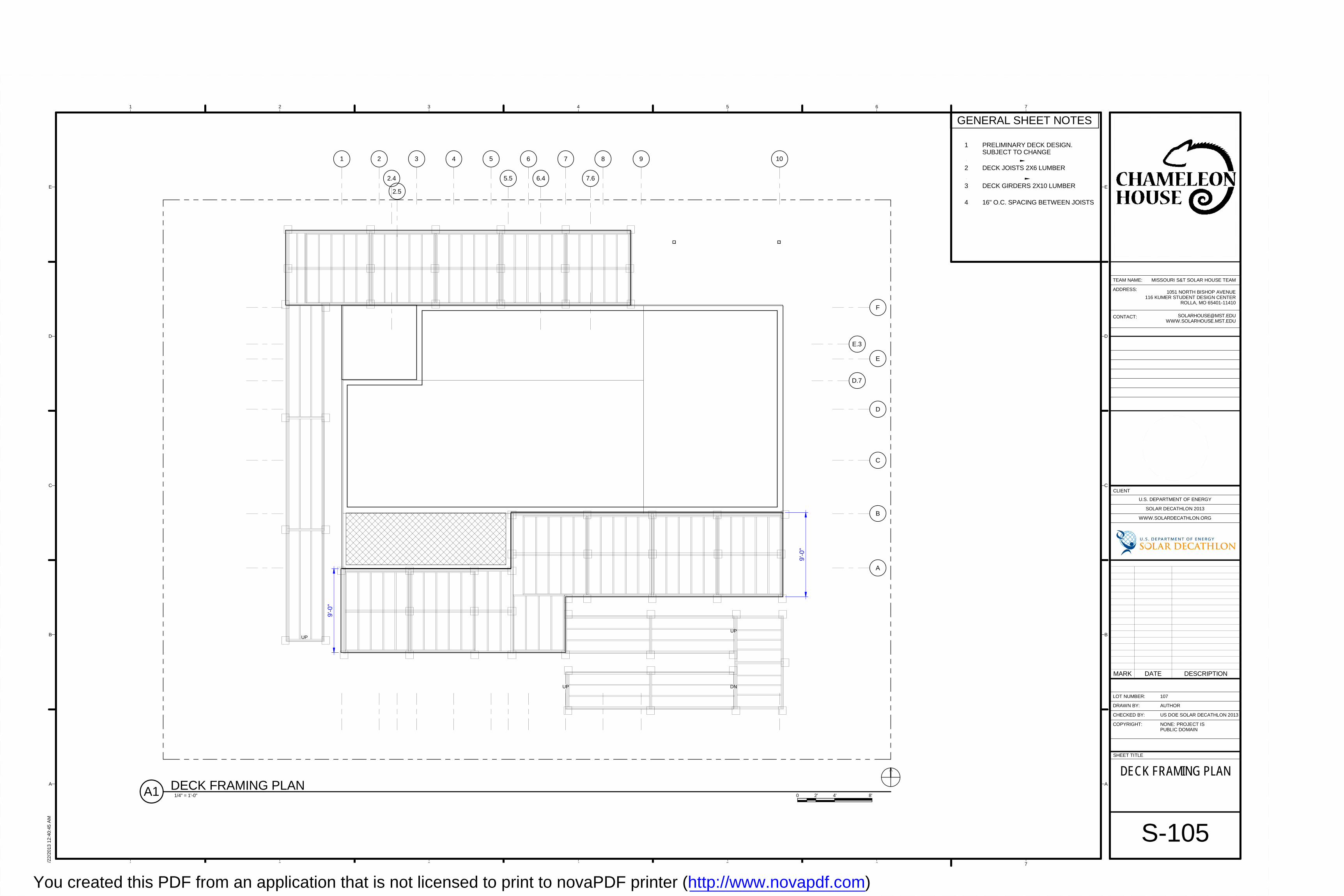
UP
UP DN
UP
1 2 3 5 10
5.5
B
C
D
E
F
A
D.7
6 7 8 9
7.66.42.4
4
E.3
2.5
9'-0
"
9'-0
"
1 2 3 4 5 6 7
A
B
C
D
E
1 2 3 4 5 6 7
A
B
C
D
E
SHEET TITLE
LOT NUMBER:
DRAWN BY:
CHECKED BY:
COPYRIGHT:
CLIENT
U.S. DEPARTMENT OF ENERGY
SOLAR DECATHLON 2013
WWW.SOLARDECATHLON.ORG
TEAM NAME:
ADDRESS:
CONTACT:
NONE: PROJECT ISPUBLIC DOMAIN
1051 NORTH BISHOP AVENUE116 KUMER STUDENT DESIGN CENTER
ROLLA, MO 65401-11410
US DOE SOLAR DECATHLON 2013
8/22
/201
3 1
2:40
:45
AM
S-105
DECK FRAMING PLAN
107
AUTHOR
MISSOURI S&T SOLAR HOUSE TEAM
1/4" = 1'-0"A1 DECK FRAMING PLAN
GENERAL SHEET NOTES
1 PRELIMINARY DECK DESIGN.SUBJECT TO CHANGE
0 2' 4' 8'
2 DECK JOISTS 2X6 LUMBER
3 DECK GIRDERS 2X10 LUMBER
MARK DATE DESCRIPTION
4 16" O.C. SPACING BETWEEN JOISTS
You created this PDF from an application that is not licensed to print to novaPDF printer (http://www.novapdf.com)
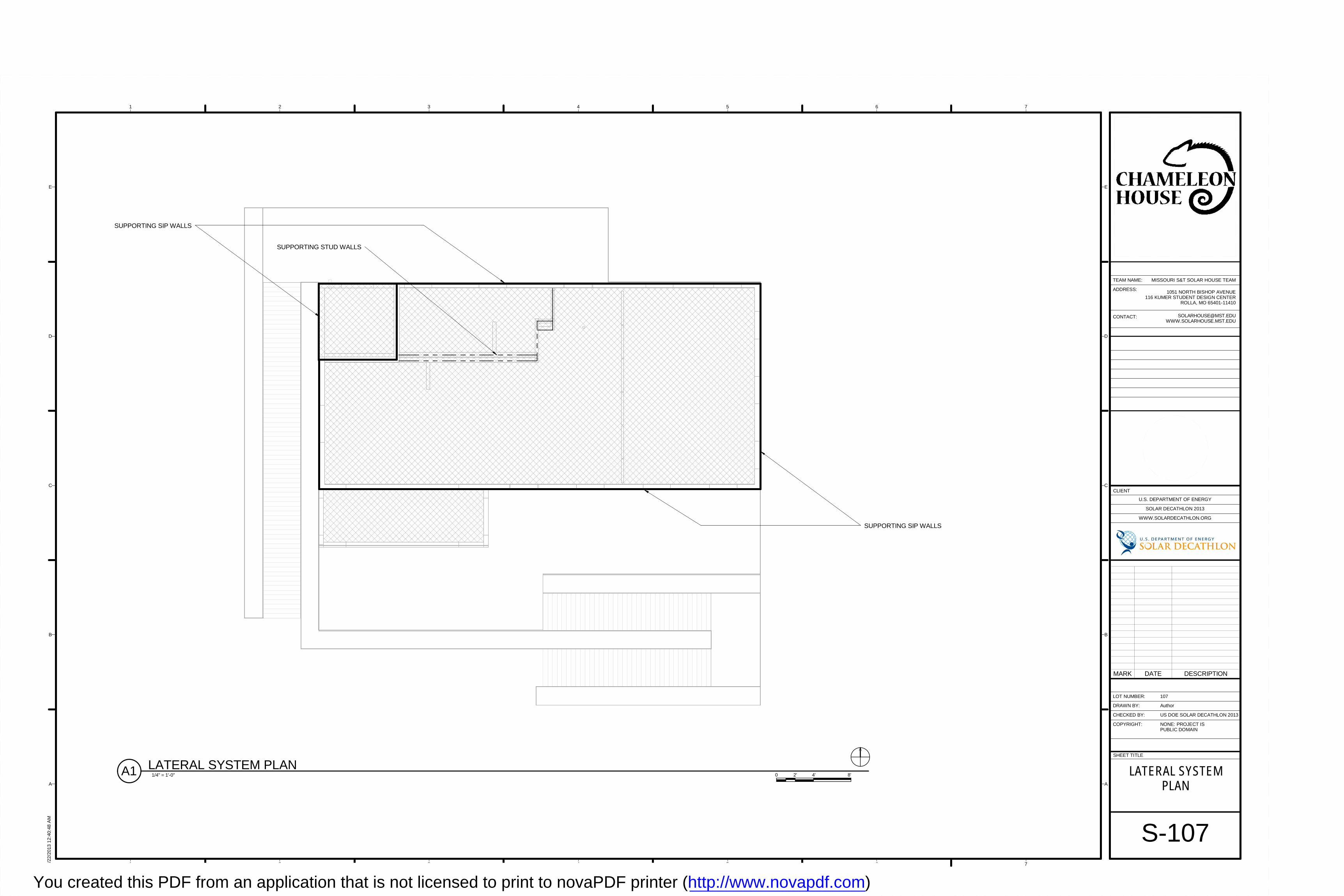
SUPPORTING SIP WALLS
SUPPORTING SIP WALLS
SUPPORTING STUD WALLS
1 2 3 4 5 6 7
A
B
C
D
E
1 2 3 4 5 6 7
A
B
C
D
E
SHEET TITLE
LOT NUMBER:
DRAWN BY:
CHECKED BY:
COPYRIGHT:
CLIENT
U.S. DEPARTMENT OF ENERGY
SOLAR DECATHLON 2013
WWW.SOLARDECATHLON.ORG
TEAM NAME:
ADDRESS:
CONTACT:
NONE: PROJECT ISPUBLIC DOMAIN
1051 NORTH BISHOP AVENUE116 KUMER STUDENT DESIGN CENTER
ROLLA, MO 65401-11410
US DOE SOLAR DECATHLON 2013
8/22
/201
3 1
2:40
:48
AM
S-107
LATERAL SYSTEMPLAN
107
Author
MISSOURI S&T SOLAR HOUSE TEAM
1/4" = 1'-0"A1 LATERAL SYSTEM PLAN0 2' 4' 8'
MARK DATE DESCRIPTION
You created this PDF from an application that is not licensed to print to novaPDF printer (http://www.novapdf.com)
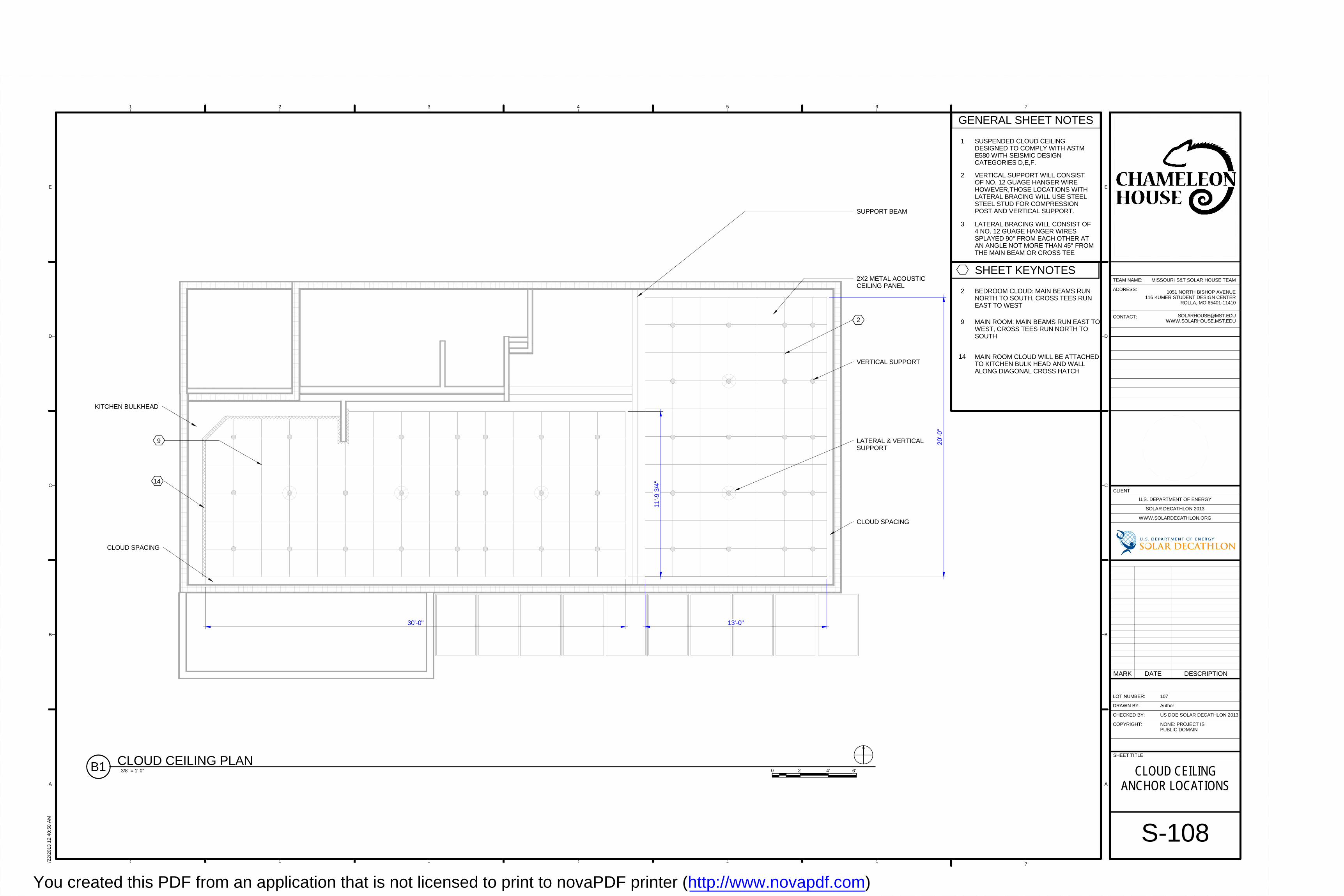
SUPPORT BEAM
2X2 METAL ACOUSTICCEILING PANEL
VERTICAL SUPPORT
LATERAL & VERTICALSUPPORT
KITCHEN BULKHEAD
CLOUD SPACING
CLOUD SPACING
14
9
2
30'-0"
20'-0
"
13'-0"
11'-9
3/4
"
1 2 3 4 5 6 7
A
B
C
D
E
1 2 3 4 5 6 7
A
B
C
D
E
SHEET TITLE
LOT NUMBER:
DRAWN BY:
CHECKED BY:
COPYRIGHT:
CLIENT
U.S. DEPARTMENT OF ENERGY
SOLAR DECATHLON 2013
WWW.SOLARDECATHLON.ORG
TEAM NAME:
ADDRESS:
CONTACT:
NONE: PROJECT ISPUBLIC DOMAIN
1051 NORTH BISHOP AVENUE116 KUMER STUDENT DESIGN CENTER
ROLLA, MO 65401-11410
US DOE SOLAR DECATHLON 2013
8/22
/201
3 1
2:40
:50
AM
S-108
CLOUD CEILINGANCHOR LOCATIONS
107
Author
MISSOURI S&T SOLAR HOUSE TEAM
3/8" = 1'-0"B1 CLOUD CEILING PLAN0 4' 6'2'
GENERAL SHEET NOTES
1 SUSPENDED CLOUD CEILINGDESIGNED TO COMPLY WITH ASTME580 WITH SEISMIC DESIGNCATEGORIES D,E,F.
2 VERTICAL SUPPORT WILL CONSISTOF NO. 12 GUAGE HANGER WIREHOWEVER,THOSE LOCATIONS WITHLATERAL BRACING WILL USE STEELSTEEL STUD FOR COMPRESSIONPOST AND VERTICAL SUPPORT.
3 LATERAL BRACING WILL CONSIST OF4 NO. 12 GUAGE HANGER WIRESSPLAYED 90° FROM EACH OTHER ATAN ANGLE NOT MORE THAN 45° FROMTHE MAIN BEAM OR CROSS TEE
SHEET KEYNOTES
2 BEDROOM CLOUD: MAIN BEAMS RUNNORTH TO SOUTH, CROSS TEES RUNEAST TO WEST
9 MAIN ROOM: MAIN BEAMS RUN EAST TOWEST, CROSS TEES RUN NORTH TOSOUTH
14 MAIN ROOM CLOUD WILL BE ATTACHEDTO KITCHEN BULK HEAD AND WALLALONG DIAGONAL CROSS HATCH
MARK DATE DESCRIPTION
You created this PDF from an application that is not licensed to print to novaPDF printer (http://www.novapdf.com)
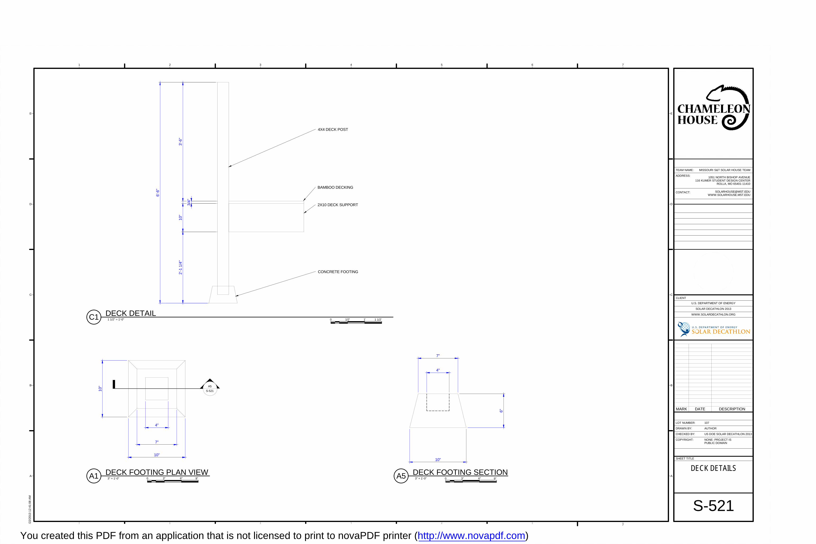
10"
10"
7"
4"
A5
S-521
6'-6
"
3'-6
"1
0"2'
-1 1
/4"
3/4
"
4X4 DECK POST
BAMBOO DECKING
2X10 DECK SUPPORT
CONCRETE FOOTING
4"
10"
4"
7"
6"
1 2 3 4 5 6 7
A
B
C
D
E
1 2 3 4 5 6 7
A
B
C
D
E
SHEET TITLE
LOT NUMBER:
DRAWN BY:
CHECKED BY:
COPYRIGHT:
CLIENT
U.S. DEPARTMENT OF ENERGY
SOLAR DECATHLON 2013
WWW.SOLARDECATHLON.ORG
TEAM NAME:
ADDRESS:
CONTACT:
NONE: PROJECT ISPUBLIC DOMAIN
1051 NORTH BISHOP AVENUE116 KUMER STUDENT DESIGN CENTER
ROLLA, MO 65401-11410
US DOE SOLAR DECATHLON 2013
8/22
/201
3 1
2:41
:08
AM
S-521
DECK DETAILS
107
AUTHOR
MISSOURI S&T SOLAR HOUSE TEAM
3" = 1'-0"A1 DECK FOOTING PLAN VIEW
1 1/2" = 1'-0"C1 DECK DETAIL
MARK DATE DESCRIPTION
3" = 1'-0"A5 DECK FOOTING SECTION0 6" 9"3" 0 6" 9"3"
0 1' 1 1/2'1/2'
You created this PDF from an application that is not licensed to print to novaPDF printer (http://www.novapdf.com)

1
EYE HOOK
MIN. 12 GUAGE HANGER WIRE
ARMSTRONG PRELUDE XL5/16" MAIN BEAM
SPLAY WIRES (LATERAL SUPPORTS)
HANGER WIRE (VERTICAL SUPPORT)
1/2 " DIAMETERELECTRICAL METAL TUBING (ETM)COMPRESSION POST
ARMSTRONG PRELUDE5/16" CROSS TEE
ARMSTRONG AXIOM VECTOR TRIM
ARSTRONG METALWORKS VECTOR SERIESMICRO-PERFORATED INTERIOR CEILING TILE 27.57°
2
DIMENSIONED LUMBER 2X4
90°
3
SPLAY WIRES (LATERAL SUPPORTS)
HANGER WIRE (VERTICAL SUPPORTS)
ARMSTRONG PRELUDE XL 5/16" MAIN BEAM
ARMSTRONG PRELUDE XL 5/16" CROSS TEE
1/2" DIAMETER EMT COMPRESSION POST
ARMSTRONG SEISMIC JOINT CLIP
1 2 3 4 5 6 7
A
B
C
D
E
1 2 3 4 5 6 7
A
B
C
D
E
SHEET TITLE
LOT NUMBER:
DRAWN BY:
CHECKED BY:
COPYRIGHT:
CLIENT
U.S. DEPARTMENT OF ENERGY
SOLAR DECATHLON 2013
WWW.SOLARDECATHLON.ORG
TEAM NAME:
ADDRESS:
CONTACT:
NONE: PROJECT ISPUBLIC DOMAIN
1051 NORTH BISHOP AVENUE116 KUMER STUDENT DESIGN CENTER
ROLLA, MO 65401-11410
US DOE SOLAR DECATHLON 2013
8/22
/201
3 1
2:41
:13
AM
S-541
SUSPENDED CEILINGDETAILS
107
Author
MISSOURI S&T SOLAR HOUSE TEAM
3" = 1'-0"D2 SUSPENDED CEILING SECTION DETAIL
0 6" 9"3"
3" = 1'-0"A2 SUSPENDED CEILING PLAN DETAIL0 6" 9"3"
GENERAL SHEET NOTES1 HANGER WIRES (VERTICAL SUPPORTS)MUST BE POSITIONED EVERY 4'
2 COMPRESSION POSTS MUST BEPOSITIONED EVERY 12'
3 SPLAY WIRES (LATERAL SUPPORTS) MUSTBE POSITIONED EVERY 12'
ALL SUPPORT WIRES MUST BESECURED WITH A MINIMUM OF 3 TWISTS
1
2 SPLAY WIRES (LATERAL SUPPORTS)MUST MAKE AN ANGLE OF 45° OR LESSWITH THE CEILING PLANE
3 SPLAY WIRES (LATERAL SUPPORTS)MUST MAKE AN ANGLE OF 90° WITHEACHOTHER WHEN MEASURED IN PLANVIEW
MARK DATE DESCRIPTION
SHEET KEYNOTES
You created this PDF from an application that is not licensed to print to novaPDF printer (http://www.novapdf.com)
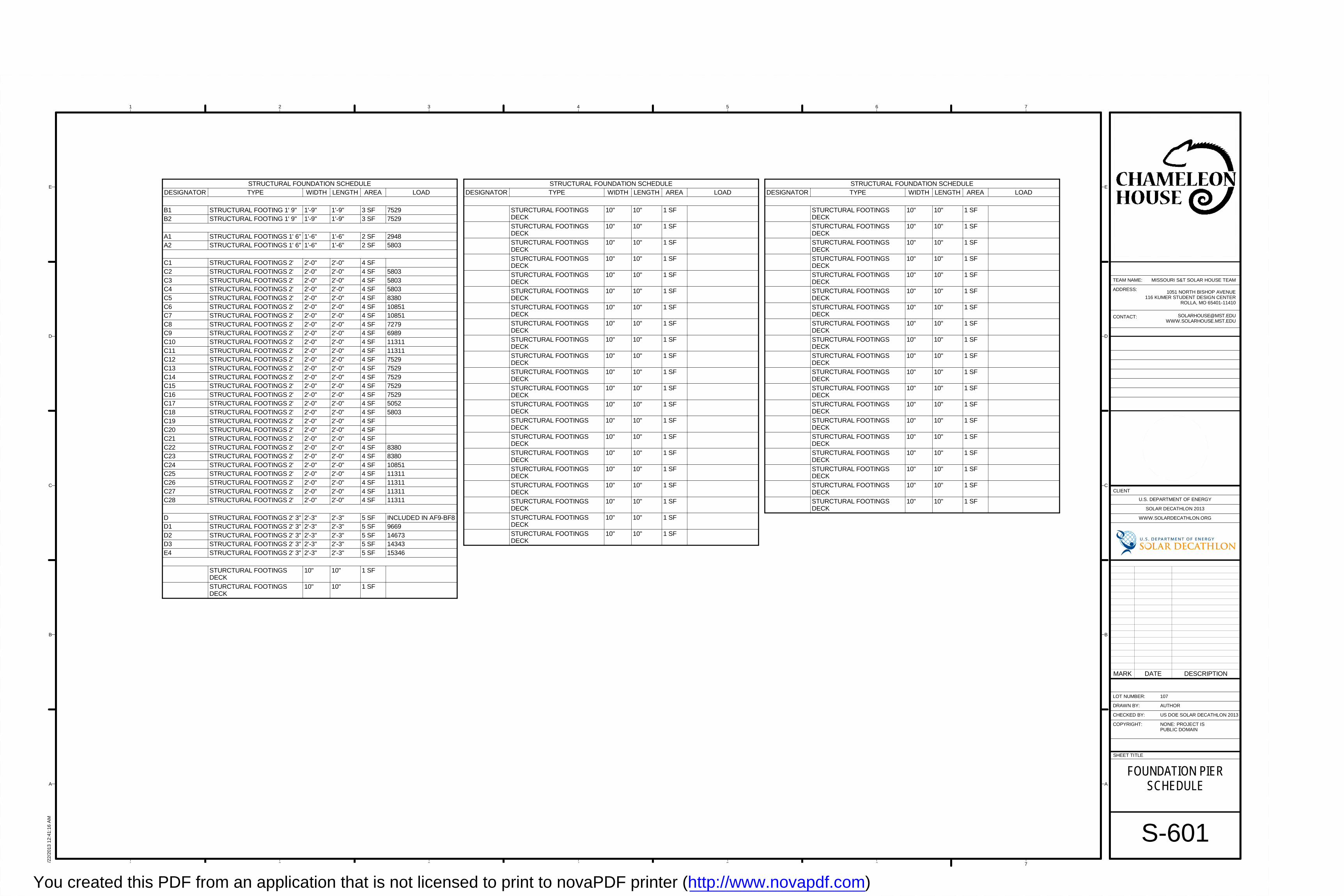
1 2 3 4 5 6 7
A
B
C
D
E
1 2 3 4 5 6 7
A
B
C
D
E
SHEET TITLE
LOT NUMBER:
DRAWN BY:
CHECKED BY:
COPYRIGHT:
CLIENT
U.S. DEPARTMENT OF ENERGY
SOLAR DECATHLON 2013
WWW.SOLARDECATHLON.ORG
TEAM NAME:
ADDRESS:
CONTACT:
NONE: PROJECT ISPUBLIC DOMAIN
1051 NORTH BISHOP AVENUE116 KUMER STUDENT DESIGN CENTER
ROLLA, MO 65401-11410
US DOE SOLAR DECATHLON 2013
8/22
/201
3 1
2:41
:16
AM
S-601
FOUNDATION PIERSCHEDULE
107
AUTHOR
MISSOURI S&T SOLAR HOUSE TEAM
MARK DATE DESCRIPTION
STRUCTURAL FOUNDATION SCHEDULEDESIGNATOR TYPE WIDTH LENGTH AREA LOAD
STURCTURAL FOOTINGSDECK
10" 10" 1 SF
STURCTURAL FOOTINGSDECK
10" 10" 1 SF
STURCTURAL FOOTINGSDECK
10" 10" 1 SF
STURCTURAL FOOTINGSDECK
10" 10" 1 SF
STURCTURAL FOOTINGSDECK
10" 10" 1 SF
STURCTURAL FOOTINGSDECK
10" 10" 1 SF
STURCTURAL FOOTINGSDECK
10" 10" 1 SF
STURCTURAL FOOTINGSDECK
10" 10" 1 SF
STURCTURAL FOOTINGSDECK
10" 10" 1 SF
STURCTURAL FOOTINGSDECK
10" 10" 1 SF
STURCTURAL FOOTINGSDECK
10" 10" 1 SF
STURCTURAL FOOTINGSDECK
10" 10" 1 SF
STURCTURAL FOOTINGSDECK
10" 10" 1 SF
STURCTURAL FOOTINGSDECK
10" 10" 1 SF
STURCTURAL FOOTINGSDECK
10" 10" 1 SF
STURCTURAL FOOTINGSDECK
10" 10" 1 SF
STURCTURAL FOOTINGSDECK
10" 10" 1 SF
STURCTURAL FOOTINGSDECK
10" 10" 1 SF
STURCTURAL FOOTINGSDECK
10" 10" 1 SF
STURCTURAL FOOTINGSDECK
10" 10" 1 SF
STURCTURAL FOOTINGSDECK
10" 10" 1 SF
STRUCTURAL FOUNDATION SCHEDULEDESIGNATOR TYPE WIDTH LENGTH AREA LOAD
B1 STRUCTURAL FOOTING 1' 9" 1'-9" 1'-9" 3 SF 7529B2 STRUCTURAL FOOTING 1' 9" 1'-9" 1'-9" 3 SF 7529
A1 STRUCTURAL FOOTINGS 1' 6" 1'-6" 1'-6" 2 SF 2948A2 STRUCTURAL FOOTINGS 1' 6" 1'-6" 1'-6" 2 SF 5803
C1 STRUCTURAL FOOTINGS 2' 2'-0" 2'-0" 4 SFC2 STRUCTURAL FOOTINGS 2' 2'-0" 2'-0" 4 SF 5803C3 STRUCTURAL FOOTINGS 2' 2'-0" 2'-0" 4 SF 5803C4 STRUCTURAL FOOTINGS 2' 2'-0" 2'-0" 4 SF 5803C5 STRUCTURAL FOOTINGS 2' 2'-0" 2'-0" 4 SF 8380C6 STRUCTURAL FOOTINGS 2' 2'-0" 2'-0" 4 SF 10851C7 STRUCTURAL FOOTINGS 2' 2'-0" 2'-0" 4 SF 10851C8 STRUCTURAL FOOTINGS 2' 2'-0" 2'-0" 4 SF 7279C9 STRUCTURAL FOOTINGS 2' 2'-0" 2'-0" 4 SF 6989C10 STRUCTURAL FOOTINGS 2' 2'-0" 2'-0" 4 SF 11311C11 STRUCTURAL FOOTINGS 2' 2'-0" 2'-0" 4 SF 11311C12 STRUCTURAL FOOTINGS 2' 2'-0" 2'-0" 4 SF 7529C13 STRUCTURAL FOOTINGS 2' 2'-0" 2'-0" 4 SF 7529C14 STRUCTURAL FOOTINGS 2' 2'-0" 2'-0" 4 SF 7529C15 STRUCTURAL FOOTINGS 2' 2'-0" 2'-0" 4 SF 7529C16 STRUCTURAL FOOTINGS 2' 2'-0" 2'-0" 4 SF 7529C17 STRUCTURAL FOOTINGS 2' 2'-0" 2'-0" 4 SF 5052C18 STRUCTURAL FOOTINGS 2' 2'-0" 2'-0" 4 SF 5803C19 STRUCTURAL FOOTINGS 2' 2'-0" 2'-0" 4 SFC20 STRUCTURAL FOOTINGS 2' 2'-0" 2'-0" 4 SFC21 STRUCTURAL FOOTINGS 2' 2'-0" 2'-0" 4 SFC22 STRUCTURAL FOOTINGS 2' 2'-0" 2'-0" 4 SF 8380C23 STRUCTURAL FOOTINGS 2' 2'-0" 2'-0" 4 SF 8380C24 STRUCTURAL FOOTINGS 2' 2'-0" 2'-0" 4 SF 10851C25 STRUCTURAL FOOTINGS 2' 2'-0" 2'-0" 4 SF 11311C26 STRUCTURAL FOOTINGS 2' 2'-0" 2'-0" 4 SF 11311C27 STRUCTURAL FOOTINGS 2' 2'-0" 2'-0" 4 SF 11311C28 STRUCTURAL FOOTINGS 2' 2'-0" 2'-0" 4 SF 11311
D STRUCTURAL FOOTINGS 2' 3" 2'-3" 2'-3" 5 SF INCLUDED IN AF9-BF8D1 STRUCTURAL FOOTINGS 2' 3" 2'-3" 2'-3" 5 SF 9669D2 STRUCTURAL FOOTINGS 2' 3" 2'-3" 2'-3" 5 SF 14673D3 STRUCTURAL FOOTINGS 2' 3" 2'-3" 2'-3" 5 SF 14343E4 STRUCTURAL FOOTINGS 2' 3" 2'-3" 2'-3" 5 SF 15346
STURCTURAL FOOTINGSDECK
10" 10" 1 SF
STURCTURAL FOOTINGSDECK
10" 10" 1 SF
You created this PDF from an application that is not licensed to print to novaPDF printer (http://www.novapdf.com)
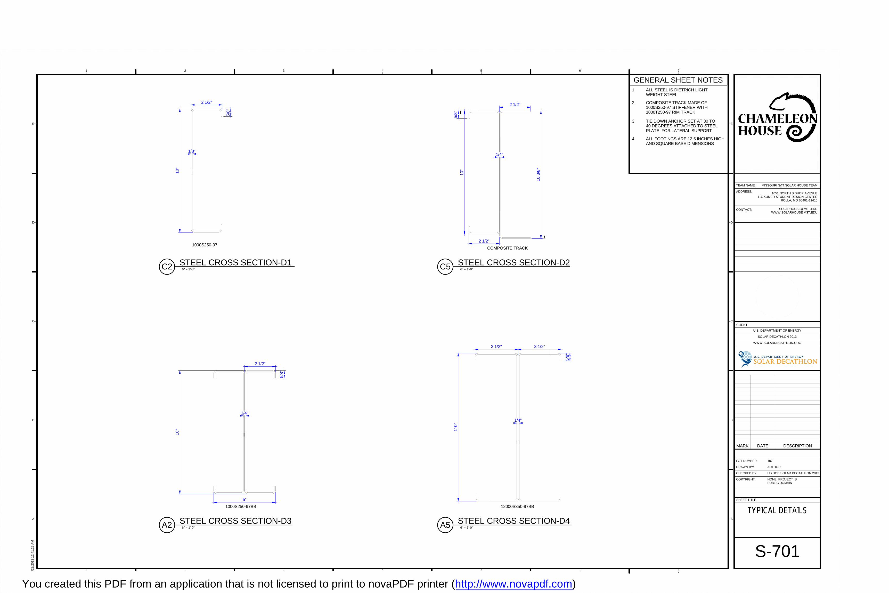
5/8
"
2 1/2"
10"
1/8"
1000S250-97
10
3/8
"
1/4"
2 1/2"
5/8
"
10"
2 1/2"
COMPOSITE TRACK
5/8"
2 1/2"
10"
1/4"
5"
1000S250-97BB
5/8"
3 1/2"
1'-0
"
1/4"
3 1/2"
12000S350-97BB
1 2 3 4 5 6 7
A
B
C
D
E
1 2 3 4 5 6 7
A
B
C
D
E
SHEET TITLE
LOT NUMBER:
DRAWN BY:
CHECKED BY:
COPYRIGHT:
CLIENT
U.S. DEPARTMENT OF ENERGY
SOLAR DECATHLON 2013
WWW.SOLARDECATHLON.ORG
TEAM NAME:
ADDRESS:
CONTACT:
NONE: PROJECT ISPUBLIC DOMAIN
1051 NORTH BISHOP AVENUE116 KUMER STUDENT DESIGN CENTER
ROLLA, MO 65401-11410
US DOE SOLAR DECATHLON 2013
8/22
/201
3 1
2:41
:25
AM
S-701
TYPICAL DETAILS
107
AUTHOR
MISSOURI S&T SOLAR HOUSE TEAM
6" = 1'-0"C2 STEEL CROSS SECTION-D1
GENERAL SHEET NOTES1 ALL STEEL IS DIETRICH LIGHT
WEIGHT STEEL
2 COMPOSITE TRACK MADE OF1000S250-97 STIFFENER WITH1000T250-97 RIM TRACK
3 TIE DOWN ANCHOR SET AT 30 TO40 DEGREES ATTACHED TO STEELPLATE FOR LATERAL SUPPORT
4 ALL FOOTINGS ARE 12.5 INCHES HIGHAND SQUARE BASE DIMENSIONS
6" = 1'-0"C5 STEEL CROSS SECTION-D2
6" = 1'-0"A2 STEEL CROSS SECTION-D3 6" = 1'-0"A5 STEEL CROSS SECTION-D4
MARK DATE DESCRIPTION
You created this PDF from an application that is not licensed to print to novaPDF printer (http://www.novapdf.com)
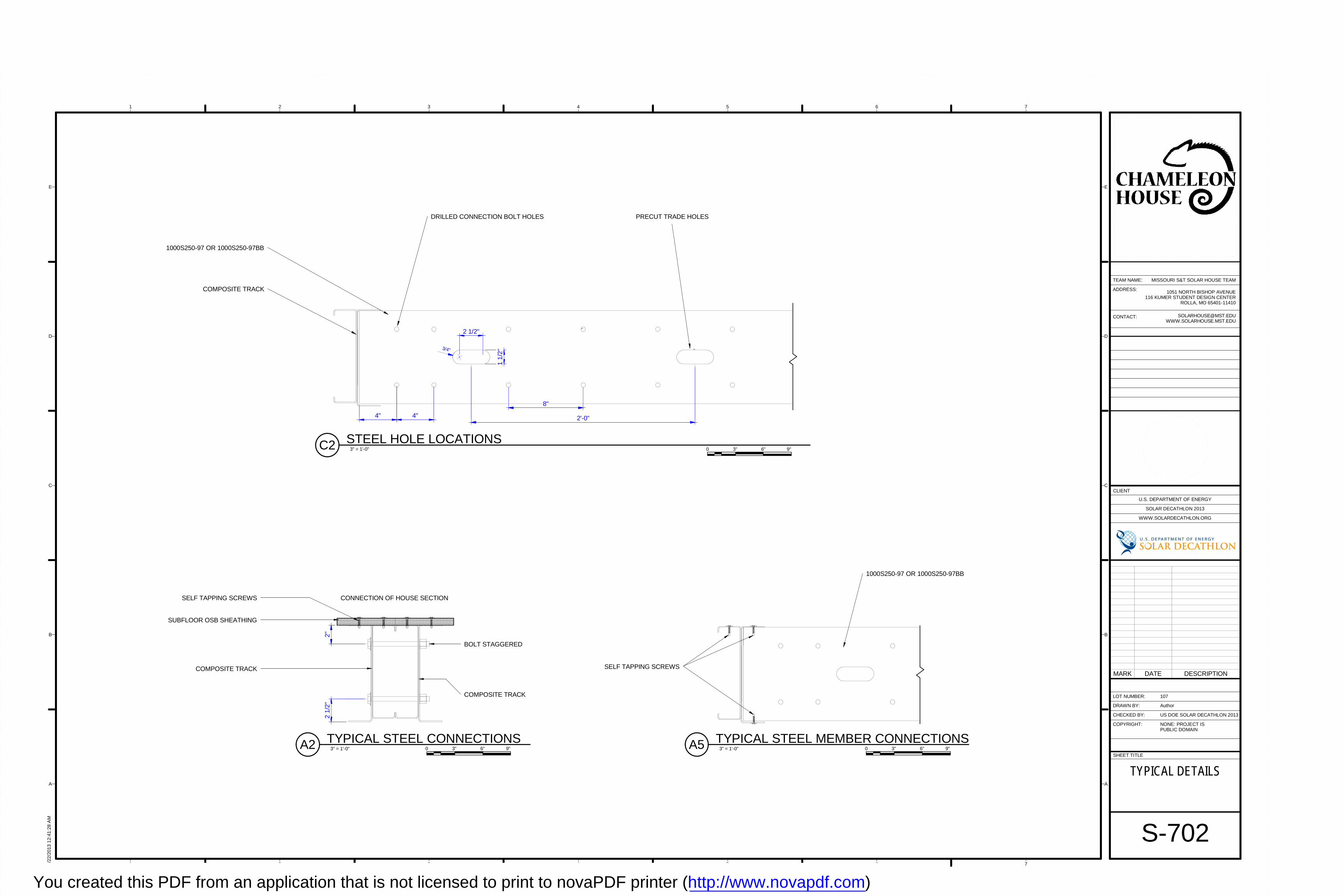
1000S250-97 OR 1000S250-97BB
SELF TAPPING SCREWS
BOLT STAGGERED
2"2
1/2"
CONNECTION OF HOUSE SECTION
SUBFLOOR OSB SHEATHING
SELF TAPPING SCREWS
COMPOSITE TRACK
COMPOSITE TRACK
PRECUT TRADE HOLESDRILLED CONNECTION BOLT HOLES
4" 4"
8"
2 1/2"
1 1
/2"3/4"
2'-0"
COMPOSITE TRACK
1000S250-97 OR 1000S250-97BB
1 2 3 4 5 6 7
A
B
C
D
E
1 2 3 4 5 6 7
A
B
C
D
E
SHEET TITLE
LOT NUMBER:
DRAWN BY:
CHECKED BY:
COPYRIGHT:
CLIENT
U.S. DEPARTMENT OF ENERGY
SOLAR DECATHLON 2013
WWW.SOLARDECATHLON.ORG
TEAM NAME:
ADDRESS:
CONTACT:
NONE: PROJECT ISPUBLIC DOMAIN
1051 NORTH BISHOP AVENUE116 KUMER STUDENT DESIGN CENTER
ROLLA, MO 65401-11410
US DOE SOLAR DECATHLON 2013
8/22
/201
3 1
2:41
:28
AM
S-702
TYPICAL DETAILS
107
Author
MISSOURI S&T SOLAR HOUSE TEAM
3" = 1'-0"A5 TYPICAL STEEL MEMBER CONNECTIONS 3" = 1'-0"A2 TYPICAL STEEL CONNECTIONS
3" = 1'-0"C2 STEEL HOLE LOCATIONS
0 6" 9"3" 0 6" 9"3"
0 6" 9"3"
MARK DATE DESCRIPTION
You created this PDF from an application that is not licensed to print to novaPDF printer (http://www.novapdf.com)
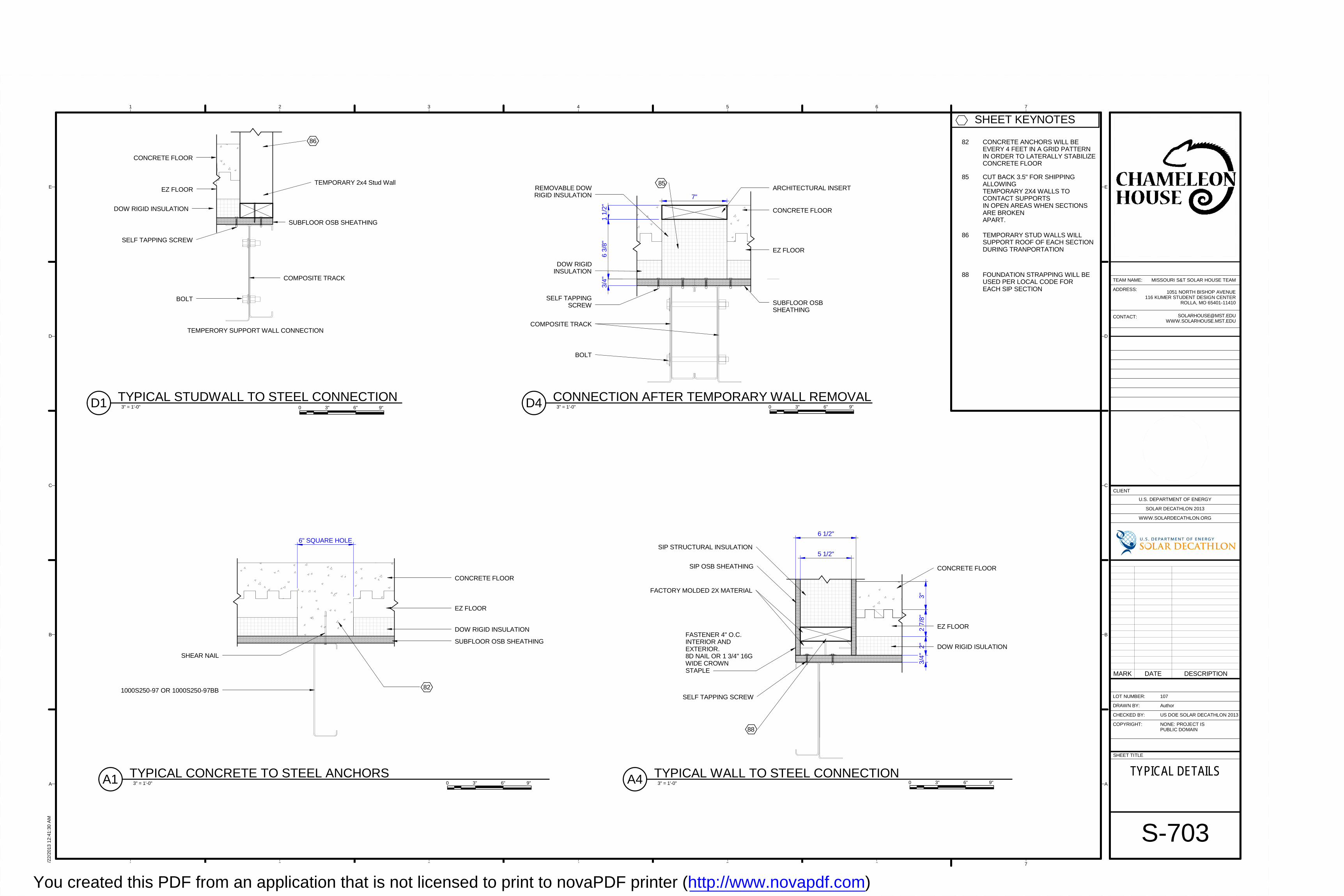
3"2
7/8"
2"3/
4"
5 1/2"
6 1/2"
FASTENER 4" O.C.INTERIOR ANDEXTERIOR.8D NAIL OR 1 3/4" 16GWIDE CROWNSTAPLE
SELF TAPPING SCREW
FACTORY MOLDED 2X MATERIAL
CONCRETE FLOOR
EZ FLOOR
DOW RIGID ISULATION
SIP STRUCTURAL INSULATION
SIP OSB SHEATHING
88
TEMPORARY 2x4 Stud Wall
COMPOSITE TRACK
BOLT
SUBFLOOR OSB SHEATHING
SELF TAPPING SCREW
DOW RIGID INSULATION
EZ FLOOR
CONCRETE FLOOR
TEMPERORY SUPPORT WALL CONNECTION
86
82
CONCRETE FLOOR
EZ FLOOR
DOW RIGID INSULATION
SUBFLOOR OSB SHEATHING
1000S250-97 OR 1000S250-97BB
SHEAR NAIL
6" SQUARE HOLE
1 1
/2"
7"
6 3
/8"
85REMOVABLE DOWRIGID INSULATION
DOW RIGID INSULATION
CONCRETE FLOOR
EZ FLOOR
SELF TAPPING SCREW
COMPOSITE TRACK
BOLT
SUBFLOOR OSBSHEATHING
3/4
"
ARCHITECTURAL INSERT
1 2 3 4 5 6 7
A
B
C
D
E
1 2 3 4 5 6 7
A
B
C
D
E
SHEET TITLE
LOT NUMBER:
DRAWN BY:
CHECKED BY:
COPYRIGHT:
CLIENT
U.S. DEPARTMENT OF ENERGY
SOLAR DECATHLON 2013
WWW.SOLARDECATHLON.ORG
TEAM NAME:
ADDRESS:
CONTACT:
NONE: PROJECT ISPUBLIC DOMAIN
1051 NORTH BISHOP AVENUE116 KUMER STUDENT DESIGN CENTER
ROLLA, MO 65401-11410
US DOE SOLAR DECATHLON 2013
8/22
/201
3 1
2:41
:30
AM
S-703
TYPICAL DETAILS
107
Author
MISSOURI S&T SOLAR HOUSE TEAM
SHEET KEYNOTES
82 CONCRETE ANCHORS WILL BEEVERY 4 FEET IN A GRID PATTERNIN ORDER TO LATERALLY STABILIZECONCRETE FLOOR
85 CUT BACK 3.5" FOR SHIPPINGALLOWINGTEMPORARY 2X4 WALLS TOCONTACT SUPPORTSIN OPEN AREAS WHEN SECTIONSARE BROKENAPART.
86 TEMPORARY STUD WALLS WILLSUPPORT ROOF OF EACH SECTIONDURING TRANPORTATION
88 FOUNDATION STRAPPING WILL BEUSED PER LOCAL CODE FOREACH SIP SECTION
3" = 1'-0"A4 TYPICAL WALL TO STEEL CONNECTION
3" = 1'-0"D1 TYPICAL STUDWALL TO STEEL CONNECTION
3" = 1'-0"A1 TYPICAL CONCRETE TO STEEL ANCHORS
3" = 1'-0"D4 CONNECTION AFTER TEMPORARY WALL REMOVAL0 6" 9"3"
0 6" 9"3"0 6" 9"3"
0 6" 9"3"
MARK DATE DESCRIPTION
You created this PDF from an application that is not licensed to print to novaPDF printer (http://www.novapdf.com)
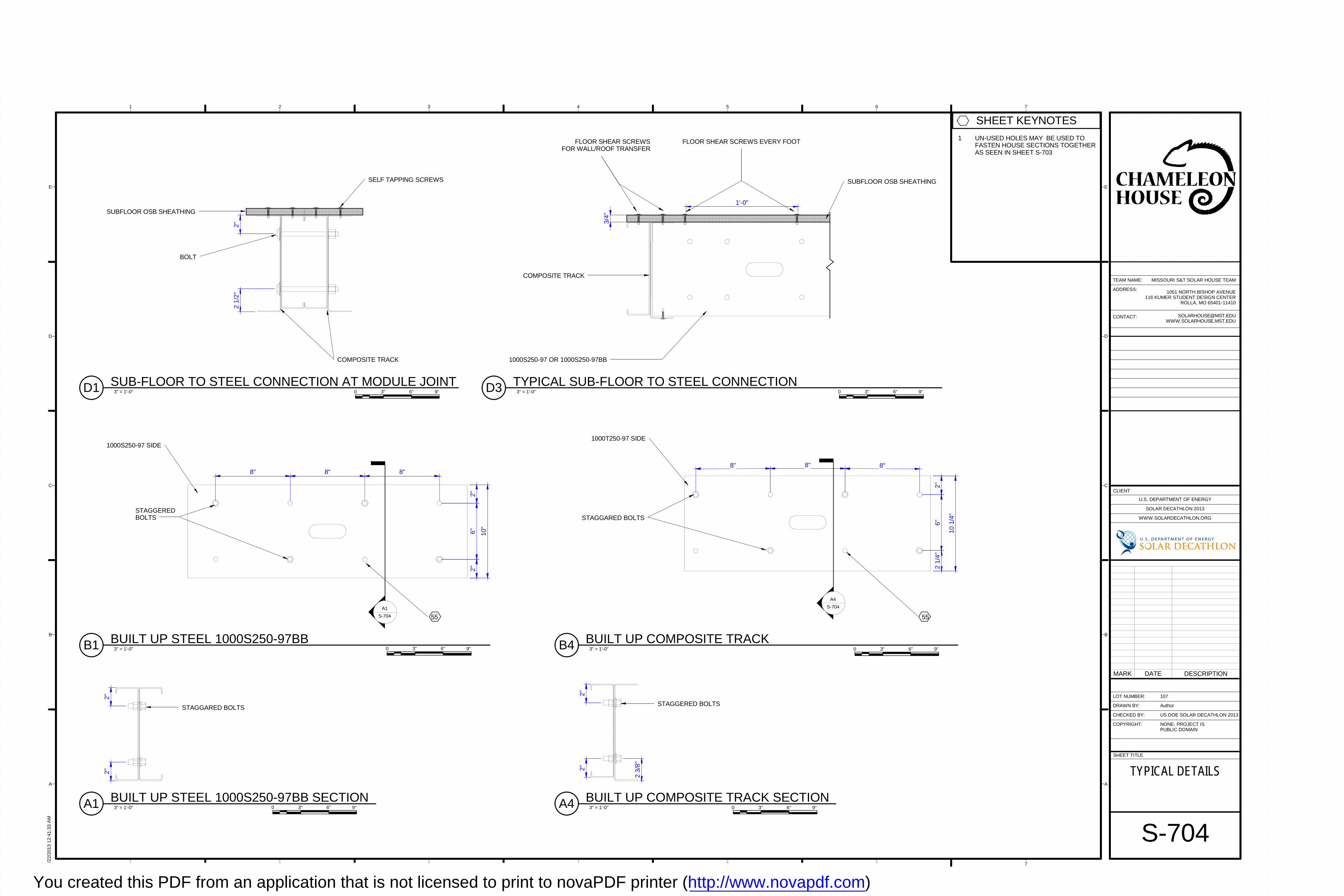
BOLT
2"
2 1
/2"
SUBFLOOR OSB SHEATHING
COMPOSITE TRACK
SELF TAPPING SCREWS
FLOOR SHEAR SCREWSFOR WALL/ROOF TRANSFER
FLOOR SHEAR SCREWS EVERY FOOT
3/4
"
COMPOSITE TRACK
1000S250-97 OR 1000S250-97BB
SUBFLOOR OSB SHEATHING
1'-0"
8" 8" 8"6
"
1000S250-97 SIDE
2"
10"
2"
STAGGEREDBOLTS
55
A1
S-704
8" 8" 8"
6"
1000T250-97 SIDE
10 1
/4"
2"2
1/4"
STAGGARED BOLTS
55
A4
S-704
STAGGARED BOLTS
2"2"
2"2"
2 3/
8"
STAGGERED BOLTS
1 2 3 4 5 6 7
A
B
C
D
E
1 2 3 4 5 6 7
A
B
C
D
E
SHEET TITLE
LOT NUMBER:
DRAWN BY:
CHECKED BY:
COPYRIGHT:
CLIENT
U.S. DEPARTMENT OF ENERGY
SOLAR DECATHLON 2013
WWW.SOLARDECATHLON.ORG
TEAM NAME:
ADDRESS:
CONTACT:
NONE: PROJECT ISPUBLIC DOMAIN
1051 NORTH BISHOP AVENUE116 KUMER STUDENT DESIGN CENTER
ROLLA, MO 65401-11410
US DOE SOLAR DECATHLON 2013
8/22
/201
3 1
2:41
:33
AM
S-704
TYPICAL DETAILS
107
Author
MISSOURI S&T SOLAR HOUSE TEAM
SHEET KEYNOTES
1 UN-USED HOLES MAY BE USED TOFASTEN HOUSE SECTIONS TOGETHERAS SEEN IN SHEET S-703
3" = 1'-0"D1 SUB-FLOOR TO STEEL CONNECTION AT MODULE JOINT 3" = 1'-0"D3 TYPICAL SUB-FLOOR TO STEEL CONNECTION
3" = 1'-0"B1 BUILT UP STEEL 1000S250-97BB 3" = 1'-0"B4 BUILT UP COMPOSITE TRACK
0 6" 9"3"0 6" 9"3"
0 6" 9"3" 0 6" 9"3"
3" = 1'-0"A1 BUILT UP STEEL 1000S250-97BB SECTION0 6" 9"3" 3" = 1'-0"A4 BUILT UP COMPOSITE TRACK SECTION
0 6" 9"3"
MARK DATE DESCRIPTION
You created this PDF from an application that is not licensed to print to novaPDF printer (http://www.novapdf.com)
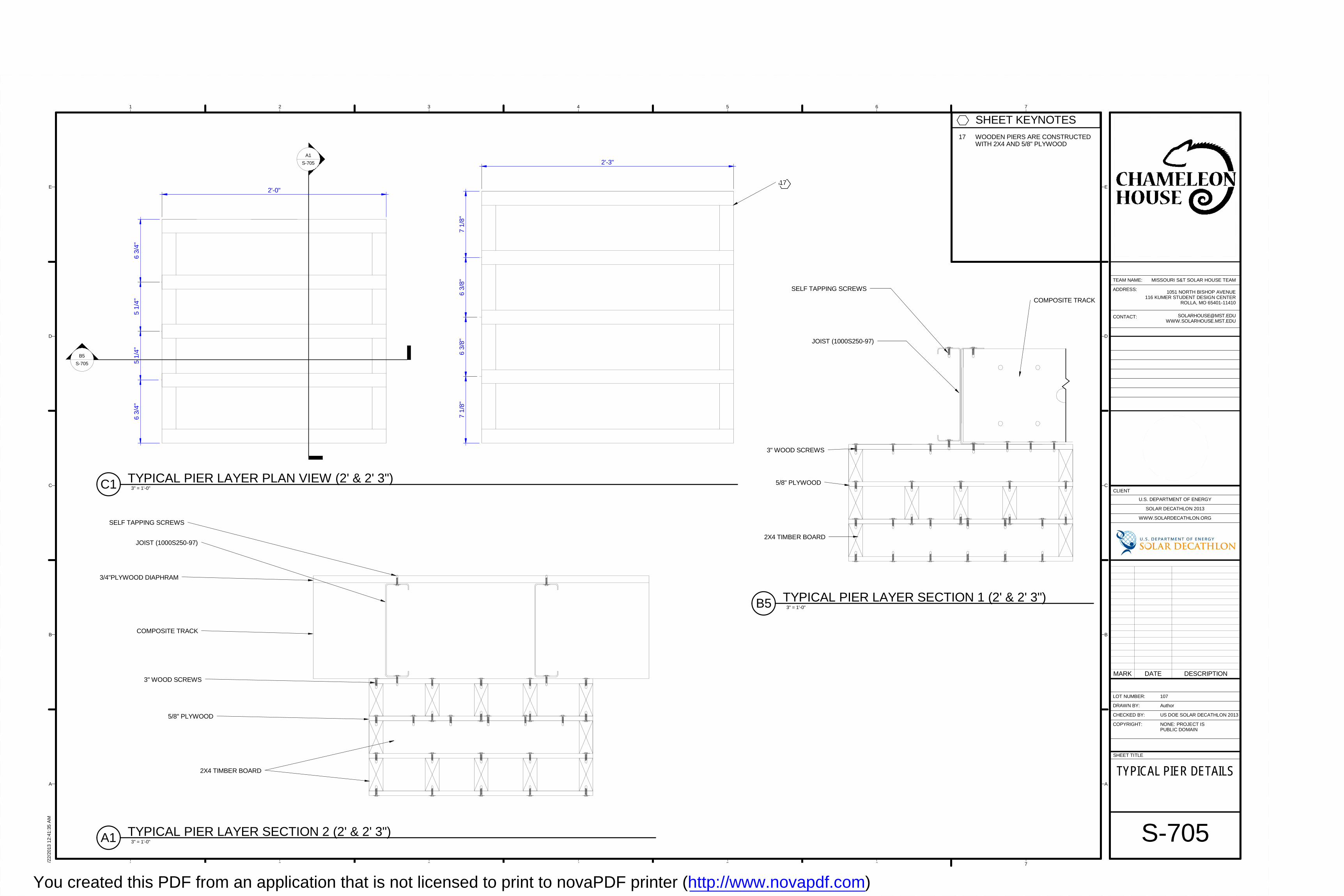
6 3/
4"5
1/4
"5
1/4
"6
3/4
"
2'-0"
7 1/
8"6
3/8
"6
3/8
"7
1/8
"
2'-3"
17
B5
S-705
A1
S-705
2X4 TIMBER BOARD
5/8" PLYWOOD
3" WOOD SCREWS
COMPOSITE TRACK
JOIST (1000S250-97)
SELF TAPPING SCREWS
2X4 TIMBER BOARD
5/8" PLYWOOD
3" WOOD SCREWS
COMPOSITE TRACK
3/4"PLYWOOD DIAPHRAM
JOIST (1000S250-97)
SELF TAPPING SCREWS
1 2 3 4 5 6 7
A
B
C
D
E
1 2 3 4 5 6 7
A
B
C
D
E
SHEET TITLE
LOT NUMBER:
DRAWN BY:
CHECKED BY:
COPYRIGHT:
CLIENT
U.S. DEPARTMENT OF ENERGY
SOLAR DECATHLON 2013
WWW.SOLARDECATHLON.ORG
TEAM NAME:
ADDRESS:
CONTACT:
NONE: PROJECT ISPUBLIC DOMAIN
1051 NORTH BISHOP AVENUE116 KUMER STUDENT DESIGN CENTER
ROLLA, MO 65401-11410
US DOE SOLAR DECATHLON 2013
8/22
/201
3 1
2:41
:35
AM
S-705
TYPICAL PIER DETAILS
107
Author
MISSOURI S&T SOLAR HOUSE TEAM
MARK DATE DESCRIPTION
3" = 1'-0"C1 TYPICAL PIER LAYER PLAN VIEW (2' & 2' 3")
SHEET KEYNOTES17 WOODEN PIERS ARE CONSTRUCTED
WITH 2X4 AND 5/8" PLYWOOD
3" = 1'-0"B5 TYPICAL PIER LAYER SECTION 1 (2' & 2' 3")
3" = 1'-0"A1 TYPICAL PIER LAYER SECTION 2 (2' & 2' 3")
You created this PDF from an application that is not licensed to print to novaPDF printer (http://www.novapdf.com)
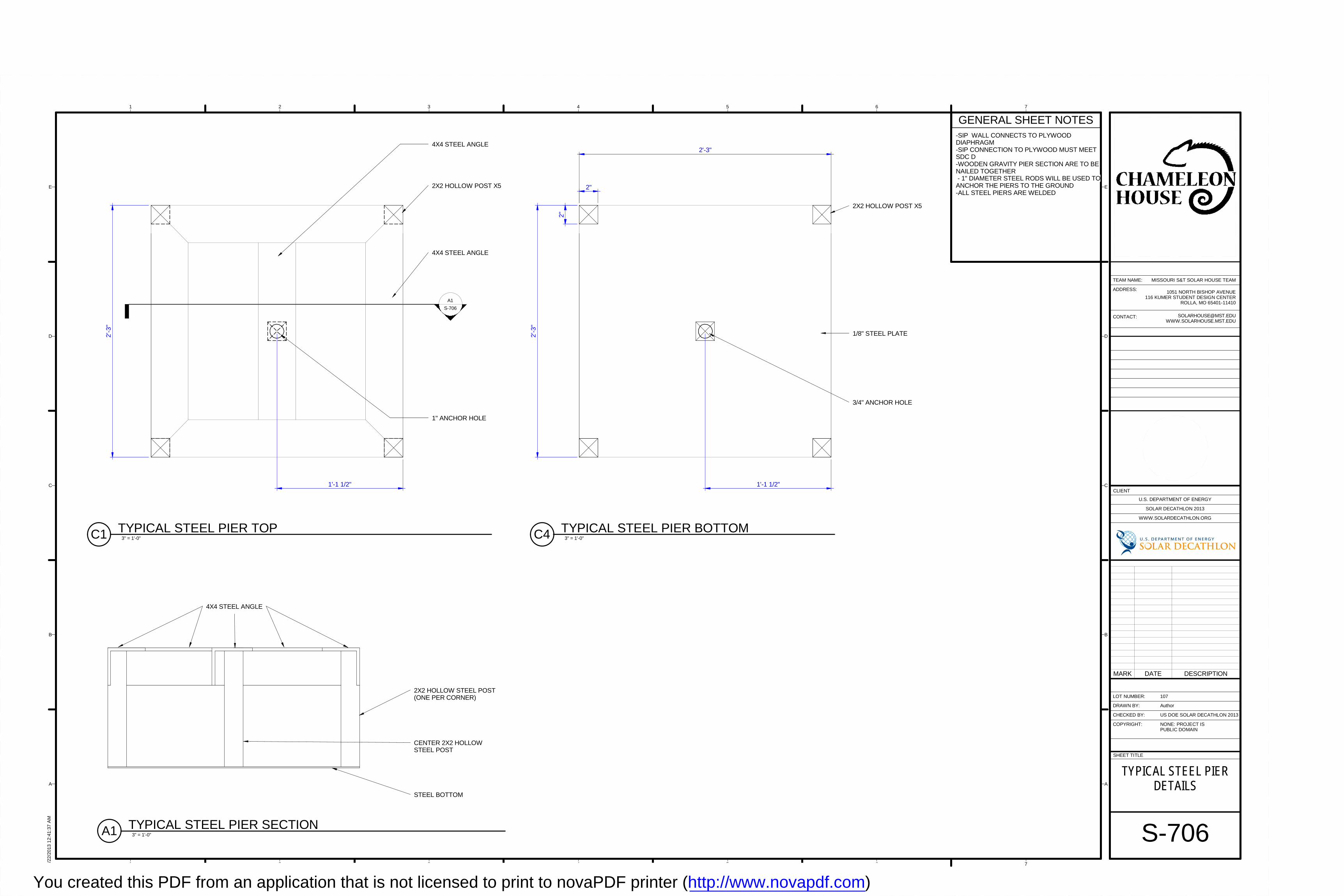
3/4" ANCHOR HOLE
1'-1 1/2"
2"
2X2 HOLLOW POST X5
2'-3"
2'-3
"
2"
1/8" STEEL PLATE
STEEL BOTTOM
4X4 STEEL ANGLE
2X2 HOLLOW STEEL POST(ONE PER CORNER)
CENTER 2X2 HOLLOWSTEEL POST
4X4 STEEL ANGLE
1" ANCHOR HOLE
1'-1 1/2"
2X2 HOLLOW POST X5
4X4 STEEL ANGLE
2'-3
"
A1
S-706
1 2 3 4 5 6 7
A
B
C
D
E
1 2 3 4 5 6 7
A
B
C
D
E
SHEET TITLE
LOT NUMBER:
DRAWN BY:
CHECKED BY:
COPYRIGHT:
CLIENT
U.S. DEPARTMENT OF ENERGY
SOLAR DECATHLON 2013
WWW.SOLARDECATHLON.ORG
TEAM NAME:
ADDRESS:
CONTACT:
NONE: PROJECT ISPUBLIC DOMAIN
1051 NORTH BISHOP AVENUE116 KUMER STUDENT DESIGN CENTER
ROLLA, MO 65401-11410
US DOE SOLAR DECATHLON 2013
8/22
/201
3 1
2:41
:37
AM
S-706
TYPICAL STEEL PIERDETAILS
107
Author
MISSOURI S&T SOLAR HOUSE TEAM
MARK DATE DESCRIPTION
3" = 1'-0"C4 TYPICAL STEEL PIER BOTTOM
3" = 1'-0"A1 TYPICAL STEEL PIER SECTION
3" = 1'-0"C1 TYPICAL STEEL PIER TOP
GENERAL SHEET NOTES-SIP WALL CONNECTS TO PLYWOODDIAPHRAGM-SIP CONNECTION TO PLYWOOD MUST MEETSDC D-WOODEN GRAVITY PIER SECTION ARE TO BENAILED TOGETHER - 1" DIAMETER STEEL RODS WILL BE USED TOANCHOR THE PIERS TO THE GROUND-ALL STEEL PIERS ARE WELDED
You created this PDF from an application that is not licensed to print to novaPDF printer (http://www.novapdf.com)

COMPOSITE TRACK
JOIST (1000S250-97)
SELF TAPPING SCREWS
STEEL BOTTOM
2X2 HOLLOW STEEL POST(ONE PER CORNER)
CENTER 2X2 HOLLOWSTEEL POST
JOINT WELD
COMPOSITE TRACK
3/4"PLYWOOD DIAPHRAM
JOIST (1000S250-97)
SELF TAPPING SCREWS
STEEL BOTTOM
2X2 HOLLOW STEEL POST(ONE PER CORNER)
CENTER 2X2 HOLLOWSTEEL POST
1 2 3 4 5 6 7
A
B
C
D
E
1 2 3 4 5 6 7
A
B
C
D
E
SHEET TITLE
LOT NUMBER:
DRAWN BY:
CHECKED BY:
COPYRIGHT:
CLIENT
U.S. DEPARTMENT OF ENERGY
SOLAR DECATHLON 2013
WWW.SOLARDECATHLON.ORG
TEAM NAME:
ADDRESS:
CONTACT:
NONE: PROJECT ISPUBLIC DOMAIN
1051 NORTH BISHOP AVENUE116 KUMER STUDENT DESIGN CENTER
ROLLA, MO 65401-11410
US DOE SOLAR DECATHLON 2013
8/22
/201
3 1
2:41
:40
AM
S-707
TYPICAL STEEL PIERDETAILS
107
Author
MISSOURI S&T SOLAR HOUSE TEAM
MARK DATE DESCRIPTION
3" = 1'-0"C1 TYPICAL STEEL SECTION TO FRAME 1
3" = 1'-0"A1 TYPICAL STEEL SECTION TO FRAME 2
You created this PDF from an application that is not licensed to print to novaPDF printer (http://www.novapdf.com)
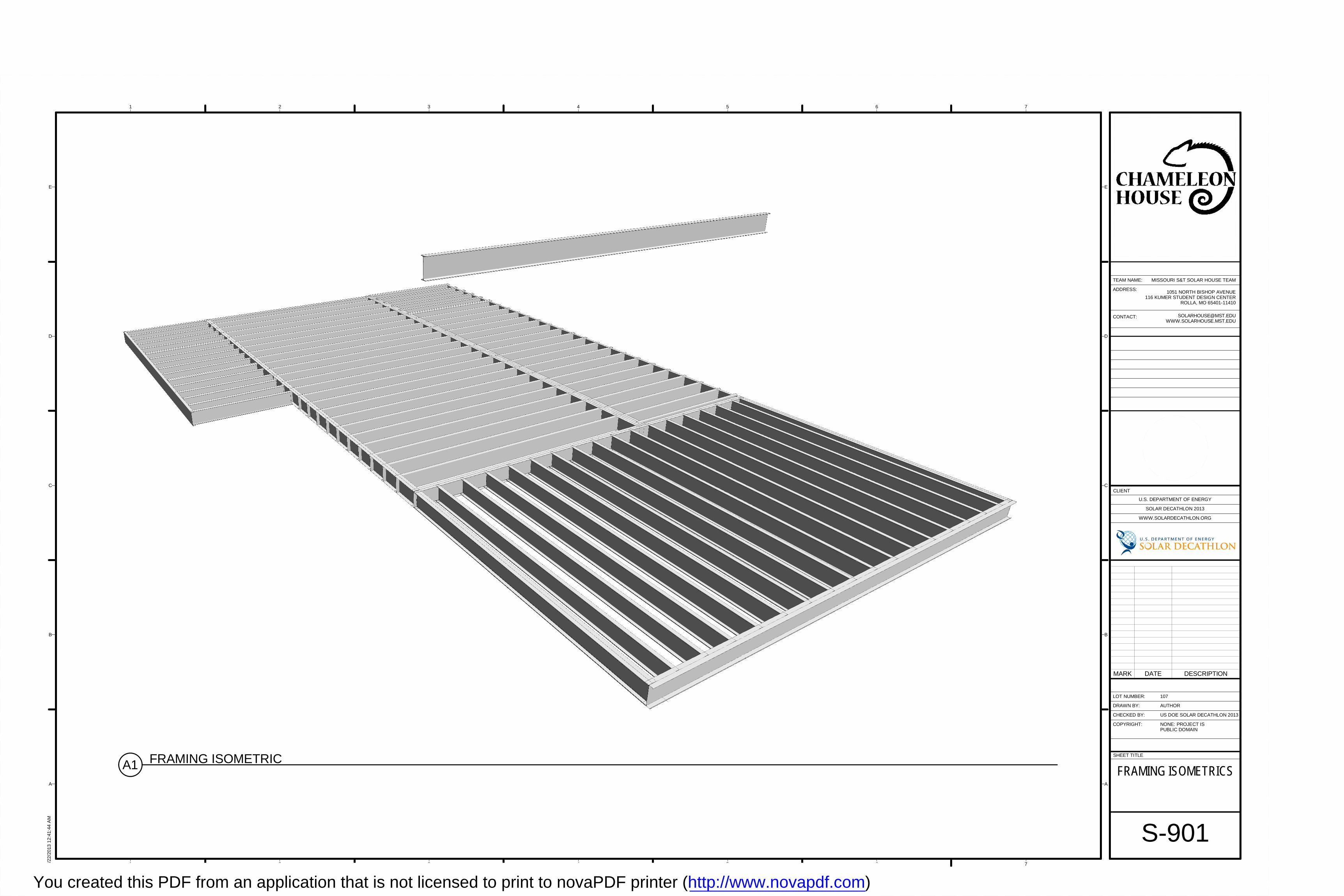
1 2 3 4 5 6 7
A
B
C
D
E
1 2 3 4 5 6 7
A
B
C
D
E
SHEET TITLE
LOT NUMBER:
DRAWN BY:
CHECKED BY:
COPYRIGHT:
CLIENT
U.S. DEPARTMENT OF ENERGY
SOLAR DECATHLON 2013
WWW.SOLARDECATHLON.ORG
TEAM NAME:
ADDRESS:
CONTACT:
NONE: PROJECT ISPUBLIC DOMAIN
1051 NORTH BISHOP AVENUE116 KUMER STUDENT DESIGN CENTER
ROLLA, MO 65401-11410
US DOE SOLAR DECATHLON 2013
8/22
/201
3 1
2:41
:44
AM
S-901
FRAMING ISOMETRICS
107
AUTHOR
MISSOURI S&T SOLAR HOUSE TEAM
A1 FRAMING ISOMETRIC
MARK DATE DESCRIPTION
You created this PDF from an application that is not licensed to print to novaPDF printer (http://www.novapdf.com)
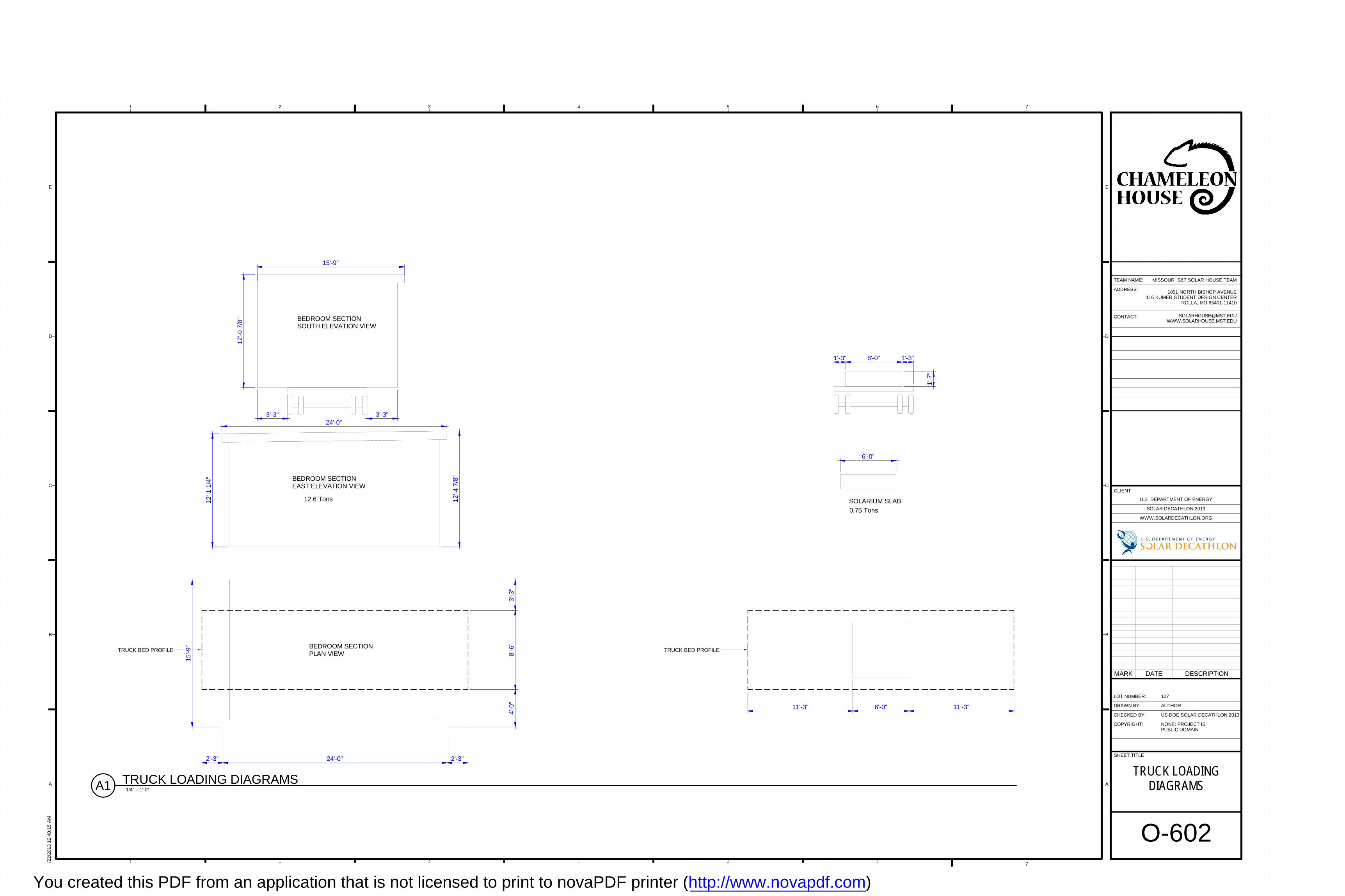
BEDROOM SECTIONSOUTH ELEVATION VIEW
BEDROOM SECTIONEAST ELEVATION VIEW
BEDROOM SECTIONPLAN VIEW
TRUCK BED PROFILE
12.6 Tons
TRUCK BED PROFILE
SOLARIUM SLAB
0.75 Tons
12
'-0 7
/8"
15'-9"
3'-3" 3'-3"24'-0"
12'-4
7/8
"
12'-1
1/4
"
3'-3
"8'
-6"
4'-0
"
15'-9
"
2'-3" 24'-0" 2'-3"
1'-7
"
6'-0"
1'-3" 6'-0" 1'-3"
11'-3" 6'-0" 11'-3"
1 2 3 4 5 6 7
A
B
C
D
E
1 2 3 4 5 6 7
A
B
C
D
E
SHEET TITLE
LOT NUMBER:
DRAWN BY:
CHECKED BY:
COPYRIGHT:
CLIENT
U.S. DEPARTMENT OF ENERGY
SOLAR DECATHLON 2013
WWW.SOLARDECATHLON.ORG
TEAM NAME:
ADDRESS:
CONTACT:
NONE: PROJECT ISPUBLIC DOMAIN
1051 NORTH BISHOP AVENUE116 KUMER STUDENT DESIGN CENTER
ROLLA, MO 65401-11410
US DOE SOLAR DECATHLON 2013
8/22
/201
3 1
2:40
:15
AM
O-602
TRUCK LOADINGDIAGRAMS
107
AUTHOR
MISSOURI S&T SOLAR HOUSE TEAM
MARK DATE DESCRIPTION
1/4" = 1'-0"A1 TRUCK LOADING DIAGRAMS
You created this PDF from an application that is not licensed to print to novaPDF printer (http://www.novapdf.com)

LIVING ROOM SECTIONSOUTH ELEVATION VIEW
LIVING ROOM SECTIONPLAN VIEW
LIVING ROOM SECTIONEAST ELEVATION VIEW
BATHROOM SECTIONEAST ELEVATION VIEW
BATHROOM SECTIONSOUTH ELEVATION VIEW
BATHROOM SECTIONPLAN VIEW
TRUCK BED PROFILE
TRUCK BED PROFILE
15.7 Tons9.76 Tons
8'-0"
8'-9"
12
'-4 7
/8"
12
'-3 1
/2"
33'-0"
32'-3"
9"
9"8'
-6"
14'-3"
15'-0"1
2'-3
1/2
"
12
'-1 3
/8"
33'-0"
32'-3"
1'-1
1/4
"11
'-2 1
/4"
2'-1
0 1/
2"8'
-6"
3'-7
1/2
"
15'-0
"
38'-3"
1 2 3 4 5 6 7
A
B
C
D
E
1 2 3 4 5 6 7
A
B
C
D
E
SHEET TITLE
LOT NUMBER:
DRAWN BY:
CHECKED BY:
COPYRIGHT:
CLIENT
U.S. DEPARTMENT OF ENERGY
SOLAR DECATHLON 2013
WWW.SOLARDECATHLON.ORG
TEAM NAME:
ADDRESS:
CONTACT:
NONE: PROJECT ISPUBLIC DOMAIN
1051 NORTH BISHOP AVENUE116 KUMER STUDENT DESIGN CENTER
ROLLA, MO 65401-11410
US DOE SOLAR DECATHLON 2013
8/22
/201
3 1
2:40
:19
AM
O-603
TRUCK LOADINGDIAGRAMS
107
Author
MISSOURI S&T SOLAR HOUSE TEAM
MARK DATE DESCRIPTION
1/4" = 1'-0"A1 TRUCK LOADING DIAGRAMS 2
You created this PDF from an application that is not licensed to print to novaPDF printer (http://www.novapdf.com)
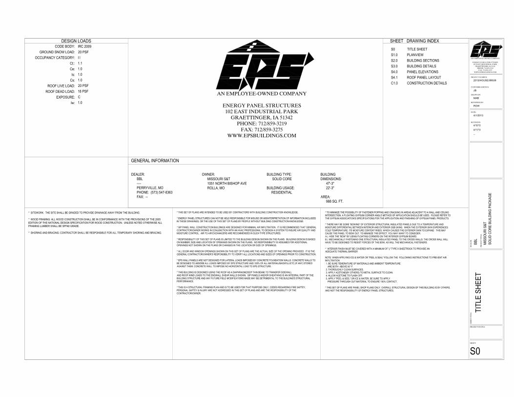
������������� ������
��������������������������������� ������������
������������������������������ !�"����"
#�$����� !�"��������%���&��� ����%��
������������� ������
��������������������������������� ������������
������������������������������ !�"����"
#�$����� !�"��������%���&��� ����%��
�
��
��
�
��
'��
���
���
��
����
��(������
��'�������&���
2013/HOUSE/89539
�����&�
MAB
��(���� �&�
RGW
������
���
��
����
��
�
4/1/2013
��'�����������
�����������(����
JB
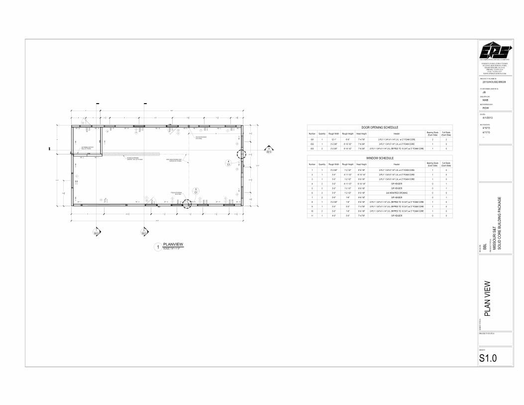
PLANVIEW
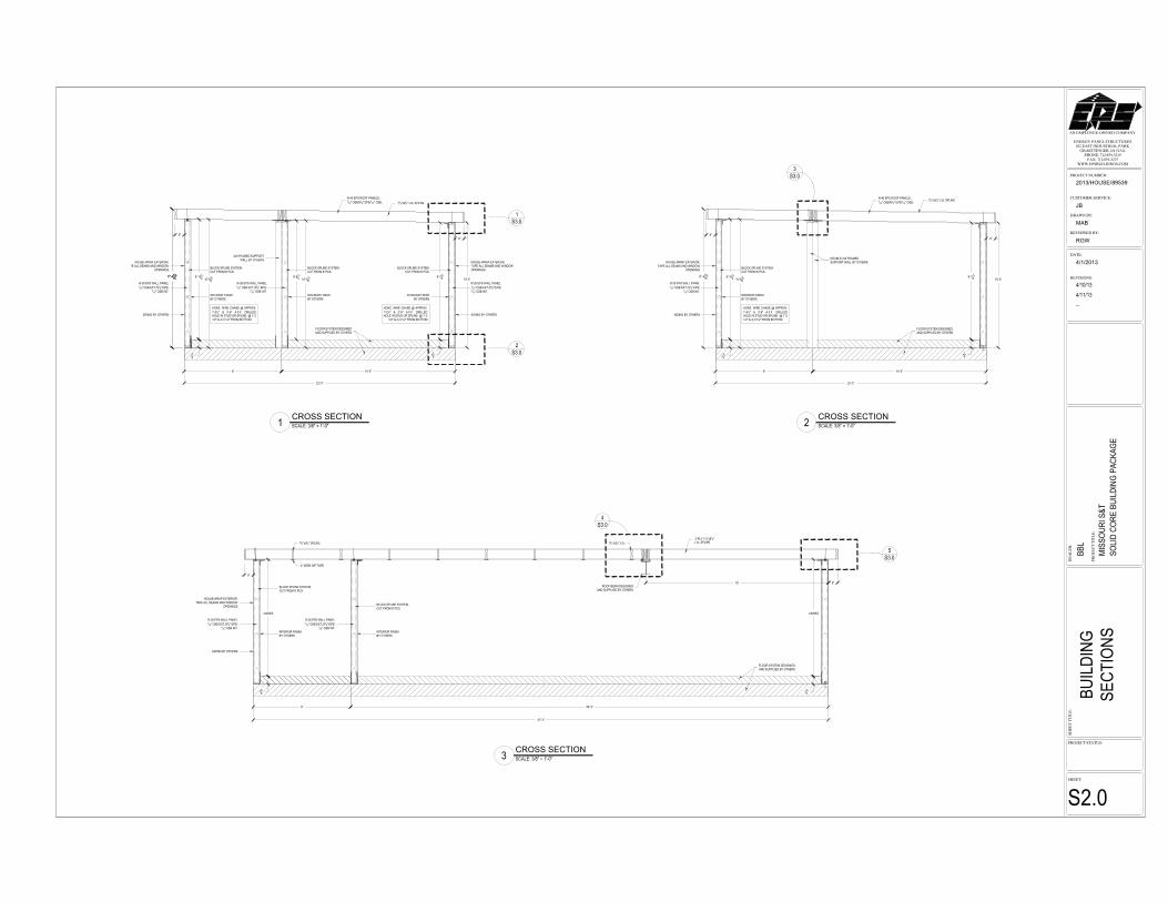
������������� ������
��������������������������������� ������������
������������������������������ !�"����"
#�$����� !�"��������%���&��� ����%��
�
��
��
�
��
'��
���
���
��
����
��(������
��'�������&���
2013/HOUSE/89539
�����&�
MAB
��(���� �&�
RGW
������
���
��
����
��
�
4/1/2013
��'�����������
�����������(����
JB
CROSS SECTION CROSS SECTION
CROSS SECTION
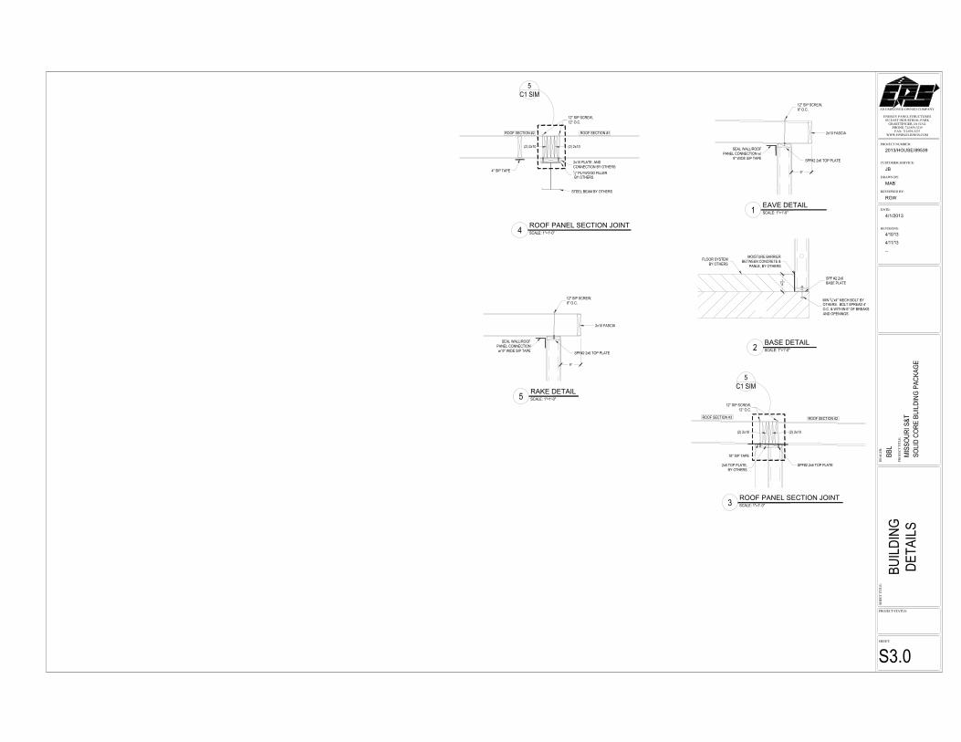
������������� ������
��������������������������������� ������������
������������������������������ !�"����"
#�$����� !�"��������%���&��� ����%��
�
��
��
�
��
'��
���
���
��
����
��(������
��'�������&���
2013/HOUSE/89539
�����&�
MAB
��(���� �&�
RGW
������
���
��
����
��
�
4/1/2013
��'�����������
�����������(����
JB
EAVE DETAIL
BASE DETAIL
ROOF PANEL SECTION JOINT
ROOF PANEL SECTION JOINT
RAKE DETAIL
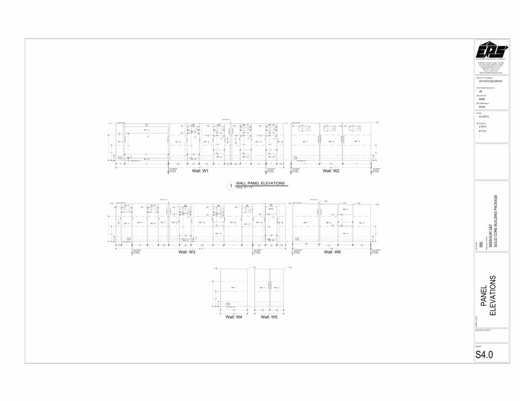
������������� ������
��������������������������������� ������������
������������������������������ !�"����"
#�$����� !�"��������%���&��� ����%��
�
��
��
�
��
'��
���
���
��
����
��(������
��'�������&���
2013/HOUSE/89539
�����&�
MAB
��(���� �&�
RGW
������
���
��
����
��
�
4/1/2013
��'�����������
�����������(����
JB
WALL PANEL ELEVATIONS
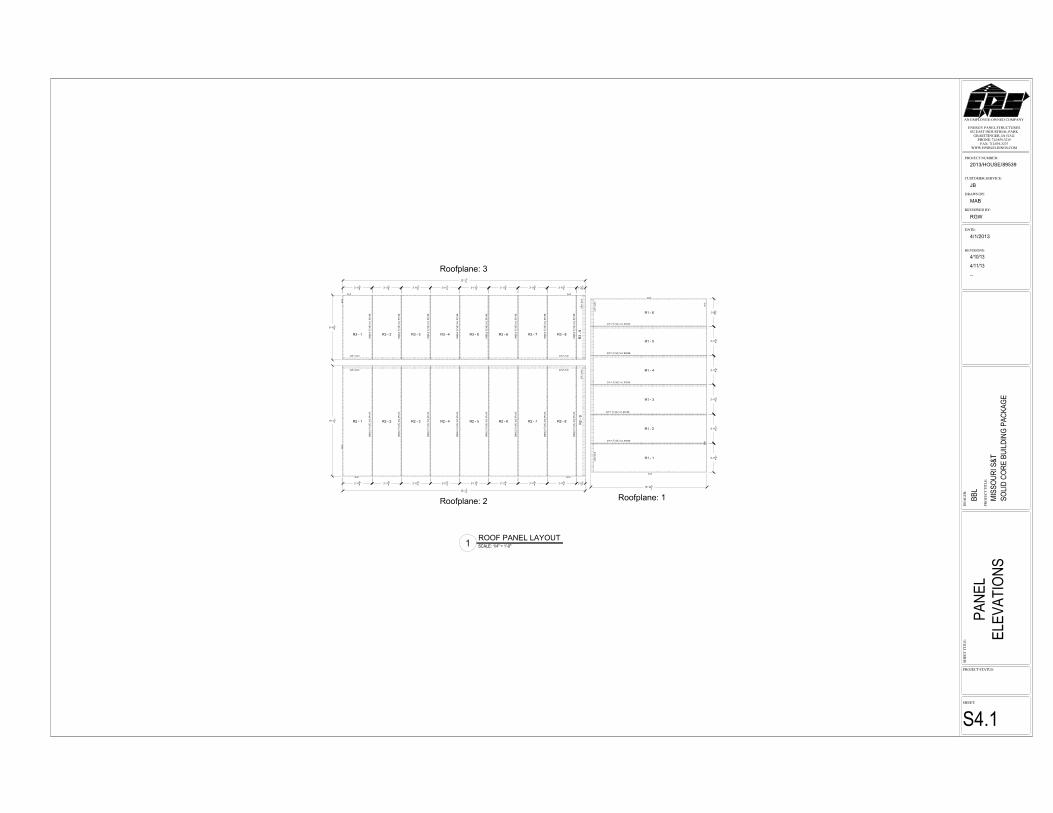
������������� ������
��������������������������������� ������������
������������������������������ !�"����"
#�$����� !�"��������%���&��� ����%��
�
��
��
�
��
'��
���
���
��
����
��(������
��'�������&���
2013/HOUSE/89539
�����&�
MAB
��(���� �&�
RGW
������
���
��
����
��
�
4/1/2013
��'�����������
�����������(����
JB
ROOF PANEL LAYOUT
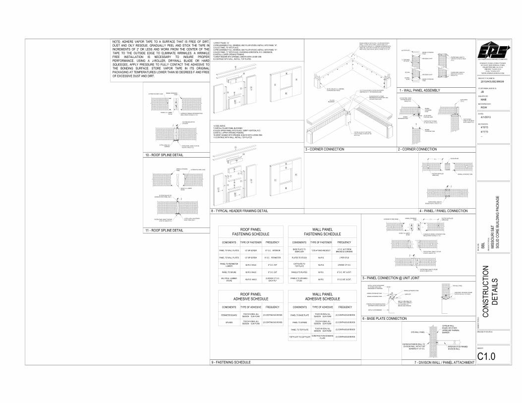
������������� ������
��������������������������������� ������������
������������������������������ !�"����"
#�$����� !�"��������%���&��� ����%��
�
��
��
�
��
'��
���
���
��
����
��(������
��'�������&���
2013/HOUSE/89539
�����&�
MAB
��(���� �&�
RGW
������
���
��
����
��
�
4/1/2013
��'�����������
�����������(����
JB