project manual - houston isd
TRANSCRIPT
HISD 01-101_Package Cover_10-14-14.docx10 14 14
PROJECT MANUAL
Houston Academy for International Studies New Elevator Installation
Houston Independent School District HISD Project Number: 19-11-06
Issued for Proposals Due Date and Time:
Thursday, 12/20/2018 2:00 PM
Project Manual Publication Date November 16, 2018
Architect IDG ARCHITECTS
440 Benmar Dr. Suite 3335 Houston, TX 77060
Phone: 832 448-2462 Fax: 832-448-2466
Project Manager Albert B. Charles
3200 Center St Houston, Tx 77007-5909
Phone: 713-556-9254 Fax: 713-556-9315
11/16/19

02: TABLE OF CONTENTS NUMBER OF PAGES
HISD 02-1 02_Table of Contents_ 07-07-2015 (003).docx
GENERAL DOCUMENTS
NUMBER OF PAGES
01 Title Page 1
02 Table of Contents 2
03 Proposal Advertisement 1
04 Project Information 3
05 HISD School Operations Parameter Statement 3
06 Project Close-Out Documents 1
07A Labor Compliance Program 76
PROPOSED SUBMITTAL REQUIREMENTS
0AA Instructions for Competitive Sealed Proposal Submittals 4
AB Specific Conditions for M/WBE Participation (Procedure and Required Forms) 30
CONTRACT FORMS
BA Cover Page For Standard Form Agreement Between Owner and Contractor
A101 - 2007, as modified by Owner
1
BA CSP Construction Contract_AIA101-2007_11-18-2015 7
BB Cover Page for General Conditions of the Contract for Construction 1
BB General Conditions of the Contract for Construction, AIA Document A201 - 2007,
as modified by Owner 56
BD Wage Rate Schedule 2
BE Notice to Proceed Form 1
BF Performance Bond Form 2
11/16/18
02: TABLE OF CONTENTS NUMBER OF PAGES
HISD 02-2 02_Table of Contents_ 07-07-2015 (003).docx
BG Payment Bond Form 2
PROPOSAL FORMS
CA
Overall Proposal Packaging Checklist
2
CB Proposal Form (Base Price, Alternates, Allowances, Unit Prices, Duration) 9
CC Proposal Guarantee Bond 2
CD Proposer’s Technical Proposal 14
CE Equal Opportunity Employer Statement 1
CF Equal Opportunity Employer Affidavit
1
CG Certificate of Non-Segregated Facilities 2
CH Felony Conviction Notification 2
CI Notification of Hazardous Materials Affidavit 2
CJ Safety Plan Requirement Certification 2
CHANGE PROPOSAL AND PROJECT CLOSE-OUT FORMS
DA Change Proposal Request 1
DB Change Proposal – Contractor’s Estimate 1
DC Change Proposal – Cost Detail 1
DD
Certificate of Asbestos Free Construction (required for final payment) 1
OWNER FURNISHED INFORMATION AVAILABLE TO PROPOSERS
1) Geotechnical report 21

02: TABLE OF CONTENTS NUMBER OF PAGES
HISD 02-3 02_Table of Contents_ 07-07-2015 (003).docx
DRAWINGS
Cover Sheet
A002
S000
S100
S101
S101
A100
A200
A201
A202
A400
A500
A501
A800
A900
MEP100
E100
E200
E300
E400
Drawing Index
General Notes
Partial Plan & Elevations
Details
Existing Site Plan
First Floor Plan
Second Floor Plan
Roof Plan
Elevations
Sections
Section Details
Wall Types
Details
Wall Types
Mechanical Floor Plans
Electrical Overall Plans
Electrical Enlarged Plans
Electrical One-Line & Schedules
Electrical Schedules, Notes, & Details

HISD 02-4 02_Table of Contents_ 07-07-2015 (003).docx
02: TABLE OF CONTENTS NUMBER OF PAGES
SPECIFICATIONS
DIVISION 01 – GENERAL REQUIREMENTS
00 31 32 Geotechnical Data 01 10 00 Summary 01 25 00 Substitution Procedures 01 26 00 Contract Modification Procedures 01 29 00 Payment Procedures 01 31 00 Project Management & Coordination 01 32 00 Construction Progress Documentation 01 33 00 Submittal Procedures 01 40 00 Quality Requirements 01 42 00 References 01 45 29 Structural Testing & Inspections 01 50 00 Temporary Facilities & Controls 01 57 21 Indoor Air Quality Controls 01 60 00 Product Requirements 01 73 00 Execution 01 73 01 Traffic Regulations 01 73 30 Trench Safety Systems 01 74 19 Construction Waste Management & Disposal 01 77 00 Closeout Procedures 01 78 23 Operation & Maintenance Data 01 78 39 Project Record Documents 01 79 00 Demonstration & Training
DIVISION 02 – EXISTING CONDITIONS
02 41 16 Structure Demolition
DIVISION 03 – CONCRETE
03 15 00 Concrete Accessories 03 20 00 Concrete Reinforcing 03 30 00 Cast-In-Place Concrete 03 50 00 Grouting 03 52 00 Light Weight Concrete Roof Insulation
DIVISION 04 – MASONRY 04 20 00 Unit Masonry
DIVISION 05 – METALS 05 12 00 Structural Steel Framing 05 31 00 Steel Decking 05 31 23 Steel Roof Decking 05 40 00 Cold-Formed Metal Framing 05 41 00 Structural Metal Stud Framing
DIVISION 06 – WOOD, PLASTICS, & COMPOSITES 06 10 00 Rough Carpentry 06 16 00 Sheathing
HISD 02-5 02_Table of Contents_ 07-07-2015 (003).docx
DIVISION 07 – THERMAL & MOISTURE PROTECTION
07 05 00 Common Work Results for Thermal & Moisture Protection 07 21 00 Thermal Insulation 07 22 00 Roof & Deck Insulation 07 27 26 Fluid-Applied Membrane Air Barrier 07 52 50 Modified Bitumen Membrane Roofing 07 62 03 Sheet Metal Wall Flashing & Trim 07 84 46 Fire-Resistive Joint Systems
07 92 00 Joint Sealants
DIVISION 08 – OPENINGS
08 11 13 08 31 13 08 71 00 08 90 00
DIVISION 09 – FINISHES
09 29 00 09 51 13 09 65 13 09 91 23
DIVISION 10 – SPECIALTIES 10 44 16
DIVISION 14 – CONVEYING EQUIPMENT
14 24 00
DIVISION 31 – EARTHWORK 31 10 00 31 20 00 31 23 00 31 32 13.16 31 32 13.19
DIVISION 32 – EXTERIOR IMPROVEMENTS 32 13 13 32 13 13.26 32 13 19 32 16 13
DIVISION 33 – UTILITES
33 31 00 33 41 00
Hollow Metal Doors & Frames Access Doors & Frames Door Hardware Louvers & Vents
Gypsum Board Acoustical Panel Ceiling Resilient Base & Accessories Interior Painting Fire Extinguishers Hydraulic Elevators Site Clearing Earth Moving Excavation Grading & Fill Cement Stabilizing Sand Soil Stabilization
Concrete Paving Concrete Walks & Ramps Concrete Pavement Joints Concrete Curbs, Curbs, & Gutters Sanitary Sewage System
Storm Sewage System
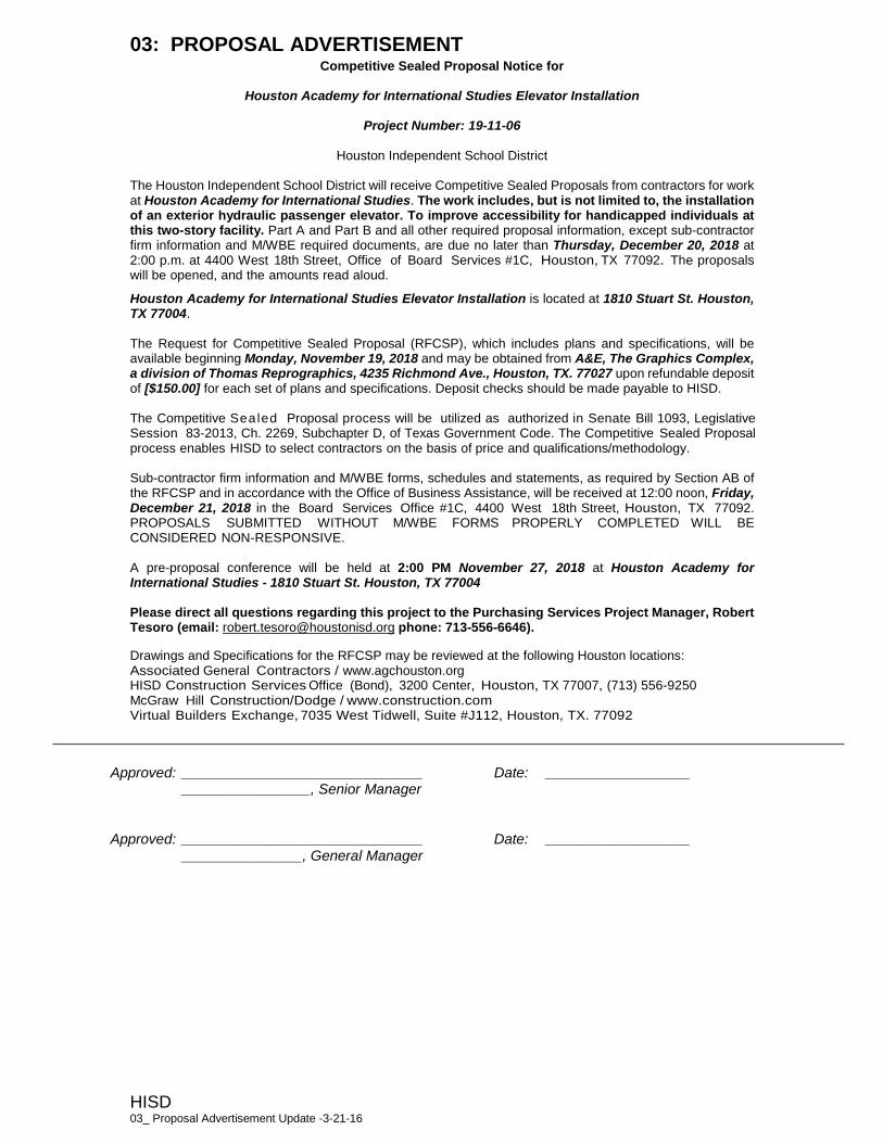
03: PROPOSAL ADVERTISEMENT
HISD 03_ Proposal Advertisement Update -3-21-16
Competitive Sealed Proposal Notice for
Houston Academy for International Studies Elevator Installation
Project Number: 19-11-06
Houston Independent School District The Houston Independent School District will receive Competitive Sealed Proposals from contractors for work at Houston Academy for International Studies. The work includes, but is not limited to, the installation of an exterior hydraulic passenger elevator. To improve accessibility for handicapped individuals at this two-story facility. Part A and Part B and all other required proposal information, except sub-contractor firm information and M/WBE required documents, are due no later than Thursday, December 20, 2018 at 2:00 p.m. at 4400 West 18th Street, Office of Board Services #1C, Houston, TX 77092. The proposals will be opened, and the amounts read aloud.
Houston Academy for International Studies Elevator Installation is located at 1810 Stuart St. Houston, TX 77004. The Request for Competitive Sealed Proposal (RFCSP), which includes plans and specifications, will be available beginning Monday, November 19, 2018 and may be obtained from A&E, The Graphics Complex, a division of Thomas Reprographics, 4235 Richmond Ave., Houston, TX. 77027 upon refundable deposit of [$150.00] for each set of plans and specifications. Deposit checks should be made payable to HISD. The Competitive Sealed Proposal process will be utilized as authorized in Senate Bill 1093, Legislative Session 83-2013, Ch. 2269, Subchapter D, of Texas Government Code. The Competitive Sealed Proposal process enables HISD to select contractors on the basis of price and qualifications/methodology. Sub-contractor firm information and M/WBE forms, schedules and statements, as required by Section AB of the RFCSP and in accordance with the Office of Business Assistance, will be received at 12:00 noon, Friday, December 21, 2018 in the Board Services Office #1C, 4400 West 18th Street, Houston, TX 77092. PROPOSALS SUBMITTED WITHOUT M/WBE FORMS PROPERLY COMPLETED WILL BE CONSIDERED NON-RESPONSIVE. A pre-proposal conference will be held at 2:00 PM November 27, 2018 at Houston Academy for International Studies - 1810 Stuart St. Houston, TX 77004 Please direct all questions regarding this project to the Purchasing Services Project Manager, Robert Tesoro (email: [email protected] phone: 713-556-6646).
Drawings and Specifications for the RFCSP may be reviewed at the following Houston locations: Associated General Contractors / www.agchouston.org HISD Construction Services Office (Bond), 3200 Center, Houston, TX 77007, (713) 556-9250 McGraw Hill Construction/Dodge / www.construction.com Virtual Builders Exchange, 7035 West Tidwell, Suite #J112, Houston, TX. 77092
Approved: ______________________________ Date: __________________ ________________, Senior Manager Approved: ______________________________ Date: __________________ _______________, General Manager

04: PROJECT INFORMATION
HISD 04-1 04_Project Information_9-25-185-23-16
1.0 Houston Academy for International Students Elevator Installation Houston Academy for International Students Elevator Installation 1810 Stuart Street Houston, TX 77004 19-11-06
2.0 OWNER Houston Independent School District 4400 West 18th Street Houston, Texas 77092 3.0 HISD PROJECT MANAGER (PM)
Albert B. Charles, HISD’s Project Manager (PM) has been retained as HISD’s representative for the management of planning, design, and construction. During construction, PM shall have authority to act on behalf of HISD for owner related direction. HISD Purchasing Services Manager: Per the Districts “Code of Silence” Policy (CAA LOCAL), all correspondence and communication during the proposal shall be directed to the Purchasing Services Project Manager. After the project is awarded, communication shall be directed to the Construction Services Project Manager.
Robert Tesoro Purchasing Services Houston Independent School District 4400 W. 18th Street Houston, TX 77092 Phone: 713-556-6646 E-mail: [email protected]
HISD CS Senior Manager Marcus Sheppard Construction Services Houston Independent School District 3200 Center Street Houston, TX 77007-5909 Phone: 713-556-9251 Fax: 713-556-9275 E-mail: [email protected]
04: PROJECT INFORMATION
HISD 04-2 04_Project Information_9-25-185-23-16
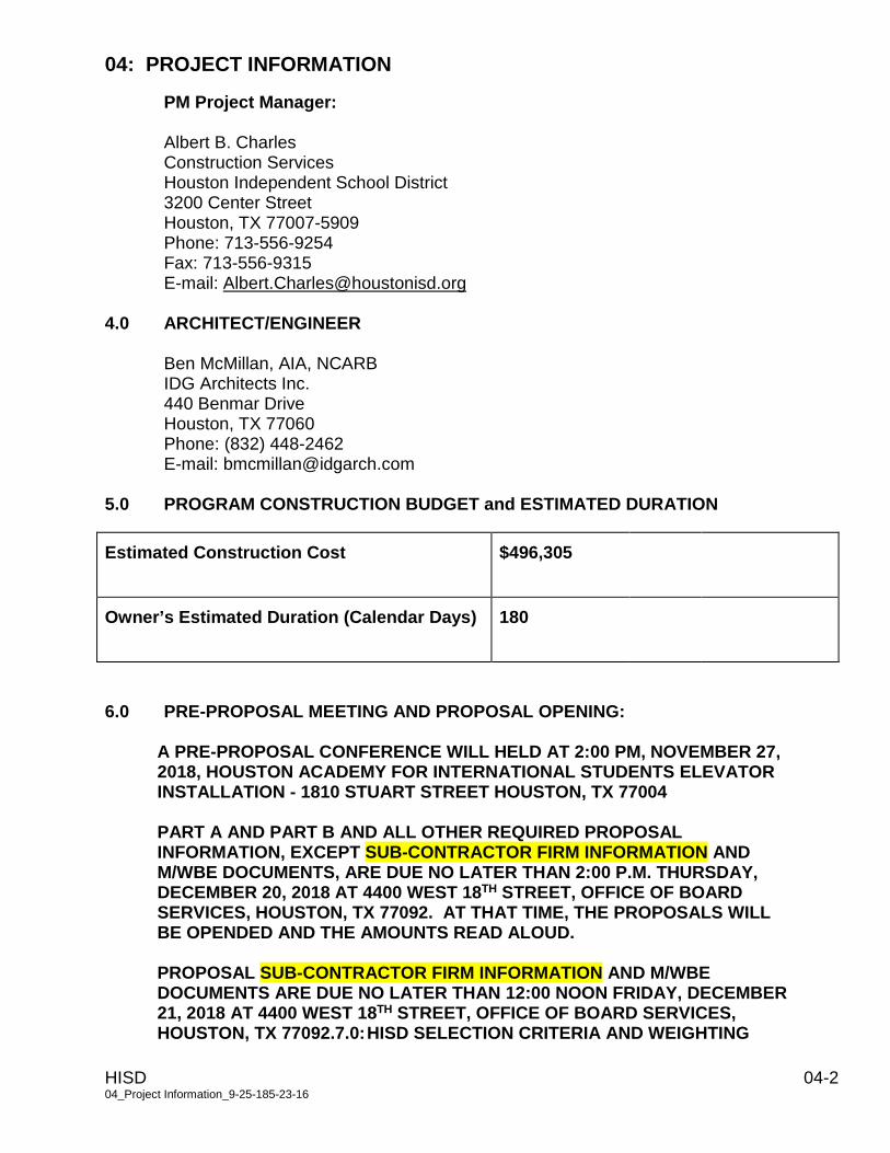
PM Project Manager: Albert B. Charles Construction Services Houston Independent School District 3200 Center Street Houston, TX 77007-5909 Phone: 713-556-9254 Fax: 713-556-9315 E-mail: [email protected]
4.0 ARCHITECT/ENGINEER
Ben McMillan, AIA, NCARB IDG Architects Inc. 440 Benmar Drive Houston, TX 77060 Phone: (832) 448-2462 E-mail: [email protected]
5.0 PROGRAM CONSTRUCTION BUDGET and ESTIMATED DURATION
Estimated Construction Cost $496,305
Owner’s Estimated Duration (Calendar Days) 180
6.0 PRE-PROPOSAL MEETING AND PROPOSAL OPENING:
A PRE-PROPOSAL CONFERENCE WILL HELD AT 2:00 PM, NOVEMBER 27, 2018, HOUSTON ACADEMY FOR INTERNATIONAL STUDENTS ELEVATOR INSTALLATION - 1810 STUART STREET HOUSTON, TX 77004 PART A AND PART B AND ALL OTHER REQUIRED PROPOSAL INFORMATION, EXCEPT SUB-CONTRACTOR FIRM INFORMATION AND M/WBE DOCUMENTS, ARE DUE NO LATER THAN 2:00 P.M. THURSDAY, DECEMBER 20, 2018 AT 4400 WEST 18TH STREET, OFFICE OF BOARD SERVICES, HOUSTON, TX 77092. AT THAT TIME, THE PROPOSALS WILL BE OPENDED AND THE AMOUNTS READ ALOUD. PROPOSAL SUB-CONTRACTOR FIRM INFORMATION AND M/WBE DOCUMENTS ARE DUE NO LATER THAN 12:00 NOON FRIDAY, DECEMBER 21, 2018 AT 4400 WEST 18TH STREET, OFFICE OF BOARD SERVICES, HOUSTON, TX 77092.7.0: HISD SELECTION CRITERIA AND WEIGHTING
04: PROJECT INFORMATION
HISD 04-3 04_Project Information_9-25-185-23-16
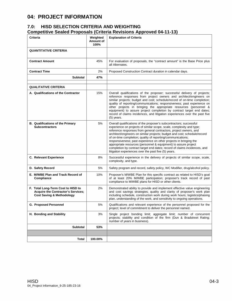
7.0: HISD SELECTION CRITERIA AND WEIGHTING Competitive Sealed Proposals (Criteria Revisions Approved 04-11-13)
Criteria Weighted Amount of
100%
Explanation of Criteria
QUANTITATIVE CRITERIA
Contract Amount 45% For evaluation of proposals, the “contract amount” is the Base Price plus all Alternates.
Contract Time 2% Proposed Construction Contract duration in calendar days.
Subtotal 47%
QUALITATIVE CRITERIA
A. Qualifications of the Contractor 15% Overall qualifications of the proposer; successful delivery of projects; reference responses from project owners and architect/engineers on similar projects; budget and cost; schedule/record of on-time completion; quality of reporting/communications; responsiveness; past experience on other projects in bringing the appropriate resources (personnel & equipment) to assure project completion by contract target end dates; record of claims incidences, and litigation experiences over the past five (5) years.
B. Qualifications of the Primary Subcontractors
5% Overall qualifications of the proposer’s subcontractors; successful experience on projects of similar scope, scale, complexity and type; reference responses from general contractors, project owners, and architect/engineers on similar projects; budget and cost; schedule/record of on-time completion; quality of reporting/communications; responsiveness; past experience on other projects in bringing the appropriate resources (personnel & equipment) to assure project completion by contract target end dates; record of claims incidences, and litigation experiences over the past five (5) years.
C. Relevant Experience 8% Successful experience in the delivery of projects of similar scope, scale, complexity, and type.
D. Safety Record 5% Safety program and record, safety policy, WC Modifier, drug/alcohol policy.
E. M/WBE Plan and Track Record of Compliance
10% Proposer's M/WBE Plan for this specific contract as related to HISD’s goal of at least 20% M/WBE participation; proposer's track record of past compliance to M/WBE plans for HISD or other clients.
F. Total Long-Term Cost to HISD to Acquire the Contractor’s Services; Cost Saving & Methodology
2% Demonstrated ability to provide and implement effective value engineering and cost savings strategies; quality and clarity of proposer's work plan including schedule, construction work during work hours; logistics/phasing plan, understanding of the work, and sensitivity to ongoing operations.
G. Proposed Personnel 5% Qualifications and relevant experience of the personnel proposed for the project; level of commitment to deliver the personnel named.
H. Bonding and Stability 3% Single project bonding limit; aggregate limit; number of concurrent projects; stability and condition of the firm (Dun & Bradstreet Rating; number of years in business).
Subtotal 53%
Total 100.00%
05: HISD SCHOOL OPERATIONS PARAMETER STATEMENT
HISD 05-1 05_HISD School Operations Parameter Statement_10-14-14
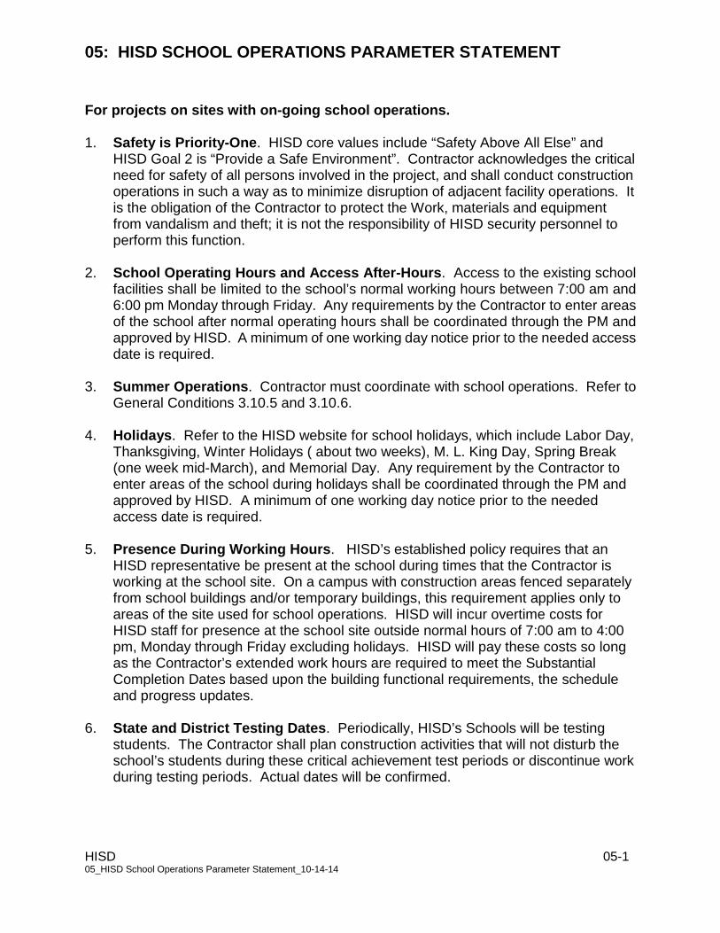
For projects on sites with on-going school operations.
1. Safety is Priority-One. HISD core values include “Safety Above All Else” and HISD Goal 2 is “Provide a Safe Environment”. Contractor acknowledges the critical need for safety of all persons involved in the project, and shall conduct construction operations in such a way as to minimize disruption of adjacent facility operations. It is the obligation of the Contractor to protect the Work, materials and equipment from vandalism and theft; it is not the responsibility of HISD security personnel to perform this function.
2. School Operating Hours and Access After-Hours. Access to the existing school facilities shall be limited to the school’s normal working hours between 7:00 am and 6:00 pm Monday through Friday. Any requirements by the Contractor to enter areas of the school after normal operating hours shall be coordinated through the PM and approved by HISD. A minimum of one working day notice prior to the needed access date is required.
3. Summer Operations. Contractor must coordinate with school operations. Refer to
General Conditions 3.10.5 and 3.10.6. 4. Holidays. Refer to the HISD website for school holidays, which include Labor Day,
Thanksgiving, Winter Holidays ( about two weeks), M. L. King Day, Spring Break (one week mid-March), and Memorial Day. Any requirement by the Contractor to enter areas of the school during holidays shall be coordinated through the PM and approved by HISD. A minimum of one working day notice prior to the needed access date is required.
5. Presence During Working Hours. HISD’s established policy requires that an HISD representative be present at the school during times that the Contractor is working at the school site. On a campus with construction areas fenced separately from school buildings and/or temporary buildings, this requirement applies only to areas of the site used for school operations. HISD will incur overtime costs for HISD staff for presence at the school site outside normal hours of 7:00 am to 4:00 pm, Monday through Friday excluding holidays. HISD will pay these costs so long as the Contractor’s extended work hours are required to meet the Substantial Completion Dates based upon the building functional requirements, the schedule and progress updates.
6. State and District Testing Dates. Periodically, HISD’s Schools will be testing students. The Contractor shall plan construction activities that will not disturb the school’s students during these critical achievement test periods or discontinue work during testing periods. Actual dates will be confirmed.

05: HISD SCHOOL OPERATIONS PARAMETER STATEMENT
HISD 05-2 05_HISD School Operations Parameter Statement_10-14-14
7. Critical Systems and Areas of Operation. Critical systems including air conditioning systems, water systems, fire alarm, intercom, intrusion alarm, CCTV systems, electrical systems and critical areas such as kitchen/food service areas must remain functional at all times school is in operation. Any work that would require a shut down of these items must be accomplished during vacations, holidays and other times when the school is not operating unless the Contractor makes arrangement for temporary systems or services that are acceptable to HISD.
8. 10-Day Notice of Power Shutdown. Contractor must provide HISD with
notification of power or other utility shutdown no less than 10 days in advance of the shutdown. Notification includes HISD Construction and Facility Services, A/E, PM, and the Principal.
9. Worker Identity Badges. Contractor must provide all construction workers with
identification badges, with photograph, that shall be worn visibly at all time while workers are present in areas of the school property used for school operations. Contractor must assure that the Crisis Management contact information is provided on the reverse side of each worker’s badge. Refer to General Conditions Article 19 for background check requirements.
10. Construction Fencing, Parking and Staging Areas. The contractor shall erect construction fences as indicated on the documents. Access to the site may be limited as indicated in the documents. Contractor site activities, storage offices and fabrication shall be limited to the area enclosed by the construction fences. Contractor parking shall be limited to the area enclosed by the construction fence or as indicated in the documents.
If the Contractor plans to shut down a part of an occupied and operational school facility for construction work, then the Contractor shall erect appropriate construction barricades to completely eliminate access for non-construction personnel to the work area. The barrier shall be made of 3/4" plywood, and it shall extend from floor to ceiling, wall to wall. The temporary barrier shall have a door that can be locked. This barrier will remain until work in the specified area is completely finished. The barrier may subsequently be moved to a different location, provided that it still meets the requirements. Proper signage should be displayed near the temporary barrier, according to safety regulations. Temporary construction barriers will also be required for tie-ins from Additions to existing structures. All temporary barriers must be approved by the Fire Marshall.
11. Fire Alarm System Maintenance, Operation, Removal and Certification.
Contractor is responsible for maintaining existing fire alarm operational throughout construction duration for buildings and areas used for school operations and other HISD activities. If the contractor requires the temporary interruption of the fire
05: HISD SCHOOL OPERATIONS PARAMETER STATEMENT
HISD 05-3 05_HISD School Operations Parameter Statement_10-14-14
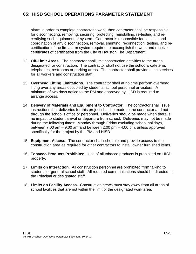
alarm in order to complete contractor’s work, then contractor shall be responsible for disconnecting, removing, securing, protecting, reinstalling, re-testing and re-certifying such equipment or system. Contractor is responsible for all costs and coordination of any disconnection, removal, shunting, reconnection, testing, and re-certification of the fire alarm system required to accomplish the work and receive certificates of certification from the City of Houston Fire Department.
12. Off-Limit Areas. The contractor shall limit construction activities to the areas
designated for construction. The contractor shall not use the school’s cafeteria, telephones, restrooms or parking areas. The contractor shall provide such services for all workers and construction staff.
13. Overhead Lifting Limitations. The contractor shall at no time perform overhead
lifting over any areas occupied by students, school personnel or visitors. A minimum of two days notice to the PM and approved by HISD is required to arrange access.
14. Delivery of Materials and Equipment to Contractor. The contractor shall issue
instructions that deliveries for this project shall be made to the contractor and not through the school’s office or personnel. Deliveries should be made when there is no impact to student arrival or departure from school. Deliveries may not be made during the following times: Monday through Friday excluding school holidays, between 7:00 am – 9:00 am and between 2:00 pm – 4:00 pm, unless approved specifically for the project by the PM and HISD.
15. Equipment Access. The contractor shall schedule and provide access to the
construction area as required for other contractors to install owner furnished items.
16. Tobacco Products Prohibited. Use of all tobacco products is prohibited on HISD property.
17. Limits on Interaction. All construction personnel are prohibited from talking to
students or general school staff. All required communications should be directed to the Principal or designated staff.
18. Limits on Facility Access. Construction crews must stay away from all areas of
school facilities that are not within the limit of the designated work area.
06: PROJECT CLOSE-OUT DOCUMENTS
HISD 06-1 06_Project Close Out Documents_11-30-10
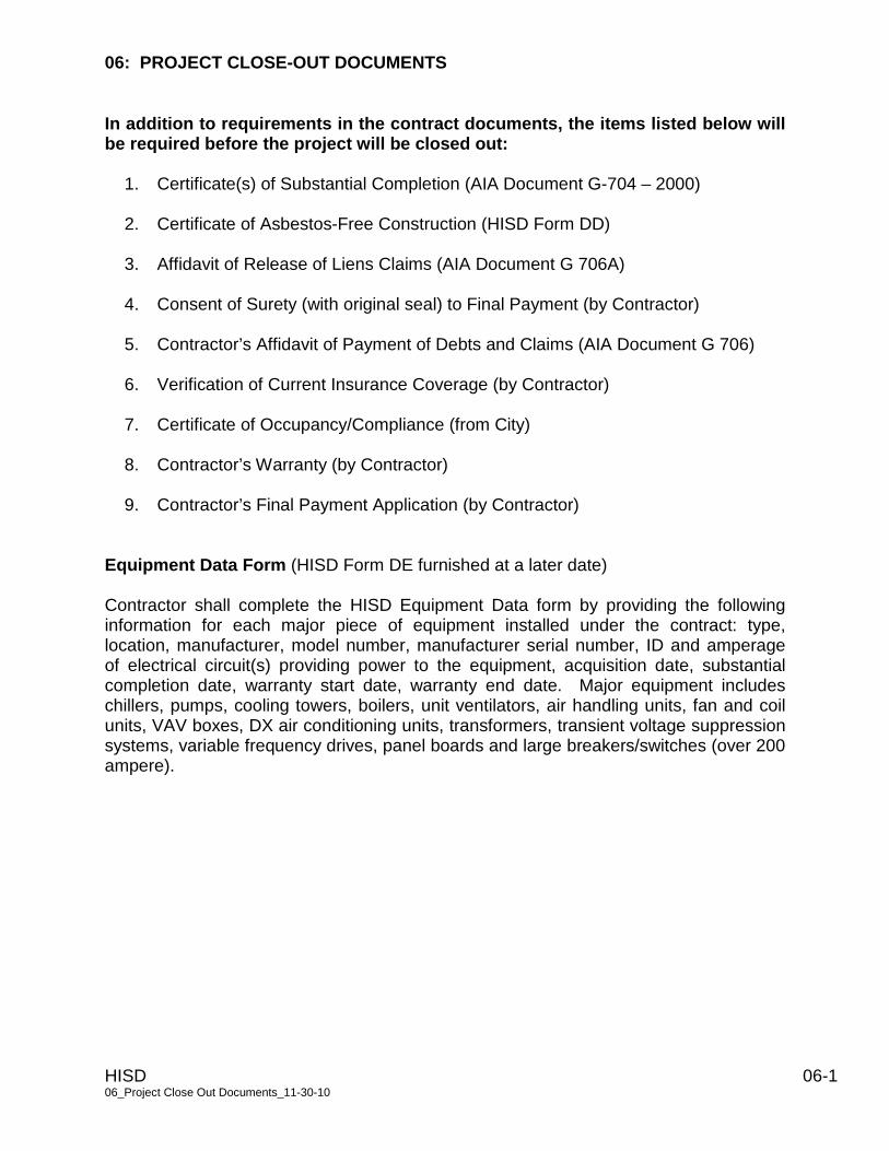
In addition to requirements in the contract documents, the items listed below will be required before the project will be closed out:
1. Certificate(s) of Substantial Completion (AIA Document G-704 – 2000)
2. Certificate of Asbestos-Free Construction (HISD Form DD)
3. Affidavit of Release of Liens Claims (AIA Document G 706A)
4. Consent of Surety (with original seal) to Final Payment (by Contractor)
5. Contractor’s Affidavit of Payment of Debts and Claims (AIA Document G 706)
6. Verification of Current Insurance Coverage (by Contractor)
7. Certificate of Occupancy/Compliance (from City)
8. Contractor’s Warranty (by Contractor)
9. Contractor’s Final Payment Application (by Contractor)
Equipment Data Form (HISD Form DE furnished at a later date) Contractor shall complete the HISD Equipment Data form by providing the following information for each major piece of equipment installed under the contract: type, location, manufacturer, model number, manufacturer serial number, ID and amperage of electrical circuit(s) providing power to the equipment, acquisition date, substantial completion date, warranty start date, warranty end date. Major equipment includes chillers, pumps, cooling towers, boilers, unit ventilators, air handling units, fan and coil units, VAV boxes, DX air conditioning units, transformers, transient voltage suppression systems, variable frequency drives, panel boards and large breakers/switches (over 200 ampere).

1
Houston Independent School District
2012 Bond Program Labor and Compliance Program
2
INTRODUCTION
HOUSTON INDEPENDENT SCHOOL DISTRICT LABOR COMPLIANCE PROGRAM
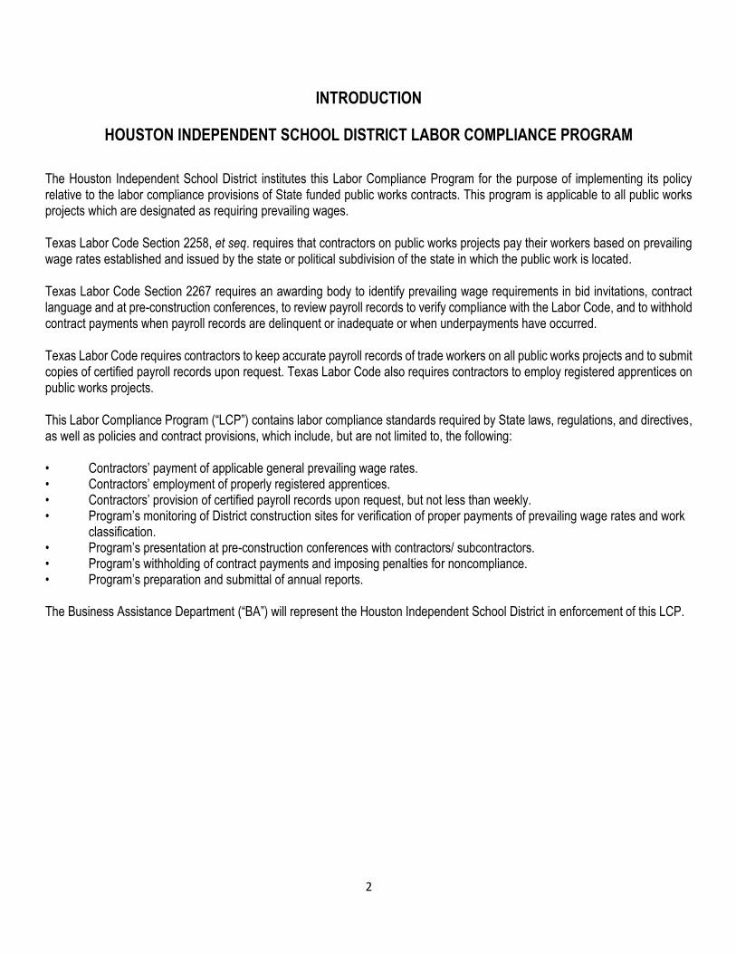
The Houston Independent School District institutes this Labor Compliance Program for the purpose of implementing its policy relative to the labor compliance provisions of State funded public works contracts. This program is applicable to all public works projects which are designated as requiring prevailing wages.
Texas Labor Code Section 2258, et seq. requires that contractors on public works projects pay their workers based on prevailing wage rates established and issued by the state or political subdivision of the state in which the public work is located.
Texas Labor Code Section 2267 requires an awarding body to identify prevailing wage requirements in bid invitations, contract language and at pre-construction conferences, to review payroll records to verify compliance with the Labor Code, and to withhold contract payments when payroll records are delinquent or inadequate or when underpayments have occurred.
Texas Labor Code requires contractors to keep accurate payroll records of trade workers on all public works projects and to submit copies of certified payroll records upon request. Texas Labor Code also requires contractors to employ registered apprentices on public works projects.
This Labor Compliance Program (“LCP”) contains labor compliance standards required by State laws, regulations, and directives, as well as policies and contract provisions, which include, but are not limited to, the following:
• Contractors’ payment of applicable general prevailing wage rates. • Contractors’ employment of properly registered apprentices. • Contractors’ provision of certified payroll records upon request, but not less than weekly. • Program’s monitoring of District construction sites for verification of proper payments of prevailing wage rates and work
classification. • Program’s presentation at pre-construction conferences with contractors/ subcontractors. • Program’s withholding of contract payments and imposing penalties for noncompliance. • Program’s preparation and submittal of annual reports. The Business Assistance Department (“BA”) will represent the Houston Independent School District in enforcement of this LCP.
3
COMPETITIVE BIDDING ON DISTRICT PUBLIC WORKS CONTRACTS
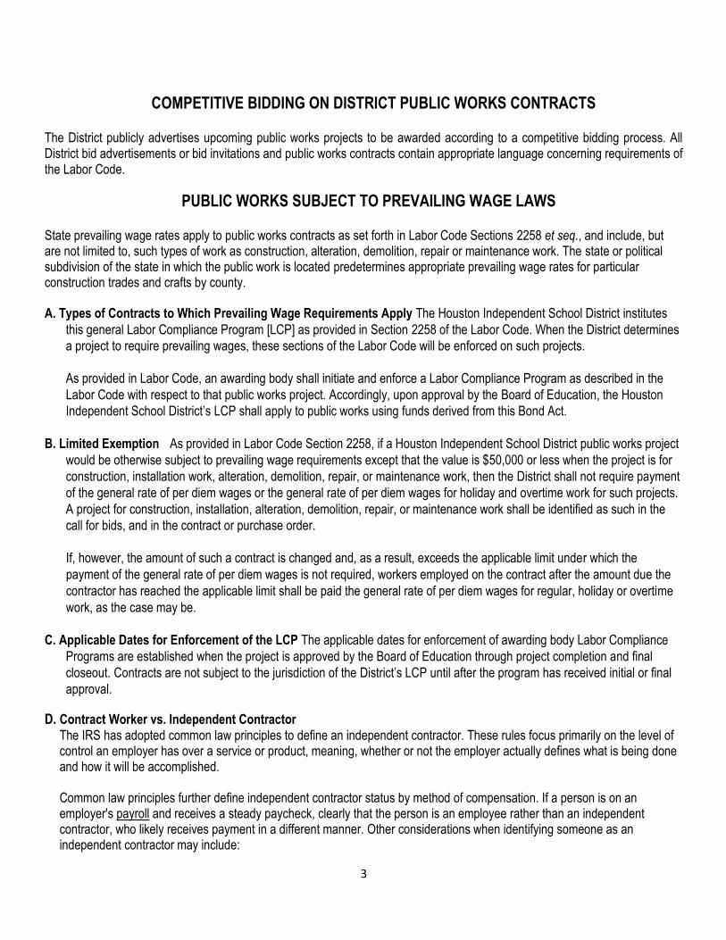
The District publicly advertises upcoming public works projects to be awarded according to a competitive bidding process. All District bid advertisements or bid invitations and public works contracts contain appropriate language concerning requirements of the Labor Code.
PUBLIC WORKS SUBJECT TO PREVAILING WAGE LAWS
State prevailing wage rates apply to public works contracts as set forth in Labor Code Sections 2258 et seq., and include, but are not limited to, such types of work as construction, alteration, demolition, repair or maintenance work. The state or political subdivision of the state in which the public work is located predetermines appropriate prevailing wage rates for particular construction trades and crafts by county.
A. Types of Contracts to Which Prevailing Wage Requirements Apply The Houston Independent School District institutes
this general Labor Compliance Program [LCP] as provided in Section 2258 of the Labor Code. When the District determines
a project to require prevailing wages, these sections of the Labor Code will be enforced on such projects.
As provided in Labor Code, an awarding body shall initiate and enforce a Labor Compliance Program as described in the
Labor Code with respect to that public works project. Accordingly, upon approval by the Board of Education, the Houston
Independent School District’s LCP shall apply to public works using funds derived from this Bond Act.
B. Limited Exemption As provided in Labor Code Section 2258, if a Houston Independent School District public works project
would be otherwise subject to prevailing wage requirements except that the value is $50,000 or less when the project is for
construction, installation work, alteration, demolition, repair, or maintenance work, then the District shall not require payment
of the general rate of per diem wages or the general rate of per diem wages for holiday and overtime work for such projects.
A project for construction, installation, alteration, demolition, repair, or maintenance work shall be identified as such in the
call for bids, and in the contract or purchase order.
If, however, the amount of such a contract is changed and, as a result, exceeds the applicable limit under which the
payment of the general rate of per diem wages is not required, workers employed on the contract after the amount due the
contractor has reached the applicable limit shall be paid the general rate of per diem wages for regular, holiday or overtime
work, as the case may be.
C. Applicable Dates for Enforcement of the LCP The applicable dates for enforcement of awarding body Labor Compliance
Programs are established when the project is approved by the Board of Education through project completion and final
closeout. Contracts are not subject to the jurisdiction of the District’s LCP until after the program has received initial or final
approval.
D. Contract Worker vs. Independent Contractor The IRS has adopted common law principles to define an independent contractor. These rules focus primarily on the level of control an employer has over a service or product, meaning, whether or not the employer actually defines what is being done and how it will be accomplished. Common law principles further define independent contractor status by method of compensation. If a person is on an employer's payroll and receives a steady paycheck, clearly that the person is an employee rather than an independent contractor, who likely receives payment in a different manner. Other considerations when identifying someone as an independent contractor may include:
4
If the worker supplies his or her own equipment, materials and tools If all necessary materials are not supplied by the employer If the worker can be discharged at any time and can choose whether or not to come to work without fear of
losing employment If the worker control the hours of employment thus indicating they are acting as an independent contractor
Whether the work is temporary or permanent.
E. Employer Tax Liability An employer's tax liability is determined by the worker's employment status. When a worker is an employee, employers must pay state and federal unemployment tax, social security tax and workers compensation/disability premiums to a State Insurance Fund. When a worker is an independent contractor, the hiring party is not required to make any of these payments. Should employers incorrectly define a worker as an independent contractor, they may find themselves liable for past taxes including FICA and federal unemployment tax.
5
SECTION I
HOUSTON INDEPENDENT SCHOOL DISTRICT
LABOR COMPLIANCE PROGRAM
Implementation Plan

6
SECTION I IMPLEMENTATION PLAN
1. The Business Assistance Department receives construction contract awards/work schedules from the Approved Board Agenda and Construction and Facility Services Department for all 2012 Bond Program Capital Improvement and Facilities Projects.
2. The Business Assistance Department participates in Pre- Bid and Pre-Construction Conference.
3. The Business Assistance Department verifies information from certified payroll records.
4. The Business Assistance Department conducts on-site interviews with contractors’ employees and includes interview sheets in Project Wage Files.
5. The Business Assistance Department notifies contractor in writing of any discrepancies with certified payroll records.
6. If clarification/correction is not received from the contractor within two (2) weeks, The Business Assistance Department will commence an investigation.
7. Upon completion of the investigation, a report will be sent to the General Manager, Business Assistance with recommendations for penalties to be applied to the contractor.
8. The Business Assistance Department prepares and submits public works violation reports to the Board of Education as required.
9. The Business Assistance Department receives Monthly Employment Report from the contractor and its subcontractors; Program Manager maintains database of this information for year-end report.
10. The Business Assistance Department communicates on a regular basis with contractors, workers, building and trade organizations and other community entities and in-service management to District personnel.
11. The Business Assistance Department prepares and submits annual program reports to the Chief Operating Officer, Chief Financial Officer, Officer of Construction and Facility Services, and General Managers of Business Assistance, Procurement, and Construction with a copy provided to the Board of Education.
12. Labor Compliance Program Manager manages all facets and is the primary contact for the District’s Labor Compliance Program.

7
OUTREACH ACTIVITIES
To ensure the successful implementation of the District’s Labor Compliance Program, there shall be several outreach activities initiated and maintained.
A. Providing Information to the Public
1. The Business Assistance Department shall be responsible for communication and outreach activities relative to public
information on the District’s LCP:
a. Regular presentations to contractors at all District Pre-Bid Conferences and Pre-Construction Conferences.
b. Ongoing communication via correspondence with workers at District job sites when review of the certified payroll records reveals the possibility of prevailing wage violations.
c. Periodic meetings with contractor organizations, prime contractors and subcontractors interested in public works contracting with the District.
B. In-service Management Training on the Labor Compliance Program
1. The Labor Compliance Program shall provide ongoing management in-service training and workshops for District staff
relative to the terms, requirements and administration of this Labor Compliance Program.

8
SECTION II PRE-CONSTRUCTION CONFERENCE
After the District awards a public works contract and prior to commencement of the work, a mandatory Pre-Construction Conference shall be conducted with the contractor and those subcontractors listed in its bid documents. The Office of Business Assistance or its designee shall present information at this conference.
At that meeting, the Business Assistance will discuss State labor law requirements applicable to the contract, including prevailing wage requirements, respective record-keeping responsibilities, the requirement for submittal of certified payroll records to the District and the prohibition against discrimination in employment.
Business Assistance will provide the contractor and each subcontractor with a Checklist of Labor Law Requirements and will discuss in detail the following checklist items:
1. Contractor’s duty to pay prevailing wages.
2. Penalties for failure to pay prevailing wages and to employ apprentices, including forfeitures and debarment.
3. Requirement to maintain and submit copies of certified payroll records to the District, on a weekly basis, as required and penalties for failure to do so. The requirement includes and applies to all subcontractors performing work on this project even if their portion of the work is less than on half of one-percent (0.5%) of the total amount of the contract.
4. Prohibition against employment discrimination.
5. Prohibition against taking or receiving a portion of an employee’s wages (kickback).
6. Prohibition against accepting fees for registering any person for public works or for filing work orders on public works.
7. Requirement to list all subcontractors that are performing one-half of one percent (0.5%) of the total amount of the contract.
8. Requirement for specialty contractors (Mechanical, Electrical and Plumbing) to be properly licensed and to require penalties for employing workers while unlicensed.
9. Prohibition against unfair competition.
10. Requirement that contractor and subcontractor be properly insured for Workers’ Compensation.
11. Requirement that the contractor abide by Occupational Safety and Health laws and regulations that apply to this particular public works project.
12. Prohibition against hiring undocumented workers and requirement to secure proof of eligibility/citizenship from all workers.
13. Requirement to provide itemized wage statements to employees.

9
Contractors and subcontractors present at the Pre-Construction Conference will be given the opportunity to ask questions of Business Assistance relative to items contained in the Checklist of Labor Law Requirements. The checklist will then be signed by the contractor’s representative and a representative of each subcontractor and the District’s Business Assistance Department.
At the Pre-Construction Conference, Business Assistance will provide the contractor with a copy of the District’s LCP packet which includes: a copy of the approved LCP, the Checklist of Labor Law Requirements, applicable Prevailing Wage Rate Determinations, blank certified payroll record forms, fringe benefit statements, State apprenticeship requirements, and a copy of the Labor Code relating to Public Works and Public Agencies.
It will be the contractor’s responsibility to provide copies of the LCP package to all listed subcontractors and to any substituted subcontractors.
10
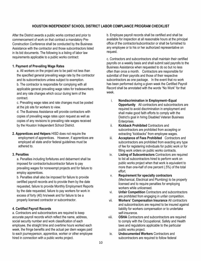
HOUSTON INDEPENDENT SCHOOL DISTRICT LABOR COMPLIANCE PROGRAM CHECKLIST
After the District awards a public works contract and prior to
commencement of work on that contract a mandatory Pre-
Construction Conference shall be conducted by the Business
Assistance with the contractor and those subcontractors listed
in its bid documents. The following is a listing of labor law
requirements applicable to a public works contract:
1. Payment of Prevailing Wage Rates
a. All workers on the project are to be paid not less than
the specified general prevailing wage rate by the contractor
and its subcontractors unless subject to exemption.
b. The contractor is responsible for complying with all
applicable general prevailing wage rates for tradesworkers
and any rate changes which occur during term of the
contract.
c. Prevailing wage rates and rate changes must be posted
at the job site for workers to view.
d. The Business Assistance will provide contractors with
copies of prevailing wage rates upon request as well as
copies of any revisions to prevailing rate wages received
by the Houston Independent School District. 2. Apprentices and Helpers HISD does not require the
employment of apprentices. However, if apprentices are employed all state and/or federal guidelines must be adhered to.
3. Penalties
a. Penalties including forfeitures and debarment shall be
imposed for contractor/subcontractor failure to pay
prevailing wages for nonexempt projects and for failure to
employ apprentices.
b. Penalties shall also be imposed for failure to provide
certified payroll records and to provide them by the date
requested, failure to provide Monthly Employment Reports
by the date requested, failure to pay workers for work in
excess of forty (40) hrs/week and for failure to be a
properly licensed contractor or subcontractor.
4. Certified Payroll Records a. Contractors and subcontractors are required to keep accurate payroll records which reflect the name, address, social security number and work classification of each employee, the straight time and overtime hours worked each week, the fringe benefits and the actual per diem wages paid to each journeyperson, apprentice, worker or other employee hired in connection with a public works project.
b. Employee payroll records shall be certified and shall be available for inspection at all reasonable hours at the principal office of the contractor/subcontractor or shall be furnished to any employee or to his or her authorized representative on request.
c. Contractors and subcontractors shall maintain their certified payrolls on a weekly basis and shall submit said payrolls to the Business Assistance when requested to do so but no less often than once a month. Contractors are responsible for submittal of their payrolls and those of their respective subcontractors as one package. In the event that no work has been performed during a given week the Certified Payroll Record shall be annotated with the words “No Work” for that week.
i. Nondiscrimination in Employment--Equal Opportunity All contractors and subcontractors are required to avoid discrimination in employment and shall make good faith efforts to comply with the District’s goal in hiring Disabled Veteran Business Enterprises.
ii. Kickback Prohibited Contractors and subcontractors are prohibited from accepting or extracting “kickbacks” from employee wages.
iii. Acceptance of Fees Prohibited Contractors and subcontractors are prohibited from exacting any type of fee for registering individuals for public work or for filling work orders on public works contracts.
iv. Listing of Subcontractors Contractors are required to list all subcontractors hired to perform work on public works project when that work is equivalent to more than one-half of one percent (.5%) of the total effort.
v. Requirement for specialty contractors (Mechanical, Electrical and Plumbing) to be properly licensed and to require penalties for employing workers while unlicensed.
vi. Unfair Competition Contractors and subcontractors are prohibited from engaging in unfair competition.
vii. Workers’ Compensation Insurance All contractors and subcontractors are required to be insured against liability for workers compensation or to undertake self-insurance.
viii. OSHA Contractors and subcontractors are required to comply with the Occupational, Safety and Health laws and regulations applicable to the particular public works project.
ix. Undocumented Workers Contractors and subcontractors are required to follow federal
11
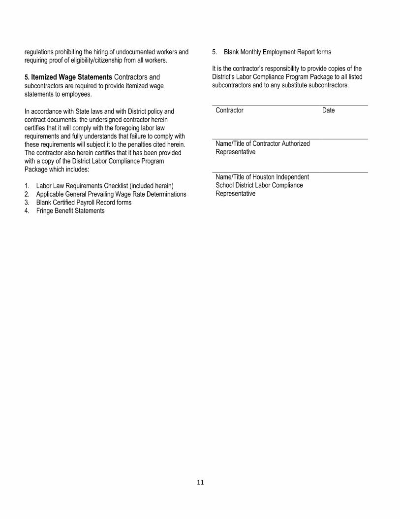
regulations prohibiting the hiring of undocumented workers and requiring proof of eligibility/citizenship from all workers.
5. Itemized Wage Statements Contractors and subcontractors are required to provide itemized wage statements to employees. In accordance with State laws and with District policy and contract documents, the undersigned contractor herein certifies that it will comply with the foregoing labor law requirements and fully understands that failure to comply with these requirements will subject it to the penalties cited herein. The contractor also herein certifies that it has been provided with a copy of the District Labor Compliance Program Package which includes: 1. Labor Law Requirements Checklist (included herein) 2. Applicable General Prevailing Wage Rate Determinations 3. Blank Certified Payroll Record forms 4. Fringe Benefit Statements
5. Blank Monthly Employment Report forms
It is the contractor’s responsibility to provide copies of the District’s Labor Compliance Program Package to all listed subcontractors and to any substitute subcontractors.
Contractor Date
Name/Title of Contractor Authorized Representative
Name/Title of Houston Independent School District Labor Compliance Representative

12
The Houston Independent School District Office of Business Assistance Labor Compliance Program
4400 West 18th Street, Houston, TX 77092 January 1, 2014 Certified Mail Mr. John Doe ACME Painting 123 Main Street Somewherein, TX 77001 Dear Mr. Doe: The Houston Independent School District has identified your firm as the apparent awarded bidder for Contract #_______________________ and has scheduled board approval of a contract requiring your compliance with Texas Labor Code 2258. This will require payment of prevailing wages to all workers employed on the project and reporting of certified weekly payrolls. The Labor Code requires, prior to the start of work, that a qualified representative certify documents for your firm, attend a review meeting with the District concerning the Labor Code prevailing wage laws and the Labor Compliance Program.
The Labor Compliance Manager is formally requesting the appearance of the certifying person for the code review, the submittal of the required weekly certified payroll records or nonperformance reports, and the monthly submittal of employment utilization reports, all identified in the contract general conditions.
The goal of the Labor Compliance Officer is to provide necessary information, assistance, forms and procedures to allow your project to move forward on schedule and in compliance with the State’s Labor Code. Please call the Houston Independent School District’s Labor Compliance Officer at (713) 556-7273 to set an appointment and receive necessary forms prior to the start of your project.
Respectfully, Bernard E. Willingham Labor Compliance Program Manager
Sample
Pre-award Letter
13
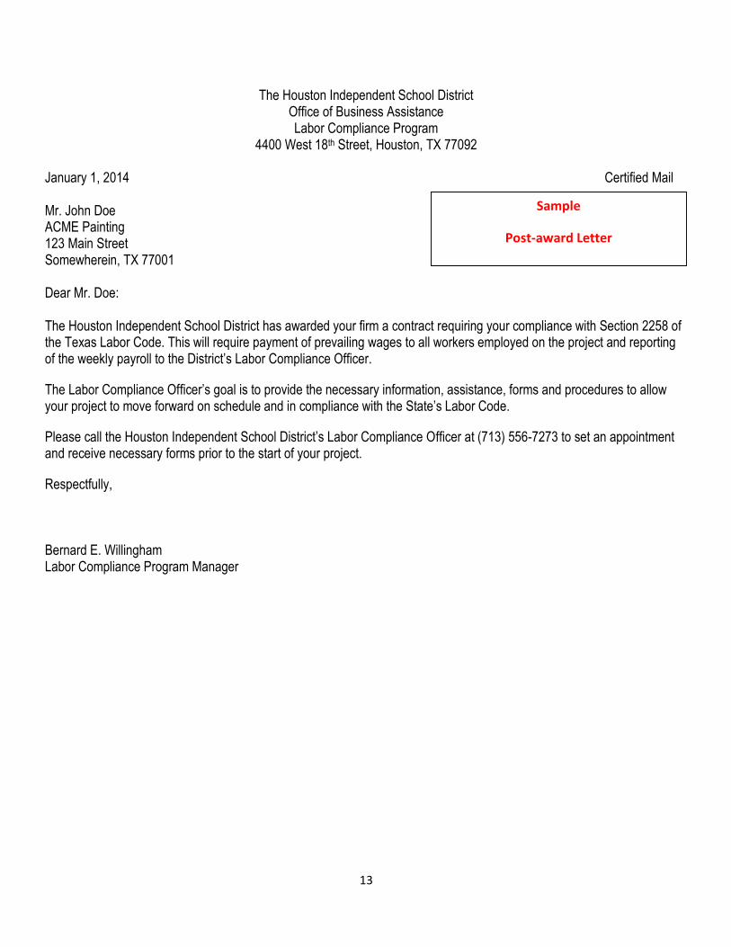
The Houston Independent School District Office of Business Assistance Labor Compliance Program
4400 West 18th Street, Houston, TX 77092 January 1, 2014 Certified Mail Mr. John Doe ACME Painting 123 Main Street Somewherein, TX 77001 Dear Mr. Doe: The Houston Independent School District has awarded your firm a contract requiring your compliance with Section 2258 of the Texas Labor Code. This will require payment of prevailing wages to all workers employed on the project and reporting of the weekly payroll to the District’s Labor Compliance Officer.
The Labor Compliance Officer’s goal is to provide the necessary information, assistance, forms and procedures to allow your project to move forward on schedule and in compliance with the State’s Labor Code.
Please call the Houston Independent School District’s Labor Compliance Officer at (713) 556-7273 to set an appointment and receive necessary forms prior to the start of your project.
Respectfully, Bernard E. Willingham Labor Compliance Program Manager
Sample
Post-award Letter
14
SECTION III
HOUSTON INDEPENDENT SCHOOL DISTRICT LABOR COMPLIANCE PROGRAM
Review of Certified Payroll Records
15
SECTION III REVIEW OF CERTIFIED PAYROLL RECORDS
A. Certified Payroll Records Required The contractor and each subcontractor shall maintain weekly payrolls and basic records (timecards, canceled checks, cash receipts, trust fund forms, accounting ledgers, tax forms, superintendent and foreman daily logs, general description of work for each worker, etc.) during the course of the work and shall preserve them for a period of three (3) years thereafter for all trades workers working on District projects subject to the LCP. Such records shall include the name, address, and social security number of each worker, his or her classification, a general description of the work each employee performed each day, rate of pay (including rates of contributions for or costs assumed to provide fringe benefits), daily and weekly number of hours worked, actual wages paid and the payroll check numbers.
1. Submittal of Certified Payroll Records
The contractor and each subcontractor shall maintain weekly certified payroll records for submittal to the Houston Independent
School District Business Assistance as required. The Business Assistance Office shall be responsible for approving all certified
payroll records. Certified payroll records shall be accompanied by a statement of compliance signed by the contractor or each
subcontractor indicating payroll records are correct and complete, wage rates contained therein are not less than those
determined by the Board of Education and classifications set forth for each employee conform with work performed.
Time cards, front and back copies of canceled checks, daily logs, employee sign-in sheets and/or any other record maintained
for the purposes of reporting payroll may be requested by the Business Assistance at any time and shall be provided within
ten (10) days following receipt of request.
2. Use of Electronic Reporting Forms
Certified payroll records required are maintained and submitted electronically subject to all of the following conditions:
a. The reports must contain all information required, organized in a manner that is similar to how the information is reported on the U.S. Department of Labor form (WH347).
b. The reports shall be in a format and use software that is readily accessible and available to contractors, awarding bodies, Labor Compliance Programs, and the Business Assistance Department.
c. Reports submitted to this Labor Compliance Program must be either (1) in the form of non-modifiable image or record that bears an electronic signature or includes a copy of an original certification made on paper, or alternatively (2) printed out and submitted on paper with an original signature.
d. The requirements for redacting certain information shall be followed when certified payroll records are disclosed to the public, whether the records are provided electronically or as hard copies.
e. No contractor or subcontractor shall be mandated to submit or receive electronic reports when it otherwise lacks the resources or capacity to do so, nor shall any contractor or subcontractor be required to purchase or use proprietary software that is not generally available to the public.
3. Full Accountability
Each individual, laborer or craftsperson working on this public works contract must appear on the payroll. The employer who
pays the trade worker must report that individual on its payroll. This includes individuals working as apprentices in an
apprenticeable trade. Owner-operators are to be reported by the contractor employing them, rental equipment operators are
to be reported by the rental company paying the workers’ wages.
16
Sole owners and partners who work on this contract must also submit a certified payroll record listing days and hours
worked and the trade classification descriptive of work actually done.
The contractor shall provide records required under this section to the Houston Independent School District within five (5)
days of each payday, and shall make these records available for inspection by the Department of Industrial Relations, and
shall permit representatives of each to interview trade workers during working hours on the project site.
4. Responsibility for Subcontractors
The contractor shall be responsible for ensuring adherence to labor standards provisions by its subcontractors. Moreover,
the prime contractor is responsible for Labor Code violations of its subcontractors.
5. Payment to Employees
Employees must be paid unconditionally, and not less often than once each week, the full amounts due and payable for the
period covered by the particular payday. Thus, an employer must establish a fixed workweek (Sunday through Saturday, for
example) and an established payday (such as every Friday or the preceding day should such payday fall on a holiday). On
each and every payday each worker must be paid all sums due as of the end of the preceding workweek and must be
provided with an itemized wage statement.
The worker’s rate for straight time hours must equal or exceed the rate specified in the contract by reference to the
“Prevailing Wage Determinations” for the class of work actually performed. Any work performed on Saturday, Sunday,
and/or on a holiday, or portion thereof, must be paid the prevailing rate established for those days regardless of the fixed
workweek. The hourly rate for hours worked in excess of forty (40) hours in a workweek shall be time and one-half. All work
performed on Saturday, Sunday and holidays shall be paid pursuant to the Prevailing Wage Determination. B. Apprentices Apprentices shall be permitted to work as such only when they are registered, individually, under a bona fide apprenticeship program registered and approved by the State Division of Apprenticeship Standards. The allowable ratio of apprentices to journeypersons in any craft/classification shall not be greater than the ratio permitted to the contractor as to its entire workforce under the registered program. Any worker listed on a payroll at an apprentice wage rate who is not registered shall be paid the journey level wage rate determined by the Houston Independent School District for the classification of the work he/she actually performed. Pre-apprentice trainees, trainees in non-apprenticeable crafts, and others who are not duly registered will not be permitted on public works projects unless they are paid full prevailing wage rates as journeypersons.
If the contractor is registered to train apprentices, the contractor shall furnish written evidence of the registration of its training program and apprentices, as well as the ratios allowed and the wage rates required to be paid thereunder for the area of construction, prior to using any apprentices in the contract work. It should be noted that a prior approval for a separate project does not confirm approval to train on any project. The contractor/subcontractor must check with the applicable apprenticeship oversight body to verify status.
C. Audit of Certified Payroll Records Audits shall be conducted by Business Assistance and shall also be conducted at the request of the Board of Education to determine whether all trade workers on project sites have been paid according to the prevailing wage rates. The audit record procedures demonstrate the sufficient detail that is necessary to verify compliance with Labor Code requirements.

17
(PAGE PURPOSELY LEFT BLANK)
Manual revision

18
PROCEDURES
Certified Payroll Verification Procedures
1. Construction Services will provide the Business Assistance Department with construction work schedules.
2. Upon receipt of certified payroll reports from prime and subcontractors once a week, The Business Assistance Department will compare information from employee interviews, and Monthly Employee Reports to the contractors certified payroll reports and the prevailing wage schedule.
3. The Business Assistance Department will compare name and social security number with trade classification listed.
4. The Business Assistance Department will ensure prevailing wage listed is correct for the classification listed using the prevailing wage schedule and job descriptions.
5. The Business Assistance Department will check for employment of apprentices, correct rate of pay for period of apprenticeship and proper hourly ratio to journey workers.
6. The Business Assistance Department will contact the contractor in writing and send by certified mail any inaccuracies in the verification of its certified payroll.
7. If clarification/correction is not received within two weeks from the contractor, Business Assistance will commence an investigation.
8. Upon completion of an investigation, a report will be sent to the Board of Education with recommendations for penalties to be applied to the contractor.
9. The Business Assistance Department will retain all original interview forms and annotate databases as applicable. Site Monitor Procedures
1. The Business Assistance Department will receive construction site work schedules and site sign in sheets from project managers or resident engineers.
1. The Business Assistance Department will check in with site administrative office/site superintendent.
2. The Business Assistance Department will conduct interviews with workers utilizing the Labor Compliance Site Visitation Interview form.
3. The Business Assistance Department will note on the form any infractions observed while conducting an interview.
4. Interview forms will be included in Project Wage Files.
5. Any infractions observed by the Business Assistance will be reported to the Labor Compliance Program Manager, then the General Manager, Business Assistance, General Manager of Construction, and Facility Services.

19
HISD 2012 Bond Rates: WAGE RATE SCHEDULE
The building construction wage rates have been ascertained and determined by the Owner as the general prevailing wage rates in the locality of the Project for the classifications listed, and as such, represent minimum rates for each craft or type of worker or mechanic needed to execute the Contract. "This determination of prevailing wages shall not be construed to prohibit the payment of more than the rates named."
Non-Fringe CRAFT RATE Asbestos Worker* 14.09 Asphalt Raker 12.00 Bricklayer Helper 10.30 Bricklayer/Stone Mason* 16.53 Carpenter-Form* 12.76 Carpenter-Trim & Finish 13.49 Ceiling Tile Installer 12.63 Concrete Finisher/Cement Mason* 12.66 Concrete Worker 8.22 Drywall Hanger* 11.75 Drywall-Tape & Float* 11.50 Electrician* 15.17 Electrician-Helper 8.55 Electrician – Trainee/Apprentice 8.34 Electronic Data/Low Voltage Tech 14.22 Elevator-Constructor 21.21 Elevator-Constructor Helper 14.85 Equipment Operator-Heavy Equip 15.52 Equipment Operator-Light Equip 12.27 Floor Layer/Finisher 10.50 Glaziers* 13.52 HVAC Installer/Mechanic 13.39 HVAC Trainee/Helper 8.39 HVAC Service Technician 14.14 Insulator-Building 11.46 Insulator-Piping 12.58 Ironworker* 14.08 Ironworker-Helper 9.50 Laborer-Skilled 9.94 Laborer-Semi Skilled/Helper 9.81

20
HISD 2012 Bond Rates: WAGE RATE SCHEDULE
Laborer-Unskilled 7.62 Landscape Laborer Skilled 10.21 Landscape Laborer Semi-Skilled 9.23 Landscape Laborer-Unskilled 8.54 Lather* 14.90 Lightning Protection Installer 14.50 Lightning Protection Installer-Helper 10.00 Metal Building Assembler 10.84 Mill Wright 14.40 Painter* 12.89 Painter-Helper 8.02 Pipe Fitter* 16.45 Pipe Fitter-Foreman 20.11 Pipe Layer 10.34 Plasterer* 15.10 Playground Equipment Installer 10.50 Playground Equipment Installer-Helper 8.07 Plumber* 16.28 Plumber-Helper 8.69 Roofer* 11.56 Sheetmetal Worker-Ductwork 14.39 Sheetmetal Worker-General* 11.85 Sheetmetal Worker-Roofing* 13.50 Sheetmetal Foreman 17.27 Sprinkler Fitter* 21.37 Terrazzo Finisher/Mechanic 16.24 Terrazzo Grinder 13.58 Tile Setter* 15.15 Truck Driver 11.19 Waterproofer/Caulker 10.98 Welder-Pipe 15.89 Welder-Structural 13.89
* when apprentice, helpers should not be utilized

21
(WH347 FORM)
(Page purposely left blank)
22
The Houston Independent School District Office of Business Assistance Labor Compliance Program
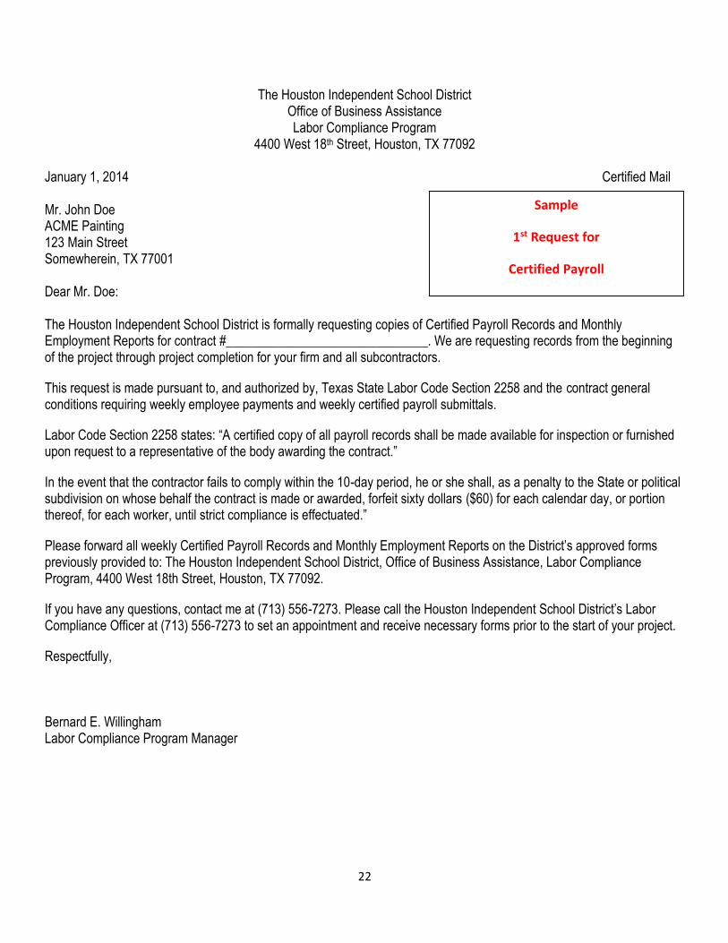
4400 West 18th Street, Houston, TX 77092 January 1, 2014 Certified Mail Mr. John Doe ACME Painting 123 Main Street Somewherein, TX 77001 Dear Mr. Doe: The Houston Independent School District is formally requesting copies of Certified Payroll Records and Monthly Employment Reports for contract #_______________________________. We are requesting records from the beginning of the project through project completion for your firm and all subcontractors.
This request is made pursuant to, and authorized by, Texas State Labor Code Section 2258 and the contract general conditions requiring weekly employee payments and weekly certified payroll submittals.
Labor Code Section 2258 states: “A certified copy of all payroll records shall be made available for inspection or furnished upon request to a representative of the body awarding the contract.”
In the event that the contractor fails to comply within the 10-day period, he or she shall, as a penalty to the State or political subdivision on whose behalf the contract is made or awarded, forfeit sixty dollars ($60) for each calendar day, or portion thereof, for each worker, until strict compliance is effectuated.”
Please forward all weekly Certified Payroll Records and Monthly Employment Reports on the District’s approved forms previously provided to: The Houston Independent School District, Office of Business Assistance, Labor Compliance Program, 4400 West 18th Street, Houston, TX 77092.
If you have any questions, contact me at (713) 556-7273. Please call the Houston Independent School District’s Labor Compliance Officer at (713) 556-7273 to set an appointment and receive necessary forms prior to the start of your project.
Respectfully, Bernard E. Willingham Labor Compliance Program Manager
Sample
1st Request for
Certified Payroll
23
The Houston Independent School District Office of Business Assistance Labor Compliance Program
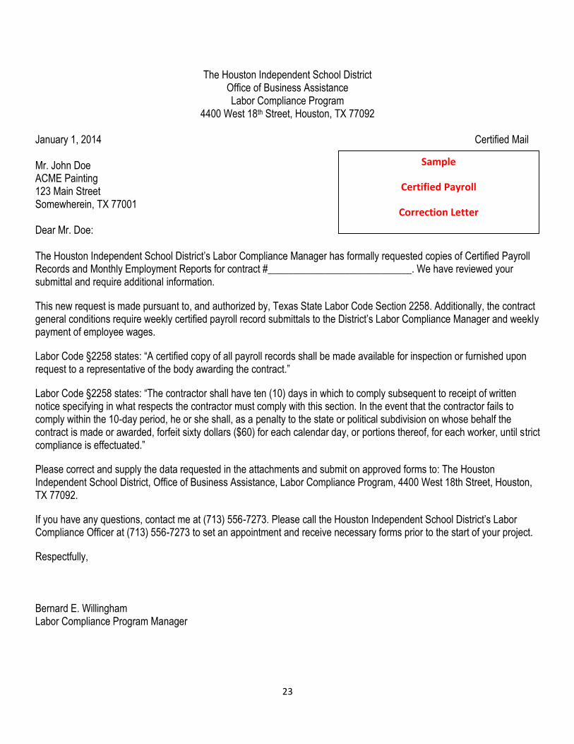
4400 West 18th Street, Houston, TX 77092 January 1, 2014 Certified Mail Mr. John Doe ACME Painting 123 Main Street Somewherein, TX 77001 Dear Mr. Doe: The Houston Independent School District’s Labor Compliance Manager has formally requested copies of Certified Payroll Records and Monthly Employment Reports for contract #____________________________. We have reviewed your submittal and require additional information.
This new request is made pursuant to, and authorized by, Texas State Labor Code Section 2258. Additionally, the contract general conditions require weekly certified payroll record submittals to the District’s Labor Compliance Manager and weekly payment of employee wages.
Labor Code §2258 states: “A certified copy of all payroll records shall be made available for inspection or furnished upon request to a representative of the body awarding the contract.”
Labor Code §2258 states: “The contractor shall have ten (10) days in which to comply subsequent to receipt of written notice specifying in what respects the contractor must comply with this section. In the event that the contractor fails to comply within the 10-day period, he or she shall, as a penalty to the state or political subdivision on whose behalf the contract is made or awarded, forfeit sixty dollars ($60) for each calendar day, or portions thereof, for each worker, until strict compliance is effectuated.”
Please correct and supply the data requested in the attachments and submit on approved forms to: The Houston Independent School District, Office of Business Assistance, Labor Compliance Program, 4400 West 18th Street, Houston, TX 77092.
If you have any questions, contact me at (713) 556-7273. Please call the Houston Independent School District’s Labor Compliance Officer at (713) 556-7273 to set an appointment and receive necessary forms prior to the start of your project.
Respectfully, Bernard E. Willingham Labor Compliance Program Manager
Sample
Certified Payroll
Correction Letter

24
PAYROLL REPORT SUBMITTAL AFFIDAVIT
I, _____________________________, the undersigned, am the __________________________ with authority to act for
and behalf of __________________________________, certify under penalty of perjury that the records or copies thereof
submitted and consisting of _____________________________ are the originals or true, full, and correct copies of the
originals which depict the payroll record(s) of the actual disbursements by way of cash, check, or whatever form to the
individual or individuals named.
Date Signature
(Name – Print) Position/Title
(Name of Business and/or contractor)
(Description, number of pages)
25
SECTION IV
HOUSTON INDEPENDENT SCHOOL DISTRICT LABOR COMPLIANCE PROGRAM
Site Visitations
26
SECTION IV SITE VISITATIONS
Site Visitations
1. Safety is the paramount factor for any site visit to any District construction projects. Business Assistance Department personnel shall not enter any area that appears unsafe. Business Assistance Department personnel are expected to exercise reasonable caution at all times.
2. All authorized Business Assistance Office personnel visiting any District construction site are required to be properly identified as a District representative by wearing visible picture ID’s (badge). Additionally, all authorized personnel are required to wear hard hats, safety shoes and safety vests.
3. Authorized personnel shall visit all sites and take a minimum amount of the workers’ time for interview purposes. All contractors shall permit interviews of trade workers during work hours on the project (not during lunch and break times).
4. Upon arrival at a site, the Business Assistance will check in at the site superintendent’s (contractor’s) trailer prior to any interviewing. In the event there is not a construction trailer, Business Assistance Department personnel will check in at the site’s administrative office. Business Assistance will identify self and state the purpose of the visit. Business Assistance will sign in if required to do so. If the site superintendent cites some reason that denies access to the site, Business Assistance will promptly and politely remove self and make a note of this occurrence and include it in a report to the Business Assistance manager.
5. Business Assistance will check to see if the following are displayed in the contractor’s trailer: a. EEO Posters b. Posted prevailing wage sheets and LCP program and # for inquiries c. Sign-in Log d. Listing of subcontractors on site
6. If any of these items are not readily visible, Business Assistance will remind the contractor these postings are part of the
contractual requirements. On subsequent visits, Business Assistance will make sure that these items are posted or the
contractor will be found to be in noncompliance.
7. There will be times when the site superintendent is somewhere on the site and/or there is no contractor present in the trailer.
Business Assistance Department personnel should check in at the District’s Resident Engineer’s (RE) trailer. The RE will
also know which contractors are on site at that time. If all trailers are empty or locked, Business Assistance Department
personnel should locate the site superintendent or RE on the site prior to commencing interviews.
Interviewing
1. Once Business Assistance Department personnel has checked in with the site superintendent and obtained access to the
site, Business Assistance Department personnel should try to locate trade persons working in clusters; for instance, several
painters, electricians, roofers, etc. working in one area. The workers should be approached individually in a non-threatening,
professional manner. Business Assistance Department personnel should identify self, indicating they are a District
representative needing only a few seconds of time to ask some very generic questions to ensure receipt of the proper rate of
pay for the type of work performed. Again, no person’s safety should be endangered in conducting these interviews. For
instance, Business Assistance Department personnel should not insist that someone on a scaffold 40 feet in the air come
down for an interview. Employees should not be asked to form a line but should be allowed to continue working until
interviewed individually.
27
2. These interviews are random; two or three trade persons for each subcontractor are more than sufficient for one visit. Any
persons missed are usually picked up on the next visit. If only one trade person is at the site, then that person should be
interviewed if possible. If Business Assistance Department personnel is told the rest of a crew will be there in an hour,
Business Assistance Department personnel should not wait unless total site interviewing will take that length of time. Thirty
minutes of interviewing per site is typically sufficient, depending upon site size and/or number of subcontractors present.
3. Business Assistance shall use the Labor Compliance Site Visitation Interview form during site interviews.
4. If someone declines to speak with a Labor Compliance Officer, those wishes should be respected. If someone asks if the interview is union-related, they should be told no. The District works with both open and closed shop trades.
5. If Business Assistance Department personnel tries to interview someone who does not speak English and communication in the appropriate language cannot occur, Business Assistance Department personnel should try to locate a coworker who can interpret. If an entire crew is unable to speak English and no interpreter is available this should be included in your report to the Program Manager.
6. If an interviewee refuses to disclose a social security number, those wishes should be respected. However, interviewees should be assured that all information given is kept strictly confidential.
7. If an interviewee does not know their rate of pay (most trade persons don’t know), Business Assistance Department personnel should ask for a guesstimate. If the response is, “whatever prevailing wage is,” that response should be indicated on the form.
8. If an interviewee indicates that he/she is an apprentice, Business Assistance Department personnel should make sure to
ask “What period?” These can be anywhere from 1st
to 10th
. If the interviewee is not sure, ask how many years have been apprenticed in the specific trade and/or to guesstimate and so indicate on the interview form.
9. Labor Compliance Officer’s should ALWAYS thank each interviewee for their time.
10. Labor Compliance Officers are there to collect information only, not to dictate how to perform jobs. Should Business Assistance Department personnel witness a potentially unsafe or unwarranted condition, Business Assistance Department personnel should contact the site inspector or job superintendent immediately and make a note on the site visitation log of what was observed. Upon return to the office, Business Assistance Department personnel should report findings to the Program Manager.
Reporting
a. All original interview forms conducted by The Business Assistance Department shall be included in Project Wage Files no
later than the end of each workweek.

28
14. Have you ever been threatened, intimidated, or coerced into giving up part of your pay?
Yes No Don’t Know
LABOR COMPLIANCE PROGRAM Houston Independent School District Office of Business Assistance 4400 West 18th Street Houston, TX 77092 713-556-7273 Phone 713-556-7274 Fax
CONSTRUCTION INTERVIEWS
Employee Statement
Page 1 of 2
CONFIDENTIAL
This document contains personal
information and it shall be kept confidential in order to protect against
unauthorized disclosure.
School/Project Name Interview Date
Contract #
Project # Prime Contractor Subcontractor
Employee Name Employee Zip Code
Ethnicity
Gender Social Security Number/Green Card (Last 4 digits)
1. When did you start on this project? 2. Last date you worked on this project before today?
Number of hours worked on this date?
3. Your Hourly Pay Rate
4. Date of Pay
SU M T W T F SA
5. Badge?
Yes No
6. What is Your Job Classification? 7. Are you part of a union?
Apprentice? Yes No Don’t know If Yes, What Period?
8. Have you received either 5, 10, or 30 hours of OSHA training? Yes No Don’t Know
9. What Tools or Equipment Do You Use on the Job?
10. Do you provide materials and tools? Yes No Don’t Know
11. How many hours did you work last week on this project?
12. Was any of that time overtime? Yes No Don’t know
13. Have you done any other type of work on this project?
Yes No Don’t Know
29
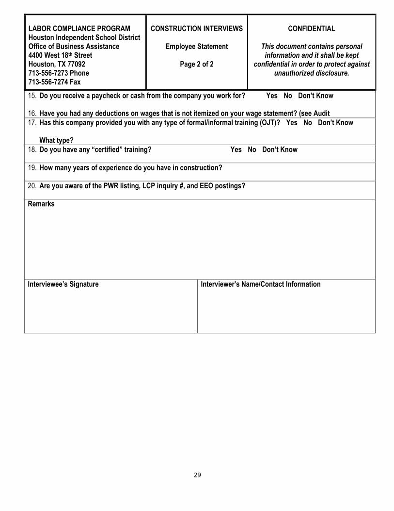
15. Do you receive a paycheck or cash from the company you work for? Yes No Don’t Know
16. Have you had any deductions on wages that is not itemized on your wage statement? (see Audit
17. Has this company provided you with any type of formal/informal training (OJT)? Yes No Don’t Know What type?
18. Do you have any “certified” training? Yes No Don’t Know
19. How many years of experience do you have in construction?
20. Are you aware of the PWR listing, LCP inquiry #, and EEO postings?
Remarks
Interviewee’s Signature Interviewer’s Name/Contact Information
LABOR COMPLIANCE PROGRAM Houston Independent School District Office of Business Assistance 4400 West 18th Street Houston, TX 77092 713-556-7273 Phone 713-556-7274 Fax
CONSTRUCTION INTERVIEWS
Employee Statement
Page 2 of 2
CONFIDENTIAL
This document contains personal
information and it shall be kept confidential in order to protect against
unauthorized disclosure.

30
LABOR COMPLIANCE PROGRAM
Houston Independent School District Office of Business Assistance 4400 West 18th Street Houston, TX 77092 713-556-7273 Phone 713-556-7274 Fax
SUPERINTENDENT OR FOREMAN STATEMENT FORM
Page 1 of 2
CONFIDENTIAL
This document contains personal information and it shall be kept confidential in order to protect
against unauthorized disclosure.
Company Name:
Superintendent/Foreman:
Project Name: Project No.:
Job site/Location:
Contract #
Ethnicity: Gender: Report Date:
Badge? ___Yes ____ No Questions:
1. How long have you worked for this company (Date of Hire)?
2. How long have you been the superintendent or foreman?
3. How did you hear about this job or company?
4. What is your recruitment or hiring process?
5. Are you involved in the hiring process?
6. Do you maintain a record or file of names addresses and phone numbers of off-the-street applicants (females, minorities, disabled and veterans) for employment?
7. Do you refer them to your hiring official and/or to the Union?
8. Does the company or Union allow you to do your own recruitment?
9. Are you responsible for work assignments, layoffs and terminations?
31
LABOR COMPLIANCE PROGRAM
Houston Independent School District Office of Business Assistance 4400 West 18th Street Houston, TX 77092 713-556-7273 Phone 713-556-7274 Fax
SUPERINTENDENT OR FOREMAN STATEMENT FORM
Page 2 of 2
CONFIDENTIAL
This document contains personal information and it shall be kept confidential in order to protect
against unauthorized disclosure.
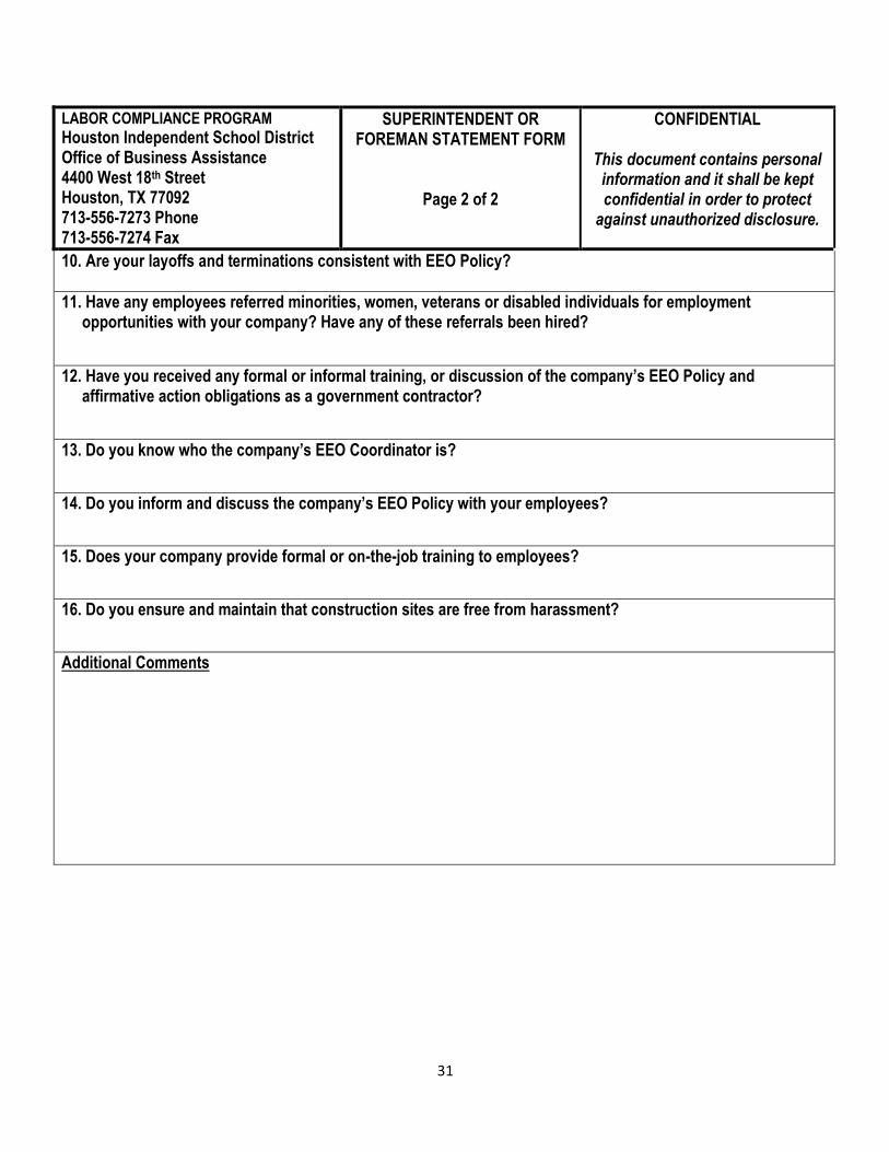
10. Are your layoffs and terminations consistent with EEO Policy?
11. Have any employees referred minorities, women, veterans or disabled individuals for employment opportunities with your company? Have any of these referrals been hired?
12. Have you received any formal or informal training, or discussion of the company’s EEO Policy and affirmative action obligations as a government contractor?
13. Do you know who the company’s EEO Coordinator is?
14. Do you inform and discuss the company’s EEO Policy with your employees?
15. Does your company provide formal or on-the-job training to employees?
16. Do you ensure and maintain that construction sites are free from harassment?
Additional Comments
32
SECTION V
HOUSTON INDEPENDENT SCHOOL DISTRICT LABOR COMPLIANCE PROGRAM
Audit Procedures

33
SECTION V
HOUSTON INDEPENDENT SCHOOL DISTRICT
LABOR COMPLIANCE PROGRAM
AUDIT PROCEDURES
An audit record is sufficiently detailed to “verify compliance with the requirements of The Labor Compliance Program when the audit record displays that the following procedures have been followed:
A. Audit of the obligation to carry workers’ compensation insurance means producing written evidence of a binder issued by the
carrier, or telephone or written inquiry to the Texas Department of Insurance Division of Workers’ Compensation.
B. Audit of apprentices where applicable means inquiry to the program sponsor for the apprenticeable craft or trade in the area of the public work as to: Whether contract award information was received, including an estimate of journeyperson hours to be performed and the number of apprentices to be employed; whether apprentices have been requested, and whether the request has been met; whether the program sponsor knows of any amounts received from the contractor or subcontractor for the training fund or Texas Workforce Commission; and whether persons listed on the certified payroll in that craft or trade being paid less than the journeyperson rate are apprentices registered with that program and working under apprentice agreements approved by the U.S. Department of Labor Office of Apprenticeship.
C. Audit of the obligation to pass through amounts, made part of the bid, for apprenticeship and non-apprenticeship training contributions to either the training trust or the Texas Workforce Commission, means asking for copies of checks remitted, or when the audit occurs more than thirty (30) days after the month in which payroll has been paid, copies of canceled checks remitted.
D. Audit of “illegal taking of wages” means inspection of written authorizations for deductions in the contractor’s files and comparison to wage deduction statements furnished to employees together with an interview of several employees as to any payments made which are not reflected on the wage deduction statements.
E. Audit of the obligation to keep records of working hours and pay not less than required for hours worked in excess of forty (40) hours/week means review and audit of weekly certified payroll records.
F. Audit of the obligation to pay the prevailing per diem wage means review and audit of weekly certified payroll records for compliance with:
a. All elements defined as the General Prevailing Rate of Per Diem Wages which were determined to be prevailing in the Office of Business Assistance’s determination in effect on the date of the call for bids, or as reflected in any subsequent revised determination issued by Business Assistance, copies of which are available at the Construction and Facilities Services Office and posted at the public works job site.
b. All elements defined as Employer Payments to Workers which were determined to be prevailing in Business Assistance’s determination in effect on the date of the call for bids, or as reflected in any subsequent revised determination issued by Business Assistance, copies of which are available at the Construction and Facilities Services Office and posted at the public works job site.
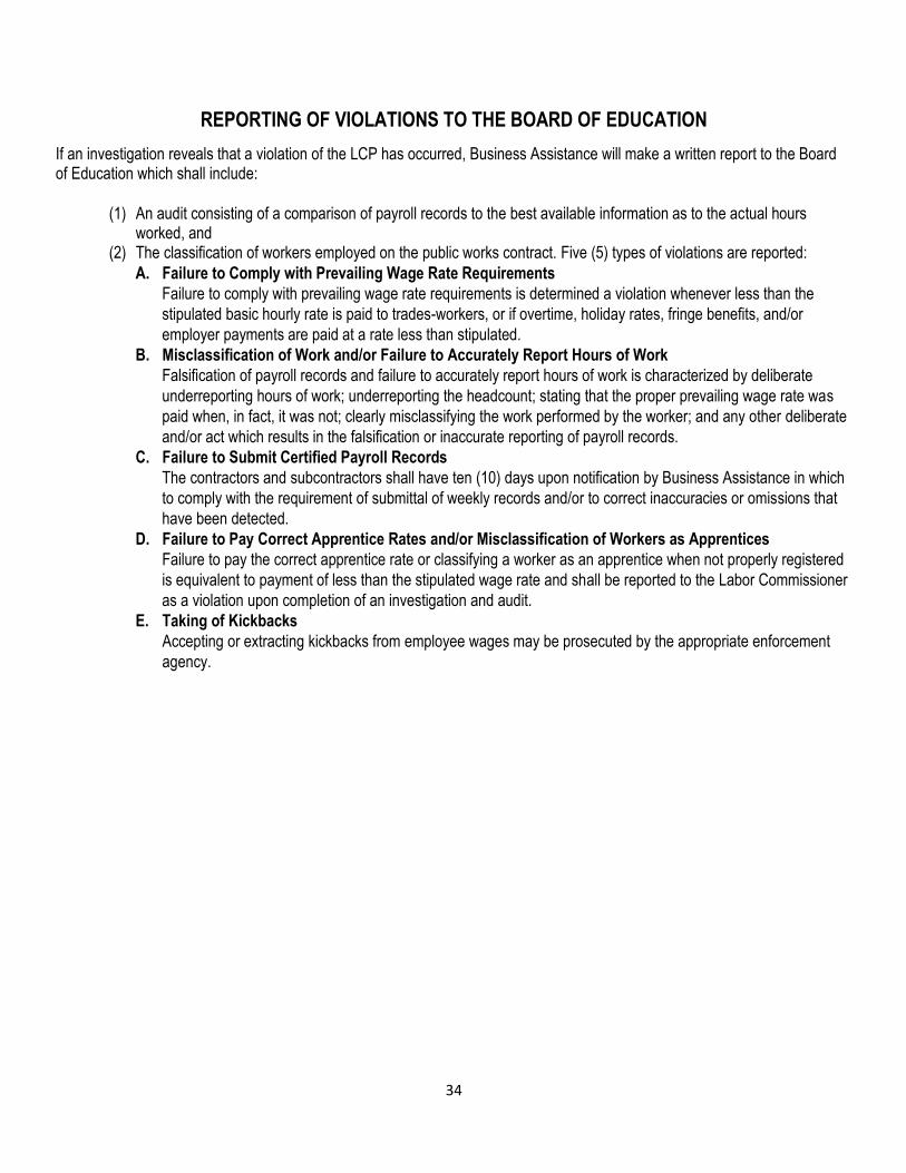
34
REPORTING OF VIOLATIONS TO THE BOARD OF EDUCATION
If an investigation reveals that a violation of the LCP has occurred, Business Assistance will make a written report to the Board of Education which shall include:
(1) An audit consisting of a comparison of payroll records to the best available information as to the actual hours
worked, and (2) The classification of workers employed on the public works contract. Five (5) types of violations are reported:
A. Failure to Comply with Prevailing Wage Rate Requirements
Failure to comply with prevailing wage rate requirements is determined a violation whenever less than the
stipulated basic hourly rate is paid to trades-workers, or if overtime, holiday rates, fringe benefits, and/or
employer payments are paid at a rate less than stipulated.
B. Misclassification of Work and/or Failure to Accurately Report Hours of Work
Falsification of payroll records and failure to accurately report hours of work is characterized by deliberate
underreporting hours of work; underreporting the headcount; stating that the proper prevailing wage rate was
paid when, in fact, it was not; clearly misclassifying the work performed by the worker; and any other deliberate
and/or act which results in the falsification or inaccurate reporting of payroll records.
C. Failure to Submit Certified Payroll Records
The contractors and subcontractors shall have ten (10) days upon notification by Business Assistance in which
to comply with the requirement of submittal of weekly records and/or to correct inaccuracies or omissions that
have been detected.
D. Failure to Pay Correct Apprentice Rates and/or Misclassification of Workers as Apprentices
Failure to pay the correct apprentice rate or classifying a worker as an apprentice when not properly registered
is equivalent to payment of less than the stipulated wage rate and shall be reported to the Labor Commissioner
as a violation upon completion of an investigation and audit.
E. Taking of Kickbacks
Accepting or extracting kickbacks from employee wages may be prosecuted by the appropriate enforcement
agency.
35
ENFORCEMENT ACTION
A. Duty of the Awarding Body
The Houston Independent School District as the awarding body having an approved LCP has a duty to the Board of
Education to enforce the requirements of the Labor Code. The primary function of this LCP is to ensure public works
contractors comply with prevailing wage requirements found in the Labor Code. The procedures specified herein, including
proactive investigation methods, comprise the minimum obligations required of this LCP to operate. The Houston
Independent School District Labor Compliance Program will:
1. Review payroll records
Review payroll records furnished by contractors and subcontractors as promptly as practicable after receipt, but in no
event more than 30 days after such receipt. "Review" for this purpose shall be defined as inspection of the records
furnished to determine if:
a. all appropriate data elements identified in the Labor Code have been reported;
b. certification forms have been completed and signed in compliance; and
c. correct prevailing wage rates have been reported as paid for each classification of labor listed, with confirmation of payment through worker interviews, examination of paychecks or paycheck stubs, direct confirmation of payments from third party recipients of "Employer Payments", or any other reasonable method.
i. For each month a contractor or subcontractor reports workers employed on the public work,
confirmation of furnished payroll records shall be undertaken randomly for at least one worker for at
least one weekly period within that month.
ii. Confirmation shall be undertaken whenever complaints from workers or other interested persons or
other circumstances or information reasonably suggest payroll records furnished by a contractor or
subcontractor are inaccurate.
2. Conduct in-person inspections at sites where public work is being performed.
Such On-Site Visits may be undertaken randomly or as deemed necessary, but shall be undertaken during each week
that workers are present. On-Site Visits may include any activities deemed necessary to corroborate prevailing wage
payments reported on payroll records furnished by contractors and subcontractors. All On-Site Visits shall include visual
inspection of:
a. the copy of the wage determination(s) required to be posted at each job site in compliance with the Labor Code, and
b. Notice of Labor Compliance Program Approval required to be posted at the job site, including a phone number for inquiries, questions, or assistance with regard to the LCP.
3. Respond to receipt of a written complaint
Alleging failure of a contractor or subcontractor to pay prevailing wages by performing all of the following actions: a. Within 15 days after receipt of the complaint, send a written acknowledgement to the complainant
acknowledging receipt of the complaint and identifying the name, address, and phone number of the Business Assistance staff member or designee assigned to the complaint;
36
b. Within 15 days after receipt of the complaint, provide the affected contractor with the notice required under the
Labor Code if the complaint is against a subcontractor;
c. Notify the complainant in writing of the resolution of the complaint within ten days after the complaint has been resolved;
d. Notify the complainant in writing at least once every 30 days of the status of a complaint that has not yet been resolved; and
e. Notify the complainant in writing at least once every 90 days of the status of a complaint that has been resolved by the District’s LCP but remains under review or in litigation before another entity.
4. With respect to apprenticeship standards,
Perform the following only if contractor employs apprentices:
a. Inform contractors and subcontractors bidding public works about apprenticeship requirements; b. Send copies of awards and notices of discrepancies to the Texas Workforce Commission; c. refer complaints and promptly report suspected violations of apprenticeship requirements to the Texas
Workforce Commission; d. enforce prevailing wage pay requirements for apprentices to ensure that:
i. any contributions required are paid to the appropriate entity; ii. apprentices are paid no less than the prevailing apprentice rate; iii. workers listed and paid as apprentices on certified payroll records are, in fact, duly registered as
apprentices with the Texas Workforce Commission; and iv. the regular prevailing wage rate is paid to any worker who is not a duly registered apprentice and for all
hours worked in excess of the maximum ratio permitted.
5. Maintain records for each public work project. Subject to prevailing wage requirements which include a separate, written
summary of labor compliance activities and relevant facts pertaining to that particular project.
a. The summary shall be maintained using the form, Single Project Labor Compliance Review and Enforcement Report Form.
b. The summary shall demonstrate that reasonable and sufficient efforts have been made to enforce prevailing wage requirements consistent with the practice of the Labor Commissioner.
c. Records for a prevailing wage project shall be retained for the later of:
i. at least one year after the acceptance of the public work or 5 years after cessation of all labor on a public
work that has not been accepted; or
ii. one year after a final decision or judgment in any litigation.
d. A written summary or report includes information maintained electronically, provided the summary or report can be printed in hard copy form or is in an electronic format that can be transmitted by email or compact disk and would be acceptable for the filing of documents in a state court of record in Texas.
6. Prepare an Audit as a written summary when there has been a violation of the Public Works Chapter of the Labor Code resulting in the underpayment of wages.
a. An Audit will include prevailing wage deficiencies for each underpaid worker with any penalties to be assessed as determined after consideration of the best information available as to actual hours worked, amounts paid, and classifications of workers employed in connection with the public work.
b. An Audit may include, but is not limited to:
37
i. worker interviews; ii. complaints from workers or other interested persons; iii. all time cards, cancelled checks, cash receipts, trust fund forms, books, documents, schedules, forms,
reports, receipts or other evidences which reflect job assignments; iv. work schedules by days and hours; and v. disbursement by way of cash, check, or any other method, of funds to a person(s) by job classification
and/or skill pursuant to a public works project. c. An Audit will contain details sufficient to enable the Board of Education, if requested to determine the amount of
forfeiture, to draw reasonable conclusions as to compliance with the requirements of the Public Works Labor Code, and to enable accurate computation of underpayments of wages to workers and of applicable penalties and forfeitures. To meet such standards, the Audit Reporting will be utilized:
i. Public Works Investigation Worksheet ii. Public Works Audit Worksheet iii. Prevailing Wage Determination Summary
d. An Audit report will also include a brief narrative identifying the Bid Advertisement Date of the contract for public work and summarizing the nature of the violation and the basis upon which the determination of underpayment was made.
e. Records supporting an Audit shall be maintained by the District to satisfy its burden of coming forward with evidence in administrative review proceedings and regulations.
7. Provide notification of an opportunity to resolve a wage deficiency to the contractor and affected subcontractor
prior to a determination of the amount of forfeiture by the Board of Education after a determination that violations
of the prevailing wage laws have resulted in the underpayment of wages and an audit has been prepared.
a. The contractor and affected subcontractor shall be provided at least 10 days following such notification to
submit exculpatory information consistent with the "good faith mistake" factors. b. Based upon the contractor's submission, the District’s LCP may reasonably conclude the failure to pay correct
wages was a good faith mistake and the District shall not be required to request the Board of Education for a determination of the amount of penalties to be assessed if the following terms are met:
i. the contractor and/or affected subcontractor have no known prior record of failure to meet their prevailing
wage obligations;
ii. underpayment of wages to workers is promptly corrected; and
iii. proof of such payment is received by the District’s LCP.
c. For each instance in which a wage deficiency is resolved in accordance with this regulation, the District’s LCP
shall maintain a written record of the failure of the contractor or subcontractor to meet its prevailing wage
obligation. The record shall include:
i. name and description of the public works project;
ii. contractor or affected subcontractor involved;
iii. gross amount of wages paid to workers to resolve the prevailing wage deficiency; and
iv. a copy of the Audit prepared for this incident including any exculpatory information submitted by the
affected contractor or subcontractor.
8. Recommend a withhold of penalties, forfeitures, and underpayment of wages for violations of the requirements of this program.
9. Ensure accord with Labor Code that this LCP requires at a minimum the inclusion of appropriate language in bid requests, design-build requests, the contract, and purchase orders concerning Texas Labor Code 2258:
a. A provision that contract payments are not made when payroll records are delinquent or inadequate; and

38
b. A pre-construction conference with listed contractors and subcontractors to discuss applicable state labor law requirements as outlined in the Checklist of Labor Law Requirements with copies of forms furnished and discussed.
10. Take cognizance of prevailing wage violations under Texas Labor Code 2258 and take any appropriate action pursuant to and in accordance with that responsibility and authority.
11. Enforce prevailing wage requirements, consistent with the policy of the state by taking reasonable, vigorous and prompt action to determine whether violations exist and enforce compliance, including through imposition of appropriate penalties and formal enforcement action, when violations are found. This LCP shall neither avoid use of its enforcement authority based on cost considerations nor use its authority in an unreasonable manner to gain leverage over a contractor or subcontractor. Unreasonable use of enforcement authority includes, but is not limited to, prolonged or excessive withholdings of contract payments without making a determination a violation has occurred.
a. Pursue continual development of abilities to perform labor compliance oversight including securing training
on enforcement of prevailing wage requirements, monitoring and investigation, and procedural requirements and responsibilities.
b. Designate employees for this program who participate in making decisions for this Labor Compliance Program and require those employees to file Semi-Annual Disclosure Statements through the filing officer for the Houston Independent School District and to comply with other applicable requirements in connection with this work.
c. Any failure of this Labor Compliance Program to comply with an requirement shall not of itself constitute a defense to the failure to pay prevailing wages or meet other obligations imposed by Texas Labor Code Title 10, Subtitle F., Chapter 2258.
B. Withholding Contract Payments When Payroll Records are Delinquent or Inadequate
a. “Withhold” means to cease payments by the awarding body, its agents or others who pay on its behalf to the contractor. Where the violation is by a subcontractor, the contractor shall be notified of the nature of the violation and reference made to its rights. A release bond may not be posted for release of funds being withheld for the violation of the prevailing wage law.
b. “Contracts” except as otherwise provided by agreement, means only contracts under a single master contract, or contracts entered into as stages of a single project which may be the subject of withholding.
c. “Delinquent payroll records” means those not submitted on the basis set forth in the District Contract and the LCP.
d. “Inadequate payroll records” are any one of the following: i. A record lacking the information required. ii. A record which contains the required information but which is not certified, or certified by someone not
an agent of the contractor or subcontractor. iii. A record remaining uncorrected for one payroll period after the awarding body has given the contractor
notice of inaccuracies detected by audit or record review, provided, however, that prompt correction will stop any duty to withhold if such inaccuracies do not amount to one-percent (1%) of the entire certified weekly payroll in dollar value and does not affect more than half the persons listed as workers employed on that certified weekly payroll. Prompt correction will stop any duty to withhold if such inaccuracies are de minimus.
iv. When payroll records are delinquent or inadequate, the withholding of contract payments is required and does not require the prior approval of the Board of Education. The District shall only withhold those payments due or estimated to be due to the contractor or subcontractor whose payroll records are delinquent or inadequate, plus any additional amount that the District’s LCP has reasonable cause to believe may be needed to cover a back wage and penalty assessment against the contractor or
39
subcontractor whose payroll records are delinquent or inadequate. A contractor shall be required in turn to cease all payments to a subcontractor whose payroll records are delinquent or inadequate until the District’s LCP provides notice that the subcontractor has cured the delinquency or deficiency.
a. When contract payments are withheld under this section, the District’s LCP shall provide the
contractor and subcontractor, if applicable, with immediate (3-5 working days) written notice that
includes all of the following:
1) a statement that payments are being withheld due to delinquent or inadequate payroll records,
and that identifies what records are missing or states why records that have been submitted are
deemed inadequate;
2) the specific amount being withheld; and
3) notification of the contractor’s or subcontractor’s right to request an expedited hearing to review
the withholding of contract payments is limited to the issue of whether the records are delinquent
or inadequate or the District’s LCP has exceeded its authority under this section.
b. No contract payments shall be withheld solely on the basis of delinquent or inadequate payroll records after the required records have been produced.
c. In addition to withholding contract payments based on delinquent or inadequate payroll records, penalties shall be assessed under Labor Code Section 2258.023(b) for failure to timely comply with a written request for certified payroll records. The assessment of penalties under Labor Code Section 2258.023(b) does require the prior approval of the Board of Education. The contractor shall, as a penalty to the District, forfeit Sixty dollars ($60) for each calendar day, or portion thereof, for each worker, until strict compliance is effectuated.
C. Withholding for Violation for Not Paying the Per Diem Prevailing Wages
1. Where the violation is by a subcontractor, the general contractor shall be notified of the nature of the violation and reference made to its rights under Labor Code Section 2258.
2. “Amount equal to the underpayment” is the total of the following determined by payroll review, audit, or admission of the contractor or subcontractor.
a. The difference between the amounts paid to workers and the correct General Prevailing Wage Rate of Per Diem Wages.
b. The difference between the amounts paid to workers and the correct amounts of employer payments and determined to be part of the prevailing rate costs of contractors due for employment of workers in such craft, classification or trade in which they were employed and the amounts paid.
c. Estimated amounts of “illegal taking of wages.”
d. Amounts of apprenticeship training contributions paid to neither the program sponsor’s training trust or the Texas Workforce Commission.
e. The withholding of contract payments when, after investigation, it is established that underpayment or violations have occurred requires the prior approval of the Board of Education.
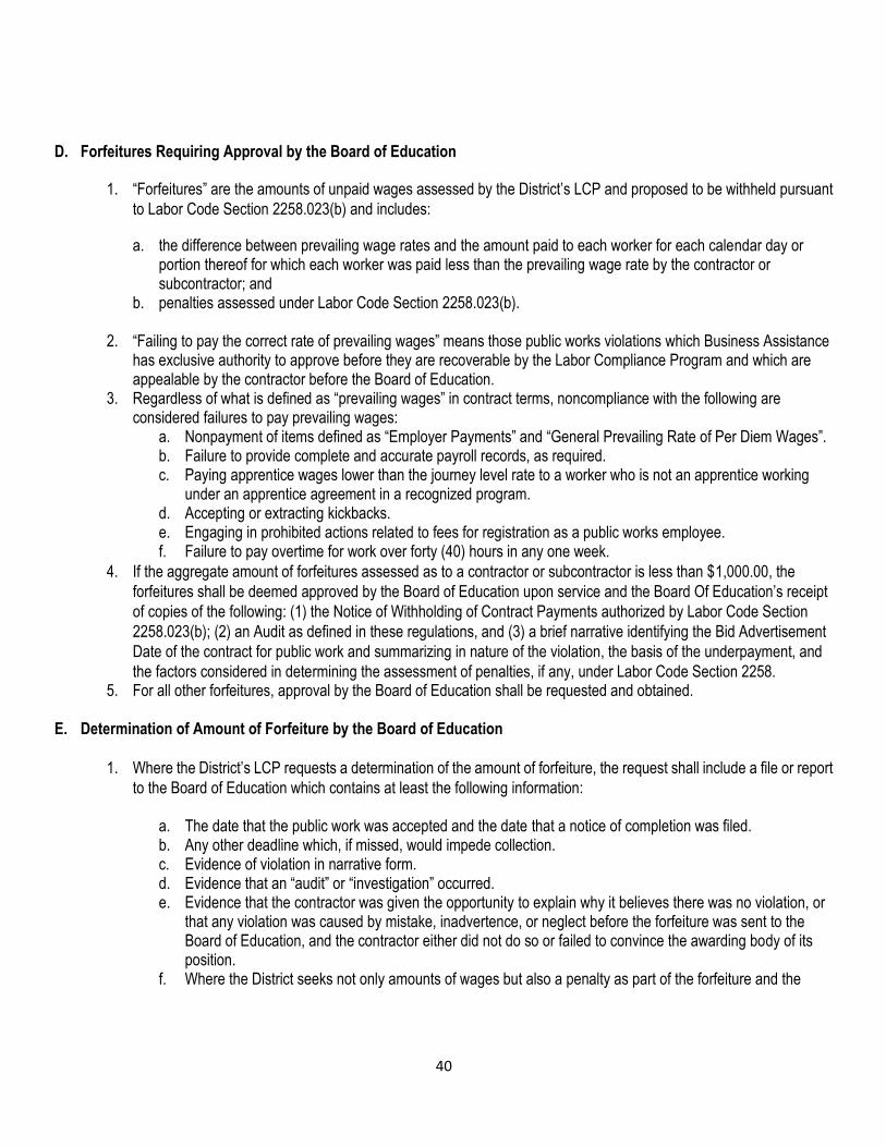
40
D. Forfeitures Requiring Approval by the Board of Education
1. “Forfeitures” are the amounts of unpaid wages assessed by the District’s LCP and proposed to be withheld pursuant
to Labor Code Section 2258.023(b) and includes:
a. the difference between prevailing wage rates and the amount paid to each worker for each calendar day or portion thereof for which each worker was paid less than the prevailing wage rate by the contractor or subcontractor; and
b. penalties assessed under Labor Code Section 2258.023(b).
2. “Failing to pay the correct rate of prevailing wages” means those public works violations which Business Assistance has exclusive authority to approve before they are recoverable by the Labor Compliance Program and which are appealable by the contractor before the Board of Education.
3. Regardless of what is defined as “prevailing wages” in contract terms, noncompliance with the following are considered failures to pay prevailing wages:
a. Nonpayment of items defined as “Employer Payments” and “General Prevailing Rate of Per Diem Wages”. b. Failure to provide complete and accurate payroll records, as required. c. Paying apprentice wages lower than the journey level rate to a worker who is not an apprentice working
under an apprentice agreement in a recognized program. d. Accepting or extracting kickbacks. e. Engaging in prohibited actions related to fees for registration as a public works employee. f. Failure to pay overtime for work over forty (40) hours in any one week.
4. If the aggregate amount of forfeitures assessed as to a contractor or subcontractor is less than $1,000.00, the
forfeitures shall be deemed approved by the Board of Education upon service and the Board Of Education’s receipt
of copies of the following: (1) the Notice of Withholding of Contract Payments authorized by Labor Code Section
2258.023(b); (2) an Audit as defined in these regulations, and (3) a brief narrative identifying the Bid Advertisement
Date of the contract for public work and summarizing in nature of the violation, the basis of the underpayment, and
the factors considered in determining the assessment of penalties, if any, under Labor Code Section 2258. 5. For all other forfeitures, approval by the Board of Education shall be requested and obtained.
E. Determination of Amount of Forfeiture by the Board of Education
1. Where the District’s LCP requests a determination of the amount of forfeiture, the request shall include a file or report
to the Board of Education which contains at least the following information:
a. The date that the public work was accepted and the date that a notice of completion was filed. b. Any other deadline which, if missed, would impede collection. c. Evidence of violation in narrative form. d. Evidence that an “audit” or “investigation” occurred. e. Evidence that the contractor was given the opportunity to explain why it believes there was no violation, or
that any violation was caused by mistake, inadvertence, or neglect before the forfeiture was sent to the Board of Education, and the contractor either did not do so or failed to convince the awarding body of its position.
f. Where the District seeks not only amounts of wages but also a penalty as part of the forfeiture and the

41
contractor has unsuccessfully contended that the cause of violation was a mistake, inadvertence or neglect, a statement should accompany the proposal for forfeiture with a recommended penalty amount, pursuant to Labor Code Section 2258.
g. Where the District seeks only wages or a penalty less than Sixty dollars ($60) per day as part of the forfeiture and the contractor has successfully contended that the cause of violation was a mistake, inadvertence or neglect, then the file should include the evidence as to the contractor’s knowledge of its obligation, including the LCP’s communication to the contractor of the obligation in the bid invitations, in the preconstruction conference agenda and records, and any other notice given as part of the contracting process. Included with the file should be a statement similar to that described in subsection (f) above and recommended penalty amounts, pursuant to Labor Code Section 2258.
h. The previous record of the contractor in meeting prevailing wage obligations. i. Whether the District’s LCP is approved on an interim or temporary basis or extended.
2. The file or report shall be served on the Board of Education as soon as practicable after the violation has been
discovered, and not less than 30 days before the final payment, but in no event less than 30 days before the expiration
of the limitations period. 3. A copy of the file or report shall be served on the contractor at the same time it is sent to the Board of Education.
The District may exclude from the documents served on the contractor/subcontractor or surety copies of documents secured from these parties during an audit, investigation or meeting if those documents are clearly referenced in the file or report.
4. The Board of Education shall affirm, reject or modify the forfeiture in whole or in part as to penalty and/or wages due.
5. The determination of the forfeiture by the Board of Education is effective on the following date for Labor Compliance Program’s having initial approval:
a. On the date Business Assistance serves by first class mail on the District and on the contractor, an endorsed copy of the proposed forfeiture, or a drafted forfeiture statement which sets out the amount of forfeiture approved. Service on the contractor is effective if made on the last address supplied by the contractor in the record. Business Assistance’s approval, modification or disapproval of the proposed forfeiture shall be served within thirty (30) days of receipt of the proposed forfeiture.
b. If the District’s LCP is operating with extended authority, approval is effective 20 days after the requested forfeitures are served upon the Board of Education, unless Business Assistance serves a notice upon the parties, within that time period, that this forfeiture request is subject to further review. In such cases, a notice that approval will follow such a procedure will be included in the transmittal of the forfeiture request to the contractor. If Business Assistance notifies the parties of a decision to undertake further review, the Board of Education’s final approval, modification or disapproval of the proposed forfeiture shall be served within 30 days of the date of notice of further review.
F. Liquidated Damages
1. After 60 days following the service of a civil wage and penalty assessment the affected contractor, subcontractor,
and surety on a bond or bonds issues to secure the payment of wages covered by the assessment or notice shall
be liable for liquidated damages in an amount equal to the wages, or portion thereof, that still remain unpaid.
a. If the assessment or notice subsequently is overturned or modified after administrative or judicial review, liquidated damages shall be payable only on the wages found to be due and unpaid.
b. If the contractor or subcontractor demonstrates to the satisfaction of Business Assistance substantial grounds for appealing the assessment or notice with respect to a portion of the unpaid wages covered by the assessment or notice, Business Assistance may exercise discretion to waive payment of the liquidated damages with respect to that portion of the unpaid wages.
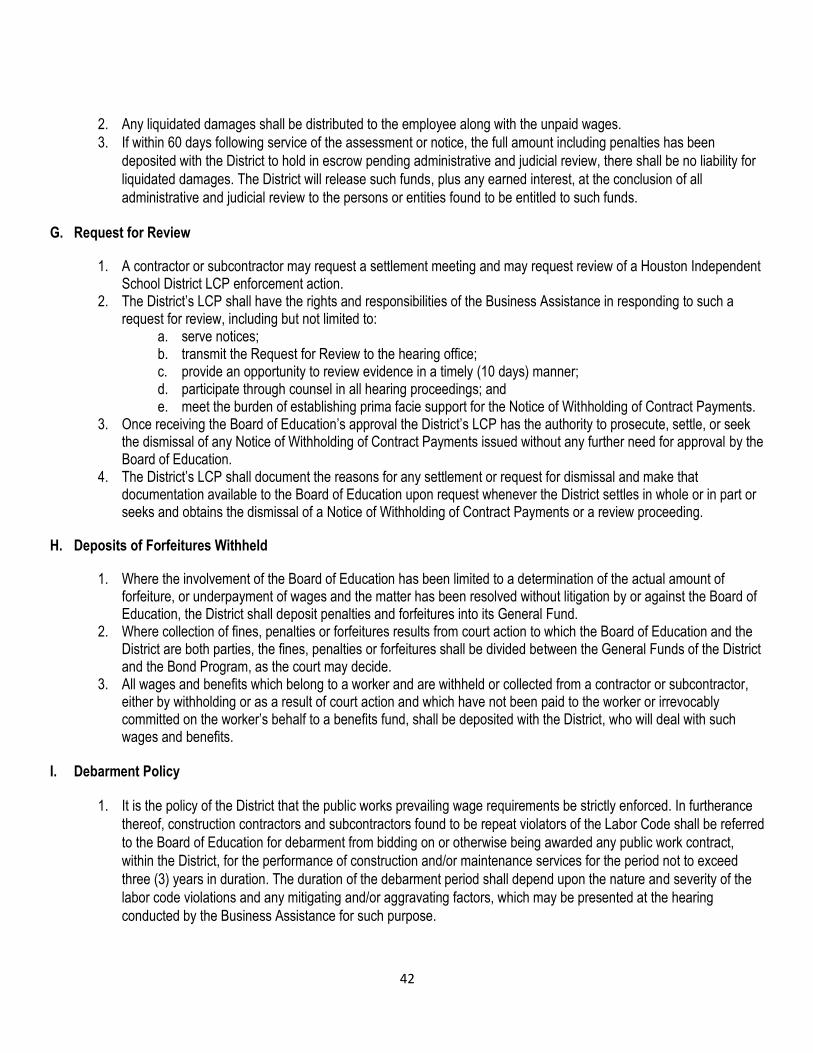
42
2. Any liquidated damages shall be distributed to the employee along with the unpaid wages.
3. If within 60 days following service of the assessment or notice, the full amount including penalties has been
deposited with the District to hold in escrow pending administrative and judicial review, there shall be no liability for
liquidated damages. The District will release such funds, plus any earned interest, at the conclusion of all
administrative and judicial review to the persons or entities found to be entitled to such funds. G. Request for Review
1. A contractor or subcontractor may request a settlement meeting and may request review of a Houston Independent School District LCP enforcement action.
2. The District’s LCP shall have the rights and responsibilities of the Business Assistance in responding to such a request for review, including but not limited to:
a. serve notices; b. transmit the Request for Review to the hearing office; c. provide an opportunity to review evidence in a timely (10 days) manner; d. participate through counsel in all hearing proceedings; and e. meet the burden of establishing prima facie support for the Notice of Withholding of Contract Payments.
3. Once receiving the Board of Education’s approval the District’s LCP has the authority to prosecute, settle, or seek the dismissal of any Notice of Withholding of Contract Payments issued without any further need for approval by the Board of Education.
4. The District’s LCP shall document the reasons for any settlement or request for dismissal and make that documentation available to the Board of Education upon request whenever the District settles in whole or in part or seeks and obtains the dismissal of a Notice of Withholding of Contract Payments or a review proceeding.
H. Deposits of Forfeitures Withheld
1. Where the involvement of the Board of Education has been limited to a determination of the actual amount of forfeiture, or underpayment of wages and the matter has been resolved without litigation by or against the Board of Education, the District shall deposit penalties and forfeitures into its General Fund.
2. Where collection of fines, penalties or forfeitures results from court action to which the Board of Education and the District are both parties, the fines, penalties or forfeitures shall be divided between the General Funds of the District and the Bond Program, as the court may decide.
3. All wages and benefits which belong to a worker and are withheld or collected from a contractor or subcontractor, either by withholding or as a result of court action and which have not been paid to the worker or irrevocably committed on the worker’s behalf to a benefits fund, shall be deposited with the District, who will deal with such wages and benefits.
I. Debarment Policy
1. It is the policy of the District that the public works prevailing wage requirements be strictly enforced. In furtherance
thereof, construction contractors and subcontractors found to be repeat violators of the Labor Code shall be referred
to the Board of Education for debarment from bidding on or otherwise being awarded any public work contract,
within the District, for the performance of construction and/or maintenance services for the period not to exceed
three (3) years in duration. The duration of the debarment period shall depend upon the nature and severity of the
labor code violations and any mitigating and/or aggravating factors, which may be presented at the hearing
conducted by the Business Assistance for such purpose.
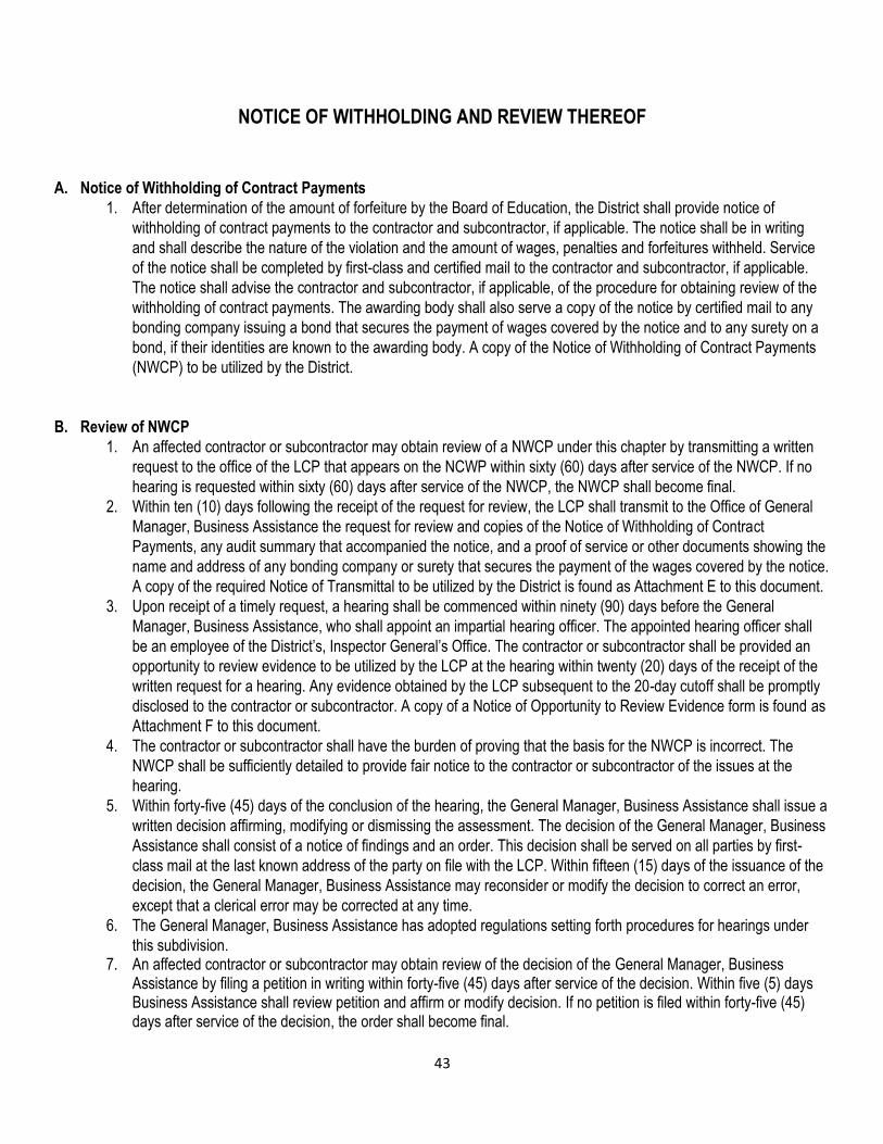
43
NOTICE OF WITHHOLDING AND REVIEW THEREOF
A. Notice of Withholding of Contract Payments
1. After determination of the amount of forfeiture by the Board of Education, the District shall provide notice of
withholding of contract payments to the contractor and subcontractor, if applicable. The notice shall be in writing
and shall describe the nature of the violation and the amount of wages, penalties and forfeitures withheld. Service
of the notice shall be completed by first-class and certified mail to the contractor and subcontractor, if applicable.
The notice shall advise the contractor and subcontractor, if applicable, of the procedure for obtaining review of the
withholding of contract payments. The awarding body shall also serve a copy of the notice by certified mail to any
bonding company issuing a bond that secures the payment of wages covered by the notice and to any surety on a
bond, if their identities are known to the awarding body. A copy of the Notice of Withholding of Contract Payments
(NWCP) to be utilized by the District.
B. Review of NWCP
1. An affected contractor or subcontractor may obtain review of a NWCP under this chapter by transmitting a written
request to the office of the LCP that appears on the NCWP within sixty (60) days after service of the NWCP. If no
hearing is requested within sixty (60) days after service of the NWCP, the NWCP shall become final.
2. Within ten (10) days following the receipt of the request for review, the LCP shall transmit to the Office of General
Manager, Business Assistance the request for review and copies of the Notice of Withholding of Contract
Payments, any audit summary that accompanied the notice, and a proof of service or other documents showing the
name and address of any bonding company or surety that secures the payment of the wages covered by the notice.
A copy of the required Notice of Transmittal to be utilized by the District is found as Attachment E to this document.
3. Upon receipt of a timely request, a hearing shall be commenced within ninety (90) days before the General
Manager, Business Assistance, who shall appoint an impartial hearing officer. The appointed hearing officer shall
be an employee of the District’s, Inspector General’s Office. The contractor or subcontractor shall be provided an
opportunity to review evidence to be utilized by the LCP at the hearing within twenty (20) days of the receipt of the
written request for a hearing. Any evidence obtained by the LCP subsequent to the 20-day cutoff shall be promptly
disclosed to the contractor or subcontractor. A copy of a Notice of Opportunity to Review Evidence form is found as
Attachment F to this document.
4. The contractor or subcontractor shall have the burden of proving that the basis for the NWCP is incorrect. The
NWCP shall be sufficiently detailed to provide fair notice to the contractor or subcontractor of the issues at the
hearing.
5. Within forty-five (45) days of the conclusion of the hearing, the General Manager, Business Assistance shall issue a
written decision affirming, modifying or dismissing the assessment. The decision of the General Manager, Business
Assistance shall consist of a notice of findings and an order. This decision shall be served on all parties by first-
class mail at the last known address of the party on file with the LCP. Within fifteen (15) days of the issuance of the
decision, the General Manager, Business Assistance may reconsider or modify the decision to correct an error,
except that a clerical error may be corrected at any time.
6. The General Manager, Business Assistance has adopted regulations setting forth procedures for hearings under
this subdivision. 7. An affected contractor or subcontractor may obtain review of the decision of the General Manager, Business
Assistance by filing a petition in writing within forty-five (45) days after service of the decision. Within five (5) days Business Assistance shall review petition and affirm or modify decision. If no petition is filed within forty-five (45) days after service of the decision, the order shall become final.
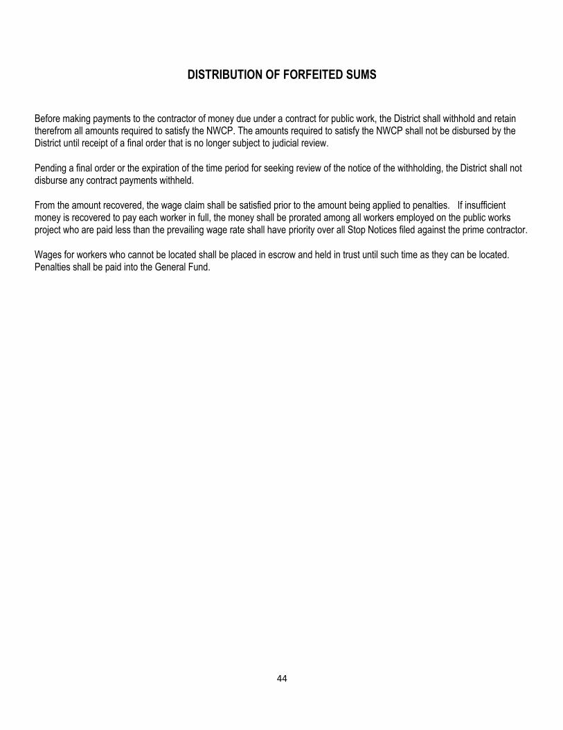
44
DISTRIBUTION OF FORFEITED SUMS
Before making payments to the contractor of money due under a contract for public work, the District shall withhold and retain therefrom all amounts required to satisfy the NWCP. The amounts required to satisfy the NWCP shall not be disbursed by the District until receipt of a final order that is no longer subject to judicial review.
Pending a final order or the expiration of the time period for seeking review of the notice of the withholding, the District shall not disburse any contract payments withheld. From the amount recovered, the wage claim shall be satisfied prior to the amount being applied to penalties. If insufficient money is recovered to pay each worker in full, the money shall be prorated among all workers employed on the public works project who are paid less than the prevailing wage rate shall have priority over all Stop Notices filed against the prime contractor.
Wages for workers who cannot be located shall be placed in escrow and held in trust until such time as they can be located. Penalties shall be paid into the General Fund.

45
HOUSTON INDEPENDENT SCHOOL DISTRICT LABOR COMPLIANCE PROGRAM
NOTICE OF DEADLINES FOR FORFEITURES TO:
(NAME OF CONTRACTOR)
This document requests the Board of Education to approve a forfeiture of money you would otherwise be paid. The Office of Business Assistance is asking the Board of Education to agree, in twenty (20) days, that the enclosed Evidence Report and package of materials indicates that you have violated the law.
Your failure to respond to District’s request that the Board of Education approve a forfeiture, by writing to the Office of Business Assistance within twenty (20) days of the date of service (the date of postmark) of this document on you, may lead the Board of Education to affirm the proposed forfeiture and may also end your right to contest those amounts further.
You must serve any written response on the Board of Education and the District’s Office of Business Assistance by return receipt requested/certified mail. If you serve a written explanation, with evidence, as to why the violation did not occur or why the penalties should not be assessed, within the twenty (20)-day period, it will be considered.
If you change your address, or decide to hire an attorney, it is your responsibility to advise the Office of Business Assistance by certified mail. Otherwise, notices will be served at your last address on file, and deadlines may pass before you receive such notice.
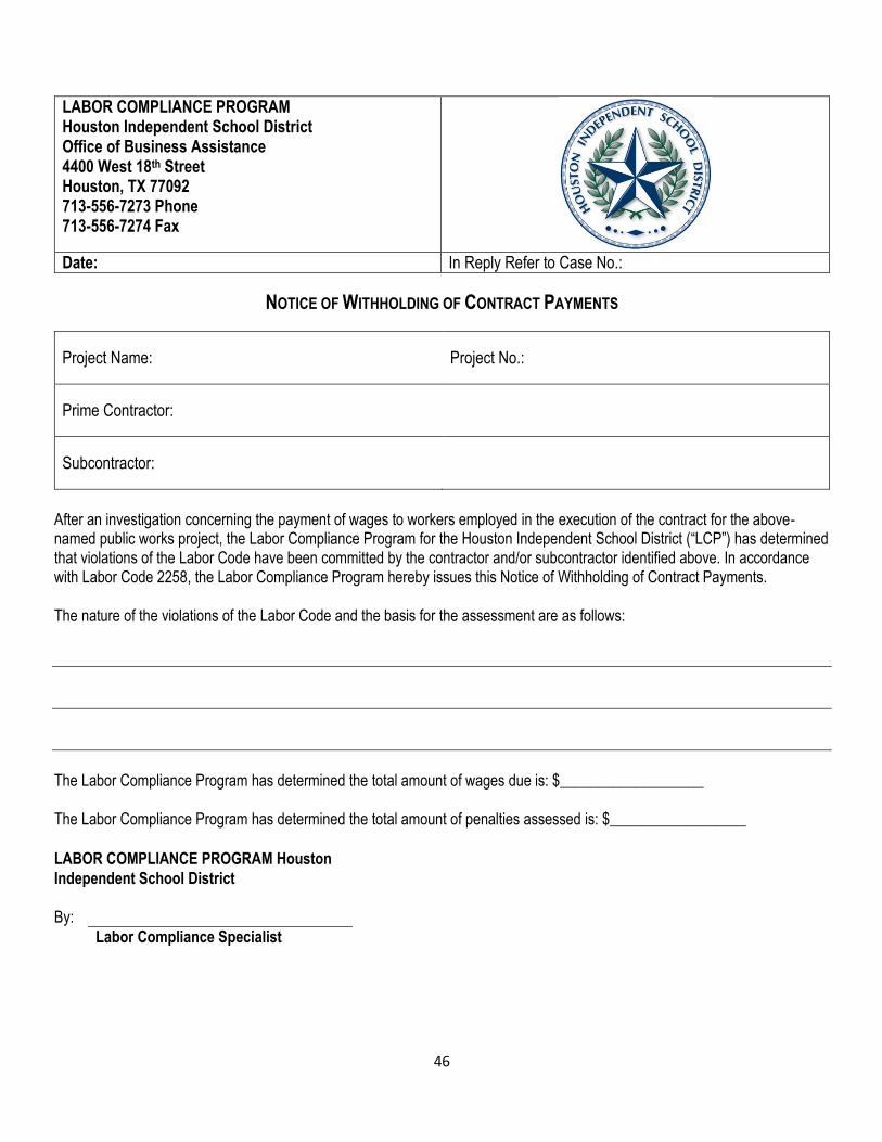
46
LABOR COMPLIANCE PROGRAM Houston Independent School District Office of Business Assistance 4400 West 18th Street Houston, TX 77092 713-556-7273 Phone 713-556-7274 Fax
Date: In Reply Refer to Case No.:
NOTICE OF WITHHOLDING OF CONTRACT PAYMENTS
Project Name: Project No.:
Prime Contractor:
Subcontractor:
After an investigation concerning the payment of wages to workers employed in the execution of the contract for the above-named public works project, the Labor Compliance Program for the Houston Independent School District (“LCP”) has determined that violations of the Labor Code have been committed by the contractor and/or subcontractor identified above. In accordance with Labor Code 2258, the Labor Compliance Program hereby issues this Notice of Withholding of Contract Payments.
The nature of the violations of the Labor Code and the basis for the assessment are as follows:
The Labor Compliance Program has determined the total amount of wages due is: $___________________
The Labor Compliance Program has determined the total amount of penalties assessed is: $__________________
LABOR COMPLIANCE PROGRAM Houston
Independent School District
By:
Labor Compliance Specialist
47
NOTICE OF RIGHT TO OBTAIN REVIEW -FORMAL HEARING
In accordance with Labor Code Section 2258, an affected contractor or subcontractor may obtain review of this Notice of Withholding of Contract Payments by transmitting a written request to the office of the Labor Compliance Program that appears below within sixty (60) days after service of the notice. To obtain a hearing, a written Request for Review must be transmitted to the following address:
Houston Independent School District Labor Compliance Program
Office of Business Assistance-Notice of Withholding of Contract Payments
4400 West 18th Street
Houston, TX 77092
A Request for Review either shall clearly identify the Notice of Withholding of Contract Payments from which review is sought, including the date of the notice, or it shall include a copy of the notice as an attachment, and shall also set forth the basis upon which the notice is being contested. In accordance with Labor Code Section 2258, the contractor or subcontractor shall be provided an opportunity to review evidence to be utilized by the Labor Compliance Program at the hearing within twenty (20) days of the Labor Compliance Program's receipt of the written Request for Review.
Failure by a contractor or subcontractor to submit a timely Request for Review will result in a final order
which shall be binding on the contractor and subcontractor, and which shall also be binding, with respect
to the amount due, on a bonding company issuing a bond that secures the payment of wages and a
surety on a bond.
OPPORTUNITY FOR SETTLEMENT MEETING
In accordance with Labor Code Section 2258 the Labor Compliance Program shall, upon receipt of a request from the affected contractor or subcontractor within thirty (30) days following the service of this Notice of Withholding of Contract Payments, afford the contractor or subcontractor the opportunity to meet with the Labor Compliance Program's designee to attempt to settle a dispute regarding the notice. The settlement meeting may be held in person or by telephone and shall take place before the expiration of the 60-day period for seeking a hearing as set forth above under the heading Notice of Right to Obtain Review. No evidence of anything said or any admission made for the purpose of, in the course of, or pursuant to, the settlement meeting is admissible or subject to discovery in any administrative or civil proceeding. No writing prepared for the purpose of, in the course of, or pursuant to, the settlement meeting, other than a final settlement agreement, is admissible or subject to discovery in any administrative or civil proceeding. This opportunity to timely request an informal settlement meeting is in addition to the right to obtain a formal hearing, and a settlement meeting may be requested even if a written Request for Review has already been made. Requesting a settlement meeting, however, does not extend the 60-day period during which a formal hearing may be requested.
A written request to meet with the Labor Compliance Program's designee to attempt to settle a dispute regarding this notice must be transmitted to ______________________ at the following address:
Houston Independent School District Office of Business Assistance-Notice of Withholding of Contract
Payments 4400 West 18th Street, Houston, TX 77092

48
LIQUIDATED DAMAGES
In accordance with Labor Code Section 2258 after 60 days following the service of a civil wage and penalty assessment or a notice of withholding, the affected contractor, subcontractor, and surety on a bond or bonds issues to secure the payment of wages covered by the assessment or notice shall be liable for liquidated damages in an amount equal to the wages, or portion thereof, that still remain unpaid. If the assessment or notice subsequently is overturned or modified after administrative or judicial review, liquidated damages shall be payable only on the wages found to be due and unpaid. Additionally, if the contractor or subcontractor demonstrates to the satisfaction of the director that he or she had substantial grounds for appealing the assessment or notice with respect to a portion of the unpaid wages covered by the assessment or notice, the director may exercise his or her discretion to waive payment of the liquidated damages with respect to that portion of the unpaid wages. Any liquidated damages shall be distributed to the employee along with the unpaid wages. Under Section 2258, there shall be no liability for liquidated damages if the full amount of the assessment or notice, including penalties, has been deposited with the Office of Business Assistance, within 60 days following service of the assessment or notice, for the department to hold in escrow pending administrative and judicial review. The department shall release such funds, plus any earned interest, at the conclusion of all administrative and judicial review to the persons or entities who are found to be entitled to such funds.
The Amount of Liquidated Damages Available Under this Notice is $_______________.
Distribution:
Prime Contractor
Subcontractor
Surety(s) on Bond
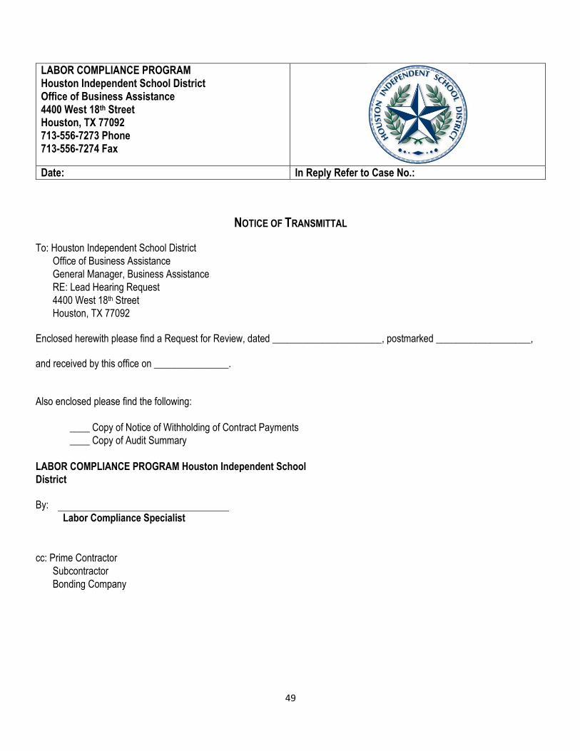
49
LABOR COMPLIANCE PROGRAM Houston Independent School District Office of Business Assistance 4400 West 18th Street Houston, TX 77092 713-556-7273 Phone 713-556-7274 Fax
Date: In Reply Refer to Case No.:
NOTICE OF TRANSMITTAL
To: Houston Independent School District
Office of Business Assistance
General Manager, Business Assistance
RE: Lead Hearing Request
4400 West 18th Street
Houston, TX 77092
Enclosed herewith please find a Request for Review, dated ______________________, postmarked ___________________,
and received by this office on _______________.
Also enclosed please find the following:
____ Copy of Notice of Withholding of Contract Payments
____ Copy of Audit Summary
LABOR COMPLIANCE PROGRAM Houston Independent School
District
By:
Labor Compliance Specialist
cc: Prime Contractor
Subcontractor
Bonding Company

50
LABOR COMPLIANCE PROGRAM Houston Independent School District Office of Business Assistance 4400 West 18th Street Houston, TX 77092 713-556-7273 Phone 713-556-7274 Fax
Date: In Reply Refer to Case No.:
Notice of Opportunity to Review Evidence
To: Prime Contractor
Subcontractor
Please be advised that this office has received your Request for Review, dated _____________, and pertaining to the Notice of Withholding of Contract Payments issued by the Labor Compliance Program in Case No. _____________.
This notice provides you with an opportunity to review evidence to be utilized by the Labor Compliance Program at the hearing on the Request for Review, and the procedures for reviewing such evidence.
Rules of the Prevailing Wage Hearing are as follows:
a. Within ten (10) days following its receipt of a Request for Review, Business Assistance shall also notify the
affected contractor or subcontractor of its opportunity and the procedures for reviewing evidence to be
utilized by Business Assistance at the hearing of the Request for Review.
b. Business Assistance shall be deemed to have provided the opportunity to review evidence required by this
Rule if it
(1) gives the affected contractor or subcontractor the option at said party's own expense to either
(i) obtain copies of all such evidence through a commercial copying service or
(ii) inspect and copy such evidence at the office of the Business Assistance during normal
business hours; or if

51
(2) the Business Assistance, at its own expense, forwards copies of all such evidence to the affected
contractor or subcontractor.
c. The evidence required to be provided under this Rule shall include the identity of witnesses whose
testimony the Business Assistance intends to present, either in person at the hearing or by declaration or
affidavit. This provision shall not be construed as requiring the Business Assistance to prepare or provide
any separate listing of witnesses whose identities are disclosed within the written materials made available.
d. Business Assistance shall make evidence available for review within twenty (20) days of its receipt of the Request for Review; provided that, this deadline may be extended by written request or agreement of the affected contractor or subcontractor. Business Assistance's failure to make evidence available for shall preclude the Business Assistance from introducing such evidence in proceedings before the Hearing Officer or the General Manager, Business Assistance.
e. This Rule shall not preclude Business Assistance from relying upon or presenting any evidence first obtained after the initial disclosure of evidence provided that, such evidence is promptly disclosed to the affected contractor or subcontractor. This Rule also shall not preclude Business Assistance from presenting previously undisclosed evidence to rebut new or collateral claims raised by another party in the proceeding.
f. In accordance with the above Rule, please be advised that the Labor Compliance Program's procedure for you to exercise your opportunity to review evidence is as follows:
Within five calendar days of the date of this notice, please transmit the attached
Request to Review Evidence to the following address:
LABOR COMPLIANCE PROGRAM
Houston Independent School District
Office Business Assistance
Attention: Labor Compliance Program Manager
4400 West 18th Street
Houston, TX 77092
713-556-7273 Phone
713-556-7274 Fax

52
REQUEST TO REVIEW EVIDENCE
To: LABOR COMPLIANCE PROGRAM
Houston Independent School District
Office Business Assistance
Attention: Labor Compliance Program Manager
4400 West 18th Street
Houston, TX 77092
713-556-7273 Phone
713-556-7274 Fax From:
Regarding Notice of Withholding of Contract Payments Dated ___________
Our Case No.: _________________
The undersigned hereby requests an opportunity to review evidence to be utilized by the Labor Compliance Program at the hearing on the Request for Review.
Authorized Company Representative
Phone No.:_______________________
Fax No.:_________________________

53
PREVAILING WAGE REGULATIONS
(Page purposely left blank)
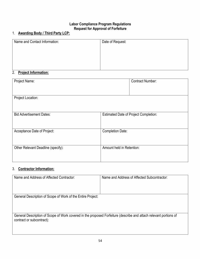
54
Labor Compliance Program Regulations Request for Approval of Forfeiture
1. Awarding Body / Third Party LCP:
Name and Contact Information: Date of Request:
2. Project Information:
Project Name: Contract Number:
Project Location:
Bid Advertisement Dates: Estimated Date of Project Completion:
Acceptance Date of Project: Completion Date:
Other Relevant Deadline (specify): Amount held in Retention:
3. Contractor Information:
Name and Address of Affected Contractor: Name and Address of Affected Subcontractor:
General Description of Scope of Work of the Entire Project:
General Description of Scope of Work covered in the proposed Forfeiture (describe and attach relevant portions of contract or subcontract):
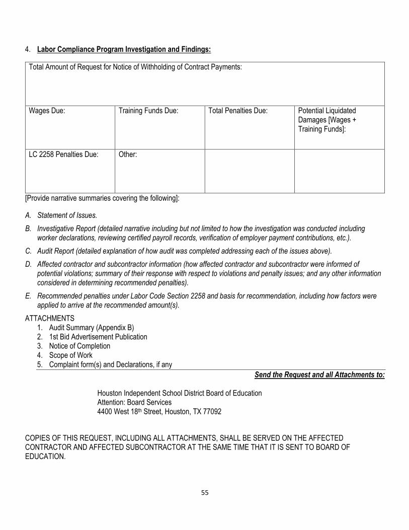
55
4. Labor Compliance Program Investigation and Findings:
Total Amount of Request for Notice of Withholding of Contract Payments:
Wages Due: Training Funds Due: Total Penalties Due: Potential Liquidated Damages [Wages + Training Funds]:
LC 2258 Penalties Due: Other:
[Provide narrative summaries covering the following]:
A. Statement of Issues.
B. Investigative Report (detailed narrative including but not limited to how the investigation was conducted including worker declarations, reviewing certified payroll records, verification of employer payment contributions, etc.).
C. Audit Report (detailed explanation of how audit was completed addressing each of the issues above).
D. Affected contractor and subcontractor information (how affected contractor and subcontractor were informed of potential violations; summary of their response with respect to violations and penalty issues; and any other information considered in determining recommended penalties).
E. Recommended penalties under Labor Code Section 2258 and basis for recommendation, including how factors were applied to arrive at the recommended amount(s).
ATTACHMENTS 1. Audit Summary (Appendix B) 2. 1st Bid Advertisement Publication 3. Notice of Completion 4. Scope of Work 5. Complaint form(s) and Declarations, if any
Send the Request and all Attachments to:
Houston Independent School District Board of Education Attention: Board Services 4400 West 18th Street, Houston, TX 77092
COPIES OF THIS REQUEST, INCLUDING ALL ATTACHMENTS, SHALL BE SERVED ON THE AFFECTED CONTRACTOR AND AFFECTED SUBCONTRACTOR AT THE SAME TIME THAT IT IS SENT TO BOARD OF EDUCATION.

56
SECTION VI
HOUSTON INDEPENDENT SCHOOL DISTRICT LABOR COMPLIANCE PROGRAM
Reporting
57
SECTION VI REPORTING
A. Annual Report on Prevailing Wage Monitoring
1. The District’s LCP will submit to the Board of Education with copies to the Chief Operating Officer, Chief Financial
Officer, Officer of Construction and Facility Services, General Managers of Business Assistance and Procurement,
and Bond Program Oversight Committee an annual report on prevailing wage monitoring which will include the
following information:
a. Progress report on the LCP in sufficient detail to afford a basis for evaluating the scope and level of enforcement activity of the LCP.
b. Annual reporting period summary of:
i. Monitoring activities; ii. Record keeping activities; iii. Labor Code violations identified and reported to Business Assistance; iv. Statistical analysis of the prevailing wage violations on District public works projects; v. Summary of outreach activities; and vi. Certification of compliance with conflict of interest disclosure requirements.
2. Annual Report on the LCP to the Board of Education
1. The District’s LCP will submit to the Board of Education an annual report on the operation of its LCP within sixty
(60) days after the end of its annual reporting period. The annual report shall contain, as a minimum, the following
information: a. Number of public works contracts awarded which are subject to prevailing wages and their total value.
b. A summary of wages due to workers resulting from failure by contractors to pay prevailing wage rates, the total amount withheld from money due the contractors and the total amount recovered by action in any court of competent jurisdiction.
c. A summary of penalties and forfeitures imposed and withheld or recovered in a court of competent jurisdiction.
d. A special summary of all audits that were conducted upon request of Business Assistance.
e. A certification of compliance with conflict of interest disclosure requirements by employees and consultants who participate in making governmental decisions and a current statement disclosing the information.
f. Information in the Annual Report shall be reported in sufficient detail to afford a basis to evaluate the scope and level of enforcement activity of the LCP.
g. Copies of this report will be distributed to the Board of Education and the Chief Operating Officer.
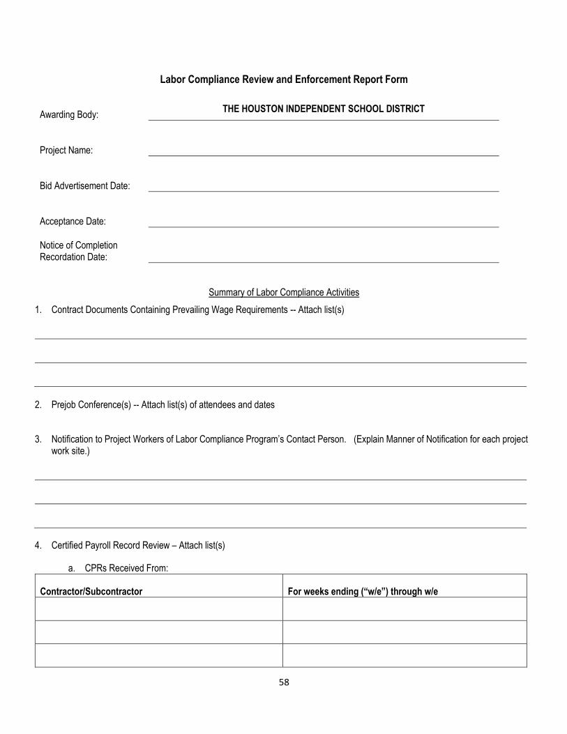
58
Labor Compliance Review and Enforcement Report Form
Awarding Body:
THE HOUSTON INDEPENDENT SCHOOL DISTRICT
Project Name:
Bid Advertisement Date:
Acceptance Date:
Notice of Completion Recordation Date:
Summary of Labor Compliance Activities
1. Contract Documents Containing Prevailing Wage Requirements -- Attach list(s)
2. Prejob Conference(s) -- Attach list(s) of attendees and dates
3. Notification to Project Workers of Labor Compliance Program’s Contact Person. (Explain Manner of Notification for each project work site.)
4. Certified Payroll Record Review – Attach list(s)
a. CPRs Received From:
Contractor/Subcontractor For weeks ending (“w/e”) through w/e

59
b. Classifications identified in CPRs and applicable Prevailing Wage Determinations – Attach lists(s)
Classification Determination No.
5. Further investigation or audit due to CPR review, information or complaint from worker or other interested person, or other reason:
a. Independent Confirmation of CPR Data – Attach lists(s)
Contractor/Subcontractor Worker Interviews (Yes/No) Reconciled CPRs with Pay-checks
or Stubs (Yes/No)
b. Employer Payments (Health & Welfare, Pension, Vacation/Holiday) Confirmation – Attach lists(s)
Contractor/Subcontractor Recipients of Employer Payments Written confirmation obtained
(Yes/No)
c. Contributions to TWC or Other Approved Apprenticeship Program – Attach lists(s)
Contractor/Subcontractor Recipients of Contributions Written confirmation obtained
(Yes/No)

60
d. Additional Wage Payments or Training Fund Contributions Resulting from Review of CPRs – Attach lists(s)
Contractor/Subcontractor Additional Amounts Paid
to Workers Additional Training Fund Explanation
*
*
*
*
* Use separate page(s) for explanation
6. Complaints Received Alleging Noncompliance with Prevailing Wage Requirements.
Additional Wage Payments or Training Fund Contributions Resulting from Review of CPRs – Attach lists(s)
Name of Complainant Date Received
Resolution or Current Status
*
*
*
*
* Use separate page(s) to explain resolution or current status
7. Requests for Approval of Forfeiture to Board of Education – Attach list(s)
Contractor/Subcontractor Date of Request Approved/Modified/Denied

61
8. Litigation Pending – Attach List(s)
Contractor/Subcontractor Case Number
9. (Check one): Final report this project Annual report this project
Authorized Representative for Labor Compliance Program
62
SECTION VII
HOUSTON INDEPENDENT SCHOOL DISTRICT LABOR COMPLIANCE PROGRAM
Glossary
63
GLOSSARY OF TERMS
Apprentice - A “registered” apprentice under a bona fide apprenticeship program registered and approved by the State Division
of Apprenticeship Standards.
Any worker listed on a payroll at an apprentice wage rate who is not registered shall be paid the journey level wage rate
determined by the Department of Industrial Relations for the classification of the work he/she actually performed. Pre-apprentice
trainees, trainees in non-apprenticeable crafts, and others who are not duly registered will not be permitted on projects unless
they are paid full prevailing wage rates as journeypersons.
Audit - An official examination and verification of accounts and records.
BA - Business Assistance office – Houston Independent School District.
Certified payroll - Certified payroll ensures that set wages are paid in accordance to contract documents.
Complainant - A person, group, or company that makes a complaint.
Contract - Except as otherwise provided by agreement, means only contracts under a single master contract, or contracts entered into as stages of a single project which may be the subject of withholding. Contract worker - A contract worker is not an employee of a company. He is a self-employed person who operates his own
business, usually as a sole proprietor (see also 1099 Independent Contractor).
Contractor - A business entity that provides independent contractor services to owners through the use of subcontractors when
using the general contracting system.
Craftsperson - One who performs any labor on a project.
Delinquent - Failing in or neglectful of a duty or obligation; past due or overdue.
Employee - An individual in which a company has strict control over the person's work schedule, work location and closely
examines the work process.
Forfeitures - Are the amounts of unpaid penalties and wages assessed by the District’s LCP and proposed to be withheld
pursuant to Labor Code Section 2258.023.
Good Faith - Efforts that are steps taken to achieve an contract requirements which, by their scope, intensity and usefulness
demonstrates the contractor’s responsiveness to fulfill the business opportunity objective as well as the contractor’s responsibility
to put forth measures to meet or exceed the contract goal throughout the duration of the contract.
Helper - A helper is a semi-skilled worker (rather than a skilled craftworker) who works under the direction of and assists a
craftworker. Under the craftworker’s direction and supervision, the helper performs a variety of duties to assist the craftworker
such as preparing, carrying, and furnishing equipment, supplies and maintaining them in order; cleaning and preparing work
areas; lifting, positioning, and holding materials or tools; and other related semi-skilled tasks.
64
Job Description - A broad-scope explanation of a position’s requirements indicating the duties for the position and the expertise
and capabilities required of a person to adequately perform in that position.
Skilled Craftworker - A craft professional who has achieved a craftworker-level credential or certification for the craft they
perform from a nationally-recognized professional organization or Federal or State apprenticeship authority. Examples:
Department of Labor Certificate.
Kickback - An act of taking or receiving a portion of an employee’s wages.
LCP - Labor Compliance Program setup by HISD.
Laborer - Performs tasks involving physical labor at construction sites, including clean-up of rubble, debris and other waste
materials. May assist other craft workers; however, construction laborers who primarily assist a particular craft worker are
classified under Sub-journey level craft persons.
OSHA - Occupational Safety and Health Administration.
Overtime Pay - An employee is entitled to be compensated at one and one-half (1) times his/her hourly rate for any hours, or
fraction of hours, worked in excess of forty (40) hours in one week. Overtime pay is paid for actual hours worked, not for hours
for which the employee is paid even though he/she did not work (such as sick days, holidays, or vacation days).
Prevailing Wages - Determined wage rates for particular construction trades or crafts.
Prime Contractor - Any contractor having a contract directly with the owner. Usually the main (general) contractor for a specific
project.
Project - A word used to represent the overall scope of work being performed to complete a specific construction job.
Proof of eligibility - Employees must provide proof that they are U.S. citizens or nationals, lawful permanent residents, or
people otherwise authorized to be employed in the United States. Documents include proof of identity (ID card, Driver’s
License) and proof of their eligibility to work in the U.S. (i.e., social security card)
Split-classification - If you have employees that perform work in more than one trade during a work week, you can pay the wage rates specified for each work classification in which work was performed only if you maintain accurate time records showing the amount of time spent in each classification. If you do not maintain accurate time records, you must pay these employees the highest wage rate of all of the classifications of work performed.
Subcontractor - A qualified subordinate contractor to the prime or main contractor.
Sub-subcontractor - An individual or firm having a written contract with a subcontractor to perform a portion of the work.
1099 Independent Contractor - An individual is an independent contractor if the payer has the right to control or direct only the
result of the work and not what will be done and how it will be done.
Trade (skill) Worker - Possessing or demonstrating accomplishment, skill, or special training
Underpayments - To pay less than is deserved or usual.

65
Undocumented worker - Individual not having the official documents that are needed to enter, live in, or work in a country
legally.
Unfair competition - Acts done by a company to confuse or deceive the public with intent to acquire a larger portion of the
market, as by cutting prices below cost.
Violation - A breach, infringement, or transgression, as of a law, rule, and/or regulation.
Withhold - Means to cease payments by the awarding body, its agents or others who pay on its behalf to the contractor. Where
the violation is by a subcontractor, the contractor shall be notified of the nature of the violation and reference made to its rights. A
release bond may not be posted for release of funds being withheld for the violation of the prevailing wage law.
Work Schedule - A plan for performing work or achieving an objective.
Work week - Forty (40) hours is considered a "work week" under the Federal Labor Standards Act (FLSA). The hours worked may be scheduled by the employer for any day of the week, including Saturdays, Sundays, and holidays (unless otherwise dictated by state or other federal laws, contract, or agreement).
Working Foreman - Foremen or supervisors that regularly spend more than 20% of their time performing construction work and
do not meet the exclusions listed below are covered “laborers” and “mechanics” for labor standards purposes for the time spent
performing construction work. Exclusions: People whose duties are primarily administrative, executive or clerical are not laborers
or mechanics. Examples include superintendents, office staff, timekeepers, messengers, etc.
66
BUILDING CONSTRUCTION PREVAILING WAGES - CLASSIFICATION DEFINITIONS Asbestos Abatement Worker * (Ceilings, Floors, & Walls only) Ratio 1/3 Apprentice Removes asbestos from ceilings, walls, beams, boilers, and other structures, following hazardous waste handling guidelines: Assembles scaffolding and seals off work area, using plastic sheeting and duct tape. Positions mobile decontamination unit or portable showers at entrance of work area. Builds connecting walkway between mobile unit or portable showers and work area, using hand tools, lumber, nails, plastic sheeting, and duct tape. Positions portable air evacuation and filtration system inside work area. Sprays chemical solution over asbestos covered surfaces, using tank with attached hose and nozzle, to soften asbestos. Cuts and scrapes asbestos from surfaces, using knife and scraper. Shovels asbestos into plastic disposal bags and seals bags, using duct tape. Cleans work area of loose asbestos, using vacuum, broom, and dustpan. Places asbestos in disposal bags and seals bags, using duct tape. Dismantles scaffolding and temporary walkway, using hand tools, and places plastic sheeting and disposal bags into transport bags. Seals bags, using duct tape, and loads bags into truck. Asphalt Raker Semiskilled work raking and spreading asphalt mixtures used in the construction and repair of City streets and thoroughfares. Operates asphalt spreading machines and other tools including rakes and lutes to distribute asphaltic mixtures over street surfaces. Uses hand and pneumatic powered tools to break up street surfaces and shovels to load broken paving material into trucks. Heats smoothing irons and tampers over a fire to the proper temperature and applies oil to rakes and lutes to prevent these tools from adhering to the worked asphalt. Uses rake and/or lute in distributing hot asphaltic road-building binder and topping evenly over road surfaces by raking and brushing material to correct thickness. Rakes out or breaks lumps, so that the surface is brought to the proper grade and conforms to the general contour of the street. Tamps and smooths joints, gutters, and connections in order that asphalt mixture will properly adhere to old surfaces. Smooths and tamps asphalt surfaces inaccessible to a roller. Paints joints with hot asphalt to create water-tight seal. Bricklayer * (See Mason Tender) - Ratio 1/3 Apprentice Lays building materials, such as brick, structural tile, and concrete cinder, glass, gypsum, and terra cotta block (except stone) to construct or repair walls, partitions, arches, sewers, and other structures: Measures distance from reference points and marks guidelines on working surface to lay out work. Spreads soft bed (layer) of mortar that serves as base and binder for block, using trowel. Applies mortar to end of block and positions block in mortar bed. Taps block with trowel to level, align, and embed in mortar, allowing specified thickness of joint. Removes excess mortar from face of block, using trowel. Finishes mortar between brick with pointing tool or trowel. Breaks bricks to fit spaces too small for whole brick, using edge of trowel or brick hammer. Determines vertical and horizontal alignment of courses, using plumb bob, gauge line (tightly stretched cord), and level. Fastens brick or terra cotta veneer to face of structures, with tie wires embedded in mortar between bricks, or in anchor holes in veneer brick. May weld metal parts to steel structural members. May apply plaster to walls and ceiling, using trowel, to complete repair work. Carpenter * (Including Acoustical Ceiling Work) - Ratio 2/1 Apprentice Constructs, erects, installs, and repairs structures and fixtures of wood, plywood, and wallboard, using carpenter’s hand tools and power tools, and conforming to local building codes: Studies blueprints, sketches, or building plans for information pertaining to type of material required, such as lumber or fiberboard, and dimensions of structure or fixture to be fabricated. Selects specified type of lumber or other materials. Prepares layout, using rule, framing square, and calipers. Marks cutting and assembly lines on materials, using pencil, chalk, and marking gauge. Shapes materials to prescribed measurements, using saws, chisels, and planes. Assembles cut and shaped materials and fastens them together with nails, dowel pins, or glue. Verifies trueness of structure with plumb bob and carpenter’s level. Erects framework for structures and lays subflooring. Builds stairs and lays out and installs partitions and cabinetwork. Covers sub floor with building paper to keep out moisture and lays hardwood, parquet, and wood-strip-block floors by nailing floors to sub floor or cementing them to mastic or asphalt base. Applies shock-absorbing, sound-deadening, and decorative paneling to ceilings and walls. Fits and installs prefabricated window
67
frames, doors, doorframes, weather stripping, interior and exterior trim, and finish hardware, such as locks, letter drops, and kick plates. Constructs forms and chutes for pouring concrete. Erects scaffolding and ladders for assembling structures above ground level. May weld metal parts to steel structural members. Carpenter – Trim & Finish Install and repair the molding and trim of windows, doors, baseboards, mantels and other ornamental pieces. Assemble and install exterior and interior house trim including molding, cabinets and handrails. Measure and cut to create a seamless finished appearance. Use hand tools, power tools, precision measuring tools, pneumatic tools, levels and measuring tape. Cement Mason/Concrete Finisher *(See Concrete Mason/Concrete Finisher) - Ratio 1/3 Apprentice Finisher; concrete floater Smoothes and finishes surfaces of poured concrete floors, walls, sidewalks, or curbs to specified textures, using hand tools or power tools, including floats, trowels, and screeds: Signals concrete deliverer to position truck to facilitate pouring concrete. Moves discharge chute of truck to direct concrete into forms. Spreads concrete into inaccessible sections of forms, using rake or shovel. Levels concrete to specified depth and workable consistency, using hand held screed and floats to bring water to surface and produce soft topping. Smoothes, and shapes surfaces of freshly poured concrete, using straightedge and float or power screed. Finishes concrete surfaces, using power trowel, or wets and rubs concrete with abrasive stone to impart finish. Removes rough or defective spots from concrete surfaces, using power grinder or chisel and hammer, and patches holes with fresh concrete or epoxy compound. Molds expansion joints and edges, using edging tools, jointers, and straightedge. May sprinkle colored stone chips, powdered steel, or coloring powder on concrete to produce prescribed finish. May produce rough concrete surface, using broom. May mix cement, using hoe or concrete-mixing machine. May direct sub grade work, mixing of concrete, and setting of forms. Concrete Worker Level, smooth and shape surfaces of freshly poured concrete on projects ranging from patios and basements to dams, highways, and foundations and walls of building. Have a thorough knowledge of concrete characteristics and related materials. Also, they must know the effects of heat, cold, and wind on the curing of concrete. Able to tell by sight and touch what is happening to concrete in order to prevent defects. Drywall Finisher/Taper * - Ratio 1/3 Helpers Wallboard and plasterboard; sheetrock taper; taper and bedder; taper and floater Seals joints between plasterboard or other wallboards to prepare wall surface for painting or papering; Mixes sealing compound by hand or with portable electric mixer, and spreads compound over joints between boards, using trowel, broad knife, or spatula. Presses paper tape over joint to embed tape into compound and seal joint, or tapes joint, using mechanical applicator that spreads compound and embeds tape in one operation. Spreads and smoothes cementing material over tape, using trowel or floating machine to blend joint with wall surface. Sands rough spots after cement has dried. Fills cracks and holes in walls and ceiling with sealing compound. Installs metal molding at corners in lieu of sealant and tape. Usually works as member of crew. May apply texturing compound and primer to walls and ceiling preparatory to final finishing, using brushes, roller, or spray gun. May countersink nails or screws below surface of wall prior to applying sealing compound, using hammer or screwdriver. Drywall Hanger * (Includes Installing Metal Studs) - Ratio 1/3 Helpers Dry-wall installer; gypsum dry-wall systems installer Plans gypsum drywall installations, erects metal framing and furring channels for fastening drywall, and installs drywall to cover walls, ceilings, soffits, shafts, and movable partitions in residential, commercial, and industrial buildings: Reads blueprints and other specifications to determine method of installation, work procedures, and material, tool, and work aid requirements. Lays out reference lines and points for use in computing location and position of metal framing and furring channels and marks position for erecting metalwork, using chalk line. Measures, marks, and cuts metal runners, studs, and furring channels to specified size, using tape measure, straightedge and hand and portable power cutting tools. Secures metal framing to walls and furring channels to ceilings, using hand and portable power tools. Measures and marks cutting lines on drywall, using square, tape measure, and marking devices. Scribes cutting lines on drywall, using straightedge and utility knife and breaks board along cut lines. Fits and fastens board into specified position on wall, using

68
screws, hand tools, portable power tools, or adhesive. Cuts openings into board for electrical outlets, vents, or fixtures, using keyhole saw or other cutting tools. Measures, cuts, assembles, and installs metal framing and decorative trim for windows, doorways, and vents. Fits, aligns, and hangs doors and installs hardware, such as locks and kick plates Electrician * (Including Pulling Wire and Low Voltage Wiring and Installation of Fire Alarms, Security Systems, Telephones, and Computers.) - Ratio 3/2 Apprentice Plans layout, installs, and repairs wiring, electrical fixtures, apparatus, and control equipment: Plans new or modified installations to minimize waste of materials, provide access for future maintenance, and avoid unsightly, hazardous, and unreliable wiring, consistent with specifications and local electrical codes. Prepares sketches showing location of wiring and equipment, or follows diagrams or blueprints, ensuring that concealed wiring is installed before completion of future walls, ceilings, and flooring. Measures, cuts, bends, threads, assembles, and installs electrical conduit, using tools, such as hacksaw, pipe threader, and conduit bender. Pulls wiring through conduit. Splices wires by stripping insulation from terminal leads, using knife or pliers, twisting or soldering wires together, and applying tape or terminal caps. Connects wiring to lighting fixtures and power equipment, using hand tools. Installs control and distribution apparatus, such as switches, relays, and circuit-breaker panels, fastening in place with screws or bolts, using hand tools and power tools. Connects power cables to equipment, such as electric range or motor, and installs grounding leads. Tests continuity of circuit to ensure electrical compatibility and safety of components, using testing instruments, such as ohmmeter, battery and buzzer, and oscilloscope. Observes functioning of installed equipment or system to detect hazards and need for adjustments, relocation, or replacement. Electronic Data/Low Voltage Tech Work involving commercial sound, radio, television, and low voltage control systems. Reads blueprints, wiring diagrams, and schematic drawings for assembling electronics. Elevator Constructor (ratio for helpers needed) Erector; elevator installer; elevator mechanic Assembles and installs electric and hydraulic freight and passenger elevators, escalators, and dumbwaiters, determining layout and electrical connections from blueprints: Studies blueprints and lays out location of framework, counterbalance rails, motor pump, cylinder, and plunger foundations. Drills holes in concrete or structural steel members with portable electric drill. Secures anchor bolts or welds brackets to support rails and framework, and verifies alignment with plumb bob and level. Cuts prefabricated sections of framework, rails, and other elevator components to specified dimensions, using acetylene torch, power saw, and disk grinder. Installs cables, counterweights, pumps, motor foundations, escalator drives, guide rails, elevator cars, and control panels, using hand tools. Connects electrical wiring to control panels and electric motors. Installs safety and control devices. Positions electric motor and equipment on top of elevator shaft, using hoists and cable slings. Equipment Operator – Heavy Equipment Operates heavy equipment such as cranes, clamshells, power shovels, motor graders, heavy loaders, carryalls, bulldozers, rollers, scrapers, and large industrial tractors with pan or scrapper attachments. Equipment is used to excavate, load or move dirt, gravel or other materials. Operator may read and interpret grade and slope stakes and simple plans. May grease, adjust and make emergency repairs to equipment.
Backhoe (operator) Operates power-driven machine, equipped with movable shovel, to excavate or move coal, dirt, rock, sand, and other materials: Receives written or oral instructions from supervisor regarding material to move or excavate. Pushes levers and depresses pedals to move machine, to lower and push shovel into stockpiled material, to lower and dig shovel into surface of ground, and to lift, swing, and dump contents of shovel into truck, car, or onto conveyor, hopper, or stockpile. Observes markings on ground, hand signals, or grade stakes to remove material, when operating machine at excavation site. Crane (operator) Operates electric-, diesel-, gasoline-, or steam-powered guy-derrick or stiff-leg derrick (mast supported by fixed legs or tripod), to move products, equipment, or materials to and from quarries, storage areas, and processes, or to load and

69
unload trucks or railroad cars: Pushes and pulls levers and depresses pedals to raise, lower, and rotate boom and to raise and lower load line in response to signals.
Forklift (operator) Drives gasoline-, liquefied gas-, or electric-powered industrial truck equipped with lifting devices, such as forklift, boom, scoop, lift beam and swivel-hook, fork-grapple, clamps, elevating platform, or trailer hitch, to push, pull, lift, stack, tier, or move products, equipment, or materials in warehouse, storage yard, or factory: Moves levers and presses pedals to drive truck and control movement of lifting apparatus. Positions forks, lifting platform, or other lifting device under, over, or around loaded pallets, skids, boxes, products, or materials or hooks tow trucks to trailer hitch, and transports load to designated area. Unloads and stacks material by raising and lowering lifting device.
Equipment Operator – Light Equipment Operate and maintain a variety of powerful equipment ranging from air compressors, pumps, and other power equipment at construction sites. Lubricate, maintain, and perform minor repair and adjustment to machinery. Floor Layer / Finisher Install floor coverings such as linoleum, laminate, vinyl, cork, and rubber. They can install carpet, wood, ceramic, marble, or granite tiles and these functions are more for basic functional purposes to reduce noise or absorb shocks, rather than for aesthetics. Inspect floor surfaces for even conditions to smooth floor material installation. Clear imperfections as well by sand, scrape. Apply adhesive compounds to floor or wall material to join foundation materials perfectly. Staple MASONITE or plywood over the floor or by brushing waterproof compound onto surface and filling cracks with plaster, putty, or grout to seal pores. Measure floor size and estimate covering materials and amount of glue and padding required. Measure flooring laminate, linoleum, vinyl, cork or rubber to correspond to floor size and shape and fit around fixed obstructions. Glazier * - Ratio 1/3 Helpers Installs glass in windows, skylights, store fronts, and display cases, or on surfaces, such as building fronts, interior walls, ceilings, and tabletops: Marks outline or pattern on glass, and cuts glass, using glasscutter. Breaks off excess glass by hand or with notched tool. Fastens glass panes into wood sash with glaziers points, and spreads and smoothes putty around edge of panes with knife to seal joints. Installs mirrors or structural glass on building fronts, walls, ceilings, or tables, using mastic, screws, or decorative molding. Bolts metal hinges, handles, locks, and other hardware to prefabricated glass doors. Sets glass doors into frame and fits hinges. May install metal window and doorframes into which glass panels are to be fitted. May press plastic adhesive film to glass or spray glass with tinting solution to prevent light glare. May install stained glass windows. HVAC Installer/Mechanic (ratio for helpers needed) An HVAC installer installs duct work, furnaces, air conditioners and/or gas piping by reading the blue prints. An HVAC installer is also responsible for installation of copings, fascia, wall panels, trim, metal roofing and underpayment and rain screen systems. An HVAC installer is responsible for checking and reviewing the shop drawings of electrical design, detailed design including material specifications, liaison with customer regarding technical issues. HVAC Service Technician Diagnosing, repair, installation, servicing and maintenance of heating and air conditioning equipment and systems found in commercial buildings, hospitals, supermarkets, industrial and manufacturing plants. This job requires climbing, bending, stooping, crawling, kneeling, lifting and working in extreme temperature ranges Insulator (Batt and Foam) * - Ratio 1/3 Helpers Applies batt and form insulation to walls, ceilings and other surfaces according to manufacturer’s specifications and blue print instructions. May use sealants such as cement plaster or asphalt compound to seal insulation; may spread concrete over floor slabs to form wearing floor: brushes adhesives, cuts insulating materials to specified shape to cover surfaces; uses tape or other sealants to adhere insulation to surfaces. May use staple gun, towel, paintbrushes and caulking guns.

70
Insulator - Building Building insulators install or apply special material to buildings or to the exposed surfaces of equipment to prevent or reduce heat, cold, air, sound or moisture. Install heat insulation in ceilings, walls and under floors. Cut insulation materials to the size required, attach insulation materials using glue, staples or tape. Operate equipment to inject loose fill or foamed insulation Repair and maintain existing insulation. Install hot water cylinder wraps, install sound and fireproofing products, put draught excluders on doors, put draught sealant around doors and windows, and put security stays on windows Insulator - Piping Covers boilers, pipes, tanks, and also refrigeration units, with insulating materials, like asbestos, cork, plastic, and also magnesia to reduce loss or absorption of heat, prevent moisture condensation, and also to deaden sound. Wires prefabricated asbestos covering around steam hot water piping, using handtools. Trowels mastic or brushes cement on asbestos cloth to obtain smooth finish covers piping with cloth. Fits thermoblock magnesia-block insulation around insulating boilers, evaporators, and also turbines. Wires insulation on machinery staples wire netting over insulation. Trowels cement on wire netting to protect insulating material Wires cork on salt water, refrigeration, and also air-conditioning piping cements cloth over insulating material to obtain smooth finish. Cuts sheets of insulation into sections, using handsaw miter box. Fits cements sections around fittings. Covers gas piping of refrigeration or air-conditioning systems with molded plastic. Fabricates detachable insulation for valves or similar fitting by measuring connections, preparing patterns, cutting asbestos cloth, stuffing cloth with amosite plastic pipe covering, and also sewing cover together on power sewing machine Wires detachable covers on valves or fittings, using handtools. Installs fiberglass or spun glass on ventilating systems to deaden sound prevent vibration. Ironworker (Reinforcing) * - Ratio 1/3 Helpers Positions and secures steel bars in concrete forms to reinforce concrete; places rods in forms, spacing and fastening together with wire and pliers. Cuts bars using hacksaw, bar cutters or acetylene torch. Bends steel rods with hand tools or rod bending machine; reinforces concrete with wire mesh; welds reinforcing bars together. Ironworker (Structural) * - Ratio 1/3 Helpers Erector; ironworker; steel erector; structural-iron erector; structural-iron worker; structural steel erector Performs any combination of following duties to raise, place, and unite girders, columns, and other structural-steel members to form completed structures or structure frameworks, working as member of crew: Sets up hoisting equipment for raising and placing structural-steel members. Fastens steel members to cable of hoist, using chain, cable, or rope. Signals worker operating hoisting equipment to lift and place steel member. Guides member, using tab line (rope) or rides on member in order to guide it into position. Pulls, pushes, or pries steel members into approximate position while member is supported by hoisting device. Forces members into final position, using turnbuckles, crowbars, jacks, and hand tools. Aligns rivet holes in member with corresponding holes in previously placed member by driving drift pins or handle of wrench through holes. Verifies vertical and horizontal alignment of members, using plumb bob and level. Laborer (Skilled) Performs any combination of the following tasks in erecting, repairing and wrecking buildings; dig, spread and level dirt and gravel; lift carry and hold building materials, tools and supplies; clean tools, equipment, materials and work areas; mix, pour and spread concrete, asphalt, gravel and other materials; join, wrap and seal sections of pipe; routine non-machine tasks such as removing forms from set concrete, filling expansion joints with asphalt, and placing culverts in trench. May also signal construction equipment operators; measure distances from grade stakes, drive stakes and stretch lines; bolt, nail align and block up under forms; mix and finish poured concrete, erect scaffolding; spread paint or coating to seal surfaces; caulking compounds to seal surfaces; remove projections from concrete, and mount pipe hangers.
71
Laborer (Semi-Skilled) A semi-skilled laborer/helper is a semi-skilled worker who works under adequate supervision and performs a variety of duties to assist by preparing, carrying, and furnishing equipment, supplies, and maintaining them in order, cleaning, and preparing work areas; lifting, positioning, and holding materials or tools; and other related semi-skilled tasks as directed by skilled laborers. Laborer (Unskilled) Performs simple duties, primarily manual, that may be learned within a short period of time and that require little or no independent judgment. Landscape Laborer Landscaping workers (Skilled) create new outdoor spaces or upgrade existing ones by planting trees, flowers, and shrubs. They also trim, fertilize, mulch, and water plants. Some grade and install lawns or construct hardscapes such as walkways, patios, and decks. Others help install lighting or sprinkler systems.
Groundskeeping workers, also called groundskeepers, (Semi – Skilled) maintain existing grounds. They care for plants and trees, rake and mulch leaves, and clear snow from walkways. See to the proper upkeep of sidewalks, parking lots, groundskeeping equipment, fountains, fences, planters, and benches.
(Unskilled) perform unskilled, simple duties, primarily manual, that may be learned within a short period of time and that require little or no independent judgment.
Lather * - Ratio 1/3 Helpers Fastens wooden, metal, or rockboard lath to walls, ceilings, and partitions of buildings to provide supporting base for plaster, fireproofing, or acoustical material, using hand tools and portable power tools: Erects horizontal metal framework to which laths are fastened, using nails, bolts, and studgun. Drills holes in floor and ceiling, using portable electric tool, and drives ends of wooden or metal studs into holes to provide anchor for furring or rockboard lath. Wires horizontal strips to furring to stiffen framework. Cuts lath to fit openings and projections, using hand tools or portable power tools. Wires, nails, clips, or staples lath to framework, ceiling joists, and flat concrete surfaces. Bends metal lath to fit corners, or attaches preformed corner reinforcements. Wires plasterer’s channels to overhead structural framework to provide support for plaster or acoustical ceiling tile. Lightning Protection Installer (ratio needed for helper) Repair or replace wiring, equipment, or fixtures, using hand tools or power tools. Test electrical systems or continuity of circuits in electrical wiring, equipment, or fixtures, using testing devices, such as ohmmeters, voltmeters, or oscilloscopes, to ensure compatibility and safety of system. Use a variety of tools or equipment, such as power construction equipment, measuring devices, power tools, and testing equipment, such as oscilloscopes, ammeters, or test lamps. Work from ladders, scaffolds, or roofs to install, maintain, or repair electrical wiring, equipment, or fixtures. Assemble, install, test, or maintain electrical or electronic wiring, equipment, appliances, apparatus, or fixtures, using hand tools or power tools. Connect wires to circuit breakers, transformers, or other components. Diagnose malfunctioning systems, apparatus, or components, using test equipment and hand tools to locate the cause of a breakdown and correct the problem. Inspect electrical systems, equipment, or components to identify hazards, defects, or the need for adjustment or repair, and to ensure compliance with codes. Prepare sketches or follow blueprints to determine the location of wiring or equipment and to ensure conformance to building and safety codes. Fasten small metal or plastic boxes to walls to house electrical switches or outlets. Plan layout and installation of electrical wiring, equipment, or fixtures, based on job specifications and local codes. Place conduit, pipes, or tubing, inside designated partitions, walls, or other concealed areas, and pull insulated wires or cables through the conduit to complete circuits between boxes. Perform physically demanding tasks, such as digging trenches to lay conduit or moving or lifting heavy objects. Install ground leads and connect power cables to equipment, such as motors. Construct and fabricate parts, using hand tools and specifications. Metal Building Assembler
72
Assembles prefabricated metal buildings according to blueprint specifications, using handtools, power tools, and also hoisting equipment. Erects frame of building, using hoist. Bolts steel frame members together. Attaches wire insulating materials to framework. Bolts sheet metal panels to framework. Reads blueprint to define location of items, like doors, windows, ventilators, and also skylights installs items, using cutting torch, wrenches, and also power drill. Trims excess sheet metal, using cutting torch, power saw, and also tin snips. Millwright Installs new machines or heavy equipment, and dismantles and installs machines or heavy equipment when changes in the plant layout are required. Work involves most of the following: Planning and laying out work; interpreting blueprints or other specifications; using a variety of hand tools and rigging; making standard shop computations relating to stresses, strength of materials, and centers of gravity; aligning and balancing equipment; selecting standard tools, equipment and parts to be used; and installing and maintaining in good order power transmission equipment such as drives and speed reducers. In general, the Millwright's work normally requires a rounded training and experience in the trade acquired through a formal apprenticeship or equivalent training and experience. Painter (Brush, Roller, and Spray) * - Ratio 1/3 Helpers Applies coats of paint, varnish, stain, enamel, or lacquer to decorate and protect interior or exterior surfaces, trimmings, and fixtures of buildings and other structures: Reads work order or receives instructions from supervisor or homeowner regarding painting. Smoothes surfaces, using sandpaper, brushes, or steel wool, and removes old paint from surfaces, using paint remover, scraper, wire brush, or blowtorch to prepare surfaces for painting. Fills nail holes, cracks, and joints with caulk, putty, plaster, or other filler, using caulking gun and putty knife. Selects premixed paints, or mixes required portions of pigment, oil, and thinning and drying substances to prepare paint that matches specified colors. Removes fixtures, such as pictures and electric switchcovers, from walls prior to painting, using screwdriver. Spreads dropcloths over floors and room furnishings, and covers surfaces, such as baseboards, doorframes, and windows with masking tape and paper to protect surfaces during painting. Paints surfaces, using brushes, spray gun, or paint rollers. Simulates wood grain, marble, brick, or tile effects. Applies paint with cloth, brush, sponge, or fingers to create special effects. Erects scaffolding or sets up ladders to perform tasks above ground level. Pipe fitter * (HVAC Pipe Only) - Ratio 1/3 Apprentice Lays out, assembles, installs, and maintains pipe systems, pipe supports, and related hydraulic and pneumatic equipment for steam, hot water, heating, cooling, lubricating, sprinkling, and industrial production and processing systems, applying knowledge of system operation, and following blueprints: Selects type and size of pipe, and related materials and equipment, such as supports, hangers, and hydraulic cylinders, according to specifications. Inspects work site to determine presence of obstructions and to ascertain that holes cut for pipe will not cause structural weakness. Plans installation or repair to avoid obstructions and to avoid interfering with activities of other workers. Cuts pipe, using saws, pipe cutter, hammer and chisel, cutting torch, and pipe cutting machine. Threads pipe, using pipe threading machine. Bends pipe, using pipe bending tools and pipe bending machine. Assembles and installs variety of metal and nonmetal pipes, tubes, and fittings, including iron, steel, copper, and plastic. Connects pipes, using threaded, caulked, soldered, brazed, fused, or cemented joints, and hand tools. Secures pipes to structure with brackets, clamps, and hangers, using hand tools and power tools. Installs and maintains hydraulic and pneumatic components of machines and equipment, such as pumps and cylinders, using hand tools. Installs and maintains refrigeration and air conditioning systems, including compressors, pumps, meters, pneumatic and hydraulic controls, and piping, using hand tools and power tools, and following specifications and blueprints. Increases pressure in pipe system and observes connected pressure gauge to test system for leaks. May weld pipe supports to structural steel members. May observe production machines in assigned area of manufacturing facility to detect machinery malfunctions. May operate machinery to verify repair. May modify programs of automated machinery, such as robots and conveyors, to change motion and speed of machine, using teach pendant, control panel, or keyboard and display screen of robot controller and programmable controller. May be designated Steam Fitter (construction) when installing piping systems that must withstand high pressure.

73
Pipe Fitter * (Excluding HVAC) – Ratio 1/1 Apprentice Lays out, assembles, installs, and maintains pipe systems, pipe supports, and related hydraulic and pneumatic equipment for steam, hot water, heating, cooling, lubricating, sprinkling, and industrial production and processing systems, applying knowledge of system operation, and following blueprints: Selects type and size of pipe, and related materials and equipment, such as supports, hangers, and hydraulic cylinders, according to specifications. Inspects work site to determine presence of obstructions and to ascertain that holes cut for pipe will not cause structural weakness. Plans installation or repair to avoid obstructions and to avoid interfering with activities of other workers. Cuts pipe, using saws, pipe cutter, hammer and chisel, cutting torch, and pipe cutting machine. Threads pipe, using pipe-threading machine. Bends pipe, using pipe bending tools and pipe bending machine. Assembles and installs variety of metal and nonmetal pipes, tubes, and fittings, including iron, steel, copper, and plastic. Connects pipes, using threaded, caulked, soldered, brazed, fused, or cemented joints, and hand tools. Secures pipes to structure with brackets, clamps, and hangers, using hand tools and power tools. Installs and maintains hydraulic and pneumatic components of machines and equipment, such as pumps and cylinders, using hand tools. Installs and maintains refrigeration and air conditioning systems, including compressors, pumps, meters, pneumatic and hydraulic controls, and piping, using hand tools and power tools, and following specifications and blueprints. Increases pressure in pipe system and observes connected pressure gauge to test system for leaks. Pipe layer Lay pipe for storm or sanitation sewers, drains, and water mains. Perform any combination of the following tasks: grade trenches or culverts, position pipe, or seal joints Plasterer * - Ratio 1/3 Apprentice Applies coats of plaster to interior walls, ceilings, and partitions of buildings, to produce finished surface, according to blueprints, architect’s drawings, or oral instructions, using hand tools and portable power tools: Directs workers to mix plaster to desired consistency and to erect scaffolds. Spreads plaster over lath or masonry base, using trowel, and smoothes plaster with darby and float to attain uniform thickness. Applies scratch, brown, or finish coats of plaster to wood, metal, or board lath successively. Roughens undercoat with scratcher (wire or metal scraper) to provide bond for succeeding coats of plaster. Playground Equipment Installer (helper ratio needed) Erects prefabricated playground equipment for schools, recreational centers, and also institutions. Assembles parts, like swings, horizontal ladders, basketball standards, slides plus other equipment, using wrenches, stocks plus dies plus other tools to join parts with flanges plus sleeve elbow joints. Mixes places cement around bases of standards. Performs necessary carpentry work. Plumber * (Excluding HVAC Pipe) - Ratio 3/2 Apprentice Assembles, installs, and repairs pipes, fittings, and fixtures of heating, water, and drainage systems, according to specifications and plumbing codes: Studies building plans and working drawings to determine work aids required and sequence of installations. Inspects structure to ascertain obstructions to be avoided to prevent weakening of structure resulting from installation of pipe. Locates and marks position of pipe and pipe connections and passage holes for pipes in walls and floors, using ruler, spirit level, and plumb bob. Cuts openings in walls and floors to accommodate pipe and pipe fittings, using hand tools and power tools. Cuts and threads pipe, using pipe cutters, cutting torch, and pipe-threading machine. Bends pipe to required angle by use of pipe-bending machine or by placing pipe over block and bending it by hand. Assembles and installs valves, pipe fittings, and pipes composed of metals, such as iron, steel, brass, and lead, and nonmetals, such as glass, vitrified clay, and plastic, using hand tools and power tools. Joins pipes by use of screws, bolts, fittings, solder, plastic solvent, and caulks joints. Fills pipe system with water or air and reads pressure gauges to determine whether system is leaking. Installs and repairs plumbing fixtures, such as sinks, commodes, bathtubs, water heaters, hot water tanks, garbage disposal units, dishwashers, and water softeners. Repairs and maintains plumbing by replacing washers in leaky faucets, mending burst pipes, and opening clogged drains. Roofer *- Ratio 1/3 Helpers

74
Covers roofs with roofing materials other than sheet metal, such as composition shingles or sheets, wood shingles, or asphalt and gravel, to waterproof roofs: Cuts roofing paper to size, using knife, and nails or staples it to roof in overlapping strips to form base for roofing materials. Installs gutters and downs spouts. Aligns roofing material with edge of roof, and overlaps successive layers, gauging distance of overlap with chalkline, gauge on shingling hatchet, or by lines on shingles. Fastens composition shingles or sheets to roof with asphalt, cement, or nails. Punches holes in slate, tile, terra cotta, or wooden shingles, using punch and hammer. Cuts strips of flashing and fits them into angles formed by walls, vents, and intersecting roof surfaces. When applying asphalt or tar and gravel to roof, mops or pours hot asphalt or tar onto roof base. Applies alternate layers of hot asphalt or tar and roofing paper until roof covering is as specified. Applies gravel or pebbles over top layer, using rake or stiff bristled broom. Sheetmetal Worker – General Install assemblies, such as flashing, pipes, tubes, heating and air conditioning ducts, furnace casings, rain gutters, and down spouts, in supportive frameworks. Select gauges and types of sheet metal or non-metallic material, according to product specifications. Drill and punch holes in metal, for screws, bolts, and rivets. Fasten seams and joints together with welds, bolts, cement, rivets, solder, caulks, metal drive clips, and bonds in order to assemble components into products or to repair sheet metal items. Fabricate or alter parts at construction sites, using shears, hammers, punches, and drills. Trim, file, grind, deburr, buff, and smooth surfaces, seams, and joints of assembled parts, using hand tools and portable power tools. Sheetmetal Worker – Roofing* Ratio 2/1 Apprentice (Including Setting HVAC System)(Excluding HVAC Duct) - Ratio 3/1 Apprentice Fabricates, assembles, installs and repairs sheet metal products, including sheet metal roof (also see Roofer). Operates soldering and welding equipment to join together sheet metal parts. Seals seams and joints with sealant. Installs roof sheets, trims, flashing, gutters down spouts and other related items. Performs other related duties. Sprinkler Fitter (Fire) * - Ratio 1/1 Apprentice Lays out, assembles, installs, and maintains pipe systems, pipe supports, and related hydraulic and pneumatic equipment for steam, hot water, heating, cooling, lubricating, sprinkling, and industrial production and processing systems, applying knowledge of system operation, and following blueprints: Selects type and size of pipe, and related materials and equipment, such as supports, hangers, and hydraulic cylinders, according to specifications. Inspects work site to determine presence of obstructions and to ascertain that holes cut for pipe will not cause structural weakness. Plans installation or repair to avoid obstructions and to avoid interfering with activities of other workers. Cuts pipe, using saws, pipe cutter, hammer and chisel, cutting torch, and pipe cutting machine. Threads pipe, using pipe-threading machine. Bends pipe, using pipe bending tools and pipe bending machine. Assembles and installs variety of metal and nonmetal pipes, tubes, and fittings, including iron, steel, copper, and plastic. Connects pipes, using threaded, caulked, soldered, brazed, fused, or cemented joints, and hand tools. Secures pipes to structure with brackets, clamps, and hangers, using hand tools and power tools. Installs and maintains hydraulic and pneumatic components of machines and equipment, such as pumps and cylinders, using hand tools. Installs and maintains refrigeration and air conditioning systems, including compressors, pumps, meters, pneumatic and hydraulic controls, and piping, using hand tools and power tools, and following specifications and blueprints. Increases pressure in pipe system and observes connected pressure gauge to test system for leaks. May weld pipe supports to structural steel members. May observe production machines in assigned area of manufacturing facility to detect machinery malfunctions. May operate machinery to verify repair. May modify programs of automated machinery, such as robots and conveyors, to change motion and speed of machine, using teach pendant, control panel, or keyboard and display screen of robot controller and programmable controller.
Terrazzo Finisher / Mechanic Supplies and mixes construction materials, applies grout, and finishes surface of installed terrazzo: Moves terrazzo installation materials, tools, machines, and work devices to work areas, manually or using wheelbarrow. Measures designated amounts of ingredients for terrazzo or grout, using graduated containers and scale, following standard formulas and specifications, and loads portable mixer, using shovel. Mixes materials and dumps mixed materials that form base or top surface of terrazzo into prepared installation site, using wheelbarrow. Applies curing agent to installed terrazzo to promote even curing, using brush or

75
sprayer. Grinds surface of cured terrazzo, using power grinders, to smooth terrazzo and prepare for grouting. Spreads grout across terrazzo to fill surface imperfections, using trowel. Fine grinds and polishes surface of terrazzo, when grout has set, using power grinders. Washes surface of polished terrazzo, using cleaner and water, and applies sealer, according to manufacturer's specifications, using brush. Installs grinding stones in power grinders, using handtools. Cleans installation site, mixing and storage areas, tools, machines, and equipment, using water and various cleaning devices. Stores terrazzo installation materials, machines, tools, and equipment. Terrazzo Grinder Applies cement, sand, pigment, and marble chips to floors, stairways, and cabinet fixtures to attain durable and decorative surfacing according to specifications and drawings: Spreads roofing paper on surface of foundation. Spreads mixture of sand, cement, and water over surface with trowel to form terrazzo base. Cuts metal division strips and presses them into terrazzo base so that top edges form desired design or pattern and define level of finished floor surface. Spreads mixture of marble chips, cement, pigment, and water over terrazzo base to form finished surface, using float and trowel. Scatters marble chips over finished surface. Pushes roller over surface to imbed chips. Allows surface to dry, and pushes electric-powered surfacing machine over floor to grind and polish terrazzo surface. Grinds curved surfaces and areas inaccessible to surfacing machine, such as stairways and cabinet tops, with portable hand grinder. Tile Setter * - Ratio 1/3 Helpers Applies tile to walls, floors, ceilings, and promenade roof decks, following design specifications: Examines blueprints, measures and marks surfaces to be covered, and lays out work. Measures and cuts metal lath to size for walls and ceilings with tin snips. Tacks lath to wall and ceiling surfaces with staple gun or hammer. Spreads plaster base over lath with trowel and levels plaster to specified thickness, using screed. Spreads concrete on sub floor, with trowel and levels it with screed. Spreads mastic or other adhesive base on roof deck, using serrated spreader to form base for promenade tile. Cuts and shapes tile with tile cutters and biters. Positions tile and taps it with trowel handle to affix tile to plaster or adhesive base. Truck Driver Drives truck with capacity of more than three (3) tons, to transport materials to and from specified destinations: Drives truck to destination, applying knowledge of commercial driving regulations and area roads. Prepares receipts for load picked up. Collects payment for goods delivered and for delivery charges. May maintain truck log, according to state and federal regulations. May maintain telephone or radio contact with supervisor to receive delivery instructions. May load and unload truck. May inspect truck equipment and supplies, such as tires, lights, brakes, gas, oil, and water. May perform emergency roadside repairs, such as changing tires, installing light bulbs, tire chains, and spark plugs. May position blocks and tie rope around items to secure cargo during transit. Waterproof / Caulker Caulk new and existing masonry buildings and also do some waterproofing. Restore existing and old historical masonry buildings. Clean and seal new and existing masonry buildings to include graffiti removal. Welder - Pipe Plan pipe system layout, installation, or repair, according to specifications. Cut, thread, or hammer pipes to specifications, using tools such as saws, cutting torches, pipe threaders, or pipe benders. Assemble or secure pipes, tubes, fittings, or related equipment, according to specifications, by welding, brazing, cementing, soldering, or threading joints. Select pipe sizes, types, or related materials, such as supports, hangers, or hydraulic cylinders, according to specifications. Measure and mark pipes for cutting or threading. Inspect, examine, or test installed systems or pipe lines, using pressure gauge, hydrostatic testing, observation, or other methods. Lay out full scale drawings of pipe systems, supports, and related equipment, following blueprints. Attach pipes to walls, structures, or fixtures, such as radiators or tanks, using brackets, clamps, tools, or welding equipment. Cut or bore holes in structures, such as bulkheads, decks, walls, or mains, prior to pipe installation, using hand or power tools. Modify, clean, and maintain pipe systems, units, fittings, and related machines and equipment, following
76
specifications and using hand and power tools. Dip nonferrous piping materials in a mixture of molten tin and lead to obtain a coating that prevents erosion or galvanic or electrolytic action. Welder - Structural Works with a steel or aluminum erection team and uses equipment such as cutting torches and carbon air arc torches to join together different parts of the steel or aluminum structure. Cleans and maintains tools used in structural welding. Read blueprints and translate them into specific orders. Apprentices Apprentices may be used in any of the crafts listed above where noted, if they are currently certified in a program recognized by the Bureau of Apprenticeship and Training, U.S. Department of Labor, providing the proper ratio between craftworker and apprentice is observed. Apprentice certification certificates must be supplied with the first weekly payroll upon which the apprentice’s name appears. Helper (65% of the craftworker classification) (Must not exceed 3 helpers to 1 craftworker) A helper is a semi-skilled worker (rather than a skilled craftworker) who works under the direction of and assists a craftworker. Under the craftworker’s direction and supervision, the helper performs a variety of duties to assist the craftworker such as preparing, carrying, and furnishing equipment, supplies and maintaining them in order; cleaning and preparing work areas; lifting, positioning, and holding materials or tools; and other related semi-skilled tasks as directed by the craftworker. A helper may use the tools of the trade at and under the direction of the craftworker. The particular duties performed by a helper vary according to area practice. The craftworker must work in close proximity to the location of the helpers work area. The helpers wage rate shall be calculated at no less than 65% of the prevailing wage for that craftworker’s classification. Helper who assists more than one craftworker craft should be listed with the notation indicating each craftworker craft classification they assist.

AA: INSTRUCTIONS FOR COMPETITIVE SEALED PROPOSALS
HISD AA-1 AA_Instructions for Competitive Sealed Proposals Update 05-23-16
1.0 GENERAL:
1.1 In accordance with Chapter 2269, Subchapter D, of the Texas Government Code, the Board of Education of HISD is requesting Competitive Sealed Proposals (CSP) from general construction contractors.
1.2 All data submitted with a Proposal, except as noted herein, is deemed to be a part of
the terms and condition of the Contract.
2.0 DISCREPANCIES AND INTERPRETATIONS:
2.1 Proposer must notify the A/E, with copies to HISD CS Procurement Manager and PM, in writing, at least three (3) business days prior to the scheduled Proposal opening date, if discrepancies, ambiguities or omissions are found in the Proposal documents, or if further information or interpretation is desired.
2.2 Answers to inquiries will be provided in writing to all proposers in addenda form. All
provisions and requirements of such addenda will supersede or modify affected portions of the Proposal documents. All addenda will be incorporated into and bound with the Contract Documents. No other explanation or interpretation will be considered binding.
3.0 SUBMITTAL PROCEDURE:
3.1 Submit the Proposal sealed in an envelope or sealed packages of sufficient size to hold all of the copies of the Proposal documents.
3.2 Provide properly formatted labels on the exterior of the Proposal envelopes or
packages providing the proposer’s identification including due date and time. 3.3 If the Proposal is submitted by mail, place the envelope in a mailing envelope
addressed per Project Information (04) for Competitive Sealed Proposals. Delivery of the Proposal prior to the advertised time set for the Proposal opening is the responsibility of the proposer.
4.0 PREPARATION OF COMPETITIVE SEALED PROPOSAL:
4.1 The Proposal must be based on conditions at the project site, the project Drawings and Specifications and any addenda issued.
4.2 All original Proposal Forms must be authoritatively executed and submitted on the
Proposal forms furnished by PM.
4.3 If the Technical Proposal Form (CD) does not provide sufficient space to adequately respond to a question, the proposer should attach additional 8 1/2" X 11" white paper sheets as required, referencing the page and question numbers to which the response pertains.
4.4 A Proposal showing omissions, alterations, conditions, or carrying riders or other
qualifiers which modify the Proposal form may be rejected as irregular.
4.5 If the proposer chooses to issue a "No Response" (N/R) to a question on the Proposal, an explanation of this action is required. Failure to do so may be viewed by HISD as incomplete and may subject the entire Proposal to rejection.

AA: INSTRUCTIONS FOR COMPETITIVE SEALED PROPOSALS
HISD AA-2 AA_Instructions for Competitive Sealed Proposals Update 05-23-16
4.6 Only one proposal shall be submitted by each proposer (HISD Form). If two or more Proposals are submitted, either in one envelope or in separate envelopes, such multiple Proposals may be subject to rejection. The blank Proposal form bound in the Specification is for the proposer's information only.
4.7 Facsimile submissions or modifications are not allowed.
4.8 The proposer will receive no compensation or reimbursement of expenses incurred
in the preparation of this Proposal. 4.9 HISD reserves the right to reject or accept any or all Proposals. HISD also
reserves the right to waive errors and omissions in any proposal if it deems it in the best interest of HISD to do so.
5.0 PUBLIC INFORMATION AND NOTICE OF CONFIDENTIALITY
5.1 HISD considers all Proposal information, documentation and supporting materials submitted in response to this RFCSP to be non-confidential and/or non-proprietary in nature, and therefore, shall be subject to the public disclosure under the Texas Public Information Act (Texas Government Code, Sec. 552.001, et seq.) after the award of the contract.
5.2 The Proposer must identify and designate those portions of their technical Proposal
which contains trade secrets or other proprietary data. If the Proposal includes such data, the proposer shall:
5.2.1 Mark the cover sheet of the Technical Proposal with the following phrase:
"This Proposal includes data that shall not be disclosed outside HISD, PM and the A/E design team and shall not be duplicated, used or disclosed in whole or in part for any purpose other than to evaluate this Proposal."
5.2.2 Mark each sheet and the specific data on that sheet that the proposer wishes to restrict with the following phrase: "Use or disclosure of this specifically marked data is subject to the restrictions regarding confidentiality cited on the cover sheet of this Proposal."
6.0 PROPOSAL GUARANTY BOND:
6.1 A certified or cashier's check on a State or National Bank or a Proposal bond on HISD Proposal Guarantee Bond Form (CC), from a Surety authorized to transact business in the State of Texas, in the amount of not less than ten percent (10%) of the greatest total amount of the proposed contract amount (Base Price OR Base Price plus total of all Alternates), payable without recourse to the order of the Board of Education, must accompany the Proposal as a guarantee that, if awarded the Contract, the proposer will promptly enter into and execute the Contract and Performance and Payment Bonds on the forms provided.
6.2 The Proposal Guarantee Bond (CC) must be accompanied by a properly dated and
executed Power of Attorney with a live Surety seal on each document. Failure to do so will constitute an irregular Proposal which may be rejected. Use of a Surety company's bond form is not acceptable and will cause the Proposal to be rejected.

AA: INSTRUCTIONS FOR COMPETITIVE SEALED PROPOSALS
HISD AA-3 AA_Instructions for Competitive Sealed Proposals Update 05-23-16
6.3 Should the successful proposer fail to execute the Contract and Bonds within fifteen (15) days after the date of transmittal of the Contract Documents for execution, the Proposal Guaranty Bond becomes the property of HISD, not as a penalty, but as liquidated damages.
6.4 Proposal guaranties of all proposers will be retained until after the Contract and
Bonds have been executed. 7.0 INSURANCE & BONDS
7.1 Letters from Proposer’s insurance and bonding companies, documenting that the Proposer can provide the required insurance coverage and Payment and Performance Bonds, are required to be submitted with the proposal.
7.2 Actual Certificates of Insurance and Payment and Performance Bonds on HISD’s
bond forms (BF and BG), as required by the contract documents, are due upon contract execution.
8.0 OWNERSHIP OF THE COMPETITIVE SEALED PROPOSAL AND CONTRACTOR’S
PROPRIETARY INFORMATION 8.1 Submitted Proposals, documentation and supporting materials shall become the
property of HISD. 9.0 SITE INVESTIGATION:
9.1 It is the responsibility of each proposer to examine the project site, existing improvements and adjacent property and be familiar with existing conditions before submission of a Proposal.
9.2 After investigating the project site and comparing the Drawings and Specifications
with the existing conditions, the proposer should immediately notify the A/E and PM, in accordance with paragraph 4.0, of these Instructions for Competitive Sealed Proposals of any conditions for which requirements are not clear; or about which there is any question regarding the extent of the Work involved.
9.3 Should the successful proposer fail to make the required investigation and should a
question arise after award of contract as to the extent of the Work involved in any particular case, after receiving recommendations from the A/E and PM, PM will make the interpretation of the Contract Documents.

AA: INSTRUCTIONS FOR COMPETITIVE SEALED PROPOSALS
HISD AA-4 AA_Instructions for Competitive Sealed Proposals Update 05-23-16
10.0 EVALUATION AND CONTRACT AWARD PROCESS:
10.1 Proposals will be opened publicly to identify the names of the proposer and their respective proposed contract amount (Base Price plus total of all Alternates). Other contents of the Proposals will be afforded security sufficient to preclude disclosure of the contents prior to award.
10.2 The Proposal Evaluation Committee will evaluate the Proposals. The criteria for evaluation and selection of the successful proposer for this award will be based upon the factors listed in the HISD Selection Criteria and Weighting (Section 04: Project Information).
10.3 After opening the Proposals, HISD will evaluate and rank each Proposal with
respect to the published selection criteria. After opening and ranking, an award may be made on the basis of the initially submitted Proposal, without discussion, clarification or modification, or HISD may discuss with the selected proposer, offers for cost adjustment and other elements of the Proposal. Other than the data read at the Proposal opening, HISD shall not disclose any information derived from the Proposals submitted by competing firms in conducting such discussions.
10.4 If HISD determines that it is unable to reach a satisfactory agreement with the first ranked proposer, HISD will terminate discussions with that proposer. HISD will then proceed with negotiations with each successive proposer as they appear in the order of ranking until an agreement is reached, or until HISD has rejected all Proposals. After termination of discussions with any proposer, Owner will not resume discussions with that proposer.
10.5 Following execution of a contract agreement between HISD and the successful contractor, all proposers will be notified about the outcome of the selection process.
10.6 HISD reserves the right to accept or reject any or all alternates or to accept any combination of alternates considered advantageous to HISD.
10.7 The award or rejection action regarding this Proposal is at the sole discretion of HISD and HISD makes no warranty regarding this Proposal that a contract will be awarded to any proposer.
10.8 HISD agrees that if the Contract is awarded, it will be awarded to the proposer offering the best value to HISD.
10.9 HISD is not bound to accept the lowest priced Proposal, if that Proposal is judged
not to be the best value for HISD, as determined by HISD.
END OF INSTRUCTIONS FOR REQUEST FOR COMPETITIVE SEALED PROPOSALS
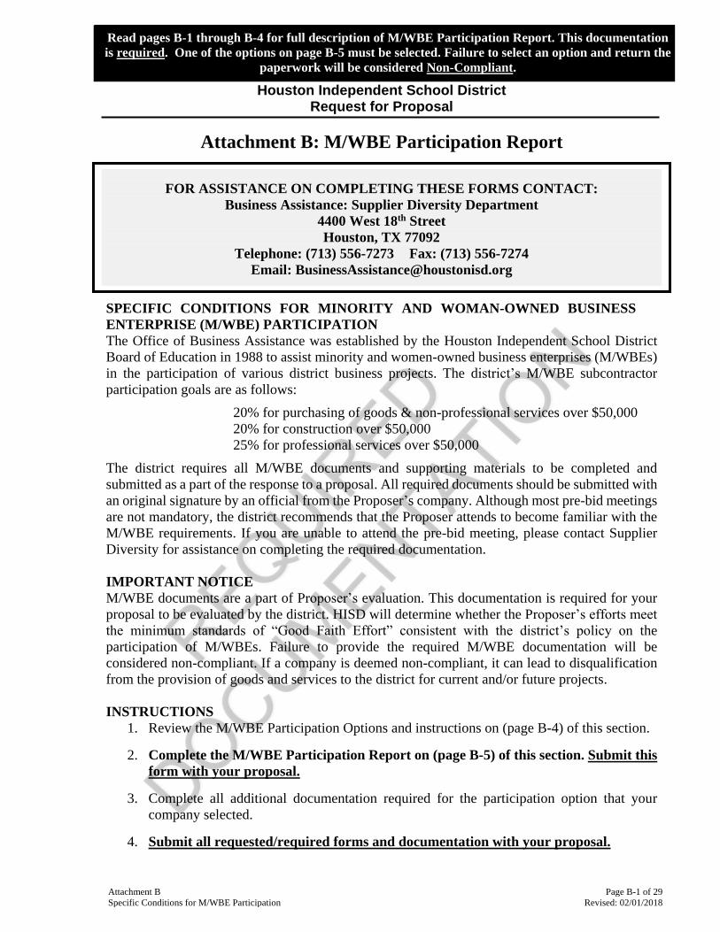
Attachment B Page B-1 of 29
Specific Conditions for M/WBE Participation Revised: 02/01/2018
Read pages B-1 through B-4 for full description of M/WBE Participation Report. This documentation
is required. One of the options on page B-5 must be selected. Failure to select an option and return the
paperwork will be considered Non-Compliant.
Houston Independent School District Request for Proposal
Attachment B: M/WBE Participation Report
SPECIFIC CONDITIONS FOR MINORITY AND WOMAN-OWNED BUSINESS
ENTERPRISE (M/WBE) PARTICIPATION
The Office of Business Assistance was established by the Houston Independent School District
Board of Education in 1988 to assist minority and women-owned business enterprises (M/WBEs)
in the participation of various district business projects. The district’s M/WBE subcontractor
participation goals are as follows:
20% for purchasing of goods & non-professional services over $50,000
20% for construction over $50,000
25% for professional services over $50,000
The district requires all M/WBE documents and supporting materials to be completed and
submitted as a part of the response to a proposal. All required documents should be submitted with
an original signature by an official from the Proposer’s company. Although most pre-bid meetings
are not mandatory, the district recommends that the Proposer attends to become familiar with the
M/WBE requirements. If you are unable to attend the pre-bid meeting, please contact Supplier
Diversity for assistance on completing the required documentation.
IMPORTANT NOTICE
M/WBE documents are a part of Proposer’s evaluation. This documentation is required for your
proposal to be evaluated by the district. HISD will determine whether the Proposer’s efforts meet
the minimum standards of “Good Faith Effort” consistent with the district’s policy on the
participation of M/WBEs. Failure to provide the required M/WBE documentation will be
considered non-compliant. If a company is deemed non-compliant, it can lead to disqualification
from the provision of goods and services to the district for current and/or future projects.
INSTRUCTIONS
1. Review the M/WBE Participation Options and instructions on (page B-4) of this section.
2. Complete the M/WBE Participation Report on (page B-5) of this section. Submit this
form with your proposal.
3. Complete all additional documentation required for the participation option that your
company selected.
4. Submit all requested/required forms and documentation with your proposal.
FOR ASSISTANCE ON COMPLETING THESE FORMS CONTACT:
Business Assistance: Supplier Diversity Department
4400 West 18th Street
Houston, TX 77092
Telephone: (713) 556-7273 Fax: (713) 556-7274
Email: [email protected]
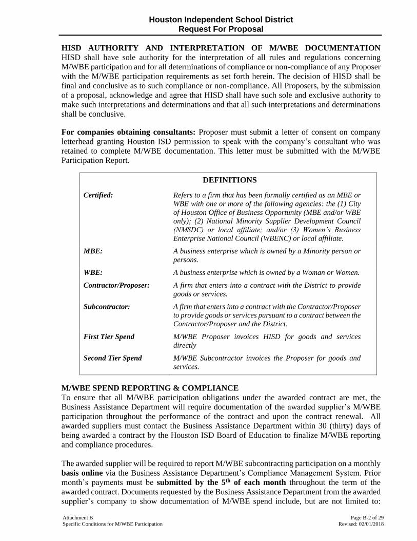
Houston Independent School District Request For Proposal
Attachment B Page B-2 of 29
Specific Conditions for M/WBE Participation Revised: 02/01/2018
HISD AUTHORITY AND INTERPRETATION OF M/WBE DOCUMENTATION
HISD shall have sole authority for the interpretation of all rules and regulations concerning
M/WBE participation and for all determinations of compliance or non-compliance of any Proposer
with the M/WBE participation requirements as set forth herein. The decision of HISD shall be
final and conclusive as to such compliance or non-compliance. All Proposers, by the submission
of a proposal, acknowledge and agree that HISD shall have such sole and exclusive authority to
make such interpretations and determinations and that all such interpretations and determinations
shall be conclusive.
For companies obtaining consultants: Proposer must submit a letter of consent on company
letterhead granting Houston ISD permission to speak with the company’s consultant who was
retained to complete M/WBE documentation. This letter must be submitted with the M/WBE
Participation Report.
DEFINITIONS
Certified: Refers to a firm that has been formally certified as an MBE or
WBE with one or more of the following agencies: the (1) City
of Houston Office of Business Opportunity (MBE and/or WBE
only); (2) National Minority Supplier Development Council
(NMSDC) or local affiliate; and/or (3) Women’s Business
Enterprise National Council (WBENC) or local affiliate.
MBE: A business enterprise which is owned by a Minority person or
persons.
WBE: A business enterprise which is owned by a Woman or Women.
Contractor/Proposer: A firm that enters into a contract with the District to provide
goods or services.
Subcontractor: A firm that enters into a contract with the Contractor/Proposer
to provide goods or services pursuant to a contract between the
Contractor/Proposer and the District.
First Tier Spend M/WBE Proposer invoices HISD for goods and services
directly
Second Tier Spend M/WBE Subcontractor invoices the Proposer for goods and
services.
M/WBE SPEND REPORTING & COMPLIANCE
To ensure that all M/WBE participation obligations under the awarded contract are met, the
Business Assistance Department will require documentation of the awarded supplier’s M/WBE
participation throughout the performance of the contract and upon the contract renewal. All
awarded suppliers must contact the Business Assistance Department within 30 (thirty) days of
being awarded a contract by the Houston ISD Board of Education to finalize M/WBE reporting
and compliance procedures.
The awarded supplier will be required to report M/WBE subcontracting participation on a monthly
basis online via the Business Assistance Department’s Compliance Management System. Prior
month’s payments must be submitted by the 5th of each month throughout the term of the
awarded contract. Documents requested by the Business Assistance Department from the awarded
supplier’s company to show documentation of M/WBE spend include, but are not limited to:

Houston Independent School District Request For Proposal
Attachment B Page B-3 of 29
Specific Conditions for M/WBE Participation Revised: 02/01/2018
invoices, purchase orders, and other pertinent documents that the district deems necessary to verify
the usage of M/WBE companies. Awarded Proposers will also be required to complete M/WBE
documentation provided by the Business Assistance Department, which includes monthly
reporting.
The awarded supplier could be deemed as non-compliant if they fail to meet and/or report their
M/WBE subcontracting commitment, provides inaccurate, incorrect, and/or false information
related to reporting M/WBE information.
If the district determines that a supplier is non-compliant, actions include, but are not limited
to the following:
1. If the supplier, during any year of the contract, (a) fails to meet their M/WBE
subcontracting commitment; and/or (b) fails to provide the requested and accurate M/WBE
documentation will be subject to having the contract terminated.
2. If the supplier is undergoing M/WBE compliance review at the end of their current contract
and (a) fails to meet their M/WBE subcontracting commitment; and/or (b) fails to provide
the requested and accurate M/WBE documentation, the supplier may not be allowed to bid
on the new proposal issued for that particular product or service.
3. If a supplier fails to meet their M/WBE subcontracting commitment on more than one
contract with the district, the supplier may not be eligible to do business with the district
for a minimum of one year.
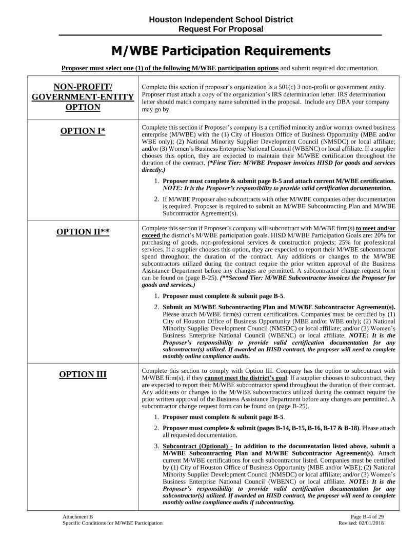
Houston Independent School District Request For Proposal
Attachment B Page B-4 of 29
Specific Conditions for M/WBE Participation Revised: 02/01/2018
M/WBE Participation Requirements
Proposer must select one (1) of the following M/WBE participation options and submit required documentation.
NON-PROFIT/
GOVERNMENT-ENTITY
OPTION
Complete this section if proposer’s organization is a 501(c) 3 non-profit or government entity.
Proposer must attach a copy of the organization’s IRS determination letter. IRS determination
letter should match company name submitted in the proposal. Include any DBA your company
may go by.
OPTION I*
Complete this section if Proposer’s company is a certified minority and/or woman-owned business enterprise (M/WBE) with the (1) City of Houston Office of Business Opportunity (MBE and/or WBE only); (2) National Minority Supplier Development Council (NMSDC) or local affiliate; and/or (3) Women’s Business Enterprise National Council (WBENC) or local affiliate. If a supplier chooses this option, they are expected to maintain their M/WBE certification throughout the duration of the contract. (*First Tier: M/WBE Proposer invoices HISD for goods and services directly.)
1. Proposer must complete & submit page B-5 and attach current M/WBE certification. NOTE: It is the Proposer’s responsibility to provide valid certification documentation.
2. If M/WBE Proposer also subcontracts with other M/WBE companies other documentation is required. Proposer is required to submit an M/WBE Subcontracting Plan and M/WBE Subcontractor Agreement(s).
OPTION II**
Complete this section if Proposer’s company will subcontract with M/WBE firm(s) to meet and/or exceed the district’s M/WBE participation goals. HISD M/WBE Participation Goals are: 20% for purchasing of goods, non-professional services & construction projects; 25% for professional services. If a supplier chooses this option, they are expected to report their M/WBE subcontractor spend throughout the duration of the contract. Any additions or changes to the M/WBE subcontractors utilized during the contract require the prior written approval of the Business Assistance Department before any changes are permitted. A subcontractor change request form can be found on (page B-25). (**Second Tier: M/WBE Subcontractor invoices the Proposer for goods and services.)
1. Proposer must complete & submit page B-5.
2. Submit an M/WBE Subcontracting Plan and M/WBE Subcontractor Agreement(s). Please attach M/WBE firm(s) current certifications. Companies must be certified by (1) City of Houston Office of Business Opportunity (MBE and/or WBE only); (2) National Minority Supplier Development Council (NMSDC) or local affiliate; and/or (3) Women’s Business Enterprise National Council (WBENC) or local affiliate. NOTE: It is the Proposer’s responsibility to provide valid certification documentation for any subcontractor(s) utilized. If awarded an HISD contract, the proposer will need to complete monthly online compliance audits.
OPTION III
Complete this section to comply with Option III. Company has the option to subcontract with M/WBE firm(s), if they cannot meet the district’s goal. If a supplier chooses to subcontract, they are expected to report their M/WBE subcontractor spend throughout the duration of their contract. Any additions or changes to the M/WBE subcontractors utilized during the contract require the prior written approval of the Business Assistance Department before any changes are permitted. A subcontractor change request form can be found on (page B-25).
1. Proposer must complete & submit page B-5.
2. Proposer must complete & submit (pages B-14, B-15, B-16, B-17 & B-18). Please attach all requested documentation.
3. Subcontract (Optional) - In addition to the documentation listed above, submit a M/WBE Subcontracting Plan and M/WBE Subcontractor Agreement(s). Attach current M/WBE certifications for each subcontractor listed. Companies must be certified by (1) City of Houston Office of Business Opportunity (MBE and/or WBE); (2) National Minority Supplier Development Council (NMSDC) or local affiliate; and/or (3) Women’s Business Enterprise National Council (WBENC) or local affiliate. NOTE: It is the Proposer’s responsibility to provide valid certification documentation for any subcontractor(s) utilized. If awarded an HISD contract, the proposer will need to complete monthly online compliance audits if subcontracting.
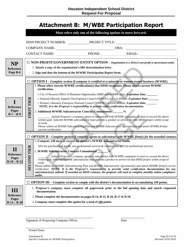
Houston Independent School District Request For Proposal
Attachment B Page B-5 of 29
Specific Conditions for M/WBE Participation Revised: 02/01/2018
Attachment B: M/WBE Participation Report
□ NON-PROFIT/GOVERNMENT-ENTITY OPTION – Organization is a 501(c)3 non-profit or government entity.
1. Attach a copy of the organization’s IRS determination letter.
2. Sign and date the bottom of the M/WBE Participation Report form.
□ OPTION I – Complete section if company is certified as a minority or woman-owned business (M/WBE).
FIR
ST
TIE
R
1. Please select current M/WBE certification(s) that HISD recognizes. Please attach current M/WBE
certification.
□ City of Houston Office of Business Opportunity (MBE and/or WBE only). Expiration Date: _______
□ National Minority Supplier Development Council (NMSDC) or local affiliate. Expiration Date: _______
□ Women’s Business Enterprise National Council (WBENC) or local affiliate. Expiration Date: _______
NOTE: It is the Proposer’s responsibility to provide valid certification documentation.
2. Additional M/WBE Subcontractor Contract Commitment: _______%
_________ (initial) Proposer’s company agrees to subcontract with M/WBE companies to meet or exceed the above
written goal. Selected M/WBE subcontractor must provide a product or service for this HISD project within scope
of work.
Please submit an M/WBE Subcontracting Plan and M/WBE Subcontractor Agreement(s) and attach M/WBE firm(s)
current certification.
□ OPTION II – Complete section if company agrees to subcontract with M/WBE firm(s) for the awarded contract.
SE
CO
ND
TIE
R
1. Company will meet or exceed the district’s M/WBE Subcontractor Goals.
20% for purchasing of goods, non-professional services & construction; 25% for professional services
2. M/WBE Subcontractor Contract Commitment _______%
_________ (initial) Proposer’s company agrees to subcontract with M/WBE companies to meet or exceed the above
written goal. Selected M/WBE subcontractor must provide a product or service for this HISD project within scope of
work. Please submit an M/WBE Subcontracting Plan and M/WBE Subcontractor Agreement(s) and attach M/WBE firm(s) current
certification. NOTE: It is the Proposer’s responsibility to provide valid certification documentation for any subcontractor(s) utilized. If awarded an HISD contract, the proposer will need to complete monthly online compliance audits.
□ OPTION III – Complete section to comply with the district’s documentation in accumulating 100 points.
1. Proposer’s company must complete all paperwork prior to the bid opening date and attach requested
documentation.
2. Please complete the documentation on pages B-14, B-15, B-16, B-17 & B-18.
3. Company must complete this option for a total of 100 points.
___________________________________________ _______________
Signature of Proposing Company Officer Date
____________________________________________ Printed Name
Must select only one of the following options to move forward.
HISD PROJECT NUMBER: PROJECT TITLE:
COMPANY NAME: DBA:
CONTACT NAME: PHONE: EMAIL:
NP Reference
Page B-6
I Reference
Pages
B-7 – B-9
II Reference
Pages
B-10 – B-12
III Reference
Pages
B-13 – B-30
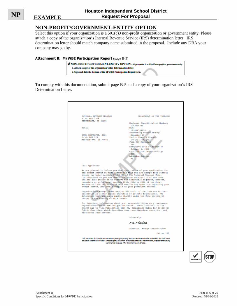
Houston Independent School District Request For Proposal
Attachment B Page B-6 of 29
Specific Conditions for M/WBE Participation Revised: 02/01/2018
NON-PROFIT/GOVERNMENT-ENTITY OPTION Select this option if your organization is a 501(c)3 non-profit organization or government entity. Please
attach a copy of the organization‘s Internal Revenue Service (IRS) determination letter. IRS
determination letter should match company name submitted in the proposal. Include any DBA your
company may go by.
Attachment B: M/WBE Participation Report (page B-5)
To comply with this documentation, submit page B-5 and a copy of your organization’s IRS
Determination Letter.
NP EXAMPLE
COMPLETE
√

Houston Independent School District Request For Proposal
Attachment B Page B-7 of 29
Specific Conditions for M/WBE Participation Revised: 02/01/2018
OPTION I – CERTIFIED M/WBE COMPANY Select this option if you are a certified M/WBE company. To comply with this documentation, submit
page B-5 and a copy of your current certification.
Attachment B: M/WBE Participation Report (page B-5)
Houston ISD only accepts the following certifications:
A. City of Houston Office of Business Opportunity (MBE and/or WBE only)
B. National Minority Supplier Development Council (NMSDC) or local affiliate
C. Women’s Business Enterprise National Council (WBENC) or local affiliate
NOTE: WE DO NOT ACCEPT HUB CERTIFICATION
If you choose to subcontract with additional M/WBE firms, a M/WBE Subcontracting Plan and M/WBE
Subcontracting Agreement(s) is required, along with a copy of the subcontractor’s current certification
from one of the certifying agencies listed above. To comply with this documentation, submit page B-5,
B-8, and B-9.
COMPLETE
√
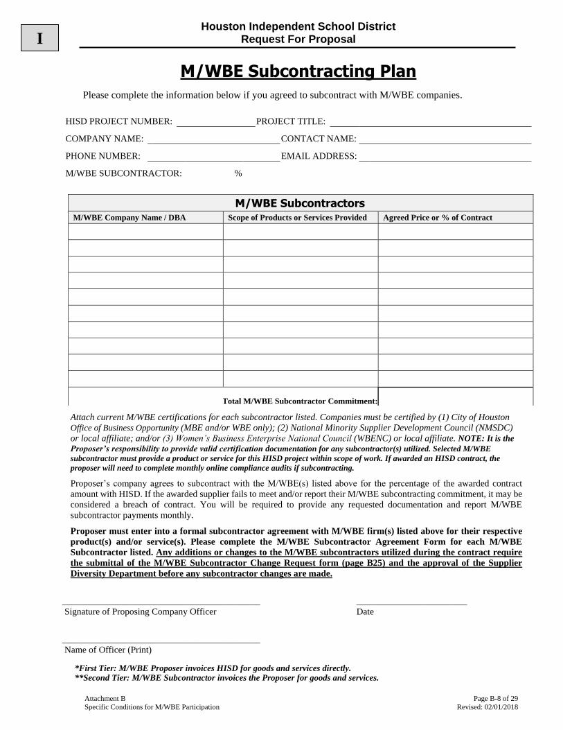
Houston Independent School District Request For Proposal
Attachment B Page B-8 of 29
Specific Conditions for M/WBE Participation Revised: 02/01/2018
M/WBE Subcontracting Plan
Please complete the information below if you agreed to subcontract with M/WBE companies.
Attach current M/WBE certifications for each subcontractor listed. Companies must be certified by (1) City of Houston
Office of Business Opportunity (MBE and/or WBE only); (2) National Minority Supplier Development Council (NMSDC)
or local affiliate; and/or (3) Women’s Business Enterprise National Council (WBENC) or local affiliate. NOTE: It is the
Proposer’s responsibility to provide valid certification documentation for any subcontractor(s) utilized. Selected M/WBE
subcontractor must provide a product or service for this HISD project within scope of work. If awarded an HISD contract, the
proposer will need to complete monthly online compliance audits if subcontracting.
Proposer’s company agrees to subcontract with the M/WBE(s) listed above for the percentage of the awarded contract
amount with HISD. If the awarded supplier fails to meet and/or report their M/WBE subcontracting commitment, it may be
considered a breach of contract. You will be required to provide any requested documentation and report M/WBE
subcontractor payments monthly.
Proposer must enter into a formal subcontractor agreement with M/WBE firm(s) listed above for their respective
product(s) and/or service(s). Please complete the M/WBE Subcontractor Agreement Form for each M/WBE
Subcontractor listed. Any additions or changes to the M/WBE subcontractors utilized during the contract require
the submittal of the M/WBE Subcontractor Change Request form (page B25) and the approval of the Supplier
Diversity Department before any subcontractor changes are made.
___________________________________________ ________________________
Signature of Proposing Company Officer Date
___________________________________________
Name of Officer (Print)
*First Tier: M/WBE Proposer invoices HISD for goods and services directly. **Second Tier: M/WBE Subcontractor invoices the Proposer for goods and services.
HISD PROJECT NUMBER: PROJECT TITLE:
COMPANY NAME: CONTACT NAME:
PHONE NUMBER: EMAIL ADDRESS:
M/WBE SUBCONTRACTOR: %
M/WBE Subcontractors M/WBE Company Name / DBA Scope of Products or Services Provided Agreed Price or % of Contract
Total M/WBE Subcontractor Commitment:
I

Houston Independent School District Request For Proposal
Attachment B Page B-9 of 29
Specific Conditions for M/WBE Participation Revised: 02/01/2018
M/WBE Subcontractor Agreement
Please complete the information below if you agreed to subcontract with M/WBE companies. The
submission of your subcontractor agreement is required for each M/WBE subcontractor.
M/WBE SUBCONTRACTOR INFORMATION
________________________________________ _______________________
Signature of M/WBE Subcontractor Officer Date
_________________________________________ _________________________________________
Printed Name Printed Title
_________________________________________ _______________________
Signature of Proposing Company Officer Date
_________________________________________ _________________________________________
Printed Name Printed Title
*First Tier: M/WBE Proposer invoices HISD for goods and services directly. **Second Tier: M/WBE Subcontractor invoices the Proposer for goods and services.
HISD PROJECT NUMBER:
PROJECT TITLE:
COMPANY NAME:
M/WBE COMPANY NAME:
COMPANY DBA:
OWNER NAME(S):
SELECT CURRENT M/WBE CERTIFICATION(S) & ATTACH CURRENT CERTIFICATION(S)
□ City of Houston Office of Business Opportunity (MBE and/or WBE only). Expiration Date: _______
□ National Minority Supplier Development Council (NMSDC) or local affiliate. Expiration Date: _______
□ Women’s Business Enterprise National Council (WBENC) or local affiliate. Expiration Date: _______
NOTE: It is the Proposer’s responsibility to provide valid certification documentation for any subcontractor(s) utilized.
SCOPE OF SERVICE:
AGREED CONTRACT PRICE OR % OF CONTRACT AWARD:
COMPANY CONTACT NAME:
PHONE NUMBER:
EMAIL ADDRESS:
I
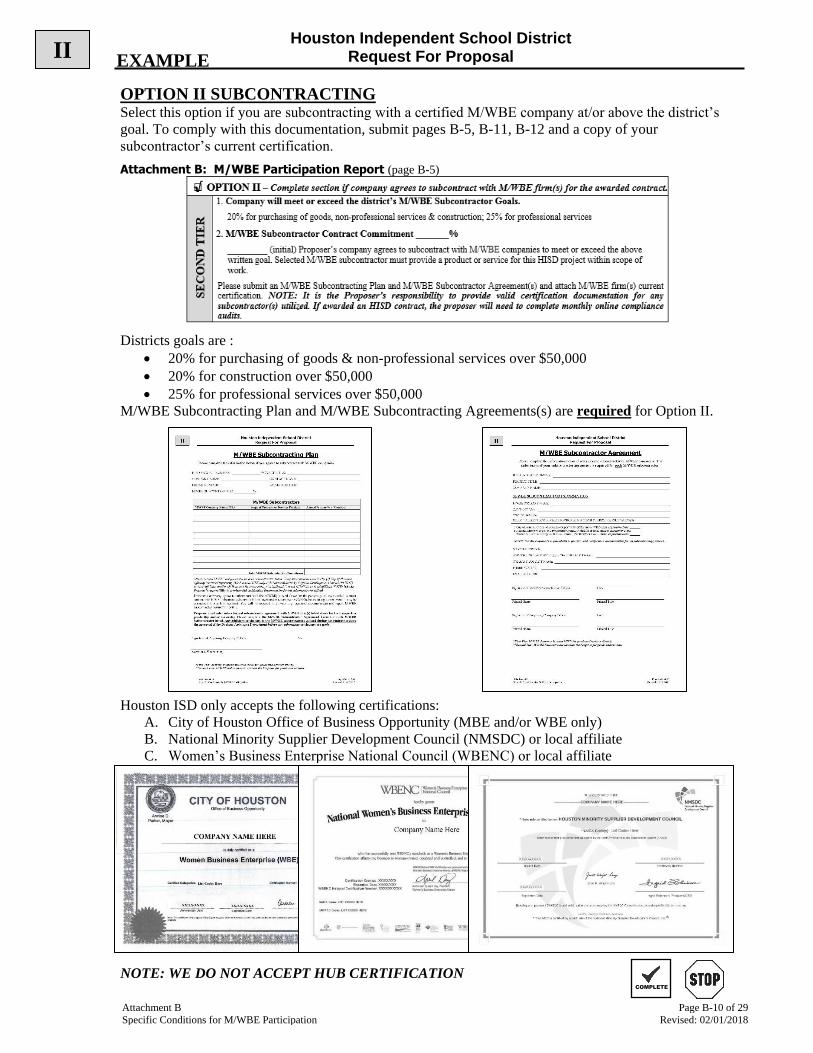
Houston Independent School District Request For Proposal
Attachment B Page B-10 of 29
Specific Conditions for M/WBE Participation Revised: 02/01/2018
OPTION II SUBCONTRACTING Select this option if you are subcontracting with a certified M/WBE company at/or above the district’s
goal. To comply with this documentation, submit pages B-5, B-11, B-12 and a copy of your
subcontractor’s current certification.
Attachment B: M/WBE Participation Report (page B-5)
Districts goals are :
• 20% for purchasing of goods & non-professional services over $50,000
• 20% for construction over $50,000
• 25% for professional services over $50,000
M/WBE Subcontracting Plan and M/WBE Subcontracting Agreements(s) are required for Option II.
Houston ISD only accepts the following certifications:
A. City of Houston Office of Business Opportunity (MBE and/or WBE only)
B. National Minority Supplier Development Council (NMSDC) or local affiliate
C. Women’s Business Enterprise National Council (WBENC) or local affiliate
NOTE: WE DO NOT ACCEPT HUB CERTIFICATION COMPLETE
EXAMPLE II
√

Houston Independent School District Request For Proposal
Attachment B Page B-11 of 29
Specific Conditions for M/WBE Participation Revised: 02/01/2018
M/WBE Subcontracting Plan
Please complete the information below if you agreed to subcontract with M/WBE companies.
Attach current M/WBE certifications for each subcontractor listed. Companies must be certified by (1) City of Houston
Office of Business Opportunity (MBE and/or WBE only); (2) National Minority Supplier Development Council (NMSDC)
or local affiliate; and/or (3) Women’s Business Enterprise National Council (WBENC) or local affiliate. NOTE: It is the
Proposer’s responsibility to provide valid certification documentation for any subcontractor(s) utilized. Selected M/WBE
subcontractor must provide a product or service for this HISD project within scope of work. If awarded an HISD contract, the
proposer will need to complete monthly online compliance audits if subcontracting.
Proposer’s company agrees to subcontract with the M/WBE(s) listed above for the percentage of the awarded contract
amount with HISD. If the awarded supplier fails to meet and/or report their M/WBE subcontracting commitment, it may be
considered a breach of contract. You will be required to provide any requested documentation and report M/WBE
subcontractor payments monthly.
Proposer must enter into a formal subcontractor agreement with M/WBE firm(s) listed above for their respective
product(s) and/or service(s). Please complete the M/WBE Subcontractor Agreement Form for each M/WBE
Subcontractor listed. Any additions or changes to the M/WBE subcontractors utilized during the contract require
the submittal of the M/WBE Subcontractor Change Request form (page B25) and the approval of the Supplier
Diversity Department before any subcontractor changes are made.
___________________________________________ ________________________
Signature of Proposing Company Officer Date
___________________________________________
Name of Officer (Print)
*First Tier: M/WBE Proposer invoices HISD for goods and services directly. **Second Tier: M/WBE Subcontractor invoices the Proposer for goods and services.
HISD PROJECT NUMBER: PROJECT TITLE:
COMPANY NAME: CONTACT NAME:
PHONE NUMBER: EMAIL ADDRESS:
M/WBE SUBCONTRACTOR: %
M/WBE Subcontractors M/WBE Company Name / DBA Scope of Products or Services Provided Agreed Price or % of Contract
Total M/WBE Subcontractor Commitment:
II

Houston Independent School District Request For Proposal
Attachment B Page B-12 of 29
Specific Conditions for M/WBE Participation Revised: 02/01/2018
M/WBE Subcontractor Agreement
Please complete the information below if you agreed to subcontract with M/WBE companies. The
submission of your subcontractor agreement is required for each M/WBE subcontractor.
M/WBE SUBCONTRACTOR INFORMATION
________________________________________ _______________________
Signature of M/WBE Subcontractor Officer Date
_________________________________________ _________________________________________
Printed Name Printed Title
_________________________________________ _______________________
Signature of Proposing Company Officer Date
_________________________________________ _________________________________________
Printed Name Printed Title
*First Tier: M/WBE Proposer invoices HISD for goods and services directly. **Second Tier: M/WBE Subcontractor invoices the Proposer for goods and services.
HISD PROJECT NUMBER:
PROJECT TITLE:
COMPANY NAME:
M/WBE COMPANY NAME:
COMPANY DBA:
OWNER NAME(S):
SELECT CURRENT M/WBE CERTIFICATION(S) & ATTACH CURRENT CERTIFICATION(S)
□ City of Houston Office of Business Opportunity (MBE and/or WBE only). Expiration Date: _______
□ National Minority Supplier Development Council (NMSDC) or local affiliate. Expiration Date: _______
□ Women’s Business Enterprise National Council (WBENC) or local affiliate. Expiration Date: _______
NOTE: It is the Proposer’s responsibility to provide valid certification documentation for any subcontractor(s) utilized.
SCOPE OF SERVICE:
AGREED CONTRACT PRICE OR % OF CONTRACT AWARD:
COMPANY CONTACT NAME:
PHONE NUMBER:
EMAIL ADDRESS:
II
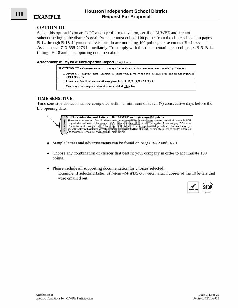
Houston Independent School District Request For Proposal
Attachment B Page B-13 of 29
Specific Conditions for M/WBE Participation Revised: 02/01/2018
OPTION III Select this option if you are NOT a non-profit organization, certified M/WBE and are not
subcontracting at the district’s goal. Proposer must collect 100 points from the choices listed on pages
B-14 through B-18. If you need assistance in accumulating 100 points, please contact Business
Assistance at 713-556-7273 immediately. To comply with this documentation, submit pages B-5, B-14
through B-18 and all supporting documentation.
Attachment B: M/WBE Participation Report (page B-5)
TIME SENSITIVE:
Time sensitive choices must be completed within a minimum of seven (7) consecutive days before the
bid opening date.
• Sample letters and advertisements can be found on pages B-22 and B-23.
• Choose any combination of choices that best fit your company in order to accumulate 100
points.
• Please include all supporting documentation for choices selected.
Example: if selecting Letter of Intent –M/WBE Outreach, attach copies of the 10 letters that
were emailed out.
III EXAMPLE
COMPLETE
√
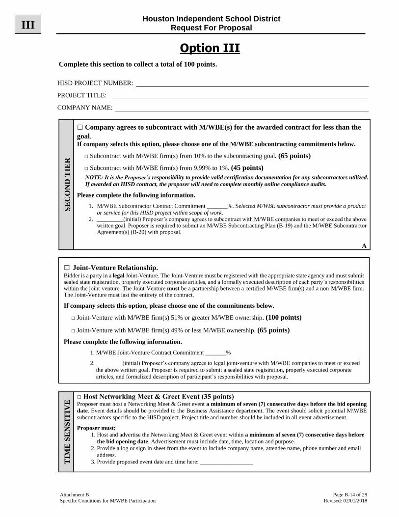
Houston Independent School District Request For Proposal
Attachment B Page B-14 of 29
Specific Conditions for M/WBE Participation Revised: 02/01/2018
Option III
Complete this section to collect a total of 100 points.
SE
CO
ND
TIE
R
□ Company agrees to subcontract with M/WBE(s) for the awarded contract for less than the
goal. If company selects this option, please choose one of the M/WBE subcontracting commitments below.
□ Subcontract with M/WBE firm(s) from 10% to the subcontracting goal. (65 points)
□ Subcontract with M/WBE firm(s) from 9.99% to 1%. (45 points)
NOTE: It is the Proposer’s responsibility to provide valid certification documentation for any subcontractors utilized.
If awarded an HISD contract, the proposer will need to complete monthly online compliance audits.
Please complete the following information.
1. M/WBE Subcontractor Contract Commitment _______%. Selected M/WBE subcontractor must provide a product
or service for this HISD project within scope of work. 2. _________(initial) Proposer’s company agrees to subcontract with M/WBE companies to meet or exceed the above
written goal. Proposer is required to submit an M/WBE Subcontracting Plan (B-19) and the M/WBE Subcontractor Agreement(s) (B-20) with proposal.
A
TIM
E S
EN
SIT
IVE
□ Host Networking Meet & Greet Event (35 points) Proposer must host a Networking Meet & Greet event a minimum of seven (7) consecutive days before the bid opening
date. Event details should be provided to the Business Assistance department. The event should solicit potential M\WBE
subcontractors specific to the HISD project. Project title and number should be included in all event advertisement.
Proposer must:
1. Host and advertise the Networking Meet & Greet event within a minimum of seven (7) consecutive days before
the bid opening date. Advertisement must include date, time, location and purpose.
2. Provide a log or sign in sheet from the event to include company name, attendee name, phone number and email
address.
3. Provide proposed event date and time here: __________________
HISD PROJECT NUMBER:
PROJECT TITLE:
COMPANY NAME:
□ Joint-Venture Relationship. Bidder is a party in a legal Joint-Venture. The Joint-Venture must be registered with the appropriate state agency and must submit sealed state registration, properly executed corporate articles, and a formally executed description of each party’s responsibilities within the joint-venture. The Joint-Venture must be a partnership between a certified M/WBE firm(s) and a non-M/WBE firm. The Joint-Venture must last the entirety of the contract.
If company selects this option, please choose one of the commitments below.
□ Joint-Venture with M/WBE firm(s) 51% or greater M/WBE ownership. (100 points)
□ Joint-Venture with M/WBE firm(s) 49% or less M/WBE ownership. (65 points)
Please complete the following information.
1. M/WBE Joint-Venture Contract Commitment _______%
2. _________(initial) Proposer’s company agrees to legal joint-venture with M/WBE companies to meet or exceed
the above written goal. Proposer is required to submit a sealed state registration, properly executed corporate
articles, and formalized description of participant’s responsibilities with proposal.
A
III

Houston Independent School District Request For Proposal
Attachment B Page B-15 of 29
Specific Conditions for M/WBE Participation Revised: 02/01/2018
Option III
TIM
E S
EN
SIT
IVE
□ Letters of Intent – M/WBE Outreach (35 points) Proposer must send (10) outreach letters to relevant certifying agencies accepted by HISD (City of Houston Office of
Business Opportunity, National Minority Supplier Development Council (NMSDC) or local affiliate, Women’s Business
Enterprise National Council (WBENC) or local affiliate and individual M/WBE companies to solicit potential M/WBE
subcontractor participation. Please see page B-21 for “Letters of Intent – M/WBE Outreach” example letter. Proposer must
solicit M/WBE companies a minimum of seven (7) consecutive days before the bid opening date.
The following documentation must be attached and includes:
1. Send (10) outreach letters via email to individual M/WBE companies. Letters should include project number and
project title. *Reference page B-26 for a list of certifying agencies and page B-27 for a list of M/WBE Business
Organizations & Associations.
2. Attach copies of the (10) outreach letters sent via email to individual M/WBE companies. Carbon Copy (cc)
[email protected] when emailing the 10 letters of intent.
3. Proposer must respond to M/WBEs who show interest in becoming a subcontractor. Attach additional email and
fax responses and communications from company with potential M/WBE subcontractors.
4. Proposer must follow-up with initial solicitations by contacting the (10) M/WBE companies to determine whether
the companies are interested in proposed subcontracting opportunity.
5. Proposer should provide interested minority and women business enterprises with adequate information about the
plans, specifications and requirements for the subcontracting opportunities available.
□ Formalized/Notarized Mentor-Protégé Relationship. Bidder is a party in a Formalized/Notarized mentoring relationship with M/WBE firm(s). The Formalized/Notarized agreement must include S.M.A.R.T. (Specific, Measurable, Achievable, Realistic, Time-Bound) goals. Participants in the relationship are required to submit joint, quarterly reports signed by both parties. Upon submittal of quarterly report each participant will participate in a joint quarterly review meeting with HISD staff.
If company selects this option, please choose one of the commitments below.
□ Formalized/Notarized Mentor-Protégé Relationship- Partnership with M/WBE firm(s) related to
current project with Houston ISD. (100 points) □ Formalized/Notarized Mentor-Protégé Relationship-Partnership with M/WBE Firm(s) outside of
Houston ISD (50 points)
Please complete the following information.
1. Attach current M/WBE certifications for each Protégé listed. Protégés must be certified by (1) City of Houston
Office of Business Opportunity (MBE and/or WBE only); (2) National Minority Supplier Development Council
(NMSDC) or local affiliate; and/or (3) Women’s Business Enterprise National Council (WBENC) or local
affiliate. NOTE: It is the Proposer’s responsibility to provide valid certification documentation.
2. _________(initial) Proposer’s company must provide formalized/notarized mentor-protégé relationship with
firm(s). Proposer is required to submit formalized documentation including S.M.A.R.T. goals for either Mentor-
Protégé relationship listed above.
A
□ Letters of Acceptance/Rejection – M/WBE Outreach (15 points) This option can only be selected if Letters of Intent – M/WBE Outreach has been selected and completed.
Proposer must provide an explanation of rejection or an acceptance to at least (5) of the M/WBE companies who were contacted
for the “Letters of Intent – M/WBE Outreach”. Please see page B-22 for “Acceptance/Rejection Example Letter”. To select this
option Proposer must have sent “Letters of Intent – M/WBE Outreach”.
1. A written rejection and/or acceptance letter, including the reason(s) for rejection or the terms of acceptance, will
be sent to at least (5) of the M/WBE companies. If less than (5) M/WBEs responded to the letter of intent,
failure of an M/WBE to respond can be a reason for a rejection letter to be sent.
2. Please attach a copy of each rejection and/or acceptance letter sent to potential M/WBE subcontractors.
3. Please attach an explanation to HISD, written on company letterhead, of why company was unable to utilize
M/WBE subcontractors to meet the district’s M/WBE subcontractor goal.
III

Houston Independent School District Request For Proposal
Attachment B Page B-16 of 29
Specific Conditions for M/WBE Participation Revised: 02/01/2018
Option III
TIM
E S
EN
SIT
IVE
□ Place Advertisement to Find M/WBE Subcontractors (25 points) Proposer must place an advertisement in one (1) general print circulation newspaper, magazine, trade association publication,
or minority and/or women-focused publication, concerning the potential subcontracting opportunity. Proposer must place
advertisement a minimum of seven (7) consecutive days before the bid opening date. Please see page B-23 for an
“Advertisement Example” and page B-29 for a list of newspapers and periodicals. *Please attach copy of the advertisement
and receipt for proof of purchase.
TIM
E S
EN
SIT
IVE
□ Place Advertisement Letters to find M/WBE Subcontractors (10 points) Proposer must send out five (5) advertisement letters, emails and/or faxes to newspapers, periodicals and/or M/WBE
organizations within a minimum of seven (7) consecutive days before the bid opening date. Please see page B-23 for an
“Advertisement Example Letter” and page B-29 for a list of newspapers and periodicals. Carbon Copy (cc)
[email protected] when emailing the five (5) advertisement letters. *Please attach copy of five (5) letters
sent to newspapers, periodicals and/or M/WBE organizations.
□ Indirect Spend with M/WBE Suppliers (20 points) Proposer must track the business it does with M/WBE suppliers as part of its overall operations and submit the M/WBE
Participation Indirect Spend Report on page B-24. Proposer must report Indirect Spend with M/WBE Supplier by completing
the Indirect Spend report on page B-24. The Indirect Spend reported with M/WBE supplier(s) must be part of the company’s
operation expenses. M/WBE Suppliers listed on the Indirect Spend report must be current suppliers doing business for at least
6 months.
□ Attend Pre-Bid Meeting to Network with Potential M/WBE Subcontractors (10 points) Proposer attended the Pre-Bid Meeting in an effort to meet potential M/WBE subcontractors. Business Assistance will verify attendance via the Pre-Bid meeting sign in sheet.
□ Review M/WBE Participation Report with a Supplier Diversity Specialist (10 points) Proposer must contact the office of Business Assistance and review the M/WBE Participation Report (Attachment B) with a Supplier Diversity Specialist.
_________________Include name of Supplier Diversity Specialist _________________Initial/Verification from Supplier Diversity Specialist
□ Participation as an Attendee in Business Expo (20 points) Proposer participates as an Attendee in a Business Expo in an effort to meet potential M/WBE subcontractors. Proposer must have attended one of the following expos no more than one year prior to project bid date. Please contact organization for Expo details.
□ City of Houston Meet the Buyer Purchasing Forum
□ Houston Minority Business Development Agency (MBDA) MED Week
□ Houston Minority Supplier Development Council (HMSDC) Annual Expo or NMSDC local affiliate Expo
□ Women’s Business Enterprise Alliance (WBEA) Annual EXPO or WBENC local affiliate Expo
Please attach a copy of your registration form and receipt.
□ Participation as an Exhibitor in Business Expo (40 points) Proposer participates as an Exhibitor in a Business Expo in an effort to meet potential M/WBE subcontractors. Proposer must have participated as an exhibitor in one of the following expos no more than one year prior to project bid date. Please contact organization for Expo details.
□ Houston Minority Business Development Agency (MBDA) MED Week
□ Houston Minority Supplier Development Council (HMSDC) Annual Expo or NMSDC local affiliate Expo (must be corporate member to exhibit).
□ Women’s Business Enterprise Alliance (WBEA) Annual EXPO or WBENC local affiliate Expo
Please attach a copy of your registration form and receipt.
III
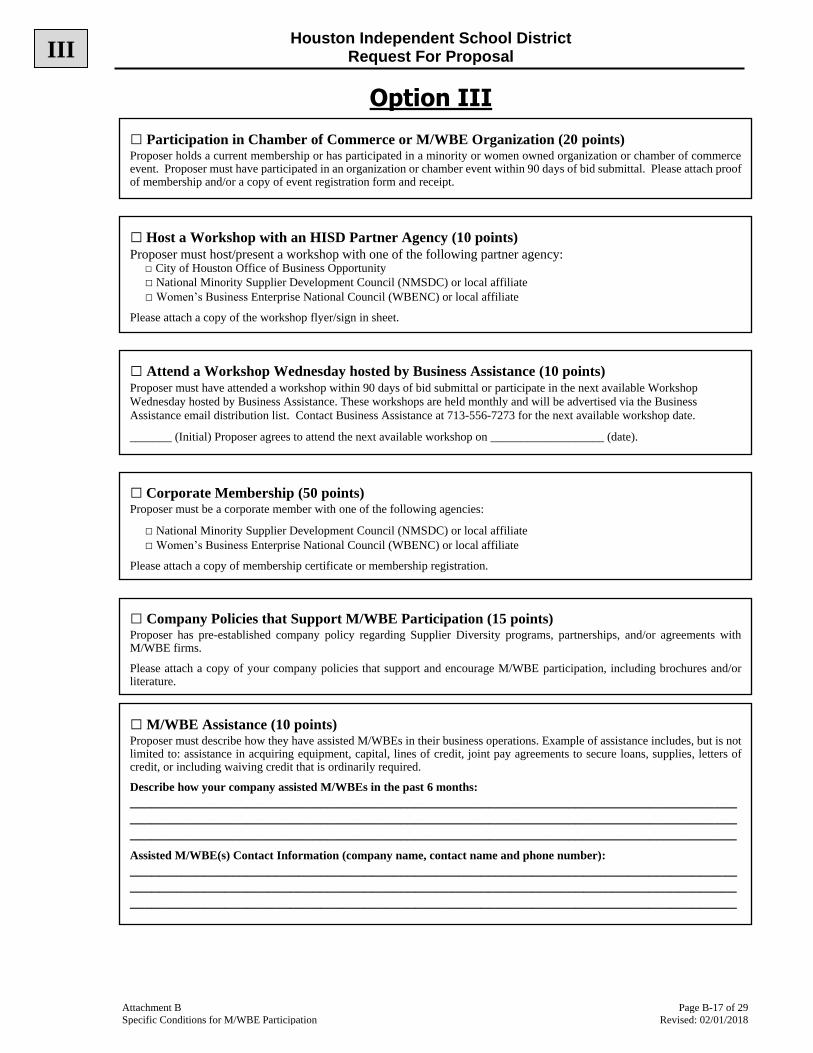
Houston Independent School District Request For Proposal
Attachment B Page B-17 of 29
Specific Conditions for M/WBE Participation Revised: 02/01/2018
Option III
□ Participation in Chamber of Commerce or M/WBE Organization (20 points) Proposer holds a current membership or has participated in a minority or women owned organization or chamber of commerce event. Proposer must have participated in an organization or chamber event within 90 days of bid submittal. Please attach proof of membership and/or a copy of event registration form and receipt.
□ Host a Workshop with an HISD Partner Agency (10 points)
Proposer must host/present a workshop with one of the following partner agency: □ City of Houston Office of Business Opportunity
□ National Minority Supplier Development Council (NMSDC) or local affiliate
□ Women’s Business Enterprise National Council (WBENC) or local affiliate
Please attach a copy of the workshop flyer/sign in sheet.
□ Attend a Workshop Wednesday hosted by Business Assistance (10 points) Proposer must have attended a workshop within 90 days of bid submittal or participate in the next available Workshop
Wednesday hosted by Business Assistance. These workshops are held monthly and will be advertised via the Business
Assistance email distribution list. Contact Business Assistance at 713-556-7273 for the next available workshop date.
_______ (Initial) Proposer agrees to attend the next available workshop on ___________________ (date).
□ Corporate Membership (50 points) Proposer must be a corporate member with one of the following agencies:
□ National Minority Supplier Development Council (NMSDC) or local affiliate
□ Women’s Business Enterprise National Council (WBENC) or local affiliate
Please attach a copy of membership certificate or membership registration.
□ Company Policies that Support M/WBE Participation (15 points) Proposer has pre-established company policy regarding Supplier Diversity programs, partnerships, and/or agreements with M/WBE firms.
Please attach a copy of your company policies that support and encourage M/WBE participation, including brochures and/or literature.
□ M/WBE Assistance (10 points) Proposer must describe how they have assisted M/WBEs in their business operations. Example of assistance includes, but is not limited to: assistance in acquiring equipment, capital, lines of credit, joint pay agreements to secure loans, supplies, letters of credit, or including waiving credit that is ordinarily required.
Describe how your company assisted M/WBEs in the past 6 months:
_________________________________________________________________________________________________________________________________________________________________________________________________________________________________________________________
Assisted M/WBE(s) Contact Information (company name, contact name and phone number): _________________________________________________________________________________________________________________________________________________________________________________________________________________________________________________________
III
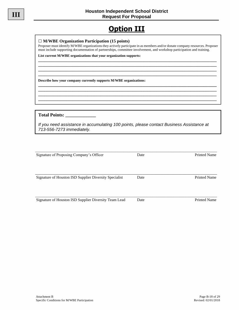
Houston Independent School District Request For Proposal
Attachment B Page B-18 of 29
Specific Conditions for M/WBE Participation Revised: 02/01/2018
Option III
_____________________________________________________________________________________________
Signature of Proposing Company’s Officer Date Printed Name
_____________________________________________________________________________________________
Signature of Houston ISD Supplier Diversity Specialist Date Printed Name
_____________________________________________________________________________________________
Signature of Houston ISD Supplier Diversity Team Lead Date Printed Name
□ M/WBE Organization Participation (15 points) Proposer must identify M/WBE organizations they actively participate in as members and/or donate company resources. Proposer must include supporting documentation of partnerships, committee involvement, and workshop participation and training.
List current M/WBE organizations that your organization supports: ____________________________________________________________________________________________________________________________________________________________________________________________________________________________________________________________________________________________________________________________________________
Describe how your company currently supports M/WBE organizations: ____________________________________________________________________________________________________________________________________________________________________________________________________________________________________________________________________________________________________________________________________________
Total Points: _____________
If you need assistance in accumulating 100 points, please contact Business Assistance at 713-556-7273 immediately.
III

Houston Independent School District Request For Proposal
Attachment B Page B-19 of 29
Specific Conditions for M/WBE Participation Revised: 02/01/2018
M/WBE Subcontracting Plan
Please complete the information below if you agreed to subcontract with M/WBE companies.
Attach current M/WBE certifications for each subcontractor listed. Companies must be certified by (1) City of Houston
Office of Business Opportunity (MBE and/or WBE only); (2) National Minority Supplier Development Council (NMSDC)
or local affiliate; and/or (3) Women’s Business Enterprise National Council (WBENC) or local affiliate. NOTE: It is the
Proposer’s responsibility to provide valid certification documentation for any subcontractor(s) utilized. Selected M/WBE
subcontractor must provide a product or service for this HISD project within scope of work. If awarded an HISD contract, the
proposer will need to complete monthly online compliance audits if subcontracting.
Proposer’s company agrees to subcontract with the M/WBE(s) listed above for the percentage of the awarded contract
amount with HISD. If the awarded supplier fails to meet and/or report their M/WBE subcontracting commitment, it may be
considered a breach of contract. You will be required to provide any requested documentation and report M/WBE
subcontractor payments monthly.
Proposer must enter into a formal subcontractor agreement with M/WBE firm(s) listed above for their respective
product(s) and/or service(s). Please complete the M/WBE Subcontractor Agreement Form for each M/WBE
Subcontractor listed. Any additions or changes to the M/WBE subcontractors utilized during the contract require
the submittal of the M/WBE Subcontractor Change Request form (page B25) and the approval of the Supplier
Diversity Department before any subcontractor changes are made.
___________________________________________ ________________________
Signature of Proposing Company Officer Date
___________________________________________
Name of Officer (Print)
*First Tier: M/WBE Proposer invoices HISD for goods and services directly. **Second Tier: M/WBE Subcontractor invoices the Proposer for goods and services.
HISD PROJECT NUMBER: PROJECT TITLE:
COMPANY NAME: CONTACT NAME:
PHONE NUMBER: EMAIL ADDRESS:
M/WBE SUBCONTRACTOR: %
M/WBE Subcontractors M/WBE Company Name / DBA Scope of Products or Services Provided Agreed Price or % of Contract
Total M/WBE Subcontractor Commitment:
III
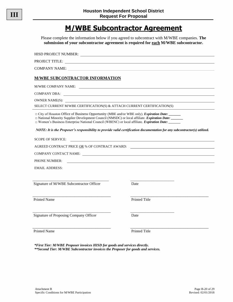
Houston Independent School District Request For Proposal
Attachment B Page B-20 of 29
Specific Conditions for M/WBE Participation Revised: 02/01/2018
M/WBE Subcontractor Agreement
Please complete the information below if you agreed to subcontract with M/WBE companies. The
submission of your subcontractor agreement is required for each M/WBE subcontractor.
M/WBE SUBCONTRACTOR INFORMATION
________________________________________ _______________________
Signature of M/WBE Subcontractor Officer Date
_________________________________________ _________________________________________
Printed Name Printed Title
_________________________________________ _______________________
Signature of Proposing Company Officer Date
_________________________________________ _________________________________________
Printed Name Printed Title
*First Tier: M/WBE Proposer invoices HISD for goods and services directly. **Second Tier: M/WBE Subcontractor invoices the Proposer for goods and services.
HISD PROJECT NUMBER:
PROJECT TITLE:
COMPANY NAME:
M/WBE COMPANY NAME:
COMPANY DBA:
OWNER NAME(S):
SELECT CURRENT M/WBE CERTIFICATION(S) & ATTACH CURRENT CERTIFICATION(S)
□ City of Houston Office of Business Opportunity (MBE and/or WBE only). Expiration Date: _______
□ National Minority Supplier Development Council (NMSDC) or local affiliate. Expiration Date: _______
□ Women’s Business Enterprise National Council (WBENC) or local affiliate. Expiration Date: _______
NOTE: It is the Proposer’s responsibility to provide valid certification documentation for any subcontractor(s) utilized.
SCOPE OF SERVICE:
AGREED CONTRACT PRICE OR % OF CONTRACT AWARD:
COMPANY CONTACT NAME:
PHONE NUMBER:
EMAIL ADDRESS:
III
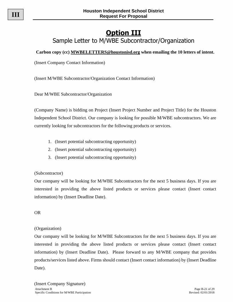
Houston Independent School District Request For Proposal
Attachment B Page B-21 of 29
Specific Conditions for M/WBE Participation Revised: 02/01/2018
Option III
Sample Letter to M/WBE Subcontractor/Organization
Carbon copy (cc) [email protected] when emailing the 10 letters of intent.
(Insert Company Contact Information)
(Insert M/WBE Subcontractor/Organization Contact Information)
Dear M/WBE Subcontractor/Organization
(Company Name) is bidding on Project (Insert Project Number and Project Title) for the Houston
Independent School District. Our company is looking for possible M/WBE subcontractors. We are
currently looking for subcontractors for the following products or services.
1. (Insert potential subcontracting opportunity)
2. (Insert potential subcontracting opportunity)
3. (Insert potential subcontracting opportunity)
(Subcontractor)
Our company will be looking for M/WBE Subcontractors for the next 5 business days. If you are
interested in providing the above listed products or services please contact (Insert contact
information) by (Insert Deadline Date).
OR
(Organization)
Our company will be looking for M/WBE Subcontractors for the next 5 business days. If you are
interested in providing the above listed products or services please contact (Insert contact
information) by (Insert Deadline Date). Please forward to any M/WBE company that provides
products/services listed above. Firms should contact (Insert contact information) by (Insert Deadline
Date).
(Insert Company Signature)
III

Houston Independent School District Request For Proposal
Attachment B Page B-22 of 29
Specific Conditions for M/WBE Participation Revised: 02/01/2018
Option III Acceptance/Rejection Sample Letter
Rejection Letters Sample 1
March 23, 2013 Dear ABC Company, This letter is to serve as formal notification that due to a lack of response by the due date, we will not be able to use your services at this time in accordance with the terms set out in the HISD Project #xxxxx. We will keep your information on file and may reach back out to you at another time. Sincerely,
Sample 2 Dear ABC Co, WE Corporation is bidding on Project #xxxxx for Houston Independent School District. We have solicited several MWBE companies to potentially serve as subcontractors and have had a strong response. We have made our selections and at this time we did not select your company due to ABC's inability to provide services in Houston. However, we may be in touch with you for future proposal opportunities. Regards, Sample 3 Ms. ABC, Since we did not receive a reply from you by the requested 2-12-2013 deadline, we will not be able to include you as a possible subcontractor with our proposal. Thank you.
Acceptance Letter Dear MWBE Supplier, WE Corporation has accepted your MWBE Certification and has added you to our list of potential subcontractors for Project #xxxxx for the HISD. If we are the awarded vendor, we may contact you directly regarding potential subcontracting opportunities. Thank you for your interest. Best regards,
III
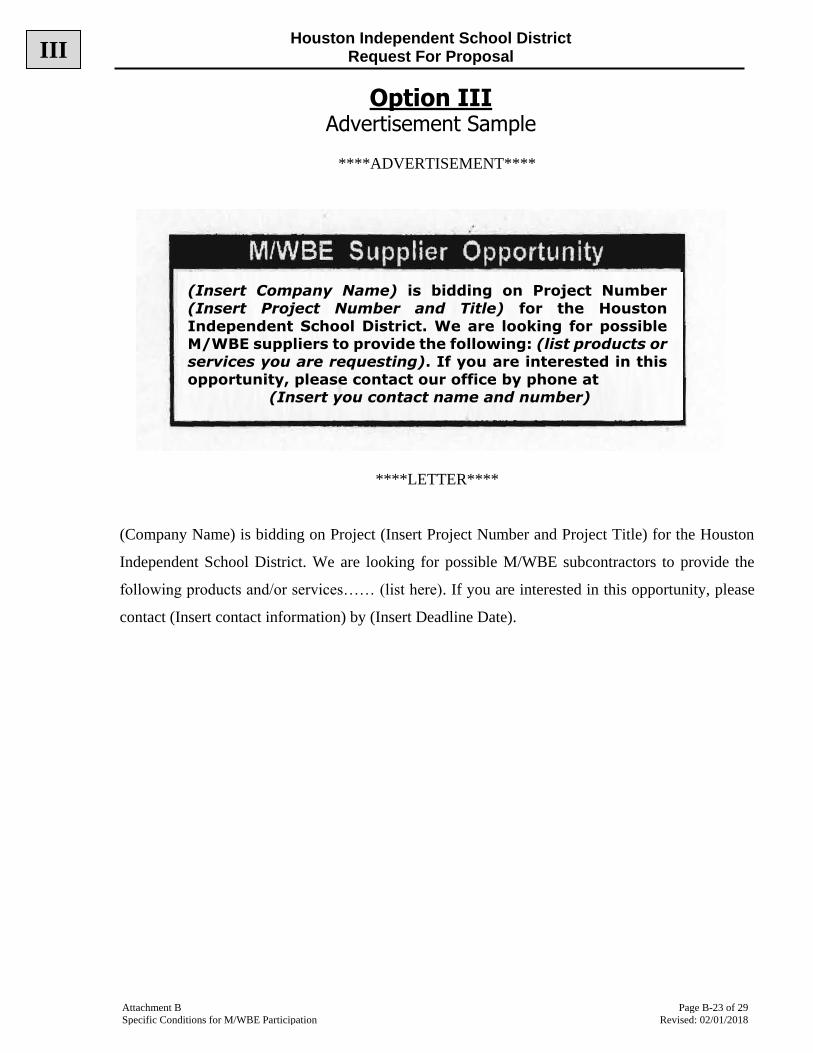
Houston Independent School District Request For Proposal
Attachment B Page B-23 of 29
Specific Conditions for M/WBE Participation Revised: 02/01/2018
Option III Advertisement Sample
****ADVERTISEMENT****
****LETTER****
(Company Name) is bidding on Project (Insert Project Number and Project Title) for the Houston
Independent School District. We are looking for possible M/WBE subcontractors to provide the
following products and/or services…… (list here). If you are interested in this opportunity, please
contact (Insert contact information) by (Insert Deadline Date).
(Insert Company Name) is bidding on Project Number
(Insert Project Number and Title) for the Houston
Independent School District. We are looking for possible M/WBE suppliers to provide the following: (list products or
services you are requesting). If you are interested in this
opportunity, please contact our office by phone at (Insert you contact name and number)
III
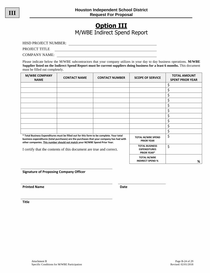
Houston Independent School District Request For Proposal
Attachment B Page B-24 of 29
Specific Conditions for M/WBE Participation Revised: 02/01/2018
Option III M/WBE Indirect Spend Report
HISD PROJECT NUMBER:
PROJECT TITLE
COMPANY NAME: Please indicate below the M/WBE subcontractors that your company utilizes in your day to day business operations. M/WBE
Supplier listed on the Indirect Spend Report must be current suppliers doing business for a least 6 months. This document
must be filled out completely.
M/WBE COMPANY NAME
CONTACT NAME CONTACT NUMBER SCOPE OF SERVICE TOTAL AMOUNT
SPENT PRIOR YEAR
$
$
$
$
$
$
$
$
$
$
* Total Business Expenditures must be filled out for this form to be complete. Your total business expenditures (total purchases) are the purchases that your company has had with other companies. This number should not match your M/WBE Spend Prior Year.
TOTAL M/WBE SPEND PRIOR YEAR
$
I certify that the contents of this document are true and correct. TOTAL BUSINESS EXPENDITURES PRIOR YEAR*
$
TOTAL M/WBE INDIRECT SPEND % %
Signature of Proposing Company Officer
Printed Name Date
Title
III
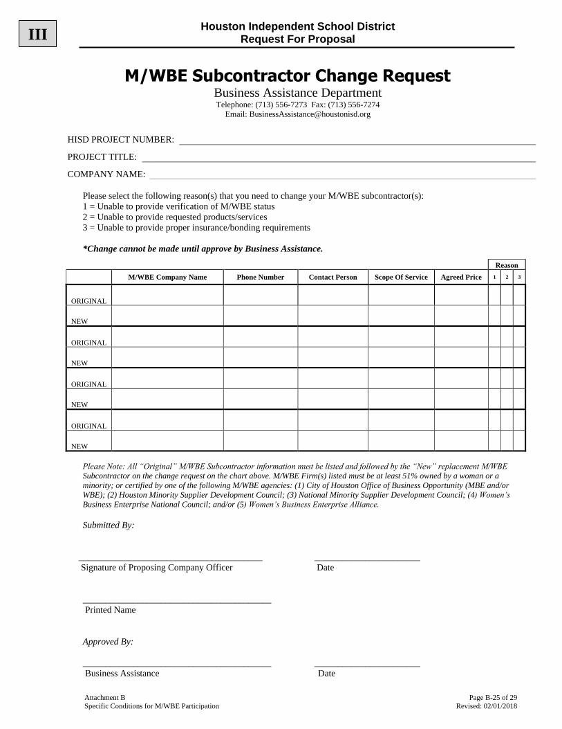
Houston Independent School District Request For Proposal
Attachment B Page B-25 of 29
Specific Conditions for M/WBE Participation Revised: 02/01/2018
M/WBE Subcontractor Change Request Business Assistance Department Telephone: (713) 556-7273 Fax: (713) 556-7274
Email: [email protected]
Please select the following reason(s) that you need to change your M/WBE subcontractor(s):
1 = Unable to provide verification of M/WBE status
2 = Unable to provide requested products/services
3 = Unable to provide proper insurance/bonding requirements
*Change cannot be made until approve by Business Assistance.
Reason
M/WBE Company Name Phone Number Contact Person Scope Of Service Agreed Price 1 2 3
ORIGINAL
NEW
ORIGINAL
NEW
ORIGINAL
NEW
ORIGINAL
NEW
Please Note: All “Original” M/WBE Subcontractor information must be listed and followed by the “New” replacement M/WBE
Subcontractor on the change request on the chart above. M/WBE Firm(s) listed must be at least 51% owned by a woman or a
minority; or certified by one of the following M/WBE agencies: (1) City of Houston Office of Business Opportunity (MBE and/or
WBE); (2) Houston Minority Supplier Development Council; (3) National Minority Supplier Development Council; (4) Women’s
Business Enterprise National Council; and/or (5) Women’s Business Enterprise Alliance.
Submitted By:
________________________________________ _______________________
Signature of Proposing Company Officer Date
_________________________________________
Printed Name
Approved By:
_________________________________________ _______________________
Business Assistance Date
HISD PROJECT NUMBER:
PROJECT TITLE:
COMPANY NAME:
III

Houston Independent School District Request For Proposal
Attachment B Page B-26 of 29
Specific Conditions for M/WBE Participation Revised: 02/01/2018
Certifying Agencies
CITY OF HOUSTON OFFICE OF BUSINESS OPPORTUNITY 611 Walker, 7th Floor Houston, Texas 77002 Phone: (832) 393-0600 Website: https://houston.mwdbe.com Email: [email protected]
HOUSTON MINORITY SUPPLIER DEVELOPMENT COUNCIL Three Riverway, Suite 555 Houston, Texas 77056 Phone: (713) 271-7805 Website: www.hmsdc.org Email: [email protected]
NATIONAL MINORITY SUPPLIER DEVELOPMENT COUNCIL 1359 Broadway, 10th Floor, Suite 1000 New York, NY 10018 Phone: (212) 944-2430 Website: www.nmsdc.org Email: [email protected]
WOMEN’S BUSINESS ENTERPRISE ALLIANCE 9800 Northwest Freeway Suite 120 Houston, Texas 77092 Phone: (713) 681-9232 Website: www.wbea-texas.org Email: [email protected] WOMEN’S BUSINESS ENTERPRISE NATIONAL ALLIANCE 1120 Connecticut Avenue, NW, Suite 1000 Washington, DC 20036 Phone: (202) 872-5515 Website: www.wbenc.org Email: [email protected]
III
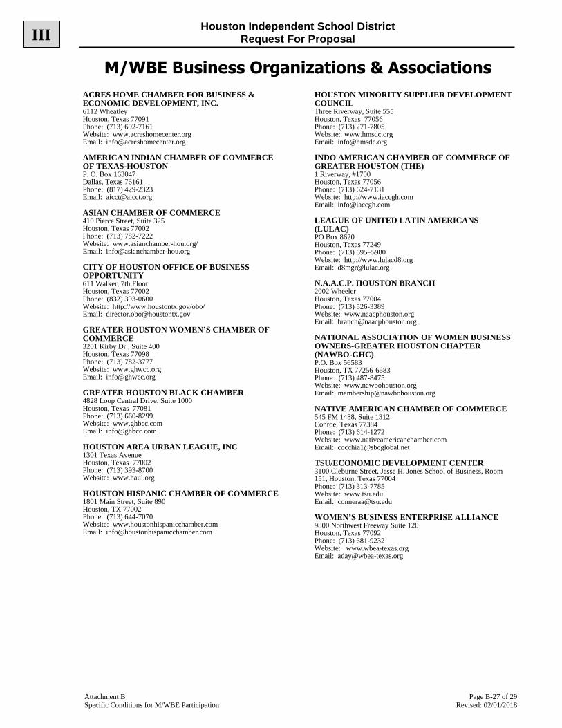
Houston Independent School District Request For Proposal
Attachment B Page B-27 of 29
Specific Conditions for M/WBE Participation Revised: 02/01/2018
M/WBE Business Organizations & Associations
ACRES HOME CHAMBER FOR BUSINESS & ECONOMIC DEVELOPMENT, INC. 6112 Wheatley Houston, Texas 77091 Phone: (713) 692-7161 Website: www.acreshomecenter.org Email: [email protected]
AMERICAN INDIAN CHAMBER OF COMMERCE OF TEXAS-HOUSTON P. O. Box 163047 Dallas, Texas 76161 Phone: (817) 429-2323 Email: [email protected]
ASIAN CHAMBER OF COMMERCE 410 Pierce Street, Suite 325 Houston, Texas 77002 Phone: (713) 782-7222 Website: www.asianchamber-hou.org/ Email: [email protected]
CITY OF HOUSTON OFFICE OF BUSINESS OPPORTUNITY 611 Walker, 7th Floor Houston, Texas 77002 Phone: (832) 393-0600 Website: http://www.houstontx.gov/obo/ Email: [email protected]
GREATER HOUSTON WOMEN’S CHAMBER OF COMMERCE 3201 Kirby Dr., Suite 400 Houston, Texas 77098 Phone: (713) 782-3777 Website: www.ghwcc.org Email: [email protected]
GREATER HOUSTON BLACK CHAMBER 4828 Loop Central Drive, Suite 1000 Houston, Texas 77081 Phone: (713) 660-8299 Website: www.ghbcc.com Email: [email protected]
HOUSTON AREA URBAN LEAGUE, INC 1301 Texas Avenue Houston, Texas 77002 Phone: (713) 393-8700 Website: www.haul.org
HOUSTON HISPANIC CHAMBER OF COMMERCE 1801 Main Street, Suite 890 Houston, TX 77002 Phone: (713) 644-7070 Website: www.houstonhispanicchamber.com Email: [email protected]
HOUSTON MINORITY SUPPLIER DEVELOPMENT COUNCIL Three Riverway, Suite 555 Houston, Texas 77056 Phone: (713) 271-7805 Website: www.hmsdc.org Email: [email protected]
INDO AMERICAN CHAMBER OF COMMERCE OF GREATER HOUSTON (THE) 1 Riverway, #1700 Houston, Texas 77056 Phone: (713) 624-7131 Website: http://www.iaccgh.com Email: [email protected]
LEAGUE OF UNITED LATIN AMERICANS (LULAC) PO Box 8620 Houston, Texas 77249 Phone: (713) 695–5980 Website: http://www.lulacd8.org Email: [email protected]
N.A.A.C.P. HOUSTON BRANCH 2002 Wheeler Houston, Texas 77004 Phone: (713) 526-3389 Website: www.naacphouston.org Email: [email protected]
NATIONAL ASSOCIATION OF WOMEN BUSINESS OWNERS-GREATER HOUSTON CHAPTER (NAWBO-GHC) P.O. Box 56583 Houston, TX 77256-6583 Phone: (713) 487-8475 Website: www.nawbohouston.org Email: [email protected]
NATIVE AMERICAN CHAMBER OF COMMERCE 545 FM 1488, Suite 1312 Conroe, Texas 77384 Phone: (713) 614-1272 Website: www.nativeamericanchamber.com Email: [email protected]
TSU/ECONOMIC DEVELOPMENT CENTER 3100 Cleburne Street, Jesse H. Jones School of Business, Room 151, Houston, Texas 77004 Phone: (713) 313-7785 Website: www.tsu.edu Email: [email protected]
WOMEN’S BUSINESS ENTERPRISE ALLIANCE 9800 Northwest Freeway Suite 120 Houston, Texas 77092 Phone: (713) 681-9232 Website: www.wbea-texas.org Email: [email protected]
III
Houston Independent School District Request For Proposal
Attachment B Page B-28 of 29
Specific Conditions for M/WBE Participation Revised: 02/01/2018
M/WBE Organizations & Associations (Construction)
ASIAN AMERICAN ENGINEERS/ARCHITECTS PO Box 270718 Houston, Texas 77277 President: Alan Sadeghpour Email: [email protected]
ASSOCIATION OF BLACK CONSULTING ENGINEERS AND ARCHITECTS P.O. Box 771992 Houston, Texas 77215 Phone: (713) 988-0145 Website: www.abcea.org Email: [email protected]
ASSOCIATED GENERAL CONTRACTORS OF AMERICA-HOUSTON CHAPTER 3825 Dacoma Street Houston, Texas 77092-8717 Phone: (713) 843-3700 Website: www.agchouston.org Email: [email protected]
HOUSTON HISPANIC ARCHITECTS AND ENGINEERS P.O. 421372 Houston, Texas 77042 Phone: (713) 426-7488 Website: www.hhae.org Email: [email protected]
NATIONAL ASSOCIATION OF MINORITY CONTRACTORS (NAMC) - GREATER HOUSTON CHAPTER 1337 W. 43rd, Suite, 165 Houston, Texas 77018 Phone: (281) 616-6757 Website: www.namctexas.org Email: [email protected]
NATIONAL ASSOCIATION OF WOMEN IN CONSTRUCTION-HOUSTON CHAPTER (NAWIC) Website: www.nawic-houston.org/ Email: [email protected]
WOMEN CONTRACTORS ASSOCIATION P O Box 70966 Houston, TX 77270 Phone: (713) 807-9977 Website: www.womencontractors.org Email: [email protected]
III

Houston Independent School District Request For Proposal
Attachment B Page B-29 of 29
Specific Conditions for M/WBE Participation Revised: 02/01/2018
M/WBE Newspapers and Periodicals
AFRICAN-AMERICAN NEWS & ISSUES 6130 Wheatley Street Houston, Texas 77091-3947 Phone: (713) 692-1892 Website: www.aframnews.com Email: [email protected]
FORWARD TIMES 4411 Almeda Houston, Texas 77004 Phone: (713) 526-4727 Website: www.forwardtimesonline.com Email: [email protected]
HOUSTON DEFENDER (THE) 12401 South Post Oak, #223 Houston, Texas 77045 Phone: (713) 663-6996 Website: www.defendernetwork.com Email: [email protected]
HOUSTON INSIDER (THE) 1713 Rosewood Street Houston, Texas 77004 Phone: (713) 526-0544 Website: http://thehoustoninsider.com/ Email: [email protected]
INDO AMERICAN NEWS 7545 Harwin Drive, Suite #262 Houston, Texas 77036 Phone: (713) 789-6397 Website: http://www.indoamerican-news.com Email: [email protected]
LA INFORMACIÓN 6065 Hillcroft, Suite 400B Houston, Texas 77081 Telephone: (713) 272-0100 Website: http://www.lainformacion.us/ Email: [email protected]
LA PRENSA DE HOUSTON 7100 Regency Square, Suite 217 Houston, Texas 77036 Phone: (713) 334-4959 Website: www.prensadehouston.com Email: [email protected]
LA VOZ DE HOUSTON 4747 SW Freeway Houston, Texas 77027-6901 Telephone: (713) 362-8100 Website: http://lavoztx.com/ Email: [email protected]
MINORITY PRINT MEDIA, LLC dba HOUSTON STYLE MAGAZINE PO Box 14035 Houston, Texas 77221-4035 Phone: (713) 748-6300 Website: www.stylemagazine.com Email: [email protected]
SOUTHERN CHINESE DAILY NEWS 11122 Bellaire Blvd. Houston, Texas 77072 Telephone: (281) 498-4310 Website: http://www.scdaily.com/ Email: [email protected]
VOICE OF ASIA 8303 Southwest Freeway, Suite 325 Houston, Texas 77074 Phone: (713) 774-5140/5141 Website: www.voiceofasiaonline.com Email: [email protected]
WORLD JOURNAL OF TEXAS, INC. 5855 Sovereign Dr. Unit C Houston, Texas 77036 Telephone: (713) 771-4363
III

BA: STANDARD FORM OF AGREEMENT BETWEEN OWNER AND
CONTRACTOR, AIA DOCUMENT A101 - 2007 EDITION (MODIFIED)
HISD BA-1
Attached is a non-reproducible copy of the Modified AIA Document A101 - 2007 Edition.
SAMPLE
SAMPLE
SAMPLE

SAMPLE

SAMPLE
SAMPLE
SAMPLE

BB: GENERAL CONDITIONS OF THE CONTRACT AIA A201 - 2007 EDITION
(MODIFIED)
HISD BB-1
Attached is a non-reproducible copy of the AIA Document A201™- 2007 Edition.
[INSERT CURRENT EDITION]

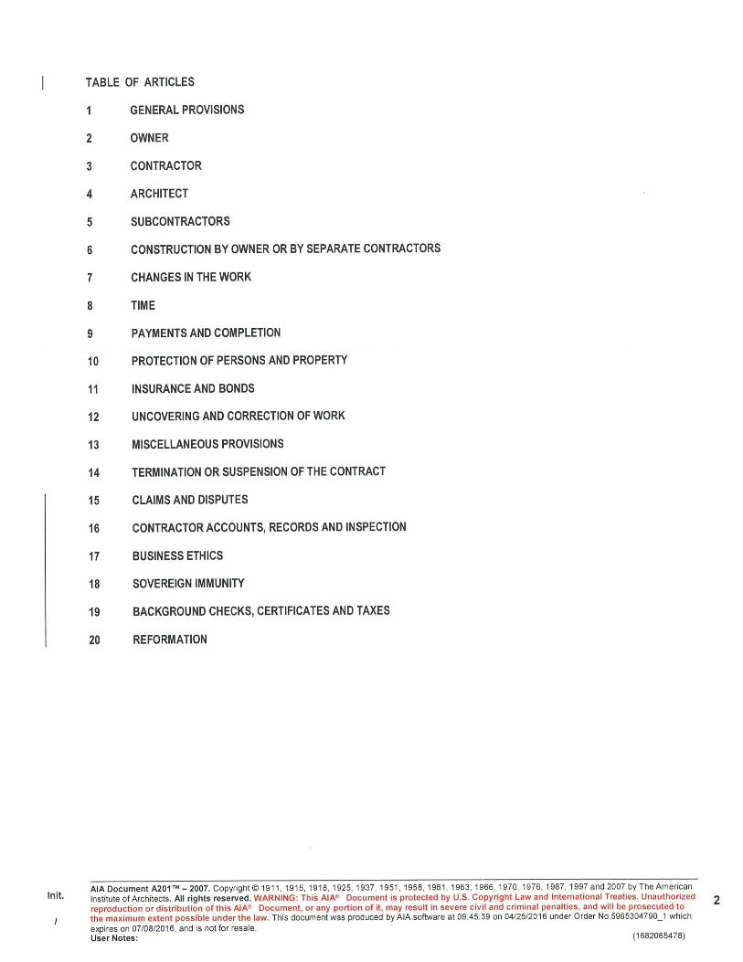

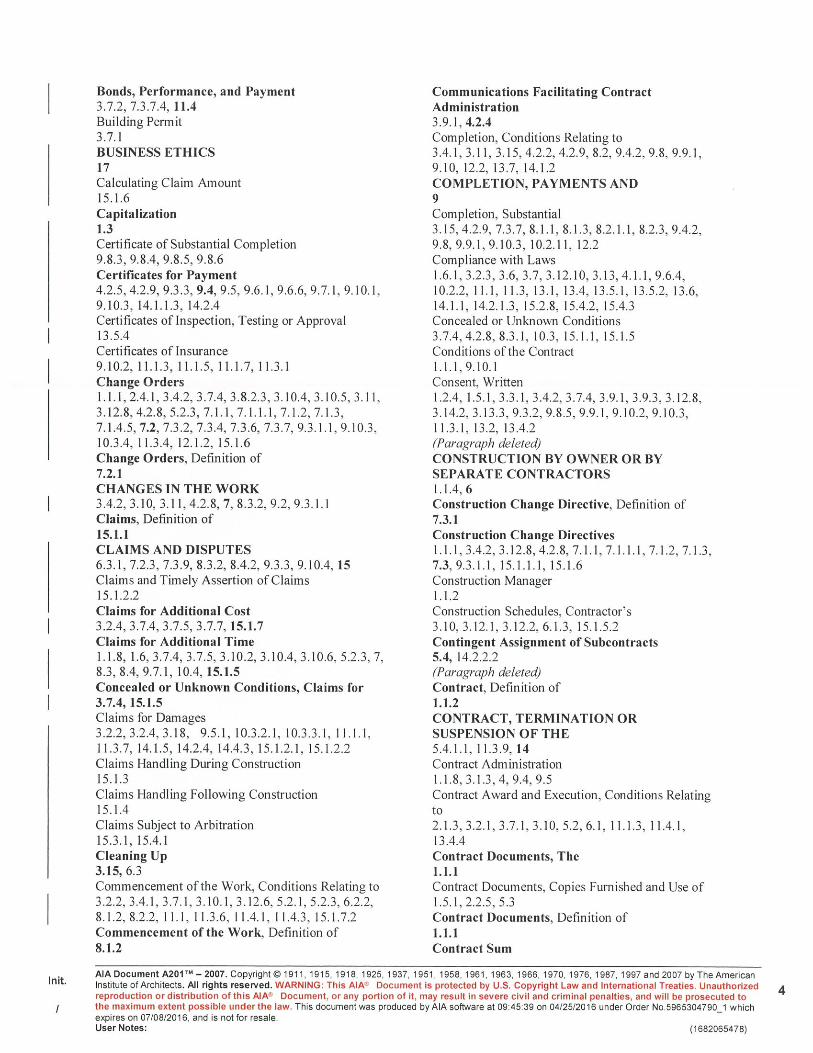


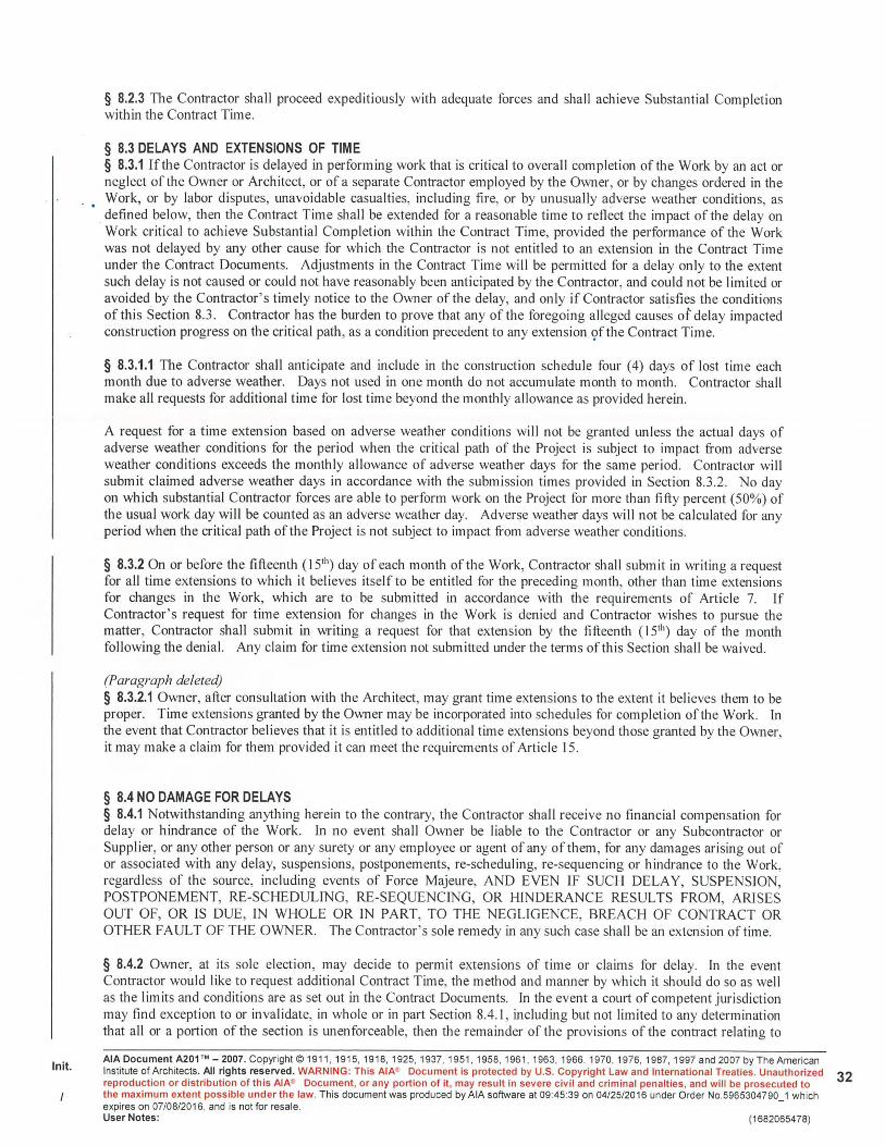

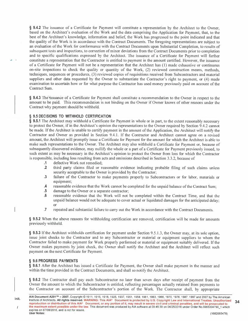


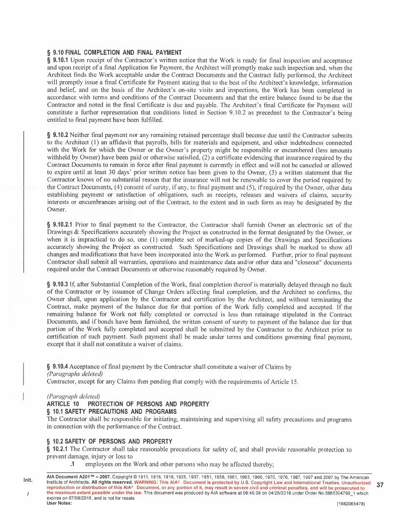
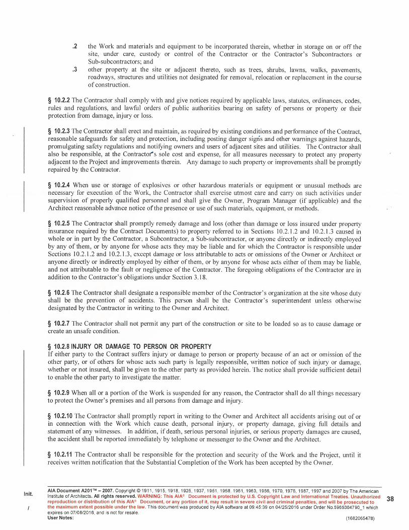


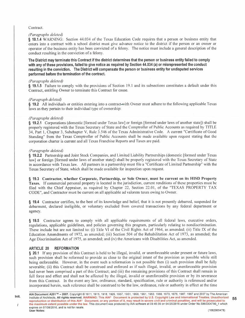
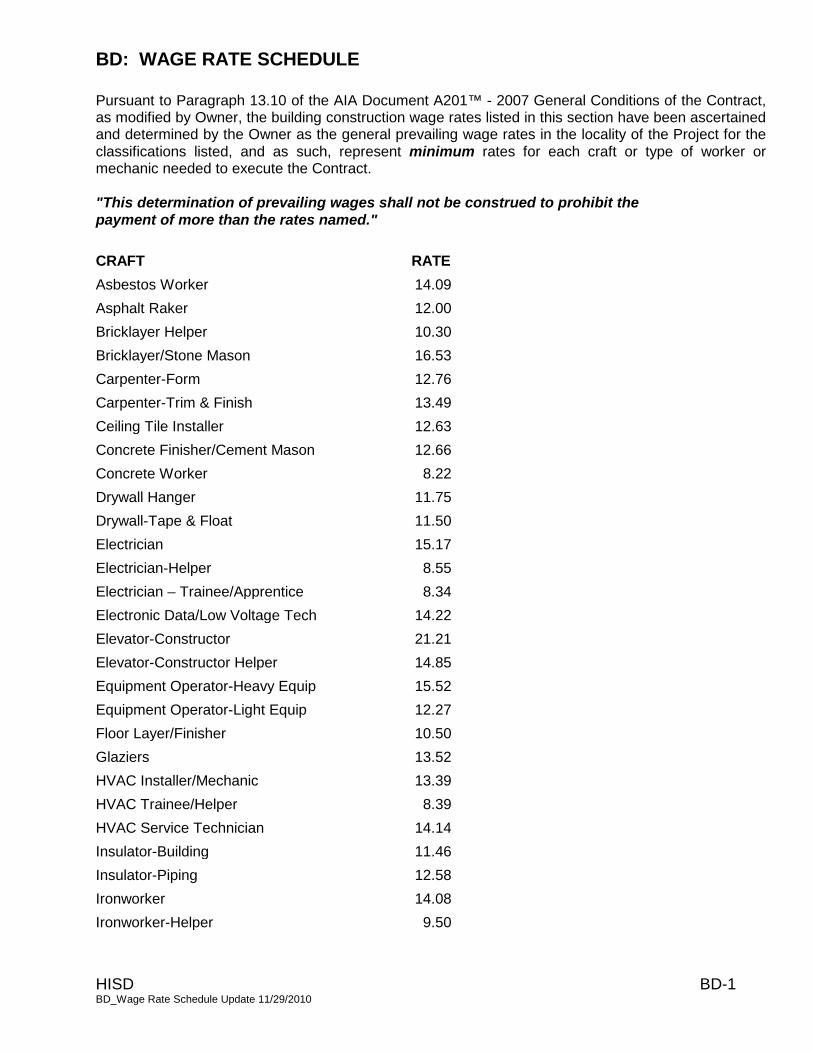
BD: WAGE RATE SCHEDULE
HISD BD-1 BD_Wage Rate Schedule Update 11/29/2010
Pursuant to Paragraph 13.10 of the AIA Document A201™ - 2007 General Conditions of the Contract, as modified by Owner, the building construction wage rates listed in this section have been ascertained and determined by the Owner as the general prevailing wage rates in the locality of the Project for the
classifications listed, and as such, represent minimum rates for each craft or type of worker or mechanic needed to execute the Contract.
"This determination of prevailing wages shall not be construed to prohibit the payment of more than the rates named."
CRAFT RATE
Asbestos Worker 14.09
Asphalt Raker 12.00
Bricklayer Helper 10.30
Bricklayer/Stone Mason 16.53
Carpenter-Form 12.76
Carpenter-Trim & Finish 13.49
Ceiling Tile Installer 12.63
Concrete Finisher/Cement Mason 12.66
Concrete Worker 8.22
Drywall Hanger 11.75
Drywall-Tape & Float 11.50
Electrician 15.17
Electrician-Helper 8.55
Electrician – Trainee/Apprentice 8.34
Electronic Data/Low Voltage Tech 14.22
Elevator-Constructor 21.21
Elevator-Constructor Helper 14.85
Equipment Operator-Heavy Equip 15.52
Equipment Operator-Light Equip 12.27
Floor Layer/Finisher 10.50
Glaziers 13.52
HVAC Installer/Mechanic 13.39
HVAC Trainee/Helper 8.39
HVAC Service Technician 14.14
Insulator-Building 11.46
Insulator-Piping 12.58
Ironworker 14.08
Ironworker-Helper 9.50

BD: WAGE RATE SCHEDULE
HISD BD-2 BD_Wage Rate Schedule Update 11/29/2010
Laborer-Skilled 9.81
Laborer-Semi Skilled/Helper 9.94
Laborer-Unskilled 7.62
Landscape Laborer Skilled 10.21
Landscape Laborer Semi-Skilled 9.23
Landscape Laborer-Unskilled 8.54
Lather 14.90
Lightning Protection Installer 14.50
Lightning Protection Installer-Helper 10.00
Metal Building Assembler 10.84
Mill Wright 14.40
Painter 12.89
Painter-Helper 8.02
Pipe Fitter 16.45
Pipe Fitter-Foreman 20.11
Pipe Layer 10.34
Plasterer 15.10
Playground Equipment Installer 10.50
Playground Equipment Installer-Helper 8.07
Plumber 16.28
Plumber-Helper 8.69
Roofer 11.56
Sheetmetal Worker-Ductwork 14.39
Sheetmetal Worker-General 11.85
Sheetmetal Worker-Roofing 13.50
Sheetmetal Foreman 17.27
Sprinkler Fitter 21.37
Terrazzo Finisher/Mechanic 16.24
Terrazzo Grinder 13.58
Tile Setter 15.15
Truck Driver 11.19
Waterproofer/Caulker 10.98
Welder-Pipe 15.89
Welder-Structural 13.89
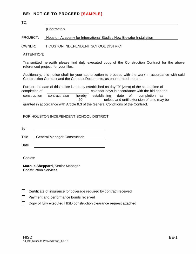
BE: NOTICE TO PROCEED [SAMPLE]
HISD BE-1 14_BE_Notice to Proceed Form_1-9-13
TO:
(Contractor) PROJECT: Houston Academy for International Studies New Elevator Installation
OWNER: HOUSTON INDEPENDENT SCHOOL DISTRICT ATTENTION: Transmitted herewith please find duly executed copy of the Construction Contract for the above referenced project, for your files. Additionally, this notice shall be your authorization to proceed with the work in accordance with said Construction Contract and the Contract Documents, as enumerated therein. Further, the date of this notice is hereby established as day "0" (zero) of the stated time of
completion of calendar days in accordance with the bid and the
construction contract; also hereby establishing date of completion as
, 20 unless and until extension of time may be
granted in accordance with Article 8.3 of the General Conditions of the Contract. FOR HOUSTON INDEPENDENT SCHOOL DISTRICT
By
Title General Manager Construction
Date Copies: Marcus Sheppard, Senior Manager Construction Services
Certificate of insurance for coverage required by contract received
Payment and performance bonds received
Copy of fully executed HISD construction clearance request attached

BF: PERFORMANCE BOND
10/15/09
Project No. ______________________
THE STATE OF TEXAS § § KNOW ALL MEN BY THESE PRESENTS: THE COUNTY OF HARRIS § THAT WE, ____________________________________, as Principal, hereinafter called “Contractor” and the other subscriber hereto _____________________________________, as Surety, do hereby acknowledge ourselves to be held and firmly bound to The Houston Independent School District “Owner”, in the sum of _________________ ($_______) for the payment of which sum, well and truly to be made to Owner and its successors, the said Contractor and Surety do bind themselves, their heirs, executors, administrators, successors, and assigns, jointly and severally. THE CONDITIONS OF THIS OBLIGATION ARE SUCH THAT: WHEREAS, the Contractor has on or about this day executed a Contract in writing with Owner for _______________________________________________________________________________________________________________________________________________________________ all of such work to be done as set out in full in said Contract Documents therein referred to and adopted by the Owner, all of which are made a part of this instrument as fully and completely as if set out in full herein. NOW THEREFORE, if the said Contractor shall faithfully and strictly perform Contract in all its terms, provisions, and stipulations in accordance with its true meaning and effect, and in accordance with the Contract Documents referred to therein and shall comply strictly with each and every provision of Contract and with this bond, then this obligation shall become null and void and shall have no further force and effect; otherwise the same is to remain in full force and effect. Should the Contractor fail to faithfully and strictly perform the Contract in all its terms, the Surety shall be liable for all damages, losses, expenses and liabilities that the Owner may suffer in consequence thereof, as more fully set forth herein. It is further understood and agreed that the Surety does hereby relieve Owner or its representatives from the exercise of any diligence whatever in securing compliance on the part of the Contractor with the terms of the Contract, including in relation to Owner’s making of payments thereunder, and, having fully considered it’s Principal’s competence to perform the Contract in the underwriting of this Performance Bond, the Surety hereby waives any notice of delay by the Contractor in the performance of the Contract. The Surety understands and agrees that the provision in the Contract that Owner shall retain certain amounts due the Contractor until the expiration of thirty days from the acceptance of the Work is intended for the Owner’s benefit, and Owner shall have the right to pay or withhold such retained amounts or any other amount owing under the Contract without changing or affecting the liability of the Surety hereon in any degree.
BF: PERFORMANCE BOND
10/15/09
It is further expressly agreed by Surety that Owner or its representatives are at liberty at any time, without notice to the Surety, to make any change in the Contract Documents and in the Work to be done thereunder, as provided in the Contract, and in the terms and conditions thereof, or to make any change in, addition to, or deduction from the work to be done thereunder; and that such changes, if made, shall not in any way vitiate the obligation in this bond and undertaking or release the Surety therefrom. This bond and all obligations created hereunder shall be performable in Harris County, Texas. This bond is given in compliance with the provisions of Chapter 2253 of the Texas Government Code, as amended, which is incorporated herein by this reference. However, all of the express provisions hereof shall be applicable whether or not within the scope of said statute. IN WITNESS THEREOF, the said Contractor and Surety have signed and sealed this instrument on the respective dates written below their signatures and have attached current Power of Attorney. ATTEST, SEAL: (if a corporation) __________________________________________ WITNESS: (if not a corporation) (Name of Contractor) By: _______________________________________ By: ______________________________________ Name: Name: Title: Title: Date: ATTEST/WITNESS (SEAL) __________________________________________
(Full Name of Surety) By: _______________________________________ __________________________________________
Name: (Address of Surety for Notice) Title:
Date: __________________________________________ By: ______________________________________ Name: Title: Date:
BG: PAYMENT BOND Project No: ________________ STATE OF TEXAS COUNTY OF HARRIS KNOW ALL PERSONS BY THESE PRESENTS: That (Contractor), of the City of , County of , and State of ,as Principal, and , authorized under the Laws of the State of Texas to act as surety on bonds for principals, are held and firmly bound unto Houston Independent School District (Owner), in the penal sum of Dollars ($ ) for the payment whereof, the said Principal and Surety bind themselves, and their respective officers, directors, shareholders, partners, heirs, administrators, executors, successors and assigns, jointly and severally, by these presents: WHEREAS, the Principal has entered into a certain written contract with the Owner, dated the day of __________________ , 20 , for construction of:
which contract is hereby referred to and made a part hereof as fully and to the same extent as if copied at length herein. NOW, THEREFORE, THE CONDITIONS OF THIS OBLIGATION IS SUCH, that if the said Principal shall pay all claimants supplying Public Work Labor and Public Work Material (as defined by Section 2252.001 of the Texas Government Code) to him or a subcontractor in the prosecution of the work provided for in said contract, then, this obligation shall be void; otherwise to remain in full force and effect; PROVIDED, HOWEVER, That this bond is executed pursuant to the provisions of Chapter 2253 of the Texas Government Code as amended and all liabilities on this bond shall be determined in accordance with the provisions of said Statute to the same extent as if it were copied at length herein. Surety, for value received, stipulates and agrees that no change, extension of time, alteration or addition to the terms of the contract, or to work performed thereunder, or the plans, specifications, or drawings, accompanying the same, shall in anyway affect its obligation on this bond, and it does hereby waive notice of any such change, extension of time, alteration or addition to the terms of the contract, or the work to be performed thereunder.
575524-2 10/02/09
575524-2 10/02/09
IN WITNESS WHEREOF, the said Principal and Surety have signed and sealed this instrument _________ day of ___________________________, 20 . ________________________________ Principal Surety BY: BY: TITLE: TITLE: ADDRESS: PHYSICAL ADDRESS: MAILING ADDRESS: TELEPHONE: LOCAL RECORDING AGENT PERSONAL IDENTIFICATION NUMBER: The name and address of the Resident Agent of Surety is:

CA: OVERALL PROPOSAL PACKAGING CHECKLIST
CA-1 17_CA_Overall Proposal Packaging Checklist_1-29-16
CSP PROPOSAL INFORMATION PACKAGE Submit the following documents sealed in an 8.5” x 11” or larger envelope and labeled:
“CSP CONTRACTOR PROPOSAL INFORMATION FOR H.A.I.S.
ELEVATOR INSTALLATION DUE BY 2:00 PM, THURSDAY, DECEMBER 20, 2018.” Proposers are to package all information into an original document set and a copy set, organized as follows with divider tabs in 3-ring binders. Do not spiral or GBC bind the submittal documents. TAB DESCRIPTION ORIGINAL
BINDER
COPY
BINDER
A.1 Proposal Form Part A (Form CB) One (1) Signed & Executed Original One (1) Copy
A.2 Proposal Guarantee Bond Form (Form CC)
One (1) Signed & Executed Original One (1) Copy
A.3 Letter from Bonding Company One (1) Signed Original One (1) Copy
A.3 Letter from Insurance Company One (1) Signed Original One (1) Copy
A.3 Texas Secretary of State Certificate of Filing
One (1) Copy One (1) Copy
B.1 Proposal Form Part B (Form CD) Technical Proposal
One (1) Signed & Executed Original One (1) Copy
B.2 Proposer’s Project Schedule One (1) Original One (1) Copy
B.3 Safety Program (Checklist)
(Form CJ)
One (1) Signed & Executed Original One (1) Copy
B.3 Proposer’s Safety Manual One (1) paper, or electronic copy on disk
One (1) paper, or electronic copy on disk
C Equal Opportunity Employer Statement Form (Form CE)
One (1) Signed & Executed Original One (1) Copy
C Equal Opportunity Employer Affidavit Form (Form CF)
One (1) Signed & Executed Original One (1) Copy
C Certification of Non-Segregated Facilities Form (Form CG)
One (1) Signed & Executed Original One (1) Copy
C Felony Conviction Notification Form (Form CH)
One (1) Signed & Executed Original One (1) Copy
C Notification of Hazardous Materials Affidavit Form (Form CI)
One (1) Signed & Executed Original One (1) Copy
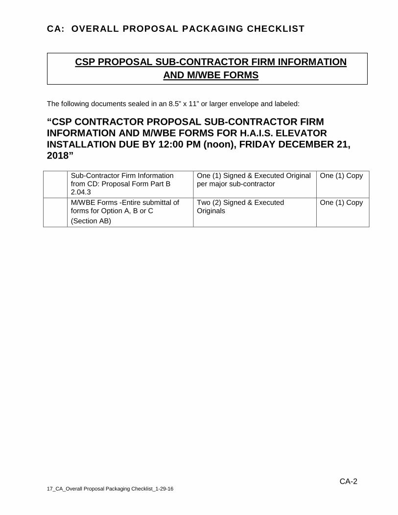
CA: OVERALL PROPOSAL PACKAGING CHECKLIST
CA-2 17_CA_Overall Proposal Packaging Checklist_1-29-16
CSP PROPOSAL SUB-CONTRACTOR FIRM INFORMATION
AND M/WBE FORMS The following documents sealed in an 8.5” x 11” or larger envelope and labeled:
“CSP CONTRACTOR PROPOSAL SUB-CONTRACTOR FIRM INFORMATION AND M/WBE FORMS FOR H.A.I.S. ELEVATOR
INSTALLATION DUE BY 12:00 PM (noon), FRIDAY DECEMBER 21, 2018”
Sub-Contractor Firm Information from CD: Proposal Form Part B 2.04.3
One (1) Signed & Executed Original per major sub-contractor
One (1) Copy
M/WBE Forms -Entire submittal of forms for Option A, B or C
(Section AB)
Two (2) Signed & Executed Originals
One (1) Copy
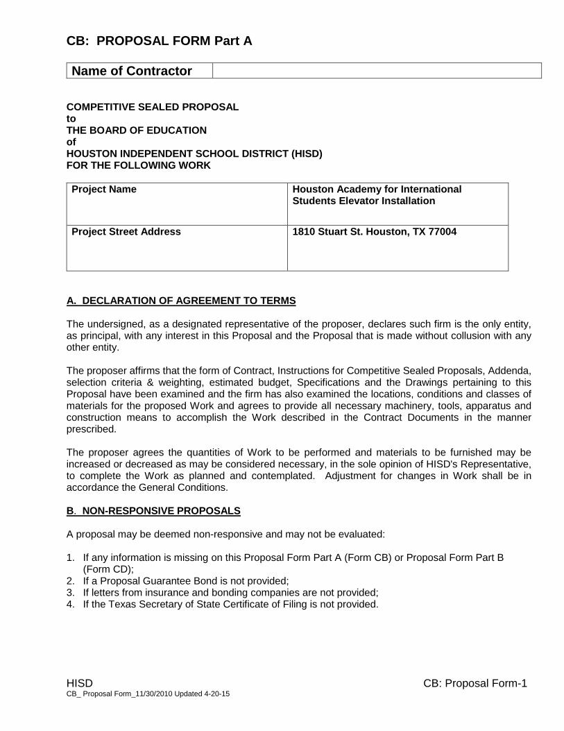
CB: PROPOSAL FORM Part A
Name of Contractor
HISD CB: Proposal Form-1 CB_ Proposal Form_11/30/2010 Updated 4-20-15
COMPETITIVE SEALED PROPOSAL to THE BOARD OF EDUCATION of HOUSTON INDEPENDENT SCHOOL DISTRICT (HISD) FOR THE FOLLOWING WORK
Project Name Houston Academy for International Students Elevator Installation
Project Street Address 1810 Stuart St. Houston, TX 77004
A. DECLARATION OF AGREEMENT TO TERMS The undersigned, as a designated representative of the proposer, declares such firm is the only entity, as principal, with any interest in this Proposal and the Proposal that is made without collusion with any other entity. The proposer affirms that the form of Contract, Instructions for Competitive Sealed Proposals, Addenda, selection criteria & weighting, estimated budget, Specifications and the Drawings pertaining to this Proposal have been examined and the firm has also examined the locations, conditions and classes of materials for the proposed Work and agrees to provide all necessary machinery, tools, apparatus and construction means to accomplish the Work described in the Contract Documents in the manner prescribed. The proposer agrees the quantities of Work to be performed and materials to be furnished may be increased or decreased as may be considered necessary, in the sole opinion of HISD's Representative, to complete the Work as planned and contemplated. Adjustment for changes in Work shall be in accordance the General Conditions. B. NON-RESPONSIVE PROPOSALS A proposal may be deemed non-responsive and may not be evaluated: 1. If any information is missing on this Proposal Form Part A (Form CB) or Proposal Form Part B
(Form CD); 2. If a Proposal Guarantee Bond is not provided; 3. If letters from insurance and bonding companies are not provided; 4. If the Texas Secretary of State Certificate of Filing is not provided.

CB: PROPOSAL FORM Part A
Name of Contractor
HISD CB: Proposal Form-2 CB_ Proposal Form_11/30/2010 Updated 4-20-15
C. ADDENDA The proposer acknowledges receipt and incorporation of the following addenda into this Proposal. Contractor is to insert the addendum number and addendum date to indicate acknowledge of receipt.
Addenda No. Addenda No. Addenda No. Addenda No. Addenda No. Addenda No.
Addenda Date Addenda Date Addenda Date Addenda Date Addenda Date Addenda Date
D. WITHDRAWAL OF PROPOSALS PRIOR TO PUBLIC OPENING A Proposal may be withdrawn only upon request by the proposer or his duly authorized representative, provided such request is received by HISD at the place designated for receipt of Proposals and prior to the time fixed for the opening of Proposals. No Proposal may be withdrawn after the time fixed for the opening of Proposals for a period of 90 days. The Proposer may request in writing to HISD, withdrawal of the Proposal due to errors or the Proposer’s inability to perform the work. HISD may, at its sole discretion, grant or refuse the request. E. AWARD OF CONTRACT The proposer to whom the award of a Contract is made will be promptly notified following Board action. If a proposer, (a) withdraws his Proposal within 90 days after the date and time fixed for the opening of Proposals in the Advertisement for Proposals, or, (b) fails or refuses to execute the Agreement, or other required forms within ten (10) days after the same are presented to him for signature, or (c) fails or refuses to furnish properly executed Performance and Payment Bonds, if required, and certification of required insurance upon the execution of the Agreement, HISD may award the Work to another proposer or proposers or may re-solicit the contract. The Proposal Bond is forfeited if Proposal is withdrawn after the Proposal opening, or Contract Documents are not executed in accordance with the above requirements. HISD reserves the right to reject any or all Proposals, to accept or reject any or all alternates, and to waive any irregularities in any Proposal received. Award may be made to other than the low dollar proposer. F. NOTICE TO PROCEED The Contractor shall not commence the Work under this Contract until execution of the Notice to Proceed is duly signed by HISD’s representative. G. COLLUSION, LITIGATION, DEFAULT, COMPETENCY, AND CONFLICT OF INTEREST By completing and submitting a Proposal, the proposer agrees to comply with the requirements of the following paragraph. A proposer who subsequently does not agree to comply with these requirements may automatically disqualify himself from Proposal or receiving award of Contract on the project. The responses to the items of the Contractor’s Qualification Statement will be used in evaluation of the Proposals on the project.

CB: PROPOSAL FORM Part A
Name of Contractor
HISD CB: Proposal Form-3 CB_ Proposal Form_11/30/2010 Updated 4-20-15
Proposers may be disqualified and their proposals not considered for any of the following specific reasons. 1. Reason for believing collusion exists among proposers. 2. Reasonable grounds for believing that any proposer is interested in more than one proposal for the
work contemplated. 3. The proposer being involved in or having an interest in any litigation against the HISD and /or its
representatives. 4. The proposer being in arrears on any existing contract with HISD or having defaulted on a previous
contract with HISD. 5. Uncompleted work which, in the judgment of the Board, will prevent or hinder the prompt completion
of this Work, if awarded. 6. Other information or circumstance that establishes reasonable grounds for belief that the proposer is
not a “responsible proposer”. By entering into a contract with HISD, the proposer agrees that; (1) Work on the project will begin upon receipt of the Notice to Proceed, (2) Contractor will participate as a team member in cooperation with the Program Manager (PM), Architect/Engineer and HISD, (3) Comply with the requirements set forth in Section 05 – School Operations Parameter Statement, (4) The Contractor will assign a competent superintendent, full time to each campus, and that superintendent shall be maintained on the project for the duration of the project, subject only to his continuous employment, (5) The Contractor will furnish and pay for bonds as follows:
• Projects over $100,000: Proposal, Performance and Payment Bonds are required Contractor will carry and keep in full force for the duration of the project, Insurance and bonds required in Article II – Insurance and bonds of the General Conditions of the Contract for Construction, A201 – 2007, as modified by the Owner. H. ULTIMATE CORPORATE OWNERSHIP In the space below, enter the address of the proposer's place of business and, if applicable, the name and address of the proposer's ultimate parent company or majority owner. Is proposer a corporation? Check One, Yes ____ No____ Proposer's name and address of principal place of business: Ultimate parent company or majority owner's name and address of principal place of business:

CB: PROPOSAL FORM Part A
Name of Contractor
HISD CB: Proposal Form-4 CB_ Proposal Form_11/30/2010 Updated 4-20-15
I. CONTRACTOR’S PRICE Total amount for the furnishing of all labor, materials, services, equipment and appliances required in conjunction with and properly incidental to all Work, for construction of the project in conformance with the terms and condition set out in the Contract Documents. Proposal amounts must be shown in both words and figures. In case of discrepancy, the amount shown in words will govern.
Base Proposal (In Words) Dollars
All Schools Total Cost (including abatement cost for all projects with abatement).
$
Abatement Cost: Total Base Proposal above includes $ for abatement.
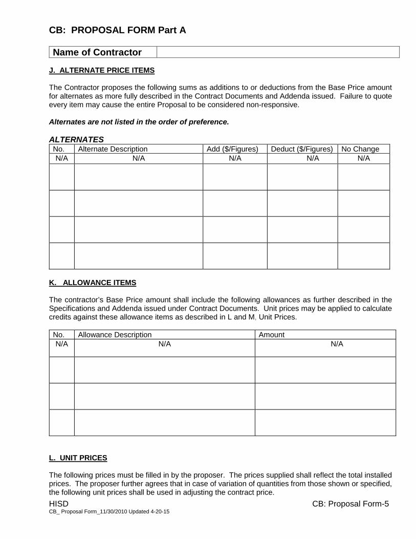
CB: PROPOSAL FORM Part A
Name of Contractor
HISD CB: Proposal Form-5 CB_ Proposal Form_11/30/2010 Updated 4-20-15
J. ALTERNATE PRICE ITEMS The Contractor proposes the following sums as additions to or deductions from the Base Price amount for alternates as more fully described in the Contract Documents and Addenda issued. Failure to quote every item may cause the entire Proposal to be considered non-responsive. Alternates are not listed in the order of preference. ALTERNATES No. Alternate Description Add ($/Figures) Deduct ($/Figures) No Change
N/A N/A N/A N/A N/A
K. ALLOWANCE ITEMS The contractor’s Base Price amount shall include the following allowances as further described in the Specifications and Addenda issued under Contract Documents. Unit prices may be applied to calculate credits against these allowance items as described in L and M, Unit Prices.
No. Allowance Description Amount
N/A
N/A
N/A
L. UNIT PRICES The following prices must be filled in by the proposer. The prices supplied shall reflect the total installed prices. The proposer further agrees that in case of variation of quantities from those shown or specified, the following unit prices shall be used in adjusting the contract price.
CB: PROPOSAL FORM Part A
Name of Contractor
HISD CB: Proposal Form-6 CB_ Proposal Form_11/30/2010 Updated 4-20-15
No. Unit Price Description Add ($/Figures) Deduct ($/Figures) Unit of
measure
N/A N/A N/A N/A N/A
CB: PROPOSAL FORM Part A
Name of Contractor
HISD CB: Proposal Form-7 CB_ Proposal Form_11/30/2010 Updated 4-20-15
M. HAZARDOUS MATERIALS ABATEMENT UNIT PRICES The following prices must be filled in by the proposer. The prices supplied shall reflect the total installed prices. The proposer further agrees that in case of variation of quantities from those shown or specified, the following unit prices shall be used in adjusting the contract price.
No. Unit Price Description Add ($/Figures) Deduct ($/Figures) Unit of
measure
N/A N/A N/A N/A N/A
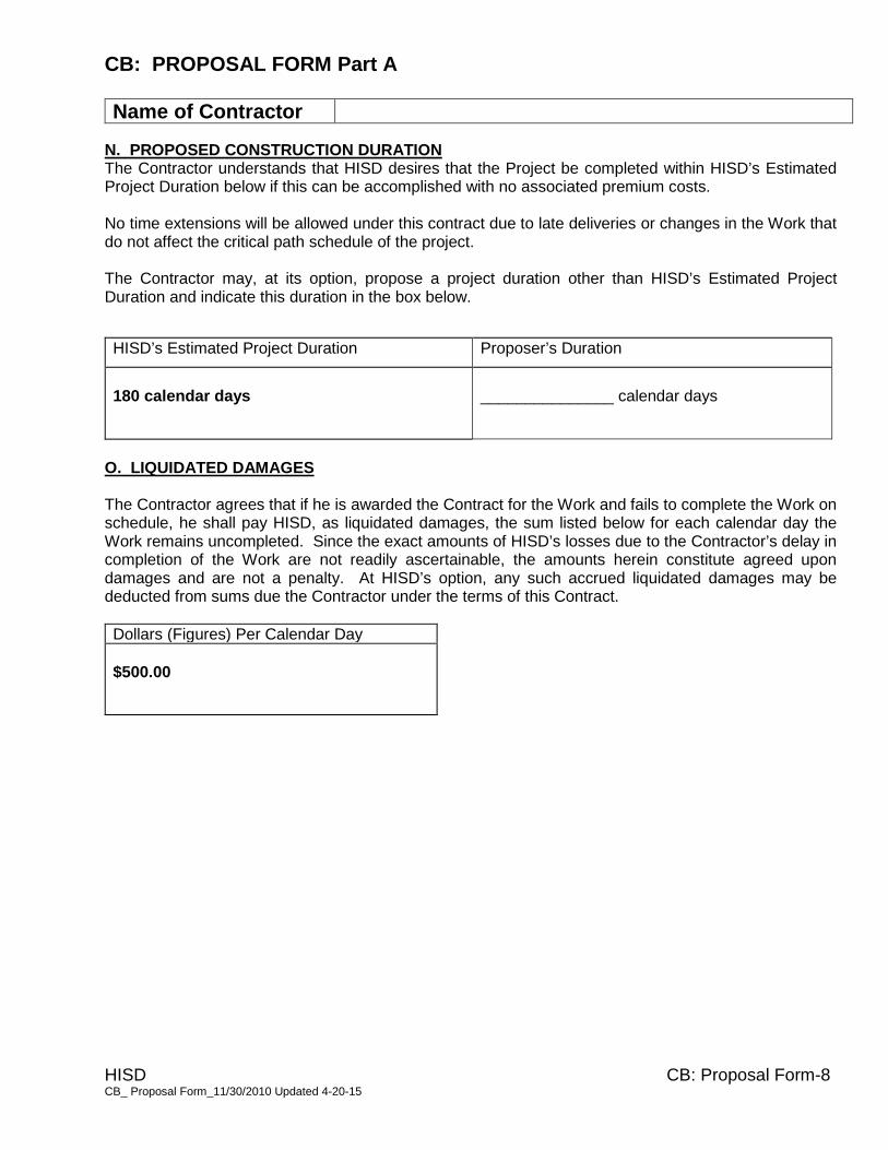
CB: PROPOSAL FORM Part A
Name of Contractor
HISD CB: Proposal Form-8 CB_ Proposal Form_11/30/2010 Updated 4-20-15
N. PROPOSED CONSTRUCTION DURATION The Contractor understands that HISD desires that the Project be completed within HISD’s Estimated Project Duration below if this can be accomplished with no associated premium costs. No time extensions will be allowed under this contract due to late deliveries or changes in the Work that do not affect the critical path schedule of the project. The Contractor may, at its option, propose a project duration other than HISD’s Estimated Project Duration and indicate this duration in the box below.
HISD’s Estimated Project Duration Proposer’s Duration
180 calendar days
_______________ calendar days
O. LIQUIDATED DAMAGES The Contractor agrees that if he is awarded the Contract for the Work and fails to complete the Work on schedule, he shall pay HISD, as liquidated damages, the sum listed below for each calendar day the Work remains uncompleted. Since the exact amounts of HISD’s losses due to the Contractor’s delay in completion of the Work are not readily ascertainable, the amounts herein constitute agreed upon damages and are not a penalty. At HISD’s option, any such accrued liquidated damages may be deducted from sums due the Contractor under the terms of this Contract.
Dollars (Figures) Per Calendar Day
$500.00
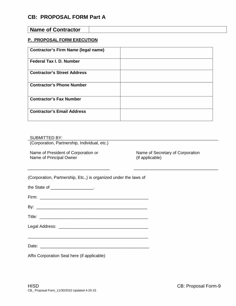
CB: PROPOSAL FORM Part A
Name of Contractor
HISD CB: Proposal Form-9 CB_ Proposal Form_11/30/2010 Updated 4-20-15
P. PROPOSAL FORM EXECUTION
Contractor’s Firm Name (legal name)
Federal Tax I. D. Number
Contractor’s Street Address
Contractor’s Phone Number
Contractor’s Fax Number
Contractor’s Email Address
SUBMITTED BY:
(Corporation, Partnership, Individual, etc.) Name of President of Corporation or Name of Secretary of Corporation Name of Principal Owner (if applicable)
(Corporation, Partnership, Etc.,) is organized under the laws of
the State of __________________.
Firm: ______________________________________________
By: _______________________________________________
Title: ______________________________________________
Legal Address: ______________________________________
___________________________________________________
Date: ______________________________________________
Affix Corporation Seal here (if applicable)

CC: PROPOSAL GUARANTEE BOND
HISD CC-1 19_CC_Proposal Guarantee Bond Form_11-30-10
KNOW ALL MEN BY THESE PRESENTS, THAT we _____________________________ as Principal,
and _____________________ as Surety, are held and firmly bound unto the Board of Education,
Houston Independent School District, Houston, Harris County, Texas, hereinafter called the Obligee, in
the penal sum of _______________________________ Dollars ($_______________), lawful money of
the United States, for the payment of which sum well and truly to be made, we bind ourselves, our
heirs, executors, administrators, successors and assigns, jointly and severally, firmly by these
presents.
THE CONDITION OF THIS OBLIGATION IS SUCH, that whereas the Principal has submitted the
accompanying Competitive Sealed Proposal, dated _____________, 20_____, being for the
construction of ____________________________ with appurtenances thereto, at Houston, Harris
County, Texas, the kind and extent of work involved being set forth in detail in the proposed Contract
Documents;
NOW, THEREFORE, if the Obligee shall accept the proposal of the Principal and the Principal shall
enter into a Contract with the Obligee in accordance with the terms of such proposal, and give such
bond or bonds as may be specified in the proposal or Contract Documents with good and sufficient
surety for the faithful performance of such Contract and for the prompt payment of labor and material
furnished in the prosecution thereof, or in the event of the failure of the Principal to enter such Contract
and give such bond or bonds, if the Principal shall pay to the Obligee the difference not to exceed the
penalty hereof between the amount specified in said proposal and such larger amount for which the
Obligee may in good faith contract with another party to perform the Work covered by said proposal,
then this obligation shall be null and void, otherwise to remain in full force and effect.
This Proposal Guarantee Bond applies to all contracts in excess of $100,000 involving a contract for
construction, alteration or repair of any public building or the completion or prosecution of any public
work.
This Proposal Guarantee Bond must be payable to the awarding authority, Houston Independent
School District, as the named Obligee, and it must be approved as to form by such awarding authority.
Surety must be corporate surety duly authorized to do business in Texas.
This Proposal Guarantee Bond must be equal to 10% of the full amount of the contract which it
secures.
Power of Attorney from Corporate Surety should be attached to this Proposal Guarantee Bond.
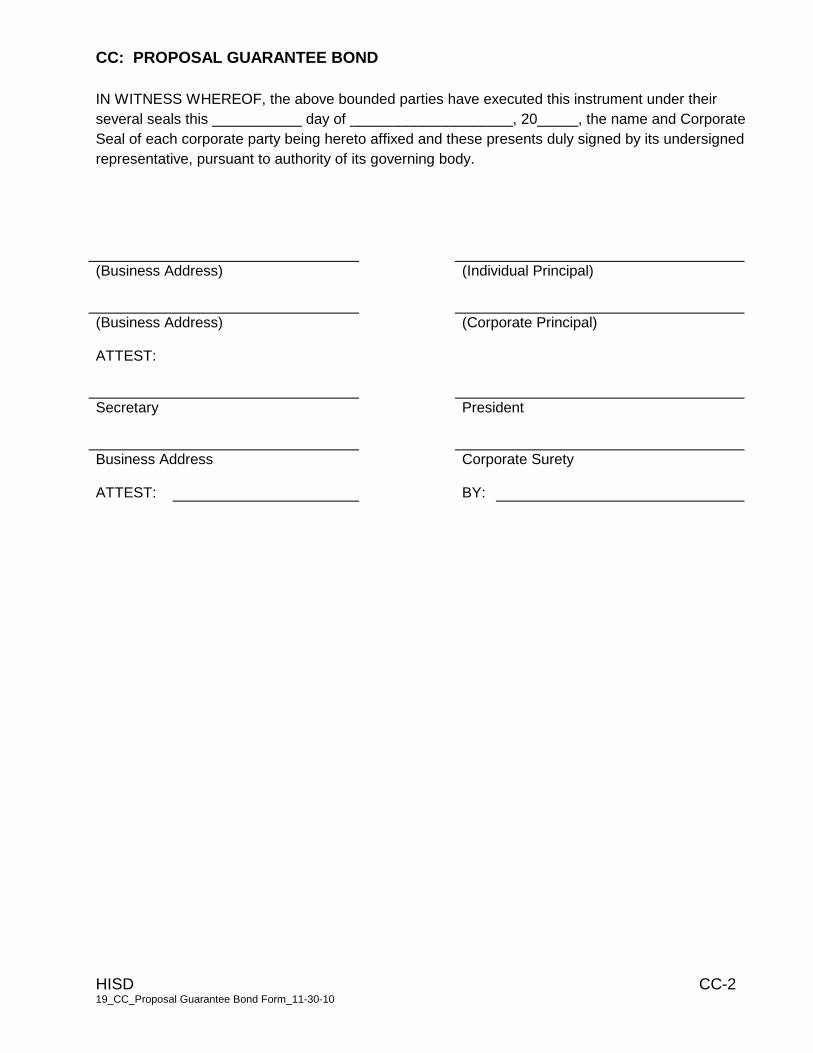
CC: PROPOSAL GUARANTEE BOND
HISD CC-2 19_CC_Proposal Guarantee Bond Form_11-30-10
IN WITNESS WHEREOF, the above bounded parties have executed this instrument under their
several seals this ___________ day of ____________________, 20_____, the name and Corporate
Seal of each corporate party being hereto affixed and these presents duly signed by its undersigned
representative, pursuant to authority of its governing body.
(Business Address) (Individual Principal)
(Business Address) (Corporate Principal)
ATTEST:
Secretary President
Business Address Corporate Surety
ATTEST: BY:
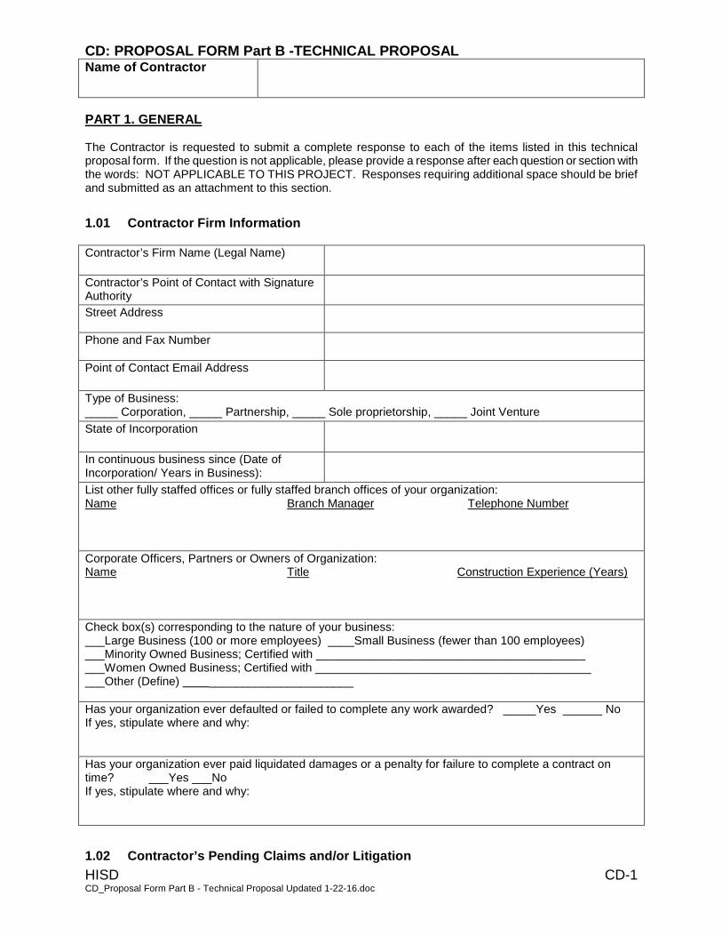
CD: PROPOSAL FORM Part B -TECHNICAL PROPOSAL Name of Contractor
HISD CD-1 CD_Proposal Form Part B - Technical Proposal Updated 1-22-16.doc
PART 1. GENERAL The Contractor is requested to submit a complete response to each of the items listed in this technical proposal form. If the question is not applicable, please provide a response after each question or section with the words: NOT APPLICABLE TO THIS PROJECT. Responses requiring additional space should be brief and submitted as an attachment to this section.
1.01 Contractor Firm Information
Contractor’s Firm Name (Legal Name)
Contractor’s Point of Contact with Signature Authority
Street Address
Phone and Fax Number
Point of Contact Email Address
Type of Business: _____ Corporation, _____ Partnership, _____ Sole proprietorship, _____ Joint Venture
State of Incorporation
In continuous business since (Date of Incorporation/ Years in Business):
List other fully staffed offices or fully staffed branch offices of your organization: Name Branch Manager Telephone Number
Corporate Officers, Partners or Owners of Organization: Name Title Construction Experience (Years)
Check box(s) corresponding to the nature of your business: ___Large Business (100 or more employees) ____Small Business (fewer than 100 employees) ___Minority Owned Business; Certified with _________________________________________ ___Women Owned Business; Certified with __________________________________________ ___Other (Define) ______________________
Has your organization ever defaulted or failed to complete any work awarded? _____Yes ______ No If yes, stipulate where and why:
Has your organization ever paid liquidated damages or a penalty for failure to complete a contract on time? ___Yes ___No If yes, stipulate where and why:
1.02 Contractor’s Pending Claims and/or Litigation
CD: PROPOSAL FORM Part B -TECHNICAL PROPOSAL Name of Contractor
HISD CD-2 CD_Proposal Form Part B - Technical Proposal Updated 1-22-16.doc
List pending claims and/or litigation at time of submitting Proposal. (Show project name, owner and summary explanation.)
PART 2. TECHNICAL PROPOSAL 2.01 Qualifications of the Contractor
Provide no fewer than 3 and no more than 10 projects with appropriate references. Answer the questions for each relevant project, with specific emphasis on relevant renovation/new K-12 project experience with HISD and other local districts and other relevant renovation/new construction projects, that your organization has in-progress or completed in the last seven years, using the format below: A member of the Evaluation Committee will verify the information with the references provided and may ask additional questions.
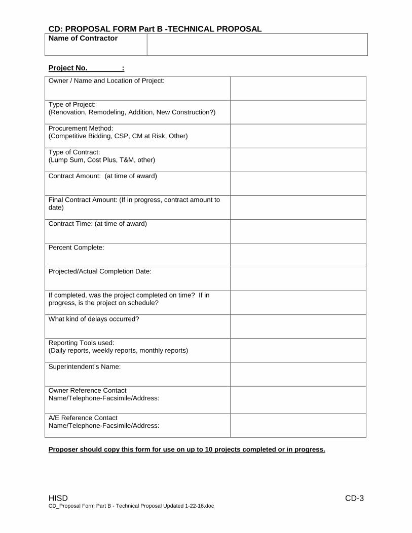
CD: PROPOSAL FORM Part B -TECHNICAL PROPOSAL Name of Contractor
HISD CD-3 CD_Proposal Form Part B - Technical Proposal Updated 1-22-16.doc
Project No. :
Owner / Name and Location of Project:
Type of Project: (Renovation, Remodeling, Addition, New Construction?)
Procurement Method: (Competitive Bidding, CSP, CM at Risk, Other)
Type of Contract: (Lump Sum, Cost Plus, T&M, other)
Contract Amount: (at time of award)
Final Contract Amount: (If in progress, contract amount to date)
Contract Time: (at time of award)
Percent Complete:
Projected/Actual Completion Date:
If completed, was the project completed on time? If in progress, is the project on schedule?
What kind of delays occurred?
Reporting Tools used: (Daily reports, weekly reports, monthly reports)
Superintendent’s Name:
Owner Reference Contact Name/Telephone-Facsimile/Address:
A/E Reference Contact Name/Telephone-Facsimile/Address:
Proposer should copy this form for use on up to 10 projects completed or in progress.
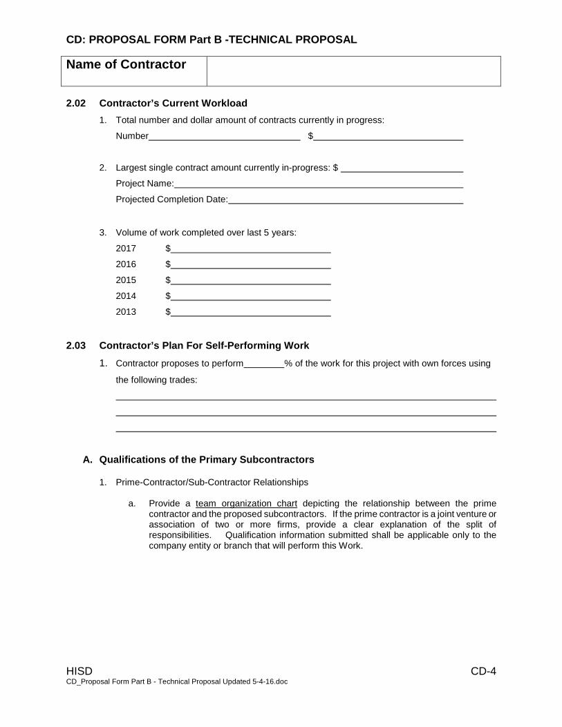
CD: PROPOSAL FORM Part B -TECHNICAL PROPOSAL
Name of Contractor
HISD CD-4 CD_Proposal Form Part B - Technical Proposal Updated 5-4-16.doc
2.02 Contractor’s Current Workload
1. Total number and dollar amount of contracts currently in progress:
Number $
2. Largest single contract amount currently in-progress: $
Project Name:
Projected Completion Date:
3. Volume of work completed over last 5 years:
2017 $
2016 $
2015 $
2014 $
2013 $
2.03 Contractor’s Plan For Self-Performing Work
1. Contractor proposes to perform % of the work for this project with own forces using
the following trades:
A. Qualifications of the Primary Subcontractors 1. Prime-Contractor/Sub-Contractor Relationships
a. Provide a team organization chart depicting the relationship between the prime
contractor and the proposed subcontractors. If the prime contractor is a joint venture or association of two or more firms, provide a clear explanation of the split of responsibilities. Qualification information submitted shall be applicable only to the company entity or branch that will perform this Work.
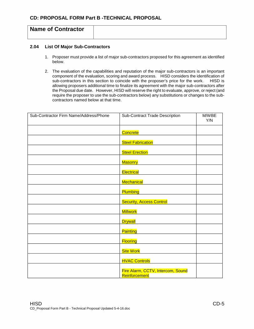
CD: PROPOSAL FORM Part B -TECHNICAL PROPOSAL
Name of Contractor
HISD CD-5 CD_Proposal Form Part B - Technical Proposal Updated 5-4-16.doc
2.04 List Of Major Sub-Contractors
1. Proposer must provide a list of major sub-contractors proposed for this agreement as identified below.
2. The evaluation of the capabilities and reputation of the major sub-contractors is an important component of the evaluation, scoring and award process. HISD considers the identification of sub-contractors in this section to coincide with the proposer’s price for the work. HISD is allowing proposers additional time to finalize its agreement with the major sub-contractors after the Proposal due date. However, HISD will reserve the right to evaluate, approve, or reject (and require the proposer to use the sub-contractors below) any substitutions or changes to the sub-contractors named below at that time.
Sub-Contractor Firm Name/Address/Phone Sub-Contract Trade Description M/WBE
Y/N
Concrete
Steel Fabrication
Steel Erection
Masonry
Electrical
Mechanical
Plumbing
Security, Access Control
Millwork
Drywall
Painting
Flooring
Site Work
HVAC Controls
Fire Alarm, CCTV, Intercom, Sound Reinforcement

CD: PROPOSAL FORM Part B -TECHNICAL PROPOSAL
Name of Contractor
HISD CD-6 CD_Proposal Form Part B - Technical Proposal Updated 5-4-16.doc
2.04.3 Sub-Contractor Firm Information
1. Note to proposers: Refer to CA: Overall Proposal Packaging Checklist for due date/time.
Sub-Contractor Category/Trade
Sub-Contractor’s Firm Name
Street Address
Phone/Fax Number
Point of Contact and E-mail Address
Have you previously worked with this Proposer?
Yes
No
Volume of work completed in the last Five (5) years
2017 $
2016 $
2015 $
2014 $
2013 $
List major K-12 school construction projects this subcontractor has completed in the last five (5) years below. Other projects of particular significance may also be listed.
Project Name and Location
Contract Amount
Completion Date
If in progress, list percent complete and projected completion date
Owner Reference Contact (Name/Title, Company, Address, Phone Number.)
General Contractor Reference Contact (Name/Title, Company, Address, Phone Number.)
A/E Reference Contact (Name/Title, Company, Address, Phone Number.)
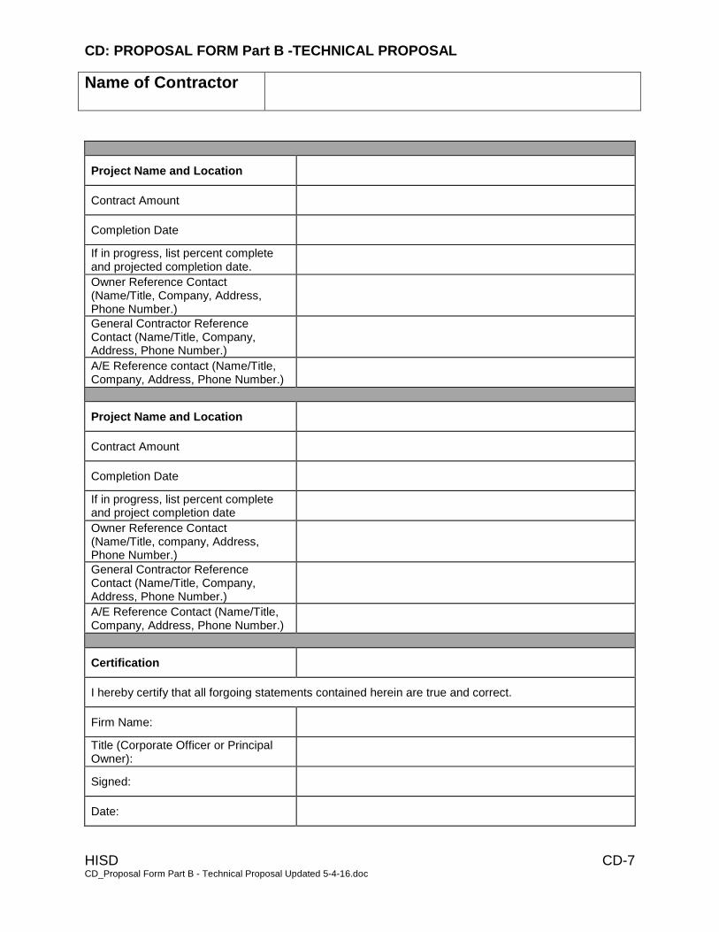
CD: PROPOSAL FORM Part B -TECHNICAL PROPOSAL
Name of Contractor
HISD CD-7 CD_Proposal Form Part B - Technical Proposal Updated 5-4-16.doc
Project Name and Location
Contract Amount
Completion Date
If in progress, list percent complete and projected completion date.
Owner Reference Contact (Name/Title, Company, Address, Phone Number.)
General Contractor Reference Contact (Name/Title, Company, Address, Phone Number.)
A/E Reference contact (Name/Title, Company, Address, Phone Number.)
Project Name and Location
Contract Amount
Completion Date
If in progress, list percent complete and project completion date
Owner Reference Contact (Name/Title, company, Address, Phone Number.)
General Contractor Reference Contact (Name/Title, Company, Address, Phone Number.)
A/E Reference Contact (Name/Title, Company, Address, Phone Number.)
Certification
I hereby certify that all forgoing statements contained herein are true and correct.
Firm Name:
Title (Corporate Officer or Principal Owner):
Signed:
Date:
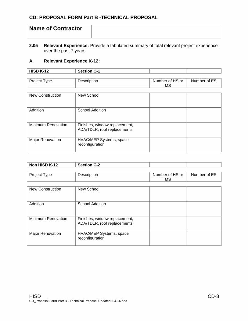
CD: PROPOSAL FORM Part B -TECHNICAL PROPOSAL
Name of Contractor
HISD CD-8 CD_Proposal Form Part B - Technical Proposal Updated 5-4-16.doc
2.05 Relevant Experience: Provide a tabulated summary of total relevant project experience over the past 7 years
A. Relevant Experience K-12: HISD K-12 Section C-1
Project Type Description Number of HS or MS
Number of ES
New Construction New School
Addition School Addition
Minimum Renovation Finishes, window replacement, ADA/TDLR, roof replacements
Major Renovation HVAC/MEP Systems, space reconfiguration
Non HISD K-12 Section C-2
Project Type Description Number of HS or MS
Number of ES
New Construction New School
Addition School Addition
Minimum Renovation Finishes, window replacement, ADA/TDLR, roof replacements
Major Renovation HVAC/MEP Systems, space reconfiguration

CD: PROPOSAL FORM Part B -TECHNICAL PROPOSAL
Name of Contractor
HISD CD-9 CD_Proposal Form Part B - Technical Proposal Updated 5-4-16.doc
B. Relevant Experience Other Than K-12:
Project Type Number of Higher
Education University
Number of Mid Rise, Office,
Garages
Number of Clinics, Strip Centers, Restaurants,
Retail
New Construction
Addition
Minimum Renovation
Major Renovation
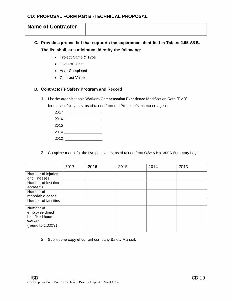
CD: PROPOSAL FORM Part B -TECHNICAL PROPOSAL
Name of Contractor
HISD CD-10 CD_Proposal Form Part B - Technical Proposal Updated 5-4-16.doc
C. Provide a project list that supports the experience identified in Tables 2.05 A&B.
The list shall, at a minimum, identify the following:
• Project Name & Type
• Owner/District
• Year Completed
• Contract Value
D. Contractor’s Safety Program and Record
1. List the organization's Workers Compensation Experience Modification Rate (EMR)
for the last five years, as obtained from the Proposer’s insurance agent.
2017
2016
2015
2014
2013
2. Complete matrix for the five past years, as obtained from OSHA No. 300A Summary Log:
2017 2016 2015 2014 2013
Number of injuries and illnesses
Number of lost time accidents
Number of recordable cases
Number of fatalities
Number of employee direct hire fixed hours worked (round to 1,000's)
3. Submit one copy of current company Safety Manual.

CD: PROPOSAL FORM Part B -TECHNICAL PROPOSAL
Name of Contractor
HISD CD-11 CD_Proposal Form Part B - Technical Proposal Updated 5-4-16.doc
E. Total Long-Term Cost to HISD to Acquire the Contractor’s Services; Cost Saving
& Methodology
1. Briefly address each of the construction issues listed below as you feel it relates to this bid package and how those issues might affect your work plan. If this proposal involves multiple project sites, please explain below how the GC intends to manage and coordinate multiple sites simultaneously. Contractors proposing on multi-site (Schools) bundles should describe how they intend to manage and coordinate multiple projects simultaneously. Issues such as weekly jobsite meetings, geographic proximity between sites, logistics, ordering & delivery of materials, approval of shop drawings & submittals, etc., should be addressed. Should the Contractor anticipate any significant issues or concerns that it feels must be considered by HISD, please address them in this section. A. Multiple-site coordination and management B. Site logistics and staging C. Coordination of Shop Drawings and other project submittals D. Weekly Meetings and Site Visits E. Phasing and Sequencing of Work Around Existing School Operations. F. Work at the project site on evenings, weekends, holidays, and summer breaks. G. Safety of your construction team, students, and faculty. H. Acknowledge feasibility of the preliminary phasing plan included in the construction
documents. I. Provide recommendations on phasing J. Provide recommendations regarding time/cost savings ideas to be implemented in work plan.
Any cost savings proposed as a result of time/cost savings ideas should be stated in your response to this item and should not be deducted from your base bid amount. These cost savings recommendations will be considered by the evaluation team. If they are considered viable, you will receive points for the recommendation. Should your firm be selected to enter contract negotiations, your cost savings recommendation will be evaluated further and either accepted or declined, at which point your base bid amount may be reduced by the proposed savings item.
K. Proposed Construction Schedule: 1. Provide, as an attachment to the Technical Proposal form, a bar chart schedule
depicting how the organization anticipates delivering the project in the time frame proposed by HISD. Clearly describe the scope of work to be completed in each phase.
The contractor’s proposed schedule is a vital part of the evaluation process and contractors should provide sufficient information for HISD to assess the contractor’s time frame, work plan and approach.
The Contractor may, at its option, propose a project duration other than the Owner’s Optimum Project Duration and indicate this duration on form CB.
2. Describe the type of software utilized to prepare construction schedules, if
applicable.
PLEASE RESPOND TO ITEMS “A” THROUGH “K” ABOVE ON A SEPARATE ATTACHMENT
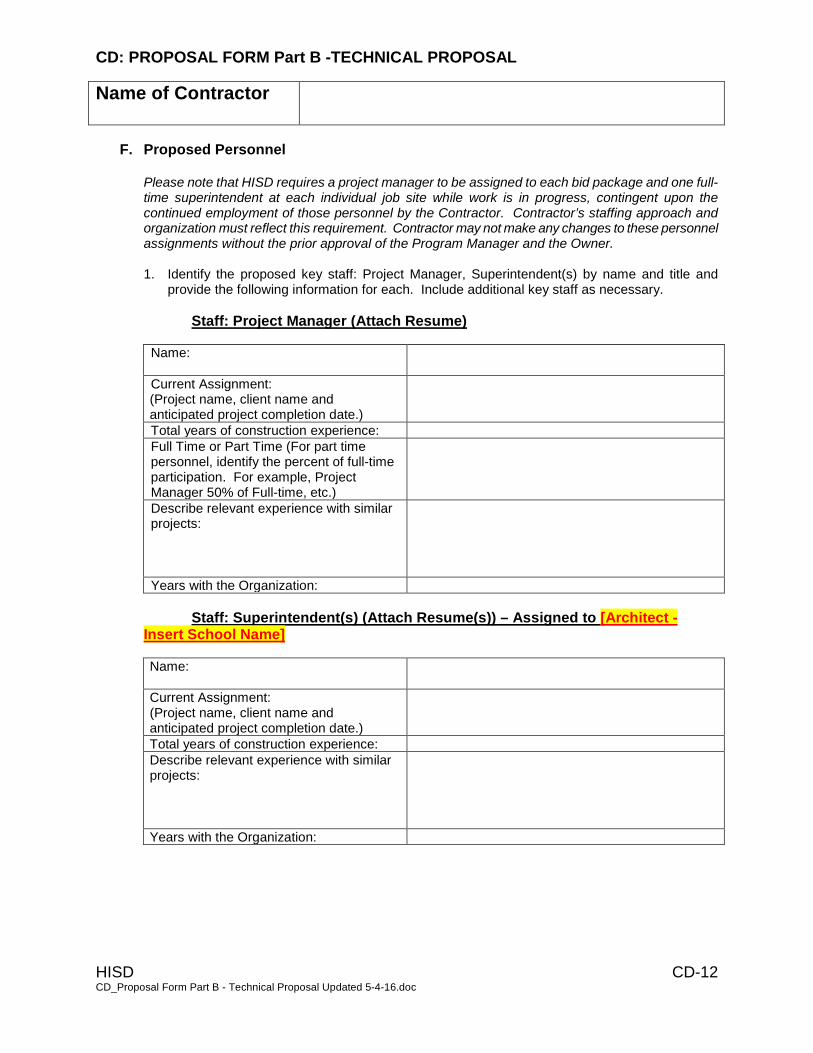
CD: PROPOSAL FORM Part B -TECHNICAL PROPOSAL
Name of Contractor
HISD CD-12 CD_Proposal Form Part B - Technical Proposal Updated 5-4-16.doc
F. Proposed Personnel Please note that HISD requires a project manager to be assigned to each bid package and one full-time superintendent at each individual job site while work is in progress, contingent upon the continued employment of those personnel by the Contractor. Contractor’s staffing approach and organization must reflect this requirement. Contractor may not make any changes to these personnel assignments without the prior approval of the Program Manager and the Owner. 1. Identify the proposed key staff: Project Manager, Superintendent(s) by name and title and
provide the following information for each. Include additional key staff as necessary.
Staff: Project Manager (Attach Resume)
Name:
Current Assignment: (Project name, client name and anticipated project completion date.)
Total years of construction experience:
Full Time or Part Time (For part time personnel, identify the percent of full-time participation. For example, Project Manager 50% of Full-time, etc.)
Describe relevant experience with similar projects:
Years with the Organization:
Staff: Superintendent(s) (Attach Resume(s)) – Assigned to [Architect - Insert School Name]
Name:
Current Assignment: (Project name, client name and anticipated project completion date.)
Total years of construction experience:
Describe relevant experience with similar projects:
Years with the Organization:
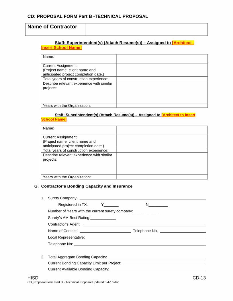
CD: PROPOSAL FORM Part B -TECHNICAL PROPOSAL
Name of Contractor
HISD CD-13 CD_Proposal Form Part B - Technical Proposal Updated 5-4-16.doc
Staff: Superintendent(s) (Attach Resume(s)) – Assigned to [Architect - Insert School Name]
Name:
Current Assignment: (Project name, client name and anticipated project completion date.)
Total years of construction experience:
Describe relevant experience with similar projects:
Years with the Organization:
Staff: Superintendent(s) (Attach Resume(s)) – Assigned to [Architect to Insert
School Name]
Name:
Current Assignment: (Project name, client name and anticipated project completion date.)
Total years of construction experience:
Describe relevant experience with similar projects:
Years with the Organization:
G. Contractor’s Bonding Capacity and Insurance
1. Surety Company:
Registered in TX: Y_______ N_________
Number of Years with the current surety company:____________
Surety’s AM Best Rating:____________
Contractor’s Agent:
Name of Contact: Telephone No.
Local Representative:
Telephone No:
2. Total Aggregate Bonding Capacity:
Current Bonding Capacity Limit per Project:
Current Available Bonding Capacity:

CD: PROPOSAL FORM Part B -TECHNICAL PROPOSAL
Name of Contractor
HISD CD-14 CD_Proposal Form Part B - Technical Proposal Updated 5-4-16.doc
3. List active Concurrent Projects with their contract values:
4. Submit an original signed letter from the surety documenting that the Proposer can provide the
required Payment and Performance Bonds.
5. Submit an original signed letter from the insurance company documenting that the Proposer can
provide the required insurance.
H. Technical Proposal Form Execution
Contractor’s Firm Name (legal name)
Federal Tax I. D. Number
Contractor’s Street Address
Contractor’s Phone Number
Contractor’s Fax Number
Contractor’s Email Address
Name of Owner:
Social Security Number of Owner:
Signature of Owner:
Date of Signature:

CE: EQUAL OPPORTUNITY EMPLOYER STATEMENT
HISD 07/13/04 CE-1 21_CE_EOE Statement 6 28 07
Submitted to:
HOUSTON INDEPENDENT SCHOOL DISTRICT
4400 West 18th Street
Houston, Texas 77092
DATE
COMPANY NAME
P. O. BOX
STREET ADDRESS
CITY STATE ZIP CODE
The Houston Independent School District can do business only with those contractors and vendors
who are Equal Opportunity Employers and requires that these forms be completed and attached to
the Proposal Form in order for the proposal to be considered responsive at the time the proposal is
submitted.
1. Name of Owner or President Phone
2. Current total employment No. of males No. of females
3. Of the total number of persons currently employed, please provide the following race or
ethnic breakdown: No. Of whites _________, No. Of Hispanics (Mexican American or
Spanish (surname) _________, No. Of blacks ________, No Of other minorities _________.
4. Do you advertise as an equal opportunity employer? Y ____ N ____
5. Do you have a written nondiscriminatory policy on employment? Y ____ N ____
6. Has this policy been circulated throughout your organization? Y ____ N ____
7. Name and title of the person to contact should any questions arise.
Name Title Phone
NOTE: Contractors who have previously submitted an Equal Opportunity Employer Statement and/or
an Equal Opportunity Employer Affidavit are nonetheless required to complete these forms,
provide updated information and submit it with the Proposal.

CF: EQUAL OPPORTUNITY EMPLOYER AFFIDAVIT
HISD 07/13/04 CF-1 22_CF_EOE Affidavit Form 6 28 07
Affidavit submitted to:
HOUSTON INDEPENDENT SCHOOL DISTRICT
4400 West 18th Street
Houston, Texas 77092
STATE OF
COUNTY OF
This company, contractor or subcontractor agrees to refrain from discrimination in terms and
conditions of employment on the basis of race, color, religion, sex or national origin, and agrees to
take affirmative action as required by Federal Statutes and Rules and Regulations issued pursuant
thereto in order to maintain and insure nondiscriminatory employment practices.
___________________________, being duly sworn, deposes and says that he/she is the
_________________________________ Contractor, and that answers to the foregoing questions
and all statements herein contained are true and correct.
SUBSCRIBED AND SWORN TO BEFORE ME this ____ day of _____________, _______
Notary Public County of State of
My Commission expires
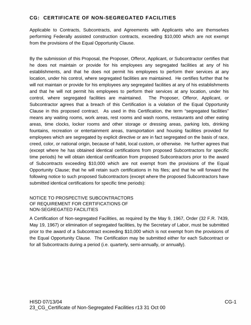
CG: CERTIFICATE OF NON-SEGREGATED FACILITIES
HISD 07/13/04 CG-1 23_CG_Certificate of Non-Segregated Facilities r13 31 Oct 00
Applicable to Contracts, Subcontracts, and Agreements with Applicants who are themselves
performing Federally assisted construction contracts, exceeding $10,000 which are not exempt
from the provisions of the Equal Opportunity Clause.
By the submission of this Proposal, the Proposer, Offeror, Applicant, or Subcontractor certifies that
he does not maintain or provide for his employees any segregated facilities at any of his
establishments, and that he does not permit his employees to perform their services at any
location, under his control, where segregated facilities are maintained. He certifies further that he
will not maintain or provide for his employees any segregated facilities at any of his establishments
and that he will not permit his employees to perform their services at any location, under his
control, where segregated facilities are maintained. The Proposer, Offeror, Applicant, or
Subcontractor agrees that a breach of this Certification is a violation of the Equal Opportunity
Clause in this proposed contract. As used in this Certification, the term “segregated facilities”
means any waiting rooms, work areas, rest rooms and wash rooms, restaurants and other eating
areas, time clocks, locker rooms and other storage or dressing areas, parking lots, drinking
fountains, recreation or entertainment areas, transportation and housing facilities provided for
employees which are segregated by explicit directive or are in fact segregated on the basis of race,
creed, color, or national origin, because of habit, local custom, or otherwise. He further agrees that
(except where he has obtained identical certifications from proposed Subcontractors for specific
time periods) he will obtain identical certification from proposed Subcontractors prior to the award
of Subcontracts exceeding $10,000 which are not exempt from the provisions of the Equal
Opportunity Clause; that he will retain such certifications in his files; and that he will forward the
following notice to such proposed Subcontractors (except where the proposed Subcontractors have
submitted identical certifications for specific time periods):
NOTICE TO PROSPECTIVE SUBCONTRACTORS
OF REQUIREMENT FOR CERTIFICATIONS OF
NON-SEGREGATED FACILITIES
A Certification of Non-segregated Facilities, as required by the May 9, 1967, Order (32 F.R. 7439,
May 19, 1967) or elimination of segregated facilities, by the Secretary of Labor, must be submitted
prior to the award of a Subcontract exceeding $10,000 which is not exempt from the provisions of
the Equal Opportunity Clause. The Certification may be submitted either for each Subcontract or
for all Subcontracts during a period (i.e. quarterly, semi-annually, or annually).

CG: CERTIFICATE OF NON-SEGREGATED FACILITIES
HISD 07/13/04 CG-2 23_CG_Certificate of Non-Segregated Facilities r13 31 Oct 00
NOTE: The penalty for making false statements in offers is prescribed in 18U .S.C. 1001. Name of Company
By
Title
STATE OF TEXAS
COUNTY OF HARRIS
Sworn to and subscribed before me at Houston, Texas this the _______ day of
___________________, 20_____, A.D.
Notary Public in and for Harris, County, Texas
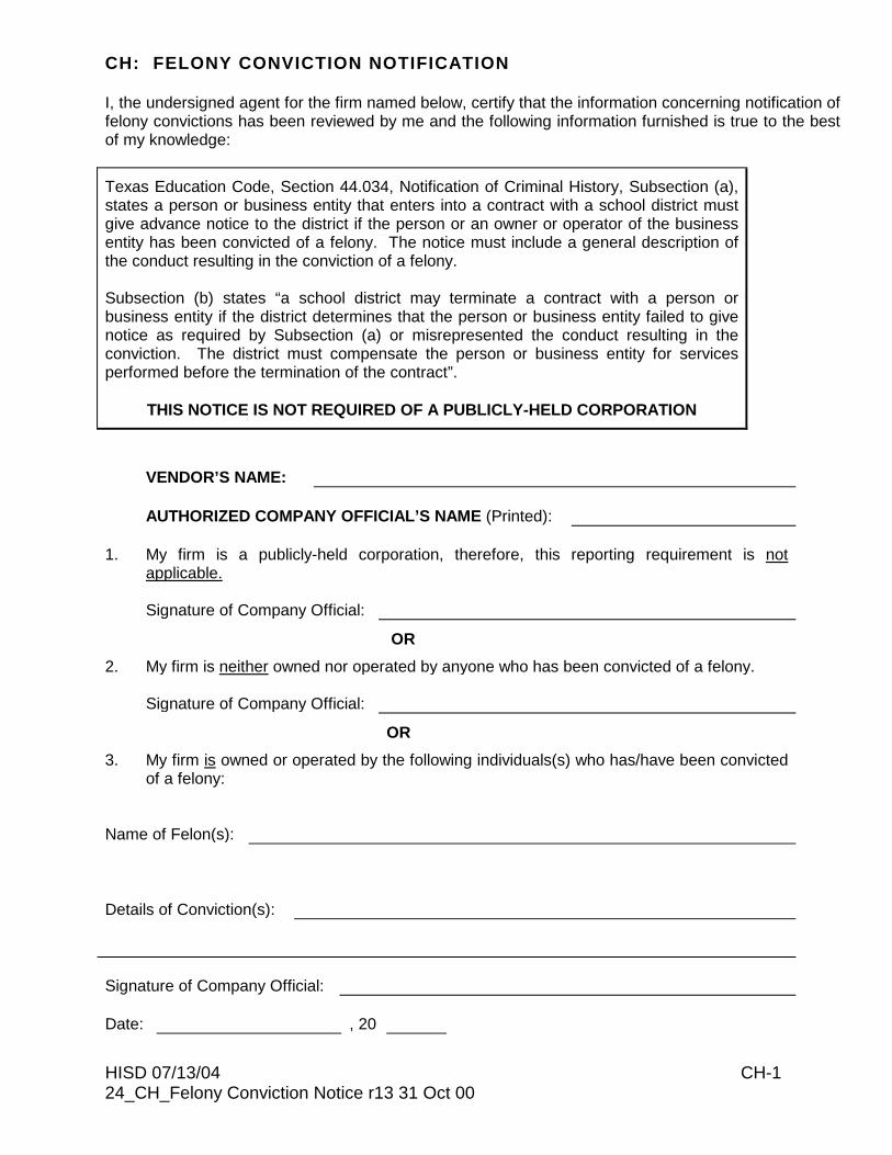
CH: FELONY CONVICTION NOTIFICATION
HISD 07/13/04 CH-1 24_CH_Felony Conviction Notice r13 31 Oct 00
I, the undersigned agent for the firm named below, certify that the information concerning notification of felony convictions has been reviewed by me and the following information furnished is true to the best of my knowledge:
Texas Education Code, Section 44.034, Notification of Criminal History, Subsection (a), states a person or business entity that enters into a contract with a school district must give advance notice to the district if the person or an owner or operator of the business entity has been convicted of a felony. The notice must include a general description of the conduct resulting in the conviction of a felony. Subsection (b) states “a school district may terminate a contract with a person or business entity if the district determines that the person or business entity failed to give notice as required by Subsection (a) or misrepresented the conduct resulting in the conviction. The district must compensate the person or business entity for services performed before the termination of the contract”.
THIS NOTICE IS NOT REQUIRED OF A PUBLICLY-HELD CORPORATION
VENDOR’S NAME:
AUTHORIZED COMPANY OFFICIAL’S NAME (Printed):
1. My firm is a publicly-held corporation, therefore, this reporting requirement is not
applicable. Signature of Company Official:
OR
2. My firm is neither owned nor operated by anyone who has been convicted of a felony. Signature of Company Official:
OR
3. My firm is owned or operated by the following individuals(s) who has/have been convicted of a felony:
Name of Felon(s):
Details of Conviction(s):
Signature of Company Official:
Date: , 20

CI: NOTIFICATION OF HAZARDOUS MATERIALS AFFIDAVIT
HISD 1 25_CI_Notice of Hazardous Material 6 28 07
STATE OF TEXAS
COUNTY OF HARRIS
Before me, the undersigned authority on this day personally appeared _____________, known
to me to be the person whose name is subscribed below, who, on oath stated:
“As the appropriate official of the company, contractor, or subcontractor submitting this affidavit
in conjunction with a bid proposal submitted to the Houston Independent School District, I
acknowledge that this company, contractor, or subcontractor has been notified that copies of
the Asbestos Hazard Emergency Response Act (AHERA) for the school(s) where such
company, contractor or subcontractor has contracted to perform work are available at the
individual school library and at the Risk Management Department at the Houston Independent
School District, 228 McCarty, Houston, Texas 77029. I understand that it is our responsibility to
familiarize ourselves with such plans and that it is our responsibility to inform every worker that
we use on this project as to the availability of these plans.
We also acknowledge that we will be required to obtain written clearance from the Houston
Independent School District, Bureau of Hazardous Materials Management, prior to executing
any work on this project.”
Name of Company
By
Title
STATE OF TEXAS
COUNTY OF HARRIS
Sworn to and subscribed before me at Houston, Texas this the ______________ day of
_____________________, 20 __________, A.D.
Notary Public in and for Harris, County, Texas
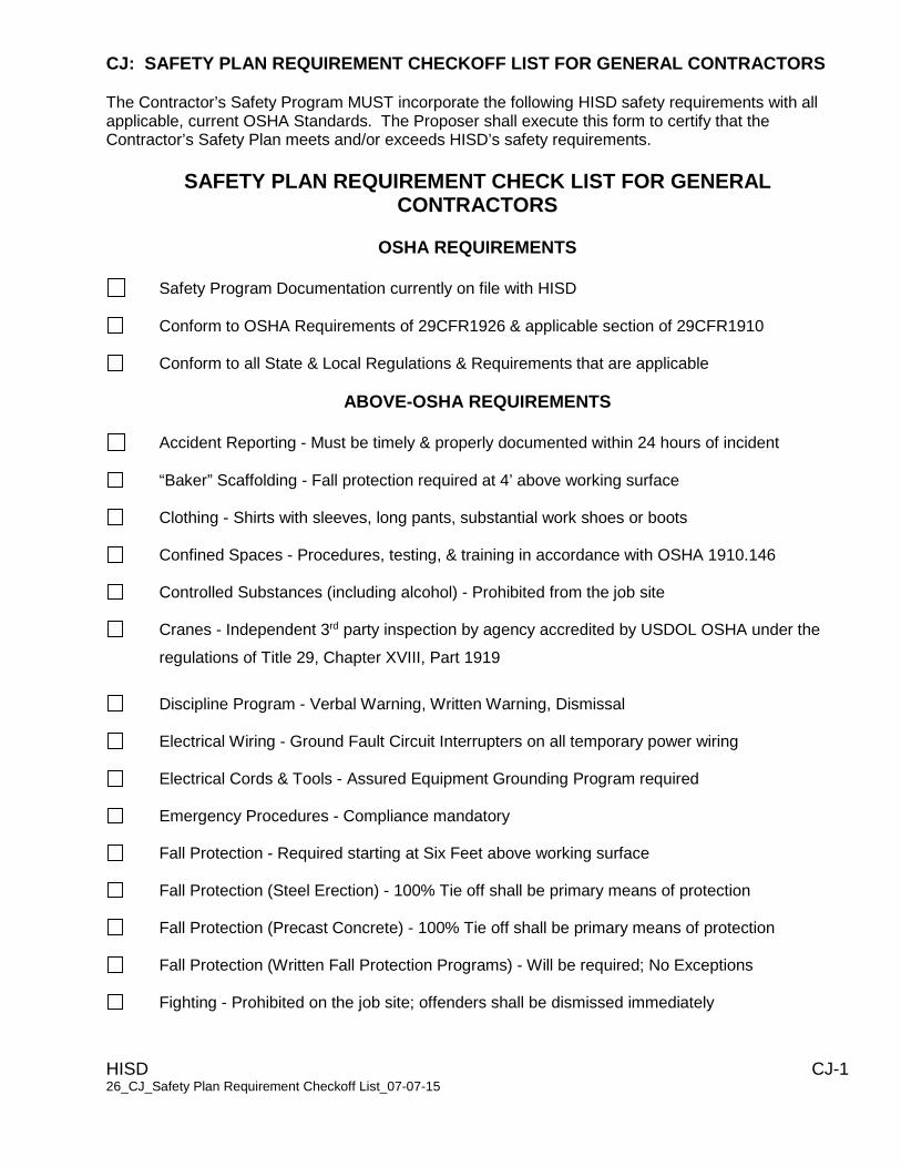
CJ: SAFETY PLAN REQUIREMENT CHECKOFF LIST FOR GENERAL CONTRACTORS
HISD CJ-1 26_CJ_Safety Plan Requirement Checkoff List_07-07-15
The Contractor’s Safety Program MUST incorporate the following HISD safety requirements with all applicable, current OSHA Standards. The Proposer shall execute this form to certify that the Contractor’s Safety Plan meets and/or exceeds HISD’s safety requirements.
SAFETY PLAN REQUIREMENT CHECK LIST FOR GENERAL CONTRACTORS
OSHA REQUIREMENTS
Safety Program Documentation currently on file with HISD
Conform to OSHA Requirements of 29CFR1926 & applicable section of 29CFR1910
Conform to all State & Local Regulations & Requirements that are applicable
ABOVE-OSHA REQUIREMENTS
Accident Reporting - Must be timely & properly documented within 24 hours of incident
“Baker” Scaffolding - Fall protection required at 4’ above working surface
Clothing - Shirts with sleeves, long pants, substantial work shoes or boots
Confined Spaces - Procedures, testing, & training in accordance with OSHA 1910.146
Controlled Substances (including alcohol) - Prohibited from the job site
Cranes - Independent 3rd party inspection by agency accredited by USDOL OSHA under the
regulations of Title 29, Chapter XVIII, Part 1919
Discipline Program - Verbal Warning, Written Warning, Dismissal
Electrical Wiring - Ground Fault Circuit Interrupters on all temporary power wiring
Electrical Cords & Tools - Assured Equipment Grounding Program required
Emergency Procedures - Compliance mandatory
Fall Protection - Required starting at Six Feet above working surface
Fall Protection (Steel Erection) - 100% Tie off shall be primary means of protection
Fall Protection (Precast Concrete) - 100% Tie off shall be primary means of protection
Fall Protection (Written Fall Protection Programs) - Will be required; No Exceptions
Fighting - Prohibited on the job site; offenders shall be dismissed immediately

CJ: SAFETY PLAN REQUIREMENT CHECKOFF LIST FOR GENERAL CONTRACTORS
HISD CJ-2 26_CJ_Safety Plan Requirement Checkoff List_07-07-15
SAFETY PLAN REQUIREMENT CHECKOFF LIST FOR GENERAL CONTRACTORS
(Continued)
Hazard Communication - HazCom Programs & Material Safety Data Sheets required
Hot Work - Permits and dedicated Fire Watch required for all operations.
Housekeeping - Combustible scrap materials & debris must be removed daily.
Immediate Danger to Safety or Health - Work shall be stopped immediately
Job Hazard Analysis - Must be created prior to & strictly followed for all work activities
Orientation Session - All employees must attend before starting work at Project Site
Personal Protective Equipment - Hard Hats & Safety Glasses required at all times
Principal’s Meeting - Must be performed within 72 hours after a Lost Time Accident
Return to Work - Restricted Duty to be made available to extent allowed by Doctor
Safety Representative - Must meet requirements of the Competent Person Standard and have
completed OSHA 10 hour construction outreach training.
Scaffolding - Inspection & Documentation required daily by Competent Person
Sign-in Sheets – Maintain daily record of each worker present on the site
Training - Weekly “Tool-Box” Safety Meeting performed with attendance roster
Weapons - Possession of weapons on the project site is prohibited
Weekly Safety inspections conducted by Safety Representative
Contractor has included one (1) copy of their current Safety Manual with this proposal I certify that our company’s Safety Plan meets and/or exceeds the HISD Safety Requirements on this checklist.
Corporate Officer: Company: Date:
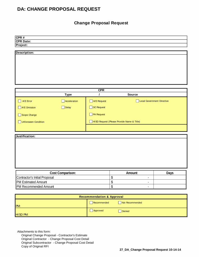
DA: CHANGE PROPOSAL REQUEST
Change Proposal Request
CPR #CPR Date:Project:
Description:
CPRType / Source
Justification:
Recommendation & Approval
PM:
HISD PM:
A/E Error
A/E Omission
Unforeseen Condition
Scope Change
A/E Request
PA Request
GC Request
HISD Request (Please Provide Name & Title)
Cost Comparison: Amount Days
Contractor's Initial Proposal -$
PM Estimated Amount -$
PM Recommended Amount -$
Recommended Not Recommended
Approved Denied
Acceleration
Delay
Local Government Directive
Attachments to this form:
Original Change Proposal - Contractor's Estimate
Original Contractor - Change Proposal Cost Detail
Original Subcontractor - Change Proposal Cost Detail
Copy of Original RFI27_DA_Change Proposal Request 10-14-14

DB: CHANGE PROPOSAL - CONTRACTOR'S ESTIMATE
Dated CPR NO.
PROJECT
Subcontractor Cost
Material -$
Labor -$
Equipment -$
Subtotal -$
Subcontractor's Overhead & Profit (10%) -$
Total Cost for Subcontractor -$
General Contractor Cost
Material -$
Labor -$
Equipment -$
Subtotal -$
General Contractor Overhead & Profit (10%) -$
Subtotal General Contractor Cost -$
GC's Subcontractor Overhead & Profit (5%) -$
Total Cost for General Contractor -$
Subtotal Cost for General Contractor & Subcontractor -$
Bond & Insurance (GC Only)
Cost of Insurance 0% -$
Cost of Payment & Performance Bonds 0.0% -$
Total Cost for Change Proposal -$
TIME EXTENSION IN DAYS (FOR THIS CHANGE)
DatedGeneral Contractor Signature
DatedA/E Signature
Change Proposal - Contractor's Estimate
Attachments to this form:
Copy of Original RFI
Contractor - Change Proposal Cost Detail
Subcontractor - Change Proposal Cost Detail 28_DB_Change Proposal Contractors Estimate
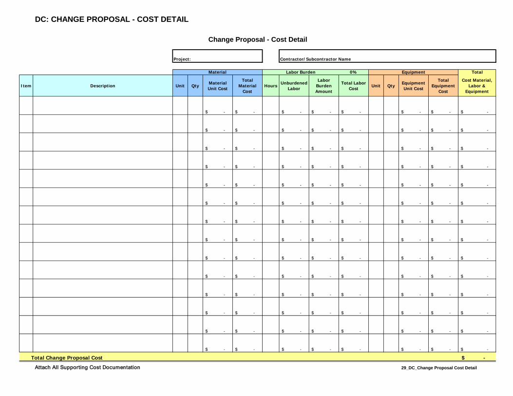
DC: CHANGE PROPOSAL - COST DETAIL
Contractor/Subcontractor Name
0% Total
Item Description Unit Qty Material Unit Cost
Total Material
CostHours Unburdened
Labor
Labor Burden Amount
Total Labor Cost Unit Qty Equipment
Unit Cost
Total Equipment
Cost
Cost Material, Labor &
Equipment
-$ -$ -$ -$ -$ -$ -$ -$
-$ -$ -$ -$ -$ -$ -$ -$
-$ -$ -$ -$ -$ -$ -$ -$
-$ -$ -$ -$ -$ -$ -$ -$
-$ -$ -$ -$ -$ -$ -$ -$
-$ -$ -$ -$ -$ -$ -$ -$
-$ -$ -$ -$ -$ -$ -$ -$
-$ -$ -$ -$ -$ -$ -$ -$
-$ -$ -$ -$ -$ -$ -$ -$
-$ -$ -$ -$ -$ -$ -$ -$
-$ -$ -$ -$ -$ -$ -$ -$
-$ -$ -$ -$ -$ -$ -$ -$
-$ -$ -$ -$ -$ -$ -$ -$
-$ -$ -$ -$ -$ -$ -$ -$
Total Change Proposal Cost -$
Change Proposal - Cost Detail
Material Equipment
Project:
Labor Burden
Attach All Supporting Cost Documentation 29_DC_Change Proposal Cost Detail

DD: CERTIFICATE OF ASBESTOS-FREE CONSTRUCTION
HOUSTON INDEPENDENT SCHOOL DISTRICT
6/28/07 Page 1 30_DD_Certificate of Asbestos Free Construction
6 28 07
STATE OF TEXAS COUNTY OF HARRIS PROJECT:
The undersigned, pursuant to Article 9 of the General and Supplementary Conditions of
the Contract for Construction, hereby certifies that to the best of his/her knowledge,
information and belief, the materials incorporated into the project, and as used during the
construction process are free of any type of asbestos material.
SEAL: CONTRACTOR:
ADDRESS:
BY:
Signature TITLE:
Subscribed and Sworn to me this ________ day of ___________________ , 20________. Notary Public:
My Commission Expires:

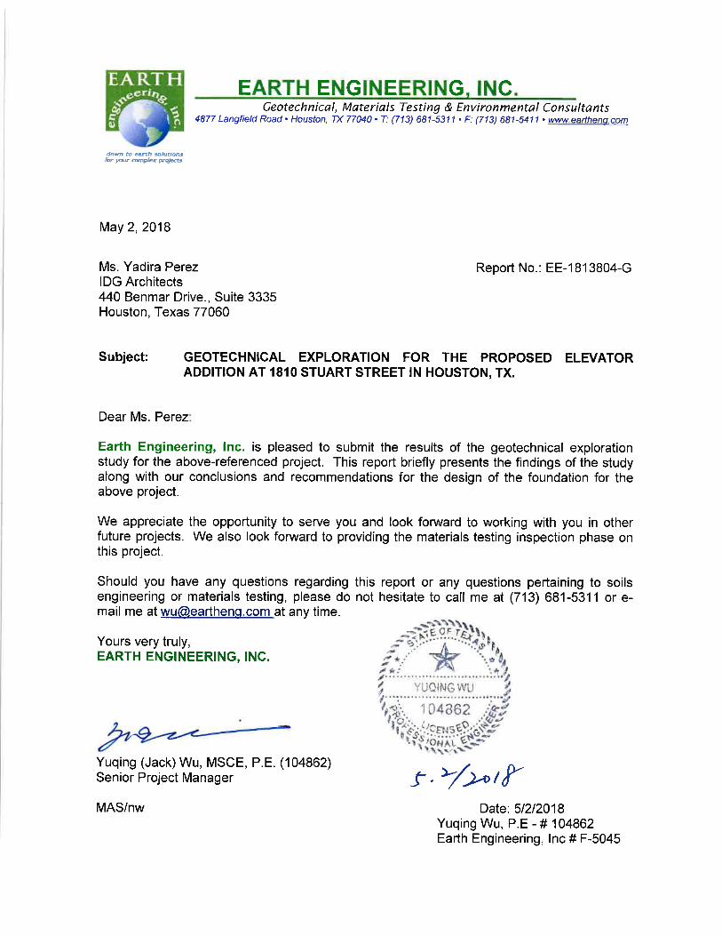


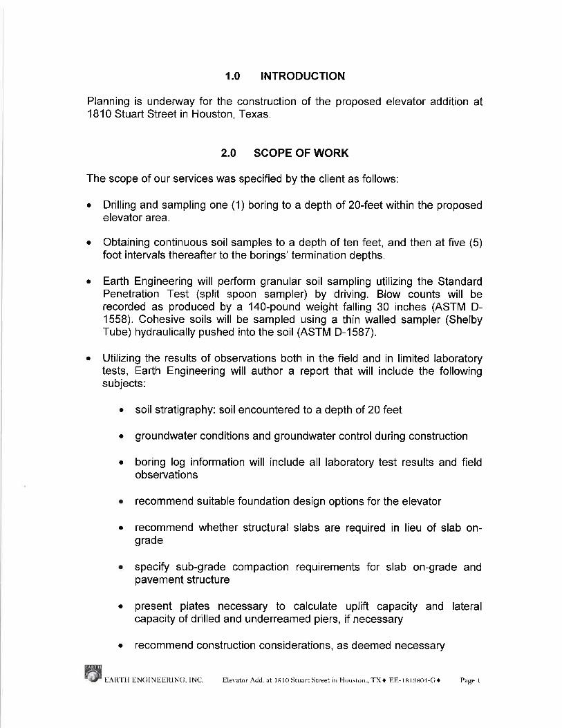
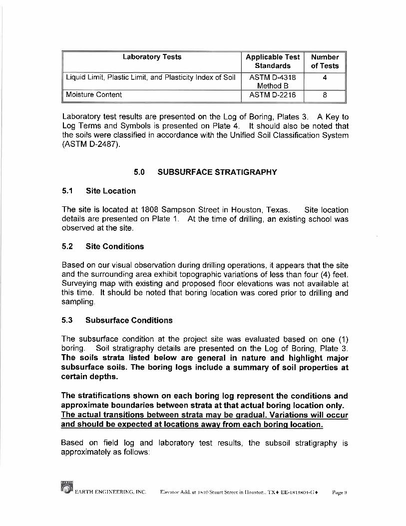
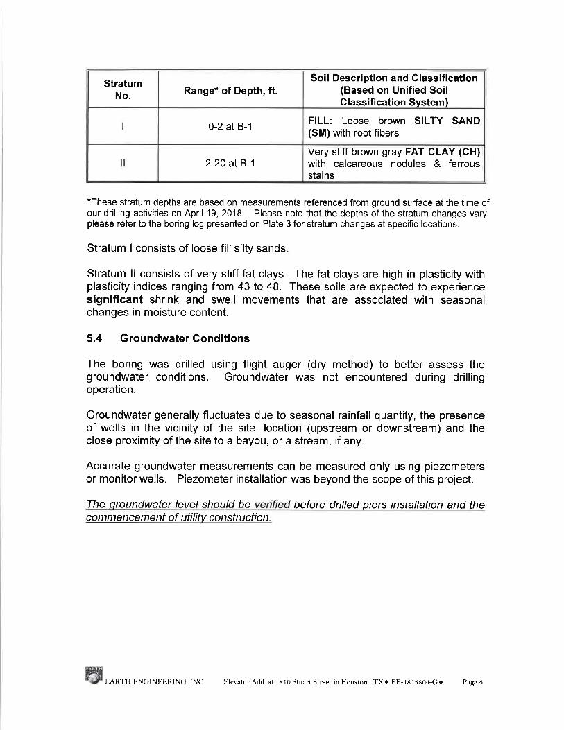


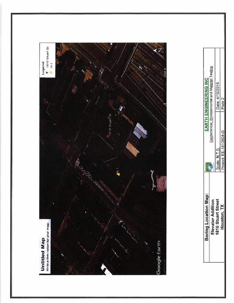

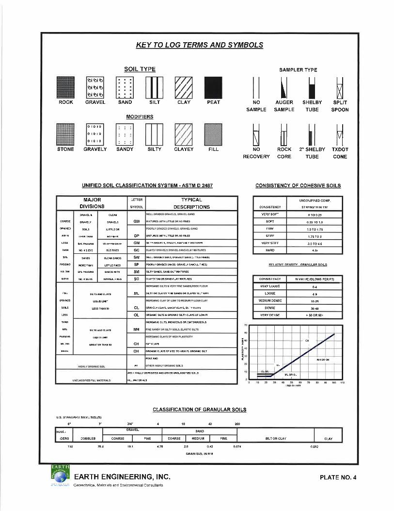
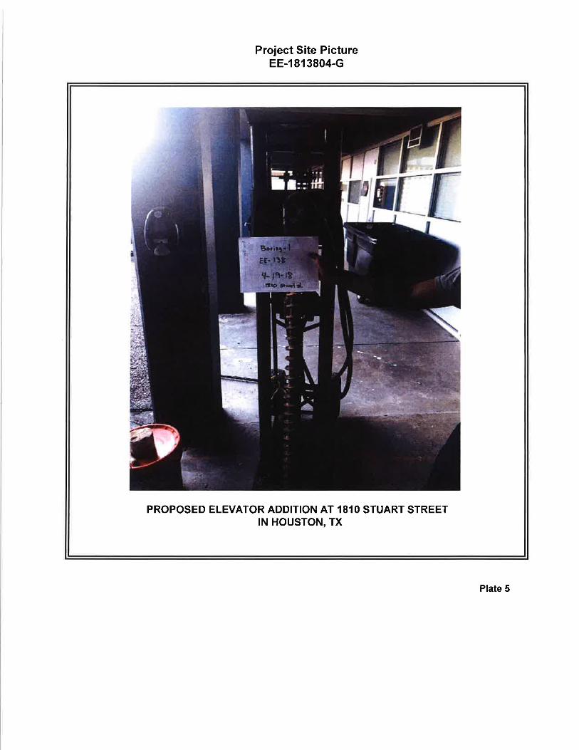

IDG Architects Houston Independent School District Proj. No. 4004-07 H.A.I.S. Elevator Project
STORM SEWAGE SYSTEM
33 41 00
IDG Architects Houston Independent School District
Proj. No. 4004-07 H.A.I.S. Elevator Project
STRUCTURAL TESTING AND INSPECTIONS
01 45 29 Issued for Permit – 06/18/2018
SECTION 01 45 29 – STRUCTURAL TESTING AND INSPECTIONS
PART 1 - GENERAL
1.1 RELATED DOCUMENTS
A. Drawings and general provisions of the Contract, including General and Supplementary Conditions and Division 01 Specification Sections, apply to this Section.
1.2 SUMMARY
A. Section includes requirements for quality assurance and quality control to be completed by the Testing Laboratory, Contractor, and/or the Geotechnical Engineer for the following structural items:
1. Concrete Forming and Accessories. 2. Concrete Reinforcing. 3. Cast-in-Place Concrete. 4. Masonry. 5. Structural Steel. 6. Steel Decking. 7. Cold-Formed Metal Framing. 8. Earthwork.
B. Related Requirements:
1. Specification 01 40 00 “Quality Requirements” for other independent testing agency procedures and administrative requirements.
1.3 PRICE AND PAYMENT PROCEDURES
A. Unit Prices:
1. Cost Proposal: The Testing Laboratory’s proposal to the Owner shall contain unit price stipulations for specified tests and inspections and on an hourly basis for personnel. A total estimated price shall also be submitted.
B. Measurement and Payment
1. Payment of the Testing Laboratory: The Owner will pay for the initial Laboratory services for inspection and testing of materials for compliance with the requirements of the Contract Documents.
2. Payment for Substitution Testing: The Contractor shall arrange for and pay for any additional samples and tests above those required by the Contract Documents as requested by the Contractor for his convenience in performing the work.
3. Payment for Retesting: When initial tests indicate work does not comply with the requirements of the Contract Documents, the Contractor shall be liable to the Owner for the cost for any additional inspections, sampling, testing, and retesting done by the Testing Laboratory.
IDG Architects Houston Independent School District
Proj. No. 4004-07 H.A.I.S. Elevator Project
STRUCTURAL TESTING AND INSPECTIONS
01 45 29 Issued for Permit – 06/18/2018
4. Payment by Contractor: The Contractor shall furnish and pay for the following items if required:
a. Soil survey of the location of borrow soil materials, samples of existing soil materials, and delivery to the Contractor’s Testing Laboratory.
b. Samples of concrete aggregates and delivery to the Contractor’s Testing Laboratory.
c. Concrete mix designs as prepared by his concrete supplier. d. Site-situated storage boxes for concrete cylinders e. Concrete coring, tests of below strength concrete, and load tests, if ordered by the
Owner, Architect, or Engineer. f. Certification of reinforcing steel mill order. g. Certification of structural steel mill order. h. Certification of portland cement, lime, fly ash. i. Certification of welders and preparation of Welding Procedure Specifications. j. Tests, samples, and mock-ups of substitute material where the substitution is
requested by the Contractor and the tests are necessary in the opinion of the Owner, Architect or Engineer to establish equality with specified items.
k. The making and testing of concrete cylinders for the purpose of evaluating strength at time of form stripping or the time spent evaluating the in situ strength of concrete using the Maturity Method.
l. Any other tests when such costs are required by the Contract Documents to be paid by the Contractor.
5. Payment for Tests of Suspected Deficient Work: If, in the opinion of the Building Official, Owner, Architect, or Engineer, any of the work of the Contractor is not satisfactory, the Contractor shall furnish and pay for all tests that the Owner, Architect, or Engineer deem advisable to determine its proper construction. The Owner shall pay all costs if the tests prove the questioned work to be satisfactory.
1.4 OWNER RESPONSIBILITIES
A. The Owner shall engage a Geotechnical Engineer to provide inspection services for the foundations as outlined below in Article 3.8.
B. The Owner shall provide a copy of the project plans and specifications to the Testing Laboratory prior to the start of construction and prior to any preinstallation meetings.
1.5 CONTRACTOR RESPONSIBILITIES
A. The Contractor shall not engage the same Testing Laboratory for construction services as the Owner has for Structural Testing Laboratory Services as defined herein unless agreed to by the Owner.
B. Furnishing Samples and Certificates: The Contractor shall provide to the laboratory certificates and representative samples of materials proposed for use in the work in quantities sufficient for accurate testing as specified.
C. Furnishing Casual Labor, Equipment and Facilities: The Contractor shall furnish casual labor, equipment, and facilities as required for sampling and testing by the laboratory and otherwise facilitate the required inspections and tests.

IDG Architects Houston Independent School District
Proj. No. 4004-07 H.A.I.S. Elevator Project
STRUCTURAL TESTING AND INSPECTIONS
01 45 29 Issued for Permit – 06/18/2018
1.6 TESTING LABORATORY RESPONSIBILITIES
A. The Testing Laboratory shall sample and test materials as they are being installed for compliance with specified acceptance criteria. The Testing Laboratory will report and interpret the test results. The Laboratory shall monitor and report on the installation of construction work and shall perform tests on the completed construction as required to indicate Contractor’s compliance with the various material specifications governing this work.
B. The Testing Laboratory shall serve as a Special Inspector to provide Special Inspection services for the items listed below. The scope of such services for each item shall be as defined in the International Building Code 2012 or as defined in the local building code of the jurisdiction wherein the project is located. These inspections are mandatory for conformance to the legal requirements of the building code and shall be in addition to the inspections and tests otherwise defined in this specification.
1. Special Inspector Responsibilities:
a. The special inspector shall observe the work assigned to ascertain that, to the best of his/her knowledge, it is in conformance with the approved design drawings and specifications.
b. The special inspector shall furnish inspection reports to the Building Official, the Architect/Engineer, and the Owner. All discrepancies shall be brought to the immediate attention of the Architect/Engineer, Contractor, and Owner. A report that the corrected work has been inspected shall be sent to the Building Official, the Architect/Engineer, and the Owner.
c. The special inspector shall create and maintain a log of all discrepancies throughout the duration of the Project. This log shall include, but is not limited to, discrepancy date, description of discrepancy, drawing and/or detail reference, description of as-built condition, description of any remedial work performed, and status of discrepancy. This log shall be submitted to the Architect/Engineer on a periodic basis for review and comment. Upon completion of the Project, this log shall be submitted in its entirety as an attachment to the final signed report described below.
d. The special inspector shall submit a final signed report stating whether the work requiring special inspection was, to the best of the inspector’s knowledge, in conformance to the approved plans and specifications and the applicable workmanship provisions of the building code.
C. The Testing Laboratory shall provide inspections on the following items:
1. Reinforcing steel placement. 2. Concrete work. 3. Welding of reinforcing steel. 4. Bolts to be installed in concrete. 5. Bolts, anchors, and reinforcing bars installed in hardened concrete (post-installed
anchors). 6. Inspection of structural steel, bolting, and welding material. 7. Welding of structural steel. 8. High-strength bolting. 9. Compacted earth fill. (By Geotechnical Engineer of Record) 10. Pier foundations. (By Geotechnical Engineer of Record) 11. Masonry work. 12. Cold-formed metal framing.
IDG Architects Houston Independent School District
Proj. No. 4004-07 H.A.I.S. Elevator Project
STRUCTURAL TESTING AND INSPECTIONS
01 45 29 Issued for Permit – 06/18/2018
D. Inspections Required by Government Agencies: The Testing Laboratory shall perform inspections and submit reports and certifications as required by government agencies having jurisdiction over the aspects of the project covered by this specification.
E. Notification of Deficiencies in the Work: The Testing Laboratory shall notify the Architect, Engineer, and Contractor within 24 hours of discovery of observed irregularities and deficiencies of the Work and other conditions not in compliance with the requirements of the Contract Documents. Notification shall be by telephone or e-mail and then in writing.
F. Accounting: The Testing Laboratory shall be responsible for separating and billing costs attributed to the Owner and costs attributed to the Contractor.
G. Monitoring Product and Material Certifications: The Testing Laboratory shall be responsible for monitoring the submittals of product and material certifications from manufacturers and suppliers as specified in the Specifications and shall report to the Owner, Architect, and Engineer when those submittals are not made in a timely manner.
H. Limitations of Authority: The Testing Laboratory is not authorized to revoke, alter, relax, enlarge upon, or release any requirements of the Specifications or to approve or accept any portion of the work or to perform any duties of the General Contractor and his Subcontractors.
1.7 ADMINISTRATIVE REQUIREMENTS
A. Coordination:
1. The Testing Laboratory shall cooperate with the Architect, Engineer, and Contractor and provide qualified personnel promptly on notice.
2. The Contractor shall cooperate with Testing Laboratory personnel and provide access to the work and to manufacturers’ operations.
3. Notification of Source Change: The Contractor shall be responsible for notifying the Owner, Architect, Engineer, and Testing Laboratory when the source of any material is changed after the original tests or inspections have been made.
B. Preinstallation Meetings: The Testing Laboratory shall attend preinstallation meetings with the Architect, Engineer, Contractor, and material suppliers as required to coordinate materials inspection and testing requirements with the planned construction schedule and shall participate in such meetings throughout the course of the project.
C. Scheduling:
1. Advance Notice: The Contractor shall be responsible for notifying the Testing Laboratory sufficiently in advance of operations to allow for assignment of personnel and scheduling of tests. Failure to sufficiently notify may result in additional costs incurred by the Testing Laboratory that may be back-charged to the Contractor by the Owner.
1.8 SUBMITTALS
A. Quality Control Reports:
1. Information on Reports: The Testing Laboratory shall submit copies of reports of inspections and tests promptly. The reports shall contain at least the following information:
IDG Architects Houston Independent School District
Proj. No. 4004-07 H.A.I.S. Elevator Project
STRUCTURAL TESTING AND INSPECTIONS
01 45 29 Issued for Permit – 06/18/2018
a. Project name. b. Date report issued. c. Testing Laboratory name and address. d. Name and signature of inspector/technician. e. Date of inspection and/or sampling. f. Date of test. g. Identification of product and Specification section. h. Location in the project. i. Identification of inspection or test. j. Record of weather conditions and temperature (if applicable). k. Results of test regarding compliance with Contract Documents.
2. Copies: The Laboratory shall send signed copies of test and inspection reports to the following parties:
a. One electronic copy to the Owner or his/her representative. b. One electronic copy to the General Contractor. c. One electronic copy to the Architect. d. One electronic copy to the Engineer of Record.
B. Discrepancy Log: The Testing Laboratory shall create and maintain a log of all discrepancies throughout the duration of the project.
1. Information on Log: This log shall include, but is not limited to:
a. Discrepancy date. b. Description of discrepancy. c. Drawing and/or detail reference. d. Description of as-built condition. e. Description of any remedial work performed. f. Status of discrepancy.
2. Submission Schedule: This log shall be submitted to the Architect/Engineer on a periodic basis for review and comment. Upon completion of the Project, this log shall be submitted in its entirety as an attachment to the final signed report described below under Certifications.
C. Certification: Upon completion of the job, the Laboratory shall furnish to the Owner, Architect, and Engineer of Record, a statement signed by a licensed professional engineer that, to the best of their knowledge, required tests and inspections were made in accordance with the requirements of the Contract Documents.
1.9 QUALITY ASSURANCE
A. Qualifications of Special Inspector: The special inspector shall be a qualified person who shall demonstrate competence, to the satisfaction of the Building Official, for inspection of the particular type of construction or operation being inspected. The Special Inspector shall meet the legal qualifications of the building code having jurisdiction.
B. Qualifications of Testing Laboratory:
1. The Testing Laboratory shall meet the basic requirements of ASTM E 329 and shall submit to the Owner, Architect, and Engineer evidence of current accreditation from the

IDG Architects Houston Independent School District
Proj. No. 4004-07 H.A.I.S. Elevator Project
STRUCTURAL TESTING AND INSPECTIONS
01 45 29 Issued for Permit – 06/18/2018
American Association for Laboratory Accreditation, the AASHTO Accreditation Program or the “NIST” National Voluntary Laboratory Accreditation Program.
2. The Testing Laboratory shall be an Approved Agency by the Building Official to perform Special Inspections and other tests and inspections as outlined in the applicable building code.
3. Tests and inspections shall be conducted in accordance with specified requirements, and if not specified, in accordance with the applicable standards of the American Society for Testing and Materials or other recognized and accepted authorities in the field.
4. Qualifications of Welding Inspectors
a. Inspectors performing visual weld inspection shall meet the requirements of AWS D1.1 Section 6.1.4. Inspectors shall have current certification as an AWS Certified Welding Inspector (CWI). Assistant inspectors, if any, shall be supervised by an Inspector and shall be qualified by training and experience to perform the specific functions to which they are assigned.
b. Inspectors performing nondestructive examinations of welds other than visual inspection (MT, PT, UT, and RT) shall meet the requirements of AWS D1.1, Section 6.14.6.
C. The Contractor shall not engage the same testing laboratory for construction services as the Owner has for quality assurance testing, unless agreed to by the Owner.
PART 2 - PRODUCTS (Not Used)
PART 3 - EXECUTION
3.1 SCOPE OF WORK
A. The work to be performed by the Testing Laboratory shall be as specified in this Section of the Specification and as determined in meetings with the Owner, Architect, and Engineer.
3.2 CONCRETE FORMING AND ACCESSORIES
A. Field Inspection:
1. Shallow Foundation Elements:
a. Verify element width, length, depth, and elevation. b. Verify that forms are plumb and straight, braced against movement, and lubricated
for removal.
2. Slabs-on-Grade:
a. Verify formwork at turndowns and slab edges is plumb and straight, braced against movement and lubricated for removal.
3. Columns and Walls:
a. Verify that forms are plumb and straight, braced against movement, lubricated for removal, and conform to approved shop drawings.

IDG Architects Houston Independent School District
Proj. No. 4004-07 H.A.I.S. Elevator Project
STRUCTURAL TESTING AND INSPECTIONS
01 45 29 Issued for Permit – 06/18/2018
b. Verify proper dimensions and orientation. c. Verify top of column elevation is set in form and that it is 1/2 inch below the future
slab soffit.
4. In-Situ Concrete Strength Verification Prior to Form Stripping: The Testing Laboratory shall verify that the concrete has reached the required minimum strength before form removal by evaluating the specified tests. Refer to Paragraph 3.4B.2.a for additional information regarding the tests.
3.3 CONCRETE REINFORCING
A. Quality Assurance: 1. Review the Welding Procedure Specification (WPS) submitted by the contractor for any
reinforcing steel other than ASTM A 706 that is proposed to be welded for consistency with acceptable welding practices and AWS.
2. Review welder qualifications by certification or verify by retesting. Obtain welder certificates.
B. Field Inspection: The scope of the work to be performed by the inspector on the jobsite shall be as follows:
1. Reinforcing Steel: The Testing Laboratory or designated Special Inspector shall inspect 100% of reinforcement before each concrete pour to verify the information noted below. Inspection reports shall be prepared and distributed in accordance with the local building code and as specified in this specification.
a. Primary and secondary longitudinal reinforcement has correct size and number in proper layers.
b. Longitudinal reinforcement has correct length and lap. c. Ties and stirrups are of correct size, spacing, and number and have the proper
termination hook geometry. d. Unscheduled face reinforcement in beams are provided and are of correct size,
number and spacing and have the proper end terminations. e. Proper hooks are provided at bar ends as detailed. f. Reinforcement is properly supported and braced to formwork to prevent movement
during concrete placement. g. Reinforcement has proper cover. h. Sufficient spacing between reinforcement for concrete placement. i. Dowel reinforcement is of proper size, at proper spacing, and has proper lap length
and embedment length. j. Proper construction/control/expansion joint spacing and reinforcement. k. Reinforcement around embedded items is placed according to details.
3.4 CAST-IN-PLACE CONCRETE
A. Quality Assurance:
1. Concrete Mix Designs: The Testing Laboratory shall review the submitted mix designs for conformance to the specifications and for suitability for use in the project.
2. Preinstallation Meetings: The Testing Laboratory shall attend the preinstallation meetings as noted in Specification 033000.02 “Cast-in-Place Concrete.”
IDG Architects Houston Independent School District
Proj. No. 4004-07 H.A.I.S. Elevator Project
STRUCTURAL TESTING AND INSPECTIONS
01 45 29 Issued for Permit – 06/18/2018
B. Field Testing: The following tests shall be completed by the Testing Laboratory:
1. During Concrete Placement:
a. Record the amount of water added and note if it exceeds the amount allowed to be added shown in the approved mix design.
b. Mold concrete test cylinders as specified below in Paragraph 3.a. c. Perform tests to determine slump, concrete temperature, unit weight, and air
entrainment as specified below. d. Record information for concrete test reports as specified below. e. Pick up and transport to Laboratory cylinders cast the previous day.
2. After Concrete Placement:
a. In-situ Concrete Strength Verification for Form Stripping: The Testing Laboratory shall perform the tests necessary to determine the concrete strength prior to form stripping:
1) If concrete strength for form stripping is to be determined using field-cured cylinders, the cylinder shall be broken at the time of form removal as directed by the Contractor.
2) If concrete strength for form stripping is to be determined using the Maturity Method, the Testing Laboratory shall verify that the requirements of ASTM C 1074 are being followed and that the proper criteria for determining concrete strength by this method has been established and is being followed.
b. Investigation of Low Strength Concrete Test Results:
1) Cost of Investigations for Low Strength Concrete: The Contractor shall reimburse the Owner for the costs of investigations of low strength concrete, as defined in Part I above.
2) Scope of Investigations: See Specification Section 033000.02 “Cast-In-Place Concrete” for the investigations that may be required by the Engineer. The Testing Laboratory will conduct these investigations if required.
c. Floor Flatness and Levelness Measuring: Perform tests as defined below.
d. Testing of Concrete Floor Slabs for Acceptability to Receive an Adhesive-Applied, Low-Permeable Floor Covering: Perform tests as defined below.
e. Testing of Non-Shrink Grout for Base Plates, Bearing Plates, and Precast Wall Panels:
1) Compressive Strength Tests: Compressive strength of grout shall be determined by testing grout cubes according to the requirements of ASTM C 109 - Modified. Test one set of three cubes at one day, and one set of three cubes at 28 days.
2) Frequency of Testing: One set of cubes (6 cubes) shall be made for every ten base plates and bearing plates or fraction thereof but not less than one set for each day's operation. One set of cubes shall be made for each day's operation of grouting wall panels.
3. Standards for Concrete Tests:

IDG Architects Houston Independent School District
Proj. No. 4004-07 H.A.I.S. Elevator Project
STRUCTURAL TESTING AND INSPECTIONS
01 45 29 Issued for Permit – 06/18/2018
a. Concrete Test Cylinders: Mold and test concrete cylinders as described below:
1) Cylinder Molding and Testing: Cylinders for strength tests shall be molded and Laboratory cured in accordance with ASTM C 31 and tested in accordance with ASTM C 39. Cylinders may be either 6” in diameter by 12” or 4” in diameter by 8”, however, the diameter of the cylinder shall be at least three times the nominal maximum size of the coarse aggregate in the mix tested. All of the cylinders for each class of concrete shall be of the same dimension for all sets of that class.
2) Field Samples: Field samples for strength tests shall be taken in accordance with ASTM C 172 at the point of placement.
3) Quantity of Cylinders: Each set of test cylinders shall consist of a minimum of four standard test cylinders. If concrete strength for form stripping is to be determined using field-cured cylinders, one additional cylinder per set will be required for formed slab and pan-formed beam floors for the purpose of evaluating the concrete strength at the time of form stripping. This cylinder shall be stored on the floor where form removal is to occur under the same exposure conditions as the floor concrete. The cylinder shall be cured under field conditions in accordance with ASTM C 31. Field-cured test cylinders shall be molded at the same time and from the same samples as laboratory-cured test specimens. The Contractor shall reimburse the Owner for the cost of making and testing these cylinders.
4) Frequency of Testing: A set of test cylinders shall be made according to the following minimum frequency guidelines:
a) One set for each class of concrete taken not less than once a day. b) Piers, Piles: One set for each 50 cubic yards or fraction thereof. c) Pile Caps: One set for each 50 cubic yards or fraction thereof. d) Basement Walls: One set for each 150 cubic yards. e) Floors: One set for each 150 cubic yards or fraction thereof but not
less than one set for each 5,000 square foot of floor area. f) Columns: One set for each 50 cubic yards or fraction thereof with a
minimum of two sets per floor. g) All Other Concrete: A minimum of one set for each 150 cubic yards
or fraction thereof but not less than one set for each 5,000 square foot of area for walls.
h) No more than one set of cylinders at a time shall be made from any single truck.
i) If the total volume of concrete is such that the frequency of testing as specified above would provide less than five strength tests for a given class of concrete, tests shall be made from at least five randomly selected batches or from each batch if fewer than five batches are used.
j) The above frequencies assume that one batch plant will be used for each pour. If more than one batch plant is used, the frequencies cited above shall apply for each plant used.
5) The cylinders shall be numbered, dated, and the point of concrete placement in the building recorded.
6) For concrete specified on the drawings to reach the required strength at 28 days, break one cylinder of the set at seven days, two 6” by 12” cylinders or three 4” by 8” cylinders at 28 days, and keep one in reserve for testing at the Engineer’s direction.
7) For concrete specified on the drawings to reach the required strength at 56 days, break one cylinder of the set at seven days, one cylinder at 28 days,

IDG Architects Houston Independent School District
Proj. No. 4004-07 H.A.I.S. Elevator Project
STRUCTURAL TESTING AND INSPECTIONS
01 45 29 Issued for Permit – 06/18/2018
two 6” by 12” cylinders or three 4” by 8” cylinders at 56 days, and one kept in reserve for testing at the Engineer’s direction.
8) Cylinder Storage Box: The Contractor shall be responsible for providing a protected concrete cylinder wooden storage box at a point on the job site mutually agreeable with the Testing Laboratory for the purpose of storing concrete cylinders until they are transported to the Laboratory. The box shall be constructed and equipped to maintain the environment specified for initial curing in ASTM C 31.
9) Transporting Cylinders: The Testing Laboratory shall be responsible for transporting the cylinders to the Laboratory in a protected environment such that no damage or ill effect will occur to the concrete cylinders including loss of moisture, freezing temperatures or jarring.
10) Information on Concrete Test Reports: The Testing Laboratory shall make and distribute concrete test reports after each job cylinder is broken. Such reports shall contain the following information:
a) Truck number and ticket number. b) Concrete Batch Plant. c) Mix design number. d) Accurate location of pour in the structure. e) Strength requirement. f) Date cylinders made and broken. g) Technician making cylinders. h) Concrete temperature at placing. i) Air temperature at point of placement in the structure. j) Amount of water added to the truck at the batch plant and at the site
and whether or not it exceeds the amount allowed by the mix design. k) Slump. l) Unit weight. m) Air content. n) Cylinder compressive strengths with type of failure if concrete does
not meet Specification requirements. Seven day breaks are to be flagged if they are less than 60% of the required 28 day strength. 28 day breaks are to be brought to the attention of the Architect and Engineer in writing if either cylinder fails to meet specification requirements.
b. Slump Tests: Slump Tests (ASTM C 143) shall be completed at the beginning of concrete placement for each batch plant and for each set of test cylinders made. The slump test shall be made from concrete taken from the end of the concrete truck chute. The concrete shall be considered acceptable if the slump is within the slump tolerance noted on the mix design submittal form for that class of concrete.
c. Air Entrainment: Air entrainment tests (ASTM C 231 or C 173, C 173 only for lightweight concrete) shall be made at the same time slump tests are made as cited above. Samples for air entrainment tests shall be taken at the point of
placement. d. Concrete Temperature: Concrete temperature at placement shall be measured
(ASTM C 1064) at the same time slump tests are made as cited above. e. Floor Flatness and Levelness Measuring:
1) The Testing Laboratory shall measure the floor for flatness and levelness according to ASTM E 1155.
2) Measurement of the finished concrete surface profile for any test section shall be made when requested by the Representative at his option. Notwithstanding, measurements shall be made within 24 hours after
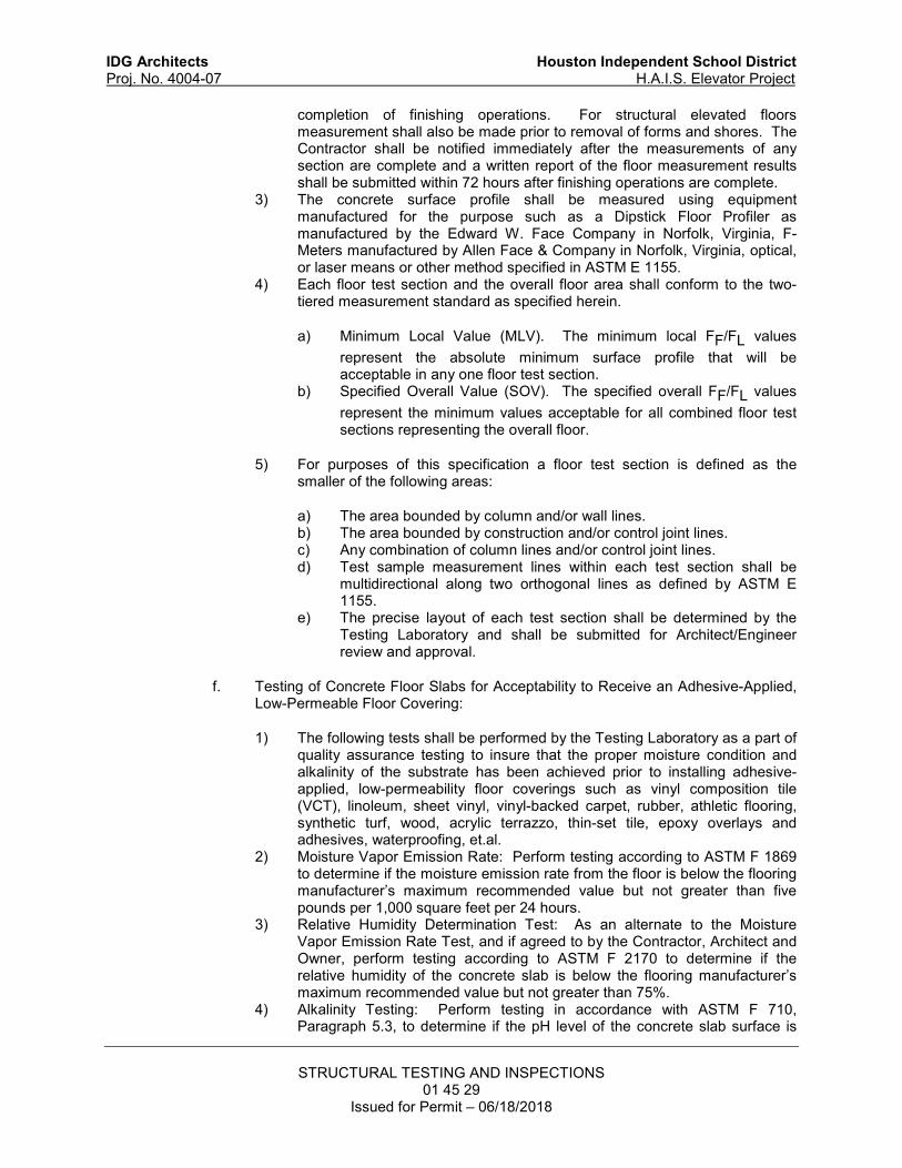
IDG Architects Houston Independent School District
Proj. No. 4004-07 H.A.I.S. Elevator Project
STRUCTURAL TESTING AND INSPECTIONS
01 45 29 Issued for Permit – 06/18/2018
completion of finishing operations. For structural elevated floors measurement shall also be made prior to removal of forms and shores. The Contractor shall be notified immediately after the measurements of any section are complete and a written report of the floor measurement results shall be submitted within 72 hours after finishing operations are complete.
3) The concrete surface profile shall be measured using equipment manufactured for the purpose such as a Dipstick Floor Profiler as manufactured by the Edward W. Face Company in Norfolk, Virginia, F-Meters manufactured by Allen Face & Company in Norfolk, Virginia, optical, or laser means or other method specified in ASTM E 1155.
4) Each floor test section and the overall floor area shall conform to the two-tiered measurement standard as specified herein.
a) Minimum Local Value (MLV). The minimum local FF/FL values
represent the absolute minimum surface profile that will be acceptable in any one floor test section.
b) Specified Overall Value (SOV). The specified overall FF/FL values
represent the minimum values acceptable for all combined floor test sections representing the overall floor.
5) For purposes of this specification a floor test section is defined as the smaller of the following areas:
a) The area bounded by column and/or wall lines. b) The area bounded by construction and/or control joint lines. c) Any combination of column lines and/or control joint lines. d) Test sample measurement lines within each test section shall be
multidirectional along two orthogonal lines as defined by ASTM E 1155.
e) The precise layout of each test section shall be determined by the Testing Laboratory and shall be submitted for Architect/Engineer review and approval.
f. Testing of Concrete Floor Slabs for Acceptability to Receive an Adhesive-Applied, Low-Permeable Floor Covering:
1) The following tests shall be performed by the Testing Laboratory as a part of quality assurance testing to insure that the proper moisture condition and alkalinity of the substrate has been achieved prior to installing adhesive-applied, low-permeability floor coverings such as vinyl composition tile (VCT), linoleum, sheet vinyl, vinyl-backed carpet, rubber, athletic flooring, synthetic turf, wood, acrylic terrazzo, thin-set tile, epoxy overlays and adhesives, waterproofing, et.al.
2) Moisture Vapor Emission Rate: Perform testing according to ASTM F 1869 to determine if the moisture emission rate from the floor is below the flooring manufacturer’s maximum recommended value but not greater than five pounds per 1,000 square feet per 24 hours.
3) Relative Humidity Determination Test: As an alternate to the Moisture Vapor Emission Rate Test, and if agreed to by the Contractor, Architect and Owner, perform testing according to ASTM F 2170 to determine if the relative humidity of the concrete slab is below the flooring manufacturer’s maximum recommended value but not greater than 75%.
4) Alkalinity Testing: Perform testing in accordance with ASTM F 710, Paragraph 5.3, to determine if the pH level of the concrete slab surface is

IDG Architects Houston Independent School District
Proj. No. 4004-07 H.A.I.S. Elevator Project
STRUCTURAL TESTING AND INSPECTIONS
01 45 29 Issued for Permit – 06/18/2018
below the flooring manufacturer’s maximum recommended value but not greater than 10. Perform one test per 1,000 square feet with a minimum of three tests within the total area being tested.
4. Evaluation and Acceptance of Concrete:
a. Strength Test: A strength test shall be defined as the average strength of two six inch cylinder breaks or three four inch cylinder breaks from each set of cylinders tested at the time indicated above.
b. Quality Control Charts and Logs: The Testing Laboratory shall keep the following quality control logs and charts for each class of concrete containing more than 2,000 cubic yards. The records shall be kept for each batch plant and submitted on a weekly basis with cylinder test reports:
1) Number of strength tests made to date. 2) Strength test results containing the average of all strength tests to date, the
high test result, the low test result, the standard deviation, and the coefficient of variation.
3) Number of tests under specified strength. 4) A histogram plotting the number of strength test cylinders versus
compressive strength. 5) Quality control chart plotting compressive strength test results for each test. 6) Quality control chart plotting moving average for strength where each point
plotted is the average strength of three previous test results. 7) Quality control chart plotting moving average for range where each point
plotted is the average of 10 previous ranges.
c. Acceptance Criteria: The strength level of an individual class of concrete shall be considered satisfactory if both of the following requirements are met:
1) The average of all sets of three consecutive strength tests equal or exceed the required f'c.
2) No individual strength test falls below the required f'c by more than the greater of 10% of f’c or 500 PSI.
d. If either of the above Acceptance Criteria requirements is not met, the Testing Laboratory shall immediately notify the Engineer by telephone. Steps shall immediately be taken to increase the average of subsequent strength tests.
C. Field Inspection: The scope of the work to be performed by the inspector on the jobsite shall be as follows:
1. Before Concrete Placement:
a. Inspect concrete formwork per Article 3.2. b. Inspect concrete reinforcing per Article 3.3. c. Inspect bolts and rods to be embedded in concrete for proper grade, size, length,
and embedment. d. For slabs-on-grade, verify that the moisture retarder is provided, is lapped
properly, and is not torn or punctured. e. Verify that there is no standing water in pour area and that all debris has been
removed from the area and from the formwork. f. Verify that openings and sleeves in slabs or walls are correct size and location.
Verify that the openings are shown on the structural drawings and notify the
IDG Architects Houston Independent School District
Proj. No. 4004-07 H.A.I.S. Elevator Project
STRUCTURAL TESTING AND INSPECTIONS
01 45 29 Issued for Permit – 06/18/2018
Engineer immediately of any openings in the field that are not shown on the drawings.
g. Verify that horizontal and vertical sleeves through girders, beams, or joists have been approved by the Engineer and that approved reinforcement is provided.
h. Verify the tops of previously poured columns and/or walls are 1/2 inch below the deck soffit.
2. During Concrete Placement: Provide continuous monitoring to:
a. Upon arrival of concrete, inspect the concrete to verify that the proper concrete mix number, type of concrete, concrete strength is being placed at the proper location. Verify that the mix meets the project specifications and is not over 90 minutes old at the time of placement. Report concrete not meeting the specified requirements and immediately notify the Contractor, Batch Plant Inspector, Architect, Engineer, and Owner.
b. Inspect plastic concrete upon arrival at the jobsite to verify proper batching. Observe mix consistency and adding of water as required to achieve target slumps in mix designs. The responsibility for adding water to trucks at the job site shall rest only with the Contractor's designated representative. The Contractor is responsible that all concrete placed in the field is in conformance to the Contract Documents.
c. Verify that the Contractor is following appropriate Hot Weather or Cold Weather concreting practices consistent with any extreme environmental conditions at the point of placement in the structure.
d. Verify that concrete deposited is uniform and that vertical drop does not exceed six feet and is not permitted to drop freely over reinforcement causing segregation.
e. Verify that the formwork has remained stable during the concreting operation. f. Verify that there are no cold joints. g. Verify that the concrete is properly vibrated. h. Inspect bolts embedded in concrete during concrete placement for verification that
they have been properly installed to the specified embedment. i. Verify that the finishing of the concrete surface is done according to specifications.
The Testing Laboratory shall report any irregularities that occur in the concrete at the job site or test results to the Contractor, Architect, Owner, and Engineer.
3. After Concrete Placement:
a. Verify that the curing process is according to Specifications and that any curing compound used is applied in accordance with the manufacturer’s recommendations.
b. Verify that sawcut control joints in slab-on-grades are cut within 12 hours of placement.
c. Post-Installed Anchors in Concrete: Provide inspection of post-installed anchor installations at the frequency noted in the specifications and in accordance with the published, currently valid, Evaluation Service Report (ESR) for each anchor product. Post-installed anchors include anchors and reinforcing steel. Inspection of post-installed anchors shall include but not be limited to the following:
1) Periodic Inspection: Verify initial installation of post-installed anchors in concrete for each individual installer with each individual anchor product in accordance with the requirements stated below for each type of anchor. Periodically inspect anchor installation after the initial verification.

IDG Architects Houston Independent School District
Proj. No. 4004-07 H.A.I.S. Elevator Project
STRUCTURAL TESTING AND INSPECTIONS
01 45 29 Issued for Permit – 06/18/2018
2) Continuous Inspection: Verify each installation of post-installed anchors in concrete in accordance with the requirements stated below for each type of anchor.
3) All Post-Installed Anchors: Verify that the anchor is installed in accordance with manufacturer’s printed installation instructions as well as the following design requirements.
a) Concrete type, concrete strength and concrete thickness are in accordance with design drawings.
b) Anchor manufacturer and product, including material, is in accordance with design drawings or approved substitution.
c) Anchor diameter, length and installed embedment depth. d) Drill bit type and diameter. e) Anchor edge distance and spacing. f) Hole diameter and depth. g) Hole cleaning procedure and cleanliness. h) Anchor maximum tightening torque.
4) Adhesive Anchors: In addition to the requirements for All Post-Installed Anchors, verify adhesive identification and expiration date.
a) The installation of all adhesive anchors shall be continuously inspected when anchors are subject to sustained tension loads, such as anchors for shelf angles, or when anchors are installed in an upwardly inclined condition.
D. Causes for Rejection of Concrete: The Contractor shall reject concrete delivered to the site for any of the following reasons:
1. Wrong class of concrete (incorrect mix design number). 2. Environmental Conditions: Environmental condition limits shall be as follows unless
appropriate provisions in concreting practices have been made for cold or hot weather:
a. Cold Weather: Air temperature must be 40°F and rising or the average daily temperature cannot have been lower than 40°F for 3 consecutive days unless the temperature rose above 50°F for at least one-half of any of those 24 hour periods.
b. Hot Weather: Environmental conditions must be such that cause an evaporation rate from the concrete surface of 0.2 lb./sq. ft./hr. or less as determined by Figure 2.1.5 in ACI 305R-91.
Concrete may be placed at other environmental condition ranges only with approval of the job inspector for the Testing Laboratory or other duly appointed representative.
3. Concrete with temperatures exceeding 95°F shall not be placed in the structure. 4. Air contents outside the limits specified in the mix designs. 5. Slumps outside the limits specified. 6. Excessive Age: Concrete shall be discharged within 90 minutes of plant departure or
before it begins to set if sooner than 90 minutes unless approved by the Laboratory job inspector or other duly appointed representative.
E. Concrete Batch Trip Tickets: Concrete batch trip tickets shall be collected and retained by the Contractor. Compressive strength, slump, air, and temperature tests shall be identified by reference to a particular trip ticket. Tickets shall contain the information specified in ASTM C 94. Each ticket shall also show the amount of water that may be added in the field for the entire batch that will not exceed the specified water cement ratio for the design mix. The Contractor
IDG Architects Houston Independent School District
Proj. No. 4004-07 H.A.I.S. Elevator Project
STRUCTURAL TESTING AND INSPECTIONS
01 45 29 Issued for Permit – 06/18/2018
and Testing Laboratory shall immediately notify the Architect/Engineer and each other of tickets not meeting the criteria specified.
3.5 MASONRY
A. Quality Assurance:
1. Concrete Masonry Unit: For each type of concrete masonry unit indicated, verify compliance with ASTM C 90 and the strength required by design. Verification may be by reviewing certification from unit producer showing compliance.
2. Review field welder qualifications by certification or verify by retesting. Obtain welder certificates.
B. Field Testing:
1. Masonry Strength Testing:
a. Verification Testing Frequency: Verification of masonry strength (f’m) will be performed at the beginning of masonry construction.
b. Mortar:
1) As construction begins, verify the proportions of the site-prepared mortar mix comply with the requirements of ASTM C 270 for the type specified.
2) Verify the proportions of materials in premixed or preblended mortar comply with the requirements of ASTM C 270 for the type specified as delivered to the site.
c. Grout:
1) Prior to grouting, verify the proportions of site-prepared grout mix comply with the requirements of ASTM C 476 for each type of grout used.
2) Verify the proportions of materials in premixed or preblended grout comply with the requirements of ASTM C 476 as delivered to the site.
3) For grout pre-mixed at a batch plant or otherwise not prepared on site, grout shall be sampled and tested in accordance with ASTM C 1019. Prepare one set of grout samples for testing at seven days and two sets for testing at 28 days.
d. Report test results in writing and in form specified under each test method, to Architect and Contractor, on same day tests are made.
e. Retests: Where prism tests indicate non-compliance with specified requirements, additional testing shall be performed at the frequency of two additional tests for each unsatisfactory test. The cost of such additional testing shall be the responsibility of the Contractor. Where retesting fails to indicate conformance with specified requirements, any masonry construction represented by unsatisfactory tests shall be removed and replaced with acceptable masonry construction.
2. Testing of Non-Shrink Grout for Base Plates and Bearing Plates:
a. Compressive Strength Tests: Compressive strength of grout shall be determined by testing grout cubes according to the requirements of ASTM C 109 - Modified. Test one set of three cubes at one day, and one set of three cubes at 28 days.
IDG Architects Houston Independent School District
Proj. No. 4004-07 H.A.I.S. Elevator Project
STRUCTURAL TESTING AND INSPECTIONS
01 45 29 Issued for Permit – 06/18/2018
b. Frequency of Testing: One set of cubes (6 cubes) shall be made for every ten base plates and bearing plates or fraction thereof but not less than one set for each day's operation. One set of cubes shall be made for each day's operation of grouting wall panels.
C. Field Inspection:
1. Mortar Joints: As construction begins, verify that mortar joints are being prepared in accordance with these specifications and ACI 530.1/ASCE 6/TMS 602.
2. Reinforcement and Connectors: Prior to grouting, verify the size, grade, type and placement of reinforcement and connectors is in compliance with specified requirements.
3. Grouting: Prior to any grouting procedure, the grout space shall be inspected to verify that it is clean and that cleanouts, if required, are in place and conform to requirements. Verify through continuous inspection that the placement of grout is in compliance with the requirements of the contract specifications and ACI 530.1/ASCE 6/TMS 602.
4. Anchors: Periodically verify the type, size and location of anchors including anchors of masonry to other structural members, frames, or construction is in compliance with specified requirements.
5. Welding of Reinforcing Bars: Continuously observe the welding of reinforcing bars. 6. Installed items: Verify that installed flashing, weep holes, construction joints, control
joints and wall vents are installed in accordance with specifications.
3.6 STRUCTURAL STEEL
A. Scope of Work:
1. Contract Obligations:
a. Owner Responsibility: The Owner shall pay for initial shop and field inspections and tests as required during the fabrication and erection of the structural steel.
b. Testing Laboratory Responsibility: The inspection by the Testing Laboratory of the Fabricator’s work shall be in sequence, timely, and performed in such a manner so that corrections can be made without delaying the progress of the work. Inspections shall be performed by qualified technicians with a minimum of two years of experience in structural steel testing and inspection. Refer to Paragraph 1.9B.4 for special requirements for welding inspectors. The Testing Laboratory shall provide test reports of inspections. All test reports shall indicate types and locations of defects found during inspection, the measures required and performed to correct such defects, statements of final approval of welding and bolting of shop and field connections, and other fabrication and erection data pertinent to the safe and proper welding and bolting of shop and field connections. Weld inspection reports shall be signed by an inspector with current certification as an AWS Certified Welding Inspector (CWI). In addition to the parties listed in this Specification the Fabricator and Erector shall receive copies of the test reports.
c. Rejection of Material or Workmanship: The Owner, Architect, Engineer, and Testing Laboratory reserve the right to reject any material or workmanship not in conformance with the Contract Documents at any time during the progress of the work. However, this provision does not allow waiving the obligation for timely, in sequence inspections.
B. Quality Assurance: 1. Review field welder qualifications by certification or verify by retesting. Obtain welder
certificates.
IDG Architects Houston Independent School District
Proj. No. 4004-07 H.A.I.S. Elevator Project
STRUCTURAL TESTING AND INSPECTIONS
01 45 29 Issued for Permit – 06/18/2018
C. Source Testing: The Testing Laboratory shall provide the following tests at the designated fabrication shops:
1. Test welds completed in the shop according to Paragraph F “Weld Testing” below. 2. Test bolted connections completed in the shop according to Paragraph I “High-Strength
Bolt Testing.”
D. Field Testing: The Testing Laboratory shall provide the following tests in the field:
1. Test welds completed in the field according to Paragraph F “Weld Testing:” below. 2. Test bolted connections completed in the field according to Paragraph I “High-Strength
Bolt Testing.” 3. Testing of Non-Shrink Grout for Base Plates, Bearing Plates, and Precast Wall Panels:
a. Compressive Strength Tests: Compressive strength of grout shall be determined by testing grout cubes according to the requirements of ASTM C 109 - Modified. Test one set of three cubes at one day, and one set of three cubes at 28 days.
b. Frequency of Testing: One set of cubes (6 cubes) shall be made for every ten base plates and bearing plates or fraction thereof but not less than one set for each day's operation. One set of cubes shall be made for each day's operation of grouting wall panels.
E. Field Inspection: The Testing Laboratory shall provide the following inspections in the field:
1. Inspect galvanized HSS and other cold-worked structural steel members for cracking or other damage resulting from galvanizing process. Endeavor to complete inspections prior to erection of these members. Immediately notify Contractor and Architect/Engineer of any irregularities discovered.
2. Provide continuous or periodic monitoring of field welding as described below in Paragraph G “Weld Inspection and Process Monitoring.”
3. Provide continuous or periodic monitoring of field bolting as described below in Paragraph H “High-Strength Bolt Inspection and Process Monitoring” of high-strength bolt installation in pre-tensioned or slip-critical joints using turn-of-the-nut without matchmarking or calibrated wrench method of bolt installation.
4. Inspect welded or bolted connections that were completed, but not inspected, in the shop. Perform inspections according to Paragraph G “Weld Inspection and Process Monitoring” and/or Paragraph H “High-Strength Bolt Inspection and Process Monitoring” as appropriate.
5. Check the installation of base plates for proper leveling, grout type, and grout application. 6. Check structural steel as received in the field for possible shipping damage,
workmanship, and identification marking to conform to AISC 360 for structural steel and specified ASTM standards for other steel.
7. Verify that surveys are occurring as specified to check plumbness and frame alignment as erection progresses. Review the submitted survey report.
8. Endeavor to guard the Owner against the Contractor cutting, grinding, reaming, or making any other field modification to structural steel without the prior approval of the Engineer. Report any noted unauthorized modifications to the Owner and Engineer.
F. Weld Testing:
1. Perform nondestructive examination services using a qualified technician with the necessary equipment to perform the following:
a. Nondestructive examination conducted in accordance with the specific requirements for the item being examined including radiographic (RT), ultrasonic
IDG Architects Houston Independent School District
Proj. No. 4004-07 H.A.I.S. Elevator Project
STRUCTURAL TESTING AND INSPECTIONS
01 45 29 Issued for Permit – 06/18/2018
(UT), magnetic particle (MT), or dye-penetrant inspection (PT). Nondestructive inspection procedures shall conform to AWS D1.1.
b. Interpret, record, and report results of the nondestructive tests. c. Mark for repair, any area not meeting Specification requirements. Correction of
rejected welds shall be made in accordance with AWS D1.1. d. Re-examine repair areas and interpret, record, and report the results of
examinations of repair welds. e. Verify that quality of welds meet the requirements of AWS D1.1.
2. Fillet Welds: Provide the following:
a. MT test a minimum of 10% of the length of each fillet weld exceeding 5/16". b. Increase MT testing rate for welders having a high rejection rate as required to
ensure acceptable welds.
3. Partial Joint Penetration (PJP) Welds, including Flare-Bevel Groove Welds: Provide the following:
a. MT test a minimum of 25% of the length of each PJP weld exceeding 5/16" effective throat.
b. Periodic MT testing of representative PJP welds 5/16” and less but need not exceed 10% of all such welds, except as required for high rejection rates as indicated in the following paragraph.
c. Increase MT testing rate for welders having a high rejection rate as required to ensure acceptable welds.
4. Complete Joint Penetration (CJP) Welds: Provide the following:
a. All CJP welds exceeding 5/16" thickness shall be 100% UT tested per AWS D1.1 Clause 6 Part F. The Testing Laboratory shall review the CJP joints to determine where geometry or accessibility precludes the use of standard scanning patterns per AWS D1.1 Clause 6 Part F. At these locations the testing laboratory shall develop and submit for approval a written testing procedure in accordance with AWS D1.1 Annex S.
b. Periodic MT testing of representative CJP welds 5/16” and less not to exceed 10% of all such welds, except as required for high rejection rates as indicated in the following paragraph.
c. Increase MT testing rate for welders having a high rejection rate as required to ensure acceptable welds.
5. .Acceptance Criteria:
a. Visual, MT, PT shall be per AWS D1.1 Table 6.1. b. UT testing shall be per AWS D1.1 6.13.1 and Table 6.2.
6. Welds of Anchors to Embedded Plates:
a. Headed Studs: Perform field bend tests according to AWS D1.1 on 2% of the studs welded to plates, but not less than one stud per plate.
b. Deformed Bar Anchors: Perform MT testing on 10% of deformed bar anchors larger than #5 bar.
7. The costs of repairing defective welds and the costs of retesting by the Testing Laboratory providing services for the Owner shall be borne by the Contractor. If removal of a backing strip is required by the Testing Laboratory to investigate a suspected weld defect, such cost shall be borne by the Contractor.
IDG Architects Houston Independent School District
Proj. No. 4004-07 H.A.I.S. Elevator Project
STRUCTURAL TESTING AND INSPECTIONS
01 45 29 Issued for Permit – 06/18/2018
G. Weld Inspection and Process Monitoring: The Testing Laboratory shall make the following inspections of the welds and welding processes. Welds performed in the fabricating shop may be inspected in the field unless continuous monitoring of the welding process is herein specified or if access in the field due to other work or shop finishes makes field inspection impractical: 1. Approve Welding Procedure Specifications submitted by the Contractor. Approve any
changes submitted by the Contractor to any WPS that has already been approved. Obtain the Welding Procedure Qualification Record (WPQR) for each successful WPS qualification.
2. Periodically verify welding electrodes to be used and other welding consumables as the job progresses.
3. Periodically observe joint preparation, assembly practice, welding techniques including preheating and sequence, and the performance of welders with sufficient frequency to assure compliance with code and contract document requirements. Check preheating to assure conformance with AWS D1.1, Section 5.6. Verify procedure for control of distortion and shrinkage stresses.
4. Continuously observe joint preparation and fit up, backing strips, and runout plates for welded moment connections and column splices.
5. Periodically provide visual inspection of the root pass of partial and complete joint penetration welds.
6. Visually inspect 100 % of welds for proper size, length, location, and weld quality in accordance with AWS D1.1 requirements. Unless specifically noted otherwise, all welding shall be considered statically loaded nontubular connections.
7. Visually inspect 100% of completed shear connectors on each beam. 8. Visually inspect 100% of the welds of anchors to embedded plates that are to be cast into
concrete elements.
H. High-Strength Bolt Inspection and Process Monitoring: The Testing Laboratory shall perform the following inspections for connections joined with high-strength bolts. Bolting performed in the shop may be inspected in the field unless continuous monitoring of the bolting operation is specified herein:
1. Observe preinstallation verification testing of the pretensioning method to be used in accordance with the requirements of the “Specification for Structural Joints Using High-Strength Bolts”.
2. Check daily the calibration of impact wrenches used in field bolted connections. 3. Inspect bolt installation for 100% of high strength bolted connections according to
inspection procedures outlined in the "Specification for Structural Joints Using High-Strength Bolts".
I. High-Strength Bolt Testing: The Testing Laboratory shall perform the following tests for connections joined with high-strength bolts:
1. Perform Arbitration Testing according to procedures outlined in the "Specification for Structural Joints using High-Strength Bolts" when a disagreement exists between the Testing Laboratory and the Fabricator as to the minimum tension of installed bolts that have been inspected according to paragraph below.
3.7 STEEL DECKING
A. Field Inspection:
1. Check steel deck as received in the field for possible shipping damage, workmanship, and identification marking to conform to specified ASTM standards for steel deck.
IDG Architects Houston Independent School District
Proj. No. 4004-07 H.A.I.S. Elevator Project
STRUCTURAL TESTING AND INSPECTIONS
01 45 29 Issued for Permit – 06/18/2018
2. Periodically monitor the method of attaching the steel floor and roof decking to the structural frame.
3. Visually inspect 100% of the welding or other attachment method of steel deck to the structure and at sidelaps.
3.8 EARTHWORK
A. Field Testing:
1. Compacted Fill:
a. Verification of Fill Material: Perform classification and testing to verify that the fill material to be used complies with the project specifications.
b. Field Density Testing: Perform field density testing as described below:
1) Field density tests shall be run according to ASTM D 2937 or ASTM D 6938 as applicable.
2) Acceptance Criteria: The results of field density tests by the Laboratory will be considered satisfactory if the average of any three consecutive tests has a value not less than the required density with no single test falling more than 2 percent below the required density and the moisture content conforms to the requirements of the specification.
3) Test Frequency for Paved Areas and Building Slab Subgrade:
a) Make at least one field density test of the natural subgrade for every 2500 square feet of paved area or building slab but in no case less than three tests.
b) In each compacted fill layer or lift, make one field density test for every 2500 square feet of building slab or paved area but in no case less than three tests.
4) Test Frequency for Foundation Wall Backfill: Make at least one field density test for each 200 lineal feet of wall with a minimum of 4 tests for the basement walls around the perimeter of each building and a minimum of one test for every other type of foundation wall on the site. Tests shall be performed in random lifts along each wall.
c. Report Copies: Moisture-density curves and results of field density tests shall be submitted to the parties specified earlier in this section.
d. Additional Testing: If reports by the Laboratory indicate field densities lower than specified, additional tests will be run by the Laboratory with at least the frequencies scheduled above on recompacted fill and/or natural subgrade. The Testing Laboratory shall notify the Contractor on a timely basis for any required retesting so as not to delay the work. The costs of such tests shall be liable to the Owner for repayment by the Contractor.
2. Auger Cast Piles:
a. Grout Tests: Make and test one set of six two-inch cubes according to the requirements of ASTM C 109. Each strength test shall be the average of two 28 day strengths. Test two cubes at three days, two at seven days, and two cubes at 28 days. Make an additional set of three cubes and test them at 90 days if a special pozzolan is used in the grout mix. Make one set of cubes for each day's
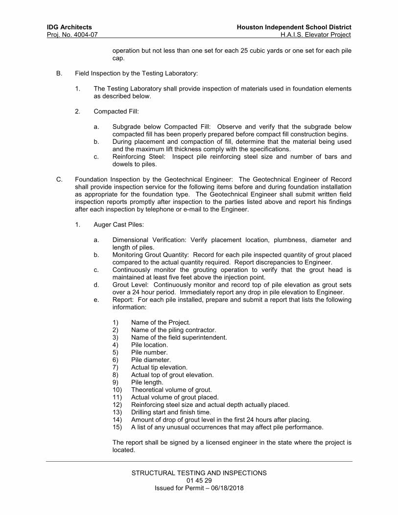
IDG Architects Houston Independent School District
Proj. No. 4004-07 H.A.I.S. Elevator Project
STRUCTURAL TESTING AND INSPECTIONS
01 45 29 Issued for Permit – 06/18/2018
operation but not less than one set for each 25 cubic yards or one set for each pile cap.
B. Field Inspection by the Testing Laboratory:
1. The Testing Laboratory shall provide inspection of materials used in foundation elements as described below.
2. Compacted Fill:
a. Subgrade below Compacted Fill: Observe and verify that the subgrade below compacted fill has been properly prepared before compact fill construction begins.
b. During placement and compaction of fill, determine that the material being used and the maximum lift thickness comply with the specifications.
c. Reinforcing Steel: Inspect pile reinforcing steel size and number of bars and dowels to piles.
C. Foundation Inspection by the Geotechnical Engineer: The Geotechnical Engineer of Record shall provide inspection service for the following items before and during foundation installation as appropriate for the foundation type. The Geotechnical Engineer shall submit written field inspection reports promptly after inspection to the parties listed above and report his findings after each inspection by telephone or e-mail to the Engineer.
1. Auger Cast Piles:
a. Dimensional Verification: Verify placement location, plumbness, diameter and length of piles.
b. Monitoring Grout Quantity: Record for each pile inspected quantity of grout placed compared to the actual quantity required. Report discrepancies to Engineer.
c. Continuously monitor the grouting operation to verify that the grout head is maintained at least five feet above the injection point.
d. Grout Level: Continuously monitor and record top of pile elevation as grout sets over a 24 hour period. Immediately report any drop in pile elevation to Engineer.
e. Report: For each pile installed, prepare and submit a report that lists the following information:
1) Name of the Project. 2) Name of the piling contractor. 3) Name of the field superintendent. 4) Pile location. 5) Pile number. 6) Pile diameter. 7) Actual tip elevation. 8) Actual top of grout elevation. 9) Pile length. 10) Theoretical volume of grout. 11) Actual volume of grout placed. 12) Reinforcing steel size and actual depth actually placed. 13) Drilling start and finish time. 14) Amount of drop of grout level in the first 24 hours after placing. 15) A list of any unusual occurrences that may affect pile performance.
The report shall be signed by a licensed engineer in the state where the project is located.

IDG Architects Houston Independent School District
Proj. No. 4004-07 H.A.I.S. Elevator Project
STRUCTURAL TESTING AND INSPECTIONS
01 45 29 Issued for Permit – 06/18/2018
D. Pile Load Test: The Geotechnical Engineer shall supervise a pile load test(s) as specified on the drawings according to ASTM D 1143. He/she shall submit a written report of his findings to the parties listed above and report, by telephone or e-mail to the Engineer, the results of the pile load tests. Refer to the Pile Specifications for additional requirements of the test.
END OF SECTION 01 45 29

IDG Architects Houston Independent School District Proj. No. 4004-07 H.A.I.S. Elevator Project
STORM SEWAGE SYSTEM
33 41 00

IDG Architects Houston Independent School District
Proj. No. 4004-07 H.A.I.S. Elevator Project
CONCRETE FORMING AND ACCESSORIES
03 10 00 Issued for Permit – 06/18/2018
SECTION 03 10 00 – CONCRETE FORMING AND ACCESSORIES
PART 1 - GENERAL
1.1 RELATED DOCUMENTS
A. Drawings and general provisions of the Contract, including General and Supplementary Conditions and Division 01 Specification sections, apply to work of this section.
1.2 SUMMARY
A. Section includes formwork, shoring, reshoring, backshoring, falsework, bracing, and other temporary supports required to form and support all cast-in-place concrete shown on the drawings.
B. Related Requirements: 1. Specification 014529.01 “Structural Testing and Inspections” for inspection requirements
associated with forming and accessories. 2. Specification 032000 “Concrete Reinforcing” for reinforcement associated with cast-in-
place concrete. 3. Specification 033000.02 “Cast-in-Place Concrete” for cast-in-place concrete and related
products.
1.3 REFERENCES
A. Definitions:
1. Backshores: Shores placed snugly under a stripped concrete structural member after the original formwork and shores have been removed from a small area without allowing the structural member to deflect or support its own weight or superimposed construction loads. It is assumed that backshores carry the same load as that carried by the original shores they replace.
2. Formwork: The total system of support for freshly placed concrete, including the mold or sheathing that contacts the concrete and all supporting members, hardware, and necessary bracing.
3. Professional Engineer: A professional engineer who is licensed to practice engineering in the state where the project is located and who is experienced in providing engineering services of the kind indicated. Engineering services are defined as those performed for projects with concrete formwork that are similar to that indicated for this Project in material.
4. Reshores: Shores placed snugly under a stripped concrete structural member after the original forms and shores have been removed from the member, thus requiring the member to carry its own weight and superimposed construction loads at the time of installation. Reshores are assumed to carry no load at the time of installation. After the installation of reshores, superimposed construction loads are assumed to be distributed among all members connected by reshores.
5. Shores: Vertical or inclined support members designed to carry the weight of formwork, concrete, and construction loads above.
B. Reference Standards:
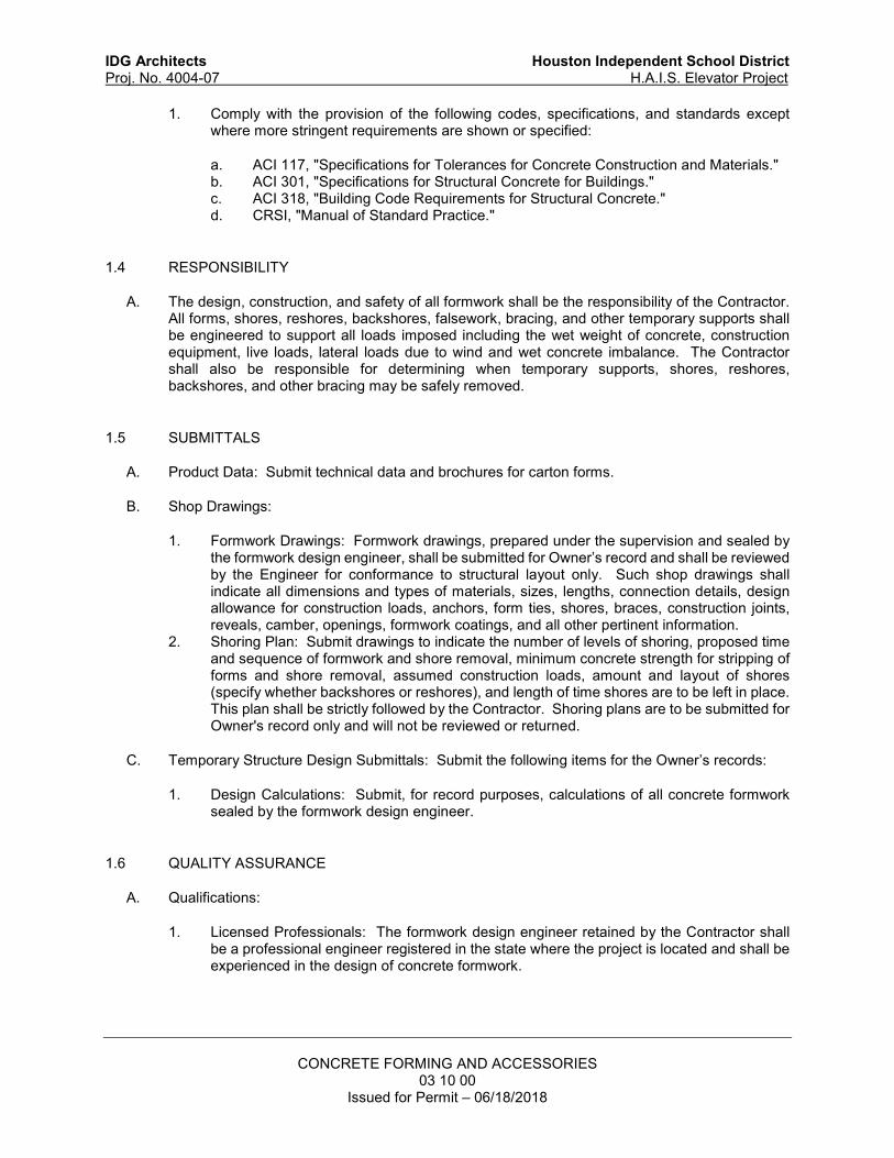
IDG Architects Houston Independent School District
Proj. No. 4004-07 H.A.I.S. Elevator Project
CONCRETE FORMING AND ACCESSORIES
03 10 00 Issued for Permit – 06/18/2018
1. Comply with the provision of the following codes, specifications, and standards except where more stringent requirements are shown or specified:
a. ACI 117, "Specifications for Tolerances for Concrete Construction and Materials." b. ACI 301, "Specifications for Structural Concrete for Buildings." c. ACI 318, "Building Code Requirements for Structural Concrete." d. CRSI, "Manual of Standard Practice."
1.4 RESPONSIBILITY
A. The design, construction, and safety of all formwork shall be the responsibility of the Contractor. All forms, shores, reshores, backshores, falsework, bracing, and other temporary supports shall be engineered to support all loads imposed including the wet weight of concrete, construction equipment, live loads, lateral loads due to wind and wet concrete imbalance. The Contractor shall also be responsible for determining when temporary supports, shores, reshores, backshores, and other bracing may be safely removed.
1.5 SUBMITTALS
A. Product Data: Submit technical data and brochures for carton forms.
B. Shop Drawings:
1. Formwork Drawings: Formwork drawings, prepared under the supervision and sealed by the formwork design engineer, shall be submitted for Owner’s record and shall be reviewed by the Engineer for conformance to structural layout only. Such shop drawings shall indicate all dimensions and types of materials, sizes, lengths, connection details, design allowance for construction loads, anchors, form ties, shores, braces, construction joints, reveals, camber, openings, formwork coatings, and all other pertinent information.
2. Shoring Plan: Submit drawings to indicate the number of levels of shoring, proposed time and sequence of formwork and shore removal, minimum concrete strength for stripping of forms and shore removal, assumed construction loads, amount and layout of shores (specify whether backshores or reshores), and length of time shores are to be left in place. This plan shall be strictly followed by the Contractor. Shoring plans are to be submitted for Owner's record only and will not be reviewed or returned.
C. Temporary Structure Design Submittals: Submit the following items for the Owner’s records:
1. Design Calculations: Submit, for record purposes, calculations of all concrete formwork sealed by the formwork design engineer.
1.6 QUALITY ASSURANCE
A. Qualifications:
1. Licensed Professionals: The formwork design engineer retained by the Contractor shall be a professional engineer registered in the state where the project is located and shall be experienced in the design of concrete formwork.

IDG Architects Houston Independent School District
Proj. No. 4004-07 H.A.I.S. Elevator Project
CONCRETE FORMING AND ACCESSORIES
03 10 00 Issued for Permit – 06/18/2018
PART 2 - PRODUCTS
2.1 FORM-FACING MATERIALS
A. Smooth-Formed Finished Concrete: Unless otherwise specified, formwork for exposed concrete surfaces as defined by the Surface Finish Class noted on the drawings, shall consist of plywood, metal, metal framed plywood, or other acceptable surface. Formwork shall provide a continuous straight and smooth surface conforming to the joint system as specified on the Architect's drawings. Form material shall have sufficient thickness to withstand pressure of concrete without bow or deflection. Plywood shall be exterior grade plywood panels, suitable for concrete forms, complying with U.S. Product Standard PS-1, each piece bearing a legible inspection trademark, and as follows: 1. High Density Overlay (100/30 min. rating) on Hardwood Face, Class 1or better.
B. Non-specific formed concrete: Unless otherwise specified, the default finish for formed surfaces shall be rough-form finish constructed with plywood, lumber, metal, or other acceptable material. Lumber shall be dressed on at least two edges and one side for tight fit. The minimum grade shall be B-C, exterior grade.
2.2 CYLINDRICAL COLUMNS AND SUPPORTS
A. Round section members shall be formed with metal, fiberglass, unless otherwise specified. Paper or fiber tubes shall be constructed of laminated plies using water-resistant adhesive with wax impregnated exterior for weather and moisture protection. Units shall have sufficient wall thickness to resist loads imposed by wet concrete without detrimental deformation.
2.3 FORMWORK COATINGS
A. Formwork coatings shall be of a commercial formulation that will not bond with, stain, nor adversely affect concrete surfaces or impair subsequent treatment of concrete surfaces requiring bond or adhesion, nor impede curing with water or curing compounds. Provide a product that has a maximum VOC (Volatile Organic Compounds) of 50 g/l but not greater than that permitted by the local government agency having jurisdiction in the area where the project is located.
B. Products: Subject to compliance with requirements, provide one of the following:
1. Dayton Superior; Bio-Release EF. 2. Unitex; Farm Fresh. 3. Universal Form Clamp; Bio-Form. 4. US Spec; Aqua Blue.
2.4 NAILS AND FASTENERS
A. Use only galvanized nails and fasteners for securing formwork in structures exposed to weather or unconditioned spaces such as garages, canopies, and porte-cocheres.

IDG Architects Houston Independent School District
Proj. No. 4004-07 H.A.I.S. Elevator Project
CONCRETE FORMING AND ACCESSORIES
03 10 00 Issued for Permit – 06/18/2018
2.5 FORM TIES
A. Factory-fabricated, removable or snap-off metal or glass-fiber-reinforced plastic form ties designed to resist lateral pressure of fresh concrete on forms and to minimize spalling of concrete on removal.
1. Exposed Surfaces: For surfaces designated with Surface Finish Class SF-2.x or SF-3.x, furnish units that will leave no portion of the tie closer than 3/4 inch to the plane of the concrete surface and that will leave holes not larger than one inch in diameter in concrete surface when the ends or end-fasteners have been removed.
2. Dampproofed Surfaces: Furnish ties with integral water-barrier plates to walls indicated to receive dampproofing or waterproofing.
3. Exposed to Weather or Unconditioned Space: Provide removable, glass-fiber-reinforced plastic, stainless steel, or galvanized form ties that will leave no corrodible metal closer than 1 1/2 inches in surfaces that will be exposed to weather or in an unconditioned space in the final structure. The ties shall leave holes no larger than one inch in diameter in concrete surfaces when the ends or end-fasteners are removed.
2.6 CHAMFER STRIPS
A. Provide wood, metal, PVC, or rubber strips, 3/4 by 3/4 inch, minimum.
PART 3 - EXECUTION
3.1 FABRICATION AND CONSTRUCTION
A. Design, erect, support, brace, and maintain formwork, according to ACI 301, to support vertical, lateral, static, and dynamic construction loads that might be applied until the concrete structure can support such loads.
1. The formwork design engineer shall design the concrete formwork, formwork removal, shoring, reshoring, and backshoring.
B. Construct forms to sizes, shapes, lines, and dimensions shown, and to obtain accurate alignment, location, grades, level and plumb work in finished structures. Provide for openings, offsets, sinkages, keyways, recesses, moldings, rustications, reglets, chamfers, blocking, screeds, bulkheads, anchorages, inserts, and other features required in work. Use selected materials to obtain required finishes. Solidly butt joints and provide back-up at joints to prevent leakage of concrete mortar.
C. Fabricate forms for easy removal without hammering or prying against concrete surfaces. Provide crush plates or wrecking plates where stripping may damage cast concrete surfaces. Provide top forms for inclined surfaces steeper than 1.5 horizontal to 1 vertical. Kerf wood inserts for forming keyways, reglets, recesses, and the like, to prevent swelling and for easy removal.
D. Set edge forms, bulkheads, and intermediate screed strips for slabs to achieve required elevations and slopes in finished concrete surfaces. Provide and secure units to support screed strips; use strike-off templates or compacting-type screeds.
E. Provide temporary openings where interior area of formwork is inaccessible for cleanout, for inspection before concrete placement, and for placement of concrete. Securely brace temporary

IDG Architects Houston Independent School District
Proj. No. 4004-07 H.A.I.S. Elevator Project
CONCRETE FORMING AND ACCESSORIES
03 10 00 Issued for Permit – 06/18/2018
openings and patch forms to prevent loss of concrete mortar. Locate temporary openings on forms at inconspicuous locations.
F. Chamfer exposed corners and edges as indicated, using specified chamfer strips fabricated to produce uniform smooth lines and tight edge joints.
G. Provisions for Other Trades: Provide openings in concrete formwork to accommodate work of other trades. Determine size and location of openings, recesses and chases from trades providing such items. Accurately place and securely support items built into forms.
H. Pan Form Fabrication and Construction:
1. Factory fabricate pan form units to specified sizes and shapes as indicated on the drawings. Units shall be designed for easy removal without damaging placed concrete. Units shall be shored properly and adjoining pan units shall be blocked if required to prevent lateral or vertical deflection of formwork during concrete placement.
3.2 CLEANING AND TIGHTENING
A. Thoroughly clean forms and adjacent surfaces to receive concrete. Remove chips, wood, sawdust, dirt, and all other debris just prior to concrete placement. Retighten forms and bracing prior to concrete placement as required to prevent concrete mortar leaks and maintain proper alignment.
3.3 CLEANING AND RE-USE OF FORMS
A. Forms reused in the work shall be repaired and cleaned. Split, frayed, delaminated, or otherwise damaged facing material will not be acceptable for exposed surfaces. Forms intended for successive concrete placement shall have surfaces cleaned, fins and laitance removed, and joints tightened to avoid surface offsets. New form coating compound shall be applied to reused forms. Thin form-coating compounds only with thinning agent of type, and in amount, and under conditions of form-coating compound manufacturer's directions. Do not allow excess form-coating material to accumulate in forms or to come into contact with in-place concrete surfaces against which fresh concrete will be placed. Apply in compliance with manufacturer's instructions. Coat steel forms with a non-staining, rust-preventative form oil or otherwise protect against rusting. Rust-stained steel formwork is not acceptable.
3.4 TOLERANCES
A. Unless specified otherwise, all tolerances for concrete formwork shall conform to ACI Standard 117, "Standard Tolerances for Concrete Construction and Materials". Before concrete placement the Contractor shall check lines and levels of erected formwork and make any corrections and adjustments as required to ensure proper size and location of concrete members and stability of forming systems. During concrete placement the Contractor shall check formwork and supports to ensure that forms have not displaced and that completed work will be within specified tolerances.
B. Construct forms so as to limit the offset between adjacent pieces of formwork facing material in accordance with the surface tolerance class as defined in ACI 117 corresponding to the Surface Finish Class noted on the drawings. The offset limits shall apply to both abrupt and gradual variations in the surface.
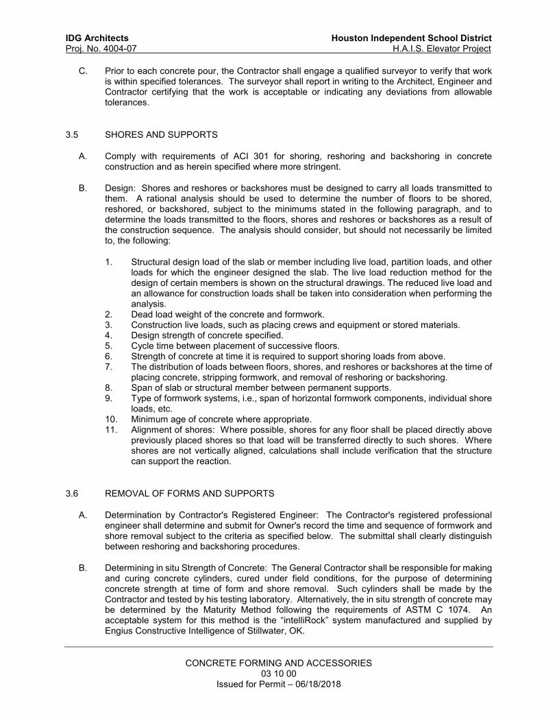
IDG Architects Houston Independent School District
Proj. No. 4004-07 H.A.I.S. Elevator Project
CONCRETE FORMING AND ACCESSORIES
03 10 00 Issued for Permit – 06/18/2018
C. Prior to each concrete pour, the Contractor shall engage a qualified surveyor to verify that work is within specified tolerances. The surveyor shall report in writing to the Architect, Engineer and Contractor certifying that the work is acceptable or indicating any deviations from allowable tolerances.
3.5 SHORES AND SUPPORTS
A. Comply with requirements of ACI 301 for shoring, reshoring and backshoring in concrete construction and as herein specified where more stringent.
B. Design: Shores and reshores or backshores must be designed to carry all loads transmitted to them. A rational analysis should be used to determine the number of floors to be shored, reshored, or backshored, subject to the minimums stated in the following paragraph, and to determine the loads transmitted to the floors, shores and reshores or backshores as a result of the construction sequence. The analysis should consider, but should not necessarily be limited to, the following:
1. Structural design load of the slab or member including live load, partition loads, and other loads for which the engineer designed the slab. The live load reduction method for the design of certain members is shown on the structural drawings. The reduced live load and an allowance for construction loads shall be taken into consideration when performing the analysis.
2. Dead load weight of the concrete and formwork. 3. Construction live loads, such as placing crews and equipment or stored materials. 4. Design strength of concrete specified. 5. Cycle time between placement of successive floors. 6. Strength of concrete at time it is required to support shoring loads from above. 7. The distribution of loads between floors, shores, and reshores or backshores at the time of
placing concrete, stripping formwork, and removal of reshoring or backshoring. 8. Span of slab or structural member between permanent supports. 9. Type of formwork systems, i.e., span of horizontal formwork components, individual shore
loads, etc. 10. Minimum age of concrete where appropriate. 11. Alignment of shores: Where possible, shores for any floor shall be placed directly above
previously placed shores so that load will be transferred directly to such shores. Where shores are not vertically aligned, calculations shall include verification that the structure can support the reaction.
3.6 REMOVAL OF FORMS AND SUPPORTS
A. Determination by Contractor's Registered Engineer: The Contractor's registered professional engineer shall determine and submit for Owner's record the time and sequence of formwork and shore removal subject to the criteria as specified below. The submittal shall clearly distinguish between reshoring and backshoring procedures.
B. Determining in situ Strength of Concrete: The General Contractor shall be responsible for making and curing concrete cylinders, cured under field conditions, for the purpose of determining concrete strength at time of form and shore removal. Such cylinders shall be made by the Contractor and tested by his testing laboratory. Alternatively, the in situ strength of concrete may be determined by the Maturity Method following the requirements of ASTM C 1074. An acceptable system for this method is the “intelliRock” system manufactured and supplied by Engius Constructive Intelligence of Stillwater, OK.
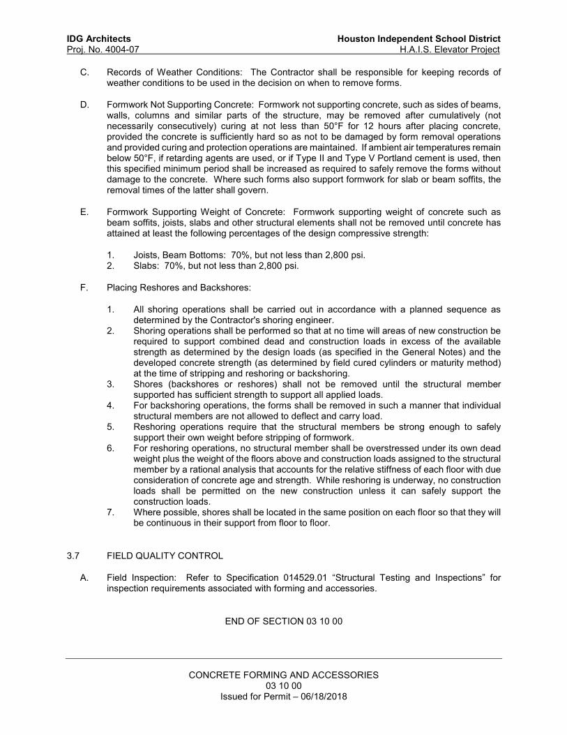
IDG Architects Houston Independent School District
Proj. No. 4004-07 H.A.I.S. Elevator Project
CONCRETE FORMING AND ACCESSORIES
03 10 00 Issued for Permit – 06/18/2018
C. Records of Weather Conditions: The Contractor shall be responsible for keeping records of weather conditions to be used in the decision on when to remove forms.
D. Formwork Not Supporting Concrete: Formwork not supporting concrete, such as sides of beams, walls, columns and similar parts of the structure, may be removed after cumulatively (not necessarily consecutively) curing at not less than 50°F for 12 hours after placing concrete, provided the concrete is sufficiently hard so as not to be damaged by form removal operations and provided curing and protection operations are maintained. If ambient air temperatures remain below 50°F, if retarding agents are used, or if Type II and Type V Portland cement is used, then this specified minimum period shall be increased as required to safely remove the forms without damage to the concrete. Where such forms also support formwork for slab or beam soffits, the removal times of the latter shall govern.
E. Formwork Supporting Weight of Concrete: Formwork supporting weight of concrete such as beam soffits, joists, slabs and other structural elements shall not be removed until concrete has attained at least the following percentages of the design compressive strength:
1. Joists, Beam Bottoms: 70%, but not less than 2,800 psi. 2. Slabs: 70%, but not less than 2,800 psi.
F. Placing Reshores and Backshores:
1. All shoring operations shall be carried out in accordance with a planned sequence as determined by the Contractor's shoring engineer.
2. Shoring operations shall be performed so that at no time will areas of new construction be required to support combined dead and construction loads in excess of the available strength as determined by the design loads (as specified in the General Notes) and the developed concrete strength (as determined by field cured cylinders or maturity method) at the time of stripping and reshoring or backshoring.
3. Shores (backshores or reshores) shall not be removed until the structural member supported has sufficient strength to support all applied loads.
4. For backshoring operations, the forms shall be removed in such a manner that individual structural members are not allowed to deflect and carry load.
5. Reshoring operations require that the structural members be strong enough to safely support their own weight before stripping of formwork.
6. For reshoring operations, no structural member shall be overstressed under its own dead weight plus the weight of the floors above and construction loads assigned to the structural member by a rational analysis that accounts for the relative stiffness of each floor with due consideration of concrete age and strength. While reshoring is underway, no construction loads shall be permitted on the new construction unless it can safely support the construction loads.
7. Where possible, shores shall be located in the same position on each floor so that they will be continuous in their support from floor to floor.
3.7 FIELD QUALITY CONTROL
A. Field Inspection: Refer to Specification 014529.01 “Structural Testing and Inspections” for inspection requirements associated with forming and accessories.
END OF SECTION 03 10 00

IDG Architects Houston Independent School District
Proj. No. 4004-07 H.A.I.S. Elevator Project
CONCRETE REINFORCING
03 20 00 Issued for Permit – 06/18/2018
SECTION 03 20 00 – CONCRETE REINFORCING
PART 1 - GENERAL
1.1 RELATED DOCUMENTS
A. Drawings and general provisions of the Contract, including General and Supplementary Conditions and Division 01 Specification sections, apply to work of this section.
1.2 SUMMARY
A. Section includes labor, materials, hardware, equipment, transportation and services required to fabricate and place all reinforcement for cast-in-place concrete including bars, welded wire reinforcement, ties and supports shown on the drawings and as specified.
B. Related Requirements:
1. Specification 01 45 29.01 “Structural Testing and Inspections” for testing and inspection requirements associated with concrete reinforcing.
2. Specification 03 10 00 “Concrete Forming and Accessories” for forming associated with cast-in-place concrete.
3. Specification 03 30 00.02 “Cast-in-Place Concrete” for cast-in-place concrete and related products.
1.3 PRICE AND PAYMENT PROCEDURES
A. Alternates:
1. Products Requiring International Code Council (ICC) Evaluation Service Reports:
a. For those products listed in Part 2 as requiring Evaluation Service Reports (ESRs), alternate products that do not have ESRs will be considered by the Engineer only if valid research reports or test data from an independent and approved agency is provided and use of the product receives prior approval from the Building Official.
1.4 REFERENCES
A. Reference Standards:
1. Comply with all provisions of the following codes, specifications, and standards except where more stringent requirements are shown or specified:
a. ACI 117, “Specifications for Tolerances for Concrete Construction and Materials." b. ACI 301, "Specifications for Structural Concrete for Buildings." c. ANSI/AWS D1.4, “Structural Welding Code – Reinforcing Steel.” d. CRSI, "Manual of Standard Practice."

IDG Architects Houston Independent School District
Proj. No. 4004-07 H.A.I.S. Elevator Project
CONCRETE REINFORCING
03 20 00 Issued for Permit – 06/18/2018
1.5 ADMINISTRATIVE REQUIREMENTS
A. Coordination:
1. Quality Control: The Contractor is responsible for quality control, including workmanship and materials furnished by subcontractors and suppliers.
2. Document Conflict and Precedence: In case of conflict among documents, including architectural and structural drawings and specifications, notify the Architect/Engineer prior to submitting proposal. In case of conflict between and/or among the structural drawings and specifications, the strictest interpretation shall govern, unless specified otherwise in writing by the Architect/Engineer.
1.6 SUBMITTALS
A. Product Data: Submit manufacturer’s product data with application and installation instructions for proprietary materials and items including mechanical splices, hooked anchorage systems, dowel bar replacement systems, and dowel bar sleeves.
B. Shop Drawings:
1. Submit shop drawings for all reinforcing steel and related accessories for the Engineer's approval. Shop drawings shall show arrangement and layout, bending and assembly diagrams, bar schedules, stirrup spacing, splicing and laps of bars and shall be prepared in accordance with CRSI Standards.
C. Certificates:
1. Submit, for record, mill certificates and/or test results signed by Producer, for all reinforcement.
D. Test and Evaluation Reports:
1. Submit International Code Council (ICC) Evaluation Service Reports indicating approval from ICC Evaluation Service, Inc. for mechanical splices, hooked anchorage systems, and dowel bar replacement systems.
2. Submit test results for deformed bar material not identifiable as outlined in Part 2 below.
E. Qualification Statements: Submit welding certificates.
1.7 QUALITY ASSURANCE
A. Welder Qualifications: Qualify procedures and personnel according to ANSI/AWS D1.4.
PART 2 - PRODUCTS
2.1 MATERIALS
A. Steel Reinforcement:
IDG Architects Houston Independent School District
Proj. No. 4004-07 H.A.I.S. Elevator Project
CONCRETE REINFORCING
03 20 00 Issued for Permit – 06/18/2018
1. Reinforcing materials shall be delivered from the mill in bundles that are identified as to heat number and manufacturer and accompanied with mill and analysis test reports and an affidavit from the supplier stating that the material conforms to the requirements of the governing ASTM specification listed herein.
2. Deformed bar material that is not identifiable according to the criteria listed above shall be tested for tensile strength and bend tests according to ASTM A 615 on a sample of two bars for each ten tons or fraction thereof of unidentified material for each bar size. The bars shall be a minimum of 24 inches long. Bend tests are not required for #14 and #18 bars. Submit the results of such tests for record.
3. Reinforcing Bars: Reinforcing bars shall conform to ASTM A 615, Grade 60 or Grade 75 as noted on the drawings.
4. Reinforcing Steel: Reinforcing steel used as transverse reinforcing or as spiral reinforcing as noted on the drawings shall conform to ASTM A 1035.
5. Weldable Reinforcing Bars: All reinforcing bars noted on the drawings as being required to be welded shall conform to ASTM A 706.
6. Deformed Bar Anchors: AWS Type D studs manufactured in conformance with ASTM A 496 with a minimum tensile strength of 80,000 PSI. ASTM A 615 reinforcing bars may not be substituted for deformed bar anchors. Reinforcement shall be approved by the ICC-Evaluation Service, Inc and shall have the Evaluation Service Report submitted for Engineer review. The following are acceptable products, provided that their Evaluation Service Reports are still valid at the time of intended use on the project: a. Nelson Stud Welding, Inc.; Nelson D2L Deformed Bar Anchor Studs (ESR-2907). b. Tru-Weld Division, TFP Corporation; Deformed Bar Anchors (ESR-2823).
7. Galvanized Reinforcing Steel: Provide galvanized reinforcing bars at the locations indicated on the drawings. Galvanized reinforcing bars shall conform to ASTM A 767 Class II (2.0 ounces zinc per square foot), hot dipped galvanized after fabrication and bending. Bars that are to be galvanized shall conform to the type of steel required for the given situation as noted on the drawings.
8. Epoxy-Coated Reinforcing Steel: Provide epoxy coated reinforcing bars at the locations indicated on the drawings. Epoxy coated reinforcing bars shall conform to ASTM A 775. Bars that are to be epoxy coated shall conform to the type of steel required for the given situation as noted on the drawings.
9. Plain Steel Welded Wire Reinforcement: ASTM A 185 with a yield strength of 65,000 PSI. Provide in flat sheets only.
10. Deformed-Steel Welded Wire Reinforcement: ASTM A 497 with a yield strength of 70,000 PSI. Provide in flat sheets only.
11. Galvanized Plain-Steel Welded Wire Reinforcement: ASTM A 185, fabricated from galvanized steel wire into flat sheets.
12. Epoxy Coated Plain-Steel Welded Wire Reinforcement: ASTM A 884, Class A, plain steel.
13. Epoxy Coated Deformed-Steel Welded Wire Reinforcement: ASTM A 884, Class A, deformed steel.
14. Wire: Smooth wire for spiral reinforcement shall conform to ASTM A 82 with a minimum yield strength of 70,000 PSI.
15. Epoxy-Coated Plain-Steel Wire: ASTM A 884, Class A, plain-steel wire.
2.2 SPLICES
A. Mechanical Tension Splices:
1. Mechanical splices shall conform to Type 1 splices.

IDG Architects Houston Independent School District
Proj. No. 4004-07 H.A.I.S. Elevator Project
CONCRETE REINFORCING
03 20 00 Issued for Permit – 06/18/2018
a. Type 1 splice shall develop, in tension and compression, 1.25 times the specified yield strength of the splice bar.
b. Type 2 splice shall meet the requirements of Type 1 splice and, in addition, develop the full tensile strength of the splice bar.
2. Splices shall be approved by the ICC-Evaluation Service, Inc and shall have the Evaluation Service Report submitted for Engineer review.
3. The bar ends that are to attach to the splice shall be prepared and installed in accordance with the manufacturer’s requirements.
4. The following are acceptable mechanical tension splices (splices qualified for use with grade 75 bars are parenthetically noted), provided that their Evaluation Service Reports are still valid at the time of intended use on the project:
a. BarSplice Products, Inc.; BPI-Grip XL System (ESR-2299). (Type 1 or Type 2) b. BarSplice Products, Inc.; Taper Threaded Grip-Twist System (ESR-2299). (Type 1
or Type 2) c. BarSplice Products, Inc.; Position Taper Threaded Grip-Twist System (ESR-2299).
(Type 1 or Type 2) d. Headed Reinforcement Corporation; HRC 500/510 Xtender Mechanical Coupler
System (ESR-2764). (Type 1 or Type 2) e. Dayton Superior Corporation; DBDI Reinforcing Bar Mechanical Splice System
(ESR-2649). (Type 1 or Type 2).
B. Dowel Bar Replacement: All grade 60 reinforcing steel dowel bars shown on the drawings crossing concrete construction joint surfaces with inserts cast flush against the form and having reinforcing bars connected to the insert in a subsequent concrete pour shall conform to the following:
1. Splice connection to the insert shall develop the 1.25 times the specified yield strength and the full tensile strength of the spliced bar.
2. Splices shall be approved by the ICC Evaluation Service, Inc. as expressed in an ICC Evaluation Service Report which shall be submitted for review.
3. The following are acceptable products (for use only with grade 60 bars), provided that their Evaluation Service Reports are still valid at the time of intended use on the project:
a. Dextra Manufacturing Co., Ltd.; Bartec Mechanical Splice System for Steel Reinforcing Bars in Concrete (ESR-1705).
b. Erico Products, Inc.; Lenton Form Saver (ER-3967).
C. Hooked Anchorage Replacement: Reinforcing bar terminations shall be manufactured out of ASTM A 576, ASTM A 615, or A 706 material and shall develop the full tensile strength of the bar when installed at the manufacturer’s recommended depth.
1. The anchorage shall be approved by the ICC Evaluation Service Inc. as expressed in an ICC Evaluation Service Report which shall be submitted for review.
2. The following are acceptable products (for use only with grade 60 bars), provided that their Evaluation Service Reports are still valid at the time of intended use on the project:
a. Dextra Manufacturing Co., Ltd; Bartec Mechanical Anchorages for Steel Reinforcing Bars in Concrete (ESR-2166).
b. Headed Reinforcement Corporation; HRC 555 Headed Reinforcing Bars (ESR-2935).
IDG Architects Houston Independent School District
Proj. No. 4004-07 H.A.I.S. Elevator Project
CONCRETE REINFORCING
03 20 00 Issued for Permit – 06/18/2018
2.3 REINFORCEMENT ACCESSORIES
A. Joint Dowel Bars: Smooth bars used to dowel across slab-on-grade construction joints shall conform to ASTM A 615, Grade 40 or ASTM A 36, plain-steel bars. Cut bars true to length with ends square and free of burrs.
B. Epoxy-Coated Joint Dowel Bars: Smooth epoxy-coated bars used to dowel across slab-on-grade construction joints shall conform to ASTM A 775 with ASTM A 615, Grade 40 or ASTM A 36 plain-steel bars. Cut bars true to length with ends square and free of burrs.
C. Dowel Bar Sleeves: Plastic or gage metal (26 gauge minimum) sleeves with an inside diameter of 1/16 inch greater than the dowel bar that it encases, that have the strength, durability, and design to provide free movement of the dowel relative to the concrete slab and that are specifically manufactured for this purpose.
D. Alternate Slab-on-Grade Joint Load Transfer Systems: A system that consists of flat, ASTM A 36 plate that is saw cut into a square or rectangular shape and is embedded into or encased by a plastic sleeve that allows movement in both lateral directions but not in the vertical direction. Acceptable systems are manufactured by PNA Construction Technologies with products known by the names “Diamond Dowel System” and “PD3 Basket” and Greenstreak Group Inc. with products known as “Speed Plate’ and “Double-Tapered Basket”.
E. Tie Wire: Tie wire shall be annealed steel tie wire, minimum 16 gauge.
a. Tie wire in architecturally exposed concrete shall be plastic coated or stainless steel.
b. Tie wire for epoxy-coated reinforcement shall be epoxy-coated. c. Tie wire for galvanized reinforcement shall be galvanized.
F. Holding Wire: Holding wire shall conform to ASTM A 82 or ASTM A 496.
G. Coating Repair Materials: Repair damaged areas of epoxy-coated or galvanized reinforcement using the following products.
1. Epoxy Repair Coating: Liquid, two-part, epoxy repair coating compatible with epoxy coating on reinforcement and complying with ASTM A 775.
2. Zinc Repair Material: ASTM A 780, zinc-based solder, paint containing zinc dust, or sprayed zinc shall be used to repair damaged areas of galvanized reinforcement.
H. Supports for Reinforcement: Provide supports for reinforcement including bolsters, chairs, spacers, and other devices for spacing, supporting, and fastening reinforcing bars and welded wire reinforcement in place. Use wire bar type supports complying with CRSI recommendations.
1. Slabs-on-Grade: Use precast concrete bar supports (dobies) or supports with sand plates or horizontal runners designed for use on ground.
2. Spread Footing Bottom Reinforcement: Use precast concrete bar supports (dobies) or chairs designed for soil-supported slabs.
3. Mat Foundation: Use precast concrete bar supports (dobies), chairs designed for soil-supported slabs, or cast-in-place concrete curbs.
4. Exposed to View Concrete: Provide supports with legs which are plastic protected (CRSI, Class 1) or stainless steel protected (CRSI, Class 2).
5. Support of Epoxy-Coated Reinforcement: Provide epoxy-coated or other dielectric-polymer-coated wire bar supports to support epoxy-coated reinforcement.
IDG Architects Houston Independent School District
Proj. No. 4004-07 H.A.I.S. Elevator Project
CONCRETE REINFORCING
03 20 00 Issued for Permit – 06/18/2018
6. Support of Galvanized Reinforcement: Provide galvanized wire bar supports to support galvanized reinforcement.
PART 3 - EXECUTION
3.1 FABRICATION AND DELIVERY
A. Bending and Forming: Fabricate bars of indicated sizes and accurately form to shapes and lengths indicated and required, by methods not injurious to materials. Do not heat reinforcement for bending. Bars shall be free from injurious defects, have a workman-like finish with no excessive rust and/or pitting, and have no unusual kinks or bends.
B. Marking and Shipping: Bundle reinforcement and tag in accordance with Section 7.4.5 of the CRSI “Manual of Standard Practice.” Transport and store at site so as not to damage material. Keep sufficient supply of tested, approved, and proper reinforcement at the site to avoid delays. Maintain reinforcing bars free of mud, dirt, grease, or other coating.
C. Repair of Epoxy-Coated Reinforcing: Repair cut and damaged epoxy coatings on fabricated reinforcing before delivery with epoxy repair coating according to ASTM D 3963
3.2 PLACING REINFORCEMENT
A. Comply with CRSI recommended practice for "Placing Reinforcing Bars", for details and methods of reinforcement placement and supports and as herein specified.
B. Before placing reinforcement and again before concrete is placed, clean reinforcement of loose rust and mill scale, earth, ice, and other materials which reduce or destroy bond with concrete.
C. Accurately position, support, and secure reinforcement against displacement by formwork, construction, or concrete placement operations. Locate and support reinforcing by chairs, runners, bolsters, spacers, and hangers as required. Exercise particular care to maintain proper distance and clearance between parallel bars and between bars and forms. Provide spreaders and spacers to hold steel in position. Support steel at proper height upon approved chairs.
D. Place reinforcement to obtain at least minimum coverages for concrete protection. Arrange, space, and securely tie bars and bar supports to hold reinforcement in position during concrete placement operations. Set tie wires so ends are directed into concrete, not toward exposed concrete surfaces.
E. Install welded wire reinforcement in as long lengths as practicable. Provide lap splice for wires of adjoining pieces per ACI 318 Chapter 12.18.1 or 12.19.1 and lace splices with wire. Offset end laps in adjacent widths to prevent continuous laps in either direction.
F. Coordinate with other trades and expedite materials and labor to avoid omissions and delay.
G. Install waterproof membrane or vapor retarder as specified prior to placing steel for concrete slabs-on-grade.
H. Extend reinforcement continuous through construction joints unless otherwise shown on the drawings.

IDG Architects Houston Independent School District
Proj. No. 4004-07 H.A.I.S. Elevator Project
CONCRETE REINFORCING
03 20 00 Issued for Permit – 06/18/2018
I. Slab-on-Grade Joint Dowel Bars: Support slab-on-grade joint dowel bars independently of support for slab reinforcement on soil supported slab bolsters or specially manufactured cradles such that dowel bar remains parallel to slab surface and at right angles to joint during concreting operations. Lightly coat the exposed end of the dowel with a paraffin-base lubricant, asphalt emulsion, form oil, or grease or use a dowel bar sleeve.
J. Alternate Slab-on-Grade Joint Load Transfer Systems: Install the alternate load transfer system in accordance with the manufacturer’s instructions such that the largest plane of the flat plate is parallel to the plane of the subgrade on which the slab is bearing.
K. Provide and place additional reinforcing steel at all sleeves and openings in beams, slabs, and walls as specified on the drawings. Where sleeves or openings not shown on the drawings interrupt the reinforcement, consult with Engineer for instructions for placing and splicing of bars. Provide required additional reinforcing steel at no additional cost to the Owner.
L. Epoxy-Coated Reinforcement: Use epoxy-coated steel tie wires to fasten epoxy-coated reinforcement. Repair cut and damaged epoxy coatings with epoxy repair coating according to ASTM D 3963.
M. Galvanized Reinforcement: Use galvanized steel tie wires to fasten galvanized reinforcement. Repair cut and damaged zinc coatings with zinc repair material.
N. Do not bend reinforcement that is embedded partially in concrete except in locations noted on the drawings or approved by the Engineer.
3.3 SPLICING REINFORCING STEEL
A. Provide splices as indicated on the drawings. Splice reinforcing bars only at locations shown on the structural drawings and approved shop drawings. Unauthorized or unscheduled splices not approved by the Engineer in writing will not be accepted.
B. All lap splices in reinforcing steel shall be contact lap splices unless detailed otherwise on the drawings.
C. Maintain proper cover and spacing between reinforcing bars at splices.
D. Lap unscheduled reinforcing bars not otherwise specified with a Class B lap splice. Lap welded wire reinforcement per ACI 318 Chapter 12.18.1 or 12.19.1.
E. Manufacturer of mechanical tension splice shall be present for first day's installation.
3.4 WELDING REINFORCING STEEL
A. Welding reinforcing steel is permitted only where specifically shown on the drawings. All welding shall conform to AWS D1.4. Only weldable reinforcing steel conforming to ASTM A 706 or deformed bar anchors conforming to ASTM A 496 shall be permitted. ASTM A 615 bars may not be welded for structural use.
B. Tack welding of reinforcement shall not be permitted.

IDG Architects Houston Independent School District
Proj. No. 4004-07 H.A.I.S. Elevator Project
CONCRETE REINFORCING
03 20 00 Issued for Permit – 06/18/2018
3.5 SHRINKAGE AND TEMPERATURE REINFORCEMENT
A. Provide shrinkage and temperature reinforcement as indicated on the drawings at right angles to main top and bottom bars for all structural slabs unless detailed otherwise on the drawings.
3.6 REINFORCEMENT IN GRADE BEAMS
A. Provide reinforcing in grade beams as shown on the drawings.
B. Bar Support for Grade Beam Cages: Grade beam bottom steel shall be supported at 5'-0" maximum centers using beam bolsters that provide bottom cover to the reinforcing steel as noted on the drawings. Beam bolsters used shall be designed and manufactured for support on soil.
3.7 REINFORCEMENT IN TOPPING SLABS
A. Provide minimum #3@18” in all topping slabs unless specified otherwise on the drawings.
3.8 REINFORCEMENT IN HOUSEKEEPING PADS
A. Provide minimum #3@18” in all housekeeping pads supporting mechanical equipment unless detailed otherwise on the drawings.
3.9 REINFORCEMENT IN SIDEWALKS
A. Provide welded smooth wire reinforcement minimum 6 x 6 W1.4 x W1.4 in all sidewalks unless detailed otherwise on the Architectural, Civil, or Structural Drawings.
3.10 MECHANICAL AND PLUMBING REQUIREMENTS
A. Refer to Mechanical and Plumbing Drawings for concrete requiring reinforcing steel. Such reinforcement shall be furnished as part of the work of this section.
3.11 FIELD QUALITY CONTROL
A. Field Testing and Inspection: Refer to Specification 01 45 29.01 “Structural Testing and Inspections” for testing and inspection requirements associated with concrete reinforcing.
END OF SECTION 03 20 00
IDG Architects Houston Independent School District
Proj. No. 4004-07 H.A.I.S. Elevator Project
CAST-IN-PLACE CONCRETE
03 30 00 Issued for Permit – 06/18/2018
SECTION 03 30 00 – CAST-IN-PLACE CONCRETE
PART 1 - GENERAL
1.1 RELATED DOCUMENTS
A. Drawings and general provisions of the Contract, including General and Supplementary Conditions and Division 01 Specification sections, apply to work of this section.
1.2 SUMMARY
A. Section includes all labor, materials, services, equipment, and hardware required in conjunction with or related to the forming, delivery, and pouring of all cast-in-place concrete work. Concrete paving and walks are specified in Division 32. Architectural Concrete, Precast Concrete, Post-Tensioned Concrete and special requirements for Tilt-Up Concrete are specified in other Division 03 sections.
B. Related Requirements: 1. Specification 014529.01 “Structural Testing and Inspections” for inspection requirements
associated with cast-in-place concrete. 2. Specification 031000 “Concrete Forming and Accessories” for forming associated with
cast-in-place concrete. 3. Specification 032000 “Concrete Reinforcing” for reinforcement for cast-in-place concrete.
1.3 REFERENCES
A. Reference Standards:
1. Codes and Standards: Comply with provisions of following codes, specifications and standards, except where more stringent requirements are shown or specified: a. AISC 360, "Specification for Structural Steel Buildings." b. ACI 117, “Specifications for Tolerances for Concrete Construction and Materials.” c. ACI 301, “Specifications for Structural Concrete for Buildings.” d. ACI 305.1, “Specification for Hot Weather Concreting.” e. ACI 318, “Building Code Requirements for Structural Concrete.” f. CRSI, “Manual of Standard Practice.”
1.4 ADMINISTRATIVE REQUIREMENTS
A. Coordination:
1. Quality Control: The Contractor is responsible for quality control, including workmanship and materials furnished by subcontractors and suppliers.
2. Document Conflict and Precedence: In case of conflict among documents, including architectural and structural drawings and specifications, notify the Architect/Engineer prior to submitting proposal. In case of conflict between and/or among the structural
IDG Architects Houston Independent School District
Proj. No. 4004-07 H.A.I.S. Elevator Project
CAST-IN-PLACE CONCRETE
03 30 00 Issued for Permit – 06/18/2018
drawings and specifications, the strictest interpretation shall govern, unless specified otherwise in writing by the Architect/Engineer.
3. Materials and installed work may require testing and retesting, as directed by the governing building code or the Architect/Engineer, at any time during progress of work.
a. The Contractor shall provide adequate notification to the Owner’s Testing Agency of construction operations including the project schedule to allow the Testing Agency to schedule inspections. Failure to notify sufficiently may result in additional costs incurred by the Testing Laboratory that may be back-charged to the Contractor by the Owner.
b. The Contractor shall cooperate with laboratory personnel, provide access to the work, and provide access to manufacturer's operations.
c. The Contractor shall make adequate arrangement with the Owner’s Testing Agency for inspection of material stockpiles and facilities.
d. The Contractor shall provide to the laboratory certificates and representative samples of materials proposed for use in the work in quantities sufficient for accurate testing as specified.
e. The Contractor shall furnish casual labor, equipment, and facilities as required for sampling and testing by the laboratory and otherwise facilitate the required inspections and tests.
f. Inspection or testing by the Owner does not relieve the Contractor of his responsibility to perform the Work in accordance with the Contract Documents. Tests not specifically indicated to be done at the Owner’s expense, including retesting of rejected materials and installed work, shall be done at the Contractor’s expense. See Structural Testing and Inspections section of the Specifications.
4. Responsibility for Selection and Use of Concrete Admixtures and Chemical Treatments: The Contractor shall be responsible for selecting admixtures and surface treatments that are compatible with the intended use of the concrete including all final surface treatments called for within this or other specifications or on the structural or architectural drawings. The Contractor is responsible for following the manufacturer’s instructions for the use of their product including abiding by any limitations placed by the manufacturer on the use of any of its products.
B. Preinstallation Meetings: 1. Pre-Concrete Conference:
a. At least seven days prior to beginning concrete work, the Contractor shall conduct a meeting to review the proposed design mixtures and to discuss required methods and procedures to produce concrete construction of the required quality. Also, review requirements for submittals, status of coordinating work and availability of materials. Establish work progress schedule and procedures for materials inspection, testing, and certifications. The contractor shall send a pre-concrete conference agenda to all attendees seven days prior to the scheduled date of the conference.
b. The Contractor shall require responsible representatives of every party who is concerned with the concrete work to attend the conference, including but not limited to the following:
1) Contractor’s Superintendent. 2) Laboratory responsible for the concrete design mix. 3) Laboratory responsible for field quality control. 4) Concrete Subcontractor. 5) Ready-Mix Concrete Producer.
IDG Architects Houston Independent School District
Proj. No. 4004-07 H.A.I.S. Elevator Project
CAST-IN-PLACE CONCRETE
03 30 00 Issued for Permit – 06/18/2018
6) Admixture Supplier. 7) Concrete Pumping Contractor. 8) Fiber Reinforcement Representative. 9) Owner’s and Architect’s/Engineer’s Representative.
c. Minutes of the meeting shall be recorded, typed and printed by the Contractor and distributed by him to all parties concerned within five days of the meeting. One copy of the minutes shall be transmitted to the following for information purposes:
1) Owner’s Representative. 2) Architect. 3) Engineer-of-Record.
d. The Engineer shall be present at the conference. The Contractor shall notify the Engineer at least seven days prior to the scheduled date of the conference.
C. Sequencing:
1. Provide for installation of inserts, hangers, metal ties, anchors, bolts, angle guards, dowels, thimbles, slots, nailing strips, blocking, grounds, and other fastening devices required for attachment of work. Properly locate in cooperation with other trades and secure in position before concrete is poured. Do not install sleeves in any concrete slabs, beams, or columns except where shown on the drawings or upon written approval of the Architect/Engineer.
1.5 SUBMITTALS
A. Product Data: Submit manufacturer’s product data with application and installation instructions for proprietary materials and items, including admixtures, patching compounds, epoxies, grouts, waterstops, joint systems, curing compounds, dry-shake finish materials, hardeners, sealers, joint fillers, and others as requested by Architect/Engineer.
B. Shop Drawings:
1. Construction Joints: Submit drawings of proposed construction joint locations in concrete for slab-on-grade, mat foundations, structural floors, roofs and walls. Submit any additional or changed reinforcing that is required at construction joints that differs from that shown on the drawings.
2. Openings, Sleeves, and Cores: Submit drawings of all openings to be formed, sleeved, cored, or sawcut in cast-in-place elements. Drawings shall indicate size and location of openings, sleeves, or cores.
3. Penetrations in Beams and Joists: Submit drawings locating all horizontal and vertical penetrations in beams and joists. Drawings shall indicate location, size, orientation, and type of penetrations.
4. Embedded Items: Submit drawings showing all items to be embedded in concrete elements, including plates, angles, bolts, and any non-structural items, such as conduit. Drawings shall indicate location, size, orientation, and type of embedded item.
C. Samples: Submit samples of materials specified if requested by Architect/Engineer, including names, sources, and descriptions.
IDG Architects Houston Independent School District
Proj. No. 4004-07 H.A.I.S. Elevator Project
CAST-IN-PLACE CONCRETE
03 30 00 Issued for Permit – 06/18/2018
D. Certificates:
1. Material and Mill Certificates:
a. Provide material and mill certificates as specified herein and in the Testing Laboratory section of the Specifications. The Manufacturer and Contractor shall sign the material and mill certificates certifying that each material item complies with specified requirements.
b. Provide certification from admixture manufacturers that chloride ion content complies with specified requirements.
E. Design Mixtures: Submit for each concrete mixture as specified herein.
F. Field Quality Control Submittals:
1. Surveys: Submit report certifying that all anchor rods and reinforcing dowels into columns above are in their proper location prior to placing of concrete.
G. Qualification Statements: Submit certifications for adhesive anchor installers.
H. Minutes of Preinstallation Meetings: Submit for review.
1.6 QUALITY ASSURANCE
A. Qualifications:
1. Concrete Supplier: The concrete supplier shall have a minimum of five years of experience in manufacturing ready-mixed concrete products complying with ASTM C 94 requirements for production facilities and equipment. The supplier must be certified according to the National Ready Mixed Concrete Association’s Certification of Ready Mixed Concrete Production Facilities.
2. Concrete Contractor: The concrete contractor shall have a minimum of five years of experience with installation of concrete similar in material, design, and extent to that indicated for this Project and whose work has resulted in construction with a record of successful service performance.
3. Adhesive Anchor Installers: The individuals performing the installation of adhesive anchors that are horizontally or upwardly inclined shall be certified in accordance with the ACI/CRSI Adhesive Anchor Installer Certification program.
B. Survey for Anchor Rods and Reinforcing Steel Dowels: The Contractor shall use a qualified licensed professional engineer or licensed land surveyor to lay out the proper location of all embedded anchor rods and reinforcing steel dowels for columns above before they are encased in concrete. The surveyed locations of such elements shall be submitted to the Architect/Engineer for record, if requested.
C. Manufacturer Representative Presence:
1. Post-installed anchors: The manufacturer’s representative for each post-installed anchor product (adhesive, expansion, undercut, screw, or insert anchor) shall be present during the first day’s installation of the product to provide instruction for the correct installation of each type of any to be installed in accordance with the manufacturer’s recommendation and the current ICC-ES Evaluation Report.
IDG Architects Houston Independent School District
Proj. No. 4004-07 H.A.I.S. Elevator Project
CAST-IN-PLACE CONCRETE
03 30 00 Issued for Permit – 06/18/2018
PART 2 - PRODUCTS
2.1 CONCRETE MATERIALS
A. Refer to the drawings for classes and strengths of concrete required.
B. Hydraulic Cement:
1. Use ASTM C 150, Type I or Type III, or ASTM C 1157, Type GU or HE unless otherwise specified. Do not use Type III cement in slabs-on-grade unless approved in advance by the Engineer.
2. Concrete Exposed to Sulfates in Soil or Water:
a. Exposure Class S1: For concrete designated on the drawings as Exposure Class S1, use ASTM C 150, Type II or ASTM C 1157, Type MS.
b. Alternate Cement Types for Exposure Classes S1 and S2: ASTM C 150, Type I or III cement may be used for concrete designated as Exposure Class S1 or S2 if the tricalcium aluminate (C3A) content is less than eight percent for Exposure Class S1 or five percent for Exposure Class S2. ASTM C 150, Type I or III cement may be used for exposure to seawater if the tricalcium aluminate content does not exceed 10 percent and the water/cementitious material ratio of the concrete mix does not exceed 0.40.
3. Use one brand of cement, for each class of concrete, throughout the project, unless approved otherwise by the Architect/Engineer and the Owner’s Testing Laboratory. Submit mill certificates certifying conformance to this specification for each brand and type of cement.
4. Testing of cement in lieu of mill certificate submittal will be required if:
a. The cement has been in storage at the mixing site for over 30 days. b. It is suspected by the Owner, Architect, Engineer, or Owner’s Testing Laboratory
that the cement has been damaged in storage or in transit or is in any way defective.
C. Low-alkali cement: Cement that has the additional requirement that equivalent alkalis (Na2O + 0.658K2O) do not exceed 0.60% according to ASTM C 150-00, Table 2.
D. Slag Cement: ASTM C 989, Grade 100 or 120 or ASTM C 595, Type IS or Type S.
E. Normalweight Aggregates: ASTM C 33, and as herein specified. Submit material certificates from aggregate supplier or test results from an independent testing agency certifying conformance to this specification for each source of aggregate.
F. Water: Comply with the requirements of ASTM C 1602.
2.2 ADMIXTURES
A. Air-Entraining Admixture: ASTM C 260.
1. Subject to compliance with requirements, provide one of the following products and manufacturers:
IDG Architects Houston Independent School District
Proj. No. 4004-07 H.A.I.S. Elevator Project
CAST-IN-PLACE CONCRETE
03 30 00 Issued for Permit – 06/18/2018
a. W.R. Grace & Co.; Darex or Daravair series. b. BASF Admixtures, Inc.; MB-VR, MB-AE90, or Micro-Air. c. Sika Corporation; Sika AER. d. The Euclid Chemical Company; Air Mix or AEA-92. e. The Euclid Chemical Company; Eucon Air 30 or Eucon Air 40.
2. Submit manufacturer's certification that product conforms to the requirements specified and is compatible with all other admixtures to be used.
B. Water-Reducing Admixture: ASTM C 494, Type A. See maximum permissible chloride ion content in concrete specified below.
1. Subject to compliance with requirements, provide one of the following products and manufacturers:
a. BASF Construction Chemicals; Pozzolith series or Glenium 7000. b. Sika Chemical Corp.; Plastocrete 161. c. The Euclid Chemical Company; Eucon WR-75 or WR-91. d. W.R. Grace & Co.; WRDA series. e. The Euclid Chemical Company; Eucon NW or Eucon LW.
2. Submit manufacturer's certification that product conforms to the requirements specified and is compatible with all other admixtures to be used.
C. Mid-Range Water-Reducing Admixture: ASTM C 494, Type A and Type F. See maximum permissible chloride ion content in concrete specified below.
1. Subject to compliance with requirements, provide one of the following products and manufacturers:
a. BASF Construction Chemicals; Polyheed series or Glenium 7000. b. The Euclid Chemical Company; Eucon MR. c. Sika Chemical Corp.; Sikament HP. d. W.R. Grace & Co.; Daracem or Mira series. e. The Euclid Chemical Company; Eucon X-15 or Eucon X-20.
2. Submit manufacturer's certification that product conforms to the requirements specified and is compatible with all other admixtures to be used.
D. High-Range Water-Reducing Admixture (Superplasticizer): ASTM C 494, Type F or Type G. See maximum permissible chloride ion content in concrete specified below.
1. Subject to compliance with requirements, provide one of the following products and manufacturers:
a. W.R. Grace & Co.; ADVA or Daracem Series. b. BASF Construction Chemicals; Rheobuild 1000 or Glenium series. c. Sika Chemical Corp.; Sikament. d. The Euclid Chemical Company; Eucon 37/1037 or Plastol series. e. The Euclid Chemical Company; Eucon SP or Eucon RD2.
2. Submit manufacturer's certification that product conforms to the requirements specified and is compatible with all other admixtures to be used.
IDG Architects Houston Independent School District
Proj. No. 4004-07 H.A.I.S. Elevator Project
CAST-IN-PLACE CONCRETE
03 30 00 Issued for Permit – 06/18/2018
E. Water-Reducing, Accelerator Admixture (Non-Corrosive, Non-Chloride): ASTM C 494, Type C or E. See maximum permissible chloride ion content in concrete specified below.
1. Subject to compliance with requirements, provide one of the following products and manufacturers:
a. W.R. Grace & Co.; Polarset, Gilco, Lubricon NCA, Daraset 400, or DCI. b. BASF Admixtures, Inc.; Pozzutec 20+ or Pozzolith NC 534. c. The Euclid Chemical Company; Accelguard 80/90, NCA, or AcN. d. Sika Chemical Co.; Plastocrete 161FL. e. The Euclid Chemical Company; Eucon AcN.
2. Submit manufacturer's certification that product conforms to the requirements specified and is compatible with all other admixtures to be used.
F. Water-Reducing, Retarding Admixture: ASTM C 494, Type D. See maximum permissible chloride ion content in concrete specified below.
1. Subject to compliance with requirements, provide one of the following products and manufacturers:
a. W.R. Grace & Co.; Daratard series. b. BASF Construction Chemicals; Pozzolith series or DELVO series. c. Sika Chemical Co.; Plastiment. d. The Euclid Chemical Company; Eucon Retarder series.
2. Submit manufacturer's certification that product conforms to the requirements specified and is compatible with all other admixtures to be used.
G. Calcium Chloride and Chloride Ion Content: Calcium chloride or admixtures containing more than 0.5% chloride ions by weight of the admixture are not permitted. For shrinkage compensating concrete, industrial slabs, and concrete designated as Exposure Class S2 or S3 as noted on the drawings, admixtures must be completely free of chloride ions.
H. Certification: Written conformance to all the above-mentioned requirements and the chloride ion content of the admixture as tested by an accredited laboratory will be required from the admixture manufacturer at the time of design mixture review by the Engineer.
2.3 WATERSTOPS
A. Provide waterstops at all construction joints and other joints in all foundation walls below grade and where shown on the drawings. Size to suit joints.
1. Products:
1) American Volclay Products; Bentonite Waterstop RX.
2.4 VAPOR RETARDERS
A. Provide vapor retarder cover chosen from products specified below over prepared base material where indicated.
IDG Architects Houston Independent School District
Proj. No. 4004-07 H.A.I.S. Elevator Project
CAST-IN-PLACE CONCRETE
03 30 00 Issued for Permit – 06/18/2018
1. Plastic Vapor Retarder: Provide a flexible, preformed sheet membrane conforming to ASTM E 1745 with the following properties:
a. Class A material. b. Minimum of 15 mils thick. c. Maximum water vapor permeance rating of 0.01 perms after mandatory
conditioning as tested by ASTM E 96. d. Manufacturer’s recommended tape and mastic. e. Acceptable products include the following:
1) Stego Industries, LLC; Stego Wrap Vapor Barrier (15 mil). 2) Epro; Ecoshield-E (15 mil). 3) Raven Industries; VAPORBLOCK 15 (15 mil).
2. Tape for Plastic Vapor Retarders: High-density polyethylene tape with pressure sensitive adhesive having a minimum width of 3.75” having a maximum water vapor transmission rate of 0.3 perms.
2.5 FLOOR AND SLAB TREATMENTS
A. Slip-Resistive Emery Aggregate or Aluminum Granule Finish: Provide fused aluminum-oxide granules, or crushed emery, as abrasive aggregate for slip-resistive finish. The emery aggregate shall contain not less than 50% aluminum oxide and not less than 20% ferric oxide. The aluminum aggregate material shall contain not less than 95% fused aluminum-oxide granules. Use material that is factory-graded, packaged, rustproof, and non-glazing, and is unaffected by freezing, moisture, and cleaning materials.
1. Subject to compliance with requirements, provide one of the following:
a. Dayton-Superior; Emery Tuff Non-Slip. b. L&M Construction Chemicals, Inc.; Grip-It or Grip-It AO. c. Sonneborn-ChemRex; Frictex NS.
2.6 CURING MATERIALS
A. Liquid Membrane-Forming Curing and Curing and Sealing Compounds:
1. Water-Based Dissipating Resin Type Curing Compound: Curing Compound shall be a dissipating resin type, which chemically breaks down after approximately four weeks. Membrane forming compound shall meet ASTM C 309, Types 1 or 1D, Class B with a VOC content less than 350 grams per liter.
a. Products: Subject to compliance with requirements, provide one of the following:
1) The Euclid Chemical Company; Kurez DR VOX. 2) L&M Construction Chemicals; L&M Cure R. 3) Unitex; Hydro Cure 309. 4) W.R. Meadows; Sealtight 1100-Clear. 5) US Mix Co.; US Spec Maxcure Resin Clear. 6) SpecChem; SpecRez.
IDG Architects Houston Independent School District
Proj. No. 4004-07 H.A.I.S. Elevator Project
CAST-IN-PLACE CONCRETE
03 30 00 Issued for Permit – 06/18/2018
b. Submit manufacturer's certification that product conforms to the requirements specified and is compatible with any covering or surface treatments to be applied. Submit any instructions that must be followed prior to any subsequent surface treatments and floor coverings.
2. High Solids, Water-Based, Non-Yellowing Curing and Sealing Compound: Water based membrane-forming curing and sealing compound, acrylic type, complying with ASTM C 1315, Type 1, Class A classified as low odor with a VOC content less than 350 grams per liter. Do not apply to surfaces that are to receive subsequent cementitious toppings, sealers, hardeners, ceramic tile resilient flooring, vinyl-backed carpet, wood, terrazzo, epoxy overlays or adhesives, or other coating or finishing products.
a. Products: Subject to compliance with requirements, provide one of the following:
1) The Euclid Chemical Company; Super Diamond Clear VOX. 2) L&M Construction Chemicals; Lumiseal 30 WB. 3) BASF Building Systems; Kure 1315. 4) Unitex; Hydro Seal 30. 5) W.R. Meadows; Vocomp 30. 6) US Mix Co.; US Spec Radiance UV-25. 7) SpecChem; Cure & Seal WB 30.
b. Submit manufacturer's certification that product conforms to the requirements specified and is compatible with any covering or surface treatments to be applied. Submit any instructions that must be followed prior to any subsequent surface treatments.
B. Evaporation Control: Monomolecular film forming compound applied to exposed concrete slab surfaces for temporary protection from rapid moisture loss in hot, dry, or windy weather conditions.
1. Products: Subject to compliance with requirements, provide one of the following:
a. The Euclid Chemical Company; Eucobar. b. L&M Construction Chemicals; E-Con. c. BASF Building Systems; Confilm. d. Dayton-Superior; Sure Film (J-74). e. Sika Chemical Co.; SikaFilm. f. Unitex; Pro-Film. g. W.R. Meadows; Sealtight Evapre. h. US Mix Co.; US Spec Monofilm ER. i. SpecChem; SpecFilm RTU.
2. Submit manufacturer's certification that product conforms to the requirements specified and is compatible with all coverings and surface treatments to be applied. Submit any instructions that must be followed prior to any subsequent surface treatments.
C. Absorptive Cover: Burlap cloth made from jute or kenaf, weighing approximately nine ounces per square yard, complying with AASHTO M 182, Class 2.
D. Moisture-Retaining Cover: One of the following, complying with ANSI/ASTM C 171:
1. Waterproof paper. 2. Polyethylene film.
IDG Architects Houston Independent School District
Proj. No. 4004-07 H.A.I.S. Elevator Project
CAST-IN-PLACE CONCRETE
03 30 00 Issued for Permit – 06/18/2018
3. Polyethylene-coated burlap. 4. Polyethylene-coated natural cellulose fabric such as Greenstreak Group, Inc.; Aquacure.
2.7 LIQUID FLOOR TREATMENTS
A. Water and Chloride Ion Repelling Penetrating Sealer: Clear, solvent free, Silane penetrating sealer which reacts chemically with the concrete surface to function as a Chloride Ion screen with a minimum 83% factor when tested in accordance with NCHRP #244, Series II and applied in accordance with the manufacturer's recommendation.
1. Products: Subject to compliance with requirements, provide one of the following:
a. 40% solids:
1) BASF Building Systems; Enviroseal 40. 2) Lymtal International, Inc.; Iso-flex 618-40 WB. 3) SpecChem; SpecSilane WB 40.
2.8 RELATED MATERIALS
A. Post-Installed Anchors:
1. ICC Approval: Only anchors evaluated by the ICC Evaluations Service, Inc. (ICC-ES) with a published Evaluation Report, valid at the time of installation, showing it as having passed Acceptance Criteria 193 and approval for use in cracked concrete and resisting wind and seismic loads shall be approved for use.
2. Alternate Anchor Approval: Install only anchors identified on the drawings by manufacturer and product. Substitutions using products approved by this Specification may be permitted provided complete design calculations, as required by and in accordance with the proposed product’s current and valid ICC Evaluations Service Reports (ESR) and ACI 318 Appendix D, are signed and sealed by a registered professional engineer licensed in the state where the project is located and furnished to the Engineer for review and approval prior to commencement of work. The Contractor shall request design criteria for all conditions where a product substitution is considered. Failure to obtain approval for an anchor substitution may result in the request by the Engineer to remove installed anchors and replace with the product specified on the drawings at the Contractor’s expense.
3. Installation: All installation of post-installed anchors shall be in accordance with the Manufacturer’s Printed Installation Instructions (MPII).
4. Interior Use: All anchors for use in interior conditioned environments free of potential moisture shall be manufactured from carbon steel zinc plated in accordance with Federal Specification QQ-Z-325C, Type II, Class 3.
5. Exterior or Exposed Use: All anchors for use in exposed or potentially wet environments or for attachment of exterior cladding materials shall be galvanized or stainless steel. Galvanized anchors shall conform to ASTM A 153. Stainless steel anchors shall be manufactured from 300 series stainless steel.
6. Nuts and Washers: Nuts and washers shall be furnished from the manufacturer and used with the anchors.
7. Anchor Types:
a. Expansion and Undercut Anchors in Concrete:
IDG Architects Houston Independent School District
Proj. No. 4004-07 H.A.I.S. Elevator Project
CAST-IN-PLACE CONCRETE
03 30 00 Issued for Permit – 06/18/2018
1) Type: All expansion and undercut anchors in concrete shall be wedge type expansion, sleeve type expansion, or undercut type anchors.
2) Acceptable Products and Manufacturers – Normalweight and Sand-Lightweight Concrete Not on Corrugated Steel Deck:
a) Hilti, Inc.; Kwik Bolt TZ (ESR-1917). b) Hilti, Inc.; HDA Undercut Anchor (ESR-1546). c) Hilti, Inc.; HSL-3 Heavy Duty Sleeve Anchor (ESR-1545). d) Simpson Strong-Tie Co., Inc.; Strong-Bolt Wedge Anchor (ESR-
1771). e) Simpson Strong-Tie Co., Inc.; Strong-Bolt 2 Wedge Anchor (ESR-
3037). a) ITW Red Head; Red Head Trubolt+ Wedge Anchor (ESR-2427). b) USP Structural Connectors; DUC Undercut Anchor (ESR-1970). c) Powers Fasteners, Inc.; Power Stud+ SD1 Expansion Anchor (ESR-
2818). d) Powers Fasteners, Inc.; Power Stud+ SD2 Anchor (ESR-2502). e) Powers Fasteners, Inc.; Atomic+ Undercut Anchor (ESR-3067). f) MKT Metall-Kunststoff-Technik/UCan Fastening Products; SRS TZ
Anchor (ESR-2461).
3) Acceptable Products and Manufacturers – Normalweight and Sand-Lightweight Concrete on Corrugated Steel Deck:
a) Hilti, Inc.; Kwik Bolt TZ (ESR-1917). b) Simpson Strong-Tie Co., Inc.; Strong-Bolt Wedge-Anchor (ESR-
1771). c) Powers Fasteners, Inc.; Power Stud+ SD1 Expansion Anchor (ESR-
2818). d) Powers Fasteners, Inc.; Power Stud+ SD2 Anchor (ESR-2502).
b. Screw and Insert Anchors in Concrete
1) Acceptable Products and Manufacturers:
a) Hilti, Inc.; KWIK HUS-EZ Anchor (ESR-3027). b) Simpson Strong-Tie Co., Inc.; Titen HD (ESR-2713). c) Powers Fasteners, Inc.; Snake+ Anchor (ESR-2272). d) Powers Fasteners, Inc.; Wedge-Bolt+ (ESR-2526).
c. Adhesive Anchoring Systems in Normalweight Concrete: Product that conforms to ASTM C 881-02, Type IV, Grade 3, Class A, B, & C except gel times, and that is dispensed from a two-component cartridge system through a mixing nozzle that thoroughly mixes the two components as it is injected into the hole.
1) Chemical anchoring of anchors, rods, or reinforcing steel is not allowed for fire-rated assemblies, unless specified provided for in the drawings.
2) Consult with the manufacturer for the minimum temperature of the concrete substrate allowed.
3) Only personnel trained to install adhesive anchors and certified in accordance with the ACI/CRSI Adhesive Anchor Installer Certification Program shall install adhesive anchors, including reinforcing steel.
4) All anchors installed horizontally or upwardly inclined require continuous inspection.
IDG Architects Houston Independent School District
Proj. No. 4004-07 H.A.I.S. Elevator Project
CAST-IN-PLACE CONCRETE
03 30 00 Issued for Permit – 06/18/2018
5) All adhesive anchors shall be installed in concrete having a minimum age of 21 days at the time of anchor installation.
6) Normalweight Concrete: a) Hilti, Inc.; HIT-HY 150 MAX-SD (ESR-3013). b) Hilti, Inc.; HIT-HY 200 (ESR-3187). c) Hilti, Inc.; HIT-RE 500-SD (ESR-2322). d) ITW Red Head; EPCON G5 (ESR-1137). e) ITW Red Head; EPCON S7 (ESR-2308). f) Powers Fasteners, Inc.; PE 1000+ (ESR-2583). g) Simpson Strong-Tie; AT-XP (IAPMO ER-263). h) Simpson Strong-Tie; SET-XP Adhesive (ESR-2508).
7) Lightweight Concrete:
a) No approved products.
8) These products may not be used in concrete cast over corrugated deck. 9) Threaded Rods Chemically Anchored in Concrete:
a) Type: Threaded rods installed in holes using a chemical anchoring process shall have a 45º chiseled end on the embedded end.
b) Interior Application: Meet the requirements of ASTM A 307, A 36 or A 193, grade B7.
c) Exterior Application: Meet the requirements of ASTM A 153 galvanized steel, or F 593, Group 1 or 2, condition CW stainless steel.
B. Bonding Compound: Polyvinyl acetate or acrylic base, for use in cosmetic and/or nonstructural repairs.
1. Products: Subject to compliance with requirements, provide one of the following:
a. Acrylic or Styrene Butadiene:
1) Dayton-Superior; Day-Chem Ad Bond (J-40). 2) The Euclid Chemical Company; SBR Latex. 3) W.R. Grace; Daraweld C. 4) BASF Building Systems; Acrylic Additive. 5) Sika Chemical Co.; SikaLatex. 6) W.R. Meadows; Intralok. 7) US Mix Co.; US Spec Acrylcoat. 8) The Euclid Chemical Company; Akkro-7T. 9) SpecChem; Acrylic Bonder.
b. Polyvinyl Acetate (Interior Use Only):
1) The Euclid Chemical Company; Tammseld. 2) L&M Construction Chemicals; Everweld. 3) Dayton-Superior; Superior Concrete Bonder (J-41). 4) US Mix Co.; US Spec Bondcoat. 5) SpecChem; SpecWeld.
C. Epoxy Products: Two-component material suitable for use on dry or damp surface, complying with ASTM C 881.
IDG Architects Houston Independent School District
Proj. No. 4004-07 H.A.I.S. Elevator Project
CAST-IN-PLACE CONCRETE
03 30 00 Issued for Permit – 06/18/2018
1. Products for Crack Repair:
a. Sika Chemical Co.; Sikadur 35 Hi Mod LV – injection type. b. Sika Chemical Co.; Sikadur 52 – injection type. c. Sika Chemical Co.; Sikadur 55 SLV – gravity feed. d. The Euclid Chemical Company; Eucopoxy Injection Resin. e. Dayton-Superior; Sure-Inject (J-56). f. BASF Building Systems; Epofil SLV. g. Simpson Strong-Tie Co., Inc.; ETI-LV or ETI-GV – injection type. h. Unitex; Pro-Poxy 100 LV or Pro-Poxy 50-1. i. Adhesives Technology; Crackbond. j. W.R. Meadows; Rezi-Weld LV. k. US Mix Co.; US Spec Maxibond – injection or gravity feed. l. US Mix Co.; US Spec Eposeal LVS – gravity feed. m. The Euclid Chemical Company; Duralcrete LV. n. SpecChem; SpecPoxy 1000.
2. Products for Epoxy Mortar Patches:
a. Sika Chemical Co.; Sikadur Lo-Mod LV. b. The Euclid Chemical Company; Duracrete Series. c. Dayton-Superior; Sure Level Epoxy (J-57). d. BASF Building Systems; Epofil. e. Unitex; Pro-Poxy 2500. f. W.R. Meadows; Rezi-Weld 1000. g. US Mix Co.; US Spec EPM 3000. h. The Euclid Chemical Company; Duralcrete LV. i. SpecChem; SpecPoxy Binder.
3. Products for Epoxying Steel Plates to Concrete: Conform to ASTM C 881, Type IV, Grade 3, Class A, B, & C except gel times.
a. Sika Chemical Co.; Sikadur 31 Hi-Mod Gel. b. Dayton-Superior; Sure Anchor I (J-S1). c. BASF Building Systems; Epo Gel or Rapid Gel. d. Unitex; Pro-Poxy 300. e. US Mix Co.; US Spec Gelbond NS. f. The Euclid Chemical Company; Duralcrete Gel. g. SpecChem; SpecPoxy 3000.
D. Reglets: Where resilient or elastomeric sheet flashing or bituminous membrane is terminated in reglets, provide reglets of not less than 26 gauge galvanized sheet steel. Fill reglet or cover face opening to prevent intrusion of concrete or debris.
E. Contraction and Construction Joint-Filler Material for Slabs-on-Grade: Provide a two-component semi-rigid, 100% solids epoxy having a minimum Shore A Hardness of 80 when tested in accordance with ASTM D 2240. Subject to compliance with requirements, provide one of the following:
1. The Euclid Chemical Company; Euco 700. 2. Conspec Marketing and Manufacturing Co.; Inc.; Spec-Joint CJ. 3. BASF Building Systems; Masterfill 300 I. 4. Metzger/McGuire Co.; MM-80. 5. W.R. Meadows; Rezi-Weld Flex. 6. US Mix Co.; US Spec SR-50 EJF.
IDG Architects Houston Independent School District
Proj. No. 4004-07 H.A.I.S. Elevator Project
CAST-IN-PLACE CONCRETE
03 30 00 Issued for Permit – 06/18/2018
7. SpecChem; SpecPoxy CJ.
F. Bondbreaker for Construction Joints in Slabs-on-Grade: A dissipating bondbreaking compound containing no silicones, resins, or waxes, and that conforms to ASTM C 309. Subject to compliance with requirements, acceptable manufacturers include the following:
1. Dayton-Superior Corporation, Inc.; Sure-Lift. 2. Conspec Marketing and Manufacturing Co.; Tilt-Eez. 3. SpecChem; SpecTilt 100.
G. Joint-Filler Strips for Isolation Joints in Slabs-on-Grade: ASTM D 1751, asphalt-saturated cellulosic fiber, or ASTM D 1752, cork or self-expanding cork.
H. Rigid-Cellular-Polystyrene Boards use as Fill under Topping Slabs or Slabs-on-Grade: Provide rigid, expanded (EPS) or extruded (XPS) cellular polystyrene boards that conform to ASTM D 6817 or ASTM C 578 with a minimum density of 26 kilograms per cubic meter. Subject to compliance with requirements, acceptable manufacturers include the following:
1. Dow Chemical Company; STYROFOAM Brand. 2. R-Control Buiding Systems; R-Control EPS Geofoam – All grades. 3. Carpenter Co.; EPS Geofoam. 4. Knauf Polystyrene; Knauf Geofoam. 5. Premier Industries; Insulfill.
2.9 REPAIR MATERIALS
A. Self-Leveling Mortars, Underlayment Compound: Freeflowing, self-leveling, pumpable cementitious base compound. Follow manufacturer’s instruction regarding the use of a bonding agent.
1. Products: Unless specified otherwise, provide one of the following:
a. BASF Building Systems; Sonoflow. b. Sika Chemical Co.; Sikatop 111. c. The Euclid Chemical Company; Flo-Top or Super Flo-Top. d. Dayton-Superior; Levelayer I. e. US Mix Co.; US Spec Self-Leveling Underlayment. f. The Euclid Chemical Company; Level Magic. g. SpecChem; SpecFlow.
B. Polymer Patching Mortar: Polymer and microsilica modified cementitious-based compounds.
1. Products:
a. Horizontal Application:
1) The Euclid Chemical Company; Thin Top Supreme, Concrete Top Supreme. 2) Sika Chemical Co.; Sikatop 121 or 122. 3) BASF Building Systems; Emaco R310 CI. 4) BASF Building Systems; Sonopatch 100 or 200. 5) US Mix Co.; US Spec H2 or NuTop. 6) The Euclid Chemical Company; Speed Crete PM. 7) SpecChem; RepCon H.
IDG Architects Houston Independent School District
Proj. No. 4004-07 H.A.I.S. Elevator Project
CAST-IN-PLACE CONCRETE
03 30 00 Issued for Permit – 06/18/2018
b. Upwardly Inclined Application:
1) The Euclid Chemical Company; Verticoat/Verticoat Supreme. 2) Sika Chemical Co.; Sikatop 123. 3) BASF Building Systems; Emaco R350 CI. 4) BASF Building Systems; Sonopatch 200. 5) US Mix Co.; US Spec V/O Patch. 6) The Euclid Chemical Company; Speed Crete PM. 7) SpecChem; RepCon V/O.
C. High Strength Flowing Repair Mortar: For forming and pouring structural members, or large horizontal repairs, provide flowable one-part, high strength microsilica polymer modified repair mortar with 3/8" aggregate. The product shall achieve 9,000 PSI at 28-days at a nine inch slump.
1. Products:
a. BASF Building Systems; Road Patch. b. US Mix Co.; US Spec STR Mortar. c. The Euclid Chemical Company; Eucocrete. d. The Euclid Chemical Company; Tamms Form and Pour. e. SpecChem; RepCon 928.
D. Anti-Corrosive Epoxy/Cementitious Adhesive: Water-based epoxy/cementitious compound for adhesion and corrosion protection or reinforcing members (20 hour maximum open time).
1. Products:
a. The Euclid Chemical Company; Duralprep A.C. b. Sika Chemical Co.; Armatec 110. c. BASF Building Systems; Sonoprep Plus.
2.10 PROPORTIONING AND DESIGN OF CONCRETE MIXTURES
A. The Contractor shall submit design concrete mixtures for each class of concrete indicated on the structural drawings and in the Specifications for approval by the Engineer and Owner's Testing Laboratory at least 15 working days prior to the start of construction. If required, the Contractor shall engage the services of an independent Testing Laboratory to assist in preparing the design mixtures. The Contractor shall not begin work with a particular mixture until that design mixture has been approved.
B. The Contractor, acting in conjunction with his Concrete Supplier and his Testing Laboratory, shall submit in writing, with his design mixtures, the method used to select mixture proportions. Either of the following methods, as outlined in ACI 301, may be used:
1. Field Experience Method. 2. Laboratory Trial Mixture Method.
C. Required types of concrete and compressive strengths shall be as indicated on the Structural Drawings.
D. All design mixtures shall state the following information:
IDG Architects Houston Independent School District
Proj. No. 4004-07 H.A.I.S. Elevator Project
CAST-IN-PLACE CONCRETE
03 30 00 Issued for Permit – 06/18/2018
1. Design mixture number or code designation by which the Contractor shall order the concrete from the Supplier.
2. Identify design mixture usage (i.e., columns, shear walls, footings, slab-on-grade, etc.). 3. Wet and dry unit weights. 4. Compressive strength and associated age (28-day, 56-day, etc.). 5. Aggregate type, source, size, gradation, fineness modulus. 6. Cement type and brand. 7. Fly ash or other pozzolan type and brand (if any). 8. Admixtures including air entrainment, water reducers, high-range water reducers,
accelerators, and retarders. 9. Design slump or slump/flow. 10. Proportions of each material used. 11. Water/cementitious ratio and maximum allowable water content. 12. Method by which the concrete is intended to be placed (bucket, chute, or pump). 13. Required average strength qualification calculations per ACI 301 4.2.3.3a and 4.2.3.3b.
Submit separate qualification calculations for each production facility that will supply concrete to the project.
14. Documentation of Average Strength (Trial Mixture Data or Field Test Data) per ACI 301: When field test data is used to qualify average strength, submit separate documentation for each production facility that will supply concrete to the project.
15. Field test data submitted for qualification of average strength under ACI 301 shall include copies of the Concrete Testing Agency's reports from which the data was compiled.
E. Low Alkali Concrete: For concrete identified on the drawings as Exposure Classes C1 and C2, the total alkali contribution from cementitious materials in the concrete mix shall not exceed 4.0 pounds per cubic yard of concrete unless the aggregate used is certified to contain no deleterious materials that react with alkalis in the concrete mix as defined in ASTM C 33. This requirement may be met by the use of low-alkali cement.
F. Supplementary Cementitious Materials: Fly ash and/or ground granulated blast-furnace slag replacement of Portland cement shall be within percentage replacement levels listed on the drawings unless noted otherwise. Every effort should be made to reduce the amount of cement to the minimum practical amount, and still achieve performance requirements contained in the Contract Documents.
1. Cement replacement shall not exceed a percentage level that has been shown by experience on other projects to exhibit satisfactory performance using materials from identical sources as proposed for this project. As an alternate, trial concrete batches can be performed to identify design mixtures that maximize cement replacement while meeting strength requirements per ACI 318 Section 5.3 and finishability criteria.
2. The use of fly ash or slag in architecturally exposed structural concrete shall be coordinated with the Architect, Engineer, and Contractor.
3. If fly ash is used, it must be at a minimum replacement percentage of 15%. 4. Overall replacement percentages with combined fly ash and slag shall not exceed the
maximum identified with slag or be less than the minimum identified with fly ash for each type of element. In addition, the replacement percentage of fly ash within the combined mixture shall not exceed the maximum identified with fly ash alone.
5. Replacement percentages exceeding the maximum may be permitted at the discretion of the Architect, Engineer of Record, and Contractor.
6. For concrete identified on the drawings as being subject to Exposure Class F3, the maximum amount of supplementary cementitious materials shall not exceed the limits noted in Table 4.2.2.7.b.2 “Maximum cementitious materials requirements for concrete exposed to deicing chemicals” of ACI 301.
IDG Architects Houston Independent School District
Proj. No. 4004-07 H.A.I.S. Elevator Project
CAST-IN-PLACE CONCRETE
03 30 00 Issued for Permit – 06/18/2018
7. Except for Mass Concrete, the Contractor may submit for approval a revised design mixture with lower supplementary cementitious material percentages than herein specified should finishability or other issues arise due to changing weather conditions.
G. Aggregate: Comply with the following special requirements:
1. For exposed concrete, provide aggregates from a single source. 2. For slabs and other designated concrete, combined aggregate gradation shall be 8% -
18% for large top size aggregates (1 1/2 inches) or 8% - 22% for smaller top size aggregates (1 inch or 3/4 inch) retained on each sieve below the top size and above the No. 100. Deviations from this gradation may be allowed upon the approval of the Engineer subject to the following limitations:
a. The percent retained on two adjacent sieves shall be not less than 5%. b. The percent retained on three adjacent sieves shall be not less than 8%. c. If the percent retained on two adjacent sieves is less than 8%, the total percent
retained on either of those sieves and the adjacent outside sieve shall be not less than 13%.
H. Admixtures:
1. Admixtures to be used in concrete shall be subject to the approval of the Engineer and Owner's Testing Laboratory and shall be used for the purpose intended by the manufacturer to produce concrete to meet the specified requirements.
2. Quantities of admixtures to be used shall be in strict accordance with the manufacturer’s instructions.
3. Air Content Requirements: For concrete subject to Exposure Class F1, F2 or F3 as noted on the drawings, use air-entrainment admixtures to provide concrete such that the air content at the point of placement shall conform to the requirements of ACI 301 Table 4.2.2.7.b “For Exposure Category F: Freezing and thawing exposures” within plus or minus 1.5%. Required air content levels may be reduced by 1.0 percent for concrete strengths above 5,000 PSI.
a. Interior steel troweled surfaces subjected to vehicular traffic shall not have more than 3% total air content.
b. Surfaces scheduled to receive hardeners shall not have more than 3% total air content.
c. Air-entraining admixtures are not permitted in industrial slabs.
I. Adjustments of Concrete Mixtures: Design mixture adjustments may be requested by the Contractor when characteristics of materials, job conditions, weather, test results, or other circumstances warrant. Such adjustments shall be provided at no additional cost to the Owner. Any adjustments in approved design mixtures including changes in admixtures shall be submitted in writing to the Engineer and Owner's Testing Laboratory for approval prior to field use.
J. Chloride Ion Content:
1. Unless noted otherwise, the maximum water soluble chloride ion concentration in hardened concrete measured at ages from 28 to 42 days contributed from all ingredients including water, aggregates, cementitious materials, and admixtures shall not exceed the limits specified in ACI 301 Table 4.2.2.7.a.1 “Requirements for establishing suitability of cementitious materials combinations exposed to water-soluble sulfate” depending on to which Corrosion Exposure Class (C0, C1 or C2) the concrete is subject as noted on the drawings. Water-soluble chloride ion tests shall conform to ASTM C 1218. One test

IDG Architects Houston Independent School District
Proj. No. 4004-07 H.A.I.S. Elevator Project
CAST-IN-PLACE CONCRETE
03 30 00 Issued for Permit – 06/18/2018
shall be run for each class of concrete before the design mixture submittal and each time a change is made to the design mixture (such as change in aggregate type or source).
2. The chloride ion content in all concrete used for prestressed or post-tensioned concrete shall not exceed 0.06 percent by weight of cement.
3. The Concrete Supplier shall certify that the chloride ion content in all concrete design mixtures used on the project does not exceed the limits stated above.
2.11 CONCRETE MIXING
A. Ready-Mix Concrete: Comply with requirements of ANSI/ASTM C 94 and the Structural Testing and Inspections section of the specifications.
2.12 SOURCE QUALITY CONTROL
A. Source Inspection: Refer to Specification 014529.01 “Structural Testing and Inspections” for inspection requirements associated with cast-in-place concrete.
PART 3 - EXECUTION
3.1 SLUMP LIMIT
A. The slump, as measured in the field where concrete cylinders are taken, shall be within plus or minus one inch of the design slump noted in the approved Design Mixture submittal. Self-Consolidating Concrete shall have a slump/flow of plus or minus two inches of the design slump/flow noted on the approved Design Mixture submittal. Water may be added to the concrete in the field only to the extent that the prescribed water/cementitious ratio noted in the approved Design Mixture submittal is not exceeded. The responsibility for adding water to trucks at the job site shall rest only with the Contractor’s designated representative. The Contractor is responsible that all concrete placed in the field is in conformance with the Contract Documents.
3.2 VAPOR RETARDER INSTALLATION
A. Install and repair damaged vapor retarder in accordance with ASTM E 1643 and manufacturer’s instructions.
B. Lap all seams per manufacturer’s instruction (6” minimum lap) and seal all joints in the field with the specified pressure sensitive tape. Heat-welded joints done in a shop prior to delivery is an acceptable method to minimize the number of field joints.
C. Seal all pipe penetrations through the vapor retarder with a boot made from the vapor retarder material and tape or mastic.
3.3 JOINTS IN CONCRETE
A. Construction Joints: Locate and install construction joints as indicated on the drawings or if not shown on drawings, located so as not to impair strength and appearance of the structure, as acceptable to Architect/Engineer.

IDG Architects Houston Independent School District
Proj. No. 4004-07 H.A.I.S. Elevator Project
CAST-IN-PLACE CONCRETE 03 30 00
Issued for Permit – 06/18/2018
1. Keyways: Provide keyways with a depth of one tenth of the member thickness (1 1/2"minimum or as shown on the drawings) in construction joints only where shown on thedrawings.
2. Joint Construction: Place construction joints in the center one third of suspended spansand grade beams and as shown on the drawings for slabs-on-grade and walls unlessshown otherwise. Offset joints in girders a minimum distance of twice the beam widthfrom a beam-girder intersection. Place joints perpendicular to main reinforcement.Continue reinforcement across construction joints unless otherwise shown on thedrawings. Dowels that cross construction joints shall be supported during concretingoperations so as to remain parallel with the slab or wall surface and at right angles to thejoint. Submit all construction joint locations as a shop drawing submittal.
3. Waterstops: Provide waterstops in construction joints as indicated on the Architecturaland Structural Drawings. Install waterstops to form continuous diaphragm in each joint.Make provisions to support and protect exposed waterstops during progress of work.Fabricate field joints in waterstops in accordance with manufacturer's printed instructions.
4. Isolation Joints in Slabs-on-Grade: Construct isolation joints (without dowels) in slabs-on-grade at points of contact between slabs-on-grade and vertical surfaces only wherespecifically detailed on the drawings. Install joint-filler strips at joints where indicated.Extend joint-filler strips full width and depth of joint, terminating flush with finishedconcrete surface, unless otherwise indicated on the drawings. Install joint-filler strips inlengths as long as practicable. Where more than one length is required, lace or clipsections together. Provide construction joints with dowels at all locations unless isolationjoints are detailed.
B. Contraction Joints in Slabs-on-Grade: Install contraction joints at locations and spacings asindicated on the drawings or if not shown on drawings, located so as not to impair strength andappearance of the structure, as acceptable to Architect/Engineer. Maximum joint spacing shallbe per the drawings and be perpendicular to the slab surface. Use one of the two followingmethods (sawed or formed) to create the joints. Do not use the formed joint in areas subject tovehicular traffic or in industrial slabs.
1. Sawed Joints:
a. Primary Method: Early-Entry, dry-cut method, using Soff-Cut saws. Finisher musthave documented successful experience in the use of this method prior to thisproject. Install cuts within one to four hours, depending on air temperature, afterfinal finish as soon as the concrete surface is firm enough to not be torn ordamaged by the blade at each saw cut location. Use 1/8 inch thick blade, cuttingto a depth of one quarter of the slab thickness but not less than one inch. Cut to adepth of one third of the slab thickness for slabs reinforced with steel fibers orsynthetic fibers.
b. Optional Method (where Soff-Cut System method equipment is not available,subject to limitations): This method may not be used when there is no dowelpassing through the contraction joint. Use a conventional saw to cut joints withinfour to 12 hours after finishing as soon as the concrete has hardened sufficiently toprevent aggregates from being dislodged by the saw. Complete cutting beforeshrinkage stresses become sufficient to produce cracking. Use 1/8 inch thickblade, cutting to a depth of one quarter of the slab thickness but not less than oneinch. Cut to a depth of one third of the slab thickness for slabs reinforced withsteel fibers.
2. Formed Joints: Form contraction joints by inserting premolded plastic hardboard orfiberboard strip into fresh concrete until top surface of strip is flush with slab surface. Thedepth is to be one quarter of the slab thickness, but not less than one inch. Tool slab
IDG Architects Houston Independent School District
Proj. No. 4004-07 H.A.I.S. Elevator Project
CAST-IN-PLACE CONCRETE 03 30 00
Issued for Permit – 06/18/2018
edges round on each side of insert. After concrete has cured, remove inserts and clean groove of loose debris.
3. Joint Filler: Provide in both contraction and saw-cut construction joints when specified.
a. Remove dirt and debris from the joint by vacuuming immediately prior to fillingjoint. Clean the joint of curing compounds and sealers.
b. Filler material shall be applied to the joints when the building is under permanenttemperature control, but no less than 90 days after slab construction.
c. Follow the manufacturer's recommended procedure for installing filler material.The joint filler must be flush with the adjacent concrete. A concave profile on thetop of the joint filler is unacceptable and will be grounds for removal andreplacement.
4. The Contractor shall protect the joints from damage caused by wheeled traffic or othersources during construction until a joint-filler material (if specified) has been installed.
3.4 INSTALLATION OF EMBEDDED ITEMS
A. General: Set and build into work anchorage devices and other embedded items required forother work that is attached to, or supported by, cast-in-place concrete. Use setting drawings,diagrams, instructions and directions provided by suppliers of items to be attached theretounless directed otherwise by these specifications. Install reglets to receive top edge offoundation sheet waterproofing where specified by the Architect, and to receive thru-wallflashings in outer face of concrete frame at exterior walls, where flashing is shown at lintels,relieving angles and other conditions.
B. Edge Forms and Screed Strips for Slabs: Set edge forms or bulkheads and intermediatescreed strips for slabs to obtain required elevations and contours in finished slab surface.Provide and secure units sufficiently strong to support types of screed strips by use of strike-offtemplates or accepted compacting type screeds.
C. Do not install sleeves in any concrete member except where shown on the structural drawingsor approved by the Architect and Engineer.
D. Securely fasten embedded plates, angles, anchor rods and other items to be built into theconcrete to the formwork or hold in place with templates. Insertion of these items into concreteafter concrete placement is prohibited.
3.5 CONCRETE PLACEMENT
A. Pre-placement Inspection: Before placing concrete, inspect and complete formwork installation,reinforcing steel, and items to be embedded or cast-in. Notify other crafts to permit installationof their work; cooperate with other trades in setting such work. Moisten wood formsimmediately before placing concrete where form coatings are not used.
B. Concrete Batch Trip Tickets: The Contractor shall collect and retain concrete batch trip tickets.Compressive strength, slump, air content, and temperature tests shall be identified by referenceto a particular trip ticket. Tickets shall contain the information specified in ASTM C 94. Eachticket shall also show the amount of water that may be added in the field for the entire batch thatwill not exceed the specified water cement ratio for the design mixture. The Contractor andTesting Laboratory shall immediately notify the Architect/Engineer and each other of tickets notmeeting the criteria specified.

IDG Architects Houston Independent School District
Proj. No. 4004-07 H.A.I.S. Elevator Project
CAST-IN-PLACE CONCRETE 03 30 00
Issued for Permit – 06/18/2018
C. Causes for Rejection of Concrete: The Contractor shall reject concrete delivered to the site forany of the following reasons:
1. Wrong class of concrete (incorrect design mixture number).2. Environmental condition limits shall be as follows unless appropriate provisions in
concrete practices have been made for cold or hot weather:
a. Cold Weather: Air temperature must be 40°F and rising or the average dailytemperature cannot have been lower than 40°F for three consecutive days unlessthe temperature rose about 50°F for at least one-half of any of those 24 hourperiods.
b. Hot Weather: Environmental conditions must be such that cause an evaporationrate from the concrete surface of 0.2 pounds per square foot per hour or less asdetermined by the figure “NRMCA Nomograph for Estimating Evaporation Rate onthe Basis of Menzel Formula” in Appendix A of ACI 305.1.
c. Concrete may be placed at other environmental condition ranges only with theapproval of the job inspector for the Testing Laboratory or other duly appointedrepresentative.
3. Concrete with temperatures exceeding 95°F.4. Air contents outside the limits specified in the design mixtures.5. Slumps outside the limits specified.6. Water added to the mix that exceeds the maximum allowed water-to-cementitious
material ratio.7. Excessive Age: Concrete shall be discharged within 90 minutes of plant departure or
before it begins to set if sooner than 90 minutes and it shall be discharged before thedrum has revolved 300 revolutions, unless approved by the Testing Laboratory jobinspector or other duly appointed representative.
D. Coordinate the installation of joint materials and vapor retarders with placement of forms andreinforcing steel.
E. Comply with ACI 301 and as herein specified:
1. Concrete Temperature: The maximum acceptable concrete temperature at the truckdischarge point shall be 95°F.
2. Deposit concrete continuously or in layers of such thickness that no concrete will beplaced on concrete that has hardened sufficiently to cause the formation of seams orplanes of weakness. If a section cannot be placed continuously, provide constructionjoints as herein specified. Deposit concrete as nearly as practicable to its final location toavoid segregation. Spread concrete using short-handled, square-ended shovels, orcome-alongs.
3. Placing Concrete in Forms: Deposit concrete in forms in horizontal layers not deeperthan 24" and in a manner to avoid inclined construction joints. Where placement consistsof several layers, place each layer while preceding layer is still plastic to avoid cold joints.
4. Consolidate placed concrete by mechanical vibrating equipment supplemented by hand-spading, rodding or tamping. Use internal vibrators of the largest size and power that canproperly be used in the work.
5. Do not vibrate Self-Consolidating Concrete.6. Do not use vibrators to transport concrete inside forms. Insert and withdraw vibrators
vertically at uniformly spaced locations not farther than visible effectiveness of machine.Place vibrators to penetrate rapidly placed layer and at least 6" into preceding layer. Donot insert vibrators into lower layers of concrete that have begun to set. At each insertionlimit duration of vibration to time necessary to consolidate concrete and completeembedment of reinforcement and other embedded items without causing segregation ofmix.

IDG Architects Houston Independent School District
Proj. No. 4004-07 H.A.I.S. Elevator Project
CAST-IN-PLACE CONCRETE 03 30 00
Issued for Permit – 06/18/2018
7. Placing Concrete Slabs: Deposit and consolidate concrete slabs in a continuousoperation, within limits of construction joints, until the placing of a panel or section iscompleted. Place concrete for beams, girders, brackets, column capitals, haunches, anddrop panels at the same time as concrete for slabs. Do not place concrete over columnsand walls until concrete in columns and walls is no longer plastic and has been in placeat least one hour.
8. Consolidate concrete during placing operations so that concrete is thoroughly workedaround reinforcement and other embedded items and into corners of forms, eliminatingair and stone pockets that may cause honeycombing, pitting, or planes of weakness.
9. Bring slab surfaces to correct level with straightedge and strikeoff. Use highwaystraightedges, bull floats, or darbies to smooth surface free of humps or hollows beforeexcess moisture or bleedwater appears on the surface. Do not disturb slab surfaces priorto beginning finishing operations.
10. Maintain reinforcing in proper position during concrete placement operations.11. Protect adjacent finish materials against damage and spatter during concrete placement.12. Placing Concrete by Pump: If concrete is placed by using a pump, the grout used for
pump priming must not become a part of the completed structure unless an engineeredgrout design mix and grout location are approved in advance by the Engineer.
3.6 FINISH OF FORMED SURFACES
A. General: Formed surfaces shall have the finishes as described below and as shown on thedrawings after formwork is removed and repairs made.
B. Matching Mockup Finish: In all areas where a special finish is required or a mock-up is requiredbelow, Contractor shall prepare a 100 square foot mock-up to match the required finish. Themock-up should match the finish on a sample panel furnished to the Contractor. If a sample isnot furnished, provide finish to match SF2.0 or any other finish specified for the project. Protectmock-up from damage for the duration of project. Approval of mock-up by Architect is requiredbefore proceeding with application of finish in project.
C. Classifications and Finish Requirements:
1. Surface Finish 1.0 (SF-1.0):
a. No formwork facing material is specified.b. Patch voids larger than 1-1/2 inch wide or 1/2 inch deep.c. Remove projections larger than 1.0 inch.d. Provide surface tolerance Class D as specified in ACI 117.e. Tie holes need not be patched.
2. Surface Finish 2.0 (SF-2.0):
a. Provide specified formwork-facing material.b. Patch voids larger than 3/4 inch wide or 1/2 inch deep.c. Patch tie holes.d. Remove projections larger than 1/4 inch.e. Provide surface tolerance Class B as specified in ACI 117.f. Provide mock-up of concrete surface appearance.
3. Surface Finish 3.1 (SF-3.1):
a. Provide specified formwork-facing material.

IDG Architects Houston Independent School District
Proj. No. 4004-07 H.A.I.S. Elevator Project
CAST-IN-PLACE CONCRETE 03 30 00
Issued for Permit – 06/18/2018
b. Patch voids larger than 3/4 inch wide or 1/2 inch deep.c. Patch tie holes.d. Remove projections larger than 1/8 inch.e. Provide surface tolerance Class A as specified in ACI 117.f. Provide specified rubbed finish after formwork removal.g. Provide mock-up of concrete surface appearance.
D. Standard Finish: Provide SF-1.0 on all concrete surfaces not exposed to view in the finalcondition unless otherwise specified.
E. Exposed Finishes: Provide SF-3.1 on all concrete surfaces exposed to view in final conditionunless otherwise specified.
F. Rubbed Finishes: Remove forms as early as permitted by these specifications and perform anynecessary repairs and patches.
1. Smooth Rubbed Finish: Provide smooth rubbed finish to scheduled or specified concretesurfaces where indicated, not later than one day after form removal. Moisten concretesurfaces and rub with carborundum brick or other abrasive until a uniform color andtexture is produced. Do not apply cement grout other than that created by the rubbingprocess.
G. Related Unformed Surfaces: At tops of walls, horizontal offsets and similar unformed surfacesoccurring adjacent to formed surfaces, strike-off smooth and finish with a texture matchingadjacent formed surfaces. Continue final surface treatment of formed surfaces uniformly acrossadjacent unformed surfaces, unless otherwise indicated.
3.7 MONOLITHIC SLAB FINISHES
A. Place, consolidate, strike off, and level concrete, eliminating high spots and low spots, beforeproceeding with any other finish operation. Do not add water to the surface of the concreteduring finishing operation.
B. Scratch Finish: Apply scratch finish to monolithic slab surfaces that are to receive concrete floortopping or mortar setting beds for tile, portland cement terrazzo and other bonded appliedcementitious finish flooring material, and as otherwise indicated. After placing slabs, planesurface to tolerance specified below. Slope surfaces uniformly to drains where required. Afterleveling, roughen surface before final set, with stiff brushes, brooms, or rakes.
C. Float Finish: Apply float finish to monolithic slab surfaces to receive trowel finish and otherfinishes as hereinafter specified, and slab surfaces which are to be covered with membrane orelastic waterproofing, membrane or elastic roofing, or sand-bed terrazzo, and as otherwiseindicated. After screeding, consolidating and leveling concrete slabs, do not work surface untilready for floating. Begin floating, using a hand float, a bladed power float equipped with floatshoes, or a powered disk float, when the bleed water sheen has disappeared and the concretesurface has stiffened sufficiently to permit the operation. Check and level surface plane to atolerance as specified below. Cut down high spots and fill low spots. Uniformly slope surfacesto drains. Immediately after leveling, refloat surface to a uniform, smooth, granular texture.
D. Trowel Finish: Apply trowel finish to monolithic slab surfaces to be exposed-to-view, and slabsurfaces to be covered with resilient flooring, carpet, ceramic or quarry tile, paint or other thinfilm finish coating system. After floating, begin first trowel finish operation by hand or power-driven trowel. Begin final troweling when surface produces a ringing sound as trowel is moved
IDG Architects Houston Independent School District
Proj. No. 4004-07 H.A.I.S. Elevator Project
CAST-IN-PLACE CONCRETE 03 30 00
Issued for Permit – 06/18/2018
over surface. Consolidate concrete surface by final hand-troweling operation, free of trowel marks, uniform in texture and appearance, and with a level surface to a tolerance as specified below. Grind smooth surface defects that would telegraph through applied floor covering system.
E. Trowel and Fine Broom Finish: Where ceramic or quarry tile is to be installed with thin-setmortar, apply initial trowel finish as specified above, then immediately follow with slightlyscarifying surface by fine brooming.
F. Slip-Resistive Broom Finish: Apply slip-resistive broom finish to garage floors and ramps lessthan 6% slope, exterior concrete platforms, steps, and ramps and elsewhere as indicated.Immediately after float finishing, slightly roughen concrete surface by brooming with fiber bristlebroom perpendicular to main traffic route. Coordinate required final finish with Architect beforeapplication. For concrete containing fibers, broom once only in one direction.
G. Slip-Resistive Aggregate Finish: Apply slip-resistive aggregate finish to concrete stair treads,platforms, ramps, and elsewhere as indicated on the Architect's or Structural Drawings.
1. After completion of float finishing, and before starting trowel finish, uniformly spread 25pounds of dampened slip-resistive aggregate per 100 square feet of surface. Tampaggregate flush with surface using a steel trowel, but do not force below surface. Afterbroadcasting and tamping, apply trowel finishing as herein specified.
2. After curing, lightly work surface with a steel wire brush, or an abrasive stone, and waterto expose slip-resistive aggregate.
3.8 CONCRETE FINISH MEASUREMENT AND TOLERANCES
A. Testing Procedure: ASTM E 1155.
B. Tolerance on Floor Elevations: Construction tolerance on absolute floor elevation from thespecified elevation as shown on the drawings shall be as specified below, taken from ACI 117:
1. Slab-on-Grade Construction: ±3/4".2. Top Surfaces of Formed Slabs Measured Prior to Removal of Supporting Shores: ±3/4".3. Top Surfaces of All Other Slabs: ±3/4".
C. Random Traffic Floor Finish Tolerances:
1. Specified overall values for flatness (SOFF) and levelness (SOFL) shall conform to thevalues listed below for the floor surface classification noted for each slab category noted.
a. Conventional:
1) SOFF: 20.2) SOFL: 15.
b. Moderately Flat:
1) SOFF: 25.2) SOFL: 20.
c. Flat:

IDG Architects Houston Independent School District
Proj. No. 4004-07 H.A.I.S. Elevator Project
CAST-IN-PLACE CONCRETE 03 30 00
Issued for Permit – 06/18/2018
1) SOFF: 35.2) SOFL: 25.
d. Very Flat:
1) SOFF: 45.2) SOFL: 35.
e. Super Flat:
1) SOFF: 60.2) SOFL: 40.
2. Minimum local values for flatness (MLFF) and levelness (MLFL) shall equal 3/5 of theSOFF and SOFL values, respectively, unless noted otherwise. The MLFF and MLFL
values shall apply to the minimum areas bounded by the column lines and half-columnlines, or the minimum areas bounded by the construction and contraction joints,whichever are the smaller areas.
3. The SOFL and MFLL tolerance values shall apply only to level slabs-on-ground or to level,uncambered suspended slabs that are shored such that it cannot deflect from the timethe floor is placed to the time it is measured.
4. Slabs specified to slope shall have a tolerance from the specified slope of 3/8" in 10 feetat any point.
D. Construction Requirements to Achieve Specified Floor Finish Tolerances:
1. Forms shall be properly leveled, in good condition, and securely anchored includingspecial attention to ends and transitions.
2. Bearing surfaces for straightedges such as form edges or previously poured slabs shallbe kept clean of laitance, sand, gravel, or other foreign elements.
3. Screeds shall be maintained in good condition with true round rolling wheels and levelcutting edges. The use of optical sighting equipment such as lasers is recommended forchecking levelness and straightness. The Contractor shall promptly adjust or replaceequipment when test results indicate substandard work.
4. Highway straightedges are recommended for use in lieu of bullfloats for all slabplacement and finishing operations. If mineral, non-oxidizing metallic, or metallic floorhardeners are used, the slab shall be wood bullfloated immediately after the straightedge.
E. Contractor Responsibility for Concrete Floor Finish Requirements: Floor finish requirementsshown below (flatness and levelness tolerances) are minimum requirements that apply unlessstricter requirements are contained in instructions for installation of applied floor products inwhich case the Contractor is responsible for attaining the values prescribed by the manufacturerof such products.
F. Concrete Floor Finish Tolerance for Slab-on-Grade Construction:
1. Concrete Placement: Concrete shall be placed and screeded to predetermined marksset to elevations prescribed on the drawings.
2. Finish Tolerances of Random Traffic Floor Surfaces:
a. Slabs in nonpublic areas, mechanical rooms, surfaces to received raised computerflooring, surfaces to have thick-set tile or a topping, and parking structures:Conventional.
b. Carpeted Areas: Moderately Flat.
IDG Architects Houston Independent School District
Proj. No. 4004-07 H.A.I.S. Elevator Project
CAST-IN-PLACE CONCRETE 03 30 00
Issued for Permit – 06/18/2018
c. Exposed Slabs in Public Spaces, Slabs to Receive Thin-Set Flooring: Flat.
G. Concrete Floor Finish Tolerance for Shored, Cast-in-Place Suspended Slab Construction:
1. Concrete Placement: Formwork shall be set and securely braced so that soffits arepositioned to allow scheduled concrete member sizes and thicknesses within tolerancesspecified in ACI 117. Concrete shall be placed and screeded to predetermined marks onthe form surface conforming to elevations prescribed on the drawings.
2. Camber: Formwork camber, as indicated on the drawings, shall be set to provide auniform, smooth soffit profile in each direction. Minimum slab thickness, as specified onthe drawings, shall be maintained throughout the slab surface to a tolerance as specifiedin ACI 117. Tolerance on camber shall be ±1/4". Levelness F-Number tolerancesspecified below do not apply to areas of the floor where camber or intentional slope isshown.
3. Finish Tolerances of Random Traffic Floor Surfaces:
a. Slabs in Nonpublic Areas, Mechanical Rooms, Surfaces to Received RaisedComputer Flooring, Surfaces to Have Thick-Set Tile or a Topping, and ParkingStructures: Conventional.
b. Carpeted Areas: Moderately Flat.c. Exposed Slabs in Public Spaces, Slabs to Receive Thin-Set Flooring: Flat.
4. Extra Concrete: The contractor shall include in his bid any additional concrete required toachieve the specified slab surface finish tolerance.
H. Remedial Measures for Slab Finish Construction Not Meeting Specified Tolerances:
1. Application of Remedial Measures. Remedial measures specified herein are requiredwhenever either or both of the following occur:
a. The composite overall values of FF or FL of the entire floor installation measureless than specified values.
b. Any individual test section measures less than the specified absolute minimum FF
or FL value.
2. Modification of Existing Surface:
a. If, in the opinion of the Architect/Engineer or Owner's Representative, all or anyportion of the substandard work can be repaired without sacrifice to theappearance or serviceability of the area, then the Contractor shall immediatelyundertake the approved repair method.
b. The Contractor shall submit for review and approval a detailed work plan of theproposed repair showing areas to be repaired, method of repair, and time to affectthe repair.
c. Repair method(s), at the sole discretion of the Architect/Engineer or Owner'sRepresentative, may include grinding (floor stoning), planing, retopping with self- leveling underlayment compound or repair topping, or any combination of theabove.
d. The Architect/Engineer or Owner's Representative maintains the right to require atest repair section using the approved method of repair for review and approval todemonstrate a satisfactory end product. If, in the opinion of the Architect/Engineeror Owner's Representative, the repair is not satisfactory an alternate method ofrepair shall be submitted or the defective area shall be replaced.
IDG Architects Houston Independent School District
Proj. No. 4004-07 H.A.I.S. Elevator Project
CAST-IN-PLACE CONCRETE 03 30 00
Issued for Permit – 06/18/2018
e. The judgment of the Architect/Engineer or Owner's Representative on theappropriateness of a repair method and its ability to achieve the desired endproduct shall be final.
f. All repair work shall be performed at no additional cost to the Owner and with noextension to the construction schedule.
3. Removal and Replacement:
a. If, in the opinion of the Architect/Engineer or Owner's Representative, all or anyportion of the substandard work cannot be satisfactorily repaired without sacrificeto the appearance or serviceability of the area, then the Contractor shallimmediately commence to remove and replace the defective work.
b. Replacement section boundaries shall be made to coincide with the test sectionboundaries as previously defined.
c. Sections requiring replacement shall be removed by sawcutting along the sectionboundary lines to provide a neat clean joint between new replacement floor andexisting floor.
d. The new section shall be reinforced the same as the removed section and doweledinto the existing floor as required by the Engineer. No existing removed reinforcingsteel may be used. All reinforcing steel shall be new steel.
e. Replacement sections may be retested for compliance at the discretion of theArchitect/Engineer or Owner's Representative.
f. The judgment of the Architect/Engineer or Owner's Representative on the need forreplacement shall be final.
g. All replacement work shall be performed at no additional cost to the Owner andwith no extension to the construction schedule.
3.9 CONCRETE CURING AND PROTECTION
A. General:
1. Protect freshly placed concrete from premature drying and excessive cold or hottemperatures. Maintain concrete with minimal moisture loss at a relatively constanttemperature for the period necessary for hydration of the cement and hardening ofconcrete. Limit moisture loss to a maximum of 0.05 pounds per square foot per hour forconcrete containing silica fume and 0.2 pounds per square foot per hour for all otherconcrete before and during finishing operations. If using an evaporation retarder, apply inaccordance with manufacturer's instructions after screeding and bull floating, but beforepower floating and troweling.
2. Curing shall commence as soon as free water has disappeared from the concrete surfaceafter placing and finishing. The curing period shall be seven days for all concrete excepthigh early strength concrete that shall be cured for three days minimum.
3. Alternatively, curing times may be reduced if either of the following provisions is compliedwith:
a. If tests are made of cylinders kept adjacent to the structure and cured by the samemethods, curing measures may be terminated when the average compressivestrength has reached 70% of the specified compressive strength.
b. If the temperature of the concrete is maintained at a minimum of 50°F for the samelength of time required for laboratory cured cylinders of the same concrete to reach85% of the specified compressive strength, then curing may be terminatedthereafter.
IDG Architects Houston Independent School District
Proj. No. 4004-07 H.A.I.S. Elevator Project
CAST-IN-PLACE CONCRETE 03 30 00
Issued for Permit – 06/18/2018
4. Curing shall be in accordance with ACI 301 procedures. Avoid rapid drying at the end ofthe curing period.
B. Curing Formed Surfaces: Where wooden forms are used, cure formed concrete surfaces,including undersides of beams, supported slabs and other similar surfaces by moist curing withforms in place for full curing period or until forms are removed. When forms are removed,continue curing by one or a combination of the methods specified below, as applicable:
1. Columns Not Exposed to View: Moist cure in forms or by one or a combination ofMethods 1, 2, or 3 specified below. Use a high–solids, liquid membrane-forming curingand sealing compound conforming to ASTM C 1315, Type I, Class A or B for Method 3.
2. Columns Exposed to View: Moist cure in forms or by one or a combination of Methods 1,2, or 3 specified below. Use a high-solids, non-yellowing, liquid membrane-formingcuring and sealing compound conforming to ASTM C 1315, Type 1, class A for Method 3.
3. Sides and Soffits of Beams and Pan-Joist Ribs, Soffits of Slabs: Moist cure in forms or byone or a combination of Methods 1, 2, or 3 specified below. Use a liquid membrane-forming dissipating resin curing compound conforming to ASTM C 309, Type 1, class Aor B for Method 3.
4. Basement Walls, Sides of Exterior Retaining Walls: Moist cure in forms or by one or acombination of Methods 1, 2, or 3 specified below. Use a liquid membrane-formingdissipating resin curing compound conforming to ASTM C 309, Type 1, class A or B forMethod 3.
C. Curing Unformed Surfaces: Cure unformed surfaces, such as slabs, floor topping, and other flatsurfaces by one or a combination of the methods specified below, as applicable. TheContractor shall choose a curing method that is compatible with the requirements forsubsequent material usage on the concrete surface.1. Floors in Non-Public Spaces that are Left Exposed to View and Not Receiving Sealers or
Hardeners, Floors Involved in Under-Floor Air Distribution Systems: Apply one coat of ahigh-solids, water-based, non-yellowing, liquid membrane-forming curing and sealingcompound conforming to ASTM C 1315, Type 1, Class A or B in accordance with Method3 as specified below.
2. Floors that are to Receive Subsequent Cementitious Toppings, Sealers, Hardeners,Ceramic Tile, Acrylic Terrazzo, Vinyl Composition Tile, Sheet Vinyl, Linoleum, Vinyl-Backed Carpet, Rubber, Athletic Flooring, Synthetic Turf, Wood, Epoxy Overlay orAdhesive, or Other Coating or Finishing Products: Cure using Methods 2 or 3 asspecified below. Use a water-based dissipating resin type curing compound conformingto ASTM C 309, Type 1, class A or B for Method 3.
3. All Other Surfaces: Cure using Methods 1, 2, or 3 as specified below. Use a water-baseddissipating resin type curing compound conforming to ASTM C 309, Type 1, class A or Bfor Method 3.
D. Curing Methods:
1. Method 1 – Moisture Curing: Provide moisture curing by one of the following methods:
a. Keep concrete surface continuously wet by covering with water.b. Continuous water-fog spray.c. Covering concrete surface with specified absorptive cover, thoroughly saturating
cover with water, and keeping continuously wet. Place absorptive cover to providecoverage of concrete surfaces and edges, with 4" lap over adjacent absorptivecovers.
2. Method 2 – Moisture-Retaining Cover Curing: Provide moisture-retaining cover curing asfollows:
IDG Architects Houston Independent School District
Proj. No. 4004-07 H.A.I.S. Elevator Project
CAST-IN-PLACE CONCRETE 03 30 00
Issued for Permit – 06/18/2018
a. Cover concrete surfaces with moisture-retaining cover for curing concrete, placedin widest practicable width with sides and ends lapped at least 3" and sealed bywaterproof tape or adhesive. Immediately repair any holes or tears during curingperiod using cover material and waterproof tape. Water may be added to concretesurface to prevent drying before the cover is installed, but the surface shall not beflooded with water if a non-absorptive cover is used.
3. Method 3 – Curing or Curing and Sealing Compound: Provide curing, liquid membrane-forming curing, or curing and sealing compound as follows:
a. Apply specified compound to concrete slabs as soon as final finishing operationsare complete (within two hours and after surface water sheen has disappeared).Apply uniformly in continuous operation by power-spray or roller in accordancewith manufacturer's directions. Do not allow to puddle. Recoat areas subjected toheavy rainfall within three hours after initial application. Maintain continuity ofcoating and repair damage during curing period. Apply second coat for sealingtwo to three hours after the first coat was applied.
b. Do not use membrane-forming curing and sealing compounds on surfaces whichare to be covered with coating material applied directly to concrete, liquid floorhardener, waterproofing, dampproofing, membrane roofing, flooring (such asceramic or quarry tile, glued-down carpet, vinyl composition tile, linoleum, sheetvinyl, rubber, athletic flooring, synthetic turf, or wood), paint, or other coatings andfinish materials. Dissipating resin type cures are acceptable in these locations.
3.10 HOT WEATHER CONCRETING
A. Definition:
1. Conditions warranting hot weather concreting practices are defined as any combinationof high air temperature, low relative humidity, and wind velocity tending to impair thequality of fresh or hardened concrete or otherwise result in abnormal properties. Ifconditions cause an evaporation rate of 0.2 pounds per square foot per hour or greateras calculated by the figure “NRMCA Nomograph for Estimating Evaporation Rate on theBasis of Menzel Formula” in Appendix A of ACI 305.1, then precautions shall be taken toprevent plastic shrinkage cracks from occurring.
B. Specification: Follow hot weather concreting practices specified below when required to limitthe concrete temperature at the truck discharge point to the stated maximum acceptabletemperature.
C. Records: Under hot weather conditions, the Contractor shall keep records of outside airtemperature, concrete temperature at truck discharge and general weather conditions.
D. Hot Weather Concreting Requirements: The following items, all or in part as required, shall befollowed to limit the concrete temperature to the stated maximum acceptable temperature andto minimize the possibility of plastic shrinkage cracks from developing.
1. Design the concrete mixtures specifically for hot weather conditions replacing somecement with fly ash or other pozzolan and using a water reducing retarding admixture(ASTM C 494 Type D).
2. Use the largest size and amount of coarse aggregate compatible with the job.3. Use sunshades and/or windbreaks.4. Delay construction of indoor slabs-on-grade until the walls and roof are constructed.5. Cool and shade aggregate stockpiles.
IDG Architects Houston Independent School District
Proj. No. 4004-07 H.A.I.S. Elevator Project
CAST-IN-PLACE CONCRETE 03 30 00
Issued for Permit – 06/18/2018
6. Use ice as part of the mixing water or cool the water with liquid nitrogen. Do not placeconcrete that contains unmelted ice.
7. Limit the number of revolutions at mixing speed to 125 maximum.8. Reduce time between mixing and placing as much as possible.9. Do not add water to ready-mixed concrete at the job site unless it is part of the amount
required initially for the specified water-cement ratio and the specified slump.10. Schedule concrete placement for early morning, late afternoon, or night.11. Have all forms, equipment, and workers ready to receive and handle concrete.12. Maintain one standby vibrator for every three vibrators used.13. Keep all equipment and material cool by spraying with water including exteriors of forms,
reinforcing steel, subgrade, chutes, conveyors, pump lines, tremies, and buggies.14. Protect slab concrete at all stages against undue evaporation by applying a fog spray or
mist above the surface or applying a monomolecular film. Where high temperaturesand/or placing conditions dictate, use water-reducing retarding admixture (Type D) in lieuof the water-reducing admixture (Type A) as directed by the Owner's Testing Laboratory.
15. Provide continuous curing, preferably with water, during the first 24 hours using wetburlap, cotton mats, continuous spray mist, or by applying a curing compound meetingASTM C 1315. Continue curing for three days minimum.
16. Cover reinforcing steel with water soaked burlap so that steel temperature will not exceedambient air temperature immediately before placement of concrete.
17. As soon as possible, loosen forms and run water down the inside. When forms areremoved, provide a wet cover to newly exposed surfaces.
3.11 COLD WEATHER CONCRETING
A. Definition:
1. Concrete shall not be placed when the outside air temperature is 40°F or less unless coldweather concreting practices are followed as specified below.
2. Cold weather concreting practices should also be followed whenever the average dailyair temperature is expected to be less than 40°F for more than three successive days.The average daily air temperature is the average of the highest and lowest temperatureoccurring during the period from midnight to midnight. The requirement for adhering tothese cold-weather concreting practices may be terminated when the air temperature isabove 50º F for more than half of any 24 hour duration.
3. Cold-weather concreting practices invoked shall keep the temperature of the concreteimmediately after placing within the following temperature ranges:
a. 55º to 75º F for sections less than 12 inches in the least dimension.b. 50º to 70º F for sections 12 to 36 inches in the least dimension.c. 45º to 65º F for sections 36 to 72 inches in the least dimension.d. 40º to 60º F for sections greater than 72 inches in the least dimension.
4. Concrete Protection: Protect the concrete immediately after placing and during thedefined protection period such that the concrete does not freeze nor fall below thetemperature levels stated in the above paragraph. For concrete not loaded duringconstruction, the protection period shall be for a minimum of three days if cold-weatherconditions persist. The time may be reduced to a minimum of two days if Type III cementor an accelerating admixture is used or if an additional 100 pounds of cement per cubicyard is added to the concrete mix. Concrete fully loaded during construction shall beprotected during cold weather conditions for whatever time is required to obtain therequired strength as determined by nondestructive strength tests (Windsor probe, SwissHammer Test) on the in-place concrete. Protect concrete surfaces from freezing for the
IDG Architects Houston Independent School District
Proj. No. 4004-07 H.A.I.S. Elevator Project
CAST-IN-PLACE CONCRETE 03 30 00
Issued for Permit – 06/18/2018
first 24 hours even if cold-weather conditions do not officially exist due to high volatility in ambient temperatures.
5. Protection Deficiency: If the temperature requirements during any portion of theprotection period are not met but the concrete surface did not freeze, the protectionperiod shall be extended until twice the deficiency expressed in degree-hours is made up.Deficiency degree-hours are defined as the average deficiency in temperature below therequired value times the number of hours the deficiency persisted. Make-up degreehours are the average increase in temperature above the minimum value times the hoursrequired to make up twice the deficiency degree-hours. Contact the Architect/Engineer ifthe concrete surface was allowed to freeze during the protection period.
6. Protection Removal: As the protection is being removed the decrease in temperaturemeasured at the surface of the concrete in a 24 hour period shall not exceed thefollowing:
a. 50º F for sections less than 12 inches in the least dimension.b. 40º F for sections 12 to 36 inches in the least dimension.c. 30º F for sections 36 to 72 inches in the least dimension.d. 20º F for sections greater than 72 inches in the least dimension.
7. The maximum concrete temperature heated by artificial means at point of placementshall not exceed 90°F.
B. Records: Under cold weather conditions, the Contractor shall keep records of outside airtemperature, concrete temperature as placed and general weather conditions. The temperaturerecord shall be taken no less than two times per 24 hour duration.
C. Cold Weather Concreting Requirements: The following items, all or in part as required, shouldbe followed to assure acceptable concrete in cold weather conditions:
1. Design the concrete mixture to obtain high early strength by using higher cement content,a high early strength cement (Type III), or a specified non-chloride accelerator (ASTM C494 Type C or E).
2. Protect the concrete during curing period using insulating blankets, insulated forms,enclosures, and/or heaters.
3. Concrete cured in heated enclosures shall have heaters vented to prevent exposure ofconcrete and workmen to noxious gases.
4. Frozen subgrade shall be thawed prior to concrete placement and snow and ice shall beremoved from forms.
5. Temperature of embedments in concrete must be heated to above 32°F prior to placingconcrete
6. Heat the mixing water and then blend hot and cold water to obtain concrete no more than10°F above the required temperature.
7. Heat the aggregates by circulating steam in pipes placed in the storage bins for airtemperatures consistently below 32°F. When either water or aggregate is heated to over140°F, combine them in the mixer first to obtain a maximum temperature of the mixturenot to exceed 140°F in order to prevent flash set of the concrete.
8. Uniformly thaw aggregates far in advance of batching to prevent moisture variations inthe stockpile.
9. Cover warmed stockpiles with tarps to retain heat.10. Place air entraining admixture in the batch after the water temperature has been reduced
by mixing with cooler solid materials.11. Use wind screens to protect concrete from rapid cooling.12. Place vertical pump lines inside the building, if possible, for concrete being pumped.13. Maintain artificial heat as low as possible to reduce temperature stresses during cooling.

IDG Architects Houston Independent School District
Proj. No. 4004-07 H.A.I.S. Elevator Project
CAST-IN-PLACE CONCRETE 03 30 00
Issued for Permit – 06/18/2018
14. Avoid water curing of concrete except for parking garage structures. Apply the requiredcuring compound to unformed surfaces as soon as possible to prevent drying of concretefrom heated enclosures.
15. Delay form stripping as long as possible to help prevent drying from heated enclosuresand to reduce damage to formed surfaces caused by premature stripping.
16. Provide triple thickness of insulating materials at corners and edges vulnerable tofreezing.
17. Wrap protruding reinforcing bars with insulation to avoid heat drain from the warmconcrete.
18. Gradually reduce the heat at the end of the heating period to reduce likelihood of thermalshock.
3.12 MISCELLANEOUS CONCRETE ITEMS
A. Filling-In: Fill-in holes and openings left in concrete structures for passage of work by othertrades, unless otherwise shown or directed, after work of other trades is in place. Mix, place,and cure concrete as herein specified, to blend with in-place construction. Provide othermiscellaneous concrete filling shown or required to complete work.
B. Curbs: Provide monolithic finish to interior curbs by stripping forms while concrete is still greenand steel-troweling surfaces to a hard, dense finish with corners, intersections, and terminationsslightly rounded.
C. Equipment Bases and Foundations: Provide machine and equipment bases and foundations,as shown on drawings. Set anchor rods for machines and equipment to template at correctelevations, complying with certified diagrams or templates of manufacturer furnishing machinesand equipment.
D. Steel Pan Stairs: Provide concrete fill for steel pan stair treads and landings and associateditems. Cast-in safety inserts and accessories as shown on drawings. Screed, tamp and finishconcrete surfaces as scheduled.
3.13 INVESTIGATION OF LOW CONCRETE STRENGTH TEST RESULTS
A. Contractor Responsibility for Low Strength Concrete:
1. If the average of any three consecutive strength tests falls below the required f’c for aclass of concrete but no individual strength test is more than 500 PSI below the requiredf’c, the Contractor shall immediately notify the Engineer by telephone or email and takeimmediate steps to increase the average of subsequent strength tests.
2. If any individual strength test falls more than 500 PSI below the required f'c, theContractor shall immediately notify the Engineer by telephone or e-mail and takeimmediate steps to assure that the load-carrying capacity of the structure is notjeopardized.
B. Additional Field Tests to Confirm Low Concrete Strengths:
1. The cost of all investigations of low-strength concrete, as defined by any individualstrength test being more than 500 PSI below the required f’c, shall be borne by theContractor.
2. Code-Prescribed Acceptance: The only accepted field-test methods of determiningactual in-situ concrete strength is by the way of core tests as prescribed by ACI 318.
IDG Architects Houston Independent School District
Proj. No. 4004-07 H.A.I.S. Elevator Project
CAST-IN-PLACE CONCRETE 03 30 00
Issued for Permit – 06/18/2018
3. Non-Destructive Tests: If any individual strength test falls more than 500 PSI below therequired f'c, the Engineer may request that non-destructive field tests be performed onthe concrete in question using Swiss Hammer, Windsor Probe, or other appropriatemethods as approved by the Engineer. Report the comparative test results of thesuspect concrete under consideration with identical tests done on concrete of knownstrength and of the same class. The Engineer considers these test results as onlyapproximate indicators of strength and may not necessarily, by themselves, resolve thelow concrete strength issue. These test results will be considered as additionalinformation by which to make an informed judgment. The Engineer reserves the right toaccept the concrete based on the results of these approximate tests or order that coretests be taken as prescribed below. At the Contractor’s option, the approximate non-destructive field-tests may be waived and core tests immediately initiated.
4. Core Tests: If, in the opinion of the Engineer, the likelihood of low-strength concrete isconfirmed and it has been determined that the load-carrying capacity of the structure issignificantly reduced as a result, the Engineer may request that core tests be taken fromthe area in question as directed by the Engineer. There shall be a minimum of threecores taken for each strength test more than 500 PSI below the required f'c inaccordance with ASTM C 42. If concrete in the structure will be dry under serviceconditions, cores shall be air dried (temperature 60° to 80°F, relative humidity less than60 percent) for seven days before test and shall be tested dry. If concrete in the structurewill be more than superficially wet under service conditions, cores shall be immersed inwater for at least 40 hours and tested wet. The Contractor shall fill all holes made bydrilling cores with an approved drypack concrete.
5. Acceptance Criteria for Core Test: Concrete in an area represented by core tests shallbe considered adequate if the average of three cores is equal to at least 85% of therequired f'c and no single core is less than 75% of the required f'c. If approved by theEngineer, locations of erratic core strengths may be retested to check testing accuracy.
6. Load Test: If the concrete strength is not considered adequate based on core tests andthe structural adequacy remains in doubt, the Engineer may order a load test as specifiedin ACI 318 be conducted for the questionable portion of the structure.
7. Strengthening or Demolition of the Structure: If the structural adequacy of the affectedportion of the structure remains in doubt following the load test, the Engineer may orderthe structure to be strengthened by an appropriate means or demolished and rebuilt atthe Contractor's expense.
3.14 CONCRETE SURFACE REPAIRS
A. Defective Areas:
1. Formed Surfaces: Concrete surfaces requiring repairs shall include all cracks in excessof 0.016” in width and any other defects that affect the durability or structural integrity ofthe concrete. Voids, including honeycombing and rock pockets, and tie holes shall berepaired as required by the specified Surface Finish.
2. Unformed Surfaces: Concrete surfaces requiring repair shall include all surface defectssuch as crazing, cracks in excess of 0.016” in width or cracks that penetrate toreinforcement or through the member, popouts, spalling, and honeycombs.
B. Classification:
1. Structural Concrete Repair: Major defective areas in concrete members that are loadcarrying (such as shear walls, beams, joists and slabs), are highly stressed, and are vitalto the structural integrity of the structure shall require structural repairs. Structuralconcrete repairs shall be made using a two-part epoxy bonder, epoxy mortar, or specified

IDG Architects Houston Independent School District
Proj. No. 4004-07 H.A.I.S. Elevator Project
CAST-IN-PLACE CONCRETE 03 30 00
Issued for Permit – 06/18/2018
polymer repair mortar. The Engineer shall determine the locations of required structural concrete repairs.
2. Cosmetic Concrete Repair: Defective areas in concrete members that are non-loadcarrying and minor defective areas in load carrying concrete members shall requirecosmetic concrete repair when exposed to view and not covered up by architecturalfinishes. Cosmetic concrete repairs may be made using a polymer repair mortar andcompatible bonding agent. The Architect/Engineer shall determine the locations ofrequired cosmetic concrete repairs. Stains and other discolorations that cannot beremoved by cleaning and are exposed to view will require cosmetic repair. Cosmeticconcrete repair in exposed-to-view surfaces will require Architect's approval prior topatching operation.
3. Slab Repairs: High and low areas in concrete slabs shall be repaired by removing andreplacing defective slab areas unless an alternate method, such as grinding and/or fillingwith self-leveling underlayment compound or repair mortar is approved by theArchitect/Engineer. Repair of slab spalls and other surface defects shall be made usingepoxy products as specified above and as determined by the Engineer. The highstrength flowing repair mortar may be used for areas greater than one inch in depth.
3.15 FIELD QUALITY CONTROL
A. Field Testing and Inspection: Refer to Specification 014529.01 “Structural Testing and Inspections” for testing and inspection requirements associated with cast-in-place concrete.
END OF SECTION 03 30 00
IDG Architects Houston Independent School District
June 201803 30 10
SECTION 03 30 10
CEMENT CONCRETE PAVING PART 1 - GENERAL
1.01 RELATED DOCUMENTS
A. Drawings and general provisions of the Contract, including General andSupplementary Conditions and Division 1 Specification Sections, apply to thisSection.
1.02 SUMMARY
A. Section includes providing cement concrete paving, walks, wheel stops, curbsand gutters, including expansion and control joints and concrete finishing.
1.03 RELATED WORK
A. Related Work of Other Sections1. Testing Laboratory Services.2. Earthwork.3. Pavement Marking.4. Lawns.5. Cast-In-Place Concrete: General requirements for poured in place
concrete.6. Joint Sealants: Pavement joint sealants.
PART 2 - SUBMITTALS
A. Submit the following:
1. Contractor’s Mix Design and Testing: Submit mix designs at 15 daysprior to start of work. Engage a testing laboratory acceptable toArchitect/Structural Engineer, to perform material evaluation tests and todesign concrete mixes as specified in this Section. Provide 4,000 psi 28day compressive strength concrete designed by either laboratory trialbatch (Method 1) or field experience method (Method 2) in accordancewith ACI 301, and with a slump of between 3” to 5”.
2. Product Data: Submit manufacturer’s product data for each proprietary materialsand accessory item, such as reinforcement and forming accessories,admixtures, concrete patching, topping and repair materials, joint systems,curing compound and hardeners, and similar items as requested by Architect.
3. Material Certificates: Submit material certificates instead of materials laboratorytest reports when permitted by Architect. Certificates shall be signed byproducer and Contractor certifying material meets or exceeds specifiedrequirements.
4. Reinforcement: Submit shop drawing for fabrication, bending, and placement ofconcrete reinforcement. Comply with ACI 315 “Manual of Standard Practice forDetailing Reinforced Concrete Structures”. Show bar schedules, stirrup spacing,
Proj. No. 4004-07 H.A.I.S. Elevator Project
June 201803 30 10
diagrams of bent bars, and arrangements of reinforcement. Include special reinforcement required at openings through concrete construction and locations of construction joints not indicated on the Drawings.
5. Aggregate Samples: Submit representative samples of aggregate that will beused in the project, showing size, color and graduation of sample to matchexisting aggregate.
1.05 QUALITY ASSURANCE
A. Reference Specifications: Comply with the requirements specified in Section03300 including forming, reinforcing, concrete materials, tolerances, mixing,placing and curing of concrete.
B. Provide an in place “mock-up” sample to demonstrate surface finish(s) and edgetooling for Architect’s review. Maintain acceptable mockup sample duringconstruction in an undisturbed condition as a standard for judging remainder ofthe pavement Work.
PART 2 - PRODUCTS
2.01 MATERIALS
A. Forms: Refer to Section 03300. Use flexible spring steel forms or laminatedboards to form radius bends as required.
B. Expansion Joint Filler: ASTM D 1751, asphalt saturated cellulosic fiber, inthickness shown, with ½” deep removable cap strip; “Conflex” by the MasoniteCorp. or equivalent accepted by Architect. Space joints maximum 20’ o.c., atdriveway aprons, curbs, expansion joints and similar locations.
C. Reinforcing Bars and Dowels: Deformed steel bars, ASTM A 615, Grade 60,except Grade 40 permitted for No 3 and No 2 sizes.
D. Synthetic Concrete Reinforcing Fiber (Curbs, Walks, Paving, and UndergroundCivil Structures): Fibrillated or monofilament polypropylene fibers engineeredand designed for use in concrete complying with ASTM C 1116, Type III, ½ to 1-1/2 inches (13 to 38 mm) long; Fibrasol IIP; Axim Concrete Technologies;Fiberstrand 100; Euclid Chemical CO.; Fibermix Stealth; Fibermesh, Div. ofSynthetic Industries, Forta Corporation, Grace MicroFiber; W.R. Grace & Co.;Construction Products Div., Hi-Tech PPM Fiber; Hi-Tech Fibers, Div. of MartinColor-Fi, Inc., or Polystrand 1000; Metalcrete Industries.
E. Welded Wire Fabric (Sidewalks Only): ASTM A 185, flat sheets only.
F. Joint Dowel Bars: ASTM A 615, Grade 60, unless otherwise noted. Cut barstrue to length with ends cut square and free of burrs.
IDG Architects Houston Independent School DistrictProj. No. 4004-07 H.A.I.S. Elevator Project
June 201803 30 10
G. Metal Expansion Caps: Provide for 1 end of each dowel bar in expansion joints.Design caps with 1 end closed and a minimum length of 3” to allow barmovement of not less than 1”, unless otherwise shown.
H. Concrete: Comply with applicable requirements of Section 03300 for concretematerials, admixtures, bonding agents, shake-on color hardener (wheelchairramps), and related materials, concreting placing, finishing, and curingprocedures, and other materials as required to complete the work of this Section.
2.02 CONCRETE MIX DESIGN AND TESTING
A. Comply with applicable requirements of Section 03300 for concrete mix design,sampling and testing, quality control testing, and as herein specified.
B. Design the mix to produce standard-weight concrete consisting of Portlandcement, aggregate, air-entraining admixture, and water to produce the followingproperties:
1. Compressive Strength: 4,000 psi, minimum, at 28 days2. Slump Range: 2” to 5”3. Air Content: 5% to 8%4. Paving Flexural Strength: ASTM C 78, 500 psi minimum, at 28 days.
2.03 PRECAST CONCRETE WHEELSTOPS
A. Wheel Stops: Precast, air-entrained concrete, 2500-psi (17.2-MPa) minimumcompressive strength, 4-1/2 inches (115 mm) high by 9 inches (225 mm) wide by72 inches (1800 mm) long. Provide chamfered corners and drainage slots onunderside and holes for anchoring to substrate.
B. On concrete paving, use expansion bolts and set wheel stop in a bed of `epoxy grout.
PART 3 - EXECUTION
3.01 EXAMINATION
A. Confirm subgrade slopes and elevations before proceeding. When curbs, walksand paving are indicated to be without slope, confirm with Architect beforeproceeding. Verify subgrade, fill and drainage fill courses are compacted andready for subsequent construction.
B. Proof-roll prepared subbase surface to check for unstable areas and verify needfor additional compaction. Do not begin paving work until such conditions havebeen corrected and are ready to receive paving. Continue rolling and sprinklingto maintain subgrade compaction and moisture content required by Section02300 - Earthwork.
IDG Architects Houston Independent School DistrictProj. No. 4004-07 H.A.I.S. Elevator Project
June 201803 30 10
3.02 PREPARATION
A. Notify Owner’s Representative minimum 24 hours prior to commencement ofconcreting operations.
B. Moisten base as required to minimize absorption of water from fresh concrete.Do not permit puddles of water to accumulate.
3.03 FORMING
A. Comply with the requirements of Section 03300 and as specified herein. Setforms and screeds to the required grades and lines, rigidly braced and secured.Install sufficient quantity of forms to allow continuous progress of the work andso that forms can remain in place at least 24 hours after concrete placement.Place joint fillers vertical, in locations indicated and secured to preventdisplacement during concrete placement operations.
B Check complete work for grade and alignment to the following tolerances:
1. Top of Form or Screed Units: Maximum 1/8” deviation in 10’.2. Vertical Face: Longitudinal axis, maximum ¼” in 10’.
C. Assemble formwork to permit easy stripping and dismantling without damagingconcrete.
D. Place joint fillers vertical in position, in straight lines. Secure to formwork duringconcrete placement.
3.04 REINFORCEMENT
A. Locate, place, and support reinforcement as specified in Section 03300 and asindicated.
B. Provide doweled joints at interruptions of concrete with one end of dowel set incapped sleeve to allow longitudinal movement. Confirm dowels are positioned90 degrees to expansion joint filler.
C. Lay welded wire fabric in flat sheets overlapping at least one full mesh.
3.05 JOINTS
A. Place expansion joints at intervals to elevations and profiles indicated. If notshown provide expansion joints at approximately 20’ intervals. Generally, if notshown otherwise, align curb, gutter, and sidewalk joints.
B. Place expansion joint filler between paving components, building and relatedwork. Precut filler ½” down from top for removal for sealant application. SeeSection 07900.
IDG Architects Houston Independent School DistrictProj. No. 4004-07 H.A.I.S. Elevator Project
June 201803 30 10
C. Provide scored or tooled weakened, plane (contraction) joints as indicated on theDrawing. If not shown provide at approximately 4’ intervals for walks and 10’intervals for paving unless otherwise indicated. Construct joints 1/4” of pavingthickness unless otherwise indicated. Verify with Architect.
3.06 CONCRETE
A. Comply with application requirement Section 03300 for mixing, transporting,testing, placing, finishing, and curing concrete, and as specified in this Section.
B. Ensure reinforcement, inserts, embedded parts, and formed joints are notdisturbed during concrete placement.
C. Deposit and spread concrete in a continuous operation between predeterminedconstruction joints. Do not break or interrupt successive pours such that coldjoints occur,
3.07 CONCRETE FINISHING
A. After striking-off and consolidating concrete, smooth the surface by screeningand floating. Use hand methods only where mechanical floating is not possible.Adjust the floating to compact the surface and produce a uniform texture.
B. After floating, test surface for trueness with a 10’ straightedge. Distributeconcrete as necessary to remove surface irregularities, and float repaired areasto provide a continuous, smooth finish.
C. Work edges of slabs, gutters, back top edge of curb, and formed joints with anedging tool, and round to ½” radius, unless otherwise shown. Eliminate toolmarks on concrete surface.
D. After completion of floating and when excess moisture or surface sheen hasdisappeared, complete surface finishing, as follows:
1. Sidewalk Paving: Broom finish, by drawing a fine hair broom acrossconcrete surface, perpendicular to line of traffic. Repeat operation asnecessary to provide texture to match approved sample. Troweled finishoutside 4-inch corners as shown on drawings and Tool edges and jointsafter booming and toweling.
2. Vehicular Paving: Broom finish, by drawing a stiff broom across concretesurface as required to match Architect’s approved sample.
3. Non-Slip Sloped Surfaces: On inclined slab surfaces, provide a coarse,non-slip finish by scoring surface with a stiff-bristled broom.
4. Contraction Joints: Provide 1/8” wide sawn weakened plane contractionjoints in paving and tooled weakened plane contraction joints in walks,equal to 1/4 “ of depth of slab, at locations indicated. Tool edges andjoints after booming.
5. Provide uniformly spaced, tooled (scored) joints at ramps to comply withADA and TA requirements. Provide shake-on color hardener atwheelchair ramp surfaces as specified in Section 03300 - Concrete Work
IDG Architects Houston Independent School DistrictProj. No. 4004-07 H.A.I.S. Elevator Project

June 201803 30 10
E. Barricade completed paving areas to prevent accidental traffic over completedpaving until concrete has cured at least 7 days.
END OF SECTION 03 30 10
IDG Architects Houston Independent School DistrictProj. No. 4004-07 H.A.I.S. Elevator Project

IDG Architects Houston Independent School District Proj. No. 4004-07 H.A.I.S. Elevator Project
STORM SEWAGE SYSTEM 33 41 00
IDG Architects Houston Independent School District
Proj. No. 4004-07 H.A.I.S. Elevator Project
Architectural Face Brick 04 21 00-1
SECTION 04 21 00 ARCHITECTURAL FACE BRICK
PART 1 GENERAL
1.1 SECTION INCLUDES
A. Brick units.
B. Reinforcement, anchors, and accessories.
1.2 RELATED SECTIONS
A. Section 03 30 00 - Cast-in-Place Concrete
B. Section 04 05 00 - Common Work Results for Masonry
C. Section 05 50 00 - Metal Fabrications.
D. Section 06 10 00 - Rough Carpentry.
E. Section 07 60 00 - Flashing and Sheet Metal
F. Section 07 65 00 - Flexible Flashing.
G. Section 07 91 26 - Joint Fillers.
1.3 ALLOWANCES
A. Allowance included under provisions of Section 01210 - Allowances, includes all brickproducts included in this specification. Installation is included in this Section and is part ofContract Sum/Price.
1.4 REFERENCES
A. ASTM A153 - Standard Specification for Zinc Coating (Hot-Dip) on Iron and Steel Hardware.
B. ASTM C 216 - Standard Specification for Facing Brick (Solid Masonry Units Made from Clayor Shale).
C. ASTM D 1056 - Standard Specification for Flexible Cellular Materials - Sponge or ExpandedRubber.
1.5 SUBMITTALS
A. Submit under provisions of Section 01 30 00 - Administrative Requirements.
B. Selection Samples: For each product specified, two complete samples of brick to reflect thefull range of color, shades and surface texture of brick specified.
C. Verification Samples: For each product specified, two samples of four brick each,representing actual product, color, and texture.
D. Manufacturer's Certificates: Certify products meet or exceed specified requirements.
1.6 MOCKUP
IDG Architects Houston Independent School District
Proj. No. 4004-07 H.A.I.S. Elevator Project
Architectural Face Brick 04 21 00-2
A. As soon as the brick and stone samples have been approved, deliver enough brick to the jobsite to construct a __ foot by __ foot mockup wall panel.
B. Construct the mockup panel using the brick, mortar, reinforcing, weep holes, tooling, andcleaning as specified, with appropriate backup walls as shown on the Drawing.
C. The approved sample panel shall be a standard of workmanship for the Work.
D. As construction proceeds, the first full panel of brickwork, between expansion joints shallbecome the standard of workmanship for issues, such as head joint alignment, that are notapparent on the smaller mockup panel.
E. Mockup panel shall not be removed until masonry work required by this Section has beencompleted and accepted.
1.7 DELIVERY, STORAGE, AND HANDLING
A. Deliver, store, and handle materials to prevent inclusion of foreign materials and damage bywater or weather. Store packaged materials in their original packages. Remove damaged ordeteriorated materials from the premises
1.8 PROJECT CONDITIONS
A. Follow hot weather and cold weather requirements in the masonry code and specifications,TMS 402 and TMS 602.
PART 2 PRODUCTS
2.1 MANUFACTURERS
A. Acceptable Manufacturer: Acme Brick Company, which is located at: 3024 Acme BrickPlaza; Fort Worth, TX 76109; Toll Free Tel: 800-792-1234; Tel: 817-332-4101; Fax: 817-390-2404; Email:[email protected]; Web:www.brick.com
B. Substitutions: Not permitted.
C. Requests for substitutions will be considered in accordance with provisions of Section 01 6000 - Product Requirements.
2.2 BRICK UNITS
A. Face Brick: Brick shall be Type FBS or HBS as follows:1. Modular in size, 2-1/4 by 3-5/8 by 7-5/8 inches, and conform to the requirements of
ASTM C 216, Grade SW.2. King size 2-5/8 by 2-5/8 by 9-5/8 inches and conform to the requirements of ASTM C
216, Grade SW.3. Queen size 2-3/4 by 2-3/4 by 7-5/8 inches, and conform to the requirements of ASTM
C 216 Grade SW. Use field cut closers as required for half-bond pattern.4. Western Queen size 2-13/16 by 2-13/16 by 8-5/8 inches, and conform to the
requirements of ASTM C 216 Grade SW. Use field cut closers as required for half-bond pattern.
5. Utility 3-5/8 by 3-5/8 by 11-5/8 inches and conform to the requirements of ASTM C216, Grade SW. Use field cut closers as required for half-bond pattern.
6. Closure 3-5/8 by 3-5/8 by 7-5/8 inches and conform to the requirements of ASTM C216, Grade SW.
7. Norman 3-5/8 by 2-1/4 by 11-5/8 inches and conform to the requirements of ASTM C216, Grade SW. Use field cut closers as required for half-bond pattern.
8. Estate 3-5/8 by 3-5/8 by 15-5/8 inches and conform to the requirements of ASTM C

IDG Architects Houston Independent School District
Proj. No. 4004-07 H.A.I.S. Elevator Project
Architectural Face Brick 04 21 00-3
216, Grade SW. Use field cut closers as required for half-bond pattern. 9. Other Sizes: ___________
B. Special shape face bricks shall be as detailed and at locations as indicated on the Drawings.
C. Furnish special uncored face brick in locations where cores would be exposed in finish work.
D. Color: 1. Denton, TX Plant
a. Academy b. Alton Bridge c. Astoria d. Auburn Hills e. Bartonville f. Blueridge Mountain g. Bristol Oak h. Brookshire i. Burgundy j. Burnt Pumpkin k. Cameron Hills l. Cape Cod m. Caramel Ironspot n. Castle Brown o. Cedar Valley p. Charcoal Gray q. Chicago Southside r. Cinnebar s. Copper Sand t. Cranberry u. Denton Antique v. Desert Peach w. Ebony x. Elderwood y. Golden Sunset z. Gray Mist aa. Hickory Creek bb. Highland Park cc. Ironstone dd. Mark IV ee. Mocha Ironspot ff. Monterrey gg. Mushroom Brown hh. Norwood ii. Old Denton jj. Old Rockwall kk. Park Avenue ll. Presidio mm. Quorum nn. Red Sunset oo. Rockefeller Plaza pp. Roxbury qq. Royal Birkdale rr. Sable Oak ss. Saddlebrook tt. Texas uu. Twilight Pink
IDG Architects Houston Independent School District
Proj. No. 4004-07 H.A.I.S. Elevator Project
Architectural Face Brick 04 21 00-4
vv. Valley Rose ww. Via Roma xx. Village yy. Weatherwood Gray zz. Westchester aaa. Frosty Pink blend bbb. Highstone blend ccc. Quakertown blend ddd. Rustic Tavern blend eee. Redstone fff. Rio Grande ggg. Slate hhh. Summer Mesa iii. Tuscan Villa jjj. University kkk. Valley Mist lll. Windermere mmm. Brownwood Mill Ironspot blend nnn. CR Red Ironspot blend ooo. Castle Ridge Ironspot blend ppp. Denver Claret Ironspot blend qqq. Desert Tan Ironspot blend rrr. Driftwood Ironspot blend sss. Harvard blend ttt. Harvard Ironspot blend uuu. Moffat Ironspot blend vvv. Onyx Ironspot blend www. Rustic Flash blend xxx. Slate Ironspot blend yyy. University Ironspot blend
2. Elgin, TX Plant a. Alpine b. Americana c. Baja Blend d. Big Bend e. Cactus Flower f. Canyon Brown g. Canyon Gray h. Canyon Springs i. Carbon Sky j. Castle Gray k. Colonial Brown l. Copper Sunset m. Coral Skye n. Craftwork 7026 o. Cremello p. Dark Baja Blend q. Dark Gray 644d r. Desert Sand s. Doeskin t. Dovetail u. El Ricardo v. Firewheel w. Galena x. Granite y. Gray Wolf

IDG Architects Houston Independent School District
Proj. No. 4004-07 H.A.I.S. Elevator Project
Architectural Face Brick 04 21 00-5
z. Light Orchid aa. Medium Gray bb. Medium Orchid cc. Mimosa dd. Mission Pink ee. Monte Carlo ff. Navajo Red gg. Painted Desert hh. Palisade ii. Paloma Gray jj. Palomino kk. Pecos Desert ll. Pewter Gray mm. Purple Sage nn. Rainstorm oo. Rio Colorado pp. Royal Orchid qq. Russett rr. Sage Brush ss. Sahara tt. Santa Fe uu. Sedona vv. Sierra ww. Silverado xx. Southern Lights yy. Sunset zz. Texas Rosewood aaa. Thistle bbb. Twilight Rose ccc. Craftwork 7025 blend ddd. Southern Frost blend eee. Sundown blend fff. Logan's Run blend
2.3 ANCHORS AND TIES
A. Acceptable Manufacturers: 1. Products of Hohmann and Barnard and Heckman Building Products, conforming to
specification requirements are acceptable.
B. Requests for substitutions will be considered in accordance with provisions of Section 01 60 00 - Product Requirements.
C. Anchors: 1. Slotted anchors of type DW10 shall be used with steel stud or wood stud backup walls
unless noted otherwise. 2. Dur-O-Eye or equal anchors welded to joint reinforcing shall be used with masonry
backup walls. Missing or damaged anchors shall be replaced as necessary with DW10 anchors fastened to wall with corrosion resistant Tapcon screws.
3. Zinc coating shall comply with ASTM A153-B2.
2.4 ACCESSORlES
A. Weep Holes: Open head joints every third brick at lintels and other locations.
B. Compressible Filler: Premolded, flexible cellular neoprene rubber filler strips complying with ASTM D 1056, Grade RE41E1, capable of compression up to 35 percent of width and
IDG Architects Houston Independent School District
Proj. No. 4004-07 H.A.I.S. Elevator Project
Architectural Face Brick 04 21 00-6
thickness indicated.
C. Mortar Net: Provide continuous Mortar Net along base of air space to catch mortar drippings. High-density polyethylene, 90 percent open mesh, dovetail shape.
D. As an alternate to Mortar Net, every third brick may be left out at base of air space and cavity cleaned and inspected to be free of mortar droppings.
PART 3 EXECUTION
3.1 EXAMINATION
A. Do not begin installation until backup substrates have been properly prepared.
B. Verify field conditions are acceptable and are ready to receive work.
C. Verify built-in items are in proper location, and ready for roughing into masonry work.
D. If backup substrate and other preparation work is the responsibility of another installer, notify Architect of unsatisfactory preparation before proceeding.
3.2 PREPARATION
A. Clean surfaces thoroughly prior to installation.
B. Furnish temporary bracing during installation of masonry work. Maintain in place until building structure provides permanent support.
3.3 INSTALLATION
A. Pre-wet all brick having initial rate of absorption greater than 30 before laying.
B. Heat water and sand in cold weather. Do not lay brick in temperature below freezing unless such heating of materials and protection of work is properly provided for.
C. Lay brickwork true to dimensions, plumb, square, and in bond. All courses shall be level with joints of uniform width and height.
D. Vertical joints in facing bond work shall be spaced so as to line up plumb and true, and all joints shall be as uniform as the type of brick will allow.
E. Lay facing brick in full mortar bed with shoved head joints. Completely fill joints with mortar. Do not deep furrow bed joints.
F. Allow space for caulking of joints at frames.
G. Bond for facing brick shall be running bond unless otherwise indicated on the Drawings. Match existing bond patterns unless noted otherwise.
H. Anchor facing brick to metal studs or masonry backup at 16 inches o.c. vertically and 16 inches o.c. horizontally with adjustable anchors and ties.
I. Joint thickness shall be such as to provide coursing pattern to match existing brickwork. When the joints have become thumbprint hard, all exposed joints shall be tooled with a sled-jointing tool. The jointer shall be larger than the width of the joints so that a complete contact is made along the edges of the units, compressing and sealing the surface of the joint. Joints shall be pointed as the tool proceeds.
J. Form weep holes in head joints at face brick over shelf angles and lintels and where shown
IDG Architects Houston Independent School District
Proj. No. 4004-07 H.A.I.S. Elevator Project
Architectural Face Brick 04 21 00-7
on the Drawings. Rake out bed joint mortar to clean flashing surface. Weep holes shall be filled with preformed mesh type vent at bottom of head joints not more than 24 inches o.c.
K. Keep air space clean of mortar at all times. Where brick extends below grade, fill brick cavitysolid to level of flashing and slope mortar slightly to outside under flashing.
L. When flashing is to be laid on or against masonry, the surface of the masonry shall besmooth and free from projections that might puncture the flashing material.
M. Where fresh masonry joins masonry that is partially set or totally set, the exposed surface ofthe set masonry shall be cleaned and lightly wetted so as to obtain the best possible bondwith the new work. All loose brick and mortar shall be removed.
N. Expansion Joints:1. Vertical: Locate where indicated on Drawings. Lay units to form a vertical joint free of
mortar and of same width as normal head joint.2. Horizontal: Locate under shelf angles and other dissimilar materials abutted by brick.
Maintain a clear space at least 1/4-inch thick free of mortar. Inspect with trowel beforeinstalling backer rod and sealant.
3. Sealant. Shall be in accordance with Section 07 90 00 - Joint Protection.
3.4 FLASHING
A. Build in, as the work progresses all flashings which enter the masonry as specified inSections 07600 Sheet Metal Flashing and 07670 Thru-Wall Flashing.
B. Extend all flexible flashing 1 inch past face of wall and trim after tooling joints.
C. Where metal flashing or drip edge is shown, align drip with face of brick. Edge of flashing ordrip edge shall be a simple hem rolled edge and not turned down.
3.5 OPENINGS AND HOLES
A. Provide all chases and recesses in masonry work of all types as indicated on the Drawingsand as required for pipes, ducts, and other work of Mechanical and Electrical trades. Suchwork shall be accurately located by the trades requiring the work, but masonry work shall notbe constructed without giving other trades due notices and opportunity to lay out or installsuch items as may be required for their work.
B. Where required for installation of work of other trades, leave openings as indicated on theDrawing or as required to receive a later installation.
C. After work of other trades is in place, openings shall be neatly filled with masonry of thesame type as in the adjoining surfaces.
3.6 SETTING AND BUILDING-IN
A. Build-in materials occurring in any type of masonry construction that are furnished by othertrades. All built-in work shall be accurately placed, secured, held in position, and located bythe trade requiring the work.
B. Set and built -in items of related miscellaneous iron such as loose lintels and anchorsrequired to complete all parts not connected to building framing.
C. Set all anchor bolts required for the attachment of work to masonry.
D. Build-in recesses, flashings, receivers, slots, anchors, sleeves and other work shown onDrawings.
IDG Architects Houston Independent School District
Proj. No. 4004-07 H.A.I.S. Elevator Project
Architectural Face Brick 04 21 00-8
3.7 CLEANING
A. After tooling and pointing is done, clean face brick surface with dry brush.
B. After 3 days clean with water and mild detergent or cleaners recommended by brickmanufacturer. Do not use muriatic acid.1. Wet brick surfaces thoroughly before applying cleaning solution.2. Apply cleaning solution with bucket and brush or LOW PRESSURE spray.3. Remove all stains and mortar streaks using stiff fiber bristle brush.4. Rinse THOROUGHLY with water.5. Protect windows, landscaping, and surrounding masonry surfaces from cleaning
solution and rinse water.
END OF SECTION

IDG Architects Houston Independent School District Proj. No. 4004-07 H.A.I.S. Elevator Project
STORM SEWAGE SYSTEM 33 41 00
IDG Architects Houston Independent School District
Proj. No. 4004-07 H.A.I.S. Elevator Project
STRUCTURAL STEEL FRAMING 05 12 00
Issued for Permit – 06/18/2018
SECTION 05 12 00 – STRUCTURAL STEEL FRAMING
PART 1 - GENERAL
1.1 RELATED DOCUMENTS
A. Drawings and general provisions of the Contract, including General and SupplementaryConditions and Division 01 Specification sections, apply to work of this section.
1.2 SUMMARY
A. Section includes labor, materials, services, equipment, and appliances required in conjunctionwith or related to the furnishing, fabrication, delivery, and erection of all structural steel, asdefined below. Include all supplementary parts, members, and connections necessary tocomplete the structural steel work, regardless of whether all such items specifically are shownor specified on the drawings. Miscellaneous metal fabrications, architecturally exposedstructural steel, metal stairs and ladders, steel joists and joist girders, cold-formed metalframing, and steel deck are specified in other Division 05 sections.
B. Related Requirements:1. Specification 014529.01 “Structural Testing and Inspections” for testing and inspection
requirements associated with structural steel.2. Specification 099000 “Painting” for surface preparation and priming requirements.
1.3 PRICE AND PAYMENT PROCEDURES
A. Alternates: Substitutions for the member sizes, type(s) of steel connection details, or any othermodifications proposed will be considered by the Architect/Engineer only under the followingconditions:
1. The request has been made and accepted prior to the submission of shop drawings. Allsubstitutions shall be marked clearly and indicated on the shop drawings as a substitute.
2. There is a substantial cost advantage or time advantage to the Owner or that theproposed revision is necessary to obtain the required materials or methods at the propertimes to accomplish the work in the time scheduled.
3. Sufficient sketches, engineering calculations, and other data have been submitted tofacilitate checking by the Architect/Engineer, including cost reductions or savings in timeto complete the work.
4. In no case shall such substitutions result in additional cost to the Owner.
1.4 REFERENCES
A. Definitions:1. Erection Drawings: Field installation or member-placement drawings that are prepared
by the Fabricator to show the location and attachment of the individual shipping pieces.2. Erection-Bracing Drawings: Drawings that are prepared by the Erector to illustrate the
sequence of erection, any requirements for temporary supports, and the requirements for
IDG Architects Houston Independent School District
Proj. No. 4004-07 H.A.I.S. Elevator Project
STRUCTURAL STEEL FRAMING 05 12 00
Issued for Permit – 06/18/2018
raising, bolting, and or/welding. These drawings are in addition to and separate from the Erection Drawings.
3. Professional Engineer: A professional engineer who is licensed to practice engineeringin the state where the project is located and who is experienced in providing engineeringservices of the kind indicated. Engineering services are defined as those performed forprojects with structural steel framing that are similar to that indicated for this Project inmaterial.
4. Shop Drawings: Drawings of the individual structural steel shipping pieces that are to beproduced in the fabrication shop.
5. Structural Steel: Structural steel shall be defined as that work prescribed in Section 2.1of AISC 303 and all steel support for elevator guide rails and catwalks (including supportmembers and attached structural steel shapes and plates such as hangers, toe plates,and the grating, checkered plate walking surface).
B. Reference Standards:
1. Codes and Standards: Comply with provisions of following codes, specifications, andstandards, except where more stringent requirements are shown or specified.
a. All federal (OSHA), state, and local laws that govern safety requirements for steelerection and other requirements if more stringent than the codes and standardsenumerated below. OSHA requirements include regulation 29 CFG 1926, Part R,“Safety Standard for Steel Erection”.
b. AISC, “Steel Construction Manual.”c. AISC 303, "Code of Standard Practice for Steel Buildings and Bridges," except as
noted herein.
1) Certain sections in this specification contain requirements that are morerestrictive and/or different than contained in this standard. In such cases,the requirements of this specification shall control.
d. ANSI/AISC 360, “Specification for Structural Steel Buildings.”e. ANSI/AWS D1.1, "Structural Welding Code – Steel.”f. ANSI/AWS D1.3, "Structural Welding Code – Sheet Steel.”g. ANSI/AWS D1.4, "Structural Welding Code – Reinforcing Steel.”h. Research Council on Structural Connections (RCSC), “Specification for Structural
Joints using High-Strength Bolts.”i. The Society of Protective Coatings, "SSPC Painting Manual", Volumes 1 and 2.
1.5 ADMINISTRATIVE REQUIREMENTS
A. Coordination:
1. Quality Control:
a. The Contractor is responsible for quality control, including workmanship andmaterials furnished by his subcontractors and suppliers.
b. The Contractor shall coordinate the fabrication and erection of all structural steelwork with the work of other trades.
c. The Fabricator alone shall be responsible for all errors of detailing, fabrication, andfor the correct fitting of the structural members.
d. The Fabricator shall coordinate connection details, joint fit-up procedures, and fieldadjustment requirements with Erector. The Contractor shall coordinate provisionof all erection bolts, lifting lugs, or other devices required for erection with the

IDG Architects Houston Independent School District
Proj. No. 4004-07 H.A.I.S. Elevator Project
STRUCTURAL STEEL FRAMING
05 12 00 Issued for Permit – 06/18/2018
Fabricator and the Erector and for interference with architectural finishes and constraints.
2. Document Conflict and Precedence:
a. In case of conflict among documents, including architectural and structural drawings and specifications, notify Architect/Engineer prior to submitting proposal. In case of conflict between and/or among the structural drawings and specifications, the strictest interpretation shall govern, unless specified otherwise in writing by the Architect/Engineer.
b. Questions about Contract Documents: The Contractor shall notify promptly the Architect/Engineer whenever design of members and connections for any portion of the structure are not indicated clearly or when other questions exist about the Contract Documents. Such questions shall be resolved prior to the submission of shop drawings.
3. Materials and installed work may require testing and retesting, as directed by the governing building code or the Architect/Engineer, at any time during progress of work.
a. The Contractor shall provide adequate notification to the Owner’s Testing Agency of construction operation including the project schedule to allow the Testing Agency to schedule inspections. Failure to notify sufficiently may result in additional costs incurred by the Testing Laboratory that may be back-charge to the Contractor by the Owner.
b. The Contractor shall cooperate with laboratory personnel, provide access to the work, and provide access to manufacturer’s operations.
c. The Contractor shall cooperate with the Owner’s Testing Laboratory when Arbitration Testing and Inspection is called for due to a disagreement regarding the tension in installed bolts that have been inspected according to the Structural Testing and Inspections specification.
d. The Contractor shall make adequate arrangement with the Owner’s Testing Agency for inspection of material stockpiles and facilities.
e. The Contractor shall provide to the laboratory certificates and representative samples of materials proposed for use in the work in quantities sufficient for accurate testing as specified.
f. The Contractor shall furnish labor, equipment, and facilities as required for sampling and testing by the laboratory and other facilitate the required inspections and test.
g. Inspection or testing by the Owner does not relieve the Contractor of his responsibility to perform the Work in accordance with the Contract Documents. Test not specifically indicated to be done at the Owner’s expense, including retesting of rejected materials and installed work, shall be done at the Contractor’s expense. See the Structural Testing and Inspections Specification.
B. Preinstallation Meetings:
1. At least 14 days prior to beginning structural steel erection, the Contractor shall hold a meeting to review the detailed quality control and construction requirements and to determine the procedures for producing proper structural steel construction. Also, review requirements for submittals, status of coordinated work, and availability of materials. Establish work progress schedule and procedures for materials inspection, testing, and certification.
IDG Architects Houston Independent School District
Proj. No. 4004-07 H.A.I.S. Elevator Project
STRUCTURAL STEEL FRAMING
05 12 00 Issued for Permit – 06/18/2018
2. The Contractor shall require responsible representatives of every party who is concerned with the structural steel work to attend the conference, including, but not limited to, the following:
a. Contractor’s Superintendent. b. Laboratory responsible for field quality control. c. Special Inspector or Laboratory responsible for shop inspection or testing. d. Structural steel detailer. e. Structural steel fabricator. f. Structural steel erector. g. Owner’s Representative. h. Engineer.
3. Minutes of the meeting shall be record, typed, and printed by the contractor and distributed to all parties concerned within five days of the meeting. One copy of the minutes shall be transmitted to the following for information purposes:
a. Owner’s Representative. b. Architect. c. Engineer.
4. The Engineer shall be present at the conference. The Contractor shall notify the Engineer at least seven days prior to the scheduled date of the conference.
1.6 SUBMITTALS
A. Product Data: Submit producer’s or manufacturer’s specifications and installation instructions for following products to show compliance with specifications, including the specified standards):
1. Shrinkage-Resistant Grout. 2. Welding Electrodes. 3. Structural Steel Primer Paint. 4. Inorganic or Other Protective Paint. 5. Direct Tension Indicators.
B. Shop Drawings: 1. Detailed Shop Drawings: Submit drawings showing complete details and schedules for
fabrication and assembly of structural steel members. Drawings shall include the following minimum information:
a. Details of cuts, connections, camber, holes, and other pertinent data. b. Indication of welds by standard AWS symbols, and show size, length, and type of
each weld. c. Indication of type, size, and length of bolts, distinguishing between shop and field
bolts. Identify the type of high-strength bolted connection (slip-critical, direct-tension, or bearing connections). Indicate locations of pretensioned bolts.
d. Connection material specification and sizes. e. Joints or groups of joints in which a specific assembly order, welding sequence,
welding technique, or other special precautions are required. f. Holes, flange cuts, slots, and openings shall be made as required by the structural
drawings, all of which shall be properly located by means of templates. g. Setting drawings, templates, and directions for installation of anchor rods and other
anchorages to be installed by others.
IDG Architects Houston Independent School District
Proj. No. 4004-07 H.A.I.S. Elevator Project
STRUCTURAL STEEL FRAMING
05 12 00 Issued for Permit – 06/18/2018
h. Non-Destructive Testing (NDT) to be performed by the Fabricator, if any. i. A letter sealed by the Fabricator’s Professional Engineer responsible for the design
of any of the connections shown on the shop drawings attesting that the engineer has reviewed the shop drawings and that the connections detailed and shown on the shop drawings conform to the engineer’s design.
2. All drawings submitted for review shall have blank space for a 2” high and 3.5” wide shop drawing stamp of the Engineer as part of the title block
C. Certificates:
1. Structural Steel: Submit for each type. 2. High-Strength Bolts: Submit for each type, including nuts and washers. 3. Unfinished Bolts and Nuts.
D. Test and Evaluations Reports: Submit certified reports of tests required by this Specification. Include data on type(s) of tests conducted and test results.
E. Field Quality Control Submittals:
1. Surveys: Submit for each survey required.
F. Qualification Statements:
1. Submit qualification data, including required certifications, for firms and persons specified in the “Qualifications” section under Part 1, to demonstrate their capabilities and experience. Include lists of completed projects with project names and addresses, names and addresses of architects and owners, and other information specified.
2. Submit Welding Procedure Specifications (WPS) in accordance with ANSI/AWS D1.1 for all welded joints. Submit test reports showing successful passage of qualification tests for all non-prequalified WPSs.
3. Provide certification that welders to be employed in work have satisfactorily passed AWS qualification tests as specified in the “Qualifications” section under Part 1. If recertification of welders is required, retesting will be at Contractor's responsibility.
G. Minutes of Preinstallation Meeting: Submit for review.
1.7 QUALITY ASSURANCE
A. Qualifications:
1. Fabricator: a. The structural steel fabricator shall have not less than five years of experience in
the successful fabrication of structural steel similar to this project.
2. Detailer:
a. The structural steel detailer shall have not less than two years of experience in the successful detailing of structural steel similar to this project including experience in selecting or completing structural steel connection details using information found in tables in the AISC “Steel Construction Manual.
3. Erector:

IDG Architects Houston Independent School District
Proj. No. 4004-07 H.A.I.S. Elevator Project
STRUCTURAL STEEL FRAMING
05 12 00 Issued for Permit – 06/18/2018
a. The structural steel erector shall have not less than two years of successful experience in the erection of structural steel of a similar nature to this project.
4. Welding Qualifications: Qualify welding processes and welding operators in accordance with AWS “Structural Welding Code – Steel”.
5. Independent Testing Laboratory:
a. Any testing laboratory retained to perform tests that are required by this specification shall meet the basic requirements of ASTM E 329 and shall submit to the Owner, Architect, and Engineer evidence of current accreditation from the American Association for Laboratory Accreditation, the AASTHO Accreditation Program or the “NIST” National Voluntary Laboratory Accreditation Program.
b. The Testing Laboratory shall be an Approved Agency by the Building Official to perform Special Inspections and other tests and inspections as outlined in the applicable building code.
c. Tests and inspections shall be conducted in accordance with specified requirements, and if not specified, in accordance with the applicable standards of the American Society for Testing and Materials or other recognized and accepted authorities in the field.
d. Qualification of Welding Inspectors:
1) Inspectors performing visual weld inspection shall meet the requirements of AWS D1.1 Section 6.1.4. Inspectors shall have current certification as an AWS Certified Welding Inspector (CWI). Assistant inspectors, if any, shall be supervised by an Inspector and shall be qualified by training and experience to perform the specific functions to which they are assigned.
2) Inspectors performing nondestructive examinations of welds other than visual inspection (MT, PT, UT, and RT) shall meet the requirements of AWS D1.1, Section 6.14.6.
1.8 DELIVERY, STORAGE, AND HANDLING
A. Deliver materials to site at such intervals to ensure uninterrupted progress of work.
B. Deliver anchor rods and anchorage devices, which are to be embedded in cast-in-place concrete or masonry, in ample time so as not to delay work.
C. Store materials to permit easy access for inspection and identification. Keep steel members off ground, using pallets, platforms, or other supports. Protect steel members and packaged materials from corrosion and deterioration. Do not store materials on structure in a manner that might exceed allowable loads on or cause distortion or damage to members or supporting structures. Repair or replace damaged materials or structures as directed by Architect/Engineer.
PART 2 - PRODUCTS
2.1 MATERIALS
A. Structural Steel:

IDG Architects Houston Independent School District
Proj. No. 4004-07 H.A.I.S. Elevator Project
STRUCTURAL STEEL FRAMING
05 12 00 Issued for Permit – 06/18/2018
1. All hot rolled steel plates, shapes, sheet piling, and bars shall be new steel conforming to ASTM A 6.
2. Comply with the provisions of ASTM specifications for grades and types as specified on the structural general notes for the following items:
a. Structural Steel Wide Flange and WT Shapes b. M-Shapes, S-Shapes, and Channels c. Angle Shapes d. Structural Steel Plates and Bars e. Steel Pipe f. Round HSS g. Square and Rectangular HSS
3. Connection Material: Unless noted otherwise on the drawings, column stiffener plates and doubler plates at moment connections shall be the same grade of steel as the beam connecting the column (highest grade if more than one grade is used). All other connection material except as noted otherwise on the drawings including bearing plates, gusset plates, stiffener plates, filler plates, angles, etc. shall be A36 steel unless a higher or matching grade of steel with the members connected is required by strength or stiffness calculations and provided the resulting sizes are compatible with the members connected.
4. Potential Non-conforming Material: For structural steel for which evidence exists that the steel may not conform to ASTM requirements, the Contractor, where permitted by the Engineer, shall engage the services of an independent testing laboratory to test the material according to ASTM A 6 and submit certified test reports that verify conformity to ASTM standards. Tests shall be made for each 10 tons of affected material unless otherwise directed by the Engineer.
B. Structural Bolts and Threaded Fasteners: Structural bolts and threaded fasteners shall comply with the following ASTM Specifications as appropriate for the types and at the locations as specified on the drawings:
1. ASTM A 325 Type 1. 2. ASTM A 490 Type 1.
3. Threaded Round Stock:
a. ASTM A 36.
4. Bolts and Nuts, High Strength Bolts: Bolts and nuts for all high strength bolts shall be heavy hex head conforming to ANSI Standards B18.2.1 and B18.2.2 respectively. Nuts shall conform to ASTM A 563.
5. Washers: All washers shall be circular, flat and smooth and shall conform to the requirements of Type A washers in ANSI Standard B23.1. Washers for high strength bolts shall be hardened and conform to ASTM F 436. Beveled washers for American Standard Beams and channels shall be square or rectangular, shall taper in thickness (16 2/3% slope) with an average thickness of 5/16". When an outer face of a bolted part has a slope greater than 1:20 with respect to a plane normal to the bolt axis, a beveled washer shall be used. Washers to be used with A490 bolts larger than 1 inch in diameter and installed over oversized or short-slotted holes and other similar situations shall conform to ASTM F 436 except with 5/16 inch minimum thickness.
6. Zinc-Coated Bolts: ASTM A 325 bolts, with their nuts and washers, that are used to connect steel called for on the drawings or in the specifications as hot-dip galvanized after fabrication shall be zinc-coated either by the hot-dip process in accordance with ASTM A 153, Class C or by the mechanical deposition process in accordance with ASTM
IDG Architects Houston Independent School District
Proj. No. 4004-07 H.A.I.S. Elevator Project
STRUCTURAL STEEL FRAMING
05 12 00 Issued for Permit – 06/18/2018
B 695, Class 50, Type 1. The bolts, nuts, and washers shall all be zinc-coated using the same process and they shall be considered together as an assembly and shall be tested and shipped together as such. Comply with all the requirements of ASTM A 325 and ASTM A 563 as they relate to zinc-coated materials. ASTM F 1852 bolts with their nuts, and washers shall be zinc-coated only by the mechanical deposition process in accordance with ASTM B 695, Class 50, Type 1. Do not zinc-coat ASTM A 490 bolts.
7. Atmospheric Corrosion Resistant Bolts: High strength bolts, nuts and washers connecting steel specified as ASTM A 588 or A242 weathering steel shall be weather resistant Type 3 bolts and similarly treated nuts and washers.
8. Direct Tension Indicators: Compressible washer-type direct-tension indicators conforming to ASTM F 959.
a. Subject to conformance with specified requirements, acceptable manufacturers include but are not limited to:
1) Applied Bolting Technology. 2) Turnasure, LLC.
9. Bolt Lubrication: All bolts shall be well lubricated at time of installation. Dry, rusty bolts will not be allowed.
10. New Bolts: All bolts shall be new and shall not be reused.
C. Electrodes for Welding:
1. Provide electrodes that comply with AWS D1.1, "Structural Welding Code - Steel" and that can produce welds that have a minimum Charpy V-notch toughness of 20 ft-lbs at
40° F, unless noted otherwise in these specifications or on the drawings. 2. Electrodes for various welding processes shall be as specified below:
a. SMAW:
1) E70XX low hydrogen.
b. SAW:
1) F7X-EXXX.
c. GMAW:
1) ER70S-X.
d. FCAW:
1) E7XT-X.
3. Weathering Steel Electrodes shall conform to Table 3.3 of the ANSI/AWS D1.1 Manual. 4. Electrodes shall be compatible with parent metal joined.
D. Headed Studs used as Anchors for Structural Steel Plates and Members connecting to Concrete: AWS Type A studs manufactured in conformance with ASTM A 29 with a minimum tensile strength of 61,000 psi of sizes as specified on the drawings.
IDG Architects Houston Independent School District
Proj. No. 4004-07 H.A.I.S. Elevator Project
STRUCTURAL STEEL FRAMING
05 12 00 Issued for Permit – 06/18/2018
E. Deformed Bar Anchors: AWS Type C studs manufactured in conformance with ASTM A 496 with a minimum tensile strength of 80,000 PSI. ASTM A 615 reinforcing bars may not be substituted for deformed bar anchors.
F. Anchor Rods:
1. All anchor rods shall conform to ASTM F 1554. unless noted otherwise on the drawings and shall be of the yield strength as specified below as appropriate for the types and at the locations as specified on the drawings:
a. Grade 55 (1/4 inch to 4 inches in diameter), complying with Supplementary Requirement S1 of ASTM F 1554.
2. Anchor rods used with galvanized baseplates shall be galvanized. 3. Nuts: All nuts with anchor rods shall be heavy hex head conforming to ASTM A 563. 4. Washers: Unless indicated otherwise, washers for all base plates shall be in accordance
with the AISC “Steel Construction Manual”, Table 14-2 with holes 1/16” larger than the anchor rod diameter. Washers shall conform to ASTM A 36 steel.
G. Structural Steel Primer Paint:
1. Unless noted otherwise, primer paint shall be one of the following types with the indicated surface preparation:
a. SSPC-Paint 25.1, Type II; zinc oxide, raw linseed oil and alkyd primer, surface prepared according to SSPC-SP-2 (Hand Tool Cleaning) unless noted otherwise in this specification.
2. Refer to Architect's drawings and specifications for final paint finish requirements of structural steel. Primer paint shall be compatible with final paint requirements.
H. Non-Shrink Grout: Provide grout type(s) as specified on the drawings:
1. Non-Metallic Non-Shrink Grout: Premixed, non-corrosive, non-staining product containing Portland cement, silica sands, shrinkage compensating agents, and fluidity improving compounds. Conform to ASTM C 1107. Provide the minimum strength as shown below as determined by grout cube test at 28 days:
a. 6,000 PSI for supporting concrete 3,000 PSI and less. b. 8,000 PSI for supporting concrete greater than 3,000 PSI and less than or equal to
4,000 psi. c. Unless noted otherwise on the drawings, grout strength for supporting concrete
greater than 4,000 PSI shall be 8,000 PSI.
Subject to conformance with specified requirements, acceptable non-shrink grouts include:
a. L&M Construction Chemicals, Inc.; Crystex and Duragrout. b. Dayton-Superior Corporation; Sure Grip High Performance Grout and 1107
Advantage Grout. c. BASF Construction Chemicals; Masterflow 555 and Set Grout. d. U.S. Grout Corp.; Five Star Grout. e. The Euclid Chemical Company; NS Grout. f. Hilti, Inc.; CG 200 PC.
IDG Architects Houston Independent School District
Proj. No. 4004-07 H.A.I.S. Elevator Project
STRUCTURAL STEEL FRAMING
05 12 00 Issued for Permit – 06/18/2018
I. Hot-Dip Galvanizing:
1. Scope: All structural steel items and their connections permanently exposed to exterior conditions or that are within areas of unconditioned airspace, whether specified on the drawings or not, shall be hot-dip galvanized after fabrication unless indicated on the drawings or in Specification 099000 to receive a primer and/or finish coat. Such items include, but are not limited to:
a. Base plates and anchor rods supporting galvanized members. b. Shelf angles. c. Parapet wall supporting members. d. Screen wall supporting members. e. Window washing support members. f. Exterior covered walkways. g. Embedded plates in concrete exposed to unconditioned airspace. h. Garage guardrail steel and connections. i. Cooling tower support steel. j. Building skin support steel exposed to moisture outside the exterior waterproofing
surface. k. Examine the architectural and structural drawings for other items required to be
hot-dip galvanized.
2. Zinc-coat all ASTM A 325 bolts nuts, and washers used in the connection of such steel. Field welded connections shall have welds protected and the exposed portions of ASTM A 490 bolts, nuts, and washers shall be protected with galvanizing repair paint.
3. Surface Preparation: All steel to be hot-dip galvanized shall undergo the following surface preparation as specified by the Society for Protective Coatings (SSPC), Volume 2.
a. Remove all grease, oil, grime and foreign contaminants by thorough cleaning with an alkaline or organic solvent followed by thorough rinsing in cold water.
b. Remove scale by pickling in diluted sulfuric or hydrochloric acid. Pickling shall be followed by a rinse in warm water and a second rinse in cold water. As an alternative to pickling, the steel may be white metal blast cleaned according to SSPC-SP-5.
c. Dip in a flux solution of zinc ammonia chloride followed by drying at room temperature.
4. Zinc Coating: The zinc coating for steel shapes and plates shall conform to ASTM A 123. Weight of zinc coating per square foot of surface for 1/8 inch and 3/16 inch thick steels shall average not less than 3.0 mils with no individual thickness less than 2.6 mils. The coating weight shall average not less than 3.9 mils for 1/4" thick and heavier steel with no individual thickness less than 3.3 mils.
J. Galvanizing Repair Paint: Galvanizing repair paint shall be "ZRC Cold Galvanizing Compound" as manufactured by ZRC Chemical Products or a paint complying with SSPC-Paint 20, Level 1.
2.2 FABRICATION
A. Structural steel members for which shop drawings have not been reviewed shall not be fabricated. Any steel detailed or fabricated prior to the Initial Survey from Part 3 below is at contractor’s risk.
B. All fabricated material and connections shall fit within architectural constraints.

IDG Architects Houston Independent School District
Proj. No. 4004-07 H.A.I.S. Elevator Project
STRUCTURAL STEEL FRAMING 05 12 00
Issued for Permit – 06/18/2018
C. The omission from the shop drawings of any materials required by the Contract Documentsshall not relieve the Contractor of the responsibility of furnishing and installing such materials,even though the shop drawings may have been reviewed.
D. Shop Fabrication and Assembly:
1. Fabricate and assemble structural assemblies in shop to greatest extent possible.Fabricate items of structural steel in accordance with AISC Specification and as indicatedon approved final shop drawings. Provide camber in structural members whereindicated.
2. Properly mark and match-mark materials for field assembly. Fabricate for deliverysequence which will expedite erection and minimize field handling of materials.
3. Milled surfaces of built-up sections shall be completely assembled or welded beforemilling.
4. Fitted stiffeners shall be fabricated neatly between flanges, and the ends of stiffenersshall be milled or ground to secure an even bearing against abutting surfaces. All milledor ground joints shall bear throughout their contact length.
E. Dimensional Tolerances: Dimensional tolerances of fabricated structural steel shall conform toSection 6.4 of the AISC Code of Standard Practice.
F. Splices in Structural Steel: Splicing of structural steel members in the shop or the field isprohibited without prior approval of the Engineer. Any member having a splice not shown anddetailed on approved shop drawings will be rejected.
G. Cutting: Manual oxygen cutting shall be done only with a mechanically guided torch. Anunguided torch may be used provided the cut is not within 1/8 inch of the finished dimensionand final removal is completed by means such as chipping or grinding to produce a smoothsurface quality free of notches or jagged edges. All corners shall be smooth and rounded to aminimum 1/2" radius.
H. Anchor Rods: Furnish anchor rods and other connectors required for securing structural steelto foundations and other in-place work. Furnish 1/8" minimum steel templates for presettingbolts and other anchors to accurate locations.
I. Large Plates to be Embedded in Concrete: For steel plates that are larger than 24”x24” and areto be embedded horizontally in and at the top surface of concrete, provide one-inch diameterholes to prevent trapped air underneath plates and to achieve full consolidation. The location ofholes shall be shown on the shop drawings and shall not impair the strength of the plate.
J. Holes for Other Work: Provide holes required for securing other work to structural steel framing,and for passage of other work through steel framing members as shown on the contractdocuments, and/or the final shop drawings.
1. Provide specialty items as indicated to receive other work.2. Cut, drill, or punch holes perpendicular to metal surfaces. Do not flame cut holes or
enlarge holes by burning. Drill holes in bearing plates.
K. Lifting and Erection Devices: The Fabricator shall be responsible for designing, detailing, andfurnishing all lifting devices and erection aids required for erection. Such devices shall beremoved after erection if they interfere with architectural finish requirements.
L. Drainage Holes: Provide 1 inch diameter drainage (weep) holes in all members (girders,beams, etc.) exposed to weather where rain water could collect (at low points and/or behind
IDG Architects Houston Independent School District
Proj. No. 4004-07 H.A.I.S. Elevator Project
STRUCTURAL STEEL FRAMING 05 12 00
Issued for Permit – 06/18/2018
dams caused by connections, stiffener plates, etc.). Show all holes on shop drawings for review by the Engineer.
2.3 WELDING
A. Code: All shop and field welding shall conform to all requirements in the "Structural WeldingCode – Steel", ANSI/AWS D1.1, as published by the American Welding Society (AWS).
B. Welder Certification: All shop and field welders shall be certified according to all the applicableAWS procedures for the welding process and welding position used. Each welder shall beassigned an identifying symbol or mark and all shop and field welded connections containingcomplete or partial joint penetration welds, multi-pass fillet welds, and fillet welds greater than5/16” shall be identified by the symbol or mark of the welder responsible for the connection.
C. Minimum Size and Strength:
1. Fillet Welds: Minimum size of fillet welds shall be as specified in Table J2.4 in AISCSpecification, Chapter J.
2. Partial-Penetration Groove Welds: The minimum effective throat thickness of partial-penetration groove welds shall be as specified in Table J2.1 in AISC Specification,Chapter J.
3. Minimum Strength of Welded Connections: Except as specified below in "Connections"or noted otherwise on the drawings, all shop and field welds shall develop the full tensilestrength of the member or element joined. All members with moment connections asindicated on the drawings shall be welded to develop the full flexural capacity of themember, unless noted otherwise on the drawings.
D. Filler Metal Requirements: Weld metal shall be as specified in Table J2.5 in AISC Specification,Chapter J and other requirements of this specification.
E. Welding Procedure Specification:
1. All welding shall be performed in accordance with a Welding Procedure Specification(WPS) as required in AWS D1.1 and reviewed by the Owner’s Testing Laboratory and bythe Architect/Engineer. The WPS variables shall be within the parameters established bythe filler-metal manufacturer. Engage the services of an independent Testing Laboratoryto provide the qualification testing required by AWS D 1.1, Chapter 4, part B to qualifyany non-prequalified WPS needed for the project. The independent Testing Laboratoryshall prepare Welding Procedure Qualification Records (WPQR) documenting thesuccessful qualification of each Welding Procedure Specification.
F. Welding Procedures:
1. All welding processes shall comply with the requirements of ANSI/AWS D1.1 unlessnoted otherwise.
2. Built-up sections assembled by welding shall be free of warpage and all axes shall havetrue alignment.
3. Welds not specified shall, if possible, be continuous fillet welds developing the minimumstrength, as specified above, using not less than the minimum fillet welds as specified byAISC.
4. The toughness and notch sensitivity of the steel shall be considered in the formation of allwelding procedures to prevent brittle and premature fracture during fabrication anderection.
IDG Architects Houston Independent School District
Proj. No. 4004-07 H.A.I.S. Elevator Project
STRUCTURAL STEEL FRAMING
05 12 00 Issued for Permit – 06/18/2018
5. The Welding Procedure Specification shall be followed without deviation unless specific approval for change is obtained from the Owner's Testing Laboratory and the Architect/Engineer.
6. Before welding, particular attention shall be paid to surface preparation, fit up, and cleanliness of surfaces to be welded.
7. Minimum preheat and interpass temperatures for structural steel welding shall be as specified in ANSI/AWS D1.1, except that no welding shall be performed when the ambient temperature is lower than 0 degrees F. The temperature shall be measured from the side opposite that upon which the preheat is applied.
8. The heat, input, length of weld, and sequence of weld shall be controlled to prevent distortions. The surfaces to be welded and the filler metals to be used shall be subject to inspection before any welding is performed.
9. Welds shall be sound throughout. There shall be no crack in any weld or weld pass. Welds shall be considered sound if they conform to AWS requirements, as confirmed by non-destructive testing.
10. Welds shall be free from overlap. 11. Craters shall be filled to the full cross section of the welds. 12. For high-strength low-alloy steels, follow welding procedures as recommended by steel
producer for exposed and concealed connections. 13. Fabricator and Erector shall coordinate welding responsibility at all welded joints.
G. Stress Relieving: All welding sequences shall be such as to reduce the residual stresses due to welding to a minimum value. If high residual stresses are present, stress relieving of joints shall be required. Welded connections shall be detailed and designed to minimize the accumulation and concentration of through-thickness strains due to weld shrinkage.
2.4 BOLTING
A. Bolt Diameter: Minimum bolt diameter shall be 3/4 inch. The difference in diameter between bolts of differing sizes used on the project shall be not less than ¼”.
B. Connection Type: Unless noted otherwise on the drawings, all bolted connections shall be snug-tightened using high-strength bolts in standard holes (hole diameter nominally 1/16 inch greater than the nominal bolt diameter) with threads included in the shear planes. Notwithstanding, the contractor shall be responsible to adhere to provisions of ANSI/AISC 360 Section J1.10, which lists circumstances under which certain connections require pretensioned high strength bolts.
C. Oversize, Short-Slotted and Long-Slotted Holes: The dimensions and washer requirements of oversize, short-slotted, and long-slotted holes shall conform to ANSI/AISC 360 Table J3.3.
D. Fastener Tension:
1. High strength bolts in snug-tightened joints shall be tightened to a snug tight condition only. Do not pretension bolts in snug-tightened joints the same as if they were in slip-critical joints. The snug-tightened condition is defined as the tightness that exists when all plies are in firm contact. This may usually be attained by a few impacts of an impact wrench or the full effort of an ironworker using an ordinary spud wrench. If Twist-Off-Type Tension-Control Bolt Assemblies are used in snug-tightened joints, do not fully tension bolts and leave the splines intact.
2. High-strength Bolts in Pretensioned Joints:
IDG Architects Houston Independent School District
Proj. No. 4004-07 H.A.I.S. Elevator Project
STRUCTURAL STEEL FRAMING
05 12 00 Issued for Permit – 06/18/2018
a. High-strength bolts in pretensioned joints shall be tightened to achieve the minimum bolt tension as specified in the RCSC’s "Specification for Structural Joints using High-Strength Bolts” when all the fasteners of a joint are tight.
b. Any of the four methods to tighten bolts specified in the RCSC Specification may be used to achieve the minimum bolt tension. The tightening procedure that uses direct tension indicator washers shall conform to the requirements of ASTM F 959. Conform to the requirements of ASTM F 1852 for a Twist-Off-Type Tension-Control bolt pretensioning.
E. Washers: Washers under the bolt head and/or nut shall be used as required by the RCSC Specification.
F. Bolt Lubrication: All bolts shall be well lubricated at time of installation. Dry, rusty bolts are not be allowed.
G. Impact Wrenches: Properly sized and lubricated air impact wrenches with adequate air pressure shall be utilized for all bolt installation.
H. New Bolts: All bolts shall be new and shall not be reused.
2.5 CONNECTIONS
A. Conceptual connection details with the required member design forces are shown on the drawings for bidding purposes and are applicable to all connections not designed and completely detailed on the drawings. The conceptual details are provided only to indicate the connection type required and may not fully represent the complexity of the connection as required by the final connection design for the forces they must resist. Except as noted below, the Fabricator is responsible for engaging the services of a professional engineer to prepare a final connection design for submission that meets the requirements of the conceptual connection details and resists the indicated design forces. Refer to the drawings and specifications for complete requirements.
By bidding this project, the fabricator acknowledges that additional connection elements may not be specifically shown in the conceptual details but may be required by the final connection design, such as stiffener plates, doubler plates, supplement/reinforcing plates or other connection material. The fabricator is responsible to include within his bid all material and labor required to conform to the intent of the conceptual details and to carry the design forces indicated, regardless of whether or not all connection elements (such as stiffener plates, doubler plates, supplement/reinforcing plates or any other connection material) required by final connection design are shown in the conceptual detail.
B. Typical connection details are indicated on the drawings.
C. Design and Detailing Procedure:
1. Unless noted otherwise or specifically detailed on the drawings, end connections of beams, girders shall be designed as flexible and the connection shall accommodate end rotations of the unrestrained beams. Restrained end connections, as indicated on the drawings, shall be designed for the combined effect of bending moment and shears induced by the rigidity of the connection. Forces to be used in the design are described below.

IDG Architects Houston Independent School District
Proj. No. 4004-07 H.A.I.S. Elevator Project
STRUCTURAL STEEL FRAMING
05 12 00 Issued for Permit – 06/18/2018
2. The Fabricator's licensed professional engineer shall design and submit sealed calculations documenting the design and showing details of the assembled joint with the bolts and welds required for the conditions noted below:
a. For each connection not otherwise completely detailed on the drawings. b. Where connections are encountered on the project that do not match those
assumed in the AISC Manual.
3. Where connections are of the type than can be selected or completed using information found in tables in the AISC “Steel Construction Manual”, sealed calculations need not be submitted provided the project design conditions precisely match those assumed in the referenced publications. For conditions encountered on the project that do not conform to the AISC Manual, a complete design shall be prepared and submitted for Engineer’s review.
4. The Fabricator’s licensed professional engineer shall seal all design calculations. 5. The Engineer reserves the right to reject all shop drawings submitted without complete
design calculations if required. Failure to adhere to the requirements of this section obligates the Contractor to take responsibility for any and all resulting delays in the detailing and fabrication of structural steel.
D. Design Intent: It is the intention of the plans and specifications that shop connections be welded or bolted and that field connections be bolted, unless detailed otherwise on the drawings.
E. Preliminary Connection Review: Proposed variations from the details shown on the drawings will be considered and such variations must obtain preliminary approval from the Engineer prior to preparation of detailed shop drawings.
F. Flexible (Simple) Beam Connections:
1. All typical beam simple connections shall conform to requirements of the AISC specifications. Refer to the drawings for typical connection types.
2. Seated beam connections and stiffened seated beam connections shall not be used unless indicated on the drawings or unless Engineer approval is obtained to verify capacity of supporting member for the resulting eccentricity. The Fabricator must verify and bear responsibility that the use of such connections does not interfere with architectural or MEP requirements.
3. Simple Beam Connection Capacity: Support a factored load reaction R equal to the reaction shown on the plans. Contact the Engineer if no reaction for a beam is shown on the plan. Each connection shall contain not less than the minimum number of bolts shown in the AISC connection tables for each beam size.
G. Restrained (Moment) Connections:
1. Refer to the drawings for moment connection details. 2. Design Reactions for Moment Connected Beams: Shear connections for moment-
connected beams shall be designed for the factored reactions shown on the drawings. 3. Design and Furnishing of Reinforcement in Moment Connected Joints: As part of the
design responsibility outlined above, the fabricator shall design and furnish all additional reinforcement in moment connected joints to resist the specified design forces unless otherwise specifically detailed on the drawings. Column sections shall be investigated for web shear, web yielding, web buckling, and tension. Stiffeners and/or doubler plates shall be furnished as required by the AISC Specification Section J10.

IDG Architects Houston Independent School District
Proj. No. 4004-07 H.A.I.S. Elevator Project
STRUCTURAL STEEL FRAMING
05 12 00 Issued for Permit – 06/18/2018
H. Tightening of Bolts in Welded Moment Connections: At moment connections where beams are complete-joint penetration welded directly to columns or girders in the field, welds shall be made after installation of erection bolts to draw the pieces together and before the final shear connection bolts are tightened. Where loose moment plates are used, such plates shall be groove welded to columns prior to connecting these plates to the beams.
I. Column Splices:
1. Compression Splice: Unless indicated otherwise on the drawings, all column splices shall be either a bolted compression splice using high strength snug-tightened bolts or a welded compression splice. Splice and filler plate sizes, thicknesses, and number of fasteners or weld information shall be as shown in Table 14-3 of AISC "Steel Construction Manual". It shall be the Fabricator’s responsibility to examine the architectural drawings to verify that splice plates and fasteners do not violate architectural finish requirements.
2. Bearing and Fit-Up of Column Compression Joints: All column splices, except those that are direct welded with complete-joint penetration welds, shall be considered as a compression joint as defined herein unless noted otherwise on the drawings.
J. Base Plates and Bearing Plates:
1. Finish: All baseplates and bearing plates shall be finished in accordance with AISC Specification M2.8.
2. Anchor Rod Holes in Baseplates: Hole sizes in baseplates for anchor rods shall be per the AISC “Steel Construction Manual”, Table 14-2.
K. Stiffeners: Provide stiffeners finished to bear under load concentrations where shown on the drawings.
L. Steel Shelf Angles: Shelf angles supporting veneer shown on the drawings to be continuous shall be furnished to a maximum length of 20’-0”. Provide a 1/4" gap at each joint. The gap shall not be welded. The distance from the joint to the first supporting bolt shall not exceed 40% of the bolt spacing (12" maximum). Shelf angles shall be continuous around corners with corner joint complete-joint penetration welded. The distance to the first supporting bolt from the corner shall not exceed 12”.
M. Limitations on Use of A307 Bolts: ASTM A 307 bolts shall not be used in any permanent steel-to-steel or concrete-to-steel connection.
N. Bolts in Combination with Welds: Bolts shall not be considered as sharing the load in combination with welds, except as allowed in AISC Specification Section J1.8.
2.6 SURFACE PREPARATION AND SHOP PRIME PAINTING
A. Specification: Surface preparation, paint, and painting practices shall conform to the "SSPC Painting Manual", Volumes 1 and 2.
B. Scope: All steel shall remain unpainted, except the following:
1. Shop paint surfaces that are to remain exposed to view in the final construction. 2. Shop paint any steel other than weathering steel that, in the final construction, will not be
in a controlled environment and is therefore subject to moisture or high humidity infiltration and that has not been specified to be galvanized.
IDG Architects Houston Independent School District
Proj. No. 4004-07 H.A.I.S. Elevator Project
STRUCTURAL STEEL FRAMING
05 12 00 Issued for Permit – 06/18/2018
3. Shop paint any steel that is shown on the drawings to receive a finished paint system as defined in Specification 099000.
4. Coordinate all shop painting of structural steel with Architect's painting requirements as specified on the architectural drawings and in the specifications. The Fabricator shall be responsible for determining all painting requirements (which surfaces are to be painted or left unpainted) on the project prior to fabrication.
C. Additional Painting Requirements:
1. Extend shop paint to 2" from location of welds on surfaces that are to be field welded. 2. If individual elements (including the mating surfaces) of an assembly that is required to
be painted are painted prior to welding into an assembly, then all painted surfaces affected by welding shall be touched-up and repaired (according to manufacturer’s instructions, if any) to prevent corrosion bleeding.
3. The fabricator shall be responsible to ensure that all elements of all assemblies that are to be painted are fabricated so that no exposed surface shall be subject to stains due to corrosion bleeding during the warranty period of the paint.
D. Surface Preparation – Unpainted Steel: All structural steel that is not specified to receive a shop coat of primer paint shall be prepared in accordance with Society for Protective Coatings specifications as follows:
1. SSPC-SP 2, “Hand Tool Cleaning” or SSPC-SP 3, “Power Tool Cleaning” unless otherwise specified.
2. SSPC-SP 6, “Commercial Blast Cleaning” shall be applied to the faying surfaces of connections that are noted on the drawings as slip-critical connections requiring a Class B surface. Apply this surface preparation to the area surrounding all bolt holes including the area up to 2” outside the outer-most holes.
E. Surface Preparation and Primer Paint – Shop Painted Steel:
1. Surface Preparation: Prepare the surface of all structural steel specified to be shop painted as required by the paint manufacturer or the Society for Protective Coatings specifications, but not less than the following:
a. SSPC-SP 2, “Hand Tool Cleaning” or SSPC-SP 3, “Power Tool Cleaning” unless otherwise specified.
b. SSPC-SP 6, “Commercial Blast Cleaning” shall be applied to the faying surfaces (including filler and member-end supplement plates, if any) of connections that are noted on the drawings as requiring a slip-critical coating. At a minimum, apply this surface preparation to the area between and surrounding all bolt holes including the area up to 2” outside the outer-most holes.
2. Priming: Immediately after surface preparation, apply primer to all structural steel specified to be shop primed in strict accordance with manufacturer’s instructions and the Society for Protective Coatings specifications. Apply paint at a rate to conform to the manufacturer’s written instructions and to provide a dry film thickness of not less the 1.5 mils. Use priming methods that result in full coverage of joints, corners, edges, welds, and all exposed surfaces. Apply two coats to surfaces that are inaccessible after assembly or erection. Change the color of the second coat to distinguish it from the first coat.
3. Finish Coat: Coordinate shop primer paint requirements with architectural drawings and specifications. The primer selected must be compatible with any specified finish coat.
IDG Architects Houston Independent School District
Proj. No. 4004-07 H.A.I.S. Elevator Project
STRUCTURAL STEEL FRAMING
05 12 00 Issued for Permit – 06/18/2018
F. Shop Touch-Up Painting: The Fabricator shall provide for cleaning and touch-up painting of welds, bolted connections (including nuts, bolts, washers, filler plates, member end supplement plates and welds, if any), and abraded areas. Prior to shipment, apply paint to exposed areas using same materials and surface preparation as used for shop painting. Paint shall be applied by brush or spray with minimum dry film thickness of 1.5 mils.
2.7 SOURCE QUALITY CONTROL
A. Source Testing and Inspection: Refer to Specification 014529.01 “Structural Testing and Inspections” for testing and inspection requirements associated with structural steel.
PART 3 - EXECUTION
3.1 EXAMINATION
A. Inspection Prior to Erection: Erector shall examine areas and conditions under which structural steel work is to be installed and notify the Contractor and the Architect/Engineer in writing of conditions detrimental to proper and timely completion of the work.
3.2 ERECTION
A. The erection work shall comply with the requirements of AISC Specification Section M4.
B. Surveys: The following surveys shall be performed by a qualified land surveyor:
1. Initial Survey: Check elevations of concrete and masonry bearing surfaces, anchor bolt locations, embedded connection plates, and all dimensions of existing structures to which new connections are to be made prior to erection and submit any discrepancies to the Engineer prior to the start of erection. Corrections or compensating adjustments to the structural steel shall be made and approved prior to the start of erection.
2. Final Survey: Upon completion of erection of the steel frame, and before the start of work by other trades that may be supported, attached, or applied to the frame, a final survey shall be made and a report submitted certifying compliance with specified tolerances.
C. Erection Tolerances: Erection tolerances of anchor rods, embedded items, and all structural steel shall conform to the AISC Code of Standard Practice, Section 7, unless stricter tolerances are specified elsewhere in the contract documents.
D. Wherever the erection equipment is supported by the structure, the contractor shall be responsible for the retention of a licensed professional engineer to determine the adequacy of the member supporting the erection equipment in relation to the loads imposed thereon. The Contractor shall submit to the Architect/Engineer, for review, the loads that will be imposed by the erection equipment on the building structure. Where the imposed load exceeds the allowable strength, the Contractor shall be responsible for any additional materials, supports, bracing, connections and similar measures required to support the imposed load of the equipment while in use, subject to review by the Architect/Engineer.
E. Anchor Rods: Tighten anchor rods after supported members have been positioned and plumbed. Do not remove wedges or shims, but if protruding, cut off flush with edge of base or bearing plate prior to packing with grout. Use only steel wedges or shims.

IDG Architects Houston Independent School District
Proj. No. 4004-07 H.A.I.S. Elevator Project
STRUCTURAL STEEL FRAMING
05 12 00 Issued for Permit – 06/18/2018
F. Base Plates and Bearing Plates: Remove loose latent material from bearing surfaces and base and bearing plates. Set plates to the elevation indicated on the drawings and level using steel shims (plastic shims will not be allowed) or by three leveling screws with weldments at the plate edges. After all protruding plates have been trimmed, grout plates solidly between bearing surfaces using the specified grout, ensuring no voids are present. Finish exposed surfaces, protect installed materials, and allow to wet cure. For proprietary grout materials, comply with manufacturer's instructions. Tighten anchor bolts after supported members have been positioned and plumbed.
G. Splices: Splices will be permitted only where indicated on the contract drawings and approved shop drawings. Fastenings of splices of compression members shall be done after the abutting surfaces have been brought completely into contact within AISC tolerances. Bearing surfaces and surfaces that will be in permanent contact are to be cleaned before the members are assembled.
H. Field Assembly of Structural Steel:
1. As erection of the steel progresses, the work shall be fastened securely to safely carry all dead load, wind, and erection forces. Particular care shall be exercised to ensure straightness and tautness of bracing immediately upon raising a steel column.
2. Provide temporary planking and working platforms as necessary to effectively complete work.
3. Set structural frames accurately to lines and elevations indicated. Align and adjust various members forming part of complete frame or structure before permanently fastening. Clean bearing surfaces and other surfaces which will be in permanent contact before assembly. Perform necessary adjustments to compensate for discrepancies in elevations and alignment. Level and plumb individual members of structure within specified AISC tolerances. The Contractor shall coordinate with Erector and Fabricator regarding possible discrepancies in member lengths between temperature at time of fabrication and temperatures during erection, and shall make necessary adjustments to ensure plumbness within AISC tolerances at 70°F. Compensate for cumulative welding draw, construction loadings, sequential applications of dead loads, or any other predictable conditions that could cause distortions to exceed tolerance limitations.
4. On welded construction exposed to view or weather, remove erection bolts, fill holes with plug welds or filler and grind smooth at exposed surfaces.
5. Comply with AISC Specifications for bearing, adequacy of temporary connections, alignment, and removal of paint on surfaces receiving field welds.
6. Comply with all bolting and welding requirements of Part 2 of this specification.
I. Field Modifications to Structural Steel: Errors in shop fabrication or deformation resulting from handling and transportation that prevent the proper assembly and structural fitting of parts shall be reported immediately to the Architect/Engineer, and approval of the method of correction shall be obtained. Approved corrections shall be made at no additional cost to the Owner. Do not use cutting torches, reamers, or other devices in the field for unauthorized correction of fabrication errors.
J. Miscellaneous Framing: Provide supplemental structural steel support framing for steel deck where columns, or other framing members or floor openings interrupt normal deck bearing whether shown or not on the architectural, mechanical, or structural drawings.
K. Removal of Erection Aids and Devices: The Erector shall remove all erection aids and devices that interfere with architectural finish or MEP requirements.
L. Field Touch-Up Painting:

IDG Architects Houston Independent School District
Proj. No. 4004-07 H.A.I.S. Elevator Project
STRUCTURAL STEEL FRAMING
05 12 00 Issued for Permit – 06/18/2018
1. Clean field welds, ungalvanized areas of bolted connections (including all exposed areas of nuts, bolts, washers, filler plates, member end supplement plates, and welds), and any galvanized areas that are abraded. Prepare surfaces and apply two coats of the specified galvanizing repair paint in accordance with ASTM A 780.
2. The Contractor shall ensure that, at the substantial completion of the project, all structural steel, bolted and/or welded, required to be painted shall have all necessary steel surfaces painted (including touch-up painting as required) to prevent corrosion bleeding.
M. Headed Stud Anchor Installation:
1. Steel Plates Embedded in Concrete:
a. Studs shall be welded using automatically timed stud welding equipment. b. Plates must be unpainted and free of heavy rust, mill scale, dirt, sand or other
foreign material that will interfere with the welding operation.
N. Crane Runways: Install runways complete with columns, girders, beams, bracing, rails, crane stops and other required items. Set and adjust gauge, alignment and elevation of crane rails to tolerances of Association of Iron and Steel Engineers (AISE) Standard No. 13, "Specifications for the Design and Construction of Mill Buildings", unless otherwise indicated. Stagger joint locations in opposite rails. Do not locate joints in rails over crane girder joints.
O. Clean Up: Clean up all debris caused by the Work of this Section, keeping the premises neat and clean at all times.
3.3 FIELD QUALITY CONTROL
A. Field Testing and Inspection: Refer to Specification 014529.01 “Structural Testing and Inspections” for testing and inspection requirements associated with structural steel.
END OF SECTION 05 12 00
IDG Architects Houston Independent School District
Proj. No. 4004-07 H.A.I.S. Elevator Project
STEEL ROOF DECKING
05 31 23 Issued for Permit – 06/18/2018
SECTION 05 31 23 - STEEL ROOF DECKING
PART 1 - GENERAL
1.1 RELATED DOCUMENTS
A. Drawings and general provisions of the contract, including General and Supplementary Conditions and Division 01 Specification sections, apply to work of this section.
1.2 SCOPE OF WORK
A. Supplier: The steel deck supplier shall furnish all steel deck materials and accessories indicated on the Architectural, Structural, and Mechanical Drawings required to produce a complete job including but not necessarily limited to deck units, cover plates, steel deck edge closures, cell closures, cant strips, sump pans, and all related accessories.
B. Erector: The Subcontractor responsible for erecting the steel deck shall provide all labor and equipment as required to place all steel deck components and accessories as described above.
1.3 QUALIFICATIONS
A. The steel deck supplier shall be a manufacturer with a minimum of two years successful experience and with a minimum of two successful jobs of a comparable size and scope to this project.
1.4 QUALITY ASSURANCE
A. The Contractor is responsible for quality control, including workmanship and materials furnished by his subcontractors and suppliers.
B. Codes and Standards: Comply with provisions of the following codes and standards except as otherwise indicated or specified:
1. SDI, "Design Manual for Composite Decks, Form Decks, and Roof Decks." 2. AISI, "Specification for the Design of Cold Formed Steel Structural Members." 3. AWS D1.3, "Structural Welding Code – Sheet Steel."
C. Qualification of Field Welding: Qualify welding processes and welding operators in accordance with AWS procedures.
D. Factory Mutual Listing: Provide steel roof deck units which have been evaluated by Factory Mutual Research Corporation and are listed as an approved product in "Factory Mutual Research Approval Guide 2006- Building Materials." Products must meet FM1-120 rating.
IDG Architects Houston Independent School District
Proj. No. 4004-07 H.A.I.S. Elevator Project
STEEL ROOF DECKING
05 31 23 Issued for Permit – 06/18/2018
1.5 SUBMITTALS
A. Product Certification: Submit manufacturer's specifications and installation instructions for each type of deck specified. Also submit a certificate of product compliance with SDI Standards as specified.
B. Shop Drawings: Submit detailed shop drawings showing type of deck, complete layout, attachment details, closures, edge strips, supplementary framing, and all other accessories.
C. Insurance Certification: Assist Architect and Owner in preparation and submittal of roof installation acceptance certification as may be necessary in connection with fire, windstorm, and extended coverage insurance.
D. Welding Certificates: Submit Copies of certificates for welding procedures and personnel.
PART 2 - PRODUCTS
2.1 GENERAL REQUIREMENTS
A. See General Notes on the drawings for the location, depth of deck, design thickness, and type of deck required.
B. Acceptable manufacturers include: 1. ASC Steel Deck. 2. Canam Group. 3. Consolidated Systems, Inc. 4. Cordeck. 5. Epic Metals Corp. 6. Loadmasters Systems, Inc. 7. Marylyn Steel Decks, Inc. 8. New Millennium Building Systems, Inc. 9. United Steel Deck, Inc. 10. Valley Joist, Inc. 11. Verco Manufacturing Co. 12. Vulcraft/Div. Nucor Corp. 13. Wheeling Corrugating Co. 14. Other manufacturers may be used only with Architect/Engineer approval.
2.2 GRADES OF STEEL
A. Steel deck shall be manufactured from steel conforming to ASTM A1008 Grades C, D, or E for painted deck or A653, Structural Steel Grade for galvanized deck or Engineer approved equal, having a minimum yield strength of 80,000 PSI.
2.3 FINISH
A. Galvanizing: Steel deck shall be galvanized with a protective zinc coating conforming to ASTM A653 G90.
IDG Architects Houston Independent School District
Proj. No. 4004-07 H.A.I.S. Elevator Project
STEEL ROOF DECKING
05 31 23 Issued for Permit – 06/18/2018
B. Galvanizing Repair Paint: High zinc-dust content paint for repair of damaged galvanized surfaces complying with Department of Defense Specifications DOD-P-21035.
2.4 ROOF DECK ACCESSORIES
A. Provide minimum 20 gauge ridge and valley plates, minimum 20 gauge cant strips, minimum 14 gauge sump pans, minimum 20 gauge inside or outside closure channels angles or plates, minimum 20 gauge butt strips at change of deck directions, and minimum 20 gauge filler sheets.
2.5 MECHANICAL FASTENERS
A. Powder-Actuated or Pneumatically Driven Pins: Provide corrosion-resistant, powder-actuated or pneumatically driven fasteners manufactured from steel conforming to AISI 1060 or 1061 steel, austempered to a core hardness of 52 to 58 Rockwell C. Fasteners shall have a knurled shank and shall be zinc-plated in accordance with ASTM B633, Sc. I, Type III.
1. Subject to compliance with requirements, provide products of one of the following manufacturers:
a. Hilti, Inc. b. ITWBuildex. c. Pneutek, Inc.
B. Self-Drilling Screw Fasteners: Provide corrosion-resistant, hexagonal head, steel self drilling screws, austempered to a core hardness of Rockwell C 50.
1. Subject to compliance with requirements, provide products of one of the following manufacturers:
a. ITWBuildex. b. Grabber Construction Products. c. SFS Intec Fastening Systems, Inc., Wyomissing. d. Textron Fastening Systems.
2.6 SIDE-LAP FASTENERS:
A. Provide Corrosion-resistant, hexagonal washer head; self-drilling, carbon-steel screws, No. 10 minimum diameter.
2.7 FABRICATION
A. General: Fabricate deck panels, without top-flange stiffening grooves, to comply with “SDI Specifications and Commentary for Steel Roof Deck”, in SDI Publication No. 29, and the following.
B. Steel Deck Spans: Where possible, all steel deck shall extend over three or more supports. Single span deck is prohibited.
IDG Architects Houston Independent School District
Proj. No. 4004-07 H.A.I.S. Elevator Project
STEEL ROOF DECKING 05 31 23
Issued for Permit – 06/18/2018
2.8 ROOF OPENINGS
A. Provide a 20 gage galvanized flat plate to reinforce openings in roof deck that are greater than6” and less than 10” in any one direction.
PART 3 - EXECUTION
3.1 INSTALLATION
A. General: Install deck units and accessories in accordance with manufacturers recommendations and approved shop drawings, and as specified herein:
1. Place deck units on supporting framework and adjust to final position with accuratelyaligned side laps and ends bearing 2" minimum on supporting members before beingpermanently fastened. Do not stretch or contract side lap interlocks. Place the end jointover a chord angle for deck bearing on steel bar joists.
2. Place deck units in straight alignment for entire length of run of cells and with closealignment between cells at ends of abutting units.
3. Place deck units flat and square, secured to adjacent framing without warp or excessivedeflection.
4. Do not place deck units on concrete supporting structure until concrete has cured and isdry.
5. Coordinate and cooperate with structural steel erector in locating decking bundles toprevent overloading of structural members.
6. Do not use roof deck units for storage or working platforms until permanently secured.
B. Attachment of Roof Deck:
1. The method of attachment, attachment pattern, and side lap fastener type and spacingshall be as shown on the drawings and comply with the requirements noted below.
2. Method of Attachment: The attachment method noted in the drawings shall comply withthe applicable requirements below.
a. Welding: Comply with AWS requirements and procedures for manual shieldedmetal arc welding, appearance and quality of welds, and methods used incorrecting welding work. Weld metal shall penetrate all layers of deck material atend laps and side joints and shall have good fusion to the supporting member.Welding washers shall be used only when welding steel deck less than 0.028"thickness. The diameter of the puddle weld on the supporting member shall be, ata minimum, the diameter stated in the drawings but no less than 1/2 inch.
b. Powder-Actuated or Pneumatically Driven Pins: An operator licensed by the pinmanufacturer shall install all pins. Comply with the manufacturer's requirements toinstall the pins through all layers of the deck material and the manufacturer’srequired embedment into the supporting member.
c. Self-Drilling Fasteners: Comply with the manufacturer's requirements to install thescrews through all layers of the deck material and the manufacturer's requiredembedment into the supporting member.
3. Side Lap Fastening: Unless required otherwise by provisions of this specification, sidelaps of adjacent units shall be fastened by #10 (min.) TEK screws so that spacingbetween supports and fasteners does not exceed the value prescribed on the drawings.Button Punching is not allowable as a side-lap fastener.
IDG Architects Houston Independent School District
Proj. No. 4004-07 H.A.I.S. Elevator Project
STEEL ROOF DECKING 05 31 23
Issued for Permit – 06/18/2018
4. End Bearing: Provide a minimum end bearing of 2" over supports.5. End Joints: End joints of sheets shall be lapped 2” minimum over supports. Decks that
slope 1/4 inch or more in 12 inches in the long direction shall be erected beginning at thelow side to insure that end laps are shingle fashion.
6. Attachment to Girders: At locations noted in the drawings, attach the deck to steelmembers that are parallel to the deck flutes in accordance with the requirements noted inthe drawings.
C. Cutting and Fitting: Cut and neatly fit deck units and accessories around other work projectingthrough or adjacent to the decking.
D. Reinforcement at Openings: Roof openings less than 6" square or diameter require noreinforcement. Openings 6" to 10" inclusive shall be reinforced with a 20 gauge galvanizedplate welded to the deck at each corner and 6" maximum centers with a 5/8" diameter puddleweld or sheet metal screws. For openings greater than 10" in diameter or width, refer to thedrawings and structural steel specifications for additional framing to support the deck around theopening.
E. Roof Sump Pans and Sump Plates: Install over openings provided in roof decking and weldflanges to top of deck. Space welds not more than 12 inches apart with at least 1 weld in eachcorner.
F. Joint Covers: Provide steel joint covers at changes in direction of deck units, except wheretaped joints are specified.
G. Miscellaneous Roof Deck Accessories: Install ridge and valley plates, finish strips, cover plates,and reinforcing channels according to deck manufacturer’s written instructions. Weld tosubstrate to provide a complete deck installation.
3.2 TOUCH-UP PAINTING
A. After deck installation, wire brush, clean and paint scarred areas, welds and rust spots on topand bottom surfaces of decking units and supporting steel members.
B. Touch-up galvanized surfaces with galvanizing repair paint applied in accordance withmanufacturer's instructions.
C. Touch-up painted surfaces with same type of shop paint used on adjacent surfaces.
D. In areas where shop-painted surfaces are to be exposed, apply touch-up paint to blend intoadjacent surfaces.
3.3 QUALITY ASSURANCE INSPECTION DURING CONSTRUCTION
A. The method of attaching the deck to the frame is subject to inspection by the Owner’sdesignated Testing Laboratory. The Contractor shall, at its own expense, remove work found tobe defective and replace with new acceptable work.
B. The Owner shall engage a qualified testing and inspection agency (The Owner’s TestingLaboratory) to perform the following inspections and prepare reports.
1. Welding or Self-drilling Fasteners
IDG Architects Houston Independent School District
Proj. No. 4004-07 H.A.I.S. Elevator Project
STEEL ROOF DECKING 05 31 23
Issued for Permit – 06/18/2018
a. Visually inspect 100% of the attachment of the steel deck to the structural frameand at side laps.
b. Periodically monitor the method of attaching the steel deck to the structural frame.
2. Powder-actuated or pneumatically-driven pins
a. Visually inspect 100% of the Powder-Actuated or Compressed-Air fasteners usingan inspection gauge supplied by the manufacturer to verify that the stand-offdistance from the top of the deck is in accordance with the manufacturer'srequirements.
END OF SECTION 053123
IDG Architects Houston Independent School District
Proj. No. 4004-07 H.A.I.S. Elevator Project
05 40 00-1
SECTION 05 40 00
COLD-FORMED METAL FRAMING
PART 1 GENERAL
1.1 SECTION INCLUDES
A. Structural metal framing: 1. Cold-formed metal framing for walls. 2. Cold-formed metal framing for floors. 3. Bridging, bracing, clips and accessories.
1.2 RELATED SECTIONS
A. Section 06 16 36 - Wood Panel Product Sheathing.
B. Section 07 25 00 - WeatherBarriers.
C. Section 09 22 00 - Supports for Plaster and Gypsum Board.
D. Section 09 21 16.33 - Gypsum Board Area Separation Wall Assemblies.
1.3 REFERENCES
A. ASTM International (ASTM): 1. ASTM A 1003 - Standard Specification for Steel Sheet, Carbon, Metallic- and
Nonmetallic-Coated for Cold-Formed Framing Members. 2. ASTM C 955 - Standard Specification for Load-Bearing (Transverse and Axial) Steel
Studs, Runners (Tracks), and Bracing or Bridging for Screw Application of Gypsum Panel Products and Metal Plaster Bases.
3. ASTM C 1007 - Standard Specification for Installation of Load Bearing (Transverse and Axial) Steel Studs and Related Accessories.
B. American Iron and Steel Institute (AISI) - Standard for Cold-Formed Steel Framing General Provisions.
C. American Iron and Steel Institute (AISI) - North American Specification for the Design of Cold-Formed Steel Structural Members.
D. American Welding Society (AWS) D.1.3 - Structural Welding Code - Sheet Steel.
1.4 SUBMITTALS
A. Submit under provisions of Section 01 30 00 - Administrative Requirements.
B. Product Data: Manufacturer's data sheets on each product to be used, including: 1. Manufacturer's certification of product compliance with codes and standards. 2. Preparation instructions and recommendations. 3. Storage and handling requirements and recommendations. 4. Installation methods.
C. Structural Calculations: Submit structural calculations prepared by manufacturer for approval. Submittal shall be sealed by a professional engineer registered in the state of the project.
IDG Architects Houston Independent School District
Proj. No. 4004-07 H.A.I.S. Elevator Project
05 40 00-2
1. Description of design criteria. 2. Engineering analysis depicting stress and deflection (stiffness) requirements for each
framing application. 3. Selection of framing components, accessories and welded connection requirements. 4. Verification of attachments to structure and adjacent framing components. 5. Engineer shall have a minimum of 5 years' experience with projects of similar scope.
D. Shop Drawings: 1. Submit shop drawings prepared by the cold-formed metal framing manufacturer
showing plans, sections, elevations, layouts, profiles and product component locations, including anchorage, bracing, fasteners, accessories and finishes.
2. Show connection details with screw types and locations, weld lengths and locations, and other fastener requirements.
3. Where prefabricated or pre-finished panels are to be provided, provided drawings depicting panel configurations, dimensions and locations.
4. Shop Drawings shall be signed and sealed by a registered PE (professional cold-formed specialty engineer) registered in the state of the project.
E. Sustainable Design Submittals: 1. LEED v4 Submittals:
a. MR Credit: Building Product Disclosure and Optimization - Environmental Product Declarations: Provide Type III EPDs from manufacturers that have third-party verified environmental impact data.
b. MR Credit: Building Product Disclosure and Optimization - Sourcing of Raw Materials: Provide recycled content of products showing the percentage of postconsumer and/or preconsumer recycled content by weight and its associated cost.
c. MR Credit: Building Product Disclosure and Optimization - Material Ingredients: Provide Health Product Declarations (HPDs) from manufacturers with full disclosure of known hazards in compliance with the Health Product Declaration Open Standard.
d. MR Credit: Construction and Demolition Waste Management: Include a statement indicating percentage of materials diverted from disposal in landfills and incinerators, and where recyclable resources are directed back to the manufacturing process.
2. LEED 2009 Submittals: a. Product Data for Credit MR 4.1 and Credit MR 4.2 as applicable: For products
having recycled content, documentation indicating percentages by weight of postconsumer and pre-consumer recycled content. Include statement indicating cost for each product having recycled content.
b. Product Data for Credit MR 2.1 and Credit MR 2.2 as applicable: For products diverted from disposal in landfills and incinerators, and where recycled resources are directed back to the manufacturing process. Include a statement indicating percentage of materials diverted and recycled and the costs associated with each.
c. Product Data for Credit MR 5: For products where product manufacturing is within a 500-mile radius of the jobsite and the point of extraction of the raw materials. Include a statement indicating the location and distances for the manufacturing plant and the point of extraction of raw materials in relation to the jobsite location.
1.5 QUALITY ASSURANCE
A. Contractor shall provide effective, full time quality control over all fabrication and erection complying with the pertinent codes and regulations of government agencies having jurisdiction.
IDG Architects Houston Independent School District
Proj. No. 4004-07 H.A.I.S. Elevator Project
05 40 00-3
B. Installer Qualifications: Installer experienced in performing work of this section who has specialized in installation of work similar to that required for this project.
C. Welding Standards: Comply with applicable provisions AWS D1.1 "Structural Welding Code - Steel" and AWS D1.3 "Structural Welding Code-Sheet Steel."
D. Qualify welding processes and welding operators in accordance with AWS "Standard Qualification Procedure."
1.6 PRE-INSTALLATION MEETINGS
A. Convene minimum two weeks prior to starting work of this section.
1.7 DELIVERY, STORAGE, AND HANDLING
A. Deliver and store products in manufacturer's unopened packaging bearing the brand name and manufacturer's identification until ready for installation.
B. Handling: Handle materials to avoid damage.
1.8 PROJECT CONDITIONS
A. Maintain environmental conditions (temperature, humidity, and ventilation) within limits recommended by manufacturer for optimum results. Do not install products under environmental conditions outside manufacturer's recommended limits.
1.9 SEQUENCING
A. Ensure that products of this section are supplied to affected trades in time to prevent interruption of construction progress.
PART 2 PRODUCTS
2.1 MANUFACTURERS
A. Acceptable Manufacturer: Steel Structural Products, which is located at: 1195 Port Rd.; Jeffersonville, IN 47130; Toll Free Tel: 877-369-4252; Tel: 812-670-4195; Fax: 812-640-4196; Email:request info ([email protected]); Web:www.steelstructuralproducts.com
B. Substitutions: Not permitted.
C. Requests for substitutions will be considered in accordance with provisions of Section 01 60 00 - Product Requirements.
2.2 STRUCTURAL STUDS
A. Design Requirements: 1. Design steel in accordance with American Iron and Steel Institute Publication
"Specification for the Design of Cold-Formed Steel Structural Members", except as otherwise detailed or required.
2. Design Loads: As indicated on the Structural Drawings. 3. Design framing systems to withstand design loads without deflections greater than the
following: a. Exterior Walls: Lateral deflection of: L/240. b. Exterior Walls: Lateral deflection of: L/360. c. Exterior Walls: Lateral deflection of: L/600.
IDG Architects Houston Independent School District
Proj. No. 4004-07 H.A.I.S. Elevator Project
05 40 00-4
d. Interior Load-Bearing Walls: Lateral deflection of: L/240. e. Interior Load-Bearing Walls: Lateral deflection of: L/360. f. Interior Load-Bearing Walls: Lateral deflection of: L/600.
4. Design framing systems to provide for movement of framing members without damage or overstressing, sheathing failure, connection failure, undue strain on fasteners and anchors, or other detrimental effects when subject to a maximum ambient temperature change (range) of 67 degrees C (120 degrees F).
5. Design framing system to accommodate deflection of primary building structure and construction tolerances.
6. Design exterior non-load-bearing curtain wall framing to accommodate lateral deflection without regard to contribution of sheathing materials.
B. Materials: 1. Cold-Formed Steel Sheet: Complying with ASTM A 1003/A 1003M; unless indicated
otherwise. 2. Galvanized Coating: G60 coating weight minimum, complying with ASTM C 955.
a. Where required or scheduled: G90 coating weight minimum, complying with ASTM C 955.
C. Structural Studs: Cold-formed galvanized steel C-studs as manufactured by Steel Structural Products, LLC. 1. Size: 1-3/8 inch (35 mm) flange width, 3/8 inch (9.5 mm) returns, and web depth as
indicated on drawings; 2. Size: 1-5/8 inch (41 mm) flange width, 1/2 inch (12.7 mm) returns, and web depth as
indicated on drawings; 3. Size: 2 inches (51 mm) flange width, 5/8 inch (15.9 mm) returns, and web depth as
indicated on drawings; 4. Size: 2-1/2 inch (64 mm) flange width, 5/8 inch (15.9 mm) returns, and web depth as
indicated on drawings; 5. Size: 3 inch (76 mm) flange width, 5/8 inch (15.9 mm) returns, and web depth as
indicated on drawings; 6. Sizes: As indicated on drawings. 7. Web Depth: 2-1/2 inches (64 mm) 250 depth. 8. Web Depth: 3-5/8 inches (92 mm) 362 depth. 9. Web Depth: 4 inches (102 mm) 400 depth. 10. Web Depth: 6 inches (152.4 mm) 600 depth. 11. Web Depth: 8 inches (203 mm) 800 depth. 12. Web Depth: 10 inches (254 mm) 1000 depth. 13. Web Depth: 12 inches (305 mm) 1200 depth. 14. Web Depth: As indicated on drawings. 15. Minimum Yield Strength: 33 ksi (227 MPa). 16. Minimum Yield Strength: 50 ksi (345 MPa). 17. Minimum Yield Strength: As required for design. 18. Design Thickness: 20 gauge, 33 mil (0.84 mm). 19. Design Thickness: 18 gauge, 43 mil (1.09 mm). 20. Design Thickness: 16 gauge, 54 mil (1.37 mm). 21. Design Thickness: 14 gauge, 68 mil (1.72 mm). 22. Design Thickness: 12 gauge, 97 mil (2.45 mm).
D. Structural Runner Track: Cold formed galvanized steel sheet; by Steel Structural Products, LLC. 1. Flange Length: 1-1/4 inches (32 mm). 2. Flange Length: 2 inches (51 mm). 3. Web Depth: 2-1/2 inches (64mm) 250 depth. 4. Web Depth: 3-5/8 inches (92mm) 362 depth.

IDG Architects Houston Independent School District
Proj. No. 4004-07 H.A.I.S. Elevator Project
05 40 00-5
5. Web Depth: 4 inches (102mm) 400 depth. 6. Web Depth: 6 inches (152.4mm) 600 depth. 7. Web Depth: Track Web Size to match stud web size. 8. Minimum Yield Strength: 33 ksi (227 MPa). 9. Minimum Yield Strength: 50 ksi (345 MPa). 10. Minimum Yield Strength: As required for design. 11. Design Thickness: 20 gauge, 33 mil (0.84 mm). 12. Design Thickness: 18 gauge, 43 mil (1.09 mm). 13. Design Thickness: 16 gauge, 54 mil (1.37 mm). 14. Design Thickness: 14 gauge, 68 mil (1.72 mm). 15. Design Thickness: 12 gauge, 97 mil (2.45 mm).
E. Framing Component Accessories: Provide the following accessories as required for a complete system. 1. Flat strapping. 2. Angles, plates, sheets. 3. Custom brake-formed shapes.
F. Fasteners: Self-drilling, self-tapping screws; Steel, complying with ASTM C 1513; Galvanized coating, plated or oil-phosphate coated complying with ASTM B 633 as needed for required corrosion resistance.
G. Touch-Up Paint: Complying with ASTM A 780 - Standard Practice for Repair of Damaged and Uncoated Areas of Hot-Dip Galvanized Coatings. Zinc rich, containing 95-percent metallic zinc, ZRC 350 as manufactured by ZRC Worldwide, Marshfield, MA.
2.3 ACCESSORlES
A. Sheet steel accessories as manufactured by Steel Structural Products, LLC
B. U Channel: Cold-formed galvanized steel. 1. Designation and size as indicated on the drawings. 2. Designation: galvanized, 16 gauge, 0.0538 inch (1.37 mm) steel thickness, 3/4 inches
(19.1 mm) size. 3. Designation: galvanized, 16 gauge, 0.0538 inch (1.37 mm) steel thickness, 1-1/2
inches (38 mm) size. 4. Designation: galvanized, 16 gauge, 0.0538 inch (1.37 mm) steel thickness, 2 inches
(51 mm) size.
C. Metal Trims: Cold-formed galvanized steel corner angle. 1. Size: 1.5 inches by 1.5 inches (38 mm by 38 mm). 2. Size: 2 inches by 2 inches (51 mm by 51 mm). 3. Size: 3 inches by 3 inches (76 mm by 76 mm). 4. Size: 4 inches by 4 inches (102 mm by 102 mm). 5. Size: 6 inches by 6 inches (152 mm by 152 mm). 6. Gage: 25 ga (.0179 inch). 7. Gage: 20 ga (.0298 inch). 8. Gage: 18 ga (.0428 inch). 9. Gage: 16 ga (.0538 inch). 10. Gage: 14 ga (.0677 inch). 11. Material: G40. Yield (Fy): 33 ksi. 12. Material: G40. Yield (Fy): 50 ksi. 13. Material: G60. Yield (Fy): 33 ksi. 14. Material: G60. Yield (Fy): 50 ksi.
D. Furring Channel: Cold-formed galvanized steel in conformance with AISI's North American
IDG Architects Houston Independent School District
Proj. No. 4004-07 H.A.I.S. Elevator Project
05 40 00-6
Specifications for Design of Cold-Formed Steel Structural Members. 1. Designation and size as indicated on the drawings. 2. Designation: 25 gauge, 0.0179 inch (0.45 mm) sheet thickness, 7/8 inch (22 mm)
height. 3. Designation: 20 gauge, 0.0296 inch (0.75 mm) sheet thickness, 7/8 inch (22 mm)
height. 4. Designation: 18 gauge, 0.0428 inch (1.08 mm) sheet thickness, 7/8 inch (22 mm)
height. 5. Designation: 25 gauge, 0.0179 inch (0.45 mm) sheet thickness, 1-1/2 inches (38 mm)
height. 6. Designation: 20 gauge, 0.0296 inch (0.75 mm) sheet thickness, 1-1/2 inches (38 mm)
height. 7. Designation: 18 gauge, 0.0428 inch (1.08 mm) sheet thickness, 1-1/2 inches (38 mm)
height.
E. Metal Strap: Cold-formed galvanized steel. 1. Size: 1-1/2 inches (38 mm). 2. Size: 2 inches (51 mm). 3. Size: 3 inches (76 mm). 4. Size: 4 inches (102 mm). 5. Size: 6 inches (152 mm). 6. Size: 8 inches (203 mm). 7. Size: 10 inches (254 mm). 8. Size: 12 inches (305 mm). 9. Gage: 20 ga (.0298 inch). 10. Gage: 18 ga (.0428 inch). 11. Gage: 16 ga (.0538 inch). 12. Gage: 14 ga (.0677 inch). 13. Material: G40. Yield (Fy): 33 ksi. 14. Material: G40. Yield (Fy): 50 ksi. 15. Material: G60. Yield (Fy): 33 ksi. 16. Material: G60. Yield (Fy): 50 ksi.
F. Resilient Furring Channels: Steel sheet members designed to reduce sound transmissions. 1. Product: RFC1 (25 ga). 2. Description: 1/2 inch by 1.25 inches by 2 inches (13 mm by 32 mm by 51 mm).
G. CH Shaftwall Studs and J-Tabbed Track: Cold-formed galvanized steel, approved for the use intended based on a current Evaluation Report. Test Ref. WHI-495-TRL-0206/0225, issued August 4, 1995. CT Studs and J Track are same gauge. Based on deflection limits with adjustment to conform to a minimum safety factor of 1.5 for ultimate bending strength and end reaction. 1. Size: 2-1/2 inches (64 mm). 2. Size: 4 inches (102 mm). 3. Size: 6 inches (152 mm). 4. Sheet Thickness: 20 gauge. 5. Deflection Limitation: L/120. 6. Deflection Limitation: L/180. 7. Deflection Limitation: L/240. 8. Deflection Limitation: L/360.
H. Slotted Deflection Track: Cold-formed galvanized steel in conformance with AISI's Specifications for Design of Cold-Formed Steel Members. 1. Designation and web size as indicated on the drawings. 2. Minimum Delivered Thickness: 25 gauge, 0.0179 inch (0.45 mm). 3. Minimum Delivered Thickness: 20 gauge, 0.0329 inch (0.84 mm).
IDG Architects Houston Independent School District
Proj. No. 4004-07 H.A.I.S. Elevator Project
05 40 00-7
4. Minimum Delivered Thickness: 18 gauge, 0.0428 inch (1.09 mm). 5. Minimum Delivered Thickness: 16 gauge, 0.0538 inch (1.37 mm). 6. Minimum Delivered Thickness: 14 gauge, 0.0677 inch (1.72 mm). 7. Standard leg 2-1/2 inches (64 mm). 8. Standard Vertical Slot of 1-1/2 inches (38 mm) in leg. 9. Minimum yield strength of 50 ksi in 14 gauge (1.72 mm) and minimum yield strength
of 33 ksi in 16 gauge (1.37 mm) and lighter. G60 coating except G40 on 25 ga (0.45 mm).
I. "Z" Furring Channel: Cold-formed galvanized steel. 1. Size: 1 inch (25 mm). 2. Size: 1.5 inches (38 mm). 3. Size: 2 inches (51 mm). 4. Size: 2.5 inches (64 mm). 5. Gage: 20 ga (.0296 inch). 6. Gage: 25 ga (.0179 inch). 7. Material: G40. Yield (Fy): 33 ksi.
2.4 FABRlCATlON
A. General: Framing components may be pre-assembled into panels prior to erecting. 1. Fabricate panels square, with components attached in a manner so as to prevent
racking or distortion. 2. Cut all framing components squarely for attachment to perpendicular members, or as
required for an angular fit against abutting members. Hold members positively in place until properly fastened.
3. Provide insulation as specified elsewhere in all double jamb studs and double header members, which will not be accessible to the insulation contractor.
B. Axially Loaded Studs: Install axial loaded studs with full bearing against inside track web (1/8 inch (3.2 mm) maximum gap) prior to stud and track attachment. Splices in axially loaded studs are not permitted.
C. Fasteners: Fasten components using self-tapping screws or welding.
D. Welding: Welding is permitted on 18 gauge or heavier material only. Specify welding configuration and size on the Structural Calculation submittal. Qualify welding operators in accordance with Section 6.0 of AWS D.1.3. Touch up all welds with zinc-rich paint in compliance with ASTM A 780.
PART 3 EXECUTION
3.1 EXAMINATION
A. Do not begin installation until substrates have been properly prepared.
B. If substrate preparation is the responsibility of another installer, notify Architect of unsatisfactory preparation before proceeding.
3.2 PREPARATION
A. Clean surfaces thoroughly prior to installation.
B. Prepare surfaces using the methods recommended by the manufacturer for achieving the best result for the substrate under the project conditions.
3.3 STRUCTURAL FRAMING INSTALLATION
IDG Architects Houston Independent School District
Proj. No. 4004-07 H.A.I.S. Elevator Project
05 40 00-8
A. General Erection Requirements: 1. Install cold-formed framing in accordance with requirements of ASTM C 1007. 2. Weld in compliance with AWS D.1.3. 3. Install in compliance with applicable sections of the AISI's Standard for Cold-Formed
Steel Framing General Provisions.
B. Wall Systems: 1. Erect framing and panels plumb, level and square in strict accordance with approved
shop drawings. 2. Handle and lift prefabricated panels in a manner so as not to cause distortion in any
member. 3. Anchor runner track securely to the supporting structure as shown on the erection
drawings. Install concrete anchors only after full compressive strength has been achieved. Provide a sill sealer or gasket barrier between all concrete and steel connections.
4. Butt all track joints. Securely anchor abutting pieces of track to a common structural element, or butt-weld or splice them together.
5. Align and plumb studs, and securely attach to the flanges or webs of both upper and lower tracks except when vertical movement is specified.
6. Install jack studs or cripples below window sills, above window and door heads, at freestanding stair rails and elsewhere to furnish support, securely attached to supporting members.
7. Attach wall stud bridging in a manner to prevent stud rotation. Space bridging rows according to manufacturer's recommendations.
8. Frame wall openings to include headers and supporting studs as shown in the drawings.
9. Provide temporary bracing until erection is completed. 10. Provide stud walls at locations indicated on plans as "shear walls" for frame stability
and lateral load resistance. 11. Where indicated in the drawings, provide for structural vertical movement using a
vertical slide clip or other means in accordance with manufacturer's recommendations.
C. Steel Joists: 1. Locate joists directly over bearing studs within 3/4 inch (19 mm) or provide a suitable
load distribution member at the top track. 2. Provide web stiffeners at reaction points where indicated in drawings. 3. Provide joist bridging as shown in drawings. 4. Provide end blocking where joist ends are not otherwise restrained from rotation.
D. Field Quality Control: 1. Inspection: Periodic special inspections are required by local code authorities.
a. Owner will hire and pay inspection agency. b. Submit schedule showing when the following activities will be performed and
resubmit schedule when timing changes. c. Notify inspection agency not less than 3 days before the start of any of the
following activities. d. Inspections are required during welding operations, screw attachment, bolting,
anchoring and other fastening of components within the force resisting structural system, including struts, braces, and hold-downs.
3.4 PROTECTION
A. Protect installed products until completion of project.
B. Touch-up, repair or replace damaged products before Substantial Completion.

IDG Architects Houston Independent School District
Proj. No. 4004-07 H.A.I.S. Elevator Project
05 40 00-9
END OF SECTION
IDG Architects Houston Independent School District Proj. No. 4004-07 H.A.I.S. Elevator Project
Steel Stud Framing 09285.000 – 05410 - 1
SECTION 05410
STEEL STUD FRAMING
PART 1 GENERAL
1.01 SUMMARY
A. This section includes steel studs for exterior wall framing and locations indicated on Drawings.
B. Related Work: Coordinate the steel stud requirements of this section and drawings with relatedwork to properly execute the Work in accordance with the Project Schedule. Sections whichcontain requirements that relate to steel stud work include but are not limited to the following:
1. Section 01010 - Summary of Work2. Section 03300 - Cast-In-Place Concrete3. Section 03450 - Architectural Precast Concrete4. Section 05500 - Miscellaneous Steel Fabrications5. Section 06100 - Rough Carpentry6. Section 07210 - Building Insulation7. Section in Division 7 for roofing system.8. Sections in Division 8 for doors and frames.9. Section 09250 - Interior Gypsum Board
C. Related Documents: Drawings and general provisions of Contract including Spring ISDContracting Requirements and Division 1 Sections apply to this Section.
D. Coordination of Work: All Work shall be closely coordinated with security andContracting requirements established by the Spring Independent School District.
1.02 REFERENCE STANDARDS
A. Requirements for reference standards are specified in Section 01090.
B. American Society for Testing and Materials:1. ASTM A446 - Sheet Steel, Zinc-Coated (Galvanized by the Hot-Dip Process), Structural
Physical Quality.2. ASTM A525 - General Requirements for Steel Sheet, Zinc Coated (Galvanized) by the
Hot- Dip Process.3. ASTM A570 - Hot-Rolled Carbon Steel Sheet and Strip, Structural Quality.
C. American Iron and Steel Institute:1. AISI - Design of Cold-Formed Steel Structural Members.
D. American Welding Society:1. AWS D1.1 - Structural Welding Code.
1.03 QUALITY ASSURANCE
A. Manufacturer Qualifications: Stud Manufacturer shall be regularly engaged in
IDG Architects Houston Independent School District Proj. No. 4004-07 H.A.I.S. Elevator Project
Steel Stud Framing 09285.000 – 05410 - 2
manufacturing and marketing the type of steel studs specified in this section, and have the facilities capable of meeting all requirements of Contract Documents. 1. Products and materials used in manufacturing steel studs shall be free of lead, asbestos,
polychlorinated biphenyls (PCB) or other types of hazardous materials.
B. Installer Qualifications: Steel studs shall be installed by skilled workers thoroughly experienced inthe necessary crafts required to meet Contract Document requirements using products, materialsand method of installation which do not contain lead, asbestos, PCB or other types of hazardousmaterials.
1.04 SUBMITTALS
A. Shop Drawings: Submit in accordance with Section 01340 to include but not be limited to:1. All details and information indicating full compliance with Contract
Documents.2. Plans, elevations and full size details of steel studs and components, complete with
references to detail numbers on architectural drawings and reference to specificationsection to identify material types and finishes.
3. Elevations of steel studs showing locations and type of bridging and supplementaryframing members.
4. Method of anchoring steel studs to structure and other required types of connectionsincluding welded connections using AWS welding symbols.
5. Type of finish for steel studs and accessories.6. Type, size, yield strength of steel studs and supplementary members, including
manufacturer's name and product designation.7. Types and locations of finish materials which will be secured to steel studs.
Note: Before submitting to Architect, shop drawings must be sealed and signed by a Professional Engineer registered in the State of Texas.
B. Structural Calculations for Steel Studs: Shall be prepared by Stud Manufacturer in accordancewith AISI Standards/Latest Edition, including all information required for design and fabricationof steel stud framing system in compliance with requirements of this section, applicable buildingcode specified in this section and Contract Documents.
1. Calculations shall be reviewed for compliance with requirements of this section andContract Documents, sealed and signed by a Professional Structural Engineer registeredin the State of Texas.
2. Calculations shall be cross-referenced to applicable shop-drawing details.3. Review of structural calculations shall not relieve Contractor from responsibilities and
requirements of this section and Contract Documents.
Note: Calculations shall be submitted with each set of shop drawings.
C. Manufacturer's Product Data: Submit in accordance with Section 01340. Technical informationspecified in this section shall be clearly marked in data required for this work. Information andmanufacturer's published recommendations required to meet Contract Documents shall beclearly marked and identified to indicate full compliance with contract requirements. Submit datafor the following:
1. Steel stud performance and quality including accessories.
IDG Architects Houston Independent School District Proj. No. 4004-07 H.A.I.S. Elevator Project
Steel Stud Framing 09285.000 – 05410 - 3
1.05 DELIVERY, STORAGE, HANDLING
A. Steel studs and accessories shall be delivered, stored and handled in accordance with Sections01610 and 01620, and manufacturer's recommendations.
1. Steel studs and accessories shall be protected from corrosion, deformation and otherdamage during delivery, storage and handling.
2. Store steel studs and accessories, and protect with a waterproof covering. Ventilate toavoid condensation.
B. Damaged studs and accessories shall be replaced as required and approved by Architect andOwner at no additional cost to Owner. Remove damaged materials from Project site.
1.06 WARRANTY
A. General: Warranty for steel stud framing shall not deprive Owner of other rights the Owner mayhave under other provisions of the Contract Documents. Steel stud framing warranty shall be inaddition to, and run concurrent with, other warranties made by Contractor under requirements ofthe Contract Documents.
B. Warranty for steel stud framing shall be in compliance with Section 01740.
PART 2 PRODUCTS
2.01 MANUFACTURERS
A. Basis-of-Design: Requirements for steel studs are based on products specified. Subject tocompliance with Project requirements, provide either the specified products or comparableproducts by one of the other manufacturers specified:
1. Allied American Studio, Inc Phoenix, AZ (800) 877-88232. Clark Steel Framing Industries Middletown, OH (800) 543-7140
3. Dietrich Industries, Inc. Pittsburgh, PA (800) 873-2443
4. Dale Industries, Inc Dearborn, MI (800) 882-7883
5. Marino / Ware South Plainfield, NJ (800) 627-4661
B. Substitutions: Steel studs of other manufacturers are acceptable only after receiving Architect'sprior written approval, full compliance with the requirements of this section, Section 01630,Section 01631 and Contract Documents.1. Before submitting a substitution for Architect's evaluation, comply with Section
01630 and fill-in all blanks in Substitution Request Form in Section 01631. Formsnot properly completed will be returned.
2.02 STEEL STUDS
A. Type: Cee-shaped type of structural quality galvanized steel with 1-5/8" knurled flange and returnlip with punched web. Unpunched webs are not acceptable.1. Stud system shall be complete with supplementary framing members and accessories of
types recommended and approved by stud manufacturer for compliance with ContractDocument requirements.
2. Stud Sizes: As indicated on Drawings and as required for compliance with Project
IDG Architects Houston Independent School District Proj. No. 4004-07 H.A.I.S. Elevator Project
Steel Stud Framing 09285.000 – 05410 - 4
conditions and Architect's design requirements.
B. Finish: Hot-dip galvanized, ASTM A525/G90.1. Electro-galvanized finish is not acceptable.
2.03 ACCESSORIES
A. General: Provide accessories required for compliance with Project conditions and designrequirements including but not limited to the following:1. Bridging, Bracing, Furring: Formed sheet steel; same shape, finish and gauge as steel
studs.2. Tracks: Deep leg type, unpunched, same gauge and finish as steel studs.3. Plates, Gussets, Clips: Formed sheet steel; thickness determined for conditions
encountered; finish same as steel studs.4. Finish: Hot-dip galvanized, ASTM A525/G90. Electro-galvanizing is not acceptable.
B. Acoustical Sealant: Of type specified in Section 09250 - Interior Gypsum Board.
PART 3 EXECUTION
3.01 PREPARATION
A. General: Examine Project conditions, with Installer present, for compliance with requirements forinstallation tolerances and other conditions affecting the installation and performance of steel studframing.
B. Notify Architect in writing of any unsatisfactory condition. Do not proceed with steel stud framinguntil unsatisfactory conditions detrimental to the proper completion of the work have beencorrected and reviewed with Architect.1. Beginning of steel stud framing implies General Contractor and Installer have inspected
and accept the substrate and Project conditions as being properly prepared in accordancewith stud manufacturer's published installation specifications for compliance with ContractDocuments.
C. Hazardous Material: Products, materials and methods used in steel stud framing shall be free oflead, asbestos, PCB or other types of hazardous materials.
3.02 INSTALLATION
A. General: Install steel studs in accordance with approved shop drawings, manufacturer'spublished recommendations and Contract Documents, complete with supplementary framing,blocking and bracing in steel stud framing system wherever walls or partitions are indicated tosupport fixtures, equipment, services, cabinetwork, and furnishings and similar work requiringattachment to the wall or partition.1. Handle and lift stud panels in a manner to prevent distortion of any member.2. Coordinate steel stud work with requirements for each type exterior wall finish.3. Install steel studs plumb, level and free of warp or twist.4. Maintain dimensional tolerances and alignment with adjacent work.5. Secure steel studs to produce flush, even, true to line joints.6. Alignment between stud panels shall not exceed 1/16".
B. Exterior Walls: Shall be designed and fabricated with steel studs as required to meet Project

IDG Architects Houston Independent School District Proj. No. 4004-07 H.A.I.S. Elevator Project
Steel Stud Framing 09285.000 – 05410 - 5
conditions and Architect's design requirements, including but not limited to the following: 1. Steel studs supporting or bracing masonry shall be designed for maximum deflection L/6002. Steel studs not bracing masonry shall be designed for maximum deflection L/360.3. Fabrication Tolerances: 1/8" in 10'-0" maximum variation from plumb, level and true to line.4. Where steel stud framing is part of building code requirements, coordinate stud work with
applicable building code.
C. Wall Stud Spacings: As indicated on Drawings. If not indicated, place studs 16" o.c. maximum.1. Openings in Walls: Install additional studs each side of openings, complete with header,
sill members and jack studs or cripples at same spacing as studs. Coordinate withdetails on Drawings.
2. Corners: Use minimum three steel studs.3. Between Studs: Install framing and blocking for attachment of electrical boxes,
mechanical items, equipment, cabinetwork, and similar items.4. Butting Walls: Place studs not closer than 2" from walls.5. Bridging: Provide to meet wind load requirements and attach to prevent stud rotation.6. Cut framing components squarely for attachment to perpendicular members, or as
required for an angular fit against abutting members.7. Use steel studs in one-piece full lengths. Splicing of framing components with screws or
wire ties is not acceptable.8. Make provisions for erection stresses.
D. Acoustical Sealant: Apply two '/" round beads of acoustical sealant longitudinally under studtracks to seal runner to floor.
E. Expansion / Control Joints: Spacings between stud panels shall be as indicated on Drawings.1. Do not bridge the expansion/control joints with framing components.
F. Field Painting: Touch-up framing members damaged during handling and installation withspecified type of touch-up paint.
3.03 PROTECTION
A. Provide protection for completed steel stud framing system from damage for duration ofconstruction activities. Damaged studs shall be repaired or replaced as required and approved byArchitect and Owner at no additional cost to Owner.
B. Coordinate with protection requirements specified in Section 01620.
END OF SECTION

IDG Architects Houston Independent School District Proj. No. 4004-07 H.A.I.S. Elevator Project
STORM SEWAGE SYSTEM 33 41 00

IDG Architects Houston Independent School District Proj. No. 4004-07 H.A.I.S. Elevator Project
Rough Carpentry 06100 - 1
SECTION 06100
ROUGH CARPENTRY
PART 1 GENERAL
1.01 SUMMARY
A. This section includes miscellaneous requirements for rough carpentry workto complete this Project including but not limited to the following:
1. Blocking in interior stud walls for support of plumbing, mechanicaland electrical items.
2. Plywood backing panels for electrical and telephone equipment.3. Blocking for roofing work specified in Division 7.4. Plywood for exterior wall sheathing.
B. Related Work: Coordinate the rough carpentry requirements of this sectionand drawings with related work to properly execute the Work inaccordance with the Project Schedule. Sections which containrequirements that relate to rough carpentry work include but are notlimited to the following:
1. Section 01010 - Summary of Work2. Sections in Division 3 for concrete requirements.3. Sections in Division 5 for structural steel requirements.4. Section 05410 - Steel Stud Framing5. Section 05500 - Miscellaneous Steel Fabrications6. Section in Division 7 for roofing system.7. Section 07620 - Sheet Metal Flashing and Trim8. Section 07650 - Membrane Flashing9. Sections in Division 8 for doors and frames.10. Section 08410 - Aluminum Entrances and Storefronts11. Sections in Division 9 for wall and ceiling finishes.12. Section 09220 - Portland Cement Plaster13. Section 09250 - Interior Gypsum Board14. Section 10155 - Toilet Compartments15. Section 10522 - Fire Extinguishers16. Section 12300 - Educational Casework17. HVAC and plumbing requirements.18. Electrical requirements.
C. Related Documents: Drawings and general provisions of Contract including Spring ISDContracting Requirements and Division 1 Sections apply to this Section.
D. Coordination of Work: All Work shall be closely coordinated with security and contractingrequirements established by the Spring Independent School District.
1.02 REFERENCE STANDARDS
A. Requirements for reference standards are specified in Section 01090.
B. American Society for Testing and Materials:1. ASTM D3201 - Test Method for Hygroscopic Properties of Fire-Retardant Wood and
IDG Architects Houston Independent School District Proj. No. 4004-07 H.A.I.S. Elevator Project
Rough Carpentry 06100 - 2
VVood Base Products. 2. ASTM E84 - Test Method for Surface Burning Characteristics of Building Materials.
C. American Wood Preservers Association:
1. AWPA C-20 - Structural Lumber Fire-Retardant Treatment by Pressure Processes. 2. AWPA C-27 - Plywood, Fire-Retardant Treatment by Pressure Processes.
D. Federal Specifications:
1. FS MIL-L-19140E - Lumber and Plywood, Fire-Retardant Treated. 2. FS MM-L-736 - Lumber - Hardwood.
E. Product Standard - U.S. Department of Commerce:
1. PS 1 - Construction and Industrial Plywood. 2. PS 20 - American Softwood Lumber Standard.
F. Underwriters' Laboratories, Inc:
1. UL - Underwriters' Building Materials Directory. G. National Forest Products Association:
1. N.F.P.A. - National Design Specifications for Stress Grade Lumber and its Fastening.
1.03 QUALITY ASSURANCE
A. Installer Qualifications: Rough carpentry work shall be performed by skilled workers thoroughly experienced in the necessary crafts required to Contract Document requirements using products, materials and method of installation which do not contain lead, asbestos, polychlorinated biphenyls (PCB) or other types of hazardous materials. B. Grading Associations and Inspection Bureaus: The following govern the grades specified for each type of lumber used:
1. Southern Forest Products Association (SFPA). 2. Southern Pine Inspection Bureau (SPIB). 3. Western Wood Products Association (WWPA). 4. West Coast Lumber Inspection Bureau (WCLIB). 5. American Plywood Association (APA) or Inspection Bureau.
C. Wood Treatment Plant: Shall specialize in the type of pressure-treated wood products specified in this section, licensed by manufacturer of treatment material and have the facilities capable of meeting all requirements of Contract Documents, and provide a single-source responsibility for preservative treatment and fire-retardant formulation.
D. Preservative Treatment: Pressure-treat with water-borne CCA preservatives complying with FS TT-W-546D using practices complying with FS TT-W-571. After treatment, kiln-dry to maximum 15 percent moisture content.
1. Hoover Universal Wood Preserving Division "Dixie CCA". 2. Koppers Company Inc. "Wolmanize". 3. Osmose Wood Preserving Company of America, Inc. "K-33".
E. Fire-Retardant Treatment: Chemically treated and pressure impregnated in

IDG Architects Houston Independent School District Proj. No. 4004-07 H.A.I.S. Elevator Project
Rough Carpentry 06100 - 3
compliance with AWPA C20 and C27, with flame spread less than 25 when tested in compliance with ASTM E84, UL Test 723, or NFPA Test 355. After treatment, kiln-dry to maximum 15 percent moisture content.
1. Hoover Universal Wood Preserving Division "Pro-Tex". 2. Koppers Company Inc. "Dricon". 3. Osmose Wood Preserving Company of America, Inc. "Flame Proof'.
1.04 DELIVERY, STORAGE, HANDLING A. Materials shall be delivered, stored and handled in accordance with Sections 01610 and 01620.
1. Materials shall be maintained dry, protected against exposure to weather, and protected from contact with damp or wet surfaces during delivery and at Project site.
2. Provide for air circulation within and around stacks of material.
B. Damaged materials shall be replaced as required and approved by Architect and Owner at no additional cost to Owner. Remove damaged materials from Project site.
1.05 WARRANTY A. General: Warranty for rough carpentry work shall not deprive Owner of other
rights the Owner may have under other provisions of the Contract Documents, Rough carpentry warranty shall be in addition to, and run concurrent with, other warranties made by Contractor under requirements of the Contract Documents.
B. Warranty for rough carpentry work shall be in compliance with Section 01740.
PART 2 PRODUCTS 2.01 MANUFACTURERS A. General: Products and materials specified in this section establish the minimum
functional and quality standards required for rough carpentry.
B. Substitutions: Acceptable only after receiving Architect's prior written approval, full compliance with the requirements of this section, Section 01630, Section 01631 and Contract Documents.
1. Before submitting a substitution for Architect's evaluation, comply with Section 01630 and fill-in all blanks in Substitution Request Form in Section 01631. Forms not properly completed will be returned.
2.02 LUMBER A. General: Lumber shall be sound, thoroughly seasoned and manufactured to
comply with PS 20 and applicable grading rules of inspection agencies certified by American Lumber Standards Committee's (ALSC) Board of Review. 1. Each piece of lumber shall bear an identification stamp of the accredited test agency. 2. Moisture Content: Maximum 15% at time of dressing and shipment for sizes 2" or less.
B. Fire-Retardant Lumber: No. 2 Southern Pine, S4S finish, pressure-treated, clear.
IDG Architects Houston Independent School District Proj. No. 4004-07 H.A.I.S. Elevator Project
Rough Carpentry 06100 - 4
C. Decay/Insect-Resistant Lumber: No. 2 Southern Pine, S4S finish pressure-treated, clear.
2.03 PLYWOOD
A. General: Each plywood panel shall be stamped with the appropriate trademark of the American Plywood Association (APA), and shall meet requirements of the latest edition of Voluntary Product Standard PS 2 or APA PRP-108 Performance Standards.
B. Fire-Retardant Plywood: AC-EXT-APA exterior quality, Douglas Fir faces, solid faces each side. C. Wall Sheathing: Structural I exterior grade plywood.
1. Thickness: 3/4 inch minimum.
2.04 FASTENERS
A. Types & Sizes: Each of the following fasteners shall be of size and finish to suit application:
1. Nails for Concealed Locations: Steel common type. 2. Nails for Finishing Work: Steel finish type. 3. Bolts, Nuts, Washers, Lags, Pins, Screws: Medium carbon steel. 4. Toggle Bolts: Steel type for hollow masonry. 5. Expansion Shield & Log Bolt: Steel type for solid masonry and concrete. 6. Powder-Activated Bolts: Steel type for anchorage to steel. 7. Staples: Not acceptable.
B. Finishes for All Fasteners: 1. Hot-Dip Galvanized: For exterior locations, high humidity areas and treated wood products. 2. Electro-Galvanized: Do not use with treated wood products.
PART 3 EXECUTION
3.01 PREPARATION
A. General: Examine Project conditions, with Installer present, for compliance with Requirements for installation tolerances and other conditions affecting the rough carpentry work. B. Notify Architect in writing of any unsatisfactory conditions. Do not proceed with rough carpentry work until unsatisfactory conditions detrimental to the proper completion of the work have been corrected and reviewed with Architect.
1. Beginning of rough carpentry work implies General Contractor and Installer have inspected and accept the substrate and Project conditions as being properly prepared for compliance with Contract Documents.
C. Hazardous Material: Products, materials and methods used in rough carpentry work shall be free of lead, asbestos, PCB or other types of hazardous materials.
IDG Architects Houston Independent School District Proj. No. 4004-07 H.A.I.S. Elevator Project
Rough Carpentry 06100 - 5
3.02 INSTALLATION – GENERAL A. General: In addition to the locations specified below, perform carpentry
work as required to complete all requirements of Contract Documents. 1. Verify mechanical, electrical, and building items affecting this section are placed and ready to receive this work. 2. Prime paint surfaces of items or assemblies in contact with cementitious materials. 3. Set and secure materials and components in place rigid, plumb and square.
B. Locations for Decay/Insect-Resistant Lumber: 1. Where not required to be fire-retardant, use decay/insect-resistant lumber for blockings and nailing strips in contact with concrete and steel. 2. Do not let this type of lumber make contact with items containing oil-based preservatives. 3. Apply 2 drenching coats of specified preservative to job-cut ends of lumber.
C. Locations for Fire-Retardant Lumber:
1. Use for all framing, blocking and nailing strips on interior of building, and required by building code. 2. In metal stud walls, use for blockings to provide strong support for items to be attached to walls such as railings, mechanical and electrical items, etc. 3. Coordinate with blocking requirements for plumbing, mechanical and electrical items. 4. Apply 2 drenching coats of specified preservative to job-cut ends of lumber.
D. Locations for Fire-Retardant Plywood: 1. Use for backing panels for all electrical and telephone equipment, and secure to metal studs with self-drilling/self-tapping screws 12" o.c. at each stud. 2. Use for types of applications required by building code.
E. Wood Blocking to Steel Members: 1. Use decay/insect resistant wood blockings, unless fire-retardant type is required. 2. Secure to steel members with machine bolts, washers, lock-washers and nuts; spacings at 24" o.c., unless otherwise shown on drawings. 3. Bore and counterbore wood members to keep surfaces free of projections. 4. When steel members are not drilled, drill holes at 24" o.c. unless otherwise indicated on Drawings.
F. Wood Blocking for Roofing Work Specified in Division 7: 1. Install decay/insect resistant lumber. Secure in place with bolts at 24" o.c., unless otherwise shown on drawings. 2. Where blocking is installed over steel members, span wood blocking across joints of steel members at 24" o.c. 3. Install a bolt at each end of blocking members 3" from end.
G. Wood Blockings Installed Over Wood Blockings:

IDG Architects Houston Independent School District Proj. No. 4004-07 H.A.I.S. Elevator Project
Rough Carpentry 06100 - 6
1. Secure in place with 16 penny common nails of finish specified.2. Nail Spacings: 16" o.c. staggered.
3.03 WALL SHEATHING
A. General: Install plywood wall sheathing with long dimension parallel to wallstuds. Install ends over solid bearing. Stagger the ends of plywood panels.
B. Coordinate sheathing requirements with the following:1. Section 09220 for Portland Cement Plaster and building felt over plywood
sheathing.
END OF SECTION
IDG Architects Houston Independent School District
Proj. No. 4004-07 H.A.I.S. Elevator Project
Exterior Structural Sheathing 06 16 00-1
SECTION 06 16 00 EXTERIOR STRUCTURAL SHEATHING
PART 1 GENERAL
1.1 SECTION INCLUDES
A. Glass fiber-mat reinforced magnesium oxide (MgO) panels for use as exterior structuralsheathing.
1.2 RELATED SECTIONS
A. Section 05 40 00 - Cold-Formed Metal Framing
B. Section 06 10 00 - Rough Carpentry.
C. Section 06 11 16 - Mechanically Graded Lumber.
D. Section 07 27 00 - Air Barriers.
1.3 REFERENCES
A. ASTM International (ASTM):1. ASTM C 518 - Standard Test Method for Steady-State Thermal Transmission
Properties by Means of the Heat Flow Meter Apparatus. (R-Value).2. ASTM D 3273 - Standard Test Method for Resistance to Growth of Mold on the
Surface of Interior Coatings in and Environmental Chamber.3. ASTM E 72 - Standard Test Methods of Conducting Strength Tests of Panels for
Building Construction.4. ASTM E 84 - Standard Test Method for Surface Burning Characteristics of Building
Materials.5. ASTM E 96 - Standard Test Methods for Water Vapor Transmission of Materials.6. ASTM E 119 - Standard Test Methods for Fire Tests of Building Construction and
Materials.7. ASTM E 162 - Standard Test Method for Surface Flammability of Materials Using a
Radiant Heat Energy Source.8. ASTM E331 - Standard Test Method for Water Penetration of Exterior Windows,
Skylights, Doors, and Curtain Walls by Uniform Static Air Pressure Difference.9. ASTM E 136 - Standard Test Method for Behavior of Materials in a Vertical Tube
Furnace at 750 degrees10. ASTM C 1325 - Standard Specification for Non-Asbestos Fiber-Mat Reinforced
Cementitious Backer Units
B. Underwriters Laboratories (UL): UL 263 - Fire Resistance Ratings.
1.4 SUBMITTALS
A. Submit in accordance with Division 01 Section "Submittal Procedures".
B. Product Data: Submit manufacturers current published data including component materials,dimensions, standard details, and installation instructions.
1.5 QUALITY ASSURANCE
A. Fire Test Response Characteristics: Provide assemblies identical to those tested for fireresistance per reference standards above, by a testing agency acceptable to the local
IDG Architects Houston Independent School District
Proj. No. 4004-07 H.A.I.S. Elevator Project
Exterior Structural Sheathing 06 16 00-2
building authority including: 1. Surface Burning Characteristics per ASTM E 84:
a. Flame Spread: 0. b. Smoke Developed: 0.
2. Pass ASTM E 119 for Firewall Assembly Rating. a. Intertek Design JPL/GFRCP 60-01, 1 hour fire rated non-load-bearing wall
system. 3. National Fire Protection Association (NFPA) Fire Rating:
a. Class A. 4. International Code Council (ICC) Fire Rating:
a. Class 1.
B. Deflection Limit of Panels and Supporting Framing: L/240.
C. Shear Values (pounds per foot) for Panel Shear Walls Framed with Wood Framing: ASTM E 72, Section 14. Shear values with Factor of Safety (FOS) applied provided as reference only. It is the responsibility of the engineer of record to apply FOS appropriate for the application. 1. JetBoard, 1/4 inch (6 mm) thickness, 8d nail size, shear (plf):
a. Ultimate: 291 at 6 inch edge nail spacing, 584 at 4 inch nail spacing. b. FOS = 2.0: 145 at 6 inch edge nail spacing, 292 at 4 inch edge nail spacing. c. FOS = 3.0: 97 at 6 inch edge nail spacing, 195 at 4 inch edge nail spacing.
2. JetBoard, 1/2 inch (12 mm) thickness, 8d nail size, shear (plf): a. Ultimate: 368 at 6 inch edge nail spacing, 713 at 4 inch nail spacing. b. FOS = 2.0: 184 at 6 inch edge nail spacing, 357 at 4 inch edge nail spacing. c. FOS = 3.0: 123 at 6 inch edge nail spacing, 238 at 4 inch edge nail spacing.
D. Single Source Responsibility: Except where indicated otherwise, provide all products and accessories from a single manufacturer.
E. Qualifications: 1. Manufacturer Qualifications: Minimum 5 year experience manufacturing similar
products. 2. Installer Qualifications: Minimum 2 year experience installing similar products and
acceptable to the manufacturer.
F. Pre-Installation Meeting: Convene at the project site minimum two weeks prior to starting work of this section.
1.6 DELIVERY, STORAGE, AND HANDLING
A. Deliver and store products in manufacturer's unopened packaging bearing the brand name and manufacturer's identification until ready for installation.
B. Store materials on level supports off the ground to prevent sagging. Cover loosely with waterproof material to prevent condensation from forming while protecting against weather, direct sunlight, surface contamination, and construction traffic.
C. Handle materials to avoid damage to edges and surfaces.
1.7 PROJECT CONDITIONS
A. Maintain temperature, humidity, and ventilation within limits recommended by the manufacturer. Do not install products under environmental conditions outside manufacturer's recommended limits. 1. Maximum exterior exposure to sunlight and weather: 90 days.
1.8 WARRANTY
IDG Architects Houston Independent School District
Proj. No. 4004-07 H.A.I.S. Elevator Project
Exterior Structural Sheathing 06 16 00-3
A. Warranty: Provide manufacturer's standard limited 10-year warranty.
PART 2 PRODUCTS
2.1 MANUFACTURERS
A. Acceptable Manufacturer: JetProducts™, which is located at: 770 Bradfield Rd. Suite 575; Houston, TX 77060; Toll Free Tel: 877-453-8868; Email:request info ([email protected]); Web:http://www.jet-board.com
B. Substitutions: Not permitted.
C. Requests for substitutions will be considered in accordance with provisions of the General Conditions and Division 01.
2.2 EXTERIOR STRUCTURAL SHEATHING
A. Exterior Structural Sheathing: JetBoard and JetBacker by JetProducts complying with the following: 1. Type: Fire rated, vapor permeable, mold and mildew resistant, glass-mat reinforced
magnesium oxide (MgO) panel. 2. Thickness: nominal 1/4 inch (6 mm). 3. Thickness: nominal 3/8 inch (9.5 mm). 4. Thickness: nominal 1/2 inch (12 mm). 5. Board Size: 4 x 8 feet (1220 x 2440 mm), 4 x 9 feet (1220 x 2740 mm), 4 x 10 feet
(1220 x 3050 mm) as applicable to project conditions 6. ASTM tested, Class A fire rated. 7. Mold and mildew resistant per ASTM D3273. 8. Non-toxic, contains no crystalline silica.
2.3 ACCESSORlES
A. Fasteners: Corrosion resistant #8 coarse thread screws minimum 2.5 times board thickness or approved equivalent as directed by the engineer of record to meet the following: 1. Lateral Capacity: 89 lbf (395 N). 2. Withdrawal Capacity: 135 lbf (600 N). 3. Head Pull-Through Capacity: 125 lbf (556 N).
B. Sealants: ASTM C 920, Type S, Grade NS, compatible with board products and adjacent materials.
C. Tape: Glass fiber mesh, nominal 2 inches (50 mm) wide of type recommended by the manufacturer for use with silicone sealants.
D. Flexible Flashing: Self-adhesive composite product compatible with adjacent sealants, air barriers, and cladding materials. Provide with primer when recommended by the flashing manufacturer.
PART 3 EXECUTION
3.1 EXAMINATION
A. Do not begin installation until adjacent construction is within manufacturers acceptable tolerance and substrates have been properly prepared. 1. If substrate preparation is the responsibility of another installer, notify Architect of
unsatisfactory preparation before proceeding.
B. Do not use materials with defects that would interfere with installation quality.
IDG Architects Houston Independent School District
Proj. No. 4004-07 H.A.I.S. Elevator Project
Exterior Structural Sheathing 06 16 00-4
3.2 INSTALLATION
A. Install materials in accordance with manufacturer's recommendations and in proper relationship with adjacent construction.
B. Do not bridge building expansion joints, maintain alignment to structural elements.
C. Arrange to minimize joints and cutouts to fit tightly against adjacent construction. 1. Vertical joints must be located over and supported by framing members or structural
components acceptable to the project engineer. Edges attached to top and bottom plates.
2. Allow minimum 1/4 inch (6mm) set back of all edges and cuts for penetrations and obstructions.
3. Butt joints over 1/8 inch (3mm) will not be accepted.
D. Fasten tightly directly into building structure until screw heads are flush with the surface but do not cut into facing materials. Unless otherwise specified, fasten using a 6 inch (152 mm) perimeter, 12 inch (203 mm) field nailing pattern, 3/8 inch (9.5 mm) from edges and 2 inches (50 mm) from corners.
E. Seal edges and joints with manufacturers recommended sealants and tapes.
F. Coordinate construction sequence with installation of flashing, air barriers, and other adjacent materials provided by others to prevent exterior moisture from entering or passing through completed assemblies.
3.3 CLEANING
A. Remove all excess and waste materials from the job site in accordance with the Owner's construction waste management requirements.
3.4 PROTECTION
A. Protect installed products until Substantial Completion.
B. Repair or replace damaged products before Substantial Completion.
END OF SECTION

IDG Architects Houston Independent School District Proj. No. 4004-07 H.A.I.S. Elevator Project
STORM SEWAGE SYSTEM 33 41 00
BUILDING INSULATION 072100-1
IDG Architects Houston Independent School District
Proj. No. 4004-07 H.A.I.S. Elevator Project
SECTION 072100 - BUILDING INSULATION
PART 1 - GENERAL
1.1 RELATED DOCUMENTS:
A. Drawings and general provisions of Contract, including General and Supplementary Conditions and
Division-1 Specification Sections, apply to work specified in this Section.
1.2 GENERAL DESCRIPTION OF THE WORK OF THIS SECTION:
A. Work includes furnishing and installing building insulation materials, accessories, and related work.
1.3 RELATED WORK OF OTHER SECTIONS:
A. Coordinate work of this Section with work of other Sections as required to properly execute the Work
and as necessary to maintain satisfactory progress of the work of other Sections.
1.4 QUALITY ASSURANCE:
A. The thicknesses shown are for the thermal conductivity (k-value at 75 deg F) specified for each
material. Provide adjusted thicknesses as directed for the use of material having a different thermal
conductivity. Where insulation is identified by "R" value, provide appropriate thickness.
B. Provide insulation materials identical to those whose indicated fire-test-response characteristics have
been determined per the ASTM test method indicated below, by UL or other testing and inspecting
organizations acceptable to authorities having jurisdiction. Identify products with appropriate markings
of applicable testing and inspecting organization.
1. Surface Burning Characteristic: ASTM E 84.
2. Fire Resistance Ratings: ASTM E 119.
3. Combustion Characteristics: ASTM E 136.
C. Obtain each type of building insulation from a single source with resources to provide products of
consistent quality in appearance and physical properties without delaying progress of the Work.
1.5 SUBMITTALS:
A. Submit manufacturer's specifications and installation instructions for each type of insulation required.
Include data substantiating that the materials comply with specified requirements.
1.6 PRODUCT HANDLING:
A. Do not allow insulation materials to become wet or soiled. Comply with manufacturer's
recommendations for handling, storage, and protection during installation.
B. Protect plastic insulation from excessive exposure to sunlight. Protect against ignition at all times. Do
not deliver plastic insulation materials to the Project Site ahead of installation time. Complete installa-
tion and concealment of plastic insulation materials as rapidly as possible in each area of work.
1.7 JOB CONDITIONS:
A. Do not proceed with the installation of insulation until subsequent work which conceals the insulation is
ready to be performed.
BUILDING INSULATION 072100-2
IDG Architects Houston Independent School District
Proj. No. 4004-07 H.A.I.S. Elevator Project
PART 2 - PRODUCTS
2.1 MATERIALS:
A. Extruded Polystyrene Plastic Board Insulation: Provide extruded polystyrene plastic board insulation
manufactured as rigid, closed-cell, extruded polystyrene insulation board with integral high-density
skin; complying with ASTM C 578, Type IV, 1.6 pcf min. density, minimum 25 psi compressive
strength; k-value of 0.20; 0.1% maximum water absorption; manufacturer's standard lengths and
widths.
1. Provide "Styrofoam Square Edge" by Dow Chemical Co. "Foamular 250" by Owens Corning, or
"Amofoam-CM" by Tenneco Building Products.
2. Thickness and Thermal Resistance: 2" thickness, R-10, at wall areas indicated.
B. Miscellaneous Materials:
1. Tapes and Sealers: Type recommended by insulation manufacturer for sealing joints between
units and filling voids in the work.
PART 3 - EXECUTION
3.1 INSTALLATION:
A. Comply with manufacturer's instructions for the particular conditions of installation in each case. If
printed instructions are not available or do not apply to the Project conditions, consult the manufac-
turer's technical representative for specific recommendations before proceeding with the work.
1. Extend insulation full thickness as shown over entire area to be insulated. Cut and fit tightly
around obstructions, and fill voids with insulation.
2. Apply a single layer of insulation of the required thickness.
3. Fit courses of insulation between wall ties and other confining obstructions in cavity, with edges
butted tightly both ways.
B. Apply insulation units to substrate by method indicated, complying with manufacturer's
recommendations. If no specific method is indicated, use mechanical anchorage to provide
permanent placement and support of units.
END OF SECTION 072100
IDG Architects Houston Independent School District
Proj. No. 4004-07 H.A.I.S. Elevator Project
FLUID-APPLIED MEMBRANE AIR BARRIERS 07 27 26-1
SECTION 07 27 26 FLUID-APPLIED MEMBRANE AIR BARRIERS
PART 1 GENERAL
1.1 SECTION INCLUDES
A. Fluid-applied membrane air and water-resistive barrier for exterior assemblies.
1.2 RELATED SECTIONS
A. Section 03 30 00 - Cast-in-Place Concrete.
B. Section 04 20 00 - Unit Masonry.
C. Section 06 16 36 - Wood Panel Product Sheathing.
D. Section 07 25 00 - WeatherBarriers.
E. Section 07 50 00 - Membrane Roofing.
F. Section 07 60 00 - Flashing and Sheet Metal.
G. Section 07 65 26 - Self-Adhering Sheet Flashing.
H. Section 07 90 00 - Joint Protection.
I. Section 09 26 13 - Gypsum Veneer Plastering.
1.3 REFERENCES
A. AATCC Test Method 127. "Water Resistance - Hydrostatic Pressure Test".
B. ASTM International (ASTM): 1. ASTM C 734 - Standard Test Method for Low-Temperature Flexibility of Latex
Sealants after Artificial Weathering. 2. ASTM C 836 - Standard Specification for High Solids Content, Cold Liquid-Applied
Elastomeric Waterproofing Membrane for Use with Separate Wearing Course. 3. ASTM D 412 - Test Methods for Vulcanized Rubber and Thermoplastic Rubbers and
Thermoplastic Elastomers-Tension. 4. ASTM D 1970 - Standard Specification for Self-Adhering Polymer Modified
Bituminous Sheet Materials Used as Steep slope roofing Underlayment for Ice Dam Protection.
5. ASTM D 5590 - Standard Test Method for Determining the Resistance of Paint Films and Related Coatings to Fungal Defacement by Accelerated Four-Week Agar Plate Assay.
6. ASTM E 96 - Standard Test Methods for Water Vapor Transmission of Materials. 7. ASTM E 283 - Standard Test Method for Determining Rate of Air Leakage Through
Exterior Windows, Curtain Walls, and Doors Under Specified Pressure Differences Across the Specimen.
8. ASTM E 331 - Standard Test Method for Water Penetration of Exterior Windows, Skylights, Doors, and Curtain Walls by Uniform Static Air Pressure Difference.
9. ASTM E 2178 - Standard Test Method for Air Permeance of Building Materials. 10. ASTM E 2357 - Standard Test Method for Determining Air Leakage of Air Barrier
Assemblies.
IDG Architects Houston Independent School District
Proj. No. 4004-07 H.A.I.S. Elevator Project
FLUID-APPLIED MEMBRANE AIR BARRIERS 07 27 26-2
C. Canadian General Standards Board (CGSB) 71-GP-24M - Adhesive, Flexible, for Bonding Cellular Polystyrene Insulation.
D. National Fire Protection Association (NFPA) 285 - Standard Fire Test Method for Evaluation of Fire Propagation Characteristics of Exterior Non-Load-Bearing Wall Assemblies Containing Combustible Components
1.4 SUBMITTALS
A. Submit under provisions of Section 01 30 00 - Administrative Requirements.
B. Product Data: Manufacturer's data sheets on each product to be used, including: 1. Preparation instructions and recommendations. 2. Storage and handling requirements and recommendations. 3. Installation methods.
C. Shop drawings showing locations and extent of air barrier and details of all typical conditions.
D. Manufacturers Instructions: For installation and field quality control testing.
E. Site Quality Control Submittals: 1. Preconstruction compatibility and adhesion test reports. 2. Field quality control adhesion test reports.
F. LEED Submittals: 1. Product Data for LEED-NC Credit IEQ 4.2 Low-Emitting Materials-Paints and
Coatings, including printed statement of VOC content. 2. Laboratory Test Reports for LEED for Schools Credit IEQ 4 Low-Emitting Materials:
indicating compliance with California DHS standard.
G. Qualification Data: For qualified applicator. 1. Submit list of ABAA certified air barrier installation personnel performing the work. 2. Provide evidence to the Architect of installer qualification by the air barrier
manufacturer.
H. Certification: Certification of compatibility by manufacturer, listing all materials on the project with which the product and accessories may come into contact.
I. Certification: Certification that the air leakage rates of the air barrier system assembly, primary membrane, primer and sealants have been tested to meet ASTM E2357.
J. Certification: Certification that the air leakage and vapor permeance rates of the air barrier system, including primary membrane and transition material, meet or exceed the requirements of the Massachusetts Energy Code. 1. Test report shall include test results on porous substrate and include sustained wind
load and gust load air leakage results.
K. NFPA Assembly: Manufacturer's list and description of wall assemblies, incorporating product, approved per NFPA 285.
L. Verification Sample: Free film sample of product at representative cured thickness, minimum 2 inches by 3 inches (51 mm by 76 mm) size.
M. Flashing Sample: Sample of detail flashing and transition membrane, minimum 2 inches by 3 inches (51 mm by 76 mm) size.
N. Operation and Maintenance Data: Manufacturer's cleaning and maintenance instructions.
IDG Architects Houston Independent School District
Proj. No. 4004-07 H.A.I.S. Elevator Project
FLUID-APPLIED MEMBRANE AIR BARRIERS 07 27 26-3
O. Warranties: Sample of special warranty.
1.5 QUALITY ASSURANCE
A. Manufacturer Qualifications: Minimum 5 year experience manufacturing similar products.
B. Applicator Qualifications: Experienced in applying the same or similar materials and shall be specifically approved in writing by Manufacturer. 1. Employer of ABAA-certified air barrier installers.
C. Single-Source Responsibility: Obtain product and accessories from single manufacturer, including air barrier system sealants, primers, mastics, and adhesives.
D. Product and Accessories shall comply with all state and local regulations controlling use of volatile organic compounds (VOCs).
E. Maintain copy of air barrier system manufacturer written instruction on project site.
F. Allow site access to air barrier system manufacturer representative.
G. Comply with the provisions of the Owner's building envelope commissioning program in accordance with Division 01.
H. Ensure continuity of the specified materials throughout the scope of this section. 1. Air barrier system to include liquid applied air barrier system, transition materials and
seals at all penetrations. 2. Drainage plane to include flexible flashing material to exterior.
I. Field-Constructed Mock-Ups: Prior to installation on Project, apply product and accessories on mock-up to verify details under shop drawing submittals, to demonstrate tie-ins with adjoining construction and other termination conditions and to become familiar with properties of materials in application: 1. Apply in field-constructed mockups of assemblies as specified in Section 01 43 39 -
Mockups. 2. Construct typical exterior wall panel, 6 feet long by 6 feet wide (1829 mm by 1829
mm), incorporating back-up wall, cladding, window and doorframe and sill, insulation, flashing, building corner condition, junction with roof system foundation wall and typical penetrations and gaps; illustrating interface of materials and seals.
3. Allow for inspection of mock-up by architect before proceeding with air barrier work. 4. Allow full cure of product and test mock-up in accordance with Section 01 43 00 -
Quality Assurance and test in accordance with ASTM E 783 and ASTM E1105 for air and water infiltration.
J. Cooperate and coordinate with the Owner's inspection and testing agency. Do not cover any installed product unless it has been inspected, tested and approved.
1.6 PRE-INSTALLATION MEETINGS
A. Pre-Installation Meeting: Convene one week prior to commencing Work of this Section, in accordance with Division 01.
B. Convene minimum one week prior to starting work of this section.
1.7 DELIVERY, STORAGE, AND HANDLING
A. Deliver materials to Project site in original packages with seals unbroken, labeled with manufacturer's name, product, lot number and directions for storage.
IDG Architects Houston Independent School District
Proj. No. 4004-07 H.A.I.S. Elevator Project
FLUID-APPLIED MEMBRANE AIR BARRIERS 07 27 26-4
B. Store materials in accordance with manufacturer instructions.
C. Store materials in their original undamaged packages in a clean, dry, protected location and within temperature range required by manufacturer. 1. Do not store product where temperature will exceed 90 degrees F.
D. Avoid spillage. Immediately notify Owner, Architect if spillage occurs and start clean up procedures. Clean spills and leave area as it was prior to spill.
1.8 WASTE MANAGEMENT AND DISPOSAL
A. Separate and recycle waste materials in accordance with Division 01, and with the Waste Reduction Work Plan.
B. Place materials defined as hazardous or toxic waste in designated containers.
C. Ensure emptied containers are stored safely for disposal away from children.
1.9 PROJECT CONDITIONS
A. Do not apply product or accessories during rain or accumulating snowfall.
B. Apply product and accessories within approved ambient and substrate temperature range stated in manufacturer's literature.
C. Do not apply product or accessories over incompatible materials.
D. Observe safety and environmental measures indicated in manufacturer's MSDS, and mandated by federal, state and local regulations.
1.10 SEQUENCING
A. Ensure that products of this section are supplied to affected trades in time to prevent interruption of construction progress.
1.11 WARRANTY
A. Warranty: Provide manufacturer's standard ten year material warranty for air barrier system materials, sealant, and flashing system.
PART 2 PRODUCTS
2.1 MANUFACTURERS
A. Acceptable Manufacturer: Karnak Corp., which is located at: 330 Central Ave.; Clark, NJ 07066; Toll Free Tel: 800-526-4236; Tel: 732-388-0300; Fax: 732-388-9422; Email:request info ([email protected]); Web:www.karnakcorp.com
B. Substitutions: Not permitted.
C. Requests for substitutions will be considered in accordance with provisions of Section 01 60 00 - Product Requirements.
2.2 PERFORMANCE REQUIREMENTS
A. Materials and installation are intended to bridge and seal the following air leakage pathways and gaps: 1. Connections of the walls to the roof air barrier. 2. Connections of the walls to the foundations.

IDG Architects Houston Independent School District
Proj. No. 4004-07 H.A.I.S. Elevator Project
FLUID-APPLIED MEMBRANE AIR BARRIERS 07 27 26-5
3. Seismic and expansion joints. 4. Openings and penetrations of window frames, door frames, store front, and curtain
wall. 5. Barrier pre-cast concrete and other envelope systems. 6. Piping, conduit, duct and similar penetrations. 7. Masonry ties, screws, bolts and similar penetrations. 8. All other air leakage pathways through the building envelope.
B. Installed product and accessories constitute a continuous air barrier, as described in ASHRAE Standard 90.1-2010 Section 5.4.3.1
C. Installed product and accessories shall perform as a liquid water drainage plane flashed to discharge to the exterior any incidental condensation or water penetration.
D. Installed product and accessories shall exhibit an air leakage rate, infiltration and exfiltration modes, measured after pressure cycling, not to exceed 0.2 L/s*m2 at 75 Pa (0.040 CFM/ft2 at 1.57 PSF) according to ASTM E 2357.
E. Product shall be formulated with UV resistance, having an exterior exposure limit of ___ days or longer.
F. Fire Propagation Characteristics: Provide air barrier coatings and accessory materials that are tested for compliance with NFPA 285 when used as part of an exterior wall assembly identical to that required for Project. 1. When testing of identical wall assembly is not available, provide engineering judgment
by qualified third party testing agency acceptable to authorities having jurisdiction demonstrating equivalent compliance with requirements.
G. System shall accommodate movements of building materials by providing expansion and control joints as required, with accessory air sealant materials at such locations, changes in substrate, perimeter conditions, and penetrations.
H. Product shall be a nominal 0.040 inch (40 mils) thickness membrane, with dry film thickness of installed product measuring a minimum of 0.030 inch (30 mils) with a comb gauge.
2.3 AIR BARRIER ASSEMBLY
A. Product: Spray Applied: K-NRG Seal VP as manufactured by Karnak Corp.
B. Single component, water based, liquid applied, elastomeric membrane designed to provide a vapor permeable weather barrier when applied to above-grade wall assemblies.
C. Cures to a tough monolithic, rubber-like membrane.
D. Product shall meet the following requirements: 1. Air Permeability: 0.0014 CFM/ft2 at 1.57 PSF when tested in accordance with ASTM
E 2178 and ASTM E 283. No increased air leakage when subjected to a sustained wind load of 10.5 PSF for 1 hour and gusting wind load pressure of 62.8 PSF for 10 seconds when tested at 1.57 PSF in accordance with ASTM E 331.
2. Air Leakage: Pass when tested in accordance with ASTM E 2357. 3. Fastener Sealability: No water leaking through nail penetration after 24 h. (ASTM D
1970). 4. Water Resistance: Pass when tested in accordance with AATCC 127. 5. Water Vapor Permeance (30 mil dry thickness): 12 Perms (ASTM E96, Method B). 6. Nominal Wet Film Thickness: 60 mil. 7. Volatile Organic Compound (VOC) Content: Less than 50 g/L. 8. Solids by Weight: 60 percent.
IDG Architects Houston Independent School District
Proj. No. 4004-07 H.A.I.S. Elevator Project
FLUID-APPLIED MEMBRANE AIR BARRIERS 07 27 26-6
9. Weight: 10.4 lbs/gallon. 10. Drying Time: 2 hours to touch, 24 hours to firm dry. 11. Service Temperature: -40 to 158 degrees F (-40 to 70 degrees C). 12. Tensile Strength (ASTM D412): 150 PSI. 13. Elongation (ASTM D412): 800 percent. 14. Peel Strength, to Dry Concrete (ASTM C836): 98.4 kPa. 15. Low Temperature Flexibility (ASTM C836): Pass. 16. Aging Long Term Flexibility (CGSB 71-GP-24M): No fracturing. 17. Resistance to Mold, Mildew and Fungal Growth (ASTM D5590): 0, No Growth.
E. No primer required.
2.4 LIQUID JOINT SEALANT AND FIBERGLASS MESH REINFORCEMENT
A. Liquid joint and penetration sealant: 1. Product: K-NRG Gap Seal as manufactured by Karnak Corp. 2. Compatible with air barrier system, roofing, and waterproofing membranes and
substrates. 3. Weight per Gallon: 11.8 pounds. 4. Percent NV by Volume: 65 percent. 5. Tensile Strength: 40 PSI 6. Elongation: 500 percent. 7. Low Temperature Flexibiity (ASTM C734): Pass, no cracking. Recovery 75 percent
minimum.
PART 3 EXECUTION
3.1 EXAMINATION
A. Examine substrates, areas, and conditions affecting installation of the air and vapor barrier and accessory products for compliance with requirements. Verify that surfaces and conditions are suitable prior to commencing Work of this section. Do not proceed with installation until unsatisfactory conditions have been corrected.
B. Verify that areas where curing compounds were used are clear of resin, oil, wax, and pigments.
C. Surfaces shall be sound, dry and free of oil, grease, dirt, excess mortar or other contaminants.
D. Fill voids, gaps and spalled areas in substrate to provide an even plane.
E. Mortar joints shall be struck flush.
F. Do not proceed with application of air barrier system if rain is expected within 24 hours.
G. Inform Architect in writing of the following: 1. Cracks in concrete and masonry. 2. Gaps or obstructions such as steel beams, angles, plates and projections which
cannot be spanned or covered by Product or Accessories. 3. Anticipated problems applying product and accessories over substrate.
3.2 SURFACE PREPARATION
A. Mechanical fasteners used to secure sheathing boards or penetrate sheathing boards shall be set flush with sheathing and fastened into solid substrate.
3.3 JOINT AND CRACK TREATMENT
IDG Architects Houston Independent School District
Proj. No. 4004-07 H.A.I.S. Elevator Project
FLUID-APPLIED MEMBRANE AIR BARRIERS 07 27 26-7
A. Joints: Seal joints 14 inch (6 mm) and less between panels of exterior grade gypsum, DensGlass Gold, plywood, OSB, or cementitious panels with liquid joint tape. 1. Fill joint between sheathing with Karna-Flex WB sealant ensuring contact with all
edges of sheathing board. 2. Seal gaps and voids or irregular joints greater than 1/4 inch (6 mm) between panels of
exterior grade gypsum, DensGlass Gold, plywood, OSB or cementitious panels with a 1/16th inch thick application of K-NRG Gap Seal minimum of 1-1/2 inches (38 mm) on both sides of the joint. a. Align and position Karnak No. 31 Fiberglas Mesh into K-NRG Gap Seal making
sure reinforcement is fully embedded. b. Apply a 1/16 inch ( mm) thick application of Karnak K-NRG Gap Seal over the
reinforcing making sure it is completely covered with a minimum of 1-1/2 inches (38 mm) on both sides of the joint.
B. Corners: Seal inside and outside corners with K-NRG Gap Seal. Seal joints 1/4 inch (6 mm) and less between panels of exterior grade gypsum, DensGlass Gold, plywood, OSB or cementitious panels with liquid joint tape. 1. Fill joint between sheathing with Karnak K-NRG Gap Seal ensuring contact with all
edges of sheathing board. 2. Seal gaps and voids or irregular joints greater than 1/4 inch (6 mm) between panels of
exterior grade gypsum, DensGlass Gold, plywood, OSB or cementitious panels with a 1/16 inch (3 mm) thick application of K-NRG Gap Seal minimum of 1-1/2 inches (39 mm) on both sides of the joint. a. Align and position Karnak ReSat-Mat into K-NRG Gap Seal making sure
reinforcement is fully embedded. b. Apply a 1/16 inch (3 mm) thick application of Karnak K-NRG Gap Seal over the
reinforcing making sure it is completely covered with a minimum of 1-1/2 inches (38 mm) on both sides of the joint.
C. Masonry and Concrete: 1. Seal cracks 1/4 inch (6 mm) and less in masonry and concrete with Karnak K-NRG
Gap Seal applied over the crack. 2. Seal cracks and voids in masonry and concrete greater than 1/4 inch (6 mm) with a
1/16 inch (3 mm) thick application of Karnak K-NRG Gap Seal minimum of 1-1/2 inches (38 mm) on both sides of the joint. a. Align and position Karnak ReSat-Mat into K-NRG Gap Seal making sure
reinforcement is fully embedded. 3. Where NFPA 285 Compliance is required, consult NFPA 285 test results for detailed
system component requirements.
D. Transition Areas: 1. Tie-in to structural beams, columns, floor slabs and intermittent floors, parapet curbs,
foundation walls, roofing systems and at the interface of dissimilar materials as indicated in drawings with self-adhering transition membrane. a. Prime surfaces as per manufacturers' instructions and allow to dry. b. Align and position self-adhering transition membrane, remove protective film
and press firmly into place. Provide minimum 3 inch (76 mm) lap to all substrates.
c. Ensure minimum 2 inch (52 mm) overlap at all end and side laps of membrane. d. Roll all laps and membrane with a counter top roller to ensure seal.
E. Windows and Rough Openings: 1. Wrap jamb or rough openings with specified self-adhering transition membrane as
detailed. 2. Apply Karna-Flex WB into all rough window openings sufficient to provide a
connection to interior vapor retarder.
IDG Architects Houston Independent School District
Proj. No. 4004-07 H.A.I.S. Elevator Project
FLUID-APPLIED MEMBRANE AIR BARRIERS 07 27 26-8
F. Interface of dissimilar substrates: Flashing or reinforcement shall bear 3 inches (76 mm) minimum onto either side of joint. Select any: 1. Minimum 9 inch detail flashing. 2. 12 inches (305 mm) reinforcing fabric imbedded in roller-applied product. 3. 12 inches (305 mm) glass mat imbedded in roller-applied product.
3.4 AIR BARRIER INSTALLATION
A. Allow damp substrates to dry. Drying time may vary depending on interior and exterior temperature, and relative humidity.
B. Apply by brush, roller, or spray in a complete continuous unbroken film.
C. Apply Air Barrier Coating at a uniform rate of 40 square feet per gallon to achieve a minimum required dry film thickness of 40 mils.
D. Apply when temperatures are a minimum of 40 degrees F and rising.
E. Do not apply when inclement weather is imminent.
F. Trowel sealant around all projections and penetrations ensuring a continuous air barrier system reinforcing with fiberglass mesh where applicable.
G. Depending on the porosity of the substrate, it is recommended to adjust coverage rate accordingly. It is advisable to back roll spray applications.
H. Allow air barrier system to dry per manufacturers recommendations prior to placement of cladding materials.
I. Penetrations: 1. Seal terminations, fasteners, masonry ties, penetrations, duct work, electrical and
other projections through the air barrier system and around the perimeter edge, terminations at window and door frames using fiberglass mesh reinforcement where applicable with K-NRG Gap Seal.
2. Seal the leading edge of system terminations with K-NRG Gap Seal.
3.5 INSTALLATION - INSULATION
A. Coordinate with Thermal Insulation Section 07 21 26 - Blown Insulation for insulating materials.
3.6 FIELD QUALITY CONTROL
A. When sections of work are complete, allow review prior to covering air barrier system.
B. Owner to engage manufacturer and/or independent consultant to observe substrate and system installation prior to placement of cladding systems and provide installation documentation including but not limited to photos or videos.
3.7 PROTECTION
A. Protect exposed back-up walls against weather conditions during and after application of Air Barrier System.
B. Protect uncured air barrier from wet weather conditions for a minimum of 24 hours.
C. Protect air barrier system from damage and inclement weather during the construction.

IDG Architects Houston Independent School District
Proj. No. 4004-07 H.A.I.S. Elevator Project
FLUID-APPLIED MEMBRANE AIR BARRIERS 07 27 26-9
D. Air barrier system is not designed for permanent UV exposure. Cover as soon as possible.
END OF SECTION
SHEET METAL FLASHING AND TRIM 076200 - 1
IDG Architects Houston Independent School District
Proj. No. 4004-07 H.A.I.S. Elevator Project
SECTION 076200 – SHEET METAL FLASHING AND TRIM
PART 1 - GENERAL
SECTION INCLUDES
A. Fabricated sheet metal items, including flashings, counter flashings, gutters,
downspouts, cap flashing, gravel stop-fascia, coping, parapet caps, and other items
indicated.
B. Reglets and accessories.
1.2 REFERENCES
A. ASTM A 666 - Standard Specification for Annealed or Cold-Worked Austenitic
Stainless Steel Sheet, Strip, Plate, and Flat Bar; 2003.
B. ASTM B 32 - Standard Specification for Solder Metal; 2004.
C. ASTM D 4586 - Standard Specification for Asphalt Roof Cement, Asbestos-Free; 2000.
D. SMACNA (ASMM) - Architectural Sheet Metal Manual; Sheet Metal and Air
Conditioning Contractors' National Association; 2003.
1.3 PERFORMANCE REQUIREMENTS
A. SPRI Wind Design Standard: Manufacture and install copings and roof edge
flashings tested according to SPRI ES-1 and capable of resisting the design
pressure as indicated on the Drawings.
1.4 SUBMITTALS
A. Shop Drawings: Indicate material profile, jointing pattern, jointing details, fastening
methods, flashings, terminations, and installation details.
B. Samples: Submit two samples 12 x 12 inch in size illustrating metal finish color.
1.5 QUALITY ASSURANCE
A Perform work in accordance with SMACNA Architectural Sheet Metal Manual
requirements and standard details, except as otherwise indicated.
B. Fabricator and Installer Qualifications: Company specializing in sheet metal work
with three years of documented experience.
C. For copings and roof edge flashings that are SPRI ES-1 tested, shop shall be listed
as able to fabricate required details as tested and approved.
1.6 DELIVERY, STORAGE, AND HANDLING
A. Stack material to prevent twisting, bending, and abrasion, and to provide
ventilation. Slope metal sheets to ensure drainage.
B. Prevent contact with materials which may cause discoloration or
staining.
SHEET METAL FLASHING AND TRIM 076200 - 2
IDG Architects Houston Independent School District
Proj. No. 4004-07 H.A.I.S. Elevator Project
PART 2 PRODUCTS
2.1 SHEET MATERIALS
A Stainless Steel: ASTM A 666 Type 304, soft temper, 0.019 inch thick; smooth No. 4
finish.
2.2 ACCESSORIES
A. Fasteners: Stainless steel, with soft neoprene washers.
B. Underlayment: Self-adhering sheet, 40 mils thick, one of the following:
1. Dur-0-Wal, Dur-0-Barrier:www.dur-o-wal.com.
2. Protecto Wrap, Protecto Flash Building Tape: www.protectowrap.com.
3. Grace, Perm-A-Barrier Wall Seam Tape: www.na.graceconstruction.com.
4. Covalence Adhesives, Polyken 627-35 Shadowlastic Premium
Flashing Tape: http://covalenceadhesives.com.
C. Protective Backing Paint: Zinc molybdate alkyd.
D. Sealant: Type specified in Section 079000.
E. Plastic Cement: ASTM D 4586, Type I.
F. Reglets: Surface mounted type, stainless steel; face and ends covered with plastic tape.
G. Solder for Stainless Steel: ASTM B 32, lead-free, with acid flux of type
recommended by stainless-steel sheet manufacturer.
2.3 FABRICATION
A Form sections true to shape, accurate in size, square, and free from distortion or
defects.
B. Fabricate cleats of same material as sheet, minimum 3 inches wide, interlocking with sheet.
C. Form pieces in 10 feet lengths.
D. Hem exposed edges on underside 1/2 inch; miter and seam corners.
E. Form material with flat lock seams, except where otherwise indicated. At moving
joints, use sealed lapped, bayonet-type or interlocking hooked seams.
F. Stainless-Steel Soldering: Pretin edges of uncoated sheets to be soldered using solder
recommended for stainless steel and phosphoric acid flux. Promptly wash off acid flux
residue from metal after soldering.
G. Fabricate corners from one piece with minimum 18 inch long legs; seam for rigidity,
seal with sealant.
H. Fabricate vertical faces with bottom edge formed outward 1/4 inch and hemmed to form
drip.
I. Fabricate flashings to allow toe to extend 2 inches over roofing gravel. Return and brake
edges.
2.4 DOWNSPOUT FABRICATION
A. Downspouts: Rectangular profile.
B. Conductor Heads: SMACNA Architectural Sheet Metal Manual, detail figure 1-25, unless
otherwise indicated.
SHEET METAL FLASHING AND TRIM 076200 - 3
IDG Architects Houston Independent School District
Proj. No. 4004-07 H.A.I.S. Elevator Project
C. Scupper: SMACNA Architectural Sheet Metal Manual, detail figure 1-27 and 1-28, unless
otherwise indicated.
D. Downspouts: Size indicated.
E. Accessories: Profiled to suit gutters and downspouts.
1. Anchorage Devices: In accordance with SMACNA requirements.
2. Gutter supports: Brackets.
3. Downspout Supports: Brackets.
F. Splash Pads: Precast concrete type, of size and profiles indicated; minimum 3000
psi at 28 days, with minimum 5 percent air entrainment.
PAR T 3 -
EX E CUTIO
3.1 EXAMINATION
A. Verify roof openings, curbs, pipes, sleeves, ducts, and vents through roof are solidly set,
reglets in place, and nailing strips located.
B. Verify roofing termination and base flashings are in place, sealed, and secure.
3.2 PREPARATION
A. Install starter and edge strips, and cleats before starting installation.
B. Install surface mounted reglets true to lines and levels. Seal top of reglets with sealant.
C. Back paint concealed metal surfaces with protective backing paint to a minimum
dry film thickness of 15 mil.
3.3 INSTALLATION
A. Conform to drawing details:
1. Roof Penetrations: SMACNA Architectural Sheet Metal Manual, Detail figure 4-
14A or figure 4-148, or figure 4-14C as applicable.
2. Reglets, Surface Mounted Type: SMACNA Architectural Sheet Metal Manual,
Detail figure 4-5A.
3. Gravel Stop-Fascia: SMACNA Architectural Sheet Metal Manual, Detail figure 2-1.
B. Insert flashings into reglets to form tight fit. Secure in place with lead wedges. Pack
remaining spaces with lead wool. Seal flashings into reglets with sealant.
C. Secure flashings in place using concealed fasteners. Use exposed fasteners only
where permitted.
D. Apply plastic cement compound between metal flashings and felt flashings.
E. Fit flashings tight in place. Make corners square, surfaces true and straight in planes,
and lines accurate to profiles.
F. Seal metal joints watertight.
G. Stainless-Steel Soldering: Pretin edges of uncoated sheets to be soldered using solder
recommended for stainless steel and phosphoric acid flux. Promptly wash off acid flux
residue from metal after soldering.
H. Secure gutters and downspouts in place using concealed fasteners.
I. Slope gutters ¼ inch per foot minimum.
SHEET METAL FLASHING AND TRIM 076200 - 4
IDG Architects Houston Independent School District
Proj. No. 4004-07 H.A.I.S. Elevator Project
J. Set splash pads under downspouts.
3.4 SCHEDULE
A. Conductor Heads and Downspouts: Stainless Steel.
B. Scuppers: Stainless Steel.
C. Coping, Cap, Parapet, Sill and Ledge Flashings: Stainless Steel.
D. Counterflashings at Roofing Terminations (over roofing base flashings): Stainless Steel.
E. Counterflashings at Curb-Mounted Roof Items: Stainless Steel.
F. Roofing Penetration Flashings, for Pipes, Structural Steel, and Equipment Supports:
Stainless Steel.
END OF SECTION

JOINT FIRESTOPPING 078443 - 1
IDG Architects Houston Independent School District
Proj. No. 4004-07 H.A.I.S. Elevator Project
SECTION 078443 - JOINT FIRESTOPPING
PART 1 - GENERAL
1.1 RELATED DOCUMENTS
A. Drawings and general provisions of the Contract, including General and Supplementary
Conditions and Division 01 Specification Sections, apply to this Section.
1.2
SUMMARY
A. Section Includes:
1. Joints in or between fire-resistance-rated constructions. 2. Joints in smoke barriers.
1.3 ACTION SUBMITTALS
A. Product Data: For each type of product.
B. Product Schedule: For each joint firestopping system. Include location, illustration of
firestopping system, and design designation of qualified testing agency.
1. Engineering Judgments: Where Project conditions require modification to a qualified
testing agency's illustration for a particular joint firestopping system condition, submit illustration, with modifications marked, approved by joint firestopping system manufacturer's fire-protection engineer as an engineering judgment or equivalent fire- resistance-rated assembly.
1.4 INFORMATIONAL SUBMITTALS
A. Qualification Data: For Installer.
B. Product Test Reports: For each joint firestopping system, for tests performed by a qualified
testing agency.
1.5
CLOSEOUT SUBMITTALS
A. Installer Certificates: From Installer indicating that joint firestopping systems have been installed
in compliance with requirements and manufacturer's written instructions.
1.6
QUALITY ASSURANCE
A. Installer Qualifications: A firm that has been approved by FM Global according to
FM Global 4991, "Approval of Firestop Contractors," or been evaluated by UL and found to comply with UL's "Qualified Firestop Contractor Program Requirements."
JOINT FIRESTOPPING 078443 - 2
IDG Architects Houston Independent School District
Proj. No. 4004-07 H.A.I.S. Elevator Project
1.7 PROJECT CONDITIONS
A. Environmental Limitations: Do not install joint firestopping systems when ambient or substrate
temperatures are outside limits permitted by joint firestopping system manufacturers or when substrates are wet due to rain, frost, condensation, or other causes.
B. Install and cure joint firestopping systems per manufacturer's written instructions using natural
means of ventilation or, where this is inadequate, forced-air circulation.
1.8 COORDINATION
A. Coordinate construction of joints to ensure that joint firestopping systems can be installed
according to specified firestopping system design.
B. Coordinate sizing of joints to accommodate joint firestopping systems.
PART 2 - PRODUCTS
2.1 PERFORMANCE REQUIREMENTS
A. Fire-Test-Response Characteristics:
1. Perform joint firestopping system tests by a qualified testing agency acceptable to
authorities having jurisdiction. 2. Test per testing standards referenced in "Joint Firestopping Systems" Article. Provide
rated systems complying with the following requirements:
a. Joint firestopping systems shall bear classification marking of a qualified testing
agency.
1) UL in its "Fire Resistance Directory." 2) Intertek Group in its "Directory of Listed Building Products."
2.2 JOINT FIRESTOPPING SYSTEMS
A. Joint Firestopping Systems: Systems that resist spread of fire, passage of smoke and other
gases, and maintain original fire-resistance rating of assemblies in or between which joint firestopping systems are installed. Joint firestopping systems shall accommodate building movements without impairing their ability to resist the passage of fire and hot gases.
B. Joints in or between Fire-Resistance-Rated Construction: Provide joint firestopping systems
with ratings determined per ASTM E 1966 or UL 2079.
1. Manufacturers: Subject to compliance with requirements, provide products by one of the
following:
a. 3M Fire Protection Products. b. Hilti, Inc. c. Specified Technologies, Inc.
JOINT FIRESTOPPING 078443 - 3
IDG Architects Houston Independent School District
Proj. No. 4004-07 H.A.I.S. Elevator Project
2. Fire-Resistance Rating: Equal to or exceeding the fire-resistance rating of the wall, floor, or roof in or between which it is installed.
C. Joints in Smoke Barriers: Provide fire-resistive joint systems with ratings determined per
UL 2079 based on testing at a positive pressure differential of 0.30-inch wg (74.7 Pa).
1. Manufacturers: Subject to compliance with requirements, provide products by one of the
following:
a. 3M Fire Protection Products. b. Hilti, Inc. c. Specified Technologies, Inc.
2. L-Rating: Not exceeding 5.0 cfm/ft. (0.00775 cu. m/s x m) of joint at both ambient and elevated temperatures.
D. Exposed Joint Firestopping Systems: Flame-spread and smoke-developed indexes of less than
25 and 450, respectively, as determined per ASTM E 84.
E. Accessories: Provide components of fire-resistive joint systems, including primers and forming
materials, that are needed to install elastomeric fill materials and to maintain ratings required. Use only components specified by joint firestopping system manufacturer and approved by the qualified testing agency for conditions indicated.
PART 3 - EXECUTION
3.1 EXAMINATION
A. Examine substrates and conditions, with Installer present, for compliance with requirements for
joint configurations, substrates, and other conditions affecting performance of the Work.
B. Proceed with installation only after unsatisfactory conditions have been corrected.
3.2 PREPARATION
A. Surface Cleaning: Before installing fire-resistive joint systems, clean joints immediately to
comply with fire-resistive joint system manufacturer's written instructions and the following requirements:
1. Remove from surfaces of joint substrates foreign materials that could interfere with
adhesion of elastomeric fill materials or compromise fire-resistive rating. 2. Clean joint substrates to produce clean, sound surfaces capable of developing optimum
bond with elastomeric fill materials. Remove loose particles remaining from cleaning operation.
3. Remove laitance and form-release agents from concrete.
B. Prime substrates where recommended in writing by joint firestopping system manufacturer
using that manufacturer's recommended products and methods. Confine primers to areas of bond; do not allow spillage and migration onto exposed surfaces.
JOINT FIRESTOPPING 078443 - 4
IDG Architects Houston Independent School District
Proj. No. 4004-07 H.A.I.S. Elevator Project
3.3 INSTALLATION
A. General: Install fire-resistive joint systems to comply with manufacturer's written installation
instructions and published drawings for products and applications indicated.
B. Install forming materials and other accessories of types required to support elastomeric fill
materials during their application and in position needed to produce cross-sectional shapes and depths required to achieve fire ratings indicated.
1. After installing elastomeric fill materials and allowing them to fully cure, remove
combustible forming materials and other accessories not indicated as permanent components of fire-resistive joint system.
C. Install elastomeric fill materials for fire-resistive joint systems by proven techniques to produce
the following results:
1. Elastomeric fill voids and cavities formed by joints and forming materials as required to
achieve fire-resistance ratings indicated. 2. Apply elastomeric fill materials so they contact and adhere to substrates formed by joints. 3. For elastomeric fill materials that will remain exposed after completing the Work, finish to
produce smooth, uniform surfaces that are flush with adjoining finishes.
3.4 IDENTIFICATION
A. Joint Identification: Identify joint firestopping systems with legible metal or plastic labels. Attach
labels permanently to surfaces adjacent to and within 6 inches (150 mm) of joint edge so labels are visible to anyone seeking to remove or joint firestopping system. Use mechanical fasteners or self-adhering-type labels with adhesives capable of permanently bonding labels to surfaces on which labels are placed. Include the following information on labels:
1. The words "Warning - Joint Firestopping - Do Not Disturb. Notify Building Management of
Any Damage." 2. Contractor's name, address, and phone number. 3. Designation of applicable testing agency. 4. Date of installation. 5. Manufacturer's name. 6. Installer's name.
3.5 FIELD QUALITY CONTROL
A. Inspecting Agency: Owner will engage a qualified testing agency to perform tests and
inspections according to ASTM E 2393.
B. Where deficiencies are found or joint firestopping systems are damaged or removed due to
testing, repair or replace joint firestopping systems so they comply with requirements.
C. Proceed with enclosing joint firestopping systems with other construction only after inspection
reports are issued and installations comply with requirements.
JOINT FIRESTOPPING 078443 - 5
IDG Architects Houston Independent School District
Proj. No. 4004-07 H.A.I.S. Elevator Project
3.6 CLEANING AND PROTECTION
A. Clean off excess elastomeric fill materials adjacent to joints as the Work progresses by methods
and with cleaning materials that are approved in writing by joint firestopping system manufacturers and that do not damage materials in which joints occur.
B. Provide final protection and maintain conditions during and after installation that ensure joint
firestopping systems are without damage or deterioration at time of Substantial Completion. If damage or deterioration occurs despite such protection, cut out and remove damaged or deteriorated fire-resistive joint systems immediately and install new materials to produce fire- resistive joint systems complying with specified requirements.
3.7 JOINT FIRESTOPPING SYSTEM SCHEDULE
A. Refer to Drawings.
END OF SECTION 078443
JOINT SEALANTS 07 92 00 - 1
IDG Architects Houston Independent School District
Proj. No. 4004-07 H.A.I.S. Elevator Project
SECTION 07 92 00 - JOINT SEALANTS
PART 1 - GENERAL
1.1 RELATED DOCUMENTS
A. Drawings and general provisions of the Contract, including General and Supplementary Conditions and Division 1 Specification Sections, apply to this Section.
1.2 SUMMARY
A. Summary: Section includes furnishing and installing joint sealants and back-up
materials at locations indicated and required to comply with performance requirements.
1.3 RELATED WORK
A. Coordinate work of this Section with work of other Sections as required to properly execute the Work and as necessary to maintain satisfactory progress of the work of other Sections.
1.4 PERFORMANCE REQUIREMENTS
A. It is required that sealant work provide durable weathertight joint seals that are well
cured, of uniform depth, tooled to provide good adhesion to sealant bond surfaces, and not to deteriorate in excess of limits published by sealant manufacturer.
1.5 SUBMITTALS
A. Submit manufacturer’s product data and details showing layout of recommended
minimum and maximum joint width to depth relationships, and recommended primers for substrates and conditions indicated. Include material specifications showing compliance with requirements.
B. Preconstruction Sealant Testing: Perform sealant manufacturer's standard tests for
compatibility and adhesion of sealants with each material that will come in contact with sealants and each condition required by systems.
1. Test a minimum of 12 samples of each metal, glazing, and other material.
Determine adhesion test data of sealant bond to actual production samples of finished metal and glass that will be incorporated into the work. Perform adhesion tests in accordance with ASTM C 794.
2. Prepare samples using techniques and primers required for installed systems. 3. Perform tests under environmental conditions that duplicate those under which
systems will be installed. 4. For materials that fail tests, determine corrective measures required to prepare
each material to ensure compatibility with and adhesion of sealants, including, but not limited to, specially formulated primers. After performing these corrective measures on the minimum number of samples required for each material, retest materials.
5. Compatibility statement that the materials in contact with the sealant such as gaskets, spacers, setting blocks, are compatible with the sealant after 21-days exposure to 2000 to 4000 microwatts of ultraviolet radiation.
6. Stress statements that the sealant dimensions (per detail) do not exceed 20-psi when exposed to the specified wind load (6:1 Safety Factor).
JOINT SEALANTS 07 92 00 - 2
IDG Architects Houston Independent School District
Proj. No. 4004-07 H.A.I.S. Elevator Project
7. Certification from sealant manufacturer that the sealant manufacturer has reviewed all sealant details and finds same suitable for the purpose intended and compatible with the surfaces with which they are in contact.
1.6 QUALITY ASSURANCE
A. Perform preconstruction joint sealer/substrate tests to confirm adhesion and compatibility and field tests to confirm technique required for appearance and adhesion.
B. Mockups: Prior to installing exterior joint sealant work, construct mockups of joint
sealants between each type of substrate construction and finish required to verify selections made under Sample submittals and to demonstrate sealant joint adhesion and compatibility, aesthetic effects, as well as qualities of materials and execution. Build mockups to comply with the following requirements, using materials indicated for Work.
1. Locate mockups on-site in the location and of the size indicated or, if not
indicated, as directed by Architect. 2. Notify Architect 7-days in advance of the dates and times when mockups will be
constructed. 3. Demonstrate the proposed range of aesthetic effects and workmanship. 4. Obtain Architect's approval of mockups before start of Work. 5. Retain and maintain mockups during construction in an undisturbed condition as
a standard for judging the completed Work.
1.7 DELIVERY, STORAGE AND PROTECTION
A. Deliver materials and store in manufacturer’s original unopened containers. Store materials between 40-degrees F (4-degrees C) and 90-degrees F (32-degrees C).
1.8 PROJECT CONDITIONS
A. Do not apply joint sealants, primers, and related materials to surfaces without first verifying compatibility required by the Quality Assurance paragraph. Install sealants when air temperature and substrate temperature are over 40-degrees F (4-degrees C) and rising, but less than 100-degrees F (37-degrees C).
PART 2 - PRODUCTS
2.1 SEALANT MATERIALS
A. One-Part Non-Acid Curing Silicone Sealant: ASTM C 920, Type S, Grade NS, Class 25, and Uses NT, M, G, A, and, as applicable to joint substrates indicated, O; medium modulus with a tensile strength between 45 psi and 75 psi at 100% elongation when tested after 14 days at 77-degrees F (25-degrees C.) and 50% relative humidity per ASTM D 412.
1. Products: Subject to compliance with requirements, provide either General Electric "Silpruf 2000" or Dow Corning "795 Building Construction Sealant."
2. Locations: All exterior locations not otherwise noted or specified, including interior sealant joints on interior side of components subject to thermal movement from exterior heat sources.
3. Colors: As selected by Architect from manufacturer's standard colors.

JOINT SEALANTS 07 92 00 - 3
ALDINE SENIOR HIGH SCHOOL ADDITION & RENOVATIONS Proj. No. 4002-006
B. Two-Part Pourable Urethane Sealant: ASTM C 920, Type M, Grade P, Class 25, and Uses T, M, A, and, as applicable to joint substrates indicated, O.
1. Products: Subject to compliance with requirements, provide Pecora "NR-200
Urexpan" or Sika "Sikaflex-2C-SL" or Bostik Construction Products Division "Chem-Calk 550" or Sonneborn "Sonolastic SL 2."
2. Locations:
a. Exterior locations subject to pedestrian and vehicular traffic.
3. Colors: As selected by Architect from manufacturer's standard available colors.
C. Two-Part Low-Sag or Non-Sag Urethane Sealant: Type M, Grade NS, Class 25, and Uses T, M, A, and, as applicable to joint substrates indicated, O.
1. Products: Subject to compliance with requirements, provide Pecora "Dynatred"
or Bostik Construction Products Division "Chem-Calk 500," or Sika "Sikaflex-2C- NS," or Sto "CR671 Traffic Joint Sealant," or Sonneborn "NP-2" for slopes over 12 percent.
2. Locations: Exterior locations subject to pedestrian and vehicular traffic. 3. Colors: As selected by Architect from manufacturer's standard available colors.
D. Acrylic-Emulsion Sealant: Manufacturer's standard, one- part, non-sag, mildew-
resistant, acrylic-emulsion sealant complying with ASTM C 834, formulated to be paintable and recommended for exposed applications on interior and protected exterior exposures involving joint movement of not more than ± 7.5%.
1. Products: Subject to compliance with requirements, provide Bostik Construction
Products Division "Chem-Calk 600" or Pecora Corp. "AC-20+Silicone" or Polymeric Systems, Inc. "PSI-701" or Sonneborn Building Products Division/Rexnord Chem. Products, Inc. "Sonolac".
2. Locations: All exposed interior locations. 3. Colors: As selected by Architect from manufacturer's standard colors.
E. One-Part Non-Acid Curing Mildew-Resistant Silicone Sealant: ASTM C 920, Type S,
Grade NS, Class 25, and Uses NT, M, G, A, and, as applicable to joint substrates indicated, O; medium modulus sealant formulated with fungicide that are intended for sealing interior ceramic tile joints and other non-porous substrates that are subject to in-service exposures to high humidity and temperature extremes.
1. Products: Subject to compliance with requirements, provide either Dow Corning "786 Mildew Resistant Sealant," or GE Silicones "Sanitary 1700 Sealant," or Pecora "898 Silicone," or Polymeric Systems, Inc. "PSI 611".
2. Locations: Interior tile and other similar locations subject to both high humidity and temperature extremes.
3. Colors: As selected by Architect from manufacturer's standard colors.
F. Acoustical Sealant for Concealed Joints: Manufacturer's standard, nondrying nonhardening, nonskinning, nonstaining, gunnable, synthetic rubber sealant recommended for sealing interior concealed joints to reduce transmission of airborne sound.
1. Products: Subject to compliance with requirements, provide Pecora Corp. "BA- 98" or US Gypsum "Acoustical Sealant" or Sika "Sikaflex 11 FC."
2. Locations: Concealed gypsum drywall partitions perimeter and penetrations.

JOINT SEALANTS 07 92 00 - 4
ALDINE SENIOR HIGH SCHOOL ADDITION & RENOVATIONS Proj. No. 4002-006
2.2 ACCESSORY MATERIALS
A. Bond Breaker Tape: Polyethylene tape or other plastic tape as recommended by the sealant manufacturer for preventing sealant from adhering to rigid, inflexible joint filler materials or joint surfaces at back of joint where such adhesion would result in sealant failure. Provide self-adhesive tape where applicable.
B. Joint Sealant Backing:
1. ASTM C1330; closed-cell polyethylene foam rod, non-gassing; Nomaco "Noma
Spec," or approved equivalent. 2. Expanding foam sealant; Polytite B by Polytite Manufacturing Corp. or Polyseal
by Sandell Mfg. Co., or "Colorseal" by Emseal.
PART 3 - EXECUTION
3.1 PREPARATION
A. Examination:
1. Examine substrates and verify that joint dimensions are correct and that substrate is in proper condition to receive sealants.
2. Do not proceed with installation until unsatisfactory conditions have been corrected.
B. Cleaning Joints:
1. Clean out joints just before installing sealants; follow joint sealer manufacturer’s
recommendations. 2. Remove dust; paints, except for permanent, protective coatings tested and
approved for sealant adhesion and compatibility by sealant manufacturer; oil, grease, water repellents, water, surface dirt and frost, and other similar materials which would prevent or reduce sealant bond.
3. Clean metal, glass, and other non-porous surfaces by means that are not harmful to substrates or leave residues capable of interfering with sealant adhesion.
C. Joint Sealant Backing: Install joint backing without twisting, compress more than 50%,
or stretch during installation. Install sealant backup materials to provide support of sealants during application and at position required to produce the cross-sectional shapes and depths of installed sealants relative to joint widths that allow optimum sealant movement capability.
1. For joints 1/4-inch to 1/2-inch wide, install backer rod to provide sealant joint
depth equal to joint width. 2. For joints wider than 1/2-inch, install backer rod at depth to provide 1/2-inch
sealant joint depth. 3. Do not leave gaps between ends of joint-fillers. Do not stretch, twist, puncture or
tear joint-fillers. Remove absorbent joint-fillers that have become wet prior to sealant application and replace with dry material.
4. Install bond breaker tape between sealants and joint-fillers, compression seals or back of joints where required to prevent third-side adhesion of sealant to back of joints.
5. Provide joint sealant over all sight exposed backer rod, expansion joint filler, and expanding foam sealant.

JOINT SEALANTS 07 92 00 - 5
ALDINE SENIOR HIGH SCHOOL ADDITION & RENOVATIONS Proj. No. 4002-006
D. Bond Surface Priming:
1. Prime cleaned joint substrates where recommended by joint sealer manufacturer based on preconstruction joint sealer-substrate tests or prior experience.
2. Follow joint sealer manufacturer's recommendations. 3. Confine primers to sealant bond area; do not allow spillage or migration onto
adjoining surfaces. 4. Prime bond surfaces prior to installation of sealant joint backing.
E. Mixing:
1. Mix multi-part sealants in accordance with sealant manufacturer’s printed instruction, using only whole units.
2. Do not use partial units.
3.2 INSTALLATION
A. Manufacturer’s Instructions: Follow sealant manufacturers' printed installation instructions applicable to products and applications indicated, except where more stringent requirements apply.
B. Masking: Mask surfaces that might be permanently stained or damaged by sealant
contact or by cleaning methods required to remove sealant smears. Promptly remove tape after tooling without disturbing joint seal.
C. Installation Technique: Install sealants using techniques that result in sealants directly
contacting and fully wetting joint substrates, completely filling recesses provided for each joint configuration and providing uniform, cross-sectional shapes and depths relative to joint widths which allow optimum sealant movement capability.
D. Tooling: Tool non-sag sealants slightly concave prior to time skinning or curing begins
to form smooth, uniform beads, to eliminate air bubbles and air pockets, and to assure contact and adhesion of sealant with sides of joint. Remove excess sealants from surfaces adjacent to joint. Do not use tooling agents that discolor sealants or adjacent surfaces or are not approved by sealant manufacturer.
E. Protection: Protect joint sealants during and after curing period from contact with
contaminating substances or from damage resulting from construction operations or other causes so that they are without deterioration or damage at time of Substantial Completion.
3.3 FIELD QUALITY CONTROL
A. Procedure: Make a cut in the sealant across the joint for the entire depth of the
sealant. Make two vertical cuts several inches long, paralleling the sides of the joint as closely as possible and extending down from the cross cut. Grasp the free length of sealant and pull at a 90-degree angle, tearing sealant from joint for several inches.
B. Interpretation of Results: Field quality control test results shall be interpreted as follows:
1. Sealant Tears Cohesively: Pass 2. Sealant Fails in Adhesion at Joint Face: Fail; remove sealant, prepare joint bond
surfaces anew, and reinstall sealant to comply with requirements.

JOINT SEALANTS 07 92 00 - 6
ALDINE SENIOR HIGH SCHOOL ADDITION & RENOVATIONS Proj. No. 4002-006
END OF SECTION 07 92 00

EXPANSION CONTROL 079500 - 1
IDG Architects Houston Independent School District
Proj. No. 4004-07 H.A.I.S. Elevator Project
SECTION 07 95 00 - EXPANSION CONTROL
PART 1 - GENERAL
1.1 RELATED DOCUMENTS
A. Drawings and general provisions of the Contract, including General and Supplementary Conditions and
Division 01 Specification Sections, apply to this Section.
1.2 SUMMARY
A. This Section includes the following:
1. Architectural joint systems for building interiors.
B. Related Sections include the following:
1. Division 03 Section "Cast-in-Place Concrete" for cast-in architectural-joint-system frames
furnished, but not installed, in this Section. 2. Division 04 Section "Unit Masonry" for masonry wall joint systems. 3. Division 07 Section "Sheet Metal Roofing" for sheet metal roof joint systems. 4. Division 07 Section "Sheet Metal Flashing and Trim" for sheet metal wall joint systems. 5. Division 07 Section "Fire-Resistive Joint Systems" for liquid-applied joint sealants in fire-resistive
building joints. 6. Division 07 Section "Joint Sealants" for liquid-applied joint sealants.
1.3 DEFINITIONS
A. Maximum Joint Width: Widest linear gap a joint system tolerates and in which it performs its designed
function without damaging its functional capabilities.
B. Minimum Joint Width: Narrowest linear gap a joint system tolerates and in which it performs its
designed function without damaging its functional capabilities.
C. Movement Capability: Value obtained from the difference between widest and narrowest widths of a
joint.
D. Nominal Joint Width: The width of the linear opening specified in practice and in which the joint system
is installed.
1.4 SUBMITTALS
A. Shop Drawings: Provide the following for each joint system specified and obtain approval prior to
fabrication and shipment of materials to the job site:
1. Placement Drawings: Include line diagrams showing plans, elevations, sections, details, splices,
blockout requirement, entire route of each joint system, and attachments to other work. Where joint systems change planes, provide isometric or clearly detailed drawing depicting how components interconnect.
EXPANSION CONTROL 079500 - 2
IDG Architects Houston Independent School District
Proj. No. 4004-07 H.A.I.S. Elevator Project
ALDINE SENIOR HIGH SCHOOL ADDITION & RENOVATIONS Proj. No. 4002-006
B. Product Data: Submit copies of manufacturer’s latest published literature for materials specified herein for approval, and obtain approval before materials are fabricated and delivered to the site. Data to clearly indicate movement capability of cover assemblies and suitability of material used in exterior seal for UV exposure.
C. Samples for Initial Selection: For each type of joint system indicated.
1. Include manufacturer's color charts showing the standard range of colors and finishes available
for each exposed metal and elastomeric seal material.
D. Certificates – Material test reports from qualified independent testing laboratory indicating and
interpreting test results relative to compliance of fire-rated expansion joint assemblies with requirements indicated.
1.5 QUALITY ASSURANCE
A. Installer Qualifications: Approved by manufacturer.
B. Source Limitations: Obtain all architectural joint systems through one source from a single
manufacturer.
C. Product Options: Drawings indicate size, profiles, and dimensional requirements of architectural joint
systems and are based on the specific systems indicated. Refer to Division 01 Section "Product Requirements."
1. Do not modify intended aesthetic effects, as judged solely by Architect, except with Architect's
approval. If modifications are proposed, submit comprehensive explanatory data to Architect for review.
D. Loading Characteristics: Standard loading refers to covers that are capable of withstanding up to 500 lb.
point loads. Heavy duty refers to covers that are capable of withstanding up to 2000 lb. point loads.
E. Fire-Test-Response Characteristics: Where indicated, provide architectural joint system and fire-barrier
assemblies identical to those of assemblies tested for fire resistance per UL 2079 and/or ASTM E 1966 by a testing and inspecting agency acceptable to authorities having jurisdiction. Fire rating not less than the rating of adjacent construction.
F. Manufacturer to provide 5 year warranty for all joint covers.
1.6 COORDINATION
A. Coordinate installation of exterior wall joint systems with roof expansion assemblies to ensure that wall
transitions are watertight.
PART 2 - PRODUCTS
2.1 MATERIALS
A. Aluminum: ASTM B 221, Alloy 6005A-T61, 6063-T5, 6061-T5, 6105-T5 for extrusions; ASTM B 209,
Alloy 6061-T6, 3003-H14, 5005-H34 for sheet and plate.

EXPANSION CONTROL 079500 - 3
IDG Architects Houston Independent School District
Proj. No. 4004-07 H.A.I.S. Elevator Project
1. Apply manufacturer's standard protective coating on aluminum surfaces to be placed in contact with cementitious materials.
2. Class II, Clear Anodic Finish: AA-M12C22A31 (Mechanical Finish: nonspecular as fabricated; Chemical Finish: etched, medium matte; Anodic Coating: Architectural Class II, clear coating 0.010 mm or thicker) complying with AAMA 611.
B. Elastomeric Seals: Preformed elastomeric membranes or extrusions to be installed in metal frames.
C. Compression Seals: ASTM D2000; preformed rectangular elastomeric extrusions having internal baffle
system and designed to function under compression.
D. Fire Barriers: Any material or material combination, when fire tested after cycling, designated to resist
the passage of flame and hot gases through a movement joint and to meet performance criteria for required rating period.
E. Moisture Barrier: 7-ply laminate reinforced Polyethylene.
F. Accessories: Manufacturer's standard anchors, clips, fasteners, set screws, spacers, and other
accessories compatible with material in contact, as indicated or required for complete installations.
2.2 ARCHITECTURAL JOINT SYSTEMS, GENERAL
A. General: Provide architectural joint systems of design, basic profile, materials, and operation indicated.
Provide units with capability to accommodate variations in adjacent surfaces.
B. Design architectural joint systems for the following size and movement characteristics:
1. Nominal Joint Width: As indicated on Drawings 2. Maximum Joint Width: As indicated on Drawings 3. Minimum Joint Width: As indicated on Drawings 4. Lateral Shear Movement Capability: As indicated on Drawings
2.3 ARCHITECTURAL JOINT SYSTEMS FOR BUILDING INTERIORS
A. Construction Specialties, Inc., 6696 Route 405 Highway, Muncy, PA, shall manufacture expansion joint
cover assemblies specified herein and indicated on the drawings. Equal systems by Balco, Inc., or Nystrom will be considered if the manufacturer can demonstrate product compliance with the requirements of the contract documents.
1. Details 2. ASTM- E1399 test reports 3. Mock-ups 4. Reference list of projects with similar products as those specified herein. 5. Sample of written 5 year warranty
B. Floor-to-Floor Joint Systems:
1. Basis-of-Design Product: Construction Specialties, Inc. Model GFS 2. Type: Surface mounted. 3. Type: Elastomeric seal.
a. Exposed Metal: Aluminum.
C. Comply with NAAMM's "Metal Finishes Manual for Architectural and Metal Products" for
recommendations for applying and designating finishes.

EXPANSION CONTROL 079500 - 4
IDG Architects Houston Independent School District
Proj. No. 4004-07 H.A.I.S. Elevator Project
D. Protect mechanical finishes on exposed surfaces from damage by applying a strippable, temporary protective covering before shipping.
E. Appearance of Finished Work: Noticeable variations in same piece are not acceptable.
PART 3 - EXECUTION
3.1 EXAMINATION
A. Examine surfaces and blockouts where architectural joint systems will be installed for installation
tolerances and other conditions affecting performance of work.
1. Proceed with installation only after unsatisfactory conditions have been corrected.
3.2 PREPARATION
A. Prepare substrates according to architectural joint system manufacturer's written instructions.
B. Repair concrete slabs and blockouts using manufacturer's recommended repair grout of compressive
strength adequate for anticipated structural loadings.
C. Coordinate and furnish anchorages, setting drawings, and instructions for installing joint systems.
Provide fasteners of metal, type, and size to suit type of construction indicated and to provide for secure attachment of joint systems.
D. Cast-In Frames: Coordinate and furnish frames to be cast into concrete.
3.3 INSTALLATION
A. Comply with manufacturer's written instructions for storing, handling, and installing architectural joint
assemblies and materials unless more stringent requirements are indicated.
B. Metal Frames: Perform cutting, drilling, and fitting required to install joint systems.
1. Install in true alignment and proper relationship to joints and adjoining finished surfaces
measured from established lines and levels. 2. Adjust for differences between actual structural gap and nominal design gap due to ambient
temperature at time of installation. Notify Architect where discrepancies occur that will affect proper joint installation and performance.
3. Cut and fit ends to accommodate thermal expansion and contraction of metal without buckling of frames.
4. Locate in continuous contact with adjacent surfaces. 5. Standard-Duty Systems: Shim to level where required. Support underside of frames
continuously to prevent vertical deflection when in service. 6. Heavy-Duty Systems: Repair or grout blockout as required for continuous frame support and to
bring frame to proper level. Shimming is not allowed. 7. Locate anchors at interval recommended by manufacturer, but not less than 3 inches from each
end and not more than 24 inches o.c.
C. Seals in Metal Frames: Install elastomeric seals and membranes in frames to comply with
manufacturer's written instructions. Install with minimum number of end joints.
1. Provide in continuous lengths for straight sections.
EXPANSION CONTROL 079500 - 5
IDG Architects Houston Independent School District
Proj. No. 4004-07 H.A.I.S. Elevator Project
ALDINE SENIOR HIGH SCHOOL ADDITION & RENOVATIONS Proj. No. 4002-006
2. Seal transitions according to manufacturer's written instructions. Vulcanize or heat-weld field- spliced joints as recommended by manufacturer.
3. Installation: Mechanically lock seals into frames or adhere to frames with adhesive or pressure- sensitive tape as recommended by manufacturer.
D. Compression Seals: Apply adhesive or lubricant adhesive as recommended by manufacturer before
installing compression seals.
E. Terminate exposed ends of joint assemblies with field- or factory-fabricated termination devices.
F. Fire-Resistance-Rated Assemblies: Coordinate installation of architectural joint assembly materials and
associated work so complete assemblies comply with assembly performance requirements.
1. Fire Barriers: Install fire barriers to provide continuous, uninterrupted fire resistance throughout
length of joint, including transitions and field splices.
G. Water Barrier: Provide water barrier at exterior joints and where called for on Drawings. Provide
drainage fittings where indicated.
3.4 PROTECTION
A. Do not remove protective covering until finish work in adjacent areas is complete. When protective
covering is removed, clean exposed metal surfaces to comply with manufacturer's written instructions.
B. Protect the installation from damage by work of other Sections. Where necessary due to heavy
construction traffic, remove and properly store cover plates or seals and install temporary protection over joints. Reinstall cover plates or seals prior to Substantial Completion of the Work.
END OF SECTION 07 95 00

IDG Architects Houston Independent School District Proj. No. 4004-07 H.A.I.S. Elevator Project
STORM SEWAGE SYSTEM 33 41 00

IDG Architects Houston Independent School District Proj. No. 4004-07 H.A.I.S. Elevator Project
Interior Gypsum Board 09250 - 1
SECTION 09250
INTERIOR GYPSUM BOARD
PART 1 GENERAL 1.01 SUMMARY A. This section includes requirements for interior gypsum board work including the following:
1. Metal stud framing and gypsum board for interior walls. 2. Metal furring channels for walls. 3. Ceiling framing system and gypsum board for suspended ceilings. 4. Acoustical insulation, acoustical sealant and acoustical foam tape.
B. Related Work: Coordinate interior gypsum board requirements of this section and drawings with related work to properly execute the Work in accordance with the Project Schedule. Sections which contain requirements that relate to interior gypsum board work include but are not limited to the following: 1. Section 01010 - Summary of Work 2. Section 06100 - Rough Carpentry 3. Section 07210 - Building Insulation 4. Section 07840 - Firestopping 5. Section 07920 - Building Sealants 6. Sections in Division S for doors and frames. 7. Sections in Division 9 for floor, wall and ceiling finishes. 8. Section 09910 - Painting 9. Section 12100 - Miscellaneous Furnishings 10. Section 12300 - Educational Casework 11. HVAC and plumbing requirements. 12. Electrical requirements.
C. Related Documents: Drawings and general provisions of Contract including Spring ISD Contracting Requirements and Division 1 Sections apply to this Section.
D. Coordination of Work: All Work shall be closely coordinated with security and contracting requirements established by the Spring Independent School District.
1.02 REFERENCE STANDARDS
A. Requirements for reference standards are specified in Section 01090. B. American Society for Testing and Materials:
1. ASTM A153 - Zinc Coating (Hot-Dip) on Iron and Steel Hardware. 2. ASTM A446 - Steel Sheet, Zinc-Coated (Galvanized) by Hot-Dip Process, Structural /
Physical Quality. 3. ASTM A525-Sheet Steel, Zinc-coated, (Galvanized) by Hot-Dip Process, General
Requirements. 4. ASTM A568/A568M - General Requirements for Steel, Sheet, Carbon, and High Strength,
Low-Alloy, Hot-Rolled and Cold-Rolled. 5. ASTM A641 - Zinc-Coated (Galvanized) Carbon Steel Wire. 6. ASTM A668 - Steel Forgings, Carbon and Alloy, for General Industrial Use. 7. ASTM C11 - Definitions of Terms Relating to Gypsum and Related Building Materials. 8. ASTM C36 - Gypsum Wallboard.

IDG Architects Houston Independent School District Proj. No. 4004-07 H.A.I.S. Elevator Project
Interior Gypsum Board 09250 - 2
9. ASTM C442 - Gypsum Backing Board and Coreboard. 10. ASTM C475 - Joint Treatment Materials for Gypsum Wallboard Construction. 11. ASTM C514 - Nails for the Application of Gypsum Wallboard. 12. ASTM C630 - Water-Resistant Gypsum Backing Board. 13. ASTM C645 - Non-Load (Axial) Beadng Steel Studs, Runners (Track) and Rigid Furring
Channels for Screw Application of Gypsum Board. 14. ASTM C665 - Mineral Fiber Blanket Thermal Insulation for Light Construction and
Manufactured Housing. 15. ASTM C754 - Installation of Steel Framing Members to Receive Screw-Attached Gypsum
Wallboard, Backing Board. 16. ASTM C840 - Application and Finishing of Gypsum Board. 17. ASTM C1047 - Accessories for Gypsum Wallboard and Gypsum Veneer Base. 18. ASTM E84 - Test Method for Surface Burning Characteristics of Building Materials. 19. ASTM E119 - Test Methods for Fire Tests of Building Construction and Materials. 20. ASTM E136-Test Method for Behavior of Materials in Vertical Tube Furnace at 750 deg C.
C. Gypsum Association: 1. GA 214 - Recommended Levels of Gypsum Board Finish 2. GA 216 - Application and Finishing of Gypsum Board. 3. GA 219 - Installation of Steel Fire Door Frames in Steel Stud-Gypsum Board Fire-Rated
Partitions. 4. GA 600 - Fire Resistance Design Manual Sound Control.
D. Underwriters' Laboratories, Inc: 1. UL - Underwriters' Building Materials Directory.
1.03 QUALITY ASSURANCE A. Manufacturer Qualifications: Manufacturers shall be regularly engaged in manufacturing and
marketing the types of products required for this Project, and have the facilities capable of meeting all requirements of Contract Documents. 1. Products and materials used in manufacturing gypsum board and accessories shall not
contain lead, asbestos, polychlorinated biphenyls (PCB) or other types of hazardous materials.
B. Installer Qualifications: The gypsum board work shall be performed by skilled workers
thoroughly experienced in the necessary crafts required to meet Contract Document requirements using products, materials and method of installation which do not contain lead, asbestos, PCB or other types of hazardous materials.
C. Keep a copy of GA 216 in Field Office for duration of the Project. 1.04 SUBMITTALS A. Manufacturer's Product Data: Submit in accordance with Section 01340. Technical information
specified in this section shall be clearly marked in data, including information and manufacturer's published recommendations required to meet Project conditions and design requirements for compliance with Contract Documents. Submit data for the following: 1. Interior wall studs and installation accessories. 2. Furring channels for walls. 3. Components for suspended ceiling system. 4. Each type of gypsum board required including finishing accessories. 5. Acoustical insulation.
IDG Architects Houston Independent School District Proj. No. 4004-07 H.A.I.S. Elevator Project
Interior Gypsum Board 09250 - 3
6. Acoustical sealant. 1.05 DELIVERY, STORAGE, HANDLING A. Materials and accessories required for interior gypsum board work shall be delivered, stored and
handled in accordance with Sections 01610 and 01620, and manufacturer's recommendations. 1. Store materials inside, under cover, in a dry place. 2. Handle materials in a way which will prevent damage to materials and surrounding
construction. 3. Stack gypsum board flat, off floor, on boards. 4. Support interior gypsum boards to prevent sagging. 5. Store adhesives and joint material in a warm, dry place in accordance with
manufacturer's printed instructions. 6. Overloading floors is prohibited.
B. Damaged or deteriorated materials shall be replaced as required and approved by Architect and Owner at no additional cost to Owner. Remove damaged materials from Project site.
1.06 WARRANTY A. General: Warranty for interior gypsum board work shall not deprive Owner of other rights the
Owner may have under other provisions of the Contract Documents. Warranty for interior gypsum board work shall be in addition to, and run concurrent with, other warranties made by Contractor under requirements of the Contract Documents.
B. Warranty for interior gypsum board work shall be in compliance with Section 01740.
PART 2 PRODUCTS 2.01 MANUFACTURERS A. Basis-of-Design: For the purpose of establishing the minimum functional, aesthetic and quality
standards required for interior gypsum board work, products of the following manufacturers are specified: 1. USG Corporation Chicago, ILHouston, TX 2. Owens-Corning Fiberglass Toledo, OH
B. Substitutions: Materials and accessories of the following, and other manufacturers, are acceptable only after receiving Architect's prior written approval, full compliance with the requirements of this section, Section 01630, Section 01631 and Contract Documents. Before submitting a substitution for Architect's evaluation, comply with Section 01630 and fill-in all blanks in Substitution Request Form in Section 01631. Forms not properly completed will be returned.
1. Domtar Gypsum, Inc. Ann Arbor, MI (800) 449-7762 2. Georgia Pacific Corp./Gypsum Div Atlanta, GA (800) 225-6119 3. National Gypsum Company/Gold
Charlotte, NC (800) 628-4662
4. Dale-Incor Industries, Inc. Dearbom, MI (800) 882-7883
(800) 874-4968 (713) 868-9937 (800) 248-8000 2.02 WALL FRAMING COMPONENTS
A. General: Provide miscellaneous accessories for completion of wall installations as required to meet Project conditions and Architect's design requirements.
B. Interior Studs: C-shaped, punched web, hot-dip galvanized steel, ASTM A446/G60.
IDG Architects Houston Independent School District Proj. No. 4004-07 H.A.I.S. Elevator Project
Interior Gypsum Board 09250 - 4
1. Sizes and Gauges: As indicated on Drawings. 2. Top and Bottom Runners: U-shaped channels, 1-1/4" flanges, unpunched webs, of metal,
gauges and finish to match studs.
C. Attachments to Structural Steel: Secure floor and ceiling runners for stud wall as shown on Drawings.
1. Should a method of attachment not be shown on Drawings, use a 14-gauge continuous steel plate attached to structural steel with power fasteners at 24" o.c., or equivalent welding.
D. Furring Channels for Walls: Hat-shaped roll-formed electro-galvanized steel, ASTM C645.
1. Size: 1-3/8" face, 7/8" furring depth, 2-1/2" back, 25 gauge.
E. Z-Furring Members: Z-shaped steel sheet with slotted or non-slotted web complying with ASTM A525 or ASTM A568. 1. Size: 1-1/4" face flange, 7/8" attachment flange, depth to fit insulation thickness required.
F. Metal Angle: Hot-dip galvanized steel, ASTM A668/G90. 1. Size: Minimum 1-3/8" x 7/8", 18 gauge.
2.03 CEILING FRAMING COMPONENTS
A. General: Provide miscellaneous accessories for completion of ceiling installations as required to meet Project conditions and Architect's design requirements.
B. Carrying Channels: USG Cold-Rolled Channels, hot-dip galvanized steel, ASTM A446/G90,
1. Size: 1-1/2" deep with 7/16" flange, 16 gauge.
C. Furring Channels: USG "DWC" Metal Furring Channel, roll-formed, hat-shaped, galvanized steel, complete with USG clips for attaching furring channels to carrying channels. 1. Size: 1-1/4" face, 7/8" furring depth, 2-9/16" back dimension, 25 gauge.
D. Hanger Wire: 9 gauge carbon steel, hot-dip galvanized carbon steel, ASTM A641/
Class 1, unless noted otherwise.
2.04 INTERIOR GYPSUM BOARD
A. Standard Gypsum Board: ASTM C36, regular, square-cut ends, tapered or beveled edges, maximum permissible length. 1. For gypsum board installations subject to moisture damage in the early stages of
construction, use water-resistant gypsum board of type specified in this section. 2. Thickness: As indicated on Drawings.
B. Water-Resistant Gypsum Board: AS TM C630; water-resistant paper faces, square-cut ends,
tapered or beveled edges, maximum length. 1. Thickness: As indicated on Drawings.
2.05 GYPSUM BOARD ACCESSORIES
A. General: Provide miscellaneous accessories for completion of gypsum board installations as required to meet Project conditions and Architects design requirements.

IDG Architects Houston Independent School District Proj. No. 4004-07 H.A.I.S. Elevator Project
Interior Gypsum Board 09250 - 5
B. Control Joints: USG No. 093, zinc.
C. External Corner Protection Beads: USG "Dur-A-Bead" galvanized steel, 1-1/8" x 1-1/8". D. Moldings: Extruded 6063-T5 aluminum with factory-applied corrosion-resistant primer.
1. Types: Shall be of types, sizes and shapes required to meet Architect's design requirements and Project conditions.
2. Manufacturer: Pittcon Industries, Inc. / Riverdale, MD / (800) 637-7638
E. Reinforcing Tape, Joint Compound, Adhesive: Types as recommended by gypsum wallboard manufacturer to suit intended use. 1. Joint compound and floating mud shall be compatible with coatings scheduled for gypsum
board.
F. Metal Deck Filler: Of type approved by Local Authorities having jurisdiction. Provide filler at metal deck where partitions contact the deck perpendicular to deck. G. Firestopping Materials: Coordinate with Section 07840.
2.06 ACOUSTICAL ACCESSORIES
A. Acoustical Insulation Batts: 1. For Non-Rated Walls: Owens-Corning "Sound-Attenuation Batts", unfaced glass fiber
acoustical insulation complying with ASTM C665 Type 1 and ASTM E 136, 3-1/2" thick. 2. For 1-Hour Rated Walls: Owens-Corning "Firecore 60" Sound-Attenuation Batts, maximum
flame spread 10, maximum smoke developed 10 when tested in accordance with ASTM E84.
B. AcousticalSealant: USG "Acoustical Sealant" sound-tested, fire-tested /ASTM E119, non-toxic,
paintable, non-staining. C. Acoustical Foam Tape: Self-Adhesive, highly compressible acoustical foam tape of type
recommended for intended use of size shown on Drawings or required.
PART 3 EXECUTION 3.01 PREPARATION
A. General: Examine Project conditions, with Installer present, for compliance with requirements for installation tolerances and other conditions affecting the installation and performance of gypsum board system.
B. Notify Architect in writing of any unsatisfactory conditions. Do not proceed with gypsum board
work until unsatisfactory conditions detrimental to the proper completion of the work have been corrected and reviewed with Architect. 1. Beginning of gypsum board work implies General Contractor and Installer have inspected
and accept the substrate and Project conditions as being properly prepared in accordance with manufacturer's published installation specifications for compliance with Contract Documents.
C. Hazardous Material: Products, materials and methods used in the installation of gypsum board
system shall be free of hazardous materials.
IDG Architects Houston Independent School District Proj. No. 4004-07 H.A.I.S. Elevator Project
Interior Gypsum Board 09250 - 6
3.02 INTERIOR WALL FRAMING
A. Metal Studs: Install studs for interior walls in accordance with ASTM C754 and ASTM C840. 1. Stud Spacings: As indicated on Drawings and as required to complete the Work. 2. Door Framing: Install double studs at door jambs. Comply with GA 219 where applicable. 3. Coordinate installation of bucks, anchors, blocking and other items placed in or behind wall
framing which are required to complete the electrical and mechanical work. 4. Coordinate wood blocking with Section 06100 - Rough Carpentry.
B. Metal Furring Channels on Walls: 1. Spacings: Place horizontally not to exceed 24" o.c. or as indicated on Drawings. 2. First Channel: Install 4" above floor. 3. Attach to masonry or concrete with suitable fasteners.
C. Additional Wall Framing: Install additional framing, bracing and wood blockings as required to complete the work in accord ancewith Section 06100 - Rough Carpentry, including but not limited to the following: 1. Fixtures and equipment services. 2. Toilet accessories and grab bars. 3. Furnishings and similar work shall comply with details. If not indicated, comply with
"Gypsum Construction Handbook".
D. Walls Which Extend Thru Ceilings: Extend wall stud system through acoustical ceilings and elsewhere indicated to structural support or substrate above ceiling. 1. Where walls extend above ceilings, but not to structure, brace top of walls with diagonal
stud braces at approximately 36" o.c. 2. Stud Braces: Attach to galvanized steel angles secured to bottom of structure.
E. Separation from Structural System: Isolate stud system from transfer of structural loading to studs, both horizontally and vertically. Studs shall be 3/8" short of top runner. 1. Provide slip or cushioned type joints to attain lateral support and avoid axial loading.
F. Deflection Criteria: 1. Walls Without Brittle Finishes, More Than 101-0" High: Use stud manufacturer's published
limiting heights for single span conditions with a limiting deflection of L1240. 2. Walls With Brittle Finishes: Use stud manufacturer's published limiting heights for single
span conditions with a limiting deflection of L/360.
G. Tolerances for Tile Walls: 1. Maximum variation from vertical not to exceed 1/8" in 8 ft. nor more than 1/16" in
12",noncumulative. 2. Corners, Door Jambs, Etc: Shall be plumb within 1/8" in 8 ft., noncumulative. 3. Tolerances shall be in accordance with recommendations of TCA"Handbook for Ceramic
Tile Installation".
H. Tolerances for Walls Without Tile: Maximum variation from vertical not to exceed 1/4" in 101-0", noncumulative. 1. Bump in Board: 1/8" in 24" maximum. 2. Corners: Maximum out-of-square 3/16" in 16".
I. Control Joints: Install double stud s 1/2" apart to create control joints. 1. Control Joint Spacings: Not over 30 ft. apart. 2. Fill control joint spaces between studs with sating insulation.
IDG Architects Houston Independent School District Proj. No. 4004-07 H.A.I.S. Elevator Project
Interior Gypsum Board 09250 - 7
3.03 CEILING FRAMING INSTALLATION
A. Hanger Wire Installation: 1. Coordinate the location of hanger wires with other work. 2. Anchor Hangers: Secure to structural members. 3. Hanger Wires: Secure to carrying channels at 48" o.c. Do not attach hanger wires to or
bend around obstructions. 4. Terminal Ends of Carrying Channels: Support within 8" from walls. 5. Light Fixtures: Where fixtures occur (recessed and surface mounted), provide hanger wires
anchored to structure at four corners of light fixtures, and additional wires at appropriate locations to carry the weight of light fixtures.
6. Do not support light fixtures directly from suspended ceiling members.
B. Installation of Suspended Framing: 1. Carrying Channels: Install 48" o.c. to within 6" of walls, columns, and other work above
ceiling. Lap splices minimum 12" and secure together 2" from each end of splice. 2. Furring Channels: Install 24" o.c. at right angles to carrying channels with clips to within 2"
walls, columns and other work above ceiling. Lap splices minimum 8" and secure together 1" from each end of splice.
C. Adjustments: Adjust sags ortwists which developed in suspended framing.
1. Replace which are damaged or faulty parts. 3.04 GYPSUM BOARD INSTALLATION
A. General: Install and finish gypsum board in accordance with ASTM C840, manufacturer's published recommendations and as required to meet Architect's design requirements.
B. Single-Layer Applications: Coordinate gypsum board types with wall details and Drawings.
1. Standard Gypsum Board: Install in direction most practical and economical with ends on firm bearing.
C. Double-Layer Applications: Coordinate gypsum board requirements with wall details and
Drawings. 1. First Layer: Place perpendicular to studs or furring members with ends on firm bearings. 2. Second Layer: Place perpendicular to first layer with joints staggered and secured with
mechanical fasteners.
D. Tile Walls: Coordinate gypsum board work with Section 09310 for ceramic tile work. 1. Install water-resistant gypsum board. Treat cut edges and holes in water-resistant
gypsum board with manufacturer's recommended sealant. E. Control Joints in Partitions: Locate in partitions at 301-0" maximum spacing.
1. In case of a discrepancy, check with Architect for spacings and locations.
F. Control Joint in Ceilings: Locate in ceilings at 30'-0" maximum spacing. 1. Ceiling control joint areas shall not exceed 900 square feet in area. 2. In case of a discrepancy, check with Architect for spacings and locations.
G. Corner Beads: Place at external comers. 1. Edge Trim: Please where gypsum board abuts dissimilar material. 2. Use longest practical lengths.
IDG Architects Houston Independent School District Proj. No. 4004-07 H.A.I.S. Elevator Project
Interior Gypsum Board 09250 - 8
H. Moldings & Channel Screeds: Install straight, plumb and level and in accordance with
manufacturers published recommendations.
I. Tape, float and sand exposed joints, edges, corners, openings and accessories to produce surface ready to receive surface finishes. 1. Feather coats onto adjoining surfaces so that camber is maximum 1/16".
3.05 ACOUSTICAL ACCESSORIES INSTALLATION
A. Acoustical Insulation: Place blankets in partitions tight within spaces, around cut openings, behind and around electrical and mechanical items within or behind partitions and tight to items passing through partitions. 1. Comply with manufacturer's published instructions.
B. Acoustical Sealant: Place in accordance with manufacturer's published recommendations. 1. Locations: Where indicated on Drawings and required.
C. Acoustical Foam Tape: Place in accordance with manufacturers published recommendations. 1. Locations: Where indicated on Drawings and required.
3.06 CLEANING AND PROTECTION
A. Cleaning: Clean the completed gypsum board work as required to receive the scheduled gypsum board finish. 1. Remove debris and leave areas neat and clean. 2. Coordinate with cleaning requirements specified in section 01710.
B. Protection: Provide protection for completed gypsum board work from damage for duration of construction activities. Damaged gypsum board shall be repaired or replaced as required and approved by Architect and Owner at no additional cost to Owner. 1. Coordinate with protection requirements specified in section 01620.
END OF SECTION
IDG Architects Houston Independent School District Proj. No. 4004-07 H.A.I.S. Elevator Project
Acoustical Panel Ceiling 09 51 10- 1
SECTION 095110
ACOUSTICAL PANEL CEILINGS PART 1 GENERAL 1.01 SUMMARY
A. This section includes requirements for suspended acoustical ceiling system constructed of exposed steel tee grid and lay-in acoustical panels.
B. Related Work: Coordinate acoustical panel ceiling requirements of this section and drawings with
related work to properly execute the Work in accordance with the Project Schedule. Sections which contain requirements that relate to acoustical panel ceiling work include but are not limited to the following: 1. Section 01010 - Summary of Work 2. Section 06100 - Rough Carpentry 3. Sections in Division 8 for frames and doors. 4. Sections in Division 9 for floor, wall and ceiling finishes. 5. Section 09250 - Interior Gypsum Board 6. Section 09910 - Painting 7. Section 11400 - Foodservice 8. Section 12100 - Miscellaneous Furnishings 9. Section 12300 - Educational Casework 10. Requirements for HVAC work. 11. Requirements for lighting system.
C. Related Documents: Drawings and general provisions of Contract including Spring ISD Contracting Requirements and Division 1 Sections apply to this Section.
D. Coordination of Work: All Work shall be closely coordinated with security and Contracting requirements established by the Spring Independent School District.
1.02 REFERENCE STANDARDS
A. Requirements for reference standards are specified in Section 01090. B. American Society for Testing and Materials:
1. ASTM A625 - Single-Reduced Black Plate. 2. ASTM A641 - Zinc-Coated (Galvanized) Carbon Steel Wire. 3. ASTM A653/A653M - Steel Sheet, Zinc-Coated (Galvanized) or Zinc-Iron Alloy-Coated
(Galvannealed) by the Hot-Dip Process. 4. ASTM B164 - Nickel-Copper Alloy Rod, Bar and Wire. 5. ASTM B633 - Electrodeposited Coatings of Zinc on Iron and Steel. 6. ASTM C635 - The Manufacture, Performance, and Testing of Metal Suspension Systems for
Acoustical Tile and Lay-in Panel Ceilings. 7. ASTM C636 - Practice for Installation of Metal Ceiling Suspension Systems for Acoustical
Tile and Lay-in Panels. 8. ASTM E84 - Test Method for Surface Burning Characteristics of Building Materials. 9. ASTM E90 - Test Method for Laboratory Measurement of Airborne Sound Transmission Loss
of Building Partitions. 10. ASTM E119 - Method for Fire Tests of Building Construction and Materials. 11. ASTM E795 - Practices for Mounting Test Specimens during Sound Absorption Tests.
IDG Architects Houston Independent School District Proj. No. 4004-07 H.A.I.S. Elevator Project
Acoustical Panel Ceiling 09 51 10- 2
12. ASTM E1190 - Test Methods for Strength of Power-Actuated Fasteners Installed in Structural Members.
13. ASTM E1264 - Classification for Acoustical Ceiling Products. 14. ASTM F593 - Stainless Steel Bolts, Hex Cap Screws and Studs. 15. ASTM F594 - Stainless Steel Nuts.
C. Ceiling and Interior Systems Construction Association: 1. CISCA - Ceiling Systems Handbook.
D. Underwriters' Laboratories, Inc:
1. UL - Fire Resistance Directory, Latest Edition.
1.03 QUALITY ASSURANCE
A. Manufacturer Qualifications: Manufacturer shall be regularly engaged in manufacturing and marketing the types of suspended grid system and ceiling panels required for this project, and have the facilities capable of meeting all requirements of Contract Documents and warranty. 1. Products and materials used in manufacturing grids and ceiling panels shall be free of lead,
asbestos, polychlorinated biphenyls (PCB) or other types of hazardous materials.
B. Installer Qualifications: Acoustical panel ceiling work shall be performed by a company which specializes in the types of acoustical ceilings required to meet Project requirements using products, materials and method of installation which do not contain lead, asbestos, PCB or other types of hazardous materials.
C. Source Limitations for Ceiling System:
1. Ceiling Units: Obtain each acoustical ceiling panel from one source with resources to provide products of consistent quality in appearance and physical properties without delaying the Work.
2. Suspension System: Obtain each suspension system from one source with resources to provide products of consistent quality in appearance and physical properties without delaying the Work.
1.04 PROJECT CONDITIONS
A. General: Do not install suspended acoustical ceilings until building is enclosed and weatherproof, sufficient heat is provided, dust generating activities have stopped, and overhead mechanical and electrical work are completed, tested and approved. 1. Coordinate ceiling system with manufacturer's requirements and recommendations.
B. Temperature: Ambient temperature and humidity conditions shall be maintained at levels required
for Project when occupied for its intended use.
1.05 SUBMITTALS
A. Shop Drawings: Submit in accordance with Section 01340 to include but not be limited to: 1. All information and details indicating full compliance with Contract Documents. 2. Reflected ceiling plan including type of suspended grid system, edge trim and grid layout for
each room and area including dimensions and relationship to other work. 3. Method of securing grid system to building structure. 4. Finishes of all grid components. 5. Type and size of ceiling panels. 6. Mechanical and electrical items relating to ceiling finish.

IDG Architects Houston Independent School District Proj. No. 4004-07 H.A.I.S. Elevator Project
Acoustical Panel Ceiling 09 51 10- 3
B. Manufacturer's Product Data: Submit in accordance with Section 01340. All technical information
specified in this section shall be clearly marked in data. Information and manufacturer's published recommendations required to meet Contract Documents shall be clearly marked and identified to indicate full compliance with contract requirements. Submit data for the following: 1. Suspended grid system including edge trim and accessories. 2. Ceiling panel.
C. Office Samples: The Architect may have samples in his office that he has approved or is currently
reviewing acoustical ceiling requirements. Verify and coordinate this with Architect.
D. Grid Samples: Submit in accordance with Section 01340. 1. Submit samples of the selected grid with edge trim and moldings for Architect's Verification
and approval.
E. Ceiling Panel Samples: Submit in accordance with Section 01340. 1. Initial Selection: When ceiling panel type is not specified or scheduled on Drawings, submit
the manufacturer's full range of available designs and colors for Architect's selection. 2. Verification: Submit full-size samples of each type of selected ceiling panel required for
Architect's verification and approval.
1.06 DELIVERY, STORAGE, HANDLING
A. Ceiling grid components, acoustical panels and accessories shall be delivered, stored and handled in accordance with Sections 01610 and 01620, and manufacturer's recommendations. 1. Materials shall be delivered to Project site in manufacturer's original, unopened containers
with contents clearly identified. 2. Store materials in clean, dry location and protect against damage by water and excessive
moisture. Leave in unopened containers until ready for installation. 3. Carefully handle metal suspension system to prevent warping, twisting and bending of
members. 4. Handle acoustical ceiling panels carefully to prevent breaking corners and edges and to
prevent soiling exposed surfaces.
B. Damaged materials or finish shall be replaced as required and approved by Architect and Owner at no additional cost to Owner. Remove damaged materials from Project site.
1.07 WARRANTY
A. General: Warranty for acoustical ceiling system installation shall not deprive Owner of other rights the Owner may have under other provisions of the Contract Documents. Acoustical ceiling system warranty shall be in addition to, and run concurrent with, other warranties made by Contractor under requirements of the Contract Documents.
B. Warranty for acoustical ceiling system shall be in compliance with Section 01740, including but
not limited to warping, buckling, shrinking, or cracking, discoloration and loose or missing parts.
1.08 EXTRA MATERIALS
A. General: Do not include extra materials in Base Bid for Owner's maintenance purposes without first getting an acceptance from Architect and a written approval from Owner.
B. Quantity: Should extra material be required for maintenance purposes, deliver the types and
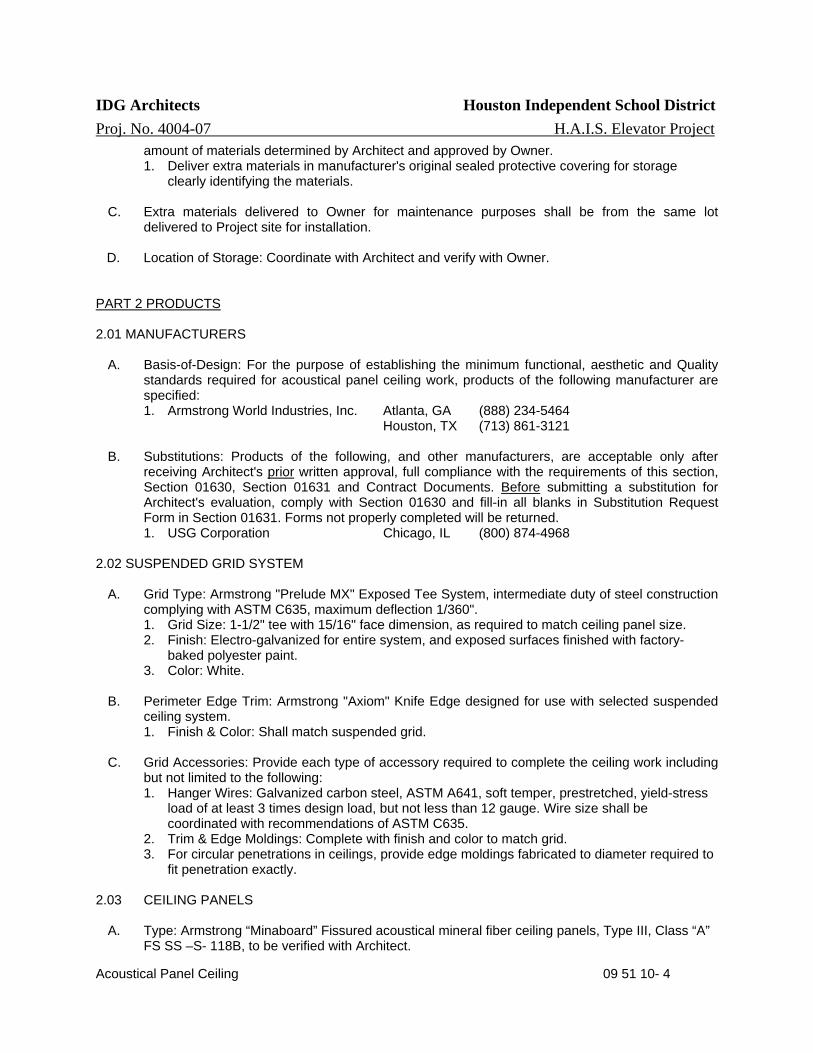
IDG Architects Houston Independent School District Proj. No. 4004-07 H.A.I.S. Elevator Project
Acoustical Panel Ceiling 09 51 10- 4
amount of materials determined by Architect and approved by Owner. 1. Deliver extra materials in manufacturer's original sealed protective covering for storage
clearly identifying the materials.
C. Extra materials delivered to Owner for maintenance purposes shall be from the same lot delivered to Project site for installation.
D. Location of Storage: Coordinate with Architect and verify with Owner. PART 2 PRODUCTS 2.01 MANUFACTURERS
A. Basis-of-Design: For the purpose of establishing the minimum functional, aesthetic and Quality standards required for acoustical panel ceiling work, products of the following manufacturer are specified: 1. Armstrong World Industries, Inc. Atlanta, GA (888) 234-5464
Houston, TX (713) 861-3121
B. Substitutions: Products of the following, and other manufacturers, are acceptable only after receiving Architect's prior written approval, full compliance with the requirements of this section, Section 01630, Section 01631 and Contract Documents. Before submitting a substitution for Architect's evaluation, comply with Section 01630 and fill-in all blanks in Substitution Request Form in Section 01631. Forms not properly completed will be returned. 1. USG Corporation Chicago, IL (800) 874-4968
2.02 SUSPENDED GRID SYSTEM
A. Grid Type: Armstrong "Prelude MX" Exposed Tee System, intermediate duty of steel construction complying with ASTM C635, maximum deflection 1/360". 1. Grid Size: 1-1/2" tee with 15/16" face dimension, as required to match ceiling panel size. 2. Finish: Electro-galvanized for entire system, and exposed surfaces finished with factory-
baked polyester paint. 3. Color: White.
B. Perimeter Edge Trim: Armstrong "Axiom" Knife Edge designed for use with selected suspended
ceiling system. 1. Finish & Color: Shall match suspended grid.
C. Grid Accessories: Provide each type of accessory required to complete the ceiling work including
but not limited to the following: 1. Hanger Wires: Galvanized carbon steel, ASTM A641, soft temper, prestretched, yield-stress
load of at least 3 times design load, but not less than 12 gauge. Wire size shall be coordinated with recommendations of ASTM C635.
2. Trim & Edge Moldings: Complete with finish and color to match grid. 3. For circular penetrations in ceilings, provide edge moldings fabricated to diameter required to
fit penetration exactly. 2.03 CEILING PANELS
A. Type: Armstrong “Minaboard” Fissured acoustical mineral fiber ceiling panels, Type III, Class “A” FS SS –S- 118B, to be verified with Architect.

IDG Architects Houston Independent School District Proj. No. 4004-07 H.A.I.S. Elevator Project
Acoustical Panel Ceiling 09 51 10- 5
1. NRC Range: .50-.60 2. STC Range : 35-39 3. Light Reflectance: LR-1 (75% or over) 4. Flame Resistive Rating: Flamespread 0-25 ASTM E84, Class A, FS SS-S-118B, 25 or under UL label.
B. Panel Finish & Color: Factory-applied white vinyl latex. C. Edge and Size Profile: 24”x 24” x 5/8” square edge lay in for exposed 15/16" grid.
PART 3 EXECUTION 3.01 PREPARATION
A. General: Examine Project conditions and structural framing to which acoustical panel ceilings attach or abutt, with Installer present, for compliance with requirements specified in this and other sections that affect ceiling installation and anchorage, and other conditions affecting performance of acoustical panel ceilings.
B. Ceiling Layout: Measure each ceiling area and establish layout of acoustical panels to balance
border widths at opposite edges of each ceiling. 1. Avoid using less-than-half-width panels at borders, and comply with layout shown on
reflected ceiling plans.
C. Notify Architect in writing of any unsatisfactory conditions. Do not proceed with acoustical panel ceiling work until unsatisfactory conditions detrimental to the proper completion of the work have been corrected and reviewed with Architect. 2. Beginning of ceiling work implies General Contractor and Installer have inspected and accept
the Project conditions as being properly prepared in accordance with ceiling manufacturer's published installation specifications for compliance with Contract Documents.
D. Hazardous Material: Products, materials and methods used in the installation of ceiling system
shall be free of hazardous materials.
3.02 GRID INSTALLATION
A. General: Install acoustical panel ceilings in accordance with approved shop drawings, ASTM C636 recommendations manufacturer's published recommendations and Contract Documents. 1. Perform ceiling grid work after major work above ceiling is complete and approved. 2. Install ceiling system capable of supporting imposed loads to a deflection of 1/360 maximum. 3. Variation from Flat to Level: 1/8" in 10 ft. 4. Ceiling system shall be capable of supporting a lay-in light fixture in either direction.
Additional cross tees shall be furnished as required by tenant layouts to frame light fixtures. 5. Ceiling system shall be capable of supporting lay-in HVAC distribution fixtures as required. 6. Do not eccentrically load ceiling system, or produce rotation of runners.
B. Hanger Installation: Coordinate the locations of hangers with other work. 1. Where ductwork and other equipment prevent the regular spacing of hangers, reinforce the
nearest affected hangers and related channels to span the extra distance. 2. Do not support ceiling grid from ductwork above.
C. Main & Cross Tees: Install at 48" on centers or as shown on Architectural Drawings. Cross tees
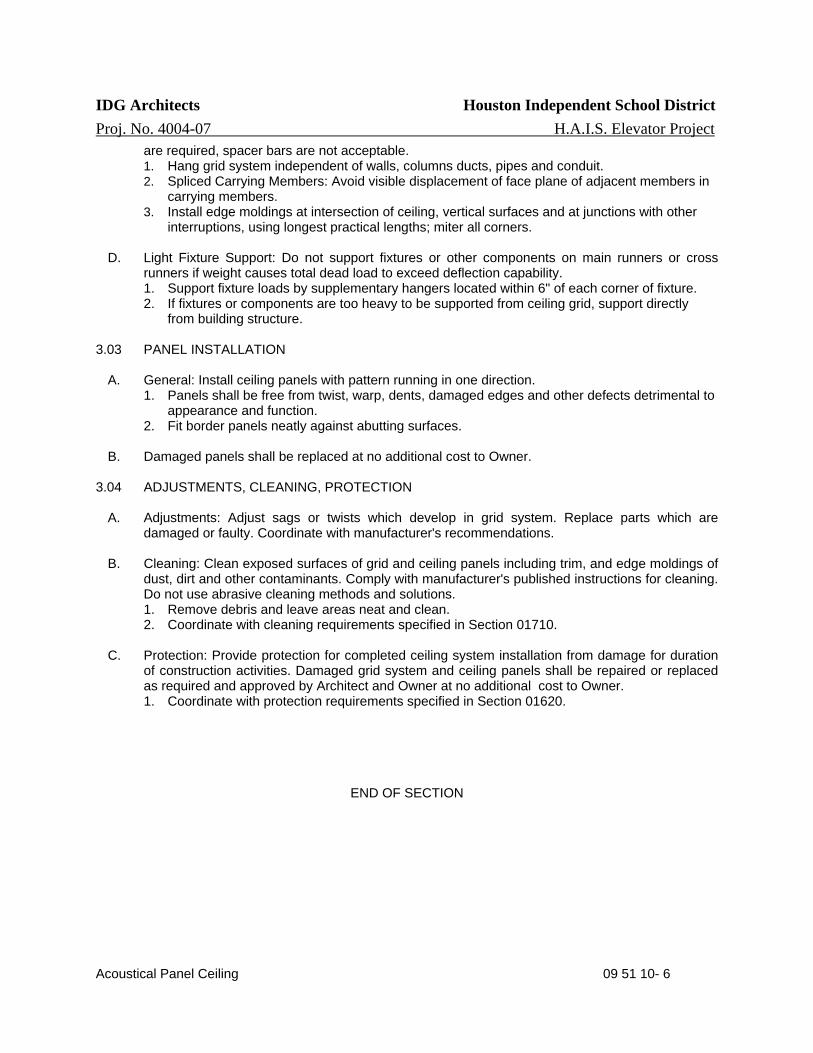
IDG Architects Houston Independent School District Proj. No. 4004-07 H.A.I.S. Elevator Project
Acoustical Panel Ceiling 09 51 10- 6
are required, spacer bars are not acceptable. 1. Hang grid system independent of walls, columns ducts, pipes and conduit. 2. Spliced Carrying Members: Avoid visible displacement of face plane of adjacent members in
carrying members. 3. Install edge moldings at intersection of ceiling, vertical surfaces and at junctions with other
interruptions, using longest practical lengths; miter all corners.
D. Light Fixture Support: Do not support fixtures or other components on main runners or cross runners if weight causes total dead load to exceed deflection capability. 1. Support fixture loads by supplementary hangers located within 6" of each corner of fixture. 2. If fixtures or components are too heavy to be supported from ceiling grid, support directly
from building structure.
3.03 PANEL INSTALLATION
A. General: Install ceiling panels with pattern running in one direction. 1. Panels shall be free from twist, warp, dents, damaged edges and other defects detrimental to
appearance and function. 2. Fit border panels neatly against abutting surfaces.
B. Damaged panels shall be replaced at no additional cost to Owner.
3.04 ADJUSTMENTS, CLEANING, PROTECTION
A. Adjustments: Adjust sags or twists which develop in grid system. Replace parts which are damaged or faulty. Coordinate with manufacturer's recommendations.
B. Cleaning: Clean exposed surfaces of grid and ceiling panels including trim, and edge moldings of
dust, dirt and other contaminants. Comply with manufacturer's published instructions for cleaning. Do not use abrasive cleaning methods and solutions. 1. Remove debris and leave areas neat and clean. 2. Coordinate with cleaning requirements specified in Section 01710.
C. Protection: Provide protection for completed ceiling system installation from damage for duration
of construction activities. Damaged grid system and ceiling panels shall be repaired or replaced as required and approved by Architect and Owner at no additional cost to Owner. 1. Coordinate with protection requirements specified in Section 01620.
END OF SECTION

IDG Architects Houston Independent School District Proj. No. 4004-07 H.A.I.S. Elevator Project
Resilient Wall Base & Accessories 096580- 1
SECTION 09658 RESILIENT
WALL BASE & ACCESSORIES
PART 1 GENERAL
1.01 SUMMARY
A. This section includes requirements for resilient wall base for floor finishes scheduledon Drawings and specified in other sections of Division 9.
B. Related Work: Coordinate resilient wall base requirements of this section anddrawings with related work to properly execute the Work in accordance with theProject Schedule. Sections which contain requirements that relate to wall baseinstallation include but are not limited to the following:
1. Section 01010 - Summary of Work2. Sections in Division 8 for doors and frames.3. Sections in Division 9 for floor, wall and ceiling finishes.4. Section 09250 - Interior Gypsum Board5. Section 09910 - Painting6. Section 12100 - Miscellaneous Furnishings7. Section 12300 - Educational Casework
C. Related Documents: Drawings and general provisions of Contract includingSpring ISD Contracting Requirements and Division 1 Sections apply to this Section.Coordination of Work: All Work shall be closely coordinated with security andcontracting requirements established by the Spring Independent School District.
1.02 REFERENCE STANDARDS
A. Requirements for reference standards are specified in Section 01090.
B. American Society for Testing and Materials:1. ASTM E648 - Test Method for Critical Radiant Flux of Floor-Covering Systems
Using a Radiant Heat Energy Source.2. ASTM E662 - Test Method for Specific Optical Density of Smoke Generated by
Solid Materials.3. ASTM F710 - Practice for Preparing Concrete Floors to Receive Resilient
Flooring.4. ASTM F1861 - Resilient Wall Base.
C. Federal Specification:1. FS SS-W-40a - Wall Base: Rubber and Vinyl Plastic.
1.03 QUALITY ASSURANCE
A. Manufacturer Qualifications: Wall Base Manufacturer shall be regularly engaged inmanufacturing and marketing the type of wall base required to meet Projectrequirements and conditions, and have the facilities capable of meeting allrequirements of Contract Documents. 1. Products and materials used inmanufacturing resilient wall base shall be free of lead,asbestos, polychlorinated biphenyls (PCB) or other types of hazardous materials.
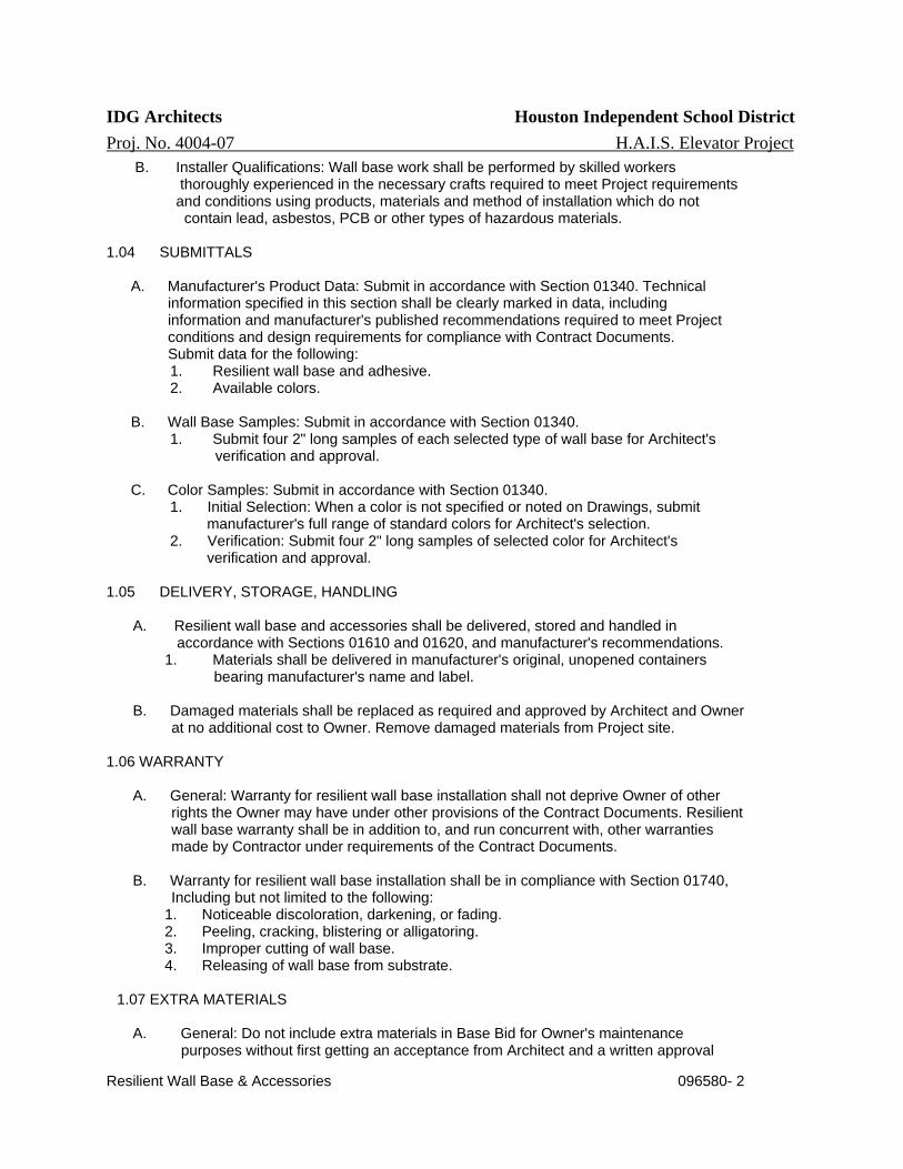
IDG Architects Houston Independent School District Proj. No. 4004-07 H.A.I.S. Elevator Project
Resilient Wall Base & Accessories 096580- 2
B. Installer Qualifications: Wall base work shall be performed by skilled workers thoroughly experienced in the necessary crafts required to meet Project requirements and conditions using products, materials and method of installation which do not contain lead, asbestos, PCB or other types of hazardous materials. 1.04 SUBMITTALS A. Manufacturer's Product Data: Submit in accordance with Section 01340. Technical information specified in this section shall be clearly marked in data, including information and manufacturer's published recommendations required to meet Project conditions and design requirements for compliance with Contract Documents. Submit data for the following:
1. Resilient wall base and adhesive. 2. Available colors.
B. Wall Base Samples: Submit in accordance with Section 01340. 1. Submit four 2" long samples of each selected type of wall base for Architect's verification and approval.
C. Color Samples: Submit in accordance with Section 01340. 1. Initial Selection: When a color is not specified or noted on Drawings, submit manufacturer's full range of standard colors for Architect's selection. 2. Verification: Submit four 2" long samples of selected color for Architect's verification and approval.
1.05 DELIVERY, STORAGE, HANDLING
A. Resilient wall base and accessories shall be delivered, stored and handled in accordance with Sections 01610 and 01620, and manufacturer's recommendations.
1. Materials shall be delivered in manufacturer's original, unopened containers bearing manufacturer's name and label.
B. Damaged materials shall be replaced as required and approved by Architect and Owner at no additional cost to Owner. Remove damaged materials from Project site.
1.06 WARRANTY
A. General: Warranty for resilient wall base installation shall not deprive Owner of other rights the Owner may have under other provisions of the Contract Documents. Resilient wall base warranty shall be in addition to, and run concurrent with, other warranties made by Contractor under requirements of the Contract Documents.
B. Warranty for resilient wall base installation shall be in compliance with Section 01740, Including but not limited to the following:
1. Noticeable discoloration, darkening, or fading. 2. Peeling, cracking, blistering or alligatoring. 3. Improper cutting of wall base. 4. Releasing of wall base from substrate.
1.07 EXTRA MATERIALS
A. General: Do not include extra materials in Base Bid for Owner's maintenance purposes without first getting an acceptance from Architect and a written approval

IDG Architects Houston Independent School District Proj. No. 4004-07 H.A.I.S. Elevator Project
Resilient Wall Base & Accessories 096580- 3
from Owner.
B. Quantity: Should maintenance materials be required, deliver amount of resilient wall base required and approved by Owner.
1. Deliver extra resilient wall base in manufacturer's original sealed containers for storage clearly identifying the tiles.
C. Extra resilient wall base delivered to Owner for maintenance purposes shall be from the same lot delivered to Project site for installation.
D. Location of Storage: Coordinate with Architect and verify with Owner.
PART 2 PRODUCTS 2.01 MANUFACTURERS
A. Basis-of-Design: Products, materials and manufacturers specified in this section establish the minimum functional, aesthetic and quality standards required for resilient wall base, Subject to compliance with Contract Documents, Project conditions and Architect's written approval, resilient wall base from one of the following manufacturers are acceptable:
1. Armstrong World Industries, Inc. Atlanta, GA (800) 292-6308 Houston, TX (713) 224-8300 & 686-0777
2. Azrock Commercial Flooring Florence, AL (800) 558-2240
3. Johnsonite Middlefield, OH (800) 899-8916
Houston, TX (713) 682-7474 & 939-8300
4. Mercer Products Company, Inc. Eustis, FL (800) 447-8442
5. R.C. Musson Rubber Co. Akron, OH (800) 321-2381
6. Roppe Rubber Corp. Fosteria, OH (800) 537-9527
Houston, TX (713) 932-0092
B. Substitutions: Resilient wall base of other manufacturers are acceptable only after
receiving Architect's prior, written approval, full compliance with the requirements of this section, Section 01630, Section 01631 and Contract Documents. 1. Before submitting a substitution for Architect's evaluation, comply with Section 01630 and fill-in all blanks in Substitution Request Form in Section 01631. Forms not properly completed will be returned.
2.02 RESILIENT WALL BASE A. Type & Manufacturer: Rubber wall base of type and manufacturer scheduled on Drawings, asbestos-free and manufactured to meet requirements of FS SS-W-40a, Type [I, Class I, Flame Spread Rating less than 25 under ASTM E84 Tunnel Test.
1. Base for Resilient Flooring: Standard type with coved toe, 1/8" thick, size as scheduled on Drawings. 2. Base for Carpet Flooring: Standard type without coved toe, 1/8" thick, size as scheduled on Drawings. 3. Required: Roll stock wall base. 4. Not Acceptable: Manufacturer's preformed corners with precut wall base.
B. Color: As scheduled on Drawings. If color is not scheduled, color will be selected by Architect.
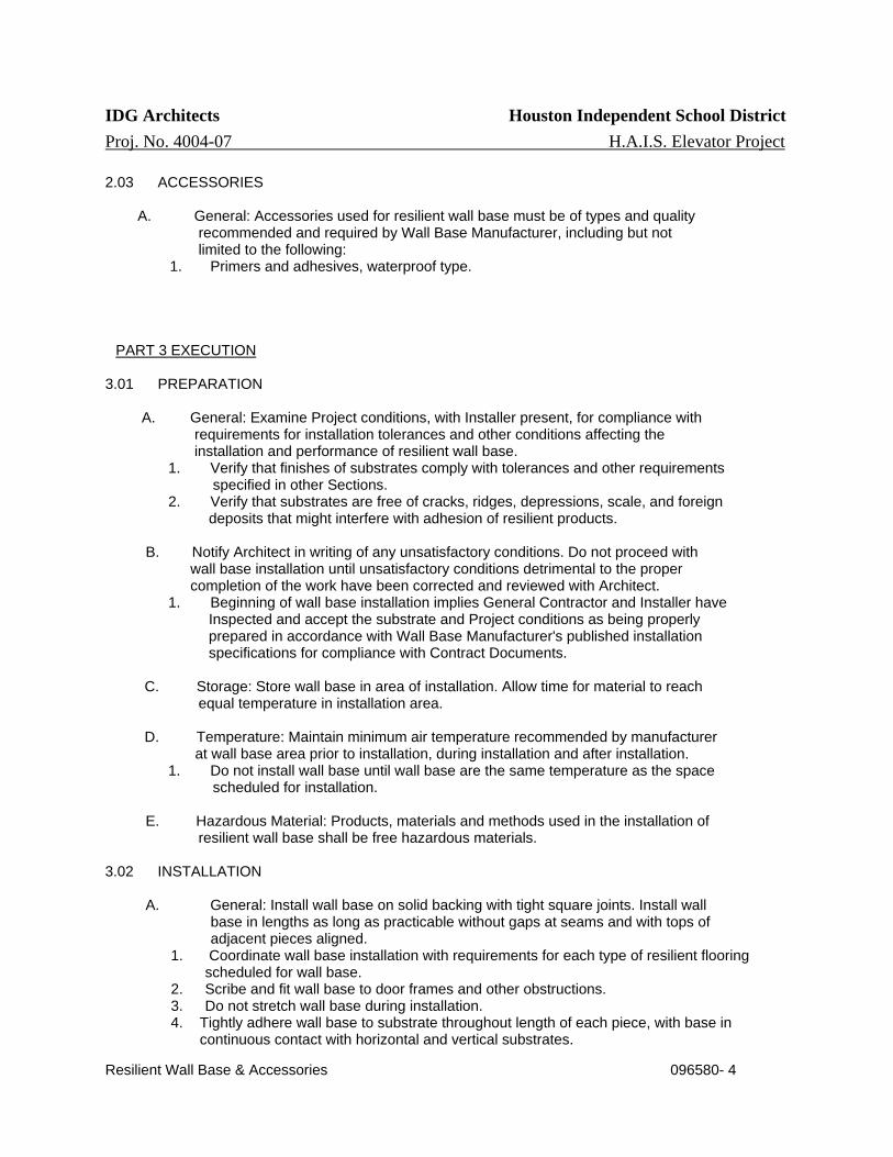
IDG Architects Houston Independent School District Proj. No. 4004-07 H.A.I.S. Elevator Project
Resilient Wall Base & Accessories 096580- 4
2.03 ACCESSORIES A. General: Accessories used for resilient wall base must be of types and quality recommended and required by Wall Base Manufacturer, including but not limited to the following:
1. Primers and adhesives, waterproof type.
PART 3 EXECUTION
3.01 PREPARATION A. General: Examine Project conditions, with Installer present, for compliance with requirements for installation tolerances and other conditions affecting the installation and performance of resilient wall base.
1. Verify that finishes of substrates comply with tolerances and other requirements specified in other Sections. 2. Verify that substrates are free of cracks, ridges, depressions, scale, and foreign deposits that might interfere with adhesion of resilient products.
B. Notify Architect in writing of any unsatisfactory conditions. Do not proceed with wall base installation until unsatisfactory conditions detrimental to the proper completion of the work have been corrected and reviewed with Architect.
1. Beginning of wall base installation implies General Contractor and Installer have Inspected and accept the substrate and Project conditions as being properly prepared in accordance with Wall Base Manufacturer's published installation specifications for compliance with Contract Documents.
C. Storage: Store wall base in area of installation. Allow time for material to reach equal temperature in installation area.
D. Temperature: Maintain minimum air temperature recommended by manufacturer
at wall base area prior to installation, during installation and after installation. 1. Do not install wall base until wall base are the same temperature as the space scheduled for installation.
E. Hazardous Material: Products, materials and methods used in the installation of resilient wall base shall be free hazardous materials. 3.02 INSTALLATION A. General: Install wall base on solid backing with tight square joints. Install wall base in lengths as long as practicable without gaps at seams and with tops of adjacent pieces aligned.
1. Coordinate wall base installation with requirements for each type of resilient flooring scheduled for wall base.
2. Scribe and fit wall base to door frames and other obstructions. 3. Do not stretch wall base during installation. 4. Tightly adhere wall base to substrate throughout length of each piece, with base in
continuous contact with horizontal and vertical substrates.
IDG Architects Houston Independent School District Proj. No. 4004-07 H.A.I.S. Elevator Project
Resilient Wall Base & Accessories 096580- 5
B. Substrates: Remove substrate coatings and other substances that are incompatible with adhesives and that contain soap, wax, oil, or silicone, using mechanical methods recommended by manufacturer. Do not use solvents.
1. Immediately before installation, sweep and vacuum clean substrates to be covered with resilient wall base. After cleaning, examine substrates for moisture, alkaline salts, carbonation, and dust.
C. Adhesive: Spread adhesive evenly in quantity recommended by manufacturer to ensure adhesion over entire area of base installation. D. Outside Corners: Use straight pieces of maximum lengths possible. Form outside corners without producing discoloration (whitening) at bends.
1. Form corner pieces with minimum 12-inch return. 2. Splice at outside corner is not acceptable. 3. Shave back of base at points where bends occur. 4. Factory-formed corner pieces are not acceptable for outside corners.
E. Inside Corners: Use straight pieces of maximum lengths possible. Form inside corners by cutting an inverted V-shaped notch in toe of wall base at the point where inside corner is formed.
1. Shave back of base where necessary to produce a snug fit to substrate. 2. Factory-formed corner pieces are not acceptable for inside corners.
3.03 CLEANING AND PROTECTION
A. Cleaning: After completing wall base installation, clean wall base and wall surfaces of adhesive, dust, dirt and other contaminants. Comply with Wall Base Manufacturer's published recommendations.
1. Do not use abrasive cleaners and cleaning methods. 2. Remove debris and leave areas neat and clean. 3. Coordinate with cleaning requirements specified in Section 01710.
B. Protection: Protect resilient wall base from mars, marks, indentations, and other damage from construction activities, and the placement of equipment and fixtures during remainder of construction period. Use protection methods recommended in writing by manufacturer.
1. Damaged resilient wall base and wall surfaces shall be repaired or replaced as required and approved by Architect and Owner at no additional cost to Owner. 2. Coordinate with protection requirements specified in Section 01620.
END OF SECTION
INTERIOR PAINTING 09 91 23 - 1
IDG Architects Houston Independent School District Proj. No. 4004-07 H.A.I.S. Elevator Project
SECTION 099123 - INTERIOR PAINTING
PART 1 - GENERAL
1.1 RELATED DOCUMENTS
A. Drawings and general provisions of the Contract, including General and SupplementaryConditions and Division 01 Specification Sections, apply to this Section.
1.2 SUMMARY
A. Section includes surface preparation and the application of paint systems on interior substrates.1. Concrete masonry units (CMU).2. Galvanized metal.3. Aluminum (not anodized or otherwise coated).
4. Gypsum board.
1.3 DEFINITIONS
A. Gloss Level 1: Not more than 5 units at 60 degrees and 10 units at 85 degrees, according toASTM D 523, a matte flat finish.
B. Gloss Level 2: Not more than 10 units at 60 degrees and 10 to 35 units at 85 degrees,according to ASTM D 523, a high-side sheen flat, velvet-like finish.
C. Gloss Level 3: 10 to 25 units at 60 degrees and 10 to 35 units at 85 degrees, according toASTM D 523, an eggshell finish.
D. Gloss Level 4: 20 to 35 units at 60 degrees and not less than 35 units at 85 degrees, accordingto ASTM D 523, a satin-like finish.
E. Gloss Level 5: 35 to 70 units at 60 degrees, according to ASTM D 523, a semi-gloss finish.
F. Gloss Level 6: 70 to 85 units at 60 degrees, according to ASTM D 523, a gloss finish.
1.4 ACTION SUBMITTALS
A. Product Data: For each type of product. Include preparation requirements and applicationinstructions.
B. Samples for Verification: For each type of paint system and in each color and gloss of topcoat.
1. Submit Samples on rigid backing, 8 inches (200 mm) square.2. Step coats on Samples to show each coat required for system.3. Label each coat of each Sample.4. Label each Sample for location and application area.
C. Product List: For each product indicated, include the following:
INTERIOR PAINTING 09 91 23 - 2
IDG Architects Houston Independent School District Proj. No. 4004-07 H.A.I.S. Elevator Project
1. Cross-reference to paint system and locations of application areas. Use samedesignations indicated on Drawings and in schedules.
2. VOC content.
1.5 CLOSEOUT SUBMITTALS
A. Coating Maintenance Manual: Provide coating maintenance manual including area summarywith finish schedule, area detail designating location where each product/color/finish was used,product data pages, material safety data sheets, care and cleaning instructions, touch-upprocedures, and color samples of each color and finish used.
1.6 MAINTENANCE MATERIAL SUBMITTALS
A. Furnish extra materials, from the same product run, that match products installed and that arepackaged with protective covering for storage and identified with labels describing contents.
1. Paint: 5 percent, but not less than 1 gal. (3.8 L) of each material and color applied.
1.7 QUALITY ASSURANCE
A. Mockups: Apply mockups of each paint system indicated and each color and finish selected toverify preliminary selections made under Sample submittals and to demonstrate aestheticeffects and set quality standards for materials and execution.
1. Architect will select one surface to represent surfaces and conditions for application ofeach paint system specified in Part 3.
a. Vertical and Horizontal Surfaces: Provide samples of at least 100 sq. ft. (9 sq. m).b. Other Items: Architect will designate items or areas required.
2. Final approval of color selections will be based on mockups.
a. If preliminary color selections are not approved, apply additional mockups ofadditional colors selected by Architect at no added cost to Owner.
3. Approval of mockups does not constitute approval of deviations from the ContractDocuments contained in mockups unless Architect specifically approves such deviationsin writing.
4. Subject to compliance with requirements, approved mockups may become part of thecompleted Work if undisturbed at time of Substantial Completion.
1.8 DELIVERY, STORAGE, AND HANDLING
A. Delivery and Handling: Deliver products to Project site in an undamaged condition inmanufacturer's original sealed containers, complete with labels and instructions for handling,storing, unpacking, protecting, and installing. Packaging shall bear the manufacturer’s label withthe following information:
1. Product name and type (description).2. Batch date.3. Color number.
INTERIOR PAINTING 09 91 23 - 3
IDG Architects Houston Independent School District Proj. No. 4004-07 H.A.I.S. Elevator Project
4. VOC content. 5. Environmental handling requirements. 6. Surface preparation requirements. 7. Application instructions.
B. Store materials not in use in tightly covered containers in well-ventilated areas with ambient
temperatures continuously maintained at not less than 45 deg F (7 deg C).
1. Maintain containers in clean condition, free of foreign materials and residue. 2. Remove rags and waste from storage areas daily.
1.9 FIELD CONDITIONS
A. Apply paints only when temperature of surfaces to be painted and ambient air temperatures are
between 50 and 95 deg F (10 and 35 deg C).
B. Do not apply paints when relative humidity exceeds 85 percent; at temperatures less than 5
deg F (3 deg C) above the dew point; or to damp or wet surfaces.
PART 2 - PRODUCTS
2.1 MANUFACTURERS
A. Basis-of-Design Product: Subject to compliance with requirements, provide Sherwin-Williams
Company products indicated or comparable product from one of the following:
1. Benjamin Moore & Co. 2. PPG Architectural Finishes, Inc. 3. Pratt & Lambert.
B. Source Limitations: Obtain paint materials from single source from single listed manufacturer.
1. Manufacturer's designations listed on a separate color schedule are for color reference
only and do not indicate prior approval.
2.2 PAINT, GENERAL
A. Material Compatibility:
1. Provide materials for use within each paint system that are compatible with one another
and substrates indicated, under conditions of service and application as demonstrated by manufacturer, based on testing and field experience.
2. For each coat in a paint system, provide products recommended in writing by manufacturers of topcoat for use in paint system and on substrate indicated.
B. VOC Content: Products shall comply with VOC limits of authorities having jurisdiction and, for
interior paints and coatings applied at Project site, the following VOC limits, exclusive of colorants added to a tint base, when calculated according to 40 CFR 59, Subpart D (EPA Method 24).
1. Flat Paints and Coatings: 50 g/L.

INTERIOR PAINTING 09 91 23 - 4
IDG Architects Houston Independent School District Proj. No. 4004-07 H.A.I.S. Elevator Project
2. Nonflat Paints and Coatings: 150 g/L. 3. Dry-Fog Coatings: 400 g/L. 4. Primers, Sealers, and Undercoaters: 200 g/L. 5. Anticorrosive and Antirust Paints Applied to Ferrous Metals: 250 g/L.
6. Zinc-Rich Industrial Maintenance Primers: 340 g/L. 7. Pretreatment Wash Primers: 420 g/L. 8. Floor Coatings: 100 g/L. 9. Shellacs, Clear: 730 g/L. 10. Shellacs, Pigmented: 550 g/L.
C. Low-Emitting Materials: Interior paints and coatings shall comply with the testing and product
requirements of the California Department of Health Services' "Standard Practice for the Testing of Volatile Organic Emissions from Various Sources Using Small-Scale Environmental Chambers."
D. Colors: Match Architect's samples.
2.3 SOURCE QUALITY CONTROL
A. Testing of Paint Materials: Owner reserves the right to invoke the following procedure:
1. Owner may engage the services of a qualified testing agency to sample paint materials.
Contractor will be notified in advance and may be present when samples are taken. If paint materials have already been delivered to Project site, samples may be taken at Project site. Samples will be identified, sealed, and certified by testing agency.
2. Testing agency will perform tests for compliance with product requirements. 3. Owner may direct Contractor to stop applying coatings if test results show materials
being used do not comply with product requirements. Contractor shall remove noncomplying paint materials from Project site, pay for testing, and repaint surfaces painted with rejected materials. Contractor will be required to remove rejected materials from previously painted surfaces if, on repainting with complying materials, the two paints are incompatible.
PART 3 - EXECUTION
3.1 EXAMINATION
A. Examine substrates and conditions, with Applicator present, for compliance with requirements
for maximum moisture content and other conditions affecting performance of the Work. Verify suitability of substrates, including surface conditions and compatibility with existing finishes and primers. Where acceptability of substrate conditions is in question, apply samples and perform in-situ testing to verify compatibility, adhesion, and film integrity of new paint application.
1. Report, in writing, conditions that may affect application, appearance, or performance of
paint.
B. Substrate Conditions:
1. Maximum Moisture Content of Substrates: When measured with an electronic moisture
meter as follows: a. Masonry (Clay and CMU): 12 percent. b. Gypsum Board: 12 percent.
INTERIOR PAINTING 09 91 23 - 5
IDG Architects Houston Independent School District Proj. No. 4004-07 H.A.I.S. Elevator Project
2. Gypsum Board Substrates: Verify that finishing compound is sanded smooth.
C. Proceed with coating application only after unsatisfactory conditions have been corrected;
application of coating indicates acceptance of surfaces and conditions.
3.2 PREPARATION
A. Comply with manufacturer's written instructions and recommendations in "MPI Manual"
applicable to substrates indicated.
B. Remove hardware, covers, plates, and similar items already in place that are removable and
are not to be painted. If removal is impractical or impossible because of size or weight of item, provide surface-applied protection before surface preparation and painting.
1. After completing painting operations, use workers skilled in the trades involved to reinstall
items that were removed. Remove surface-applied protection if any.
C. Clean substrates of substances that could impair bond of paints, including dust, dirt, oil, grease,
and incompatible paints and encapsulants.
1. Remove incompatible primers and reprime substrate with compatible primers or apply tie
coat as required to produce paint systems indicated.
D. Masonry Substrates: Remove efflorescence and chalk. Do not paint surfaces if moisture content
or alkalinity of surfaces or mortar joints exceed that permitted in manufacturer's written instructions.
E. Shop-Primed Steel Substrates: Clean field welds, bolted connections, and abraded areas of
shop paint, and paint exposed areas with the same material as used for shop priming to comply with SSPC-PA 1 for touching up shop-primed surfaces.
F. Galvanized-Metal Substrates: Remove grease and oil residue from galvanized sheet metal
fabricated from coil stock by mechanical methods to produce clean, lightly etched surfaces that promote adhesion of subsequently applied paints.
3.3 APPLICATION
A. Apply paints according to manufacturer's written instructions and to recommendations in "MPI
Manual."
1. Use applicators and techniques suited for paint and substrate indicated. 2. Paint surfaces behind movable equipment and furniture same as similar exposed
surfaces. Before final installation, paint surfaces behind permanently fixed equipment or furniture with prime coat only.
3. Paint front and backsides of access panels, removable or hinged covers, and similar hinged items to match exposed surfaces.
4. Do not paint over labels of independent testing agencies or equipment name, identification, performance rating, or nomenclature plates.
5. Primers specified in painting schedules may be omitted on items that are factory primed or factory finished if acceptable to topcoat manufacturers.
INTERIOR PAINTING 09 91 23 - 6
IDG Architects Houston Independent School District Proj. No. 4004-07 H.A.I.S. Elevator Project
B. Tint each undercoat a lighter shade to facilitate identification of each coat if multiple coats of same material are to be applied. Tint undercoats to match color of topcoat, but provide sufficient difference in shade of undercoats to distinguish each separate coat.
C. If undercoats or other conditions show through topcoat, apply additional coats until cured film
has a uniform paint finish, color, and appearance.
D. Apply paints to produce surface films without cloudiness, spotting, holidays, laps, brush marks,
roller tracking, runs, sags, ropiness, or other surface imperfections. Cut in sharp lines and color breaks.
E. Painting Fire Suppression, Plumbing, HVAC, Electrical, Communication, and Electronic Safety
and Security Work:
1. Paint the following work where exposed in equipment rooms:
a. Equipment, including panelboards and switch gear. b. Uninsulated metal piping. c. Uninsulated plastic piping. d. Pipe hangers and supports. e. Metal conduit. f. Plastic conduit. g. Tanks that do not have factory-applied final finishes. h. Duct, equipment, and pipe insulation having cotton or canvas insulation covering
or other paintable jacket material.
2. Paint the following work where exposed in occupied spaces:
a. Equipment, including panelboards. b. Uninsulated metal piping. c. Uninsulated plastic piping. d. Pipe hangers and supports. e. Metal conduit. f. Plastic conduit. g. Duct, equipment, and pipe insulation having cotton or canvas insulation covering
or other paintable jacket material. h. Other items as directed by Architect.
3. Paint portions of internal surfaces of metal ducts, without liner, behind air inlets and outlets that are visible from occupied spaces.
3.4 FIELD QUALITY CONTROL
A. Dry Film Thickness Testing: Owner may engage the services of a qualified testing and
inspecting agency to inspect and test paint for dry film thickness.
1. Contractor shall touch up and restore painted surfaces damaged by testing. 2. If test results show that dry film thickness of applied paint does not comply with paint
manufacturer's written recommendations, Contractor shall pay for testing and apply additional coats as needed to provide dry film thickness that complies with paint manufacturer's written recommendations.

INTERIOR PAINTING 09 91 23 - 7
IDG Architects Houston Independent School District Proj. No. 4004-07 H.A.I.S. Elevator Project
3.5 CLEANING AND PROTECTION
A. At end of each workday, remove rubbish, empty cans, rags, and other discarded materials fromProject site.
B. After completing paint application, clean spattered surfaces. Remove spattered paints bywashing, scraping, or other methods. Do not scratch or damage adjacent finished surfaces.
C. Protect work of other trades against damage from paint application. Correct damage to work ofother trades by cleaning, repairing, replacing, and refinishing, as approved by Architect, andleave in an undamaged condition.
D. At completion of construction activities of other trades, touch up and restore damaged ordefaced painted surfaces.
3.6 INTERIOR PAINTING SCHEDULE
A. CMU Substrates:
1. Latex System:
a. Block Filler: Block filler, latex, interior/exterior: S-W PrepRite Block Filler, B25W25,at 100 to 200 sq. ft. per gal (2.4 to 4.9 sq. m per l).
b. Intermediate Coat: Latex, interior, matching topcoat.
c. Topcoat: Latex, interior, low sheen, (Gloss Level 2): S-W ProMar 200 Zero VOCLatex Low Sheen Enamel, B24-2600 Series, at 4.0 mils wet, 1.6 mils dry, per coat.
B. Metal Substrates (Aluminum, Steel, Galvanized Steel):
1. Latex System:
a. Prime Coat: Primer, rust-inhibitive, water based: S-W Pro Industrial Pro-CrylUniversal Primer, B66-310 Series, at 5.0 to 10 mils wet, 2.0 to 4.0 mils dry.
b. Intermediate Coat: Water-based acrylic, interior, matching topcoat.c. Topcoat: Water-based acrylic, semi-gloss, (Gloss Level 5): S-W Pro Industrial
Acrylic Semi-Gloss Coating, B66-650 Series, at 2.5 to 4.0 mils dry, per coat.
C. Gypsum Board Substrates:
1. Latex System:
a. Prime Coat: Primer, latex, interior: S-W ProMar 200 Zero VOC Latex Primer,B28W2600, at 4.0 mils wet, 1.5 mils dry.
b. Intermediate Coat: Latex, interior, matching topcoat.c. Topcoat: Latex, interior, eggshell, (Gloss Level 3): S-W ProMar 200 Zero VOC
Latex Eg-Shel, B20-2600 Series, at 4.0 mils wet, 1.7 mils dry, per coat.
END OF SECTION 099123

IDG Architects Houston Independent School District Proj. No. 4004-07 H.A.I.S. Elevator Project
STORM SEWAGE SYSTEM 33 41 00
FIRE PROTECTION SPECIALTIES 104400 - 1
IDG Architects Houston Independent School District
Proj. No. 4004-07 H.A.I.S. Elevator Project
SECTION 104400 - FIRE PROTECTION SPECIALTIES
PART 1 - GENERAL
1.1 RELATED DOCUMENTS:
A. Drawings and general provisions of Contract, including General and Supplementary Conditions and
Division-1 Specification Sections, apply to work specified in this Section.
1.2 GENERAL DESCRIPTION OF THE WORK OF THIS SECTION:
A. Work shall include furnishing and installing fire extinguishers, cabinets, and accessories.
1.3 RELATED WORK OF OTHER SECTIONS:
A. Coordinate work of this Section with work of other Sections as required to properly execute the Work
and as necessary to maintain satisfactory progress of the work of other Sections.
1.4 QUALITY ASSURANCE:
A. NFPA Compliance: Fabricate and label fire extinguishers to comply with NFPA 10, "Standard for
Portable Fire Extinguishers."
B. Provide new portable fire extinguishers which comply with applicable UL standard and are labeled by
UL.
C. Provide portable fire extinguishers and cabinets by one manufacturer, unless otherwise acceptable to
Architect.
1.5 SUBMITTALS:
A. Submit manufacturer's technical data and installation instructions for all fire extinguishers and cabinets
required. For fire extinguisher cabinets include roughing-in dimensions, and details showing mounting
methods, relationships to surrounding construction, door hardware, cabinet type and materials, trim
style and door construction, style, and materials. Where color selection is required include color charts
showing full range of manufacturer's standard colors and designs available.
PART 2 - PRODUCTS
2.1 FIRE EXTINGUISHERS:
A. Provide fire extinguishers for each location indicated on the Drawings, in colors and finishes selected
from manufacturer's standard which comply with requirements of governing authorities. Fill and
service extinguishers to comply with requirements of governing authorities and manufacturer's
requirements. Abbreviations indicated below to identify extinguisher types relate to UL classification
and ratings system and not, necessarily, to type and amount of extinguishing material contained in
extinguisher.
B. Provide fire extinguisher types as follows:
1. Dry Chemical, UL Rated 2A-80B:C, 10 lb. (2.3 kg) nominal capacity, in enameled steel container,
for Class A, B, and C fires.
a. J.L. Industries "Cosmic 10E", or equal by Larsen's Manufacturing Co., or Potter-Roemer,
Inc.
FIRE PROTECTION SPECIALTIES 104400 - 2
IDG Architects Houston Independent School District
Proj. No. 4004-07 H.A.I.S. Elevator Project
2.2 FIRE EXTINGUISHER CABINETS:
A. Provide fire extinguisher cabinets where indicated. Provide sizes required for housing specified fire
extinguishers, and as follows:
1. J.L. Industries “Academy” aluminum construction, semi-recess.
2. Trim Style: 1-1/4” flat face trim.
3. Door Style: Duo-Panel, non-locking, magnetic catch, pull handles.
4. Door Glazing: DS (Double Strength) clear glass.
5. Finish: #180 clear anodized aluminum frame and door.
PART 3 - EXECUTION
3.1 INSTALLATION:
A. Install items included in this Section in locations indicated on Drawings, and at heights complying with
applicable regulations of governing authorities.
1. Securely fasten cabinet to substrate construction, square and plumb, to comply with
manufacturer's instructions.
2. Securely fasten mounting brackets to structure, square, and plumb, to comply with
manufacturer's instructions.
3. Where exact location of bracket-mounted fire extinguishers is not indicated, locate as directed by
Architect.
END OF SECTION 104400

IDG Architects Houston Independent School District Proj. No. 4004-07 H.A.I.S. Elevator Project
STORM SEWAGE SYSTEM 33 41 00

IDG Architects Houston Independent School District Proj. No. 4004-07 H.A.I.S. Elevator Project
STORM SEWAGE SYSTEM 33 41 00

H.I.S.D. H.A.I.S. ELEVATOR PROJECTProj. No. 4004-07
GENERAL PLUMBING REQUIREMENTS 22 00 00-1
SECTION 22 00 00 GENERAL PLUMBING REQUIREMENTS
PART 1 – GENERAL REQUIREMENTS
1.1 RELATED DOCUMENTS
A. The General Provisions of the Contract, including General, Supplementary and SpecialConditions, apply to the work specified in this Section.
1.2 INTENT OF DRAWINGS AND SPECIFICATIONS
A. GENERAL: Drawings and Specifications are intended to be complimentary. Any workdescribed in either of them, shall be work required under this contract. Should any workrequired by the drawings and specifications be in violation of any Federal, State, Countyor City laws, ordinance or regulation, those laws and regulations shall prevail, and shallbe complied with by the Contractor as a part of this work with no extra compensation.
B. DRAWINGS: The drawings are schematic in nature, intended to show the variouscomponents of the system approximately to scale and indicate how they are to beintegrated with other parts of the building. Determine exact locations by closecoordination with the Owner’s Representative, job measurements, determining therequirements of other trades and reviewing all contract documents. The Drawingsindicated general routing of the various parts of the systems, but do not indicated allfittings and offsets which may be required to fit the system into spaces allotted for them.The Contract shall include these items as required for a complete installation.
C. BASIS OF DESIGN: Equipment that is scheduled is the basis of the design and hasbeen coordinated for space, installation and electrical requirements. Equipment andmodels from other acceptable manufacturers have not been verified or coordinated.Contractor shall verify these requirements prior to using other equipment in his bid andinclude any additional costs for installation of the substitute equipment.
1.3 MATERIALS
A. GENERAL: Manufacturer's printed directions shall be followed for preparing, assembling,installing, erecting and cleaning manufactured materials or equipment, unless otherwisedirected. Materials, when not otherwise definitely specified, shall conform to applicableNational Specifications and Standards. All materials shall be certified to not contain anyasbestos or other material banned by the Environmental Protection Agency. Lead shallnot be used in any material, pipe or solder in contact with the domestic water system.
B. SUBSTITUTION: The names of manufacturers and model numbers have been used inthe Contract Documents to establish type of equipment and standard of quality. Whereonly one name is mentioned for a particular item of material, then that manufacturer is theonly one acceptable. Where several names are mentioned, any one of those listed maybe furnished provided submittal contains sufficient information to show completecompliance with contract Documents. No attempt has been made to determine if eachmanufacturer listed will produce material that will comply with all requirements of thisproject or will fit the allotted space. All specified equipment shall be considered to include“or approved equal.” Approval must be granted before the proposal date as detailedbelow.
C. SUBSTITUTION REQUIREMENTS: Requests for substitution during the bidding period,in accordance with the requirements of the Special Conditions, must be accompanied bya complete product submittal with all features, accessories and capacities noted. Large
H.I.S.D. H.A.I.S. ELEVATOR PROJECTProj. No. 4004-07
GENERAL PLUMBING REQUIREMENTS 22 00 00-2
equipment must include a drawing to scale showing how the equipment and required access space will fit the available space. Acceptance for bidding will be made by addendum to the project prior the proposal date, and acceptance does not waive the post bidding requirement for formal submittal and approval.
1.4 DEMOLITION AND REMODELING
A. In areas of demolition, contractor shall remove all plumbing equipment, piping anddevices not to be reused. Any material that has salvage value shall be offered to theOwner, and if accepted, delivered to his designated location. If not accepted it shall beproperly disposed of with the other construction material.
B. Where existing systems serve other areas as well, they shall remain active in thoseareas. Cap, patch and relocate piping to keep these systems operating.
C. Remove and replace ceilings as necessary to install or modify plumbing systems. Whereceilings are to be removed or replaced, adjust/reinstall existing sprinkler devices.
D. Where existing starters are to be reused, install heaters with proper size for revisedloads.
E. Where large equipment is to be replaced, ensure that equipment that is an acceptablemanufacturer but not the scheduled brand will fit the available space and can be installedthrough existing doors, louvers or windows, prior to using this equipment in the bid.
1.5 RELATED WORK SPECIFIED IN OTHER SECTIONS
A. ELECTRICAL: Power wiring is specified in the Electrical Section. Controllers andstarters, unless part of a motor control center, are specified under this Section.
B. PAINTING OF EQUIPMENT, PIPING AND ACCESSORIES: Painting Section. However,all items furnished under this Section shall be kept clean and free from corrosion.
C. OPENINGS: Various Sections. The locations of all inserts and openings shall bedetermined under this Section and coordinated with other Sections in ample time to avoidcutting new construction.
D. EQUIPMENT AND PIPING SUPPORTS REQUIREMENTS: Refer to structural drawings,details and notes for specific support and pipe hanging requirements. Specific loadingand attachment methods shall be followed to assure that individual structural membersare not overloaded.
1.6 ALTERNATES
A. PROJECT ALTERNATES: Determine the scope of each specified alternate proposal bycarefully reading all Divisions of the Documents. The Bid Form contains informationexplaining the extent of the construction to be performed under a specific alternate.Alternate proposals, which are not predominantly plumbing in scope, are described inother Divisions of these Documents. Pay particular note to re-roofing items that maynecessitate adjustments to existing piping.
1.7 PERMITS, FEES AND APPROVALS
A. The contractor shall obtain and pay for all permits and fees to perform his work. He shallcomply with all laws, ordinances, rules and regulations bearing on the conduct of thework specified or shown on the drawings. This applies to Federal, State and LocalCodes and Requirements. Approval from the various insuring and inspection authoritiesshall also be obtained. Refer to Architectural sections for additional information.
H.I.S.D. H.A.I.S. ELEVATOR PROJECTProj. No. 4004-07
GENERAL PLUMBING REQUIREMENTS 22 00 00-3
1.8 PLUMBING RELATED UTILITIES
A. WATER, SEWER, STORM AND FIRE SPRINKLER SYSTEMS: These systems will be coordinated by the Civil Engineer with the various utility districts.
B. NATURAL GAS: Contractor shall contact and coordinate with the gas provider to provide service to the building. Installation of the meter shall be in accordance with the gas company’s requirements and standards. Where the meter is located in paved areas, leave a minimum 48”x48” (or larger if required by the provider) block-out in the concrete for the gas piping to turn up to grade if the concrete is poured before the gas main is installed.
1.9 VISITING THE SITE
A. The Contractor shall be familiar with the Drawings and Specifications and shall have examined the premises and understand the conditions under which he will be obligated to operate in performing the contract. No additional compensation shall be allowed for failure to fully understand the requirements.
1.10 GUARANTEE
A. All equipment and materials furnished under this Section of these Specifications shall be new and free from any defects when accepted by the Owner and shall be guaranteed in writing for a period of one year from the date of acceptance by the Owner unless noted to have extended warranties.
1.11 NOISE AND VIBRATIONS
A. The Contractor shall guarantee that the entire system and its component items of equipment, as installed by him, shall operate without objectionable vibration or noises. If, in the opinion of the Architect, objectionable vibration or noise is present, the Contractor shall execute such remedial measures as are necessary to eliminate such unsatisfactory operating conditions and the material and labor thereby required shall be performed at the Contractor's expense.
1.12 INSTALLATION REQUIREMENTS
A. COORDINATION: The Contractor shall cooperate with other trades on the job and make installations in the proper sequence during the construction of the buildings, and he shall notify the Architect well in advance of construction of all interference of his work with that of other trades and of building construction. This notification shall not relieve the contractor of his responsibilities to coordinate his work with the total project.
B. WORKMANSHIP: All work shall be performed in a neat workmanlike manner and in the best practice of the trade. Only workmen skilled in the trades shall be employed to perform the work included in these specifications.
C. CLEAN-UP: Keep area of operations free from accumulation of waste material or rubbish at all times. All piping above accessible ceilings shall be cleaned of cement, plaster and other construction debris prior to being concealed. The parts of the Plumbing installation which are to be painted or insulated shall be thoroughly cleaned of cement, plaster, grease, oil spots and other materials in preparation for painting or insulating.
D. EQUIPMENT PROTECTION: Do not deliver equipment to jobsite until it is actually needed for installation. Protect equipment from damage due to construction activities and the weather. Equipment allowed to stand in weather will be rejected and Contractor
H.I.S.D. H.A.I.S. ELEVATOR PROJECTProj. No. 4004-07
GENERAL PLUMBING REQUIREMENTS 22 00 00-4
is obligated to furnish new equipment at no cost to Owner.
1.13 CLOSEOUT REQUIREMENTS
A. AS-BUILT DRAWINGS: Obtain a set of project drawings and keep these at jobsite during construction. During the course of construction, mark on these prints any changes which are made, noting particularly locations for those items which will need to be located for servicing. At completion of job, mark each sheet "Record Drawings", date and deliver to Architect.
B. OWNER’S INSTRUCTIONS: Provide four hours of instruction on operation and maintenance of the installed systems to the Owner's designated personnel upon completion of the system's installation.
C. CLOSEOUT MANUALS: At completion of job, furnish three copies of spare parts lists and operating instructions for all equipment furnished under this Division. These lists and instructions shall be published by the manufacturer of the equipment. Bind in 3-ring binders with project name.
D. SPARE PARTS: Upon completion of the installation, deliver to the Owner all tools and spare parts that are furnished by the Equipment Manufacturer for use with the equipment furnished under this Contract.
1.14 SHOP DRAWINGS
A. All submittals shall be submitted in PDF form. Submittal will be reviewed with comments incorporated in this PDF. After final approval, Contractor shall provide a hard copy for use at the project site.
B. The purpose of these submittals is to attempt to aid the contractor in such a manner that improper or unacceptable materials are not delivered to or installed on the job. Shop drawings shall be approved before installation of the material under consideration. Approval of these submittals shall not be construed as releasing The Contractor from compliance with the Contract Documents. All materials and equipment shall be subject to final acceptance by the Engineer at completion of construction.
C. Shop Drawings shall consist of published ratings of capacity data, detailed construction drawings, wiring and control diagrams, performance curves, installation instructions, manufacturer's installation drawings and other pertinent data. Where the literature is submitted covering a group or series of similar items, the item under consideration shall be clearly indicated. Drawings shall be submitted showing revisions to equipment layouts due to use of alternate or substitute equipment. The front sheet of each copy of the submittal shall have the following typed information:
01 Job name and location.
02 General Contractor's name, address, Project Manager's name and telephone number.
03 Submitting Sub-contractor's name, address, Project Manager's name and telephone number.
04 Suppliers company name, address, salesman's name and telephone number.
D. Shop Drawings are required for but are not limited to the following items:
Plumbing Carriers, Drains & Cleanouts Pipe MarkersPumps Plumbing Fixtures & EquipmentInsulation Plumbing Pipe, Valves & Fittings
H.I.S.D. H.A.I.S. ELEVATOR PROJECTProj. No. 4004-07
GENERAL PLUMBING REQUIREMENTS 22 00 00-5
E. Major equipment in AHU/Mechanical Rooms will not be approved until contractor has submitted and received approved 1/4” scale coordination drawings of mechanical and air handling unit rooms showing sizes of proposed equipment, including access space, and mechanical and electrical equipment also located in the room.
F. If a submittal is returned to the Contractor marked “Rejected” or “Revise and Resubmit”, only one (1) additional submittal will be permitted without the Contractor incurring charges for the additional re-submittals. SEG shall be reimbursed by the Contractor for any expense in connection with any necessary submission in addition to the two (2) submissions allowed. Contractor will be billed by SEG at a rate of $125/hr. for these occurrences.
1.15 PLUMBING INSPECTIONS
A. GENERAL: Contractor shall formally request inspections of any and all plumbing systems installations. Inspections shall include but not be limited to: pipe tests, underground installations prior to backfill, rough-in installations, wall cover inspections, above ceiling inspections and final inspection.
B. Contractor shall provide a MINIMUM of 48-hour notice prior to requested inspection time, no exceptions.
C. INSPECTION REPORTS: After each inspection, SEG will generate an inspection report and distribute promptly. The Contractor will then be given 7 working days from date of report to address all deficiencies listed on the report. The GENERAL CONTRACTOR shall verify that all items on each inspection report have been addressed by their subcontractors in this time period. Once verified the GENERAL CONTRACTOR shall sign-off on each deficiency listed on the report and return the signed-off copy of the inspection report to SEG via e-mail. After the signed-off report is returned to SEG, the GENERAL CONTRACTOR shall request a re-inspection by SEG to close the report. If after 7 working days no re-inspection is requested by the GENERAL CONTRACTOR to close a report, SEG reserves the right to re-inspect whenever our schedule allows, with these re-inspections still being subject to Paragraph E below.
D. TEST REJECTIONS AND RE-INSPECTIONS: If a test is rejected or a re-inspection of an issued SEG Inspection Report is found to NOT be completely addressed, only ONE (1) additional inspection will be permitted without the Contractor incurring charges for each additional inspection required. SEG shall be reimbursed $500 by the GENERAL CONTRACTOR for expenses in connection with EACH inspection in addition to the two (2) inspections allowed.
END OF SECTION
H.I.S.D. H.A.I.S. ELEVATOR PROJECTProj. No. 4004-07
COMMON WORK RESULTS FOR PLUMBING 22 05 00-1
SECTION 22 05 00 COMMON WORK RESULTS FOR PLUMBING
PART 1 – GENERAL REQUIREMENTS
1.1 RELATED DOCUMENTS
A. The General Provisions of the Contract, including General, Supplementary and Special Conditions, apply to the work specified in this Section.
B. The General Plumbing Requirements as specified in Sections 22, apply to the work specified in this Section.
C. Equipment shall meet or follow applicable requirements in other sections of the specifications and on the drawings.
D. Equipment shall meet applicable requirements include in the NEC, UL, NEMA and ANSI Standards and be so labeled.
E. Provide Shop Drawings per Section 22 00 00.
PART 2 - MATERIALS AND METHODS
2.1 CUTTING AND PATCHING
A. Coordinate the work with other trades to arrange for all holes, chases, and other spaces necessary for the installation of all components of the plumbing systems. Inform the other trades in ample time for these to be provided. Failure to comply with this requirement may necessitate cutting and patching work. If such work becomes necessary, it will be done under this Section of the specifications, and shall conform to all applicable requirements of other Sections of the Specifications.
B. Where concrete flooring or paving must be cut to install MEP systems, contractor shall take measures to prevent damaging existing underground services. Contractor shall utilize ground penetrating radar and electrical circuit tracing equipment in the area to be saw cut to determine the existence of underground services. When saw cutting, limit the depth of the cut to less than the thickness of the concrete. Breakout the concrete manually with special care in areas of possible underground services.
2.2 STRUCTURAL STEEL
A. All structural steel used for the purpose of fabricating pipe supports, pipe guides, pipe anchors and equipment supports, shall conform to ASTM Designation A-36. All steel used for these purposes shall be new, clean, straight and galvanized.
2.3 CONCRETE PADS
A. All equipment mounted on the floor shall have a concrete housekeeping pad. Concrete pads shall be sized for the equipment to be supplied. Pad shall exceed base dimensions by approximately 4" all around. Reinforce pads rebar including #4 bar around perimeter. Tool pad to form chamfered edge. Nominal thickness shall be 4”. Refer to details for outdoor equipment.
2.4 PIPE SUPPORTS

H.I.S.D. H.A.I.S. ELEVATOR PROJECTProj. No. 4004-07
COMMON WORK RESULTS FOR PLUMBING 22 05 00-2
A. GENERAL: Provide pipe supports and guides of size and type to support pipe as well as limit movement. Minimum size hanger rod shall be 3/8”. Piping connected to a piece of equipment shall have a support located near enough to the equipment that there will be no pipe weight supported by the equipment. In no case shall the nearest support be more than two feet horizontally from the connection point. Pipe support material shall be selected to be compatible with the pipe material to prevent galvanic corrosion. Un-insulated copper piping shall be wrapped with gas wrap tape at each hanger (minimum 2” beyond hanger), and supports shall be hot dipped copper clad or plastic covered. Vertical copper piping shall have a minimum on one intermediate support if over five feet.
B. HORIZONTAL PIPING SUPPORT SPACING: As recommended by support manufacturer, but spaced not more than listed below:
Pipe Size Steel Pipe Other Pipe
1" & Smaller 6 Feet 4 Feet
1¼" & 1½" 8 Feet 5 Feet
2" 8 Feet 5 Feet
2½" to 4" 8 Feet 6 Feet
6" and Larger 8 Feet 6 Feet
C. SUPPORT FROM ABOVE: Support piping near roof or upper floor from structure if sufficient strength exists. Use a method suitable for type of construction and of sufficient strength. Use threaded steel hanger rods of diameter required to safely support loads. Minimum size hanger rod shall be 3/8”. Install rods through holes drilled in beam flanges, 1½" x 1½" x 8" angles welded to structural members or top cord slot at joist panel points and secure with large washers and nuts. Refer to structural drawing details for additional information. Hangers shall be manufactured by Grinnell or Tolco. Do not use perforated strap.
01 SINGLE RUNS OF PIPE, NO EXPANSION PROBLEM: Adjustable clevis type Grinnell Figure 260.
02 MULTIPLE RUNS: Trapeze hangers.
03 BEAM CLAMPS: Grinnell Figure 92 for smaller pipe
04 BEAM CLAMPS: Grinnell Figure 228 (storm or sanitary 8” and larger)
D. SUPPORT FROM BELOW: All piping near the floor, or where ceiling structure does not have sufficient strength, or where there is no ceiling shall be supported from below. Support members shall be steel pipe with base plates, or welded steel structure suitably braced. Unless described by detail on the drawings, provide Tolco Pipe Pier Supports four foot on center to support piping on the roof. Select for proper weight loading.
E. SUPPORT MATERIAL FINISH: Galvanized or cadmium plated steel. Provide hot dipped copper clad supports for copper piping.
F. PIPE SADDLES: Install 18 gauge, formed galvanized sheets at each support point for insulated pipe, shaped to fit pipe, and covering bottom half of pipe. Length at saddle shall be not less than twice the insulation outside diameter, 16” minimum length. Provide compressible gasketing between non-insulated plastic pipe and hangers. Provide insulating material between dissimilar metal.
G. PLUMBING CHASE PIPING: Plumbing piping located in chases and at individual fixtures not located at chases shall be rigidly supported and aligned using the Sumner Pipe Support and Alignment System, Hubbard Holdrite System or Unistrut with U-bolts and pipe clips.
H.I.S.D. H.A.I.S. ELEVATOR PROJECTProj. No. 4004-07
COMMON WORK RESULTS FOR PLUMBING 22 05 00-3
H. SWAY BRACING: All horizontal no-hub cast iron piping larger than 4” shall have sway bracing per the manufacturer’s recommendations.
2.5 VALVE AND FITTING SIZES
A. All hand valves, fittings and other piping accessories shall be size of the line in which installed unless specifically indicated otherwise on the Drawings.
2.6 VALVES, STRAINERS AND DEVICES
A. GENERAL: All pressures shown below are minimum working pressures. Provide memory stops for valves used for throttling service. All devices shall suitable for domestic water service and shall be of lead free construction, meeting the requirements of ANSI-61 and ANSU-372.
B. BALL VALVE: Provide for 2" and smaller pipe: Bronze body, threaded connection or press fit connection, full port, Teflon seat, stainless steel trim, extension stem for insulation. Nibco T-585-66-LF-EL
C. BUTTERFLY: 2½" and larger, 200# full lug ductile iron type body, EPDM stem seals and seat liner, aluminum bronze disc, 416 stainless steel stem, extended neck for insulated lines, notched top plate with handle for throttling. All valves certified suitable for dead end service with no downstream flange. Nibco LD-2000
D. GATE VALVE: Provide for copper pipe 2½" and larger only: 150# bronze, threaded OR press fit connection, union bonnet, solid wedge and non-rising stem. Nibco PC111 or F-619. Nibco LD-2000-3, 200 psig butterfly valve with lever-lock operator shall be acceptable in lieu of gate valve.
E. GAS VALVES: Ball type ANSI B16.33-1981, ANSI B16.38-1978 or UL 842-1980 approved and rated at the gas pressure of application. Nibco T-580-70-UL
F. SMALL GAS COCKS: Nibco T-585-70-UL
G. SHUTOFF VALVE AT GAS METER: Rockwell plug valve with grease fittings
H. CHECK: 2" and under, 125# bronze body, bronze swing check with Teflon seat; 2½" and over 125# iron body, flanged, bronze trim. Nibco T-413-Y-LF or W-920-W-LF
I. UNIONS: Brass insert, ground joint
J. INSULATION PROVISIONS: Valves on insulated lines shall have stems extending through insulation.
K. BACKFLOW PREVENTER: Provide Watts Series LF909SQT preventer at makeup water connection to building chilled and heating water systems. Provide 909AG air gap drain funnel with drain line extension. Equal by Wilkins or Apollo is acceptable.
L. INSTALLATION: Ball and butterfly valves shall be installed such that handle for valve is positioned on the side of the pipe and is pulled down to close the valve. All valves above a ceiling shall be installed within 24” of the ceiling.
M. ACCEPTABLE MANUFACTURERS: Nibco, Kitz, Apollo
2.7 VALVE INSTALLATION
A. Ball and butterfly valves shall be installed such that handle for valve is positioned on the side of the pipe and is pulled down to close the valve. Provide access panels of adequate size for concealed valves. All valves above a ceiling shall be installed within 24” of the ceiling.

H.I.S.D. H.A.I.S. ELEVATOR PROJECTProj. No. 4004-07
COMMON WORK RESULTS FOR PLUMBING 22 05 00-4
2.8 EQUIPMENT IDENTIFICATION
A. GENERAL: Each piece of mechanical equipment shall be suitably marked with the name as listed on the plans. Name shall be prominently displayed so it may be easily located and read after equipment installation. Pumps may be marked on adjacent piping.
B. The following equipment shall be marked with decal or stencil painted, 3" high letters:
01 Water Heaters
C. The following equipment shall be marked with decal or stencil painted, 2" high letters:
01 Electronic Trap Primers
D. Install factory made arrow marker on piping in Mechanical Rooms.
2.9 PIPE IDENTIFICATION
A. Identify all new and existing system piping. Use EMED Co. Kwik-Koil Pipe Markers of appropriate legend and background color, complete with direction arrow. Select appropriate size for O.D. of piping including insulation. Markers or arrows not wrapping the full circumference of the pipe shall be tie wrapped in place, otherwise taped at each end.
B. Apply markers as follows:
01 At input and output of each piece of equipment inside building.
02 At each valve not in a mechanical room.
03 At every point a pipe enters or exits a wall or floor.
04 At intervals not exceeding 20 feet.
C. These markers shall conform to OSHA and ANSI A 13.1 Codes. Arrow markers must have same ANSI background colors as their companion pipe markers and wrap completely around pipe with 3” overlap.
D. Pipe markers and arrow markers shall be provided as follows:
01 Forced Sanitary
2.10 VALVE IDENTIFICATION
A. GENERAL: Each valve 2” and larger, except those located adjacent to the equipment they serve, shall have a tag of .050-inch-thick by 1½" diameter brass, stamped or engraved with the valve number and service symbol. Attach tag to the valve with stainless steel chain.
B. SCHEDULE: Furnish a valve schedule properly identifying the valve number and service with the exact location, the material within the pipe and the room numbers or area that the valve serves. Mark the symbol and number of all valves, exactly as the valves are tagged on the "As Built" Drawings. Provide one valve schedule, as above, installed in aluminum frame with plastic shield, and mount on wall of main equipment room.
C. CEILING IDENTIFICATION: For valves above accessible ceilings, glue red star on ceiling tee intersection nearest the valve location.
2.11 PAINTING
A. GENERAL: All piping or insulation on piping exposed to view shall be painted. Insulated pipe with required metal jacket shall not be painted. All above grade gas piping shall be

H.I.S.D. H.A.I.S. ELEVATOR PROJECTProj. No. 4004-07
COMMON WORK RESULTS FOR PLUMBING 22 05 00-5
painted.
B. PAINT TYPE: Industrial grade, high gloss enamel over suitable primer. Provide two finish coats.
C. COLOR CODING: (Verify with Architect prior to painting)
2.12 TESTING SANITARY AND STORM PIPING SYSTEMS
A. GENERAL: Test all piping systems to assure that they are absolutely leak free. Test for sanitary piping shall include the first fitting above slab (i.e. transition fitting between underground PVC and cast iron). Pipes that will contain water or sewage shall be leak tested with water. Pipe to be insulated shall be proved leak free before pipe is concealed. SEG to witness and approve all testing. If piping is concealed prior to SEG witnessing and approving testing, contractor shall expose entire piping system and re-test piping for SEG to witness and approve.
B. PRESSURE TEST METHOD: For drainage systems, plug outlet and fill piping with water to top of vent. System shall remain plugged and filled with water until after system below grade is backfilled and compacted per specification. Multistory systems shall be tested one floor at a time at ten feet of hydrostatic head without leaks. Maintain pressure for 8 hours. During this test period, inspect all pipe fittings and accessories in the piping and eliminate all leaks.
C. UNDERGROUND PIPE TESTING AND INSPECTION
01 Initial open trench underground piping tested to 10-foot head for 8 hours. SEG will inspect pipe installation, approve/reject test and approve installation for backfill.
02 Pipe to remain full of water through backfill and compaction.
03 After backfill and compaction, pipes to be topped off for 10-foot head to account for evaporation. New water level to be marked and dated on pipe.
04 Prior to concrete pour, Architect’s CA (already on site for concrete pour) and Contractor to check water levels and CA to approve/reject test for concrete pour.
05 After concrete is poured and dry, Architect’s CA or SEG to check water levels and approve/reject pipe tests accordingly. Test shall not be removed until approval is granted by A/E team.
06 If water drops or is released prior to A/E review after concrete is placed, then an investigation will begin immediately by the sub and GC to locate the problem. If issue is determined to be a leak then it must be located, concrete removed, corrections made, pipe re-tested and water from test left on until after re-compaction and concrete placement.
D. FINAL TEST: Test underground PVC sanitary drainage piping for physical deformation by passing a mandrel of 95% pipe inside diameter through piping 8" and larger. Just prior to substantial complete, contractor shall smoke test all sanitary and vent piping to confirm that the piping system is complete, access cleanouts are properly installed and all joints are tight.
E. UNDERGROUND PIPE CLEANING AND CERTIFICATION: All underground sanitary sewer piping shall be hydro-flushed or rodded prior to substantial completion. After cleaning, contractor shall provide 3rd-party subcontractor to camera and video tape inside of all underground sanitary sewer piping and provide video tape as well as detailed report outlining quality of installation and noting exact areas of poor installation. Contractor shall repair all areas noted as problems and re-camera/video tape those areas
H.I.S.D. H.A.I.S. ELEVATOR PROJECTProj. No. 4004-07
COMMON WORK RESULTS FOR PLUMBING 22 05 00-6
to confirm proper installation at no cost to the Owner. Just prior to substantial complete, contractor shall smoke test all sanitary and vent piping to confirm that the piping system is complete, access cleanouts are properly installed and all joints are tight. Owner’s Representative and the Engineer shall both be present at smoke testing to review and approve. Both Owner and the Engineer must approve smoke testing of sanitary and vent systems before substantial completion can be granted.
2.13 SLEEVES
A. Provide sleeves for all piping passing through walls, floors not on grade and roof slabs. Make sleeves of galvanized pipe and sized to provide clearance of 1/4" around piping or pipe insulation if pipe is insulated. Set end of sleeve flush with the surrounding surface of wall or ceiling in which sleeve is installed. Floor slab sleeves shall extend 3" above floor level. Provide vented sleeves for all gas piping below floor slabs, paved areas and unventilated walls and ceiling cavities. Pipes through grade beams shall be sleeved per structural engineer’s drawings. As a minimum pipe through structure shall be wrapped with 1” thick closed cell pipe insulation.
B. Sleeves through floors and through fire walls shall be fire caulked or otherwise protected to maintain the fire rating of the wall.
2.14 PLATES
A. Provide chromium plated wall and ceiling plates for all exposed piping, at point piping passes through walls or ceilings. Plates shall be large enough to completely cover pipe sleeves. On insulated piping, inside diameter of plates shall just exceed outside diameter of pipe covering. Plates may be omitted for pipe sizes larger than 3".
2.15 DIELECTRIC UNIONS
A. Provide dielectric insulating unions at all connections between dissimilar metals.
2.16 MISCELLANEOUS COPPER PIPING
A. GENERAL: Provide all required piping not specifically shown on the drawings but necessary for the proper operation of the systems and equipment. Piping materials, methods of installation, fittings, valves, etc., shall conform to that specified for similar piping systems.
B. PLUMBING CONNECTIONS: Make all required connections between HVAC Systems and Plumbing Systems. Pipe extensions to equipment shall be same materials as supply. Provide a valve at each and every connection between Plumbing and HVAC Systems.
C. TRAP PRIMER PIPING: Use Type K copper. Piping in contact with concrete shall be installed in a protective sleeve.
D. MISCELLANEOUS DRAINS: Provide drain line to floor drain from backflow preventers, relief valves and other plumbing equipment with automatic drains.
2.17 ROUGH-INS AND CONNECTIONS
A. SPECIAL FIXTURES AND TRIM: Provide rough-ins and connections to cabinet sinks and all trim where shown on the Drawings. Fixtures and trim requiring rough-ins and connections will be furnished loose under the special equipment section of those specifications, installation shall be under this Section. Refer to Architectural
H.I.S.D. H.A.I.S. ELEVATOR PROJECTProj. No. 4004-07
COMMON WORK RESULTS FOR PLUMBING 22 05 00-7
Specifications for information on prefab cabinets. Provide stops, risers and P-traps under this Section for prefab cabinets and kitchen equipment provided under the Architectural Specifications.
B. COORDINATION: The piping and connections for these areas have been indicated approximately. The exact arrangements and locations of various piping and connections shall be determined by shop drawings provided under other sections of these Specifications.
END OF SECTION

H.I.S.D. H.A.I.S. ELEVATOR PROJECTProj. No. 4004-07
BUILDING SANITARY SEWERAGE 22 13 00-1
SECTION 22 13 00 BUILDING SANITARY SEWERAGE
PART 1 - GENERAL
1.1 RELATED DOCUMENTS
A. The General Provisions of the Contract, including General, Supplementary and Special Conditions, apply to the work specified in this Section.
B. The General Plumbing Requirements as specified in Sections 22, apply to the work specified in this Section.
C. Equipment shall meet or follow applicable requirements in other sections of the specifications and on the drawings.
D. Equipment shall meet applicable requirements include in the NEC, UL, NEMA and ANSI Standards and be so labeled.
E. Provide Shop Drawings per Section 22 00 00.
1.2 GENERAL REQUIREMENTS
A. Piping shall be installed in a neat and orderly manner parallel to building coordinates with vertical drops. Piping shown underground shall be buried a minimum of 12 inches to top of pipe. Piping in the vicinity of equipment shall not interfere with access panels and maintenance space.
B. Piping shall be concealed in walls, chases and above ceilings except in mechanical equipment areas.
PART 2 - MATERIALS
2.1 SANITARY SOIL, WASTE AND VENT PIPING
A. GENERAL: Provide for all fixtures, equipment and floor drains as indicated and as required by Code. Provide appropriate wye fittings and bends. Do not use sanitary tees. Do not use any fittings prohibited by the codes. Cast iron pipe shall be manufactured by Charlotte or Tyler Pipe. All piping shall comply with ASTM D1785/D2665.
B. MATERIALS:
01 ABOVE SLAB: Schedule 40, DWV PVC
02 BELOW SLAB: Schedule 40, DWV PVC
03 BELOW GRADE, BEYOND FIVE FEET FROM BUILDING: Schedule 40, DWV PVC. Pipe sizes over 6" may be heavy wall SDR-26 PVC sewer pipe meeting ASTM D3034 requirements.
C. CLEANOUTS: Install at each change of direction and at locations indicated on drawings. Exact location shall be reviewed by Architect prior to setting. Cleanouts shall be size of the line served, except maximum size of 4". Provide double cleanout for two-way rodding after each pipe exits the building. Wall cleanouts behind access panels shall be within 2” of the panel for ease of use.
D. DRAINS: Floor drains installed in floors with waterproofing membranes shall have clamping collars.
H.I.S.D. H.A.I.S. ELEVATOR PROJECTProj. No. 4004-07
BUILDING SANITARY SEWERAGE 22 13 00-2
E. GRADING: Continuously grade all drainage piping. Inside building, grade 1/4" per foot for lines 3" and smaller. Grade 1/8" per foot for line 4" and larger. Piping below grade beyond five feet from building shall have maximum continuous slope consistent with site conditions of existing mains to which they will be connected or 1/8" per foot whichever is less (1/4" per foot for lines smaller than 4").
F. SYSTEM CLEANING: Hydroflush or rod out all sections of sanitary waste lines prior to substantial completion.
END OF SECTION
H.I.S.D. H.A.I.S. ELEVATOR PROJECTProj. No. 4004-07
BUILDING STORM PIPING 22 14 00-1
SECTION 22 14 00 BUILDING STORM PIPING
PART 1 - GENERAL
1.1 RELATED DOCUMENTS
A. The General Provisions of the Contract, including General, Supplementary and Special Conditions, apply to the work specified in this Section.
B. The General Plumbing Requirements as specified in Sections 22, apply to the work specified in this Section.
C. Equipment shall meet or follow applicable requirements in other sections of the specifications and on the drawings.
D. Equipment shall meet applicable requirements include in the NEC, UL, NEMA and ANSI Standards and be so labeled.
E. Provide Shop Drawings per Section 22 00 00.
1.2 GENERAL REQUIREMENTS
A. Piping shall be installed in a neat and orderly manner parallel to building coordinates with vertical drops. Piping shown underground shall be buried a minimum of 12 inches to top of pipe. Piping in the vicinity of equipment shall not interfere with access panels and maintenance space.
B. Piping shall be concealed in walls, chases and above ceilings except in mechanical equipment areas.
PART 2 - MATERIALS
2.1 STORM DRAINAGE, OUTSIDE BUILDING
A. GENERAL: Plumbing subcontractor shall extend building storm piping to the existing storm inlets and make connection to inlet or junction box.
B. MATERIALS: SDR-26 PVC pipe in sizes through 12", and Schedule 40 PVC or standard weight cast iron with Ty-Seal joints for larger sizes. Cast iron pipe shall be manufactured by Charlotte or Tyler Pipe. All piping shall comply with ASTM D1785/D2665.
C. INSTALLATION: Continuously grade down in direction of flow 1/8" per foot. Piping below grade shall have maximum continuous slope consistent with the site conditions of mains to which they will be connected.
D. FINAL CLEANING: Hydroflush or rod out all sections of storm drain lines prior to substantial completion.
END OF SECTION

H.I.S.D. H.A.I.S. ELEVATOR PROJECTProj. No. 4004-07
GENERAL HVAC REQUIREMENTS 23 00 00-1
SECTION 23 00 00 GENERAL HVAC REQUIREMENTS
PART 1 - GENERAL
1.1 RELATED DOCUMENTS
A. The General Provisions of the Contract, including General, Supplementary and Special Conditions, apply to the work specified in this Section.
1.2 INTENT OF DRAWINGS AND SPECIFICATIONS
A. GENERAL: Drawings and Specifications are intended to be complimentary. Any work described in either of them, will be work required under this contract. Should any work required by the drawings and specifications be in violation of any Federal, State, County or City laws, ordinance or regulation, those laws and regulations shall prevail, and shall be complied with by the Contractor as a part of this work with no extra compensation.
B. DRAWINGS: The drawings are schematic in nature, intended to show the various components of the system approximately to scale and indicate how they are to be integrated with other parts of the building. Determine exact locations by close coordination with the Owner’s Representative, job measurements, determining the requirements of other trades and reviewing all contract documents. The Drawings indicated general routing of the various parts of the systems, but do not indicated all fittings and offsets which may be required to fit the system into spaces allotted for them. The Contract shall include these items as required for a complete installation.
C. BASIS OF DESIGN: Equipment that is scheduled is the basis of the design and has been coordinated for space, installation and electrical requirements. Equipment and models from other acceptable manufacturers have not been verified or coordinated. Contractor shall verify these requirements prior to using other equipment in his bid and include any additional costs for installation of the substitute equipment.
1.3 MATERIALS
A. GENERAL: Manufacturer's printed directions shall be followed for preparing, assembling, installing, erecting and cleaning manufactured materials or equipment, unless otherwise directed. Materials, when not otherwise definitely specified, shall conform to applicable National Specifications and Standards. All materials shall be certified to not contain any asbestos or other material banned by the Environmental Protection Agency. Lead shall not be used in any material, pipe or solder in contact with the domestic water system.
B. SUBSTITUTION: The names of manufacturers and model numbers have been used in the Contract Documents to establish type of equipment and standard of quality. Where only one name is mentioned for a particular item of material, then that is the basis of design. Where several names are mentioned, any one of those listed may be furnished provided submittal contains sufficient information to show complete compliance with contract Documents. No attempt has been made to determine if each manufacturer listed will produce material that will comply with all requirements of this project or will fit the allotted space. All specified equipment shall be considered to include “or approved equal.” Approval must be granted before the proposal date as detailed below.
C. SUBSTITUTION REQUIREMENTS: Requests for substitution shall be made during the bidding period, in accordance with the requirements of the Special Conditions, must be accompanied by a complete product submittal with all features, accessories and capacities noted. Large equipment must include a drawing to scale showing how the
H.I.S.D. H.A.I.S. ELEVATOR PROJECTProj. No. 4004-07
GENERAL HVAC REQUIREMENTS 23 00 00-2
equipment and required access space will fit the available space. Acceptance for bidding will be made by addendum to the project prior the proposal date, and acceptance does not waive the post bidding requirement for formal submittal and approval.
1.4 RELATED WORK SPECIFIED IN OTHER SECTIONS
A. ELECTRICAL: Power wiring is specified in the Electrical Section. Interlock and control wiring (any voltage) is specified under this Section. Controllers and starters, unless part of a motor control center, are specified under this Section.
B. PAINTING OF EQUIPMENT, PIPING AND ACCESSORIES: Painting Section. However, all items furnished under this Section shall be kept clean and free from corrosion.
C. OPENINGS: Various other sections. The locations of all inserts and openings shall be determined under this Section and coordinated with the other Sections in ample time to avoid cutting new construction.
D. EQUIPMENT AND PIPING SUPPORT REQUIREMENTS: Refer to structural drawings, details and notes for specific support and pipe hanging requirements. Specific loading and attachment methods shall be followed to assure that individual structural members are not overloaded.
1.5 ALTERNATES
A. GENERAL: Determine the scope of each specified alternate proposal by carefully reading all Divisions of the Documents. The Bid Form contains information explaining the extent of the construction to be performed under a specific alternate. Alternate proposals, which are not predominantly mechanical in scope, are described in other Divisions of these Documents. Pay particular note to re-roofing items that may necessitate adjustments to existing piping.
B. ALTERNATE EQUIPMENT: Certain types of equipment as listed below require the specified brand and model to be included in the base bid. At the contractor’s option, he may propose equivalent equipment from one of the listed alternate manufacturers for one or more of these types of equipment. The contractor shall list in this alternate bid the name of the item, manufacturer’s name, model number and the amount to be deducted from his base bid. The following types of equipment shall be bid in this manner:
1.6 PERMIT, FEES AND APPROVALS
A. The contractor shall obtain and pay for all permits and fees to perform his work. He shall comply with all laws, ordinances, rules and regulations bearing on the conduct of the work specified or shown on the drawings. This applies to Federal, State and Local Codes and Requirements. Approval from the various insuring and inspection authorities shall also be obtained. Refer to Architectural sections for additional information.
1.7 VISITING THE SITE
A. The Contractor shall be familiar with the Drawings and Specifications and shall have examined the premises and understand the conditions under which he will be obligated to operate in performing the contract. No additional compensation shall be allowed for failure to fully understand the requirements.
1.8 GUARANTEE
A. All materials, apparatus and equipment furnished and installed under this Section of
H.I.S.D. H.A.I.S. ELEVATOR PROJECTProj. No. 4004-07
GENERAL HVAC REQUIREMENTS 23 00 00-3
these Specifications shall be new and free from any defects when accepted by the Owner and shall be guaranteed in writing for a period of one year from the date of acceptance by the Owner unless noted to have extended warranties.
1.9 NOISE AND VIBRATIONS
A. The Contractor shall guarantee that the entire system and its component items of equipment, as installed by him, shall operate without objectionable vibration or noises, as determined by the Architect. If, in the opinion of the Architect, objectionable vibration or transmission thereof to the building occurs, the Contractor shall execute such remedial measures as are necessary to eliminate such unsatisfactory operating conditions and the material and labor thereby required shall be performed at the Contractor's expense.
1.10 INSTALLATION REQUIREMENTS
A. COORDINATION: The Contractor shall cooperate with other trades on the job and make installations in the proper sequence during the construction of the buildings, and he shall notify the Architect well in advance of construction of all interference of his work with that of other trades and of building construction. This notification shall not relieve the contractor of his responsibilities to coordinate his work with the total project.
B. WORKMANSHIP: All work shall be performed in a neat workmanlike manner and in the best practice of the trade. Only workmen skilled in the trades shall be employed to perform the work included in these specifications.
C. CLEAN-UP: Keep area of operations free from accumulation of waste material or rubbish at all times. All piping above accessible ceilings shall be cleaned of cement, plaster and other construction debris prior to being concealed. The parts of the Plumbing installation which are to be painted or insulated shall be thoroughly cleaned of cement, plaster, grease, oil spots and other materials in preparation for painting or insulating.
D. EQUIPMENT PROTECTION: Do not deliver equipment to jobsite until it is actually needed for installation. Protect equipment from damage due to construction activities and the weather. Equipment allowed to stand in weather will be rejected and Contractor is obligated to furnish new equipment at no cost to Owner.
E. CUTTING AND PATCHING: Coordinate the work with other trades to arrange for all holes, chases, and other spaces necessary for the installation of all components of the mechanical systems. Inform the other trades in ample time for these to be provided. Where concrete flooring or paving must be cut to install MEP systems, contractor shall take measures to prevent damaging existing underground services. Contractor shall x-ray the area to be saw cut to determine the existence of underground services. When saw cutting, limit the depth of the cut to less than the thickness of the concrete. Breakout the concrete manually with special care in areas of possible underground services.
F. CONCRETE PADS: All equipment mounted on the floor, including expansion tanks and pot feeder, shall have a concrete housekeeping pad. Concrete pads shall be sized for the equipment to be supplied. Pad shall exceed base dimensions by approximately 4" all around. Reinforce pads rebar including #4 bar around perimeter. Tool pad to form chamfered edge. Nominal thickness shall be 4” except air handling units and indoor chillers shall be 6”. Refer to details for outdoor equipment.
G. STRUCTURAL STEEL: All structural steel used for the purpose of fabricating equipment supports, pipe supports, pipe guides, pipe anchors and framing for large ducts and plenums, shall conform to ASTM Designation A-36. All steel used for these purposes shall be new, clean, straight and galvanized.
1.11 CLOSEOUT REQUIREMENTS
H.I.S.D. H.A.I.S. ELEVATOR PROJECTProj. No. 4004-07
GENERAL HVAC REQUIREMENTS 23 00 00-4
A. ENERGY MANAGEMENT SYSTEM: No portion of the total contract will be declared substantially complete until the automatic temperature controls for that portion has been demonstrated to be complete and functioning as intended. The temperature control system shall maintain all of the space temperatures at plus or minus two degrees of set point.
B. AS-BUILT DRAWINGS: Obtain a set of project drawings and keep these at jobsite during construction. During the course of construction, mark on these prints any changes which are made, noting particularly locations for those items which will need to be located for servicing. At completion of job, mark each sheet "Record Drawings", date and deliver to Architect.
C. OWNER’S INSTRUCTIONS: Provide the following periods of instruction to the Owner's designated personnel upon completion of the system's installation. Provide additional training as noted in individual equipment specifications.
01 HVAC System - 8 Hours02 Temperature Controls Systems - 8 Hours
D. CLOSEOUT MANUALS: At completion of job, furnish three copies of spare parts lists and operating instructions for all equipment furnished under this Division. These lists and instructions shall be published by the manufacturer of the equipment. Bind in 3-ring binders with project name.
E. REFRIGERANT: Furnish and install full refrigerant and oil charge in the air conditioning refrigeration systems and maintain it for full term of the guarantee.
F. LUBRICATION: After the installation is completed, lubricate all moving parts of all equipment furnished under this Division of the Specifications. Leave with the Owner a brief but complete set of lubrication instructions, showing the recommended frequency of lubrication and the type of lubricant recommended for each piece of equipment.
G. SPARE PARTS: Upon completion of the installation, deliver to the Owner all tools and spare parts that are furnished by the Equipment Manufacturer for use with the equipment furnished under this Contract.
1.12 OPERATION TESTS AND ADJUSTMENTS
A. After completion of the work and before final acceptance thereof, the Contractor shall notify the Architect when he is ready for the balancing of air and hydronic systems which will be performed by a professional test and balance firm selected by the Owner as described in Section 23 05 93.
1.13 SHOP DRAWINGS
A. All submittals shall be submitted in PDF form. Submittal will be reviewed with comments incorporated in this PDF. After final approval, Contractor shall provide a hard copy for use at the project site.
B. The purpose of these submittals is to attempt to aid the contractor in such a manner that improper or unacceptable materials are not delivered to or installed on the job. Shop drawings shall be approved before installation of the material under consideration. Approval of these submittals shall not be construed as releasing The Contractor from compliance with the Contract Documents. All materials and equipment shall be subject to final acceptance by the Engineer at completion of construction.
C. Shop Drawings shall consist of published ratings of capacity data, detailed construction drawings, wiring and control diagrams, performance curves, installation instructions, manufacturer's installation drawings and other pertinent data. Where the literature is

H.I.S.D. H.A.I.S. ELEVATOR PROJECTProj. No. 4004-07
GENERAL HVAC REQUIREMENTS 23 00 00-5
submitted covering a group or series of similar items, the item under consideration shall be clearly indicated. Ductwork shop drawings shall include one printed set of drawings in addition to the PDF. Drawings shall be submitted showing revisions to equipment layouts due to use of alternate or substitute equipment. The front sheet of each copy of the submittal shall have the following typed information:
01 Job name and location.
02 General Contractor's name, address, project manager's name and telephone number.
03 Submitting Sub-contractor's name, address, project manager's name and telephone number.
04 Suppliers company name, address, salesman's name and telephone number.
D. Equipment that has regional representation shall only be supplied by the regional representative that serves the area where the project is located. The regional representative’s name and signature shall be included with the shop drawing.
E. Shop Drawings are required for but are not limited to the following items:
Rooftop Units Fire Dampers Air Devices
F. Approval of these submittals shall not be construed as releasing the contractor from compliance with the contract Documents. They are a means of coordinating the work and aiding in the proper selection and installation of equipment. Do not release items such as fire dampers and starters until associated equipment or ductwork drawings are approved. All materials and equipment shall be subject to final acceptance by the Engineer at the completion of construction and adjustments of the system.
G. Major equipment in AHU/Mechanical Rooms will not be approved until contractor has submitted and received approved 1/4” scale coordination drawings of mechanical and air handling unit rooms showing sizes of proposed equipment, including access space, and plumbing and electrical equipment also located in the room.
H. If a submittal is returned to the Contractor marked “Rejected” or “Revise and Resubmit”, only one (1) additional submittal will be permitted without the Contractor incurring charges for the additional re-submittals. SEG shall be reimbursed by the Contractor for any expense in connection with any necessary submission in addition to the two (2) submissions allowed. Contractor will be billed by SEG at a rate of $125/hr for these occurrences.
1.14 MECHANICAL INSPECTIONS
A. GENERAL: Contractor shall formally request inspections of any and all mechanical systems installations. Inspections shall include but not be limited to: pipe tests, underground installations prior to backfill, rough-in installations, wall cover inspections, above ceiling inspections and final inspection.
B. INSPECTION REPORTS: After each inspection, the Engineer will generate an inspection report and distribute promptly. The Contractor will then be given 7 working days from date of report to address all deficiencies listed on the report. The General Contractor shall verify that all items on each inspection report have been addressed by their subcontractors in this time period. Once verified the General Contractor shall sign-off on each deficiency listed on the report and return the signed-off copy of the inspection report to the Architect and Engineer via e-mail.
C. Contractor shall provide a MINIMUM of 48 hour notice prior to requested inspection time,

H.I.S.D. H.A.I.S. ELEVATOR PROJECTProj. No. 4004-07
GENERAL HVAC REQUIREMENTS 23 00 00-6
no exceptions.
D. INSPECTION REPORTS: After each inspection, SEG will generate an inspection report and distribute promptly. The Contractor will then be given 7 working days from date of report to address all deficiencies listed on the report. The GENERAL CONTRACTOR shall verify that all items on each inspection report have been addressed by their subcontractors in this time period. Once verified the GENERAL CONTRACTOR shall sign-off on each deficiency listed on the report and return the signed-off copy of the inspection report to SEG via e-mail. After the signed-off report is returned to SEG, the GENERAL CONTRACTOR shall request a re-inspection by SEG to close the report. If after 7 working days no re-inspection is requested by the GENERAL CONTRACTOR to close a report, SEG reserves the right to re-inspect whenever our schedule allows, with these re-inspections still being subject to Paragraph E below.
E. TEST REJECTIONS AND RE-INSPECTIONS: If a test is rejected or a re-inspection of an issued SEG Inspection Report is found to NOT be completely addressed, only ONE (1) additional inspection will be permitted without the Contractor incurring charges for each additional inspection required. SEG shall be reimbursed $500 by the GENERAL CONTRACTOR for expenses in connection with EACH inspection in addition to the two (2) inspections allowed.
1.15 DEMOLITION AND REMODELING
A. In areas of demolition, contractor shall remove all HVAC equipment, ductwork, piping and devices not to be reused. Any material that has salvage value shall be offered to the Owner, and if accepted, delivered to his warehouse. If not accepted it shall be properly disposed of with the other construction debris.
B. Where existing systems serve other areas as well, they shall remain active in those areas. Cap, patch and relocate ducts and piping to keep systems operable.
C. General Contractor shall remove and replace ceilings, walls, floors and other finishes as necessary to install or modify mechanical systems.
D. Where ceilings are to be removed or replaced, remove and reinstall diffusers, grilles or other existing mechanical devices.
E. Relocate ductwork and piping as necessary to allow new or modified construction. Repair existing mechanical systems damaged by construction activities.
F. Where existing starters are to be reused, install heaters with proper size for revised loads.
G. Where large equipment is to be replaced (chillers, boilers, air handling units, etc.), ensure that equipment that is an acceptable manufacturer but not the scheduled brand will fit the available space and can be installed through existing doors, louvers or windows, prior to using this equipment in the bid.
H. Where new chilled or heating water piping connects to the existing system, system will require partial or complete draining of water. Include the costs of existing system shutdown, drainage, refilling with properly treated water, and restarting of the system. Clean strainers to ensure proper flow.
I. Where existing equipment is modified or replaced (MEP and Architectural) and interfaces with the Energy Management System, disconnect and reconnect EMS wiring, and replace sensors as necessary.
END OF SECTION
H.I.S.D. H.A.I.S. ELEVATOR PROJECTProj. No. 4004-07
COMMON WORK RESULTS FOR HVAC 23 05 00-1
SECTION 23 05 00 COMMON WORK RESULTS FOR HVAC
PART 1 - GENERAL
1.1 RELATED DOCUMENTS
A. The General Provisions of the Contract, including General, Supplementary and Special Conditions, apply to the work specified in this Section.
B. The General Mechanical Requirements as specified in Sections 23, apply to the work specified in this Section.
C. Equipment shall meet or follow applicable requirements in other sections of the specifications and on the drawings.
D. Equipment shall meet applicable requirements include in the NEC, UL, NEMA and ANSI Standards and be so labeled.
E. Provide Shop Drawings per Section 23 00 00.
PART 2 - MATERIALS AND METHODS
2.1 PIPE SUPPORTS
A. GENERAL: Provide pipe supports and guides of size and type to support pipe as well as limit movement. Minimum size hanger rod shall be 3/8”. Piping connected to a piece of equipment shall have a support located near enough to the equipment that there will be no pipe weight supported by the equipment. In no case shall the nearest support be more than two feet horizontally from the connection point. Pipe support material shall be selected to be compatible with the pipe material to prevent galvanic corrosion. Un-insulated copper piping shall be wrapped with gas wrap tape at each hanger (minimum 2” beyond hanger), and supports shall be hot dipped copper clad or plastic covered. Vertical copper piping shall have a minimum on one intermediate support if over five feet.
B. HORIZONTAL PIPING SUPPORT SPACING: As recommended by support manufacturer, but spaced not more than listed below:
Pipe Size Steel Pipe Other Pipe
1" & Smaller 6 Feet 4 Feet
1¼" & 1½" 8 Feet 5 Feet
2" 8 Feet 5 Feet
2½" to 4" 8 Feet 6 Feet
6" and Larger 8 Feet 6 Feet
C. SUPPORT FROM ABOVE: Support piping near roof or upper floor from structure if sufficient strength exists. Use a method suitable for type of construction and of sufficient strength. Use threaded steel hanger rods of diameter required to safely support loads. Minimum size hanger rod shall be 3/8”. Install rods through holes drilled in beam flanges, 1½" x 1½" x 8" angles welded to structural members or top cord slot at joist panel points and secure with large washers and nuts. Refer to structural drawing details for additional information. Hangers shall be manufactured by Grinnell or Tolco. Do not use perforated strap.

H.I.S.D. H.A.I.S. ELEVATOR PROJECTProj. No. 4004-07
COMMON WORK RESULTS FOR HVAC 23 05 00-2
01 SINGLE RUNS OF PIPE, NO EXPANSION PROBLEM: Adjustable clevis type Grinnell Figure 260.
02 MULTIPLE RUNS: Trapeze hangers.
03 BEAM CLAMPS: Grinnell Figure 92 for smaller pipe
04 BEAM CLAMPS: Grinnell Figure 228 (storm or sanitary 8” and larger)
D. SUPPORT FROM BELOW: All piping near the floor, or where ceiling structure does not have sufficient strength, or where there is no ceiling shall be supported from below. Support members shall be steel pipe with base plates, or welded steel structure suitably braced.
E. SUPPORT MATERIAL FINISH: Galvanized or cadmium plated steel. Provide hot dipped copper clad supports for copper piping.
F. PIPE SADDLES: Install 18 gauge, formed galvanized sheets at each support point for insulated pipe, shaped to fit pipe, and covering bottom half of pipe. Length at saddle shall be not less than twice the insulation outside diameter, 16” minimum length. Provide compressible gasketing between non-insulated plastic pipe and hangers. Provide insulating material between dissimilar metal.
2.2 MOTORS
A. GENERAL: This section applies to motors larger than 1/2 horsepower and not part of an assembly. Select for starting torque and current, suitable to start and continuously run equipment served. Horsepower rating shown on Drawings are preferred, but motor must not be loaded more than 1.0 X nameplate horsepower. Provide larger motor if required to stay within this limitation, and include all costs for any required increases in the electrical system. All motors shall have metallic nameplates marked with information required by NEC 430-7. Motors that are controlled by inverters shall be designed for this application.
B. ENCLOSURE: Drip proof for locations protected from the weather; totally enclosed fan cooled for exposure to weather or installed inside air handling units or serving pumps. Frame construction shall be steel or cast iron with all surfaces including air passages coated with a rust inhibiting primer and finished with an alkyd or epoxy enamel paint.
C. INSULATION: Class B for maximum 40° C ambient, Class F or H or higher.
D. EFFICIENCY: Motors shall be premium efficiency type and have all copper windings.
E. SERVICE FACTOR: 1.15.
F. ELECTRICAL CHARACTERISTICS: Provide nameplate ratings the same as circuit voltage indicated on the electrical drawings. Coordinate to give proper operation with starting equipment scheduled.
G. SINGLE PHASE MOTORS: Permanent split capacitor start unless special load requires another type, resilient mounting, inherent overload protection and sealed bearings requiring no lubrication but with provisions for future lubrication.
H. THREE PHASE MOTORS: Ball bearings with grease lubrication fitting on top and drain on side or bottom. Provide sleeve bearings with oil cups for units requiring minimum noise level. Average bearing life shall be 150,000 hours.
I. ACCEPTABLE MANUFACTURERS: Allis Chalmers, Baldor, Century, General Electric,
Marathon, Reliance, Siemens, US Motors and Westinghouse.
2.3 EQUIPMENT IDENTIFICATION
H.I.S.D. H.A.I.S. ELEVATOR PROJECTProj. No. 4004-07
COMMON WORK RESULTS FOR HVAC 23 05 00-3
A. GENERAL: Each piece of mechanical equipment shall be suitably marked with the name as listed on the plans. Name shall be prominently displayed so it may be easily located and read after equipment installation. Pumps may be marked on adjacent piping.
B. The following equipment shall be marked with decal or stencil painted, 3" high letters:
01 Roof Top Units
2.4 PIPE IDENTIFICATION
A. Identify all new and existing system piping. Use EMED Co. Kwik-Koil Pipe Markers of appropriate legend and background color, complete with direction arrow. Select appropriate size for diameter of the piping including insulation. Markers or arrows not wrapping the full circumference of the pipe shall be tie wrapped in place, otherwise taped at each end.
B. Apply markers as follows:
01 At input and output of each piece of equipment inside building.
02 At each valve not in a mechanical room.
03 At every point a pipe enters or exits a wall or floor.
04 At intervals not exceeding 20 feet.
C. These markers shall conform to OSHA and ANSI A 13.1 Codes. Arrow markers must have same ANSI background colors as their companion pipe markers and wrap completely around pipe with 3” overlap.
D. Pipe markers and arrow markers shall be provided as follows:
01 Condensate
2.5 SLEEVES
A. Provide sleeves for all piping passing through walls, floors not on grade and roof slabs. Make sleeves of galvanized pipe and sized to provide clearance of 1/4" around piping or pipe insulation if pipe is insulated. Set end of sleeve flush with the surrounding surface of wall or ceiling in which sleeve is installed. Floor slab sleeves shall extend 3" above floor level.
B. Sleeves through floors and through fire walls shall be fire caulked or otherwise protected to maintain the fire rating of the wall.
2.6 PLATES
A. Provide chromium plated wall and ceiling plates for all exposed piping, at point piping passes through walls or ceilings. Plates shall be large enough to completely cover pipe sleeves. On insulated piping, inside diameter of plates shall just exceed outside diameter of pipe covering. Plates may be omitted for pipe sizes larger than 3".
2.7 DIELECTRIC UNIONS
A. Provide dielectric insulating unions at all connections between dissimilar metals.
END OF SECTION
H.I.S.D. H.A.I.S. ELEVATOR PROJECTProj. No. 4004-07
HVAC TEST AND BALANCING 23 05 93-1
SECTION 23 05 93 HVAC TEST AND BALANCING
PART 1 - GENERAL
1.1 RELATED DOCUMENTS
A. The General Provisions of the Contract, including General, Supplementary and Special Conditions, apply to the work specified in this Section.
B. The General Mechanical Requirements as specified in Sections 23, apply to the work specified in this Section.
1.2 GENERAL REQUIREMENTS
A. Contractor shall complete the HVAC systems installation and ensure it is operating in the specified manner in a timely manner so the third party Testing and Balancing Contractor may complete his work prior to substantial completion.
B. Provide all instruments and equipment required to pre-balance the system. All instruments shall be in accurate calibration, and shall be calibrated in ranges that will be expected.
1.3 DESIGN CONDITIONS
A. The air conditioning systems have been designed and the equipment selected to perform as follows:
Summer Conditions
Indoor Temperatures 75° F DB 60% RHOutdoor Temperatures 95° F DB 80° F WB
Winter Conditions
Indoor Temperatures 75° F DBOutdoor Temperatures 20° F DB
PART 2 - MATERIALS AND METHODS
2.1 GENERAL
A. The HVAC contractor shall clean and adjust all systems as described in paragraph 2.2.
B. The testing, adjusting and balancing (TAB) of the air conditioning systems and related equipment for the Owner will be performed by an impartial, technical TAB firm selected and employed by the Owner as described in paragraph 2.3.
2.2 HVAC
A. HVAC CONTRACTOR’S SCOPE OF WORK
01 The contractor shall operate the systems for the length of time necessary to properly verify their completion including final adjustments, balancing and readiness for Owner’s TAB firm.

H.I.S.D. H.A.I.S. ELEVATOR PROJECTProj. No. 4004-07
HVAC TEST AND BALANCING 23 05 93-2
02 The HVAC Contractor shall provide and coordinate services of qualified personnel and equipment suppliers as required to correct repair or replace all deficient items or conditions found during the testing, adjusting and balancing period.
03 The HVAC Contractor shall make any changes in the sheaves, belts, dampers, valves and pump impellers required by the TAB firm to balance the system, at no additional cost to the Owner.
04 Contract completion schedules shall provide sufficient time to permit the completion of TAB firm’s services prior to Owner occupancy.
05 The Drawings and Specifications have indicated valves, dampers and miscellaneous adjusting devices for the purpose of adjustment to obtain optimum operating conditions. Should any such device not be readily accessible, the contractor shall provide access as requested by the TAB firm. Any malfunction encountered by TAB personnel and reported to the contractor or to the inspector shall be immediately corrected by the contractor so the balancing work can proceed.
06 The TAB firm will not have a contractual relationship with this contractor but will be responsible to the Inspector and Owner for the satisfactory execution of the TAB work. The contractor shall allow sufficient funds in the project cost estimate and bid proposal to provide all work which may be required in the TAB phases as defined herein and as may be necessary for the completion of the TAB work as defined by the TAB firm.
B. RELATED WORK
01 The contractor shall have the building and air conditioning systems in complete operational readiness and shall perform all other items as described herein to assist the TAB company in performing the balancing, testing and adjusting of the HVAC systems.
02 For the air distribution systems, the contractor shall complete and verify the following:
a. Verify installation for conformity to design.
b. All supply, return and exhaust ducts shall be completed. All volume, splitter, extractor and fire dampers properly located and functional. Dampers shall provide tight closure and full opening, smooth and free operation.
c. All supply, return, exhaust, transfer grilles, registers, diffusers and terminal units installed, leak tested and operational.
d. Air handling units and ductwork shall be sealed to eliminate excessive by-bass or leakage of air.
e. All air handling units and fans shall be operating and verified for freedom from vibration, proper fan rotation and belt tension. Starter overload heater elements shall be properly sized, and clean filters installed.
03 For the automatic controls system, the contractor shall complete the following:
a. Verify that all control components are installed in accordance with project requirements, a point-to-point check of all DDC and computer controls has been completed and that all controls are functional.
b. All controlling instruments calibrated and set for design conditions.
H.I.S.D. H.A.I.S. ELEVATOR PROJECTProj. No. 4004-07
HVAC TEST AND BALANCING 23 05 93-3
04 The contractor and the suppliers of the equipment installed shall all cooperate with the TAB firm to provide all necessary data on the design and proper application of the system components and shall furnish all labor and material required to eliminate any deficiencies or mal-performance. Furnish a list of all motors with nameplate data and size of overload heater installed with motor amperage during operation.
05 During the balancing the temperature regulation shall be adjusted for proper relationship between controlling instruments and calibrated by the Control Manufacturer using data submitted by the TAB firm. The correctness of the final setting shall be proved by taking hourly readings for a period of three successive eight hour days, in a typical room on each separately controlled zone. The total
variation shall not exceed 2 F from the preset medium temperature during the entire temperature survey period.
06 In all fan systems, the air quantities shown on the plans may be varied as
required to secure a maximum temperature variation of 2 F within each separately controlled space, but the total air quantity indicated for each zone must be obtained.
07 The contractor shall assist the TAB firm in performing three inspections approximately 30 days apart within 90 days after occupancy of the building to insure that satisfactory conditions are being maintained throughout and to correct any unusual condition.
08 The contractor shall assist the TAB firm in performing inspections in the building during the opposite season from that in which the initial adjustments required to produce optimum operation of the system components, to produce the proper conditions in each conditioned space.
C. STORAGE
01 The contractor shall provide the TAB firm a secure area of ample size, conveniently located for storage of tools, equipment and other items as required.
D. NOTIFICATION
01 Systems shall be complete and in operational readiness prior to notifying the Owner that the project is ready for the services of the TAB firm and the contractor shall so certify in writing to the Owner that such a condition exists.
02 Should the Owner be so notified and the TAB work commence and the systems are found to not be in readiness or a dispute occurs as to the readiness of the systems, the contractor shall request an inspection be made by the Owner. This inspection shall establish to the satisfaction of the represented parties whether or not the systems meet the basic requirements for TAB services. Should the inspection reveal the notification to have been premature, all costs of the inspection and work previously accomplished by the TAB firm shall be paid for by the contractor. Furthermore, such items as are not ready for TAB services shall again be re-tested. Complete, operational readiness, prior to commencement of TAB services, shall include the work described in RELATED WORK above.
2.3 HVAC TESTING, ADJUSTING AND BALANCING
A. The testing, adjusting and balancing of the air conditioning systems will be performed by an impartial technical firm whose operations are limited only to the field of professional TAB. The TAB work shall be done under the direct supervision of a qualified engineer employed by the TAB company. Work shall be in accordance with procedures and techniques as outlined in the ASHRAE Systems Handbook in Chapter 57 on TAB and
H.I.S.D. H.A.I.S. ELEVATOR PROJECTProj. No. 4004-07
HVAC TEST AND BALANCING 23 05 93-4
procedural standards for TAB, National Environmental Balancing Bureau.
B. The TAB firm shall be responsible for inspecting, adjusting, balancing and tabulating the data on the performance of fans, all dampers in the duct systems, all air distribution devices and the flow of water through all coils. The Mechanical Subcontractor, the various subcontractors involved and the suppliers of the equipment installed shall all cooperate with the TAB firm to provide all necessary data on the design and proper application of the system components and shall furnish all labor and material required to eliminate any deficiencies or mal-performance.
C. Professional firms desiring to submit proposals for the performance of professional services for testing and balancing of HVAC systems for projects shall submit the necessary brochures, history of the firm, qualifications of personnel and other pertinent information to the Owner.
D. Professional firms submitting such information on its qualifications and personnel shall keep the information current by submittal of supplemental data a minimum of once every six months or when professional or technical personnel who shall perform the work may change. The Owner shall review the qualified professional firms, with current qualifications submitted, which may be available to perform this work and request proposals, from time to time, for new projects.
E. Each professional firm warrants by the submittal of its personnel qualifications, that such personnel shall be used in the performance of the work. In the event of personnel change, the professional firm submitting a proposal shall submit the complete qualifications and experience record of new personnel. The Owner, upon acceptance of the proposal, expects the work to be performed by the personnel whose experience is so described.
F. QUALIFICATIONS OF THE FIRM
01 The firm shall be one which is licensed to do professional services of this specified type in the State of Texas and as a minimum, have one professional engineer licensed in the State of Texas, with current registration, to perform such professional services.
02 The firm shall have a minimum of one year operation under its current firm name.
03 The firm shall be capable of performing the services specified at the location of the facility described within the time specified, preparing and submitting the detailed report of the actual field work performed and following up the basic work as may be required.
G. DOCUMENTS
01 The Owner will provide plans, specifications and change orders to the TAB firm.
02 The Owner will provide approved submittal data on equipment installed.
03 The Owner will transmit one copy of the following “Records for Owner” to the TAB firm for review and comment:
a. “As-Installed” Drawingsb. Approved Fixture Brochures, Wiring Diagrams and Control Diagramsc. Shop Drawingsd. Instructionse. Valve Charts
H. RESPONSIBILITY OF THE TAB FIRM
01 The TAB personnel shall check, adjust and balance the components of the air conditioning system which will result in optimum noise, temperature and air flow
H.I.S.D. H.A.I.S. ELEVATOR PROJECTProj. No. 4004-07
HVAC TEST AND BALANCING 23 05 93-5
conditions in the conditioned spaces of the building while the equipment for the system is operating economically. This is intended to be accomplished after the system components are installed and operating as provided for in the contract documents, which is the responsibility of the project contractor.
02 The tests shall demonstrate the specified capacities and operation of all equipment and materials comprising the systems. Such tests shall be made as are deemed necessary by the Architect to indicate the fulfillment of the contract. The TAB firm shall then make available to the Engineer such instruments and technicians as are required for spot checks of the systems.
03 The TAB firm will not instruct nor direct the contractor in any of the work. Any proposed changes or revisions in the work shall be submitted to the Architect in writing. The Architect will process the proposal as appropriate.
I. BALANCING SERVICES
01 The TAB firm, Architect and Owner will inspect the installation of heating and cooling pipe systems, sheet metal work, temperature controls and other component parts of the heating, air conditioning and ventilating systems. The inspection of the work will cover that part relating to proper arrangement and adequate provisions for the testing and balancing. The inspections shall be performed periodically as the work progresses.
02 Upon formal notification of completion of the installation and start-up of the mechanical equipment by the contractor, TAB firm will balance, test and adjust the system components to obtain optimum condition in each conditioned space in the building.
03 The TAB firm shall be responsible for inspecting, balancing, adjusting, testing and compiling the data on the performance of fans, all dampers in the duct systems, all air distribution devices or heat exchangers, and the water flow through all coils.
04 The TAB firm will, fourteen days prior to Final Inspection, as requested by the Owner prepare seven copies of the completed Test and Balance Report. The report shall be complete with logs, data and records as required herein and all logs, data and records shall be typed, produced on white bond paper and spiral bound. The report shall be certified accurate and complete by a principle engineer of the TAB firm. Transmit one copy directly to the Owner’s Representative and the remaining six copies to the Architect. The Architect will review and approve the report. Upon approval, two copies will be submitted to the Owner’s Representative and two copies transmitted to the Contractor.
J. REPORT: After balancing is complete and before calling for final observation, record and submit for record, the following data for new and revised equipment:
01 Each Rooftop Unit:
a. Total supply, return and outside air CFM.b. Suction and discharge static pressure, total static pressure.c. Fan RPM measured by tachometer. Verify rotation.d. Motor nameplate F.L.A., actual amps and voltage.e. Entering and leaving air temperature for cooling and heating.f. Suction and discharge pressures and temperatures.g. Verification that dry eye sight glass shows full charge of dry refrigerant.h. Settings of all operating and safety controls.
02 For each data value that cannot be balanced to meet scheduled design value:
H.I.S.D. H.A.I.S. ELEVATOR PROJECTProj. No. 4004-07
HVAC TEST AND BALANCING 23 05 93-6
a. List the cause of the discrepancy between the actual data and the design value.
b. List corrective action that must be taken to meet design value.c. Note that “Not Operating” is not an acceptable entry into the Testing and
Balancing report. If a piece of equipment is not operating during the testing and balancing process, TAB firm must contact the Mechanical Contractor. Mechanical Contractor will repair system as required. TAB firm will then test and balance the system as specified.
K. REPORT APPROVAL
01 After report is submitted and reviewed by Engineer, Test and Balance Contractor shall meet with the Engineer at the site to review balancing problems and perform a random check of data values listed in report. Contractor shall bring all necessary testing and balancing equipment to site necessary to measure values.
L. AFTER OWNER OCCUPANCY:
01 After Owner has occupied and is using the building, make three additional inspections of the system during the one-year warranty period (at times directed by Owner) to:
a. Correct any Owner observed temperature imbalances.b. Architect for each trip. List in the letter corrections made.
02 At the season opposite that of startup, inspect and verify correct operation of all systems. Make adjustments as required.
END OF SECTION
H.I.S.D. H.A.I.S. ELEVATOR PROJECTProj. No. 4004-07
DECENTRALIZED UNITARY HVAC EQUIPMENT 23 81 00-1
SECTION 23 81 00 DECENTRALIZED UNITARY HVAC EQUIPMENT
PART 1 - GENERAL
1.1 RELATED DOCUMENTS
A. The General Provisions of the Contract, including General, Supplementary and Special Conditions, apply to the work specified in this Section.
B. The General Mechanical Requirements as specified in Sections 23, apply to the work specified in this Section.
C. Equipment shall meet or follow applicable requirements in other sections of the specifications and on the drawings.
D. Equipment shall meet applicable requirements include in the NEC, UL, NEMA and ANSI Standards and be so labeled.
E. Provide Shop Drawings per Section 23 00 00.
1.2 EQUIPMENT NAMEPLATES
A. Each piece of equipment shall have a stainless steel nameplate with engraved or stamped 1/32" deep markings identifying manufacturer, model number, serial number, voltage, phase, amperage, refrigerant type, etc. as applicable. Attach to equipment with a minimum of two stainless steel fasteners.
PART 2 - MATERIALS AND METHODS
2.1 PACKAGED ROOFTOP HEAT PUMP
A. Refer to schedule on drawings for requirements.
END OF SECTION
H.I.S.D. H.A.I.S. ELEVATOR PROJECTProj. No. 4004-07
GENERAL ELECTRICAL REQUIREMENTS Section 26 00 00-1
SECTION 26 00 00 GENERAL ELECTRICAL REQUIREMENTS
PART 1 - GENERAL
1.1 RELATED DOCUMENTS
A. The General Provisions of the Contract, including General, Supplementary and Special Conditions, apply to the work specified in this Section.
B. The General Electrical Requirements as specified in Sections 26, apply to the work specified in this Section.
C. Equipment shall meet applicable requirements include in the NEC, UL, NEMA and ANSI Standards and be so labeled.
1.2 GENERAL REQUIREMENTS
A. Provide all supervision, labor, equipment and materials required for the installation of complete and operating electrical systems in the building. Pay all fees and obtain all permits related to construction activities and utility service installation.
1.3 DRAWINGS AND SPECIFICATIONS
A. GENERAL: Drawings and Specifications are intended to be complimentary. Any work described in either of them, will be work required under this contract. Where there is a conflict between the Drawings and Specifications it shall be clarified by RFI. Barring clarification prior to bidding the most expensive option shall be included and clarification shall be made during construction. Should any work required by the drawings and specifications be in violation of any Federal, State, County or City laws, ordinance or regulation, those laws and regulations shall prevail, and shall be complied with by the Contractor as a part of this work with no extra compensation.
B. EQUIPMENT AND DEVICE LOCATION: The drawings indicate approximate locations of the various items of electrical systems. These items are shown approximately to scale and attempt to show how these items should be integrated with building construction. Locate all the various items by on-the-job measurements, conformance with Contract Documents and cooperation with other trades. Refer to Architectural Drawings that may locate devices relative to casework or devices provided by other contractors. The drawings are schematic in nature and are not intended to show exact locations of conduit, but rather to indicate distribution, circuitry and control.
C. CEILING DEVICES: All light fixtures, speakers and other ceiling devices shall be located to conform to the ceiling grid system as shown on the Architect’s reflected ceiling plan. Examine all drawings to become familiar with this requirement. In no case should fixture locations be determined by scaling drawings. Lighting fixtures in mechanical spaces are shown in their approximate location only. Do not install light fixtures until mechanical piping and ductwork is installed. At that time install lights in a location to provide best lighting.
D. MINOR RELOCATION: In certain instances, the Architect may require minor relocation of outlets, switches, etc. of up to five (5) feet. If Contractor is informed of necessary relocation before work is begun on this portion of the job, no extra compensation will be allowed.
H.I.S.D. H.A.I.S. ELEVATOR PROJECTProj. No. 4004-07
GENERAL ELECTRICAL REQUIREMENTS Section 26 00 00-2
1.4 REQUIREMENTS FOR ALL MATERIALS
A. U. L. LABEL: All materials must be new and of good quality and shall bear the stamp of approval of the Underwriters' Laboratories, Inc. (U. L.). Equipment and materials shall be used and installed consistent with the U. L. testing and U. L. requirements.
B. MISCELLANEOUS ACCESSORIES: Provide all parts and accessories necessary for a complete installation for the systems and equipment specified.
C. HAZARDOUS MATERIAL: All materials shall be certified to not contain any asbestos, PCB's or other material banned by the Environmental Protection Agency.
1.5 INSTALLATION REQUIREMENTS
A. COORDINATION: The Contractor shall cooperate with other trades on the job and make installations in the proper sequence during the construction of the buildings, and he shall notify the Architect well in advance of construction of all interference of his work with that of other trades and of building construction. This notification shall not relieve the contractor of his responsibilities to coordinate his work with the total project. Where various items of equipment and materials are specified and scheduled, the purpose is to define the general type and quality level, not to set forth the exact trim required to fit the various types of ceiling, wall or floor finishes. Provide materials which will fit properly the types of finishes actually installed.
B. BASIS OF DESIGN: Equipment that is scheduled is the basis of the design and has been coordinated for space, installation and electrical requirements. Equipment and models from other acceptable manufacturers have not been verified or coordinated and may vary from scheduled equipment. Contractor shall verify these requirements prior to using other equipment in his bid and include any additional costs for installation of the substitute equipment. Confirm electrical installation requirements of equipment provided by other trades prior to installation. Incorrectly installed materials shall be replaced at no cost to the Owner.
C. WORKMANSHIP: All work shall be performed in a neat workmanlike manner and in the best practice of the trade. Only workmen skilled in the trades shall be employed to perform the work included in these specifications.
D. EQUIPMENT PROTECTION: Do not deliver equipment to jobsite until it is actually needed for installation. Protect equipment from damage due to construction activities and the weather. Equipment allowed to stand in weather will be rejected and Contractor is obligated to furnish new equipment at no cost to Owner.
1.6 ALTERNATES
A. Determine the scope of each specified alternate proposal by carefully reading all Divisions of the Documents. The Bid Form contains information explaining the extent of the construction to be performed under a specific alternate. Alternate proposals, which are not predominantly electrical in scope, are described in other Divisions of these Documents.
1.7 CODES
A. All materials and their installation shall be in accordance with the National Electrical Code, local building codes and the National Safety Code. Nothing in the plans and specifications shall be construed to permit work not conforming to the most stringent of the codes. Particular attention shall be paid to the U. L. codes for fireproofing of conduit, electrical devices and light fixtures that are part of or pass through fire rated ceilings,
H.I.S.D. H.A.I.S. ELEVATOR PROJECTProj. No. 4004-07
GENERAL ELECTRICAL REQUIREMENTS Section 26 00 00-3
walls and floors.
1.8 VISITING THE SITE
A. The Contractor shall be familiar with the Drawings and Specifications and shall have examined the premises and understand the conditions under which he will be obligated to operate in performing the contract. No allowance shall be made consequently for any error through negligence in this regard.
1.9 ELECTRICAL SERVICE
A. GENERAL: Obtain (during the bidding period) from the Power Company all required information modify the existing electrical service as indicated on the Drawings.
B. SERVICE: The service characteristics are 480Y/277V, 3 phase, 4 wire. The Power Company is CenterPoint Energy.
C. FEES: Refer to Architectural Sections for requirements.
1.10 TEMPORARY SERVICE
A. Provide a temporary electrical service for construction power. Size and voltage as required for construction activities as specified by the General Contractor. Construction site distribution shall be overhead and comply with the latest NEC and OSHA Standards and the current edition of the National Electrical Safety Code (NFPA 70e) for safety in the workplace. Remove all temporary wiring upon project completion.
B. Pay all fees and installation costs charged by the Power Company for temporary service for construction power and its removal.
C. Where the Owner allows the use of the building permanent service for construction activities the contractor shall pay all fees, kilowatt hour charges, etc. related to its use.
1.11 GUARANTEE
A. All materials, apparatus and equipment furnished and installed under this Section of these Specifications shall be new and free from any defects when accepted by the Owner and shall be guaranteed in writing for a period of one year from the date of acceptance by the Owner.
1.12 SUBMITTALS
A. All submittals shall be submitted in PDF form. Submittal will be reviewed with comments incorporated in this PDF. After final approval, Contractor shall provide a hard copy for use at the project site.
B. The purpose of these submittals is to attempt to aid the contractor in such a manner that improper or unacceptable materials are not delivered to or installed on the job. Shop drawings shall be approved before installation of the material under consideration. Approval of these submittals shall not be construed as releasing the Contractor from compliance with the Contract Documents. All materials and equipment shall be subject to final acceptance by the Engineer at completion of construction.
C. Equipment and material submittals must show sufficient data to indicate complete compliance with contract documents as follows:

H.I.S.D. H.A.I.S. ELEVATOR PROJECTProj. No. 4004-07
GENERAL ELECTRICAL REQUIREMENTS Section 26 00 00-4
01 Proper sizes and capacities.
02 That the item will fit in the available space in a manner that will allow proper service.
03 Floor plans, elevations, wiring diagrams, etc. necessary to verify proposed installation.
D. Catalog data must be clearly marked to indicate the item or model number being submitted and must include all specified accessories. All information on a catalog sheet not pertaining to the item being submitted must be marked out.
E. All submittals shall include a table of contents listing all items in that specific submittal. All submittals on the project need not be submitted in PDF. The front sheet of each copy of the submittal shall have the following typed information:
01 Job name and location.
02 General Contractor's name, address, project manager's name and telephone number.
03 Submitting Sub-contractor's name, address, project manager's name and telephone number.
04 Supplier's company name, address, salesman's name and telephone number.
F. For any item to be installed in or on a finished surface (such as tee bar acoustical ceiling, plaster wall), Contractor certifies by making the submittal that he has checked all applicable contract Documents and that the item submitted is compatible with the surface finish on which it is to be installed.
G. Submit shop drawings and/or brochures as indicated in individual sections and for:
Panelboards Circuit Breakers Disconnect Switches
Light Fixtures Wiring Devices Low Voltage Controls
Telephone Cabling/Routing Fire Alarm System
H. Major equipment in AHU/Mechanical/Electrical/Elevator Rooms will not be approved until contractor has submitted and received approved 1/4” scale coordination drawings of mechanical and air handling unit rooms showing sizes of proposed equipment, including access space, and mechanical and plumbing equipment also located in the room.
I. If a submittal is returned to the Contractor marked “Rejected” or “Revise and Resubmit”, only one (1) additional submittal will be permitted without the Contractor incurring charges for the additional re-submittals. SEG shall be reimbursed by the Contractor for any expense in connection with any necessary submission in addition to the two (2) submissions allowed. Contractor will be billed by SEG at a rate of $125/hr for these occurrences.
1.13 SUBSTITUTIONS
A. The names of manufacturer and model numbers have been used in the Contract Documents to establish types of equipment and standards of quality and are intended to be the Basis of Bid. No attempt has been made to determine if each manufacturer listed for a particular item of equipment will produce material that will comply with all requirements. If only one manufacturer is named for a specific item of equipment (except

H.I.S.D. H.A.I.S. ELEVATOR PROJECTProj. No. 4004-07
GENERAL ELECTRICAL REQUIREMENTS Section 26 00 00-5
lighting fixtures), the specified manufacturer will be the only acceptable one. Where more than one manufacturer is named for a specific item of equipment, only one of these manufacturers will be considered for approval. Where only one manufacturer is mentioned with the phrase "or approved equal", Contractor may submit an alternate manufacturer as outlined in Special Conditions and this Article. If a submittal contains sufficient information to prove compliance with the Contract Documents, then that submittal will be acceptable.
01 ALTERNATE LIGHT FIXTURES: Alternate light fixtures may be submitted but a substitute fixture must be equal from the standpoint of materials, construction and performance. Request for substitution must be accompanied by complete data and descriptive sheets during the bidding period as described in these documents.
B. All other brands, including any additional names which may be listed as “Alternates” or “Approved Equal” must conform with the specifications, size, accessories, etc. of the first named brand and be subject to Paragraph D and E of this Article. Alternate equipment must be equal from the standpoint of materials, construction and performance. Request for substitution must be accompanied by complete data and descriptive sheets during the bidding period as described in Paragraph D and E of this Article.
01 Submitted on Bidder’s letterhead attached to Proposal Form with individual deductive amounts stipulated and the documentation required in Paragraph E-03.
02 All savings for Owners selection of deductive amounts by acceptance of alternate or substituted items are to be paid to the Owner.
C. All equipment within common group or category (e.g. switchgear, lighting fixtures, fire alarm, etc.) shall be same manufacturer.
D. Proposed Substitutions/Approved Equals:
01 Submitted no less than 14 calendar days prior to bid date.
02 Submit proposed substitutions with catalog data and/or manufacturer’s shop details indicating all modifications required to conform with specified brand. Include all relevant items necessary to make a determination of equal status or submittal shall be deemed incomplete and rejected.
03 If submittal contains sufficient information to prove compliance with the Contract Documents, then that alternate submittal will be acceptable. Approved submittals for bidding purposes only will be published by addenda.
E. Substitutions with prior approval:
01 Submitted on Bidder’s letterhead attached to Proposal Form with individual additive/deductive amounts stipulated and the documentation required in Paragraph B-2.
02 Owner reserves the right to accept or reject any or all substitution proposals before execution of Contract.
03 Provide all design/engineering services required to make adjustments in space, systems, utilities, etc. and pay all additional costs of utilities, construction or professional services that may be incurred due to the acceptance of any substitution.
1.14 FOUNDATIONS AND EQUIPMENT SUPPORTS
A. GENERAL: Provide all foundations and supports.

H.I.S.D. H.A.I.S. ELEVATOR PROJECTProj. No. 4004-07
GENERAL ELECTRICAL REQUIREMENTS Section 26 00 00-6
B. CONCRETE HOUSEKEEPING PADS: 4" high concrete pad to be provided under Division 3, for all floor mounted equipment. Concrete pads shall be sized for the equipment to be supplied. Pad shall exceed base dimensions by approximately 4" all around. Reinforce pads with 6" x 6" woven wire mesh and #4 bar around perimeter. Tool pad to form chamfered edge. Coordinate sizes and locations with the General Contractor.
C. OUTDOOR ELECTRICAL EQUIPMENT: Provide structural pad to support pad mounted transformers, outdoor switchgear and generators. Provide galvanized pipe or angle iron structure to support weatherheads, meters, and outdoor protective devices and disconnect switches. Provide bollards to protect equipment installed in traffic areas.
D. INSIDE ELECTRICAL EQUIPMENT: Securely attach panels to block walls with concrete bolts. When attaching to sheetrock or other less substantial walls, provide blocking and unistrut cross supports to securely attach panel to structural members. Where panels are required to be freestanding provide angle iron support structure bolted to floor and building structure.
E. VIBRATION ISOLATION: Install dry type transformers on four waffle pad type isolators.
1.15 NOISE
A. Eliminate any abnormal noises which are not considered by the Architect to be an inherent part of the systems as designed. Abnormal buzzing in equipment components will not be acceptable.
1.16 TESTING BY CONTRACTOR
A. GENERAL: All wiring, instruments, apparatus and equipment shall be tested for continuity, ground and short circuits before the circuits are energized. For 120 Volts circuits, the neutral/s may require disconnecting. A complete record of all testing shall be submitted to Owner at completion.
B. GROUND TESTING: The resistance of the grounding system to ground shall not exceed 3 ohms for water pipe ground or 6 ohms for driven ground rods. If tests indicate a higher value, additional ground rods shall be installed to reduce the resistance to a value of 6 ohms or less. Whenever connection is required to an existing ground conductor, tests shall be made before connection to ensure that the existing ground conductor is unbroken and continuous. Testing shall be in accordance with generally accepted practice.
C. INSULATION TESTING: Test all electrical equipment bussing, underground feeders and feeders 1/0 and larger at 85% of rated insulation value. Insulation tests shall be made with a 500 volt "Megger" as manufactured by James G. Biddle Company or equal. Test one conductor at a time with other two grounded. Attempt to raise voltage to maximum in one minute. Do not exceed 2 MA. Polarization Index (amps ratio - 1 minute/10 minutes) to be at least 3 unless approved otherwise.
D. INFRARED SCANNING: After Substantial Completion, but not more than 60 days after Final Acceptance, perform an infrared scan of each panelboard, switchboard, switchgear and splice in cables/conductors No. 3 AWG or larger. Remove box and equipment covers so switchgear interiors and splices are accessible to the portable scanner.
01 Follow-up Infrared Scanning: Perform an additional follow-up infrared scan of each splice no more than eleven (11) months after date of Substantial Completion or one (1) month before the end of the warranty period whichever is sooner.
H.I.S.D. H.A.I.S. ELEVATOR PROJECTProj. No. 4004-07
GENERAL ELECTRICAL REQUIREMENTS Section 26 00 00-7
02 Instrument: Use an infrared scanning device designed to measure temperature or to detect significant deviations from normal values and produce a thermal image of the tested location. Provide calibration record for device.
03 Record of Infrared Scanning: Prepare a certified report that identifies locations/equipment checked and that describes scanning results. Include images generated by thermal scanner, notation of deficiencies detected, remedial action taken, and observations after remedial action.
E. GROUND PENETRATING RADAR: Where concrete flooring or paving must be cut to install MEP systems, contractor shall take measures to prevent damaging existing underground services. Contractor shall utilize ground penetrating radar and electrical circuit tracing equipment in the area to be excavated to determine the existence of underground services. When saw cutting, limit the depth of the cut to less than the thickness of the concrete. Breakout the concrete manually with special care in areas of possible underground services.
F. ADDITIONAL TESTING: The Contractor shall make such other tests as may be or become necessary to assure satisfactory operation of each unit device or equipment.
1.17 CLOSEOUT REQUIREMENTS
A. AS-BUILT DRAWINGS: Obtain a set of project drawings and keep these at jobsite during construction. During the course of construction, mark on these prints any changes which are made, noting particularly locations for those items which will need to be located for servicing. At completion of job, mark each sheet "Record Drawings", date and deliver to Architect.
B. OWNER’S INSTRUCTIONS: Provide the following periods of instruction for each site to the Owner's designated personnel upon completion of the system's installation. Provide additional training as noted in individual equipment specifications.
01 Electrical Systems: 2 Hours
02 Fire Alarm System: 2 Hours
C. CLOSEOUT MANUALS: At completion of job, furnish three copies of spare parts lists, operating instructions, product cutsheets, test results, manufacturer’s studies/settings/reports and as-builts for all equipment furnished under this Division. These lists and instructions shall be published by the manufacturer of the equipment. Bind in 3-ring binders with project name. Provide a CD with a digital copy of complete closeout manual with each binder.
D. MOUNTING HEIGHTS
01 GENERAL: Heights are measured to centerline from the finished floor. Where devices are located in block walls Architect may require height to be adjusted so junction box is in a desired relationship with the mortar joint. Device must still be mounted within the acceptable height range for ADA.
02 DEVICE:
Light switch 46"
Receptacle 18"
Wall Pack Lights As shown on the Architectural Drawings or coordinated in the field.
1.18 ELECTRICAL INSPECTIONS
H.I.S.D. H.A.I.S. ELEVATOR PROJECTProj. No. 4004-07
GENERAL ELECTRICAL REQUIREMENTS Section 26 00 00-8
A. GENERAL: Contractor shall request inspections to review any and all electrical installations. Inspections shall include but not be limited to: system tests, grounding tests, underground installations prior to backfill, rough-in installations, wall cover inspections, above ceiling inspections, final inspection.
B. GOVERNMENTAL INSPECTIONS: Contractor shall test and demonstrate systems, allow for Engineer and Owner inspections, and correct all punch list items before arranging for inspections from the Fire Marshall or other final “Certificate of Occupancy” inspection requirements. This will require that the contractor complete systems in a timely manner to meet construction schedules.
C. Contractor shall provide a MINIMUM of 48 hour notice prior to requested inspection time, no exceptions.
D. INSPECTION REPORTS: After each inspection, SEG will generate an inspection report and distribute promptly. The Contractor will then be given 7 working days from date of report to address all deficiencies listed on the report. The GENERAL CONTRACTOR shall verify that all items on each inspection report have been addressed by their subcontractors in this time period. Once verified the GENERAL CONTRACTOR shall sign-off on each deficiency listed on the report and return the signed-off copy of the inspection report to SEG via e-mail. After the signed-off report is returned to SEG, the GENERAL CONTRACTOR shall request a re-inspection by SEG to close the report. If after 7 working days no re-inspection is requested by the GENERAL CONTRACTOR to close a report, SEG reserves the right to re-inspect whenever our schedule allows, with these re-inspections still being subject to Paragraph E below.
E. TEST REJECTIONS AND RE-INSPECTIONS: If a test is rejected or a re-inspection of an issued SEG Inspection Report is found to NOT be completely addressed, only ONE (1) additional inspection will be permitted without the Contractor incurring charges for each additional inspection required. SEG shall be reimbursed $1000 by the GENERAL CONTRACTOR for expenses in connection with EACH inspection in addition to the two (2) re-inspections allowed.
1.19 DEMOLITION AND REMODELING
A. In areas of demolition, contractor shall remove all electrical devices, conduit and wiring not to be reused. Any material that has salvage value shall be offered to the Owner, and if accepted, delivered to his warehouse or other designated location. If not accepted it shall be properly disposed of with the other construction debris.
B. Where partial circuits or systems are to be reused, ensure that they remain active. Where existing equipment is removed and reinstalled or replaced with new equipment, modify, extend and relocate existing feeder and other wiring, and connect to equipment. Relocate conduit as necessary to allow new or modified construction. Repair existing electrical systems damaged by construction activities.
C. Remove and replace ceilings as necessary to install or modify electrical systems.
D. Where ceilings are removed or replaced, remove and reinstall lights, speakers, security devices, fire alarm devices and other existing electrical and low voltage devices in the ceiling. Any low voltage cabling laying on ceilings shall be supported from structure per applicable codes and standards. Segregate fire alarm and security from other cabling.
E. Where existing adjustable circuit breakers are to be reused, adjust for revised loads. Where existing fused switches are to be reused, replace fuses with proper size for revised loads. Where new circuit breakers are to be installed in existing panels, verify that the circuit breaker will fit in the allotted space. Provide NEMA 1 enclosure installed adjacent to panel and wire connect to bussing if there is insufficient space.
F. Where light fixtures are to be replaced or added in existing areas, verify and coordinate
H.I.S.D. H.A.I.S. ELEVATOR PROJECTProj. No. 4004-07
GENERAL ELECTRICAL REQUIREMENTS Section 26 00 00-9
existing voltages with fixtures to be supplied prior to ordering fixtures.
G. Where auxiliary systems such as fire alarm, security, data, sound, etc, interface with existing equipment that is replaced or modified (mechanical, electrical or plumbing), disconnect and reconnect these systems.
END OF SECTION
H.I.S.D. H.A.I.S. ELEVATOR PROJECTProj. No. 4004-07
COMMON WORK RESULTS FOR ELECTRICAL Section 26 05 00-1
SECTION 26 05 00 COMMON WORK RESULTS FOR ELECTRICAL
PART 1 - GENERAL
1.1 RELATED DOCUMENTS
A. The General Provisions of the Contract, including General, Supplementary and Special Conditions, apply to the work specified in this Section.
B. The General Electrical Requirements as specified in Sections 26, apply to the work specified in this Section.
C. Equipment shall meet or follow applicable requirements in other sections of the specifications and on the drawings.
D. Equipment shall meet applicable requirements include in the NEC, UL, NEMA and ANSI Standards and be so labeled.
E. Provide Shop Drawings per Section 26 00 00.
1.2 GENERAL INSTALLATION REQUIREMENTS
A. All electrical work dealing with electrical circuits or power requirements of 110 volts or higher shall be performed by a licensed journeyman electrician supervised by an on-site master electrician.
B. All cables not installed in conduit shall be plenum rated.
C. All conductors and cable shall be properly labeled at both ends and at any intermediate splice.
D. All low voltage cables shall be installed in continuous length without splice.
E. All miscellaneous plenum rated cables shall be supported from and near structure with nylon straps or D-rings. Refer to individual specification sections for additional requirements. Do not weave through joists for support. All exposed cabling, and cabling above inaccessible ceilings shall be installed in raceway.
F. Install conduit sleeves with protective grommets for all wall penetrations for plenum rated cables.
G. Seal all sleeve and conduit penetrations of walls with grout or hardening caulk, suitable for wall material, to mechanically attach sleeves to the wall. Provide fire rated sealant at fire rated walls.
H. In areas of remodeling, remove all conduit and wire that is not to be reused. Resupport existing conduit and wire to remain.
I. Provide grounding bushings for all connections at concentric and eccentric knockouts, and where reducing washers are used.
J. All junction boxes and other devices above ceiling that may require maintenance shall be located within 8” of the ceiling.
K. Where light fixture switches are shown together, they shall be installed in a common junction box and faceplate.
L. Where receptacles and/or data outlets are shown grouped, install close together. Provide Caddy TSGB16, RBS16 or equal mounting bar for sheetrock walls to accomplish this.
H.I.S.D. H.A.I.S. ELEVATOR PROJECTProj. No. 4004-07
COMMON WORK RESULTS FOR ELECTRICAL Section 26 05 00-2
M. All exterior junction boxes in the ground shall be concrete type with traffic rated tops.
N. All junction and pull boxes shall be marked noting panelboard name, branch circuit number(s) and voltage of conductors within the junction box. Additionally, junction boxes for emergency and exit circuits shall be painted red.
O. Where concrete flooring or paving must be cut to install MEP systems, contractor shall take measures to prevent damaging existing underground services. Contractor shall utilize ground penetrating radar and electrical circuit tracing equipment in the area to be excavated to determine the existence of underground services. When saw cutting, limit the depth of the cut to less than the thickness of the concrete. Breakout the concrete manually with special care in areas of possible underground services.
PART 2 - MATERIALS AND METHODS
2.1 RACEWAY SYSTEMS
A. REQUIRED: Complete raceway systems for all wiring. This includes, but is not limited to feeders, branch circuit wiring, low voltage lighting controls, temperature controls wiring, data cabling, video cabling, sound systems wiring, security systems wiring and fire alarm system wiring. Generally auxiliary system and controls wiring is plenum rated so conduit system would consist of junction boxes and conduit in walls, above inaccessible ceilings and sleeves through walls. Control and interlock wiring shall be provided under the Mechanical Section. Refer to technology drawings for conduit sizes and locations for technology and security systems.
B. SLEEVES
01 Provide sleeves for all wiring passing through walls, floors not on grade and roof slabs.
02 Sleeves shall be sized with maximum 40% conduit fill.
03 Sleeves through floors shall be increased one trade size with a minimum size of 2” to provide spare capacity for the future.
04 Floor slab sleeves shall extend minimum 3" above floor level. Fully grout and seal the penetration around the sleeve to prevent water from entering the space below. Grouting shall form a 1” curb above floor level around the sleeve.
05 Sleeve interiors through floors and through fire walls shall be fire caulked or otherwise protected to maintain the fire rating of the wall.
C. RACEWAY CAPACITY: It shall be the Contractor's responsibility to determine the correct sizes of all types of raceway, to be installed, as instructed in the NEC and all applicable Codes. Runs of underground conduit longer than 80 feet shall be one size larger than NEC requirement, 4" maximum.
D. INSTALLATION:
01 LOCATION: Conceal all raceway systems in ceilings, walls and floors, except feeders serving equipment in mechanical and electrical equipment rooms, and in such other areas as indicated where conduit may be exposed. Keep conduits at least 8" away from any heat producing items.
a. Do not install conduit below grade or in floor slabs unless there is no other way to conceal conduit.
b. Equipment feeders in mechanical rooms or mechanical yards shall be run above grade.
H.I.S.D. H.A.I.S. ELEVATOR PROJECTProj. No. 4004-07
COMMON WORK RESULTS FOR ELECTRICAL Section 26 05 00-3
c. Conduits in mechanical yards shall be routed overhead to the equipment being served in a manner that maintains access and does not interfere with equipment, piping, devices, etc. Conduits may be mounted on the underside of piping supports provided by the mechanical contractor.
d. Major feeders from switchboard to distribution panels or electrical panels may be run underground where they consist of either:
1) Single runs containing 4/0 or larger wire
2) Parallel runs of 3/0 or larger.
e. Do not install conduit on roof unless specifically shown to be on the roof or authorized in writing by the Engineer.
f. All junction and pull boxes above accessible ceilings shall be mounted so that the access panel is no higher than 8” above the ceiling.
02 ROUTING: Conduit shall be installed parallel to building coordinates, except for underground feeders from panel to panel may be installed in the most direct manner except where indicated on the drawings. Install all horizontal conduit at structure unless mounted to a wall.
03 EXPOSED RACEWAY: Run parallel to walls, ceiling or structural members, in a manner to present a neat appearance. Before installation, explain to the Inspector the proposed method of routing and obtain his approval. Hold all horizontal conduit at ceiling or structure, unless mounted on wall. Exposed conduit visible in public spaces shall be painted to match.
04 SUPPORT: Provide adequate and sturdy support for all parts of raceway system.
a. Conduit concealed in walls or slabs may be supported with wire hangers, provided they are of heavy gage and spaced to give adequate strength.
b. Exposed conduit must be supported with materials specifically made for this purpose; do not use wire hangers.
c. Do not attach any parts of raceway system to air conditioning ducts or ceiling systems.
d. Wiring above ceiling without conduit shall be supported from structure or wall with J hooks or other manufactured devices designed for this service.
e. Unless described by detail on the drawings, provide Tolco Pipe Pier, Caddy Pyramid, Eaton Dura-Blok or similar strut based supports four feet on center to support conduit on the roof. Select for proper weight loading. Confirm with other trades that conduit supports are compatible with the roofing system prior to installation.
f. Provide Eaton Dura-Block strut based supports four feet on center to support conduit on above Avadek or similar fluted canopies. Align support with and place in the bottom flute. Select for proper weight loading. Equal strut based supports with integral drainage channel shall also be acceptable.
05 CONTINUITY: Make all joints and connections in a manner which will ensure mechanical strength and electrical continuity. Use double locknuts and insulated bushings for rigid conduit, and insulated type connectors for EMT conduit 1” and larger for connections to boxes. Use insulated grounding bushings wherever connection is subject to vibration or moisture, such as near mechanical equipment, when internal ground wire is installed, and when concentric or

H.I.S.D. H.A.I.S. ELEVATOR PROJECTProj. No. 4004-07
COMMON WORK RESULTS FOR ELECTRICAL Section 26 05 00-4
eccentric knockouts are encountered, as well as where reducing washers are used.
06 PULL BOX LOCATIONS: As required by the National Electrical Code and utility provider requirements.
07 EXPANSION FITTINGS: Install O. Z. or equal expansion fitting in each run of conduit which crosses building expansion joint, and in all runs longer than 200 feet.
08 CORROSION PROTECTION: For all non-coated metal raceway in contact with concrete or mortar, tape with 3M corrosion protective tape, or equal. Tape shall extend for approximately 6" before entering and after exiting concrete. Conduit through slabs at grade shall be PVC coated rigid galvanized steel.
09 PULL WIRE: Install nylon pull cord in all empty electrical power raceway systems.
10 OPENINGS: Keep all raceway openings closed in a manner to prevent entry of moisture and foreign materials until conductors are installed.
11 FIRE PROOFING: All power and telephone raceway components passing through or installed within U. L. fire rated walls, ceiling or floor structures shall be fireproofed in the manner prescribed by the U. L. Fire Resistive Index and local building codes. All penetrations shall be fireproofed with 3M Fire Barrier CP25WB caulk, moldable putty or FS-195 wrap/strip installed per the manufacturer's recommendations.
12 SEALING: All conduit, junction box, outlet box and other penetrations of the building envelop shall be sealed with non-hardening caulking or other non-hardening material as required by the International Energy Conservation Code.
E. MANUFACTURERS: All components of raceway systems must be made in U.S.A. and bear U. L. label.
2.2 CONDUIT
A. CONDUIT TYPES
01 RIGID GALVANIZED STEEL – Threaded fittings
02 PVC COATED RIGID GALVANIZED STEEL - All PVC coated rigid galvanized steel conduit shall comply with UL 6 and NEMA No. RN-1 standards and meet ASTM D870 and ASTM D2247 testing requirements. Provide PVC coated couplings, fittings and pulling elbows matching the installed conduit.
a. Plasti-Bond REDH2OT with ETL Verified PVC-001 label
b. Perma-Cote with ETL Verified PVC-001 label
c. KorKap with ETL Verified PVC-001 label
d. Or approved equal with ETL Verified PVC-001 label.
03 PVC CONDUIT – Schedule 80
04 EMT – Steel conduit
a. Provide steel compression fittings.
b. Provide insulated throat watertight fittings where conduit is exposed to dampness inside building.
05 FLEXIBLE METAL CONDUIT – Greenfield, galvanized steel conduit for field
H.I.S.D. H.A.I.S. ELEVATOR PROJECTProj. No. 4004-07
COMMON WORK RESULTS FOR ELECTRICAL Section 26 05 00-5
installation of conductors (maximum 24”)
06 LIQUID TIGHT FLEXIBLE METAL CONDUIT – SealTite Type UA galvanized steel conduit with PVC waterproof coating for field installation of conductors (maximum 24” long except light fixtures up to 72”)
07 MC CABLE – Flexible steel conduit with factory installed, stranded, color coded copper conductors, green insulated ground wire and polypropylene sheath/tape. Conduit exterior shall be color coded for contained conductors. Provide full size aluminum bonding/grounding conductor and additional Green Grounding wire. AFC MC Tuff
08 SURFACE RACEWAY – Wiremold steel raceway, ivory finished and mechanically connected to walls or casework. Type based on application. (only allowed where specifically noted on the drawings)
B. TYPE OF CONDUIT FOR VARIOUS LOCATIONS:
01 UNDERGROUND: Rigid galvanized steel or Schedule 80 PVC.
a. Conduit in contact with concrete shall be PVC coated, rigid galvanized steel.
b. Install PVC coated, rigid galvanized steel, long radius elbows where conduit turns up to grade including straight length section to a minimum of 6” above grade/concrete slab or extended to final equipment connection, whichever is greater.
c. Encase underground conduit not under building slab in a 3" red concrete envelope located a minimum of 24" below finished grade to top of envelope (48" if above 600 volts) with detectable tracer tape installed on top of red concrete. Where more than one conduit is installed in the same trench, provide manufactured conduit support spacers to organize conduit and ensure proper concrete encasement. Notify Inspector for inspection of duct bank at least 24 hours prior to concrete placement.
d. Conduit, except service entrance feeder/ductbanks, below building slab do not require concrete encasement.
e. Conduit for telephone, data, etc. does not require concrete encasement.
f. Conduit depth:
1) Do not run any conduit within the slab.
i Conduit 1” and smaller may be run just under the concrete.
ii Larger conduit shall be minimum 24” below finished floor.
2) All electrical feeders outside the building shall be installed 4ft to the top of the encasement.
3) Electrical service feeder/ductbank shall be installed 4ft to the top of the encasement.
4) Miscellaneous circuits, including site lighting circuits, outside the building shall be installed at ~3ft using a Ditch Witch or equivalent trenching equipment.
5) Low voltage and technology conduit outside the building shall be installed at ~3ft using a Ditch Witch or equivalent trenching equipment.
H.I.S.D. H.A.I.S. ELEVATOR PROJECTProj. No. 4004-07
COMMON WORK RESULTS FOR ELECTRICAL Section 26 05 00-6
i Low voltage and technology conduits may be run in the same trench as electrical conduits while maintaining minimum 1ft above electrical conduits and a minimum cover of 2ft.
6) Where electrical and civil/plumbing underground is in conflict, civil/plumbing installations shall have priority. Electrical and technology conduit depth shall be increased or decreased to eliminate conflict while maintaining minimum cover of 2ft.
g. Provide detectable tracer tape located 6” above underground conduits with identifying markings and colored per APWA color-code:
1) Electrical Power Red
2) Low Voltage Orange
02 IN POURED CONCRETE WALLS: PVC coated, rigid galvanized steel or Schedule 80 PVC. Install PVC coated rigid steel fittings on PVC conduit prior to conduit exiting concrete.
03 IN MASONRY WALLS: Galvanized steel EMT with steel, watertight compression fittings.
04 EXPOSED OUTSIDE OF BUILDING: Rigid galvanized steel. For conduit in mechanical courtyard within 50 feet of a cooling tower provide PVC coated, rigid galvanized steel conduit and fittings. Do not use EMT, IMC or PVC conduit.
05 INSIDE OF BUILDING IN CEILING CAVITIES, IN EXPOSED FLOOR OR ROOF STRUCTURE AREAS, OR IN DRY WALL TYPE CONSTRUCTION: Galvanized steel EMT or rigid galvanized steel.
06 EXPOSED ON EXISTING MASONRY OR PLASTER WALLS IN FINISHED AREAS (only where specifically noted on the Drawings): Wiremold V500 metallic raceway, ivory finish, complete with various boxes, devices, offsets and transitions. For data systems provide Wiremold 2000 Series or larger consistent with cabling requirements, ivory finish, metal raceway with various devices, offsets and transitions. Provide Wiremold 4000 two compartment if both data and power wiring are installed together. All raceway shall be mechanically fastened to walls or cabinets. No tapes or glues allowed.
07 IN CONCRETE SLABS: Do not install conduit in concrete slabs.
08 FLEXIBLE METAL CONDUIT CONNECTIONS: Use only for connection to lights, motors and transformers from rigid conduit system. Do not loop flexible conduit between light fixtures or receptacles. Provide liquid tight construction and fittings in wet, damp or outside areas. Connections to mechanical equipment in main mechanical or boiler room, and kitchen equipment shall be in liquid tight. Do not install liquid tight flex inside an air handling unit room. Minimum length shall be 18”. Maximum length shall be three feet except light fixture whips may be up to six feet.
09 LIGHT FIXTURE WHIPS: BX cable not to exceed six feet in length.
10 CONDUIT SLEEVES THROUGH WALLS AND FIREWALLS: EMT extending a minimum of 3” beyond wall with protective bushing at each end. Size to handle cabling with a maximum of 40% fill.
C. MINIMUM CONDUIT SIZE: 3/4"
D. FITTINGS:
01 RIGID CONDUIT: All rigid galvanized steel conduit shall have threaded fittings with insulated bushings.

H.I.S.D. H.A.I.S. ELEVATOR PROJECTProj. No. 4004-07
COMMON WORK RESULTS FOR ELECTRICAL Section 26 05 00-7
02 EMT CONDUIT: Provide insulated bushings for all EMT conduit 1" or larger or housing #6 or larger wires.
03 GROUNDING: Provide fitting with grounding lug where conduit attaches to a painted box (disconnect switch, starter, transformer case, etc.), conduit attaches to a box through a knockout which has an associated larger knockout or a reducing washer is used, or conduit contains a feeder from switchgear to switchgear or between switchgear and transformer.
04 TELEPHONE, DATA AND LOW VOLTAGE CONDUIT: Provide protective bushing on the end of telephone, data, sound system or other low voltage conduit stubbed into the ceiling cavity.
a. Bridgeport 90 Insulated Bushings
b. Bridgeport Mighty-Rite Split Bushings
c. Or approved equal.
E. LOW VOLTAGE CONDUCTORS: Low voltage conductors may be run in accessible ceilings without conduit. Provide conduit sleeve with protective end fittings through all walls and floors where raceway system is not installed. All exposed conductors shall be in conduit. All splices shall be in supported junction boxes. Low voltage conductors installed without conduit shall be independently supported on ring hangers, and plenum rated. Low voltage conductors for audio and data wiring shall be stranded unless otherwise recommended by the manufacturer.
2.3 PULL BOXES
A. REQUIRED: Pull boxes, junction boxes, wiring troughs and cabinets wherever required for proper installation of various electrical systems.
B. ABOVE GRADE CONSTRUCTION: Made of code gage steel with sides formed and welded, screw covers unless shown to have hinged doors. Hinged doors to be same as furnished on panel boards, with same locking device. Knockouts shall be factory made or formed in field with a cutting tool which will provide a clean, symmetrically cut hole. Do not gang boxes or use extension rings to increase capacity. Boxes outside shall be steel NEMA 3 Type.
C. UNDERGROUND CONSTRUCTION: Underground enclosures shall be Hubbell Quazite series underground enclosure, UL listed and manufactured by Lenoir City, Inc. Equal underground enclosure manufactured by CDR with ETL verification shall also be acceptable. Enclosures, boxes and covers are required to conform to all test provisions of the most current ANSI/SCTE 77 “Specification for Underground Enclosure Integrity” for ANSI Tier 22 applications for both covers and boxes. All covers are required to have the tier level rating embossed on the surface with 2 bolts. In no assembly can the cover design load exceed the design load of the box. All components in an assembly (box & cover) are manufactured using matched surface tooling. Independent third party verification or test reports stamped by a registered professional engineer certifying that all test provisions of this specification have been met are required with each submittal. Electrical contractor shall provide proper size of underground enclosure to coordinate with the conduits and feeders per national electrical code.
2.4 OUTLET BOXES
A. REQUIRED: For all switches, light fixtures, receptacles and the various other outlets shown.
B. CONSTRUCTION: Galvanized steel, one-piece construction, in all cases suitable for
H.I.S.D. H.A.I.S. ELEVATOR PROJECTProj. No. 4004-07
COMMON WORK RESULTS FOR ELECTRICAL Section 26 05 00-8
intended use. Provide "gang" boxes where devices are shown grouped. Use hot dipped galvanized cast iron for floors or exterior locations. Boxes outside shall be steel NEMA 3 Type.
C. TYPES FOR VARIOUS LOCATION:
01 CEILINGS: 4" square, 2-1/8" deep.
a. All devices installed in lay-in ceilings shall have bracket to support device from ceiling tees.
b. Caddy Heavy Duty T-Grid Box Hanger or equal.
02 DRY WALLS: Standard galvanized switchbox, gangable for multiple switches or receptacles. Provide 4" square, 2-1/8" deep galvanized switch box (1900) where additional volume is required for wiring. Provide shallow boxes where necessary. Provide Caddy TSGB16, RBS16 or equal mounting bar to fully support and align box with studs.
03 MASONRY WALLS: Galvanized switch boxes designed especially for masonry installations. Depths of boxes must be properly coordinated for each specific installation. Box shall be installed within 1/8” of surface of block.
a. Raco Block-Loc
b. Or approved equal.
04 FLOOR: Watertight, adjustable, cast iron.
05 SURFACE MOUNTED: Boxes surface mounted on walls or floor shall be Bell, cast aluminum box with appropriate plate and threaded hubs.
D. MOUNTING PLATES: Boxes mounted in drywall construction shall have extension plates matched to wall thickness so the box can be mounted flush with the metal stud and the wiring device mounts flush with the wall.
E. BACK-TO-BACK OUTLETS: Outlets shown back-to-back on the drawings are to be installed with a minimum of 6" of lateral separation between outlets for minimum sound transmission, grouping outlets on the same side of the wall. "Through-the-wall" type boxes are not permitted.
2.5 CONDUCTORS
A. REQUIRED: A complete system of conductors in all raceway systems except where shown otherwise. No conductors are to be installed in telephone conduit. Emergency or exit circuitry shall be installed in a separate raceway system.
B. BUILDING WIRE: 600 Volt, stranded, soft drawn annealed copper, 98% conductivity, continuous from outlet to outlet. Minimum wire size #12 except remote control wire may be #14. All wires shall be color coded with same color connected to same ungrounded phase throughout the installation.
01 All wire shall be type THHN, THW-2 or THWN-2 (wet rated for 90 C) except where raceways or cables are exposed to direct sunlight on or above roofs which shall be type XHHW-2 insulated conductors.
C. BURIED GROUND WIRE: Conductors used to interconnect ground rods of a grounding triad or supplemental ground loop shall be minimum #2, bare, tinned, solid copper wire. Connect this wire to rod with short length of same wire, thermo-welded to loop and rod.
D. MANUFACTURERS: Collier, General Cable, General Electric, Simplex, Triangle and Southwire Co.

H.I.S.D. H.A.I.S. ELEVATOR PROJECTProj. No. 4004-07
COMMON WORK RESULTS FOR ELECTRICAL Section 26 05 00-9
E. CONNECTORS: Make all connections on #10 and smaller wire with Code approved solderless pressure type insulated connectors; Ideal Wingnut, 3M Spring Connectors, or equal. Solderless lugs must be used for all terminations.
F. TEST: After installation of all conductors, and before final acceptance, make such tests as are required to determine proper functioning of all circuits. Furnish all necessary instruments required to make such tests and correct any deficiencies found.
2.6 CONNECTIONS TO MOTORS, EQUIPMENT AND DEVICES
A. POWER WIRING: Make wiring connections to all mechanical, plumbing and other equipment being installed as a part of this Contract. In addition, make connections to Owner furnished equipment as shown.
B. CONTROL WIRING: Control and interlock wiring for HVAC Systems will be provided by the Mechanical Contractor. Motorized dampers of the same voltage as the associated fan shall be wired by the electrical contractor when the damper is in close proximity to the fan. Under this section provide a 20 amp, 120 volt circuit to the control panel in each mechanical room from the local low voltage panel.
C. CONNECTIONS TO EQUIPMENT: Make connection to each motor and other equipment subject to vibration with not less than 18" nor more than 24” of flexible conduit. All horizontal runs of conduit (not strapped to walls) must be kept above 7 feet high, with a vertical drop to equipment. Conduit blocking walk and service space is not acceptable and will require relocation. Conduit on and adjacent to equipment must be located to allow free access to all removable panels for equipment service. Wire adjacent to heat producing equipment, such as boilers and electric heaters, must be of a type approved for this use.
D. CONNECTIONS TO TRANSFORMERS: Install not less than 18" nor more than 24” of flexible conduit at each connection to floor mounted transformers.
E. CONNECTIONS TO RECEPTACLES: Multiple devices on a circuit such as receptacles shall be back wired with pigtail so device does not provide continuity path.
2.7 CIRCUITRY
A. The intent of the drawings is to indicate schematically the circuitry required.
B. 20 amp, single phase branch circuits serving lighting and general receptacles may be grouped in a single raceway provided a neutral conductor is installed for each circuit requiring a neutral. Do not install more than four current carrying conductors in a conduit except nine #12 or #10 conductors may be installed in 3/4" or larger conduit. Segregate data processing circuits and stage dimming circuits from other types of circuits. Do not install 480/277 volt conductors in the same conduit with 240/208/120 volt conductors.
C. The work performed in grouping conductors in a single raceway shall comply with all applicable articles in the latest edition of the NEC and Local Codes which shall include, but shall not be limited to, ampacity de-rating of conductors and maximum capacities of raceways.
2.8 POWER CONDUCTOR COLOR CODING
A. 480/277 VOLT SYSTEM: Conductors shall have insulation of the proper color as listed below:
Phase A - Brown
H.I.S.D. H.A.I.S. ELEVATOR PROJECTProj. No. 4004-07
COMMON WORK RESULTS FOR ELECTRICAL Section 26 05 00-10
Phase B - Purple
Phase C - Yellow
Neutral - Natural Gray
Ground - Green
Isolated Ground - Green w/yellow stripe
B. 208Y/120 VOLT SYSTEMS: Conductors shall have insulation of the proper color as listed below:
Phase A - Black
Phase B - Red
Phase C - Blue
Neutral - White
Ground - Green
Isolated Ground - Green w/ yellow stripe
C. If the existing facility has a consistent but different color coding, match existing.
D. Contractor may use colored tape marking for size 8 and larger phase and neutral conductors, and size 4 and larger ground conductors.
E. Switch legs are to be color coded the same as the un-switched phase, i.e., all wiring from lighting control panels and contactors shall retain the phase color.
2.9 GROUNDING
A. GENERAL: Permanently and securely ground the mechanical and plumbing equipment and piping systems, conduit system, panel boards and all other components of the electrical system installed or connected by the Sub-contractor. Follow NEC and building code requirements.
B. CIRCUIT GROUNDS:
01 Provide a green ground wire sized per the NEC for every circuit.
02 Provide an additional green w/ yellow strip isolated ground wire for all computer and isolated ground circuits. Refer to drawings.
C. EQUIPMENT ENCLOSURES: Make firm ground to raceway system. For equipment connected with flexible conduit or sealtite shall have the specified ground wire installed inside conduit. Do not install on the outside of the conduit. Where enclosure is painted, remove paint where ground lugs are installed.
2.10 TELEPHONE SYSTEM
A. An emergency telephone, with a dedicated line, shall be provided in the elevator cab, with a telephone junction box provided in the elevator machine room. Connect the dedicated line directly from the elevator phone system to the existing telephone demarc.
B. All cabling for the elevator telephone system shall be by a certified telephone system installer under the electrical contractor. Conduit routing shall be as designed by the low voltage installed and shall minimize any exposed conduit.
01 Conduit routing, cabling and cabling supports shall be submitted for Owner/Engineer review.

H.I.S.D. H.A.I.S. ELEVATOR PROJECTProj. No. 4004-07
COMMON WORK RESULTS FOR ELECTRICAL Section 26 05 00-11
C. For telephone connections shown, provide J-box and 3/4" conduit to accessible ceiling. Electrical Contractor shall provide junction box and empty conduit for telephone cabling. Coordinate with general contractor and other trades for junction box and conduit requirements and include cost in base proposal.
D. Electrical Contractor shall provide sleeves through fire walls, walls, and floors for low voltage systems. Sleeves shall be EMT conduit with protective end bushings securely fastened to the wall. After installation of wiring, install fire caulking to maintain rating of the wall as required.
2.11 SIGNS AND NAMEPLATES
A. Provide all signs/labels as required by local codes and authority having jurisdiction.
B. Provide an engraved nameplate for each panel, switchboard, transformer, disconnect switch, fused switch, and starter stating the name as listed on the drawings (or load serviced), equipment voltage and where its power is derived. Provide short circuit label on all new switchboards and panelboards.
C. Refer to individual equipment specifications for additional labels required.
END OF SECTION
H.I.S.D. H.A.I.S. ELEVATOR PROJECTProj. No. 4004-07
PANELBOARDS Section 26 24 00-1
SECTION 26 24 00 PANELBOARDS
PART 1 - GENERAL
1.1 RELATED DOCUMENTS
A. The General Provisions of the Contract, including General, Supplementary and Special Conditions, apply to the work specified in this Section.
B. The General Electrical Requirements as specified in Sections 26 apply to the work specified in this Section.
C. Equipment shall meet or follow applicable requirements in other sections of the specifications and on the drawings.
D. Equipment shall meet applicable requirements include in the NEC, UL, NEMA and ANSI Standards and be so labeled.
E. Provide Shop Drawings per Section 26 00 00.
1.2 ABBREVIATIONS
A. TVSS Transient Voltage and Surge Suppressor
B. SPD Surge Protection Devices
PART 2 - MATERIALS AND METHODS
2.1 LIGHTING PANELS
A. GENERAL: Provide for panels 400 amps and smaller. Circuit breaker type; Square D Type NQOD for 120/208-240 Volts, NF for 277/480 Volts. Construction shall comply with NEMA and U. L. Standards. Panels and circuit breakers shall be listed for use with 75° C wiring. Mount panel with top of can at 72" above finished floor. All products shall be manufactured in the United States.
B. CABINETS:
01 Panels located in mechanical, electrical, and elevator rooms: Safety dead front type with front hinged trim to box with full length piano hinge and quarter turn fasteners; box made of code gage galvanized steel; provide wire bending space per NEC Table 373-6; door-in-door construction with both inner door and outer door with flush type lock and latch, all keyed alike.
C. CIRCUIT BREAKERS: Plug in for 120/208-240 Volts, bolt in for 277/480 Volts; quick make, quick break, trip free, thermal magnetic trip; automatic tripping indicated by handle at midpoint position; multi-pole breakers to have common trip (handle ties are not acceptable). Minimum interrupting ratings shall be 14,000 Amps symmetrical at 277/480 Volts and 10,000 Amps symmetrical at 120/208-240 Volts. All main circuit breakers shall be rated 22,000 Amps minimum and be vertically mounted. Ratings as scheduled on drawings. Square D I-line construction with plug on breakers is acceptable for 277/480 Volts. Install circuit breakers in same order as shown on the drawings. Where spaces are noted, provide buss connectors and all other provisions necessary to add future breakers of any size and number of poles up to 100 amps and three poles.
D. BUSSING: Tin plated copper sized in accordance with NEMA temperature rise

H.I.S.D. H.A.I.S. ELEVATOR PROJECTProj. No. 4004-07
PANELBOARDS Section 26 24 00-2
standards and installed completely throughout panel for installation of future breakers where schedule shows space only. Lugs U. L. rated for Cu/Al terminations. Unless indicated otherwise on drawings, buss bracing shall be 22,000 Amps symmetrical. Panels with 24 or more circuits shall have a minimum of 225 Amp bussing. Provide a ground bar in the Service Entrance Equipment and in each electrical panel having a branch circuit ground wire.
E. SURGE SUPPRESSION: Panels noted to have integral SPD surge suppression shall include SPD mounted inside panel. See SPD section within this specification for more information. The surge suppress device shall not use any of the scheduled spaces. Provide additional bussing and larger can to accommodate the surge suppression device.
F. DIRECTORY: Complete at end of job, typewritten, stating equipment or rooms served by circuit. Type even circuits on right side of card, odd on left side. Provide laminated directory for exterior or wet locations.
G. FINISH: Gray enamel over rust inhibiting treatment after fabrication and before assembly. After installation, and before acceptance by the Owner, assembly shall be painted with a rust inhibiting paint (color selected by Architect). Recessed cans may have galvanized finish.
H. NAMEPLATES & LABELINE
01 Factory Nameplate: Provide information per industry standards but shall include voltage, phase, buss amperage and short circuit rating.
02 Circuit Number Labels: All circuits and spaces shall be clearly labeled on the panel dead front with the typed circuit number labeling provided by the switchgear manufacturer. Circuit numbers shall be attached adjacent to each circuit breaker and space on the panel, even circuits on right side, odd on left.
03 Field Nameplate: Provide lamacoid nameplate with 5/16" letters on front face showing panel name, voltage, amperage rating and upstream source. Attach with mastic and two screws. Coordinate to give same name as shown on panelboard schedule.
Panel HA
225 MCB
480Y/277V, 3, 4W
Fed from Panel DA
04 Short Circuit Nameplate: A permanently affixed label shall be attached to all new electrical equipment with the available fault current at the time of installation and calculation. The label shall be minimum 2” x 3” in size and shall be blue lettering on a contrasting background. The label shall also include the date of the calculation. Refer to drawings and equipment short circuit analysis table.
05 Conduit Labeling: Label all conduits including feeders with the circuit numbers and designation.
06 Identification of ungrounded conductors: Provide permanent label indicating the color coding of phase conductors based on voltage as noted below:
480Y/277 Volt Panel
Phase A - Brown
Phase B - Purple
Phase C - Yellow
208Y/120 Volt Panel

H.I.S.D. H.A.I.S. ELEVATOR PROJECTProj. No. 4004-07
PANELBOARDS Section 26 24 00-3
Phase A - Black
Phase B - Red
Phase C - Blue
I. ACCEPTABLE MANUFACTURERS: General Electric, Siemens, Square D, and Cutler-Hammer.
END OF SECTION
H.I.S.D. H.A.I.S. ELEVATOR PROJECTProj. No. 4004-07
WIRING DEVICES Section 26 27 26-1
SECTION 26 27 26 WIRING DEVICES
PART 1 - GENERAL
1.1 RELATED DOCUMENTS
A. The General Provisions of the Contract, including General, Supplementary and Special Conditions, apply to the work specified in this Section.
B. The General Electrical Requirements as specified in Sections 26, apply to the work specified in this Section.
C. Equipment shall meet or follow applicable requirements in other sections of the specifications and on the drawings.
D. Equipment shall meet applicable requirements include in the NEC, UL, NEMA and ANSI Standards and be so labeled.
E. Provide Shop Drawings per Section 26 00 00.
PART 2 - MATERIALS AND METHODS
2.1 WIRING DEVICES
A. GENERAL: All devices must be suitable for use intended, and have voltage and current ratings adequate for loads served. All devices shall have terminals designed for use with stranded wire. All receptacles shall have a grounded pole and green painted grounding screw. Grounded receptacles shall ground lug internally connected to mounting tabs. Wall outlets shall be installed with the ground pin down. Devices installed in or served through fire rated structures shall be fireproofed in a manner compatible with the U. L. fire rating.
B. ACCEPTABLE MANUFACTURERS: Catalog numbers listed below are Hubbell or Legrand (Pass & Seymour), unless indicated otherwise. Equivalent items made by Arrow-Hart, Bryant, Hubble, Legrand, Leviton and Lutron will be acceptable provided they meet specification requirements.
C. DEVICE COLORS:
01 Typical devices shall be ivory color unless noted otherwise.
D. WIRING TYPES:
01 Side wire or plug tail devices.
02 Backstab devices are NOT acceptable.
E. WALL SWITCHES: (20 Amp/277 Volt) HBL1221
F. MOTOR RATED SWITCH WITH PILOT LIGHT:
01 (20 amp, 277V, Red) P&S PS20AC1-RPL7
02 (20 amp, 120/277V, Double Pole, Red) P&S PS20AC2-RPL
03 (30 Amp, 120/277V, Double Pole, Red) P&S PS30AC2-RPL.
04 All switches shall have minimum rating of upstream overcurrent protection.
G. CONVENIENCE OUTLETS: (20 amp/125v/3 wire) Legrand TR5362. (Heavy-Duty,
H.I.S.D. H.A.I.S. ELEVATOR PROJECTProj. No. 4004-07
WIRING DEVICES Section 26 27 26-2
Tamper-Resistant)
H. GFI OUTLET: (20 amp/125v/3 wire) (Heavy-Duty, Tamper-Resistant, LED Indicators, Auto Self-Test
01 Hubbell GFTRST20I or Legrand 2097TR-I
02 GFI outlets at the exterior of the building or damp/wet locations shall be weather-resistant, Hubbell GFTWRST20I or Legrand 2097TRWR-I
I. SPECIAL DEVICES: Refer to Drawings; all devices shall be specification grade. Provide matching cord and cap.
J. PLATES:
01 Provide combination and/or gangable plates where adjacently located multi-outlet assemblies are indicated on drawings which shall include multi-switch installations.
02 Provide Type 302/304 smooth stainless steel plates for all devices.
a. Plates for surface mounted switch or outlet boxes shall be Sierra galvanized steel handy box plates (H series).
b. Mounting screws shall be stainless steel.
c. Jumbo plates are not acceptable.
K. OUTDOOR COVERS:
01 Electrical devices noted “WP” shall have weatherproof covers.
02 Devices installed under canopies or other areas not subject to direct rainfall shall have aluminum self-closing covers that are rated for wet location with cover closed, Hubbell RW5xxxx Series.
03 Devices subject to direct rainfall shall have Hubbell WPxxx Series aluminum cover rated for wet location with cord connected to device.
L. Receptacle Circuit Labeling
01 All receptacle plates, light switch plates and outlet boxes shall be permanently labeled with panel and circuit number on outside (or inside) of cover plate and inside of outlet box.
02 Receptacles/Switches: Identify panel board and circuit number from which served. Use hot, stamped or engraved machine printing with black-filled lettering on face of plate, and durable wire markers or tags inside outlet boxes.
END OF SECTION
H.I.S.D. H.A.I.S. ELEVATOR PROJECTProj. No. 4004-07
LOW VOLTAGE CIRCUIT PROTECTIVE DEVICES Section 26 28 00-1
SECTION 26 28 00 LOW-VOLTAGE CIRCUIT PROTECTIVE DEVICES
PART 1 - GENERAL
1.1 RELATED DOCUMENTS
A. The General Provisions of the Contract, including General, Supplementary and Special Conditions, apply to the work specified in this Section.
B. The General Electrical Requirements as specified in Sections 26, apply to the work specified in this Section.
C. Equipment shall meet or follow applicable requirements in other sections of the specifications and on the drawings.
D. Equipment shall meet applicable requirements include in the NEC, UL, NEMA and ANSI Standards and be so labeled.
E. Provide Shop Drawings per Section 26 00 00.
PART 2 - MATERIALS AND METHODS
2.1 FUSED AND SAFETY DISCONNECT SWITCHES
A. GENERAL: Provide a safety disconnect switch for each motor, motor starter, electric duct heater and other equipment required by the NEC. Provide fusible where shown.
Switches shall be listed for use with 75 C wiring. All products shall be manufactured in the United States.
B. TYPE: Heavy duty switch sized for load served; non-fusible where used purely as disconnect device. Fused switches shall accommodate Class RK1 fuses. Provide NEMA 1 enclosure for switches inside, and NEMA 3R for switches outside unless noted to be NEMA 4X stainless steel on the Drawings. Provide combination starter disconnect switch where shown on the drawings. Disconnect switches for motors controlled by variable frequency drives shall have auxiliary “early break” contact to turn off VFD when motor is disconnected.
C. FUSES: Refer to section on fuses.
D. NAMEPLATE: Provide each device with an engraved nameplate showing load served and circuit number.
E. MANUFACTURERS: General Electric Type TH, Siemens and Square D.
2.2 ENCLOSED CIRCUIT BREAKERS
A. TYPE: Single or multi-pole circuit breaker suitable for the short circuit requirements as listed on the Drawings. Mount in NEMA 1 or NEMA 3R enclosure to match application.
B. NAMEPLATE: Provide each device with an engraved nameplate showing load served and circuit number.
C. LARGE TRANSFORMERS: Provide adjustable type breakers for overcurrent protection of all low voltage transformers 112.5kVA and larger.
D. LARGE MOTORS AND EQUIPMENT: Circuit breakers serving 50 hp and larger motors or large equipment such as chillers shall be adjustable type coordinated with the starting
H.I.S.D. H.A.I.S. ELEVATOR PROJECTProj. No. 4004-07
LOW VOLTAGE CIRCUIT PROTECTIVE DEVICES Section 26 28 00-2
requirements of the equipment.
E. MANUFACTURERS: General Electric, Siemens and Square D.
END OF SECTION
H.I.S.D. H.A.I.S. ELEVATOR PROJECTProj. No. 4004-07
LOW VOLTAGE CONTROLLERS Section 26 29 00-1
SECTION 26 29 00 LOW-VOLTAGE CONTROLLERS
PART 1 - GENERAL
1.1 RELATED DOCUMENTS
A. The General Provisions of the Contract, including General, Supplementary and Special Conditions, apply to the work specified in this Section.
B. The General Electrical Requirements as specified in Sections 26, apply to the work specified in this Section.
C. Equipment shall meet or follow applicable requirements in other sections of the specifications and on the drawings.
D. Equipment shall meet applicable requirements include in the NEC, UL, NEMA and ANSI Standards and be so labeled.
E. Provide Shop Drawings per Section 26 00 00.
PART 2 - MATERIALS AND METHODS
2.1 PHASE LOSS MONITOR
A. Motor starters not in motor control centers are provided under Division 23.
B. For each motor starter, provide and install a Time Mark Series 18 monitor. Wire into starter control circuit to de-energize motor on phase loss, phase reversal or low voltage. Unit automatically resets after fault conditions are corrected, after adjustable time delay. Do not provide for chiller, DX compressor motors, or motors controlled by a VFD. Adjust trip level to 20% below motor voltage and trip delay to mid-scale. Re-adjust set points at the Engineer’s direction should frequent, nuisance tripping occur.
2.2 CONTACTORS
A. GENERAL: Contactors shall have poles and rating consistent with the load being served but shall have a minimum of three poles, 30 amps (20 amps tungsten) per pole at 600 volts. The load may consist of all types of ballast and tungsten lighting, resistance and motor loads. Contactors for lighting control shall be provided with a minimum of two (2) spare poles for future use.
B. CONTACTS: The unit shall have 100% rated double-break, silver-cadmium-oxide power contacts, field convertible from N.O. to N.C. and vice-versa and with clearly visible N.O. and N.C. contact-status indicators.
C. CONTROL: The unit shall be electrically held installed in a NEMA 1 enclosure. Provide 120 volt coil. Provide controls transformer with input and output fusing if circuit controlled is not 120 volt. Provide HOA switch to allow manual control of lights. Provide NEMA 3R enclosure for exterior locations or as indicated on the drawings.
D. LABELING: List circuits controlled inside enclosure. Provide contactor nameplate.
E. ACCEPTABLE MANUFACTURERS: General Electric, Siemens and Square D.
END OF SECTION

H.I.S.D. H.A.I.S. ELEVATOR PROJECTProj. No. 4004-07
INTERIOR LIGHTING Section 26 51 00-1
SECTION 26 51 00 INTERIOR LIGHTING
PART 1 - GENERAL
1.1 RELATED DOCUMENTS
A. The General Provisions of the Contract, including General, Supplementary and Special Conditions, apply to the work specified in this Section.
B. The General Electrical Requirements as specified in Sections 26, apply to the work specified in this Section.
C. Equipment shall meet or follow applicable requirements in other sections of the specifications and on the drawings.
D. Equipment shall meet applicable requirements include in the NEC, UL, NEMA and ANSI Standards and be so labeled.
E. Provide Shop Drawings per Section 26 00 00.
PART 2 - MATERIALS AND METHODS
2.1 LIGHT FIXTURES
A. GENERAL: Provide all fixtures as shown, completely wired and securely attached to supports. Include all necessary accessories including heavy duty, chrome plated wire guards on high bay and indirect HID fixtures, and over exit lights located in the gymnasium. Fixture models scheduled are to show general type of fixtures required. Furnish mounting design and trim to fit type of ceiling and finish on which fixture is to be installed. Fixture shall be designed to operate satisfactorily where installed including the required fire proofing. All lens doors shall securely attach to the housing with spring operated latches to prevent release due to vibration or gravity.
B. PAINT: All fixture housings shall have a complete coverage of white enamel or baked polyester powder finish with 85% minimum reflectivity.
C. PLASTIC REFRACTORS/DIFFUSERS: Material shall be light-stable 100% virgin acrylic with a nominal thickness of .125”.
D. LED FIXTURES: LED lamps shall be 4000K color temperature with a minimum CRI of 80 and shall come standard with 0-10V dimming and a five year warranty on LED boards and drivers. All LED fixtures shall be DesignLights Consortium (DLC) or EnergyStar certified. Models shall have a minimum projected life of 50,000 hours at 70% lumen output using IESNA LM-79, LM-80 and TM-21 standards.
E. LED DRIVERS: LED drivers shall be electronic-type, labeled as compliant with radio frequency interference (RFI) requirements of FCC Title 47 Part 15, and comply with NEMA SSL 1 “Electronic Drivers for LED Devices, Arrays, or Systems”. LED drivers shall have a sound rating of “A”, have a minimum efficiency of 85%, and be rated for a THD of less than 20 percent at all input voltages.
01 Dimmable LED fixtures shall have a 0-10 volt, 3-wire, phase, or a two-step (50%-100%) line voltage, two switch controlled dimming driver, as shown on the drawings. Dimmable LED drivers shall be capable of dimming without LED strobing or flicker across their full dimming range.
02 Drivers shall be rated for the ambient temperatures and conditions in which they
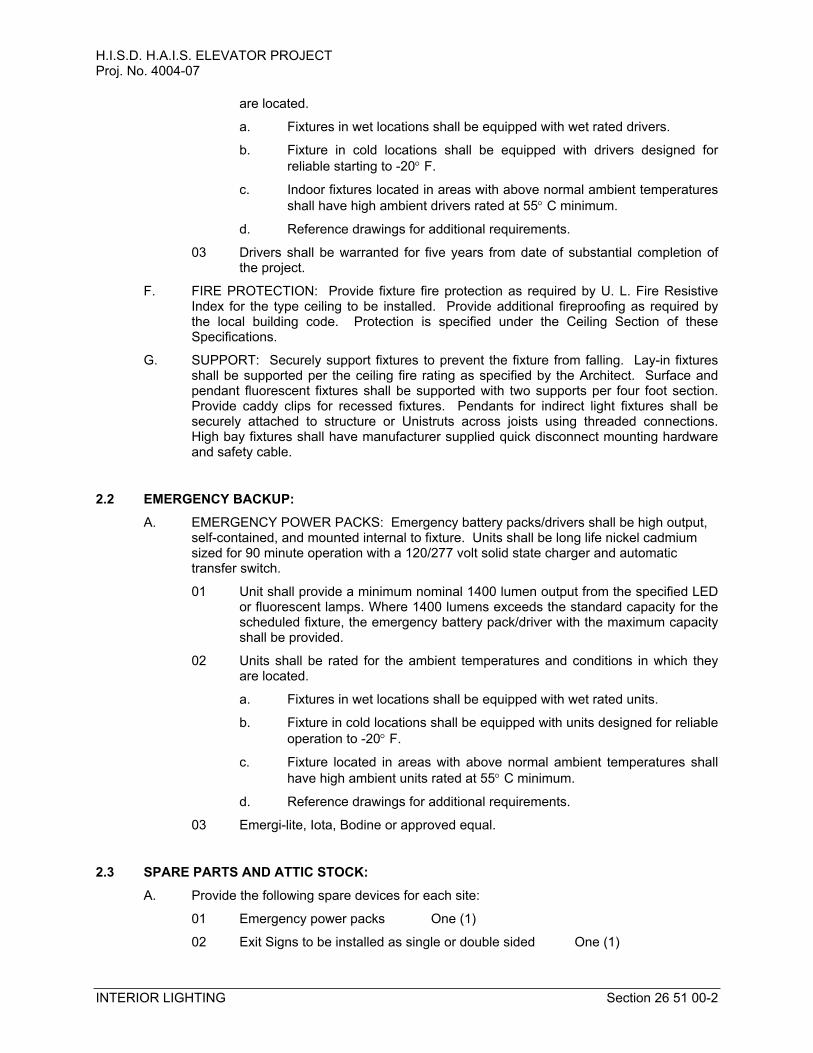
H.I.S.D. H.A.I.S. ELEVATOR PROJECTProj. No. 4004-07
INTERIOR LIGHTING Section 26 51 00-2
are located.
a. Fixtures in wet locations shall be equipped with wet rated drivers.
b. Fixture in cold locations shall be equipped with drivers designed for
reliable starting to -20 F.
c. Indoor fixtures located in areas with above normal ambient temperatures
shall have high ambient drivers rated at 55 C minimum.
d. Reference drawings for additional requirements.
03 Drivers shall be warranted for five years from date of substantial completion of the project.
F. FIRE PROTECTION: Provide fixture fire protection as required by U. L. Fire Resistive Index for the type ceiling to be installed. Provide additional fireproofing as required by the local building code. Protection is specified under the Ceiling Section of these Specifications.
G. SUPPORT: Securely support fixtures to prevent the fixture from falling. Lay-in fixtures shall be supported per the ceiling fire rating as specified by the Architect. Surface and pendant fluorescent fixtures shall be supported with two supports per four foot section. Provide caddy clips for recessed fixtures. Pendants for indirect light fixtures shall be securely attached to structure or Unistruts across joists using threaded connections. High bay fixtures shall have manufacturer supplied quick disconnect mounting hardware and safety cable.
2.2 EMERGENCY BACKUP:
A. EMERGENCY POWER PACKS: Emergency battery packs/drivers shall be high output, self-contained, and mounted internal to fixture. Units shall be long life nickel cadmium sized for 90 minute operation with a 120/277 volt solid state charger and automatic transfer switch.
01 Unit shall provide a minimum nominal 1400 lumen output from the specified LED or fluorescent lamps. Where 1400 lumens exceeds the standard capacity for the scheduled fixture, the emergency battery pack/driver with the maximum capacity shall be provided.
02 Units shall be rated for the ambient temperatures and conditions in which they are located.
a. Fixtures in wet locations shall be equipped with wet rated units.
b. Fixture in cold locations shall be equipped with units designed for reliable
operation to -20 F.
c. Fixture located in areas with above normal ambient temperatures shall
have high ambient units rated at 55 C minimum.
d. Reference drawings for additional requirements.
03 Emergi-lite, Iota, Bodine or approved equal.
2.3 SPARE PARTS AND ATTIC STOCK:
A. Provide the following spare devices for each site:
01 Emergency power packs One (1)
02 Exit Signs to be installed as single or double sided One (1)
H.I.S.D. H.A.I.S. ELEVATOR PROJECTProj. No. 4004-07
INTERIOR LIGHTING Section 26 51 00-3
B. Electrical contractor shall include in his bid the cost to provide and install the additional spare parts and associated wiring as directed by the Owner/engineer. All devices not used during construction shall be turned over to the Owner at the time of job completion.
END OF SECTION

H.I.S.D. H.A.I.S. ELEVATOR PROJECTProj. No. 4004-07
EXTERIOR LIGHTING Section 26 56 00-1
SECTION 26 56 00 EXTERIOR LIGHTING
PART 1 - GENERAL
1.1 RELATED DOCUMENTS
A. The General Provisions of the Contract, including General, Supplementary and Special Conditions, apply to the work specified in this Section.
B. The General Electrical Requirements as specified in Sections 26, apply to the work specified in this Section.
C. Equipment shall meet or follow applicable requirements in other sections of the specifications and on the drawings.
D. Equipment shall meet applicable requirements include in the NEC, UL, NEMA and ANSI Standards and be so labeled.
E. Provide Shop Drawings per Section 26 00 00.
PART 2 - MATERIALS AND METHODS
2.1 LIGHT FIXTURES
A. GENERAL: Provide fixtures as shown and scheduled on the drawings, with all necessary accessories for a complete installation. Provide all lamps as scheduled.
B. LED FIXTURES: LED lamps shall be 4000K color temperature with a minimum CRI of 70 and shall come standard with a five year warranty on LED boards and drivers. All LED fixtures shall be DesignLights Consortium (DLC) or EnergyStar certified. Models shall have a minimum projected life of 50,000 hours at 70% lumen output using IESNA LM-79, LM-80 and TM-21 standards.
C. LED DRIVERS: LED drivers shall be electronic-type, labeled as compliant with radio frequency interference (RFI) requirements of FCC Title 47 Part 15, and comply with NEMA SSL 1 “Electronic Drivers for LED Devices, Arrays, or Systems”. LED drivers shall have a sound rating of “A”, have a minimum efficiency of 85%, and be rated for a THD of less than 20 percent at all input voltages.
01 Dimmable LED fixtures shall have a 0-10 volt, 3-wire, phase, or a two-step (50%-100%) line voltage, two switch controlled dimming driver, as shown on the drawings. Dimmable LED drivers shall be capable of dimming without LED strobing or flicker across their full dimming range.
02 Drivers shall be rated for the ambient temperatures and conditions in which they are located.
a. Outdoor fixtures shall be equipped with wet rated drivers designed for a
minimum reliable operation temperature range of 0 F to 104F.
b. Reference drawings for additional requirements.
03 Drivers shall be warranted for five years from date of substantial completion of the project.
2.2 EMERGENCY BACKUP:
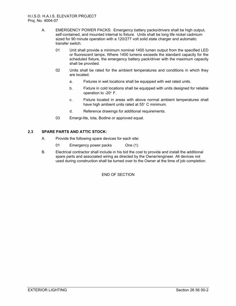
H.I.S.D. H.A.I.S. ELEVATOR PROJECTProj. No. 4004-07
EXTERIOR LIGHTING Section 26 56 00-2
A. EMERGENCY POWER PACKS: Emergency battery packs/drivers shall be high output, self-contained, and mounted internal to fixture. Units shall be long life nickel cadmium sized for 90 minute operation with a 120/277 volt solid state charger and automatic transfer switch.
01 Unit shall provide a minimum nominal 1400 lumen output from the specified LED or fluorescent lamps. Where 1400 lumens exceeds the standard capacity for the scheduled fixture, the emergency battery pack/driver with the maximum capacity shall be provided.
02 Units shall be rated for the ambient temperatures and conditions in which they are located.
a. Fixtures in wet locations shall be equipped with wet rated units.
b. Fixture in cold locations shall be equipped with units designed for reliable
operation to -20 F.
c. Fixture located in areas with above normal ambient temperatures shall
have high ambient units rated at 55 C minimum.
d. Reference drawings for additional requirements.
03 Emergi-lite, Iota, Bodine or approved equal.
2.3 SPARE PARTS AND ATTIC STOCK:
A. Provide the following spare devices for each site:
01 Emergency power packs One (1)
B. Electrical contractor shall include in his bid the cost to provide and install the additional spare parts and associated wiring as directed by the Owner/engineer. All devices not used during construction shall be turned over to the Owner at the time of job completion.
END OF SECTION
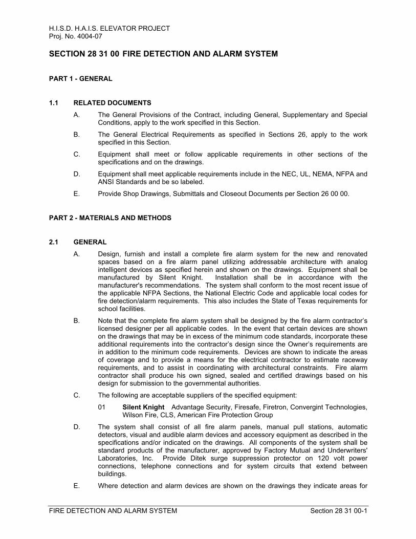
H.I.S.D. H.A.I.S. ELEVATOR PROJECTProj. No. 4004-07
FIRE DETECTION AND ALARM SYSTEM Section 28 31 00-1
SECTION 28 31 00 FIRE DETECTION AND ALARM SYSTEM
PART 1 - GENERAL
1.1 RELATED DOCUMENTS
A. The General Provisions of the Contract, including General, Supplementary and Special Conditions, apply to the work specified in this Section.
B. The General Electrical Requirements as specified in Sections 26, apply to the work specified in this Section.
C. Equipment shall meet or follow applicable requirements in other sections of the specifications and on the drawings.
D. Equipment shall meet applicable requirements include in the NEC, UL, NEMA, NFPA and ANSI Standards and be so labeled.
E. Provide Shop Drawings, Submittals and Closeout Documents per Section 26 00 00.
PART 2 - MATERIALS AND METHODS
2.1 GENERAL
A. Design, furnish and install a complete fire alarm system for the new and renovated spaces based on a fire alarm panel utilizing addressable architecture with analog intelligent devices as specified herein and shown on the drawings. Equipment shall be manufactured by Silent Knight. Installation shall be in accordance with the manufacturer's recommendations. The system shall conform to the most recent issue of the applicable NFPA Sections, the National Electric Code and applicable local codes for fire detection/alarm requirements. This also includes the State of Texas requirements for school facilities.
B. Note that the complete fire alarm system shall be designed by the fire alarm contractor’s licensed designer per all applicable codes. In the event that certain devices are shown on the drawings that may be in excess of the minimum code standards, incorporate these additional requirements into the contractor’s design since the Owner’s requirements are in addition to the minimum code requirements. Devices are shown to indicate the areas of coverage and to provide a means for the electrical contractor to estimate raceway requirements, and to assist in coordinating with architectural constraints. Fire alarm contractor shall produce his own signed, sealed and certified drawings based on his design for submission to the governmental authorities.
C. The following are acceptable suppliers of the specified equipment:
01 Silent Knight Advantage Security, Firesafe, Firetron, Convergint Technologies, Wilson Fire, CLS, American Fire Protection Group
D. The system shall consist of all fire alarm panels, manual pull stations, automatic detectors, visual and audible alarm devices and accessory equipment as described in the specifications and/or indicated on the drawings. All components of the system shall be standard products of the manufacturer, approved by Factory Mutual and Underwriters' Laboratories, Inc. Provide Ditek surge suppression protector on 120 volt power connections, telephone connections and for system circuits that extend between buildings.
E. Where detection and alarm devices are shown on the drawings they indicate areas for
H.I.S.D. H.A.I.S. ELEVATOR PROJECTProj. No. 4004-07
FIRE DETECTION AND ALARM SYSTEM Section 28 31 00-2
detection and alarm coverage and not the exact number and placement of devices. Provide devices in sufficient number and locate to protect and alarm the specified areas in accordance with the NFPA, these specifications and the limitations of the devices provided.
F. Under this Division, engage the services of a fire alarm company who is an authorized distributor for an approved fire alarm system (as indicated below) who shall:
01 Maintain a staff of specialists for engineering assistance, installation and maintenance of the fire alarm system and associated equipment.
02 Stock the required spare parts to keep the fire alarm system in operation.
03 Have proof of experience in the installation and maintenance of the type of fire alarm system specified herein.
G. After installation and prior to the final inspection, the Contractor must certify in a letter to the Owner that the system is working in accordance with the Contract Documents.
H. Provide an adequate period of instruction on the operation of the system to the Owner's designated personnel upon completion of the system installation.
I. Provide the Owner with the following:
01 Two composite wiring diagrams of the system indicating point to point connections, one to be placed in the control panel.
02 Two block diagrams of the system indicating conduit and number and size of wires between all devices, one to be placed in the control panel.
03 Three complete instructional/operational maintenance manuals including as-built drawings, test reports, calculations, etc. One shall be placed in the control panel.
04 Floor plan of building noting zoning, pull station and detector locations, acceptable to the Fire Marshall. Provide frame and install where directed by the Fire Marshall.
J. Contractor shall have a representative at the job site during the final inspection by the Engineer to demonstrate system operation and specification compliance. Representative will be required to "smoke test" a number of randomly selected active devices.
K. System warranty shall be for one year of complete maintenance coverage after final acceptance of the system and include all material and labor to provide consistent peak performance of the system. Post-warranty maintenance shall be available on contract or call basis.
2.2 SYSTEM LAYOUT
A. Device layout shown on the Drawings shows areas of coverage and to assist the electrical contractor in estimating junction box requirements during bidding. Fire alarm supplier shall properly design a system based on his equipment and devices that meets ADA, NFPA and Texas Accessibility requirements and these specifications.
B. Provide sound and visual alarm coverage of the building.
C. Provide smoke detector coverage of all elevator rooms, at each new panel or power supply, and additionally as indicated on the drawings.
D. Provide smoke duct detector in the return air or supply air of each air handling unit. Where return air is not ducted, provide photoelectric coverage of return air openings in the room. Provide smoke duct detector in each fan powered VAV box 2000 CFM or larger.
H.I.S.D. H.A.I.S. ELEVATOR PROJECTProj. No. 4004-07
FIRE DETECTION AND ALARM SYSTEM Section 28 31 00-3
E. Provide heat detector coverage of all elevator landings and additionally as indicated on the drawings.
F. Provide a heat detector located in the elevator equipment room and elevator shaft. Upon alarm, elevator shall be signaled to return to the first floor, then elevator power shunt trip circuit breakers shall be tripped. In the event an alarm is sounded by a device other than these heat detectors, elevator shall be signaled to return to the first floor, but the circuit breakers shall not be tripped.
G. Refer to Drawings for additional information.
2.3 SYSTEM OPERATION
A. Actuation of any alarm initiating device shall cause the following:
01 An LCD readout on the main control panel shall indicate the device in alarm.
02 Alarm tones shall sound throughout the facility. Upon expiration of the alert tone, a digitized predetermined voice evacuation message shall be automatically transmitted throughout the facility via evacuation speakers. The system shall have the capability to generate multiple distinct digital messages as determined by event initiated programs
03 All horn/flasher alarms shall sound continuously until reset at main panel.
04 De-energize air handling units serving the area in alarm. Also de-energize supply fans, VAV boxes and other air circulating devices if 2000 CFM or over, serving the area in alarm. Exhaust fans to the exterior and devices less than 2000 CFM are required to be controlled.
a. De-energize all high volume low speed (HVLS) fans.
05 Interface with the elevators.
06 Release fire doors and smoke dampers.
07 Transmit alarm warning to remote location via telephone line. Alarm communication shall send individual point information to the central receiving station.
B. The actuation of automatic detection devices shall be visually identified by light on device. The light shall remain illuminated until the initiating device has been restored to normal and the Fire Alarm Panel reset. A remote alarm lamp shall light where indicated on drawings.
2.4 SYSTEM PANEL
A. GENERAL: All equipment shall be manufactured by the same company as the control panel or be a factory authorized compatible device. Devices that may operate but are not factory authorized compatible shall not be used. This includes remote power supplies, horns and strobes. Devices shall be WHITE in color where that option is available. Communication between the Silent Knight control panel and remote devices shall use the existing protocol.
B. CONTROL PANEL: The existing control panel is a Silent Knight Model 5820XL microprocessor based, addressable intelligent system enclosed in a semi-flush style cabinet. The door and frame assembly shall be equipped with a lock and transparent door panel for viewing of indicators of operation and annunciation. The control panel shall contain, but not limited to the following:
01 Control modules as required to provide system monitoring, alarm control, trouble
H.I.S.D. H.A.I.S. ELEVATOR PROJECTProj. No. 4004-07
FIRE DETECTION AND ALARM SYSTEM Section 28 31 00-4
sensing and remote equipment control.
02 City/remote station module to service as interface unit between the fire alarm control panel and an authorized remote monitoring point.
03 Power supply modules as required to supply continuous filtered power of the proper voltage. Module shall indicate a normal power, battery trouble and power supply trouble, all readable on front of the enclosure. System shall also meet additional spare capacity requirements below.
04 Sealed and rechargeable battery supply, sized for 24 hour sensing and 15 minute alarm capability. System shall also meet additional spare capacity requirements below.
05 Remote alarm signal distributing panels with power supplies as needed by final design of the fire alarm contractor. Remote power supplies shall be located in mechanical and electrical rooms. Do not install in storage rooms or finished spaces.
06 All power supplies, amplifiers and battery supplies shall be sized based on the system installed plus 50% additional alarm devices. For example, no more than 4A shall be allocated on a 6A power supply or 50W on a 75W amplifier to provide spare capacity for future growth. Power supply, amplifier and battery calculations must be submitted for engineer review.
2.5 REMOTE EQUIPMENT
A. MANUAL PULL STATIONS: Addressable type, red Lexan, non-coded, dual action type. Provide Stopper II cover with battery powered sounder over all pull stations in unrestricted areas.
B. AREA SMOKE DETECTORS: White, analog addressable, photoelectric type, non-polarized with 360° smoke entry, LED normal/alarm status light and separable base.
C. DUCT DETECTORS: Analog addressable, photoelectric type with DPST auxiliary relay. Provide LED remote alarm light with engraved stainless steel plate on ceiling near detector where detectors are not located in mechanical rooms.
01 Provide a duct smoke detector located within 5 feet of each smoke or fire/smoke damper. Reference mechanical drawings for locations.
D. HEAT DETECTORS: White, analog addressable. Heat detectors shall be rate of rise type except in kitchen spaces which shall be 135°F fixed temperature.
E. COMBINATION DETECTORS:
01 Where smoke, heat and/or carbon monoxide detectors are shown together they may be combined into a single device meeting all requirements and functionality were they to be provided separately.
F. HORNS: White, semi-flush, ADA compatible, electronic horn with high visibility, synchronized strobe and field selectable sound level. Set level based on individual application (hall, classroom, restroom, office, etc.) Audible portion shall sound a three beat temporal tone for alarm signaling as required by NFPA. Strobe intensity shall conform to NFPA Chapter 6 requirements and also 75 candela to meet ADA and TAS requirements.
G. STROBE LIGHTS: White, semi-flush, ADA compatible, synchronized strobe with intensity suitable for the individual application (hall, classroom, restroom, office, etc.). Strobe intensity shall conform to NFPA 1993 Chapter 6 requirements and also 75 candela to meet ADA and TAS requirements.
H.I.S.D. H.A.I.S. ELEVATOR PROJECTProj. No. 4004-07
FIRE DETECTION AND ALARM SYSTEM Section 28 31 00-5
H. RELAYS: Provide and install control relays to perform the specified functions. This includes relays to shut down the various HVAC equipment. Relays shall be mounted near items to be controlled. Coordinate with HVAC controls contractor for relay contact voltage capability (120 volts minimum) and preferred mounting location.
I. WEATHERPROOF: Devices located outside, even if sheltered from rain shall be weatherproof and suitable for outdoor installation.
J. PROTECTIVE GUARDS: Provide Stopper Type Lexan protective guards on devices located in gymnasiums and locker rooms, and in additional areas noted on the Drawings.
K. REMOTE STROBE CONTROLLER: Provide local controller as necessary to power and synchronize flash for strobe devices.
L. SURGE SUPPRESSOR: Provide a Ditek Model DTK-120SD surge suppressor mounted in a junction box above the ceiling at the fire alarm panel. Note unit must be a minimum of three feet from the panel. Fire alarm panel shall monitor the suppressor dry contact so panel will go into failure if the suppressor is inoperable. Provide Ditek surge suppression protector on all 120 volt power connections and for system low voltage circuits (including telephone circuits) that extend to the exterior of the building or between buildings.
2.6 SPARE PARTS AND ATTIC STOCK
A. Provide the following spare devices:
01 Ceiling Smoke Detectors Two (2)
02 Ceiling Heat Detectors Two (2)
03 Pull Station One (1)
04 Monitor Module One (1)
05 Control Module One (1)
B. The fire alarm contractor shall include in their bid the cost to furnish and install the additional spare parts and attic stock and all associated cabling. These devices shall be used to fulfill any changes request issued until the list is depleted. Upon the completion of the project, all remaining material shall be delivered to the project for Owner stock. No devices shall be used without documentation and written authorization from the Owner’s representative. Contractor shall obtain a signed transmittal of additional equipment to the owner at the end of the project. The signed transmittal shall be included in the contractor’s closeout documents.
2.7 INSTALLATION
A. WIRING:
01 Fire alarm contractor shall provide and install all wiring for his system. He shall include wiring of control relays and the landing of power and control wiring to these relays to “break” control circuits or power wiring to controls transformers, door release magnets and other devices requiring shutdown. HVAC controls interlock wiring between fire alarm relay and starters, VFD’s or other temperature controls devices shall be provided by the temperature controls contractor.
02 All wiring shall be installed in conduit. In existing areas not in mechanical rooms, use metal, Wiremold surface raceway where exposed. Low smoke wiring may be installed without conduit above accessible ceilings if wiring is supported at structure or walls 48” on center with cable rings or other manufactured devices specifically designed for supporting cable. Do not support from data system
H.I.S.D. H.A.I.S. ELEVATOR PROJECTProj. No. 4004-07
FIRE DETECTION AND ALARM SYSTEM Section 28 31 00-6
cable rings. Provide conduit sleeve with protective end fittings through all walls and floors where raceway system is not installed. All connections shall be in supported junction boxes. All auxiliary control circuits shall be connected to NAC type circuits and be supervised per NFPA.
03 Wiring outside or between buildings shall be suitable for and installed properly for this application, and comply with NEC Article 800. Provide isolation and surge suppression for all aerial and inter-building cables.
04 Wire shall be color coded in accordance with IPCEA Standards. Provide numbered labels on all wires entering annunciators, terminal boxes and the main control panel.
05 The minimum wire sizes to be used when not otherwise directed by Codes are as follows:
a. Detector Circuits #18 AWG
b. Remote Annunciators #18 AWG
c. Remote Alarm Lamps #18 AWG
d. Notification Circuits: #14 AWG (up to 1.1 A) or larger as necessary
e. Speaker Circuits #16 AWG Twisted/Shielded
f. 120 volt or higher #12 AWG
g. All other wiring #18 AWG
06 Limited energy cable for 24 volt low voltage systems shall be Plastic Wire and Cable Company Low Energy Safety Control Wire, 90° C, red, or equal.
a. Provide solid core up to #14 AWG and stranded for #12 AWG and larger.
07 Should 120 volt power be required other than at the main panel, include the cost of additional circuits.
B. RACEWAY SYSTEMS
01 RACEWAY CAPACITY: It shall be the contractor's responsibility to determine the correct sizes of all type of raceway, to be installed, as instructed in the NEC and all applicable Codes.
02 See Section Common Work Results for Electrical for conduit types and installation requirements.
C. CEILING SUPPORTS: All devices installed in lay-in ceilings shall have bracket to support device from ceiling tees.
D. MOUNTING HEIGHTS
01 PULL STATIONS: 46" above finished floor to top
02 HORNS/SPEAKERS/STROBES: 82" or 6" below ceiling (or on ceiling)
E. LABELING: All devices shall be labeled with their system address.
F. REMOTE LED INDICATOR: Any automatic detection device concealed from view, such as a duct detector for an FCU above the ceiling, shall have a remote alarm lamp with engraved steel faceplate on the ceiling or wall visible from an occupied space.
2.8 TESTING
A. REQUIREMENTS: All components and circuits of the fire alarm system shall be tested under operating conditions for proper functions. The testing shall demonstrate that all
H.I.S.D. H.A.I.S. ELEVATOR PROJECTProj. No. 4004-07
FIRE DETECTION AND ALARM SYSTEM Section 28 31 00-7
requirements as herein specified have been successfully accomplished, and that the system is fully operational. Testing shall include, but shall not be limited to, the following:
01 EXISTING SYSTEM: The fire alarm contractor shall perform a complete test of the existing system, noting any alarms or non-functioning devices or equipment and the report shall be provided to the Owner Prior to beginning work. Deficiencies shall be corrected utilizing the spare devices as directed by the Owner or the Owner’s agent. Any devices or equipment that becomes non-functioning and is not identified as such on the report shall be corrected at no cost to the Owner. If no system test is performed or report provided prior to beginning work, the contractor shall be responsible for repairing and/or replacing all non-functioning devices prior to acceptance by the Owner.
02 INITIATING DEVICES: Each initiating device shall be activated and proper operation of all visual and audible alarm and auxiliary devices shall be demonstrated.
03 DUCT AND PHOTOELECTRIC DETECTORS: Each detector shall be adjusted with electronic measuring equipment for calibration sensitivity. Each detector shall subsequently be checked for operation.
04 AUDIBLE ALARM DEVICES: Each audible alarm device shall be tested for proper operation and connection to the correct circuit.
B. TEST REPORT: Upon completion of testing, three copies of a report shall be submitted to the Owner containing the following information:
01 Complete as-built wiring diagrams
02 Detailed catalog data on all components of system
03 Ionization detector sensitivity settings
04 Certification of system performance and operation as specified
C. FIRE MARSHAL REVIEW: System shall be demonstrated to the local Fire Marshall for his review and approval. Make adjustments as required to obtain the approval for certificate of occupancy. Provide minimum 48 hour advance notice of the demonstration to the Owner/Engineer so they may be in attendance.
2.9 WARRANTY
A. System (materials and installation) shall be warranted for one year following substantial completion. Problem trouble shooting and repair shall begin within 24 hours of notification.
2.10 TRAINING
A. Provide designated representatives of the Owner with complete technical training in the proper operation of the system, at a time mutually convenient. He shall assist in the preparation of a set of detailed operating instructions for the system.
B. Provide number of hours and quantity of training sessions to Owner’s onsite and maintenance personnel as required in specification section 26 00 00.
END OF SECTION

IDG Architects Houston Independent School District Proj. No. 4004-07 H.A.I.S. Elevator Project
STORM SEWAGE SYSTEM
33 41 00
IDG Architects Houston Independent School District
Proj. No. 4004-07 H.A.I.S. Elevator Project
Site Clearing 31 10 00-1
SECTION 31 10 00 SITE CLEARING
PART 1 GENERAL
1.1 SECTION INCLUDES
A. Site clearing of designated site improvements and landscaping
B. Tagging of vegetation and items to remain after site clearing.
1.2 RELATED SECTIONS
A. Section 31 20 00 - Earth Moving.
1.3 SUBMITTALS
A. Submit under provisions of Section 01 30 00 - Administrative Requirements.
B. Clearing Plan: Submit list of proposed operations, and identify site improvements and features to remain. Include proposed location for stockpiles.
1.4 QUALITY ASSURANCE
A. Installer Qualifications: Minimum 2 year experience performing similar operations.
1.5 PRE-INSTALLATION MEETINGS
A. Convene minimum two weeks prior to starting work of this section.
1.6 SEQUENCING
A. Ensure that work of this section is performed in time to prevent interruption of construction progress.
PART 2 PRODUCTS
2.1 MANUFACTURERS
A. Acceptable Manufacturers: ______.
B. Substitutions: Not permitted.
C. Requests for substitutions will be considered in accordance with provisions of Section 01 60 00 - Product Requirements.
2.2 MATERIALS
A. Site Clearing Materials Suitable for Site Conditions: 1. Tree protection. 2. Erosion control. 3. Siltation control. 4. Dust control materials.
PART 3 EXECUTION
IDG Architects Houston Independent School District
Proj. No. 4004-07 H.A.I.S. Elevator Project
Site Clearing 31 10 00-2
3.1 SITE CLEARING OPERATIONS
A. Protection of existing trees, vegetation, landscaping, and site improvements not scheduled for clearing which might be damaged by construction activities.
B. Trimming of existing trees and vegetation as recommended by arborist for protection during construction activities.
C. Clearing and grubbing of stumps and vegetation, and removal and disposal of debris, rubbish, designated trees, and site improvements.
D. Topsoil stripping and stockpiling.
E. Temporary erosion control, siltation control, and dust control.
F. Temporary protection of adjacent property, structures, benchmarks, and monuments.
G. Temporary relocation of play structures, fencing, and site improvements scheduled for reuse.
H. Watering of trees and vegetation during construction activities.
I. Removal and legal disposal of cleared materials.
3.2 CLEARING
A. Prevent damage to existing improvements indicated to remain, including improvements on and off site. Protect existing trees and vegetation indicated to remain. Do not stockpile materials and restrict traffic within drip line of existing trees to remain. Provide and maintain temporary guards to encircle trees or groups of trees to remain; obtain approval before beginning work.
B. Water vegetation as required to maintain health. Cover temporarily exposed roots with wet burlap and backfill as soon as possible. Coat cut plant surfaces with approved emulsified asphalt plant coating.
C. Repair or replace vegetation, which has been damaged, or pay damages. Remove heavy growths of grass before stripping. Stockpile satisfactory topsoil containing no large stones, foreign matter and weeds on site for reuse.
D. Completely remove all improvements including stumps and debris except for those indicated to remain. Remove below grade improvements at least 12" below finish grade and to the extent necessary so as not to interfere with new construction. Remove abandoned mechanical and electrical work as required.
E. Prevent erosion and siltation of streets, catch basins and piping. Control windblown dust. Remove waste materials and unsuitable soil from site and dispose of in a legal manner.
END OF SECTION
EARTH MOVING 312000 - 1
IDG Architects Houston Independent School District Proj. No. 4004-07 H.A.I.S. Elevator Project
SECTION 312000 - EARTH MOVING
PART 1 - GENERAL
1.1 RELATED DOCUMENTS
A. Drawings and general provisions of the Contract, including General and Supplementary Conditions and Division 01 Specification Sections, apply to this Section.
1.2 SUMMARY
A. Section Includes:
1. Excavating and filling for rough grading the Site. 2. Preparing subgrades for slabs-on-grade walks pavements turf and grasses and plants. 3. Excavating and backfilling for buildings and structures. 4. Drainage course for concrete slabs-on-grade. 5. Subbase course for concrete pavements. 6. Subbase course and base course for asphalt paving. 7. Subsurface drainage backfill for walls and trenches. 8. Excavating and backfilling trenches for utilities and pits for buried utility structures. 9. Excavating well hole to accommodate elevator-cylinder assembly.
1.3 DEFINITIONS
A. Backfill: Soil material or controlled low-strength material used to fill an excavation.
1. Initial Backfill: Backfill placed beside and over pipe in a trench, including haunches to support sides of pipe.
2. Final Backfill: Backfill placed over initial backfill to fill a trench.
B. Base Course: Aggregate layer placed between the subbase course and hot-mix asphalt paving.
C. Bedding Course: Aggregate layer placed over the excavated subgrade in a trench before laying pipe.
D. Borrow Soil: Satisfactory soil imported from off-site for use as fill or backfill.
E. Drainage Course: Aggregate layer supporting the slab-on-grade that also minimizes upward
capillary flow of pore water.
F. Excavation: Removal of material encountered above subgrade elevations and to lines and dimensions indicated.
1. Authorized Additional Excavation: Excavation below subgrade elevations or beyond
indicated lines and dimensions as directed by Architect. Authorized additional excavation
EARTH MOVING 312000 - 2
IDG Architects Houston Independent School District Proj. No. 4004-07 H.A.I.S. Elevator Project
and replacement material will be paid for according to Contract provisions for changes in the Work.
2. Bulk Excavation: Excavation more than 10 feet (3 m) in width and more than 30 feet (9 m) in length.
3. Unauthorized Excavation: Excavation below subgrade elevations or beyond indicated lines and dimensions without direction by Architect. Unauthorized excavation, as well as remedial work directed by Architect, shall be without additional compensation.
G. Fill: Soil materials used to raise existing grades.
H. Rock: Rock material in beds, ledges, unstratified masses, conglomerate deposits, and boulders
of rock material that exceed 1 cu. yd. for bulk excavation or 3/4 cu. yd. for footing, trench, and pit excavation that cannot be removed by rock-excavating equipment equivalent to the following in size and performance ratings, without systematic drilling, ram hammering, ripping, or blasting, when permitted:
1. Equipment for Footing, Trench, and Pit Excavation: Late-model, track-mounted
hydraulic excavator; equipped with a 42-inch- (1065-mm-) maximum-width, short-tip- radius rock bucket; rated at not less than 138-hp (103-kW) flywheel power with bucket- curling force of not less than 28,700 lbf (128 kN) and stick-crowd force of not less than 18,400 lbf (82 kN) with extra-long reach boom.
2. Equipment for Bulk Excavation: Late-model, track-mounted loader; rated at not less than 230-hp (172-kW) flywheel power and developing a minimum of 47,992-lbf (213.3-kN) breakout force with a general-purpose bare bucket.
I. Rock: Rock material in beds, ledges, unstratified masses, conglomerate deposits, and boulders
of rock material 3/4 cu. yd. (0.57 cu. m)] or more in volume that exceed a standard penetration resistance of 100 blows/2 inches (97 blows/50 mm) when tested by a geotechnical testing agency, according to ASTM D 1586.
J. Structures: Buildings, footings, foundations, retaining walls, slabs, tanks, curbs, mechanical and
electrical appurtenances, or other man-made stationary features constructed above or below the ground surface.
K. Subbase Course: Aggregate layer placed between the subgrade and base course for hot-mix
asphalt pavement, or aggregate layer placed between the subgrade and a cement concrete pavement or a cement concrete or hot-mix asphalt walk.
L. Subgrade: Uppermost surface of an excavation or the top surface of a fill or backfill
immediately below subbase, drainage fill, drainage course, or topsoil materials.
M. Utilities: On-site underground pipes, conduits, ducts, and cables as well as underground services within buildings.
1.4 ACTION SUBMITTALS
A. Product Data: For each type of the following manufactured products required:
1. Controlled low-strength material, including design mixture. 2. Warning tapes.
EARTH MOVING 312000 - 3
IDG Architects Houston Independent School District Proj. No. 4004-07 H.A.I.S. Elevator Project
B. Samples for Verification: For the following products, in sizes indicated below:
1. Warning Tape: 12 inches (300 mm) long; of each color.
1.5 INFORMATIONAL SUBMITTALS
A. Qualification Data: For qualified testing agency.
B. Material Test Reports: For each [on-site] [and] [borrow] soil material proposed for fill and backfill as follows:
1. Classification according to ASTM D 2487. 2. Laboratory compaction curve according to [ASTM D 698] [ASTM D 1557].
C. Preexcavation Photographs or Videotape: Show existing conditions of adjoining construction
and site improvements, including finish surfaces that might be misconstrued as damage caused by earth-moving operations. Submit before earth moving begins.
1.6 QUALITY ASSURANCE
A. Geotechnical Testing Agency Qualifications: Qualified according to ASTM E 329 and ASTM D 3740 for testing indicated.
1.7 FIELD CONDITIONS
A. Traffic: Minimize interference with adjoining roads, streets, walks, and other adjacent occupied or used facilities during earth-moving operations.
1. Do not close or obstruct streets, walks, or other adjacent occupied or used facilities
without permission from Owner and authorities having jurisdiction. 2. Provide alternate routes around closed or obstructed traffic ways if required by Owner or
authorities having jurisdiction.
B. Improvements on Adjoining Property: Authority for performing earth moving indicated on property adjoining Owner's property will be obtained by Owner before award of Contract.
1. Do not proceed with work on adjoining property until directed by Architect.
C. Utility Locator Service: Notify utility locator service call 811 for area where Project is located
before beginning earth-moving operations.
D. Do not commence earth-moving operations until temporary site fencing and erosion- and sedimentation-control.
E. Do not commence earth-moving operations until plant-protection measures as indicated on
plans are in place.
F. The following practices are prohibited within protection zones:
EARTH MOVING 312000 - 4
IDG Architects Houston Independent School District Proj. No. 4004-07 H.A.I.S. Elevator Project
1. Storage of construction materials, debris, or excavated material. 2. Parking vehicles or equipment. 3. Foot traffic. 4. Erection of sheds or structures. 5. Impoundment of water. 6. Excavation or other digging unless otherwise indicated. 7. Attachment of signs to or wrapping materials around trees or plants unless otherwise
indicated.
G. Do not direct vehicle or equipment exhaust towards protection zones.
H. Prohibit heat sources, flames, ignition sources, and smoking within or near protection zones.
PART 2 - PRODUCTS
2.1 SOIL MATERIALS
A. General: Provide borrow soil materials when sufficient satisfactory soil materials are not available from excavations.
B. Satisfactory Soils: Soil Classification [Groups GW, GP, GM, SW, SP, and SM according to
ASTM D 2487] [Groups A-1, A-2-4, A-2-5, and A-3 according to AASHTO M 145], or a combination of these groups; free of rock or gravel larger than 3 inches (75 mm) in any dimension, debris, waste, frozen materials, vegetation, and other deleterious matter.
1. Liquid Limit: <Insert value>. 2. Plasticity Index: <Insert value>.
C. Unsatisfactory Soils: Soil Classification [Groups GC, SC, CL, ML, OL, CH, MH, OH, and PT
according to ASTM D 2487] [Groups A-2-6, A-2-7, A-4, A-5, A-6, and A-7 according to AASHTO M 145], or a combination of these groups.
1. Unsatisfactory soils also include satisfactory soils not maintained within 2 percent of
optimum moisture content at time of compaction.
D. Subbase Material: Naturally or artificially graded mixture of natural or crushed gravel, crushed stone, and natural or crushed sand; ASTM D 2940/D 2940M; with at least 90 percent passing a 1-1/2-inch (37.5-mm) sieve and not more than 12 percent passing a No. 200 (0.075-mm) sieve.
E. Base Course: Naturally or artificially graded mixture of natural or crushed gravel, crushed
stone, and natural or crushed sand; ASTM D 294/D 2940M 0; with at least 95 percent passing a 1-1/2-inch (37.5-mm) sieve and not more than 8 percent passing a No. 200 (0.075-mm) sieve.
F. Engineered Fill: Naturally or artificially graded mixture of natural or crushed gravel, crushed
stone, and natural or crushed sand; ASTM D 2940/D 2940M; with at least 90 percent passing a 1-1/2-inch (37.5-mm) sieve and not more than 12 percent passing a No. 200 (0.075-mm) sieve.
EARTH MOVING 312000 - 5
IDG Architects Houston Independent School District Proj. No. 4004-07 H.A.I.S. Elevator Project
G. Bedding Course: Naturally or artificially graded mixture of natural or crushed gravel, crushed stone, and natural or crushed sand; ASTM D 2940/D 2940M; except with 100 percent passing a 1-inch (25-mm) sieve and not more than 8 percent passing a No. 200 (0.075-mm) sieve.
H. Drainage Course: Narrowly graded mixture of [washed ]crushed stone, or crushed or uncrushed
gravel; ASTM D 448; coarse-aggregate grading Size 57; with 100 percent passing a 1-1/2-inch (37.5-mm) sieve and zero to 5 percent passing a No. 8 (2.36-mm) sieve.
I. Filter Material: Narrowly graded mixture of natural or crushed gravel, or crushed stone and
natural sand; ASTM D 448; coarse-aggregate grading Size 67; with 100 percent passing a 1- inch (25-mm) sieve and zero to 5 percent passing a No. 4 (4.75-mm) sieve.
J. Sand: ASTM C 33/C 33M; fine aggregate.
K. Impervious Fill: Clayey gravel and sand mixture capable of compacting to a dense state.
2.2 ACCESSORIES
A. Warning Tape: Acid- and alkali-resistant, polyethylene film warning tape manufactured for marking and identifying underground utilities, 6 inches (150 mm) wide and 4 mils (0.1 mm) thick, continuously inscribed with a description of the utility; colored as follows:
1. Red: Electric. 2. Yellow: Gas, oil, steam, and dangerous materials. 3. Orange: Telephone and other communications. 4. Blue: Water systems. 5. Green: Sewer systems.
B. Detectable Warning Tape: Acid- and alkali-resistant, polyethylene film warning tape
manufactured for marking and identifying underground utilities, a minimum of 6 inches (150 mm) wide and 4 mils (0.1 mm) thick, continuously inscribed with a description of the utility, with metallic core encased in a protective jacket for corrosion protection, detectable by metal detector when tape is buried up to 30 inches (750 mm) deep; colored as follows:
1. Red: Electric. 2. Yellow: Gas, oil, steam, and dangerous materials. 3. Orange: Telephone and other communications. 4. Blue: Water systems. 5. Green: Sewer systems.
PART 3 - EXECUTION
3.1 PREPARATION
A. Protect structures, utilities, sidewalks, pavements, and other facilities from damage caused by settlement, lateral movement, undermining, washout, and other hazards created by earth-moving operations.

EARTH MOVING 312000 - 6
IDG Architects Houston Independent School District Proj. No. 4004-07 H.A.I.S. Elevator Project
B. Protect and maintain erosion and sedimentation controls during earth-moving operations.
C. Protect subgrades and foundation soils from freezing temperatures and frost. Remove temporary protection before placing subsequent materials.
3.2 DEWATERING
A. Prevent surface water and ground water from entering excavations, from ponding on prepared subgrades, and from flooding Project site and surrounding area.
B. Protect subgrades from softening, undermining, washout, and damage by rain or water
accumulation.
1. Reroute surface water runoff away from excavated areas. Do not allow water to accumulate in excavations. Do not use excavated trenches as temporary drainage ditches.
3.3 EXPLOSIVES
A. Explosives: Do not use explosives.
3.4 EXCAVATION, GENERAL
A. Unclassified Excavation: Excavate to subgrade elevations regardless of the character of surface and subsurface conditions encountered. Unclassified excavated materials may include rock, soil materials, and obstructions. No changes in the Contract Sum or the Contract Time will be authorized for rock excavation or removal of obstructions.
1. If excavated materials intended for fill and backfill include unsatisfactory soil materials
and rock, replace with satisfactory soil materials.
B. Classified Excavation: Excavate to subgrade elevations. Material to be excavated will be classified as earth and rock. Do not excavate rock until it has been classified and cross sectioned by Architect. The Contract Sum will be adjusted for rock excavation according to unit prices included in the Contract Documents. Changes in the Contract Time may be authorized for rock excavation.
1. Earth excavation includes excavating pavements and obstructions visible on surface;
underground structures, utilities, and other items indicated to be removed; and soil, boulders, and other materials not classified as rock or unauthorized excavation.
a. Intermittent drilling; blasting, if permitted; ram hammering; or ripping of material
not classified as rock excavation is earth excavation.
3.5 EXCAVATION FOR STRUCTURES
A. Excavate to indicated elevations and dimensions within a tolerance of plus or minus 1 inch (25 mm). If applicable, extend excavations a sufficient distance from structures for placing and removing concrete formwork, for installing services and other construction, and for inspections.

EARTH MOVING 312000 - 7
IDG Architects Houston Independent School District Proj. No. 4004-07 H.A.I.S. Elevator Project
1. Excavations for Footings and Foundations: Do not disturb bottom of excavation. Excavate by hand to final grade just before placing concrete reinforcement. Trim bottoms to required lines and grades to leave solid base to receive other work.
2. Pile Foundations: Stop excavations 6 to 12 inches (150 to 300 mm) above bottom of pile cap before piles are placed. After piles have been driven, remove loose and displaced material. Excavate to final grade, leaving solid base to receive concrete pile caps.
3. Excavation for Underground Tanks, Basins, and Mechanical or Electrical Utility Structures: Excavate to elevations and dimensions indicated within a tolerance of plus or minus 1 inch (25 mm). Do not disturb bottom of excavations intended as bearing surfaces.
B. Excavations at Edges of Tree- and Plant-Protection Zones:
1. Excavate by hand or with an air spade to indicated lines, cross sections, elevations, and
subgrades. If excavating by hand, use narrow-tine spading forks to comb soil and expose roots. Do not break, tear, or chop exposed roots. Do not use mechanical equipment that rips, tears, or pulls roots.
2. Cut and protect roots according to requirements in Section 015639 "Temporary Tree and Plant Protection."
3.6 EXCAVATION FOR WALKS AND PAVEMENTS
A. Excavate surfaces under walks and pavements to indicated lines, cross sections, elevations, and subgrades.
3.7 EXCAVATION FOR UTILITY TRENCHES
A. Excavate trenches to indicated gradients, lines, depths, and elevations.
1. Beyond building perimeter, excavate trenches to allow installation of top of pipe below frost line.
B. Excavate trenches to uniform widths to provide the following clearance on each side of pipe or
conduit. Excavate trench walls vertically from trench bottom to 12 inches (300 mm) higher than top of pipe or conduit unless otherwise indicated.
1. Clearance: As indicated.
C. Trench Bottoms: Excavate trenches 4 inches (100 mm) deeper than bottom of pipe and conduit
elevations to allow for bedding course. Hand-excavate deeper for bells of pipe.
1. Excavate trenches 6 inches (150 mm) deeper than elevation required in rock or other unyielding bearing material to allow for bedding course.
D. Trenches in Tree- and Plant-Protection Zones:
1. Hand-excavate to indicated lines, cross sections, elevations, and subgrades. Use narrow-
tine spading forks to comb soil and expose roots. Do not break, tear, or chop exposed roots. Do not use mechanical equipment that rips, tears, or pulls roots.
EARTH MOVING 312000 - 8
IDG Architects Houston Independent School District Proj. No. 4004-07 H.A.I.S. Elevator Project
2. Do not cut main lateral roots or taproots; cut only smaller roots that interfere with installation of utilities.
3. Cut and protect roots according to requirements in Section 015639 "Temporary Tree and Plant Protection."
3.8 SUBGRADE INSPECTION
A. Notify Architect when excavations have reached required subgrade.
B. If Architect determines that unsatisfactory soil is present, continue excavation and replace with compacted backfill or fill material as directed.
C. Proof-roll subgrade below the building slabs and pavements with a pneumatic-tired and loaded
10-wheel, tandem-axle dump truck weighing not less than 15 tons to identify soft pockets and areas of excess yielding. Do not proof-roll wet or saturated subgrades.
1. Completely proof-roll subgrade in one direction, repeating proof-rolling in direction
perpendicular to first direction. Limit vehicle speed to 3 mph (5 km/h). 2. Excavate soft spots, unsatisfactory soils, and areas of excessive pumping or rutting, as
determined by Architect, and replace with compacted backfill or fill as directed.
D. Authorized additional excavation and replacement material will be paid for according to Contract provisions for changes in the Work.
E. Reconstruct subgrades damaged by freezing temperatures, frost, rain, accumulated water, or
construction activities, as directed by Architect, without additional compensation.
3.9 UNAUTHORIZED EXCAVATION
A. Fill unauthorized excavation under foundations or wall footings by extending bottom elevation of concrete foundation or footing to excavation bottom, without altering top elevation. Lean concrete fill, with 28-day compressive strength of 2500 psi (17.2 MPa), may be used when approved by Architect.
1. Fill unauthorized excavations under other construction, pipe, or conduit as directed by
Architect.
3.10 STORAGE OF SOIL MATERIALS
A. Stockpile borrow soil materials and excavated satisfactory soil materials without intermixing. Place, grade, and shape stockpiles to drain surface water. Cover to prevent windblown dust.
1. Stockpile soil materials away from edge of excavations. Do not store within drip line of
remaining trees.
3.11 BACKFILL
A. Place and compact backfill in excavations promptly, but not before completing the following:

EARTH MOVING 312000 - 9
IDG Architects Houston Independent School District Proj. No. 4004-07 H.A.I.S. Elevator Project
1. Construction below finish grade including, where applicable, subdrainage, dampproofing, waterproofing, and perimeter insulation.
2. Surveying locations of underground utilities for Record Documents. 3. Testing and inspecting underground utilities. 4. Removing concrete formwork. 5. Removing trash and debris. 6. Removing temporary shoring, bracing, and sheeting. 7. Installing permanent or temporary horizontal bracing on horizontally supported walls.
B. Place backfill on subgrades free of mud, frost, snow, or ice.
3.12 UTILITY TRENCH BACKFILL
A. Place backfill on subgrades free of mud, frost, snow, or ice.
B. Place and compact bedding course on trench bottoms and where indicated. Shape bedding course to provide continuous support for bells, joints, and barrels of pipes and for joints, fittings, and bodies of conduits.
C. Trenches under Footings: Backfill trenches excavated under footings and within 18 inches of
bottom of footings with satisfactory soil; fill with concrete to elevation of bottom of footings. Concrete is specified in [Section 033000 "Cast-in-Place Concrete
D. Trenches under Roadways: Provide 6-inch- (100-mm-) thick, concrete-base slab support for
piping or conduit less than [30 inches (750 mm) below surface of roadways. After installing and testing, completely encase piping or conduit in a minimum of [6 inches (100 mm) of cement stabilized sand before backfilling or placing roadway subbase course.
E. Backfill voids with satisfactory soil while removing shoring and bracing.
F. Initial Backfill:
1. Soil Backfill: Place and compact initial backfill of subbase material or satisfactory soil],
free of particles larger than [1 inch (25 mm) in any dimension, to a height of 12 inches (300 mm) over the pipe or conduit.
a. Carefully compact initial backfill under pipe haunches and compact evenly up on
both sides and along the full length of piping or conduit to avoid damage or displacement of piping or conduit. Coordinate backfilling with utilities testing.
2. Controlled Low-Strength Material: Place initial backfill of controlled low-strength
material to a height of 12 inches (300 mm) over the pipe or conduit. Coordinate backfilling with utilities testing.
G. Final Backfill:
1. Soil Backfill: Place and compact final backfill of satisfactory soil to final subgrade
elevation. 2. Controlled Low-Strength Material: Place final backfill of controlled low-strength
material to final subgrade elevation.

EARTH MOVING 312000 - 10
IDG Architects Houston Independent School District Proj. No. 4004-07 H.A.I.S. Elevator Project
H. Warning Tape: Install warning tape directly above utilities, 12 inches (300 mm) below finished grade, except 6 inches (150 mm) below subgrade under pavements and slabs.
3.13 SOIL FILL
A. Plow, scarify, bench, or break up sloped surfaces steeper than 1 vertical to 4 horizontal so fill material will bond with existing material.
B. Place and compact fill material in layers to required elevations as follows:
1. Under grass and planted areas, use satisfactory soil material. 2. Under walks and pavements, use satisfactory soil material. 3. Under steps and ramps, use engineered fill. 4. Under building slabs, use engineered fill. 5. Under footings and foundations, use engineered fill.
C. Place soil fill on subgrades free of mud, frost, snow, or ice.
3.14 SOIL MOISTURE CONTROL
A. Uniformly moisten or aerate subgrade and each subsequent fill or backfill soil layer before compaction t indicated of optimum moisture content, within tolerance.
1. Do not place backfill or fill soil material on surfaces that are muddy, frozen, or contain
frost or ice. 2. Remove and replace, or scarify and air dry, otherwise satisfactory soil material that
exceeds optimum moisture content by 2 percent and is too wet to compact to specified dry unit weight.
3.15 COMPACTION OF SOIL BACKFILLS AND FILLS
A. Place backfill and fill soil materials in layers not more than 8 inches (200 mm) in loose depth for material compacted by heavy compaction equipment and not more than 4 inches (100 mm) in loose depth for material compacted by hand-operated tampers.
B. Place backfill and fill soil materials evenly on all sides of structures to required elevations and
uniformly along the full length of each structure.
C. Compact soil materials to not less than the following percentages of maximum dry unit weight according to [ASTM D 698]:
1. Under structures, building slabs, steps, and pavements, scarify and recompact top 12
inches (300 mm) of existing subgrade and each layer of backfill or fill soil material at 95 percent.
2. Under walkways, scarify and recompact top 6 inches (150 mm) below subgrade and compact each layer of backfill or fill soil material at 95 percent.
3. Under turf or unpaved areas, scarify and recompact top 6 inches (150 mm) below subgrade and compact each layer of backfill or fill soil material at 90 percent.
EARTH MOVING 312000 - 11
IDG Architects Houston Independent School District Proj. No. 4004-07 H.A.I.S. Elevator Project
4. For utility trenches, compact each layer of initial and final backfill soil material at 95 percent.
3.16 GRADING
A. General: Uniformly grade areas to a smooth surface, free of irregular surface changes. Comply with compaction requirements and grade to cross sections, lines, and elevations indicated.
1. Provide a smooth transition between adjacent existing grades and new grades. 2. Cut out soft spots, fill low spots, and trim high spots to comply with required surface
tolerances.
B. Site Rough Grading: Slope grades to direct water away from buildings and to prevent ponding. Finish subgrades to elevations required to achieve indicated finish elevations, within the following subgrade tolerances:
1. Turf or Unpaved Areas: Plus or minus 1 inch. 2. Walks: Plus or minus 1 inch. 3. Pavements: Plus or minus 1/2 inch.
C. Grading inside Building Lines: Finish subgrade to a tolerance of 1/2 inch when tested with a 10-
foot (3-m) straightedge.
3.17 SUBBASE AND BASE COURSES UNDER PAVEMENTS AND WALKS
A. Place subbase course[ and base course] on subgrades free of mud, frost, snow, or ice.
B. On prepared subgrade, place subbase course[ and base course] under pavements and walks as follows:
1. Place base course material over subbase course under hot-mix asphalt pavement. 2. Shape subbase course[ and base course] to required crown elevations and cross-slope
grades. 3. Place subbase course[ and base course] 6 inches (150 mm) or less in compacted thickness
in a single layer. 4. Place subbase course[ and base course] that exceeds 6 inches (150 mm) in compacted
thickness in layers of equal thickness, with no compacted layer more than 6 inches (150 mm) thick or less than 3 inches (75 mm) thick.
5. Compact subbase course[ and base course] at optimum moisture content to required grades, lines, cross sections, and thickness to not less than 95 percent of maximum dry unit weight according to ASTM D 698.
C. Pavement Shoulders: Place shoulders along edges of subbase course[ and base course] to
prevent lateral movement. Construct shoulders, at least 12 inches (300 mm) wide, of satisfactory soil materials and compact simultaneously with each subbase[ and base] layer to not less than 95 percent of maximum dry unit weight according to ASTM D 698.

EARTH MOVING 312000 - 12
IDG Architects Houston Independent School District Proj. No. 4004-07 H.A.I.S. Elevator Project
3.18 DRAINAGE COURSE UNDER CONCRETE SLABS-ON-GRADE
A. Place drainage course on subgrades free of mud, frost, snow, or ice.
B. On prepared subgrade, place and compact drainage course under cast-in-place concrete slabs- on-grade as follows:
1. Place drainage course 6 inches (150 mm) or less in compacted thickness in a single layer. 2. Place drainage course that exceeds 6 inches (150 mm) in compacted thickness in layers of
equal thickness, with no compacted layer more than 6 inches (150 mm) thick or less than 3 inches (75 mm) thick.
3. Compact each layer of drainage course to required cross sections and thicknesses to not less than 95 percent of maximum dry unit weight according to ASTM D 698.
3.19 FIELD QUALITY CONTROL
A. Special Inspections: Owner will engage a qualified special inspector to perform the following special inspections:
1. Determine prior to placement of fill that site has been prepared in compliance with
requirements. 2. Determine that fill material classification and maximum lift thickness comply with
requirements. 3. Determine, during placement and compaction, that in-place density of compacted fill
complies with requirements.
B. Testing Agency: Owner will engage a qualified geotechnical engineering testing agency to perform tests and inspections.
C. Allow testing agency to inspect and test subgrades and each fill or backfill layer. Proceed with
subsequent earth moving only after test results for previously completed work comply with requirements.
D. Footing Subgrade: At footing subgrades, at least one test of each soil stratum will be performed
to verify design bearing capacities. Subsequent verification and approval of other footing subgrades may be based on a visual comparison of subgrade with tested subgrade when approved by Architect.
E. Testing agency will test compaction of soils in place according to ASTM D 1556,
ASTM D 2167, ASTM D 2937, and ASTM D 6938, as applicable. Tests will be performed at the following locations and frequencies:
1. Paved and Building Slab Areas: At subgrade and at each compacted fill and backfill
layer, at least one test for every 2000 sq. ft. or less of paved area or building slab but in no case fewer than three tests.
2. Foundation Wall Backfill: At each compacted backfill layer, at least one test for every 100 feet or less of wall length but no fewer than two tests.
3. Trench Backfill: At each compacted initial and final backfill layer, at least one test for every 150 feet or less of trench length but no fewer than two tests.
EARTH MOVING 312000 - 13
IDG Architects Houston Independent School District Proj. No. 4004-07 H.A.I.S. Elevator Project
F. When testing agency reports that subgrades, fills, or backfills have not achieved degree of compaction specified, scarify and moisten or aerate, or remove and replace soil materials to depth required; recompact and retest until specified compaction is obtained.
3.20 PROTECTION
A. Protecting Graded Areas: Protect newly graded areas from traffic, freezing, and erosion. Keep free of trash and debris.
B. Repair and reestablish grades to specified tolerances where completed or partially completed
surfaces become eroded, rutted, settled, or where they lose compaction due to subsequent construction operations or weather conditions.
1. Scarify or remove and replace soil material to depth as directed by Architect; reshape and
recompact.
C. Where settling occurs before Project correction period elapses, remove finished surfacing, backfill with additional soil material, compact, and reconstruct surfacing.
1. Restore appearance, quality, and condition of finished surfacing to match adjacent work,
and eliminate evidence of restoration to greatest extent possible.
3.21 DISPOSAL OF SURPLUS AND WASTE MATERIALS
A. Remove surplus satisfactory soil and waste materials, including unsatisfactory soil, trash, and debris, and legally dispose of them off Owner's property.
B. Transport surplus satisfactory soil to designated storage areas on Owner's property. Stockpile or
spread soil as directed by Architect.
1. Remove waste materials, including unsatisfactory soil, trash, and debris, and legally dispose of them off Owner's property.
END OF SECTION 312000
IDG Architects Houston Independent School District
Proj. No. 4004-07 H.A.I.S. Elevator Project
EXCAVATION AND FILL
31 23 00 Issued for Permit – 06/18/2018
SECTION 31 23 00 – EXCAVATION AND FILL
PART 1 - GENERAL
1.1 RELATED DOCUMENTS
A. Drawings and general provisions of Contract, including General and Supplementary Conditions and Division-1 Specification sections, apply to Work of this section.
1.2 STANDARDS
A. The following Standards are listed in this specification: 1. ASTM C 31. 2. ASTM C 33. 3. ASTM C 150. 4. ASTM D 448. 5. ASTM D 698. 6. ASTM D 1557. 7. ASTM D 1621. 8. ASTM D 2487. 9. ASTM D 4253. 10. ASTM D 4254. 11. ASTM D 4491. 12. ASTM D 4533. 13. ASTM D 4632. 14. ASTM D 4716. 15. ASTM D 4751. 16. ASTM D 4759. 17. ASTM D 4833.
1.3 DESCRIPTION OF WORK
A. Earthwork: The extent of earthwork is indicated on the drawings. The work, in general, includes the following items: 1. Excavation and backfill for building structure and foundation. 2. Preparation of subgrade for building slabs, and walks. 3. Excavation and backfill in conjunction with underground mechanical and electrical utilities
under slabs on grade, and mechanical and electrical appurtenances that are buried under the building slab.
4. Rough and finish grading adjacent to the building. 5. Furnishing Unit Prices for additional earthwork.
B. Excavation Definition: "Excavation" consists of removal of all material encountered to required subgrade elevations indicated and subsequent disposal of all materials removed.

IDG Architects Houston Independent School District
Proj. No. 4004-07 H.A.I.S. Elevator Project
EXCAVATION AND FILL
31 23 00 Issued for Permit – 06/18/2018
1.4 QUALITY ASSURANCE
A. Codes and Standards: Perform excavation work in compliance with all applicable requirements of governing authorities having jurisdiction.
B. Testing and Inspection Services: 1. Owner's Testing Laboratory: The Owner will engage a soil testing and inspection service
for quality control testing during earthwork operations. Reference Section entitled "Testing Laboratory Services".
2. Contractor's Testing Laboratory: The Contractor shall engage at his own expense a testing laboratory acceptable to the Architect/Engineer to perform quality control testing of all proposed soil materials. Reference Section entitled "Testing Laboratory Services".
C. Depth of Bearing Strata: It is to be understood that site soil conditions are variable across the site. Footing design dimensions and bearing elevations shown are minimums. The design of the footings is based on the assumed strata bearing capacity at the elevation shown on the drawings and as indicated in the General Notes. If the indicated depth of footing excavation is reached without developing the required strata bearing capacity, the Owner's Geotechnical Engineer on site will immediately advise the Contractor on the required bearing elevation for each individual footing or mat. Revisions will be paid for in accordance with the Contract condition relative to changes in the Work.
D. Survey Work, Grades, and Elevations: 1. Grades and Elevations: Finished grades indicated by spot elevation and normal contour
line elevations denote finished top surface elevations. Report conflicts, errors and inconsistencies in grades and elevations to Architect/Engineer for resolution. Do not proceed with the work in questionable areas until conflicts are resolved by the Architect/Engineer.
2. Survey Work: Lay out work to the lines and levels required before excavation. Record actual measurements of each footing and mat plan centerline location, bottom elevation, deviation from specified tolerances, and all other pertinent data as required.
1.5 SUBMITTALS
A. Laboratory Test Reports: Submit the following reports directly to the Architect/Engineer from the testing services, with copy to Contractor: 1. Test reports on borrow and fill material including optimum moisture-maximum density
curve for each type of soil. 2. Verification reports of each footing subgrade. 3. Field density test reports. 4. Report of actual unconfined compressive strength and/or results of bearing tests of each
strata tested. 5. All other test reports as required by "Testing Laboratory Services", and other specification
sections. 6. Product Data.
1.6 JOB CONDITIONS
A. Site Information: Data on indicated subsurface conditions are not intended as representations or warranties of accuracy or continuity between soil borings. It is expressly understood that Owner will not be responsible for interpretations or conclusions drawn therefrom by Contractor. Data are made available for convenience of Contractor. Additional test borings and other exploratory operations may be made by the Contractor at no cost to the Owner.

IDG Architects Houston Independent School District
Proj. No. 4004-07 H.A.I.S. Elevator Project
EXCAVATION AND FILL
31 23 00 Issued for Permit – 06/18/2018
B. Removal of Items Remaining from Demolition: Include as part of earthwork the breaking up and removal of all concrete slabs, pavements, footings, foundations, cisterns, septic tanks, abandoned underground utility lines and all other obstructions remaining from previous demolition operations that may have occurred.
C. Existing Utilities: 1. The drawings indicate the locations of known active and inactive above grade and below
grade utilities. Locate all existing underground utilities in areas of work before proceeding. Provide adequate support and protection during earthwork operations of utilities that are to remain in place. Demolish and completely remove from the site existing utilities indicated to be removed. Coordinate with utility companies for proper shut-off of services for active lines.
2. If any active utility not indicated in drawings is encountered, notify Architect/Engineer and protect from damage until instructions for proper disposition of the utility are given by the Architect/Engineer. Perform the requested work in compliance with rules and regulations of authority having jurisdiction.
3. Repair active utilities scheduled to remain that are damaged by earthwork operations to the satisfaction of the utility owner.
4. If any inactive utility not indicated on the drawings is encountered, remove, plug, or cap as directed by the Architect/Engineer. Obtain any necessary data relative to proposed abandonment of existing utility service from authority having jurisdiction.
5. Do not interrupt existing utilities serving facilities occupied and used by Owner or others, during occupied hours, except when permitted in writing by Architect/Engineer and then only after acceptable temporary utility services have been provided. a. Provide minimum of 48-hour notice to Architect/Engineer, and receive written
notice to proceed before interrupting any utility.
D. Use of Explosives: 1. The use of explosives is not permitted.
E. Protection of Persons and Property: 1. Barricade open excavations occurring as part of this work and post with warning lights.
Operate warning lights as recommended by authorities having jurisdiction. 2. Protect structures, utilities, sidewalks, pavements, and other facilities from damage
caused by settlement, lateral movement, undermining, washout and other hazards created by earthwork operations.
3. Accidental or Careless Damage to Work Intended to Remain in Place: Restore to a condition as good or better than existed before work was commenced as approved by the Architect/Engineer and at no additional cost to the Owner.
PART 2 - PRODUCTS
2.1 DEFINITION OF SOIL MATERIALS
A. Satisfactory Soil Materials: Satisfactory soil materials are defined as those complying with ASTM D 2487 soil classification groups GW, GP, GM, SM, SW, and SP.
B. Unsatisfactory Soil Materials: Unsatisfactory soil materials are defined as those complying with ASTM D 2487 soil classification groups GC, CL, ML, MH, CH, OL, OH, and PT. Groups SC and CL are also unsatisfactory unless conforming to requirements specified below.
C. Fill and Backfill:
IDG Architects Houston Independent School District
Proj. No. 4004-07 H.A.I.S. Elevator Project
EXCAVATION AND FILL
31 23 00 Issued for Permit – 06/18/2018
1. Definition: "Fill" is soil material that is used to raise existing grades such as under foundation slabs or above footings, or to replace unsuitable material. Backfill" is soil material that is used to fill an excavation, to fill against the structure, or to fill behind foundation walls.
2. Select Fill: "Select fill" material shall be used as noted on the drawings as fill and/or backfill and shall conform to one of the following: a. Sandy clay or clayey sand having a plasticity index between 7 and 20 and a liquid
limit not exceeding 35. Material shall be free of debris, roots, vegetation, organic matter and all other deleterious substances and free of rock or gravel greater than 2" in any dimension.
b. Satisfactory Soil Material as defined above free of clay, rock, or gravel larger than 2" in any dimension and free of debris, roots, vegetation, waste and all other deleterious materials.
3. Drainage Fill: "Drainage fill" shall be used as noted on the drawings as fill material that is used around a drainage pipe in a wall drainage system or under a foundation slab as part of an underfloor drainage system and shall conform to the following: a. Uniformly graded mixture of natural or crushed gravel, crushed stone, and natural
sand, conforming to the coarse aggregate requirements of ASTM C 33, size 67 with 100% passing a 1" sieve and 0% to 5% passing a No. 8 sieve.
4. Drainage Backfill: "Drainage backfill" shall be used as noted on the drawings as backfill material that is used behind a foundation wall as part of a wall drainage system. Drainage backfill must be compatible with any drainage fill material to which it comes in contact as part of the complete wall drainage system. Drainage backfill shall conform to the following: a. A washed free draining river sand graded so that 100% will pass a 3/8" sieve and
less than 3% shall pass a No. 200 sieve. 5. Impervious Fill: "Impervious Fill" shall be used as noted on the drawings as backfill
material that is used as a cap to seal off surface water from penetrating into backfill below. The material shall be lean clay with a Liquid Limit of between 35 and 50, with a Plasticity Index of between 20 and 30, and capable of compacting to a dense composite.
6. Granular Base under slab-on-grade: "Granular Base" material shall be used as noted on the drawings as fill material between the moisture retarder and the slab and shall be a clean, well-graded, granular mixture of crushed stone, crushed, recycled concrete, or crushed or uncrushed gravel that is trimmable, compactable, and drains well. a. Subject to compliance with requirements, the following materials are acceptable:
1) Crushed, recycled concrete with 100% passing the 1 1/2 inch sieve, 45% to 60% passing the 3/8” sieve, 25% to 40% passing the #4 sieve, 20% to 35% passing the #8 sieve, 10% to 30% passing the #100 sieve, and 0% to 5% passing the #200 sieve.
7. Leveling Sub-base under Moisture Retarder: "Leveling Sub-Base" shall be used as noted on the drawings as a thin smoothing layer over the sub-grade and directly below the moisture retarder. The material shall be a clean mixture of crushed stone, crushed gravel, and manufactured or natural sand; ASTM D 448, size 10, with 100 percent passing a No. 4 sieve and 10 to 30 percent passing a No. 100 sieve; meeting deleterious substance limits of ASTM C 33 for fine aggregates.
8. Cement Stabilized Sand Backfill: "Cement Stabilized Sand" shall be used as noted on the drawings and in these specifications as backfill material and shall be a well mixed composite of the following materials: a. Granular soil material conforming to one of the following:
1) Uniformly graded mixture of natural or crushed gravel, crushed stone, and natural sand, conforming to the fine aggregate (concrete sand) requirements of ASTM C 33, with 100% passing a 3/8" sieve and 2% to 10% passing a No. 100 sieve.
2) Concrete sand, 3/8" to No. 100, conforming to ASTM C 33.

IDG Architects Houston Independent School District
Proj. No. 4004-07 H.A.I.S. Elevator Project
EXCAVATION AND FILL
31 23 00 Issued for Permit – 06/18/2018
3) A washed free draining river sand graded so that 100% will pass a 3/8" sieve and less than 3% shall pass a No. 200 sieve.
b. Potable Water added in such proportion to make the mixture workable and fully hydrate the cement.
c. Cement, Type I, ASTM C 150 added in such proportion that the cement to dry sand ratio by weight shall be a minimum of 7%. 1) The cement stabilized sand shall produce a minimum unconfined
compressive strength of 100 PSI in 48 hours and 400 PSI in 7 days where compacted to 95% density according to ASTM D 698 without additional moisture control, cured in accordance with ASTM C 31 Item 9, and tested in accordance with ASTM C 31.
9. Use of On-site Materials: On-site materials are not satisfactory for use on this project and shall be hauled off and disposed of in a safe manner.
D. Approval: All soil materials used for the project shall be approved by the Owner's Testing Laboratory prior to hauling or placement. Soil materials used for fill and backfill shall be retested and reapproved each time the source or character of the material changes.
E. Filter Fabric: Nonwoven geotextile, specifically manufactured as a drainage geotextile: made from polyolefins, polyesters, or polyamides: and with the following minimum properties determined according to ASTM D 4759 and referenced standard test methods: 1. Grab Tensile Strength: 100 lbf: ASTM D 4632 2. Tear Strength: 40 lbf: ASTM D 4533 3. Puncture Resistance: 50 lbf; ASTM D 4833 4. Water Flow Rate; 90 gpm per sq. ft.; ASTM D 4491 5. Apparent Opening Size; No. 50; ASTM D 4751
PART 3 - EXECUTION
3.1 CLEARING AND GRUBBING
A. Remove all existing slabs, pavements, trash, rubbish, debris, trees, roots, stumps, underbrush, grass, shrubs, plants and other vegetation from within the mass excavation limits.
3.2 PREPARATION
A. Survey Work: 1. Set required lines and levels as required to accurately perform the excavation work. 2. Maintain all bench marks and other reference points.
B. Protection of Existing Work: 1. Protect bench marks and existing structures, utilities, roads, sidewalks, paving, curbs and
other facilities from damage caused by settlement, lateral movement, undermining, washout, and other hazards created by earthwork operations. In areas where excavations must be carried to such depths that surcharge from streets, sidewalks, or earth pressure create hazardous conditions, provide sheet piling, shoring and bracing, or combinations thereof, as required to protect excavations. Remove shoring and bracing before backfilling is completed, but not before permanent supporting structure is in place.
2. Protect excavations by laying back sides on a maximum 1:1 slope or by other methods as required to prevent cave-ins and loose dirt from falling into excavations.
IDG Architects Houston Independent School District
Proj. No. 4004-07 H.A.I.S. Elevator Project
EXCAVATION AND FILL
31 23 00 Issued for Permit – 06/18/2018
3. Provide erosion-control measures to prevent erosion or displacement of soils and discharge of soil- bearing water runoff or airborne dust to adjacent properties and walkways.
4. Notify Architect/Engineer of any unexpected subsurface conditions. Discontinue work in area until Architect/Engineer provides notification to resume work.
3.3 EXCAVATION
A. Unauthorized Excavation: 1. Unauthorized excavation consists of removal of materials beyond indicated subgrade
elevations or dimensions without specific direction of Architect/Engineer. Unauthorized excavation, as well as remedial work directed by Architect/Engineer, shall be at Contractor's expense.
2. Under footings, foundation bases, or foundation walls, fill unauthorized excavation by extending indicated bottom elevation of footing or base to excavation bottom, without altering required top elevation. Lean concrete fill or cement stabilized sand may be used to bring elevation to proper position, when acceptable to Architect/Engineer and approved by the Geotechnical Engineer.
3. Elsewhere, backfill and compact unauthorized excavations as specified for authorized excavations of same classification, unless otherwise directed by Architect/Engineer.
B. Approval of Subgrade: 1. When excavation has reached required subgrade elevations, notify Owner's
Geotechnical Engineer who will make an inspection of conditions. 2. Proofroll exposed subgrade below building with appropriate compaction equipment.
Conduct proofrolling operations only in the presence of the Owner's Geotechnical Engineer. Undercut areas which "pump" or "rut" during operations to firm natural soil, and backfill and compact as specified.
3. If unsuitable bearing materials are encountered at required subgrade elevations, carry excavations deeper and replace excavated material with cement stabilized sand, lean concrete, or select fill as directed by Owner's Geotechnical Engineer.
4. Removal of unsuitable material and its replacement as directed will be paid on basis of contract conditions relative to changes in the work.
5. Reconstruct subgrades damaged by freezing temperature, frost, rain, accumulated water, or construction activities as directed by the Owner’s Geotechnical Engineer.
C. Stability of Excavations: 1. Slope sides of excavations to comply with local codes and ordinances having jurisdiction
and in accordance with the requirements noted in the Geotechnical Report. Shore and brace where sloping is not possible because of space restrictions or stability of material excavated.
2. Maintain sides and slopes of excavations in safe condition until completion of backfilling. Protect slopes from erosion by covering the slope with material such as polyethylene sheet.
D. Shoring and Bracing: 1. Provide materials for shoring and bracing, such as sheet piling, uprights, stringers and
cross-braces, in good serviceable condition. 2. Establish requirements for trench shoring and bracing to comply with local codes and
authorities having jurisdiction. 3. Maintain shoring and bracing in excavations regardless of time period excavations will be
open. Carry down shoring and bracing as excavation progresses.
E. Dewatering:

IDG Architects Houston Independent School District
Proj. No. 4004-07 H.A.I.S. Elevator Project
EXCAVATION AND FILL
31 23 00 Issued for Permit – 06/18/2018
1. Prevent surface water and subsurface or ground water from flowing into excavations and from flooding project site and surrounding area.
2. Do not allow water to accumulate in excavations. Remove water to prevent softening of foundation bottoms, undercutting footings, and soil changes detrimental to stability of subgrades and foundations. Provide and maintain pumps, well points, sumps, suction and discharge lines, and other dewatering system components necessary to convey water away from excavations.
3. Establish and maintain temporary drainage ditches and other diversions outside excavation limits to convey rain water and water removed from excavations to collecting or run-off areas. Do not use trench excavations as temporary drainage ditches. Do not discharge drainage water lines into municipal sewers without municipal approval. Prevent water running onto adjacent properties and public thoroughfares. Direct surface drainage away from excavated areas.
F. Material Storage: 1. Where required by schedule or site limitations, stockpile satisfactory soil materials and/or
select fill where directed, until required for backfill or fill. Place, grade and shape stockpiles for proper drainage.
2. Locate and retain soil materials away from edge of excavations. Do not store within drip-line of trees indicated to remain.
3. Dispose of excess soil material and waste materials as herein specified.
G. Excavation for Structures: 1. Conform to elevations and dimensions shown within a tolerance of plus or minus 0.10'.
Excavations for footings and mats may be neat excavated where possible with sides and top edges free of loose or wet materials. Where neat excavation is not possible, excavate by open cut and allow sufficient distance from the edge of footings and foundations to permit placing and removing concrete formwork, installing services, other construction, and for inspection.
2. In excavating for footings and foundation, take care not to disturb bottom of excavation. Excavate by hand to final grade just before concrete reinforcement is placed. Where unsatisfactory bearing surfaces are encountered, the area shall be undercut as required and backfilled with cement stabilized sand or lean concrete as directed by the Geotechnical Engineer. Trim bottoms to required lines and grades to leave solid, clean, level and flat base to receive other work.
3. Protect soils exposed at the base of completed foundation excavations against disturbance from construction activities and changes in moisture content. Excavations shall not be left overnight unless it is protected with a minimum 2" thick seal slab of lean concrete. Where the bottom of the excavation will be exposed to movement of crawler type heavy equipment, the contractor may leave about one foot of undisturbed soil above indicated bottom of footing elevations until just prior to final excavation.
4. For pile foundations, stop excavations from 6" to 12" above bottom of pile cap before piles are placed. After piles have been driven, remove loose and displaced material, and excavate to final grade, leaving solid base to receive concrete pile caps.
H. Excavation and Backfilling for Trenches: 1. Dig trenches to the uniform width required for particular item to be installed, sufficiently
wide to provide ample working room. Provide 6" to 9" clearance on both sides of pipe or conduit.
2. Excavate trenches to depth indicated or required. Carry depth of trenches for piping to establish indicated flow lines and invert elevations. Beyond building perimeter, keep bottoms of trenches sufficiently below finish grade to keep the top of pipe or conduit below the frost line.
3. Where rock is encountered, carry excavation 6" below required elevation and backfill with a 6" layer of crushed stone or gravel prior to installation of pipe.
IDG Architects Houston Independent School District
Proj. No. 4004-07 H.A.I.S. Elevator Project
EXCAVATION AND FILL
31 23 00 Issued for Permit – 06/18/2018
4. For pipes or conduit 5" or less in nominal size and for flat-bottomed multiple-duct conduit units, do not excavate beyond indicated depths. Hand excavate bottom cut to accurate elevations and support pipe or conduit on undisturbed soil.
5. For pipes or conduit 6" or larger in nominal size, tanks and other mechanical/electrical work indicated to receive subbase, excavate to subbase depth indicated, or, if not otherwise indicated, to 6" below bottom of work to be supported.
6. Except as otherwise indicated, excavate for exterior waterbearing piping (water, seam, condensate, drainage) so top of piping is not less than 3'-6" below finished grade.
7. Grade bottoms of trenches as indicated, notching under pipe bells to provide solid bearing for entire body of pipe.
8. Backfill trenches with concrete where trench excavations are close to column or wall footings such that the bottom of the excavation is below the zone of influence of such footings, or which pass under wall footings. The zone of influence of a footing is defined by 45 degree planes extending downward from the bottom edges of the footing. Place concrete to level of bottom of adjacent footing. In other locations, backfill trenches with select fill.
9. Do not backfill trenches until tests and inspections have been made and backfilling authorized by Geotechnical Engineer or other authorized Owner's representative. Use care in backfilling to avoid damage or displacement of pipe systems.
10. For piping or conduit less than 2'-6" below surface of roadways, provide 4" thick concrete base slab support. After installation and testing of piping or conduit, provide minimum 4" thick encasement (sides and top) of concrete prior to backfilling or placement of roadway subbase.
3.4 PLACING FILL AND BACKFILL
A. Location: Place satisfactory and approved soil material in layers to required subgrade elevations for each area classification listed below: 1. Excavations: In excavations use select fill or approved excavated material. Place in
layers to required subgrade elevations. 2. Building Slabs: Under building slabs use select fill as shown on the drawings. Place fill
between the top of footings and mats and the building slab or the bottom of the drainage course.
3. Behind Foundation Walls: Behind foundation walls, use drainage fill around the wall drain and drainage backfill over the drainage fill and wall drain up to within two feet of grade. Use impervious fill material at the top 24" of the wall backfill.
4. Under Walks: Use minimum 6" deep course of base or subbase material, or approved excavated material.
5. Backfill Adjacent to Structures: Backfill against the structure with select fill up to within two feet of grade. Use impervious fill material at the top 24" of backfill adjacent to structures.
6. Under Steps: Use minimum 6" course of subbase or base material. 7. Under Piping and Conduit: Under piping and conduit use subbase or base material,
shaped to fit bottom of trench.
B. Prior to Backfill Placement: Backfill excavations as promptly as work permits but not until completion of each of the following: 1. Acceptance of construction below finish grade including, where applicable, dampproofing,
waterproofing, and perimeter insulation. 2. Inspection, testing, approval, and recording locations of underground utilities. 3. Removal of concrete formwork. 4. Removal of shoring and bracing, and backfilling of voids with satisfactory materials. Cut
off temporary sheet piling driven below bottom of structures and remove in manner to prevent settlement of the structure or utilities, or leave in place if required.
IDG Architects Houston Independent School District
Proj. No. 4004-07 H.A.I.S. Elevator Project
EXCAVATION AND FILL
31 23 00 Issued for Permit – 06/18/2018
5. For basement walls, until floor construction at top of wall is complete. 6. Removal of trash and debris. 7. Permanent or temporary horizontal bracing is in place on horizontally supported walls.
C. Ground Surface Preparation: 1. Remove vegetation, debris, unsatisfactory soil materials, obstructions, and deleterious
materials from ground surface prior to placement of fills. Plow, strip, or break-up sloped surfaces steeper than 1 vertical to 4 horizontal so that fill material will bond with existing surface.
2. When existing ground surface has a density less than that specified under "Compaction" for particular area classification, break up ground surface, pulverize, moisture-condition to optimum moisture content, and compact to required depth and percentage of maximum density.
D. Grading: 1. General: Uniformly grade areas within limits of grading under this section, including
adjacent transition areas. Smooth finished surface within specified tolerances, compact with uniform levels or slopes between points where elevations are indicated, or between such points and existing grades.
2. Grading Outside Building Lines: Grade areas adjacent to building lines to drain away from structures and to prevent ponding. Finish surfaces free from irregular surface changes to the following tolerances: a. Lawn or Unpaved Areas: Plus or minus 1 inch. b. Walks: Plus or minus 1 inch.
3. Grading Surface of Fill Under Building Slabs: Provide final grades within a tolerance of 1/2" when tested with a 10' straightedge.
4. Compaction: After grading, compact subgrade surfaces to the depth and indicated percentage of maximum or relative density for each area classification.
5. Allowance for Compaction and Settlement: Allow for natural compaction and settlement during grading operations. Where excessive settlement occurs, scarify settled areas, fill and compact to required subgrade levels.
3.5 COMPACTION
A. General: Control all soil compaction during construction, providing minimum percentage of density specified for each area classification indicated below. Place backfill and fill materials in layers not more than 8 inches in loose depth for material compacted by heavy compaction equipment, and not more than 4 inches in loose depth for material compacted by hand-operated tampers.
B. Percentage of Maximum Density Requirements: Compact soil to not less than the following percentages of maximum density for soils which exhibit a well-defined moisture density relationship (cohesive soils) determined in accordance with ASTM D 698 ASTM D 1557; and not less than the following percentages of relative density, determined in accordance with ASTM D 4253 and 4254, for soils which will not exhibit a well-defined moisture-density relationship (cohesionless soils). Cohesive soils are defined as those that have more than 50% of the soil material by weight passing the #200 sieve. 1. Structures, Building Slabs and Steps, and Pavements: Scarify the top 6" of subgrade.
Re-compact the top six inches and compact each lift of fill material at the optimum
moisture content (± 2%) to 95% maximum density for cohesive material or 85% relative density for cohesionless material. After installing the moisture retarder, place and
compact the granular base material at the optimum moisture content (± 2%) to 85% relative density.

IDG Architects Houston Independent School District
Proj. No. 4004-07 H.A.I.S. Elevator Project
EXCAVATION AND FILL
31 23 00 Issued for Permit – 06/18/2018
2. Behind Foundation Walls: Compaction requirements within five feet of the wall shall be 75% relative density. Compaction requirements outside the five-foot band shall be 85% of
relative density. The moisture content shall be at optimum moisture (± 2%). The top two feet of impervious fill shall be compacted at optimum moisture content to 90% or 95% of maximum density depending on the proximity to the wall.
3. Lawn or Unpaved Areas: Scarify and re-compact top 6" of subgrade and each layer of backfill or fill material at the optimum moisture content (± 2%) to 90% maximum density for cohesive soils and 85% relative density for cohesionless soils.
4. Walkways: Scarify and re-compact top 6" of subgrade and each layer of backfill or fill material at the optimum moisture content (± 2%) to 90% maximum density for cohesive material and 85% relative density for cohesionless material.
C. Moisture Control: 1. Where subgrade or layer of soil material must be moisture conditioned before
compaction, uniformly apply water to surface of subgrade, or layer of soil material, to prevent free water appearing on surface during or subsequent to compaction operations.
2. Remove and replace, or scarify and air dry, soil material that is too wet to permit compaction to specified density.
3. Soil material that has been removed because it is too wet to permit compaction may be stockpiled or spread and allowed to dry. Assist drying by discing, harrowing or pulverizing until moisture content is reduced to a satisfactory value.
3.6 FIELD QUALITY CONTROL
A. Refer to Section entitled “Testing Laboratory Services” for required quality control testing during construction.
3.7 MAINTENANCE
A. Protection of Graded Areas: 1. Protect newly graded areas from traffic and erosion. Keep free of trash and debris. 2. Repair and re-establish grades in settled, eroded, and rutted areas to specified
tolerances.
B. Reconditioning Compacted Areas: Where completed compacted areas are disturbed by subsequent construction operations or adverse weather, scarify surface, re-shape, and compact to required density prior to further construction.
C. Settling: Where settling is measurable or observable at excavated areas during general project warranty period, remove surface (pavement, lawn or other finish), add backfill material, compact, and replace surface treatment. Restore appearance, quality, and condition of surface or finish to match adjacent work, and eliminate evidence of restoration to greatest extent possible.
3.8 DISPOSAL OF EXCESS WASTE MATERIALS
A. Removal from Owner's Property: Remove waste materials, including unacceptable excavated material, trash and debris, and dispose of it off Owner's property.
IDG Architects Houston Independent School District
Proj. No. 4004-07 H.A.I.S. Elevator Project
EXCAVATION AND FILL
31 23 00 Issued for Permit – 06/18/2018
3.9 UNIT PRICES
A. Basis of Bids: Include excavation work and other earthwork necessary to produce the work required.
B. Changes in the Work: Payment for changes in earthwork will be made on the actual net volume change of foundation in place and accepted based on design dimensions shown. No additional compensation will be made for excavation, concrete fill, reinforcing, or other costs due to unauthorized over-excavating in any dimension.
C. Unit Prices: Quote Unit Prices which include full compensation for labor, materials, tools, equipment, and incidentals required for excavation, trimming, shoring, casing as required, dewatering, and other necessary items for complete installation. Provide Unit Prices for the following items, as set forth in the Contract conditions, which will apply in the event additions to or deductions from the Work are required and authorized by a written order from the Architect and approved by the Owner to the Contractor. Refer to Section 03 30 00.02 for concrete, reinforcing steel, and dowel Unit Price requirements. 1. Soil excavation, per cu. yd. 2. Rock excavation, per cu. yd. 3. Select fill material, placement, and compaction, per cu. yd. 4. Cement stabilized sand and/lean concrete material and placement, per cu. yd.
END OF SECTION 31 23 00

IDG Architects Houston Independent School District Proj. No. 4004-07 H.A.I.S. Elevator Project
STORM SEWAGE SYSTEM
33 41 00
COMMON WORK RESULTS FOR UTILITIES 330500 - 1
IDG Architects Houston Independent School District Proj. No. 4004-07 H.A.I.S. Elevator Project
SECTION 330500 - COMMON WORK RESULTS FOR UTILITIES
PART 1 - GENERAL
1.1 RELATED DOCUMENTS
A. Drawings and general provisions of the Contract, including General and Supplementary Conditions and Division 01 Specification Sections, apply to this Section.
1.2 SUMMARY
A. This Section includes the following:
1. Piping joining materials. 2. Transition fittings. 3. Dielectric fittings. 4. Sleeves. 5. Identification devices. 6. Grout. 7. Flowable fill. 8. Piped utility demolition. 9. Piping system common requirements. 10. Equipment installation common requirements. 11. Painting. 12. Concrete bases. 13. Metal supports and anchorages.
1.3 DEFINITIONS
A. Exposed Installations: Exposed to view outdoors or subject to outdoor ambient temperatures and weather conditions.
B. Concealed Installations: Concealed from view and protected from weather conditions and
physical contact by building occupants but subject to outdoor ambient temperatures. Examples include installations within unheated shelters.
C. ABS: Acrylonitrile-butadiene-styrene plastic.
D. CPVC: Chlorinated polyvinyl chloride plastic.
E. PE: Polyethylene plastic.
F. PVC: Polyvinyl chloride plastic.
COMMON WORK RESULTS FOR UTILITIES 330500 - 2
IDG Architects Houston Independent School District Proj. No. 4004-07 H.A.I.S. Elevator Project
1.4 ACTION SUBMITTALS
A. Product Data: For the following:
1. Dielectric fittings. 2. Identification devices.
1.5 INFORMATIONAL SUBMITTALS
A. Welding certificates.
1.6 QUALITY ASSURANCE
A. Steel Support Welding: Qualify procedures and personnel according to AWS D1.1/D1.1M, "Structural Welding Code - Steel."
B. Steel Piping Welding: Qualify processes and operators according to ASME Boiler and Pressure
Vessel Code: Section IX, "Welding and Brazing Qualifications."
1. Comply with provisions in ASME B31 Series, "Code for Pressure Piping." 2. Certify that each welder has passed AWS qualification tests for welding processes
involved and that certification is current.
C. Comply with ASME A13.1 for lettering size, length of color field, colors, and viewing angles of identification devices.
1.7 DELIVERY, STORAGE, AND HANDLING
A. Deliver pipes and tubes with factory-applied end caps. Maintain end caps through shipping, storage, and handling to prevent pipe end damage and to prevent entrance of dirt, debris, and moisture.
B. Store plastic pipes protected from direct sunlight. Support to prevent sagging and bending.
1.8 COORDINATION
A. Coordinate installation of required supporting devices and set sleeves in poured-in-place concrete and other structural components as they are constructed.
B. Coordinate installation of identifying devices after completing covering and painting if devices
are applied to surfaces.
C. Coordinate size and location of concrete bases. Formwork, reinforcement, and concrete requirements are specified in [Section 033000 "Cast-in-Place Concrete."] [Section 033053 "Miscellaneous Cast-in-Place Concrete."].

COMMON WORK RESULTS FOR UTILITIES 330500 - 3
IDG Architects Houston Independent School District Proj. No. 4004-07 H.A.I.S. Elevator Project
PART 2 - PRODUCTS
2.1 PIPING JOINING MATERIALS
A. Pipe-Flange Gasket Materials: Suitable for chemical and thermal conditions of piping system contents.
1. ASME B16.21, nonmetallic, flat, asbestos free, 1/8-inch (3.2-mm) maximum thickness,
unless otherwise indicated.
a. Full-Face Type: For flat-face, Class 125, cast-iron and cast-bronze flanges. b. Narrow-Face Type: For raised-face, Class 250, cast-iron and steel flanges.
2. AWWA C110, rubber, flat face, 1/8 inch (3.2 mm) thick, unless otherwise indicated; and
full-face or ring type, unless otherwise indicated.
B. Flange Bolts and Nuts: ASME B18.2.1, carbon steel, unless otherwise indicated.
C. Plastic, Pipe-Flange Gasket, Bolts, and Nuts: Type and material recommended by piping system manufacturer, unless otherwise indicated.
D. Solder Filler Metals: ASTM B 32, lead-free alloys. Include water-flushable flux according to
ASTM B 813.
E. Brazing Filler Metals: AWS A5.8, BCuP Series, copper-phosphorus alloys for general-duty brazing, unless otherwise indicated; and AWS A5.8, BAg1, silver alloy for refrigerant piping, unless otherwise indicated.
F. Welding Filler Metals: Comply with AWS D10.12/D10.12M for welding materials appropriate
for wall thickness and chemical analysis of steel pipe being welded.
G. Solvent Cements for Joining Plastic Piping:
1. CPVC Piping: ASTM F 493. 2. PVC Piping: ASTM D 2564. Include primer according to ASTM F 656.
2.2 TRANSITION FITTINGS
A. Transition Fittings, General: Same size as, and with pressure rating at least equal to and with ends compatible with, piping to be joined.
B. Transition Couplings NPS 1-1/2 (DN 40) and Smaller:
1. Underground Piping: Manufactured piping coupling or specified piping system fitting. 2. Aboveground Piping: Specified piping system fitting.
C. AWWA Transition Couplings NPS 2 (DN 50) and Larger:
1. <Double click here to find, evaluate, and insert list of manufacturers and products.>
COMMON WORK RESULTS FOR UTILITIES 330500 - 4
IDG Architects Houston Independent School District Proj. No. 4004-07 H.A.I.S. Elevator Project
2. Description: AWWA C219, metal sleeve-type coupling for underground pressure piping.
D. Plastic-to-Metal Transition Fittings:
1. <Double click here to find, evaluate, and insert list of manufacturers and products.> 2. Description: [CPVC] [CPVC and PVC] [PVC] one-piece fitting with manufacturer's
Schedule 80 equivalent dimensions; one end with threaded brass insert, and one solvent- cement-joint[ or threaded] end.
E. Plastic-to-Metal Transition Unions:
1. <Double click here to find, evaluate, and insert list of manufacturers and products.> 2. Description: MSS SP-107, [CPVC] [CPVC and PVC] [PVC] four-part union. Include
brass[ or stainless-steel] threaded end, solvent-cement-joint[ or threaded] plastic end, rubber O-ring, and union nut.
F. Flexible Transition Couplings for Underground Nonpressure Drainage Piping:
1. <Double click here to find, evaluate, and insert list of manufacturers and products.> 2. Description: ASTM C 1173 with elastomeric sleeve, ends same size as piping to be
joined, and corrosion-resistant metal band on each end.
2.3 DIELECTRIC FITTINGS
A. Dielectric Fittings, General: Assembly of copper alloy and ferrous materials or ferrous material body with separating nonconductive insulating material suitable for system fluid, pressure, and temperature.
B. Dielectric Unions:
1. <Double click here to find, evaluate, and insert list of manufacturers and products.> 2. Description: Factory fabricated, union, NPS 2 (DN 50) and smaller.
a. Pressure Rating: [150 psig (1035 kPa) minimum] [250 psig (1725 kPa)] at 180
deg F (82 deg C). b. End Connections: Solder-joint copper alloy and threaded ferrous; threaded ferrous.
C. Dielectric Flanges:
1. <Double click here to find, evaluate, and insert list of manufacturers and products.> 2. Description: Factory-fabricated, bolted, companion-flange assembly, NPS 2-1/2 to NPS 4
(DN 65 to DN 100) and larger.
a. Pressure Rating: 150 psig (1035 kPa) minimum. b. End Connections: Solder-joint copper alloy and threaded ferrous; threaded solder-
joint copper alloy and threaded ferrous.
D. Dielectric-Flange Kits:
E.
COMMON WORK RESULTS FOR UTILITIES 330500 - 5
IDG Architects Houston Independent School District Proj. No. 4004-07 H.A.I.S. Elevator Project
1. Description: Nonconducting materials for field assembly of companion flanges, NPS 2- 1/2 (DN 65) and larger.
a. Pressure Rating: [150 psig (1035 kPa) minimum] <Insert pressure>. b. Gasket: Neoprene or phenolic. c. Bolt Sleeves: Phenolic or polyethylene. d. Washers: Phenolic with steel backing washers.
F. Dielectric Couplings:
1. Description: Galvanized-steel coupling with inert and noncorrosive, thermoplastic lining, NPS 3 and smaller.
a. Pressure Rating: 300 psig at 225 deg F. b. End Connections: Threaded.
G. Dielectric Nipples:
1. <Double click here to find, evaluate, and insert list of manufacturers and products.> 2. Description: Electroplated steel nipple with inert and noncorrosive, thermoplastic lining.
a. Pressure Rating: [300 psig (2070 kPa) at 225 deg F. b. End Connections: Threaded or grooved.
2.4 SLEEVES
A. Mechanical sleeve seals for pipe penetrations are specified in Section 220517 "Sleeves and Sleeve Seals for Plumbing Piping."
B. Galvanized-Steel Sheet Sleeves: 0.0239-inch (0.6-mm) minimum thickness; round tube closed
with welded longitudinal joint.
C. Steel Pipe Sleeves: ASTM A 53/A 53M, Type E, Grade B, Schedule 40, galvanized, plain ends.
D. Cast-Iron Sleeves: Cast or fabricated "wall pipe" equivalent to ductile-iron pressure pipe, with plain ends and integral waterstop, unless otherwise indicated.
E. Molded PVC Sleeves: Permanent, with nailing flange for attaching to wooden forms.
F. PVC Pipe Sleeves: ASTM D 1785, Schedule 40.
G. Molded PE Sleeves: Reusable, PE, tapered-cup shaped, and smooth outer surface with nailing
flange for attaching to wooden forms.
2.5 IDENTIFICATION DEVICES
A. General: Products specified are for applications referenced in other utilities Sections. If more than single type is specified for listed applications, selection is Installer's option.
COMMON WORK RESULTS FOR UTILITIES 330500 - 6
IDG Architects Houston Independent School District Proj. No. 4004-07 H.A.I.S. Elevator Project
B. Equipment Nameplates: Metal permanently fastened to equipment with data engraved or stamped.
1. Data: Manufacturer, product name, model number, serial number, capacity, operating and
power characteristics, labels of tested compliances, and essential data. 2. Location: Accessible and visible.
C. Stencils: Standard stencils prepared with letter sizes complying with recommendations in
ASME A13.1. Minimum letter height is 1-1/4 inches (30 mm) for ducts, and 3/4 inch (20 mm) for access door signs and similar operational instructions.
1. Material: Fiberboard or Brass. 2. Stencil Paint: Exterior, oil-based, alkyd-gloss black enamel, unless otherwise indicated.
Paint may be in pressurized spray-can form. 3. Identification Paint: Exterior, oil-based, alkyd enamel in colors according to
ASME A13.1, unless otherwise indicated.
D. Snap-on Plastic Pipe Markers: Manufacturer's standard preprinted, semirigid, snap-on type. Include color-coding according to ASME A13.1, unless otherwise indicated.
E. Pressure-Sensitive Pipe Markers: Manufacturer's standard preprinted, color-coded, pressure-
sensitive-vinyl type with permanent adhesive.
F. Pipes with OD, Including Insulation, Less Than 6 Inches (150 mm): Full-band pipe markers, extending 360 degrees around pipe at each location.
G. Pipes with OD, Including Insulation, 6 Inches (150 mm) and Larger: Either full-band or strip-
type pipe markers, at least three times letter height and of length required for label.
H. Lettering: Manufacturer's standard preprinted captions as selected by Architect.
I. Lettering: Use piping system terms indicated and abbreviate only as necessary for each application length.
1. Arrows: Either integrally with piping system service lettering to accommodate both
directions of flow, or as separate unit on each pipe marker to indicate direction of flow.
J. Plastic Tape: Manufacturer's standard color-coded, pressure-sensitive, self-adhesive vinyl tape, at least 3 mils thick.
1. Width: 1-1/2 inches on pipes with OD, including insulation, less than 6 inches; 2-1/2
inches for larger pipes. 2. Color: Comply with ASME A13.1, unless otherwise indicated.
K. Valve Tags: Stamped or engraved with 1/4-inch (6.4-mm) letters for piping system abbreviation
and 1/2-inch (13-mm) sequenced numbers. Include 5/32-inch (4-mm) hole for fastener.
1. Material: 0.032-inch- (0.8-mm-) thick, [polished brass] [or] [aluminum]. 2. Material: 0.0375-inch- (1-mm-) thick stainless steel. 3. Material: 3/32-inch- (2.4-mm-) thick plastic laminate with 2 black surfaces and a white
inner layer.
COMMON WORK RESULTS FOR UTILITIES 330500 - 7
IDG Architects Houston Independent School District Proj. No. 4004-07 H.A.I.S. Elevator Project
4. Material: Valve manufacturer's standard solid plastic. 5. Size: 1-1/2 inches (40 mm) in diameter, unless otherwise indicated. 6. Shape: As indicated for each piping system.
L. Valve Tag Fasteners: Brass, wire-link or beaded chain; or brass S-hooks.
M. Engraved Plastic-Laminate Signs: ASTM D 709, Type I, cellulose, paper-base, phenolic-resin-
laminate engraving stock; Grade ES-2, black surface, black phenolic core, with white melamine subcore, unless otherwise indicated. Fabricate in sizes required for message. Provide holes for mechanical fastening.
1. Engraving: Engraver's standard letter style, of sizes and with terms to match equipment
identification. 2. Thickness: 1/8 inch (3 mm), unless otherwise indicated. 3. Thickness: 1/16 inch (1.6 mm), for units up to 20 sq. in or 8 inches in length, and 1/8 inch
for larger units. 4. Fasteners: Self-tapping, stainless-steel screws or contact-type permanent adhesive.
N. Plastic Equipment Markers: Manufacturer's standard laminated plastic, in the following color
codes:
1. Green: Cooling equipment and components. 2. Yellow: Heating equipment and components. 3. Brown: Energy reclamation equipment and components. 4. Blue: Equipment and components that do not meet criteria above. 5. Hazardous Equipment: Use colors and designs recommended by ASME A13.1. 6. Terminology: Match schedules as closely as possible. Include the following:
a. Name and plan number. b. Equipment service. c. Design capacity. d. Other design parameters such as pressure drop, entering and leaving conditions,
and speed.
7. Size: 2-1/2 by 4 inches (65 by 100 mm) for control devices, dampers, and valves; 4-1/2 by 6 inches (115 by 150 mm) for equipment.
O. Plasticized Tags: Preprinted or partially preprinted, accident-prevention tags, of plasticized card
stock with mat finish suitable for writing.
1. Size: 3-1/4 by 5-5/8 inches (83 by 143 mm). 2. Fasteners: Brass grommets and wire. 3. Nomenclature: Large-size primary caption such as DANGER, CAUTION, or DO NOT
OPERATE.
P. Lettering and Graphics: Coordinate names, abbreviations, and other designations used in piped utility identification with corresponding designations indicated. Use numbers, letters, and terms indicated for proper identification, operation, and maintenance of piped utility systems and equipment.

COMMON WORK RESULTS FOR UTILITIES 330500 - 8
IDG Architects Houston Independent School District Proj. No. 4004-07 H.A.I.S. Elevator Project
1. Multiple Systems: Identify individual system number and service if multiple systems of same name are indicated.
2.6 GROUT
A. Description: ASTM C 1107, Grade B, nonshrink and nonmetallic, dry hydraulic-cement grout.
1. Characteristics: Post hardening, volume adjusting, nonstaining, noncorrosive, nongaseous, and recommended for interior and exterior applications.
2. Design Mix: 5000-psi (34.5-MPa), 28-day compressive strength. 3. Packaging: Premixed and factory packaged.
2.7 FLOWABLE FILL
A. Description: Low-strength-concrete, flowable-slurry mix.
1. Cement: ASTM C 150, Type I, portland. 2. Density: [115- to 145-lb/cu. ft. (1840- to 2325-kg/cu. m)] <Insert value>. 3. Aggregates: ASTM C 33, natural sand, fine and crushed gravel or stone, coarse. 4. Aggregates: ASTM C 33, natural sand, fine. 5. Admixture: ASTM C 618, fly-ash mineral. 6. Water: Comply with ASTM C 94/C 94M. 7. Strength: [100 to 200 psig (690 to 1380 kPa)] <Insert value> at 28 days.
2.8 CEMENT STABILED SAND
1. Cement stabilized sand backfill shall be in accordance with Harris County engineering department standards engineering specifications Item 443 “Cement Stabilized Sand Bedding and Backfill Material”.
PART 3 - EXECUTION
3.1 PIPED UTILITY DEMOLITION
A. Refer to Section 024119 "Selective Demolition" for general demolition requirements and procedures.
B. Disconnect, demolish, and remove piped utility systems, equipment, and components indicated
to be removed.
1. Piping to Be Removed: Remove portion of piping indicated to be removed and cap or plug remaining piping with same or compatible piping material.
2. Piping to Be Abandoned in Place: Drain piping. Fill abandoned piping with flowable fill, and cap or plug piping with same or compatible piping material.
3. Equipment to Be Removed: Disconnect and cap services and remove equipment.
COMMON WORK RESULTS FOR UTILITIES 330500 - 9
IDG Architects Houston Independent School District Proj. No. 4004-07 H.A.I.S. Elevator Project
4. Equipment to Be Removed and Reinstalled: Disconnect and cap services and remove, clean, and store equipment; when appropriate, reinstall, reconnect, and make operational.
5. Equipment to Be Removed and Salvaged: Disconnect and cap services and remove equipment and deliver to Owner.
C. If pipe, insulation, or equipment to remain is damaged in appearance or is unserviceable,
remove damaged or unserviceable portions and replace with new products of equal capacity and quality.
3.2 DIELECTRIC FITTING APPLICATIONS
A. Dry Piping Systems: Connect piping of dissimilar metals with the following:
1. NPS 2 (DN 50) and Smaller: Dielectric unions. 2. NPS 2-1/2 to NPS 12 (DN 65 to DN 300): Dielectric flanges[ or dielectric flange kits].
B. Wet Piping Systems: Connect piping of dissimilar metals with the following:
1. NPS 2 (DN 50) and Smaller: Dielectric [couplings] [couplings or dielectric nipples]
[nipples]. 2. NPS 2-1/2 to NPS 4 (DN 65 to DN 100): Dielectric nipples. 3. NPS 2-1/2 to NPS 8 (DN 65 to DN 200): Dielectric nipples[ or dielectric flange kits]. 4. NPS 10 and NPS 12 (DN 250 and DN 300): Dielectric flange kits.
3.3 PIPING INSTALLATION
A. Install piping according to the following requirements and utilities Sections specifying piping systems.
B. Drawing plans, schematics, and diagrams indicate general location and arrangement of piping
systems. Indicated locations and arrangements were used to size pipe and calculate friction loss, expansion, pump sizing, and other design considerations. Install piping as indicated unless deviations to layout are approved on the Coordination Drawings.
C. Install piping indicated to be exposed and piping in equipment rooms and service areas at right
angles or parallel to building walls. Diagonal runs are prohibited unless specifically indicated otherwise.
D. Install piping to permit valve servicing.
E. Install piping at indicated slopes.
F. Install piping free of sags and bends.
G. Install fittings for changes in direction and branch connections.
H. Select system components with pressure rating equal to or greater than system operating
pressure.

COMMON WORK RESULTS FOR UTILITIES 330500 - 10
IDG Architects Houston Independent School District Proj. No. 4004-07 H.A.I.S. Elevator Project
I. Sleeves are not required for core-drilled holes.
J. Permanent sleeves are not required for holes formed by removable PE sleeves.
K. Install sleeves for pipes passing through concrete and masonry walls and concrete floor and roof slabs.
1. Cut sleeves to length for mounting flush with both surfaces.
a. Exception: Extend sleeves installed in floors of equipment areas or other wet areas
2 inches (50 mm) above finished floor level.
2. Install sleeves in new walls and slabs as new walls and slabs are constructed.
a. [PVC] Pipe Sleeves: For pipes smaller than NPS 6. b. Steel Sheet Sleeves: For pipes NPS 6 and larger, penetrating gypsum-board
partitions.
L. Verify final equipment locations for roughing-in.
M. Refer to equipment specifications in other Sections for roughing-in requirements.
3.4 PIPING JOINT CONSTRUCTION
A. Join pipe and fittings according to the following requirements and utilities Sections specifying piping systems.
B. Ream ends of pipes and tubes and remove burrs. Bevel plain ends of steel pipe.
C. Remove scale, slag, dirt, and debris from inside and outside of pipe and fittings before
assembly.
D. Threaded Joints: Thread pipe with tapered pipe threads according to ASME B1.20.1. Cut threads full and clean using sharp dies. Ream threaded pipe ends to remove burrs and restore full ID. Join pipe fittings and valves as follows:
1. Apply appropriate tape or thread compound to external pipe threads unless dry seal
threading is specified. 2. Damaged Threads: Do not use pipe or pipe fittings with threads that are corroded or
damaged. Do not use pipe sections that have cracked or open welds.
E. Welded Joints: Construct joints according to AWS D10.12/D10.12M, using qualified processes and welding operators according to Part 1 "Quality Assurance" Article.
F. Flanged Joints: Select appropriate gasket material, size, type, and thickness for service
application. Install gasket concentrically positioned. Use suitable lubricants on bolt threads.
G. Grooved Joints: Assemble joints with grooved-end pipe coupling with coupling housing, gasket, lubricant, and bolts according to coupling and fitting manufacturer's written instructions.
COMMON WORK RESULTS FOR UTILITIES 330500 - 11
IDG Architects Houston Independent School District Proj. No. 4004-07 H.A.I.S. Elevator Project
H. Soldered Joints: Apply ASTM B 813 water-flushable flux, unless otherwise indicated, to tube end. Construct joints according to ASTM B 828 or CDA's "Copper Tube Handbook," using lead-free solder alloy (0.20 percent maximum lead content) complying with ASTM B 32.
I. Brazed Joints: Construct joints according to AWS's "Brazing Handbook," "Pipe and Tube"
Chapter, using copper-phosphorus brazing filler metal complying with AWS A5.8.
J. Pressure-Sealed Joints: Assemble joints for plain-end copper tube and mechanical pressure seal fitting with proprietary crimping tool to according to fitting manufacturer's written instructions.
K. Plastic Piping Solvent-Cemented Joints: Clean and dry joining surfaces. Join pipe and fittings
according to the following:
1. Comply with ASTM F 402 for safe-handling practice of cleaners, primers, and solvent cements.
2. ABS Piping: Join according to ASTM D 2235 and ASTM D 2661 appendixes. 3. CPVC Piping: Join according to ASTM D 2846/D 2846M Appendix. 4. PVC Pressure Piping: Join schedule number ASTM D 1785, PVC pipe and PVC socket
fittings according to ASTM D 2672. Join other-than-schedule-number PVC pipe and socket fittings according to ASTM D 2855.
5. PVC Nonpressure Piping: Join according to ASTM D 2855. 6. PVC to ABS Nonpressure Transition Fittings: Join according to ASTM D 3138
Appendix.
L. Plastic Pressure Piping Gasketed Joints: Join according to ASTM D 3139.
M. Plastic Nonpressure Piping Gasketed Joints: Join according to ASTM D 3212.
N. Plastic Piping Heat-Fusion Joints: Clean and dry joining surfaces by wiping with clean cloth or paper towels. Join according to ASTM D 2657.
1. Plain-End PE Pipe and Fittings: Use butt fusion. 2. Plain-End PE Pipe and Socket Fittings: Use socket fusion.
O. Bonded Joints: Prepare pipe ends and fittings, apply adhesive, and join according to pipe
manufacturer's written instructions.
3.5 PIPING CONNECTIONS
A. Make connections according to the following, unless otherwise indicated:
1. Install unions, in piping NPS 2 and smaller, adjacent to each valve and at final connection to each piece of equipment.
2. Install flanges, in piping NPS 2-1/2 and larger, adjacent to flanged valves and at final connection to each piece of equipment.
3. Install dielectric fittings at connections of dissimilar metal pipes

COMMON WORK RESULTS FOR UTILITIES 330500 - 12
IDG Architects Houston Independent School District Proj. No. 4004-07 H.A.I.S. Elevator Project
3.6 EQUIPMENT INSTALLATION
A. Install equipment level and plumb, unless otherwise indicated.
B. Install equipment to facilitate service, maintenance, and repair or replacement of components. Connect equipment for ease of disconnecting, with minimum interference with other installations. Extend grease fittings to an accessible location.
C. Install equipment to allow right of way to piping systems installed at required slope.
3.7 PAINTING
A. Painting of piped utility systems, equipment, and components is specified in Section 099113 "Exterior Painting," Section 099123 "Interior Painting," and Section 099600 "High-Performance Coatings."
B. Damage and Touchup: Repair marred and damaged factory-painted finishes with materials and
procedures to match original factory finish.
3.8 IDENTIFICATION
A. Piping Systems: Install pipe markers on each system. Include arrows showing normal direction of flow.
1. Stenciled Markers: According to ASME A13.1. 2. Plastic markers, with application systems. Install on insulation segment if required for hot
noninsulated piping. 3. Locate pipe markers on exposed piping according to the following:
a. Near each valve and control device. b. Near each branch, excluding short takeoffs for equipment and terminal units. Mark
each pipe at branch if flow pattern is not obvious. c. Near locations where pipes pass through walls or floors or enter inaccessible
enclosures. d. At manholes and similar access points that permit view of concealed piping. e. Near major equipment items and other points of origination and termination.
B. Equipment: Install engraved plastic-laminate sign or equipment marker on or near each major
item of equipment.
1. Lettering Size: Minimum 1/4 inch (6.4 mm) high for name of unit if viewing distance is less than 24 inches (610 mm), 1/2 inch (13 mm) high for distances up to 72 inches (1800 mm), and proportionately larger lettering for greater distances. Provide secondary lettering two-thirds to three-fourths of size of principal lettering.
2. Text of Signs: Provide name of identified unit. Include text to distinguish among multiple units, inform user of operational requirements, indicate safety and emergency precautions, and warn of hazards and improper operations.
COMMON WORK RESULTS FOR UTILITIES 330500 - 14
C. Adjusting: Relocate identifying devices that become visually blocked by work of this or other Divisions.
3.9 CONCRETE BASES
A. Concrete Bases: Anchor equipment to concrete base according to equipment manufacturer's written instructions and according to seismic codes at Project.
1. Construct concrete bases of dimensions indicated, but not less than 4 inches (100 mm)
larger in both directions than supported unit. 2. Install dowel rods to connect concrete base to concrete floor. Unless otherwise indicated,
install dowel rods on 18-inch (450-mm) centers around the full perimeter of base. 3. Install epoxy-coated anchor bolts for supported equipment that extend through concrete
base, and anchor into structural concrete floor. 4. Place and secure anchorage devices. Use supported equipment manufacturer's setting
drawings, templates, diagrams, instructions, and directions furnished with items to be embedded.
5. Install anchor bolts to elevations required for proper attachment to supported equipment. 6. Install anchor bolts according to anchor-bolt manufacturer's written instructions. 7. Use 3000-psi 28-day compressive-strength concrete and reinforcement.
3.10 ERECTION OF METAL SUPPORTS AND ANCHORAGES
A. Refer to Section 055000 "Metal Fabrications" for structural steel.
B. Cut, fit, and place miscellaneous metal supports accurately in location, alignment, and elevation to support and anchor piped utility materials and equipment.
C. Field Welding: Comply with AWS D1.1/D1.1M.
3.11 GROUTING
A. Mix and install grout for equipment base bearing surfaces, pump and other equipment base plates, and anchors.
B. Clean surfaces that will come into contact with grout.
C. Provide forms as required for placement of grout.
D. Avoid air entrapment during placement of grout.
E. Place grout, completely filling equipment bases.
F. Place grout on concrete bases and provide smooth bearing surface for equipment.
G. Place grout around anchors.
H. Cure placed grout.
END OF SECTION 330500
IDG Architects Houston Independent School District Proj. No. 4004-07 H.A.I.S. Elevator Project
STORM SEWAGE SYSTEM
33 41 00
SECTION 33 41 00 STORM SEWER SYSTEM
PART 1 - GENERAL 1.1 RELATED DOCUMENTS
A. Drawings and general provisions of the Contract, including General and Supplementary
Conditions and Division 1 Specification Sections, apply to this Section. 1.2 SUMMARY
A. Section includes storm sewer system, cleanouts, and appurtenances from a point 5 feet outside
building lines to the point of disposal.
B. Refer to Division 15 Sections for continuation of storm sewer system. 1.3 RELATED WORK
A. Related Work of Other Sections
1. Trench Safety 2. Earthwork: Excavation, backfill and compaction requirements 3. Soil Stabilization 4. Cement Concrete Paving 8. Division 15 Sections: Underground storm sewer piping within 5 feet of building 9. Division 16 Sections - Underground electrical service.
PART 2 - SUBMITTALS
A. Submit shop drawings for the system, showing pipe sizes, locations, elevations, and slopes for
horizontal runs. Include detail of manholes, catch basins; grates, covers, and frames; piping, fittings, and connections.
B. Submit Record Documents locating actual horizontal and vertical location of installed storm sewer
system piping, manholes, area drains, catch basins, cleanouts, and related work in accordance with requirements of Section 01770 - Contract Closeout.
PART 2 - PRODUCTS
2.1 PIPE AND FITTINGS
A. Corrugated PE Drainage Pipe and fittings NPS 10 (DN 250) and Smaller: AASHTO M 252M,
Type S, with smooth waterway for coupling joints.
IDG Architects Houston Independent School District Proj. No. 4004-07 H.A.I.S. Elevator Project
STORM SEWAGE SYSTEM
33 41 00
1. Silt-tight Couplings: PE sleeve with ASTM D 1056, Type 2, Class A, Grade 2 gasket material that mates with tube and fittings to form silt-tight joints.
2.2 CATCH BASINS
A. Normal-Traffic, Precast Concrete Catch Basins: ASTM C 478 (ASTM C 478M).precast,
reinforced concrete, of depth indicated, with provision for rubber gasketed joints.
1. Base Selection: 6-inch (150-mm) minimum thickness for floor slab and 4- inch (100 mm) minimum thickness for walls and base riser section, and having separate base slab or base section with integral floor.
2. Riser Sections: 4-inch (100 mm) minimum thickness, 48-inch (1220 mm) diameter, and
lengths to provide depth indicated. 3. Top Section: Eccentric-cone type, unless concentric-cone or flat-slap-top type is
indicated. Top of cone of size that matches grade rings. 4. Gaskets: ASTM C 443 (ASTM C 443M), rubber. 5. Grade Rings: Include two or three reinforced-concrete rings, of 6 to 9- inch (150- to 229-
mm) total thickness, that match 24-inch-(610-mm-) diameter frame and grate. 6. Pipe Connectors: ASTM C 923 (ASTM C 923M), resilient, of size required, for each pipe
connecting to base section.
B. Frames and Grates: Gray iron ASTM A48 Class 35B, cast iron designed for heavy-duty service. Include 24-inch (610-mm) ID by 7- to 9-inch (178- to 229- mm) riser with 4-inch (100-mm) minimum width flange, and 26-inch-(660-mm-) diameter flat grate with small square or short-slotted drainage openings.
1. Grate Free Area: Approximately 50 percent, unless otherwise indicated. 2. Acceptable Manufacturers
a. Vulcan Foundry b. Neenah Foundry Company c. McKinley d. Equivalent accepted by Architect
2.3 STORMWATER INLETS
A. Curb Inlets: Made with vertical curb opening, of materials and dimensions according to utility
standards. 2.4 CONCRETE
A. General: Cast-in-place concrete according to ACI 318, ACI 350R. See Section 03300 - Concrete
Work for cast-in-place concrete, concrete reinforcing and related materials.
IDG Architects Houston Independent School District Proj. No. 4004-07 H.A.I.S. Elevator Project
STORM SEWAGE SYSTEM
33 41 00
B. Portland Cement Design Mix: 4000 psi (27.6 MPa) minimum, with 0.45 maximum water-cementitious ratio.
1. Reinforcement Fabric: ASTM A 185, steel, welded wire fabric, plain. 2. Reinforcement Bars: ASTM A 615/A 615M, Grade 60 (Grade 420),
deformed steel.
C. Ballast and Pipe Supports: Portland cement design mix, 4000 psi (20.7 MPa) minimum, with 0.58 maximum water-cementitious ratio.
1. Reinforcement Fabric: ASTM A 185, steel, welded wire fabric, plain.
` 2. Reinforcement Bars: ASTM A 615/A 615M, Grade 60 (Grade 420), deformed steel. 2.5 PROTECTIVE COATINGS
A. Description: 1- or 2-coat, coal-tar epoxy; 15-mil (0.38-mm) minimum thickness, unless otherwise
indicated; factory or field applied to the following surfaces:
1. Concrete Manholes: On exterior and interior surfaces. 2. Manhole Frames and Covers: On entire surfaces. 3. Catch Basins: On exterior and interior surfaces. 4. Catch Basin Frames and Grates: On entire surfaces. 5. Stormwater Inlets: On exterior and interior surfaces. 6. Stormwater Inlet Frames and Grates: On entire surfaces.
2.6 CLEANOUTS
A. PVC Cleanouts: Heavy-Duty PVC bodies (ASTM F 794 is made in NPS 4 to NPS 48 (DN 100 to
DN 1200), for gasketed joints) with silt-tight gasketed adapters for corrugated PE pipe and round, gray-iron cover. Use units with top- loading classifications according to the following applications:
1. Extra-Heavy Duty H20 Loading: In paving and drives
PART 3 - EXECUTION
3.1 INSTALLATION, GENERAL
A. General Locations and Arrangements: Drawing plans and details indicate general location and
arrangement of underground storm drainage piping. Location and arrangement of piping layout take design considerations into account. Install piping as indicated, to extent practical.
B. Laying Pipe: Lay pipe with full bearing for each pipe section throughout its length, to true grades
and alignment and continuous slope in the direction of flow. Provide recesses in the excavation bottom to receive bells for pipe having bell and spigot ends. Lay pipe with bells facing up the slope with spigot end entered fully into adjacent bell. Seal joint in accordance with local authorities having jurisdiction
IDG Architects Houston Independent School District Proj. No. 4004-07 H.A.I.S. Elevator Project
STORM SEWAGE SYSTEM
33 41 00
C. Install piping beginning at low point, true to grades and alignment indicated with unbroken continuity of invert. Place bell ends of piping facing upstream.
D. Use manholes for changes in direction, unless fittings are indicated. Use fittings for branch
connections, unless direct tap into existing sewer is indicated.
E. Use proper size increasers, reducers, and couplings where different sizes or materials of pipes and fittings are connected. Reducing size of piping in direction of flow is prohibited.
F. Install gravity-flow piping and connect to building’s storm drains, of sizes and in locations
indicated.
G. Terminate piping as indicated.
1. Install piping pitched down in direction of flow, at minimum slop of 1 percent, unless otherwise indicated.
2. Install piping with 35-inch (1000 mm) minimum cover.
H. Extend storm drainage piping and connect to building’s storm drains, of sizes and in locations
indicated. Terminate piping as indicated.
I. Provide bedding and backfill constructed in accordance with the City of Houston Department of Public Works and Engineering “Standard Construction Specifications for Wastewater Collection Systems, Water Lines, Storm Drainage and Street Paving”, dated September 1997, and Section 02300 - Earthwork.
3.2 PIPE JOINT CONSTRUCTION AND INSTALLATION
A. Join and install pipe and fittings according to installations indicated.
B. Install gaskets, seals, sleeves, and couplings according to referenced pipe specification and
manufacturer’s written instructions for use of lubricants, cements, and other installation requirements. Join piping made of different materials or dimensions with couplings made for this application. Use couplings that are compatible with and that fit both systems’ materials and dimensions.
C. Maintain swab or drag in line, and pull past each joint as it is completed. 3.3 CATCH-BASIN INSTALLATION
A. Set frames and grates to elevations indicated.
3.4 CONCRETE PLACEMENT
A. Place cast-in-place concrete according to ACI 318 and ACI 350R.

IDG Architects Houston Independent School District Proj. No. 4004-07 H.A.I.S. Elevator Project
STORM SEWAGE SYSTEM
33 41 00
3.5 DRAINAGE SYSTEM INSTALLATION
A. Install cleanouts and riser extension from sewer pipe to clean out at grade. Use cast-iron soil pipe fittings in sewer pipes at branches for cleanouts and cast-iron soil pipe for riser extensions to cleanouts. Install piping so cleanouts open in direction of flow in sewer pipe.
1. Set cleanout frames and covers in earth in cast-in-place concrete block, 18 by 12 inches
(450 by 450 by 300 mm) deep. Set with tops 1 inch (25mm) above surrounding grade. 2. Set cleanout frames and covers in concrete pavement with tops flush with pavement
surface.
B. Install drains in locations indicated.
1. Embed drains in 4-inch (100-mm) minimum depth of concrete around bottom and sides. 2. Set drain frames and covers with tops flush with pavement surface.
C. Make connections to existing piping and underground structures so finished Work complies as
nearly as practical with requirements specified for new Work.
D. Use commercially manufactured wye fittings for piping branch connections. Remove section of existing pipe; install wye fitting into existing piping; and encase entire wye fitting, plus 6-inch (150-mm) overlap, with not less than 6 inches (150 mm) of concrete with 28-day compressive strength of 4000 psi (20.7 MPa).
E. Make branch connections from side into existing piping, NPS 4 to NPS 20 (DN 100 to DN 500).
Remove section of existing pipe; install wye fitting into existing piping; and encase entire wye with not less than 6 inches (150 mm) of concrete with 28-day compressive strength of 4000 psi (20.7 MPa).
F. Make branch connections from side into existing piping, NPS 21 (DN 525) or larger, or to
underground structures by cutting opening into existing unit large enough to allow 3 inches (76 mm) of concrete to be packed around entering connection. Cut end of connection pipe passing through pipe or structure wall to conform to shape of and be flush with inside wall, unless otherwise indicated. On outside of pipe or structure wall, encase entering connection in 6 inches (150 mm) of concrete for minimum length of 12 inches (300 mm) to provide additional support of collar from connection to undisturbed ground.
1. Use concrete that will attain minimum 28-day compressive strength of 4000 psi (20.7
MPa), unless otherwise indicated. 2. Use epoxy-bonding compound as interface between new and existing concrete and piping
materials. 3.6 FIELD QUALITY CONTROL
IDG Architects Houston Independent School District Proj. No. 4004-07 H.A.I.S. Elevator Project
STORM SEWAGE SYSTEM
33 41 00
A. Inspect interior of piping to determine whether line displacement or other damage has occurred. Inspect after approximately 24 inches (600 mm) of backfill is in place, and again at completion of Project.
B. Defects requiring correction include the following:
1. Alignment: Less than full diameter of inside of pipe is visible between structures. 2. Deflection: Flexible piping with deflection that prevents passage of ball or cylinder of
size not less than 92.5 percent of piping diameter. 3. Crushed, broken, cracked, or otherwise damaged piping. 4. Infiltration: Water leakage into piping. 5. Exfiltration: Water leakage from or around piping. 6. Replace defective piping using new materials, and repeat inspections until defects are
within allowances specified. 7. Re-inspect and repeat procedure until results are satisfactory.
C. Testing Lines: Inspect and test lines before backfilling to assure free flow without displacement or
other damage. Remove obstructions, replace damaged components, and re-inspect system until satisfactory. Plug ends of completed pipe and conduct low-pressure (4 psig) air test in accordance with ASTM C 924.
3.7 PROTECTION AND CLEANING
A. Protect existing piping and structures to prevent concrete or debris from entering while making tap
connections. Remove debris or other extraneous material that may accumulate.
B. Clear interior of piping and structures of dirt and superfluous material as work progresses. Maintain swab or drag in piping, and pull past each joint as it is completed.
1. Place plug in end of incomplete piping at end of day and when work stops. 2. Flush piping between manholes and other structures to remove collected debris, if
required by authorities having jurisdiction.
END OF SECTION 33 41 00