technical specification - bidnet
TRANSCRIPT
TECHNICAL SPECIFICATION
No. TS1020 Page i of 22
REV 2 DATE: 2-8-18
CATEGORY
CATEGORY: CABLE
SUBJECT
1250 kcmil, 120 kV CROSSLINKED POLYETHYLENE INSULATED CABLE AND ACCESSORIES
Changes in this Revision from the last approved Revision 1 dated 7-31-17 are highlighted in gray.
VERSION HISTORY
Version Change By Date
0 Initial issue. Steve Breece Aug-2011
1
Correct typo’s, reword, rearrange, and expand references; increase rating to 120 kV, include references in text, replace lead (Pb) with copper laminate tape moisture barrier, use copper wires for centric neutral, add more compounds to lists,
change emergency temperature to 105 C. Incorporated comments.
Tom Lyons 07-31-17
2 Corrected errors, added data, added peak load value and duration, and clarified text in several sections as highlighted.
Tom Lyons 02-8-18
TECHNICAL REVIEW / CONCURRENCE
Name Title Initials Date
Tom Lyons Principal Distribution Design Engineer
Ed Stockman Principal Distribution Design Engineer
Marco Villegas Principal Distribution Systems Engineer
Daniel Honeyfield Manager, T&D Maintenance Planning
APPROVALS
Approved by Print Name Signature Date
Shahbaz Khan Manager, Electric Design & Standards
Maria Veloso Koenig Director, Grid Planning
Mike Deis Director, Substation, Telecom, Metering
TECHNICAL SPECIFICATION
No. TS1020 Page 1 of 22
REV 2 DATE: 2-8-18
CATEGORY
CATEGORY: CABLE
SUBJECT
1250 kcmil, 120 kV CROSSLINKED POLYETHYLENE INSULATED CABLE AND ACCESSORIES
Table of Contents
1 PURPOSE ................................................................................................................. 2
2 SCOPE ...................................................................................................................... 2
3 REFERENCES – LATEST EDITIONS, INTERPRETATIONS, CORRECTIONS, AND ERRATA ..................... 2
4 DEFINITIONS ............................................................................................................ 3
5 QUALIFICATION OF BIDDERS ............................................................................... 3
6 CABLE SETTING ...................................................................................................... 4
7 CABLE SPECIFICATION ......................................................................................... 6
8 CABLE ACCESSORIES (IF REQUESTED IN THE BID) ....................................... 13
9 BID SUBMITTAL REQUIREMENTS ....................................................................... 14
10 TESTING AND INSPECTION ................................................................................. 17
11 SHIPPING AND STORING ..................................................................................... 18
12 SUMMER AND WINTER TEMPERATURES IN THE SACRAMENTO AREA ........ 19
13 DRAWINGS AND MANUALS ................................................................................. 20
14 CABLE CUT-AWAY VIEW OF EXISTING SILEC CABLE ..................................... 21
TECH. SPEC. TS1020
REV 2
1250 kcmil, 120 kV CROSSLINKED POLYETHYLENE INSULATED CABLE AND ACCESSORIES
Page 2
of 22
1 Purpose
This Engineering Specification provides the requirements for a single conductor,
unfilled crosslinked polyethylene insulated, wet design water barrier (copper
wires with copper laminate tape), and jacketed cable for use by SMUD for its 115
kV transmission system, which is normally operated at 122 kV (1).
2 Scope
This specification covers all work and material used to design, fabricate, test, and
deliver a 120 kV cable. This specification includes the requirements for high
voltage terminations and straight, cross-bonding, and grounding joints compatible
with the specified cable (if requested on the bid request).
3 References – Latest Editions, Interpretations, Corrections, and Errata
The manufacturer shall fabricate and test the cable and accessories in
accordance with the following standards as applicable. When there is a conflict
between the listed standards and this specification, the requirements of this
specification shall govern.
3.1 AEIC CS9: Specification for Extruded Insulation Power Cables and their
Accessories Rated Above 46 kV Through 345 kV.
3.2 ASTM B8: Standard Specification for Concentric Lay Stranded Copper
Conductors: Hard, Medium-Hard, or Soft.
3.3 ASTM B496: Standard Specification for Compact Round Concentric-Lay-
Stranded Copper Conductors.
3.4 ICEA P-32-382: Short Circuit Characteristics of Insulated Cables.
3.5 ICEA P-45-482: Short Circuit Performance of Metallic Shields and
Sheaths on Insulated Cable.
3.6 ICEA S-108-720: Extruded Insulation Power Cables Rated Above 46
Through 345 kV.
3.7 ICEA T-31-610: Test Method for Conducting Longitudinal Water
Penetration Resistance Tests on Blocked Conductors.
3.8 ICEA T-32-645: Test Method for Establishing Volume Resistivity
Compatibility of Water Blocking Components with Extruded
Semiconducting Shield Materials.
3.9 ICEA T-34-664: Test Method for Conducting Longitudinal Water
Penetration Resistance Tests on Longitudinal Water Blocked Cables.
3.10 IEC 60840: Power cables with extruded insulation and their accessories
for rated voltages above 30 kV (Um = 36 kV) up to 150 kV (Um = 170 kV) –
Test methods and requirements
(1)
ICEA S-108-720, Appendix F, Note 2: The actual operating voltage shall not exceed the rated circuit voltage by
more than (a) 5 percent during continuous operations or (b) 10 percent during emergencies lasting not more
than 15 minutes.
TECH. SPEC. TS1020
REV 2
1250 kcmil, 120 kV CROSSLINKED POLYETHYLENE INSULATED CABLE AND ACCESSORIES
Page 3
of 22
3.11 IEEE 48: Test Procedures and Requirements for Alternating Current
Cable Terminations Used on Shielded Cables Having Laminated
Insulation Rated 2.5 kV through 765 kV or Extruded Insulation Rated 2.5
kV through 500 kV.
3.12 IEEE 404: Extruded and Laminated Dielectric Shielded Cable Joints
Rated 2.5 kV to 500 kV.
3.13 IEEE 532: Guide for Selecting and Testing Jackets for Power,
Instrumentation, and Control Cables.
3.14 IEEE 1142: Guide for the Selection, Testing, Application, and Installation
of Cables having Radial-Moisture Barriers and/or Longitudinal Water
Blocking.
3.15 NEMA WC-26: Binational Wire and Cable Packaging Standard.
3.16 SMUD TD6406: Underground Transmission Conductor Ampacity.
4 Definitions
For definitions not listed, refer to IEEE 100 CD Standards Dictionary: Glossary of Terms and Definitions.
5 Qualification of Bidders
Bids will only be accepted from manufacturers who have:
5.1 A minimum of ten years of continuous experience manufacturing
crosslinked polyethylene cable of 115 kV, or greater, voltages.
5.2 A manufacturing process which uses a triple extrusion process where the
conductor shield, insulation, and insulation shield are extruded through a
single extrusion device.
5.3 The capability to manufacture or to supply cable terminations and cross-
bonding joints for the cable specified by this specification.
5.4 Manufacturing facility must use a vertical tower extrusion process to build
this cable.
TECH. SPEC. TS1020
REV 2
1250 kcmil, 120 kV CROSSLINKED POLYETHYLENE INSULATED CABLE AND ACCESSORIES
Page 4
of 22
6 Cable Setting
The supplier shall provide a cable compatible with SMUD’s system and
installation described below.
6.1 System Characteristics
6.1.1 Normal Operating Current and Temperature = 766 Amps, 90° C (2),
6.1.2 Emergency Operating Current and Temperature = 920 Amps, 105° C
for 2,880 cumulative hours (3)
6.1.3 Emergency overload duration and magnitude: Hours 0 – 6 = 50% of
peak magnitude, Hours 7 – 11 = 80% of peak magnitude, Hours 12 –
18 = 100% of peak, and Hours 19 – 23 = 60% of peak, repeated for
three consecutive days (72-hours total),
6.1.4 Frequency = 60 Hz,
6.1.5 Nominal phase-to phase operating voltage = 122.2 kV,
6.1.6 Maximum phase-to-phase operating voltage = 128.3 kV,
6.1.7 Nominal phase-to-ground operating voltage = 70.6 kV,
6.1.8 Maximum phase-to-ground operating voltage = 74.1 kV,
6.1.9 BIL = 550 kV,
6.1.10 Symmetrical Fault Current = 30 kA for 30 cycles three-phase to
ground and phase-to-ground(4),
6.1.11 Asymmetrical Fault Current = 48 kA for 9 cycles three-phase to
ground and phase-to-ground (4),
6.1.12 Fault Limitation Temperature = 250° C,
6.1.13 Maximum Laminate Temperature = 150 C, and
6.1.14 Normal Operating Daily Load Factor = 80%.
6.2 Existing Cable Installation
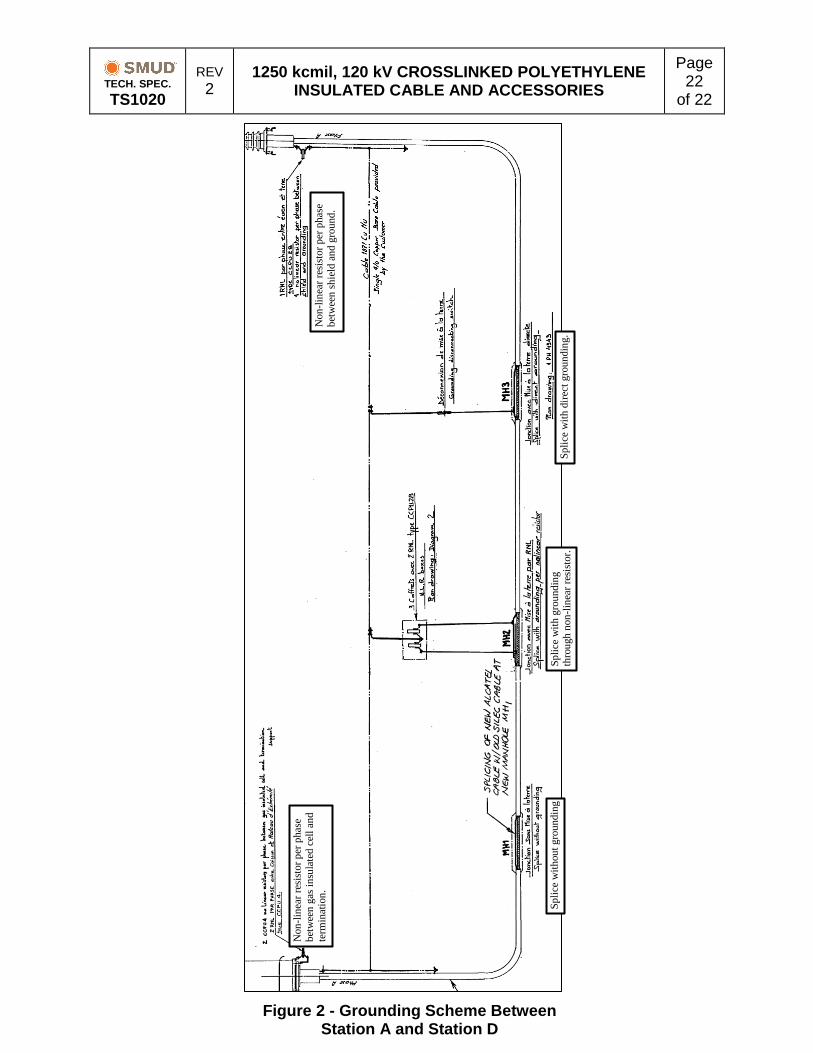
6.2.1 Connection = three phase, single point ground. Sheaths are either
bonded directly to ground, cross-bonded at splices and connected to
ground through surge arrestors, cross bonded with no ground
connections, or spliced straight through (#4/0 bare copper ground at
bottom center of entire duct bank). Refer to Figure 2 on page 22.
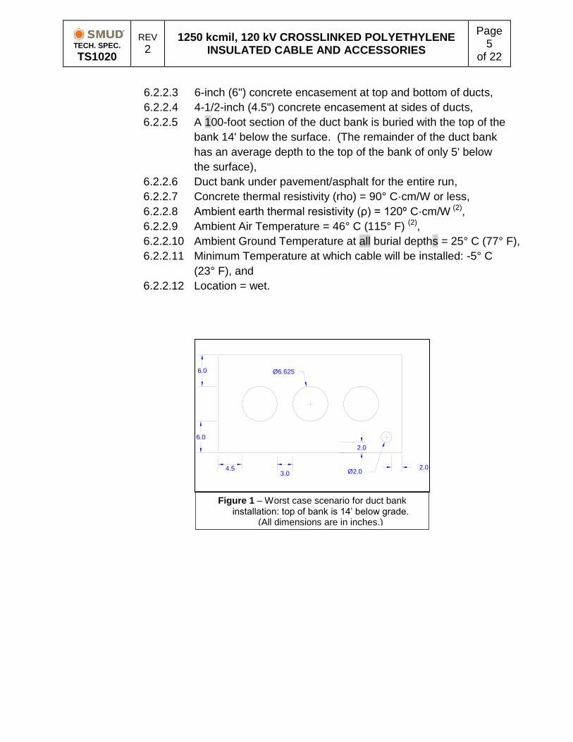
6.2.2 Worst Case Duct bank Condition (see Figure 1 next page):
6.2.2.1 Three (3) horizontal 6-inch (6") PVC conduits, (1) – 120 kV
cable per duct (no spare conduits for 120 kV cable),
6.2.2.2 (1) – 2" conduit for communication cable,
(2)
As per SMUD TP6401 Transmission Facilities Ratings Methodologies, Rev 3, 11/2014 (3)
From ICEA S-108-720, Appendix B: “Operation up to the stated maximum overload temperature should be for
no more than 72 hours duration on average per year during the design life of the cable system, without
exceeding 216 hours in any 12-month period. Assuming a 40-year design life (for planning purposes not a
guarantee), this implies that the cable system should be able to withstand cumulative operation at overload
temperature for a total of 72 x 40 = 2880 hours.” (4)
As per email from SMUD’s System Protection And Control group 12-11-17.
TECH. SPEC. TS1020
REV 2
1250 kcmil, 120 kV CROSSLINKED POLYETHYLENE INSULATED CABLE AND ACCESSORIES
Page 5
of 22
6.2.2.3 6-inch (6") concrete encasement at top and bottom of ducts,
6.2.2.4 4-1/2-inch (4.5") concrete encasement at sides of ducts,
6.2.2.5 A 100-foot section of the duct bank is buried with the top of the
bank 14' below the surface. (The remainder of the duct bank
has an average depth to the top of the bank of only 5' below
the surface),
6.2.2.6 Duct bank under pavement/asphalt for the entire run,
6.2.2.7 Concrete thermal resistivity (rho) = 90° C·cm/W or less,
6.2.2.8 Ambient earth thermal resistivity (ρ) = 120º C·cm/W (2),
6.2.2.9 Ambient Air Temperature = 46° C (115° F) (2),
6.2.2.10 Ambient Ground Temperature at all burial depths = 25° C (77° F),
6.2.2.11 Minimum Temperature at which cable will be installed: -5° C
(23° F), and
6.2.2.12 Location = wet.
Figure 1 – Worst case scenario for duct bank installation: top of bank is 14’ below grade.
(All dimensions are in inches.)
4.53.0
6.0
6.0
2.0
2.0Ø2.0
Ø6.625
TECH. SPEC. TS1020
REV 2
1250 kcmil, 120 kV CROSSLINKED POLYETHYLENE INSULATED CABLE AND ACCESSORIES
Page 6
of 22
7 Cable Specification
7.1 General
7.1.1 Minimum length on at least one reel = 1,900 feet.
7.1.2 The manufacturer shall design, fabricate, and test the cable in
accordance with ICEA S-108-720, as applicable except as otherwise
defined in this specification.
7.1.3 The manufacturer shall use triple head extrusion of conductor shield,
insulation, and insulation shield.
7.1.4 The manufacturer shall use a dry-cure process.
7.1.5 The manufacturer shall have a materials handling process that does
not introduce contamination into the insulation system during
manufacturing.
7.1.6 The cable manufacturer shall utilize material from a single supplier
for the conductor shield, the insulation, and the insulation shield. All
materials shall meet the testing requirements in Section 10 of this
specification.
7.1.7 The manufacturer shall test all materials used to manufacture the
cable and they shall have successfully passed the qualification tests
per ICEA S-108-720. The manufacturer will also provide a cable
system qualification test report in accordance with AEIC CS9.
7.1.8 The cable design shall allow for the thermal expansion of the
components without degradation of the cable.
7.1.9 Cable shall be manufactured with concentric copper wires and a
copper laminate foil shield:
7.1.9.1 Compact Copper Conductor: Strand-Filled – the strand fill will
be compatible with the conductor shield and will not leach into
the conductor shield over time. The conductor may also
contain water blocking yarn or tapes,
7.1.9.2 Optional Semi-Conductive tape,
7.1.9.3 Extruded Non-metallic Semi-conductive Conductor Shield,
7.1.9.4 Extruded unfilled XLPE Insulation,
7.1.9.5 Extruded Non-metallic Semi-conductive Insulation shield,
7.1.9.6 Cushioning Water-Swellable Semi-Conductive Tape,
7.1.9.7 Copper Concentric Wires,
7.1.9.8 Cushioning Water-Swellable Semi-Conductive Tape,
7.1.9.9 Copper Laminate Foil Tape Shield,
7.1.9.10 High Density Polyethylene Jacket, and
7.1.9.11 Semi-Conductive Jacket Layer.
TECH. SPEC. TS1020
REV 2
1250 kcmil, 120 kV CROSSLINKED POLYETHYLENE INSULATED CABLE AND ACCESSORIES
Page 7
of 22
7.2 Conductor
7.2.1 General
The conductor shall meet the requirements of ICEA S-108-720 and
AEIC CS-9.
7.2.2 Conductor Size
The manufacturer shall provide 1250 kcmil copper conductor,
compact strand.
7.2.3 Conductor Material
Copper phase conductors shall be soft drawn copper Class B
furnished in accordance with ASTM B8.
7.2.4 Conductor Stranding
Copper Conductor stranding shall be in compact stranded per
ASTM B496.
7.2.5 Conductor Sealant
7.2.5.1 In order to prevent water propagation through the conductor
strands and to prevent water treeing of the insulation, the
cable manufacturer shall apply a strand blocking to the inner
layers of all stranded conductors in accordance with ICEA S-
108-720, Section 2.2.
7.2.5.2 The manufacturer shall use a material compatible with the
conductor, conductor shield materials, and the insulation in
accordance with ICEA T-32-645.
7.2.5.3 The conductor water blocking shall withstand a water
penetration test pressure of 5.0 psig (AEIC CS9, 2.1.2) for
qualification and production testing in accordance with ICEA
T-31-610.
TECH. SPEC. TS1020
REV 2
1250 kcmil, 120 kV CROSSLINKED POLYETHYLENE INSULATED CABLE AND ACCESSORIES
Page 8
of 22
7.3 Non-metallic Semi-conductive Conductor Shield
7.3.1 The manufacturer may apply an optional semi-conductive tape over
the bare conductor, based upon the manufacturer’s normal cable
design methodology.
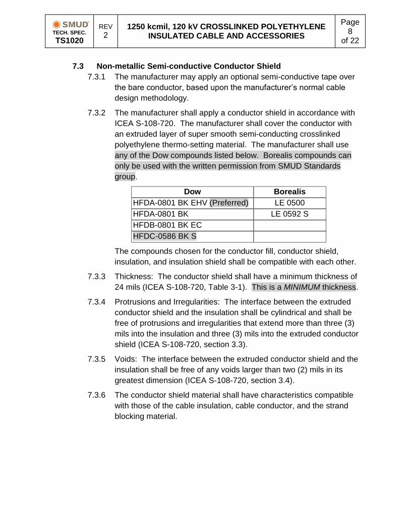
7.3.2 The manufacturer shall apply a conductor shield in accordance with
ICEA S-108-720. The manufacturer shall cover the conductor with
an extruded layer of super smooth semi-conducting crosslinked
polyethylene thermo-setting material. The manufacturer shall use
any of the Dow compounds listed below. Borealis compounds can
only be used with the written permission from SMUD Standards
group.
Dow Borealis
HFDA-0801 BK EHV (Preferred) LE 0500
HFDA-0801 BK LE 0592 S
HFDB-0801 BK EC
HFDC-0586 BK S
The compounds chosen for the conductor fill, conductor shield,
insulation, and insulation shield shall be compatible with each other.
7.3.3 Thickness: The conductor shield shall have a minimum thickness of
24 mils (ICEA S-108-720, Table 3-1). This is a MINIMUM thickness.
7.3.4 Protrusions and Irregularities: The interface between the extruded
conductor shield and the insulation shall be cylindrical and shall be
free of protrusions and irregularities that extend more than three (3)
mils into the insulation and three (3) mils into the extruded conductor
shield (ICEA S-108-720, section 3.3).
7.3.5 Voids: The interface between the extruded conductor shield and the
insulation shall be free of any voids larger than two (2) mils in its
greatest dimension (ICEA S-108-720, section 3.4).
7.3.6 The conductor shield material shall have characteristics compatible
with those of the cable insulation, cable conductor, and the strand
blocking material.
TECH. SPEC. TS1020
REV 2
1250 kcmil, 120 kV CROSSLINKED POLYETHYLENE INSULATED CABLE AND ACCESSORIES
Page 9
of 22
7.4 Insulation
7.4.1 The cable manufacturer shall use insulation that meets all
appropriate requirements of ICEA S-108-720.
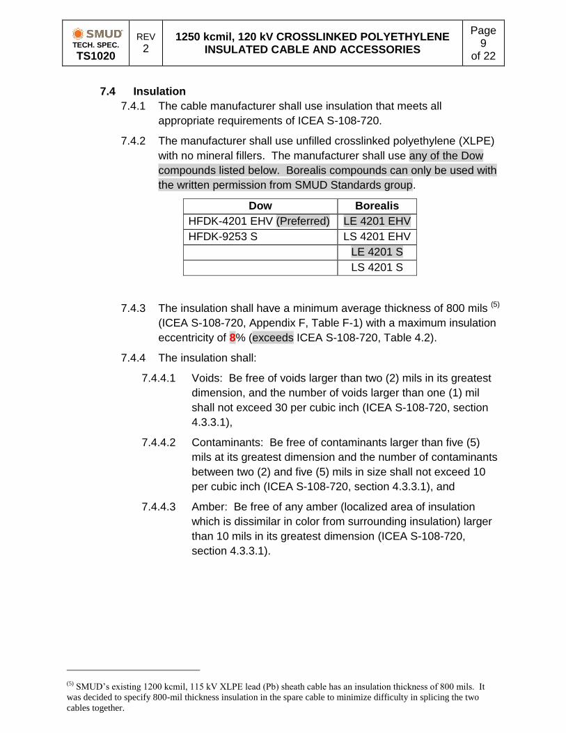
7.4.2 The manufacturer shall use unfilled crosslinked polyethylene (XLPE)
with no mineral fillers. The manufacturer shall use any of the Dow
compounds listed below. Borealis compounds can only be used with
the written permission from SMUD Standards group.
Dow Borealis
HFDK-4201 EHV (Preferred) LE 4201 EHV
HFDK-9253 S LS 4201 EHV
LE 4201 S
LS 4201 S
7.4.3 The insulation shall have a minimum average thickness of 800 mils (5)
(ICEA S-108-720, Appendix F, Table F-1) with a maximum insulation
eccentricity of 8% (exceeds ICEA S-108-720, Table 4.2).
7.4.4 The insulation shall:
7.4.4.1 Voids: Be free of voids larger than two (2) mils in its greatest
dimension, and the number of voids larger than one (1) mil
shall not exceed 30 per cubic inch (ICEA S-108-720, section
4.3.3.1),
7.4.4.2 Contaminants: Be free of contaminants larger than five (5)
mils at its greatest dimension and the number of contaminants
between two (2) and five (5) mils in size shall not exceed 10
per cubic inch (ICEA S-108-720, section 4.3.3.1), and
7.4.4.3 Amber: Be free of any amber (localized area of insulation
which is dissimilar in color from surrounding insulation) larger
than 10 mils in its greatest dimension (ICEA S-108-720,
section 4.3.3.1).
(5)
SMUD’s existing 1200 kcmil, 115 kV XLPE lead (Pb) sheath cable has an insulation thickness of 800 mils. It
was decided to specify 800-mil thickness insulation in the spare cable to minimize difficulty in splicing the two
cables together.
TECH. SPEC. TS1020
REV 2
1250 kcmil, 120 kV CROSSLINKED POLYETHYLENE INSULATED CABLE AND ACCESSORIES
Page 10
of 22
7.5 Non-Metallic Insulation Shield and Tape
7.5.1 Extruded Layer
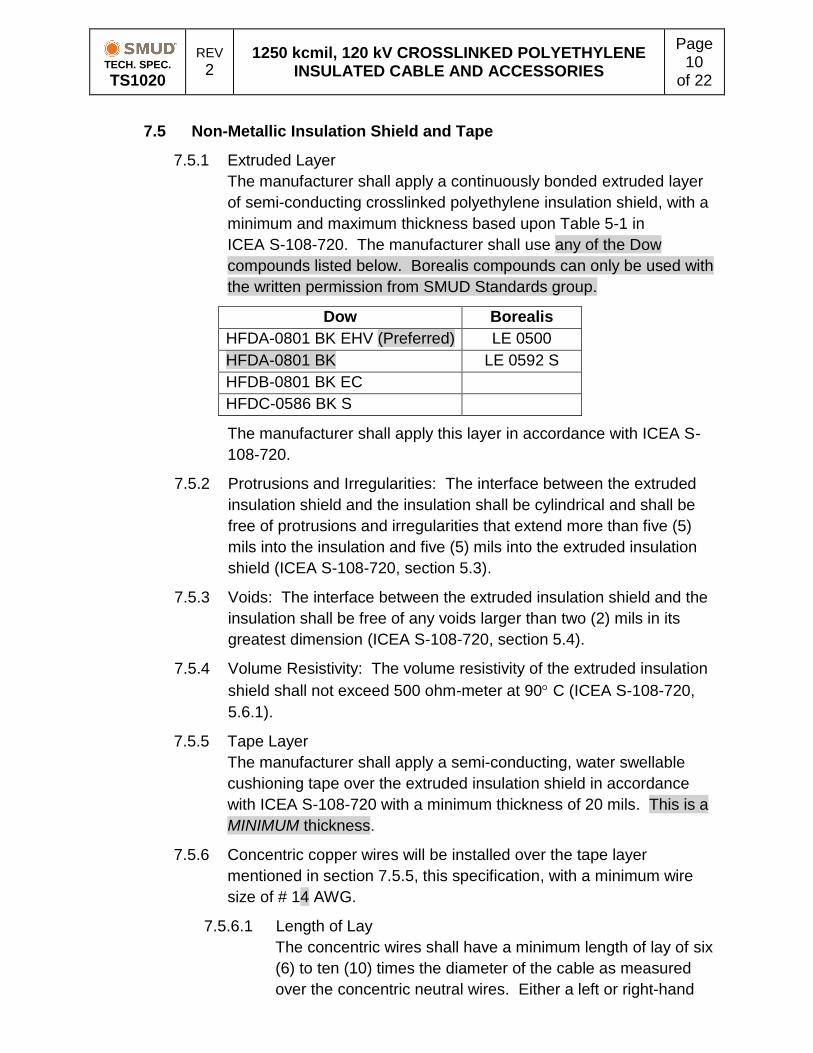
The manufacturer shall apply a continuously bonded extruded layer
of semi-conducting crosslinked polyethylene insulation shield, with a
minimum and maximum thickness based upon Table 5-1 in
ICEA S-108-720. The manufacturer shall use any of the Dow
compounds listed below. Borealis compounds can only be used with
the written permission from SMUD Standards group.
Dow Borealis
HFDA-0801 BK EHV (Preferred) LE 0500
HFDA-0801 BK LE 0592 S
HFDB-0801 BK EC
HFDC-0586 BK S
The manufacturer shall apply this layer in accordance with ICEA S-
108-720.
7.5.2 Protrusions and Irregularities: The interface between the extruded
insulation shield and the insulation shall be cylindrical and shall be
free of protrusions and irregularities that extend more than five (5)
mils into the insulation and five (5) mils into the extruded insulation
shield (ICEA S-108-720, section 5.3).
7.5.3 Voids: The interface between the extruded insulation shield and the
insulation shall be free of any voids larger than two (2) mils in its
greatest dimension (ICEA S-108-720, section 5.4).
7.5.4 Volume Resistivity: The volume resistivity of the extruded insulation
shield shall not exceed 500 ohm-meter at 90 C (ICEA S-108-720,
5.6.1).
7.5.5 Tape Layer
The manufacturer shall apply a semi-conducting, water swellable
cushioning tape over the extruded insulation shield in accordance
with ICEA S-108-720 with a minimum thickness of 20 mils. This is a
MINIMUM thickness.
7.5.6 Concentric copper wires will be installed over the tape layer
mentioned in section 7.5.5, this specification, with a minimum wire
size of # 14 AWG.
7.5.6.1 Length of Lay
The concentric wires shall have a minimum length of lay of six
(6) to ten (10) times the diameter of the cable as measured
over the concentric neutral wires. Either a left or right-hand
TECH. SPEC. TS1020
REV 2
1250 kcmil, 120 kV CROSSLINKED POLYETHYLENE INSULATED CABLE AND ACCESSORIES
Page 11
of 22
lay will be determined by the manufacturer and stated in the
bid response.
7.5.6.2 Wire Spacing
The wires shall be spaced around the circumference of the
cable such that the distance between conductors is
approximately equal, but spacing between conductors shall
not exceed 0.5 inch (ICEA S-108-720, 6.2.3).
7.5.6.3 Wire Layer Requirements
All other requirements of the ICEA S-108-720 shall apply to
the concentric wires.
7.5.7 The concentric copper wires will have the capacity to carry a
symmetrical fault current of 30,000 Amps for 30 cycles.
7.5.8 The manufacturer shall apply a semi-conducting, water swellable
cushioning tape over the concentric copper wires in accordance with
ICEA S-108-720 with a minimum thickness of 20 mils.
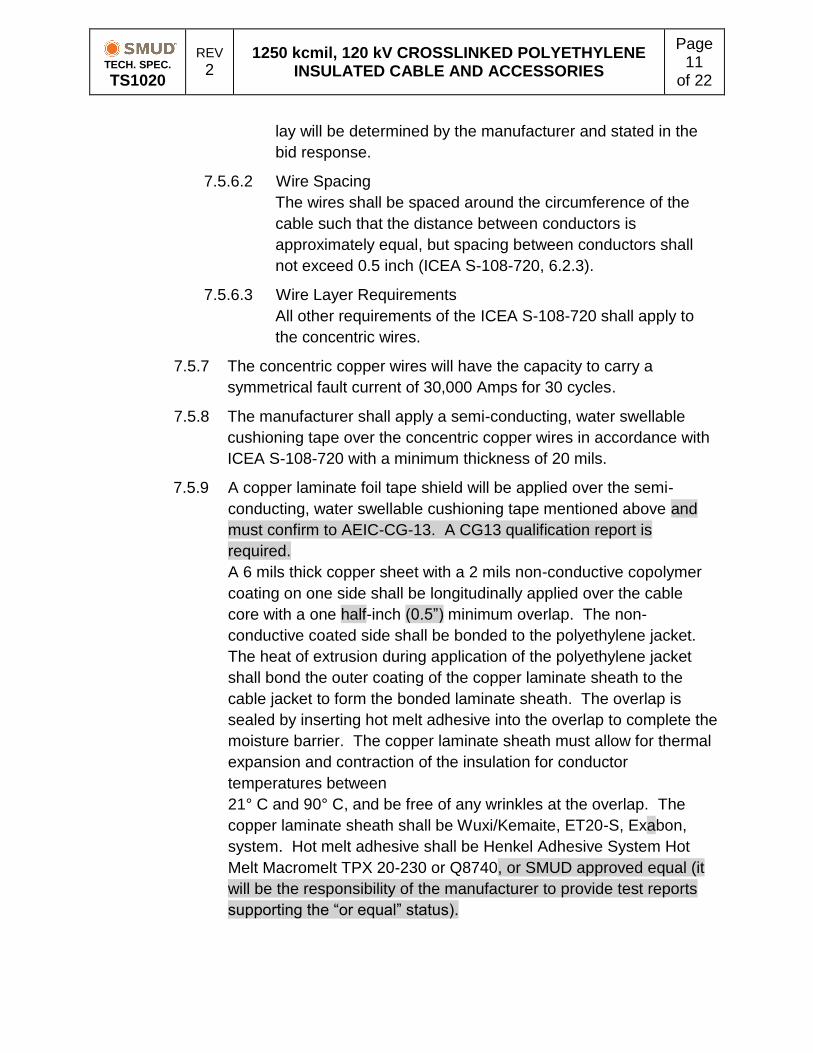
7.5.9 A copper laminate foil tape shield will be applied over the semi-
conducting, water swellable cushioning tape mentioned above and
must confirm to AEIC-CG-13. A CG13 qualification report is
required.
A 6 mils thick copper sheet with a 2 mils non-conductive copolymer
coating on one side shall be longitudinally applied over the cable
core with a one half-inch (0.5”) minimum overlap. The non-
conductive coated side shall be bonded to the polyethylene jacket.
The heat of extrusion during application of the polyethylene jacket
shall bond the outer coating of the copper laminate sheath to the
cable jacket to form the bonded laminate sheath. The overlap is
sealed by inserting hot melt adhesive into the overlap to complete the
moisture barrier. The copper laminate sheath must allow for thermal
expansion and contraction of the insulation for conductor
temperatures between
21° C and 90° C, and be free of any wrinkles at the overlap. The
copper laminate sheath shall be Wuxi/Kemaite, ET20-S, Exabon,
system. Hot melt adhesive shall be Henkel Adhesive System Hot
Melt Macromelt TPX 20-230 or Q8740, or SMUD approved equal (it
will be the responsibility of the manufacturer to provide test reports
supporting the “or equal” status).
TECH. SPEC. TS1020
REV 2
1250 kcmil, 120 kV CROSSLINKED POLYETHYLENE INSULATED CABLE AND ACCESSORIES
Page 12
of 22
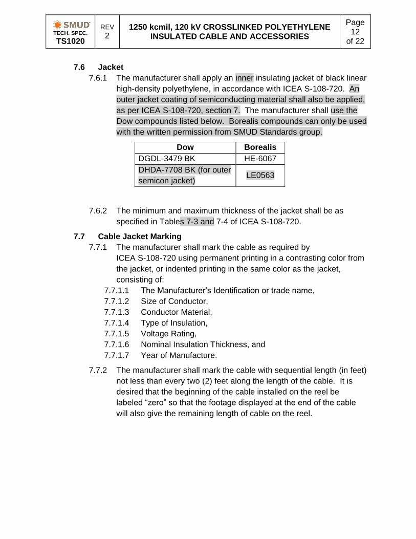
7.6 Jacket
7.6.1 The manufacturer shall apply an inner insulating jacket of black linear
high-density polyethylene, in accordance with ICEA S-108-720. An
outer jacket coating of semiconducting material shall also be applied,
as per ICEA S-108-720, section 7. The manufacturer shall use the
Dow compounds listed below. Borealis compounds can only be used
with the written permission from SMUD Standards group.
Dow Borealis
DGDL-3479 BK HE-6067
DHDA-7708 BK (for outer
semicon jacket) LE0563
7.6.2 The minimum and maximum thickness of the jacket shall be as
specified in Tables 7-3 and 7-4 of ICEA S-108-720.
7.7 Cable Jacket Marking
7.7.1 The manufacturer shall mark the cable as required by
ICEA S-108-720 using permanent printing in a contrasting color from
the jacket, or indented printing in the same color as the jacket,
consisting of:
7.7.1.1 The Manufacturer’s Identification or trade name,
7.7.1.2 Size of Conductor,
7.7.1.3 Conductor Material,
7.7.1.4 Type of Insulation,
7.7.1.5 Voltage Rating,
7.7.1.6 Nominal Insulation Thickness, and
7.7.1.7 Year of Manufacture.
7.7.2 The manufacturer shall mark the cable with sequential length (in feet)
not less than every two (2) feet along the length of the cable. It is
desired that the beginning of the cable installed on the reel be
labeled “zero” so that the footage displayed at the end of the cable
will also give the remaining length of cable on the reel.
TECH. SPEC. TS1020
REV 2
1250 kcmil, 120 kV CROSSLINKED POLYETHYLENE INSULATED CABLE AND ACCESSORIES
Page 13
of 22
8 Cable Accessories (if requested in the bid)
SMUD will require the cable supplier to provide cable accessories such as cable
terminations, straight joints, cross-bonding joints, cross-bonding joints grounded
via surge arresters, and grounded joints. The cable supplier shall provide all
materials and accessories needed for terminating or splicing the cable. The
terminations and joints shall meet the requirements of the following sections.
8.1 Cable Terminations
8.1.1 Termination Ratings
The termination shall have the following ratings:
8.1.1.1 Basic Impulse Level, 550 kV, and
8.1.1.2 Insulation Class, 120 kV
8.1.2 Termination Class
The supplier shall provide terminations that meet the requirements of
a Class 1A termination as defined in IEEE Std 48.
8.1.3 Termination Markings
Cable terminations shall have the following markings:
8.1.3.1 Manufacturer’s name, type, designation number,
manufacturing date or date code,
8.1.3.2 IEEE termination class number,
8.1.3.3 Insulation class,
8.1.3.4 Maximum design voltage to ground,
8.1.3.5 Maximum and minimum cable conductor size,
8.1.3.6 Maximum and minimum cable insulation diameter, and
8.1.3.7 Basic Impulse Level (BIL).
8.1.4 Outdoor Terminations
The cable supplier shall provide terminations with non-porcelain
termination insulators that are compatible with their cable.
8.1.5 SF6 Gas Insulated Switchgear Terminations
SMUD may connect the specified cable to SF6 gas insulated
switchgear. When specified, SMUD will provide the dimension
requirements or the cable supplier shall coordinate with the GIS
provider to ensure correct dimensions as directed in the purchasing
documents.
TECH. SPEC. TS1020
REV 2
1250 kcmil, 120 kV CROSSLINKED POLYETHYLENE INSULATED CABLE AND ACCESSORIES
Page 14
of 22
8.2 Straight joints, cross-bonding joints, cross-bonding joints grounded
via surge arresters, and grounded joints
8.2.1 Straight Splice Joint Category
The supplier shall provide extruded straight splice joints that meet the
requirements defined in IEEE Std 404.
8.2.2 Straight Splice Joint Construction
The supplier shall provide pre-molded straight splice joints that are
compatible with their cable and with the existing SILEC cable. These
joints will be capable to have the concentric shield grounded through
a surge arrester.
8.2.3 Straight Splice Joint Ratings
The supplied straight splice joint shall have the following ratings:
8.2.3.1 Maximum phase to phase voltage rating, 128.3 kV,
8.2.3.2 Maximum phase to ground voltage rating, 74.1 kV, and
8.2.3.3 Basic Impulse Level (BIL), 550 kV.
8.2.4 Straight Splice Joint Size
8.2.5 The supplier shall provide pre-molded straight splice joints that, in
addition to accommodating the cable specified in this specification,
can connect to existing installed cables:
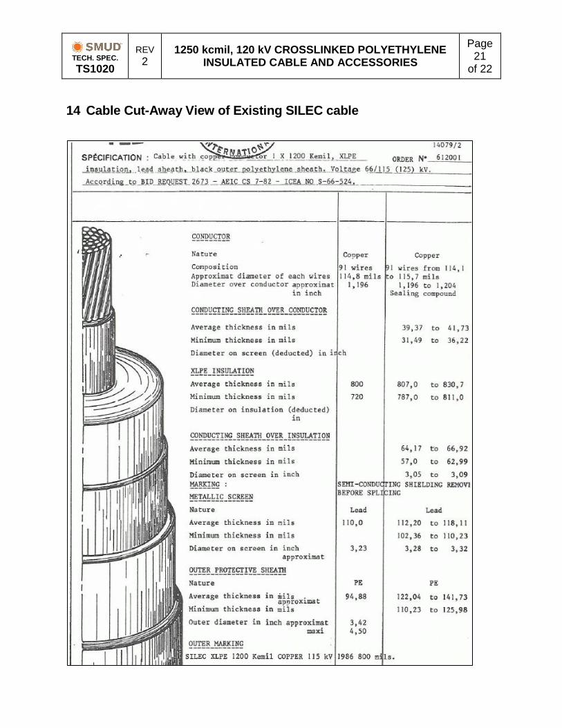
8.2.5.1 1200 kcmil, 115 kV, 800 mils XLPE insulation, with lead (Pb)
sheath, manufactured by SILEC (refer to cut-away drawing in
Section 14, this specification), or
8.2.5.2 1250 kcmil, 115 kV, 800 mils XLPE insulation, with lead (Pb)
sheath, manufactured by ALCATEL.
9 Bid Submittal Requirements
9.1 Cable Bid Submittals
At the time of bid, the cable supplier shall provide a cross-sectional
drawing of the cable being bid, identifying the components to construct the
cable identified in Section 7 above.
Manufacturers proposing cables with different designs shall provide similar
dimensional information and layer identification of the cable.
9.2 Additional information to be supplied by the Manufacturer:
9.2.1 Nominal phase-to-phase voltage,
9.2.2 Normal conductor maximum operation temperature the cable was
designed to meet,
9.2.3 Emergency conductor maximum operation temperature the cable
was designed to meet,
9.2.4 The voltage stress at the conductor shield/insulation interface
(maximum stress) and at the insulation/insulation shield interface
(minimum stress),
TECH. SPEC. TS1020
REV 2
1250 kcmil, 120 kV CROSSLINKED POLYETHYLENE INSULATED CABLE AND ACCESSORIES
Page 15
of 22
9.2.5 Maximum allowable pulling tension (with basket and with eye) and
maximum sidewall bearing pressure,
9.2.6 Dielectric constant,
9.2.7 Skin, proximity, and loss factors for the conductor,
9.2.8 TanDelta and Epsilon for the insulation,
9.2.9 Minimum bending radius, and
9.2.10 Weight per unit of length.
9.3 Safety Data Sheets: The material used in the manufacturing of the cable,
including supplier’s technical data sheet and complete material description
including all Safety Data Sheets of the components to construct the cable
identified in Section 7 above.
9.4 Qualification Tests: A copy of the qualification tests in accordance with
ICEA S-108-720 and AEIC CS9 and Water Penetration Resistance Test
per ICEA T-31-610 or SMUD approved equivalent standard for the specific
combination of cable materials proposed.
9.5 Manufacturing Process: The manufacturing of the triple extrusion and
dry-curing equipment and complete description of the extrusion and curing
process. Manufacturer must use a vertical tower extrusion process.
9.6 The short circuit capability of the conductor and the shield: At 30
cycles and 9 cycles per ICEA P-32-382 and ICEA P-45-482 and
calculations of the maximum temperature of the conductors at the fault
levels prescribed in this specification Section 6.
For a single circuit installed in accordance with methods per this
specification Section 6, indicate the method of calculation and the
ampacity for a single point grounded shield and a multipoint-grounded
shield:
9.6.1.1 Normal ampacity and
9.6.1.2 Emergency ampacity.
9.7 The shipping reel information for each cable being bid including:
9.7.1 The reel flange diameter, the outside traverse flange-to–flange width,
the drum diameter, and the shaft-hole dimensions.
9.7.2 The longest expected length of each cable on the reel along with the
maximum weight of each reel with the longest length with wood
lagging or other lagging method approved by SMUD.
9.7.3 The labeling on the reel will include the weight of the cable, the tare
weight, and the total weight (all in pounds).
9.7.4 Please refer to Section 11, this specification, for dimensional limits for
reel.
TECH. SPEC. TS1020
REV 2
1250 kcmil, 120 kV CROSSLINKED POLYETHYLENE INSULATED CABLE AND ACCESSORIES
Page 16
of 22
9.7.5 Please note – for cable designated as “spare,” the cable reel will
remain on site for the life of the cable. Please include the price of the
reel with your bid.
9.8 Termination Bid Submittals (if requested in bid)
9.8.1 At the time of bid, the cable supplier shall provide outline and cross-
section drawings identifying component parts and showing
dimensions.
9.8.2 The cable supplier shall provide the following ratings for the
terminations:
9.8.2.1 Basic Impulse Level (BIL),
9.8.2.2 Basic Switching Impulse Insulation Level,
9.8.2.3 Insulation Class Maximum,
9.8.2.4 Cable Diameter Minimum,
9.8.2.5 Cable Diameter Maximum, and
9.8.2.6 Design Voltage-to-ground.
9.8.3 At the time of bid, the cable supplier shall provide installation
instructions for the specific terminations proposed.
9.9 Cross-bonding joint Bid Submittals (if requested in bid)
9.9.1 At the time of bid, the cable supplier shall provide outline and cross-
section drawings identifying component parts and showing
dimensions.
9.9.2 The cable supplier shall provide the following ratings for the joints:
9.9.2.1 Voltage rating, phase to phase,
9.9.2.2 Voltage rating, phase to ground, and
9.9.2.3 Basic Impulse Level.
9.9.3 At the time of bid, the cable supplier shall provide installation
instructions for the specific cross-bonding joints proposed.
9.10 Cable and Accessories Storage
The cable manufacturer shall provide any requirements for long-term
storage (approximately 20+ years) of cable on reels such as indoor or
outdoor storage, reel rotation, etc. and for the long-term storage and shelf
life of any terminations or straight splice joints if specified in the bid.
Please refer to Section 12, this document, for the peak high and low
temperatures for the Sacramento area for 2010 through 2016 which would
show the temperature conditions that the spare cable would be subjected
to if stored outdoors. The manufacturer shall provide a separate price for
supplying any equipment necessary for long-term storage of cable as an
option with the bid.
TECH. SPEC. TS1020
REV 2
1250 kcmil, 120 kV CROSSLINKED POLYETHYLENE INSULATED CABLE AND ACCESSORIES
Page 17
of 22
9.11 Cable Design Changes
Following approval by SMUD of the specific design and materials
submitted to SMUD by the supplier, the supplier shall not make changes
in such design or materials without the prior written approval of SMUD.
Any potential changes require submittal of information in accordance with
Section 9, this specification.
10 Testing and Inspection
10.1 Witnessing Production and Testing
SMUD shall have the right to witness any or all production or production
tests. The manufacturer shall notify SMUD at least two weeks prior to any
manufacturing and and/or testing of cable supplied in accordance with
these specifications.
10.2 Cable Tests
10.2.1 Cable Qualification Tests
The manufacturer of the cable shall have successfully passed all
applicable Qualification Tests in accordance with ICEA S-108-720
and AEIC CS9 for the design of cables similar to that proposed for
delivery to SMUD.
10.2.2 Water Penetration Test
Longitudinal Water Penetration Resistance Tests shall be
successfully performed per ICEA T-31-610 or SMUD approved
equivalent standard.
10.2.3 Production Tests
The manufacturer shall perform all factory Production Tests in
accordance with ICEA S-108-720 Part 9. Report data shall be
recorded and kept on file at the manufacturing facility for a minimum
of three years. All test data shall be made available to SMUD upon
request. One copy of completed Production Test Reports performed
in accordance with ICEA S-108-720, and certified by the
manufacturer’s Quality Assurance organization shall be submitted
before or at the time of shipment of the cable. The tests report shall
be sent to SMUD’s specifying engineer listed on purchase
documents.
10.2.4 Cable Acceptance
Cable acceptance and payment for the cable may be affected by
delays in receipt of the production test data.
TECH. SPEC. TS1020
REV 2
1250 kcmil, 120 kV CROSSLINKED POLYETHYLENE INSULATED CABLE AND ACCESSORIES
Page 18
of 22
10.3 Termination Tests (if requested in bid)
The supplied terminations shall meet the applicable testing requirement of
Section 7 of IEEE Std 48.
10.4 Joint Tests (if requested in bid)
The supplied joints shall meet the applicable testing requirement of
Section 7 of IEEE Standard 404.
11 Shipping and Storing
11.1 The manufacturer shall furnish the “spare” cable on non-returnable steel
fluted reels, similar to Class II heavy duty, in accordance with NEMA
Standard No. WC-26. The cable reel dimensions shall not exceed 120
inches on the flange and 82 inches on the reel width unless explicitly
approved otherwise. The reel shall easily accommodate a 5-inch diameter
shaft.
11.2 The “spare” reel barrel dimension shall be adequate for long-term storage
(20+ years) of the cable on the reel without damage. The manufacturer
shall protect the cable by utilizing Class 4 wood lagging in accordance
with NEMA Standard No. WC-26, Section 4, or other SMUD approved
lagging. If the 120-inch diameter by 82-inch wide reels will not
accommodate the specified cable lengths with the wood lagging, the
supplier may request in writing to waive the wood lagging requirement or
recommend use of another reel.
11.3 The manufacturer shall suggest any other method(s) that can be applied
to the cable and reel to prevent deterioration due to moisture, UV light, or
other factors that could degrade the cable over time.
11.4 SMUD will list reel shipping lengths in the purchasing documents. The
tolerance on all defined lengths shall be -0% and +5%. SMUD will not
accept lengths shorter than the values defined.
11.5 The manufacturer shall install a pulling eye on outer end of the cable on
each reel. The manufacturer shall seal the inner cable ends and the
pulling eyes against moisture and water intrusion.
11.6 The manufacturer will provide instructions as to how to re-seal the cable
ends after a section has been removed.
11.7 Cable reel stand. Owing to the anticipated weight of the reel, the
manufacturer shall include in their bid a cable stand capable of
supporting the “spare” reel for long-term (20+ years) storage.
TECH. SPEC. TS1020
REV 2
1250 kcmil, 120 kV CROSSLINKED POLYETHYLENE INSULATED CABLE AND ACCESSORIES
Page 19
of 22
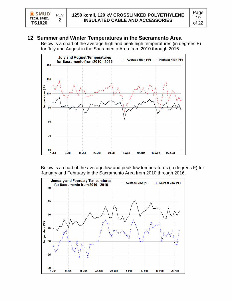
12 Summer and Winter Temperatures in the Sacramento Area Below is a chart of the average high and peak high temperatures (in degrees F) for July and August in the Sacramento Area from 2010 through 2016.
Below is a chart of the average low and peak low temperatures (in degrees F) for January and February in the Sacramento Area from 2010 through 2016.
TECH. SPEC. TS1020
REV 2
1250 kcmil, 120 kV CROSSLINKED POLYETHYLENE INSULATED CABLE AND ACCESSORIES
Page 20
of 22
13 Drawings and Manuals
An electronic version of the final documents submitted and or agreed upon
shall be provided in Acrobat® (*.pdf), Microsoft Word® (*.docx), Microsoft
Excel® (*.xlsx), and/or AutoCAD® (*.dwg) format and shall be submitted to
SMUD’s specifying engineer listed on purchase documents.
TECH. SPEC. TS1020
REV 2
1250 kcmil, 120 kV CROSSLINKED POLYETHYLENE INSULATED CABLE AND ACCESSORIES
Page 21
of 22
14 Cable Cut-Away View of Existing SILEC cable
TECH. SPEC. TS1020
REV 2
1250 kcmil, 120 kV CROSSLINKED POLYETHYLENE INSULATED CABLE AND ACCESSORIES
Page 22
of 22
Non
-lin
ear
resi
stor
per
phas
e
bet
wee
n g
as i
nsu
late
d c
ell
and
ter
min
atio
n.
Sp
lice
wit
hou
t gro
und
ing
Sp
lice
wit
h d
irec
t gro
un
din
g.
Non
-lin
ear
resi
stor
per
phas
e
bet
wee
n s
hie
ld a
nd g
rou
nd
.
Sp
lice
wit
h g
rou
nd
ing
th
rou
gh
non
-lin
ear
resi
stor.
Figure 2 - Grounding Scheme Between Station A and Station D