technical provisions part iii technical specifications - bidnet
TRANSCRIPT
TECHNICAL PROVISIONS
PART III
Technical Specifications

THIS PAGE INTENTIONALLY LEFT BLANK
MAA-CO-19-001
000000-1
100% Submission, August 2018Concourse A Improvements – Phase II Technical SpecificationsBWI Thurgoood Marshall Airport Table of Contents
PART III
TECHNICAL SPECIFICATIONS
TABLE OF CONTENTS
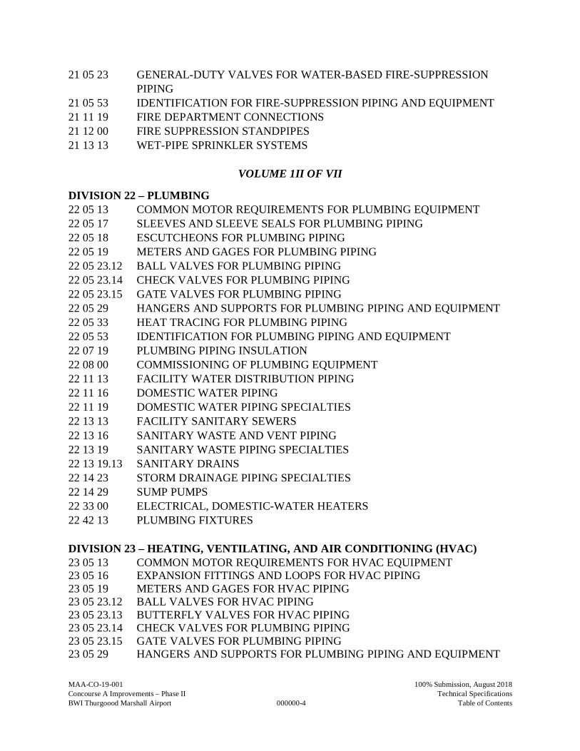
VOLUME 1 OF VII
DIVISION 1 – GENERAL REQUIREMENTS01 00 01X MOBILIZATION/DEMOBILIZATION01 00 02X CONSTRUCTION QUALITY CONTROL PLAN01 00 04X TEMPORARY CONSTRUCTION ITEMS01 00 05X SECURITY REQUIREMENTS DURING CONSTRCTION AT BWI
MARSHALL AIRPORT01 10 00 CONCOURSE A IMPROVEMENTS – PHASE II01 21 00 ALLOWANCES01 31 00 PROJECT MANAGEMENT AND COORDINATION01 31 28 BUILDING INFORMATION MODEL01 33 00 SUBMITTAL PROCEDURES01 40 00 QUALITY REQUIREMENTS01 50 00 TEMPORARY FACILITIES AND CONTROLS01 73 00 EXECUTION01 74 19 CONSTRUCTION WASTE MANAGEMENT AND DISPOSAL01 770 0 CLOSEOUT PROCEDURES01 78 23X OPERATION AND MAINTENANCE DATA01 81 50 GENERAL COMMISSIONING REQUIREMENTS
DIVISION 2 – EXISTING CONDITIONS02 41 19 SELECTIVE DEMOLITION
DIVISION 3 – CONCRETE03 30 00 CAST-IN-PLACE CONCRETE
DIVISION 4 – MASONRY04 22 00 CONCRETE UNIT MASONRY
DIVISION 5 – METALS05 12 00 STRUCTURAL STEEL FRAMING05 12 50 ARCHITECTURALLY EXPOSED STRUCTURAL STEEL05 31 00 STEEL DECKING05 40 00 COLD-FORMED METAL FRAMING
MAA-CO-19-001
000000-2
100% Submission, August 2018Concourse A Improvements – Phase II Technical SpecificationsBWI Thurgoood Marshall Airport Table of Contents
05 50 00 METAL FABRICATIONS05 51 13 METAL PAN STAIRS05 52 13 PIPE AND TUBE RAILINGS05 75 00 DECORATIVE FORMED METAL
DIVISION 6 – WOOD, PLASTICS, AND COMPOSITES06 10 53 MISCELLANEOUS ROUGH CARPENTRY06 64 02 SOLID SURFACING MILLWORK
DIVISION 7 – THERMAL AND MOISTURE PROTECTION07 11 13 BITUMINOUS DAMPROOFING07 21 00 THERMAL INSULATION07 21 19 FOAMED-IN-PLACE INSULATION07 27 26 FLUID-APPLIED MEMBRANE WEATHER BARRIERS07 41 13.16 STANDING-SEAM METAL ROOF PANELS07 42 13.16 METAL PLATE WALL PANELS07 42 13.19 INSULATED METAL WALL PANELS07 52 16 STYRENE-BUTADIENE-STYRENE (SBS) MODIFIED BITUMINOUS
MEMBRANE ROOFING07 71 00 ROOF SPECIALTIES07 72 00 ROOF ACCESSORIES07 72 53 SNOW GUARDS07 81 00 APPLIED FIREPROOFING07 81 23 INTUMESCENT FIREPROOFING07 84 13 PENETRATION FIRESTOPPING
VOLUME 1I OF VII
DIVISION 7 – THERMAL AND MOISTURE PROTECTION (CONTINUED)07 84 43 JOINT FIRESTOPPING07 92 00 JOINT SEALANTS07 95 00 EXPANSION CONTROL
DIVISION 8 – OPENINGS08 11 13 HOLLOW METAL DOORS AND FRAMES08 12 16 ALUMINUM DOOR FRAMES08 17 00 INTEGRATED METAL DOOR OPENING SYSTEMS08 31 13 ACCESS DOORS AND FRAMES08 33 23 OVERHEAD COILING DOORS08 43 13 GLAZED ALUMINUM STOREFRONT08 44 13 GLAZED ALUMINUM CURTAIN WALLS08 51 13 FIRE-PROTECTIVE ALUMINUM WINDOWS
MAA-CO-19-001
000000-3
100% Submission, August 2018Concourse A Improvements – Phase II Technical SpecificationsBWI Thurgoood Marshall Airport Table of Contents
08 63 00 METAL-FRAMED SKYLIGHTS08 71 00 DOOR HARDWARE08 71 13 AUTOMATIC DOOR OPERATORS08 80 00 GLAZING08 83 00 MIRRORS
DIVISION 9 – FINISHES09 21 16.23 GYPSUM BOARD SHAFT WALL ASSEMBLIES09 22 16 NON-STRUCTURAL METAL FRAMING09 29 00 GYPSUM BOARD09 30 13 CERAMIC TILING09 51 13 ACOUSTICAL PANEL CEILINGS09 51 33 ACOUSTICAL METAL PAN CEILINGS09 59 77 SPECIAL WALL FINISHES09 65 13 RESILIENT BASE AND ACCESSORIES09 65 36 STATIC-CONTROL RESILIENT FLOORING09 66 23 RESINOUS MATRIX TERRAZZO FLOORING09 67 23 RESINOUS FLOORING09 68 13 TILE CARPETING09 72 00 EXTERIOR WALL COVERINGS09 74 00 INTERIOR WALL COVERINGS09 91 13 EXTERIOR PAINTING09 91 23 INTERIOR PAINTING
DIVISION 10 – SPECIALTIES10 14 23 PANEL SIGNAGE10 14 26 POST AND PANEL SIGNAGE10 22 13 WIRE MESH PARTITIONS10 28 00 TOILET, BATH AND LAUNDRY ACCESSORIES10 44 13 FIRE PROTECTION CABINETS10 44 16 FIRE EXTINGUISHERS
DIVISION 11 – EQUIPMENT11 40 00 FOODSERVICE EQUIPMENT11 81 29 FALL PROTECTION
DIVISION 14 – CONVEYING SYSTEMS14 24 00 HYDRAULIC ELEVATORS
DIVISION 21 – FIRE SUPPRESSION21 05 18 ESCUTCHEONS FOR FIRE-SUPPRESSION PIPING
MAA-CO-19-001
000000-4
100% Submission, August 2018Concourse A Improvements – Phase II Technical SpecificationsBWI Thurgoood Marshall Airport Table of Contents
21 05 23 GENERAL-DUTY VALVES FOR WATER-BASED FIRE-SUPPRESSIONPIPING
21 05 53 IDENTIFICATION FOR FIRE-SUPPRESSION PIPING AND EQUIPMENT21 11 19 FIRE DEPARTMENT CONNECTIONS21 12 00 FIRE SUPPRESSION STANDPIPES21 13 13 WET-PIPE SPRINKLER SYSTEMS
VOLUME 1II OF VII
DIVISION 22 – PLUMBING22 05 13 COMMON MOTOR REQUIREMENTS FOR PLUMBING EQUIPMENT22 05 17 SLEEVES AND SLEEVE SEALS FOR PLUMBING PIPING22 05 18 ESCUTCHEONS FOR PLUMBING PIPING22 05 19 METERS AND GAGES FOR PLUMBING PIPING22 05 23.12 BALL VALVES FOR PLUMBING PIPING22 05 23.14 CHECK VALVES FOR PLUMBING PIPING22 05 23.15 GATE VALVES FOR PLUMBING PIPING22 05 29 HANGERS AND SUPPORTS FOR PLUMBING PIPING AND EQUIPMENT22 05 33 HEAT TRACING FOR PLUMBING PIPING22 05 53 IDENTIFICATION FOR PLUMBING PIPING AND EQUIPMENT22 07 19 PLUMBING PIPING INSULATION22 08 00 COMMISSIONING OF PLUMBING EQUIPMENT22 11 13 FACILITY WATER DISTRIBUTION PIPING22 11 16 DOMESTIC WATER PIPING22 11 19 DOMESTIC WATER PIPING SPECIALTIES22 13 13 FACILITY SANITARY SEWERS22 13 16 SANITARY WASTE AND VENT PIPING22 13 19 SANITARY WASTE PIPING SPECIALTIES22 13 19.13 SANITARY DRAINS22 14 23 STORM DRAINAGE PIPING SPECIALTIES22 14 29 SUMP PUMPS22 33 00 ELECTRICAL, DOMESTIC-WATER HEATERS22 42 13 PLUMBING FIXTURES
DIVISION 23 – HEATING, VENTILATING, AND AIR CONDITIONING (HVAC)23 05 13 COMMON MOTOR REQUIREMENTS FOR HVAC EQUIPMENT23 05 16 EXPANSION FITTINGS AND LOOPS FOR HVAC PIPING23 05 19 METERS AND GAGES FOR HVAC PIPING23 05 23.12 BALL VALVES FOR HVAC PIPING23 05 23.13 BUTTERFLY VALVES FOR HVAC PIPING23 05 23.14 CHECK VALVES FOR PLUMBING PIPING23 05 23.15 GATE VALVES FOR PLUMBING PIPING23 05 29 HANGERS AND SUPPORTS FOR PLUMBING PIPING AND EQUIPMENT
MAA-CO-19-001
000000-5
100% Submission, August 2018Concourse A Improvements – Phase II Technical SpecificationsBWI Thurgoood Marshall Airport Table of Contents
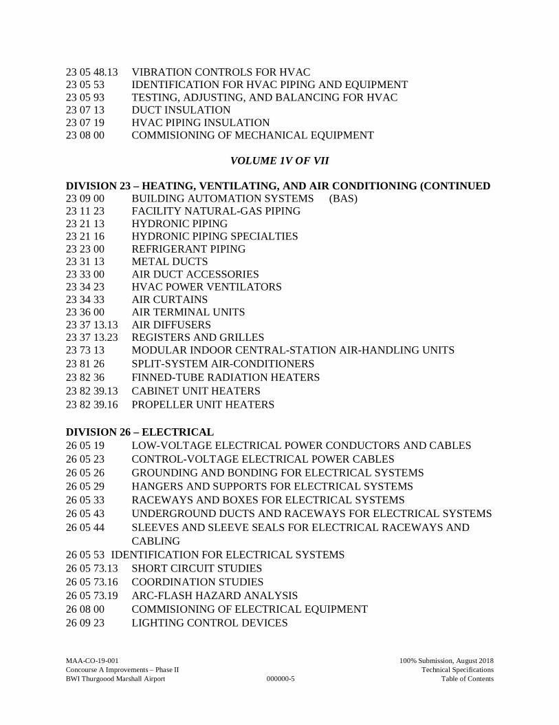
23 05 48.13 VIBRATION CONTROLS FOR HVAC23 05 53 IDENTIFICATION FOR HVAC PIPING AND EQUIPMENT23 05 93 TESTING, ADJUSTING, AND BALANCING FOR HVAC23 07 13 DUCT INSULATION23 07 19 HVAC PIPING INSULATION23 08 00 COMMISIONING OF MECHANICAL EQUIPMENT
VOLUME 1V OF VII
DIVISION 23 – HEATING, VENTILATING, AND AIR CONDITIONING (CONTINUED23 09 00 BUILDING AUTOMATION SYSTEMS (BAS)23 11 23 FACILITY NATURAL-GAS PIPING23 21 13 HYDRONIC PIPING23 21 16 HYDRONIC PIPING SPECIALTIES23 23 00 REFRIGERANT PIPING23 31 13 METAL DUCTS23 33 00 AIR DUCT ACCESSORIES23 34 23 HVAC POWER VENTILATORS23 34 33 AIR CURTAINS23 36 00 AIR TERMINAL UNITS23 37 13.13 AIR DIFFUSERS23 37 13.23 REGISTERS AND GRILLES23 73 13 MODULAR INDOOR CENTRAL-STATION AIR-HANDLING UNITS23 81 26 SPLIT-SYSTEM AIR-CONDITIONERS23 82 36 FINNED-TUBE RADIATION HEATERS23 82 39.13 CABINET UNIT HEATERS23 82 39.16 PROPELLER UNIT HEATERS
DIVISION 26 – ELECTRICAL26 05 19 LOW-VOLTAGE ELECTRICAL POWER CONDUCTORS AND CABLES26 05 23 CONTROL-VOLTAGE ELECTRICAL POWER CABLES26 05 26 GROUNDING AND BONDING FOR ELECTRICAL SYSTEMS26 05 29 HANGERS AND SUPPORTS FOR ELECTRICAL SYSTEMS26 05 33 RACEWAYS AND BOXES FOR ELECTRICAL SYSTEMS26 05 43 UNDERGROUND DUCTS AND RACEWAYS FOR ELECTRICAL SYSTEMS26 05 44 SLEEVES AND SLEEVE SEALS FOR ELECTRICAL RACEWAYS AND
CABLING26 05 53 IDENTIFICATION FOR ELECTRICAL SYSTEMS26 05 73.13 SHORT CIRCUIT STUDIES26 05 73.16 COORDINATION STUDIES26 05 73.19 ARC-FLASH HAZARD ANALYSIS26 08 00 COMMISIONING OF ELECTRICAL EQUIPMENT26 09 23 LIGHTING CONTROL DEVICES
MAA-CO-19-001
000000-6
100% Submission, August 2018Concourse A Improvements – Phase II Technical SpecificationsBWI Thurgoood Marshall Airport Table of Contents
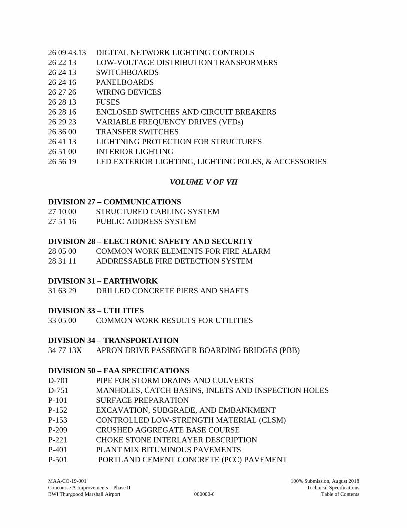
26 09 43.13 DIGITAL NETWORK LIGHTING CONTROLS26 22 13 LOW-VOLTAGE DISTRIBUTION TRANSFORMERS26 24 13 SWITCHBOARDS26 24 16 PANELBOARDS26 27 26 WIRING DEVICES26 28 13 FUSES26 28 16 ENCLOSED SWITCHES AND CIRCUIT BREAKERS26 29 23 VARIABLE FREQUENCY DRIVES (VFDs)26 36 00 TRANSFER SWITCHES26 41 13 LIGHTNING PROTECTION FOR STRUCTURES26 51 00 INTERIOR LIGHTING26 56 19 LED EXTERIOR LIGHTING, LIGHTING POLES, & ACCESSORIES
VOLUME V OF VII
DIVISION 27 – COMMUNICATIONS27 10 00 STRUCTURED CABLING SYSTEM27 51 16 PUBLIC ADDRESS SYSTEM
DIVISION 28 – ELECTRONIC SAFETY AND SECURITY28 05 00 COMMON WORK ELEMENTS FOR FIRE ALARM28 31 11 ADDRESSABLE FIRE DETECTION SYSTEM
DIVISION 31 – EARTHWORK31 63 29 DRILLED CONCRETE PIERS AND SHAFTS
DIVISION 33 – UTILITIES33 05 00 COMMON WORK RESULTS FOR UTILITIES
DIVISION 34 – TRANSPORTATION34 77 13X APRON DRIVE PASSENGER BOARDING BRIDGES (PBB)
DIVISION 50 – FAA SPECIFICATIONSD-701 PIPE FOR STORM DRAINS AND CULVERTSD-751 MANHOLES, CATCH BASINS, INLETS AND INSPECTION HOLESP-101 SURFACE PREPARATIONP-152 EXCAVATION, SUBGRADE, AND EMBANKMENTP-153 CONTROLLED LOW-STRENGTH MATERIAL (CLSM)P-209 CRUSHED AGGREGATE BASE COURSEP-221 CHOKE STONE INTERLAYER DESCRIPTIONP-401 PLANT MIX BITUMINOUS PAVEMENTSP-501 PORTLAND CEMENT CONCRETE (PCC) PAVEMENT
MAA-CO-19-001
000000-7
100% Submission, August 2018Concourse A Improvements – Phase II Technical SpecificationsBWI Thurgoood Marshall Airport Table of Contents
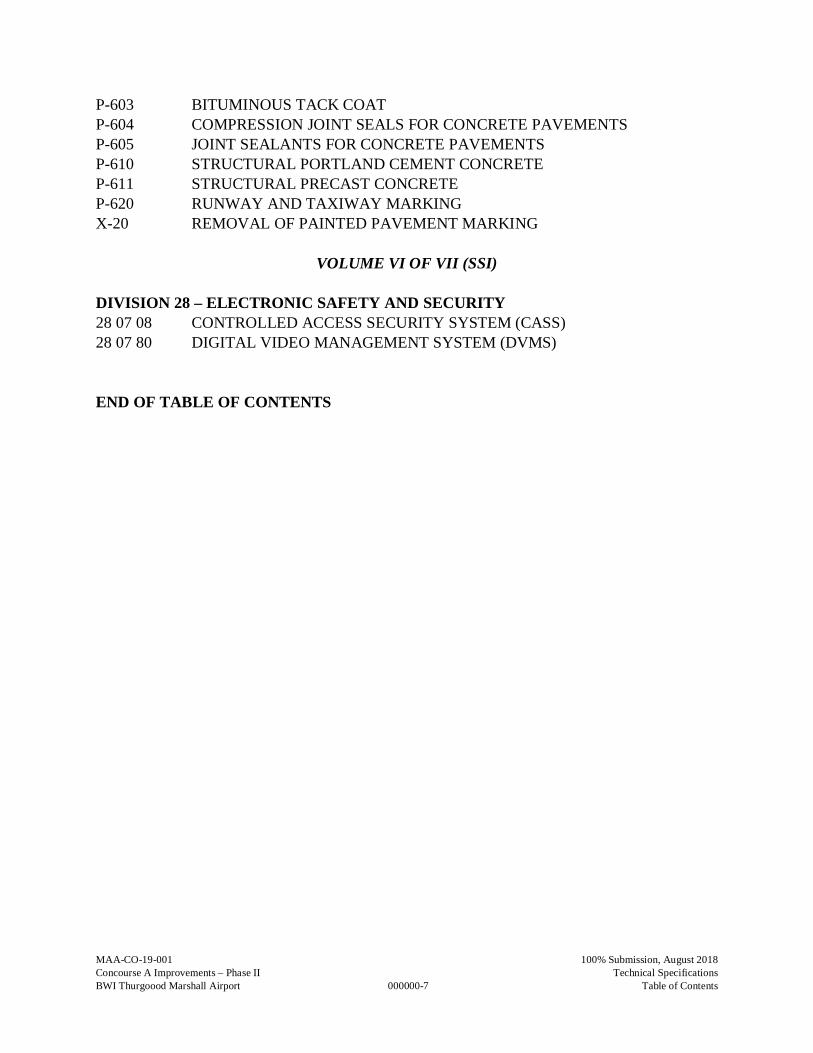
P-603 BITUMINOUS TACK COATP-604 COMPRESSION JOINT SEALS FOR CONCRETE PAVEMENTSP-605 JOINT SEALANTS FOR CONCRETE PAVEMENTSP-610 STRUCTURAL PORTLAND CEMENT CONCRETEP-611 STRUCTURAL PRECAST CONCRETEP-620 RUNWAY AND TAXIWAY MARKINGX-20 REMOVAL OF PAINTED PAVEMENT MARKING
VOLUME VI OF VII (SSI)
DIVISION 28 – ELECTRONIC SAFETY AND SECURITY28 07 08 CONTROLLED ACCESS SECURITY SYSTEM (CASS)28 07 80 DIGITAL VIDEO MANAGEMENT SYSTEM (DVMS)
END OF TABLE OF CONTENTS
THIS PAGE INTENTIONALLY LEFT BLANK
MAA-CO-19-001
010001X-1
100% Submission, August 2018 Concourse A Improvements – Phase II Technical Specifications BWI Thurgood Marshall Airport Mobilization/Demobilization
SECTION 010001X MOBILIZATION/DEMOBILIZATION
PART 1 – GENERAL 1.1 DESCRIPTION
A. This item shall consist of the performance of construction preparatory operations, including the
movement of personnel, equipment, and materials to and from the project site; field survey and stake-out; payment of performance bond, payment bond, guaranty bond, and other insurance premiums; cranes and equipment rented; the creation, maintaining and submittal of final record drawings; general requirements of the Contract not otherwise included in pay items; and for the establishment and subsequent removal of the Contractor's offices and other facilities necessary to begin and sustain work on a substantial phase of the contract. At the completion of work, all areas disturbed by the Contractor's operations shall be restored to substantially the same condition as existed prior to commencement of mobilization operations. Some typical items for inclusion may include (but not limited to):
1. Pavement Cleaning 2. Traffic control maintenance 3. Temporary barricades and signage 4. Crane Rental 5. Temporary toilets 6. Pre-construction photos 7. Progress photos 8. Temporary protection of adjacent spaces/ structures 9. Temporary weather protection 10. Dumpsters 11. Safety expenses (first aid, drug testing, etc.) 12. Contractor’s trailer
1.2 RELATED DOCUMENTS
A. Drawings and general provisions of the Contract, including Maryland Department of Transportation/ Maryland Aviation Administration Standard Provisions to the Construction Contract for the Concourse A Improvements – Phase II at BWI Thurgood Marshall Airport and other Divisions 1 Specification Sections, apply to this Section.
PART 2 – PRODUCTS 2.1 RADIOS. Radios shall be capable of transmitting and receiving between the Control Tower
and the airfield work sites on a frequency of 121.9 MHZ for ground control and 154.98 MHZ for Airport Operations, as specified or required herein. Sufficient radios shall be on site and operating at all times so that instructions for communications may be dispatched to all crews and/or equipment working in an active Airport Operations Area (AOA). Radios shall not be used within 10 feet of the fill or vent points of the aircraft fuel systems unless they are intrinsically safe for Class I, Division 1, Group D hazardous areas (classified conditions) in accordance with ANSI/UL 913.
MAA-CO-19-001
010001X-2
100% Submission, August 2018 Concourse A Improvements – Phase II Technical Specifications BWI Thurgood Marshall Airport Mobilization/Demobilization
2.2 CONTRACTOR’S STAGING AREA. A Contractor’s staging area has been provided and is shown on the Plans. All work associated with setting up the staging area including cleaning, fencing, stabilization, protection, providing all required utility (electric, water, communications, etc.) connections shall not be paid separately and considered incidental to Mobilization/Demobilization. All areas disturbed by the installation or construction of the Engineers/Contractor’s Office, stockpiles, haul routes, vehicle parking areas, and incidentals shall be restored to their pre-construction condition at the completion of the project unless otherwise directed by the construction manager.
PART 3 – EXECUTION 3.1 CONSTRUCTION LAYOUT. The Contractor shall provide a Professional Land Surveyor
licensed in the State of Maryland to perform field layout of the horizontal and vertical control. Surveyor shall furnish all other lines, grades, and measurements necessary for layout and construction of the project as well as documentation of Record Drawings. Survey information from construction shall be incorporated into record drawings for submittal to the Engineer.
3.2 COMMUNICATIONS. Contractor shall provide radios/cell phones for communication for his
personnel on the job site. The frequency utilized for these transmissions shall be selected by the Contractor and approved by the Engineer, but shall not conflict with or overlay any of the Airport’s radio frequencies. The Contractor’s personnel required to be provided with communication devices shall at a minimum include the Project Superintendent, Foreman of all work groups physically separated from the general vicinity of the project Superintendent, gate guards, safety personnel and others who may be working in a separate and remote area.
For work adjacent to or impacting taxiways, runways, or apron areas, the Contractor shall have
two-way radios capable of operating on both the FAA ground control and MAA Airport Operations frequencies. Sufficient number of radios shall be deployed to allow each isolated area to have direct communications ability.
3.3 AS-BUILT SURVEY. The Contractor shall provide as-built drawings in accordance with the
Contract Documents. The Contractor is to provide the Engineer with a compiled as-built survey at the completion of the project. The survey shall include the final as-built grades of the project. All underground utilities and infrastructure are to be surveyed at prior to backfilling, identifying both horizontal and vertical locations, and included in the as-built survey. Tops of all underground structures are to be located, again providing both horizontal and vertical locations at the center of the structure and included in the as-built survey. The survey shall provide state plane data in U.S. survey feet as defined by any of the accepted U.S. State Plane Coordinate System definitions. The Contractor shall use NAD83 and NAVD88 for horizontal and vertical datum respectively on top of all utilities and underground infrastructure as well as at the center of all structures. All of the above information shall be provided to the Engineer in an electronic 3D CADD file in AutoCAD compatible format.
MAA-CO-19-001
010001X-3
100% Submission, August 2018 Concourse A Improvements – Phase II Technical Specifications BWI Thurgood Marshall Airport Mobilization/Demobilization
PART 4 – METHOD OF MEASUREMENT 4.1 Payment for mobilization will be made on a lump sum basis wherein no measurement will be
made. PART 5 – BASIS OF PAYMENT 5.1 This item will be paid for at the contract lump sum price for Mobilization/ Demobilization,
which price shall be full compensation for performing the work specified and the furnishing of all materials, labor, tools, equipment, and incidentals necessary to mobilize and subsequently demobilize the construction preparatory operations.
5.2 Payment for this item will be made in installments. The first payment of 30 percent of the lump
sum price will be included in the first progress estimate following partial mobilization including the placement or erection of the contractor's office and the initiation of construction work. The remaining 70 percent of the lump sum price will be included as installments in subsequent progress estimates. Each such installment will be determined based on the ratio of the total work completed to date to the total contract amount.
The lump sum price for Mobilization/Demobilization shall not exceed five (5) percent of the total Contract bid amount for base bid less the bid price for Mobilization/Demobilization, as shown on the provided Bid Tabulation Form. No payment in excess of five (5) percent of the total Contract bid amount for base bid less the bid price for Mobilization/Demobilization will be made for this item. If the total cost for all items required for Mobilization/Demobilization is in excess of five (5) percent of the total Contract bid amount for base/alternate bid less the bid price for Mobilization/Demobilization, the Contractor shall include the excess in the unit price of other items of work.
No additional payment will be made for demobilization and remobilization due to weather related shutdowns, suspensions of the work or for other mobilization activities or for work under “Miscellaneous Construction Allowance”.
Payment will be made under:
Item 010001X.1 Mobilization/Demobilization (Shall not exceed 5% of the total
contract bid amount less the bid price for mobilization and demobilization) – per lump sum
END OF SECTION 010001X
MAA-CO-19-001
010001X-4
100% Submission, August 2018 Concourse A Improvements – Phase II Technical Specifications BWI Thurgood Marshall Airport Mobilization/Demobilization
THIS PAGE HAS BEEN INTENTIONALLY LEFT BLANK
MAA-CO-19-001
010002X-1
100% Submission, August 2018Concourse A Improvements – Phase II Technical SpecificationsBWI Thurgood Marshall Airport Construction Quality Control Plan
SECTION 010002X CONSTRUCTION QUALITY CONTROL PLAN
PART 1 – GENERAL
1.1 DESCRIPTIONA. This item consists of development, implementation, and maintenance throughout the contract
of an approved Construction Quality Control (CQC) Plan by the Contractor.
The Contractor shall submit a Construction Quality Control Plan fully complying with therequirements detailed in Special Provision SP-8-05 of the Maryland Aviation Administration’sStandard Provisions for Construction Contracts. Once approved by the Engineer, theContractor is responsible for fully implementing and maintaining the Construction QualityControl Plan throughout the duration of the Contract.
1.2 RELATED DOCUMENTS
A. Drawings and general provisions of the Contract, including Maryland Department ofTransportation/ Maryland Aviation Administration Standard Provisions to the ConstructionContract for the Concourse A Improvements – Phase II at BWI Thurgood Marshall Airportand other Divisions 1 Specification Sections, apply to this Section.
PART 2 – PRODUCTS (NOT USED)
PART 3 – EXECUTION (NOT USED)
PART 4 – METHOD OF MEASUREMENT
4.1 This item will be measured on an earned daily basis for each day the Contractor successfullyperforms all requirements of the approved Construction Quality Control Plan.
PART 5 – BASIS OF PAYMENT
5.1 The Contractor’s Lump Sum bid price for this item shall be sufficient to cover the costs ofdeveloping, implementing and maintaining throughout the duration of the Contract, aConstruction Quality Control Plan fully conforming with the requirements of Special ProvisionSP-8.05. However, in no event shall the bid price be less than three percent (3%) of the totalContract bid amount (base bid only) less the bid price for Construction Quality Control Plan.
5.2 If the contract includes a Miscellaneous Construction allowance or Add Alternates, anadditional CQC is required for each of these work packages. In no event shall the ConstructionQuality Control Plan for Miscellaneous Construction allowance and/or Add Alternate bid pricebe less than (3%) of each of their respective amounts.
MAA-CO-19-001
010002X-2
100% Submission, August 2018Concourse A Improvements – Phase II Technical SpecificationsBWI Thurgood Marshall Airport Construction Quality Control Plan
5.3 The Engineer will take the bid price for this item and divide it by the total number of contractdays, as specified elsewhere in the contract documents under Contract Performance Time, todetermine a daily rate for payment.
5.4 The Contractor will earn payment on a daily basis at the rate determined above based onsuccessful performance of all requirements of the approved Construction Quality Control Plan.Payment will not be earned or made for any day that the Contractor fails to successfullyperform all requirements of the approved Construction Quality Control Plan.
5.5 Daily determination of the Contractor’s successful or unsuccessful performance shall be madeat the sole discretion of the Engineer. The basis of unsuccessful performance shall be theissuance of a “CQC Plan Deficiency Notice” or a “Nonconformance Report” by the Engineerin accordance with Special Provision SP-8.05, Paragraphs J-K.
Payment will be made under:
Item 010002X.1 Construction Quality Control Plan (not less than 3% of the totalContract bid amount (base bid only) less the bid price for ConstructionQuality Control Plan) – per lump sum
Item 010002X.2 Construction Quality Control Plan for Miscellaneous ConstructionAllowance (not less than 3% of the Contract bid amount forMiscellaneous Construction Allowance) – per lump sum
Item 010002X.3 Construction Quality Control Plan for Corporate Partnering Allowance(not less than 3% of the Contract bid amount for Corporate PartneringAllowance) – per lump sum
Item 010002X.4 Construction Quality Control Plan for AED Equipment Allowance(not less than 3% of the Contract bid amount for AED EquipmentAllowance) – per lump sum
Item 010002X.5 Construction Quality Control Plan for Construction SignageAllowance (not less than 3% of the Contract bid amount forConstruction Signage Allowance) – per lump sum
Item 010002X.6 Construction Quality Control Plan for Photo DocumentationAllowance (not less than 3% of the Contract bid amount for PhotoDocumentation Allowance) – per lump sum
Item 010002X.7 Construction Quality Control Plan for Pest Control Allowance (notless than 3% of the Contract bid amount for Pest Control Allowance) –per lump sum
Item 010002X.8 Construction Quality Control Plan for Architectural EnhancementsAllowance (not less than 3% of the Contract bid amount forArchitectural Enhancements Allowance) – per lump sum
END OF SECTION 010002X
MAA-CO-19-001
010004X-1
100% Submission, August 2018 Concourse A Improvements – Phase II Technical Specifications BWI Thurgood Marshall Airport Temporary Construction Items
SECTION 010004X TEMPORARY CONSTRUCTION ITEMS PART 1 – GENERAL 1.1 DESCRIPTION
A. This item consists of furnishing all labor, materials and equipment for temporary construction items necessary for the safe and proper execution of construction and not otherwise included in other Contract items. The Contractor will be expected to supply and utilize the items listed below and other items as required in the Construction Notes or as contained in the drawings and technical specifications. Temporary construction items include, but are not limited to providing and maintaining construction barricades, portable floodlighting, haul road maintenance, marking cleanup, maintenance of traffic, escorts, flaggers, safety personnel, personnel training, temporary sanitary facilities, waste disposal facilities, reworked/temporary materials, men and equipment as needed to keep all aircraft and/or vehicle traffic areas free of debris and ongoing construction activities.
1.2 RELATED DOCUMENTS
A. Drawings and general provisions of the Contract, including Maryland Department of Transportation/ Maryland Aviation Administration Standard Provisions to the Construction Contract for the Concourse A Improvements – Phase II at BWI Thurgood Marshall Airport and other Divisions 1 Specification Sections, apply to this Section.
PART 2 – PRODUCTS
2.1 CONSTRUCTION BARRICADES. Construction barricades shall be High Density
Polyethylene (HDPE) water-ballast barricades and shall be constructed in accordance with the details shown in the plans. Construction barricades shall be placed in accordance with the Construction Safety and Phasing Plans and around all cranes, equipment, and staging areas on the apron area.
2.2 PORTABLE FLOODLIGHTING. Portable floodlighting shall be provided, as required, for
construction operations during nighttime work. The Contractor shall provide sufficient units so that all work areas are illuminated to a level of 5 horizontal footcandles. The lighting levels shall be calculated and measured in accordance with the current standards of the Illumination Engineering Society.
2.3 STEEL PLATES. Steel plates or similar protective material of adequate size and thickness shall be furnished as necessary to cover temporary excavations, unfinished structures or surfaces requiring protection or for safety purposes. Plates shall be securely fastened and shall be adequate to safely support any anticipated loadings to be imposed.
2.4 HAUL ROADS/PERIMETER SERVICE ROAD MAINTENANCE. Contractor haul routes
have been designated on the Plans. It shall be the Contractor's responsibility to inspect existing roads so that he may assess their conditions properly. If the Contractor deems necessary, he shall be responsible for supplying materials to maintain the haul roads and drainage devices to adequately support his construction equipment. The roads shall be inspected prior to
MAA-CO-19-001
010004X-2
100% Submission, August 2018 Concourse A Improvements – Phase II Technical Specifications BWI Thurgood Marshall Airport Temporary Construction Items
construction and restored to their pre-construction condition if damaged at the Contractor's expense as determined by the Engineer. The contractor shall periodically (once every six months) clean the VSR markings, Non-Movement line markings and all other markings in the Alternate Deicing Pad area and the project area. The Contractor shall maintain and make repairs as directed by the Engineer.
2.5 VEHICLE SERVICE ROAD ACCESS. The Contractor is required to maintain a vehicular
path through the site that can be used by Maryland Aviation Administration (MAA) operations/Federal Aviation Administration (FAA) personnel as needed to perform their duties. This can be accomplished via cones/barricades, marking or other means depending on the location of the access route. The contractor shall submit method to Engineer for approval. In addition, fire department access roads shall be provided per NFPA 1, Fire Code, 2015 Edition, and Section 18.2. Fire Department access roads must be maintained and unobstructed of a width not less than 20 ft. with a vertical clearance of not less than 13 ft. 6 inches. Turning radius for fire department access roads shall be approved by the Authority Having Jurisdiction (AHJ). Dead end roads must be approved by the AHJ.
2.6 MAINTENANCE OF TRAFFIC. Additional items required for temporary traffic control around the airports roadways include temporary signs, variable message signs, flashing arrow boards, lighting and warning devices, temporary pavement markings, channelizing devices, concrete barriers, crash cushions, barrels, and cones. All temporary traffic control devices shall be in accordance with the latest version of the Maryland State Highway Administration (MDSHA) Standard Specifications for Construction and Materials, MDSHA Supplemental Specifications and Provisions, and the Maryland Manual on Uniform Traffic Control Devices (MdMUTCD) available on the MDSHA website. Temporary signs shall also be in accordance with the contract documents.
2.7 CONTRACTOR'S OFFICES. The establishment and subsequent removal of any Contractor's
offices are not covered under this item but shall be included in SECTION 010001X MOBILIZATION/DEMOBILIZATION”.
2.8 WASTE DISPOSAL FACILITIES. Provide waste-collection containers in sizes adequate to handle waste from construction operations. Comply with requirements of authorities having jurisdiction.
2.9 ESCORTS (BWI ONLY). The Contractor will be responsible for escorts and escorting of all
personnel and vehicles from the access gates in this project to the worksite locations. Escorts will be assigned separately from other security functions and safety personnel required for the project. 2.9.1 Escort Definition: The individual BWI Marshall Badge holder, having escort authority, who may accompany non-badged people or vehicles into an Airport restricted area. Under typical conditions, an escort may accompany from one to five people and shall have no other duties other than escorting. Any modifications to these typical conditions will be identified in Paragraph 2.4 of Item 010005X, Security Requirements during Construction. Proper escort procedures at BWI Marshall require the badged employee providing the escort to be able to identify the specific individual(s) they are escorting at any time and that they remain within sight and reasonable speaking distance and positive control of badged individual while in the SIDA. As a badged person, each escort is responsible for challenging non-badged, unescorted personnel within the secure area.
MAA-CO-19-001
010004X-3
100% Submission, August 2018 Concourse A Improvements – Phase II Technical Specifications BWI Thurgood Marshall Airport Temporary Construction Items
(1) Escorting within the Sterile Area. Escorts into the Sterile Area must be for official business purposes only.
(2) Escorts. The General Contractor shall provide the number of escorts that will be
responsible for escorting non-badged employees. All escorts must be conducted through a guarded portal. Escorts must be conducted by the General Contractor’s own personnel, a subcontractor or the OAS Approved Airport Security Contractor may be used for escorting in the project worksite areas. Under normal circumstances, one badge holder with escort privileges may escort up to five non-badged workers. One BWI Marshall Airport approved stickered vehicle can escort up to three (3) non-stickered vehicles. Contractor personnel acting as escort for non-badged personnel shall have no other work-related responsibilities while performing escort duties unless otherwise defined in Paragraph 2.4 of Item 010005X Security Requirements during Construction.
PART 3 – EXECUTION 3.1 CONSTRUCTION BARRICADES. Barricades shall be placed in accordance with the
construction plans and as needed and shall remain in place or moved as directed until completion of work in each phase or area. The contractor shall be responsible for maintaining the barricades in good working condition throughout the duration of the contract.
3.2 PORTABLE FLOODLIGHTING. Portable floodlighting is required for construction during
periods of limited visibility (i.e., nighttime). Illumination requirements shall be those contained in Paragraph 2.2. Portable floodlighting shall not penetrate any operational surfaces. Floodlighting shall be directed to avoid interference with Air Traffic Controllers or aircraft pilots. Hoods or shields may be required to prevent interference. See additional requirements on the plans.
3.3 NOT USED.
3.4 MAINTENANCE OF TRAFFIC. Temporary traffic control shall be in accordance with Maryland State Highway Administration standards and the Maryland Manual on Uniform Traffic Control Devices (MdMUTCD).
3.5 ESCORTS. The escort will be responsible for guiding contractor and subcontractor personnel from the access gates to the worksite if located within the movement area. Escorts must have successfully completed Airfield Movement Area training (provided by MAA Operations) which includes a written exam. Safety personnel (as defined above) will control the Contractor’s traffic during the prosecution of work as well as vehicles crossing active aircraft pavements. Escorts will lead contractor traffic to and from the work site. Contractor provided escorts must meet the following requirements when working on this project:
• Complete Movement Area training (provided by MAA Operations, no cost to contractor)
• Work a maximum of 12 continuous hours per shift • Off duty (without any work) for a minimum of 8 hours after each shift regardless of
time frame worked • Have identification to signify escorts as approved by MAA Operations (hardhat, flag,
stop sign, vest, flashlight, etc.)
MAA-CO-19-001
010004X-4
100% Submission, August 2018 Concourse A Improvements – Phase II Technical Specifications BWI Thurgood Marshall Airport Temporary Construction Items
3.6 CONSTRUCTION MATERIALS STOCKPILING AND EQUIPMENT STORAGE.
Stockpiling of construction materials and equipment storage is not permitted within operating taxiway object free areas. Stockpiled material must be protected against jet blast. Stockpiled materials and equipment should be prominently marked and lighted during hours of restricted visibility or darkness if in the air operations area. Stockpiled material or equipment should not be stored near aircraft turning areas or operational movement areas, aprons, or excavations and trenches. The stockpiled construction materials and equipment shall not cause degraded or hazardous conditions to airport operations safety. This includes determining and verifying that stockpiled materials and equipment are stored or parked at an approved location, that they are properly stowed to prevent foreign object debris (FOD), attraction of wildlife, or obstruction of airport operations either by their proximity to NAVAIDs or to aircraft movement areas.
3.7 FOREIGN OBJECT DEBRIS (FOD) MANAGEMENT. Waste and loose materials capable
of causing damage to aircraft landing gear or propellers or capable of being ingested in jet engines should not be left or placed on or near active aircraft movement areas. Materials tracked onto these areas shall be continuously removed by the Contractor during the construction project. Waste or loose materials that could attract wildlife shall be carefully controlled and removed on a continuous basis. The contractor shall periodically (once every six months) clean the VSR markings, Non-Movement line markings and all other markings in the Alternate Deicing Pad area and the project area. The Contractor shall have sufficient mechanized sweepers and covered trash containers on site to comply with this requirement at all times. The construction area shall be kept clean at all times of debris that may blow onto the airfield.
3.8 FLAGGERS. Flaggers shall be provided, as necessary, to control the Contractor’s traffic
during the prosecution of the work. All Contractor vehicles or equipment that are required to cross active roadway areas shall do so under the direct control of a competent flagger.
PART 4 – METHOD OF MEASUREMENT 4.1 Temporary Construction Items: No direct measurement will be made for this item as payment
will be made on a lump sum basis. 4.2 Escorts shall not be measured for payment, but included in the lump sum cost for temporary
construction items. PART 5 – BASIS OF PAYMENT 5.1 TEMPORARY CONSTRUCTION ITEMS. Payment will be made at the lump sum bid
price for "Temporary Construction Items." This payment shall be full compensation for furnishing all materials and labor for placing, moving and removing construction barricades; providing flaggers; escorts, safety personnel, furnishing portable floodlighting; maintenance of traffic; and for any other labor, materials, equipment, tools and incidentals necessary for temporary items required for construction of this project.
5.2 Payment for this item will be made in installments. The first payment of 10 percent of the lump
sum price will be included in the first progress estimate following the initiation of construction work. The remaining 90 percent of the lump sum price will be included as installments in
MAA-CO-19-001
010004X-5
100% Submission, August 2018 Concourse A Improvements – Phase II Technical Specifications BWI Thurgood Marshall Airport Temporary Construction Items
subsequent progress estimates. Each such installment will be determined based on the ratio of the total work completed to date to the total contract amount. The lump sum price for Temporary Construction Items shall not exceed five (5) percent of the total Contract bid amount for base/alternate bid less the bid prices for Mobilization/Demobilization and Temporary Construction Items, as shown on the provided Bid Tabulation Form. No payment in excess of five (5) percent of the total Contract bid amount for base/alternate bid less the bid prices for Mobilization/Demobilization and Temporary Construction Items will be made for this item. If the total cost for all items required for Temporary Construction Items is in excess of five (5) percent of the total Contract bid amount for base/alternate bid less the bid prices for Mobilization/Demobilization and Temporary Construction Items, the Contractor shall include the excess in the unit price of other items of work. No payment will be made under this item for Temporary Construction Items related to work under “Miscellaneous Construction Allowance”. Payment will be made under: Item 010004X.1 Temporary Construction Items (not to exceed 5% of the total
contract bid amount less bid price for Mobilization/ Demobilization and Temporary Construction Items) – per lump sum
END OF SECTION 010004X
MAA-CO-19-001
010004X-6
100% Submission, August 2018 Concourse A Improvements – Phase II Technical Specifications BWI Thurgood Marshall Airport Temporary Construction Items
THIS PAGE HAS BEEN INTENTIONALLY LEFT BLANK
MAA-CO-19-001
010005X-1
100% Submission, August 2018 Concourse A Improvements – Phase II Technical Specifications BWI Thurgood Marshall Airport Security Requirements during Construction
SECTION 010005X SECURITY REQUIREMENTS DURING CONSTRUCTION AT BWI MARSHALL AIRPORT
PART 1 – GENERAL 1.1 DESCRIPTION
A. This item shall consist of all labor and materials necessary to establish one or more secure perimeters around the construction site, and to provide personnel to maintain secure access and secure worksites for the duration of the project. Work shall be completed in accordance with the contract specifications and the approved Project Security Plan (submitted by the selected contractor after bidding). A Security Bid Plan (SBP) will be provided with the Contract Drawings to serve as the basis for the Project Security Plan (PSP). The Contractor shall also reference the General Construction and Safety Notes, and the Project Phasing Plan(s) as necessary for timing and safety restrictions included as part of the Contract Drawings.
1.2 RELATED DOCUMENTS
A. Drawings and general provisions of the Contract, including Maryland Department of Transportation/ Maryland Aviation Administration Standard Provisions to the Construction Contract for the Concourse A Improvements – Phase II at BWI Thurgood Marshall Airport and other Divisions 1 Specification Sections, apply to this Section.
1.3 SECURITY REQUIREMENTS DOCUMENTATION. It is the Contractor’s responsibility to
become familiar with the various aspects of 49 CFR 1542, Transportation Security Administration, Department of Transportation, Airport Security. Any violation by the Contractor and any subsequent fines imposed due to any violation will be the responsibility of the Contractor. UPON ISSUANCE OF NOTICE OF RECOMMENDED AWARD (NORA), THE CONTRACTOR MUST CONTACT the OFFICE OF AIRPORT SECURITY (OAS) AND REQUEST A SECURITY MEETING TO FINALIZE THE PROJECT SECURITY PLAN (PSP). The meeting shall include (at a minimum): • Maryland Aviation Administration (MAA) Office of Airport Security (OAS) • Project Manager from the General Contractor (GC) • Project Manager from MAA OAS approved Security contractor (as necessary) • Resident Engineer or MAA Construction Representative(s)
The Security Bid Plan (SBP) is included in the Contract Documents for bidding purposes and to provide the contractor with a baseline for Security requirements. The SBP, a component of the contract drawings, will take precedence over Section 010005X for the specific project identified in the contract documents. For purposes of bidding, the SBP will be used to develop costs along with the 010005X specification included in the Contract Documents. Additional security information is located in various parts of the Contract Documents including the Project Phasing Plan(s), General Construction and Safety Notes, and the Temporary Construction Items specification. The SBP includes a detailed drawing with detailed project specific notes for application and the included specification that is signed. The SBP is developed in coordination with the Project Phasing Plan(s) which must be approved by MAA Airport Operations (OPS). The Contractor is responsible for implementation of the approved PSP and is required to maintain constant

MAA-CO-19-001
010005X-2
100% Submission, August 2018 Concourse A Improvements – Phase II Technical Specifications BWI Thurgood Marshall Airport Security Requirements during Construction
communication with MAA OAS throughout the duration of construction. It is required that the construction phasing matches the approved PSP once submitted. Therefore, any changes to project phasing will require modification of the PSP.
1.4 DEFINITIONS.
A. Airport Operator. An entity holding an FAA Airport Operating Certificate who
operates an airport regularly serving scheduled passenger operations or public charter operations. These entities are regulated under TSR 1542. The MAA is the Airport Operator for Baltimore/Washington International Thurgood Marshall (BWI Marshall) Airport.
B. Air Operations Area (AOA). The portion of an airport designed and used for landing, taking off or surface maneuvering of airplanes (includes aprons, taxiways, and runways) and enclosed by a security fence or line of building which is not open to the public.
C. Airfield Registered Vehicle. A vehicle that has been issued a decal allowing the use of that vehicle within the restricted areas of the Airport when driven by a person who has a BWI Security Identification Display Area (SIDA) access badge with power gate and driving privileges. The vehicle must be properly maintained in accordance with all Airport standard operating procedures and must have appropriate safety equipment on board and adequate insurance requirements. In order to obtain the decal, a badged person with power gate and driving privileges must take the vehicle to the MAA Auto Shop for the vehicle inspection and, if passed, bring the given form to MAA Operations, filled out appropriately with a tenant’s signature (a tenant representative authorizing the vehicle to have access to the airfield) and a certificate of liability insurance form from their insurance company showing at least one million dollars of liability insurance. Upon approval, an airfield decal will be given.”
D. Airport Security Contractor. The approved private company under contract to the Maryland Aviation Administration providing personnel and equipment to perform all assigned security duties at BWI Marshall. The Contractor must contact the MAA OAS approved security contractor for bid prices related to internal secure perimeter system guards (labor), supplemental perimeter guards (labor), supervisor coverage, and breakers. Initial contact MUST occur prior to bidding to confirm labor needs and costs prior to bid submission.
E. Airport Security Coordinator. The Director of the Office of Airport Security who is an MAA employee serving as the primary contact for all security-related activities and communications with the Transportation Security Administration (TSA). The approved MAA OAS contact shall be The Manager or Director of MAA OAS.
F. Office of Airport Security (OAS). The organization within the MAA charged with coordinating, directing, and approving (in writing) all Airport security functions at BWI Marshall.
G. Aviation Security Regulatory Unit (ASRU). The section within the TSA responsible for conducting tests of an Airport’s Security Program. They perform special emphasis assessments and comprehensive assessments of the Airport’s security posture. The ASRU regularly conducts field checks to verify that badged personnel are performing their responsibilities, including but not limited to challenging a non-badged person in a
MAA-CO-19-001
010005X-3
100% Submission, August 2018 Concourse A Improvements – Phase II Technical Specifications BWI Thurgood Marshall Airport Security Requirements during Construction
restricted area. Failure to pass a field check will result in penalties imparted by the TSA. Refer to “Challenge Procedure.”
H. Badged Personnel (also Badge Holder). A person who has obtained Sterile or SIDA BWI Marshall Badge. SIDA badges allow access to the SIDA. Refer to the definitions of Sterile Area and SIDA. A badge holder is not automatically granted authority to provide escort services; request badges as an Authorized Signer; to drive on the airfield; or to access Federal Inspection Sites (FIS). These privileges must be requested at the initiation of the badging process and will only be granted as needed. All badged personnel are responsible for challenging non-badged unescorted personnel within the restricted area. Badges will be valid for the construction contract duration only.
I. BWI SIDA Access Badge. Allows the badge holder unescorted access to the BWI Air Operations Area/Security Identification Display Area (AOA/SIDA). A badge holder is not automatically granted authority to provide escort services; to drive on the airfield; or to access Federal Inspection Sites (FIS). These privileges must be requested at the initiation of the badging process and will only be granted as needed. Note also that driving privileges do not allow for unescorted access in aircraft movement areas. Additional training is required for movement area access. Additional information on movement area access can be found in the General Construction and Safety Notes contained in the Contract Drawings. Refer also to Challenge Procedure. Badges will be valid for the construction contract duration only.
J. BWI Sterile Area Access Badge. Allows the badge holder access through Airport passenger screening security, but not secure areas outside of the building. A badge holder is not automatically granted authority to provide escort services or granted access to Federal Inspection Sites (FIS). These privileges must be requested at the initiation of the badging process and will only be granted as needed. Refer also to Challenge Procedure. Badges will be valid for the construction contract duration only.
K. Challenge Procedure. It shall be the responsibility of each badge holder with unescorted access to the SIDA or other areas controlled for security purposes, to contact, approach, or point out to appropriate authorities, individuals or vehicles present in the SIDA or other areas controlled for security purposes but not displaying appropriate Airport-approved identification.
L. Criminal History Records Check (CHRC). A fingerprint based check of an individual’s criminal history performed through the FBI’s Criminal Fingerprint Database to determine if an individual has been convicted of a disqualifying crime in accordance with Public Laws 106-528 and 107-71. This is required of all new applicants requesting a BWI Marshall Access Badge after December 23, 2000, by Public Law 106-528 and for all Airport Employees having unescorted SIDA access by Public Law 107-71. The disqualifying crimes are listed on the badge application form.
M. Escort. The individual BWI Marshall Badge holder, having escort authority, who may accompany non-badged people or vehicles into an Airport restricted area. Under typical conditions, an escort may accompany from one to five people and shall have no other duties other than escorting. Any modifications to these typical conditions will be identified in Paragraph 2.4 of this item. Proper escort procedures at BWI Marshall require the badged employee providing the escort to be able to identify the specific individual(s) they are escorting at any time and that they remain within sight and
MAA-CO-19-001
010005X-4
100% Submission, August 2018 Concourse A Improvements – Phase II Technical Specifications BWI Thurgood Marshall Airport Security Requirements during Construction
reasonable speaking distance and positive control of badged individual while in the SIDA. As a badged person, each escort is responsible for challenging non-badged, unescorted personnel within the secure area. Procedures required for escorting are also discussed in the 010004X Specification Section – Temporary Construction Items. Escorts (when escorting personnel) shall not perform any other work function other than escorting the non-badged personnel.
N. Internal Secure Perimeter System. A perimeter system set up within the SIDA or Sterile Area of the Airport within which non-badged personnel may move about unescorted. Contractor-provided Airport Security Contractor personnel will guard all ingress/egress points. However, the perimeter must also be monitored by the Worksite Supervisor. Non-badged workers must be escorted to and from the internal perimeter, but once inside they can move about within the perimeter unescorted.
O. Movement Area. Runways, taxiways, and other areas within the Air Operations Area of the airport that are used for taxiing, hover-taxiing, air-taxiing, takeoff, and landing of aircraft, exclusive of aircraft loading ramps and aircraft parking areas. Refer to the General Construction and Safety Notes sheets in the Contract Drawings for additional information on accessing movement areas.
P. Non-Badged Personnel. An individual requiring access to a restricted area that does not have an appropriate access badge. This person must be escorted to and from the worksite and remain under continuous escort at all times while in a restricted area.
Q. Project Security Coordinator. The individual BWI Marshall SIDA access badge holder, having escort authority, designated by the Contractor who is responsible for ensuring compliance by all Contractor and Subcontractor personnel to all OAS and TSA security rules and regulations. This person shall oversee and coordinate the implementation of and compliance with all established security rules, regulations and procedures. The individual is responsible for security on all worksites under this Contract and is the primary point of contact for security issues encountered during both working and non-working hours. An alternate shall be designated as a secondary contact. The Project Security Coordinator or an alternate must be available to respond to the Office of Airport Security 24 hours per day, 7 day a week, 365 days per year for the duration of the contract. Refer to Paragraph 2.4 of this item for additional requirements and restrictions.
R. Project Security Plan (PSP). Documentation depicting project specific security requirements that is submitted after a contractor is selected. The PSP is coordinated in detail with the project phasing and includes access points, delivery routes, security guard locations, details for construction of internal security perimeters, identification of worksites, and any other job specific security requirements. The PSP should be based on the SBP provided in the contract documents for bidding. The Contractor shall complete the following portions of the PSP for review and approval by the OAS:
(1) Name and contact information for the Project Security Coordinator and a designated alternate;
(2) Name and contact information for each Worksite Supervisor and designated alternates (these two individuals can be the same);
MAA-CO-19-001
010005X-5
100% Submission, August 2018 Concourse A Improvements – Phase II Technical Specifications BWI Thurgood Marshall Airport Security Requirements during Construction
(3) Approximate dates and duration for each phase of construction, location, and access points. Staging areas must be identified, including, security measures to control un-badged individuals, equipment, associated tools, and Sensitive Security Information (SSI).
S. Restricted Area. Includes the Sterile Area and the SIDA.
T. Restricted Public Area. Public areas inside the Airport’s main terminal building and extending 300 feet from the non-secure (public-side) face of the main terminal building, as well as, public areas within ten feet of both sides of the security perimeter fence, although public areas, have specific security requirements for construction. Note that the Hourly Garage is exempt from these restrictions.
U. Security Bid Plan. The Security drawings and notes provided in the contract documents. These documents serve as a baseline for the Contractor to develop a PSP for submission to OAS after award of the contract. The SBP must be developed by the design team and signed by the Airport Security Coordinator.
V. Security Identification Display Area (SIDA). The area of the Airport enclosed by security fence, security checkpoints, and/or building egress to the airfield. Each person within this area is required to display an Airport-approved identification badge, unless the person is under Airport-approved escort. At BWI Marshall, the SIDA is considered to be everything within the Airport’s security fence-line.
W. Security Perimeter Fence (SPF). Any portion of the perimeter fence that controls access to any of the BWI Marshall Airport Restricted Areas.
X. Security Threat Assessment (STA). Check conducted by the TSA of databases relevant to confirming (1) that an individual does not pose a security threat; (2) that an individual possesses lawful status in the United States (rights to live and work); and (3) an individual’s identity.
Y. Sensitive Security Information (SSI). 49 CFR Part 1520 discusses the protection of
Sensitive Security Information (SSI) and requires entities involved in activities inside the restricted areas of a commercial airport to maintain, safeguard, and control the disclosure of sensitive security information. Individuals privileged to have this information MUST have an operational need to know and MUST understand the importance of safeguarding the information.
Z. Sterile Area. The Sterile Areas at BWI Marshall Airport are the concourses, or piers, and are restricted to ticketed passengers and appropriately badged or documented personnel. The appropriately badged person will have a Sterile Area or SIDA access badge issued by the MAA OAS. Otherwise, access is controlled by the inspection of persons and property with reason to be within the Sterile Areas in accordance with an approved security program.
AA. Transportation Security Administration (TSA). An agency of the United States Federal Government (Executive Branch) responsible for Civil Aviation Security through the enforcement of regulations (under Title 49) designed to safeguard Civil Aviation Operations against acts of violence or acts of unlawful interference. TSA is responsible

MAA-CO-19-001
010005X-6
100% Submission, August 2018 Concourse A Improvements – Phase II Technical Specifications BWI Thurgood Marshall Airport Security Requirements during Construction
for the safety and security of passengers, flight crews, ground operations personnel, and the general public.
BB. Unescorted Access. Authority to be in the SIDA or Sterile Areas for completion of Airport-related services. An individual must possess and properly display a BWI Marshall Access badge in order to have unescorted access privileges.
CC. Worksite. The largest MAA OAS approved area within which the Worksite Supervisor can maintain positive control of all workers and activities. A single construction project may be comprised of a single worksite or numerous worksites dependent on approval of the MAA OAS and PSP. Worksites do not remove the requirement for positive control of escorted individuals in restricted areas.
DD. Worksite Supervisor. The person assigned by the Contractor to a worksite in a restricted public/non-public area responsible for ensuring compliance by all Contractor and Subcontractor personnel to all security rules and regulations. Each worksite supervisor (or a designated alternate) must be present at the worksite at all times while work is in progress and be available to respond to the OAS or its authorized representatives upon demand. Refer to Paragraph 2.4 of this item for additional requirements and restrictions.
EE. Approved Security Subcontractor Staff Definitions: Guards: To support Airport Security Plan (ASP) and Project Security
Plan (PSP). Breakers: To provide bathroom and meal breaks and additional break
dependent on weather (more frequent for hot and cold). Supervisors: To coordinate and schedule with construction company(s) to
ensure guards are assigned, in position, and performing duties, meet daily to ensure construction needs are met and any personnel issue are addressed and coordinate breaks.
Rover Guards: To provide routine checks and additional control/security with a
vehicle. Compliance Officer: To ensure PSP and ASP are adhered by guards and construction
workers; attend progress meetings; conduct inspections; bringing security issues/needs, changes and concerns to the Office of Airport Security. (Compliance Officers will be provided by and report directly to MAA OAS).
PART 2 – REQUIREMENTS 2.1 GENERAL REQUIREMENTS. All work within the Airport’s restricted areas is required to
have an approved Project Security Plan (PSP).
As part of the PSP, each project shall have an overall Security Coordinator who is in charge of enforcing the approved security requirements for the project as a whole. This person is named the Project Security Coordinator. In addition, each worksite shall have a designated person and
MAA-CO-19-001
010005X-7
100% Submission, August 2018 Concourse A Improvements – Phase II Technical Specifications BWI Thurgood Marshall Airport Security Requirements during Construction
alternate responsible for security requirements unless otherwise approved by MAA OAS. For work within the SIDA or Sterile Area, this person is the Worksite Supervisor. Specific requirements and restrictions for these personnel are discussed in the definitions above and in Paragraph 2.4 of this item. The General Contractor shall initiate contact with the MAA OAS Representative(s) a minimum of thirty (30) days prior to construction activities. The above-mentioned individuals should be present along with the required individuals (MAA- OAS, PM from GC, and PM from approved security sub-contractor).
An approved (signed) SBP is included as part of the Contract Documents. The Plan considers the requirements of this Specification and is coordinated with the Project Phasing Plan(s). Upon award of the Contract, the Contractor is to review the approved SBP, make changes necessary specific to the bid proposal, and amend it with the required information. At this time, the Contractor will obtain all paperwork from OAS to submit an official PSP for review and approval (signature must be obtained). Any revisions to the PSP that require additional compensation must be identified (in writing) at this time and provided to the Resident Engineer and OAS for review and concurrence (in writing). The Contractor and all subcontractors engaged under this Contract are equally bound by all security rules, regulations, and procedures/requirements in effect at BWI Marshall. The Contractor is responsible for overseeing all subcontractors and ensuring full compliance with all security rules and regulations for all work performed as part of this Contract.
Any action required by TSA or MAA in response to security violations based on the PSP and this Specification shall be addressed immediately by the Contractor at his/her expense. This includes payment of any fees, fines, or other payment that the Contractor is required to make as a result of a security infraction(s) by the Contractor’s or Subcontractor’s personnel. Payment of such fees, fines, etc. shall not be the basis for a claim, as the Contractor shall bear the financial responsibility for any actions taken by MAA or TSA for security violations, including potential temporary closures of work site(s).
If any damage to the Security Perimeter Fence (SPF) is noted at any time during the project, the Contractor must immediately notify Airport Operations at 410-859-7018 and make arrangements to provide Airport Security Contractor personnel to maintain security at the site of the damage until the damage is repaired by the Contractor and inspected and approved by the OAS. The Project Security Coordinator shall assign a badged employee to stand at the breach location until relieved by the OAS or the Airport Security Contractor. If any damage to the SPF results from the Contractor’s work, the procedure above should be followed and the cost of the guards will be at the Contractor’s expense.
2.2 RESTRICTED AREAS (STERILE AREAS AND SIDA).
The Contractor must evaluate the SBP and develop a PSP to ensure that it details all measures he/she will undertake to implement the requirements of this Specification. Key personnel (PM, QC) or any designated security individuals within this Specification are required to have an appropriate BWI Marshall Access badge.
A. As part of the PSP, the Contractor shall make provisions to obtain the appropriate BWI Marshall Access badges for all Contractor and Subcontractor key personnel working on the project at least twenty (20) calendar days prior to the commencement of work. To obtain badges, each applicant must complete an application that includes the Criminal History Records Check (CHRC), Security Threat Assessment, and fingerprinting. Once approved, the contractor shall participate in the appropriate training program. The
MAA-CO-19-001
010005X-8
100% Submission, August 2018 Concourse A Improvements – Phase II Technical Specifications BWI Thurgood Marshall Airport Security Requirements during Construction
Contractor shall contact the MAA Security Center (410-859-7488) for badging hours and to obtain current forms.
(1) Non-Badged Personnel. All individuals who require access into the restricted areas and who have not processed for a BWI Marshall access badge must remain under continuous escort at all times while in the restricted areas in accordance with Paragraph a.(2), below. Escorting related to movement areas will be described and provided under the 010004X Specification Section for Temporary Construction Items. The Contractor must provide to the OAS the full name, date of birth, and Social Security Number of each person being escorted for security screening purposes. Some individuals may be denied access at the discretion of the Airport Security Director and/or his/her designee(s).
If the individual has been processed and was denied eligibility for a BWI Marshall Access badge they CANNOT be under escort at any time. This is a direct violation of the Airport Security Program and Federally regulated Security Directives pertaining to Airport Security.
(2) Escorts. The General Contractor shall provide the number of escorts that will be responsible for escorting non-badged employees. All escorts must be conducted through a guarded portal. A subcontractor shall not be allowed to perform two functions on the worksite (i.e. safety (as defined in Section 01 00 04 Temporary Construction Items) and security). The security function must be performed by an OAS approved airport security contractor. Under typical conditions, one badge holder with escort privileges may escort up to five non-badged workers.
One (1) BWI Marshall Airport approved stickered vehicle can escort up to three (3) non-stickered vehicles. However, for convoys of four (4) or more vehicles, a second airfield registered vehicle must be provided by the Contractor to exercise control of the rear of the convoy. The second vehicle must also be driven by an authorized badge holder with escort, power gate and AOA driving privileges.
Contractor personnel acting as escort for non-badged personnel shall have no other work related responsibilities while performing escort duties unless otherwise defined in Paragraph 2.4 of these Specifications.
Escorting from the access point to a worksite within the movement area can be performed by the same personnel. However, once the escort is at the worksite, they can only perform one function (safety or security).
(3) Vehicles. All self-propelled vehicles must be inspected per the MAA airfield vehicle requirements. Vehicles that have not been inspected but need access to the restricted areas must be escorted in accordance with the above-mentioned procedures.
B. If the Contractor has no proposed changes to the SBP, the following information shall be added to the plan and submitted to the OAS for final approval as a PSP during the initial submittal period of the Contract (Mobilization), but no later than thirty (30) calendar days prior to start of work:
MAA-CO-19-001
010005X-9
100% Submission, August 2018 Concourse A Improvements – Phase II Technical Specifications BWI Thurgood Marshall Airport Security Requirements during Construction
(1) Name and contact information for the Project Security Coordinator and a designated alternate;
(2) Name and contact information for each Worksite Supervisor and designated alternates (these two individuals can be the same);
(3) Approximate dates and duration for each phase of construction, location, and access points. Staging areas must be identified, including, security measures to control un-badged individuals; equipment; associated tools; and Sensitive Security Information (SSI).
If there is a changed security condition required with TSA (i.e. security fence relocation), the contractor must submit this plan sixty (60) calendar days prior to the construction NTP.
C. The Contractor shall submit any proposed changes to the SBP to the Resident Engineer at least thirty (30) calendar days prior to the commencement of work for review and approval. A changed security condition will require sixty (60) calendar days for review and approval. All revisions to the SBP must be documented in the submission of the PSP for concurrence. All modifications must be submitted to the OAS and approved before the commencement of construction.
D. All work expected to require access through a non-power/unguarded perimeter gate, including any work involving tunneling below the secure line of the Airport, is included in the SBP. Should additional access be required, a written amendment to the PSP must be submitted for approval to the Resident Engineer a minimum of sixty (60) calendar days prior to the commencement of such work. All non-power/unguarded perimeter gates used to escort vehicles and equipment into any of the Airport’s restricted areas shall be staffed by the MAA approved Airport Security Contractor personnel scheduled and provided for at the Contractor’s expense. The Director or designee of the OAS shall determine whether the appropriate security personnel have been provided.
E. All work expected to be performed within ten (10) feet of either side of the Security Perimeter Fence (SPF) is included in the PSP. Should work within ten (10) feet of the SPF be added, a written amendment to the PSP must be submitted for approval to the Resident Engineer a minimum of thirty (30) calendar days prior to the commencement of such work. If work being performed as indicated in the Contract Documents requires the opening, repositioning, or dismantling of any portion of the SPF where access into the Airport’s restricted area may be gained, an adequate number of security guards shall be provided by the Airport Security Contractor at the Contractor’s expense. If any damage to the SPF is noted at any time during the project, the Contractor must immediately notify Airport Operations at 410-859-7018 and make arrangements to provide Airport Security Contractor personnel to maintain security at the site of the damage until the damage is repaired by the Contractor and inspected and approved by the OAS. The Worksite Supervisor shall assign a badged employee to stand at the breach location until relieved by the OAS or the Airport Security Contractor. If the damage results from the Contractor’s work, the procedure should be followed and the cost of the guards will be at the Contractor’s expense.
2.3 RESTRICTED PUBLIC AREAS.
MAA-CO-19-001
010005X-10
100% Submission, August 2018 Concourse A Improvements – Phase II Technical Specifications BWI Thurgood Marshall Airport Security Requirements during Construction
With the exception of the Hourly Garage, work performed inside the Airport’s main terminal and extending to within 300 feet of the non-secure (public-side) face of the main terminal building, as well as public areas within ten feet of the Security Perimeter Fence (SPF) falls within a Restricted Public Area and is subject to restrictions as identified herein. The Contractor must evaluate the SBP and ensure that it details all measures he/she will undertake to implement the requirements of this Specification for restricted public areas.
A. If the Contractor has no proposed changes to the SBP, the standard information as stated
in this Specification shall be provided for final acceptance by MAA OAS in the PSP submission.
B. All work expected to be performed within ten (10) feet of either side of the SPF shall be included in the PSP. Should work within ten (10) feet of the SPF be added, a written amendment to the PSP must be submitted for approval to the OAS a minimum of thirty (30) calendar days prior to the commencement of such work. If at any point the work being performed requires the opening, repositioning, or dismantling of any portion of the SPF where access into the Airport’s restricted area may be gained, an adequate number of security guards shall be provided by the Airport Security Contractor at the Contractor’s expense. This information should be provided sixty (60) calendar days in advance to MAA OAS for coordination with TSA.
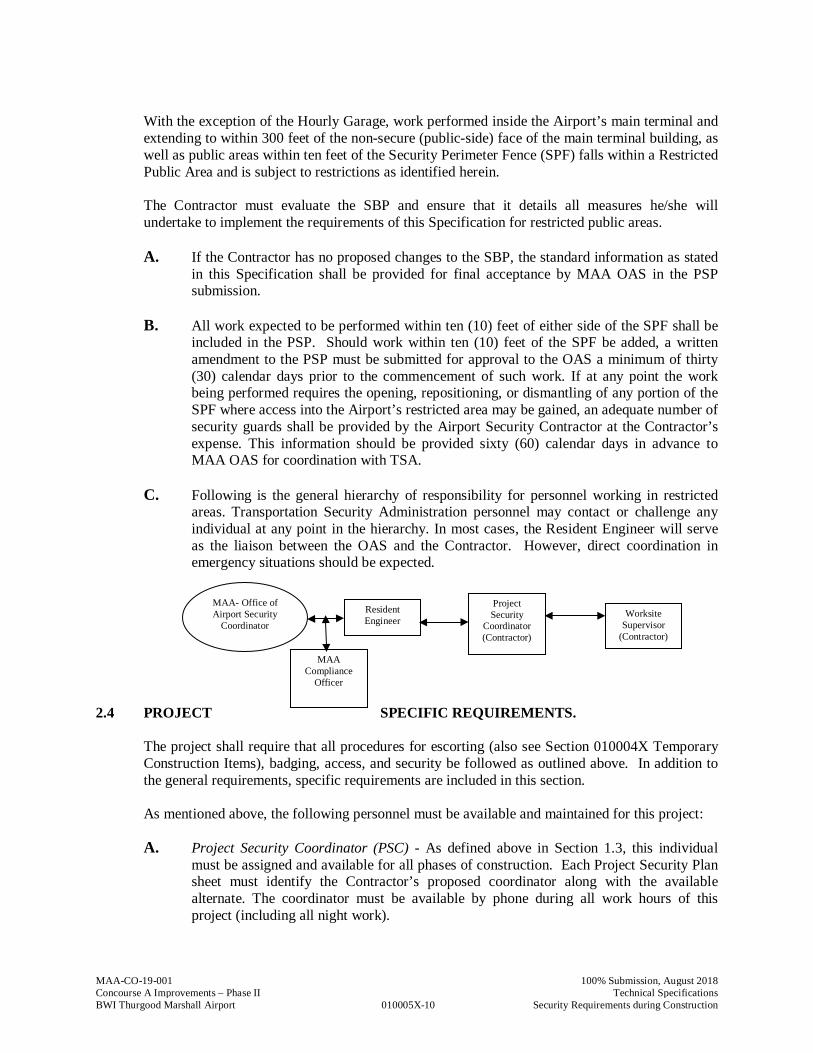
C. Following is the general hierarchy of responsibility for personnel working in restricted
areas. Transportation Security Administration personnel may contact or challenge any individual at any point in the hierarchy. In most cases, the Resident Engineer will serve as the liaison between the OAS and the Contractor. However, direct coordination in emergency situations should be expected.
2.4 PROJECT SPECIFIC REQUIREMENTS. The project shall require that all procedures for escorting (also see Section 010004X Temporary
Construction Items), badging, access, and security be followed as outlined above. In addition to the general requirements, specific requirements are included in this section. As mentioned above, the following personnel must be available and maintained for this project:
A. Project Security Coordinator (PSC) - As defined above in Section 1.3, this individual must be assigned and available for all phases of construction. Each Project Security Plan sheet must identify the Contractor’s proposed coordinator along with the available alternate. The coordinator must be available by phone during all work hours of this project (including all night work).
Worksite Supervisor
(Contractor)
MAA- Office of Airport Security
Coordinator
Resident Engineer
Project Security
Coordinator (Contractor)
MAA Compliance
Officer
MAA-CO-19-001
010005X-11
100% Submission, August 2018 Concourse A Improvements – Phase II Technical Specifications BWI Thurgood Marshall Airport Security Requirements during Construction
B. Escort - As defined above in Section 1.3, this individual can escort up to five (5) individuals into the Airport’s restricted areas, as long as the escorting regulation is followed as defined in the 010004X Temporary Construction Items Specification. Any escort must be solely committed to escorting of individuals and should not have any other responsibilities during the time of escorting. See Specification Section 010004X Temporary Construction Items for payment and requirements during measurement.
C. Worksite Supervisor - As defined above in Section 1.3, this individual must be assigned and be on site for all phases of construction. The Worksite Supervisor will need to be on site during all work hours and have radio contact with all of the identified escorts. The Worksite Supervisor will be responsible on this project to provide the following each working day:
(1) Daily report of the escorts on site for all phases of construction;
(2) Maintain positive control of escorting personnel at all times;
(3) Identify the quantity of inspected and badged vehicles construction site(s).
The Worksite Supervisor must be able to accurately present that the PSP is being implemented and enforced on the worksite to the TSA and/or MAA as required during the construction periods.
D. Guards - Guards shall be limited to eight (8) hour shifts to the maximum extent possible. Guards can work a maximum of 16-hours only if approved in writing prior to starting the shift by the MAA OAS. Every four (4) guards will require a breaker guard (1 individual for relief) to be available during the entire shift. Therefore, Contractor must assume that any requirement up to four (4) guards includes an additional guard to act as a breaker (total of 5 guards).
E. Temporary Sanitary Facilities - For projects requiring use of AOA access gates that are not equipped with sanitary facilities, facilities shall be rented and provided as required for security staff.
The Security Bid Plan (SBP) is included in the contract drawings for this project and includes the following:
(1) Project specific security requirements coordinated in detail with Project phasing
(2) Project Phases and the durations of each phase. (as shown on contract documents)
(3) Guard locations
(4) Access points/SIDA entrance/security guard locations. The designer shall make note of anticipated processing times at access points, if any inspections should be anticipated, etc. The designer shall make note that the Contractor shall consider the processing time when computing his bid price for this item
(5) Delivery routes
(6) Identification of worksites
(7) Locations/phases where an escort from MAA Operations is required
MAA-CO-19-001
010005X-12
100% Submission, August 2018 Concourse A Improvements – Phase II Technical Specifications BWI Thurgood Marshall Airport Security Requirements during Construction
(8) Signature Block with OAS Project Security Plan
The SBP shall be used as a basis for the PSP submittal after a Contractor has been awarded the project. Contractor shall request and obtain any necessary documentation from the OAS for PSP submission. The OAS requires a thirty (30) calendar day period for review of the PSP. Consider that more than one submittal may be required when scheduling the submittal. Upon completion of the PSP, a meeting shall be set up with the OAS. If the plans are intended to be final, three sets of PSP shall be brought to the meeting so that if they are approved without changes, three original signatures shall be obtained at the meeting - one set of PSP will remain on file with the OAS; one set of PSP will remain with the Resident Engineer; and the other will become part of the Contract Documents. The mobilization or submittal duration for this contract has been set to allow the Contractor time to obtain PSP approval by OAS. Construction Notice to Proceed (NTP) will only be granted following approval of PSP by MAA OAS. If acceptance of the PSP occurs after the specified thirty (30) calendar day period, due to late or non-conforming submissions by the Contractor, the contract performance time specified elsewhere in the contract shall be reduced by the number of days of delay in acceptance of the PSP.
2.5 ACCESS TO THE SITE. Access point locations for this project to the airfield are shown on the construction phasing plans and SBP’s and PSP’s. Gate usage will vary from phase to phase and shall be as shown on the Contract Documents.
All perimeter fence gates (manual and automatic) shown on the Contract Drawings as being contractor controlled shall be secured and staffed by MAA OAS approved Airport Security Contractor personnel. Confirm with the MAA OAS that the Contractor’s plans for providing appropriate security personnel will be adequate. Any access portal (gates/doors) found to be unsecured, or cause any entry by any unauthorized person(s) and/or vehicle(s) as a result of the Contractor's failure to follow proper Airport Security procedures per this specification shall subject the Contractor to TSA-imposed fine(s), work stoppage; and/or suspension/ revocation of the violator(s) BWI Marshall Access Badge. Project specific TSA-mandated security rules and regulations, as well as, BWI Airport Security Program requirements will be provided by the OAS to the successful bidder.
PART 4 – METHOD OF MEASUREMENT 4.1 No direct measurement will be made for as Security Materials/Equipment as this payment will be
made on a lump sum basis. This includes Gate guards, Breakers, etc. or any staffing required for implementation of the Project Security Plan.
PART 5 – BASIS OF PAYMENT
MAA-CO-19-001
010005X-13
100% Submission, August 2018 Concourse A Improvements – Phase II Technical Specifications BWI Thurgood Marshall Airport Security Requirements during Construction
5.1 “Security Materials/Equipment” will be made per lump sum bid price. This payment shall be full compensation for all costs associated with the security requirements identified in this Specification and shall include all labor, materials, training, and equipment required to complete the work specified. This cost shall include establishment and removal of security perimeter/s (as required to meet project phasing or airport operational requirements); badging of employees; registering of airfield vehicles; provision of all Worksite Supervisors, designated alternates; internal secure perimeter system guards; supplemental perimeter guards; any costs related to the maintenance/maneuvering of the security tower (if included in the SBP); provision of equipment for appropriate identification of personnel of varying security clearance levels (i.e. hardhats); and all other items related to the provision of security for the site(s).
5.2 In developing costs, the Contractor shall consider that the MAA is responsible for costs associated with perimeter guards under normal operating conditions (i.e. Power Gate G/A guards for every day usage) except when a security breach is caused by the Contractor’s work (as noted in 2.1e; and 2.2b). However, in order to expedite construction, the Contractor shall staff perimeter gate locations (i.e. Gate G) with supplemental perimeter guards during heavy construction vehicle volume conditions as directed and approved by the Director of the OAS and shown on the PSP. The Contractor shall consider that they are responsible for the supplemental perimeter guard costs. Providing guards at gates utilized for construction access purposes that would not regularly require that staffing, or currently have no guards (i.e. Gate 30), should all be considered supplemental and shall be the responsibility of the Contractor.
5.3 The first payment on the lump sum item will be ten percent (10%) of the bid price for that item and shall be included in the first progress estimate following the initiation of construction work. The remaining ninety percent (90%) of the lump sum item price will be included as installments in subsequent progress estimates as the project progresses. The total lump sum cost for security materials/equipment shall not exceed 5% of the overall construction bid price.
Payment will be made under:
Item 010005X.1 Security Materials/Equipment – per lump sum
END OF SECTION 010005X
MAA-CO-19-001
010005X-14
100% Submission, August 2018 Concourse A Improvements – Phase II Technical Specifications BWI Thurgood Marshall Airport Security Requirements during Construction
THIS PAGE HAS BEEN INTENTIONALLY LEFT BLANK
MAA-CO-19-001
01 10 00-1
100% Submission, August 2018Concourse A Improvements – Phase II Technical SpecificationsBWI Thurgood Marshall Airport Concourse A Improvements – Phase II
SECTION 01 10 00 – CONCOURSE A IMPROVEMENTS – PHASE II
PART 1 - GENERAL
1.1 RELATED DOCUMENTS
A. Drawings and general provisions of the Contract, including Maryland Department ofTransportation/Maryland Aviation Administration "Standard Provisions for ConstructionContracts", consisting of "Volume 1: General Provisions" January 2014 Edition, and "Volume 2:Special Provisions" January 2014 Edition, and other Division 01 Specifications Sections apply tothis Section.
1.2 DESCRIPTION
A. Provide all labor, materials, equipment and supervision for the construction for the Concourse AImprovements – Phase II at Baltimore/Washington International Thurgood Marshall Airport(BWI Marshall) project, as defined in the project drawings and specifications. The projectconsists of constructing an addition, approximately 230 feet by 130 feet, at the end of ConcourseA including the addition of 5 new gates, and construct related airfield paving. Specific Featuresinclude:1. Demolition of concrete and asphalt apron pavements and pavement markings.2. Full depth Portland cement concrete pavement construction.3. Storm drain inlet and pipe construction.4. Passenger boarding bridge and fixed section procurement and installation (including
associated concrete pier foundation construction, and electrical and mechanicalconnections/installations).
5. Selective building demolition such as exterior wall panels, CMU, aluminum windows,doors, roofing, interior particitions, steel framing, and floor slabs.
6. Concrete foundations and floor slabs, and steel framing.7. Exterior CMU walls and metal wall panels.8. Standing seam metal roof and SBS roofing membrane.9. Thermal insulation.10. Fire insulation.11. Doors and hardware.12. Interior partitions consisting of metal studs and gypsum wallboard.13. Interior CMU partitions.14. Interior finishes including resilient flooring and base; paint.15. Fire suppression system.16. Plumbing (roof drains and sub-slab piping)17. HVAC including hydronics piping, valves and pumps; metal ducts; louvers; exhaust fans;
condenser units; split system AC units; indoor air-handling units; unit heaters.18. Electrical including lighting, panelboards, low-voltage transformers, and wiring devices;
fuses; enclosed switches and circuit breakers; enclosed controllers; lightning protection;fire alarm.
19. Communications.
MAA-CO-19-001
01 10 00-2
100% Submission, August 2018Concourse A Improvements – Phase II Technical SpecificationsBWI Thurgood Marshall Airport Concourse A Improvements – Phase II
PART 2 - PRODUCTS
2.1 PRODUCTS
A. Provide all work in accordance with the requirements of the related Specification Sections.
PART 3 - EXECUTION
3.1 EXECUTION
A. Perform all work in accordance with the requirements of the related Specfications Sections.
3.2 MOBILIZATION/DEMOBILIZATION
A. Refer to Section 01 00 01X “Mobilization/Demobilization.”
3.3 CONSTRUCTION QUALITY CONTROL PLAN
A. Refer to Section 01 00 02X, “Construction Quality Control Plan.”
3.4 TEMPORARY CONSTRUCTION ITEMS
A. Refer to Section 01 00 04X “Temporary Construction Items.”
3.5 SECURITY MATERIALS AND EQUIPMENT
A. Refer to Section 01 00 05X “Security Requirements During Construction at BWI MarshallAirport.”
3.6 ALLOWANCES
A. Refer to Section 01 21 00 “Allowances”
PART 4 - MEASUREMENT
4.1 METHOD OF MEASUREMENT
A. Payment for “Concourse A Improvements – Phase II” will be made on a lump sum basis for thefollowing items, and separate measurements must be made for each item.
MAA-CO-19-001
01 10 00-3
100% Submission, August 2018Concourse A Improvements – Phase II Technical SpecificationsBWI Thurgood Marshall Airport Concourse A Improvements – Phase II
Item 01 10 00.1 “Building Construction”, which includes all base bid work notincluded in Section 01 00 01X “Mobilization/Demobilization”, Section01 00 02X, “Construction Quality Control Plan”, Section 01 00 04S“Temporary Construction Items”, Section 01 00 05X “SecurityRequirements During Construction at BWI Marshall Airport”, orSection 01 21 00 “Allowances”, nor any of the work included in thefollowing items:
Item 01 10 00.2 All materials, labor, and equipment, and any other associated costsrequired to provide Passenger Boarding Bridges and PC Air – 400 Hzat the new departure gates.
Item 01 10 00.3 All materials, labor, and equipment and any other associated costsrequired to subcontract with Johnson Controls to provide the BuildingAutomation System work as described in the Contract Documents.
Item 01 10 00.4 All materials, labor, and equipment and any other associated costsrequired to subcontract with either Washington Professional Sound orElite Audio LLC to provide the Paging System work as described inthe Contract Documents.
Item 01 10 00.5 All materials, labor, and equipment and any other associated costsrequired to subcontract with TYCO to provide the Video Surveillancework as described in the Contract Documents.
Item 01 10 00.6 All materials, labor, and equipment and any other associated costsrequired to subcontract with TYCO to provide the Integrated AirportSecurity System work as described in the Contract Documents.
Item 01 10 00.7 All materials, labor, and equipment and any other associated costsrequired to subcontract with Honeywell to provide the Fire AlarmSystem work as described in the Contract Documents.
Item 01 10 00.8 All materials, labor, and equipment and any other associated costsrequired to subcontract with Comnet to provide the Visual Paging andMUFIDS work as described in the Contract Documents.
PART 5 - PAYMENT
5.1 BASIS OF PAYMENT
A. This item will be paid for at the Contract lump sum price bid for “Concourse A Improvements –Phase II”. This price shall be full compensation for all work contained in the bid item as describedand required by the related sections.
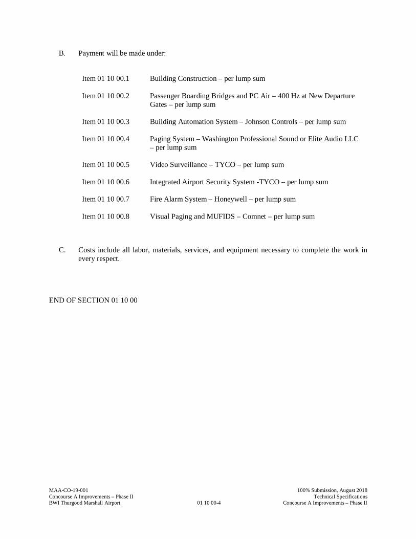
MAA-CO-19-001
01 10 00-4
100% Submission, August 2018Concourse A Improvements – Phase II Technical SpecificationsBWI Thurgood Marshall Airport Concourse A Improvements – Phase II
B. Payment will be made under:
Item 01 10 00.1 Building Construction – per lump sum
Item 01 10 00.2 Passenger Boarding Bridges and PC Air – 400 Hz at New DepartureGates – per lump sum
Item 01 10 00.3 Building Automation System – Johnson Controls – per lump sum
Item 01 10 00.4 Paging System – Washington Professional Sound or Elite Audio LLC– per lump sum
Item 01 10 00.5 Video Surveillance – TYCO – per lump sum
Item 01 10 00.6 Integrated Airport Security System -TYCO – per lump sum
Item 01 10 00.7 Fire Alarm System – Honeywell – per lump sum
Item 01 10 00.8 Visual Paging and MUFIDS – Comnet – per lump sum
C. Costs include all labor, materials, services, and equipment necessary to complete the work inevery respect.
END OF SECTION 01 10 00

MAA-CO-19-001
01 21 00-1
100% Submission, August 2018Concourse A Improvements – Phase II Technical SpecificationsBWI Thurgood Marshall Airport Allowances
SECTION 01 21 00 – ALLOWANCES
PART 1 - GENERAL
1.1 RELATED DOCUMENTS
A. Drawings and general provisions of the Contract, including Maryland Department ofTransportation/ Maryland Aviation Administration “Standard Provisions for ConstructionContracts”, consisting of “Volume 1: General Provisions” January 2014 Edition, and “Volume 2:Special Provisions” January 2014 Edition, and other Division 01 Specifications Sections apply tothis Section.
1.2 SUMMARY
A. This Section includes administrative and procedural requirements governing the following:1. Unit Cost allowances.
1.3 SELECTION AND PURCHASE
A. At the earliest practical date after award of the Contract, advise the Engineer of the date whenfinal selection and purchase of each product or system described by an allowance must be com-pleted to avoid delaying the Work.
B. At the Engineer’s request, obtain proposals for each allowance for use in making final selections.Include recommendations that are relevant to performing the Work.
C. Purchase products and systems selected by the Engineer from the designated supplier.
1.4 SUBMITTALS
A. Submit proposal for purchase of products or systems included in allowances, in the form specifiedfor Change Orders.
B. Submit invoices or delivery slips to show actual quantities of materials delivered to the site foruse in fulfillment of each allowance.
1.5 UNUSED MATERIALS
A. Return unused materials purchased under an allowance to manufacturer or supplier for credit toOwner, after installation has been completed and accepted.1. If requested by the Engineer, prepare unused material for storage by Owner when it is not
economically practical to return the material for credit. If directed by the Engineer, deliverunused material to Owner’s storage space. Otherwise, disposal of unused material isContractor’s responsibility.
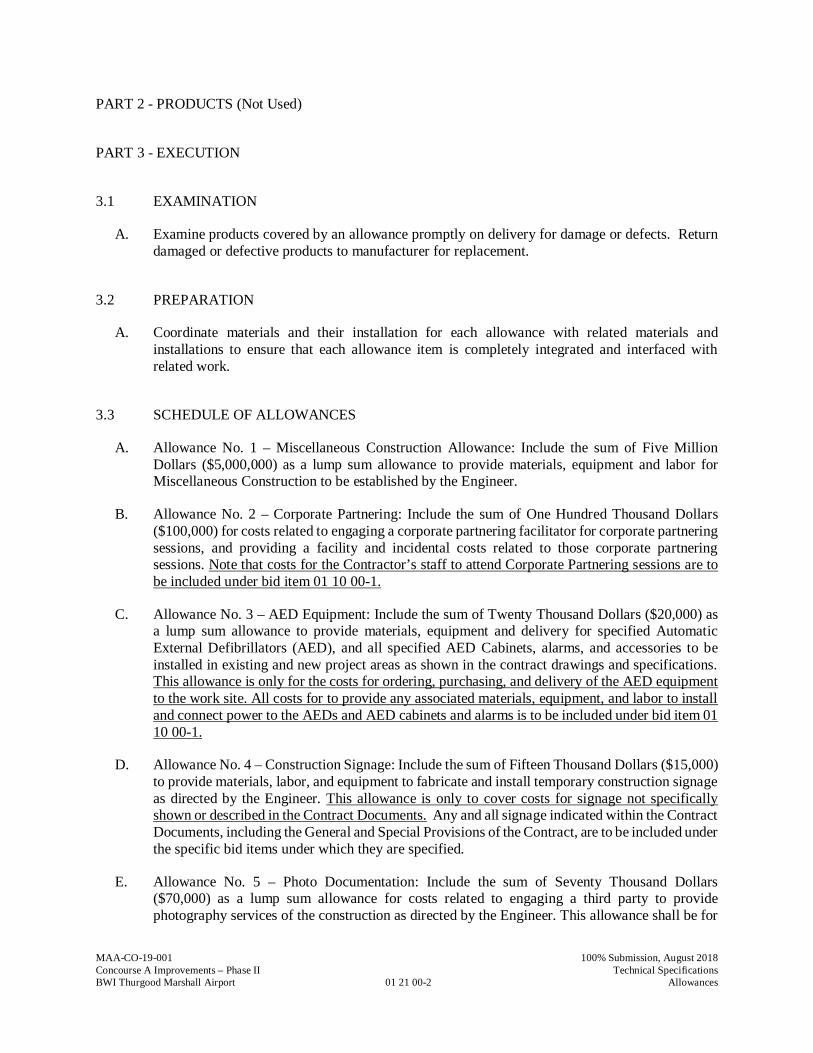
MAA-CO-19-001
01 21 00-2
100% Submission, August 2018Concourse A Improvements – Phase II Technical SpecificationsBWI Thurgood Marshall Airport Allowances
PART 2 - PRODUCTS (Not Used)
PART 3 - EXECUTION
3.1 EXAMINATION
A. Examine products covered by an allowance promptly on delivery for damage or defects. Returndamaged or defective products to manufacturer for replacement.
3.2 PREPARATION
A. Coordinate materials and their installation for each allowance with related materials andinstallations to ensure that each allowance item is completely integrated and interfaced withrelated work.
3.3 SCHEDULE OF ALLOWANCES
A. Allowance No. 1 – Miscellaneous Construction Allowance: Include the sum of Five MillionDollars ($5,000,000) as a lump sum allowance to provide materials, equipment and labor forMiscellaneous Construction to be established by the Engineer.
B. Allowance No. 2 – Corporate Partnering: Include the sum of One Hundred Thousand Dollars($100,000) for costs related to engaging a corporate partnering facilitator for corporate partneringsessions, and providing a facility and incidental costs related to those corporate partneringsessions. Note that costs for the Contractor’s staff to attend Corporate Partnering sessions are tobe included under bid item 01 10 00-1.
C. Allowance No. 3 – AED Equipment: Include the sum of Twenty Thousand Dollars ($20,000) asa lump sum allowance to provide materials, equipment and delivery for specified AutomaticExternal Defibrillators (AED), and all specified AED Cabinets, alarms, and accessories to beinstalled in existing and new project areas as shown in the contract drawings and specifications.This allowance is only for the costs for ordering, purchasing, and delivery of the AED equipmentto the work site. All costs for to provide any associated materials, equipment, and labor to installand connect power to the AEDs and AED cabinets and alarms is to be included under bid item 0110 00-1.
D. Allowance No. 4 – Construction Signage: Include the sum of Fifteen Thousand Dollars ($15,000)to provide materials, labor, and equipment to fabricate and install temporary construction signageas directed by the Engineer. This allowance is only to cover costs for signage not specificallyshown or described in the Contract Documents. Any and all signage indicated within the ContractDocuments, including the General and Special Provisions of the Contract, are to be included underthe specific bid items under which they are specified.
E. Allowance No. 5 – Photo Documentation: Include the sum of Seventy Thousand Dollars($70,000) as a lump sum allowance for costs related to engaging a third party to providephotography services of the construction as directed by the Engineer. This allowance shall be for
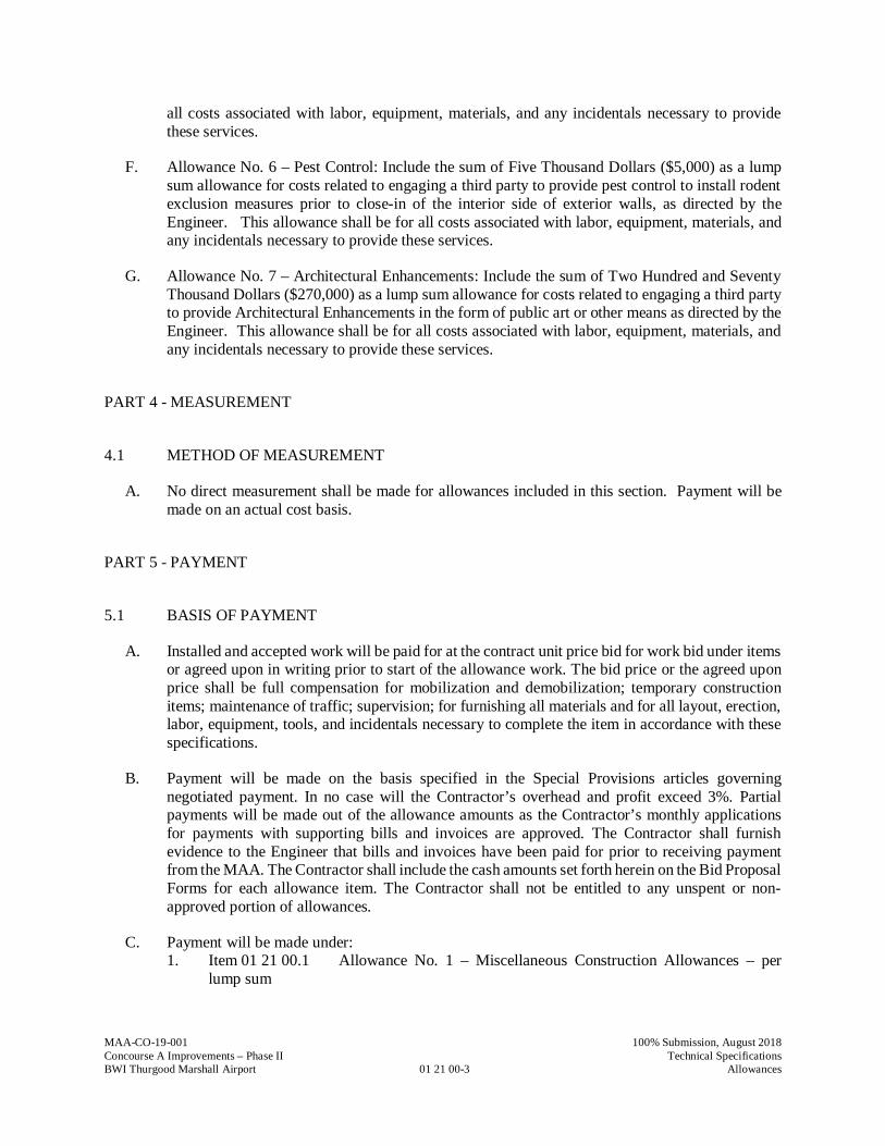
MAA-CO-19-001
01 21 00-3
100% Submission, August 2018Concourse A Improvements – Phase II Technical SpecificationsBWI Thurgood Marshall Airport Allowances
all costs associated with labor, equipment, materials, and any incidentals necessary to providethese services.
F. Allowance No. 6 – Pest Control: Include the sum of Five Thousand Dollars ($5,000) as a lumpsum allowance for costs related to engaging a third party to provide pest control to install rodentexclusion measures prior to close-in of the interior side of exterior walls, as directed by theEngineer. This allowance shall be for all costs associated with labor, equipment, materials, andany incidentals necessary to provide these services.
G. Allowance No. 7 – Architectural Enhancements: Include the sum of Two Hundred and SeventyThousand Dollars ($270,000) as a lump sum allowance for costs related to engaging a third partyto provide Architectural Enhancements in the form of public art or other means as directed by theEngineer. This allowance shall be for all costs associated with labor, equipment, materials, andany incidentals necessary to provide these services.
PART 4 - MEASUREMENT
4.1 METHOD OF MEASUREMENT
A. No direct measurement shall be made for allowances included in this section. Payment will bemade on an actual cost basis.
PART 5 - PAYMENT
5.1 BASIS OF PAYMENT
A. Installed and accepted work will be paid for at the contract unit price bid for work bid under itemsor agreed upon in writing prior to start of the allowance work. The bid price or the agreed uponprice shall be full compensation for mobilization and demobilization; temporary constructionitems; maintenance of traffic; supervision; for furnishing all materials and for all layout, erection,labor, equipment, tools, and incidentals necessary to complete the item in accordance with thesespecifications.
B. Payment will be made on the basis specified in the Special Provisions articles governingnegotiated payment. In no case will the Contractor’s overhead and profit exceed 3%. Partialpayments will be made out of the allowance amounts as the Contractor’s monthly applicationsfor payments with supporting bills and invoices are approved. The Contractor shall furnishevidence to the Engineer that bills and invoices have been paid for prior to receiving paymentfrom the MAA. The Contractor shall include the cash amounts set forth herein on the Bid ProposalForms for each allowance item. The Contractor shall not be entitled to any unspent or non-approved portion of allowances.
C. Payment will be made under:1. Item 01 21 00.1 Allowance No. 1 – Miscellaneous Construction Allowances – per
lump sum
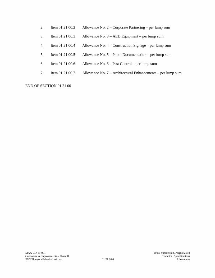
MAA-CO-19-001
01 21 00-4
100% Submission, August 2018Concourse A Improvements – Phase II Technical SpecificationsBWI Thurgood Marshall Airport Allowances
2. Item 01 21 00.2 Allowance No. 2 – Corporate Partnering – per lump sum
3. Item 01 21 00.3 Allowance No. 3 – AED Equipment – per lump sum
4. Item 01 21 00.4 Allowance No. 4 – Construction Signage – per lump sum
5. Item 01 21 00.5 Allowance No. 5 – Photo Documentation – per lump sum
6. Item 01 21 00.6 Allowance No. 6 – Pest Control – per lump sum
7. Item 01 21 00.7 Allowance No. 7 – Architectural Enhancements – per lump sum
END OF SECTION 01 21 00
MAA-CO-19-001 Technical SpecificationsConcourse A Improvements - Phase II
01 31 00-1Project Management And Coordination
at BWI Thurgood Marshall Airport 100% Submission, August 2018
SECTION 01 31 00 - PROJECT MANAGEMENT AND COORDINATION
PART 1 - GENERAL
1.1 RELATED DOCUMENTS
A. Drawings and general provisions of the Contract, including Maryland Department ofTransportation/Maryland Aviation Administration “Standard Provisions for ConstructionContracts", consisting of "Volume 1: General Provisions” January 2014 Edition, and “Volume2: Special Provisions” January 2014 Edition, and other Division 01 Specifications Sectionsapply to this Section.
1.2 SUMMARY
A. Section includes administrative provisions for coordinating construction operations on Projectincluding, but not limited to, the following:
1. General coordination procedures.2. Coordination drawings.3. Requests for Information (RFIs).4. Project Web site.5. Project meetings.6. Project Web Site.
B. Related Requirements:
1. Section GI-1.01 - Contract Summary.2. Section GI-1.03 – Description of Project.3. Section GI-1.04 – Special Construction Requirements.4. Section 01 73 00 "Execution" for procedures for coordinating general installation and
field-engineering services, including establishment of benchmarks and control points.5. Section 01 77 00 "Closeout Procedures" for coordinating closeout of the Contract.
1.3 DEFINITIONS
A. RFI: Request from Owner, Engineer, or Contractor seeking information required by orclarifications of the Contract Documents.
1.4 GENERAL COORDINATION PROCEDURES
A. Coordination: Coordinate construction operations included in different Sections of theSpecifications to ensure efficient and orderly installation of each part of the Work. Coordinateconstruction operations, included in different Sections, that depend on each other for properinstallation, connection, and operation.
MAA-CO-19-001 Technical SpecificationsConcourse A Improvements - Phase II
01 31 00-2Project Management And Coordination
at BWI Thurgood Marshall Airport 100% Submission, August 2018
1. Schedule construction operations in sequence required to obtain the best results whereinstallation of one part of the Work depends on installation of other components, beforeor after its own installation.
2. Coordinate installation of different components to ensure maximum performance andaccessibility for required maintenance, service, and repair.
3. Make adequate provisions to accommodate items scheduled for later installation.
B. Coordination: Each contractor shall coordinate its construction operations with those of othercontractors and entities to ensure efficient and orderly installation of each part of the Work.Each contractor shall coordinate its operations with operations, included in different Sections,that depend on each other for proper installation, connection, and operation.
1. Schedule construction operations in sequence required to obtain the best results whereinstallation of one part of the Work depends on installation of other components, beforeor after its own installation.
2. Coordinate installation of different components with other contractors to ensuremaximum performance and accessibility for required maintenance, service, and repair.
3. Make adequate provisions to accommodate items scheduled for later installation.
C. Prepare memoranda for distribution to each party involved, outlining special proceduresrequired for coordination. Include such items as required notices, reports, and list of attendeesat meetings.
1. Prepare similar memoranda for Owner and separate contractors if coordination of theirWork is required.
D. Administrative Procedures: Coordinate scheduling and timing of required administrativeprocedures with other construction activities and activities of other Projects to avoid conflictsand to ensure orderly progress of the Work. Such administrative activities include, but are notlimited to, the following:
1. Preparation of Contractor's construction schedule.2. Preparation of the schedule of values.3. Installation and removal of temporary facilities and controls.4. Delivery and processing of submittals.5. Progress meetings.6. Preinstallation conferences.7. Project closeout activities.8. Startup and adjustment of systems.9. Notify Administration and OFM of any fire alarm system or fire suppression system
outages.
E. Conservation: Coordinate construction activities to ensure that operations are carried out withconsideration given to conservation of energy, water, and materials. Coordinate use oftemporary utilities to minimize waste.
1. Salvage materials and equipment involved in performance of, but not actuallyincorporated into, the Work. See other Sections for disposition of salvaged materials thatare designated as Owner's property.
MAA-CO-19-001 Technical SpecificationsConcourse A Improvements - Phase II
01 31 00-3Project Management And Coordination
at BWI Thurgood Marshall Airport 100% Submission, August 2018
1.5 COORDINATION DRAWINGS
A. Coordination Drawings, General: Prepare coordination drawings according to requirements inindividual Sections, and additionally where installation is not completely shown on ShopDrawings, where limited space availability necessitates coordination, or if coordination isrequired to facilitate integration of products and materials fabricated or installed by more thanone entity.
1. Content: Project-specific information, drawn accurately to a scale large enough toindicate and resolve conflicts. Do not base coordination drawings on standard printeddata. Include the following information, as applicable:
a. Use applicable Drawings as a basis for preparation of coordination drawings.Prepare sections, elevations, and details as needed to describe relationship ofvarious systems and components.
b. Coordinate the addition of trade-specific information to the coordination drawingsby multiple contractors in a sequence that best provides for coordination of theinformation and resolution of conflicts between installed components beforesubmitting for review.
c. Indicate functional and spatial relationships of components of architectural,structural, civil, mechanical, and electrical systems.
d. Indicate space requirements for routine maintenance and for anticipatedreplacement of components during the life of the installation.
e. Show location and size of access doors required for access to concealed dampers,valves, and other controls.
f. Indicate required installation sequences.g. Indicate dimensions shown on the Drawings. Specifically note dimensions that
appear to be in conflict with submitted equipment and minimum clearancerequirements. Provide alternate sketches to Engineer indicating proposedresolution of such conflicts. Minor dimension changes and difficult installationswill not be considered changes to the Contract.
B. Coordination Drawing Organization: Organize coordination drawings as follows:
1. Floor Plans and Reflected Ceiling Plans: Show architectural and structural elements, andmechanical, plumbing, fire-protection, fire-alarm, and electrical Work. Show locations ofvisible ceiling-mounted devices relative to acoustical ceiling grid. Supplement plandrawings with section drawings where required to adequately represent the Work.
2. Plenum Space: Indicate subframing for support of ceiling and wall systems, mechanicaland electrical equipment, and related Work. Locate components within ceiling plenum toaccommodate layout of light fixtures indicated on Drawings. Indicate areas of conflictbetween light fixtures and other components.
3. Mechanical Rooms: Provide coordination drawings for mechanical rooms showing plansand elevations of mechanical, plumbing, fire-protection, fire-alarm, and electricalequipment.
4. Structural Penetrations: Indicate penetrations and openings required for all disciplines.5. Slab Edge and Embedded Items: Indicate slab edge locations and sizes and locations of
embedded items for metal fabrications, sleeves, anchor bolts, bearing plates, angles, doorfloor closers, slab depressions for floor finishes, curbs and housekeeping pads, andsimilar items.
6. Mechanical and Plumbing Work: Show the following:

MAA-CO-19-001 Technical SpecificationsConcourse A Improvements - Phase II
01 31 00-4Project Management And Coordination
at BWI Thurgood Marshall Airport 100% Submission, August 2018
a. Sizes and bottom elevations of ductwork, piping, and conduit runs, includinginsulation, bracing, flanges, and support systems.
b. Dimensions of major components, such as dampers, valves, diffusers, accessdoors, cleanouts and electrical distribution equipment.
c. Fire-rated enclosures around ductwork.
7. Electrical Work: Show the following:
a. Runs of vertical and horizontal conduit 1-1/4 inches in diameter and larger.b. Light fixture, exit light, emergency battery pack, smoke detector, and other fire-
alarm locations.c. Panel board, switch board, switchgear, transformer, busway, generator, and motor
control center locations.d. Location of pull boxes and junction boxes, dimensioned from column center lines.
8. Fire-Protection System: Show the following:
a. Locations of standpipes, mains piping, branch lines, pipe drops, and sprinklerheads.
9. Review: Engineer will review coordination drawings to confirm that the Work is beingcoordinated, but not for the details of the coordination, which are Contractor'sresponsibility. If Engineer determines that coordination drawings are not being preparedin sufficient scope or detail, or are otherwise deficient, Engineer will so informContractor, who shall make changes as directed and resubmit.
10. Coordination Drawing Prints: Prepare coordination drawing prints according torequirements in Section 01 33 00 "Submittal Procedures."
C. Coordination Digital Data Files: Prepare coordination digital data files according to thefollowing requirements:
1. File Preparation Format: Same digital data software program, version, and operatingsystem as original Drawings.
2. File Preparation Format: DWG, AutoCAD Version 2000, operating in MicrosoftWindows operating system.
3. File Submittal Format: Submit or post coordination drawing files using Portable Data File(PDF) format.
4. Engineer will furnish Contractor one set of digital data files of Drawings for use inpreparing coordination digital data files.
a. Engineer makes no representations as to the accuracy or completeness of digitaldata files as they relate to Drawings.
b. Digital Data Software Program: Drawings are available in AutoCAD and PDFformats.
c. Contractor shall execute a data licensing agreement in the form ofAIA Document C106.
d. Any and all digital files furnished to the Contractor shall incorporate the followingdisclaimer by inclusion in this specification:
WSP USA INC IS FURNISHING THE ATTACHED ELECTONIC DATA FILES TO THE CONTRACTOR ONLY FOR THE SOLE
MAA-CO-19-001 Technical SpecificationsConcourse A Improvements - Phase II
01 31 00-5Project Management And Coordination
at BWI Thurgood Marshall Airport 100% Submission, August 2018
CONVENIENCE AND USE BY CONTRACTOR. CONTRACTORRECOGNIZES THAT THE ELECTOINIC DATA FILES MAY NOT BEADEQUATE OR APPROPRIATE FOR ITS NEEDS, AND ARE INHERENTLYSUSCEPTIBLE TO TRANSMISSION ERROR, DATA CORRUPTON OR FILEINCOMPATIBLILITY. IN THE EVENT OF ANY DISCREPANCIESBETWEEN THE ELCTRONIC DATA FILES AND THE CORRESPONDINGHARD COPY DATA, THE HARD COPY DATA SHALL GOVERN. WSP USA RESERVES THE RIGHT TO REMOVE ITS ELECTRONICSTAMP OR OTHER IDENTIFYING INFORMATION FROM THEELCTRONIC DATA FILES. WSP USA SHALL BEAR NO LIABILITY FOR ANY USE, REUSE, MODIFICATION, OR DISCLOSURE OF THE ELECTRONIC DATA FILES BY CONTRACTOR, ITS OFFICERS,DIRECTORS, EMPLOYEES, AGENTS, CONTRACTORS, OR ANY THIRDPARTY. FURTHER, WSP USA IS PROVIDING THEINFORMATION "AS IS", AND MAKES NO REPRESENTATION ORWARRANTY AS TO TITLE, NON-INFRINGEMENT, SUITABILITY,MERCHANTIBILITY, FITNESS OF PURPOSE, ACCURACY, INTEGRITY,COMPATIBLITY, CORRECTNESS OF THE ELECTRONIC DATA FILES ORANY OTHER MATTER.
1.6 KEY PERSONNEL
A. Key Personnel Names: Within seven (7) days of starting construction operations, submit a listof key personnel assignments, including superintendent and other personnel in attendance atProject site. Identify individuals and their duties and responsibilities; list addresses andtelephone numbers, including home, office, and cellular telephone numbers and emailaddresses. Provide names, addresses, and telephone numbers of individuals assigned asstandbys in the absence of individuals assigned to Project.
1. Post copies of list in Project meeting room, in temporary field office, on Project Website(if applicable), and by each temporary telephone. Keep list current at all times.
1.7 REQUESTS FOR INFORMATION (RFIs)
A. Refer to Special Provisions SP-4.14.
1.8 PROJECT WEB SITE
A. Provide, administer, and use Project Web site for purposes of hosting and managing projectcommunication and documentation until Final Completion. Project Web site shall include thefollowing functions:
1. Project directory.2. Project correspondence.3. Meeting minutes.4. Contract modifications forms and logs.5. RFI forms and logs.6. Task and issue management.
MAA-CO-19-001 Technical SpecificationsConcourse A Improvements - Phase II
01 31 00-6Project Management And Coordination
at BWI Thurgood Marshall Airport 100% Submission, August 2018
7. Photo documentation.8. Schedule and calendar management.9. Submittals forms and logs.10. Payment application forms.11. Drawing and specification document hosting, viewing, and updating.12. Online document collaboration.13. Reminder and tracking functions.14. Archiving functions.
B. Provide up to 50 Project Web site user licenses for use of the Owner, Engineer, and Engineer'sconsultants. Provide eight hours of software training at Engineer's office for Project Web siteusers.
C. Upon completion of Project, provide one complete archive copy of Project Web site files toOwner and to Engineer in a digital storage format acceptable to Engineer.
D. Provide one of the following Project Web site software packages under their current publishedlicensing agreements:
1. Autodesk, Buzzsaw.2. Autodesk, Constructware.3. Meridian Systems, Prolog and ProjectTalk.4. Another Project Web site software package, acceptable to the Engineer and the Owner,
offering similar functionality as those listed above.
E. Contractor, subcontractors, and other parties granted access by Contractor to Project Web siteshall execute a data licensing agreement in the form of Agreement acceptable to Owner andEngineer.
F. The Contractor shall provide representatives of the Engineer and the Owner full administrativeand oversight privileges of the data on the Project Web site for purposes of verifyingconformance with these provisions.
1.9 PROJECT MEETINGS
A. Refer to Special Provisions SP-8.04.
B. Preinstallation Conferences: Conduct a preinstallation conference at Project site before eachconstruction activity that requires coordination with other construction.
1. Attendees: Installer and representatives of manufacturers and fabricators involved in oraffected by the installation and its coordination or integration with other materials andinstallations that have preceded or will follow, shall attend the meeting. Advise Engineerof scheduled meeting dates.
2. Agenda: Review progress of other construction activities and preparations for theparticular activity under consideration, including requirements for the following:
a. Contract Documents.b. Options.c. Related RFIs.
MAA-CO-19-001 Technical SpecificationsConcourse A Improvements - Phase II
01 31 00-7Project Management And Coordination
at BWI Thurgood Marshall Airport 100% Submission, August 2018
d. Related Change Orders.e. Purchases.f. Deliveries.g. Submittals.h. Review of mockups.i. Possible conflicts.j. Compatibility requirements.k. Time schedules.l. Weather limitations.m. Manufacturer's written instructions.n. Warranty requirements.o. Compatibility of materials.p. Acceptability of substrates.q. Temporary facilities and controls.r. Space and access limitations.s. Regulations of authorities having jurisdiction.t. Testing and inspecting requirements.u. Installation procedures.v. Coordination with other work.w. Required performance results.x. Protection of adjacent work.y. Protection of construction and personnel.
3. Record significant conference discussions, agreements, and disagreements, includingrequired corrective measures and actions.
4. Reporting: Distribute minutes of the meeting to each party present and to other partiesrequiring information.
5. Do not proceed with installation if the conference cannot be successfully concluded.Initiate whatever actions are necessary to resolve impediments to performance of theWork and reconvene the conference at earliest feasible date.
C. Coordination Meetings: Conduct Project coordination meetings at regular intervals. Projectcoordination meetings are in addition to specific meetings held for other purposes, such asprogress meetings and preinstallation conferences.
1. Attendees: In addition to representatives of Owner and Engineer, each contractor,subcontractor, supplier, and other entity concerned with current progress or involved inplanning, coordination, or performance of future activities shall be represented at thesemeetings. All participants at the meetings shall be familiar with Project and authorized toconclude matters relating to the Work.
2. Agenda: Review and correct or approve minutes of the previous coordination meeting.Review other items of significance that could affect progress. Include topics fordiscussion as appropriate to status of Project.
a. Combined Contractor's Construction Schedule: Review progress since the lastcoordination meeting. Determine whether each contract is on time, ahead ofschedule, or behind schedule, in relation to combined Contractor's constructionschedule. Determine how construction behind schedule will be expedited; securecommitments from parties involved to do so. Discuss whether schedule revisionsare required to ensure that current and subsequent activities will be completedwithin the Contract Time.
MAA-CO-19-001 Technical SpecificationsConcourse A Improvements - Phase II
01 31 00-8Project Management And Coordination
at BWI Thurgood Marshall Airport 100% Submission, August 2018
b. Schedule Updating: Revise combined Contractor's construction schedule after eachcoordination meeting where revisions to the schedule have been made orrecognized. Issue revised schedule concurrently with report of each meeting.
c. Review present and future needs of each contractor present, including thefollowing:
1) Interface requirements.2) Sequence of operations.3) Resolution of BIM component conflicts.4) Status of submittals.5) Deliveries.6) Off-site fabrication.7) Access.8) Site utilization.9) Temporary facilities and controls.10) Work hours.11) Hazards and risks.12) Progress cleaning.13) Quality and work standards.14) Change Orders.
3. Reporting: Record meeting results and distribute copies to everyone in attendance and toothers affected by decisions or actions resulting from each meeting.
PART 2 - PRODUCTS (Not Used)
PART 3 - EXECUTION (Not Used)
PART 4 - MEASUREMENT
4.1 METHOD OF MEASUREMENT
A. No separate measurement will be made for work under this section.
PART 5 - PAYMENT
5.1 BASIS OF PAYMENT
A. No separate payment will be made for work under this section. The cost of the work describedin this section for base bid items shall be included in the lump sum contract price for Section01 10 00.
B. Payment will be made under:

MAA-CO-19-001 Technical SpecificationsConcourse A Improvements - Phase II
01 31 00-9Project Management And Coordination
at BWI Thurgood Marshall Airport 100% Submission, August 2018
Item 01 10 00-1 Building Construction
C. Costs include all labor, materials, services, and equipment necessary to complete the work inevery respect.
END OF SECTION 01 31 00
MAA-CO-19-001
01 31 28-2
100% Submission, August 2018Concourse A Improvements – Phase II Technical SpecificationsBWI Thurgood Marshall Airport Section Title
SECTION 01 31 28 – BUILDING INFORMATION MODEL
PART 1 - GENERAL
1.01 SECTION INCLUDES
A. Furnishing a digital, 3-dimensional, comprehensive, fully-integrated, as-designed and as-built Building Information Model (BIM) of the proposed extension of Concourse A, asdescribed in Section 01 10 00 Concourse A Improvements – Phase II.
B. Requirements for an as-built BIM, to be used by MAA for operation and maintenancepurposes.
1.02 RELATED SECTIONS
1. 01 33 00 Submittal Procedures
2. 01 43 10 Project Quality Program Requirements
3. 01 31 00 Project Management and Coordination
4. 01 78 39 As-Built Drawings and Current Status Documents
1.03 REFERENCES
A. Reference Standards
1. National BIM Standard (NBIMS) – United States™ Latest Version
2. MAA CADD Standards
B. Reference Documents
1. BIM Implementation Plan (provided as Appendix xx – or Section xx xx xx)
C. Abbreviations and Acronyms
1. BIM – Building Information Model
2. VDC – Virtual Design & Construction
3. FF&E – Furniture Fixtures & Equipment
4. 3D – 3-Dimensional
D. Definitions
1. Building Information Model (BIM)
a. A Building Information Model is as defined by General Services AdministrationBIM Guide.
MAA-CO-19-001
01 31 28-3
100% Submission, August 2018Concourse A Improvements – Phase II Technical SpecificationsBWI Thurgood Marshall Airport Section Title
2. BIM Implementation Plan (BIP)
a. A detailed plan that defines how the project will be executed, monitored andcontrolled with respect to BIM. It includes a master information and datamanagement plan, data security, quality control, assignment of roles andresponsibilities, clash detection procedures, list of disciplines, file and objectnaming convention, procedures and protocols for submittals, establishment of acommon coordinate system, software and hardware to be used, interoperability andcoordination, and folder structure.
3. Interoperability
a. The exchange of information among project participants throughout the lifecycleof a facility by direct communication between software applications.
4. Level of Development (LOD)
a. Level of Development describes the completeness of elements in a BuildingInformation Model. Completeness will range from geometric detail to elementinformation.
E. Units of Measurement
1. BIM Electronic Files shall be developed and delivered in US Feet (fractional).
F. Coordinate System
1. All BIM Electronic Files shall be developed and delivered in the project coordinatesystem, which has been set to permanent project monuments using the Maryland StatePlane Coordinates System,which is tied to the NAD 83/2011. Elevations are set toNAVD 88 Benchmarks as defined in the BWI Survey Control Manual.
1.04 QUALITY ASSURANCE
A. Comply with requirements of Section 01 43 10, Project Quality Program Requirements –.
B. Fully review the Model before any submittal, design or construction. A Quality ControlReport must be completed, documenting any and all measures to ensure quality of the Model.
C. Document all QC documents in a BIM Data Tracking Report.
1.05 SUBMITTALS
A. Refer to Section 01 33 00, Submittal Procedures.
B. BIM Implementation Plan
1. Submit for approval within 30 days of project award.
2. See Section 3.01 BIM Implementation Plan for minimum requirements.
C. BIM Data Tracking Report
MAA-CO-19-001
01 31 28-4
100% Submission, August 2018Concourse A Improvements – Phase II Technical SpecificationsBWI Thurgood Marshall Airport Section Title
1. See Section 3.02 BIM Data Tracking Report for minimum requirements.
D. BIM Quality Control Report
1. Clash detection reports shall be provided with all design and construction submittals.
2. Clash detection reports shall report status of all hard clashes, soft clashes includingmaintenance clearances
3. See Section 3.03 BIM Quality Control Report for minimum requirements.
4. See Appendix xx for an example template.
E. Design Milestone Submittals
1. The BIM Electronic Files in a software format compatible with AutoDesk format (.dwg,.rvt, .nwd). Develop and deliver the models in the georeferenced project coordinatesystem and reflective of the level of design of the drawing packages at each of the designmilestones.
F. Construction Submittals
1. A georeferenced set of models on a monthly basis as part of the Contractor Applicationfor Payment process. Each model must include all comprehensive as-built informationavailable at the time of submission.
G. Operation and Maintenance Data
1. Section 01 78 39, As-built Drawings and Current Status Documents, for as-builtrequirements.
2. A georeferenced as-built Model of the entire project. As construction progresses, theModel shall be updated if changes occur on site due to conflicts and/or changes in scope.Updates to the as-built Model shall be kept current as to meet the monthly submissions.
3. See 3.04 As-Built Model for minimum requirements.
PART 2 - PRODUCTS
2.01 EQUIPMENT
A. Hardware
1. Provide hardware as necessary to efficiently run the software products required, asdefined by the manufacturer minimum performance thresholds.
B. Software
1. Comply with BIM authoring software that is compatible with Autodesk’s Revit, Civil3D, Navisworks.
MAA-CO-19-001
01 31 28-5
100% Submission, August 2018Concourse A Improvements – Phase II Technical SpecificationsBWI Thurgood Marshall Airport Section Title
PART 3 - EXECUTION
3.01 BIM IMPLEMENTATION PLAN
A. At a minimum, the BIM Implementation Plan shall include:
1. Identification of Models that are to be created and their purpose;
2. Schedules of objects;
3. Established coordinate system;
4. Established unit conventions;
5. Conventions for defining critical dimensions and critical Model content;
6. File formats used;
7. Quality Control and Clash detection procedures;
8. Data security;
9. File structure used;
10. File-naming and object-naming conventions;
11. Software;
12. Hardware;
13. Measures needed to achieve interoperability of applications;
14. Utilization of BIM for the RFI process, response protocol and timing, incorporation ofresponses into any Model;
15. Utilization of a project BIM website;
16. Procedures and protocols for confirmation of field changes through an as-built ProjectModel.
17. Use of content in collaboration meetings and project issue communications
18. Connectivity to project schedule
B. Conduct an Implementation demonstration at the initial Design Review Meeting to reviewthe Implementation Plan for clarification, and to verify the functionality of Model technologyworkflow and processes. MAA shall confirm acceptability of the Plan or propose additionalprocesses or activities necessary to be incorporated into the Plan. If modifications arerequired, the Contractor shall execute the modifications and resubmit the finalImplementation Plan for MAA acceptance.
C. An example of a BIM Implementation Plan used by WSP during design and development ofthe bid documents, can be found in the included references.
MAA-CO-19-001
01 31 28-6
100% Submission, August 2018Concourse A Improvements – Phase II Technical SpecificationsBWI Thurgood Marshall Airport Section Title
3.02 BIM DATA TRACKING REPORT
A. Each BIM Electronic File shall be recorded and maintained in a database to track its status,transmittance, and any other pertinent information associated with it.
B. Include with each BIM Electronic File submittal and indicate the changes incurred after theprevious submittal.
C. Each BIM Electronic File shall be uniquely numbered and the file-number shall never be re-assigned to any other BIM Electronic File.
D. At a minimum, record the following information: ID number, version number, description,file type, date created, file name, file path, date sent, date returned, the person sent to orreceived from, and notes/comments.
3.03 BIM QUALITY CONTROL REPORT
A. Include with each BIM Electronic File submittal.
B. At a minimum, the report shall contain the following information: non-standard objects,geometry misalignments, coordinate system issues, clash detection results, reviewing teammembers, action dates, and report names.
C. Clash detection software must be used during the coordination process to resolve conflictsearly.
1. Intra-disciplinary and inter-disciplinary clash detection is required for all disciplines.
2. Coordination of temporary works, permanent works, laydown/staging areas shall beindicated in these clash and coordination processes.
D. See the Appendix for an example template of a BIM Quality Control Report.
3.04 AS-BUILT MODEL
A. Coordinate with MAA Operation and Maintenance personnel to determine minimalinformation required to be included in the model, such as equipment manuals, product data,maintenance instructions, inspection records, manufacturer’s contact information, materialspecifications, etc.
B. As construction progresses, the BIM shall be updated if changes occur on site due to conflictsand/or changes in scope.
C. The as-built model shall include at a minimum the LOD as listed in Appendix XX and asfollows:
1. Each discipline shall have its own Model. The deliverable Model shall be a referencedconglomerate of all the discipline Models, each having been developed to include thefeatures described below as they would be built and the processes of installing them,and to reflect final as-built conditions:
a. All Disciplines:

MAA-CO-19-001
01 31 28-7
100% Submission, August 2018Concourse A Improvements – Phase II Technical SpecificationsBWI Thurgood Marshall Airport Section Title
1) Any and all of the following attributes are to be included in all individualdiscipline Models to the fullest extent possible:
a) Dimensions
b) Manufacturer
c) Material
d) Design/Part/ID/Model Number
e) Inspection Records
f) Operation & Maintenance data, schedules and requirements in PDFformat
g) Fabrication details
h) Erection details
i) Location/Room Numbers
j) Unexpected obstructions for both temporary and permanent works
k) Shop drawings
l) Laser scans
m) Project/Construction photographs
n) Test results
o) Warranty data
p) Recommended spare parts
q) Vendor/Manufacturer-provided models
END OF SECTION 01 31 28
MAA-CO-19-001 Technical SpecificationsConcourse A Improvements - Phase II
01 33 00-1Submittal Procedures
at BWI Thurgood Marshall Airport 100% Submission, August 2018
SECTION 01 33 00 - SUBMITTAL PROCEDURES
PART 1 - GENERAL
1.1 RELATED DOCUMENTS
A. Drawings and general provisions of the Contract, including Maryland Department ofTransportation/Maryland Aviation Administration "Standard Provisions for ConstructionContracts", consisting of "Volume 1: General Provisions" January 2014 Edition, and "Volume2: Special Provisions" January 2014 Edition, and other Division 01 Specifications Sectionsapply to this Section.
1.2 SUMMARY
A. Section includes requirements for the submittal schedule and administrative and proceduralrequirements for submitting Shop Drawings, Product Data, Samples, and other submittals.
1.3 DEFINITIONS
A. Action Submittals: Written and graphic information and physical samples that requireEngineer's responsive action. Action submittals are those submittals indicated in individualSpecification Sections as "action submittals."
B. Informational Submittals: Written and graphic information and physical samples that do notrequire Engineer's responsive action. Submittals may be rejected for not complying withrequirements. Informational submittals are those submittals indicated in individual SpecificationSections as "informational submittals."
C. Portable Document Format (PDF): An open standard file format licensed by Adobe Systemsused for representing documents in a device-independent and display resolution-independentfixed-layout document format.
D. Days: Calendar days.
1.4 ACTION SUBMITTALS
A. Submittal Schedule: Submit a schedule of submittals, arranged in chronological order by datesrequired by construction schedule. Include time required for review, ordering, manufacturing,fabrication, and delivery when establishing dates. Include additional time required for makingcorrections or revisions to submittals noted by Engineer and additional time for handling andreviewing submittals required by those corrections.
1. Coordinate submittal schedule with list of subcontracts, the schedule of values, andContractor's construction schedule.
2. Format: Arrange the following information in a tabular format:
MAA-CO-19-001 Technical SpecificationsConcourse A Improvements - Phase II
01 33 00-2Submittal Procedures
at BWI Thurgood Marshall Airport 100% Submission, August 2018
a. Scheduled date for first submittal.b. Specification Section number and title.c. Submittal category: Action; informational.d. Description of the Work covered.e. Scheduled date for Engineer's final release or approval.f. Scheduled date of fabrication.
1.5 SUBMITTAL ADMINISTRATIVE REQUIREMENTS
A. Coordination: Coordinate preparation and processing of submittals with performance ofconstruction activities.
B. Processing Time: Allow time for submittal review, including time for resubmittals, as follows.Time for review shall commence on Engineer's receipt of submittal. No extension of theContract Time will be authorized because of failure to transmit submittals enough in advance ofthe Work to permit processing, including resubmittals.
1. Initial Review: Allow 21 days for initial review of each submittal. Allow additional timeif coordination with subsequent submittals is required. Engineer will advise Contractorwhen a submittal being processed must be delayed for coordination.
2. Intermediate Review: If intermediate submittal is necessary, process it in same manner asinitial submittal.
3. Resubmittal Review: Allow 21 days for review of each resubmittal.4. Sequential Review: Where sequential review of submittals by Engineer's consultants,
Owner, or other parties is indicated, allow 21 days for initial review of each submittal.5. Allow an additional 21 days for initial review and for all subsequent reviews for
submittal and resubmittals that require reviews by both the Engineer and the MAA FireMarshal. This applies to all Fire Alarm and Fire Suppression submittals, and othersubmittals as noted in individual sections.
6. Allow an additional 21 days for initial review and for all subsequent reviews forsubmittal and resubmittals that require reviews by both the Engineer and the MAA Officeof Technology. This applies to all product and engineering submittals in specificationdivisions 27 and 28.
C. Paper Submittals: Place a permanent label or title block on each submittal item foridentification.
1. Indicate name of firm or entity that prepared each submittal on label or title block.2. Provide a space approximately 6 by 6 inches on label or beside title block to record
Contractor's review and approval markings and action taken by Engineer andConstruction Manager.
3. Include the following information for processing and recording action taken:
a. Project name.b. Date.c. Name of Engineer.d. Name of Construction Manager.e. Name of Contractor.f. Submittal number or other unique identifier, including revision identifier.g. Number and title of appropriate Specification Section.

MAA-CO-19-001 Technical SpecificationsConcourse A Improvements - Phase II
01 33 00-3Submittal Procedures
at BWI Thurgood Marshall Airport 100% Submission, August 2018
h. Drawing number and detail references, as appropriate.i. Location(s) where product is to be installed, as appropriate.j. Other necessary identification.
D. Electronic Submittals: Identify and incorporate information in each electronic submittal file asfollows:
1. Assemble complete submittal package into a single indexed file incorporating submittalrequirements of a single Specification Section and transmittal form with links enablingnavigation to each item.
2. Name file with submittal number or other unique identifier, including revision identifier.3. Provide means for insertion to permanently record Contractor's review and approval
markings and action taken by Engineer.4. Metadata: Include the following information as keywords in the electronic submittal file
metadata:
a. Project name.b. Number and title of appropriate Specification Section.c. Manufacturer name.d. Product name.
E. Options: Identify options requiring selection by Engineer.
F. Deviations and Additional Information: On an attached separate sheet, prepared on Contractor'sletterhead, record relevant information, requests for data, revisions other than those requestedby Engineer on previous submittals, and deviations from requirements in the ContractDocuments, including minor variations and limitations. Include same identification informationas related submittal.
G. Resubmittals: Make resubmittals in same form and number of copies as initial submittal.
1. Note date and content of previous submittal.2. Note date and content of revision in label or title block and clearly indicate extent of
revision.3. Resubmit submittals until they are marked with approval notation from Engineer's action
stamp.
H. Distribution: Furnish copies of final submittals to manufacturers, subcontractors, suppliers,fabricators, installers, authorities having jurisdiction, and others as necessary for performance ofconstruction activities. Show distribution on transmittal forms.
I. Use for Construction: Retain complete copies of submittals on Project site. Use only final actionsubmittals that are marked with approval notation from Engineer's action stamp.
MAA-CO-19-001 Technical SpecificationsConcourse A Improvements - Phase II
01 33 00-4Submittal Procedures
at BWI Thurgood Marshall Airport 100% Submission, August 2018
PART 2 - PRODUCTS
2.1 SUBMITTAL PROCEDURES
A. General Submittal Procedure Requirements: Prepare and submit submittals required byindividual Specification Sections. Types of submittals are indicated in individual SpecificationSections.
1. Submit electronic submittals as PDF electronic files.
a. Engineer will return annotated file. Annotate and retain one copy of file as anelectronic Project record document file.
2. Certificates and Certifications Submittals: Provide a statement that includes signature ofentity responsible for preparing certification. Certificates and certifications shall besigned by an officer or other individual authorized to sign documents on behalf of thatentity.
a. Provide a digital signature with digital certificate on electronically submittedcertificates and certifications where indicated.
b. Provide a notarized statement on original paper copy certificates and certificationswhere indicated.
B. Product Data: Collect information into a single submittal for each element of construction andtype of product or equipment.
1. If information must be specially prepared for submittal because standard published dataare not suitable for use, submit as Shop Drawings, not as Product Data.
2. Mark each copy of each submittal to show which products and options are applicable.3. Include the following information, as applicable:
a. Manufacturer's catalog cuts.b. Manufacturer's product specifications.c. Standard color charts.d. Statement of compliance with specified referenced standards.e. Testing by recognized testing agency.f. Application of testing agency labels and seals.g. Notation of coordination requirements.h. Availability and delivery time information.
4. For equipment, include the following in addition to the above, as applicable:
a. Wiring diagrams showing factory-installed wiring.b. Printed performance curves.c. Operational range diagrams.d. Clearances required to other construction, if not indicated on accompanying Shop
Drawings.
5. Submit Product Data before or concurrent with Samples.
MAA-CO-19-001 Technical SpecificationsConcourse A Improvements - Phase II
01 33 00-5Submittal Procedures
at BWI Thurgood Marshall Airport 100% Submission, August 2018
C. Shop Drawings: Prepare Project-specific information, drawn accurately to scale. Do not baseShop Drawings on reproductions of the Contract Documents or standard printed data.
1. Preparation: Fully illustrate requirements in the Contract Documents. Include thefollowing information, as applicable:
a. Identification of products.b. Schedules.c. Compliance with specified standards.d. Notation of coordination requirements.e. Notation of dimensions established by field measurement.f. Relationship and attachment to adjoining construction clearly indicated.g. Seal and signature of professional engineer if specified.
D. Samples: Submit Samples for review of kind, color, pattern, and texture for a check of thesecharacteristics with other elements and for a comparison of these characteristics betweensubmittal and actual component as delivered and installed.
1. Transmit Samples that contain multiple, related components such as accessories togetherin one submittal package.
2. Identification: Attach label on unexposed side of Samples that includes the following:
a. Generic description of Sample.b. Product name and name of manufacturer.c. Sample source.d. Number and title of applicable Specification Section.e. Specification paragraph number and generic name of each item.
3. Samples for Initial Selection: Submit manufacturer's color charts consisting of units orsections of units showing the full range of colors, textures, and patterns available.
4. Samples for Verification: Submit full-size units or Samples of size indicated, preparedfrom same material to be used for the Work, cured and finished in manner specified, andphysically identical with material or product proposed for use, and that show full range ofcolor and texture variations expected. Samples include, but are not limited to, thefollowing: partial sections of manufactured or fabricated components; small cuts orcontainers of materials; complete units of repetitively used materials; swatches showingcolor, texture, and pattern; color range sets; and components used for independent testingand inspection.
E. Qualification Data: Prepare written information that demonstrates capabilities and experience offirm or person. Include lists of completed projects with project names and addresses, contactinformation of Engineers and owners, and other information specified.
F. Welding Certificates: Prepare written certification that welding procedures and personnelcomply with requirements in the Contract Documents. Submit record of Welding ProcedureSpecification and Procedure Qualification Record on AWS forms. Include names of firms andpersonnel certified.
G. Installer Certificates: Submit written statements on manufacturer's letterhead certifying thatInstaller complies with requirements in the Contract Documents and, where required, isauthorized by manufacturer for this specific Project.
MAA-CO-19-001 Technical SpecificationsConcourse A Improvements - Phase II
01 33 00-6Submittal Procedures
at BWI Thurgood Marshall Airport 100% Submission, August 2018
H. Manufacturer Certificates: Submit written statements on manufacturer's letterhead certifyingthat manufacturer complies with requirements in the Contract Documents. Include evidence ofmanufacturing experience where required.
I. Product Certificates: Submit written statements on manufacturer's letterhead certifying thatproduct complies with requirements in the Contract Documents.
J. Material Certificates: Submit written statements on manufacturer's letterhead certifying thatmaterial complies with requirements in the Contract Documents.
K. Material Test Reports: Submit reports written by a qualified testing agency, on testing agency'sstandard form, indicating and interpreting test results of material for compliance withrequirements in the Contract Documents.
L. Product Test Reports: Submit written reports indicating that current product produced bymanufacturer complies with requirements in the Contract Documents. Base reports onevaluation of tests performed by manufacturer and witnessed by a qualified testing agency, oron comprehensive tests performed by a qualified testing agency.
M. Research Reports: Submit written evidence, from a model code organization acceptable toauthorities having jurisdiction, that product complies with building code in effect for Project.Include the following information:
1. Name of evaluation organization.2. Date of evaluation.3. Time period when report is in effect.4. Product and manufacturers' names.5. Description of product.6. Test procedures and results.7. Limitations of use.
N. Preconstruction Test Reports: Submit reports written by a qualified testing agency, on testingagency's standard form, indicating and interpreting results of tests performed before installationof product, for compliance with performance requirements in the Contract Documents.
O. Compatibility Test Reports: Submit reports written by a qualified testing agency, on testingagency's standard form, indicating and interpreting results of compatibility tests performedbefore installation of product. Include written recommendations for primers and substratepreparation needed for adhesion.
P. Field Test Reports: Submit written reports indicating and interpreting results of field testsperformed either during installation of product or after product is installed in its final location,for compliance with requirements in the Contract Documents.
Q. Design Data: Prepare and submit written and graphic information, including, but not limited to,performance and design criteria, list of applicable codes and regulations, and calculations.Include list of assumptions and other performance and design criteria and a summary of loads.Include load diagrams if applicable. Provide name and version of software, if any, used forcalculations. Include page numbers.
MAA-CO-19-001 Technical SpecificationsConcourse A Improvements - Phase II
01 33 00-7Submittal Procedures
at BWI Thurgood Marshall Airport 100% Submission, August 2018
2.2 DELEGATED-DESIGN SERVICES
A. Performance and Design Criteria: Where professional design services or certifications by adesign professional are specifically required of Contractor by the Contract Documents, provideproducts and systems complying with specific performance and design criteria indicated.
1. If criteria indicated are not sufficient to perform services or certification required, submita written request for additional information to Engineer.
B. Delegated-Design Services Certification: In addition to Shop Drawings, Product Data, and otherrequired submittals, submit paper copies of certificate, signed and sealed by the responsibledesign professional, for each product and system specifically assigned to Contractor to bedesigned or certified by a design professional.
1. Indicate that products and systems comply with performance and design criteria in theContract Documents. Include list of codes, loads, and other factors used in performingthese services.
PART 3 - EXECUTION
3.1 CONTRACTOR'S REVIEW
A. Action and Informational Submittals: Review each submittal and check for coordination withother Work of the Contract and for compliance with the Contract Documents. Note correctionsand field dimensions. Mark with approval stamp before submitting to Engineer.
B. Approval Stamp: Stamp each submittal with a uniform, approval stamp. Include Project nameand location, submittal number, Specification Section title and number, name of reviewer, dateof Contractor's approval, and statement certifying that submittal has been reviewed, checked,and approved for compliance with the Contract Documents.
3.2 ENGINEER'S ACTION
A. Action Submittals: Engineer will review each submittal, make marks to indicate corrections orrevisions required, and return it. Engineer will stamp each submittal with an action stamp andwill mark stamp appropriately to indicate action.
B. Informational Submittals: Engineer will review each submittal and will not return it, or willreturn it if it does not comply with requirements. Engineer will forward each submittal toappropriate party.
C. Partial submittals prepared for a portion of the Work will be reviewed when use of partialsubmittals has received prior approval from Engineer.
D. Incomplete submittals are unacceptable, will be considered nonresponsive, and will be returnedfor resubmittal without review.
E. Submittals not required by the Contract Documents may be returned by the Engineer withoutaction.
MAA-CO-19-001 Technical SpecificationsConcourse A Improvements - Phase II
01 33 00-8Submittal Procedures
at BWI Thurgood Marshall Airport 100% Submission, August 2018
PART 4 - MEASUREMENT
4.1 METHOD OF MEASUREMENT
A. No separate measurement will be made for work under this section.
PART 5 - PAYMENT
5.1 BASIS OF PAYMENT
A. No separate payment will be made for work under this section. The cost of the work describedin this section for base bid items shall be included in the lump sum contract price for Section01 10 00.
B. Payment will be made under:
Item 01 10 00-1 Building Construction
C. Costs include all labor, materials, services, and equipment necessary to complete the work inevery respect.
END OF SECTION 01 33 00
MAA-CO-19-001 Technical SpecificationsConcourse A Improvements - Phase II Quality Requirementsat BWI Thurgood Marshall Airport 100% Submission, August 2018 01 40 00 - 1
SECTION 01 40 00 - QUALITY REQUIREMENTS
PART 1 - GENERAL
1.1 RELATED DOCUMENTS
A. Drawings and general provisions of the Contract, including Maryland Department of Transportation/Maryland Aviation Administration “Standard Provisions for Construction Contracts", consisting of "Volume 1: General Provisions” January 2014 Edition, and “Volume 2: Special Provisions” January 2014 Edition, and other Division 01 Specifications Sections apply to this Section.
1.2 SUMMARY
A. Section includes administrative and procedural requirements for quality assurance and qualitycontrol.
B. Testing and inspecting services are required to verify compliance with requirements specified orindicated. These services do not relieve Contractor of responsibility for compliance with theContract Document requirements.
1. Specific quality-assurance and -control requirements for individual construction activitiesare specified in the Sections that specify those activities. Requirements in those Sectionsmay also cover production of standard products.
2. Specified tests, inspections, and related actions do not limit Contractor's other quality-assurance and -control procedures that facilitate compliance with the Contract Documentrequirements.
3. Requirements for Contractor to provide quality-assurance and -control services requiredby Owner, Engineer, Commissioning Authority, or authorities having jurisdiction are notlimited by provisions of this Section.
4. Specific test and inspection requirements are not specified in this Section.
C. Related Requirements:
1. Section 01 21 00 "Allowances" for testing and inspecting allowances.2. Section 01 00 02X “Construction Quality Control Plan” for quality control plan require-ments.
1.3 DEFINITIONS
A. Quality-Assurance Services: Activities, actions, and procedures performed before and duringexecution of the Work to guard against defects and deficiencies and substantiate that proposedconstruction will comply with requirements.

B. Quality-Control Services: Tests, inspections, procedures, and related actions during and after execution of the Work to evaluate that actual products incorporated into the Work and completed construction comply with requirements. Services do not include contract enforcement activities performed by Engineer.
C. Mockups: Full-size physical assemblies that are constructed on-site. Mockups are constructed to verify selections made under Sample submittals; to demonstrate aesthetic effects and, where indicated, qualities of materials and execution; to review coordination, testing, or operation; to show interface between dissimilar materials; and to demonstrate compliance with specified installation tolerances. Mockups are not Samples. Unless otherwise indicated, approved mockups establish the standard by which the Work will be judged.
1. Laboratory Mockups: Full-size physical assemblies constructed at testing facility to verify performance characteristics.
2. Consolidated Building Mockup: Mockups of the exterior envelope erected separately from the building but on Project site, consisting of multiple products, assemblies, and subassemblies.
D. Preconstruction Testing: Tests and inspections performed specifically for Project before products and materials are incorporated into the Work, to verify performance or compliance with specified criteria.
E. Product Testing: Tests and inspections that are performed by an NRTL, an NVLAP, or a testing agency qualified to conduct product testing and acceptable to authorities having jurisdiction, to establish product performance and compliance with specified requirements.
F. Source Quality-Control Testing: Tests and inspections that are performed at the source, e.g., plant, mill, factory, or shop.
G. Field Quality-Control Testing: Tests and inspections that are performed on-site for installation of the Work and for completed Work.
H. Testing Agency: An entity engaged to perform specific tests, inspections, or both. Testing laboratory shall mean the same as testing agency.
I. Installer/Applicator/Erector: Contractor or another entity engaged by Contractor as an employee, Subcontractor, or Sub-subcontractor, to perform a particular construction operation, including installation, erection, application, and similar operations.
1. Use of trade-specific terminology in referring to a trade or entity does not require that certain construction activities be performed by accredited or unionized individuals, or that requirements specified apply exclusively to specific trade(s).
J. Experienced: When used with an entity or individual, "experienced" means having successfully completed a minimum of five previous projects similar in nature, size, and extent to this Project; being familiar with special requirements indicated; and having complied with requirements of authorities having jurisdiction.
MAA-CO-19-001 Technical SpecificationsConcourse A Improvements - Phase II Quality Requirementsat BWI Thurgood Marshall Airport 100% Submission, August 2018 01 40 00 - 2
1.4 CONFLICTING REQUIREMENTS
A. Referenced Standards: If compliance with two or more standards is specified and the standards establish different or conflicting requirements for minimum quantities or quality levels, comply with the most stringent requirement. Refer conflicting requirements that are different, but apparently equal, to Engineer for a decision before proceeding.
B. Minimum Quantity or Quality Levels: The quantity or quality level shown or specified shall be the minimum provided or performed. The actual installation may comply exactly with the minimum quantity or quality specified, or it may exceed the minimum within reasonable limits. To comply with these requirements, indicated numeric values are minimum or maximum, as appropriate, for the context of requirements. Refer uncertainties to Engineer for a decision before proceeding.
1.5 ACTION SUBMITTALS
A. Shop Drawings: For consolidated building mockup, provide plans, sections, and elevations, indicating materials and size of mockup construction.
1. Indicate manufacturer and model number of individual components. 2. Provide axonometric drawings for conditions difficult to illustrate in two dimensions.
1.6 INFORMATIONAL SUBMITTALS
A. Contractor's Quality-Control Plan: For quality-assurance and quality-control activities and responsibilities.
B. Qualification Data: For Contractor's quality-control personnel.
C. Contractor's Statement of Responsibility: When required by authorities having jurisdiction, submit copy of written statement of responsibility sent to authorities having jurisdiction before starting work on the following systems:
1. Seismic-force-resisting system, designated seismic system, or component listed in the designated seismic system quality-assurance plan prepared by Engineer.
2. Main wind-force-resisting system or a wind-resisting component listed in the wind-force-resisting system quality-assurance plan prepared by Engineer.
D. Testing Agency Qualifications: For testing agencies specified in "Quality Assurance" Article to demonstrate their capabilities and experience. Include proof of qualifications in the form of a recent report on the inspection of the testing agency by a recognized authority.
E. Schedule of Tests and Inspections: Prepare in tabular form and include the following:
1. Specification Section number and title. 2. Entity responsible for performing tests and inspections. 3. Description of test and inspection. 4. Identification of applicable standards. 5. Identification of test and inspection methods.
MAA-CO-19-001 Technical SpecificationsConcourse A Improvements - Phase II Quality Requirementsat BWI Thurgood Marshall Airport 100% Submission, August 2018 01 40 00 - 3
6. Number of tests and inspections required. 7. Time schedule or time span for tests and inspections. 8. Requirements for obtaining samples. 9. Unique characteristics of each quality-control service.
1.7 REPORTS AND DOCUMENTS
A. Test and Inspection Reports: Prepare and submit certified written reports specified in other Sections. Include the following:
1. Date of issue. 2. Project title and number. 3. Name, address, and telephone number of testing agency. 4. Dates and locations of samples and tests or inspections. 5. Names of individuals making tests and inspections. 6. Description of the Work and test and inspection method. 7. Identification of product and Specification Section. 8. Complete test or inspection data. 9. Test and inspection results and an interpretation of test results. 10. Record of temperature and weather conditions at time of sample taking and testing and
inspecting. 11. Comments or professional opinion on whether tested or inspected Work complies with
the Contract Document requirements. 12. Name and signature of laboratory inspector. 13. Recommendations on retesting and reinspecting.
B. Manufacturer's Technical Representative's Field Reports: Prepare written information documenting manufacturer's technical representative's tests and inspections specified in other Sections. Include the following:
1. Name, address, and telephone number of technical representative making report. 2. Statement on condition of substrates and their acceptability for installation of product. 3. Statement that products at Project site comply with requirements. 4. Summary of installation procedures being followed, whether they comply with
requirements and, if not, what corrective action was taken. 5. Results of operational and other tests and a statement of whether observed performance
complies with requirements. 6. Statement whether conditions, products, and installation will affect warranty. 7. Other required items indicated in individual Specification Sections.
C. Factory-Authorized Service Representative's Reports: Prepare written information documenting manufacturer's factory-authorized service representative's tests and inspections specified in other Sections. Include the following:
1. Name, address, and telephone number of factory-authorized service representative making report.
2. Statement that equipment complies with requirements. 3. Results of operational and other tests and a statement of whether observed performance
complies with requirements. 4. Statement whether conditions, products, and installation will affect warranty.
MAA-CO-19-001 Technical SpecificationsConcourse A Improvements - Phase II Quality Requirementsat BWI Thurgood Marshall Airport 100% Submission, August 2018 01 40 00 - 4
5. Other required items indicated in individual Specification Sections.
D. Permits, Licenses, and Certificates: For Owner's records, submit copies of permits, licenses, certifications, inspection reports, releases, jurisdictional settlements, notices, receipts for fee payments, judgments, correspondence, records, and similar documents, established for compliance with standards and regulations bearing on performance of the Work.
1.8 QUALITY ASSURANCE
A. General: Qualifications paragraphs in this article establish the minimum qualification levels required; individual Specification Sections specify additional requirements.
B. Manufacturer Qualifications: A firm experienced in manufacturing products or systems similar to those indicated for this Project and with a record of successful in-service performance, as well as sufficient production capacity to produce required units.
C. Fabricator Qualifications: A firm experienced in producing products similar to those indicated for this Project and with a record of successful in-service performance, as well as sufficient production capacity to produce required units.
D. Installer Qualifications: A firm or individual experienced in installing, erecting, or assembling work similar in material, design, and extent to that indicated for this Project, whose work has resulted in construction with a record of successful in-service performance.
E. Professional Engineer Qualifications: A professional engineer who is legally qualified to practice in jurisdiction where Project is located and who is experienced in providing engineering services of the kind indicated. Engineering services are defined as those performed for installations of the system, assembly, or products that are similar in material, design, and extent to those indicated for this Project.
F. Specialists: Certain Specification Sections require that specific construction activities shall be performed by entities who are recognized experts in those operations. Specialists shall satisfy qualification requirements indicated and shall be engaged for the activities indicated.
1. Requirements of authorities having jurisdiction shall supersede requirements for specialists.
G. Testing Agency Qualifications: An NRTL, an NVLAP, or an independent agency with the experience and capability to conduct testing and inspecting indicated, as documented according to ASTM E 329; and with additional qualifications specified in individual Sections; and, where required by authorities having jurisdiction, that is acceptable to authorities.
1. NRTL: A nationally recognized testing laboratory according to 29 CFR 1910.7. 2. NVLAP: A testing agency accredited according to NIST's National Voluntary Laboratory
Accreditation Program.
H. Manufacturer's Technical Representative Qualifications: An authorized representative of manufacturer who is trained and approved by manufacturer to observe and inspect installation of manufacturer's products that are similar in material, design, and extent to those indicated for this Project.
MAA-CO-19-001 Technical SpecificationsConcourse A Improvements - Phase II Quality Requirementsat BWI Thurgood Marshall Airport 100% Submission, August 2018 01 40 00 - 5
I. Factory-Authorized Service Representative Qualifications: An authorized representative of manufacturer who is trained and approved by manufacturer to inspect installation of manufacturer's products that are similar in material, design, and extent to those indicated for this Project.
J. Preconstruction Testing: Where testing agency is indicated to perform preconstruction testing for compliance with specified requirements for performance and test methods, comply with the following:
1. Contractor responsibilities include the following:
a. Provide test specimens representative of proposed products and construction. b. Submit specimens in a timely manner with sufficient time for testing and analyzing
results to prevent delaying the Work. c. Provide sizes and configurations of test assemblies, mockups, and laboratory
mockups to adequately demonstrate capability of products to comply with performance requirements.
d. Build site-assembled test assemblies and mockups using installers who will perform same tasks for Project.
e. When testing is complete, remove test specimens, assemblies, and mockups; do not reuse products on Project.
2. Testing Agency Responsibilities: Submit a certified written report of each test, inspection, and similar quality-assurance service to Engineer and Commissioning Authority, with copy to Contractor. Interpret tests and inspections and state in each report whether tested and inspected work complies with or deviates from the Contract Documents.
K. Mockups: Before installing portions of the Work requiring mockups, build mockups for each form of construction and finish required to comply with the following requirements, using materials indicated for the completed Work:
1. Build mockups in location and of size indicated or, if not indicated, as directed by Engineer.
2. Notify Engineer seven days in advance of dates and times when mockups will be constructed.
3. Employ supervisory personnel who will oversee mockup construction. Employ workers that will be employed during the construction at Project.
4. Demonstrate the proposed range of aesthetic effects and workmanship. 5. Obtain Engineer’s approval of mockups before starting work, fabrication, or construction.
a. Allow seven days for initial review and each re-review of each mockup.
6. Maintain mockups during construction in an undisturbed condition as a standard for judging the completed Work.
7. Demolish and remove mockups when directed unless otherwise indicated.
L. Consolidated Building Mockup: Construct consolidated building mockup according to approved Shop Drawings. Coordinate installation of exterior envelope materials and products for which mockups are required in individual Specification Sections, along with supporting materials.
MAA-CO-19-001 Technical SpecificationsConcourse A Improvements - Phase II Quality Requirementsat BWI Thurgood Marshall Airport 100% Submission, August 2018 01 40 00 - 6
1.9 QUALITY CONTROL
A. Owner Responsibilities: Where quality-control services are indicated as Owner's responsibility, Owner will engage a qualified testing agency to perform these services.
1. Owner will furnish Contractor with names, addresses, and telephone numbers of testing agencies engaged and a description of types of testing and inspecting they are engaged to perform.
2. Payment for these services will be made from testing and inspecting allowances, as authorized by Change Orders.
3. Costs for retesting and reinspecting construction that replaces or is necessitated by work that failed to comply with the Contract Documents will be charged to Contractor, and the Contract Sum will be adjusted by Change Order.
B. Contractor Responsibilities: Tests and inspections not explicitly assigned to Owner are Contractor's responsibility. Perform additional quality-control activities required to verify that the Work complies with requirements, whether specified or not.
1. Unless otherwise indicated, provide quality-control services specified and those required by authorities having jurisdiction. Perform quality-control services required of Contractor by authorities having jurisdiction, whether specified or not.
2. Where services are indicated as Contractor's responsibility, engage a qualified testing agency to perform these quality-control services.
a. Contractor shall not employ same entity engaged by Owner, unless agreed to in writing by Owner.
3. Notify testing agencies at least 24 hours in advance of time when Work that requires testing or inspecting will be performed.
4. Where quality-control services are indicated as Contractor's responsibility, submit a certified written report, in duplicate, of each quality-control service.
5. Testing and inspecting requested by Contractor and not required by the Contract Documents are Contractor's responsibility.
6. Submit additional copies of each written report directly to authorities having jurisdiction, when they so direct.
C. Manufacturer's Field Services: Where indicated, engage a factory-authorized service representative to inspect field-assembled components and equipment installation, including service connections. Report results in writing as specified in Section 01 33 00 "Submittal Procedures."
D. Manufacturer's Technical Services: Where indicated, engage a manufacturer's technical representative to observe and inspect the Work. Manufacturer's technical representative's services include participation in preinstallation conferences, examination of substrates and conditions, verification of materials, observation of Installer activities, inspection of completed portions of the Work, and submittal of written reports.
E. Retesting/Reinspecting: Regardless of whether original tests or inspections were Contractor's responsibility, provide quality-control services, including retesting and reinspecting, for construction that replaced Work that failed to comply with the Contract Documents.
MAA-CO-19-001 Technical SpecificationsConcourse A Improvements - Phase II Quality Requirementsat BWI Thurgood Marshall Airport 100% Submission, August 2018 01 40 00 - 7
F. Testing Agency Responsibilities: Cooperate with Engineer, Commissioning Authority and Contractor in performance of duties. Provide qualified personnel to perform required tests and inspections.
1. Notify Engineer, Commissioning Authority, and Contractor promptly of irregularities or deficiencies observed in the Work during performance of its services.
2. Determine the location from which test samples will be taken and in which in-situ tests are conducted.
3. Conduct and interpret tests and inspections and state in each report whether tested and inspected work complies with or deviates from requirements.
4. Submit a certified written report, in duplicate, of each test, inspection, and similar quality-control service through Contractor.
5. Do not release, revoke, alter, or increase the Contract Document requirements or approve or accept any portion of the Work.
6. Do not perform any duties of Contractor.
G. Associated Services: Cooperate with agencies performing required tests, inspections, and similar quality-control services, and provide reasonable auxiliary services as requested. Notify agency sufficiently in advance of operations to permit assignment of personnel. Provide the following:
1. Access to the Work. 2. Incidental labor and facilities necessary to facilitate tests and inspections. 3. Adequate quantities of representative samples of materials that require testing and
inspecting. Assist agency in obtaining samples. 4. Facilities for storage and field curing of test samples. 5. Delivery of samples to testing agencies. 6. Preliminary design mix proposed for use for material mixes that require control by testing
agency. 7. Security and protection for samples and for testing and inspecting equipment at Project
site.
H. Coordination: Coordinate sequence of activities to accommodate required quality-assurance and -control services with a minimum of delay and to avoid necessity of removing and replacing construction to accommodate testing and inspecting.
1. Schedule times for tests, inspections, obtaining samples, and similar activities.
I. Schedule of Tests and Inspections: Prepare a schedule of tests, inspections, and similar quality-control services required by the Contract Documents as a component of Contractor's quality-control plan. Coordinate and submit concurrently with Contractor's construction schedule. Update as the Work progresses.
1. Distribution: Distribute schedule to Owner, Engineer, Commissioning Authority, testing agencies, and each party involved in performance of portions of the Work where tests and inspections are required.
MAA-CO-19-001 Technical SpecificationsConcourse A Improvements - Phase II Quality Requirementsat BWI Thurgood Marshall Airport 100% Submission, August 2018 01 40 00 - 8
PART 2 - PRODUCTS (Not Used)
PART 3 - EXECUTION
3.1 TEST AND INSPECTION LOG
A. Test and Inspection Log: Prepare a record of tests and inspections. Include the following:
1. Date test or inspection was conducted. 2. Description of the Work tested or inspected. 3. Date test or inspection results were transmitted to Engineer. 4. Identification of testing agency or special inspector conducting test or inspection.
B. Maintain log at Project site. Post changes and revisions as they occur. Provide access to test and inspection log for Engineer’s, Commissioning Authority's, reference during normal working hours.
3.2 REPAIR AND PROTECTION
A. General: On completion of testing, inspecting, sample taking, and similar services, repair damaged construction and restore substrates and finishes.
1. Provide materials and comply with installation requirements specified in other Specification Sections or matching existing substrates and finishes. Restore patched areas and extend restoration into adjoining areas with durable seams that are as invisible as possible. Comply with the Contract Document requirements for cutting and patching in Section 01 73 00 "Execution."
B. Protect construction exposed by or for quality-control service activities.
C. Repair and protection are Contractor's responsibility, regardless of the assignment of responsibility for quality-control services.
PART 4 - MEASUREMENT
4.1 METHOD OF MEASUREMENT
A. No separate measurement will be made for work under this section.
PART 5 - PAYMENT
5.1 BASIS OF PAYMENT
A. No separate payment will be made for work under this section.
MAA-CO-19-001 Technical SpecificationsConcourse A Improvements - Phase II Quality Requirementsat BWI Thurgood Marshall Airport 100% Submission, August 2018 01 40 00 - 9
1. The cost of the work described in this section for base bid items shall be included in thelump sum contract price for Section 01 10 00.
B. Payment will be made under:
Item 01 10 00-1 Building Construction
C. Costs include all labor, materials, services, and equipment necessary to complete the work inevery respect.
END OF SECTION 01 40 00
MAA-CO-19-001 Technical SpecificationsConcourse A Improvements - Phase II Quality Requirementsat BWI Thurgood Marshall Airport 100% Submission, August 2018 01 40 00 - 10
MAA-CO-19-001 Technical SpecificationsConcourse A Improvements - Phase II
01 50 00-1Temporary Facilities And Controls
at BWI Thurgood Marshall Airport 100% Submission, August 2018
SECTION 01 50 00 - TEMPORARY FACILITIES AND CONTROLS
PART 1 - GENERAL
1.1 RELATED DOCUMENTS
A. Drawings and general provisions of the Contract, including Maryland Department ofTransportation/Maryland Aviation Administration “Standard Provisions for ConstructionContracts", consisting of "Volume 1: General Provisions” January 2014 Edition, and “Volume2: Special Provisions” January 2014 Edition, and other Division 01 Specifications Sectionsapply to this Section.
1.2 SUMMARY
A. Section includes requirements for temporary utilities, support facilities, and security andprotection facilities.
B. Related Requirements:
1. Section 01 00 01X “Mobilization/Demobilization” for performance of constructionpreparatory operations and support facilities.
2. Section 01 00 04X “Temporary Construction Items” for temporary construction items notincluded in this section.
3. Divisions 2 through 28 for temporary heat, ventilation, and humidity requirements forproducts in those Sections.
4. Section 06 10 53 “Miscellaneous Rough Carpentry”5. Section 10 14 23 and 10 14 26, “Signage” 6. Division 21, “Fire Suppression”7. Division 26, “Electrical” for temporary lighting, conduit and wire.8. Section 28 31 11, Addressable Fire Detection System.9. Section 31 63 29 “Drilled Concrete Piers and Shafts” for dewatering requirements.10. Item P-401 “Plant Mix Bituminous Pavements" for construction and maintenance of
asphalt pavement for temporary roads and paved areas.11. Item P-501 "Portland Cement Concrete Pavement" for construction and maintenance of
cement concrete pavement for temporary roads and paved areas.
C. Temporary utilities include, but are not limited to, the following:
1. Sewers and drainage.2. Water service and distribution.3. Sanitary facilities, including toilets, wash facilities, and drinking-water facilities.4. Heating.5. Electric power service.6. Lighting.7. Telephone service.
MAA-CO-19-001 Technical SpecificationsConcourse A Improvements - Phase II
01 50 00-2Temporary Facilities And Controls
at BWI Thurgood Marshall Airport 100% Submission, August 2018
8. Fire Protection service.9. Alarm service.10. Security service.
D. Support facilities include, but are not limited to, the following:
1. Temporary paving.2. Dewatering facilities and drains.3. Project identification and temporary signs.4. Waste disposal facilities.5. Field offices.6. Lifts and hoists.7. Construction aids and miscellaneous services and facilities.
E. Security and protection facilities include, but are not limited to, the following:
1. Environmental protection.2. Stormwater control.3. Pest control.4. Site enclosure fence and barriers.5. Security enclosure and lockup.6. Barricades, warning signs, and lights.7. Temporary enclosures.8. Temporary dust/construction partitions.
a. Contractor to field verify and coordinate ultimate location of constructionpartitions with the Engineer prior to installation.
9. Fire protection.10. Security Patrols.
1.3 USE CHARGES
A. General: No use charges for consumption of water or electricity. Allow other entities to usetemporary services and facilities without cost, including, but are not limited to the following:
1. Owner’s construction forces.2. Engineer.3. Testing agencies.4. Personnel of authorities having jurisdiction.5. Electrical Power Service.
B. Water Service: Utilize Owner’s water service, whether metered or otherwise, for water used byall entities engaged in construction activities at Project site.
1.4 SUBMITTALS
A. Site Plan: Show temporary facilities, utility hookups, staging areas, and parking areas forconstruction personnel.

MAA-CO-19-001 Technical SpecificationsConcourse A Improvements - Phase II
01 50 00-3Temporary Facilities And Controls
at BWI Thurgood Marshall Airport 100% Submission, August 2018
B. Temporary Utility Reports: Submit reports of tests, inspections, meter readings, and similarprocedures performed on temporary utilities.
C. Implementation and Termination Schedule: Within 15 days of date established for submittal ofContractor’s Construction Schedule, submit a schedule indicating implementation andtermination of each temporary utility.
D. Dust- and HVAC-Control Plan: Submit coordination drawing and narrative that indicates thedust- and HVAC-control measures proposed for use, proposed locations, and proposed timeframe for their operation. Identify further options if proposed measures are later determined tobe inadequate. Include the following:
1. Locations of dust-control partitions at each phase of work.2. HVAC system isolation schematic drawing.3. Location of proposed air-filtration system discharge.4. Waste handling procedures.5. Other dust-control measures.
1.5 QUALITY ASSURANCE
A. Standards: Comply with ANSI A10.6, NECA’s “Temporary Electrical Facilities”, and NFPA241.
1. Trade Jurisdictions: Assigned responsibilities for installation and operation of temporaryutilities are not intended to interfere with trade regulations and union jurisdictions.
2. Electric Service: Comply with NECA, NEMA, and UL standards and regulations fortemporary electric service. Install service to comply with NFPA 70.
B. Tests and Inspections: Arrange for authorities having jurisdiction to test and inspect eachtemporary utility before use. Obtain required certifications and permits.
C. Accessible Temporary Egress: Comply with applicable provisions in the U.S. Architectural &Transportation Barriers Compliance Board's ADA-ABA Accessibility Guidelines andICC/ANSI A117.1.
D. Refer to Section 01 00 02X “Construction Quality Control Plan”.
1.6 PROJECT CONDITIONS
A. Temporary Utilities: At earliest feasible time, when acceptable to Owner, change over from useof temporary service to use of permanent service.
1. Temporary Use of Permanent Facilities: Engage Installer of each permanent service toassume responsibility for operation, maintenance, and protection of each permanentservice during its use as a construction facility before Owner's acceptance, regardless ofpreviously assigned responsibilities.
B. Conditions of Use: The following conditions apply to use of temporary services and facilities byall parties engaged in the Work:
MAA-CO-19-001 Technical SpecificationsConcourse A Improvements - Phase II
01 50 00-4Temporary Facilities And Controls
at BWI Thurgood Marshall Airport 100% Submission, August 2018
1. Keep temporary services and facilities clean and neat.2. Operate in a safe and efficient manner.3. Relocate temporary services and facilities as required by progress of the Work.4. Do not overload facilities or permit them to interfere with progress.5. Take necessary fire prevention measures.6. Do not allow dangerous, hazardous or unsanitary conditions, or public nuisances to
develop or persist on-site.
C. Permitting: A special use permit may be required by the MAA Fire Marshal for temporary fuelstorage tanks, temporary heaters, the temporary connector walkway, etc.
PART 2 - PRODUCTS
2.1 MATERIALS
A. General: Provide new materials. Undamaged, previously used materials in serviceable conditionmay be used if approved by Engineer. Provide materials suitable for use intended.
B. Pavement: Comply with Section Item P-401 “Plant Mix Bituminous Pavements" andSection Item P-501 "Portland Cement Concrete Pavement" for paving requirements.
C. Polyethylene Sheet: Reinforced, fire-resistive sheet, 10-mil minimum thickness, with flame-spread rating of 15 or less per ASTM E 84 and passing NFPA 701 Test Method 2.
D. Dust-Control Adhesive-Surface Walk-off Mats: Provide mats minimum 36 by 60 inches.
E. Insulation: Unfaced mineral-fiber blanket, manufactured from glass, slag wool, or rock wool;with maximum flame-spread and smoke-developed indexes of 25 and 50, respectively.
2.2 TEMPORARY FACILITIES
A. Field Offices: Provide as described in Item 01 00 01X “Mobilization/Demobilization.
2.3 EQUIPMENT
A. Fire Extinguishers: Portable, UL rated; with class and extinguishing agent as required bylocations and classes of fire exposures.
B. HVAC Equipment: Unless Owner authorizes use of permanent HVAC system, provide vented,self-contained, liquid-propane-gas or fuel-oil heaters with individual space thermostatic control.
1. Use of gasoline-burning space heaters, open-flame heaters, or salamander-type heatingunits is prohibited.
2. Heating Units: Listed and labeled for type of fuel being consumed, by a qualified testingagency acceptable to authorities having jurisdiction, and marked for intended locationand application.
MAA-CO-19-001 Technical SpecificationsConcourse A Improvements - Phase II
01 50 00-5Temporary Facilities And Controls
at BWI Thurgood Marshall Airport 100% Submission, August 2018
C. Air-Filtration Units: Primary and secondary HEPA-filter-equipped portable units with four-stage filtration. Provide single switch for emergency shutoff. Configure to run continuously.
D. Power Distribution System: Service entrance drop cable to the first disconnect may bealuminum, subject to conditions specified in Part 3 of this specification. Circuit wiringconductors, inward from the firs disconnect shall be copper.
E. Power Distribution System Circuits: Circuits for temporary power distribution and lighting, notexceeding 125 volts AC, 20 ampere rating, may be permitted to use nonmetallic sheathed cable,provided that:1. The installation meets requirements of the NEC, and2. The cables are installed overhead and left exposed for surveillance.
PART 3 - EXECUTION
3.1 INSTALLATION, GENERAL
A. Locate facilities where they will serve Project adequately and result in minimum interferencewith performance of the Work, or as otherwise indicated on the drawings. Relocate and modifyfacilities as required by progress of the Work.
1. Locate facilities to limit site disturbance as specified in Section 01 10 00 "DEConnector."
B. Provide each facility ready for use when needed to avoid delay. Do not remove until facilitiesare no longer needed or are replaced by authorized use of completed permanent facilities.
3.2 TEMPORARY UTILITY INSTALLATION
A. General: Install temporary service or connect to existing service.
1. Arrange with Engineer, for time when service can be interrupted, if necessary, to makeconnections for temporary services.
B. Sewers and Drainage: Provide temporary utilities to remove effluent lawfully.
1. Connect temporary sewers to private system indicated as directed by authorities havingjurisdiction.
C. Water Service: Connect to Owner's existing water service facilities. Clean and maintain waterservice facilities in a condition acceptable to Owner. At Substantial Completion, restore thesefacilities to condition existing before initial use.
D. Sanitary Facilities: Provide temporary toilets, wash facilities, and drinking water for use ofconstruction personnel. Comply with requirements of authorities having jurisdiction for type,number, location, operation, and maintenance of fixtures and facilities.
E. Heating and Cooling: Provide temporary heating and cooling required by construction activitiesfor curing or drying of completed installations or for protecting installed construction from
MAA-CO-19-001 Technical SpecificationsConcourse A Improvements - Phase II
01 50 00-6Temporary Facilities And Controls
at BWI Thurgood Marshall Airport 100% Submission, August 2018
adverse effects of low temperatures or high humidity. Select equipment that will not have aharmful effect on completed installations or elements being installed.
F. Isolation of Work Areas in Occupied Facilities: Prevent dust, fumes, and odors from enteringoccupied areas.
1. Prior to commencing work, isolate the HVAC system in area where work is to beperformed according to coordination drawings.
a. Disconnect supply and return ductwork in work area from HVAC systemsservicing occupied areas.
b. Maintain negative air pressure within work area using HEPA-equipped air-filtration units, starting with commencement of temporary partition construction,and continuing until removal of temporary partitions is complete.
2. Maintain dust partitions during the Work. Use vacuum collection attachments on dust-producing equipment. Isolate limited work within occupied areas using portable dust-containment devices.
3. Perform daily construction cleanup and final cleanup using approved, HEPA-filter-equipped vacuum equipment.
G. Ventilation and Humidity Control: Provide temporary ventilation required by constructionactivities for curing or drying of completed installations or for protecting installed constructionfrom adverse effects of high humidity. Select equipment that will not have a harmful effect oncompleted installations or elements being installed. Coordinate ventilation requirements toproduce ambient condition required and minimize energy consumption.
1. Provide dehumidification systems when required to reduce substrate moisture levels tolevel required to allow installation or application of finishes.
H. Electric Power Service: Connect to Owner's existing electric power service. Maintain equipmentin a condition acceptable to Owner.
I. Lighting: Provide temporary lighting with local switching that provides adequate illuminationfor construction operations, observations, inspections, and traffic conditions.
1. Install and operate temporary lighting that fulfills security and protection requirementswithout operating entire system.
2. Install lighting for Project identification sign.3. Refer to Item X-6 “Temporary Construction Items” for additional requirements.
J. If aluminum conductors are used for service drops, for items in Part 2 – Products, they shall beinspected monthly for the duration of their use. A written report on the cable condition shall besubmitted to the MAA’s authorized inspection firm.
3.3 SUPPORT FACILITIES INSTALLATION
A. Temporary Roads and Paved Areas: Construct and maintain temporary roads and paved areasadequate for construction operations. Locate temporary roads and paved areas as indicated onDrawings.
MAA-CO-19-001 Technical SpecificationsConcourse A Improvements - Phase II
01 50 00-7Temporary Facilities And Controls
at BWI Thurgood Marshall Airport 100% Submission, August 2018
1. Provide dust-control treatment that is nonpolluting and nontracking. Reapply treatment asrequired to minimize dust.
B. Haul Roads: Refer to Item X-6 “Temporary Construction Items” for use of airport haul roads.
C. Traffic Controls: Comply with requirements of authorities having jurisdiction and Item X-6“Temporary Construction Items” for additional requirements.
1. Protect existing site improvements to remain including curbs, pavement, and utilities.2. Maintain access for fire-fighting equipment and access to fire hydrants.
D. Parking: Use designated areas of Owner's existing parking areas for construction personnel.
E. Dewatering Facilities and Drains: Comply with requirements of authorities having jurisdiction.Maintain Project site, excavations, and construction free of water.
1. Dispose of rainwater in a lawful manner that will not result in flooding Project oradjoining properties or endanger permanent Work or temporary facilities.
2. Remove snow and ice as required to minimize accumulations.
F. Project Signs: Provide Project signs as indicated. Unauthorized signs are not permitted.
1. Identification Signs: Provide Project identification signs as indicated on Drawings.2. Temporary Signs: Provide other signs as indicated and as required to inform public and
individuals seeking entrance to Project.
a. Provide temporary, directional signs for construction personnel and visitors.
3. Maintain and touchup signs so they are legible at all times.
G. Waste Disposal Facilities: Comply with requirements specified in Section 01 74 19"Construction Waste Management and Disposal."
H. Lifts and Hoists: Provide facilities necessary for hoisting materials and personnel.
I. Existing Elevator Use: Use of Owner's existing elevators will be permitted, provided elevatorsare cleaned and maintained in a condition acceptable to Owner. At Substantial Completion,restore elevators to condition existing before initial use, including replacing worn cables, guideshoes, and similar items of limited life.
1. Do not load elevators beyond their rated weight capacity.2. Provide protective coverings, barriers, devices, signs, or other procedures to protect
elevator car and entrance doors and frame. If, despite such protection, elevators becomedamaged, engage elevator Installer to restore damaged work so no evidence remains ofcorrection work. Return items that cannot be refinished in field to the shop, makerequired repairs and refinish entire unit, or provide new units as required.
J. Temporary Stairs: Until permanent stairs are available, provide temporary stairs where laddersare not adequate.
MAA-CO-19-001 Technical SpecificationsConcourse A Improvements - Phase II
01 50 00-8Temporary Facilities And Controls
at BWI Thurgood Marshall Airport 100% Submission, August 2018
K. Existing Stair Usage: Use of Owner's existing stairs will be permitted, provided stairs arecleaned and maintained in a condition acceptable to Owner. At Substantial Completion, restorestairs to condition existing before initial use.
1. Provide protective coverings, barriers, devices, signs, or other procedures to protect stairsand to maintain means of egress. If stairs become damaged, restore damaged areas so noevidence remains of correction work.
L. Temporary Use of Permanent Stairs: Use of new stairs for construction traffic will be permitted,provided stairs are protected and finishes restored to new condition at time of SubstantialCompletion.
3.4 SECURITY AND PROTECTION FACILITIES INSTALLATION
A. Protection of Existing Facilities: Protect existing vegetation, equipment, structures, utilities, andother improvements at Project site and on adjacent properties, except those indicated to beremoved or altered. Repair damage to existing facilities.
B. Environmental Protection: Provide protection, operate temporary facilities, and conductconstruction as required to comply with environmental regulations and that minimize possibleair, waterway, and subsoil contamination or pollution or other undesirable effects.
1. Comply with work restrictions specified in Section 01 10 00 "Summary."
C. Temporary Erosion and Sedimentation Control: Comply with requirements of 2003 EPAConstruction General Permit or authorities having jurisdiction, whichever is more stringent andrequirements specified in Section P-156 “Temporary Air and Water Pollution, Soil Erosion, andSiltation Control”.
D. Temporary Erosion and Sedimentation Control: Provide measures to prevent soil erosion anddischarge of soil-bearing water runoff and airborne dust to undisturbed areas and to adjacentproperties and walkways, according to erosion- and sedimentation-control Drawings,requirements of 2003 EPA Construction General Permit or authorities having jurisdiction,whichever is more stringent.
1. Verify that flows of water redirected from construction areas or generated by constructionactivity do not enter or cross tree- or plant- protection zones.
2. Inspect, repair, and maintain erosion- and sedimentation-control measures duringconstruction until permanent vegetation has been established.
3. Clean, repair, and restore adjoining properties and roads affected by erosion andsedimentation from Project site during the course of Project.
4. Remove erosion and sedimentation controls and restore and stabilize areas disturbedduring removal.
E. Stormwater Control: Comply with requirements of authorities having jurisdiction. Providebarriers in and around excavations and subgrade construction to prevent flooding by runoff ofstormwater from heavy rains.
MAA-CO-19-001 Technical SpecificationsConcourse Improvements - Phase II
01 50 00-9Temporary Facilities And Controls
at BWI Thurgood Marshall Airport 100% Submission, August 2018
F. Pest Control: Engage pest-control service to recommend practices to minimize attraction andharboring of rodents, roaches, and other pests and to perform extermination and controlprocedures at regular intervals so Project will be free of pests and their residues at SubstantialCompletion. Perform control operations lawfully, using environmentally safe materials.
G. Site Enclosure Fence: Before construction operations begin , furnish and install site enclosurefence in a manner that will prevent unauthorized access to and from the construction site exceptby entrance gates.
1. Extent of Fence: As indicated on Drawings.
H. Barricades, Warning Signs, and Lights: Comply with requirements of authorities havingjurisdiction and Item X-6 “Temporary Construction Items”.
I. Temporary Egress: Maintain temporary egress from existing occupied facilities as indicated andas required by authorities having jurisdiction.
J. Temporary Enclosures: Provide temporary enclosures for protection of construction, in progressand completed, from exposure, foul weather, other construction operations, and similaractivities. Provide temporary weathertight enclosure for building exterior.
1. Where heating or cooling is needed and permanent enclosure is incomplete, insulatetemporary enclosures.
K. Temporary Partitions: Provide floor-to-ceiling dustproof partitions to limit dust and dirtmigration and to separate areas occupied by Owner and tenants from fumes and noise.
1. Construct dustproof partitions with gypsum wallboard with joints taped on occupied side,and fire-retardant-treated plywood on construction operations side.
2. Where fire-resistance-rated temporary partitions are indicated or are required byauthorities having jurisdiction, construct partitions according to the rated assemblies.
3. Insulate partitions to control noise transmission to occupied areas.4. Seal joints and perimeter. Equip partitions with gasketed dustproof doors and security
locks where openings are required.5. Protect air-handling equipment.6. Provide walk-off mats at each entrance through temporary partition.
L. Temporary Fire Protection: Install and maintain temporary fire-protection facilities of typesneeded to protect against reasonably predictable and controllable fire losses. Comply withNFPA 241; manage fire-prevention program.
1. Prohibit smoking in construction areas.2. Supervise welding operations, combustion-type temporary heating units, and similar
sources of fire ignition according to requirements of authorities having jurisdiction.3. Develop and supervise an overall fire-prevention and -protection program for personnel
at Project site. Review needs with local fire department and establish procedures to befollowed. Instruct personnel in methods and procedures. Post warnings and information.
4. Provide temporary standpipes and hoses for fire protection. Hang hoses with a warningsign stating that hoses are for fire-protection purposes only and are not to be removed.Match hose size with outlet size and equip with suitable nozzles.
MAA-CO-19-001 Technical SpecificationsConcourse A Improvements - Phase II
01 50 00-10Temporary Facilities And Controls
at BWI Thurgood Marshall Airport 100% Submission, August 2018
3.5 MOISTURE AND MOLD CONTROL
A. Contractor's Moisture-Protection Plan: Avoid trapping water in finished work. Documentvisible signs of mold that may appear during construction.
B. Exposed Construction Phase: Before installation of weather barriers, when materials are subjectto wetting and exposure and to airborne mold spores, protect as follows:
1. Protect porous materials from water damage.2. Protect stored and installed material from flowing or standing water.3. Keep porous and organic materials from coming into prolonged contact with concrete.4. Remove standing water from decks.5. Keep deck openings covered or dammed.
C. Partially Enclosed Construction Phase: After installation of weather barriers but before fullenclosure and conditioning of building, when installed materials are still subject to infiltrationof moisture and ambient mold spores, protect as follows:
1. Do not load or install drywall or other porous materials or components, or items withhigh organic content, into partially enclosed building.
2. Keep interior spaces reasonably clean and protected from water damage.3. Periodically collect and remove waste containing cellulose or other organic matter.4. Discard or replace water-damaged material.5. Do not install material that is wet.6. Discard, replace, or clean stored or installed material that begins to grow mold.7. Perform work in a sequence that allows any wet materials adequate time to dry before
enclosing the material in drywall or other interior finishes.
D. Controlled Construction Phase of Construction: After completing and sealing of the buildingenclosure but prior to the full operation of permanent HVAC systems, maintain as follows:
1. Control moisture and humidity inside building by maintaining effective dry-in conditions.2. Use permanent HVAC system to control humidity.3. Comply with manufacturer's written instructions for temperature, relative humidity, and
exposure to water limits.
a. Hygroscopic materials that may support mold growth, including wood andgypsum-based products, that become wet during the course of construction andremain wet for 48 hours are considered defective.
b. Measure moisture content of materials that have been exposed to moisture duringconstruction operations or after installation. Record readings beginning at time ofexposure and continuing daily for 48 hours. Identify materials containing moisturelevels higher than allowed. Report findings in writing to Engineer.
c. Remove materials that can not be completely restored to their manufacturedmoisture level within 48 hours.
3.6 OPERATION, TERMINATION, AND REMOVAL
A. Supervision: Enforce strict discipline in use of temporary facilities. To minimize waste andabuse, limit availability of temporary facilities to essential and intended uses.
MAA-CO-19-001 Technical SpecificationsConcourse A Improvements - Phase II
01 50 00-11Temporary Facilities And Controls
at BWI Thurgood Marshall Airport 100% Submission, August 2018
B. Maintenance: Maintain facilities in good operating condition until removal.
1. Maintain operation of temporary enclosures, heating, cooling, humidity control,ventilation, and similar facilities on a 24-hour basis where required to achieve indicatedresults and to avoid possibility of damage.
C. Temporary Facility Changeover: Do not change over from using temporary security andprotection facilities to permanent facilities until Substantial Completion.
D. Termination and Removal: Remove each temporary facility when need for its service has ended,when it has been replaced by authorized use of a permanent facility, or no later than SubstantialCompletion. Complete or, if necessary, restore permanent construction that may have beendelayed because of interference with temporary facility. Repair damaged Work, clean exposedsurfaces, and replace construction that cannot be satisfactorily repaired.
1. Materials and facilities that constitute temporary facilities are property of Contractor.Owner reserves right to take possession of Project identification signs.
2. Remove temporary roads and paved areas not intended for or acceptable for integrationinto permanent construction. Where area is intended for landscape development, removesoil and aggregate fill that do not comply with requirements for fill or subsoil. Removematerials contaminated with road oil, asphalt and other petrochemical compounds, andother substances that might impair growth of plant materials or lawns. Repair or replacestreet paving, curbs, and sidewalks at temporary entrances, as required by authoritieshaving jurisdiction.
3. At Substantial Completion, repair, renovate, and clean permanent facilities used duringconstruction period.
PART 4 - MEASUREMENT
4.1 METHOD OF MEASUREMENT
A. No separate measurement will be made for work under this section.
PART 5 - PAYMENT
5.1 BASIS OF PAYMENT
A. No separate payment will be made for work under this section.
1. The cost of the work described in this section for base bid items shall be included in thelump sum contract price for Section 01 10 00.
B. Payment will be made under:
Item 01 10 00-1 Building Construction
C. Costs include all labor, materials, services, and equipment necessary to complete the work inevery respect.
MAA-CO-19-001 Technical SpecificationsConcourse A Improvements - Phase II
01 50 00-12Temporary Facilities And Controls
at BWI Thurgood Marshall Airport 100% Submission, August 2018
END OF SECTION 01 50 00
MAA-CO-19-001 Technical SpecificationsConcourse A Improvements - Phase II
01 73 00-1Execution
at BWI Thurgood Marshall Airport 100% Submission, August 2018
SECTION 01 73 00 - EXECUTION
PART 1 - GENERAL
1.1 RELATED DOCUMENTS
A. Drawings and general provisions of the Contract, including Maryland Department ofTransportation/Maryland Aviation Administration "Standard Provisions for ConstructionContracts", consisting of "Volume 1: General Provisions" January 2014 Edition, and "Volume2: Special Provisions" January 2014 Edition, and other Division 01 Specifications Sectionsapply to this Section.
1.2 SUMMARY
A. Section includes general administrative and procedural requirements governing execution of theWork including, but not limited to, the following:
1. Construction layout.2. Field engineering and surveying.3. Installation of the Work.4. Cutting and patching.5. Progress cleaning.6. Starting and adjusting.7. Protection of installed construction.
B. Related Requirements:
1. Section 01 10 00 "Concourse A Improvements - Phase II" for limits on use of Project site.2. Section 02 41 19 "Selective Demolition" for demolition and removal of selected portions
of the building.3. Section 07 84 13 "Penetration Firestopping" for patching penetrations in fire-rated
construction.
1.3 DEFINITIONS
A. Cutting: Removal of in-place construction necessary to permit installation or performance ofother work.
B. Patching: Fitting and repair work required to restore construction to original conditions afterinstallation of other work.
1.4 INFORMATIONAL SUBMITTALS
A. Qualification Data: For land surveyor.
MAA-CO-19-001 Technical SpecificationsConcourse A Improvements - Phase II
01 73 00-2Execution
at BWI Thurgood Marshall Airport 100% Submission, August 2018
B. Certificates: Submit certificate signed by land surveyor certifying that location and elevation ofimprovements comply with requirements.
C. Final Property Survey: Submit record survey data.
1.5 QUALITY ASSURANCE
A. Land Surveyor Qualifications: A professional land surveyor who is legally qualified to practicein jurisdiction where Project is located and who is experienced in providing land-surveyingservices of the kind indicated.
B. Cutting and Patching: Comply with requirements for and limitations on cutting and patching ofconstruction elements.
1. Structural Elements: When cutting and patching structural elements, notify Engineer oflocations and details of cutting and await directions from Engineer before proceeding.Shore, brace, and support structural elements during cutting and patching. Do not cut andpatch structural elements in a manner that could change their load-carrying capacity orincrease deflection
2. Operational Elements: Do not cut and patch operating elements and related componentsin a manner that results in reducing their capacity to perform as intended or that results inincreased maintenance or decreased operational life or safety. Operational elementsinclude the following:
a. Primary operational systems and equipment.b. Fire separation assemblies.c. Air or smoke barriers.d. Fire-suppression systems.e. Mechanical systems piping and ducts.f. Control systems.g. Communication systems.h. Fire-detection and -alarm systems.i. Conveying systems.j. Electrical wiring systems.k. Operating systems of special construction.l. Integrated Airport Security System elements.
3. Other Construction Elements: Do not cut and patch other construction elements orcomponents in a manner that could change their load-carrying capacity, that results inreducing their capacity to perform as intended, or that results in increased maintenance ordecreased operational life or safety. Other construction elements include but are notlimited to the following:
a. Water, moisture, or vapor barriers.b. Membranes and flashings.c. Exterior curtain-wall construction.d. Sprayed fire-resistive material.e. Equipment supports.f. Piping, ductwork, vessels, and equipment.g. Noise- and vibration-control elements and systems.
MAA-CO-19-001 Technical SpecificationsConcourse A Improvements - Phase II
01 73 00-3Execution
at BWI Thurgood Marshall Airport 100% Submission, August 2018
4. Visual Elements: Do not cut and patch construction in a manner that results in visualevidence of cutting and patching. Do not cut and patch exposed construction in a mannerthat would, in Engineer's opinion, reduce the building's aesthetic qualities. Remove andreplace construction that has been cut and patched in a visually unsatisfactory manner.
C. Manufacturer's Installation Instructions: Obtain and maintain on-site manufacturer's writtenrecommendations and instructions for installation of products and equipment.
PART 2 - PRODUCTS
2.1 MATERIALS
A. General: Comply with requirements specified in other Sections.
B. In-Place Materials: Use materials for patching identical to in-place materials. For exposedsurfaces, use materials that visually match in-place adjacent surfaces to the fullest extentpossible.
1. If identical materials are unavailable or cannot be used, use materials that, when installed,will provide a match acceptable to Engineer for the visual and functional performance ofin-place materials.
PART 3 - EXECUTION
3.1 EXAMINATION
A. Existing Conditions: The existence and location of underground and other utilities andconstruction indicated as existing are not guaranteed. Before beginning sitework, investigateand verify the existence and location of underground utilities, mechanical and electricalsystems, and other construction affecting the Work.
1. Before construction, verify the location and invert elevation at points of connection ofsanitary sewer, storm sewer, and water-service piping; underground electrical services,and other utilities.
2. Furnish location data for work related to Project that must be performed by publicutilities serving Project site.
B. Examination and Acceptance of Conditions: Before proceeding with each component of theWork, examine substrates, areas, and conditions, with Installer or Applicator present whereindicated, for compliance with requirements for installation tolerances and other conditionsaffecting performance. Record observations.
1. Examine roughing-in for mechanical and electrical systems to verify actual locations ofconnections before equipment and fixture installation.
2. Examine walls, floors, and roofs for suitable conditions where products and systems areto be installed.
3. Verify compatibility with and suitability of substrates, including compatibility withexisting finishes or primers.
MAA-CO-19-001 Technical SpecificationsConcourse A Improvements - Phase II
01 73 00-4Execution
at BWI Thurgood Marshall Airport 100% Submission, August 2018
C. Proceed with installation only after unsatisfactory conditions have been corrected. Proceedingwith the Work indicates acceptance of surfaces and conditions.
3.2 PREPARATION
A. Existing Utility Information: Furnish information to Owner that is necessary to adjust, move, orrelocate existing utility structures, utility poles, lines, services, or other utility appurtenanceslocated in or affected by construction. Coordinate with authorities having jurisdiction.
B. Field Measurements: Take field measurements as required to fit the Work properly. Recheckmeasurements before installing each product. Where portions of the Work are indicated to fit toother construction, verify dimensions of other construction by field measurements beforefabrication. Coordinate fabrication schedule with construction progress to avoid delaying theWork.
C. Space Requirements: Verify space requirements and dimensions of items showndiagrammatically on Drawings.
D. Review of Contract Documents and Field Conditions: Immediately on discovery of the need forclarification of the Contract Documents caused by differing field conditions outside the controlof Contractor, submit a request for information to Engineer.
E. Fire Alarm System and Fire Sprinkler System Outages: Provide fire watch during scheduledoutages.
3.3 CONSTRUCTION LAYOUT
A. Verification: Before proceeding to lay out the Work, verify layout information shown onDrawings, in relation to the property survey and existing benchmarks. If discrepancies arediscovered, notify Engineer promptly.
B. General: Engage a land surveyor to lay out the Work using accepted surveying practices.
1. Establish benchmarks and control points to set lines and levels at each story ofconstruction and elsewhere as needed to locate each element of Project.
2. Establish limits on use of Project site.3. Establish dimensions within tolerances indicated. Do not scale Drawings to obtain
required dimensions.4. Inform installers of lines and levels to which they must comply.5. Check the location, level and plumb, of every major element as the Work progresses.6. Notify Engineer when deviations from required lines and levels exceed allowable
tolerances.7. Close site surveys with an error of closure equal to or less than the standard established
by authorities having jurisdiction.
C. Site Improvements: Locate and lay out site improvements, including pavements, grading, filland topsoil placement, utility slopes, and rim and invert elevations.
MAA-CO-19-001 Technical SpecificationsConcourse A Improvements - Phase II
01 73 00-5Execution
at BWI Thurgood Marshall Airport 100% Submission, August 2018
D. Building Lines and Levels: Locate and lay out control lines and levels for structures, buildingfoundations, column grids, and floor levels, including those required for mechanical andelectrical work. Transfer survey markings and elevations for use with control lines and levels.Level foundations and piers from two or more locations.
E. Record Log: Maintain a log of layout control work. Record deviations from required lines andlevels. Include beginning and ending dates and times of surveys, weather conditions, name andduty of each survey party member, and types of instruments and tapes used. Make the logavailable for reference by Engineer.
3.4 FIELD ENGINEERING
A. Identification: Engineer will identify existing benchmarks, control points, and property corners.
B. Certified Survey: On completion of foundation walls, major site improvements, and other workrequiring field-engineering services, prepare a certified survey showing dimensions, locations,angles, and elevations of construction and sitework.
C. Final Property Survey: Engage a land surveyor to prepare a final property survey showingsignificant features for Project. Include on the survey a certification, signed by land surveyor,that principal lines, and levels of Project are accurately positioned as shown on the survey.
3.5 INSTALLATION
A. General: Locate the Work and components of the Work accurately, in correct alignment andelevation, as indicated.
1. Make vertical work plumb and make horizontal work level.2. Where space is limited, install components to maximize space available for maintenance
and ease of removal for replacement.3. Conceal pipes, ducts, and wiring in finished areas unless otherwise indicated.4. Maintain minimum headroom clearance of Insert dimension in occupied spaces and 90
inches in unoccupied spaces.
B. Comply with manufacturer's written instructions and recommendations for installing products inapplications indicated.
C. Install products at the time and under conditions that will ensure the best possible results.Maintain conditions required for product performance until Substantial Completion.
D. Conduct construction operations so no part of the Work is subjected to damaging operations orloading in excess of that expected during normal conditions of occupancy.
E. Sequence the Work and allow adequate clearances to accommodate movement of constructionitems on site and placement in permanent locations.
F. Tools and Equipment: Do not use tools or equipment that produce harmful noise levels.
G. Templates: Obtain and distribute to the parties involved templates for work specified to befactory prepared and field installed. Check Shop Drawings of other work to confirm that
MAA-CO-19-001 Technical SpecificationsConcourse A Improvements - Phase II
01 73 00-6Execution
at BWI Thurgood Marshall Airport 100% Submission, August 2018
adequate provisions are made for locating and installing products to comply with indicatedrequirements.
H. Attachment: Provide blocking and attachment plates and anchors and fasteners of adequate sizeand number to securely anchor each component in place, accurately located and aligned withother portions of the Work. Where size and type of attachments are not indicated, verify sizeand type required for load conditions.
1. Mounting Heights: Where mounting heights are not indicated, mount components atheights directed by Engineer.
2. Allow for building movement, including thermal expansion and contraction.3. Coordinate installation of anchorages. Furnish setting drawings, templates, and directions
for installing anchorages, including sleeves, concrete inserts, anchor bolts, and items withintegral anchors, that are to be embedded in concrete or masonry. Deliver such items toProject site in time for installation.
I. Joints: Make joints of uniform width. Where joint locations in exposed work are not indicated,arrange joints for the best visual effect. Fit exposed connections together to form hairline joints.
J. Hazardous Materials: Use products, cleaners, and installation materials that are not consideredhazardous.
3.6 CUTTING AND PATCHING
A. Cutting and Patching, General: Employ skilled workers to perform cutting and patching.Proceed with cutting and patching at the earliest feasible time, and complete without delay.
1. Cut in-place construction to provide for installation of other components or performanceof other construction, and subsequently patch as required to restore surfaces to theiroriginal condition.
B. Existing Warranties: Remove, replace, patch, and repair materials and surfaces cut or damagedduring installation or cutting and patching operations, by methods and with materials so as notto void existing warranties.
C. Temporary Support: Provide temporary support of work to be cut.
D. Protection: Protect in-place construction during cutting and patching to prevent damage.Provide protection from adverse weather conditions for portions of Project that might beexposed during cutting and patching operations.
E. Existing Utility Services and Mechanical/Electrical Systems: Where existing services/systemsare required to be removed, relocated, or abandoned, bypass such services/systems beforecutting to prevent interruption to occupied areas.
F. Cutting: Cut in-place construction by sawing, drilling, breaking, chipping, grinding, and similaroperations, including excavation, using methods least likely to damage elements retained oradjoining construction. If possible, review proposed procedures with original Installer; complywith original Installer's written recommendations.
MAA-CO-19-001 Technical SpecificationsConcourse A Improvements - Phase II
01 73 00-7Execution
at BWI Thurgood Marshall Airport 100% Submission, August 2018
1. In general, use hand or small power tools designed for sawing and grinding, nothammering and chopping. Cut holes and slots neatly to minimum size required, and withminimum disturbance of adjacent surfaces. Temporarily cover openings when not in use.
2. Finished Surfaces: Cut or drill from the exposed or finished side into concealed surfaces.3. Concrete and Masonry: Cut using a cutting machine, such as an abrasive saw or a
diamond-core drill.4. Excavating and Backfilling: Comply with requirements in applicable Sections where
required by cutting and patching operations.5. Mechanical and Electrical Services: Cut off pipe or conduit in walls or partitions to be
removed. Cap, valve, or plug and seal remaining portion of pipe or conduit to prevententrance of moisture or other foreign matter after cutting.
6. Proceed with patching after construction operations requiring cutting are complete.
G. Patching: Patch construction by filling, repairing, refinishing, closing up, and similar operationsfollowing performance of other work. Patch with durable seams that are as invisible aspracticable. Provide materials and comply with installation requirements specified in otherSections, where applicable.
1. Inspection: Where feasible, test and inspect patched areas after completion todemonstrate physical integrity of installation.
2. Exposed Finishes: Restore exposed finishes of patched areas and extend finish restorationinto retained adjoining construction in a manner that will minimize evidence of patchingand refinishing.
a. Clean piping, conduit, and similar features before applying paint or other finishingmaterials.
b. Restore damaged pipe covering to its original condition.
3. Floors and Walls: Where walls or partitions that are removed extend one finished areainto another, patch and repair floor and wall surfaces in the new space. Provide an evensurface of uniform finish, color, texture, and appearance. Remove in-place floor and wallcoverings and replace with new materials, if necessary, to achieve uniform color andappearance.
a. Where patching occurs in a painted surface, prepare substrate and apply primer andintermediate paint coats appropriate for substrate over the patch, and apply finalpaint coat over entire unbroken surface containing the patch. Provide additionalcoats until patch blends with adjacent surfaces.
4. Ceilings: Patch, repair, or rehang in-place ceilings as necessary to provide an even-planesurface of uniform appearance.
5. Exterior Building Enclosure: Patch components in a manner that restores enclosure to aweathertight condition and ensures thermal and moisture integrity of building enclosure.
H. Cleaning: Clean areas and spaces where cutting and patching are performed. Remove paint,mortar, oils, putty, and similar materials from adjacent finished surfaces.
MAA-CO-19-001 Technical SpecificationsConcourse A Improvements - Phase II
01 73 00-8Execution
at BWI Thurgood Marshall Airport 100% Submission, August 2018
3.7 PROGRESS CLEANING
A. General: Clean Project site and work areas daily, including common areas. Enforcerequirements strictly. Dispose of materials lawfully.
1. Comply with requirements in NFPA 241 for removal of combustible waste materials anddebris.
2. Do not hold waste materials more than seven days during normal weather or three days ifthe temperature is expected to rise above 80 deg F.
3. Containerize hazardous and unsanitary waste materials separately from other waste. Markcontainers appropriately and dispose of legally, according to regulations.
a. Use containers intended for holding waste materials of type to be stored.
4. Coordinate progress cleaning for joint-use areas where Contractor and other contractorsare working concurrently.
B. Site: Maintain Project site free of waste materials and debris.
C. Work Areas: Clean areas where work is in progress to the level of cleanliness necessary forproper execution of the Work.
1. Remove liquid spills promptly.2. Where dust would impair proper execution of the Work, broom-clean or vacuum the
entire work area, as appropriate.
D. Installed Work: Keep installed work clean. Clean installed surfaces according to writteninstructions of manufacturer or fabricator of product installed, using only cleaning materialsspecifically recommended. If specific cleaning materials are not recommended, use cleaningmaterials that are not hazardous to health or property and that will not damage exposed surfaces.
E. Concealed Spaces: Remove debris from concealed spaces before enclosing the space.
F. Exposed Surfaces in Finished Areas: Clean exposed surfaces and protect as necessary to ensurefreedom from damage and deterioration at time of Substantial Completion.
G. Waste Disposal: Do not bury or burn waste materials on-site. Do not wash waste materialsdown sewers or into waterways. Comply with waste disposal requirements in Section 01 74 19"Construction Waste Management and Disposal."
H. During handling and installation, clean and protect construction in progress and adjoiningmaterials already in place. Apply protective covering where required to ensure protection fromdamage or deterioration at Substantial Completion.
I. Clean and provide maintenance on completed construction as frequently as necessary throughthe remainder of the construction period. Adjust and lubricate operable components to ensureoperability without damaging effects.
J. Limiting Exposures: Supervise construction operations to assure that no part of the construction,completed or in progress, is subject to harmful, dangerous, damaging, or otherwise deleteriousexposure during the construction period.
MAA-CO-19-001 Technical SpecificationsConcourse A Improvements - Phase II
01 73 00-9Execution
at BWI Thurgood Marshall Airport 100% Submission, August 2018
3.8 STARTING AND ADJUSTING
A. Coordinate startup and adjusting of equipment and operating components as required.
B. Start equipment and operating components to confirm proper operation. Removemalfunctioning units, replace with new units, and retest.
C. Adjust equipment for proper operation. Adjust operating components for proper operationwithout binding.
D. Test each piece of equipment to verify proper operation. Test and adjust controls and safeties.Replace damaged and malfunctioning controls and equipment.
3.9 PROTECTION OF INSTALLED CONSTRUCTION
A. Provide final protection and maintain conditions that ensure installed Work is without damageor deterioration at time of Substantial Completion.
B. Comply with manufacturer's written instructions for temperature and relative humidity.
PART 4 - MEASUREMENT
4.1 METHOD OF MEASUREMENT
A. No separate measurement will be made for work under this section.
PART 5 - PAYMENT
5.1 BASIS OF PAYMENT
A. No separate payment will be made for work under this section. The cost of the work describedin this section for base bid items shall be included in the lump sum contract price for Section01 10 00.
B. Payment will be made under:
Item 01 10 00-1 Building Construction
C. Costs include all labor, materials, services, and equipment necessary to complete the work inevery respect.
END OF SECTION 01 73 00
MAA-CO-19-001 Technical SpecificationsConcourse A Improvements - Phase II Construction Waste Management And Disposalat BWI Thurgood Marshall Airport 100% Submission, August 2018
01 74 19 - 1
SECTION 01 74 19 – CONSTRUCTION WASTE MANAGEMENT AND DISPOSAL
PART 1 - GENERAL
1.1 RELATED DOCUMENTS
A. Drawings and general provisions of the Contract, including Maryland Department of Transportation/Maryland Aviation Administration “Standard Provisions for Construction Contracts", consisting of "Volume 1: General Provisions” January 2014 Edition, and “Volume 2: Special Provisions” January 2014 Edition, and other Division 01 Specifications Sections apply to this Section.
1.2 SUMMARY
A. Section includes administrative and procedural requirements for the following:
1. Salvaging nonhazardous demolition and construction debris.2. Recycling nonhazardous demolition and construction debris.3. Disposing of nonhazardous demolition and construction debris.
B. Related Requirements:
1. Section 01 73 00 “Execution” for disposition of debris resulting from cutting andpatching.
2. Section 02 41 19 "Selective Demolition" for disposition of debris resulting from partialdemolition of buildings, structures, and site improvements, and for disposition ofhazardous debris.
3. Section 04 22 00 "Concrete Unit Masonry" for disposal requirements for masonry debris.
1.3 DEFINITIONS
A. Construction Debris: Building and site improvement materials and other solid debris resulting from construction, remodeling, renovation, or repair operations. Construction debris includes packaging.
B. Demolition Debris: Building and site improvement materials resulting from demolition or selective demolition operations.
C. Disposal: Removal off-site of demolition and construction debris and subsequent sale, recycling, reuse, or deposit in landfill or incinerator acceptable to authorities having jurisdiction.
D. Recycle: Recovery of demolition or construction debris for subsequent processing in preparation for reuse.
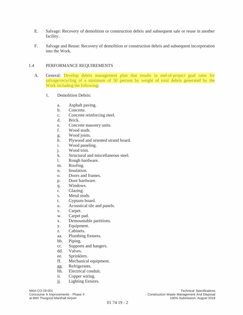
MAA-CO-19-001 Technical SpecificationsConcourse A Improvements - Phase II Construction Waste Management And Disposalat BWI Thurgood Marshall Airport 100% Submission, August 2018
01 74 19 - 2
E. Salvage: Recovery of demolition or construction debris and subsequent sale or reuse in another facility.
F. Salvage and Reuse: Recovery of demolition or construction debris and subsequent incorporation into the Work.
1.4 PERFORMANCE REQUIREMENTS
A. General: Develop debris management plan that results in end-of-project goal rates for salvage/recycling of a minimum of 50 percent by weight of total debris generated by the Work including the following:
1. Demolition Debris:
a. Asphalt paving.b. Concrete.c. Concrete reinforcing steel.d. Brick.e. Concrete masonry units.f. Wood studs.g. Wood joists.h. Plywood and oriented strand board.i. Wood paneling.j. Wood trim.k. Structural and miscellaneous steel.l. Rough hardware.m. Roofing.n. Insulation.o. Doors and frames.p. Door hardware.q. Windows.r. Glazing.s. Metal studs.t. Gypsum board.u. Acoustical tile and panels.v. Carpet.w. Carpet pad.x. Demountable partitions.y. Equipment.z. Cabinets.aa. Plumbing fixtures.bb. Piping.cc. Supports and hangers.dd. Valves.ee. Sprinklers.ff. Mechanical equipment.gg. Refrigerants.hh. Electrical conduit.ii. Copper wiring.jj. Lighting fixtures.

MAA-CO-19-001 Technical SpecificationsConcourse A Improvements - Phase II Construction Waste Management And Disposalat BWI Thurgood Marshall Airport 100% Submission, August 2018
01 74 19 - 3
kk. Lamps.ll. Ballasts.mm. Electrical devices.nn. Switchgear and panelboards.oo. Transformers.
2. Construction Debris:
a. Site-clearing debris.b. Masonry and CMU.c. Lumber.d. Wood sheet materials.e. Wood trim.f. Metals.g. Roofing.h. Insulation.i. Carpet and pad.j. Gypsum board.k. Piping.l. Electrical conduit.m. Packaging: Regardless of salvage/recycle goal indicated above, salvage or recycle
100 percent of the following uncontaminated packaging materials:
1) Paper.2) Cardboard.3) Boxes.4) Plastic sheet and film.5) Polystyrene packaging.6) Wood crates.7) Plastic pails.
1.5 SUBMITTALS
A. Debris Management Plan: Submit plan within 7 days of date established for the Notice of Award.
B. Debris Reduction Progress Reports: Concurrent with each Application for Payment, submit 3copies of report. Include the following information:
1. Material category.2. Generation point of debris.3. Total quantity of debris in tons.4. Quantity of debris salvaged, both estimated and actual in tons.5. Quantity of debris recycled, both estimated and actual in tons.6. Total quantity of debris recovered (salvaged plus recycled) in tons.7. Total quantity of debris recovered (salvaged plus recycled) as a percentage of total debris.
C. Qualification Data: For refrigerant recovery technician.
MAA-CO-19-001 Technical SpecificationsConcourse A Improvements - Phase II Construction Waste Management And Disposalat BWI Thurgood Marshall Airport 100% Submission, August 2018
01 74 19 - 4
D. Statement of Refrigerant Recovery: Signed by refrigerant recovery technician responsible for recovering refrigerant, stating that all refrigerant that was present was recovered and that recovery was performed according to EPA regulations. Include name and address of technician and date refrigerant was recovered.
1.6 QUALITY ASSURANCE
A. Refrigerant Recovery Technician Qualifications: Certified by EPA-approved certification program.
B. Regulatory Requirements: Comply with hauling and disposal regulations of authorities having jurisdiction.
1.7 DEBRIS MANAGEMENT PLAN
A. General: Develop a plan consisting of debris identification, debris reduction work plan, and cost/revenue analysis. Include separate sections in plan for demolition and construction debris.Indicate quantities by weight or volume, but use same units of measure throughout debris management plan.
B. Debris Reduction Work Plan: List each type of debris and whether it will be salvaged, recycled, or disposed of in landfill or incinerator. Include points of debris generation, total quantity of each type of debris, quantity for each means of recovery, and handling and transportation procedures.
1. Salvaged Materials for Reuse: For materials that will be salvaged and reused in this Project, describe methods for preparing salvaged materials before incorporation into the Work.
2. Salvaged Materials for Sale: For materials that will be sold to individuals and organizations, include list of their names, addresses, and telephone numbers.
3. Recycled Materials: Include list of local receivers and processors and type of recycled materials each will accept. Include names, addresses, and telephone numbers.
4. Disposed Materials: Indicate how and where materials will be disposed of. Include name, address, and telephone number of each landfill and incinerator facility.
5. Handling and Transportation Procedures: Include method that will be used for separating recyclable waste including sizes of containers, container labeling, and designated location where materials separation will be performed.
PART 2 - PRODUCTS (Not Used)
PART 3 - EXECUTION
3.1 PLAN IMPLEMENTATION
A. General: Implement approved waste management plan. Provide handling, containers, storage, signage, transportation, and other items as required to implement waste management plan during the entire duration of the Contract.
MAA-CO-19-001 Technical SpecificationsConcourse A Improvements - Phase II Construction Waste Management And Disposalat BWI Thurgood Marshall Airport 100% Submission, August 2018
01 74 19 - 5
1. Comply with operation, termination, and removal requirements in Section 01 50 00"Temporary Facilities and Controls."
B. Training: Train workers, subcontractors, and suppliers on proper debris management procedures, as appropriate for the Work.
1. Distribute debris management plan to everyone concerned within three days of submittal return.
2. Distribute debris management plan to entities when they first begin work on-site. Review plan procedures and locations established for salvage, recycling, and disposal.
C. Site Access and Temporary Controls: Conduct waste management operations to ensure minimum interference with roads, streets, walks, walkways, and other adjacent occupied and used facilities.
1. Designate and label specific areas on Project site necessary for separating materials that are to be salvaged, recycled, reused, and sold.
2. Comply with Section 01 50 00 "Temporary Facilities and Controls" for controlling dust and dirt, environmental protection, and noise control.
3.2 SALVAGING DEMOLITION DEBRIS
A. Salvaged Items for Reuse in the Work: Salvage items for reuse and handle as follows:
1. Clean salvaged items.2. Pack or crate items after cleaning. Identify contents of containers with label indicating
elements, date of removal, quantity, and location where removed.3. Store items in a secure area until installation.4. Protect items from damage during transport and storage.5. Install salvaged items to comply with installation requirements for new materials and
equipment. Provide connections, supports, and miscellaneous materials necessary to make items functional for use indicated.
B. Salvaged Items for Sale: Prohibited on Project site.
C. Salvaged Items for Owner's Use: Salvage items for Owner's use and handle as follows:
1. Clean salvaged items.2. Pack or crate items after cleaning. Identify contents of containers with label indicating
elements, date of removal, quantity, and location where removed.3. Store items in a secure area until delivery to Owner.4. Protect items from damage during transport and storage.
D. Doors and Hardware: Brace open end of door frames. Except for removing door closers, leave door hardware attached to doors.
3.3 RECYCLING DEMOLITION WASTE
A. Asphalt Paving: Break up and transport paving to asphalt-recycling facility.
MAA-CO-19-001 Technical SpecificationsConcourse A Improvements - Phase II Construction Waste Management And Disposalat BWI Thurgood Marshall Airport 100% Submission, August 2018
01 74 19 - 6
B. Concrete: Remove reinforcement and other metals from concrete and sort with other metals.
1. Pulverize concrete to maximum 4-inch size.
C. Masonry: Remove metal reinforcement, anchors, and ties from masonry and sort with other metals.
1. Pulverize masonry to maximum 4-inch size.
2. Clean and stack undamaged, whole masonry units on wood pallets.
D. Wood Materials: Sort and stack members according to size, type, and length. Separate lumber, engineered wood products, panel products, and treated wood materials.
E. Metals: Separate metals by type.
1. Structural Steel: Stack members according to size, type of member, and length.2. Remove and dispose of bolts, nuts, washers, and other rough hardware.
F. Gypsum Board: Stack large clean pieces on wood pallets or in container and store in a dry location. Remove edge trim and sort with other metals. Remove and dispose of fasteners.
G. Acoustical Ceiling Panels and Tile: Stack large clean pieces on wood pallets and store in a dry location.
H. Metal Suspension System: Separate metal members including trim, and other metals from acoustical panels and tile and sort with other metals.
I. Carpet and Pad: Roll large pieces tightly after removing debris, trash, adhesive, and tack strips.
1. Store clean, dry carpet and pad in a closed container or trailer provided by Carpet Reclamation Agency or carpet recycler.
J. Carpet Tile: Remove debris, trash, and adhesive.
1. Stack tile on pallet and store clean, dry carpet in a closed container or trailer provided by Carpet Reclamation Agency or carpet recycler.
K. Piping: Reduce piping to straight lengths and store by type and size. Separate supports, hangers, valves, sprinklers, and other components by type and size.
L. Conduit: Reduce conduit to straight lengths and store by type and size.
3.4 RECYCLING CONSTRUCTION DEBRIS
A. Packaging:
1. Cardboard and Boxes: Break down packaging into flat sheets. Bundle and store in a dry location.
2. Polystyrene Packaging: Separate and bag materials.
MAA-CO-19-001 Technical SpecificationsConcourse A Improvements - Phase II Construction Waste Management And Disposalat BWI Thurgood Marshall Airport 100% Submission, August 2018
01 74 19 - 7
3. Pallets: As much as possible, require deliveries using pallets to remove pallets from Project site. For pallets that remain on-site, break down pallets into component wood pieces and comply with requirements for recycling wood.
4. Crates: Break down crates into component wood pieces and comply with requirements for recycling wood.
B. Wood Materials:
1. Clean Cut-Offs of Lumber: Grind or chip into small pieces.2. Clean Sawdust: Bag sawdust that does not contain painted or treated wood.
C. Gypsum Board: Stack large clean pieces on wood pallets or in container and store in a dry location.
1. Clean Gypsum Board: Grind scraps of clean gypsum board using small mobile chipper or hammer mill. Screen out paper after grinding.
3.5 DISPOSAL OF DEBRIS
A. General: Except for items or materials to be salvaged, recycled, or otherwise reused, remove waste materials from Project site and legally dispose of them in a landfill or incinerator acceptable to authorities having jurisdiction.
1. Except as otherwise specified, do not allow waste materials that are to be disposed of accumulate on-site.
2. Remove and transport debris in a manner that will prevent spillage on adjacent surfaces and areas.
B. Burning: Do not burn waste materials.
C. Disposal: Transport debris materials off Owner's property and legally dispose of them.
PART 4 - MEASUREMENT
4.1 METHOD OF MEASUREMENT
A. No separate measurement will be made for work under this section.
PART 5 - PAYMENT
5.1 BASIS OF PAYMENT
A. No separate payment will be made for work under this section.
1. The cost of the work described in this section for base bid items shall be included in the lump sum contract price for Section 01 10 00.
MAA-CO-19-001 Technical SpecificationsConcourse A Improvements - Phase II Construction Waste Management And Disposalat BWI Thurgood Marshall Airport 100% Submission, August 2018
01 74 19 - 8
B. Payment will be made under:
Item 01 10 00-1 Building Construction
C. Costs include all labor, materials, services, and equipment necessary to complete the work inevery respect.
END OF SECTION 01 74 19
MAA-CO-19-001 Technical SpecificationsConcourse A Improvements - Phase II
01 77 00-1Closeout Procedures
at BWI Thurgood Marshall Airport 100% Submission, August 2018
SECTION 01 77 00 - CLOSEOUT PROCEDURES
PART 1 - GENERAL
1.1 RELATED DOCUMENTS
A. Drawings and general provisions of the Contract, including Maryland Department ofTransportation/Maryland Aviation Administration “Standard Provisions for ConstructionContracts", consisting of "Volume 1: General Provisions” January 2014 Edition, and “Volume2: Special Provisions” January 2014 Edition, and other Division 01 Specifications Sectionsapply to this Section.
1.2 SUMMARY
A. Section includes administrative and procedural requirements for contract closeout, including,but not limited to, the following:
1. Substantial Completion procedures.2. Final completion procedures.3. Warranties.4. Final cleaning.5. Repair of the Work.6. Project Record Documents
B. Related Requirements:
1. Section 01 73 00 "Execution" for progress cleaning of Project site.2. Section 01 78 23X "Operation and Maintenance Data" for operation and maintenance
manual requirements.
1.3 ACTION SUBMITTALS
A. Product Data: For cleaning agents.
B. Contractor's List of Incomplete Items: Initial submittal at Substantial Completion.
C. Certified List of Incomplete Items: Final submittal at Final Completion.
1.4 CLOSEOUT SUBMITTALS
A. Certificates of Release: From authorities having jurisdiction.
B. Certificate of Insurance: For continuing coverage.
C. Field Report: For pest control inspection.

MAA-CO-19-001 Technical SpecificationsConcourse A Improvements - Phase II
01 77 00-2Closeout Procedures
at BWI Thurgood Marshall Airport 100% Submission, August 2018
1.5 MAINTENANCE MATERIAL SUBMITTALS
A. Schedule of Maintenance Material Items: For maintenance material submittal items specified inother Sections.
1.6 SUBSTANTIAL COMPLETION PROCEDURES
A. Contractor's List of Incomplete Items: Prepare and submit a list of items to be completed andcorrected (Contractor's punch list), indicating the value of each item on the list and reasons whythe Work is incomplete.
B. Submittals Prior to Substantial Completion: Complete the following a minimum of 10 daysprior to requesting inspection for determining date of Substantial Completion. List items belowthat are incomplete at time of request.
1. The Contractor shall document satisfactory completion of the HVAC CommissioningRequirements (in accordance with specification Sections 23 08 00 and 23 09 00) for theHVAC system component of the area being considered for Substantial Completion. If theHVAC system commissioning has not been accepted by the MAA, the HVAC systemshall not be eligible for Substantial Completion. If the HVAC system is utilized by thecontractor or is required to be used to provide heated and/or cooled conditioned space forthe project area, the warranty for HVAC system and equipment shall not be initiated untilthe HVAC system commissioning has been accepted by the MAA. The warranty for theHVAC system and equipment will initiate when the HVAC systems commissioning isaccepted.
2. Certificates of Release: Obtain and submit releases from authorities having jurisdictionpermitting Owner unrestricted use of the Work and access to services and utilities.Include occupancy permits, operating certificates, and similar releases.
3. Submit closeout submittals specified in other Division 01 Sections, including projectrecord documents, operation and maintenance manuals, final completion constructionphotographic documentation, damage or settlement surveys, property surveys, and similarfinal record information.
4. Submit closeout submittals specified in individual Sections, including specific warranties,workmanship bonds, maintenance service agreements, final certifications, and similardocuments.
5. Submit maintenance material submittals specified in individual Sections, including tools,spare parts, extra materials, and similar items, and deliver to location designated byEngineer. Label with manufacturer's name and model number where applicable.
a. Schedule of Maintenance Material Items: Prepare and submit schedule ofmaintenance material submittal items, including name and quantity of each itemand name and number of related Specification Section. Obtain Engineer's signaturefor receipt of submittals.
6. Submit test/adjust/balance records.7. Submit changeover information related to Owner's occupancy, use, operation, and
maintenance.
MAA-CO-19-001 Technical SpecificationsConcourse A Improvements - Phase II
01 77 00-3Closeout Procedures
at BWI Thurgood Marshall Airport 100% Submission, August 2018
C. Procedures Prior to Substantial Completion: Complete the following a minimum of 10 daysprior to requesting inspection for determining date of Substantial Completion. List items belowthat are incomplete at time of request.
1. Advise Owner of pending insurance changeover requirements.2. Make final changeover of permanent locks and deliver keys to Owner. Advise Owner's
personnel of changeover in security provisions.3. Complete startup and testing of systems and equipment.4. Perform preventive maintenance on equipment used prior to Substantial Completion.5. Advise Owner of changeover in heat and other utilities.6. Participate with Owner in conducting inspection and walkthrough with local emergency
responders.7. Terminate and remove temporary facilities from Project site, along with mockups,
construction tools, and similar elements.8. Complete final cleaning requirements, including touchup painting.9. Touch up and otherwise repair and restore marred exposed finishes to eliminate visual
defects.
D. Inspection: Submit a written request for inspection to determine Substantial Completion aminimum of 10 days prior to date the work will be completed and ready for final inspection andtests. On receipt of request, Engineer will either proceed with inspection or notify Contractor ofunfulfilled requirements. Engineer will prepare the Certificate of Substantial Completion afterinspection or will notify Contractor of items, either on Contractor's list or additional itemsidentified by Engineer, that must be completed or corrected before certificate will be issued.
1. Reinspection: Request reinspection when the Work identified in previous inspections asincomplete is completed or corrected.
2. Results of completed inspection will form the basis of requirements for final completion.
1.7 FINAL COMPLETION PROCEDURES
A. Submittals Prior to Final Completion: Before requesting final inspection for determining finalcompletion, complete the following:
1. Certified List of Incomplete Items: Submit certified copy of Engineer's SubstantialCompletion inspection list of items to be completed or corrected (punch list), endorsedand dated by Engineer. Certified copy of the list shall state that each item has beencompleted or otherwise resolved for acceptance.
2. Certificate of Insurance: Submit evidence of final, continuing insurance coveragecomplying with insurance requirements.
3. Submit pest-control final inspection report.
B. Inspection: Submit a written request for final inspection to determine acceptance a minimum of10 days prior to date the work will be completed and ready for final inspection and tests. Onreceipt of request, Engineer will either proceed with inspection or notify Contractor ofunfulfilled requirements. Engineer will prepare a final Certificate for Payment after inspectionor will notify Contractor of construction that must be completed or corrected before certificatewill be issued.
MAA-CO-19-001 Technical SpecificationsConcourse A Improvements - Phase II
01 77 00-4Closeout Procedures
at BWI Thurgood Marshall Airport 100% Submission, August 2018
1. Reinspection: Request reinspection when the Work identified in previous inspections asincomplete is completed or corrected.
1.8 LIST OF INCOMPLETE ITEMS (PUNCH LIST)
A. Organization of List: Include name and identification of each space and area affected byconstruction operations for incomplete items and items needing correction including, ifnecessary, areas disturbed by Contractor that are outside the limits of construction.
1. Organize list of spaces in sequential order, starting with exterior areas first andproceeding from lowest floor to highest floor.
2. Organize items applying to each space by major element, including categories for ceiling,individual walls, floors, equipment, and building systems.
3. Include the following information at the top of each page:
a. Project name.b. Date.c. Name of Engineerd. Name of Contractor.e. Page number.
4. Submit list of incomplete items in the following format:
a. MS Excel electronic file. Engineer will return annotated file.b. PDF electronic file. Engineer will return annotated file.c. 5 paper copies. Engineer, will return 2 copies.
1.9 SUBMITTAL OF PROJECT WARRANTIES
A. Time of Submittal: Submit written warranties on request of Engineer for designated portions ofthe Work where commencement of warranties other than date of Substantial Completion isindicated, or when delay in submittal of warranties might limit Owner's rights under warranty.
B. Partial Occupancy: Submit properly executed warranties within 15 days of completion ofdesignated portions of the Work that are completed and occupied or used by Owner duringconstruction period by separate agreement with Contractor.
C. Organize warranty documents into an orderly sequence based on the table of contents of ProjectManual.
1. Bind warranties and bonds in heavy-duty, three-ring, vinyl-covered, loose-leaf binders,thickness as necessary to accommodate contents, and sized to receive 8-1/2-by-11-inchpaper.
2. Provide heavy paper dividers with plastic-covered tabs for each separate warranty. Marktab to identify the product or installation. Provide a typed description of the product orinstallation, including the name of the product and the name, address, and telephonenumber of Installer.
3. Identify each binder on the front and spine with the typed or printed title"WARRANTIES," Project name, and name of Contractor.
MAA-CO-17-001 Technical SpecificationsConcourse E Extension – Building
01 77 00-5Closeout Procedures
at BWI Thurgood Marshall Airport 100% Submission, August 2018
4. Warranty Electronic File: Scan warranties and bonds and assemble complete warrantyand bond submittal package into a single indexed electronic PDF file with links enablingnavigation to each item. Provide bookmarked table of contents at beginning of document.
D. Provide additional copies of each warranty to include in operation and maintenance manuals.
1.10 PROJECT RECORD DOCUMENTS
A. General: Do not use Project Record Documents for construction purposes. Protect ProjectRecord Documents from deterioration and loss. Provide access to Project Record Documentsfor Engineer’s reference during normal working hours.
B. Record Drawings: Produce and provide Record Drawings as stipulated in Special Provision SP8.08.
C. Record Product Data: Submit one copy of each Product Data submittal. Mark one set to indicatethe actual product installation where installation varies substantially from that indicated inProduct Data.
1. Give particular attention to information on concealed products and installations thatcannot be readily identified and recorded later.
2. Include significant changes in the product delivered to Project site and changes inmanufacturer's written instructions for installation.
3. Note related Change Orders, Record Drawings, where applicable.
D. Miscellaneous Record Submittals: Assemble miscellaneous records required by otherSpecification Sections for miscellaneous record keeping and submittal in connection with actualperformance of the Work. Bind or file miscellaneous records and identify each, ready forcontinued use and reference.
PART 2 - PRODUCTS
2.1 MATERIALS
A. Cleaning Agents: Use cleaning materials and agents recommended by manufacturer orfabricator of the surface to be cleaned. Do not use cleaning agents that are potentially hazardousto health or property or that might damage finished surfaces.
PART 3 - EXECUTION
3.1 FINAL CLEANING
A. General: Perform final cleaning. Conduct cleaning and waste-removal operations to complywith local laws and ordinances and Federal and local environmental and antipollutionregulations.
MAA-CO-19-001 Technical SpecificationsConcourse A Improvements - Phase II
01 77 00-6Closeout Procedures
at BWI Thurgood Marshall Airport 100% Submission, August 2018
B. Cleaning: Employ experienced workers or professional cleaners for final cleaning. Clean eachsurface or unit to condition expected in an average commercial building cleaning andmaintenance program. Comply with manufacturer's written instructions.
1. Complete the following cleaning operations before requesting inspection for certificationof Substantial Completion for entire Project or for a designated portion of Project:
a. Clean Project site, yard, and grounds, in areas disturbed by construction activities,including landscape development areas, of rubbish, waste material, litter, and otherforeign substances.
b. Sweep paved areas broom clean. Remove petrochemical spills, stains, and otherforeign deposits.
c. Rake grounds that are neither planted nor paved to a smooth, even-texturedsurface.
d. Remove tools, construction equipment, machinery, and surplus material fromProject site.
e. Remove snow and ice to provide safe access to building.f. Clean exposed exterior and interior hard-surfaced finishes to a dirt-free condition,
free of stains, films, and similar foreign substances. Avoid disturbing naturalweathering of exterior surfaces. Restore reflective surfaces to their originalcondition.
g. Remove debris and surface dust from limited access spaces, including roofs,plenums, shafts, trenches, equipment vaults, manholes, attics, and similar spaces.
h. Sweep concrete floors broom clean in unoccupied spaces.i. Vacuum carpet and similar soft surfaces, removing debris and excess nap; clean
according to manufacturer's recommendations if visible soil or stains remain.j. Clean transparent materials, including mirrors and glass in doors and windows.
Remove glazing compounds and other noticeable, vision-obscuring materials.Polish mirrors and glass, taking care not to scratch surfaces.
k. Remove labels that are not permanent.l. Wipe surfaces of mechanical and electrical equipment and similar equipment.
Remove excess lubrication, paint and mortar droppings, and other foreignsubstances.
m. Clean plumbing fixtures to a sanitary condition, free of stains, including stainsresulting from water exposure.
n. Replace disposable air filters and clean permanent air filters. Clean exposedsurfaces of diffusers, registers, and grills.
o. Clean ducts, blowers, and coils if units were operated without filters duringconstruction or that display contamination with particulate matter on inspection.
1) Clean HVAC system in compliance with NADCA Standard 1992-01.Provide written report on completion of cleaning.
p. Clean light fixtures, lamps, globes, and reflectors to function with full efficiency.q. Leave Project clean and ready for occupancy.
C. Pest Control: Comply with pest control requirements in Section 01 50 00 "Temporary Facilitiesand Controls." Prepare written report.
MAA-CO-19-001 Technical SpecificationsConcourse A Improvements - Phase II
01 77 00-7Closeout Procedures
at BWI Thurgood Marshall Airport 100% Submission, August 2018
D. Construction Waste Disposal: Comply with waste disposal requirements in Section 01 50 00"Temporary Facilities and Controls" and Section 01 74 19 "Construction Waste Managementand Disposal."
3.2 REPAIR OF THE WORK
A. Complete repair and restoration operations before requesting inspection for determination ofSubstantial Completion.
B. Repair or remove and replace defective construction. Repairing includes replacing defectiveparts, refinishing damaged surfaces, touching up with matching materials, and properlyadjusting operating equipment. Where damaged or worn items cannot be repaired or restored,provide replacements. Remove and replace operating components that cannot be repaired.Restore damaged construction and permanent facilities used during construction to specifiedcondition.
1. Remove and replace chipped, scratched, and broken glass, reflective surfaces, and otherdamaged transparent materials.
2. Touch up and otherwise repair and restore marred or exposed finishes and surfaces.Replace finishes and surfaces that that already show evidence of repair or restoration.
a. Do not paint over "UL" and other required labels and identification, includingmechanical and electrical nameplates. Remove paint applied to required labels andidentification.
3. Replace parts subject to operating conditions during construction that may impedeoperation or reduce longevity.
4. Replace burned-out bulbs, bulbs noticeably dimmed by hours of use, and defective andnoisy starters in fluorescent and mercury vapor fixtures to comply with requirements fornew fixtures.
PART 4 - MEASUREMENT
4.1 METHOD OF MEASUREMENT
A. No separate measurement will be made for work under this section.
PART 5 - PAYMENT
5.1 BASIS OF PAYMENT
A. No separate payment will be made for work under this section. The cost of the work describedin this section for base bid items shall be included in the lump sum contract price for Section01 10 00.
MAA-CO-19-001 Technical SpecificationsConcourse A Improvements - Phase II
01 77 00-8Closeout Procedures
at BWI Thurgood Marshall Airport 100% Submission, August 2018
B. Payment will be made under:
Item 01 10 00-1 Building Construction
C. Costs include all labor, materials, services, and equipment necessary to complete the work inevery respect.
END OF SECTION 01 77 00
MAA-CO-19-001 Technical SpecificationsConcourse A Improvements - Phase IIat BWI Thurgood Marshall Airport 01 78 23X - 1
Operation And Maintenance Data100% Submission, August 2018
SECTION 01 78 23X - OPERATION AND MAINTENANCE DATA
PART 1 - GENERAL
1.1 RELATED DOCUMENTS
A. Maryland Aviation Administration Standard Provisions for ConstructionContracts, SP-8.11, Operating and Maintenance Data.
B. Technical Specifications, specific training or operation and maintenance manualrequirements.
1.2 SUMMARY
A. This Section includes requirements for preparing manuals, including thefollowing:
1. Training manuals, for all required training.
2. Operation and maintenance manuals, for the entire contract.
3. Interim operation and maintenance manuals, for each phase of construction andpartial turnover.
PART 2 – PRODUCTS
2.1 MANUALS, GENERAL
A. Construction
1. Manuals shall be submitted in heavy-duty, 3-ring, vinyl-covered, loose-leafbinders, with locking rings. Binders shall be sized to hold 8-1/2-by-11 inch paper,with spines no more than 3 inches wide. Covers and spines shall be white andshall have clear plastic sleeves to hold printed labels. The insides of covers shallhave pockets to hold loose items.
2. Index dividers shall be of heavy paper with reinforced holes and printable tabs.
3. Loose-leaf binder pockets and sheet protectors shall be of clear plastic withpunched holes.
MAA-CO-19-001 Technical SpecificationsConcourse A Improvements - Phase IIat BWI Thurgood Marshall Airport 01 78 23X - 2
Operation And Maintenance Data100% Submission, August 2018
4. Sheet lifters shall be inserted between the front and back binder covers and thefirst and last sheets.
B. Organization
1. Arrange contents numerically by technical specification section, oralphabetically by system. If two or more binders are needed to accommodate allmanual pages, organize each binder into related groupings. If possible, placeinformation on individual specification sections or systems into a single binder.
2. Identify each binder on front and spine with the printed title "TRAININGMANUAL," "OPERATION AND MAINTENANCE MANUAL," or "INTERIMOPERATION AND MAINTENANCE MANUAL". Labels shall also include thecontract number and name, volume number, and an abbreviated list of contents.
3. Use index dividers with printed tabs to divide sections. Provide a table ofcontents showing each tab and its contents. If multiple binders are used, in eachbinder provide a table of contents for all binders.
4. After each divider provide a title page that states the number and name of thespecification section or system, along with the name, address, and contactinformation for the subcontractor or supplier who installed or provided theequipment.
5. If possible print oversize pages or drawings on 11-by-17 inch paper, folded inhalf and punched. Otherwise use binder pockets to hold folded oversize sheets.
6. Use binder pockets to hold items that cannot be punched, such as samples,compact discs or DVDs.
C. Electronic Version
1. Provide CDs or DVDs containing an electronic version of the entire set ofoperation and maintenance manuals in pdf format, including all oversize sheets.
2. Use pdf files prepared by manufacturer or supplier whenever available.Otherwise scan all pages into pdf files with a minimum resolution of 200 dpi. Usefull color scans for color coded pages and grayscale scans for all other pages.
3. Insert bookmarks for each volume, table of contents, divider, specificationsection, and system.
D. Quantities
1. Provide one training manual for each person who is to receive training.
MAA-CO-19-001 Technical SpecificationsConcourse A Improvements - Phase IIat BWI Thurgood Marshall Airport 01 78 23X - 3
Operation And Maintenance Data100% Submission, August 2018
2. Provide four full sets of bound operation and maintenance manuals. When sodirected by the Engineer, provide one additional operation and maintenancemanual for individual sections such as fire protection or information techno logy.
3. Provide three copies of the electronic version of the operation and maintenancemanuals.
2.2 TRAINING MANUALS
A. Provide training manuals for all training required by the technical specifications.
B. Training manuals shall contain all information and references to be covered in thetraining sessions, and a syllabus or summary of the training provided. Includemanufacturer's or supplier's published training guides if applicable.
2.3 OPERATION AND MAINTENANCE MANUALS
A. Provide all operation and maintenance information required by the technicalspecifications. Use material published by or otherwise available frommanufacturers or suppliers.
B. Documents shall include, as required or as appropriate:
1. Installation manuals.
2. Operating procedures.
3. Product data and cut sheets.
4. Oversize sheets.
5. Parts listings.
6. Wiring diagrams.
7. Process diagrams.
8. Control sequences.
9. Approved shop drawings and submittals.
10. Test results.
11. Inspection reports and sign-off sheets.
MAA-CO-19-001 Technical SpecificationsConcourse Improvements - Phase IIat BWI Thurgood Marshall Airport 01 78 23X - 4
Operation And Maintenance Data100% Submission, August 2018
12. Certifications.
13. Warranties.
C. For phased construction with partial turnovers, provide an interim operation andmaintenance manual for each phase of the work being turned over, covering onlythe work being turned over. Interim manuals are in addition to the full set ofoperation and maintenance manuals to be provided for the entire contract.
PART 3 - EXECUTION
3.1 MANUAL PREPARATION
A. Training Manuals: Where manuals contain manufacturer's standard printed data,include sheets pertinent to the product or component installed. Where one sheetshows more than one product, mark sheet to identify each product or componentactually incorporated into the work. If data includes more than one item in atabular format, identify each item using appropriate references to the contractdocuments.
Provide supplementary text as available from manufacturer, supplier, or installer.
B. Operation and Maintenance Manuals: Assemble a complete set of operation andmaintenance information describing operation and maintenance of each piece ofequipment or system installed. Where one sheet shows more than one product,mark sheet to identify each product or component actually incorporated into thework. If data includes more than one item in a tabular format, identify each itemusing appropriate references to the contract documents.
Provide supplementary text as available from manufacturer, supplier, or installer.
Insert additional information as provided and directed by the Engineer.
C. Submittal due date: Submit training manuals and interim operation andmaintenance manuals to the Engineer for review and comment prior to thescheduled training or partial turnover. Make corrections and submit correctedcopies before the training or turnover.
Submit full sets of operation and maintenance manuals for the entire contractwithin two weeks after substantial completion. Make corrections and resubmitcorrected manuals within the designated contract punch list period.
MAA-CO-19-001 Technical SpecificationsConcourse A Improvements - Phase IIat BWI Thurgood Marshall Airport 01 78 23X - 5
Operation And Maintenance Data100% Submission, August 2018
PART 4 – METHOD OF MEASUREMENT
4.1 No separate measurement will be made for work under this Section.
PART 5 – BASIS OF PAYMENT
5.1 No separate payment will be made for work under this Section. The cost of the workdescribed in this section shall be included in the individual referenced Specificationsections.
END OF SECTION 01 78 23X
MAA-CO-19-001
018150-1
100% Submission, August 2018Concourse A Improvements – Phase II Technical Specifications
BWI Thurgood Marshall Airport GENERAL COMMISSIONING REQUIREMENTS
SECTION 018150 - GENERAL COMMISSIONING REQUIREMENTS
PART 1 - GENERAL
1.1 GENERAL
A. The intended result of the Commissioning process is to assure that the identified systems
are installed and operate in accordance with contract drawings and specifications prior to
Owner acceptance of the building.
1.2 RELATED DOCUMENTS
A. Drawings and general provisions of the Contract, including Maryland Department of
Transportation/ Maryland Aviation Administration Standard Provisions to the
Construction Contract for the Concourse A Improvements – Phase II at BWI Thurgood
Marshall Airport and other Divisions 1 Specification Sections, apply to this Section.
B. Basis of Design documentation prepared by Owner and Engineer contains requirements
that apply to this Section.
C. Related specification sections include the following:
1. Section 011000 – Summary of Work
2. Section 013300 – Submittals and Project Closeout
3. Section 014000 – Quality Requirements
4. Section 017823 – Operation and Maintenance Data
5. Section 017900 – Demonstration and Training
6. Section 220800 – Commissioning of Plumbing Equipment
7. Section 230593 – Testing, Adjusting, and Balancing for HVAC
8. Section 230800 – Commissioning of Mechanical Equipment
9. Section 230900 – Building Automation System (BAS)
10. Section 260800 – Commissioning of Electrical Equipment
1.3 SCOPE
A. Work Included: The commissioning shall provide substantial verification that systems
and equipment are installed and performing in accordance with the Contract Documents
MAA-CO-19-001
018150-2
100% Submission, August 2018Concourse A Improvements – Phase II Technical Specifications
BWI Thurgood Marshall Airport GENERAL COMMISSIONING REQUIREMENTS
and design intent. This independent commissioning shall be complementary to the
construction period services performed by the Construction Team.
B. Work Not Included: It shall not be incumbent upon the Commissioning Authority to
evaluate design. Systems installed and performing in accordance with plans and
specifications that do not achieve and/or maintain the specified performance will be so
noted when observed.
1.4 DEFINITIONS
A. Commissioning Authority (CxA): An entity identified by the Owner who leads, plans,
schedules, and coordinates the commissioning team to implement the Commissioning
Process.
B. Pre-Construction Commissioning Meetings: Meetings which occur prior to installation of
specific elements of the project and focus on the integration of the commissioning
process into the construction activities.
C. Commissioning Meetings: Meetings which occur on a regularly scheduled basis which
address the adherence to the commissioning process.
D. Initial Commissioning: Validation of system performance in accordance with the
Contract Documents requirements which includes construction documents and the basis
of design documents.
E. Checklists: Verification checklists that are developed and used during all phases of the
commissioning process to verify that the Owner Project Requirements are being
achieved. This includes checklists for equipment installation, start-up procedures,
functional testing, testing & balancing, training and other specific requirements.
F. Corrective Action Log: A log maintained by the CxA which identifies the issues related
to system/construction implementation or quality and identifies the nature of the issue,
date identified by the CxA, contractor response and final resolution.
G. Functional Testing: A procedure used to verify that the equipment and systems installed
in the project meet the intent of the Owner Project Requirements as well as the
Construction Documents.
H. Construction Checklist: A form used by the contractor to verify that appropriate
components are onsite, ready for installation, correctly installed, and functional.
I. Construction Documents: These include the project manual (specifications), plans
(drawings), and general terms and conditions of the contract.
J. Adjustments: Modifications to existing equipment, components or devices to achieve the
desired performance.
K. Building Automation Controls System (BAS): A software and hardware based
automation system utilizing distributed hardware configuration over a high-speed open
protocol network.
MAA-CO-19-001
018150-3
100% Submission, August 2018Concourse A Improvements – Phase II Technical Specifications
BWI Thurgood Marshall Airport GENERAL COMMISSIONING REQUIREMENTS
L. Trends: BAS software based continuous monitoring of analog and binary control points
over a continuous period of time.
M. System Acceptance: A formal action, taken by a person with appropriate authority to
declare that some aspect of the project meets defined requirements, thus permitting
subsequent activities to proceed.
N. Measuring Instruments: Devices which typically measure temperature, static pressure,
velocity pressure, airflow, humidity, current, power quality (phase-to phase comparison
and voltage sag). Devices may be permanently installed or hand-held for temporary use.
O. Logging Devices: Devices which record real time data related to a specific system
parameter.
P. Data Acquisition Equipment: Devices which record multiple types of data including real
time data, software generated information. Typically, data acquisition equipment process
data for further analysis and/or trending.
Q. Commissioning Process (CxP): A quality focused process for enhancing the delivery of a
project. The process focuses upon verifying and documenting that the facility and all of
its systems and assemblies are planned, designed, installed, tested, operated, and
maintained to meet the Owner’s Project Requirements.
R. Commissioning Process Activities: Components on the Commissioning Process.
S. Commissioning Process Progress Report: A written document that details activities
completed as part of the Commissioning Process and significant findings from those
activities, which is continuously updated during the course of a project. Usually
incorporated in the Commissioning Plan as an ongoing appendix.
T. Basis of Design HVAC: The section of the Basis of Design that specifically pertains to
the HVAC system.
U. Testing and Balancing (TAB): Evaluation, testing, adjusting and verification of HVAC
and electrical system performance.
V. Control: Control is the performance result of a complete mechanical, electrical and
software based system to meet a defined objective. The defined objective may be
conveyed as a written sequence of operation or an industry standard concept which is
accepted by those involved in the Building Automation and Control profession. A system
is considered to be under control when both the overall system response to a change in an
input variable (pressure, temperature, actuator position, system demand, alarm input,
etc.) maintains setpoint performance within the controlled system and the individual
pieces of equipment which makeup the system are maintaining stable operations within
the defined deadband limits.
W. Setpoint: A defined performance standard for a component or system under control,
which is established by the control system user. Typically, a setpoint is defined with an
acceptable deadband, to allow the mechanical or electrical system the opportunity to
dampen or eliminate excessive start/stop or oscillation of the equipment.
MAA-CO-19-001
018150-4
100% Submission, August 2018Concourse A Improvements – Phase II Technical Specifications
BWI Thurgood Marshall Airport GENERAL COMMISSIONING REQUIREMENTS
X. Deadband: The acceptable range associated with the setpoint, in which the control
system is satisfied and no mechanical or electrical system response if requested from the
control system. Typically, a deadband is expressed as a + and – range around the
numerical value of the setpoint.
1.5 COMMISSIONING AUTHORITY
A. Throughout the commissioning process, the commissioning authority's role is primarily
one of an observer/witness; monitoring the installation, start-up, and operation of the
commissioned systems. The commissioning authority shall have no authority to alter
design or installation procedures. If acceptable performance cannot be achieved, it will
be the commissioning authority's responsibility to apprise the Owner, designers, and/or
contractor of the deficiency. Corrective actions shall be the responsibility of the Owner,
designer, and/or contractor; and not that of the commissioning authority. The
commissioning authority shall have the authority to require tests and demonstrations to
verify proper performance.
1.6 RESPONSIBILITY
A. Each member of the commissioning team has responsibilities for the successful
completion of the commissioning process as follows:
B. Owner’s Representative
1. The Owner's Representatives shall perform their normal construction contract
administration functions.
C. Architect/Engineer
1. In addition to their normal performance of Construction Period Services, the
Architect/Engineer will furnish to the Commissioning Authority an electronic
copy of all Shop Drawings and Submittals for commissioned systems and
equipment and place the Commissioning Authority on the mailing list for all
communications regarding the commissioned systems.
2. The Engineer shall respond in writing to deficiencies cited in correspondence
issued by the Commissioning Authority.
3. The Engineer shall assure that the commissioning authority is notified of the
date, time and place of all regularly scheduled progress meetings, and of any
special meetings that may be called regarding commissioned systems and copied
on all correspondence pertinent to the commissioned systems including but not
limited to minutes of progress meetings, responses to contractor requests for
information and change order documentation.
D. Contractor
1. Each Prime Contractor shall, in addition to his normal responsibilities for
construction of the project, assure that his subcontractors recognize the authority
MAA-CO-19-001
018150-5
100% Submission, August 2018Concourse A Improvements – Phase II Technical Specifications
BWI Thurgood Marshall Airport GENERAL COMMISSIONING REQUIREMENTS
of the Commissioning Authority and perform responsively to the requirements of
the commissioning process. The Contractor shall assure that proper notification is
provided to the commissioning authority at least one week in advance of the
milestones of the commissioned systems installation. Examples of milestones are
as follows:
a. Pressure testing of piping systems.
b. Flushing and cleaning of piping systems.
c. Start-up of equipment required to be performed by manufacturers’
authorized personnel.
d. Calibration of controls systems.
e. Start date of Air and Water Balancing.
f. Start date of standby power distribution system date of energizing the
normal power service.
g. Date of instructions to Owner’s operating personnel regarding operations
of commissioned systems.
E. Building Automation System Contractor
1. Building Automation System Contractor shall perform his normal contract
obligations and be responsive to the authority of the commissioning authority;
particularly by furnishing printed histories of trended points.
F. Commissioning Authority
1. The Commissioning Authority will follow the procedures as set forth herein to
execute his responsibility for:
a. Verifying that the commissioned systems are installed and operating in
accordance with contract documents and specifications.
b. Assuring that Owner's Operating and Maintenance personnel are fully
trained on systems operation and maintenance.
c. Assuring that Close Out documentation is properly provided to the
Owner.
1.7 COMMISSIONING TEAM (CxT)
A. Members Appointed by Contractor(s): An individual with knowledge and experience in
the commissioning process for HVAC specific projects shall lead the commissioning
process for the Contractor. Individuals, each having authority to act on behalf of the
entity he or she represents, explicitly organized to implement the commissioning process
through coordinated actions. The commissioning team shall consist of, but not be limited
to, representatives of each Contractor, including Project superintendent and
subcontractors, installers, suppliers, and specialists deemed appropriate by the CxA. The
Contractor and all subcontractors involved with commissioned systems with particularly
critical involvement of the Testing, Adjusting, and Balancing and Automatic
Temperature Controls subcontractors.
B. Members Appointed by Owner:
1. The owner’s authorized representative.
MAA-CO-19-001
018150-6
100% Submission, August 2018Concourse A Improvements – Phase II Technical Specifications
BWI Thurgood Marshall Airport GENERAL COMMISSIONING REQUIREMENTS
2. CxA: The designated person, company, or entity that plans, schedules, and
coordinates the commissioning team to implement the commissioning process
and provides commissioning reports. Owner will engage the CxA under a
separate contract.
3. Representatives of the facility user and operation and maintenance personnel.
4. Engineer and engineering design professionals.
1.8 SUMMARY
General Requirements: The Contractor shall have responsibility for providing a working system
in which the commissioning process (CxP) is an integral part of the construction activities.
System startup, testing, prove-out, and verification demonstration to the owner shall be the
responsibility of the Contractor. The CxP will be managed by the owner’s Commissioning
Authority (CxA) and will require close coordination between the contractor, the CxA, owner’s
representative, and engineering team.
A. General Intent: The intent of the commissioning process is to assure that identified
systems are installed and operate in accordance with the contract drawings and
specifications prior to the owner acceptance of the building and that the owner achieves a
project which meets the contract document requirements and design intent. The
Commissioning Team will work collectively throughout the construction, startup, and
commissioning phase to achieve the Contract Documents intent.
1. Compliance with Contract Documents: The Contractor shall validate compliance
with the contract documents. The pre-construction commissioning conferences
along with construction checklists will be the primary tools utilized to confirm
this compliance validation. The contractor will be required to complete the
construction checklists. The CxA will audit select checklists completed by the
Contractor for verification of specific elements called for within the checklist.
2. Equipment and Component Performance Verification: The Contractor shall
validate proper equipment installation, pre-startup test, alignment, balance, and
achieve a manufacturer’s certification prior to testing and commissioning.
3. Integrated System Performance Verification: The Contractor shall validate
integrated system performance under normal and alarm/emergency conditions.
Where possible, the CxA shall request that the contractor/sub-contractor simulate
conditions related to design conditions to validate system performance.
Functional performance testing protocol will be developed by the CxA,
implemented by the contractor and retested by the contractor under CxA
observation. Trending of system performance via the BAS will be an integral
component of this activity.
B. Commissioning Activities: This Section includes requirements of the Contractor as
follows:
1. Pre-Construction Commissioning Meetings: Attendance at multiple pre-
construction commissioning meetings with the installing/performing
MAA-CO-19-001
018150-7
100% Submission, August 2018Concourse A Improvements – Phase II Technical Specifications
BWI Thurgood Marshall Airport GENERAL COMMISSIONING REQUIREMENTS
subcontractor, CxA, the Owner’s representative, the Engineer and the equipment
manufacturer’s representative. The meetings shall be combined with the regularly
scheduled construction progress meetings. The preconstruction commissioning
meetings shall be required for the following construction elements:
a. Initial commissioning process kickoff meeting (combined with the
project kickoff meeting)
The pre-construction commissioning meeting for a specific area of work shall not
occur until a submittal is approved and returned by the Engineer. The agenda for
the pre-construction commissioning meeting shall include, but is not limited to,
review of approved submittal, proposed schedule of construction activities,
proposed sequencing of construction activities, and methodology of prove-out,
startup and performance verification. Meeting minutes shall be maintained and
submitted by the Engineer for review and approval by the CxA and Owner.
2. Commissioning Coordination Meetings: This Section includes requirements of
the Contractor to attend regularly scheduled commissioning meetings (CxM)
with the Commissioning Authority, the Owners representative and the Engineer.
The CxM will be incorporated into the regularly scheduled progress meetings
initially, but will become standalone meetings as required once verification and
approval activities are occurring. The agenda for the commissioning meetings
shall be as follows:
a. Schedule of commissioning prove-out, startup and performance
verification tests
b. Construction installation status
c. Issues log
d. Meeting minutes shall be maintained and submitted by the Engineer for
review and approval by the CxA and Owner.
3. Equipment and Component Commissioning: This Section includes requirements
of the Contractor to perform equipment and sub-system installation
validation/factory startup, testing, component prove-out, component start-up and
component performance verification testing of the systems and subsystems to be
commissioned. Activities shall be performed by the contractor, subcontractor or
manufacturer’s representative and witnessed by the CxA. The equipment and
components to be included are identified in the specific discipline sections
(23800-Commissioning of Mechanical Equipment, 220800-Commission of
Plumbing Systems and 260800-Commissioning of Electrical Systems.).
Individual specification sections identify the components requiring any of the
stated requirements for component commissioning. Checklist sign-off by the
Contractor and the CxA shall be required to validate completion.
4. System Performance Commissioning: This Section includes requirements of the
Contractor to perform integrated system performance verification as performed
by the contractor and subcontractor and witnessed by the CxA. The integrated
systems commissioning incorporates the full functionality of the HVAC system
with the Building Automation System.
MAA-CO-19-001
018150-8
100% Submission, August 2018Concourse A Improvements – Phase II Technical Specifications
BWI Thurgood Marshall Airport GENERAL COMMISSIONING REQUIREMENTS
1.9 COMMISSIONING AUTHORITY PROCEDURES
The Commissioning Authority will perform systems commissioning following the procedures
listed herein, and all members of the Commissioning Team shall cooperate fully with the
execution of these procedures. To achieve systems commissioning, the Commissioning
Authority shall:
A. Prepare commissioning plan.
B. Attend periodic construction progress meetings and perform unscheduled walks through
the building to observe and keep abreast of systems installation progress. Commissioning
Authority's presence at meetings and in the building will be for his benefit in preparing to
commission the building and shall in no way be construed as superseding the authority of
the owner or project Architect/Engineers.
C. Perform a complementary review of Shop Drawings for commissioned systems in
conjunction with the review of the Engineer. The purpose of this review is primarily one
of familiarization with equipment to be furnished on the project for on-site verification as
well as compliance with the project documents. CxA review and comments are for
coordination of systems integration and Cx progress. The Engineer comments and
approval status represent formal direction to the contractor.
D. Issue Construction Checklists relevant to the project for Contractor monitoring and
verification of installation progress (See Sample Checklist). Establish milestones in the
systems installation at which time interim commissioning status reports will be prepared
and issued by the Commissioning Agent.
E. Issue Functional Performance Test Procedure Forms (See Sample Forms).
F. Be present during Contractors’ instructions to Owner’s operating personnel regarding
operations of the commissioned systems.
G. Review Contractor prepared Operating and Maintenance Manuals, As-Built drawings,
and all certifications and warranties required for submission by the project specifications.
H. Furnish a written report and recommend acceptance of the commissioned systems upon
satisfactorily completing the commissioning process. Recommendations for approval,
when appropriate, will be forwarded to contractor for inclusion in their final submission
of project close out documentation to the Owner.
1.10 CONTRACTOR COMMISSIONING PROCEDURES:
Each Prime Contractor and all relevant Sub-Contractors shall, in addition to being responsive to
the procedures cited for execution by the Commissioning Authority, perform as follows to
achieve satisfactory systems commissioning. The Contractor shall:
A. Demonstrate the performance of each piece of equipment to the Commissioning
Authority and Owner's Representative after completion of construction. Schedule the
sub-Trade Representatives as may apply to demonstrate the performance of the
equipment and systems.
MAA-CO-19-001
018150-9
100% Submission, August 2018Concourse A Improvements – Phase II Technical Specifications
BWI Thurgood Marshall Airport GENERAL COMMISSIONING REQUIREMENTS
B. In addition to the foregoing, the Contractor shall repeat any other measurement contained
in the Testing and Balancing report where required by the Commissioning Authority for
verification or diagnostic purposes. Should any verification test reveal that the equipment
is not performing as specified or control operation is not acceptable, additional
inspections will be scheduled as required. The Contractor will be entitled to one re-
inspection of any failed item at no additional cost. Should the verification test determine
that the equipment is still not performing as specified or control operation is not
acceptable on the second inspection, the time and expenses of the Commissioning Agent
to make further verification shall be considered as additional cost to the Owner.
1.11 CONTRACTOR'S RESPONSIBILITIES
A. The Division of Aviation Project Manager shall be responsible for assuring that the
Commissioning Authority is provided with all relevant correspondence, submittals,
notifications, and assistance as may be required to satisfactorily complete the
commissioning process.
B. Each Prime Contractor and his sub-contractors will actively participate in the
Commissioning Process Activities throughout the life of the project and assure that the
required submittals and documentation for commissioning have been submitted to the
Project Manager. This section provides minimum commissioning requirements;
however, each Prime Contractor shall exceed those requirements whenever necessary to
achieve the intent of Commissioning. Each Prime Contractor and his subcontractors are
responsible for, but not limited to, the following items:
1. Attend pre-commissioning meeting.
2. Attend commissioning meetings identified within this section and as required to
support the commissioning process.
3. Provide a CPM schedule that includes the following commissioning milestones:
a. Pre-construction meetings
b. Equipment Start-up
c. TAB Completion and Report Submission
d. O&M Submission
e. Manufactures’ Startup
f. BAS System Logic, Graphics and Trending
g. Functional Test Dates
h. Training
4. Perform and provide proper documentation for startup testing as specified by
technical sections and manufacturer recommendations. Provide start-up
procedures at least 6 weeks in advance of testing date to the CxA so proper/final
checklists can be completed by the CxA.
5. Attend preconstruction commissioning meetings for MEP systems.
6. Perform construction testing and complete checklists.
7. Provide O&M manuals 60 days prior to functional testing.

MAA-CO-19-001
018150-10
100% Submission, August 2018Concourse A Improvements – Phase II Technical Specifications
BWI Thurgood Marshall Airport GENERAL COMMISSIONING REQUIREMENTS
8. Perform manufacturers startup (with manufacturers checklist) prior to functional
performance testing.
9. Complete checklists and finalize items on the corrective action log as required by
this section.
10. Perform functional testing as required by this section.
11. Certify that TAB Work is complete and accurate. TAB Report shall be provided
15 days prior to functional testing of the BAS system.
12. Provide personnel to accompany the commissioning activities performed by
others.
13. Provide single point of responsibility for a complete and operable system
C. Division 22 Work:
1. Any item required by the contractor which is to be completed under this division.
2. Along with the Division 23 task, coordinate installations and connections
between and among plumbing equipment and plumbing systems, subsystems,
and equipment.
3. Demonstrate equipment operation and provide manufacturer’s startup
documentation as well as test reports.
4. Additional Responsibilities: Participate in tests specified in Section 230800 –
Commissioning of Plumbing Equipment.
D. Division 23 Work:
1. Any item required by the contractor which is to be completed under this division.
2. Provide measuring instruments and logging devices to record test data, and data
acquisition equipment to record data for functional tests that are specific to the
provided mechanical system.
3. The Contractor shall assure that the task efforts of Section 230800
“Commissioning of Mechanical Equipment”, 230900 “Building Automation
System (BAS),” 230593 “Testing, Adjusting, and Balancing for HVAC” will
have representatives working together with Division 23 equipment
representatives and mechanical equipment installers to troubleshoot any
deficiencies found in functional testing of mechanical systems.
E. Section 230800 “Commissioning of Mechanical Equipment” and 230900 “Building
Automation System (BAS)”:
1. Any item required by the Contractor which is under this specification section.
MAA-CO-19-001
018150-11
100% Submission, August 2018Concourse A Improvements – Phase II Technical Specifications
BWI Thurgood Marshall Airport GENERAL COMMISSIONING REQUIREMENTS
2. With the CxA, review control designs for compliance with the Contract
Documents, controllability with respect to actual equipment to be installed, and
recommend adjustments to control designs and sequence of operation equipment
operation and interlocks. The BAS shall provide trending and other relevant data
to be used to show the mechanical, electrical, and controls equipment functions
as stated in the construction documents.
3. The contractor shall provide trends of system performance (via BAS system,
Spec section 230900 and 230993) prior to system acceptance by the owner and
CxA. Reference minimum required points to be trended listed in Section 230800
“Commissioning of Mechanical Equipment”.
4. Troubleshoot BAS based upon analysis completed by the CxA.
F. Section 230593 Testing, Adjusting, and Balancing for HVAC:
1. Any item required by the contractor which is under this specification section.
2. Contract Documents Review: Review the Contract Documents before developing
TAB procedures. This review of the Contract Documents by the contractor
satisfies the requirements for a design review report as specified in Division 23
Section “Testing, Adjusting, and Balancing.”
a. Verify the following:
1) Accessibility of equipment and components required for TAB Work.
2) Adequate number and placement of duct balancing dampers to allow
proper balancing while minimizing sound levels in occupied spaces.
3) Adequate number and placement of balancing valves to allow proper
balancing and recording of water flow.
4) Adequate number and placement of test ports and test instrumentation to
allow reading and compilation of system and equipment performance
data needed to conduct both TAB and commissioning testing.
5) Air and water flow rates have been specified and compared to central
equipment scheduled output capacities.
b. Identify discontinuities and omissions in the Contract Documents.
c. Calibrate sensors and actuators prior to TAB.
3. Additional Responsibilities: Participate in tests specified in Section 230800 –
Commissioning of Mechanical Equipment.
G. Division 26 Work:
1. Any item required by the Contractor which is to be completed under these
divisions.
2. Along with the Division 23 task, coordinate installations and connections
between and among electrical and HVAC systems, subsystems, and equipment.
3. Demonstrate equipment operation and provide manufacturer’s startup
documentation as well as test reports.

MAA-CO-19-001
018150-12
100% Submission, August 2018Concourse A Improvements – Phase II Technical Specifications
BWI Thurgood Marshall Airport GENERAL COMMISSIONING REQUIREMENTS
4. Additional Responsibilities: Participate in tests specified in Section 260800 –
Commissioning of Electrical Equipment.
1.12 COMMISSIONING DOCUMENTATION
A. Project Contract Documents: The design contract documents will be used to identify the
basis of design in developing the commissioning plan.
B. Construction Checklists: CxA, with review and comment by the Engineer, shall develop
test checklists for systems, subsystems, and equipment, including interfaces and
interlocks with other systems. CxA shall record test data, observations, and
measurements on construction checklists. Photographs, forms, and other means
appropriate for the application shall be included with data. CxA shall compile inspection
checklists, test and inspection certificates. The following systems shall have construction
checklists:
1. HVAC Systems
a. Reference Section 230800 “Commissioning of Mechanical Equipment”
2. Electrical Systems
a. Reference Section 260800 “Commissioning of Electrical Equipment”
3. Examples of the construction checklists can be found at the end of this
specification section. These are examples and shall be modified to match the
construction document requirements and control sequences. Select checklists
have been provided with this specification section. It is the responsibility of the
CxA to create the remainder of the checklists that are required by this section and
the construct documents.
C. Functional Test Forms and Functional Performance Test Protocol: CxA, with review and
comment by the Engineer shall develop test forms for commissioned systems,
subsystems, and equipment, including interfaces and interlocks with other systems. CxA
shall prepare functional testing protocol/checklists for each mode of operation and
provide space to indicate whether the mode under test responded as required. The
following systems shall have functional test forms:
1. HVAC Systems
a. Reference Section 230800 “Commissioning of Mechanical Equipment”
2. Electrical Systems
a. Reference Section 260800 “Commissioning of Electrical Equipment”
3. Examples of the construction checklists and functional performance test forms
can be found at the end of this specification section and. The examples are
provided for reference only and shall be modified to match the construction
document requirements and control sequences. Select checklists and forms have
been provided with this specification section. It is the responsibility of the CxA
to create the remainder of the checklists that are required by this section and the
construct documents.
MAA-CO-19-001
018150-13
100% Submission, August 2018Concourse A Improvements – Phase II Technical Specifications
BWI Thurgood Marshall Airport GENERAL COMMISSIONING REQUIREMENTS
D. Manufacturers Installation and Startup Checklists and Reports: The Contractor shall
complete manufacturers’ standard/required installation checklists and startup checklists
and provide written documentation that the manufacturers’ requirements are achieved.
E. Corrective Action Documents: CxA shall document corrective action taken for systems
and equipment that fail functional performance tests which is performed by either the
Contractor or the CxA. Include required modifications to systems and equipment and
revisions to test procedures, if any. Retest systems and equipment requiring corrective
action and document retest results.
F. Corrective Actions Log: CxA shall prepare and maintain a corrective action/issues log
that describes installation and performance issues that are at variance with the Contract
Documents. The issues log shall be discussed on the commissioning meetings and
progress meetings. Identify and track issues as they are encountered, documenting the
status of unresolved and resolved issues.
1. Creating a Corrective Action/Issues Log Entry:
a. Identify the issue with unique numeric or alphanumeric identifier by
which the issue may be tracked.
b. Assign a descriptive title of the issue.
c. Identify date and time of the issue.
d. Identify system, subsystem, and equipment to which the issue applies.
e. Identify location of system, subsystem, and equipment.
f. Include information that may be helpful in diagnosing or evaluating the
issue.
g. Note recommended corrective action.
h. Identify commissioning team member responsible for corrective action.
i. Identify expected date of correction.
j. Identify person documenting the issue.
2. Documenting Action/Issue Resolution:
a. Log date correction is completed or the issue is resolved.
b. Describe corrective action or resolution taken. Include description of
diagnostic steps taken to determine root cause of the issue, if any.
c. Identify changes to the Contract Documents that may require action.
d. State that correction was completed and system, subsystem, and
equipment is ready for retest, if applicable. Schedule retest with
Commissioning Team. Contractor shall incorporate the retest into the
CPM schedule.
e. Identify person(s) who corrected or resolved the issue.
f. Identify person(s) documenting the issue resolution.
3. Corrective Action/Issues Log Report: On a periodic basis, but not less than for
each commissioning team progress meeting (or general progress meeting), CxA
shall prepare a written narrative for review of outstanding issues and a status
update of the issues log. As a minimum, CxA shall include the following
information in the issues log and expand it in the narrative:
a. Issue number and title.
b. Date of the identification of the issue.
c. Name of the commissioning team member assigned responsibility for
resolution.
MAA-CO-19-001
018150-14
100% Submission, August 2018Concourse A Improvements – Phase II Technical Specifications
BWI Thurgood Marshall Airport GENERAL COMMISSIONING REQUIREMENTS
d. Expected date of correction.
1.13 COORDINATION
A. Commissioning Meetings: CxA shall conduct coordination meetings of the
commissioning team to review progress on the commissioning plan, to discuss
scheduling conflicts, and to discuss upcoming commissioning process activities. These
meetings shall be integrated into the general progress meetings. The Engineer shall
maintain minutes of the Commissioning Meetings.
B. Pre-Construction Commissioning Meetings: Prior to the start of a construction activity
(previously identified as requiring a pre-construction meeting), a meeting between the
CxA, the Owner’s Project Manager, the Engineer, and the Contractor/Subcontractor shall
be conducted to review the submittal, contractor means and methods, testing
requirements and checklists.
C. Functional Test Meetings: CxA shall conduct meetings in advance of the functional
testing activities with the commissioning team. These meetings shall be conducted prior
to the Contractors/Manufacturers functional performance testing and the CxA’s
functional performance testing. The intent of the meeting is to review startup reports,
pretest inspection results, testing procedures, testing personnel and instrumentation
requirements, and manufacturers' authorized service representative services for each
system, subsystem, equipment, and component to be tested. This information can be
reviewing in the recurring commissioning meetings if all required parties are present but
is required to be reviewed at least 7 days prior to the functional test. As previously stated
the contractor shall provide O&M Manuals 60 days prior to functional testing dates.
D. Testing Coordination: The CxT, with participation from the Contractor and the CxA,
shall coordinate sequence of testing activities to accommodate required quality-assurance
and -control services with a minimum of delay and to avoid necessity of removing and
replacing construction to accommodate testing and inspecting.
1. The CxT members shall collectively schedule times for construction inspection
activities, functional performance tests, logging trends, and similar activities.
PART 2 - PRODUCTS (NOT USED)
PART 3 - EXECUTION
3.1 SYSTEMS TO BE COMMISSIONED
A. Systems listed will require attendance and commissioning by the Contractor and the
CxA. The systems listed include major equipment and ancillary components such as fire
alarm interface, piping specialties, ductwork specialties, valves, dampers, motors,
actuators, electrical disconnects and starters, breakers and variable frequency drives.
Additional testing shall be determined by the CxA and completed by the Contractor.

MAA-CO-19-001
018150-15
100% Submission, August 2018Concourse A Improvements – Phase II Technical Specifications
BWI Thurgood Marshall Airport GENERAL COMMISSIONING REQUIREMENTS
1. HVAC Systems
a. Reference Section 230800 “Commissioning of Mechanical Equipment”
2. Plumbing Systems
a. Reference Section 220800 “Commissioning of Plumbing Equipment”
3. Electrical Systems
a. Reference Section 260800 “Commissioning of Electrical Equipment”
3.2 COMMISSIONING SEQUENCE, PROCESS ACTIVITIES AND RESPONSIBILITIES
A. The sequence of the commissioning process (CxP), which will be led and organized by
the Owner’s CxA, is initiated during the initial phase of the construction process and is
completed after satisfactory completion of all functional performance testing. The CxP
activities for all systems to be commissioned shall be performed according to the
following approach, unless otherwise indicated.
B. CxA shall schedule commissioning activities, witness and document tests, inspections,
and systems startup.
1. Construction and functional tests shall be performed by the contractor with
guidance provided by the CxA.
2. The CxA shall convene CxT meetings for the purpose of coordination,
communication, and conflict resolution; discuss progress of the commissioning
processes. CxT meetings will aligned with the regular construction progress
status meetings.
3. The CxA shall prepare and distribute minutes to commissioning team members
and attendees within two weeks of the commissioning meeting. The CxT
members identified previously shall attend.
C. CxA shall prepare a construction-phase commissioning plan.
1. At the pre-construction meeting collaborate with each Contractor and with
subcontractors to develop test and inspection procedures and tentative dates. The
CxA shall work with each Contractor and with subcontractors as required to
develop a tentative schedule for commissioning activities. This information shall
be included in the construction-phase commissioning plan. Identify
commissioning team member responsibilities, by name, firm, and trade specialty,
for performance of each commissioning task.
2. This plan shall be issued 21 days after the pre-construction meeting and shall be
reviewed by the Owner, Engineer, and Contractor.
D. CxA shall conduct an initial construction-phase coordination meeting, prior to beginning
of the construction phase, with the CxT for the purpose of reviewing the commissioning
activities and establishing tentative schedules for commissioning activities; operation and
maintenance submittals; operation and maintenance training sessions; TAB Work; and
Project completion.

MAA-CO-19-001
018150-16
100% Submission, August 2018Concourse A Improvements – Phase II Technical Specifications
BWI Thurgood Marshall Airport GENERAL COMMISSIONING REQUIREMENTS
E. CxA shall, in conjunction with the Engineer, review and comment on submittals from
each Contractor for compliance with the Contract Documents and construction-phase
commissioning plan. Review and comment on performance expectations of systems and
equipment and interfaces between systems relating to Contract Documents or design
intent.
1. CxA review and comments are for coordination of systems integration and Cx
progress. The Engineer comments and approval status represent formal direction
to the contractor.
F. Contractor shall provide manufacturers installation checklist and start-up procedures to
the CxA so proper/final checklists can be completed by the CxA.
G. CxA shall review equipment and system start-up procedures developed and to be
performed by contractor and manufacturer prior to start-up date.
1. CxA shall develop and finalize construction checklists.
2. With necessary assistance and review from installing contractors, write the
functional performance test procedures for equipment and systems. This will
include functional test forms and building automation system trending.
H. CxA shall perform preconstruction commissioning meetings with the CxT prior to
specific elements of the project previously listed. The construction checklists specific to
that area of work shall be distributed and discussed at the meeting
I. CxA shall attend selected planning and job-site meetings to obtain information on
construction progress. Review construction meeting minutes for revisions related to the
commissioning process. Assist in resolving any deficiencies.
J. CxA shall generate construction checklists to be completed by the Contractor.
1. CxA shall observe and inspect construction progress and deficiencies for
compliance with the Contract Documents.
2. CxA shall observe component installation and inspect systems and equipment
installation for adequate accessibility for maintenance and component
replacement or repair.
K. Contractor shall complete construction checklists finalized by CxA and submit
completed checklists to CxA prior to the Contractor performing functional testing
activities.
1. The CxA will audit select checklists completed by the Contractor for verification
of specific elements called for within the checklist.
L. Contractor shall perform manufacturer startup and develop trend data.
1. The Contractor shall provide written documentation of the acceptability of
startup and testing from the manufacturer.
MAA-CO-19-001
018150-17
100% Submission, August 2018Concourse A Improvements – Phase II Technical Specifications
BWI Thurgood Marshall Airport GENERAL COMMISSIONING REQUIREMENTS
2. The CxA reserves the right to witness these tests and shall be notified a minimum
of 3 business days in advance of the tests.
3. When the contractor has proven that the system is meeting the performance
standards required by the contract documents, the CxA shall be notified.
M. Contractor shall perform functional tests with guidance from the CxA.
1. The CxA shall review the Contractors test and trend data. If the test and trend
data does not meet the contract documents, the Contractor shall be required to
retest the system and the CxA shall be notified of a successful performance
standard.
N. CxA shall compile test data, inspection reports, and certificates and include them in the
systems manual and commissioning report. Provide comments on test data and how it
could impact compliance with the Contract Documents, commissioning, and acceptance
for maintenance.
O. CxA shall certify date of acceptance and startup for each item of equipment for start of
warranty periods. The warranty will start when the DOA accepts the system or
equipment for maintenance.
P. CxA shall review Project Record Documents developed by the Contractor for accuracy.
Request revisions from Contractor to achieve accuracy. Project Record Documents
requirements are specified in Division 1.
Q. CxA shall review and comment on operation and maintenance documentation developed
by Contractor for compliance with the Contract Documents. Operation and maintenance
documentation requirements are specified in Division 1 Section "Operation and
Maintenance Data."
R. CxA shall prepare commissioning report.
1. The commissioning report shall detail the entire commissioning process
throughout the project. The report shall include any outstanding commissioning
issues and a plan to resolve these issues after substantial completion.
S. CxA shall verify completion of as-built documentation. As-builts will be provided by the
Engineer per information from the Contractor for review by the CxA.
T. CxA shall assemble the final commissioning documentation, including the
commissioning report and Project Record Documents.
3.3 OPERATION AND MAINTENANCE TRAINING REQUIREMENTS
A. Training Modules: The Contractor must develop an instruction program that includes
individual training modules for each system, subsystem, and equipment as specified in
Division 1 Section "Demonstration and Training”.
MAA-CO-19-001
018150-18
100% Submission, August 2018Concourse A Improvements – Phase II Technical Specifications
BWI Thurgood Marshall Airport GENERAL COMMISSIONING REQUIREMENTS
B. The CxA shall be responsible for overseeing and approving the content and adequacy of
the training of Owner personnel for commissioned equipment.
1. In addition to these general requirements, the specific training requirements of
Owner personnel by contractor and vendors is specified in Divisions 22, 23, 26,
27 and 28.
2. For the primary HVAC equipment, the BAS Contractor shall provide a short
discussion of the control of the equipment during the mechanical or electrical
training conducted by others.
3. The GC will provide videotaping of the training sessions, with tapes cataloged by
the GC, and added to the O&M manuals.
3.4 DEFICIENCY RESOLUTION:
A. Deficiencies identified during the commissioning process shall be corrected in a timely
fashion. The Commissioning Authority has no authority to dictate ways and means of
deficiency resolution other than enforcing the dictates of Contract Drawings and
Specifications. Resolution of deficiencies that require interpretations or modifications to
the contract documents shall be the responsibility of the Engineer. Project completion
date shall not be delayed due to lack of timely resolution of deficiencies unless
authorized contract extensions have been executed.
B. Written responses shall be made to deficiencies correspondence issued by the
Commissioning Authority. The Commissioning Authority shall issue such
correspondence as deemed appropriate during the commissioning process with original
provided to Owner and copies to the CxT. The CxT shall provide Owner with a written
response to each deficiency item cited by the Commissioning Authority as to corrective
actions implemented. The written response shall be provided to Owner within two (2)
weeks of the date of the Commissioning Authority's deficiency correspondence; with a
copy provided to the Commissioning Authority. Deficiencies which have not been fully
resolved within the two-week period shall be noted as such with explanation of intended
resolution; and subsequent status reports of the continued deficiency resolution shall be
made in writing at two week intervals until such time as the deficiency has been fully
rectified. Owner reserves the right to withhold partial payment for the construction
contract or design services, as applicable, until satisfactory resolution of deficiencies
have been documented and verified.
3.5 SATISFACTORY COMPLETION
A. The Contractor's personnel shall be made available to execute all aspects of the
commissioning process until the Owner grants Final Acceptance. Commissioning tasks
and meetings may be repeated until the Owner grants Final Acceptance.
MAA-CO-19-001
018150-19
100% Submission, August 2018Concourse A Improvements – Phase II Technical Specifications
BWI Thurgood Marshall Airport GENERAL COMMISSIONING REQUIREMENTS
3.6 COMMISSIONING REPORTS
A. The Commissioning Authority shall document commissioning milestones with reports.
The documents shall separately list deficiencies observed or discovered at the milestone.
The document shall be distributed to Commissioning Team members.
B. The Commissioning Authority shall prepare a final formal report to the Owner that will
include a narrative in the form of an Executive Summary of the results of commissioning
process, impressions of the training sessions, and a certification that the verification of
each item is complete, and all systems are operating as intended.
PART 4 - METHODS OF MEASUREMENTS
A. No separate measurement shall be made for work under this Specification Section.
PART 5 - METHOD OF PAYMENT
A. No separate payment will be made for work under this Specification Section. The cost of
work, complete in place, described in this Specification Section shall be included in the
Lump Sum Bid under “Building Construction”.
B. Costs include all labor, material, services, and equipment necessary to complete the work
in every aspect.
MAA-AE-14-013 Task No.4604.2
024119-1
100% Submission August 2018Concourse A Improvements – Phase II Technical SpecificationsBWI Thurgood Marshall Airport Selective Demolition
SECTION 024119 - SELECTIVE DEMOLITION
PART 1 - GENERAL
1.1 RELATED DOCUMENTS
A. Drawings and general provisions of the Contract, including Maryland Department of Transportation/ Maryland Aviation Administration Standard Provisions to the Construction Contract for the Concourse A Improvements – Phase II at BWI Thurgood Marshall Airport and other Divisions 1 Specification Sections, apply to this Section.
B. Related Requirements:
1. Division One Section: "Temporary Facilities and Controls”
1.2 SUMMARY
A. Section Includes:
1. Demolition and removal of selected portions of building or structure. 2. Demolition and removal of selected site elements. 3. Salvage of existing items to be reused or recycled.
1.3 DEFINITIONS
A. Remove: Detach items from existing construction and dispose of them off-site unless indicated to be salvaged or reinstalled.
B. Remove and Salvage: Detach items from existing construction, in a manner to prevent damage, and deliver to Owner.
C. Remove and Reinstall: Detach items from existing construction, in a manner to prevent damage, prepare for reuse, and reinstall where indicated.
D. Existing to Remain: Leave existing items that are not to be removed and that are not otherwise indicated to be salvaged or reinstalled.
E. Dismantle: To remove by disassembling or detaching an item from a surface, using gentle methods and equipment to prevent damage to the item and surfaces; disposing of items unless indicated to be salvaged or reinstalled.

MAA-AE-14-013 Task No.4604.2
024119-2
100% Submission August 2018Concourse A Improvements – Phase II Technical SpecificationsBWI Thurgood Marshall Airport Selective Demolition
1.4 MATERIALS OWNERSHIP
A. Unless otherwise indicated, demolition waste becomes property of Contractor.
B. Historic items, relics, antiques, and similar objects including, but not limited to, cornerstones and their contents, commemorative plaques and tablets, and other items of interest or value to Owner that may be uncovered during demolition remain the property of Owner.
1. Carefully salvage in a manner to prevent damage and promptly return to Owner.
1.5 INFORMATIONAL SUBMITTALS
A. Qualification Data: For refrigerant recovery technician.
B. Engineering Survey: Submit engineering survey of condition of building.
C. Proposed Protection Measures: Submit report, including Drawings, that indicates the measures proposed for protecting individuals and property, for environmental protection, for dust control and for noise control. Indicate proposed locations and construction of barriers.
D. Schedule of Selective Demolition Activities: Indicate the following:
1. Detailed sequence of selective demolition and removal work, with starting and ending dates for each activity. Ensure Owner and other tenants' on-site operations are uninterrupted.
2. Interruption of utility services. Indicate how long utility services will be interrupted. 3. Coordination for shutoff, capping, and continuation of utility services. 4. Use of elevator and stairs. 5. Coordination of Owner's continuing occupancy of portions of existing building and of
Owner's partial occupancy of completed Work.
E. Pre-demolition Photographs or Video: Show existing conditions of adjoining construction, including finish surfaces, that might be misconstrued as damage caused by demolition operations. Comply with Division One Section "Photographic Documentation." Submit before Work begins.
F. Statement of Refrigerant Recovery: Signed by refrigerant recovery technician responsible for recovering refrigerant, stating that all refrigerant that was present was recovered and that recovery was performed according to EPA regulations. Include name and address of technician and date refrigerant was recovered.
G. Warranties: Documentation indicating that existing warranties are still in effect after completion of selective demolition.
1.6 CLOSEOUT SUBMITTALS
A. Inventory: Submit a list of items that have been removed and salvaged.
MAA-AE-14-013 Task No.4604.2
024119-3
100% Submission August 2018Concourse A Improvements – Phase II Technical SpecificationsBWI Thurgood Marshall Airport Selective Demolition
1.7 QUALITY ASSURANCE
A. Pre-demolition Conference: Conduct conference at Project site.
1. Inspect and discuss condition of construction to be selectively demolished. 2. Review structural load limitations of existing structure. 3. Review and finalize selective demolition schedule and verify availability of materials,
demolition personnel, equipment, and facilities needed to make progress and avoid delays. 4. Review requirements of work performed by other trades that rely on substrates exposed by
selective demolition operations. 5. Review areas where existing construction is to remain and requires protection.
B. Refrigerant Recovery Technician Qualifications: Certified by an EPA-approved certification program.
1.8 FIELD CONDITIONS
A. Owner will occupy portions of building immediately adjacent to selective demolition area. Conduct selective demolition so Owner's operations will not be disrupted. 1. Provide not less than 72 hours’ notice to Owner of activities that will affect
Owners’/Tenants’ operations. 2. Maintain access to all walkways, exists and other adjacent occupied or used facilities.
B. Conditions existing at time of inspection for bidding purpose will be maintained by Owner as far as practical.
C. Notify Architect of discrepancies between existing conditions and Drawings before proceeding with selective demolition.
D. Hazardous Materials: It is not expected that hazardous materials will be encountered in the Work.
1. Hazardous materials will be removed by Owner before start of the Work. 2. If suspected hazardous materials are encountered, do not disturb; immediately notify
Architect and Owner. Hazardous materials will be removed by Owner under a separate contract.
E. Hazardous Materials: Present in buildings and structures to be selectively demolished. A report on the presence of hazardous materials is on file for review and use. Examine report to become aware of locations where hazardous materials are present.
1. Hazardous material remediation is specified elsewhere in the Contract Documents. 2. Do not disturb hazardous materials or items suspected of containing hazardous materials
except under procedures specified elsewhere in the Contract Documents. 3. Owner will provide material safety data sheets for suspected hazardous materials that are
known to be present in buildings and structures to be selectively demolished because of building operations or processes performed there.
F. Storage or sale of removed items or materials on-site is not permitted.
MAA-AE-14-013 Task No.4604.2
024119-4
100% Submission August 2018Concourse A Improvements – Phase II Technical SpecificationsBWI Thurgood Marshall Airport Selective Demolition
G. Utility Service: Maintain existing utilities indicated to remain in service and protect them against damage during selective demolition operations.
1. Maintain fire-protection facilities in service during selective demolition operations.
1.9 WARRANTY
A. Existing Warranties: Remove, replace, patch, and repair materials and surfaces cut or damaged during selective demolition, by methods and with materials and using approved contractors so as not to void existing warranties. Notify warrantor before proceeding. Existing warranties include the following:
B. Notify warrantor on completion of selective demolition, and obtain documentation verifying that existing system has been inspected and warranty remains in effect. Submit documentation at Project closeout.
1.10 COORDINATION
A. Arrange selective demolition schedule so as not to interfere with Owner's operations.
PART 2 - PRODUCTS
2.1 PERFORMANCE REQUIREMENTS
A. Regulatory Requirements: Comply with governing EPA notification regulations before beginning selective demolition. Comply with hauling and disposal regulations of authorities having jurisdiction.
B. Standards: Comply with ASSE A10.6 and NFPA 241.
PART 3 - EXECUTION
3.1 EXAMINATION
A. Verify that utilities have been disconnected and capped before starting selective demolition operations.
B. Review Project Record Documents of existing construction or other existing condition and hazardous material information provided by Owner. Owner does not guarantee that existing conditions are same as those indicated in Project Record Documents.
C. Engage a professional engineer to perform an engineering survey of condition of building to determine whether removing any element might result in structural deficiency or unplanned
MAA-AE-14-013 Task No.4604.2
024119-5
100% Submission August 2018Concourse A Improvements – Phase II Technical SpecificationsBWI Thurgood Marshall Airport Selective Demolition
collapse of any portion of structure or adjacent structures during selective building demolition operations.
1. Perform surveys as the Work progresses to detect hazards resulting from selective demolition activities.
D. Survey of Existing Conditions: Record existing conditions by use of preconstruction photographs or video.
1. Comply with requirements specified in Division One Section "Photographic Documentation."
2. Inventory and record the condition of items to be removed and salvaged. Provide photographs or video of conditions that might be misconstrued as damage caused by salvage operations.
3. Before selective demolition or removal of existing building elements that will be reproduced or duplicated in final Work, make permanent record of measurements, materials, and construction details required to make exact reproduction.
3.2 PREPARATION
A. Refrigerant: Before starting demolition, remove refrigerant from mechanical equipment according to 40 CFR 82 and regulations of authorities having jurisdiction.
3.3 UTILITY SERVICES AND MECHANICAL/ELECTRICAL SYSTEMS
A. Existing Services/Systems to Remain: Maintain services/systems indicated to remain and protect them against damage.
B. Existing Services/Systems to Be Removed, Relocated, or Abandoned: Locate, identify, disconnect, and seal or cap off utility services and mechanical/electrical systems serving areas to be selectively demolished.
1. Owner will arrange to shut off indicated services/systems when requested by Contractor. 2. Arrange to shut off utilities with utility companies. 3. If services/systems are required to be removed, relocated, or abandoned, provide temporary
services/systems that bypass area of selective demolition and that maintain continuity of services/systems to other parts of building.
4. Disconnect, demolish, and remove fire-suppression systems, plumbing, and HVAC systems, equipment, and components indicated on Drawings to be removed.
a. Piping to Be Removed: Remove portion of piping indicated to be removed and cap or plug remaining piping with same or compatible piping material.
b. Piping to Be Abandoned in Place: Drain piping and cap or plug piping with same or compatible piping material and leave in place.
c. Equipment to Be Removed: Disconnect and cap services and remove equipment.

MAA-AE-14-013 Task No.4604.2
024119-6
100% Submission August 2018Concourse A Improvements – Phase II Technical SpecificationsBWI Thurgood Marshall Airport Selective Demolition
d. Equipment to Be Removed and Reinstalled: Disconnect and cap services and remove, clean, and store equipment; when appropriate, reinstall, reconnect, and make equipment operational.
e. Equipment to Be Removed and Salvaged: Disconnect and cap services and remove equipment and deliver to Owner.
f. Ducts to Be Removed: Remove portion of ducts indicated to be removed and plug remaining ducts with same or compatible ductwork material.
g. Ducts to Be Abandoned in Place: Cap or plug ducts with same or compatible ductwork material and leave in place.
3.4 PROTECTION
A. Temporary Protection: Provide temporary barricades and other protection required to prevent injury to people and damage to adjacent buildings and facilities to remain.
1. Provide protection to ensure safe passage of people around selective demolition area and to and from occupied portions of building.
2. Provide temporary weather protection, during interval between selective demolition of existing construction on exterior surfaces and new construction, to prevent water leakage and damage to structure and interior areas.
3. Protect walls, ceilings, floors, and other existing finish work that are to remain or that are exposed during selective demolition operations.
4. Cover and protect furniture, furnishings, and equipment that have not been removed. 5. Comply with requirements for temporary enclosures, dust control, heating, and cooling
specified in Division One Section "Temporary Facilities and Controls."
B. Temporary Shoring: Design, provide, and maintain shoring, bracing, and structural supports as required to preserve stability and prevent movement, settlement, or collapse of construction and finishes to remain, and to prevent unexpected or uncontrolled movement or collapse of construction being demolished.
1. Strengthen or add new supports when required during progress of selective demolition.
C. Remove temporary barricades and protections where hazards no longer exist.
3.5 SELECTIVE DEMOLITION, GENERAL
A. General: Demolish and remove existing construction only to the extent required by new construction and as indicated. Use methods required to complete the Work within limitations of governing regulations and as follows:
1. Proceed with selective demolition systematically, from higher to lower level. Complete selective demolition operations above each floor or tier before disturbing supporting members on the next lower level.
2. Neatly cut openings and holes plumb, square, and true to dimensions required. Use cutting methods least likely to damage construction to remain or adjoining construction. Use hand
MAA-AE-14-013 Task No.4604.2
024119-7
100% Submission August 2018Concourse A Improvements – Phase II Technical SpecificationsBWI Thurgood Marshall Airport Selective Demolition
tools or small power tools designed for sawing or grinding, not hammering and chopping. Temporarily cover openings to remain.
3. Cut or drill from the exposed or finished side into concealed surfaces to avoid marring existing finished surfaces.
4. Do not use cutting torches until work area is cleared of flammable materials. At concealed spaces, such as duct and pipe interiors, verify condition and contents of hidden space before starting flame-cutting operations. Maintain portable fire-suppression devices during flame-cutting operations.
5. Maintain fire watch during and for at least <Insert number> hours after flame-cutting operations.
6. Maintain adequate ventilation when using cutting torches. 7. Remove decayed, vermin-infested, or otherwise dangerous or unsuitable materials and
promptly dispose of off-site. 8. Remove structural framing members and lower to ground by method suitable to avoid free
fall and to prevent ground impact or dust generation. 9. Locate selective demolition equipment and remove debris and materials so as not to impose
excessive loads on supporting walls, floors, or framing. 10. Dispose of demolished items and materials promptly. Comply with Division One
Section "Construction Waste Management and Disposal."
B. Site Access and Temporary Controls: Conduct selective demolition and debris-removal operations to ensure minimum interference with roads, streets, walks, walkways, and other adjacent occupied and used facilities.
C. Removed and Salvaged Items:
1. Clean salvaged items. 2. Pack or crate items after cleaning. Identify contents of containers. 3. Store items in a secure area until delivery to Owner. 4. Transport items to Owner's storage area designated by Owner. 5. Protect items from damage during transport and storage.
D. Removed and Reinstalled Items:
1. Clean and repair items to functional condition adequate for intended reuse. 2. Pack or crate items after cleaning and repairing. Identify contents of containers. 3. Protect items from damage during transport and storage. 4. Reinstall items in locations indicated. Comply with installation requirements for new
materials and equipment. Provide connections, supports, and miscellaneous materials necessary to make item functional for use indicated.
E. Existing Items to Remain: Protect construction indicated to remain against damage and soiling during selective demolition. When permitted, items may be removed to a suitable, protected storage location during selective demolition and cleaned and reinstalled in their original locations after selective demolition operations are complete.
MAA-AE-14-013 Task No.4604.2
024119-8
100% Submission August 2018Concourse A Improvements – Phase II Technical SpecificationsBWI Thurgood Marshall Airport Selective Demolition
3.6 SELECTIVE DEMOLITION PROCEDURES FOR SPECIFIC MATERIALS
A. Concrete: Demolish in sections. Cut concrete full depth at junctures with construction to remain and at regular intervals using power-driven saw, and then remove concrete between saw cuts.
B. Masonry: Demolish in small sections. Cut masonry at junctures with construction to remain, using power-driven saw, and then remove masonry between saw cuts.
C. Concrete Slabs-on-Grade: Saw-cut perimeter of area to be demolished, and then break up and remove.
D. Resilient Floor Coverings: Remove floor coverings and adhesive according to recommendations in RFCI's "Recommended Work Practices for the Removal of Resilient Floor Coverings." Do not use methods requiring solvent-based adhesive strippers.
E. Roofing: Remove no more existing roofing than what can be covered in one day by new roofing and so that building interior remains watertight and weathertight.
1. Remove existing roof membrane, flashings, copings, and roof accessories. 2. Remove existing roofing system down to substrate.
3.7 DISPOSAL OF DEMOLISHED MATERIALS
A. Remove demolition waste materials from Project site and recycle or dispose of them according to Division One Section "Construction Waste Management and Disposal."
1. Do not allow demolished materials to accumulate on-site. 2. Remove and transport debris in a manner that will prevent spillage on adjacent surfaces
and areas. 3. Remove debris from elevated portions of building by chute, hoist, or other device that will
convey debris to grade level in a controlled descent.
B. Burning: Do not burn demolished materials.
3.8 CLEANING
A. Clean adjacent structures and improvements of dust, dirt, and debris caused by selective demolition operations. Return adjacent areas to condition existing before selective demolition operations began.
PART 4 - MEASUREMENT
4.1 METHODS OF MEASUREMENT
A. No separate measurement shall be made for work under this Specification Section
MAA-AE-14-013 Task No.4604.2
024119-9
100% Submission August 2018Concourse A Improvements – Phase II Technical SpecificationsBWI Thurgood Marshall Airport Selective Demolition
PART 5 - PAYMENT
5.1 METHOD OF PAYMENT
A. No separate payment will be made for work under this Specification Section. The cost of work, complete in place, described in this Specification Section shall be included in the Lump Sum Bid under “Building Construction”
B. Costs include all labor, material, services, and equipment necessary to complete the work in every aspect.
END OF SECTION 024119
MAA-AE-14-013 Task No.4604.2
024119-10
100% Submission August 2018Concourse A Improvements – Phase II Technical SpecificationsBWI Thurgood Marshall Airport Selective Demolition
THIS PAGE INTENTIONALLY LEFT BLANK
MAA-CO-19-001
033000-1
100% Submission, August 2018Concourse A Improvements – Phase II Technical SpecificationsBWI Thurgood Marshall Airport CAST-IN-PLACE CONCRETE
SECTION 033000 - CAST-IN-PLACE CONCRETE
PART 1 - GENERAL
1.1 RELATED DOCUMENTS
A. Drawings and general provisions of the Contract, including Maryland Department ofTransportation/ Maryland Aviation Administration Standard Provisions to the ConstructionContract for the Concourse A Improvements – Phase II at BWI Thurgood Marshall Airport andother Divisions 1 Specification Sections, apply to this Section.
1.2 SUMMARY
A. Section includes cast-in-place concrete, including formwork, reinforcement, concrete materials,mixture design, placement procedures, and finishes, for the following:
1. Footings.2. Foundation walls.3. Slabs-on-grade.4. Encasement of steel columns.5. Lightweight concrete slabs placed on steel deck.6. Concrete topping slabs and housekeeping pads.7. Provide steel materials manufactured in the United States of America complying with
Federal Aviation Administration (FAA) 49 U.S.C. § 50101 – Buy American regulations
B. Related Sections:
1. Division 01 Section "Quality Requirements" for independent testing agency proceduresand administrative requirements.
2. Division 31 Section "Earth Moving" for drainage fill under slabs-on-grade.3. Division 32 Section "Concrete Paving" for concrete pavement and walks.
1.3 DEFINITIONS
A. Cementitious Materials: Portland cement alone or in combination with one or more of thefollowing: blended hydraulic cement, fly ash and other pozzolans, ground granulated blast-furnace slag, and silica fume; subject to compliance with requirements.
1.4 SUBMITTALS
A. Product Data: For each type of product indicated.
B. Design Mixtures: For each concrete mixture. Submit alternate design mixtures whencharacteristics of materials, Project conditions, weather, test results, or other circumstanceswarrant adjustments.
MAA-CO-19-001
033000-2
100% Submission, August 2018Concourse A Improvements – Phase II Technical SpecificationsBWI Thurgood Marshall Airport CAST-IN-PLACE CONCRETE
1. Indicate amounts of mixing water to be withheld for later addition at Project site.
C. Steel Reinforcement Shop Drawings: Placing drawings that detail fabrication, bending, andplacement. Include bar sizes, lengths, material, grade, bar schedules, stirrup spacing, bent bardiagrams, bar arrangement, splices and laps, mechanical connections, tie spacing, hoop spacing,and supports for concrete reinforcement.
D. Formwork Shop Drawings: Prepared by or under the supervision of a qualified professionalengineer detailing fabrication, assembly, and support of formwork.
1. Shoring and Reshoring: Indicate proposed schedule and sequence of stripping formwork,shoring removal, and reshoring installation and removal.
E. Samples: For waterstops and vapor retarder .
F. Qualification Data: For Installer, Manufacturer and, testing agency.
G. Material Certificates: For each of the following, signed by manufacturers:
1. Cementitious materials.2. Admixtures.3. Form materials and form-release agents.4. Steel reinforcement and accessories.5. Fiber reinforcement.6. Waterstops.7. Curing compounds.8. Floor and slab treatments.9. Bonding agents.10. Adhesives.11. Vapor retarders.12. Semirigid joint filler.13. Joint-filler strips.14. Repair materials.
H. Material Test Reports: For the following, from a qualified testing agency, indicatingcompliance with requirements:
1. Aggregates. Include service record data indicating absence of deleterious expansion ofconcrete due to alkali aggregate reactivity.
I. Floor surface flatness and levelness measurements indicating compliance with specifiedtolerances.
J. Field quality-control reports.
K. Minutes of preinstallation conference.
MAA-CO-19-001
033000-3
100% Submission, August 2018Concourse A Improvements – Phase II Technical SpecificationsBWI Thurgood Marshall Airport CAST-IN-PLACE CONCRETE
1.5 QUALITY ASSURANCE
A. Installer Qualifications: A qualified installer who employs on Project personnel qualified asACI-certified Flatwork Technician and Finisher and a supervisor who is an ACI-certifiedConcrete Flatwork Technician.
B. Manufacturer Qualifications: A firm experienced in manufacturing ready-mixed concreteproducts and that complies with ASTM C 94/C 94M requirements for production facilities andequipment.
1. Manufacturer certified according to NRMCA's "Certification of Ready Mixed ConcreteProduction Facilities."
C. Testing Agency Qualifications: An independent agency, acceptable to the MAA, qualifiedaccording to ASTM C 1077 and ASTM E 329 for testing indicated.
1. Personnel conducting field tests shall be qualified as ACI Concrete Field TestingTechnician, Grade 1, according to ACI CP-1 or an equivalent certification program.
2. Personnel performing laboratory tests shall be ACI-certified Concrete Strength TestingTechnician and Concrete Laboratory Testing Technician - Grade I. Testing Agencylaboratory supervisor shall be an ACI-certified Concrete Laboratory Testing Technician -Grade II.
D. Source Limitations: Obtain each type or class of cementitious material of the same brand fromthe same manufacturer's plant, obtain aggregate from single source, and obtain admixtures fromsingle source from single manufacturer.
E. ACI Publications: Comply with the following unless modified by requirements in the ContractDocuments:
1. ACI 301, "Specifications for Structural Concrete," Sections 1 through 5 and Section 7,"Lightweight Concrete."
2. ACI 117, "Specifications for Tolerances for Concrete Construction and Materials."
F. Concrete Testing Service: Engage a qualified independent testing agency to perform materialevaluation tests and to design concrete mixtures.
G. Mockups: Cast concrete slab-on-grade panels to demonstrate typical joints, surface finish,texture, tolerances, floor treatments, and standard of workmanship.
1. Build panel approximately 200 sq. ft. for slab-on-grade in the location indicated or, if notindicated, as directed by Architect.
2. Approved mockups may become part of the completed Work if undisturbed at time ofSubstantial Completion.
H. Preinstallation Conference: Conduct conference at Project site.
1. Before submitting design mixtures, review concrete design mixture and examineprocedures for ensuring quality of concrete materials. Require representatives of eachentity directly concerned with cast-in-place concrete to attend, including the following:
MAA-CO-19-001
033000-4
100% Submission, August 2018Concourse A Improvements – Phase II Technical SpecificationsBWI Thurgood Marshall Airport CAST-IN-PLACE CONCRETE
a. Contractor's superintendent.b. Independent testing agency responsible for concrete design mixtures.c. Ready-mix concrete manufacturer.d. Concrete subcontractor.e. Special concrete finish subcontractor.
2. Review special inspection and testing and inspecting agency procedures for field qualitycontrol, concrete finishes and finishing, cold- and hot-weather concreting procedures,curing procedures, construction contraction and isolation joints, and joint-filler strips,semirigid joint fillers, forms and form removal limitations, vapor-retarder installation,anchor rod and anchorage device installation tolerances, steel reinforcement installation,floor and slab flatness and levelness measurement, concrete repair procedures, andconcrete protection.
1.6 DELIVERY, STORAGE, AND HANDLING
A. Steel Reinforcement: Deliver, store, and handle steel reinforcement to prevent bending anddamage.
B. Waterstops: Store waterstops under cover to protect from moisture, sunlight, dirt, oil, and othercontaminants.
PART 2 - PRODUCTS
2.1 FORM-FACING MATERIALS
A. Smooth-Formed Finished Concrete: Form-facing panels that will provide continuous, true, andsmooth concrete surfaces. Furnish in largest practicable sizes to minimize number of joints.
1. Plywood, metal, or other approved panel materials.2. Exterior-grade plywood panels, suitable for concrete forms, complying with DOC PS 1,
and as follows:a. Structural 1, B-B or better; mill oiled and edge sealed.b. B-B (Concrete Form), Class 1 or better; mill oiled and edge sealed.
B. Chamfer Strips: Wood, metal, PVC, or rubber strips, 3/4 by 3/4 inch, minimum.
C. Rustication Strips: Wood, metal, PVC, or rubber strips, kerfed for ease of form removal.
D. Form-Release Agent: Commercially formulated form-release agent that will not bond with,stain, or adversely affect concrete surfaces and will not impair subsequent treatments ofconcrete surfaces.
1. Formulate form-release agent with rust inhibitor for steel form-facing materials.
E. Form Ties: Factory-fabricated, removable or snap-off metal or glass-fiber-reinforced plasticform ties designed to resist lateral pressure of fresh concrete on forms and to prevent spalling ofconcrete on removal.
MAA-CO-19-001
033000-5
100% Submission, August 2018Concourse A Improvements – Phase II Technical SpecificationsBWI Thurgood Marshall Airport CAST-IN-PLACE CONCRETE
1. Furnish units that will leave no corrodible metal closer than 1 inch to the plane ofexposed concrete surface.
2. Furnish ties that, when removed, will leave holes no larger than 1 inch in diameter inconcrete surface.
3. Furnish ties with integral water-barrier plates to walls indicated to receive dampproofingor waterproofing.
2.2 STEEL REINFORCEMENT
A. Recycled Content of Steel Products: Provide products with an average recycled content of steelproducts so postconsumer recycled content plus one-half of preconsumer recycled content is notless than 60 percent.
B. Reinforcing Bars: ASTM A 615/A 615M, Grade 60, deformed.
C. Low-Alloy-Steel Reinforcing Bars: ASTM A 706/A 706M, deformed.
D. Epoxy-Coated Reinforcing Bars: ASTM A 615, Grade 60 or ASTM A 706, deformed bars,ASTM A 775, epoxy coated, with less than 2 percent damaged coating in each 12-inch barlength.
E. Plain-Steel Wire: ASTM A 82/A 82M, as drawn.
F. Epoxy-Coated Wire: ASTM A 884/A 884M, Class A, Type 1 coated, as-drawn, plain-steelwire, with less than 2 percent damaged coating in each 12-inch wire length.
G. Plain-Steel Welded Wire Reinforcement: ASTM A 185/A 185M, plain, fabricated from as-drawn steel wire into flat sheets.
H. Epoxy-Coated Welded Wire Reinforcement: ASTM A 884/A 884M, Class A coated, Type 1,plain steel.
2.3 REINFORCEMENT ACCESSORIES
A. Joint Dowel Bars: ASTM A 615, Grade 60, plain-steel bars, cut true to length with ends squareand free of burrs.
B. Epoxy-Coated Joint Dowel Bars: ASTM A 615, Grade 60, plain-steel bars,ASTM A 775/A 775M epoxy coated.
C. Epoxy Repair Coating: Liquid, two-part, epoxy repair coating; compatible with epoxy coatingon reinforcement and complying with ASTM A 775.
D. Bar Supports: Bolsters, chairs, spacers, and other devices for spacing, supporting, and fasteningreinforcing bars and welded wire reinforcement in place. Manufacture bar supports from steelwire, plastic, or precast concrete according to CRSI's "Manual of Standard Practice," of greatercompressive strength than concrete and as follows:
1. For concrete surfaces exposed to view where legs of wire bar supports contact forms, useCRSI Class 1 plastic-protected steel wire or CRSI Class 2 stainless-steel bar supports.
MAA-CO-19-001
033000-6
100% Submission, August 2018Concourse A Improvements – Phase II Technical SpecificationsBWI Thurgood Marshall Airport CAST-IN-PLACE CONCRETE
2. For epoxy-coated reinforcement, use epoxy-coated or other dielectric-polymer-coatedwire bar supports.
2.4 CONCRETE MATERIALS
A. Cementitious Material: Use the following cementitious materials, of the same type, brand, andsource, throughout Project:
1. Portland Cement: ASTM C 150, Type I, Type II, or Type I/II. Supplement with thefollowing:
a. Fly Ash: ASTM C 618, Class F.b. Ground Granulated Blast-Furnace Slag: ASTM C 989, Grade 100 or 120.
2. Blended Hydraulic Cement: ASTM C 595, Type IS, portland blast-furnace slag cement.
B. Normal-Weight Aggregates: ASTM C 33, Class 4S coarse aggregate or better, graded. Provideaggregates from a single source with documented service record data of at least 10 years'satisfactory service in similar applications and service conditions using similar aggregates andcementitious materials.
1. Maximum Coarse-Aggregate Size: 1 inch nominal.2. Fine Aggregate: Free of materials with deleterious reactivity to alkali in cement.
C. Lightweight Aggregate: ASTM C 330, 3/4-inch nominal maximum aggregate size.
D. Water: ASTM C 94/C 94M and potable.
2.5 ADMIXTURES
A. Air-Entraining Admixture: ASTM C 260.
B. Chemical Admixtures: Provide admixtures certified by manufacturer to be compatible withother admixtures and that will not contribute water-soluble chloride ions exceeding thosepermitted in hardened concrete. Do not use calcium chloride or admixtures containing calciumchloride.
1. Water-Reducing Admixture: ASTM C 494/C 494M, Type A.2. Retarding Admixture: ASTM C 494/C 494M, Type B.3. Water-Reducing and Retarding Admixture: ASTM C 494/C 494M, Type D.4. High-Range, Water-Reducing Admixture: ASTM C 494/C 494M, Type F.5. High-Range, Water-Reducing and Retarding Admixture: ASTM C 494/C 494M,
Type G.
C. Non-Set-Accelerating Corrosion-Inhibiting Admixture: Commercially formulated, non-set-accelerating, anodic inhibitor or mixed cathodic and anodic inhibitor; capable of forming aprotective barrier and minimizing chloride reactions with steel reinforcement in concrete.
1. Products: Subject to compliance with requirements, available products that may beincorporated into the Work include, but are not limited to, the following:
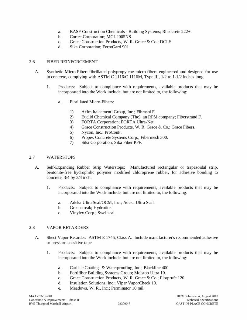
MAA-CO-19-001
033000-7
100% Submission, August 2018Concourse A Improvements – Phase II Technical SpecificationsBWI Thurgood Marshall Airport CAST-IN-PLACE CONCRETE
a. BASF Construction Chemicals - Building Systems; Rheocrete 222+.b. Cortec Corporation; MCI-2005NS.c. Grace Construction Products, W. R. Grace & Co.; DCI-S.d. Sika Corporation; FerroGard 901.
2.6 FIBER REINFORCEMENT
A. Synthetic Micro-Fiber: fibrillated polypropylene micro-fibers engineered and designed for usein concrete, complying with ASTM C 1116/C 1116M, Type III, 1/2 to 1-1/2 inches long.
1. Products: Subject to compliance with requirements, available products that may beincorporated into the Work include, but are not limited to, the following:
a. Fibrillated Micro-Fibers:
1) Axim Italcementi Group, Inc.; Fibrasol F.2) Euclid Chemical Company (The), an RPM company; Fiberstrand F.3) FORTA Corporation; FORTA Ultra-Net.4) Grace Construction Products, W. R. Grace & Co.; Grace Fibers.5) Nycon, Inc.; ProConF.6) Propex Concrete Systems Corp.; Fibermesh 300.7) Sika Corporation; Sika Fiber PPF.
2.7 WATERSTOPS
A. Self-Expanding Rubber Strip Waterstops: Manufactured rectangular or trapezoidal strip,bentonite-free hydrophilic polymer modified chloroprene rubber, for adhesive bonding toconcrete, 3/4 by 3/4 inch.
1. Products: Subject to compliance with requirements, available products that may beincorporated into the Work include, but are not limited to, the following:
a. Adeka Ultra Seal/OCM, Inc.; Adeka Ultra Seal.b. Greenstreak; Hydrotite.c. Vinylex Corp.; Swellseal.
2.8 VAPOR RETARDERS
A. Sheet Vapor Retarder: ASTM E 1745, Class A. Include manufacturer's recommended adhesiveor pressure-sensitive tape.
1. Products: Subject to compliance with requirements, available products that may beincorporated into the Work include, but are not limited to, the following:
a. Carlisle Coatings & Waterproofing, Inc.; Blackline 400.b. Fortifiber Building Systems Group; Moistop Ultra 10.c. Grace Construction Products, W. R. Grace & Co.; Florprufe 120.d. Insulation Solutions, Inc.; Viper VaporCheck 10.e. Meadows, W. R., Inc.; Perminator 10 mil.
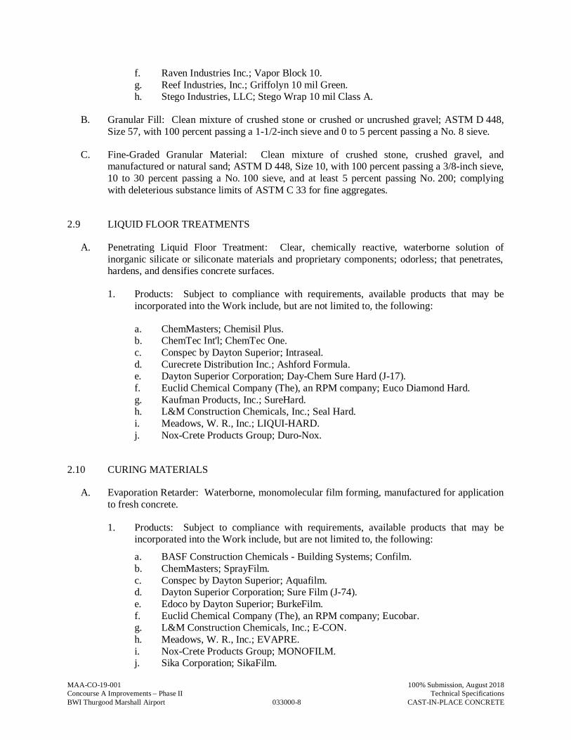
MAA-CO-19-001
033000-8
100% Submission, August 2018Concourse A Improvements – Phase II Technical SpecificationsBWI Thurgood Marshall Airport CAST-IN-PLACE CONCRETE
f. Raven Industries Inc.; Vapor Block 10.g. Reef Industries, Inc.; Griffolyn 10 mil Green.h. Stego Industries, LLC; Stego Wrap 10 mil Class A.
B. Granular Fill: Clean mixture of crushed stone or crushed or uncrushed gravel; ASTM D 448,Size 57, with 100 percent passing a 1-1/2-inch sieve and 0 to 5 percent passing a No. 8 sieve.
C. Fine-Graded Granular Material: Clean mixture of crushed stone, crushed gravel, andmanufactured or natural sand; ASTM D 448, Size 10, with 100 percent passing a 3/8-inch sieve,10 to 30 percent passing a No. 100 sieve, and at least 5 percent passing No. 200; complyingwith deleterious substance limits of ASTM C 33 for fine aggregates.
2.9 LIQUID FLOOR TREATMENTS
A. Penetrating Liquid Floor Treatment: Clear, chemically reactive, waterborne solution ofinorganic silicate or siliconate materials and proprietary components; odorless; that penetrates,hardens, and densifies concrete surfaces.
1. Products: Subject to compliance with requirements, available products that may beincorporated into the Work include, but are not limited to, the following:
a. ChemMasters; Chemisil Plus.b. ChemTec Int'l; ChemTec One.c. Conspec by Dayton Superior; Intraseal.d. Curecrete Distribution Inc.; Ashford Formula.e. Dayton Superior Corporation; Day-Chem Sure Hard (J-17).f. Euclid Chemical Company (The), an RPM company; Euco Diamond Hard.g. Kaufman Products, Inc.; SureHard.h. L&M Construction Chemicals, Inc.; Seal Hard.i. Meadows, W. R., Inc.; LIQUI-HARD.j. Nox-Crete Products Group; Duro-Nox.
2.10 CURING MATERIALS
A. Evaporation Retarder: Waterborne, monomolecular film forming, manufactured for applicationto fresh concrete.
1. Products: Subject to compliance with requirements, available products that may beincorporated into the Work include, but are not limited to, the following:
a. BASF Construction Chemicals - Building Systems; Confilm.b. ChemMasters; SprayFilm.c. Conspec by Dayton Superior; Aquafilm.d. Dayton Superior Corporation; Sure Film (J-74).e. Edoco by Dayton Superior; BurkeFilm.f. Euclid Chemical Company (The), an RPM company; Eucobar.g. L&M Construction Chemicals, Inc.; E-CON.h. Meadows, W. R., Inc.; EVAPRE.i. Nox-Crete Products Group; MONOFILM.j. Sika Corporation; SikaFilm.

MAA-CO-19-001
033000-9
100% Submission, August 2018Concourse A Improvements – Phase II Technical SpecificationsBWI Thurgood Marshall Airport CAST-IN-PLACE CONCRETE
B. Absorptive Cover: AASHTO M 182, Class 2, burlap cloth made from jute or kenaf, weighingapproximately 9 oz./sq. yd. when dry.
C. Moisture-Retaining Cover: ASTM C 171, polyethylene film or white burlap-polyethylenesheet.
D. Water: Potable.
E. Clear, Waterborne, Membrane-Forming Curing Compound: ASTM C 309, Type 1, Class B,dissipating.
1. Products: Subject to compliance with requirements, available products that may beincorporated into the Work include, but are not limited to, the following:
a. Anti-Hydro International, Inc.; AH Curing Compound #2 DR WB.b. BASF Construction Chemicals - Building Systems; Kure 200.c. ChemMasters; Safe-Cure Clear.d. Conspec by Dayton Superior; W.B. Resin Cure.e. Dayton Superior Corporation; Day-Chem Rez Cure (J-11-W).f. Edoco by Dayton Superior; Res X Cure WB.g. Euclid Chemical Company (The), an RPM company; Kurez W VOX;
TAMMSCURE WB 30C.h. Kaufman Products, Inc.; Thinfilm 420.i. Lambert Corporation; AQUA KURE - CLEAR.j. L&M Construction Chemicals, Inc.; L&M Cure R.k. Meadows, W. R., Inc.; 1100-CLEAR.l. Nox-Crete Products Group; Resin Cure E.m. SpecChem, LLC; Spec Rez Clear.n. Symons by Dayton Superior; Resi-Chem Clear.o. TK Products, Division of Sierra Corporation; TK-2519 DC WB.
2.11 RELATED MATERIALS
A. Expansion- and Isolation-Joint-Filler Strips: ASTM D 1751, asphalt-saturated cellulosic fiberor ASTM D 1752, cork or self-expanding cork.
B. Semirigid Joint Filler: Two-component, semirigid, 100 percent solids, epoxy resin with aType A shore durometer hardness of 80 per ASTM D 2240.
C. Bonding Agent: ASTM C 1059/C 1059M, Type II, non-redispersible, acrylic emulsion orstyrene butadiene.
D. Epoxy Bonding Adhesive: ASTM C 881, two-component epoxy resin, capable of humid curingand bonding to damp surfaces, of class suitable for application temperature and of grade to suitrequirements, and as follows:
1. Types IV and V, load bearing, for bonding hardened or freshly mixed concrete tohardened concrete.
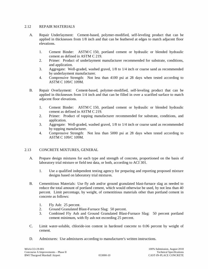
MAA-CO-19-001
033000-10
100% Submission, August 2018Concourse A Improvements – Phase II Technical SpecificationsBWI Thurgood Marshall Airport CAST-IN-PLACE CONCRETE
2.12 REPAIR MATERIALS
A. Repair Underlayment: Cement-based, polymer-modified, self-leveling product that can beapplied in thicknesses from 1/8 inch and that can be feathered at edges to match adjacent floorelevations.
1. Cement Binder: ASTM C 150, portland cement or hydraulic or blended hydrauliccement as defined in ASTM C 219.
2. Primer: Product of underlayment manufacturer recommended for substrate, conditions,and application.
3. Aggregate: Well-graded, washed gravel, 1/8 to 1/4 inch or coarse sand as recommendedby underlayment manufacturer.
4. Compressive Strength: Not less than 4100 psi at 28 days when tested according toASTM C 109/C 109M.
B. Repair Overlayment: Cement-based, polymer-modified, self-leveling product that can beapplied in thicknesses from 1/4 inch and that can be filled in over a scarified surface to matchadjacent floor elevations.
1. Cement Binder: ASTM C 150, portland cement or hydraulic or blended hydrauliccement as defined in ASTM C 219.
2. Primer: Product of topping manufacturer recommended for substrate, conditions, andapplication.
3. Aggregate: Well-graded, washed gravel, 1/8 to 1/4 inch or coarse sand as recommendedby topping manufacturer.
4. Compressive Strength: Not less than 5000 psi at 28 days when tested according toASTM C 109/C 109M.
2.13 CONCRETE MIXTURES, GENERAL
A. Prepare design mixtures for each type and strength of concrete, proportioned on the basis oflaboratory trial mixture or field test data, or both, according to ACI 301.
1. Use a qualified independent testing agency for preparing and reporting proposed mixturedesigns based on laboratory trial mixtures.
B. Cementitious Materials: Use fly ash and/or ground granulated blast-furnace slag as needed toreduce the total amount of portland cement, which would otherwise be used, by not less than 40percent. Limit percentage, by weight, of cementitious materials other than portland cement inconcrete as follows:
1. Fly Ash: 25 percent.2. Ground Granulated Blast-Furnace Slag: 50 percent.3. Combined Fly Ash and Ground Granulated Blast-Furnace Slag: 50 percent portland
cement minimum, with fly ash not exceeding 25 percent.
C. Limit water-soluble, chloride-ion content in hardened concrete to 0.06 percent by weight ofcement.
D. Admixtures: Use admixtures according to manufacturer's written instructions.
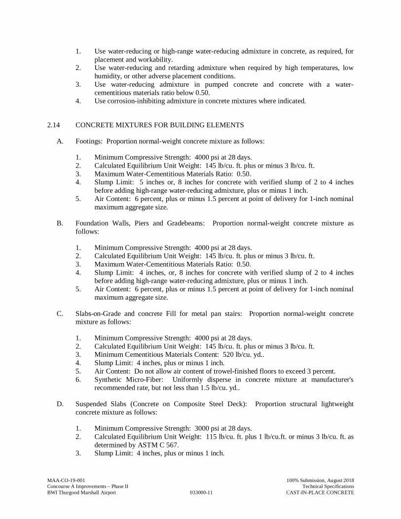
MAA-CO-19-001
033000-11
100% Submission, August 2018Concourse A Improvements – Phase II Technical SpecificationsBWI Thurgood Marshall Airport CAST-IN-PLACE CONCRETE
1. Use water-reducing or high-range water-reducing admixture in concrete, as required, forplacement and workability.
2. Use water-reducing and retarding admixture when required by high temperatures, lowhumidity, or other adverse placement conditions.
3. Use water-reducing admixture in pumped concrete and concrete with a water-cementitious materials ratio below 0.50.
4. Use corrosion-inhibiting admixture in concrete mixtures where indicated.
2.14 CONCRETE MIXTURES FOR BUILDING ELEMENTS
A. Footings: Proportion normal-weight concrete mixture as follows:
1. Minimum Compressive Strength: 4000 psi at 28 days.2. Calculated Equilibrium Unit Weight: 145 lb/cu. ft. plus or minus 3 lb/cu. ft.3. Maximum Water-Cementitious Materials Ratio: 0.50.4. Slump Limit: 5 inches or, 8 inches for concrete with verified slump of 2 to 4 inches
before adding high-range water-reducing admixture, plus or minus 1 inch.5. Air Content: 6 percent, plus or minus 1.5 percent at point of delivery for 1-inch nominal
maximum aggregate size.
B. Foundation Walls, Piers and Gradebeams: Proportion normal-weight concrete mixture asfollows:
1. Minimum Compressive Strength: 4000 psi at 28 days.2. Calculated Equilibrium Unit Weight: 145 lb/cu. ft. plus or minus 3 lb/cu. ft.3. Maximum Water-Cementitious Materials Ratio: 0.50.4. Slump Limit: 4 inches, or, 8 inches for concrete with verified slump of 2 to 4 inches
before adding high-range water-reducing admixture, plus or minus 1 inch.5. Air Content: 6 percent, plus or minus 1.5 percent at point of delivery for 1-inch nominal
maximum aggregate size.
C. Slabs-on-Grade and concrete Fill for metal pan stairs: Proportion normal-weight concretemixture as follows:
1. Minimum Compressive Strength: 4000 psi at 28 days.2. Calculated Equilibrium Unit Weight: 145 lb/cu. ft. plus or minus 3 lb/cu. ft.3. Minimum Cementitious Materials Content: 520 lb/cu. yd..4. Slump Limit: 4 inches, plus or minus 1 inch.5. Air Content: Do not allow air content of trowel-finished floors to exceed 3 percent.6. Synthetic Micro-Fiber: Uniformly disperse in concrete mixture at manufacturer's
recommended rate, but not less than 1.5 lb/cu. yd..
D. Suspended Slabs (Concrete on Composite Steel Deck): Proportion structural lightweightconcrete mixture as follows:
1. Minimum Compressive Strength: 3000 psi at 28 days.2. Calculated Equilibrium Unit Weight: 115 lb/cu. ft. plus 1 lb/cu.ft. or minus 3 lb/cu. ft. as
determined by ASTM C 567.3. Slump Limit: 4 inches, plus or minus 1 inch.
MAA-CO-19-001
033000-12
100% Submission, August 2018Concourse A Improvements – Phase II Technical SpecificationsBWI Thurgood Marshall Airport CAST-IN-PLACE CONCRETE
4. Air Content: 6 percent, plus or minus 2 percent at point of delivery for nominalmaximum aggregate size greater than 3/8 inch.
5. Synthetic Micro-Fiber: Uniformly disperse in concrete mixture at manufacturer'srecommended rate, but not less than 1.5 lb/cu. yd..
E. Concrete Toppings: Proportion normal-weight concrete mixture as follows:
1. Minimum Compressive Strength: 3000 psi at 28 days.2. Minimum Cementitious Materials Content: 520 lb/cu. yd..3. Slump Limit: 5 inches , plus or minus 1 inch.4. Air Content: 6 percent, plus or minus 1.5 percent at point of delivery for 1-inch nominal
maximum aggregate size.5. Air Content: Do not allow air content of trowel-finished toppings to exceed 3 percent.6. Synthetic Micro-Fiber: Uniformly disperse in concrete mixture at manufacturer's
recommended rate, but not less than 1.0 lb/cu. yd..
2.15 FABRICATING REINFORCEMENT
A. Fabricate steel reinforcement according to CRSI's "Manual of Standard Practice."
2.16 CONCRETE MIXING
A. Ready-Mixed Concrete: Measure, batch, mix, and deliver concrete according to ASTM C 94,and furnish batch ticket information.
1. When air temperature is between 85 and 90 deg F, reduce mixing and delivery time from1-1/2 hours to 75 minutes; when air temperature is above 90 deg F, reduce mixing anddelivery time to 60 minutes.
B. Project-Site Mixing: Measure, batch, and mix concrete materials and concrete according toASTM C 94/C 94M. Mix concrete materials in appropriate drum-type batch machine mixer.
1. For mixer capacity of 1 cu. yd. or smaller, continue mixing at least 1-1/2 minutes, but notmore than 5 minutes after ingredients are in mixer, before any part of batch is released.
2. For mixer capacity, larger than 1 cu. yd., increase mixing time by 15 seconds for eachadditional 1 cu. yd..
3. Provide batch ticket for each batch discharged and used in the Work, indicating Projectidentification name and number, date, mixture type, mixture time, quantity, and amountof water added. Record approximate location of final deposit in structure.
PART 3 - EXECUTION
3.1 FORMWORK
A. Design, erect, shore, brace, and maintain formwork, according to ACI 301, to support vertical,lateral, static, and dynamic loads, and construction loads that might be applied, until structurecan support such loads.
MAA-CO-19-001
033000-13
100% Submission, August 2018Concourse A Improvements – Phase II Technical SpecificationsBWI Thurgood Marshall Airport CAST-IN-PLACE CONCRETE
B. Construct formwork so concrete members and structures are of size, shape, alignment,elevation, and position indicated, within tolerance limits of ACI 117.
C. Limit concrete surface irregularities, designated by ACI 347 as abrupt or gradual, as follows:
1. Class A, 1/8 inch for smooth-formed finished surfaces.
D. Construct forms tight enough to prevent loss of concrete mortar.
E. Fabricate forms for easy removal without hammering or prying against concrete surfaces.Provide crush or wrecking plates where stripping may damage cast concrete surfaces. Providetop forms for inclined surfaces steeper than 1.5 horizontal to 1 vertical.
1. Install keyways, reglets, recesses, and the like, for easy removal.2. Do not use rust-stained steel form-facing material.
F. Set edge forms, bulkheads, and intermediate screed strips for slabs to achieve requiredelevations and slopes in finished concrete surfaces. Provide and secure units to support screedstrips; use strike-off templates or compacting-type screeds.
G. Provide temporary openings for cleanouts and inspection ports where interior area of formworkis inaccessible. Close openings with panels tightly fitted to forms and securely braced toprevent loss of concrete mortar. Locate temporary openings in forms at inconspicuouslocations.
H. Chamfer exterior corners and edges of permanently exposed concrete.
I. Form openings, chases, offsets, sinkages, keyways, reglets, blocking, screeds, and bulkheadsrequired in the Work. Determine sizes and locations from trades providing such items.
J. Clean forms and adjacent surfaces to receive concrete. Remove chips, wood, sawdust, dirt, andother debris just before placing concrete.
K. Retighten forms and bracing before placing concrete, as required, to prevent mortar leaks andmaintain proper alignment.
L. Coat contact surfaces of forms with form-release agent, according to manufacturer's writteninstructions, before placing reinforcement.
3.2 EMBEDDED ITEMS
A. Place and secure anchorage devices and other embedded items required for adjoining work thatis attached to or supported by cast-in-place concrete. Use setting drawings, templates,diagrams, instructions, and directions furnished with items to be embedded.
1. Install anchor rods, accurately located, to elevations required and complying withtolerances in Section 7.5 of AISC's "Code of Standard Practice for Steel Buildings andBridges."
2. Install reglets to receive waterproofing and to receive through-wall flashings in outer faceof concrete at exterior walls.
3. Install dovetail anchor slots in concrete structures as indicated.
MAA-CO-19-001
033000-14
100% Submission, August 2018Concourse A Improvements – Phase II Technical SpecificationsBWI Thurgood Marshall Airport CAST-IN-PLACE CONCRETE
3.3 REMOVING AND REUSING FORMS
A. General: Formwork for sides of walls, piers, and similar parts of the Work that does not supportweight of concrete may be removed after cumulatively curing at not less than 50 deg F for 24hours after placing concrete. Concrete must be hard enough to not be damaged by form-removal operations and curing and protection operations need to be maintained.
1. Remove forms only if shores have been arranged to permit removal of forms withoutloosening or disturbing shores.
B. Clean and repair surfaces of forms to be reused in the Work. Split, frayed, delaminated, orotherwise damaged form-facing material will not be acceptable for exposed surfaces. Applynew form-release agent.
C. When forms are reused, clean surfaces, remove fins and laitance, and tighten to close joints.Align and secure joints to avoid offsets. Do not use patched forms for exposed concretesurfaces unless approved by Architect.
3.4 VAPOR RETARDERS
A. Sheet Vapor Retarders: Place, protect, and repair sheet vapor retarder according toASTM E 1643 and manufacturer's written instructions.
1. Lap joints 6 inches and seal with manufacturer's recommended tape.
2. Place and compact a 1/2-inch- thick layer of fine-graded granular material over granularfill.
3. Place Sheet Vapor Retarder directly below the slab-on-grade concrete.
3.5 STEEL REINFORCEMENT
A. General: Comply with CRSI's "Manual of Standard Practice" for placing reinforcement.
1. Do not cut or puncture vapor retarder. Repair damage and reseal vapor retarder beforeplacing concrete.
B. Clean reinforcement of loose rust and mill scale, earth, ice, and other foreign materials thatwould reduce bond to concrete.
C. Accurately position, support, and secure reinforcement against displacement. Locate andsupport reinforcement with bar supports to maintain minimum concrete cover. Do not tackweld crossing reinforcing bars.
1. Weld reinforcing bars according to AWS D1.4/D 1.4M, where indicated.
D. Set wire ties with ends directed into concrete, not toward exposed concrete surfaces.
E. Install welded wire reinforcement in longest practicable lengths on bar supports spaced tominimize sagging. Lap edges and ends of adjoining sheets at least one mesh spacing. Offset
MAA-CO-19-001
033000-15
100% Submission, August 2018Concourse A Improvements – Phase II Technical SpecificationsBWI Thurgood Marshall Airport CAST-IN-PLACE CONCRETE
laps of adjoining sheet widths to prevent continuous laps in either direction. Lace overlaps withwire.
F. Epoxy-Coated Reinforcement: Repair cut and damaged epoxy coatings with epoxy repaircoating according to ASTM D 3963/D 3963M. Use epoxy-coated steel wire ties to fastenepoxy-coated steel reinforcement.
3.6 JOINTS
A. General: Construct joints true to line with faces perpendicular to surface plane of concrete.
B. Construction Joints: Install so strength and appearance of concrete are not impaired, atlocations indicated or as approved by Architect.
1. Place joints perpendicular to main reinforcement. Continue reinforcement acrossconstruction joints unless otherwise indicated.
2. Form keyed joints as indicated. Embed keys at least 1-1/2 inches into concrete.3. Locate joints for slabs in the middle third of spans.4. Locate horizontal joints in walls and columns at underside of floor slabs, and at the top of
footings or floor slabs.5. Space vertical joints in walls at 60’-0”, maximum. Locate joints beside piers integral
with walls, near corners, and in concealed locations where possible.6. Use a bonding agent at locations where fresh concrete is placed against hardened or
partially hardened concrete surfaces.7. Use epoxy-bonding adhesive at locations where fresh concrete is placed against hardened
or partially hardened concrete surfaces.
C. Contraction Joints in Slabs-on-Grade: Form weakened-plane contraction joints, sectioningconcrete into areas as indicated. Construct contraction joints for a depth equal to at least one-fourth of concrete thickness for Grooved Joints or Sawed Joints, and at least one-third of theslab depth for joints created by use of a removeable plastic control joint former product, asfollows:
1. Grooved Joints: Form contraction joints after initial floating by grooving and finishingeach edge of joint to a radius of 1/8 inch. Repeat grooving of contraction joints afterapplying surface finishes. Eliminate groover tool marks on concrete surfaces.
2. Sawed Joints: Form contraction joints with power saws equipped with shatterproofabrasive or diamond-rimmed blades. Cut 1/8-inch-wide joints into concrete when cuttingaction will not tear, abrade, or otherwise damage surface and before concrete developsrandom contraction cracks.
3. Plastic Control Joint Former Joints: Form 1/8” wide contraction joints after initialfloating by placing and using a plastic control joint forming device in accordance with themanufacturer’s recommendations. Finish concrete adjacent to the joint former toeliminate any surface marks.
D. Isolation Joints in Slabs-on-Grade: After removing formwork, install joint-filler strips at slabjunctions with vertical surfaces, such as column pedestals, foundation walls, grade beams, andother locations, as indicated.
MAA-CO-19-001
033000-16
100% Submission, August 2018Concourse A Improvements – Phase II Technical SpecificationsBWI Thurgood Marshall Airport CAST-IN-PLACE CONCRETE
1. Extend joint-filler strips full width and depth of joint, terminating flush with finishedconcrete surface unless otherwise indicated.
2. Terminate full-width joint-filler strips not less than 1/2 inch or more than 1 inch belowfinished concrete surface where joint sealants, specified in Division 07 Section "JointSealants," are indicated.
3. Install joint-filler strips in lengths as long as practicable. Where more than one length isrequired, lace or clip sections together.
3.7 WATERSTOPS
A. Self-Expanding Strip Waterstops: Install in construction joints and at other locations indicated,according to manufacturer's written instructions, adhesive bonding, mechanically fastening, andfirmly pressing into place. Install in longest lengths practicable.
3.8 CONCRETE PLACEMENT
A. Before placing concrete, verify that installation of formwork, reinforcement, and embeddeditems is complete and that required inspections have been performed.
B. Do not add water to concrete during delivery, at Project site, or during placement unlessapproved by Engineer.
C. Before test sampling and placing concrete, water may be added at Project site, subject tolimitations of ACI 301. Water added to the concrete mix must not exceed the amount of waterthat is withheld from the initial concrete mixing as documented in the submitted and approvedconcrete mix design for the subject mix. For each batch where water is withheld at the plant thequantity withheld must be documented on the concrete mixing truck plant ticket .
1. Do not add water to concrete after adding high-range water-reducing admixtures tomixture.
D. Deposit concrete continuously in one layer or in horizontal layers of such thickness that no newconcrete will be placed on concrete that has hardened enough to cause seams or planes ofweakness. If a section cannot be placed continuously, provide construction joints using detailsas indicated in the plans. Deposit concrete to avoid segregation.
1. Deposit concrete in horizontal layers of depth to not exceed formwork design pressuresand in a manner to avoid inclined construction joints.
2. Consolidate placed concrete with mechanical vibrating equipment according to ACI 301.3. Do not use vibrators to transport concrete inside forms. Insert and withdraw vibrators
vertically at uniformly spaced locations to rapidly penetrate placed layer and at least 6inches into preceding layer. Do not insert vibrators into lower layers of concrete thathave begun to lose plasticity. At each insertion, limit duration of vibration to timenecessary to consolidate concrete and complete embedment of reinforcement and otherembedded items without causing mixture constituents to segregate.
E. Deposit and consolidate concrete for floors and slabs in a continuous operation, within limits ofconstruction joints, until placement of a panel or section is complete.
MAA-CO-19-001
033000-17
100% Submission, August 2018Concourse A Improvements – Phase II Technical SpecificationsBWI Thurgood Marshall Airport CAST-IN-PLACE CONCRETE
1. Consolidate concrete during placement operations so concrete is thoroughly workedaround reinforcement and other embedded items and into corners.
2. Maintain reinforcement in position on chairs during concrete placement.3. Screed slab surfaces with a straightedge and strike off to correct elevations.4. Slope surfaces uniformly to drains where required.5. Begin initial floating using bull floats or darbies to form a uniform and open-textured
surface plane, before excess bleedwater appears on the surface. Do not further disturbslab surfaces before starting finishing operations.
F. Cold-Weather Placement: Comply with ACI 306.1 and as follows. Protect concrete work fromphysical damage or reduced strength that could be caused by frost, freezing actions, or lowtemperatures.
1. When average high and low temperature is expected to fall below 40 deg F for threesuccessive days, maintain delivered concrete mixture temperature within the temperaturerange required by ACI 301.
2. Do not use frozen materials or materials containing ice or snow. Do not place concreteon frozen subgrade or on subgrade containing frozen materials.
3. Do not use calcium chloride, salt, or other materials containing antifreeze agents orchemical accelerators unless otherwise specified and approved in mixture designs.
G. Hot-Weather Placement: Comply with ACI 301 and as follows:
1. Maintain concrete temperature below 90 deg F at time of placement. Chilled mixingwater or chopped ice may be used to control temperature, provided water equivalent ofice is calculated to total amount of mixing water. Using liquid nitrogen to cool concreteis Contractor's option.
2. Fog-spray forms, steel reinforcement, and subgrade just before placing concrete. Keepsubgrade uniformly moist without standing water, soft spots, or dry areas.
3.9 FINISHING FORMED SURFACES
A. Rough-Formed Finish: As-cast concrete texture imparted by form-facing material with tie holesand defects repaired and patched. Remove fins and other projections that exceed specifiedlimits on formed-surface irregularities.
1. Apply to concrete surfaces that will be below grade in the finished construction, unlessnoted otherwise.
B. Smooth-Formed Finish: As-cast concrete texture imparted by form-facing material, arranged inan orderly and symmetrical manner with a minimum of seams. Repair and patch tie holes anddefects. Remove fins and other projections that exceed specified limits on formed-surfaceirregularities.
1. Apply to concrete surfaces exposed to public view, to be covered with a coating orcovering material applied directly to concrete, and the interior surface of elevator pit.
C. Related Unformed Surfaces: At tops of walls, horizontal offsets, and similar unformed surfacesadjacent to formed surfaces, strike off smooth and finish with a texture matching adjacent
MAA-CO-19-001
033000-18
100% Submission, August 2018Concourse A Improvements – Phase II Technical SpecificationsBWI Thurgood Marshall Airport CAST-IN-PLACE CONCRETE
formed surfaces. Continue final surface treatment of formed surfaces uniformly across adjacentunformed surfaces unless otherwise indicated.
3.10 FINISHING FLOORS AND SLABS
A. General: Comply with ACI 302.1R recommendations for screeding, restraightening, andfinishing operations for concrete surfaces. Do not wet concrete surfaces.
B. Float Finish: Consolidate surface with power-driven floats or by hand floating if area is smallor inaccessible to power driven floats. Restraighten, cut down high spots, and fill low spots.Repeat float passes and restraightening until surface is left with a uniform, smooth, granulartexture.
1. Apply float finish to surfaces to receive trowel finish, trowel and fine broom finish, andbroom finish.
C. Trowel Finish: After applying float finish, apply first troweling and consolidate concrete byhand or power-driven trowel. Continue troweling passes and restraighten until surface is free oftrowel marks and uniform in texture and appearance. Grind smooth any surface defects thatwould telegraph through applied coatings or floor coverings.
1. Apply a trowel finish to surfaces exposed to view or to be covered with resilient flooring,carpet, ceramic or quarry tile set over a cleavage membrane, paint, or another thin-film-finish coating system.
2. Finish surfaces to the following tolerances, according to ASTM E 1155, for a randomlytrafficked floor surface:
a. Arrivals Level Slab - Specified overall values of flatness, F(F) 25; and oflevelness, F(L) 20; with minimum local values of flatness, F(F) 17; and oflevelness, F(L) 15.
b. Departures Level Slab - Specified overall values of flatness, F(F) 30; and oflevelness, F(L) 20; with minimum local values of flatness, F(F) 24; and oflevelness, F(L) 15; for suspended slabs.
D. Trowel and Fine-Broom Finish: Apply a first trowel finish to surfaces where ceramic or quarrytile is to be installed by either thickset or thin-set method. While concrete is still plastic,slightly scarify surface with a fine broom.
1. Comply with flatness and levelness tolerances for trowel-finished floor surfaces.
E. Broom Finish: Apply a broom finish to exterior concrete platforms, steps, ramps, andelsewhere as indicated.
1. Immediately after float finishing, slightly roughen trafficked surface by brooming withfiber-bristle broom perpendicular to main traffic route. Coordinate required final finishwith Architect before application.

MAA-CO-19-001
033000-19
100% Submission, August 2018Concourse A Improvements – Phase II Technical SpecificationsBWI Thurgood Marshall Airport CAST-IN-PLACE CONCRETE
3.11 MISCELLANEOUS CONCRETE ITEMS
A. Filling In: Fill in holes and openings left in concrete structures after work of other trades is inplace unless otherwise indicated. Mix, place, and cure concrete, as specified, to blend with in-place construction. Provide other miscellaneous concrete filling indicated or required tocomplete the Work.
B. Curbs: Provide monolithic finish to interior curbs by stripping forms while concrete is stillgreen and by steel-troweling surfaces to a hard, dense finish with corners, intersections, andterminations slightly rounded.
C. Equipment Bases and Foundations: Provide machine and equipment bases and foundations asshown on Drawings. Set anchor bolts for machines and equipment at correct elevations,complying with diagrams or templates from manufacturer furnishing machines and equipment.
D. Steel Pan Stairs: Provide concrete fill for steel pan stair treads, landings, and associated items.Cast-in inserts and accessories as shown on Drawings. Screed, tamp, and trowel finish concretesurfaces.
3.12 CONCRETE PROTECTING AND CURING
A. General: Protect freshly placed concrete from premature drying and excessive cold or hottemperatures. Comply with ACI 306.1 for cold-weather protection and ACI 301 for hot-weather protection during curing.
B. Evaporation Retarder: Apply evaporation retarder to unformed concrete surfaces if hot, dry, orwindy conditions cause moisture loss approaching 0.2 lb/sq. ft. x h before and during finishingoperations. Apply according to manufacturer's written instructions after placing, screeding, andbull floating or darbying concrete, but before float finishing.
C. Formed Surfaces: Cure formed concrete surfaces, including underside of beams, supportedslabs, and other similar surfaces. If forms remain during curing period, moist cure afterloosening forms. If removing forms before end of curing period, continue curing for theremainder of the curing period.
D. Unformed Surfaces: Begin curing immediately after finishing concrete. Cure unformedsurfaces, including floors and slabs, concrete floor toppings, and other surfaces.
E. Cure concrete according to ACI 308.1, by one or a combination of the following methods:
1. Moisture Curing: Keep surfaces continuously moist for not less than seven days with thefollowing materials:
a. Water.b. Continuous water-fog spray.c. Absorptive cover, water saturated, and kept continuously wet. Cover concrete
surfaces and edges with 12-inch lap over adjacent absorptive covers.
2. Moisture-Retaining-Cover Curing: Cover concrete surfaces with moisture-retainingcover for curing concrete, placed in widest practicable width, with sides and ends lapped
MAA-CO-19-001
033000-20
100% Submission, August 2018Concourse A Improvements – Phase II Technical SpecificationsBWI Thurgood Marshall Airport CAST-IN-PLACE CONCRETE
at least 12 inches, and sealed by waterproof tape or adhesive. Cure for not less thanseven days. Immediately repair any holes or tears during curing period using covermaterial and waterproof tape.
a. Moisture cure or use moisture-retaining covers to cure concrete surfaces to receivefloor coverings.
b. Moisture cure or use moisture-retaining covers to cure concrete surfaces to receivepenetrating liquid floor treatments.
c. Cure concrete surfaces to receive floor coverings with either a moisture-retainingcover or a curing compound that the manufacturer certifies will not interfere withbonding of floor covering used on Project.
3. Curing Compound: Apply uniformly in continuous operation by power spray or rolleraccording to manufacturer's written instructions. Recoat areas subjected to heavy rainfallwithin three hours after initial application. Maintain continuity of coating and repairdamage during curing period.
a. Removal: After curing period has elapsed, remove curing compound withoutdamaging concrete surfaces by method recommended by curing compoundmanufacturer.
3.13 LIQUID FLOOR TREATMENTS
A. Penetrating Liquid Floor Treatment: Prepare, apply, and finish penetrating liquid floortreatment to slab areas identified on plan, according to manufacturer's written instructions.
1. Remove curing compounds, sealers, oil, dirt, laitance, and other contaminants andcomplete surface repairs.
2. Do not apply to concrete that is less than 28 days old.3. Apply liquid until surface is saturated, scrubbing into surface until a gel forms; rewet;
and repeat brooming or scrubbing. Rinse with water; remove excess material untilsurface is dry. Apply a second coat in a similar manner if surface is rough or porous.
3.14 JOINT FILLING
A. Prepare, clean, and install joint filler according to manufacturer's written instructions.
1. Defer joint filling until concrete has aged at least three months. Do not fill joints untilconstruction traffic has permanently ceased.
B. Remove dirt, debris, saw cuttings, curing compounds, and sealers from joints; leave contactfaces of joint clean and dry.
C. Install semirigid joint filler full depth in saw-cut joints and at least 2 inches deep in formedjoints. Overfill joint and trim joint filler flush with top of joint after hardening.
MAA-CO-19-001
033000-21
100% Submission, August 2018Concourse A Improvements – Phase II Technical SpecificationsBWI Thurgood Marshall Airport CAST-IN-PLACE CONCRETE
3.15 CONCRETE SURFACE REPAIRS
A. Defective Concrete: Repair and patch defective areas when approved by Architect. Removeand replace concrete that cannot be repaired and patched to Architect's approval.
B. Patching Mortar: Mix dry-pack patching mortar, consisting of one part portland cement to twoand one-half parts fine aggregate passing a No. 16 sieve, using only enough water for handlingand placing.
C. Repairing Formed Surfaces: Surface defects include color and texture irregularities, cracks,spalls, air bubbles, honeycombs, rock pockets, fins and other projections on the surface, andstains and other discolorations that cannot be removed by cleaning.
1. Immediately after form removal, cut out honeycombs, rock pockets, and voids more than1/2 inch in any dimension to solid concrete. Limit cut depth to 3/4 inch. Make edges ofcuts perpendicular to concrete surface. Clean, dampen with water, and brush-coat holesand voids with bonding agent. Fill and compact with patching mortar before bondingagent has dried. Fill form-tie voids with patching mortar or cone plugs secured in placewith bonding agent.
2. Repair defects on surfaces exposed to view by blending white portland cement andstandard portland cement so that, when dry, patching mortar will match surroundingcolor. Patch a test area at inconspicuous locations to verify mixture and color matchbefore proceeding with patching. Compact mortar in place and strike off slightly higherthan surrounding surface.
3. Repair defects on concealed formed surfaces that affect concrete's durability andstructural performance as determined by Architect.
D. Repairing Unformed Surfaces: Test unformed surfaces, such as floors and slabs, for finish andverify surface tolerances specified for each surface. Correct low and high areas. Test surfacessloped to drain for trueness of slope and smoothness; use a sloped template.
1. Repair finished surfaces containing defects. Surface defects include spalls, popouts,honeycombs, rock pockets, crazing and cracks in excess of 0.01 inch wide or thatpenetrate to reinforcement or completely through unreinforced sections regardless ofwidth, and other objectionable conditions.
2. After concrete has cured at least 14 days, correct high areas by grinding.3. Correct localized low areas during or immediately after completing surface finishing
operations by cutting out low areas and replacing with patching mortar. Finish repairedareas to blend into adjacent concrete.
4. Correct other low areas scheduled to receive floor coverings with a repair underlayment.Prepare, mix, and apply repair underlayment and primer according to manufacturer'swritten instructions to produce a smooth, uniform, plane, and level surface. Featheredges to match adjacent floor elevations.
5. Correct other low areas scheduled to remain exposed with a repair topping. Cut out lowareas to ensure a minimum repair topping depth of 1/4 inch to match adjacent floorelevations. Prepare, mix, and apply repair topping and primer according tomanufacturer's written instructions to produce a smooth, uniform, plane, and levelsurface.
6. Repair defective areas, except random cracks and single holes 1 inch or less in diameter,by cutting out and replacing with fresh concrete. Remove defective areas with clean,square cuts and expose steel reinforcement with at least a 3/4-inch clearance all around.
MAA-CO-19-001
033000-22
100% Submission, August 2018Concourse A Improvements – Phase II Technical SpecificationsBWI Thurgood Marshall Airport CAST-IN-PLACE CONCRETE
Dampen concrete surfaces in contact with patching concrete and apply bonding agent.Mix patching concrete of same materials and mixture as original concrete except withoutcoarse aggregate. Place, compact, and finish to blend with adjacent finished concrete.Cure in same manner as adjacent concrete.
7. Repair random cracks and single holes 1 inch or less in diameter with patching mortar.Groove top of cracks and cut out holes to sound concrete and clean off dust, dirt, andloose particles. Dampen cleaned concrete surfaces and apply bonding agent. Placepatching mortar before bonding agent has dried. Compact patching mortar and finish tomatch adjacent concrete. Keep patched area continuously moist for at least 72 hours.
E. Perform structural repairs of concrete, subject to Architect's approval, using epoxy adhesive andpatching mortar.
F. Repair materials and installation not specified above may be used, subject to Architect'sapproval.
3.16 FIELD QUALITY CONTROL
A. Testing and Inspecting: Owner will engage a special inspector and qualified testing andinspecting agency to perform field tests and inspections and prepare test reports.
B. Inspections:
1. Steel reinforcement placement.2. Headed bolts and studs.3. Verification of use of required design mixture.4. Concrete placement, including conveying and depositing.5. Curing procedures and maintenance of curing temperature.6. Verification of concrete strength before removal of shores and forms from beams and
slabs.
C. Concrete Tests: Testing of composite samples of fresh concrete obtained according toASTM C 172 shall be performed according to the following requirements:
1. Testing Frequency: Obtain one composite sample for each day's pour of each concretemixture exceeding 5 cu. yd., but less than 25 cu. yd., plus one set for each additional 50cu. yd. or fraction thereof.
a. When frequency of testing will provide fewer than five compressive-strength testsfor each concrete mixture, testing shall be conducted from at least five randomlyselected batches or from each batch if fewer than five are used.
2. Slump: ASTM C 143/C 143M; one test at point of placement for each composite sample,but not less than one test for each day's pour of each concrete mixture. Performadditional tests when concrete consistency appears to change.
3. Air Content: ASTM C 231, pressure method, for normal-weight concrete;ASTM C 173/C 173M, volumetric method, for structural lightweight concrete; one testfor each composite sample, but not less than one test for each day's pour of each concretemixture.
MAA-CO-19-001
033000-23
100% Submission, August 2018Concourse A Improvements – Phase II Technical SpecificationsBWI Thurgood Marshall Airport CAST-IN-PLACE CONCRETE
4. Concrete Temperature: ASTM C 1064/C 1064M; one test hourly when air temperature is40 deg F and below and when 80 deg F and above, and one test for each compositesample.
5. Unit Weight: ASTM C 567, fresh unit weight of structural lightweight concrete; one testfor each composite sample, but not less than one test for each day's pour of each concretemixture.
6. Compression Test Specimens: ASTM C 31/C 31M.
a. Cast and laboratory cure two sets of two standard cylinder specimens for eachcomposite sample.
b. Cast and field cure two sets of two standard cylinder specimens for each compositesample.
7. Compressive-Strength Tests: Per ASTM C 39/C 39M
a. Test one set of two laboratory-cured specimens at 7 days and one set of twospecimens at 28 days.
b. Test one set of two field-cured specimens at 7 days and one set of two specimensat 28 days.
c. A compressive-strength test shall be the average compressive strength from a set oftwo specimens obtained from same composite sample and tested at age indicated.
8. When strength of field-cured cylinders is less than 85 percent of companion laboratory-cured cylinders, Contractor shall evaluate operations and provide corrective proceduresfor protecting and curing in-place concrete.
9. Strength of each concrete mixture will be satisfactory if every average of any threeconsecutive compressive-strength tests equals or exceeds specified compressive strengthand no compressive-strength test value falls below specified compressive strength bymore than 500 psi.
10. Test results shall be reported in writing to Engineer, concrete manufacturer, andContractor within 48 hours of testing. Reports of compressive-strength tests shall containProject identification name and number, date of concrete placement, name of concretetesting and inspecting agency, location of concrete batch in Work, design compressivestrength at 28 days, concrete mixture proportions and materials, compressive breakingstrength, and type of break for both 7- and 28-day tests.
11. Nondestructive Testing: Impact hammer, sonoscope, or other nondestructive device maybe permitted by Engineer but will not be used as sole basis for approval or rejection ofconcrete.
12. Additional Tests: Testing and inspecting agency shall make additional tests of concretewhen test results indicate that slump, air entrainment, compressive strengths, or otherrequirements have not been met, as directed by Architect. Testing and inspecting agencymay conduct tests to determine adequacy of concrete by cored cylinders complying withASTM C 42/C 42M or by other methods as directed by Architect.
13. Additional testing and inspecting, at Contractor's expense, will be performed to determinecompliance of replaced or additional work with specified requirements.
14. Correct deficiencies in the Work that test reports and inspections indicate do not complywith the Contract Documents.
D. Measure floor and slab flatness and levelness according to ASTM E 1155 within 48 hours offinishing.
MAA-CO-19-001
033000-24
100% Submission, August 2018Concourse A Improvements – Phase II Technical SpecificationsBWI Thurgood Marshall Airport CAST-IN-PLACE CONCRETE
3.17 PROTECTION OF LIQUID FLOOR TREATMENTS
A. Protect slabs treated with liquid floor treatment from damage and wear during the remainder ofconstruction period. Use protective methods and materials, including temporary covering,recommended in writing by liquid floor treatments installer.
PART 4 - METHODS OF MEASUREMENTS
A. No separate measurement shall be made for work under this Specification Section
PART 5 - METHOD OF PAYMENT
A. No separate payment will be made for work under this Specification Section. The cost of work,complete in place, described in this Specification Section shall be included in the Lump SumBid under “Building Construction”
B. Costs include all labor, material, services, and equipment necessary to complete the work inevery aspect.
END OF SECTION 033000

MAA-AE-14-013 Task No.4604.2
042200-1
100% Submission, August 2018Concourse A Improvements – Phase II Technical SpecificationsBWI Thurgood Marshall Airport Concrete Unit Masonry
SECTION 042200 - CONCRETE UNIT MASONRY
PART 1 - GENERAL
1.1 RELATED DOCUMENTS
A. Drawings and general provisions of the Contract, including Maryland Department of Transportation/ Maryland Aviation Administration Standard Provisions to the Construction Contract for the Concourse A Improvements – Phase II at BWI Thurgood Marshall Airport and other Divisions 1 Specification Sections, apply to this Section.
1.2 SUMMARY
A. Section Includes:
1. Concrete masonry units. 2. Decorative concrete masonry units. 3. Mortar and grout. 4. Steel reinforcing bars. 5. Masonry-joint reinforcement. 6. Embedded flashing. 7. Miscellaneous masonry accessories.
B. Related Requirements: 1. 072726 - Fluid-Applied Membrane Weather Barriers
1.3 DEFINITIONS
A. CMU(s): Concrete masonry unit(s).
B. Reinforced Masonry: Masonry containing reinforcing steel in grouted cells.
1.4 ACTION SUBMITTALS
A. Product Data: For each type of product.
B. Shop Drawings: For the following:
1. Masonry Units: Show sizes, profiles, coursing, and locations of special shapes. 2. Reinforcing Steel: Detail bending, lap lengths, and placement of unit masonry reinforcing
bars. Comply with ACI 315. 3. Fabricated Flashing: Detail corner units, end-dam units, and other special applications.
C. Samples for Initial Selection:
MAA-AE-14-013 Task No.4604.2
042200-2
100% Submission, August 2018Concourse A Improvements – Phase II Technical SpecificationsBWI Thurgood Marshall Airport Concrete Unit Masonry
1. Decorative CMUs, in the form of small-scale units. 2. Pre-faced CMUs. 3. Colored mortar. 4. Weep holes/vents.
D. Samples for Verification: For each type and color of the following:
1. Decorative CMUs. 2. Pre-faced CMUs. 3. Pigmented and colored-aggregate mortar. Make Samples using same sand and mortar
ingredients to be used on Project.
1.5 INFORMATIONAL SUBMITTALS
A. The Contractor shall certify that the materials being submitted conform to the requirements of the Contract in all respects, including all Federal requirements such as “Buy American,” except as otherwise noted.
B. Qualification Data: For testing agency.
C. Material Certificates: For each type and size of the following:
1. Masonry units.
a. Include data on material properties and material test reports substantiating compliance with requirements.
b. For masonry units include data and calculations establishing average net-area compressive strength of units.
2. Integral water repellant used in CMUs. 3. Cementitious materials. Include name of manufacturer, brand name, and type. 4. Mortar admixtures. 5. Preblended, dry mortar mixes. Include description of type and proportions of ingredients. 6. Grout mixes. Include description of type and proportions of ingredients. 7. Reinforcing bars. 8. Joint reinforcement. 9. Anchors, ties, and metal accessories.
D. Mix Designs: For each type of mortar and grout. Include description of type and proportions of ingredients.
1. Include test reports for mortar mixes required to comply with property specification. Test according to ASTM C 109/C 109M for compressive strength, ASTM C 1506 for water retention, and ASTM C 91/C 91M for air content.
2. Include test reports, according to ASTM C 1019, for grout mixes required to comply with compressive strength requirement.
E. Statement of Compressive Strength of Masonry: For each combination of masonry unit type and mortar type, provide statement of average net-area compressive strength of masonry units,
MAA-AE-14-013 Task No.4604.2
042200-3
100% Submission, August 2018Concourse A Improvements – Phase II Technical SpecificationsBWI Thurgood Marshall Airport Concrete Unit Masonry
mortar type, and resulting net-area compressive strength of masonry determined according to TMS 602/ACI 530.1/ASCE 6.
F. Cold-Weather and Hot-Weather Procedures: Detailed description of methods, materials, and equipment to be used to comply with requirements.
1.6 QUALITY ASSURANCE
A. Testing Agency Qualifications: Qualified according to ASTM C 1093 for testing indicated.
B. Preinstallation Conference: Conduct conference at Project site.
C. Mockups: Build mockups to verify selections made under Sample submittals, to demonstrate aesthetic effects, and to set quality standards for materials and execution.
1. Build mockup of typical wall area as shown on Drawings.
a. Include a sealant-filled joint at least 16 inches (400 mm) long inmockup. b. Include through-wall flashing installed for a 24-inch (600-mm) length in corner of
exterior wall mockup approximately 16 inches (400 mm) down from top of mockup, with a 12-inch (300-mm) length of flashing left exposed to view (omit masonry above half of flashing).
2. Water-Spray Test: Conduct water-spray test of masonry assembly mockup, testing for water penetration according to ASTM C 1601
3. Protect accepted mockups from the elements with weather-resistant membrane. 4. Approval of mockups is for color, texture, and blending of masonry units; relationship of
mortar and sealant colors to masonry unit colors; tooling of joints; and aesthetic qualities of workmanship.
a. Approval of mockups is also for other material and construction qualities specifically approved by Architect in writing.
b. Approval of mockups does not constitute approval of deviations from the Contract Documents contained in mockups unless Architect specifically approves such deviations in writing.
5. Subject to compliance with requirements, approved mockups may become part of the completed Work if undisturbed at time of Substantial Completion.
1.7 SOURCE QUALITY CONTROL
A. Owner will engage a qualified independent testing agency to perform source quality-control testing indicated below:
1. Payment for these services will be made by Owner. 2. Retesting of materials failing to meet specified requirements shall be done at Contractor's
expense.
MAA-AE-14-013 Task No.4604.2
042200-4
100% Submission, August 2018Concourse A Improvements – Phase II Technical SpecificationsBWI Thurgood Marshall Airport Concrete Unit Masonry
B. Concrete Masonry Unit Tests: For each type of concrete masonry unit indicated, units will be tested according to ASTM C 140
1.8 DELIVERY, STORAGE, AND HANDLING
A. Store masonry units on elevated platforms in a dry location. If units are not stored in an enclosed location, cover tops and sides of stacks with waterproof sheeting, securely tied. If units become wet, do not install until they are dry.
B. Store cementitious materials on elevated platforms, under cover, and in a dry location. Do not use cementitious materials that have become damp.
C. Store aggregates where grading and other required characteristics can be maintained and contamination avoided.
D. Deliver preblended, dry mortar mix in moisture-resistant containers. Store preblended, dry mortar mix in delivery containers on elevated platforms in a dry location or in covered weatherproof dispensing silos.
E. Store masonry accessories, including metal items, to prevent corrosion and accumulation of dirt and oil.
1.9 FIELD CONDITIONS
A. Protection of Masonry: During construction, cover tops of walls, projections, and sills with waterproof sheeting at end of each day's work. Cover partially completed masonry when construction is not in progress.
1. Extend cover a minimum of 24 inches (600 mm) down both sides of walls, and hold cover securely in place.
B. Stain Prevention: Prevent grout, mortar, and soil from staining the face of masonry to be left exposed or painted. Immediately remove grout, mortar, and soil that come in contact with such masonry.
1. Protect base of walls from rain-splashed mud and from mortar splatter by spreading coverings on ground and over wall surface.
2. Protect sills, ledges, and projections from mortar droppings. 3. Protect surfaces of window and door frames, as well as similar products with painted and
integral finishes, from mortar droppings. 4. Turn scaffold boards near the wall on edge at the end of each day to prevent rain from
splashing mortar and dirt onto completed masonry.
C. Cold-Weather Requirements: Do not use frozen materials or materials mixed or coated with ice or frost. Do not build on frozen substrates. Remove and replace unit masonry damaged by frost or by freezing conditions. Comply with cold-weather construction requirements contained in TMS 602/ACI 530.1/ASCE 6.
MAA-AE-14-013 Task No.4604.2
042200-5
100% Submission, August 2018Concourse A Improvements – Phase II Technical SpecificationsBWI Thurgood Marshall Airport Concrete Unit Masonry
1. Cold-Weather Cleaning: Use liquid cleaning methods only when air temperature is 40 deg F (4 deg C) and higher and will remain so until masonry has dried, but not less than seven days after completing cleaning.
D. Hot-Weather Requirements: Comply with hot-weather construction requirements contained in TMS 602/ACI 530.1/ASCE 6.
PART 2 - PRODUCTS
2.1 MANUFACTURERS
A. Source Limitations for Masonry Units: Obtain exposed masonry units of a uniform texture and color, or a uniform blend within the ranges accepted for these characteristics, from single source from single manufacturer for each product required.
B. Source Limitations for Mortar Materials: Obtain mortar ingredients of a uniform quality, including color for exposed masonry, from single manufacturer for each cementitious component and from single source or producer for each aggregate.
2.2 PERFORMANCE REQUIREMENTS
A. Provide unit masonry that develops indicated net-area compressive strengths at 28 days.
1. Determine net-area compressive strength of masonry from average net-area compressive strengths of masonry units and mortar types (unit-strength method) according to TMS 602/ACI 530.1/ASCE 6.
2. Determine net-area compressive strength of masonry by testing masonry prisms according to ASTM C 1314.
2.3 UNIT MASONRY, GENERAL
A. Masonry Standard: Comply with TMS 602/ACI 530.1/ASCE 6 except as modified by requirements in the Contract Documents.
B. Defective Units: Referenced masonry unit standards may allow a certain percentage of units to contain chips, cracks, or other defects exceeding limits stated. Do not use units where such defects are exposed in the completed Work.
C. Fire-Resistance Ratings: Comply with requirements for fire-resistance-rated assembly designs indicated.
1. Where fire-resistance-rated construction is indicated, units shall be listed and labeled by a qualified testing agency acceptable to authorities having jurisdiction.
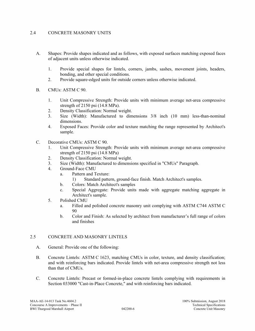
MAA-AE-14-013 Task No.4604.2
042200-6
100% Submission, August 2018Concourse A Improvements – Phase II Technical SpecificationsBWI Thurgood Marshall Airport Concrete Unit Masonry
2.4 CONCRETE MASONRY UNITS
A. Shapes: Provide shapes indicated and as follows, with exposed surfaces matching exposed faces of adjacent units unless otherwise indicated.
1. Provide special shapes for lintels, corners, jambs, sashes, movement joints, headers, bonding, and other special conditions.
2. Provide square-edged units for outside corners unless otherwise indicated.
B. CMUs: ASTM C 90.
1. Unit Compressive Strength: Provide units with minimum average net-area compressive strength of 2150 psi (14.8 MPa).
2. Density Classification: Normal weight. 3. Size (Width): Manufactured to dimensions 3/8 inch (10 mm) less-than-nominal
dimensions. 4. Exposed Faces: Provide color and texture matching the range represented by Architect's
sample.
C. Decorative CMUs: ASTM C 90. 1. Unit Compressive Strength: Provide units with minimum average net-area compressive
strength of 2150 psi (14.8 MPa) 2. Density Classification: Normal weight. 3. Size (Width): Manufactured to dimensions specified in "CMUs" Paragraph. 4. Ground-Face CMU
a. Pattern and Texture: 1) Standard pattern, ground-face finish. Match Architect's samples.
b. Colors: Match Architect's samples c. Special Aggregate: Provide units made with aggregate matching aggregate in
Architect's sample. 5. Polished CMU
a. Filled and polished concrete masonry unit complying with ASTM C744 ASTM C 90
b. Color and Finish: As selected by architect from manufacturer’s full range of colors and finishes
2.5 CONCRETE AND MASONRY LINTELS
A. General: Provide one of the following:
B. Concrete Lintels: ASTM C 1623, matching CMUs in color, texture, and density classification; and with reinforcing bars indicated. Provide lintels with net-area compressive strength not less than that of CMUs.
C. Concrete Lintels: Precast or formed-in-place concrete lintels complying with requirements in Section 033000 "Cast-in-Place Concrete," and with reinforcing bars indicated.
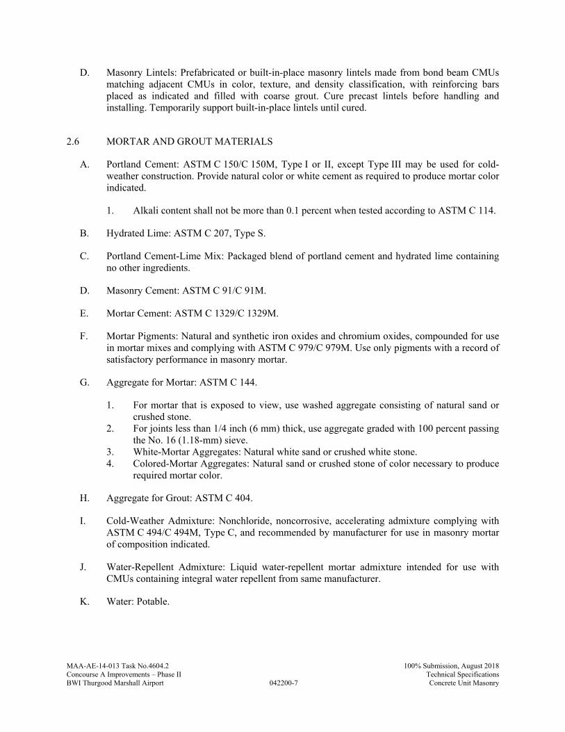
MAA-AE-14-013 Task No.4604.2
042200-7
100% Submission, August 2018Concourse A Improvements – Phase II Technical SpecificationsBWI Thurgood Marshall Airport Concrete Unit Masonry
D. Masonry Lintels: Prefabricated or built-in-place masonry lintels made from bond beam CMUs matching adjacent CMUs in color, texture, and density classification, with reinforcing bars placed as indicated and filled with coarse grout. Cure precast lintels before handling and installing. Temporarily support built-in-place lintels until cured.
2.6 MORTAR AND GROUT MATERIALS
A. Portland Cement: ASTM C 150/C 150M, Type I or II, except Type III may be used for cold-weather construction. Provide natural color or white cement as required to produce mortar color indicated.
1. Alkali content shall not be more than 0.1 percent when tested according to ASTM C 114.
B. Hydrated Lime: ASTM C 207, Type S.
C. Portland Cement-Lime Mix: Packaged blend of portland cement and hydrated lime containing no other ingredients.
D. Masonry Cement: ASTM C 91/C 91M.
E. Mortar Cement: ASTM C 1329/C 1329M.
F. Mortar Pigments: Natural and synthetic iron oxides and chromium oxides, compounded for use in mortar mixes and complying with ASTM C 979/C 979M. Use only pigments with a record of satisfactory performance in masonry mortar.
G. Aggregate for Mortar: ASTM C 144.
1. For mortar that is exposed to view, use washed aggregate consisting of natural sand or crushed stone.
2. For joints less than 1/4 inch (6 mm) thick, use aggregate graded with 100 percent passing the No. 16 (1.18-mm) sieve.
3. White-Mortar Aggregates: Natural white sand or crushed white stone. 4. Colored-Mortar Aggregates: Natural sand or crushed stone of color necessary to produce
required mortar color.
H. Aggregate for Grout: ASTM C 404.
I. Cold-Weather Admixture: Nonchloride, noncorrosive, accelerating admixture complying with ASTM C 494/C 494M, Type C, and recommended by manufacturer for use in masonry mortar of composition indicated.
J. Water-Repellent Admixture: Liquid water-repellent mortar admixture intended for use with CMUs containing integral water repellent from same manufacturer.
K. Water: Potable.
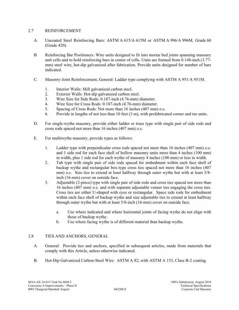
MAA-AE-14-013 Task No.4604.2
042200-8
100% Submission, August 2018Concourse A Improvements – Phase II Technical SpecificationsBWI Thurgood Marshall Airport Concrete Unit Masonry
2.7 REINFORCEMENT
A. Uncoated Steel Reinforcing Bars: ASTM A 615/A 615M or ASTM A 996/A 996M, Grade 60 (Grade 420).
B. Reinforcing Bar Positioners: Wire units designed to fit into mortar bed joints spanning masonry unit cells and to hold reinforcing bars in center of cells. Units are formed from 0.148-inch (3.77-mm) steel wire, hot-dip galvanized after fabrication. Provide units designed for number of bars indicated.
C. Masonry-Joint Reinforcement, General: Ladder type complying with ASTM A 951/A 951M.
1. Interior Walls: Mill galvanized carbon steel. 2. Exterior Walls: Hot-dip galvanized carbon steel. 3. Wire Size for Side Rods: 0.187-inch (4.76-mm) diameter. 4. Wire Size for Cross Rods: 0.187-inch (4.76-mm) diameter. 5. Spacing of Cross Rods: Not more than 16 inches (407 mm) o.c. 6. Provide in lengths of not less than 10 feet (3 m), with prefabricated corner and tee units.
D. For single-wythe masonry, provide either ladder or truss type with single pair of side rods and cross rods spaced not more than 16 inches (407 mm) o.c.
E. For multiwythe masonry, provide types as follows:
1. Ladder type with perpendicular cross rods spaced not more than 16 inches (407 mm) o.c. and 1 side rod for each face shell of hollow masonry units more than 4 inches (100 mm) in width, plus 1 side rod for each wythe of masonry 4 inches (100 mm) or less in width.
2. Tab type with single pair of side rods spaced for embedment within each face shell of backup wythe and rectangular box-type cross ties spaced not more than 16 inches (407 mm) o.c. Size ties to extend at least halfway through outer wythe but with at least 5/8-inch (16-mm) cover on outside face.
3. Adjustable (2-piece) type with single pair of side rods and cross ties spaced not more than 16 inches (407 mm) o.c. and with separate adjustable veneer ties engaging the cross ties. Cross ties are either U-shaped with eyes or rectangular. Space side rods for embedment within each face shell of backup wythe and size adjustable ties to extend at least halfway through outer wythe but with at least 5/8-inch (16-mm) cover on outside face.
a. Use where indicated and where horizontal joints of facing wythe do not align with those of backup wythe.
b. Use where facing wythe is of different material than backup wythe.
2.8 TIES AND ANCHORS, GENERAL
A. General: Provide ties and anchors, specified in subsequent articles, made from materials that comply with this Article, unless otherwise indicated.
B. Hot-Dip Galvanized Carbon-Steel Wire: ASTM A 82; with ASTM A 153, Class B-2 coating.
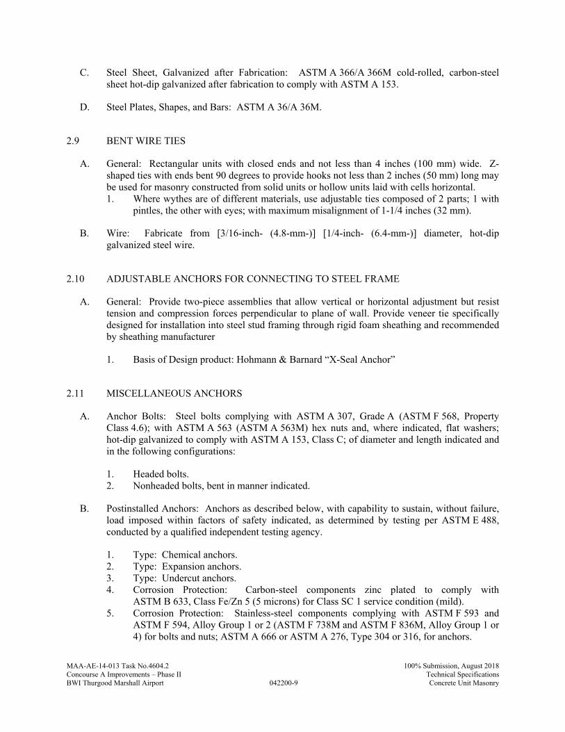
MAA-AE-14-013 Task No.4604.2
042200-9
100% Submission, August 2018Concourse A Improvements – Phase II Technical SpecificationsBWI Thurgood Marshall Airport Concrete Unit Masonry
C. Steel Sheet, Galvanized after Fabrication: ASTM A 366/A 366M cold-rolled, carbon-steel sheet hot-dip galvanized after fabrication to comply with ASTM A 153.
D. Steel Plates, Shapes, and Bars: ASTM A 36/A 36M.
2.9 BENT WIRE TIES
A. General: Rectangular units with closed ends and not less than 4 inches (100 mm) wide. Z-shaped ties with ends bent 90 degrees to provide hooks not less than 2 inches (50 mm) long may be used for masonry constructed from solid units or hollow units laid with cells horizontal. 1. Where wythes are of different materials, use adjustable ties composed of 2 parts; 1 with
pintles, the other with eyes; with maximum misalignment of 1-1/4 inches (32 mm).
B. Wire: Fabricate from [3/16-inch- (4.8-mm-)] [1/4-inch- (6.4-mm-)] diameter, hot-dip galvanized steel wire.
2.10 ADJUSTABLE ANCHORS FOR CONNECTING TO STEEL FRAME
A. General: Provide two-piece assemblies that allow vertical or horizontal adjustment but resist tension and compression forces perpendicular to plane of wall. Provide veneer tie specifically designed for installation into steel stud framing through rigid foam sheathing and recommended by sheathing manufacturer
1. Basis of Design product: Hohmann & Barnard “X-Seal Anchor”
2.11 MISCELLANEOUS ANCHORS
A. Anchor Bolts: Steel bolts complying with ASTM A 307, Grade A (ASTM F 568, Property Class 4.6); with ASTM A 563 (ASTM A 563M) hex nuts and, where indicated, flat washers; hot-dip galvanized to comply with ASTM A 153, Class C; of diameter and length indicated and in the following configurations:
1. Headed bolts. 2. Nonheaded bolts, bent in manner indicated.
B. Postinstalled Anchors: Anchors as described below, with capability to sustain, without failure, load imposed within factors of safety indicated, as determined by testing per ASTM E 488, conducted by a qualified independent testing agency.
1. Type: Chemical anchors. 2. Type: Expansion anchors. 3. Type: Undercut anchors. 4. Corrosion Protection: Carbon-steel components zinc plated to comply with
ASTM B 633, Class Fe/Zn 5 (5 microns) for Class SC 1 service condition (mild). 5. Corrosion Protection: Stainless-steel components complying with ASTM F 593 and
ASTM F 594, Alloy Group 1 or 2 (ASTM F 738M and ASTM F 836M, Alloy Group 1 or 4) for bolts and nuts; ASTM A 666 or ASTM A 276, Type 304 or 316, for anchors.
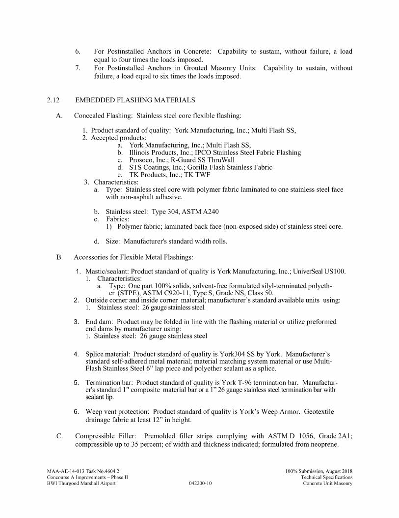
MAA-AE-14-013 Task No.4604.2
042200-10
100% Submission, August 2018Concourse A Improvements – Phase II Technical SpecificationsBWI Thurgood Marshall Airport Concrete Unit Masonry
6. For Postinstalled Anchors in Concrete: Capability to sustain, without failure, a load equal to four times the loads imposed.
7. For Postinstalled Anchors in Grouted Masonry Units: Capability to sustain, without failure, a load equal to six times the loads imposed.
2.12 EMBEDDED FLASHING MATERIALS
A. Concealed Flashing: Stainless steel core flexible flashing: 1. Product standard of quality: York Manufacturing, Inc.; Multi Flash SS, 2. Accepted products:
a. York Manufacturing, Inc.; Multi Flash SS, b. Illinois Products, Inc.; IPCO Stainless Steel Fabric Flashing c. Prosoco, Inc.; R-Guard SS ThruWall d. STS Coatings, Inc.; Gorilla Flash Stainless Fabric e. TK Products, Inc.; TK TWF
3. Characteristics: a. Type: Stainless steel core with polymer fabric laminated to one stainless steel face
with non-asphalt adhesive. b. Stainless steel: Type 304, ASTM A240 c. Fabrics:
1) Polymer fabric; laminated back face (non-exposed side) of stainless steel core.
d. Size: Manufacturer's standard width rolls.
B. Accessories for Flexible Metal Flashings:
1. Mastic/sealant: Product standard of quality is York Manufacturing, Inc.; UniverSeal US100. 1. Characteristics:
a. Type: One part 100% solids, solvent-free formulated silyl-terminated polyeth-er (STPE), ASTM C920-11, Type S, Grade NS, Class 50.
2. Outside corner and inside corner material; manufacturer’s standard available units using: 1. Stainless steel: 26 gauge stainless steel.
3. End dam: Product may be folded in line with the flashing material or utilize preformed
end dams by manufacturer using: 1. Stainless steel: 26 gauge stainless steel
4. Splice material: Product standard of quality is York304 SS by York. Manufacturer’s standard self-adhered metal material; material matching system material or use Multi-Flash Stainless Steel 6” lap piece and polyether sealant as a splice.
5. Termination bar: Product standard of quality is York T-96 termination bar. Manufactur-
er's standard 1" composite material bar or a 1” 26 gauge stainless steel termination bar with sealant lip.
6. Weep vent protection: Product standard of quality is York’s Weep Armor. Geotextile
drainage fabric at least 12” in height.
C. Compressible Filler: Premolded filler strips complying with ASTM D 1056, Grade 2A1; compressible up to 35 percent; of width and thickness indicated; formulated from neoprene.

MAA-AE-14-013 Task No.4604.2
042200-11
100% Submission, August 2018Concourse A Improvements – Phase II Technical SpecificationsBWI Thurgood Marshall Airport Concrete Unit Masonry
D. Preformed Control-Joint Gaskets: Material as indicated below, designed to fit standard sash block and to maintain lateral stability in masonry wall; size and configuration as indicated.
1. Styrene-Butadiene-Rubber Compound: ASTM D 2000, Designation M2AA-805.
E. Bond-Breaker Strips: Asphalt-saturated, organic roofing felt complying with ASTM D 226, Type I (No. 15 asphalt felt).
F. Plastic Weep Hole/Vent: One-piece, flexible extrusion made from UV-resistant polypropylene copolymer, designed to fill head joint with outside face held back 1/8 inch (3 mm) from exterior face of masonry, in color selected from manufacturer's standard.
G. Reinforcing Bar Positioners: Wire units designed to fit into mortar bed joints spanning masonry unit cells with loops for holding reinforcing bars in center of cells. Units are formed from 0.142-inch (3.6-mm) steel wire, hot-dip galvanized after fabrication.
1. Provide units with either two loops or four loops as needed for number of bars indicated.
H. Products: Subject to compliance with requirements, provide one of the following:
1. Plastic Weep Hole/Vent:
a. Cell Vent; Dur-O-Wal, Inc.
2. Reinforcing Bar Positioners:
a. D/A 811; Dur-O-Wal, Inc. b. D/A 816; Dur-O-Wal, Inc. c. No. 376 Rebar Positioner; Heckman Building Products, Inc. d. #RB Rebar Positioner; Hohmann & Barnard, Inc. e. #RB-Twin Rebar Positioner; Hohmann & Barnard, Inc. f. Double O-Ring Rebar Positioner; Masonry Reinforcing Corporation of America. g. O-Ring Rebar Positioner; Masonry Reinforcing Corporation of America.
2.13 MISCELLANEOUS MASONRY ACCESSORIES
A. Compressible Filler: Premolded filler strips complying with ASTM D 1056, Grade 2A1; compressible up to 35 percent; of width and thickness indicated; formulated from neoprene.
B. Preformed Control-Joint Gaskets: Made from styrene-butadiene-rubber compound, complying with ASTM D 2000, Designation M2AA-805 and designed to fit standard sash block and to maintain lateral stability in masonry wall; size and configuration as indicated.
C. Bond-Breaker Strips: Asphalt-saturated felt complying with ASTM D 226/D 226M, Type I (No. 15 asphalt felt).
2.14 MASONRY CLEANERS
MAA-AE-14-013 Task No.4604.2
042200-12
100% Submission, August 2018Concourse A Improvements – Phase II Technical SpecificationsBWI Thurgood Marshall Airport Concrete Unit Masonry
A. Job-Mixed Detergent Solution: Solution of 1/2-cup (0.14-L) dry measure tetrasodium polyphosphate and 1/2-cup (0.14-L) dry measure laundry detergent dissolved in 1 gal. (4 L) of water.
2.15 MORTAR AND GROUT MIXES
A. General: Do not use admixtures, including pigments, air-entraining agents, accelerators, retarders, water-repellent agents, antifreeze compounds, or other admixtures, unless otherwise indicated.
1. Do not use calcium chloride in mortar or grout.
B. Preblended, Dry Mortar Mix: Furnish dry mortar ingredients in the form of a preblended mix. Measure quantities by weight to ensure accurate proportions, and thoroughly blend ingredients before delivering to Project site.
C. Mortar for Unit Masonry: Comply with ASTM C 270, Proportion Specification.
1. Extended-Life Mortar for Unit Masonry: Mortar complying with ASTM C 1142 may be used instead of mortar specified above, at Contractor's option.
2. Limit cementitious materials in mortar to portland cement and lime. 3. Limit cementitious materials in mortar for exterior and reinforced masonry to portland
cement and lime. 4. For reinforced masonry and where indicated, use Type S. 5. For interior non-load-bearing partitions; and for other applications where another type is
not indicated, use Type N. 6. For interior non-load-bearing partitions, Type O may be used instead of Type N.
D. Pigmented Mortar: Select and proportion pigments with other ingredients to produce color required. Limit pigments to the following percentages of cement content by weight:
1. For mineral-oxide pigments and portland cement-lime mortar, not more than 10 percent. 2. For carbon-black pigment and portland cement-lime mortar, not more than 2 percent.
E. Colored-Aggregate Mortar: Produce required mortar color by using colored aggregates combined with selected cementitious materials.
1. Mix to match Architect's sample.
F. Grout for Unit Masonry: Comply with ASTM C 476.
1. Use grout of type indicated or, if not otherwise indicated, of type (fine or coarse) that will comply with Table 5 of ACI 530.1/ASCE 6/TMS 602 for dimensions of grout spaces and pour height.
2. Provide grout with a slump of 8 to 11 inches (200 to 280 mm) as measured according to ASTM C 143.
MAA-AE-14-013 Task No.4604.2
042200-13
100% Submission, August 2018Concourse A Improvements – Phase II Technical SpecificationsBWI Thurgood Marshall Airport Concrete Unit Masonry
PART 3 - EXECUTION
3.1 EXAMINATION
A. Examine conditions, with Installer present, for compliance with requirements for installation tolerances and other conditions affecting performance of the Work.
1. For the record, prepare written report, endorsed by Installer, listing conditions detrimental to performance of the Work.
2. Verify that foundations are within tolerances specified. 3. Verify that reinforcing dowels are properly placed. 4. Verify that substrates are free of substances that would impair mortar bond.
B. Before installation, examine rough-in and built-in construction for piping systems to verify actual locations of piping.
C. Proceed with installation only after unsatisfactory conditions have been corrected.
3.2 INSTALLATION, GENERAL
A. Build chases and recesses to accommodate items specified in this and other Sections.
B. Leave openings for equipment to be installed before completing masonry. After installing equipment, complete masonry to match construction immediately adjacent to opening.
C. Use full-size units without cutting if possible. If cutting is required to provide a continuous pattern or to fit adjoining construction, cut units with motor-driven saws; provide clean, sharp, unchipped edges. Allow units to dry before laying unless wetting of units is specified. Install cut units with cut surfaces and, where possible, cut edges concealed.
D. Cut masonry units with motor-driven saws to provide clean, sharp, unchipped edges. Cut units as required to provide a continuous pattern and to fit adjoining construction. Where possible, use full-size units without cutting. Allow units cut with water-cooled saws to dry before placing, unless wetting of units is specified. Install cut units with cut surfaces and, where possible, cut edges concealed.
E. Select and arrange units for exposed unit masonry to produce a uniform blend of colors and textures.
1. Mix units from several pallets or cubes as they are placed.
3.3 TOLERANCES
A. Comply with tolerances in ACI 530.1/ASCE 6/TMS 602 and the following:
B. For conspicuous vertical lines, such as external corners, door jambs, reveals, and expansion and control joints, do not vary from plumb by more than 1/4 inch in 20 feet (6 mm in 6 m), nor 1/2 inch (12 mm) maximum.
MAA-AE-14-013 Task No.4604.2
042200-14
100% Submission, August 2018Concourse A Improvements – Phase II Technical SpecificationsBWI Thurgood Marshall Airport Concrete Unit Masonry
C. For vertical alignment of exposed head joints, do not vary from plumb by more than 1/4 inch in 10 feet (6 mm in 3 m), nor 1/2 inch (12 mm) maximum.
D. For conspicuous horizontal lines, such as exposed lintels, sills, parapets, and reveals, do not vary from level by more than 1/4 inch in 20 feet (6 mm in 6 m), nor 1/2 inch (12 mm) maximum.
E. For exposed bed joints, do not vary from thickness indicated by more than plus or minus 1/8 inch (3 mm), with a maximum thickness limited to 1/2 inch (12 mm). Do not vary from bed-joint thickness of adjacent courses by more than 1/8 inch (3 mm).
F. For exposed head joints, do not vary from thickness indicated by more than plus or minus 1/8 inch (3 mm). Do not vary from adjacent bed-joint and head-joint thicknesses by more than 1/8 inch (3 mm).
3.4 LAYING MASONRY WALLS
A. Lay out walls in advance for accurate spacing of surface bond patterns with uniform joint thicknesses and for accurate location of openings, movement-type joints, returns, and offsets. Avoid using less-than-half-size units, particularly at corners, jambs, and, where possible, at other locations.
B. Bond Pattern for Exposed Masonry: Unless otherwise indicated, lay exposed masonry in running bond; do not use units with less-than-nominal 4-inch (100-mm) horizontal face dimensions at corners or jambs.
C. Stopping and Resuming Work: Stop work by stepping back units in each course from those in course below; do not tooth. When resuming work, clean masonry surfaces that are to receive mortar, remove loose masonry units and mortar, and wet brick if required before laying fresh masonry.
D. Built-in Work: As construction progresses, build in items specified in this and other Sections. Fill in solidly with masonry around built-in items.
E. Fill space between steel frames and masonry solidly with mortar unless otherwise indicated.
F. Where built-in items are to be embedded in cores of hollow masonry units, place a layer of metal lath, wire mesh, or plastic mesh in the joint below, and rod mortar or grout into core.
G. Fill cores in hollow CMUs with grout 24 inches (600 mm) under bearing plates, beams, lintels, posts, and similar items unless otherwise indicated.
H. Build nonload-bearing interior partitions full height of story to underside of solid floor or roof structure above unless otherwise indicated.
1. Install compressible filler in joint between top of partition and underside of structure above.
2. Fasten partition top anchors to structure above and build into top of partition. Grout cells of CMUs solidly around plastic tubes of anchors and push tubes down into grout to

MAA-AE-14-013 Task No.4604.2
042200-15
100% Submission, August 2018Concourse A Improvements – Phase II Technical SpecificationsBWI Thurgood Marshall Airport Concrete Unit Masonry
provide 1/2-inch (13-mm) clearance between end of anchor rod and end of tube. Space anchors 48 inches (1200 mm)o.c. unless otherwise indicated.
3. Wedge nonload-bearing partitions against structure above with small pieces of tile, slate, or metal. Fill joint with mortar after dead-load deflection of structure above approaches final position.
4. At fire-rated partitions, treat joint between top of partition and underside of structure above to comply with Section 078443 "Joint Firestopping."
3.5 MORTAR BEDDING AND JOINTING
A. Lay hollow CMUs as follows:
1. Bed face shells in mortar and make head joints of depth equal to bed joints. 2. Bed webs in mortar in all courses of piers, columns, and pilasters. 3. Bed webs in mortar in grouted masonry, including starting course on footings. 4. Fully bed entire units, including areas under cells, at starting course on footings where
cells are not grouted.
B. Lay solid CMUs with completely filled bed and head joints; butter ends with sufficient mortar to fill head joints and shove into place. Do not deeply furrow bed joints or slush head joints.
C. Set cast-stone trim units in full bed of mortar with full vertical joints. Fill dowel, anchor, and similar holes.
1. Clean soiled surfaces with fiber brush and soap powder and rinse thoroughly with clear water.
2. Wet joint surfaces thoroughly before applying mortar. 3. Rake out mortar joints for pointing with sealant.
D. Rake out mortar joints at pre-faced CMUs to a uniform depth of 1/4 inch (6 mm) and point with epoxy mortar to comply with epoxy-mortar manufacturer's written instructions.
E. Tool exposed joints slightly concave when thumbprint hard, using a jointer larger than joint thickness unless otherwise indicated.
F. Cut joints flush for masonry walls to receive plaster or other direct-applied finishes (other than paint) unless otherwise indicated.
G. Cut joints flush where indicated to receive waterproofing unless otherwise indicated.
3.6 BONDING OF MULTIWYTHE MASONRY
A. Use individual metal ties installed in horizontal joints to bond wythes together. Provide ties as shown, but not less than one metal tie for 2.67 sq. ft. (0.25 sq. m) of wall area spaced not to exceed 24 inches (610) o.c. horizontally and 16 inches (406 mm) o.c. vertically. Stagger ties in alternate courses. Provide additional ties within 12 inches (305 mm) of openings and space not more than 36 inches (915 mm) apart around perimeter of openings. At intersecting and abutting walls, provide ties at no more than 24 inches (610 mm) o.c. vertically.

MAA-AE-14-013 Task No.4604.2
042200-16
100% Submission, August 2018Concourse A Improvements – Phase II Technical SpecificationsBWI Thurgood Marshall Airport Concrete Unit Masonry
B. Use masonry joint reinforcement installed in horizontal mortar joints to bond wythes together.
C. Use either bonding system specified above.
D. Use bonding system indicated on Drawings.
E. Corners: Provide interlocking masonry unit bond in each wythe and course at corners, unless otherwise indicated.
1. Provide continuity with masonry joint reinforcement at corners by using prefabricated "L" units as well as masonry bonding.
F. Intersecting and Abutting Walls: Unless vertical expansion or control joints are shown at juncture, bond walls together as follows:
1. Provide individual metal ties not more than 16 inches (406 mm) o.c. 2. Provide continuity with masonry joint reinforcement by using prefabricated "T" units. 3. Provide rigid metal anchors not more than 24 inches (610 mm) o.c. If used with hollow
masonry units, embed ends in mortar-filled cores.
3.7 CAVITIES
A. Keep cavities clean of mortar droppings and other materials during construction. Strike joints facing cavities flush.
1. Use wood strips temporarily placed in cavity to collect mortar droppings. As work progresses, remove strips, clean off mortar droppings, and replace in cavity.
B. Coat cavity face of backup wythe to comply with Section 072726 - “Fluid-Applied Membrane Weather Barriers”
C. Installing Cavity-Wall Insulation: Place small dabs of adhesive, spaced approximately 12 inches (300 mm) o.c. both ways, on inside face of insulation boards, or attach with plastic fasteners designed for this purpose. Fit courses of insulation between wall ties and other confining obstructions in cavity, with edges butted tightly both ways. Press units firmly against inside wythe of masonry or other construction as shown.
1. Fill cracks and open gaps in insulation with crack sealer compatible with insulation and masonry.
3.8 MASONRY-JOINT REINFORCEMENT
A. General: Install entire length of longitudinal side rods in mortar with a minimum cover of 5/8 inch (16 mm) on exterior side of walls, 1/2 inch (13 mm) elsewhere. Lap reinforcement a minimum of 6 inches (150 mm).
1. Space reinforcement not more than 16 inches (406 mm) o.c. 2. Space reinforcement not more than 8 inches (203 mm) o.c. in foundation walls and
parapet walls.
MAA-AE-14-013 Task No.4604.2
042200-17
100% Submission, August 2018Concourse A Improvements – Phase II Technical SpecificationsBWI Thurgood Marshall Airport Concrete Unit Masonry
3. Provide reinforcement not more than 8 inches (203 mm) above and below wall openings and extending 12 inches (305 mm) beyond openings in addition to continuous reinforcement.
B. Interrupt joint reinforcement at control and expansion joints unless otherwise indicated.
C. Provide continuity at wall intersections by using prefabricated T-shaped units.
D. Provide continuity at corners by using prefabricated L-shaped units.
E. Cut and bend reinforcing units as directed by manufacturer for continuity at corners, returns, offsets, column fireproofing, pipe enclosures, and other special conditions.
3.9 ANCHORING MASONRY TO STRUCTURAL STEEL AND CONCRETE
A. Anchor masonry to structural steel and concrete, where masonry abuts or faces structural steel or concrete, to comply with the following:
1. Provide an open space not less than 1 inch (25 mm) wide between masonry and structural steel or concrete unless otherwise indicated. Keep open space free of mortar and other rigid materials.
2. Anchor masonry with anchors embedded in masonry joints and attached to structure. 3. Space anchors as indicated, but not more than 24 inches (610 mm) o.c. vertically and 36
inches (915 mm) o.c. horizontally.
3.10 ANCHORING MASONRY VENEERS
A. Anchor masonry veneers masonry backup with masonry-veneer anchors to comply with the following requirements:
1. Fasten each anchor to masonry backup with two metal fasteners of type indicated. 2. Embed tie sections in masonry joints. Provide not less than 2 inches (50 mm) of air space
between back of masonry veneer and face of sheathing or insulation. 3. Locate anchor sections to allow maximum vertical differential movement of ties up and
down. 4. Space anchors as indicated, but not more than 18 inches (458 mm) o.c. vertically and 24
inches (610 mm) o.c. horizontally, with not less than 1 anchor for each 2 sq. ft. (0.2 sq. m) of wall area. Install additional anchors within 12 inches (305 mm) of openings and at intervals, not exceeding 8 inches (203 mm), around the perimeter.
5. Space anchors as indicated, but not more than 16 inches (406 mm) o.c. vertically and 24 inches (610) o.c. horizontally with not less than 1 anchor for each 2.67 sq. ft. (0.25 sq. m) of wall area. Install additional anchors within 12 inches (305 mm) of openings and at intervals, not exceeding 36 inches (914 mm), around perimeter
MAA-AE-14-013 Task No.4604.2
042200-18
100% Submission, August 2018Concourse A Improvements – Phase II Technical SpecificationsBWI Thurgood Marshall Airport Concrete Unit Masonry
3.11 CONTROL AND EXPANSION JOINTS
A. General: Install control- and expansion-joint materials in unit masonry as masonry progresses. Do not allow materials to span control and expansion joints without provision to allow for in-plane wall or partition movement.
B. Form control joints in concrete masonry using one of the following methods:
1. Fit bond-breaker strips into hollow contour in ends of CMUs on one side of control joint. Fill resultant core with grout, and rake out joints in exposed faces for application of sealant.
2. Install preformed control-joint gaskets designed to fit standard sash block. 3. Install interlocking units designed for control joints. Install bond-breaker strips at joint.
Keep head joints free and clear of mortar, or rake out joint for application of sealant. 4. Install temporary foam-plastic filler in head joints, and remove filler when unit masonry
is complete for application of sealant.
3.12 LINTELS
A. Provide concrete or masonry lintels where shown and where openings of more than 12 inches (305 mm) for brick-size units and 24 inches (610 mm) for block-size units are shown without structural steel or other supporting lintels.
B. Provide minimum bearing of 8 inches (200 mm) at each jamb unless otherwise indicated.
3.13 FLASHING
A. General: Install embedded flashing at ledges and other obstructions to downward flow of water in wall where indicated.
B. Install flashing as follows unless otherwise indicated:
1. Prepare masonry surfaces so they are smooth and free from projections that could puncture flashing. Where flashing is within mortar joint, place through-wall flashing on sloping bed of mortar and cover with mortar. Before covering with mortar, seal penetrations in flashing with adhesive, sealant, or tape as recommended by flashing manufacturer.
2. At lintels, extend flashing a minimum of 6 inches (150 mm) into masonry at each end. At heads and sills, extend flashing 6 inches (150 mm) at ends and turn up not less than 2 inches (50 mm) to form end dams.
3. Interlock end joints of ribbed sheet metal flashing by overlapping ribs not less than 1-1/2 inches (38 mm) or as recommended by flashing manufacturer, and seal lap with elastomeric sealant complying with requirements in Section 079200 "Joint Sealants" for application indicated.
4. Install metal drip edges beneath flexible flashing at exterior face of wall. Stop flexible flashing 1/2 inch (13 mm) back from outside face of wall, and adhere flexible flashing to top of metal drip edge.
MAA-AE-14-013 Task No.4604.2
042200-19
100% Submission, August 2018Concourse A Improvements – Phase II Technical SpecificationsBWI Thurgood Marshall Airport Concrete Unit Masonry
5. Install metal flashing termination beneath flexible flashing at exterior face of wall. Stop flexible flashing 1/2 inch (13 mm) back from outside face of wall, and adhere flexible flashing to top of metal flashing termination.
6. Cut flexible flashing off flush with face of wall after masonry wall construction is completed.
C. Install single-wythe CMU flashing system in bed joints of CMU walls where indicated to comply with manufacturer's written instructions. Install CMU cell pans with upturned edges located below face shells and webs of CMUs above and with weep spouts aligned with face of wall. Install CMU web covers so that they cover upturned edges of CMU cell pans at CMU webs and extend from face shell to face shell.
D. Install reglets and nailers for flashing and other related construction where they are shown to be built into masonry.
3.14 REINFORCED UNIT MASONRY INSTALLATION
A. Temporary Formwork and Shores: Construct formwork and shores as needed to support reinforced masonry elements during construction.
1. Construct formwork to provide shape, line, and dimensions of completed masonry as indicated. Make forms sufficiently tight to prevent leakage of mortar and grout. Brace, tie, and support forms to maintain position and shape during construction and curing of reinforced masonry.
2. Do not remove forms and shores until reinforced masonry members have hardened sufficiently to carry their own weight and other loads that may be placed on them during construction.
B. Placing Reinforcement: Comply with requirements in TMS 602/ACI 530.1/ASCE 6.
C. Grouting: Do not place grout until entire height of masonry to be grouted has attained enough strength to resist grout pressure.
1. Comply with requirements in TMS 602/ACI 530.1/ASCE 6 for cleanouts and for grout placement, including minimum grout space and maximum pour height.
2. Limit height of vertical grout pours to not more than 60 inches (1520 mm).
3.15 FIELD QUALITY CONTROL
A. Testing and Inspecting: Owner will engage special inspectors to perform tests and inspections and prepare reports. Allow inspectors access to scaffolding and work areas as needed to perform tests and inspections. Retesting of materials that fail to comply with specified requirements shall be done at Contractor's expense.
B. Testing Frequency: One set of tests for each 5000 sq. ft. (464 sq. m) of wall area or portion thereof.
MAA-AE-14-013 Task No.4604.2
042200-20
100% Submission, August 2018Concourse A Improvements – Phase II Technical SpecificationsBWI Thurgood Marshall Airport Concrete Unit Masonry
C. Concrete Masonry Unit Test: For each type of unit provided, according to ASTM C 140 for compressive strength.
D. Grout Test (Compressive Strength): For each mix provided, according to ASTM C 1019.
E. Prism Test: For each type of construction provided, according to ASTM C 1314 at 7 days and at 28 days.
3.16 REPAIRING, POINTING, AND CLEANING
A. Remove and replace masonry units that are loose, chipped, broken, stained, or otherwise damaged or that do not match adjoining units. Install new units to match adjoining units; install in fresh mortar, pointed to eliminate evidence of replacement.
B. Pointing: During the tooling of joints, enlarge voids and holes, except weep holes, and completely fill with mortar. Point up joints, including corners, openings, and adjacent construction, to provide a neat, uniform appearance. Prepare joints for sealant application, where indicated.
C. In-Progress Cleaning: Clean unit masonry as work progresses by dry brushing to remove mortar fins and smears before tooling joints.
D. Final Cleaning: After mortar is thoroughly set and cured, clean exposed masonry as follows:
1. Remove large mortar particles by hand with wooden paddles and nonmetallic scrape hoes or chisels.
2. Test cleaning methods on sample wall panel; leave one-half of panel uncleaned for comparison purposes. Obtain Architect's approval of sample cleaning before proceeding with cleaning of masonry.
3. Protect adjacent stone and nonmasonry surfaces from contact with cleaner by covering them with liquid strippable masking agent or polyethylene film and waterproof masking tape.
4. Wet wall surfaces with water before applying cleaners; remove cleaners promptly by rinsing surfaces thoroughly with clear water.
5. Clean concrete masonry by applicable cleaning methods indicated in NCMA TEK 8-4A.
3.17 MASONRY WASTE DISPOSAL
A. Salvageable Materials: Unless otherwise indicated, excess masonry materials are Contractor's property. At completion of unit masonry work, remove from Project site.
B. Waste Disposal as Fill Material: Dispose of clean masonry waste, including excess or soil-contaminated sand, waste mortar, and broken masonry units, by crushing and mixing with fill material as fill is placed.
1. Crush masonry waste to less than 4 inches (100 mm) in each dimension. 2. Mix masonry waste with at least two parts of specified fill material for each part of
masonry waste. Fill material is specified in Section 312000 "Earth Moving."
MAA-AE-14-013 Task No.4604.2
042200-21
100% Submission, August 2018Concourse A Improvements – Phase II Technical SpecificationsBWI Thurgood Marshall Airport Concrete Unit Masonry
3. Do not dispose of masonry waste as fill within 18 inches (450 mm) of finished grade.
C. Masonry Waste Recycling: Return broken CMUs not used as fill to manufacturer for recycling.
D. Excess Masonry Waste: Remove excess clean masonry waste that cannot be used as fill, as described above or recycled, and other masonry waste, and legally dispose of off Owner's property.
PART 4 - MEASUREMENT
4.1 METHODS OF MEASUREMENT
A. No separate measurement shall be made for work under this Specification Section
PART 5 - PAYMENT
5.1 METHOD OF PAYMENT
A. No separate payment will be made for work under this Specification Section. The cost of work, complete in place, described in this Specification Section shall be included in the Lump Sum Bid under “Building Construction”
B. Costs include all labor, material, services, and equipment necessary to complete the work in every aspect.
END OF SECTION 042200
MAA-AE-14-013 Task No.4604.2
042200-22
100% Submission, August 2018Concourse A Improvements – Phase II Technical SpecificationsBWI Thurgood Marshall Airport Concrete Unit Masonry
THIS PAGE INTENTIONALLY LEFT BLANK
MAA-CO-19-001 100% Submission, April 2018Concourse A Improvements – Phase II Technical SpecificationsBWI Thurgood Marshall Airport 051200-1 STRUCTURAL STEEL FRAMING
SECTION 051200 - STRUCTURAL STEEL FRAMING
PART 1 - GENERAL
1.1 RELATED DOCUMENTS
A. Drawings and general provisions of the Contract, including Maryland Department ofTransportation/ Maryland Aviation Administration Standard Provisions to the ConstructionContract for the Concourse A Improvements – Phase II at BWI Thurgood Marshall Airport andother Divisions 1 Specification Sections, apply to this Section.
1.2 SUMMARY
A. Section Includes:1. Structural steel. Provide steel materials manufactured in the United States of America
complying with Federal Aviation Administration (FAA) 49 U.S.C. § 50101 – BuyAmerican regulations.
2. Grout.
B. Related Sections:
1. Division 01 Section "Quality Requirements" for independent testing agency proceduresand administrative requirements.
2. Division 05 Section 051250 "Architecturally Exposed Structural Steel Framing” for fitand finish requirements for steel exposed to view.
3. Division 05 Section 053100 "Steel Decking" for field installation of shear connectorsthrough deck.
4. Division 05 Section 055000 "Metal Fabrications" for steel lintels not attached tostructural-steel frame, miscellaneous steel fabrications, and other metal items not definedas structural steel.
5. Division 05 Section 055113 "Metal Pan Stairs."6. Division 05 Section 055213 “Pipe and Tube Railings” for steel railings that are not
connected to Metal Pan Stairs.7. Division 07 Sections for fireproofing requirements.8. Division 09 Sections for finish painting requirements.
1.3 DEFINITIONS
A. Structural Steel: Elements of structural-steel frame, as classified by AISC 303, "Code ofStandard Practice for Steel Buildings and Bridges."
B. Seismic-Load-Resisting System: Elements of structural-steel frame designated as "SLRS" oralong grid lines designated as "SLRS" on Drawings, including columns, beams, and braces andtheir connections.
C. Heavy Sections: Rolled and built-up sections as follows:
MAA-CO-19-001 100% Submission, April 2018Concourse A Improvements – Phase II Technical SpecificationsBWI Thurgood Marshall Airport 051200-2 STRUCTURAL STEEL FRAMING
1. Shapes included in ASTM A 6/A 6M with flanges thicker than 1-1/2 inches.2. Welded built-up members with plates thicker than 2 inches.3. Column base plates thicker than 2 inches.
1.4 PERFORMANCE REQUIREMENTS
A. Connections: Provide details of simple shear connections required by the Contract Documentsto be selected or completed by structural-steel fabricator, including comprehensive engineeringdesign by a qualified professional engineer, to withstand loads indicated and comply with otherinformation and restrictions indicated.
1. Select and complete connections using schematic details indicated and AISC 360.2. Use ASD; data are given at service-load level.
B. Moment Connections: Type FR, fully restrained.
C. Construction: Moment frame.
1.5 SUBMITTALS
A. Product Data: For each type of product indicated.
B. Shop Drawings: Show fabrication of structural-steel components.
1. Include details of cuts, connections, splices, camber, holes, and other pertinent data.2. Include embedment drawings.3. Indicate welds by standard AWS symbols, distinguishing between shop and field welds,
and show size, length, and type of each weld. Show backing bars that are to be removedand supplemental fillet welds where backing bars are to remain.
4. Indicate type, size, and length of bolts, distinguishing between shop and field bolts.Identify pretensioned and slip-critical high-strength bolted connections.
5. For structural-steel connections indicated to comply with design loads, include structuraldesign data signed and sealed by the qualified professional engineer responsible for theirpreparation.
C. Qualification Data: For qualified Installer and fabricator.
D. Welding certificates.
E. Paint Compatibility Certificates: From manufacturers of topcoats applied over shop primers,certifying that shop primers are compatible with topcoats.
F. Mill test reports for structural steel, including chemical and physical properties.
G. Product Test Reports: For the following:
1. Bolts, nuts, and washers including mechanical properties and chemical analysis.2. Direct-tension indicators.3. Tension-control, high-strength bolt-nut-washer assemblies.4. Shear stud connectors.
MAA-CO-19-001 100% Submission, April 2018Concourse A Improvements – Phase II Technical SpecificationsBWI Thurgood Marshall Airport 051200-3 STRUCTURAL STEEL FRAMING
5. Shop primers.6. Nonshrink grout.
H. Source quality-control reports.
1.6 QUALITY ASSURANCE
A. Fabricator Qualifications: A qualified fabricator that participates in the AISC QualityCertification Program and is designated an AISC-Certified Plant, Category STD.
B. Installer Qualifications: A qualified installer who participates in the AISC Quality CertificationProgram and is designated an AISC-Certified Erector, Category CSE.
C. Shop-Painting Applicators: Qualified according to SSPC-QP 3, "Standard Procedure forEvaluating Qualifications of Shop Painting Applicators."
D. Welding Qualifications: Qualify procedures and personnel according to AWS D1.1/D1.1M,"Structural Welding Code - Steel."
E. Comply with applicable provisions of the following specifications and documents:
1. AISC 303.2. AISC 360.3. RCSC's "Specification for Structural Joints Using ASTM A 325 or A 490 Bolts."
F. Preinstallation Conference: Conduct conference at Project site.
1.7 DELIVERY, STORAGE, AND HANDLING
A. Store materials to permit easy access for inspection and identification. Keep steel members offground and spaced by using pallets, dunnage, or other supports and spacers. Protect steelmembers and packaged materials from corrosion and deterioration.
1. Do not store materials on structure in a manner that might cause distortion, damage, oroverload to members or supporting structures. Repair or replace damaged materials orstructures as directed.
B. Store fasteners in a protected place in sealed containers with manufacturer's labels intact.
1. Fasteners may be repackaged provided Owner's testing and inspecting agency observesrepackaging and seals containers.
2. Clean and relubricate bolts and nuts that become dry or rusty before use.3. Comply with manufacturers' written recommendations for cleaning and lubricating
ASTM F 1852 fasteners and for retesting fasteners after lubrication.
MAA-CO-19-001 100% Submission, April 2018Concourse A Improvements – Phase II Technical SpecificationsBWI Thurgood Marshall Airport 051200-4 STRUCTURAL STEEL FRAMING
1.8 COORDINATION
A. Coordinate selection of shop primers with topcoats to be applied over them. Comply with paintand coating manufacturers' recommendations to ensure that shop primers and topcoats arecompatible with one another.
B. Coordinate installation of anchorage items to be embedded in or attached to other constructionwithout delaying the Work. Provide setting diagrams, sheet metal templates, instructions, anddirections for installation.
PART 2 - PRODUCTS
2.1 STRUCTURAL-STEEL MATERIALS
A. Recycled Content of Steel Products: Provide products with an average recycled content of steelproducts so postconsumer recycled content plus one-half of preconsumer recycled content is notless than 25 percent.
B. W-Shapes: ASTM A 992/A 992M or ASTM A 572/A 572M, Grade 50.
C. Channels, Angles, Plates and Bars: ASTM A 36/A 36M, typically, or ASTM A 572/A 572M,Grade 50 where noted.
D. Cold-Formed Hollow Structural Sections: ASTM A 500, Grade B, structural tubing.
E. Steel Pipe: ASTM A 53/A 53M, Type E or S, Grade B.
F. Welding Electrodes: Comply with AWS requirements.
2.2 BOLTS, CONNECTORS, AND ANCHORS
A. High-Strength Bolts, Nuts, and Washers: ASTM A 325, Type 1, heavy-hex steel structuralbolts; ASTM A 563, Grade C, heavy-hex carbon-steel nuts; and ASTM F 436, Type 1, hardenedcarbon-steel washers; all with plain finish.
1. Direct-Tension Indicators: ASTM F 959, Type 325, compressible-washer type with plainfinish.
B. High-Strength Bolts, Nuts, and Washers: ASTM A 490, Type 1, heavy-hex steel structuralbolts or tension-control, bolt-nut-washer assemblies with splined ends; ASTM A 563,Grade DH, heavy-hex carbon-steel nuts; and ASTM F 436, Type 1, hardened carbon-steelwashers with plain finish.
1. Direct-Tension Indicators: ASTM F 959, Type 490, compressible-washer type with plainfinish.
C. Zinc-Coated High-Strength Bolts, Nuts, and Washers: ASTM A 325, Type 1, heavy-hex steelstructural bolts; ASTM A 563, Grade DH heavy-hex carbon-steel nuts; and ASTM F 436,Type 1, hardened carbon-steel washers.
MAA-CO-19-001 100% Submission, April 2018Concourse A Improvements – Phase II Technical SpecificationsBWI Thurgood Marshall Airport 051200-5 STRUCTURAL STEEL FRAMING
1. Finish: Hot-dip zinc coating.2. Direct-Tension Indicators: ASTM F 959, Type 325, compressible-washer type with
mechanically deposited zinc coating finish.
D. Tension-Control, High-Strength Bolt-Nut-Washer Assemblies: ASTM F 1852, Type 1, heavy-hex or round head assemblies consisting of steel structural bolts with splined ends, heavy-hexcarbon-steel nuts, and hardened carbon-steel washers.
1. Finish: Plain.
E. Shear Connectors: ASTM A 108, Grades 1015 through 1020, headed-stud type, cold-finishedcarbon steel; AWS D1.1/D1.1M, Type B.
F. Unheaded Anchor Rods: ASTM F 1554, Grade 36, typical, or ASTM F 1554, Grade 55,weldable, where indicated..
1. Configuration: Straight and threaded for heavy hex nuts.2. Nuts: ASTM A 563 heavy-hex carbon steel.3. Plate Washers: ASTM A 36/A 36M carbon steel.4. Washers: ASTM F 436 , Type 1, hardened carbon steel.5. Finish: Plain, typical and Hot-dip zinc coated, ASTM A 153/A 153M, Class C, where
indicated.
G. Threaded Rods: ASTM A 36.
1. Nuts: ASTM A 563 heavy-hex carbon steel.2. Washers: ASTM F 436 (ASTM F 436M), Type 1, hardened carbon steel.3. Finish: Plain, typical, or Hot-dip zinc coated, where indicated.
2.3 PRIMER
A. Primer: Comply with Division 09 painting Sections.
B. Galvanizing Repair Paint: ASTM A 780.
2.4 GROUT
A. Nonmetallic, Shrinkage-Resistant Grout: ASTM C 1107, factory-packaged, nonmetallicaggregate grout, noncorrosive and nonstaining, mixed with water to consistency suitable forapplication and a 30-minute working time.
2.5 FABRICATION
A. Structural Steel: Fabricate and assemble in shop to greatest extent possible. Fabricateaccording to AISC's "Code of Standard Practice for Steel Buildings and Bridges" andAISC 360.
1. Camber structural-steel members where indicated.2. Fabricate beams with rolling camber up.
MAA-CO-19-001 100% Submission, April 2018Concourse A Improvements – Phase II Technical SpecificationsBWI Thurgood Marshall Airport 051200-6 STRUCTURAL STEEL FRAMING
3. Identify high-strength structural steel according to ASTM A 6/A 6M and maintainmarkings until structural steel has been erected.
4. Mark and match-mark materials for field assembly.5. Complete structural-steel assemblies, including welding of units, before starting shop-
priming operations.
B. Thermal Cutting: Perform thermal cutting by machine to greatest extent possible.
1. Plane thermally cut edges to be welded to comply with requirements inAWS D1.1/D1.1M.
C. Bolt Holes: Cut, drill, or punch standard bolt holes perpendicular to metal surfaces.
D. Finishing: Accurately finish ends of columns and other members transmitting bearing loads.
E. Cleaning: Clean and prepare steel surfaces that are to remain unpainted according to SSPC-SP 2, "Hand Tool Cleaning".
F. Shear Connectors: Prepare steel surfaces as recommended by manufacturer of shearconnectors. Use automatic end welding of headed-stud shear connectors according toAWS D1.1/D1.1M and manufacturer's written instructions.
G. Steel Wall-Opening Framing: Select true and straight members for fabricating steel wall-opening framing to be attached to structural steel. Straighten as required to provide uniform,square, and true members in completed wall framing.
H. Holes: Provide holes required for securing other work to structural steel and for other work topass through steel framing members.
1. Cut, drill, or punch holes perpendicular to steel surfaces. Do not thermally cut bolt holesor enlarge holes by burning.
2. Baseplate Holes: Cut, drill, or punch holes perpendicular to steel surfaces.3. Weld threaded nuts to framing and other specialty items indicated to receive other work.
2.6 SHOP CONNECTIONS
A. High-Strength Bolts: Shop install high-strength bolts according to RCSC's "Specification forStructural Joints Using ASTM A 325 or A 490 Bolts" for type of bolt and type of jointspecified.
1. Joint Type: Pretensioned, unless noted otherwise.
B. Weld Connections: Comply with AWS D1.1/D1.1M for tolerances, appearances, weldingprocedure specifications, weld quality, and methods used in correcting welding work.
1. Assemble and weld built-up sections by methods that will maintain true alignment ofaxes without exceeding tolerances in AISC 303 for mill material.
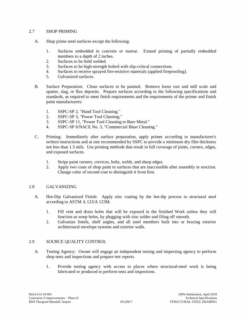
MAA-CO-19-001 100% Submission, April 2018Concourse A Improvements – Phase II Technical SpecificationsBWI Thurgood Marshall Airport 051200-7 STRUCTURAL STEEL FRAMING
2.7 SHOP PRIMING
A. Shop prime steel surfaces except the following:
1. Surfaces embedded in concrete or mortar. Extend priming of partially embeddedmembers to a depth of 2 inches.
2. Surfaces to be field welded.3. Surfaces to be high-strength bolted with slip-critical connections.4. Surfaces to receive sprayed fire-resistive materials (applied fireproofing).5. Galvanized surfaces.
B. Surface Preparation: Clean surfaces to be painted. Remove loose rust and mill scale andspatter, slag, or flux deposits. Prepare surfaces according to the following specifications andstandards, as required to meet finish requirements and the requirements of the primer and finishpaint manufacturers:
1. SSPC-SP 2, "Hand Tool Cleaning."2. SSPC-SP 3, "Power Tool Cleaning."3. SSPC-SP 11, "Power Tool Cleaning to Bare Metal."4. SSPC-SP 6/NACE No. 3, "Commercial Blast Cleaning."
C. Priming: Immediately after surface preparation, apply primer according to manufacturer'swritten instructions and at rate recommended by SSPC to provide a minimum dry film thicknessnot less than 1.5 mils. Use priming methods that result in full coverage of joints, corners, edges,and exposed surfaces.
1. Stripe paint corners, crevices, bolts, welds, and sharp edges.2. Apply two coats of shop paint to surfaces that are inaccessible after assembly or erection.
Change color of second coat to distinguish it from first.
2.8 GALVANIZING
A. Hot-Dip Galvanized Finish: Apply zinc coating by the hot-dip process to structural steelaccording to ASTM A 123/A 123M.
1. Fill vent and drain holes that will be exposed in the finished Work unless they willfunction as weep holes, by plugging with zinc solder and filing off smooth.
2. Galvanize lintels, shelf angles, and all steel members built into or bracing exteriorarchitectural envelope systems and exterior walls.
2.9 SOURCE QUALITY CONTROL
A. Testing Agency: Owner will engage an independent testing and inspecting agency to performshop tests and inspections and prepare test reports.
1. Provide testing agency with access to places where structural-steel work is beingfabricated or produced to perform tests and inspections.
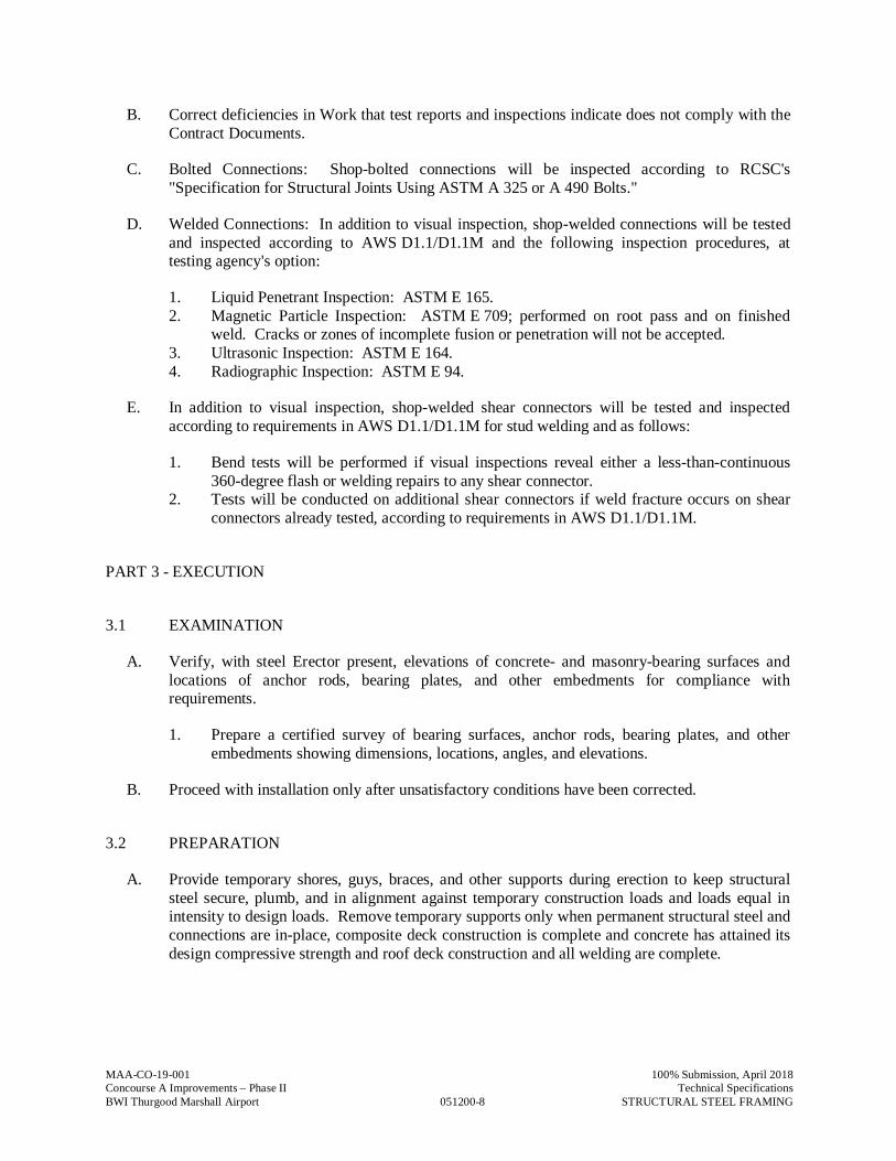
MAA-CO-19-001 100% Submission, April 2018Concourse A Improvements – Phase II Technical SpecificationsBWI Thurgood Marshall Airport 051200-8 STRUCTURAL STEEL FRAMING
B. Correct deficiencies in Work that test reports and inspections indicate does not comply with theContract Documents.
C. Bolted Connections: Shop-bolted connections will be inspected according to RCSC's"Specification for Structural Joints Using ASTM A 325 or A 490 Bolts."
D. Welded Connections: In addition to visual inspection, shop-welded connections will be testedand inspected according to AWS D1.1/D1.1M and the following inspection procedures, attesting agency's option:
1. Liquid Penetrant Inspection: ASTM E 165.2. Magnetic Particle Inspection: ASTM E 709; performed on root pass and on finished
weld. Cracks or zones of incomplete fusion or penetration will not be accepted.3. Ultrasonic Inspection: ASTM E 164.4. Radiographic Inspection: ASTM E 94.
E. In addition to visual inspection, shop-welded shear connectors will be tested and inspectedaccording to requirements in AWS D1.1/D1.1M for stud welding and as follows:
1. Bend tests will be performed if visual inspections reveal either a less-than-continuous360-degree flash or welding repairs to any shear connector.
2. Tests will be conducted on additional shear connectors if weld fracture occurs on shearconnectors already tested, according to requirements in AWS D1.1/D1.1M.
PART 3 - EXECUTION
3.1 EXAMINATION
A. Verify, with steel Erector present, elevations of concrete- and masonry-bearing surfaces andlocations of anchor rods, bearing plates, and other embedments for compliance withrequirements.
1. Prepare a certified survey of bearing surfaces, anchor rods, bearing plates, and otherembedments showing dimensions, locations, angles, and elevations.
B. Proceed with installation only after unsatisfactory conditions have been corrected.
3.2 PREPARATION
A. Provide temporary shores, guys, braces, and other supports during erection to keep structuralsteel secure, plumb, and in alignment against temporary construction loads and loads equal inintensity to design loads. Remove temporary supports only when permanent structural steel andconnections are in-place, composite deck construction is complete and concrete has attained itsdesign compressive strength and roof deck construction and all welding are complete.
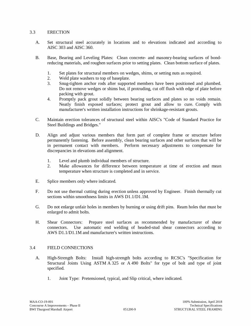
MAA-CO-19-001 100% Submission, April 2018Concourse A Improvements – Phase II Technical SpecificationsBWI Thurgood Marshall Airport 051200-9 STRUCTURAL STEEL FRAMING
3.3 ERECTION
A. Set structural steel accurately in locations and to elevations indicated and according toAISC 303 and AISC 360.
B. Base, Bearing and Leveling Plates: Clean concrete- and masonry-bearing surfaces of bond-reducing materials, and roughen surfaces prior to setting plates. Clean bottom surface of plates.
1. Set plates for structural members on wedges, shims, or setting nuts as required.2. Weld plate washers to top of baseplate.3. Snug-tighten anchor rods after supported members have been positioned and plumbed.
Do not remove wedges or shims but, if protruding, cut off flush with edge of plate beforepacking with grout.
4. Promptly pack grout solidly between bearing surfaces and plates so no voids remain.Neatly finish exposed surfaces; protect grout and allow to cure. Comply withmanufacturer's written installation instructions for shrinkage-resistant grouts.
C. Maintain erection tolerances of structural steel within AISC's "Code of Standard Practice forSteel Buildings and Bridges."
D. Align and adjust various members that form part of complete frame or structure beforepermanently fastening. Before assembly, clean bearing surfaces and other surfaces that will bein permanent contact with members. Perform necessary adjustments to compensate fordiscrepancies in elevations and alignment.
1. Level and plumb individual members of structure.2. Make allowances for difference between temperature at time of erection and mean
temperature when structure is completed and in service.
E. Splice members only where indicated.
F. Do not use thermal cutting during erection unless approved by Engineer. Finish thermally cutsections within smoothness limits in AWS D1.1/D1.1M.
G. Do not enlarge unfair holes in members by burning or using drift pins. Ream holes that must beenlarged to admit bolts.
H. Shear Connectors: Prepare steel surfaces as recommended by manufacturer of shearconnectors. Use automatic end welding of headed-stud shear connectors according toAWS D1.1/D1.1M and manufacturer's written instructions.
3.4 FIELD CONNECTIONS
A. High-Strength Bolts: Install high-strength bolts according to RCSC's "Specification forStructural Joints Using ASTM A 325 or A 490 Bolts" for type of bolt and type of jointspecified.
1. Joint Type: Pretensioned, typical, and Slip critical, where indicated.
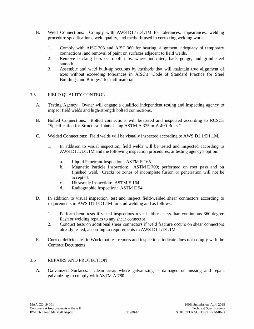
MAA-CO-19-001 100% Submission, April 2018Concourse A Improvements – Phase II Technical SpecificationsBWI Thurgood Marshall Airport 051200-10 STRUCTURAL STEEL FRAMING
B. Weld Connections: Comply with AWS D1.1/D1.1M for tolerances, appearances, weldingprocedure specifications, weld quality, and methods used in correcting welding work.
1. Comply with AISC 303 and AISC 360 for bearing, alignment, adequacy of temporaryconnections, and removal of paint on surfaces adjacent to field welds.
2. Remove backing bars or runoff tabs, where indicated, back gouge, and grind steelsmooth.
3. Assemble and weld built-up sections by methods that will maintain true alignment ofaxes without exceeding tolerances in AISC's "Code of Standard Practice for SteelBuildings and Bridges" for mill material.
3.5 FIELD QUALITY CONTROL
A. Testing Agency: Owner will engage a qualified independent testing and inspecting agency toinspect field welds and high-strength bolted connections.
B. Bolted Connections: Bolted connections will be tested and inspected according to RCSC's"Specification for Structural Joints Using ASTM A 325 or A 490 Bolts."
C. Welded Connections: Field welds will be visually inspected according to AWS D1.1/D1.1M.
1. In addition to visual inspection, field welds will be tested and inspected according toAWS D1.1/D1.1M and the following inspection procedures, at testing agency's option:
a. Liquid Penetrant Inspection: ASTM E 165.b. Magnetic Particle Inspection: ASTM E 709; performed on root pass and on
finished weld. Cracks or zones of incomplete fusion or penetration will not beaccepted.
c. Ultrasonic Inspection: ASTM E 164.d. Radiographic Inspection: ASTM E 94.
D. In addition to visual inspection, test and inspect field-welded shear connectors according torequirements in AWS D1.1/D1.1M for stud welding and as follows:
1. Perform bend tests if visual inspections reveal either a less-than-continuous 360-degreeflash or welding repairs to any shear connector.
2. Conduct tests on additional shear connectors if weld fracture occurs on shear connectorsalready tested, according to requirements in AWS D1.1/D1.1M.
E. Correct deficiencies in Work that test reports and inspections indicate does not comply with theContract Documents.
3.6 REPAIRS AND PROTECTION
A. Galvanized Surfaces: Clean areas where galvanizing is damaged or missing and repairgalvanizing to comply with ASTM A 780.
MAA-CO-19-001 100% Submission, April 2018Concourse A Improvements – Phase II Technical SpecificationsBWI Thurgood Marshall Airport 051200-11 STRUCTURAL STEEL FRAMING
B. Touchup Painting: Immediately after erection, clean exposed areas where primer is damaged ormissing and paint with the same material as used for shop painting to comply with SSPC-PA 1for touching up shop-painted surfaces.
1. Clean and prepare surfaces by SSPC-SP 2 hand-tool cleaning or SSPC-SP 3 power-toolcleaning.
C. Touchup Painting: Cleaning and touchup painting are specified in Division 09 paintingSections.
PART 4 - METHODS OF MEASUREMENTS
A. No separate measurement shall be made for work under this Specification Section
PART 5 - METHOD OF PAYMENT
A. No separate payment will be made for work under this Specification Section. The cost of work,complete in place, described in this Specification Section shall be included in the Lump SumBid under “Building Construction”
B. Costs include all labor, material, services, and equipment necessary to complete the work inevery aspect.
END OF SECTION 051200
MAA-CO-19-001
051250-1
100% Submission, August 2018Concourse A Improvements – Phase II Technical SpecificationsBWI Thurgood Marshall Airport ARCHITECTURALLY EXPOSED STRUCTURAL STEEL
SECTION 051250 - ARCHITECURALLY EXPOSED STRUCTURAL STEEL
PART 1 — GENERAL
1.1 RELATED DOCUMENTS
A. Drawings and general provisions of the Contract, including Maryland Department ofTransportation/ Maryland Aviation Administration Standard Provisions to the ConstructionContract for the Concourse A Improvements – Phase II at BWI Thurgood Marshall Airport andother Divisions 1 Specification Sections, apply to this Section.
1.2 SUMMARY
A. This Section includes requirements regarding the appearance and surface preparation ofArchitecturally Exposed Structural Steel (AESS). Refer to Division 5, Section ‘Structural Steel’for all other requirements regarding steel work not included in this section. This section appliesto any members noted on Architectural or Structural drawings as AESS [and in the areas definedas AESS below].
B. Related Sections: The following Sections contain requirements that relate to this Section:
1. Division 1 Section “Quality Control” for independent testing agency procedures andadministrative requirements.2. Division 5 Section “Structural Steel”3. Division 5 Section “Steel Decking” for erection requirements relating to exposed steeldecking and its connections4. Division 9 painting Sections for finish coat requirements and coordination with primer andsurface preparation specified in this section.
1.3 SUBMITTALS
A. General: Submit each item below according to the Conditions of the Contract and Division 1Specification Sections.
B. Product Data for each type of product specified.C. Shop Drawings detailing fabrication of AESS components.
1. Provide erection drawings clearly indicating which members are considered as AESSmembers.2. Include details that clearly identify all of the requirements listed in sections 2.3“Fabrication“ and 3.3 “Erection” of this specification. Provide connections for exposedAESS consistent with concepts shown on the architectural or structural drawings.3. Indicate welds by standard AWS symbols, distinguishing between shop and field welds,and show size, length and type of each weld. Identify grinding, finish and profile of welds asdefined herein.4. Indicate type, size, finish and length of bolts, distinguishing between shop and field bolts.Identify high-strength bolted slip-critical, direct-tensioned shear/bearing connections. Indicateto which direction bolt heads should be oriented.5. Clearly indicate which surfaces or edges are exposed and what class of surface preparationis being used.6. Indicate special tolerances and erection requirements as noted on the drawings or definedherein.
MAA-CO-19-001
051250-2
100% Submission, August 2018Concourse A Improvements – Phase II Technical SpecificationsBWI Thurgood Marshall Airport ARCHITECTURALLY EXPOSED STRUCTURAL STEEL
D. Qualification data for firms and persons specified in the ‘Quality Assurance” Article todemonstrate their capabilities and experience. Include lists of completed projects names andaddress, names and addresses of architects and owners, and other information specified. For eachproject, submit photographs showing detail of installed AESS.
1.4 QUALITY ASSURANCE
A. Fabricator Qualifications: In addition to those qualifications listed in Division 5 Section‘Structural Steel,’ engage a firm experienced in fabricating AESS similar to that indicated for thisProject with a record of successful in-service performance, as well as sufficient productioncapacity to fabricate AESS without delaying the Work.
B. Erector Qualifications: In addition to those qualifications listed in Division 5 Section ‘StructuralSteel,’ engage an experienced Erector who has completed AESS work similar in material, design,and extent to that indicted for this Project and with a record of successful in-service performance.
C. Comply with applicable provisions of the following specifications and documents:
1. AISC “Code of Standard Practice,” latest edition, Section 10 as amended herein.
D. Mockups: At least four weeks prior to fabricating AESS, the contractor shall construct mockupsto demonstrate aesthetic effects as well as qualities of materials and execution. A mockup foreach of the following elements shall be constructed. Build mockups to comply with the followingrequirements, using materials indicated for final unit of Work.
1. Locate mockups on-site or in the fabricator’s shop as directed by Architect. Mockups shallbe full-size pieces unless the Architect approves smaller models.2. Notify the Architect one week in advance of the dates and times when mockups will beavailable for review.3. Demonstrate the proposed range of aesthetic effects regarding each element listed underthe fabrication heading below.4. Mockup will have finished surface (including surface preparation and paint system).5. Obtain Architect’s approval of mockups before starting fabrication of final units.6. Retain and maintain mockups during construction in an undisturbed condition as a standardfor judging the completed work.
a. Approved mockups in an undisturbed condition at the time of Substantial completionmay become part of the completed work.
E. Pre-installation Conference: The General Contractor shall schedule and conduct conference at theproject site to comply with requirements of Division.
1. Section “Project Meetings.” As a minimum, the meeting shall include the GeneralContractor, Fabricator, Erector, the finish-painting subcontractor, and the Architect.Coordinate requirements for shipping, special handling, attachment of safety cables andtemporary erection bracing, touch up painting and other requirements for AESS.
1.5 DELIVERY, STORAGE, AND HANDLING
A. Deliver AESS to Project site in such quantities and at such times to ensure continuity ofinstallation.
B. Store materials to permit easy access for inspection and identification. Keep steel members offground by using pallets, platforms, or other supports. Protect steel members and packaged
MAA-CO-19-001
051250-3
100% Submission, August 2018Concourse A Improvements – Phase II Technical SpecificationsBWI Thurgood Marshall Airport ARCHITECTURALLY EXPOSED STRUCTURAL STEEL
materials from erosion and deterioration. Use special care in handling to prevent twisting orwarping of AESS members.
C. Erect pre-painted finish pieces using padded slings or other methods such that they are notdamaged. Provide padding as required to protect while rigging and aligning member’s frames.Weld tabs for temporary bracing and safety cabling only at points concealed from view in thecompleted structure or where approved by the Architect during the pre-installation meeting.Methods of removing temporary erection devices and finishing the AESS members shall beapproved by the Architect prior to erection.
1.6 PROJECT CONDITIONS
A. Field Measurements: Where AESS is indicated to fit against walls and other construction, verifydimensions by field measurements before fabrication and indicate measurements on shopdrawings. Coordinate fabrication schedule with construction progress to avoid delaying the work.
1.7 COORDINATION
A. Coordinate installation of anchors for AESS members that connect to the work of other trades.Furnish setting drawings, templates, and directions for installing anchors, including sleeves,concrete inserts, anchor bolts, and items with integral anchors, that are to be embedded inconcrete or masonry. Deliver such items to the project site in time for installation.
PART 2 — PRODUCTS
2.1 MATERIALS
A. General: Meet requirements Division 5 Section ‘Structural Steel’.
2.2 PRIMERS
A. Coordinate and provide in accordance with Section 051200.
2.3 FABRICATION
A. Fabricate and assemble AESS in the shop to the greatest extent possible. Locate field joints inAESS assemblies at concealed locations or as approved by the Architect. Detail AESSassemblies to minimize field handling and expedite erection.
B. Fabricate AESS with exposed surfaces smooth, square and of surface quality consistent with theapproved mock up. Use special care in handling and shipping of AESS both before and after shoppainting.
C. In addition to special care used to handle and fabricate AESS, employ the following fabricationtechniques.
1. Fabrication Tolerance: Fabricate steel to one half the normal tolerance as specified in theCode of Standard Practice Section 10.2. Welds ground smooth: Fabricator shall grind welds of AESS smooth. For groove welds,the weld shall be made flush to the surfaces each side and be within +1/16”, -0” of platethickness.3. Contouring and blending of welds: Where fillet welds are indicated to be ground-contoured, or blended, oversize welds as required and grind to provide a smooth transitionand to match profile on approved mock-up.
MAA-CO-19-001
051250-4
100% Submission, August 2018Concourse A Improvements – Phase II Technical SpecificationsBWI Thurgood Marshall Airport ARCHITECTURALLY EXPOSED STRUCTURAL STEEL
4. Continuous Welds: Where welding is noted on the drawings, provide continuous welds ofa uniform size and profile.5. Minimize Weld Show Through: At locations where welding on the far side of an exposedconnection occurs, grind distortion and marking of the steel to a smooth profile with adjacentmaterial.6. Coping and Blocking Tolerance: Maintain a uniform gap of 1/8” ± 1/32” at all copes andblocks.7. Joint Gap Tolerance: Maintain a uniform gap of 1/8” ± 1/32”.8. Piece Marks Hidden: Fabricate such that piece marks are fully hidden in the final structureor made with such media to permit full removal after erection.10. Mill Mark Removal: Fabricator shall deliver steel with no mill marks (stenciled, stamped,raised etc) in exposed locations. Mill marks shall be omitted by cutting of mill material toappropriate lengths where possible. Where not possible, the fabricator can fill and/or grind toa surface finish consistent with the approved mock up.11. Grinding of sheared edges: Fabricator shall grind all edges of sheared, punched orflamecut steel to match approved mockup.12. Rolled Members: Member specified to be rolled to a final curved shape shall be fullyshaped in the shop and tied during shipping to prevent stress relieving. Distortion of the webor stem, and of outstanding flanges or legs of angles shall be visibly acceptable to theArchitect from a distance of 20’ under any lighting condition determined by the Architect.Tolerances for the vertical and horizontal walls of rectangular HSS members after rollingshall be the specified dimension +/- ½”.13. Seal weld open ends of round and rectangular hollow structural section with 3/8” closureplates. Provide continuous, sealed welds at angle to gusset-plate connections and similarlocations where AESS is exposed to weather.
2.4 SHOP CONNECTIONS
A. Bolted Connections: Make in accordance with Section 05120. Provide bolt type and finish asnoted herein and align bolt heads as indicated on the approved shop erection drawings.
B. Weld Connections: Comply with AWS D1.1 and Section 05120. Appearance and quality ofwelds shall be consistent with the mock up. Assemble and weld built-up sections by methods thatwill maintain alignment of members without warp exceeding the tolerance of this section.
2.5 SHOP PRIMING
A. Shop-prime steel surfaces, except the following:
1. Surfaces embedded in concrete or mortar. Extend priming of partially embedded membersto a depth of 2”.2. Surfaces to be field welded.3. Surfaces to be high-strength bolted with slip-critical connections, if primer does not meetthe specified AISC slip coefficient.
B. Surface Preparation: Clean surfaces to be painted. Remove loose rust, loose mill scale, andspatter, slag, or flux deposits. Prepare surfaces according to SSPC Specifications as follows:
1. SSPC-SP 3 “Power Tool Cleaning.”, minimum.2. SSPC-SP 6 “Commercial Blast Cleaning”, where required to coordinate with specifiedpaint system and for locations where a rust inhibitive primer will be used in an exteriorapplication.
MAA-CO-19-001
051250-5
100% Submission, August 2018Concourse A Improvements – Phase II Technical SpecificationsBWI Thurgood Marshall Airport ARCHITECTURALLY EXPOSED STRUCTURAL STEEL
3. Coordinate the required blast profile with the approved paint submittal prior to beginningsurface preparation.
C. Priming: Immediately after surface preparation, apply primer according to manufacturer’sinstructions to provide a dry film thickness of not less than 1.5 mils (0.038 mm). Use primingmethods that result in full coverage of joints, corners, edges, and exposed surfaces.
1. Stripe paint corners, crevices, bolts, welds, and sharp edges.2. Apply two coats of shop primer to surfaces that are inaccessible after assembly or erection.
2.6 GALVANIZING
A. Hot-Dip Galvanized Finish: Apply zinc coating by the hot-dip process to AESS indicated forgalvanizing according to ASTM A 123. Fabricate such that all connections of assemblies aremade in the field with bolted connections. Provide galvanized finish or members and assemblieswithin the range of color and surface textures presented in the mockups.
PART 3 — EXECUTION
3.1 EXAMINATION
A. The erector shall check all AESS members upon delivery for twist, kinks, gouges or otherimperfections which might result in rejection of the appearance of the member. Coordinateremedial action with fabricator prior to erecting steel.
3.2 PREPARATON
A. Provide connections for temporary shoring, bracing and supports only where noted on theapproved shop drawings. Temporary connections not shown shall be made at locations notexposed to view in the final structure or as approved by the Architect. Handle, lift and alignpieces using padded slings and/or other protection required to maintain the appearance of theAESS through the process of erection.
3.3 ERECTION
A. Set AESS accurately in locations and to elevations indicated, and according to AISCspecifications referenced in this Section.
B. In addition to the special care used to handle and erect AESS, employ the following erectiontechniques:
1. AESS Erection tolerances: Erection tolerances shall meet the requirements of standardframe tolerances for structural steel per Chapter 7 of the AISC Code of Standard Practice.OR1. AESS Erection Tolerances: Erection Tolerances shall meet the requirements of Chapter 10of the AISC Code of Standard Practice.2. Welds ground smooth: Erector shall grind welds smooth in the connections of AESSmembers. For groove welds, the weld shall be made flush to the surfaces of each side and bewithin + 1/16”, -0” of plate thickness.3. Contouring and blending of welds: Where fillet welds are indicated to be groundcontoured, or blended, oversize welds as required; grind to provide a smooth transition and tomatch profile on approved mock-up .
MAA-CO-19-001
051250-6
100% Submission, August 2018Concourse A Improvements – Phase II Technical SpecificationsBWI Thurgood Marshall Airport ARCHITECTURALLY EXPOSED STRUCTURAL STEEL
4. Continuous Welds: Where noted on the drawings, provide continuous welds of a uniformsize and profile.5. Minimize Weld Show Through: At locations where welding on the far side of an exposedconnection occurs, grind distortion and marking of the steel to a smooth profile with adjacentmaterial.6. Bolt Head Orientation: All bolt heads shall be oriented as indicated on the contractdocuments. Where bolt-head alignment is specified, the orientation shall be noted for eachconnection on the erection drawings. Where not noted, the bolt heads in a given connectionshall be oriented to one side.7. Removal of field connection aids: Run-out tabs, erection bolts and other steel membersadded to connections to allow for alignment, fit-up, and welding in the field shall be removedfrom the structure. Field groove welds shall be selected to eliminate the need for backing barsor to permit their removal after welding. Welds at run-out tabs shall be removed to matchadjacent surfaces and ground smooth. Holes for erection bolts shall be plug welded andground smooth.8. Filling of weld access holes: Where holes must be cut in the web at the intersection withflanges on W shapes and structural tees to permit field welding of the flanges, they shall befilled. Filling shall be executed with proper procedures to minimize restraint and addressthermal stresses in group 4 and 5 shapes.
C. Field Welding: Weld profile, quality, and finish shall be consistent with mock-ups approved priorto fabrication.
D. Splice members only where indicated.E. Obtain permission for any torch cutting or field fabrication from the Architect. Finish sections
thermally cut during erection to a surface appearance consistent with the mock up.F. Do not enlarge unfair holes in members by burning or by using drift pins. Ream holes that must
be enlarged to admit bolts. Replace connection plates that are misaligned where holes cannot bealigned with acceptable final appearance.
3.4 FIELD CONNECTIONS
A. Bolted Connections: Install bolts of the specified type and finish in accordance with Division 5section “Structural Steel.”
B. Welded Connections: Comply with AWS D1.1 for procedures, and appearance. Refer to Division5 section “Structural Steel” for other requirements.
1. Assemble and weld built-up sections by methods that will maintain true alignment of axeswithout warp. Verify that weld sizes, fabrication sequence, and equipment used for AESSwill limit distortions to allowable tolerances.2. Obtain Architects approval for appearance of welds in repaired or field modified work.
3.5 FIELD QUALITY CONTROL
A. Structural requirements: The Owner will engage an independent testing and inspecting agency toperform field inspections and tests and to prepare test reports. Refer to Division 5 section“Structural Steel” for detailed bolt and weld testing requirements.
B. AESS acceptance: The Architect shall observe the AESS steel in place and determineacceptability based on the mockup. The Testing Agency shall have no responsibility for enforcingthe requirements of this section.
MAA-CO-19-001
051250-7
100% Submission, August 2018Concourse A Improvements – Phase II Technical SpecificationsBWI Thurgood Marshall Airport ARCHITECTURALLY EXPOSED STRUCTURAL STEEL
3.6 ADJUSTING AND CLEANING
A. Touchup Painting: Cleaning and touchup painting of field welds, bolted connections, and abradedareas of shop paint shall completed to blend with the adjacent surfaces of AESS. Such touch upwork shall be done in accordance with manufacturer’s instructions as specified in Division 9,Section “Painting.”
B. Galvanized Surfaces: Clean field welds, bolted connections, and abraded areas and repairgalvanizing to comply with ASTM A780.
PART 4 - METHODS OF MEASUREMENTS
A. No separate measurement shall be made for work under this Specification Section
PART 5 - METHOD OF PAYMENT
A. No separate payment will be made for work under this Specification Section. The cost of work,complete in place, described in this Specification Section shall be included in the Lump Sum Bidunder “Building Construction”
B. Costs include all labor, material, services, and equipment necessary to complete the work in everyaspect.
END OF SECTION 051250
MAA-CO-19-001
053100-1
100% Submission, April 2018Concourse A Improvements – Phase II Technical SpecificationsBWI Thurgood Marshall Airport STEEL DECKING
SECTION 053100 - STEEL DECKING
PART 1 - GENERAL
1.1 RELATED DOCUMENTS
A. Drawings and general provisions of the Contract, including Maryland Department ofTransportation/ Maryland Aviation Administration Standard Provisions to the ConstructionContract for the Concourse A Improvements – Phase II at BWI Thurgood Marshall Airport andother Divisions 1 Specification Sections, apply to this Section.
1.2 SUMMARY
A. This Section includes the following:
1. Roof deck.2. Acoustical cellular roof deck.3. Composite floor deck.4. Provide steel materials manufactured in the United States of America complying with
Federal Aviation Administration (FAA) 49 U.S.C. § 50101 – Buy American regulations.
B. Related Sections include the following:
1. Division 03 Section 033000 "Cast-in-Place Concrete" for concrete fill.2. Division 05 Section 051200 "Structural Steel Framing" for shop- and field-welded shear
connectors.3. Division 09 painting Sections for repair painting of primed deck.
1.3 SUBMITTALS
A. Product Data: For each type of deck, accessory, and product indicated.
B. Shop Drawings: Show layout and types of deck panels, anchorage details, reinforcing channels,pans, cut deck openings, special jointing, accessories, and attachments to other construction.
C. Product Certificates: For each type of steel deck, signed by product manufacturer.
D. Welding certificates.
E. Field quality-control test and inspection reports.
F. Product Test Reports: Based on evaluation of comprehensive tests performed by a qualifiedtesting agency, indicating that each of the following complies with requirements:
1. Power-actuated mechanical fasteners.2. Acoustical roof deck.
MAA-CO-19-001
053100-2
100% Submission, April 2018Concourse A Improvements – Phase II Technical SpecificationsBWI Thurgood Marshall Airport STEEL DECKING
G. Research/Evaluation Reports: For steel deck.
1.4 QUALITY ASSURANCE
A. Testing Agency Qualifications: An independent agency qualified according to ASTM E 329 fortesting indicated.
B. Welding: Qualify procedures and personnel according to AWS D1.3, "Structural WeldingCode - Sheet Steel."
C. Fire-Test-Response Characteristics: Where indicated, provide steel deck units identical to thosetested for fire resistance per ASTM E 119 by a testing and inspecting agency acceptable toauthorities having jurisdiction.
1. Fire-Resistance Ratings: Indicated by design designations of applicable testing andinspecting agency.
2. Steel deck units shall be identified with appropriate markings of applicable testing andinspecting agency.
D. AISI Specifications: Comply with calculated structural characteristics of steel deck accordingto AISI's "North American Specification for the Design of Cold-Formed Steel StructuralMembers."
E. FMG Listing: Provide steel roof deck evaluated by FMG and listed in its "Approval Guide,Building Materials" for Class 1 fire rating and Class 1-90 windstorm ratings.
F. Recycled Content of Steel Products: Provide products with an average recycled content of steelproducts so postconsumer recycled content plus one-half of preconsumer recycled content is notless than 25 percent.
1.5 DELIVERY, STORAGE, AND HANDLING
A. Protect steel deck from corrosion, deformation, and other damage during delivery, storage, andhandling.
B. Stack steel deck on platforms or pallets and slope to provide drainage. Protect with awaterproof covering and ventilate to avoid condensation.
1. Protect and ventilate acoustical cellular roof deck with factory-installed insulation tomaintain insulation free of moisture.
1.6 COORDINATION
A. Coordinate installation of sound-absorbing insulation strips in topside ribs of acoustical deckwith roofing installation to ensure protection of insulation strips against damage from effects ofweather and other causes.
MAA-CO-19-001
053100-3
100% Submission, April 2018Concourse A Improvements – Phase II Technical SpecificationsBWI Thurgood Marshall Airport STEEL DECKING
PART 2 - PRODUCTS
2.1 MANUFACTURERS
A. Available Manufacturers: Subject to compliance with requirements, manufacturers offeringproducts that may be incorporated into the Work include, but are not limited to, the following:
1. Steel Deck:
a. ASC Profiles, Inc.b. Canam Steel Corp.;The Canam Manac Group.c. Consolidated Systems, Inc.d. Epic Metals Corporation.e. Marlyn Steel Decks, Inc.f. New Millennium Building Systems, LLC.g. Nucor Corp.; Vulcraft Division.h. Roof Deck, Inc.i. United Steel Deck, Inc.j. Wheeling Corrugating Company; Div. of Wheeling-Pittsburgh Steel Corporation.
2.2 ROOF DECK
A. Steel Roof Deck: Fabricate panels, without top-flange stiffening grooves, to comply with "SDISpecifications and Commentary for Steel Roof Deck," in SDI Publication No. 30, and with thefollowing:
1. Galvanized Steel Sheet: ASTM A 653/A 653M, Structural Steel (SS), Grade 33,minimum, with G90 zinc coating.
2. Deck Profile: Type WR, wide rib.3. Profile Depth: 1-1/2 inches.4. Design Uncoated-Steel Thickness: 0.0358 inch.5. Span Condition: Triple span or more.6. Side Laps: Overlapped or interlocking seam at Contractor's option.7. Provide deck panels bent about the strong axis to match the curve of framing as indicated.
2.3 ACOUSTICAL ROOF DECK
A. Acoustical Steel Roof Deck: Fabricate panels, without top-flange stiffening grooves, to complywith "SDI Specifications and Commentary for Steel Roof Deck," in SDI Publication No. 30,and with the following:1. Galvanized and Shop-Primed Steel Sheet: ASTM A 653/A 653M, Structural Steel (SS),
Grade 33, with G90 zinc coating; cleaned, pretreated, and primed with manufacturer'sstandard baked-on, rust-inhibitive primer.
a. Color: White.2. Cellular Deck Profile: Type WR, wide rib, with perforated bottom plate.3. Profile Depth: 1-1/2 inches.4. Design Uncoated-Steel Thicknesses; Deck Unit/Bottom Plate: 0.0358/0.0358 inch.
MAA-CO-19-001
053100-4
100% Submission, April 2018Concourse A Improvements – Phase II Technical SpecificationsBWI Thurgood Marshall Airport STEEL DECKING
5. Span Condition: Triple span or more.6. Side Laps: Overlapped or interlocking seam at Contractor's option.7. Acoustical Perforations: Cellular deck units with manufacturer's standard perforated flat-
bottom plate welded to ribbed deck.8. Sound-Absorbing Insulation: Manufacturer's standard premolded roll or strip of glass or
mineral fiber.
a. Factory install sound-absorbing insulation into cells of cellular deck.
9. Acoustical Performance: NRC 0.80 tested according to ASTM C 423.
2.4 COMPOSITE FLOOR DECK
A. Composite Steel Floor Deck: Fabricate panels, with integrally embossed or raised pattern ribsand interlocking side laps, to comply with "SDI Specifications and Commentary for CompositeSteel Floor Deck," in SDI Publication No. 30, with the minimum section properties indicated,and with the following:1. Galvanized Steel Sheet: ASTM A 653/A 653M, Structural Steel (SS), Grade 33,
minimum G60 zinc coating.2. Profile Depth: 3 inches.3. Design Uncoated-Steel Thickness: 0.0474 inch4. Span Condition: Triple span or more.5. Span Condition: Triple span or more.6. Side Laps: Overlapped or interlocking seam at Contractor's option.
2.5 ACCESSORIES
A. General: Provide manufacturer's standard accessory materials for deck that comply withrequirements indicated.
B. Mechanical Fasteners: Corrosion-resistant, low-velocity, power-actuated or pneumaticallydriven carbon-steel fasteners; or self-drilling, self-threading screws.
C. Side-Lap Fasteners: Corrosion-resistant, hexagonal washer head; self-drilling, carbon-steelscrews, No. 10 minimum diameter.
D. Flexible Closure Strips: Vulcanized, closed-cell, synthetic rubber.
E. Miscellaneous Sheet Metal Deck Accessories: Steel sheet, minimum yield strength of 33,000psi, not less than 0.0358-inch design uncoated thickness, of same material and finish as deck; ofprofile indicated or required for application.
F. Pour Stops and Girder Fillers: Steel sheet, minimum yield strength of 33,000 psi, of samematerial and finish as deck, and of thickness and profile indicated.
G. Column Closures, End Closures, Z-Closures, and Cover Plates: Steel sheet, of same material,finish, and thickness as deck, unless otherwise indicated.
H. Piercing Hanger Tabs: Piercing steel sheet hanger attachment devices for use with floor deck.
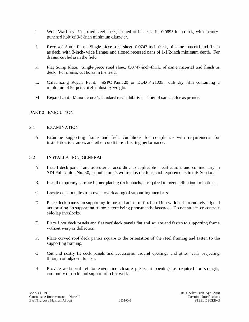
MAA-CO-19-001
053100-5
100% Submission, April 2018Concourse A Improvements – Phase II Technical SpecificationsBWI Thurgood Marshall Airport STEEL DECKING
I. Weld Washers: Uncoated steel sheet, shaped to fit deck rib, 0.0598-inch-thick, with factory-punched hole of 3/8-inch minimum diameter.
J. Recessed Sump Pans: Single-piece steel sheet, 0.0747-inch-thick, of same material and finishas deck, with 3-inch- wide flanges and sloped recessed pans of 1-1/2-inch minimum depth. Fordrains, cut holes in the field.
K. Flat Sump Plate: Single-piece steel sheet, 0.0747-inch-thick, of same material and finish asdeck. For drains, cut holes in the field.
L. Galvanizing Repair Paint: SSPC-Paint 20 or DOD-P-21035, with dry film containing aminimum of 94 percent zinc dust by weight.
M. Repair Paint: Manufacturer's standard rust-inhibitive primer of same color as primer.
PART 3 - EXECUTION
3.1 EXAMINATION
A. Examine supporting frame and field conditions for compliance with requirements forinstallation tolerances and other conditions affecting performance.
3.2 INSTALLATION, GENERAL
A. Install deck panels and accessories according to applicable specifications and commentary inSDI Publication No. 30, manufacturer's written instructions, and requirements in this Section.
B. Install temporary shoring before placing deck panels, if required to meet deflection limitations.
C. Locate deck bundles to prevent overloading of supporting members.
D. Place deck panels on supporting frame and adjust to final position with ends accurately alignedand bearing on supporting frame before being permanently fastened. Do not stretch or contractside-lap interlocks.
E. Place floor deck panels and flat roof deck panels flat and square and fasten to supporting framewithout warp or deflection.
F. Place curved roof deck panels square to the orientation of the steel framing and fasten to thesupporting framing.
G. Cut and neatly fit deck panels and accessories around openings and other work projectingthrough or adjacent to deck.
H. Provide additional reinforcement and closure pieces at openings as required for strength,continuity of deck, and support of other work.
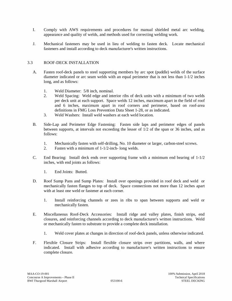
MAA-CO-19-001
053100-6
100% Submission, April 2018Concourse A Improvements – Phase II Technical SpecificationsBWI Thurgood Marshall Airport STEEL DECKING
I. Comply with AWS requirements and procedures for manual shielded metal arc welding,appearance and quality of welds, and methods used for correcting welding work.
J. Mechanical fasteners may be used in lieu of welding to fasten deck. Locate mechanicalfasteners and install according to deck manufacturer's written instructions.
3.3 ROOF-DECK INSTALLATION
A. Fasten roof-deck panels to steel supporting members by arc spot (puddle) welds of the surfacediameter indicated or arc seam welds with an equal perimeter that is not less than 1-1/2 incheslong, and as follows:
1. Weld Diameter: 5/8 inch, nominal.2. Weld Spacing: Weld edge and interior ribs of deck units with a minimum of two welds
per deck unit at each support. Space welds 12 inches, maximum apart in the field of roofand 6 inches, maximum apart in roof corners and perimeter, based on roof-areadefinitions in FMG Loss Prevention Data Sheet 1-28, or as indicated.
3. Weld Washers: Install weld washers at each weld location.
B. Side-Lap and Perimeter Edge Fastening: Fasten side laps and perimeter edges of panelsbetween supports, at intervals not exceeding the lesser of 1/2 of the span or 36 inches, and asfollows:
1. Mechanically fasten with self-drilling, No. 10 diameter or larger, carbon-steel screws.2. Fasten with a minimum of 1-1/2-inch- long welds.
C. End Bearing: Install deck ends over supporting frame with a minimum end bearing of 1-1/2inches, with end joints as follows:
1. End Joints: Butted.
D. Roof Sump Pans and Sump Plates: Install over openings provided in roof deck and weld ormechanically fasten flanges to top of deck. Space connections not more than 12 inches apartwith at least one weld or fastener at each corner.
1. Install reinforcing channels or zees in ribs to span between supports and weld ormechanically fasten.
E. Miscellaneous Roof-Deck Accessories: Install ridge and valley plates, finish strips, endclosures, and reinforcing channels according to deck manufacturer's written instructions. Weldor mechanically fasten to substrate to provide a complete deck installation.
1. Weld cover plates at changes in direction of roof-deck panels, unless otherwise indicated.
F. Flexible Closure Strips: Install flexible closure strips over partitions, walls, and whereindicated. Install with adhesive according to manufacturer's written instructions to ensurecomplete closure.
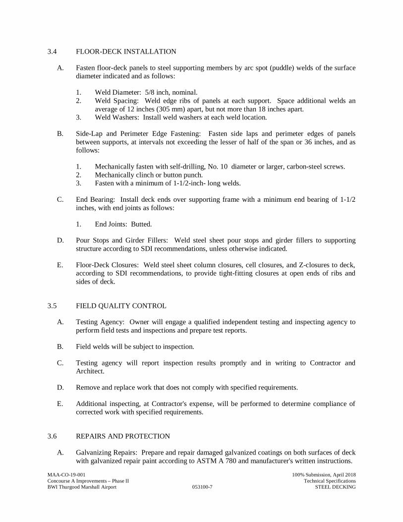
MAA-CO-19-001
053100-7
100% Submission, April 2018Concourse A Improvements – Phase II Technical SpecificationsBWI Thurgood Marshall Airport STEEL DECKING
3.4 FLOOR-DECK INSTALLATION
A. Fasten floor-deck panels to steel supporting members by arc spot (puddle) welds of the surfacediameter indicated and as follows:
1. Weld Diameter: 5/8 inch, nominal.2. Weld Spacing: Weld edge ribs of panels at each support. Space additional welds an
average of 12 inches (305 mm) apart, but not more than 18 inches apart.3. Weld Washers: Install weld washers at each weld location.
B. Side-Lap and Perimeter Edge Fastening: Fasten side laps and perimeter edges of panelsbetween supports, at intervals not exceeding the lesser of half of the span or 36 inches, and asfollows:
1. Mechanically fasten with self-drilling, No. 10 diameter or larger, carbon-steel screws.2. Mechanically clinch or button punch.3. Fasten with a minimum of 1-1/2-inch- long welds.
C. End Bearing: Install deck ends over supporting frame with a minimum end bearing of 1-1/2inches, with end joints as follows:
1. End Joints: Butted.
D. Pour Stops and Girder Fillers: Weld steel sheet pour stops and girder fillers to supportingstructure according to SDI recommendations, unless otherwise indicated.
E. Floor-Deck Closures: Weld steel sheet column closures, cell closures, and Z-closures to deck,according to SDI recommendations, to provide tight-fitting closures at open ends of ribs andsides of deck.
3.5 FIELD QUALITY CONTROL
A. Testing Agency: Owner will engage a qualified independent testing and inspecting agency toperform field tests and inspections and prepare test reports.
B. Field welds will be subject to inspection.
C. Testing agency will report inspection results promptly and in writing to Contractor andArchitect.
D. Remove and replace work that does not comply with specified requirements.
E. Additional inspecting, at Contractor's expense, will be performed to determine compliance ofcorrected work with specified requirements.
3.6 REPAIRS AND PROTECTION
A. Galvanizing Repairs: Prepare and repair damaged galvanized coatings on both surfaces of deckwith galvanized repair paint according to ASTM A 780 and manufacturer's written instructions.

MAA-CO-19-001
053100-8
100% Submission, April 2018Concourse A Improvements – Phase II Technical SpecificationsBWI Thurgood Marshall Airport STEEL DECKING
B. Repair Painting: Wire brush and clean rust spots, welds, and abraded areas on both surfaces ofprime-painted deck immediately after installation, and apply repair paint.
1. Apply repair paint, of same color as adjacent shop-primed deck, to bottom surfaces ofdeck exposed to view.
C. Provide final protection and maintain conditions to ensure that steel deck is without damage ordeterioration at time of Substantial Completion.
PART 4 - METHODS OF MEASUREMENTS
A. No separate measurement shall be made for work under this Specification Section
PART 5 - METHOD OF PAYMENT
A. No separate payment will be made for work under this Specification Section. The cost of work,complete in place, described in this Specification Section shall be included in the Lump SumBid under “Building Construction”
B. Costs include all labor, material, services, and equipment necessary to complete the work inevery aspect.
END OF SECTION 053100
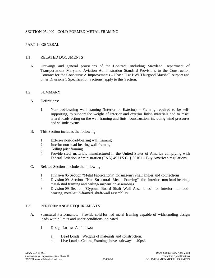
MAA-CO-19-001
054000-1
100% Submission, April 2018Concourse A Improvements – Phase II Technical SpecificationsBWI Thurgood Marshall Airport COLD-FORMED METAL FRAMING
SECTION 054000 - COLD-FORMED METAL FRAMING
PART 1 - GENERAL
1.1 RELATED DOCUMENTS
A. Drawings and general provisions of the Contract, including Maryland Department ofTransportation/ Maryland Aviation Administration Standard Provisions to the ConstructionContract for the Concourse A Improvements – Phase II at BWI Thurgood Marshall Airport andother Divisions 1 Specification Sections, apply to this Section.
1.2 SUMMARY
A. Definitions:
1. Non-load-bearing wall framing (Interior or Exterior) – Framing required to be self-supporting, to support the weight of interior and exterior finish materials and to resistlateral loads acting on the wall framing and finish construction, including wind pressuresand seismic events.
B. This Section includes the following:
1. Exterior non-load-bearing wall framing.2. Interior non-load-bearing wall framing.3. Ceiling joist framing.4. Provide steel materials manufactured in the United States of America complying with
Federal Aviation Administration (FAA) 49 U.S.C. § 50101 – Buy American regulations.
C. Related Sections include the following:
1. Division 05 Section "Metal Fabrications" for masonry shelf angles and connections.2. Division 09 Section "Non-Structural Metal Framing" for interior non-load-bearing,
metal-stud framing and ceiling-suspension assemblies.3. Division 09 Section "Gypsum Board Shaft Wall Assemblies" for interior non-load-
bearing, metal-stud-framed, shaft-wall assemblies.
1.3 PERFORMANCE REQUIREMENTS
A. Structural Performance: Provide cold-formed metal framing capable of withstanding designloads within limits and under conditions indicated.
1. Design Loads: As follows:
a. Dead Loads: Weights of materials and construction.b. Live Loads: Ceiling Framing above stairways – 40psf.
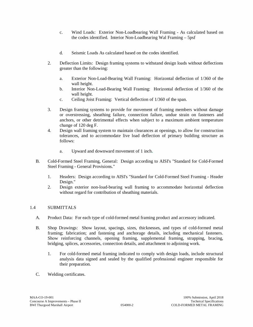
MAA-CO-19-001
054000-2
100% Submission, April 2018Concourse A Improvements – Phase II Technical SpecificationsBWI Thurgood Marshall Airport COLD-FORMED METAL FRAMING
c. Wind Loads: Exterior Non-Loadbearing Wall Framing - As calculated based onthe codes identified. Interior Non-Loadbearing Wal Framing – 5psf
d. Seismic Loads As calculated based on the codes identified.
2. Deflection Limits: Design framing systems to withstand design loads without deflectionsgreater than the following:
a. Exterior Non-Load-Bearing Wall Framing: Horizontal deflection of 1/360 of thewall height.
b. Interior Non-Load-Bearing Wall Framing: Horizontal deflection of 1/360 of thewall height.
c. Ceiling Joist Framing: Vertical deflection of 1/360 of the span.
3. Design framing systems to provide for movement of framing members without damageor overstressing, sheathing failure, connection failure, undue strain on fasteners andanchors, or other detrimental effects when subject to a maximum ambient temperaturechange of 120 deg F.
4. Design wall framing system to maintain clearances at openings, to allow for constructiontolerances, and to accommodate live load deflection of primary building structure asfollows:
a. Upward and downward movement of 1 inch.
B. Cold-Formed Steel Framing, General: Design according to AISI's "Standard for Cold-FormedSteel Framing - General Provisions."
1. Headers: Design according to AISI's "Standard for Cold-Formed Steel Framing - HeaderDesign."
2. Design exterior non-load-bearing wall framing to accommodate horizontal deflectionwithout regard for contribution of sheathing materials.
1.4 SUBMITTALS
A. Product Data: For each type of cold-formed metal framing product and accessory indicated.
B. Shop Drawings: Show layout, spacings, sizes, thicknesses, and types of cold-formed metalframing; fabrication; and fastening and anchorage details, including mechanical fasteners.Show reinforcing channels, opening framing, supplemental framing, strapping, bracing,bridging, splices, accessories, connection details, and attachment to adjoining work.
1. For cold-formed metal framing indicated to comply with design loads, include structuralanalysis data signed and sealed by the qualified professional engineer responsible fortheir preparation.
C. Welding certificates.
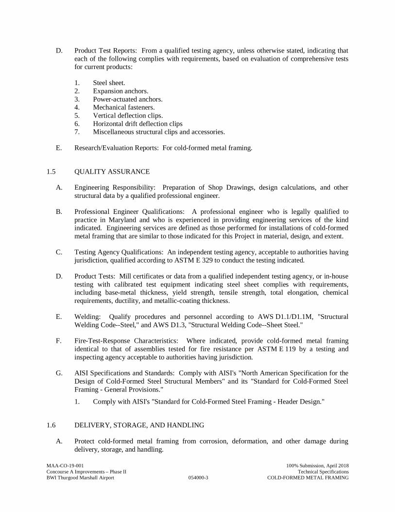
MAA-CO-19-001
054000-3
100% Submission, April 2018Concourse A Improvements – Phase II Technical SpecificationsBWI Thurgood Marshall Airport COLD-FORMED METAL FRAMING
D. Product Test Reports: From a qualified testing agency, unless otherwise stated, indicating thateach of the following complies with requirements, based on evaluation of comprehensive testsfor current products:
1. Steel sheet.2. Expansion anchors.3. Power-actuated anchors.4. Mechanical fasteners.5. Vertical deflection clips.6. Horizontal drift deflection clips7. Miscellaneous structural clips and accessories.
E. Research/Evaluation Reports: For cold-formed metal framing.
1.5 QUALITY ASSURANCE
A. Engineering Responsibility: Preparation of Shop Drawings, design calculations, and otherstructural data by a qualified professional engineer.
B. Professional Engineer Qualifications: A professional engineer who is legally qualified topractice in Maryland and who is experienced in providing engineering services of the kindindicated. Engineering services are defined as those performed for installations of cold-formedmetal framing that are similar to those indicated for this Project in material, design, and extent.
C. Testing Agency Qualifications: An independent testing agency, acceptable to authorities havingjurisdiction, qualified according to ASTM E 329 to conduct the testing indicated.
D. Product Tests: Mill certificates or data from a qualified independent testing agency, or in-housetesting with calibrated test equipment indicating steel sheet complies with requirements,including base-metal thickness, yield strength, tensile strength, total elongation, chemicalrequirements, ductility, and metallic-coating thickness.
E. Welding: Qualify procedures and personnel according to AWS D1.1/D1.1M, "StructuralWelding Code--Steel," and AWS D1.3, "Structural Welding Code--Sheet Steel."
F. Fire-Test-Response Characteristics: Where indicated, provide cold-formed metal framingidentical to that of assemblies tested for fire resistance per ASTM E 119 by a testing andinspecting agency acceptable to authorities having jurisdiction.
G. AISI Specifications and Standards: Comply with AISI's "North American Specification for theDesign of Cold-Formed Steel Structural Members" and its "Standard for Cold-Formed SteelFraming - General Provisions."
1. Comply with AISI's "Standard for Cold-Formed Steel Framing - Header Design."
1.6 DELIVERY, STORAGE, AND HANDLING
A. Protect cold-formed metal framing from corrosion, deformation, and other damage duringdelivery, storage, and handling.
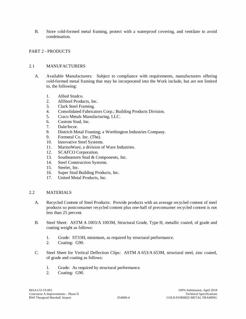
MAA-CO-19-001
054000-4
100% Submission, April 2018Concourse A Improvements – Phase II Technical SpecificationsBWI Thurgood Marshall Airport COLD-FORMED METAL FRAMING
B. Store cold-formed metal framing, protect with a waterproof covering, and ventilate to avoidcondensation.
PART 2 - PRODUCTS
2.1 MANUFACTURERS
A. Available Manufacturers: Subject to compliance with requirements, manufacturers offeringcold-formed metal framing that may be incorporated into the Work include, but are not limitedto, the following:
1. Allied Studco.2. AllSteel Products, Inc.3. Clark Steel Framing.4. Consolidated Fabricators Corp.; Building Products Division.5. Craco Metals Manufacturing, LLC.6. Custom Stud, Inc.7. Dale/Incor.8. Dietrich Metal Framing; a Worthington Industries Company.9. Formetal Co. Inc. (The).10. Innovative Steel Systems.11. MarinoWare; a division of Ware Industries.12. SCAFCO Corporation.13. Southeastern Stud & Components, Inc.14. Steel Construction Systems.15. Steeler, Inc.16. Super Stud Building Products, Inc.17. United Metal Products, Inc.
2.2 MATERIALS
A. Recycled Content of Steel Products: Provide products with an average recycled content of steelproducts so postconsumer recycled content plus one-half of preconsumer recycled content is notless than 25 percent.
B. Steel Sheet: ASTM A 1003/A 1003M, Structural Grade, Type H, metallic coated, of grade andcoating weight as follows:
1. Grade: ST33H, minimum, as required by structural performance.2. Coating: G90.
C. Steel Sheet for Vertical Deflection Clips: ASTM A 653/A 653M, structural steel, zinc coated,of grade and coating as follows:
1. Grade: As required by structural performance.2. Coating: G90.
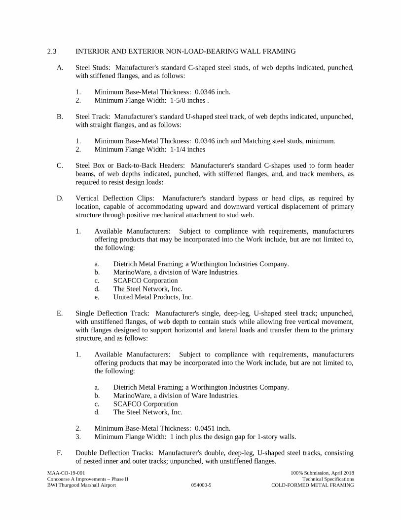
MAA-CO-19-001
054000-5
100% Submission, April 2018Concourse A Improvements – Phase II Technical SpecificationsBWI Thurgood Marshall Airport COLD-FORMED METAL FRAMING
2.3 INTERIOR AND EXTERIOR NON-LOAD-BEARING WALL FRAMING
A. Steel Studs: Manufacturer's standard C-shaped steel studs, of web depths indicated, punched,with stiffened flanges, and as follows:
1. Minimum Base-Metal Thickness: 0.0346 inch.2. Minimum Flange Width: 1-5/8 inches .
B. Steel Track: Manufacturer's standard U-shaped steel track, of web depths indicated, unpunched,with straight flanges, and as follows:
1. Minimum Base-Metal Thickness: 0.0346 inch and Matching steel studs, minimum.2. Minimum Flange Width: 1-1/4 inches
C. Steel Box or Back-to-Back Headers: Manufacturer's standard C-shapes used to form headerbeams, of web depths indicated, punched, with stiffened flanges, and, and track members, asrequired to resist design loads:
D. Vertical Deflection Clips: Manufacturer's standard bypass or head clips, as required bylocation, capable of accommodating upward and downward vertical displacement of primarystructure through positive mechanical attachment to stud web.
1. Available Manufacturers: Subject to compliance with requirements, manufacturersoffering products that may be incorporated into the Work include, but are not limited to,the following:
a. Dietrich Metal Framing; a Worthington Industries Company.b. MarinoWare, a division of Ware Industries.c. SCAFCO Corporationd. The Steel Network, Inc.e. United Metal Products, Inc.
E. Single Deflection Track: Manufacturer's single, deep-leg, U-shaped steel track; unpunched,with unstiffened flanges, of web depth to contain studs while allowing free vertical movement,with flanges designed to support horizontal and lateral loads and transfer them to the primarystructure, and as follows:
1. Available Manufacturers: Subject to compliance with requirements, manufacturersoffering products that may be incorporated into the Work include, but are not limited to,the following:
a. Dietrich Metal Framing; a Worthington Industries Company.b. MarinoWare, a division of Ware Industries.c. SCAFCO Corporationd. The Steel Network, Inc.
2. Minimum Base-Metal Thickness: 0.0451 inch.3. Minimum Flange Width: 1 inch plus the design gap for 1-story walls.
F. Double Deflection Tracks: Manufacturer's double, deep-leg, U-shaped steel tracks, consistingof nested inner and outer tracks; unpunched, with unstiffened flanges.
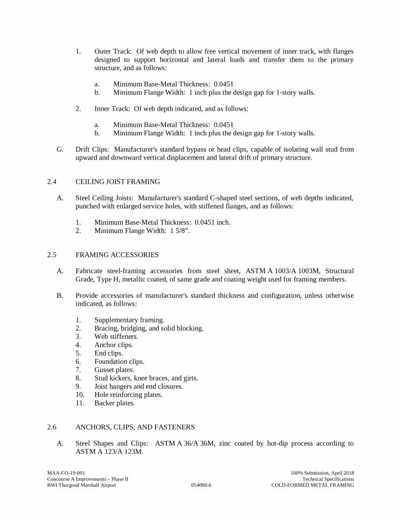
MAA-CO-19-001
054000-6
100% Submission, April 2018Concourse A Improvements – Phase II Technical SpecificationsBWI Thurgood Marshall Airport COLD-FORMED METAL FRAMING
1. Outer Track: Of web depth to allow free vertical movement of inner track, with flangesdesigned to support horizontal and lateral loads and transfer them to the primarystructure, and as follows:
a. Minimum Base-Metal Thickness: 0.0451b. Minimum Flange Width: 1 inch plus the design gap for 1-story walls.
2. Inner Track: Of web depth indicated, and as follows:
a. Minimum Base-Metal Thickness: 0.0451b. Minimum Flange Width: 1 inch plus the design gap for 1-story walls.
G. Drift Clips: Manufacturer's standard bypass or head clips, capable of isolating wall stud fromupward and downward vertical displacement and lateral drift of primary structure.
2.4 CEILING JOIST FRAMING
A. Steel Ceiling Joists: Manufacturer's standard C-shaped steel sections, of web depths indicated,punched with enlarged service holes, with stiffened flanges, and as follows:
1. Minimum Base-Metal Thickness: 0.0451 inch.2. Minimum Flange Width: 1 5/8”.
2.5 FRAMING ACCESSORIES
A. Fabricate steel-framing accessories from steel sheet, ASTM A 1003/A 1003M, StructuralGrade, Type H, metallic coated, of same grade and coating weight used for framing members.
B. Provide accessories of manufacturer's standard thickness and configuration, unless otherwiseindicated, as follows:
1. Supplementary framing.2. Bracing, bridging, and solid blocking.3. Web stiffeners.4. Anchor clips.5. End clips.6. Foundation clips.7. Gusset plates.8. Stud kickers, knee braces, and girts.9. Joist hangers and end closures.10. Hole reinforcing plates.11. Backer plates.
2.6 ANCHORS, CLIPS, AND FASTENERS
A. Steel Shapes and Clips: ASTM A 36/A 36M, zinc coated by hot-dip process according toASTM A 123/A 123M.
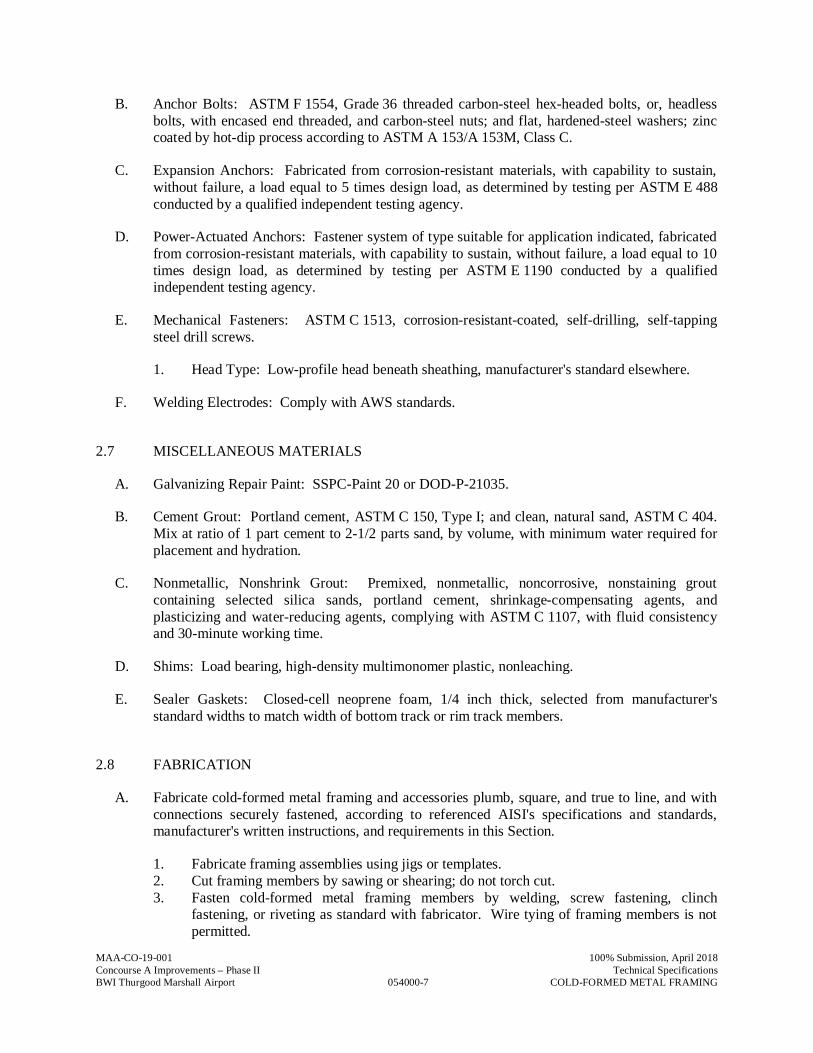
MAA-CO-19-001
054000-7
100% Submission, April 2018Concourse A Improvements – Phase II Technical SpecificationsBWI Thurgood Marshall Airport COLD-FORMED METAL FRAMING
B. Anchor Bolts: ASTM F 1554, Grade 36 threaded carbon-steel hex-headed bolts, or, headlessbolts, with encased end threaded, and carbon-steel nuts; and flat, hardened-steel washers; zinccoated by hot-dip process according to ASTM A 153/A 153M, Class C.
C. Expansion Anchors: Fabricated from corrosion-resistant materials, with capability to sustain,without failure, a load equal to 5 times design load, as determined by testing per ASTM E 488conducted by a qualified independent testing agency.
D. Power-Actuated Anchors: Fastener system of type suitable for application indicated, fabricatedfrom corrosion-resistant materials, with capability to sustain, without failure, a load equal to 10times design load, as determined by testing per ASTM E 1190 conducted by a qualifiedindependent testing agency.
E. Mechanical Fasteners: ASTM C 1513, corrosion-resistant-coated, self-drilling, self-tappingsteel drill screws.
1. Head Type: Low-profile head beneath sheathing, manufacturer's standard elsewhere.
F. Welding Electrodes: Comply with AWS standards.
2.7 MISCELLANEOUS MATERIALS
A. Galvanizing Repair Paint: SSPC-Paint 20 or DOD-P-21035.
B. Cement Grout: Portland cement, ASTM C 150, Type I; and clean, natural sand, ASTM C 404.Mix at ratio of 1 part cement to 2-1/2 parts sand, by volume, with minimum water required forplacement and hydration.
C. Nonmetallic, Nonshrink Grout: Premixed, nonmetallic, noncorrosive, nonstaining groutcontaining selected silica sands, portland cement, shrinkage-compensating agents, andplasticizing and water-reducing agents, complying with ASTM C 1107, with fluid consistencyand 30-minute working time.
D. Shims: Load bearing, high-density multimonomer plastic, nonleaching.
E. Sealer Gaskets: Closed-cell neoprene foam, 1/4 inch thick, selected from manufacturer'sstandard widths to match width of bottom track or rim track members.
2.8 FABRICATION
A. Fabricate cold-formed metal framing and accessories plumb, square, and true to line, and withconnections securely fastened, according to referenced AISI's specifications and standards,manufacturer's written instructions, and requirements in this Section.
1. Fabricate framing assemblies using jigs or templates.2. Cut framing members by sawing or shearing; do not torch cut.3. Fasten cold-formed metal framing members by welding, screw fastening, clinch
fastening, or riveting as standard with fabricator. Wire tying of framing members is notpermitted.
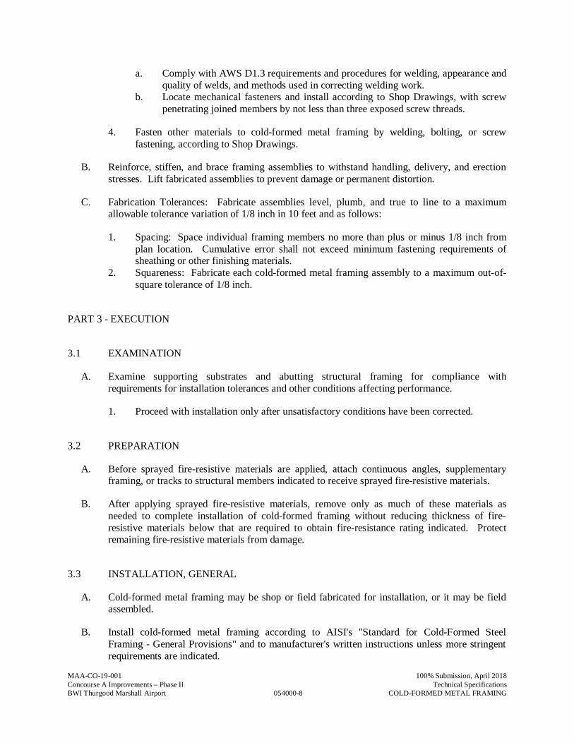
MAA-CO-19-001
054000-8
100% Submission, April 2018Concourse A Improvements – Phase II Technical SpecificationsBWI Thurgood Marshall Airport COLD-FORMED METAL FRAMING
a. Comply with AWS D1.3 requirements and procedures for welding, appearance andquality of welds, and methods used in correcting welding work.
b. Locate mechanical fasteners and install according to Shop Drawings, with screwpenetrating joined members by not less than three exposed screw threads.
4. Fasten other materials to cold-formed metal framing by welding, bolting, or screwfastening, according to Shop Drawings.
B. Reinforce, stiffen, and brace framing assemblies to withstand handling, delivery, and erectionstresses. Lift fabricated assemblies to prevent damage or permanent distortion.
C. Fabrication Tolerances: Fabricate assemblies level, plumb, and true to line to a maximumallowable tolerance variation of 1/8 inch in 10 feet and as follows:
1. Spacing: Space individual framing members no more than plus or minus 1/8 inch fromplan location. Cumulative error shall not exceed minimum fastening requirements ofsheathing or other finishing materials.
2. Squareness: Fabricate each cold-formed metal framing assembly to a maximum out-of-square tolerance of 1/8 inch.
PART 3 - EXECUTION
3.1 EXAMINATION
A. Examine supporting substrates and abutting structural framing for compliance withrequirements for installation tolerances and other conditions affecting performance.
1. Proceed with installation only after unsatisfactory conditions have been corrected.
3.2 PREPARATION
A. Before sprayed fire-resistive materials are applied, attach continuous angles, supplementaryframing, or tracks to structural members indicated to receive sprayed fire-resistive materials.
B. After applying sprayed fire-resistive materials, remove only as much of these materials asneeded to complete installation of cold-formed framing without reducing thickness of fire-resistive materials below that are required to obtain fire-resistance rating indicated. Protectremaining fire-resistive materials from damage.
3.3 INSTALLATION, GENERAL
A. Cold-formed metal framing may be shop or field fabricated for installation, or it may be fieldassembled.
B. Install cold-formed metal framing according to AISI's "Standard for Cold-Formed SteelFraming - General Provisions" and to manufacturer's written instructions unless more stringentrequirements are indicated.

MAA-CO-19-001
054000-9
100% Submission, April 2018Concourse A Improvements – Phase II Technical SpecificationsBWI Thurgood Marshall Airport COLD-FORMED METAL FRAMING
C. Install shop- or field-fabricated, cold-formed framing and securely anchor to supportingstructure.
1. Screw, bolt, or weld wall panels at horizontal and vertical junctures to produce flush,even, true-to-line joints with maximum variation in plane and true position betweenfabricated panels not exceeding 1/16 inch.
D. Install cold-formed metal framing and accessories plumb, square, and true to line, and withconnections securely fastened.
1. Cut framing members by sawing or shearing; do not torch cut.2. Fasten cold-formed metal framing members by welding, screw fastening, clinch
fastening, or riveting. Wire tying of framing members is not permitted.
a. Comply with AWS D1.3 requirements and procedures for welding, appearance andquality of welds, and methods used in correcting welding work.
b. Locate mechanical fasteners and install according to Shop Drawings, andcomplying with requirements for spacing, edge distances, and screw penetration.
E. Install framing members in one-piece lengths unless splice connections are indicated for trackor tension members.
F. Install temporary bracing and supports to secure framing and support loads comparable inintensity to those for which structure was designed. Maintain braces and supports in place,undisturbed, until entire integrated supporting structure has been completed and permanentconnections to framing are secured.
G. Do not bridge building expansion and control joints with cold-formed metal framing.Independently frame both sides of joints.
H. Install insulation, specified in Division 07 Section "Thermal Insulation," in built-up exteriorframing members, such as headers, sills, boxed joists, and multiple studs at openings, that areinaccessible on completion of framing work.
I. Fasten hole reinforcing plate over web penetrations that exceed size of manufacturer's standardpunched openings.
J. Erection Tolerances: Install cold-formed metal framing level, plumb, and true to line to amaximum allowable tolerance variation of 1/8 inch in 10 feet and as follows:
1. Space individual framing members no more than plus or minus 1/8 inch from planlocation. Cumulative error shall not exceed minimum fastening requirements ofsheathing or other finishing materials.
3.4 INTERIOR AND EXTERIOR NON-LOAD-BEARING WALL INSTALLATION
A. Install continuous tracks sized to match studs. Align tracks accurately and securely anchor tosupporting structure as indicated.
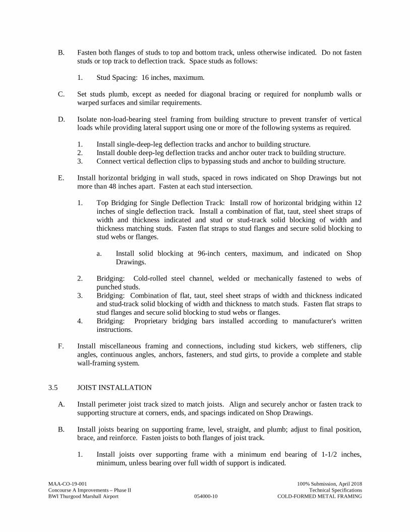
MAA-CO-19-001
054000-10
100% Submission, April 2018Concourse A Improvements – Phase II Technical SpecificationsBWI Thurgood Marshall Airport COLD-FORMED METAL FRAMING
B. Fasten both flanges of studs to top and bottom track, unless otherwise indicated. Do not fastenstuds or top track to deflection track. Space studs as follows:
1. Stud Spacing: 16 inches, maximum.
C. Set studs plumb, except as needed for diagonal bracing or required for nonplumb walls orwarped surfaces and similar requirements.
D. Isolate non-load-bearing steel framing from building structure to prevent transfer of verticalloads while providing lateral support using one or more of the following systems as required.
1. Install single-deep-leg deflection tracks and anchor to building structure.2. Install double deep-leg deflection tracks and anchor outer track to building structure.3. Connect vertical deflection clips to bypassing studs and anchor to building structure.
E. Install horizontal bridging in wall studs, spaced in rows indicated on Shop Drawings but notmore than 48 inches apart. Fasten at each stud intersection.
1. Top Bridging for Single Deflection Track: Install row of horizontal bridging within 12inches of single deflection track. Install a combination of flat, taut, steel sheet straps ofwidth and thickness indicated and stud or stud-track solid blocking of width andthickness matching studs. Fasten flat straps to stud flanges and secure solid blocking tostud webs or flanges.
a. Install solid blocking at 96-inch centers, maximum, and indicated on ShopDrawings.
2. Bridging: Cold-rolled steel channel, welded or mechanically fastened to webs ofpunched studs.
3. Bridging: Combination of flat, taut, steel sheet straps of width and thickness indicatedand stud-track solid blocking of width and thickness to match studs. Fasten flat straps tostud flanges and secure solid blocking to stud webs or flanges.
4. Bridging: Proprietary bridging bars installed according to manufacturer's writteninstructions.
F. Install miscellaneous framing and connections, including stud kickers, web stiffeners, clipangles, continuous angles, anchors, fasteners, and stud girts, to provide a complete and stablewall-framing system.
3.5 JOIST INSTALLATION
A. Install perimeter joist track sized to match joists. Align and securely anchor or fasten track tosupporting structure at corners, ends, and spacings indicated on Shop Drawings.
B. Install joists bearing on supporting frame, level, straight, and plumb; adjust to final position,brace, and reinforce. Fasten joists to both flanges of joist track.
1. Install joists over supporting frame with a minimum end bearing of 1-1/2 inches,minimum, unless bearing over full width of support is indicated.
MAA-CO-19-001
054000-11
100% Submission, April 2018Concourse A Improvements – Phase II Technical SpecificationsBWI Thurgood Marshall Airport COLD-FORMED METAL FRAMING
2. Reinforce ends and bearing points of joists with web stiffeners, end clips, joist hangers,steel clip angles, or steel-stud sections as indicated on Shop Drawings.
C. Space joists not more than 2 inches from abutting walls, and as follows:
1. Joist Spacing: 16 inches, maximum.
D. Frame openings with built-up joist headers consisting of joist and joist track, nesting joists, oranother combination of connected joists if indicated.
E. Install joist reinforcement at interior supports with single, short length of joist section locateddirectly over interior support, with lapped joists of equal length to joist reinforcement, or asindicated on Shop Drawings.
1. Install web stiffeners to transfer axial loads of walls above.
F. Install bridging at intervals indicated on Shop Drawings. Fasten bridging at each joistintersection as follows:
1. Bridging: Joist-track solid blocking of width and thickness indicated, secured to joistwebs.
2. Bridging: Combination of flat, taut, steel sheet straps of width and thickness indicatedand joist-track solid blocking of width and thickness indicated. Fasten flat straps tobottom flange of joists and secure solid blocking to joist webs.
G. Secure joists to load-bearing interior walls to prevent lateral movement of bottom flange.
H. Install miscellaneous joist framing and connections, including web stiffeners, closure pieces,clip angles, continuous angles, hold-down angles, anchors, and fasteners, to provide a completeand stable joist-framing assembly.
3.6 FIELD QUALITY CONTROL
A. Testing: Owner will engage a qualified independent testing and inspecting agency to performfield tests and inspections and prepare test reports.
B. Field and shop welds will be subject to testing and inspecting.
C. Testing agency will report test results promptly and in writing to Contractor and Architect.
D. Remove and replace work where test results indicate that it does not comply with specifiedrequirements.
E. Additional testing and inspecting, at Contractor's expense, will be performed to determinecompliance of replaced or additional work with specified requirements.
MAA-CO-19-001
054000-12
100% Submission, April 2018Concourse A Improvements – Phase II Technical SpecificationsBWI Thurgood Marshall Airport COLD-FORMED METAL FRAMING
3.7 REPAIRS AND PROTECTION
A. Galvanizing Repairs: Prepare and repair damaged galvanized coatings on fabricated andinstalled cold-formed metal framing with galvanized repair paint according to ASTM A 780 andmanufacturer's written instructions.
B. Provide final protection and maintain conditions, in a manner acceptable to manufacturer andInstaller, that ensure that cold-formed metal framing is without damage or deterioration at timeof Substantial Completion.
PART 4 - METHODS OF MEASUREMENTS
A. No separate measurement shall be made for work under this Specification Section
PART 5 - METHOD OF PAYMENT
A. No separate payment will be made for work under this Specification Section. The cost of work,complete in place, described in this Specification Section shall be included in the Lump SumBid under “Building Construction”
B. Costs include all labor, material, services, and equipment necessary to complete the work inevery aspect.
END OF SECTION 054000
MAA-AE-14-013 Task No.4604.2
055000-1
100% Submission, August 2018Concourse A Improvements – Phase II Technical SpecificationsBWI Thurgood Marshall Airport Metal Fabrications
SECTION 055000 - METAL FABRICATIONS
PART 1 - GENERAL
1.1 RELATED DOCUMENTS
A. Drawings and general provisions of the Contract, including Maryland Department of Transportation/ Maryland Aviation Administration Standard Provisions to the Construction Contract for the Concourse A Improvements – Phase II at BWI Thurgood Marshall Airport and other Divisions 1 Specification Sections, apply to this Section.
1.2 SUMMARY
A. Section Includes: 1. Steel framing and supports for overhead doors. 2. Steel framing and supports for countertops. 3. Steel tube reinforcement for low partitions and millwork. 4. Steel framing and supports for mechanical and electrical equipment. 5. Steel framing and supports for applications where framing and supports are not specified
in other Sections. 6. Elevator machine beams, hoist beams, and divider beams. 7. Steel shapes for supporting elevator door sills. 8. Shelf angles. 9. Metal ladders. 10. Metal floor plate and supports. 11. Elevator pit sump covers. 12. Channel frames in CMU walls of OH doors 13. Loose bearing and leveling plates for applications where they are not specified in other
Sections. 14. Soffit Guards
B. Products furnished, but not installed, under this Section include the following:
1. Loose steel lintels. 2. Anchor bolts, steel pipe sleeves, slotted-channel inserts, and wedge-type inserts indicated
to be cast into concrete or built into unit masonry. 3. Steel weld plates and angles for casting into concrete for applications where they are not
specified in other Sections.
C. Related Requirements:
1. Section 033000 "Cast-in-Place Concrete" for installing anchor bolts, steel pipe sleeves, slotted-channel inserts, wedge-type inserts, and other items cast into concrete.
2. Section 042000 "Unit Masonry" for installing loose lintels, anchor bolts, and other items built into unit masonry.
3. Section 051200 "Structural Steel Framing."
MAA-AE-14-013 Task No.4604.2
055000-2
100% Submission, August 2018Concourse A Improvements – Phase II Technical SpecificationsBWI Thurgood Marshall Airport Metal Fabrications
1.3 COORDINATION
A. Coordinate selection of shop primers with topcoats to be applied over them. Comply with paint and coating manufacturers' written recommendations to ensure that shop primers and topcoats are compatible with one another.
B. Coordinate installation of metal fabrications that are anchored to or that receive other work. Furnish setting drawings, templates, and directions for installing anchorages, including sleeves, concrete inserts, anchor bolts, and items with integral anchors, that are to be embedded in concrete or masonry. Deliver such items to Project site in time for installation.
1.4 ACTION SUBMITTALS
A. Product Data: For the following:
1. Nonslip aggregates and nonslip-aggregate surface finishes. 2. Metal nosings and treads. 3. Paint products. 4. Grout.
B. Shop Drawings: Show fabrication and installation details. Include plans, elevations, sections, and details of metal fabrications and their connections. Show anchorage and accessory items. Provide Shop Drawings for the following:
1. Steel framing and supports for ceiling-hung toilet compartments. 2. Steel framing and supports for overhead doors. 3. Steel framing and supports for countertops. 4. Steel tube reinforcement for low partitions. 5. Steel framing and supports for mechanical and electrical equipment. 6. Steel framing and supports for applications where framing and supports are not specified
in other Sections. 7. Elevator machine beams, hoist beams, and divider beams. 8. Steel shapes for supporting elevator door sills. 9. Metal ladders. 10. Metal floor plate and supports. 11. Elevator pit sump covers. 12. Metal bollards. 13. Soffit guards 14. Channel frames in CMU walls of OH doors
C. Delegated-Design Submittal: For ladders and soffit guards including analysis data signed and sealed by the qualified professional engineer responsible for their preparation.
1.5 INFORMATIONAL SUBMITTALS
A. The Contractor shall certify that the materials being submitted conform to the requirements of the Contract in all respects, including all Federal requirements such as “Buy American,” except as otherwise noted.
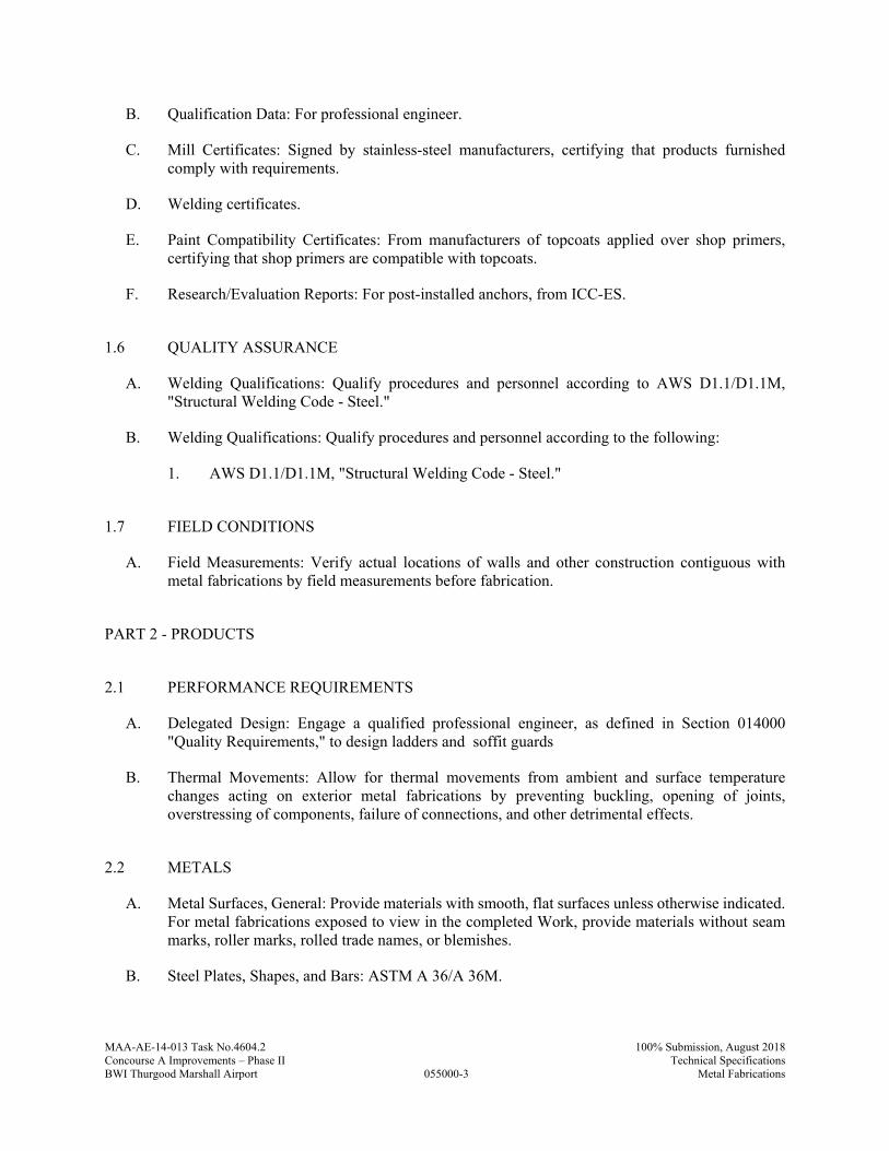
MAA-AE-14-013 Task No.4604.2
055000-3
100% Submission, August 2018Concourse A Improvements – Phase II Technical SpecificationsBWI Thurgood Marshall Airport Metal Fabrications
B. Qualification Data: For professional engineer.
C. Mill Certificates: Signed by stainless-steel manufacturers, certifying that products furnished comply with requirements.
D. Welding certificates.
E. Paint Compatibility Certificates: From manufacturers of topcoats applied over shop primers, certifying that shop primers are compatible with topcoats.
F. Research/Evaluation Reports: For post-installed anchors, from ICC-ES.
1.6 QUALITY ASSURANCE
A. Welding Qualifications: Qualify procedures and personnel according to AWS D1.1/D1.1M, "Structural Welding Code - Steel."
B. Welding Qualifications: Qualify procedures and personnel according to the following:
1. AWS D1.1/D1.1M, "Structural Welding Code - Steel."
1.7 FIELD CONDITIONS
A. Field Measurements: Verify actual locations of walls and other construction contiguous with metal fabrications by field measurements before fabrication.
PART 2 - PRODUCTS
2.1 PERFORMANCE REQUIREMENTS
A. Delegated Design: Engage a qualified professional engineer, as defined in Section 014000 "Quality Requirements," to design ladders and soffit guards
B. Thermal Movements: Allow for thermal movements from ambient and surface temperature changes acting on exterior metal fabrications by preventing buckling, opening of joints, overstressing of components, failure of connections, and other detrimental effects.
2.2 METALS
A. Metal Surfaces, General: Provide materials with smooth, flat surfaces unless otherwise indicated. For metal fabrications exposed to view in the completed Work, provide materials without seam marks, roller marks, rolled trade names, or blemishes.
B. Steel Plates, Shapes, and Bars: ASTM A 36/A 36M.
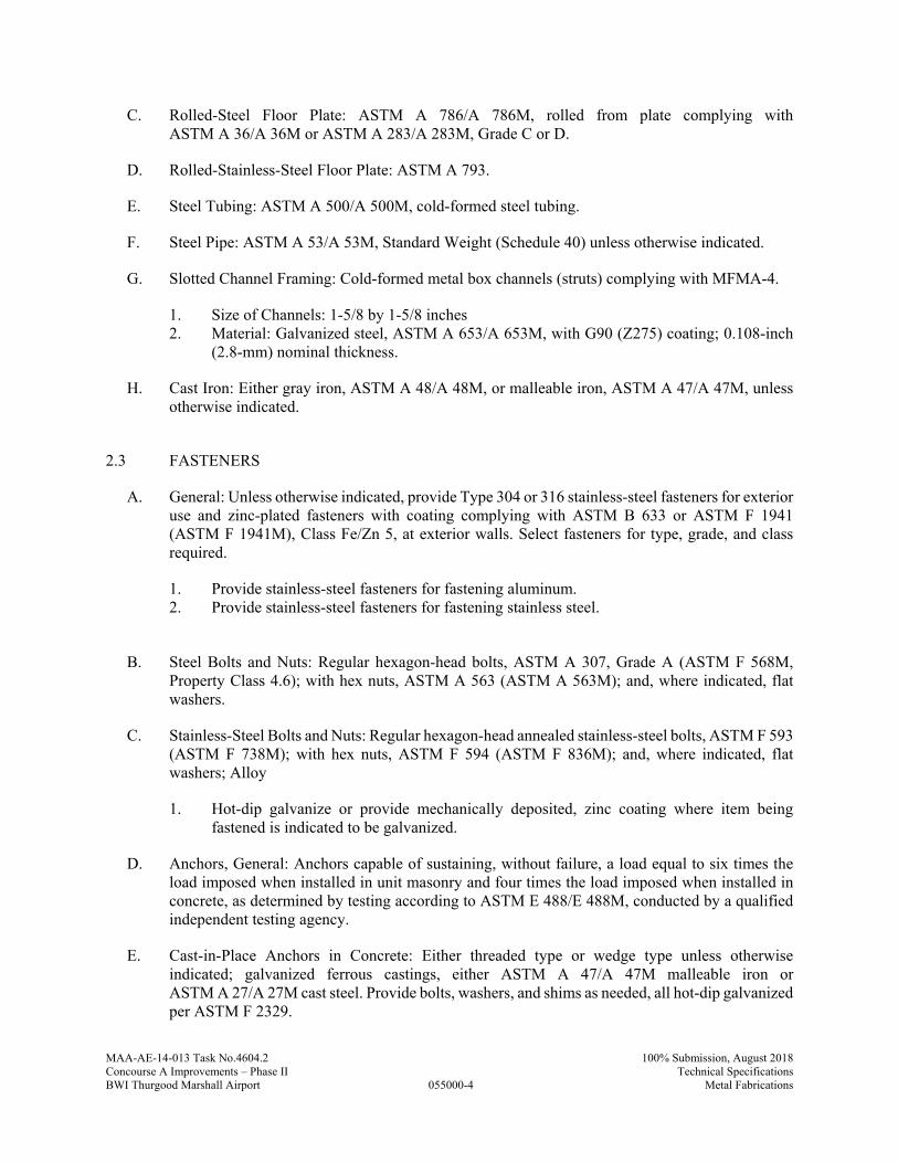
MAA-AE-14-013 Task No.4604.2
055000-4
100% Submission, August 2018Concourse A Improvements – Phase II Technical SpecificationsBWI Thurgood Marshall Airport Metal Fabrications
C. Rolled-Steel Floor Plate: ASTM A 786/A 786M, rolled from plate complying with ASTM A 36/A 36M or ASTM A 283/A 283M, Grade C or D.
D. Rolled-Stainless-Steel Floor Plate: ASTM A 793.
E. Steel Tubing: ASTM A 500/A 500M, cold-formed steel tubing.
F. Steel Pipe: ASTM A 53/A 53M, Standard Weight (Schedule 40) unless otherwise indicated.
G. Slotted Channel Framing: Cold-formed metal box channels (struts) complying with MFMA-4.
1. Size of Channels: 1-5/8 by 1-5/8 inches 2. Material: Galvanized steel, ASTM A 653/A 653M, with G90 (Z275) coating; 0.108-inch
(2.8-mm) nominal thickness.
H. Cast Iron: Either gray iron, ASTM A 48/A 48M, or malleable iron, ASTM A 47/A 47M, unless otherwise indicated.
2.3 FASTENERS
A. General: Unless otherwise indicated, provide Type 304 or 316 stainless-steel fasteners for exterior use and zinc-plated fasteners with coating complying with ASTM B 633 or ASTM F 1941 (ASTM F 1941M), Class Fe/Zn 5, at exterior walls. Select fasteners for type, grade, and class required.
1. Provide stainless-steel fasteners for fastening aluminum. 2. Provide stainless-steel fasteners for fastening stainless steel.
B. Steel Bolts and Nuts: Regular hexagon-head bolts, ASTM A 307, Grade A (ASTM F 568M, Property Class 4.6); with hex nuts, ASTM A 563 (ASTM A 563M); and, where indicated, flat washers.
C. Stainless-Steel Bolts and Nuts: Regular hexagon-head annealed stainless-steel bolts, ASTM F 593 (ASTM F 738M); with hex nuts, ASTM F 594 (ASTM F 836M); and, where indicated, flat washers; Alloy
1. Hot-dip galvanize or provide mechanically deposited, zinc coating where item being fastened is indicated to be galvanized.
D. Anchors, General: Anchors capable of sustaining, without failure, a load equal to six times the load imposed when installed in unit masonry and four times the load imposed when installed in concrete, as determined by testing according to ASTM E 488/E 488M, conducted by a qualified independent testing agency.
E. Cast-in-Place Anchors in Concrete: Either threaded type or wedge type unless otherwise indicated; galvanized ferrous castings, either ASTM A 47/A 47M malleable iron or ASTM A 27/A 27M cast steel. Provide bolts, washers, and shims as needed, all hot-dip galvanized per ASTM F 2329.
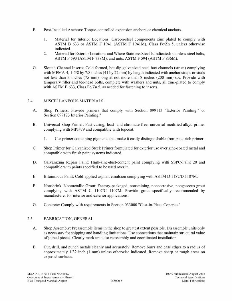
MAA-AE-14-013 Task No.4604.2
055000-5
100% Submission, August 2018Concourse A Improvements – Phase II Technical SpecificationsBWI Thurgood Marshall Airport Metal Fabrications
F. Post-Installed Anchors: Torque-controlled expansion anchors or chemical anchors.
1. Material for Interior Locations: Carbon-steel components zinc plated to comply with ASTM B 633 or ASTM F 1941 (ASTM F 1941M), Class Fe/Zn 5, unless otherwise indicated.
2. Material for Exterior Locations and Where Stainless Steel Is Indicated: stainless-steel bolts, ASTM F 593 (ASTM F 738M), and nuts, ASTM F 594 (ASTM F 836M).
G. Slotted-Channel Inserts: Cold-formed, hot-dip galvanized-steel box channels (struts) complying with MFMA-4, 1-5/8 by 7/8 inches (41 by 22 mm) by length indicated with anchor straps or studs not less than 3 inches (75 mm) long at not more than 8 inches (200 mm) o.c. Provide with temporary filler and tee-head bolts, complete with washers and nuts, all zinc-plated to comply with ASTM B 633, Class Fe/Zn 5, as needed for fastening to inserts.
2.4 MISCELLANEOUS MATERIALS
A. Shop Primers: Provide primers that comply with Section 099113 "Exterior Painting." or Section 099123 Interior Painting."
B. Universal Shop Primer: Fast-curing, lead- and chromate-free, universal modified-alkyd primer complying with MPI#79 and compatible with topcoat.
1. Use primer containing pigments that make it easily distinguishable from zinc-rich primer.
C. Shop Primer for Galvanized Steel: Primer formulated for exterior use over zinc-coated metal and compatible with finish paint systems indicated.
D. Galvanizing Repair Paint: High-zinc-dust-content paint complying with SSPC-Paint 20 and compatible with paints specified to be used over it.
E. Bituminous Paint: Cold-applied asphalt emulsion complying with ASTM D 1187/D 1187M.
F. Nonshrink, Nonmetallic Grout: Factory-packaged, nonstaining, noncorrosive, nongaseous grout complying with ASTM C 1107/C 1107M. Provide grout specifically recommended by manufacturer for interior and exterior applications.
G. Concrete: Comply with requirements in Section 033000 "Cast-in-Place Concrete"
2.5 FABRICATION, GENERAL
A. Shop Assembly: Preassemble items in the shop to greatest extent possible. Disassemble units only as necessary for shipping and handling limitations. Use connections that maintain structural value of joined pieces. Clearly mark units for reassembly and coordinated installation.
B. Cut, drill, and punch metals cleanly and accurately. Remove burrs and ease edges to a radius of approximately 1/32 inch (1 mm) unless otherwise indicated. Remove sharp or rough areas on exposed surfaces.

MAA-AE-14-013 Task No.4604.2
055000-6
100% Submission, August 2018Concourse A Improvements – Phase II Technical SpecificationsBWI Thurgood Marshall Airport Metal Fabrications
C. Form bent-metal corners to smallest radius possible without causing grain separation or otherwise impairing work.
D. Form exposed work with accurate angles and surfaces and straight edges.
E. Weld corners and seams continuously to comply with the following:
1. Use materials and methods that minimize distortion and develop strength and corrosion resistance of base metals.
2. Obtain fusion without undercut or overlap. 3. Remove welding flux immediately. 4. At exposed connections, finish exposed welds and surfaces smooth and blended so no
roughness shows after finishing and contour of welded surface matches that of adjacent surface.
F. Form exposed connections with hairline joints, flush and smooth, using concealed fasteners or welds where possible. Where exposed fasteners are required, use Phillips flat-head (countersunk) fasteners unless otherwise indicated. Locate joints where least conspicuous.
G. Fabricate seams and other connections that are exposed to weather in a manner to exclude water. Provide weep holes where water may accumulate.
H. Cut, reinforce, drill, and tap metal fabrications as indicated to receive finish hardware, screws, and similar items.
I. Provide for anchorage of type indicated; coordinate with supporting structure. Space anchoring devices to secure metal fabrications rigidly in place and to support indicated loads.
J. Where units are indicated to be cast into concrete or built into masonry, equip with integrally welded steel strap anchors, 1/8 by 1-1/2 inches (3.2 by 38 mm), with a minimum 6-inch (150-mm) embedment and 2-inch (50-mm) hook, not less than 8 inches (200 mm) from ends and corners of units and 24 inches (600 mm) o.c., unless otherwise indicated.
2.6 MISCELLANEOUS FRAMING AND SUPPORTS
A. General: Provide steel framing and supports not specified in other Sections as needed to complete the Work.
B. Fabricate units from steel shapes, plates, and bars of welded construction unless otherwise indicated. Fabricate to sizes, shapes, and profiles indicated and as necessary to receive adjacent construction.
1. Fabricate units from slotted channel framing where indicated. 2. Furnish inserts for units installed after concrete is placed.
C. Galvanize miscellaneous framing and supports where indicated.
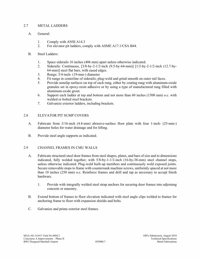
MAA-AE-14-013 Task No.4604.2
055000-7
100% Submission, August 2018Concourse A Improvements – Phase II Technical SpecificationsBWI Thurgood Marshall Airport Metal Fabrications
2.7 METAL LADDERS
A. General:
1. Comply with ANSI A14.3 2. For elevator pit ladders, comply with ASME A17.1/CSA B44.
B. Steel Ladders:
1. Space siderails 16 inches (406 mm) apart unless otherwise indicated. 2. Siderails: Continuous, [3/8-by-2-1/2-inch (9.5-by-64-mm)] [1/2-by-2-1/2-inch (12.7-by-
64-mm)] steel flat bars, with eased edges. 3. Rungs: 3/4-inch- (19-mm-) diameter 4. Fit rungs in centerline of siderails; plug-weld and grind smooth on outer rail faces. 5. Provide nonslip surfaces on top of each rung, either by coating rung with aluminum-oxide
granules set in epoxy-resin adhesive or by using a type of manufactured rung filled with aluminum-oxide grout.
6. Support each ladder at top and bottom and not more than 60 inches (1500 mm) o.c. with welded or bolted steel brackets.
7. Galvanize exterior ladders, including brackets.
2.8 ELEVATOR PIT SUMP COVERS
A. Fabricate from 3/16-inch (4.8-mm) abrasive-surface floor plate with four 1-inch- (25-mm-) diameter holes for water drainage and for lifting.
B. Provide steel angle supports as indicated.
2.9 CHANNEL FRAMES IN CMU WALLS
A. Fabricate structural-steel door frames from steel shapes, plates, and bars of size and to dimensions indicated, fully welded together, with 5/8-by-1-1/2-inch (16-by-38-mm) steel channel stops, unless otherwise indicated. Plug-weld built-up members and continuously weld exposed joints. Secure removable stops to frame with countersunk machine screws, uniformly spaced at not more than 10 inches (250 mm) o.c. Reinforce frames and drill and tap as necessary to accept finish hardware.
1. Provide with integrally welded steel strap anchors for securing door frames into adjoining concrete or masonry.
B. Extend bottom of frames to floor elevation indicated with steel angle clips welded to frames for anchoring frame to floor with expansion shields and bolts.
C. Galvanize and prime exterior steel frames.
MAA-AE-14-013 Task No.4604.2
055000-8
100% Submission, August 2018Concourse A Improvements – Phase II Technical SpecificationsBWI Thurgood Marshall Airport Metal Fabrications
2.10 STEEL WELD PLATES AND ANGLES
A. Provide steel weld plates and angles not specified in other Sections, for items supported from concrete construction as needed to complete the Work. Provide each unit with no fewer than two integrally welded steel strap anchors for embedding in concrete.
2.11 FINISHES, GENERAL
A. Finish metal fabrications after assembly.
B. Finish exposed surfaces to remove tool and die marks and stretch lines, and to blend into surrounding surface.
2.12 STEEL AND IRON FINISHES
A. Galvanizing: Hot-dip galvanize items as indicated to comply with ASTM A 153/A 153M for steel and iron hardware and with ASTM A 123/A 123M for other steel and iron products.
1. Do not quench or apply post galvanizing treatments that might interfere with paint adhesion.
B. Preparation for Shop Priming Galvanized Items: After galvanizing, thoroughly clean railings of grease, dirt, oil, flux, and other foreign matter, and treat with metallic phosphate process.
C. Shop prime iron and steel items not indicated to be galvanized unless they are to be embedded in concrete, sprayed-on fireproofing, or masonry, or unless otherwise indicated.
PART 3 - EXECUTION
3.1 INSTALLATION, GENERAL
A. Cutting, Fitting, and Placement: Perform cutting, drilling, and fitting required for installing metal fabrications. Set metal fabrications accurately in location, alignment, and elevation; with edges and surfaces level, plumb, true, and free of rack; and measured from established lines and levels.
B. Fit exposed connections accurately together to form hairline joints. Weld connections that are not to be left as exposed joints but cannot be shop welded because of shipping size limitations. Do not weld, cut, or abrade surfaces of exterior units that have been hot-dip galvanized after fabrication and are for bolted or screwed field connections.
C. Field Welding: Comply with the following requirements:
1. Use materials and methods that minimize distortion and develop strength and corrosion resistance of base metals.
2. Obtain fusion without undercut or overlap. 3. Remove welding flux immediately.

MAA-AE-14-013 Task No.4604.2
055000-9
100% Submission, August 2018Concourse A Improvements – Phase II Technical SpecificationsBWI Thurgood Marshall Airport Metal Fabrications
4. At exposed connections, finish exposed welds and surfaces smooth and blended so no roughness shows after finishing and contour of welded surface matches that of adjacent surface.
D. Fastening to In-Place Construction: Provide anchorage devices and fasteners where metal fabrications are required to be fastened to in-place construction. Provide threaded fasteners for use with concrete and masonry inserts, toggle bolts, through bolts, lag screws, wood screws, and other connectors.
E. Provide temporary bracing or anchors in formwork for items that are to be built into concrete, masonry, or similar construction.
F. Corrosion Protection: Coat concealed surfaces of aluminum that come into contact with grout, concrete, masonry, wood, or dissimilar metals with the following:
3.2 INSTALLING MISCELLANEOUS FRAMING AND SUPPORTS
A. General: Install framing and supports to comply with requirements of items being supported, including manufacturers' written instructions and requirements indicated on Shop Drawings.
B. Anchor supports for ceiling hung toilet partitions, overhead doors and overhead grilles securely to, and rigidly brace from, building structure.
3.3 INSTALLING BEARING AND LEVELING PLATES
A. Clean concrete and masonry bearing surfaces of bond-reducing materials, and roughen to improve bond to surfaces. Clean bottom surface of plates.
B. Set bearing and leveling plates on wedges, shims, or leveling nuts. After bearing members have been positioned and plumbed, tighten anchor bolts. Do not remove wedges or shims but, if protruding, cut off flush with edge of bearing plate before packing with nonshrink grout. Pack grout solidly between bearing surfaces and plates to ensure that no voids remain.
3.4 ADJUSTING AND CLEANING
A. Touchup Painting: Immediately after erection, clean field welds, bolted connections, and abraded areas. Paint uncoated and abraded areas with the same material as used for shop painting to comply with SSPC-PA 1 for touching up shop-painted surfaces.
1. Apply by brush or spray to provide a minimum 2.0-mil (0.05-mm) dry film thickness.
B. Galvanized Surfaces: Clean field welds, bolted connections, and abraded areas and repair galvanizing to comply with ASTM A 780/A 780M.
MAA-AE-14-013 Task No.4604.2
055000-10
100% Submission, August 2018Concourse A Improvements – Phase II Technical SpecificationsBWI Thurgood Marshall Airport Metal Fabrications
PART 4 - MEASUREMENT
4.1 METHODS OF MEASUREMENT
A. No separate measurement shall be made for work under this Specification Section
PART 5 - PAYMENT
5.1 METHOD OF PAYMENT
A. No separate payment will be made for work under this Specification Section. The cost of work, complete in place, described in this Specification Section shall be included in the Lump Sum Bid under “Building Construction”
B. Costs include all labor, material, services, and equipment necessary to complete the work in every aspect.
END OF SECTION 055000
MAA-AE-14-013 Task No.4604.2
055113-1
100% Submission, August 2018Concourse A Improvements – Phase II Technical SpecificationsBWI Thurgood Marshall Airport Metal Pan Stairs
SECTION 055113 - METAL PAN STAIRS
PART 1 - GENERAL
1.1 RELATED DOCUMENTS
A. Drawings and general provisions of the Contract, including Maryland Department of Transportation/ Maryland Aviation Administration Standard Provisions to the Construction Contract for the Concourse A Improvements – Phase II at BWI Thurgood Marshall Airport and other Divisions 1 Specification Sections, apply to this Section.
1.2 SUMMARY
A. Section Includes:
1. Preassembled steel stairs with concrete-filled treads. 2. Steel tube railings attached to metal stairs. 3. Steel tube handrails attached to walls adjacent to metal stairs.
B. Related Requirements:
1. Section 033000 "Cast-in-Place Concrete" for concrete fill for stair treads and platforms. 2. Section 055213 "Pipe and Tube Railings" for pipe and tube railings not attached to metal
stairs or to walls adjacent to metal stairs.
1.3 COORDINATION
A. Coordinate selection of shop primers with topcoats to be applied over them. Comply with paint and coating manufacturers' written recommendations to ensure that shop primers and topcoats are compatible with one another.
B. Coordinate installation of anchorages for metal stairs. Furnish setting drawings, templates, and directions for installing anchorages, including sleeves, concrete inserts, anchor bolts, and items with integral anchors, that are to be embedded in concrete or masonry. Deliver such items to Project site in time for installation.
C. Coordinate locations of hanger rods and struts with other work so that they do not encroach on required stair width and are within the fire-resistance-rated stair enclosure.
1.4 ACTION SUBMITTALS
A. Product Data: For metal pan stairs and the following:
1. Abrasive inserts
MAA-AE-14-013 Task No.4604.2
055113-2
100% Submission, August 2018Concourse A Improvements – Phase II Technical SpecificationsBWI Thurgood Marshall Airport Metal Pan Stairs
2. Paint products.
B. Shop Drawings: Include plans, elevations, sections, details, and attachments to other work.
C. Delegated-Design Submittal: For stairs and railings, including analysis data signed and sealed by the qualified professional engineer responsible for their preparation.
1.5 INFORMATIONAL SUBMITTALS
A. The Contractor shall certify that the materials being submitted conform to the requirements of the Contract in all respects, including all Federal requirements such as “Buy American,” except as otherwise noted.
B. Welding certificates.
C. Paint Compatibility Certificates: From manufacturers of topcoats applied over shop primers certifying that shop primers are compatible with topcoats.
1.6 QUALITY ASSURANCE
A. Installer Qualifications: Fabricator of products.
B. Welding Qualifications: Qualify procedures and personnel according to the following:
1. AWS D1.1/D1.1M, "Structural Welding Code - Steel." 2. AWS D1.3/D1.3M, "Structural Welding Code - Sheet Steel."
PART 2 - PRODUCTS
2.1 MANUFACTURERS
A. Manufacturers: Subject to compliance with requirements, available manufacturers offering products that may be incorporated into the Work include, but are not limited to the following:
1. Alfab, Inc. 2. American Stair, Inc. 3. Worthington Metal Fabricators.
2.2 PERFORMANCE REQUIREMENTS
A. Delegated Design: Engage a qualified professional engineer to design stairs and railings.
B. Structural Performance of Stairs: Metal stairs shall withstand the effects of gravity loads and the following loads and stresses within limits and under conditions indicated:
1. Uniform Load: 100 lbf/sq. ft. (4.79 kN/sq. m). 2. Concentrated Load: 300 lbf (1.33 kN) applied on an area of 4 sq. in. (2580 sq. mm).
MAA-AE-14-013 Task No.4604.2
055113-3
100% Submission, August 2018Concourse A Improvements – Phase II Technical SpecificationsBWI Thurgood Marshall Airport Metal Pan Stairs
3. Uniform and concentrated loads need not be assumed to act concurrently. 4. Stair Framing: Capable of withstanding stresses resulting from railing loads in addition to
loads specified above. 5. Limit deflection of treads, platforms, and framing members to L/360 > or 1/4 inch (6.4
mm), whichever is less.
C. Structural Performance of Railings: Railings shall withstand the effects of gravity loads and the following loads and stresses within limits and under conditions indicated:
1. Handrails and Top Rails of Guards:
a. Uniform load of 50 lbf/ft. (0.73 kN/m) applied in any direction. b. Concentrated load of 200 lbf (0.89 kN) applied in any direction. c. Uniform and concentrated loads need not be assumed to act concurrently.
2. Infill of Guards:
a. Concentrated load of 50 lbf (0.22 kN) applied horizontally on an area of 1 sq. ft. (0.093 sq. m).
b. Infill load and other loads need not be assumed to act concurrently.
D. Seismic Performance of Stairs: Metal stairs shall withstand the effects of earthquake motions determined according to ASCE/SEI 7
1. Component Importance Factor: 1.5.
2.3 METALS
A. Metal Surfaces, General: Provide materials with smooth, flat surfaces unless otherwise indicated. For components exposed to view in the completed Work, provide materials without seam marks, roller marks, rolled trade names, or blemishes.
B. Steel Plates, Shapes, and Bars: ASTM A 36/A 36M.
C. Steel Tubing: ASTM A 500 (cold formed) ASTM A 513.
D. Cast Iron: Either gray iron, ASTM A 48/A 48M, or malleable iron, ASTM A 47/A 47M, unless otherwise indicated.
E. Uncoated, Cold-Rolled Steel Sheet: ASTM A 1008/A 1008M, either commercial steel, Type B, or structural steel, Grade 25 (Grade 170), unless another grade is required by design loads; exposed.
F. Uncoated, Hot-Rolled Steel Sheet: ASTM A 1011/A 1011M, either commercial steel, Type B, or structural steel, Grade 30 (Grade 205), unless another grade is required by design loads.
MAA-AE-14-013 Task No.4604.2
055113-4
100% Submission, August 2018Concourse A Improvements – Phase II Technical SpecificationsBWI Thurgood Marshall Airport Metal Pan Stairs
2.4 ABRASIVE NOSINGS
A. Extruded Units: Aluminum units with abrasive filler consisting of aluminum oxide, silicon carbide, or a combination of both, in an epoxy-resin binder. Fabricate units in lengths necessary to accurately fit openings or conditions.
1. Manufacturers: Subject to compliance with requirements, available manufacturers offering products that may be incorporated into the Work include, but are not limited to the following:
a. ACL Industries, Inc. b. American Safety Tread Co., Inc. c. Armstrong Products, Inc. d. Balco, Inc.
2. Provide ribbed units, with abrasive filler strips projecting 1/16 inch (1.5 mm) above aluminum extrusion.
3. Provide solid-abrasive-type units without ribs.
B. Provide anchors for embedding units in concrete, either integral or applied to units, as standard with manufacturer.
C. Apply bituminous paint to concealed surfaces of cast-metal units set into concrete.
D. Apply clear lacquer to concealed surfaces of extruded units set into concrete.
2.5 FASTENERS
A. General: Provide zinc-plated fasteners with coating complying with ASTM B 633 or ASTM F 1941 (ASTM F 1941M), Class Fe/Zn 12 for exterior use, and Class Fe/Zn 5 where built into exterior walls. Select fasteners for type, grade, and class required.
B. Bolts and Nuts: Regular hexagon-head bolts, ASTM A 307, Grade A (ASTM F 568M, Property Class 4.6); with hex nuts, ASTM A 563 (ASTM A 563M); and, where indicated, flat washers.
C. Anchor Bolts: ASTM F 1554, Grade 36, of dimensions indicated; with nuts, ASTM A 563 (ASTM A 563M); and, where indicated, flat washers.
D. Post-Installed Anchors: Torque-controlled expansion anchors or chemical anchors capable of sustaining, without failure, a load equal to six times the load imposed when installed in unit masonry and four times the load imposed when installed in concrete, as determined by testing according to ASTM E 488/E 488M, conducted by a qualified independent testing agency.
1. Material for Interior Locations: Carbon-steel components zinc plated to comply with ASTM B 633 or ASTM F 1941 (ASTM F 1941M), Class Fe/Zn 5, unless otherwise indicated.
2. Material for Exterior Locations and Where Stainless Steel Is Indicated: Alloy Group 1 (A1) stainless-steel bolts, ASTM F 593 (ASTM F 738M), and nuts, ASTM F 594 (ASTM F 836M).
MAA-AE-14-013 Task No.4604.2
055113-5
100% Submission, August 2018Concourse A Improvements – Phase II Technical SpecificationsBWI Thurgood Marshall Airport Metal Pan Stairs
2.6 MISCELLANEOUS MATERIALS
A. Shop Primers: Provide primers that comply with Section 099113 "Exterior Painting" and Section 099123 "Interior Painting."
B. Concrete Materials and Properties: Comply with requirements in Section 033000 "Cast-in-Place Concrete" for normal-weight, air-entrained, ready-mix concrete with a minimum 28-day compressive strength of 3000 psi (20 MPa) unless otherwise indicated.
C. Nonslip-Aggregate Concrete Finish: Factory-packaged abrasive aggregate made from fused, aluminum-oxide grits or crushed emery; rustproof and nonglazing; unaffected by freezing, moisture, or cleaning materials.
D. Welded Wire Reinforcement: ASTM A 185/A 185M, 6 by 6 inches (152 by 152 mm), W1.4 by W1.4, unless otherwise indicated.
2.7 FABRICATION, GENERAL
A. Provide complete stair assemblies, including metal framing, hangers, struts, railings, clips, brackets, bearing plates, and other components necessary to support and anchor stairs and platforms on supporting structure.
1. Join components by welding unless otherwise indicated. 2. Use connections that maintain structural value of joined pieces.
B. Preassembled Stairs: Assemble stairs in shop to greatest extent possible. Disassemble units only as necessary for shipping and handling limitations. Clearly mark units for reassembly and coordinated installation.
C. Cut, drill, and punch metals cleanly and accurately. Remove burrs and ease edges to a radius of approximately 1/32 inch (1 mm) unless otherwise indicated. Remove sharp or rough areas on exposed surfaces.
D. Form bent-metal corners to smallest radius possible without causing grain separation or otherwise impairing work.
E. Form exposed work with accurate angles and surfaces and straight edges.
F. Weld connections to comply with the following:
1. Use materials and methods that minimize distortion and develop strength and corrosion resistance of base metals.
2. Obtain fusion without undercut or overlap. 3. Remove welding flux immediately. 4. Weld exposed corners and seams continuously unless otherwise indicated. 5. At exposed connections, finish exposed welds to comply with NOMMA's "Voluntary Joint
Finish Standards" for Type 3 welds: partially dressed weld with spatter removed.
MAA-AE-14-013 Task No.4604.2
055113-6
100% Submission, August 2018Concourse A Improvements – Phase II Technical SpecificationsBWI Thurgood Marshall Airport Metal Pan Stairs
G. Form exposed connections with hairline joints, flush and smooth, using concealed fasteners where possible. Where exposed fasteners are required, use Phillips flat-head (countersunk) screws or bolts unless otherwise indicated. Locate joints where least conspicuous.
2.8 STEEL-FRAMED STAIRS
A. NAAMM Stair Standard: Comply with "Recommended Voluntary Minimum Standards for Fixed Metal Stairs" in NAAMM AMP 510, "Metal Stairs Manual," Commercial or Service Class, unless more stringent requirements are indicated.
B. Stair Framing:
1. Fabricate stringers of steel plates or channels.
a. Provide closures for exposed ends of channel stringers.
2. Construct platforms of steel plate or channel headers and miscellaneous framing members as needed to comply with performance requirements.
3. Weld or bolt stringers to headers; weld or bolt framing members to stringers and headers. If using bolts, fabricate and join so bolts are not exposed on finished surfaces.
4. Where stairs are enclosed by gypsum board shaft-wall assemblies, provide hanger rods or struts to support landings from floor construction above or below. Locate hanger rods and struts where they do not encroach on required stair width and are within the fire-resistance-rated stair enclosure.
5. Where masonry walls support metal stairs, provide temporary supporting struts designed for erecting steel stair components before installing masonry.
C. Metal Pan Stairs: Form risers, subtread pans, and subplatforms to configurations shown from steel sheet of thickness needed to comply with performance requirements, but not less than 0.067.
1. Steel Sheet: Uncoated cold or hot-rolled steel sheet. 2. Attach risers and subtreads to stringers with brackets made of steel angles or bars. Weld
brackets to stringers and attach metal pans to brackets by welding, riveting, or bolting. 3. Shape metal pans to include nosing integral with riser. 4. At Contractor's option, provide stair assemblies with metal pan subtreads filled with
reinforced concrete during fabrication. 5. Provide subplatforms of configuration indicated or, if not indicated, the same as subtreads.
Weld subplatforms to platform framing.
a. Smooth Soffit Construction: Construct subplatforms with flat metal under surfaces to produce smooth soffits.
2.9 STAIR RAILINGS
A. Steel Tube Railings: Fabricate railings to comply with requirements indicated for design, dimensions, details, finish, and member sizes, including wall thickness of tube, post spacings, and anchorage, but not less than that needed to withstand indicated loads.
MAA-AE-14-013 Task No.4604.2
055113-7
100% Submission, August 2018Concourse A Improvements – Phase II Technical SpecificationsBWI Thurgood Marshall Airport Metal Pan Stairs
1. Rails and Posts: 1 ¼” Nominal pipe diameter, minimum (1.66” O.D.) square posts.
B. Welded Connections: Fabricate railings with welded connections. Cope components at connections to provide close fit, or use fittings designed for this purpose. Weld all around at connections, including at fittings.
1. Finish welds to comply with NOMMA's "Voluntary Joint Finish Standards" for Type 3 welds: partially dressed weld with spatter removed as shown in NAAMM AMP 521.
C. Form changes in direction of railings as follows:
1. As detailed. 2. By bending or by inserting prefabricated elbow fittings.
D. For changes in direction made by bending, use jigs to produce uniform curvature for each repetitive configuration required. Maintain cross section of member throughout entire bend without buckling, twisting, cracking, or otherwise deforming exposed surfaces of components.
E. Close exposed ends of railing members with prefabricated end fittings.
F. Provide wall returns at ends of wall-mounted handrails unless otherwise indicated. Close ends of returns unless clearance between end of rail and wall is 1/4 inch (6 mm) or less.
G. Connect posts to stair framing by direct welding unless otherwise indicated.
H. Brackets, Flanges, Fittings, and Anchors: Provide wall brackets, end closures, flanges, miscellaneous fittings, and anchors for interconnecting components and for attaching to other work. Furnish inserts and other anchorage devices for connecting to concrete or masonry work. 1. For nongalvanized railings, provide nongalvanized ferrous-metal fittings, brackets,
fasteners, and sleeves, except galvanize anchors embedded in exterior masonry and concrete construction.
2. Provide type of bracket that provides 1-1/2-inch (38-mm) clearance from inside face of handrail to finished wall surface.
I. Fillers: Provide fillers made from steel plate, or other suitably crush-resistant material, where needed to transfer wall bracket loads through wall finishes to structural supports. Size fillers to suit wall finish thicknesses and to produce adequate bearing area to prevent bracket rotation and overstressing of substrate.
2.10 FINISHES
A. Finish metal stairs after assembly.
B. Preparation for Shop Priming: Prepare uncoated ferrous-metal surfaces to comply with SSPC-SP 3, "Power Tool Cleaning."
C. Apply shop primer to uncoated surfaces of metal stair components, except those with galvanized finishes and those to be embedded in concrete or masonry unless otherwise indicated. Comply
MAA-AE-14-013 Task No.4604.2
055113-8
100% Submission, August 2018Concourse A Improvements – Phase II Technical SpecificationsBWI Thurgood Marshall Airport Metal Pan Stairs
with SSPC-PA 1, "Paint Application Specification No. 1: Shop, Field, and Maintenance Painting of Steel," for shop painting.
PART 3 - EXECUTION
3.1 INSTALLING METAL PAN STAIRS
A. Fastening to In-Place Construction: Provide anchorage devices and fasteners where necessary for securing metal stairs to in-place construction. Include threaded fasteners for concrete and masonry inserts, through-bolts, lag bolts, and other connectors.
B. Cutting, Fitting, and Placement: Perform cutting, drilling, and fitting required for installing metal stairs. Set units accurately in location, alignment, and elevation, measured from established lines and levels and free of rack.
C. Install metal stairs by welding stair framing to steel structure or to weld plates cast into concrete unless otherwise indicated.
D. Provide temporary bracing or anchors in formwork for items that are to be built into concrete, masonry, or similar construction.
E. Fit exposed connections accurately together to form hairline joints. Weld connections that are not to be left as exposed joints but cannot be shop welded because of shipping size limitations. Do not weld, cut, or abrade surfaces of exterior units that have been hot-dip galvanized after fabrication and are for bolted or screwed field connections.
F. Field Welding: Comply with requirements for welding in "Fabrication, General" Article.
G. Place and finish concrete fill for treads and platforms to comply with Section 033000 "Cast-in-Place Concrete."
1. Install abrasive nosings with anchors fully embedded in concrete. Center nosings on tread width.
3.2 INSTALLING RAILINGS
A. Adjust railing systems before anchoring to ensure matching alignment at abutting joints. Space posts at spacing indicated or, if not indicated, as required by design loads. Plumb posts in each direction. Secure posts and rail ends to building construction as follows:
1. Anchor posts to steel by welding to steel supporting members. 2. Anchor handrail ends to concrete and masonry with steel round flanges welded to rail ends
and anchored with postinstalled anchors and bolts.
B. Attach handrails to wall with wall brackets. Locate brackets as indicated or, if not indicated, at spacing required to support structural loads. Secure wall brackets to building construction as follows:
MAA-AE-14-013 Task No.4604.2
055113-9
100% Submission, August 2018Concourse A Improvements – Phase II Technical SpecificationsBWI Thurgood Marshall Airport Metal Pan Stairs
1. For concrete and solid masonry anchorage, use drilled-in expansion shields and hanger or lag bolts.
2. For steel-framed partitions, use self-tapping screws fastened to steel framing or to concealed steel reinforcements.
3.3 ADJUSTING AND CLEANING
A. Touchup Painting: Immediately after erection, clean field welds, bolted connections, and abraded areas of shop paint, and paint exposed areas with same material as used for shop painting to comply with SSPC-PA 1 for touching up shop-painted surfaces.
1. Apply by brush or spray to provide a minimum 2.0-mil (0.05-mm) dry film thickness.
PART 4 - MEASUREMENT
4.1 METHODS OF MEASUREMENT
A. No separate measurement shall be made for work under this Specification Section
PART 5 - PAYMENT
5.1 METHOD OF PAYMENT
A. No separate payment will be made for work under this Specification Section. The cost of work, complete in place, described in this Specification Section shall be included in the Lump Sum Bid under “Building Construction”
B. Costs include all labor, material, services, and equipment necessary to complete the work in every aspect.
1.
END OF SECTION 055113
MAA-AE-14-013 Task No.4604.2
055113-10
100% Submission, August 2018Concourse A Improvements – Phase II Technical SpecificationsBWI Thurgood Marshall Airport Metal Pan Stairs
THIS PAGE INTENTIONALLY LEFT BLANK
MAA-AE-14-013 Task No.4604.2
055213-1
100% Submission, August 2018Concourse A Improvements – Phase II Technical SpecificationsBWI Thurgood Marshall Airport Pipe and Tube Railings
SECTION 055213 - PIPE AND TUBE RAILINGS
PART 1 - GENERAL
1.1 RELATED DOCUMENTS
A. Drawings and general provisions of the Contract, including Maryland Department of Transportation/ Maryland Aviation Administration Standard Provisions to the Construction Contract for the Concourse A Improvements – Phase II at BWI Thurgood Marshall Airport and other Divisions 1 Specification Sections, apply to this Section.
1.2 SUMMARY
A. Section Includes:
1. Steel pipe and tube railings.
B. Related Requirements:
1. Section 055112 "Metal Pan Stairs" for steel tube railings associated with metal pan stairs.
1.3 COORDINATION
A. Coordinate selection of shop primers with topcoats to be applied over them. Comply with paint and coating manufacturers' written recommendations to ensure that shop primers and topcoats are compatible with one another.
B. Coordinate installation of anchorages for railings. Furnish setting drawings, templates, and directions for installing anchorages, including sleeves, concrete inserts, anchor bolts, and items with integral anchors, that are to be embedded in concrete or masonry. Deliver such items to Project site in time for installation.
C. Schedule installation so wall attachments are made only to completed walls. Do not support railings temporarily by any means that do not satisfy structural performance requirements.
1.4 ACTION SUBMITTALS
A. Product Data: For the following:
1. Manufacturer's product lines of mechanically connected railings. 2. Railing brackets. 3. Grout, anchoring cement, and paint products.
B. Shop Drawings: Include plans, elevations, sections, details, and attachments to other work.
MAA-AE-14-013 Task No.4604.2
055213-2
100% Submission, August 2018Concourse A Improvements – Phase II Technical SpecificationsBWI Thurgood Marshall Airport Pipe and Tube Railings
1. Sections of each distinctly different linear railing member, including handrails, top rails, posts, and balusters, including finish.
2. Fittings and brackets. 3. Assembled Sample of railing system, made from full-size components, including top rail,
post, handrail, and infill. Sample need not be full height.
a. Show method of connecting and finishing members at intersections.
C. Delegated-Design Submittal: For railings, including analysis data signed and sealed by the qualified professional engineer responsible for their preparation.
1.5 INFORMATIONAL SUBMITTALS
A. The Contractor shall certify that the materials being submitted conform to the requirements of the Contract in all respects, including all Federal requirements such as “Buy American,” except as otherwise noted.
B. Qualification Data: For testing agency.
C. Welding certificates.
D. Mill Certificates: Signed by manufacturers of stainless-steel products certifying that products furnished comply with requirements.
E. Paint Compatibility Certificates: From manufacturers of topcoats applied over shop primers certifying that shop primers are compatible with topcoats.
F. Product Test Reports: For pipe and tube railings, for tests performed by a qualified testing agency, according to ASTM E 894 and ASTM E 935.
G. Evaluation Reports: For post-installed anchors, from ICC-ES.
1.6 QUALITY ASSURANCE
A. Welding Qualifications: Qualify procedures and personnel according to the following:
1. AWS D1.1/D1.1M, "Structural Welding Code - Steel." 2. AWS D1.2/D1.2M, "Structural Welding Code - Aluminum." 3. AWS D1.6/D1.6M, "Structural Welding Code - Stainless Steel."
1.7 DELIVERY, STORAGE, AND HANDLING
A. Protect mechanical finishes on exposed surfaces from damage by applying a strippable, temporary protective covering before shipping.
MAA-AE-14-013 Task No.4604.2
055213-3
100% Submission, August 2018Concourse A Improvements – Phase II Technical SpecificationsBWI Thurgood Marshall Airport Pipe and Tube Railings
1.8 FIELD CONDITIONS
A. Field Measurements: Verify actual locations of walls and other construction contiguous with metal fabrications by field measurements before fabrication.
PART 2 - PRODUCTS
2.1 MANUFACTURERS
A. Steel Pipe and Tube Railings:
1. Manufacturers: Subject to compliance with requirements, available manufacturers offering products that may be incorporated into the Work include, but are not limited to the following:
a. VIVA Railings, LLC. b. Wagner, R & B, Inc.
B. Source Limitations: Obtain each type of railing from single source from single manufacturer.
2.2 PERFORMANCE REQUIREMENTS
A. Delegated Design: Engage a qualified professional engineer, as defined in Section 014000 "Quality Requirements," to design railings, including attachment to building construction.
B. Structural Performance: Railings, including attachment to building construction, shall withstand the effects of gravity loads and the following loads and stresses within limits and under conditions indicated:
1. Handrails and Top Rails of Guards:
a. Uniform load of 50 lbf/ ft. (0.73 kN/m) applied in any direction. b. Concentrated load of 200 lbf (0.89 kN) applied in any direction. c. Uniform and concentrated loads need not be assumed to act concurrently.
2. Infill of Guards:
a. Concentrated load of 50 lbf (0.22 kN) applied horizontally on an area of 1 sq. ft. (0.093 sq. m).
b. Infill load and other loads need not be assumed to act concurrently.
2.3 METALS, GENERAL
A. Metal Surfaces, General: Provide materials with smooth surfaces, without seam marks, roller marks, rolled trade names, stains, discolorations, or blemishes.
MAA-AE-14-013 Task No.4604.2
055213-4
100% Submission, August 2018Concourse A Improvements – Phase II Technical SpecificationsBWI Thurgood Marshall Airport Pipe and Tube Railings
B. Brackets, Flanges, and Anchors: Cast or formed metal of same type of material and finish as supported rails unless otherwise indicated.
2.4 STEEL AND IRON
A. Tubing: ASTM A 500 (cold formed) or ASTM A 513.
B. Plates, Shapes, and Bars: ASTM A 36/A 36M.
C. Cast Iron: Either gray iron, ASTM A 48/A 48M, or malleable iron, ASTM A 47/A 47M, unless otherwise indicated.
2.5 FASTENERS
A. General: Provide the following:
1. Ungalvanized-Steel Railings: Plated steel fasteners complying with ASTM B 633 or ASTM F 1941 (ASTM F 1941M), Class Fe/Zn 5 for zinc coating.
2. Provide exposed fasteners with finish matching appearance, including color and texture, of railings.
B. Fasteners for Anchoring Railings to Other Construction: Select fasteners of type, grade, and class required to produce connections suitable for anchoring railings to other types of construction indicated and capable of withstanding design loads.
C. Fasteners for Interconnecting Railing Components: 1. Provide concealed fasteners for interconnecting railing components and for attaching them
to other work, unless exposed fasteners are unavoidable or are the standard fastening method for railings indicated.
D. Post-Installed Anchors: Torque-controlled expansion anchors or chemical anchors capable of sustaining, without failure, a load equal to 6 times the load imposed when installed in unit masonry and 4 times the load imposed when installed in concrete, as determined by testing according to ASTM E 488/E 488M, conducted by a qualified independent testing agency.
1. Material for Interior Locations: Carbon-steel components zinc-plated to comply with ASTM B 633 or ASTM F 1941 (ASTM F 1941M), Class Fe/Zn 5, unless otherwise indicated.
2.6 MISCELLANEOUS MATERIALS
A. Welding Rods and Bare Electrodes: Select according to AWS specifications for metal alloy welded.
B. Shop Primers: Provide primers that comply with Section 099113 "Exterior Painting" and Section 099123 "Interior Painting."
MAA-AE-14-013 Task No.4604.2
055213-5
100% Submission, August 2018Concourse A Improvements – Phase II Technical SpecificationsBWI Thurgood Marshall Airport Pipe and Tube Railings
C. Nonshrink, Nonmetallic Grout: Factory-packaged, nonstaining, noncorrosive, nongaseous grout complying with ASTM C 1107/C 1107M. Provide grout specifically recommended by manufacturer for interior and exterior applications.
2.7 FABRICATION
A. General: Fabricate railings to comply with requirements indicated for design, dimensions, member sizes and spacing, details, finish, and anchorage, but not less than that required to support structural loads.
B. Shop assemble railings to greatest extent possible to minimize field splicing and assembly. Disassemble units only as necessary for shipping and handling limitations. Clearly mark units for reassembly and coordinated installation. Use connections that maintain structural value of joined pieces.
C. Cut, drill, and punch metals cleanly and accurately. Remove burrs and ease edges to a radius of approximately 1/32 inch (1 mm) unless otherwise indicated. Remove sharp or rough areas on exposed surfaces.
D. Form work true to line and level with accurate angles and surfaces.
E. Fabricate connections that are exposed to weather in a manner that excludes water. Provide weep holes where water may accumulate.
F. Cut, reinforce, drill, and tap as indicated to receive finish hardware, screws, and similar items.
G. Connections: Fabricate railings with welded connections unless otherwise indicated.
H. Welded Connections: Cope components at connections to provide close fit, or use fittings designed for this purpose. Weld all around at connections, including at fittings.
1. Use materials and methods that minimize distortion and develop strength and corrosion resistance of base metals.
2. Obtain fusion without undercut or overlap. 3. Remove flux immediately. 4. At exposed connections, finish exposed surfaces smooth and blended so no roughness
shows after finishing and welded surface matches contours of adjoining surfaces.
I. Nonwelded Connections: Connect members with concealed mechanical fasteners and fittings. Fabricate members and fittings to produce flush, smooth, rigid, hairline joints.
1. Fabricate splice joints for field connection using an epoxy structural adhesive if this is manufacturer's standard splicing method.
J. Form Changes in Direction as Follows:
1. As detailed.
MAA-AE-14-013 Task No.4604.2
055213-6
100% Submission, August 2018Concourse A Improvements – Phase II Technical SpecificationsBWI Thurgood Marshall Airport Pipe and Tube Railings
K. For changes in direction made by bending, use jigs to produce uniform curvature for each repetitive configuration required. Maintain cross section of member throughout entire bend without buckling, twisting, cracking, or otherwise deforming exposed surfaces of components.
L. Close exposed ends of railing members with prefabricated end fittings.
M. Provide wall returns at ends of wall-mounted handrails unless otherwise indicated. Close ends of returns unless clearance between end of rail and wall is 1/4 inch (6 mm) or less.
N. Brackets, Flanges, Fittings, and Anchors: Provide wall brackets, flanges, miscellaneous fittings, and anchors to interconnect railing members to other work unless otherwise indicated.
1. At brackets and fittings fastened to plaster or gypsum board partitions, provide crush-resistant fillers or other means to transfer loads through wall finishes to structural supports and prevent bracket or fitting rotation and crushing of substrate.
O. Provide inserts and other anchorage devices for connecting railings to concrete or masonry work. Fabricate anchorage devices capable of withstanding loads imposed by railings. Coordinate anchorage devices with supporting structure.
2.8 STEEL AND IRON FINISHES
A. For nongalvanized-steel railings, provide nongalvanized ferrous-metal fittings, brackets, fasteners, and sleeves; however, galvanize anchors to be embedded in exterior concrete or masonry.
B. Primer Application: Apply shop primer to prepared surfaces of railings unless otherwise indicated. Comply with requirements in SSPC-PA 1, "Shop, Field, and Maintenance Painting of Steel," for shop painting. Primer need not be applied to surfaces to be embedded in concrete or masonry.
PART 3 - EXECUTION
3.1 EXAMINATION
A. Examine plaster and gypsum board assemblies, where reinforced to receive anchors, to verify that locations of concealed reinforcements are clearly marked for Installer. Locate reinforcements and mark locations if not already done.
3.2 INSTALLATION, GENERAL
A. Fit exposed connections together to form tight, hairline joints.
B. Perform cutting, drilling, and fitting required for installing railings. Set railings accurately in location, alignment, and elevation; measured from established lines and levels and free of rack.
MAA-AE-14-013 Task No.4604.2
055213-7
100% Submission, August 2018Concourse A Improvements – Phase II Technical SpecificationsBWI Thurgood Marshall Airport Pipe and Tube Railings
1. Do not weld, cut, or abrade surfaces of railing components that are coated or finished after fabrication and that are intended for field connection by mechanical or other means without further cutting or fitting.
2. Set posts plumb within a tolerance of 1/16 inch in 3 feet (2 mm in 1 m). 3. Align rails so variations from level for horizontal members and variations from parallel
with rake of steps and ramps for sloping members do not exceed 1/4 inch in 12 feet (6 mm in 3.5 m).
C. Control of Corrosion: Prevent galvanic action and other forms of corrosion by insulating metals and other materials from direct contact with incompatible materials.
D. Adjust railings before anchoring to ensure matching alignment at abutting joints.
E. Fastening to In-Place Construction: Use anchorage devices and fasteners where necessary for securing railings and for properly transferring loads to in-place construction.
3.3 RAILING CONNECTIONS
A. Nonwelded Connections: Use mechanical or adhesive joints for permanently connecting railing components. Seal recessed holes of exposed locking screws using plastic cement filler colored to match finish of railings.
B. Welded Connections: Use fully welded joints for permanently connecting railing components. Comply with requirements for welded connections in "Fabrication" Article whether welding is performed in the shop or in the field.
C. Expansion Joints: Install expansion joints at locations indicated but not farther apart than required to accommodate thermal movement. Provide slip-joint internal sleeve extending 2 inches (50 mm) beyond joint on either side, fasten internal sleeve securely to one side, and locate joint within 6 inches (150 mm) of post.
3.4 ANCHORING POSTS
A. Form or core-drill holes not less than 5 inches (125 mm) deep and 3/4 inch (20 mm) larger than OD of post for installing posts in concrete. Clean holes of loose material, insert posts, and fill annular space between post and concrete with nonshrink, nonmetallic grout mixed and placed to comply with anchoring material manufacturer's written instructions.
B. Anchor posts to metal surfaces with oval flanges, angle type, or floor type as required by conditions, connected to posts and to metal supporting members as follows: 1. For steel pipe railings, weld flanges to post and bolt to metal supporting surfaces.
3.5 ATTACHING RAILINGS
A. Attach railings to wall with wall brackets, except where end flanges are used. Locate brackets as indicated or, if not indicated, at spacing required to support structural loads.
MAA-AE-14-013 Task No.4604.2
055213-8
100% Submission, August 2018Concourse A Improvements – Phase II Technical SpecificationsBWI Thurgood Marshall Airport Pipe and Tube Railings
B. Secure wall brackets and railing end flanges to building construction as follows:
1. For concrete and solid masonry anchorage, use drilled-in expansion shields and hanger or lag bolts.
2. For hollow masonry anchorage, use toggle bolts.
C. Touchup Painting: Cleaning and touchup painting of field welds, bolted connections, and abraded areas of shop paint are specified in Section 099113 "Exterior Painting" and Section 099123 "Interior Painting."
3.6 PROTECTION
A. Protect finishes of railings from damage during construction period with temporary protective coverings approved by railing manufacturer. Remove protective coverings at time of Substantial Completion.
PART 4 - MEASUREMENT
4.1 METHODS OF MEASUREMENT
A. No separate measurement shall be made for work under this Specification Section
PART 5 - PAYMENT
5.1 METHOD OF PAYMENT
A. No separate payment will be made for work under this Specification Section. The cost of work, complete in place, described in this Specification Section shall be included in the Lump Sum Bid under “Building Construction”
B. Costs include all labor, material, services, and equipment necessary to complete the work in every aspect.
END OF SECTION 055213
MAA-AE-14-013 Task No.4604.2
057500-1
100% Submission, August 2018Concourse A Improvements – Phase II Technical SpecificationsBWI Thurgood Marshall Airport Decorative Formed Metal
SECTION 057500 - DECORATIVE FORMED METAL
PART 1 - GENERAL
1.1 RELATED DOCUMENTS
A. Drawings and general provisions of the Contract, including Maryland Department of Transportation/ Maryland Aviation Administration Standard Provisions to the Construction Contract for the Concourse A Improvements – Phase II at BWI Thurgood Marshall Airport and other Divisions 1 Specification Sections, apply to this Section.
1.2 SUMMARY
A. Section Includes: 1. Closures and trim 2. Metal base 3. Column Covers 4. Corner Guards
1.3 COORDINATION
A. Coordinate installation of anchorages for decorative formed metal items. Furnish setting drawings, templates, and directions for installing anchorages, including sleeves, concrete inserts, anchor bolts, and items with integral anchors, that are to be embedded in concrete or masonry. Deliver items to Project site in time for installation.
B. Coordinate installation of decorative formed metal with adjacent construction to ensure that wall assemblies, flashings, trim, and joint sealants, are protected against damage from the effects of weather, age, corrosion, and other causes of deterioration.
1.4 ACTION SUBMITTALS
A. Product Data: For each type of product, including finishing materials.
B. Shop Drawings: Show fabrication and installation details for decorative formed metal.
1. Include plans, elevations, component details, and attachment details. 2. Indicate materials and profiles of each decorative formed metal member, fittings, joinery,
finishes, fasteners, anchorages, and accessory items.
C. Samples for Verification: For each type of exposed finish required, prepared on 6-inch- (150-mm-) square Samples of metal of same thickness and material indicated for the Work.
MAA-AE-14-013 Task No.4604.2
057500-2
100% Submission, August 2018Concourse A Improvements – Phase II Technical SpecificationsBWI Thurgood Marshall Airport Decorative Formed Metal
1.5 INFORMATIONAL SUBMITTALS
A. The Contractor shall certify that the materials being submitted conform to the requirements of the Contract in all respects, including all Federal requirements such as “Buy American,” except as otherwise noted.
B. Coordination Drawings: For decorative formed metal elements that house items specified in other Sections. Show dimensions of housed items, including locations of housing penetrations and attachments, and necessary clearances.
C. Qualification Data: For Installer and fabricator.
D. Mill Certificates: Signed by stainless-steel manufacturers certifying that products furnished comply with requirements.
E. Evaluation Reports: For post-installed anchors, from ICC-ES.
1.6 CLOSEOUT SUBMITTALS
A. Maintenance Data: For stainless-steel finish to include in maintenance manuals.
1.7 QUALITY ASSURANCE
A. Fabricator Qualifications: A firm experienced in producing decorative formed metal similar to that indicated for this Project and with a record of successful in-service performance as well as sufficient production capacity to produce required units.
B. Installer Qualifications: Fabricator of products.
C. Preinstallation Conference: Conduct conference at Project site.
D. Mockups: Build mockups to verify selections made under Sample submittals, to demonstrate aesthetic effects, and to set quality standards for fabrication and installation.
1. Build mockups for the following types of decorative formed metal:
a. Beam Wrap – one segment of installation
b. Column cover – one complete installation
c. Corner guard - one complete installation
2. Subject to compliance with requirements, approved mockups may become part of the completed Work if undisturbed at time of Substantial Completion.
MAA-AE-14-013 Task No.4604.2
057500-3
100% Submission, August 2018Concourse A Improvements – Phase II Technical SpecificationsBWI Thurgood Marshall Airport Decorative Formed Metal
1.8 DELIVERY, STORAGE, AND HANDLING
A. Deliver decorative formed metal products wrapped in protective coverings and strapped together in suitable packs or in heavy-duty cartons. Remove protective coverings before they stain or bond to finished surfaces.
B. Store products on elevated platforms in a dry location.
1.9 FIELD CONDITIONS
A. Field Measurements: Verify actual locations of walls, columns, beams, and other construction contiguous with decorative formed metal by field measurements before fabrication and indicate measurements on Shop Drawings.
PART 2 - PRODUCTS
2.1 PERFORMANCE REQUIREMENTS
A. Structural Performance: Decorative formed metal items, including anchors and connections, shall withstand the effects of gravity loads and the following loads and stresses without exceeding the allowable design working stress of materials involved and without exhibiting permanent deformation in any components:
B. Thermal Movements: Allow for thermal movements from ambient and surface temperature changes acting on exterior metal fabrications by preventing buckling, opening of joints, overstressing of components, failure of connections, and other detrimental effects.
1. Temperature Change: 120 deg F (67 deg C), ambient; 180 deg F (100 deg C), material surfaces.
2.2 SHEET METAL
A. General: Fabricate products from sheet metal without pitting, seam marks, roller marks, stains, discolorations, or other imperfections where exposed to view on finished units.
B. Stainless-Steel Sheet: ASTM A 240/A 240M or ASTM A 666, Type 304 stretcher-leveled standard of flatness.
2.3 MISCELLANEOUS MATERIALS
A. Sealants, Interior: Nonsag, paintable sealant complying with Section 079200 "Joint Sealants" and as recommended in writing by decorative formed metal manufacturer.
B. Filler Metal and Electrodes: Provide type and alloy of filler metal and electrodes as recommended by producer of metal to be welded or brazed and as necessary for strength, corrosion resistance, and compatibility in fabricated items.
MAA-AE-14-013 Task No.4604.2
057500-4
100% Submission, August 2018Concourse A Improvements – Phase II Technical SpecificationsBWI Thurgood Marshall Airport Decorative Formed Metal
1. Use filler metals that will match the finish of metal being joined and will not cause discoloration.
C. Fasteners: Fabricated from same basic metal and alloy as fastened metal unless otherwise indicated. Do not use metals that are incompatible with materials joined.
1. Provide concealed fasteners for interconnecting decorative formed metal items and for attaching them to other work unless otherwise indicated.
2.4 FABRICATION, GENERAL
A. Shop Assembly: Preassemble decorative formed metal items in shop to greatest extent possible to minimize field splicing and assembly. Disassemble units only as necessary for shipping and handling limitations. Clearly mark units for reassembly and coordinated installation.
B. Coordinate dimensions and attachment methods of decorative formed metal items with those of adjoining construction to produce integrated assemblies with closely fitting joints and with edges and surfaces aligned unless otherwise indicated.
C. Form metal to profiles indicated, in maximum lengths to minimize joints. Produce flat, flush surfaces without cracking or grain separation at bends. Fold back exposed edges of unsupported sheet metal to form a 1/2-inch- (12-mm-) wide hem on the concealed side, or ease edges to a radius of approximately 1/32 inch (1 mm) and support with concealed stiffeners.
D. Increase metal thickness or reinforce with concealed stiffeners, backing materials, or both, as needed to provide surface flatness equivalent to stretcher-leveled standard of flatness and sufficient strength for indicated use.
1. Support joints with concealed stiffeners as needed to hold exposed faces of adjoining sheets in flush alignment.
E. Build in straps, plates, and brackets as needed to support and anchor fabricated items to adjoining construction. Reinforce decorative formed metal items as needed to attach and support other construction.
F. Provide support framing, mounting and attachment clips, splice sleeves, fasteners, and accessories needed to install decorative formed metal items.
G. Where welding or brazing is indicated, weld or braze joints and seams continuously. Grind, fill, and dress to produce smooth, flush, exposed surfaces in which joints are not visible after finishing is completed.
1. Use welding and brazing procedures that will blend with and not cause discoloration of metal being joined.
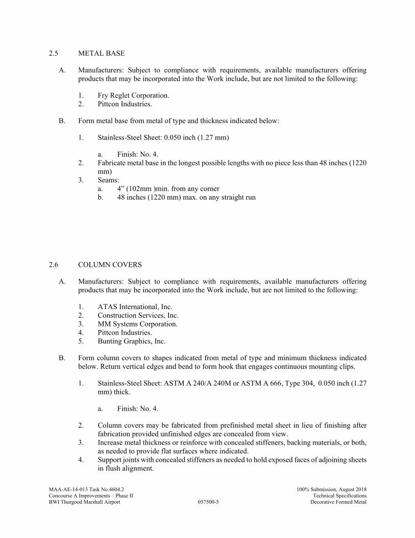
MAA-AE-14-013 Task No.4604.2
057500-5
100% Submission, August 2018Concourse A Improvements – Phase II Technical SpecificationsBWI Thurgood Marshall Airport Decorative Formed Metal
2.5 METAL BASE
A. Manufacturers: Subject to compliance with requirements, available manufacturers offering products that may be incorporated into the Work include, but are not limited to the following:
1. Fry Reglet Corporation. 2. Pittcon Industries.
B. Form metal base from metal of type and thickness indicated below:
1. Stainless-Steel Sheet: 0.050 inch (1.27 mm)
a. Finish: No. 4. 2. Fabricate metal base in the longest possible lengths with no piece less than 48 inches (1220
mm) 3. Seams:
a. 4” (102mm )min. from any corner b. 48 inches (1220 mm) max. on any straight run
2.6 COLUMN COVERS
A. Manufacturers: Subject to compliance with requirements, available manufacturers offering products that may be incorporated into the Work include, but are not limited to the following:
1. ATAS International, Inc. 2. Construction Services, Inc. 3. MM Systems Corporation. 4. Pittcon Industries. 5. Bunting Graphics, Inc.
B. Form column covers to shapes indicated from metal of type and minimum thickness indicated below. Return vertical edges and bend to form hook that engages continuous mounting clips.
1. Stainless-Steel Sheet: ASTM A 240/A 240M or ASTM A 666, Type 304, 0.050 inch (1.27 mm) thick.
a. Finish: No. 4.
2. Column covers may be fabricated from prefinished metal sheet in lieu of finishing after fabrication provided unfinished edges are concealed from view.
3. Increase metal thickness or reinforce with concealed stiffeners, backing materials, or both, as needed to provide flat surfaces where indicated.
4. Support joints with concealed stiffeners as needed to hold exposed faces of adjoining sheets in flush alignment.
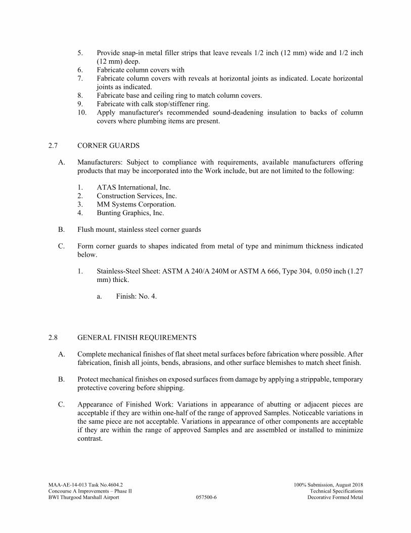
MAA-AE-14-013 Task No.4604.2
057500-6
100% Submission, August 2018Concourse A Improvements – Phase II Technical SpecificationsBWI Thurgood Marshall Airport Decorative Formed Metal
5. Provide snap-in metal filler strips that leave reveals 1/2 inch (12 mm) wide and 1/2 inch (12 mm) deep.
6. Fabricate column covers with 7. Fabricate column covers with reveals at horizontal joints as indicated. Locate horizontal
joints as indicated. 8. Fabricate base and ceiling ring to match column covers. 9. Fabricate with calk stop/stiffener ring. 10. Apply manufacturer's recommended sound-deadening insulation to backs of column
covers where plumbing items are present.
2.7 CORNER GUARDS
A. Manufacturers: Subject to compliance with requirements, available manufacturers offering products that may be incorporated into the Work include, but are not limited to the following:
1. ATAS International, Inc. 2. Construction Services, Inc. 3. MM Systems Corporation. 4. Bunting Graphics, Inc.
B. Flush mount, stainless steel corner guards
C. Form corner guards to shapes indicated from metal of type and minimum thickness indicated below.
1. Stainless-Steel Sheet: ASTM A 240/A 240M or ASTM A 666, Type 304, 0.050 inch (1.27 mm) thick.
a. Finish: No. 4.
2.8 GENERAL FINISH REQUIREMENTS
A. Complete mechanical finishes of flat sheet metal surfaces before fabrication where possible. After fabrication, finish all joints, bends, abrasions, and other surface blemishes to match sheet finish.
B. Protect mechanical finishes on exposed surfaces from damage by applying a strippable, temporary protective covering before shipping.
C. Appearance of Finished Work: Variations in appearance of abutting or adjacent pieces are acceptable if they are within one-half of the range of approved Samples. Noticeable variations in the same piece are not acceptable. Variations in appearance of other components are acceptable if they are within the range of approved Samples and are assembled or installed to minimize contrast.
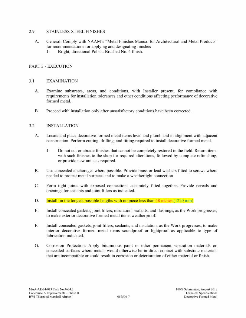
MAA-AE-14-013 Task No.4604.2
057500-7
100% Submission, August 2018Concourse A Improvements – Phase II Technical SpecificationsBWI Thurgood Marshall Airport Decorative Formed Metal
2.9 STAINLESS-STEEL FINISHES
A. General: Comply with NAAM’s “Metal Finishes Manual for Architectural and Metal Products” for recommendations for applying and designating finishes 1. Bright, directional Polish: Brushed No. 4 finish.
PART 3 - EXECUTION
3.1 EXAMINATION
A. Examine substrates, areas, and conditions, with Installer present, for compliance with requirements for installation tolerances and other conditions affecting performance of decorative formed metal.
B. Proceed with installation only after unsatisfactory conditions have been corrected.
3.2 INSTALLATION
A. Locate and place decorative formed metal items level and plumb and in alignment with adjacent construction. Perform cutting, drilling, and fitting required to install decorative formed metal.
1. Do not cut or abrade finishes that cannot be completely restored in the field. Return items with such finishes to the shop for required alterations, followed by complete refinishing, or provide new units as required.
B. Use concealed anchorages where possible. Provide brass or lead washers fitted to screws where needed to protect metal surfaces and to make a weathertight connection.
C. Form tight joints with exposed connections accurately fitted together. Provide reveals and openings for sealants and joint fillers as indicated.
D. Install in the longest possible lengths with no piece less than 48 inches (1220 mm)
E. Install concealed gaskets, joint fillers, insulation, sealants, and flashings, as the Work progresses, to make exterior decorative formed metal items weatherproof.
F. Install concealed gaskets, joint fillers, sealants, and insulation, as the Work progresses, to make interior decorative formed metal items soundproof or lightproof as applicable to type of fabrication indicated.
G. Corrosion Protection: Apply bituminous paint or other permanent separation materials on concealed surfaces where metals would otherwise be in direct contact with substrate materials that are incompatible or could result in corrosion or deterioration of either material or finish.
MAA-AE-14-013 Task No.4604.2
057500-8
100% Submission, August 2018Concourse A Improvements – Phase II Technical SpecificationsBWI Thurgood Marshall Airport Decorative Formed Metal
3.3 ADJUSTING AND CLEANING
A. Unless otherwise indicated, clean metals by washing thoroughly with water and soap, rinsing with clean water, and drying with soft cloths.
B. Restore finishes damaged during installation and construction period so no evidence remains of correction work. Return items that cannot be refinished in the field to the shop; make required alterations and refinish entire unit or provide new units.
3.4 PROTECTION
A. Protect finishes of decorative formed metal items from damage during construction period. Remove temporary protective coverings at time of Substantial Completion.
PART 4 - MEASUREMENT
4.1 METHODS OF MEASUREMENT
A. No separate measurement shall be made for work under this Specification Section
PART 5 - PAYMENT
5.1 METHOD OF PAYMENT
A. No separate payment will be made for work under this Specification Section. The cost of work, complete in place, described in this Specification Section shall be included in the Lump Sum Bid under “Building Construction”
B. Costs include all labor, material, services, and equipment necessary to complete the work in every aspect.
END OF SECTION 057500
MAA-AE-14-013 Task No.4604-4
061053-1
100% Submission, August 2018Concourse A Improvements – Phase II Technical SpecificationsBWI Thurgood Marshall Airport Miscellaneous Rough Carpentry
SECTION 061053 - MISCELLANEOUS ROUGH CARPENTRY
PART 1 - GENERAL
1.1 RELATED DOCUMENTS
A. Drawings and general provisions of the Contract, including Maryland Department of Transportation/ Maryland Aviation Administration Standard Provisions to the Construction Contract for the Concourse A Improvements – Phase II at BWI Thurgood Marshall Airport and other Divisions 1 Specification Sections, apply to this Section.
1.2 SUMMARY
A. Section Includes:
1. Rooftop equipment bases and support curbs. 2. Wood blocking, cants, and nailers. 3. Wood furring and grounds. 4. Plywood backing panels. 5. Plywood Wainscot 6. Utility shelving. 7. Wall Sheathing
1.3 DEFINITIONS
A. Boards or Strips: Lumber of less than 2 inches nominal (38 mm actual) size in least dimension.
B. Dimension Lumber: Lumber of 2 inches nominal (38 mm actual) or greater size but less than 5 inches nominal (114 mm actual) size in least dimension.
1.4 ACTION SUBMITTALS
A. Product Data: For each type of process and factory-fabricated product. Indicate component materials and dimensions and include construction and application details.
1. Include data for wood-preservative treatment from chemical treatment manufacturer and certification by treating plant that treated materials comply with requirements. Indicate type of preservative used and net amount of preservative retained.
2. Include data for fire-retardant treatment from chemical treatment manufacturer and certification by treating plant that treated materials comply with requirements. Include physical properties of treated materials based on testing by a qualified independent testing agency.
MAA-AE-14-013 Task No.4604-4
061053-2
100% Submission, August 2018Concourse A Improvements – Phase II Technical SpecificationsBWI Thurgood Marshall Airport Miscellaneous Rough Carpentry
3. For fire-retardant treatments, include physical properties of treated lumber both before and after exposure to elevated temperatures, based on testing by a qualified independent testing agency according to ASTM D 5664.
4. For products receiving a waterborne treatment, include statement that moisture content of treated materials was reduced to levels specified before shipment to Project site.
1.5 INFORMATIONAL SUBMITTALS
A. The Contractor shall certify that the materials being submitted conform to the requirements of the Contract in all respects, including all Federal requirements such as “Buy American,” except as otherwise noted.
B. Evaluation Reports: For the following, from ICC-ES:
1. Preservative-treated wood. 2. Fire-retardant-treated wood. 3. Power-driven fasteners. 4. Post-installed anchors. 5. Metal framing anchors.
1.6 QUALITY ASSURANCE
A. Testing Agency Qualifications: For testing agency providing classification marking for fire-retardant-treated material, an inspection agency acceptable to authorities having jurisdiction that periodically performs inspections to verify that the material bearing the classification marking is representative of the material tested.
1.7 DELIVERY, STORAGE, AND HANDLING
A. Stack lumber flat with spacers beneath and between each bundle to provide air circulation. Protect lumber from weather by covering with waterproof sheeting, securely anchored. Provide for air circulation around stacks and under coverings.
PART 2 - PRODUCTS
2.1 WOOD PRODUCTS, GENERAL
A. Lumber: DOC PS 20 and applicable rules of grading agencies indicated. If no grading agency is indicated, provide lumber that complies with the applicable rules of any rules-writing agency certified by the ALSC Board of Review. Provide lumber graded by an agency certified by the ALSC Board of Review to inspect and grade lumber under the rules indicated.
1. Factory mark each piece of lumber with grade stamp of grading agency. 2. Dress lumber, S4S, unless otherwise indicated.
MAA-AE-14-013 Task No.4604-4
061053-3
100% Submission, August 2018Concourse A Improvements – Phase II Technical SpecificationsBWI Thurgood Marshall Airport Miscellaneous Rough Carpentry
B. Maximum Moisture Content of Lumber: 19 percentmaximum at time of dressing for more than 2-inch nominal (38-mm actual) thickness unless otherwise indicated.
2.2 WOOD-PRESERVATIVE-TREATED MATERIALS
A. Preservative Treatment by Pressure Process: AWPA U1; Use Category UC2
1. Preservative Chemicals: Acceptable to authorities having jurisdiction and containing no arsenic or chromium.
B. Kiln-dry lumber after treatment to a maximum moisture content of 19 percent. Do not use material that is warped or does not comply with requirements for untreated material.
C. Mark lumber with treatment quality mark of an inspection agency approved by the ALSC Board of Review.
D. Application: Treat items indicated on Drawings, and the following:
1. Wood cants, nailers, curbs, equipment support bases, blocking, stripping, and similar members in connection with roofing, flashing, vapor barriers, and waterproofing.
2. Wood sills, sleepers, blocking, furring, stripping, and similar concealed members in contact with masonry or concrete.
3. Wood framing and furring attached directly to the interior of below-grade exterior masonry or concrete walls.
4. Wood framing members that are less than 18 inches (460 mm) above the ground in crawlspaces or unexcavated areas.
5. Wood floor plates that are installed over concrete slabs-on-grade.
2.3 FIRE-RETARDANT-TREATED MATERIALS
A. General: Where fire-retardant-treated materials are indicated, materials shall comply with requirements in this article, that are acceptable to authorities having jurisdiction, and with fire-test-response characteristics specified as determined by testing identical products per test method indicated by a qualified testing agency.
B. Fire-Retardant-Treated Lumber and Plywood by Pressure Process: Products with a flame-spread index of 25 or less when tested according to ASTM E 84, and with no evidence of significant progressive combustion when the test is extended an additional 20 minutes, and with the flame front not extending more than 10.5 feet (3.2 m) beyond the centerline of the burners at any time during the test.
1. Treatment shall not promote corrosion of metal fasteners. 2. Exterior Type: Treated materials shall comply with requirements specified above for fire-
retardant-treated lumber and plywood by pressure process after being subjected to accelerated weathering according to ASTM D 2898. Use for exterior locations and where indicated.
MAA-AE-14-013 Task No.4604-4
061053-4
100% Submission, August 2018Concourse A Improvements – Phase II Technical SpecificationsBWI Thurgood Marshall Airport Miscellaneous Rough Carpentry
3. Interior Type A: Treated materials shall have a moisture content of 28 percent or less when tested according to ASTM D 3201 at 92 percent relative humidity. Use where exterior type is not indicated.
C. Kiln-dry lumber after treatment to a maximum moisture content of 19 percent. Kiln-dry plywood after treatment to a maximum moisture content of 15 percent.
D. Identify fire-retardant-treated wood with appropriate classification marking of qualified testing agency.
2.4 MISCELLANEOUS LUMBER
A. General: Provide miscellaneous lumber indicated and lumber for support or attachment of other construction, including the following:
1. Blocking. 2. Nailers. 3. Rooftop equipment bases and support curbs. 4. Cants. 5. Furring. 6. Grounds. 7. Utility shelving
B. Dimension Lumber Items: Construction or No. 2 grade lumber of any of the following species:
1. Hem-fir (north); NLGA. 2. Mixed southern pine or southern pine; SPIB. 3. Spruce-pine-fir (south); NeLMA, WCLIB, or WWPA.
C. Concealed Boards: 19 percent maximum moisture content of any of the following species and grades:
1. Mixed southern pine or southern pine, No. 2grade; SPIB. 2. Hem-fir or hem-fir (north), Construction or No. 2 Common grade; NLGA, WCLIB, or
WWPA. 3. Spruce-pine-fir (south) or spruce-pine-fir, Standard or No. 3 Common grade; NeLMA,
NLGA, WCLIB, or WWPA. 4. Eastern softwoods, No. 2 Common grade; NELMA. 5. Northern species, No. 2 Common grade; NLGA. 6. Western woods, Construction or No. 2 Common grade; WCLIB or WWPA.
D. Utility Shelving: Lumber with 19 percent maximum moisture content of any of the following species and grades:
1. Eastern white pine, Idaho white, lodgepole, ponderosa, or sugar pine; Premium or No. 2 Common (Sterling) grade; NeLMA, NLGA, WCLIB, or WWPA.
2. Mixed southern pine or southern pine No. 1 grade; SPIB. 3. Hem-fir or hem-fir (north), Select Merchantable or No. 1 Common grade; NLGA, WCLIB,
or WWPA.
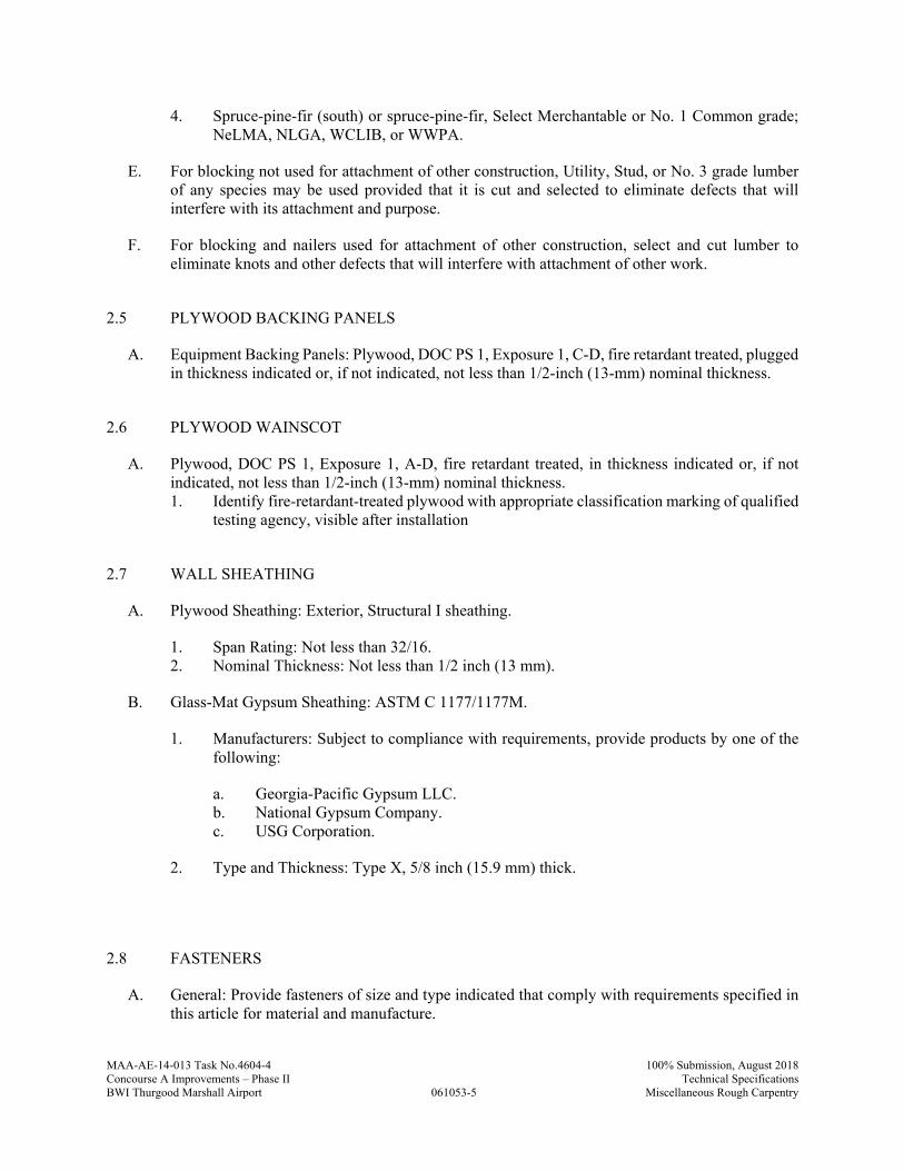
MAA-AE-14-013 Task No.4604-4
061053-5
100% Submission, August 2018Concourse A Improvements – Phase II Technical SpecificationsBWI Thurgood Marshall Airport Miscellaneous Rough Carpentry
4. Spruce-pine-fir (south) or spruce-pine-fir, Select Merchantable or No. 1 Common grade; NeLMA, NLGA, WCLIB, or WWPA.
E. For blocking not used for attachment of other construction, Utility, Stud, or No. 3 grade lumber of any species may be used provided that it is cut and selected to eliminate defects that will interfere with its attachment and purpose.
F. For blocking and nailers used for attachment of other construction, select and cut lumber to eliminate knots and other defects that will interfere with attachment of other work.
2.5 PLYWOOD BACKING PANELS
A. Equipment Backing Panels: Plywood, DOC PS 1, Exposure 1, C-D, fire retardant treated, plugged in thickness indicated or, if not indicated, not less than 1/2-inch (13-mm) nominal thickness.
2.6 PLYWOOD WAINSCOT
A. Plywood, DOC PS 1, Exposure 1, A-D, fire retardant treated, in thickness indicated or, if not indicated, not less than 1/2-inch (13-mm) nominal thickness. 1. Identify fire-retardant-treated plywood with appropriate classification marking of qualified
testing agency, visible after installation
2.7 WALL SHEATHING
A. Plywood Sheathing: Exterior, Structural I sheathing.
1. Span Rating: Not less than 32/16. 2. Nominal Thickness: Not less than 1/2 inch (13 mm).
B. Glass-Mat Gypsum Sheathing: ASTM C 1177/1177M.
1. Manufacturers: Subject to compliance with requirements, provide products by one of the following:
a. Georgia-Pacific Gypsum LLC. b. National Gypsum Company. c. USG Corporation.
2. Type and Thickness: Type X, 5/8 inch (15.9 mm) thick.
2.8 FASTENERS
A. General: Provide fasteners of size and type indicated that comply with requirements specified in this article for material and manufacture.
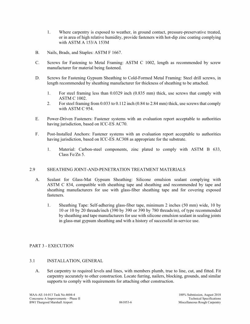
MAA-AE-14-013 Task No.4604-4
061053-6
100% Submission, August 2018Concourse A Improvements – Phase II Technical SpecificationsBWI Thurgood Marshall Airport Miscellaneous Rough Carpentry
1. Where carpentry is exposed to weather, in ground contact, pressure-preservative treated, or in area of high relative humidity, provide fasteners with hot-dip zinc coating complying with ASTM A 153/A 153M
B. Nails, Brads, and Staples: ASTM F 1667.
C. Screws for Fastening to Metal Framing: ASTM C 1002, length as recommended by screw manufacturer for material being fastened.
D. Screws for Fastening Gypsum Sheathing to Cold-Formed Metal Framing: Steel drill screws, in length recommended by sheathing manufacturer for thickness of sheathing to be attached.
1. For steel framing less than 0.0329 inch (0.835 mm) thick, use screws that comply with ASTM C 1002.
2. For steel framing from 0.033 to 0.112 inch (0.84 to 2.84 mm) thick, use screws that comply with ASTM C 954.
E. Power-Driven Fasteners: Fastener systems with an evaluation report acceptable to authorities having jurisdiction, based on ICC-ES AC70.
F. Post-Installed Anchors: Fastener systems with an evaluation report acceptable to authorities having jurisdiction, based on ICC-ES AC308 as appropriate for the substrate.
1. Material: Carbon-steel components, zinc plated to comply with ASTM B 633, Class Fe/Zn 5.
2.9 SHEATHING JOINT-AND-PENETRATION TREATMENT MATERIALS
A. Sealant for Glass-Mat Gypsum Sheathing: Silicone emulsion sealant complying with ASTM C 834, compatible with sheathing tape and sheathing and recommended by tape and sheathing manufacturers for use with glass-fiber sheathing tape and for covering exposed fasteners.
1. Sheathing Tape: Self-adhering glass-fiber tape, minimum 2 inches (50 mm) wide, 10 by 10 or 10 by 20 threads/inch (390 by 390 or 390 by 780 threads/m), of type recommended by sheathing and tape manufacturers for use with silicone emulsion sealant in sealing joints in glass-mat gypsum sheathing and with a history of successful in-service use.
PART 3 - EXECUTION
3.1 INSTALLATION, GENERAL
A. Set carpentry to required levels and lines, with members plumb, true to line, cut, and fitted. Fit carpentry accurately to other construction. Locate furring, nailers, blocking, grounds, and similar supports to comply with requirements for attaching other construction.
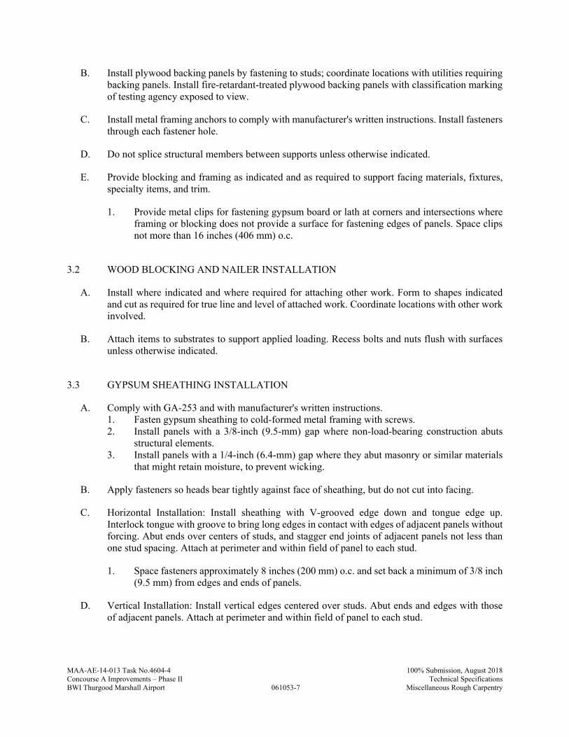
MAA-AE-14-013 Task No.4604-4
061053-7
100% Submission, August 2018Concourse A Improvements – Phase II Technical SpecificationsBWI Thurgood Marshall Airport Miscellaneous Rough Carpentry
B. Install plywood backing panels by fastening to studs; coordinate locations with utilities requiring backing panels. Install fire-retardant-treated plywood backing panels with classification marking of testing agency exposed to view.
C. Install metal framing anchors to comply with manufacturer's written instructions. Install fasteners through each fastener hole.
D. Do not splice structural members between supports unless otherwise indicated.
E. Provide blocking and framing as indicated and as required to support facing materials, fixtures, specialty items, and trim.
1. Provide metal clips for fastening gypsum board or lath at corners and intersections where framing or blocking does not provide a surface for fastening edges of panels. Space clips not more than 16 inches (406 mm) o.c.
3.2 WOOD BLOCKING AND NAILER INSTALLATION
A. Install where indicated and where required for attaching other work. Form to shapes indicated and cut as required for true line and level of attached work. Coordinate locations with other work involved.
B. Attach items to substrates to support applied loading. Recess bolts and nuts flush with surfaces unless otherwise indicated.
3.3 GYPSUM SHEATHING INSTALLATION
A. Comply with GA-253 and with manufacturer's written instructions. 1. Fasten gypsum sheathing to cold-formed metal framing with screws. 2. Install panels with a 3/8-inch (9.5-mm) gap where non-load-bearing construction abuts
structural elements. 3. Install panels with a 1/4-inch (6.4-mm) gap where they abut masonry or similar materials
that might retain moisture, to prevent wicking.
B. Apply fasteners so heads bear tightly against face of sheathing, but do not cut into facing.
C. Horizontal Installation: Install sheathing with V-grooved edge down and tongue edge up. Interlock tongue with groove to bring long edges in contact with edges of adjacent panels without forcing. Abut ends over centers of studs, and stagger end joints of adjacent panels not less than one stud spacing. Attach at perimeter and within field of panel to each stud.
1. Space fasteners approximately 8 inches (200 mm) o.c. and set back a minimum of 3/8 inch (9.5 mm) from edges and ends of panels.
D. Vertical Installation: Install vertical edges centered over studs. Abut ends and edges with those of adjacent panels. Attach at perimeter and within field of panel to each stud.

MAA-AE-14-013 Task No.4604-4
061053-8
100% Submission, August 2018Concourse A Improvements – Phase II Technical SpecificationsBWI Thurgood Marshall Airport Miscellaneous Rough Carpentry
1. Space fasteners approximately 8 inches (200 mm) o.c. and set back a minimum of 3/8 inch (9.5 mm) from edges and ends of panels.
E. Seal sheathing joints according to sheathing manufacturer's written instructions.
1. Apply elastomeric sealant to joints and fasteners and trowel flat. Apply sufficient amount of sealant to completely cover joints and fasteners after troweling. Seal other penetrations and openings.
2. Apply glass-fiber sheathing tape to glass-mat gypsum sheathing joints and apply and trowel sealant to embed entire face of tape in sealant. Apply sealant to exposed fasteners with a trowel so fasteners are completely covered. Seal other penetrations and openings.
3.4 PROTECTION
A. Protect wood that has been treated with inorganic boron (SBX) from weather. If, despite protection, inorganic boron-treated wood becomes wet, apply EPA-registered borate treatment. Apply borate solution by spraying to comply with EPA-registered label.
B. Protect miscellaneous rough carpentry from weather. If, despite protection, miscellaneous rough carpentry becomes wet, apply EPA-registered borate treatment. Apply borate solution by spraying to comply with EPA-registered label.
PART 4 - MEASUREMENT
4.1 METHODS OF MEASUREMENT
A. No separate measurement shall be made for work under this Specification Section
PART 5 - PAYMENT
5.1 METHOD OF PAYMENT
A. No separate payment will be made for work under this Specification Section. The cost of work, complete in place, described in this Specification Section shall be included in the Lump Sum Bid under “Building Construction”
B. Costs include all labor, material, services, and equipment necessary to complete the work in every aspect.
END OF SECTION 061053
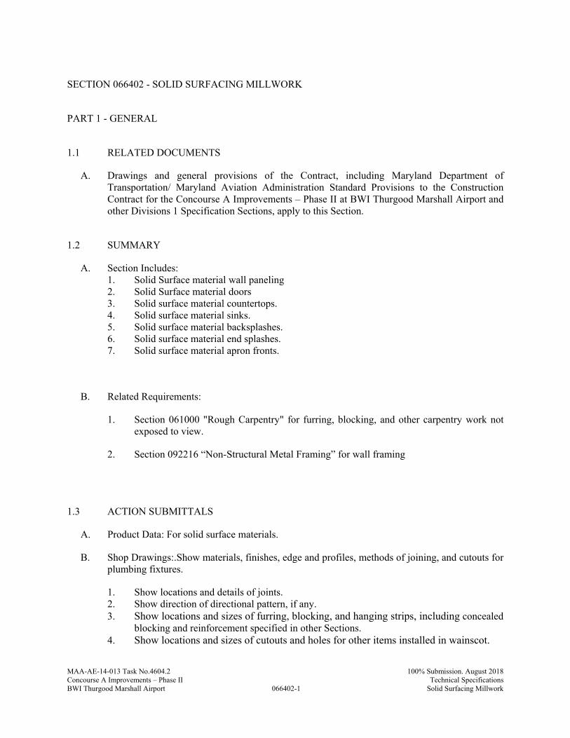
MAA-AE-14-013 Task No.4604.2
066402-1
100% Submission. August 2018Concourse A Improvements – Phase II Technical SpecificationsBWI Thurgood Marshall Airport Solid Surfacing Millwork
SECTION 066402 - SOLID SURFACING MILLWORK
PART 1 - GENERAL
1.1 RELATED DOCUMENTS
A. Drawings and general provisions of the Contract, including Maryland Department of Transportation/ Maryland Aviation Administration Standard Provisions to the Construction Contract for the Concourse A Improvements – Phase II at BWI Thurgood Marshall Airport and other Divisions 1 Specification Sections, apply to this Section.
1.2 SUMMARY
A. Section Includes: 1. Solid Surface material wall paneling 2. Solid Surface material doors 3. Solid surface material countertops. 4. Solid surface material sinks. 5. Solid surface material backsplashes. 6. Solid surface material end splashes. 7. Solid surface material apron fronts.
B. Related Requirements:
1. Section 061000 "Rough Carpentry" for furring, blocking, and other carpentry work not exposed to view.
2. Section 092216 “Non-Structural Metal Framing” for wall framing
1.3 ACTION SUBMITTALS
A. Product Data: For solid surface materials.
B. Shop Drawings:.Show materials, finishes, edge and profiles, methods of joining, and cutouts for plumbing fixtures.
1. Show locations and details of joints. 2. Show direction of directional pattern, if any. 3. Show locations and sizes of furring, blocking, and hanging strips, including concealed
blocking and reinforcement specified in other Sections. 4. Show locations and sizes of cutouts and holes for other items installed in wainscot.
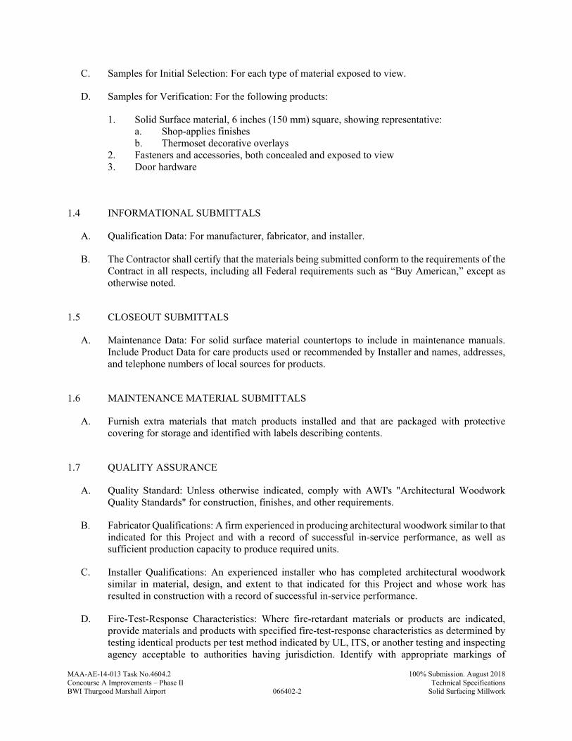
MAA-AE-14-013 Task No.4604.2
066402-2
100% Submission. August 2018Concourse A Improvements – Phase II Technical SpecificationsBWI Thurgood Marshall Airport Solid Surfacing Millwork
C. Samples for Initial Selection: For each type of material exposed to view.
D. Samples for Verification: For the following products:
1. Solid Surface material, 6 inches (150 mm) square, showing representative: a. Shop-applies finishes b. Thermoset decorative overlays
2. Fasteners and accessories, both concealed and exposed to view 3. Door hardware
1.4 INFORMATIONAL SUBMITTALS
A. Qualification Data: For manufacturer, fabricator, and installer.
B. The Contractor shall certify that the materials being submitted conform to the requirements of the Contract in all respects, including all Federal requirements such as “Buy American,” except as otherwise noted.
1.5 CLOSEOUT SUBMITTALS
A. Maintenance Data: For solid surface material countertops to include in maintenance manuals. Include Product Data for care products used or recommended by Installer and names, addresses, and telephone numbers of local sources for products.
1.6 MAINTENANCE MATERIAL SUBMITTALS
A. Furnish extra materials that match products installed and that are packaged with protective covering for storage and identified with labels describing contents.
1.7 QUALITY ASSURANCE
A. Quality Standard: Unless otherwise indicated, comply with AWI's "Architectural Woodwork Quality Standards" for construction, finishes, and other requirements.
B. Fabricator Qualifications: A firm experienced in producing architectural woodwork similar to that indicated for this Project and with a record of successful in-service performance, as well as sufficient production capacity to produce required units.
C. Installer Qualifications: An experienced installer who has completed architectural woodwork similar in material, design, and extent to that indicated for this Project and whose work has resulted in construction with a record of successful in-service performance.
D. Fire-Test-Response Characteristics: Where fire-retardant materials or products are indicated, provide materials and products with specified fire-test-response characteristics as determined by testing identical products per test method indicated by UL, ITS, or another testing and inspecting agency acceptable to authorities having jurisdiction. Identify with appropriate markings of
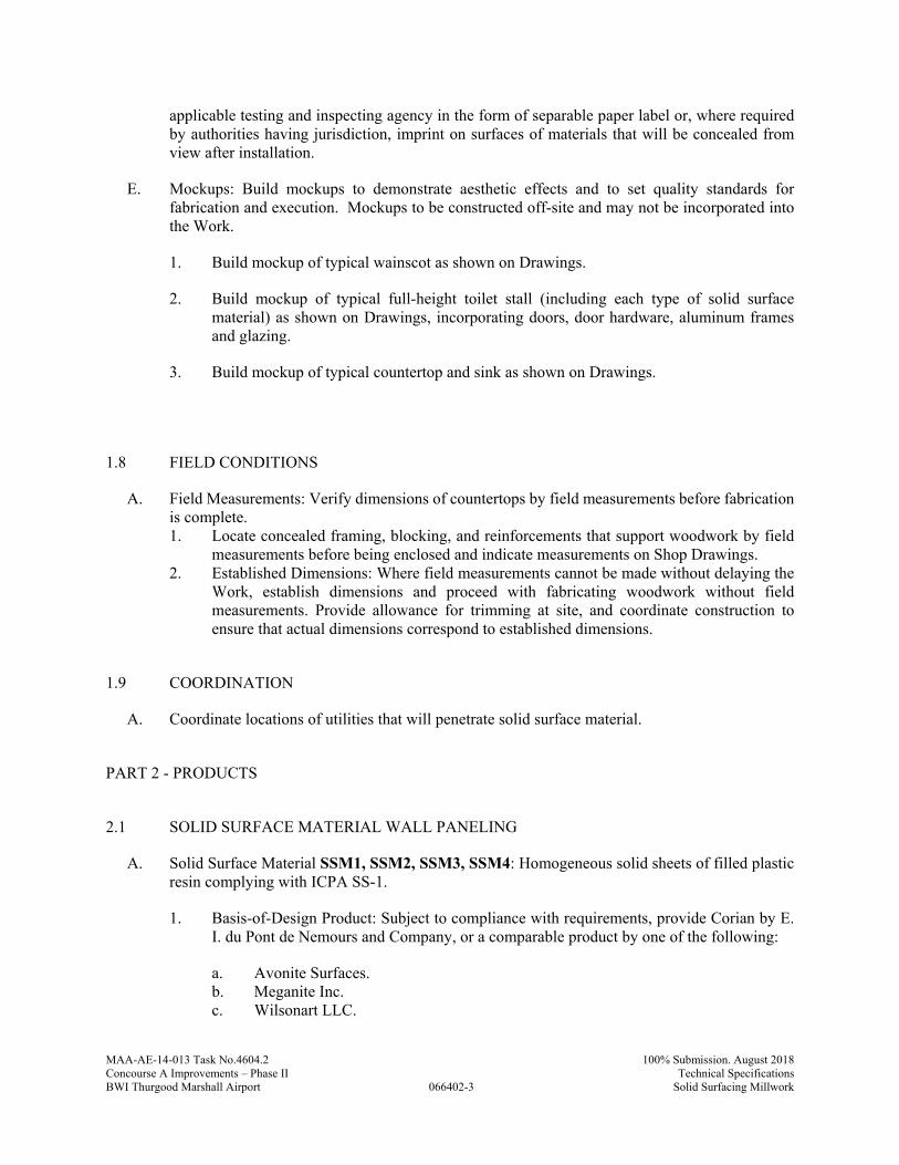
MAA-AE-14-013 Task No.4604.2
066402-3
100% Submission. August 2018Concourse A Improvements – Phase II Technical SpecificationsBWI Thurgood Marshall Airport Solid Surfacing Millwork
applicable testing and inspecting agency in the form of separable paper label or, where required by authorities having jurisdiction, imprint on surfaces of materials that will be concealed from view after installation.
E. Mockups: Build mockups to demonstrate aesthetic effects and to set quality standards for fabrication and execution. Mockups to be constructed off-site and may not be incorporated into the Work.
1. Build mockup of typical wainscot as shown on Drawings.
2. Build mockup of typical full-height toilet stall (including each type of solid surface material) as shown on Drawings, incorporating doors, door hardware, aluminum frames and glazing.
3. Build mockup of typical countertop and sink as shown on Drawings.
1.8 FIELD CONDITIONS
A. Field Measurements: Verify dimensions of countertops by field measurements before fabrication is complete. 1. Locate concealed framing, blocking, and reinforcements that support woodwork by field
measurements before being enclosed and indicate measurements on Shop Drawings. 2. Established Dimensions: Where field measurements cannot be made without delaying the
Work, establish dimensions and proceed with fabricating woodwork without field measurements. Provide allowance for trimming at site, and coordinate construction to ensure that actual dimensions correspond to established dimensions.
1.9 COORDINATION
A. Coordinate locations of utilities that will penetrate solid surface material.
PART 2 - PRODUCTS
2.1 SOLID SURFACE MATERIAL WALL PANELING
A. Solid Surface Material SSM1, SSM2, SSM3, SSM4: Homogeneous solid sheets of filled plastic resin complying with ICPA SS-1.
1. Basis-of-Design Product: Subject to compliance with requirements, provide Corian by E. I. du Pont de Nemours and Company, or a comparable product by one of the following:
a. Avonite Surfaces. b. Meganite Inc. c. Wilsonart LLC.
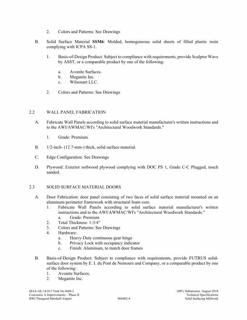
MAA-AE-14-013 Task No.4604.2
066402-4
100% Submission. August 2018Concourse A Improvements – Phase II Technical SpecificationsBWI Thurgood Marshall Airport Solid Surfacing Millwork
2. Colors and Patterns: See Drawings
B. Solid Surface Material SSM6: Molded, homogeneous solid sheets of filled plastic resin complying with ICPA SS-1.
1. Basis-of-Design Product: Subject to compliance with requirements, provide Sculptor Wave by ASST, or a comparable product by one of the following:
a. Avonite Surfaces. b. Meganite Inc. c. Wilsonart LLC.
2. Colors and Patterns: See Drawings
2.2 WALL PANEL FABRICATION
A. Fabricate Wall Panels according to solid surface material manufacturer's written instructions and to the AWI/AWMAC/WI's "Architectural Woodwork Standards."
1. Grade: Premium.
B. 1/2-inch- (12.7-mm-) thick, solid surface material.
C. Edge Configuration: See Drawings
D. Plywood: Exterior softwood plywood complying with DOC PS 1, Grade C-C Plugged, touch sanded.
2.3 SOLID SURFACE MATERIAL DOORS
A. Door Fabrication: door panel consisting of two faces of solid surface material mounted on an aluminum perimeter framework with structural foam core. 1. Fabricate Wall Panels according to solid surface material manufacturer's written
instructions and to the AWI/AWMAC/WI's "Architectural Woodwork Standards." a. Grade: Premium
2. Total Thickness: 1-3/4” 3. Colors and Patterns: See Drawings 4. Hardware:
a. Heavy-Duty continuous gear hinge b. Privacy Lock with occupancy indicator c. Finish: Aluminum, to match door frames
B. Basis-of-Design Product: Subject to compliance with requirements, provide FUTRUS solid-surface door system by E. I. du Pont de Nemours and Company, or a comparable product by one of the following: 1. Avonite Surfaces. 2. Meganite Inc.
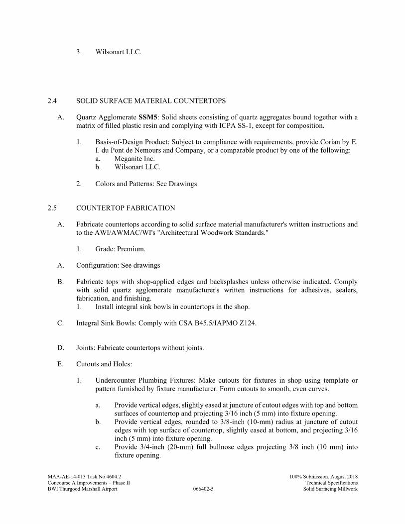
MAA-AE-14-013 Task No.4604.2
066402-5
100% Submission. August 2018Concourse A Improvements – Phase II Technical SpecificationsBWI Thurgood Marshall Airport Solid Surfacing Millwork
3. Wilsonart LLC.
2.4 SOLID SURFACE MATERIAL COUNTERTOPS
A. Quartz Agglomerate SSM5: Solid sheets consisting of quartz aggregates bound together with a matrix of filled plastic resin and complying with ICPA SS-1, except for composition.
1. Basis-of-Design Product: Subject to compliance with requirements, provide Corian by E. I. du Pont de Nemours and Company, or a comparable product by one of the following: a. Meganite Inc. b. Wilsonart LLC.
2. Colors and Patterns: See Drawings
2.5 COUNTERTOP FABRICATION
A. Fabricate countertops according to solid surface material manufacturer's written instructions and to the AWI/AWMAC/WI's "Architectural Woodwork Standards."
1. Grade: Premium.
A. Configuration: See drawings
B. Fabricate tops with shop-applied edges and backsplashes unless otherwise indicated. Comply with solid quartz agglomerate manufacturer's written instructions for adhesives, sealers, fabrication, and finishing. 1. Install integral sink bowls in countertops in the shop.
C. Integral Sink Bowls: Comply with CSA B45.5/IAPMO Z124.
D. Joints: Fabricate countertops without joints.
E. Cutouts and Holes:
1. Undercounter Plumbing Fixtures: Make cutouts for fixtures in shop using template or pattern furnished by fixture manufacturer. Form cutouts to smooth, even curves.
a. Provide vertical edges, slightly eased at juncture of cutout edges with top and bottom surfaces of countertop and projecting 3/16 inch (5 mm) into fixture opening.
b. Provide vertical edges, rounded to 3/8-inch (10-mm) radius at juncture of cutout edges with top surface of countertop, slightly eased at bottom, and projecting 3/16 inch (5 mm) into fixture opening.
c. Provide 3/4-inch (20-mm) full bullnose edges projecting 3/8 inch (10 mm) into fixture opening.

MAA-AE-14-013 Task No.4604.2
066402-6
100% Submission. August 2018Concourse A Improvements – Phase II Technical SpecificationsBWI Thurgood Marshall Airport Solid Surfacing Millwork
2. Counter-Mounted Plumbing Fixtures: Prepare countertops in shop for field cutting openings for counter-mounted fixtures. Mark tops for cutouts and drill holes at corners of cutout locations. Make corner holes of largest radius practical.
3. Fittings: Drill countertops in shop for plumbing fittings, undercounter soap dispensers, and similar items.
2.6 INSTALLATION MATERIALS
A. Adhesive: Manufacturer’s standard silicone-based panel adhesive complying with ANSI A136.1-1967, UL listed.
B. Sealant: Comply with applicable requirements in Section 079200 "Joint Sealants."
PART 3 - EXECUTION
3.1 EXAMINATION
A. Examine substrates to receive solid surface material wainscots and conditions under which wainscots will be installed, with Installer present, for compliance with requirements for installation tolerances and other conditions affecting performance of wainscots.
B. Proceed with installation only after unsatisfactory conditions have been corrected.
3.2 INSTALLATION
A. Install Wall Panels level to a tolerance of 1/8 inch in 8 feet (3 mm in 2.4 m), 1/4 inch (6 mm) maximum. Do not exceed 1/64-inch (0.4-mm) difference between planes of adjacent units.
1. Adhere Solid Surfacing panels per manufacturer’s instructions. 2. SSM-6: Anchor to supporting substrate with Z-clip/rail attachment as indicated.
B. Complete cutouts not finished in shop. Mask areas of wainscots adjacent to cutouts to prevent damage while cutting. Make cutouts to accurately fit items to be installed, and at right angles to finished surfaces unless beveling is required for clearance. Ease edges slightly to prevent chipping.
C. Install Doors
D. Install countertops level to a tolerance of 1/8 inch in 8 feet (3 mm in 2.4 m), 1/4 inch (6 mm) maximum. Do not exceed 1/64-inch (0.4-mm) difference between planes of adjacent units.

MAA-AE-14-013 Task No.4604.2
066402-7
100% Submission. August 2018Concourse A Improvements – Phase II Technical SpecificationsBWI Thurgood Marshall Airport Solid Surfacing Millwork
E. Secure countertops to subtops with adhesive according to solid surface material manufacturer's written instructions. Align adjacent surfaces and, using adhesive in color to match countertop, form seams to comply with manufacturer's written instructions. Carefully dress joints smooth, remove surface scratches, and clean entire surface.
F. Bond joints with adhesive and draw tight as countertops are set. Mask areas of countertops adjacent to joints to prevent adhesive smears.
1. Install metal splines in kerfs in countertop edges at joints where indicated. Fill kerfs with adhesive before inserting splines and remove excess immediately after adjoining units are drawn into position.
2. Clamp units to temporary bracing, supports, or each other to ensure that countertops are properly aligned and joints are of specified width.
G. Install backsplashes and end splashes by adhering to wall and countertops with adhesive. Mask areas of countertops and splashes adjacent to joints to prevent adhesive smears.
H. Install aprons to backing and countertops with adhesive. Mask areas of countertops and splashes adjacent to joints to prevent adhesive smears. Fasten by screwing through backing. Predrill holes for screws as recommended by manufacturer.
I. Complete cutouts not finished in shop. Mask areas of countertops adjacent to cutouts to prevent damage while cutting. Make cutouts to accurately fit items to be installed, and at right angles to finished surfaces unless beveling is required for clearance. Ease edges slightly to prevent snipping.
1. Seal edges of cutouts in particleboard subtops by saturating with varnish.
J. Apply sealant to gaps at walls; comply with Section 079200 "Joint Sealants."
3.3 ADJUSTING
A. Door Hardware Adjustment: Adjust and lubricate hardware according to hardware manufacturer's written instructions for proper operation. Set hinges on in-swinging doors to hold doors open approximately 30 degrees from closed position when unlatched. Set hinges on out-swinging doors to return doors to fully closed position.
PART 4 - MEASUREMENT
4.1 METHODS OF MEASUREMENT
A. No separate measurement shall be made for work under this Specification Section
MAA-AE-14-013 Task No.4604.2
066402-8
100% Submission. August 2018Concourse A Improvements – Phase II Technical SpecificationsBWI Thurgood Marshall Airport Solid Surfacing Millwork
PART 5 - PAYMENT
5.1 METHOD OF PAYMENT
A. No separate payment will be made for work under this Specification Section. The cost of work, complete in place, described in this Specification Section shall be included in the Lump Sum Bid under “Building Construction”
B. Costs include all labor, material, services, and equipment necessary to complete the work in every aspect.
END OF SECTION 066402
MAA-AE-14-013 Task No.4604.2
071113-1
100% Submission August 2018Concourse A Improvements – Phase II Technical SpecificationsBWI Thurgood Marshall Airport Bituminous Dampproofing
SECTION 071113 - BITUMINOUS DAMPPROOFING
PART 1 - GENERAL
1.1 RELATED DOCUMENTS
A. Drawings and general provisions of the Contract, including Maryland Department of Transportation/ Maryland Aviation Administration Standard Provisions to the Construction Contract for the Concourse A Improvements – Phase II at BWI Thurgood Marshall Airport and other Divisions 1 Specification Sections, apply to this Section.
1.2 SUMMARY
A. Section Includes: 1. Cold-applied, emulsified-asphalt dampproofing.
1.3 ACTION SUBMITTALS
A. Product Data: For each type of product.
1.4 FIELD CONDITIONS
A. Weather Limitations: Proceed with application only when existing and forecasted weather conditions permit dampproofing to be performed according to manufacturers' written instructions.
B. Ventilation: Provide adequate ventilation during application of dampproofing in enclosed spaces. Maintain ventilation until dampproofing has cured.
PART 2 - PRODUCTS
2.1 MANUFACTURERS
A. Source Limitations: Obtain primary dampproofing materials and primers from single source from single manufacturer. Provide drainage panels and auxiliary materials recommended in writing by manufacturer of primary materials.
2.2 PERFORMANCE REQUIREMENTS
A. VOC Content: Products shall comply with VOC content limits of authorities having jurisdiction unless otherwise indicated.
MAA-AE-14-013 Task No.4604.2
071113-2
100% Submission August 2018Concourse A Improvements – Phase II Technical SpecificationsBWI Thurgood Marshall Airport Bituminous Dampproofing
2.3 COLD-APPLIED, EMULSIFIED-ASPHALT DAMPPROOFING
A. Manufacturers: Subject to compliance with requirements, available manufacturers offering products that may be incorporated into the Work include, but are not limited to the following:
1. BASF Corporation. 2. Henry Company. 3. W.R. Meadows, Inc.
B. Trowel Coats: ASTM D 1227, Type II, Class 1.
C. Fibered Brush and Spray Coats: ASTM D 1227, Type II, Class 1.
D. Brush and Spray Coats: ASTM D 1227, Type III, Class 1.
2.4 AUXILIARY MATERIALS
A. Furnish auxiliary materials recommended in writing by dampproofing manufacturer for intended use and compatible with bituminous dampproofing.
B. Emulsified-Asphalt Primer: ASTM D 1227, Type III, Class 1, except diluted with water as recommended in writing by manufacturer.
C. Asphalt-Coated Glass Fabric: ASTM D 1668/D 1668M, Type I.
D. Patching Compound: Asbestos-free fibered mastic of type recommended in writing by dampproofing manufacturer.
2.5 INSULATION DRAINAGE PANELS
A. Insulation Drainage Panels: Comply with Section 072100 "Thermal Insulation" for insulation drainage panels.
PART 3 - EXECUTION
3.1 EXAMINATION
A. Examine substrates, areas, and conditions, with Applicator present, for compliance with requirements for surface smoothness, maximum surface moisture content, and other conditions affecting performance of the Work.
B. Proceed with application only after substrate construction and penetrating work have been completed and unsatisfactory conditions have been corrected.

MAA-AE-14-013 Task No.4604.2
071113-3
100% Submission August 2018Concourse A Improvements – Phase II Technical SpecificationsBWI Thurgood Marshall Airport Bituminous Dampproofing
3.2 PREPARATION
A. Clean, prepare, and treat substrates according to manufacturer's written instructions. Provide clean, dust-free, and dry substrates for dampproofing application.
B. Mask or otherwise protect adjoining exposed surfaces from being stained, spotted, or coated with dampproofing. Prevent dampproofing materials from entering and clogging weep holes and drains.
C. Clean substrates of projections and substances detrimental to dampproofing work; fill voids, seal joints, and remove bond breakers if any.
D. Apply patching compound to patch and fill tie holes, honeycombs, reveals, and other imperfections.
3.3 APPLICATION, GENERAL
A. Comply with manufacturer's written instructions for dampproofing application, cure time between coats, and drying time before backfilling unless otherwise indicated.
1. Apply dampproofing to provide continuous plane of protection. 2. Apply additional coats if recommended in writing by manufacturer or to achieve a smooth
surface and uninterrupted coverage.
B. Where dampproofing footings and foundation walls, apply from finished-grade line to top of footing; extend over top of footing and down a minimum of 6 inches (150 mm) over outside face of footing.
1. Extend dampproofing 12 inches (300 mm) onto intersecting walls and footings, but do not extend onto surfaces exposed to view when Project is completed.
2. Install flashings and corner protection stripping at internal and external corners, changes in plane, construction joints, cracks, and where indicated as "reinforced," by embedding an 8-inch- (200-mm-) wide strip of asphalt-coated glass fabric in a heavy coat of dampproofing. Dampproofing coat for embedding fabric is in addition to other coats required.
3.4 COLD-APPLIED, EMULSIFIED-ASPHALT DAMPPROOFING
A. Concrete Foundations and Parged Masonry Foundation Walls: Apply two brush or spray coats at not less than 1.5 gal./100 sq. ft. (0.6 L/sq. m) for first coat and 1 gal./100 sq. ft. (0.4 L/sq. m) for second coat.
3.5 DRAINAGE PANEL INSTALLATION
A. Insulation Drainage Panels: Install panels over dampproofed surfaces. Use adhesive or another method that does not penetrate dampproofing. Cut and fit panels to within 3/4 inch (19 mm) of projections and penetrations.
MAA-AE-14-013 Task No.4604.2
071113-4
100% Submission August 2018Concourse A Improvements – Phase II Technical SpecificationsBWI Thurgood Marshall Airport Bituminous Dampproofing
1. Ensure that drainage channels are aligned and free of obstructions.
3.6 PROTECTION
A. Protect installed insulation drainage panels from damage due to UV light, harmful weather exposures, physical abuse, and other causes. Provide temporary coverings where panels are subject to abuse and cannot be concealed and protected by permanent construction immediately after installation.
B. Correct dampproofing that does not comply with requirements; repair substrates, and reapply dampproofing.
PART 4 - MEASUREMENT
4.1 METHODS OF MEASUREMENT
A. No separate measurement shall be made for work under this Specification Section
PART 5 - PAYMENT
5.1 METHOD OF PAYMENT
A. No separate payment will be made for work under this Specification Section. The cost of work, complete in place, described in this Specification Section shall be included in the Lump Sum Bid under “Building Construction”
B. Costs include all labor, material, services, and equipment necessary to complete the work in every aspect.
END OF SECTION 071113
MAA-AE-14-013 Task No.4604.2
072100-1
100% Submission, August 2018Concourse A Improvements – Phase II Technical SpecificationsBWI Thurgood Marshall Airport Thermal Insulation
SECTION 072100 - THERMAL INSULATION
PART 1 - GENERAL
1.1 RELATED DOCUMENTS
A. Drawings and general provisions of the Contract, including Maryland Department of Transportation/ Maryland Aviation Administration Standard Provisions to the Construction Contract for the Concourse A Improvements – Phase II at BWI Thurgood Marshall Airport and other Divisions 1 Specification Sections, apply to this Section.
1.2 SUMMARY
A. Section Includes:
1. Extruded polystyrene foam-plastic board. 2. Mineral-wool blanket.
B. Related Requirements: 1. Section 074113.16 “Standing-Seam Metal Roof Panels for insulation specified as part of
roofing construction. 2. Section 075552.16 "Styrene-Butadiene-Styrene (SBS) Modified Bituminous Protected
Membrane Roofing" for insulation specified as part of roofing construction. 3. Section 092900 “Gypsum Board” for sound attenuation blanket used as acoustic insulation.
1.3 ACTION SUBMITTALS
A. Product Data: For each type of product.
1.4 INFORMATIONAL SUBMITTALS
A. The Contractor shall certify that the materials being submitted conform to the requirements of the Contract in all respects, including all Federal requirements such as “Buy American,” except as otherwise noted.
B. Product Test Reports: For each product, for tests performed by a qualified testing agency.
C. Evaluation Reports: For foam-plastic insulation, from ICC-ES.
1.5 DELIVERY, STORAGE, AND HANDLING
A. Protect insulation materials from physical damage and from deterioration due to moisture, soiling, and other sources. Store inside and in a dry location. Comply with manufacturer's written instructions for handling, storing, and protecting during installation.
MAA-AE-14-013 Task No.4604.2
072100-2
100% Submission, August 2018Concourse A Improvements – Phase II Technical SpecificationsBWI Thurgood Marshall Airport Thermal Insulation
B. Protect foam-plastic board insulation as follows:
1. Do not expose to sunlight except to necessary extent for period of installation and concealment.
2. Protect against ignition at all times. Do not deliver foam-plastic board materials to Project site until just before installation time.
3. Quickly complete installation and concealment of foam-plastic board insulation in each area of construction.
PART 2 - PRODUCTS
2.1 EXTRUDED POLYSTYRENE FOAM-PLASTIC BOARD
A. Extruded polystyrene boards in this article are also called "XPS boards." Roman numeral designators in ASTM C 578 are assigned in a fixed random sequence, and their numeric order does not reflect increasing strength or other characteristics.
B. Extruded Polystyrene Board, Type IV: ASTM C 578, Type IV, 25-psi (173-kPa) minimum compressive strength; unfaced; maximum flame-spread and smoke-developed indexes of 75 and 450, respectively, per ASTM E 84.
1. Manufacturers: Subject to compliance with requirements, available manufacturers offering products that may be incorporated into the Work include, but are not limited to the following:
a. DiversiFoam Products. b. Dow Chemical Company (The). c. Owens Corning.
2. Fire Propagation Characteristics: Passes NFPA 285 testing as part of an approved assembly.
C. Extruded Polystyrene Board, Type IV, Drainage Panels : ASTM C 578, Type IV, 25-psi (173-kPa) minimum compressive strength; unfaced; maximum flame-spread and smoke-developed indexes of 25 and 450, respectively, per ASTM E 84; fabricated with shiplap or channel edges and with one side having grooved drainage channels.
1. Location: install Drainage Panels at Bituminous Dampproofing locations on foundation.
2. Manufacturers: Subject to compliance with requirements, available manufacturers offering products that may be incorporated into the Work include, but are not limited to the following:
a. DiversiFoam Products. b. Dow Chemical Company (The). c. Owens Corning.
MAA-AE-14-013 Task No.4604.2
072100-3
100% Submission, August 2018Concourse A Improvements – Phase II Technical SpecificationsBWI Thurgood Marshall Airport Thermal Insulation
2.2 MINERAL-WOOL BLANKET
A. Mineral-Wool Blanket, Unfaced ASTM C 665, Type I (blankets without membrane facing); consisting of fibers; with maximum flame-spread and smoke-developed indexes of 25 and 50, respectively, per ASTM E 84; passing ASTM E 136 for combustion characteristics.
1. Basis-of-Design Product: Subject to compliance with requirements, provide ROCKWOOL (ROXUL Inc.); ComfortBatt or a comparable product by one of the following:
a. Johns Manville; a Berkshire Hathaway company. b. Thermafiber, Inc.; an Owens Corning company.
2. Locations: a. Within CFMF
2.3 MINERAL-WOOL BOARD
A. Mineral-Wool Board, Types IA and IB, Unfaced ASTM C 612, Types IA and IB; with maximum flame-spread and smoke-developed indexes of zero, respectively, per ASTM E 84; passing ASTM E 136 for combustion characteristics. Nominal density of 4 lb/cu. ft. (64 kg/cu. m).
1. Basis-of-Design Product: Subject to compliance with requirements, ROCKWOOL (ROXUL Inc.); Curtainrock or comparable product by one of the following:
a. Johns Manville; a Berkshire Hathaway company. b. Thermafiber, Inc.; an Owens Corning company.
2. Locations: a. Within Curtainwall framing, behind opaque spandrel glazing
2.4 INSULATION FASTENERS
A. Adhesively Attached, Spindle-Type Anchors: Plate welded to projecting spindle; capable of holding insulation of specified thickness securely in position with self-locking washer in place.
1. Manufacturers: Subject to compliance with requirements, available manufacturers offering products that may be incorporated into the Work include, but are not limited to the following:
a. AGM Industries, Inc. b. Gemco.
2. Plate: Perforated, galvanized carbon-steel sheet, 0.030 inch (0.762 mm) thick by 2 inches (50 mm) square.
3. Spindle: Copper-coated, low-carbon steel; fully annealed; 0.105 inch (2.67 mm) in diameter; length to suit depth of insulation.
B. Adhesively Attached, Angle-Shaped, Spindle-Type Anchors: Angle welded to projecting spindle; capable of holding insulation of specified thickness securely in position with self-locking washer in place.

MAA-AE-14-013 Task No.4604.2
072100-4
100% Submission, August 2018Concourse A Improvements – Phase II Technical SpecificationsBWI Thurgood Marshall Airport Thermal Insulation
1. Manufacturers: Subject to compliance with requirements, available manufacturers offering products that may be incorporated into the Work include, but are not limited to the following:
a. Gemco. 2. Angle: Formed from 0.030-inch- (0.762-mm-) thick, perforated, galvanized carbon-steel
sheet with each leg 2 inches (50 mm) square. 3. Spindle: Copper-coated, low-carbon steel; fully annealed; 0.105 inch (2.67 mm) in
diameter; length to suit depth of insulation.
C. Insulation-Retaining Washers: Self-locking washers formed from 0.016-inch- (0.41-mm-) thick galvanized-steel sheet, with beveled edge for increased stiffness, sized as required to hold insulation securely in place, but not less than 1-1/2 inches (38 mm) square or in diameter.
1. Manufacturers: Subject to compliance with requirements, available manufacturers offering products that may be incorporated into the Work include, but are not limited to the following:
a. AGM Industries, Inc. b. Gemco.
2. Protect ends with capped self-locking washers incorporating a spring steel insert to ensure permanent retention of cap in the following locations: a. Ceiling plenums.
D. Anchor Adhesive: Product with demonstrated capability to bond insulation anchors securely to substrates without damaging insulation, fasteners, or substrates.
1. Manufacturers: Subject to compliance with requirements, available manufacturers offering products that may be incorporated into the Work include, but are not limited to the following:
a. AGM Industries, Inc. b. Gemco.
2.5 ACCESSORIES
A. Insulation for Miscellaneous Voids: 1. Spray Polyurethane Foam Insulation: ASTM C 1029, Type II, closed cell, with maximum
flame-spread and smoke-developed indexes of 75 and 450, respectively, per ASTM E 84.
B. Adhesive for Bonding Insulation: Product compatible with insulation and air and water barrier materials, and with demonstrated capability to bond insulation securely to substrates without damaging insulation and substrates.
MAA-AE-14-013 Task No.4604.2
072100-5
100% Submission, August 2018Concourse A Improvements – Phase II Technical SpecificationsBWI Thurgood Marshall Airport Thermal Insulation
PART 3 - EXECUTION
3.1 PREPARATION
A. Clean substrates of substances that are harmful to insulation, including removing projections capable of puncturing insulation or vapor retarders, or that interfere with insulation attachment.
3.2 INSTALLATION, GENERAL
A. Comply with insulation manufacturer's written instructions applicable to products and applications.
B. Install insulation that is undamaged, dry, and unsoiled and that has not been left exposed to ice, rain, or snow at any time.
C. Extend insulation to envelop entire area to be insulated. Fit tightly around obstructions and fill voids with insulation. Remove projections that interfere with placement.
D. Provide sizes to fit applications and selected from manufacturer's standard thicknesses, widths, and lengths. Apply single layer of insulation units unless multiple layers are otherwise shown or required to make up total thickness or to achieve R-value.
3.3 INSTALLATION OF SLAB INSULATION
A. On vertical slab edge and foundation surfaces, set insulation units using manufacturer's recommended adhesive according to manufacturer's written instructions.
B. On horizontal surfaces, loosely lay insulation units according to manufacturer's written instructions. Stagger end joints and tightly abut insulation units.
3.4 INSTALLATION OF FOUNDATION WALL INSULATION
A. Butt panels together for tight fit.
B. Anchor Installation: Install board insulation on concrete substrates by adhesively attached, spindle-type insulation anchors as follows:
1. Fasten insulation anchors to concrete substrates with insulation anchor adhesive according to anchor manufacturer's written instructions. Space anchors according to insulation manufacturer's written instructions for insulation type, thickness, and application.
2. Apply insulation standoffs to each spindle to create cavity width indicated on Drawings between concrete substrate and insulation.
3. After adhesive has dried, install board insulation by pressing insulation into position over spindles and securing it tightly in place with insulation-retaining washers, taking care not to compress insulation.
4. Where insulation will not be covered by other building materials, apply capped washers to tips of spindles.
MAA-AE-14-013 Task No.4604.2
072100-6
100% Submission, August 2018Concourse A Improvements – Phase II Technical SpecificationsBWI Thurgood Marshall Airport Thermal Insulation
C. Adhesive Installation: Install with adhesive or press into tacky waterproofing or dampproofing according to manufacturer's written instructions.
3.5 INSTALLATION OF INSULATION IN FRAMED CONSTRUCTION
A. Blanket Insulation: Install in cavities formed by framing members according to the following requirements:
1. Use insulation widths and lengths that fill the cavities formed by framing members. If more than one length is required to fill the cavities, provide lengths that will produce a snug fit between ends.
2. Place insulation in cavities formed by framing members to produce a friction fit between edges of insulation and adjoining framing members.
3. Maintain 3-inch (76-mm) clearance of insulation around recessed lighting fixtures not rated for or protected from contact with insulation.
4. For metal-framed wall cavities where cavity heights exceed 96 inches (2438 mm), support unfaced blankets mechanically and support faced blankets by taping flanges of insulation to flanges of metal studs.
B. Miscellaneous Voids: Install insulation in miscellaneous voids and cavity spaces where required to prevent gaps in insulation using the following materials: 1. Spray Polyurethane Insulation: Apply according to manufacturer's written instructions.
3.6 INSTALLATION OF CURTAIN-WALL INSULATION
A. Install board insulation in curtain-wall construction according to curtain-wall manufacturer's written instructions.
1. Hold insulation in place by securing metal clips and straps or integral pockets within window frames, spaced at intervals recommended in writing by insulation manufacturer to hold insulation securely in place without touching spandrel glass. Maintain cavity width of dimension indicated on Drawings between insulation and glass.
2. Install insulation to fit snugly without bowing.
3.7 PROTECTION
A. Protect installed insulation from damage due to harmful weather exposures, physical abuse, and other causes. Provide temporary coverings or enclosures where insulation is subject to abuse and cannot be concealed and protected by permanent construction immediately after installation.
PART 4 - MEASUREMENT
4.1 METHODS OF MEASUREMENT
A. No separate measurement shall be made for work under this Specification Section
MAA-AE-14-013 Task No.4604.2
072100-7
100% Submission, August 2018Concourse A Improvements – Phase II Technical SpecificationsBWI Thurgood Marshall Airport Thermal Insulation
PART 5 - PAYMENT
5.1 METHOD OF PAYMENT
A. No separate payment will be made for work under this Specification Section. The cost of work, complete in place, described in this Specification Section shall be included in the Lump Sum Bid under “Building Construction”
B. Costs include all labor, material, services, and equipment necessary to complete the work in every aspect.
END OF SECTION 072100
MAA-AE-14-013 Task No.4604.2
072100-8
100% Submission, August 2018Concourse A Improvements – Phase II Technical SpecificationsBWI Thurgood Marshall Airport Thermal Insulation
THIS PAGE INTENTIONALLY LEFT BLANK
MAA-AE-14-013 Task No.4604.2
072119-1
100% Submission, August 2018Concourse A Improvements – Phase II Technical SpecificationsBWI Thurgood Marshall Airport Foamed-In-Place Insulation
SECTION 072119 - FOAMED-IN-PLACE INSULATION
PART 1 - GENERAL
1.1 RELATED DOCUMENTS
A. Drawings and general provisions of the Contract, including Maryland Department of Transportation/ Maryland Aviation Administration Standard Provisions to the Construction Contract for the Concourse A Improvements – Phase II at BWI Thurgood Marshall Airport and other Divisions 1 Specification Sections, apply to this Section.
1.2 SUMMARY
A. Section Includes:
1. Closed-cell spray polyurethane foam.
1.3 ACTION SUBMITTALS
A. Product Data: For each type of product.
1.4 INFORMATIONAL SUBMITTALS
A. The Contractor shall certify that the materials being submitted conform to the requirements of the Contract in all respects, including all Federal requirements such as “Buy American,” except as otherwise noted.
B. Qualification Data: For Installer.
C. Product Test Reports: For each product, for tests performed by a qualified testing agency.
D. Evaluation Reports: For spray-applied polyurethane foam-plastic insulation, from ICC-ES.
1.5 QUALITY ASSURANCE
A. Installer Qualifications: An authorized representative who is trained and approved by manufacturer.
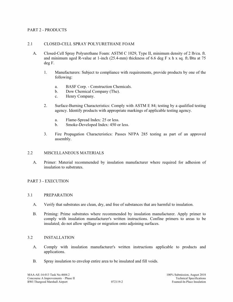
MAA-AE-14-013 Task No.4604.2
072119-2
100% Submission, August 2018Concourse A Improvements – Phase II Technical SpecificationsBWI Thurgood Marshall Airport Foamed-In-Place Insulation
PART 2 - PRODUCTS
2.1 CLOSED-CELL SPRAY POLYURETHANE FOAM
A. Closed-Cell Spray Polyurethane Foam: ASTM C 1029, Type II, minimum density of 2 lb/cu. ft. and minimum aged R-value at 1-inch (25.4-mm) thickness of 6.6 deg F x h x sq. ft./Btu at 75 deg F.
1. Manufacturers: Subject to compliance with requirements, provide products by one of the following:
a. BASF Corp. - Construction Chemicals. b. Dow Chemical Company (The). c. Henry Company.
2. Surface-Burning Characteristics: Comply with ASTM E 84; testing by a qualified testing agency. Identify products with appropriate markings of applicable testing agency.
a. Flame-Spread Index: 25 or less. b. Smoke-Developed Index: 450 or less.
3. Fire Propagation Characteristics: Passes NFPA 285 testing as part of an approved assembly.
2.2 MISCELLANEOUS MATERIALS
A. Primer: Material recommended by insulation manufacturer where required for adhesion of insulation to substrates.
PART 3 - EXECUTION
3.1 PREPARATION
A. Verify that substrates are clean, dry, and free of substances that are harmful to insulation.
B. Priming: Prime substrates where recommended by insulation manufacturer. Apply primer to comply with insulation manufacturer's written instructions. Confine primers to areas to be insulated; do not allow spillage or migration onto adjoining surfaces.
3.2 INSTALLATION
A. Comply with insulation manufacturer's written instructions applicable to products and applications.
B. Spray insulation to envelop entire area to be insulated and fill voids.
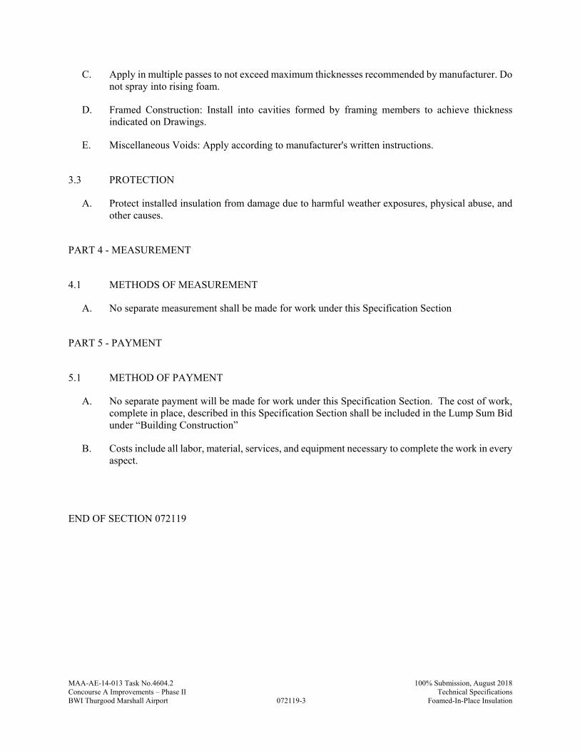
MAA-AE-14-013 Task No.4604.2
072119-3
100% Submission, August 2018Concourse A Improvements – Phase II Technical SpecificationsBWI Thurgood Marshall Airport Foamed-In-Place Insulation
C. Apply in multiple passes to not exceed maximum thicknesses recommended by manufacturer. Do not spray into rising foam.
D. Framed Construction: Install into cavities formed by framing members to achieve thickness indicated on Drawings.
E. Miscellaneous Voids: Apply according to manufacturer's written instructions.
3.3 PROTECTION
A. Protect installed insulation from damage due to harmful weather exposures, physical abuse, and other causes.
PART 4 - MEASUREMENT
4.1 METHODS OF MEASUREMENT
A. No separate measurement shall be made for work under this Specification Section
PART 5 - PAYMENT
5.1 METHOD OF PAYMENT
A. No separate payment will be made for work under this Specification Section. The cost of work, complete in place, described in this Specification Section shall be included in the Lump Sum Bid under “Building Construction”
B. Costs include all labor, material, services, and equipment necessary to complete the work in every aspect.
END OF SECTION 072119
MAA-AE-14-013 Task No.4604.2
072119-4
100% Submission, August 2018Concourse A Improvements – Phase II Technical SpecificationsBWI Thurgood Marshall Airport Foamed-In-Place Insulation
THIS PAGE INTENTIONALLY LEFT BLANK
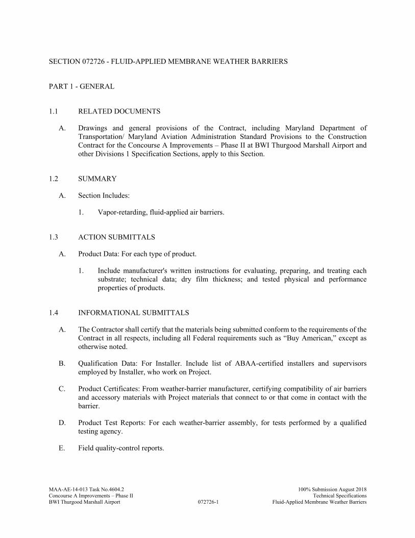
MAA-AE-14-013 Task No.4604.2
072726-1
100% Submission August 2018Concourse A Improvements – Phase II Technical SpecificationsBWI Thurgood Marshall Airport Fluid-Applied Membrane Weather Barriers
SECTION 072726 - FLUID-APPLIED MEMBRANE WEATHER BARRIERS
PART 1 - GENERAL
1.1 RELATED DOCUMENTS
A. Drawings and general provisions of the Contract, including Maryland Department of Transportation/ Maryland Aviation Administration Standard Provisions to the Construction Contract for the Concourse A Improvements – Phase II at BWI Thurgood Marshall Airport and other Divisions 1 Specification Sections, apply to this Section.
1.2 SUMMARY
A. Section Includes:
1. Vapor-retarding, fluid-applied air barriers.
1.3 ACTION SUBMITTALS
A. Product Data: For each type of product.
1. Include manufacturer's written instructions for evaluating, preparing, and treating each substrate; technical data; dry film thickness; and tested physical and performance properties of products.
1.4 INFORMATIONAL SUBMITTALS
A. The Contractor shall certify that the materials being submitted conform to the requirements of the Contract in all respects, including all Federal requirements such as “Buy American,” except as otherwise noted.
B. Qualification Data: For Installer. Include list of ABAA-certified installers and supervisors employed by Installer, who work on Project.
C. Product Certificates: From weather-barrier manufacturer, certifying compatibility of air barriers and accessory materials with Project materials that connect to or that come in contact with the barrier.
D. Product Test Reports: For each weather-barrier assembly, for tests performed by a qualified testing agency.
E. Field quality-control reports.
MAA-AE-14-013 Task No.4604.2
072726-2
100% Submission August 2018Concourse A Improvements – Phase II Technical SpecificationsBWI Thurgood Marshall Airport Fluid-Applied Membrane Weather Barriers
1.5 QUALITY ASSURANCE
A. Installer Qualifications: An entity that employs installers and supervisors who are trained and approved by manufacturer.
1. Installer shall be licensed by ABAA according to ABAA's Quality Assurance Program and shall employ ABAA-certified installers and supervisors on Project.
1.6 DELIVERY, STORAGE, AND HANDLING
A. Remove and replace liquid materials that cannot be applied within their stated shelf life.
B. Protect stored materials from direct sunlight.
1.7 FIELD CONDITIONS
A. Environmental Limitations: Apply air barrier within the range of ambient and substrate temperatures recommended in writing by weather-barrier manufacturer.
1. Protect substrates from environmental conditions that affect weather-barrier performance. 2. Do not apply air barrier to a damp or wet substrate or during snow, rain, fog, or mist.
PART 2 - PRODUCTS
2.1 MATERIALS
A. Source Limitations: Obtain primary weather-barrier materials and weather-barrier accessories from single source from single manufacturer.
2.2 PERFORMANCE REQUIREMENTS
A. Weather-barrier Performance: Weather-barrier assembly and seals with adjacent construction shall be capable of performing as a continuous air barrier and as a liquid-water drainage plane flashed to discharge to the exterior incidental condensation or water penetration. Weather-barrier assemblies shall be capable of accommodating substrate movement and of sealing substrate expansion and control joints, construction material changes, penetrations and transitions at perimeter conditions without deterioration and air leakage exceeding specified limits.
2.3 HIGH-BUILD AIR BARRIERS, VAPOR RETARDING
A. High-Build, Vapor-Retarding Air Barrier: synthetic polymer membrane with an installed dry film thickness, according to manufacturer's written instructions, of 35 mils (0.9 mm) or thicker over smooth, void-free substrates.
1. Synthetic Polymer Type:
MAA-AE-14-013 Task No.4604.2
072726-3
100% Submission August 2018Concourse A Improvements – Phase II Technical SpecificationsBWI Thurgood Marshall Airport Fluid-Applied Membrane Weather Barriers
a. Manufacturers: Subject to compliance with requirements, available manufacturers offering products that may be incorporated into the Work include, but are not limited to the following:
1) Carlisle Coatings & Waterproofing Inc. 2) Henry Company. 3) Hohmann & Barnard, Inc. 4) Sto Corp.
2. Physical and Performance Properties:
a. Air Permeance: Maximum 0.004 cfm/sq. ft. of surface area at 1.57-lbf/sq. ft. (0.02 L/s x sq. m of surface area at 75-Pa) pressure difference; ASTM E 2178.
b. Vapor Permeance: Maximum 0.1 perm (5.8 ng/Pa x s x sq. m); ASTM E 96/E 96M, Desiccant Method.
c. Ultimate Elongation: Minimum 500percent; ASTM D 412, Die C. d. Adhesion to Substrate: Minimum 30 lbf/sq. in. (207 kPa) when tested according to
ASTM D 4541. e. Fire Propagation Characteristics: Passes NFPA 285 testing as part of an approved
assembly. f. UV Resistance: Can be exposed to sunlight for 90 days according to manufacturer's
written instructions.
2.4 ACCESSORY MATERIALS
A. Requirement: Provide primers, transition strips, termination strips, joint reinforcing fabric and strips, joint sealants, counterflashing strips, flashing sheets and metal termination bars, termination mastic, substrate patching materials, adhesives, tapes, foam sealants, lap sealants, and other accessory materials that are recommended in writing by weather-barrier manufacturer to produce a complete weather-barrier assembly and that are compatible with primary weather-barrier material and adjacent construction to which they may seal.
B. Primer: Liquid primer recommended for substrate by weather-barrier material manufacturer.
C. Stainless-Steel Sheet: ASTM A 240/A 240M, Type 304, and Series 300 stainless-steel fasteners.
D. Preformed Silicone Extrusion: Manufacturer's standard system consisting of cured low-modulus silicone extrusion, sized to fit opening widths, with a single-component, neutral-curing, Class 100/50 (low-modulus) silicone sealant for bonding extrusions to substrates.
PART 3 - EXECUTION
3.1 EXAMINATION
A. Examine substrates, areas, and conditions, with Installer present, for compliance with requirements and other conditions affecting performance of the Work.
MAA-AE-14-013 Task No.4604.2
072726-4
100% Submission August 2018Concourse A Improvements – Phase II Technical SpecificationsBWI Thurgood Marshall Airport Fluid-Applied Membrane Weather Barriers
1. Verify that substrates are sound and free of oil, grease, dirt, excess mortar, or other contaminants.
2. Verify that substrates have cured and aged for minimum time recommended in writing by weather-barriermanufacturer.
3. Verify that substrates are visibly dry and free of moisture. Test concrete substrates for capillary moisture by plastic sheet method according to ASTM D 4263.
4. Verify that masonry joints are flush and completely filled with mortar.
B. Proceed with installation only after unsatisfactory conditions have been corrected.
3.2 SURFACE PREPARATION
A. Clean, prepare, treat, fill, and seal substrate and joints and cracks in substrate according to manufacturer's written instructions and details. Provide clean, dust-free, and dry substrate for weather-barrierapplication.
B. Mask off adjoining surfaces not covered by air barrier to prevent spillage and overspray affecting other construction.
C. Remove grease, oil, bitumen, form-release agents, paints, curing compounds, and other penetrating contaminants or film-forming coatings from concrete.
D. Remove fins, ridges, mortar, and other projections and fill honeycomb, aggregate pockets, holes, and other voids in concrete with substrate-patching material.
E. Remove excess mortar from masonry ties, shelf angles, and other obstructions.
F. At changes in substrate plane, apply sealant or termination mastic beads at sharp corners and edges to form a smooth transition from one plane to another.
G. Cover gaps in substrate plane and form a smooth transition from one substrate plane to another with stainless-steel sheet mechanically fastened to structural framing to provide continuous support for air barrier.
H. Bridge isolation joints, expansion joints, and discontinuous wall-to-wall, deck-to-wall, and deck-to-deck joints with weather-barrier accessory material that accommodates joint movement according to manufacturer's written instructions and details.
3.3 ACCESSORIES INSTALLATION
A. Install accessory materials according to weather-barrier manufacturer's written instructions and details to form a seal with adjacent construction and ensure continuity of air and water barrier.
1. Coordinate the installation of air barrier with installation of roofing membrane and base flashing to ensure continuity of air barrier with roofing membrane.
2. Install transition strip on roofing membrane or base flashing so that a minimum of 3 inches (75 mm) of coverage is achieved over each substrate.
MAA-AE-14-013 Task No.4604.2
072726-5
100% Submission August 2018Concourse A Improvements – Phase II Technical SpecificationsBWI Thurgood Marshall Airport Fluid-Applied Membrane Weather Barriers
3. Unless manufacturer recommends in writing against priming, apply primer to substrates at required rate and allow it to dry.
4. Apply primer to substrates at required rate and allow it to dry. Limit priming to areas that will be covered by weather-barrier material on same day. Reprime areas exposed for more than 24 hours.
B. Connect and seal exterior wall weather-barrier material continuously to roofing-membrane air barrier, concrete below-grade structures, floor-to-floor construction, exterior glazing and window systems, glazed curtain-wall systems, storefront systems, exterior louvers, exterior door framing, and other construction used in exterior wall openings, using accessory materials.
C. At end of each working day, seal top edge of strips and transition strips to substrate with termination mastic.
D. Apply joint sealants forming part of weather-barrier assembly within manufacturer's recommended application temperature ranges. Consult manufacturer when sealant cannot be applied within these temperature ranges.
E. Wall Openings: Prime concealed, perimeter frame surfaces of windows, curtain walls, storefronts, and doors. Apply transition strip or preformed silicone extrusion so that a minimum of 3 inches (75 mm) of coverage is achieved over each substrate. Maintain 3 inches (75 mm) of full contact over firm bearing to perimeter frames, with not less than 1 inch (25 mm) of full contact.
1. Transition Strip: Roll firmly to enhance adhesion. 2. Preformed Silicone Extrusion: Set in full bed of silicone sealant applied to walls, frame,
and weather-barriermaterial.
F. Fill gaps in perimeter frame surfaces of windows, curtain walls, storefronts, and doors, and miscellaneous penetrations of weather-barriermaterial with foam sealant.
G. Seal strips and transition strips around masonry reinforcing or ties and penetrations with termination mastic.
H. Seal top of through-wall flashings to air barrier with an additional 6-inch- (150-mm-) wide, transition membrane strip.
I. Seal exposed edges of strips at seams, cuts, penetrations, and terminations not concealed by metal counterflashings or ending in reglets with termination mastic.
J. Repair punctures, voids, and deficient lapped seams in strips and transition strips. Slit and flatten fishmouths and blisters. Patch with transition strips extending 6 inches (150 mm) beyond repaired areas in strip direction.
3.4 PRIMARY WEATHER-BARRIER MATERIAL INSTALLATION
A. Apply weather-barrier material to form a seal with strips and transition strips and to achieve a continuous air barrier according to weather-barrier manufacturer's written instructions and details. Apply weather-barrier material within manufacturer's recommended application temperature ranges.
MAA-AE-14-013 Task No.4604.2
072726-6
100% Submission August 2018Concourse A Improvements – Phase II Technical SpecificationsBWI Thurgood Marshall Airport Fluid-Applied Membrane Weather Barriers
1. Unless manufacturer recommends in writing against priming, apply primer to substrates at required rate and allow it to dry.
2. Limit priming to areas that will be covered by weather-barrier material on same day. Reprime areas exposed for more than 24 hours.
3. Where multiple prime coats are needed to achieve required bond, allow adequate drying time between coats.
B. High-Build Weather Barriers: Apply continuous unbroken weather-barrier material to substrates according to the following thickness. Apply weather-barrier material in full contact around protrusions such as masonry ties.
1. Vapor-Retarding, High-Build Air Barrier: Total dry film thickness as recommended in writing by manufacturer to comply with performance requirements, but not less than 35 mils (0.9 mm), applied in one or more equal coats.
C. Do not cover air barrier until it has been tested and inspected by testing agency.
D. Correct deficiencies in or remove air barrier that does not comply with requirements; repair substrates and reapply weather-barrier components.
3.5 CLEANING AND PROTECTION
A. Protect weather-barrier system from damage during application and remainder of construction period, according to manufacturer's written instructions.
1. Protect air barrier from exposure to UV light and harmful weather exposure as recommended in writing by manufacturer. If exposed to these conditions for longer than recommended, remove and replace air barrier or install additional, full-thickness, weather-barrier application after repairing and preparing the overexposed materials according to weather-barrier manufacturer's written instructions.
2. Protect air barrier from contact with incompatible materials and sealants not approved by weather-barrier manufacturer.
B. Clean spills, stains, and soiling from construction that would be exposed in the completed work using cleaning agents and procedures recommended in writing by manufacturer of affected construction.
C. Remove masking materials after installation.
PART 4 - MEASUREMENT
4.1 METHODS OF MEASUREMENT
A. No separate measurement shall be made for work under this Specification Section
MAA-AE-14-013 Task No.4604.2
072726-7
100% Submission August 2018Concourse A Improvements – Phase II Technical SpecificationsBWI Thurgood Marshall Airport Fluid-Applied Membrane Weather Barriers
PART 5 - PAYMENT
5.1 METHOD OF PAYMENT
A. No separate payment will be made for work under this Specification Section. The cost of work, complete in place, described in this Specification Section shall be included in the Lump Sum Bid under “Building Construction”
B. Costs include all labor, material, services, and equipment necessary to complete the work in every aspect.
END OF SECTION 072726

MAA-AE-14-013 Task No.4604.2
072726-8
100% Submission August 2018Concourse A Improvements – Phase II Technical SpecificationsBWI Thurgood Marshall Airport Fluid-Applied Membrane Weather Barriers
THIS PAGE INTENTIONALLY LEFT BLANK
MAA-AE-14-013 Task No.4604.2
074113.16-1
100% Submission, August 2018Concourse A Improvements – Phase II Technical SpecificationsBWI Thurgood Marshall Airport Standing-Seam Metal Roof Panels
SECTION 074113.16 - STANDING-SEAM METAL ROOF PANELS
PART 1 - GENERAL
1.1 RELATED DOCUMENTS
A. Drawings and general provisions of the Contract, including Maryland Department of Transportation/ Maryland Aviation Administration Standard Provisions to the Construction Contract for the Concourse A Improvements – Phase II at BWI Thurgood Marshall Airport and other Divisions 1 Specification Sections, apply to this Section
1.2 SUMMARY
A. Section includes factory-formed and field assembled structural standing-seam roof panels with mechanically fastened seams and accessories, including substrate and insulation as required for a complete watertight installation.
B. Related Requirements: 1. Section 086300 - “Metal-Framed Skylights”
1.3 ACTION SUBMITTALS
A. Product Data: For each type of product.
1. Include construction details, material descriptions, dimensions of individual components and profiles, and finishes for each type of panel and accessory.
B. Shop Drawings:
1. Include fabrication and installation layouts of metal panels; details of edge conditions, joints, panel profiles, corners, anchorages, attachment system, trim, flashings, closures, and accessories; and special details.
2. Accessories: Include details of the flashing, trim, and anchorage systems, at a scale of not less than 1-1/2 inches per 12 inches (1:10).
C. Samples for Initial Selection: For each type of metal panel indicated with factory-applied color finishes.
1. Include similar Samples of trim and accessories involving color selection.
D. Samples for Verification: For each type of exposed finish required, prepared on Samples of size indicated below.
1. Metal Panels: 12 inches (305 mm) long by actual panel width. Include clips, fasteners, closures, and other metal panel accessories.
MAA-AE-14-013 Task No.4604.2
074113.16-2
100% Submission, August 2018Concourse A Improvements – Phase II Technical SpecificationsBWI Thurgood Marshall Airport Standing-Seam Metal Roof Panels
1.4 INFORMATIONAL SUBMITTALS
A. The Contractor shall certify that the materials being submitted conform to the requirements of the Contract in all respects, including all Federal requirements such as “Buy American,” except as otherwise noted.
B. Qualification Data: For Installer.
C. Product Test Reports: For each product, for tests performed by a qualified testing agency.
D. Field quality-control reports.
E. Sample Warranties: For special warranties.
1.5 CLOSEOUT SUBMITTALS
A. Maintenance Data: For metal panels to include in maintenance manuals.
1.6 QUALITY ASSURANCE
A. Installer Qualifications: An entity that employs installers and supervisors who are trained and approved by manufacturer.
B. UL-Certified, Portable Roll-Forming Equipment: UL-certified, portable roll-forming equipment capable of producing metal panels warranted by manufacturer to be the same as factory-formed products. Maintain UL certification of portable roll-forming equipment for duration of work.
C. Preinstallation Conference: Conduct conference at Project site
1. Meet with Owner, Architect, Owner's insurer if applicable, metal panel Installer, metal panel manufacturer's representative, structural-support Installer, and installers whose work interfaces with or affects metal panels, including installers of roof accessories and roof-mounted equipment.
2. Review and finalize construction schedule and verify availability of materials, Installer's personnel, equipment, and facilities needed to make progress and avoid delays.
3. Review methods and procedures related to metal panel installation, including manufacturer's written instructions.
4. Examine support conditions for compliance with requirements, including alignment between and attachment to structural members.
5. Review structural loading limitations of deck and framing during and after roofing. 6. Review flashings, special details, drainage, penetrations, equipment curbs, and condition
of other construction that affect metal panels. 7. Review governing regulations and requirements for insurance, certificates, and tests and
inspections if applicable. 8. Review temporary protection requirements for metal panel systems during and after
installation. 9. Review procedures for repair of metal panels damaged after installation.
MAA-AE-14-013 Task No.4604.2
074113.16-3
100% Submission, August 2018Concourse A Improvements – Phase II Technical SpecificationsBWI Thurgood Marshall Airport Standing-Seam Metal Roof Panels
10. Document proceedings, including corrective measures and actions required, and furnish copy of record to each participant.
D. Mockups: Build mockups to verify selections made under Sample submittals and to demonstrate aesthetic effects and set quality standards for fabrication and installation.
1. Build mockup of typical roof area and eave including section of gutter as shown on Drawings; approximately 12 feet (3.5 m) square including attachments, underlayment, and accessories.
2. Build additional mockup of typical roof area at interface with Skylight as shown on Drawings; including flashings, attachments, underlayment, and accessories. Coordinate with Mockup requirements in Section 086300 - “Metal-Framed Skylights”
3. Approval of mockups does not constitute approval of deviations from the Contract Documents contained in mockups unless Architect specifically approves such deviations in writing.
4. Approved mockups may become part of the completed Work if undisturbed at time of Substantial Completion.
1.7 DELIVERY, STORAGE, AND HANDLING
A. Deliver components, metal panels, and other manufactured items so as not to be damaged or deformed. Package metal panels for protection during transportation and handling.
B. Unload, store, and erect metal panels in a manner to prevent bending, warping, twisting, and surface damage.
C. Stack metal panels horizontally on platforms or pallets, covered with suitable weathertight and ventilated covering. Store metal panels to ensure dryness, with positive slope for drainage of water. Do not store metal panels in contact with other materials that might cause staining, denting, or other surface damage.
D. Retain strippable protective covering on metal panels during installation.
1.8 FIELD CONDITIONS
A. Weather Limitations: Proceed with installation only when existing and forecasted weather conditions permit assembly of metal panels to be performed according to manufacturers' written instructions and warranty requirements.
B. Field Measurements: Verify locations of roof framing and roof opening dimensions by field measurements before metal roof panel fabrication and indicate measurements on Shop Drawings.
1.9 COORDINATION
A. Coordinate sizes and locations of roof curbs, equipment supports, and roof penetrations with actual equipment provided.
MAA-AE-14-013 Task No.4604.2
074113.16-4
100% Submission, August 2018Concourse A Improvements – Phase II Technical SpecificationsBWI Thurgood Marshall Airport Standing-Seam Metal Roof Panels
B. Coordinate metal panel installation with rain drainage work, flashing, trim, construction of soffits, and other adjoining work to provide a leak proof, secure, and noncorrosive installation.
1.10 WARRANTY
A. Special Warranty: Manufacturer's standard form in which manufacturer agrees to repair or replace components of metal panel systems that fail in materials or workmanship within specified warranty period.
1. Failures include, but are not limited to, the following:
a. Structural failures including rupturing, cracking, or puncturing. b. Deterioration of metals and other materials beyond normal weathering.
2. Warranty Period: 20 years from date of Substantial Completion
B. Special Warranty on Panel Finishes: Manufacturer's standard form in which manufacturer agrees to repair finish or replace metal panels that show evidence of deterioration of factory-applied finishes within specified warranty period.
1. Exposed Panel Finish: Deterioration includes, but is not limited to, the following:
a. Color fading more than 5 Hunter units when tested according to ASTM D 2244. b. Chalking in excess of a No. 8 rating when tested according to ASTM D 4214. c. Cracking, checking, peeling, or failure of paint to adhere to bare metal.
2. Finish Warranty Period: 20 years from date of Substantial Completion.
C. Special Weathertightness Warranty: Manufacturer's standard form in which manufacturer agrees to repair or replace standing-seam metal roof panel assemblies that fail to remain weathertight, including leaks, within specified warranty period.
1. Warranty Period: 20 years from date of Substantial Completion.
PART 2 - PRODUCTS
2.1 PERFORMANCE REQUIREMENTS
A. Energy Performance: Provide roof panels that are listed on the EPA/DOE's ENERGY STAR "Roof Product List" for low-slope roof products.
B. Energy Performance: Provide roof panels according to the following when tested according to CRRC-1: 1. Three-year, aged Solar Reflectance Index of not less than 78 for slopes of 2:12 or less and
29 for slopes greater than 2:12 when calculated according to ASTM E 1980.
C. Structural Performance: Provide metal panel systems capable of withstanding the effects of the following loads, based on testing according to ASTM E 1592:
MAA-AE-14-013 Task No.4604.2
074113.16-5
100% Submission, August 2018Concourse A Improvements – Phase II Technical SpecificationsBWI Thurgood Marshall Airport Standing-Seam Metal Roof Panels
1. Wind Loads: As indicated on Drawings. 2. Other Design Loads: As indicated on Drawings. 3. Deflection Limits: For wind loads, no greater than 1/180of the span.
D. Air Infiltration: Air leakage of not more than 0.06 cfm/sq. ft. (0.3 L/s per sq. m) when tested according to ASTM E 1680 or ASTM E 283 at the following test-pressure difference:
1. Test-Pressure Difference: 1.57 lbf/sq. ft. (75 Pa).
E. Water Penetration under Static Pressure: No water penetration when tested according to ASTM E 1646[ or ASTM E 331] at the following test-pressure difference:
1. Test-Pressure Difference: 2.86 lbf/sq. ft. (137 Pa).
F. Hydrostatic-Head Resistance: No water penetration when tested according to ASTM E 2140.
G. Wind-Uplift Resistance: Provide metal roof panel assemblies that comply with UL 580 for wind-uplift-resistance class indicated.
1. Uplift Rating: Class 90.
H. FM Global Listing: Provide metal roof panels and component materials that comply with requirements in FM Global 4471 as part of a panel roofing system and that are listed in FM Global's "Approval Guide" for Class 1 or noncombustible construction, as applicable. Identify materials with FM Global markings.
1. Fire/Windstorm Classification: Class 1A-90.
I. Exterior Fire-Test Exposure: ASTM E 108 or UL 790, Class A; for application and roof slopes indicated; testing by a qualified testing agency. Identify products with appropriate markings of applicable testing agency.
J. Thermal Movements: Provide system to allow for thermal movements from ambient and surface temperature changes by preventing buckling, opening of joints, overstressing of components, failure of joint sealants, failure of connections, and other detrimental effects. Base calculations on surface temperatures of materials due to both solar heat gain and nighttime-sky heat loss.
1. Temperature Change (Range): 120 deg F (67 deg C), ambient; 180 deg F (100 deg C), material surfaces.
2.2 STANDING-SEAM METAL ROOF PANELS
A. General: Provide factory-formed metal roof panels designed to be installed by lapping and interconnecting raised side edges of adjacent panels with joint type indicated and mechanically attaching panels to supports using concealed clips in side laps. Include clips, cleats, pressure plates, and accessories required for weathertight installation.
1. Steel Panel Systems: Unless more stringent requirements are indicated, comply with ASTM E 1514.
MAA-AE-14-013 Task No.4604.2
074113.16-6
100% Submission, August 2018Concourse A Improvements – Phase II Technical SpecificationsBWI Thurgood Marshall Airport Standing-Seam Metal Roof Panels
B. Formed with vertical ribs at panel edges and evenly spaced longitudinal stiffening beads or planks, manufactured for sequential installation by attaching panels to supports using concealed clips and engaging edges of adjacent panels and mechanically seaming panel ribs together, sealed with factory-applied sealant.
1. Basis-of-Design Product: Subject to compliance with requirements, provide ATAS; Field-Lok or a comparable product by one of the following:
a. AEP Span; A BlueScope Steel Company. b. CENTRIA Architectural Systems.
2. Metallic-Coated Steel Sheet: Zinc-coated (galvanized) steel sheet complying with ASTM A 653/A 653M, G90 (Z275) coating designation; structural quality. Pre-painted by the coil-coating process to comply with ASTM A 755/A 755M.
a. Nominal Thickness: 0.022 inch (0.56 mm) min. b. Exterior Finish: Two-coat fluoropolymer c. Color: As selected by Architect from manufacturer's full range
3. Clips: Two-piece floating to accommodate thermal movement.
4. Panel Coverage: 18 inches (457 mm) 5. Seam Height: 2” min
2.3 ROOF INSULATION
A. General: Preformed roof insulation boards manufactured or approved by roofing manufacturer, selected from manufacturer's standard sizes suitable for application, of thicknesses indicated.
B. Polyisocyanurate Board Insulation: ASTM C 1289, Type II, Class 1, Grade 2 felt or glass-fiber mat facer on both major surfaces. HCFC-Free and Zero Ozone Depletion Potential (ODP);
C. Tapered Insulation: Provide factory-tapered insulation boards fabricated to slope of 1/4 inch per 12 inches (1:48) unless otherwise indicated.
D. Provide preformed saddles, crickets, tapered edge strips, and other insulation shapes where indicated for sloping to drain. Fabricate to slopes indicated, ½” per 12 inches (1:24) minimum.
2.4 INSULATION ACCESSORIES
A. General: Roof insulation accessories recommended by insulation manufacturer for intended use and compatibility with roofing.
B. Fasteners: Factory-coated steel fasteners and metal or plastic plates complying with corrosion-resistance provisions in FM Global 4470, designed for fastening roof insulation to substrate, and acceptable to roofing system manufacturer.
C. Insulation Adhesive: Insulation manufacturer's recommended adhesive, approved for vapor-retarder application.
MAA-AE-14-013 Task No.4604.2
074113.16-7
100% Submission, August 2018Concourse A Improvements – Phase II Technical SpecificationsBWI Thurgood Marshall Airport Standing-Seam Metal Roof Panels
D. Cant and Tapered strips: Insulation Cant Strips: 1. ASTM C 728, perlite insulation board or ASTM C 208, Type II, Grade 1, cellulosic-fiber
insulation board. 2. Tapered Edge Strips: ASTM C 728, perlite insulation board or ASTM C 208, Type II,
Grade 1, cellulosic-fiber insulation board.
2.5 SUBSTRATE BOARDS
A. Substrate Board: ASTM C 1177/C 1177M, glass-mat, water-resistant gypsum substrate, 1/2 inch (13 mm) factory primed.
B. Fasteners: Factory-coated steel fasteners and metal or plastic plates complying with corrosion-resistance provisions in FM Global 4470, designed for fastening substrate board to roof deck.
2.6 VAPOR RETARDER
A. Polyethylene Film: ASTM D 4397, 6 mils (0.15 mm) thick, minimum, with maximum permeance rating of 0.13 perm (7.5 ng/Pa x s x sq. m). 1. Adhesive: Manufacturer's standard lap adhesive, FM Global approved for vapor-retarder
application.
B. Glass-Fiber Felt: ASTM D 2178, Type IV, asphalt impregnated.
2.7 MISCELLANEOUS MATERIALS
A. Miscellaneous Metal Subframing and Furring: ASTM C 645; cold-formed, metallic-coated steel sheet, ASTM A 653/A 653M, G90 (Z275 hot-dip galvanized) coating designation or ASTM A 792/A 792M, Class AZ50 (Class AZM150) coating designation unless otherwise indicated. Provide manufacturer's standard sections as required for support and alignment of metal panel system.
B. Panel Accessories: Provide components required for a complete, weathertight panel system including trim, copings, fasciae, mullions, sills, corner units, clips, flashings, sealants, gaskets, fillers, closure strips, and similar items. Match material and finish of metal panels unless otherwise indicated.
1. Closures: Provide closures at eaves and ridges, fabricated of same metal as metal panels. 2. Backing Plates: Provide metal backing plates at panel end splices, fabricated from material
recommended by manufacturer. 3. Closure Strips: Closed-cell, expanded, cellular, rubber or crosslinked, polyolefin-foam or
closed-cell laminated polyethylene; minimum 1-inch- (25-mm-) thick, flexible closure strips; cut or premolded to match metal panel profile. Provide closure strips where indicated or necessary to ensure weathertight construction.
C. Flashing and Trim: Provide flashing and trim formed from same material as metal panels as required to seal against weather and to provide finished appearance. Locations include, but are
MAA-AE-14-013 Task No.4604.2
074113.16-8
100% Submission, August 2018Concourse A Improvements – Phase II Technical SpecificationsBWI Thurgood Marshall Airport Standing-Seam Metal Roof Panels
not limited to, eaves, rakes, corners, bases, framed openings, ridges, fasciae, and fillers. Finish flashing and trim with same finish system as adjacent metal panels.
D. Gutters: Formed from same material as roof panels, complete with end pieces, outlet tubes, and other special pieces as required. Fabricate in minimum 96-inch- (2400-mm-) long sections, of size and metal thickness according to SMACNA's "Architectural Sheet Metal Manual." Provide wire ball strainers of compatible metal at outlets. Finish gutters to match metal roof panels. Provide spliced joints for expansion every 50’-0” along length of gutter.
E. Panel Fasteners: Self-tapping screws, bolts, nuts and other acceptable fasteners recommended by metal roof system manufacturer, designed to withstand design loads.
1. Exposed screws: Manufacturer’s recommended stainless steel screws with bonded
neoprene and stainless steel washers, coasted to match panel color 2. Concealed screws: Manufacturer’s recommended corrosion resistant carbon steel with
corrosion-resistant coating.
F. Panel Sealants: Provide sealant type recommended by manufacturer that are compatible with panel materials, are nonstaining, and do not damage panel finish.
1. Sealant Tape: Pressure-sensitive, 100 percent solids, gray polyisobutylene compound sealant tape with release-paper backing. Provide permanently elastic, nonsag, nontoxic, nonstaining tape 1/2 inch (13 mm) wide and 1/8 inch (3 mm) thick.
2. Joint Sealant: ASTM C 920; elastomeric polyurethane or silicone sealant; of type, grade, class, and use classifications required to seal joints in metal panels and remain weathertight; and as recommended in writing by metal panel manufacturer.
3. Butyl-Rubber-Based, Solvent-Release Sealant: ASTM C 1311.
G. Thermal Spacers at purlins: Manufacturer’s recommended spacer.
2.8 FABRICATION
A. General: Fabricate and finish metal panels and accessories at the factory, by manufacturer's standard procedures and processes, as necessary to fulfill indicated performance requirements demonstrated by laboratory testing. Comply with indicated profiles and with dimensional and structural requirements.
B. On-Site Fabrication: Subject to compliance with requirements of this Section, metal panels may be fabricated on-site using UL-certified, portable roll-forming equipment if panels are of same profile and warranted by manufacturer to be equal to factory-formed panels. Fabricate according to equipment manufacturer's written instructions and to comply with details shown.
C. Provide panel profile, including major ribs and intermediate stiffening ribs, if any, for full length of panel.
D. Fabricate metal panel joints with factory-installed captive gaskets or separator strips that provide a weathertight seal and prevent metal-to-metal contact, and that minimize noise from movements.
MAA-AE-14-013 Task No.4604.2
074113.16-9
100% Submission, August 2018Concourse A Improvements – Phase II Technical SpecificationsBWI Thurgood Marshall Airport Standing-Seam Metal Roof Panels
E. Sheet Metal Flashing and Trim: Fabricate flashing and trim to comply with manufacturer's recommendations and recommendations in SMACNA's "Architectural Sheet Metal Manual" that apply to design, dimensions, metal, and other characteristics of item indicated.
1. Form exposed sheet metal accessories that are without excessive oil canning, buckling, and tool marks and that are true to line and levels indicated, with exposed edges folded back to form hems.
2. Seams for Other Than Aluminum: Fabricate nonmoving seams in accessories with flat-lock seams. Tin edges to be seamed, form seams, and solder.
3. Sealed Joints: Form nonexpansion, but movable, joints in metal to accommodate sealant and to comply with SMACNA standards.
4. Conceal fasteners and expansion provisions where possible. Exposed fasteners are not allowed on faces of accessories exposed to view.
5. Fabricate cleats and attachment devices from same material as accessory being anchored or from compatible, noncorrosive metal recommended in writing by metal panel manufacturer.
a. Size: As recommended by SMACNA's "Architectural Sheet Metal Manual" or metal panel manufacturer for application, but not less than thickness of metal being secured.
2.9 FINISHES
A. Protect mechanical and painted finishes on exposed surfaces from damage by applying a strippable, temporary protective covering before shipping.
B. Appearance of Finished Work: Variations in appearance of abutting or adjacent pieces are acceptable if they are within one-half of the range of approved Samples. Noticeable variations in same piece are unacceptable. Variations in appearance of other components are acceptable if they are within the range of approved Samples and are assembled or installed to minimize contrast.
C. Steel Panels and Accessories:
1. Two-Coat Fluoropolymer: AAMA 621. Fluoropolymer finish containing not less than 70 percent PVDF resin by weight in color coat. Prepare, pretreat, and apply coating to exposed metal surfaces to comply with coating and resin manufacturers' written instructions.
2. Concealed Finish: Apply pretreatment and manufacturer's standard white or light-colored acrylic or polyester backer finish consisting of prime coat and wash coat with a minimum total dry film thickness of 0.5 mil (0.013 mm).
PART 3 - EXECUTION
3.1 EXAMINATION
A. Examine substrates, areas, and conditions, with Installer present, for compliance with requirements for installation tolerances, metal panel supports, and other conditions affecting performance of the Work.

MAA-AE-14-013 Task No.4604.2
074113.16-10
100% Submission, August 2018Concourse A Improvements – Phase II Technical SpecificationsBWI Thurgood Marshall Airport Standing-Seam Metal Roof Panels
1. Examine primary and secondary roof framing to verify that rafters, purlins, angles, channels, and other structural panel support members and anchorages have been installed within alignment tolerances:
2. Panel Support Tolerances: Install metal roof panels on substrate within tolerances acceptable to metal roof panel manufacturer: a. 1/4 inch (6 mm) in any 20 foot (6100 mm) in any direction b. 1/2 inch (13 mm) over any single roof plane
B. Examine roughing-in for components and systems penetrating metal panels to verify actual locations of penetrations relative to seam locations of metal panels before installation.
C. Proceed with installation only after unsatisfactory conditions have been corrected.
3.2 PREPARATION
A. Miscellaneous Supports: Install subframing, furring, and other miscellaneous panel support members and anchorages according to ASTM C 754 and metal panel manufacturer's written recommendations.
3.3 SUBSTRATE BOARD INSTALLATION
A. Install substrate board with long joints in continuous straight lines, perpendicular to roof slopes with end joints staggered between rows. Tightly butt substrate boards together.
1. Fasten substrate board to top flanges of steel deck according to recommendations in FM Global's "RoofNav" and FM Global Loss Prevention Data Sheet 1-29 for specified Windstorm Resistance Classification.
3.4 VAPOR-RETARDER INSTALLATION
A. Polyethylene Film: Loosely lay polyethylene-film vapor retarder in a single layer over area to receive vapor retarder, side and end lapping each sheet a minimum of 2 inches (50 mm) and 6 inches (150 mm), respectively. Continuously seal side and end laps with adhesive.
B. Completely seal vapor retarder at terminations, obstructions, and penetrations to prevent air movement into roofing system.
3.5 INSULATION INSTALLATION
A. Coordinate installing roofing system components so insulation is not exposed to precipitation or left exposed at the end of the workday
B. Comply with roofing system manufacture’s written instructions for installing roofing insulation
C. After installation of vapor retarder, install tapered insulation under area of roofing to conform to slopes indicated on Shop Drawings
MAA-AE-14-013 Task No.4604.2
074113.16-11
100% Submission, August 2018Concourse A Improvements – Phase II Technical SpecificationsBWI Thurgood Marshall Airport Standing-Seam Metal Roof Panels
D. Install required thickness in 2 or more layers with joints of each succeeding layer staggered from joints of previous layer a minimum of 6 inches in each direction.
E. Trim surface of insulation where necessary at gutters scuppers and roof drains so completed surface is flush and does not restrict flow of water.
F. Install insulation with long joints of insulation in continuous straight lined with end joints staggered in between rows, abutting edges and ends between boards. Fill gaps exceeding ¼” with insulation. 1. Cut and fit insulation within ¼” of nailers, projections, and penetrations.
G. Mechanically Fastened Insulation: Install each layer of insulation and secure to deck using mechanical fasteners specifically designed and sized for fastenting specified board type roofing insulation to deck type. 1. Fasten insulation according to requirements in FMG’s “Approval Guide” for specified
Windstorm Resistance Classification and tine insulation and roofing systems manufacturers’ written instructions.
3.6 METAL PANEL INSTALLATION
A. General: Install metal roof panel system in accordance with approved shop drawings, installation manual, and manufacturer's instructions and recommendations. Install metal roof panels in orientation, sizes, and locations indicated. Install metal roof panels in one piece lengths from the ridge to eave unless otherwise indicated on approved shop drawings. Anchor panels and other components securely in place. Provide for thermal and structural movement.
B. Attach panels to metal framing using recommended clips, screws, fasteners, sealants, and adhesives indicated on approved shop drawings.
C. Fasten metal roof panels to supports with concealed clips at each joint at location, spacing, and with fasteners recommended by manufacturer. Install clips to supports with self-tapping fasteners approved by manufacturer.
D. Provide weatherproof escutcheons for pipe and conduit penetrating roof.
E. Fasteners:
1. Steel Panels: Use stainless-steel fasteners for surfaces exposed to the exterior; use galvanized-steel fasteners for surfaces exposed to the interior.
F. Anchor Clips: Anchor metal roof panels and other components of the Work securely in place, using manufacturer's approved fasteners according to manufacturers' written instructions.
G. Metal Protection: Where dissimilar metals contact each other or corrosive substrates, protect against galvanic action as recommended in writing by metal panel manufacturer.
H. Standing-Seam Metal Roof Panel Installation: Fasten metal roof panels to supports with concealed clips at each standing-seam joint at location, spacing, and with fasteners recommended in writing by manufacturer.

MAA-AE-14-013 Task No.4604.2
074113.16-12
100% Submission, August 2018Concourse A Improvements – Phase II Technical SpecificationsBWI Thurgood Marshall Airport Standing-Seam Metal Roof Panels
I. Accessory Installation: Install accessories with positive anchorage to building and weathertight mounting, and provide for thermal expansion. Coordinate installation with flashings and other components.
1. Install components required for a complete metal panel system including trim, copings, corners, seam covers, flashings, sealants, gaskets, fillers, closure strips, and similar items. Provide types indicated by metal roof panel manufacturers; or, if not indicated, types recommended by metal roof panel manufacturer.
J. Flashing and Trim: Comply with performance requirements, manufacturer's written installation instructions, and SMACNA's "Architectural Sheet Metal Manual." Provide concealed fasteners where possible, and set units true to line and level as indicated. Install work with laps, joints, and seams that will be permanently watertight and weather resistant.
1. Install exposed flashing and trim that is without buckling and tool marks, and that is true to line and levels indicated, with exposed edges folded back to form hems. Install sheet metal flashing and trim to fit substrates and achieve waterproof and weather-resistant performance.
2. Expansion Provisions: Provide for thermal expansion of exposed flashing and trim. Space movement joints at a maximum of 10 feet (3 m) with no joints allowed within 24 inches (610 mm) of corner or intersection. Where lapped expansion provisions cannot be used or would not be sufficiently weather resistant and waterproof, form expansion joints of intermeshing hooked flanges, not less than 1 inch (25 mm) deep, filled with mastic sealant (concealed within joints).
K. Pipe Flashing: Form flashing around pipe penetration and metal roof panels. Fasten and seal to metal roof panels as recommended by manufacturer.
3.7 ERECTION TOLERANCES
A. Installation Tolerances: Shim and align metal panel units within installed tolerance of 1/4 inch in 20 feet (6 mm in 6 m) on slope and location lines as indicated and within 1/8-inch (3-mm) offset of adjoining faces and of alignment of matching profiles.
3.8 FIELD QUALITY CONTROL
A. Manufacturer's Field Service: Engage a factory-authorized service representative to test and inspect metal roof panel installation, including accessories. Report results in writing.
B. Remove and replace applications of metal roof panels where tests and inspections indicate that they do not comply with specified requirements.
C. Additional tests and inspections, at Contractor's expense, are performed to determine compliance of replaced or additional work with specified requirements.
D. Prepare test and inspection reports.
MAA-AE-14-013 Task No.4604.2
074113.16-13
100% Submission, August 2018Concourse A Improvements – Phase II Technical SpecificationsBWI Thurgood Marshall Airport Standing-Seam Metal Roof Panels
3.9 CLEANING AND PROTECTION
A. Remove temporary protective coverings and strippable films, if any, as metal panels are installed, unless otherwise indicated in manufacturer's written installation instructions. On completion of metal panel installation, clean finished surfaces as recommended by metal panel manufacturer. Maintain in a clean condition during construction.
B. Replace metal panels that have been damaged or have deteriorated beyond successful repair by finish touchup or similar minor repair procedures.
PART 4 - MEASUREMENT
4.1 METHODS OF MEASUREMENT
A. No separate measurement shall be made for work under this Specification Section
PART 5 - PAYMENT
5.1 METHOD OF PAYMENT
A. No separate payment will be made for work under this Specification Section. The cost of work, complete in place, described in this Specification Section shall be included in the Lump Sum Bid under “Building Construction”
B. Costs include all labor, material, services, and equipment necessary to complete the work in every aspect.
END OF SECTION 074113.16
MAA-AE-14-013 Task No.4604.2
074113.16-14
100% Submission, August 2018Concourse A Improvements – Phase II Technical SpecificationsBWI Thurgood Marshall Airport Standing-Seam Metal Roof Panels
THIS PAGE INTENTIONALLY LEFT BLANK
MAA-AE-14-013 Task No.4604.2
074213.16-1
100% Submission, August 2018 Concourse A Improvements – Phase II Technical SpecificationsBWI Thurgood Marshall Airport Metal Plate Wall Panels
SECTION 074213.16 - METAL PLATE WALL PANELS
PART 1 - GENERAL
1.1 RELATED DOCUMENTS
A. Drawings and general provisions of the Contract, including Maryland Department of Transportation/ Maryland Aviation Administration Standard Provisions to the Construction Contract for the Concourse A Improvements – Phase II at BWI Thurgood Marshall Airport and other Divisions 1 Specification Sections, apply to this Section.
1.2 SUMMARY
A. Section includes metal plate wall panels installed as fascia components to standing seam metal roof panels and insulated metal wall panels
1.3 RELATED REQUIREMENTS:
A. Section “074113.16”, Standing-Seam Metal Roof Panels
B. Section ”074213.19”, Insulated Metal Wall Panels
1.4 ACTION SUBMITTALS
A. Product Data: For each type of product.
1. Include construction details, material descriptions, dimensions of individual components and profiles, and finishes for each type of panel and accessory.
B. Shop Drawings:
1. Include fabrication and installation layouts of metal panels; details of edge conditions, joints, panel profiles, corners, anchorages, attachment assembly, trim, flashings, closures, and accessories; and special details.
2. Accessories: Include details of the flashing, trim, and anchorage, at a scale of not less than 1-1/2 inches per 12 inches (1:10).
C. Samples for Initial Selection: For each type of metal panel indicated with factory-applied color finishes.
1. Include similar Samples of trim and accessories involving color selection.
D. Samples for Verification: For each type of exposed finish required, prepared on Samples of size indicated below.
MAA-AE-14-013 Task No.4604.2
074213.16-2
100% Submission, August 2018 Concourse A Improvements – Phase II Technical SpecificationsBWI Thurgood Marshall Airport Metal Plate Wall Panels
1. Metal Panels: 12 inches (305 mm) long by actual panel width. Include fasteners, closures, and other metal panel accessories.
1.5 INFORMATIONAL SUBMITTALS
A. The Contractor shall certify that the materials being submitted conform to the requirements of the Contract in all respects, including all Federal requirements such as “Buy American,” except as otherwise noted.
B. Qualification Data: For Installer.
C. Product Test Reports: For each product, tests performed by a qualified testing agency.
D. Field quality-control reports.
E. Sample Warranties: For special warranties.
1.6 CLOSEOUT SUBMITTALS
A. Maintenance Data: For metal panels to include in maintenance manuals.
1.7 QUALITY ASSURANCE
A. Installer Qualifications: An entity that employs installers and supervisors who are trained and approved by manufacturer.
B. Mockups: Build mockups to verify selections made under Sample submittals and to demonstrate aesthetic effects and set quality standards for fabrication and installation.
1. Build mockup of typical metal panel assembly as shown on Drawings including flat and curved fascia, including supports, attachments, and accessories.
2. Approval of mockups does not constitute approval of deviations from the Contract Documents contained in mockups unless Architect specifically approves such deviations in writing.
3. Subject to compliance with requirements, approved mockups may become part of the completed Work if undisturbed at time of Substantial Completion.
1.8 DELIVERY, STORAGE, AND HANDLING
A. Deliver components, metal panels, and other manufactured items so as not to be damaged or deformed. Package metal panels for protection during transportation and handling.
B. Unload, store, and erect metal panels in a manner to prevent bending, warping, twisting, and surface damage.
C. Stack metal panels horizontally on platforms or pallets, covered with suitable weathertight and ventilated covering. Store metal panels to ensure dryness, with positive slope for drainage of
MAA-AE-14-013 Task No.4604.2
074213.16-3
100% Submission, August 2018 Concourse A Improvements – Phase II Technical SpecificationsBWI Thurgood Marshall Airport Metal Plate Wall Panels
water. Do not store metal panels in contact with other materials that might cause staining, denting, or other surface damage.
D. Retain strippable protective covering on metal panels during installation.
1.9 FIELD CONDITIONS
A. Weather Limitations: Proceed with installation only when existing and forecasted weather conditions permit assembly of metal panels to be performed according to manufacturers' written instructions and warranty requirements.
1.10 COORDINATION
A. Coordinate metal panel installation with rain drainage work, flashing, trim, construction of soffits, and other adjoining work to provide a leakproof, secure, and noncorrosive installation.
1.11 WARRANTY
A. Special Warranty: Manufacturer's standard form in which manufacturer agrees to repair or replace components of metal panel systems that fail in materials or workmanship within specified warranty period.
1. Failures include, but are not limited to, the following:
a. Structural failures including rupturing, cracking, or puncturing. b. Deterioration of metals and other materials beyond normal weathering.
2. Warranty Period: Two years from date of Substantial Completion.
B. Special Warranty on Panel Finishes: Manufacturer's standard form in which manufacturer agrees to repair finish or replace metal panels that show evidence of deterioration of factory-applied finishes within specified warranty period.
1. Exposed Panel Finish: Deterioration includes, but is not limited to, the following:
a. Color fading more than 5 Hunter units when tested according to ASTM D 2244. b. Chalking in excess of a No. 8 rating when tested according to ASTM D 4214. c. Cracking, checking, peeling, or failure of paint to adhere to bare metal.
2. Finish Warranty Period: 20 years from date of Substantial Completion.
MAA-AE-14-013 Task No.4604.2
074213.16-4
100% Submission, August 2018 Concourse A Improvements – Phase II Technical SpecificationsBWI Thurgood Marshall Airport Metal Plate Wall Panels
PART 2 - PRODUCTS
2.1 PERFORMANCE REQUIREMENTS
A. Structural Performance: Provide metal panel systems capable of withstanding the effects of the following loads, based on testing according to ASTM E 330:
1. Wind Loads: As indicated on Drawings. 2. Other Design Loads: As indicated on Drawings.
B. Thermal Movements: Allow for thermal movements from ambient and surface temperature changes by preventing buckling, opening of joints, overstressing of components, failure of joint sealants, failure of connections, and other detrimental effects. Base calculations on surface temperatures of materials due to both solar heat gain and nighttime-sky heat loss.
1. Temperature Change (Range): 120 deg F (67 deg C), ambient; 180 deg F (100 deg C), material surfaces.
2.2 METAL PLATE WALL PANELS
A. Metal Plate Wall Panels: Provide factory-formed, metal plate wall panels fabricated from single sheets of metal formed into profile for installation method indicated. Include attachment assembly components, panel stiffeners, and accessories required.
1. Manufacturers: Subject to compliance with requirements, available manufacturers offering products that may be incorporated into the Work include, but are not limited to the following:
a. Alply Insulated Panels LLC. b. Architectural Specialty Products, Inc. c. Industrial Building Panels, Inc.
B. Aluminum Sheet: Tension-leveled, smooth aluminum sheet, ASTM B 209 (ASTM B 209M), 0.190 inch (4.82 mm)] thick.
1. Exterior Finish: Two-coat fluoropolymer >.
a. Color: To match adjacent roof panels.
2.3 MISCELLANEOUS MATERIALS
A. Miscellaneous Metal Subframing and Furring: ASTM C 645, cold-formed, metallic-coated steel sheet, ASTM A 653/A 653M, G90 (Z275 hot-dip galvanized) coating designation or ASTM A 792/A 792M, Class AZ50 (Class AZM150) aluminum-zinc-alloy coating designation unless otherwise indicated. Provide manufacturer's standard sections as required for support and alignment of metal panel system.
MAA-AE-14-013 Task No.4604.2
074213.16-5
100% Submission, August 2018 Concourse A Improvements – Phase II Technical SpecificationsBWI Thurgood Marshall Airport Metal Plate Wall Panels
B. Panel Accessories: Provide components required for a complete, weathertight panel system including trim, copings, fasciae, mullions, sills, corner units, clips, flashings, sealants, gaskets, fillers, closure strips, and similar items. Match material and finish of metal panels unless otherwise indicated.
C. Flashing and Trim: Provide flashing and trim formed from same material as metal panels as required to seal against weather and to provide finished appearance. Locations include, but are not limited to, bases, drips, sills, jambs, corners, endwalls, framed openings, rakes, fasciae, parapet caps, soffits, reveals, and fillers. Finish flashing and trim with same finish system as adjacent metal panels.
D. Panel Fasteners: Self-tapping screws designed to withstand design loads. Provide exposed fasteners with heads matching color of metal panels by means of plastic caps or factory-applied coating. Provide EPDM or PVC sealing washers for exposed fasteners.
E. Panel Sealants: ASTM C 920; elastomeric polyurethane or silicone sealant; of type, grade, class, and use classifications required to seal joints in metal panels and remain weathertight; and as recommended in writing by metal panel manufacturer. Provide sealant types that are compatible with panel materials, are nonstaining, and do not damage panel finish.
2.4 FABRICATION
A. General: Fabricate and finish metal panels and accessories at the factory, by manufacturer's standard procedures and processes, as necessary to fulfill indicated performance requirements demonstrated by laboratory testing. Comply with indicated profiles and with dimensional and structural requirements.
B. Fabricate metal panel joints with factory-installed captive gaskets or separator strips that provide a weathertight seal and prevent metal-to-metal contact, and that minimize noise from movements.
C. Sheet Metal Flashing and Trim: Fabricate flashing and trim to comply with manufacturer's recommendations and recommendations in SMACNA's "Architectural Sheet Metal Manual" that apply to design, dimensions, metal, and other characteristics of item indicated.
1. Form exposed sheet metal accessories that are without excessive oil canning, buckling, and tool marks and that are true to line and levels indicated, with exposed edges folded back to form hems.
2. Seams for Aluminum: Fabricate nonmoving seams with flat-lock seams. Form seams and seal with epoxy seam sealer. Rivet joints for additional strength.
3. Seams for Other Than Aluminum: Fabricate nonmoving seams in accessories with flat-lock seams. Tin edges to be seamed, form seams, and solder.
4. Sealed Joints: Form nonexpansion, but movable, joints in metal to accommodate sealant and to comply with SMACNA standards.
5. Conceal fasteners and expansion provisions where possible. Exposed fasteners are not allowed on faces of accessories exposed to view.
6. Fabricate cleats and attachment devices from same material as accessory being anchored or from compatible, noncorrosive metal recommended in writing by metal panel manufacturer.
MAA-AE-14-013 Task No.4604.2
074213.16-6
100% Submission, August 2018 Concourse A Improvements – Phase II Technical SpecificationsBWI Thurgood Marshall Airport Metal Plate Wall Panels
a. Size: As recommended by SMACNA's "Architectural Sheet Metal Manual" or metal wall panel manufacturer for application but not less than thickness of metal being secured.
2.5 FINISHES
A. Protect mechanical and painted finishes on exposed surfaces from damage by applying a strippable, temporary protective covering before shipping.
B. Appearance of Finished Work: Variations in appearance of abutting or adjacent pieces are acceptable if they are within one-half of the range of approved Samples. Noticeable variations in same piece are not acceptable. Variations in appearance of other components are acceptable if they are within the range of approved Samples and are assembled or installed to minimize contrast.
C. Panels and Accessories:
1. Two-Coat Fluoropolymer: AAMA 2605. Fluoropolymer finish containing not less than 70 percent PVDF resin by weight in color coat. Prepare, pretreat, and apply coating to exposed metal surfaces to comply with coating and resin manufacturers' written instructions.
PART 3 - EXECUTION
3.1 EXAMINATION
A. Examine substrates, areas, and conditions, with Installer present, for compliance with requirements for installation tolerances, metal panel supports, and other conditions affecting performance of the Work.
1. Examine wall framing to verify that girts, angles, channels, studs, and other structural panel support members and anchorage have been installed within alignment tolerances required by metal wall panel manufacturer.
2. Examine wall sheathing to verify that sheathing joints are supported by framing or blocking and that installation is within flatness tolerances required by metal wall panel manufacturer.
a. Verify that air- or water-resistive barriers have been installed over sheathing or backing substrate to prevent air infiltration or water penetration.
B. Examine roughing-in for components and systems penetrating metal panels to verify actual locations of penetrations relative to seam locations of metal panels before installation.
C. Proceed with installation only after unsatisfactory conditions have been corrected.
MAA-AE-14-013 Task No.4604.2
074213.16-7
100% Submission, August 2018 Concourse A Improvements – Phase II Technical SpecificationsBWI Thurgood Marshall Airport Metal Plate Wall Panels
3.2 PREPARATION
A. Miscellaneous Supports: Install subframing, furring, and other miscellaneous panel support members and anchorages according to ASTM C 754 and metal panel manufacturer's written recommendations.
3.3 INSTALLATION
A. General: Install metal panels according to manufacturer's written instructions in orientation, sizes, and locations indicated. Install panels perpendicular to supports unless otherwise indicated. Anchor metal panels and other components of the Work securely in place, with provisions for thermal and structural movement.
1. Shim or otherwise plumb substrates receiving metal panels. 2. Flash and seal metal panels at perimeter of all openings. Fasten with self-tapping screws.
Do not begin installation until air- or water-resistive barriers and flashings that will be concealed by metal panels are installed.
3. Install screw fasteners in predrilled holes. 4. Locate and space fastenings in uniform vertical and horizontal alignment. 5. Install flashing and trim as metal panel work proceeds. 6. Locate panel splices over, but not attached to, structural supports. Stagger panel splices
and end laps to avoid a four-panel lap splice condition. 7. Align bottoms of metal panels and fasten with blind rivets, bolts, or self-tapping screws.
Fasten flashings and trim around openings and similar elements with self-tapping screws. 8. Provide weathertight escutcheons for pipe- and conduit-penetrating panels.
B. Fasteners:
1. Aluminum Panels: Use aluminum or stainless-steel fasteners for surfaces exposed to the exterior; use aluminum or galvanized-steel fasteners for surfaces exposed to the interior.
C. Metal Protection: Where dissimilar metals contact each other or corrosive substrates, protect against galvanic action as recommended in writing by metal panel manufacturer.
D. Attachment Assembly, General: Install attachment assembly required to support metal plate wall panels and to provide a complete weathertight wall system, including subgirts, perimeter extrusions, tracks, drainage channels, panel clips, and anchor channels.
1. Include attachment to supports, panel-to-panel joinery, panel-to-dissimilar-material joinery, and panel-system joint seals.
E. Installation: Attach metal plate wall panels to supports at locations, spacings, and with fasteners recommended by manufacturer to achieve performance requirements specified.
1. Wet Seal Systems: Seal horizontal and vertical joints between adjacent metal plate wall panels with sealant backing and sealant. Install sealant backing and sealant according to requirements specified in Section 079200 "Joint Sealants."
2. Rainscreen Systems: Do not apply sealants to joints unless otherwise indicated.
MAA-AE-14-013 Task No.4604.2
074213.16-8
100% Submission, August 2018 Concourse A Improvements – Phase II Technical SpecificationsBWI Thurgood Marshall Airport Metal Plate Wall Panels
3. Seal horizontal and vertical joints between adjacent metal plate wall panels with sealant backing and sealant. Install sealant backing and sealant according to requirements specified in Section 079200 "Joint Sealants."
4. Seal horizontal and vertical joints between adjacent metal plate wall panels with manufacturer's standard gaskets.
F. Accessory Installation: Install accessories with positive anchorage to building and weathertight mounting, and provide for thermal expansion. Coordinate installation with flashings and other components.
1. Install components required for a complete metal panel system including trim, copings, corners, seam covers, flashings, sealants, gaskets, fillers, closure strips, and similar items. Provide types indicated by metal panel manufacturer; or, if not indicated, provide types recommended in writing by metal panel manufacturer.
G. Flashing and Trim: Comply with performance requirements, manufacturer's written installation instructions, and SMACNA's "Architectural Sheet Metal Manual." Provide concealed fasteners where possible, and set units true to line and level as indicated. Install work with laps, joints, and seams that are permanently watertight.
1. Install exposed flashing and trim that is without buckling and tool marks and that is true to line and levels indicated, with exposed edges folded back to form hems. Install sheet metal flashing and trim to fit substrates and to result in waterproof performance.
2. Expansion Provisions: Provide for thermal expansion of exposed flashing and trim. Space movement joints at a maximum of 10 feet (3 m) with no joints allowed within 24 inches (605 mm) of corner or intersection. Where lapped expansion provisions cannot be used or would not be sufficiently waterproof, form expansion joints of intermeshing hooked flanges, not less than 1 inch (25 mm) deep, filled with mastic sealant (concealed within joints).
3.4 ERECTION TOLERANCES
A. Installation Tolerances: Shim and align metal plate wall panel units within installed tolerance of 1/4 inch in 20 feet (6 mm in 6 m), non-accumulative, on level, plumb, and location lines as indicated, and within 1/8-inch (3-mm) offset of adjoining faces and of alignment of matching profiles.
3.5 CLEANING AND PROTECTION
A. Remove temporary protective coverings and strippable films, if any, as metal panels are installed, unless otherwise indicated in manufacturer's written installation instructions. On completion of metal panel installation, clean finished surfaces as recommended by metal panel manufacturer. Maintain in a clean condition during construction.
B. After metal panel installation, clear weep holes and drainage channels of obstructions, dirt, and sealant.
MAA-AE-14-013 Task No.4604.2
074213.16-9
100% Submission, August 2018 Concourse A Improvements – Phase II Technical SpecificationsBWI Thurgood Marshall Airport Metal Plate Wall Panels
C. Replace metal panels that have been damaged or have deteriorated beyond successful repair by finish touchup or similar minor repair procedures.
PART 4 - MEASUREMENT
4.1 METHODS OF MEASUREMENT
A. No separate measurement shall be made for work under this Specification Section
PART 5 - PAYMENT
5.1 METHOD OF PAYMENT
A. No separate payment will be made for work under this Specification Section. The cost of work, complete in place, described in this Specification Section shall be included in the Lump Sum Bid under “Building Construction”
B. Costs include all labor, material, services, and equipment necessary to complete the work in every aspect.
END OF SECTION 074213.16
MAA-AE-14-013 Task No.4604.2
074213.16-10
100% Submission, August 2018 Concourse A Improvements – Phase II Technical SpecificationsBWI Thurgood Marshall Airport Metal Plate Wall Panels
THIS PAGE INTENTIONALLY LEFT BLANK
MAA-AE-14-013 Task No. 4604.2
074213.19-1
100% Submission, August 2018Concourse A Improvements – Phase II Technical SpecificationsBWI Thurgood Marshall Airport Insulated Metal Wall Panels
SECTION 074213.19 - INSULATED METAL WALL PANELS
PART 1 - GENERAL
1.1 RELATED DOCUMENTS
A. Drawings and general provisions of the Contract, including Maryland Department of Transportation/ Maryland Aviation Administration Standard Provisions to the Construction Contract for the Concourse A Improvements – Phase II at BWI Thurgood Marshall Airport and other Divisions 1 Specification Sections, apply to this Section.
1.2 SUMMARY
A. Section Includes:
1. Foamed-insulation-core metal wall panels.
2. Integrated Louvers
1.3 ACTION SUBMITTALS
A. Product Data: For each type of product.
1. Include construction details, material descriptions, dimensions of individual components and profiles, and finishes for each type of panel and accessory.
B. Shop Drawings:
1. Include fabrication and installation layouts of metal panels; details of edge conditions, joints, panel profiles, corners, anchorages, attachment system, trim, flashings, closures, and accessories; and special details.
2. Accessories: Include details of the flashing, trim, integrated louvers, and anchorage systems, at a scale of not less than 1-1/2 inches per 12 inches (1:10).
C. Samples for Initial Selection: For each type of metal panel indicated with factory-applied color finishes.
1. Include similar Samples of trim and accessories involving color selection.
D. Samples for Verification: For each type of exposed finish, prepared on Samples of size indicated below.
1. Metal Panels: 12 inches (305 mm) long by actual panel width. Include fasteners, closures, and other metal panel accessories.
MAA-AE-14-013 Task No. 4604.2
074213.19-2
100% Submission, August 2018Concourse A Improvements – Phase II Technical SpecificationsBWI Thurgood Marshall Airport Insulated Metal Wall Panels
1.4 INFORMATIONAL SUBMITTALS
A. The Contractor shall certify that the materials being submitted conform to the requirements of the Contract in all respects, including all Federal requirements such as “Buy American,” except as otherwise noted.
B. Qualification Data: For Installer.
C. Product Test Reports: For each product, tests performed by a qualified testing agency.
D. Field quality-control reports.
E. Sample Warranties: For special warranties.
1.5 CLOSEOUT SUBMITTALS
A. Maintenance Data: For metal panels to include in maintenance manuals.
1.6 QUALITY ASSURANCE
A. Manufacturer/Source: Provide metal wall panel system and panel accessories from a single manufacturer.
B. Manufacturer Qualifications: Approved manufacturer listed in this Section with minimum 10 years experience in manufacture of similar products in successful use in similar applications.
C. Installer Qualifications: An entity that employs installers and supervisors who are trained and approved by manufacturer.
D. Preinstallation Conference: Conduct conference at Project site.
1. Meet with Owner, Architect, Owner's insurer if applicable, metal panel Installer, metal panel manufacturer's representative, structural-support Installer, and installers whose work interfaces with or affects metal panels, including installers of doors, windows, and louvers.
2. Review and finalize construction schedule and verify availability of materials, Installer's personnel, equipment, and facilities needed to make progress and avoid delays.
3. Review methods and procedures related to metal panel installation, including manufacturer's written instructions.
4. Examine support conditions for compliance with requirements, including alignment between and attachment to structural members.
5. Review flashings, special siding details, wall penetrations, openings, and condition of other construction that affect metal panels.
6. Review governing regulations and requirements for insurance, certificates, and tests and inspections if applicable.
7. Review temporary protection requirements for metal panel assembly during and after installation.
8. Review procedures for repair of metal panels damaged after installation.
MAA-AE-14-013 Task No. 4604.2
074213.19-3
100% Submission, August 2018Concourse A Improvements – Phase II Technical SpecificationsBWI Thurgood Marshall Airport Insulated Metal Wall Panels
9. Document proceedings, including corrective measures and actions required, and furnish copy of record to each participant.
E. Mockups: Build mockups to verify selections made under Sample submittals and to demonstrate aesthetic effects and set quality standards for fabrication and installation.
1. Build mockup of typical metal panel assembly including corner, soffits, supports, attachments, and accessories.
2. Water-Spray Test: Conduct water-spray test of metal panel assembly mockup, testing for water penetration according to AAMA 501.2.
3. Approval of mockups does not constitute approval of deviations from the Contract Documents contained in mockups unless Architect specifically approves such deviations in writing.
4. Subject to compliance with requirements, approved mockups may become part of the completed Work if undisturbed at time of Substantial Completion.
1.7 DELIVERY, STORAGE, AND HANDLING
A. Deliver components, metal panels, and other manufactured items so as not to be damaged or deformed. Package metal panels for protection during transportation and handling.
B. Unload, store, and erect metal panels in a manner to prevent bending, warping, twisting, and surface damage.
C. Stack metal panels horizontally on platforms or pallets, covered with suitable weathertight and ventilated covering. Store metal panels to ensure dryness, with positive slope for drainage of water. Do not store metal panels in contact with other materials that might cause staining, denting, or other surface damage.
D. Retain strippable protective covering on metal panels during installation.
1.8 FIELD CONDITIONS
A. Weather Limitations: Proceed with installation only when existing and forecasted weather conditions permit assembly of metal panels to be performed according to manufacturers' written instructions and warranty requirements.
1.9 COORDINATION
A. Coordinate metal panel installation with rain drainage work, flashing, trim, construction of soffits, and other adjoining work to provide a leakproof, secure, and noncorrosive installation.
1.10 WARRANTY
A. Special Warranty: Manufacturer's standard form in which manufacturer agrees to repair or replace components of metal panel systems that fail in materials or workmanship within specified warranty period.
MAA-AE-14-013 Task No. 4604.2
074213.19-4
100% Submission, August 2018Concourse A Improvements – Phase II Technical SpecificationsBWI Thurgood Marshall Airport Insulated Metal Wall Panels
1. Failures include, but are not limited to, the following:
a. Structural failures including rupturing, cracking, or puncturing. b. Deterioration of metals and other materials beyond normal weathering.
2. Warranty Period: Two years from date of Substantial Completion.
B. Special Warranty on Panel Finishes: Manufacturer's standard form in which manufacturer agrees to repair finish or replace metal panels that show evidence of deterioration of factory-applied finishes within specified warranty period.
1. Exposed Panel Finish: Deterioration includes, but is not limited to, the following:
a. Color fading more than 5 Hunter units when tested according to ASTM D 2244. b. Chalking in excess of a No. 8 rating when tested according to ASTM D 4214. c. Cracking, checking, peeling, or failure of paint to adhere to bare metal.
2. Finish Warranty Period: 20 years from date of Substantial Completion.
PART 2 - PRODUCTS
2.1 PERFORMANCE REQUIREMENTS
A. Structural Performance: Provide metal panel systems capable of withstanding the effects of the following loads, based on testing according to ASTM E 72:
1. Wind Loads: As indicated on Drawings. 2. Other Design Loads: As indicated on Drawings.
B. Air Infiltration: Air leakage of not more than 0.06 cfm/sq. ft. (0.3 L/s per sq. m) when tested according to ASTM E 283 at the following test-pressure difference:
C. Water Penetration under Static Pressure: No water penetration when tested according to ASTM E 331 at the following test-pressure difference:
D. Thermal Movements: Allow for thermal movements from ambient and surface temperature changes by preventing buckling, opening of joints, overstressing of components, failure of joint sealants, failure of connections, and other detrimental effects. Base calculations on surface temperatures of materials due to both solar heat gain and nighttime-sky heat loss.
1. Temperature Change (Range): [120 deg F (67 deg C), ambient; 180 deg F (100 deg C), material surfaces] <Insert temperature range>.
E. Fire-Test-Response Characteristics: Provide metal wall panels and system components with the following fire-test-response characteristics, as determined by testing identical panels and system components per test method indicated below by UL or another testing and inspecting agency
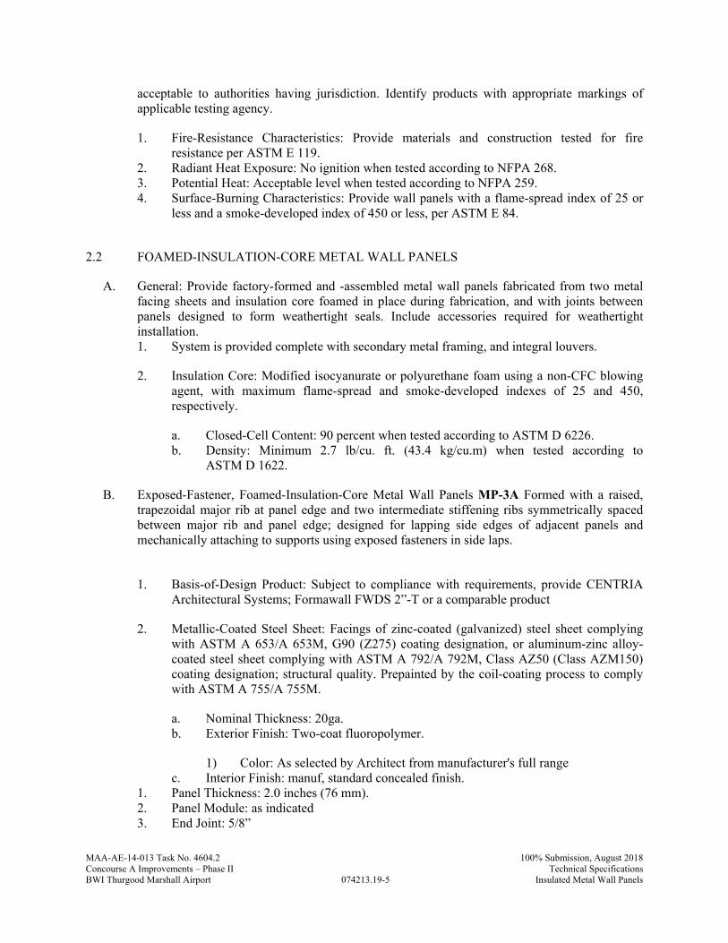
MAA-AE-14-013 Task No. 4604.2
074213.19-5
100% Submission, August 2018Concourse A Improvements – Phase II Technical SpecificationsBWI Thurgood Marshall Airport Insulated Metal Wall Panels
acceptable to authorities having jurisdiction. Identify products with appropriate markings of applicable testing agency.
1. Fire-Resistance Characteristics: Provide materials and construction tested for fire resistance per ASTM E 119.
2. Radiant Heat Exposure: No ignition when tested according to NFPA 268. 3. Potential Heat: Acceptable level when tested according to NFPA 259. 4. Surface-Burning Characteristics: Provide wall panels with a flame-spread index of 25 or
less and a smoke-developed index of 450 or less, per ASTM E 84.
2.2 FOAMED-INSULATION-CORE METAL WALL PANELS
A. General: Provide factory-formed and -assembled metal wall panels fabricated from two metal facing sheets and insulation core foamed in place during fabrication, and with joints between panels designed to form weathertight seals. Include accessories required for weathertight installation. 1. System is provided complete with secondary metal framing, and integral louvers.
2. Insulation Core: Modified isocyanurate or polyurethane foam using a non-CFC blowing agent, with maximum flame-spread and smoke-developed indexes of 25 and 450, respectively.
a. Closed-Cell Content: 90 percent when tested according to ASTM D 6226. b. Density: Minimum 2.7 lb/cu. ft. (43.4 kg/cu.m) when tested according to
ASTM D 1622.
B. Exposed-Fastener, Foamed-Insulation-Core Metal Wall Panels MP-3A Formed with a raised, trapezoidal major rib at panel edge and two intermediate stiffening ribs symmetrically spaced between major rib and panel edge; designed for lapping side edges of adjacent panels and mechanically attaching to supports using exposed fasteners in side laps.
1. Basis-of-Design Product: Subject to compliance with requirements, provide CENTRIA
Architectural Systems; Formawall FWDS 2”-T or a comparable product
2. Metallic-Coated Steel Sheet: Facings of zinc-coated (galvanized) steel sheet complying with ASTM A 653/A 653M, G90 (Z275) coating designation, or aluminum-zinc alloy-coated steel sheet complying with ASTM A 792/A 792M, Class AZ50 (Class AZM150) coating designation; structural quality. Prepainted by the coil-coating process to comply with ASTM A 755/A 755M.
a. Nominal Thickness: 20ga. b. Exterior Finish: Two-coat fluoropolymer.
1) Color: As selected by Architect from manufacturer's full range c. Interior Finish: manuf, standard concealed finish.
1. Panel Thickness: 2.0 inches (76 mm). 2. Panel Module: as indicated 3. End Joint: 5/8”
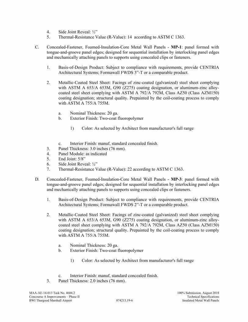
MAA-AE-14-013 Task No. 4604.2
074213.19-6
100% Submission, August 2018Concourse A Improvements – Phase II Technical SpecificationsBWI Thurgood Marshall Airport Insulated Metal Wall Panels
4. Side Joint Reveal: ½” 5. Thermal-Resistance Value (R-Value): 14 according to ASTM C 1363.
C. Concealed-Fastener, Foamed-Insulation-Core Metal Wall Panels - MP-1: panel formed with tongue-and-groove panel edges; designed for sequential installation by interlocking panel edges and mechanically attaching panels to supports using concealed clips or fasteners.
1. Basis-of-Design Product: Subject to compliance with requirements, provide CENTRIA Architectural Systems; Formawall FWDS 3”-T or a comparable product.
2. Metallic-Coated Steel Sheet: Facings of zinc-coated (galvanized) steel sheet complying with ASTM A 653/A 653M, G90 (Z275) coating designation, or aluminum-zinc alloy-coated steel sheet complying with ASTM A 792/A 792M, Class AZ50 (Class AZM150) coating designation; structural quality. Prepainted by the coil-coating process to comply with ASTM A 755/A 755M.
a. Nominal Thickness: 20 ga. b. Exterior Finish: Two-coat fluoropolymer
1) Color: As selected by Architect from manufacturer's full range
c. Interior Finish: manuf, standard concealed finish.
3. Panel Thickness: 3.0 inches (76 mm). 4. Panel Module: as indicated 5. End Joint: 5/8” 6. Side Joint Reveal: ½” 7. Thermal-Resistance Value (R-Value): 22 according to ASTM C 1363.
D. Concealed-Fastener, Foamed-Insulation-Core Metal Wall Panels - MP-3: panel formed with tongue-and-groove panel edges; designed for sequential installation by interlocking panel edges and mechanically attaching panels to supports using concealed clips or fasteners.
1. Basis-of-Design Product: Subject to compliance with requirements, provide CENTRIA Architectural Systems; Formawall FWDS 2”-T or a comparable product.
2. Metallic-Coated Steel Sheet: Facings of zinc-coated (galvanized) steel sheet complying with ASTM A 653/A 653M, G90 (Z275) coating designation, or aluminum-zinc alloy-coated steel sheet complying with ASTM A 792/A 792M, Class AZ50 (Class AZM150) coating designation; structural quality. Prepainted by the coil-coating process to comply with ASTM A 755/A 755M.
a. Nominal Thickness: 20 ga. b. Exterior Finish: Two-coat fluoropolymer
1) Color: As selected by Architect from manufacturer's full range
c. Interior Finish: manuf, standard concealed finish.
3. Panel Thickness: 2.0 inches (76 mm).
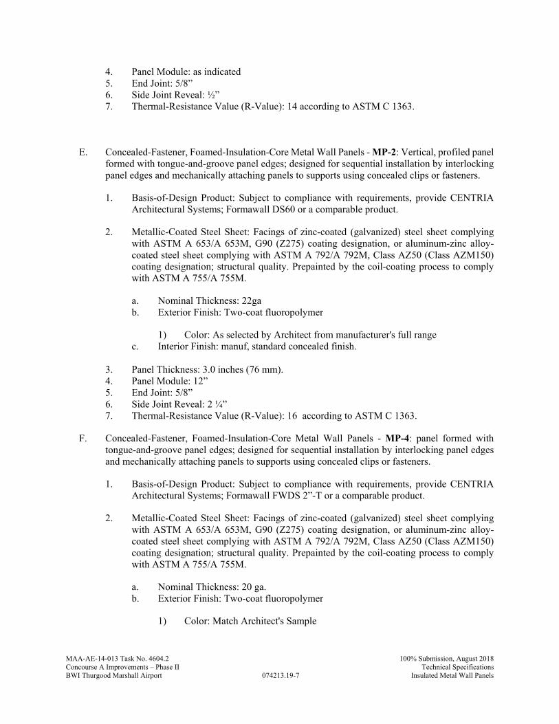
MAA-AE-14-013 Task No. 4604.2
074213.19-7
100% Submission, August 2018Concourse A Improvements – Phase II Technical SpecificationsBWI Thurgood Marshall Airport Insulated Metal Wall Panels
4. Panel Module: as indicated 5. End Joint: 5/8” 6. Side Joint Reveal: ½” 7. Thermal-Resistance Value (R-Value): 14 according to ASTM C 1363.
E. Concealed-Fastener, Foamed-Insulation-Core Metal Wall Panels - MP-2: Vertical, profiled panel formed with tongue-and-groove panel edges; designed for sequential installation by interlocking panel edges and mechanically attaching panels to supports using concealed clips or fasteners.
1. Basis-of-Design Product: Subject to compliance with requirements, provide CENTRIA Architectural Systems; Formawall DS60 or a comparable product.
2. Metallic-Coated Steel Sheet: Facings of zinc-coated (galvanized) steel sheet complying with ASTM A 653/A 653M, G90 (Z275) coating designation, or aluminum-zinc alloy-coated steel sheet complying with ASTM A 792/A 792M, Class AZ50 (Class AZM150) coating designation; structural quality. Prepainted by the coil-coating process to comply with ASTM A 755/A 755M.
a. Nominal Thickness: 22ga b. Exterior Finish: Two-coat fluoropolymer
1) Color: As selected by Architect from manufacturer's full range c. Interior Finish: manuf, standard concealed finish.
3. Panel Thickness: 3.0 inches (76 mm). 4. Panel Module: 12” 5. End Joint: 5/8” 6. Side Joint Reveal: 2 ¼” 7. Thermal-Resistance Value (R-Value): 16 according to ASTM C 1363.
F. Concealed-Fastener, Foamed-Insulation-Core Metal Wall Panels - MP-4: panel formed with tongue-and-groove panel edges; designed for sequential installation by interlocking panel edges and mechanically attaching panels to supports using concealed clips or fasteners.
1. Basis-of-Design Product: Subject to compliance with requirements, provide CENTRIA Architectural Systems; Formawall FWDS 2”-T or a comparable product.
2. Metallic-Coated Steel Sheet: Facings of zinc-coated (galvanized) steel sheet complying with ASTM A 653/A 653M, G90 (Z275) coating designation, or aluminum-zinc alloy-coated steel sheet complying with ASTM A 792/A 792M, Class AZ50 (Class AZM150) coating designation; structural quality. Prepainted by the coil-coating process to comply with ASTM A 755/A 755M.
a. Nominal Thickness: 20 ga. b. Exterior Finish: Two-coat fluoropolymer
1) Color: Match Architect's Sample
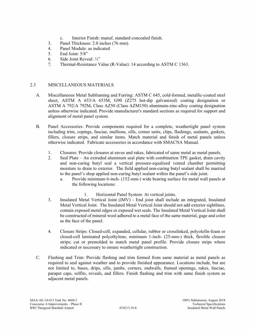
MAA-AE-14-013 Task No. 4604.2
074213.19-8
100% Submission, August 2018Concourse A Improvements – Phase II Technical SpecificationsBWI Thurgood Marshall Airport Insulated Metal Wall Panels
c. Interior Finish: manuf, standard concealed finish.
3. Panel Thickness: 2.0 inches (76 mm). 4. Panel Module: as indicated 5. End Joint: 5/8” 6. Side Joint Reveal: ½” 7. Thermal-Resistance Value (R-Value): 14 according to ASTM C 1363.
2.3 MISCELLANEOUS MATERIALS
A. Miscellaneous Metal Subframing and Furring: ASTM C 645, cold-formed, metallic-coated steel sheet, ASTM A 653/A 653M, G90 (Z275 hot-dip galvanized) coating designation or ASTM A 792/A 792M, Class AZ50 (Class AZM150) aluminum-zinc-alloy coating designation unless otherwise indicated. Provide manufacturer's standard sections as required for support and alignment of metal panel system.
B. Panel Accessories: Provide components required for a complete, weathertight panel system including trim, copings, fasciae, mullions, sills, corner units, clips, flashings, sealants, gaskets, fillers, closure strips, and similar items. Match material and finish of metal panels unless otherwise indicated. Fabricate accessories in accordance with SMACNA Manual.
1. Closures: Provide closures at eaves and rakes, fabricated of same metal as metal panels. 2. Seal Plate – An extruded aluminum seal plate with combination TPE gasket, drain cavity
and non-curing butyl seal a vertical pressure-equalized vented chamber permitting moisture to drain to exterior. The field applied non-curing butyl sealant shall be married to the panel’s shop applied non-curing butyl sealant within the panel’s side joint. a. Provide minimum 6-inch- (152-mm-) wide bearing surface for metal wall panels at
the following locations:
1. Horizontal Panel System: At vertical joints. 3. Insulated Metal Vertical Joint (IMV) - End joint shall include an integrated, Insulated
Metal Vertical Joint. The Insulated Metal Vertical Joint should not add exterior sightlines, contain exposed metal edges or exposed wet seals. The Insulated Metal Vertical Joint shall be constructed of mineral wool adhered to a metal face of the same material, gage and color as the face of the panel.
4. Closure Strips: Closed-cell, expanded, cellular, rubber or crosslinked, polyolefin-foam or
closed-cell laminated polyethylene; minimum 1-inch- (25-mm-) thick, flexible closure strips; cut or premolded to match metal panel profile. Provide closure strips where indicated or necessary to ensure weathertight construction.
C. Flashing and Trim: Provide flashing and trim formed from same material as metal panels as required to seal against weather and to provide finished appearance. Locations include, but are not limited to, bases, drips, sills, jambs, corners, endwalls, framed openings, rakes, fasciae, parapet caps, soffits, reveals, and fillers. Finish flashing and trim with same finish system as adjacent metal panels.
MAA-AE-14-013 Task No. 4604.2
074213.19-9
100% Submission, August 2018Concourse A Improvements – Phase II Technical SpecificationsBWI Thurgood Marshall Airport Insulated Metal Wall Panels
D. Panel Fasteners: Self-tapping screws designed to withstand design loads. Provide exposed fasteners with heads matching color of metal panels by means of plastic caps or factory-applied coating. Provide EPDM or PVC sealing washers for exposed fasteners.
E. Panel Sealants: Provide sealant type recommended by manufacturer that are compatible with panel materials, are nonstaining, and do not damage panel finish.
2.4 INTEGRATED WALL LOUVER UNITS
A. Manufacturers/Products:
1. Product: C/S Louvers by Construction Specialties, Inc
B. Exterior Wall Louvers, General: Extruded aluminum louvers, designed to integrate with metal wall panel profile and secondary support system without receptor channels or other flashing, nominal thickness not less than 0.060 inch (1.5 mm) for blades and 0.080 inch (2.0 mm) for frames, of types and performance indicated. System to be tested integrated with panels per the requirements of section 1.5 B and 1.5 C.
1. Louver Depth: 4 inches (100 mm) deep.
C. Horizontal, Drainable-Blade Fixed Louver:
1. Free Area: Not less than 54 percent. 2. Air Performance: Not exceeding 0.2-inch wg (50-Pa) static pressure drop at 950-fpm (4.8-
m/s) free area velocity. 3. Point of Beginning Water Penetration: Not less than 950 fpm (4.8 m/s).
D. AMCA Seal: Mark units with AMCA Certified Ratings Seal.
E. Finish, Exterior:
1. Match metal wall panel finish.
2.5 SECONDARY METAL FRAMING
A. Miscellaneous Framing Components, General: Cold-formed metallic-coated steel sheet, ASTM C 645, Grade 50, with ASTM A 653/A 653M, G90 (Z180) hot-dip galvanized zinc coating.
B. Subgirts: C- or Z- shaped sections, 0.054-inch (1.37-mm) minimum.
C. Sill Channels: 0.054-inch (1.37-mm) minimum.
D. Hat Channels: 0.054 (1.37mm) minimum.

MAA-AE-14-013 Task No. 4604.2
074213.19-10
100% Submission, August 2018Concourse A Improvements – Phase II Technical SpecificationsBWI Thurgood Marshall Airport Insulated Metal Wall Panels
2.6 FABRICATION
A. General: Fabricate and finish metal panels and accessories at the factory, by manufacturer's standard procedures and processes, as necessary to fulfill indicated performance requirements demonstrated by laboratory testing. Comply with indicated profiles and with dimensional and structural requirements.
B. Provide panel profile, including major ribs and intermediate stiffening ribs, if any, for full length of panel.
C. Fabricate metal panel joints with factory-installed captive gaskets or separator strips that provide a weathertight seal and prevent metal-to-metal contact, and that minimize noise from movements.
D. Sheet Metal Flashing and Trim: Fabricate flashing and trim to comply with manufacturer's recommendations and recommendations in SMACNA's "Architectural Sheet Metal Manual" that apply to design, dimensions, metal, and other characteristics of item indicated.
1. Form exposed sheet metal accessories that are without excessive oil canning, buckling, and tool marks and that are true to line and levels indicated, with exposed edges folded back to form hems.
2. Seams for Other Than Aluminum: Fabricate nonmoving seams in accessories with flat-lock seams. Tin edges to be seamed, form seams, and solder.
3. Sealed Joints: Form nonexpansion, but movable, joints in metal to accommodate sealant and to comply with SMACNA standards.
4. Conceal fasteners and expansion provisions where possible. 5. Fabricate cleats and attachment devices from same material as accessory being anchored
or from compatible, noncorrosive metal recommended in writing by metal panel manufacturer.
a. Size: As recommended by SMACNA's "Architectural Sheet Metal Manual" or metal wall panel manufacturer for application but not less than thickness of metal being secured.
2.7 FINISHES
A. Protect mechanical and painted finishes on exposed surfaces from damage by applying a strippable, temporary protective covering before shipping.
B. Appearance of Finished Work: Variations in appearance of abutting or adjacent pieces are acceptable if they are within one-half of the range of approved Samples. Noticeable variations in same piece are not acceptable. Variations in appearance of other components are acceptable if they are within the range of approved Samples and are assembled or installed to minimize contrast.
C. Steel Panels and Accessories:
1. Two-Coat Fluoropolymer: AAMA 621. 0.2 mil primer with 0.8 mil finish 70 percent min PVDF Fluoropolymer resin by weight in color coat. Prepare, pretreat, and apply coating to
MAA-AE-14-013 Task No. 4604.2
074213.19-11
100% Submission, August 2018Concourse A Improvements – Phase II Technical SpecificationsBWI Thurgood Marshall Airport Insulated Metal Wall Panels
exposed metal surfaces to comply with coating and resin manufacturers' written instructions.
2. Concealed Finish: Apply pretreatment and manufacturer's standard white or light-colored acrylic or polyester backer finish consisting of prime coat and wash coat with a minimum total dry film thickness of 0.5 mil (0.013 mm).
PART 3 - EXECUTION
3.1 EXAMINATION
A. Examine substrates, areas, and conditions, with Installer present, for compliance with requirements for installation tolerances, metal panel supports, and other conditions affecting performance of the Work.
1. Examine wall framing to verify that girts, angles, channels, studs, and other structural panel support members and anchorage have been installed within alignment tolerances required by metal wall panel manufacturer. a. Maximum deviations acceptable:
1) 1/4-inch in 20 feet (6.4 mm in 6 m) vertically or horizontally from face plane of framing.
2) 1/2-inch (12.7 mm) from flat substrate on any building elevation. 3) 1/8-inch in 5 feet (3.2 mm in 1.5 m).
B. Framing: Inspect framing that will support metal wall panels to determine if support components are installed as indicated on approved shop drawings. Confirm presence of acceptable framing members at recommended spacing to match installation requirements of metal wall panels.
C. Openings: Verify that windows, doors, louvers and other penetrations match layout on shop drawings.
D. Examine roughing-in for components and systems penetrating metal panels to verify actual locations of penetrations relative to seam locations of metal panels before installation.
E. Advise G.C., in writing, of all out- of-tolerance work and other deficient conditions prior to proceeding with metal wall panel installation.
F. Proceed with installation only after unsatisfactory conditions have been corrected.
3.2 PREPARATION
A. Secondary Metal Framing: Install secondary metal framing components as indicated. Install secondary metal framing and other metal panel supports per ASTM C 754 and metal wall panel manufacturer's recommendations.
1. Shim or otherwise plumb substrates receiving metal panels.
MAA-AE-14-013 Task No. 4604.2
074213.19-12
100% Submission, August 2018Concourse A Improvements – Phase II Technical SpecificationsBWI Thurgood Marshall Airport Insulated Metal Wall Panels
2. Flash and seal metal panels at perimeter of all openings. Fasten with self-tapping screws. Do not begin installation until air- or water-resistive barriers and flashings that will be concealed by metal panels are installed.
3. Install screw fasteners in predrilled holes. 4. Locate and space fastenings in uniform vertical and horizontal alignment. 5. Install flashing and trim as metal panel work proceeds. 6. Locate panel splices over, but not attached to, structural supports. Stagger panel splices
and end laps to avoid a four-panel lap splice condition. 7. Align bottoms of metal panels and fasten with blind rivets, bolts, or self-tapping screws.
Fasten flashings and trim around openings and similar elements with self-tapping screws. 8. Provide weathertight escutcheons for pipe- and conduit-penetrating panels.
3.3 METAL PANEL INSTALLATION
A. General: Install metal panels according to manufacturer's written instructions in orientation, sizes, and locations indicated. Install panels perpendicular to supports unless otherwise indicated. Anchor metal panels and other components of the Work securely in place, with provisions for thermal and structural movement.
1. Shim or otherwise plumb substrates receiving metal panels. 2. Flash and seal metal panels at perimeter of all openings. Fasten with self-tapping screws.
Do not begin installation until air- or water-resistive barriers and flashings that will be concealed by metal panels are installed.
3. Install screw fasteners in predrilled holes. 4. Locate and space fastenings in uniform vertical and horizontal alignment. 5. Install flashing and trim as metal panel work proceeds. 6. Locate panel splices over, but not attached to, structural supports. Stagger panel splices
and end laps to avoid a four-panel lap splice condition. 7. Align bottoms of metal panels and fasten with blind rivets, bolts, or self-tapping screws.
Fasten flashings and trim around openings and similar elements with self-tapping screws. 8. Provide weathertight escutcheons for pipe- and conduit-penetrating panels.
B. Fasteners:
1. Steel Panels: Use stainless-steel fasteners for surfaces exposed to the exterior; use galvanized-steel fasteners for surfaces exposed to the interior.
C. Metal Protection: Where dissimilar metals contact each other or corrosive substrates, protect against galvanic action as recommended in writing by metal panel manufacturer.
D. Joint Sealers: Install gaskets, joint fillers, and sealants where indicated and where required for weathertight performance of metal wall panel assemblies. Provide types of gaskets, fillers, and sealants indicated by metal panel manufacturer; or, if not indicated, provide types recommended by metal wall panel manufacturer.
1. Seal metal wall panel end laps with double beads of tape or sealant, full width of panel. Seal side joints where recommended by metal wall panel manufacturer.
2. Prepare joints and apply sealants to comply with requirements in Section 079200 "Joint Sealants."
MAA-AE-14-013 Task No. 4604.2
074213.19-13
100% Submission, August 2018Concourse A Improvements – Phase II Technical SpecificationsBWI Thurgood Marshall Airport Insulated Metal Wall Panels
3.4 INSULATED METAL WALL PANEL INSTALLATION
A. General: Install metal wall panel system in accordance with approved shop drawings and manufacturer's recommendations. Install metal wall panels in orientation, sizes, and locations indicated. Anchor metal wall panels and other components securely in place. Provide for thermal and structural movement
B. Attach panels to metal framing using recommended clips, screws, fasteners, sealants, and adhesives indicated on approved shop drawings.
1. Fasteners for Steel Wall Panels: Stainless-steel for exterior locations and locations exposed to moisture; carbon steel for interior use only.
2. Apply elastomeric sealant continuously between metal base channel (sill angle) and concrete, and elsewhere as indicated or, if not indicated, as approved by manufacturer.
3. Fasten metal wall panels to supports with concealed clips at each joint at location, spacing, and with fasteners recommended by manufacturer. Install clips to supports with self-tapping fasteners.
4. Provide weatherproof escutcheons for pipe and conduit penetrating exterior walls. 5. Horizontal Joinery: Working from base of installation to top connect upper panel to lower
panel at dry seal joinery. 6. Vertical Joinery: Provide reveal between vertical ends of panels as shown on shop drawings
using hardware and gaskets furnished by manufacturer to form a weather tight seal between panels.
7. Dissimilar Materials: Where elements of metal wall panel system will come into contact with dissimilar materials, treat faces and edges in contact with dissimilar materials as recommended by manufacturer.
C. Joint Sealers: Install gaskets, joint fillers, and sealants where indicated and where required for weatherproof performance of metal wall panel assemblies.
1. Seal panel end utilizing 2 beads of non-curing butyl aligning with factory-applied seal in adjacent panel pocket; apply continuously without gaps to complete panel system air barrier.
2. Seal metal wall panel to supports or back-up flashing sealant, full width of panel. Seal side joints where recommended by metal wall panel manufacturer. Do not install sealant in locations that will interfere with drainage of pressure-equalized panel chambers.
3. Prepare joints and apply sealants per Division 07 Section "Joint Sealants."
D. Accessory Installation: Install metal wall panel accessories with positive anchorage to building and weathertight mounting and provide for thermal expansion. Coordinate installation with flashings and other components. 1. Install components required for a complete metal wall panel assembly, including trim,
copings, corners, seam covers, flashings, sealants, gaskets, fillers, closure strips, and similar items.
2. Comply with performance requirements and manufacturer's written installation instructions.
3. Provide concealed fasteners except where noted on approved shop drawings.
MAA-AE-14-013 Task No. 4604.2
074213.19-14
100% Submission, August 2018Concourse A Improvements – Phase II Technical SpecificationsBWI Thurgood Marshall Airport Insulated Metal Wall Panels
4. Set units true to line and level as indicated. Install work with laps, joints, and seams that will be permanently watertight and weather resistant.
5. Install components required for a complete metal panel system including trim, copings, corners, seam covers, flashings, sealants, gaskets, fillers, closure strips, and similar items. Provide types indicated by metal panel manufacturer; or, if not indicated, provide types recommended by metal panel manufacturer.
E. Flashing and Trim: Comply with performance requirements, manufacturer's written installation instructions, and SMACNA's "Architectural Sheet Metal Manual." Provide concealed fasteners where possible, and set units true to line and level. Install work with laps, joints, and seams that are permanently watertight.
1. Install exposed flashing and trim that is without buckling and tool marks, and that is true to line and levels indicated, with exposed edges folded back to form hems. Install sheet metal flashing and trim to fit substrates and to achieve waterproof performance.
2. Expansion Provisions: Provide for thermal expansion of exposed flashing and trim. Space movement joints at a maximum of 10 feet (3 m) with no joints allowed within 24 inches (610 mm) of corner or intersection. Where lapped expansion provisions cannot be used or would not be sufficiently waterproof, form expansion joints of intermeshing hooked flanges, not less than 1 inch (25 mm) deep, filled with mastic sealant (concealed within joints).
3.5 INTEGRATED UNIT INSTALLATION
A. Install window units and louvers in accordance with manufacturer's recommendations and approved shop drawings. Anchor supports to structure with approved anchors. Assemble wall components using gaskets, fasteners, and trim supplied by metal wall panel manufacturer. Separate dissimilar metals with manufacturer's approved coating.
3.6 FIELD QUALITY CONTROL
A. Testing Agency: Owner will engage a qualified testing agency to perform tests and inspections.
B. Progress or check tests can be performed by the installer following test procedures noted in AAMA 501.2. No independent test agency need to be employed in this test phase. Results of this test phase is to be recorded and reported to the panel manufacturer.
C. Final AAMA 501.2 testing will be conducted by an independent test agency following project completion. Areas of test are to be determined by the Architect/Engineer and General Contractor/Contract Manager and the panel installer. A field representative from the panel manufacturer is required for the final inspection and testing.
D. Metal wall panels will be considered defective if they do not pass test and inspections. 1. Areas that do not pass will be disassembled, remedied and re-installed.
E. Additional tests and inspections, at Contractor's expense, are performed to determine compliance of replaced or additional work with specified requirements.
MAA-AE-14-013 Task No. 4604.2
074213.19-15
100% Submission, August 2018Concourse A Improvements – Phase II Technical SpecificationsBWI Thurgood Marshall Airport Insulated Metal Wall Panels
F. Prepare test and inspection reports.
3.7 CLEANING AND PROTECTION
A. Remove temporary protective coverings and strippable films, if any, as metal panels are installed, unless otherwise indicated in manufacturer's written installation instructions. On completion of metal panel installation, clean finished surfaces as recommended by metal panel manufacturer. Maintain in a clean condition during construction.
B. After metal panel installation, clear weep holes and drainage channels of obstructions, dirt, and sealant.
C. Replace metal panels that have been damaged or have deteriorated beyond successful repair by finish touchup or similar minor repair procedures.
PART 4 - MEASUREMENT
4.1 METHODS OF MEASUREMENT
A. No separate measurement shall be made for work under this Specification Section
PART 5 - PAYMENT
5.1 METHOD OF PAYMENT
A. No separate payment will be made for work under this Specification Section. The cost of work, complete in place, described in this Specification Section shall be included in the Lump Sum Bid under “Building Construction”
B. Costs include all labor, material, services, and equipment necessary to complete the work in every aspect.
END OF SECTION 074213.19
MAA-AE-14-013 Task No. 4604.2
074213.19-16
100% Submission, August 2018Concourse A Improvements – Phase II Technical SpecificationsBWI Thurgood Marshall Airport Insulated Metal Wall Panels
THIS PAGE INTENTIONALLY LEFT BLANK
MAA-AE-14-013 Task No.4604.2
075216-1
100% Submission, August 2018Concourse A Improvements – Phase II Technical SpecificationsBWI Thurgood Marshall Airport Styrene-Butadiene-Styrene (SBS) Modified Bituminous Roofing
SECTION 075216 - STYRENE-BUTADIENE-STYRENE (SBS) MODIFIED BITUMINOUS MEMBRANE ROOFING
PART 1 - GENERAL
1.1 RELATED DOCUMENTS
A. Drawings and general provisions of the Contract, including Maryland Department of Transportation/ Maryland Aviation Administration Standard Provisions to the Construction Contract for the Concourse A Improvements – Phase II at BWI Thurgood Marshall Airport and other Divisions 1 Specification Sections, apply to this Section.
1.2 SUMMARY
A. Section Includes:
1. Styrene-butadiene-styrene (SBS)-modified bituminous membrane roofing. 2. Roof insulation. 3. Vapor Barrier 4. Substrate Board
B. Related Requirements: 1. Section 077129 "Manufactured Roof Expansion Joints" for proprietary manufactured roof
expansion-joint assemblies. 2. Section 079200 "Joint Sealants" for joint sealants, joint fillers, and joint preparation. 3. Section 221423 "Storm Drainage Piping Specialties" for roof drains.
1.3 DEFINITIONS
A. Roofing Terminology: Definitions in ASTM D 1079 and glossary of NRCA's "The NRCA Roofing and Waterproofing Manual" apply to work of this Section.
1.4 ACTION SUBMITTALS
A. Product Data: For each type of product.
B. Shop Drawings: For roofing system. Include plans, elevations, sections, details, and attachments to other work, including:
1. Base flashings and membrane terminations. 2. Tapered insulation, including slopes. 3. Crickets, saddles, and tapered edge strips, including slopes. 4. Insulation fastening patterns for corner, perimeter, and field-of-roof locations.
C. Samples for Verification: For the following products:
MAA-AE-14-013 Task No.4604.2
075216-2
100% Submission, August 2018Concourse A Improvements – Phase II Technical SpecificationsBWI Thurgood Marshall Airport Styrene-Butadiene-Styrene (SBS) Modified Bituminous Roofing
1. Cap sheet, of color required. 2. Flashing sheet, of color required.
1.5 INFORMATIONAL SUBMITTALS
A. The Contractor shall certify that the materials being submitted conform to the requirements of the Contract in all respects, including all Federal requirements such as “Buy American,” except as otherwise noted.
B. Qualification Data: For Installer, manufacturer, and testing agency.
C. Manufacturer Certificates: Signed by roofing manufacturer certifying that roofing system complies with requirements specified in "Performance Requirements" Article.
1. Submit evidence of complying with performance requirements.
D. Product Test Reports: For components of membrane roofing system, for tests performed by manufacturer and witnessed by a qualified testing agency.
E. Research/Evaluation Reports: For components of membrane roofing system, from ICC-ES.
F. Sample Warranties: For manufacturer's special warranties.
1.6 CLOSEOUT SUBMITTALS
A. Maintenance Data: For roofing system to include in maintenance manuals.
1.7 QUALITY ASSURANCE
A. Manufacturer Qualifications: A qualified manufacturer that is UL listed, and FM Global approved for membrane roofing system identical to that used for this Project.
B. Installer Qualifications: A qualified firm that is approved, authorized, or licensed by roofing system manufacturer to install manufacturer's product and that is eligible to receive manufacturer's special warranty.
C. Preliminary Roofing Conference: Before starting roof deck construction, conduct conference at Project site
1. Meet with Owner, Architect, Owner's insurer if applicable, testing and inspecting agency representative, roofing Installer, roofing system manufacturer's representative, deck Installer, and installers whose work interfaces with or affects roofing, including installers of roof accessories and roof-mounted equipment.
2. Review methods and procedures related to roofing installation, including manufacturer's written instructions.
3. Review and finalize construction schedule, and verify availability of materials, Installer's personnel, equipment, and facilities needed to make progress and avoid delays.
MAA-AE-14-013 Task No.4604.2
075216-3
100% Submission, August 2018Concourse A Improvements – Phase II Technical SpecificationsBWI Thurgood Marshall Airport Styrene-Butadiene-Styrene (SBS) Modified Bituminous Roofing
4. Review deck substrate requirements for conditions and finishes, including flatness and fastening.
5. Review structural loading limitations of roof deck during and after roofing. 6. Review base flashings, special roofing details, roof drainage, roof penetrations, equipment
curbs, and condition of other construction that affects roofing system. 7. Review governing regulations and requirements for insurance and certificates if applicable. 8. Review temporary protection requirements for roofing system during and after installation. 9. Review roof observation and repair procedures after roofing installation.
1.8 DELIVERY, STORAGE, AND HANDLING
A. Deliver roofing materials to Project site in original containers with seals unbroken and labeled with manufacturer's name, product brand name and type, date of manufacture, approval or listing agency markings, and directions for storing and mixing with other components.
B. Store liquid materials in their original undamaged containers in a clean, dry, protected location and within the temperature range required by roofing system manufacturer. Protect stored liquid material from direct sunlight.
1. Discard and legally dispose of liquid material that cannot be applied within its stated shelf life.
C. Protect roof insulation materials from physical damage and from deterioration by sunlight, moisture, soiling, and other sources. Store in a dry location. Comply with insulation manufacturer's written instructions for handling, storing, and protecting during installation. Manufacturer’s shrink-wrap is not an acceptable protection.
D. Handle and store roofing materials, and place equipment in a manner to avoid permanent deflection of deck.
1.9 FIELD CONDITIONS
A. Weather Limitations: Proceed with installation only when existing and forecasted weather conditions permit roofing system to be installed according to manufacturer's written instructions and warranty requirements.
1.10 WARRANTY
A. General Warranty: The warranties specified in this Article shall not deprive the Owner of other rights the Owner may have under other provisions of the Contract Documents and shall be in addition to, and run concurrent with, other warranties made by the Contractor under requirements of the Contract Documents.
B. Premium Roofing Manufacturer’s Warranty: Submit a written warranty, without monetary limitation, signed by roofing system manufacturer agreeing to promptly repair leaks in the roof membrane and base flashings resulting from defects in materials or workmanship for the following warranty period:
MAA-AE-14-013 Task No.4604.2
075216-4
100% Submission, August 2018Concourse A Improvements – Phase II Technical SpecificationsBWI Thurgood Marshall Airport Styrene-Butadiene-Styrene (SBS) Modified Bituminous Roofing
1. Warranty Period: 20 years from date of Substantial Completion.
C. Special Project Warranty: Submit roofing Installer's warranty, on warranty form at end of this Section, signed by Installer, covering the Work of this Section, including all components of roofing system such as membrane roofing, base flashing, roof insulation, fasteners, cover boards, substrate boards, vapor retarders, and walkway products, for the following warranty period:
1. Warranty Period: Two years from date of Substantial Completion.
PART 2 - PRODUCTS
2.1 MANUFACTURERS
A. Basis-of-Design Product: Subject to compliance with requirements, provide Siplast; Paradiene or a comparable product by one of the following: 1. Garland Company, Inc. (The). 2. Tremco Incorporated.
B. Source Limitations: Obtain components including roof insulation, fasteners, substrate boards and vapor barriers for roofing system from same manufacturer as membrane roofing or manufacturer approved by membrane roofing manufacturer.
2.2 PERFORMANCE REQUIREMENTS
A. General Performance: Installed roofing and base flashings shall withstand specified uplift pressures, thermally induced movement, and exposure to weather without failure due to defective manufacture, fabrication, installation, or other defects in construction. Roofing and base flashings shall remain watertight.
1. Accelerated Weathering: Roofing system shall withstand 2000 hours of exposure when tested according to ASTM G 152, ASTM G 154, or ASTM G 155.
2. Impact Resistance: Roofing system shall resist impact damage when tested according to ASTM D 3746 or ASTM D 4272.
B. Material Compatibility: Roofing materials shall be compatible with one another and adjacent materials under conditions of service and application required, as demonstrated by roofing manufacturer based on testing and field experience.
C. FM Global Listing: Roofing, base flashings, and component materials shall comply with requirements in FM Global 4450 or FM Global 4470 as part of a roofing system, and shall be listed in FM Global's "RoofNav" for Class 1 or noncombustible construction, as applicable. Identify materials with FM Global markings.
1. Fire/Windstorm Classification: Class 1A-90
MAA-AE-14-013 Task No.4604.2
075216-5
100% Submission, August 2018Concourse A Improvements – Phase II Technical SpecificationsBWI Thurgood Marshall Airport Styrene-Butadiene-Styrene (SBS) Modified Bituminous Roofing
2. Hail-Resistance Rating: SH.
D. Exterior Fire-Test Exposure: ASTM E 108 or UL 790, Class A; for application and roof slopes indicated; testing by a qualified testing agency. Identify products with appropriate markings of applicable testing agency.
2.3 ROOFING SHEET MATERIALS
A. Roofing Membrane Base Sheet: ASTM D 6164/D 6164M, Grade S, Type I or II, SBS-modified asphalt sheet (reinforced with polyester fabric) or ASTM D 6163, Grade S, Type I or II, SBS-modified asphalt sheet (reinforced with glass fibers)] smooth surfaced; suitable for application method specified.
B. Granule-Surfaced Roofing Cap Sheet: ASTM D 6164/D 6164M, Grade G, Type I or II, SBS-modified asphalt sheet (reinforced with polyester fabric) or ASTM D 6163, Grade G, Type I or II, SBS-modified asphalt sheet (reinforced with glass fibers);granule surfaced; suitable for application method specified.
2.4 BASE FLASHING SHEET MATERIALS
A. Backer Sheet: ASTM D 6164/D 6164M, Grade S, Type I or II, SBS-modified asphalt sheet (reinforced with polyester fabric) or ASTM D 6163, Grade S, Type I or II, SBS-modified asphalt sheet (reinforced with glass fibers) smooth surfaced; suitable for application method specified.
B. Metal-Foil-Surfaced Flashing Sheet: ASTM D 6298, glass-fiber-reinforced SBS-modified asphalt sheet (reinforced with glass fibers); metal-foil surfaced; suitable for application method specified, and as follows:
1. Foil Surfacing: Aluminum.
2.5 AUXILIARY ROOFING MATERIALS
A. General: Auxiliary materials recommended by roofing system manufacturer for intended use and compatible with roofing.
1. Liquid-type auxiliary materials shall comply with VOC limits of authorities having jurisdiction.
B. Cold-Applied Adhesive: Roofing system manufacturer's standard asphalt-based, one- or two-part, asbestos-free, cold-applied adhesive specially formulated for compatibility and use with roofing membrane and base flashing.
C. Asphalt Roofing Cement: ASTM D 4586, asbestos free, of consistency required by roofing system manufacturer for application.
D. Mastic Sealant: Polyisobutylene, plain or modified bitumen; nonhardening, nonmigrating, nonskinning, and nondrying.
MAA-AE-14-013 Task No.4604.2
075216-6
100% Submission, August 2018Concourse A Improvements – Phase II Technical SpecificationsBWI Thurgood Marshall Airport Styrene-Butadiene-Styrene (SBS) Modified Bituminous Roofing
E. Fasteners: Factory-coated steel fasteners and metal or plastic plates complying with corrosion-resistance provisions in FM Global 4470, designed for fastening roofing components to substrate; tested by manufacturer for required pullout strength, and acceptable to roofing system manufacturer.
F. Miscellaneous Accessories: Provide those recommended by roofing system manufacturer.
2.6 ROOF INSULATION
A. General: Preformed roof insulation boards manufactured or approved by roofing manufacturer, selected from manufacturer's standard sizes suitable for application, of thicknesses indicated.
B. Polyisocyanurate Board Insulation: ASTM C 1289, Type II, Class 1, Grade 2 felt or glass-fiber mat facer on both major surfaces. HCFC-Free and Zero Ozone Depletion Potential (ODP);
C. Tapered Insulation: Provide factory-tapered insulation boards fabricated to slope of 1/4 inch per 12 inches (1:48) unless otherwise indicated.
D. Provide preformed saddles, crickets, tapered edge strips, and other insulation shapes where indicated for sloping to drain. Fabricate to slopes indicated.
2.7 INSULATION ACCESSORIES
A. General: Roof insulation accessories recommended by insulation manufacturer for intended use and compatibility with roofing.
B. Fasteners: Factory-coated steel fasteners and metal or plastic plates complying with corrosion-resistance provisions in FM Global 4470, designed for fastening roof insulation to substrate, and acceptable to roofing system manufacturer.
C. Insulation Adhesive: Insulation manufacturer's recommended adhesive, approved for vapor-retarder application.
D. Cant and Tapered strips: Insulation Cant Strips: 1. ASTM C 728, perlite insulation board or ASTM C 208, Type II, Grade 1, cellulosic-fiber
insulation board. 2. Tapered Edge Strips: ASTM C 728, perlite insulation board or ASTM C 208, Type II,
Grade 1, cellulosic-fiber insulation board.
2.8 SUBSTRATE BOARDS
A. Substrate Board/Cover Board: ASTM C 1177/C 1177M, glass-mat, water-resistant gypsum substrate, 1/2 inch (13 mm) factory primed. 1. Basis-of-Design Product: Subject to compliance with requirements, provide DensDeck
Prime or comparable product by one of the following:
a. Georgia-Pacific Gypsum LLC.
MAA-AE-14-013 Task No.4604.2
075216-7
100% Submission, August 2018Concourse A Improvements – Phase II Technical SpecificationsBWI Thurgood Marshall Airport Styrene-Butadiene-Styrene (SBS) Modified Bituminous Roofing
B. Fasteners: Factory-coated steel fasteners and metal or plastic plates complying with corrosion-resistance provisions in FM Global 4470, designed for fastening substrate board to roof deck.
2.9 VAPOR RETARDER
A. Polyethylene Film: ASTM D 4397, 6 mils (0.15 mm) thick, minimum, with maximum permeance rating of 0.13 perm (7.5 ng/Pa x s x sq. m). 1. Adhesive: Manufacturer's standard lap adhesive, FM Global approved for vapor-retarder
application.
B. Glass-Fiber Felt: ASTM D 2178, Type IV, asphalt impregnated.
PART 3 - EXECUTION
3.1 EXAMINATION
A. Examine substrates, areas, and conditions, with Installer present, for compliance with requirements and other conditions affecting performance of the Work:
1. Verify that roof openings and penetrations are in place, curbs are set and braced, and roof-drain bodies are securely clamped in place.
2. Verify that wood cants, blocking, curbs, and nailers are securely anchored to roof deck at penetrations and terminations and that nailers match thicknesses of insulation.
3. Verify that surface plane flatness and fastening of steel roof deck complies with requirements in Section 053100 "Steel Decking."
B. Proceed with installation only after unsatisfactory conditions have been corrected.
3.2 PREPARATION
A. Clean substrate including all deck flutes of dust, debris, moisture, and other substances detrimental to roofing installation according to roofing system manufacturer's written instructions. Remove sharp projections.
B. Prevent materials from entering and clogging roof drains and conductors and from spilling or migrating onto surfaces of other construction. Remove roof-drain plugs when no work is taking place or when rain is forecast.
3.3 INSTALLATION, GENERAL
A. Comply with roofing system manufacturer's written instructions.
MAA-AE-14-013 Task No.4604.2
075216-8
100% Submission, August 2018Concourse A Improvements – Phase II Technical SpecificationsBWI Thurgood Marshall Airport Styrene-Butadiene-Styrene (SBS) Modified Bituminous Roofing
3.4 SUBSTRATE BOARD INSTALLATION
A. Install substrate board with long joints in continuous straight lines, perpendicular to roof slopes with end joints staggered between rows. Tightly butt substrate boards together.
1. Fasten substrate board to top flanges of steel deck according to recommendations in FM Global's "RoofNav" and FM Global Loss Prevention Data Sheet 1-29 for specified Windstorm Resistance Classification.
3.5 VAPOR-RETARDER INSTALLATION
A. Polyethylene Film: Loosely lay polyethylene-film vapor retarder in a single layer over area to receive vapor retarder, side and end lapping each sheet a minimum of 2 inches (50 mm) and 6 inches (150 mm), respectively. Continuously seal side and end laps with adhesive.
B. Completely seal vapor retarder at terminations, obstructions, and penetrations to prevent air movement into roofing system.
3.6 INSULATION INSTALLATION
A. Coordinate installing roofing system components so insulation is not exposed to precipitation or left exposed at the end of the workday
B. Comply with roofing system manufacture’s written instructions for installing roofing insulation
C. After installation of vapor retarder, install tapered insulation under area of roofing to conform to slopes indicated on Shop Drawings
D. Install required thickness in 2 or more layers with joints of each succeeding layer staggered from joints of previous layer a minimum of 6 inches in each direction.
E. Trim surface of insulation where necessary at gutters scuppers and roof drains so completed surface is flush and does not restrict flow of water.
F. Install insulation with long joints of insulation in continuous straight lined with end joints staggered in between rows, abutting edges and ends between boards. Fill gaps exceeding ¼” with insulation. 1. Cut and fit insulation within ¼” of nailers, projections, and penetrations.
G. Mechanically Fastened Insulation: Install each layer of insulation and secure to deck using mechanical fasteners specifically designed and sized for fastenting specified board type roofing insulation to deck type. 1. Fasten insulation according to requirements in FMG’s “Approval Guide” for specified
Windstorm Resistance Classification and tine insulation and roofing systems manufacturers’ written instructions.

MAA-AE-14-013 Task No.4604.2
075216-9
100% Submission, August 2018Concourse A Improvements – Phase II Technical SpecificationsBWI Thurgood Marshall Airport Styrene-Butadiene-Styrene (SBS) Modified Bituminous Roofing
3.7 ROOFING INSTALLATION, GENERAL
A. Install roofing system according to roofing system manufacturer's written instructions and applicable recommendations in ARMA/NRCA's "Quality Control Guidelines for the Application of Polymer Modified Bitumen Roofing."
1. Install roofing system according to roof assembly identification matrix and roof assembly layout illustrations in NRCA's "The NRCA Roofing and Waterproofing Manual" and to Section requirements.
B. Start installation of roofing in presence of manufacturer's technical personnel.
C. Coordinate installation of roofing system so insulation and other components of the roofing system not permanently exposed are not subjected to precipitation or left uncovered at the end of the workday or when rain is forecast.
1. Provide tie-offs at end of each day's work to cover exposed roofing sheets and insulation with a course of coated felt set in roofing cement or hot roofing asphalt, with joints and edges sealed.
2. Complete terminations and base flashings, and provide temporary seals to prevent water from entering completed sections of roofing system.
3. Remove and discard temporary seals before beginning work on adjoining roofing.
3.8 SBS-MODIFIED BITUMINOUS MEMBRANE INSTALLATION
A. Install modified bituminous roofing sheet and cap sheet according to roofing manufacturer's written instructions, starting at low point of roofing system. Extend roofing membrane sheets over and terminate beyond cants, installing as follows: 1. Torch apply to substrate. 2. Unroll roofing sheets and allow them to relax for minimum time period required by
manufacturer.
B. Laps: Accurately align roofing sheets, without stretching, and maintain uniform side and end laps. Stagger end laps. Completely bond and seal laps, leaving no voids.
1. Repair tears and voids in laps and lapped seams not completely sealed.
C. Install roofing sheets so side and end laps shed water.
3.9 FLASHING AND STRIPPING INSTALLATION
A. Install base flashing over cant strips and other sloped and vertical surfaces, at roof edges, and at penetrations through roof, and secure to substrates according to roofing system manufacturer's written instructions and as follows:
1. Prime substrates with asphalt primer if required by roofing system manufacturer. 2. Flashing-Sheet Application: Torch apply flashing sheet to substrate.
MAA-AE-14-013 Task No.4604.2
075216-10
100% Submission, August 2018Concourse A Improvements – Phase II Technical SpecificationsBWI Thurgood Marshall Airport Styrene-Butadiene-Styrene (SBS) Modified Bituminous Roofing
B. Extend base flashing up walls or parapets a minimum of 8 inches (200 mm) above roofing membrane and 4 inches (100 mm) onto field of roofing membrane.
C. Mechanically fasten top of base flashing securely at terminations and perimeter of roofing.
D. Roof Drains: Set 30-by-30-inch- (760-by-760-mm-) metal flashing in bed of asphaltic adhesive on completed roofing membrane. Cover metal flashing with roofing cap-sheet stripping, and extend a minimum of 4 inches (100 mm) beyond edge of metal flashing onto field of roofing membrane. Clamp roofing membrane, metal flashing, and stripping into roof-drain clamping ring.
1. Install stripping according to roofing system manufacturer's written instructions.
3.10 FIELD QUALITY CONTROL
A. Testing Agency: Owner will engage a qualified testing agency to inspect substrate conditions, surface preparation, membrane application, flashings, protection, and drainage components, and to furnish reports to Architect.
B. Final Roof Inspection: Arrange for roofing system manufacturer's technical personnel to inspect roofing installation on completion.
1. Notify Architect and Owner 48 hours in advance of date and time of inspection.
C. Roofing system will be considered defective if it does not pass tests and inspections.
1. Additional testing and inspecting, at Contractor's expense, will be performed to determine if replaced or additional work complies with specified requirements.
3.11 PROTECTING AND CLEANING
A. Protect roofing system from damage and wear during remainder of construction period. When remaining construction does not affect or endanger roofing, inspect roofing for deterioration and damage, describing its nature and extent in a written report, with copies to Architect and Owner.
B. Correct deficiencies in or remove roofing system that does not comply with requirements, repair substrates, and repair or reinstall roofing system to a condition free of damage and deterioration at time of Substantial Completion and according to warranty requirements.
C. Clean overspray and spillage from adjacent construction using cleaning agents and procedures recommended by manufacturer of affected construction.
PART 4 - MEASUREMENT
4.1 METHODS OF MEASUREMENT
A. No separate measurement shall be made for work under this Specification Section
MAA-AE-14-013 Task No.4604.2
075216-11
100% Submission, August 2018Concourse A Improvements – Phase II Technical SpecificationsBWI Thurgood Marshall Airport Styrene-Butadiene-Styrene (SBS) Modified Bituminous Roofing
PART 5 - PAYMENT
5.1 METHOD OF PAYMENT
A. No separate payment will be made for work under this Specification Section. The cost of work, complete in place, described in this Specification Section shall be included in the Lump Sum Bid under “Building Construction”
B. Costs include all labor, material, services, and equipment necessary to complete the work in every aspect.
END OF SECTION 075216

MAA-AE-14-013 Task No.4604.2
075216-12
100% Submission, August 2018Concourse A Improvements – Phase II Technical SpecificationsBWI Thurgood Marshall Airport Styrene-Butadiene-Styrene (SBS) Modified Bituminous Roofing
THIS PAGE INTENTIONALLY LEFT BLANK
MAA-AE-14-013 Task No.4604-4
077100-1
100% Submission, August 2018Concourse A Improvements – Phase II Technical SpecificationsBWI Thurgood Marshall Airport Roof Specialties
SECTION 077100 - ROOF SPECIALTIES
PART 1 - GENERAL
1.1 RELATED DOCUMENTS
A. Drawings and general provisions of the Contract, including Maryland Department of Transportation/ Maryland Aviation Administration Standard Provisions to the Construction Contract for the Concourse A Improvements – Phase II at BWI Thurgood Marshall Airport and other Divisions 1 Specification Sections, apply to this Section.
1.2 SUMMARY
A. Section Includes: 1. Roof-edge specialties. 2. Roof-edge drainage systems. 3. Reglets and counterflashings.
B. Related Requirements: 1. Section 061053 "Miscellaneous Rough Carpentry" for wood nailers, curbs, and blocking. 2. Section 074113.16 "Standing-Seam Metal Roof Panels" for roof-edge drainage-system
components provided by metal-roof-panel manufacturer. 3. Section 077129 "Manufactured Roof Expansion Joints" for manufactured roof expansion-
joint cover assemblies. 4. Section 077200 "Roof Accessories" for set-on-type curbs, equipment supports, roof
hatches, vents, and other manufactured roof accessory units. 5. Section 079200 "Joint Sealants" for field-applied sealants between roof specialties and
adjacent materials.
1.3 ACTION SUBMITTALS
A. Product Data: For each type of product.
1. Include construction details, material descriptions, dimensions of individual components and profiles, and finishes.
B. Shop Drawings: For roof specialties.
1. Include plans, elevations, expansion-joint locations, keyed details, and attachments to other work. Distinguish between plant- and field-assembled work.
2. Include details for expansion and contraction; locations of expansion joints, including direction of expansion and contraction.
3. Indicate profile and pattern of seams and layout of fasteners, cleats, clips, and other attachments.
4. Detail termination points and assemblies, including fixed points.
MAA-AE-14-013 Task No.4604-4
077100-2
100% Submission, August 2018Concourse A Improvements – Phase II Technical SpecificationsBWI Thurgood Marshall Airport Roof Specialties
5. Include details of special conditions.
C. Samples: For each type of roof specialty and for each color and texture specified.
D. Samples for Initial Selection: For each type of roof specialty indicated with factory-applied color finishes.
E. Samples for Verification:
1. Include Samples of each type of roof specialty to verify finish and color selection, in manufacturer's standard sizes.
1.4 INFORMATIONAL SUBMITTALS
A. The Contractor shall certify that the materials being submitted conform to the requirements of the Contract in all respects, including all Federal requirements such as “Buy American,” except as otherwise noted.
B. Qualification Data: For manufacturer.
C. Product Certificates: For each type of roof specialty.
D. Product Test Reports: For roof-edge flashings, for tests performed by a qualified testing agency.
E. Sample Warranty: For manufacturer's special warranty.
1.5 CLOSEOUT SUBMITTALS
A. Maintenance Data: For roofing specialties to include in maintenance manuals.
1.6 QUALITY ASSURANCE
A. Manufacturer Qualifications: A qualified manufacturer offering products meeting requirements that are FM Approvals listed for specified class.
B. Source Limitations: Obtain roof specialties approved by manufacturer providing roofing-system warranty specified in Sections 074113.16 - Standing-Seam Metal Roof Panels and 075216 - Styrene-Butadiene-Styrene (SBS) Modified Bituminous Membrane Roofing
C. Mockups: Build mockups to verify selections made under Sample submittals, to demonstrate aesthetic effects, and set quality standards for fabrication and installation.
1. Build mockup of typical roof edge as shown on Drawings integral to each roofing system.
MAA-AE-14-013 Task No.4604-4
077100-3
100% Submission, August 2018Concourse A Improvements – Phase II Technical SpecificationsBWI Thurgood Marshall Airport Roof Specialties
1.7 DELIVERY, STORAGE, AND HANDLING
A. Do not store roof specialties in contact with other materials that might cause staining, denting, or other surface damage. Store roof specialties away from uncured concrete and masonry.
B. Protect strippable protective covering on roof specialties from exposure to sunlight and high humidity, except to extent necessary for the period of roof-specialty installation.
1.8 FIELD CONDITIONS
A. Field Measurements: Verify profiles and tolerances of roof-specialty substrates by field measurements before fabrication, and indicate measurements on Shop Drawings.
B. Coordination: Coordinate roof specialties with flashing, trim, and construction of parapets, roof deck, roof and wall panels, and other adjoining work to provide a leakproof, secure, and noncorrosive installation.
1.9 WARRANTY
A. Roofing-System Warranty: Roof specialties are included in warranty provisions in Section Sections 074113.16 - Standing-Seam Metal Roof Panels and 075216 - Styrene-Butadiene-Styrene (SBS) Modified Bituminous Membrane Roofing
B. Special Warranty on Painted Finishes: Manufacturer agrees to repair finish or replace roof specialties that show evidence of deterioration of factory-applied finishes within specified warranty period.
1. Fluoropolymer Finish: Deterioration includes, but is not limited to, the following:
a. Color fading more than 5 Hunter units when tested according to ASTM D 2244. b. Chalking in excess of a No. 8 rating when tested according to ASTM D 4214. c. Cracking, checking, peeling, or failure of paint to adhere to bare metal.
2. Finish Warranty Period: 20 years from date of Substantial Completion.
PART 2 - PRODUCTS
2.1 PERFORMANCE REQUIREMENTS
A. General Performance: Roof specialties shall withstand exposure to weather and resist thermally induced movement without failure, rattling, leaking, or fastener disengagement due to defective manufacture, fabrication, installation, or other defects in construction.
B. FM Approvals' Listing: Manufacture and install roof-edge specialties that are listed in FM Approvals' "RoofNav" and approved for windstorm classification to match roof assembly. Identify materials with FM Approvals' markings.
MAA-AE-14-013 Task No.4604-4
077100-4
100% Submission, August 2018Concourse A Improvements – Phase II Technical SpecificationsBWI Thurgood Marshall Airport Roof Specialties
C. SPRI Wind Design Standard: Manufacture and install roof-edge specialties tested according to SPRI ES-1 and capable of resisting the following design pressures:
1. Design Pressure: As indicated on Drawings.
D. Thermal Movements: Allow for thermal movements from ambient and surface temperature changes to prevent buckling, opening of joints, hole elongation, overstressing of components, failure of joint sealants, failure of connections, and other detrimental effects. Provide clips that resist rotation and avoid shear stress as a result of thermal movements. Base calculations on surface temperatures of materials due to both solar heat gain and nighttime-sky heat loss.
1. Temperature Change (Range): 120 deg F (67 deg C), ambient; 180 deg F (100 deg C), material surfaces.
2.2 ROOF-EDGE SPECIALTIES
A. Canted Roof-Edge Fascia: Manufactured, two-piece, roof-edge fascia consisting of metal fascia cover in section lengths not exceeding 12 feet (3.6 m) and a continuous formed galvanized-steel sheet cant, 0.028 inch (0.71 mm) thick, minimum, with extended vertical leg terminating in a drip-edge cleat. Provide matching corner units.
1. Manufacturers: Subject to compliance with requirements, available manufacturers offering products that may be incorporated into the Work include, but are not limited to the following:
a. ATAS International, Inc. b. Hickman Company, W. P. c. Metal-Era, Inc.
2. Metallic-Coated Steel Sheet Fascia Covers: Zinc-coated (galvanized) steel
a. Thickness: 22 ga. min.
b. Surface: Smooth, flat finish. c. Finish: Two-coat fluoropolymer d. Color: To match adjacent metal roofing.
3. Corners: Factory mitered and continuously welded. 4. Splice Plates: Concealed, of same material, finish, and shape as fascia cover.
B. Roof-Edge Fascia: Manufactured, two-piece, roof-edge fascia consisting of metal fascia cover in section lengths not exceeding 12 feet (3.6 m) and a continuous metal receiver with integral drip-edge cleat to engage fascia cover. Provide matching corner units.
1. Manufacturers: Subject to compliance with requirements, available manufacturers offering products that may be incorporated into the Work include, but are not limited to the following:
a. ATAS International, Inc. b. Hickman Company, W. P.
MAA-AE-14-013 Task No.4604-4
077100-5
100% Submission, August 2018Concourse A Improvements – Phase II Technical SpecificationsBWI Thurgood Marshall Airport Roof Specialties
c. Metal-Era, Inc. 2. Metallic-Coated Steel Sheet Fascia Covers: Zinc-coated (galvanized) steel.
a. Thickness 22 ga. min.
b. Surface: Smooth, flat finish. c. Finish: Two-coat fluoropolymer d. Color: To match adjacent metal roofing.
3. Corners: Factory mitered and continuously welded. 4. Splice Plates: Concealed, of same material, finish, and shape as fascia cover.
2.3 ROOF-EDGE DRAINAGE SYSTEMS
A. Manufacturers: Subject to compliance with requirements, available manufacturers offering products that may be incorporated into the Work include, but are not limited to the following:
1. Architectural Products Company. 2. ATAS International, Inc. 3. Hickman Company, W. P. 4. Metal-Era, Inc.
B. Gutters: Manufactured in uniform section lengths not exceeding 12 feet (3.6 m) with matching corner units, ends, outlet tubes, and other accessories. Elevate back edge at least 1 inch (25 mm) above front edge. Furnish flat-stock gutter straps, gutter brackets, expansion joints, and expansion-joint covers fabricated from same metal as gutters.
1. Zinc-Coated Steel: Nominal 0.034-inch (0.86-mm) thickness. 2. Gutter Profile: Style B according to SMACNA's "Architectural Sheet Metal Manual." 3. Corners: Factory mitered and mechanically clinched and sealed watertight. 4. Gutter Supports: Straps with finish matching the gutters. 5. Gutter Accessories: Wire ball downspout strainer.
C. Downspouts: Plain round complete with machine-crimped elbows, manufactured from the following exposed metal. Furnish with metal hangers, from same material as downspouts, and anchors.
1. Zinc-Coated Steel: Nominal 0.034-inch (0.86-mm) thickness.
D. Splash Pans: Cast concrete.
E. Zinc-Coated Steel Finish: Two-coat fluoropolymer.
1. Color: To match adjacent metal roofing.
2.4 REGLETS AND COUNTERFLASHINGS
A. Manufacturers: Subject to compliance with requirements, available manufacturers offering products that may be incorporated into the Work include, but are not limited to the following:
MAA-AE-14-013 Task No.4604-4
077100-6
100% Submission, August 2018Concourse A Improvements – Phase II Technical SpecificationsBWI Thurgood Marshall Airport Roof Specialties
1. Cheney Flashing Company. 2. Hickman Company, W. P. 3. Metal-Era, Inc.
B. Reglets: Manufactured units formed to provide secure interlocking of separate reglet and counterflashing pieces, from the following exposed metal: 1. Formed Aluminum: 0.024 inch (0.61 mm) thick. 2. Corners: Factory mitered and continuously welded. 3. Surface-Mounted Type: Provide reglets with slotted holes for fastening to substrate, with
neoprene or other suitable weatherproofing washers, and with channel for sealant at top edge.
C. Counterflashings: Manufactured units of heights to overlap top edges of base flashings by 4 inches (100 mm) and in lengths not exceeding 12 feet (3.6 m)designed to snap into reglets or through-wall-flashing receiver and compress against base flashings with joints lapped, from the following exposed metal: 1. Formed Aluminum: 0.032 inch (0.81 mm) thick.
D. Accessories:
1. Flexible-Flashing Retainer: Provide resilient plastic or rubber accessory to secure flexible flashing in reglet where clearance does not permit use of standard metal counterflashing or where reglet is provided separate from metal counterflashing.
2. Counterflashing Wind-Restraint Clips: Provide clips to be installed before counterflashing to prevent wind uplift of counterflashing lower edge.
E. Zinc-Coated Steel Finish: Two-coat fluoropolymer.
1. Color: To match adjacent metal roofing.
2.5 MATERIALS
A. Zinc-Coated (Galvanized) Steel Sheet: ASTM A 653/A 653M, G90 (Z275) coating designation.
B. Aluminum Sheet: ASTM B 209 (ASTM B 209M), alloy as standard with manufacturer for finish required, with temper to suit forming operations and performance required.
C. Aluminum Extrusions: ASTM B 221 (ASTM B 221M), alloy and temper recommended by manufacturer for type of use and finish indicated, finished as follows:
2.6 UNDERLAYMENT MATERIALS
A. Self-Adhering, High-Temperature Sheet: Minimum 30 to 40 mils (0.76 to 1.0 mm) thick, consisting of slip-resisting polyethylene-film top surface laminated to layer of butyl or SBS-modified asphalt adhesive, with release-paper backing; cold applied. Provide primer when recommended by underlayment manufacturer.
MAA-AE-14-013 Task No.4604-4
077100-7
100% Submission, August 2018Concourse A Improvements – Phase II Technical SpecificationsBWI Thurgood Marshall Airport Roof Specialties
1. Manufacturers: Subject to compliance with requirements, available manufacturers offering products that may be incorporated into the Work include, but are not limited to the following:
a. Carlisle Coatings & Waterproofing Inc. b. GCP Applied Technologies Inc. c. Henry Company.
2. Thermal Stability: ASTM D 1970/D 1970M; stable after testing at 240 deg F (116 deg C). 3. Low-Temperature Flexibility: ASTM D 1970/D 1970M; passes after testing at minus 20
deg F (29 deg C).
2.7 MISCELLANEOUS MATERIALS
A. Fasteners: Manufacturer's recommended fasteners, suitable for application and designed to meet performance requirements. Furnish the following unless otherwise indicated:
1. Exposed Penetrating Fasteners: Gasketed screws with hex washer heads matching color of sheet metal.
2. Fasteners for Aluminum: Aluminum or Series 300 stainless steel. 3. Fasteners for Zinc-Coated (Galvanized) Steel Sheet: Series 300 stainless steel or hot-dip
zinc-coated steel according to ASTM A 153/A 153M or ASTM F 2329.
B. Elastomeric Sealant: ASTM C 920, elastomeric polymer sealant of type, grade, class, and use classifications required by roofing-specialty manufacturer for each application.
C. Butyl Sealant: ASTM C 1311, single-component, solvent-release butyl rubber sealant; polyisobutylene plasticized; heavy bodied for hooked-type joints with limited movement.
D. Bituminous Coating: Cold-applied asphalt emulsion complying with ASTM D 1187/D 1187M.
E. Asphalt Roofing Cement: ASTM D 4586, asbestos free, of consistency required for application.
2.8 FINISHES
A. Comply with NAAMM's "Metal Finishes Manual for Architectural and Metal Products" for recommendations for applying and designating finishes.
B. Protect mechanical and painted finishes on exposed surfaces from damage by applying a strippable, temporary protective covering before shipping.
C. Appearance of Finished Work: Noticeable variations in same piece are unacceptable. Variations in appearance of adjoining components are acceptable if they are within the range of approved Samples and are assembled or installed to minimize contrast.
D. Coil-Coated Galvanized-Steel Sheet Finishes:
MAA-AE-14-013 Task No.4604-4
077100-8
100% Submission, August 2018Concourse A Improvements – Phase II Technical SpecificationsBWI Thurgood Marshall Airport Roof Specialties
1. High-Performance Organic Finish: Prepare, pretreat, and apply coating to exposed metal surfaces to comply with ASTM A 755/A 755M and coating and resin manufacturers' written instructions.
a. Two-Coat Fluoropolymer: AAMA 621. Fluoropolymer finish containing not less than 70 percent PVDF resin by weight in color coat. Prepare, pretreat, and apply coating to exposed metal surfaces to comply with coating and resin manufacturers' written instructions.
b. Concealed Surface Finish: Apply pretreatment and manufacturer's standard acrylic or polyester backer finish consisting of prime coat and wash coat with a minimum total dry film thickness of 0.5 mil (0.013 mm).
E. Coil-Coated Aluminum Sheet Finishes:
1. High-Performance Organic Finish: Prepare, pretreat, and apply coating to exposed metal surfaces to comply with coating and resin manufacturers' written instructions.
a. Two-Coat Fluoropolymer: AAMA 2605. Fluoropolymer finish containing not less than 70 percent PVDF resin by weight in color coat. Prepare, pretreat, and apply coating to exposed metal surfaces to comply with coating and resin manufacturers' written instructions.
PART 3 - EXECUTION
3.1 EXAMINATION
A. Examine substrates, areas, and conditions, with Installer present, to verify actual locations, dimensions, and other conditions affecting performance of the Work.
B. Examine walls, roof edges, and parapets for suitable conditions for roof specialties.
C. Verify that substrate is sound, dry, smooth, clean, sloped for drainage where applicable, and securely anchored.
D. Proceed with installation only after unsatisfactory conditions have been corrected.
3.2 UNDERLAYMENT INSTALLATION
A. Self-Adhering Sheet Underlayment: Apply primer if required by manufacturer. Comply with temperature restrictions of underlayment manufacturer for installation. Apply wrinkle free, in shingle fashion to shed water, and with end laps of not less than 6 inches (152 mm) staggered 24 inches (610 mm) between courses. Overlap side edges not less than 3-1/2 inches (90 mm). Roll laps with roller. Cover underlayment within 14 days.
1. Apply continuously under roof-edge specialties. 2. Coordinate application of self-adhering sheet underlayment under roof specialties with
requirements for continuity with adjacent air barrier materials.
MAA-AE-14-013 Task No.4604-4
077100-9
100% Submission, August 2018Concourse A Improvements – Phase II Technical SpecificationsBWI Thurgood Marshall Airport Roof Specialties
3.3 INSTALLATION, GENERAL
A. General: Install roof specialties according to manufacturer's written instructions. Anchor roof specialties securely in place, with provisions for thermal and structural movement. Use fasteners, solder, protective coatings, separators, underlayments, sealants, and other miscellaneous items as required to complete roof-specialty systems.
1. Install roof specialties level, plumb, true to line and elevation; with limited oil-canning and without warping, jogs in alignment, buckling, or tool marks.
2. Provide uniform, neat seams with minimum exposure of solder and sealant. 3. Install roof specialties to fit substrates and to result in weathertight performance. Verify
shapes and dimensions of surfaces to be covered before manufacture. 4. Torch cutting of roof specialties is not permitted. 5. Do not use graphite pencils to mark metal surfaces.
B. Metal Protection: Protect metals against galvanic action by separating dissimilar metals from contact with each other or with corrosive substrates by painting contact surfaces with bituminous coating or by other permanent separation as recommended by manufacturer.
1. Coat concealed side of uncoated aluminum roof specialties with bituminous coating where in contact with wood, ferrous metal, or cementitious construction.
2. Bed flanges in thick coat of asphalt roofing cement where required by manufacturers of roof specialties for waterproof performance.
C. Expansion Provisions: Allow for thermal expansion of exposed roof specialties.
1. Space movement joints at a maximum of 12 feet (3.6 m) with no joints within 18 inches (450 mm) of corners or intersections unless otherwise indicated on Drawings.
2. When ambient temperature at time of installation is between 40 and 70 deg F (4 and 21 deg C), set joint members for 50 percent movement each way. Adjust setting proportionately for installation at higher ambient temperatures.
D. Fastener Sizes: Use fasteners of sizes that penetrate substrate not less than recommended by fastener manufacturer to achieve maximum pull-out resistance.
E. Seal concealed joints with butyl sealant as required by roofing-specialty manufacturer.
F. Seal joints as required for weathertight construction. Place sealant to be completely concealed in joint. Do not install sealants at temperatures below 40 deg F (4 deg C).
3.4 ROOF-EDGE SPECIALITIES INSTALLATION
A. Install cleats, cants, and other anchoring and attachment accessories and devices with concealed fasteners.
B. Anchor roof edgings with manufacturer's required devices, fasteners, and fastener spacing to meet performance requirements.
MAA-AE-14-013 Task No.4604-4
077100-10
100% Submission, August 2018Concourse A Improvements – Phase II Technical SpecificationsBWI Thurgood Marshall Airport Roof Specialties
3.5 ROOF-EDGE DRAINAGE-SYSTEM INSTALLATION
A. General: Install components to produce a complete roof-edge drainage system according to manufacturer's written instructions. Coordinate installation of roof perimeter flashing with installation of roof-edge drainage system.
B. Gutters: Join and seal gutter lengths. Allow for thermal expansion. Attach gutters to firmly anchored gutter supports spaced not more than 24 inches (610 mm) apart. Attach ends with rivets and seal with sealant to make watertight. Slope to downspouts.
C. Downspouts: Join sections with manufacturer's standard telescoping joints. Provide hangers with fasteners designed to hold downspouts securely to walls and 1 inch (25 mm) away from walls; locate fasteners at top and bottom and at approximately 60 inches (1500 mm) o.c.
1. Provide elbows at base of downspouts at grade to direct water away from building. 2. Connect downspouts to underground drainage system indicated.
D. Splash Pans: Install where downspouts discharge on low-slope roofs. Set in asphalt roofing cement.
3.6 REGLET AND COUNTERFLASHING INSTALLATION
A. General: Coordinate installation of reglets and counterflashings with installation of base flashings.
B. Surface-Mounted Reglets: Install reglets to receive flashings where flashing without embedded reglets is indicated on Drawings. Install at height so that inserted counterflashings overlap 4 inches (100 mm) over top edge of base flashings.
C. Counterflashings: Insert counterflashings into reglets or other indicated receivers; ensure that counterflashings overlap 4 inches (100 mm) over top edge of base flashings. Lap counterflashing joints a minimum of 4 inches (100 mm) and bed with butyl sealant. Fit counterflashings tightly to base flashings.
3.7 CLEANING AND PROTECTION
A. Clean exposed metal surfaces of substances that interfere with uniform oxidation and weathering.
B. Clean and neutralize flux materials. Clean off excess solder and sealants.
C. Remove temporary protective coverings and strippable films as roof specialties are installed. On completion of installation, clean finished surfaces, including removing unused fasteners, metal filings, pop rivet stems, and pieces of flashing. Maintain roof specialties in a clean condition during construction.
D. Replace roof specialties that have been damaged or that cannot be successfully repaired by finish touchup or similar minor repair procedures.
MAA-AE-14-013 Task No.4604-4
077100-11
100% Submission, August 2018Concourse A Improvements – Phase II Technical SpecificationsBWI Thurgood Marshall Airport Roof Specialties
PART 4 - MEASUREMENT
4.1 METHODS OF MEASUREMENT
A. No separate measurement shall be made for work under this Specification Section
PART 5 - PAYMENT
5.1 METHOD OF PAYMENT
A. No separate payment will be made for work under this Specification Section. The cost of work, complete in place, described in this Specification Section shall be included in the Lump Sum Bid under “Building Construction”
B. Costs include all labor, material, services, and equipment necessary to complete the work in every aspect.
END OF SECTION 077100
MAA-AE-14-013 Task No.4604-4
077100-12
100% Submission, August 2018Concourse A Improvements – Phase II Technical SpecificationsBWI Thurgood Marshall Airport Roof Specialties
THIS PAGE INTENTIONALLY LEFT BLANK
MAA-AE-14-013 Task No.4604.2
077200-1
100% Submission August 2018Concourse A Improvements – Phase II Technical SpecificationsBWI Thurgood Marshall Airport Roof Accessories
SECTION 077200 - ROOF ACCESSORIES
PART 1 - GENERAL
1.1 RELATED DOCUMENTS
A. Drawings and general provisions of the Contract, including Maryland Department of Transportation/ Maryland Aviation Administration Standard Provisions to the Construction Contract for the Concourse A Improvements – Phase II at BWI Thurgood Marshall Airport and other Divisions 1 Specification Sections, apply to this Section.
1.2 SUMMARY
A. Section Includes: 1. Roof hatches. 2. Preformed flashing sleeves.
B. Related Sections:
1. Section 055000 "Metal Fabrications" for metal vertical ladders, and stairs for access to roof hatches.
2. Section 077100 "Roof Specialties" for manufactured fasciae, gutters and downspouts, and counterflashing.
3. Section 077129 "Manufactured Roof Expansion Joints" for manufactured roof expansion-joint covers.
4. Section 086300 “Metal-Framed Skylights” for single- and double-glazed plastic skylights with curb frame.
1.3 COORDINATION
A. Coordinate layout and installation of roof accessories with roofing membrane and base flashing and interfacing and adjoining construction to provide a leakproof, weathertight, secure, and noncorrosive installation.
B. Coordinate dimensions with rough-in information or Shop Drawings of equipment to be supported.
1.4 ACTION SUBMITTALS
A. Product Data: For each type of roof accessory.
1. Include construction details, material descriptions, dimensions of individual components and profiles, and finishes.
MAA-AE-14-013 Task No.4604.2
077200-2
100% Submission August 2018Concourse A Improvements – Phase II Technical SpecificationsBWI Thurgood Marshall Airport Roof Accessories
B. Shop Drawings: For roof accessories.
1. Include plans, elevations, keyed details, and attachments to other work. Indicate dimensions, loadings, and special conditions. Distinguish between plant- and field-assembled work.
C. Samples: For each exposed product and for each color and texture specified, prepared on Samples of size to adequately show color.
1.5 INFORMATIONAL SUBMITTALS
A. The Contractor shall certify that the materials being submitted conform to the requirements of the Contract in all respects, including all Federal requirements such as “Buy American,” except as otherwise noted.
B. Coordination Drawings: Roof plans, drawn to scale, and coordinating penetrations and roof-mounted items. Show the following:
1. Size and location of roof accessories specified in this Section. 2. Method of attaching roof accessories to roof or building structure. 3. Other roof-mounted items including mechanical and electrical equipment, ductwork,
piping, and conduit. 4. Required clearances.
C. Sample Warranties: For manufacturer's special warranties.
1.6 CLOSEOUT SUBMITTALS
A. Operation and Maintenance Data: For roof accessories to include in operation and maintenance manuals.
1.7 WARRANTY
A. Special Warranty on Painted Finishes: Manufacturer's standard form in which manufacturer agrees to repair finishes or replace roof accessories that show evidence of deterioration of factory-applied finishes within specified warranty period.
1. Fluoropolymer Finish: Deterioration includes, but is not limited to, the following:
a. Color fading more than 5 Hunter units when tested according to ASTM D 2244. b. Chalking in excess of a No. 8 rating when tested according to ASTM D 4214. c. Cracking, checking, peeling, or failure of paint to adhere to bare metal.
2. Finish Warranty Period: 20 years from date of Substantial Completion.
MAA-AE-14-013 Task No.4604.2
077200-3
100% Submission August 2018Concourse A Improvements – Phase II Technical SpecificationsBWI Thurgood Marshall Airport Roof Accessories
PART 2 - PRODUCTS
2.1 PERFORMANCE REQUIREMENTS
A. General Performance: Roof accessories shall withstand exposure to weather and resist thermally induced movement without failure, rattling, leaking, or fastener disengagement due to defective manufacture, fabrication, installation, or other defects in construction.
2.2 ROOF HATCH
A. Roof Hatches: Metal roof-hatch units with lids and insulated double-walled curbs, welded or mechanically fastened and sealed corner joints, continuous lid-to-curb counterflashing and weathertight perimeter gasketing, stepped integral metal cant raised the thickness of roof insulation, and integrally formed deck-mounting flange at perimeter bottom.
1. Basis-of-Design Product: Subject to compliance with requirements, provide <insert manufacturer name, product name or designation> or comparable product by one of the following:
a. Acudor Products, Inc. b. JL Industries, Inc.; a division of the Activar Construction Products Group. c. Milcor; Commercial Products Group of Hart & Cooley, Inc.
B. Type and Size: Single-leaf lid, 36 by 36 inches (900 by 900 mm).
C. Hatch Material: Aluminum sheet.
1. Thickness: Manufacturer's standard thickness for hatch size indicated. 2. Finish: Mill.
D. Construction:
1. Insulation: Polyisocyanurate board.
a. R-Value: 20 according to ASTM C 1363.
2. Nailer: Factory-installed wood nailer continuous around hatch perimeter. 3. Hatch Lid: Opaque, insulated, and double walled, with manufacturer's standard metal liner
of same material and finish as outer metal lid. 4. Curb Liner: Manufacturer's standard, of same material and finish as metal curb. 5. On ribbed or fluted metal roofs, form flange at perimeter bottom to conform to roof profile. 6. Fabricate curbs to minimum height of 12 inches (305 mm) above roofing surface unless
otherwise indicated.
E. Hardware 1. Heavy stainless steel pintle hinges shall be provided 2. Cover shall be equipped with a spring latch with interior and exterior turn handles 3. Roof hatch shall be equipped with interior and exterior padlock hasps.
MAA-AE-14-013 Task No.4604.2
077200-4
100% Submission August 2018Concourse A Improvements – Phase II Technical SpecificationsBWI Thurgood Marshall Airport Roof Accessories
4. The latch strike shall be a stamped component bolted to the curb assembly. 5. Cover shall automatically lock in the open position with a rigid hold open arm equipped
with a 1” (25mm) diameter red vinyl grip handle to permit easy release for closing. 6. Compression spring tubes shall be an anti-corrosive composite material and all other
hardware shall be zinc plated and chromate sealed. 7. Cover hardware shall be bolted into heavy gauge channel reinforcing welded to the
underside of the cover and concealed within the insulation space.
2.3 PREFORMED FLASHING SLEEVES
A. Vent Stack Flashing: Metal flashing sleeve, uninsulated, with integral deck flange.
1. Manufacturers: Subject to compliance with requirements, available manufacturers offering products that may be incorporated into the Work include, but are not limited to, the following:
a. Custom Solution Roof and Metal Products. b. Milcor; Commercial Products Group of Hart & Cooley, Inc. c. Thaler Metal Industries Ltd.
2. Metal: Aluminum sheet, 0.063 inch (1.60 mm) thick 3. Diameter: As indicated on Drawings 4. Finish: To match adjacent metal roofing
B. Aluminum Sheet: ASTM B 209 (ASTM B 209M), manufacturer's standard alloy for finish required, with temper to suit forming operations and performance required.
1. Mill Finish: As manufactured. 2. Factory Prime Coating: Where field painting is indicated, apply pretreatment and white or
light-colored, factory-applied, baked-on epoxy primer coat, with a minimum dry film thickness of 0.2 mil (0.005 mm).
3. Concealed Finish: Pretreat with manufacturer's standard white or light-colored acrylic or polyester-backer finish consisting of prime coat and wash coat, with a minimum total dry film thickness of 0.5 mil (0.013 mm).
C. Aluminum Extrusions and Tubes: ASTM B 221 (ASTM B 221M), manufacturer's standard alloy and temper for type of use, finished to match assembly where used; otherwise mill finished.
D. Stainless-Steel Sheet and Shapes: ASTM A 240/A 240M or ASTM A 666, Type 304.
E. Steel Shapes: ASTM A 36/A 36M, hot-dip galvanized according to ASTM A 123/A 123M unless otherwise indicated.
2.4 MISCELLANEOUS MATERIALS
A. General: Provide materials and types of fasteners, protective coatings, sealants, and other miscellaneous items required by manufacturer for a complete installation.
MAA-AE-14-013 Task No.4604.2
077200-5
100% Submission August 2018Concourse A Improvements – Phase II Technical SpecificationsBWI Thurgood Marshall Airport Roof Accessories
B. Polyisocyanurate Board Insulation: ASTM C 1289, thickness and thermal resistivity as indicated.
C. Wood Nailers: Softwood lumber, pressure treated with waterborne preservatives for aboveground use, acceptable to authorities having jurisdiction, containing no arsenic or chromium, and complying with AWPA C2; not less than 1-1/2 inches (38 mm) thick.
D. Bituminous Coating: Cold-applied asphalt emulsion complying with ASTM D 1187/D 1187M.
E. Underlayment:
1. Felt: ASTM D 226/D 226M, Type II (No. 30), asphalt-saturated organic felt, nonperforated.
2. Polyethylene Sheet: 6-mil- (0.15-mm-) thick polyethylene sheet complying with ASTM D 4397.
3. Slip Sheet: Building paper, 3 lb/100 sq. ft. (0.16 kg/sq. m) minimum, rosin sized. 4. Self-Adhering, High-Temperature Sheet: Minimum 30 to 40 mils (0.76 to 1.0 mm) thick,
consisting of slip-resisting polyethylene-film top surface laminated to layer of butyl or SBS-modified asphalt adhesive, with release-paper backing; cold applied. Provide primer when recommended by underlayment manufacturer.
5. Fasteners: Roof accessory manufacturer's recommended fasteners suitable for application and metals being fastened. Match finish of exposed fasteners with finish of material being fastened. Provide nonremovable fastener heads to exterior exposed fasteners. Furnish the following unless otherwise indicated:
6. Fasteners for Zinc-Coated or Aluminum-Zinc Alloy-Coated Steel: Series 300 stainless steel or hot-dip zinc-coated steel according to ASTM A 153/A 153M or ASTM F 2329.
7. Fasteners for Aluminum Sheet: Aluminum or Series 300 stainless steel. 8. Fasteners for Stainless-Steel Sheet: Series 300 stainless steel.
F. Gaskets: Manufacturer's standard tubular or fingered design of neoprene, EPDM, PVC, or silicone or a flat design of foam rubber, sponge neoprene, or cork.
G. Elastomeric Sealant: ASTM C 920, elastomeric polymer sealant as recommended by roof accessory manufacturer for installation indicated; low modulus; of type, grade, class, and use classifications required to seal joints and remain watertight.
H. Butyl Sealant: ASTM C 1311, single-component, solvent-release butyl rubber sealant; polyisobutylene plasticized; heavy bodied for expansion joints with limited movement.
I. Asphalt Roofing Cement: ASTM D 4586/D 4586M, asbestos free, of consistency required for application.
2.5 GENERAL FINISH REQUIREMENTS
A. Comply with NAAMM's "Metal Finishes Manual for Architectural and Metal Products" for recommendations for applying and designating finishes.
B. Appearance of Finished Work: Noticeable variations in same piece are not acceptable. Variations in appearance of adjoining components are acceptable if they are within the range of approved Samples and are assembled or installed to minimize contrast.
MAA-AE-14-013 Task No.4604.2
077200-6
100% Submission August 2018Concourse A Improvements – Phase II Technical SpecificationsBWI Thurgood Marshall Airport Roof Accessories
PART 3 - EXECUTION
3.1 EXAMINATION
A. Examine substrates, areas, and conditions, with Installer present, to verify actual locations, dimensions, and other conditions affecting performance of the Work.
B. Verify that substrate is sound, dry, smooth, clean, sloped for drainage, and securely anchored.
C. Verify dimensions of roof openings for roof accessories.
D. Proceed with installation only after unsatisfactory conditions have been corrected.
3.2 INSTALLATION
A. General: Install roof accessories according to manufacturer's written instructions.
1. Install roof accessories level; plumb; true to line and elevation; and without warping, jogs in alignment, buckling, or tool marks.
2. Anchor roof accessories securely in place so they are capable of resisting indicated loads. 3. Use fasteners, separators, sealants, and other miscellaneous items as required to complete
installation of roof accessories and fit them to substrates. 4. Install roof accessories to resist exposure to weather without failing, rattling, leaking, or
loosening of fasteners and seals.
B. Metal Protection: Protect metals against galvanic action by separating dissimilar metals from contact with each other or with corrosive substrates by painting contact surfaces with bituminous coating or by other permanent separation as recommended by manufacturer.
1. Coat concealed side of uncoated aluminum and stainless-steel roof accessories with bituminous coating where in contact with wood, ferrous metal, or cementitious construction.
2. Underlayment: Where installing roof accessories directly on cementitious or wood substrates, install a course of underlayment and cover with manufacturer's recommended slip sheet.
3. Bed flanges in thick coat of asphalt roofing cement where required by manufacturers of roof accessories for waterproof performance.
C. Equipment Support Installation: Install equipment supports so top surfaces are level with each other.
D. Roof-Hatch Installation: 1. Install products in strict accordance with manufacturer’s instructions and approved
submittals. Locate units level, plumb, and in proper alignment with adjacent work. 2. Test units for proper function and adjust until proper operation is achieved. 3. Repair finishes damaged during installation. 4. Restore finishes so no evidence remains of corrective work.
MAA-AE-14-013 Task No.4604.2
077200-7
100% Submission August 2018Concourse A Improvements – Phase II Technical SpecificationsBWI Thurgood Marshall Airport Roof Accessories
5. Clean exposed surfaces using methods acceptable to the manufacturer which will not damage finish.
E. Preformed Flashing-Sleeve Installation: Secure flashing sleeve to roof membrane according to flashing-sleeve manufacturer's written instructions; flash sleeve flange to surrounding roof membrane according to roof membrane manufacturer's instructions.
F. Seal joints with elastomeric or butyl sealant as required by roof accessory manufacturer.
3.3 REPAIR AND CLEANING
A. Galvanized Surfaces: Clean field welds, bolted connections, and abraded areas and repair galvanizing according to ASTM A 780/A 780M.
B. Touch up factory-primed surfaces with compatible primer ready for field painting according to Section 099113 "Exterior Painting."
C. Clean exposed surfaces according to manufacturer's written instructions.
D. Clean off excess sealants.
E. Replace roof accessories that have been damaged or that cannot be successfully repaired by finish touchup or similar minor repair procedures.
PART 4 - MEASUREMENT
4.1 METHODS OF MEASUREMENT
A. No separate measurement shall be made for work under this Specification Section
PART 5 - PAYMENT
5.1 METHOD OF PAYMENT
A. No separate payment will be made for work under this Specification Section. The cost of work, complete in place, described in this Specification Section shall be included in the Lump Sum Bid under “Building Construction”
B. Costs include all labor, material, services, and equipment necessary to complete the work in every aspect.
END OF SECTION 077200
MAA-AE-14-013 Task No.4604.2
077200-8
100% Submission August 2018Concourse A Improvements – Phase II Technical SpecificationsBWI Thurgood Marshall Airport Roof Accessories
THIS PAGE INTENTIONALLY LEFT BLANK
MAA-AE-14-013 Task No.4604.2
077253-1
100% Submission August 2018Concourse A Improvements – Phase II Technical SpecificationsBWI Thurgood Marshall Airport Snow Guards
SECTION 077253 - SNOW GUARDS
PART 1 - GENERAL
1.1 RELATED DOCUMENTS
A. Drawings and general provisions of the Contract, including Maryland Department of Transportation/ Maryland Aviation Administration Standard Provisions to the Construction Contract for the Concourse A Improvements – Phase II at BWI Thurgood Marshall Airport and other Divisions 1 Specification Sections, apply to this Section.
1.2 SUMMARY
A. Section Includes: 1. Seam-mounted snow guards. 2. Non-penetrating attachment system.
B. Related Sections: 1. 074113.16 – “Standing-Seam Metal Roof Panels”
1.3 ACTION SUBMITTALS
A. Product Data: For each type of product, include construction details, material descriptions, dimensions of individual components and profiles, and finishes.
B. Shop Drawings: Include roof plans showing layouts and attachment details of snow guards.
1. Include details of rail-type snow guards.
C. Samples:
1. Bracket and 12-inch- (300-mm-) long rail.
a. For units with factory-applied finishes, submit specified color.
1.4 INFORMATIONAL SUBMITTALS
A. Product Test Reports: For each type of snow guard, for tests performed by a qualified testing agency, indicating point of failure of attachment to roof system identical as that used on this Project.
MAA-AE-14-013 Task No.4604.2
077253-2
100% Submission August 2018Concourse A Improvements – Phase II Technical SpecificationsBWI Thurgood Marshall Airport Snow Guards
1.5 FIELD CONDITIONS
A. Weather Limitations: Proceed with installation only when existing and forecasted weather conditions permit adhesive-mounted snow guards to be installed according to adhesive manufacturer's written instructions.
PART 2 - PRODUCTS
2.1 PERFORMANCE REQUIREMENTS
A. Provide snow guards that withstand exposure to weather and resist thermally induced movement without failure, rattling, or fastener disengagement due to defective manufacture, fabrication, installation, or other defects in construction.
1. Temperature Change: 120 deg F (67 deg C), ambient; 180 deg F (100 deg C), material surfaces.
B. Structural Performance: Snow guards shall withstand the effects of gravity loads and the following loads and stresses within limits and under conditions indicated.
1. Snow Loads: As indicated on Drawings.
2.2 RAIL-TYPE SNOW GUARDS
A. Seam-Mounted, Rail-Type Snow Guards:
1. Basis-of-Design Product: Subject to compliance with requirements, provide LMCurbs; S-5! or a comparable product by one of the following:
a. Metal Roof Innovations, Ltd. b. PMC Industries, Ltd.
B. Components: 1. Clamps:
a. Manufactured from 6061-T6 aluminum extrusions conforming to ASTM B221 or aluminum castings conforming to ASTM B85 and to AA Aluminum Standards and Data.
b. Set screws: 300 Series stainless steel, 18-8 alloy, 3/8 inch diameter, with round nose point.
c. Attachment bolts: 300 Series stainless steel, 18-8 alloy, 10 mm diameter, flanged head.
2. Snow Straps: Lower / Upper: a. Manufactured from 6061-T6 alloy and temper aluminum extrusions conforming to
ASTM B221 and AA Aluminum Standards and Data. 3. Stop Collar:
a. Manufactured from Type 303 stainless steel conforming to ASTM A581/A581M or ASTM A 582.
MAA-AE-14-013 Task No.4604.2
077253-3
100% Submission August 2018Concourse A Improvements – Phase II Technical SpecificationsBWI Thurgood Marshall Airport Snow Guards
4. Cross Members: a. Manufactured from 6061-T6 alloy and temper aluminum extrusions conforming to
ASTM B221 and AA Aluminum Standards and Data. b. Provide coupler ensuring alignment and structural continuity at end joints.
5. Finish: High-Performance Organic Finish: Prepare, pretreat, and apply coating to exposed metal surfaces to comply with ASTM A 755/A 755M and coating and resin manufacturers' written instructions.
a. Two-Coat Fluoropolymer: AAMA 621. Fluoropolymer finish containing not less than 70 percent PVDF resin by weight in color coat. Prepare, pretreat, and apply coating to exposed metal surfaces to comply with coating and resin manufacturers' written instructions.
b. Color: To match metal roofing.
PART 3 - EXECUTION
3.1 EXAMINATION
A. Examine substrates and conditions, with Installer present, for compliance with requirements for installation tolerances, snow guard attachment, and other conditions affecting performance of the Work.
1. Verify compatibility with and suitability of substrates, including compatibility with existing finishes or primers.
B. Proceed with installation only after unsatisfactory conditions have been corrected.
3.2 PREPARATION
A. Clean and prepare substrates for bonding snow guards.
B. Prime substrates according to snow guard manufacturer's written instructions. 1. Provide isolation b/w dissimilate materials.
3.3 INSTALLATION
A. Install snow guards according to manufacturer's written instructions. 1. Space rows as recommended by manufacturer.
B. Attachment for Standing-Seam Metal Roofing:
1. Do not use fasteners that will penetrate metal roofing or fastening methods that void metal roofing finish warranty.
2. Install system in accordance with manufacturer's instructions and approved Shop Drawings.
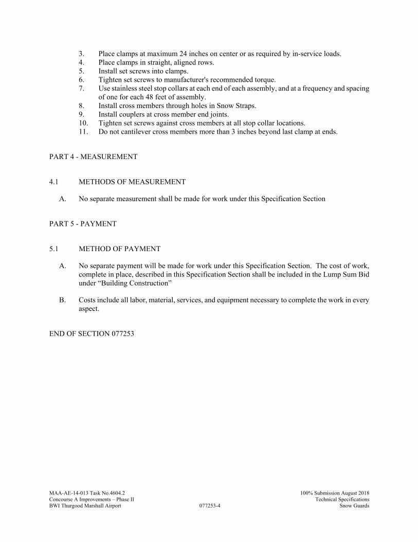
MAA-AE-14-013 Task No.4604.2
077253-4
100% Submission August 2018Concourse A Improvements – Phase II Technical SpecificationsBWI Thurgood Marshall Airport Snow Guards
3. Place clamps at maximum 24 inches on center or as required by in-service loads. 4. Place clamps in straight, aligned rows. 5. Install set screws into clamps. 6. Tighten set screws to manufacturer's recommended torque. 7. Use stainless steel stop collars at each end of each assembly, and at a frequency and spacing
of one for each 48 feet of assembly. 8. Install cross members through holes in Snow Straps. 9. Install couplers at cross member end joints. 10. Tighten set screws against cross members at all stop collar locations. 11. Do not cantilever cross members more than 3 inches beyond last clamp at ends.
PART 4 - MEASUREMENT
4.1 METHODS OF MEASUREMENT
A. No separate measurement shall be made for work under this Specification Section
PART 5 - PAYMENT
5.1 METHOD OF PAYMENT
A. No separate payment will be made for work under this Specification Section. The cost of work, complete in place, described in this Specification Section shall be included in the Lump Sum Bid under “Building Construction”
B. Costs include all labor, material, services, and equipment necessary to complete the work in every aspect.
END OF SECTION 077253
MAA-AE-14-013 Task No.4604.2
078100-1
100% Submission, August 2018Concourse A Improvements – Phase II Technical SpecificationsBWI Thurgood Marshall Airport Applied Fireproofing
SECTION 078100 - APPLIED FIREPROOFING
PART 1 - GENERAL
1.1 RELATED DOCUMENTS
A. Drawings and general provisions of the Contract, including Maryland Department of Transportation/ Maryland Aviation Administration Standard Provisions to the Construction Contract for the Concourse A Improvements – Phase II at BWI Thurgood Marshall Airport and other Divisions 1 Specification Sections, apply to this Section.
1.2 SUMMARY
A. Section includes sprayed fire-resistive materials.
B. Related Requirements: 1. 078123 - Intumescent Fireproofing
1.3 DEFINITIONS
A. SFRM: Sprayed fire-resistive materials.
1.4 ACTION SUBMITTALS
A. Product Data: For each type of product.
B. Shop Drawings: Framing plans or schedules, or both, indicating the following:
1. Extent of fireproofing for each construction and fire-resistance rating. 2. Applicable fire-resistance design designations of a qualified testing and inspecting agency
acceptable to authorities having jurisdiction. 3. Minimum fireproofing thicknesses needed to achieve required fire-resistance rating of each
structural component and assembly. 4. Treatment of fireproofing after application.
1.5 INFORMATIONAL SUBMITTALS
A. The Contractor shall certify that the materials being submitted conform to the requirements of the Contract in all respects, including all Federal requirements such as “Buy American,” except as otherwise noted.
B. Qualification Data: For Installer, manufacturer, and testing agency.
C. Product Certificates: For each type of fireproofing.
MAA-AE-14-013 Task No.4604.2
078100-2
100% Submission, August 2018Concourse A Improvements – Phase II Technical SpecificationsBWI Thurgood Marshall Airport Applied Fireproofing
D. Evaluation Reports: For fireproofing, from ICC-ES.
E. Preconstruction Test Reports: For fireproofing.
F. Field quality-control reports.
1.6 QUALITY ASSURANCE
A. Installer Qualifications: A firm or individual certified, licensed, or otherwise qualified by fireproofing manufacturer as experienced and with sufficient trained staff to install manufacturer's products according to specified requirements.
B. Preinstallation Conference: Conduct conference at Project site.
1. Review products, design ratings, restrained and unrestrained conditions, densities, thicknesses, bond strengths, and other performance requirements.
C. Mockups: Build mockups to set quality standards for materials and execution.
1. Build mockup of each type of fireproofing and different substrate as shown on Drawings. 2. Approval of mockups does not constitute approval of deviations from the Contract
Documents contained in mockups unless Architect specifically approves such deviations in writing.
3. Subject to compliance with requirements, approved mockups may become part of the completed Work if undisturbed at time of Substantial Completion.
1.7 PRECONSTRUCTION TESTING
A. Preconstruction Testing Service: Owner will engage a qualified testing agency to perform preconstruction testing on field mockups of fireproofing.
B. Preconstruction Adhesion and Compatibility Testing: Test for compliance with requirements for specified performance and test methods.
1. Bond Strength: Test for cohesive and adhesive strength according to ASTM E 736. Provide bond strength indicated in referenced fire-resistance design, but not less than minimum specified in Part 2.
2. Density: Test for density according to ASTM E 605. Provide density indicated in referenced fire-resistance design, but not less than minimum specified in Part 2.
3. Verify that manufacturer, through its own laboratory testing or field experience, attests that primers or coatings are compatible with fireproofing.
4. Schedule sufficient time for testing and analyzing results to prevent delaying the Work. 5. For materials failing tests, obtain applied-fireproofing manufacturer's written instructions
for corrective measures including the use of specially formulated bonding agents or primers.
MAA-AE-14-013 Task No.4604.2
078100-3
100% Submission, August 2018Concourse A Improvements – Phase II Technical SpecificationsBWI Thurgood Marshall Airport Applied Fireproofing
1.8 FIELD CONDITIONS
A. Environmental Limitations: Do not apply fireproofing when ambient or substrate temperature is 44 deg F (7 deg C)or lower unless temporary protection and heat are provided to maintain temperature at or above this level for 24 hours before, during, and for 24 hours after product application.
B. Ventilation: Ventilate building spaces during and after application of fireproofing, providing complete air exchanges according to manufacturer's written instructions. Use natural means or, if they are inadequate, forced-air circulation until fireproofing dries thoroughly.
PART 2 - PRODUCTS
2.1 PERFORMANCE REQUIREMENTS
A. Assemblies: Provide fireproofing, including auxiliary materials, according to requirements of each fire-resistance design and manufacturer's written instructions.
B. Source Limitations: Obtain fireproofing from single source.
C. Fire-Resistance Design: Indicated on Drawings, tested according to ASTM E 119 or UL 263 ; testing by a qualified testing agency. Identify products with appropriate markings of applicable testing agency.
1. Steel members are to be considered unrestrained unless specifically noted otherwise.
D. Asbestos: Provide products containing no detectable asbestos.
2.2 SPRAYED FIRE-RESISTIVE MATERIALS
A. Sprayed Fire-Resistive Material Manufacturer's standard, factory-mixed, lightweight, dry formulation, complying with indicated fire-resistance design, and mixed with water at Project site to form a slurry or mortar before conveyance and application or conveyed in a dry state and mixed with atomized water at place of application.
1. Manufacturers: Subject to compliance with requirements, available manufacturers offering products that may be incorporated into the Work include, but are not limited to the following:
a. Carboline Company; a subsidiary of RPM International. b. GCP Applied Technologies Inc. (formerly Grace Construction Products). c. Isolatek International. d. Pyrok, Inc. e. Schundler Company (The). f. Southwest Fireproofing Products Co.
2. Bond Strength: Minimum 150-lbf/sq. ft. (7.18-kPa) cohesive and adhesive strength based on field testing according to ASTM E 736.
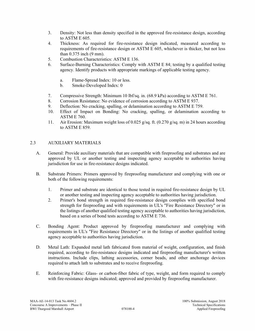
MAA-AE-14-013 Task No.4604.2
078100-4
100% Submission, August 2018Concourse A Improvements – Phase II Technical SpecificationsBWI Thurgood Marshall Airport Applied Fireproofing
3. Density: Not less than density specified in the approved fire-resistance design, according to ASTM E 605.
4. Thickness: As required for fire-resistance design indicated, measured according to requirements of fire-resistance design or ASTM E 605, whichever is thicker, but not less than 0.375 inch (9 mm).
5. Combustion Characteristics: ASTM E 136. 6. Surface-Burning Characteristics: Comply with ASTM E 84; testing by a qualified testing
agency. Identify products with appropriate markings of applicable testing agency.
a. Flame-Spread Index: 10 or less. b. Smoke-Developed Index: 0
7. Compressive Strength: Minimum 10 lbf/sq. in. (68.9 kPa) according to ASTM E 761. 8. Corrosion Resistance: No evidence of corrosion according to ASTM E 937. 9. Deflection: No cracking, spalling, or delamination according to ASTM E 759. 10. Effect of Impact on Bonding: No cracking, spalling, or delamination according to
ASTM E 760. 11. Air Erosion: Maximum weight loss of 0.025 g/sq. ft. (0.270 g/sq. m) in 24 hours according
to ASTM E 859.
2.3 AUXILIARY MATERIALS
A. General: Provide auxiliary materials that are compatible with fireproofing and substrates and are approved by UL or another testing and inspecting agency acceptable to authorities having jurisdiction for use in fire-resistance designs indicated.
B. Substrate Primers: Primers approved by fireproofing manufacturer and complying with one or both of the following requirements:
1. Primer and substrate are identical to those tested in required fire-resistance design by UL or another testing and inspecting agency acceptable to authorities having jurisdiction.
2. Primer's bond strength in required fire-resistance design complies with specified bond strength for fireproofing and with requirements in UL's "Fire Resistance Directory" or in the listings of another qualified testing agency acceptable to authorities having jurisdiction, based on a series of bond tests according to ASTM E 736.
C. Bonding Agent: Product approved by fireproofing manufacturer and complying with requirements in UL's "Fire Resistance Directory" or in the listings of another qualified testing agency acceptable to authorities having jurisdiction.
D. Metal Lath: Expanded metal lath fabricated from material of weight, configuration, and finish required, according to fire-resistance designs indicated and fireproofing manufacturer's written instructions. Include clips, lathing accessories, corner beads, and other anchorage devices required to attach lath to substrates and to receive fireproofing.
E. Reinforcing Fabric: Glass- or carbon-fiber fabric of type, weight, and form required to comply with fire-resistance designs indicated; approved and provided by fireproofing manufacturer.

MAA-AE-14-013 Task No.4604.2
078100-5
100% Submission, August 2018Concourse A Improvements – Phase II Technical SpecificationsBWI Thurgood Marshall Airport Applied Fireproofing
F. Reinforcing Mesh: Metallic mesh reinforcement of type, weight, and form required to comply with fire-resistance design indicated; approved and provided by fireproofing manufacturer. Include pins and attachment.
G. Sealer: Transparent-drying, water-dispersible, tinted protective coating recommended in writing by fireproofing manufacturer for each fire-resistance design.
H. Topcoat: Suitable for application over applied fireproofing; of type recommended in writing by fireproofing manufacturer for each fire-resistance design.
PART 3 - EXECUTION
3.1 EXAMINATION
A. Examine substrates, areas, and conditions, with Installer present, for compliance with requirements for substrates and other conditions affecting performance of the Work and according to each fire-resistance design.
1. Verify that substrates are free of dirt, oil, grease, release agents, rolling compounds, mill scale, loose scale, incompatible primers, paints, and encapsulants, or other foreign substances capable of impairing bond of fireproofing with substrates under conditions of normal use or fire exposure.
2. Verify that objects penetrating fireproofing, including clips, hangers, support sleeves, and similar items, are securely attached to substrates.
3. Verify that substrates receiving fireproofing are not obstructed by ducts, piping, equipment, or other suspended construction that will interfere with fireproofing application.
B. Verify that concrete work on steel deck is complete before beginning fireproofing work.
C. Verify that roof construction, installation of rooftop HVAC equipment, and other related work are complete before beginning fireproofing work.
D. Conduct tests according to fireproofing manufacturer's written instructions to verify that substrates are free of substances capable of interfering with bond.
E. Prepare written report, endorsed by Installer, listing conditions detrimental to performance of the Work.
F. Proceed with installation only after unsatisfactory conditions have been corrected.
3.2 PREPARATION
A. Cover other work subject to damage from fallout or overspray of fireproofing materials during application.
B. Clean substrates of substances that could impair bond of fireproofing.
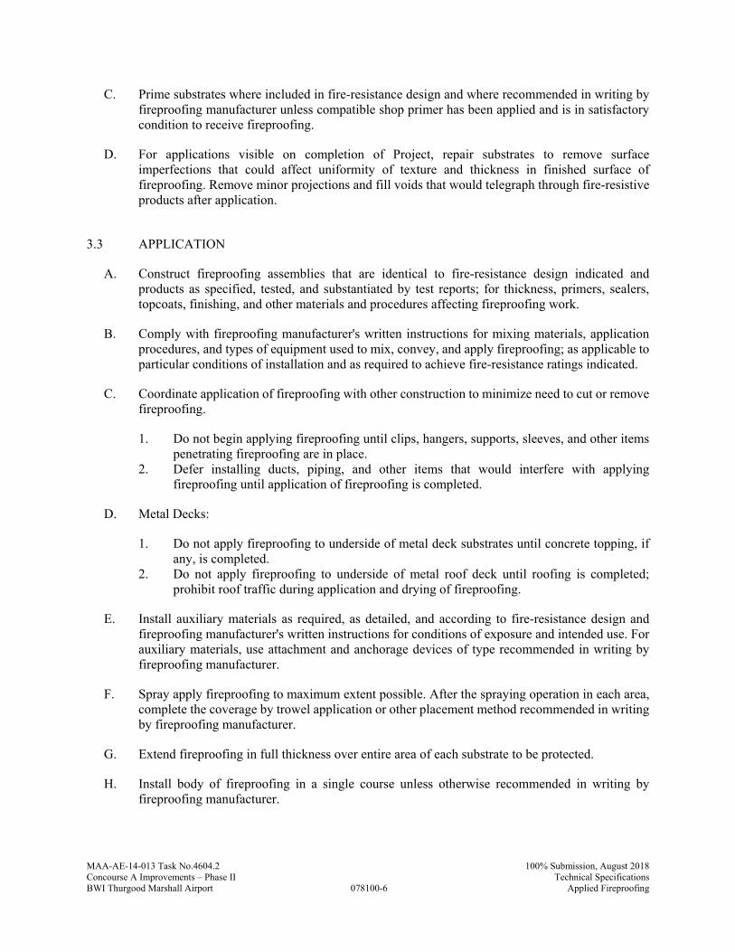
MAA-AE-14-013 Task No.4604.2
078100-6
100% Submission, August 2018Concourse A Improvements – Phase II Technical SpecificationsBWI Thurgood Marshall Airport Applied Fireproofing
C. Prime substrates where included in fire-resistance design and where recommended in writing by fireproofing manufacturer unless compatible shop primer has been applied and is in satisfactory condition to receive fireproofing.
D. For applications visible on completion of Project, repair substrates to remove surface imperfections that could affect uniformity of texture and thickness in finished surface of fireproofing. Remove minor projections and fill voids that would telegraph through fire-resistive products after application.
3.3 APPLICATION
A. Construct fireproofing assemblies that are identical to fire-resistance design indicated and products as specified, tested, and substantiated by test reports; for thickness, primers, sealers, topcoats, finishing, and other materials and procedures affecting fireproofing work.
B. Comply with fireproofing manufacturer's written instructions for mixing materials, application procedures, and types of equipment used to mix, convey, and apply fireproofing; as applicable to particular conditions of installation and as required to achieve fire-resistance ratings indicated.
C. Coordinate application of fireproofing with other construction to minimize need to cut or remove fireproofing.
1. Do not begin applying fireproofing until clips, hangers, supports, sleeves, and other items penetrating fireproofing are in place.
2. Defer installing ducts, piping, and other items that would interfere with applying fireproofing until application of fireproofing is completed.
D. Metal Decks:
1. Do not apply fireproofing to underside of metal deck substrates until concrete topping, if any, is completed.
2. Do not apply fireproofing to underside of metal roof deck until roofing is completed; prohibit roof traffic during application and drying of fireproofing.
E. Install auxiliary materials as required, as detailed, and according to fire-resistance design and fireproofing manufacturer's written instructions for conditions of exposure and intended use. For auxiliary materials, use attachment and anchorage devices of type recommended in writing by fireproofing manufacturer.
F. Spray apply fireproofing to maximum extent possible. After the spraying operation in each area, complete the coverage by trowel application or other placement method recommended in writing by fireproofing manufacturer.
G. Extend fireproofing in full thickness over entire area of each substrate to be protected.
H. Install body of fireproofing in a single course unless otherwise recommended in writing by fireproofing manufacturer.
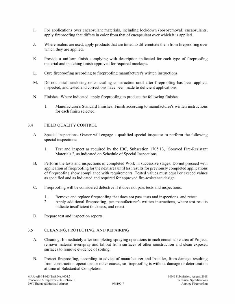
MAA-AE-14-013 Task No.4604.2
078100-7
100% Submission, August 2018Concourse A Improvements – Phase II Technical SpecificationsBWI Thurgood Marshall Airport Applied Fireproofing
I. For applications over encapsulant materials, including lockdown (post-removal) encapsulants, apply fireproofing that differs in color from that of encapsulant over which it is applied.
J. Where sealers are used, apply products that are tinted to differentiate them from fireproofing over which they are applied.
K. Provide a uniform finish complying with description indicated for each type of fireproofing material and matching finish approved for required mockups.
L. Cure fireproofing according to fireproofing manufacturer's written instructions.
M. Do not install enclosing or concealing construction until after fireproofing has been applied, inspected, and tested and corrections have been made to deficient applications.
N. Finishes: Where indicated, apply fireproofing to produce the following finishes:
1. Manufacturer's Standard Finishes: Finish according to manufacturer's written instructions for each finish selected.
3.4 FIELD QUALITY CONTROL
A. Special Inspections: Owner will engage a qualified special inspector to perform the following special inspections:
1. Test and inspect as required by the IBC, Subsection 1705.13, "Sprayed Fire-Resistant Materials.", as indicated on Schedule of Special Inspections.
B. Perform the tests and inspections of completed Work in successive stages. Do not proceed with application of fireproofing for the next area until test results for previously completed applications of fireproofing show compliance with requirements. Tested values must equal or exceed values as specified and as indicated and required for approved fire-resistance design.
C. Fireproofing will be considered defective if it does not pass tests and inspections.
1. Remove and replace fireproofing that does not pass tests and inspections, and retest. 2. Apply additional fireproofing, per manufacturer's written instructions, where test results
indicate insufficient thickness, and retest.
D. Prepare test and inspection reports.
3.5 CLEANING, PROTECTING, AND REPAIRING
A. Cleaning: Immediately after completing spraying operations in each containable area of Project, remove material overspray and fallout from surfaces of other construction and clean exposed surfaces to remove evidence of soiling.
B. Protect fireproofing, according to advice of manufacturer and Installer, from damage resulting from construction operations or other causes, so fireproofing is without damage or deterioration at time of Substantial Completion.
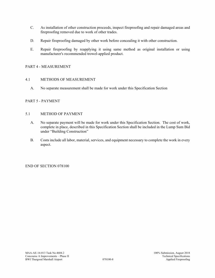
MAA-AE-14-013 Task No.4604.2
078100-8
100% Submission, August 2018Concourse A Improvements – Phase II Technical SpecificationsBWI Thurgood Marshall Airport Applied Fireproofing
C. As installation of other construction proceeds, inspect fireproofing and repair damaged areas and fireproofing removed due to work of other trades.
D. Repair fireproofing damaged by other work before concealing it with other construction.
E. Repair fireproofing by reapplying it using same method as original installation or using manufacturer's recommended trowel-applied product.
PART 4 - MEASUREMENT
4.1 METHODS OF MEASUREMENT
A. No separate measurement shall be made for work under this Specification Section
PART 5 - PAYMENT
5.1 METHOD OF PAYMENT
A. No separate payment will be made for work under this Specification Section. The cost of work, complete in place, described in this Specification Section shall be included in the Lump Sum Bid under “Building Construction”
B. Costs include all labor, material, services, and equipment necessary to complete the work in every aspect.
END OF SECTION 078100
MAA-AE-14-013 Task No.4604.2
078123-1
100% Submission, August 2018Concourse A Improvements – Phase II Technical SpecificationsBWI Thurgood Marshall Airport Intumescent Fireproofing
SECTION 078123 - INTUMESCENT FIREPROOFING
PART 1 - GENERAL
1.1 RELATED DOCUMENTS
A. Drawings and general provisions of the Contract, including Maryland Department of Transportation/ Maryland Aviation Administration Standard Provisions to the Construction Contract for the Concourse A Improvements – Phase II at BWI Thurgood Marshall Airport and other Divisions 1 Specification Sections, apply to this Section.
1.2 SUMMARY
A. Section includes mastic and intumescent fire-resistive coatings.
B. Related Requirements:
1. Section 078100 "Applied Fireproofing" for sprayed fire-resistive materials (SFRM).
1.3 ACTION SUBMITTALS
A. Product Data: For each type of product.
B. Shop Drawings: Framing plans or schedules, or both, indicating the following:
1. Extent of fireproofing for each construction and fire-resistance rating. 2. Applicable fire-resistance design designations of a qualified testing and inspecting agency
acceptable to authorities having jurisdiction. 3. Minimum fireproofing thicknesses needed to achieve required fire-resistance rating of each
structural component and assembly. 4. Treatment of fireproofing after application.
C. Samples: For each exposed product and for each color and texture specified, in manufacturer's standard dimensions in size.
1.4 INFORMATIONAL SUBMITTALS
A. The Contractor shall certify that the materials being submitted conform to the requirements of the Contract in all respects, including all Federal requirements such as “Buy American,” except as otherwise noted.
B. Qualification Data: For Installer and testing agency.
C. Product Certificates: For each type of fireproofing.
MAA-AE-14-013 Task No.4604.2
078123-2
100% Submission, August 2018Concourse A Improvements – Phase II Technical SpecificationsBWI Thurgood Marshall Airport Intumescent Fireproofing
D. Evaluation Reports: For fireproofing, from ICC-ES.
E. Field quality-control reports.
1.5 QUALITY ASSURANCE
A. Installer Qualifications: A firm or individual certified, licensed, or otherwise qualified by fireproofing manufacturer as experienced and with sufficient trained staff to install manufacturer's products according to specified requirements.
B. Preinstallation Conference: Conduct conference at Project site.
1. Review products, design ratings, restrained and unrestrained conditions, thicknesses, and other performance requirements.
2. Review ventilation strategy.
C. Mockups: Build mockups to verify selections made under Sample submittals and to demonstrate aesthetic effects and to set quality standards for materials and execution.
1. Build mockup of each type of fireproofing and different substrate] [and] [each required finish.
2. Approval of mockups does not constitute approval of deviations from the Contract Documents contained in mockups unless Architect specifically approves such deviations in writing.
3. Subject to compliance with requirements, approved mockups may become part of the completed Work if undisturbed at time of Substantial Completion.
1.6 FIELD CONDITIONS
A. When temperature is less than 40F, follow manufacturer's field instructions for cold weather installation. So not apply when surface temperature is less than 5 degrees F above the dew point.
B. Provide ventilation in areas to receive fireproofing during and 72 hours, minimum, after application, to dry materials and dissipate solvent odors.
C. Maintain non-toxic, unpolluted working area. Provide temporary enclosure to prevent spray from contaminating air.
D. Ventilation: Ventilate building spaces during and after application of fireproofing, providing complete air exchanges according to manufacturer's written instructions. Use natural means or, if they are inadequate, forced-air circulation until fireproofing dries thoroughly.
MAA-AE-14-013 Task No.4604.2
078123-3
100% Submission, August 2018Concourse A Improvements – Phase II Technical SpecificationsBWI Thurgood Marshall Airport Intumescent Fireproofing
PART 2 - PRODUCTS
2.1 PERFORMANCE REQUIREMENTS
A. Assemblies: Provide fireproofing, including auxiliary materials, according to requirements of each fire-resistance design and manufacturer's written instructions.
B. Source Limitations: Obtain fireproofing from single source.
C. Fire-Resistance Design: Indicated on Drawings, tested according to ASTM E 119 ; testing by a qualified testing agency. Identify products with appropriate markings of applicable testing agency.
D. Asbestos: Provide products containing no detectable asbestos.
2.2 MASTIC AND INTUMESCENT FIRE-RESISTIVE COATINGS
A. Mastic and Intumescent Fire-Resistive Coating UL- X638: Manufacturer's standard, water based, factory mixed, asbestos free, intumescent material blended for uniform texture;
1. Basis-of-Design Product: Subject to compliance with requirements, provide Albi Manufacturing; a division of StanChem, Inc.; Albi Clad TF or a comparable product by one of the following:
a. Hilti, Inc. b. Isolatek International. c. Sherwin-Williams Company (The).
2. Application: Designated for “interior general purpose" use by a qualified testing agency acceptable to authorities having jurisdiction.
3. Thickness: As required for fire-resistance design indicated, measured according to requirements of fire-resistance design.
4. Surface-Burning Characteristics: Comply with ASTM E 84; testing by a qualified testing agency. Identify products with appropriate markings of applicable testing agency.
a. Flame-Spread Index: 2 or less. b. Smoke-Developed Index 5 or less.
5. Hardness: Not less than 45 Type D durometer, according to ASTM D 2240. 6. Finish: As selected by Architect from manufacturer's standard finishes. 7. Color and Gloss: As selected by Architect from manufacturer's full range.
2.3 AUXILIARY MATERIALS
A. General: Provide auxiliary materials that are compatible with fireproofing and substrates and are approved by UL or another testing and inspecting agency acceptable to authorities having jurisdiction for use in fire-resistance designs indicated.

MAA-AE-14-013 Task No.4604.2
078123-4
100% Submission, August 2018Concourse A Improvements – Phase II Technical SpecificationsBWI Thurgood Marshall Airport Intumescent Fireproofing
B. Substrate Primers: Primers approved by fireproofing manufacturer and complying with required fire-resistance design by UL or another testing and inspecting agency acceptable to authorities having jurisdiction.
C. Topcoat: Suitable for application over applied fireproofing; of type recommended in writing by fireproofing manufacturer for each fire-resistance design. 1. Areas exposed to view: Semi-gloss, color to match existing.
PART 3 - EXECUTION
3.1 EXAMINATION
A. Examine substrates, areas, and conditions, with Installer present, for compliance with requirements for substrates and other conditions affecting performance of the Work and according to each fire-resistance design.
1. Verify that substrates are free of dirt, oil, grease, release agents, rolling compounds, mill scale, loose scale, incompatible primers, paints, and encapsulants, or other foreign substances capable of impairing bond of fireproofing with substrates under conditions of normal use or fire exposure.
2. Verify that objects penetrating fireproofing, including clips, hangers, support sleeves, and similar items, are securely attached to substrates.
3. Verify that substrates receiving fireproofing are not obstructed by ducts, piping, equipment, or other suspended construction that will interfere with fireproofing application.
B. Conduct tests according to fireproofing manufacturer's written instructions to verify that substrates are free of substances capable of interfering with bond.
C. Prepare written report, endorsed by Installer, listing conditions detrimental to performance of the Work.
D. Proceed with installation only after unsatisfactory conditions have been corrected.
3.2 PREPARATION
A. Cover other work subject to damage from fallout or overspray of fireproofing materials during application.
B. Clean substrates of substances that could impair bond of fireproofing.
C. Prime substrates where included in fire-resistance design and where recommended in writing by fireproofing manufacturer unless compatible shop primer has been applied and is in satisfactory condition to receive fireproofing.
D. For applications visible on completion of Project, repair substrates to remove surface imperfections that could affect uniformity of texture and thickness in finished surface of fireproofing. Remove minor projections and fill voids that would telegraph through fire-resistive products after application.
MAA-AE-14-013 Task No.4604.2
078123-5
100% Submission, August 2018Concourse A Improvements – Phase II Technical SpecificationsBWI Thurgood Marshall Airport Intumescent Fireproofing
3.3 APPLICATION
A. Construct fireproofing assemblies that are identical to fire-resistance design indicated and products as specified, tested, and substantiated by test reports; for thickness, primers, topcoats, finishing, and other materials and procedures affecting fireproofing work.
B. Comply with fireproofing manufacturer's written instructions for mixing materials, application procedures, and types of equipment used to mix, convey, and apply fireproofing; as applicable to particular conditions of installation and as required to achieve fire-resistance ratings indicated.
C. Coordinate application of fireproofing with other construction to minimize need to cut or remove fireproofing.
1. Do not begin applying fireproofing until clips, hangers, supports, sleeves, and other items penetrating fireproofing are in place.
2. Defer installing ducts, piping, and other items that would interfere with applying fireproofing until application of fireproofing is completed.
D. Install auxiliary materials as required, as detailed, and according to fire-resistance design and fireproofing manufacturer's written instructions for conditions of exposure and intended use. For auxiliary materials, use attachment and anchorage devices of type recommended in writing by fireproofing manufacturer.
E. Spray apply fireproofing to maximum extent possible. After the spraying operation in each area, complete the coverage by trowel application or other placement method recommended in writing by fireproofing manufacturer.
F. Extend fireproofing in full thickness over entire area of each substrate to be protected.
G. Install body of fireproofing in a single course unless otherwise recommended in writing by fireproofing manufacturer.
H. Provide a uniform finish complying with description indicated for each type of fireproofing material and matching finish approved for required mockups.
I. Cure fireproofing according to fireproofing manufacturer's written instructions.
J. Do not install enclosing or concealing construction until after fireproofing has been applied, inspected, and tested and corrections have been made to deficient applications.
K. Finishes: Where indicated, apply fireproofing to produce the following finishes:
1. Manufacturer's Standard Finishes: Finish according to manufacturer's written instructions for each finish selected.
3.4 FIELD QUALITY CONTROL
A. Special Inspections: Owner will engage a qualified special inspector to perform the following special inspections:
MAA-AE-14-013 Task No.4604.2
078123-6
100% Submission, August 2018Concourse A Improvements – Phase II Technical SpecificationsBWI Thurgood Marshall Airport Intumescent Fireproofing
1. Test and inspect as required by the IBC as indicated on Schedule of Special Inspections.
B. Perform the tests and inspections of completed Work in successive stages. Do not proceed with application of fireproofing for the next area until test results for previously completed applications of fireproofing show compliance with requirements. Tested values must equal or exceed values as specified and as indicated and required for approved fire-resistance design.
C. Fireproofing will be considered defective if it does not pass tests and inspections.
1. Remove and replace fireproofing that does not pass tests and inspections, and retest. 2. Apply additional fireproofing, per manufacturer's written instructions, where test results
indicate insufficient thickness, and retest.
D. Prepare test and inspection reports.
3.5 CLEANING, PROTECTING, AND REPAIRING
A. Cleaning: Immediately after completing spraying operations in each containable area of Project, remove material overspray and fallout from surfaces of other construction and clean exposed surfaces to remove evidence of soiling.
B. Protect fireproofing, according to advice of manufacturer and Installer, from damage resulting from construction operations or other causes, so fireproofing is without damage or deterioration at time of Substantial Completion.
C. As installation of other construction proceeds, inspect fireproofing and repair damaged areas and fireproofing removed due to work of other trades.
D. Repair fireproofing damaged by other work before concealing it with other construction.
E. Repair fireproofing by reapplying it using same method as original installation or using manufacturer's recommended trowel-applied product.
PART 4 - MEASUREMENT
4.1 METHODS OF MEASUREMENT
A. No separate measurement shall be made for work under this Specification Section
PART 5 - PAYMENT
5.1 METHOD OF PAYMENT
A. No separate payment will be made for work under this Specification Section. The cost of work, complete in place, described in this Specification Section shall be included in the Lump Sum Bid under “Building Construction”
MAA-AE-14-013 Task No.4604.2
078123-7
100% Submission, August 2018Concourse A Improvements – Phase II Technical SpecificationsBWI Thurgood Marshall Airport Intumescent Fireproofing
B. Costs include all labor, material, services, and equipment necessary to complete the work in every aspect
END OF SECTION 078123
MAA-AE-14-013 Task No.4604.2
078123-8
100% Submission, August 2018Concourse A Improvements – Phase II Technical SpecificationsBWI Thurgood Marshall Airport Intumescent Fireproofing
THIS PAGE INTENTIONALLY LEFT BLANK
MAA-AE-14-013 Task No.4604.2
078413-1
100% Submission, August 2018Concourse A Improvements – Phase II Technical SpecificationsBWI Thurgood Marshall Airport Penetration Firestopping
SECTION 078413 - PENETRATION FIRESTOPPING
PART 1 - GENERAL
1.1 RELATED DOCUMENTS
A. Drawings and general provisions of the Contract, including Maryland Department of Transportation/ Maryland Aviation Administration Standard Provisions to the Construction Contract for the Concourse A Improvements – Phase II at BWI Thurgood Marshall Airport and other Divisions 1 Specification Sections, apply to this Section.
1.2 SUMMARY
A. Section Includes:
1. Penetrations in fire-resistance-rated walls. 2. Penetrations in horizontal assemblies. 3. Penetrations in smoke barriers.
B. Related Requirements:
1. Section 078443 "Joint Firestopping" for joints in or between fire-resistance-rated construction, at exterior curtain-wall/floor intersections, and in smoke barriers.
1.3 ACTION SUBMITTALS
A. Product Data: For each type of product.
B. Product Schedule: For each penetration firestopping system. Include location, illustration of firestopping system, and design designation of qualified testing and inspecting agency.
1. Engineering Judgments: Where Project conditions require modification to a qualified testing and inspecting agency's illustration for a particular penetration firestopping system, submit illustration, with modifications marked, approved by penetration firestopping system manufacturer's fire-protection engineer as an engineering judgment or equivalent fire-resistance-rated assembly. Obtain approval of authorities having jurisdiction prior to submittal.
1.4 INFORMATIONAL SUBMITTALS
A. The Contractor shall certify that the materials being submitted conform to the requirements of the Contract in all respects, including all Federal requirements such as “Buy American,” except as otherwise noted.
B. Qualification Data: For Installer.
MAA-AE-14-013 Task No.4604.2
078413-2
100% Submission, August 2018Concourse A Improvements – Phase II Technical SpecificationsBWI Thurgood Marshall Airport Penetration Firestopping
C. Product Test Reports: For each penetration firestopping system, for tests performed by a qualified testing agency.
1.5 CLOSEOUT SUBMITTALS
A. Installer Certificates: From Installer indicating that penetration firestopping systems have been installed in compliance with requirements and manufacturer's written instructions.
1.6 QUALITY ASSURANCE
A. Installer Qualifications: A firm that has been approved by FM Global according to FM Global 4991, "Approval of Firestop Contractors," or been evaluated by UL and found to comply with its "Qualified Firestop Contractor Program Requirements."
B. Preinstallation Conference: Conduct conference at Project site.
C. Source Limitations: All Penetration and Joint Firestopping to be installed by one single firestop Installer.
1.7 PROJECT CONDITIONS
A. Environmental Limitations: Do not install penetration firestopping system when ambient or substrate temperatures are outside limits permitted by penetration firestopping system manufacturers or when substrates are wet because of rain, frost, condensation, or other causes.
B. Install and cure penetration firestopping materials per manufacturer's written instructions using natural means of ventilations or, where this is inadequate, forced-air circulation.
1.8 COORDINATION
A. Coordinate construction of openings and penetrating items to ensure that penetration firestopping systems can be installed according to specified firestopping system design.
B. Coordinate sizing of sleeves, openings, core-drilled holes, or cut openings to accommodate penetration firestopping systems.
PART 2 - PRODUCTS
2.1 PERFORMANCE REQUIREMENTS
A. Fire-Test-Response Characteristics:
MAA-AE-14-013 Task No.4604.2
078413-3
100% Submission, August 2018Concourse A Improvements – Phase II Technical SpecificationsBWI Thurgood Marshall Airport Penetration Firestopping
1. Perform penetration firestopping system tests by a qualified testing agency acceptable to authorities having jurisdiction.
2. Test per testing standards referenced in "Penetration Firestopping Systems" Article. Provide rated systems complying with the following requirements:
a. Penetration firestopping systems shall bear classification marking of a qualified testing agency.
1) UL in its "Fire Resistance Directory." 2) Intertek Group in its "Directory of Listed Building Products." 3) FM Global in its "Building Materials Approval Guide."
2.2 PENETRATION FIRESTOPPING SYSTEMS
A. Penetration Firestopping Systems: Systems that resist spread of fire, passage of smoke and other gases, and maintain original fire-resistance rating of construction penetrated. Penetration firestopping systems shall be compatible with one another, with the substrates forming openings, and with penetrating items if any.
1. Manufacturers: Subject to compliance with requirements, available manufacturers offering products that may be incorporated into the Work include, but are not limited to the following:
a. 3M Fire Protection Products. b. Hilti, Inc. c. Tremco, Inc.
B. Penetrations in Fire-Resistance-Rated Walls: Penetration firestopping systems with ratings determined per ASTM E 814 or UL 1479, based on testing at a positive pressure differential of 0.01-inch wg (2.49 Pa).
1. F-Rating: Not less than the fire-resistance rating of constructions penetrated.
C. Penetrations in Horizontal Assemblies: Penetration firestopping systems with ratings determined per ASTM E 814 or UL 1479, based on testing at a positive pressure differential of 0.01-inch wg (2.49 Pa).
1. F-Rating: At least one hour, but not less than the fire-resistance rating of constructions penetrated.
2. T-Rating: At least one hour, but not less than the fire-resistance rating of constructions penetrated except for floor penetrations within the cavity of a wall.
3. W-Rating: Provide penetration firestopping systems showing no evidence of water leakage when tested according to UL 1479.
D. Penetrations in Smoke Barriers: Penetration firestopping systems with ratings determined per UL 1479, based on testing at a positive pressure differential of 0.30-inch wg (74.7 Pa).
MAA-AE-14-013 Task No.4604.2
078413-4
100% Submission, August 2018Concourse A Improvements – Phase II Technical SpecificationsBWI Thurgood Marshall Airport Penetration Firestopping
1. L-Rating: Not exceeding 5.0 cfm/sq. ft. (0.025 cu. m/s per sq. m) of penetration opening at and no more than 50-cfm (0.024-cu. m/s) cumulative total for any 100 sq. ft. (9.3 sq. m) at both ambient and elevated temperatures.
E. Exposed Penetration Firestopping Systems: Flame-spread and smoke-developed indexes of less than 25 and 450, respectively, per ASTM E 84.
F. Accessories: Provide components for each penetration firestopping system that are needed to install fill materials and to maintain ratings required. Use only those components specified by penetration firestopping system manufacturer and approved by qualified testing and inspecting agency for conditions indicated.
1. Permanent forming/damming/backing materials. 2. Substrate primers. 3. Collars. 4. Steel sleeves.
2.3 FILL MATERIALS
A. Cast-in-Place Firestop Devices: Factory-assembled devices for use in cast-in-place concrete floors and consisting of an outer sleeve lined with an intumescent strip, a flange attached to one end of the sleeve for fastening to concrete formwork, and a neoprene gasket.
B. Latex Sealants: Single-component latex formulations that do not re-emulsify after cure during exposure to moisture.
C. Firestop Devices: Factory-assembled collars formed from galvanized steel and lined with intumescent material sized to fit specific diameter of penetrant.
D. Intumescent Composite Sheets: Rigid panels consisting of aluminum-foil-faced intumescent elastomeric sheet bonded to galvanized-steel sheet.
E. Intumescent Putties: Nonhardening, water-resistant, intumescent putties containing no solvents or inorganic fibers.
F. Intumescent Wrap Strips: Single-component intumescent elastomeric sheets with aluminum foil on one side.
G. Mortars: Prepackaged dry mixes consisting of a blend of inorganic binders, hydraulic cement, fillers and lightweight aggregate formulated for mixing with water at Project site to form a nonshrinking, homogeneous mortar.
H. Pillows/Bags: Reusable heat-expanding pillows/bags consisting of glass-fiber cloth cases filled with a combination of mineral-fiber, water-insoluble expansion agents, and fire-retardant additives. Where exposed, cover openings with steel-reinforcing wire mesh to protect pillows/bags from being easily removed.
I. Silicone Foams: Multicomponent, silicone-based liquid elastomers that, when mixed, expand and cure in place to produce a flexible, nonshrinking foam.
MAA-AE-14-013 Task No.4604.2
078413-5
100% Submission, August 2018Concourse A Improvements – Phase II Technical SpecificationsBWI Thurgood Marshall Airport Penetration Firestopping
J. Silicone Sealants: Single-component, silicone-based, neutral-curing elastomeric sealants.
2.4 MIXING
A. Penetration Firestopping Materials: For those products requiring mixing before application, comply with penetration firestopping system manufacturer's written instructions for accurate proportioning of materials, water (if required), type of mixing equipment, selection of mixer speeds, mixing containers, mixing time, and other items or procedures needed to produce products of uniform quality with optimum performance characteristics for application indicated.
PART 3 - EXECUTION
3.1 EXAMINATION
A. Examine substrates and conditions, with Installer present, for compliance with requirements for opening configurations, penetrating items, substrates, and other conditions affecting performance of the Work.
B. Proceed with installation only after unsatisfactory conditions have been corrected.
3.2 PREPARATION
A. Surface Cleaning: Before installing penetration firestopping systems, clean out openings immediately to comply with manufacturer's written instructions and with the following requirements:
1. Remove from surfaces of opening substrates and from penetrating items foreign materials that could interfere with adhesion of penetration firestopping materials.
2. Clean opening substrates and penetrating items to produce clean, sound surfaces capable of developing optimum bond with penetration firestopping materials. Remove loose particles remaining from cleaning operation.
3. Remove laitance and form-release agents from concrete.
B. Prime substrates where recommended in writing by manufacturer using that manufacturer's recommended products and methods. Confine primers to areas of bond; do not allow spillage and migration onto exposed surfaces.
3.3 INSTALLATION
A. General: Install penetration firestopping systems to comply with manufacturer's written installation instructions and published drawings for products and applications.
B. Install forming materials and other accessories of types required to support fill materials during their application and in the position needed to produce cross-sectional shapes and depths required to achieve fire ratings.
MAA-AE-14-013 Task No.4604.2
078413-6
100% Submission, August 2018Concourse A Improvements – Phase II Technical SpecificationsBWI Thurgood Marshall Airport Penetration Firestopping
1. After installing fill materials and allowing them to fully cure, remove combustible forming materials and other accessories not forming permanent components of firestopping.
C. Install fill materials by proven techniques to produce the following results:
1. Fill voids and cavities formed by openings, forming materials, accessories and penetrating items to achieve required fire-resistance ratings.
2. Apply materials so they contact and adhere to substrates formed by openings and penetrating items.
3. For fill materials that will remain exposed after completing the Work, finish to produce smooth, uniform surfaces that are flush with adjoining finishes.
3.4 IDENTIFICATION
A. Wall Identification: Permanently label walls containing penetration firestopping systems with the words "FIRE AND/OR SMOKE BARRIER - PROTECT ALL OPENINGS," using lettering not less than 3 inches (76 mm) high and with minimum 0.375-inch (9.5-mm) strokes.
1. Locate in accessible concealed floor, floor-ceiling, or attic space at 15 feet (4.57 m) from end of wall and at intervals not exceeding 30 feet (9.14 m).
B. Penetration Identification: Identify each penetration firestopping system with legible metal or plastic labels. Attach labels permanently to surfaces adjacent to and within 6 inches (150 mm) of penetration firestopping system edge so labels are visible to anyone seeking to remove penetrating items or firestopping systems. Use mechanical fasteners or self-adhering-type labels with adhesives capable of permanently bonding labels to surfaces on which labels are placed. Include the following information on labels:
1. The words "Warning - Penetration Firestopping - Do Not Disturb. Notify Building Management of Any Damage."
2. Contractor's name, address, and phone number. 3. Designation of applicable testing and inspecting agency. 4. Date of installation. 5. Manufacturer's name. 6. Installer's name.
3.5 FIELD QUALITY CONTROL
A. Owner will engage a qualified testing agency to perform tests and inspections according to ASTM E 2174.
B. Where deficiencies are found or penetration firestopping system is damaged or removed because of testing, repair or replace penetration firestopping system to comply with requirements.
C. Proceed with enclosing penetration firestopping systems with other construction only after inspection reports are issued and installations comply with requirements.

MAA-AE-14-013 Task No.4604.2
078413-7
100% Submission, August 2018Concourse A Improvements – Phase II Technical SpecificationsBWI Thurgood Marshall Airport Penetration Firestopping
3.6 CLEANING AND PROTECTION
A. Clean off excess fill materials adjacent to openings as the Work progresses by methods and with cleaning materials that are approved in writing by penetration firestopping system manufacturers and that do not damage materials in which openings occur.
B. Provide final protection and maintain conditions during and after installation that ensure that penetration firestopping systems are without damage or deterioration at time of Substantial Completion. If, despite such protection, damage or deterioration occurs, immediately cut out and remove damaged or deteriorated penetration firestopping material and install new materials to produce systems complying with specified requirements.
PART 4 - MEASUREMENT
4.1 METHODS OF MEASUREMENT
A. No separate measurement shall be made for work under this Specification Section
PART 5 - PAYMENT
5.1 METHOD OF PAYMENT
A. No separate payment will be made for work under this Specification Section. The cost of work, complete in place, described in this Specification Section shall be included in the Lump Sum Bid under “Building Construction”
B. Costs include all labor, material, services, and equipment necessary to complete the work in every aspect.
END OF SECTION 078413

MAA-AE-14-013 Task No.4604.2
078413-8
100% Submission, August 2018Concourse A Improvements – Phase II Technical SpecificationsBWI Thurgood Marshall Airport Penetration Firestopping
THIS PAGE INTENTIONALLY LEFT BLANK
MAA-AE-14-013 Task No.4604.2
078443-1
100% Submission, August 2018Concourse A Improvements – Phase II Technical SpecificationsBWI Thurgood Marshall Airport Joint Firestopping
SECTION 078443 - JOINT FIRESTOPPING
PART 1 - GENERAL
1.1 RELATED DOCUMENTS
A. Drawings and general provisions of the Contract, including Maryland Department of Transportation/ Maryland Aviation Administration Standard Provisions to the Construction Contract for the Concourse A Improvements – Phase II at BWI Thurgood Marshall Airport and other Divisions 1 Specification Sections, apply to this Section.
1.2 SUMMARY
A. Section Includes:
1. Joints in or between fire-resistance-rated constructions. 2. Joints at exterior curtain-wall/floor intersections. 3. Joints in smoke barriers.
B. Related Requirements:
1. Section 078413 "Penetration Firestopping" for penetrations in fire-resistance-rated walls, horizontal assemblies, and smoke barriers and for wall identification.
1.3 ACTION SUBMITTALS
A. Product Data: For each type of product.
B. Product Schedule: For each joint firestopping system. Include location, illustration of firestopping system, and design designation of qualified testing agency.
1. Engineering Judgments: Where Project conditions require modification to a qualified testing agency's illustration for a particular joint firestopping system condition, submit illustration, with modifications marked, approved by joint firestopping system manufacturer's fire-protection engineer as an engineering judgment or equivalent fire-resistance-rated assembly.
1.4 INFORMATIONAL SUBMITTALS
A. The Contractor shall certify that the materials being submitted conform to the requirements of the Contract in all respects, including all Federal requirements such as “Buy American,” except as otherwise noted.
B. Qualification Data: For Installer.
MAA-AE-14-013 Task No.4604.2
078443-2
100% Submission, August 2018Concourse A Improvements – Phase II Technical SpecificationsBWI Thurgood Marshall Airport Joint Firestopping
C. Product Test Reports: For each joint firestopping system, for tests performed by a qualified testing agency.
1.5 CLOSEOUT SUBMITTALS
A. Installer Certificates: From Installer indicating that joint firestopping systems have been installed in compliance with requirements and manufacturer's written instructions.
1.6 QUALITY ASSURANCE
A. Installer Qualifications: A firm that has been approved by FM Global according to FM Global 4991, "Approval of Firestop Contractors," or been evaluated by UL and found to comply with UL's "Qualified Firestop Contractor Program Requirements."
B. Preinstallation Conference: Conduct conference at Project site.
C. Source Limitations: All Penetration and Joint Firestopping to be installed by one single firestop Installer.
1.7 PROJECT CONDITIONS
A. Environmental Limitations: Do not install joint firestopping systems when ambient or substrate temperatures are outside limits permitted by joint firestopping system manufacturers or when substrates are wet due to rain, frost, condensation, or other causes.
B. Install and cure joint firestopping systems per manufacturer's written instructions using natural means of ventilation or, where this is inadequate, forced-air circulation.
1.8 COORDINATION
A. Coordinate construction of joints to ensure that joint firestopping systems can be installed according to specified firestopping system design.
B. Coordinate sizing of joints to accommodate joint firestopping systems.
PART 2 - PRODUCTS
2.1 PERFORMANCE REQUIREMENTS
A. Fire-Test-Response Characteristics:
1. Perform joint firestopping system tests by a qualified testing agency acceptable to authorities having jurisdiction.
MAA-AE-14-013 Task No.4604.2
078443-3
100% Submission, August 2018Concourse A Improvements – Phase II Technical SpecificationsBWI Thurgood Marshall Airport Joint Firestopping
2. Test per testing standards referenced in "Joint Firestopping Systems" Article. Provide rated systems complying with the following requirements:
a. Joint firestopping systems shall bear classification marking of a qualified testing agency.
1) UL in its "Fire Resistance Directory." 2) Intertek Group in its "Directory of Listed Building Products."
2.2 JOINT FIRESTOPPING SYSTEMS
A. Joint Firestopping Systems: Systems that resist spread of fire, passage of smoke and other gases, and maintain original fire-resistance rating of assemblies in or between which joint firestopping systems are installed. Joint firestopping systems shall accommodate building movements without impairing their ability to resist the passage of fire and hot gases.
B. Joints in or between Fire-Resistance-Rated Construction: Provide joint firestopping systems with ratings determined per ASTM E 1966 or UL 2079.
1. Manufacturers: Subject to compliance with requirements, available manufacturers offering products that may be incorporated into the Work include, but are not limited to the following:
a. 3M Fire Protection Products. b. Hilti, Inc. c. ROCKWOOL (ROXUL Inc.). d. Tremco, Inc.
2. Fire-Resistance Rating: Equal to or exceeding the fire-resistance rating of the wall, floor, or roof in or between which it is installed.
C. Joints at Exterior Curtain-Wall/Floor Intersections: Provide joint firestopping systems with rating determined per ASTM E 2307.
1. Manufacturers: Subject to compliance with requirements, available manufacturers offering products that may be incorporated into the Work include, but are not limited to the following:
a. 3M Fire Protection Products. b. Hilti, Inc. c. ROCKWOOL (ROXUL Inc.). d. Tremco, Inc.
2. F-Rating: Equal to or exceeding the fire-resistance rating of the floor assembly.
D. Joints in Smoke Barriers: Provide fire-resistive joint systems with ratings determined per UL 2079 based on testing at a positive pressure differential of 0.30-inch wg (74.7 Pa).
MAA-AE-14-013 Task No.4604.2
078443-4
100% Submission, August 2018Concourse A Improvements – Phase II Technical SpecificationsBWI Thurgood Marshall Airport Joint Firestopping
1. Manufacturers: Subject to compliance with requirements, available manufacturers offering products that may be incorporated into the Work include, but are not limited to the following:
a. 3M Fire Protection Products. b. Hilti, Inc. c. ROCKWOOL (ROXUL Inc.). d. Tremco, Inc.
2. L-Rating: Not exceeding 5.0 cfm/ft. (0.00775 cu. m/s x m) of joint at both ambient and elevated temperatures.
E. Exposed Joint Firestopping Systems: Flame-spread and smoke-developed indexes of less than 25 and 450, respectively, as determined per ASTM E 84.
F. Accessories: Provide components of fire-resistive joint systems, including primers and forming materials, that are needed to install elastomeric fill materials and to maintain ratings required. Use only components specified by joint firestopping system manufacturer and approved by the qualified testing agency for conditions indicated.
PART 3 - EXECUTION
3.1 EXAMINATION
A. Examine substrates and conditions, with Installer present, for compliance with requirements for joint configurations, substrates, and other conditions affecting performance of the Work.
B. Proceed with installation only after unsatisfactory conditions have been corrected.
3.2 PREPARATION
A. Surface Cleaning: Before installing fire-resistive joint systems, clean joints immediately to comply with fire-resistive joint system manufacturer's written instructions and the following requirements:
1. Remove from surfaces of joint substrates foreign materials that could interfere with adhesion of elastomeric fill materials or compromise fire-resistive rating.
2. Clean joint substrates to produce clean, sound surfaces capable of developing optimum bond with elastomeric fill materials. Remove loose particles remaining from cleaning operation.
3. Remove laitance and form-release agents from concrete.
B. Prime substrates where recommended in writing by joint firestopping system manufacturer using that manufacturer's recommended products and methods. Confine primers to areas of bond; do not allow spillage and migration onto exposed surfaces.
MAA-AE-14-013 Task No.4604.2
078443-5
100% Submission, August 2018Concourse A Improvements – Phase II Technical SpecificationsBWI Thurgood Marshall Airport Joint Firestopping
3.3 INSTALLATION
A. General: Install fire-resistive joint systems to comply with manufacturer's written installation instructions and published drawings for products and applications indicated.
B. Install forming materials and other accessories of types required to support elastomeric fill materials during their application and in position needed to produce cross-sectional shapes and depths required to achieve fire ratings indicated.
1. After installing elastomeric fill materials and allowing them to fully cure, remove combustible forming materials and other accessories not indicated as permanent components of fire-resistive joint system.
C. Install elastomeric fill materials for fire-resistive joint systems by proven techniques to produce the following results:
1. Elastomeric fill voids and cavities formed by joints and forming materials as required to achieve fire-resistance ratings indicated.
2. Apply elastomeric fill materials so they contact and adhere to substrates formed by joints. 3. For elastomeric fill materials that will remain exposed after completing the Work, finish to
produce smooth, uniform surfaces that are flush with adjoining finishes.
3.4 IDENTIFICATION
A. Joint Identification: Identify joint firestopping systems with legible metal or plastic labels. Attach labels permanently to surfaces adjacent to and within 6 inches (150 mm) of joint edge so labels are visible to anyone seeking to remove or joint firestopping system. Use mechanical fasteners or self-adhering-type labels with adhesives capable of permanently bonding labels to surfaces on which labels are placed. Include the following information on labels:
1. The words "Warning - Joint Firestopping - Do Not Disturb. Notify Building Management of Any Damage."
2. Contractor's name, address, and phone number. 3. Designation of applicable testing agency. 4. Date of installation. 5. Manufacturer's name. 6. Installer's name.
3.5 FIELD QUALITY CONTROL
A. Inspecting Agency: Owner will engage a qualified testing agency to perform tests and inspections according to ASTM E 2393.
B. Where deficiencies are found or joint firestopping systems are damaged or removed due to testing, repair or replace joint firestopping systems so they comply with requirements.
C. Proceed with enclosing joint firestopping systems with other construction only after inspection reports are issued and installations comply with requirements.
MAA-AE-14-013 Task No.4604.2
078443-6
100% Submission, August 2018Concourse A Improvements – Phase II Technical SpecificationsBWI Thurgood Marshall Airport Joint Firestopping
3.6 CLEANING AND PROTECTION
A. Clean off excess elastomeric fill materials adjacent to joints as the Work progresses by methods and with cleaning materials that are approved in writing by joint firestopping system manufacturers and that do not damage materials in which joints occur.
B. Provide final protection and maintain conditions during and after installation that ensure joint firestopping systems are without damage or deterioration at time of Substantial Completion. If damage or deterioration occurs despite such protection, cut out and remove damaged or deteriorated fire-resistive joint systems immediately and install new materials to produce fire-resistive joint systems complying with specified requirements.
PART 4 - MEASUREMENT
4.1 METHODS OF MEASUREMENT
A. No separate measurement shall be made for work under this Specification Section
PART 5 - PAYMENT
5.1 METHOD OF PAYMENT
A. No separate payment will be made for work under this Specification Section. The cost of work, complete in place, described in this Specification Section shall be included in the Lump Sum Bid under “Building Construction”
B. Costs include all labor, material, services, and equipment necessary to complete the work in every aspect.
END OF SECTION 078443