dallas county purchasing department - bidnet
TRANSCRIPT

DALLASCOUNTYPURCHASINGDEPARTMENT
FoundersSquare900JacksonStreet*6thFloor*Suite680
Dallas,Texas75202CharlesPrice
InterimPurchasingDirectorNovember26,2018
ADDENDUMNo.2
BidNo.2019‐005‐6769
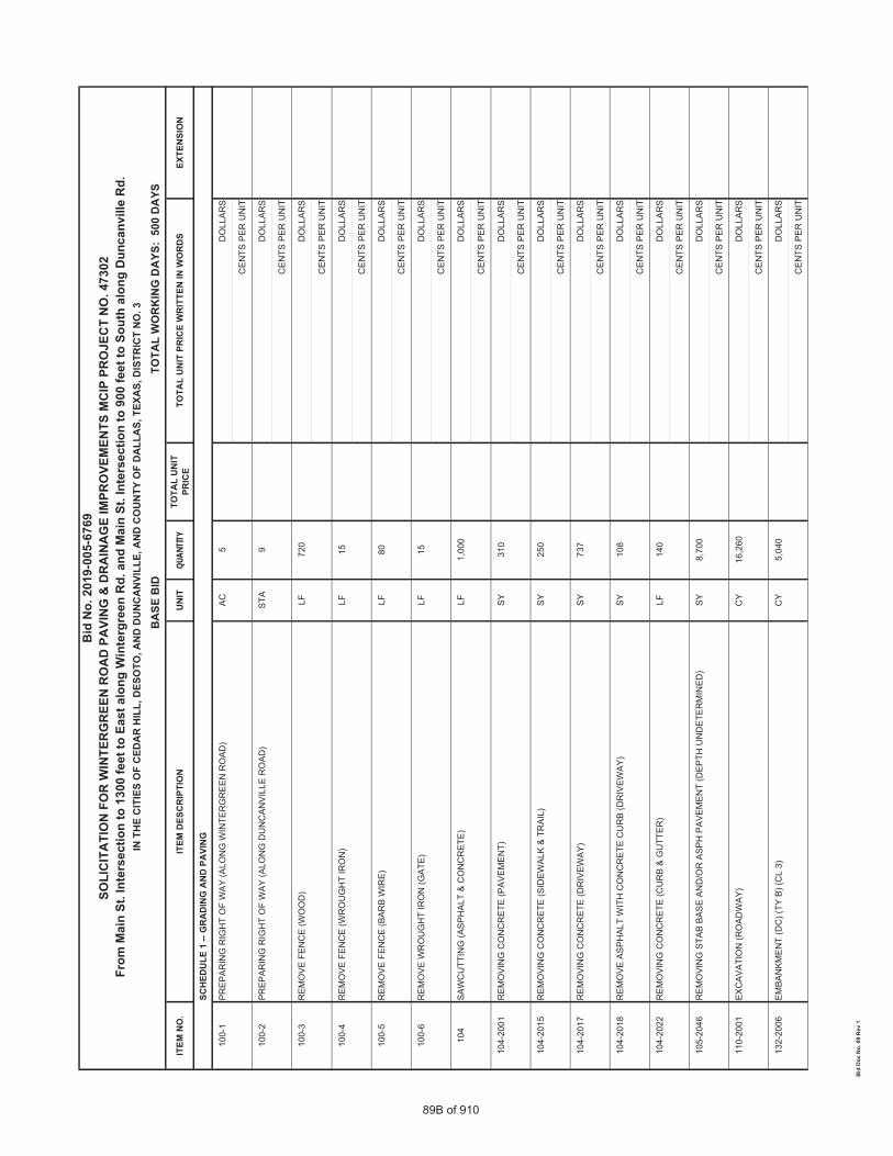
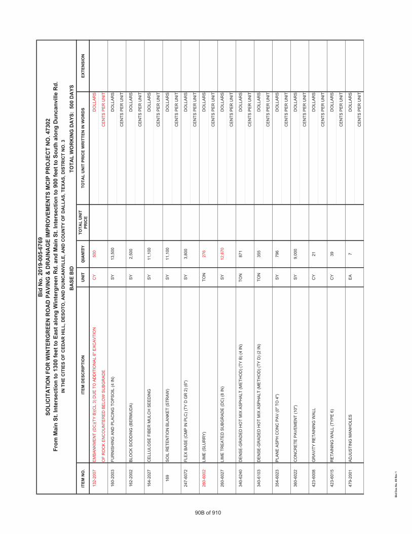
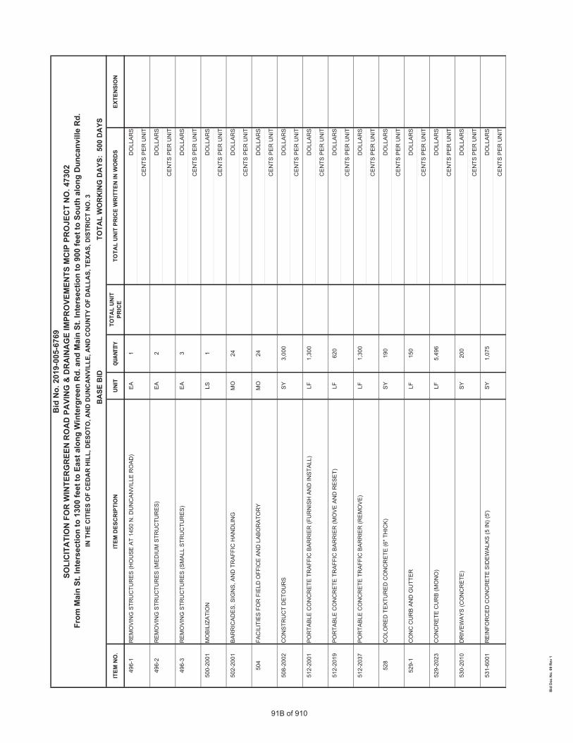
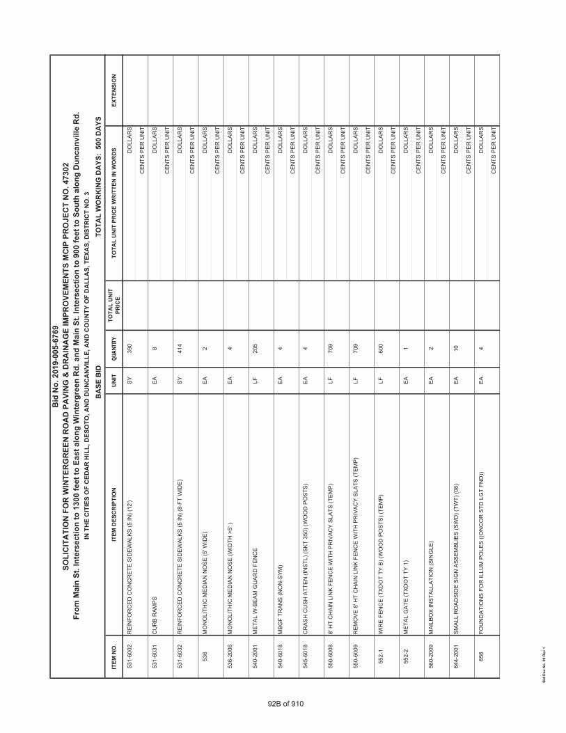
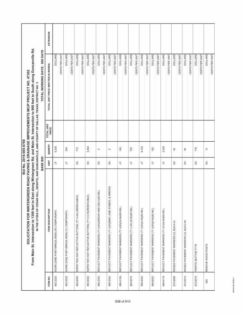
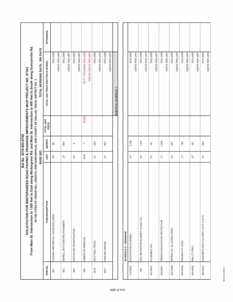
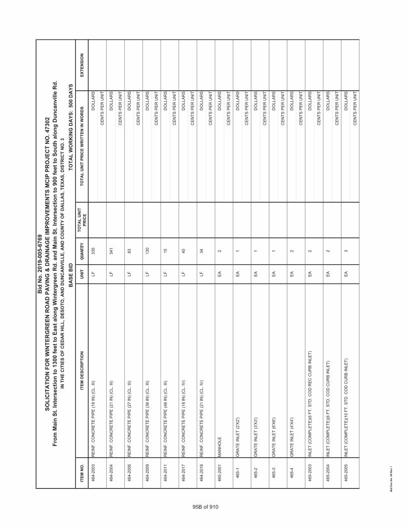
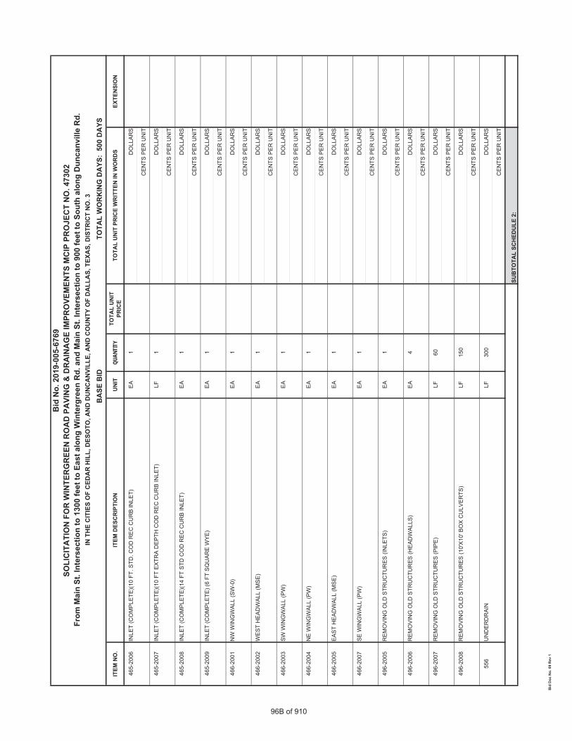
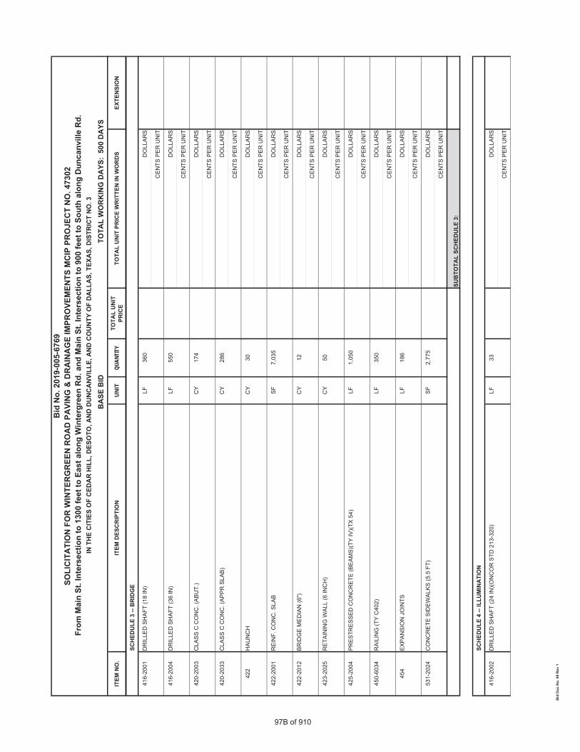
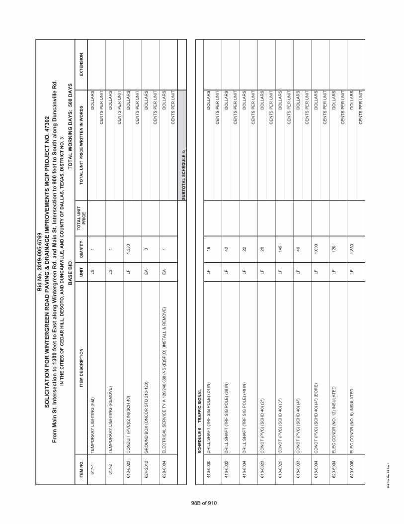
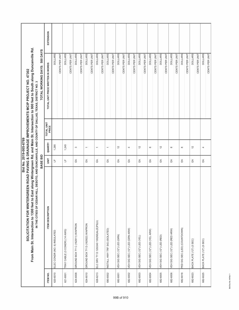
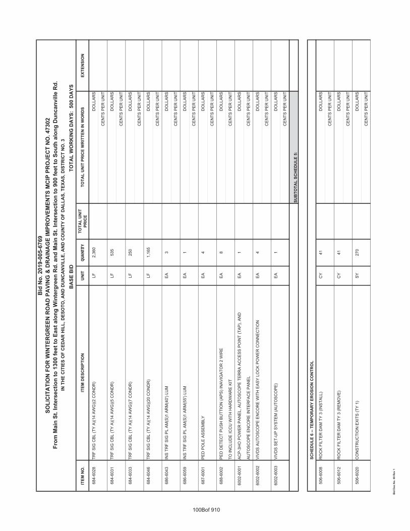
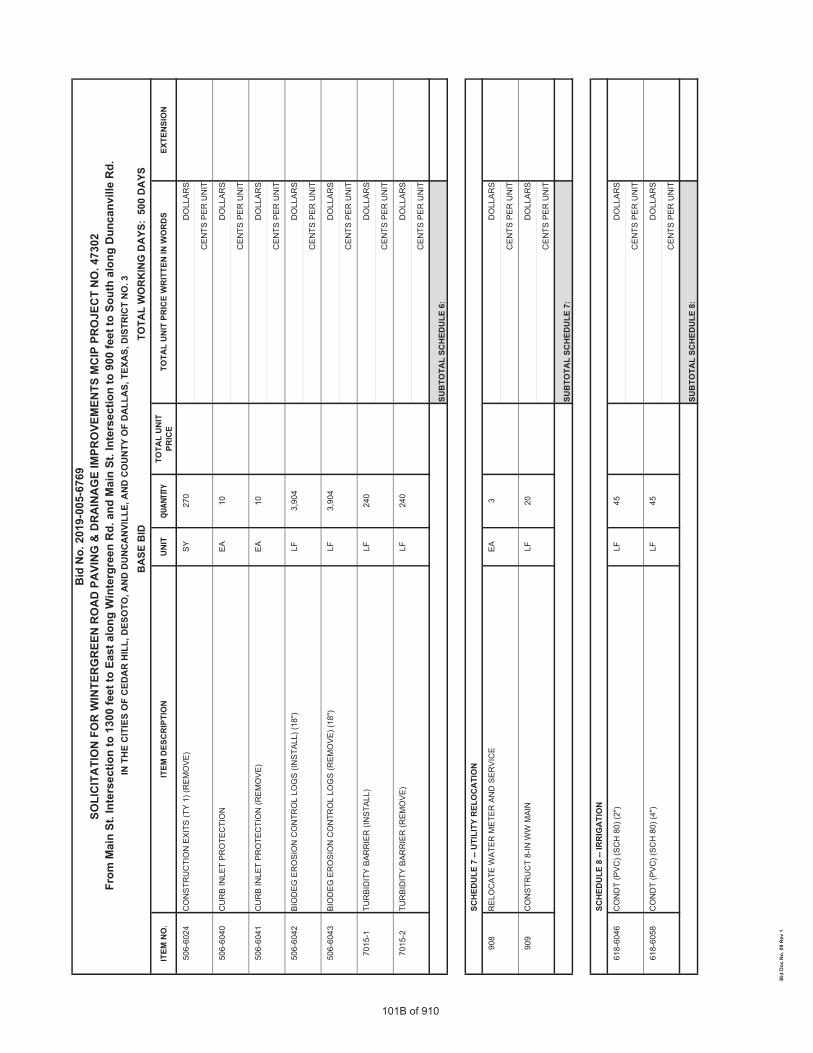
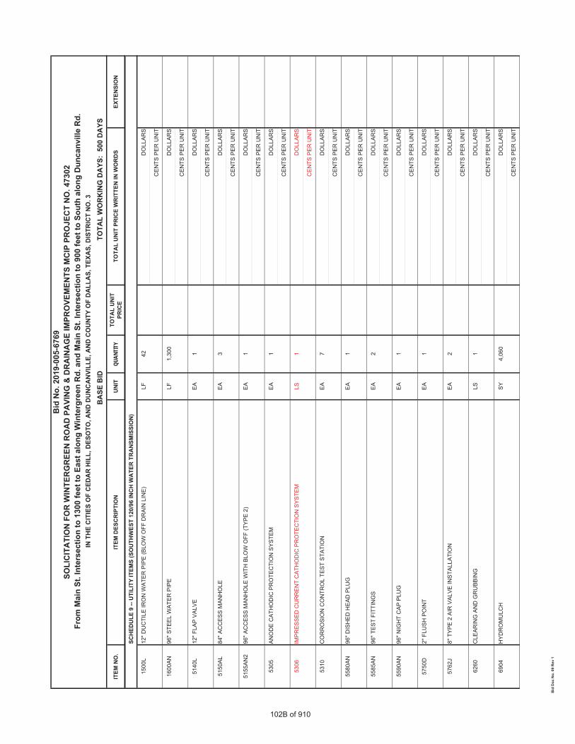
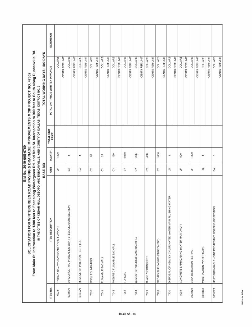
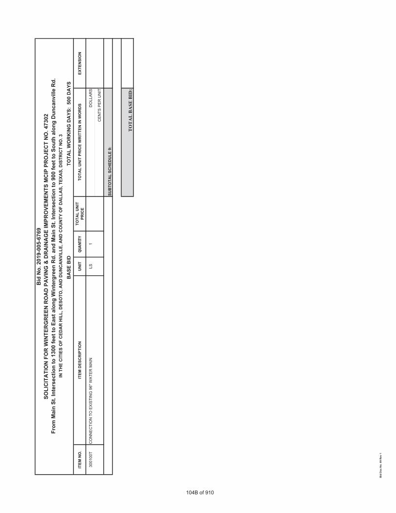
CONTRACTFORMAJORCAPITALIMPROVEMENTPROGRAMNO.47302WintergreenRoadfromMainStreetIntersectionto1300feetEastalongWintergreenRoadandMainStreetIntersectionto900feetSouthalongDuncanvilleRoad.
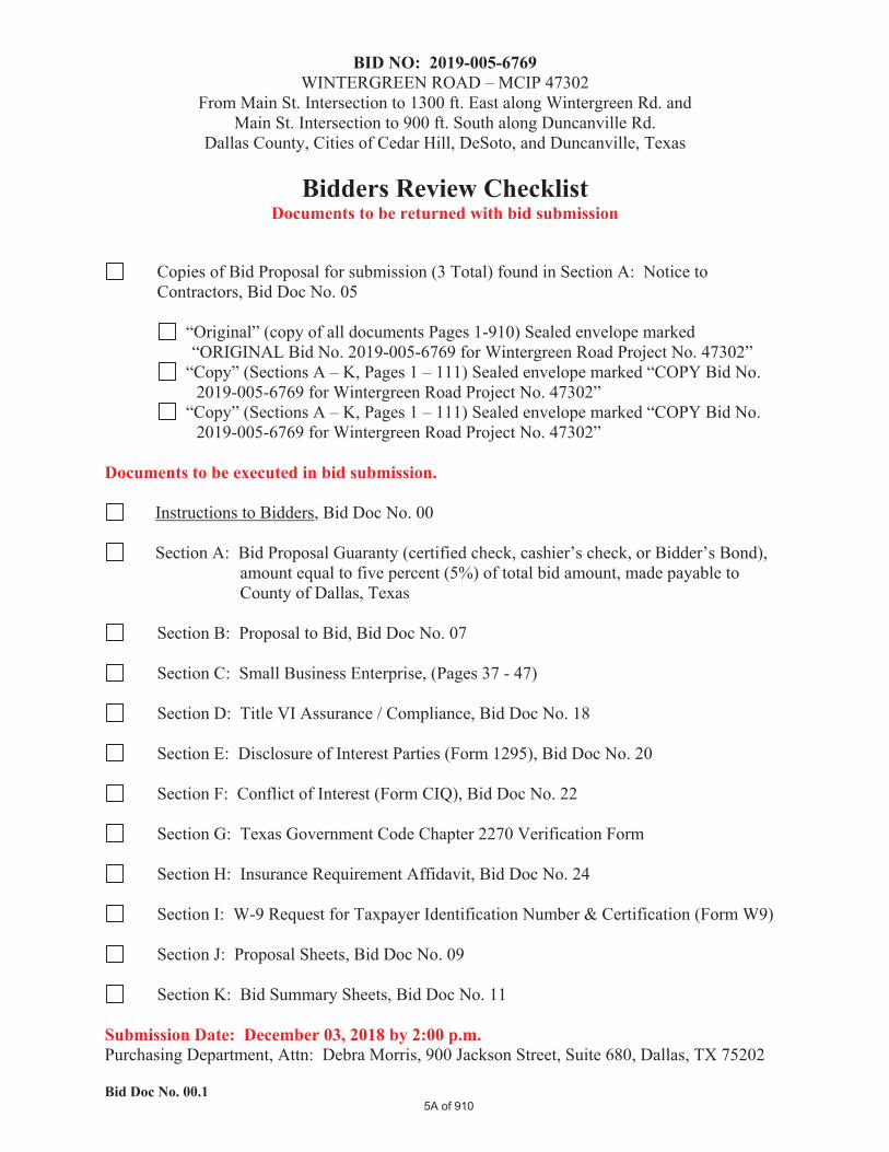
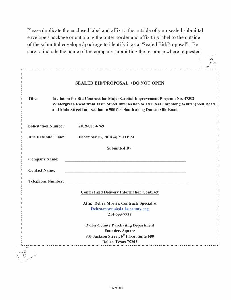
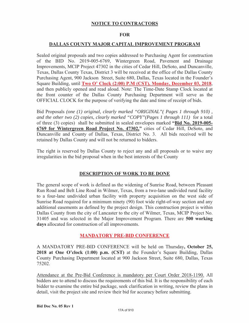
Whereas,thebidopeningdateisherebychangedtoreadasfollows:Monday,December03,2018at2:00p.m.Whereas,Page3inthebiddocumentisherebyreplacedwithpage3AWhereasPage5inthebiddocumentisherebyreplacedwithpage5AWhereasPage7inthebiddocumentisherebyreplacedwithpage7AWhereas,Pages17,19,and21inthebiddocumentareherebyreplacedwithpages17A,19A,and21A.WhereasBidSheetspages89Athrough104AareherebyreplacedwithBidSheets89Bthrough104B.ItemsupdatedareinRed.BidItem5306UnitPricechangedfromEAtoLS.Whereas,DWUTechnicalSpecificationSection15642isherebyreplacedwithRevisedDWUTechnicalSpecificationSection15642AddendumNo.1.Whereas,DWUSpecialProvisionisherebyaddedSpecialProvisionS‐18.Except as provided herein / above, all other specification requirements of the original solicitation referenced shall remain unchanged in and full force and effect. This addendum should be signed and returned with your Solicitation package on or before Thursday, November 29, 2018 @ 2:00 P.M. (CT). This addendum is hereby acknowledged, understood and considered in our Solicitation. Printed Name: _____________________________________________________ Signature of Authorized Representative: _______________________________ Title: ______________________________________________________________ Company: __________________________________________________________
INSTRUCTIONS TO BIDDERS
PLEASE READ THE ENTIRE PACKAGE CAREFULLY This page will need to be signed and returned with bid submission.
Bids are solicited for furnishing the merchandise, supplies, services and/or equipment set forth in this Bid Proposal. Completed SEALED Bid Proposals, ORIGINAL AND TWO (2) COPIES, must be received in the Purchasing Department, 900 Jackson Street (Founder’s Square), Suite 680, Dallas, Texas 75202, BY 2:00 P.M. ON THE ABOVE "DUE DATE". The official time clock will be time clock located in the Purchasing Department. Bids received at 2:01 and thereafter are Late Bids and will not be accepted.
Bids may be withdrawn at any time prior to the official opening. Alterations made before opening time must be initialed by bidder guaranteeing authenticity. After the official opening, bids may not be amended, altered, or withdrawn without the recommendation of the Purchasing Agent and the approval of the Commissioners' Court.
The County is exempt from Federal Excise and State Sales Tax; therefore, tax must not be included in this bid.
The undersigned agrees, if this bid is accepted, to furnish any and all items upon which prices are offered, at the price(s) and upon the terms and conditions contained in the Specifications. The period for acceptance of this Bid Proposal will be 150 calendar days unless a different period is noted by bidder.
The County reserves the right to accept or reject in part or in whole any bids submitted. The Commissioners Court will award the contract to the responsible bidder who submits the lowest and best bid as determined by Commissioners Court. The Commissioners Court reserves the right to determine compliance and to waive technicalities or irregularities and to make award in the best interest of Dallas County.
The undersigned affirms that they are duly authorized to execute this contract, that this company, corporation, firm, partnership or individual has not prepared this bid in collusion with any other Bidder, and that the contents of this bid as to prices, terms or conditions of said bid have not been communicated by the undersigned nor by any employee or agent to any other bidder or to any other person(s) engaged in this type of business prior to the official opening of this bid. And further, that the Manager, Secretary or other agent or officer signing this bid is not and has not been for the past six months directly or indirectly concerned in any pool or agreement or combination to control the price of Supplies, Services or Equipment bid on, or to influence any person to bid or not to bid thereon.
**NAME AND ADDRESS OF COMPANY/BIDDER: ALL BIDS MUST BE SIGNED PRIOR TO AWARDCompany Name (PRINTED): Name (PRINTED):
Mailing Address: Title:
Signature:
City/ State: ZIP: E-Mail Address:
***Texas Secretary of State Filing Number, Jurisdiction and Formation Date:
Telephone and Fax No.:
Federal Taxpayer ID/Certificate Number: WEB Site:
HELP US KEEP OUR VENDORS' LIST CURRENTNO BID is submitted for this time only; NOT THIS COMMODITY/SERVICE ONLY. FAILURE TO RESPOND TO BID SOLICITATIONS FOR TWO (2) BID PERIODS MAY RESULT IN REMOVAL FROM THE VENDORS LIST; however, if removed you will be reinstated upon request ** Legal Name, Address and Taxpayer ID number: Bidders are to submit the company’s “Legal Name” as identified by their Federal Tax Certification certificate. Bidders are to complete the attached Federal Form “W-9" for verification and filing purposes. Dallas County reserves the right to withhold any invoices and/or payments, without penalties, for documents submitted under a different name/billing address than that identified on the proposal document/award court order or contract.
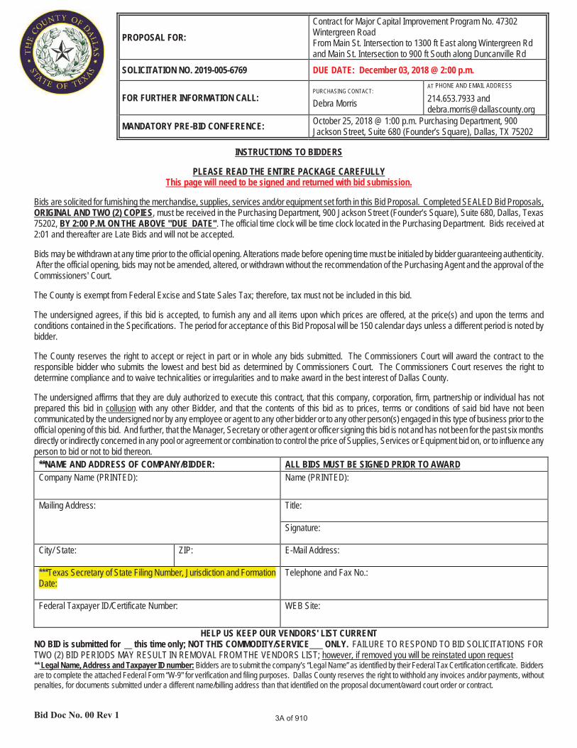
PROPOSAL FOR:Contract for Major Capital Improvement Program No. 47302Wintergreen RoadFrom Main St. Intersection to 1300 ft East along Wintergreen Rd and Main St. Intersection to 900 ft South along Duncanville Rd
SOLICITATION NO. 2019-005-6769 DUE DATE: December 03, 2018 @ 2:00 p.m.
FOR FURTHER INFORMATION CALL:PURCHASING CONTACT:
Debra Morris
AT PHONE AND EMAIL ADDRESS
214.653.7933 and [email protected]
MANDATORY PRE-BID CONFERENCE: October 25, 2018 @ 1:00 p.m. Purchasing Department, 900 Jackson Street, Suite 680 (Founder’s Square), Dallas, TX 75202
3A of 910
5A of 910
•
7A of 910
(one (1) original, clearly marked “ORIGINAL”( Pages 1 through 910) , and the other two (2) copies, clearly marked “COPY”(Pages 1 through 111)
17A of 910
19A of 910
10:00 AM (CST), Monday, October 22, 2018.
10:00-AM (CST), Thursday, November 01, 2018.
21A of 910
QUAN
TITY
89B of 910
QUAN
TITY
90B of 910
QUAN
TITY
91B of 910
QUAN
TITY
92B of 910
QUAN
TITY
93B of 910
QUAN
TITY
94B of 910
QUAN
TITY
95B of 910
QUAN
TITY
96B of 910
QUAN
TITY
97B of 910
QUAN
TITY
98B of 910
QUAN
TITY
99B of 910
QUAN
TITY
100Bof 910
QUAN
TITY
101B of 910
QUAN
TITY
102B of 910
QUAN
TITY
103B of 910
QUAN
TITY
104B of 910
1
DWU – ADDENDUM NO.1
SOUTHWEST 120/96-INCH WATER TRANSMISSION PIPELINE PROJECTIN
WINTERGREEN ROAD FROM MAIN STREET TO 1300 FEET EAST OF MAIN STREET
CONTRACT NO. 18-481F
DWU TECHNICAL SPECIFICATION 15642 – ICCP
Replace Technical Specification Section 15642 in Bid package with attached revised Section15642 dated November 20, 2018.
DWU SPECIAL PROVISIONS
Add the following Special Provision S-18:
S-18 CONTINUITY TESTING OF EXISTING 96-inch PCCP PIPELINE
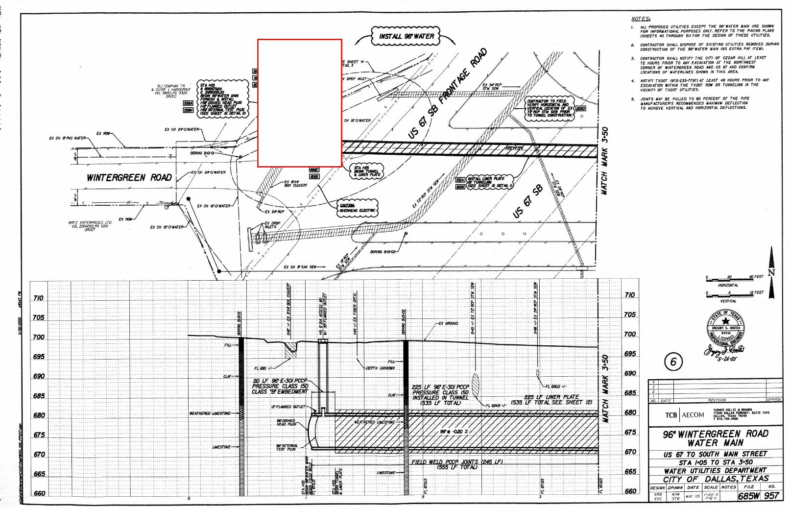
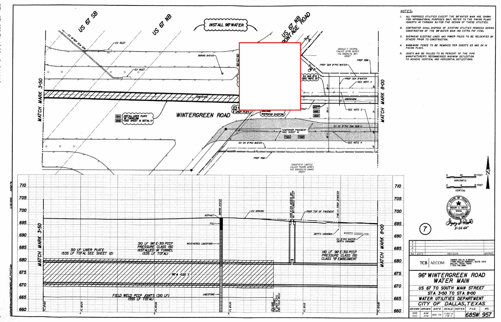
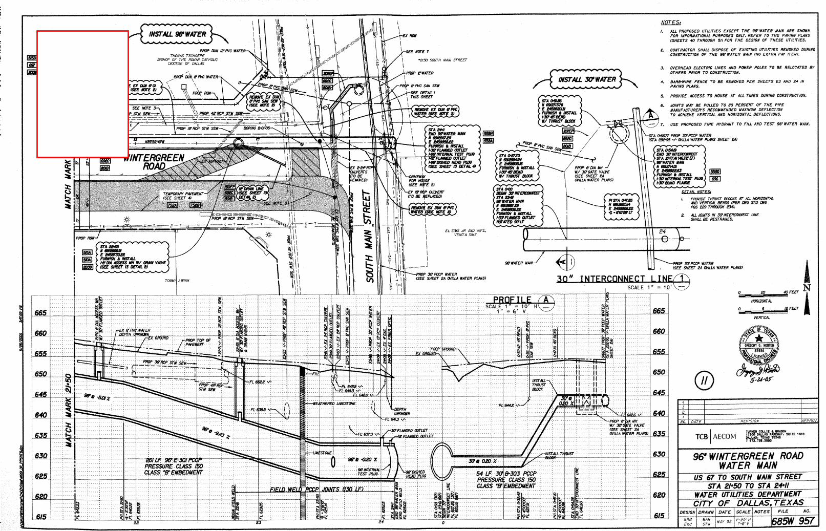
The continuity test referenced in Technical Specification Section 15642, Part 3, Item3.05.A shall be conducted on the existing 96-inch PCCP pipeline located in WintergreenRoad between Highway US 67 and South Main Street and the test results shall bedelivered to Dallas Water Utilities (DWU)for review prior to beginning any other workunder Section 15642. Depending on the results of the continuity test, DWU reserves theright not to authorize any of the remaining work covered under Bid Item No. 5306 to bedone. The locations of the existing test stations installed on the existing 96-inch PCCPpipeline are shown on the selected plan sheets for the existing 96-inch PCCP pipelineprovided in Appendix C.
DWU BID ITEM NO. 5306
Replace the Bid item description for ITEM NO. 5306 in the Bid package with the followingdescription:
ITEM NO. 5306 IMPRESSED CURRENT CATHODIC PROTECTION SYSTEMThis item consists of furnishing and installing an Impressed Current
Cathodic Protection System (ICCPS) as shown on the detail drawings on the plans andas described in the Technical Specifications Section 15642. This item includes allmaterials, equipment, labor, rectifier fencing (if needed), and any incidentals required toconduct the continuity test for the existing 96-PCCP pipeline first and to furnish andinstall a complete and fully functional ICCPS. This item also includes furnishing all thenecessary labor and material such as but not limited to conduits, wires, meter sockets,splice boxes and equipment to acquire the service connection to feed the ICCPS asrequired by the plans and specifications, City of Cedar Hill building codes, and ONCOR

2
requirements. The Contractor is responsible under this item to coordinate, pay for, andacquire all necessary permits.
Payment will be Lump Sum at contract bid price.
Southwest 120/96-inch Water Transmission Pipeline Project Phase IV-A
Wintergreen Road at Main Street
Prepared For:
Dallas Water Utilities Contract 18-481F
Prepared By:
AECOM Technical Services, Inc.
13355 Noel Road Suite 400 Dallas, Texas 75240
TBPE Reg. No. F-3580
In Association With:
Corrpro Companies, Inc. 7000-B Hollister Street Houston, Texas 77064 TBPE Reg. No. F-4567
Technical Specification Numbers Listed Below Only: 15640 – Joint Bonding and Electrical Isolation 15641 – Corrosion Control Test Stations 15642 – Impressed Current Cathodic Protection 15643 – Galvanic Anode Cathodic Protection Systems
Southwest 120/96-inch Water Transmission Pipeline Project Impressed Current Cathodic Protection Contract No. 18-481F 15642 - 1 of 8 11/20/2018
CITY OF DALLAS WATER UTILITITES
IMPRESSED CURRENT CATHODIC PROTECTION
SECTION 15642
PART 1 GENERAL
1.01 SCOPE OF WORK
A. Requirements for impressed current cathodic protection systems to provide corrosion protection to the project pipeline including prestressed concrete cylinder pipe.
1.02 RELATED SECTIONS
Section 15640 - Joint Bonding and Electrical Isolation Section 15641 - Corrosion Control Test Stations
1.03 REFERENCES
A. The publications listed below form a part of the specifications for this project for the extent referenced. The publications are referred to in the text by designation only. Where reference is made to one of the below standards, the revision in effect at the time of bid opening shall apply.
NEC 70 National Electrical Code NACE SP0169 Control of External Corrosion on Underground or Submerged
Metallic Piping Systems NACE SP0100 Cathodic Protection to Control External Corrosion of Concrete
Pressure Pipelines and Mortar-Coated Steel Pipelines for Water or Waste Water Service
NACE SP0572 Design, Operation, and Maintenance of Impressed Current Deep Anode Beds
NEMA 4 TYPE 3R ENCLOSURES
1.04 SUBMITTALS
A. Submittals shall conform to the requirements of Section 01300 - Submittals.
B. Rectifier Operation and Maintenance Manual: The rectifier manufacturer shall include a complete operation and maintenance manual with each rectifier shipped to the job site. In addition to operating instructions, the manual shall include a circuit diagram. The rectifier shall be operated under full load conditions at the factory and shall be thoroughly inspected and tested by the manufacturer prior to delivery to the job site. Results of this testing shall be reported on a manufacturer's quality control form and shall be included in the operation manual.
C. Operating and Maintenance Manual: Submit two (2) operating, monitoring and maintenance manuals for the cathodic protection system. The manuals shall include operating instructions, maintenance data and test procedures.
Southwest 120/96-inch Water Transmission Pipeline Project Impressed Current Cathodic Protection Contract No. 18-481F 15642 - 2 of 8 11/20/2018
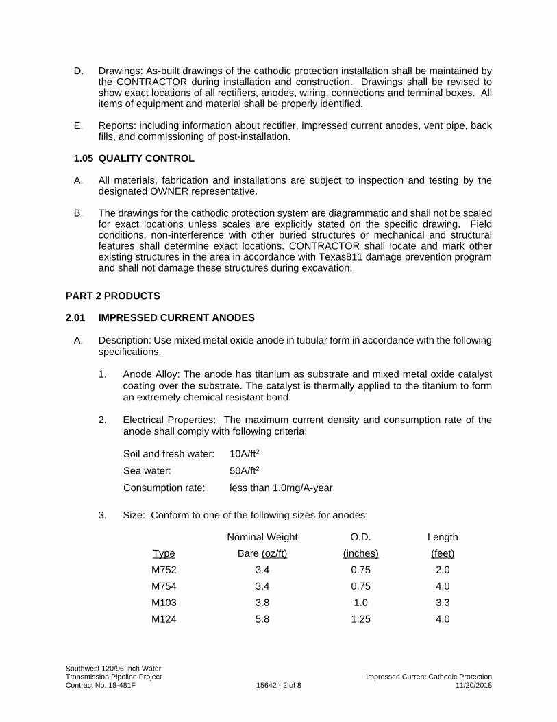
D. Drawings: As-built drawings of the cathodic protection installation shall be maintained by the CONTRACTOR during installation and construction. Drawings shall be revised to show exact locations of all rectifiers, anodes, wiring, connections and terminal boxes. All items of equipment and material shall be properly identified.
E. Reports: including information about rectifier, impressed current anodes, vent pipe, back fills, and commissioning of post-installation.
1.05 QUALITY CONTROL
A. All materials, fabrication and installations are subject to inspection and testing by the designated OWNER representative.
B. The drawings for the cathodic protection system are diagrammatic and shall not be scaled for exact locations unless scales are explicitly stated on the specific drawing. Field conditions, non-interference with other buried structures or mechanical and structural features shall determine exact locations. CONTRACTOR shall locate and mark other existing structures in the area in accordance with Texas811 damage prevention program and shall not damage these structures during excavation.
PART 2 PRODUCTS
2.01 IMPRESSED CURRENT ANODES
A. Description: Use mixed metal oxide anode in tubular form in accordance with the following specifications.
1. Anode Alloy: The anode has titanium as substrate and mixed metal oxide catalyst coating over the substrate. The catalyst is thermally applied to the titanium to form an extremely chemical resistant bond.
2. Electrical Properties: The maximum current density and consumption rate of the anode shall comply with following criteria:
Soil and fresh water: 10A/ft2
Sea water: 50A/ft2
Consumption rate: less than 1.0mg/A-year
3. Size: Conform to one of the following sizes for anodes:
Nominal Weight O.D. Length Type Bare (oz/ft) (inches) (feet) M752 3.4 0.75 2.0 M754 3.4 0.75 4.0 M103 3.8 1.0 3.3 M124 5.8 1.25 4.0
Southwest 120/96-inch Water Transmission Pipeline Project Impressed Current Cathodic Protection Contract No. 18-481F 15642 - 3 of 8 11/20/2018
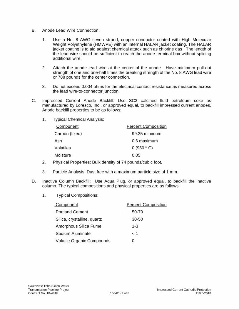
B. Anode Lead Wire Connection:
1. Use a No. 8 AWG seven strand, copper conductor coated with High Molecular Weight Polyethylene (HMWPE) with an internal HALAR jacket coating. The HALAR jacket coating is to aid against chemical attack such as chlorine gas The length of the lead wire should be sufficient to reach the anode terminal box without splicing additional wire.
2. Attach the anode lead wire at the center of the anode. Have minimum pull-out strength of one and one-half times the breaking strength of the No. 8 AWG lead wire or 788 pounds for the center connection.
3. Do not exceed 0.004 ohms for the electrical contact resistance as measured across the lead wire-to-connector junction.
C. Impressed Current Anode Backfill: Use SC3 calcined fluid petroleum coke as manufactured by Loresco, Inc., or approved equal, to backfill impressed current anodes. Anode backfill properties to be as follows:
1. Typical Chemical Analysis: Component Percent Composition
Carbon (fixed) 99.35 minimum
Ash 0.6 maximum Volatiles 0 (950 C)
Moisture 0.05 2. Physical Properties: Bulk density of 74 pounds/cubic foot.
3. Particle Analysis: Dust free with a maximum particle size of 1 mm.
D. Inactive Column Backfill: Use Aqua Plug, or approved equal, to backfill the inactive column. The typical compositions and physical properties are as follows:
1. Typical Compositions:
Component Percent Composition
Portland Cement 50-70
Silica, crystalline, quartz 30-50 Amorphous Silica Fume 1-3
Sodium Aluminate < 1
Volatile Organic Compounds 0
Southwest 120/96-inch Water Transmission Pipeline Project Impressed Current Cathodic Protection Contract No. 18-481F 15642 - 4 of 8 11/20/2018
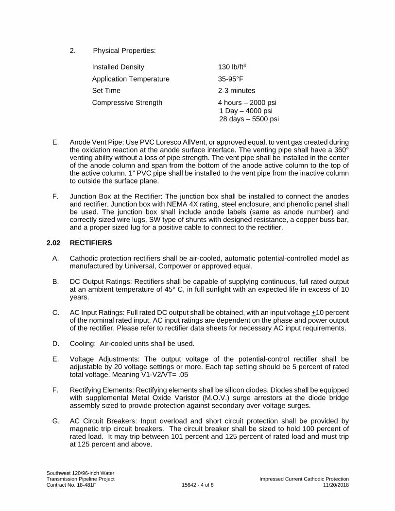
2. Physical Properties:
Installed Density 130 lb/ft3
Application Temperature 35-95°F Set Time 2-3 minutes
Compressive Strength 4 hours – 2000 psi 1 Day – 4000 psi 28 days – 5500 psi
E. Anode Vent Pipe: Use PVC Loresco AllVent, or approved equal, to vent gas created during the oxidation reaction at the anode surface interface. The venting pipe shall have a 360° venting ability without a loss of pipe strength. The vent pipe shall be installed in the center of the anode column and span from the bottom of the anode active column to the top of the active column. 1” PVC pipe shall be installed to the vent pipe from the inactive column to outside the surface plane.
F. Junction Box at the Rectifier: The junction box shall be installed to connect the anodes and rectifier. Junction box with NEMA 4X rating, steel enclosure, and phenolic panel shall be used. The junction box shall include anode labels (same as anode number) and correctly sized wire lugs, SW type of shunts with designed resistance, a copper buss bar, and a proper sized lug for a positive cable to connect to the rectifier.
2.02 RECTIFIERS
A. Cathodic protection rectifiers shall be air-cooled, automatic potential-controlled model as manufactured by Universal, Corrpower or approved equal.
B. DC Output Ratings: Rectifiers shall be capable of supplying continuous, full rated output at an ambient temperature of 45° C, in full sunlight with an expected life in excess of 10 years.
C. AC Input Ratings: Full rated DC output shall be obtained, with an input voltage +10 percent of the nominal rated input. AC input ratings are dependent on the phase and power output of the rectifier. Please refer to rectifier data sheets for necessary AC input requirements.
D. Cooling: Air-cooled units shall be used.
E. Voltage Adjustments: The output voltage of the potential-control rectifier shall be adjustable by 20 voltage settings or more. Each tap setting should be 5 percent of rated total voltage. Meaning V1-V2/VT= .05
F. Rectifying Elements: Rectifying elements shall be silicon diodes. Diodes shall be equipped with supplemental Metal Oxide Varistor (M.O.V.) surge arrestors at the diode bridge assembly sized to provide protection against secondary over-voltage surges.
G. AC Circuit Breakers: Input overload and short circuit protection shall be provided by magnetic trip circuit breakers. The circuit breaker shall be sized to hold 100 percent of rated load. It may trip between 101 percent and 125 percent of rated load and must trip at 125 percent and above.
Southwest 120/96-inch Water Transmission Pipeline Project Impressed Current Cathodic Protection Contract No. 18-481F 15642 - 5 of 8 11/20/2018
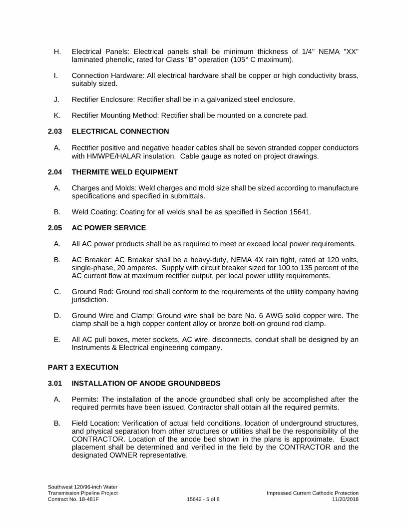
H. Electrical Panels: Electrical panels shall be minimum thickness of 1/4" NEMA "XX" laminated phenolic, rated for Class "B" operation (105° C maximum).
I. Connection Hardware: All electrical hardware shall be copper or high conductivity brass, suitably sized.
J. Rectifier Enclosure: Rectifier shall be in a galvanized steel enclosure.
K. Rectifier Mounting Method: Rectifier shall be mounted on a concrete pad.
2.03 ELECTRICAL CONNECTION
A. Rectifier positive and negative header cables shall be seven stranded copper conductors with HMWPE/HALAR insulation. Cable gauge as noted on project drawings.
2.04 THERMITE WELD EQUIPMENT
A. Charges and Molds: Weld charges and mold size shall be sized according to manufacture specifications and specified in submittals.
B. Weld Coating: Coating for all welds shall be as specified in Section 15641.
2.05 AC POWER SERVICE
A. All AC power products shall be as required to meet or exceed local power requirements.
B. AC Breaker: AC Breaker shall be a heavy-duty, NEMA 4X rain tight, rated at 120 volts, single-phase, 20 amperes. Supply with circuit breaker sized for 100 to 135 percent of the AC current flow at maximum rectifier output, per local power utility requirements.
C. Ground Rod: Ground rod shall conform to the requirements of the utility company having jurisdiction.
D. Ground Wire and Clamp: Ground wire shall be bare No. 6 AWG solid copper wire. The clamp shall be a high copper content alloy or bronze bolt-on ground rod clamp.
E. All AC pull boxes, meter sockets, AC wire, disconnects, conduit shall be designed by an Instruments & Electrical engineering company.
PART 3 EXECUTION
3.01 INSTALLATION OF ANODE GROUNDBEDS
A. Permits: The installation of the anode groundbed shall only be accomplished after the required permits have been issued. Contractor shall obtain all the required permits.
B. Field Location: Verification of actual field conditions, location of underground structures, and physical separation from other structures or utilities shall be the responsibility of the CONTRACTOR. Location of the anode bed shown in the plans is approximate. Exact placement shall be determined and verified in the field by the CONTRACTOR and the designated OWNER representative.
Southwest 120/96-inch Water Transmission Pipeline Project Impressed Current Cathodic Protection Contract No. 18-481F 15642 - 6 of 8 11/20/2018
C. Anode Trench or Deep Anode: The anode trench or deep anode shall be of sufficient size to accommodate impressed current anodes and backfill material. Refer to project drawings for details.
D. Anode Installation: The anode trench or deep anode well shall contain mixed metal oxides tubular anodes in accordance with project drawings. The anodes shall be installed by placing them individually into the trench or deep anode well. The anode lead wires shall not be damaged during handling or lowering into the trench or deep anode well. Under no circumstances shall the anode lead wires be clamped or pinched around another object while lowering the anodes into the trench or deep anode well. If the insulation for any anode lead wires is cut, broken, or nicked during this operation or at any other time, the complete anode shall be rejected from use and shall be removed from the job site.
E. Anode Coke Backfill: The coke backfill shall be installed around impressed current anodes as shown on project drawings. Installation of the coke backfill shall be uniform with no voids around the anodes.
F. Deep Anode Inactive Column Installation: Aqua Plug, or approved equal, shall be backfilled above the active column that contains anodes and coke backfill. For the top 20 ft of the inactive column PVC casing or other non-metal pipe with same diameter as the bore hole shall be used to stabilize the deep anode well.
G. Precautions: The CONTRACTOR shall take all necessary precautions to avoid entrance of foreign matter into the trench or deep anode well hole, movement of soil strata, or collapsing of the trench or deep anode well hole during the progress of the work. Should movement of soil strata or collapse of the trench or deep well hole interfere with proper completion of the anode groundbed, the CONTRACTOR shall recover the wires and anodes, and retrench.
3.02 INSTALLATION OF CATHODIC PROTECTION RECTIFIER
A. Codes: The installation shall conform to National Electrical Codes (NEC) and be in compliance with all local electrical codes and standards.
B. Conduit: All wiring to the rectifier shall be contained in rigid galvanized steel conduit when run above grade.
1. Insulating bushings shall be used at the ends of all conduits.
2. Steel conduit shall extend 12 inches below grade.
C. Electrical Service: AC electrical service to the rectifier unit shall be the responsibility of the CONTRACTOR, which includes installing all necessary wiring, conduits, wires, meter sockets, splice boxes and equipment to the service connection as required by Dallas Water Utilities specifications and local power requirements. All expenses associated with installation of AC power service are the responsibility of the CONTRACTOR.
D. Rectifier Mounting: Rectifier shall be mounted on a concrete pad or wood pole. A typical concrete pad should be 5’x6’x12” with five #4 reinforcing steel rebars. Rebars shall be spaced 12” apart in parallel. Expansion concrete bolt shall be used to mount the rectifier. See detail drawings and description for proper installation.
E. Junction Box: Junction box shall be installed on a 4”x4” wood beam adjacent to the deep anode groundbed. The junction box may also be placed next to the rectifier, anode lead
Southwest 120/96-inch Water Transmission Pipeline Project Impressed Current Cathodic Protection Contract No. 18-481F 15642 - 7 of 8 11/20/2018
lengths have to be designed accordingly. In location with live stock or potential traffic a bollard shall be placed around the box for damage prevention. The pole shall be placed minimally 3’ below surface grade with a concrete footing, approximately 6” radial concrete placement around the pole. See design drawings for full details of installation.
F. Completion: The installation shall not be considered complete until the AC and DC wiring is complete and the rectifier is capable of operating at full rated load. AC power shall be installed such that the rectifier can be activated for test purposes; however, the CONTRACTOR shall leave the power off at the site. The rectifier shall be turned on and adjusted afterwards by the designated engineer/technician.
3.03 INSTALLATION OF WIRE AND CABLE
A. Depth: All underground wires and cables shall be installed at a minimum of 24 inches below final grade with a minimum separation of 6 inches from other underground structures.
B. Conduit: All negative cables and anode header cables shall be placed in rigid galvanized steel conduit when above-grade.
1. Insulating bushings shall be used at the ends of all conduits.
2. Conduit shall extend 12 inches below grade.
3.04 NEGATIVE CABLE AND TEST LEAD WIRE ATTACHMENT
A. The negative cable and test lead wires shall be attached to the structure by thermite welding as specified in Section 15641, or to a test station that is continuous to the structure. The test station lead wire must have a greater ampere rating than the maximum rectifier output. The structure cable shall be as shown on the project drawings.
3.05 POST INSTALLATION TESTING OF THE CATHODIC PROTECTION SYSTEMS
A. Preparation: Prior to energizing or commissioning of the cathodic protection system, continuity joint testing shall be performed in accordance with Section 15640 – 3.03 (Joint Bonding). This testing is required for any mechanical pipeline joint with electrical continuity bond wires, straps, or clips installed across the pipe joint for the purpose of establishing electrical continuity along the pipeline
B. General: The cathodic protection system shall be inspected, energized and adjusted as soon as possible after the cathodic protection equipment has been installed and underground structure installation completed.
C. Start Up: The energizing and testing of the cathodic protection system shall be performed under the direction of a NACE International certified cathodic protection specialist or corrosion technologist. The cathodic protection system shall be adjusted to achieve compliance with the referenced corrosion control standards set forth by NACE International.
D. Method: The following procedures shall be used:
1. Measure native state structure-to-soil potentials at test stations prior to energizing the cathodic protection system.
Southwest 120/96-inch Water Transmission Pipeline Project Impressed Current Cathodic Protection Contract No. 18-481F 15642 - 8 of 8 11/20/2018
2. Energize the cathodic protection system and measure the current and voltage for all taps settings. Then proceed to set the DC current output such that the ON structure-to-soil potentials near the cathodic protection current source (transformer-rectifier) are approximately -1000 millivolts with respect to a copper sulfate electrode (CSE). Record the DC voltage and current of the rectifier.
3. Allow a minimum of 1 week for polarization of the structures.
4. Using a current interrupter, cycle the power supply “On” and “Off”.
5. Record “On” and “Instant Off” potentials at all test stations and locations of exposed pipe where native potentials were previously obtained.
6. Adjust the cathodic protection power supplies to satisfy the criteria of a minimum 100 millivolts of polarization or an instant-off potential of -850 mV-CSE. Once the current is known for the proper polarization for the pipeline, the rectifier shall be set and switched over to auto potential control mode. Auto-potential mode should be in reference to the “On” potential associated with the “Instant-off” potential that meets criteria. Polarized potentials shall not exceed -1000 mV CSE at any point along PCCP to avoid excessive hydrogen generation.
7. Record all final adjustments of the DC power supplies.
8. Record the current output of each anode.
9. Verify that all electrical isolation devices are operating properly including flange isolators.
E. Verification and Responsibilities
Tester shall provide written documentation of any deficiencies discovered during the post installation inspection.
F. Equipment: All cathodic protection testing instruments shall be in proper working order and calibrated according to factory specifications.
G. Report: A written commissioning report including structure-to-soil cathodic protection potentials, rectifier output and settings, anode current outputs and as-built drawings shall be submitted.
END OF SECTION

APPENDIX C