technical specification for 245kv and 145kv
TRANSCRIPT

ODISHA POWER TRANSMISSION CORPORATION LIMITED
TECHNICAL SPECIFICATION FOR
245KV and 145KV
HORIZONTAL CENTRE BREAK
ISOLATORS

TECHNICAL SPECIFICATION FOR 245 KV CENTRE BREAK ISOLATORS
(245kV & 145KV, 40KA, 2000A, 3-pole Horizontal Centre Break Motor Operated Isolator with Motor drive, Rotary Insulators, Base Frame, Clamp & Connectors and all other fitting & fixing complete in all respect with/ without Earth switch)
1. SCOPE
The scope covers design, manufacture, testing, supply, delivery & supervision of erection, testing and commissioning of 245 KV and 145KV motor operated
Centre break Isolator with/ without Earth switch of rated current capacity as per technical specification enumerated herein.
2. STANDARD:
The rating as well as performance and testing of the isolators shall conform to
the latest revisions and amendments of the following standards. Equipment
meeting any other authoritative standard, which ensures an equal or better
quality than that standard mentioned above, will also be accepted.
IEC 62271-1 HIGH-VOLTAGE SWITCHGEAR AND CONTROLGEAR PART 1 COMMON SPECIFICATIONS
IEC:129/ IEC 62271-102
Indian Standard HIGH-VOLTAGE SWITCHGEAR AND CONTROLGEAR PART 102 ALTERNATING CURRENT DISCONNECTORS AND EARTHING SWITC
IS 9921 PART 1 –PART 5
SPECIFICATION FOR ALTERNATING CURRENT DISCONNECTORS ( ISOLATORS ) AND EARTHING SWITCHES FOR VOLTAGES ABOVE 1000 V
IEC 60694 IEC 60694 Common Specifications For High-Voltage Switchgear and Control gear Standards
IS 2544 SPECIFICATIONS FOR POST INSULATOR
IS:2147, IS:4691
DEGREE OF PROTECTION PROVIDED BY ENCLOSURE
IS:1573 ELECTROPLATED COATING OF ZINC ON IRON & STEEL
IS:2629 RECOMMENDED PRACTICE FOR HD GALVANIZING OF IRON & STEEL
IS:4759 HOT DIP GALVANIZATION COATING ON STRUCTURAL STEEL
3. GENERAL INFORMATION:
3.1. Isolators are 245 KV and 145KV class.
3.2. Isolators shall be out door and off-load type with three phase suitable for manual as well as local/remote electrical operation.
3.3. The Isolators with combined/ indivisual Earth switch shall be provided on isolator whenever specifically mentioned in the price schedule.

3.4. The Isolators may be installed in staggered or non-staggered position as per requirement in the existing bays.
3.5. Any material or accessories which may not have been specifically mentioned but which is usual and necessary for satisfactory and trouble free operation and maintenance of the equipment shall be within the scope of supply without any extra financial implication.
4. DESIGN CRITERIA:
4.1. The isolators shall be horizontal center break type.
4.2. The isolator including their operating mechanisms shall be designed in a
manner such a way that they cannot come out of their open or closed
position by gravity, wind pressure, vibrations, reasonable shocks or
accidental touching of the connecting rods of their operating system.
The mechanism should have preferably dead centre locking
arrangement such that it prevents any change in end position due to
external force on the arm.
4.3. The isolators should be supplied with manual as well as motor operated
mechanism. Each three pole 245KV and 145KV isolator will require only
one mechanism. The coupling rod should be suitable for continuous
adaption.
4.4. Arcing horn/guiding horn/Corona control ring shall be provided in all
isolator of 245KV and above class HCB type isolators only.
4.5. The moving contacts of 3-phase centre break type isolator shall rotate
from their fully closed position to fully open position. The break shall be
distinct and clearly visible from ground.
4.6. It should be suitable for continuous service at the system voltages
specified herein. The Isolators shall be suitable to carry the rated
current continuously and full short circuit current at site condition
without any appreciable rise in temperature. These shall also be suitable
for operation at 110% rated (normal) voltage
4.7. The Isolators are required to be used on electrically exposed installation and this should be taken into account while fixing the clearance
between phases and between phase and earth. 5. DUTY REQUIREMENT:
5.1. The dis-connector shall be of class M2 class having mechanical
endurance of 10,000 operating cycle.
5.2. Isolators shall be capable of withstanding the dynamic and thermal
effect of maximum short circuit current of the system in their closed
position. They shall be constructed such that they do not open under
influence of short circuit current.
5.3. Isolator shall be capable of making/breaking normal current with no
significant change in voltage occurs across the terminal of each pole of
isolator on account of make / break operation.
5.4. The isolators shall be capable of making/breaking magnetizing current
of 0.7A at 0.15 power factor and capacitive current of 0.7A at 0.15
power factor at rated voltage.

5.5. In addition to constructional interlock, isolator shall have provision to
prevent their electrical and manual operation unless the associated and
other interlocking conditions are met. Suitable individual interlocking
coil arrangements shall be provided. The interlocking coil shall be
suitable for continuous operation from DC supply and within a
variation range as stipulated in ‘Specific Technical Parameter’.
6. MAIN CONTACTS (MALE AND FEMALE)
6.1. The dis-connector shall be having main current carrying parts of
Aluminum or Electrolytic Copper/Copper Alloy arm as per standard
design of the manufacture to be capable for continuous rated normal
current and short time SC Current in accordance with the Standard
Technical Parameters.
6.2. The Isolator’s male and female contact shall be spring less contacts on
the hinges and jaw and all contact shall be made of silver faced copper
or electrolytic copper alloy capable of carrying continuous rated normal
current and short time SC Current as per STP. The current carrying
fingers should be fixed with the main arm without any holding
spring attachment to avoid flashing and damage of contact fingers
for failure of the holding springs. The main and secondary contact
assembly should not use springs for holding contact fingers or
maintaining contact pressure.
6.3. The contacts and other current carrying parts shall be so designed that
their temperature rise under different operating conditions shall not
exceed the value specified in IS: 9921. Temporary rise of temperature
due to passage of specified rated short circuit current for all voltage
classes shall not cause any annealing or welding of contact surfaces.
6.4. The female contacts of the horizontal type isolators shall consist of
properly tempered copper strip/electrolytic copper alloy suitable for
rated and short time current rating of the respective voltage class. The
hard drawn electrolytic copper strips/ electrolytic copper alloy shall be
silver plated of minimum 25 micron thickness.
6.5. The dimensions of the contacts should conform to the drawing
approved during type test. However the current density of the current
carrying parts shall not be more than the values specified below.
Current Density in Amps/sq. mm
Tubes Flats
Copper : 2.5 2.0
Aluminum : 1.25 1.0
6.6. These fixed and moving contacts shall be able to carry the rated current
continuously and the maximum fault current without any appreciable
rise in temperature. The Isolator blades shall retain their form and
straightness under all conditions of operation including all mechanical
stress arising out of operation as well as under rated short circuit
condition.

6.7. The Isolator contacts shall be self-aligning and self-cleaning type so
that when Isolator remains closed for long periods in a heavily polluted
atmosphere, binding does not occur. No undue wear or scuffing shall
be evident during the mechanical endurance tests.
6.8 The terminal pad should rotate 360 Deg. with tulip contacts
arrangement (maintenance free) in such that bus bar can be connected from any angle of entry.
7. BASE;
7.1 Each single pole of the center break isolator shall be provided with complete
galvanised steel base with holes for mounting on a supporting structure. 7.2 The open & close position of isolator shall be indicated by an indicator
made of metal and placed at a suitable height so that the same is easily visible from ground level.
7.3 The bearing assembly should be maintenance free for it’s life time of
product. Double ball bearing should be used in bearing assembly. The casting of bearing housing should be designed to sustain all temperature / environmental flexibility.
8 INSULATORS:
8.1. The insulators to be used shall conform to IS: 2544 and/or IEC-168
and shall be solid core type and shall be homogeneous; free from
cavities, tough and impervious to moisture.
8.2. Glazing of porcelain shall be uniform brown colour free from blister,
burns and other defects which may affect the mechanical and dielectric
quality of the insulators.
8.3. All iron parts shall be hot dip galvanized. The joints shall be so
designed that any thermal expansion of the metal and the porcelain
parts shall not be loosened during the whole range of operation.
8.4. Puncture voltage of Insulator shall be greater than dry flashover voltage
of respective Isolators.
8.5. The design of the isolator shall be such that pressure due to the
contact shall not be transferred to the Insulators after the main
blades are fully closed.
8.6. The cantilever strength (min) of solid core support insulator shall be as
specified under ‘specific technical particulars’.
8.7. The rotating insulators stacks shall be provided with double roller or
double ball bearings and shall be adjustable and easily accessible for
dismantling in the field. Bearing housing shall be weather and dust
proof
9. ARCING HORN AND GRADING HORN Suitable arcing horn made of GI shall be provided on the fixed and
moving contacts of Isolators if required. The contacts shall be of ‘make before and break after” type.

10. ELECTRICAL INTERLOCK / MECHANICAL INTERLOCK
10.1. The Isolators shall be equipped with electrical interlock for interlocking
with the associated circuit breakers . The interlocking scheme shall be
approved by OPTCL.
10.2. Suitable mechanical / constructional interlock shall be provided
between Isolator and earth switch which should be rigid in construction
and properly mounted to ensure reliable operation.
11. AUXILIARY SWITCHES
11.1. All isolators shall be provided with 220V DC (±20%) auxiliary switches
for remote position indication on the control panel and for electrical
inter locking with other equipment.
11.2. The auxiliary switch shall be provided with a minimum of auxiliary
contacts-12 normally open and 12 normally closed.
11.3. The auxiliary switches and auxiliary circuits shall have a continuous
current carrying capacity of at least 10 Amps. Auxiliary switches shall
not be used as limit switches. Details of make, rating and type of
auxiliary switch along with the type test report shall be furnished in the
offer.
11.4. The auxiliary contacts should be designed such that, it can be changed
from NO to NC and vice versa at site.
12. OPERATING MECHANISM:
12.1. Control cabinet/operating mechanism box shall be made of aluminum
sheet of adequate thickness (minimum 3 mm.) The enclosure shall be
painted with epoxy paint. Powder coated to the Shade no 631 of IS:5(for
aluminum enclosure).
12.2. The operating mechanism shall be located such that it can be directly
mounted on then support structure.
12.3. A position indicator to show the isolator is in ON or OFF position to be
provided at a suitable location
12.4 The enclosure of the operating mechanism Box shall conform to the
degree of protection IP- 55. ) The mechanism box shall have neoprene
gasket hinged door at front with locking facility. All accessories inside the
housing shall be easily accessible.
12.5 Linkage mechanism should be in built with Teflon cup bushing to
accommodate minor misalignment & avoid rust in joints.
12.6 Insulator rotating arrangement should have sealed double ball bearing
arrangement.
12.7 A Local/Remote selector switch and a set of open/ close push buttons
shall be provided on the control cabinet of the isolator to permit its
operation through local or remote push buttons.

12.8 Provision shall be made in the control cabinet to disconnect power
supply through suitable MCBs to prevent local/remote power operation.
12.9 The motor shall be an AC motor /PMDC type and should run from
400V/230V AC mains. The motor should have smooth torque/speed
characteristics.
12.10 Suitable reduction gearing shall be provided between the motor and
the drive shaft of the isolator. The mechanism shall stop immediately
when motor supply is switched off.
12.11 Suitable reduction gearing shall be provided between the motor and the
drive shaft of the isolator. The mechanism shall stop immediately when
motor supply is switched off. Gear should be of forged material suitably
chosen to avoid bending/jamming on operation after a prolonged period of
non operation. Also all gear and connected material should be so
chosen/surface treated to avoid rusting. The Gears shall be lubricated for
life with graphite or better quality non-drawing and non-hardening type
grease.
12.12 Manual operation facility (with handle) should be provided with
necessary interlock to disconnect motor.
12.13 Provision shall be made in the control cabinet to disconnect power
supply through suitable MCBs to prevent local/remote power operation.
All control switches shall be of MCB/rotary switch type and Toggle/piano
switches shall not be accepted.
12.14 Only stranded copper conductor shall be used for wiring. Minimum size
of the Conductor for control circuit wiring shall be 2.5 sq.mm Copper.
12.15 Suitable anti condensation heaters with the provision of thermostat
shall be provided.
12.16 Each operating mechanism shall be provided with 1100V grade stud
type terminal block of Polyamide material. At least 20% spare
terminals shall be provided.
12.17 A 240 V, 12W, LED tube light shall be provided in each of the motor operated mechanism for interior illumination controlled by a ON/OFF switch. A 240V, single phase, 50 Hz, 15 amp AC plug and socket shall be provided in the cabinet with ON-OFF switch for connection of hand lamps.
13. DESIGN, MATERIALS AND WORKMANSHIP
13.1. The live parts shall be designed to eliminate sharp points, edges and similar corona producing surfaces, where this is impracticable, adequate rings made out of aluminum tubes shall be provided. Corona shields are not acceptable. 13.2. All ferrous metal parts shall be hot dip galvanized, as per IS 2629.All metal
parts shall be of such materials or treated in such a way so as to avoid rust, corrosion and deterioration due to continued exposure to atmosphere and rain.
13.3. Bolts, screws and pins shall be provided with standard locking device viz.
Locknuts, spring washers, keys etc. and when used with current carrying
parts, they shall be made of copper silicon or other high conductivity and wear resistant alloys.
13.4. The switches should not need lubrication of any parts except at very long
interval of five year minimum. 13.5. Any fittings, accessories or apparatus which may not have been mentioned in this specification but which are necessary for efficient operation / performance shall deem to be included in the contract.
14. PROTECTIVE COATINGS
All ferrous parts including bolts, nuts and washers of the switches assembly shall be galvanised to withstand at least six one minute dips in copper sulphate solution of requisite strength (Preece dip tests) except the threaded portions which should withstand four dips.
15. INSULATORS
15.1. Support insulators for all type of isolators shall be of solid core type.
15.2. The insulator shall be made of homogeneous and vitreous porcelain of
high mechnical and dielectric strength. It shall have sufficient
mechanical strength to sustain electrical and mechanical loading on
account of wind load, short circuit forces etc. Glazing of the porcelains
shall be of uniform dark brown colour with a smooth surface arranged
to shed away raise water.
15.3. The porcelain shall be free from laminations and other flaws or
imperfections that might affect the mechanical or dielectric quality. It
shall be thoroughly vitrified, tough and impervious to moisture.
15.4. The porcelain and metal ports shall be assembled in such a manner
and with such material that any thermal differential expansion between
the metal and porcelain parts throughout the range of temperature
specified in this specification shall not loosen the parts or create under
internal stresses which may affect the mechanical or electrical strength
or rigidity. The assembly shall not have excessive concentration of
electrical stresses in any section or across leakage surfaces. The
cement used shall not give rise to chemical reaction with metal fittings.
15.5. The insulator shall be suitable for water washing by rain or artificial
means in service condition.
15.6. Profile of the insulator shall also conform to IEC-815.
15.7. Caps to be provided on top of the insulator shall be of high grade cast
iron or malleable steel casting. It shall be machine faced and hot dip
galvanized. The holes shall be suitable for bolts with threads having
anti corrosive protection. The effective depth of threads shall not be less
than the nominal diameter of the bolt. The cap shall be so designed
that it shall be free from visible corona and shall have radio
interference level within 500 micro volts.
15.8. Casting shall be free from blow holes cracks and such other defects.
16. NAME PLATE:
Isolator, earth switches and their operating devices shall be provided with name plate. The name plate shall be weather proof and corrosion proof. It shall be mounted in such a position that it shall be visible in the position of normal service and installation. It shall carry the following information’s duly engraved or punched on it. Name plate shall be bilingual i.e. in English & Oriya.
16.1. Isolator Base Name : OPTCL
Name of manufacturer –
Type Designation –
Manufacturers serial No. –
Rated voltage –
Rated normal current –
Rated short time current (rms) and duration –
Rated short time peak current (KAP)
Weight
16.2. Operating Device Name – OPTCL Name of manufacturer – Type Designation – Reduction gear ratio – AC motor i) Rated auxiliary voltage ii) Starting current iii) Designation of AC motor as per I.S 4722/325 iv) Starting torque at 80% of supply voltage v) Over travel in degrees after cutting off supply Total operating time in seconds
i) Close operation – Electrical ii) Open operation – electrical Open operation – manual
16.3. All components shall be given adequate treatment of climate proofing as per IS:3202 so as to withstand corrosive and severe service conditions. All metal parts not suitable for painting such as structural steel, pipes, rods ,levers,linkages, nuts and bolts used in other than current path etc. shall be hot dip gaivanised as per IS -2629 Complete details of painting, galvanizing and climate proofing of the equipment shall be furnished in the offer.
17. TESTS
17.1. Type Tests
Isolators offered, shall be fully type tested as per the relevant standards. The
Bidder shall furnish one set of the following valid type test reports for their
different type of offered Isolators along with the offer. The Purchaser reserves
the right to demand repetition of some or all the type tests in the presence of
purchaser’s representative. For this purpose the Bidder may quote unit rates
for carrying out each type test and this will be taken during bid price
evaluation, if required.
The following type test reports shall be submitted for evaluation purpose. In
the absence of any one of the following, the bid is liable to reject.
a) Short time withstand & peak withstand current test for Isolator.
b) Power frequency (Dry & Wet), Lightening Impulse dry withstand
Test
c) Radio interference voltage (RIV) test
d) Mechanical endurance Test & Terminal load test
e) Degree of Protection test (IP-55)
f) Corona Test (For 400kV Only)
g) Temperature rise test
h) Blocked rotor test
During type tests the isolator shall be mounted on it’s own support structure
or equivalent support structure and installed with its own operating
mechanism to make the type tests representative. Drawing of equivalent
support structure and mounting arrangements shall be furnished for
Purchaser’s approval before conducting the type tests.
The type tests shall be conducted on the isolator along with approved insulators
and terminal connectors.
Mechanical endurance test shall be conducted on the main switch as well as
earth switch of one isolator of each voltage class for M2 class (10000
operations). as per IEC 62271-102 which shall be tested at any NABL
accredited independent laboratory like CPRI/ERDA.
17.2. Acceptance and Routine Test :
All acceptance and routine test as stipulated in the relevant standards shall be carried out by the supplier in presence of Purchaser’s representative. Mechanical operation test (routine test) shall be conducted on isolator (main
switch and earth switch) at the supplier’s works as well as purchaser’s substation site. Immediately after completion of the routine test, the supplier shall give 20 days’ advance intimation along with routine test certificates, valid calibration reports from Govt. approved test laboratories for the equipments, instruments to be used during testing for scrutiny by the purchaser to enable him to depute his representative for witnessing the tests. If there will be any discrepancies in the routine test certificates and calibration reports furnished by the manufacturer, then after settlement of the discrepancies only, purchaser’s representative will be deputed for witnessing the tests. Special tests proposed to be conducted (if decided to conduct) as type test on isolators, are given at Annexure. These special type test charges shall be quoted along with all other type tests as per relevant IEC standard and these charges shall be included in the total bid price.
Test certificates of various raw materials and bought out items including but not limited to the following shall be furnished at the time of routine tests. a) Chemical analysis of copper alongwith a copy of excise certificate indicating genuine source of procurement of electrolytic grade copper. b) Aluminium extrusions c) Aluminium ingots & castings d) Fasteners e) Insulators f) Motor g) Gears h) Auxiliary switch i) Limit switch j) Overload / single phase preventer k) Interlocking devices l) Terminal block
18. INSPECTION
i) The Purchaser shall have access at all times to the works and all other places
ofmanufacture, where the Isolators, earth switches and associated equipment
are being manufactured and the supplier shall provide all facilities for
unrestricted inspection of the works of raw materials manufacture of all the
accessories and for conducting necessary tests as detailed herein.
ii) The supplier shall keep the purchaser informed in advance of the time of
starting of the progress of manufacture of equipment in its various stages so
that arrangements could be made for inspection.
iii) No material shall be dispatched from its point of manufacture unless the
material has been satisfactorily inspected and tested.
iv) The acceptance of any quantity of the equipment shall in no way relieve the
supplier of his responsibility for meeting all the requirements of this
specification and shall not prevent subsequent rejection if such equipment are
later found to be defective.
19. QUALITY ASSURANCE PLAN The Bidder shall invariably furnish following information along with his offer,
failing which his offer shall be liable for rejection.
(i) Names of sub suppliers for raw materials, list of standards according to
which the raw materials are tested, list of tests normally carried out on raw
materials in presence of Supplier’s representative, copies of test certificate
(ii)Information and copies of test certificates as in (I) and (ii) above in respect of
bought out accessories.
(iii) List of manufacturing facilities available
(iv) Level of automation achieved and list of areas where manual processing still
exists.
(v)List of areas in manufacturing process, where stage inspections are normally
carried out for quality control and details of such tests and inspections.
(vi) List of testing equipments with calibration certificates from Govt. approved

test house available with supplier for final testing equipment and test plant
limitation if any,vis-à-vis the type, special acceptance and routine test specified
in the relevant standards.
These limitations shall be very clearly brought out in the specified test
requirements.
The supplier shall within 30 days of placement of order, submit following
information to the purchaser.
i) List of raw material as well as bought out accessories and the names of sub-
suppliers selected from the lists furnished along with offer.
ii) Type test certificates of the raw material and both bought out accessories.
iii) Quality Assurance Plan (QAP) with hold points for purchaser’s inspection.
20. DOCUMENTATION
20.1. All drawings shall conform to relevant international standards organisation (ISO). All drawings shall be in ink and suitable for micro filming. All dimensions and data shall be in S.I. Units.
20.2. List of Drawings and Documents
The Bidder shall furnish four sets of following drawings / documents along with his offer. a) General outline and assembly drawings of the dis-connector operating
mechanism,structure, insulator and terminal connector.
b) Sectional views and descriptive details of items such as moving blades,
contacts, arms contact pressure, contact support bearing housing of bearings,
balancing of heights, phase coupling pipes, base plate, operating shaft, guides,
swivel joint operating mechanism and its components etc.
c) Loading diagram
d) Drawings with structure for the purpose of type tests.
e) Name plate.
f) Schematic drawing.
g) Type test reports.
h) Test reports, literature, pamphlets of the bought out items and raw material.
20.3. The supplier shall within 2 weeks of placement of order submit four sets
of final versions of all the above said drawings for Purchaser’s approval. The
purchaser shall communicate his comments / approval on the drawings to
the supplier. The supplier shall, if necessary, modify the drawings and
resubmit four copies of the modified drawings for Purchaser’s approval
within two weeks from the date of comments. After receipt of approval the
supplier shall within three weeks submit 5 prints and soft copies in two CD of
the approved drawings for purchaser’s use.
20.4. Six sets of the type test reports, duly approved by the Purchaser shall be
submitted by the supplier for distribution, before commencement of supply
Adequate copies of acceptance and routine test certificates, duly approved by
the Purchaser shall accompany the dispatched consignment.

20.5. The manufacturing of the equipment shall be strictly in accordance with
the approved drawings and no deviation shall be permitted without the written
approval of the purchaser. All manufacturing and fabrication work in
connection with the equipment prior to the approval of the drawing shall be at
the supplier risk.
21. INSTRUCTION MANUALS :
21.1. Five copies of the erection, operation and maintenance manuals in
English be supplied for each type of Isolator one month prior to despatch of the
equipment. The manual shall be bound volumes and shall contain all drawings
and information required for erection, operation and maintenance of the
Isolator including but not limited to the following particulars.
(a) Marked erection prints identifying the component parts of the Isolator as
shipped with assembly drawings.
(b) Detailed dimensions and description of all auxiliaries.
(c)Detailed views of the insulator stacks, metallics, operating mechanism,
structure, interlocks, spare parts etc.
22. PACKING AND FORWARDING.
The equipment shall be packed in crates suitable for vertical / horizontal
transport, as the case may be and suitable to withstand handling during
transport and outdoor storage during transit. The supplier shall be responsible
for any damage to the equipment during transit, due to improper and
inadequate packing. The easily damageable material shall be carefully packed
and marked with the appropriate caution symbols. Wherever necessary, proper
arrangement for lifting, such as lifting hooks etc. shall be provided. Any
material found short inside the packing cases shall be supplied by supplier
without any extra cost.
Each consignment shall be accompanied by a detailed packing list containing
the following information:
(a) Name of the consignee.
(b) Details of consignment.
(c)Destination.
(d) Total weight of consignment. (e) Handling and unpacking instructions. (f) Bill of material indicating contents of each package. The supplier shall ensure that the bill of material is approved by the purchaser before dispatch.
23. SUPERVISION OF ERECTION, TESTING & COMMISSIONING (ET&C).
Purchaser proposes to utilize the services of the supplier for supervision of testing and commissioning of the equipment being supplied by him, if it is required. For this purpose, the supplier should make available the services of trained personnel (Engineers) who shall correct in the field, any errors or omissions in order to make the equipment and material properly perform in
accordance with the intent of this specification. The Engineer shall also instruct the plant operators in the operation and maintenance of the commissioned equipment. The supplier shall be responsible for any damage to the equipment on commissioning the same, if such damage results for the faulty or improper ET&C.
Purchaser shall provide adequate number of skilled / semi skilled workers as well as general tools and equipment and cranes required for equipment erection, at his own expenses. Apart from the above, the Purchaser shall not be responsible for providing any other facilities to the supplier. Special tools if required for erection and commissioning shall be arranged by the supplier at his cost and on commissioning these shall be supplied to the purchaser free of cost for future use.
24. QUATITITY AND DELIVERY REQUIREMENTS :
The scope of supply shall include a supply of 2.5% extra quantity of
galvanized bolts, nuts, washers, split pins, cotter pins and such other small loose items free of cost.
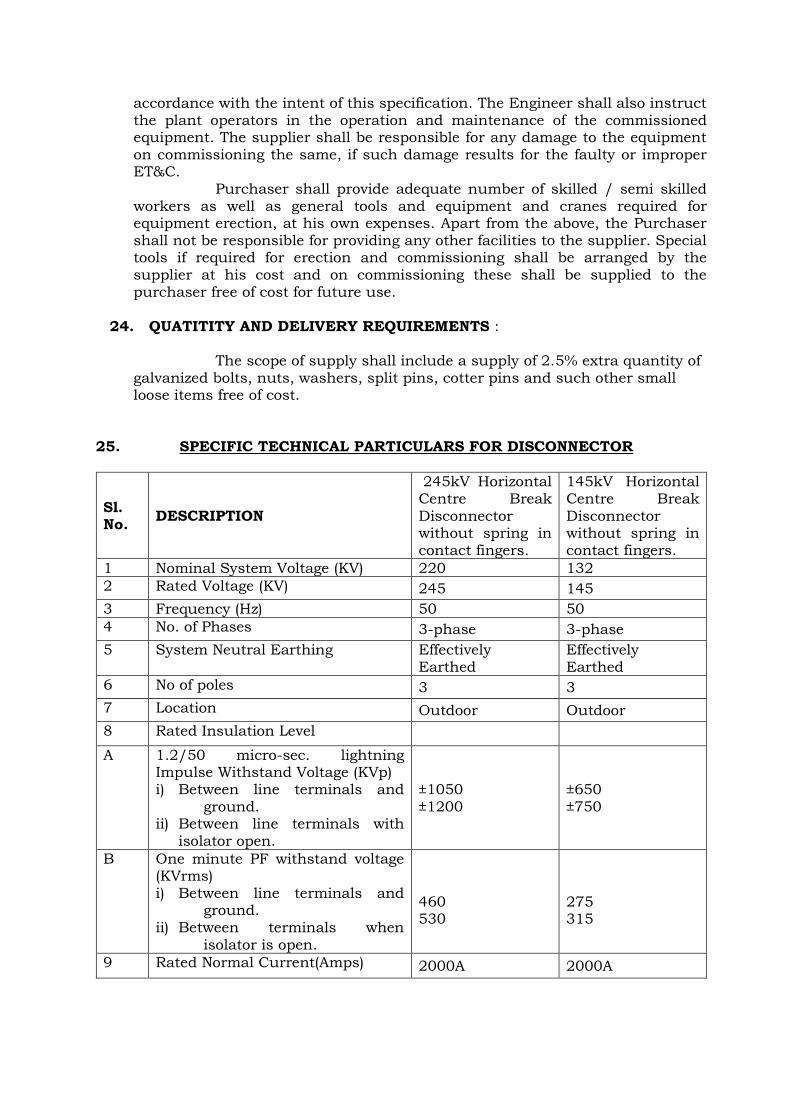
25. SPECIFIC TECHNICAL PARTICULARS FOR DISCONNECTOR
Sl. No.
DESCRIPTION
245kV Horizontal Centre Break Disconnector without spring in contact fingers.
145kV Horizontal Centre Break Disconnector without spring in contact fingers.
1 Nominal System Voltage (KV) 220 132
2 Rated Voltage (KV) 245 145
3 Frequency (Hz) 50 50
4 No. of Phases 3-phase 3-phase
5 System Neutral Earthing Effectively Earthed
Effectively Earthed
6 No of poles 3 3
7 Location Outdoor Outdoor
8 Rated Insulation Level
A 1.2/50 micro-sec. lightning Impulse Withstand Voltage (KVp) i) Between line terminals and
ground. ii) Between line terminals with
isolator open.
±1050 ±1200
±650 ±750
B One minute PF withstand voltage (KVrms) i) Between line terminals and
ground. ii) Between terminals when
isolator is open.
460 530
275 315
9 Rated Normal Current(Amps) 2000A 2000A
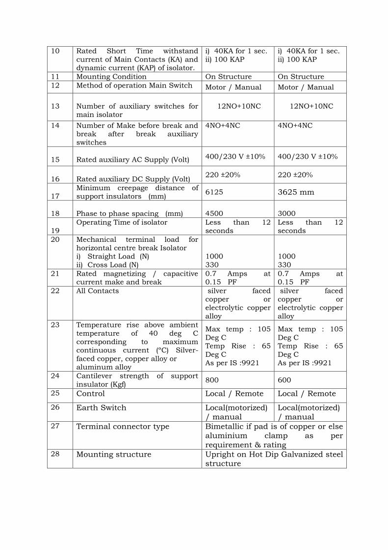
10 Rated Short Time withstand current of Main Contacts (KA) and dynamic current (KAP) of isolator.
i) 40KA for 1 sec. ii) 100 KAP
i) 40KA for 1 sec. ii) 100 KAP
11 Mounting Condition On Structure On Structure
12 Method of operation Main Switch Motor / Manual Motor / Manual
13
Number of auxiliary switches for main isolator
12NO+10NC
12NO+10NC
14 Number of Make before break and break after break auxiliary switches
4NO+4NC 4NO+4NC
15
Rated auxiliary AC Supply (Volt) 400/230 V ±10% 400/230 V ±10%
16
Rated auxiliary DC Supply (Volt)
220 ±20% 220 ±20%
17
Minimum creepage distance of support insulators (mm)
6125 3625 mm
18
Phase to phase spacing (mm)
4500
3000
19
Operating Time of isolator
Less than 12 seconds
Less than 12 seconds
20 Mechanical terminal load for horizontal centre break Isolator i) Straight Load (N) ii) Cross Load (N)
1000 330
1000 330
21 Rated magnetizing / capacitive current make and break
0.7 Amps at 0.15 PF
0.7 Amps at 0.15 PF
22 All Contacts silver faced copper or electrolytic copper alloy
silver faced copper or electrolytic copper alloy
23 Temperature rise above ambient temperature of 40 deg C corresponding to maximum continuous current (ºC) Silver-
faced copper, copper alloy or aluminum alloy
Max temp : 105 Deg C Temp Rise : 65
Deg C As per IS :9921
Max temp : 105 Deg C Temp Rise : 65
Deg C As per IS :9921
24 Cantilever strength of support insulator (Kgf)
800 600
25 Control Local / Remote Local / Remote
26 Earth Switch Local(motorized) / manual
Local(motorized) / manual
27 Terminal connector type Bimetallic if pad is of copper or else aluminium clamp as per
requirement & rating
28 Mounting structure Upright on Hot Dip Galvanized steel structure

GUARANTEED TECHNICAL PARTICULARS (To be filled in & signed by the bidder)
PACKAGE NAME : NAME OF THE BIDDER:
NIT No & DATE:
SL. DESCRIPTION
ISOLATOR
1 ISOLATOR : GENERAL:
1.01 Name of Manufacturer
1.02 Type & Model of the Manufacturer
1.03 Date of Last Type Test
1.04 Type from Operation Point (Like HCB, CR, Pantograph)
1.05 Conforming Standard
1.06 Total Height of the Isolator with structure from Plinth level after complete Erection
1.07 Total weight of the Isolator
1.08 Total weight of the structure after complete Erection
1.09 Material of the Main Blades
1.10 Material of the Main Contacts
1.11 Whether spring is used in the main or secondary contact assembly
1.12 Rated Voltage (KV)
1.13 Maximum Voltage (KV)
1.14 Rated Frequency (Hz)
2 INSULATION LEVEL : 1.2/50 MICRO-SEC. L.I. WITHSTAND VOLTAGE:
2.01 Between line terminals and ground
parts (KVp)
2.02 Between Isolating Arms (KVp)
2.03 One minute Power frequency withstand Voltage (KVrms)
2.03.1 Between line terminals and ground parts (KVp)
2.03.2 Between Isolating Arms (KVp)
3 ISOLATOR CURRENT:
3.01 Rated normal current Amps (rms)
3.02 Short time current rating (KA) (1 Sec. for 400KV & 3 Sec. for 220KV & below)
3.03 Temperature rise above ambient of 50oC at rated current (oC)

4 ISOLATOR CLEARANCE:
4.1 Clearance between : Phase to Phase (mm)
4.2 Clearance between : Phase to Earth (mm)
4.2 Clearance between Two arms in Open condition (mm)
4.5 Height of the Rotating Insulator (mm)
5 ISOLATOR DRIVES:
5.1 Type of Drive Motor (Like AC Squirrel Cage, DC Motor)
5.2 Voltage of Motor Drives
5.3 Provision of Manual Operation (Yes / No)
5.4 Rated auxiliary supply voltage to coil for close & Open Operation
6 NUMBER AND TYPE OF AUXILIARY CONTACTS FOR :
6.1 Main blade
6.2 Earth switch
6.3 Operating time for closing (secs.)
6.4 Operating time for opening (secs.)
7 ISOLATOR: SUPPORT INSULATOR:
7.1 Name of Manufacturer
7.2 Conforming Standard
7.3 Type & Designation
7.4 Cantilever Strength (Kgf)
7.5 Min.Creepage Distance(mm)
7.6 Weight of Unit (Kg)
7.7 Height of Unit (mm)
7.8
Insulation Level: One minute Power
frequency voltage withstand test (KVrms)
7.9 Insulation Level: 1.2/50 micro-sec. Lightning Impulse Voltage withstand test (KVp)
8 ISOLATORS SPARES:
8.01 The isolator spares will be available for total service life. ( Yes/ No)
8.02
If offered designed isolator are out of manufacturing, the manufacturer will arrange spares for total service life ( Yes/ No)