rstpp stage - iii : technical specification for booster fan
TRANSCRIPT
RSTPP STAGE – III
BALANCE MECHANICAL SYSTEM PACKAGE FOR FGD PLANT
TECHNICAL REQUIREMENTS
(ELECTRICAL SYSTEM & EQUIPMENTS)
Tender Doc No: RGM/PI(S)/824/ETS/101 VOLUME-II SECTION -IVB Page 1 of 29
SECTION -IVB – INDEX
TECHNICAL REQUIREMENTS - ELECTRICAL
1. GENERAL ................................................................................................................................... 2
2. QUALITY ASSURANCE, INSPECTION / TESTING .......................................................... 2
3. GENERAL REQUIREMENTS OF ELECTRICAL SYSTEM DESIGN ................................. 3
4. MOTORS ..................................................................................................................................... 5
5. L.T POWER CABLES .............................................................................................................. 15
6. L.T CONTROL CABLES ......................................................................................................... 23
RSTPP STAGE – III
BALANCE MECHANICAL SYSTEM PACKAGE FOR FGD PLANT
TECHNICAL REQUIREMENTS
(ELECTRICAL SYSTEM & EQUIPMENTS)
Tender Doc No: RGM/PI(S)/824/ETS/101 VOLUME-II SECTION -IVB Page 2 of 29
1. GENERAL
This specification defines the requirements of system design, engineering, installation,
testing and commissioning of various Equipments covered in this Technical Specification.
This specification also includes basic guidelines to design, manufacture and supply the
equipments included in this Specification. This Section Covers following Electrical
System/ Equipments.
A) GENERAL REQUIREMENTS OF ELECTRICAL SYSTEM DESIGN
B) MOTORS
C) L .T POWER CABLES
D) L.T CONTROL CABLES
E) VFD
F) H.T CABLE
2. QUALITY ASSURANCE, INSPECTION / TESTING
Brief inspection and testing aspects of the Electrical Equipments are tabulated in Section-IV-
E of the Technical Specification. Section- VII (GTR) be referred regarding Quality Assurance
Programme, Quality Assurance Documents etc.
RSTPP STAGE – III
BALANCE MECHANICAL SYSTEM PACKAGE FOR FGD PLANT
TECHNICAL REQUIREMENTS
(ELECTRICAL SYSTEM & EQUIPMENTS)
Tender Doc No: RGM/PI(S)/824/ETS/101 VOLUME-II SECTION –IV B Page 3 of 29
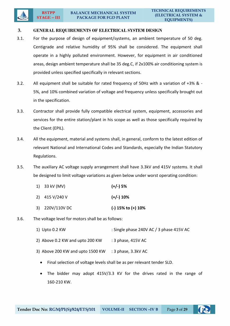
3. GENERAL REQUIREMENTS OF ELECTRICAL SYSTEM DESIGN
3.1. For the purpose of design of equipment/systems, an ambient temperature of 50 deg.
Centigrade and relative humidity of 95% shall be considered. The equipment shall
operate in a highly polluted environment. However, for equipment in air conditioned
areas, design ambient temperature shall be 35 deg.C, if 2x100% air conditioning system is
provided unless specified specifically in relevant sections.
3.2. All equipment shall be suitable for rated frequency of 50Hz with a variation of +3% & -
5%, and 10% combined variation of voltage and frequency unless specifically brought out
in the specification.
3.3. Contractor shall provide fully compatible electrical system, equipment, accessories and
services for the entire station/plant in his scope as well as those specifically required by
the Client (EPIL).
3.4. All the equipment, material and systems shall, in general, conform to the latest edition of
relevant National and International Codes and Standards, especially the Indian Statutory
Regulations.
3.5. The auxiliary AC voltage supply arrangement shall have 3.3kV and 415V systems. It shall
be designed to limit voltage variations as given below under worst operating condition:
1) 33 kV (MV) (+/-) 5%
2) 415 V/240 V (+/-) 10%
3) 220V/110V DC (-) 15% to (+) 10%
3.6. The voltage level for motors shall be as follows:
1) Upto 0.2 KW : Single phase 240V AC / 3 phase 415V AC
2) Above 0.2 KW and upto 200 KW : 3 phase, 415V AC
3) Above 200 KW and upto 1500 KW : 3 phase, 3.3kV AC
Final selection of voltage levels shall be as per relevant tender SLD.
The bidder may adopt 415V/3.3 KV for the drives rated in the range of
160-210 KW.
RSTPP STAGE – III
BALANCE MECHANICAL SYSTEM PACKAGE FOR FGD PLANT
TECHNICAL REQUIREMENTS
(ELECTRICAL SYSTEM & EQUIPMENTS)
Tender Doc No: RGM/PI(S)/824/ETS/101 VOLUME-II SECTION –IV B Page 4 of 29
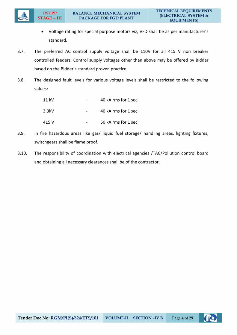
Voltage rating for special purpose motors viz, VFD shall be as per manufacturer’s
standard.
3.7. The preferred AC control supply voltage shall be 110V for all 415 V non breaker
controlled feeders. Control supply voltages other than above may be offered by Bidder
based on the Bidder’s standard proven practice.
3.8. The designed fault levels for various voltage levels shall be restricted to the following
values:
11 kV - 40 kA rms for 1 sec
3.3kV - 40 kA rms for 1 sec
415 V - 50 kA rms for 1 sec
3.9. In fire hazardous areas like gas/ liquid fuel storage/ handling areas, lighting fixtures,
switchgears shall be flame proof.
3.10. The responsibility of coordination with electrical agencies /TAC/Pollution control board
and obtaining all necessary clearances shall be of the contractor.
RSTPP STAGE – III
BALANCE MECHANICAL SYSTEM PACKAGE FOR FGD PLANT
TECHNICAL REQUIREMENTS
(ELECTRICAL SYSTEM & EQUIPMENTS)
Tender Doc No: RGM/PI(S)/824/ETS/101 VOLUME-II SECTION -IVB Page 5 of 29
4. MOTORS
4.1. GENERAL REQUIREMENTS
4.1.1. For the purpose of design of equipment/systems, an ambient temperature of 50 deg.
Centigrade and relative humidity of 95% (at 40 deg C) shall be considered. The
equipment shall operate in a highly polluted environment.
4.1.2. All equipment’s shall be suitable for rated frequency of 50 Hz with a variation of (+) 3%
and (-) 5%, and 10% combined variation of voltage and frequency unless specifically
brought out in the specification.
4.1.3. Contactor shall provide fully compatible electrical system, equipment’s, accessories and
services.
4.1.4. All the equipment, material and systems shall, in general, conform to the latest edition of
relevant National and international Codes & Standards, especially the Indian Statutory
Regulations.
4.1.5. Paint shade shall be as per RAL 5012 (Blue) for indoor and outdoor equipment.
4.1.6. The responsibility of coordination with electrical agencies and obtaining all necessary
clearances for Contactors equipment and systems shall be under the Contactor scope.
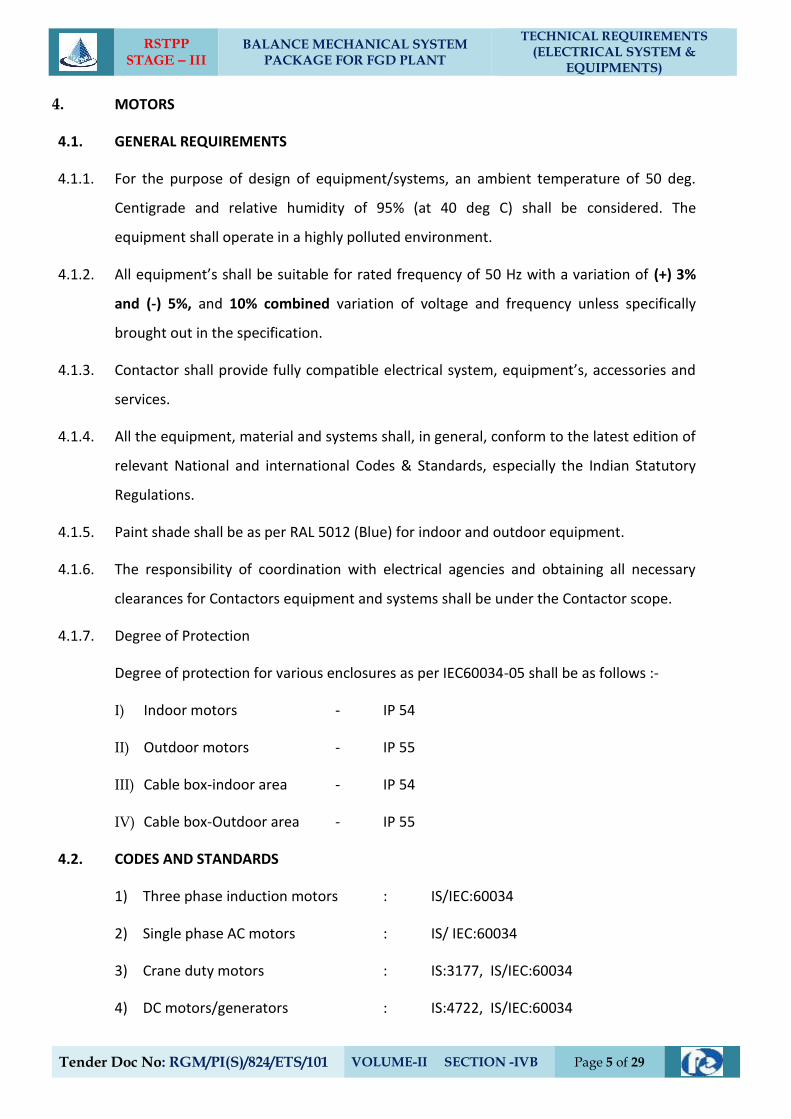
4.1.7. Degree of Protection
Degree of protection for various enclosures as per IEC60034-05 shall be as follows :-
I) Indoor motors - IP 54
II) Outdoor motors - IP 55
III) Cable box-indoor area - IP 54
IV) Cable box-Outdoor area - IP 55
4.2. CODES AND STANDARDS
1) Three phase induction motors : IS/IEC:60034
2) Single phase AC motors : IS/ IEC:60034
3) Crane duty motors : IS:3177, IS/IEC:60034
4) DC motors/generators : IS:4722, IS/IEC:60034
RSTPP STAGE – III
BALANCE MECHANICAL SYSTEM PACKAGE FOR FGD PLANT
TECHNICAL REQUIREMENTS
(ELECTRICAL SYSTEM & EQUIPMENTS)
Tender Doc No: RGM/PI(S)/824/ETS/101 VOLUME-II SECTION –IV B Page 6 of 29
4.3. Type
4.3.1. AC Motors:
a. Squirrel cage induction motor suitable for direct-on-line starting.
b. Continuous duty LT motors upto 200 KW Output rating (at 50 deg.C ambient
temperature), shall be Premium Efficiency class-IE3, conforming to IS 12615, or
IEC:60034-30. HT motors shall have minimum design efficiency of 95 %.
However, tolerance on this efficiency value shall be applicable as per IEC 60034.
c. Crane duty motors shall be slip ring/ squirrel cage Induction motor as per the
requirement.
d. Motor operating through variable frequency drives shall be suitable for inverter
duty with VPI insulation. Also these motors shall comply the requirements
stipulated in IEC: 60034-18-41 and IEC: 60034-18-42 as applicable.
e. Motors operating through variable frequency drives shall also meet the
requirements specified under title “VFD”
4.3.2. DC Motors Shunt wound.
4.4. Rating
a. Continuously rated (S1). However, crane motors shall be rated for S4 duty, 40%
cyclic duration factor.
b. Whenever the basis for motor or driven equipment ratings are not specified in the
corresponding mechanical specification sub-sections, maximum continuous motor
ratings shall be at least 10% above the maximum load demand of the driven
equipment under entire operating range including voltage and frequency variations.
4.5. Temperature Rise
Air cooled motors : 70 deg. C by resistance method for both thermal class
130(B) & 155 (F) insulation.
Water cooled motors : 80 deg. C over inlet cooling water temperature
mentioned elsewhere, by resistance method for both
thermal class 130(B) & 155 (F) insulation.
RSTPP STAGE – III
BALANCE MECHANICAL SYSTEM PACKAGE FOR FGD PLANT
TECHNICAL REQUIREMENTS
(ELECTRICAL SYSTEM & EQUIPMENTS)
Tender Doc No: RGM/PI(S)/824/ETS/101 VOLUME-II SECTION –IV B Page 7 of 29
4.6. Operational Requirements
4.6.1. Starting Time
a. For motors with starting time upto 20 secs. at minimum permissible voltage during
starting, the locked rotor withstand time under hot condition at highest voltage limit
shall be at least 2.5 secs. more than starting time.
b. For motors with starting time more than 20 secs. and upto 45 secs. at minimum
permissible voltage during starting, the locked rotor withstand time under hot
condition at highest voltage limit shall be at least 5 secs. more than starting time.
c. For motors with starting time more than 45 secs. at minimum permissible voltage
during starting, the locked rotor withstand time under hot condition at highest
voltage limit shall be more than starting time by at least 10% of the starting time.
d. Speed switches mounted on the motor shaft shall be provided in cases where above
requirements are not met.
4.6.2. Torque Requirements
a. Accelerating torque at any speed with the lowest permissible starting voltage shall
be at least 10% motor rated torque.
b. Pull out torque at rated voltage shall not be less than 205% of rated torque. It shall
be 275% for crane duty motors.
4.6.3. Starting voltage requirement
a. Up to 85% of rated voltage for ratings below 110 KW
b. Up to 80% of rated voltage for ratings from 110 KW to 200 KW
c. Up to 85% of rated voltage for ratings from 201 KW to 1000 KW
d. Up to 80% of rated voltage for ratings from 1001 KW to 4000 KW
e. Up to 75 % of rated voltage for ratings above 4000KW
4.7. Design and Constructional Features
4.7.1. Suitable single phase space heaters shall be provided on motors rated 30KW and above
to maintain windings in dry condition when motor is standstill. Separate terminal box for
RSTPP STAGE – III
BALANCE MECHANICAL SYSTEM PACKAGE FOR FGD PLANT
TECHNICAL REQUIREMENTS
(ELECTRICAL SYSTEM & EQUIPMENTS)
Tender Doc No: RGM/PI(S)/824/ETS/101 VOLUME-II SECTION –IV B Page 8 of 29
space heaters & RTDs shall be provided. However for flame proof motors, space heater
terminals inside the main terminal box may be acceptable.
4.7.2. All motors shall be either totally Enclosed Fan cooled (TEFC) or totally enclosed tube
ventilated (TETV) or Closed air circuit air cooled (CACA) type. However, motors rated
3000KW or above can be Closed air circuit water cooled (CACW).
The method of movement of primary and secondary coolant shall be self circulated by
fan or pump directly mounted on the rotor of the main motor as per IEC 60034-6.
However VFD driven motors can be offered with forced cooling type with machine
mounted fan or pump driven by separate electric motor. Motors and EPB located in
hazardous areas shall have flame proof enclosures conforming to IS:2148 as detailed
below :
a. Fuel oil area : Group – IIB
b. Hydrogen generation : Group - IIC or (Group-I, Div-II as per plant area NEC) or
(Class-1, Group-B, Div-II as per NEMA /IEC60034)
4.7.3. Winding and Insulation
a) Type : Non-hygroscopic, oil resistant, flame
resistant
b) Starting duty : Two hot starts in succession, with motor
initially at normal running temperature.
c) 3.3 kV AC motors : Thermal class 155 (F) insulation. The
winding insulation process shall be total
Vacuum Pressure Impregnated i.e resin
poor method. The lightning Impulse &
interturn insulation surge withstand level
shall be as per IEC-60034 part-15.
d) 240VAC, 415V AC & 220V DC motors : Thermal Class ( B ) or better
4.7.4. Motors rated above 1000KW shall have insulated bearings/housing to prevent flow of
shaft currents.
RSTPP STAGE – III
BALANCE MECHANICAL SYSTEM PACKAGE FOR FGD PLANT
TECHNICAL REQUIREMENTS
(ELECTRICAL SYSTEM & EQUIPMENTS)
Tender Doc No: RGM/PI(S)/824/ETS/101 VOLUME-II SECTION –IV B Page 9 of 29
4.7.5. Motors with heat exchangers shall have dial type thermometer with adjustable alarm
contacts to indicate inlet and outlet primary air temperature.
4.7.6. Noise level for all the motors shall be limited to 85 dB(A) except for BFP motor for which
the maximum limit shall be 90 dB(A). Vibration shall be limited within the limits
prescribed in IS:12075 / IEC 60034-14. Motors shall withstand vibrations produced by
driven equipment. HT motor bearing housings shall have flat surfaces, in both X and Y
directions, suitable for mounting 80mmX80mm vibration pads.
4.7.7. In HT motors, at least four numbers simplex / two numbers duplex platinum resistance
type temperature detectors shall be provided in each phase stator winding. Each bearing
of HT motor shall be provided with dial type thermometer and minimum 2 numbers
duplex platinum resistance type temperature detectors.
4.7.8. Motor body shall have two earthing points on opposite sides.
4.7.9. 3.3 KV motors shall be offered with dust tight phase separated double walled (metallic as
well as insulated barrier) Terminal box. Contractor shall provide termination kit for the
offered Terminal box. The offered Terminal Box shall be suitable for fault level of 250
MVA for 0.12 sec. Removable gland plates of thickness 3 mm (hot/cold rolled sheet steel)
or 4 mm (non magnetic material for single core cables) shall be provided.
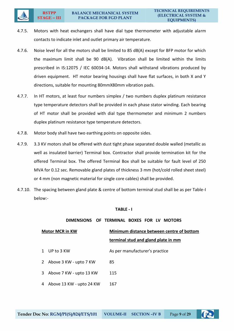
4.7.10. The spacing between gland plate & centre of bottom terminal stud shall be as per Table-I
below:-
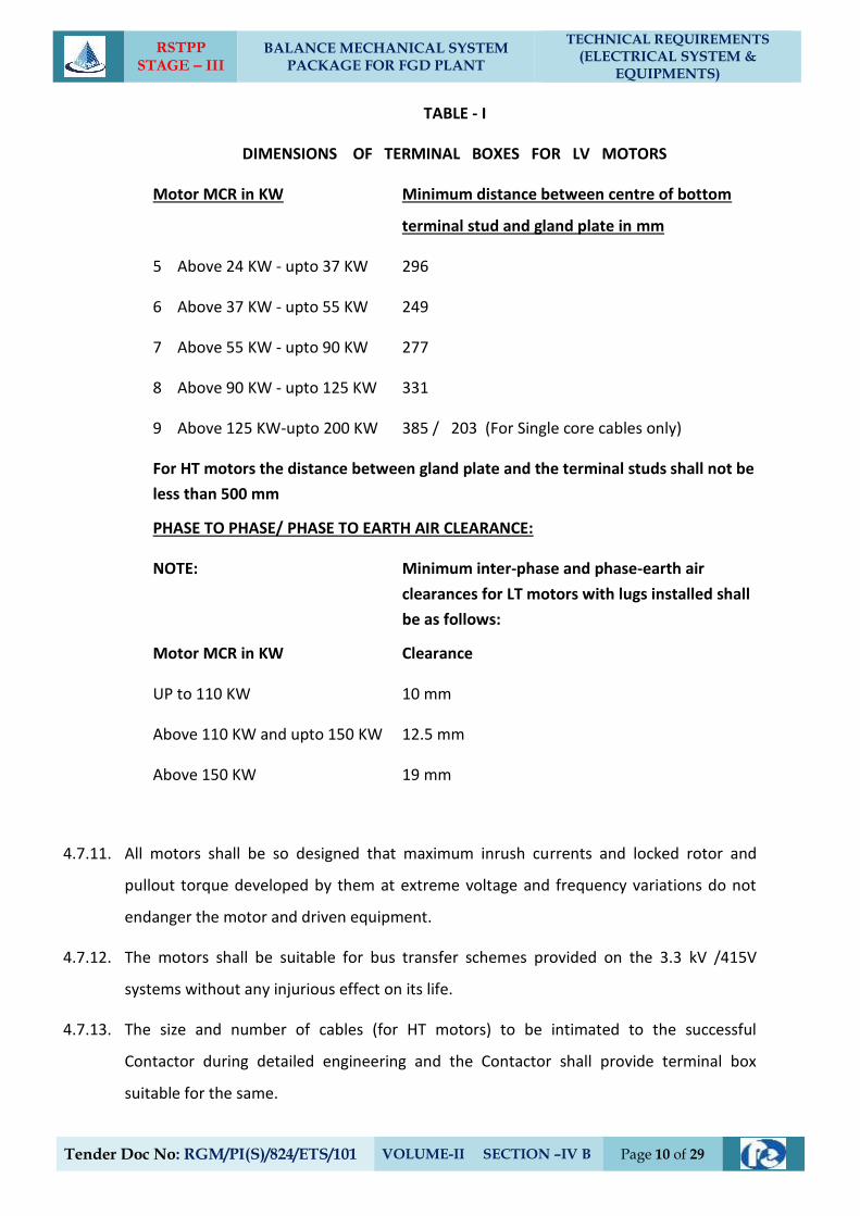
TABLE - I
DIMENSIONS OF TERMINAL BOXES FOR LV MOTORS
Motor MCR in KW Minimum distance between centre of bottom
terminal stud and gland plate in mm
1 UP to 3 KW As per manufacturer's practice
2 Above 3 KW - upto 7 KW 85
3 Above 7 KW - upto 13 KW 115
4 Above 13 KW - upto 24 KW 167
RSTPP STAGE – III
BALANCE MECHANICAL SYSTEM PACKAGE FOR FGD PLANT
TECHNICAL REQUIREMENTS
(ELECTRICAL SYSTEM & EQUIPMENTS)
Tender Doc No: RGM/PI(S)/824/ETS/101 VOLUME-II SECTION –IV B Page 10 of 29
TABLE - I
DIMENSIONS OF TERMINAL BOXES FOR LV MOTORS
Motor MCR in KW Minimum distance between centre of bottom
terminal stud and gland plate in mm
5 Above 24 KW - upto 37 KW 296
6 Above 37 KW - upto 55 KW 249
7 Above 55 KW - upto 90 KW 277
8 Above 90 KW - upto 125 KW 331
9 Above 125 KW-upto 200 KW 385 / 203 (For Single core cables only)
For HT motors the distance between gland plate and the terminal studs shall not be
less than 500 mm
PHASE TO PHASE/ PHASE TO EARTH AIR CLEARANCE:
NOTE: Minimum inter-phase and phase-earth air
clearances for LT motors with lugs installed shall
be as follows:
Motor MCR in KW Clearance
UP to 110 KW 10 mm
Above 110 KW and upto 150 KW 12.5 mm
Above 150 KW 19 mm
4.7.11. All motors shall be so designed that maximum inrush currents and locked rotor and
pullout torque developed by them at extreme voltage and frequency variations do not
endanger the motor and driven equipment.
4.7.12. The motors shall be suitable for bus transfer schemes provided on the 3.3 kV /415V
systems without any injurious effect on its life.
4.7.13. The size and number of cables (for HT motors) to be intimated to the successful
Contactor during detailed engineering and the Contactor shall provide terminal box
suitable for the same.
RSTPP STAGE – III
BALANCE MECHANICAL SYSTEM PACKAGE FOR FGD PLANT
TECHNICAL REQUIREMENTS
(ELECTRICAL SYSTEM & EQUIPMENTS)
Tender Doc No: RGM/PI(S)/824/ETS/101 VOLUME-II SECTION –IV B Page 11 of 29
4.8. The ratio of locked rotor KVA at rated voltage to rated KW shall not exceed the following
(without any further tolerance):
a) From 50KW & upto 110KW : 11.0
b) From 110 KW & upto 200 KW : 9.0
c) Above 200 KW & upto 1000KW : 10.0
d) From 1001KW & upto 4000KW : 9.0
4.9. Type Tests
4.9.1. HT Motors
a) The Contactor shall carry out the type tests as listed in this specification on the
equipment to be supplied under this contract. The Contactor shall indicate the
charges for each of these type tests separately in the relevant price schedule and
the same shall be considered for the evaluation of the bids. The type tests charges
shall be paid only for the test(s) actually conducted successfully under this contract
and upon certification by the Client (EPIL)’s engineer.
b) The type tests shall be carried out in presence of the Client (EPIL)/NTPC’s
representative, for which minimum 15 days notice shall be given by the Contactor.
The Contactor shall obtain the Client (EPIL)/NTPC’s approval for the type test
procedure before conducting the type test. The type test procedure shall clearly
specify the test set–up, instruments to be used, procedure, acceptance norms,
recording of different parameters, interval of recording, precautions to be taken
etc. for the type test(s) to be carried out.
c) In case the Contactor has conducted such specified type test(s) within last ten years
as on the date of bid opening, he may submit during detailed engineering the type
test reports to the Client (EPIL) for waival of conductance of such test(s). These
reports should be for the tests conducted on the equipment similar to those
proposed to be supplied under this contract and test(s) should have been either
conducted at an independent laboratory or should have been witnessed by a client.
The Client (EPIL) reserves the right to waive conducting of any or all the specified
RSTPP STAGE – III
BALANCE MECHANICAL SYSTEM PACKAGE FOR FGD PLANT
TECHNICAL REQUIREMENTS
(ELECTRICAL SYSTEM & EQUIPMENTS)
Tender Doc No: RGM/PI(S)/824/ETS/101 VOLUME-II SECTION –IV B Page 12 of 29
type test(s) under this contract. In case type tests are waived, the type test charges
shall not be payable to the Contactor.
d) Further the Contactor shall only submit the reports of the type tests as listed in
"LIST OF TESTS FOR WHICH REPORTS HAVE TO BE SUBMITTED" and carried out
within last ten years from the date of bid opening. These reports should be for the
test conducted on the equipment similar to those proposed to be supplied under
this contract and the test(s) should have been either conducted at an independent
laboratory or should have been witnessed by a client. However if the Contactor is
not able to submit report of the type test(s) conducted within last ten years from
the date of bid opening, or in the case of type test report(s) are not found to be
meeting the specification requirements, the Contactor shall conduct all such tests
under this contract at no additional cost to the Client (EPIL) either at third party lab
or in presence of client/ Client (EPIL)’s representative and submit the reports for
approval.
e) List of Type Tests To Be Conducted
The following type tests shall be conducted on each type and rating of HT motor.
(i) No load saturation and loss curves upto approximately 115% of rated voltage.
(ii) Measurement of noise at no load.
(iii) Momentary excess torque test (subject to test bed constraint).
(iv) Full load test (subject to test bed constraint).
(v) Temperature rise test at rated conditions. During heat run test, bearing temp.,
winding temperature, coolant flow and its temperature shall also be measured.
In case the temperature rise test is carried at load other than rated load, specific
approval for the test method and procedure is required to be obtained.
Wherever ETD's are provided, the temperature shall be measured by ETD's also
for the record purpose.
f) List of Tests For Which Reports Have To Be Submitted
The following type test reports shall be submitted for each type and rating of HT
motor.
RSTPP STAGE – III
BALANCE MECHANICAL SYSTEM PACKAGE FOR FGD PLANT
TECHNICAL REQUIREMENTS
(ELECTRICAL SYSTEM & EQUIPMENTS)
Tender Doc No: RGM/PI(S)/824/ETS/101 VOLUME-II SECTION –IV B Page 13 of 29
1) Degree of protection test for the enclosure followed by IR, HV and no load run
test.
2) Terminal box-fault level withstand test for each type of terminal box of HT
motors only.
3) Lightning Impulse withstand test on the sample coil shall be as per clause no. 4.3
IEC-60034, part-15.
4) Surge-withstand test on inter-turn insulation shall be as per clause no. 4.2 of IEC
60034, part-15.
4.9.2. LT Motors
a. LT Motors supplied shall be of type tested design. During detailed engineering, the
Contactor shall submit for Client (EPIL)’s approval the reports of all the type tests as
listed in this specification and carried out within last ten years from the date of bid
opening. These reports should be for the test conducted on the equipment similar
to those proposed to be supplied under this contract and the test(s) should have
been either conducted at an independent laboratory or should have been
witnessed by a client.
b. However if the Contactor is not able to submit report of the type test(s) conducted
within last ten years from the date of bid opening, or in the case of type test
report(s) are not found to be meeting the specification requirements, the
Contactor shall conduct all such tests under this contract at no additional cost to
the Client (EPIL) either at third party lab or in presence of client/Client (EPIL)s
representative and submit the reports for approval.
c. List of Tests For Which Reports Have To Be Submitted
The following type test reports shall be submitted for each type and rating of LT
motor of above 100 KW only.
1) Measurement of resistance of windings of stator and wound rotor.
2) No load test at rated voltage to determine input current power and speed.
3) Open circuit voltage ratio of wound rotor motors ( in case of Slip ring motors).
RSTPP STAGE – III
BALANCE MECHANICAL SYSTEM PACKAGE FOR FGD PLANT
TECHNICAL REQUIREMENTS
(ELECTRICAL SYSTEM & EQUIPMENTS)
Tender Doc No: RGM/PI(S)/824/ETS/101 VOLUME-II SECTION –IV B Page 14 of 29
4) Full load test to determine efficiency power factor and slip.
5) Temperature rise test.
6) Momentary excess torque test.
7) High voltage test.
8) Test for vibration severity of motor.
9) Test for noise levels of motor (Shall be limited as per clause no 2.07.06 of this
section).
10) Test for degree of protection
11) Over speed test.
12) Type test reports for motors located in fuel oil area having flame proof
enclosures as per IS 2148 / IEC 60079-1
4.9.3. All acceptance and routine tests as per the specification and relevant standards shall be
carried out. Charges for these shall be deemed to be included in the equipment price.
4.9.4. The type test reports once approved for any projects shall be treated as reference. For
subsequent projects of NTPC, an endorsement sheet will be furnished by the
manufacturer confirming similarity and “No design Change”. Minor changes if any shall
be highlighted on the endorsement sheet.
RSTPP STAGE – III
BALANCE MECHANICAL SYSTEM PACKAGE FOR FGD PLANT
TECHNICAL REQUIREMENTS
(ELECTRICAL SYSTEM & EQUIPMENTS)
Tender Doc No: RGM/PI(S)/824/ETS/101 VOLUME-II SECTION -IVB Page 15 of 29
5. L.T POWER CABLES
5.1. CODES & STANDARDS
5.1.1. All standards, specifications and codes of practice referred to herein shall be the latest
editions including all applicable official amendments and revisions as on date of opening
of bid. In case of conflict between this specification and those (IS, codes, standards, etc.)
referred to herein, the former shall prevail. All the cables shall conform to the
requirements of the following standards and codes:
IS :1554 - I PVC insulated (heavy duty) electric cables for working
voltages upto and including 1100V.
IS : 3961 Recommended current ratings for cables
IS : 3975 Low carbon galvanized steel wires, formed wires and tapes
for armouring of cables.
IS : 5831 PVC insulation and sheath of electrical cables.
IS:7098(Part -I) Cross linked polyethylene insulated PVC sheathed cables for
working voltages upto and including 1100V.
IS : 8130 Conductors for insulated electrical cables and flexible cords.
IS : 10418 Specification for drums for electric cables.
IS : 10810 Methods of tests for cables.
ASTM-D -2843 Standard test method for density of smoke from the burning
or decomposition of plastics.
IEC-754 (Part-I) Tests on gases evolved during combustion of electric cables.
IEC-332 Tests on electric cables under fire conditions. Part-3: Tests
on bunched wires or cables (Category-B).
5.2. TECHNICAL REQUIREMENTS
5.2.1. The cables shall be suitable for laying on racks, in ducts, trenches, conduits and under
ground buried installation with chances of flooding by water.
RSTPP STAGE – III
BALANCE MECHANICAL SYSTEM PACKAGE FOR FGD PLANT
TECHNICAL REQUIREMENTS
(ELECTRICAL SYSTEM & EQUIPMENTS)
Tender Doc No: RGM/PI(S)/824/ETS/101 VOLUME-II SECTION –IV B Page 16 of 29
5.2.2. All cables including EPR cables shall be flame retardant, low smoke (FRLS) type designed
to withstand all mechanical, electrical and thermal stresses developed under steady state
and transient operating conditions as specified elsewhere in this specification.
5.2.3. Aluminium conductor used in power cables shall have tensile strength of more than 100
N/ sq.mm. Conductors shall be stranded.
5.2.4. XLPE insulation shall be suitable for a continuous conductor temperature of 90 deg. C and
short circuit conductor temperature of 250 deg C. PVC insulation shall be suitable for
continuous conductor temperature of 70 deg C and short circuit conductor temperature
of 160 deg. C.
5.2.5. The cable cores shall be laid up with fillers between the cores wherever necessary. It shall
not stick to insulation and inner sheath. All the cables, other than single core
unarmoured cables, shall have distinct extruded PVC inner sheath of black colour as per
IS : 5831.
5.2.6. For single core armoured cables, armouring shall be of aluminium wires/ formed wires.
For multicore armoured cables, armouring shall be of galvanized steel as follows:
Calculated nominal dia.of Size and Type of armour cable under armour
Upto 13 mm 1.4mm dia GS wire
Above 13 & upto 25mm 0.8 mm thick GS formed wire /1.6 mm dia GS wire
25 & upto 40 mm 0.8mm thick GS formed wire / 2.0mm dia GS wire
40 & upto 55mm 1.4 mm thick GS formed wire /2.5mm dia GS wire
55 & upto 70 mm 1.4mm thick GS formed wire /3.15mm dia GS wire
Above 70mm 1.4 mm thick GS formed wire /4.0 mm dia GS wire
5.2.7. The aluminium used for armouring shall be of H4 grade as per IS: 8130 with maximum
resistivity of 0.028264 ohm mm2 per meter at 20 deg C. The sizes of aluminium
armouring shall be same as indicated above for galvanized steel.
5.2.8. The gap between armour wires / formed wires shall not exceed one armour wire /formed
wire space and there shall be no cross over / over-riding of armour wire /formed wire.
The minimum area of coverage of armouring shall be 90%. The breaking load of armour
RSTPP STAGE – III
BALANCE MECHANICAL SYSTEM PACKAGE FOR FGD PLANT
TECHNICAL REQUIREMENTS
(ELECTRICAL SYSTEM & EQUIPMENTS)
Tender Doc No: RGM/PI(S)/824/ETS/101 VOLUME-II SECTION –IV B Page 17 of 29
joint shall not be less than 95% of that of armour wire /formed wire. Zinc rich paint shall
be applied on armour joint surface of G.S.wires/ formed wires.
5.2.9. Outer sheath shall be of PVC as per IS: 5831 & black in colour. In addition to meeting all
the requirements of Indian standards referred to, outer sheath of all the cables shall have
the following FRLS properties.
a) Oxygen index of min. 29 (as per IS 10810 Part-58).
b) Acid gas emission of max. 20% (as per IEC-754-I).
c) Smoke density rating shall not be more than 60 % (as per ASTMD-2843).
5.2.10. Cores of the cables shall be identified by colouring of insulation. Following colour scheme
shall be adopted:
1 core - Red, Black, Yellow or Blue
2 core - Red & Black
3 core - Red, Yellow & Blue
4 core - Red, Yellow, Blue and Black
5.2.11. For reduced neutral conductors, the core shall be black.
5.2.12. In addition to manufacturer's identification on cables as per IS, following marking shall
also be provided over outer sheath.
a) Cable size and voltage grade - To be embossed
b) Word 'FRLS' at every 5 meter - To be embossed
c) Sequential marking of length of the cable in meters at every one meter - To be
embossed / printed.
The embossing shall be progressive, automatic, in line and marking shall be legible and
indelible. For EPR cables identification shall be printed on outer sheath.
5.2.13. All cables shall meet the fire resistance requirement as per Category-B of IEC 332 Part-3.
5.2.14. Allowable tolerances on the overall diameter of the cables shall be +\-2 mm maximum,
over the declared value in the technical data sheets.
RSTPP STAGE – III
BALANCE MECHANICAL SYSTEM PACKAGE FOR FGD PLANT
TECHNICAL REQUIREMENTS
(ELECTRICAL SYSTEM & EQUIPMENTS)
Tender Doc No: RGM/PI(S)/824/ETS/101 VOLUME-II SECTION –IV B Page 18 of 29
5.2.15. In plant repairs to the cables shall not be accepted. Pimples, fish eye, blow holes etc. are
not acceptable.
5.2.16. Cable selection & sizing
5.2.16.1. Cables shall be sized based on the following considerations:
a) Rated current of the equipment
b) The voltage drop in the cable, during motor starting condition, shall be limited to
10% and during full load running condition, shall be limited to 3% of the rated
voltage
c) Short circuit withstand capability
d) This will depend on the feeder type. For a fuse protected circuit, cable should be
sized to withstand the let-out energy of the fuse. For breaker controlled feeder,
cable shall be capable of withstanding the system fault current level for total
breaker tripping time inclusive of relay pickup time.
5.2.16.2. Derating Factors
a) Derating factors for various conditions of installations including the following shall
be considered while selecting the cable sizes:
b) Variation in ambient temperature for cables laid in air.
c) Grouping of cables
d) Variation in ground temperature and soil resistivity for buried cables.
5.2.16.3. Cable lengths shall be considered in such a way that straight through cable joints are
avoided
5.2.16.4. All Cables shall be of armoured type.
5.2.16.5. All LT power cables of sizes more than 120 sq.mm. shall be XLPE insulated and sizes
shall be of 1Cx150, 1Cx300, 1Cx630, 3Cx150 & 3Cx240 sq.mm. However for cable sizes
upto 120 sq.mm. both XLPE insulated & PVC insulated LT power cables are acceptable.
5.2.16.6. Same cable sizes to be used for same type & rating of motor i.e if there are three pumps
for one application, all three pumps motor should be provided with same cables sizes.
RSTPP STAGE – III
BALANCE MECHANICAL SYSTEM PACKAGE FOR FGD PLANT
TECHNICAL REQUIREMENTS
(ELECTRICAL SYSTEM & EQUIPMENTS)
Tender Doc No: RGM/PI(S)/824/ETS/101 VOLUME-II SECTION –IV B Page 19 of 29
5.3. CONSTRUCTIONAL FEATURES
5.3.1. 1.1 KV Grade Power Cables
a) 1.1 KV grade XLPE power cables shall have compacted aluminium conductor, XLPE
insulated, PVC inner-sheathed (as applicable), armoured, PVC outer-sheathed
conforming to IS:7098. (Part-I).
b) 1.1KV grade PVC power cables shall have aluminium conductor(compacted type for
sizes above 10 sq.mm), PVC Insulated, PVC inner sheathed (as applicable) armoured,
PVC outer-sheathed conforming to IS:1554 (Part-I).
c) 1.1 KV grade Trailing cables shall have tinned copper (class 5 )conductor, insulated
with heat resistant elastomeric compound based on Ethylene Propylene Rubber(EPR)
suitable for withstanding 90 deg .C continuous conductor temperature and 250deg C
during short circuit, inner-sheathed with heat resistant elastomeric compound, nylon
cord reinforced, outersheathed with heat resistant, oil resistant and flame retardant
heavy duty elastomeric compound conforming to IS 9968.
5.4. CABLE DRUMS
a) Cables shall be supplied in non returnable wooden or steel drums of heavy
construction. The surface of the drum and the outer most cable layer shall be
covered with water proof cover. Both the ends of the cables shall be properly sealed
with heat shrinkable PVC/ rubber caps secured by 'U' nails so as to eliminate ingress
of water during transportation, storage and erection. Wood preservative anti-
termite treatment shall be applied to the entire drum. Wooden drums shall comply
with IS: 10418.
b) Each drum shall carry manufacturer's name, purchaser’s name, address and contract
number, item number and type, size and length of cable and net gross weight
stenciled on both sides of the drum. A tag containing same information shall be
attached to the leading end of the cable. An arrow and suitable accompanying
wording shall be marked on one end of the reel indicating the direction in which it
should be rolled.
RSTPP STAGE – III
BALANCE MECHANICAL SYSTEM PACKAGE FOR FGD PLANT
TECHNICAL REQUIREMENTS
(ELECTRICAL SYSTEM & EQUIPMENTS)
Tender Doc No: RGM/PI(S)/824/ETS/101 VOLUME-II SECTION –IV B Page 20 of 29
c) The standard drum length of LT power cable with a maximum tolerance of +/- 5%
may be decided by the bidder subject to condition that there shall not be any joint in
cable, where application length of cable is up to & including 1000 meter for single
core cable excluding 630 sqmm size, and 750 meter for multicore cable & single core
630 sqmm. One drum length of each cable size can be of non-standard length (not
less than 250 meter) so as to match the ordered quantity Subject to condition that
there shall not be any joint in cable.
5.5. TESTS
a) All equipments to be supplied shall be of type tested design. During detailed
engineering, the contractor shall submit for Client (EPIL)’s approval the reports of all
the type tests as listed in this specification and carried out within last ten years from
the date of bid opening. These reports should be for the test conducted on the
equipment similar to those proposed to be supplied under this contract and the
test(s) should have been either conducted at an independent laboratory or should
have been witnessed by a client.
b) However if the contractor is not able to submit report of the type test(s) conducted
within last ten years from the date of bid opening, or in the case of type test
report(s) are not found to be meeting the specification requirements, the contractor
shall conduct all such tests under this contract at no additional cost to the Client
(EPIL) either at third party lab or in presence of client /Client (EPIL)s representative
and submit the reports for approval.
c) All acceptance and routine tests as per the specification and relevant standards shall
be carried out. Charges for these shall be deemed to be included in the equipment
price.
d) The type test reports once approved for any projects shall be treated as reference.
For subsequent projects of NTPC, an endorsement sheet will be furnished by the
manufacturer confirming similarity and “No design Change”. Minor changes if any
shall be highlighted on the endorsement sheet.
RSTPP STAGE – III
BALANCE MECHANICAL SYSTEM PACKAGE FOR FGD PLANT
TECHNICAL REQUIREMENTS
(ELECTRICAL SYSTEM & EQUIPMENTS)
Tender Doc No: RGM/PI(S)/824/ETS/101 VOLUME-II SECTION –IV B Page 21 of 29
5.5.1. Type Tests
The reports for the following type tests shall be submitted for one size each of LT XLPE
and LT PVC Power cables. Size shall be decided by the Client (EPIL) during detailed
engineering:
S.No. Type test Remarks
For Conductor
1. Resistance test
2. Tensile test For circular non-compacted conductors only
3. Wrapping test For circular non-compacted only
For Armour Wires/ Formed Wires
4. Measurement of Dimensions
5. Tensile Test
6. Elongation test
7. Torsion test For round wires only
8. Wrapping test For aluminium wires/formed wires only.
9. Resistance test
10(a) Mass of zinc coating test For GS Formed wires/wires only
10(b) Uniformity of zinc coating For GS Formed wires /wires only
11. Adhesion test For GS Formed wires/wires only
For PVC/XLPE insulation & PVC Sheath
12. Test for thickness
13. Tensile strength & elongation test Before ageing and after ageing
14. Ageing in air oven
15. Loss of mass test For PVC insulation and sheath only
16. Hot deformation test For PVC insulation and sheath only
RSTPP STAGE – III
BALANCE MECHANICAL SYSTEM PACKAGE FOR FGD PLANT
TECHNICAL REQUIREMENTS
(ELECTRICAL SYSTEM & EQUIPMENTS)
Tender Doc No: RGM/PI(S)/824/ETS/101 VOLUME-II SECTION –IV B Page 22 of 29
17. Heat shock test For PVC insulation and sheath only
18. Shrinkage test
19. Thermal stability test For PVC insulation and sheath only
20. Hot set test For XLPE insulation only
21. Water absorption test For XLPE insulation only
22. Oxygen index test For outer sheath only
23. Smoke density test For outer sheath only
24. Acid gas generation test For outer sheath only
For completed cables
25. Insulation resistance test (Volume resistivity method)
26. High voltage test
27. Flammability test as per IEC-332 Part-3 (Category-B)
Indicative list of tests/checks, Routine and Acceptance tests shall be as per Quality
Assurance & Inspection table of LT power cables enclosed.
RSTPP STAGE – III
BALANCE MECHANICAL SYSTEM PACKAGE FOR FGD PLANT
TECHNICAL REQUIREMENTS
(ELECTRICAL SYSTEM & EQUIPMENTS)
Tender Doc No: RGM/PI(S)/824/ETS/101 VOLUME-II SECTION -IVB Page 23 of 29
6. L.T CONTROL CABLES
6.1. CODES & STANDARDS
6.1.1. All standards, specifications and codes of practice referred to herein shall be the latest
editions including all applicable official amendments and revisions as on date of
opening of bid. In case of conflict between this specification and those (IS : codes,
standards, etc.) referred to herein, the former shall prevail. All the cables shall conform
to the requirements of the following standards and codes:
IS :1554 - I PVC insulated (heavy duty) electric cables for working voltages upto
and including 1100V.
IS : 3961 Recommended current ratings for cables
IS : 3975 Low carbon galvanized steel wires, formed wires and tapes for
armouring of cables.
IS : 5831 PVC insulation and sheath of electrical cables.
IS:7098(Part -I) Cross linked polyethylene insulated PVC sheathed cables for working
voltages upto and including 1100V.
IS : 8130 Conductors for insulated electrical cables and flexible cords.
IS : 10418 Specification for drums for electric cables.
IS : 10810 Methods of tests for cables.
ASTM-D -2843 Standard test method for density of smoke from the burning or
decomposition of plastics.
IEC-754 (Part-I) Tests on gases evolved during combustion of electric cables.
IEC-332 Tests on electric cables under fire conditions. Part-3: Tests on
bunched wires or cables (Category-B).
IS :1554 - I PVC insulated (heavy duty) electric cables for working
voltages up to and including 1100V.
IS : 8130 Conductors for insulated electrical cables and flexible
cords.
RSTPP STAGE – III
BALANCE MECHANICAL SYSTEM PACKAGE FOR FGD PLANT
TECHNICAL REQUIREMENTS
(ELECTRICAL SYSTEM & EQUIPMENTS)
Tender Doc No: RGM/PI(S)/824/ETS/101 VOLUME-II SECTION –IV B Page 24 of 29
6.2. TECHNICAL REQUIREMENTS
6.2.1. The cables shall be suitable for laying on racks, in ducts, trenches, conduits and under
ground buried installation with chances of flooding by water.
6.2.2. All cables including EPR cables shall be flame retardant, low smoke (FRLS) type designed
to withstand all mechanical, electrical and thermal stresses developed under steady state
and transient operating conditions as specified elsewhere in this specification.
6.2.3. The cable cores shall be laid up with fillers between the cores wherever necessary. It shall
not stick to insulation and inner sheath. All the cables, other than single core
unarmoured cables, shall have distinct extruded PVC inner sheath of black colour as per
IS : 5831.
6.2.4. For multicore armoured cables, armouring shall be of aluminium wires/ formed wires.
For multicore armoured cables, armouring shall be of galvanized steel as follows:
Calculated nominal dia Size and Type of armour of cable under armour
Upto 13 mm 1.4mm dia GS wire
Above 13 & upto 25mm 0.8 mm thick GS formed wire / 1.6 mm dia GS wire Above
25 & upto 40 mm 0.8mm thick GS formed wire / 2.0mm dia GS wire Above
40 & upto 55mm 1.4 mm thick GS formed wire /2.5mm dia GS wire Above
55 & upto 70 mm 1.4mm thick GS formed wire / 3.15mm dia GS wire Above
Above 70mm 1.4 mm thick GS formed wire / 4.0 mm dia GS wire
The gap between armour wires / formed wires shall not exceed one armour wire /formed
wire space and there shall be no cross over / over-riding of armour wire /formed wire.
The minimum area of coverage of armouring shall be 90%. The breaking load of armour
joint shall not be less than 95% of that of armour wire /formed wire. Zinc rich paint shall
be applied on armour joint surface of G.S.wires/ formed wires.
RSTPP STAGE – III
BALANCE MECHANICAL SYSTEM PACKAGE FOR FGD PLANT
TECHNICAL REQUIREMENTS
(ELECTRICAL SYSTEM & EQUIPMENTS)
Tender Doc No: RGM/PI(S)/824/ETS/101 VOLUME-II SECTION –IV B Page 25 of 29
6.2.5. Outer sheath shall be of PVC as per IS: 5831 & black in colour. In addition to meeting all
the requirements of Indian standards referred to, outer sheath of all the cables shall have
the following FRLS properties.
a) Oxygen index of min. 29 (as per IS 10810 Part-58).
b) Acid gas emission of max. 20% (as per IEC-754-I).
c) Smoke density rating shall not be more than 60 % (as per ASTMD-2843).
6.2.6. Cores of the cables of upto 5 cores shall be identified by colouring of insulation.
Following colour scheme shall be adopted
1 core - Red, Black, Yellow or Blue
2 core - Red & Black
3 core - Red, Yellow & Blue
4 core - Red, Yellow, Blue and Black
5 core - Red, Yellow, Blue, Black and Grey
6.2.7. For cables having more than 5 cores, core identification shall be done by numbering the
insulation of cores sequentially, starting by number 1 in the inner layer (e.g. say for 10
core cable, core numbering shall be from 1 to 10). The number shall be printed in Hindu-
Arabic numerals on the outer surfaces of the cores. All the numbers shall be of the same
colour, which shall contrast with the colour of insulation. The colour of insulation for all
the cores shall be grey only. The numerals shall be legible and indelible. The numbers
shall be repeated at regular intervals along the core, consecutive numbers being inverted
in relation to each other. When the number is a single numeral, a dash shall be placed
underneath it. If the number consists of two numerals, these shall be disposed one below
the other and a dash placed below the lower numeral. The spacing between consecutive
numbers shall not exceed 50 mm.
6.2.8. In addition to manufacturer's identification on cables as per IS, following marking shall
also be provided over outer sheath:
a) Cable size and voltage grade - To be embossed
b) Word 'FRLS' at every 5 meter - To be embossed
RSTPP STAGE – III
BALANCE MECHANICAL SYSTEM PACKAGE FOR FGD PLANT
TECHNICAL REQUIREMENTS
(ELECTRICAL SYSTEM & EQUIPMENTS)
Tender Doc No: RGM/PI(S)/824/ETS/101 VOLUME-II SECTION –IV B Page 26 of 29
c) Sequential marking of length of the cable in meters at every one meter - To be
embossed / printed.
The embossing/printing shall be progressive, automatic, in line and marking shall be
legible and indelible. For EPR cables identification shall be printed on outer sheath.
6.2.9. All cables shall meet the fire resistance requirement as per Category-B of IEC-332 Part-3.
6.2.10. Allowable tolerances on the overall diameter of the cables shall be +\-2 mm
maximum over the declared value in the technical data sheets
6.2.11. In plant repairs to the cables shall not be accepted. Pimples, fish eye, blow holes etc. are
not acceptable.
6.2.12. Cable selection and sizing
6.2.12.1.Control cables shall be sized based on the following considerations:
a) The minimum conductor cross-section shall be 1.5 sq.mm.
b) The minimum number of spare cores in control cables shall be as follows:
No. of cores in cable Min. No. of spare cores
2C, 3C NIL
5C 1
7C-12C 2
14C & above 3
6.2.12.2.Cable lengths shall be considered in such a way that straight through cable joints are
avoided.
6.2.12.3.All Cables shall be of armoured type.
6.3. CONSTRUCTIONAL FEATURES
6.3.1. 1.1 KV Grade Control Cables shall have stranded copper conductor and shall be multicore
PVC insulated, PVC inner sheathed, armoured, FRLS PVC outer sheathed conforming
to IS: 1554. (Part-I).
6.3.2. 1.1 KV grade Trailing cables shall have tinned copper (class 5) conductor, insulated with
heat resistant elastomeric compound based on Ethylene Propylene Rubber (EPR) suitable
RSTPP STAGE – III
BALANCE MECHANICAL SYSTEM PACKAGE FOR FGD PLANT
TECHNICAL REQUIREMENTS
(ELECTRICAL SYSTEM & EQUIPMENTS)
Tender Doc No: RGM/PI(S)/824/ETS/101 VOLUME-II SECTION –IV B Page 27 of 29
for withstanding 90 deg.C continuous conductor temperature and 250degC during short
circuit, inner-sheathed with heat resistant elastomeric compound, nylon cord reinforced,
outer-sheathed with heat resistant, oil resistant and flame retardant heavy duty
elastomeric compound conforming to IS 9968. Minimum conductor size shall be 2.5 sqmm.
6.4. CABLE DRUMS
a) Cables shall be supplied in non returnable wooden or steel drums of heavy
construction. The surface of the drum and the outer most cable layer shall be
covered with water proof cover. Both the ends of the cables shall be properly
sealed with heat shrinkable PVC/ rubber caps secured by 'U' nails so as to eliminate
ingress of water during transportation, storage and erection. Wood preservative
anti-termite treatment shall be applied to the entire drum. Wooden drums shall
comply with IS: 10418.
b) Each drum shall carry manufacturer's name, purchaser’s name, address and
contract number, item number and type, size and length of cable and net gross
weight stencilled on both sides of the drum. A tag containing same information
shall be attached to the leading end of the cable. An arrow and suitable
accompanying wording shall be marked on one end of the reel indicating the
direction in which it should be rolled.
c) The standard drum length of control cable with a maximum tolerance of +/- 5%
may be decided by the bidder subject to condition that there shall not be any joint
in cable, where application length of cable is up to & including 1000 meter. One
drum length of each cable size can be of non-standard length (not less than 250
meter) so as to match the ordered quantity Subject to condition that there shall not
be any joint in cable.
6.5. TESTS
a) All equipments to be supplied shall be of type tested design. During detailed
engineering, the contractor shall submit for Client (EPIL)’s approval the reports of
RSTPP STAGE – III
BALANCE MECHANICAL SYSTEM PACKAGE FOR FGD PLANT
TECHNICAL REQUIREMENTS
(ELECTRICAL SYSTEM & EQUIPMENTS)
Tender Doc No: RGM/PI(S)/824/ETS/101 VOLUME-II SECTION –IV B Page 28 of 29
all the type tests as listed in this specification and carried out within last ten years
from the date of bid opening. These reports should be for the test conducted on
the equipment similar to those proposed to be supplied under this contract and the
test(s) should have been either conducted at an independent laboratory or should
have been witnessed by a client.
b) However if the contractor is not able to submit report of the type test(s) conducted
within last ten years from the date of bid opening, or in the case of type test
report(s) are not found to be meeting the specification requirements, the
contractor shall conduct all such tests under this contract at no additional cost to
the Client (EPIL) either at third party lab or in presence of client /Client (EPIL)s
representative and submit the reports for approval.
c) All acceptance and routine tests as per the specification and relevant standards
shall be carried out. Charges for these shall be deemed to be included in the
equipment price.
d) The type test reports once approved for any projects shall be treated as reference.
For subsequent projects of NTPC, an endorsement sheet will be furnished by the
manufacturer confirming similarity and “No design Change”. Minor changes if any
shall be highlighted on the endorsement sheet.
6.5.1. Type Tests
The reports for the following type tests shall be submitted for one size of control cables.
Size shall be decided by the Client (EPIL) during detailed engineering:
S.No. Type test Remarks
For Conductor
1. Resistance test
For Armour Wires/ Formed Wires
2. Measurement of Dimensions
3. Tensile Test
4. Elongation test
RSTPP STAGE – III
BALANCE MECHANICAL SYSTEM PACKAGE FOR FGD PLANT
TECHNICAL REQUIREMENTS
(ELECTRICAL SYSTEM & EQUIPMENTS)
Tender Doc No: RGM/PI(S)/824/ETS/101 VOLUME-II SECTION –IV B Page 29 of 29
5. Torsion test For round wires only
6. Wrapping test For aluminium wires / formed wires only. 7.
Resistance test
8(a) Mass of zinc coating test For GS Formed wires/wires only
8(b) Uniformity of zinc coating For GS Formed wires /wires only
9. Adhesion test For GS Formed wires/wires only
For PVC insulation & PVC Sheath
10. Test for thickness
11. Tensile strength & elongation test Before ageing and after ageing
12. Ageing in air oven
13. Loss of mass test For PVC insulation and sheath only
14. Hot deformation test For PVC insulation and sheath only
15. Heat shock test For PVC insulation and sheath only
16. Shrinkage test
17. Thermal stability test For PVC insulation and sheath only
18 Oxygen index test For outer sheath only
19. Smoke density test For outer sheath only
20. Acid gas generation test For outer sheath only
For completed cables
21. Insulation resistance test (Volume resistivity method)
22. High voltage test
23. Flammability test as per IEC-332 Part-3 (Category-B)
6.5.2. Indicative list of tests/checks, Routine and Acceptance tests shall be as per Quality
Assurance & Inspection table of LT control cables enclosed.
RSTPP STAGE - III
BALANCE MECHANICAL SYSTEM PACKAGE FOR FGD PLANT
TECHNICAL REQUIREMENTS (CONTROL & INSTRUMENTATION
EQUIPMENTS)
Tender Doc No: RGM/PI(S)/824/ETS/101 VOLUME-II SECTION -IVC Page 1 of 76
`
SECTION-IVC – INDEX
TECHNICA REQUIRMENTS – C & I
1. GENERAL .................................................................................................................................. 2
2. QUALITY ASSURANCE, INSPECTION / TESTING ........................................................... 2
3. BASIC DESIGN CRITERIA ..................................................................................................... 3
4. MEASURING INSTRUMENTS (PRIMARY AND SECONDARY) .................................... 7
5. PROCESS CONNECTION AND PIPING ............................................................................. 40
6. INSRUMENTATION CABLES .............................................................................................. 45
7. TYPE TEST REQUIREMENTS ............................................................................................ 58
8. ELECTRICAL ACTUATOR .................................................................................................... 66
9. CONTROL VALVES, ACTUATORS & ACCESSORIES ...................................................... 72
RSTPP STAGE - III
BALANCE MECHANICAL SYSTEM PACKAGE FOR FGD PLANT
TECHNICAL REQUIREMENTS (CONTROL & INSTRUMENTATION
EQUIPMENTS)
Tender Doc No: RGM/PI(S)/824/ETS/101 VOLUME-II SECTION -IVC Page 2 of 76
`
1. GENERAL
This specification defines the requirements of system design, engineering, installation,
testing and commissioning of various Equipments covered in this Technical
Specification. This specification also includes basic guidelines to design, manufacture
and supply the equipments included in this Specification. This Section Covers
following Control & Instrumentation System/Equipments.
A) BASIC DESIGN CRITERIA
B) MEASURING INSTRUMENTS (PRIMARY AND SECONDARY)
C) PROCESS CONNECTION AND PIPING
D) INSTRUMENTATION CABLES
E) TYPE TEST REQUIREMENTS
F) ELECTRICAL ACTUATOR
G) CONTROL VALVES, ACTUATORS & ACCESSORIES
2. QUALITY ASSURANCE, INSPECTION / TESTING
Brief inspection and testing aspects of the Electrical Equipments are tabulated in
Section-IV-E of the Technical Specification. Section- VII (GTR) is referred regarding
Quality Assurance Programme, Quality Assurance Documents etc.
RSTPP STAGE - III
BALANCE MECHANICAL SYSTEM PACKAGE FOR FGD PLANT
TECHNICAL REQUIREMENTS (CONTROL & INSTRUMENTATION
EQUIPMENTS)
Tender Doc No: RGM/PI(S)/824/ETS/101 VOLUME-II SECTION -IVC Page 3 of 76
3. BASIC DESIGN CRITERIA
3.1. GENERAL
a) The Contractor shall provide specified instruments and equipments for control
and monitoring of equipments, associated /applicable drives in all regimes of
operation in safe and most efficient manner including Primary and Secondary
Instruments, Process Connection and Piping, associated Instrumentation Cables
etc. as identified in the specification.
b) The Contractor shall provide all material, equipment and services so as to make
a totally integrated Instrumentation and Control System together with all
accessories, auxiliaries and associated equipments ensuring operability,
maintainability and reliability. This work shall be consistent with modern power
plant practices and shall be in compliance with all applicable codes, standards,
guides, statutory regulations and safety requirements in force.
c) Further Bidder shall also include in his proposal and shall furnish all equipment,
devices and services which may not be specifically stated in the specification but
are needed for completeness of the equipment/systems furnished by the Bidder
and for meeting the intent and requirements of the specification.
d) Bidder shall include in his bid a detailed Bill of Material (BOM) for each of
the systems.
e) In addition to requirements specified under this Section, C&I systems/ sub-
systems/ equipment/ devices shall also meet other requirements stipulated
under other Sub-sections/ parts/ sections of specification.
3.2. RELIABILITY AND AVAILABILITY
a) Each component and system offered by the Bidder shall be of established
reliability. The minimum target reliability of each piece of equipment like each
electronic module/card, Power supply, Peripheral etc shall be established by
the Bidder, considering its failure rate/mean time between failures (MTBF),
meantime to repair (MTTR), such that the availability of the complete C&I
system is assured.
b) When more than one device uses the same measurement or control signal, the
transmitter and other components/ module shall be fully equipped to provide all
signal requirements. All the 4-20 mA output signals from transmitters/other
control system shall be able to drive minimum 500 Ohms load resistance. The
system shall be arranged so that the failure of any monitoring device or control
RSTPP STAGE - III
BALANCE MECHANICAL SYSTEM PACKAGE FOR FGD PLANT
TECHNICAL REQUIREMENTS (CONTROL & INSTRUMENTATION
EQUIPMENTS)
Tender Doc No: RGM/PI(S)/824/ETS/101 VOLUME-II SECTION -IVC Page 4 of 76
components or spurious intermediate grounding in the signal path shall not
open the signal loop nor cause the loss or malfunction of signal to other devices
using the same signal.
c) To ensure availability, adequate redundancy in system design shall be provided
at hardware, software and sensor level to satisfy the availability criteria
mentioned above. For the protection system, independent sensing device shall
be provided to ensure adequate safety of plant equipment.
3.3. OPERABILITY & MAINTAINABILITY
a) The design of the control systems and related equipments shall adhere to the
principle of ‘Fail Safe’ Operation wherever safety of personnel/plant equipment
is involved. ‘Fail Safe’ operation signifies that the loss of signal, loss of excitation
or failure of any component shall not cause a hazardous condition. However, it
shall also be ensured that occurrence of false trips are avoided/minimized.
b) The types of failure that shall be taken into account for ensuring operability
of the plant shall include but not be limited to:
— Failure of sensor or transmitter.
— Failure of main and/or redundant controller/other modules.
— Loss of motive power to final control element.
— Loss of control power.
— Loss of instrument air.
c) The choice of hardware shall also take into account sound maintainability
principles and techniques. The same shall include but shall not be limited to the
following:
— Standardization of parts.
— Minimum use of special tools.
— Grouping of functions.
— Interchangeability
— Malfunction identification facility/self surveillance facility.
— Easy modular replacement.
— Fool proof design providing proper identification and other features to
preclude improper mounting and installation.
— Appropriate de-rating of electronic components and parts.
RSTPP STAGE - III
BALANCE MECHANICAL SYSTEM PACKAGE FOR FGD PLANT
TECHNICAL REQUIREMENTS (CONTROL & INSTRUMENTATION
EQUIPMENTS)
Tender Doc No: RGM/PI(S)/824/ETS/101 VOLUME-II SECTION -IVC Page 5 of 76
d) The equipment shall employ latest state of the art technology to guard
against obsolescence. In any case, Bidder shall be required to ensure supply of
spare parts for lifetime of the plant. In case, the Bidder feels that certain
equipment/component is likely to become obsolete, the Bidder shall clearly
bring out the same in his Bid and indicate steps proposed to deal with such
obsolescence.
e) Control & Monitoring :
The control, monitoring & operation of flue gas desulphurization system and
other system being supplied under the contract, is envisaged from DDCMIS
Based Control system being supplied by the contractor under this package.
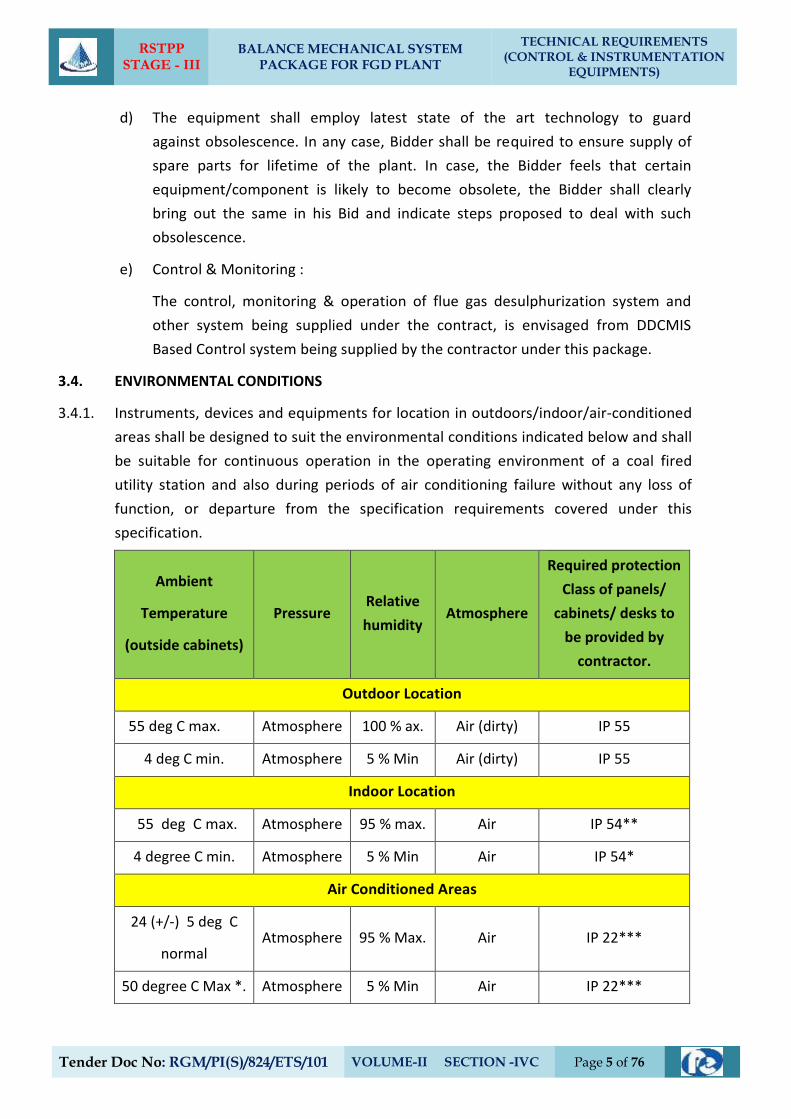
3.4. ENVIRONMENTAL CONDITIONS
3.4.1. Instruments, devices and equipments for location in outdoors/indoor/air-conditioned
areas shall be designed to suit the environmental conditions indicated below and shall
be suitable for continuous operation in the operating environment of a coal fired
utility station and also during periods of air conditioning failure without any loss of
function, or departure from the specification requirements covered under this
specification.
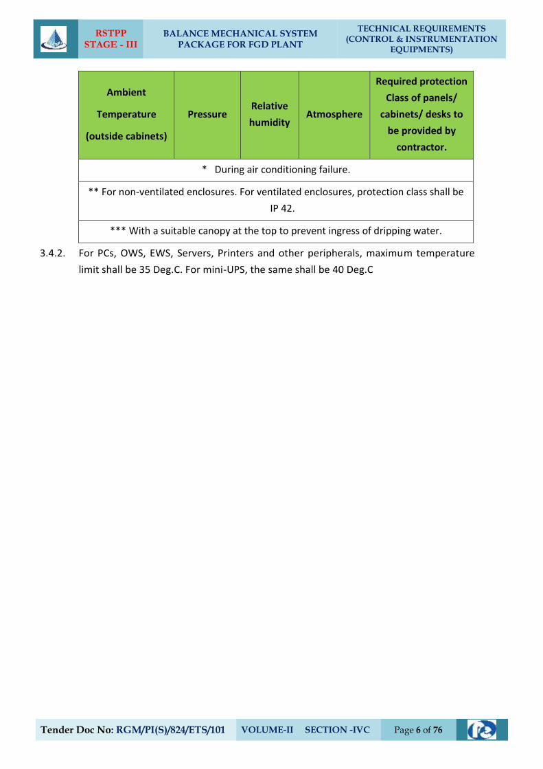
Ambient
Temperature
(outside cabinets)
Pressure Relative
humidity Atmosphere
Required protection
Class of panels/
cabinets/ desks to
be provided by
contractor.
Outdoor Location
55 deg C max. Atmosphere 100 % ax. Air (dirty) IP 55
4 deg C min. Atmosphere 5 % Min Air (dirty) IP 55
Indoor Location
55 deg C max. Atmosphere 95 % max. Air IP 54**
4 degree C min. Atmosphere 5 % Min Air IP 54*
Air Conditioned Areas
24 (+/-) 5 deg C
normal Atmosphere 95 % Max. Air IP 22***
50 degree C Max *. Atmosphere 5 % Min Air IP 22***
RSTPP STAGE - III
BALANCE MECHANICAL SYSTEM PACKAGE FOR FGD PLANT
TECHNICAL REQUIREMENTS (CONTROL & INSTRUMENTATION
EQUIPMENTS)
Tender Doc No: RGM/PI(S)/824/ETS/101 VOLUME-II SECTION -IVC Page 6 of 76
Ambient
Temperature
(outside cabinets)
Pressure Relative
humidity Atmosphere
Required protection
Class of panels/
cabinets/ desks to
be provided by
contractor.
* During air conditioning failure.
** For non-ventilated enclosures. For ventilated enclosures, protection class shall be
IP 42.
*** With a suitable canopy at the top to prevent ingress of dripping water.
3.4.2. For PCs, OWS, EWS, Servers, Printers and other peripherals, maximum temperature
limit shall be 35 Deg.C. For mini-UPS, the same shall be 40 Deg.C
RSTPP STAGE - III
BALANCE MECHANICAL SYSTEM PACKAGE FOR FGD PLANT
TECHNICAL REQUIREMENTS (CONTROL & INSTRUMENTATION
EQUIPMENTS)
Tender Doc No: RGM/PI(S)/824/ETS/101 VOLUME-II SECTION -IVC Page 7 of 76
4. MEASURING INSTRUMENTS (PRIMARY AND SECONDARY)
4.1. General
4.1.1. Measuring instruments/equipment and subsystems offered by the Bidder shall be
from reputed experienced manufacturers of specified type and range of equipment,
whose guaranteed and trouble free operation has been proven. Refer Clause
1.00.00 (titled “BASIC DESIGN CRITERIA”) of this Section IV-C Sub-section. Further,
all instruments shall be of proven reliability, accuracy, and repeatability requiring a
minimum of maintenance and shall comply with the acceptable international
standards and shall be subject to Client (EPIL)'s approval.
4.1.2. Every panel-mounted instrument requiring power supply shall be provided with
easily replaceable glass cartridge fuses of suitable rating. Every instrument shall be
provided with a grounding terminal and shall be suitably connected to the panel
grounding bus.
4.1.3. All transmitters, sensors, switches and gauges for parameters like pressure,
temperature, level, flow etc. as required for the safe and efficient operation and
maintenance as well as for operator and management information (including all
computation) of equipment in the system under the scope of specification shall be
provided on as required basis with in quoted lump sum price. The Contractor shall
furnish all Instrumentation/Control equipment & accessories under this
specification as per technical specification, ranges, makes & model as approved
by the Client (EPIL) during detailed engineering.
4.1.4. The necessary root valves, impulse piping, drain cocks, gauge-zeroing cocks, valve
manifolds and all the other accessories required for mounting/erection of these
local instruments shall be furnished, even if not specifically asked for, on as
required basis. The contacts of equipment mounted instruments, sensors; switches
etc for external connection including spare contacts shall be wired out in
flexible/rigid conduits, independently to suitably located common junction boxes.
The proposal shall include the necessary cables, flexible conduits, junction boxes
and accessories for the above purpose. Double root valves shall be provided for all
pressure tapping where the pressure exceeds 40 Kg./sq.cm.
4.1.5. All instruments envisaged for sea water applications, shall be provided with wetted
parts made of Monel/ Hastelloy-C or any other material (if provenness experience
of the proposed material for such applications is established by contractor).
For Chlorine application, instruments shall be provided with wetted parts (e.g.
diaphragm seal etc) made of Hastelloy-C. Also, filled liquid shall be Fluorolube oil/
RSTPP STAGE - III
BALANCE MECHANICAL SYSTEM PACKAGE FOR FGD PLANT
TECHNICAL REQUIREMENTS (CONTROL & INSTRUMENTATION
EQUIPMENTS)
Tender Doc No: RGM/PI(S)/824/ETS/101 VOLUME-II SECTION -IVC Page 8 of 76
Inert Hydrocarbon / CTFE etc., for these applications.
For applications of FECL3 solution, instruments shall be provided with wetted parts
(e.g. diaphragm seal, etc.) made of Tantalum.
4.1.6. For coastal areas, all instruments shall be provided with durable epoxy coating for
housings and all exposed surfaces of the instruments.
4.1.7. The instruments, for which technical specification is not attached, shall be supplied
as per the standard and proven practice of the contractor. The same shall be
established by the contractor during detailed engineering by providing detailed
explanation/concepts, if required by the Client (EPIL), of such implementation along
with standard documentation.
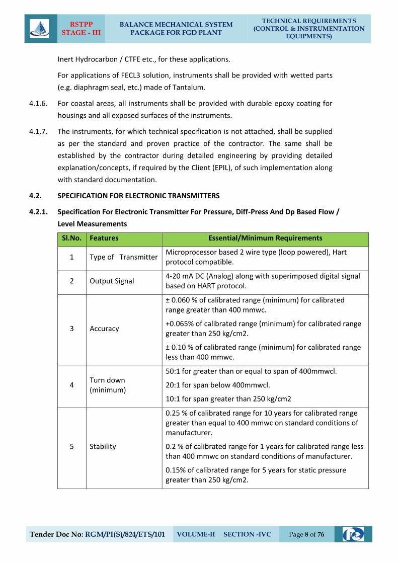
4.2. SPECIFICATION FOR ELECTRONIC TRANSMITTERS
4.2.1. Specification For Electronic Transmitter For Pressure, Diff-Press And Dp Based Flow /
Level Measurements
Sl.No. Features Essential/Minimum Requirements
1 Type of Transmitter Microprocessor based 2 wire type (loop powered), Hart protocol compatible.
2 Output Signal 4-20 mA DC (Analog) along with superimposed digital signal based on HART protocol.
3 Accuracy
± 0.060 % of calibrated range (minimum) for calibrated range greater than 400 mmwc.
+0.065% of calibrated range (minimum) for calibrated range greater than 250 kg/cm2.
± 0.10 % of calibrated range (minimum) for calibrated range less than 400 mmwc.
4 Turn down (minimum)
50:1 for greater than or equal to span of 400mmwcl.
20:1 for span below 400mmwcl.
10:1 for span greater than 250 kg/cm2
5 Stability
0.25 % of calibrated range for 10 years for calibrated range greater than equal to 400 mmwc on standard conditions of manufacturer.
0.2 % of calibrated range for 1 years for calibrated range less than 400 mmwc on standard conditions of manufacturer.
0.15% of calibrated range for 5 years for static pressure greater than 250 kg/cm2.
RSTPP STAGE - III
BALANCE MECHANICAL SYSTEM PACKAGE FOR FGD PLANT
TECHNICAL REQUIREMENTS (CONTROL & INSTRUMENTATION
EQUIPMENTS)
Tender Doc No: RGM/PI(S)/824/ETS/101 VOLUME-II SECTION -IVC Page 9 of 76
Sl.No. Features Essential/Minimum Requirements
(Above mentioned (3, 4, 5) parameters/features of offered models shall be strictly as
defined in standard published catalogue of the manufacturer only).
6 Zero and span drift
+/- 0.015 per degC at max span
+/-0.11% per degC at min. Span
7 Power Supply 24V DC ± 10%.
8 Load impedance 500 ohm (minimum)
9 Housing
Weather proof as per IP-67, metallic housing with durable corrosion resistant coating
10 Over Pressure
150% of max. Operating pressure
11 Electrical Connection
Plug and socket type except in hazardous area
12 Process connection 1/2 inch NPT (F)
13 Span and Zero
Continuous, tamper proof, Remote as well as manual adjustability from instrument with zero suppression and elevation facility.
14 Accessories Diaphragm seal, pulsation dampeners, syphon etc. As required by service and operating condition.
15 Diagnostics and isplay
Self-Indicating feature and digital display
16 Accessories
2 valve manifold for absolute & Gauge pressure transmitters,
3-valve manifold for Differential Pressure and 5 valvemanifold for Level /Flow applications.
The valve manifold shall be non integral type (except Fuel Oil area).
For hazardous area, enclosure as described in NEC article 500
2 inch pipe for mounting with Enclosure /Rack/Canopy
17 Certification SIL 2 or Better
18 Adjustment/ calibration /maintenance
From hand held HART calibrator
Notes
1) LVDT type is not acceptable.
RSTPP STAGE - III
BALANCE MECHANICAL SYSTEM PACKAGE FOR FGD PLANT
TECHNICAL REQUIREMENTS (CONTROL & INSTRUMENTATION
EQUIPMENTS)
Tender Doc No: RGM/PI(S)/824/ETS/101 VOLUME-II SECTION -IVC Page 10 of 76
Sl.No. Features Essential/Minimum Requirements
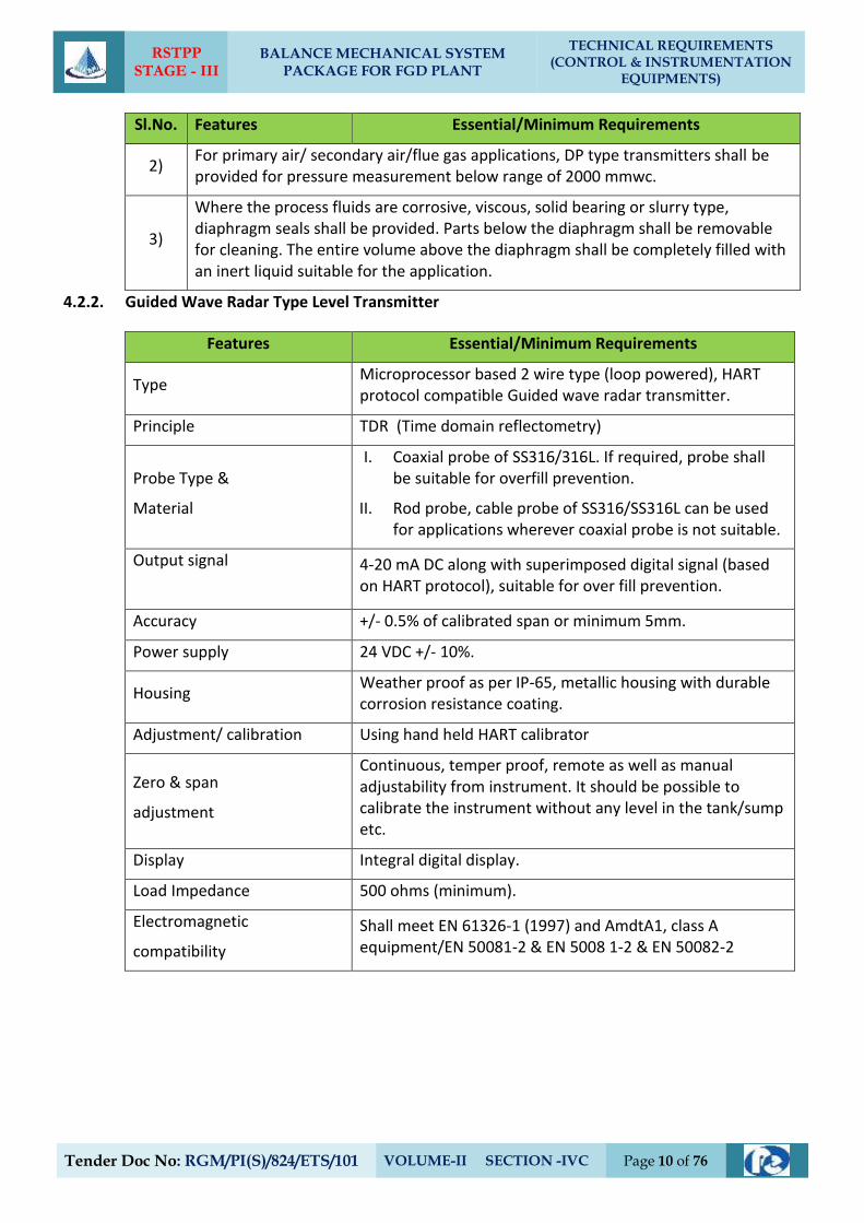
2) For primary air/ secondary air/flue gas applications, DP type transmitters shall be provided for pressure measurement below range of 2000 mmwc.
3)
Where the process fluids are corrosive, viscous, solid bearing or slurry type, diaphragm seals shall be provided. Parts below the diaphragm shall be removable for cleaning. The entire volume above the diaphragm shall be completely filled with an inert liquid suitable for the application.
4.2.2. Guided Wave Radar Type Level Transmitter
Features Essential/Minimum Requirements
Type Microprocessor based 2 wire type (loop powered), HART protocol compatible Guided wave radar transmitter.
Principle TDR (Time domain reflectometry)
Probe Type &
Material
I. Coaxial probe of SS316/316L. If required, probe shall be suitable for overfill prevention.
II. Rod probe, cable probe of SS316/SS316L can be used for applications wherever coaxial probe is not suitable.
Output signal
4-20 mA DC along with superimposed digital signal (based on HART protocol), suitable for over fill prevention.
Accuracy +/- 0.5% of calibrated span or minimum 5mm.
Power supply 24 VDC +/- 10%.
Housing Weather proof as per IP-65, metallic housing with durable corrosion resistance coating.
Adjustment/ calibration Using hand held HART calibrator
Zero & span
adjustment
Continuous, temper proof, remote as well as manual adjustability from instrument. It should be possible to calibrate the instrument without any level in the tank/sump etc.
Display Integral digital display.
Load Impedance 500 ohms (minimum).
Electromagnetic
compatibility
Shall meet EN 61326-1 (1997) and AmdtA1, class A equipment/EN 50081-2 & EN 5008 1-2 & EN 50082-2
RSTPP STAGE - III
BALANCE MECHANICAL SYSTEM PACKAGE FOR FGD PLANT
TECHNICAL REQUIREMENTS (CONTROL & INSTRUMENTATION
EQUIPMENTS)
Tender Doc No: RGM/PI(S)/824/ETS/101 VOLUME-II SECTION -IVC Page 11 of 76
Features Essential/Minimum Requirements
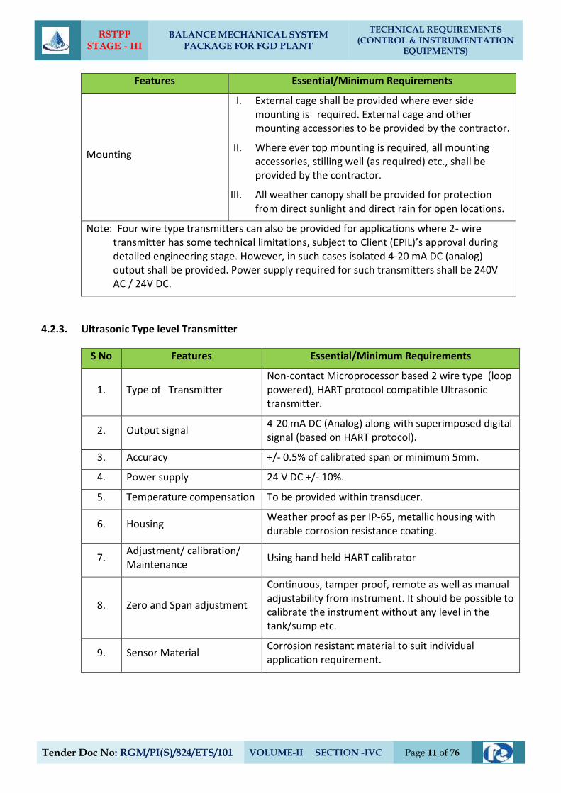
Mounting
I. External cage shall be provided where ever side mounting is required. External cage and other mounting accessories to be provided by the contractor.
II. Where ever top mounting is required, all mounting accessories, stilling well (as required) etc., shall be provided by the contractor.
III. All weather canopy shall be provided for protection from direct sunlight and direct rain for open locations.
Note: Four wire type transmitters can also be provided for applications where 2- wire transmitter has some technical limitations, subject to Client (EPIL)’s approval during detailed engineering stage. However, in such cases isolated 4-20 mA DC (analog) output shall be provided. Power supply required for such transmitters shall be 240V AC / 24V DC.
4.2.3. Ultrasonic Type level Transmitter
S No Features Essential/Minimum Requirements
1. Type of Transmitter Non-contact Microprocessor based 2 wire type (loop powered), HART protocol compatible Ultrasonic transmitter.
2. Output signal 4-20 mA DC (Analog) along with superimposed digital signal (based on HART protocol).
3. Accuracy +/- 0.5% of calibrated span or minimum 5mm.
4. Power supply 24 V DC +/- 10%.
5. Temperature compensation To be provided within transducer.
6. Housing Weather proof as per IP-65, metallic housing with durable corrosion resistance coating.
7. Adjustment/ calibration/ Maintenance
Using hand held HART calibrator
8. Zero and Span adjustment
Continuous, tamper proof, remote as well as manual adjustability from instrument. It should be possible to calibrate the instrument without any level in the tank/sump etc.
9. Sensor Material Corrosion resistant material to suit individual application requirement.
RSTPP STAGE - III
BALANCE MECHANICAL SYSTEM PACKAGE FOR FGD PLANT
TECHNICAL REQUIREMENTS (CONTROL & INSTRUMENTATION
EQUIPMENTS)
Tender Doc No: RGM/PI(S)/824/ETS/101 VOLUME-II SECTION -IVC Page 12 of 76
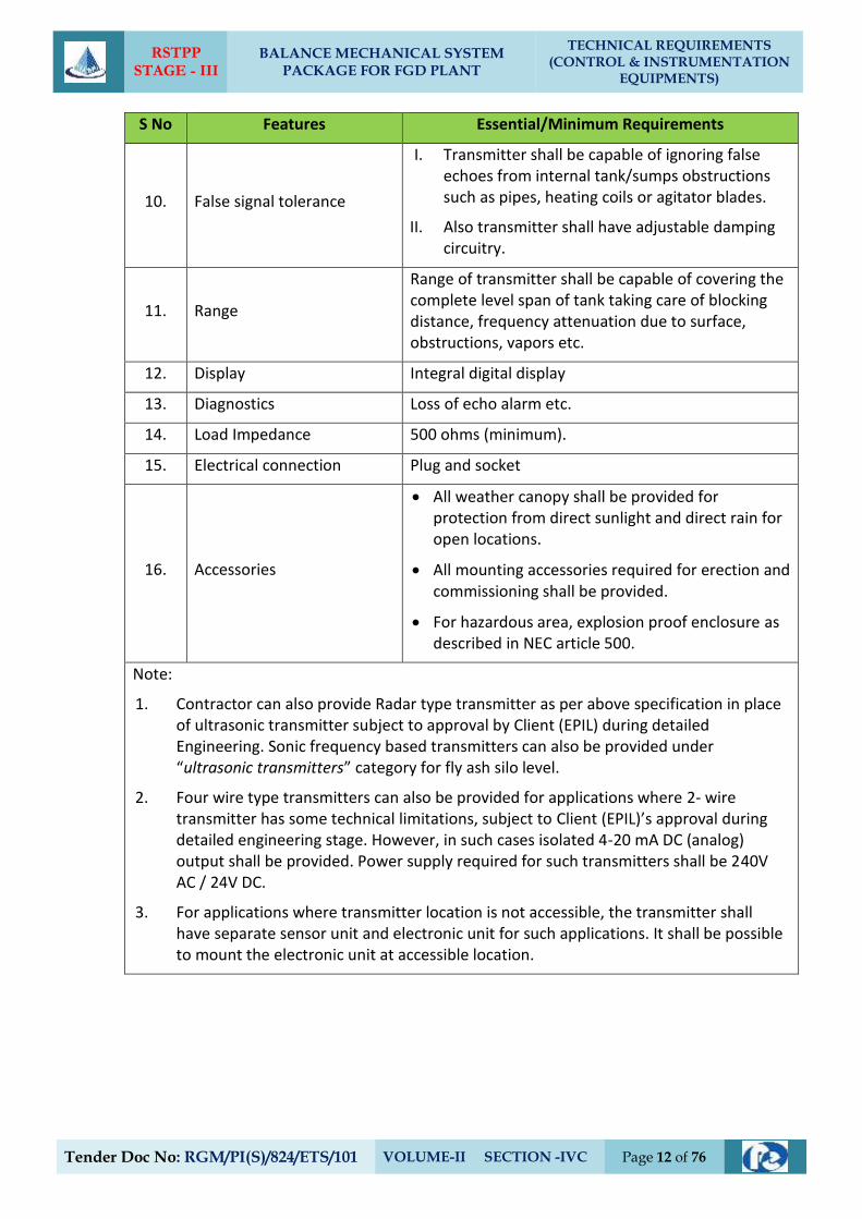
S No Features Essential/Minimum Requirements
10. False signal tolerance
I. Transmitter shall be capable of ignoring false echoes from internal tank/sumps obstructions such as pipes, heating coils or agitator blades.
II. Also transmitter shall have adjustable damping circuitry.
11. Range
Range of transmitter shall be capable of covering the complete level span of tank taking care of blocking distance, frequency attenuation due to surface, obstructions, vapors etc.
12. Display Integral digital display
13. Diagnostics Loss of echo alarm etc.
14. Load Impedance 500 ohms (minimum).
15. Electrical connection Plug and socket
16. Accessories
All weather canopy shall be provided for protection from direct sunlight and direct rain for open locations.
All mounting accessories required for erection and commissioning shall be provided.
For hazardous area, explosion proof enclosure as described in NEC article 500.
Note:
1. Contractor can also provide Radar type transmitter as per above specification in place of ultrasonic transmitter subject to approval by Client (EPIL) during detailed Engineering. Sonic frequency based transmitters can also be provided under “ultrasonic transmitters” category for fly ash silo level.
2. Four wire type transmitters can also be provided for applications where 2- wire transmitter has some technical limitations, subject to Client (EPIL)’s approval during detailed engineering stage. However, in such cases isolated 4-20 mA DC (analog) output shall be provided. Power supply required for such transmitters shall be 240V AC / 24V DC.
3. For applications where transmitter location is not accessible, the transmitter shall have separate sensor unit and electronic unit for such applications. It shall be possible to mount the electronic unit at accessible location.
RSTPP STAGE - III
BALANCE MECHANICAL SYSTEM PACKAGE FOR FGD PLANT
TECHNICAL REQUIREMENTS (CONTROL & INSTRUMENTATION
EQUIPMENTS)
Tender Doc No: RGM/PI(S)/824/ETS/101 VOLUME-II SECTION -IVC Page 13 of 76
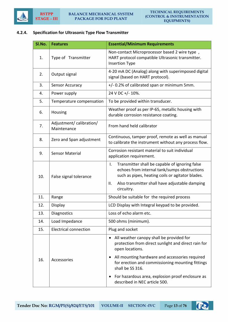
4.2.4. Specification for Ultrasonic Type Flow Transmitter
Sl.No. Features Essential/Minimum Requirements
1. Type of Transmitter Non-contact Microprocessor based 2 wire type , HART protocol compatible Ultrasonic transmitter. Insertion Type
2. Output signal 4-20 mA DC (Analog) along with superimposed digital signal (based on HART protocol).
3. Sensor Accuracy +/- 0.2% of calibrated span or minimum 5mm.
4. Power supply 24 V DC +/- 10%.
5. Temperature compensation To be provided within transducer.
6. Housing Weather proof as per IP-65, metallic housing with durable corrosion resistance coating.
7. Adjustment/ calibration/ Maintenance
From hand held calibrator
8. Zero and Span adjustment Continuous, tamper proof, remote as well as manual to calibrate the instrument without any process flow.
9. Sensor Material Corrosion resistant material to suit individual application requirement.
10. False signal tolerance
I. Transmitter shall be capable of ignoring false echoes from internal tank/sumps obstructions such as pipes, heating coils or agitator blades.
II. Also transmitter shall have adjustable damping circuitry.
11. Range Should be suitable for the required process
12. Display LCD Display with Integral keypad to be provided.
13. Diagnostics Loss of echo alarm etc.
14. Load Impedance 500 ohms (minimum).
15. Electrical connection Plug and socket
16. Accessories
All weather canopy shall be provided for protection from direct sunlight and direct rain for open locations.
All mounting hardware and accessories required for erection and commissioning mounting fittings shall be SS 316.
For hazardous area, explosion proof enclosure as described in NEC article 500.
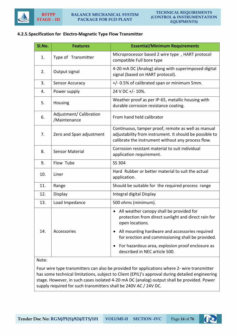
RSTPP STAGE - III
BALANCE MECHANICAL SYSTEM PACKAGE FOR FGD PLANT
TECHNICAL REQUIREMENTS (CONTROL & INSTRUMENTATION
EQUIPMENTS)
Tender Doc No: RGM/PI(S)/824/ETS/101 VOLUME-II SECTION -IVC Page 14 of 76
4.2.5. Specification for Electro-Magnetic Type Flow Transmitter
Sl.No. Features Essential/Minimum Requirements
1. Type of Transmitter Microprocessor based 2 wire type , HART protocol compatible Full bore type
2. Output signal 4-20 mA DC (Analog) along with superimposed digital signal (based on HART protocol).
3. Sensor Accuracy +/- 0.5% of calibrated span or minimum 5mm.
4. Power supply 24 V DC +/- 10%.
5. Housing Weather proof as per IP-65, metallic housing with durable corrosion resistance coating.
6. Adjustment/ Calibration /Maintenance
From hand held calibrator
7. Zero and Span adjustment Continuous, tamper proof, remote as well as manual adjustability from instrument. It should be possible to calibrate the instrument without any process flow.
8. Sensor Material Corrosion resistant material to suit individual application requirement.
9. Flow Tube SS 304
10. Liner Hard Rubber or better material to suit the actual application.
11. Range Should be suitable for the required process range
12. Display Integral digital Display
13. Load Impedance 500 ohms (minimum).
14. Accessories
All weather canopy shall be provided for protection from direct sunlight and direct rain for open locations.
All mounting hardware and accessories required for erection and commissioning shall be provided.
For hazardous area, explosion proof enclosure as described in NEC article 500.
Note:
Four wire type transmitters can also be provided for applications where 2- wire transmitter has some technical limitations, subject to Client (EPIL)’s approval during detailed engineering stage. However, in such cases isolated 4-20 mA DC (analog) output shall be provided. Power supply required for such transmitters shall be 240V AC / 24V DC.
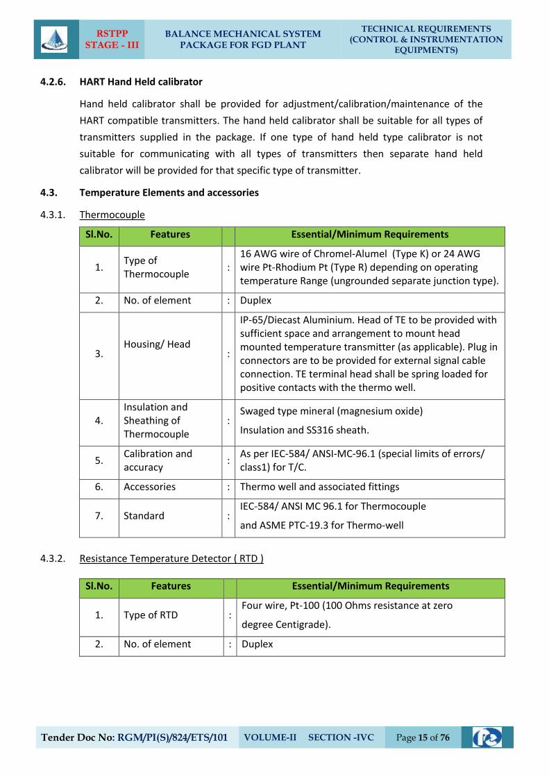
RSTPP STAGE - III
BALANCE MECHANICAL SYSTEM PACKAGE FOR FGD PLANT
TECHNICAL REQUIREMENTS (CONTROL & INSTRUMENTATION
EQUIPMENTS)
Tender Doc No: RGM/PI(S)/824/ETS/101 VOLUME-II SECTION -IVC Page 15 of 76
4.2.6. HART Hand Held calibrator
Hand held calibrator shall be provided for adjustment/calibration/maintenance of the
HART compatible transmitters. The hand held calibrator shall be suitable for all types of
transmitters supplied in the package. If one type of hand held type calibrator is not
suitable for communicating with all types of transmitters then separate hand held
calibrator will be provided for that specific type of transmitter.
4.3. Temperature Elements and accessories
4.3.1. Thermocouple
Sl.No. Features Essential/Minimum Requirements
1. Type of Thermocouple
: 16 AWG wire of Chromel-Alumel (Type K) or 24 AWG wire Pt-Rhodium Pt (Type R) depending on operating temperature Range (ungrounded separate junction type).
2. No. of element : Duplex
3. Housing/ Head
:
IP-65/Diecast Aluminium. Head of TE to be provided with sufficient space and arrangement to mount head mounted temperature transmitter (as applicable). Plug in connectors are to be provided for external signal cable connection. TE terminal head shall be spring loaded for positive contacts with the thermo well.
4. Insulation and Sheathing of Thermocouple
: Swaged type mineral (magnesium oxide)
Insulation and SS316 sheath.
5. Calibration and accuracy
: As per IEC-584/ ANSI-MC-96.1 (special limits of errors/ class1) for T/C.
6. Accessories : Thermo well and associated fittings
7. Standard : IEC-584/ ANSI MC 96.1 for Thermocouple
and ASME PTC-19.3 for Thermo-well
4.3.2. Resistance Temperature Detector ( RTD )
Sl.No. Features Essential/Minimum Requirements
1. Type of RTD : Four wire, Pt-100 (100 Ohms resistance at zero
degree Centigrade).
2. No. of element : Duplex
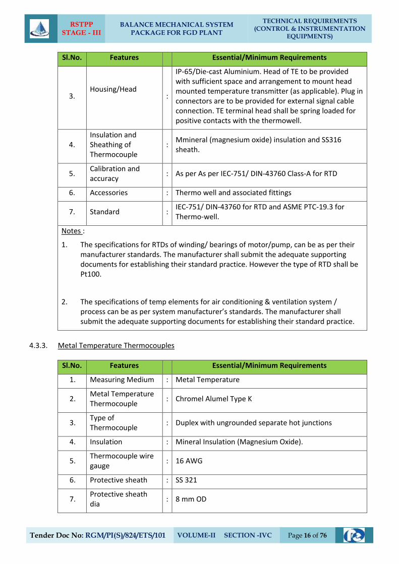
RSTPP STAGE - III
BALANCE MECHANICAL SYSTEM PACKAGE FOR FGD PLANT
TECHNICAL REQUIREMENTS (CONTROL & INSTRUMENTATION
EQUIPMENTS)
Tender Doc No: RGM/PI(S)/824/ETS/101 VOLUME-II SECTION -IVC Page 16 of 76
Sl.No. Features Essential/Minimum Requirements
3. Housing/Head
:
IP-65/Die-cast Aluminium. Head of TE to be provided with sufficient space and arrangement to mount head mounted temperature transmitter (as applicable). Plug in connectors are to be provided for external signal cable connection. TE terminal head shall be spring loaded for positive contacts with the thermowell.
4. Insulation and Sheathing of Thermocouple
: Mmineral (magnesium oxide) insulation and SS316 sheath.
5. Calibration and accuracy
: As per As per IEC-751/ DIN-43760 Class-A for RTD
6. Accessories : Thermo well and associated fittings
7. Standard : IEC-751/ DIN-43760 for RTD and ASME PTC-19.3 for Thermo-well.
Notes :
1. The specifications for RTDs of winding/ bearings of motor/pump, can be as per their manufacturer standards. The manufacturer shall submit the adequate supporting documents for establishing their standard practice. However the type of RTD shall be Pt100.
2. The specifications of temp elements for air conditioning & ventilation system / process can be as per system manufacturer’s standards. The manufacturer shall submit the adequate supporting documents for establishing their standard practice.
4.3.3. Metal Temperature Thermocouples
Sl.No. Features Essential/Minimum Requirements
1. Measuring Medium : Metal Temperature
2. Metal Temperature Thermocouple
: Chromel Alumel Type K
3. Type of Thermocouple
: Duplex with ungrounded separate hot junctions
4. Insulation : Mineral Insulation (Magnesium Oxide).
5. Thermocouple wire gauge
: 16 AWG
6. Protective sheath : SS 321
7. Protective sheath dia
: 8 mm OD
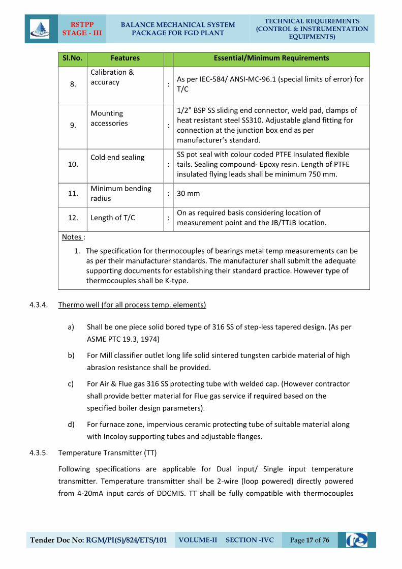
RSTPP STAGE - III
BALANCE MECHANICAL SYSTEM PACKAGE FOR FGD PLANT
TECHNICAL REQUIREMENTS (CONTROL & INSTRUMENTATION
EQUIPMENTS)
Tender Doc No: RGM/PI(S)/824/ETS/101 VOLUME-II SECTION -IVC Page 17 of 76
Sl.No. Features Essential/Minimum Requirements
8.
Calibration & accuracy
: As per IEC-584/ ANSI-MC-96.1 (special limits of error) for T/C
9.
Mounting accessories
:
1/2" BSP SS sliding end connector, weld pad, clamps of heat resistant steel SS310. Adjustable gland fitting for connection at the junction box end as per manufacturer’s standard.
10. Cold end sealing
:
SS pot seal with colour coded PTFE Insulated flexible tails. Sealing compound- Epoxy resin. Length of PTFE insulated flying leads shall be minimum 750 mm.
11. Minimum bending radius
: 30 mm
12. Length of T/C : On as required basis considering location of measurement point and the JB/TTJB location.
Notes :
1. The specification for thermocouples of bearings metal temp measurements can be as per their manufacturer standards. The manufacturer shall submit the adequate supporting documents for establishing their standard practice. However type of thermocouples shall be K-type.
4.3.4. Thermo well (for all process temp. elements)
a) Shall be one piece solid bored type of 316 SS of step-less tapered design. (As per
ASME PTC 19.3, 1974)
b) For Mill classifier outlet long life solid sintered tungsten carbide material of high
abrasion resistance shall be provided.
c) For Air & Flue gas 316 SS protecting tube with welded cap. (However contractor
shall provide better material for Flue gas service if required based on the
specified boiler design parameters).
d) For furnace zone, impervious ceramic protecting tube of suitable material along
with Incoloy supporting tubes and adjustable flanges.
4.3.5. Temperature Transmitter (TT)
Following specifications are applicable for Dual input/ Single input temperature
transmitter. Temperature transmitter shall be 2-wire (loop powered) directly powered
from 4-20mA input cards of DDCMIS. TT shall be fully compatible with thermocouples
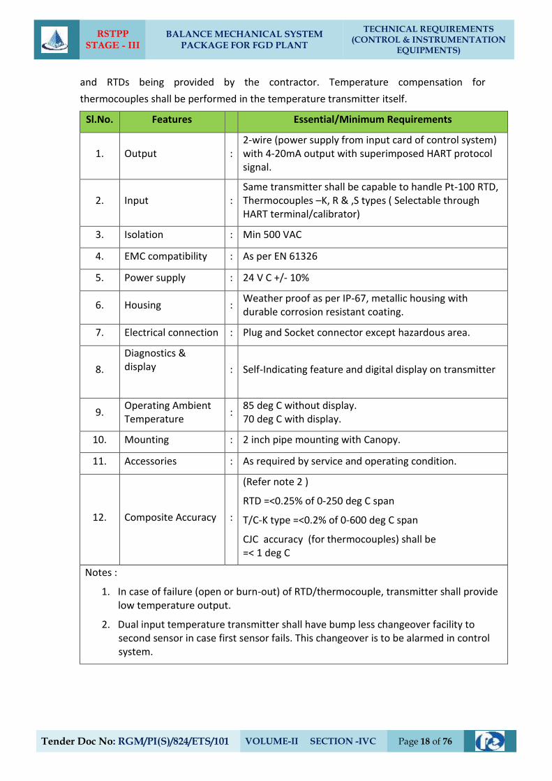
RSTPP STAGE - III
BALANCE MECHANICAL SYSTEM PACKAGE FOR FGD PLANT
TECHNICAL REQUIREMENTS (CONTROL & INSTRUMENTATION
EQUIPMENTS)
Tender Doc No: RGM/PI(S)/824/ETS/101 VOLUME-II SECTION -IVC Page 18 of 76
and RTDs being provided by the contractor. Temperature compensation for
thermocouples shall be performed in the temperature transmitter itself.
Sl.No. Features Essential/Minimum Requirements
1. Output : 2-wire (power supply from input card of control system) with 4-20mA output with superimposed HART protocol signal.
2. Input : Same transmitter shall be capable to handle Pt-100 RTD, Thermocouples –K, R & ,S types ( Selectable through HART terminal/calibrator)
3. Isolation : Min 500 VAC
4. EMC compatibility : As per EN 61326
5. Power supply : 24 V C +/- 10%
6. Housing : Weather proof as per IP-67, metallic housing with durable corrosion resistant coating.
7. Electrical connection : Plug and Socket connector except hazardous area.
8.
Diagnostics & display
: Self-Indicating feature and digital display on transmitter
9. Operating Ambient Temperature
: 85 deg C without display. 70 deg C with display.
10. Mounting : 2 inch pipe mounting with Canopy.
11. Accessories : As required by service and operating condition.
12. Composite Accuracy :
(Refer note 2 )
RTD =<0.25% of 0-250 deg C span
T/C-K type =<0.2% of 0-600 deg C span
CJC accuracy (for thermocouples) shall be =< 1 deg C
Notes :
1. In case of failure (open or burn-out) of RTD/thermocouple, transmitter shall provide low temperature output.
2. Dual input temperature transmitter shall have bump less changeover facility to second sensor in case first sensor fails. This changeover is to be alarmed in control system.
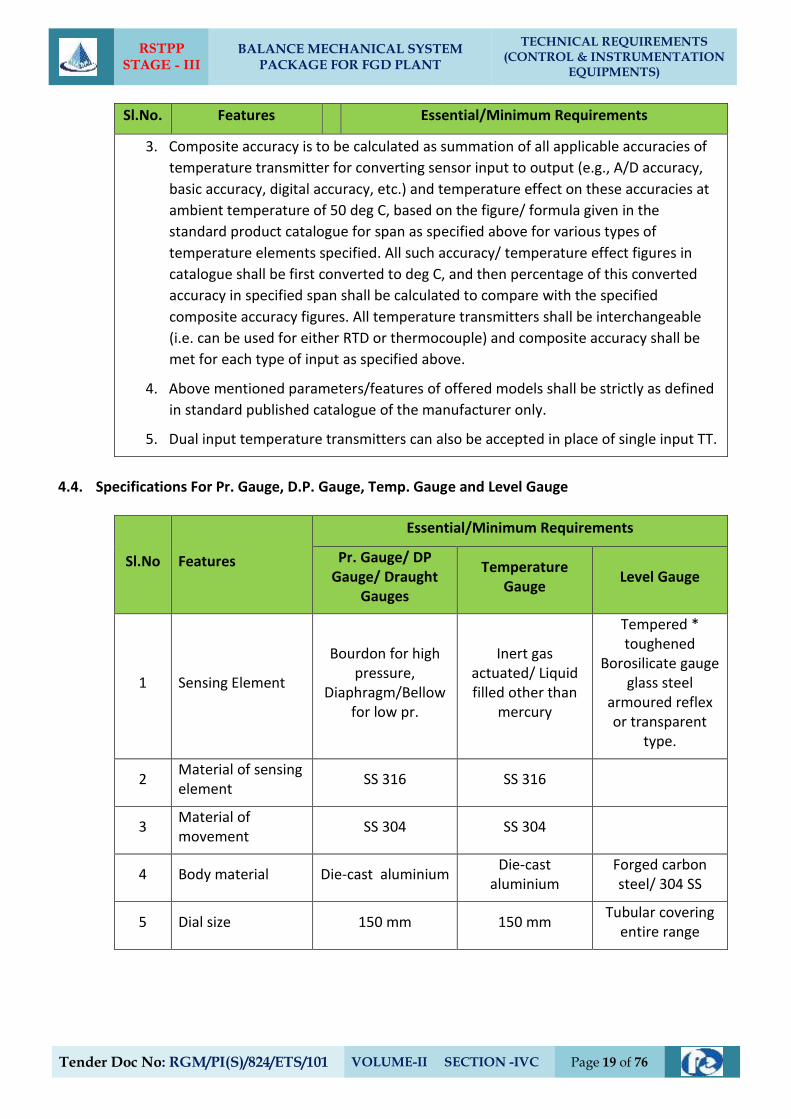
RSTPP STAGE - III
BALANCE MECHANICAL SYSTEM PACKAGE FOR FGD PLANT
TECHNICAL REQUIREMENTS (CONTROL & INSTRUMENTATION
EQUIPMENTS)
Tender Doc No: RGM/PI(S)/824/ETS/101 VOLUME-II SECTION -IVC Page 19 of 76
Sl.No. Features Essential/Minimum Requirements
3. Composite accuracy is to be calculated as summation of all applicable accuracies of
temperature transmitter for converting sensor input to output (e.g., A/D accuracy,
basic accuracy, digital accuracy, etc.) and temperature effect on these accuracies at
ambient temperature of 50 deg C, based on the figure/ formula given in the
standard product catalogue for span as specified above for various types of
temperature elements specified. All such accuracy/ temperature effect figures in
catalogue shall be first converted to deg C, and then percentage of this converted
accuracy in specified span shall be calculated to compare with the specified
composite accuracy figures. All temperature transmitters shall be interchangeable
(i.e. can be used for either RTD or thermocouple) and composite accuracy shall be
met for each type of input as specified above.
4. Above mentioned parameters/features of offered models shall be strictly as defined
in standard published catalogue of the manufacturer only.
5. Dual input temperature transmitters can also be accepted in place of single input TT.
4.4. Specifications For Pr. Gauge, D.P. Gauge, Temp. Gauge and Level Gauge
Sl.No Features
Essential/Minimum Requirements
Pr. Gauge/ DP Gauge/ Draught
Gauges
Temperature Gauge
Level Gauge
1 Sensing Element
Bourdon for high pressure,
Diaphragm/Bellow for low pr.
Inert gas actuated/ Liquid filled other than
mercury
Tempered * toughened
Borosilicate gauge glass steel
armoured reflex or transparent
type.
2 Material of sensing element
SS 316 SS 316
3 Material of movement
SS 304 SS 304
4 Body material Die-cast aluminium Die-cast
aluminium Forged carbon steel/ 304 SS
5 Dial size 150 mm 150 mm Tubular covering
entire range
RSTPP STAGE - III
BALANCE MECHANICAL SYSTEM PACKAGE FOR FGD PLANT
TECHNICAL REQUIREMENTS (CONTROL & INSTRUMENTATION
EQUIPMENTS)
Tender Doc No: RGM/PI(S)/824/ETS/101 VOLUME-II SECTION -IVC Page 20 of 76
Sl.No Features
Essential/Minimum Requirements
Pr. Gauge/ DP Gauge/ Draught
Gauges
Temperature Gauge
Level Gauge
6 End connection 1/2 inch NPT (M) 1/2 inch or 3/4
inch NPT (M).
Process connection as per
ASME PTC and drain/
vent 15 NB
7 Accuracy ±1% of span ±1% of span ± 2%
8 Scale Linear, 270° arc
graduated in metric units
Linear, 270° arc graduated in °C
Linear vertical
9 Range Selection Shall cover 125% of
max. Operating press
Shall cover 125% of max. Operating
temp
Shall cover max Operating Level
10 Over range 125% of FSD 125% of FSD
11 Housing Weather and dust proof as per IP-55
Weather and dust proof as per IP-55
CS/304 SS leak roof
12 Zero /Span Adjustment
To be Provided To be Provided
---
13 Identification Engraved with service legend or laminated phenolic name
plate
14 Accessories
Blow out disc, siphon, snubber,
Pulsation dampener,
chemical seal (if required by
process) gauge isolation valve
SS Thermowell
Gasket for all KEL-F shield for
transparent type vent and drain
valves of Steel/SS as per CS/Alloy
process requirement.
Notes
*Bicolour type level gauges will be provided for applications involving steam and water
except for condensate and feed water services.
*Length of gauge glass shall not be more than 1400 mm. If the vessel is higher, multiple
Gauge glasses with 50 mm overlapping shall be provided.
RSTPP STAGE - III
BALANCE MECHANICAL SYSTEM PACKAGE FOR FGD PLANT
TECHNICAL REQUIREMENTS (CONTROL & INSTRUMENTATION
EQUIPMENTS)
Tender Doc No: RGM/PI(S)/824/ETS/101 VOLUME-II SECTION -IVC Page 21 of 76
Sl.No Features
Essential/Minimum Requirements
Pr. Gauge/ DP Gauge/ Draught
Gauges
Temperature Gauge
Level Gauge
Where the process fluids are corrosive, viscous, solid bearing or slurry type, diaphragm seals
shall be provided. Parts below the diaphragm shall be removable for cleaning. The entire
volume above the diaphragm shall be completely filled with an inert liquid suitable for the
application.
4.5. Process Actuated Switches
Sl.No Features
Essential/Minimum Requirements
Pressure/ Draft Switches/ DP
Switches
Temperature switches
Level switches
1 Sensing Element
Vapor pressure sensing, liquid
filled bellow with SS bulb capillary (5 m minimum, to suit
application)
Vapor pressure sensing, liquid
filled bellow with SS bulb Capillary
(5 m minimum, to suit application)
Capacitance types, float type, conductivity type,
RF type, Ultrasonic type as per suitability to the application.
2 Material SS 316 Bulb 316 SS/
capillary 304 SS 316 SS
3 End connection ½ inch NPT (F) ½ inch NPT (F) Manufacturer Std
4 Over range / Proof Pressure
150% of maximum operating pr.
150% of
maximum operating pr.
5 Repeatability +/- 0.5% of full range
6 No. of contacts 2 NO+ 2NC SPDT snap action dry contact
7 Rating of contacts 60 V DC, 6 VA (or more if required by DDCMIS)
8 Elect. Connection Plug in socket.
9 Set point adjustment
Provided over full range
10 Dead band adjustment
Adjustable/ fixed as per requirement of application
11 Enclosure Weather and dust proof as per IP-55, metallic housing
RSTPP STAGE - III
BALANCE MECHANICAL SYSTEM PACKAGE FOR FGD PLANT
TECHNICAL REQUIREMENTS (CONTROL & INSTRUMENTATION
EQUIPMENTS)
Tender Doc No: RGM/PI(S)/824/ETS/101 VOLUME-II SECTION -IVC Page 22 of 76
Sl.No Features
Essential/Minimum Requirements
Pressure/ Draft Switches/ DP
Switches
Temperature switches
Level switches
12 Accessories
Siphon, snubber, chemical seal,
pulsation dampeners as
required by process
Thermo well of 316 SS and
packing glands
All mounting accessories
13 Mounting
Suitable for enclosure/ rack
mounting or direct mounting
Suitable for rack mounting or
direct mounting
14 Power Supply (wherever required)
As per Contractor’s Standard practice.
Notes
1. Where the process fluids are corrosive, viscous, solid bearing or slurry type, diaphragm
seals shall be provided. Parts below the diaphragm shall be removable for cleaning. The
entire volume above the diaphragm shall be completely filled with an inert liquid
suitable for the application.
2. Pressure/ Diff pressure switches for very low press/ DP measurements can have sensor
material other than SS316 in case of any technical limitation and the offered product is
standard product of the manufacture for very low pressure applications.
3. Repeatability can be upto +/-1% of full range in case of switches with diaphragm seals
or very low pressure/DP range.
4. The specifications of switches for air conditioning & ventilation system / process canbe
as per system manufacturer’s standards. The manufacturer shall submit the adequate
supporting documents for establishing their standard practice.
4.6. Solenoid Valves
Solenoid valves shall fulfil the following requirements: -
a) Type 2/3/4 way SS 316/ forged brass (depending on the application subject to
Client (EPIL)’s ’s approval during detailed engg.)
b) Power supply 24V DC.
c) Plug in connector connection.
d) Insulation - Class “H”
RSTPP STAGE - III
BALANCE MECHANICAL SYSTEM PACKAGE FOR FGD PLANT
TECHNICAL REQUIREMENTS (CONTROL & INSTRUMENTATION
EQUIPMENTS)
Tender Doc No: RGM/PI(S)/824/ETS/101 VOLUME-II SECTION -IVC Page 23 of 76
4.7. Limit switches
Limit switches shall be silver plated with high conductivity and non-corrosive type.
Contact rating shall be sufficient to meet the requirement of Fire alarm Control System
subject to a minimum of 60V, 6VA rating. Protection class shall be IP-55.
4.8. Specification for Coriolis Flow Transmitter
Type Coriolis
Material of Wetted Parts 316 SS
Material of Housing 304L SS
Accuracy ± 0.2% of Rate
Repeatability ± 0.1% of Rate
Output 4-20 mA DC, HART Compatible
Power Supply 230 VAC or 24VDC operated
Process Temperature range 0-200 degree Celsius
Others Drain / purging arrangement shall be
provided as per standard practice.
The offered Coriolis type flow transmitter shall be suitable for intended application.
Contractor shall submit flow and sizing calculation for Client (EPIL)’s approval. For each
type of Coriolis type flow transmitter general arrangement and assembly drawing and
cable wiring diagram shall be submitted for Client (EPIL)’s approval.
4.9. Specification For Flow Elements
4.9.1. Orifice Plate
Features Essential/Minimum Requirements Type Concentric as per ASME PTC-19.5 (Part-II), ISA
RP-3.2, 1960 or BS-1042, ISO 5167 Material 316 SS Thickness 3 mm for main pipe diameter up to 300 mm
and 6 mm for main pipe dia above 300 mm. Material of branch pipe Same as main pipe Root valve type Globe Root valve material Same as pipe material
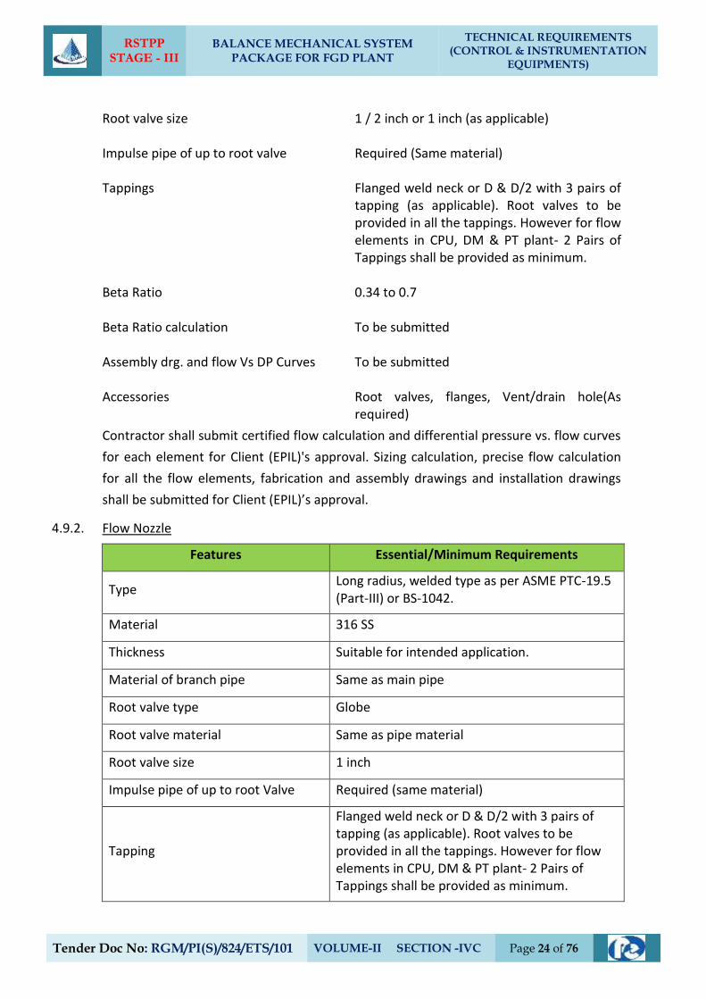
RSTPP STAGE - III
BALANCE MECHANICAL SYSTEM PACKAGE FOR FGD PLANT
TECHNICAL REQUIREMENTS (CONTROL & INSTRUMENTATION
EQUIPMENTS)
Tender Doc No: RGM/PI(S)/824/ETS/101 VOLUME-II SECTION -IVC Page 24 of 76
Root valve size 1 / 2 inch or 1 inch (as applicable) Impulse pipe of up to root valve Required (Same material) Tappings Flanged weld neck or D & D/2 with 3 pairs of
tapping (as applicable). Root valves to be provided in all the tappings. However for flow elements in CPU, DM & PT plant- 2 Pairs of Tappings shall be provided as minimum.
Beta Ratio 0.34 to 0.7 Beta Ratio calculation To be submitted Assembly drg. and flow Vs DP Curves To be submitted Accessories Root valves, flanges, Vent/drain hole(As
required)
Contractor shall submit certified flow calculation and differential pressure vs. flow curves
for each element for Client (EPIL)'s approval. Sizing calculation, precise flow calculation
for all the flow elements, fabrication and assembly drawings and installation drawings
shall be submitted for Client (EPIL)’s approval.
4.9.2. Flow Nozzle
Features Essential/Minimum Requirements
Type Long radius, welded type as per ASME PTC-19.5 (Part-III) or BS-1042.
Material 316 SS
Thickness Suitable for intended application.
Material of branch pipe Same as main pipe
Root valve type Globe
Root valve material Same as pipe material
Root valve size 1 inch
Impulse pipe of up to root Valve Required (same material)
Tapping
Flanged weld neck or D & D/2 with 3 pairs of tapping (as applicable). Root valves to be provided in all the tappings. However for flow elements in CPU, DM & PT plant- 2 Pairs of Tappings shall be provided as minimum.
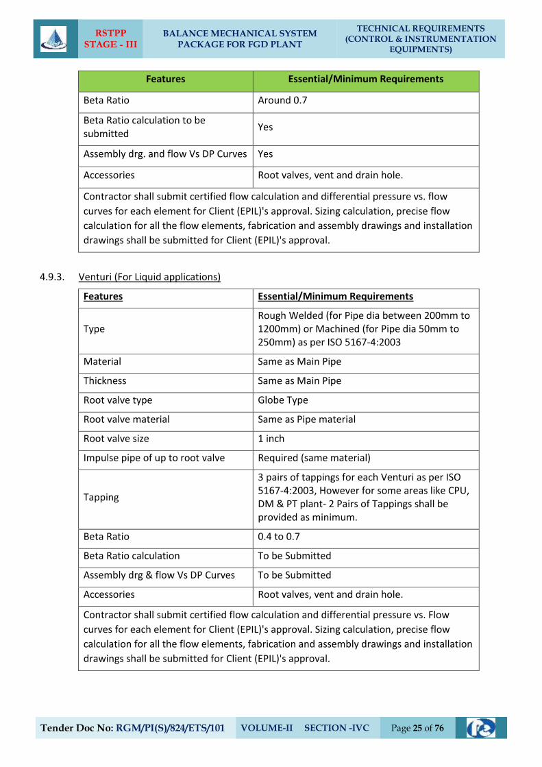
RSTPP STAGE - III
BALANCE MECHANICAL SYSTEM PACKAGE FOR FGD PLANT
TECHNICAL REQUIREMENTS (CONTROL & INSTRUMENTATION
EQUIPMENTS)
Tender Doc No: RGM/PI(S)/824/ETS/101 VOLUME-II SECTION -IVC Page 25 of 76
Features Essential/Minimum Requirements
Beta Ratio Around 0.7
Beta Ratio calculation to be submitted
Yes
Assembly drg. and flow Vs DP Curves Yes
Accessories Root valves, vent and drain hole.
Contractor shall submit certified flow calculation and differential pressure vs. flow
curves for each element for Client (EPIL)'s approval. Sizing calculation, precise flow
calculation for all the flow elements, fabrication and assembly drawings and installation
drawings shall be submitted for Client (EPIL)'s approval.
4.9.3. Venturi (For Liquid applications)
Features Essential/Minimum Requirements
Type Rough Welded (for Pipe dia between 200mm to 1200mm) or Machined (for Pipe dia 50mm to 250mm) as per ISO 5167-4:2003
Material Same as Main Pipe
Thickness Same as Main Pipe
Root valve type Globe Type
Root valve material Same as Pipe material
Root valve size 1 inch
Impulse pipe of up to root valve Required (same material)
Tapping
3 pairs of tappings for each Venturi as per ISO 5167-4:2003, However for some areas like CPU, DM & PT plant- 2 Pairs of Tappings shall be provided as minimum.
Beta Ratio 0.4 to 0.7
Beta Ratio calculation To be Submitted
Assembly drg & flow Vs DP Curves To be Submitted
Accessories Root valves, vent and drain hole.
Contractor shall submit certified flow calculation and differential pressure vs. Flow
curves for each element for Client (EPIL)'s approval. Sizing calculation, precise flow
calculation for all the flow elements, fabrication and assembly drawings and installation
drawings shall be submitted for Client (EPIL)'s approval.
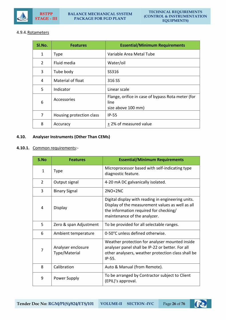
RSTPP STAGE - III
BALANCE MECHANICAL SYSTEM PACKAGE FOR FGD PLANT
TECHNICAL REQUIREMENTS (CONTROL & INSTRUMENTATION
EQUIPMENTS)
Tender Doc No: RGM/PI(S)/824/ETS/101 VOLUME-II SECTION -IVC Page 26 of 76
4.9.4. Rotameters
Sl.No. Features Essential/Minimum Requirements
1 Type Variable Area Metal Tube
2 Fluid media Water/oil
3 Tube body SS316
4 Material of float 316 SS
5 Indicator Linear scale
6 Accessories
Flange, orifice in case of bypass Rota meter (for line size above 100 mm)
7 Housing protection class IP-55
8 Accuracy + 2% of measured value
4.10. Analyser Instruments (Other Than CEMs)
4.10.1. Common requirements:-
S.No Features Essential/Minimum Requirements
1 Type Microprocessor based with self-indicating type diagnostic feature.
2 Output signal 4-20 mA DC galvanically isolated.
3 Binary Signal 2NO+2NC
4 Display
Digital display with reading in engineering units. Display of the measurement values as well as all the information required for checking/ maintenance of the analyzer.
5 Zero & span Adjustment To be provided for all selectable ranges.
6 Ambient temperature 0-50°C unless defined otherwise.
7 Analyser enclosure Type/Material
Weather protection for analyser mounted inside analyser panel shall be IP-22 or better. For all other analysers, weather protection class shall be IP-55.
8 Calibration Auto & Manual (from Remote).
9 Power Supply To be arranged by Contractor subject to Client (EPIL)’s approval.
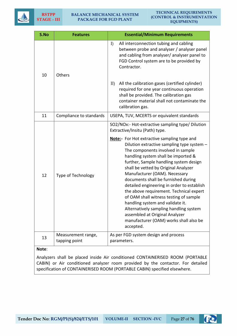
RSTPP STAGE - III
BALANCE MECHANICAL SYSTEM PACKAGE FOR FGD PLANT
TECHNICAL REQUIREMENTS (CONTROL & INSTRUMENTATION
EQUIPMENTS)
Tender Doc No: RGM/PI(S)/824/ETS/101 VOLUME-II SECTION -IVC Page 27 of 76
S.No Features Essential/Minimum Requirements
10 Others
I) All interconnection tubing and cabling between probe and analyser / analyser panel and cabling from analyser/ analyser panel to FGD Control system are to be provided by Contractor.
II) All the calibration gases (certified cylinder) required for one year continuous operation shall be provided. The calibration gas container material shall not contaminate the calibration gas.
11 Compliance to standards USEPA, TUV, MCERTS or equivalent standards
12 Type of Technology
SO2/NOx:- Hot-extractive sampling type/ Dilution Extractive/Insitu (Path) type.
Note:- For Hot extractive sampling type and Dilution extractive sampling type system – The components involved in sample handling system shall be imported & further, Sample handling system design shall be vetted by Original Analyzer Manufacturer (OAM). Necessary documents shall be furnished during detailed engineering in order to establish the above requirement. Technical expert of OAM shall witness testing of sample handling system and validate it. Alternatively sampling handling system assembled at Original Analyzer manufacturer (OAM) works shall also be accepted.
13 Measurement range, tapping point
As per FGD system design and process parameters.
Note:
Analyzers shall be placed inside Air conditioned CONTAINERISED ROOM (PORTABLE CABIN) or Air conditioned analyzer room provided by the contactor. For detailed specification of CONTAINERISED ROOM (PORTABLE CABIN) specified elsewhere.
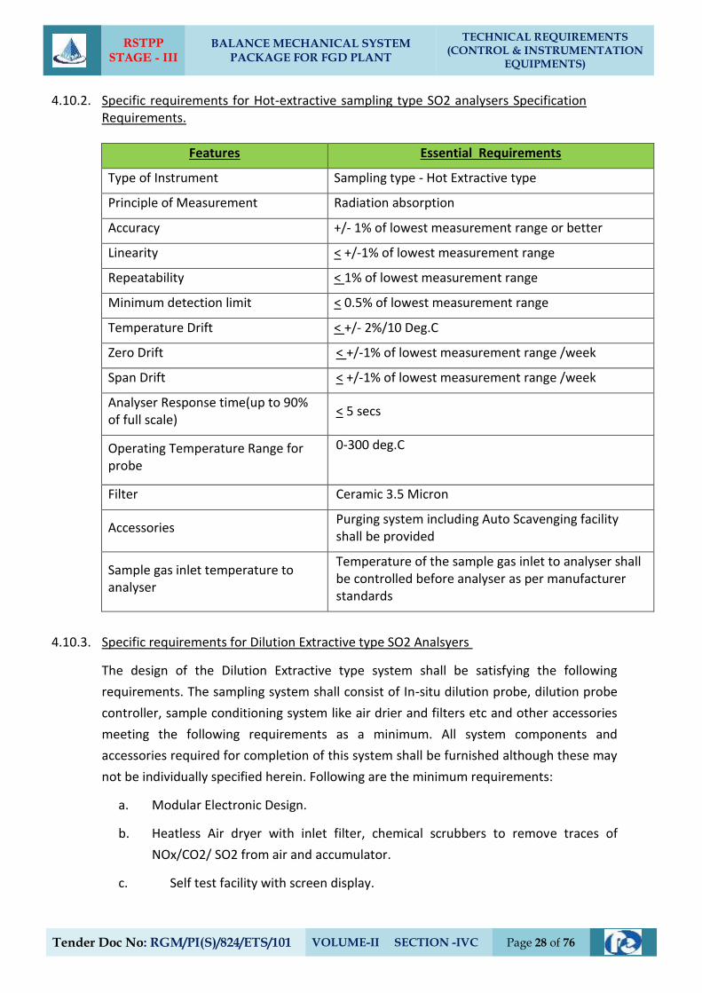
RSTPP STAGE - III
BALANCE MECHANICAL SYSTEM PACKAGE FOR FGD PLANT
TECHNICAL REQUIREMENTS (CONTROL & INSTRUMENTATION
EQUIPMENTS)
Tender Doc No: RGM/PI(S)/824/ETS/101 VOLUME-II SECTION -IVC Page 28 of 76
4.10.2. Specific requirements for Hot-extractive sampling type SO2 analysers Specification Requirements.
Features Essential Requirements
Type of Instrument Sampling type - Hot Extractive type
Principle of Measurement Radiation absorption
Accuracy +/- 1% of lowest measurement range or better
Linearity < +/-1% of lowest measurement range
Repeatability < 1% of lowest measurement range
Minimum detection limit < 0.5% of lowest measurement range
Temperature Drift < +/- 2%/10 Deg.C
Zero Drift < +/-1% of lowest measurement range /week
Span Drift < +/-1% of lowest measurement range /week
Analyser Response time(up to 90% of full scale)
< 5 secs
Operating Temperature Range for probe
0-300 deg.C
Filter Ceramic 3.5 Micron
Accessories Purging system including Auto Scavenging facility shall be provided
Sample gas inlet temperature to analyser
Temperature of the sample gas inlet to analyser shall be controlled before analyser as per manufacturer standards
4.10.3. Specific requirements for Dilution Extractive type SO2 Analsyers
The design of the Dilution Extractive type system shall be satisfying the following
requirements. The sampling system shall consist of In-situ dilution probe, dilution probe
controller, sample conditioning system like air drier and filters etc and other accessories
meeting the following requirements as a minimum. All system components and
accessories required for completion of this system shall be furnished although these may
not be individually specified herein. Following are the minimum requirements:
a. Modular Electronic Design.
b. Heatless Air dryer with inlet filter, chemical scrubbers to remove traces of
NOx/CO2/ SO2 from air and accumulator.
c. Self test facility with screen display.
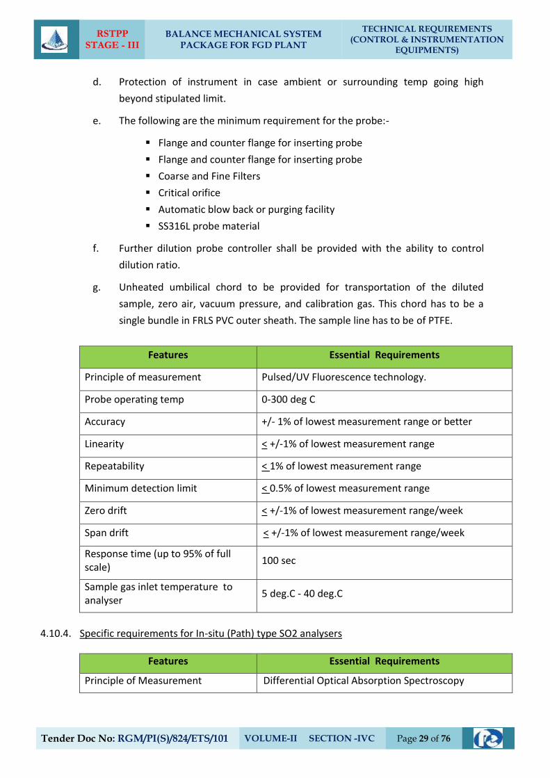
RSTPP STAGE - III
BALANCE MECHANICAL SYSTEM PACKAGE FOR FGD PLANT
TECHNICAL REQUIREMENTS (CONTROL & INSTRUMENTATION
EQUIPMENTS)
Tender Doc No: RGM/PI(S)/824/ETS/101 VOLUME-II SECTION -IVC Page 29 of 76
d. Protection of instrument in case ambient or surrounding temp going high
beyond stipulated limit.
e. The following are the minimum requirement for the probe:-
Flange and counter flange for inserting probe
Flange and counter flange for inserting probe
Coarse and Fine Filters
Critical orifice
Automatic blow back or purging facility
SS316L probe material
f. Further dilution probe controller shall be provided with the ability to control
dilution ratio.
g. Unheated umbilical chord to be provided for transportation of the diluted
sample, zero air, vacuum pressure, and calibration gas. This chord has to be a
single bundle in FRLS PVC outer sheath. The sample line has to be of PTFE.
Features Essential Requirements
Principle of measurement Pulsed/UV Fluorescence technology.
Probe operating temp 0-300 deg C
Accuracy +/- 1% of lowest measurement range or better
Linearity < +/-1% of lowest measurement range
Repeatability < 1% of lowest measurement range
Minimum detection limit < 0.5% of lowest measurement range
Zero drift < +/-1% of lowest measurement range/week
Span drift < +/-1% of lowest measurement range/week
Response time (up to 95% of full scale)
100 sec
Sample gas inlet temperature to analyser
5 deg.C - 40 deg.C
4.10.4. Specific requirements for In-situ (Path) type SO2 analysers
Features Essential Requirements
Principle of Measurement Differential Optical Absorption Spectroscopy
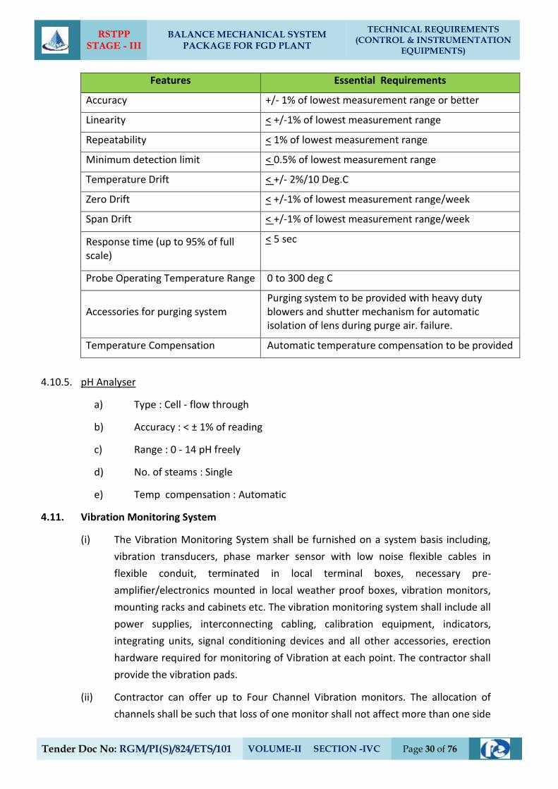
RSTPP STAGE - III
BALANCE MECHANICAL SYSTEM PACKAGE FOR FGD PLANT
TECHNICAL REQUIREMENTS (CONTROL & INSTRUMENTATION
EQUIPMENTS)
Tender Doc No: RGM/PI(S)/824/ETS/101 VOLUME-II SECTION -IVC Page 30 of 76
Features Essential Requirements
Accuracy +/- 1% of lowest measurement range or better
Linearity < +/-1% of lowest measurement range
Repeatability < 1% of lowest measurement range
Minimum detection limit < 0.5% of lowest measurement range
Temperature Drift < +/- 2%/10 Deg.C
Zero Drift < +/-1% of lowest measurement range/week
Span Drift < +/-1% of lowest measurement range/week
Response time (up to 95% of full scale)
< 5 sec
Probe Operating Temperature Range 0 to 300 deg C
Accessories for purging system Purging system to be provided with heavy duty blowers and shutter mechanism for automatic isolation of lens during purge air. failure.
Temperature Compensation Automatic temperature compensation to be provided
4.10.5. pH Analyser
a) Type : Cell - flow through
b) Accuracy : < ± 1% of reading
c) Range : 0 - 14 pH freely
d) No. of steams : Single
e) Temp compensation : Automatic
4.11. Vibration Monitoring System
(i) The Vibration Monitoring System shall be furnished on a system basis including,
vibration transducers, phase marker sensor with low noise flexible cables in
flexible conduit, terminated in local terminal boxes, necessary pre-
amplifier/electronics mounted in local weather proof boxes, vibration monitors,
mounting racks and cabinets etc. The vibration monitoring system shall include all
power supplies, interconnecting cabling, calibration equipment, indicators,
integrating units, signal conditioning devices and all other accessories, erection
hardware required for monitoring of Vibration at each point. The contractor shall
provide the vibration pads.
(ii) Contractor can offer up to Four Channel Vibration monitors. The allocation of
channels shall be such that loss of one monitor shall not affect more than one side
RSTPP STAGE - III
BALANCE MECHANICAL SYSTEM PACKAGE FOR FGD PLANT
TECHNICAL REQUIREMENTS (CONTROL & INSTRUMENTATION
EQUIPMENTS)
Tender Doc No: RGM/PI(S)/824/ETS/101 VOLUME-II SECTION -IVC Page 31 of 76
of the bearing of one machine. In the case of more than two channel Vibration
monitors being provided by the Contractor, then one spare monitor shall be
provided mounted in the panel to take care of immediate replacement of any
failed monitors. Offered vibration monitors shall be modular in construction, plug
in type.
(iii) Eddy current/piezoelectric type transducers shall be used. The sensors shall be
either proximity or velocity or accelerometer type. However, the finally selected
sensor type shall also depend on recommendation of the equipment
manufacturer & suitable for application requirement which shall be finalised
during detail engineering and without any extra price. Transducers shall be
furnished in weatherproof housing suitable for field conditions. Cables/cabling
from transducers local JB to Vibration Monitoring system in FGD Control
Room/Control Equipment Room shall be provided by the Contractor.
(iv) Vibration monitoring system shall give one no. buffered output of 4-20 mA DC and
two no. of buffered raw signal for each point monitored and one no. of buffered
raw signal for each phase marker sensor. The 4-20mA signal shall be suitable for
use as an input to DDCMIS, linear in proportion to vibration velocity or
displacement. Raw buffered signal(s) shall be suitable for archiving and analysis.
Monitor shall provide vibration indication calibrated in velocity units along with
provisions of changing to displacement unit (field-programmable) for each
measurement point in both horizontal & vertical planes. The generation of alarm
and trip signals is not envisaged in vibration monitoring system, the same shall be
derived in DDCMIS. However in case of vibration initiated protection of
equipments, OEM standard and proven practices shall also be considered.
(v) The vibration monitor racks with power supplies shall be mounted in a separate
self standing cabinet to be located in control room. The number of racks and
power supplies shall be such that on failure of a single power supply/module, not
more than four monitors shall be affected. The vibration monitoring cabinet shall
be fed from redundant 24V DC feeders with auto changeover scheme.
(vi) The power supply arrangement for monitors shall ensure that failure of one
power supply shall not affect any monitoring function in the system. Also any
power supply failure /earth fault in any of the monitors will be isolated without
affecting other monitors/ common power supply. If 230 V AC UPS power supply is
required for panel PC/ desktop PC, UPS/Mini UPS for the same shall be provided
by the contractor.
RSTPP STAGE - III
BALANCE MECHANICAL SYSTEM PACKAGE FOR FGD PLANT
TECHNICAL REQUIREMENTS (CONTROL & INSTRUMENTATION
EQUIPMENTS)
Tender Doc No: RGM/PI(S)/824/ETS/101 VOLUME-II SECTION -IVC Page 32 of 76
(vii) The functional requirement for vibration monitoring system shall include but not
be limited to the following:-
a) Vibration monitor front face status indications shall be available for
indications of healthy conditions of pick up circuit, monitor circuit and
power supply. On sensor fault/wire break in the sensor circuit, the system
shall have the feature of identifying the same through suitable means like
the signal forced to a value less than 4 mA. In case, such a feature is not
available then suitable contact shall be provided from the monitor for
sensor fault.
b) The facility shall be available for online functional checking of monitors.
c) All vibration monitoring equipment shall be functionally tested for circuit
continuity and output response. All the components & interconnection
cables shall be tested to ensure compliance with the specification
requirements & all other applicable codes & standards.
(viii) In case it is the proven standard practice of a Contractor to provide vibration
monitoring PC with TFT LCD monitor, instead of dedicated monitors with the
signal conditioning equipment in control equipment room, the same shall also be
acceptable. However, all relevant functional requirements detailed above shall be
met and the system shall be subject to Client (EPIL)’s approval.
(ix) In case it is the proven standard practice of a Contractor to provide vibration
monitoring PC with TFT LCD monitor, instead of dedicated monitors with the
signal conditioning equipment in control equipment room, the same shall also be
acceptable. However, all relevant functional requirements detailed above shall be
met and the system shall be subject to Client (EPIL)’s approval.
4.12. Field Instruments Based On Field- bus
The following instruments shall be connected to DDCMIS through fieldbus i.e.
FOUNDATION Fieldbus/PROFIBUS PA protocol complying to IEC 61158 directly from
transmitter. For all fieldbus based instruments, GSD and DTM files are to be provided
which shall be con-figured/ tested with DCS for proper interfacing and diagnostics.
4.12.1. Electronic Transmitter for Pressure, Differential Pressure and DP based Flow /
Level measurements
Sl.No Features Essential/Minimum Requirements
1 Type of
Transmitter FOUNDATION Fieldbus /PROFIBUS PA based output
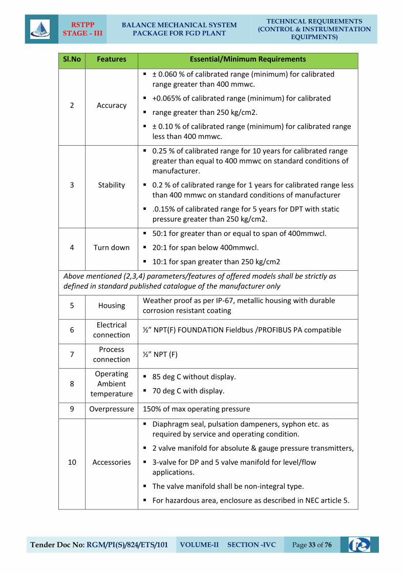
RSTPP STAGE - III
BALANCE MECHANICAL SYSTEM PACKAGE FOR FGD PLANT
TECHNICAL REQUIREMENTS (CONTROL & INSTRUMENTATION
EQUIPMENTS)
Tender Doc No: RGM/PI(S)/824/ETS/101 VOLUME-II SECTION -IVC Page 33 of 76
Sl.No Features Essential/Minimum Requirements
2 Accuracy
± 0.060 % of calibrated range (minimum) for calibrated range greater than 400 mmwc.
+0.065% of calibrated range (minimum) for calibrated
range greater than 250 kg/cm2.
± 0.10 % of calibrated range (minimum) for calibrated range less than 400 mmwc.
3 Stability
0.25 % of calibrated range for 10 years for calibrated range greater than equal to 400 mmwc on standard conditions of manufacturer.
0.2 % of calibrated range for 1 years for calibrated range less than 400 mmwc on standard conditions of manufacturer
.0.15% of calibrated range for 5 years for DPT with static pressure greater than 250 kg/cm2.
4 Turn down
50:1 for greater than or equal to span of 400mmwcl.
20:1 for span below 400mmwcl.
10:1 for span greater than 250 kg/cm2
Above mentioned (2,3,4) parameters/features of offered models shall be strictly as defined in standard published catalogue of the manufacturer only
5 Housing Weather proof as per IP-67, metallic housing with durable corrosion resistant coating
6 Electrical
connection ½” NPT(F) FOUNDATION Fieldbus /PROFIBUS PA compatible
7 Process
connection ½” NPT (F)
8 Operating Ambient
temperature
85 deg C without display.
70 deg C with display.
9 Overpressure 150% of max operating pressure
10 Accessories
Diaphragm seal, pulsation dampeners, syphon etc. as required by service and operating condition.
2 valve manifold for absolute & gauge pressure transmitters,
3-valve for DP and 5 valve manifold for level/flow applications.
The valve manifold shall be non-integral type.
For hazardous area, enclosure as described in NEC article 5.
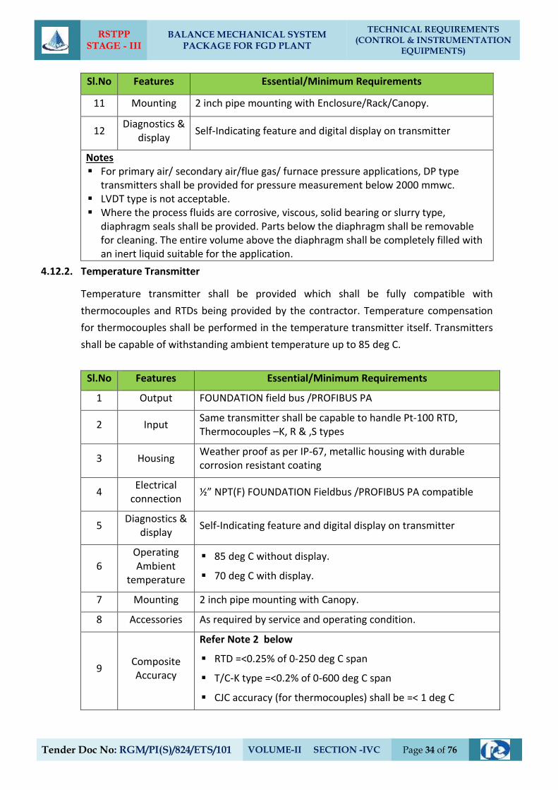
RSTPP STAGE - III
BALANCE MECHANICAL SYSTEM PACKAGE FOR FGD PLANT
TECHNICAL REQUIREMENTS (CONTROL & INSTRUMENTATION
EQUIPMENTS)
Tender Doc No: RGM/PI(S)/824/ETS/101 VOLUME-II SECTION -IVC Page 34 of 76
Sl.No Features Essential/Minimum Requirements
11 Mounting 2 inch pipe mounting with Enclosure/Rack/Canopy.
12 Diagnostics &
display Self-Indicating feature and digital display on transmitter
Notes For primary air/ secondary air/flue gas/ furnace pressure applications, DP type
transmitters shall be provided for pressure measurement below 2000 mmwc. LVDT type is not acceptable. Where the process fluids are corrosive, viscous, solid bearing or slurry type,
diaphragm seals shall be provided. Parts below the diaphragm shall be removable for cleaning. The entire volume above the diaphragm shall be completely filled with an inert liquid suitable for the application.
4.12.2. Temperature Transmitter
Temperature transmitter shall be provided which shall be fully compatible with
thermocouples and RTDs being provided by the contractor. Temperature compensation
for thermocouples shall be performed in the temperature transmitter itself. Transmitters
shall be capable of withstanding ambient temperature up to 85 deg C.
Sl.No Features Essential/Minimum Requirements
1 Output FOUNDATION field bus /PROFIBUS PA
2 Input Same transmitter shall be capable to handle Pt-100 RTD, Thermocouples –K, R & ,S types
3 Housing Weather proof as per IP-67, metallic housing with durable corrosion resistant coating
4 Electrical
connection ½” NPT(F) FOUNDATION Fieldbus /PROFIBUS PA compatible
5 Diagnostics &
display Self-Indicating feature and digital display on transmitter
6 Operating Ambient
temperature
85 deg C without display.
70 deg C with display.
7 Mounting 2 inch pipe mounting with Canopy.
8 Accessories As required by service and operating condition.
9 Composite Accuracy
Refer Note 2 below
RTD =<0.25% of 0-250 deg C span
T/C-K type =<0.2% of 0-600 deg C span
CJC accuracy (for thermocouples) shall be =< 1 deg C
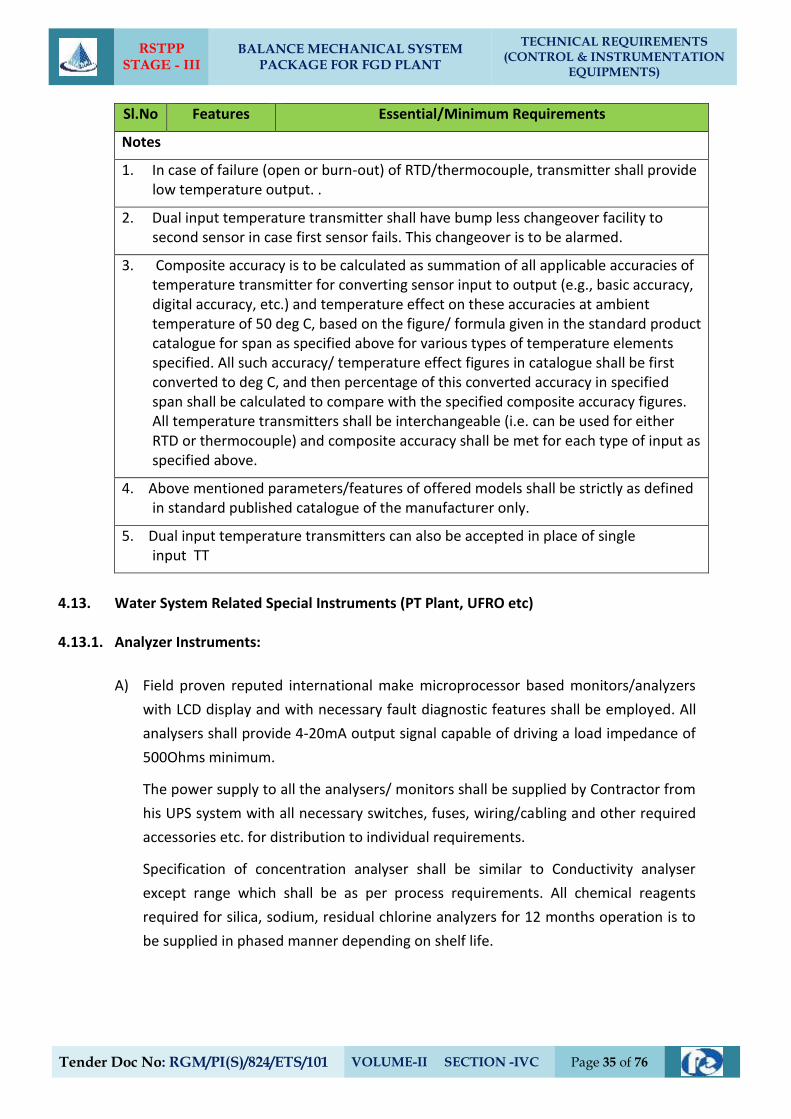
RSTPP STAGE - III
BALANCE MECHANICAL SYSTEM PACKAGE FOR FGD PLANT
TECHNICAL REQUIREMENTS (CONTROL & INSTRUMENTATION
EQUIPMENTS)
Tender Doc No: RGM/PI(S)/824/ETS/101 VOLUME-II SECTION -IVC Page 35 of 76
Sl.No Features Essential/Minimum Requirements
Notes
1. In case of failure (open or burn-out) of RTD/thermocouple, transmitter shall provide low temperature output. .
2. Dual input temperature transmitter shall have bump less changeover facility to second sensor in case first sensor fails. This changeover is to be alarmed.
3. Composite accuracy is to be calculated as summation of all applicable accuracies of temperature transmitter for converting sensor input to output (e.g., basic accuracy, digital accuracy, etc.) and temperature effect on these accuracies at ambient temperature of 50 deg C, based on the figure/ formula given in the standard product catalogue for span as specified above for various types of temperature elements specified. All such accuracy/ temperature effect figures in catalogue shall be first converted to deg C, and then percentage of this converted accuracy in specified span shall be calculated to compare with the specified composite accuracy figures. All temperature transmitters shall be interchangeable (i.e. can be used for either RTD or thermocouple) and composite accuracy shall be met for each type of input as specified above.
4. Above mentioned parameters/features of offered models shall be strictly as defined in standard published catalogue of the manufacturer only.
5. Dual input temperature transmitters can also be accepted in place of single input TT
4.13. Water System Related Special Instruments (PT Plant, UFRO etc)
4.13.1. Analyzer Instruments:
A) Field proven reputed international make microprocessor based monitors/analyzers
with LCD display and with necessary fault diagnostic features shall be employed. All
analysers shall provide 4-20mA output signal capable of driving a load impedance of
500Ohms minimum.
The power supply to all the analysers/ monitors shall be supplied by Contractor from
his UPS system with all necessary switches, fuses, wiring/cabling and other required
accessories etc. for distribution to individual requirements.
Specification of concentration analyser shall be similar to Conductivity analyser
except range which shall be as per process requirements. All chemical reagents
required for silica, sodium, residual chlorine analyzers for 12 months operation is to
be supplied in phased manner depending on shelf life.
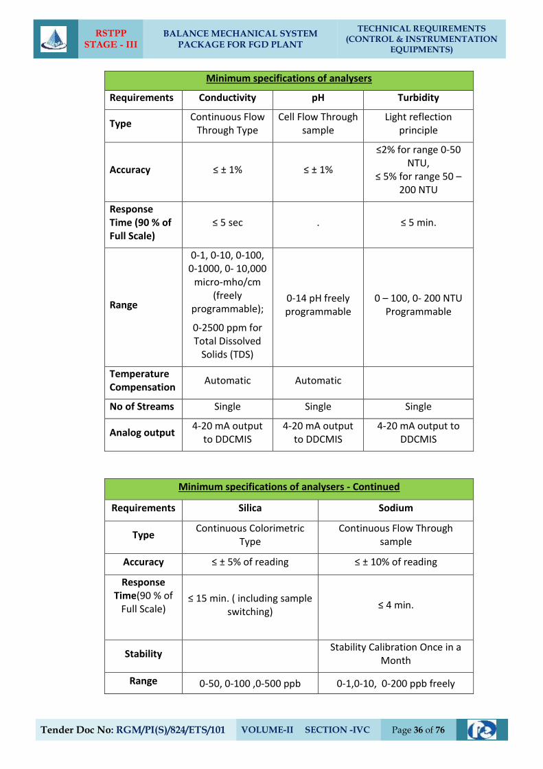
RSTPP STAGE - III
BALANCE MECHANICAL SYSTEM PACKAGE FOR FGD PLANT
TECHNICAL REQUIREMENTS (CONTROL & INSTRUMENTATION
EQUIPMENTS)
Tender Doc No: RGM/PI(S)/824/ETS/101 VOLUME-II SECTION -IVC Page 36 of 76
Minimum specifications of analysers
Requirements Conductivity pH Turbidity
Type Continuous Flow
Through Type Cell Flow Through
sample Light reflection
principle
Accuracy ≤ ± 1% ≤ ± 1%
≤2% for range 0-50 NTU,
≤ 5% for range 50 – 200 NTU
Response Time (90 % of Full Scale)
≤ 5 sec . ≤ 5 min.
Range
0-1, 0-10, 0-100, 0-1000, 0- 10,000
micro-mho/cm (freely
programmable);
0-2500 ppm for Total Dissolved
Solids (TDS)
0-14 pH freely programmable
0 – 100, 0- 200 NTU Programmable
Temperature Compensation
Automatic Automatic
No of Streams Single Single Single
Analog output 4-20 mA output
to DDCMIS 4-20 mA output
to DDCMIS 4-20 mA output to
DDCMIS
Minimum specifications of analysers - Continued
Requirements Silica Sodium
Type Continuous Colorimetric
Type Continuous Flow Through
sample
Accuracy ≤ ± 5% of reading ≤ ± 10% of reading
Response Time(90 % of
Full Scale)
≤ 15 min. ( including sample switching)
≤ 4 min.
Stability Stability Calibration Once in a
Month
Range 0-50, 0-100 ,0-500 ppb 0-1,0-10, 0-200 ppb freely
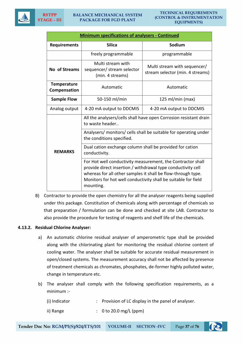
RSTPP STAGE - III
BALANCE MECHANICAL SYSTEM PACKAGE FOR FGD PLANT
TECHNICAL REQUIREMENTS (CONTROL & INSTRUMENTATION
EQUIPMENTS)
Tender Doc No: RGM/PI(S)/824/ETS/101 VOLUME-II SECTION -IVC Page 37 of 76
Minimum specifications of analysers - Continued
Requirements Silica Sodium
freely programmable programmable
No of Streams Multi stream with
sequencer/ stream selector (min. 4 streams)
Multi stream with sequencer/ stream selector (min. 4 streams)
Temperature Compensation
Automatic Automatic
Sample Flow 50-150 ml/min 125 ml/min (max)
Analog output 4-20 mA output to DDCMIS 4-20 mA output to DDCMIS
REMARKS
All the analysers/cells shall have open Corrosion resistant drain to waste header..
Analysers/ monitors/ cells shall be suitable for operating under the conditions specified.
Dual cation exchange column shall be provided for cation conductivity.
For Hot well conductivity measurement, the Contractor shall provide direct insertion / withdrawal type conductivity cell whereas for all other samples it shall be flow-through type. Monitors for hot well conductivity shall be suitable for field mounting.
B) Contractor to provide the open chemistry for all the analyser reagents being supplied
under this package. Constitution of chemicals along with percentage of chemicals so
that preparation / formulation can be done and checked at site LAB. Contractor to
also provide the procedure for testing of reagents and shelf life of the chemicals.
4.13.2. Residual Chlorine Analyser:
a) An automatic chlorine residual analyser of amperometric type shall be provided
along with the chlorinating plant for monitoring the residual chlorine content of
cooling water. The analyser shall be suitable for accurate residual measurement in
open/closed systems. The measurement accuracy shall not be affected by presence
of treatment chemicals as chromates, phosphates, de-former highly polluted water,
change in temperature etc.
b) The analyser shall comply with the following specification requirements, as a
minimum :-
(i) Indicator : Provision of LC display in the panel of analyser.
ii) Range : 0 to 20.0 mg/L (ppm)
RSTPP STAGE - III
BALANCE MECHANICAL SYSTEM PACKAGE FOR FGD PLANT
TECHNICAL REQUIREMENTS (CONTROL & INSTRUMENTATION
EQUIPMENTS)
Tender Doc No: RGM/PI(S)/824/ETS/101 VOLUME-II SECTION -IVC Page 38 of 76
(iii) Accuracy : 2% or better
(iv) Sensitivity : 0.01 mg/1
(v) Output signal : 4-20mA DC isolated output,
(vi) Alarm annunciation: High and low alarms to be provided on panel and shall be
field adjustable.
(vii) Calibration : Zero and span adjustment facility to be provided. Final
calibration adjustments of the analyser to be done at
site and duly verified by titration.
Temperature compensation range 0 to 50 deg C.
(x) Mounting : The analyser shall be suitable for field mounting
conform to protection class IP-55.
(xii) Electrodes : Platinum/Gold and copper electrodes shall be
provided with cell cleaning system.
c) Circulating water as sample to residual chlorine analyser shall be taken from hot
circulating water pipe work before entry to cooling towers. Exact location and
layout of sampling arrangement shall be finalised during detailed engg. stage.
Bidder shall provide necessary pumping system (with 100% standby) for meeting
the analyser requirements, if needed. All the drains shall be terminated up to the
nearest plant drainage system.
4.13.3. All the outdoor field instruments such as analysers/transmitters/meters etc. shall
be provided with suitable Free standing cabinet(s)/panel/rack so that the
equipments are protected against rain/ sunlight etc
4.13.4. Parshall Flume
The Bidder shall provide all the control and Instrument devices including primary sensors,
transmitters, flow indicator cum integrator / totaliser and shall include all required
accessories for the flow measurement of raw water through the clarifier. The system
shall be of reputed make and acceptable to the Client (EPIL).
Level measurement shall be based on ultrasonic/radon technology. The flow
compensation is to be implemented in the transmitter itself. The transmitter shall
provide 4-20 mA DC in direct proportion to flow and shall be able to drive a load
impedance of 500 ohms minimum Accuracy shall be +/- 1 % or better.
All the mounting hardware and accessories required for erection and commissioning of
the same are to be provided by the contractor. Mounting fittings material shall be SS316.
RSTPP STAGE - III
BALANCE MECHANICAL SYSTEM PACKAGE FOR FGD PLANT
TECHNICAL REQUIREMENTS (CONTROL & INSTRUMENTATION
EQUIPMENTS)
Tender Doc No: RGM/PI(S)/824/ETS/101 VOLUME-II SECTION -IVC Page 39 of 76
All weather canopy is to be provided for electronics/sensor to protect the same from
rain/ sunlight etc.
The Type makes and models no. shall be subject to Client (EPIL)’s approval.
4.13.5. Electronic Flow-Meter
The electronic flow meter shall include flow sensor and flow indicator cum integrator /
totaliser and shall include all required accessories for satisfactory operation. The flow
meter shall be based on full bore electromagnetic principle and shall be electronic type of
proven design, make and model acceptable to the Client (EPIL).
The Bidder shall submit all necessary technical literature and details of selection criteria
of the instrument offered to substantiate the model selected. The Bidder shall also
furnish list of similar installation along with feedback on satisfactory performance of the
instruments. The flow meter shall meet or exceed the following requirement:
(a) Output : 4-20 mA DC Isolated output
(b) Accuracy : ± 0.5% of calibrated span or better *
(c) Repeatability : ± 0.2% of calibrated span or better
(d) Power Supply : 240V AC ± 10%, 50 HZ ± 5%/ 24 V DC, to be
arranged by the contractor
(f) Protection class : IP-55
(e)Flow tube : SS304
(f) liner : Hard Rubber
The flow meter shall provide local indication for instantaneous flow. It should also be
possible to get local display for daily and monthly discharge. The flow meter shall
indicate totaliser/ integrator to get the daily and monthly discharge as stated above.
RSTPP STAGE - III
BALANCE MECHANICAL SYSTEM PACKAGE FOR FGD PLANT
TECHNICAL REQUIREMENTS (CONTROL & INSTRUMENTATION
EQUIPMENTS)
Tender Doc No: RGM/PI(S)/824/ETS/101 VOLUME-II SECTION -IVC Page 40 of 76
`
5. PROCESS CONNECTION AND PIPING
5.1. General
5.1.1. The Contractor shall provide, install and test all required material for completeness of
Impulse Piping System and Air Piping System as per the requirements of this Sub-Section
on as required basis for the connection of all instruments and control equipments of
entire plant.
5.2. Impulse Piping, Tubing, Fittings, Valves and Valve Manifolds
5.2.1. All impulse pipes shall be of seamless type conforming to ANSI B36.10 for schedule
numbers. The size of impulse pipe shall be ½” for Steam & Water Application and ¾” for
Air & Flue Gas applications. The rating of material of impulse pipes, tubes, fittings, valves
and their installation thereof shall conform to the latest edition of standards as per
following table:
Impulse Pipes, Tubes (Material, Rating) ANSI B31.1, ANSI B31.1a, ANSI/ISA 77.70
Valves (Material, Pr. Class, Size) ASTM A182/ASTM A105 as per ASME 16.34
Fittings (Size, Rating, Material) ANSI B31.1, ANSI B31.1a, ASME B16.11-2009
Installation Schemes BS 6739-2009, ANSI/ISA 77.70
Stainless steel tube shall be provided inside enclosures & racks from tee connection to
valve manifold and then to instrument. The source shut-off (primary process root valve)
and blow-down valve shall be of 1/2 inch size globe valve type for all applications except
for air and flue gas service wherein no source shut-off valves are to be provided. Two
root valves are to be used wherever pressure is more than 40 Kg/cm2 or Temp>280 oC.
The end connections of valves shall be of socket welded type. Typical installation scheme
of DP Transmitter (inside LIE/LIR) mounted below instrument source point is indicated in
Drg. No. 0000-999-POI-A-036. Same scheme with necessary changes shall be applied for
other instruments.
5.2.2. The valve manifolds of 316 SS with pressure rating suitable for intended application shall
be provided as given below:
Manifold Application/Measurement
2 Valve Pressure measurements using pressure transmitters/pressure switches.
3 Valve Pressure measurements using differential pressure transmitter/ switches.
5 Valve Differential Pressure, Flow and Level Measurements
For Pressur./D.P gauges, two-way globe/gate valve shall be provided on each impulse line
to the instrument in Fluid/Air & Flue Gas applications respectively.
RSTPP STAGE - III
BALANCE MECHANICAL SYSTEM PACKAGE FOR FGD PLANT
TECHNICAL REQUIREMENTS (CONTROL & INSTRUMENTATION
EQUIPMENTS)
Tender Doc No: RGM/PI(S)/824/ETS/101 VOLUME-II SECTION -IVC Page 41 of 76
5.3. Air Supply Piping
5.3.1. All pneumatic piping, fittings, valves, air filter cum regulator, purge rotameter and other
accessories required for instrument air for the various pneumatic devices/ instruments
shall be provided. This will include as a minimum air supply to pneumatically operated
control valves, actuators, instruments, continuous and intermittent purging requirements
etc.
5.3.2. Instrument air and Service air supply shall be provided for continuous and intermittent
purging respectively for all transmitters of mill, dirty air and flue gas applications. Purging
Scheme shall be as per Drg. No. 0000-999-POI-A-036.
5.3.3. The Contractor shall also provide SS Tubing and associated fittings (screwed type) of
suitable sizes for all pneumatic equipments/actuators (including supply air, signal air and
output to actuators) conforming to ANSI 31.1 and 31.3 standard. All other air supply lines
shall be of mild steel hot dipped galvanized inside and outside as per IS-1239, heavy duty
with threaded ends. Fittings for air supply line shall be of forged carbon steel A234 Gr.
WPB galvanized inside and outside, screwed as per ASA B2.1. Dimensions of fittings shall
be as per ASA B16.11 of rating 3000 lbs. Air supply piping shall be adequately sloped to
prevent accumulation of condensed water within the pipe. The air supply headers, sub-
headers and branch pipes shall be supported properly by clamps or supports.
5.3.4. The instrument/service air supply to each equipment/devices requiring air supply shall be
provided by a well designed air distribution scheme comprising of 2” GI Pipe Header
feeding 1” GI Pipe sub-header feeding ½” pipe at each equipment/device. Instrument air
filters cum regulator set with mounting accessories shall be provided for each pneumatic
device requiring air supply except for Ash Handling System wherein it shall be provided
on instrument air header at each location.
5.3.5. All the isolation valves in the air supply line shall be gate valves as per ASTM B62 inside
screw rising stem, screwed female ends as per ASA B2.1. Valve bonnet shall be union
type & trim material shall be stainless steel, body rating 150 pounds ASA. The valve sizes
shall be ½ inch to 2 inch.
5.3.6. Instrument air filters cum regulator set with mounting accessories shall be provided for
pneumatic device requiring air supply. The filter regulators shall be suitable for 10-kg/
sq.cm max. Inlet pressure. The filter shall be of size 5 microns and of material sintered
bronze. The air set shall have 2-inch size pressure gauge and built in filter housing
blowdown valve. The end connection shall be as per the requirement to be finalized
during detailed engineering.
RSTPP STAGE - III
BALANCE MECHANICAL SYSTEM PACKAGE FOR FGD PLANT
TECHNICAL REQUIREMENTS (CONTROL & INSTRUMENTATION
EQUIPMENTS)
Tender Doc No: RGM/PI(S)/824/ETS/101 VOLUME-II SECTION -IVC Page 42 of 76
5.4. Installation and Routing
5.4.1. All instrument piping, tubing and its accessories shall be supported in a safe manner to
prevent excessive vibrations and anchored sufficiently to prevent undue strain on
connected equipment. Impulse piping shall be supported at an interval not exceeding 1.5
meters. The slope of the impulse pipe form the process connection to the instrument
shall be as per ANSI/ISA 77.70 latest edition and BS 6739-2009. All impulse piping shall be
installed to permit free movement due to thermal expansion. Wherever required
expansion loops shall be provided. Condensate pots shall be provided for all level
measurements in steam and water services, all flow measurement in steam services and
for flow measurements in water services above 120 Deg. C. Colour coding of all impulse
pipes shall be done by the Contractor in line with the colour coding being followed for
the parent pipes.
5.5. Shop and Site Tests
5.5.1. The equipment and work performed as per this Sub-section shall be subject to shop and
site test as per requirements of Sub-section-IIIE-04 (Quality Assurance & Inspection)
other applicable clauses of this Sub-section and Client (EPIL) approved quality assurance
plan.
5.5.2. Hydrostatic and Pneumatic leakage tests shall be performed on all pipes, tubing and
systems and shall conform to ANSI B31.1.
5.6. Local Instrument Enclosure and Racks
All transmitters, switches etc. for FGD system and other system being provided under the
contract shall be suitably grouped together and mounted inside (i) local instruments
enclosures in case of open areas of the plant and (ii) In local instrument racks in case of
covered areas. The GA of LIE with purging indicated in the Drg. No. 0000-999-POI-A-036 is
to be followed by contractor. The GA of LIR shall be similar to LIE except for front/rear
doors and side panels.
The internal layout shall be such that the impulse piping/ blow down lines are accessible
from back side of the enclosure / rack and the transmitters etc. are accessible from front
side for easy maintenance. Bulkheads, especially designed to provide isolation from
process line vibration shall be installed on instrument enclosures/racks to meet the
process sensing line connection requirement. Vibration dampeners shall be installed for
each enclosure / rack. The Degree of Protection of LIE and JB of LIE/LIR shall be IP-55.
The enclosures shall be constructed of 3 mm sheet plate and shall be of modular
construction with one or more modules and two end assemblies bolted together to form
an enclosure. Double inter locking doors shall be provided. The doors shall be the three-
RSTPP STAGE - III
BALANCE MECHANICAL SYSTEM PACKAGE FOR FGD PLANT
TECHNICAL REQUIREMENTS (CONTROL & INSTRUMENTATION
EQUIPMENTS)
Tender Doc No: RGM/PI(S)/824/ETS/101 VOLUME-II SECTION -IVC Page 43 of 76
point locking type constructed of not less than 1.6 mm thick steel. Doors shall have
concealed quick removal type pinned hinges and locking handles. Door locks shall accept
the same key.
The instrument racks shall be free standing type constructed of suitable 5 mm thick
channel frame of steel and shall be provided with a canopy to protect the equipment
mounted in racks from falling objects, water etc. The canopy shall not be less than 3 mm
thick steel, and extended beyond the ends of the rack.
Enclosures/Racks shall be reinforced as required to ensure true surface and to provide
adequate support for instruments and equipment mounted therein. Centre posts or any
member which would reduce access shall not be provided.
Contractor shall provide not more than three variants for LIE/LIR with respect to man.no
transmitters mounted in each LIE/LIR.
5.7. Enclosure / Racks For Dual I/P Temperature Transmitters
All Dual Input temperature transmitters for FGD system and other system being provided
under the contract shall be suitably grouped together and mounted inside (i) Enclosures
in case of open areas of the plant and (ii) Racks in case of covered areas. Integral JB shall
be provided with each Enclosure and Rack.
The internal layout shall be such that the transmitters are accessible from both front and
back side of the enclosure / rack for easy maintenance.
Enclosure/ Racks shall be of robust and rugged design. Vibration dampeners shall be
installed for each enclosure / rack. The Degree of Protection of Enclosure and JB shall be
IP-55.
Enclosure and Racks shall be free standing type. Enclosures/Racks shall be reinforced as
required to ensure true surface and to provide adequate support for instruments and
equipment mounted therein.
Contractor shall provide not more than five variants for Enclosure/ Rack with respect to
max. no. transmitters mounted in each Enclosure/ Rack. However, the maximum number
of Transmitters that can be grouped in one Enclosure/ Rack shall be decided during detail
Engineering.
5.8. Installation of Other Instruments:
For installation and routing of other field mounted instruments which are not covered in
Cl.No. 3.06.00, Erection Conditions of Contract (ECC) of Technical Specifications be
referred.
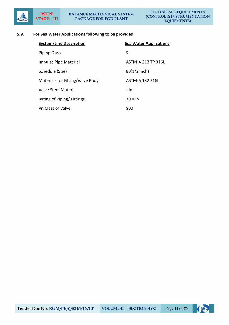
RSTPP STAGE - III
BALANCE MECHANICAL SYSTEM PACKAGE FOR FGD PLANT
TECHNICAL REQUIREMENTS (CONTROL & INSTRUMENTATION
EQUIPMENTS)
Tender Doc No: RGM/PI(S)/824/ETS/101 VOLUME-II SECTION -IVC Page 44 of 76
5.9. For Sea Water Applications following to be provided
System/Line Description Sea Water Applications
Piping Class S
Impulse Pipe Material ASTM-A 213 TP 316L
Schedule (Size) 80(1/2 inch)
Materials for Fitting/Valve Body ASTM-A 182 316L
Valve Stem Material -do-
Rating of Piping/ Fittings 3000lb
Pr. Class of Valve 800
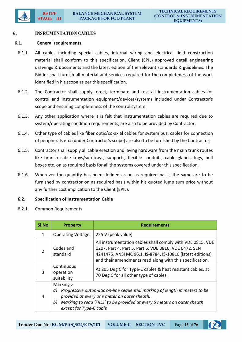
RSTPP STAGE - III
BALANCE MECHANICAL SYSTEM PACKAGE FOR FGD PLANT
TECHNICAL REQUIREMENTS (CONTROL & INSTRUMENTATION
EQUIPMENTS)
Tender Doc No: RGM/PI(S)/824/ETS/101 VOLUME-II SECTION -IVC Page 45 of 76
`
6. INSRUMENTATION CABLES
6.1. General requirements
6.1.1. All cables including special cables, internal wiring and electrical field construction
material shall conform to this specification, Client (EPIL) approved detail engineering
drawings & documents and the latest edition of the relevant standards & guidelines. The
Bidder shall furnish all material and services required for the completeness of the work
identified in his scope as per this specification.
6.1.2. The Contractor shall supply, erect, terminate and test all instrumentation cables for
control and instrumentation equipment/devices/systems included under Contractor's
scope and ensuring completeness of the control system.
6.1.3. Any other application where it is felt that instrumentation cables are required due to
system/operating condition requirements, are also to be provided by Contractor.
6.1.4. Other type of cables like fiber optic/co-axial cables for system bus, cables for connection
of peripherals etc. (under Contractor's scope) are also to be furnished by the Contractor.
6.1.5. Contractor shall supply all cable erection and laying hardware from the main trunk routes
like branch cable trays/sub-trays, supports, flexible conduits, cable glands, lugs, pull
boxes etc. on as required basis for all the systems covered under this specification.
6.1.6. Wherever the quantity has been defined as on as required basis, the same are to be
furnished by contractor on as required basis within his quoted lump sum price without
any further cost implication to the Client (EPIL).
6.2. Specification of Instrumentation Cable
6.2.1. Common Requirements
Sl.No Property Requirements
1 Operating Voltage 225 V (peak value)
2 Codes and standard
All instrumentation cables shall comply with VDE 0815, VDE 0207, Part 4, Part 5, Part 6, VDE 0816, VDE 0472, SEN 4241475, ANSI MC 96.1, IS-8784, IS-10810 (latest editions) and their amendments read along with this specification.
3 Continuous operation suitability
At 205 Deg C for Type-C cables & heat resistant cables, at 70 Deg C for all other type of cables.
4
Marking :- a) Progressive automatic on-line sequential marking of length in meters to be
provided at every one meter on outer sheath. b) Marking to read ‘FRLS’ to be provided at every 5 meters on outer sheath
except for Type-C cable
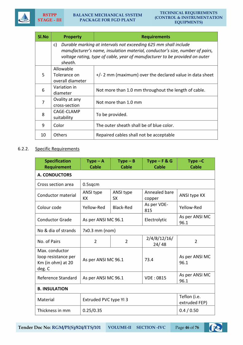
RSTPP STAGE - III
BALANCE MECHANICAL SYSTEM PACKAGE FOR FGD PLANT
TECHNICAL REQUIREMENTS (CONTROL & INSTRUMENTATION
EQUIPMENTS)
Tender Doc No: RGM/PI(S)/824/ETS/101 VOLUME-II SECTION -IVC Page 46 of 76
Sl.No Property Requirements
c) Durable marking at intervals not exceeding 625 mm shall include manufacturer’s name, insulation material, conductor’s size, number of pairs, voltage rating, type of cable, year of manufacturer to be provided on outer sheath.
5 Allowable Tolerance on overall diameter
+/- 2 mm (maximum) over the declared value in data sheet
6 Variation in diameter
Not more than 1.0 mm throughout the length of cable.
7 Ovality at any cross-section
Not more than 1.0 mm
8 CAGE-CLAMP suitability
To be provided.
9 Color The outer sheath shall be of blue color.
10 Others Repaired cables shall not be acceptable
6.2.2. Specific Requirements
Specification Requirement
Type – A Cable
Type – B Cable
Type – F & G Cable
Type –C Cable
A. CONDUCTORS
Cross section area 0.5sqcm
Conductor material ANSI type KX
ANSI type SX
Annealed bare copper
ANSI type KX
Colour code Yellow-Red Black-Red As per VDE-815
Yellow-Red
Conductor Grade As per ANSI MC 96.1 Electrolytic As per ANSI MC 96.1
No & dia of strands 7x0.3 mm (nom)
No. of Pairs 2 2 2/4/8/12/16/
24/ 48 2
Max. conductor loop resistance per Km (in ohm) at 20 deg. C
As per ANSI MC 96.1 73.4 As per ANSI MC 96.1
Reference Standard As per ANSI MC 96.1 VDE : 0815 As per ANSI MC 96.1
B. INSULATION
Material Extruded PVC type YI 3 Teflon (i.e. extruded FEP)
Thickness in mm 0.25/0.35 0.4 / 0.50
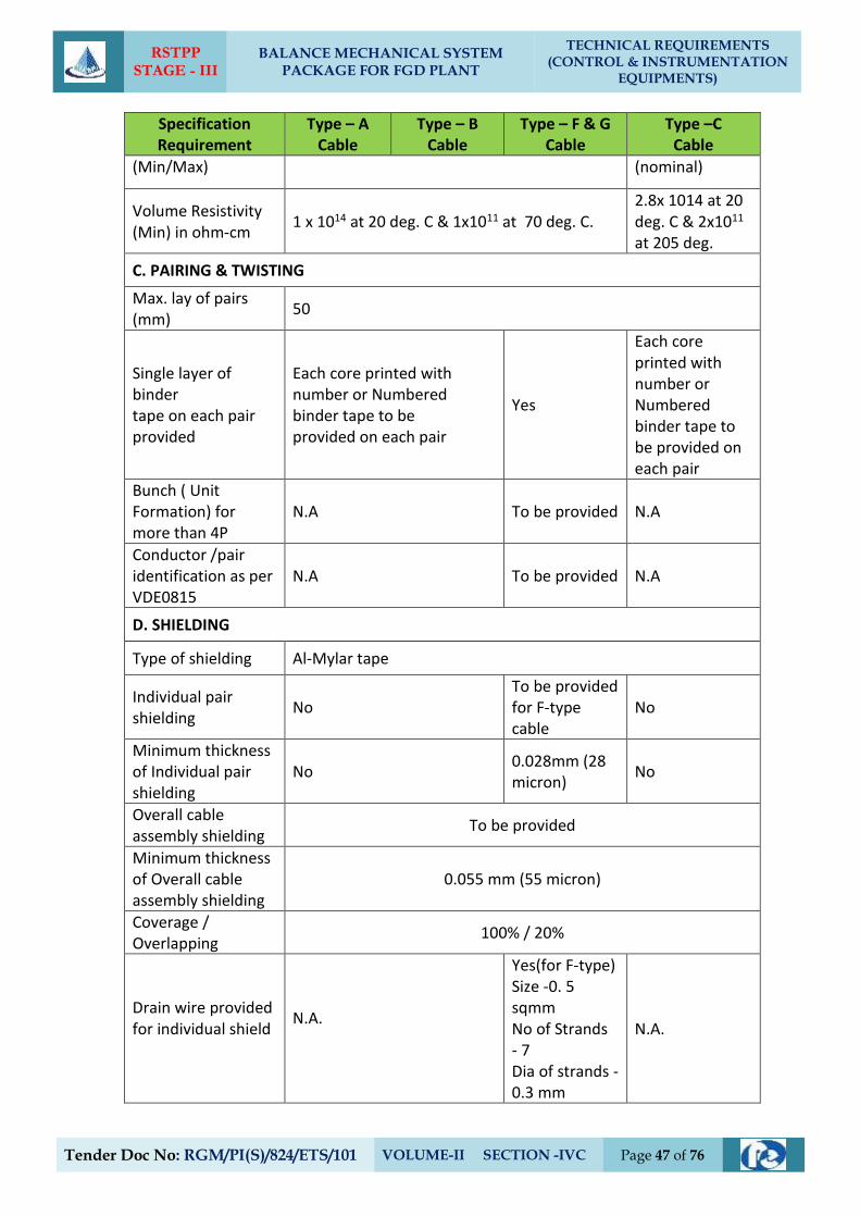
RSTPP STAGE - III
BALANCE MECHANICAL SYSTEM PACKAGE FOR FGD PLANT
TECHNICAL REQUIREMENTS (CONTROL & INSTRUMENTATION
EQUIPMENTS)
Tender Doc No: RGM/PI(S)/824/ETS/101 VOLUME-II SECTION -IVC Page 47 of 76
Specification Requirement
Type – A Cable
Type – B Cable
Type – F & G Cable
Type –C Cable
(Min/Max) (nominal)
Volume Resistivity (Min) in ohm-cm
1 x 10¹⁴ at 20 deg. C & 1x10¹¹ at 70 deg. C. 2.8x 10¹⁴ at 20 deg. C & 2x10¹¹ at 205 deg.
C. PAIRING & TWISTING
Max. lay of pairs (mm)
50
Single layer of binder tape on each pair provided
Each core printed with number or Numbered binder tape to be provided on each pair
Yes
Each core printed with number or Numbered binder tape to be provided on each pair
Bunch ( Unit Formation) for more than 4P
N.A To be provided N.A
Conductor /pair identification as per VDE0815
N.A To be provided N.A
D. SHIELDING
Type of shielding Al-Mylar tape
Individual pair shielding
No To be provided for F-type cable
No
Minimum thickness of Individual pair shielding
No 0.028mm (28 micron)
No
Overall cable assembly shielding
To be provided
Minimum thickness of Overall cable assembly shielding
0.055 mm (55 micron)
Coverage / Overlapping
100% / 20%
Drain wire provided for individual shield
N.A.
Yes(for F-type) Size -0. 5 sqmm No of Strands - 7 Dia of strands - 0.3 mm
N.A.
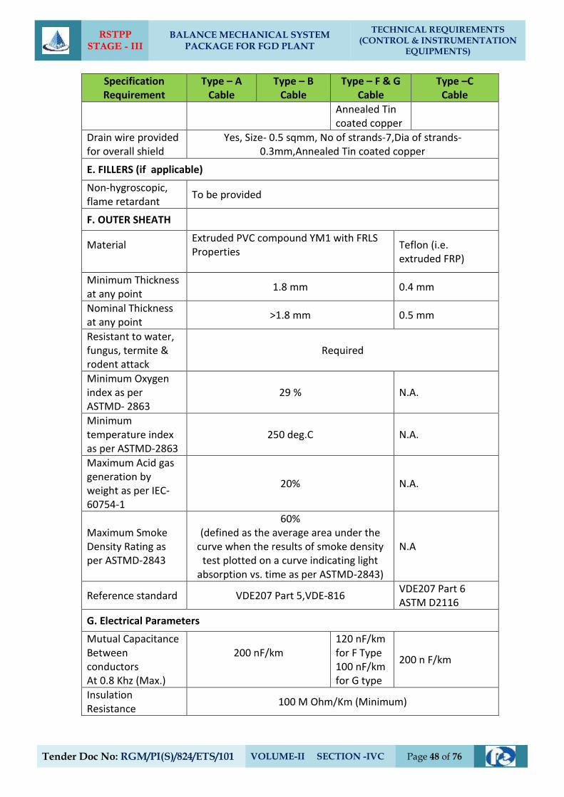
RSTPP STAGE - III
BALANCE MECHANICAL SYSTEM PACKAGE FOR FGD PLANT
TECHNICAL REQUIREMENTS (CONTROL & INSTRUMENTATION
EQUIPMENTS)
Tender Doc No: RGM/PI(S)/824/ETS/101 VOLUME-II SECTION -IVC Page 48 of 76
Specification Requirement
Type – A Cable
Type – B Cable
Type – F & G Cable
Type –C Cable
Annealed Tin coated copper
Drain wire provided for overall shield
Yes, Size- 0.5 sqmm, No of strands-7,Dia of strands- 0.3mm,Annealed Tin coated copper
E. FILLERS (if applicable)
Non-hygroscopic, flame retardant
To be provided
F. OUTER SHEATH
Material
Extruded PVC compound YM1 with FRLS Properties
Teflon (i.e. extruded FRP)
Minimum Thickness at any point
1.8 mm 0.4 mm
Nominal Thickness at any point
>1.8 mm 0.5 mm
Resistant to water, fungus, termite & rodent attack
Required
Minimum Oxygen index as per ASTMD- 2863
29 % N.A.
Minimum temperature index as per ASTMD-2863
250 deg.C N.A.
Maximum Acid gas generation by weight as per IEC-60754-1
20% N.A.
Maximum Smoke Density Rating as per ASTMD-2843
60% (defined as the average area under the
curve when the results of smoke density test plotted on a curve indicating light
absorption vs. time as per ASTMD-2843)
N.A
Reference standard VDE207 Part 5,VDE-816 VDE207 Part 6 ASTM D2116
G. Electrical Parameters
Mutual Capacitance Between conductors At 0.8 Khz (Max.)
200 nF/km
120 nF/km for F Type 100 nF/km for G type
200 n F/km
Insulation Resistance
100 M Ohm/Km (Minimum)
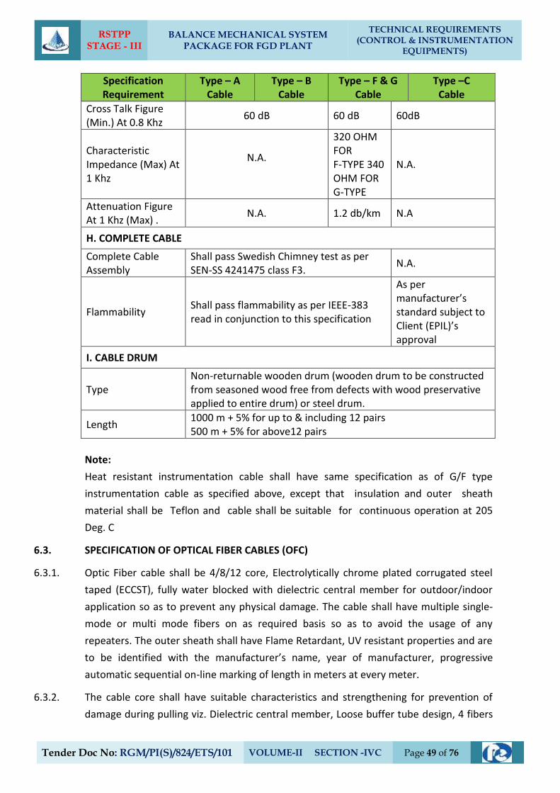
RSTPP STAGE - III
BALANCE MECHANICAL SYSTEM PACKAGE FOR FGD PLANT
TECHNICAL REQUIREMENTS (CONTROL & INSTRUMENTATION
EQUIPMENTS)
Tender Doc No: RGM/PI(S)/824/ETS/101 VOLUME-II SECTION -IVC Page 49 of 76
Specification Requirement
Type – A Cable
Type – B Cable
Type – F & G Cable
Type –C Cable
Cross Talk Figure (Min.) At 0.8 Khz
60 dB 60 dB 60dB
Characteristic Impedance (Max) At 1 Khz
N.A.
320 OHM FOR F-TYPE 340 OHM FOR G-TYPE
N.A.
Attenuation Figure At 1 Khz (Max) .
N.A. 1.2 db/km N.A
H. COMPLETE CABLE
Complete Cable Assembly
Shall pass Swedish Chimney test as per SEN-SS 4241475 class F3.
N.A.
Flammability Shall pass flammability as per IEEE-383 read in conjunction to this specification
As per manufacturer’s standard subject to Client (EPIL)’s approval
I. CABLE DRUM
Type Non-returnable wooden drum (wooden drum to be constructed from seasoned wood free from defects with wood preservative applied to entire drum) or steel drum.
Length 1000 m + 5% for up to & including 12 pairs 500 m + 5% for above12 pairs
Note:
Heat resistant instrumentation cable shall have same specification as of G/F type
instrumentation cable as specified above, except that insulation and outer sheath
material shall be Teflon and cable shall be suitable for continuous operation at 205
Deg. C
6.3. SPECIFICATION OF OPTICAL FIBER CABLES (OFC)
6.3.1. Optic Fiber cable shall be 4/8/12 core, Electrolytically chrome plated corrugated steel
taped (ECCST), fully water blocked with dielectric central member for outdoor/indoor
application so as to prevent any physical damage. The cable shall have multiple single-
mode or multi mode fibers on as required basis so as to avoid the usage of any
repeaters. The outer sheath shall have Flame Retardant, UV resistant properties and are
to be identified with the manufacturer’s name, year of manufacturer, progressive
automatic sequential on-line marking of length in meters at every meter.
6.3.2. The cable core shall have suitable characteristics and strengthening for prevention of
damage during pulling viz. Dielectric central member, Loose buffer tube design, 4 fibers
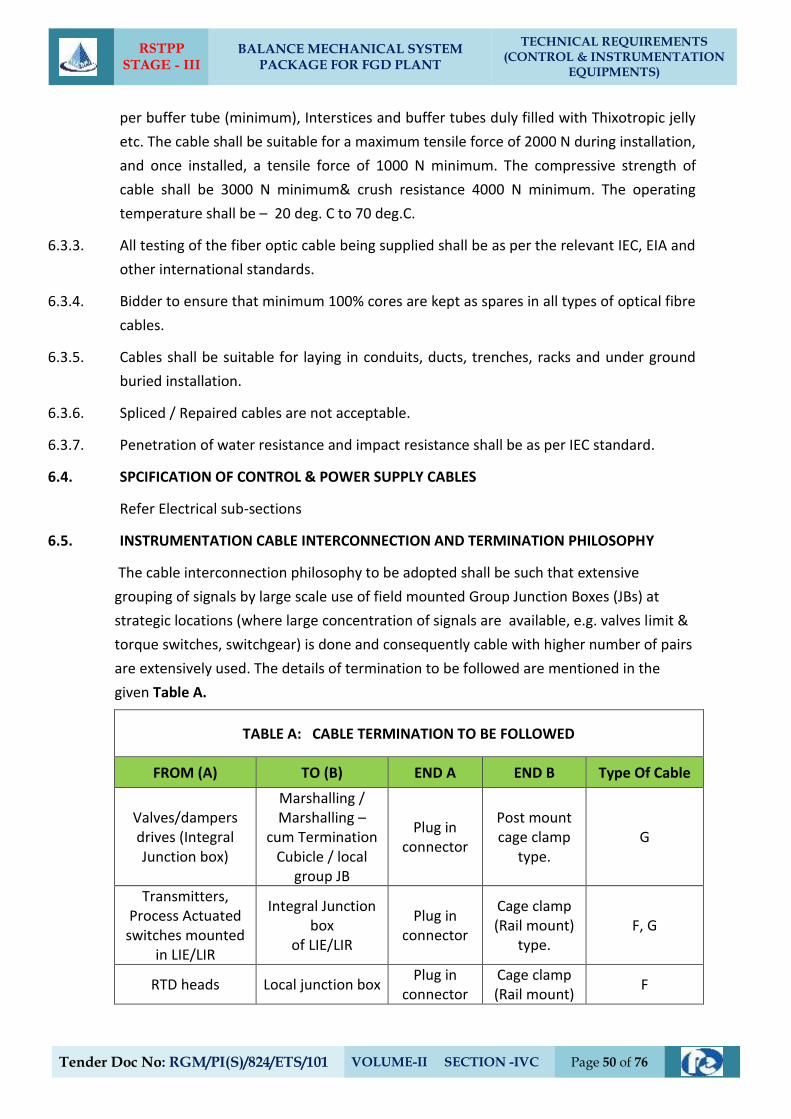
RSTPP STAGE - III
BALANCE MECHANICAL SYSTEM PACKAGE FOR FGD PLANT
TECHNICAL REQUIREMENTS (CONTROL & INSTRUMENTATION
EQUIPMENTS)
Tender Doc No: RGM/PI(S)/824/ETS/101 VOLUME-II SECTION -IVC Page 50 of 76
per buffer tube (minimum), Interstices and buffer tubes duly filled with Thixotropic jelly
etc. The cable shall be suitable for a maximum tensile force of 2000 N during installation,
and once installed, a tensile force of 1000 N minimum. The compressive strength of
cable shall be 3000 N minimum& crush resistance 4000 N minimum. The operating
temperature shall be – 20 deg. C to 70 deg.C.
6.3.3. All testing of the fiber optic cable being supplied shall be as per the relevant IEC, EIA and
other international standards.
6.3.4. Bidder to ensure that minimum 100% cores are kept as spares in all types of optical fibre
cables.
6.3.5. Cables shall be suitable for laying in conduits, ducts, trenches, racks and under ground
buried installation.
6.3.6. Spliced / Repaired cables are not acceptable.
6.3.7. Penetration of water resistance and impact resistance shall be as per IEC standard.
6.4. SPCIFICATION OF CONTROL & POWER SUPPLY CABLES
Refer Electrical sub-sections
6.5. INSTRUMENTATION CABLE INTERCONNECTION AND TERMINATION PHILOSOPHY
The cable interconnection philosophy to be adopted shall be such that extensive
grouping of signals by large scale use of field mounted Group Junction Boxes (JBs) at
strategic locations (where large concentration of signals are available, e.g. valves limit &
torque switches, switchgear) is done and consequently cable with higher number of pairs
are extensively used. The details of termination to be followed are mentioned in the
given Table A.
TABLE A: CABLE TERMINATION TO BE FOLLOWED
FROM (A) TO (B) END A END B Type Of Cable
Valves/dampers drives (Integral Junction box)
Marshalling / Marshalling –
cum Termination Cubicle / local
group JB
Plug in connector
Post mount cage clamp
type. G
Transmitters, Process Actuated
switches mounted in LIE/LIR
Integral Junction box
of LIE/LIR
Plug in connector
Cage clamp (Rail mount)
type. F, G
RTD heads Local junction box Plug in
connector Cage clamp (Rail mount)
F
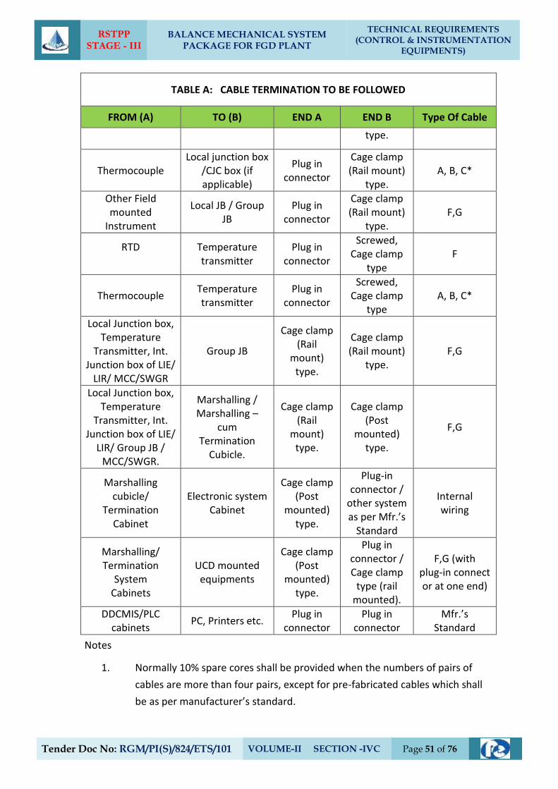
RSTPP STAGE - III
BALANCE MECHANICAL SYSTEM PACKAGE FOR FGD PLANT
TECHNICAL REQUIREMENTS (CONTROL & INSTRUMENTATION
EQUIPMENTS)
Tender Doc No: RGM/PI(S)/824/ETS/101 VOLUME-II SECTION -IVC Page 51 of 76
TABLE A: CABLE TERMINATION TO BE FOLLOWED
FROM (A) TO (B) END A END B Type Of Cable
type.
Thermocouple Local junction box
/CJC box (if applicable)
Plug in connector
Cage clamp (Rail mount)
type. A, B, C*
Other Field mounted
Instrument
Local JB / Group JB
Plug in connector
Cage clamp (Rail mount)
type. F,G
RTD
Temperature transmitter
Plug in connector
Screwed, Cage clamp
type F
Thermocouple Temperature transmitter
Plug in connector
Screwed, Cage clamp
type A, B, C*
Local Junction box, Temperature
Transmitter, Int. Junction box of LIE/
LIR/ MCC/SWGR
Group JB
Cage clamp (Rail
mount) type.
Cage clamp (Rail mount)
type. F,G
Local Junction box, Temperature
Transmitter, Int. Junction box of LIE/
LIR/ Group JB / MCC/SWGR.
Marshalling / Marshalling –
cum Termination
Cubicle.
Cage clamp (Rail
mount) type.
Cage clamp (Post
mounted) type.
F,G
Marshalling cubicle/
Termination Cabinet
Electronic system Cabinet
Cage clamp (Post
mounted) type.
Plug-in connector /
other system as per Mfr.’s
Standard
Internal wiring
Marshalling/ Termination
System Cabinets
UCD mounted equipments
Cage clamp (Post
mounted) type.
Plug in connector / Cage clamp
type (rail mounted).
F,G (with plug-in connect or at one end)
DDCMIS/PLC cabinets
PC, Printers etc. Plug in
connector Plug in
connector Mfr.’s
Standard
Notes
1. Normally 10% spare cores shall be provided when the numbers of pairs of
cables are more than four pairs, except for pre-fabricated cables which shall
be as per manufacturer’s standard.
RSTPP STAGE - III
BALANCE MECHANICAL SYSTEM PACKAGE FOR FGD PLANT
TECHNICAL REQUIREMENTS (CONTROL & INSTRUMENTATION
EQUIPMENTS)
Tender Doc No: RGM/PI(S)/824/ETS/101 VOLUME-II SECTION -IVC Page 52 of 76
2. For analog signals, individual pair shielding & overall shielding & for Binary
signals, only overall shielding of instrumentation cables shall be provided.
3* For high temperature applications only.
4. For connection between field/JB and DDCMIS marshalling cabinet Minimum 4
pair instrumentation cable shall be used.
5 All the spare cores of instrumentation cable have to be terminated in
Marshalling cabinets/ DCS panel end.
6. Not used.
6.6. TERMINAL BLOCKS
6.6.1. All terminal blocks shall be rail mounted/post mounted cage clamp type with high
quality non-flammable insulating material of melamine suitable for working
temperature of 105 deg. C. The terminal blocks in field mounted junction boxes,
temperature transmitters, instrument enclosures/racks, etc., shall be suitable for cage
clamp connections. The terminal blocks in Control Equipment Room
logic/termination/marshalling cubicles shall be suitable for post mounted cage clamp
connection at the field input end. The exact type of terminal blocks to be provided by
the Bidder and the technical details of the same including width etc. shall be subject to
Client (EPIL)’s approval.
6.6.2. All the terminal blocks shall be provided complete with all required accessories including
assembly rail, locking pin and section, end brackets, partitions, small partitions,
transparent covers, support brackets, distance sleeves, warning label, marking, etc.
6.6.3. The marking on terminal strips shall correspond to the terminal numbering on wiring
diagrams. At least 20% spare unused terminals shall be provided everywhere including
local junction boxes, instrument racks/enclosures, termination/marshalling cabinets,
etc. All terminal blocks shall be numbered for identification and grouped according to
the function. Engraved labels shall be provided on the terminal blocks.
6.6.4. For terminating each process actuated switches, drive actuators, control valves,
Thermocouple, RTD, etc. in Local Junction Boxes, etc, refer Drg no. 0000-999-POI-A-065.
6.6.5. The terminal blocks shall be arranged with at least 100 mm clearance between two sets
of terminal blocks and between terminal blocks and junction box walls.
6.7. INTERNAL PANELS/ SYSTEM CABINETS WIRING
6.7.1. Internal panel/cabinet wiring shall be of multi-stranded copper conductor with FRLS PVC
insulation without shield and outer sheath meeting the requirements of VDE 0815.
RSTPP STAGE - III
BALANCE MECHANICAL SYSTEM PACKAGE FOR FGD PLANT
TECHNICAL REQUIREMENTS (CONTROL & INSTRUMENTATION
EQUIPMENTS)
Tender Doc No: RGM/PI(S)/824/ETS/101 VOLUME-II SECTION -IVC Page 53 of 76
6.7.2. All internal wires shall be provided with tag and identification nos. etched on tightly
fitted ferules at both ends. All wires directly connected to trip devices shall be
distinguished by one additional red colour ferrule.
6.7.3. All external connection shall be made with one wire per termination point. Wires shall
not be tapped or spliced between terminal points.
6.7.4. All floor slots of desk/panels/cabinets used for cable entrance shall be provided with
removable gasketed gland plates and sealing material. Split type grommets shall be used
for prefabricated cables.
6.7.5. All the special tools as may be required for solder less connections shall be provided by
Bidder.
6.7.6. Wire sizes to be utilised for internal wiring.
i. Current (4-20 mA), low voltage signals (48V); 0.5 Sq.mm
Ammeter/Voltmeter circuit, control. Switches etc for electrical system .
ii. Power supply and internal illumination 2.5 Sq.mm.minimum (shall
be as per load requirement.)
6.8. INSTRUMENTATION CABLE INSTALLATION AND ROUTING
6.8.1. All cables assigned to a particular duct/conduit shall be grouped and pulled in
simultaneously using cable grips and suitable lubricants. Cables removed from one
duct/conduit shall not be reused without approval of Client (EPIL).
6.8.2. Cables shall be segregated as per IEEE Std.-422. In vertically stacked trays, the higher
voltage cable shall be in higher position and instrumentation cable shall be in bottom
tier of the tray stack. The distance between instrumentation cables and those of other
system shall be as follows:
From 11 kV/6.6 kV/3.3 kV tray system - 914 mm
From 415V tray system - 610 mm
From control cable tray system - 305 mm
6.8.3. Cables shall terminate in the enclosure through cable glands. All cable glands shall be
properly gasketed. Sealing (to prevent ingress of dust entry and propagation of fire) shall
be provided for all floor slots used for cable entrance. Compression cable glands (double
for armoured and single for other cables) shall be provided.
RSTPP STAGE - III
BALANCE MECHANICAL SYSTEM PACKAGE FOR FGD PLANT
TECHNICAL REQUIREMENTS (CONTROL & INSTRUMENTATION
EQUIPMENTS)
Tender Doc No: RGM/PI(S)/824/ETS/101 VOLUME-II SECTION -IVC Page 54 of 76
6.8.4. The cables emanating from redundant equipment/devices shall be routed through
different paths. The above segregation of cables & wiring for redundant
equipments/devices shall be in accordance with IEEE-Std-422.
6.9. CABLE LAYING AND ACCESSORIES
6.9.1. CABLE LAYING
1. Cables shall be laid strictly in line with cable schedule.
2. Identification tags for cables.
Indelible tags to be provided at all terminations, on both sides of wall or floor
crossing, on each conduit/duct/pipe entry/exit, and at every 20 m in cable
trench/tray.
3. Cable tray numbering and marking.
To be provided at every 10m and at each end of cable way & branch connection.
4. No jointing is permissible for Instrumentation cables. For other cables
Jointing for more than 250 Meters run of cable shall be permitted.
5. Buried cable protection
With concrete slabs; Route markers at every 20 Meters along the route & at
every bend.
6. Road Crossings
Cables to pass through buried high density PE pipes encased in PCC. At least 300
mm clearance shall be provided between
- HT power & LT power cables,
- LT power & LT control/instrumentation cables,
Spacing between cables of same voltage grade shall be in accordance with the
de-rating criteria adopted for cable sizing.
7. Segregation (physical isolation to prevent fire jumping)
a) All cable associated with the unit shall be segregated from cables of other
Units.
b) Interplant cables of station auxiliaries and unit critical drives shall be
segregated in such a way that not more than half of the drives are lost in
case of single incident of fire.
RSTPP STAGE - III
BALANCE MECHANICAL SYSTEM PACKAGE FOR FGD PLANT
TECHNICAL REQUIREMENTS (CONTROL & INSTRUMENTATION
EQUIPMENTS)
Tender Doc No: RGM/PI(S)/824/ETS/101 VOLUME-II SECTION -IVC Page 55 of 76
8. Cable clamping
All cables laid on trays shall be neatly dressed up & suitably clamped/tied to the
tray. For cables in trefoil formation, trefoil clamps shall be provided.
9. Optical fiber cables ( OFCs) :
Outside Building Area - to be laid necessarily inside GI conduit with
support from cable tray/Trestle structure.
Inside Building Area - to be laid on separate cable sub-trays.
While buried - in separate burried trench approx.1.0 meter
depth, to be laid in 2” rodent proof HDPE
conduits covered with sand, brick, laid
breadth-wise and soil along the pipe line route
by contractor;
While crossing roads - to be laid in GI/ rodent proof HDPE conduits
with sand filling at bottom and sand, soil filling
at top with cement concrete;
While crossing canals/river - to be laid in rodent proof HDPE conduits within
hume pipe.
10. Laying of Network Cable (UTP/STP) :
Outside Building Area - to be laid necessarily inside GI conduits with
support from cable tray / Trestle structure.
Inside Building Area - to be laid necessarily inside GI conduits on
separate cable sub-trays.
6.9.2. Bidder shall supply and install all cable accessories and fittings like Light Interface Units,
Surge suppressors, Opto isolators, Interface Converters, Fibre Optic Card Cage, Fibre
Optic Line Driver, Repeater / Modem (for Optical Fibre Cables), cable glands, grommets,
lugs, termination kits etc. on as required basis.
6.9.3. Cables, which terminate in cabinets of draw out sections shall have sufficient cable
coiled in the bottom of the cabinet to permit full withdrawal of draw out sections
without disconnecting the cables. When prefabricated cables with factory connectors on
both ends are longer than required, the excess cable shall be coiled in the bottom of one
or both termination cabinets.
6.9.4. The Bidder shall be responsible for proper grounding of all equipment under this
package. Further, proper termination of cable shields shall be verified and the grounding
of the same shall be coordinated so as to achieve grounding of all instrumentation cable
shields at same potential. This shall be completed prior to system tests.
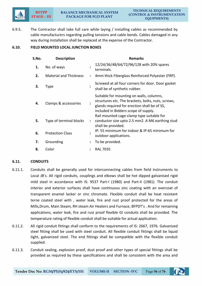
RSTPP STAGE - III
BALANCE MECHANICAL SYSTEM PACKAGE FOR FGD PLANT
TECHNICAL REQUIREMENTS (CONTROL & INSTRUMENTATION
EQUIPMENTS)
Tender Doc No: RGM/PI(S)/824/ETS/101 VOLUME-II SECTION -IVC Page 56 of 76
6.9.5. The Contractor shall take full care while laying / installing cables as recommended by
cable manufacturers regarding pulling tensions and cable bends. Cables damaged in any
way during installation shall be replaced at the expense of the Contractor.
6.10. FIELD MOUNTED LOCAL JUNCTION BOXES
S.No. Description Remarks
1. No. of ways : 12/24/36/48/64/72/96/128 with 20% spares terminals.
2. Material and Thickness : 4mm thick Fiberglass Reinforced Polyester (FRP).
3. Type : Screwed at all four corners for door. Door gasket
shall be of synthetic rubber.
4. Clamps & accessories :
Suitable for mounting on walls, columns, structures etc. The brackets, bolts, nuts, screws, glands required for erection shall be of SS, included in Bidders scope of supply.
5. Type of terminal blocks : Rail mounted cage-clamp type suitable for conductor size upto 2.5 mm2. A M6 earthing stud shall be provided.
6. Protection Class : IP: 55 minimum for indoor & IP-65 minimum for outdoor applications.
7. Grounding : To be provided.
8. Color : RAL 7035
6.11. CONDUITS
6.11.1. Conduits shall be generally used for interconnecting cables from field instruments to
Local JB’s. All rigid conduits, couplings and elbows shall be hot dipped galvanised rigid
mild steel in accordance with IS: 9537 Part-I (1980) and Part-II (1981). The conduit
interior and exterior surfaces shall have continuous zinc coating with an overcoat of
transparent enamel lacker or zinc chromate. Flexible conduit shall be heat resistant
terne coated steel with , water leak, fire and rust proof protected for the areas of
Mills,Drum, Main Steam, RH steam Air Heaters and Furnace, BFPDT’s . And for remaining
applications, water leak, fire and rust proof flexible GI conduits shall be provided. The
temperature rating of flexible conduit shall be suitable for actual application.
6.11.2. All rigid conduit fittings shall conform to the requirements of IS: 2667, 1976. Galvanized
steel fitting shall be used with steel conduit. All flexible conduit fittings shall be liquid
tight, galvanized steel. The end fittings shall be compatible with the flexible conduit
supplied.
6.11.3. Conduit sealing, explosion proof, dust proof and other types of special fittings shall be
provided as required by these specifications and shall be consistent with the area and
RSTPP STAGE - III
BALANCE MECHANICAL SYSTEM PACKAGE FOR FGD PLANT
TECHNICAL REQUIREMENTS (CONTROL & INSTRUMENTATION
EQUIPMENTS)
Tender Doc No: RGM/PI(S)/824/ETS/101 VOLUME-II SECTION -IVC Page 57 of 76
equipment with which they are installed. Fittings installed outdoors and in damp
locations shall be sealed and gasketed. Hazardous area fittings and conduits sealing shall
conform with NEC requirements for the area classification.
6.11.4. Contractor shall provide double locknuts on all conduit terminations not provided with
threaded hubs and couplings. Water tight conduit unions and rain tight conduit hubs
shall be utilised for all the application which shall be exposed to weather. Moisture
pockets shall be eliminated from conduits.
6.11.5. Conduits shall be securely fastened to all boxes and cabinets.
6.12. CABLE SUB-TRAY & SUPPORT
6.12.1. The cable sub-trays and the supporting system, to be generally used between
Local/Group JBs and the main cable trays and the same shall be furnished and installed
by the Contractor. It is the assembly of sections and associated fittings forming a rigid
structural system used to support the cable from the equipment or instrument
enclosure upto the main cable trays (trunk route).
6.12.2. The covers on the cable sub-trays shall be used for protection of cables in areas where
damage may occur from falling objects, welding spark, corrosive environment, etc. &
shall be electrically continuous and solidly grounded.
RSTPP STAGE - III
BALANCE MECHANICAL SYSTEM PACKAGE FOR FGD PLANT
TECHNICAL REQUIREMENTS (CONTROL & INSTRUMENTATION
EQUIPMENTS)
Tender Doc No: RGM/PI(S)/824/ETS/101 VOLUME-II SECTION -IVC Page 58 of 76
`
7. TYPE TEST REQUIREMENTS
7.1. General requirements
7.1.1. The Contractor shall furnish the type test reports of all type tests as per relevant
standards and codes as well as other specific tests indicated in this specification. If the
bidder proposes a different standard/code from that indicated at clause no 2.01.00 and
at table 3.00.00, same is acceptable provided the equivalence of the proposed
standard is established by the bidder. A list of such tests are given for various
equipment in table titled 'TYPE TEST REQUIREMENT FOR OTHER C&I SYSTEMS' at the
end of this chapter and under the item “Special Requirement for Solid State
Equipments/Systems”.
a) Out of the tests listed, the Bidder/ sub-vendor/ manufacturer is required to
conduct certain type tests specifically for this contract (and witnessed by
Client (EPIL) or his authorized representative) even if the same had been
conducted earlier, as clearly indicated subsequently against such tests.
b) For the rest, submission of type test results and certificate shall be
acceptable provided.
i) The same has been carried out by the Bidder/ sub-vendor on exactly
the same model /rating of equipment.
ii) There has been no change in the components from the offered
equipment & tested equipment.
iii) The test has been carried out as per the latest standards
along with amendments as on the date of Bid opening.
c) In case the approved equipment is different from the one on which the type
test had been conducted earlier or any of the above grounds, then the
tests have to be repeated and the cost of such tests shall be borne by the
Bidder/ sub-vendor within the quoted price and no extra cost will be payable
by the Client (EPIL) on this account.
7.1.2. The schedule of conduction of type tests/ submission of reports shall be
submitted and finalized during pre-award discussion.
7.1.3. For the type tests to be conducted, Contractor shall submit detailed test
procedure for approval by Client (EPIL). This shall clearly specify test setup,
instruments to be used, procedure, acceptance norms (wherever applicable),
recording of different parameters, interval of recording precautions to be taken etc.
for the tests to be carried out.
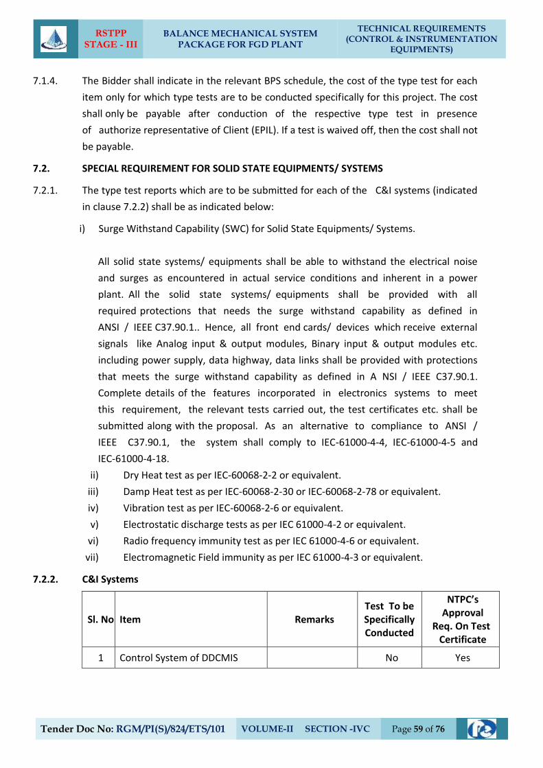
RSTPP STAGE - III
BALANCE MECHANICAL SYSTEM PACKAGE FOR FGD PLANT
TECHNICAL REQUIREMENTS (CONTROL & INSTRUMENTATION
EQUIPMENTS)
Tender Doc No: RGM/PI(S)/824/ETS/101 VOLUME-II SECTION -IVC Page 59 of 76
7.1.4. The Bidder shall indicate in the relevant BPS schedule, the cost of the type test for each
item only for which type tests are to be conducted specifically for this project. The cost
shall only be payable after conduction of the respective type test in presence
of authorize representative of Client (EPIL). If a test is waived off, then the cost shall not
be payable.
7.2. SPECIAL REQUIREMENT FOR SOLID STATE EQUIPMENTS/ SYSTEMS
7.2.1. The type test reports which are to be submitted for each of the C&I systems (indicated
in clause 7.2.2) shall be as indicated below:
i) Surge Withstand Capability (SWC) for Solid State Equipments/ Systems.
All solid state systems/ equipments shall be able to withstand the electrical noise
and surges as encountered in actual service conditions and inherent in a power
plant. All the solid state systems/ equipments shall be provided with all
required protections that needs the surge withstand capability as defined in
ANSI / IEEE C37.90.1.. Hence, all front end cards/ devices which receive external
signals like Analog input & output modules, Binary input & output modules etc.
including power supply, data highway, data links shall be provided with protections
that meets the surge withstand capability as defined in A NSI / IEEE C37.90.1.
Complete details of the features incorporated in electronics systems to meet
this requirement, the relevant tests carried out, the test certificates etc. shall be
submitted along with the proposal. As an alternative to compliance to ANSI /
IEEE C37.90.1, the system shall comply to IEC-61000-4-4, IEC-61000-4-5 and
IEC-61000-4-18.
ii) Dry Heat test as per IEC-60068-2-2 or equivalent.
iii) Damp Heat test as per IEC-60068-2-30 or IEC-60068-2-78 or equivalent.
iv) Vibration test as per IEC-60068-2-6 or equivalent.
v) Electrostatic discharge tests as per IEC 61000-4-2 or equivalent.
vi) Radio frequency immunity test as per IEC 61000-4-6 or equivalent.
vii) Electromagnetic Field immunity as per IEC 61000-4-3 or equivalent.
7.2.2. C&I Systems
Sl. No Item Remarks Test To be Specifically Conducted
NTPC’s Approval
Req. On Test Certificate
1 Control System of DDCMIS No Yes
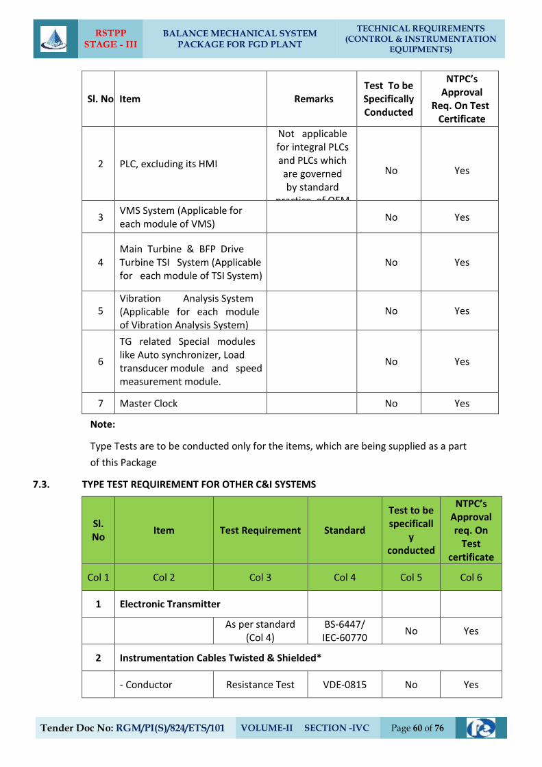
RSTPP STAGE - III
BALANCE MECHANICAL SYSTEM PACKAGE FOR FGD PLANT
TECHNICAL REQUIREMENTS (CONTROL & INSTRUMENTATION
EQUIPMENTS)
Tender Doc No: RGM/PI(S)/824/ETS/101 VOLUME-II SECTION -IVC Page 60 of 76
Sl. No Item Remarks Test To be Specifically Conducted
NTPC’s Approval
Req. On Test Certificate
2 PLC, excluding its HMI
Not applicable for integral PLCs and PLCs which are governed by standard
practice of OEM
No
Yes
3 VMS System (Applicable for each module of VMS)
No Yes
4 Main Turbine & BFP Drive Turbine TSI System (Applicable for each module of TSI System)
No Yes
5 Vibration Analysis System (Applicable for each module of Vibration Analysis System)
No Yes
6
TG related Special modules like Auto synchronizer, Load transducer module and speed measurement module.
No Yes
7 Master Clock No Yes
Note:
Type Tests are to be conducted only for the items, which are being supplied as a part
of this Package
7.3. TYPE TEST REQUIREMENT FOR OTHER C&I SYSTEMS
Sl. No
Item Test Requirement Standard
Test to be specificall
y conducted
NTPC’s Approval req. On
Test certificate
Col 1 Col 2 Col 3 Col 4 Col 5 Col 6
1 Electronic Transmitter
As per standard
(Col 4) BS-6447/ IEC-60770
No Yes
2 Instrumentation Cables Twisted & Shielded*
- Conductor Resistance Test VDE-0815 No Yes

RSTPP STAGE - III
BALANCE MECHANICAL SYSTEM PACKAGE FOR FGD PLANT
TECHNICAL REQUIREMENTS (CONTROL & INSTRUMENTATION
EQUIPMENTS)
Tender Doc No: RGM/PI(S)/824/ETS/101 VOLUME-II SECTION -IVC Page 61 of 76
Sl. No
Item Test Requirement Standard
Test to be specificall
y conducted
NTPC’s Approval req. On
Test certificate
Diameter Test IS-10810 No Yes
Tin coating test
(persulphate test) IS-8130 No Yes
-- Insulation Loss of mass VDE 0472 No Yes
Ageing in air
ovens** VDE 0472 No Yes
Tensile strength and elongation test before and
after ageing
VDE 0472 No Yes
Heat Shock VDE 0472 No Yes
Hot deformation VDE 0472 No Yes
Shrinkage VDE 0472 No Yes
Bleeding & Blooming
IS-10810 No Yes
--Inner sheath*** Loss of mass VDE 0472 No Yes
Heat shock VDE 0472 No Yes
Cold bend/cold
impact test VDE 0472 No Yes
Hot deformation VDE 0472 No Yes
Shrinkage VDE 0472 No Yes
--Outer sheath Loss of mass VDE 0472 No Yes
Ageing in air
ovens** VDE 0472 No Yes
Tensile strength and elongation test before and
after ageing
VDE 0472 No Yes
Heat Shock VDE 0472 No Yes
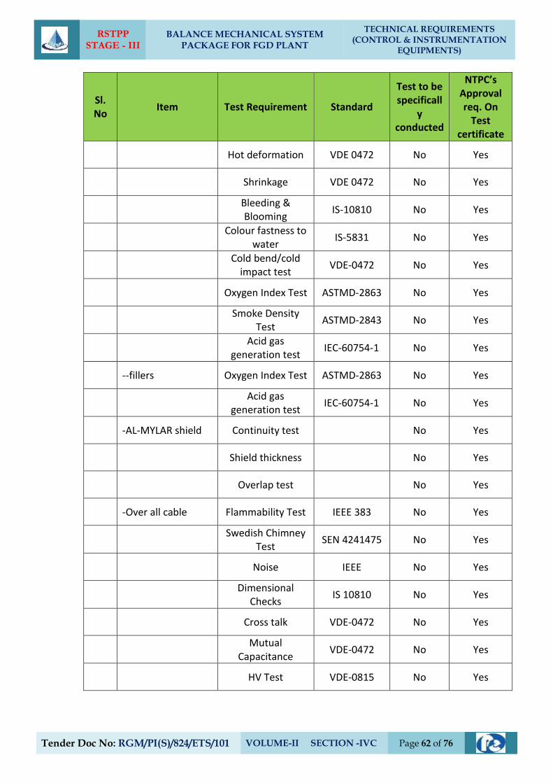
RSTPP STAGE - III
BALANCE MECHANICAL SYSTEM PACKAGE FOR FGD PLANT
TECHNICAL REQUIREMENTS (CONTROL & INSTRUMENTATION
EQUIPMENTS)
Tender Doc No: RGM/PI(S)/824/ETS/101 VOLUME-II SECTION -IVC Page 62 of 76
Sl. No
Item Test Requirement Standard
Test to be specificall
y conducted
NTPC’s Approval req. On
Test certificate
Hot deformation VDE 0472 No Yes
Shrinkage VDE 0472 No Yes
Bleeding & Blooming
IS-10810 No Yes
Colour fastness to
water IS-5831 No Yes
Cold bend/cold
impact test VDE-0472 No Yes
Oxygen Index Test ASTMD-2863 No Yes
Smoke Density
Test ASTMD-2843 No Yes
Acid gas
generation test IEC-60754-1 No Yes
--fillers Oxygen Index Test ASTMD-2863 No Yes
Acid gas
generation test IEC-60754-1 No Yes
-AL-MYLAR shield Continuity test No Yes
Shield thickness No Yes
Overlap test No Yes
-Over all cable Flammability Test IEEE 383 No Yes
Swedish Chimney
Test SEN 4241475 No Yes
Noise IEEE No Yes
Dimensional
Checks IS 10810 No Yes
Cross talk VDE-0472 No Yes
Mutual
Capacitance VDE-0472 No Yes
HV Test VDE-0815 No Yes
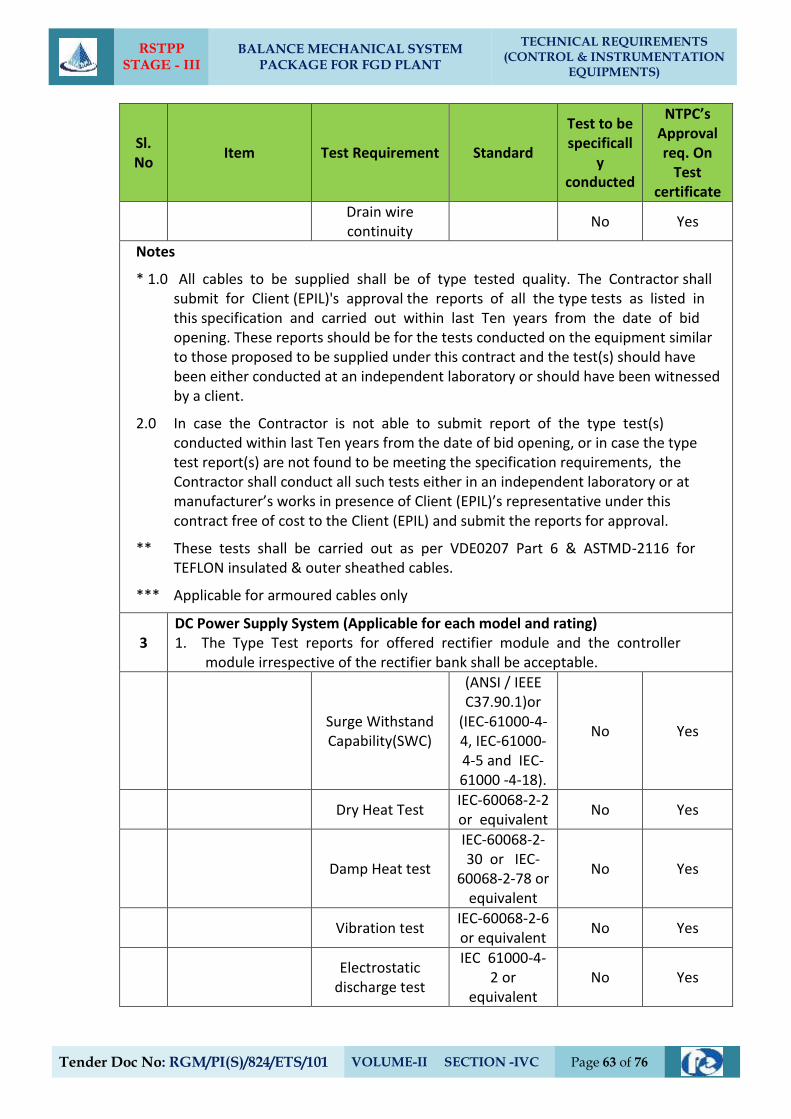
RSTPP STAGE - III
BALANCE MECHANICAL SYSTEM PACKAGE FOR FGD PLANT
TECHNICAL REQUIREMENTS (CONTROL & INSTRUMENTATION
EQUIPMENTS)
Tender Doc No: RGM/PI(S)/824/ETS/101 VOLUME-II SECTION -IVC Page 63 of 76
Sl. No
Item Test Requirement Standard
Test to be specificall
y conducted
NTPC’s Approval req. On
Test certificate
Drain wire continuity
No Yes
Notes
* 1.0 All cables to be supplied shall be of type tested quality. The Contractor shall submit for Client (EPIL)'s approval the reports of all the type tests as listed in this specification and carried out within last Ten years from the date of bid opening. These reports should be for the tests conducted on the equipment similar to those proposed to be supplied under this contract and the test(s) should have been either conducted at an independent laboratory or should have been witnessed by a client.
2.0 In case the Contractor is not able to submit report of the type test(s) conducted within last Ten years from the date of bid opening, or in case the type test report(s) are not found to be meeting the specification requirements, the Contractor shall conduct all such tests either in an independent laboratory or at manufacturer’s works in presence of Client (EPIL)’s representative under this contract free of cost to the Client (EPIL) and submit the reports for approval.
** These tests shall be carried out as per VDE0207 Part 6 & ASTMD-2116 for TEFLON insulated & outer sheathed cables.
*** Applicable for armoured cables only
3 DC Power Supply System (Applicable for each model and rating) 1. The Type Test reports for offered rectifier module and the controller
module irrespective of the rectifier bank shall be acceptable.
Surge Withstand Capability(SWC)
(ANSI / IEEE C37.90.1)or
(IEC-61000-4-4, IEC-61000-4-5 and IEC-61000 -4-18).
No Yes
Dry Heat Test IEC-60068-2-2 or equivalent
No Yes
Damp Heat test
IEC-60068-2-30 or IEC-
60068-2-78 or equivalent
No Yes
Vibration test IEC-60068-2-6 or equivalent
No Yes
Electrostatic
discharge test
IEC 61000-4- 2 or
equivalent No Yes
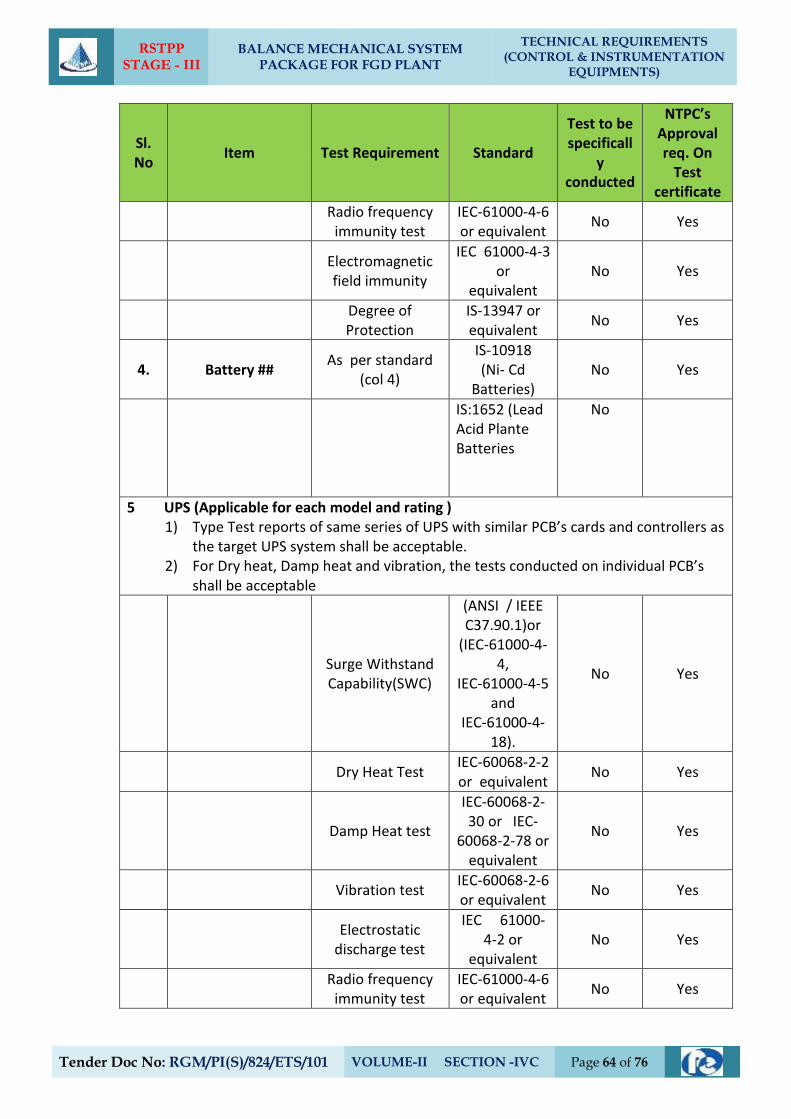
RSTPP STAGE - III
BALANCE MECHANICAL SYSTEM PACKAGE FOR FGD PLANT
TECHNICAL REQUIREMENTS (CONTROL & INSTRUMENTATION
EQUIPMENTS)
Tender Doc No: RGM/PI(S)/824/ETS/101 VOLUME-II SECTION -IVC Page 64 of 76
Sl. No
Item Test Requirement Standard
Test to be specificall
y conducted
NTPC’s Approval req. On
Test certificate
Radio frequency
immunity test IEC-61000-4-6 or equivalent
No Yes
Electromagnetic field immunity
IEC 61000-4-3 or
equivalent No Yes
Degree of Protection
IS-13947 or equivalent
No Yes
4. Battery ## As per standard
(col 4)
IS-10918 (Ni- Cd
Batteries) No Yes
IS:1652 (Lead Acid Plante Batteries
No
5 UPS (Applicable for each model and rating ) 1) Type Test reports of same series of UPS with similar PCB’s cards and controllers as
the target UPS system shall be acceptable. 2) For Dry heat, Damp heat and vibration, the tests conducted on individual PCB’s
shall be acceptable
Surge Withstand Capability(SWC)
(ANSI / IEEE C37.90.1)or
(IEC-61000-4-4,
IEC-61000-4-5 and
IEC-61000-4-18).
No Yes
Dry Heat Test IEC-60068-2-2 or equivalent
No Yes
Damp Heat test
IEC-60068-2-30 or IEC-
60068-2-78 or equivalent
No Yes
Vibration test IEC-60068-2-6 or equivalent
No Yes
Electrostatic
discharge test
IEC 61000-4-2 or
equivalent No Yes
Radio frequency
immunity test IEC-61000-4-6 or equivalent
No Yes
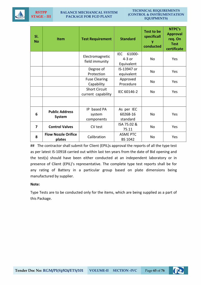
RSTPP STAGE - III
BALANCE MECHANICAL SYSTEM PACKAGE FOR FGD PLANT
TECHNICAL REQUIREMENTS (CONTROL & INSTRUMENTATION
EQUIPMENTS)
Tender Doc No: RGM/PI(S)/824/ETS/101 VOLUME-II SECTION -IVC Page 65 of 76
Sl. No
Item Test Requirement Standard
Test to be specificall
y conducted
NTPC’s Approval req. On
Test certificate
Electromagnetic field immunity
IEC 61000-4-3 or
Equivalent No Yes
Degree of Protection
IS-13947 or equivalent
No Yes
Fuse Clearing
Capability Approved Procedure
No Yes
Short Circuit
current capability IEC 60146-2 No Yes
6 Public Address
System
IP based PA system
components
As per IEC 60268-16 standard
No Yes
7 Control Valves CV test ISA 75.02 &
75.11 No Yes
8 Flow Nozzle Orifice
plates Calibration
ASME PTC BS 1042
No Yes
## The contractor shall submit for Client (EPIL)s approval the reports of all the type test
as per latest IS-10918 carried out within last ten years from the date of Bid opening and
the test(s) should have been either conducted at an independent laboratory or in
presence of Client (EPIL)’s representative. The complete type test reports shall be for
any rating of Battery in a particular group based on plate dimensions being
manufactured by supplier.
Note:
Type Tests are to be conducted only for the items, which are being supplied as a part of
this Package.
RSTPP STAGE - III
BALANCE MECHANICAL SYSTEM PACKAGE FOR FGD PLANT
TECHNICAL REQUIREMENTS (CONTROL & INSTRUMENTATION
EQUIPMENTS)
Tender Doc No: RGM/PI(S)/824/ETS/101 VOLUME-II SECTION -IVC Page 66 of 76
`
8. ELECTRICAL ACTUATOR
8.1. GENERAL:
8.1.1. Actuators shall be designed for valve operation to ensure proper function in
accordance with specifications given below and complying to EN15714-2or
equivalent. All standards, specifications and codes of practice referred to herein
shall be the latest editions including all applicable official amendments and revisions.
8.1.2. Fieldbus based Non-Intrusive Electrical Actuators with integral starters along with
associated accessories etc. shall be supplied on as required basis for Valves /Dampers
to meet the functional and the other specification requirements specified elsewhere
in the Technical specification.
8.1.3. Detailed specification is described below. These common requirements of actuators
shall comply to requirements specified at clause 8.2 (below) and specific requirements
of Non-Intrusive fieldbus actuators as specified at clause 8.4 .
Specific requirements of Non-Intrusive hardwired actuators specified in clause no. 8.3
below are not applicable for this project.
For Blade pitch actuators specification clause no. 8.5 shall be complied with.
If electric actuator requires any additional power supply/ signal for its operation
complying to specification requirements, then required power supply, cabling and
termination etc. shall be provided by the contractor.
8.1.4. The protocol of fieldbus based non-intrusive electric actuators shall be matching with
fieldbus protocol of FGD System DDCMIS, and the same shall be subject to cient’s
approval. For erection and commissioning of above specified actuators, qualified and
experienced engineers of actuator manufacturer shall be deputed at site. After
successful commissioning of actuators, minimum one qualified and experienced
engineer of main package supplier/ actuator manufacturer shall be continuously
available at site up to completion of defect liability period (warranty) of actuators, for
troubleshooting and maintenance of actuators and proper interfacing with DDCMIS.
Qualified and experienced engineers indicated above shall have expertise in all aspects
of non-intrusive actuators along with fieldbus protocol and interfacing with DDCMIS.
The description is applicable for following types of electric actuators:
8.1.5. Modulating duty electric actuators:
These shall be provided as per standard practice of OEM of equipment, meeting
other requirements of specifications. For specifications of Blade pitch actuators, refer
clause no. 8.5 of this Section.
RSTPP STAGE - III
BALANCE MECHANICAL SYSTEM PACKAGE FOR FGD PLANT
TECHNICAL REQUIREMENTS (CONTROL & INSTRUMENTATION
EQUIPMENTS)
Tender Doc No: RGM/PI(S)/824/ETS/101 VOLUME-II SECTION -IVC Page 67 of 76
8.1.6. Electric actuators for valves/ dampers/ gates (other than covered in 8.1.5):
These actuators shall be Non-Intrusive type electric actuators. The interface of these
actuators with DDCMIS shall be of two type’s viz. with Hardwired interface and with
Fieldbus interface. The common requirements of both these type of actuators are
specified at clause 8.2, specific requirements of Non-Intrusive hardwired actuators are
specified at clause 8.3 and specific requirements of Non-Intrusive field bus actuators
are specified at clause 8.4. The applications where these two types of actuators are to
be provided is specified above.
8.2. COMMON REQUIREMENTS FOR NON INTRUSIVE ELECTRIC ACTUATORS
8.2.1. TYPE:
a) The actuators shall have integral starters with built in SPP(Single Phasing
Preventer).415 V, 3 phase 3 wire power supply shall be given to the actuator
from switch board as applicable through a switch fuse unit. Control voltage of
the motor starter shall be 110 V AC / 24 V DC, derived suitably from 415V
power supply.
b) The actuators shall be Non- Intrusive electric actuator. All actuator settings
including torque, limit shall be possible without opening the actuator
cover and LCD indication shall be available integral to actuator body.
8.2.2. RATING:
a) Supply Voltage & frequency: 415V +/- 10%, 3 Phase, 3 Wire &50HZ +/-5%.
b) Sizing:
Open/Close at rated speed against designed differential pressure at
90% of rated voltage.
For ON/OFF type: Three successive open-close operations or 15
minutes, whichever is higher.
For inching type : 150 starts per hour or required cycles, whichever is
higher.
8.2.3. CONSTRUCTION:
a) Enclosure:
Totally enclosed weatherproof, minimum IP-68 degree of protection.
b) Manual Wheel:
Shall disengage automatically during motor operation.
RSTPP STAGE - III
BALANCE MECHANICAL SYSTEM PACKAGE FOR FGD PLANT
TECHNICAL REQUIREMENTS (CONTROL & INSTRUMENTATION
EQUIPMENTS)
Tender Doc No: RGM/PI(S)/824/ETS/101 VOLUME-II SECTION -IVC Page 68 of 76
8.2.4. MOTOR:
a) Type :
Squirrel cage induction motor suitable for Direct On Line ( DOL )starting.
b) Enclosure:
Totally enclosed, self-ventilated.
c) Insulation
Class F. Temperature rise 70 Deg C. over 50 Deg C ambient.
d) Bearings:
Double shielded, grease lubricated antifriction.
e) Earth Terminals : Two
f) Protection:
Single Phasing Protection, Over heating protection through Thermostat (as
applicable) and wrong phase sequence protection shall be provided over and
above other protection features standard to bidder's design. Suitable means
shall be provided to diagnose the type of fault locally.
8.2.5. POSITION/TORQUE TRANSMITTER:
The Position/ Limit measurement shall be done using absolute encoders which will
give information of position/limit in both the directions. Electronic measurement of
torque shall be provided.
8.2.6. LOCAL OPERATION:
It shall be possible to operate the actuator locally also. Lockable local/remote
selection shall be provided on the actuator.
8.2.7. LCD DISPLAY:
A local LCD display shall be provided to give information regarding actuator alarms,
status and valve position indications as a minimum in local.
8.2.8. WIRING:
Suitable voltage grade copper wire.
8.2.9. TERMINAL BLOCK:
For power cables, the grade of TBs shall be minimum 650V.
RSTPP STAGE - III
BALANCE MECHANICAL SYSTEM PACKAGE FOR FGD PLANT
TECHNICAL REQUIREMENTS (CONTROL & INSTRUMENTATION
EQUIPMENTS)
Tender Doc No: RGM/PI(S)/824/ETS/101 VOLUME-II SECTION -IVC Page 69 of 76
8.2.10. ACCESSORIES:
All required accessories (if applicable) for calibration/settings/configuration of various
parameters of actuator shall be provided. For quantities, please refer Part A of
technical specifications.
8.2.11. SIL CERTIFICATION:
All actuators shall be certified for SIL 2 or better.
8.3. SPECIFIC REQUREMENTS FOR NON INTRUSIVE HARDWIRED ACTUATORS
INTERFACES:
8.3.1. For ON-OFF and INCHING type actuators interface with the control system shall be
through hardwired signal only.
a) Open/Close command, open/ close status and disturbance monitoring
signal (common contact for Overload, Thermostat, control supply failure,
L/R selector switch at local & other protections operated) shall be provided
hardwired.
b) The actuator shall be able to accept open/close command at 24V DC with max.
2.5VA load from control system. Accordingly suitable isolated interface in the
actuator shall be provided.
c) Open/close command termination logic shall be suitably built inside actuator.
d) For typical wiring diagram Refer Tender Drawing No. 0000-999-POI-A-063
(Except plug & socket connector, if not applicable).
e) For INCHING type actuators, hard-wired analog position signal (4-20mA) derived
from absolute encoder to be provided for actuator position.
8.3.2. TERMINAL BOX:
Suitable terminals/ connectors, integral to actuator, for terminating instrumentation &
power cables shall be provided. Necessary glands for power cables and
instrumentation cables shall be provided.
8.3.3. TRAINING:
Contractor shall provide training on Non-Intrusive hardwired Electric Actuator for
Client (EPIL)’s personnel. The duration of the training shall be as elaborated in
Section – VII (GTR) of technical specifications.
RSTPP STAGE - III
BALANCE MECHANICAL SYSTEM PACKAGE FOR FGD PLANT
TECHNICAL REQUIREMENTS (CONTROL & INSTRUMENTATION
EQUIPMENTS)
Tender Doc No: RGM/PI(S)/824/ETS/101 VOLUME-II SECTION -IVC Page 70 of 76
8.4. SPECIFIC REQUIREMENTS FOR NON INTRUSIVE FIELDBUS ACTUATORS
8.4.1. INTERFACES:
For ON-OFF and INCHING type actuators interface with the control system shall be
through field-bus network
a) Open/ close commands, open/ close feedback status, disturbance signal etc. shall
be available to the Control System through the fieldbus network along with
diagnostics. The detailed diagnostics including the actuator operating data shall
be available to the DDCMIS through the fieldbus network.
b) All actuators shall be Foundation Fieldbus/ Profibus compatible. However the
exact protocol shall be based on finalized protocol of DDCMIS. If Profibus DP
protocol is envisaged then actuator shall have two (redundant) Profibus DP ports
for connecting the redundant Profibus DP cables. That is if one profibus cable is
cut or not working/ not available, then complete actuator functionality shall be
available through the second redundant cable without any manual intervention.
Also, for Profibus DP cable connection, suitable connector integral to the
actuator, or external devices/ accessories (mounted inside minimum IP65
protection class enclosure) shall be provided so that the actuator can be
isolated online from the profibus network without disturbing the Profibus
communication of other actuators of the segment.
c) Open/close command termination logic shall be suitably built inside actuator.
d) For all actuators GSD and DTM files are to be provided which shall be
configured/tested with DCS for proper interfacing and diagnostics.
8.4.2. TERMINAL BOX:
Suitable terminals/ connectors, integral to actuator, for terminating fieldbus
cables and power cables shall be provided. Necessary glands for power cables and
armored fieldbus cables shall be provided.
8.4.3. TRAINING:
Contractor shall provide training on Non-Intrusive Fieldbus Electric Actuator along
with detail training on Foundation Fieldbus/Profibusinterface used in actuator for
Client (EPIL)’s personnel. The duration of the training shall be as elaborated in Section
– VII (GTR) Section-VI of technical specifications.
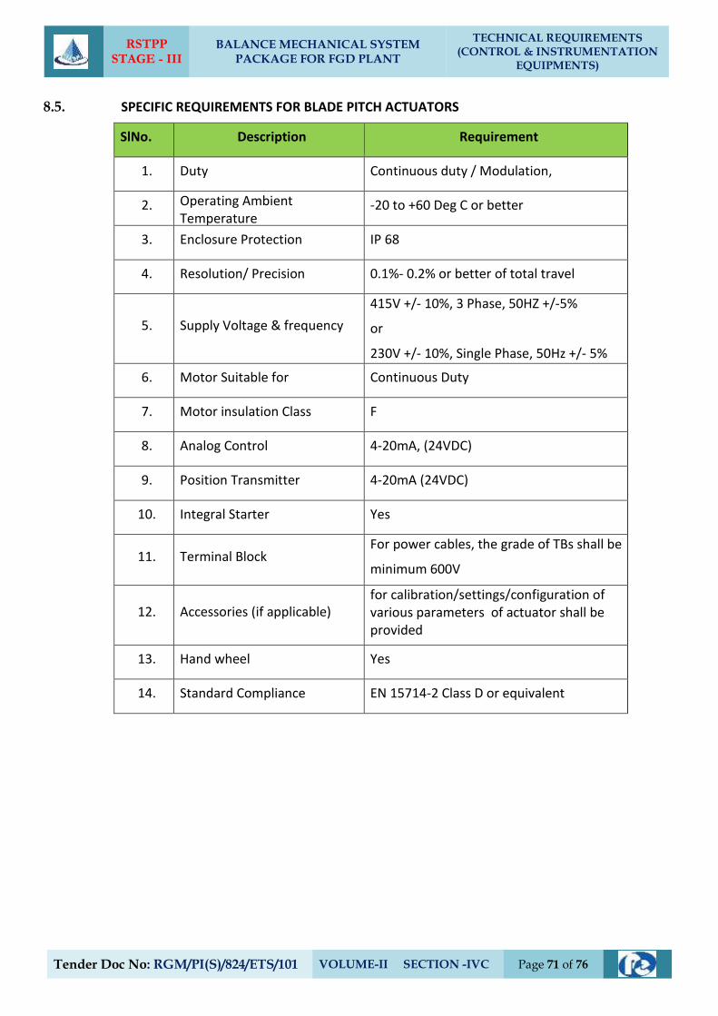
RSTPP STAGE - III
BALANCE MECHANICAL SYSTEM PACKAGE FOR FGD PLANT
TECHNICAL REQUIREMENTS (CONTROL & INSTRUMENTATION
EQUIPMENTS)
Tender Doc No: RGM/PI(S)/824/ETS/101 VOLUME-II SECTION -IVC Page 71 of 76
8.5. SPECIFIC REQUIREMENTS FOR BLADE PITCH ACTUATORS
SlNo. Description Requirement
1. Duty Continuous duty / Modulation,
2. Operating Ambient Temperature
-20 to +60 Deg C or better
3. Enclosure Protection IP 68
4. Resolution/ Precision 0.1%- 0.2% or better of total travel
5. Supply Voltage & frequency
415V +/- 10%, 3 Phase, 50HZ +/-5%
or
230V +/- 10%, Single Phase, 50Hz +/- 5%
6. Motor Suitable for Continuous Duty
7. Motor insulation Class F
8. Analog Control 4-20mA, (24VDC)
9. Position Transmitter 4-20mA (24VDC)
10. Integral Starter Yes
11. Terminal Block For power cables, the grade of TBs shall be
minimum 600V
12. Accessories (if applicable) for calibration/settings/configuration of various parameters of actuator shall be provided
13. Hand wheel Yes
14. Standard Compliance EN 15714-2 Class D or equivalent
RSTPP STAGE - III
BALANCE MECHANICAL SYSTEM PACKAGE FOR FGD PLANT
TECHNICAL REQUIREMENTS (CONTROL & INSTRUMENTATION
EQUIPMENTS)
Tender Doc No: RGM/PI(S)/824/ETS/101 VOLUME-II SECTION -IVC Page 72 of 76
9. CONTROL VALVES, ACTUATORS & ACCESSORIES
9.0 General Requirements
a) The control valves and accessories equipment furnished by the Bidder shall
bedesigned, constructed and tested in accordance with the latest applicable
requirements of code for pressure piping ANSI B 31.1, the ASME Boiler & pressure
vessel code, Indian Boiler Regulation (IBR), ISA, and other standards specified
elsewhere as well as in accordance with all applicable requirements of the “Federal
Occupational Safety and Health Standards, USA” or acceptable equal standards. All
the Control Valves, their actuators and accessories to be furnished under this
Subsection will be fully suitable and compatible with the modulating loops covered
under the Specification.
b) All the control valves and accessories offered by the Bidder, shall be from reputed,
experienced manufacturers of specified type and range of valves.
9.1 Control Valve Sizing & Construction
a) The design of all valve bodies shall meet the specification requirements and shall
conform to the requirements of ANSI (USA) for dimensions, material thickness and
material specification for their respective pressure classes.
b) The valve sizing shall be suitable for obtaining maximum flow conditions with valve
opening at approximately 80% of total valve stem travel and minimum flow
conditions with valve stem travel not less than 10% of total valve stem travel. All
the valves shall be capable of handling at least 120% of the required maximum
flow. Further, the valve stem travel range from minimum flow condition to
maximum flow condition shall not be less than 50% of the total valve stem travel.
The sizing shall be in accordance with the latest edition of ISA handbook on control
valves. While deciding the size of valves, Bidder shall ensure that valves trim exit
outlet velocity as defined in ISA handbook does not exceed 8 m/sec for liquid
services, 150 m/sec. for steam services and 50% of sonic velocity for flashing
services. Bidder shall furnish the sizing calculations clearly indicating the outlet
velocity achieved with the valve size selected by him as well as noise calculations,
which will be subject to Employer’s approval during detailed engineering
c) Control valves for steam and water applications shall be designed to prevent
cavitation, wire drawing, flashing on the downstream side of valve and downstream
piping. Thus for cavitation/flashing service, only valve with anti cavitation trim shall
RSTPP STAGE - III
BALANCE MECHANICAL SYSTEM PACKAGE FOR FGD PLANT
TECHNICAL REQUIREMENTS (CONTROL & INSTRUMENTATION
EQUIPMENTS)
Tender Doc No: RGM/PI(S)/824/ETS/101 VOLUME-II SECTION -IVC Page 73 of 76
be provided. Detailed calculations to establish whether cavitation will occur or not
for any given application shall be furnished.
d) Control valves shall have leakage rate as per leakage Class-IV.
e) The control valve induced noise shall be limited to 85 dBA at 1 meter from the
valve surface under actual operating conditions. The noise abatement shall be
achieved by valve body and trim design and not by use of silencers.
9.2 Valve Construction
a) All valves shall be of globe /Butterfly body design & straightaway pattern with single
or double port, unless otherwise specified or recommended by the manufacturer to
be of angle body type. Rotary valve may alternatively be offered when pressure and
pressure drops permit.
b) Valves with high lift cage guided plugs & quick-change trims shall be supplied.
c) Cast Iron valves are not acceptable.
d) Bonnet joints for all control valves shall be of the flanged and bolted type or other
construction acceptable to the Employer. Bonnet joints of the internal threaded or
union type will not be acceptable.
e) Plug shall be of one-piece construction cast, forged or machined from solid bar stock.
Plug shall be screwed and pinned to valve stems or shall be integral with the valve
stems.
f) All valves connected to vacuum on down stream side shall be provided with packing
suitable for vacuum applications (e.g. double vee type chevron packing)
g) Valve characteristic shall match with the process characteristics.
h) Extension bonnets shall be provided when the maximum temperature of flowing fluid
is greater than 280 deg. C.
i) Flanged valves shall be rated at no less then ANSI press class of 300 lbs
9.3 Valve Materials
Refer mechanical sections for body and trim materials. The exact body and trim materials
shall be finalised during detailed engineering depending on the service applications.
However, Bidder may offer valves with body and trim materials better than specified
materials and in such cases Bidder shall furnish the comparison of properties including
cavitation resistance, hardness, tensile strength, strain energy, corrosion resistance and
erosion resistance etc. of the offered material for Employer’s consideration and approval.
RSTPP STAGE - III
BALANCE MECHANICAL SYSTEM PACKAGE FOR FGD PLANT
TECHNICAL REQUIREMENTS (CONTROL & INSTRUMENTATION
EQUIPMENTS)
Tender Doc No: RGM/PI(S)/824/ETS/101 VOLUME-II SECTION -IVC Page 74 of 76
9.4 End Preparation
Valve body ends shall be either butt welded/socket welded, flanged (Rubber lined for
condensate service) or screwed as finalised during detailed engineering and as per
Employer’s approval. The welded ends wherever required shall be butt welded type as per
ANSI B 16.25 for control valves of sizes 65 mm and above. For valves size 50 mm and below
welded ends shall be socket welded as per ANSI B 16.11. Flanged ends wherever required
shall be of ANSI pressure-temperature class equal to or greater than that of the control
valve body.
9.5 Valve Actuators
All Control Valves shall be furnished with Pneumatic Actuators. The Bidder shall be
responsible for proper selection and sizing of valve actuators in accordance with the
pressure drop and maximum shut off pressure and leakage class requirements. The valve
actuators shall be capable of operating at 60 deg.C continuously.
Valve actuators and stems shall be adequate to handle the unbalanced forces occurring
under the specified flow conditions or the maximum differential pressure specified. An
adequate allowance for stem force, at least 0.15 Kg/sq.cm. per linear millimeter of seating
surface, shall be provided in the selection of the actuator to ensure tight seating unless
otherwise specified.
The travel time of the pneumatic actuators shall not exceed 10 seconds.
9.6 Control Valve Accessory Devices
All pneumatically actuated control valve accessories such as air locks, handwheels/hand-
jacks, limit switches, Microprocessor based Positioner, diffusers, external volume chambers,
position transmitters (capacitance or resistance type only), reversible pilot for Positioner,
tubing and air sets, solenoid valves and junction boxes etc. shall be provided as per the
requirements.
9.7 Specifications for Microprocessor based Positioners
1 Electrical a) Input signal 4-20 mA
b) Power Supply Loop powered from the output card of control system.
c)Hart Protocol Compatibility for remote calibration & diagnostics (Super-imposed Hart signal on input signal (4-20 mA)
d) Valve position Sensing
Non contact type position sensing with 4-20 mA output signal
RSTPP STAGE - III
BALANCE MECHANICAL SYSTEM PACKAGE FOR FGD PLANT
TECHNICAL REQUIREMENTS (CONTROL & INSTRUMENTATION
EQUIPMENTS)
Tender Doc No: RGM/PI(S)/824/ETS/101 VOLUME-II SECTION -IVC Page 75 of 76
2 Environment a) Operating Temp (-) 30 To 80 Deg. C
b) Humidity 0-95 %
c) Protection Class IP-65 Minimum
3 Test reports/ certificates
Factory Valve Signature Tests reports (Pr vs Valve travel and Travel vs I/P signal) are to be provided
Test certificates as per Manufacture Standard/Relevant Standard are To Be Submitted
4 Configuration/ calibration
Remote calibration, Auto & Manual calibration shall be possible. Universal HART Calibrator to be provided.
5 Operating Operating Range Full range & split range signal.
6 Modes Valve Action Direct & Reverse valve action(selectable)
Flow Characterization
Possible to fit valve characteristic curve – Linear & Equal Percentage.
7 Fail Safe/Fail Freeze
Fail safe/Fail freeze feature is to be provided. (In case, the fail freeze feature is not intrinsic to the positioner, Bidder shall achieve the same externally through solenoid valve connected in the pneumatic circuit).
8 Pneumatic Air capacity Sufficient to handle the valves selected/ boosters to be supplied if required
Air supply pressure
To suit air supply pressure/quality available
Process connection
1/4 inch NPT
9 Electrical Cable Entry
1/2-NPT, side or bottom entry to avoid water ingress.
10 Performance Characteristic Deviation
<=0.5 % Of Span
11 EMC & CE Compliance
Required To International Standard Like EN/IEC.
En50081-2& En50082 Or Equivalent
12 Accessories In-built operator panel
Display with push buttons for configuration and display on the Positioner itself (password protected/ hardware lock).
Press gauge block
For supply & output pressure.
Mounting assembly
On as required basis.
RSTPP STAGE - III
BALANCE MECHANICAL SYSTEM PACKAGE FOR FGD PLANT
TECHNICAL REQUIREMENTS (CONTROL & INSTRUMENTATION
EQUIPMENTS)
Tender Doc No: RGM/PI(S)/824/ETS/101 VOLUME-II SECTION -IVC Page 76 of 76
9.8 Test and Examination
All valves shall be tested in accordance with the quality assurance programme agreed
between the Employer and Contractor, which shall meet the requirements of IBR and other
applicable codes mentioned elsewhere in the specifications. The tests shall include but not
be limited to the following:
a) Non Destructive Test as per ANSI B-16.34.
b) Hydrostatic shell test in accordance with ANSI B 16.34 prior to seat leakage test.
c) Valve closure test and seat leakage test in accordance with ANSI-B 16.34 and as per
the leakage class indicated above.
d) Functional Test: The fully assembled valves including actuators control devices and
accessories shall be functionally tested to demonstrate times from open to close
position
e) CV Test: Refer Cl.no 3.00.00 (8) Subsection IIIC-06 (Type test requirements)
9.9 Control Valve Quantities
Bidder shall furnish all the control valves under this package as finalised during detailed
engineering stage without any price repercussions whatsoever depending on the process
requirements. All the control valves provided by the Bidder for this project shall meet the
specifications requirements specified herein. Specification for control valves in this Sub-
section has to be read in conjunction with other relevant Sub-sections of this specification.
RSTPP STAGE - III
BALANCE MECHANICAL SYSTEM PACKAGE FOR FGD PLANT
TECHNICAL REQUIREMENTS (CIVIL & STRUCTURAL WORKS)
Tender Doc No: RGM/PI(S)/824/ETS/101 VOLUME-II SECTION -IVD Page 1 of 34
SECTION-IV D – INDEX
TECHNICA REQUIRMENTS – CIVIL & STRUCTURAL WORKS
1.0 GENERAL .................................................................................................................................. 3
2.0 DELETED ................................................................................................................................... 3
3.0 WORK DESCRIPTION............................................................................................................. 3
4.0 DELETED ................................................................................................................................... 4
5.0 COLOUR COATED AND OTHER SHEETING WORK ....................................................... 4
6.0 CLAUSE DELETED .................................................................................................................. 9
7.0 CLAUSE DELETED .................................................................................................................. 9
8.0 CLAUSE DELETED .................................................................................................................. 9
9.0 CLAUSE DELETED .................................................................................................................. 9
10.0 CLAUSE DELETED .................................................................................................................. 9
11.0 CLAUSE DELETED .................................................................................................................. 9
12.0 CLAUSE DELETED .................................................................................................................. 9
13.0 CLAUSE DELETED .................................................................................................................. 9
14.0 CLAUSE DELETED .................................................................................................................. 9
15.0 CLAUSE DELETED .................................................................................................................. 9
16.0 LOADING ................................................................................................................................... 9
17.0 DESIGN CRITERIA .............................................................................................................. 12
18.0 CLAUSE DELETED ................................................................................................................ 17
19.0 FABRICATION ....................................................................................................................... 17
20.0 ELECTRODES ........................................................................................................................ 17
21.0 CLAUSE DELETED ................................................................................................................ 19
22.0 STATUTORY REQUIREMENTS ....................................................................................... 19
23.0 INSPECTION, TESTING AND QUALITY CONTROL.................................................. 20
24.0 CLAUSE DELETED ................................................................................................................ 20
RSTPP STAGE - III
BALANCE MECHANICAL SYSTEM PACKAGE FOR FGD PLANT
TECHNICAL REQUIREMENTS (CIVIL & STRUCTURAL WORKS)
Tender Doc No: RGM/PI(S)/824/ETS/101 VOLUME-II SECTION -IVD Page 2 of 34
25.0 CLAUSE DELETED ................................................................................................................ 20
26.0 GALVANISING ...................................................................................................................... 20
27.0 CLAUSE DELETED ................................................................................................................ 21
28.0 CLAUSE DELETED ................................................................................................................ 21
29.0 ARCHITECTURAL CONCEPTS ......................................................................................... 21
30.0 CLAUSE DELETED ................................................................................................................ 23
31.0 CORROSION PROTECTION ............................................................................................... 23
32.0 MISCELLANEOUS ................................................................................................................ 26
33.0 CLAUSE DELETED ................................................................................................................ 27
34.0 CLAUSE DELETED ................................................................................................................ 27
35.0 PACKAGINGAND TRANSPORTATION ......................................................................... 27
36.0 PLANT LIFE ........................................................................................................................... 27
37.0 PTFE (POLY TETRA FLUOROETHYLENE) BEARING ........................................... 28
38.0 TESTS FOR MATERIAL / WORKMANSHIP ................................................................. 28
39.0 MATERIALS ........................................................................................................................... 28
40.0 CODES AND STANDARDS ................................................................................................. 31
RSTPP STAGE - III
BALANCE MECHANICAL SYSTEM PACKAGE FOR FGD PLANT
TECHNICAL REQUIREMENTS (CIVIL & STRUCTURAL WORKS)
Tender Doc No: RGM/PI(S)/824/ETS/101 VOLUME-II SECTION -IVD Page 3 of 34
1.0 GENERAL
a) This section of the bidding document deals mainly with the technical specification for
the design and preparation of detailed drawings, getting the design and drawings
approved by the Client / NTPC, fabrication, erection and construction of the necessary
civil, structural and architectural works associated with the Flue Gas Desulphurization
system package. The work shall have to be carried out both below and above ground
level and shall be involving, basements, equipment foundations, slabs, beams,
columns, footings, rafts, walls, steel frames, brick walls, stairs, trenches, pits, access
roads, culverts, trestles, silos, sumps, Limestone storage hopper & sheds, all buildings,
Chimney, all equipment Foundations, finishes, complete architectural aspects,
drainage, sanitation, water supply (from terminal points to various
buildings/facilities) and all other civil, structural and architectural works associated
with the complete FGD package.
b) The specifications are intended for the general description of the work, quality and
workmanship. The specifications are not, however, intended to cover minutest details
and the work shall be executed according to the relevant latest Indian Standard Codes
/ I. R. S. / I. R. C. specifications. Where provisions are not covered in Indian
Standards, reference shall be made to ACI, AISC, ASCE, EN, CICIND and other
international standards or to the best prevailing local Public Works Department
practices or to the instructions of the Engineer. Some of the relevant I. S. Codes to be
followed are mentioned in the Technical Specifications. The Contractor is expected to
get clarified on any doubts about the specifications, etc. before bidding, in writing with
the Employer in respect of interpretation of any portions of this document.
c) Bidder or his agencies engaged as detailer for fabrication drawings should have the
experience of detailing for power plant structures or steel plant or Industrial structures
like Petro/ Chemical/ Refinery/ Cement/FGD Plant/Coal Handling Plant/Ash
Handling Plant etc.
d) The designer responsible for preparation of scope drawings shall review and approve
the fabrication drawings prepared by the detailer before releasing them for fabrication.
2.0 DELETED
3.0 WORK DESCRIPTION
3.1. Staircases, Gratings, Handrails
a) All floors of transfer points/crusher houses and other facility buildings shall be
accessible through staircase. All staircases of Transfer points and crusher house
shall be of steel. Cage ladders (min. 450mm wide) shall be provided for access to
RSTPP STAGE - III
BALANCE MECHANICAL SYSTEM PACKAGE FOR FGD PLANT
TECHNICAL REQUIREMENTS (CIVIL & STRUCTURAL WORKS)
Tender Doc No: RGM/PI(S)/824/ETS/101 VOLUME-II SECTION -IVD Page 4 of 34
roof of penthouses, single storey mcc rooms& mumty. All Stairs shall be minimum
1200 mm wide, maximum rise should not be more than 180 mm and minimum
tread with 250 mm. Numbers and arrangement (including enclosures etc.) of stair
cases shall be such as to meet the fire safety requirement as per guide lines of
statutory regulatory bodies. For steel staircases, Stringers shall be of rolled steel
channel ( minimum ISMC 250) and tread shall be of steel gratings. Outside stairs
to transfer points/crusher house shall be open type. However sheeting shall be
provided at the top. Minimum 50 x 50 x 6 mm size angles with lugs shall be
provided as edge protection for treads of stairs in underground TP's
b) All gratings shall be electro forged types. Minimum thickness of the grating shall
be 40 mm for indoor installation and 32 mm for outdoor installation. However, at
entry or road crossing point’s minimum thickness of grating shall be 40 mm The
opening size shall not be more than 30mmx100mm. The minimum thickness of the
main bearing bar shall be 6 mm or as per design requirement whichever is higher.
All gratings shall be designed for minimum imposed load of 500Kgs. / Sq. M. If
actual expected load is more than the specified load, then actual load is to be
considered. All gratings shall be hot dip galvanized at the rate of 610 g. per sq.m.
after surface preparation by means of blast cleaning/ acid pickling.
c) Minimum 1000 mm high hand railing shall be provided around all openings,
projections / balconies, walkways, platforms, Stairs, etc. All handrails and ladder
Pipes shall be 32 mm nominal bore MS Pipes (medium class) as per IS: 1161.
Handrails shall have top and middle rails at a height of 1000 mm and 500 mm and
the vertical post spacing shall not exceed 1.50 M, with provision of kick Plates (100
mm high and 6 mm thick). All handrails and ladders shall be galvanised at the rate of
610 Gms / Sq. M as per IS: 4736.
4.0 DELETED
5.0 COLOUR COATED AND OTHER SHEETING WORK
5.1. Material
a) Wall Cladding & Roofing Material
Troughed permanently colour coated sheet of approved shade and colour shall be:
i) either of steel with minimum 0.6mm bare metal thickness (i.e. excluding
the thickness of galvanizing/aluminium-zinc coating and painting) of
grade G250 as per AS1397 / grade SS255 as per ASTM A653M / grade
S250GD as per EN 10326 with zinc coating to class Z275 / aluminium-zinc
alloy coating to class AZ150.
RSTPP STAGE - III
BALANCE MECHANICAL SYSTEM PACKAGE FOR FGD PLANT
TECHNICAL REQUIREMENTS (CIVIL & STRUCTURAL WORKS)
Tender Doc No: RGM/PI(S)/824/ETS/101 VOLUME-II SECTION -IVD Page 5 of 34
ii) or of minimum 0.5mm BMT (i.e. excluding the thickness of
galvanizing/aluminium-zinc coating and painting) of grade G350 as per
AS1397 / grade SS340 class 4 as per ASTM A792M / grade S350GD as per
EN 10326 with zinc coating to class Z275 / aluminium-zinc alloy coating to
class AZ150
iii) or of steel of minimum 0.4mm BMT (i.e. excluding the thickness of
galvanizing/aluminum-zinc coating and painting) of grade G550 as per
AS1397 / grade SS550 as per ASTM A792M / grade S550GD as per EN
10326 with zinc coating to class Z275 / aluminum-zinc alloy coating to
class AZ150.
Alternatively aluminum feed material of minimum bare metal thickness of 0.7
mm of aluminum alloy of Series 31000 and above as per IS 737 and IS 1254.
b) Metal Deck Roof Material
Troughed permanently colour coated metal decking sheets shall be:
i either of steel with minimum 0.8mm bare metal thickness (i.e. excluding
the thickness of galvanizing/aluminum-zinc coating and painting) of grade
G250 as per AS1397 / grade SS255 as per ASTM A653M / grade S250GD as
per EN 10326 with zinc coating to class Z275.
ii or of minimum 0.6mm BMT (i.e. excluding the thickness of
galvanizing/aluminum-zinc coating and painting) of grade G350 as per
AS1397 / grade SS340 class 4 as per ASTM A792M / grade S350GD as per
EN 10326 with zinc coating to class Z275.
iii or of steel of minimum 0.6mm BMT (i.e. excluding the thickness
galvanizing/aluminum-zinc coating and painting) of grade G550 as per
AS1397 / grade SS550 as per ASTM A792M / grade S550GD as per EN
10326 with zinc coating to class Z275.
Alternatively aluminum feed material of minimum bare metal thickness of 0.9
mm of aluminum alloy of Series 31000 and above as per IS 737 and IS 1254 can
also be used for metal decking.
Thickness tolerance of (+/-) 0.04mm is permissible. However, all design
calculations shall be carried out on the basis of lowest value of sheet thickness
provided.
RSTPP STAGE - III
BALANCE MECHANICAL SYSTEM PACKAGE FOR FGD PLANT
TECHNICAL REQUIREMENTS (CIVIL & STRUCTURAL WORKS)
Tender Doc No: RGM/PI(S)/824/ETS/101 VOLUME-II SECTION -IVD Page 6 of 34
5.2. Colour Coating
Steel shall be colour coated with total coating thickness of at least 40 microns (nominal)
comprising of silicon modified polyester (SMP with silicon content of 30% to 50%) paint or
Super Polyester paint, of minimum 20 microns (nominal) dry film thickness (DFT) on
external face over primer coat of minimum 5 microns (nominal) and minimum 10 microns
(nominal) SMP or super polyester paint over primer coat of minimum 5 microns (nominal)
on internal face. SMP and Super polyester paint systems shall be of industrial finish of
product type 4 of AS/NZ2728.
5.3. Design Criteria
For wall cladding insulated / uninsulated sides and roof, permanently colour coated sheet
of troughed profile shall be used. The nominal depth of trough shall be 30 mm.
For profiled metal decking sheets (to be used for RCC floor slab or roof slab) the sectional
modulus and moment of inertia of troughed profile per meter width shall be so as to limit
the deflection of sheets to span/250 under total super imposed loading (DL +LL) comprising
the self-weight of metal deck sheet, dead weight of green concrete and an additional
construction load 100kg per sq.m for two span condition. The section modulus and moment
of inertia of troughed profile shall be computed as per the provisions of IS 801 for satisfying
the deflection and strength requirements.
For metal deck sheets used for roofing ( with or without RCC) and side cladding, the
sectional modulus and moment of inertia of troughed profile per metre width shall be such
that the deflection of sheets is limited to span/250 under design wind pressure for two span
condition. The sectional modulus and moment of inertia of troughed profile shall be
computed as per the provisions of IS 801 for satisfying the deflection and strength
requirements. No increase in allowable stress is permissible under wind load condition.
5.4. Fasteners
a) Side cladding/roofing/decking sheets shall be fixed to the runner/purlins using self-
drilling special coated fasteners confirming to corrosion resistant class 3 of AS3566 and
tested for 1000 hours salt spray test. Spacing of Self-drilling fasteners in transverse
direction (along runners/purlin) shall be equal to the pitch of trough or 250(+/-100)
mm, whichever is lesser and in longitudinal direction at every runner/purlin location.
b) Shear anchor studs shall also be provided through troughed permanently colour
coated metal decking sheets metal deck, which are to be used as permanent shuttering,
at regular interval on all top flange / flange plate of structural beams.
c) The shear anchor studs for fixing metal deck sheet to floor structural beams shall
conform to Type-B studs specified in AWS D1.1/D1.1M or equivalent as shear
RSTPP STAGE - III
BALANCE MECHANICAL SYSTEM PACKAGE FOR FGD PLANT
TECHNICAL REQUIREMENTS (CIVIL & STRUCTURAL WORKS)
Tender Doc No: RGM/PI(S)/824/ETS/101 VOLUME-II SECTION -IVD Page 7 of 34
connector of 19mm diameter and 100mm length manufactured from cold drawn round
steel bars conforming to the requirement of ASTM A 29, of grade designation 1010
through 1020, of standard quality with either semi-killed or killed, welded by Drawn
Arc Stud Welding through metal deck sheet.
d) The shear anchor studs for fixing metal deck sheet to roof structural purlins shall
conform to Type-B studs specified in AWS D1.1/D1.1M or equivalent as shear
connector of 16mm diameter and 65mm length manufactured from cold drawn round
steel bars conforming to the requirement of ASTM A 29, of grade designation 1010
through 1020, of standard quality with either semi-killed or killed, welded by Draw
Arc Stud Welding through metal deck sheet.
e) Alternatively, J/U type hooks shall be used in roofing which shall be provided in
transverse direction (along runners/purlin) at a spacing equal to the pitch of trough or
250(+/-100) mm, whichever is lesser and in longitudinal direction at every
runner/purlin location.
5.5. Miscellaneous Details
a) To minimize the number of joints, the length of the sheet shall preferably be not less
than 4.5m, cut pieces shall not be used, unless specifically approved by the Engineer.
However, the actual length shall be such so as to suit the purlin / runner spacing.
b) Lap between the sheets shall be at least 150mm in the longitudinal direction and at
least one crest wide in the transverse direction which shall be properly anchored /
fixed with fasteners.
c) Z spacers if required shall be made of at least 2 mm thick galvanised steel sheet of
grade 350 as per IS 277Sealant used for cladding shall be butyl based, two parts poly
sulphide or equivalent approved, non stainless material and be flexible enough not to
interface with fit of the sheets
d) Filler blocks as a trough filler shall be used to seal cavities formed between the profiled
sheet and the support or flashing. The filler blocks shall be manufactured from black
synthetic rubber or any other material approved by the Engineer.
e) All flashings, trim closures, caps etc. required for the metal cladding system shall be
made out of plain sheets having same material and any weather/moisture sealants
with appropriate material and coating specification as mentioned above for the outer
face of the metal cladding. Overlap shall be min. 150 mm or as specified by
manufacturer.
RSTPP STAGE - III
BALANCE MECHANICAL SYSTEM PACKAGE FOR FGD PLANT
TECHNICAL REQUIREMENTS (CIVIL & STRUCTURAL WORKS)
Tender Doc No: RGM/PI(S)/824/ETS/101 VOLUME-II SECTION -IVD Page 8 of 34
5.6. Pre-Fabricated Insulated Metal Sandwich Panels
For structures where Pre-Fabricated Insulated Metal Sandwich Panels shall be used for
Roofing, the sandwich panels shall comprise top sheet as troughed permanently colour
coated sheet & bottom sheet as plain permanently colour coated with 50mm thick insulation
sandwiched between the two sheets. Each sheet shall be:
a) either of steel with minimum 0.6mm bare metal thickness (i.e. excluding the thickness
of galvanizing/aluminum-zinc coating and painting) of grade G250 as per AS1397 /
grade SS255 as per ASTM A653M / grade S250GD as per EN 10326 with zinc coating
to class Z275 / aluminum-zinc alloy coating to class AZ150.
b) or of minimum 0.5mm BMT (i.e. excluding the thickness of galvanizing/
aluminum-zinc coating and painting) of grade G350 as per AS1397 / grade SS340 class
4 as per ASTM A792M / grade S350GD as per EN 10326 with zinc coating to class
Z275 / aluminum-zinc alloy coating to class AZ150.
c) or of steel of minimum 0.4 mm BMT (i.e. excluding the thickness of
galvanizing/aluminum-zinc coating and painting) of grade G550 as per AS1397
/grade SS550 as per ASTM A792M / grade S550GD as per EN 10326 with zinc coating
to class Z275 / aluminum-zinc alloy coating to class AZ150.
Alternatively aluminum feed material of minimum bare metal thickness of 0.7 mm of
aluminum alloy of Series 31000 and above as per IS 737 and IS 1254.
Metal sheets (steel or aluminum) shall be colour coated with total coating thickness of at
least 40 microns (nominal) dry film thickness (DFT) comprising of Silicon Modified
Polyester (SMP with silicon content of 30% to 50%) paint or Polyester paint, of minimum 20
microns (nominal) SMP or polyester paint on one side (exposed face), over minimum 5
micron (nominal) primer coat and minimum 10 micron (nominal) SMP or Polyester paint
over minimum 5 micron (nominal) primer coat on other side. SMP and Super Polyester paint
shall conform to product type 4 of AS/NZS 2728. Troughed sheet shall be of approved
profile, sectional properties, (suitable for the specified loading / deflection and purlins /
runners spacing), colour and shade.
Special coated fastener conforming to corrosion resistant Class 3 of AS3566 and tested for
1000 hours salt spray test shall be used for fixing Pre-Fabricated Insulated Metal Sandwich
Panels with the structural members below.
The contractor shall prepare working drawings of sheeting system including end and side
laps, fixing details etc. before starting sheeting work at site.
RSTPP STAGE - III
BALANCE MECHANICAL SYSTEM PACKAGE FOR FGD PLANT
TECHNICAL REQUIREMENTS (CIVIL & STRUCTURAL WORKS)
Tender Doc No: RGM/PI(S)/824/ETS/101 VOLUME-II SECTION -IVD Page 9 of 34
5.7. Polycarbonate Sheets
The polycarbonate sheet to be used for cladding and glazing purpose in conveyor galleries,
Transfer points & pump houses shall have toughed profile to match with the metal cladding
profile. Minimum 3.0mm thick fire retardant and UV resistant polycarbonate clean sheet of
approved make shall be used. The polycarbonate sheet shall be installed along with the
metal cladding so as to have a watertight lapping arrangement. Suitable detailing shall be
made to cater for the thermal expansion. IS 14434 to be referred for other details.
6.0 CLAUSE DELETED
7.0 CLAUSE DELETED
8.0 CLAUSE DELETED
9.0 CLAUSE DELETED
10.0 CLAUSE DELETED
11.0 CLAUSE DELETED
12.0 CLAUSE DELETED
13.0 CLAUSE DELETED
14.0 CLAUSE DELETED
15.0 CLAUSE DELETED
16.0 LOADING
For consideration of loads on structures IS : 875 - ‘Code of practice for structural safety of
buildings’ shall be followed. In addition to the dead load, live load, equipment load
(including impact / vibration). Temperature loads etc. various loading conditions arising
due to operation and maintenance of equipment shall be considered in the design. The
structure and equipment shall also be designed for seismic loads as per the “Criteria for
Earthquake Resistant Design of Structures and equipment" and the “Criteria for Wind
Resistant Design of Structures and equipment" specified in the “Project Information
section”of technical specification. Wind and seismic forces shall not be considered to act
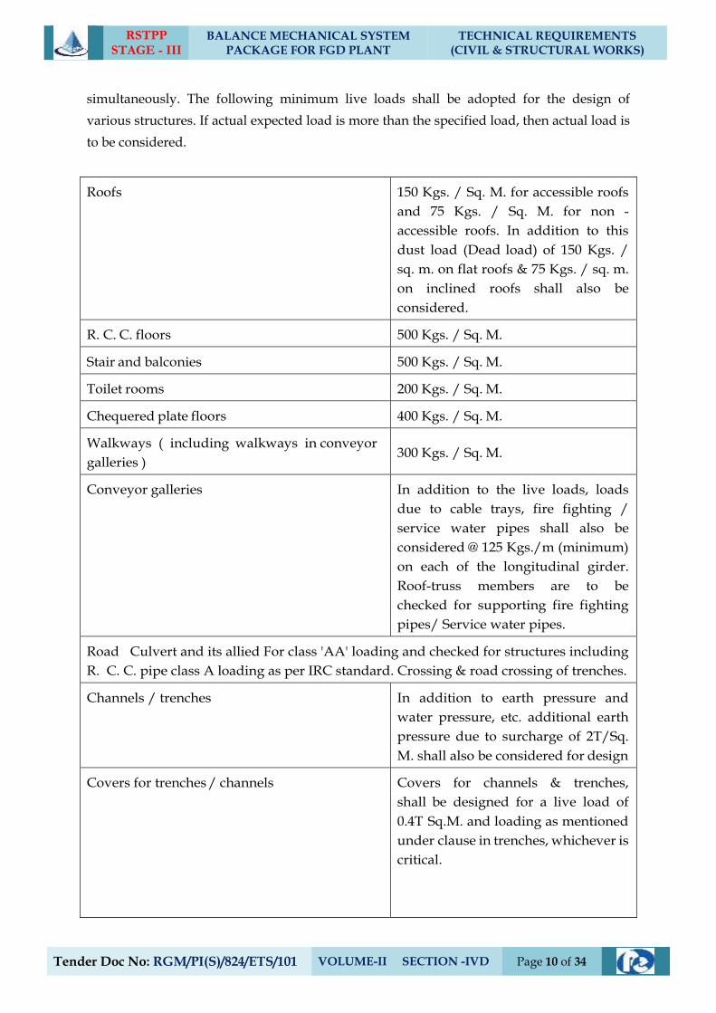
RSTPP STAGE - III
BALANCE MECHANICAL SYSTEM PACKAGE FOR FGD PLANT
TECHNICAL REQUIREMENTS (CIVIL & STRUCTURAL WORKS)
Tender Doc No: RGM/PI(S)/824/ETS/101 VOLUME-II SECTION -IVD Page 10 of 34
simultaneously. The following minimum live loads shall be adopted for the design of
various structures. If actual expected load is more than the specified load, then actual load is
to be considered.
Roofs 150 Kgs. / Sq. M. for accessible roofs
and 75 Kgs. / Sq. M. for non -
accessible roofs. In addition to this
dust load (Dead load) of 150 Kgs. /
sq. m. on flat roofs & 75 Kgs. / sq. m.
on inclined roofs shall also be
considered.
R. C. C. floors 500 Kgs. / Sq. M.
Stair and balconies 500 Kgs. / Sq. M.
Toilet rooms 200 Kgs. / Sq. M.
Chequered plate floors 400 Kgs. / Sq. M.
Walkways ( including walkways in conveyor
galleries ) 300 Kgs. / Sq. M.
Conveyor galleries In addition to the live loads, loads
due to cable trays, fire fighting /
service water pipes shall also be
considered @ 125 Kgs./m (minimum)
on each of the longitudinal girder.
Roof-truss members are to be
checked for supporting fire fighting
pipes/ Service water pipes.
Road Culvert and its allied For class 'AA' loading and checked for structures including
R. C. C. pipe class A loading as per IRC standard. Crossing & road crossing of trenches.
Channels / trenches In addition to earth pressure and
water pressure, etc. additional earth
pressure due to surcharge of 2T/Sq.
M. shall also be considered for design
Covers for trenches / channels Covers for channels & trenches,
shall be designed for a live load of
0.4T Sq.M. and loading as mentioned
under clause in trenches, whichever is
critical.
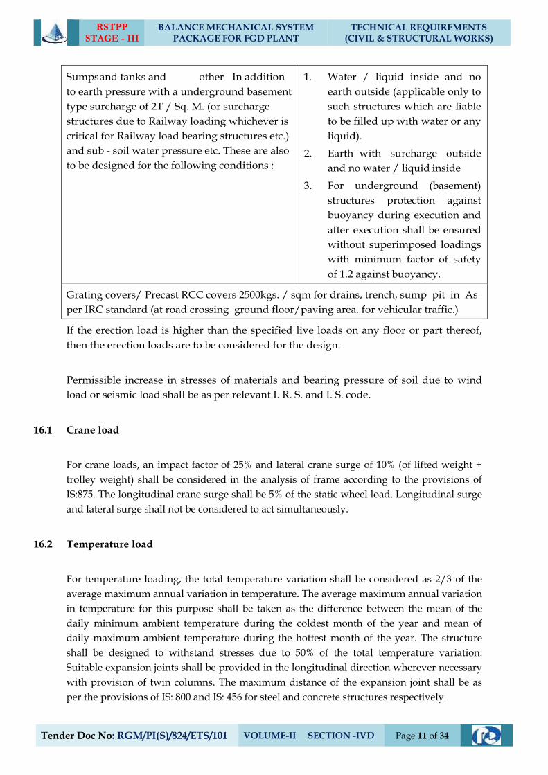
RSTPP STAGE - III
BALANCE MECHANICAL SYSTEM PACKAGE FOR FGD PLANT
TECHNICAL REQUIREMENTS (CIVIL & STRUCTURAL WORKS)
Tender Doc No: RGM/PI(S)/824/ETS/101 VOLUME-II SECTION -IVD Page 11 of 34
Sumps and tanks and other In addition
to earth pressure with a underground basement
type surcharge of 2T / Sq. M. (or surcharge
structures due to Railway loading whichever is
critical for Railway load bearing structures etc.)
and sub - soil water pressure etc. These are also
to be designed for the following conditions :
1. Water / liquid inside and no
earth outside (applicable only to
such structures which are liable
to be filled up with water or any
liquid).
2. Earth with surcharge outside
and no water / liquid inside
3. For underground (basement)
structures protection against
buoyancy during execution and
after execution shall be ensured
without superimposed loadings
with minimum factor of safety
of 1.2 against buoyancy.
Grating covers/ Precast RCC covers 2500kgs. / sqm for drains, trench, sump pit in As
per IRC standard (at road crossing ground floor/paving area. for vehicular traffic.)
If the erection load is higher than the specified live loads on any floor or part thereof,
then the erection loads are to be considered for the design.
Permissible increase in stresses of materials and bearing pressure of soil due to wind
load or seismic load shall be as per relevant I. R. S. and I. S. code.
16.1 Crane load
For crane loads, an impact factor of 25% and lateral crane surge of 10% (of lifted weight +
trolley weight) shall be considered in the analysis of frame according to the provisions of
IS:875. The longitudinal crane surge shall be 5% of the static wheel load. Longitudinal surge
and lateral surge shall not be considered to act simultaneously.
16.2 Temperature load
For temperature loading, the total temperature variation shall be considered as 2/3 of the
average maximum annual variation in temperature. The average maximum annual variation
in temperature for this purpose shall be taken as the difference between the mean of the
daily minimum ambient temperature during the coldest month of the year and mean of
daily maximum ambient temperature during the hottest month of the year. The structure
shall be designed to withstand stresses due to 50% of the total temperature variation.
Suitable expansion joints shall be provided in the longitudinal direction wherever necessary
with provision of twin columns. The maximum distance of the expansion joint shall be as
per the provisions of IS: 800 and IS: 456 for steel and concrete structures respectively.
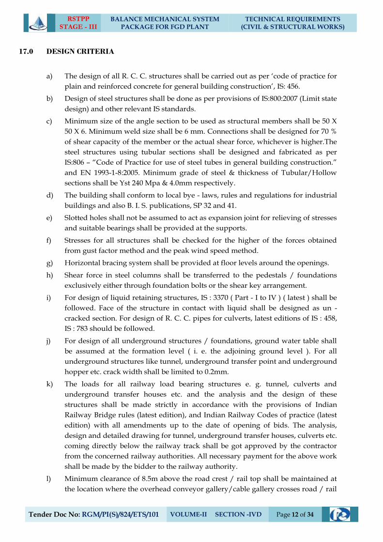
RSTPP STAGE - III
BALANCE MECHANICAL SYSTEM PACKAGE FOR FGD PLANT
TECHNICAL REQUIREMENTS (CIVIL & STRUCTURAL WORKS)
Tender Doc No: RGM/PI(S)/824/ETS/101 VOLUME-II SECTION -IVD Page 12 of 34
17.0 DESIGN CRITERIA
a) The design of all R. C. C. structures shall be carried out as per ‘code of practice for
plain and reinforced concrete for general building construction’, IS: 456.
b) Design of steel structures shall be done as per provisions of IS:800:2007 (Limit state
design) and other relevant IS standards.
c) Minimum size of the angle section to be used as structural members shall be 50 X
50 X 6. Minimum weld size shall be 6 mm. Connections shall be designed for 70 %
of shear capacity of the member or the actual shear force, whichever is higher.The
steel structures using tubular sections shall be designed and fabricated as per
IS:806 – “Code of Practice for use of steel tubes in general building construction.”
and EN 1993-1-8:2005. Minimum grade of steel & thickness of Tubular/Hollow
sections shall be Yst 240 Mpa & 4.0mm respectively.
d) The building shall conform to local bye - laws, rules and regulations for industrial
buildings and also B. I. S. publications, SP 32 and 41.
e) Slotted holes shall not be assumed to act as expansion joint for relieving of stresses
and suitable bearings shall be provided at the supports.
f) Stresses for all structures shall be checked for the higher of the forces obtained
from gust factor method and the peak wind speed method.
g) Horizontal bracing system shall be provided at floor levels around the openings.
h) Shear force in steel columns shall be transferred to the pedestals / foundations
exclusively either through foundation bolts or the shear key arrangement.
i) For design of liquid retaining structures, IS : 3370 ( Part - I to IV ) ( latest ) shall be
followed. Face of the structure in contact with liquid shall be designed as un -
cracked section. For design of R. C. C. pipes for culverts, latest editions of IS : 458,
IS : 783 should be followed.
j) For design of all underground structures / foundations, ground water table shall
be assumed at the formation level ( i. e. the adjoining ground level ). For all
underground structures like tunnel, underground transfer point and underground
hopper etc. crack width shall be limited to 0.2mm.
k) The loads for all railway load bearing structures e. g. tunnel, culverts and
underground transfer houses etc. and the analysis and the design of these
structures shall be made strictly in accordance with the provisions of Indian
Railway Bridge rules (latest edition), and Indian Railway Codes of practice (latest
edition) with all amendments up to the date of opening of bids. The analysis,
design and detailed drawing for tunnel, underground transfer houses, culverts etc.
coming directly below the railway track shall be got approved by the contractor
from the concerned railway authorities. All necessary payment for the above work
shall be made by the bidder to the railway authority.
l) Minimum clearance of 8.5m above the road crest / rail top shall be maintained at
the location where the overhead conveyor gallery/cable gallery crosses road / rail
RSTPP STAGE - III
BALANCE MECHANICAL SYSTEM PACKAGE FOR FGD PLANT
TECHNICAL REQUIREMENTS (CIVIL & STRUCTURAL WORKS)
Tender Doc No: RGM/PI(S)/824/ETS/101 VOLUME-II SECTION -IVD Page 13 of 34
line. The horizontal distance between Centre line of rail track and edge of any
nearby building/structure shall not be less than 3.0m.
m) Design of masonry walls shall be made as per IS : 1905.
n) Civil task drawing indicating various equipment loading and supporting
arrangement and floor loads to be submitted along with the design calculation.
o) Minimum 0.12% of reinforcement shall be provided on the top face of the
foundation concrete on either direction and minimum percentage of reinforcement
at bottom face of foundation shall be same as that stipulated for beam as per
IS:456.
p) Foundations for all tanks shall be designed for as per IS: 803.
q) Footings shall be so proportioned to as to minimise the differential settlement.
r) All gallery supporting trestles shall be so proportioned that the transverse
deflection of gallery due to wind / seismic load should not exceed trestle height /
1000 as stipulated in IS: 11592. This deflection condition shall be strictly followed.
Peak wind speed method shall be considered for checking the transverse
deflection.
s) The crusher and transfer house structures shall be so designed that transverse
deflection at places where conveyor galleries meet, should be equal to the
respective transverse deflection of conveyor supporting trestles.
t) Deflection criteria
u) The maximum Horizontal Deflection for various structures shall not exceed and be
limited to the following:
Sl.
No Description Maximum value
1 Height/1000(Transverse
deflection at Conveyor
supporting level)
For Trestles and transfer points
(For Wind load by Peak Wind gallery Speed
Method / Seismic Load)
2 Height/325 For other Buildings
i Permissible deflection (unless specified otherwise in this specification) for latticed
framework and beams of floors other than drive floor shall be span/325.
ii The allowable deflection for beams directly supporting drive machinery shall be
restricted to span/500 unless specified otherwise in this specification.
iii The deflection for manually operated cranes & monorail supporting beams shall
not exceed span/500.
For electric overhead cranes :
upto 50 t capacity : span/750
over 50 t capacity : span/1000
RSTPP STAGE - III
BALANCE MECHANICAL SYSTEM PACKAGE FOR FGD PLANT
TECHNICAL REQUIREMENTS (CIVIL & STRUCTURAL WORKS)
Tender Doc No: RGM/PI(S)/824/ETS/101 VOLUME-II SECTION -IVD Page 14 of 34
iv The vertical deflection of metal deck sheet for roofing and side cladding shall be
limited to span/250
v The permissible vertical deflection for beams supporting drive machinery shall be
restricted to span / 500 and for other beams it shall be within span / 325.
vi Permissible deflection for all purlins, cladding runners, roofing/cladding sheets
and grating / chequered plates shall be span/250. However, the maximum
vertical deflection of Grating/ Chequered plate shall be limited to 6 mm.
v) Dispersion of load in any direction through soil shall be as per IS: 8009 (relevant
part).
Dispersion of load through concrete shall be considered at an angle of 45 degrees
with horizontal from the edge of contact area.
w) The design and construction of RCC structures shall be carried out as per IS 456.
Working stress method shall be adopted for the design wherever specifically
mentioned in this specification.
i. For design and construction of steel-concrete composite members, IS: 11384
shall be followed.
ii. For reinforcement detailing, IS: 5525 and SP: 34 shall be followed.
iii. Two layers of reinforcement (on both inner and outer faces) shall be provided
for RCC wall sections having thickness 150 mm or more
x) All RCC liquid retaining/conveying shall be designed by working stress method
as outlined in clause no. 4.5 of IS 3370 (Part-2) 2009 unless specified otherwise.
i. Water proofing treatment shall be provided for liquid retaining/ carrying
structures and basement type structures (requiring dry working condition).
Dense and durable concrete with water cement ratio not more than 0.45 shall
be used. Plasticiser /super-plasticiser cum water proofing compound shall
be added to the concrete. All the construction/expansion joints shall be
provided with PVC water bar and/or chemical injection grouting as per
IS:6494. As applicable internal/external surface of such structures shall be
provided with acrylic based polymer modified cementitious composite
coating system for critical structures. For liquid carrying/retaining
structures, minimum two coats of such coating shall be applied. For external
application wherever the surface is in contact with the earth, fine
RSTPP STAGE - III
BALANCE MECHANICAL SYSTEM PACKAGE FOR FGD PLANT
TECHNICAL REQUIREMENTS (CIVIL & STRUCTURAL WORKS)
Tender Doc No: RGM/PI(S)/824/ETS/101 VOLUME-II SECTION -IVD Page 15 of 34
silica/quartz sand of 0.6 mm nominal size shall be added in the coating mix
for better abrasion resistance and total nominal thickness of such coating
shall be minimum 1.5 mm. For non critical structures minimum two coats of
bitumen grade 85/25 as per IS: 702, mixed with 1% of anti-stripping
compound meeting the requirement of IS:6241, shall be applied. The total
application of bitumen shall not be less than 1.7 kg/sq.m.
ii. Bidder shall submit a comprehensive scheme for water proofing treatment
based on above or any other alternative scheme, internationally accepted for
Employer's approval prior to commencement of work.
iii. All liquid retaining/carrying structures shall be tested for water tightness as
per the provisions of IS: 3370 and IS: 6494 and in case of leakage, the same
shall be rectified by chemical injection grouting through nozzles.
y) Earth pressure for all underground structures shall be calculated using coefficient
of earth pressure at rest or co-efficient of active earth pressure, whichever is
applicable, depending upon the structural configuration. However, for the design
of substructure of pump houses, earth pressure at rest shall be considered. Co-
efficient of passive earth pressure shall be used only in design of shear keys for
stability against sliding.
Following loading conditions shall be considered in addition to the loading from
super structure for the design of substructure of pump house, channels, sumps,
tanks, trenches and other underground structures containing liquid
i. Water pressure from inside and no outside pressure, like earth pressure,
ground water and surcharge pressure (applicable only to structures, which
are liable to be filled up with water or any other liquid.).
ii. Earth pressure, surcharge pressure and ground water pressure from outside
and no water pressure from inside.
iii. Design shall also be checked against buoyancy due to the ground water
during construction as well as after construction stages. Minimum factor of
safety of 1.2 against buoyancy shall be ensured considering empty condition
inside and ignoring the superimposed loadings. Provision of pressure relief
valves/flap valves, etc., shall not be permitted to counter the buoyancy
unless specified otherwise.
RSTPP STAGE - III
BALANCE MECHANICAL SYSTEM PACKAGE FOR FGD PLANT
TECHNICAL REQUIREMENTS (CIVIL & STRUCTURAL WORKS)
Tender Doc No: RGM/PI(S)/824/ETS/101 VOLUME-II SECTION -IVD Page 16 of 34
iv. Base slab and piers of the pump houses shall also be designed for the
condition of different combination of pump sumps being empty during
maintenance stages with maximum ground water level.
v. Intermediate dividing pier of pump sumps and partition wall (if applicable)
in channel shall be designed considering water on one side only and other
side being empty for maintenance.
vi. All pump houses and other substructures (wherever applicable) shall be
checked for stability against sliding and overturning during construction as
well as operating conditions for various combinations of loads.
z) Design of Block Foundation
i Block foundation resting on soil shall be analyzed using elastic half space
theory. In case the foundation is supported over piles, Novak’s
approximation shall be used for determining the spring constant and
damping ratio of pile groups. The mass of the RCC block shall be at least
three times the mass of machine. Free vibration analysis of the foundation
shall be carried out to evaluate the natural frequencies. The fundamental
natural frequency shall be kept at least 20% away from the operating
frequency (speed). Forced vibration analysis shall be carried out if the
dynamic forces are made available by the machine supplier in which case the
amplitude limits stipulated by the machine supplier and ISO 10816,
whichever is lower, shall be satisfied.
ii Reinforcement design shall be done by working stress method as per IS:456-
2000 and IS:2974 (Part-IV).
iii For the foundations supporting minor rotating equipment weighing less
than one ton or if the mass of the rotating parts is less than one hundredth of
the mass of the foundation, no dynamic analysis is necessary. However, if
such minor equipment is to be supported on building structure, floors, etc.,
suitable vibration isolation shall be provided by means of springs, neoprene
pads, etc., and such vibration isolation system shall be designed suitably.
aa) Design drawings of steel structures shall include the connection, joint & fastener
details for Main columns, Beams & Bracings.
bb) Unless specified all sand filling shall be compacted to minimum 80% of the
relative density and backfilled earth shall be compacted to minimum 90% of the
Standard proctor density at OMC.
RSTPP STAGE - III
BALANCE MECHANICAL SYSTEM PACKAGE FOR FGD PLANT
TECHNICAL REQUIREMENTS (CIVIL & STRUCTURAL WORKS)
Tender Doc No: RGM/PI(S)/824/ETS/101 VOLUME-II SECTION -IVD Page 17 of 34
18.0 CLAUSE DELETED
19.0 FABRICATION
All steel structures shall be fabricated in factor, transported and erected at site. All factory
fabricated structure shall have bolted filed connections.
Tanks, Silo with hopper &Chimney flue liners can either be fabricated at factory in segments,
transported and welded at site before erection or fabricated at site. For Chimney flue liners, to
prevent flue gas leakages, the applicable field joints shall necessarily be welded.
20.0 ELECTRODES
a) The electrodes used for welding shall be of suitable type and size depending upon
specifications of the parent material, the method of welding, the position of welding and
quality of welds desired. Only low hydrogen electrodes shall be used for welding of
medium / high tensile steel and for mild steel plate thickness above 20 mm.
b) All low hydrogen electrodes shall be baked and stored before use as per manufacturer's
recommendation. The electrodes shall be re-baked at 250oC - 300oC for one hour and
later on cooled in the same oven to 100o C. It shall be transferred to a holding oven
maintained at 60oC - 70oC. The electrodes shall be drawn from this oven for use.
c) Where coated electrodes are used they shall meet the requirements of IS: 814 and
relevant ASME - Sec. II. Covering shall be heavy to withstand normal conditions of
handling and storage.
d) Only those electrodes that give radiographic quality welds shall be used for welds,
which are subjected to radiographic testing.
e) Where bare electrodes are used these shall correspond to specification of the parent
material. The type of flux-wire combination for submerged arc welding shall conform to
the requirements of F-60 class of AWSA-5-17-69 and IS: 3613. The electrodes shall be
stored properly and the flux shall be baked before use in an oven in accordance with the
manufacturer's requirements as stipulated.
f) The contractor shall take specific approval of the weld for the various electrodes
proposed to be used on the works before any welding is started.
g) Edge Preparation for Welding
Suitable edge as per weld joint detail shall be prepared either by machines or by
automatic gas cutting. All edges cut by flame shall be ground before they are welded.
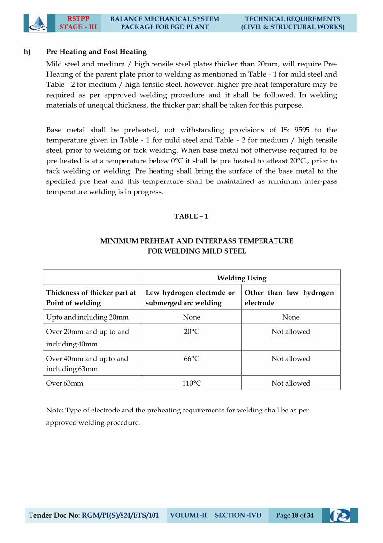
RSTPP STAGE - III
BALANCE MECHANICAL SYSTEM PACKAGE FOR FGD PLANT
TECHNICAL REQUIREMENTS (CIVIL & STRUCTURAL WORKS)
Tender Doc No: RGM/PI(S)/824/ETS/101 VOLUME-II SECTION -IVD Page 18 of 34
h) Pre Heating and Post Heating
Mild steel and medium / high tensile steel plates thicker than 20mm, will require Pre-
Heating of the parent plate prior to welding as mentioned in Table - 1 for mild steel and
Table - 2 for medium / high tensile steel, however, higher pre heat temperature may be
required as per approved welding procedure and it shall be followed. In welding
materials of unequal thickness, the thicker part shall be taken for this purpose.
Base metal shall be preheated, not withstanding provisions of IS: 9595 to the
temperature given in Table - 1 for mild steel and Table - 2 for medium / high tensile
steel, prior to welding or tack welding. When base metal not otherwise required to be
pre heated is at a temperature below 0°C it shall be pre heated to atleast 20°C., prior to
tack welding or welding. Pre heating shall bring the surface of the base metal to the
specified pre heat and this temperature shall be maintained as minimum inter-pass
temperature welding is in progress.
TABLE – 1
MINIMUM PREHEAT AND INTERPASS TEMPERATURE
FOR WELDING MILD STEEL
Welding Using
Thickness of thicker part at
Point of welding
Low hydrogen electrode or
submerged arc welding
Other than low hydrogen
electrode
Upto and including 20mm None None
Over 20mm and up to and
including 40mm
20°C Not allowed
Over 40mm and up to and
including 63mm
66°C Not allowed
Over 63mm 110°C Not allowed
Note: Type of electrode and the preheating requirements for welding shall be as per
approved welding procedure.
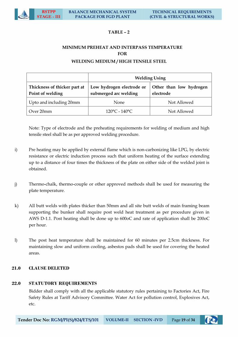
RSTPP STAGE - III
BALANCE MECHANICAL SYSTEM PACKAGE FOR FGD PLANT
TECHNICAL REQUIREMENTS (CIVIL & STRUCTURAL WORKS)
Tender Doc No: RGM/PI(S)/824/ETS/101 VOLUME-II SECTION -IVD Page 19 of 34
TABLE – 2
MINIMUM PREHEAT AND INTERPASS TEMPERATURE
FOR
WELDING MEDIUM / HIGH TENSILE STEEL
Welding Using
Thickness of thicker part at
Point of welding
Low hydrogen electrode or
submerged arc welding
Other than low hydrogen
electrode
Upto and including 20mm None Not Allowed
Over 20mm 120°C - 140°C Not Allowed
Note: Type of electrode and the preheating requirements for welding of medium and high
tensile steel shall be as per approved welding procedure.
i) Pre heating may be applied by external flame which is non-carbonizing like LPG, by electric
resistance or electric induction process such that uniform heating of the surface extending
up to a distance of four times the thickness of the plate on either side of the welded joint is
obtained.
j) Thermo-chalk, thermo-couple or other approved methods shall be used for measuring the
plate temperature.
k) All butt welds with plates thicker than 50mm and all site butt welds of main framing beam
supporting the bunker shall require post weld heat treatment as per procedure given in
AWS D-1.1. Post heating shall be done up to 600oC and rate of application shall be 200oC
per hour.
l) The post heat temperature shall be maintained for 60 minutes per 2.5cm thickness. For
maintaining slow and uniform cooling, asbestos pads shall be used for covering the heated
areas.
21.0 CLAUSE DELETED
22.0 STATUTORY REQUIREMENTS
Bidder shall comply with all the applicable statutory rules pertaining to Factories Act, Fire
Safety Rules at Tariff Advisory Committee. Water Act for pollution control, Explosives Act,
etc.
RSTPP STAGE - III
BALANCE MECHANICAL SYSTEM PACKAGE FOR FGD PLANT
TECHNICAL REQUIREMENTS (CIVIL & STRUCTURAL WORKS)
Tender Doc No: RGM/PI(S)/824/ETS/101 VOLUME-II SECTION -IVD Page 20 of 34
Provisions of safety, health and welfare according to Factories Act shall be complied with.
These shall include provision of continuous walkways along the crane - girder level on both
sides of building, comfortable approach to EOT crane cabin, railing, fire escape, locker room
for workmen, pantry, toilets, rest room etc.
Provisions for fire proof doors, number of staircases, fire separation wall, lath
plastering/encasing the structural members (in fire prone areas), type of glazing etc. shall be
made according to the recommendations of Tarrif Advisory Committee.
Statutory clearances and norms of State Pollution Control Board shall be followed.
Bidder shall obtain approval of Civil/Architectural drawings from concerned authorities
before taking up the construction work.
23.0 INSPECTION, TESTING AND QUALITY CONTROL
Sampling and testing of major items of civil works viz. earthwork, concreting, structural
steel work (including welding), piling, sheeting, etc. shall be carried out in accordance with
the requirements of this specification. Wherever nothing is specified relevant Indian
Standards shall be followed. In absence of Indian Standard equivalent International
Standards may be used.
The Bidder shall submit and finalise a detailed field Quality Assurance Programme before
starting of the construction work according to the requirement of this specification. This
shall include frequency of sampling and testing, nature/type of test, method of test, setting
of a testing laboratory, arrangement of testing apparatus/equipment, deployment of
qualified / experienced manpower, preparation of format for record, Field Quality Plan, etc.
Tests shall be done in the field and/or at a laboratory approved by the Engineer. The Bidder
shall furnish the test certificate from the manufacturer’s of various materials to be used in
the construction.
24.0 CLAUSE DELETED
25.0 CLAUSE DELETED
26.0 GALVANISING
All burrs and irregular edges of the structural steel members to be galvanised shall be
ground smooth before galvanising.
Purity of Zinc to be used for galvanising shall be 99.5 % as per IS : 209 ( latest edition).
The weight of the zinc coating shall be at least 610 Gms. / m2 unless noted otherwise.
RSTPP STAGE - III
BALANCE MECHANICAL SYSTEM PACKAGE FOR FGD PLANT
TECHNICAL REQUIREMENTS (CIVIL & STRUCTURAL WORKS)
Tender Doc No: RGM/PI(S)/824/ETS/101 VOLUME-II SECTION -IVD Page 21 of 34
27.0 CLAUSE DELETED
28.0 CLAUSE DELETED
29.0 ARCHITECTURAL CONCEPTS
Buildings shall be architecturally treated in such a way that it presents a pleasing
composition of mass and void with suitable and functionally designed projections and
recesses. The overall impact of the building shall be one of aesthetically unified
architectural composition having a comprehensive scale, blending with the
surroundings and taking full consideration of the climatic conditions and the building
orientation. All the buildings shall be architecturally treated in such a way so as to be in
harmony with the surroundings. The overall composition may have straight or
curvilinear profiles.
Necessary projections, fins, parapets, chajjas etc. in addition to the minimum area
specified elsewhere in this specification shall be provided as required.
Nothing extra shall be payable for any changes required while getting the drawings /
scheme approved and for executing the same.
All structures, buildings and facilities shall be designed as per provisions of National
Building Code 2016 and Local building by - laws as applicable including provisions of
the Factories Act of the State concerned, with regard to requirement of free access, stairs,
minimum head room, walkways, ventilation, toilets etc. and safety requirements like
railings, fire escapes etc. Further all layouts and detailed drawings shall meet th relevant
statutory requirements specified in recommendations of Petroleum act, Explosives act
and Indian Electricity rules’ as applicable.
29.1 CLAUSE DELETED
29.2 CLAUSE DELETED
29.3 CLAUSE DELETED
29.4 CLAUSE DELETED
29.5 CLAUSE DELETED
RSTPP STAGE - III
BALANCE MECHANICAL SYSTEM PACKAGE FOR FGD PLANT
TECHNICAL REQUIREMENTS (CIVIL & STRUCTURAL WORKS)
Tender Doc No: RGM/PI(S)/824/ETS/101 VOLUME-II SECTION -IVD Page 22 of 34
29.6 CLAUSE DELETED
29.7 CLAUSE DELETED
29.8 CLAUSE DELETED
29.9 CLAUSE DELETED
29.10 CLAUSE DELETED
29.11 CLAUSE DELETED
29.12 Doors, Windows, Ventilators, Louvers, Rolling Shutters & Glazing
Adequate Doors, Windows, Louvers and Ventilators shall be provided for proper
lighting and ventilation of all buildings. The area of windows shall be at least 10% of the
floor area of the respective building. In addition to the above, wherever room height is
more than 3.5 m, a band of ventilators of 600 mm height (minimum) shall be provided at
the top.
Unless specified all doors, of air conditioned areas, entrance door of air lock lobby of all
buildings shall have electro colour coated (anodised) aluminium frame work with8 mm
thick toughened glass glazing. All doors of toilet, kitchen, pantry & store areas shall be
of factory made pre - laminated solid core flush door shutters, as per IS: 2202 (Part-I)
with pressed steel door frame. Control room shall have Aluminium glazed door &
partitions. All other doors (unless otherwise specified) shall be of steel.
All steel doors shall consist of double plate flush door shutters. The door shutter shall be
45 mm thick with two outer sheets of 18 G rigidly connected with continuous
vertical 20 G stiffeners at the rate of 150 mm centre to centre. Side, top and bottom
edges of shutters shall be reinforced by continuous pressed steel channel with
minimum 18 G. The door shall be sound deadened by filling the inside void with
mineral wool. Doors shall be complete with all hardware and fixtures like door closer,
tower bolts, handles, stoppers, aldrops, etc.
Wherever functionally required, rolling shutters of suitable size approved by the
Owner, with suitable operating arrangement manual/ electric shall be provided to
facilitate smooth operations. Rolling shutters shall conform to IS: 6248.
All windows and ventilators at ground floor level shall be provided with suitable
anodised aluminum grill.
RSTPP STAGE - III
BALANCE MECHANICAL SYSTEM PACKAGE FOR FGD PLANT
TECHNICAL REQUIREMENTS (CIVIL & STRUCTURAL WORKS)
Tender Doc No: RGM/PI(S)/824/ETS/101 VOLUME-II SECTION -IVD Page 23 of 34
Fire proof doors with panic devices shall be provided at all fire exit points as per the
requirements. However minimum Fire rating shall be 2 hours. These doors shall
generally be as per IS 3614 (Part 2).Vision Panel in minimum 11 mm thick inter layered
fire resistant glass shall be provided in Fire Doors.
Hollow excluded Section of minimum 2 mm wall thickness as manufactured by
INDAL, Jindal, Hindalco or equivalent shall be used for all Aluminium doors,
windows, ventilators and Partitions.
The doors, Windows & ventilators frame shall be of suitable size & thickness for fixing
the glazing. The Glazing thickness shall be minimum 6 mm thk clear toughened glass for
all glazed doors, windows, ventilators & partitions. Windows in air conditioned areas
shall be provided with 24mm thick hermetically sealed composite double glazing.
Composite double glazing shall be 24mm thick consisting of 6mm thick clear float glass
on inner side and 6mm thick reflective toughened glass on outer side. The two glasses
shall be separated by 12mm air-gap and hermetically sealed by beading of anodized
aluminium with outer edge sealed with silicon sealant. Outer glass of 6mm thickness
shall have following technical characteristics: Solar factor 25% or less, Maximum U-
value 3.3 W/ SQMK, VLT min 30%: Light reflection internal 10 to 15%, light reflection
external 10 to 20 %, shading coefficient (0.25-
0.28).
Doors and windows on external walls shall be provided with sunshade over the
openings with width 600 mm more than the opening width. The projection from the
finished face of the wall for sunshade shall generally be 450 mm over window
openings, 750 mm over door openings and 900 over Rolling shutters, or as decided and
approved by the Engineer.
All glazing work shall conform to IS: 3548.
Windows in conveyor gallery shall be provided with welded wire fabric of 1.6mm thick
wire as per IS: 4948 and 12mm x 30mm mesh size.
30.0 CLAUSE DELETED
31.0 CORROSION PROTECTION
31.1 GENERAL
All Steel structures shall be provided with painting as given in the specification.
Further, painting system shall also meet the requirements of Corrosivity category C3
(durability High) as per ISO 12944.
RSTPP STAGE - III
BALANCE MECHANICAL SYSTEM PACKAGE FOR FGD PLANT
TECHNICAL REQUIREMENTS (CIVIL & STRUCTURAL WORKS)
Tender Doc No: RGM/PI(S)/824/ETS/101 VOLUME-II SECTION -IVD Page 24 of 34
a. Painting system for steel surfaces embedded in Concrete is given separately.
b. All Painting shall be done as per technical specification. Painting scheme shall
be submitted by the bidder for approval of employer.
c. All steel structures shall be designed by following basic design criteria in ISO
12944 Part 3.However, where it is not feasible to follow the design criteria given in
ISO 12944 Part 3 where the steel surface are inaccessible for application of
protective coating, corrosion allowance of 1.5 mm shall be kept in thickness (over
the design thickness) of structural steel members.
31.2 PAINTING OF STEEL SURFACES EMBEDDED IN CONCRETE:
a. For the portion of Steel surfaces embedded in Concrete, the surface shall be
prepared by Manual Cleaning and provided with Primer Coat of Chlorinated
Rubber based Zinc Phosphate Primer of Minimum 50 Micron Dry Film Thickness
(DFT).
b. All threaded and other surfaces of foundation bolts and its materials, insulation
pins, Anchor channels, sleeves, etc. shall be coated with temporary rust preventive
fluid and during execution of civil works, the dried film of coating shall be
removed using organic solvents.
31.3 PAINTING OF STEEL SURFACES (OTHER THAN THOSE EMBEDDED IN
CONCRETE)
a. All steel surfaces shall be provided with two component moisture curing zinc
(ethyl) silicate primer coat (having minimum 80% of metallic Zinc content in dry
film, solid by volume minimum 60% ±2%) of minimum 70 micron DFT to be
applied over blast cleaned surface conforming to Sa 2 ½ finish of ISO 8501-1 with
surface profile 40-60 Micron. The primer coat shall be applied in shop immediately
after blast cleaning by airless spray technique. Zinc dust composition and
properties shall be Type-II as per ASTM D520-00.
b. Primer coat shall be followed with the application of Intermediate coat of two
component polyamide cured epoxy with MIO Content (containing lamellar MIO
minimum 30% on pigment, solid by volume minimum 80% ±2%) of minimum 100
micron DFT. This coat shall be applied in shop after an interval of minimum 24
hours (from the application of primer coat) by airless spray technique.
c. Intermediate coat shall be followed with the application of finish coat of two- pack
aliphatic Isocyanate cured acrylic finish paint (solid by volume minimum 55%
RSTPP STAGE - III
BALANCE MECHANICAL SYSTEM PACKAGE FOR FGD PLANT
TECHNICAL REQUIREMENTS (CIVIL & STRUCTURAL WORKS)
Tender Doc No: RGM/PI(S)/824/ETS/101 VOLUME-II SECTION -IVD Page 25 of 34
±2%) with Gloss retention (SSPC Paint Spec No 36, ASTM D 4587, D 2244, D 523) of
Level 2 (after minimum 1000 hours exposure, Gloss loss less than 30 and colour
change less than 2.0 ∆E) and minimum 70 micron DFT. This coat shall be applied
shop after an interval of minimum 10 hours and within six (6) months (from the
completion of Intermediate coat), Colour and shade of the coat shall be as
approved by the Employer.
Notes:
1. For Primer, high quality surface preparation is necessary and good amount
of moisture is required for proper curing. Below 70 % relative humidity,
curing time may go up to 7 days or more. In such a case additional water
sprinkling may be ensured for completion of curing. Additionally Inorganic
zinc silicate cannot be recoated; even with itself. Typically it should be used
when coating bare steel surface for first time.
2. The most frequent problem associated when top coating Primer is
bubbling/pin holing especially with non-weathered zinc silicate coatings. To
a great extent, this bubbling of finish paint can be eliminated by applying a
mist coat of intermediate/topcoat as the first pass of the product, allow the
bubbles to subside and then apply a full coat, as required.
3. In case top coating of zinc silicate with epoxy/polyurethane coatings, is
expected to be delayed, it is advisable to use a suitable tie coat to avoid
formation of white rust. However, if white rust forms then clean the surface
with high pressure water, dry and apply the subsequent coats as required.
4. Touch up paintings on damaged areas: Surface preparation by manual
tools, wire brush/ emery paper etc. Minimum 6 inches peripheral area,
adjoining to damaged area to be covered. If metal surface is exposed, it is to
be painted with Zinc rich epoxy (70 micron) or suitable primer with existing
paint scheme. If primer is intact, intermediate & top coat to be done with
specified DFT in scheme.
31.4 COATING FOR MILD STEEL PARTS IN CONTACT WITH WATER.
a. All mild Steel parts coming in contact with water or water vapour shall be hot dip
galvanised. The Minimum Coating of Zinc shall be 610 Gms / Sq. M. for
galvanised Structures and shall comply with IS: 4759 and other relevant Codes.
Galvanising shall be checked and tested in accordance with IS: 2629.
RSTPP STAGE - III
BALANCE MECHANICAL SYSTEM PACKAGE FOR FGD PLANT
TECHNICAL REQUIREMENTS (CIVIL & STRUCTURAL WORKS)
Tender Doc No: RGM/PI(S)/824/ETS/101 VOLUME-II SECTION -IVD Page 26 of 34
b. The galvanising shall be followed by the application of an etching Primer and
dipping in black bitumen in accordance with BS: 3416, unless otherwise specified.
31.5 Gratings
All gratings shall be blast cleaned to Sa 2 ½ finish or cleaned by acid pickling as per
ISO 8501-1 and shall be hot dip galvanized at the rate of 610 Gms / Sq. M.
31.6 Hand Railings and Ladders
All Mild steel handrails and ladders shall be galvanised at the rate of 610Gms / Sq. as
per IS: 4736. 31.07.00
31.7 Sea Worthiness
All Steel Sections and fabricated Structures, which are required to be transported on sea,
shall be provided with anti corrosive Paint before shipment to take care of sea
worthiness.
31.8 For Reinforced Concrete Work.
a. The protection for concrete sub-structure shall be provided based on
aggressiveness of the soil, chemical analysis of soil/sub-soil water and presence of
harmful chemicals/salts.
b. The protection to super structure shall depend on exposure condition and
degree of atmospheric corrosion.
This shall require use of dense and durable concrete, control of water cement ratio,
increase in clear cover, use of special type of cement and reinforcement, etc., coating of
concrete surface, etc.,
Bidder shall furnish the details of corrosion protection measures.
32.0 MISCELLANEOUS
32.1 Ordinary form work shall be used in roofs and floor slabs in transfer houses, footings,
pedestals, cable trenches, pits etc., Plywood form work shall be used for all over ground
exposed work like columns, beams, floors and ceilings in control room and M. C. C.
buildings.
RSTPP STAGE - III
BALANCE MECHANICAL SYSTEM PACKAGE FOR FGD PLANT
TECHNICAL REQUIREMENTS (CIVIL & STRUCTURAL WORKS)
Tender Doc No: RGM/PI(S)/824/ETS/101 VOLUME-II SECTION -IVD Page 27 of 34
32.2 Monorail girders and fixtures shall be provided for monorails at the locations as required
and as described elsewhere in these specifications or drawings. Monorail openings in the
walls shall be provided with steel frame doors preferably sliding type or otherwise open
able inside, access platforms and ladders.
32.3 Steel frame around openings in roof and on external walls for mounting of exhaust fans
shall be provided.
32.4 Ready mix non - shrink cementitious grout of reputed manufacturer as approved by the
Employer shall be used for grouting of block outs and foundation bolts, underpinning of
base plates and machine bases. Crushing strength of grout shall be one grade higher than
the foundation concrete. Minimum crushing strength shall be 30 N / mm2 unless higher
strength requirement is specified by the equipment supplier or the grout manufacturers.
32.5 The bottom of steel in case of cable / pipe galleries and trestles shall be generally 3m above
the ground except for rail / road crossing where it shall be 8m above the rail top / road
crest/ground. Further in bunker areas it shall be 8 m above the ground.
32.6 Polysulphide Sealing Compound shall be two-part polysulphide sealant and shall be from
approved manufacturer, conforming to IS : 12118. Materials shall consist of polysulphide
polymer and a curing agent. Gun grade material shall be used unless otherwise specified.
The application of the sealant shall be strictly followed as per manufacturer’s guidelines.
33.0 CLAUSE DELETED
34.0 CLAUSE DELETED
35.0 PACKAGINGAND TRANSPORTATION
All the equipment shall be suitably protected coated, covered or boxed and crated to
prevent damage or deterioration during transit, handling and storage at site till the time
of erection. While packing all the materials the limitations from the point of view of
availability of railway wagon sizes in India should be taken into account. The contractor
shall be responsible for any loss or damage during transportation, handling and storage
due to improper packing.
36.0 PLANT LIFE
The plant shall be designed for a minimum operating life of 30 years under the
conditions of operation. Assurance shall be given that plant components are adequate
for this lifetime. If there are any exceptional items of the plant on which an assurance of
meeting this clause cannot be given, life of such components and the difficulties
associated with them shall be stated.
RSTPP STAGE - III
BALANCE MECHANICAL SYSTEM PACKAGE FOR FGD PLANT
TECHNICAL REQUIREMENTS (CIVIL & STRUCTURAL WORKS)
Tender Doc No: RGM/PI(S)/824/ETS/101 VOLUME-II SECTION -IVD Page 28 of 34
37.0 PTFE (POLY TETRA FLUOROETHYLENE) BEARING
The bearing shall be of reputed make and manufacturer as approved by the Engineer,
for required vertical load and end displacement/rotation. PTFE bearing shall be sliding
against highly polished stainless steel and the coefficient of friction between them shall
be less than 0.06 at 55 kg/sq.cm. In order to prevent cold flow in PTFE surface it shall be
rigidly bonded by a special high temperature resistance adhesive to the stainless steel
substrata. The stainless steel surface that slides against the PTFE is mirror polished. The
stainless steel shall be bonded to the top plate by special high strength adhesive. The
thickness of stainless steel plate shall be between 1.0 mm to 1.5 mm.
38.0 TESTS FOR MATERIAL / WORKMANSHIP
All tests required for all materials, quality of workmanship or any other tests as desired
by the Engineer shall be at contractor’s cost.
39.0 MATERIALS
39.1 For Civil, Structural and Architectural works
Employer will not supply any material. All materials including cement, reinforcement
steel and structural steel, whatsoever required for execution and completion of the
entire scope of work covered under this specification shall be arranged by the
contractor at his own cost. All materials procured by the contractor shall meet the
quality requirements specified in this specification.
The contractor shall keep sufficient stock of cement and steel at site at any point of time
when the work is in progress excluding what has been already incorporated in the
works, so that any disruption / delay in availability of these materials during
procurement will not affect the progress of work at site. The minimum quantity of such
materials in stock at site shall not be less then the Requirement of one ( 1 ) month in case
of Cement and Requirement of two ( 2 ) Consecutive months in case of Steel.
39.2 Structural steel
Structural Steel (including embedded Steel) shall be straight, sound, free from twists,
cracks, flaw, laminations and all other defects. Structural steel shall comprise of mild
steel, medium strength steel and high tensile steel as specified below.
39.3 Mild Steel
a) Rolled sections shall be of grade designation E250, Quality A/BR, Semi-killed/
killed conforming to IS 2062. All steel plates shall be of Grade designation E250,
Quality BR (fully killed), conforming to IS 2062 and shall be tested for impact
resistance at room temperature. Plates beyond 12mm thickness and up to 40mm
thickness shall be normalized rolled. Plates beyond 40mm thickness shall be
RSTPP STAGE - III
BALANCE MECHANICAL SYSTEM PACKAGE FOR FGD PLANT
TECHNICAL REQUIREMENTS (CIVIL & STRUCTURAL WORKS)
Tender Doc No: RGM/PI(S)/824/ETS/101 VOLUME-II SECTION -IVD Page 29 of 34
vacuum degassed & furnace normalised and shall also be 100% ultrasonically
tested as per ASTM –A578 level B-S2.
b) Pipes shall conform to IS 1161.
c) Hollow (square and rectangular) steel sections shall be hot formed conforming to
IS: 4923 and shall be of minimum Grade Yst 240.
d) Chequered plate shall conform to IS 3502 and shall be minimum 6 mm thick
excluding projection. Steel for chequered plate shall conform to grade E250A semi
killed of IS: 2062 or equivalent grade conforming to ASTM & BS standards only.
39.4 Medium and High Tensile Steel
Rolled Sections and plates shall be of grade designation E350 or higher, Quality B0
(Fully killed), conforming to IS 2062. Plates beyond 12mm thickness and up to 40mm
thickness shall be normalized rolled. Plates beyond 40mm thickness shall be vacuum
degassed & furnace normalised and shall also be 100% ultrasonically tested as per
ASTM –A578 level B-S2.
39.5 Cement
a) Fly ash based portland pozzolana cement conforming to IS:1489 (Part-1) shall be
used for all areas other than for the critical structures identified below. Other
properties shall be as per IS code.
b) Ordinary Portland Cement (OPC) shall necessarily be used for the following
structures.
i Spring supported decks of limestone crusher
ii RCC for Chimney shell.
The grade of cement shall be Grade 43 for OPC conforming to IS:269.
c) In place of fly ash based portland pozzolana cement, OPC mixed with Fly Ash can
be used. Batching plant shall have facility for mixing fly ash. Fly ash shall conform
to IS:3812(Part I & Part II). Percentage of fly ash to be mixed in concrete shall be
based on trial mix. Mix design shall be done with varying percentage of fly ash
mix with cement.
d) Reinforcement steel shall conform to:
i Mild steel bars of grade I of IS: 432 Part – I or grade A of IS: 2062.
RSTPP STAGE - III
BALANCE MECHANICAL SYSTEM PACKAGE FOR FGD PLANT
TECHNICAL REQUIREMENTS (CIVIL & STRUCTURAL WORKS)
Tender Doc No: RGM/PI(S)/824/ETS/101 VOLUME-II SECTION -IVD Page 30 of 34
ii High yield strength deformed TMT steel bars of grade Fe-500 having
minimum elongation of 14.5 % or Fe-500D, and conforming to other
requirements of IS 1786.
39.6 Aggregates
a) Coarse Aggregate
Coarse aggregate for concrete shall be crushed stones chemically inert, hard,
strong, durable against weathering of limited porosity and free from deleterious
materials. It shall be properly graded. It shall meet the requirements of IS: 383.
b) Fine Aggregate
Fine aggregate shall consist of natural sand/ crushed sand and shall be hard,
durable, clean and free from adherent coatings of organic matter and clay balls or
pellets. Fine aggregate in concrete shall conform to IS: 383. For plaster, it shall
conform to IS: 1542 and for masonrywork to IS: 2116.However, in case of chimney
shellconstruction, natural sand conformingto IS: 383 shall only be used.
b) Petrographic examination of aggregate shall be carried out by the contractor at
National Council for Cement and Building Materials (NCB), Ballabgarh, or any
other approved laboratory to ascertain the structure and rock type including
presence of strained quartz and other reactive minerals. In case, the coarse
aggregate sample is of composite nature, the proportions (by weight) of different
rock types in the composite sample and petrographic evaluation of each rock
should also be ascertained. While determining the rock type, special emphasis
should be given on identification of known reactive rocks like chalcedony, opal
etc. The procedure laid down in IS 2430 for sampling of aggregates may be
followed.
The laboratory shall determine potential reactivity of the aggregate, which may lead to
reaction of silica in aggregate with the alkalis of cement and / or potential of some
aggregates like limestone to cause residual expansion due to repeated temperature
cycle. If the same is established, the contractor shall further carry out alkali aggregates
reactivity test as per IS 2386 (Pt.VII) and / or repeated temperature cycle test to establish
the suitability of the aggregates for the concrete work. The test results, with the final
recommendations of the laboratory, as to a suitability of the aggregate, for use in the
concrete work for various structures and suggested measures, in case of results are not
satisfactory, shall be submitted to the Engineer for his review, in a report form.
RSTPP STAGE - III
BALANCE MECHANICAL SYSTEM PACKAGE FOR FGD PLANT
TECHNICAL REQUIREMENTS (CIVIL & STRUCTURAL WORKS)
Tender Doc No: RGM/PI(S)/824/ETS/101 VOLUME-II SECTION -IVD Page 31 of 34
In case in the report, it is established, that the aggregates contain reactive silica, which
would react with alkalis of the cement, the contractor shall change the source of supply
of the aggregate or use low alkali cement as per recommendation or take measures as
recommended in the report as instructed by Engineer.
In case aggregates indicate residual expansion, under repeated temperature cycle test
(from 10o Celsius to 65o Celsius and for 60 temperature cycles) the material shall not be
used for concreting of Lime stone crusher decks, Mills, Fans and other equipment
foundations which are likely to be subjected to repeated temperature cycle. The
contractor shall use aggregates free from residual expansion under repeated
temperatures cycle test.
39.6 NUTS AND BOLTS
M.S. Nuts and Bolts shall conform to IS:1363,IS:1364, IS:1367.
Hightensile fixing with bolts and nuts shall respectively be as per IS:3757 and IS:6623.
Washers shall conform to IS:5369, IS:5370, IS:5372, IS:5374, IS:6610, IS:6649, as
appropriate.
40.0 CODES AND STANDARDS
All standards, specifications, acts and code of practice referred to herein shall be the
latest editions including all applicable official amendments and revisions. Other Indian,
foreign Codes and Standards not listed here but referred to elsewhere within this
specification shall also be deemed to be part of this list.
In case of conflict between this specification and those (IS standards, codes etc.) referred
to herein, the former shall prevail.
Some of the relevant Indian standards, Acts and Codes applicable to this section of the
specification are listed below
IS : 383 Specification for coarse and fine aggregates from natural
sources for Concrete.
IS : 432 Specification for mild steel and medium tensile steel bars
and hard drawn steel wire for concrete reinforcement.
IS : 456 Code of practice for plain and reinforced concrete.
IS : 458 Specification for concrete pipes.
IS : 516 Method of test for strength of concrete.
RSTPP STAGE - III
BALANCE MECHANICAL SYSTEM PACKAGE FOR FGD PLANT
TECHNICAL REQUIREMENTS (CIVIL & STRUCTURAL WORKS)
Tender Doc No: RGM/PI(S)/824/ETS/101 VOLUME-II SECTION -IVD Page 32 of 34
IS : 800 Code of practice for use of structural steel in general
building construction.
IS : 814 Specification for covered electrodes for metal arc welding
for weld steel.
IS : 816 Code of practice for use of metal arc welding for general
construction.
IS : 817 Code of practice for training and testing of metal arc
welders.
IS : 875 (Pt.I toV) Code of practice for design loads other than
earthquake) for buildings and structures.
IS : 1038 Steel doors, windows and ventilators
IS : 1172 Basic requirements for water supply, drainage and
sanitation.
IS : 1361 Steel windows for industrial buildings.
IS : 1786 Specification for high strength deformed steel bars and
wires for concrete reinforcement.
IS : 1892 Code of practice for subsurface investigation for
foundation.
IS : 1893 Criteria for earthquake resistant design of structures.
IS : 1904 Code of practice for design and construction of
foundations in soils; general requirements.
IS : 1905 Code of practice for structural safety of buildings -
Masonry walls.
IS : 1948 Specification for aluminium doors, windows and
ventilators.
IS : 2062 Steel for general structural purposes.
IS : 2131 Method of standard penetration test for soils.
IS : 2212 Code of practice for brickwork.
IS : 2645 Specification for Integral cement water proofing
compounds.
IS:2720 (Part-II, Methods of test for soils - determination for water
IV TO VIII, XIV , content etc code of practice for earth work on canals.
XXI, XXIII, XXIV,
XXVII TO XXIX, XL)
IS : 2911 Code of practice for design and construction of pile
foundations.
(Part-1/Sec.1) Driven cast in situ concrete piles.
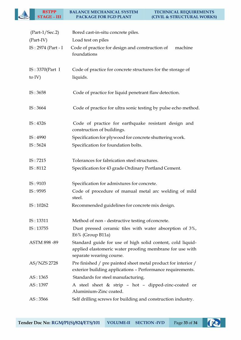
RSTPP STAGE - III
BALANCE MECHANICAL SYSTEM PACKAGE FOR FGD PLANT
TECHNICAL REQUIREMENTS (CIVIL & STRUCTURAL WORKS)
Tender Doc No: RGM/PI(S)/824/ETS/101 VOLUME-II SECTION -IVD Page 33 of 34
(Part-1/Sec.2) Bored cast-in-situ concrete piles.
(Part-IV) Load test on piles
IS : 2974 (Part - I Code of practice for design and construction of machine
foundations
IS : 3370(Part I Code of practice for concrete structures for the storage of
to IV) liquids.
IS : 3658 Code of practice for liquid penetrant flaw detection.
IS : 3664 Code of practice for ultra sonic testing by pulse echo method.
IS : 4326 Code of practice for earthquake resistant design and
construction of buildings.
IS : 4990 Specification for plywood for concrete shuttering work.
IS : 5624 Specification for foundation bolts.
IS : 7215 Tolerances for fabrication steel structures.
IS : 8112 Specification for 43 grade Ordinary Portland Cement.
IS : 9103 Specification for admixtures for concrete.
IS : 9595 Code of procedure of manual metal arc welding of mild
steel.
IS : 10262 Recommended guidelines for concrete mix design.
IS : 13311 Method of non - destructive testing of concrete.
IS : 13755 Dust pressed ceramic tiles with water absorption of 3%,
E6% (Group B11a)
ASTM 898 -89 Standard guide for use of high solid content, cold liquid-
applied elastomeric water proofing membrane for use with
separate wearing course.
AS/NZS 2728 Pre finished / pre painted sheet metal product for interior /
exterior building applications – Performance requirements.
AS : 1365 Standards for steel manufacturing.
AS : 1397 A steel sheet & strip – hot – dipped-zinc-coated or
Aluminium-Zinc coated.
AS : 3566 Self drilling screws for building and construction industry.
RSTPP STAGE - III
BALANCE MECHANICAL SYSTEM PACKAGE FOR FGD PLANT
TECHNICAL REQUIREMENTS (CIVIL & STRUCTURAL WORKS)
Tender Doc No: RGM/PI(S)/824/ETS/101 VOLUME-II SECTION -IVD Page 34 of 34
IRC : 37 Guidelines for the design of flexible pavements.
- Manual on sewerage and sewage treatment (Published by
CPH & EEO) As updated.
Indian Explosives Act. 1940 as updated.
For “Foundation System and Geotechnical Data” refer “Project Information
section” of Technical specification.
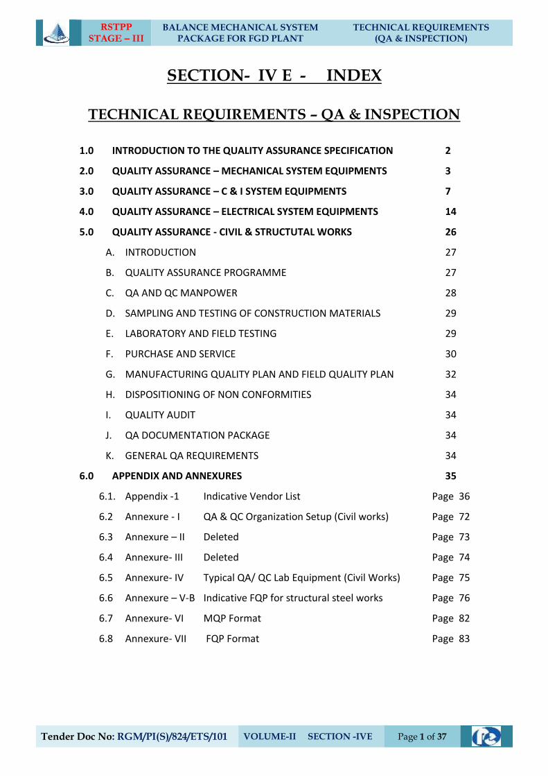
RSTPP STAGE – III
BALANCE MECHANICAL SYSTEM PACKAGE FOR FGD PLANT
TECHNICAL REQUIREMENTS (QA & INSPECTION)
Tender Doc No: RGM/PI(S)/824/ETS/101 VOLUME-II SECTION -IVE Page 1 of 37
SECTION- IV E - INDEX
TECHNICAL REQUIREMENTS – QA & INSPECTION
1.0 INTRODUCTION TO THE QUALITY ASSURANCE SPECIFICATION 2
2.0 QUALITY ASSURANCE – MECHANICAL SYSTEM EQUIPMENTS 3
3.0 QUALITY ASSURANCE – C & I SYSTEM EQUIPMENTS 7
4.0 QUALITY ASSURANCE – ELECTRICAL SYSTEM EQUIPMENTS 14
5.0 QUALITY ASSURANCE - CIVIL & STRUCTUTAL WORKS 26
A. INTRODUCTION 27
B. QUALITY ASSURANCE PROGRAMME 27
C. QA AND QC MANPOWER 28
D. SAMPLING AND TESTING OF CONSTRUCTION MATERIALS 29
E. LABORATORY AND FIELD TESTING 29
F. PURCHASE AND SERVICE 30
G. MANUFACTURING QUALITY PLAN AND FIELD QUALITY PLAN 32
H. DISPOSITIONING OF NON CONFORMITIES 34
I. QUALITY AUDIT 34
J. QA DOCUMENTATION PACKAGE 34
K. GENERAL QA REQUIREMENTS 34
6.0 APPENDIX AND ANNEXURES 35
6.1. Appendix -1 Indicative Vendor List Page 36
6.2 Annexure - I QA & QC Organization Setup (Civil works) Page 72
6.3 Annexure – II Deleted Page 73
6.4 Annexure- III Deleted Page 74
6.5 Annexure- IV Typical QA/ QC Lab Equipment (Civil Works) Page 75
6.6 Annexure – V-B Indicative FQP for structural steel works Page 76
6.7 Annexure- VI MQP Format Page 82
6.8 Annexure- VII FQP Format Page 83
RSTPP STAGE – III
BALANCE MECHANICAL SYSTEM PACKAGE FOR FGD PLANT
TECHNICAL REQUIREMENTS (QA & INSPECTION)
Tender Doc No: RGM/PI(S)/824/ETS/101 VOLUME-II SECTION -IVD Page 2 of 37
1.0 INTRODUCTION TO THE QUALITY ASSURANCE SPECIFICATION
For fulfilment of the relevant clauses (regarding Testing, Inspection etc.) of the General
Conditions of Contract (GCC) and General Technical Requirements (GTR in Section VII) of
Contract , the Quality Assurance Specification acts as a part of the Technical Specification
and is included in the Contract.
This part of the Technical Specification shall be read in conjunction with other parts of the
Technical Specifications, General Technical Requirements and Erection Conditions of the
Contract (ECC- Section VIII).
This document specifies the quality requirements, to be detailed in terms of
Tests/Checks/Procedures to be followed at the times of manufacturing, Testing, Inspection
and also during installation of various Equipment / Components at the place of
manufacturer and / or on the site. Various standards referred in this document shall be the
latest revisions.
The quality requirements are spelt out in the following ways;
1) Through description
2) In tabular form
In either of the above two formats the tests /checks / procedures that are required to be
performed are mentioned against particular item/ equipment/ component/ system etc.
This specification also contains the NTPC’s Indicative vendor list (with disclaimer)
mentioned against particular item/ equipment/ component/ system etc and enclosed as
Annexure-1 to this Section –IV E. The quality requirements specified in this document and
also the vendor list are only indicative and not exhaustive.
RSTPP STAGE – III
BALANCE MECHANICAL SYSTEM PACKAGE FOR FGD PLANT
TECHNICAL REQUIREMENTS (QA & INSPECTION)
Tender Doc No: RGM/PI(S)/824/ETS/101 VOLUME-II SECTION -IVD Page 3 of 37
2.0 QUALITY ASSURANCE – MECHANICAL SYSTEM EQUIPMENTS
RSTPP STAGE – III
BALANCE MECHANICAL SYSTEM PACKAGE FOR FGD PLANT
TECHNICAL REQUIREMENTS (QA & INSPECTION)
Tender Doc No: RGM/PI(S)/824/ETS/101 VOLUME-II SECTION -IVD Page 4 of 37
2.1 PIPING, VALVES AND SPECIALITIES
a) All pipes and fittings shall be tested as per applicable code.
b) All valves shall be hydraulically/Air tested for body, seat and back-seat (if applicable)
as per relevant standard.
c) NDT on valves shall be as per relevant standard.
d) Valves shall be offered for hydro test in unpainted conditions.
e) Functional checks of the valves for smooth opening and closing shall also be done.
2.2 TANKS / VESSELS
2.2.1 Atmospheric tanks:
a) All welds joints shall be DP tested and complete tanks shall be water fill tested.
b) All atmospheric storage tanks fabricated and erected at site shall be subjected to
tests (Hydro, NDT and Vacuum) according to design code/standard as applicable.
c) Lining of the tanks/vessels shall be tested for hardness and spark test etc, as per
applicable standard.
2.2.2 Pressure vessels:
a) NDT on weld joint shall be as per respective code requirements or the minimum as
specified as below:
i) 100% DPT on root run of butt weld, nozzle welds and finished fillet welds.
ii) 10% DPT on all finished butt welds.
iii) 10% RT (covering all ‘T’/cross joints) of butt welds.
b) Butt welds of dished ends shall be stress relieved and subjected to 100% RT.
c) Each finished vessels shall be hydraulically tested to 150% of the design pressure for
duration of 30 minutes.
2.3 HEAT EXCHANGER/HEATER:
a) All material shall be tested for chemical and mechanical properties and NDT as per
relevant standard.
b) NDT on welds and other checks shall be as per relevant code.
RSTPP STAGE – III
BALANCE MECHANICAL SYSTEM PACKAGE FOR FGD PLANT
TECHNICAL REQUIREMENTS (QA & INSPECTION)
Tender Doc No: RGM/PI(S)/824/ETS/101 VOLUME-II SECTION -IVD Page 5 of 37
c) Air heaters shall be subjected to dimensional and clearance checks as per standard
practice.
d) Lube oil system, drive system, soot blowing system etc. of Air heaters shall be
checked suitably as per standard practice.
2.4 PUMPS
a) UT on shaft forgings (greater or equal to 40mm) and MPI/DPT shall be done on
shafts and impeller to ensure freedom from defects.
b) The pump casing shall be hydraulically tested at 200% of pump rated head or at
150% of shut off head, whichever is higher. The test pressure shall be maintained for
at least half an hour.
c) The pump rotating parts shall be subjected to static and dynamic balancing.
d) All pumps shall be tested at shop for capacity, head efficiency and brake horse power
at rated speed as per relevant/applicable standard.
e) Noise and vibration shall be measured during the performance testing at shop.
2.5 STRUCTURES, DUCTS, HOPPERS:
a) All materials shall be tested for chemical and mechanical properties as per relevant
standard. All plates above 40mm shall be 100% ultrasonically tested.
b) Visual inspection of all welds shall be performed in accordance with AWSD1.1.
c) NDT requirements of structural steel welds shall be as under:
i) 100% RT/UT on butt-welds of plate thickness>= 32mm. ii) For plates of 25mm<=thickness<32mm-10% RT and 100% MPI. iii) For plates of thickness <25mm-10% MPI/LPI.
d) Edge for shop and field weld shall be examined by MPI for plate thickness >= 32mm.
e) Cladding material and its application on the ducts shall be tested as per applicable
standard.
2.6 AGITATORS:
a) Lining of the agitator shall be tested for hardness and spark test etc. as per
applicable standard.
b) Impellers shall be tested for dimensional and balancing check.
c) Gear Boxes shall be tested for run test as per standard practice.
RSTPP STAGE – III
BALANCE MECHANICAL SYSTEM PACKAGE FOR FGD PLANT
TECHNICAL REQUIREMENTS (QA & INSPECTION)
Tender Doc No: RGM/PI(S)/824/ETS/101 VOLUME-II SECTION -IVD Page 6 of 37
2.7 THERMAL INSULATION, LAGGING & CLADDING:
a) Lightly resin bonded mineral wool:
LRB mattresses/sections of Rockwool/ Glass wool shall conform to & tested as per
relevant clauses of Indian Standards and shall meet the requirements of NTPC data
Sheet. Type tests except Thermal Conductivity shall be regularly carried out once in
three months. Thermal Conductivity Type Test shall be carried out minimum once
in twelve months by the manufacturer. Requirements of various components like
Binding wires, Lacing wires, Wire mesh, etc. shall be as per NTPC approved data
sheet / as given in respective Sub-Section of Technical Requirements of Steam
Generator & Auxiliaries.
b) Lagging & Cladding:
All insulation shall be protected by means of an outer covering of Aluminium
sheeting confirming to ASTM B-209-1060 temper H14 from reputed manufacturer
meeting the requirements of NTPC data sheet.
2.8 OTHER CRITICAL EQUIPMENTS :
Checks/ NDTs shall be done as per relevant Indian Standards or equivalent International Standards
RSTPP STAGE – III
BALANCE MECHANICAL SYSTEM PACKAGE FOR FGD PLANT
TECHNICAL REQUIREMENTS (QA & INSPECTION)
Tender Doc No: RGM/PI(S)/824/ETS/101 VOLUME-II SECTION -IVD Page 7 of 37
3.0 QUALITY ASSURANCE – C & I SYSTEM EQUIPMENTS
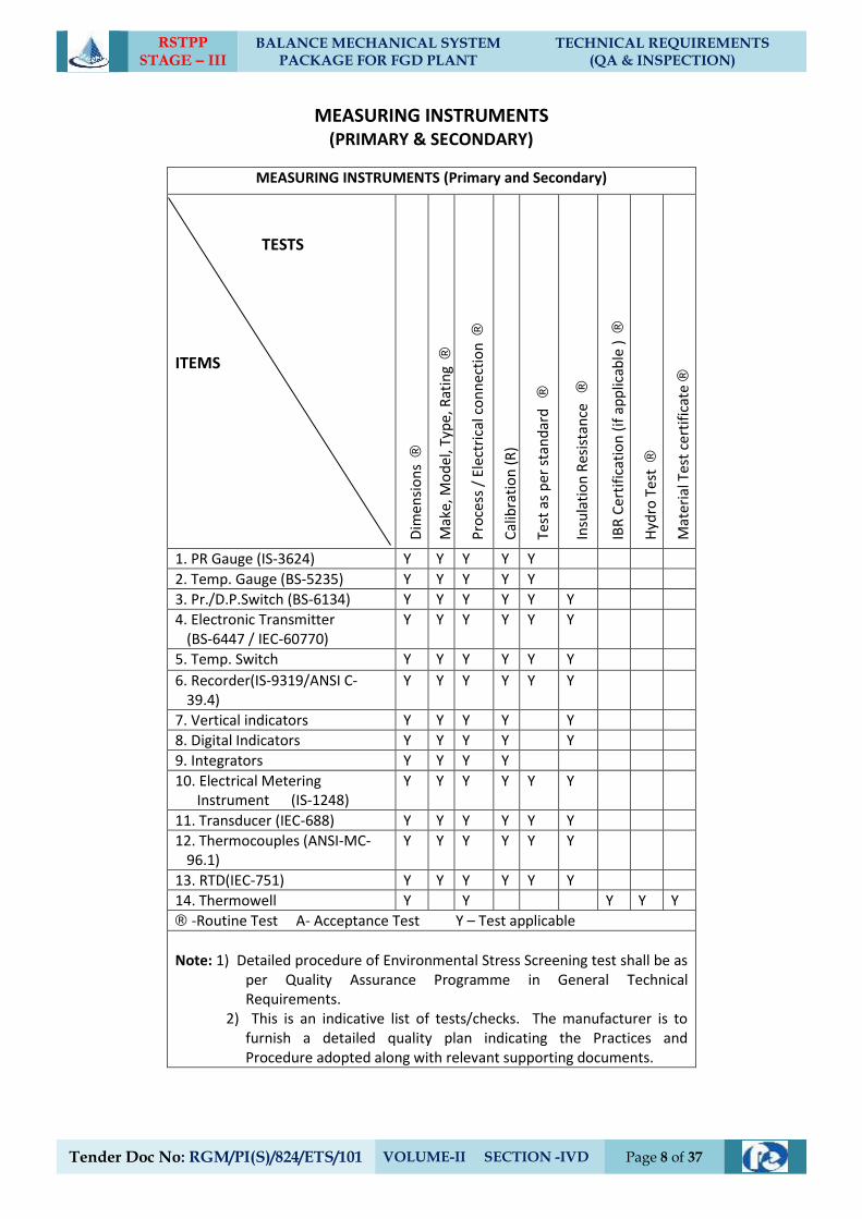
RSTPP STAGE – III
BALANCE MECHANICAL SYSTEM PACKAGE FOR FGD PLANT
TECHNICAL REQUIREMENTS (QA & INSPECTION)
Tender Doc No: RGM/PI(S)/824/ETS/101 VOLUME-II SECTION -IVD Page 8 of 37
MEASURING INSTRUMENTS (PRIMARY & SECONDARY)
MEASURING INSTRUMENTS (Primary and Secondary)
TESTS
ITEMS D
imen
sio
ns
®
Mak
e, M
od
el, T
ype,
Rat
ing
®
Pro
cess
/ E
lect
rica
l co
nn
ecti
on
®
Cal
ibra
tio
n (
R)
Test
as
per
sta
nd
ard
®
Insu
lati
on
Res
ista
nce
®
IBR
Cer
tifi
cati
on
(if
ap
plic
able
) ®
Hyd
ro T
est
®
Mat
eri
al T
est
cert
ific
ate
®
1. PR Gauge (IS-3624) Y Y Y Y Y
2. Temp. Gauge (BS-5235) Y Y Y Y Y
3. Pr./D.P.Switch (BS-6134) Y Y Y Y Y Y
4. Electronic Transmitter (BS-6447 / IEC-60770)
Y Y Y Y Y Y
5. Temp. Switch Y Y Y Y Y Y
6. Recorder(IS-9319/ANSI C-39.4)
Y Y Y Y Y Y
7. Vertical indicators Y Y Y Y Y
8. Digital Indicators Y Y Y Y Y
9. Integrators Y Y Y Y
10. Electrical Metering Instrument (IS-1248)
Y Y Y Y Y Y
11. Transducer (IEC-688) Y Y Y Y Y Y
12. Thermocouples (ANSI-MC-96.1)
Y Y Y Y Y Y
13. RTD(IEC-751) Y Y Y Y Y Y
14. Thermowell Y Y Y Y Y
® -Routine Test A- Acceptance Test Y – Test applicable
Note: 1) Detailed procedure of Environmental Stress Screening test shall be as
per Quality Assurance Programme in General Technical Requirements.
2) This is an indicative list of tests/checks. The manufacturer is to furnish a detailed quality plan indicating the Practices and Procedure adopted along with relevant supporting documents.
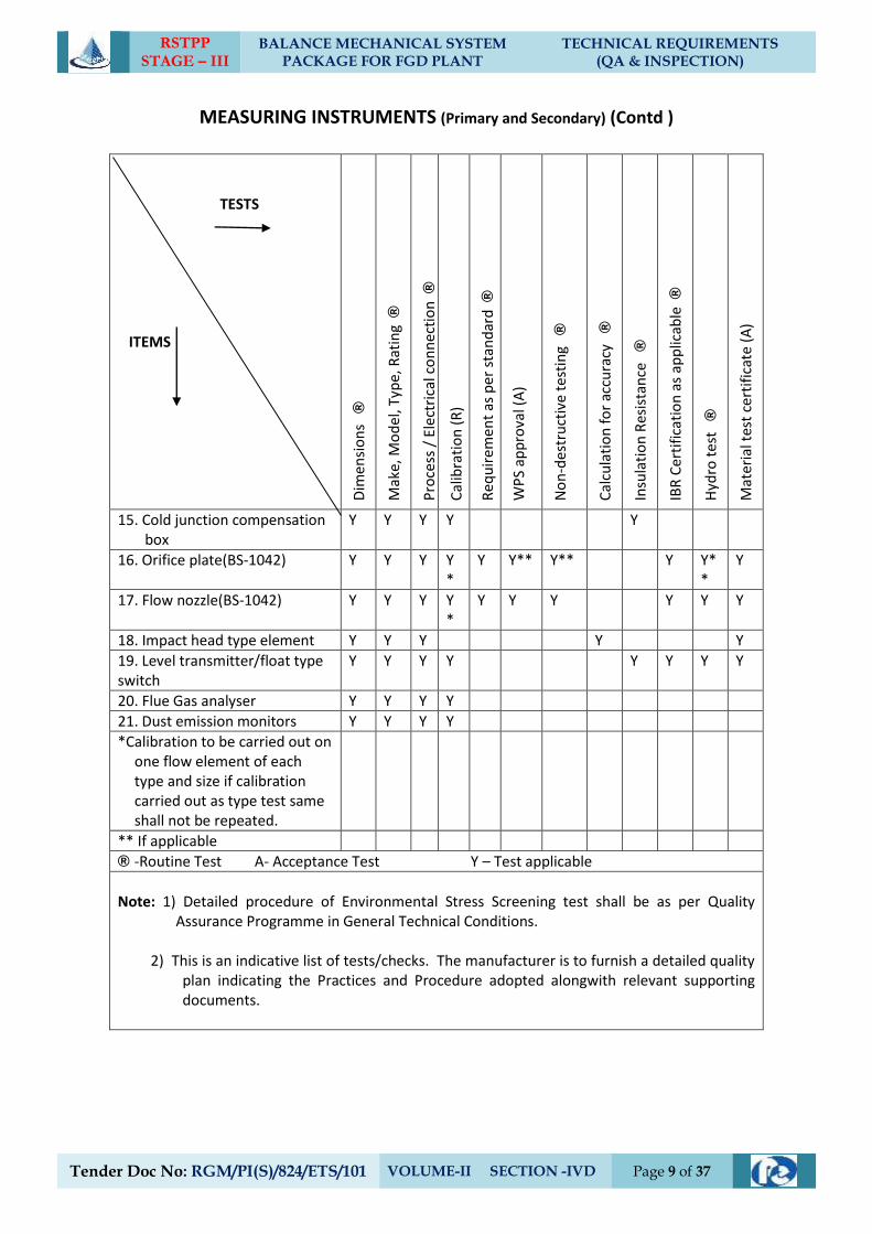
RSTPP STAGE – III
BALANCE MECHANICAL SYSTEM PACKAGE FOR FGD PLANT
TECHNICAL REQUIREMENTS (QA & INSPECTION)
Tender Doc No: RGM/PI(S)/824/ETS/101 VOLUME-II SECTION -IVD Page 9 of 37
MEASURING INSTRUMENTS (Primary and Secondary) (Contd )
TESTS ITEMS D
imen
sio
ns
®
Mak
e, M
od
el, T
ype,
Rat
ing
®
Pro
cess
/ E
lect
rica
l co
nn
ecti
on
®
Cal
ibra
tio
n (
R)
Req
uir
emen
t as
per
sta
nd
ard
®
WP
S ap
pro
val (
A)
No
n-d
estr
uct
ive
test
ing
®
Cal
cula
tio
n f
or
accu
racy
®
Insu
lati
on
Res
ista
nce
®
IBR
Cer
tifi
cati
on
as
app
licab
le ®
Hyd
ro t
est
®
Mat
eri
al t
est
cert
ific
ate
(A
)
15. Cold junction compensation box
Y Y Y Y Y
16. Orifice plate(BS-1042) Y Y Y Y*
Y Y** Y** Y Y**
Y
17. Flow nozzle(BS-1042) Y Y Y Y*
Y Y Y Y Y Y
18. Impact head type element Y Y Y Y Y
19. Level transmitter/float type switch
Y Y Y Y Y Y Y Y
20. Flue Gas analyser Y Y Y Y
21. Dust emission monitors Y Y Y Y
*Calibration to be carried out on one flow element of each type and size if calibration carried out as type test same shall not be repeated.
** If applicable
® -Routine Test A- Acceptance Test Y – Test applicable
Note: 1) Detailed procedure of Environmental Stress Screening test shall be as per Quality
Assurance Programme in General Technical Conditions. 2) This is an indicative list of tests/checks. The manufacturer is to furnish a detailed quality
plan indicating the Practices and Procedure adopted alongwith relevant supporting documents.
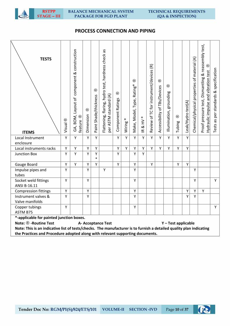
RSTPP STAGE – III
BALANCE MECHANICAL SYSTEM PACKAGE FOR FGD PLANT
TECHNICAL REQUIREMENTS (QA & INSPECTION)
Tender Doc No: RGM/PI(S)/824/ETS/101 VOLUME-II SECTION -IVD Page 10 of 37
PROCESS CONNECTION AND PIPING
TESTS
ITEMS Vis
ual
®
GA
, BO
M, L
ayo
ut
of
co
mp
on
ent
& c
on
stru
ctio
n
feat
ure
®
Dim
ensi
on
®
Pai
nt
Shad
e/th
ickn
ess
®
Flat
ten
ing,
fla
rin
g, h
ydro
tes
t, h
ard
nes
s ch
eck
as
per
AST
M s
tan
dar
d (
A)
Co
mp
on
ent
Rat
ings
®
Wir
ing
®
Mak
e, M
od
el, T
ype,
Rat
ing®
®
IR &
HV
®
Rev
iew
of
TC f
or
inst
rum
ent/
dev
ices
(R
)
Acc
essi
bili
ty o
f TB
s/D
evic
es
®
Illu
min
atio
n, g
rou
nd
ing
®
Tub
ing
®
Leak
/Hyd
ro t
est(
A)
Ch
emic
al/p
hys
ical
pro
per
ties
of
mat
eri
al (
A)
Pro
of
pre
ssu
re t
est
, Dis
man
tlin
g &
re
asse
mb
ly t
est
,
Hyd
rau
lic im
pu
lse
and
vib
rati
on
tes
t ®
Test
s as
per
sta
nd
ard
s &
sp
ecif
icat
ion
Local Instrument enclosure
Y Y Y Y Y Y Y Y Y Y Y Y Y
Local instruments racks Y Y Y Y Y Y Y Y Y Y Y Y Y
Junction Box Y Y Y Y*
Y Y Y
Gauge Board Y Y Y Y Y Y Y Y Y
Impulse pipes and tubes
Y Y Y Y Y
Socket weld fittings ANSI B-16.11
Y Y Y Y Y
Compression fittings Y Y Y Y Y Y
Instrument valves & Valve manifolds
Y Y Y Y Y
Copper tubings ASTM B75
Y Y Y
*-applicable for painted junction boxes.
Note: ® -Routine Test A- Acceptance Test Y – Test applicable Note: This is an indicative list of tests/checks. The manufacturer is to furnish a detailed quality plan indicating the Practices and Procedure adopted along with relevant supporting documents.
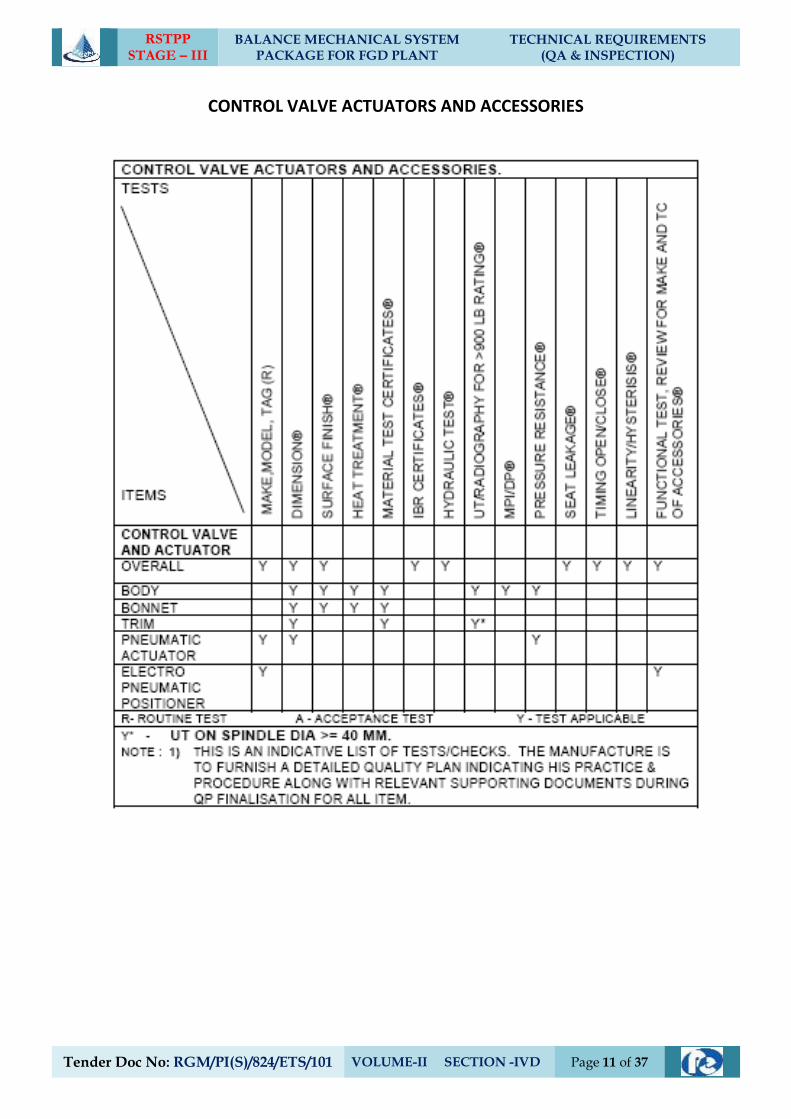
RSTPP STAGE – III
BALANCE MECHANICAL SYSTEM PACKAGE FOR FGD PLANT
TECHNICAL REQUIREMENTS (QA & INSPECTION)
Tender Doc No: RGM/PI(S)/824/ETS/101 VOLUME-II SECTION -IVD Page 11 of 37
CONTROL VALVE ACTUATORS AND ACCESSORIES
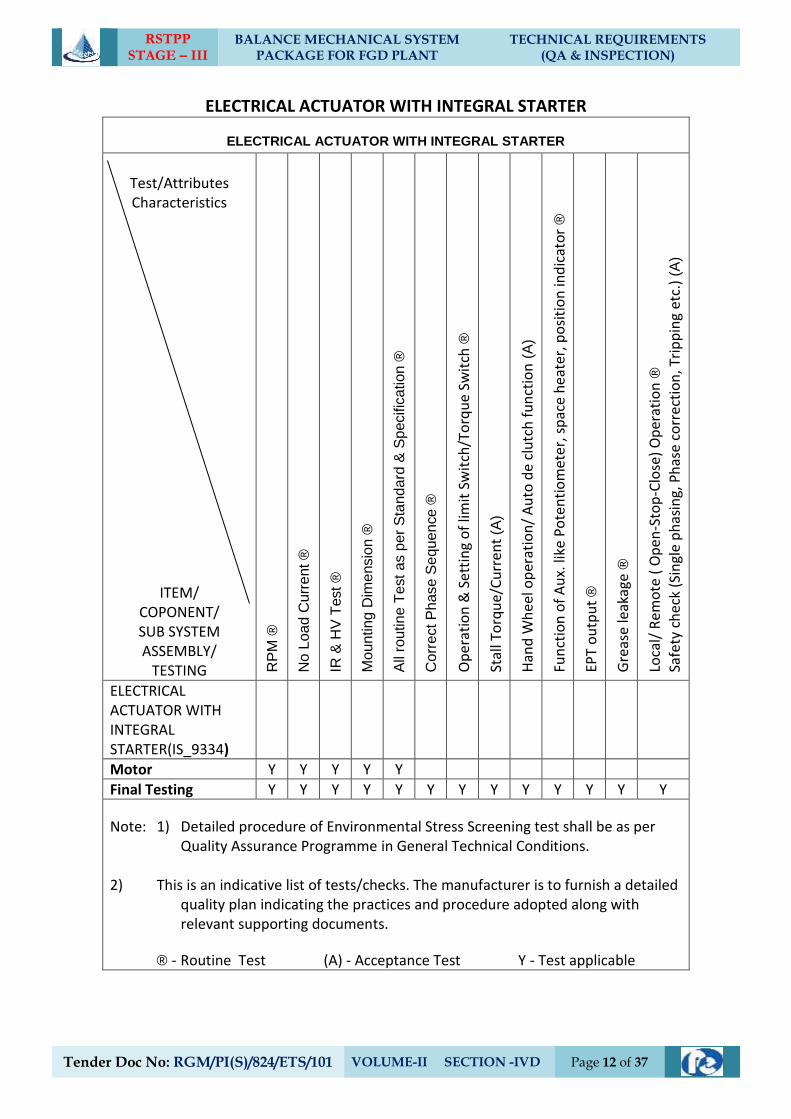
RSTPP STAGE – III
BALANCE MECHANICAL SYSTEM PACKAGE FOR FGD PLANT
TECHNICAL REQUIREMENTS (QA & INSPECTION)
Tender Doc No: RGM/PI(S)/824/ETS/101 VOLUME-II SECTION -IVD Page 12 of 37
ELECTRICAL ACTUATOR WITH INTEGRAL STARTER
ELECTRICAL ACTUATOR WITH INTEGRAL STARTER
Test/Attributes Characteristics
ITEM/ COPONENT/ SUB SYSTEM ASSEMBLY/
TESTING RP
M ®
No
Lo
ad C
urr
ent ®
IR &
HV
Test ®
Mo
un
ting
Dim
ensio
n ®
All
routin
e T
est
as p
er
Sta
nd
ard
& S
pecific
ation
®
Co
rre
ct P
hase S
equ
en
ce
®
Op
erat
ion
& S
etti
ng
of
limit
Sw
itch
/To
rqu
e Sw
itch
®
Stal
l To
rqu
e/C
urr
en
t (A
)
Han
d W
hee
l op
erat
ion
/ A
uto
de
clu
tch
fu
nct
ion
(A
)
Fun
ctio
n o
f A
ux.
like
Po
ten
tio
met
er, s
pac
e h
eate
r, p
osi
tio
n in
dic
ato
r ®
EPT
ou
tpu
t ®
Gre
ase
leak
age
®
Loca
l/ R
emo
te (
Op
en-S
top
-Clo
se)
Op
erat
ion
®
Safe
ty c
hec
k (S
ingl
e p
has
ing,
Ph
ase
corr
ecti
on
, Tri
pp
ing
etc.
) (A
)
ELECTRICAL ACTUATOR WITH INTEGRAL STARTER(IS_9334)
Motor Y Y Y Y Y
Final Testing Y Y Y Y Y Y Y Y Y Y Y Y Y
Note: 1) Detailed procedure of Environmental Stress Screening test shall be as per Quality Assurance Programme in General Technical Conditions.
2) This is an indicative list of tests/checks. The manufacturer is to furnish a detailed
quality plan indicating the practices and procedure adopted along with relevant supporting documents.
® - Routine Test (A) - Acceptance Test Y - Test applicable
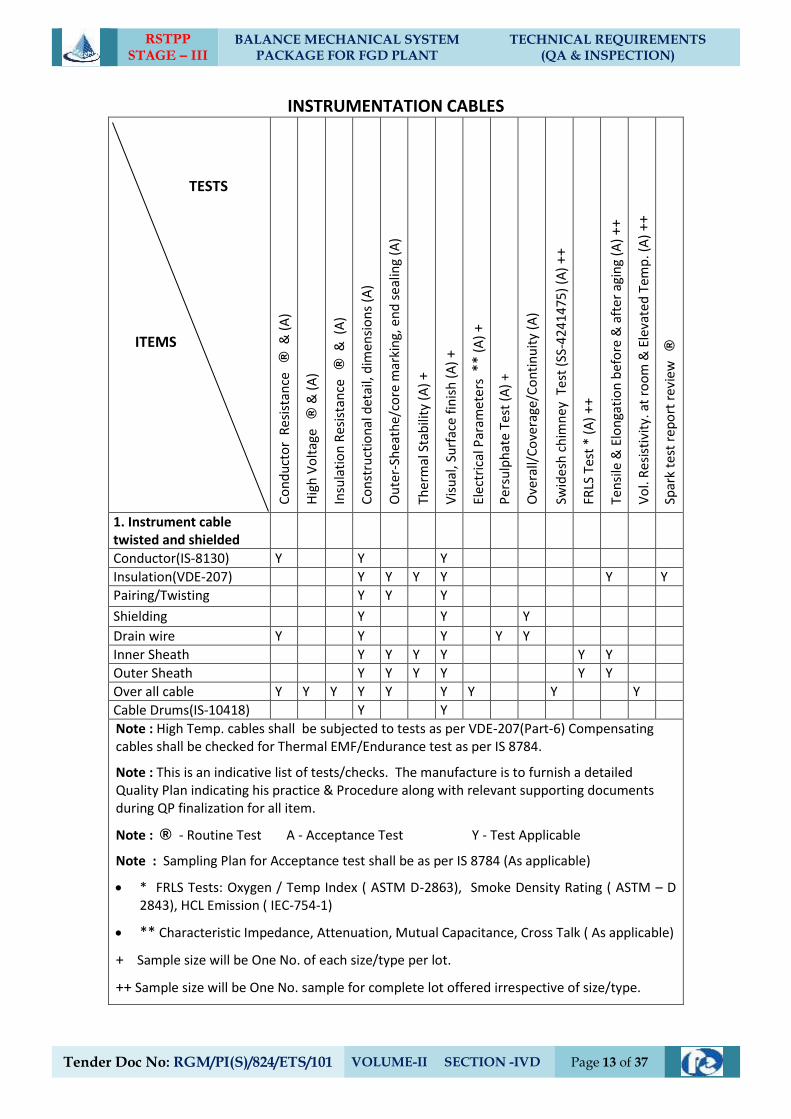
RSTPP STAGE – III
BALANCE MECHANICAL SYSTEM PACKAGE FOR FGD PLANT
TECHNICAL REQUIREMENTS (QA & INSPECTION)
Tender Doc No: RGM/PI(S)/824/ETS/101 VOLUME-II SECTION -IVD Page 13 of 37
INSTRUMENTATION CABLES TESTS ITEMS C
on
du
cto
r R
esis
tan
ce
®
& (
A)
Hig
h V
olt
age
® &
(A
)
Insu
lati
on
Res
ista
nce
®
& (
A)
Co
nst
ruct
ion
al d
etai
l, d
imen
sio
ns
(A)
Ou
ter-
Shea
the/
core
mar
kin
g, e
nd
se
alin
g (A
)
Ther
mal
Sta
bili
ty (
A)
+
Vis
ual
, Su
rfac
e fi
nis
h (
A)
+
Elec
tric
al P
aram
eter
s *
* (A
) +
Per
sulp
hat
e Te
st (
A)
+
Ove
rall/
Co
vera
ge/C
on
tin
uit
y (A
)
Swid
esh
ch
imn
ey T
est
(SS-
42
41
47
5)
(A)
++
FRLS
Tes
t *
(A) +
+
Ten
sile
& E
lon
gati
on
bef
ore
& a
fte
r ag
ing
(A)
++
Vo
l. R
esi
stiv
ity.
at
roo
m &
Ele
vate
d T
emp
. (A
) ++
Spar
k te
st r
epo
rt r
evie
w
®
1. Instrument cable twisted and shielded
Conductor(IS-8130) Y Y Y
Insulation(VDE-207) Y Y Y Y Y Y
Pairing/Twisting Y Y Y
Shielding Y Y Y
Drain wire Y Y Y Y Y
Inner Sheath Y Y Y Y Y Y
Outer Sheath Y Y Y Y Y Y
Over all cable Y Y Y Y Y Y Y Y Y
Cable Drums(IS-10418) Y Y
Note : High Temp. cables shall be subjected to tests as per VDE-207(Part-6) Compensating cables shall be checked for Thermal EMF/Endurance test as per IS 8784.
Note : This is an indicative list of tests/checks. The manufacture is to furnish a detailed Quality Plan indicating his practice & Procedure along with relevant supporting documents during QP finalization for all item.
Note : ® - Routine Test A - Acceptance Test Y - Test Applicable
Note : Sampling Plan for Acceptance test shall be as per IS 8784 (As applicable)
* FRLS Tests: Oxygen / Temp Index ( ASTM D-2863), Smoke Density Rating ( ASTM – D 2843), HCL Emission ( IEC-754-1)
** Characteristic Impedance, Attenuation, Mutual Capacitance, Cross Talk ( As applicable)
+ Sample size will be One No. of each size/type per lot.
++ Sample size will be One No. sample for complete lot offered irrespective of size/type.
RSTPP STAGE – III
BALANCE MECHANICAL SYSTEM PACKAGE FOR FGD PLANT
TECHNICAL REQUIREMENTS (QA & INSPECTION)
Tender Doc No: RGM/PI(S)/824/ETS/101 VOLUME-II SECTION -IVD Page 14 of 37
4.0 QUALITY ASSURANCE – ELECTRICAL EQUIPMENT
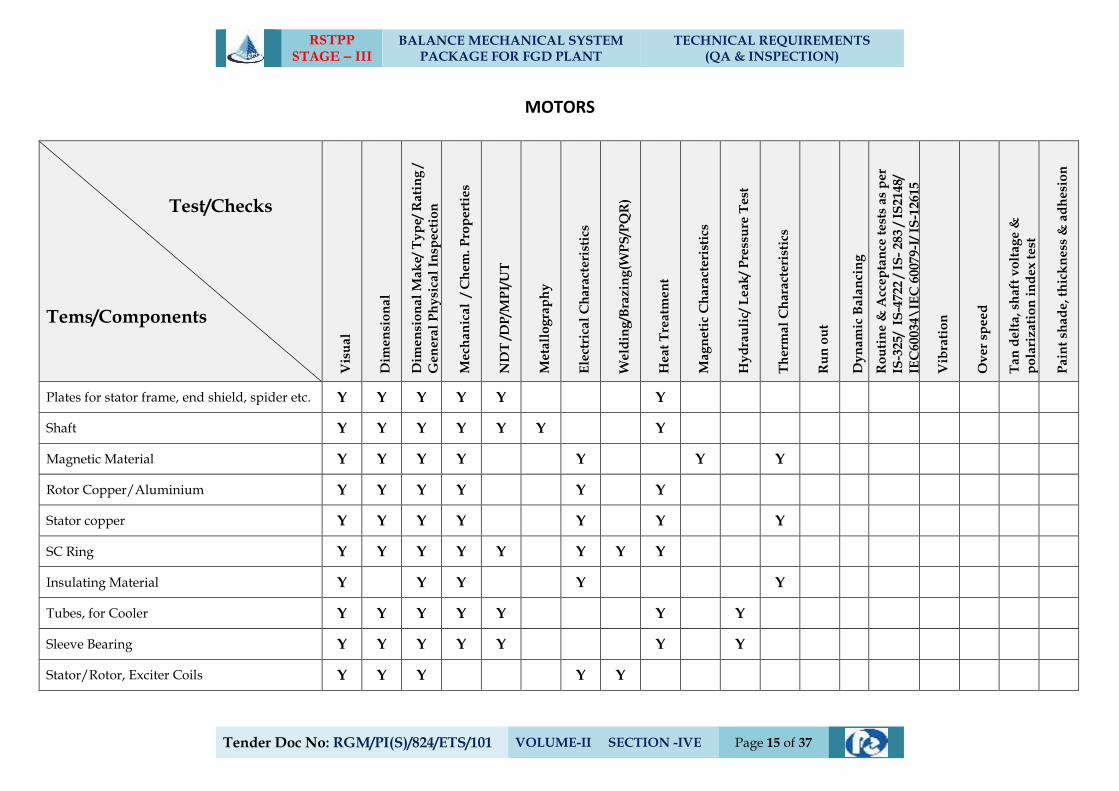
RSTPP STAGE – III
BALANCE MECHANICAL SYSTEM PACKAGE FOR FGD PLANT
TECHNICAL REQUIREMENTS (QA & INSPECTION)
Tender Doc No: RGM/PI(S)/824/ETS/101 VOLUME-II SECTION -IVE Page 15 of 37
MOTORS
Test/Checks
Tems/Components
Vis
ua
l
Dim
en
sio
na
l
Dim
en
sio
na
l M
ak
e/ T
yp
e/
Ra
tin
g /
Ge
ne
ral
Ph
ysi
cal
Insp
ect
ion
Me
cha
nic
al
/ C
he
m. P
rop
ert
ies
ND
T /
DP
/MP
I/U
T
Me
tall
og
rap
hy
Ele
ctri
cal
Ch
ara
cte
rist
ics
We
ldin
g/B
raz
ing
(WP
S/P
QR
)
He
at
Tre
atm
en
t
Ma
gn
eti
c C
ha
ract
eri
stic
s
Hy
dra
uli
c/ L
ea
k/
Pre
ssu
re T
est
Th
erm
al
Ch
ara
cte
rist
ics
Ru
n o
ut
Dy
na
mic
Ba
lan
cin
g
Ro
uti
ne
& A
cce
pta
nce
te
sts
as
pe
r
IS-3
25
/ I
S-4
722
/ I
S-
283
/ I
S2
14
8/
IEC
60
03
4\
IEC
60
079
-I/
IS-1
26
15
Vib
rati
on
Ov
er
spe
ed
Ta
n d
elt
a, s
ha
ft v
olt
ag
e &
po
lari
za
tio
n i
nd
ex
te
st
Pa
int
sha
de
, th
ick
ne
ss &
ad
he
sio
n
Plates for stator frame, end shield, spider etc. Y Y Y Y Y Y
Shaft Y Y Y Y Y Y Y
Magnetic Material Y Y Y Y Y Y Y
Rotor Copper/Aluminium Y Y Y Y Y Y
Stator copper Y Y Y Y Y Y Y
SC Ring Y Y Y Y Y Y Y Y
Insulating Material Y Y Y Y Y
Tubes, for Cooler Y Y Y Y Y Y Y
Sleeve Bearing Y Y Y Y Y Y Y
Stator/Rotor, Exciter Coils Y Y Y Y Y
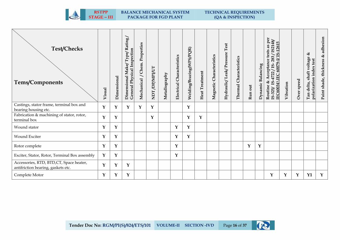
RSTPP STAGE – III
BALANCE MECHANICAL SYSTEM PACKAGE FOR FGD PLANT
TECHNICAL REQUIREMENTS (QA & INSPECTION)
Tender Doc No: RGM/PI(S)/824/ETS/101 VOLUME-II SECTION -IVD Page 16 of 37
Test/Checks
Tems/Components
Vis
ua
l
Dim
en
sio
na
l
Dim
en
sio
na
l M
ak
e/ T
yp
e/
Ra
tin
g /
Ge
ne
ral
Ph
ysi
cal
Insp
ect
ion
Me
cha
nic
al
/ C
he
m. P
rop
ert
ies
ND
T /
DP
/MP
I/U
T
Me
tall
og
rap
hy
Ele
ctri
cal
Ch
ara
cte
rist
ics
We
ldin
g/B
raz
ing
(WP
S/P
QR
)
He
at
Tre
atm
en
t
Ma
gn
eti
c C
ha
ract
eri
stic
s
Hy
dra
uli
c/ L
ea
k/
Pre
ssu
re T
est
Th
erm
al
Ch
ara
cte
rist
ics
Ru
n o
ut
Dy
na
mic
Ba
lan
cin
g
Ro
uti
ne
& A
cce
pta
nce
te
sts
as
pe
r
IS-3
25
/ I
S-4
722
/ I
S-
283
/ I
S2
14
8/
IEC
60
03
4\
IEC
60
079
-I/
IS-1
26
15
Vib
rati
on
Ov
er
spe
ed
Ta
n d
elt
a, s
ha
ft v
olt
ag
e &
po
lari
za
tio
n i
nd
ex
te
st
Pa
int
sha
de
, th
ick
ne
ss &
ad
he
sio
n
Castings, stator frame, terminal box and bearing housing etc.
Y Y Y Y Y Y
Fabrication & machining of stator, rotor, terminal box
Y Y Y Y Y
Wound stator Y Y Y Y
Wound Exciter Y Y Y Y
Rotor complete Y Y Y Y Y
Exciter, Stator, Rotor, Terminal Box assembly Y Y Y
Accessories, RTD, BTD,CT, Space heater, antifriction bearing, gaskets etc.
Y Y Y
Complete Motor Y Y Y Y Y Y Y1 Y
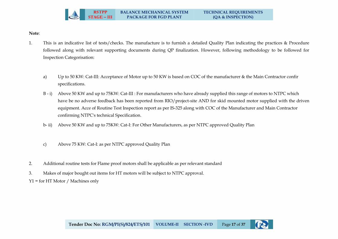
RSTPP STAGE – III
BALANCE MECHANICAL SYSTEM PACKAGE FOR FGD PLANT
TECHNICAL REQUIREMENTS (QA & INSPECTION)
Tender Doc No: RGM/PI(S)/824/ETS/101 VOLUME-II SECTION -IVD Page 17 of 37
Note:
1. This is an indicative list of tests/checks. The manufacture is to furnish a detailed Quality Plan indicating the practices & Procedure
followed along with relevant supporting documents during QP finalization. However, following methodology to be followed for
Inspection Categorisation:
a) Up to 50 KW: Cat-III: Acceptance of Motor up to 50 KW is based on COC of the manufacturer & the Main Contractor confir
specifications.
B - i) Above 50 KW and up to 75KW: Cat-III : For manufacturers who have already supplied this range of motors to NTPC which
have be no adverse feedback has been reported from RIO/project-site AND for skid mounted motor supplied with the driven
equipment. Acce of Routine Test Inspection report as per IS-325 along with COC of the Manufacturer and Main Contractor
confirming NTPC's technical Specification.
b- ii) Above 50 KW and up to 75KW: Cat-I: For Other Manufacturers, as per NTPC approved Quality Plan
c) Above 75 KW: Cat-I: as per NTPC approved Quality Plan
2. Additional routine tests for Flame proof motors shall be applicable as per relevant standard
3. Makes of major bought out items for HT motors will be subject to NTPC approval.
Y1 = for HT Motor / Machines only
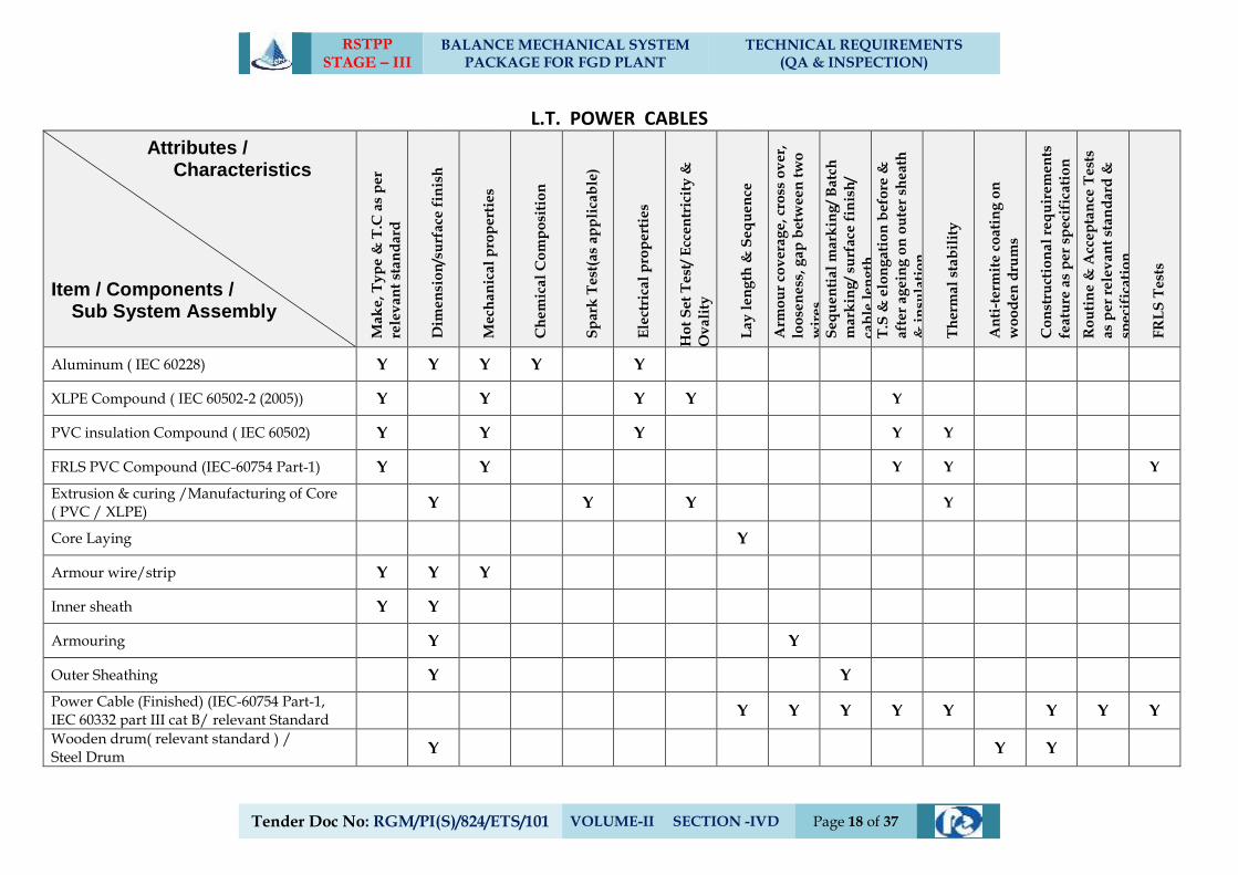
RSTPP STAGE – III
BALANCE MECHANICAL SYSTEM PACKAGE FOR FGD PLANT
TECHNICAL REQUIREMENTS (QA & INSPECTION)
Tender Doc No: RGM/PI(S)/824/ETS/101 VOLUME-II SECTION -IVD Page 18 of 37
L.T. POWER CABLES
Attributes / Characteristics
Item / Components / Sub System Assembly M
ak
e,
Ty
pe
& T
.C a
s p
er
rele
va
nt
sta
nd
ard
Dim
en
sio
n/s
urf
ace
fin
ish
Me
cha
nic
al
pro
pe
rtie
s
Ch
em
ica
l C
om
po
siti
on
Sp
ark
Te
st(a
s ap
pli
cab
le)
Ele
ctri
cal
pro
pe
rtie
s
Ho
t S
et
Te
st/
Ecc
entr
icit
y &
Ov
ali
ty
La
y l
en
gth
& S
eq
ue
nce
Arm
ou
r co
ve
rag
e,
cro
ss o
ve
r,
loo
sen
ess
, g
ap
bet
we
en
tw
o
wir
es
Se
qu
en
tia
l m
ark
ing
/ B
atc
h
ma
rkin
g/
surf
ace
fin
ish
/
cab
le l
en
gth
T
.S &
elo
ng
ati
on
be
fore
&
aft
er
ag
ein
g o
n o
ute
r sh
eat
h
& i
nsu
lati
on
Th
erm
al
sta
bil
ity
An
ti-t
erm
ite
co
ati
ng
on
wo
od
en
dru
ms
Co
nst
ruct
ion
al
req
uir
em
en
ts
fea
ture
as
pe
r sp
eci
fica
tio
n
Ro
uti
ne
& A
cce
pta
nce
Te
sts
as
pe
r re
lev
an
t st
an
da
rd &
spe
cifi
cati
on
FR
LS
Te
sts
Aluminum ( IEC 60228) Y Y Y Y Y
XLPE Compound ( IEC 60502-2 (2005)) Y Y Y Y Y
PVC insulation Compound ( IEC 60502) Y Y Y Y Y
FRLS PVC Compound (IEC-60754 Part-1) Y Y Y Y Y
Extrusion & curing /Manufacturing of Core ( PVC / XLPE)
Y Y Y Y
Core Laying Y
Armour wire/strip Y Y Y
Inner sheath Y Y
Armouring Y Y
Outer Sheathing Y Y
Power Cable (Finished) (IEC-60754 Part-1, IEC 60332 part III cat B/ relevant Standard
Y Y Y Y Y Y Y Y
Wooden drum( relevant standard ) / Steel Drum
Y Y Y
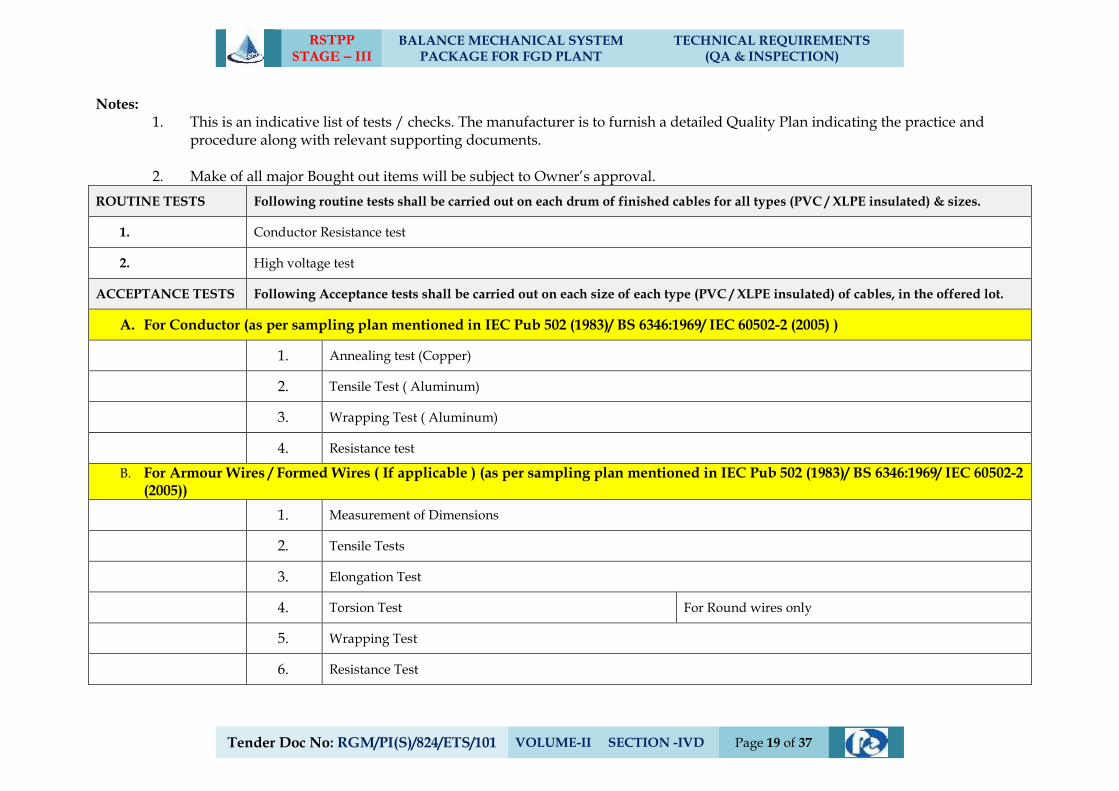
RSTPP STAGE – III
BALANCE MECHANICAL SYSTEM PACKAGE FOR FGD PLANT
TECHNICAL REQUIREMENTS (QA & INSPECTION)
Tender Doc No: RGM/PI(S)/824/ETS/101 VOLUME-II SECTION -IVD Page 19 of 37
Notes: 1. This is an indicative list of tests / checks. The manufacturer is to furnish a detailed Quality Plan indicating the practice and
procedure along with relevant supporting documents.
2. Make of all major Bought out items will be subject to Owner’s approval.
ROUTINE TESTS Following routine tests shall be carried out on each drum of finished cables for all types (PVC / XLPE insulated) & sizes.
1. Conductor Resistance test
2. High voltage test
ACCEPTANCE TESTS Following Acceptance tests shall be carried out on each size of each type (PVC / XLPE insulated) of cables, in the offered lot.
A. For Conductor (as per sampling plan mentioned in IEC Pub 502 (1983)/ BS 6346:1969/ IEC 60502-2 (2005) )
1. Annealing test (Copper)
2. Tensile Test ( Aluminum)
3. Wrapping Test ( Aluminum)
4. Resistance test
B. For Armour Wires / Formed Wires ( If applicable ) (as per sampling plan mentioned in IEC Pub 502 (1983)/ BS 6346:1969/ IEC 60502-2 (2005))
1. Measurement of Dimensions
2. Tensile Tests
3. Elongation Test
4. Torsion Test For Round wires only
5. Wrapping Test
6. Resistance Test
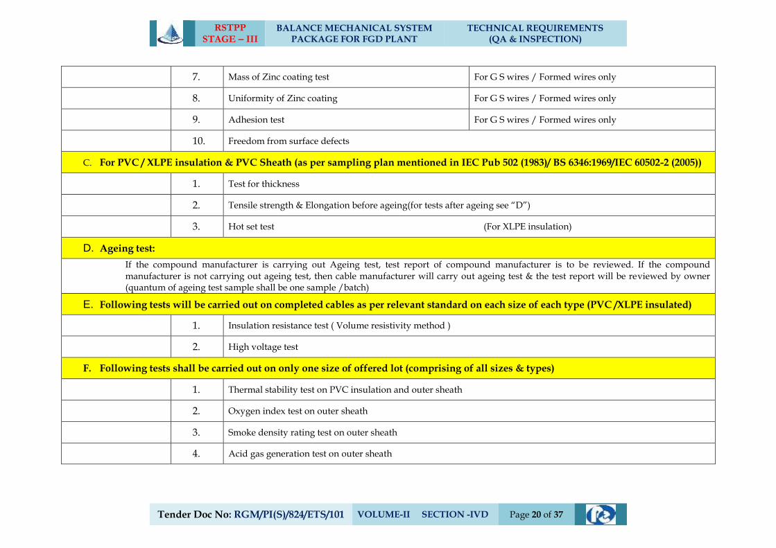
RSTPP STAGE – III
BALANCE MECHANICAL SYSTEM PACKAGE FOR FGD PLANT
TECHNICAL REQUIREMENTS (QA & INSPECTION)
Tender Doc No: RGM/PI(S)/824/ETS/101 VOLUME-II SECTION -IVD Page 20 of 37
7. Mass of Zinc coating test For G S wires / Formed wires only
8. Uniformity of Zinc coating For G S wires / Formed wires only
9. Adhesion test For G S wires / Formed wires only
10. Freedom from surface defects
C. For PVC / XLPE insulation & PVC Sheath (as per sampling plan mentioned in IEC Pub 502 (1983)/ BS 6346:1969/IEC 60502-2 (2005))
1. Test for thickness
2. Tensile strength & Elongation before ageing(for tests after ageing see “D”)
3. Hot set test (For XLPE insulation)
D. Ageing test:
If the compound manufacturer is carrying out Ageing test, test report of compound manufacturer is to be reviewed. If the compound manufacturer is not carrying out ageing test, then cable manufacturer will carry out ageing test & the test report will be reviewed by owner (quantum of ageing test sample shall be one sample /batch)
E. Following tests will be carried out on completed cables as per relevant standard on each size of each type (PVC /XLPE insulated)
1. Insulation resistance test ( Volume resistivity method )
2. High voltage test
F. Following tests shall be carried out on only one size of offered lot (comprising of all sizes & types)
1. Thermal stability test on PVC insulation and outer sheath
2. Oxygen index test on outer sheath
3. Smoke density rating test on outer sheath
4. Acid gas generation test on outer sheath
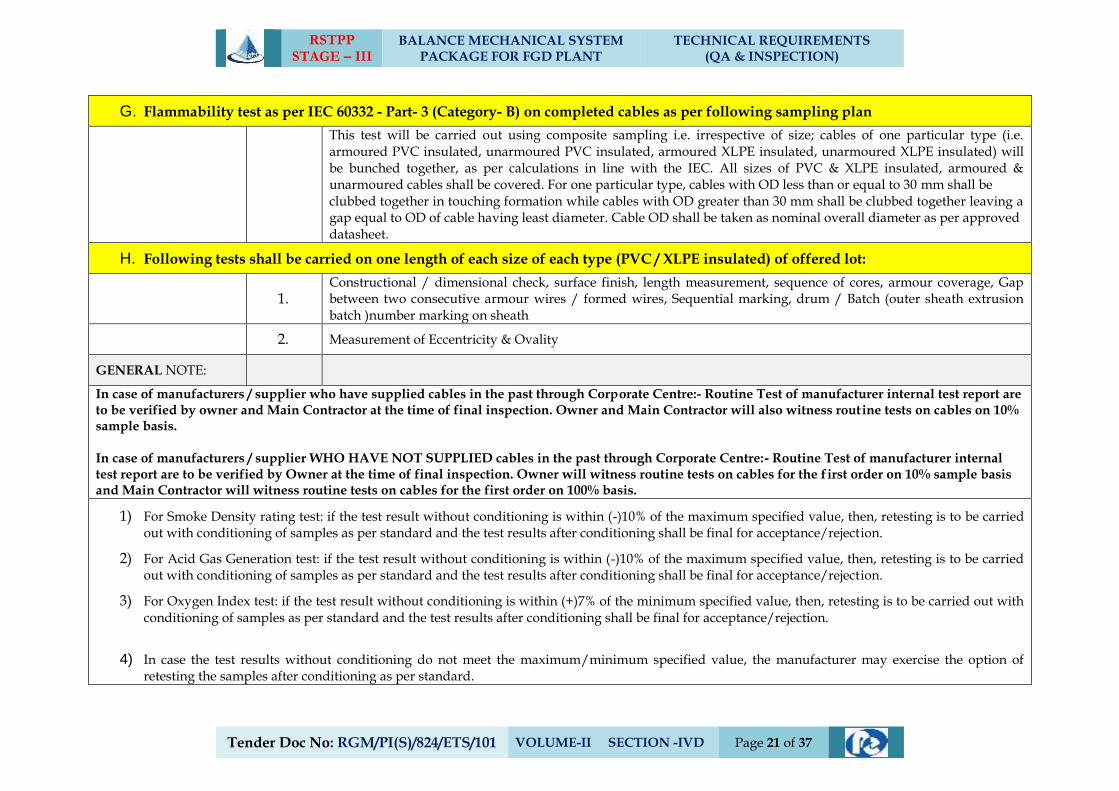
RSTPP STAGE – III
BALANCE MECHANICAL SYSTEM PACKAGE FOR FGD PLANT
TECHNICAL REQUIREMENTS (QA & INSPECTION)
Tender Doc No: RGM/PI(S)/824/ETS/101 VOLUME-II SECTION -IVD Page 21 of 37
G. Flammability test as per IEC 60332 - Part- 3 (Category- B) on completed cables as per following sampling plan
This test will be carried out using composite sampling i.e. irrespective of size; cables of one particular type (i.e. armoured PVC insulated, unarmoured PVC insulated, armoured XLPE insulated, unarmoured XLPE insulated) will be bunched together, as per calculations in line with the IEC. All sizes of PVC & XLPE insulated, armoured & unarmoured cables shall be covered. For one particular type, cables with OD less than or equal to 30 mm shall be clubbed together in touching formation while cables with OD greater than 30 mm shall be clubbed together leaving a gap equal to OD of cable having least diameter. Cable OD shall be taken as nominal overall diameter as per approved datasheet.
H. Following tests shall be carried on one length of each size of each type (PVC / XLPE insulated) of offered lot:
1. Constructional / dimensional check, surface finish, length measurement, sequence of cores, armour coverage, Gap between two consecutive armour wires / formed wires, Sequential marking, drum / Batch (outer sheath extrusion batch )number marking on sheath
2. Measurement of Eccentricity & Ovality
GENERAL NOTE:
In case of manufacturers / supplier who have supplied cables in the past through Corporate Centre:- Routine Test of manufacturer internal test report are to be verified by owner and Main Contractor at the time of final inspection. Owner and Main Contractor will also witness routine tests on cables on 10% sample basis. In case of manufacturers / supplier WHO HAVE NOT SUPPLIED cables in the past through Corporate Centre:- Routine Test of manufacturer internal test report are to be verified by Owner at the time of final inspection. Owner will witness routine tests on cables for the first order on 10% sample basis and Main Contractor will witness routine tests on cables for the first order on 100% basis.
1) For Smoke Density rating test: if the test result without conditioning is within (-)10% of the maximum specified value, then, retesting is to be carried out with conditioning of samples as per standard and the test results after conditioning shall be final for acceptance/rejection.
2) For Acid Gas Generation test: if the test result without conditioning is within (-)10% of the maximum specified value, then, retesting is to be carried out with conditioning of samples as per standard and the test results after conditioning shall be final for acceptance/rejection.
3) For Oxygen Index test: if the test result without conditioning is within (+)7% of the minimum specified value, then, retesting is to be carried out with conditioning of samples as per standard and the test results after conditioning shall be final for acceptance/rejection.
4) In case the test results without conditioning do not meet the maximum/minimum specified value, the manufacturer may exercise the option of retesting the samples after conditioning as per standard.
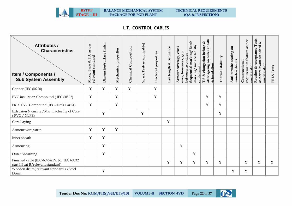
RSTPP STAGE – III
BALANCE MECHANICAL SYSTEM PACKAGE FOR FGD PLANT
TECHNICAL REQUIREMENTS (QA & INSPECTION)
Tender Doc No: RGM/PI(S)/824/ETS/101 VOLUME-II SECTION -IVD Page 22 of 37
L.T. CONTROL CABLES
Attributes / Characteristics
Item / Components / Sub System Assembly
Ma
ke
, T
yp
e &
T.C
as
pe
r
rele
va
nt
sta
nd
ard
Dim
en
sio
n/s
urf
ace
fin
ish
Me
cha
nic
al
pro
pe
rtie
s
Ch
em
ica
l C
om
po
siti
on
Sp
ark
Te
st(a
s ap
pli
cab
le)
Ele
ctri
cal
pro
pe
rtie
s
La
y l
en
gth
& S
eq
ue
nce
Arm
ou
r co
ve
rag
e,
cro
ss
ov
er,
lo
ose
ne
ss,
ga
p
be
twe
en
tw
o w
ire
s
Se
qu
en
tia
l m
ark
ing
/ B
atc
h
ma
rkin
g/
surf
ace
fin
ish
/
cab
le l
en
gth
T.S
& e
lon
ga
tio
n b
efo
re &
aft
er
ag
ein
g o
n o
ute
r sh
eat
h
& i
nsu
lati
on
Th
erm
al
sta
bil
ity
An
ti-t
erm
ite
co
ati
ng
on
wo
od
en
dru
ms
Co
nst
ruct
ion
al
req
uir
em
en
ts f
ea
ture
as
per
spe
cifi
cati
on
Ro
uti
ne
& A
cce
pta
nce
Te
sts
as
pe
r re
lev
an
t st
an
da
rd &
spe
cifi
cati
on
FR
LS
Te
sts
Copper (IEC 60228) Y Y Y Y Y
PVC insulation Compound ( IEC 60502) Y Y Y Y Y
FRLS PVC Compound (IEC-60754 Part-1) Y Y Y Y
Extrusion & curing /Manufacturing of Core ( PVC / XLPE)
Y Y Y
Core Laying Y
Armour wire/strip Y Y Y
Inner sheath Y Y
Armouring Y Y
Outer Sheathing Y Y
Finished cable (IEC-60754 Part-1, IEC 60332 part III cat B/relevant standard)
Y Y Y Y Y Y Y Y
Wooden drum( relevant standard ) /Steel Drum
Y Y Y
RSTPP STAGE – III
BALANCE MECHANICAL SYSTEM PACKAGE FOR FGD PLANT
TECHNICAL REQUIREMENTS (QA & INSPECTION)
Tender Doc No: RGM/PI(S)/824/ETS/101 VOLUME-II SECTION -IVD Page 23 of 37
Notes: 1. This is an indicative list of tests / checks. The manufacturer is to furnish a detailed Quality Plan indicating the practice and
procedure along with relevant supporting documents.
2. Make of all major Bought out items will be subject to Owner’s approval.
ROUTINE TESTS Following routine tests shall be carried out on each drum of finished cables for all sizes.
1. Conductor Resistance test
2. High voltage test
ACCEPTANCE TESTS Following Acceptance tests shall be carried out on each size of cables, in the offered lot.
A. For Conductor (as per sampling plan mentioned in IEC Pub 502 (1983)/ BS 6346:1969)
1. Annealing test (Copper)
2. Resistance test
B. For Armour Wires / Formed Wires ( If applicable ) (as per sampling plan mentioned in IEC Pub 502 (1983)/ BS 6346:1969)
1. Measurement of Dimensions
2. Tensile Tests
3. Elongation Test
4. Torsion Test For Round wires only
5. Wrapping Test
6. Resistance Test
7. Mass of Zinc coating test For G S wires / Formed wires only
RSTPP STAGE – III
BALANCE MECHANICAL SYSTEM PACKAGE FOR FGD PLANT
TECHNICAL REQUIREMENTS (QA & INSPECTION)
Tender Doc No: RGM/PI(S)/824/ETS/101 VOLUME-II SECTION -IVD Page 24 of 37
8. Uniformity of Zinc coating For G S wires / Formed wires only
9. Adhesion test For G S wires / Formed wires only
10. Freedom from surface defects
C. For PVC / XLPE insulation & PVC Sheath (as per sampling plan mentioned in IEC Pub 502 (1983)/ BS 6346:1969)
1. Test for thickness
2. Tensile strength & Elongation before ageing(for tests after ageing see “D”)
D. Ageing test:
If the compound manufacturer is carrying out Ageing test, test report of compound manufacturer is to be reviewed. If the compound manufacturer is not carrying out ageing test, then cable manufacturer will carry out ageing test & the test report will be reviewed by owner (quantum of ageing test sample shall be one sample /batch)
E. Following tests will be carried out on completed cables as per relevant standard on each size
1. Insulation resistance test ( Volume resistivity method )
2. High voltage test
F. Following tests shall be carried out on only one size of offered lot (comprising of all sizes & types)
1. Thermal stability test on PVC insulation and outer sheath
2. Oxygen index test on outer sheath
3. Smoke density rating test on outer sheath
4. Acid gas generation test on outer sheath
G. Flammability test as per IEC 60332 - Part- 3 (Category- B) on completed cables as per following sampling plan
This test will be carried out using composite sampling i.e. irrespective of size; cables of one particular type (i.e. armoured, unarmoured) will be bunched together, as per calculations in line with the IEC. All sizes of armoured & unarmoured cables shall be covered.
RSTPP STAGE – III
BALANCE MECHANICAL SYSTEM PACKAGE FOR FGD PLANT
TECHNICAL REQUIREMENTS (QA & INSPECTION)
Tender Doc No: RGM/PI(S)/824/ETS/101 VOLUME-II SECTION -IVD Page 25 of 37
H. Following tests shall be carried on one length of each size of (armoured & unarmoured) of offered lot:
1. Constructional / dimensional check, surface finish, length measurement, sequence of cores, armour coverage, Gap between two consecutive armour wires / formed wires, Sequential marking, drum / Batch (outer sheath extrusion batch )number marking on sheath
2. Measurement of Eccentricity & Ovality
GENERAL NOTE:
a) In case of manufacturers / supplier who have supplied cables in the past through Corporate Centre:- Routine Test of manufacturer internal test report are to be verified by owner and Main Contractor at the time of final inspection. Owner and Main Contractor will also witness routine tests on cables on 10% sample basis.
b) In case of manufacturers / supplier WHO HAVE NOT SUPPLIED cables in the past through Corporate Centre:- Routine Test of manufacturer internal test report are to be verified by Owner at the time of final inspection. Owner will witness routine tests on cables for the first order on 10% sample basis and Main Contractor will witness routine tests on cables for the first order on 100% basis.
1) For Smoke Density rating test: if the test result without conditioning is within (-)10% of the maximum specified value, then, retesting is to be carried out with conditioning of samples as per standard and the test results after conditioning shall be final for acceptance/rejection.
2) For Acid Gas Generation test: if the test result without conditioning is within (-)10% of the maximum specified value, then, retesting is to be carried out with conditioning of samples as per standard and the test results after conditioning shall be final for acceptance/rejection.
3) For Oxygen Index test: if the test result without conditioning is within (+)7% of the minimum specified value, then, retesting is to be carried out with conditioning of samples as per standard and the test results after conditioning shall be final for acceptance/rejection.
4) In case the test results without conditioning do not meet the maximum/minimum specified value, the manufacturer may exercise the option of retesting the samples after conditioning as per standard.
RSTPP STAGE - III
FLUE GAS DUCT PACKAGE (FGD SYSTEM)
TECHNICAL REQUIREMENTS (QA & INSPECTION)
Tender Doc No: RGM/PI(S)/824/ETS/101 VOLUME-II SECTION -IVD Page 26 of 37
5.0 QUALITY ASSURANCE - CIVIL & STRUCTUTAL WORKS
RSTPP STAGE - III
FLUE GAS DUCT PACKAGE (FGD SYSTEM)
TECHNICAL REQUIREMENTS (QA & INSPECTION)
Tender Doc No: RGM/PI(S)/824/ETS/101 VOLUME-II SECTION -IVD Page 27 of 37
A. INTRODUCTION
a) This section of the specification covers the sampling, testing and quality assurance
requirement for civil and structural works covered in this specification.
b) This section of the technical specification shall be read in conjunction with other
parts of the technical specifications, general technical requirements & erection
conditions of the contract. Wherever IS code or standards have been referred they
shall be the latest revisions.
c) The rate for respective items of work or price shall include the cost for all works,
activities, equipment, instrument, personnel, material etc. whatsoever associated
to comply with sampling, testing and quality assurance requirement including
construction tolerances and acceptance criteria and as specified in subsequent
clauses of this part of the technical specifications. The QA and QC activities in all
respects as specified in the technical specifications/ drawings / data sheets /
quality plans / contract documents shall be carried out at no extra cost to the
NTPC.
The contractor shall prepare detailed construction and erection methodology
scheme which shall be compatible to the requirements of the desired progress of
work execution, quality measures, prior approvals if any and the same shall be got
approved by the NTPC. If required, work methodology may be revised/ reviewed
at every stage of execution of work at site, to suit the site conditions by the
contractor at no extra cost to the NTPC.
B. QUALITY ASSURANCE PROGRAMME
a) The contractor shall adopt suitable Quality Assurance Programme (QAP) to ensure that
the equipments and services under the scope of contract whether manufactured or
performed within contractor’s works or at his sub-contractor’s premises or at the NTPC’s
site or at any other place of work are in accordance with the specifications. Such QAP
shall be outlined by the contractor and shall be finally accepted by the NTPC or their
authorized representative after discussions before the start of work. The QAP shall be
generally in line with IS/ISO Systems.
The contractor shall furnish complete QA & QC programme for the work envisaged which
may include the following.
i) Organization structure for the management and implementation of the proposed
quality assurance programme.
ii) Quality System Manual.
iii) Design Control System
iv) Documentation and Data Control System
v) Qualification data / details for Contractor’s key personnel
RSTPP STAGE - III
FLUE GAS DUCT PACKAGE (FGD SYSTEM)
TECHNICAL REQUIREMENTS (QA & INSPECTION)
Tender Doc No.:SRO/CON/ETS-040 VOLUME - II : SECTION – IV E Page 28 of 83
vi) The procedure for purchase of materials, parts, components and selection of
subcontractor’s services including vendor analysis, source inspection, incoming
raw material inspection, verification of materials purchased, etc.
vii) System for shop manufacturing and site erection controls including process,
fabrication and assembly
viii) Control of non-conforming items and system for corrective actions and resolution
of Deviations.
ix) Inspection and test procedure both for manufacture and field activities
x) Control of calibration and testing of measuring testing equipment
xi) System for Quality Audits
xii) System for identification and appraisal of inspection status
xiii) System for authorizing release of manufactured product to the NTPC.
xiv) System for handling, storage and delivery
xv) System for maintenance of records
xvi) Quality plans for manufacturing and field activities detailing out the specific
quality control procedure adopted for controlling the quality characteristics
relevant to each item of work/ equipment/component.
C. QA AND QC MANPOWER
a) The contractor shall nominate one overall QA coordinator for the contract
detailing the name, designation, contact details and address at the time of post bid
discussions. All correspondence related to Quality Assurance shall be addressed
by the contractor’s QA coordinator to NTPC. NTPC shall address all
correspondence related to Quality issues to the contractor’s QA coordinator. The
contractor’s QA coordinator shall be responsible for co-ordination of Quality
activities between various divisions of the contractor and their sub-vendors on one
hand & with NTPC on the other hand.
b) The contractor shall appoint a dedicated, experienced and competent QA&QC in-
charge at site, preferably directly reporting to the Project Manager, supported as
necessary by experienced personnel, to ensure the effective implementation of the
approved QAP. An indicative structure of contractor’s QA&QC manpower
required to be deployed at site is enclosed at Annexure -I. Based on the finalized
L-2 network and the approved Field Quality plan, the contractor shall finalize and
submit a deployment schedule of QA&QC personnel along with their details to
NTPC for approval/ acceptance and further shall ensure their availability well
before the start of the concern activity.
c) The QA&QC in-charge shall have the organizational freedom and authority to
implement the requirements of these quality assurance arrangements, free from
commercial and programme restraints. The QA&QC setup of the contractor shall
RSTPP STAGE - III
FLUE GAS DUCT PACKAGE (FGD SYSTEM)
TECHNICAL REQUIREMENTS (QA & INSPECTION)
Tender Doc No.:SRO/CON/ETS-040 VOLUME - II : SECTION – IV E Page 29 of 83
consist of qualified and experienced Civil, Electrical, Mechanical Engineers and
Laboratory assistants with their supporting staff both at their works and site.
d) The deployment of man power for QA & QC set up shall be affected on the basis
of agreed manpower deployment schedule, which shall be prepared by the
contractor based on the L-2 network and the same shall be submitted to the NTPC
for acceptance.
D. SAMPLING AND TESTING OF CONSTRUCTION MATERIALS
a) The method of sampling for testing of construction materials and work / job samples
shall be as per the relevant IS / standards / codes and in line with the requirements of the
technical specifications / quality plans. All samples shall be jointly drawn, signed and
sealed wherever required, by the contractor and the NTPC or his authorized
representative.
b) The contractor shall carry out testing in accordance with the relevant IS / standards /
codes and in line with the requirements of the technical specifications / quality plans.
Where no specific testing procedure is mentioned, the tests shall be carried out as per the
best prevalent engineering practices and to the directions of the NTPC. All testing shall be
done in the presence of the NTPC or his authorized representative.
E. LABORATORY AND FIELD TESTING
a) The field laboratory for QA and QC activities shall be constructed and set-up by the
contractor in line with the indicative field QA&QC laboratory set-up enclosed at
Annexure -IV. The Laboratory building shall be constructed and installed with the
adequate facilities to meet the requirement of envisaged test setup. Temperature and
humidity controls shall be available wherever necessary during testing of samples. The
quality plan shall identify the testing equipments/ instrument, which the contractor shall
deploy and equip the field quality laboratory for meeting the field quality plan
requirements. The contractor shall furnish a comprehensive list of testing equipments/
instrument required to meet the planned/scheduled tests for the execution of works for
NTPC acceptance/ approval. The contractor shall mobilize the requisite laboratory
equipment and QA&QC manpower at least 15 days prior to the planned test activity as
per the schedule of tests.
b) All equipments and instruments in the field shall be calibrated before the commencement
of tests and then at regular intervals, as per the manufacturer’s recommendation and as
directed by the NTPC. The calibration certificates shall specify the fitness of the
equipments and instruments within the limit of tolerance for use. Contractor shall arrange
for calibration of equipments and instruments by an NABL / NPL accredited agency and
the calibration report shall be submitted to NTPC.
RSTPP STAGE - III
FLUE GAS DUCT PACKAGE (FGD SYSTEM)
TECHNICAL REQUIREMENTS (QA & INSPECTION)
Tender Doc No.:SRO/CON/ETS-040 VOLUME - II : SECTION – IV E Page 30 of 83
c) Based on the schedule of work agreed with the NTPC and the approved FQP, the
contractor shall prepare a schedule of tests and submit them to the NTPC and organize to
carry out the tests as scheduled / agreed.
F. PURCHASE AND SERVICE
a) The major items/ equipments/ components to be manufactured in the shop of the
contractor i.e. in-house items and those procured from sub-vendors / sub-manufacturer /
sub-contractors i.e. bought out items (BOIs) shall be listed out by the contractor in their
bid proposal.
b) The list of manufacturers/ sub-vendors for all the BOIs envisaged in contract shall be
included in the bid proposal by the contractor which shall be discussed / reviewed by the
NTPC during post bid discussions and the list of proposed manufacturers / sub-vendors
for each of the BOIs shall be agreed/ approved. If any item is left out or gets included
during detailed engineering, the contractor shall propose the manufacturer’s /
subvendor’s details for review / approval of NTPC, prior to initiating the procurement of
such materials.
c) To facilitate advance planning of material testing/ approval of bought out items, well
before the start of activity as per L-2 network, representative samples shall be procured
by the contractor from approved sub-vendors and submitted to the NTPC for his
approval before bulk procurement at least two months prior to start of works. In case of
manufacturers test certificate (MTC) is submitted for acceptance, it shall be clearly
traceable and correlated with the consignment received at site. MTC of all bought out
items shall essentially contain all the test parameters / characteristics specified in the
technical specifications / standards / codes. In case the manufacturer’s test certificate
does not mention these details, sample from each lot shall be tested for these properties at
the third party lab acceptable to NTPC. Approval of material / sample by the NTPC shall
not relieve the contractor of his responsibility, for their conformance to the specification,
as well as the requisite performance and quality of material.
d) Monthly progress reports on sub-contractor detail submission / approval shall be
furnished as per Engineering Co-ordination Procedure. Such vendor approval shall not
relieve the contractor from any obligation, duty or responsibility under the contract.
Subvendor whose details are not submitted within the agreed cut-off date, shall be
deemed to be withdrawn by the contractor.
e) Structural steel (plates and rolled sections i.e. channels, beams & angles) and
Reinforcement steel supply if in the scope of the contractor shall be procured from
Primary Steel Producers (Refer NOTE below). Currently, Primary Steel Producers
acceptable are SAIL, JSW Steel Ltd, Jindal Steel & Power, Tata steel Ltd. (for
Reinforcement steel/TMT bars), RINL (for long products/Rolled sections and
Reinforcement steel/TMT bars), Essar Steel India Ltd. (for Flat products/ Steel Plates),
RSTPP STAGE - III
FLUE GAS DUCT PACKAGE (FGD SYSTEM)
TECHNICAL REQUIREMENTS (QA & INSPECTION)
Tender Doc No.:SRO/CON/ETS-040 VOLUME - II : SECTION – IV E Page 31 of 83
Electrosteel steel Ltd. (for Reinforcement steel/TMT bars) and Monnet Ispat and Energy
Ltd. (for long products/Rolled sections and Reinforcement steel/TMT bars).
Subsequently, if any new Primary Steel Producer/s are proposed during execution of
contract, the same may be considered for acceptance subject to meeting the following
qualifying requirements:
i. The proposed supplier should be a Primary Steel Producer, having a minimum
production capacity of one million tons per annum (MTPA).
ii. The proposed supplier should be a regular manufacturer of Steel Plates and / or
Rolled Sections and / or Reinforcement Steel for the last two years as on date of
submission of proposal.
iii. The proposed supplier should also be a registered licensee with Bureau of Indian
Standards for BIS:1786/2062 at the time of submission of proposal.
NOTE: The “Primary Steel Producer” shall mean Steel Producer of any capacity,
irrespective of process route, starting their operations from iron making using iron ore,
virgin or processed, with necessary refining facilities and rolling/processing facilities, at a
single location or else in multiple locations provided that the entire gamut of iron & steel
production, from iron making to finished steel production, is owned by the same
company or its subsidiary company(ies). Provided that the iron making capacity is
sufficiently matching the steel making capacity. Further, downstream units should use
material from the upstream units of the same company or its subsidiaries.
In case of non-availability of certain steel section/s i.e. Angle smaller than 100x100x10
mm, MS flats, rounds, square bars and chequered plate from primary steel producers, an
option is given to the Main contractor to source these sections directly from SAIL
Conversion/Wet Leasing agent subject to the conditions given at point no. i) below:
i. Approval conditions for procurement of structural steel sections through SAIL
Conversion/Wet Leasing agent:
Main Contractor to ensure continuity of BIS license of the manufacturer for
the sections being manufactured for NTPC supply.
Billets shall be procured from NTPC approved Main Steel Producers. Proper
records for traceability from raw material to final product shall be
maintained.
100% chemical analysis of the raw material (Billets) shall be carried out as
per IS: 2830. Testing of one sample per 40 MT for each type of section or part
thereof shall be carried out as per IS: 2062 on finished product.
Each lot of delivery of finished product shall be accompanied with co-
relatable Manufacturer’s Test Certificate (MTC). MTC of finished sections
shall be correlated with original MTC for Billets received from Main Steel
Producer and Manufacturer Test Report of chemical analysis of Billets
RSTPP STAGE - III
FLUE GAS DUCT PACKAGE (FGD SYSTEM)
TECHNICAL REQUIREMENTS (QA & INSPECTION)
Tender Doc No.:SRO/CON/ETS-040 VOLUME - II : SECTION – IV E Page 32 of 83
mentioned at point no.3. MTC of finished sections shall include the reference
of MTC for Billets from Main Steel Producer.
NTPC will have access to carry out the surveillance checks for in-process
stage.
In case of any defects are seen in the material, Main Contractor will replace
the material without any cost implication to NTPC.
In case of non-availability of certain size/s of steel tubes conforming to IS:1161 and
Hollow (square and rectangular) steel sections conforming to IS: 4923 from primary steel
producers, the same may be sourced from BIS approved sources having valid BIS license
subject to the conditions given at point no.ii) below:
ii. Approval conditions for procurement of Steel tubes conforming to IS: 1161 and
Hollow (square and rectangular) steel sections conforming to IS: 4923 from BIS
approved sources:
Main Contractor to ensure continuity of BIS license of the manufacturer for
the sections being manufactured for NTPC supply.
Raw materials shall be procured from NTPC approved Main Steel
Producers.
100% chemical analysis of the raw material (steel) shall be carried out as per
IS: 228. Testing of samples of steel tubes and hollow sections from each lot
shall be carried out as per IS: 1161 & IS: 4923 respectively on finished
product.
Each lot of delivery of finished product shall be accompanied with co-
relatable Manufacturer’s Test Certificate (MTC).
NTPC will have access to carry out the surveillance checks for in-process
stage.
In case of any defects are seen in the material, Main Contractor will replace
the material without any cost implication to NTPC.
The specific methodology to be followed for procurement of Structural Steel and
Reinforcement Bars through conversion route/BIS approved sources route shall be
subject to approval by NTPC in advance.
G. MANUFACTURING QUALITY PLAN AND FIELD QUALITY PLAN
a) All materials / components and equipment covered under the scope of work, shall be
procured by the contractor for the purpose of the contract, after obtaining the written
approval of the NTPC, which are to be manufactured at shop/ factory of the vendor/sub
vendor shall be covered under a comprehensive quality assurance programme. The
contractor’s purchase specifications and inquiries shall call for Manufacturing Quality
Plans (MQP) to be submitted by the sub-contractor/ sub-supplier/ sub-vendor. The MQP
called for from the sub-contractor shall detail out for all the components and equipment,
RSTPP STAGE - III
FLUE GAS DUCT PACKAGE (FGD SYSTEM)
TECHNICAL REQUIREMENTS (QA & INSPECTION)
Tender Doc No.:SRO/CON/ETS-040 VOLUME - II : SECTION – IV E Page 33 of 83
various tests / inspection, to be carried out as per the requirements of this specification
and standards mentioned therein, quality practices and procedures followed by
contractor’s / sub-contractor’s / sub-supplier's quality control organization, the relevant
reference documents and standards, acceptance norms, inspection documents raised etc.,
during all stages of materials procurement, manufacture, assembly and final testing/
performance testing. Such quality plans of the vendors / sub-vendors shall be submitted
to the NTPC for approval in the prescribed format enclosed at Annexure- VI and such
approved quality plans shall form a part of the purchase order / contract between the
contractor and sub-contractor. The quality plans shall be submitted on electronic form e.g.
CD or E-mail in addition to hard copy, for review and approval of NTPC. After approval
the same shall be submitted in compiled form on CD in addition to hard copy.
b) The contractor shall furnish copies of the reference documents/ plant standards /
acceptance norms/ tests and inspection procedure etc., as referred in quality plans. These
quality plans and reference documents/standards etc. will be subject to NTPC approval
without which manufacturer shall not proceed. These approved documents shall form a
part of the contract. In these approved quality plans, NTPC shall identify customer hold
points (CHP), i.e. test/ checks which shall be carried out in presence of the NTPC
engineer or his authorized representative and beyond which the work shall not proceed
without consent of NTPC in writing. All deviations to this specification, approved quality
plans and applicable standards must be documented and referred to NTPC along with
technical justification for approval and dispositioning.
c) Within three weeks of the release of the purchase orders /contracts for such bought out
items /components, a copy of the same without price details but together with the
detailed purchase specifications, quality plans and delivery conditions shall be furnished
to the NTPC for reference / record by the contractor along with a report of the purchase
orders placed so far for the contract.
d) Well before the start of the work, the contractor shall prepare and submit the Field
Quality Plans (FQP) on the format Annexure-VII enclosed at elsewhere, and obtain
approval of NTPC, which shall detail out for all the works, equipments, services, quality
practices and procedures etc in line with the requirement of the technical specifications to
be followed by the contractor at site. This FQP shall cover for all the items / activities
covered in the contract / schedule of items required, right from material procurement to
completion of the work at site. An Indicative Field Quality Plan for civil works is enclosed
at Annexure – V-B (Indicative FQP for structural steel works).
e) Monthly progress reports on MQP / FQP submission / approval shall be furnished by
the contractor. List of items requiring quality plans and sub-supplier approval shall be
finalized with the contractor during the post bid discussions.
RSTPP STAGE - III
FLUE GAS DUCT PACKAGE (FGD SYSTEM)
TECHNICAL REQUIREMENTS (QA & INSPECTION)
Tender Doc No.:SRO/CON/ETS-040 VOLUME - II : SECTION – IV E Page 34 of 83
H. DISPOSITIONING OF NON CONFORMITIES
The non-conformity for the site works on being detected / noted shall be reported by
the contractor as per NTPC procedure. The dispositioning of the NCR relating to
equipment, assemblies, materials condition or process during construction / erection
shall describe the proposed correction and also include the preventive / corrective
action plan for future.
I. QUALITY AUDIT
NTPC reserves the right to carry out quality audit and quality surveillance of the
quality management and control activities, systems and procedures of the contractor
or their sub-contractor. The contractor shall provide all necessary assistance to enable
the NTPC carry out such audit and surveillance. The contractor shall also take
necessary measures, raise NCRs wherever required based on the audit findings /
observations.
J. QA DOCUMENTATION PACKAGE
The contractor shall be required to submit the QA documentation in two hard copies
and two CD ROMs, as identified in respective quality plan with tick (√) mark. Typical
contents of QA documentation pertaining to field activities as per approved MQP,
FQP and other agreed manuals / procedures, prior to commissioning of individual
system shall generally contain the Quality Plan, Material mill test reports, Non-
destructive examination results/reports, Heat Treatment Certificate/Record, Non-
conformance Reports, CHP, Certificate of Conformance (COC) and MDCC.
K. GENERAL QA REQUIREMENTS
The contractor shall ensure that the works, BOIs and services under the scope of
contract whether manufactured or performed within contractor’s works or at his
subcontractor’s premises or at the NTPC’s site or at any other place of work are in
accordance with the NTPC technical specification, applicable standards / codes,
approved drawings / data sheets / quality plans and BOQ. All the works, BOIs and
services shall be carried out as per the best prevalent engineering practices and to the
directions of the NTPC.
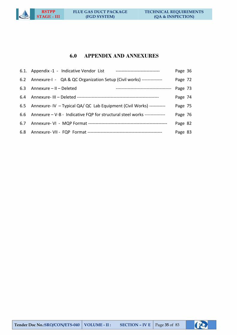
RSTPP STAGE - III
FLUE GAS DUCT PACKAGE (FGD SYSTEM)
TECHNICAL REQUIREMENTS (QA & INSPECTION)
Tender Doc No.:SRO/CON/ETS-040 VOLUME - II : SECTION – IV E Page 35 of 83
6.0 APPENDIX AND ANNEXURES
6.1. Appendix -1 - Indicative Vendor List ------------------------------ Page 36
6.2 Annexure-I - QA & QC Organization Setup (Civil works) -------------- Page 72
6.3 Annexure – II – Deleted -------------------------------------- Page 73
6.4 Annexure- III – Deleted -------------------------------------------------------- Page 74
6.5 Annexure- IV – Typical QA/ QC Lab Equipment (Civil Works) ----------- Page 75
6.6 Annexure – V-B - Indicative FQP for structural steel works -------------- Page 76
6.7 Annexure- VI - MQP Format ------------------------------------------------------ Page 82
6.8 Annexure- VII - FQP Format --------------------------------------------------- Page 83
RSTPP STAGE - III
FLUE GAS DUCT PACKAGE (FGD SYSTEM)
TECHNICAL REQUIREMENTS (QA & INSPECTION)
Tender Doc No.:SRO/CON/ETS-040 VOLUME - II : SECTION – IV E Page 36 of 83
Appendix - I
DISCLAIMER FOR INDICATIVE VENDOR LIST
1.1 Reasonable efforts have been made to collate the sub-vendors proposed by the
various main contractors from time to time against different Projects/Packages and
accepted by NTPC for various items. However, in case of error/omission, if any, and
represented by the successful bidder this will be addressed during the execution of
the contract based on the material evidence available with NTPC / Main Contractor.
1.2 The approved sub-vendor list drawn is not based on NTPC driven enlistment process
but based on the sub- vendors proposed by various Main Contractors. As such, it is
possible that some of the Suppliers/Manufacturers who may be involved in similar
work/process may not be appearing in the list as such sub-vendors may not have been
proposed by Main Contractors against NTPC Contracts.
1.3 In case the successful bidder chooses to propose additional sub-vendors with relevant
experience after the award of the contract such sub-vendors will be considered in
terms of Clause no: 19.1 of GCC, provided the proposals are received sufficiently in
time: 90 days prior to ordering date of a Bought Out Items/Start of Manufacturing so
as not to impede the progress of the contract.
1.4 Sub-vendors have been grouped under different categories of items. It is possible that
an item characterized by certain specific features such as range and type required as
per Main Contractor’s design requirements may not be in the range of the listed sub-
vendor’s manufacturing process/capability. As such the main contractor to ascertain
the vendor’s capability to meet his specific requirements before considering a sub-
vendor.
1.5 It is to be noted by the bidders that any shortfall in contract performance attributable
to the sub-vendor listed will not absolve the contractor from his contractual
obligations in any manner.
1.6 The approval was granted based on the evaluation of relevant capabilities and
facilities possessed by the sub-vendor at the time of evaluation. Also, some of the sub-
vendors may not be active. As such, the successful bidder is to carry out his own due
diligence before considering the listed sub-vendor for subletting: the current
RSTPP STAGE - III
FLUE GAS DUCT PACKAGE (FGD SYSTEM)
TECHNICAL REQUIREMENTS (QA & INSPECTION)
Tender Doc No.:SRO/CON/ETS-040 VOLUME - II : SECTION – IV E Page 37 of 83
status of the sub-vendor, the continued availability of productive resources including
Human Resources.
1.7 The list of sub-vendors is periodically revised to include new sub-vendors. Such a
revision may also see a deletion of certain sub-vendors who may have been
disqualified on grounds of inadequate performance or banned in line with NTPC’s
banning policy. The then current list will be shared with the successful bidder
immediately on award.
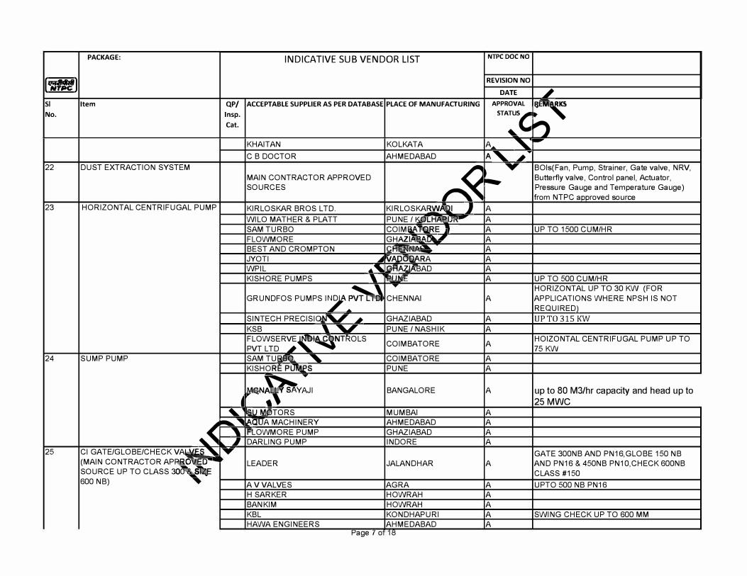
INDICATIVE SUB VENDOR LIST NTPC DOC NO PACKAGE:
,�,aitl REVISION NO
DATE ,; SI Item QP/ ACCEPTABLE SUPPLIER AS PER DATABASE PLACE OF MANUFACTURING APPROVAL
:, No. lnsp. STA:
S, Cat. n
KHAITAN KOLKATA A,.. '
-
C B DOCTOR AHMEDABAD A' iT
22 DUST EXTRACTION SYSTEM
�
T BOls(Fan, Pump, Strainer, Gate valve, NRV, MAIN CONTRACTOR APPROVED
....,. Butterfly valve, Control panel, Actuator,
SOURCES Pressure Gauge and Temperature Gauge) from NTPC aooroved source
23 HORIZONTAL CENTRIFUGAL PUMP KIRLOSKAR BROS LTD. KIRLOSKAR_wAJ I J A WILO MATHER & PLATT PLINE I MJL�_,. .. .. A SAM TURBO COIMef.�RE J A UP TO 1500 CUM/HR FLOWMORE GHAZIK-0.A�.I A BEST AND CROMPTON r,�_a-131,,. .... - A JYOTI ...i�AD�RA A WPIL .. , .GHAZ:lftBAD A KISHORE PUMPS ' PUN� A UP TO 500 CUM/HR
GRUNDFOS PUMPS I/:� """ HORIZONTAL UP TO 30 KW (FOR
CHENNAI A APPLICATIONS WHERE NPSH IS NOT REQUIRED)
SINTECH PRECISIO� i GHAZIABAD A UPTO 315 KW
KSB '" PLINE I NASHIK A FLOWSERVE��NTROLS COIMBATORE A HOIZONTAL CENTRIFUGAL PUMP UP TO PVT LTD i 75 KW
24 SUMP PUMP SAM TURS-0. ' COIMBATORE A KISHORE PIJJAE>S PLINE A
�ey;�v:, BANGALORE A up to 80 M3/hr capacity and head up to
� . 25MWC
'" SU MCl!TORS MUMBAI A .... -.."'1111 t.O'OA MACHINERY AHMEDABAD A
.... � ' PLOWMORE PUMP GHAZIABAD A I DARLING PUMP IN DORE A
25 Cl GATE/GLOBE/CHECK VAk\lE.S' ..... GATE 300NB AND PN16,GLOBE 150 NB (MAIN CONTRACTOR AP�� LEADER JALANDHAR A AND PN16 & 450NB PN1 O,CHECK 600NB SOURCE UP TO CLASS 30 S CLASS #150 600 NB) A V VALVES AGRA A UPTO 500 NB PN16
H SARKER HOWRAH A BAN KIM HOWRAH A KBL KONDHAPURI A SWING CHECK UP TO 600 MM HAWA ENGINEERS AHMEDABAD A
t-'a er o g 11:S
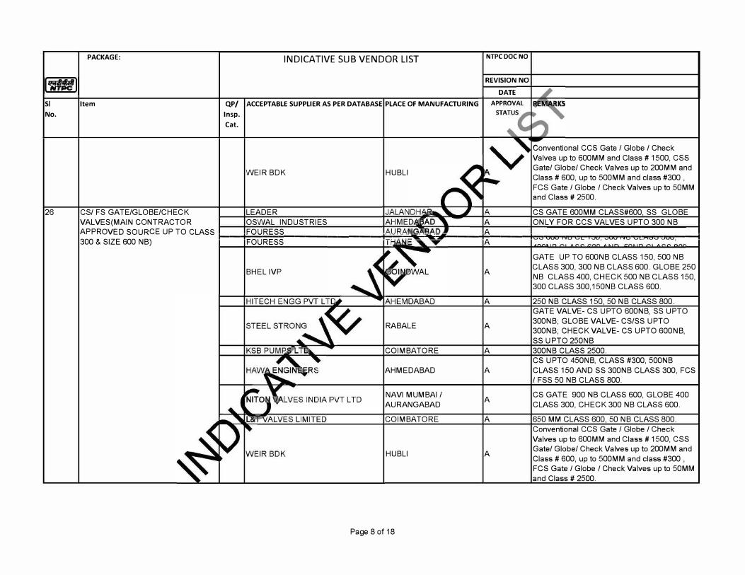
SI
No.
26
PACKAGE: INDICATIVE SUB VENDOR LIST
Item QP/ ACCEPTABLE SUPPLIER AS PER DATABASE PLACE OF MANUFACTURING
lnsp.
Cat.
WEIR BOK
CS/ FS GATE/GLOBE/CHECK LEADER VALVES(MAIN CONTRACTOR OSWAL INDUSTRIES
HUBLI
NTPC DOC NO
REVISION NO
DATE
A
Conventional CCS Gate I Globe I Check Valves up to 600MM and Class# 1500, CSS Gate/ Globe/ Check Valves up to 200MM and Class# 600, up to 500MM and class #300 , FCS Gate I Globe I Check Valves up to 50MM and Class # 2500.
CS GATE 600MM CLASS#600, SS GLOBE ONLY FOR CCS VALVES UPTO 300 NB
APPROVED SOURCE UP TO CLASS t--��FO
�U
�R
�E�S�S������������k--'"'IE����-f-'.,'���-tO"O'-rn,t,""1'1=-"���rnr,...,.r,""O'!�ro-:::roi,�---t 300 & SIZE 600 NB) FOURESS
A A
BHEL IVP
RA BALE
COIMBATORE
AHMEDABAD
NAVI MUMBAI IAURANGABAD
COIMBATORE
HUBLI
Page 8 of 18
A
A
A
A
A
A
A
A
GATE UP TO 600NB CLASS 150, 500 NB CLASS 300, 300 NB CLASS 600. GLOBE 250 NB CLASS 400, CHECK 500 NB CLASS 150, 300 CLASS 300, 150NB CLASS 600.
250 NB CLASS 150, 50 NB CLASS 800. GATE VALVE- CS UPTO 600NB, SS UPTO 300NB; GLOBE VALVE- CS/SS UPTO 300NB; CHECK VALVE- CS UPTO 600NB, SS UPTO 250NB 300NB CLASS 2500. CS UPTO 450NB, CLASS #300, 500NB CLASS 150 AND SS 300NB CLASS 300, FCS I FSS 50 NB CLASS 800.
CS GATE 900 NB CLASS 600, GLOBE 400 CLASS 300, CHECK 300 NB CLASS 600.
650 MM CLASS 600, 50 NB CLASS 800. Conventional CCS Gate I Globe I Check Valves up to 600MM and Class# 1500, CSS Gate/ Globe/ Check Valves up to 200MM and Class# 600, up to 500MM and class #300 , FCS Gate I Globe I Check Valves up to 50MM and Class # 2500.
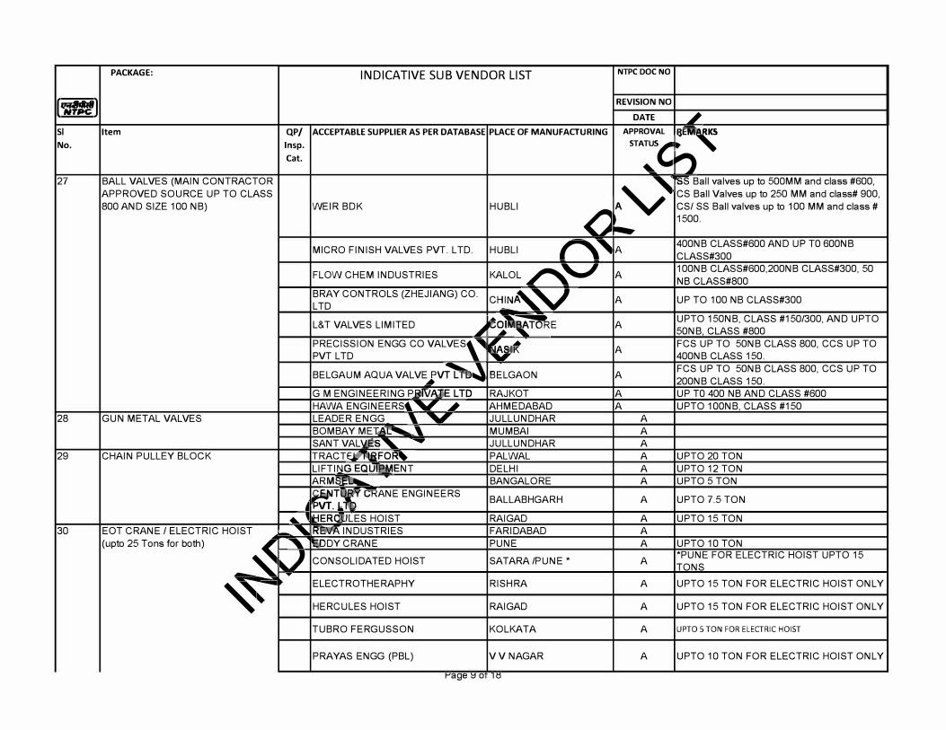
INDICATIVE SUB VENDOR LIST NTPC DOC NO PACKAGE:
,�,aitl REVISION NO
DATE ,; SI Item QP/ ACCEPTABLE SUPPLIER AS PER DATABASE PLACE OF MANUFACTURING APPROVAL
:, No. lnsp. STA:
S, Cat. n
27 BALL VALVES (MAIN CONTRACTOR
Av SS Ball valves up to 500MM and class #600,
APPROVED SOURCE UP TO CLASS CS Ball Valves up to 250 MM and class# 900, 800 AND SIZE 100 NB) WEIR BOK HUBLI
�
CS/ SS Ball valves up to 100 MM and class # 1500 .
....,.
MICRO FINISH VALVES PVT. LTD. HUBLI �"A 400NB CLASS#600 AND UP TO 600NB CLASS#300
FLOW CHEM INDUSTRIES KALOL�'-,,/ A 100NB CLASS#600,200NB CLASS#300, 50 NB CLASS#800
BRAY CONTROLS (ZHEJIANG) CO. CH�N,v A UP TO 100 NB CLASS#300 LTD
L&T VALVES LIMITED t�'b�E A UPTO 150NB, CLASS #150/300, AND UPTO � 50NB, CLASS #800
PRECISSION ENGG CO VALVES,
� &t A FCS UP TO 50NB CLASS 800, CCS UP TO PVT LTD 400NB CLASS 150.
BELGAUM AQUA VALVEJV� BELGAON A FCS UP TO 50NB CLASS 800, CCS UP TO 200NB CLASS 150.
G M ENGINEERING P&lv'A:J'E LTD RAJK OT A UP TO 400 NB AND CLASS #600 HAWA ENGINEERS�°" i AHMEDABAD A UPTO 100NB, CLASS #150
28 GUN METAL VALVES LEADER ENGG '" JULLUNDHAR A BOMBAY META1--lllllllllo....., MUMBAI A SANT VALVES' ..... JULLUNDHAR A
29 CHAIN PULLEY BLOCK TRACT E'.:Lfll:B F O � PAL WAL A UPTO 20 TON LIFTl�G EQLJleMENT DELHI A UPTO 12 TON ARMS! ::U........ BANGALORE A UPTO 5 TON
�T[ � VT.� � CRANE ENGINEERS BALLABHGARH A UPTO 7.5 TON
..... , HERCI LES HOIST RA I GAD A UPTO 15 TON 30 EOT CRANE I ELECTRIC HOIST -' Rg,tA INDUSTRIES FARIDABAD A
(upto 25 Tons for both)
--� ' EDDY CRANE PLINE A UPTO 10 TON
J CONSOLIDATED HOIST SATARA /PUNE * A *PLINE FOR ELECTRIC HOIST UPTO 15TONS
T
�-ELECTROTHERAPHY RISH RA A UPTO 15 TON FOR ELECTRIC HOIST ONLY
HERCULES HOIST RA I GAD A UPTO 15 TON FOR ELECTRIC HOIST ONLY
TUBRO FERGUSSON KOLKATA A UPTO 5 TON FOR ELECTRIC HOIST
PRAYAS ENGG (PBL) V V NAGAR A UPTO 10 TON FOR ELECTRIC HOIST ONLY
t"'a e :::i o g 10
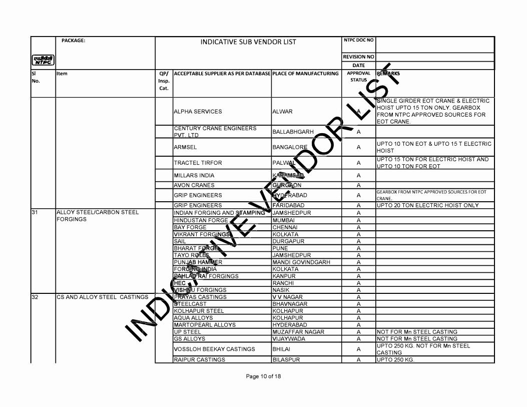
INDICATIVE SUB VENDOR LIST NTPC DOC NO PACKAGE:
,�,aitl REVISION NO
DATE ,; SI Item QP/ ACCEPTABLE SUPPLIER AS PER DATABASE PLACE OF MANUFACTURING APPROVAL
:, No. lnsp. STA:
S, Cat.
'S1NGLE GIRDER EQT CRANE & ELECTRIC
ALPHA SERVICES AL WAR HOIST UPTO 15 TON ONLY. GEARBOX FROM NTPC APPROVED SOURCES FOR
� EOT CRANE. CENTURY CRANE ENGINEERS BALLABHGARH -..._ """'<._ �APVT. LTD
ARMSEL BANGAL�u"III
A UPTO 10 TON EOT & UPTO 15 T ELECTRIC HOIST
TRACTEL TIRFOR PALW�, J A UPTO 15 TON FOR ELECTRIC HOIST AND UPTO 10 TON FOR EOT
MILLARS INDIA 1,A""l'nr-a-'... ....... A "' --
AVON CRANES ,, GliRG""�N A GRIP ENGINEERS ,� �ABAD A GEARBOX FROM NTPC APPROVED SOURCES FOR EOT
CRANE
GRIP ENGINEERS .............. , FARIDABAD A UPTO 20 TON ELECTRIC HOIST ONLY 31 ALLOY STEEL/CARBON STEEL INDIAN FORGING AND S:'.FAMPING""' JAMSHEDPUR A
FORGINGS HINDUSTAN FORGE I ,i MUMBAI A BAY FORGE '- "Y ,, CHENNAI A VIKRANT FORGJNGSl ,,... KOLKATA A SAIL '" .............. , DURGAPUR A BHARAT F0RG� - PLINE A TAYO ReIBS.. � JAMSHEDPUR A PUNJAB HAMQER MANDI GOVINDGARH A FOR�DIA KOLKATA A eAtiiLAO'RArFoRGINGS KANPUR A
� HEC • � RANCHI A ... JISHN,l.J FORGINGS NASIK A
32 CS AND ALLOY STEEL CASTING<
-s "RAYAS CASTINGS V V NAGAR A ii>TEELCAST BHAVNAGAR A
--� KOLHAPUR STEEL KOLHAPUR A AQUA ALLOYS KOLHAPUR A
�-MARTOPEARL ALLOYS HYDERABAD A UP STEEL MUZAFFAR NAGAR A NOT FOR Mn STEEL CASTING GS ALLOYS VIJAYWADA A NOT FOR Mn STEEL CASTING
VOSSLOH BEEKAY CASTINGS BHILAI A UPTO 250 KG. NOT FOR Mn STEEL CASTING
RAIPUR CASTINGS BILASPUR A UPTO 250 KG.
Page 10 of 18
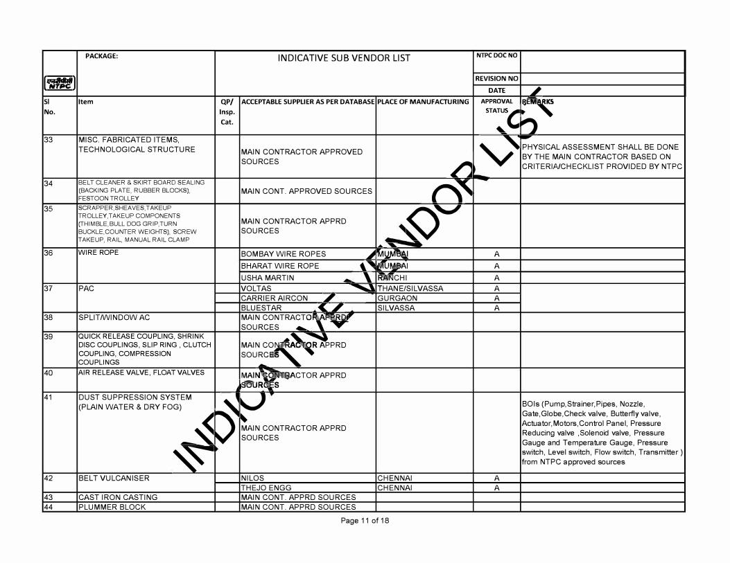
INDICATIVE SUB VENDOR LIST NTPC DOC NO PACKAGE:
,�,aitl REVISION NO
DATE ,; SI Item QP/ ACCEPTABLE SUPPLIER AS PER DATABASE PLACE OF MANUFACTURING APPROVAL
:, No. lnsp. STA:
S, Cat. n
33 MISC. FABRICATED ITEMS,
v --
TECHNOLOGICAL STRUCTURE MAIN CONTRACTOR APPROVED PHYSICAL ASSESSMENT SHALL BE DONE
SOURCES BY THE MAIN CONTRACTOR BASED ON
� CRITERINCHECKLIST PROVIDED BY NTPC
34 BELT CLEANER & SKIRT BOARD SEALING
r\' (BACKING PLATE, RUBBER BLOCKS), MAIN CONT. APPROVED SOURCES FESTOON TROLLEY
35 SCRAPPER,SHEAVES,T AKE UP
��
TROLLEY,TAKEUP COMPONENTS MAIN CONTRACTOR APPRD (THIMBLE,BULL DOG GRIP,TURN
BUCKLE,COUNTER WEIGHTS), SCREW SOURCES TAKEUP, RAIL, MANUAL RAIL CLAMP
. -
36 WIRE ROPE BOMBAY WIRE ROPES � ��at A BHARAT WIRE ROPE t' �ll�R>AI A USHA MARTIN .-. ' �CHI A
37 PAC VOLTAS � THANE/SI LVASSA A CARRIER AIRCON ,, GURGAON A BLUEST AR <I SILVASSA A
38 SPLIT/WINDOW AC MAIN CONTRACTO, .. v SOURCES -..
39 QUICK RELEASE COUPLING, SHRINK MAIN c,���PRD DISC COUPLINGS, SLIP RING , CLUTCH
COUPLING, COMPRESSION SOURC · COUPLINGS
.-.
40 AIR RELEASE VALVE, FLOAT VALVES MAIN� �ACTOR APP RD $0UR s
41 DUST SUPPRESSION SYSTEM
� v (PLAIN WATER & DRY FOG) BOls (Pump,Strainer,Pipes, Nozzle,
-� �
�Gate,Globe,Check valve, Butterfly valve, Actuator,Motors,Control Panel, Pressure MAIN CONTRACTOR APPRD Reducing valve ,Solenoid valve, Pressure SOURCES Gauge and Temperature Gauge, Pressure
�
switch, Level switch, Flow switch, Transmitter ) from NTPC approved sources
42 BELT VULCAN IS ER NILOS CHENNAI A THEJO ENGG CHENNAI A
43 CAST IRON CASTING MAIN CONT. APPRD SOURCES 44 PLUMMER BLOCK MAIN CONT. APPRD SOURCES
Page 11 of 18
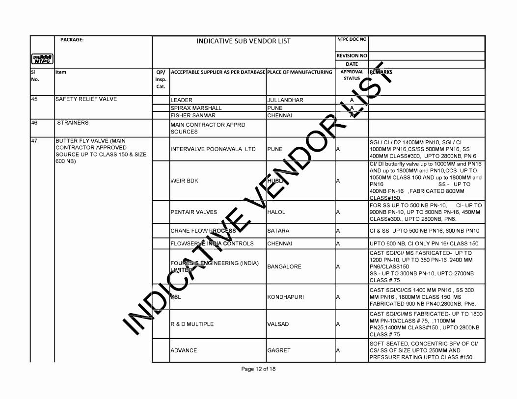
INDICATIVE SUB VENDOR LIST NTPC DOC NO PACKAGE:
,�,aitl REVISION NO
DATE ,; SI Item QP/ ACCEPTABLE SUPPLIER AS PER DATABASE PLACE OF MANUFACTURING APPROVAL
:, No. lnsp. STA:
S, Cat. n
45 SAFETY RELIEF VALVE LEADER JULLANDHAR A' -.....
SPIRAX MARSHALL PLINE � .i T
FISHER SANMAR CHENNAI � " 46 STRAINERS MAIN CONTRACTOR APPRD
�� SOURCES 47 BUTTER FLY VALVE (MAIN
PUNE_<"'\V
SGI I Cl I 02 1400MM PN10, SGI I Cl CONTRACTOR APPROVED INTERVAL VE POONAWALA LTD A 1000MM PN16,CS/SS 500MM PN16, SS SOURCE UP TO CLASS 150 & SIZE 400MM CLASS#300, UPTO 2800NB, PN 6 600 NB) ---"'-"' Cl/ DI butterfly valve up to 1000MM and PN16
AND up to 1800MM and PN1 O,CCS UP TO
WEIR BOK
� �-A 1050MM CLASS 150 AND up to 1800MM and
PN16 SS - UP TO 400NB PN-16 ,FABRICATED 800MM
.-. CLASS#150 . FOR SS UP TO 500 NB PN-10, Cl- UP TO
PENTAIR VALVES 6
�/ _.HALOL A 900NB PN-10, UP TO 500NB PN-16, 450MM
CLASS#300., UPTO 2800NB, PN6.
CRANE FLOW .... �w"W" SAT ARA A Cl & SS UPTO 500 NB PN16, 600 NB PN10
FLOWSE� I� �NTROLS CHENNAI A UPTO 600 NB, Cl ONLY PN 16/ CLASS 150
.. � T CAST SGI/CI/ MS FABRICATED- UP TO 1200 PN-10, UP TO 350 PN-16 ,2400 MM FOU
�GINEERING (INDIAJ BANGALORE A PN6/CLASS 150 �ff SS - UP TO 300NB PN-10, UPTO 2700NB
� . CLASS # 75
�
'-" CAST SGI/CI/CS 1400 MM PN16 , SS 300
-� kBL KONDHAPURI A MM PN16 , 1800MM CLASS 150, MS
FABRICATED 900 NB PN40,2800NB, PN6 . ...... CAST SGI/CI/MS FABRICATED- UP TO 1800
�-R & D MULTIPLE VALSAD A MM PN-10/CLASS # 75, , 11 OOMM
PN25, 1400MM CLASS#150 , UPTO 2800NB CLASS # 75 SOFT SEATED, CONCENTRIC BFV OF Cl/
ADVANCE GAGRET A CS/ SS OF SIZE UPTO 250MM AND PRESSURE RATING UPTO CLASS #150.
Page 12 of 18
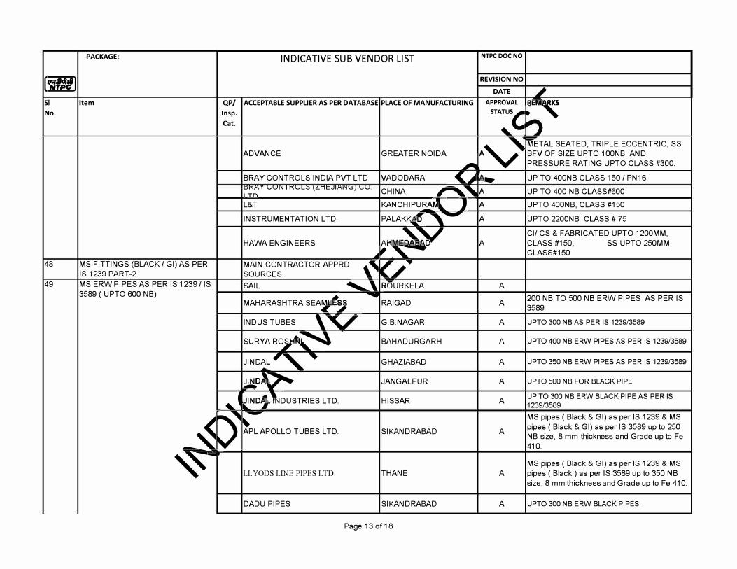
INDICATIVE SUB VENDOR LIST NTPC DOC NO PACKAGE:
,�,aitl REVISION NO
DATE SI Item QP/ ACCEPTABLE SUPPLIER AS PER DATABASE PLACE OF MANUFACTURING APPROVAL
:, No. lnsp. STA:
S, Cat.
Av
"M"ETAL SEATED, TRIPLE ECCENTRIC, SS ADVANCE GREATER NOIDA BFV OF SIZE UPTO 100NB, AND
� PRESSURE RATING UPTO CLASS #300.
BRAY CONTROLS INDIA PVT LTD VADODARA <...;1 � UP TO 400NB CLASS 150 I PN16 u,v I \JV" I "VLv \LnCvl ,,....,) \JV. CHINA "'"''A
UP TO 400 NB CLASS#600 ITn
L&T KANCHIPURA� J A UPTO 400NB, CLASS #150
INSTRUMENTATION LTD. PALAK� ,� A UPTO 2200NB CLASS # 75
-�Y Cl/ CS & FABRICATED UPTO 1200MM, HAWA ENGINEERS A' A CLASS #150, SS UPTO 250MM,
..ij, �---- CLASS#150 48 MS FITTINGS (BLACK I GI) AS PER MAIN CONTRACTOR APPRD \� (/..IS 1239 PART-2 SOURCES 49 MS ERW PIPES AS PER IS 1239 / IS SAIL ............_, R�URKELA A
3589 ( UPTO 600 NB) MAHARASHTRA SEA�,
-- 200 NB TO 500 NB ERW PIPES AS PER IS RA I GAD A 3589
INDUS TUBES \� G.B.NAGAR A UPTO 300 NB AS PER IS 1239/3589
SURYA R�� BAHADURGARH A UPTO 400 NB ERW PIPES AS PER IS 1239/3589
JIND12L #"' � GHAZIABAD A UPTO 350 NB ERW PIPES AS PER IS 1239/3589
�D� JAN GALP UR A UPTO 500 NB FOR BLACK PIPE
41,.. � .. 1NDJ lJDUSTRIES LTD. HISSAR A UP TO 300 NB ERW BLACK PIPE AS PER IS
1239/3589
-s -- MS pipes ( Black & GI) as per IS 1239 & MS
-� � pipes ( Black & GI) as per IS 3589 up to 250 APL APOLLO TUBES LTD. SIKANDRABAD A NB size, 8 mm thickness and Grade up to Fe
410.
�- MS pipes ( Black & GI) as per IS 1239 & MS LLYODS LINE PIPES LTD. THANE A pipes ( Black ) as per IS 3589 up to 350 NB
size, 8 mm thickness and Grade up to Fe 410.
DADU PIPES SIKANDRABAD A UPTO 300 NB ERW BLACK PIPES
Page 13 of 18
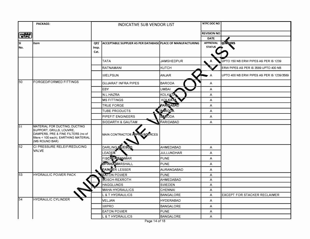
INDICATIVE SUB VENDOR LIST NTPC DOC NO PACKAGE:
,�,aitl REVISION NO
DATE ,; SI Item QP/ ACCEPTABLE SUPPLIER AS PER DATABASE PLACE OF MANUFACTURING APPROVAL
:, No. lnsp. STA:
S, Cat.
'-. A ' TATA JAMSHEDPUR UPTO 150 NB ERW PIPES AS PER IS 1239
RATNAMANI KUTCH - � ERW PIPES AS PER IS 3589 UPTO 400 NB
WELPSUN AN JAR _v ._. A UPTO 400 NB ERW PIPES AS PER IS 1239/3589
50 FORGED/FORMED FITTINGS GUJARAT INFRA PIPES BARODA ( "'� A
EBY UMBAI �'-' A N.L.HAZRA KOLK41.� ) A MS FITTINGS KQL_KA�V A TRUE FORGE .,. �ARL!iABAB A TUBE PRODUCTS .. < �q,PA A
PIPEFIT ENGINEERS \ ft'�DA A SIDDARTH & GAUTAM """"'-' FARIDABAD A
51 MATERIAL FOR DUCTING, DUCTING SUPPORT, GRILLS, LOUVRE, DAMPERS, PRE & FINE FILTERS (no of MAIN CONTRAC
� s RCES
filters< 100 each), EARTHING MATERIAL (MS ROUND BAR) �""
52 Cl PRESSURE RELEIF/REDUCING DARLING�ES� AHMEDABAD A VALVE LEAD_ER
...,.
' JULLUNDHAR A FISCFtf' �MAR PLINE A
jfflR� MARSHALL PLINE A
'"� f.AINfER LESSER AURANGABAD A 53 HYDRAULIC POWER PACK ......... "' EA,ON POWER PLINE A
--� ' B'"OSCH-REXROTH AHMEDABAD A
.... � HAGGLUNDS SWEDEN A T
MAHA HYDRAULICS CHENNAI A
,, L & T HYDRAULICS BANGALORE A EXCEPT FOR STACKER RECLAIMER 54 HYDRAULIC CYLINDER � VELJAN HYDERABAD A
WIPRO BANGALORE A EATON POWER PLINE A L & T HYDRAULICS BANGALORE A
Page 14 of 18
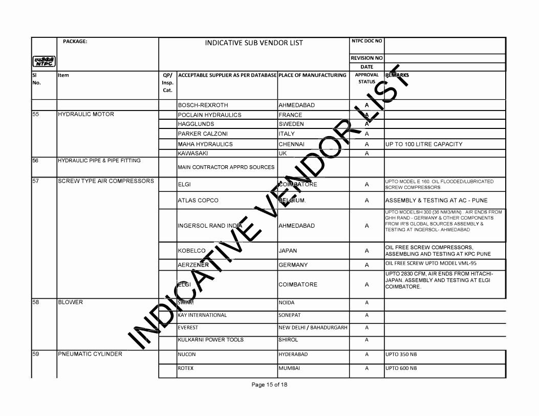
INDICATIVE SUB VENDOR LIST NTPC DOC NO PACKAGE:
,�,aitl REVISION NO
DATE SI Item QP/ ACCEPTABLE SUPPLIER AS PER DATABASE PLACE OF MANUFACTURING APPROVAL
:, No. lnsp. STA:
S, Cat. n
BOSCH-REXROTH AHMEDABAD 4lo.. A'-55 HYDRAULIC MOTOR POCLAIN HYDRAULICS FRANCE �,;
HAGGLUNDS SWEDEN r A...,,PARKER CALZONI ITALY _y �A
MAHA HYDRAULICS CHENNAI ( '"1111 A UP TO 100 LITRE CAPACITY KAWASAKI UK --"-.. 1 A
56 HYDRAULIC PIPE & PIPE FITTING
� MAIN CONTRACTOR APPRD SOURCES
57 SCREW TYPE AIR COMPRESSORS ELGI t���E A UPTO MODEL E 160. OIL FLOODED/LUBRICATED
SCREW COMPRESSORS
ATLAS COPCO �
�UM. A ASSEMBLY & TESTING AT AC - PLINE
UPTO MODELSH 300 (36 NM3/MIN) AIR ENDS FROM
INGERSOL RAND I� GHH RAND - GERMANY & OTHER COMPONENTS
AHMEDABAD A FROM IR'S GLOBAL SOURCES ASSEMBLY &
TESTING AT INGERSOL- AHMEDABAD
KOBELCO�� JAPAN A OIL FREE SCREW COMPRESSORS, ASSEMBLING AND TESTING AT KPC PUNE
AERZ_E�R, �
GERMANY A OIL FREE SCREW UPTO MODEL VML-95
UPTO 2830 CFM, AIR ENDS FROM HITACHI-
�I JAPAN.ASSEMBLY AND TESTING AT ELGI
COIMBATORE A COIMBATORE .
... � 58 BLOWER ' <"'<I '1'Tll NOIDA A
-� '""'
- .. ..
KAY INTERNATIONAL SONEPAT A
..... EVEREST NEW DELHI/ BAHADURGARH A
�- KULKARNI POWER TOOLS SHIROL A
59 PNEUMATIC CYLINDER NU CON HYDERABAD A UPTO 350 NB
RO TEX MUMBAI A UPTO 600 NB
Page 15 of 18
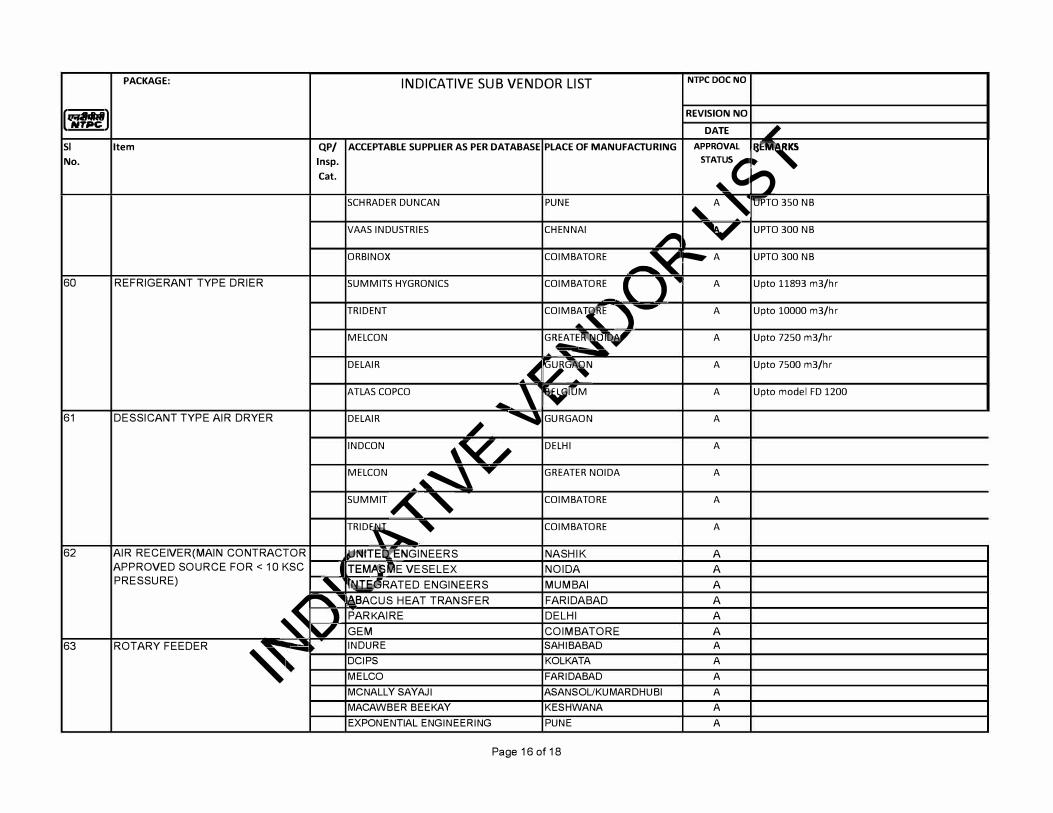
INDICATIVE SUB VENDOR LIST NTPC DOC NO PACKAGE:
,�,aitl REVISION NO
DATE SI Item QP/ ACCEPTABLE SUPPLIER AS PER DATABASE PLACE OF MANUFACTURING APPROVAL
:, No. lnsp. STA:
S, Cat. n
SCHRADER DUNCAN PUNE '-.
A ' 'EJ'PTO 350 NB
VAAS INDUSTRIES CHENNAI � "' UPTO 300 NB
ORBIN OX COIMBATORE �"<
....,. A UPTO 300 NB
60 REFRIGERANT TYPE DRIER SUMMITS HYGRONICS COIMBATORE l ) ....
A Upto 11893 m3/hr -
TRIDENT COIMB�T� " - A Upto 10000 m3/hr
MELCON GR!!:!:_E�V A Upto 7250 m3/hr -
DELAIR . .t. ��
A Upto 7500 m3/hr
ATLAS COPCO \ ymM A Upto model FD 1200 ........
61 DESSICANT TYPE AIR DRYER DELAIR ,;
� GURGAON A
INDCON \Vj
DELHI A
MELCON � '""-..\ T GREATER NOIDA A
SUMMIT A..� COIMBATORE A
TRID�
' COIMBATORE A
62 AIR RECEIVER(MAIN CONTRACTOR jjl'UTEIJ(ENGINEERS NASHIK A APPROVED SOURCE FOR < 10 KSC I TEM��E VESELEX NOIDA A PRESSURE) ' t�RATED ENGINEERS MUMBAI A
�
"""""' .... ABACUS HEAT TRANSFER FARIDABAD A
1 PAR KAI RE DELHI A .., GEM COIMBATORE A
63 ROTARY FEEDER .... IN DURE SAHIBABAD A
�
-DCIPS KOLKATA A MELCO FARIDABAD A MCNALLY SAYAJI ASANSOL/KU MARDHU Bl A MACAWBER BEEKAY KESHWANA A EXPONENTIAL ENGINEERING PUNE A
Page 16 of 18
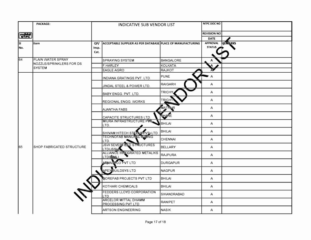
,�,aitl
PACKAGE:
SI Item QP/ No. lnsp.
Cat.
64 PLAIN WATER SPRAY NOZZLE/SPRINKLERS FOR OS SYSTEM
65 SHOP FABRICATED STRUCTURE
"'"�
-� ,� v
�-
INDICATIVE SUB VENDOR LIST
ACCEPTABLE SUPPLIER AS PER DATABASE
SPRAYING SYSTEM F.HARLEYEAGLE AGRO
INDIANA GRATINGS PVT. LTD.
JINDAL STEEL & POWER LTD.
BABY ENGG. PVT. LTD.
REGIONAL ENGG. WORKS
AJANTHA FABS �
CAPACITE STRUCTURES LTD. \-....
MIURA INFRASTRUCTURE� LTD. i
SHIVAM HITECH Sl<.EUvbL TD TECHNOFAB MANU
-'C'��1\JG
LTD. .... ........... JSW SE�.,�
l�TRl:.JCTURES LTD!JSS ALLIANCE l�GRATED METALIKSLTD!�L..l �AlpvT LTD
Bu1LosYs LTD
�OREFAB PROJECTS PVT LTD
KOTHARI CHEMICALS FEDDERS LLOYD CORPORATION LTD ARCELOR MITTAL DHAMM PROCESSING PVT LTD ARTSON ENGINEERING
PLACE OF MANUFACTURING
BANGALORE KOLKATA RAJK OT � PLINE -� RAIGARH { ,� TRI CHY�
T�V
t��---
� BHILAI
BHILAI
CHENNAI
BEL LARY
RAJ PURA
DURGAPUR
NAGPUR
BHILAI
BHILAI
SIKANDRABAD
RANI PET
NASIK
Page 17 of 18
NTPC DOC NO
REVISION NO DATE
APPROVAL :, STA
:S,
..._ A " -�,;
Afl"
....,_ A
A
A
A
A
A
A
A
A
A
A
A
A
A
A
A
A
A
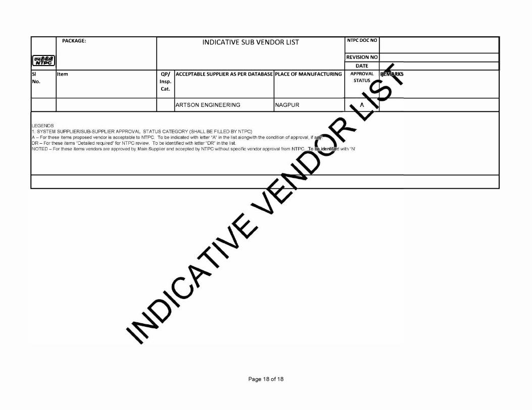
SI
No.
PACKAGE:
Item
INDICATIVE SUB VENDOR LIST
QP/ ACCEPTABLE SUPPLIER AS PER DATABASE PLACE OF MANUFACTURING
lnsp.
Cat.
ARTSON ENGINEERING NAGPUR
Page 18 of 18
NTPC DOC NO
REVISION NO
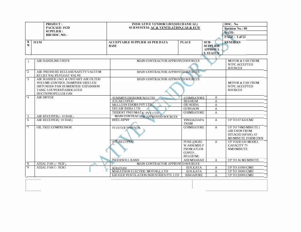
PROJECT : PACKAGE: FGD SUPPLIER : BID DOC. NO:-
S ffEM N
AIR HANDLING UNITS
2 AIR /PRESSURE RELEASE/SAFETY N ACUUM
RELIEF VAL VE/FLOAT VAL VE
3 AIR WASHER UNIT & UNITARY AIR FILTER/
VOLUME CONTROL DAMPERS/ GRILLES/ DIFFUSERS/ PAN HUMIDIFIER/ EXPANSION
TANK/LOUVERS/FABRICATED
DUCTS/PROPELLER FAN
4 AIR DRYER
5 AIR RECEIVER < 10 BAR
6 AIR RECEIVER(c>lO BAR)
7 OIL FREE COMPRESSOR
8 AXIAL FAN < 5KW
9 AXIAL FAN (c> 5KW)
INDICATIVE VENDOR LIST(MECHANICAL) SUB SYSTEM: AC & VENTILATION,CAS & ECW
ACCEPTABLE SUPPLIER AS PER DATA BASE
PLACE
MAIN CONTRACTOR APPROVED SOURCES
GURGAON
TRIDENT PNEUMAT COIMBATORE
MAIN CONTRAC
BHEL-HPVP VISHAKHAPA TNAM
COIMBATORE
PUNE.((SCRE W ASSEMBLY FROM ATLOS
COPCO , BELGIUM)
GERSOLL RAND AHEMDABAD
MAIN CONTRACTOR APPROVED SOURCES
KOLKATA
MARATHON ELECTRIC MOTOR I LTD KOLKATA
KRUGER VENTILATION INDUSTRIES PIE LTD SINGAPORE
DOC. No.
MOTOR & FAN FROM NTPC ACCEPTED
SOURCES
MOTOR & FAN FROM NTPC ACCEPTED
SOURCES
A
A
A
A
A
A UP TO 67 KG/CM2
A UP TO 74M3/MINUTE ( AIR ENDS FROM
HITACHI JAPAN), 45 M3/MINUTE FORM OWN
A UP TOZR 630-MODEL CAPACITY 75 NM3/MINUTE
A UP TO 36 M3/MINUTE
A UP TO 31000 CMH
A UP TO 50000 CMH
A UP TO 20000 CMH
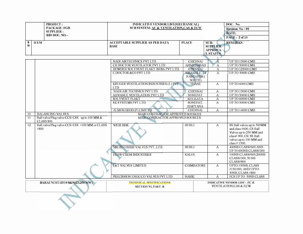
PROJECT : PACKAGE: FGD SUPPLIER : BID DOC. NO:-
S ffEM N
10 11
12
BALANCING VALVES Ball valve/Plug valve-CCS/ CSS up to 100 MM & CLASS 800 Ball valve/Plug valve-CCS/ CSS >l 00 MM or CLASS >800
INDICATIVE VENDOR LIST(MECHANICAL) SUB SYSTEM: AC & VENTILATION,CAS & ECW
ACCEPTABLE SUPPLIER AS PER DATA BASE
NADI AIRTECHNICS PVT LTD CB DOCTOR VENTILATOR PVT LTD HOWDEN SOLYVENT FLAKT INDIA PVT LTD, C DOCTOR &CO PVT LTD
KRUGER VENTILATION INDUSTRIES (I) LTD NADI AIR TECHNICS PVT LTD
ADVANCE VENTILATION PVT LTD SOL YVENT FLAKT SK SYSTEMS PVT LTD
PLACE
SONEPAT KOLKATA SONEPAT, HARYANA CHENNAI
RACTOR APPROVED SOURCES
&T VALVES LIMITED
PRECISSION ENGG CO VAL VES PVT LTD
TECHNICAL SPECIFICATIONS
SECTION VI, PART- B
HUB LI
HUB LI
KALOL
COIMBATORE
NASIK
A
A A A A
A
A
A
A
A
A
DOC. No.
UP TO 15000 CMH UP TO 50000 CMH UP TO 125000 CMH UP TO 50000 CMH
UP TO 6000 CMH
UP TO 15000 CMH UP TO 50000 CMH UP TO 60000 CMH UP TO 50000 CMH
UP TO 14000 CMH
SS Ball valves up to 500MM and class #600, CS Ball Valves up to 250 MM and class# 900, CS/ SS Ball valves up to 100 MM and class # 1500. 400NB CLASS#600 AND UP TO 600NB CLASS#300 l OONB CLASS#600,200NB CLASS#300, 50 NB CLASS#800 UPTO 150NB, CLASS #150/300, AND UPTO 50NB, CLASS #800 FCS UP TO 50NB CLASS
INDICATIVE VENDOR LIST: AC & VENTILATION,CAS & ECW
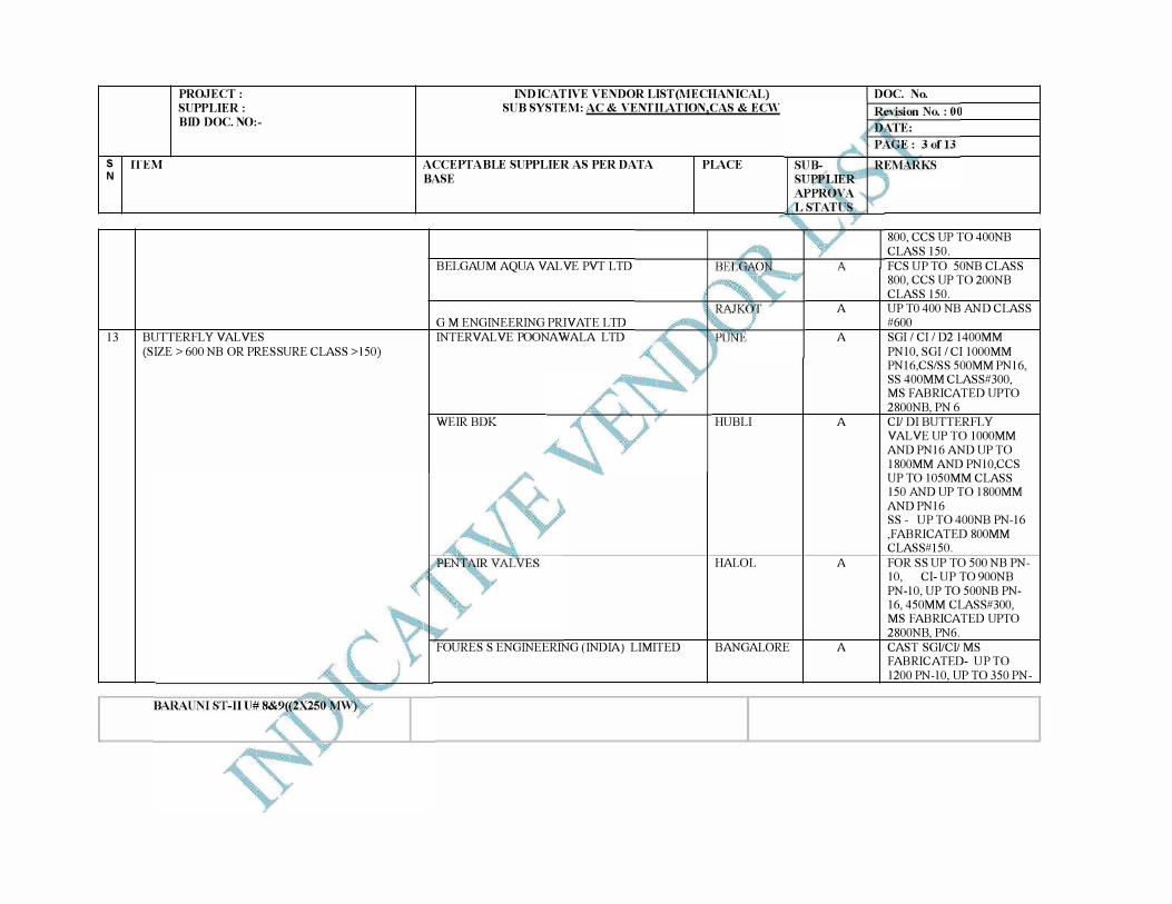
PROJECT : SUPPLIER : BID DOC. NO:-
S ffEM N
13 BUTTERFLY VALVES (SIZE> 600 NB OR PRESSURE CLASS> 150)
INDICATIVE VENDOR LIST(MECHANICAL) SUB SYSTEM: AC & VENTILATION,CAS & ECW
ACCEPTABLE SUPPLIER AS PER DATA BASE
BELGAUM AQUA VAL VE PVT LTD
G M ENGINEERING PRIVATE LTD INTERVAL VE POONA WALA LTD
WEIR BDK
FOURES S ENGINEERING (INDIA) LIMITED
PLACE
HUB LI
HALOL
BANGALORE
A
A
A
A
A
DOC. No.
800, CCS UP TO 400NB CLASS 150. FCS UP TO 50NB CLASS 800, CCS UP TO 200NB CLASS 150. UP TO 400 NB AND CLASS #600 SGI/ CI/ D2 1400MM PNlO, SGI/ CI lOOOMM PN16,CS/SS 500MM PN16, SS 400MM CLASS#300, MS FABRICATED UPTO 2800NB, PN 6 CI! DI BUTTERFLY VALVE UP TO lOOOMM AND PN16 AND UP TO 1800MM AND PNlO,CCS UP TO 1050MM CLASS 150 AND UP TO 1800MM AND PN16 SS - UP T0400NB PN-16 ,FABRICATED 800MM CLASS#l50. FOR SS UP TO 500 NB PN-10, CI- UP TO 900NB PN-10, UP TO 500NB PN-16, 450MM CLASS#300, MS FABRICATED UPTO 2800NB, PN6. CAST SGI/CI/ MS FABRICATED- UP TO 1200 PN-10, UP TO 350 PN-
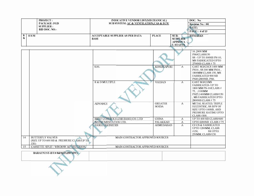
PROJECT : PACKAGE: FGD SUPPLIER : BID DOC. NO:-
S ffEM N
14 BUTTERFLY VALVES (SIZE UP TO 600 NB & PRESSURE C 150
15
INDICATIVE VENDOR LIST(MECHANICAL) SUB SYSTEM: AC & VENTILATION,CAS & ECW
ACCEPTABLE SUPPLIER AS PER DATA BASE
PLACE
KBL
R & D MULTIPLE
GREATER NO IDA
CHINA
PALAKKAD
AHMED ABAD
MAIN CONTRACTOR APPROVED SOURCES
MAIN CONTRACTOR APPROVED SOURCES
A
A
A
A
A
A
DOC. No.
16 ,2400 MM PN6/CLASS150 SS - UP TO 300NB PN-10, MS FABRICATED UPTO 2700NB CLASS # 75 CAST SGI/CI/CS 1400 MM
PN16 , SS 300 MM PN16 , 1800MM CLASS 150, MS
FABRICATED 900 NB PN40,2800NB, PN6.
CAST SGI/CI/MS FABRICATED- UP TO 1800 MM PN-10/CLASS # 75, ,llOOMM PN25,1400MM CLASS#l50 , MS FABRICATED UPTO
2800NB CLASS # 75
METAL SEATED, TRIPLE ECCENTRIC, SS BFV OF SIZE UPTO 1 OONB, AND PRESSURE RATING UPTO CLASS #300.
UP TO 400 NB CLASS#600
UPTO 2200NB CLASS # 75
CI/ CS & FABRICATED UPTO 1200MM, CLASS #150, SS UPTO 250MM, CLASS#l50
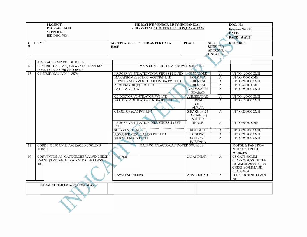
PROJECT : PACKAGE: FGD SUPPLIER : BID DOC. NO:-
S ffEM N
16
17
18
19
/PACKAGED AIR CONDITIONER CENTRIRJGAL FAN(< 5KW)/AIR BLOWERS/ LOBE TYPE ROTARY BLOWER CENTRIRJGAL FAN (2' 5KW)
CONDENSING UNIT/ PACKAGED COOLING TOWER
CONVENTIONAL GATE/GLOBE VAL VE/ CHECK VAL VE (SIZE >600 NB OR RATING PR CLAS 300)
INDICATIVE VENDOR LIST(MECHANICAL) SUB SYSTEM: AC & VENTILATION,CAS & ECW
ACCEPTABLE SUPPLIER AS PER DATA BASE
PLACE
MAIN CONTRACTOR APPROVED SO
KRUGER VENTILATION INDUSTRIES PIE LTD MARATHON ELECTRIC MOTOR I LTD HOWDEN SOLYVENT FLAKT INDIA PVT LTD, ALMONAROD (P) LIMITED PATEL AIRFLOW
CB DOCTOR VENTILATOR PVT LTD WOLTER VENTILATORS INDI
KRUGER VENT,U.ATION
AHMED ABAD BHIWADI,
DISTAL WAR
SIRAKOLE, 24 PARGANES (
SOUTH THANE
DOC. No.
A UP TO 150000 CMH A UP TO 50000 CMH A UP TO 200000 CMH A UP TO 60000 CMH A UP TO 250000 CMH
A UP TO 150000 CMH A UP TO 150000 CMH
A UP TO 250000 CMH
A UP TO 90000 CMH LTD /
""
SOLYVEN ,--���������+-�
K�O�L�KA:-:--:-cT�A-,----+�-----:A
��+-:,U�P�T�0:::-=-20�0�0700::-:::C�M�H=--�----,N PVT LTD SONEPAT
SONEPAT, HARYANA
MAIN CONTRACTOR APPROVED SOURCES
HA WA ENGINEERS
JAL AND HAR
AHMED ABAD
A UP TO 200000 CMH A UP TO 250000 CMH
A
A
MOTOR & FAN FROM NTPC ACCEPTED SOURCES CS GATE 600MM CLASS#600, SS GLOBE 600MM CLASS#600, CS CHECK 600MM AND CLASS#600 FCS I FSS 50 NB CLASS 800.
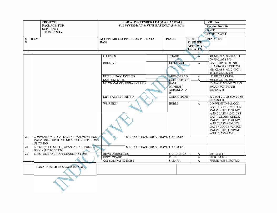
PROJECT : PACKAGE: FGD SUPPLIER : BID DOC. NO:-
S ffEM N
20
21
22
CONVENTIONAL GATE/GLOBE VAL VE/ CHECK VAL VE (SIZE UP TO 600 NB & RATING PR CLAS UP T0300 ELECTRIC HOIST/EOT CRANE/CHAIN PULL BLOCK UP TO 5 TON ,A
INDICATIVE VENDOR LIST(MECHANICAL) SUB SYSTEM: AC & VENTILATION,CAS & ECW
ACCEPTABLE SUPPLIER AS PER DATA BASE
FOURESS
BHEL IVP
HITECH ENGG PVT LTD KSB PUMPS LTD NITON VALVES INDIA PVT LTD
L&T VALVES LIMITED
WEIR BDK
PLACE
AVI MUMBAI / AURANGABA D COIMBATORE
HUB LI
MAIN CONTRACTOR APPROVED SOURCES
MAIN CONTRACTOR APPROVED SOURCES
CONSOLIDATED HOIST
FARIDABAD PUNE
SAT ARA
A A
A
A A A
DOC. No.
400NB CLASS 600 AND 50NB CLASS 800. GATE UP TO 300 NB CLASS 600. GLOBE 250 NB CLASS 400, CHECK 150NB CLASS 600. 50 NB CLASS 800.
300NB CLASS 2500. CS GATE 900 NB CLASS 600, CHECK 300 NB CLASS 600.
650 MM CLASS 600, 50 NB CLASS 800. CONVENTIONAL CCS GATE /GLOBE /CHECK VALVES UP TO 600MM AND CLASS# 1500, CSS GATE/GLOBE/CHECK VALVES UP T0200MM AND CLASS # 600, FCS GATE /GLOBE /CHECK VALVES UP TO 50MM AND CLASS# 2500.
UP T025T UPTOlOTON *PUNE FOR ELECTRIC
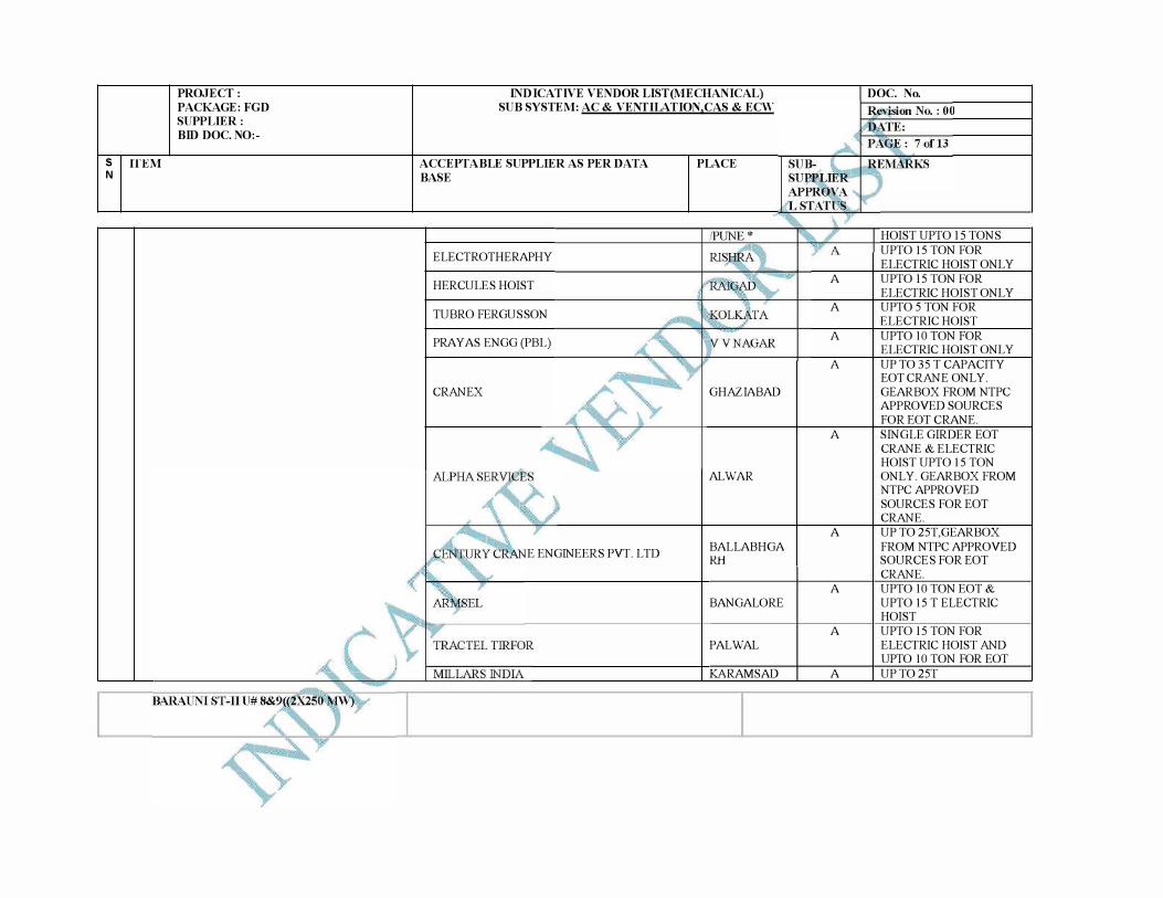
S ffEM N
PROJECT : PACKAGE: FGD SUPPLIER : BID DOC. NO:-
INDICATIVE VENDOR LIST(MECHANICAL) SUB SYSTEM: AC & VENTILATION,CAS & ECW
ACCEPTABLE SUPPLIER AS PER DATA BASE
ELECTROTHERAPHY
HERCULES HOIST
TUBRO FERGUSSON
PRAYAS ENGG(PBL)
CRANEX
E ENGINEERS PVT. LTD
PLACE
GHAZIABAD
AL WAR
BALLABHGA RH
BANGALORE
PAL WAL
KARAM SAD
A
A
A
A
A
A
A
A
A
DOC. No.
HOIST UPTO 15 TONS
UPTO 15 TON FOR
ELECTRIC HOIST ONLY
UPTO 15 TON FOR
ELECTRIC HOIST ONLY
UPTO 5 TON FOR
ELECTRIC HOIST
UPTO 10 TON FOR
ELECTRIC HOIST ONLY
UP TO 35 T CAPACITY EOT CRANE ONLY.
GEARBOX FROM NTPC
APPROVED SOURCES
FOR EOT CRANE.
SINGLE GIRDER EOT
CRANE & ELECTRIC
HOIST UPTO 15 TON
ONLY.GEARBOX FROM
NTPC APPROVED
SOURCES FOR EOT
CRANE.
UP TO 25T,GEARBOX
FROM NTPC APPROVED SOURCES FOR EOT
CRANE.
UPTO 10 TON EOT &
UPTO 15 T ELECTRIC
HOIST
UPTO 15 TON FOR
ELECTRIC HOIST AND
UPTO 10 TON FOR EOT
UP T025T
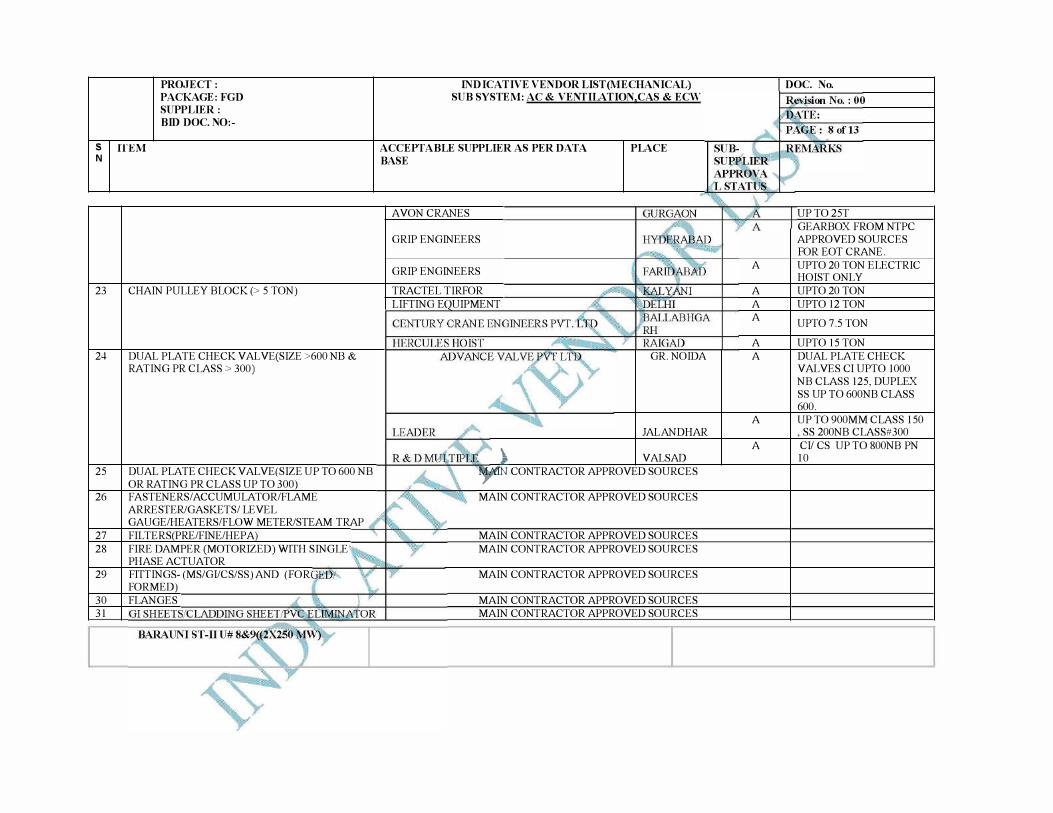
PROJECT :PACKAGE: FGD SUPPLIER : BID DOC. NO:-
S ffEM N
23
24
25
26
2728
29
3031
CHAIN PULLEY BLOCK (> 5 TON)
DUAL PLATE CHECK VAL VE(SIZE >600 NB &RATING PR CLASS > 300)
DUAL PLATE CHECK VAL VE(SIZE UP TO 600 NBOR RATING PR CLASS UP TO 300 FASTENERS/ ACCUMULATOR/FLAMEARRESTER/GASKETS/ LEVEL GAUGE/HEATERS/FLOW METER/STEAM TRAPFILTERS PRE/FINE/HEP AFIRE DAMPER (MOTORIZED) WITH SINGLEPHASE ACTUATORFITTINGS- (MS/GI/CS/SS) AND (FORFORMED)FLANGES
INDICATIVE VENDOR LIST(MECHANICAL) SUB SYSTEM: AC & VENTILATION,CAS & ECW
ACCEPTABLE SUPPLIER AS PER DATA BASE
PLACE
AVON CRANES
GRIP ENGINEERS
GRIP ENGINEERS
TRACTEL TIRFORLIFTING E UIPMENT
GR. NOIDA
JAL AND HAR
� VALSAD�'TN CONTRACTOR APPROVED SOURCES
MAIN CONTRACTOR APPROVED SOURCES
MAIN CONTRACTOR APPROVED SOURCESMAIN CONTRACTOR APPROVED SOURCES
MAIN CONTRACTOR APPROVED SOURCES
MAIN CONTRACTOR APPROVED SOURCESMAIN CONTRACTOR APPROVED SOURCES
A
AAA
AA
A
A
DOC. No.
UP T025TGEARBOX FROM NTPCAPPROVED SOURCESFOR EOT CRANE.UPTO 20 TON ELECTRICHOIST ONLYUPT020 TONUPTO 12 TON
UPT07.5TON
UPT015TONDUAL PLATE CHECK VALVES CI UPTO 1000 NB CLASS 125, DUPLEXSS UP TO 600NB CLASS600.UP T0900MM CLASS 150, SS 200NB CLASS#300CI/ CS UP TO 800NB PN 10
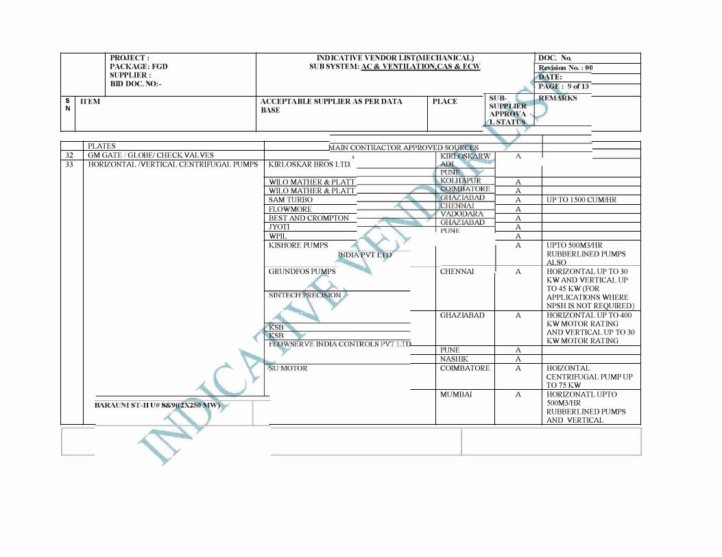
INDICATIVE VENDOR LIST(MECHANICAL) SUB SYSTEM: AC & VENTILATION,CAS & ECW
PROJECT : PACKAGE: FGD SUPPLIER : BID DOC. NO:-
S ffEM N
PLATES
32 GM GATE I GLOBE/ CHECK VALVES
ACCEPTABLE SUPPLIER AS PER DATA BASE
33 HORIZONTAL /VERTICAL CENTRIFUGAL PUMPS KIRLOSKAR BROS LTD.
WILO MATHER & PLATT
WILO MATHER & PLATT
SAM TURBO
FLO WM ORE
BEST AND CROMPTON
JYOTI
WPIL
KISHORE PUMPS
GRUNDFOS PUMPS
PLACE
CHENNAI
GHAZIABAD
PUNE
NASHIK
COIMBATORE
MUMBAI
A
A
A
A
A
A
A
A
A
A
A
A
A
A
DOC. No.
UP TO 1500 CUM/HR
UPTO 500M3/HR
RUBBERLINED PUMPS ALSO
HORIZONTAL UP TO 30 KW AND VERTICAL UP T045 KW(FOR
APPLICATIONS WHERE NPSH IS NOT REQUIRED)
HORIZONTAL UP TO 400 KW MOTOR RATING AND VERTICAL UP TO 30 KW MOTOR RATING
HOIZONTAL
CENTRIFUGAL PUMP UP T075 KW
HORIZONATL UPTO 500M3/HR
RUBBERLINED PUMPS AND VERTICAL
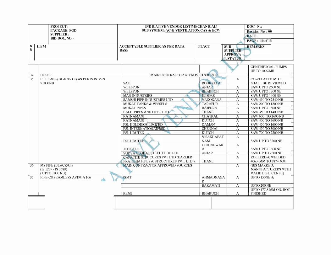
PROJECT : PACKAGE: FGD SUPPLIER : BID DOC. NO:-
S ffEM N
34 HOSES 35 PIPES-MS- (BLACK/ GI) AS PER IS IS:3589
>lOOONB
36 MS PIPE (BLACK/GI) (IS 1239 /IS 3589) ( UPTO lOOO NB)
37 PIPE-CS SEAMLESS ASTM A 106
INDICATIVE VENDOR LIST(MECHANICAL) SUB SYSTEM: AC & VENTILATION,CAS & ECW
ACCEPTABLE SUPPLIER AS PER DATA BASE
SAIL WE LS PUN WE LS PUN MAN INDUSTRIES SAMSHI PIPE INDUSTRIES LTD MUKAI TANKS & VESSELS MUKAT PIPES LALIT PIPES AND PIPES LTD RATNAMANI RATNAMANI PSL HOLDINGS LIMJ,TED PSL INTERNATIONfilt:t:f PSL LIMITED
TEEL TUBE LTD UCURES PVT LTD (EARLIER
A PIPES & STRUCTURES PVT. LTD. TRACTOR APPROVED SOURCES
REMI
PLACE
CHATRAL KUTCH DAMAN CHENNAI KUTCH VISAKHAPAT NAM CHHINDWAR A AN JAR
THANE
AHMADNAGA R BARAMATI
BHARUCH
DOC. No.
CENTRIFUGAL PUMPS UP TO lOOCMH
A CO-RELATED MIC SHALL BE REVIEWED.
A SAW UPTO 2600 NB A SAW UPTO 1300 NB A SAW UPTO 1400 NB A SAW 450 TO 2540 NB A SAW 200 TO 1200 NB A SAW UPTO 1800 NB A SAW 350 TO 1400NB A SAW 600 TO 2600 NB A SAW 400 TO 3600 NB A SAW 450 TO 1600NB A SAW 450 TO 3000 NB A SAW 700 TO 2200 NB A
SAW UP TO 3200 NB A
SAW UPTO 1600 NB A SAW UP TO 2300 NB A ROLLERD & WELDED
406.4 MM TO 3874 MM A (BIS MARKED,
MANUFACTURERS WITH VALID BIS LICENSE)
A UPTO 150NB &
A UPT0200NB UPTO 177 .8 MM OD, HOT
A FINISHED
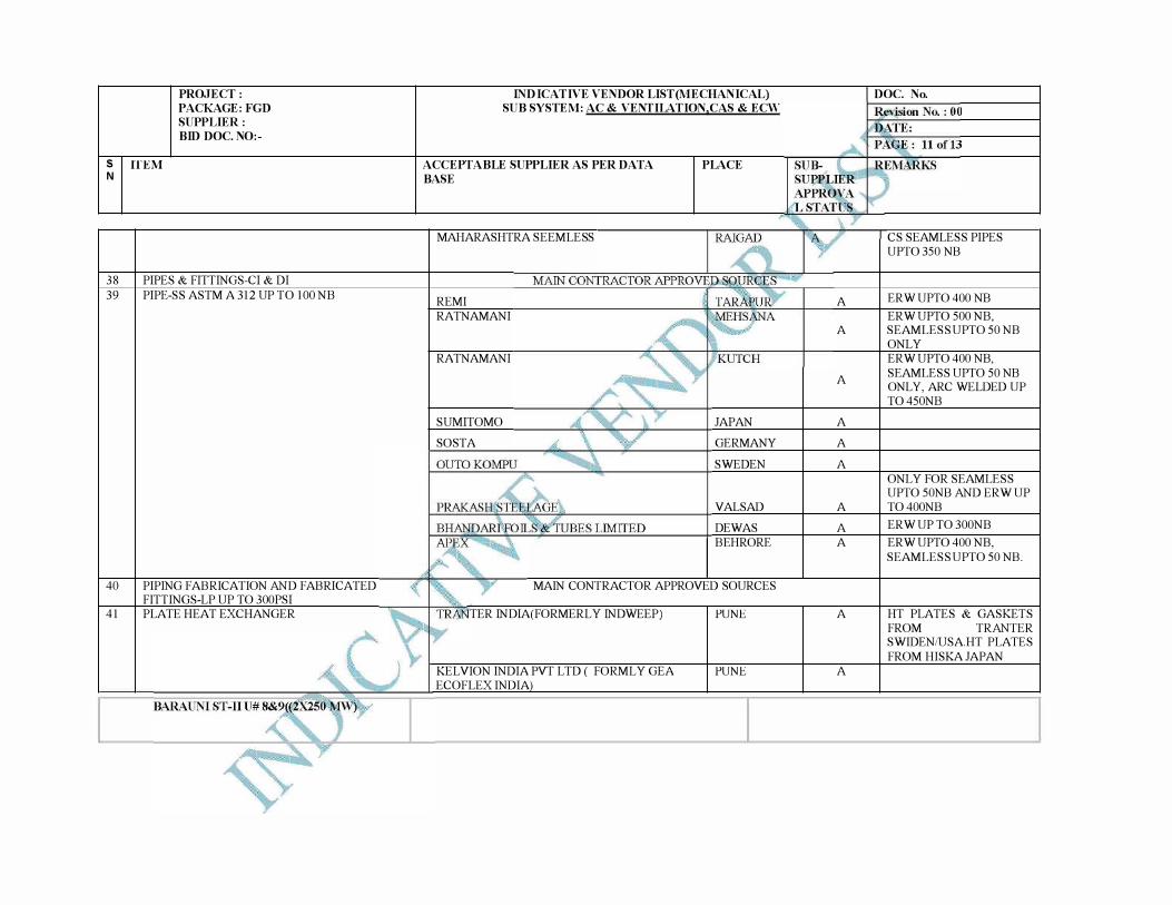
PROJECT : PACKAGE: FGD SUPPLIER : BID DOC. NO:-
S ffEM N
38 PIPES & FITTINGS-CI & DI
39
40
41
PIPE-SS ASTM A 312 UP TO 100 NB
PIPING FABRICATION AND FABRICATED
FITTINGS-LP UP TO 300PSI
PLATE HEAT EXCHANGER
INDICATIVE VENDOR LIST(MECHANICAL) SUB SYSTEM: AC & VENTILATION,CAS & ECW
ACCEPTABLE SUPPLIER AS PER DATA BASE
MAHARASHTRA SEEMLESS
REMI
RATNAMANI
RATNAMANI
SUMITOMO
SOSTA
PLACE
JAPAN
GERMANY
SWEDEN
VALSAD
DEWAS
BEHR ORE
MAIN CONTRACTOR APPROVED SOURCES
TER INDIA(FORMERL Y INDWEEP) PUNE
KELVION INDIA PVT LTD ( FORML Y GEA
ECOFLEX INDIA
PUNE
A
A
A
A
A
A
A
A
A
A
A
DOC. No.
CS SEAMLESS PIPES
UPT0350 NB
ERW UPTO 400 NB
ERW UPTO 500 NB,
SEAMLESS UPTO 50 NB
ONLY
ERW UPTO 400 NB,
SEAMLESS UPTO 50 NB
ONLY, ARC WELDED UP
T0450NB
ONLY FOR SEAMLESS
UPTO 50NB AND ERW UP
T0400NB
ERW UP T0300NB
ERW UPTO 400 NB,
SEAMLESS UPTO 50 NB.
HT PLATES & GASKETS
FROM TRANTER
SWIDEN/USA.HT PLATES
FROM HISKA JAPAN
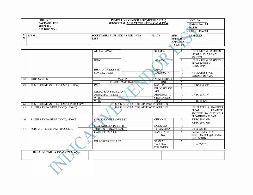
PROJECT :PACKAGE: FGD SUPPLIER : BID DOC. NO:-
S ffEM N
42 PRDS SYSTEM
43 PUMP -SUBMERSIBLE I SUMP (> 30KW)
44 PUMP -SUBMERSIBLE I SUMP -UP TO 30KW
45 RUBBER EXPANSION JOINT(<l600NB)
46 RUBBER EXPANSION JOINT(c>l600NB)
47 SCREW CHILLER(W ATER COOLED)
INDICATIVE VENDOR LIST(MECHANICAL) SUB SYSTEM: AC & VENTILATION,CAS & ECW
ACCEPTABLE SUPPLIER AS PER DATA BASE
ALPHA LAVAL
IDMC
HISAKA WORKS LTD
SONDEX INDIA
KSB
WPIL
WPIL
PLACE
PUNE
NASHIK
KIRLOSKARW
ADI
AHMED ABAD
GHAZIABAD
THANE
CONTRACTOR APPROVED SOURCES
CHENNAI
KOLKATA
TEXAS.USA
SANGHAI,CHI
NA
SASWAD,
TALUKA-
PURANDER,
A
A
A
A
A
A
A
A
A
A
A
A
A
A
A
DOC. No.
HT PLATES & GASKETS
FROM ALPHA LAV AL
SWIDEN
HT PLATES & GASKETS
FROM SONDEX DENMARK
HT PLATES FROM
SONDEX DENMARK
UP TO 130 KW
UP T0235 KW
UP T050 KW
HT PLATES & GASKETS
FROM TRANTER
SWIDEN/USA.HT PLATES
FROMHISKA JAPAN
UPT02800 MM
UPT02600 MM
U to 300 TR
Screw Chiller Up to 300TR.Centrifugal Chilleru to 500TR
Up to 350TR
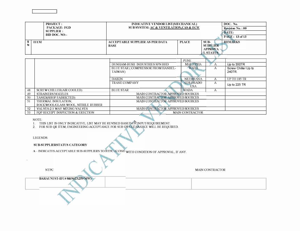
PROJECT : PACKAGE: FGD SUPPLIER : BID DOC. NO:-
INDICATIVE VENDOR LIST(MECHANICAL) SUB SYSTEM: AC & VENTILATION,CAS & ECW
S ffEM ACCEPTABLE SUPPLIER AS PER DATA BASE
PLACE N
48
49 50 51
52 53
SCREW CHILLER(AIR COOLED) STRAINERS/NOZZLES TANKS SHOP FABRICTED THERMAL INSULATION, ROCKWOOL/GLASS WOOL, NITRILE RUBBER VALVES-2!3 WAY MIXING VALVES F P RECEIPT INSPECTION & ERECTION
NOTE:
DUNHAM-BUSH INDUSTRIES SPN BHD BLUE ST AR ( COMPRESSOR FROM HANBELTAIWAN)
DAIKIN TRANE COMPANY
BLUE STAR
MAIN CONTRACTOR
1. THIS LIST IS ONLY INDICATNE, LIST MAY BE REVISED BASE "�INPUT/REQUIREMENT.2. FOR SUB QR ITEM; ENGINEERING ACCEPTANCE FOR SUB
LEGENDS:
SUB-SUPPLIERSTATUS CATEGORY
. CE WILL BE REQUIRED.
WITH CONDITION OF APPROVAL, IF ANY.
A
A
A
DOC. No.
U to 350TR Screw Chiller Up to 240TR.
UP TO 185 TR
Up to 225 TR
NTPC MAIN CONTRACTOR
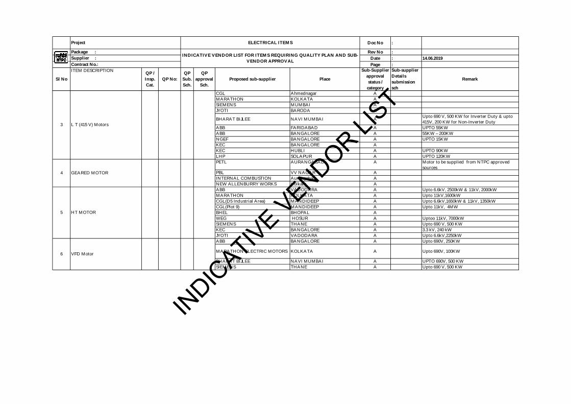
Doc No :
Rev No :Date : 14.06.2019Page :
Sub-supplier Details submission sch
RemarkSl No
ITEM DESCRIPTION QP / Insp. Cat.
QP No: QP
Sub. Sch.
QP approval
Sch.
Sub-Supplier approval status /
category
Project ELECTRICAL ITEMS
Package : INDICATIVE VENDOR LIST FOR ITEMS REQUIRING QUALITY PLAN AND SUB-
VENDOR APPROVALSupplier : Contract No.:
Proposed sub-supplier Place
CGL Ahmednagar AMARATHON KOLKATA ASIEMENS MUMBAI AJYOTI BARODA A
BHARAT BIJLEE NAVI MUMBAI A Upto 690 V, 500 KW for Inverter Duty & upto 415V, 200 KW for Non-Inverter Duty
ABB FARIDABAD A UPTO 55KWABB BANGALORE A 55KW – 200KWNGEF BANGALORE A UPTO 15KWKEC BANGALORE AKEC HUBLI A UPTO 90KWLHP SOLAPUR A UPTO 120KWPETL AURANGABAD A Motor to be supplied from NTPC approved
sourcesPBL VV NAGAR AINTERNAL COMBUSTION Aurangabad ANEW ALLENBURRY WORKS Kolkata AABB VADODARA A Upto 6.6kV, 2500kW & 11kV, 2000kWMARATHON KOLKATA A Upto 11kV,1600kWCGL(D5 Industrial Area) MANDIDEEP A Upto 6.6kV,1650kW & 11kV, 1350kWCGL(Plot 9) MANDIDEEP A Upto 11kV, 4MWBHEL BHOPAL AWEG HOSUR A Uptoo 11kV, 7000kWSIEMENS THANE A Upto 690 V, 500 KWKEC BANGALORE A 3.3 kV, 240 kW JYOTI VADODARA A Upto 6.6kV,2250kWABB BANGALORE A Upto 690V, 250KW
MARATHON ELECTRIC MOTORS KOLKATA A Upto 690V, 100KW
BHARAT BIJLEE NAVI MUMBAI A UPTO 690V, 500 KW SIEMENS THANE A Upto 690 V, 500 KW
6 VFD Motor
5 HT MOTOR
3 L T (415 V) Motors
GEARED MOTOR4
INDIC
ATIVE VENDOR LIST
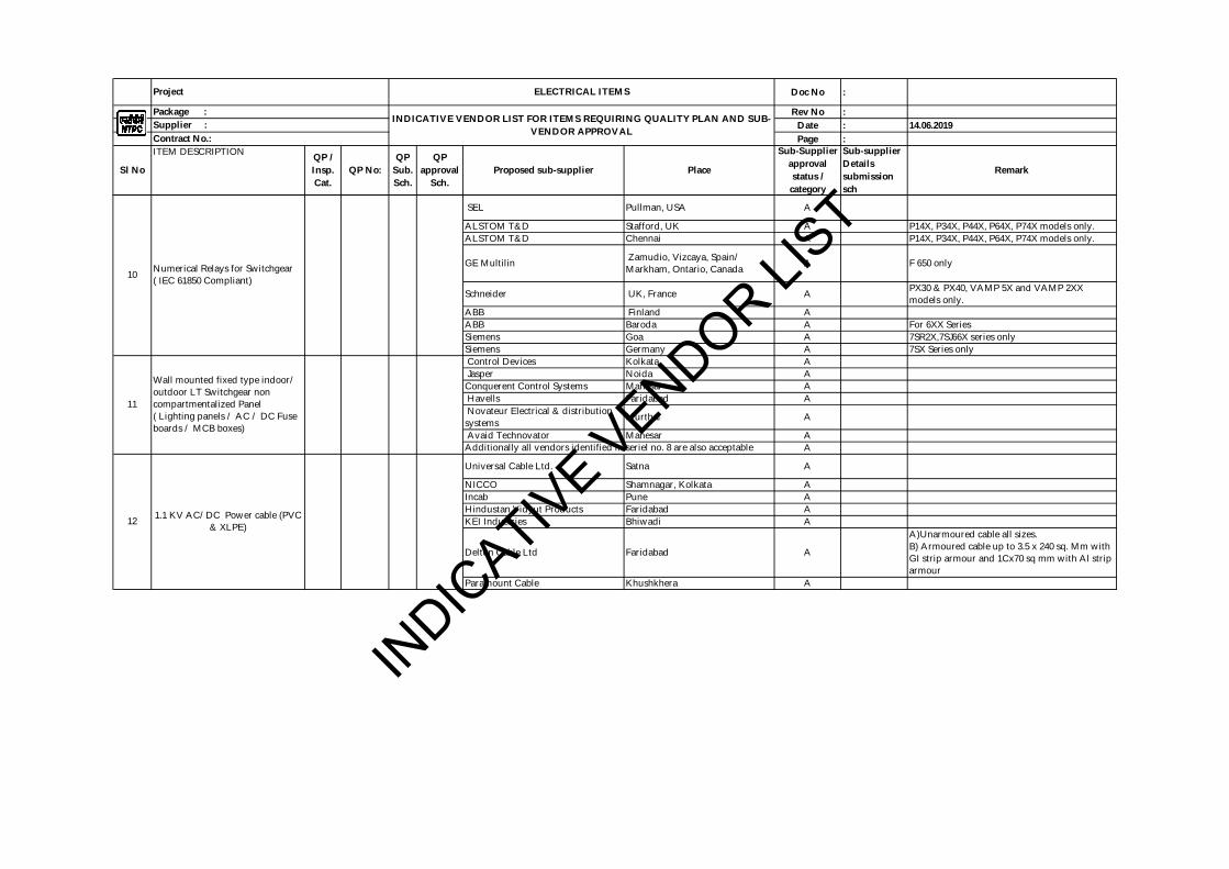
Doc No :
Rev No :Date : 14.06.2019Page :
Sub-supplier Details submission sch
RemarkSl No
ITEM DESCRIPTION QP / Insp. Cat.
QP No: QP
Sub. Sch.
QP approval
Sch.
Sub-Supplier approval status /
category
Project ELECTRICAL ITEMS
Package : INDICATIVE VENDOR LIST FOR ITEMS REQUIRING QUALITY PLAN AND SUB-
VENDOR APPROVALSupplier : Contract No.:
Proposed sub-supplier Place
SEL Pullman, USA A
ALSTOM T&D Stafford, UK A P14X, P34X, P44X, P64X, P74X models only.ALSTOM T&D Chennai A P14X, P34X, P44X, P64X, P74X models only.
GE Multilin Zamudio, Vizcaya, Spain/ Markham, Ontario, Canada A F 650 only
Schneider UK, France A PX30 & PX40, VAMP 5X and VAMP 2XX models only.
ABB Finland AABB Baroda A For 6XX SeriesSiemens Goa A 7SR2X,7SJ66X series onlySiemens Germany A 7SX Series only Control Devices Kolkata A Jasper Noida AConquerent Control Systems Manesar A Havells Faridabad A Novateur Electrical & distribution systems Murthal A
Avaid Technovator Manesar AA
Universal Cable Ltd. Satna A
NICCO Shamnagar, Kolkata AIncab Pune AHindustan Vidyut Products Faridabad AKEI Industries Bhiwadi A
Delton Cable Ltd Faridabad A
A)Unarmoured cable all sizes.B) Armoured cable up to 3.5 x 240 sq. Mm with GI strip armour and 1Cx70 sq mm with Al strip armour
Paramount Cable Khushkhera A
1.1 KV AC/DC Power cable (PVC & XLPE)
10
11
Wall mounted fixed type indoor/ outdoor LT Switchgear non compartmentalized Panel ( Lighting panels / AC / DC Fuse boards / MCB boxes)
12
Additionally all vendors identified in seriel no. 8 are also acceptable
Numerical Relays for Switchgear ( IEC 61850 Compliant)
INDIC
ATIVE VENDOR LIST
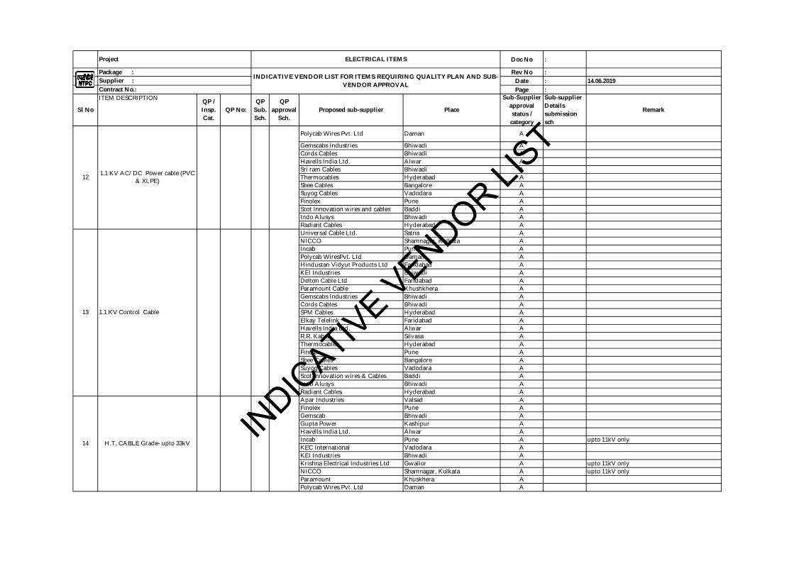
Doc No :
Rev No :Date : 14.06.2019Page :
Sub-supplier Details submission sch
RemarkSl No
ITEM DESCRIPTION QP / Insp. Cat.
QP No: QP
Sub. Sch.
QP approval
Sch.
Sub-Supplier approval status /
category
Project ELECTRICAL ITEMS
Package : INDICATIVE VENDOR LIST FOR ITEMS REQUIRING QUALITY PLAN AND SUB-
VENDOR APPROVALSupplier : Contract No.:
Proposed sub-supplier Place
Polycab Wires Pvt. Ltd Daman A
Gemscabs Industries Bhiwadi ACords Cables Bhiwadi AHavells India Ltd. Alwar ASri ram Cables Bhiwadi AThermocables Hyderabad ASbee Cables Bangalore ASuyog Cables Vadodara AFinolex Pune AScot Innovation wires and cables Baddi AIndo Alusys Bhiwadi ARadiant Cables Hyderabad AUniversal Cable Ltd. Satna ANICCO Shamnagar, Kolkata AIncab Pune APolycab WiresPvt. Ltd Daman AHindustan Vidyut Products Ltd Faridabad AKEI Industries Bhiwadi ADelton Cable Ltd Faridabad AParamount Cable Khushkhera AGemscabs Industries Bhiwadi ACords Cables Bhiwadi ASPM Cables Hyderabad AElkay Telelink Faridabad AHavells India Ltd. Alwar AR.R. Kabel Silvasa AThermocables Hyderabad AFinolex Pune ASbee Cables Bangalore ASuyog Cables Vadodara AScot Innovation wires & Cables Baddi AIndo Alusys Bhiwadi ARadiant Cables Hyderabad AApar Industries Valsad AFinolex Pune AGemscab Bhiwadi AGupta Power Kashipur AHavells India Ltd. Alwar AIncab Pune A upto 11kV onlyKEC International Vadodara AKEI Industries Bhiwadi AKrishna Electrical Industries Ltd Gwalior A upto 11kV onlyNICCO Shamnagar, Kolkata A upto 11kV onlyParamount Khuskhera APolycab Wires Pvt. Ltd Daman A
14
12 1.1 KV AC/DC Power cable (PVC & XLPE)
H.T. CABLE Grade- upto 33kV
13 1.1 KV Control Cable
INDIC
ATIVE VENDOR LIST
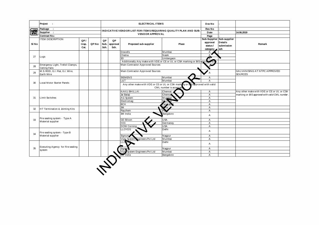
Doc No :
Rev No :Date : 14.06.2019Page :
Sub-supplier Details submission sch
RemarkSl No
ITEM DESCRIPTION QP / Insp. Cat.
QP No: QP
Sub. Sch.
QP approval
Sch.
Sub-Supplier approval status /
category
Project : ELECTRICAL ITEMS
Package : INDICATIVE VENDOR LIST FOR ITEMS REQUIRING QUALITY PLAN AND SUB-
VENDOR APPROVALSupplier : Contract No.:
Proposed sub-supplier Place
Dowells Mumbai AChetna Nasik A3D Umbergaon A
28 Emergency Light, Trefoil Clamps, Ceiling Fans A
29 M.S. ROD, G.I. Flat, G.I. Wire,Earth Wire A GALVANISING AT NTPC APPROVED
SOURCESSIEMENS Mumbai AL&T Mumbai A
KAKU BHILLAI Chennai AJai Balaji Chennai AAG System Mumbai AElectromag Mumbai ABCH Faridabad A3M Pune ARaychem Pune A3M India Bangalore A
GE Silicon USA AHilti Germaney ADOW Corning USA ALLOYDS Delhi A
Signum Nagpur AVijay System Engineers Pvt Ltd Mumbai ALLOYDS Delhi A
Signum Nagpur AVijay System Engineers Pvt Ltd Mumbai A3M India Bangalore A
35 Executing Agency for Fire sealing system
32 HT Termination & Jointing Kits
27 Lugs
Main Contractor Approved Sources
Main Contractor Approved Sources
34 Fire sealing system - Type B Material supplier
33 Fire sealing system - Type A Material supplier
31 Limit Switches
Any other make with VDE or CE or UL or CSA marking or BIS approved with valid CML number .
30 Local Motor Starter Panels Any other make with VDE or CE or UL or CSA marking or BIS approved with valid CML number is acceptable
Additionally Any make with VDE or CE or UL or CSA marking or BIS approved with
INDIC
ATIVE VENDOR LIST
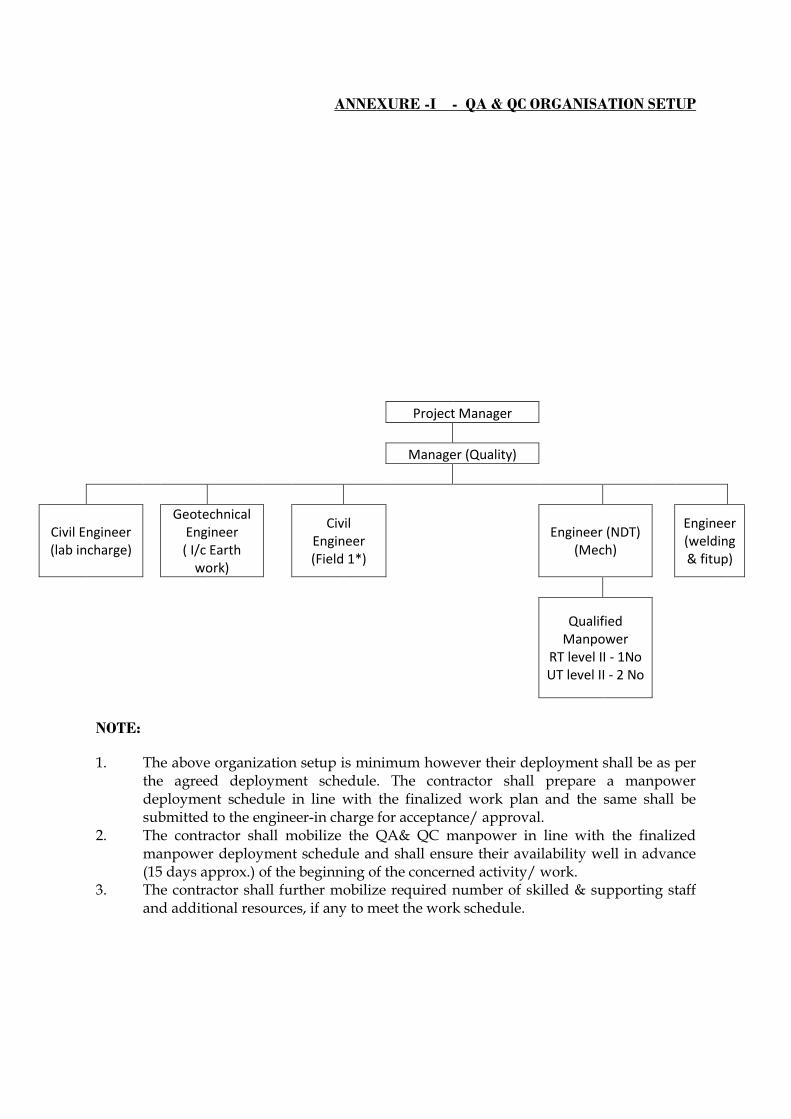
ANNEXURE -I - QA & QC ORGANISATION SETUP
Project Manager
Manager (Quality)
Civil Engineer (lab incharge)
Geotechnical Engineer ( I/c Earth
work)
Civil Engineer (Field 1*)
Engineer (NDT) (Mech)
Engineer (welding & fitup)
Qualified Manpower
RT level II - 1No UT level II - 2 No
NOTE:
1. The above organization setup is minimum however their deployment shall be as per the agreed deployment schedule. The contractor shall prepare a manpower deployment schedule in line with the finalized work plan and the same shall be submitted to the engineer-in charge for acceptance/ approval.
2. The contractor shall mobilize the QA& QC manpower in line with the finalized manpower deployment schedule and shall ensure their availability well in advance (15 days approx.) of the beginning of the concerned activity/ work.
3. The contractor shall further mobilize required number of skilled & supporting staff and additional resources, if any to meet the work schedule.

ANNEXURE II - DELETD

ANNEXURE – III - DELETED
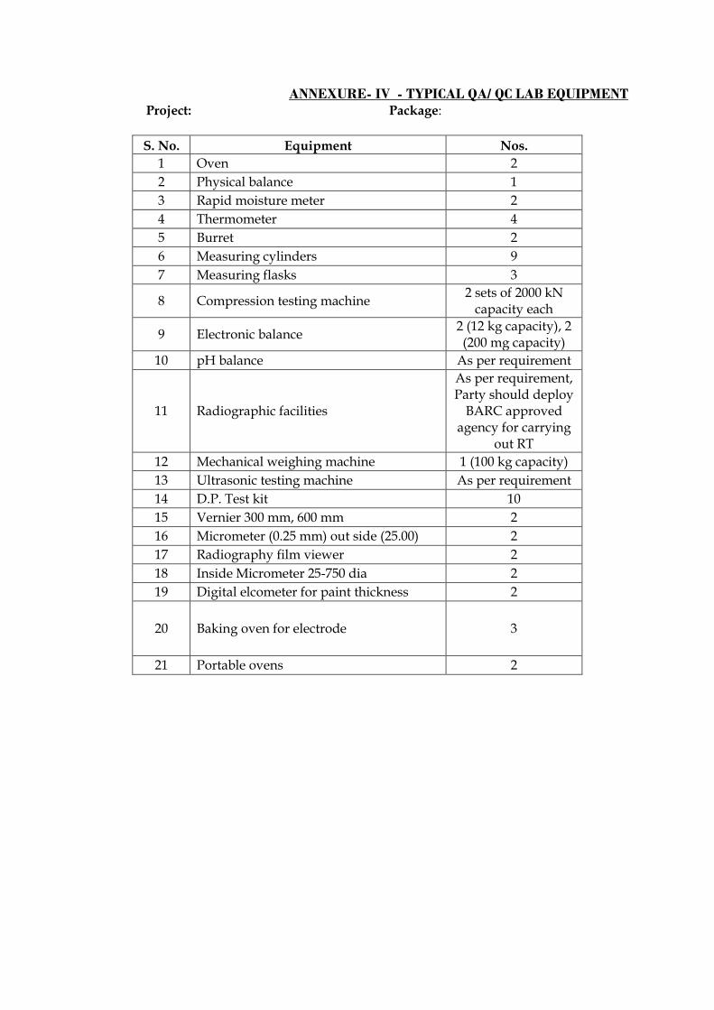
ANNEXURE- IV - TYPICAL QA/ QC LAB EQUIPMENT Project: Package:
S. No. Equipment Nos.
1 Oven 2
2 Physical balance 1
3 Rapid moisture meter 2
4 Thermometer 4
5 Burret 2
6 Measuring cylinders 9
7 Measuring flasks 3
8 Compression testing machine 2 sets of 2000 kN
capacity each
9 Electronic balance 2 (12 kg capacity), 2 (200 mg capacity)
10 pH balance As per requirement
11 Radiographic facilities
As per requirement, Party should deploy
BARC approved agency for carrying
out RT
12 Mechanical weighing machine 1 (100 kg capacity)
13 Ultrasonic testing machine As per requirement
14 D.P. Test kit 10
15 Vernier 300 mm, 600 mm 2
16 Micrometer (0.25 mm) out side (25.00) 2
17 Radiography film viewer 2
18 Inside Micrometer 25-750 dia 2
19 Digital elcometer for paint thickness 2
20 Baking oven for electrode 3
21 Portable ovens 2
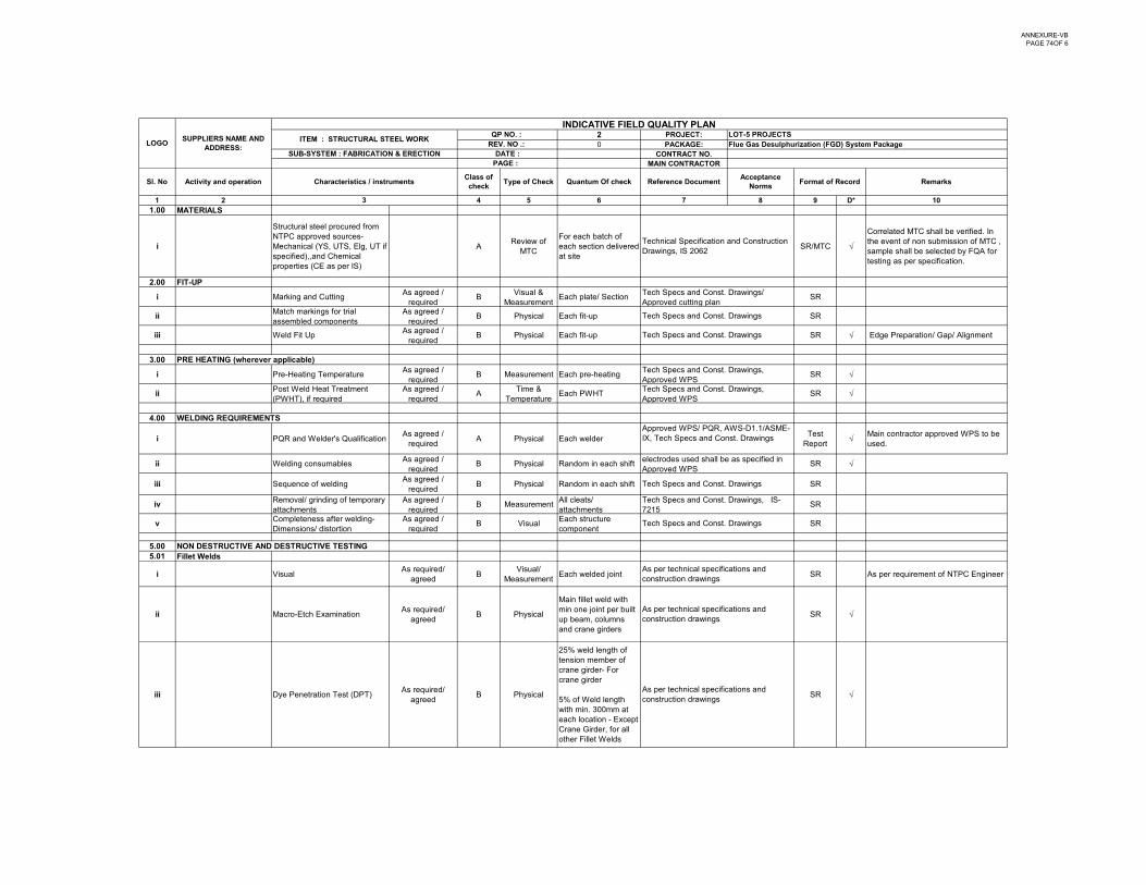
ANNEXURE-VBPAGE 74OF 6
2 PROJECT:0 PACKAGE:
CONTRACT NO.MAIN CONTRACTOR
1 2 4 5 6 7 8 9 D* 101.00 MATERIALS
i
Structural steel procured from NTPC approved sources- Mechanical (YS, UTS, Elg, UT if specified),,and Chemical properties (CE as per IS)
AReview of
MTC
For each batch of each section delivered at site
SR/MTC
Correlated MTC shall be verified. In the event of non submission of MTC , sample shall be selected by FQA for testing as per specification.
2.00 FIT-UP
i Marking and CuttingAs agreed /
requiredB
Visual & Measurement
Each plate/ Section SR
iiMatch markings for trial assembled components
As agreed / required
B Physical Each fit-up SR
iii Weld Fit UpAs agreed /
requiredB Physical Each fit-up SR Edge Preparation/ Gap/ Alignment
3.00 PRE HEATING (wherever applicable)
i Pre-Heating TemperatureAs agreed /
requiredB Measurement Each pre-heating SR
iiPost Weld Heat Treatment (PWHT), if required
As agreed / required
ATime &
TemperatureEach PWHT SR
INDICATIVE FIELD QUALITY PLAN
Tech Specs and Const. Drawings
Tech Specs and Const. Drawings
Tech Specs and Const. Drawings/ Approved cutting plan
Type of Check Quantum Of check Reference DocumentAcceptance
NormsFormat of Record Remarks
QP NO. : LOT-5 PROJECTSREV. NO .: Flue Gas Desulphurization (FGD) System Package
SUB-SYSTEM : FABRICATION & ERECTION
3
Technical Specification and Construction Drawings, IS 2062
Tech Specs and Const. Drawings, Approved WPSTech Specs and Const. Drawings, Approved WPS
Sl. No Characteristics / instrumentsClass of check
LOGOSUPPLIERS NAME AND
ADDRESS: ITEM : STRUCTURAL STEEL WORK
DATE :PAGE :
Activity and operation
4.00 WELDING REQUIREMENTS
i PQR and Welder's QualificationAs agreed /
requiredA Physical Each welder
Test Report
Main contractor approved WPS to be used.
ii Welding consumables As agreed /
requiredB Physical Random in each shift SR
iii Sequence of weldingAs agreed /
requiredB Physical Random in each shift SR
ivRemoval/ grinding of temporary attachments
As agreed / required
B MeasurementAll cleats/ attachments
SR
vCompleteness after welding- Dimensions/ distortion
As agreed / required
B VisualEach structure component
SR
5.00 NON DESTRUCTIVE AND DESTRUCTIVE TESTING 5.01 Fillet Welds
i VisualAs required/
agreedB
Visual/ Measurement
Each welded joint SR As per requirement of NTPC Engineer
ii Macro-Etch ExaminationAs required/
agreedB Physical
Main fillet weld with min one joint per built up beam, columns and crane girders
SR
iii Dye Penetration Test (DPT)As required/
agreedB Physical
25% weld length of tension member of crane girder- For crane girder
5% of Weld length with min. 300mm at each location - Except Crane Girder, for all other Fillet Welds
SR
electrodes used shall be as specified in Approved WPS
Tech Specs and Const. Drawings, IS-7215
Approved WPS/ PQR, AWS-D1.1/ASME-IX, Tech Specs and Const. Drawings
As per technical specifications and construction drawings
As per technical specifications and construction drawings
As per technical specifications and construction drawings
Tech Specs and Const. Drawings
Tech Specs and Const. Drawings
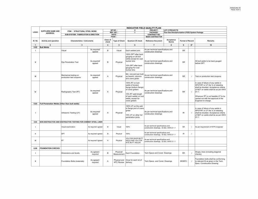
ANNEXURE-VBPAGE 75OF 6
2 PROJECT:0 PACKAGE:
CONTRACT NO.MAIN CONTRACTOR
1 2 4 5 6 7 8 9 D* 10
INDICATIVE FIELD QUALITY PLAN
Type of Check Quantum Of check Reference DocumentAcceptance
NormsFormat of Record Remarks
QP NO. : LOT-5 PROJECTSREV. NO .: Flue Gas Desulphurization (FGD) System Package
SUB-SYSTEM : FABRICATION & ERECTION
3
Sl. No Characteristics / instrumentsClass of check
LOGOSUPPLIERS NAME AND
ADDRESS: ITEM : STRUCTURAL STEEL WORK
DATE :PAGE :
Activity and operation
5.02 Butt Welds
i VisualAs required/
agreedB Visual Each welded joint SR
ii Dye Penetration TestAs required/
agreedB Physical
100% DPT after back gouging on all butt welds except for coal bunker bins
10% DPT after back gouging-For coal bunker bins
SRAll butt welds to be back gouged before DPT
iiiMechanical testing on production test coupons
As required/ agreed
A PhysicalMin. one joint per built up beams, columns and crane girder.
SR Test on production test coupons
iv Radiography Test (RT)As required/
agreedA Physical
100% RT on butt welds of tension flange (bottom flange) of crane girders
SR
In case of failure of any welds in SPOT/RT or UT the % of retesting shall be doubled. Acceptance criteria of NDT on welds shall be as per AWS D1.1.
As per technical specifications and construction drawings
As per technical specifications and construction drawings
As per technical specifications and construction drawings
As per technical specifications and construction drawings
agreed10% RT weld length of each welder on butt welds, except for crane girders
Wherever RT is not feasible UT to be carried out with the approval of the Engineer-in-charge.
5.03 Full Penetration Welds (Other than butt welds)
i Ultrasonic Testing (UT)As required/
agreedA Physical
100% UT on the web to flange joint of crane girder
10% UT on other full penetration joints
IR
In case of failure of any welds in SPOT/RT or UT the % of retesting shall be doubled. Acceptance criteria of NDT on welds shall be as per AWS D1.1.
5.04 NON DESTRUCTIVE AND DESTRUCTIVE TESTING FOR CHIMNEY STEEL LINER
i Visual examination As required/ agreed B Visual 100% SR As per requirement of NTPC Engineer
ii DPT As required/ agreed B Physical 100% IR
iii RT As required/ agreed A Physical10% FOR SHOP BUTT WELD AND 15% FOR SITE BUTT WELDS
6.00 FOUNDATION CHECKS
i Dimensions and levels As agreed /
requiredB
Physical/ Measurement
Each Foundation SR Shape, lines (including diagonal checks)
ii Foundation Bolts (materials)As agreed /
requiredA
Physical and MTC Review
Once for each lot of delivery
SR/MTC Foundation bolts shall be conforming to relevant IS as given in the Tech. Spec./ Construction Drawing
Tech Specs and Const. Drawings
construction drawings
Tech Specs and Const. Drawings
As per technical specifications and construction drawings
As per technical specifications and construction drawings, IS 822, AWS D 1.1
As per technical specifications and construction drawings, IS 822, AWS D 1.1
As per technical specifications and construction drawings, IS 822, AWS D 1.1
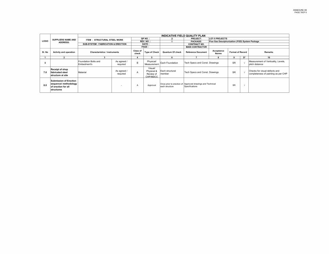
ANNEXURE-VBPAGE 76OF 6
2 PROJECT:0 PACKAGE:
CONTRACT NO.MAIN CONTRACTOR
1 2 4 5 6 7 8 9 D* 10
INDICATIVE FIELD QUALITY PLAN
Type of Check Quantum Of check Reference DocumentAcceptance
NormsFormat of Record Remarks
QP NO. : LOT-5 PROJECTSREV. NO .: Flue Gas Desulphurization (FGD) System Package
SUB-SYSTEM : FABRICATION & ERECTION
3
Sl. No Characteristics / instrumentsClass of check
LOGOSUPPLIERS NAME AND
ADDRESS: ITEM : STRUCTURAL STEEL WORK
DATE :PAGE :
Activity and operation
iiFoundation Bolts and Embedment's
As agreed / required
BPhysical/
MeasurementEach Foundation SR
Measurement of Verticality, Levels, pitch distance
7.0Receipt of shop fabricated steel structure at site
MaterialAs agreed /
requiredA
Visual/ Physical & Review of
CHP/MDCC
Each structural member
SR Checks for visual defects and completeness of painting as per CHP
8.0
Submission of Erection sequence/ methodology of erection for all structures
- A ApprovalOnce prior to erection of each structure
SR √Approved drawings and Technical Specifications
Tech Specs and Const. Drawings
Tech Specs and Const. Drawings
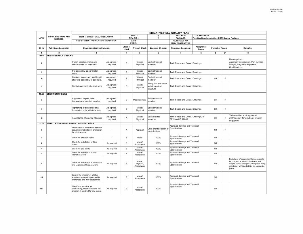
ANNEXURE-VBPAGE 77OF 6
2 PROJECT:0 PACKAGE:
CONTRACT NO.MAIN CONTRACTOR
1 2 4 5 6 7 8 9 D* 10
INDICATIVE FIELD QUALITY PLAN
Type of Check Quantum Of check Reference DocumentAcceptance
NormsFormat of Record Remarks
QP NO. : LOT-5 PROJECTSREV. NO .: Flue Gas Desulphurization (FGD) System Package
SUB-SYSTEM : FABRICATION & ERECTION
3
Sl. No Characteristics / instrumentsClass of check
LOGOSUPPLIERS NAME AND
ADDRESS: ITEM : STRUCTURAL STEEL WORK
DATE :PAGE :
Activity and operation
9.00 PRE-ASSEMBLY CHECKS
iPunch Erection marks and match marks on members
As agreed / required
BVisual/
PhysicalEach structural member
Markings for -Assembly designation, Part number, Weight, Any other important identifications.
iiPre-assembly as per match mark
As agreed / required
BVisual/
PhysicalEach structural member
iiiCamber, sweep and total length after trial assembly of structure.
As agreed / required
BVisual/
PhysicalEach structural member
SR
iv Control assembly check at shopAs agreed /
requiredB
Visual/ Physical
Every first and tenth set of identical structure
10.00
iAlignment, slopes, level, tolerances of erected member
As agreed / required
B MeasurementEach structural member
SR
iiTightening of bolts including As agreed /
BVisual/ Each structural
SR
ERECTION CHECKS
Tech Specs and Const. Drawings
Tech Specs and Const. Drawings
Tech Specs and Const. Drawings
Tech Specs and Const. Drawings
Tech Specs and Const. Drawings
Tech Specs and Const Drawingsiifoundation bolts with lock nuts required
BPhysical member
SR
iii Acceptance of erected structureAs agreed /
requiredA
Visual/ Physical
Each erected structure
SR To be verified w.r.t. approved methodology for erection / erection sequence
11.00 INSTALLATION AND ALIGNMENT OF STEEL LINER
iSubmission of Installation/ Erection sequence/ methodology of erection for all structures
- A ApprovalOnce prior to erection of each structure
SR √
ii Check for Erection Marks - B Visual 100% SR
iiiCheck for Installation of Steel Liners
As required BVisual/
Acceptance100% SR
iv Check for Site Joints As required BVisual/
Acceptance100% SR
vCheck for Installation of Inlet Transition Ducts
As required BVisual/
Acceptance100% SR
viCheck for Installation of Insulations and Expansion Compensators
As required BVisual,
Physical, Acceptance
100% SR
Each layer of expansion Compensator to be checked at shop for thickness, unit weight, tensile strength & elongation along with temp. withstand ability for composite joints
viiEnsure the Erection of all steel structures along with permissible tolerances and their acceptance
As required BVisual/
Acceptance100% SR
viiiCheck and approval for Dismantling, Modification and Re-erection, if required for any reason
As required BVisual/
Acceptance100% SR
Tech Specs and Const. Drawings
Tech Specs and Const. Drawings, IS 7215 and IS 12843
Approved drawings and Technical Specifications
Approved drawings and Technical Specifications
Approved drawings and Technical Specifications
Approved drawings and Technical Specifications
Approved drawings and Technical Specifications Approved drawings and Technical Specifications
Approved drawings and Technical Specifications Approved drawings and Technical Specifications
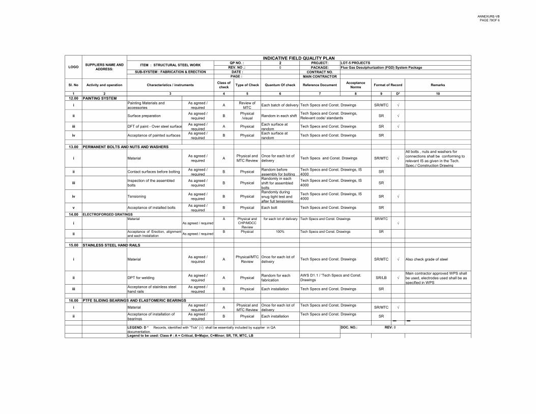
ANNEXURE-VBPAGE 78OF 6
2 PROJECT:0 PACKAGE:
CONTRACT NO.MAIN CONTRACTOR
1 2 4 5 6 7 8 9 D* 10
INDICATIVE FIELD QUALITY PLAN
Type of Check Quantum Of check Reference DocumentAcceptance
NormsFormat of Record Remarks
QP NO. : LOT-5 PROJECTSREV. NO .: Flue Gas Desulphurization (FGD) System Package
SUB-SYSTEM : FABRICATION & ERECTION
3
Sl. No Characteristics / instrumentsClass of check
LOGOSUPPLIERS NAME AND
ADDRESS: ITEM : STRUCTURAL STEEL WORK
DATE :PAGE :
Activity and operation
12.00 PAINTING SYSTEM
iPainting Materials and accessories
As agreed / required
AReview of
MTCEach batch of delivery SR/MTC
ii Surface preparation As agreed /
requiredB
Physical /visual
Random in each shift SR
iii DFT of paint - Over steel surfaceAs agreed /
requiredA Physical
Each surface at random
SR
iv Acceptance of painted surfacesAs agreed /
requiredB Physical
Each surface at random
SR
13.00 PERMANENT BOLTS AND NUTS AND WASHERS
i MaterialAs agreed /
requiredA
Physical and MTC Review
Once for each lot of delivery
SR/MTC
All bolts , nuts and washers for connections shall be conforming to relevant IS as given in the Tech. Spec./ Construction Drawing
ii Contact surfaces before boltingAs agreed /
requiredB Physical
Random before assembly for bolting
SR
iiiInspection of the assembled bolts
As agreed / required
B PhysicalRandomly in each shift for assembled bolts
SR
As agreed /Randomly during
Tech Specs and Const. Drawings, IS 4000
Tech Specs and Const. Drawings, Relevant code/ standards
Tech Specs and Const Drawings IS
Tech Specs and Const. Drawings
Tech Specs and Const. Drawings, IS 4000
Tech Specs and Const. Drawings
Tech Specs and Const. Drawings
Tech Specs and Const. Drawings
iv Tensioning As agreed /
requiredB Physical
y gsnug tight test and after full tensioning
SR
v Acceptance of installed boltsAs agreed /
requiredB Physical Each bolt SR
14.00 ELECTROFORGED GRATINGS
iMaterial
As agreed / requiredA Physical and
CHP/MDCC Review
for each lot of delivery SR/MTC
iiAcceptance of Erection, alignmentand each Installation
As agreed / requiredB Physical 100% SR
15.00
i MaterialAs agreed /
requiredA
Physical/MTC Review
Once for each lot of delivery
SR/MTC Also check grade of steel
ii DPT for weldingAs agreed /
requiredA Physical
Random for each fabrication
SR/LB Main contractor approved WPS shall be used, electrodes used shall be as specified in WPS
iiiAcceptance of stainless steel hand rails
As agreed / required
B Physical Each installation SR
16.00 PTFE SLIDING BEARINGS AND ELASTOMERIC BEARINGS
i MaterialAs agreed /
requiredA
Physical and MTC Review
Once for each lot of delivery
SR/MTC
iiAcceptance of installation of bearings
As agreed / required
B Physical Each installation SR
Tech Specs and Const. Drawings
Tech Specs and Const. Drawings
Tech Specs and Const. Drawings
Tech Specs and Const. Drawings, IS 4000
Tech Specs and Const. Drawings
Tech Specs and Const. Drawings
Tech Specs and Const. Drawings
Tech Specs and Const. Drawings
AWS D1.1 / 'Tech Specs and Const. Drawings
STAINLESS STEEL HAND RAILS
Legend to be used: Class # : A = Critical, B=Major, C=Minor; SR, TR, MTC, LB
LEGEND: D * Records, identified with “Tick” () shall be essentially included by supplier in QA documentation.
DOC. NO.: REV: 0
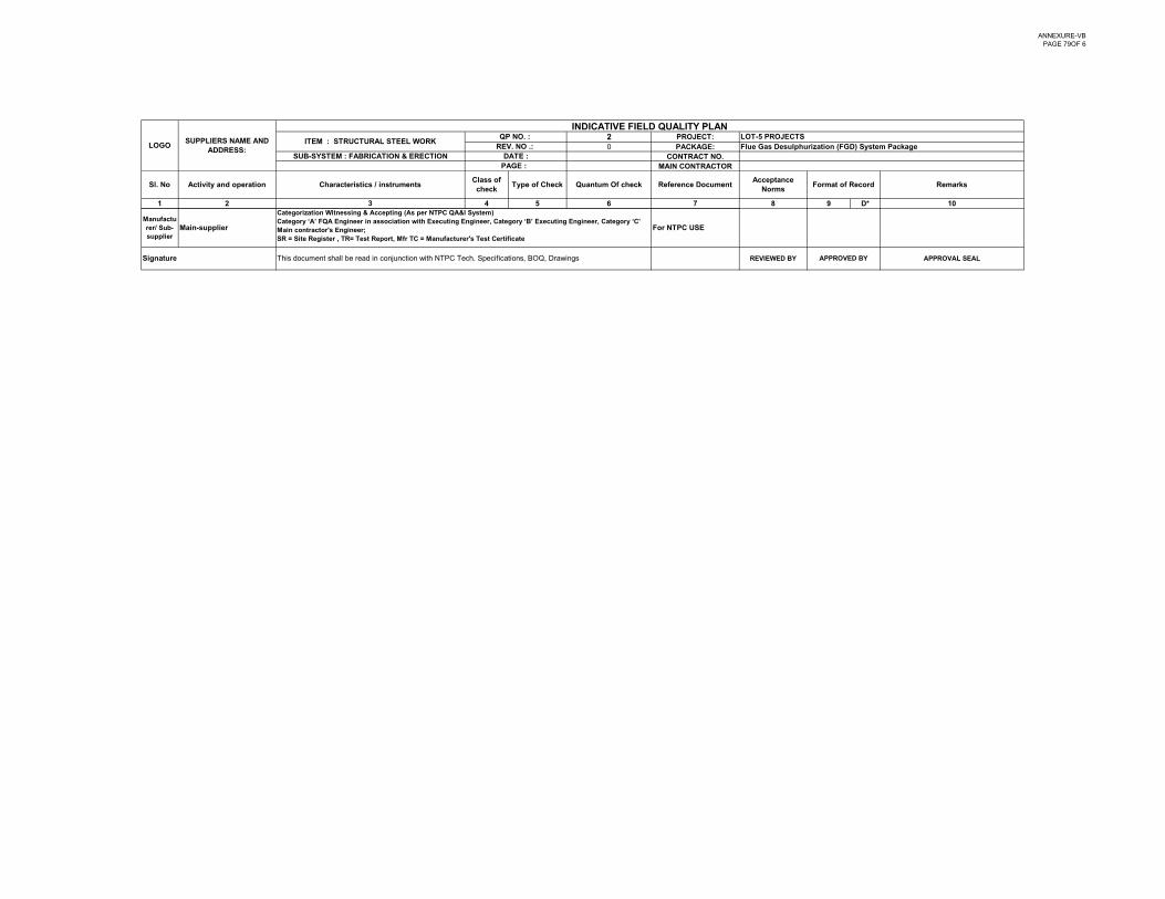
ANNEXURE-VBPAGE 79OF 6
2 PROJECT:0 PACKAGE:
CONTRACT NO.MAIN CONTRACTOR
1 2 4 5 6 7 8 9 D* 10
INDICATIVE FIELD QUALITY PLAN
Type of Check Quantum Of check Reference DocumentAcceptance
NormsFormat of Record Remarks
QP NO. : LOT-5 PROJECTSREV. NO .: Flue Gas Desulphurization (FGD) System Package
SUB-SYSTEM : FABRICATION & ERECTION
3
Sl. No Characteristics / instrumentsClass of check
LOGOSUPPLIERS NAME AND
ADDRESS: ITEM : STRUCTURAL STEEL WORK
DATE :PAGE :
Activity and operation
Manufacturer/ Sub-supplier
Main-supplier For NTPC USE
REVIEWED BY APPROVAL SEALSignature This document shall be read in conjunction with NTPC Tech. Specifications, BOQ, Drawings APPROVED BY
Categorization Witnessing & Accepting (As per NTPC QA&I System)Category ‘A’ FQA Engineer in association with Executing Engineer, Category ‘B’ Executing Engineer, Category ‘C’ Main contractor's Engineer;SR = Site Register , TR= Test Report, Mfr TC = Manufacturer's Test Certificate
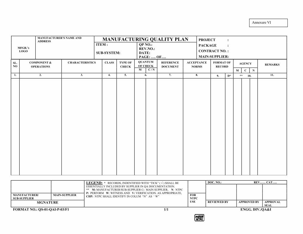
MFGR.’s LOGO
MANUFACTURER’S NAME AND ADDRESS MANUFACTURING QUALITY PLAN PROJECT :
PACKAGE :
CONTRACT NO. :
MAIN-SUPPLIER:
ITEM : SUB-SYSTEM:
QP NO.: REV.NO.: DATE: PAGE: …. OF….
LEGEND: * RECORDS, INDENTIFIED WITH “TICK” ( ) SHALL BE ESSENTIALLY INCLUDED BY SUPPLIER IN QA DOCUMENTATION. ** M: MANUFACTURER/SUB-SUPPLIER C: MAIN SUPPLIER, N: NTPC P: PERFORM W: WITNESS AND V: VERIFICATION. AS APPROPRIATE, CHP: NTPC SHALL IDENTIFY IN COLUM “N” AS ‘ W”
DOC. NO.: REV…… CAT…..
MANUFACTURER/ SUB-SUPPLIER
MAIN-SUPPLIER FOR NTPC USE SIGNATURE REVIEWED BY APPROVED BY APPROVAL
SEAL
FORMAT NO.: QS-01-QAI-P-03/F1 1/1 ENGG. DIV./QA&I
SL. NO
COMPONENT &
OPERATIONS
CHARACTERISTICS
CLASS
TYPE OF
CHECK
QUANTUM
OF CHECK REFERENCE
DOCUMENT
ACCEPTANCE
NORMS
FORMAT OF
RECORD
AGENCY REMARKS
M C / N M C N
1. 2. 3. 4. 5. 6. 7. 8. 9. D* ** 10. 11.
Annexure VI
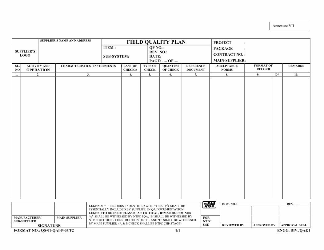
SUPPLIER’S LOGO
SUPPLIER’S NAME AND ADDRESS FIELD QUALITY PLAN PROJECT :
PACKAGE :
CONTRACT NO. :
MAIN-SUPPLIER:
ITEM : SUB-SYSTEM:
QP NO.: REV. NO.: DATE: PAGE: …. OF….
LEGEND: * RECORDS, INDENTIFIED WITH “TICK” () SHALL BE ESSENTIALLY INCLUDED BY SUPPLIER IN QA DOCUMENTATION. LEGEND TO BE USED: CLASS # : A = CRITICAL, B=MAJOR, C=MINOR; ‘A’ SHALL BE WITNESSED BY NTPC FQA, ‘B’ SHALL BE WITNESSED BY NTPC ERECTION / CONSTRUCTION DEPTT. AND ‘C’ SHALL BE WITNESSED BY MAIN SUPPLIER (A & B CHECK SHALL BE NTPC CHP STAGE)
DOC. NO.: REV……
MANUFACTURER/ SUB-SUPPLIER
MAIN-SUPPLIER FOR NTPC USE SIGNATURE REVIEWED BY APPROVED BY APPROVAL SEAL
FORMAT NO.: QS-01-QAI-P-03/F2 1/1 ENGG. DIV./QA&I
SL. NO
ACTIVITY AND OPERATION
CHARACTERISTICS / INSTRUMENTS
CLASS OF CHECK #
TYPE OF CHECK
QUANTUM OF CHECK
REFERENCE DOCUMENT
ACCEPTANCE NORMS
FORMAT OF RECORD
REMARKS
1. 2. 3. 4. 5. 6. 7. 8. 9. D* 10.
Annexure VII