standard technical specification for retrofit of sea water
TRANSCRIPT

STANDARD TECHNICAL SPECIFICATION FOR RETROFIT OF SEA WATER BASED FLUE GAS DESULPHURISATION (FGD) SYSTEM IN A TYPICAL 2 x 500 MW COAL BASED
COASTAL THERMAL POWER PLANT
CENTRAL ELECTRICITY AUTHORITY
NEW DELHI
December, 2019

STANDARD TECHNICAL SPECIFICATION FOR
RETROFIT OF SEA WATER BASED
FLUE GAS DESULPHURISATION (FGD) SYSTEM
IN A TYPICAL 2 x 500 MW COAL BASED
COASTAL THERMAL POWER PLANT
CENTRAL ELECTRICITY AUTHORITY
December, 2019
Standard Technical Specification for Retrofit of Sea Water Based Flue Gas Desulphurisation (FGD) System in a Typical 2x500 MW Coal Based Coastal Thermal Power Plant
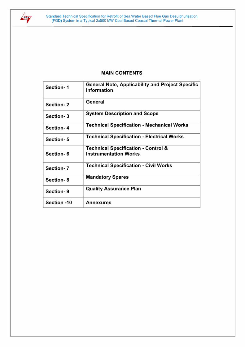
MAIN CONTENTS
Section- 1
General Note, Applicability and Project Specific Information
Section- 2 General
Section- 3 System Description and Scope
Section- 4 Technical Specification - Mechanical Works
Section- 5 Technical Specification - Electrical Works
Section- 6 Technical Specification - Control & Instrumentation Works
Section- 7 Technical Specification - Civil Works
Section- 8 Mandatory Spares
Section- 9 Quality Assurance Plan
Section -10 Annexures

Standard Technical Specification for Retrofit of Sea Water Based Flue Gas Desulphurisation (FGD) System in a Typical 2x500 MW Coal Based Coastal Thermal Power Plant
i
DETAILED CONTENTS
Clause No. Description Page No.
Section -1 : General Note, Applicability and Project Specific Information
1.1 General Note
1
1.2 Applicability
8
1.3 Brief Details about Power Plant
8
1.4 Meteorological Data
9
1.5 Salient Technical Data of Existing Power Plant 9
Section -2 : General
2.1 Intent of Specification
12
2.2 Typical Brief Description of the Existing Flue Gas Path 14
2.3 Typical Brief Description of the Existing CW System 14
2.4 Typical Brief Description of Existing Chimney 14
2.5 Design and Guarantee Conditions
15
2.6 General Design Requirements 16
2.7 Operational Performance Requirements
19
2.8 Layout Requirements 21
2.9 General Technical Requirements 23
2.10 Spare Parts 32
2.11 Quality Assurance Programme
36
2.12 Testing and Inspection 39
2.12.1 General 39
2.12.2 Material tests 41
2.12.3 Shop tests
41
2.12.4 Site tests
42
2.13 Trial Operation
43
2.14 Performance Guarantees and Acceptance Tests 44
2.14.1 General requirements
44
2.14.2. Guarantees under category- I 45
2.14.3 Guarantees under category-II 46
2.14.4 Guarantees under category-III 47
2.14.5 Auxiliary power consumption 49
2.14.6 Method of computing plant availability
50
2.14.7 Acceptance test 50
2.15 Integration of FGD System With the Power Plant Units 52
2.16 Liquidated Damages(LD) 53
Section -3 : System Description and Scope
3.1 General Description of Scheme 54
Standard Technical Specification for Retrofit of Sea Water Based Flue Gas Desulphurisation (FGD) System in a Typical 2x500 MW Coal Based Coastal Thermal Power Plant
ii
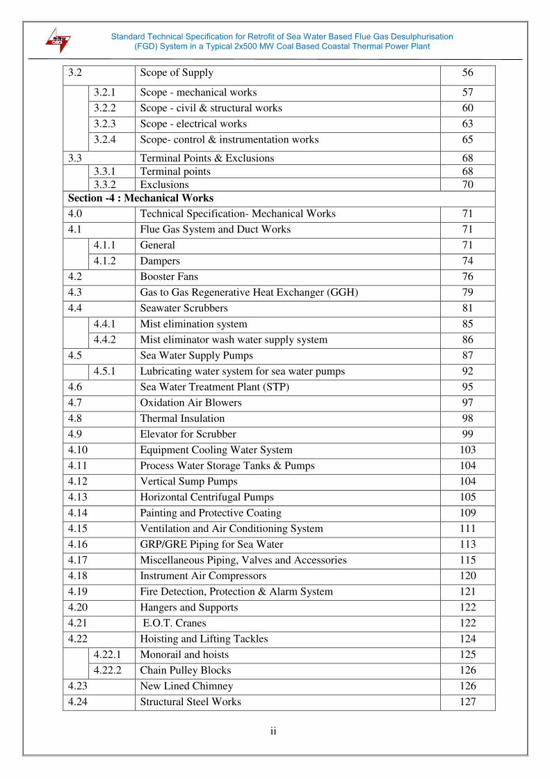
3.2 Scope of Supply 56
3.2.1 Scope - mechanical works 57
3.2.2 Scope - civil & structural works
60
3.2.3 Scope - electrical works 63
3.2.4 Scope- control & instrumentation works 65
3.3 Terminal Points & Exclusions 68
3.3.1 Terminal points 68
3.3.2 Exclusions 70
Section -4 : Mechanical Works
4.0 Technical Specification- Mechanical Works 71
4.1 Flue Gas System and Duct Works
71
4.1.1 General
71
4.1.2 Dampers
74
4.2 Booster Fans
76
4.3 Gas to Gas Regenerative Heat Exchanger (GGH)
79
4.4 Seawater Scrubbers 81
4.4.1 Mist elimination system
85
4.4.2 Mist eliminator wash water supply system 86
4.5 Sea Water Supply Pumps
87
4.5.1 Lubricating water system for sea water pumps 92
4.6 Sea Water Treatment Plant (STP)
95
4.7 Oxidation Air Blowers 97
4.8 Thermal Insulation 98
4.9 Elevator for Scrubber
99
4.10 Equipment Cooling Water System
ystem
103
4.11 Process Water Storage Tanks & Pumps
104
4.12 Vertical Sump Pumps 104
4.13 Horizontal Centrifugal Pumps
Umps
105
4.14 Painting and Protective Coating 109
4.15 Ventilation and Air Conditioning System 111
4.16 GRP/GRE Piping for Sea Water
113
4.17 Miscellaneous Piping, Valves and Accessories 115
4.18 Instrument Air Compressors
120
4.19 Fire Detection, Protection & Alarm System 121
4.20 Hangers and Supports 122
4.21 E.O.T. Cranes 122
4.22 Hoisting and Lifting Tackles 124
4.22.1 Monorail and hoists 125
4.22.2 Chain Pulley Blocks 126
4.23 New Lined Chimney 126
4.24 Structural Steel Works 127
Standard Technical Specification for Retrofit of Sea Water Based Flue Gas Desulphurisation (FGD) System in a Typical 2x500 MW Coal Based Coastal Thermal Power Plant
iii
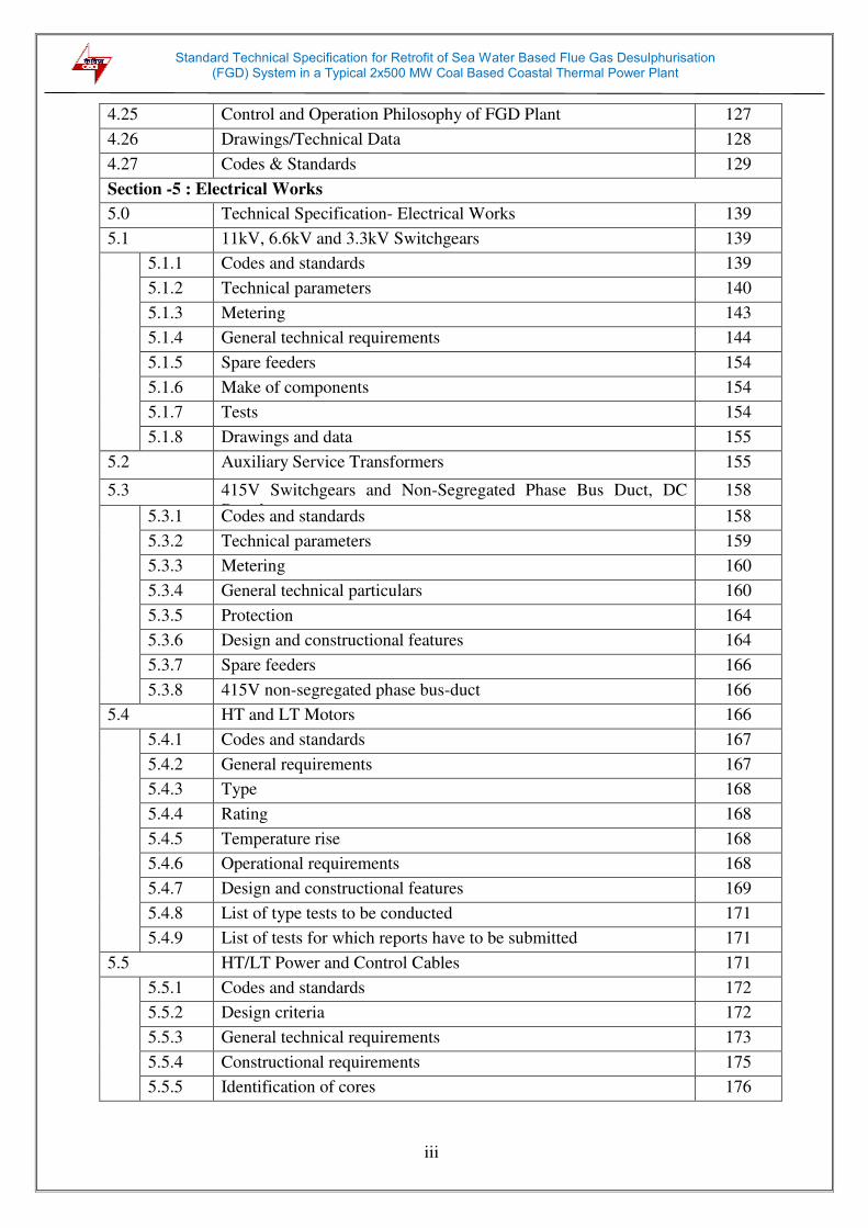
4.25 Control and Operation Philosophy of FGD Plant 127
4.26 Drawings/Technical Data 128
4.27 Codes & Standards 129
Section -5 : Electrical Works
5.0 Technical Specification- Electrical Works 139
5.1 11kV, 6.6kV and 3.3kV Switchgears 139
5.1.1 Codes and standards 139
5.1.2 Technical parameters
140
5.1.3 Metering 143
5.1.4 General technical requirements
144
5.1.5 Spare feeders 154
5.1.6 Make of components 154
5.1.7 Tests
154
5.1.8 Drawings and data
155
5.2 Auxiliary Service Transformers 155
5.3 415V Switchgears and Non-Segregated Phase Bus Duct, DC
Boards
158
5.3.1 Codes and standards 158
5.3.2 Technical parameters 159
5.3.3 Metering 160
5.3.4 General technical particulars 160
5.3.5 Protection 164
5.3.6 Design and constructional features
164
5.3.7 Spare feeders 166
5.3.8 415V non-segregated phase bus-duct 166
5.4 HT and LT Motors 166
5.4.1 Codes and standards
167
5.4.2 General requirements
167
5.4.3 Type 168
5.4.4 Rating
168
5.4.5 Temperature rise
168
5.4.6 Operational requirements 168
5.4.7 Design and constructional features 169
5.4.8 List of type tests to be conducted 171
5.4.9 List of tests for which reports have to be submitted 171
5.5 HT/LT Power and Control Cables
171
5.5.1 Codes and standards 172
5.5.2 Design criteria
172
5.5.3 General technical requirements 173
5.5.4 Constructional requirements 175
5.5.5 Identification of cores 176

Standard Technical Specification for Retrofit of Sea Water Based Flue Gas Desulphurisation (FGD) System in a Typical 2x500 MW Coal Based Coastal Thermal Power Plant
iv
5.5.6 Arrangement of cables 176
5.5.7 Drums lengths 176
5.6 Variable Frequency Drives 176
5.6.1 General 176
5.6.2 Codes and standards 176
5.6.3 Operating conditions
177
5.6.4 System description 178
5.6.5 General requirements
178
5.6.6 Technical and operational requirements 178
5.6.7 VFD compatibility with the motor 180
5.6.8 Bypass arrangement (optional, if specified) 180
5.6.9 Standby VFD arrangement (optional, if specified)
180
5.6.10 Efficiency 181
5.6.11 Cooling system 181
5.6.12 Transformer 181
5.6.13 Power converter 182
5.6.14 Output filter (as applicable) 182
5.6.15 DC link capacitor (as applicable) 182
5.6.16 AC/DC reactor (as applicable) 183
5.6.17 VFD panel requirements 183
5.6.18 Painting 183
5.6.19 HT switchgear 183
5.6.20 Motors 184
5.6.21 LT & HT cables 184
5.6.22 Control and performance requirements 184
5.6.23 Protection features 185
5.6.24 Control features 186
5.6.25 Diagnostic features 186
5.6.26 Serviceability / Maintainability 186
5.6.27 Storage and preservation 186
5.6.28 Tests 186
5.7 Installation of Cables, Earthing System and Lighting Protection
System
188
5.7.1 Codes and standards 188
5.7.2 Design and constructional features
189
5.7.3 Equipment description 189
5.7.4 Installation 193
5.7.5 Earthing system 197
5.7.6 Lightning protection system 199
5.8 Lighting
0000000
200
5.8.1 Make of equipment / components 200

Standard Technical Specification for Retrofit of Sea Water Based Flue Gas Desulphurisation (FGD) System in a Typical 2x500 MW Coal Based Coastal Thermal Power Plant
v
5.8.2 Normal service conditions 200
5.8.3 Lighting system 200
5.8.4 Main Lighting Board (MLB) 201
5.8.5 Lighting Distribution Board (LDB) 201
5.8.6 AC/DC Emergency Lighting Distribution Board (ELDB) 201
5.8.7 Guidelines for design of lighting distribution system 201
5.8.8 Illumination level design factors and type of luminaires
202
5.8.9 Description for each type of luminaire 203
5.8.10 Lighting distribution system design
204
5.8.11 Emergency lighting distribution system 204
5.8.12 Spare feeders
205
5.8.13 Power socket outlets
205
5.8.14 Welding outlet 205
5.8.15 Drawings and data 205
5.8.16 Standards 205
5.9 DC System 205
Section - 6 : Control & Instrumentation Works
6.0 Technical Specifications for C&I Works 210
6.1 General 210
6.1.1 General requirements 210
6.1.2 Reliability and availability
210
6.1.3 Standardization and uniformity of hardware 210
6.1.4 Operability & maintainability 211
6.1.5 Control & monitoring
211
6.1.6 Environmental conditions 211
6.2 PLC Based Control System 212
6.2.1 General requirement 212
6.2.2 Programmable logic based control system
213
6.2.3 Human Machine Interface System (HMIS)
215
6.2.4 Input/ Output modules 218
6.2.5 Data communication system (DCS) 220
6.2.6 Control system requirements
221
6.2.7 Annunciation system 227
6.2.8 Historical Storage and Retrieval System (HSRS) 228
6.2.9 Printer 228
6.2.10 Furniture 228 6.2.11 Software documentation and software listings 229
6.3 Measuring Instruments (Primary & Secondary) 230
6.3.1 General
230
6.3.2 Specification for electronic transmitter for pressure, Differential
Pressure (DP), flow and level
231

Standard Technical Specification for Retrofit of Sea Water Based Flue Gas Desulphurisation (FGD) System in a Typical 2x500 MW Coal Based Coastal Thermal Power Plant
vi
6.3.3 Specification for Pressure Gauge, Differential Pressure Gauge,
Temperature Gauge and Level Gauge
232
6.3.4 HART hand held calibrator 233
6.3.5 Temperature elements and accessories 233
6.3.6 Temperature transmitter
235
6.3.7 Specification for flow elements & flow meters
236
6.3.8 Analyzers 240
6.3.9 Solenoid valves 241
6.3.10 Electrical actuators 242
6.3.11 Vibration monitoring system 242
6.4 Control Valves, Actuators and Accessories Devices 244
6.4.1 Control valves 244
6.4.2 Valve actuators 246
6.4.3 Control valve accessory devices 246
6.4.4 Tests 246
6.5 Power Supply System 246
6.5.1 General 246
6.5.2 Uninterruptible power supply (UPS) system 247
6.5.3 Static inverters 247
6.5.4 Static switch and manual bypass switch
248
6.5.5 Step down transformer and voltage stabilizer 248
6.5.6 Distribution Board (ACDB) 248
6.5.9 Battery Health Monitoring System (BHMS) 249
6.5.10 Battery racks 249
6.6 Process Connection Piping
250
6.6.1 Impulse piping, tubing, fittings, valves and valve manifolds 250
6.6.2 Sample piping system 250
6.6.3 Air supply piping 251
6.6.4 Installation and routing 252
6.6.5 Piping/ Tubing support 252
6.6.6 Shop and site tests 253
6.7 FGD Control Desk, System Cabinets, Local Panels &
Transmitters Enclosures/ Racks
253
6.7.1 General 253
6.7.2 FGD control desk 254
6.7.3 Cabinets, enclosures, panels 254
6.7.4 Local instrument enclosure and racks 255
6.8 Continuous Emission Monitoring System (CEMS) 255
6.8.3 Common Requirements for all Analyzers 257

Standard Technical Specification for Retrofit of Sea Water Based Flue Gas Desulphurisation (FGD) System in a Typical 2x500 MW Coal Based Coastal Thermal Power Plant
vii
6.8.4 Specific requirements for Hot-extractive sampling type SO2/NOx,
CO2 & CO analyzers
259
6.8.5 Specific requirements for Dilution Extractive type SOx/NOx/CO2
& CO analyzers
260
6.8.6 Specific requirements for in-situ (Path) type SO2/NOx, CO2 &
CO analyzers
261
6.8.7 Specific requirements of O2 analyzer 262
6.8.8 Specific requirements for particulate emission (dust density stack
opacity) monitor
262
6.8.9 Specific requirements for continuous on- line mercury analyzer
263
6.8.10 Ultrasonic Flow Meter for Flue Gas Flow in Stack 263
6.9 Instrumentation Cables 265
6.9.1 General requirements 265
6.9.2 Instrumentation cable specifications 266
6.9.3 Instrumentation cable interconnection and termination philosophy 269
6.9.4 Fiber optical cables 271
6.9.5 Terminal blocks 271 6.9.6 Internal panels/cabinets/system cabinets wiring 272
6.9.7 Cable installation and routing
273
6.9.8 Cable laying and accessories & fittings
273
6.9.9 Field mounted local junction boxes 274
6.9.10 Conduits 274
6.10 Type Test Requirements 274
6.10.1 General requirements
274
6.10.2 Special requirement for solid state equipment/ systems
275
6.10.3 Type test requirement for C&I systems 276
6.11 Services for Analyzers and CEMS during defect liability period
and subsequent annual maintenance services (AMS) period
278
6.11.1 Services during Defect Liability/ Warranty Period 278
6.11.2 Services during Annual Maintenance Services (AMS) Period 279
6.11.3 Deputation of Engineer/ Technical Expert to the Site
279
Section -7 : Civil Works
7.0 Technical Specification-Civil Works 280
7.1 General 280
7.1.2 Nature of work 280
7.1.3 Scheme 280
7.1.4 Layouts & levels 281
7.1.5 Construction method 281
7.2 Basic Design Criteria 281
7.2.1 Basis of design
281
7.2.2 Safe bearing capacity of soil 283
7.2.4 Design criteria 283

Standard Technical Specification for Retrofit of Sea Water Based Flue Gas Desulphurisation (FGD) System in a Typical 2x500 MW Coal Based Coastal Thermal Power Plant
viii
7.2.5 Design calculations and drawings 283
7.2.6 As made drawings 284
7.3 Technical Specification for Earth Work 284
7.3.1 General 284
7.3.2 Excavation
284
7.3.3 Disposal of surplus earth
285
7.3.4 Excavation below water table
285
7.3.5 Backfill 285
7.3.6 Excavation in trenches for pipes, cables 286
7.3.7 Miscellaneous 287
7.4 Technical Specification For Cement Concrete 288
7.4.1 General Requirements
288
7.4.2 Materials 288
7.4.3 Water 289
7.4.4 Formwork
290
7.4.5 Storage of materials
290
7.4.6 Grade of concrete 290
7.4.7 Mixing and placing of concrete 291
7.4.8 Construction joints 292
7.4.9 Inserts 293
7.4.10 Cleaning and finishing 293
7.4.11 Curing 293
7.4.12 Form work 293
7.4.13 Bending and placing of reinforcement 295
7.4.14 Testing and acceptance criteria 295
7.5 Technical Specification For Reinforcement 297
7.5.1 Reinforcement 297
7.5.2 Erection of steel embedded parts including anchor bolts, anchors,
openings, sleeves, inserts and other built-In- fixtures
299
7.6 Technical Specification For Brick Masonry Works 299
7.6.1 General requirements 299
7.6.2 Materials 300
7.6.3 Bonds and coursing 300
7.6.4 Built- in- works 301
7.6.5 Masonry joints 301
7.6.6 Cleaning 302
7.7 Technical Specification for Damp Proof Course 302
7.7.1 Cement concrete layer 302
7.7.2 Curing 302

Standard Technical Specification for Retrofit of Sea Water Based Flue Gas Desulphurisation (FGD) System in a Typical 2x500 MW Coal Based Coastal Thermal Power Plant
ix
7.7.3 Application of hot bitumen 302
7.8 Technical Specification for Plastering and Pointing 302
7.8.1 Plastering 302
7.8.2 Pointing 304
7.9 Technical Specification for Flooring 304
7.9.1 Concrete floors 304
7.9.2 Floor hardening treatment 305
7.9.3 Acid/Alkali resistant flooring 306
7.10 Technical Specification for Water Proofing of Roofs 307
7.10.1 General 307
7.10.2 Specifications 307
7.10.3 Application 307
7.10.4 Surface finish 308
7.10.5 Guarantee 308
7.11 Technical Specification for Steel Doors, Panel Doors, Steel
Windows, Ventilators And Rolling Shutters
308
7.11.1 Steel doors and panel doors 308
7.11.2 Steel windows and ventilators 310
7.11.3 Glass and glazing work 310
7.11.4 Glazing works 311
7.11.5 Rolling shutters 311
7.12 Technical Specification for Plinth Protections 311
7.12.1 Materials 311
7.13 Technical specification for miscellaneous steel 312
7.13.1 Materials 312
7.14 Technical Specification for Painting, Acrylic Emulsion(Interior)
/Weather Proof Acrylic Emulsion(Exterior) Paint
312
7.14.1 Suitability for coastal areas 312
7.14.2 Water proof cement paint 313
7.14.3 Synthetic enamel paint 314
7.15 Technical Specification for grouting 314
7.15.1 General 314
7.15.2 Materials 314
7.16 Technical Specification for supply, Fabrication and Erection of
Structural Steel
315
7.16.1 Design & detailing 315
7.16.2 Test at works and test certificate 316
7.16.3 Fabrication 317
7.16.4 Bending 317
7.16.5 Cutting 317
7.16.6 Grinding 317
7.16.7 Clearance 317
7.16.8 Holes 317
7.16.9 Notches 318
7.16.10 Assembly 318
7.16.11 Bolting 318
7.16.12 Stairs, railing and ladders 318
Standard Technical Specification for Retrofit of Sea Water Based Flue Gas Desulphurisation (FGD) System in a Typical 2x500 MW Coal Based Coastal Thermal Power Plant
x
7.16.13 Foundation bolts 319
7.16.14 Fabrication drawings 320
7.17 Technical Specification for Sand Filling 320
7.17.1 General requirements 320
7.18 Technical Specification for Pipes and Pipe Fittings 320
7.18.1 General 320
7.18.2 Materials, installation and testing 321
7.19 Technical Specification for Sanitary Fittings 321
7.19.1 General requirements 321
7.19.2 Testing of pipelines for drainage and sanitation 321
7.20 Technical Specification for Open Surface Drain 322
7.21 Technical Specification for Demolition & Dismantling Work 322
7.21.1 General 322
7.21.2 Terminology 322
7.21.3 Precautions 322
7.22 Technical Specification for Vibration Isolation System For
Machine Foundations(If Required)
322
7.22.1 General 322
7.22.2 Codes of practice standards 323
7.22.3 Supporting arrangement 324
7.22.4 Equipment supply 324
7.22.5 Documentation 324
7.22.6 Packaging & transportation 325
7.22.7 Realignment of spring system 325
7.22.8 Performance guarantee 325
7.22.9 Design life of foundation 325
7.23 Technical Specification for Pre-Cast RCC Slabs 325
7.23.1 General 325
7.23.2 Concrete mix 326
7.23.3 Fixing in position of structural steel embedment 326
7.23.4 Sampling and testing in field 326
7.23.5 The erection of pre-cast slabs 326
7.23.6 Sampling and Testing in field 326
7.23.7 The erection of pre-cast slabs 326
7.24 Technical Specification for Metal Sheet Roofing, Side Sheeting
and Accessories
327

Standard Technical Specification for Retrofit of Sea Water Based Flue Gas Desulphurisation (FGD) System in a Typical 2x500 MW Coal Based Coastal Thermal Power Plant
xi
7.24.1 General 327
7.24.2 Materials 327
7.24.3 Steel roofing/cladding sheet 327
7.24.4 Translucent sheets 327
7.24.5 Roof extractors 327
7.24.6 Accessories 327
7.25 Technical Specification for G.I. Roof & Side Sheeting and
Accessories
328
7.25.1 General 328
7.25.2 Materials 328
7.25.3 Storage of materials 328
7.25.4 Laying 328
7.25.5 Fixing 329
7.25.6 Galvanized iron accessories 330
7.26 Technical Specification for Aluminium Doors, Windows,
Ventilators & Partitions
331
7.26.1 Materials 331
7.26.2 Workmanship 331
7.27 Chimney 332
7.27.1 Design criteria 332
7.27.2 Materials 333
7.27.3 Platform supporting structure 333
7.27.4 Foundation 333
7.27.5 Platforms 334
7.27.6 Roll up door 334
7.27.7 Personnel/access doors 334
7.27.8 Hatch 334
7.27.9 Elevator 334
7.27.10 Liner hood/cap 334
7.27.11 Acid collection arrangment 334
7.27.12 Chimney roof & roof drainage 335
7.27.13 Flue support arrangement 335
7.27.14 Chimney painting 335
7.27.15 Platform supporting structure 335
7.27.16 Flue ducts 335
7.27.17 Permissible stresses for chimney shell 336
7.27.18 General design criteria 336

Standard Technical Specification for Retrofit of Sea Water Based Flue Gas Desulphurisation (FGD) System in a Typical 2x500 MW Coal Based Coastal Thermal Power Plant
xii
7.27.19 Basis of design 337
7.27.20 Loading and their combinations 337
7.27.21 Analysis 337
7.27.22 Component design criteria 338
SECTION -8 : List of Mandatory Spare Parts
8.0 List Of Mandatory Spare Parts 339
8.1 Mechanical 339
8.2 Electrical 347
8.3 Control & Instrumentation 351
SECTION -9 : Quality Assurance Plan
9.0 Quality Assurance Programme 355
9.1 Mechanical Systems 355
9.1.1 Flue gas system 355
9.1.2 Gas to gas heater(GGH) 356
9.1.3 Scrubber 356
9.1.4 Sea water pumps 357
9.1.5 Monorail & hoists 358
9.1.6 Ventilation system 358
9.1.7 Packaged, split and window air conditioners 359
9.1.8 Elevators 359
9.1.9 Fire detection & protection system 360
9.1.10 Miscellaneous equipment 361
9.2 Electrical Systems 371
9.2.1 HT busduct 371
9.2.2 Auxiliary service transformers 372
9.2.3 Motors 374
9.2.4 11Kv,6.6kV and 3.3kV switchgear 376
9.2.5 415V Switchgear & bus duct 378
9.2.6 Power and control cables 382
9.2.7 Installation of cables, earthing system and lightning protection
system
388
9.2.8 DC storage battery 390
9.2.9 Battery charger 393
9.2.10 VFD module 394
9.2.11 Station lighting 395
Standard Technical Specification for Retrofit of Sea Water Based Flue Gas Desulphurisation (FGD) System in a Typical 2x500 MW Coal Based Coastal Thermal Power Plant
xiii
9.2.12 Vibration monitoring, diagnostic and analysis system 396
9.2.13 Passengers cum goods elevator 397
9.3 Control and Instrumentation (C& I) System 398
9.3.1 Measuring instruments (primary & secondary) 398
9.3.2 Process, connection & piping for C&I systems 400
9.3.3 Instrumentation cable 401
9.3.4 Control desk, PLC panel, smoke detector, fire alarm & control
system
402
9.3.5 Power supply for C&I systems (UPS/ voltage stabilizer) 403
9.3.6 Control valve actuators and accessories 404
9.3.7 Electrical actuators with integral starters 405
9.4 Civil Works 406
9.4.1 Sampling, testing and quality assurance for civil works 406
9.4.2 General QA requirements 409
9.4.3 Piling work (if applicable) 417
9.4.4 Water supply, drainage & sanitation 418
9.4.5 Architectural & Misc. works 419
9.4.6 Pre cast concrete works 419
SECTION -10 : Annexures
Annexure-I Typical seawater analysis data 420
Annexure-II Typical clarified water analysis data 421
Annexure-III Typical DM water analysis data 422
Annexure-IV Office order for constitution of committee 423
Annexure-V Record notes of discussions 424-426

Standard Technical Specification for Retrofit of Sea Water Based Flue Gas Desulphurisation (FGD) System in a Typical 2x500 MW Coal Based Coastal Thermal Power Plant
Section- 1 (General Note, Applicability and Project Specific Information)
1
SECTION 1.0
GENERAL NOTE, APPLICABILITY AND PROJECT SPECIFIC INFORMATION
1.1 GENERAL NOTE
i) Ministry of Environment, Forest and Climate Change (MOEF &CC) has issued notification no: S.O.3305(E) titled ‘Environmental (Protection) Amendment rules, 2015 dated 7.12.2015. The said notification has brought out amendments to Schedule - I of Environment (Protection) Rules, 1986 for the water consumption and emission norms applicable to thermal power stations. As per the amendment, the following emission norms are applicable to the thermal power plants:
Pollutant TPPs (units) installed up to 31.12.2003*
TPPs (units) installed after 1.4. 2004 up to 31.12. 2016*
TPPs (units) to be installed from 1.1.2017**
Particulate matter 100 mg/Nm3 50 mg/Nm3 30 mg/Nm3
Sulphur Dioxide (SO2)
600 mg/Nm3 (< 500MW capacity units)
100 mg/Nm3
200 mg/Nm3 (≥ 500MW capacity units)
Oxides of Nitrogen (NOx)
600 mg/Nm3 300 mg/Nm3 100 mg/Nm3
Mercury (Hg) 0.03 mg/Nm3
*The above emission limits are to be met within two years from date of notification. ** Including all TPPs (units) which have been accorded environmental clearance and are under construction.
After notification of new emission norms, installation of FGD has become essential in all thermal power plants for compliance of stipulated SO2 emission limits.
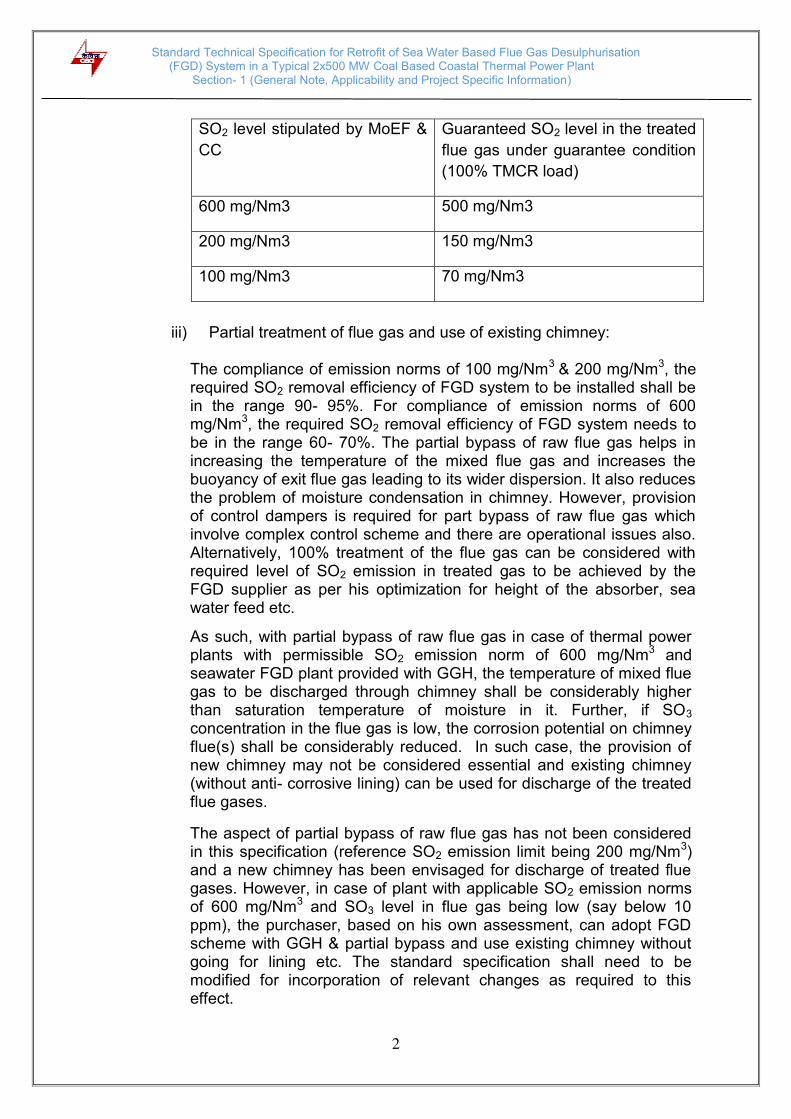
ii) To meet a specific level of SO2 emission stipulated by MoEF & CC, the SO2 level to be achieved by the bidder in the treated flue gas under guarantee condition needs to be provided with some margin. The following is proposed guaranteed SO2 level in the treated flue gas under guarantee condition to be specified in the bid:
Standard Technical Specification for Retrofit of Sea Water Based Flue Gas Desulphurisation (FGD) System in a Typical 2x500 MW Coal Based Coastal Thermal Power Plant
Section- 1 (General Note, Applicability and Project Specific Information)
2
SO2 level stipulated by MoEF &
CC
Guaranteed SO2 level in the treated
flue gas under guarantee condition
(100% TMCR load)
600 mg/Nm3 500 mg/Nm3
200 mg/Nm3 150 mg/Nm3
100 mg/Nm3 70 mg/Nm3
iii) Partial treatment of flue gas and use of existing chimney:
The compliance of emission norms of 100 mg/Nm3 & 200 mg/Nm3, the required SO2 removal efficiency of FGD system to be installed shall be in the range 90- 95%. For compliance of emission norms of 600 mg/Nm3, the required SO2 removal efficiency of FGD system needs to be in the range 60- 70%. The partial bypass of raw flue gas helps in increasing the temperature of the mixed flue gas and increases the buoyancy of exit flue gas leading to its wider dispersion. It also reduces the problem of moisture condensation in chimney. However, provision of control dampers is required for part bypass of raw flue gas which involve complex control scheme and there are operational issues also. Alternatively, 100% treatment of the flue gas can be considered with required level of SO2 emission in treated gas to be achieved by the FGD supplier as per his optimization for height of the absorber, sea water feed etc.
As such, with partial bypass of raw flue gas in case of thermal power plants with permissible SO2 emission norm of 600 mg/Nm3 and seawater FGD plant provided with GGH, the temperature of mixed flue gas to be discharged through chimney shall be considerably higher than saturation temperature of moisture in it. Further, if SO3 concentration in the flue gas is low, the corrosion potential on chimney flue(s) shall be considerably reduced. In such case, the provision of new chimney may not be considered essential and existing chimney (without anti- corrosive lining) can be used for discharge of the treated flue gases.
The aspect of partial bypass of raw flue gas has not been considered in this specification (reference SO2 emission limit being 200 mg/Nm3) and a new chimney has been envisaged for discharge of treated flue gases. However, in case of plant with applicable SO2 emission norms of 600 mg/Nm3 and SO3 level in flue gas being low (say below 10 ppm), the purchaser, based on his own assessment, can adopt FGD scheme with GGH & partial bypass and use existing chimney without going for lining etc. The standard specification shall need to be modified for incorporation of relevant changes as required to this effect.
Standard Technical Specification for Retrofit of Sea Water Based Flue Gas Desulphurisation (FGD) System in a Typical 2x500 MW Coal Based Coastal Thermal Power Plant
Section- 1 (General Note, Applicability and Project Specific Information)
3
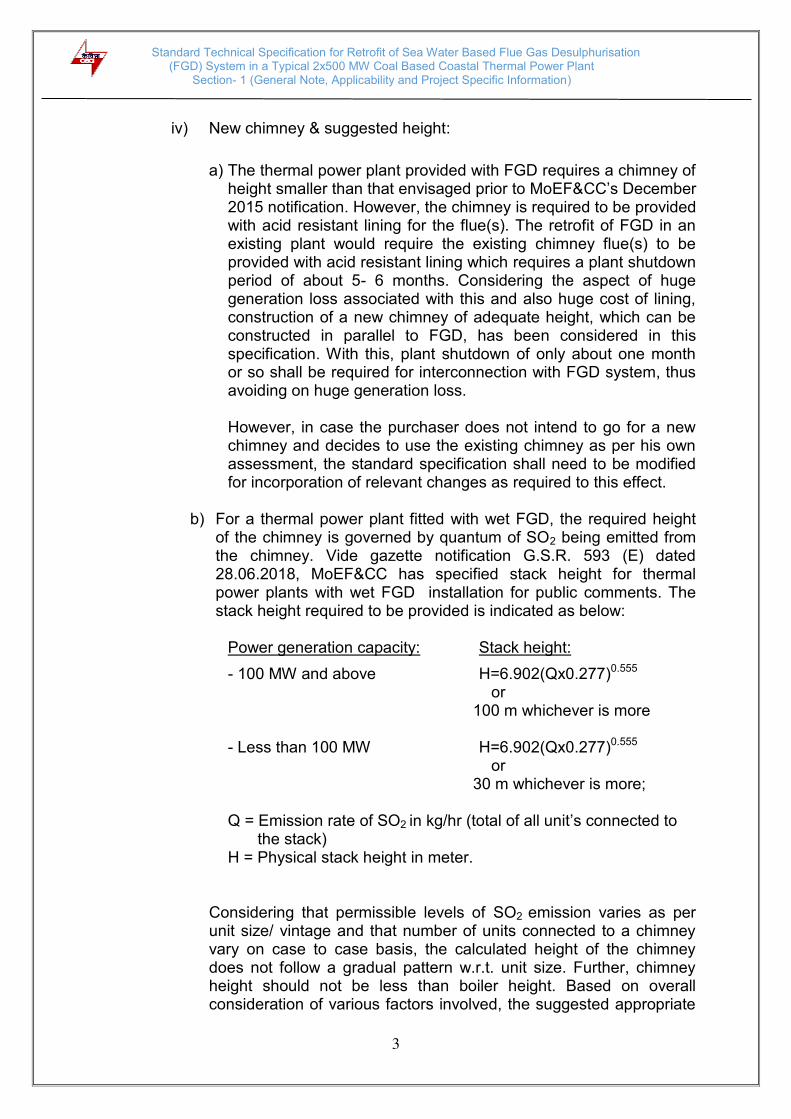
iv) New chimney & suggested height:
a) The thermal power plant provided with FGD requires a chimney of height smaller than that envisaged prior to MoEF&CC’s December 2015 notification. However, the chimney is required to be provided with acid resistant lining for the flue(s). The retrofit of FGD in an existing plant would require the existing chimney flue(s) to be provided with acid resistant lining which requires a plant shutdown period of about 5- 6 months. Considering the aspect of huge generation loss associated with this and also huge cost of lining, construction of a new chimney of adequate height, which can be constructed in parallel to FGD, has been considered in this specification. With this, plant shutdown of only about one month or so shall be required for interconnection with FGD system, thus avoiding on huge generation loss.
However, in case the purchaser does not intend to go for a new chimney and decides to use the existing chimney as per his own assessment, the standard specification shall need to be modified for incorporation of relevant changes as required to this effect.
b) For a thermal power plant fitted with wet FGD, the required height
of the chimney is governed by quantum of SO2 being emitted from the chimney. Vide gazette notification G.S.R. 593 (E) dated 28.06.2018, MoEF&CC has specified stack height for thermal power plants with wet FGD installation for public comments. The stack height required to be provided is indicated as below:
Power generation capacity: Stack height:
- 100 MW and above H=6.902(Qx0.277)0.555 or
100 m whichever is more
- Less than 100 MW H=6.902(Qx0.277)0.555 or
30 m whichever is more; Q = Emission rate of SO2 in kg/hr (total of all unit’s connected to
the stack) H = Physical stack height in meter.
Considering that permissible levels of SO2 emission varies as per unit size/ vintage and that number of units connected to a chimney vary on case to case basis, the calculated height of the chimney does not follow a gradual pattern w.r.t. unit size. Further, chimney height should not be less than boiler height. Based on overall consideration of various factors involved, the suggested appropriate

Standard Technical Specification for Retrofit of Sea Water Based Flue Gas Desulphurisation (FGD) System in a Typical 2x500 MW Coal Based Coastal Thermal Power Plant
Section- 1 (General Note, Applicability and Project Specific Information)
4
height of the chimney for different size of units installed up to 31.12.2016 is as below:
Unit size
No. of units connected to the
chimney
1 2
Suggested height of wet chimney
(m)*
< 250 MW 100 125
≥ 250 MW and < 500 MW 125 150
≥ 500 MW 150 150
The suggested appropriate height of the chimney for different size of units installed from 1.1.2017 is as below:
Unit size
No. of units connected to the
chimney
1 2
Suggested height of wet chimney
(m)*
< 250 MW 100 100
≥ 250 MW and < 500 MW 125 125
≥ 500 MW 150 150
*purchaser is required to check & review for upward revision of indicated chimney height, if any, as per applicable calculations and other environmental considerations and accordingly incorporate same in the standard specification.
v) The provision for complete bypass of FGD system with use of isolation dampers for power plant to operate through existing chimney during unit start-up with oil firing or during any exigency has been considered in this specification.
vi) The installation of sea water FGD system will require space near
existing chimney for booster fans, GGH, scrubbers and new lined chimney. Space shall be required near the condenser seal well/ return sea water channel for pump house/ building to install sea water supply pumps, oxidation air blowers and for sea water

Standard Technical Specification for Retrofit of Sea Water Based Flue Gas Desulphurisation (FGD) System in a Typical 2x500 MW Coal Based Coastal Thermal Power Plant
Section- 1 (General Note, Applicability and Project Specific Information)
5
treatment plant. The provision shall also need to be made to address the temperature rise impact of sea water FGD, complying with statutory requirement for permitted temperature rise of discharged sea water over that of the receiving water body. Layout of the FGD system for retrofit in the existing plant shall have to be developed and optimized by the bidder as per pockets of areas available at site and in consultation with the purchaser including for relocation of some plant facilities, if required.
vii) Various inputs will need to be provided by the purchaser to the contractor for installation of FGD and its interconnection/ integration with the existing power plant. These will vary from plant to plant on case to case basis. The purchaser shall make proper assessment of these requirements and appropriately incorporate in the specification.
viii) Provision for addressing temperature rise impact of seawater FGD:
In once through condenser cooling system, hot sea water outlet from the condenser is allowed to be discharged back into receiving water body with permissible temperature rise over receiving water body restricted as per statutory requirement of MoEF&CC/ CPCB/ SPCB. As per MOE&F’s notification dated 2.1.1999, the permitted temperature of discharged hot sea water is 7 deg C above the temperature of receiving water body. Sea water FGD results in increase of about 1- 2 deg C in average temperature of outlet seawater due to scrubbing of hot flue gases with sea water in the scrubber. In case of retrofit plants, this temperature rise needs to be mitigated as per maintaining the compliance of permissible temperature of discharged sea water into the receiving water body. There are two practical options to achieve this: a) To provide for a precooling channel of appropriate surface area
for discharged sea water after SWTP or enlarge the surface area
of existing precooling channel appropriately, if provided in the
original plant design.
b) To provide for requisite quantum of extra fresh sea water from source body for mixing with SWTP outlet hot sea water in the discharge channel. This can be done by either using spare capacity in existing CW pumps, if adequately available or by installing extra pump in CW pump house, if provision is available or by constructing a new pump house at sea water intake.
Standard Technical Specification for Retrofit of Sea Water Based Flue Gas Desulphurisation (FGD) System in a Typical 2x500 MW Coal Based Coastal Thermal Power Plant
Section- 1 (General Note, Applicability and Project Specific Information)
6
c) To provide helper cooling tower (FRP) to cool part of the condenser outlet sea water before FGD and mix it with discharge water after FGD to achieve the required temperature mitigation.
The power plant utility is required to evaluate/ get evaluated the best feasible option for mitigating the temperature rise impact of sea water FGD from the relevant organisations as per details of existing sea water system, margins available in it and inputs & requirement of FGD supplier. The implementation schedule of the selected option for mitigating the temperature rise impact of sea water FGD by the utility should be in conformity with the implementation schedule of the sea water FGD as provided by its supplier. Alternatively, the implementation of the measure for mitigating the temperature rise impact of sea water FGD as per its finalized scope by the utility can be included in the scope of the FGD supplier as per mutual agreement.
The standard specification shall need to be modified for
incorporation of relevant changes as required to the above effect.
ix) The FGD system and new lined chimney shall be constructed within the scheduled time without affecting operation of the existing plant/ units. The plant shutdown will be taken only for interconnection of the FGD system as per quoted/ mutually agreed period for the same in the contract. The bidder shall properly plan and ensure that the work of structural/ mechanical/ electrical/ C&I interconnection with the existing plant systems is completed within the scheduled shutdown period. In case time taken is more, liquidated damages shall be applicable for each day of delay as indicated elsewhere in the specification.
x) The standard specification envisages for meeting the requirement of the equipment cooling water for FGD equipment from DM cooling water piping of the existing units considering the requirement to be relatively small. However, depending upon his assessment on adequacy of existing DM cooling water system, the purchaser may alternatively opt for dedicated cooling water system including PHE etc. for the FGD equipment. In such case, the standard specification shall need to be modified for incorporation of relevant changes as required to this effect.
xi) The standard specification envisages for meeting the service/
instrument air requirement of FGD system from existing service/ instrument air piping. However, depending upon his assessment on adequacy of existing service/ instrument air system, the purchaser may alternatively opt for dedicated compressed air system for FGD system. In such case, the standard specification shall need to be
Standard Technical Specification for Retrofit of Sea Water Based Flue Gas Desulphurisation (FGD) System in a Typical 2x500 MW Coal Based Coastal Thermal Power Plant
Section- 1 (General Note, Applicability and Project Specific Information)
7
modified for incorporation of relevant changes as required to this effect.
xii) The standard specification envisages for sea water supply pumps
with forced water lubricated bearings using filtered sea water. However, depending upon his assessment of sea water quality available from existing CW system, the purchaser may alternatively opt for self water lubricated sea water supply pumps with also deleting the bearing lubrication water system comprising of pressure sand filters, air blowers, filtered sea water storage tank and filtered sea water supply pumps. In such case, the standard specification shall need to be modified for incorporation of relevant changes as required to this effect.
xiii) The standard specification envisages for installation of a new twin
flue chimney for 2x500 MW units. However, depending upon his assessment of plant specific aspects, the purchaser may alternatively decide for installation of individual chimneys for the plant units. In such case, the standard specification shall need to be modified for incorporation of relevant changes as required to this effect.
xiv) Auxiliary power consumption and shut down period for FGD interconnection have been included under Category- I guarantees and SO2 emission in exit flue gas, and guaranteed parameters for sea water at the outlet of sea water treatment plant have been included under Category- II guarantees. Typical liquidated damages (LD) values have been specified for Category- I guarantees. These need to be specified as per relevant inputs applicable on case to case basis. Further, bid evaluation factors for items of category- I guarantees are suggested to be kept such that LD value is at least 1.5 times the respective bid evaluation factor.
xv) Operation and control of FGD system: The standard specification envisages operation and control of complete FGD system including its common auxiliaries from PLC system to be installed in FGD control room with provision for operation and control of FGD system from existing DCS in main plant control room as well as for communication interface from PLC system to the existing DCS for exchange of equipment status/ information. However, depending upon his assessment of specific C&I aspects of existing plant, the purchaser may alternatively decide for control and operation of the FGD system from existing main plant DCS with its suitable augmentation with provision for operation and control also from OWS/ EWS to be located in FGD local control room. In such case, the standard specification shall need to be

Standard Technical Specification for Retrofit of Sea Water Based Flue Gas Desulphurisation (FGD) System in a Typical 2x500 MW Coal Based Coastal Thermal Power Plant
Section- 1 (General Note, Applicability and Project Specific Information)
8
modified for incorporation of relevant changes as required to this effect.
xvi) 220 V DC supply system:
The specification envisages 220 V DC supply system to meet 220 V DC load requirement of the FGD system. In case DC feeders with sufficient capacity are available in the existing DC system of the plant, the same can be used for FGD system and no separate DC system need to be provided for the FGD system. This needs to be checked and firmed up by the purchaser and incorporated in the relevant part of the standard specification.
1.2 APPLICABILITY
This standard technical specification for retrofit of FGD system has been prepared considering a coastal thermal power plant comprising of 2 x 500 MW units having sea water based once- through CW system and with notified SO2 emission limit of 200 mg/Nm3. The document covers only technical part of the specification in a comprehensive manner as described herewith in nine (9) sections. The specification can be made applicable for other coastal power plants also having different size & number of units and different notified SO2 emission limit by making suitable corrections for indicated technical parameters and other aspects as felt necessary by the purchaser. The specification can also be used for installation of sea water FGD system in coastal power plants based on sea water cooling tower with appropriate modifications made for incorporation of relevant changes in the specification towards making available requisite quantum of sea water in the plant from source water body.
1.3 BRIEF DETAILS ABOUT POWER PLANT
i) Site Data
1 Project Name & Address ---
2 Owner ---
3 Project Location District ---, ---State
4 Longitude ---- E
5 Latitude ---" N
6 Nearest Railway Station ---and is at a distance of --- km
7 Nearest Villages ---
8 Nearest Town ---
9 Nearest City ---
10 Nearest Port --- Port (-– km)
11 Nearest Air Port ---, --- km
12 Access Road State Highway connecting NH--- to---
Standard Technical Specification for Retrofit of Sea Water Based Flue Gas Desulphurisation (FGD) System in a Typical 2x500 MW Coal Based Coastal Thermal Power Plant
Section- 1 (General Note, Applicability and Project Specific Information)
9
town
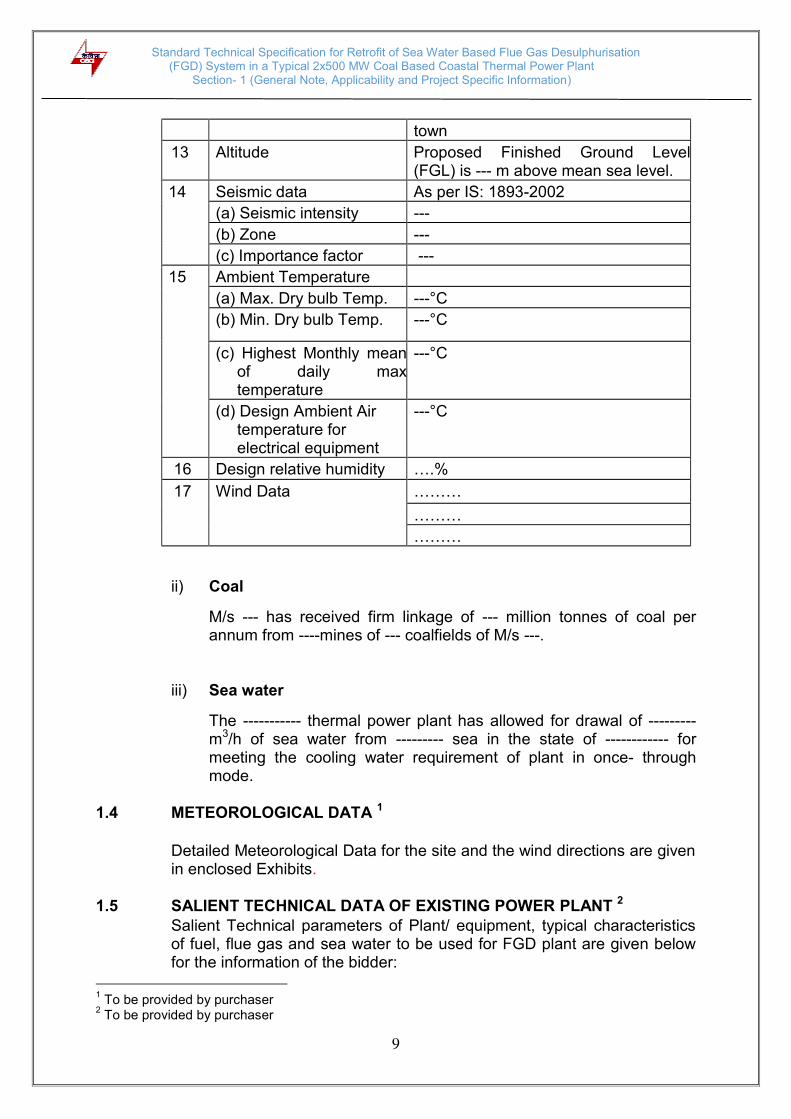
13 Altitude Proposed Finished Ground Level (FGL) is --- m above mean sea level.
14 Seismic data As per IS: 1893-2002
(a) Seismic intensity ---
(b) Zone ---
(c) Importance factor ---
15 Ambient Temperature
(a) Max. Dry bulb Temp. ---°C
(b) Min. Dry bulb Temp. ---°C
(c) Highest Monthly mean of daily max temperature
---°C
(d) Design Ambient Air temperature for electrical equipment
---°C
16 Design relative humidity ….%
17 Wind Data ………
………
………
ii) Coal
M/s --- has received firm linkage of --- million tonnes of coal per annum from ----mines of --- coalfields of M/s ---.
iii) Sea water
The ----------- thermal power plant has allowed for drawal of --------- m3/h of sea water from --------- sea in the state of ------------ for meeting the cooling water requirement of plant in once- through mode.
1.4 METEOROLOGICAL DATA 1
Detailed Meteorological Data for the site and the wind directions are given in enclosed Exhibits.
1.5 SALIENT TECHNICAL DATA OF EXISTING POWER PLANT 2
Salient Technical parameters of Plant/ equipment, typical characteristics of fuel, flue gas and sea water to be used for FGD plant are given below for the information of the bidder:
1 To be provided by purchaser
2 To be provided by purchaser
Standard Technical Specification for Retrofit of Sea Water Based Flue Gas Desulphurisation (FGD) System in a Typical 2x500 MW Coal Based Coastal Thermal Power Plant
Section- 1 (General Note, Applicability and Project Specific Information)
10
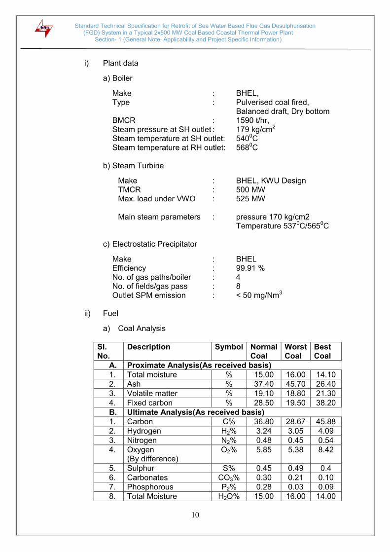
i) Plant data
a) Boiler
Make : BHEL, Type : Pulverised coal fired,
Balanced draft, Dry bottom BMCR : 1590 t/hr, Steam pressure at SH outlet : 179 kg/cm2
Steam temperature at SH outlet: 5400C Steam temperature at RH outlet: 5680C
b) Steam Turbine
Make : BHEL, KWU Design TMCR : 500 MW
Max. load under VWO : 525 MW
Main steam parameters : pressure 170 kg/cm2 Temperature 5370C/5650C
c) Electrostatic Precipitator
Make : BHEL Efficiency : 99.91 % No. of gas paths/boiler : 4 No. of fields/gas pass : 8 Outlet SPM emission : < 50 mg/Nm3
ii) Fuel
a) Coal Analysis
Sl. No.
Description Symbol Normal Coal
Worst Coal
Best Coal
A. Proximate Analysis(As received basis)
1. Total moisture % 15.00 16.00 14.10
2. Ash % 37.40 45.70 26.40
3. Volatile matter % 19.10 18.80 21.30
4. Fixed carbon % 28.50 19.50 38.20
B. Ultimate Analysis(As received basis)
1. Carbon C% 36.80 28.67 45.88
2. Hydrogen H2% 3.24 3.05 4.09
3. Nitrogen N2% 0.48 0.45 0.54
4. Oxygen (By difference)
O2% 5.85 5.38 8.42
5. Sulphur S% 0.45 0.49 0.4
6. Carbonates CO3% 0.30 0.21 0.10
7. Phosphorous P2% 0.28 0.03 0.09
8. Total Moisture H2O% 15.00 16.00 14.00

Standard Technical Specification for Retrofit of Sea Water Based Flue Gas Desulphurisation (FGD) System in a Typical 2x500 MW Coal Based Coastal Thermal Power Plant
Section- 1 (General Note, Applicability and Project Specific Information)
11
9. Ash % 37.40 45.70 26.40
10. Gross Calorific Value kcal/kg 3900 3300 4900
b) Heavy Fuel Oil (HFO) Specification- used for startup/low load only
Standard IS -1593/1971 Grade HV/LSHS
Flash Point minimum, (Pansky-Martens closed cup)
66 0C
Viscosity maximum 370 CST at 50oC
Total sulphur maximum 4.5 % by weight
Gross heating value 10,000 kcal/kg.
c) Light Diesel Oil (LDO) Specification- used for startup/low load only
Standard IS 1460/1974 Grade LDO
Flash point minimum (Pensky Martens closed cup)
66oC
Viscosity maximum 15.7 CST at 38oC
Total sulphur maximum 1.8 % by weight
Gross heating value 10300kcal/kg.
iii) Sea Water Intake/ CW Pumps:
Numbers (O+S): 5 (4 +1)
Make: Kubopta Japan
Type: Mix Flow
Capacity of each pump, m3/h: 20, 000 m3/h
Make of Motor: Fuji Electric-japan
Motor rating, kW: 1300
iv) Condenser:
Make: BHEL
Type: Once through
CW inlet flow: 80,000 m3/h
CW inlet temperature, OC: 33 0C
CW outlet temperature, OC: 40.0 0C
Condenser tube material: Titanium
The clarified water and DM water analysis are given at Annexure-II
to III respectively of the specification.

Standard Technical Specification for Retrofit of Sea Water Based Flue Gas Desulphurisation (FGD) System in a Typical 2x500 MW Coal Based Coastal Thermal Power Plant
Section- 2 (General)
12
SECTION 2.0
GENERAL
2.1 INTENT OF SPECIFICATION
2.1.1 This specification is intended to cover the design, engineering,
manufacture, procurement, inspection and testing at manufacturer’s
works, supply, packing and delivery at project site, unloading & storage at
site, in-plant transportation and handling at site, fabrication, erection,
interconnection with existing units, pre-commissioning, testing, successful
commissioning, performance testing and handing over of complete sea
water based FGD system together with a wet flue chimney including
electrical and C&I systems for 2 x 500MW coal fired thermal units of
……….. TPS of M/s ……… along with all auxiliaries & accessories,
special tools & tackles, mandatory spare parts and associated civil works
as specified herein.
2.1.2 Scope of the proposal shall cover following activities and services in
respect of all the equipment and works specified in various sections of this
specification:
i) Basic Engineering of all equipment and equipment systems; ii) Detailed design of all the equipment and equipment system(s)
including civil works; iii) Providing engineering drawings, data, instruction manuals, as built
drawings and other information for purchaser’s review, approval and records;
iv) Compliance with statutory requirements and provide support to
purchaser for obtaining clearances from statutory authorities, wherever required;
v) Complete manufacturing including shop testing; vi) Packing and transportation from the manufacturer’s works to the site
including customs clearance, port charges, if any; vii) Receipt, movement to proper storage, storage, preservation and
conservation of equipment at the site, movement from storage area to interim/ final foundation location;

Standard Technical Specification for Retrofit of Sea Water Based Flue Gas Desulphurisation (FGD) System in a Typical 2x500 MW Coal Based Coastal Thermal Power Plant
Section- 2 (General)
13
viii) Fabrication, pre-assembly, if any, erection, testing, pre-commissioning and commissioning and putting into satisfactory operation all the equipment including successful completion of initial operation;
ix) Performance guarantee/acceptance tests within a period of one
month after successful completion of initial operation; x) Guaranteeing equipment performance for a period of 12 months
from the date of commercial operation; xi) Supply of mandatory spares as per specified list and recommended
spares for three years of normal operation on FOR site basis; xii) Supply of any other equipment including special tools and tackles,
commissioning spares and services required for satisfactory completion of the project and operation and maintenance of the same;
xiii) Training of purchaser’s personnel nominated by the purchaser during
erection, testing and commissioning, and for operation and maintenance;
xiv) Reconciliation with customs authorities, in case of imported
equipment; xv) Satisfactory conclusion of the contract; xvi) All items and equipment though not specifically mentioned in the
specification, but needed to complete the system to meet the intent of the specification shall be deemed to be included in the scope of the bidder.
2.1.3 The bidder’s scope shall also include dismantling of existing
facilities/structures, where so required and their relocation at new area to be indicated by the Purchaser, rerouting of over ground and underground pipes, cables, ducts, etc. as necessary for erection and commissioning of FGD plant. Bidders are advised to visit site to see the space earmarked for FGD installation and make a personal assessment of the facilities/structures required to be shifted and confirm explicitly in the bid that they have, personally or through their representative, assessed all such works required and cost estimates for all such works have been included in the bid price. The Purchaser shall provide to the bidder the drawings etc. of the existing underground structures/ facilities as available with him.
2.1.4 It is not the intent to completely specify all details of design and
construction, but only to lay down broad sizing and quality criteria for the major equipment and systems and it is expected that the equipment shall conform in all respects to high standards of engineering, design and

Standard Technical Specification for Retrofit of Sea Water Based Flue Gas Desulphurisation (FGD) System in a Typical 2x500 MW Coal Based Coastal Thermal Power Plant
Section- 2 (General)
14
workmanship and shall be capable of performing in continuous commercial operation up to the contractor’s guarantee in a specified manner acceptable to the purchaser.
2.2 TYPICAL BRIEF DESCRIPTION OF THE EXISTING FLUE GAS PATH 1
Dust laden flue gases from second pass of the boiler are divided into two paths to enter 2 x 60% capacity rotary regenerative air pre-heaters wherein heat of the flue gases is transferred to primary and secondary combustion air. Flue gases then enter 2x60% capacity Electrostatic Precipitators (ESPs). The outlet of ESPs is connected to respective I.D. fans and then exhausted through chimney. The ESPs are designed for an efficiency of 99.91% and to maintain 150 mg/Nm3 of dust emission at ESP outlet when firing worst coal and one of the field being out of operation
The flue gas ducts are divided into two independent streams. However, interconnection with isolating dampers are provided at the inlet and outlet of major important equipment i.e. air pre-heaters, ESPs, ID Fans, to ensure flexibility of operation with any one of the equipment being out of service. Each of the equipment on flue gas path i.e. APH, ESP, ID fan is provided with isolating dampers at its inlet and outlet for on line maintenance. The vendor is expected to maintain similar uniformity in all aspects of the duct work in his scope.
2.3 TYPICAL BRIEF DESCRIPTION OF THE EXISTING CW SYSTEM 2 Project to indicated brief description of plant’s seawater based once-
through cooling system comprising of seawater intake system, travelling water screens, CW/ ACW pumps, inlet piping/ ducts, condenser, PHEs, debris filter, outlet piping/ ducts, seal pit, discharge channel/ pre- cooling channel, outfall structure on receiving water body as applicable. The description shall also include the quantum of available sea water for CW/ ACW cooling, inlet water temperature, temperature rise across the condenser, cooling being achieved in the pre- cooling channel, if any, and permissible temperature rise over temperature of receiving water body.
2.4 TYPICAL BRIEF DESCRIPTION OF EXISTING CHIMNEY 3
The twin flue chimney is of 275 m height in RCC construction. The flues inside the RCC chimney are fabricated from structural steel conforming to Grade E250 (Fe410W), quality A (semi killed) of IS:2062 from rolled steel members and plates. Stainless steel used for the top portion of flue conforms to AISI type 304L. Each flue is of hung type (i.e. of tension type) suspended from support floors with expansion joints above support floor. The rectangular cross section duct is connected to flue inside the chimney by means of bolted flange connections. The duct is supported on steel
1 To be provided by the purchaser
2 To be provided by the purchaser
3 To be provided by the purchaser

Standard Technical Specification for Retrofit of Sea Water Based Flue Gas Desulphurisation (FGD) System in a Typical 2x500 MW Coal Based Coastal Thermal Power Plant
Section- 2 (General)
15
frame inside and outside the chimney shell. The duct is fabricated out of steel of grade E250 (410W) quality (killed).
2.5 DESIGN AND GUARANTEE CONDITIONS4
2.5.1 i) The FGD plant for each unit of 2x500 MW thermal power station shall be
designed to comply with the requirements/ conditions as indicated
below:
Sl. No.
Description Guarantee point Design point
1. Boiler load 100% TMCR load BMCR
2. Type of coal Worst coal Worst coal
3. Ambient air condition 270C, 60% RH 450C, 60% RH
4. Coal flow 360 t/h 390 t/h
5. Sulhpur content in coal
0.5% 0.5%
6. Flue gas flow at FGD inlet
2,000,000 Nm3/h (wet)
2,200,000 Nm3/h (wet)
7. SO2 concentration in flue gas at FGD inlet
1800 mg/Nm3
(wet) 1800 mg/Nm3 (wet)
8. Dust concentration in flue gas at FGD inlet
100 mg/Nm3 (wet) 200 mg/Nm3 (wet)
9. Flue gas temperature at FGD inlet
1250 C 1450 C
10. Flue gas pressure at FGD inlet, mmwc
10 mmwc 10 mmwc
11. SO2 concentration in flue gas at FGD outlet
150 mg/Nm3 (6% O2, dry basis)
150 mg/Nm3 (6% O2, dry basis)
12. Minimum SO2 removal efficiency
92 % 92 %
Note: Nm3 refers to condition 101.325 kPa pressure & 298 K temperature. ii) The flue gas analysis at FGD inlet (ID fan outlet) shall be considered as below:
Sl. No.
Parameter Unit Guarantee Point Design Point
100% TMCR load BMCR
1. CO2 % v/v wet 9.87 9.54
2. O2 % v/v wet 6.26 6.04
3. SO2 % v/v wet 0.063 0.061
4. N2 % v/v wet 70.96 68.56
5. H2O % v/v wet 12.82 15.77
6. Inlet SO2 mg/Nm3-wet 1800 1800
7. SO3 Ppm 10.5 10.20
4 To be provided by the purchaser

Standard Technical Specification for Retrofit of Sea Water Based Flue Gas Desulphurisation (FGD) System in a Typical 2x500 MW Coal Based Coastal Thermal Power Plant
Section- 2 (General)
16
8. HCL ppm-wet 45 45
9. HF ppm-wet 12 12
11 NOx mg/Nm3 750 mg/Nm3 750 mg/Nm3
2.5.2 Bidder shall also guarantee that maximum concentration of SO2 in treated
flue gas at the exit of FGD for each unit shall not exceed 150 mg/Nm3 (6% O2, dry basis) under all operating conditions of the plant in the load range 50% TMCR to 100% TMCR.
2.5.3 For sea water at inlet of FGD plant having analysis as at Annexure-I, the guaranteed parameters of sea water at the outlet of sea water treatment plant shall be as below:
a) Minimum pH at 25 0C - 6.5
b) Minimum dissolved oxygen (DO) - 3 mg/l or 40% saturation value whichever is higher - 5 mg/l or 60% saturation value whichever is higher (for
ecologically sensitive zone)
c) Temperature - Not to exceed the
limiting value quoted by the contractor in his bid
Notes: Complete conversion of sulphites into harmless sulphates shall be
ensured in the oxidation basins and there shall be no stripping of SO3 from the outlet seawater.
2.6 GENERAL DESIGN REQUIREMENTS
i) The Flue Gas Desulphurisation (FGD) System shall be designed to meet
all the guaranteed parameters that are required to be satisfied as given in
Cl. No 2.14 of the specification.
ii) The complete FGD system and the associated auxiliaries shall be
designed by the standard industrial practices. The FGD system shall be
designed to achieve the required SO2 capture from flue gases, and pH &
temperature of sea water returned to the receiving water body shall be
conforming to the applicable MoEF&CC regulations. The temperature
mitigation of outlet sea water for impact of sea water FGD shall be as per
provision of a precooling channel or modifications in the existing pre
cooling channel or by use of fresh sea water drawn from source water
body. The selected measure shall be implemented by the utility or shall be
included in the scope of the bidder as per mutual agreement at bidding
stage with necessary engineering details/ inputs to be provided by the
bidder.
Standard Technical Specification for Retrofit of Sea Water Based Flue Gas Desulphurisation (FGD) System in a Typical 2x500 MW Coal Based Coastal Thermal Power Plant
Section- 2 (General)
17
iii) Sea water analysis
The analysis/ range of analysis of seawater for the design of FGD system has been indicated in the Annexure- I5.
iv) Justification of Proposed Design- The Contractor shall also furnish along with his offer the detailed calculations and data to establish as to how he will meet the performance requirements at specified guarantee point including for compliance of discharged sea water temperature.
v) The Bidder shall submit with the offer, comprehensive information on how the L/G ratio, mass balance, spray nozzle cone angle, spray nozzle arrangement, etc. as applicable for the proposed design have been arrived at. The Contractor shall also submit along with the offer, a detailed write up on the proposed design features and control philosophy at varying loads to achieve the desired level/ efficiency of SO2 removal.
vi) The FGD plant shall be designed for a service life of minimum twenty five (25) years.
vii) Adequate margins shall be considered in design capacity and head of the pumps and fans/ blowers over and above the maximum duty conditions in addition to increase in frictional losses over a period of 25 years and 5% fall in the frequency of electric supply.
viii) Stable capacity/head rising characteristics shall be provided for the pumps and the shut off head shall be minimum 20%over the rated head.
ix) All pressure vessels shall conform to requirements of IS 2825or ASME Section VIII. The minimum thickness of pressure vessels shall, however, be 6 mm.
x) The design pressure of pressure vessels shall be equal to the algebraic sum of the maximum total head encountered in H.Q. characteristic of the preceding pump stage and the total suction head of the same pump plus 5% margin.
xi) For unlined pressure vessels 2-mm corrosion allowance is to be made. Also 2-mm mill tolerance shall be made for all dished ends.
xii) In general, GRP piping shall be used for handling corrosive fluids. RCC encased steel pipelines used for carrying corrosive fluids shall be rubber lined inside to a thickness of at least 5 mm. FRP material may also be considered for smaller diameter pipes.
5 The range of seawater analysis including for representative seasonal variations, particularly for
alkalinity, to be provided by the purchaser.
Standard Technical Specification for Retrofit of Sea Water Based Flue Gas Desulphurisation (FGD) System in a Typical 2x500 MW Coal Based Coastal Thermal Power Plant
Section- 2 (General)
18
xiii) All pumps shall have discharge pressure gauges (with isolating valves) suitable to handle the particular fluid for which they are intended for.
xiv) All centrifugal pumps shall have suction and discharge gate/ butterfly valves, and check valves on the discharge side unless otherwise stated.
xv) Sampling connections, as required, shall be provided at different stages of the FGD plant.
xvi) All valves which a normal person cannot operate standing on the floor should be provided with chain operation.
xvii) The water velocities in pressure lines shall not exceed 2.4 m/sec. and pump suction line velocities shall not exceed 1.0 m/sec. except otherwise specified elsewhere in this specification.
xviii) The maximum temperature of ambient air for the purpose of designing the capacities of fans and motors shall be taken as 50 deg C.
xix) All metallic valves coming in contact with corrosive fluids shall be rubber lined metallic valves or of proven material suitable for the duty involved.
xx) The contractor shall supply all essential instrumentation and other accessories required for satisfactory and reliable performance of the FGD plant.
xxi) Wherever motors are specified to be TEFC weather proof or TEFC weather protected, it shall mean that they will be TEFC suitable for outdoor installations. All motors shall comply with specific technical requirements given in this specification.
xxii) All instruments shall be provided with isolating globe/needle valves (root valves) of suitable material.
xxiii) Wherever applicable, all level gauges, shall be provided with isolating and drain valves.
xxiv) The size of overflow pipes of all storage tanks shall be one size higher than inlet pipe sizes of these tanks.
xxv) For buried pipelines, three (3) coats of heavy duty bituminastic paint shall be applied on the cleaned surface. Finally, it shall be wrapped with minimum 3 mm thick bitumen impregnated tar-felt. The lap joint of the felt should be touched with paint.
xxvi) Heavy duty hume pipes of adequate size shall be provided for road crossing etc. of the buried pipe lines.
xxvii) Pipelines at interface terminal points shall be provided with blank flange arrangement, unless otherwise specified.
xxviii) Recirculation lines shall be provided for each centrifugal pump, unless otherwise specified.

Standard Technical Specification for Retrofit of Sea Water Based Flue Gas Desulphurisation (FGD) System in a Typical 2x500 MW Coal Based Coastal Thermal Power Plant
Section- 2 (General)
19
xxix) Each equipment/motor shall be earthed with two Nos. distinct and independent earthing electrodes.
xxx) Construction Material and Internal anticorrosive Protection:
1. In general, the material selection is the Bidder’s responsibility, but the quality of material for pressure vessels, piping, etc., however, must meet the requirements of the relevant IS/ASME standards. The Bidder shall specify in his bid the material quality and the standards applied to each equipment, piping system, etc.
2. Suitable corrosion and erosion allowances shall be provided commensurate with service conditions of the equipment. The corrosion allowances shall be determined by the Bidder on the basis of his experience/standard practice. Corrosion allowances considered for various equipment and piping system etc. shall be indicated in the bid. Similar data shall be given for erosion allowances.
3. Where necessary, an internal anticorrosive protection based on the Bidder’s proven experience shall be applied. Bidder shall include a comprehensive list of anticorrosion protection including equipment on which respective corrosion protection has been provided. Reference information on the application, reliability and suitability of the proposed anticorrosion protection as per the equipment supplied by the bidder and operating successfully for a long period shall also be furnished. Life of anti-corrosion protection, necessary repairs required, their frequency and time demands shall also be indicated.
xxxi) The annual maintenance period and capital maintenance frequency of the FGD plant shall match with those of the units which is given here under 6 and will not call for any extension of the maintenance and repair period:
Annual maintenance period of the Units: 15 days
Capital maintenance period of the Units: 45 days (every 5 years)
2.7 OPERATIONAL PERFORMANCE REQUIREMENTS
i) The FGD plant for each unit shall be designed to achieve minimum 92% (to be provided by Purchaser) SO2 removal efficiency at all operating conditions from 50% to 100% of Unit MCR.
ii) The FGD plant shall be capable of base load operation at minimum
95% availability. The bidder shall also furnish details of availability records in plants stated in his experience list.
iii) System shall be capable of safe shut down in case of unit tripping
and/or station black out. Customer shall try to provide emergency
6 To be provided by the purchaser

Standard Technical Specification for Retrofit of Sea Water Based Flue Gas Desulphurisation (FGD) System in a Typical 2x500 MW Coal Based Coastal Thermal Power Plant
Section- 2 (General)
20
AC supply for FGD system from station emergency AC supply. However, if in case it is not feasible to do so, bidder may be required to include emergency AC supply for FGD equipment needing such supply in case of unit tripping /station black out in his scope and shall have to provide DG sets of adequate capacity. Bidder may indicate price for providing emergency AC supply separately in the price bid.
iv) The normal flue gas temperature at inlet to FGD shall be about 120-
1350C. However, in case of APH failure the flue gas temperature may rise to about 2500C for 15 minutes and the FGD system shall be designed to suitably withstand such operation without any damage to the system. All duct work/duct lining, dampers etc. shall be designed to withstand above temperature conditions.
v) The provision shall be made for complete bypass of FGD system
during unit start-up with oil firing (LDO/ HFO) or during any plant operational exigency with use of isolation dampers to enable power plant operation through existing chimney.
vi) In order to be compatible for operation in conjunction with existing
units, the design of the plant must guarantee a rapid availability during start-up, a fine and favorable characteristic during load changes and reliable & stable mode of continuous operation at conditions encountered during the power plant operation.
vii) The FGD plant shall be suited to an unlimited operation at any load
point between the minimum and maximum load point being guaranteed. The plant shall be capable of being put into service (both warm and cold start-up) without the necessity of extensive and unusual activities or preparations.
viii) The FGD plant shall be able to handle the load imposed on the FGD
plant by the boiler, including rate of load changes, minimum load and the anticipated daily and annual load schedules. Furthermore, the FGD plant shall be able to be put in operation, while the boiler is in operation at any load, without any disturbance in the operation of the Units.
ix) The operation and control of the FGD system and its auxiliaries shall be carried out fully automatically by its own dedicated PLC system with provision for operation and control from existing DCS in main plant control room. Provision shall also be made for communication interface between FGD PLC and DCS for exchange of equipment status/ information. When necessary, it shall be possible for the control room staff to intervene and control the plant. Start-up and shut-down procedures shall be possible by means of semi-automatic operations which shall be released and supervised by the control room.

Standard Technical Specification for Retrofit of Sea Water Based Flue Gas Desulphurisation (FGD) System in a Typical 2x500 MW Coal Based Coastal Thermal Power Plant
Section- 2 (General)
21
x) In case failure of an item of equipment (e.g. pumps, etc.) the stand-by unit has to be activated and put into service automatically without delay and without interruption of the plant operation and audio-visual alarm to such effect shall be provided in the control room.
xi) In case of a power failure, all items of equipment which could possibly suffer irreversible damage shall be connected to the emergency power supply.
xii) In case of failure of the boiler and ancillary equipment, the
associated FGD plant shall be brought automatically to the off-load operation without restriction by the current loading.
xiii) In case of shutdown and outage periods of the plant, drains and
flushings of respective items of equipment which require such a treatment shall be possible without restriction and without necessity of extensive or unusual preparation and activity. Drains and flushings required even during short time outages or an emergency shut-down shall be started automatically and by remote control. The system shall work automatically, locally activated by a local control unit.
xiv) All items of equipment which are known to be subject to wearing,
abrasion or failure (e.g. nozzles, pumps, pipe work etc.) and thereby affecting availability of FGD plant shall be designed and installed so as to facilitate easy replacement, repair and maintenance, even if installed redundantly.
2.8 LAYOUT REQUIREMENTS
The Contractor shall offer the optimum design and layout to
accommodate the flue gas system, scrubber system, sea water pump
house, oxidation blowers, sea water treatment plant and a new wet flue
chimney within the confines of the space available.
The scrubber & its auxiliaries and new stack shall preferably be located
around/ near the existing chimney. Sea water pump house, oxidation
blowers, sea water treatment plant etc. shall be located preferably near
the existing pre-cooling channel.
The general layout requirements are as under:
i) Proper approach shall be provided for access to all equipment during normal operation and maintenance. Unless otherwise specified, platforms, staircase and ladders shall follow the stipulations specified elsewhere in this specification.
ii) Equipment requiring monitoring during regular operation shall be
approachable from the ground floor through staircase. Staircase with minimum width of 1200 mm shall be provided for approach to

Standard Technical Specification for Retrofit of Sea Water Based Flue Gas Desulphurisation (FGD) System in a Typical 2x500 MW Coal Based Coastal Thermal Power Plant
Section- 2 (General)
22
elevated structures at 5m height from the nearest platform. Below this height a vertical ladder with minimum clear width of 600 mm may also be acceptable.
iii) Platform with a minimum clear width of 1000 mm shall be provided
all around the lowest scrubber spray levels and mist eliminators. Similar platforms shall be provided at subsequent elevations if they are more than 3000 mm apart from each other. An adequately sized manhole with platform shall be provided above each spray level. Ladders/staircase shall be provided for the access to the platform.
iv) Adequate working space shall be provided around all operating
equipment and drives. v) The Contractor shall provide adequate handling facility with
motorized hoist, runway beams etc. for handling/ maintenance of heavy components. Motorized hoists shall be provided for handling all components exceeding 500 kg. Access ladders with suitable
platform shall also be provided for approach to all motorized hoists/trolleys mounted on their runway beams for the maintenance of hoists/trolleys. Items weighing more than 50 kg and required to be replaced for maintenance shall be provided with manual hoists/trolleys with runway beams/supporting structure etc.
vi) The regular basement and local pits/trenches etc. shall be avoided
as far as possible. vii) Handling arrangement of booster fans, scrubber sea water supply
pumps, oxidation blowers, etc. complete with crane/ monorail along with removal space for maintenance shall be provided by the Contractor.
viii) Approach for removal of equipment for maintenance shall be
provided. ix) All other safety requirements as per the Factories Act, Indian
Electricity Rules, CEA Regulation and other applicable codes/ standards etc. shall be complied with while developing Layout.
x) Cable trenches/slits, if unavoidable, shall be provided with adequate
cushioning of sand and the same shall be covered with PCC. xi) Each Equipment room shall be provided with alternate exits in case
of fire/ accidents as per requirements of Factories Act and Statutory bodies/ insurance companies.
xii) Minimum Headroom (free height) under all floors, ducts, walkways
and stairs shall be 2 m.

Standard Technical Specification for Retrofit of Sea Water Based Flue Gas Desulphurisation (FGD) System in a Typical 2x500 MW Coal Based Coastal Thermal Power Plant
Section- 2 (General)
23
xiii) Inter-connecting pipes/cables between various facilities of FGD plant shall be routed on the steel trestles. The clear head room for the same shall be minimum 8 m.
xiv) In case of any specific space constraint at site, the layout, clearance,
approach etc. shall be mutually agreed and subject to approval of the purchaser.
2.9 GENERAL TECHNICAL REQUIREMENTS 2.9.1 All equipment, systems and works covered under these specifications
shall be in accordance with all the latest applicable statutes, regulations, codes and standards specified as well as all such standards, statutes, regulations and safety codes applicable in the locality where the equipment will be installed. Bidders may familiarize themselves with all such requirements before preparation of bids. FGD plant design including piping, valves and fittings shall completely meet or exceed all the requirements of the latest versions of Indian Standards/ASME codes. In all other cases where IS/ ASME does not govern, Japanese, American, British, German or other international standards established to be equivalent or superior to IS/ASME shall be acceptable with the approval of the purchaser at the time of detailed engineering. In the event of any conflict between the requirements of equivalent codes and standards, and the requirements of IS/ASME code, the latter shall govern unless specified elsewhere in the specifications.
2.9.2 The responsibility of safe, efficient and reliable operation of the equipment
and system supplied shall rest on the supplier and the approval of the
drawings/documents shall not in any way relieve the manufacturer of this
and obligation to meet all the requirements stipulated in the specification
or of the responsibility for correctness of the drawings/documents.
2.9.3 It will be the responsibility of the contractor to furnish the requisite
documentation as required by the Purchaser/Consultant for ascertaining
the adequacy of the design/ soundness of the materials of
construction/manufacturing methods adopted etc.
2.9.4 The sea water FGD system offered by the bidder shall be in line with the
specified scheme of FGD process. However, minor variations are
permissible for optimization of the process based on bidder’s experience.
These variations shall, however, not change the basic essence or
configuration of the process specified. Specific advantages of such
variations shall be indicated by the bidder in his bid. All modifications/
variations proposed from the process specified shall be subject to
approval from the purchaser. Description of the process which has been
offered by the Bidder must be submitted in detail indicating clearly the
function of each equipment.
Standard Technical Specification for Retrofit of Sea Water Based Flue Gas Desulphurisation (FGD) System in a Typical 2x500 MW Coal Based Coastal Thermal Power Plant
Section- 2 (General)
24
2.9.5 The materials of construction for all exposed metal/ concrete surfaces
shall be so chosen as to withstand the prevailing environment at plant
site. Also suitable weather protection shall be provided to all exposed
surfaces as required. The equipment and the auxiliaries shall be designed
for maximum reliability and availability; operability and maintainability. The
bidder shall specifically state the design features incorporated to achieve
the high degree of reliability and availability.
2.9.6 Adequate maintenance facilities shall be provided as required, for
assembly, disassembly, handling during maintenance and alignment work
of all important equipment and auxiliaries.
2.9.7 Wherever oil coolers of any equipment are provided, these shall be of
3x50% or 2x100% capacity to facilitate cleaning without shutting down the
equipment. All coolers/ jackets shall be designed to take care of the
operating pressure of the cooling medium.
2.9.8 All stand-by auxiliaries shall be designed for auto start up, on failure of
running auxiliaries with minimum time delay and without runback on unit
load.
2.9.9 The bidder shall endeavor to supply the equipment (motors, valves,
actuators, instruments etc.) of same type and make to the extent possible
so as to reduce the spare parts inventory. However, this must not affect
the functioning and operational reliability of the given equipment.
2.9.10 All the electric motor driven equipment shall give their rated performance
even at a power supply frequency of 47.5 Hz (minimum). All equipment
and auxiliaries shall be suitable for continuous operation in the frequency
range of 47.5 Hz to 51.5 Hz.
2.9.11 The plant and its units shall be designed to operate with all the specified
margins for continuous operation without any limitations under any of the
conditions indicated in the Technical Specification.
2.9.12 All materials used for the construction of the equipment shall be new and
shall be in accordance with the requirements of this specification.
Materials utilised for various components shall be those which have
established themselves for use in such applications. It would be the
responsibility of the bidder to furnish the relevant information in this
regard, as required, at the time of detailed engineering,
2.9.13 Equipment/works offered shall be designed for high availability, low
maintenance and ease of maintenance. The Bidder shall specifically state
the design features incorporated to achieve high degree of

Standard Technical Specification for Retrofit of Sea Water Based Flue Gas Desulphurisation (FGD) System in a Typical 2x500 MW Coal Based Coastal Thermal Power Plant
Section- 2 (General)
25
reliability/availability and ease of maintenance. The FGD plant shall be
designed for minimum need for inspection. The time between inspection
for scrubber internals and major equipment shall correspond to capital
overhaul period of units (once in 5 years). The FGD plant must operate
without the replacement of the most important equipment and devices for
25 years at least. The quality of material, internal anticorrosion protection
and whole performance must correspond to this requirement. The bidder
shall enumerate the special measures incorporated in the designs to meet
these requirements. The following details on maintenance requirements
for each major equipment shall be furnished:
i) Maintenance requirements for the equipment given in hours per year.
ii) Special methods used in maintenance and in performing repairs.
iii) Recommended maintenance model and proposal of the organization of repairs.
iv) Special aids and devices necessary for performing repairs and maintenance including stationary lifting devices or possibly other mechanisms necessary for vertical as well as horizontal transport of parts to be replaced.
v) A brief description of main works, handling, transport, etc. performed during the plant operation and connected with maintenance performance.
2.9.14 Roller bearings provided on pumps, fans, air compressors, GGH, agitators
and other equipment shall have a life of at least 10 years with maximum loading conditions. Journal bearings provided should have operational life equal to the life of the equipment
2.9.15 The bidder shall develop detailed layout drawings with his equipment
sizes and confirm the adequacy of the space available for housing FGD equipment. Layout should facilitate access for operation, maintenance and inspection of any one or more equipment/components at a time, without disturbing the operation or installation of balance of plant. The offers not fitting into the space allocated for the purpose are liable to be rejected.
2.9.16 All heavy parts of the plant must be provided with some convenient
arrangement for aligning and for handling during erection and overhaul. Any item of plant required to be stripped or lifted during period of maintenance and weighing one tons or more shall be marked with its approximate weight. All equipment shall be designed to run satisfactorily without any undue noise and vibrations. Corresponding parts throughout shall be made to gauge and shall be interchangeable wherever possible. No welding, filling or plugging of defective parts shall be allowed without the permission in writing of the purchaser.
Standard Technical Specification for Retrofit of Sea Water Based Flue Gas Desulphurisation (FGD) System in a Typical 2x500 MW Coal Based Coastal Thermal Power Plant
Section- 2 (General)
26
2.9.17 Each main and auxiliary item of plant shall have permanently attached to it in a conspicuous position, a rating plate of non-corrosive material upon which shall be engraved manufacturer’s name, equipment, type or serial number together with details of the ratings, service conditions under which the item of plant in question has been designed to operate, and such diagram plates as may be required by the Engineer. The inscriptions on the name plates as also the material and design of the name plates shall be approved by the Engineer.
2.9.18 The contractor shall intimate the purchaser in writing of any changes
proposed in design, manufacturing methods or materials from those included or implied in his tender giving reasons, for purchaser’s approval. The changes shall be allowed only after written approval of the purchaser. The purchaser recognizes the importance of including the latest principles and design information in the final design of any plant.
2.9.19 The Bidder shall do everything to standardize the equipment as far as
possible. It is recommended to use the equipment of the same type and of the same manufacturer, for example for pumps, valves, motors, etc. However, this must not affect the functioning and operational reliability of the given equipment. The equipment with same rating shall be of the same manufacturer so as to reduce spare parts inventory.
2.9.20 Process Safety
i) The process proposed must be free of any danger for personnel handling the equipment, for related operations and for the surroundings. This requirement applies for normal operation as well as for starting up& shut down.
ii) Automated protection as well as alarm systems must be installed at
the places where emergency conditions could occur due to a failure. These systems must be “fail safe” i.e. they must be triggered in the case of an electric voltage or pressure air outage.
2.9.21 Valves etc.
i) All valves shall be suitable for the service conditions i.e. fluid flow,
temperature and pressure under which they are required to operate and those performing similar duties shall be interchangeable with one another unless otherwise approved.
ii) All gate valves shall be of the full way type unless otherwise
approved and when in the full open position, the bore of the valve shall not be obstructed by any part of the gate. Globe valves shall have curved or spherical seating and the discs shall be free to revolve on the spindle.
iii) All non-return valves shall have an arrow cast or embossed on the
side of the valve body to indicate the direction of flow. For severe
Standard Technical Specification for Retrofit of Sea Water Based Flue Gas Desulphurisation (FGD) System in a Typical 2x500 MW Coal Based Coastal Thermal Power Plant
Section- 2 (General)
27
service conditions, cushioned check valves are preferred to obviate valve clatter. In case of the swing check valves, the body seat shall be inclined at such an angle to the vertical so as to facilitate closing and prevent clatter.
iv) The internal diameter of all valve ends to be connected to pipes shall
be the same as the internal diameter of the pipe to which they are joined so as to minimize use of reducers/expanders.
v) Where applicable valves shall be of the outside screw and yoke type. vi) Wherever necessary, valves shall be fitted with indicators so that
percentage of valve opening can be readily determined. vii) Manually operated valves shall be operable by a single man capable
of exerting 35 kg force (max) at the valve. Wherever more force is required to operate the valve, gear mechanism shall be provided.
viii) All sampling and root valves furnished shall be of integral body
bonnet type. ix) Where necessary for the safe and efficient operation of the plant,
valves shall be provided with both hand and actuator operating gear. The valves shall be complete in all respects including actuator and necessary limit switches, torque limit switch linkages etc.
x) Each motorized valve shall be supplied with two sets of position
operated adjustable limit switches each for open and close positions for signaling and interlocking. In addition, two numbers torque limit switches (one for fully open position and the other for fully closed position) shall be provided.
xi) In case of regulating valves, provision shall also be made for suitable
two numbers resistance position transmitters for remote position indication.
xii) All gate and globe valves shall have bonnet-back seating
arrangement to facilitate easy replacement of packing with the valves in service.
xiii) All gate, globe and check valves shall be designed for reconditioning
of seating surfaces and replacement of stem and disc without removing the valve body from the line.
xiv) Wherever there is a provision for local control of valves, position
indicator shall be readily visible from the operation position. xv) All valves and specialties shall bear tag numbers for identification.

Standard Technical Specification for Retrofit of Sea Water Based Flue Gas Desulphurisation (FGD) System in a Typical 2x500 MW Coal Based Coastal Thermal Power Plant
Section- 2 (General)
28
xvi) The scheme/arrangement of valves and fittings shall be such that it shall be possible to do the maintenance of the control/regulating valves and spare/standby equipment without shutting down the FGD plant. All the control valves in the system shall be of 2x100 % capacity with proper isolating valves upstream and downstream of control valve for maintenance. The valves located in the inaccessible positions shall be motorized even if not required functionally.
2.9.22 Hangers, anchors, guides, clamps, stops and supports, auxiliary
structures etc. Required for the proper installation supports of the piping shall be provided.
2.9.23 The isolators and dampers provided in the gas ducts shall be 100% leak
proof (zero leakage type) so as to completely isolate and permit the maintenance of FGD plant and accessories.
2.9.24 Noise level should not be more than 85 dB at a distance of 1 meter and at
a height of 1.5 meter from any equipment. If necessary, suitable noise reduction covers shall be provided. For short term exposure, noise levels shall not exceed the limits as stipulated in the Occupational Safety & Health Administration Standard (OSHAS). Compliance to noise level shall be demonstrated by the bidder.
2.9.25 All the electric motor driven auxiliaries shall be sized to give their rated
performance even at a power supply frequency of 47.5 Hz. (minimum). 2.9.26 Lubrication
Provision shall be made for lubricating the parts wherever necessary to ensure smooth operation and freedom from undue wear. Gear boxes and oil bath shall be provided with filling and drain plugs of adequate size and shall be provided with level indicators. Provision shall be made for efficient lubrication of all bearings including ball and roller bearings by the use of separate grease cups, self-sealing nipples or oil bath. Housing of ball and roller bearing shall be packed with the lubricant at the time of assembly. Lubrication opening of nipples shall be so arranged that it should be possible to carryout lubrication from a gangway or landing and without the removal of or insertion of the hand into the guarding. Necessary provision shall be made for preventing dust ingress into lubricated parts. The contractor shall supply schedule drawing showing all lubricating points and recommended lubricants to be used. First fill of the lubricants wherever required and all lubricants till handing over of FGD system, shall be supplied by the contractor.
2.9.27 Safety Guards
Wire mesh or steel plate guards of suitable design shall be provided for all drives as well as exposed revolving parts of equipment. Oil drip pans shall
Standard Technical Specification for Retrofit of Sea Water Based Flue Gas Desulphurisation (FGD) System in a Typical 2x500 MW Coal Based Coastal Thermal Power Plant
Section- 2 (General)
29
be provided wherever required. Guards and pans should be of removable construction to provide access to the machine. Guards may consist of railing and tee boards placed at least at a gap of 300 mm from the parts to be covered. Suitable machinery covers shall also be provided.
2.9.28 Special Cleaning, Protection and Painting
i) Suitable protection method shall be adopted for protecting all material, plant and equipment during all stages of manufacture, transportation, storage and erection.
ii) All coated surfaces shall be protected against abrasion, impact,
discoloration and any other damages. All exposed threaded portions shall be suitably protected with either metallic or a non-metallic protection device. All ends of all valves and piping and conduit equipment connections shall be properly sealed with suitable devices to protect them from damage. The parts which are likely to get rusted, due to exposure to weather, should also be properly treated and protected in a suitable manner.
iii) All exposed metallic surfaces subject to corrosion shall be protected
by application of suitable coatings. All surfaces which will not be easily accessible after the shop assembly, shall forehand be treated and protected for the life of the equipment. All surfaces shall be thoroughly cleaned of all mill scales, oxides and other coatings and prepared in the shop. The surfaces that are to be finish-painted after installation or require corrosion protection until installation, shall be shop painted with at least two coats of primer.
iv) All the surfaces of equipment and structures of the proposed FGD
plant to be painted at site have to be sand blasted at site and painted with one coat of inorganic zinc silicate primer, two intermediate coats of polyamide cured epoxy paint and one final coat of acrylic aliphatic polyurethane paint. Shop painting of equipment shall also conform to this requirement.
v) Shop primer for all steel surfaces which will be exposed to operating
temperature below 95 deg C shall be selected by the Contractor after obtaining specific approval of the Purchaser regarding the quality of primer proposed to be applied. Special high temperature primer shall be used on surfaces exposed to temperature higher than 95 deg C and such primer shall also be subject to the approval of the Purchaser. All other steel surfaces which are not to be painted shall be coated with suitable dust preventive compound subject to the approval of the Purchaser.
vi) All equipment/ piping/ pipe services are to be painted by the Bidder
in accordance with Owner’s standard colour coding scheme, which will be furnished to the Bidder during detailed engineering stage.

Standard Technical Specification for Retrofit of Sea Water Based Flue Gas Desulphurisation (FGD) System in a Typical 2x500 MW Coal Based Coastal Thermal Power Plant
Section- 2 (General)
30
vii) The control panels and annunciation panels shall be given final painting before shipment and shall be touched up at site, if necessary.
viii) Final painting of approved colour of purchaser’s choice shall be
arranged by the contractor at site.
ix) No painting is required for stainless steel and gun metal surfaces.
2.9.29 Site Specific Safety
The structure of the FGD plant shall be adequately designed taking into account the local seismic factors and wind conditions prevailing at site. A project design manual indicating design data and detailed design criteria for civil and structure steel work shall be submitted for the approval of the consultant/purchaser. Special measures shall be adopted to protect reinforced concrete and structural steel from corrosive coastal climatic conditions and these shall be included in the design criteria of the FGD system.
2.9.30 Maintenance Tools and Tackles
i) The Contractor shall supply with the equipment, one complete set of all special tools and tackles required for the erection, assembly, disassembly and maintenance of equipment. These special tools will also include special material handling equipment, jigs and fixtures for maintenance & calibration/readjustment, checking & measurement aids etc. A list of such tools and tackles will be submitted by the Bidder along with the offer. Detailed description of each tool/tackle, its function along with the equipment/part for which it is meant for and the price of each tool/tackle shall be indicated in the offer. However, the price of all tools and tackles shall be included in the bid price and unit price shall be separately indicated for information purpose only. The bidder shall also ensure that these tools and tackles are not used by him during erection, commissioning and trial operation.
ii) The tools shall be supplied in separate containers clearly marked
with the name of equipment for which they are marked. iii) The bidder shall furnish a list of such tools included under the scope
of supply with the proposal.
2.9.31 Laboratory Equipment
The FGD plant supply must contain as its integral part, the equipment for laboratory/analysis for control of desulphurisation process, including quality control of input and output products. The power plant laboratory is equipped for standard chemical control of the steam water system, fuels and oils. All other analytical/laboratory instruments and chemicals required for analysis/quality control of input sea water, outputs from FGD

Standard Technical Specification for Retrofit of Sea Water Based Flue Gas Desulphurisation (FGD) System in a Typical 2x500 MW Coal Based Coastal Thermal Power Plant
Section- 2 (General)
31
viz. flue gas, treated sea water etc. shall be provided. Also, special instruments required for inspection and maintenance of FGD plant shall be provided.
2.9.32 All manholes and inspection openings shall be hinged and shall be
suitable for easy opening/closing. All inspection openings and manholes shall be provided with maintenance platforms for easy access. Dust catchers shall be provided in order to prevent discharge of dust when opening the doors and manholes.
2.9.33 Every equipment or parts of equipment that must operate under certain
conditions of maximum pressure, temperature, speed, position etc. should have devices to prevent such limits from being exceeded and, if necessary, to stop the operation of the machine. (Safety valves, limit switches, thermal switches, etc.).
2.9.34 Rating Plates, Name Plates & Labels
i) Each item of plant shall be provided with nameplate or label designating the service of the particular equipment. Each main and auxiliary item of plant including instruments shall have permanently attached to it in a conspicuous position, a rating plate of non-corrosive material upon which shall be engraved manufacturer’s name, equipment, type or serial number together with details of the ratings, service conditions under which the item of plant in question has been designed to operate, and such diagram plates as may be required by the Owner.
ii) Items of plant such as valves, which are subject to handling, shall be
provided with engraved chromium plated nameplate or label with engraving filled with epoxy. The name plates for valves shall be marked in accordance with MSS standard SP-25 and ANSI B 16.34 as a minimum.
iii) All segregated phases of conductors or bus ducts, indoor or outdoor,
shall be provided with coloured phase plates to clearly identify the phase of the system.
2.9.35 Material and Workmanship
i) All materials used in the manufacture of the equipment shall be free
from defects and imperfections. The purchaser will reject
components and equipment with bad workmanship and the supplier
shall have to re-supply equipment of right workmanship at no
additional cost to the purchaser.
ii) Materials not specifically described shall conform to latest revised specification of IS or equal. The equipment shall conform in every respect to high standards of engineering design and workmanship.

Standard Technical Specification for Retrofit of Sea Water Based Flue Gas Desulphurisation (FGD) System in a Typical 2x500 MW Coal Based Coastal Thermal Power Plant
Section- 2 (General)
32
The supply of equipment shall be such that the maximum facility for interchangeability of parts is provided.
iii) The materials used in the fabrication of the components shall be new and shall have such composition, grade and properties which match and suit the duties to be performed and the conditions of operation to which these components will be subjected. Site-specific conditions shall be especially taken care of in the choice of materials proposed to be adopted.
iv) The bidders shall furnish schedule of materials giving standards,
compositions, properties etc. for major/ important components of all
the equipment. The bidder shall also furnish the specifications of
materials on the respective component drawings.
v) All parts shall be manufactured true to drawing dimensions. All
tolerances shall be defined on the contractor's drawings for both
manufacturing and installation purposes.
2.9.36 Operation and Maintenance Manuals
i) The bidder shall furnish 10 copies of instruction manuals prepared on good quality paper securely bound in durable folders for assembly, installation, adjustment, operation and maintenance of the equipment furnished by him and his sub-contractors. The manuals shall be specific to the equipment furnished and not of general nature. The instructions for assembly and installation shall show the identification of part numbers of the dismounted apparatus or equipment. Instructions for initial commissioning, short duration and long duration shut down
ii) Instruction for operation, routine inspection and maintenance including preventive maintenance, recommendation for inspection points, method of inspection and period of inspection, information on detection, cause and rectification of troubles and faults and instructions on normal repairs and overhaul etc. shall be included in the manual.
iii) Necessary drawings, curves and other illustrations shall be included or copies of appropriate approved drawings shall be bound in the manuals, Tests, adjustment and calibration information, as appropriate, shall be included. Safety and other warning notices and instructions, maintenance and operating cautions shall be emphasized.
2.10 SPARE PARTS The bidder shall include in his scope of supply all the necessary
mandatory spares, start up and commissioning spares and recommended

Standard Technical Specification for Retrofit of Sea Water Based Flue Gas Desulphurisation (FGD) System in a Typical 2x500 MW Coal Based Coastal Thermal Power Plant
Section- 2 (General)
33
spares and indicate these in the relevant schedules. The requirements pertaining to the supply of these spares is given below:
i) Mandatory Spares
a) The list of mandatory spares considered essential by the
purchaser is enclosed with this specification. The bidder shall indicate the prices for each and every item (except for items not applicable to the bidder’s design) in the ‘Schedule of mandatory spares’ whether or not he considers it necessary for the purchaser to have such spares. If the bidder fails to comply with the above or fails to quote the price of any spare item, the cost of such spares shall be deemed to be included in the contract price. The bidder shall furnish the population per unit of each item in the relevant Schedules. Whenever the quantity is mentioned in “sets” the bidder has to give the item details and prices of each item. The bidder is informed that the total prices quoted for the listed mandatory spare parts will be used in tender evaluation.
b) Whenever the quantity is indicated as a percentage, it shall mean
percentage of total population of that item in the station (project) unless specified otherwise, and the fraction will be rounded off to the next higher whole number. Wherever the requirement has been specified a ‘set’ it will include the total requirement of the item for a unit, module or the station or as specified. Where it is not specified a ‘set’ would mean the requirement for the single equipment/system as the case may be. Also the ‘set’ would include all components required to replace the item; for example, a set of bearings shall include all hardware normally required while replacing the bearings.
c) The assembly/ sub- assembly which have different orientation (like left hand, right hand, top or bottom), different direction of rotation, mirror image positioning or any other reason which result in maintaining two different sets of spares shall be considered as different type of assembly/ sub- assembly.
d) The purchaser reserves the right to buy any or all the mandatory spare parts.
e) The prices of mandatory spares indicated by the bidder in the Bid Proposal shall be used for bid evaluation purposes.
f) All mandatory spares shall be delivered at site at least two months before scheduled date of initial operation of the first unit. However, spares shall not be dispatched before dispatch of corresponding main equipment.
g) Wherever quantity is specified both as a percentage and a value,

Standard Technical Specification for Retrofit of Sea Water Based Flue Gas Desulphurisation (FGD) System in a Typical 2x500 MW Coal Based Coastal Thermal Power Plant
Section- 2 (General)
34
the bidder has to supply the higher quantity until and unless specified otherwise.
ii) Recommended Spares
a) In addition to the spare parts mentioned above, the Contractor shall also provide a list of recommended spares for three (3) years of normal operation of the plant and indicate the list and total prices in relevant schedule. The list shall take into consideration the mandatory spares specified and should be independent of the list of the mandatory spares. The purchaser reserves the right to buy any or all of the recommended spares. The recommended spares shall be delivered at project site at least two months before the scheduled date of initial operation of first unit. However, the spares shall not be dispatched before the dispatch of the main equipment.
b) Prices of recommended spares will not be used for evaluation of
the bids. The price of these spares will remain valid up to execution of the contract. However, the Contractor shall be liable to provide necessary justification for the quoted prices for these spares as desired by the purchaser.
iii) Start up and Commissioning Spares
Start up and commissioning spares are those spares which may be
required during the start-up and commissioning of the equipment/system till the commercial operation of the Plant. The Contractor shall provide all such start up and commissioning spares and keep an adequate stock of the same to be brought by him to the site for the plant erection and commissioning. These must be available at site before the equipment are energized. The unused spares, if any, should be removed from there only after commercial operation of the plant. All start up spares which remain unused at the time shall remain the property of the Contractor.
iv) General Requirements
a) The Contractor shall indicate the service expectancy period for
the spares parts (both mandatory and recommended) under normal operating conditions before replacement is necessary.
b) All spares supplied under this contract shall be strictly inter-
changeable with the parts for which they are intended for replacements. The spares shall be treated and packed for long storage under the climatic conditions prevailing at the site e.g. small items shall be packed in sealed transparent plastic with desiccator packs as necessary.
c) All the spares (both recommended and mandatory) shall be

Standard Technical Specification for Retrofit of Sea Water Based Flue Gas Desulphurisation (FGD) System in a Typical 2x500 MW Coal Based Coastal Thermal Power Plant
Section- 2 (General)
35
manufactured along with the main equipment components as a continuous operation as per same specification and quality plan.
d) The contractor will provide purchaser with cross-sectional
drawings, catalogues, assembly drawings and other relevant documents so as to enable the purchaser to identify and finalise order for recommended spares.
e) Each spare part shall be clearly marked or labeled on the outside
of the packing with its description. When more than one spare part is packed in a single case, a general description of the content shall be shown on the outside of such case and a detailed list enclosed. All cases, containers and other packages must be suitably marked and numbered for the purposes of identification.
f) All cases, containers or other packages are to be opened for such
examination as may be considered necessary by the purchaser. g) The Contractor will provide the purchaser with all the addresses
and particulars of his sub-suppliers while placing the order on vendors for items/ components/ equipment covered under Contract and will further ensure with his vendors that the purchaser, if so desires, will have the right to place order for spares directly on them on mutually agreed terms based on offers of such vendors.
h) The Contractor shall warrant that all spares supplied will be new
and in accordance with the Contract documents and will be free from defects in design, material and workmanship.
i) In addition to the recommended spares listed by the Contractor, if
the purchaser further identifies certain particular items of spares, the Contractor shall submit the prices and delivery quotation for such spares within 30 days of receipt of such request for consideration by the purchaser and placement of order for additional spares if the purchaser so desires.
j) The Contractor shall guarantee the long term availability of spares
to the purchaser for the full life of the equipment covered in the Contract. The Contractor shall guarantee that before going out of production of spare parts of the equipment covered under the Contract, he shall give the purchaser at least 2 years advance notice so that the latter may order his bulk requirement of spares, if he so desires. The same provision will also be applicable to Sub-contractors. Further, in case of discontinuance of manufacture of any spares by the Contractor and/or his sub-contractors, Contractor will provide the purchaser, two years in advance, with full manufacturing drawings, material specifications and technical information including information on alternative equipment makes required by the purchaser for the purpose of

Standard Technical Specification for Retrofit of Sea Water Based Flue Gas Desulphurisation (FGD) System in a Typical 2x500 MW Coal Based Coastal Thermal Power Plant
Section- 2 (General)
36
manufacture/ procurement of such items. k) Tenders submitted without mandatory spare parts stated in the
specification along with bidder's recommended spare parts shall be treated as incomplete and are liable to be rejected.
2.11 QUALITY ASSURANCE PROGRAMME
i) All materials, components & equipment covered under this specification shall be tested at all stages of procurement, manufacturing, erection, commissioning as per a comprehensive Quality Assurance Programme. The detailed Quality plans for manufacturing and field activities should be drawn up by the bidder and shall be submitted along with the bid which shall be finally accepted by the Employer/ authorised representative after discussions before the award of the contract. The quality assurance program shall be generally in line with ISO-9001/IS-14001 and shall generally cover the following:
a) Contractor’s organization structure for the management and
implementation of the proposed quality assurance program.
b) Quality System Manual.
c) Design Control System.
d) Documentation and Data Control System.
e) Qualification and experience data for bidder’s key personnel.
f) The procedure for purchase of materials, parts, components and
selection of sub-Bidder’s services including vendor analysis,
source inspection, incoming raw-material inspection, verification
of materials purchased etc.
g) System for shop manufacturing and site erection controls
including process, fabrication and assembly.
h) System for quality audits, control of non-conforming items and
system for corrective actions and resolution of deviations.
i) Inspection and test procedure both for manufacture and field
activities.
j) Control of calibration and testing of measuring testing
equipment.
k) System for Quality Audits.
l) System for identification and appraisal of inspection status.

Standard Technical Specification for Retrofit of Sea Water Based Flue Gas Desulphurisation (FGD) System in a Typical 2x500 MW Coal Based Coastal Thermal Power Plant
Section- 2 (General)
37
m) System for authorising release of manufactured product to the
Owner.
n) System for handling, storage and delivery.
o) System for generation and maintenance of inspection and test records.
ii) All materials, components & equipment covered under this
specification shall be tested at all stages of procurement, manufacturing, erection, commissioning as per the agreed Quality Assurance Program.
iii) Manufacturing Quality Plan will detail out for all the components and
equipment, various tests/inspection, to be carried out as per the requirements of this specification and standards mentioned therein and quality practices and procedures followed by Bidder’s/ Supplier’s/ sub-supplier's Quality Control Organisation, the relevant reference documents and standards, acceptance norms, inspection documents raised etc., during all stages of materials procurement, manufacture, assembly and final testing/ performance testing. The Quality Plan shall be submitted on electronic media e.g. CD or E-mail in addition to hard copy, for review and approval. After approval, the same shall be submitted in uneditable electronic media format.
iv) Field Quality Plans will detail out for all the equipment, the quality
practices and procedure etc. to be followed by the Contractor’s site Quality Control Organization, during various stages of site activities including receipt of materials/ equipment at site, preservation and storage, pre- assembly, erection, pre-commissioning and commissioning.
v) The bidder, along with quality plan, shall also furnish copies of the
reference documents/ plant standards/ acceptance norms/ test & inspection procedure etc. referred by him in Quality Plans. These Quality Plans and reference documents/ standards etc. will be subject to purchaser’s approval and will form a part of the contract. In these approved Quality Plans, purchaser shall identify customer hold points (CHP), indicating tests/ checks which shall be carried out in presence of the Purchaser’s engineer or authorized representative and beyond which work will not proceed without consent of Purchaser’s Engineer/ authorized representative in writing.
vi) No materials/ equipment shall be dispatched from the manufacturer’s
works before the same is either accepted subsequent to pre-dispatch final inspection including verification of records of all previous tests/ inspections by Purchaser’s Engineer /authorized representatives and duly authorised for dispatch by issuance of Material Dispatch Clearance Certificate (MDCC) or such pre-
Standard Technical Specification for Retrofit of Sea Water Based Flue Gas Desulphurisation (FGD) System in a Typical 2x500 MW Coal Based Coastal Thermal Power Plant
Section- 2 (General)
38
dispatch final inspection is waived by the purchaser and dispatch is authorized after review of test reports.
vii) All materials used or supplied shall be accompanied by valid and
approved material certificates and test and inspection reports duly approved by the purchaser. These certificates and reports shall indicate the acceptable identification number of the material they proposed to certify. The material certified shall also have the identification details stamped on it.
viii) All material used for equipment construction including castings and
forgings etc. shall be of tested quality as per relevant codes/ standards. Details of results of the test conducted to determine the mechanical properties, chemical analysis and details of heat treatment procedures recommended and actually followed shall be recorded on certificates and time temperature chart. Tests shall be carried out as per applicable material standards and/or agreed details.
ix) All welding and brazing shall be carried out as per welding procedure
drawn and qualified in accordance with requirements of ASME Section IX/ BS-4870 or other International equivalent standard acceptable to the Owner. Welding procedures shall be submitted to the Purchaser for approval prior to carrying out Qualification test in the presence of Purchaser’s representative.
x) All welders/welding operators employed on any part of the contract
either in the Supplier’s works or at site or elsewhere shall be qualified as per ASME Section-IX IX/ BS-4871 or other equivalent International Standards acceptable to the Owner.
xi) Test results of qualification tests and specimen testing shall be
furnished to the Purchaser for approval. However, wherever required by the purchaser, tests shall be conducted in presence of Purchaser’s Engineer/ authorized representative.
xii) Unless otherwise proven and specifically agreed with the Owner,
welding of dissimilar materials and high alloy materials shall be carried out at shop only.
xiii) No welding shall be carried out on cast iron components for repair. xiv) All the heat treatment results shall be recorded on time temperature
charts and verified with recommended regimes. xv) All non-destructive examination shall be performed in accordance
with written procedures as per International Standards, The NDT operator shall be qualified as per SNT-TC-IA (of the American Society of non-destructive examination). NDT shall be recorded in a report, which includes details of methods and equipment used,
Standard Technical Specification for Retrofit of Sea Water Based Flue Gas Desulphurisation (FGD) System in a Typical 2x500 MW Coal Based Coastal Thermal Power Plant
Section- 2 (General)
39
result/evaluation, job data and identification of personnel employed and details of co-relation of the test report with the job.
xvi) All plates of thickness above 40mm & all bar stock/Forging above
40mm dia shall be ultrasonically tested. For pressure parts, plate of thickness equal to or above 25mm shall be ultrasonically tested.
xvii) Quality audit/surveillance/approval of the results of the tests and
inspection will not, however, prejudice the right of the Owner to reject the equipment if it does not comply with the specification when erected or does not give complete satisfaction in service and the above shall in no way limit the liabilities and responsibilities of the Bidder in ensuring complete conformance of the materials/equipment supplied to relevant specification, standard, data sheets, drawings, etc.
xviii) For all spares and replacement items, the quality requirements as
agreed for the main equipment supply shall be applicable. xix) Repair/rectification procedures to be adopted to make the job
acceptable shall be subject to the approval of the Purchaser/ authorised representative.
xx) All the sub-vendors proposed by the Bidder for procurement of major
bought out items including castings, forgings, pumps, fans, heat exchangers, semi-finished and finished components/equipment- (list of which shall be drawn up by the Bidder along with his offer and finalized with the purchaser) shall be subject to Purchaser’s approval.
xxi) All the purchase specifications for the major bought out items, list of
which shall be drawn up by the Contractor and finalized with the purchaser, shall be furnished to the Purchaser for comments and subsequent approval before orders are placed as per those specifications.
xxii) Purchaser reserves the right to carry out quality audit and quality
surveillance of the systems and procedures of the Contractor and their sub-vendors for quality management and control activities. The Contractor shall provide all necessary assistance to enable the purchaser carry out such audit and surveillance.
2.12 TESTING AND INSPECTION 2.12.1 General
i) The Contractor shall undertake an inspection and testing programme
during manufacture in his works and that of his sub-contractors to ensure the mechanical accuracy of components, compliance with drawings, conformance to functional and performance requirements,
Standard Technical Specification for Retrofit of Sea Water Based Flue Gas Desulphurisation (FGD) System in a Typical 2x500 MW Coal Based Coastal Thermal Power Plant
Section- 2 (General)
40
identification and acceptability of all materials, parts and equipment. In addition to tests as per the approved Quality Plan, the Contractor shall also carry out all tests/ inspection required to establish that the items/ equipment conform to requirements of this specification and the relevant codes/ standards specified in this specification.
ii) The word ‘Inspector’ shall mean the Purchaser/ Engineer and/or his
authorized representative and/or an outside inspection agency acting on behalf of the Owner to inspect and examine the materials and workmanship of the works during its manufacture or erection.
iii) The Purchaser/ Engineer and/or his duly authorised representative
shall have at all reasonable times access to the contractor’s premises or works and shall have the power at all reasonable times to inspect and examine the materials and workmanship of the works during its manufacture or erection and part of the work being manufactured or assembled on other’s premises or works. The contractor shall obtain for the Engineer and his duly authorised representative the permission to inspect as if the works were manufactured or assembled on the contractor’s premises or works.
iv) The contractor shall give the Engineer/Inspector fifteen (15) days
written notice of any material being ready for testing. Such tests shall be to the contractor’s account except for the expenses of the Inspector. The Engineer/Inspector unless the inspection of the tests is virtually waived, shall attend such tests within fifteen (15) days of the date on which the equipment is notified as being ready for test/inspection, failing which, the contractor may proceed with the test which shall be deemed to have been made in the Inspector’s presence and he shall forthwith forward to the Inspector duly certified copies of tests in triplicate.
v) The Engineer or Inspector shall within fifteen (15) days from the date
of inspection as defined herein give notice in writing to the contractor of any objection to any drawings or any equipment and workmanship which in his opinion is not in accordance with the contract. The contractor shall give due consideration to such objections and shall either make the modifications that may be necessary to meet the said objections or shall confirm in writing to the Engineer/Inspector, giving reasons therein that no modifications are necessary to comply with the contract.
vi) When the factory tests have been completed at the contractor’s or
sub-contractor’s works, the Engineer/Inspector shall issue a certificate to this effect within fifteen (15) days after completion of test. If the tests are not witnessed by the Engineer/Inspector, the certificate shall be issued within fifteen (15) days of the receipt of the contractor’s test certificate by the Engineer/Inspector. Failure of the Engineer/ Inspector to issue such a certificate shall not prevent the contractor from proceeding with the works. The completion of these

Standard Technical Specification for Retrofit of Sea Water Based Flue Gas Desulphurisation (FGD) System in a Typical 2x500 MW Coal Based Coastal Thermal Power Plant
Section- 2 (General)
41
tests or the issue of the certificate shall not bind the owner to accept the equipment, should on further tests after erection, the equipment is found not to comply with the contract.
vii) In all cases where the contract provides for tests whether at the
premises or works of the contractor or of any sub-contractor, the contractor, except where otherwise specified, shall provide free of charge such items as labour, materials, electricity, fuel, water, stores, apparatus and instruments as may be reasonably demanded by the Engineer/Inspector or his authorised representative, to accomplish testing.
viii) Quality audit/ surveillance/ approval of the results of the tests and
inspection will not, however, prejudice the right of the purchaser to reject the equipment if it does not comply with the specification when erected or does not give complete satisfaction in service and the above shall in no way limit the liabilities and responsibilities of the Contractor in ensuring complete conformance of the materials/equipment supplied to relevant specification, standards, data sheets, drawings etc.
ix) All inspection, measuring and test equipment used by Contractor
shall be calibrated periodically depending on its use and criticality of the test/measurement to be done. The Contractor shall maintain all the relevant records of periodic calibration and instrument identification, and shall produce the same for inspection by the Purchaser/ Inspector. Wherever asked specifically, the Contractor shall re-calibrate the measuring/test equipment in the presence of Purchaser/ Inspector.
x) The cost of all the tests shall be borne by the Contractors.
2.12.2 Material Tests Wherever tested quality material is specified and wherever called upon by
the design code, the test pieces are to be prepared and tested to the Purchaser’s satisfaction. The Purchaser may, at his discretion, after being furnished with certified particulars of tests which have been carried out by the suppliers of material, dispense with the testing of test pieces.
2.12.3 Shop Tests
i) Shop tests shall include all tests to be carried out at Contractor’s works, at the works of his sub-contractor and at works where raw materials supplied for manufacture of equipment is manufactured.
ii) Works tests are to include electrical and mechanical performance
and hydraulic tests in accordance with relevant IS, ASME or any other approved standard and/or any other tests called for by the Purchaser under these specifications to ensure that the plant being

Standard Technical Specification for Retrofit of Sea Water Based Flue Gas Desulphurisation (FGD) System in a Typical 2x500 MW Coal Based Coastal Thermal Power Plant
Section- 2 (General)
42
supplied fulfils the requirement of the specifications. For equipment not covered by any IS or other approved standards, the tests to be carried out shall be in accordance with Contractor’s quality assurance programme to be agreed to between the Contractor and the Purchaser.
iii) All pipes, valves, steam traps, are to be subjected to hydraulic test
as called for under IS, BS or other approved codes. Copies of certificates covering all the hydraulic tests shall be submitted to the purchaser. The following shop tests shall be conducted, as applicable according to the approved manufacturer’s test Procedures: a) Material Analysis b) Radiographic test at welds. c) Magnetic particle examination d) Dye penetrate examination e) Hydro static test. f) Dimension check g) Ultrasonic test (as required)
iv) All pumps and fans are to be tested at manufacturer’s works. Complete performance tests are to be carried out on each pump/ fan to verify its output (flow) against total head, power input, efficiency and suction head. Head vs. Volume, Suction head vs Volume, Volume vs Efficiency and power input curves corrected for site conditions are to be provided.
2.12.4 Site Tests Contractor shall carry out the tests at site to prove to the purchaser that
each equipment of the plant complies with all the requirements specified. Before the plant is put into commercial operation, the Contractor will be required to conduct tests to demonstrate to the Purchaser that each item of the plant is capable of correctly performing the functions for which it was specified. These tests may be conducted concurrently with those required under commissioning sequence. The tests required shall specifically include the following:
i) Checks on the operation of dampers including tests of gas tightness/
leak proofing. ii) Check on operation of all fans to ascertain level of noise and
vibration. iii) Test running of pumps and motors. iv) Check free rotation of gas heater and adjust seals, if necessary
when heater is up to working temperature.

Standard Technical Specification for Retrofit of Sea Water Based Flue Gas Desulphurisation (FGD) System in a Typical 2x500 MW Coal Based Coastal Thermal Power Plant
Section- 2 (General)
43
v) Check operation of soot blowers and retraction gear and the sequence control (if applicable).
vi) Check operation of all variable speed drives throughout their
respective ranges where applicable. vii) Check operation of all motorized isolating valves both locally and
from the FGD control room. viii) Check operation of all individual control loops in the FGD control
system. ix) Check inter-relation between each separate control loops. x) Calibration of instruments before commissioning as required. xi) Gas tightness test on FGD system. xii) Calibration tests of monitoring, instrumentation and control system/
devices (permanent one) to be used for tests. Other tests shall be conducted if required by the Purchaser to establish that the plant equipment are in accordance with requirements of specifications.
2.13 TRIAL OPERATION
The FGD plants after completion of the above tests shall be put on trial operation for a period of fifteen (15) days during which all necessary adjustments etc. shall be made while operating over full load range enabling the unit/ plant to be made ready for performance guarantee test. i) During the Trial Operation period, the FGD Plant / System shall be
operated continuously for 360 hours (15 days) at various operating loads as provided by the Purchaser and at various operating modes when firing with the specified range of coal in the Boiler. Reliability Run of 72 hours of un-interrupted operation at full load or near full load as may be provided by the Purchaser shall be conducted during the Trial Operation period. If there is any interruption in this 72 hours period of Reliability Run, the same shall have to be attempted and demonstrated for guaranteed 72 hours of un-interrupted running. In case of any interruption of up to 4 hours in period of 360 hours (15 days) operation (other than 72 hours of full load or near full load operation of Reliability Run as described above), the period of interruption must be added to 360 hours; however, if cumulative period of interruption is more than 4 hours, then 24 hours will be added to 360 hours. In case the cumulative period of interruption / down time of FGD Plant / System during Trial Operation is more than 48 hours, then the Trial Operation shall be considered as

Standard Technical Specification for Retrofit of Sea Water Based Flue Gas Desulphurisation (FGD) System in a Typical 2x500 MW Coal Based Coastal Thermal Power Plant
Section- 2 (General)
44
unsuccessful and the Contractor shall be asked to demonstrate Trial Operation again, including the Reliability Run.
ii) The trial operation shall be considered successful, provided that each
item / part of the FGD Plant/System can operate continuously at the specified operating characteristics, for the period of Trial Operation with all operating parameters within the specified limits and at or near the predicted performance of the equipment/Plant. The Contractor shall intimate the Purchaser about the commencement of Trial Operation and shall furnish adequate notice to the Purchaser in this respect.
iii) A Trial Operation report comprising of observations and recordings of
various parameters to be measured in respect of the above Trial Operation shall be prepared by the Contractor. This report with details of the various observations made during Trial Operation, details of interruptions occurred, adjustments made, and any minor repairs done, shall also include the dates of start and finish of the Trial Operation and shall be signed by the representatives of Purchaser and Contractor. Based on the observations, necessary modifications/repairs to the FGD Plant/ System shall be carried out by the Contractor to the full satisfaction of the Purchaser to enable the latter to accord permission to carry out the Performance Guarantee tests on the FGD Plant / System. However, minor defects which do not endanger the safe operation of FGD Plant / System, shall not be considered as reasons for withholding the aforesaid permission.
2.14 PERFORMANCE GUARANTEES AND ACCEPTANCE TESTS 2.14.1 General Requirements
i) The contractor shall guarantee that the equipment offered shall meet the ratings and performance requirements stipulated for various equipment covered in these specifications.
ii) The guaranteed performance parameters furnished by the bidder in his offer, shall be without any tolerance values and all margins required for instrument inaccuracies and other uncertainties shall be deemed to have been included in the guaranteed figures.
iii) The Contractor shall demonstrate all the guarantees covered herein during functional guarantee/acceptance test. The various tests which are to be carried out during performance guarantee/acceptance test are listed in this Sub-section. The guarantee tests shall be conducted by the contractor at site in presence of purchaser on each unit individually.
iv) All costs associated with the tests shall be included in the bid price.
v) In case during tests it is found that the equipment/system has failed

Standard Technical Specification for Retrofit of Sea Water Based Flue Gas Desulphurisation (FGD) System in a Typical 2x500 MW Coal Based Coastal Thermal Power Plant
Section- 2 (General)
45
to meet the guarantees, the contractor shall carry out all necessary modifications and/or replacements to make the equipment/system comply with the guaranteed requirements at no extra cost to the purchaser. However, if the contractor is not able to demonstrate the guarantees, even after the above modifications/ replacements within ninety (90) days or a reasonable period allowed by the purchaser, after the tests have been completed, the purchaser will have the right to either of the following:
a) For Category-I Guarantees
Reject the equipment/ system/ plant and recover from the contractor the payments already made.
OR
Accept the equipment/system/plant after levying liquidated damages (LDs) as specified hereunder. The liquidated damages for shortfall in performance shall be levied separately for each unit. The liquidated damages shall be prorated for the fractional parts of the deficiencies.
The performance guarantees coming under this category shall be
called ‘Category-I Guarantees’.
b) For Category-II Guarantees
Reject the equipment/ plant/ system and recover from the Contractor the payments made.
The performance guarantees under this category shall be called ‘Category-II Guarantees’. Conformance to the performance requirements under Category-II is mandatory.
c) For Category-III Guarantees
Reject the equipment/ system and recover from the contractor the payments already made.
OR
Accept the equipment/system after assessing the deficiency in respect of the various ratings, performance parameters and capabilities and recover from the contract price an amount equivalent to the damages as determined by the purchaser.
The performance guarantees coming under this category shall be
called ‘Category-III Guarantees’.
2.14.2 Guarantees under Category- I
The performance guarantees which attract liquidated damages are as follows:

Standard Technical Specification for Retrofit of Sea Water Based Flue Gas Desulphurisation (FGD) System in a Typical 2x500 MW Coal Based Coastal Thermal Power Plant
Section- 2 (General)
46
i) Guaranteed maximum auxiliary power consumption of FGD System
with each units operating at 100% unit MCR load with corresponding
conditions specified at clause no. 2.5.1 of the specification.
ii) Shut down period for integration of FGD Plant.
2.14.3 Guarantees under Category-II
i) SO2 removal in treated flue gas: Bidder shall guarantee that maximum concentration of SO2 in treated flue gas at the exit of FGD for each unit shall not exceed 1507 mg/Nm3 at 6% O2 on dry basis at 100% TMCR load with corresponding conditions specified at clause no. 2.5.1 of the specification.
ii) Guaranteed parameters of sea water at the outlet of sea water
treatment plant:
a) Minimum pH at 25 0C - 6.5
b) Minimum dissolved oxygen (DO) - 3 mg/l or 40% saturation value whichever is higher
- 5 mg/l or 60% saturation value whichever is higher (for ecologically sensitive zone)
c) Temperature - Not to exceed the limiting value quoted by the contractor in his bid Notes: 1. The outlet seawater shall meet the primary water quality criteria
for class SW -I water as stipulated under MOEF&CC’s Environmental (Protection) (second amendment) rules 1998.
2. Complete conversion of sulphites into harmless sulphates shall be ensured in the oxidation ponds. As such, bidder’s guarantee shall be for no stripping of SO3 from the outlet seawater.
Conformance to the performance requirements under Category-II is
mandatory as compliance of limiting the SO2 emission from the plant and specific parameters of outlet sea water are a statutory requirement. If the stipulated guarantee is not met, the Purchaser at his discretion will reject the FGD Plant/ System and recover from the Contractor the payments made for the entire contract.
7 To be specified by purchaser in line with stipulated limit of MoEF&CC.

Standard Technical Specification for Retrofit of Sea Water Based Flue Gas Desulphurisation (FGD) System in a Typical 2x500 MW Coal Based Coastal Thermal Power Plant
Section- 2 (General)
47
2.14.4 Guarantees under Category-III
The parameters/ capabilities to be demonstrated for various systems/ equipment shall include but not be limited to the following:
i) Minimum temperature of treated flue gas at : the exit of GGH corresponding to the design conditions of the FGD plant* ii) Maximum mist content in the treated flue gas : < 50 mg/Nm3
at the exit of the scrubber corresponding to the guarantee conditions of the FGD plant* iii) Maximum pressure drop of flue gas across the :
FGD system, corresponding to the guarantee conditions of the FGD plant*, mmwc (g) iv) Permissible range of plant load variation for :
design SO2 removal efficiency of the FGD plant (MW or % of unit MCR)
v) Permissible maximum SO2 concentration in the :
inlet flue gas for design SO2 removal efficiency of the FGD plant, mg/Nm3.
vi) Maximum temperature of inlet flue gas and duration
for which scrubber can be subjected to this temperature due to (a) failure of water spray system or (b) failure of air pre-heater without any damage to the scrubber internals, (0C and minutes).
vii) pH of sea water at the outlet of sea water treatment plant
corresponding to design inlet SO2 loading, design CW flow and design water quality conditions:
viii) Maximum average temperature rise impact of seawater FGD
on outlet seawater considering available design CW flow, 0C
ix) Increase in Sulphate content of sea water due to FGD System
x) Increase in total suspended solids in sea water due to FGD System,
ppm
*Design and guarantee point conditions of FGD plant refers to the conditions and requirements indicated at clause no. 2.5.1 of the specification.
xi) Maximum flow handling capacity of sea water
treatment plant, m3/h.

Standard Technical Specification for Retrofit of Sea Water Based Flue Gas Desulphurisation (FGD) System in a Typical 2x500 MW Coal Based Coastal Thermal Power Plant
Section- 2 (General)
48
xii) Noise
a) All the plant, equipment and systems covered under this specification shall perform continuously without exceeding the noise level of 85 dB over the entire range of output and operating frequency.
b) Noise level measurement shall be carried out using applicable and internationally acceptable standards. The measurement shall be carried out with a calibrated integrating sound level meter meeting the requirement of IEC 651 or BS 5969 or IS 9779.
c) Sound pressure shall be measured all around the equipment at a distance of 1.0 m horizontally from the nearest surface of any equipment/ machine/ enclosure and at a height of 1.5 m above the floor level in elevation.
d) A minimum of 6 points around each equipment shall be covered for measurement. Additional measurement points shall be considered based on the applicable standards and the size of the equipment. The measurement shall be done with slow response on the A – weighting scale. The average of A-weighted sound pressure level measurements expressed in decibels to a reference of 0.0002 micro bar, shall not exceed the guaranteed value. Corrections for background noise shall be considered in line with the applicable standards. All the necessary data for determining these corrections, in line with the applicable standards, shall be collected during the tests
xiii) Pumps, Fans, Compressors and Blowers etc.
Satisfactory operation of booster fans, compressors and blowers without undue noise and vibration while operating in isolation or in parallel with other fans shall be demonstrated at site.
xiv) GGH
Guaranteed maximum leakage of GGH (%), minimum temperature rise of treated flue gas by GGH and satisfactory operation of GGH without undue noise and vibration etc. shall be demonstrated at site.
xv) Passenger cum Goods Elevators (for scrubbers)
Over load tests, travel and speed checks, functional tests, performance tests, safety inspection etc. as per relevant standards and codes shall be demonstrated at site.
xvi) Cranes, Monorails etc.

Standard Technical Specification for Retrofit of Sea Water Based Flue Gas Desulphurisation (FGD) System in a Typical 2x500 MW Coal Based Coastal Thermal Power Plant
Section- 2 (General)
49
Over load test, Travel and speed checks, functional tests, performance tests, safety test as per relevant Indian standards and codes shall be demonstrated at site.
xvii) Operating time of different dampers
Operation Damper identification
Closing
Opening
2.14.5 Auxiliary Power Consumption 2.14.5.1 The auxiliary power consumption shall be calculated using the following
relationship: Pa = Ptg + TL
Pa = Guaranteed auxiliary power consumption
Ptg = Power consumed by the auxiliaries of the unit under test
TL = Losses of the transformers
While guaranteeing the auxiliary power consumption, the bidder shall necessarily include all continuously operating auxiliaries. The auxiliaries and their duty factor to be considered shall include but not be limited to the following:
Sl. No.
Description Duty factor
1. Booster fans and their integral auxiliaries 1
2. Gas to gas heat exchangers and their integral auxiliaries (if provided)
1
3. Sea water supply pumps 1
4. Oxidation air blowers 1
5. Lub water pumps 1
6. Mist eliminator wash pumps (if applicable) 0.3
7. Process water pumps 1
8. Air conditioning and ventilation system 0.5
9. 230 VAC UPS Power supply system 0.5
10. Power consumption of any other continuously operating equipment required for operation of the system
1
11. Power consumption of any other intermittent operating equipment required for operation of the system
0.3
Standard Technical Specification for Retrofit of Sea Water Based Flue Gas Desulphurisation (FGD) System in a Typical 2x500 MW Coal Based Coastal Thermal Power Plant
Section- 2 (General)
50
2.14.5.2 The power consumption of continuously operating equipment/ drives i.e.
with duty factor 1 shall be corresponding to the plant operation at 100% TMCR condition.
2.14.5.3 The power consumption of intermittently operating equipment/ drives i.e.
with duty factor less than 1 shall be corresponding to the rated design capacity of these equipment/ systems.
2.14.6 Method of Computing Plant Availability
i) The Contractor shall guarantee 95% availability of FGD plant for a continuous period of 120 days. An availability guarantee test shall be conducted to assure this level of availability for a period of 120 days as per the procedure indicated below.
Availability 'A' in %:
Tc x 100% Tk
Where, Tc — recorded time of FGD operation, expressed in hours, and
Tk — recorded time of boiler operation, expressed in hours, However, it is required that:
In order to calculate the FGD availability, operation hours will be counted normal operation of boiler excluding start-up and shutdown periods. Operation hours counting of the FGD plant will start on the moment of shut down of all oil burners.
(ii) If FGD is out of operation during the boiler operation time as a result of the Purchaser's decision, this time will not be counted as boiler operation time for calculating the FGD availability,
(iii) Boiler operation hours will be counted based on the recorded boiler operation hours and the recorded data will be made available to the Contractor by the Employer.
2.14.7 Acceptance Test
i) It is the responsibility of the Contractor to perform the performance guarantee/ acceptance test as specified in this sub-section. The performance guarantee tests will be performed using only the normal number of purchaser supplied operating staff. Contactor, vendor or other subcontractor personnel shall only be used for instructional purposes or data collection. The Contractor shall make the plant ready for the performance guarantee tests.
ii) All instruments required for performance testing shall be of the type and accuracy required by the relevant codes and prior to the test, the contractor shall get these instruments calibrated in an independent test Institute approved by the purchaser. All test instrumentation
Standard Technical Specification for Retrofit of Sea Water Based Flue Gas Desulphurisation (FGD) System in a Typical 2x500 MW Coal Based Coastal Thermal Power Plant
Section- 2 (General)
51
required for performance tests shall be supplied by the contractor and shall be retained by him upon satisfactory completion of all such tests at site. All costs associated with the supply, calibration, installation and removal of the test instrumentation shall be included in the bid price. All calibration procedures and standards shall be subjected to the approval of the purchaser. The protecting tubes, pressure connection and other test connections required for conducting guarantee test shall conform to the relevant codes. Any test chemicals, test apparatus, additional instruments or measuring points essential shall be provided by the Contractor.
iii) Prior to the test, the contractor shall submit for purchaser’s approval the detailed performance test procedure containing the following:
a) Object of the test b) Various guaranteed parameters and tests as per contract c) Method of conductance of test and test code d) Duration of test, frequency of readings and number of test runs. e) Method of calculation f) Correction curves g) Instrument list consisting of range, accuracy, least count and
location of instruments. h) Scheme showing measurement points i) Sample calculation j) Acceptance criteria k) Any other information required for conducting the test.
iv) The performance guarantee/ acceptance test shall be carried out in accordance with ASME PTC 40 (1991) code. The PG test procedure including demonstration tests shall be submitted by the bidder during detailed engineering for approval of the purchaser.
v) In the event of a test interruption resulting from an event of force- majeure or purchaser caused delay, contractor shall be entitled to relief as provided in the contract, provided that (except for certain interruptions of an Availability Test as specified below), the interrupted Performance Test must be started again and test data that were collected during the interrupted test must be ignored.
vi) In the event of test interruptions as a result of force- majeure or purchaser caused delay during an availability test, if (a) the total cumulative interrupted time during the test is more than twenty-four (24) hours and/or (b) the total number of interruptions during the test is more than four (4), the test shall not be deemed as successful performance guarantee test.
Except as provided above, the interrupted test resulting from force- majeure or purchaser caused delay shall be extended by an amount of time equal to the length of the interruptions, including time to return to steady-state operation; the test data for the period of interruptions shall be excluded from analysis; and the test data that were collected both before and after the interruptions shall be included in the analysis.

Standard Technical Specification for Retrofit of Sea Water Based Flue Gas Desulphurisation (FGD) System in a Typical 2x500 MW Coal Based Coastal Thermal Power Plant
Section- 2 (General)
52
vii) The performance test shall generally be conducted in accordance with the ASME Power Test Code 40. However, details of tests shall be mutually agreed upon. The contractor shall specify areas of responsibility and the items that specifically require preparation and agreement before the tests can be carried out. The test shall be arranged in a manner that the purchasers’ operation is not disrupted. The test shall be carried out at the operating conditions as near the specified conditions as possible. The duration of the performance test shall be four hours.
viii) The following correction curves shall be applicable for correction of test results during the performance test:
Gas flow v/s SO2 removal efficiency
Inlet SO2 concentration v/s SO2 removal efficiency
Gas flow v/s auxiliary power consumption
Inlet SO2 concentration v/s auxiliary power consumption
Gas flow v/s pressure drop of FGD system
Flue gas temperature at FGD inlet (before GGH) v/s flue gas
temperature at FGD outlet (after GGH)
Alkalinity of sea water v/s SO2 emission level in flue gas at FGD
outlet
Temperature of condenser outlet sea water v/a increase in sea
water temperature at discharge basin
The bidder shall furnish the correction curves preferably along with the bid covering the expected ranges of variations for all these parameters for the range of coal and sea water parameters specified.
ix) After the conductance of performance guarantee test, the contractor shall submit the test evaluation report of performance test results to purchaser promptly but not later than thirty (30) days from the date of conductance of performance guarantee test. However, preliminary test reports shall be submitted to the purchaser after completing each test run.
x) Performance guarantee/ acceptance tests on the equipment/ systems not covered in this Sub-Section shall be carried out as per the procedure/test codes/ specified in respective detailed specifications/ sub-sections.
2.15 INTEGRATION OF FGD SYSTEM WITH THE POWER PLANT UNITS
In case, for reasons not attributable to the purchase, the time period taken by the bidder for integration/ interconnection of FGD plant/ system with existing thermal power units/ plant is more than the quoted/ mutually

Standard Technical Specification for Retrofit of Sea Water Based Flue Gas Desulphurisation (FGD) System in a Typical 2x500 MW Coal Based Coastal Thermal Power Plant
Section- 2 (General)
53
agreed plant shutdown period, then liquidated damages shall be applicable for additional shutdown period involved. The liquidated damages for each day of delay beyond quoted/ mutually agreed period shall be applicable separately for each unit as indicated under clause 2.16 below.
2.16 LIQUIDATED DAMAGES (LD) If the guarantees specified under Category- I guarantees are not achieved
by the contractor within 90 days or a reasonable period allowed by the purchaser after notification by the purchaser, the purchaser may at his discretion reject the equipment/system and recover the payment already made or accept the equipment/system only after levying liquidated damages listed herein against the contractor and such amounts shall be deducted from the contract price:
Sl. No.
Parameters Amount of Liquidated Damages for shortfall in Performance Parameters (or part thereof)
Acceptable shortfall limit with Liquidated Damages
Auxiliary Power Consumption at 100% of FGD load at Unit MCR
Rs. 2,00,000/-8 for every one kW increase in the auxiliary Power consumption from the guaranteed value
(+) 5% of the guaranteed auxiliary power consumption
Shut down period for integration of FGD Plant
Rs. 1,00,00,000/-9 for each Unit for everyone day delay from guaranteed period.
-
Notes:
i) Each of the liquidated damages specified above shall be independent and these liquidated damages shall be levied concurrently as applicable.
ii) Contractor’s aggregate liability to pay liquidated damages for shortfall
in guaranteed performance parameters, scheduled integration of FGD system with existing thermal power plant and delay in completion of the project shall not exceed twenty five percent (25%) of the contract price.
8 To be provide by the purchaser
9 To be provide by the purchaser
Standard Technical Specification for Retrofit of Sea Water Based Flue Gas Desulphurisation (FGD) System in a Typical 2x500 MW Coal Based Coastal Thermal Power Plant
Section- 3 (System Description and Scope)
54
SECTION 3.0
SYSTEM DESCRIPTION AND SCOPE
3.1 GENERAL DESCRIPTION OF SCHEME 3.1.1 The flue gas desulphurization system is to remove sulphur oxides (mainly
SO2) from the flue gases by scrubbing flue gases with seawater. The SO2 removal efficiency of each FGD plant shall not be less than 92% at all operating conditions from 50% to 100% unit MCR load. The maximum flow rate of flue gases generated from each unit is 22,00,0001 Nm3/h and total sea water available from condenser outlet of each units is 80,0002 m3/h (considering ∆T across condenser as 73 deg C).
3.1.2 The flow diagram of seawater based FGD system has been indicated in
the drawing No. …….….4. Based on site visit to the power station, the bidder shall offer techno-economic proposal for drawal of sea water from the discharge side of the condenser (seal well/ pre- cooling/ discharge channel) for supply to the scrubbers and to the sea water treatment plant, and final disposal of treated sea water to the existing pre- cooling/ discharge channel. The offered arrangement shall not affect the operation of the existing CW system. Necessary hydraulic studies and basic engineering shall be carried out by the bidder
3.1.3 For each unit, the hot flue gases from outlet of existing 2 x 60% ID Fans shall be led to two nos. booster fans followed by Gas to Gas Heat Exchanger (GGH). GGH shall cool the inlet flue gases and reheat the outlet flue gases from the scrubber prior to release to the atmosphere through stack. The temperature of outlet flue gases shall be maximum possible temperature to avoid corrosion due to presence of remnant SO2 and SO3 in the flue gases. The tentative layout of flue gas ducting, gas to gas heat exchangers, booster fans and sea water scrubbers has been shown in the drawing No ………..5. The bidder shall submit his proposed layout along with the bid.
3.1.4 The flue gas from booster fans/ GGH outlet shall be led to the scrubber,
entering the scrubber at a lower section. The sea water from condenser outlet side shall be pumped to the top of each scrubber by requisite number of adequate capacity sea water supply pumps of vertical, wet pit design. The pumps shall be located in the seawater pump house. The seawater flows down in the scrubber while the flue gases flow up. The SO2 in the flue gases shall be absorbed by alkalinity in seawater. Suitable packing shall be provided in the scrubber for uniform distribution of water
1 To be provided by purchaser
2 To be provided by purchaser
3 To be provided by purchaser
4 To be provided by purchaser
5 To be provided by purchaser

Standard Technical Specification for Retrofit of Sea Water Based Flue Gas Desulphurisation (FGD) System in a Typical 2x500 MW Coal Based Coastal Thermal Power Plant
Section- 3 (System Description and Scope)
55
across the scrubber cross-section and better absorption of SO2 from the flue gases. Flue gases after removal of SO2 shall enter a mist eliminator section to remove water droplets entrained in it. The mist eliminator/ demisters shall be periodically cleaned by spraying clear water to prevent clogging/deposits etc. For this purpose, each unit shall be provided with one number storage tank and 2x100% capacity demister cleaning pumps. The requirement of water and frequency of demister cleaning shall be clearly indicated in the bid. The cleaned flue gas after passing through GGH shall be led to the stack.
To cater for any exigency in FGD plant, a bypass arrangement to allow flue gases from ID fan outlet to directly to the existing stack, bypassing FGD plant, shall be provided.
3.1.5 The seawater, injection reagent, for spraying in the scrubbers for
absorption of SO2 from the flue gas shall be extracted from discharge side
of condenser and pumped to the scrubber of each unit. The sea water
pump house shall be suitably located near seal well/ pre- cooling/
discharge channel as per space available and site conditions.
Alternatively, the bidder can provide sea water pump house on unitized
basis located near to individual scrubber subject to approval of the
purchaser. A part of the balance seawater available from outlet of the
condensers shall be taken to seawater treatment plant (SWTP) for dilution
purpose. Following the SWTP, the seawater shall be returned to the
existing cooling/ discharge channel downstream from its extraction point.
3.1.6 The schematic/ arrangement of providing tapping for sea water pump house from existing seal well/ pre- cooling/ discharge channel and its supply to sea water treatment plant, and its discharge to pre-cooling/ discharge channel shall be submitted by the bidder along with the bid.
3.1.7 To control the properties of the acidic scrubber effluent in terms of pH,
dissolved oxygen and temperature, the scrubber effluent shall flow
through gravity to the SWTP having three sections, mixing basin, aeration
basin and discharge basin. In the aeration section, aeration trough
blowers provide the additional oxygen required to obtain an
environmentally acceptable dissolved oxygen (D.O.) content before the
final discharge. In the aeration basin (comprising of oxidation ponds, one
for each unit) ambient air shall be blown through water by means of air
blowers so as to oxidize the absorbed SO2 into harmless sulphates and
release the CO2 from the water. 3x50% air blowers shall be provided for
each unit. The air blowers shall be located in the seawater pump house.
Alternatively, the bidder can provide air blowers adjacent to sea water
treatment plant subject to approval of the purchaser. After complete
aeration, the treated sea water shall be led to discharge basin.
3.1.8 In the discharge section, the effluent from aeration basin shall be
processed and mixed with the remaining unspent CW water to make it

Standard Technical Specification for Retrofit of Sea Water Based Flue Gas Desulphurisation (FGD) System in a Typical 2x500 MW Coal Based Coastal Thermal Power Plant
Section- 3 (System Description and Scope)
56
safe prior to final discharge to sea. Sea Water Treatment Plant (SWTP)
shall be common for both units.
3.1.9 The seawater pumps shall be of forced water lubrication type using
filtered sea water. The filtered sea water system shall consist of 2x100% capacity pressure sand filters and one twin compartment RCC storage tank. The input water for bearing lubrication system shall be tapped from discharge of the seawater supply pumps. 3x50% capacity horizontal type centrifugal pumps shall supply filtered seawater to bearings of sea water supply pumps for each unit.
3.1.10 Electrically operated travelling (E.O.T.) crane of suitable capacity shall be
provided in the seawater pump house for erection and maintenance of the equipment installed therein. One no. manually operated hoisting equipment of suitable capacity shall be provided for stop log gate and screens installed at the intake structure of the sea water pump house.
3.1.11 The MCC and control panel for the seawater pumps, lub water pumps, air
blowers and associated equipment shall be located in the seawater pump house. The MCC and control panel for the booster fans, rotary gas to gas heaters, dampers, demister cleaning pumps, air conditioning plant and associated equipment etc. shall be provided in the FGD plant control building to be located in the main plant area.
3.1.12 Calrified/ Process Water Supply for FGD System
Clarified/ process water required for FGD plant shall be taken by the bidder from the identified terminal point indicated in the specification. Water shall be collected in a RCC tank of adequate capacity, suitably internally painted/ lined as per requirement. Process water requirement of the FGD system for various applications shall be met through horizontal pumps provided with adequate redundancy.
3.1.13 Equipment Cooling Water System
For meeting equipment cooling water requirement of FGD system, the
DM cooling water shall be tapped by the bidder from DM cooling water
piping of the existing units from suitable terminal points in the main plant
area to be identified by the Purchaser. The return hot water from FGD
system shall be terminated by the bidder at suitable terminal points on
hot water sections of DM cooling water piping.
3.2 SCOPE OF SUPPLY
The FGD system to be supplied by the bidder shall comprise of one FGD plant for each unit with common facilities for scrubber sea water pump house, air blowers, and sea water treatment plant. A new chimney shall be provided for discharge of treated flue gas into the atmosphere.

Standard Technical Specification for Retrofit of Sea Water Based Flue Gas Desulphurisation (FGD) System in a Typical 2x500 MW Coal Based Coastal Thermal Power Plant
Section- 3 (System Description and Scope)
57
Necessary modifications required in the existing power plant systems for interconnection and integration of FGD plant with the existing units/facilities are also included in the bidder’s scope. The detailed scope of work is defined broadly hereunder but any equipment/ facilities/ services etc. not specifically defined herein but required for successful completion/ commissioning of system shall be deemed to have been included in scope of supply of bidder without extra cost to the purchaser. The bidder’s scope of work shall include, but not limited to, the following:
3.2.1 Scope - Mechanical Works
i) Dismantling of existing facilities/ structures, where so required and their relocation at new area to be indicated by the Purchaser, rerouting of over ground and underground pipes, cables, ducts, etc. as necessary for erection and commissioning of FGD system.
ii) Ducting and flue gas path
a) Flue gas duct work for each FGD plant taking tapping from existing ID fan discharge duct to inlet of booster fans, all duct works internal to the FGD plant and from outlet of GGH to the new stack. The ductwork shall be complete with all structural supports, stiffeners, quick opening access doors, flanged duct connections, corrosion protection lining for ducts as required & for flue(s), thermal insulation, test connections, etc.
b) Necessary isolation dampers required for interconnection of FGD
plants with existing flue gas path, for by-pass of flue gas to existing chimney and dampers at inlet and outlet of booster fans along with 2 x100% seal air fans.
c) CFD modelling for complete flue gas path from ID fan outlet to chimney simulating the conditions after FGD installation.
iii) Gas to Gas Heat Exchangers (GGH)
One (1) no. rotary regenerative type Gas to Gas heat exchanger with bisector arrangement for each FGD plant alongwith lub oil system, air motor and all required auxiliaries etc.
iv) Booster Fans
For 500 MW unit, two (2) nos. axial booster fans each of capacity 60% with constant speed motor drive and blade pitch control for each FGD plant along with oil cooling system comprising of lube oil

Standard Technical Specification for Retrofit of Sea Water Based Flue Gas Desulphurisation (FGD) System in a Typical 2x500 MW Coal Based Coastal Thermal Power Plant
Section- 3 (System Description and Scope)
58
tank, 2 x 100% lube oil pumps, coolers, duplex oil filters etc. and other accessories as required.
v) Scrubber System
Two (2) nos. seawater scrubbers (one for each unit) of RCC
construction with acid resistant lining. The scrubbers shall be complete
with packing, mist eliminators, water distribution systems, spray
nozzles (as applicable), inlet/ outlet connections for flue gas ducting
and sea water, external insulation, manholes, ladders, maintenance
scaffolding, platforms, hand railings and fittings etc. and all other
process related sub-systems for safe and reliable operation/
maintenance of scrubber tower.
vi) Emergency quenching system including dedicated water tank of
adequate capacity, 2 x 100% capacity pumps and associated piping
to cool the flue gas inlet to the scrubber in case of sudden rise in
flue gas temperature.
Alternatively, the bidder may offer gravity system for supply of emergency quenching water as per his proven and standard practice.
vii) Two (2) sets of demister cleaning systems (one for each scrubber),
each set consisting of one (1) no. clear water storage tank of adequate capacity in RCC construction, and 2x100% capacity horizontal centrifugal pumps.
viii) 3x50% capacity pumps for each unit (for packed tower design) or N
Working +1Stand by pumps (N= no. of spray levels for spray tower design) of mixed flow design and vertical, wet pit type to supply sea water to the scrubbers for absorption of SO2 from the flue gases.
ix) Bearing lubrication water supply system for two sets of scrubber seawater pumps. The system shall consisting of 2x100% capacity pressure sand filters, 2x100% air scouring blowers, one RCC twin compartment filtered sea water storage tank of total 8 hr. capacity common for both the units and 3x50% capacity horizontal type filtered seawater supply pumps for each unit.
x) Six (6) Nos. air blowers (3x50% capacity for each unit) to supply oxidation air to the oxidation basins of seawater treatment plant, including piping from blower to aeration basin and inside the aeration basin. These air blowers shall be located in the seawater pump house building or in separate building adjoining sea water treatment plant.
Standard Technical Specification for Retrofit of Sea Water Based Flue Gas Desulphurisation (FGD) System in a Typical 2x500 MW Coal Based Coastal Thermal Power Plant
Section- 3 (System Description and Scope)
59
xi) One (1) No. sea water treatment plant consisting of one (1) no. common mixing chamber, two (2) nos. oxidation basins (one for each unit) and one no. common outlet chamber. The oxidation basin chambers shall be equipped with air distribution system consisting of a network of air piping and nozzles etc.
xii) E.O.T. Crane/ hoist/ chain pulley block of suitable capacities to handle sea water pumps, air blowers, flue gas booster fans, GGH, stop log gates, screens etc. as required.
xiii) Two (2) nos. portable type submersible pumps of adequate capacity
for dewatering applications in the FGD system. xiv) GRP piping with fittings, valves and other accessories etc. from sea
water supply pumps to the scrubber towers and from the scrubber sumps to the seawater treatment plant. The bidder can also offer other options such as RCC encased MSRL piping, RCC duct for conveying seawater as per his proven practice subject to approval of the purchaser.
xv) Piping system from discharge of demister cleaning pumps to the
demister sections of the sea water scrubbers. xvi) Rubber expansion joints at the discharge of sea water pumps. xvii) Isolation/ control valves and non-return valves on discharge of all the
pumps and air blowers. xviii) Isolation/ control valves/ gates as required on piping/ channel from
condenser seal well/ discharge channel to sea water pump house, from sea water pump discharge to sea water scrubbers, from the scrubbers to sea water treatment plant, from sea water treatment plant to the discharge channel and piping from air blowers to the oxidation basins of sea water treatment plant.
xix) Fixed screen (trash rack) made of suitable material with 50 mm
mesh size and stop log gates as required at sea water pump house along with hoisting equipment.
xx) Thermal insulation of all flue gas ducting, gas to gas heat
exchangers, booster fans and scrubbers etc. as applicable. xxi) Piping, fittings, valves, nuts and bolts, mountings, gaskets,
supporting arrangement, pipe anchors, pipe hangers, trestles, vibration isolation arrangement, anchor bolts, foundation plates etc. as required for completion of the FGD system.
Standard Technical Specification for Retrofit of Sea Water Based Flue Gas Desulphurisation (FGD) System in a Typical 2x500 MW Coal Based Coastal Thermal Power Plant
Section- 3 (System Description and Scope)
60
3.2.2 Scope – Civil & Structural Works i) The Civil & Structural works to be performed under this specification
consist of construction of all the structures, buildings, foundations and facilities as required for successful completion and commissioning of FGD plant including construction of a new chimney. The scope also includes supply and transportation of all the construction material, labour, scaffolding, construction equipment, tools and tackles, and all other incidental items specifically not shown or specified but reasonably implied or necessary for successful completion of the work including necessary technical supervision during construction in strict accordance with the approved drawings, technical specifications, applicable Indian Standard Codes, directions of owner, etc.
ii) As the present work involves retrofitting of FGD plant, it shall be the
responsibility of the contractor to modify, rectify and strengthen the existing structures at the interface with the new FGD plant as per the requirements.
iii) The nature of work shall generally involve demolition, excavation,
dewatering, shoring, back filling around completed structures, plinth protection, disposal of surplus earth, plain & reinforced concrete work, form work, precast concrete work, brickwork, damp proofing, fabrication and erection of structural/miscellaneous steel, steel inserts, anchor/foundation bolts, steel gratings, various types of flooring, false ceiling works, architectural works, water supply & sanitary works, drainage work, road works, other building works etc. as per the requirements for successful commissioning of FGD plant.
iv) The scope of civil, structural and architectural works for retrofit of sea
water based FGD plant shall include the following but not limited to:
a) Detailed design and engineering including preparation of all civil/ structural/ fabrication/ architectural drawings for the complete FGD system;
b) Geotechnical investigations, site clearance including grubbing,
removing of shrubs, trees etc., survey, earth cutting & filling, plant leveling and grading including micro grading, area paving, gravel filling etc. as per requirement of actual site.
c) One twin flue chimney of RCC construction of minimum height 150 m (for 2x500 MW units) with flue liner at downstream of FGD system along with rake & pinion type elevator. Purchaser to check for adequacy of the indicated height as per MoEF&CC’s requirement. Alternately, in case existing chimney is to be used, the scope of work shall include retrofitting works of providing

Standard Technical Specification for Retrofit of Sea Water Based Flue Gas Desulphurisation (FGD) System in a Typical 2x500 MW Coal Based Coastal Thermal Power Plant
Section- 3 (System Description and Scope)
61
corrosion protection lining on chimney flues and condensate collection system (as required).
d) Construction of sea water supply pump house alongwith inlet
channel & fore bay and water sump for individual pump. The individual water sump shall be provided with fixed screen (trash rack) of suitable material and appropriate mesh size to prevent the floating material from entering into the pump chamber and stop log to isolated the pump for maintenance purpose. The oxidation air blowers for seawater treatment plant and lubricating water system for sea water pumps including sea water pressure filters, air scouring blowers, lub water pumps and RCC storage tanks etc. shall also be housed in sea water supply pump house and all civil works for their installation shall be in the scope of work of this specification. The pump house shall be of reinforced concrete construction (R.C.C.) with brick wall cladding.
e) The construction of sea water treatment plant (SWTP), common for both the FGD units and consisting of a mixing chamber, two number of oxidation basins and one common outlet chamber. The Sea water treatment plant shall be appropriately located near existing pre-cooling channel/ proposed sea water supply pump house.
The mixing chamber shall be an underground/semi-underground
R.C.C. tank of appropriate size and shall have suitable lining for
protecting the concrete against acidic seawater from scrubber. The
mixing chamber shall be provided with suitably designed baffles for
ensuring complete mixing of outlet sea water from scrubbers with
balanced water from condenser return ducts.
There shall be two oxidation basins next to mixing chamber. The water after mixing chamber shall be led to oxidation basins where ambient air shall be blown through water by means of air blowers for oxidizing absorbed SO2 into harmless sulphates. These basins shall be of R.C.C. construction of appropriate size, underground/ semi-underground type, and shall have suitable lining to protect concrete against sea/acidic water. Necessary supports for air pipes shall be provided in oxidation ponds. There shall be one common outlet chamber next to oxidation basins for receiving the treated water for disposal. This chamber shall be of R.C.C. construction of appropriate size, underground/ semi-underground type, and shall have suitable lining to protect concrete against sea/ acidic water.

Standard Technical Specification for Retrofit of Sea Water Based Flue Gas Desulphurisation (FGD) System in a Typical 2x500 MW Coal Based Coastal Thermal Power Plant
Section- 3 (System Description and Scope)
62
f) The construction of underground R.C.C. ducts/ pipes with
appropriate protection for conveying the seawater from sea water supply pump house to the SO2 scrubbers and for conveying the acidic seawater from SO2 scrubbers to mixing chamber of sea water treatment plant. The individual ducts/ pipes to be provided for conveying the seawater shall be separate for each unit. Appropriate arrangement shall be provided for discharge of treated sea water from outlet chamber of sea water treatment plant to pre-cooling channel for final disposal into the sea (exact location to be indicated by project
g) Construction of one (1) no. process water tank to receive clarified water from purchaser’s terminal point and two (2) nos. of storage tanks, one for each unit, for storing the clarified water for demister cleaning and GGH cleaning, if required. The tanks shall be of suitable capacity in R.C.C. construction. The process water supply pumps, demister cleaning pumps, GGH cleaning pumps, if applicable, shall be located in a suitable size R.C.C. buildings to protect them against weather, rain etc.
h) Construction of FGD system control room building in RCC construction, common for both the units, for housing switchgears and control panels for booster fans, gas-to-gas heat exchanger, dampers, demister cleaning pumps and other associated equipment as described in mechanical scope of work.
i) Construction of foundations including piling works (if required) for scrubbers, booster fans, GGH, various pumps, air blowers, tanks, transformers, switchgears, panels etc. and other associated equipment as per scheme defined in the mechanical & electrical scope of supply. The foundations shall be of reinforced concrete construction.
j) Reinforced concrete pedestals/foundation as required for supporting flue gas ducts and other various equipment.
k) Construction of all cable trenches, pipe & cable racks, trestles and
their foundations, RCC culverts and concrete pipes for underground
facilities.
l) Construction of necessary approach roads/paths for connecting
with the existing roads/paths of the plant for providing the access to
the facilities of FGD Plant.
m) Construction of necessary drainage facilities for new structures/
buildings of FGD plant and their inter-connection with existing plant
drainage system.
Standard Technical Specification for Retrofit of Sea Water Based Flue Gas Desulphurisation (FGD) System in a Typical 2x500 MW Coal Based Coastal Thermal Power Plant
Section- 3 (System Description and Scope)
63
n) Construction of fencing for various areas of FGD system as per
safety requirements.
o) Providing water supply & sanitary facilities and their inter-
connection to existing system required for various buildings of FGD Plant.
p) The buildings shall have adequate circulation space around equipment/ panels and separate rooms shall be provided for switchgears, control panels, batteries, office room, store and civil amenities like toilets etc.
q) Any other civil & structural work required or necessary for
successful commissioning of the FGD Plant including
modifications involved in existing structures.
3.2.3 Scope - Electrical works
The purchaser shall provide two (2) nos. 11/6.6kV supply feeders (as applicable) from his switchgear (preferably from two different sources). Further distribution at 3.3/0.415kV level shall be done by the bidder for entire FGD plant. Tentatively, the scope of electrical works shall include but not limited to the following: i) HT Switchgears:
HT switchgear of adequate rating consisting of two incomers and one bus coupler which shall cater to all the HT/ LT loads of FGD system. This switchgear shall be located in switchgear room for FGD plant. The two (2) no. incomer feeders for this switchgear shall be provided by the purchaser from his 11/6.6kV station board(s) (preferably from two different sources from reliability point of view). However, the bidder shall supply, lay and terminate these incoming cables in his 11/6.6kV switchgear. Further distribution for various HT loads for entire FGD system shall be in scope of the bidder.
Additional HT switchgear, if any, to be provided by the bidder in different areas viz. sea water handling area shall also be having two incomers and one bus coupler which shall cater to all the HT loads of that area.
ii) Transformers:
a) Two (2) no. 11/3.3kV, 11/0.433kV or 3.3/0.433kV or 6.6/ 0.433 kV cast resin dry type/ Oil filled transformers of adequate rating as required for FGD Plant.

Standard Technical Specification for Retrofit of Sea Water Based Flue Gas Desulphurisation (FGD) System in a Typical 2x500 MW Coal Based Coastal Thermal Power Plant
Section- 3 (System Description and Scope)
64
b) These transformers shall get its incoming supply from bidder’s 11/6.6/3.3kV switchboard mentioned above.
c) Any other transformer required for completeness of the system.
iii) 415 V Switchgear:
a) 415V switchgear of adequate rating consisting of two sections coupled through circuit breaker shall be provided for FGD plant and located in switchgear room. This switchgear shall get its supply from 11/6.6/3.3kV switchgear through 2x100% rating transformers and shall feed power to various LT loads of FGD Plant.
b) Any other 415V switchgear/ MCC/ Distribution board required for
completeness of the system. iv) All electrical drives for equipment. v) Local push button stations for all drives and local motor starters for
ventilation fans. vi) Connections
a) Connections from 11/6.6 kV source of supply (purchaser) to 11/6.6 kV switchgear located in switchgear room for FGD Plant shall be through 11/6.6 kV Cables.
b) Connections from 11/6.6/3.3kV switchgears to 11/3.3kV, 11/0.433 and 3.3/0.433kV or 6.6/0.433kV transformers shall be through Cables/ Bus ducts.
c) Connections from 11/0.433kV and 3.3/0.433kV or 6.6/0.433kV transformers to 415V LT switchgears shall be through LT Bus ducts.
d) 11/6.6/3.3kV cables shall be XLPE insulated, FRLS PVC sheathed.
e) LT power cable shall be 1.1kV grade XLPE/ PVC insulated and FRLS PVC sheathed and control cables shall be 1.1kV grade PVC insulated and FRLS PVC sheathed
vii) Supply, laying and termination of all required power, control and
instrumentation cables, conductor and LT bus duct. viii) Complete cable facility including cable laying along with cabling
accessories, cable trays with supporting, structures, termination and joining kits, cable trenches, overhead trestles, etc. as required for the cables.

Standard Technical Specification for Retrofit of Sea Water Based Flue Gas Desulphurisation (FGD) System in a Typical 2x500 MW Coal Based Coastal Thermal Power Plant
Section- 3 (System Description and Scope)
65
ix) 220 V DC system: 220 V DC, lead acid (Plante)/ Ni-Cd battery (Pocket plate High discharge type) with two (2) nos. float cum boost chargers and associated DC distribution board to be provided for FGD plant. (Note: In case DC feeders with sufficient capacity are available in the existing DC system of the plant, the same may be used with purchaser’s approval. However, supply, laying & termination of cables shall be in bidder’s scope of work)
x) Lighting system:
Complete illumination system as required for complete internal and external lighting of associated plant, building, including wet chimney and roads. Aviation lighting for chimney shall also be in bidder’s scope of work.
xi) Safety grounding of all electrical and other equipment and lightning protection along with earth grid and its interconnection to the nearest earth grid.
(Note: In case 6.6kV supply is not available in the plant, the 11kV or 3.3kV HT supply shall be considered as per requirement and availability).
3.2.4 Scope- Control & Instrumentation Works
Bidder shall design, engineer, manufacture, supply, erect and commission the complete Control & Instrumentation (C&l) systems including all necessary field instruments, vibration transmitters, analysers, sensors, safety switches, local/ remote monitoring, control and protection system required for safe and efficient operation of FGD system. Programmable logic controller (PLC) based control system with hot redundant controller, redundant power supplies, I/O cards and redundant communication modules for FGD plant of each unit and common systems. The control room shall be common for both the units. The scope of supply shall include but not limited to following:
i) Two (2) 24" operator work stations, one for scrubber system of each unit.
ii) One (1) 24" operator work station for common facilities. iii) One (1) 24" redundant server based engineering work station common
for both units.
iv) One (1) engineering laptop with master software.
v) One A4 size coloured laser jet printer and One no. A3 sized Dot matrix Printer

Standard Technical Specification for Retrofit of Sea Water Based Flue Gas Desulphurisation (FGD) System in a Typical 2x500 MW Coal Based Coastal Thermal Power Plant
Section- 3 (System Description and Scope)
66
vi) Local instruments, such as pressure/ temperature/ level/ flow gauges, switches, transmitters etc.
vii) Special instruments viz. SO2 measuring instrument/ analyser at FGD
inlet & outlet, vibration analyser, calibration instruments. Further, online
measuring instruments/ analysers shall be provided for pH,
conductivity, dissolved O2 content of sea water inlet from source body
and outlet to the receiving water body.
viii) Continuous emission monitoring system (CEMS) comprising of analysers and associated items for measurement of SOx, NOx, CO2, Mercury, Particulate emission (dust density/ stack opacity) monitor, stack flue gas ultrasonic flow meter etc. for chimney emission monitoring.
ix) Interlock, and Protections.
x) Closed loop control system.
xi) Hardwired and soft link interfacing with the existing unit DCS as required to ensure safe, reliable and integral operation of the FGD system along with the respective Unit operation.
xii) Instrument hook up material, erection hardware, impulse tubing/ piping, fitting, racks, stanchions, enclosures, junction boxes etc. for bidder supplied instruments/ analyzers/ devices etc.
xiii) All interconnecting I&C cables, communication cables, special cables between bidder supplied equipment, devices and for interconnection/ integration with existing unit DCS/ DDCMIS.
xiv) All accessories, special tools, testing instruments, all erection hardware etc.
xv) 230 V AC Parallel redundant UPS with SVS and 1x100% Ni Cd battery bank. Parallel redundant 230 V AC to 24 V DC convertor shall be provided for 24 V DC power supply.
xvi) Unlimited warranty on all analysers and CEMS equipments during the defect liability/ warranty period and annual maintenance services (AMS) for three (3) years subsequent to defect liability/ warranty period.
3.2.5 One (1) no. clarified/ process water tank of RCC common for both units (4
hours capacity) along with 2 x 100 % process water pumps along with associated piping valves & fittings.
3.2.6 2x100% DM booster pumps for DM water cooling of FGD system equipment. 3.2.7 All drain sump pits along with 2x 100% sump pumps for scrubber area (with
agitators, if required).
Standard Technical Specification for Retrofit of Sea Water Based Flue Gas Desulphurisation (FGD) System in a Typical 2x500 MW Coal Based Coastal Thermal Power Plant
Section- 3 (System Description and Scope)
67
3.2.8 2x100% indoor, reciprocating air compressors and 2x100% air dryers, common for both units, of suitable capacity and discharge pressure complete with accessories shall be provided to cater the requirement of instrument air for valves etc. The service air for various buildings and facilities of FGD system shall be taken from existing service air system, tapped from a terminal point identified by the purchaser.
3.2.9 The structural steel work for mechanical equipment such as conveyor support frame, deck plates, chutes.
3.2.10 All hoisting equipment, tools and tackles required for removal and
maintenance of rotating and non-rotating equipment of entire FGD system. This shall include structures, gantries, hoists, trolleys and supporting steel structure.
3.2.11 Complete service and instrument air distribution system for the entire FGD
system. 3.2.12 Complete wash down hose system for entire FGD system with 15m hoses
along with connections. 3.2.13 Thermal insulation of all flue gas ducting, gas to gas heat exchangers,
booster fans and scrubbers etc. as applicable. 3.2.14 One (1) number passenger cum goods elevator of minimum capacity 1000
kgs for each scrubber for easy access & movement of men & material. 3.2.15 Interconnecting piping, fittings, valves, nuts and bolts, mountings, gaskets,
supporting arrangement, pipe anchors, pipe hangers, trestles, vibration isolation arrangement, anchor bolts, foundation plates etc. as required for lime preparation, scrubber and gypsum handling area and for completion of the FGD system.
3.2.16 Ventilation system for all buildings including Pump/ blowers building and air-
conditioning of FGD control room. 3.2.17 Fire detection, protection & alarm system for complete FGD system
(including internal to the scrubbers) and its integration with existing system.
3.2.18 Service and potable water system for the complete FGD system. 3.2.19 Vibration monitoring system for booster fans and other HT motor driven
equipment (as required) including vibration probes, transducers, junction boxes, vibration monitoring racks and interconnecting cables.

Standard Technical Specification for Retrofit of Sea Water Based Flue Gas Desulphurisation (FGD) System in a Typical 2x500 MW Coal Based Coastal Thermal Power Plant
Section- 3 (System Description and Scope)
68
3.2.20 Implementation of the measure for mitigating the temperature rise impact of sea water FGD included in the scope of the bidder, if any, during contract stage as per mutual agreement with the purchaser.
3.2.21 Mandatory spare parts for trouble free operation of the FGD plants as included in the specification.
3.2.22 Supply of commissioning spares and all lubricants, greases and
consumables etc. as required during erection, testing, commissioning and till handing over of the FGD system.
3.2.23 Complete erection hardware for the FGD system. 3.2.24 One set of special tools and tackles including testing, calibrating and
measuring instruments required for erection, assembly, necessary tools and tackles required for operation and maintenance of all equipment/ systems covered under the scope of bidder shall be supplied. These shall not be used for erection/ commissioning purposes and shall be in unused condition. A list of such special tools and tackles shall be submitted along with the bid. The list shall include wrenches, spanners and screwdrivers, special bolts and or other accessories required for proper assembly, field welding equipment, necessary special wrenches and jigs and tools for disassembly and reassembly of pump rotors, and repacking glands, tools and tackles considered necessary for proper erection, operation and maintenance of the instruments and one (1) repair kit for field patching of cracked rubber lining along with sufficient patching material.
3.2.25 Painting/ anticorrosive treatment of complete FGD system. 3.2.26 Analytical/ laboratory instruments and chemicals required for analysis/quality
checks of sea water and flue gas etc. 3.2.27 Training of owner’s staff in operation and maintenance of system. 3.2.28 Any other item not specifically mentioned in the specification, but considered
necessary for safe and efficient operation of the system. 3.3 TERMINAL POINTS & EXCLUSIONS 3.3.1 Terminal Points
1 Flue gas inlet to FGD plant : To be tapped from common outlet duct of existing I.D. Fans.
2. Treated flue gas from exit of FGD
: To be connected to the new chimney to be constructed by the bidder with provision for bypass of raw flue gas to the

Standard Technical Specification for Retrofit of Sea Water Based Flue Gas Desulphurisation (FGD) System in a Typical 2x500 MW Coal Based Coastal Thermal Power Plant
Section- 3 (System Description and Scope)
69
existing chimney.
3.
Sea water supply to the sea water pump house (for supply to the sea water scrubber) and sea water treatment plant.
: Existing seal well or pre-cooling/ discharge water channel to be diverted to sea water pump house sump and mixing chamber of sea water treatment plant.
4. Treated sea water from outlet of sea water treatment plant
To be led to existing pre- cooling/ discharge water channel.
5. Clear/ clarified water for intermittent cleaning of mist eliminators/ demisters and GGH
: To be tapped from a terminal point to be identified by owner.
6. Water for fire hydrant system of the FGD plant system
: To be tapped from a terminal point to be identified by owner.
7 DM cooling water for
equipment cooling : To be tapped from and
returned to suitable terminal points to be identified by owner for two units
8 Service water for various plant areas
: To be tapped from a terminal point to be identified by owner.
9 Potable water for various plant areas
: To be tapped from existing potable water system
10 Service/instrument air for the intermittent cleaning of the equipment in various plant areas/control valves.
: To be tapped from the existing service/instrument air system
11 Power supply for the equipment located in various plant areas
: Two (2) number of 11/ 6.6 kV feeders shall be provided by owner at one location.
12 Steam (if required)
Steam shall be made available at single point nearby Boiler. Further, tapping, pumping, distribution piping, valves, fittings etc. shall be in bidder’s scope.

Standard Technical Specification for Retrofit of Sea Water Based Flue Gas Desulphurisation (FGD) System in a Typical 2x500 MW Coal Based Coastal Thermal Power Plant
Section- 3 (System Description and Scope)
70
13 C&I hardwired signal exchange
with existing plant : To be connected with Main
Plant DCS.
3.3.2 Exclusions
i) Fire fighting system and Equipment (unless specifically included in
scope).
ii) Station wide LAN.

Standard Technical Specification for Retrofit of Sea Water Based Flue Gas Desulphurisation (FGD) System in a Typical 2x500 MW Coal Based Coastal Thermal Power Plant
Section- 4 (Mechanical Works)
71
SECTION 4.0
MECHANICAL WORKS
4.0 TECHNICAL SPECIFICATION- MECHANICAL WORKS 4.1 Flue Gas System and Duct works 4.1.1 General
All gas ducts required within the FGD system and for connection of FGD system to the boiler gas paths shall be provided and shall conform to the requirements specified herein.
i) Flue gas ducts tapped from discharge duct of existing ID fans to inlet
of booster fans followed by GGH shall be of all welded construction of steel plates of suitable thickness but not less than 6 mm and shall be adequately stiffened by means of rolled sections. Suitable stiffening to prevent sagging, distortion, excessive vibration and pulsation under any operating conditions shall be provided.
ii) The flue gas duct from outlet of GGH (on raw flue gas side) to the
new stack shall be made of STEN-I or equivalent of minimum 9 mm thickness. Alternatively, the ducts shall be made of 6 mm thickness carbon steel provided with a flaked glass lining, if the contractor has proven experience of the same.
Lining shall be attached properly to the base to ensure that the base
material does not come into contact with the corrosive gases under any circumstance. Sufficient overlap of the lining material shall be provided. Suitable stiffening to prevent sagging, distortion, excessive vibration and pulsation under any operating conditions shall be provided.
iii) A corrosion allowance of 1.5 mm shall be considered for stress
calculation for gas ducts. iv) All flue gas ducts shall be designed for pressure of +/- 660 mmwc (g)
at 67% yield strength or for maximum conceivable pressure of Booster fan whichever is higher.
v) The velocities of flue gas in the ducts shall not exceed 15 m/sec.
The design shall ensure equal distribution of flow. Flow distribution vanes shall be provided in ducts wherever required. Bends provided shall be smooth to streamline the flow. Cross section and flow direction changes must not allow creation of dead spaces with possibility of fouling. Model studies of duct work may be carried out for optimum flow distribution with minimum pressure loss.

Standard Technical Specification for Retrofit of Sea Water Based Flue Gas Desulphurisation (FGD) System in a Typical 2x500 MW Coal Based Coastal Thermal Power Plant
Section- 4 (Mechanical Works)
72
vi) Bracing and stiffeners shall be designed to prevent corrosion and
erosion. vii) Turbulence and resistance should be minimized especially in the
proximity of fans/air heaters. Turning vanes/splitter plates shall be provided if required to streamline the flow.
viii) The duct work upstream of scrubber and the quenching/ gas cooling
zone shall be designed to withstand the temperature rise associated with the failure of upstream equipment at full load operation.
ix) The design of the duct work and supports shall ensure freedom from
vibration and noise. x) Bolted joints shall be reduced to the minimum and wherever
employed shall be provided with asbestos gaskets or approved equivalent for gas/air tightness.
xi) Duct work shall be insulated so as to restrict the surface temperature
up to 60o C and the duct design shall incorporate adequate fixing cleats for this purpose. The insulation and cladding provided shall conform to the provisions laid down elsewhere in this specification.
xii) Thermal insulation shall be applied to all air/ gas ducts to comply with the requirements as specified elsewhere in this specification.
xiii) Acoustic insulation shall be used, if required, in gas ducts to restrict
the noise level to specified values. xiv) The duct layout shall ensure that there is no accumulation of acid
mist on the duct floor. The scrubber outlet duct shall not have any horizontal section for this purpose.
xv) A wash system shall be provided to prevent the accumulation of
dried solids at wet/ dry interface where hot flue gas is contacted by sea water in the Inlet duct of scrubber. The wet/dry interface in the quenching area/ gas cooling zone shall be made of solid Alloy 59/ C276 of minimum 6 mm thickness.
xvi) All ducts shall have a sufficient slope with respect to horizontal so
that any chance of accumulation of ash particles or water in the duct can be avoided under all normal/abnormal operating conditions. Drainage facility shall be provided for all ducts where significant quantities of water are liable to collect under emergency conditions. The ducts shall be routed such that satisfactory condensate drainage is ensured. The inlet duct shall have minimum 10 degrees downward slope in the direction of scrubber. Any material collected in the inlet duct shall be taken to reaction tank.

Standard Technical Specification for Retrofit of Sea Water Based Flue Gas Desulphurisation (FGD) System in a Typical 2x500 MW Coal Based Coastal Thermal Power Plant
Section- 4 (Mechanical Works)
73
xvii) Drain fittings shall be sized to pass the expected drain flow. Drain
fittings shall be fabricated of alloy material (at least Hastelloy C or better) or FRP if surrounding requirements can be fulfilled. Additional drains shall be provided based on results of the flue gas flow model study to be furnished by Contractor. Drains shall be returned to the FGD drain pit or the scrubber sump to be constructed by the bidder for the purpose. The drain scheme shall be approved by the purchaser. No drain line shall be sized below 25 mm ID. All drain lines shall be provided with two isolating globe valves in series.
xviii) Access doors shall be provided to permit access to all duct sections
for inspection and maintenance of duct work and ductwork accessories including expansion joints and dampers. They shall be of adequate size, gas tight with bolted closing arrangement and shall be of hinged type. The required ladders/staging for maintenance inside the duct shall be included. Dampers shall be accessible from both directions by way of associated inspection doors in near vicinity.
xix) The ducting shall be complete with required number of expansion
joints, hangers, supports, flanges, gaskets, access platforms, ladders etc. Expansion joints shall, where necessary, be provided with internal plates to prevent and to eliminate the deposition of dust in the joints. A capped nipple type connection shall be provided at the bottom of all expansion joints to facilitate air cleaning.
xx) A series of test points shall be arranged in the duct work at approved
position so that the distribution of gas, can be tested. xxi) Instrument measuring connections, and sampling devices shall be
provided to permit a full range of measurements in raw and clean gas ducts. Measurements of total gas flow, pressure, temperature and concentrations of SO2 shall be provided.
xxii) Particular attention shall be given to thermal expansion of the ducts
and steel structure, in order to avoid inadmissible forces to connected equipment. Thermal expansion shall be accommodated by means of expansion joints with an internal guided plate. The ingress of fly ash into the expansion joint shall be prevented. Sliding bearing supports shall be provided as required to permit the thermal expansion of ductwork. The material chosen for expansion joints shall suitable for the duty conditions and the corrosive atmosphere of the FGD system and shall be field proven for similar applications. The expansion joint shall have a minimum guaranteed life of not less than 20000 hrs. of operation.
xxiii) All ductwork provided by Contractor shall have external stiffeners
only. No internal stiffeners or bracing are allowed. External ductwork stiffeners shall be spaced uniformly.
Standard Technical Specification for Retrofit of Sea Water Based Flue Gas Desulphurisation (FGD) System in a Typical 2x500 MW Coal Based Coastal Thermal Power Plant
Section- 4 (Mechanical Works)
74
4.1.2 Dampers
All necessary isolating and regulating dampers shall be provided. As a minimum, following dampers shall be included for each FGD plant
a) Inlet tap off point for FGD (1no.) b) At inlet and outlet of each booster fan (4 Nos. dampers) c) FGD bypass (raw flue gas to existing chimney) damper (1no.)
Alternative arrangement of dampers viz. inlet tap off to individual booster fan, as per proven and standard practice of the bidder, shall also be acceptable subject to approval of the purchaser. The bidder shall furnish a list of dampers with their purpose and size, which are provided with servo-drives for remote control. All damper shall be motorized and provided with actuators and the complete link mechanism connecting the dampers and their actuator. Such dampers shall also have provision for manual operation during maintenance.
i) The dampers shall be of balanced, heavy duty isolating gate type, of
reputed make with their bearings sufficiently insulated to protect against overheating. However, FGD bypass damper and dampers at inlet to FGD system shall be required to open/close rapidly to ensure fast isolation/bypass of FGD system to prevent unit tripping in case of emergencies in FGD system/unit. Keeping the above requirement in view, double louver type dampers with sealing air system shall be provided for these applications. Such dampers shall also be acceptable for inlet & outlet of booster fans, if flow regulation of fans is proposed through dampers. The principal consideration for damper selection shall be zero leakage (100% leak tight with seal air fans under operation) and fast action (opening/closing). The zero leakage property of the dampers shall be demonstrated by the bidder at manufacturer’s works and at site. Bidders shall indicate opening/closing time for each damper in bid data sheets. The bypass damper shall be capable of quick opening during emergency conditions within a time of 10 seconds.
ii) The dampers shall be of reputed make. The blades and frames of
the dampers provided at the inlet and outlet of Booster fan shall be made of carbon steel.
iii) The operation of dampers shall be suitably interlocked with booster
fans, ID fan and existing controls of the unit to prevent mal operation leading to damage of the unit or FGD system.
iii) Gas dampers shall be capable of being operated and be tight in the
closed position under the maximum differential pressures without bending/warping or seizure, and shall be fitted with locking devices

Standard Technical Specification for Retrofit of Sea Water Based Flue Gas Desulphurisation (FGD) System in a Typical 2x500 MW Coal Based Coastal Thermal Power Plant
Section- 4 (Mechanical Works)
75
in the fully open and closed positions. The Bidders shall state the special features provided to make them gas tight to enable maintenance of equipment whilst the steam generator is in service.
v) Special attention shall be given to the design of sealing arrangement
of dampers to ensure that they provide a positive leak proof shut off when closed. Each damper shall be provided with its own arrangement for sealing air. The seal air system for each damper shall consist of an operating seal air blower and a stand by seal air blower. The blowers shall be designed with sufficient volume and pressure head, with seal air pressure always at least 50 mmwc(g) higher than maximum flue gas pressure.
vi) The Guillotine gate type dampers and double multi-louver/ bi-plane
type dampers shall have guaranteed sealing efficiency of not less than 99.8% and 99.5 % respectively without use of sealing air fans.
vii) All dampers shall be of non-lubricating type bearings in principle. However, in case lubricating type is applied, grease lines of stainless steel shall run from all the greasing points on each damper to a convenient and easily accessible location adjacent to the respective dampers and terminated with suitable clamps and grease nipples on a steel frame to facilitate easy lubrication. The bearings shall be outside of the duct.
viii) All dampers shall be so arranged to facilitate local manual operation
from a gallery or floor level. The operating gear shall be fitted with a graduated indicator and shall be designed such that the damper may be retained in any position. The force required for manual operation of the gate shall not exceed 35 kg (max.) at the rim of the hand wheel. The isolating dampers shall, in addition, be fitted with a locking device in the fully open and close position. All powered dampers shall also have provision for manual operation during emergency and maintenance along with graduated local position indicator.
ix) Dampers shall close tightly and operate easily and smoothly without
bending or fluttering under all operating conditions. x) The actuator shall be equipped with positioning switches for both
end positions, torque switches for both function directions, hand wheels for emergencies and mechanical interlock for maintenance work. In addition to this limit switches shall be provided with all dampers to indicate fully open and fully closed positions. These limit switches shall be independent of those provided with the drive units. Limit switches shall be provided at each end of travel and shall directly indicate the blade position.

Standard Technical Specification for Retrofit of Sea Water Based Flue Gas Desulphurisation (FGD) System in a Typical 2x500 MW Coal Based Coastal Thermal Power Plant
Section- 4 (Mechanical Works)
76
xi) All the dampers shall be so located in flue gas paths that buildup of grit behind the damper blades is reduced to a minimum.
xii) Weather hood to prevent rain water entry and accumulation shall be
provided at damper top. xiii) All dampers shall be easily accessible from both outside and inside
of the ducts. For this purpose, Contractor shall furnish access platform (s) at each damper and its drives such that all components are fully and safely accessible by stairs. Drives shall move with dampers as the unit expands and contracts. Platform size and location shall be based on the damper manufacturer’s recommendation subject to owner’s acceptance. The access from insides of the ducts shall be done by providing inspection doors at the gas ducts in close vicinity to the dampers from both sides.
4.2 Booster Fans Two gas booster fans, suitable for producing adequate draft for flow of flue gases through FGD system under all operating conditions, shall be provided for each FGD plant. The Booster Fans located downstream of the ID Fans in the inlet duct to Scrubber shall be capable of handling the pressure drop in the FGD system & ducting and maintain required pressure at inlet to the new chimney over the entire load range with any one or both Booster fans in operation in conjunction with one or both ID fan in operation while firing the specified range of fuels. Fans shall be complete with drive motor, coupling, base plates fixing bolts and nuts. The booster fans shall meet the following requirements:
i) Capacity of each fan shall correspond to 60% BMCR flow. The
following margins shall be applied for sizing the fan with 100% BMCR flow met by two fans:
Margin on volume flow rate : 20% Margin on pressure corresponding to rated flow : 44%
However, the best efficiency point for the fans shall be at unit MCR. The bidder shall furnish the fan sizing calculations for approval of purchaser during detail engineering.
ii) Booster fan shall have 10% stall margin over design duty point.
iii) The gas booster fans for 500 MW size unit shall be of constant
speed, axial flow type with variable blade pitch control mechanism. The maximum speed of the fans shall be limited to 750 rpm. The booster fans shall be capable of fully meeting the pressure drop of the FGD plant and the associated ducting/dampers/fitting under all loading conditions. Booster fan shall provide for sufficient positive

Standard Technical Specification for Retrofit of Sea Water Based Flue Gas Desulphurisation (FGD) System in a Typical 2x500 MW Coal Based Coastal Thermal Power Plant
Section- 4 (Mechanical Works)
77
pressure at the inlet of new chimney so as to facilitate effective discharge of flue gases into the atmosphere through the chimney.
iv) The design shall incorporate such materials as to ensure reliability
and high availability of the fan service under adverse conditions of corrosion in the flue gases. The dust concentration in flue gases is expected to be in the range 50- 200 mg/Nm3. Suitable proven arrangements shall be provided for prevention of corrosion of fan components.
v) All stationary parts coming in contact with flue gases shall be
provided with suitable lining or made from corrosion resistant materials. The rotor shall be made from high wear resistant alloy steel. The material of the construction of fan components shall be so chosen as to give long life to obviate frequent repairs and replacement of parts. Fan casing material shall be abrasion and wear resistant, high BHN steel having minimum 8.0 mm thickness or mild steel of minimum 22 mm thickness. The impeller blades material shall be of nodular cast iron or high wear resistant alloy steel with or without hard coating as per proven practice of the fan manufacturer.
vi) Booster fan components such as blades, hubs, casing etc. shall be
able to encounter the high dust burden of the order of 200 mg/Nm3. The minimum wear life of Booster fan components shall not be less than 25000 hours of operation from the date of commissioning.
vii) Fans shall be suitable for conditions of temperature excursions specified for FGD plant.
viii) The fans shall be suitable for parallel operation with equal load
sharing. Unbalance during operation shall be signaled through suitable indication/alarm. The fans shall be suitable for stable operation continuously at all loads from 30% to 100% of the fan capacity.
ix) The fans shall be capable of operating satisfactorily in series with
existing ID fans without any problem for complete range of operation
x) The following characteristic curves of the fan shall be submitted:
a) Flow v/s Total pressure
b) Flow v/s power consumption
c) Flow v/s efficiency
The system-resistance point at different loads shall be indicated in the above performance curves.
Standard Technical Specification for Retrofit of Sea Water Based Flue Gas Desulphurisation (FGD) System in a Typical 2x500 MW Coal Based Coastal Thermal Power Plant
Section- 4 (Mechanical Works)
78
xi) Fans shall be provided with blade pitch control regulation
mechanism. The flow control shall be suitably interlocked/
integrated with existing boiler controls.
xii) Fan components along with blade pitch control mechanism shall be
designed to withstand and continuously operate with the maximum air or flue gas temperature that these fans will be required to handle. Fan component shall also be designed to withstand the excursions in flue gas temperature up to 300 deg C, which may persist for about 15minute duration. Such temperature excursion will not inhibit the safe and smooth operation of fans or cause any damage or increased maintenance.
xiii) The fan shaft shall be designed in such a way that critical speed
shall not fall within 125% of the operating speed. The fan should be
statically and dynamically balanced.
xiv) Fan induced duct vibration due to flow pulsations shall be avoided
through suitable design.
xv) Adequate temperature detectors and indicators shall be provided for
remote and local monitoring of the bearing metal temperature of fans
and motors. Suitable vibration sensor devices shall be provided for
monitoring the fan/motor bearing vibrations from FGD Control Room.
xvi) Noise shall be limited to maximum 85 dbA for all equipment as
measured at a distance of 1m and at a height of 1.5 meter
xvii) For forced oil lubrication arrangement (if envisaged) for fans and
drive motors, the complete pumping system with storage tanks,
thermostats, coolers, strainers, filters, sight glasses, pressure
gauges and separate pressure switches/ transmitters, flow gauges,
differential pressure switches/ transmitters, dial thermometers and
separate temperature switches/ transmitters, flow control valves etc.
shall be furnished. The lube oil pumps and filters shall be 2x100%
capacity with proper isolating valves etc. The system shall also
include controls, starters, ammeters for lube oil pump motors,
interlocks and protection for motors etc. for each fan and motor.
xviii) Fan bearing shall be provided with oil bath to prevent damage in case of complete loss of plant auxiliary power when the fans must coast down without power. Adequate numbers of duplex Pt-RTD (100 ohms at 0 degree Celsius) or thermocouples and one no. temperature indicator shall be provided for each bearing.
xix) Fully wired interlocks and control panels common for both the fans
shall be provided to the approval of purchaser. All necessary annunciations shall be provided for common annunciation on the FGD OWS for any trouble in the system.

Standard Technical Specification for Retrofit of Sea Water Based Flue Gas Desulphurisation (FGD) System in a Typical 2x500 MW Coal Based Coastal Thermal Power Plant
Section- 4 (Mechanical Works)
79
4.3 Gas to Gas Regenerative Heat Exchanger (GGH)
One number gas to gas heat exchanger (GGH) shall be provided for each FGD plant for heating of flue gas discharged from FGD system by hot flue gas from the Boiler. GGH shall be of rotary regenerative type with bisector arrangement and vertical axis of rotation. One sector shall be carrying hot flue gases normally at about 1350C and the other sector shall be carrying the cold flue gases exited from the scrubber section of the FGD plant. The GGH shall be of reputed make. A list of installations/power stations where proposed GGH have been functioning for FGD applications on coal fired plants of similar capacity/operating conditions shall be furnished. The heating surface of the GGH shall be liberally sized so as to achieve maximum possible temperature of treated gas at the exit of FGD plant. Suitable measures shall be taken to prevent corrosion of heating elements from acid attack. Bidders shall incorporate full details of the measures proposed for mitigating corrosion of heating elements along with anticipated life of heating elements which shall in any case not be less than 50,000 operating hrs. The arrangement provided shall be a proven arrangement satisfactorily working for units of similar capacities and operating conditions. GGH shall meet the following requirements:
i) The regenerative GGH shall be complete with all equipment’s i.e.
forced oil lubricating system for bearings; ducting, dampers, actuators; purging/ scavenging air fans; primary sensing devices; local instruments and all accessories required for a complete unit for safe operation.
ii) The design shall ensure that GGH shall be capable of running for a
minimum continuous period of up to 12,000 hours without pluggage of flow areas between heating elements, necessitating manual cleaning or any other maintenance.
iii) All element sections shall be basketed with heating elements which
shall be removable in groups and serviceable. The necessary element removal gear shall be provided.
iv) The structure of GGH shall be strong and light weight having
sufficient flexibility to operate without any difficulty under conditions of large temperature gradients encountered.
v) Special consideration must be paid to corrosion protection. Acid
resistant materials shall be used for construction of GGH. The materials of construction shall not be inferior to those indicated below:
a) Rotor housing : Carbon steel with 2 mm thick flake glass lining on internal surfaces.

Standard Technical Specification for Retrofit of Sea Water Based Flue Gas Desulphurisation (FGD) System in a Typical 2x500 MW Coal Based Coastal Thermal Power Plant
Section- 4 (Mechanical Works)
80
b) Rotor and baskets
: Corten steel as per ASTM A242 or equivalent.
c) Heating elements : Minimum 0.8 mm thick de-carburised steel as per ASTM A424 Type-I or equivalent with porcelain enamelling of 150 microns (min.) on each side as per ISO 28763
d) Seals : Hot end- Corten steel as per ASTM A242 or equivalent
Cold end- SS grade 254 SMO/ Hastelloy
e) Bearings (forced lubricated and oil cooled)
: Cold end- Spherical roller thrust bearing
Hot end- Radial guide bearing
Note: Only metallic hoses shall be used for bearing cooling/ lubrication.
Rubber hoses shall not be acceptable.
vi) Adequate numbers of thermocouples shall be furnished and fixed to
the GGH for measuring and recording the cold and hot end flue gas temperatures.
vii) Necessary openings and fittings shall be provided to enable samples
of flue gas to be taken at both inlet and outlet of the heater for the determination of the chemical composition of the gas.
viii) Necessary lube oil pumps, filters and drive motors for support and
guide bearings shall be provided. Oil filters, coolers and oil circulating pumps shall be 2x100% with one acting as standby.
ix) The GGH housing duct shall be provided with access doors to permit
inspection and replacement of the elements without dismantling the heater. Lifting equipment shall be provided, where necessary. Inspection ports with glass windows and vapour proof lights shall be provided for the element inspection.
x) The design and construction of the seals shall be such that seals can
be easily replaced. The seals shall be made of special wear resistant material so as to avoid frequent seal replacement. The design shall also incorporate arrangements for external adjustment of seal clearance. Necessary device/controls required in this respect shall be supplied.
xi) The guaranteed leakage rate shall not exceed 1.5 % of inlet flue gas flow rate in the range 50% to 100% MCR load. This shall be guaranteed by the contractor and demonstrated after 3000 hours of

Standard Technical Specification for Retrofit of Sea Water Based Flue Gas Desulphurisation (FGD) System in a Typical 2x500 MW Coal Based Coastal Thermal Power Plant
Section- 4 (Mechanical Works)
81
operation. No shut down or internal adjustment of the seals shall be permitted during the above period.
xii) The GGH shall have peripheral/ central drive. In addition to AC motor drive, an air motor drive shall also be provided for emergency purposes. While operating with air motor drive, the GGH shall be capable of operating at its full load. The air motor shall be provided with a suitable air receiver designed for capacity of at least 10 minutes continuous operation of the GGH. The arrangement provided with air motor drive shall facilitate inching operation of rotating parts/ motor to enable carrying out maintenance works, adjustment of seals and replacement of heating elements. Arrangement for supply of compressed air to the air motors shall have to be made by the bidder beyond a point where compressed air will be made available by the purchaser. A hand operated crank shall be supplied to turn the rotor slowly without electric or air drive in the event of failure of both devices.
xiii) Steam soot blowing/ cleaning system complete with the necessary
pipe work, valves and fittings shall be provided to enable on-load cleaning to be effectively carried out. Bidders shall be required to supply and erect auxiliary steam pipelines for soot blowing and other purposes from a common tap off point in boiler/turbine area to be indicated by the owner. The total quantity of auxiliary steam along with pressure and temperature parameters shall be indicated by the bidder in their offers.
In addition, bidder shall offer high pressure water cleaning system for soot blowing/ cleaning of GGH as per his standard and proven practice. The clarified water for GGH cleaning shall be tapped from process water tank. The quantity of water required for GGH cleaning shall be indicated in the bid and complete system shall be in the scope of the bidder.
xiv) The design of GGH shall permit off load water washing for removal
of bonded deposits on internal components of GGH. xv) Suitable fire fighting arrangement for GGH shall be provided. This
shall be fully integrated with the fire fighting system for FGD plant and also with fire fighting system of existing units.
xvi) Galleries and platform surrounding the GGH shall be of sufficient
height and load carrying capacity to store the elements from at least one largest section.
4.4 Seawater Scrubbers
i) Two (2) nos. seawater scrubbers shall be provided (one for each
unit) for absorption of SO2 from the flue gases. The scrubber shall

Standard Technical Specification for Retrofit of Sea Water Based Flue Gas Desulphurisation (FGD) System in a Typical 2x500 MW Coal Based Coastal Thermal Power Plant
Section- 4 (Mechanical Works)
82
be designed for 100% BMCR conditions with worst coal. The maximum flue gas flow rate of each scrubber shall be 2,200,0001 Nm3/h having input SO2 concentration of minimum 18002 mg/Nm3
(wet). The SO2 removal efficiency of each scrubber shall be not be less than 92% for all loads from 50% to 100% Unit MCR. The guaranteed SO2 concentration in flue at outlet of scrubber under 100% TMCR condition shall not exceed 1503 mg/Nm3 at 6% O2 on dry basis. The parameters of the inlet flue gas (at exit of existing I.D. fans) to be considered for the design of the FGD system have been indicated in Cl. No.1.4 of the specification.
ii) The scrubber shall be outdoor type constructed to form a gas tight, liquid leak proof envelope. The offered shape of scrubber by the bidder shall have proven and operating experience. All penetration to the shell be sealed and made leak proof.
iii) Scrubber shall be complete with sea water spray headers & nozzles (as applicable), multi stage mist eliminators, wash water nozzles, packed bed (if applicable), flue gas quenching system, scrubber internals handling system and any other additional internal required for smooth working of scrubber.
iv) Mist eliminators/ demister section shall be provided above the sea water spray system to trap water droplets entertained in the outgoing flue gas. Technical details of tower packing and mist eliminators shall be furnished with the bid. The bidder’s guarantee for mist content in flue gas at exit of scrubber shall be maximum 50 mg/Nm3. A clear water spray system shall be provided for intermittent/ periodic cleaning of the mist eliminators.
v) The scrubber sump shall be of adequate storage capacity and located above ground level so that its content can be completely discharged under gravity to the sea water treatment plant. Provision shall be kept for cleaning of scrubber sump for silt deposited from the sprayed sea water.
vi) The material of construction of the scrubber tower shall be RCC with acid resistant tiles or glass flake lining with service life of minimum 15 years. The bidder shall consider this material in his base offer and shall also quote alternate material viz. GRP based on his proven experience. However, final selection of material shall rest with the purchaser.
1 To be provided by the purchaser
2 To be provided by the purchaser
3 To be specified by the purchaser.

Standard Technical Specification for Retrofit of Sea Water Based Flue Gas Desulphurisation (FGD) System in a Typical 2x500 MW Coal Based Coastal Thermal Power Plant
Section- 4 (Mechanical Works)
83
vii) Scrubber’s internals shall be of non-inflammable materials. The seawater spray headers and pipe laterals etc. shall be of sturdy construction, and their materials of construction shall be polypropylene/ GRE as per bidder’s proven experience. The spray nozzles shall be of suitable erosion and corrosion resistant material such as silicon carbide or equivalent. The piping network and nozzles etc. for demister cleaning system shall also be of suitable material to withstand corrosive environment of the scrubber. The mist eliminator/ demisters shall be of PP/ polysulpone as per vendor’s standard proven practice. The material of tower packing shall be polypropylene suitable as per sea water application. The support of the packing material shall be Duplex stainless steel. Bidder can suggest better or more appropriate materials for internals, based on his experience.
viii) The material of the tower and other internal components should be resistant to erosion due to presence of silt in the sea water and the equipment should give long service. The scrubber shall be designed to operate without scaling or build ups in any part and clogging of nozzles/internals. Special features of the design to prevent such problems shall be clearly brought out in the bid. The bidder shall also indicate necessary safeguards provided to prevent catastrophic failures due to improper control and operation.
ix) The scrubber sump and the connecting piping to the outlet sea water duct/ pipe shall be suitable for acidic nature of the sea water to be handled by this section of the equipment. The tower materials should also be able to withstand the upset condition of high temperature due to failure of scrubber’s sea water spray system. The duration for which scrubber can be exposed to such adverse conditions without any damage to the vessel and internals shall be indicated in the bid. The bidder shall also indicate necessary safeguards provided to prevent catastrophic failure due to improper process control and operation. The outside surface of the scrubber shall be suitably insulated as per relevant codes/standards to minimise heat loss to the atmosphere.
x) Sea water required for absorption of SO2 shall enter the tower at top section through suitable nos. of inlet connections. The water spray system consisting of headers, laterals and nozzles (as applicable) etc. shall be designed to provide for uniform distribution of seawater across the entire cross-section of the tower. The nozzles shall be of hollow cone or spiral spray type and shall be designed to provide satisfactory spray pattern over a wide range of water loading in the tower. The design of nozzles shall be suitable to handle the physical quality of seawater available at inlet to the existing CW pumps. The

Standard Technical Specification for Retrofit of Sea Water Based Flue Gas Desulphurisation (FGD) System in a Typical 2x500 MW Coal Based Coastal Thermal Power Plant
Section- 4 (Mechanical Works)
84
technical details of the nozzles including material, constructional feature and principal of operation shall be furnished in the bid.
. xi) The bidder shall guarantee the operation of scrubber along with mist
eliminators without fouling or plugging continuously for the period of 20,000 hours without cleaning which requires FGD shutdown. Access for possible inspections of the mist eliminator section shall be provided.
xii) Provision shall be made for automatic spray of quenching water at the inlet to the scrubber, in case the gas temperature exceeds the design temperature due to failure of upstream equipment. For this purpose an emergency water tank shall be provided for each scrubber along with 2 x 100% pumps (if required). Alternatively, separate emergency water tanks may not be provided if dedicated storage for emergency quenching requirement is kept in mist eliminator wash water tanks.
xiii) The scrubber tower shall be designed as to allow for easy inspection, to the cleaning and repair. Due consideration shall be given to the wind loading and appropriate stiffening shall be provided on the tower to prevent failure or bucking when empty or when subject to vacuum as per relevant Indian/equivalent standards.
xiv) The scrubber tower shall be provided with manholes, ladders, maintenance scaffolding, hand railing etc. The supporting structure for sea water and clear water distribution systems, mist eliminators shall be designed to ensure unrestricted upward flow of flue gas and downward flow of water. Supporting structure shall also be made of corrosion resistant materials. Lightning arresters and grounding connections shall be provided on each tower.
xv) The design of the external steel structure of the scrubber must allow access to the whole surface of the scrubber, including the spaces beyond the service platforms (possibility of suspensions etc.).
xvi) Automatic fire water spray system shall be provided inside the scrubbers to prevent for risk of fire during welding etc. in maintenance/ overhauling.
xvii) All necessary local and remote measurements shall be included; at least for scrubber level, pH value, scrubber temperature, differential pressure and sufficient test/ measuring points shall be provided for level, pressure and temperature.

Standard Technical Specification for Retrofit of Sea Water Based Flue Gas Desulphurisation (FGD) System in a Typical 2x500 MW Coal Based Coastal Thermal Power Plant
Section- 4 (Mechanical Works)
85
xviii) The scrubber and related equipment shall be provided with representative coupons/pieces corresponding to respective operative zones. The coupons/ pieces must be easily extractable and replaceable. During 1st year of operation, the indicated loss of material from these coupons/pieces shall be analysed/ taken care by the supplier/contractor by identifying the affected zones, correcting the causes of such degradation and replacing the coupons/pieces with new one for following analysis without extra cost to the purchaser.
4.4.1 Mist elimination system
i) The mist elimination system shall comprise of minimum two sections
of mist eliminators, one coarse and one fine. The mist elimination
system shall be designed to limit the mist content of flue gas at exit
of scrubber not to exceed 50 mg/Nm3.
ii) For vertical mist eliminators, the spacing between the top of the first
and bottom of the second mist eliminators should be at least 6 feet.
The superficial gas velocity in the mist eliminator area should not
exceed 10 ft/sec for vertical gas flow mist eliminators and 18 ft/sec
for horizontal gas flow mist eliminators.
iii) The type of chevrons used for both the first and second mist
eliminators shall have continuous blades (baffle type mist eliminators with separated blades are not acceptable). The exit section of the first mist eliminator chevron shall be constructed with a straightening section and/or oriented such that the flue gas leaves in the essentially the same direction as it entered the mist eliminator.
iv) The mist eliminator shall be FRP or polypropylene, of proven design
and shall be capable of meeting ASTM E84 flammability standards. The mist eliminator chevrons shall be capable of withstanding the chemical and thermal environment in the scrubber. They shall also be capable of being periodically washed with manual high pressure wash systems (3000 psig) without damage or failure.
v) The mist elimination wash system shall consist of a fixed grid of headers and nozzles that are capable of washing the front and back sides (upstream and downstream, respectively) of the first mist eliminator and the front side of the second mist eliminator. The nozzles used in the wash system shall be full cone spray nozzles with no more than a 90 (degrees) spray angle, and they shall not use any moving parts to achieve the spray pattern. The overlap from adjacent wash nozzles shall provide a minimum of 150 percent coverage (on average) of the mist eliminators. The wash nozzles shall be located no more than 36 inches from the mist eliminator surface.

Standard Technical Specification for Retrofit of Sea Water Based Flue Gas Desulphurisation (FGD) System in a Typical 2x500 MW Coal Based Coastal Thermal Power Plant
Section- 4 (Mechanical Works)
86
vi) Mist eliminator cleaning using clarified water shall be performed automatically with provision for manual operation. Each mist eliminator face shall be automatically washed for a duration of at least one minute every hour. However, only one mist eliminator face of a given mist eliminator shall be washed at a time; the back side (top) of the first mist eliminator and the front side (bottom) of the second mist eliminator face may be washed at a time. The mist eliminator wash control system shall be capable of being easily reprogrammed to change the wash sequence, frequency, and duration. The wash system design shall ensure that the mist eliminators are cleaned thoroughly and it shall allow the operator to change the dwell time (length of time not washing), and the duration of wash of each segment.
4.4.2 Mist Eliminator Wash Water Supply System
i) Clarified water shall be used for cleaning of mist eliminators and the
system shall be provided unit wise. One no. service water/ clarified water storage tank and 2x100% capacity horizontal centrifugal pumps shall be provided for intermittent cleaning of demisters/ mist eliminators of each scrubber. The capacity and head of the pump shall be as per spray cleaning requirement of the mist eliminators with adequate margins.
ii) The storage capacity of the tanks shall be as per requirement of service water for intermittent cleaning of the mist eliminators. Input water to the storage tanks shall be supplied from process water tank. The tanks shall be made of RCC and their design shall conform to relevant Indian Standards or equivalent. The tanks shall be complete with inlet/outlet connections, overflow and drain piping connections, level indicator, manholes, air vents, and ladder etc. Level switches/ instruments shall be provided on the tanks for alarm annunciation and control interlock of demister cleaning pumps. Continuous water level reading of the tank shall be provided in the FGD control room.
iii) The demister cleaning pumps shall be of centrifugal type having horizontal design and shall be suitable for outdoor installation. However, protection sheds shall also be provided for these pumps.
iv) The pump casing, gland and stuffing box shall be of 2.5% Ni Cast Iron to IS:210 Grade FG 260 or equivalent. The impeller, wearing rings (as applicable) shall be of Stainless Steel 316 grade and shaft & shaft sleeves shall be of SS-410 grade.
v) The materials of construction of piping, valves and fittings etc. shall be of proven type as per duty involved and shall be subject to approval of the purchaser during detail engineering.

Standard Technical Specification for Retrofit of Sea Water Based Flue Gas Desulphurisation (FGD) System in a Typical 2x500 MW Coal Based Coastal Thermal Power Plant
Section- 4 (Mechanical Works)
87
4.5 Sea Water Supply Pumps
i) Sea water pumps shall be vertical, wet pit type in centrifugal design
and fitted with mixed flow type impellers. The pumps shall be of sturdy construction and shall be adequately designed to handle the sea water having typical analysis as given in the Annexure-3-I. The pump shaft and line shaft bearings of the pumps shall be of forced water lubrication type using filtered seawater. 3x50% capacity pumps for each unit (for packed tower design) or N Working +1Stand by pumps (N= no. of spray levels for spray tower design) shall be provided for the scrubber of each unit. The rated capacity and head of the sea water pumps shall be as per requirement of the sea water scrubbers. The basis/ design calculation shall be furnished in the bid to establish the adequacy of selected capacity and head of these pumps.
ii) Design, manufacture, and performance testing of the pumps shall
conform to the latest edition of following Indian standards or
equivalent:
a) IS-1717- Vertical Pumps for Clear Cold Water b) IS-5120- Technical Requirements for Rotodynamic Special
Purpose Pumps c) IS-5639- Pumps handling chemicals & corrosive liquids.
d) IS-5659- Pumps for process water e) IS-9137- Code for Acceptance Tests for Centrifugal, Mixed
Flow and Axial Pumps – Class ‘C’. f) Hydraulic Institute Standards of USA.
iii) Material of Construction The material of construction of the pumps shall be of proven type as applicable for the sea water having typical analysis indicated in the Annexure- 3-I. The pump components shall be resistant to erosion and corrosion and shall have long life. The material of construction of the pumps shall be as given below:
a) Casing and suction bell - Ni resistant CI- ASTM A439 Type D2/ Duplex SS as per
ASTM A890 Gr 4A or better material
b) Impeller & wearing rings - Duplex SS to ASTM A890 Gr 5A or better material

Standard Technical Specification for Retrofit of Sea Water Based Flue Gas Desulphurisation (FGD) System in a Typical 2x500 MW Coal Based Coastal Thermal Power Plant
Section- 4 (Mechanical Works)
88
c) Pump shaft & line shafts - Duplex SS as per ASTM A276
UNS S 31803 or better material d) Shaft sleeve - Duplex SS to ASTM- CD- 4MCu
(forged) (Plasma coated)/ Duplex SS as per ASTM A276 UNS S 31803 (Plasma coated)
(e) Shaft coupling - SS ASTM-A276-316L
f) Column pipe - Fabricated from Duplex SS plates as per ASTM A240 UNS S 31803L
g) Shaft enclosing tube - SS ASTM A276- 316L
g) Line shaft & pump shaft - Bronze bracketed cutless rubber/ bearings Thordon/ Ferroform or Equivalent h) Nuts, bolts & lock washers - SS 316 L
iv) Discharge Head Assembly The pump shall have fabricated discharge head assembly discharging below the ground. The head assembly shall contain a packed type stuffing box to prevent any leakage. A tube tension plate shall installed on the discharge head to tighten up the shaft tubes for the purpose of aligning the shafts.
v) Bowl
The bowl assembly shall consist of rotating impellers which are housed in stationary bowls having guide vanes. The bowl shall also include the bearing housing of the bottom pump shaft bearing.
In addition to housing the impeller properly, the bowls shall provide a smooth path to water passages and shall be hydraulically designed to minimse radial thrust.
vi) Impeller
The impeller shall be closed or open as per standard design of the Manufacturer. All rotating parts including the impeller shall be statically and dynamically balanced. The critical speed of all the rotating parts shall be substantially above the design speed. Impeller shall be securely fastened to the impeller shaft with keys, taper bushings or lock nuts.
vii) Suction Bell
The pump shall be complete with adequately dimensioned suction bell, to guide and streamline intake fluid. The pump shaft shall have suitable arrangement for vertical adjustment of impeller position from

Standard Technical Specification for Retrofit of Sea Water Based Flue Gas Desulphurisation (FGD) System in a Typical 2x500 MW Coal Based Coastal Thermal Power Plant
Section- 4 (Mechanical Works)
89
an accessible point. The impeller adjustment shall be such that the impellers run free in any installed condition inspite of the extension of line shaft caused by hydraulic down thrust, the weight of the shafting and impellers.
viii) Wearing Rings
Replaceable type wear rings shall be provided for casing and/ or impellers, wherever applicable.
ix) Line Shaft Bearings
Line shaft bearings shall be spaced at 2.5 meters intervals to contain vibration to minimum level. All bearings shall be of cutless type rubber bearing/ Thordon/ Feroform or equivalent and shall be of forced water lubricated type.
x) Thrust Bearings
Thrust bearings of tilting pad type (Mitchell or Kingsbury) with necessary accessories shall be provided. The Thrust Bearings shall have adequate but not less than 50% extra margin in capacity over and above the maximum thrust at shut off. These shall also be suitable for at least 15 minutes of working at shut off condition. The water for cooling of thrust bearings shall be tapped from discharge header of main pumps. Thrust bearing sizing calculations shall be submitted.
xi) Stuffing Box:
Pump stuffing box glands of split design to facilitate repackaging without removing the drive or coupling shall be provided.
xii) Coupling:
The pump shall be connected to the motor by means of a suitable coupling which shall permit easy adjustment of pump impeller clearance.
xiii) Shafts:
The line shafts and impeller shafts shall be adequately designed to withstand shock loads acting at the time of reverse flow when the non-reverse ratchet comes into play. The column shaft shall be reversible to bring new wearing surface under bearings and glands. Renewable liners of suitable material shall be provided under glands. The contractor, if required, shall furnish necessary guide or stay rods. The shaft sleeve shall be securely locked to shaft to prevent loosening while in operation.
xiv) Column Pipe:
The column pipe shall be of minimum 8 mm thickness. The size of the column pipe and shaft protection tube shall be so chosen as not to have flow velocity beyond 2 meters/sec. in the column pipe.
Standard Technical Specification for Retrofit of Sea Water Based Flue Gas Desulphurisation (FGD) System in a Typical 2x500 MW Coal Based Coastal Thermal Power Plant
Section- 4 (Mechanical Works)
90
xv) Clearance between the Impeller and stationary Parts The pumps shall be designed with proper clearance between impeller and the stationary parts to give sustained pump performance characteristics. In no case the above diametric clearance shall be less than one (1) millimeter.
xvi) Reverse rotation switch/ sensor
Pump shall be suitable for withstanding reverse rotation of 120% of
speed in forward direction, due to back‐flow of water without mechanical damage to any component of the pump. Reverse rotation ratchets/ stoppers shall not be provided. Reverse rotation switch / sensor shall be provided to generate alarm in case of reverse rotation and interlock..
xvii) Hydrostatic Test
The pump bowl casing and discharge head assembly shall be capable of withstanding hydrostatic test pressure equal to twice the pressure at rated capacity or 1.5 times shut off head whichever is more.
xviii) Cavitation
The design, construction and speed of the pump shall be such as to minimise cavitation and ensure long and trouble free service. Cavitation shall not take place at water temperature up to 45 oC. The design of the suction bell shall be such as to contain the inlet velocity within 1.6 m/sec. The pump shall perform satisfactorily without cavitation at minimum water level.
xix) Parallel Operation
The pumps shall have stable head capacity characteristics continuously rising towards shut off conditions. The design shall be such as to ensure equal load division among the pumps operating in parallel without cavitation or undue vibration over entire range of operation. All pumps shall be identical to one another with identical characteristic curves. Impeller shall be of non-over loading type to restrict motor overload curing single pump operations at highest sump water level. The design shall take care to minimise power consumption at shut off conditions. The design shall take into consideration that the pumps may be required to operate at shut off conditions, during starting/shutting down. The pumps and drives shall not be overstressed or suffer any damage when operating in parallel, due to sudden tripping of any one or more pumps and discharge valve of such tripped pumps remaining in open position.
xx) Vibration & Noise
The vibration limits of the pumps shall be as stipulated in Hydraulic Institute of Standard of USA when measured at motor end. Impeller shall be both statically and dynamically balanced and shall be fastened to the shaft such that the connections will withstand
Standard Technical Specification for Retrofit of Sea Water Based Flue Gas Desulphurisation (FGD) System in a Typical 2x500 MW Coal Based Coastal Thermal Power Plant
Section- 4 (Mechanical Works)
91
maximum torque and thrust that may occur under all operating conditions including maximum reverse rotation. The Impeller shall be without any Balance Holes. Noise level should not exceed 85 db when measured at a distance of 1 meter from any pumps while all the pumps are in operation.
xxi) Control & Interlocks
a) Thrust bearing temperature indication and interlock:
In case of thrust bearing oil temperature exceeding above or equal to the pre-set value, there shall be an alarm and annunciation in the control panel followed by the tripping of the pump motors.
b) Motor winding temperature detection and interlock:
In case of winding temperature exceeding beyond a present value, there shall be an alarm and annunciation in control panel and subsequent tripping of the motor.
c) Interlocking with butterfly valves:
The pumps shall start only if the corresponding butterfly valve at the discharge flange is almost fully closed/crack open. After the pump has started, if its discharge valve fails to operate (open) within a specified time, the pump shall automatically trip through a time delay of 2 to 3 minutes followed by alarm and annunciation.
Either manual stoppage or loss of drive power or tripping of the pump motor shall cause discharge valve to close fully. If the discharge valve fails to close, an audio-visual alarm shall be made to enable the operator to close the valve manually.
d) Interlock with space heater
As soon as the pump motor is stopped, its space heater shall be switched on and on start of motor the space heater shall be switched off automatically.
e) Interlock between pumps
Necessary interlock along with selector switch shall be provided between pumps such that in the event of any operating pump trips, the standby pump shall automatically come into operation with an audio visual annunciation in the control panel.
Standard Technical Specification for Retrofit of Sea Water Based Flue Gas Desulphurisation (FGD) System in a Typical 2x500 MW Coal Based Coastal Thermal Power Plant
Section- 4 (Mechanical Works)
92
f) In the event of water level in the sump receding below the minimum permissible level, the pumps will trip and audio-visual annunciation shall be made.
Sufficient interlocking protections and annunciation etc. shall be provided to achieve the satisfactory operation of the system besides those mentioned herewith which are only indicative but not exhaustive and not limited to.
xxii) Performance Test
Performance Test of all pumps shall be conducted at full load and full speed at the manufacturer’s works or at a reputed hydraulic laboratory in the presence of purchaser’s representative to check the guaranteed parameters of head, discharge and power consumption. In addition, site test of the pumps shall also be conducted to ensure satisfactory parallel operation and performance without undue vibrations and noise.
4.5.1 Lubricating Water System for Sea Water Pumps
i) Lubricating water system for seawater pumps shall consist of one
(1) twin compartment lub water storage tank and six (6) Nos. lubricating water pumps (3x50% for each unit). The suction header of the pumps shall be connected to both the compartments of the tank. Isolation valves shall be provided on the suction header and discharge header of the lub water pumps to have unit wise operation of the lub water system.
ii) The effective storage capacity of lub water tank shall be to hold water requirement for minimum eight (8) hours operation of the main operating pumps of both the units.
iii) Filtered sea water for bearing lubrication:
a) Filtered sea water for bearing lubrication shall be produced from seawater tapped from discharge of main sea water pumps of both the units, using adequately sized 2x100% vertical pressure sand filters incorporating dual filter media of quartz sand and anthracite. Each filter shall be rated for continuous normal flow requirement of both the units and shall be designed to ensure that the effluent shall be free of suspended impurities.
b) The pressure filters shall be of welded mild steel construction as per IS: 2825 designed for maximum working pressure and capable of withstanding a hydrostatic test pressure of 1.5 times the design pressure. The vessels shall be provided with rubber lining in three layers with total thickness of not less than 4.5 mm. Surface hardness of rubber lining shall be 65 +/- 5 deg. A (shore). The internal components of the pressure vessels shall be made of materials suitable for sea water application.
Standard Technical Specification for Retrofit of Sea Water Based Flue Gas Desulphurisation (FGD) System in a Typical 2x500 MW Coal Based Coastal Thermal Power Plant
Section- 4 (Mechanical Works)
93
c) Each vessel shall be provided with the following:
A manhole and a material withdrawal hole.
Inlet water distribution system for uniformly distributing the inlet water over the whole cross-section of the vessel..
Under drain system of strainer of plate type or lateral header type designed to give adequate and uniform lateral collection of water.
Rate of flow indicators of orifice plate type for normal and back wash operations.
Pressure gauge and sample cocks both at inlet and outlet.
Tank drain valve and vent piping.
d) The normal flow rate through the filters shall not be more than 10
m3/hr/m2. A minimum 50% free board shall be provided over the
filtering bed depth. The minimum bed depth of filtering media,
excluding the support material, shall be 1200 mm, of which 700 mm
shall comprise of quartz sand and 500 mm of anthracite.
e) Anthracite shall be washed, screened and hydraulically graded free
from iron sulphite, clay shale, or scaly pieces. Anthracite shall have
the following characteristics:
Uniformity coefficient : 1.6
Hardness : 2.5 to 3.5 (Mho. Scale)
Dust content : Less than 1%
Specific gravity : 1.75 (Approx.)
f) Sand shall be of hard and resistant quartz or quartzite and free of clay particles, soft grains and dirt of every description. Sand shall have the following properties:
Effective size : 0.45 to 0.70 mm.
Uniformity coefficient : Between 1.3 & 1.7
Ignition loss : less than 0.7 per cent by weight.
Soluble fraction in hydrochloric acid : Less than 5.0% by weight.
Silica content : Greater than 90%.
Wearing loss : Less than exceed 3%.
Specific gravity : Between 2.55 to 2.65.
g) Back washing of pressure filters shall be done on- line once in 24 hours. Filter backwash shall be taken to discharge of sea water treatment plant. Loss of head gauge shall be provided locally on the filters. The back-washing rate shall be between 25-30 m3/hr/m2 of bed area. For air scouring of the filter beds,

Standard Technical Specification for Retrofit of Sea Water Based Flue Gas Desulphurisation (FGD) System in a Typical 2x500 MW Coal Based Coastal Thermal Power Plant
Section- 4 (Mechanical Works)
94
2x100% capacity oil free type air blowers shall be provided complete with silencer and air filter, duct/pipe work, damper, coupling guard, safety valve etc.. The flow rate of air shall be 50 m3/hr/m2 of filter bed area.
h) Pressure sand filters and its auxiliaries shall be located in sea
water pump house.
iv) The lub water tank shall be of RCC construction with epoxy coating. Necessary inlet/outlet piping connections, manholes, level indicators, overflow and drain piping connections, air vent, external ladders and internal rung ladders shall be provided for both the tanks. Level switches shall be provided on the tanks for alarm annunciation and control/interlock of lub water pumps.
v) The lubricating water pumps shall be of centrifugal type in horizontal design. The pumps shall be located in the sea water pump house, and shall take suction from common header to lub water tank chambers. The pumps shall be of identical capacity and two pumps shall meet the lubrication requirement of line shaft & pump shaft bearings of operating main pumps of one unit. Ample margins shall be considered in sizing the pumps as specified, and design of the pumps shall be as per relevant Indian/ Equivalent standards. The pumps shall be provided with mechanical seal arrangement of shaft sealing. The materials of construction of the pumps shall be as given below:
a) Casing- Ni resistant CI to ASTM A439 type D2/ Duplex SS as per ASTM A890 Gr 4A b) Impeller, wearing rings- Duplex SS to ASTM A890 Gr 5A
c) Shaft- Duplex SS to ASTM A276 UNS S 31803 d) Shaft sleeve- Plasma coated duplex SS
vi) Each pump shall be provided with isolation valve on suction piping
and isolation and non- return valve on discharge piping. The design of the valves shall be as per relevant Indian/equivalent standards. The pressure gauges shall be provided on suction and discharge piping of the pumps. The suction/discharge piping system shall be of material suitable for sea water application.
vi) The following accessories shall be supplied by contractor for all
pump sets:
a) Base plates along with foundation bolts and nuts.
b) Coupling, and coupling guard.

Standard Technical Specification for Retrofit of Sea Water Based Flue Gas Desulphurisation (FGD) System in a Typical 2x500 MW Coal Based Coastal Thermal Power Plant
Section- 4 (Mechanical Works)
95
c) Lubrication fittings as necessary for proper and easy lubrication of the
equipment.
d) Drain and vent cocks as required.
e) Suitable adopter for pump suction and discharge, if required.
f) Anchor bolts, sleeves, inserts, lifting lugs, eye bolts etc.
g) Local control panel
h) Any other accessories required for the system.
4.6 Sea Water Treatment Plant (STP)
i) The acidic effluents from sea water scrubbers shall be led to the sea water treatment plant for pH correction and increasing the dissolved oxygen content of outlet sea water before discharge to the seal pit. Sea water treatment plant shall be common for both the units. It shall consist of one mixing chamber, two oxidation ponds (one for each unit) and one common outlet chamber. The material of construction of the STP shall be RCC with suitable lining provided to handle the acidic effluents of the scrubbers.
ii) The mixing chamber shall receive the acidic effluents of the
scrubbers with remaining or part of condenser outlet sea water added to mitigate the temperature rise of sea water due to FGD plant and for dilution to raise the pH of outlet sea water. Baffles shall be provided in the mixing chamber to ensure uniform mixing of scrubber effluent and condenser outlet water. The retention capacity of the mixing chamber shall be adequate as per process requirement.
iii) The mixed water shall flow under gravity to the oxidation ponds
through suitable number of sluice/isolation gates which shall be equi-
spaced across the width of the oxidation chambers. Uniform flow
shall be ensured across whole width of the oxidation ponds. The
total retention capacity of the oxidation chambers shall be adequate
as per process requirement involved. The design of the oxidation
basins shall provide for adequate contact time between oxidation air
and seawater.
iv) The air distribution system shall consist of a grid/network of pipe
headers and laterals laid at the bottom of the oxidation ponds. The
laterals shall be fitted with air nozzles facing downward so that
system does not get clogged due to deposition of silt and debris etc.
The air distribution system shall ensure uniform flow of air to different
parts of the oxidation pond. The material of construction of the
piping and nozzles etc. shall be suitable for acidic nature of the
scrubber effluent water.

Standard Technical Specification for Retrofit of Sea Water Based Flue Gas Desulphurisation (FGD) System in a Typical 2x500 MW Coal Based Coastal Thermal Power Plant
Section- 4 (Mechanical Works)
96
v) Suitable maintenance platform and maintenance provisions for
aeration piping grid shall be provided
vi) Stop log gates & handling arrangement for various chambers of STP shall
be provided.
vii) The design calculation for requirement of the oxidation air to ensure
complete conversion of sulphite ions into sulphate ions and for
raising the dissolved oxygen content of the outlet water to minimum
3 mg/l or 40% saturation value, whichever is higher (minimum 5 mg/l
or 60% saturation value, whichever is higher for ecologically
sensitive zones), as stipulated in Annexure- 3-II of this specification
shall be furnished in the bid.
viii) The sea water treatment plant shall be designed to ensure the pH of
effluent sea water led to the pre- cooling/ discharge channel as
minimum 6.5 considering total available CW flow rate of two units.
ix) The bidder’s guarantee for various parameters of the outlet seawater
shall be as indicated in the schedule of guaranteed parameters. The
treated sea water from oxidation chambers shall flow to the common
outlet chamber through suitable no. of isolation/sluice gates. The
retention capacity of the outlet chamber shall be adequate as per
requirement of the process involved.
x) The impact of sea water FGD on temperature rise of outlet seawater
due to scrubbing of hot flue gases with sea water in the scrubber
shall be mitigated as per provision to be made for maintaining the
compliance of permissible temperature of discharged sea water into
the receiving water body as per applicable statutory limit. The
implementation schedule of the provision to be made for mitigating
the temperature rise impact of sea water FGD should be in
conformity with the implementation schedule of the sea water FGD.
The selected measure viz. provision of a precooling channel or
modifications in the existing precooling channel or by use of fresh
sea water taken from source water body or provision of helper
cooling tower shall be implemented by the utility or shall be included
in the scope of the bidder as per mutual agreement at bidding stage
with necessary engineering details/ inputs to be provided by the
bidder.
[Purchaser to describe the arrangement being adopted for the above (which could be either providing a precooling channel of appropriate surface area/ enlarging the existing precooling channel, if provided in the original design or to provide for requisite quantum of extra fresh sea water from source body for mixing with SWTP outlet hot sea water in the discharge channel or provision of helping cooling tower.]
Standard Technical Specification for Retrofit of Sea Water Based Flue Gas Desulphurisation (FGD) System in a Typical 2x500 MW Coal Based Coastal Thermal Power Plant
Section- 4 (Mechanical Works)
97
xi) The sea water from outlet chamber of sea water treatment plant as corrected for mitigation of sea water temperature rise in scrubber shall be taken for final disposal to the sea water body through the existing pre- cooling/ discharge channel. The temperature, dissolved oxygen and pH value of the sea water at the entry to the receiving water body shall comply with applicable statutory requirements.
xii) Alongwith his base offer in line with above, the bidder can suggest
alternate method of temperature/ pH control based on his proven
experience and site conditions. The complete technical details of the
alternate offer supported with calculations, drawings and equipment
required etc. shall be furnished alongwith the bid. However,
acceptance of alternate shall rest with the purchaser.
4.7 Oxidation Air Blowers
i) The air blowers shall be provided to supply the oxidation air for
converting the sulphite ions into harmless sulphate ions and to increase the Dissolved Oxygen (D.O.) content of the sea water in the sea water treatment plant before discharge from it. Three (3) x 50% capacity air blowers shall be provided for each oxidation pond. The air blowers shall be located in the sea water pump house.
ii) The sizing of air blowers shall be as per requirement of adequate
treatment for total sea water available from outlet of condensers including for mitigating the temperature rise of sea water due to FGD plants (considering permissible temperature rise of discharge sea water over intake sea water as 5oC) and for increasing the pH of effluent sea water to the stipulated minimum 6.5. Adequate margins shall be provided in the capacity and head of the air blowers to meet 5% fall in the frequency of the electric supply. Over and above the values calculated for maximum duty conditions, margin of 10% on flow values and 10% on head (corresponding to the rated flow) shall be provided. The design criteria of air blowers shall be furnished by the bidder to establish the adequacy of selected air blowers.
iii) The blowers shall be of either roots or centrifugal type, rotary design
and with floating ring arrangement. It shall be compact and simple in design requiring minimum number of spare parts. The air blowers shall be complete with drive motors, coupling, coupling guard, base frame, shock scrubbers, mounting bolts, air filter with hood, silencers, safety valves and check valves etc. The air blower shall be designed for continuous operation and shall be of water-cooled/air cooled type. The rotor shall be ground all over and accurately machined.
iv) The rotor blades shall be made of chrome steel or equivalent and shall move freely and smoothly in the rotor slots. The shaft shall be of hot rolled steel or equivalent, accurately ground, polished and
Standard Technical Specification for Retrofit of Sea Water Based Flue Gas Desulphurisation (FGD) System in a Typical 2x500 MW Coal Based Coastal Thermal Power Plant
Section- 4 (Mechanical Works)
98
keyed to the rotor. It shall run in high precision heavy duty roller bearings. Lubrication system provided shall be designed such that visual checking of lubricant level is possible. The casing shall be of grey cast iron conforming to IS: 210 grade FG 300 designed for the duty specified.
v) Provision shall be made to shut off the blower automatically should the level of the lubricating oil falls below the design value. In case of water cooing, the blower shall also shut-off automatically whenever the pressure of the cooling water supply line falls below a preset value.
vi) The air intake filter cum silencer, dry type, to prevent dust and other
atmospheric impurities from entering the blower shall be provided for each blower. The silencer shall reduce the noise level to 85 decibels at a distance of 1 metre from the blower. The filter area shall be at least twice that of the inlet pipe area.
vii) Air blowers shall conform to the latest editions of the following codes
or equivalent: -ASTM Power Test code PTC-9: Displacement compressors, vacuum pumps and blowers -IS5727: Displacement compressors, vacuum pumps and air blowers
4.8 Thermal insulation
i) Thermal Insulation along with aluminum cladding shall be provided for all the equipment/ surfaces having skin temperature more than 60 deg C.
All equipment and ducts starting from tap off on outlet duct of the ID fans to inlet of new chimney, wet flue(s), bypass duct to existing chimney shall be protected for conservation of heat energy from loss to atmosphere, as required.
ii) The insulating material to be used shall be Lightly Bonded Rock
Wool insulation material of density 100 kg/m3 as per IS:8183 “Specification for Bonded Mineral Wool”. The thickness of insulation shall be such as to keep the loss of heat to the minimum/ economical and to limit the surface temperature to 60oC.
iii) Insulation mattress/section shall be supplied in thickness of 25, 40,
50 and 75 mm. Insulation of higher thickness shall be made up in multiple layers using mattress/slabs of thickness specified above. However, if the required thickness is not achieved, the mattress/slabs in increment of 5mm shall be acceptable. The minimum thickness shall not be less than 25 mm.

Standard Technical Specification for Retrofit of Sea Water Based Flue Gas Desulphurisation (FGD) System in a Typical 2x500 MW Coal Based Coastal Thermal Power Plant
Section- 4 (Mechanical Works)
99
iv) The hot surfaces where the heat loss is inconsequential but are within a distance of less than 2 m from floor or walkways shall be applied with insulation for protection and safety of personnel. The minimum thickness of insulation for such purposes shall be 25 mm.
v) The thermal conductivity of the insulating material to be considered
for the design of thickness of insulation shall be the maximum value as per the relevant standard to which the material belongs.
vi) Sheathing/cladding material for all insulated surfaces, equipment, piping etc. confirming to ASTM B 209-1060 temper H-14 or IS-737 Gr.19000/H2 shall be provided. The thickness of aluminium sheathing to be used shall be 22 SWG (0.71mm).
vii) Binding and lacing wires shall be 20 SWG stainless steel wire and screws shall be of stainless steel, check headed, self- tapping type.
viii) Hexagonal wire mesh netting shall be 10-13 mm aperture and at least 0.71mm diameter stainless steel wire.
ix) All Straps and bands shall be stainless steel. Bands shall be 20 mm wide and 0.6 mm thick. For securing Aluminum sheathing material, stainless steel or anodized aluminum bends shall be used.
x) The insulation compound shall not contain any substance detrimental to health. The use of asbestos in any form for insulation and elsewhere is not permitted.
xi) Suitable lugs and spacer rings shall be provided to support the
insulation and cladding. Heat conduction through these lugs and rings shall also be suitably checked.
4.9 Elevator for Scrubber
i) One (1) number passenger cum goods elevator of capacity 1000 kg
shall be provided for each scrubber. Minimum cab floor size (inside) shall be 1.3 m x 2.0 m x 2.1 m (W x L x H). Elevator shall be located near the scrubber and shall be capable of operating from the ground floor to the top interior platform with intermediate stops at all interior platforms.
ii) The elevators shall be designed as per latest edition of IS: 14665
(all parts). All mechanical and electrical operating devices and Trailing cable shall be designed for outdoor operation with dusty and high humidity conditions. Additionally, all mechanical and electrical components of the elevator shall be designed to withstand a temperature of 50 0 C ambient.
Standard Technical Specification for Retrofit of Sea Water Based Flue Gas Desulphurisation (FGD) System in a Typical 2x500 MW Coal Based Coastal Thermal Power Plant
Section- 4 (Mechanical Works)
100
iii) Enclosures
A three-sided enclosure with one access door shall be provided. Enclosures shall be fabricated from tubular steel and/or other structural shapes expanded metal or wire mesh of suitable height and primer coated with one coat of the manufacturer's standard primer and finish paint. Enclosure access doors shall be electrically and mechanically interlocked so that they remain closed and locked except when the cab is at a landing. Doors shall be bi-parting and swinging type.
iv) Mast
Mast shall be provided in sections of suitable length, consisting of tubular sections and/or structural shapes welded together to form a framework to which the rack is bolted. Mast shall be securely anchored to the building structure.
v) Cab
Cab frame shall be fabricated from tubular steel and/or other structural shapes enclosed with expanded metal or wire mesh. Cab floor shall be of 6 mm thick Aluminum chequered plate or approved equivalent. Cab door and landing level enclosure doors shall be electrically and mechanically interlocked to prevent the cab from being operated unless the cab door and landing level enclosure doors are fully closed and to prevent the doors from being opened while the cab is in motion.
One cabin fan and two recessed fluorescent lamps along with the fittings to be provided with one no. emergency light with battery & battery charger.
vi) Drive Unit & Safety Device
Drive unit located on the cab shall be complete with AC squirrel cage induction motor, reduction gear, drive pinion and an over-speed governor. Drive unit shall incorporate an electric disc brake and an external manual brake release. In case of the power failure, the brake will be automatically applied & will stop the cab. A hand lever, which can be operated from the cage, is to be provided to enable the occupants to ease the brake and lower the cage to the bottom level.
An over-speed governor shall be incorporated to protect the cab against over speed during the cab downward motion. A remote control shall be provided for testing the safety device.
The drive system shall be designed so that it will be capable to operate smoothly without any tendency to rock or judder with all vertical, horizontal forces as well as the moments through the rack.
Suitable arrangement shall be provided to bring the cage safely to the ground by gravity in the event of power failure.
Standard Technical Specification for Retrofit of Sea Water Based Flue Gas Desulphurisation (FGD) System in a Typical 2x500 MW Coal Based Coastal Thermal Power Plant
Section- 4 (Mechanical Works)
101
vii) Buffers
Sufficient no. of buffers of spring loaded/hydraulic type shall be fitted below the cab. The buffer shall be capable of stopping the cab without permanent damage or deformation to themselves or any other part of the equipment.
viii) Power Supply
Two in comers for the power supply to each elevator shall be
provided with cable key inter to check.
ix) Power and Control Cabinets
All electrical components furnished with the elevator shall be
completely wired, energised and checked.
All electrical control devices shall be in enclosures. Equipment
furnished shall also include the following:
a) Momentary contact push button for raise/lower control.
b) Reversing combination motor starter with a three phase
thermal overload relay for motor protection. However, the
control circuit in the elevator will have miniature circuit
breakers.
c) Electric and mechanical interlocks on cab access door and
landing level enclosure doors.
d) An ultimate three phase over travel limit switch which cuts off power and control supply in case of over travel. The switch can also be manually turned to off position.
e) The degree of protection of control panel shall be IP- 52 for pressurized dust proof machine room and IP- 21 for air conditioned machine room.
f) An alarm push button shall be provided in the cage. Alarm signal will be transferred to the auxiliary panel at elevator base. The auxiliary panel will have battery and battery charger for the alarm horn. Potential free contracts for remote alarm shall also be provided.
g) Reverse phase relay connected to prevent operation of the cab with improper phase rotation or failure in any phase in the power supply.
h) The cable shall be supported by brackets on the cage and guide rails. A cable trolley will keep it in tension and will be guided on the same rail as the cage. The trailing cable shall run through cable guides.
Standard Technical Specification for Retrofit of Sea Water Based Flue Gas Desulphurisation (FGD) System in a Typical 2x500 MW Coal Based Coastal Thermal Power Plant
Section- 4 (Mechanical Works)
102
i) One auxiliary panel shall be furnished and mounted on the ground level enclosure. Panel shall be in enclosure equipped with a main "ON-OFF" switch, main Contractor, relays, control transformer and MCB's, terminal blocks, and all other accessories required for normal operation of the elevator.
j) One main control panel shall be furnished and mounted on the top of cab. Panel shall be in enclosure equipped with necessary equipment like rectifier, battery, battery charger, contactors, breakers, control transformer and MCB's, thermal overload relays and all other equipment and accessories required for normal operation of the elevator.
k) Cab shall be controlled by a semiautomatic control system with push buttons for 'UP' 'Down' and 'Stop next landing'. The cab shall be controlled from inside and shall have painted placard located above the door. Cab shall be furnished with emergency alarm push button, limit switches, and all other necessary control devices required to ensure safe and continuous cab operation, Cable guides shall be installed every 6 meters to avoid entanglement of this cable.
l) Each landing assembly shall include a limit switch and push button control station installed and wired to a landing junction box.
m) All enclosures containing electrical, devices shall be provided with 240 Volts, single phase space heaters with adjustable thermostat control.
n) Cab shall be equipped with a 220 Volts, 20W fluorescent lights, fan, 5A, 220V, 3 pin receptacle, emergency light, battery & battery charger.
o) Control cabinets shall be sheet steel enclosed dust, weather and vermin proof. Sheet steel used shall be cold rolled and at least 2.0 mm thick. Degree of protection of control cabinet shall be as per relevant electrical section. Control cabinet shall be provided with hinged doors (s) with pad locking arrangements. All doors, removable covers and plates shall be gasketted all round with neoprene gaskets.
p) All fuses shall be of the HRC cartridge type mounted on plug in type of fuse base having a prospective current rating of not less than 80 kA.
q) All push buttons shall have 2NO and 2NC self reset contacts.
x) Electric Motor
Elevator drive motor shall be squirrel-cage induction type designed
and manufactured to conform to the requirements of this
specification.
Standard Technical Specification for Retrofit of Sea Water Based Flue Gas Desulphurisation (FGD) System in a Typical 2x500 MW Coal Based Coastal Thermal Power Plant
Section- 4 (Mechanical Works)
103
Motor shall be designed for operation at the required speed,
415Volts, 3 phase, 50 hertz, and shall be suitable for full voltage
starting, frequent starting S3 duty class as per IS:4722 with CDF of
25% and maximum number of starts 120/hour at 500 C ambient
temperature. Motor shall have class "F" non-hygroscopic insulation
with temp. rise limited to Class B (IS:325).
Motor shall be totally enclosed and furnished with cast iron or Al alloy frame, brackets, gaskets conduit box & fan cover. Motor shall be furnished with grease pre lubricated, double-shielded, anti-friction bearing having life rating of not less than 42,500 hours under coupled service requirements. All exposed metal surfaces shall be protected with a polyester paint or coating which is moisture & corrosion resistant.
Motor shall be provided with internal 220 Volt AC single-phase space heaters or an alternate heating system to prevent condensation within the motor during extended periods of idleness.
xi) Cables
Insulated armoured power /control cable shall be FRLS - HR insulated, stranded copper / aluminum conductors and shall be provided in accordance with IS: 1753 (latest edition) and IS: 1554 (Part-I) (latest edition).
Trailing cables in the elevator shaft should be specially designed for the specific service and shall conform to IS. Trailing cables shall be EPR insulated for 1.1 kV and shall be neoprene jacketed flexible cord.
Conductor accessories including terminal materials like glands, lugs etc. markers, tying materials, and cable supports shall be furnished and installed.
xii) Earthing
Complete earthing system shall be furnished for all equipment and accessories of the elevator as per relevant IS. Clamps and other hardware of iron or steel used with the grounding system shall he hot-dip galvanized. Bolts, washers, and nuts shall be hot-dip galvanized steel.
4.10 Equipment Cooling Water System
DM water shall be used for cooling of FGD system equipment. The DM
cooling water shall be tapped from DM cooling water piping of both the
existing units. 2x100% DM booster pumps shall be provided by the
bidder to meet the pressure requirement for equipment cooling through
oil coolers. The return hot water from oil coolers of FGD system shall be
terminated by the bidder at suitable terminal points on hot water section

Standard Technical Specification for Retrofit of Sea Water Based Flue Gas Desulphurisation (FGD) System in a Typical 2x500 MW Coal Based Coastal Thermal Power Plant
Section- 4 (Mechanical Works)
104
of DM cooling water piping of both the existing units. The bidder may
propose alternative arrangement to meet close cycle DM cooling water
requirement of FGD system and same be acceptable subject to approval
of the purchaser.
4.11 Process Water Storage Tanks & Pumps
i) From the terminal point for process water/ clarified water, the bidder shall
draw water to separate water storage tank(s), designed to store four (4)
hours of total water required for the entire FGD process (including mist
eliminator wash system, service water, GGH cleaning system etc., as
applicable) for the FGD plant. Two (2) x 100% booster pumps, if required,
shall be provided by the bidder to store water in process water tank (s).
ii) Process water shall be pumped from these tank(s) using 2 x 100%
pumps to cater to the water requirement of the entire FGD system.
The capacity of the pumps shall be such that total capacity of
working pumps shall meet the process water requirement of the unit
operating at maximum load with 10% margin.
iii) The design and construction of the various pumps shall meet the
requirements of the horizontal centrifugal pumps described elsewhere in the specification.
iv) All tanks except those specified otherwise shall be of RCC. The storage tanks shall be lined with suitable material/ epoxy painted, as required, and capable of satisfactorily withstanding the respective fluids to be handled by these tanks. The tanks shall be provided with inlet and outlet connections, manholes, connections for level gauges, vents, drain and overflow, etc. as may be required. All the tanks shall be provided with drain valves and piping, overflow piping and the same shall be led to the nearest drain sump.
4.12 Vertical Sump Pumps
i) The sump pumps shall pump out the drains in various areas of FGD system and shall be provided at all locations where natural drainage is not possible. The piping up to the nearest disposal point shall form part of the tenderer’s scope of supply. 2x100% capacity pumps (minimum 50 m3/h) of adequate rating shall be provided for each drain sump. The pumps shall be provided with 5% margin in flow and 10% margin in head over duty requirement. Size of the drain pit shall not be less than 2m x 2m x 1.8 (depth) m.
ii) Necessary inter-locks to ensure that sump start only with adequate
seal water flow shall be provided. These pumps shall conform to the
following requirements:
Standard Technical Specification for Retrofit of Sea Water Based Flue Gas Desulphurisation (FGD) System in a Typical 2x500 MW Coal Based Coastal Thermal Power Plant
Section- 4 (Mechanical Works)
105
a) Type - Vertical centrifugal, single stage non-clog type impeller suitable for handling sea water. b) Duty - Intermittent – However, they shall be designed for continuous operation. c) Capacity - Adequate as per requirement d) TDH - Adequate as per requirement
iii) The material of construction for various components of the pumps shall be of duplex SS type or equivalent suitable for sea water application and conforming to relevant standards like – “American Society of Testing of Materials (ASTM) and Indian Standards (IS).
4.13 Horizontal Centrifugal Pumps
i) General
The design, manufacture, shop testing, erection testing and commissioning of the horizontal centrifugal pumps shall conform to the latest revisions of the following codes and Indian Standards, subject to any modification and requirement, as specified hereinafter. a) IS : 1520 - Horizontal Centrifugal pumps for clear, cold, fresh water. b) IS: 5120 - Technical requirements for rotodynamic special purpose pumps. c) IS: 5639 - Pumps handling chemicals & corrosive liquids. d) IS: 5659 - Pumps for process water. e) IS: 6536 - Pumps for handling volatile liquids. f) API- 610 - Centrifugal pumps for general
refinery services.
ii) Materials of Construction
The materials of construction for various components of the pumps shall be of duplex SS type or equivalent suitable for sea water application and conforming to relevant standards like – “American Society of Testing of Materials (ASTM) and Indian Standards (IS).
iii) Design Requirements
Standard Technical Specification for Retrofit of Sea Water Based Flue Gas Desulphurisation (FGD) System in a Typical 2x500 MW Coal Based Coastal Thermal Power Plant
Section- 4 (Mechanical Works)
106
The equipment shall be capable of developing the required head at rated capacity for continuous operation.
The pumps shall be provided with 5% margin in flow and 10% margin in head over duty requirement. The bidder shall furnish in the offer detailed calculations justifying capacity and head of the pumps.
Pumps are required to operate for some period with discharge valve closed. The pumps shall be suitable for zero-flow operation for a reasonable period.
iv) Pump Characteristics Consistent with good operating characteristics and high efficiency,
each pump shall have a continuously rising head capacity characteristic curve without any zone of instability. Power flow characteristic shall preferably be non-overloading type beyond rated duty point. The characteristic curves of each set of pumps shall match each other for equal load sharing in case of parallel operation. Margin between shut-off head and operating head shall not be less than 20%.
The name plate kW rating of the pump motor or prime mover
(including the service factor) shall be decided after considering all operating conditions specified. At least fifteen (15) per cent margin shall be provided in power under all conditions.
v) Constructional Features
Pumps shall be of horizontal centrifugal type with required number of stages suitable for the service conditions. Each pump shall be provided with a drain, vent and priming connection at suitable locations, wherever applicable.
vi) Casing
The casing shall be structurally sound to provide housing for the pump assembly and shall be designed hydraulically to minimise radial loads at part load operations. The casing shall be capable of withstanding a hydrostatic test pressure equal to twice the pressure at rated capacity or 1.5 times shut-off head whichever is greater.
Pump casing may be axially or radially split or barrel type. The casing shall be of robust construction. All liquid passages in the casing shall be finished to smooth surfaces as far as possible. Casing drain and vent connections with plugs and valves shall be provided where required. Dowels shall be provided. Casing shall withstand without expansion joint the usual moments and thrusts.
Standard Technical Specification for Retrofit of Sea Water Based Flue Gas Desulphurisation (FGD) System in a Typical 2x500 MW Coal Based Coastal Thermal Power Plant
Section- 4 (Mechanical Works)
107
The casing shall of cast steel. Pressure casing (or outer casing) shall be generally in accordance with the stipulation of API-610.
vii) Impeller
Impellers shall be made in one piece and securely fixed to the shaft. Means shall be provided to prevent loosening during operation including rotation in reverse direction. Impeller fastening nuts (if provided) shall be of cap type and shall tighten in the direction of normal rotation. Replaceable type wearing rings shall be provided at suitable location for each pump (where applicable). The wearing rings shall be so fitted as to prevent turning while the pump is in operation.
The rotor assembly shall be statically, and dynamically balanced and designed with critical speed substantially above the operating speed.
viii) Shaft
The shaft shall be finished to close tolerance at the impeller, coupling pulley and bearing diameters. The impeller, pulley and shaft sleeves shall be firmly secured to the shaft by key and /or nuts. Pump impellers may be screwed on the shaft (threads to tighten during normal pump rotation).
The shaft shall be adequately sized to withstand all stresses from rotor weight and hydraulic loads etc. ground and polished to final dimensions. The design of the shaft shall also take into consideration the critical speed of the shaft which shall be at least 20 percent above the maximum operating speed.
ix) Shaft Sleeve
Pump shafts shall be protected by renewable type shaft sleeves which shall extend well beyond the pump glands. The sleeves shall be highly polished and shall be securely fastened to the shaft to prevent any loosening.
x) Bearings
Heavy duty ball, roller (Taper roller wherever required) or sleeve bearings, adequately designed for the type of service specified and for long and trouble free operation, shall be furnished.
The design of oil lubricated bearings shall be such that the bearing lubricating oil does not contaminate the liquid being pumped. Grease lubricated ball bearings are acceptable, if the pump is specifically designed for grease lubrication and if shaft speed is less than the speed limit recommended by the bearing manufacturer and the fluid
Standard Technical Specification for Retrofit of Sea Water Based Flue Gas Desulphurisation (FGD) System in a Typical 2x500 MW Coal Based Coastal Thermal Power Plant
Section- 4 (Mechanical Works)
108
temperature does not exceed 65.5oC (1500F). Each bearing housing shall have drain plug.
xi) Thrust Bearings
Adequately designed thrust bearings to absorb pump end thrust or other unbalanced force, if any, shall be provided wherever required. Suitable arrangement for adjusting clearances shall be provided.
xii) Stuffing Boxes & Sealing
Stuffing boxes of packed ring construction or of mechanical seal type as applicable shall be provided. Packed ring stuffing boxes shall be properly lubricated and sealed as per service requirement and manufacturer’s standard. If lantern rings are provided between the packages, these shall be complete with inlet and outlet piping connection. Lantern rings shall be axially split type.
The design should also provide for flushing of the clearance between pump rotating and stationery parts continuously by clear water flow.
The Bidder shall provide the necessary piping, valves, boosters, fitting etc. for the gland sealing connection. For mechanical seals, the mating surfaces shall be suitably hard faced to ensure long life.
xiii) Coupling
The pump & motor shaft shall be connected with a suitably designed flexible coupling of approved design preferably with a spacer to facilitate dismantling of the pump without disturbing the motor. Necessary expanded metal coupling guards for the coupling shall also be furnished.
xiv) Base Plates The base plates shall be of fabricated steel and of rigid construction,
properly ribbed as required. The base plate shall be of self draining type. All directly coupled pump-motor sets shall be supplied with common base plates.
For pumps coupled to motor with the variable speed drive
transmission system, separate base plates for pumps & motors are acceptable.
Standard Technical Specification for Retrofit of Sea Water Based Flue Gas Desulphurisation (FGD) System in a Typical 2x500 MW Coal Based Coastal Thermal Power Plant
Section- 4 (Mechanical Works)
109
xv) Accessories
The following accessories shall be supplied by Bidder for all pump motor sets:
a) Foundation bolts and nuts for pump, motor and base plate.
b) Transmission guard for flexible coupling/V-belt transmission etc.
as applicable.
c) Slide rails for motors if variable-pitch belt drive is provided.
d) Pump pulley, motor pulley (variable pitch), set of V- belts or
flexible coupling, as applicable.
e) Suitable connections for sealing/cooling/flushing water supply, if
applicable.
f) Lubrication fittings as necessary for proper and easy lubrication of
the equipment.
g) Drain and vent cocks as required.
h) Priming funnel or overhead tank, as required.
i) Anchor bolts, sleeves, inserts, lifting lugs, eye bolts etc.
j) Any other accessories mentioned elsewhere in this specification.
xvi) Drive Motors
Unless otherwise mentioned categorically, all pumps shall be furnished with suitable drive motors, which shall usually be A.C. squirrel cage induction motors. Selection of proper motors to suit the requirements of the pumps shall always be the pump vendor’s responsibility, taking also into cognizance other stipulations in this specifications.
4.14 Painting and Protective Coating
i) Painting of equipment shall be carried out as per the specifications
indicated below and shall conform to the relevant IS for the material and workmanship. The paint to be applied shall be approved by Purchaser.
i) All paints & paint material used shall be procured from approved
manufacturers. Paint shall be supplied in manufacturers original
containers with the description of content, specification No., colour,
ref. no, date of manufacture, shelf life expiry date & pot life.
ii) The paint manufacturers shall provide coating system data sheet for
each coating system to be used containing the information on
Standard Technical Specification for Retrofit of Sea Water Based Flue Gas Desulphurisation (FGD) System in a Typical 2x500 MW Coal Based Coastal Thermal Power Plant
Section- 4 (Mechanical Works)
110
surface preparations, film thickness, recoating intervals, mixing ratio,
thinner details and coating repair systems.
iii) In general, shop fabricated equipment shall be delivered to the site
coated with a shop applied system or the manufacturer's standard
finish in accordance with the requirements of this specification. For
equipment that has received shop prime coat, touch-up prime coat
and additional coats shall be applied in accordance with the coating
schedule.
iv) Preparation of Surfaces
a) All surfaces to be painted shall be thoroughly cleaned of all
grease, oil, loose mill scale, dust, rust, weld spatters, sharp edges
and any other foreign matter. Surface preparation shall be to near
white metal blast cleaning in accordance with surface preparation
standard SSPC- SP10 of Society of Protective coatings, USA.
b) The blast cleaned surface shall be checked for signs of salt
contamination as per ISO 8502-6 &9. The maximum allowable
level of contamination shall be 20 mg/m2. Surfaces that do not
meet these criteria shall be reprocessed.
v) For external surfaces (galvanized steel) hand and power tool
cleaning shall be done as per grade St-2 or St-3 of ISO 8501- 01
followed by zinc phosphate primer coat of 50 microns DFT and again
followed by acrylic aliphatic polyurethane coat of 40 microns DFT.
vi) Blast Cleaning:
a) Compressed air supply for blast cleaning shall be free of water
and oil.
b) Abrasives used for blast cleaning carbon steel and alloy steel
shall be as per ISO 8504-2 and SSPC painting manual.
Suggested abrasives may be chilled iron grit or shot steel and
malleable iron grit and shots nonmetallic abrasive (aluminum
oxide, copper slag, garnet etc.).
c) Surfaces to be coated shall be free of all grease, oil, loose rust,
and loose mill scale. Oil and grease shall be removed by solvent
cleaning method as outlined in SSPC - SP - 1 prior to blasting.
d) Surfaces prepared for coating shall be coated the same day and
before any visible rusting occurs (the time elapsed between blast
cleaning and commencement of painting shall under no
circumstances exceed 4 hours, but in any case must commence
before signs of degradation occur).

Standard Technical Specification for Retrofit of Sea Water Based Flue Gas Desulphurisation (FGD) System in a Typical 2x500 MW Coal Based Coastal Thermal Power Plant
Section- 4 (Mechanical Works)
111
e) After blasting cleaning, the surface shall be painted with one
coat of inorganic zinc silicate primer of 70 microns DFT.
vii) Paint Application Requirements
a) Paint application shall be by brush, roller or spray gun. Local
regulations regarding spray and roller coating shall be observed.
A smooth uniform film shall be applied to the surfaces to be
coated.
b) Painting shall be performed when the temperature of the surface
is greater than 30 C above the dew point of the surrounding air
and relative humidity of the air is less than 85% unless local
conditions dictate otherwise and the Customer is in agreement.
c) Paints shall not be applied within 50 mm of edges which will later
have to be welded. Such weld areas shall be taped/one coat of
weldable primer for distance of 50 mm either side of the weld line.
d) All steel equipment shall be provided with priming or coating
system to protect the steel surface during transport, storage,
installation and construction.
viii) Painting shall be carried out over the primer coated surface with two
intermediate coats (2x90 micron) of polyamide cured epoxy paint
and one final coat (70 micron) of acrylic aliphatic polyurethane paint.
The total DFT of the painted surface shall be minimum 320 micron.
Shop painting of equipment shall also conform to this requirement.
ix) The following coating inspection & test shall be carried out: a) Dry Film Thickness as per ISO 2808 No.6. b) Holiday Test as per ASTM D 5162/ NACE RP 0188. c) Adhesion Test as per ISO 2409 for cross-cut test, or a pull-off test
as per ISO 4624/ ASTM D 4541.
x) Underground piping shall be given protective coating as per latest edition of relevant codes. The pipelines routed in the corrosive area shall be provided with rubber lining on the external surface. In addition, all steel parts of the plant which are wetted or submerged in water and all structural members shall be given protective coating.
4.15 Ventilation and Air Conditioning System
i) Pressurized ventilation system shall be provided for MCC, switchgear rooms and cable galleries. The system shall be designed to maintain a positive pressure inside the room with respect to outside air by means of tube axial supply air fans and exhaust fans on the opposite wall. Supply air fans shall be provided with cleanable viscous metallic filters and exhaust fans with gravity louver dampers.
Standard Technical Specification for Retrofit of Sea Water Based Flue Gas Desulphurisation (FGD) System in a Typical 2x500 MW Coal Based Coastal Thermal Power Plant
Section- 4 (Mechanical Works)
112
ii) The pressurized ventilation system shall be designed considering
minimum 15 air changes per hour. The mechanical ventilation system shall be designed considering minimum 15 air changes per hour for underground areas and minimum 10 air changes per hour for over ground areas.
iii) The speed of the fan shall not exceed 960 rpm for fan with impeller
diameter above 450 mm and 1440 rpm for fan with impeller diameter 450 mm and less. The first critical speed of rotating assembly shall be at least 25% above operating speed.
iv) The control room of FGD system shall be air conditioned. The
system shall consist of adequate number of package air conditioners (PACs) with 100% standby arrangement. PAC units shall be provided as required. PAC units shall be factory tested and assembled self-contained units complete with refrigerant compressor, coils, fans, insulation and wiring. Various parts of PAC units wherever required shall be insulated with expanded polyethylene conforming to IS:4671. The PAC unit shall comprise of an evaporator (indoor air) blower section and an air cooled condenser (outdoor air) section. Heavy gauge steel cabinet finished with paint of approved color, shall be used to house components of PAC. The evaporator and condenser coils shall be arranged for direct expansion cooling and shall be formed of aluminum fins mechanically bonded to seamless copper tubes and electrically tinned. The inter-connecting refrigerant circuits shall comprise of hermetically sealed scroll compressor and motor with all necessary isolation valves, with adjustable set point, sight glass, copper tubing and pipeline ancillaries. The condenser coils shall be air cooled by propeller type fans complete with safety guards. The condensing coils shall be suitably arranged to avoid radiant heat pickup from solar sources.
v) All Gl sheet metal ductwork required for ventilation and air
conditioning system shall be furnished by the supplier. All ducts and plenums shall be constructed out of standard quality galvanized steel sheet. All sheet metal ducts shall be fabricated and installed in conformity to the requirements of IS:655. Steel supports for the ductwork shall be furnished as required. The thickness of ducting steel shall be 1 mm min. For ducting with large size exceeding 1300 mm it shall be 1.25 mm. The flexible connection between fan and ducting shall be on Teflon impregnated canvas. The zinc coating on Gl sheet shall be 275 gm/m2
vi) The other areas of the plant, pump house and blower house, toilets etc. shall be provided with mechanical exhaust system, using wall mounted exhaust fans. The exhaust fans shall be horizontal, wall mounted, direct drive type with low noise and minimum vibrations.
Standard Technical Specification for Retrofit of Sea Water Based Flue Gas Desulphurisation (FGD) System in a Typical 2x500 MW Coal Based Coastal Thermal Power Plant
Section- 4 (Mechanical Works)
113
The impellers shall be of aluminum cast in single piece and dynamically balanced. The fans shall be complete with suitable supporting/mounting brackets, frames nuts, bolts, gravity louver damper, brackets in inlet screen and vibration isolators etc.
4.16 GRP/GRE Piping for Sea Water
i) GRP/GRE pipes shall be used for sea water application in
FGD plant. The pipes shall be manufactured by discontinuous
filament winding with double helical reinforced layer with
different angles as per the requirements and conforming to
provisions of applicable statutes, regulations, standards and
codes.
ii) The method of manufacture should be such that the shape
and dimensions of the finished pipes and fittings are accurate
within the limits specified in ASTM D 3517-04. The pipes may
also be designed considering AWWA-M-45. The surfaces and
edges of the pipes should be well defined and true, and their
ends should be square with the longitudinal axis.
iii) All tests specified in this specification/relevant Indian
Standards/ approved QAP should be performed by Supplier/
Contractor at his own cost and in presence of Owner/
Engineer if desired. Each raw material used for manufacturing
the pipes should be tested as per relevant standards and test
certificates should be maintained. The raw material test
certificates and factory test certificate for all relevant tests
should be maintained by the Supplier/Contractor for
Owner/Consultant’s verification.
iv) All the joints will be designed by the Contractor based on the
location of joint and necessity. All the joints should be
restrained type only, unrestrained joints shall not be
acceptable. All the bends should be manufactured at shop &
must be capable of taking thrust load and hand laminations
should be minimised.
v) All openings on the pipe shall be provided with necessary
compensation or reinforcement padding.
vi) GRP/ GRE piping material

Standard Technical Specification for Retrofit of Sea Water Based Flue Gas Desulphurisation (FGD) System in a Typical 2x500 MW Coal Based Coastal Thermal Power Plant
Section- 4 (Mechanical Works)
114
The material to be used for GRP/ GRE piping shall be isopthalic resin with a minimum of 3mm thick vinyl ester lining inside the pipes. GRE piping shall be cured. The pipes used shall be machine-made reinforced thermosetting resin pressure pipe (RTRP) manufactured by the filament winding process in accordance with ASTM D2996. The pipe should have adequate stiffness to take care of the overburden loads anticipated at the site. Vendor to specifically check and understand the overburden loads and design the pipe accordingly.
vii) Pipe and valve supports
Supports shall be provided for GRP/ GRE pipe wherever required. Contractor shall submit the GA drawings of supports along with necessary calculations indicating the adequacy of the support being provided. All valves shall be independently supported either through arrangement made from flanges or the body of the valve. The contractor shall provide necessary insert plates and civil work to accommodate the valve supports in position. The load of the shall not be directly transferred to GRP/ GRE pipe. The contractor shall provide the GA drawing indicating the scheme of valve support.
viii) Steel structures Steel structures shall be provided wherever required for supporting the GRP/ GRE piping. All supports shall be painted with suitable epoxy coating as per specification to prevent corrosion.
ix) Piping layout
The contractor shall submit piping layouts indicating the position of pipe, fittings, centerline dimensions, position of pipe trench etc. and isometric drawings indicating position of pipe centerline, bends and various fittings etc. Final as built drawings shall also be submitted to the owner.
x) Workmanship and finish
All pipes and fittings should be sound, free from visible defects which impair the strength, durability and serviceability. LIV rays protection should be provided for all pipes by adding UV stabilizers. Pipes moved from stores into the field for erection

Standard Technical Specification for Retrofit of Sea Water Based Flue Gas Desulphurisation (FGD) System in a Typical 2x500 MW Coal Based Coastal Thermal Power Plant
Section- 4 (Mechanical Works)
115
purpose shall be completely covered from sunlight exposure to prevent UV light damage. UV protective end caps shall also be provided on pipe ends during transport and during storage of pipes. The end caps shall be retained until the erection of the pipe.
xi) Pipe encasement The buried pipe shall be encased in R.C.C. for full length to avoid any floating of pipe due to high water table and also to avoid any distortion/damage to the GRP/ GRE pipe due to traffic load coming on the pipe.
xii) Anchor blocks
In case of buried pipes with flexible joints, suitable concrete anchor blocks shall be provided on bends, tees, reducers and blind flanges etc. The anchor blocks shall also be provided in case of the pipeline having axially rigid joints (laminated or lock joints) to reduce stresses on the pipe or on the fittings.
xiii) The requirements for piping, valves and accessories under
clause 4.17 below, as relevant for GRP/ GRE piping, shall also
be applicable.
4.17 Miscellaneous Piping, Valves and Accessories
i) Pipes shall be designed to keep the velocity above the settling
velocity under all operating conditions. The contractor may provide a recirculation line with motorized isolation valve for the above purpose.
ii) All the pipes handling corrosive fluids shall be provided with
replaceable rubber lining of proven quality. The Contractor can provide pipes of size lower than 3" made up of FRP material if it has previous experience of providing the same.
iii) Motorized actuators shall be provided for valves requiring frequent operation.
iv) Bidder shall provide all necessary arrangements for purging &
flushing of all the process pipelines, equipment etc. v) The pipings to be provided as per the following:
a) Steel pipe: Carbon steel piping 150 mm nominal size and smaller shall be ungalvanized IS 1239, Heavy Grade.
b) Potable water piping shall be galvanized as per IS 4736.

Standard Technical Specification for Retrofit of Sea Water Based Flue Gas Desulphurisation (FGD) System in a Typical 2x500 MW Coal Based Coastal Thermal Power Plant
Section- 4 (Mechanical Works)
116
c) DM water piping shall be of SS to ASTM A312, Gr. 304 welded for sizes 65 mm NB and above and SS to ASTM A312, Gr. 304 sch.40s seamless for sizes 50mm and below.
d) Carbon steel piping 200 mm and larger nominal size shall be ungalvanized IS 3589 Gr. Fe 410.
vi) All pipes, valves, rubber expansion joints and fittings coming in
contact with corrosive fluids shall be made of, or suitably lined with material capable of satisfactorily withstanding the effects of such fluids. All the sampling valves shall be of PVC diaphragm/ rubber lined. The butterfly valves shall conform to ANSI/ AWWA C504-80/ BS 5155 or equivalent. The NRVs shall conform to BS 1868 or equivalent. The rubber expansion joints shall conform to relevant Indian standards or equivalent.
vii) The pipelines carrying water, air etc. should be sized on the following allowable velocities:
Description Velocity in m/sec.
Pipe Size Below 50mm 50-150 mm 200 mm & up
a) Water pump suction : --- 1.2 - 1.5 1.2 - 2.0
b) Water pump discharge: 1.2 - 1.8 1.8 - 2.4 2.1 - 2.6 c) Main water header : --- 1.2 - 1.7 1.2 - 1.9 (for long distance) d) Compressed air : 3 - 8 7 - 11 8 - 12 below 2.0 kg/cm2g e) Compressed air : 5 - 10 8 - 12 10 - 15 2 kg/cm2g and up.
viii) The over ground pipes shall be suitably laid on proper supports to
prevent sagging in any section. Pipe racks shall be provided for over ground crossing of the pipes over the road sections. For underground crossing below the roads, suitable RCC culvert or heavy duty hume pipes shall be provided. All pipe bends shall be provided with suitable anchors.
ix) The valve pits of adequate sizes shall be provided for housing the
valves on underground piping. The valve pits shall be properly covered from the top to prevent ingress of rain water into the pits. Suitable rung ladders/stairs shall be provided for entry into the pits.
x) Pump suction velocity for water should be restricted to maximum 1.5
m/s. Pump discharge velocity for water should be restricted to

Standard Technical Specification for Retrofit of Sea Water Based Flue Gas Desulphurisation (FGD) System in a Typical 2x500 MW Coal Based Coastal Thermal Power Plant
Section- 4 (Mechanical Works)
117
maximum 2.5 m/s. Velocity in water drain shall be kept as 1m/s. All piping handling raw water/ clarified water/ DM water shall be designed for a pressure not less than the shut-off head of the pumps of the respective system.
xi) The fittings shall be constructed of materials equivalent to the pipe
with they are used.
a) Steel Fittings: Steel fittings 65 mm and larger shall be of the butt welding type and steel fittings 50 mm and smaller shall be of the socket welding type.
b) Butt Welding Fittings: The wall thickness of butt welding fittings shall be equal to the pipe wall thickness with which they are used. The fittings shall be manufactured in accordance with ANSI B16.9. ANSI B 16.28, and IS 1239 Part 2 up to 150 NB and hot bend IS 3589 above 200 NB.
c) Forged Steel Fittings: Forged steel fittings shall be used for socket-weld and steel threaded connections and shall conform to ANSI B 16.11.
d) The minimum class rating of socket shall be 2000 lbs for threaded fittings and 3000 lbs for socket welded fittings.
e) Lined pipe Fittings: Fittings used with lined pipe shall be lined with the same material as the pipe with which they are used.
xii) Flanges
a) Flanges shall be constructed of materials equivalent to the pipe with which they are used.
b) Steel flanges shall conform to AWWA C207/ ANSI B16.5/ ASME B16.47, 150 #.
c) Steel flanges 65 mm and larger shall be of the weld neck or slip-on type; and all steel flanges 50mm and smaller shall be of the socket type. Slip-on flanges shall generally be used only when the use of weld neck flanges is impractical. Steel flanges shall have raised face flange preparation. Flat face flanges shall be used to mate with nonferrous flanges.
d) Carbon steel flanges shall be of ASTM A105 material.
xiii) Expansion joints shall be of spool type with right angle full-faced flanges of reinforced rubber and fabric with metal retaining rings.
xiv) Valves
a) Valve bodies shall generally be constructed of materials equivalent to the pipe with which they are used. Valve body and trim materials of construction shall be in accordance with applicable ASTM and AISI standards.
b) Valve body materials shall generally be as follows:

Standard Technical Specification for Retrofit of Sea Water Based Flue Gas Desulphurisation (FGD) System in a Typical 2x500 MW Coal Based Coastal Thermal Power Plant
Section- 4 (Mechanical Works)
118
Material Name Description i) Cast iron ASTM A126 Class B ii) Bronze ASTM B61 or ASTM B 62 iii) Carbon Steel ASTM A216, Grade WCB,
(Cast)
c) Steel body gate. Globe, angle, and check valves shall be designed and constructed in accordance with ANSI B16.34 as applicable. Valve bodies and bonnets shall be designed to support the valve operators (Hand wheel, gear, or motor) with the valve in any position, without external support.
d) Steel body valves 50 mm and smaller shall have forged steel
bodies. All valves, except gate valves, shall have seats of the integral type. Gate valves shall have renewable seats. Valve ends shall be socket-weld type unless otherwise required.
e) Except as otherwise required, check valves shall be of the guided
piston or swing disk type. All check valves shall be designed for installation in either horizontal piping or vertical piping with upward flow.
f) Steel body valves 65 mm and larger shall have cast steel bodies.
The face-to-face and end-to-end dimensions shall conform to ANSI B16.10. Bonnet joints shall be of the bolted flanged type having flat face flange facings for Class 150 valves; and male and female facings for Class 300 and 400 valves. Body ends shall be butt weld type unless otherwise required.
g) Check valves used on pump discharge installations, and on other
applications, in which the valves may be subjected to significant reverse flow water hammer or fluid surges, shall be of the non-slam tilting disk type. All other check valves shall be of the guided piston, swing disk, or double disk spring check type. The use of double disk spring check valves shall be limited to 350 mm and larger cold water services. All check valves shall be designed for installation in either horizontal or vertical piping with upward flow. Stop check valves, where specified, shall be Y-pattern globe type.
h) Iron body gate, globe, and check valves shall have cast iron
bodies with bronze trim. The face-to-face dimensions shall be in accordance with ANSI B16.10. These valves shall have flanged bonnet joints. Gate and globe valves shall be of the outside screw and yoke construction. Body seats shall be of the renewable type. Gate valves shall be of the wedge disk type. Lined cast iron body diaphragm and check valves used with lined piping shall be flanged body with liner and diaphragm material suitable for the service.

Standard Technical Specification for Retrofit of Sea Water Based Flue Gas Desulphurisation (FGD) System in a Typical 2x500 MW Coal Based Coastal Thermal Power Plant
Section- 4 (Mechanical Works)
119
i) Rubber-seated butterfly valves shall be generally constructed in accordance with AWWA C504 Standard for Rubber-Seated Butterfly valves. The valves shall also generally conform to the requirements of MSS Standard Practice SP-67, Butterfly Valve. Valves of the wafer or lug wafer type shall be designed for installation between two ANSI flanges. Valves with flanged ends shall be faced and drilled in accordance with ANSI B16.1/ B16.5.
i) Butterfly valves shall generally be used for size 150 mm and
above for cold water services only. Butterfly valves for buried
service shall be of cast iron body material and shall be equipped
with flanged ends.
j) Cast iron butterfly valves shall have pressure class selected based on the piping design pressure as follows:
Piping Design Pressure Valve Class i) 1.8 bar and below Class 25 ii) Above 1.8 bar to 5.2 bar Class 75 iii) Above 5.2 bar to 10.3 bar Class 150
k) Butterfly valves for other than buried services shall be of carbon
steel or cast iron body material depending on the service application. Valves 600 mm and larger in size shall be equipped with flanged ends. Valves 500 mm and smaller in size shall be of the wafer type, or lug wafer type, if used with steel piping:
l) Carbon steel butterfly valves shall have pressure class selected in
accordance with the pressure temperature ratings specified in ANSI B16.34 for 60 mm and smaller valves.
m) Bronze gate and globe valves 50 mm and smaller shall have
union bonnet joints and screwed ends. Gate valves shall be inside screw, rising stem type with solid wedge disks. Globe valves shall have renewable seats and disks.
n) Bronze valves 65 mm and larger shall have bolted flange bonnet
joints and flanged ends. Gate and globe valves shall be of the outside screws rising stem construction. Gate valves shall have either integral or renewable seats. Globe valves shall have renewable seats.
o) Bronze valves shall generally be Class 200, and shall be limited to
potable water service in size up to80 mm.
Standard Technical Specification for Retrofit of Sea Water Based Flue Gas Desulphurisation (FGD) System in a Typical 2x500 MW Coal Based Coastal Thermal Power Plant
Section- 4 (Mechanical Works)
120
4.18 Instrument Air Compressors
i) Two (2) x 100% capacity Indoor, with minimum operating pressure of
8.0 kg/cm² (g), AC motor driven multi-stage, oil free, package type
rotary screw air compressors shall be provided. Each compressor
shall consist of two (2) compressor elements, flanged to a step up
gear box with integrated oil sump, oil and water piping, intercoolers,
after coolers, pulsation dampers, moisture separators, discharge
silencers etc.
ii) Each compressor and all its accessories such as intercooler, after
cooler, motor control panel with starter, adsorption type air dryer
shall be mounted on a common skid and shall be complete with air,
water and drain piping and power and control cabling within the skid
limits such that it becomes ready to start commissioning of
compressed air package requiring no foundation. This complete skid
shall be mounted on a set of anti-vibration mounting pads and shall
have a facility for lifting.
iii) Intake Air Filter-cum-silencer
One cleanable, dry, air intake filter-cum-silencer to prevent dust and other atmospheric impurities from entering compressor and to reduce the noise level to a reasonable limit (85 decibel at a distance of 1.0 m from the compressor) shall be supplied with each compressor. The clear filter area shall be at least twice the inlet area. The filter shall be suitable for removing dust particles down to 10 micron size. The compressor shall be designed for 50oC ambient and 100% RH with 10% margin over the calculated instrument air requirement.
Silencer-cum-filter of dry panel type for oil free compressors shall be provided at each compressor suction side to remove all particles above ten (10) micron size.
Horizontal shell and tube type, water cooled cooler (inter and after) having tubes fixed on tube sheet fixed in a seamless Cast Iron shell shall be provided.
iv) Air Dryer
The air dryer shall be of adsorption type with dual tower or rotary drum type with heat-of-compression type of regeneration with no purge loss and shall be fully assembled; ready for installation and operation. Each dryer shall have two adsorbing towers, which together provide adequate cycle time and sufficient capacity to continuously dry the volume of air entering under the service

Standard Technical Specification for Retrofit of Sea Water Based Flue Gas Desulphurisation (FGD) System in a Typical 2x500 MW Coal Based Coastal Thermal Power Plant
Section- 4 (Mechanical Works)
121
conditions specified. The capacity of air dryer shall be 10% more than air delivered from compressor. The Air drying plant, at its rated capacity, shall be designed to deliver continuously air at dew point of minus (-) 40 deg C at atmospheric pressure and the quality of dry outlet air shall conform to Instrument Society of American Standard S7.3 "Quality Standard for Instrument Air.”
v) Air receiver
Each compressor shall be provided with an Air Receiver. The air receiver shall be vertical, cylindrical steel plate fabricated of 2 m³ capacity with tori spherical/ elliptical dished end construction along with all required accessories such as safety relief valves, pressure gauges, pressure switches, automatic drain trap connections. The design of air receiver shall be as per IS:2825-class II.
4.19 Fire Detection, Protection & Alarm System
i) Complete firefighting system for all areas viz. scrubber, pump and
blower house and control room etc. covered under FGD plant shall be provided. Firefighting system for FGD plant shall be provided as per NFPA, USA regulations. All equipment such as flow control valves, nozzles, projectors, fire detectors etc. shall be Underwriters Laboratory/Factory Manual approved. The provisions in the latest revisions of Indian standards shall be applicable to equipment/ services of the system. All equipment such as pipes, valves, fire extinguishers, cables etc. should be ISI marked.
ii) Firefighting system shall comprise of water hydrant system for FGD
plant area. The hydrant system shall be complete with hydrants,
hose pipes with instantaneous couplings, branch pipes with nozzles
and hose cabinets etc. The water for hydrant/ spray system for FGD
plants shall be suitably tapped from the existing hydrant/ spray
headers of the power plant.
iii) Adequate number of portable fire extinguishers of carbon dioxide,
DCP & foam type (as applicable) shall be provided for all buildings
and pump houses of plant including MCC & Control rooms.
Adequate number of mobile fire extinguishers of carbon dioxide and
DCP type shall also be provided. Fire detection & alarm system
including call points shall be provided for all buildings & complete
area of FGD system.
iv) The fire detection, protection and alarm system shall be suitably
interfaced/ integrated with the existing firefighting system.

Standard Technical Specification for Retrofit of Sea Water Based Flue Gas Desulphurisation (FGD) System in a Typical 2x500 MW Coal Based Coastal Thermal Power Plant
Section- 4 (Mechanical Works)
122
v) Automatic fire detection cum high velocity water spray system shall
be provided for various transformers (10MVA & above OR having oil
capacity 2000 liters or more) envisaged under this package.
Automatic fire detection cum medium velocity water spray system for
the various cable galleries envisaged under this package. Tapping
for spray system shall be provided from nearby fire water header.
vi) Microprocessor based fire detection and alarm system shall be
provided to detect fire in the incipient stage, give alarm and protect
the life and property in the whole FGD plant area. This shall include
automatic fire detectors, manual call points, response indicators,
interface units, fire alarm panel etc. and any other equipment
required for completion of the system.
vii) Fire detectors of requisite types such as smoke detectors (ionization
and photoelectric type) shall be provided. The coverage area of fire
detectors shall be 20-25 m2/ detector for air conditioned control
rooms and 35-45 m2/ detector for other areas. All detectors shall
have LED indicators showing ‘Normal’ and ‘Operated’ status. The
manual call points shall be provided at convenient points such as
entrance to rooms, near staircase, passage etc.
4.20 Hangers and Supports
Hangers and supports shall be capable of carrying the sum of all concurrently acting loads. They shall be designed to provide the required supporting effects and allow pipe line movements as necessary. The bidder shall provide all guides, anchors, braces, dampeners, expansion joints and structural steel to be attached to the civil works and foundations.
All hanger locations/design calculations shall be submitted for purchaser/ consultant’s approval.
4.21 E.O.T. Crane
i) E.O.T. crane shall be provided for erection and maintenance of the equipment installed in the sea water pump house. The E.O.T. crane shall be complete with bridge girders, carriages, trolleys, cross wires, lifting tackles, drives, floor operated pendent controls and other accessories as required. The safe working load for the crane shall be computed considering 10% margin over the heaviest load expected to be handled. The crane shall be controlled from operating floor using pendant control panel. Down Shop Leads (DSLs) arrangement for runway length consisting of MS (Mild Steel) angle iron runway conductors shall be provided.

Standard Technical Specification for Retrofit of Sea Water Based Flue Gas Desulphurisation (FGD) System in a Typical 2x500 MW Coal Based Coastal Thermal Power Plant
Section- 4 (Mechanical Works)
123
ii) The crane equipment shall be simple and robust in design, easy for erection, Inspection, adjustment and dismantling and shall conform to IS: 3177 or equivalent. All structures of the crane shall be designed conforming to latest edition of IS: 807 or equivalent. The structural steel shall conform to IS: 2062 or equivalent.
iii) Toe guards of minimum height of 75mm on all platforms shall be provided. Hand railings of 1100 mm height shall be provided at all places required from safety point of view. Track stops and sweeps shall be provided for both cross travel and long travel motions. All necessary safety precautions shall be incorporated in the design of the cranes.
vi) Bridge
a) The bridge shall be fabricated from built up girder of all welded construction (Box girder) carried on end trucks/ end carriage. The girders shall be designed to safely carry full rated load without undue vertical or lateral deflection or vibration. Steel rail stops shall be provided at each end of the bridge to prevent trolley from running off the ends of the bridge. The bridge shall be equipped with platforms of not less than 750mm width along with hand railing. The end trucks shall be constructed with high grade steel. Wheel axles shall be made of steel and heat treated, accurately machined and ground to receive the bearings.
b) The bridge drive mechanism shall consist of two (2) drives, one on each side of the crane bridge. Each drive will consist of an electric motor coupled to a totally enclosed oil lubricated gear box with helical/spur type gears. All gears shall be made from rolled or cast steel with machine cut teeth. All pinions shall be made from alloy steel and shall be heat treated.
vii) Trolley
a) The trolley structure shall consist of a welded frame of structural steel section adequately braced to resist vertical, lateral and torsional strains and properly machined to receive the hoisting drums, wheels, axles, load girt and hoisting and cross travel motors etc. On the bottom of the trolley frame, on each side double and spring buffers shall be provided. Hand rails shall be provided all around the trolley.
b) The trolley drive mechanism shall consist of electric motors driving through helical/spur type reduction gears. Gears shall be totally enclosed in an oil tight housing. The gears shall be made from either rolled or cast steel with machine cut teeth and pinions from alloy steel and heat treated.
c) The hoist drive mechanism shall consist of electrical motors, reduction gears, winding drums and the brakes. Helical/spur type gears shall be provided and shall be enclosed in oil tight housings and shall be readily accessible.
Standard Technical Specification for Retrofit of Sea Water Based Flue Gas Desulphurisation (FGD) System in a Typical 2x500 MW Coal Based Coastal Thermal Power Plant
Section- 4 (Mechanical Works)
124
viii) Lifting Tackle
a) The lifting tackle shall consist of a safety type lower pulley block, hook, necessary sheaves and flexible steel wire ropes. The lower block, sheaves and ropes shall be of adequate design and size to handle the specified loads. The hooks shall be standard trapezoidal section point hooks as per IS: 3815 or equivalent. The material of the hooks shall be as per latest edition of IS: 1875.
b) The wire ropes shall be of extra flexible plough steel or equivalent ungalvanized 6x37 construction, 180 kg/mm2 tensile quality. Factor of safety for the ropes shall not be less than 6. The wire ropes shall conform to IS: 2266 (latest) or equivalent. The sheaves shall be heavy duty with deep flanges made of cast steel and shall be properly grooved to fit the ropes and adequately guarded. The drum shall be made of cast steel.
ix) Load Blocks
The load blocks of cast steel or of welded construction shall be provided to protect the hoisting ropes and prevent them from leaving the sheaves under operating conditions.
x) Electromagnetic brakes
The brakes shall be electrically operated shoe type spring set brakes equally effective in both directions of motor rotation. The design of the hoist brakes shall as per IS: 3177 (latest) or equivalent.
xi) Electro – Hydraulic Thruster Brakes
The brakes shall be capable of arresting and holding any load up to 150 % of the rated capacity load of the hoist at any position of the lift when the current in the circuit is cut off or fails, irrespective of the other brakes in operation. The brakes shall be adequately sized for the crane to ensure needed inching operation. The provisions shall be made for push buttons for each motion in addition to the motor controllers so that with instantaneous pressing and releasing, the desired result can be obtained.
4.22 Hoisting and Lifting Tackles
For the normal operation and transfer of equipment (other than those located in sea water pump house) to maintenance area within the building and/ or to transfer the equipment outside the building up to ground floor for further transportation, necessary hoist complete with trolleys and chain-pulley blocks and monorails shall be provided at suitable locations. The safe working load for the hoists shall be computed considering 10% margin over the heaviest load expected to be handled. The tenderer shall indicate the brief description, location and capacity of such hoist in his tender drawings.
Standard Technical Specification for Retrofit of Sea Water Based Flue Gas Desulphurisation (FGD) System in a Typical 2x500 MW Coal Based Coastal Thermal Power Plant
Section- 4 (Mechanical Works)
125
4.22.1 Mono Rail and Hoists
i) The electric hoist shall be designed and constructed in accordance with the latest revision of IS:3938 and shall be suitable for duty class 2. All chain pulley blocks shall be designed to IS:3832, the operating hand chain shall conform to IS:2429 grade 30 pitched and polished and the load chain to IS:6216 grade 80. The chain pulley block shall be suitable for duty class 2. Hooks shall be as per IS: 8610 & with antifriction bearing. Cast iron parts, wherever used, shall be of minimum grade 30, IS:210. All gears and pinions shall be of hardened and tempered steel with machine cut teeth in metric modules.
ii) The hoist mechanism shall consist of a grooved rope drum driven by electric motor through gears. Each end of the rope shall be anchored to the drum in such a way as the anchorage is readily available for maintenance. Each rope shall have two (2) full turns of the drum when the hook is at its lowest position and one (1) spare groove when the hook is at: its highest position. The leading rope taken by the drum should not slope sideways when slack and it should not be caught between the gear wheel. Rope drum, gear box, block etc. should be fabricated out of weld able quality steel.
iii) All hoists/chain pulley blocks shall be selected to have minimum headroom and shall be selected to lift heaviest piece of equipment. Further, it shalt be possible to handle any equipment without disturbing other equipment.
iv) Electrically operated hoists shall consist of following major components.
a) Electrically operated trolley, speed maximum 15 m/min, complete with drive motor.
b) Hoist cable, hoisting block and hooks, with maximum hoisting speed 6m/min, complete with drive motor.
c) Limit switches to prevent over hoisting, over lowering and over
travel.
d) Arrangement of feeding power to trolley assembly, Pendent
control station suspended from hoist and Control panel mounted
on wall.
v) For the Hoists with more than 2.0 tonne lifting capacity or more than
10.0 m lift, motor operated hoist blocks for both long travel and lift
shall be provided. Other hoist blocks shall be of hand operated type
for both travel and lift. Minimum 3 meter length of Cantilever from
edge of building/cladding shall be provided in monorails coming out
of the building to lower the equipment to ground level clearing the
building sidewalls/ cladding and any other facilities beneath the floor
up to ground level.

Standard Technical Specification for Retrofit of Sea Water Based Flue Gas Desulphurisation (FGD) System in a Typical 2x500 MW Coal Based Coastal Thermal Power Plant
Section- 4 (Mechanical Works)
126
vi) Monorails shall be extended outside the building to handle the
equipment to ground level. For monorail/hoist routed inside the
buildings, suitable machinery well and removable hand railing and
grating shall be provided on various floors of buildings, as
necessary, to handle the equipment.
vii) For electric hoists, trolley movement and hoisting shall be effected by using two separate motors.
viii) An electromechanical brake shall be provided for hoisting as well as cross travel. Brake lining shall be of asbestos.
ix) All parts requiring replacement/inspection/lubrication shall be
accessible without need for dismantling of other parts/structures.
x) All components of hoists of identical capacity and duty shall be
interchangeable
xi) For Inspection / maintenance of hoist components a fixed platform (of
min 1.5 x 1.5m) with ladder shall be provided for each electrical hoist.
4.22.2 Chain Pulley Blocks
i) Manually operated chain pulley block with traveling trolley shall be used
for handling of gates and screens of sea water pump house and sump
pumps etc. The hoists shall be of spur gear chain pulley block type. The
design of chain pulley block shall conform to IS: 3832.
ii) The hook shall be of swiveling type fitted with thrust bearing and shall
conform to applicable IS. The pulley blocks shall be fitted with an
automatic mechanical load brake to prevent self-lowering of load in all
working positions. Wheels shall be of forged steel construction. All
gears shall be hardened and tempered steel with machine out teeth.
iii) Load chain shall be of grade 80 as per IS:3109 (Part-II) and Hand Chain
shall be as per IS:2429 (part-I) grade 30. The effort required to lift the
load shall conform to the guidelines provided in IS: 3832 and shall
ensure maximum lift with minimum effort.
4.23 New Lined Chimney
i) For retrofitting of sea water FGD system in the 2x500 MW TPS, a new
RCC chimney of minimum height 150 m consisting of two (2) number of flues shall be constructed by the bidder. Treated flue gas from the scrubber shall be discharged through this new chimney. The chimney shall be suitably lined. The chimney flue liner cladding shall be made of 2 mm thick Titanium (Grade 2 as per ASME SB265) or C-276 alloy over 8 mm thick (minimum) mild steel base metal of flue liner. Alternatively, other applicable materials such as C22 alloy, Borosilicate Block lining
Standard Technical Specification for Retrofit of Sea Water Based Flue Gas Desulphurisation (FGD) System in a Typical 2x500 MW Coal Based Coastal Thermal Power Plant
Section- 4 (Mechanical Works)
127
(minimum 38 mm thick), acid resistant tiles, flake glass lining (minimum 3 mm thick) or complete flue(s) of fire retardant GRP/ FRP can also be considered as per proven practice of the bidder and subject to approval of the purchaser. Cladding, as applicable, shall be done to achieve the required quality as per ASTM B 898-11. External surface of chimney flue liner projecting over the chimney roof shall be wrapped with 2 mm thick Titanium/ C-276 sheet over insulation.
ii) Provision shall be made for collection of the condensate/ acidic water droplets depositing on cold surfaces during unit start- up condition etc. and for its proper disposal.
iii) All chimney equipment shall be easily accessible for O&M.
4.24 Structural Steel Works
All structural and auxiliary steel works covered under the mechanical scope of supply, shall be designed and installed in accordance with the latest applicable code of Indian Standards with regard to earthquake and wind load. While designing the structures, adequate allowance for the maintenance loads shall also be taken into consideration in addition to the equipment loads and live load of 500 kg/sq.m Structural steel works shall be carried out as specified in the civil and structural works of this specification. Cathodic protection shall be provided for all structural steel works due to very corrosive and saline environment at the plant site.
4.25 Control and Operation Philosophy of FGD Plant
iv) Complete FGD system for both the units including common auxiliaries shall
be controlled from FGD control room. Provision for Operation and control of
complete FGD from main plant central control room shall also be provided.
ii) PLC with redundant (2x100%) controllers shall be provided and FGD
control system shall be capable of ensuring safe and reliable operation during all regimes of operation i.e. start up, normal operation as well as in emergency situations. The PLC shall have a communication interface link from the FGD control system to the existing Main Plant Control system for status/information exchange. However, for control purposes hardwired interconnections shall be provided between existing Main Plant control system and FGD control system. Normal mode of operation in FGD plant control room shall be through CRT/keyboards during all regimes of operation.
iii) All the required logic and interlocks shall be provided for safe and
reliable operation of FGD system. Same shall include but not limited to the following:
a) Automatic start up sequence for FGD plant scrubber system.
Standard Technical Specification for Retrofit of Sea Water Based Flue Gas Desulphurisation (FGD) System in a Typical 2x500 MW Coal Based Coastal Thermal Power Plant
Section- 4 (Mechanical Works)
128
b) All required logics/interlocks for the auxiliaries (startup permissive,
interlocks, tripping etc.) c) Wherever redundant pumps/fans have been provided, (e.g. sea
water pumps, air blowers, miscellaneous pumps, control valves etc.) the standby auxiliary shall cut in automatically in the event of tripping of working auxiliary.
d) Required interface with existing unit control system shall be provided
through hardwired interconnection which typically shall include the following:
Clear path’ permissive for starting of ID fans i.e. either FGD bypass damper is open or the FGD system is in operation (all dampers in FGD path open and limestone slurry system, booster fans on).
In the event of tripping of any one booster fan, output shall be provided to unit control system for partial unloading of the units.
In the event of tripping of both booster fans/GGH, FGD bypass dampers shall be opened and, FGD inlet and outlet dampers shall be closed and FGD units shall be tripped.
All other interlocks, as required during detailed engineering.
e) Necessary closed loop control system shall be provided as required.
4.26 Drawings/Technical Data 4.26.1 The following information/ technical data/ drawings shall be furnished by the
bidder along with his bid:
a) Process Description b) System Specification c) P & I diagrams. d) FGD layout drawing e) Equipment layout drawings. f) Pump characteristic curves. g) Fan/blower/compressor characteristic curves h) Technical literature of the equipment. i) Design calculations for FGD process, mass balance calculation &
sizing of various equipment of FGD plant. j) Technical particulars of equipment as per bidding schedules. Any other data required for proper appraisal of the equipment being offered shall also be furnished if asked for by the purchaser or purchaser’s
Standard Technical Specification for Retrofit of Sea Water Based Flue Gas Desulphurisation (FGD) System in a Typical 2x500 MW Coal Based Coastal Thermal Power Plant
Section- 4 (Mechanical Works)
129
consultants.
4.26.2 The following drawings/technical data shall be furnished after award of contract: i) All drawings/technical data mentioned at Cl. 3.5.1 above. ii) Flow Schematics of entire plant including complete mass flow
balances and operating/design parameters for all media iii) Startup & shut down diagrams iv) Detailed drawing of connections with existing equipment v) Control & Interlock write-ups. vi) PG Test procedures. vii) Valve schedules viii) Motor schedules ix) Process Water Balance. x) G.A. drawings of all equipment. xi) Data Sheet for equipment. xii) General assembly plan and elevation drawings including ducts and
piping layout drawings. xiii) Cross sectional drawings of major equipment of the FGD system xiv) Fabrication drawings of equipment. xv) Drawings indicating drains, cables channels, various cross overs of
above. xvi) Complete manufacturer’s catalogue of the equipment. xvii) Description of mode of operation of major components and auxiliary
equipment including interactions with existing units xviii) Schedule for maintenance period xix) Description of plant performance and plant protection in case of
disturbances from any item of equipment and unit failures xx) Resistance calculations for FGD System xxi) Thermodynamic and design calculations xxii) Pipe schedules xxiii) List of lifting equipment, cranes. xxiv) List of auxiliary devices required for maintenance measures xxv) Detail arrangement drawings of stairs, platforms, walkways, rails
hoists and lifts xxvi) Layout drawings showing configuration of all principal components
and auxiliary installations ducts, arrangement of platforms etc. in the buildings as well as outside buildings
xxvii) Arrangement drawings of piping, piping plans and details of pipe racks and isometrics for main pipe runs
xxviii) Detail drawings of connection at limits of supply and tie-ins including existing piping and ducting
xxix) Foundation loads for the major and auxiliary equipment xxx) Drawings of cable trays, lay down route, section xxxi) Bill of material etc.
4.27 Codes & Standards
All codes and standards referred below shall be understood to be the latest

Standard Technical Specification for Retrofit of Sea Water Based Flue Gas Desulphurisation (FGD) System in a Typical 2x500 MW Coal Based Coastal Thermal Power Plant
Section- 4 (Mechanical Works)
130
version on the date of offer made by the bidder unless otherwise indicated. Nothing in this specification shall be construed to relieve the vendor of this responsibility.
Sl. No. Standard Description
1. ASME Section II (Part A, B and C)
Materials (ferrous, Non-Ferrous and filler materials respectively).
2. ASME Section V Code of practice for Non Destructive Testing
3. ASME Section VIII Code of practice for Pressure vessels
4. ASME – Section – VIII, Division-1
Boiler & Pressure vessel code – Unfired Pressure vessel
5. ASME Section IX Code of practice for Welders’ Performance qualifications
6. ASME B16.1 Cast iron pipe flanges and flanged fittings, class 25, 125, 250, 800
7. ASME B16.5 Pipe flanges and flanged fittings
8. ASME B16.9 Factory-made wrought steel butt welding fittings
9. ASME B16.10 Face-to-face and end-to-end dimensions of valves
10. ASME B16.11 Forged steel fittings, socket-welding and threaded
11. ASME B16.25 Butt welding ends
12. ASME B16.28 Wrought steel butt welding short radius elbows and returns
13. ASME B16.34 Valves flanged, threaded and welding end
14. ASME B31.1 Power piping
15. ASME B36.10M Welded and seamless wrought steel pipe
16. ASME B36.10M Stainless steel pipe
17. ANSI B 16. 104 Valve leakages acceptance
18. ASME PTC8.2 Centrifugal pumps
19. ASME PTC 40 Flue gas desulphurization units
20. ASME PV CODE 8 DIV.1 Pressure vessels – division 1
21. ASME PV CODE 9 Welding & brazing qualifications
22. MSS-SP-58859 Hangers and Supports
23. ASTM American Standard Test Method for paints and coatings
24. ASTM A105/A105M Specification for carbon steel forging for piping applications
25. ASTM A106 Specification for seamless carbon steel pipe for high temperature service
26. ASTM A182/182M Specification for forged or rolled alloy steel pipe flanges, forged fittings and

Standard Technical Specification for Retrofit of Sea Water Based Flue Gas Desulphurisation (FGD) System in a Typical 2x500 MW Coal Based Coastal Thermal Power Plant
Section- 4 (Mechanical Works)
131
valves and parts for high temperature service
27. ASTM A193/A193M Specification for alloy steel and stainless steel bolting materials for high temperature service
28. ASTM A194/A194M Specification for carbon and alloy steel nuts for bolts for high pressure or high temperature service or both
29. ASTM A216/A216M Specification for steel castings, carbon suitable for fusion welding or high temperature service
30. ASTM A234/A234M Specification for piping fittings of wrought carbon steel and alloy steel for moderate and high temperature service
31. ASTM A 240 Specification for stainless steel plate
32. ASTM A312/A312M Specification for seamless and welded austenitic stainless steel pipe
33. ASTM A333/A333M Specification for seamless and welded steel pipe for low temperature service
34. ASTM A403/A403M Standard specification for wrought austenitic stainless steel piping fittings.
35. ASTM 02310 Standard Classification for Machine-Made Reinforced Thermosetting-Resin Pipe
36. ASTM 02996 Standard Specification for Filament-Wound “Fiberglass” (Glass-Fiber Reinforced Thermosetting Resin) Pipe
37. ASTM [)3517 Standard Specification for “Fiberglass” (Glass-Fiber Reinforced Thermosetting-Resin) Pressure Pipe
38. ASTM D3754 Standard Specification for “Fiberglass” (Glass-Fiber Reinforced Thermosetting-Resin) Sewer and Industrial Pressure Pipe
39. ASTM D4024 Standard Specification for Machine Made “Fiberglass” (Glass-Fiber Reinforced Thermosetting-Resin) Flanges
40. ASTM [)4329 Standard Practice for Fluorescent UV exposure of Plastics
41. ASTM D4161 Standard Specification for “Fiberglass” (Glass-Fiber Reinforced Thermosetting-Resin) Pipe Joints Using Flexible Elastomeric Seals
Standard Technical Specification for Retrofit of Sea Water Based Flue Gas Desulphurisation (FGD) System in a Typical 2x500 MW Coal Based Coastal Thermal Power Plant
Section- 4 (Mechanical Works)
132
42. ASTM C581 Standard Practice for Determining Chemical Resistance of Thermosetting Resins Used in Glass Fiber-Reinforced Structures Intended for Liquid Service
43. ASTM D2488 Standard Practice for Description and Identification of Soils
44. ASTM [32563 Standard Practice for Classifying Visual Defects in Glass-Reinforced Plastic Laminate Parts
45. ASTM 0258411 Standard Test Method for Ignition Loss of Cured Reinforced Resins
46. ASTM 02992 Standard Practice for Obtaining Hydrostatic or Pressure Design Basis for “Fiberglass” (Glass-Fiber-Reinforced Thermosetting-Resin) Pipe and Fittings Procedure B – Steady pressure
47. ASTM [)3567 Standard Practice for Determining Dimensions of Reinforced Thermosetting Resin Pipe (RTRP) and Fittir1CS
48. ASTM 03839 Standard Practice for Underground Installation of “Fiberglass” (Glass-Fiber-Reinforced Thermosetting-Resin) Pipe
49. ASTM D638 Standard Test Method for Tensile Properties of Plastics
50. ASTM D1586 Standard Method of Penetration Test and Split Barrel Sampling of Soils
51. ASTM 02290 Standard Test Method for Apparent Tensile Strength of Ring or Tabular Plastics and Reinforced Plastics by Split Disk Method
52. ASTM 02412 Standard Test Method for External Loading Characteristics of Plastic Pipe by parallel-Plate Loading
53. ASTM D2487 Standard Test Method for Classification of Soils for Engineering Purposes
54. ASTM D2583 Standard Test Method for Indentation Hardness of Rigid Plastics by Means of a Barcol Impressor
55. ASTM 03681 Standard Test Method for Chemical Resistance of “Fiberglass” (Glass-Fiber-Reinforced Thermosetting-Resin) Pipe in a Deflected Condition
56. ASTM 05365 Long-Term Ring Bending Strain of

Standard Technical Specification for Retrofit of Sea Water Based Flue Gas Desulphurisation (FGD) System in a Typical 2x500 MW Coal Based Coastal Thermal Power Plant
Section- 4 (Mechanical Works)
133
Fiber Glass (Glass-Fiber-Reinforced Thermosetting-Resin) Pipe
57. ASTM DI598 Standard Test Method for Time-to-failure of Plastic Pipe Under Constant Internal Pressure
58. ASTM DI 599 Standard Test Method for Short Term Hydraulic Failure Pressure of Plastic Pipe, Tubing and Fittings
59. ASTM D2924 Standard Test Method for External Pressure Resistance of Reinforced Thermosetting – Resin Pipe
60. EJMA Standards of the expansion joint manufacturers association
61. EN287 PT1 Approval testing of welders – fusion welding – steels
62. EN 288 PT3 Specification and approval of welding procedures for metallic materials – welding procedure tests for the arc welding of steels
63. NFPA 85 C Prevention of furnace explosions/implosions in multiple boiler furnaces
64. BS 848 Fans for general purpose
65. BS 1571 Specification for testing positive displacement compressors and exhausters
66. BS 5480-90 British Standard Specification for Glass reinforced plastics (GRP) pipes, joints and fittings for use for water supply or sewerage
67. BS 7159-89 Design and construction of glass reinforced plastics (CRP) piping systems for individual plants or sites
68. BS 3691 Specifications for Glass Fibre Roving
69. BS 8010 Code of practice for Pipelines – Section 2.5 Glass reinforced thermosetting plastics
70. ISO-8573-1 Quality of Air (Dew Point)
71. BS 487 Fusion welded steel air receivers
72. IS 5 Colours for ready mixed paints and enamels
73. IS 101 All parts and Sections for paint testing
74. IS 104 Ready mixed paint, brushing, Zinc Chrome, priming
75. IS 158 Ready mixed paint, brushing, bituminous, black, lead-free, acid, alkali, water and heat resisting
76. IS 210 Cast Iron
Standard Technical Specification for Retrofit of Sea Water Based Flue Gas Desulphurisation (FGD) System in a Typical 2x500 MW Coal Based Coastal Thermal Power Plant
Section- 4 (Mechanical Works)
134
77. IS 276 Manganese steel liners
78. IS 277 Galvanised Steel sheets
79. IS 458 Concrete pipes (with and without reinforcement).
80. IS 554 Pipe thread for pressure tight joints.
81. IS 655 Air receivers
82. IS 778 Specification for Copper alloy Gate, Globe & check valve for Water works purposes
83. IS 803 Code of practice for design, fabrication, erection of vertical mild steel cylindrical welded oil storage tanks.
84. IS 804 Rectangular pressed steel tanks
85. IS 807 Code of practice for design, manufacture, erection, testing (structural portion) of cranes and hoists
86. IS 816 Code of practice for use of metal arc welding for general construction in mild steel.
87. IS 817 Code of practice for training and testing of metal arc welders.
88. IS 822 Code of practice for training and testing of metal arc welders.
89. IS 1030 Cast steel
90. IS 1239 Mild steel tubes, Tubulars and other wrought steel Fittings, specification — Part 1
91. IS 1303 Glossary of terms relating to paints
92. IS 1363 Black hexagonal bolts, nuts and locknuts (dia 6 to 39 mm) and black hexagon screws (dia to 24 mm).
93. IS 1367 Pett-13 Hot dip galvanised coatings on threaded fasteners.
94. IS 1477 Code of practice for painting of ferrous metals in buildings (Parts I & Il)
95. IS 1520 Horizontal centrifugal pump for clean, cold fresh water.
96. IS 1536 Centrifugally cast (spun) iron pressure pipes for water, gas and Sewage
97. IS 1537 Vertically cast iron pressure pipes for water, gas and sewage
98. IS 1538 Cast iron fittings for pressure pipes for water, gas and sewage.
99. IS 1703 Ball valves (horizontal) plunger type including floats for water supply
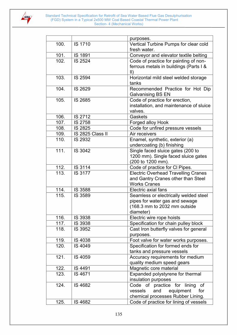
Standard Technical Specification for Retrofit of Sea Water Based Flue Gas Desulphurisation (FGD) System in a Typical 2x500 MW Coal Based Coastal Thermal Power Plant
Section- 4 (Mechanical Works)
135
purposes.
100. IS 1710 Vertical Turbine Pumps for clear cold fresh water.
101. IS 1891 Conveyor and elevator textile belting
102. IS 2524 Code of practice for painting of non-ferrous metals in buildings (Parts I & Il)
103. IS 2594 Horizontal mild steel welded storage tanks
104. IS 2629 Recommended Practice for Hot Dip Galvanising BS EN
105. IS 2685 Code of practice for erection, installation, and maintenance of sluice valves.
106. IS 2712 Gaskets
107. IS 2758 Forged alloy Hook
108. IS 2825 Code for unfired pressure vessels
109. IS 2825 Class II Air receivers
110. IS 2932 Enamel, synthetic, exterior (a) undercoating (b) finishing
111. IS 3042 Single faced sluice gates (200 to 1200 mm). Single faced sluice gates (200 to 1200 mm).
112. IS 3114 Code of practice for Cl Pipes.
113. IS 3177 Electric Overhead Travelling Cranes and Gantry Cranes other than Steel Works Cranes
114. IS 3588 Electric axial fans
115. IS 3589 Seamless or electrically welded steel pipes for water gas and sewage (168.3 mm to 2032 mm outside diameter)
116. IS 3938 Electric wire rope hoists
117. IS 3938 Specification for chain pulley block
118. IS 3952 Cast Iron butterfly valves for general purposes.
119. IS 4038 Foot valve for water works purposes.
120. IS 4049 Specification for formed ends for tanks and pressure vessels
121. IS 4059 Accuracy requirements for medium quality medium speed gears
122. IS 4491 Magnetic core material
123. IS 4671 Expanded polystyrene for thermal insulation purposes
124. IS 4682 Code of practice for lining of vessels and equipment for chemical processes Rubber Lining.
125. IS 4682 Code of practice for lining of vessels

Standard Technical Specification for Retrofit of Sea Water Based Flue Gas Desulphurisation (FGD) System in a Typical 2x500 MW Coal Based Coastal Thermal Power Plant
Section- 4 (Mechanical Works)
136
and equipment for chemical processes-rubber lining
126. IS 4894 Centrifugal fans
127. IS 4984 High Density polyethylene pipes.
128. IS 4985 Unplasticised PVC Pipes.
129. IS 5037 Basic rack and modules of straight bevel gears
130. IS 5049 Construction of structural steel for stacker reclaimer
131. IS 5120 Technical requirements for roto dynamic special purpose pumps
132. IS 5312 Specification for Swing check type Reflux (Non return) valves for water works purposes — Part —1 • Single door Pattern
133. IS 5659 Pumps for process water.
134. IS 5749 Specification for Forged Ramshorn hooks
135. IS 6278 Code of practice for white washing and colour Washing
136. IS 6393 Steel pipe flanges
137. IS 7413 Code of practice for application and finishing of thermal industrial application and finishing of thermal insulation
138. IS 7938 Code for Air receivers
139. IS 8154 Pre formed calcium silicate insulation (for temperatures upto 650 deg C)
140. IS 8183 Bonded mineral wool
141. IS 9137 Code of acceptance test for centrifugal, mixed flow and axial pumps — Class C
142. IS 10221 Code of practice for coating and wrapping of underground mild steel pipelines.
143. IS 11727 Measurement and Evaluation of Vibration severity in Situ of large rotating machines with speed range from 10 to 200 rev/s.
144. IS 13183 Aluminium Paint, heat Resistant specification
145. IS 13834 Cranes classification.
146. IS 14164 Industrial application and finishing of thermal insulation material at temperature above —80 Deg C and upto 700 Deg C — Code of practice
147. IS 14846 Sluice valve for water works purposes (50 mm to 1200 mm size)

Standard Technical Specification for Retrofit of Sea Water Based Flue Gas Desulphurisation (FGD) System in a Typical 2x500 MW Coal Based Coastal Thermal Power Plant
Section- 4 (Mechanical Works)
137
Specification
148. IS 15560 Specification for Point hooks with shank capacity upto 160 Tonnes.
149. ISO 1217 Performance Guarantee
150. ISO-3945 Mechanical Vibration of Large Rotating machines
151. ISO 8501-1 Preparation of steel substrates before application of paint & related Products. Part-I: Rust grades & preparation grades of uncoated steel substrates & steel substrates after overall removal of previous coatings
152. ISO 8502-3 Assessment of dust on steel surface prepared for painting (Pressure sensitive tape method)
153. ISO 12944 (Part 1 to 7) Corrosion protection of steel structures by Protective paint systems
154. ISO 20340 Pre-Qualification test
155. ISO 14692 Petroleum and natural gas industries – Glass reinforced plastics (GRP) piping
156. BS EN ISO 14713 Code of practice for protection of iron & steel structure against corrosion
157. SSPC US specifications of Steel Structures Painting Council, SSPC Volumes 1 and 11
158. SSPC-SP-08 Surface preparation by Pickling
159. NORSOK M-501 Surface preparation & Protective coating
160. AWWA American Water works Association
161. AWWA M45 GRP Pipe Design manual
162. AWWA C950 Standards for fibre glass pressure pipe

Standard Technical Specification for Retrofit of Sea Water Based Flue Gas Desulphurisation (FGD) System in a Typical 2x500 MW Coal Based Coastal Thermal Power Plant
Section- 4 (Mechanical Works)
138
163. NFPA National Fire Protection Association
164. HIS Hydraulic Institute Standards
165. HEI Heat Exchange Institute
166. TEMA Tubular Exchange Manufacturer’s Association
167. PTC 8.2 ASME Performance Test Code for Centrifugal Pumps
168. IBR Indian Boiler Regulations
169. UKOOA Specifications and Recommended Practice for the u se of GRP Piping Offshore
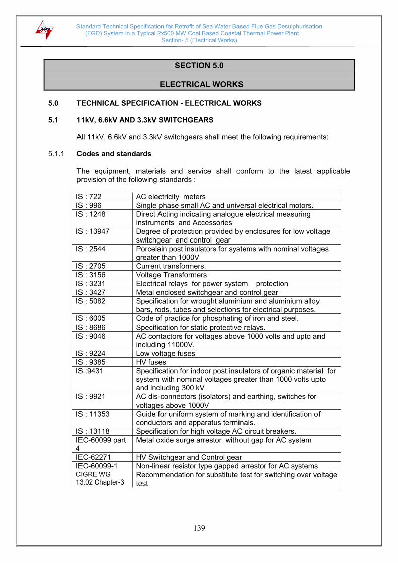
Standard Technical Specification for Retrofit of Sea Water Based Flue Gas Desulphurisation (FGD) System in a Typical 2x500 MW Coal Based Coastal Thermal Power Plant
Section- 5 (Electrical Works)
139
SECTION 5.0
ELECTRICAL WORKS
5.0 TECHNICAL SPECIFICATION - ELECTRICAL WORKS 5.1 11kV, 6.6kV AND 3.3kV SWITCHGEARS
All 11kV, 6.6kV and 3.3kV switchgears shall meet the following requirements:
5.1.1 Codes and standards
The equipment, materials and service shall conform to the latest applicable provision of the following standards :
IS : 722 AC electricity meters IS : 996 Single phase small AC and universal electrical motors. IS : 1248 Direct Acting indicating analogue electrical measuring
instruments and Accessories IS : 13947 Degree of protection provided by enclosures for low voltage
switchgear and control gear IS : 2544 Porcelain post insulators for systems with nominal voltages
greater than 1000V IS : 2705 Current transformers. IS : 3156 Voltage Transformers IS : 3231 Electrical relays for power system protection IS : 3427 Metal enclosed switchgear and control gear IS : 5082 Specification for wrought aluminium and aluminium alloy
bars, rods, tubes and selections for electrical purposes. IS : 6005 Code of practice for phosphating of iron and steel. IS : 8686 Specification for static protective relays. IS : 9046 AC contactors for voltages above 1000 volts and upto and
including 11000V. IS : 9224 Low voltage fuses IS : 9385 HV fuses IS :9431 Specification for indoor post insulators of organic material for
system with nominal voltages greater than 1000 volts upto and including 300 kV
IS : 9921 AC dis-connectors (isolators) and earthing, switches for voltages above 1000V
IS : 11353 Guide for uniform system of marking and identification of conductors and apparatus terminals.
IS : 13118 Specification for high voltage AC circuit breakers. IEC-60099 part 4
Metal oxide surge arrestor without gap for AC system
IEC-62271 HV Switchgear and Control gear IEC-60099-1 Non-linear resistor type gapped arrestor for AC systems CIGRE WG 13.02 Chapter-3
Recommendation for substitute test for switching over voltage test

Standard Technical Specification for Retrofit of Sea Water Based Flue Gas Desulphurisation (FGD) System in a Typical 2x500 MW Coal Based Coastal Thermal Power Plant
Section- 5 (Electrical Works)
140
5.1.2 Technical Parameters i) The switchgears shall be indoor, metal clad, draw out type. The feeders rated
2000kW and above shall be provided with vacuum/ SF6 circuit breakers. However, the motor feeders below 2000kW rating shall have vacuum/ SF6 contactors backed up by HRC. The operating mechanism of the circuit breakers shall be of the stored energy type DC motor operated charging springs.
ii) The circuit breaker, contactor and switchgear assemblies shall have the
following technical parameters :
a) System parameters
1) Nominal System voltage 11 kV 6.6kV 3.3 kV 2) Highest System voltage 12 kV 7.2kV 3.6 kV 3) Rated Frequency 50 Hz 50 Hz 50 Hz 4) Number of phases Three Three Three 5) System neutral earthing Earthed through resistance to limit fault
current to 300A or
High resistance grounding through artificial earthing transformer and earthing resistor
6) One minute power frequency withstand voltage
- for Type tests 28 20 10
- for Routine tests 28 20 10 7) 1.2/50 microsecond Impulse
withstand voltage 75 kV (peak)
60 kV (peak)
40 kV(peak)
8) Maximum system fault level including initial motor contribution
40 kA for 1 second
40 kA for 1 second
40 kA for 1 second
9) Dynamic withstand rating 100 kA (peak) 10) IAC Rating 40kA, 1sec
11) Control supply voltage - Trip and closing coils ---- 220V DC ----
- Spring charging motor ------220V DC ----- (240V AC can be accepted for off-site
areas) - Space heaters ----- 240V AC ----
12) Ambient temperature
500C
b) Busbars
1) Continuous current rating at 500C ambient:
as per system requirements
2) Temperature rise
- 400C for plain joints - 550C for silver plated joints

Standard Technical Specification for Retrofit of Sea Water Based Flue Gas Desulphurisation (FGD) System in a Typical 2x500 MW Coal Based Coastal Thermal Power Plant
Section- 5 (Electrical Works)
141
c) Constructional requirements
1) Colour finish - exterior and interior
as mentioned elsewhere
2) Cable entry
- Power cables Bottom
- Control cables
Bottom
3) Bus duct entry
----Top---
4) Earthing conductor
Galvanised steel strip
5) Service Continuity of swgrs (as per IEC 62271-200)
LSC2B-PM
d) Circuit breakers
1) Short circuit breaking current
- AC component 40 kA
- DC component As per IS 13118 or IEC 62271
2) Short circuit making current 100 kA (peak)
3) Operating Duty B – 3min – MB – 3min – MB 4) Total break time Not more than 4 cycles 5) Total make time Not more than 5 cycles 6) Operating Mechanism Motor wound spring charged stored
energy type as per IEC 62271
e) Relays 1) One minute power
frequency 2.0 kV (rms)
f) Meters
1) Accuracy class for energy accounting and audit meters
- on incomer of each 11kV, 6.6kV and 3.3kV switchgear
- on all 11kV, 6.6kV and 3.3kV motor
other meters
0.2S
0.2S
1.0
2) One minute power frequency
2.0 kV (rms)
g) Current Transformer 1) Class of Insulation Class E or better
2) Rated output of each
Adequate for the relays and devices connected, but not less than fifteen (15) VA.

Standard Technical Specification for Retrofit of Sea Water Based Flue Gas Desulphurisation (FGD) System in a Typical 2x500 MW Coal Based Coastal Thermal Power Plant
Section- 5 (Electrical Works)
142
3) Accuracy class
Measurement core for energy accounting and audit meters
- on incomer of each 11kV, 6.6kV and 3.3kV switchgear
- on all 11kV, 6.6kV and 3.3kV motor
0.2S
0.2S
Protection core - differential and core
balance CTs - other protection CTs
PS
5P20
4) Minimum primary earth fault current to be detected by core balance CT
3 A
h) Voltage Transformers
1) Rated voltage factor 1.2 continuous for all VTs, and 1.9 for 30 sec. for star connected VTs.
2) Measurement 0.2S 3) Protection 3P 4) VA burden Adequate for application
i) Fuses
1) Voltage class 11kV
6.6kV 3.3kV
2) Rupturing Capacity Adequate for 100 kA (peak)
3) Rated current
As per application
j) Surge arresters
11 kV 6.6kV 3.3kV
1) Nominal discharge current (8x20 micro-sec.)
500 Amp
2) Maximum system voltage 12 kV 7.2kV 3.6kV 3) Maximum standard impulse
spark over voltage (peak) 25 kV (without any positive tolerance)
4) Residual voltage at nominal discharge current
25 kV
12kV 8kV
5) Temporary over voltage capability (rms)
a) For 10,000 seconds 12 kV 7.2kV 3.6kV
b) For 5 seconds 14.3 kV 8.6kV 4.3kV
6) Installation
Inside the switchgear panel
k) Contactors 1) Nominal system voltage NA 6.6kV 3.3kV 2) Highest system voltage NA 7.2kV 3.6kV
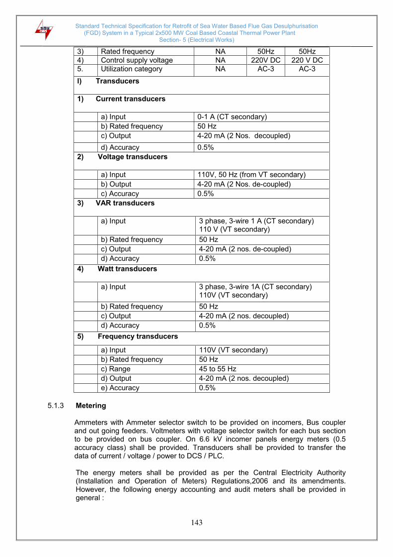
Standard Technical Specification for Retrofit of Sea Water Based Flue Gas Desulphurisation (FGD) System in a Typical 2x500 MW Coal Based Coastal Thermal Power Plant
Section- 5 (Electrical Works)
143
3) Rated frequency NA 50Hz 50Hz 4) Control supply voltage NA 220V DC 220 V DC 5. Utilization category NA AC-3 AC-3
l) Transducers 1) Current transducers
a) Input 0-1 A (CT secondary)
b) Rated frequency 50 Hz
c) Output 4-20 mA (2 Nos. decoupled)
d) Accuracy 0.5%
2) Voltage transducers
a) Input 110V, 50 Hz (from VT secondary)
b) Output 4-20 mA (2 Nos. de-coupled)
c) Accuracy 0.5%
3) VAR transducers
a) Input
3 phase, 3-wire 1 A (CT secondary) 110 V (VT secondary)
b) Rated frequency 50 Hz
c) Output 4-20 mA (2 nos. de-coupled)
d) Accuracy 0.5%
4) Watt transducers
a) Input 3 phase, 3-wire 1A (CT secondary) 110V (VT secondary)
b) Rated frequency 50 Hz
c) Output 4-20 mA (2 nos. decoupled)
d) Accuracy 0.5%
5) Frequency transducers
a) Input 110V (VT secondary)
b) Rated frequency 50 Hz
c) Range 45 to 55 Hz
d) Output 4-20 mA (2 nos. decoupled)
e) Accuracy 0.5%
5.1.3 Metering Ammeters with Ammeter selector switch to be provided on incomers, Bus coupler and out going feeders. Voltmeters with voltage selector switch for each bus section to be provided on bus coupler. On 6.6 kV incomer panels energy meters (0.5 accuracy class) shall be provided. Transducers shall be provided to transfer the data of current / voltage / power to DCS / PLC.
The energy meters shall be provided as per the Central Electricity Authority (Installation and Operation of Meters) Regulations,2006 and its amendments. However, the following energy accounting and audit meters shall be provided in general :

Standard Technical Specification for Retrofit of Sea Water Based Flue Gas Desulphurisation (FGD) System in a Typical 2x500 MW Coal Based Coastal Thermal Power Plant
Section- 5 (Electrical Works)
144
- On each incoming feeder of 11kV, 6.6kV and 3.3kV buses. - On all 11kV,6.6kV and 3.3kV motor feeders Energy accounting and audit meters shall be of accuracy class of 0.2S. The accuracy class of CTs and VTs shall not be inferior to that of associated meters. In case, numerical relays having built-in features of energy measurement of requisite accuracy are provided in switchgear, separate energy meter is not necessary.
5.1.4 General Technical Requirements
i) Switchgear panel
a) Each 3.3kV switchboard shall have two sections each of 100% capacity
and connected through a ‘Normally Open’ bus-coupler. These two sections shall be fed from two independent sources to be arranged by the bidder.
b) Single phase VTs on the incoming breaker panels shall be provided for
checking the voltage on both of the sections while paralleling. The Automatic Reserve Closure (ARC) facility shall be provided on bus-coupler breaker such that it will close automatically in case of failure of any one incomer.
c) The ‘Synchronizing Check’ relay with necessary ancillary equipment
shall be provided for manual bus transfer with and without voltage interruption. The type, make etc. of the relay/scheme shall be subjected to prior approval of the purchaser.
d) All necessary instruments, such as ammeter, voltmeter with selector
switch, etc. in incomer breaker panels shall be provided. e) The switchgear shall have a single front, single tier, fully
compartmentalized, metal clad construction complying with clause No. 3.102 of IEC-62271-200, comprising of a row of free standing floor mounted panels. Each circuit shall have a separate vertical panel with distinct compartments for circuit breaker/contactor truck, cable termination, main busbars and auxiliary control devices. The adjacent panels shall be completely separated by steel sheets except in busbar compartments where insulated barriers shall be provided to segregate adjacent panels.
f) The circuit breakers/ contactors and bus VTs shall be mounted on
withdrawable trucks which shall roll out horizontally from service position to isolated position.
g) The trucks shall have distinct Service, Test and Isolated positions. It
shall be possible to close the breaker/contactor compartment door in Isolated position also, so that the switchgear retains its specified degree of protection. While switchboard designs with doors for breaker/contactor compartments would be preferred, standard designs of reputed switchgear manufacturer's where the truck front serves as the compartment cover may also be considered, provided the breaker/ contactor compartment is completely sealed from all other compartments and retains the IP-4X degree of protection in the Isolated
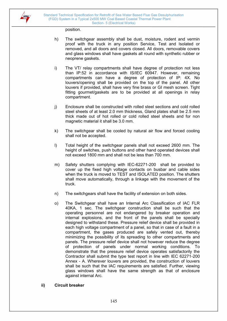
Standard Technical Specification for Retrofit of Sea Water Based Flue Gas Desulphurisation (FGD) System in a Typical 2x500 MW Coal Based Coastal Thermal Power Plant
Section- 5 (Electrical Works)
145
position. h) The switchgear assembly shall be dust, moisture, rodent and vermin
proof with the truck in any position Service, Test and Isolated or removed, and all doors and covers closed. All doors, removable covers and glass windows shall have gaskets all round with synthetic rubber or neoprene gaskets.
i) The VT/ relay compartments shall have degree of protection not less
than IP:52 in accordance with IS/IEC 60947. However, remaining compartments can have a degree of protection of IP: 4X. No louvers/opening shall be provided on the top of the panel. All other louvers if provided, shall have very fine brass or GI mesh screen. Tight fitting gourmet/gaskets are to be provided at all openings in relay compartment.
j) Enclosure shall be constructed with rolled steel sections and cold rolled
steel sheets of at least 2.0 mm thickness, Gland plates shall be 2.5 mm thick made out of hot rolled or cold rolled steel sheets and for non magnetic material it shall be 3.0 mm.
k) The switchgear shall be cooled by natural air flow and forced cooling
shall not be accepted. l) Total height of the switchgear panels shall not exceed 2600 mm. The
height of switches, push buttons and other hand operated devices shall not exceed 1800 mm and shall not be less than 700 mm.
m) Safety shutters complying with IEC-62271-200 shall be provided to
cover up the fixed high voltage contacts on busbar and cable sides when the truck is moved to TEST and ISOLATED position. The shutters shall move automatically, through a linkage with the movement of the truck.
n) The switchgears shall have the facility of extension on both sides. o) The Switchgear shall have an Internal Arc Classification of IAC FLR
40KA, 1 sec. The switchgear construction shall be such that the operating personnel are not endangered by breaker operation and internal explosions, and the front of the panels shall be specially designed to withstand these. Pressure relief device shall be provided in each high voltage compartment of a panel, so that in case of a fault in a compartment, the gases produced are safely vented out, thereby minimizing the possibility of its spreading to other compartments and panels. The pressure relief device shall not however reduce the degree of protection of panels under normal working conditions. To demonstrate that the pressure relief device operates satisfactorily the Contractor shall submit the type test report in line with IEC 62271-200 Annex - A. Wherever louvers are provided, the construction of louvers shall be such that the IAC requirements are satisfied. Further, viewing glass windows shall have the same strength as that of enclosure against internal Arc.
ii) Circuit breaker

Standard Technical Specification for Retrofit of Sea Water Based Flue Gas Desulphurisation (FGD) System in a Typical 2x500 MW Coal Based Coastal Thermal Power Plant
Section- 5 (Electrical Works)
146
a) The circuit breakers shall be of Vacuum/ Sulphur hexaflouride (SF6) type. They shall comprise of three separate, identical single pole interrupting units, operated through a common shaft by a sturdy operating mechanism. Surge arrestor shall be provided for each motor/ transformer feeder.
b) Circuit breaker shall be restrike free, stored energy operated and trip
free type. Motor wound closing spring charging shall only be acceptable. An anti-pumping relay shall be provided for each breaker, even if it has built-in mechanical anti-pumping features.
c) Plug and socket isolating Contacts for main power circuit shall be silver
plated, of self-aligning type, of robust design and capable of withstanding the specified short circuit currents. They shall preferably be shrouded with an insulating material. Plug and socket contacts for auxiliary circuits shall also be silver plated, sturdy and of self-aligning type having a high degree of reliability. Thickness of silver plating shall not be less than 10 microns.
d) In case of SF6 gas type circuit breaker, necessary pressure/ density
monitoring switch along with the contact for remote indication shall be provided.
iii) Protection
The protective Numerical relays shall be provided for protection of all the three phases of feeders. Adequate electrical protections with auxiliary relays and timers as required shall be provided for all the equipment which shall include but not limited to following. a. The 11/6.6/3.3 kV Incoming (Main & Bus Coupler) and Outgoing
supply feeders :
i) Three Phase Over current (50). ii) Bus No-volt iii) Lockout (86) iv) Earth fault protection (50N) v) Synchronizing check (25)
b. The 11/6.6/3.3kV motor feeders :
i) Instantaneous over current relay (50) ii) Thermal overload relay (49). iii) Locked rotor protection (50LR) iv) Protection relay for Unbalance current (46) v) Earth fault protection (50N) vi) Under voltage (27M) with VT fuse failure vii) Motor start monitoring & Restart inhibit feature viii) Number of starts limitation (66) ix) Differential Protection-High Impedance(87M) for Motors of rating ≥
2MW
Standard Technical Specification for Retrofit of Sea Water Based Flue Gas Desulphurisation (FGD) System in a Typical 2x500 MW Coal Based Coastal Thermal Power Plant
Section- 5 (Electrical Works)
147
c. 11kV/3.3kV, 11kV/433V, 6.6kV/433V auxiliary service transformers
feeders :
i) Instantaneous Over current for short circuit protection (50) ii) Back-up Instantaneous Over current for short circuit protection (51) iii) Transformer in-built protection for incipient fault. iv) Earth fault protections (50N) v) Zero sequence protection/REF on LV side (neutral CT to be provided
in case of solid grounding) vi) Stand by earth fault protection (51N) for TRF LV neutral resistively
grounded vii) Transformer Differential protection-Low impedance (87T) for
Transformer rating ≥ 5 MVA
iv) Relays
a) The protective relays shall be numerical type. All relays, auxiliary relays and devices shall be of reputed make and types proven for the application and shall be subject to purchaser approval. The relays and timers shall have appropriate setting ranges, accuracy, resetting ratio, transient over-reach and other characteristics to provide required sensitivity to the satisfaction of the owner.
b) Relays shall be suitable for efficient and reliable operation of the
protection scheme. Necessary auxiliary relays, timers, trip relays, etc. required for complete scheme, interlocking, alarm, logging, etc. shall be provided. No control relay, which shall trip the circuit breaker when relay is de-energized, shall be employed in the circuits.
c) Relays shall be flush mounted on the front with connections at the rear.
Provision shall be made for easy isolation of trip circuits for testing and maintenance.
d) Relays shall be provided with self-reset contacts except the trip, lockout
relays and interlocking (contact multiplication) relays which shall be manual reset type
e) Auxiliary relays shall be provided in the trip circuits of protections
located outside the board, such as Buchholz relay, temperature indicators, fire protection, etc.
f) Suitable measures shall be provided to ensure that transients present in
CT and VT connections due to extraneous sources in 400kV system do not cause damage to static circuit.
g) Only DC/ DC converters shall be provided in the solid state devices/
relays wherever necessary to provide a stable auxiliary supply for relay operation
h) All relays shall have hand-reset flags or other means for ready visual
indication of their operation and also of the faulty phase.
v) Contactor
a) Mechanically latched type contactors shall be backed by HRC fuses for

Standard Technical Specification for Retrofit of Sea Water Based Flue Gas Desulphurisation (FGD) System in a Typical 2x500 MW Coal Based Coastal Thermal Power Plant
Section- 5 (Electrical Works)
148
outgoing motor feeders. The high voltage contactors shall be of AC-3 utilization category and shall be SF6 or vacuum type. The fuse and contactor assembly shall be mounted on a withdrawable truck. Circuits shall be provided with suitable single phasing protection.
b) Surge suppressors shall be provided on all contactor controlled motor feeders.
vi) Surge arrestor
The surge arrestors shall be provided for all motor/ transformer feeders and shall be metal oxide, gapped or gap less type generally in accordance with IEC 60099-1 and suitable for indoor duty. These shall be mounted within the switchgear cubicle between line and earth, preferably in the cable compartment. Surge arrestor selected shall be suitable for non-effectively earthed system and rating shall be in such a way that the value of steep fronted switching over voltage generated at the switchgear terminals shall be limited to the requirements of switchgear.
vii) Control and Interlocks
a) The circuit breaker/ contactor will normally be controlled from remote control panels through closing and shunt trip coils. The control switch located on the switchgear would normally be used only for testing of circuit breaker/ contactor in isolated position, and for tripping it in an emergency.
b) The circuit-breaker shall have three distinct positions as follows: ‘Service’ - Both power and control contacts connected. 'Test' - Power contacts isolated, control contacts connected. 'Isolated' - Both power and control contacts isolated.
c) ‘Red’, ‘Green’ and ‘white’ indication lamps shall be provided on the panel to indicate breaker ‘Close’, ‘Open’ and ‘Auto-Trip’ position. In addition to above, mechanical indicator shall be provided which shall be clearly visible to the operator standing in front of the panel.
d) Suitable indication to show the circuit-breaker 'service' and 'Test' positions shall be provided.
e) Facilities shall be provided for mechanical tripping of the breaker/
contactor and for manual charging of the stored energy mechanism for a complete duty cycle, in an emergency. These facilities shall be accessible only after opening the compartment door.
f) Six (6) normally open (NO) and six (6) normally closed (NC) auxiliary
contacts shall be provided in Incomer, Bus coupler and tie feeders for future use. For all other breakers/ contactor modules four (4) NO and four (4) NC contacts shall be provided. The above contacts shall be wired out to the terminal blocks. Contact multiplication, if necessary to meet the above contact requirement, shall be done through electrical reset latch relay.
viii) Busbars and Insulators
a) All busbar and jumper connections shall be of high conductivity

Standard Technical Specification for Retrofit of Sea Water Based Flue Gas Desulphurisation (FGD) System in a Typical 2x500 MW Coal Based Coastal Thermal Power Plant
Section- 5 (Electrical Works)
149
aluminium alloy. They shall be adequately supported on insulators to withstand electrical and mechanical stresses due to specified short circuit currents.
Busbar cross-section shall be uniform throughout the length of switchgear. Busbars and other high voltage connection shall be sufficiently corona free at maximum working voltage. All busbars shall be colour coded. .All horizontal & vertical busbars shall have high voltage sleeving.
b) The temperature rise of the horizontal and vertical busbars when
carrying the rated current shall be in no case exceed 550C for silver plated joints and 400C for all other type of joints. The temperature rise at the switchgear terminals intended for external cable termination shall not exceed 400C. Further the switchgear parts handled by the operator shall not exceed a rise of 50C. The temperature rise of the accessible parts/ external enclosure expected to be touched in normal operation shall not exceed 200C.
ix) Earthing and earthing devices
a) A galvanised steel or copper earthing bus shall be provided at the
bottom and shall extend through out the length of each switchgear. It shall be bolted/ welded to the framework of each panel and each breaker/ contactor earthing contact bar.
b) The earth bus shall have sufficient cross section to carry the momentary
short circuit and short time fault currents to earth as indicated under switchgear parameters without exceeding the allowable temperature rise.
c) All joint splices to the earth bus shall be made through atleast two bolts
and taps by proper lug and bolt connection. d) The truck and breaker / contactor frame shall get earthed while the truck
is being inserted in the panel and positive earthing of the truck and breaker / contactor frame shall be maintained in all positions i.e. Service, Test and Isolated as well as throughout the intermediate travel. The truck shall also get and remain earthed when the control plug is connected irrespective of its position.
e) All metallic cases of relays, instruments and other panel mounted
equipment shall be connected to earth by independent stranded copper wires of suitable size.
f) VT and CT secondary neutral point earthing shall be at one place only
on the terminal block. Such earthing shall be made through links so that earthing of one secondary circuit may be removed without disturbing the earthing of other circuits.
g) Separate earthing trucks shall be provided for maintenance work. These
trucks shall be suitable for earthing the switchgear busbars as well as outgoing / incoming cables or bus ducts. The trucks shall have a voltage transformer and an interlock to prevent earthing of any live connection. The earthing trucks shall in addition have a visual and audible

Standard Technical Specification for Retrofit of Sea Water Based Flue Gas Desulphurisation (FGD) System in a Typical 2x500 MW Coal Based Coastal Thermal Power Plant
Section- 5 (Electrical Works)
150
annunciation to warn the operator against earthing of live connections. As an alternative to separate earthing trucks, built-in earthing facilities for the busbars and outgoing / incoming connections, in case such facilities are available in their standard proven switchgear design shall also be acceptable. The inbuilt earthing switches shall have provision for short circuiting and earthing a circuit intended to be earthed. These switches shall be quick make type, independent of the action of the operator and shall be operable from the front of the switchgear panel. These switches shall have facility for padlocking in the earthed condition. h) Interlocks shall be provided to prevent : - Closing of the earthing switch if the associated circuit breaker truck is in
Service position.
- Insertion of the breaker truck to Service position if earthing switch is in closed position.
- Closing of the earth switch on a live connection. Three (3) nos. voltage
capacitive dividers shall be provided on each phase of the section intended for earthing and three (3) nos. "RED" neon lamps/ LEDs connected to these on the panel front for visual indication.
- Energising an earthed Section : Complete details of arrangement
offered shall be included in the bid, describing the safety features and interlocks.
i) The earthing device (truck/ switch) shall have the short circuit withstand
capability equal to that of associated switchgear panel. 4 NO+4 NC of auxiliary contacts of the earthing device shall be provided for interlocking purpose.
j) All hinged doors shall be earthed through flexible earthing braid.
x) Painting
All sheet steel work shall be pretreated, in tanks, in accordance with IS:6005. Degreasing shall be done by alkaline cleaning. Rust and scales shall be removed by pickling with acid. After pickling, the parts shall be washed in running water. Then these shall be rinsed in slightly alkaline hot water and dried. The phosphate coating shall be "Class-C " as specified in IS : 6005. The phosphated surfaces shall be rinsed and passivated prior to application of stoved lead oxide primer coating. After primer application, Electrostatic Powder Painting shall be used. Finishing paint shade for complete panels excluding end covers shall be RAL9002 and RAL5012 for extreme end covers of all switchgears. The paint thickness shall not be less than 50 microns.
xi) Instrument transformers (CT’s and VT’s)
a) All current and voltage transformers shall be completely encapsulated cast resin insulated type, suitable for continuous operation at the ambient temperature prevailing inside the switchgear enclosure. The class of insulation shall be E or better.

Standard Technical Specification for Retrofit of Sea Water Based Flue Gas Desulphurisation (FGD) System in a Typical 2x500 MW Coal Based Coastal Thermal Power Plant
Section- 5 (Electrical Works)
151
b) Current transformers may be multi or single core and shall be located in the cable termination compartment. All voltage transformers shall be single phase type. The bus VTs shall be housed in a separate panel on a truck so as to be fully withdrawable. Separate set of current transformer shall be provided for differential protection of the feeder.
c) Core balance CTs (CBCT) shall be provided on outgoing motor and
transformer feeders having CT ratio 50/1A. These CBCTs shall be mounted inside the switchgear panel.
d) All voltage transformers shall have suitable HRC current limiting fuses
on both primary and secondary sides. Primary fuses shall be mounted on the withdrawable portion. Replacement of the primary fuses shall be possible with VT truck in Isolated position.
xii. Instruments and Meters
a) Indicating instruments and integrating meters shall be flush mounted on panel front. The instruments shall be of atleast 96 mm2 size with 90 deg. scales. The covers and cases of instruments and meters shall provide a dust and vermin proof construction.
b) Ammeters on motor feeders shall have a compressed scale at the upper
current region to cover the motor starting current without graduation from one to six times the rated CT secondary current. These shall be suitable to withstand the above current of motors which can last upto 30 seconds (under stalled condition) without any damage or loss of accuracy.
c) Watt-hour meters shall preferably be 3-phase two (2) element type
suitable for measurement of unbalanced loads in three phase three wire system.
d) Watt-hour meters shall preferably be provided in drawout cases with
built-in testing facilities. Alternatively, they may have test blocks to facilitate testing of meters without disturbing CT and VT secondary connections. Watthour meters shall have reverse running stops. They shall have sixdigit register indicating primary circuit energy in MWH with atleast count on 0.1 MWH.
e) Suitableself powered transducers as per IS:12784 Part-I for feeding
signals to panel mounted electrical meters (ammeters, voltmeters, VAR meters and wattmeters etc.) and DCCMIS shall be provided.
Transducers shall be tested as per IEC – 600298 or impulse test etc and short circuit withstand capability as per ANSI C 37.90a, 1989.
Transducers shall be provided with two decoupled 4-20mA output signals, one for meter and one for DDCMIS. Current limiting features shall be provided for all the transducers.
f) Necessary hardware shall be provided in the switchgear panel like
coupling relays (24VDC with maximum burden of 2.5VA), auxiliary relays in addition to current/ bus-voltage transducers (4-20 mA, dual
Standard Technical Specification for Retrofit of Sea Water Based Flue Gas Desulphurisation (FGD) System in a Typical 2x500 MW Coal Based Coastal Thermal Power Plant
Section- 5 (Electrical Works)
152
output) etc. to effect interlocks, exchange information/ status and exercise control from remote.
xiii) Control and Selector switches
a) Control and selector switches shall be of heavy duty, rotary type with escutcheon plates clearly marked to show the positions. The switches shall be of sturdy construction suitable for mounting on panel front. Switches with shrouding of live parts and sealing of contacts against dust ingress shall be preferred.
b) On-Off control switches shall have three positions and shall be spring
return to 'Neutral' from close and trip positions. They shall have two contacts closing in close position and two contacts closing in trip positions, and shall have Pistol Grip handles. Lost motion feature shall be provided wherever required.
c) Selector switch shall have two stay put positions as per the module
requirements indicated elsewhere. They shall have two contacts for each of the positions and shall have black Spade handle.
d) Ammeter and Voltmeter selector switches shall have four stay-put
positions with adequate number of contacts for three phase system. These shall have oval handles. Ammeter selector switches shall have make before break type contacts to prevent open circuiting of CT secondary.
xiv) Indicating lamps
a) Indicating lamps shall be of the panel mounting, LED type and low watt consumption preferably built in the lamp assembly. The lamps shall have escutcheon plates marked with its function, wherever necessary.
b) Lamps shall have translucent lamp-covers of the following colours, as
warranted by the application:
Red Closed Green Open White Auto-trip Blue For all healthy conditions (e.g. control supply, spring
charged, and lock out relay coil healthy) Amber For all alarm conditions (e.g. pressure low, over load)
also for Service and Test positions indications.
xv) Control supply and Space heater supply a) Each switchboard shall be provided with two (2) Nos. of 220 V DC feeders
for the control supply. b) Under voltage relay to monitor each of the control supply shall be provided. c) All DC circuits shall be fused on both poles. Single phase AC circuits shall
have fuses on line and link on neutral.

Standard Technical Specification for Retrofit of Sea Water Based Flue Gas Desulphurisation (FGD) System in a Typical 2x500 MW Coal Based Coastal Thermal Power Plant
Section- 5 (Electrical Works)
153
xvi) Space heater a) Each switchgear panel shall be equipped with thermostatically controlled
space heater(s), suitably located in breaker/contactor and cable compartments to prevent condensation within the enclosure. The space heater shall be connected to 240 V single phase AC auxiliary supply available in the switchgear, through switches and fuses provided separately for each panel.
b) For motor space heater supply, one breaker / contactor normally closed
(NC) auxiliary contact of each motor feeder shall be wired out in series of switch fuse upto terminals block in the respective panels of switch boards. The motor space heater supply shall be taken from Panel space heater supply given to switch board.
c) A 240V single phase 50 Hz AC plug point shall be provided in the interior
of each cubicle with ON-OFF switch for connection of hand lamp.
xvii) Terminal blocks
a) Terminal blocks shall be 650 Volts grade, 10 Amps rated, one piece moulded complete with insulating barriers. clip on type terminals, washers, nuts and identification strips.
b) Terminal blocks for CT and VT secondary leads shall be provided with
links to facilitate testing, isolation star/delta formation and earthing. Terminal blocks for CT secondary shall have the short circuiting facility.
c) Atleast 10% spare terminals for external connections shall be provided on
each panel and these spare terminals shall be uniformly distributed on all terminal blocks. Space for adding another 10% spare terminals shall also be available in each panel.
xviii) Power cable termination
a) Cable termination compartment shall receive stranded Aluminium conductor, XLPE insulated, shielded, armoured/ unarmoured, PVC jacketed, single core/ three core unearthed/ earthed grade power cable(s).
b) A minimum clearance of about 600 mm shall be kept between the cable
lug bottom ends and gland plates for stress cone formation for XLPE cables. Interphase clearance in the cable termination compartment shall be adequate to meet electrical and mechanical requirement besides facilitating easy connections and disconnections of cables.
c) Cable termination compartment shall be complete with power terminals,
power lugs and associated hardware and removable undrilled gland plates. For all single core cables gland plates shall be of nonmagnetic material.
xix) Name plates and Labels
a) Each switchgear shall have a name plate for its identification. All enclosure mounted equipment shall be provided with individual engraved name plates for clear equipment identification. All panels shall be identified on front as well as backside by large engraved name plates giving the distinct

Standard Technical Specification for Retrofit of Sea Water Based Flue Gas Desulphurisation (FGD) System in a Typical 2x500 MW Coal Based Coastal Thermal Power Plant
Section- 5 (Electrical Works)
154
feeder description along with panel numbers. Back side name plates shall be fixed in panel frame and not on the rear removable cover.
b) Name plate shall be of non-rusting metal or 3-ply lacmoid with white
engraved letterings, on black background. Letter size shall be of at least 10mm height.
5.1.5 Spare feeders
10% spare feeders with at least one of each type of highest rating shall be provided in each switchgear section.
5.1.6 Make of Components
The bidder shall indicate the proposed makes of various bought out components such as relays, CT’s, VT’s, control transformers, load breaker switch, fuse, contactor, push button. Space heater, instruments etc. in the technical bidding schedule. However, this shall not be bindings on the purchaser, final make shall be approved by the purchaser/ consultant during detailed engineering to satisfy the specification requirement.
5.1.7 Tests
a) Type Tests:
Reports of all type tests shall be submitted before dispatch for approval. In case type test report on similar equipment (conducted within 10 years as on the date of bid opening) is not available, these tests shall be carried out. The bidder shall clearly indicate in his tender whether he would be furnishing the type tests reports or he shall be conducting the tests along with the additional cost for such tests, if any. The purchaser reserves the right either to waive the type tests or get these type tests conducted.
b) Routine tests: All routine tests as per relevant standards shall be conducted on the assembly and the various components. The successful bidder shall submit five (5) copies of certified test reports on all routine tests before dispatch for approval.
c) The purchaser reserves the right to witness all the tests. The tenderer shall give at least three weeks clear notice prior to conducting these tests to enable the purchaser and/or his representative to be present to witness the test.
d) Site Tests : The following site tests shall be conducted as per the approved procedure to be submitted during detailed engineering : Visual inspection Insulation Test Calibration of relays & Instruments Function / interlock test Ratio and polarity for CTs and VTs Breaker closing and tripping time

Standard Technical Specification for Retrofit of Sea Water Based Flue Gas Desulphurisation (FGD) System in a Typical 2x500 MW Coal Based Coastal Thermal Power Plant
Section- 5 (Electrical Works)
155
Anti-pumping operation HV test on completely installed switchboard
5.1.8 Drawings and data
The bidders shall furnish the following drawings and data with the bid. a) Single line diagram and Bill of Material for every 11kV/6.6kV/3.3kV (as
applicable) switchboard including points of control. b) Single line diagram and schematic (interconnection) drawing of
11kV/6.6kV/3.3kV (as applicable) switchboards and 415V switchboard / MCCs/ distribution boards.
c) Layout drawings for the above equipment.
5.2 Auxiliary Service Transformer
a) 11/3.3kV HT OIL/ DRY TYPE TRANSFORMERS
(i) The transformers shall be provided with delta connected primary and a star
connected secondary with the star point brought out and resistance earthed
for 3.3kV system.
(ii) All auxiliary transformers shall be dry type (indoor)/ oil filled (outdoor) as per site requirement and considerations.
(iii) Rating
1. Vector Group
-- Dyn11/ Dyn1 (To be matched with existing transformers)
2. Tap Changing -- Off load externally hand operated
3. Tappings -- ± 2½ % and ± 5% on HV side
4. Impulse test Voltage --
75kV peak on 11kV and 40kV on 3.3kV
5. Power Freq. Test voltage
-- 28kV rms on 11kV, 10kV rms on 3.3kV
6. Type of transformers
-- Oil/ Cast Resin Dry Type Transformer
7. Type of cooling -- ONAN/ AN 8. Impedance -- The impedance of the transformers
shall be as per system requirement
9. Terminal connections of 11/3.3 or 6.6kV (as applicable)/ 0.433kV LT Transformers
-- Terminal connections of these transformers on 11/3.3kV side will be through 11/3.3kV (UE) (as applicable) XLPE Aluminium cables. Crimping lugs and compression glands shall be used for cable connections.
10. CT details and Bushing details
To be given by the utility

Standard Technical Specification for Retrofit of Sea Water Based Flue Gas Desulphurisation (FGD) System in a Typical 2x500 MW Coal Based Coastal Thermal Power Plant
Section- 5 (Electrical Works)
156
11. No load voltage correction factor
1.045 (Transformer No Load voltage/ rated bus Voltage)
12. Sizing The transformer size = the calculated size X no load voltage correction factor X 1.1 design margin
b) 11/0.433kV, 6.6/0.433kV or 3.3/ 0.433 kV LT OIL/ DRY TYPE TRANSFORMERS
i) The 415V distribution system shall have solidly earthed neutral. 415V Auxiliary supply for catering to various auxiliaries shall be obtained from 11/6.6/3.3/ 0.433kV Delta/ Star Transformers which in turn shall be fed from 11/6.6/3.3kV switchgear respectively. The 415V distribution system shall be designed with 2x100% rating transformers. The capacity of the transformers shall not exceed 2000kVA. In case the total 415V load for a system works out to be more then 2000kVA, the bidder shall design the 415V supply system with 3x50% rating transformer. These transformers shall have the following technical features and the capacity of each shall be either 500kVA, 630kVA, 1000kVA, 1600kVA or 2000kVA, and they shall be of the same make and type for interchangeability.
ii) All auxiliary transformers shall be dry type (indoor)/ oil filled (outdoor) as per site requirement and considerations.
iii) Rating
1. Vector Group
-- Dyn11/Dyn1(To be matched with existing transformers)
2. Tap Changing -- Off load externally hand operated
3. Tappings -- ± 2½ % and ± 5% on HV side
4. Impulse test Voltage --
75/60/40kV peak on HV
5. Power Freq. Test voltage
-- 28/20/10kV rms on 11kV/6.6kV/3.3 kV, 3.0kV rms on 0.433kV
6. Type of transformers
-- Oil/ Cast Resin Dry Type Transformer
7. Type of cooling -- ONAN/ AN 8. Impedance -- The impedance of the transformers
shall be in the range of the values in relevant standards. Impedance shall be chosen to limit the voltage drop on 415V system to the prescribed limits in the relevant standards as well as to limit the parameters of the 415V system to the following values:
System fault level - 50KA rms
Breaking capacity - 50KA rms

Standard Technical Specification for Retrofit of Sea Water Based Flue Gas Desulphurisation (FGD) System in a Typical 2x500 MW Coal Based Coastal Thermal Power Plant
Section- 5 (Electrical Works)
157
Making capacity - 105 KA p
Normal system voltage - 415 V
Highest system voltage - 476 V
Voltage variation - ±10 %
Frequency - 50 Hz
Frequency variation - ± 5 %
9. Terminal connections of 11/3.3 or 6.6kV (as applicable)/ 0.433kV LT Transformers
-- Terminal connections of these transformers on 11/6.6/3.3kV side will be through 11/6.6/3.3kV (UE) (as applicable) XLPE Aluminium cables. Terminal connections on LV (0.433kV) side shall be through non-segregated phase bus duct/ Cable. Crimping lugs and compression glands shall be used for cable connections.
10. CT details and Bushing details
To be given by the utility
11. No load voltage correction factor
1.045 (Transformer No Load voltage/ rated bus Voltage)
12. Sizing The transformer size = the calculated size X no load voltage correction factor X 1.1 design margin
c) General Requirements :
i) For Dry type transformer of encapsulated design HV and LV coils shall be
separately encapsulated under vacuum in cast resin compound. In case of design involving coils impregnated in Silicone varnish, the entire winding block shall be vacuum impregnated with polyester material without using any mould such that transformer can be installed in a high humid atmosphere.
ii) The supplier shall connect tank / body frame and HV neutral terminal to the
earth mat. The HV neutral terminal shall be connected at two different points of earth mat.
iii) Temperature Indicator :
A winding temperature with necessary current transformer, heating coil and RTDs (placed in windings) shall be mounted locally so as to be readable at a standing height from ground level. The WTI shall be provided with necessary contacts for alarm and trip.
iv) A warning plate indicating “Switch shall be operated only when the
Transformer is de-energised” shall be fitted on the off circuit tap changer.

Standard Technical Specification for Retrofit of Sea Water Based Flue Gas Desulphurisation (FGD) System in a Typical 2x500 MW Coal Based Coastal Thermal Power Plant
Section- 5 (Electrical Works)
158
v) Terminal Arrangement :
The primary and secondary of the transformer shall be suitable for cables/ Bus duct. The cable box shall be self supporting, weather proof to suit out door service. It shall be designed for sufficient phase to phase and ground clearance. It shall be furnished complete with removable gland plate of non-magnetic material. The terminals for bus duct connections shall be located in this box.
vi) Marshalling Box :
Stainless steel vermin proof, well ventilated and weather proof marshalling box with water-tight hinged and padlocked door of a suitable construction shall be provided for the transformer ancillary apparatus. The box shall have slopping roof. Padlock along with duplicate keys shall be supplied for marshalling box. The degree of protection shall be IP-55.
Cubicle illumination lamp with door switch and space heater with thermostat and ON/OFF switch shall be provided. 1 no. 5 Amp. socket switch shall be provided inside the cubicle.
vii) The fittings required such as PRV, Bucholz relay, OTI, WTI, MOG, valves, drain plug etc. for satisfactory operation of the Transformers shall be provided as per relevant standards/manuals.
d) Standards :
The transformers to be supplied by the bidder shall conform to the latest revision of IS/IEC including the following :
IS 2026 - Power Transformers IS 11171 - Dry type Power Transformers IS 2029 - Bushing for Power Transformers
5.3 415V SWITCHGEARS AND NON-SEGREGATED PHASE BUS DUCT, DC
BOARDS
All 415V switchgears (i.e. Power control centres (PCCs), Motor control centres (MCCs)), 415V non-segregated phase bus duct, and DC Boards for FGD system shall be provided.
5.3.1 Codes and standards
The equipment, materials and service shall conform to the following standards :-
IS : 5 Colours for ready-mixed paints and enamels. IS: 694 PVC insulated cables for working voltages upto and including
1100V IS : 722 AC Electricity Meters IS : 1248 Electrical Indicating instruments IS : 13947 Pt. 1
Degree of protection provided by enclosures for low voltage Switchgear and Control gear
IS : 13947Part-2 / IEC-60947
AC Circuit Breakers

Standard Technical Specification for Retrofit of Sea Water Based Flue Gas Desulphurisation (FGD) System in a Typical 2x500 MW Coal Based Coastal Thermal Power Plant
Section- 5 (Electrical Works)
159
IS : 2551 Danger Notice Plates IS : 2629 Hot dip galvanising IS : 2705 Current Transformers IS : 13947Pt 4,Sec-1 (IEC-60947)
Contactors and motors starter for voltages not exceeding 1000 V AC or 1200 V DC
IS : 3043 Code of practice for earthing IS : 3072 Code of practice for installation and maintenance of Switchgear IS : 3156 Voltage Transformers IS : 3202 Code of practice for climate proofing of electrical equipment IS : 3231 Electrical relays for power system protection IS : 13947 Air-Break Switches, air break disconnectors, air Break
disconnector and fuse combination units for voltages not exceeding 1000V AC or 1200 V DC.
IS : 13947 Pt. - I IEC –60947
General Requirements for Switchgear and Control gear for voltages <1000 V
IS : 5082 Wrought Aluminium and Aluminium alloys for electrical purposes. IS : 6005 Code of practice of phosphating of iron and steel IS:13947 Pt.-5 Sec.1, IEC-60947
LV switchgear and Control gear Control current devices and switching element
IS : 8623 (3 parts)/ IEC-61439
Specification for factory built assemblies of Switchgear and Control gear for voltages upto and including 1000V AC and 1200V DC
IS : 8686 Static Relays IS : 13703 / IEC-60269
HRC Cartridge fuses
IS : 10118 (4 parts)
Code of practice for selection, installation and maintenance of switchgear and control gear
IS : 11171 Specification for dry type transformers IS : 11353 Guide for uniform system of marking and identification of
conductors and apparatus terminals IS : 12021 Specification of control transformers for switchgear and Control
gear for voltage not exceeding 1000V AC IS:8084 Updated upto:1992
Interconnecting bus bars for A.C. voltage above 1kV upto and including 36kV.
ANSI C37:20 Switchgear Assemblies including Metal enclosed Bus.
5.3.2 Technical parameters
i) The switchgears shall be indoor, metal clad having following features :
Circuit Breakers
Air break, three pole, spring charged, horizontal drawout type, suitable for electrical operation
Switchgear Fully drawout type, single front
MCC/ VDDC Fully drawout type, single front
ACDB/ DCDB Fixed type, single front
Note : In case of space constraint, double front switchgear can be accepted and shall be decided by the utility as per site conditions.
ii) System parameters
1) Nominal system voltage 415VAC 220V DC
Standard Technical Specification for Retrofit of Sea Water Based Flue Gas Desulphurisation (FGD) System in a Typical 2x500 MW Coal Based Coastal Thermal Power Plant
Section- 5 (Electrical Works)
160
2) Highest system voltage 456V 240V DC 3) Voltage variation ± 10% 185 – 240V DC 4) Rated frequency 50 Hz -- 5) Frequency variation (+) 3 to (-) 5% -- 6) System earthing solidly grounded Unearthed 7) Maximum system fault
level 50kA for 1 seconds 20kA for 1 second
5.3.3 Metering
The energy meters shall be provided as per the Central Electricity Authority (Installation and Operation of Meters) Regulations,2006 and its amendments. However, the energy accounting and audit meters shall be provided on LV side of each incoming transformer feeder of 415V buses. Energy accounting and audit meters shall be of accuracy class of 0.2S. The accuracy class of CTs and VTs shall not be inferior to that of associated meters. In case, numerical relays having built-in features of energy measurement of requisite accuracy are provided in switchgear, separate energy meter is not necessary.
5.3.4 General technical particulars
a) Temperature rise - The temperature rise of the horizontal and vertical bus bars and main bus link including all power draw out contacts when carrying 90% of the rated current along the full run shall in no case exceed 550C with silver plated joints and 400C with all other types of joints over an ambient of 500C.
b) Breakers
i) Breakers shall have anti-pumping feature. ii) The incomer and bus coupler breakers for switchgear shall be electrically
operated with over current releases or relays. iii) Breakers shall have inherent fault making and breaking capacities. They
shall have shunt trip coils. In case releases are offered, the same shall have contact for energization of lockout relay. All breakers shall have built in interlocks for equipment and personnel safety.
iv) Paralleling of two supplies shall be avoided by interlocking except for
switchgear where auto-changerover is provided. Breaker contact multiplication, if required, shall be through latch relay.
v) Mechanical tripping shall be through red ‘Trip’ push button outside the
panels for breakers, and through control switches for other circuits. vi) Provision of mechanical closing of breaker only in ‘Withdrawn’ position
shall be made. Alternatively, mechanical closing facility should be normally inaccessible, accessibility rendered only after deliberate removal of shrouds. The circuit breaker rack in and rack out from Service to Test, Test to Isolated position or vice-versa shall be possible only in the door closed condition. It shall not be possible to open the ACB panel door in breaker
Standard Technical Specification for Retrofit of Sea Water Based Flue Gas Desulphurisation (FGD) System in a Typical 2x500 MW Coal Based Coastal Thermal Power Plant
Section- 5 (Electrical Works)
161
closed condition. vii) Clear status indication for each circuit shall be provided through lamps,
switch positions or other mechanical means. viii) Supervision relay shall be provided for trip coil monitoring.
c) Switches, Contactors, MCCB and Fuses
i) Incomers for MCCs and DBs rated upto 400A shall be MCCB. Above
400A, breaker shall be provided. ii) Motor starter contactors shall be of air break, electromagnetic type suitable
for DOL starting of motor, and shall be of utilisation category AC-3 for ordinary and AC-4 for reversing starters. DC contactor shall be of DC-3 utilisation category.
iii) Fuses shall be HRC type with operation indicator. Isolating switches shall
be of AC 23A category when used in motor circuit, and AC 22A category for other applications. Fuse switch combination shall be provided wherever possible.
iv) Isolating switches and MCCBs shall have door interlocks and padlocking
facility.
d) Panels
i) All switchgears, MCCs, DBs, panels, modules, local starters and push buttons shall have prominent engraved identification plates.
ii) Local push button stations shall have metal enclosure of die cast
aluminium or rolled sheet steel of 1.6mm thickness and shall be of DOP IP55. Push buttons shall be of latch type with mushroom knobs.
iii) Where breaker/starter module front serves as compartment cover,
suitable blanking covers, one for each size of modules per switchboard shall be supplied for use when carriage is withdrawn.
iv) All non-current carrying metal work of boards/panels shall be effectively
bonded to earth bus of galavanised steel, extending throughout the switchboard/ MCC/ DB. Positive earthing shall be maintained for all positions of chassis and breaker frame.
v) Suitable trolley arrangement shall be provided for breaker/starter
modules. One trolley per switchgear room shall be provided so that top most breaker module of all types, sizes and rating can be withdrawn on trolley and lowered for maintenance purpose.
vi) The incoming connection to transformer of more than 1000KVA and inter-
connecting sections between switchboards shall preferably be of bus ducts. The bus duct enclosure shall be made of minimum 3mm thick aluminium alloy. The section of the bus duct should have adequate strength to withstand internal and external forces resulting from the various operating conditions. Aluminium sheet hood shall be provided for outdoor bus duct enclosure joints to provide additional protection against

Standard Technical Specification for Retrofit of Sea Water Based Flue Gas Desulphurisation (FGD) System in a Typical 2x500 MW Coal Based Coastal Thermal Power Plant
Section- 5 (Electrical Works)
162
water ingress. The bus duct top shall be sloped to prevent retention of water. The bus duct shall have DOP of IP55.
vii) It should be possible to carryout maintenance on a feeder with adjacent
feeders alive. A full-height vertical cable alley of adequate width shall be provided for power and control cables. Cable alley shall have no exposed live parts and shall have no communication with busbar compartment. Cable terminations located in cable alley shall be designed to meet the Form 4b as per IEC 61439 for safety purpose. Necessary grommets shall be provided at the cable entry of individual modules.
viii) All draw-out modules shall be provided with “Closed door operation”
feature wherein movement of the module from “Isolated” position to “Service” position & vice-versa and power ON / OFF operation of the module shall be possible only with the module door closed condition.
ix) The switchboards shall comply to the Internal arc fault containment tests
of 50 kA for 0.3s.as per IEC/TR 61641.
e) Relays and Meters
i) All breaker feeders shall have Numerical relays. All relays, auxiliary relays and devices shall be of reputed make and types proven for the application and shall be subject to purchaser approval. The relays and timers shall have appropriate setting ranges, accuracy, resetting ratio, transient over-reach and other characteristics to provide required sensitivity to the satisfaction of the owner.
ii) Relays shall be suitable for efficient and reliable operation of the
protection scheme. Necessary auxiliary relays, timers, trip relays, etc. required for complete scheme, interlocking, alarm, logging, etc. shall be provided. No control relay, which shall trip the circuit breaker when relay is de-energized, shall be employed in the circuits.
iii) Relays shall be flush mounted on the front with connections at the rear.
Provision shall be made for easy isolation of trip circuits for testing and maintenance.
iv) Relays shall be provided with self reset contacts except the trip, lockout
relays and interlocking (contact multiplication) relays which shall be manual reset type
v) Auxiliary relays shall be provided in the trip circuits of protections located
outside the board, such as Buchholz relay, temperature indicators, fire protection, etc.
vi) Suitable measures shall be provided to ensure that transients present in
CT and VT connections due to extraneous sources in 400kV system do not cause damage to static circuit.
vii) Only DC/ DC converters shall be provided in the solid state devices/
relays wherever necessary to provide a stable auxiliary supply for relay operation
viii) All relays shall have hand-reset flags or other means for ready visual
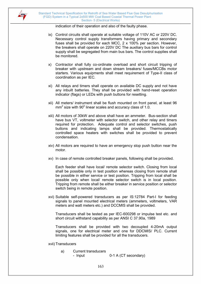
Standard Technical Specification for Retrofit of Sea Water Based Flue Gas Desulphurisation (FGD) System in a Typical 2x500 MW Coal Based Coastal Thermal Power Plant
Section- 5 (Electrical Works)
163
indication of their operation and also of the faulty phase. ix) Control circuits shall operate at suitable voltage of 110V AC or 220V DC.
Necessary control supply transformers having primary and secondary fuses shall be provided for each MCC, 2 x 100% per section. However, the breakers shall operate on 220V DC The auxiliary bus bars for control supply shall be segregated from main bus bars. The control supplies shall be monitored.
x) Contractor shall fully co-ordinate overload and short circuit tripping of
breaker with upstream and down stream breakers/ fuses/MCCBs motor starters. Various equipments shall meet requirement of Type-II class of coordination as per IEC.
xi) All relays and timers shall operate on available DC supply and not have
any inbuilt batteries. They shall be provided with hand-reset operation indicator (flags) or LEDs with push buttons for resetting.
xii) All meters/ instrument shall be flush mounted on front panel, at least 96
mm2 size with 900 linear scales and accuracy class of 1.0. xiii) All motors of 30kW and above shall have an ammeter. Bus-section shall
have bus VT, voltmeter with selector switch, and other relay and timers required for protection. Adequate control and selector switches, push buttons and indicating lamps shall be provided. Thermostatically controlled space heaters with switches shall be provided to prevent condensation.
xiv) All motors are required to have an emergency stop push button near the
motor. xv) In case of remote controlled breaker panels, following shall be provided.
Each feeder shall have local/ remote selector switch. Closing from local shall be possible only in test position whereas closing from remote shall be possible in either service or test position. Tripping from local shall be possible only when local/ remote selector switch is in local position. Tripping from remote shall be either breaker in service position or selector switch being in remote position.
xvi) Suitable self-powered transducers as per IS:12784 Part-I for feeding
signals to panel mounted electrical meters (ammeters, voltmeters, VAR meters and watt meters etc.) and DCCMIS shall be provided.
Transducers shall be tested as per IEC-600298 or impulse test etc. and short circuit withstand capability as per ANSI C 37.90a, 1989
Transducers shall be provided with two decoupled 4-20mA output signals, one for electrical meter and one for DDCMIS/ PLC. Current limiting features shall be provided for all the transducers.
xvii) Transducers
a) Current transducers - Input 0-1 A (CT secondary)

Standard Technical Specification for Retrofit of Sea Water Based Flue Gas Desulphurisation (FGD) System in a Typical 2x500 MW Coal Based Coastal Thermal Power Plant
Section- 5 (Electrical Works)
164
- Rated frequency 50 Hz - Output 4-20 mA (2 Nos. decoupled) for meter/
DDCMIS - Accuracy 0.5%
b) Bus voltage transducers
- Input 110V, 50 Hz (from VT secondary) - Output 4-20 mA (2 Nos. de-coupled) - Accuracy 0.5%
xviii) Necessary hardware shall be provided in the switchgear panel like coupling relays (24VDC with maximum burden of 2.5VA), auxiliary relays in addition to current/ bus-voltage transducers (4-20 mA, dual output) etc. to effect interlocks, exchange information/ status and exercise control from remote.
5.3.5 Protection
a) Incomer to 415V Switch boards :
i. Instantaneous over current protection (50) ii. Sync Check (25) iii. Restricted earth fault protection for Transformer LV winding (64R). iv. Lockout (86), preferably built in Numerical Relay
b) 415 V Bus coupler :
i. Instantaneous over current protection (50) ii. Sync Check (25) iii. Lockout (86), preferably built in Numerical Relay
c) 415V Out going feeders from PCC and Incomer to MCCs :
i. Over current protection (50) ii. Lockout (86) ,preferably built in Numerical Relay
d) 415 Volts motor feeders :
1) Contactor controlled motor feeders (Motors below 110kW)
a) Instantaneous short circuit protection on all phases through HRC cartridge type fuses rated for 80kA rms (prospective breaking capacity at 415V).
b) Thermal overload protection c) Single phasing protection for motors protected by fuses
2) Breaker controlled motors feeders (motors rated 110kW &above)
a) Instantaneous short circuit protection (50) b) Thermal Overload protection (49) c) Over load alarm (49A) d) Earth fault protection (50N) e) Under voltage protection (27M) f) Lockout (86), preferably built in Numerical Relay
5.3.6 Design and constructional features
a) All 415V switchgears, AC and DC distribution boards (DBs) etc. shall have
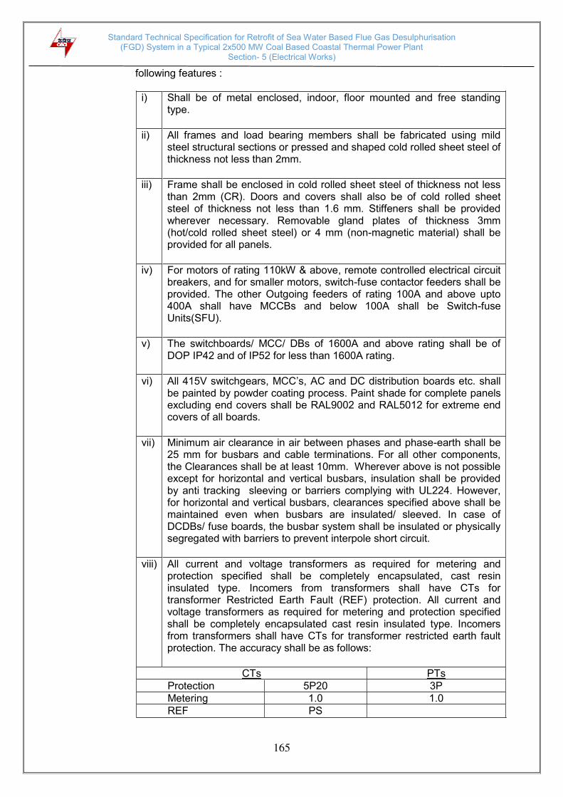
Standard Technical Specification for Retrofit of Sea Water Based Flue Gas Desulphurisation (FGD) System in a Typical 2x500 MW Coal Based Coastal Thermal Power Plant
Section- 5 (Electrical Works)
165
following features :
i) Shall be of metal enclosed, indoor, floor mounted and free standing type.
ii) All frames and load bearing members shall be fabricated using mild steel structural sections or pressed and shaped cold rolled sheet steel of thickness not less than 2mm.
iii) Frame shall be enclosed in cold rolled sheet steel of thickness not less than 2mm (CR). Doors and covers shall also be of cold rolled sheet steel of thickness not less than 1.6 mm. Stiffeners shall be provided wherever necessary. Removable gland plates of thickness 3mm (hot/cold rolled sheet steel) or 4 mm (non-magnetic material) shall be provided for all panels.
iv) For motors of rating 110kW & above, remote controlled electrical circuit breakers, and for smaller motors, switch-fuse contactor feeders shall be provided. The other Outgoing feeders of rating 100A and above upto 400A shall have MCCBs and below 100A shall be Switch-fuse Units(SFU).
v) The switchboards/ MCC/ DBs of 1600A and above rating shall be of DOP IP42 and of IP52 for less than 1600A rating.
vi) All 415V switchgears, MCC’s, AC and DC distribution boards etc. shall be painted by powder coating process. Paint shade for complete panels excluding end covers shall be RAL9002 and RAL5012 for extreme end covers of all boards.
vii) Minimum air clearance in air between phases and phase-earth shall be 25 mm for busbars and cable terminations. For all other components, the Clearances shall be at least 10mm. Wherever above is not possible except for horizontal and vertical busbars, insulation shall be provided by anti tracking sleeving or barriers complying with UL224. However, for horizontal and vertical busbars, clearances specified above shall be maintained even when busbars are insulated/ sleeved. In case of DCDBs/ fuse boards, the busbar system shall be insulated or physically segregated with barriers to prevent interpole short circuit.
viii) All current and voltage transformers as required for metering and protection specified shall be completely encapsulated, cast resin insulated type. Incomers from transformers shall have CTs for transformer Restricted Earth Fault (REF) protection. All current and voltage transformers as required for metering and protection specified shall be completely encapsulated cast resin insulated type. Incomers from transformers shall have CTs for transformer restricted earth fault protection. The accuracy shall be as follows:
CTs PTs Protection 5P20 3P Metering 1.0 1.0 REF PS

Standard Technical Specification for Retrofit of Sea Water Based Flue Gas Desulphurisation (FGD) System in a Typical 2x500 MW Coal Based Coastal Thermal Power Plant
Section- 5 (Electrical Works)
166
b) Indicating lamps shall be cluster LED type.
5.3.7 Spare feeders - 20% spare feeders with atleast one of each type and rating shall be
provided in each switchgear. 5.3.8 415V Non-segregated phase bus-duct
i) The section of three phase and neutral metal enclosed non segregated phase bus duct shall be rectangular. The design of the bus duct enclosures shall be of sturdy construction such that it will withstand the internal or external forces resulting from the various operating conditions.
ii) The entire bus duct shall be designed for dust, vermin and weather proof
construction. A suitable aluminium sheet flange-protection hood shall be provided to cover all outdoor bus duct enclosure joints to facilitate additional protection against rain water ingress. All horizontal runs of bus duct shall have a suitable sloped enclosure top to prevent retention of water for both indoor and out-door portion of bus ducts. Bus duct enclosure shall have a degree of protection of IP-55.
iii) The inside of the bus enclosure may be treated with black paint to enable
efficient heat dissipation. The matt paint used shall be suitable for temperature experienced during continuous loading of the bus conductor.
iv) Enclosures shall be provided with flanged ends with drilling dimensions to suit
the flanges at the switchgear and transformer terminals. v) The synthetic/ neoprene gaskets shall be provided so as to satisfy the
operating conditions imposed by temperature, weathering, durability etc. Flange gaskets shall be provided at the equipment terminal connections.
vi) Necessary earthing arrangement as applicable shall be provided with clamps
to receive station earthing bus. This shall be a GI strip of adequate size, continuously running along the bus duct and shall be earthed at both ends. Bus duct enclosures shall be bolted type.
vii) The material of the conductor shall be aluminium. The bus bars shall be rated
in accordance with the service conditions and the rated continuous and short time current ratings.
viii) All steel structures required for bus duct support shall be hot dip galvanised. ix) Technical Data
a) Type Non-Segregated b) 1 minute power frequency withstand voltage 2.5 kV c) Maximum short circuit withstand current 50kA for 1 second d) Momentary dynamic current withstand 105kA (Peak)
5.4 HT AND LT MOTORS
All the HT and LT motors as required for FGD Plant shall be provided.

Standard Technical Specification for Retrofit of Sea Water Based Flue Gas Desulphurisation (FGD) System in a Typical 2x500 MW Coal Based Coastal Thermal Power Plant
Section- 5 (Electrical Works)
167
i. All motors upto200kW rating shall be 3 phase, 415V squirrel cage Induction
motors.
ii. Motors of rating above 200kW and upto 1500kW shall be rated for 6.6/3.3kV voltage and above 1500kW shall be rated for 11/6.6kV.
iii. All motors of rating 30kW and above shall be provided with single phase 240V
space heaters.
5.4.1 Codes and Standards
All the motors shall conform to the following standards :
IS/ IEC:60034 Three phase induction motors IS/ IEC:60034 Single phase AC motors IS/ IEC:60034 Crane duty motors IS:4722 DC motors IS12615, IEC 60034-30 Energy Efficient Motors
5.4.2 General Requirements
i) All the motors shall be suitable for an ambient temperature of 500C and relative humidity of 95%. The motors shall be suitable for operation in a highly polluted environment
ii) Voltage and Frequency variations: All motors shall be suitable for following
variations
Frequency variation (+) 3% and (-)5% Voltage variation a. (±) 6% for 11kV,6.6kV & 3.3kV
b. (±) 10% for 415 V
Combined variation of voltage and frequency.
10% (absolute sum)
iii) The voltage level for motors shall be as follows
1) Upto 200 kW 415V
2) Above 200 kW and upto 1500 kW 6.6/ 3.3kV
3) Above 1500 kW 11/ 6.6kV
iv) Fault level
1) 11kV, 6.6kV and 3.3 kV 40kA for 1 second
2) 415V 50kA for 1 second
3) 220V DC 20kA for 1 second
v) System grounding
1) 11 kV,6.6kV and 3.3 kV Earthed through resistance to limit the current to 300A or high resistance grounding through Neutral grounding Resistor (NGR)
2) 415V Solidly grounded
3) 220V DC Ungrounded

Standard Technical Specification for Retrofit of Sea Water Based Flue Gas Desulphurisation (FGD) System in a Typical 2x500 MW Coal Based Coastal Thermal Power Plant
Section- 5 (Electrical Works)
168
vi) Paint shade shall be RAL 5012 (Blue).
vii) Degree of protection
1) Indoor motors IP 55
2) Outdoor motors IP 55
3) Cable box – indoor area IP 55
4) Cable box – outdoor area IP 55
5.4.3 Type
i) AC Motors:
- Squirrel cage induction motor suitable for direct-on-line starting. Further, continuous duty LT motors upto 200 kW Output rating (at 500C ambient temperature), shall be Premium Efficiency class-IE3, conforming to IS 12615, or IEC:60034-30.
- Crane duty motors shall be slip ring/ squirrel cage with VVVF type induction motor. Motor operating through variable frequency drives shall be suitable for inverter duty. Also these motors shall comply the requirements stipulated in IEC: 60034-18-41 and IEC: 60034-18-42 as applicable.
ii) DC Motors: Shunt wound.
5.4.4 Rating
i) Continuously rated (S1). However, crane motors shall be rated for S4 duty i.e.
40% cyclic duration factor. ii) Maximum continuous motor ratings shall be at least 10% above the maximum
load demand of the driven equipment unless otherwise specified, under entire operating range including voltage and frequency variations.
iii) Motors starting shall be as per IEC-60034 (part12)
5.4.5 Temperature Rise
Air cooled motors 700C by resistance method for both class 130(B) and 155(F) insulation
Water cooled motors 800C over inlet cooling water temperature, by resistance method for both class 130(B) and 155(F) insulation
5.4.6 Operational Requirements
i) Starting Time
a) For motors with starting time upto 20 secs. at minimum permissible voltage during starting, the locked rotor withstand time under hot condition at highest voltage limit shall be at least 2.5 secs. more than starting time.
b) For motors with starting time more than 20secs. and upto 45secs. at
minimum permissible voltage during starting, the locked rotor withstand time under hot condition at highest voltage limit shall be at least 5 secs.

Standard Technical Specification for Retrofit of Sea Water Based Flue Gas Desulphurisation (FGD) System in a Typical 2x500 MW Coal Based Coastal Thermal Power Plant
Section- 5 (Electrical Works)
169
more than starting time. c) For motors with starting time more than 45secs. at minimum permissible
voltage during starting, the locked rotor withstand time under hot condition at highest voltage limit shall be more than starting time by at least 10% of the starting time.
d) Speed switches mounted on the motor shaft shall be provided in cases
where above requirements are not met. ii) Torque Requirements
a) Accelerating torque at any speed with the lowest permissible starting
voltage shall be at least 10% motor full load torque. b) Pull out torque at rated voltage shall not be less than 205% of full load
torque. It shall be 275% for crane duty motors.
iii) Starting voltage requirement a) All motors (except mill motors):
80% of rated voltage for motors upto 4000 kW 75% of rated voltage for motors above 4000 kW
b) For mill motors
85% of rated voltage for motors above 1000 kW 90% of rated voltage for motors below 1000 kW
5.4.7 Design and constructional features
i) Suitable single phase space heaters shall be provided on motors rated 30kW
and above to maintain windings in dry condition when motor is standstill. Separate terminal box for space heaters and RTDs shall be provided.
ii) All motors shall be either totally enclosed fan cooled (TEFC) or totally
enclosed tube ventilated (TETV) or closed air circuit air cooled (CACA) type. However, motors rated 3000 kW or above can be closed air circuit water cooled (CACW). The method of movement of primary and secondary coolant shall be self-circulated by fan or pump directly mounted on the rotor of the main motor as per IEC 60034-6. However, VFD driven motors can be offered with forced cooling type with machine mounted fan or pump driven by separate electric motor.
iii) For hazardous location such as fuel oil facilities area, the enclosure of motors
shall have flame proof construction conforming to IS:2148 as detailed below:
1) Fuel oil area Group – IIB
2) Hydrogen generation plant area
Group – IIC (or Group-I Div-II as per NEC) or (Class-1, Group-B, Div-II as per
NEMA / IEC60034)
iv. Winding and Insulation
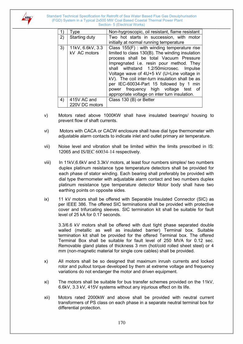
Standard Technical Specification for Retrofit of Sea Water Based Flue Gas Desulphurisation (FGD) System in a Typical 2x500 MW Coal Based Coastal Thermal Power Plant
Section- 5 (Electrical Works)
170
1) Type Non-hygroscopic, oil resistant, flame resistant
2) Starting duty Two hot starts in succession, with motor initially at normal running temperature
3) 11kV, 6.6kV, 3.3 kV AC motors
Class 155(F) : with winding temperature rise limited to class 130(B). The winding insulation process shall be total Vacuum Pressure Impregnated i.e. resin pour method. They shall withstand 1.2/50microsec. Impulse Voltage wave of 4U+5 kV (U=Line voltage in kV). The coil inter-turn insulation shall be as per IEC-60034-Part 15 followed by 1 min power frequency high voltage test of appropriate voltage on inter turn insulation.
4) 415V AC and 220V DC motors
Class 130 (B) or Better
v) Motors rated above 1000KW shall have insulated bearings/ housing to
prevent flow of shaft currents.
vi) Motors with CACA or CACW enclosure shall have dial type thermometer with adjustable alarm contacts to indicate inlet and outlet primary air temperature.
vii) Noise level and vibration shall be limited within the limits prescribed in IS:
12065 and IS/IEC 60034-14 respectively.
viii) In 11kV,6.6kV and 3.3kV motors, at least four numbers simplex/ two numbers
duplex platinum resistance type temperature detectors shall be provided for
each phase of stator winding. Each bearing shall preferably be provided with
dial type thermometer with adjustable alarm contact and two numbers duplex
platinum resistance type temperature detector Motor body shall have two
earthing points on opposite sides.
ix) 11 kV motors shall be offered with Separable Insulated Connector (SIC) as per IEEE 386. The offered SIC terminations shall be provided with protective cover and trifurcating sleeves. SIC termination kit shall be suitable for fault level of 25 kA for 0.17 seconds.
3.3/6.6 kV motors shall be offered with dust tight phase separated double walled (metallic as well as insulated barrier) Terminal box. Suitable termination kit shall be provided for the offered Terminal box. The offered Terminal Box shall be suitable for fault level of 250 MVA for 0.12 sec. Removable gland plates of thickness 3 mm (hot/cold rolled sheet steel) or 4 mm (non-magnetic material for single core cables) shall be provided.
x) All motors shall be so designed that maximum inrush currents and locked
rotor and pullout torque developed by them at extreme voltage and frequency variations do not endanger the motor and driven equipment.
xi) The motors shall be suitable for bus transfer schemes provided on the 11kV,
6.6kV, 3.3 kV, 415V systems without any injurious effect on its life.
xii) Motors rated 2000kW and above shall be provided with neutral current transformers of PS class on each phase in a separate neutral terminal box for differential protection.

Standard Technical Specification for Retrofit of Sea Water Based Flue Gas Desulphurisation (FGD) System in a Typical 2x500 MW Coal Based Coastal Thermal Power Plant
Section- 5 (Electrical Works)
171
xiii) The ratio of locked rotor KVA at rated voltage to rated KW shall not exceed
the following (without any further tolerance) : (a) From 50KW & upto 110KW : 11.0 (b) From 110 KW & upto 200 KW : 9.0 (c) Above 200 KW & upto 1000KW : 10.0 (d) From 1001KW & upto 4000KW : 9.0 (e) Above 4000KW : 6 to 6.5
5.4.8 LIST OF TYPE TESTS TO BE CONDUCTED
The following type tests shall be conducted on each type and rating of HT motor: a) No load saturation and loss curves upto approximately 115% of rated voltage b) Measurement of noise at no load. c) Momentary excess torque test (subject to test bed constraint). d) Full load test (subject to test bed constraint) e) Temperature rise test at rated conditions. During heat run test, bearing temp.,
winding temp., coolant flow and its temp. shall also be measured. In case the temperature rise test is carried at load other than rated load, specific approval for the test method and procedure is required to be obtained. Wherever ETD's are provided, the temperature shall be measured by ETD's also for the record purpose.
5.4.9 LIST OF TESTS FOR WHICH REPORTS HAVE TO BE SUBMITTED :
The following type test reports shall be submitted for each type and rating of HT motor:
a) Degree of protection test for the enclosure followed by IR, HV and no load run
test. b) Terminal box-fault level withstand test for each type of terminal box of HT motors
only. c) Lightning Impulse withstand test on the sample coil shall be as per clause no. 4.3
IEC-60034, part-15 d) Surge-withstand test on inter turn insulation shall be as per clause no. 4.2 of IEC
60034, part-15
In case the contractor has conducted such specified type test(s) within last ten years as on the date of bid opening, he may submit during detailed engineering the type test reports to the employer for waival of conductance of such test(s). These reports should be for the tests conducted on the equipment similar to those proposed to be supplied under this contract and test(s) should have been either conducted at an independent laboratory or should have been witnessed by a client. The employer reserves the right to waive conducting of any or all the specified type test(s) under this contract. In case type tests are waived, the type test charges shall not be payable to the contractor.
5.5 HT/LT POWER AND CONTROL CABLES
All 11kV, 6.6kV, 3.3kV and 415V power cables, control cables and DC cables required to connect auxiliaries shall be supplied.

Standard Technical Specification for Retrofit of Sea Water Based Flue Gas Desulphurisation (FGD) System in a Typical 2x500 MW Coal Based Coastal Thermal Power Plant
Section- 5 (Electrical Works)
172
5.5.1 Codes and standards All cables to be supplied shall conform to the latest revisions of IS or any other international standards acceptable to purchaser. Some of the Indian Standards/ IEC considered relevant to the cables are given below:
IS:1554(Part-I) PVC insulated (heavy duty) electric cables for working voltage up to and including 1100 V.
IS:1554 (Part-II) PVC insulated (heavy duty) electric cables for working voltage from 3.3kV upto and including 11kV.
IS:7098 (Part-III) XLPE insulated PVC sheathed cables for working voltages from 3.3 kV upto and including 33kV.
IS:3961 Recommended current ratings for cables. IS:8130 Conductors for insulated electric cables and flexible cords. IS:5831 PVC insulation and sheath of electric cables. IS:2982 Copper conductor in insulated cables and cords. IS:3975 Mild steel wires, strips and tapes for armouring cables IS:5609 Specification for low frequency wires and cables with PVC
insulation and PVC Sheath. IS:6380 Spec. of elastomeric insulation of sheath of electric cables.
IS:434(I and II) Specification for rubber insulation cables IEC:540 The methods for insulations and sheaths of electric cables and
cords (elastomeric and thermoplastic compounds). IEC:230 Impulse tests on cables and their accessories. IEC:60 High voltage test techniques. IEC:287 Calculations of the continuous current rating of cables(100% load
factor). IEC:288 Nominal cross-sectional area and composition of conductor of
insulated cables. IEC:502 Extruded solid dielectric insulated power cables for rated voltages
from 1.00 kV upto 30 kV. NEMA-WC-5 Thermoplastic insulated wires and cables for transmission and
distribution of electrical energy. IEEE:383 Standard for type test for class IE electric cables, filled splices
and connections for nuclear power generation stations IEC: 332-1 Test on electric cables under fire conditions. ASTM-D-2843 Standard test method for density of smoke from burning/
decomposition of plastics. ASTM-D-2863 Test for determination of Oxygen Index. IEC-754-I Test method for acid gas generation.
IEC-331 Fire resisting characteristics of electric cables. SVENSK Standard SS- 4241475 Class F3 BICC Hand Book For cables in fire regarding temperature index-chapter-6
5.5.2 Design criteria
i) The cable shall be suitable for installation in a tropical monsoon area having a
hot humid climate. The reference ambient temperature to be considered for the purpose of this specification is 500C.
ii) The derating factor for the various conditions of installation including the
following shall be considered while choosing the conductor size and
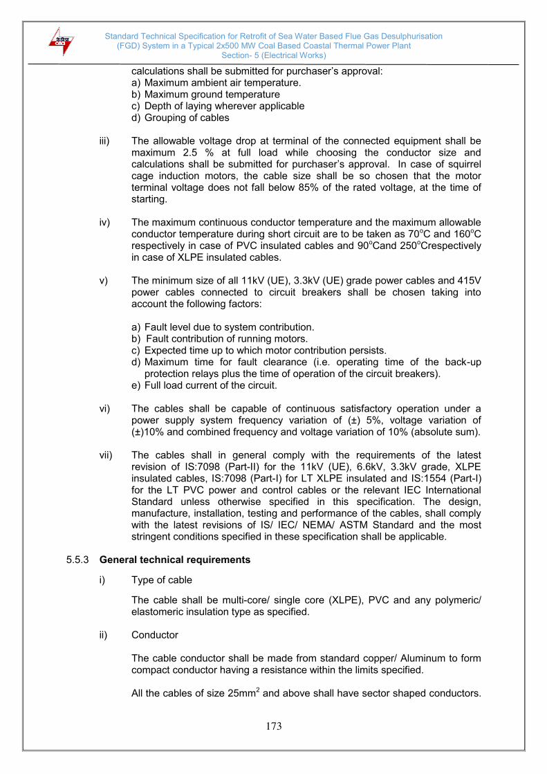
Standard Technical Specification for Retrofit of Sea Water Based Flue Gas Desulphurisation (FGD) System in a Typical 2x500 MW Coal Based Coastal Thermal Power Plant
Section- 5 (Electrical Works)
173
calculations shall be submitted for purchaser’s approval: a) Maximum ambient air temperature. b) Maximum ground temperature c) Depth of laying wherever applicable d) Grouping of cables
iii) The allowable voltage drop at terminal of the connected equipment shall be
maximum 2.5 % at full load while choosing the conductor size and calculations shall be submitted for purchaser’s approval. In case of squirrel cage induction motors, the cable size shall be so chosen that the motor terminal voltage does not fall below 85% of the rated voltage, at the time of starting.
iv) The maximum continuous conductor temperature and the maximum allowable
conductor temperature during short circuit are to be taken as 70oC and 160oC respectively in case of PVC insulated cables and 90oCand 250oCrespectively in case of XLPE insulated cables.
v) The minimum size of all 11kV (UE), 3.3kV (UE) grade power cables and 415V
power cables connected to circuit breakers shall be chosen taking into account the following factors:
a) Fault level due to system contribution. b) Fault contribution of running motors. c) Expected time up to which motor contribution persists. d) Maximum time for fault clearance (i.e. operating time of the back-up
protection relays plus the time of operation of the circuit breakers). e) Full load current of the circuit.
vi) The cables shall be capable of continuous satisfactory operation under a
power supply system frequency variation of (±) 5%, voltage variation of (±)10% and combined frequency and voltage variation of 10% (absolute sum).
vii) The cables shall in general comply with the requirements of the latest
revision of IS:7098 (Part-II) for the 11kV (UE), 6.6kV, 3.3kV grade, XLPE insulated cables, IS:7098 (Part-I) for LT XLPE insulated and IS:1554 (Part-I) for the LT PVC power and control cables or the relevant IEC International Standard unless otherwise specified in this specification. The design, manufacture, installation, testing and performance of the cables, shall comply with the latest revisions of IS/ IEC/ NEMA/ ASTM Standard and the most stringent conditions specified in these specification shall be applicable.
5.5.3 General technical requirements
i) Type of cable
The cable shall be multi-core/ single core (XLPE), PVC and any polymeric/ elastomeric insulation type as specified.
ii) Conductor
The cable conductor shall be made from standard copper/ Aluminum to form compact conductor having a resistance within the limits specified.
All the cables of size 25mm2 and above shall have sector shaped conductors.

Standard Technical Specification for Retrofit of Sea Water Based Flue Gas Desulphurisation (FGD) System in a Typical 2x500 MW Coal Based Coastal Thermal Power Plant
Section- 5 (Electrical Works)
174
The minimum no. of strands in conductor shall be 7 (seven) except as otherwise specified. Power cables shall be of stranded aluminum conductor with a minimum size 6mm2 and the control cables shall be stranded copper (electrolytic) conductor with a minimum size of 2.5 mm2.
iii) Conductor Shield
The conductor having a semi-conducting screen shall ensure perfectly smooth profile and avoid stress concentration. The conductor screen shall be extruded in the same operation as the insulation, the semi-conducting polymer shall be cross-linked for XLPE cables.
iv) Insulation
The insulation of the cable shall be extruded type and shall be designed and manufactured for the specified system voltage. The manufacturing process shall ensure that insulation shall be free from voids. The insulation shall withstand mechanical and thermal stresses under steady state and transient operating conditions. The extrusion method should give a very smooth interface between semi conducting screen and insulati0on. The insulation of the cables shall be of high standard quality. The minimum volume resistivity of the PVC insulation of all the PVC insulated cables shall be 1x10¹⁴ ohm-cm at 27oC and 1x10¹¹ ohm-cm at 70oC.
v) Insulation shield
In XLPE cables to confine electrical field to the insulation, a non-magnetic semi-conducting shield shall be put over the insulation. The insulation shield shall be extruded in the same operation as the conductor shield and the insulation by triple extrusion/process. The XLPE cable insulation shield shall be strippable. Metallic screening as given in this specification for the various power and control and special cables shall be provided.
vi) Sheath
The sheath shall be suitable to withstand the site conditions and the desired temperature. It shall be of adequate thickness and applied by a continuous process to produce a sheath of consistent quality free from all defects. PVC sheath shall be extruded.
vii) Armour
Hard drawn aluminum wire armouring/ galvanized steel tape/ wire armouring shall be used for single core and multi-core cable respectively.
The hard drawn aluminium wire for armour shall be of H4 grade, as per IS-8130 (having tensile strength above 150 N/mm2) The diameter of the aluminium wire shall be as per the table for the dimensions of the galvanized steel wire armour given in the relevant standard.
viii) Serving/ outer sheath
Extruded PVC serving as per IS: 5831 or as specified otherwise shall be applied over the armouring with suitable additives to prevent attach by rodent and termites. All serving must be given anti-termite treatment.

Standard Technical Specification for Retrofit of Sea Water Based Flue Gas Desulphurisation (FGD) System in a Typical 2x500 MW Coal Based Coastal Thermal Power Plant
Section- 5 (Electrical Works)
175
5.5.4 Constructional requirements i) Cable shall have suitable filters laid up with the conductors to provide a
substantially circular cross section before the sheath is applied. Fillers shall be suitable for the operating temperature of the cable and compatible with the insulating material. All materials shall be new, unused and of finest quality. Workmanship shall be neat, clean and of highest grade.
a) 11 kV system power cables - The cable shall be 11kV/11kV (unearthed)
grade, heavy duty, stranded aluminium conductor, XLPE insulated, provided with conductor screening and insulation screening, galvanized steel wire/strip armoured, flame retardant low smoke (FRLS) extruded PVC of type ST2 outer sheathed.
b) 6.6kV system power cables - The cable shall be 6.6kV/6.6kV (unearthed)
grade, heavy duty, stranded aluminium conductor, XLPE insulated, provided with conductor screening and insulation screening, galvanized steel wire/strip armoured, flame retardant low smoke (FRLS) extruded PVC of type ST2 outer sheathed.
c) 3.3 kV system power cables - The cable shall be 3.3kV/3.3kV (unearthed)
grade, heavy duty, stranded aluminium conductor, XLPE insulated, provided with conductor screening and insulation screening, galvanized steel wire/ strip armoured, flame retardant low smoke (FRLS) extruded PVC of type ST2 outer sheathed.
d) 415V system power cables - The cable shall be 1.1kV, grade, heavy duty,
stranded aluminium conductor, PVC Type-A Insulated galvanized steel wire/strip armoured, flame retardant low smoke (FRLS) extruded PVC type ST1 outer sheathed. XLPE insulated cables shall also be acceptable.
e) Control cables - The cable shall be 1.1kV grade, heavy duty, stranded
copper conductor, PVC Type-A insulated, galvanized steel wire/ strip armoured, flame retardant low smoke (FRLS) extruded PVC of Type-ST1 outer sheathed.
ii) Special properties - All the above cables shall be conforming to the relevant
Indian/ IEC standard in general, with the following special properties:
a) Oxygen Index of the outer sheath shall not be less than 29, when tested as per ASTM-D-2863.
b) Temperature Index of the outer sheath shall not be less than 250oC, when
tested as per ASTM-D-2863. c) Halogen acid contents in outer sheath shall not be more than 20%, when
tested as per IEC-60754. d) The maximum smoke density in percent light absorption should not exceed
60% in case of PVC compound and 20% in case of fire survival cables, when tested as per ASTM-D-2843.
e) Swedish chimney test as per SS-4241475 class F3 and ladder test for
flammability as per IEEE-383.
Standard Technical Specification for Retrofit of Sea Water Based Flue Gas Desulphurisation (FGD) System in a Typical 2x500 MW Coal Based Coastal Thermal Power Plant
Section- 5 (Electrical Works)
176
iii) Fire survival cables - The cable shall be of copper conductor and comply with IEC-60331 in addition to the above requirement. Also the halogen acid contents in outer sheath shall not be more than 2% when tested and per IEC-60754 and the smoke density in percent light absorption shall not exceed 20% when tested as per ASTM-D- 2843.
5.5.5 Identification of cores
The insulated cores of HT and LT power cables shall be identified by coloured code. The control cables shall have identification by means if indelible printing of numbers of its cores at intervals not more than 75 mm. At least 20% cores shall be kept as spares in the multi-core control cables.
5.5.6 Arrangement of cables
As far as feasible, separate cables shall be provided for circuits of different plant and auxiliaries, for circuits of different voltages, and for circuit used separately. Power, control and instrumentation circuit shall invariably be taken through different routes, which shall not be laid together on the same cable trays.
5.5.7 Drums lengths
Drum lengths of the cables shall be so chosen that straight through joints are eliminated. However, the drum lengths shall not be less than the following lengths:
i) 11/ 6.6/ 3.3 kV grade power cables: 500 M ii) 1.1 kV grade power / Fire survival cables etc.
a) Including and above 400 mm2 size: 400 M b) Below 400mm2 size: 500 M
iii) 1.1 kV grade control and instrumentation cables: 1000M
5.6 VARIABLE FREQUENCY DRIVES
5.6.1 General
The Design, manufacture, erection, testing and performance of items and services provided under this specification shall comply with the latest edition including all applicable official amendments and revisions as on date of award of the following standards. In case of conflict between this specification and code (IS Code, standards, etc.) referred herein, the former shall prevail. All work shall be carried out as per the following codes and standards.
5.6.2 Codes and Standards
IEC:60056 HT breaker IEC 60289 DC reactor
IS:2026, IEC: 60076,
IEC 61378
Transformers
IS: 2099, IEC 60137 Bushing
IEC 61800 Adjustable Speed Electrical Power Drive Systems
IEC 60146 Semiconductor converters–General requirements
IEEE 519 IEEE Recommended practices and requirements for
Standard Technical Specification for Retrofit of Sea Water Based Flue Gas Desulphurisation (FGD) System in a Typical 2x500 MW Coal Based Coastal Thermal Power Plant
Section- 5 (Electrical Works)
177
harmonic control in electrical power systems
IEC 60529 Degrees of protection provided by enclosures (IP Code)
IEC1000-4-2 Electrostatic immunity test
IEC1000-4-4 Fast transient immunity test
IEC1000-4-5 Surge immunity test
IEC 62271-102 High-voltage switchgear and controlgear; Pt.102: Alternating current disconnectors and earthing switches
IS/IEC: 62271-200 High-voltage switchgear and controlgear; Pt.200: AC metal-enclosed switchgear and controlgear for rated voltages above 1 kV and up to and including 52 kV
IS: 722 AC electricity meters
IEC: 60099-4 Metal oxide surge arrestor without gap for AC system
IEC: 60947-7-1 Terminal blocks for copper conductors
IS: 11171 Dry transformer
IEC 60034-18-41 &42, IEC 60034, NEMA 30 & 31
Motor
IEC:60947, IS: 13947 Contactor/Switches/Fuses etc.
IEEE:519/ IEC: 61000 Harmonics & EM compatibility
IEC: 60034/ IEC: 61800 VFD
Equipment complying with other internationally accepted standards will also be considered if they ensure performance and constructional features equivalent or superior to standards listed above. In such a case, the Bidder shall clearly indicate the standard(s) adopted, furnish a copy in English of the latest revision amendments and revision in force as on date of opening of bid and shall clearly bring out the salient features for comparison.
5.6.3 Operating Conditions
For the purpose of design of equipment/systems, an ambient temperature of 500C and also relative humidity of 95% at 400C shall be considered.
i) All equipment shall be suitable for rated frequency of 50 Hz with a variation of +3% & -5%, and 10% combined variation of voltage and frequency unless specifically brought out in the specification.
ii) The auxiliary AC voltage supply arrangement shall have 11/6.6/3.3kV and 415V systems (as applicable). It shall be designed to limit voltage variations as given below under worst operating condition:
a. 11kV/ 3.3 kV/ 6.6 KV : ± 6%
b. 415V : ± 10%
Note: The Voltage level mentioned above is the Nominal Voltage available at the input of the VFD System from the MCC/ Switchgear/transformer, based on the system requirement/Availability.
The voltage level for the VFD output to be fed to motor shall be as follows:-
Upto 400 kW 415V/690V, Low Voltage, Three Phase AC
Above 400kW and upto 700 kW
690V, Low Voltage, Three Phase AC
Above 700kW Medium Voltage

Standard Technical Specification for Retrofit of Sea Water Based Flue Gas Desulphurisation (FGD) System in a Typical 2x500 MW Coal Based Coastal Thermal Power Plant
Section- 5 (Electrical Works)
178
All the VFD Systems consisting of either 415 V or 690 V may be termed as LV VFD while the higher rated VFD System shall be termed as MV VFD. If nothing is mentioned than the Clause is applicable for both the LV and the MV VFD until deliberated otherwise.
5.6.4 System Description
Type of drive 3-Phase Diode / Thyristor / Multi Stage IGBT / IGCT / SGCT/ IEGT
Type of Cooling of VFD Naturally air cooled/ forced air cooled/ Liquid cooled
Converter Type Full wave diode rectifier/ active front end type
Inverter Type Thyristor/ IGBT/ IGCT/ SGCT/ IEGT
5.6.5 General Requirements
i) Medium Voltage VFD: The Variable frequency drive (VFD) system shall be
of a modern proven design for similar applications in power plants/industry.
The system shall be either Current Source Inverter (CSI) or Voltage Source
Inverter (VSI) type with minimum eighteen (18) pulse design.
ii) 415 V/690 V LV VFD: The Variable frequency drive (VFD) system shall be of
a modern proven design for similar applications in power plants/industry. The system shall be either Current Source Inverter (CSI) or Voltage Source Inverter (VSI) type with minimum Twelve (12) pulse design. For drives less than 100 kW Six (6) pulse can be offered meeting all other requirements.
iii) The system shall be fully digital, PLC/Microprocessor based, energy efficient,
and shall provide very high reliability, high power factor, low harmonic distortion and low vibration and wear and noise. It shall be easy to install in minimum time and expense and no special tools shall be required for routine maintenance.
iv) The offered equipment shall be with state of art technology and proven field
track record. No prototype equipment shall be offered.
iv) The VFD manufacturer shall ensure the proper coordination of their VFD with
the Driven Motor and the supply system. All the Motors which are to be driven
by VFDs will be of Inverter duty type. Also these motors shall comply the
requirements stipulated in IEC: 60034-18-41 and IEC: 60034-18-42 as
applicable. The VFD operation shall have no inherent detrimental impact on
the Motors/ cables & supply system.
5.6.6 Technical and Operational Requirements
i) The system shall be designed to deliver the motor input current and torque for the complete speed torque characteristics of the driven equipment, with worst input supply voltage and frequency variation. The system shall be suitable for the load characteristics and the operational duty of the driven equipment.

Standard Technical Specification for Retrofit of Sea Water Based Flue Gas Desulphurisation (FGD) System in a Typical 2x500 MW Coal Based Coastal Thermal Power Plant
Section- 5 (Electrical Works)
179
ii) The overload capacity of the controller shall be 150% of the rated current of the motor for one minute for constant torque applications and 110% of rated current for one minute for variable torque applications at rated voltage. If the motor load exceeds the limit, the drive shall automatically reduce the frequency and voltage to the motor to guard against overload.
iii) The drive system shall be designed to operate in one or more of the following operating modes as to suit characteristics of the driven equipment or specified by the load:
a. Variable torque changing as a function of speed.
b. Constant torque over a specific speed range.
c. Constant power over a specific speed range.
d. Any other as specified in data-sheet
iv) VFDs shall comply with the latest edition of IEEE 519 & IEC 61000 for both individual as well as total harmonic voltage and current distortion limits. The Voltage and Current limits shall be applicable at the Point of Common Coupling (PCC), which shall be the MCC/ Switchgear/ from which the VFD system is fed.
v) The above compliance shall be verified by the field measurements of harmonics at the PCC with and without VFDs operation.
vi) VFD shall be capable of withstanding the thermal and dynamic stresses and the transient mechanical torque, resulting from short circuit. Any damage resulting from such a short circuit or internal fault shall be limited to the component concerned.
vii) The system shall be suitable to maintain speed variation within range 10-110% or as per the requirement of driven equipment with speed set accuracy of +1% of rated maximum speed and steady state regulation of +0.5% of rated speed as per system requirement.
viii) The VFD System shall maintain a power factor of 0.95 (minimum) (for LV VFD system) and 0.9 (minimum) (for MV VFD system) in the entire operating range.
ix) Maximum allowable audible noise from the VFD system will be 85 dB (A) at a distance of one meter under rated loaded with all cooling fan operating conditions.
x) All the circuit components shall be suitably protected against over voltages, surges, lightning etc.
xi) The panels shall be designed to provide easy access to hardware, to facilitate replacement of cards in case of any failure.
xii) All the VFDs for particular application shall be of same design so as to ensure 100 % interchangeability of components.

Standard Technical Specification for Retrofit of Sea Water Based Flue Gas Desulphurisation (FGD) System in a Typical 2x500 MW Coal Based Coastal Thermal Power Plant
Section- 5 (Electrical Works)
180
xiii) For each programmed warning and fault protection function, the VFD shall display a message in complete English words or Standard English abbreviations. At least 30 time tagged fault messages shall be stored in the drive’s fault history.
xiv) The VFD cubicles shall be placed in air conditioned environment. However, if
VFDs of less than 100 kW are designed to operate in non-air condition environment the same shall also be acceptable.
xv) The 3-Phase Thyristor/ IGCT/ SGCT/ multistage IGBT/IEGT based VFD system shall have minimum number of components to ensure very high reliability. The input side converter shall have 3-Phase Diode/ Thyristor bridge configuration modular type and inverter shall be of 3-Phase Thyristor/ IGCT/ SGCT/ multi stage IGBT/IEGT type, using Pulse Width Modulation or better technique for generating near sine wave output to motor.
xvi) Fiber optic cable connection shall be provided preferably to ensure high
network reliability. 5.6.7 VFD Compatibility with the Motor
i) MV VFD output current waveform, as measured at the motor, shall be inherently sinusoidal at nominal loads, with a total harmonic current and voltage distortion within acceptable/standard limits. VFD with transformers on output side are not acceptable.
ii) The system design shall not have any inherent output harmonic resonance in the operating speed range.
iii) VFD shall provide stable operation of motor from high-voltage dv/dt stress, regardless of cable length to motor. The vendor shall clearly state the limitations in the motor cable distance in his proposal. However, due to system requirements & constraints if the cable length becomes critical, filters/ chokes etc. shall be provided by the VFD manufacturers as an integral part of the VFD to mitigate the reflected wave effect of harmonics.
5.6.8 Bypass Arrangement (optional, if specified)
i) The VFD System shall have an optional feature to run the motor under bypass arrangement for operation of Motor with VFD bypassed. During starting (under rated conditions) the motor will be switched on in VFD Mode to limit the starting current and after gaining speed, the load would be switched over to bypass mode.
ii) Comprehensive motor protection scheme for protection and control for operation VFD during bypass mode shall be finalized during detailed engineering.
5.6.9 Standby VFD Arrangement (optional, if specified)
A Common standby arrangement with auto/manual switchover shall be provided in case of failure of any VFD in a group of drives. Complete protection, interlocks & control required shall be provided in the changeover module.

Standard Technical Specification for Retrofit of Sea Water Based Flue Gas Desulphurisation (FGD) System in a Typical 2x500 MW Coal Based Coastal Thermal Power Plant
Section- 5 (Electrical Works)
181
5.6.10 Efficiency
i) Efficiency (Drive only) shall be minimum 98% for both MV VFD and LV VFD. Overall efficiency shall be minimum 96.5% for LV VFD and minimum 94 % for MV VFD at rated load and speed. Overall Efficiency evaluation shall include input transformer, harmonic filters and power factor correction (if applicable), VFD converters, cooling fans and output filter, as applicable in the system. Auxiliary controls, such as internal VFD control boards, cooling fans/pumps.
ii) In absence of valid test report, a factory test shall be performed at the VFD manufacturer’s facility verifying the efficiencies. Manufactures who are supplying Drive and transformer from different locations, efficiency test will be conducted separately for Drive and transformer.
5.6.11 Cooling System
i) The VFD shall be designed to operate indoor under temperature range of 00C to 500C and relative humidity of 95% ( at 400C ).
ii) VFD manufacturer to primarily offer Air cooled Design. However, in case of large ratings, liquid cooled drives may be accepted subject to employer’s approval. In case of liquid cooled system, there shall be no necessity of continuous water supply system (Closed Loop System).
iii) In case of Air cooled design, the VFD Cooling system shall be such that it
puts minimum heat load inside the room and preferably throw the hot air outside the room with ventilation ducts. The Cooling system shall be designed in such a way that the Air Conditioning & Ventilation Air requirements are kept to minimum. The VFD Manufacturer shall furnish the data regarding heat load, air flow requirements during the detailed engineering.
iv) Air cooled VFDs shall be provided with cooling fans mounted integral to the VFD/ enclosure. The VFD shall include air-flow pressure switches and temperature detectors to monitor proper operation of the air cooling system. If the fan fails, the system must generate the alarm/trip for the fan failure.
5.6.12 Transformer:
i) Type: Outdoor Mineral oil filled ONAN type or Indoor air-cooled Dry type, Three phase unit, rectifier/converter duty type transformer.
ii) All other components, technical parameters shall be as per applicable IEC/IS.
iii) Enclosure for Dry Type Transformer (as applicable) Enclosure shall be of a tested quality sheet steel of minimum thickness 2 mm & shall also accommodate cable terminations. The housing door shall be interlocked such that it should be possible to open the door only when transformer is off. The enclosure shall be provided with lifting lugs and other hardware for floor mounting.
iv) Core : Shall be High grade non-ageing cold rolled grain oriented silicon steel Laminations.
v) Winding conductor : Shall be electrolytic grade copper. Windings shall be of
class F insulation.

Standard Technical Specification for Retrofit of Sea Water Based Flue Gas Desulphurisation (FGD) System in a Typical 2x500 MW Coal Based Coastal Thermal Power Plant
Section- 5 (Electrical Works)
182
vi) Winding temperature Indicator (WTI) : Shall be Platinum resistance type
temperature detector in each limb.
vii) Thermistors : Shall be embedded in each limb with alarm and trip contacts for remote annunciation.
viii) Temperature rise: Winding temperature rise shall be as per applicable IEC.
5.6.13 Power Converter:
i) The static power converter shall consist of a line side converter for operation as a rectifier and a load side power converter for operation as a fully controller inverter. Power converter shall be fast switching, most efficient and low loss type.
ii) The converter shall be coordinated with the transformers. The converter shall be able to withstand a three phase short circuit current until interrupted by normal breaker operation.
iii) Adequate short circuit and over voltage protection shall be provided for the converter and inverter system.
iv) All power converter devices shall include protective devices, snubber networks and dv/dt networks as required.
v) The current rating of the converter’s semi-conductor components shall not be less than 120% of the nominal current flowing through the elements at full load of the VFD through the whole speed range. If the parallel connection of semiconductor is applied, the above current rating shall not be less than 140% of the above values.
vi) All power diodes shall be of silicon type with minimum VBO rating at 2.5 times the rated operating voltage.
vii) The power converter circuit shall be designed so that motor can be powered at its full nameplate rating continuously without exceeding its rated temperature rise nor reducing its service factor due to harmonic currents generated by the inverter operation. The conversion devices and associated heat sinks shall be assembled such that individual devices can be replaced without requiring the use of any special precautions / tools.
viii) The cooling system of the electronic components, if provided, shall be monitored and necessary alarms shall be provided to prevent any consequential damage to the power control devices.
5.6.14 Output Filter (as applicable):
Output/ dv/dt filter shall be provided, if required. It shall be an integral part of the VFD system and included within the VFD enclosure. It shall inherently protect motor from high voltage dv/dt stress.
5.6.15 DC Link Capacitor (as applicable):
Capacitor shall be of self-healing film or electrolytic type having high life time. The capacitor shall be an integral part of VFD system. DC link Capacitors shall have discharge resistors which shall be capable of reducing the residual charges to zero
Standard Technical Specification for Retrofit of Sea Water Based Flue Gas Desulphurisation (FGD) System in a Typical 2x500 MW Coal Based Coastal Thermal Power Plant
Section- 5 (Electrical Works)
183
just after the capacitor is disconnected from the supply source. The capacitor shall be suitable for high ripple currents.
5.6.16 AC/DC Reactor (As applicable)
1) Type: Dry type, air cored, self cooled, indoor type. Suitable for withstanding earth fault continuously.
2) Insulation: Thermal Class 155(F), temperature rise is limited to thermal class 130 (B).
3) Noise level shall not exceed value specified in NEMA TR-1.
5.6.17 VFD Panel Requirements
i) Enclosure frames and load bearing members shall be fabricated using suitable mild steel structural sections or pressed and shaped cold-rolled sheet steel of thickness 2.0 mm. Frames shall be enclosed in cold-rolled sheet steel of thickness 1.6 mm. Doors and covers shall also be of cold rolled sheet steel of thickness 1.6 mm. Stiffeners shall be provided wherever necessary. The gland plate thickness shall be 3.0 mm for hot / cold-rolled sheet steel and 4.0 mm for non-magnetic material. In case dry type transformer is provided inside VFD panels, the enclosure and in its frame thickness shall be same as indicated in this para.
ii) The cable entry shall be from the bottom of the panel and a removable bolted un-drilled gland plate.
iii) All Panels shall be of dust-proof and vermin-proof construction and shall be provided with a degree of protection of IP: 3X or better for MV VFD and IP: 4X or better for LV VFD as per IS/IEC 60947
iv) Enclosures must be designed to avoid harmonic and inductive heating effects and to shield any outside equipment from interference, enclosing and shielding the complete to eliminate any radio frequency interference. The construction of the panel shall provide effective protection against electromagnetic emissions.
v) Each panel shall be provided with illuminating lamp, space heater with switch fuse and variable setting thermostat.
vi) Proper ventilation using air filters and fans/pumps shall be provided in the
panels to ensure that maximum temperature inside the cubicle is within permissible limits for reliable and continuous operation of the system.
5.6.18 Painting
Paint shade shall be as follows :
VFD transformer reactor enclosure
RAL 5012 (Blue), legend in black letter
Motors RAL 5012 (Blue)
VFD Panels Front and rear panels in Grey (RAL9002). End panel sides in blue (RAL 5012)
5.6.19 HT Switchgear
The technical requirements of HT switchgear shall be as per chapter of HT switchgear in Technical specifications.

Standard Technical Specification for Retrofit of Sea Water Based Flue Gas Desulphurisation (FGD) System in a Typical 2x500 MW Coal Based Coastal Thermal Power Plant
Section- 5 (Electrical Works)
184
5.6.20 Motors
i) VFD shall be used to drive three (3) phase squirrel cage inverter duty Induction motor with VPI insulation (Resin poor) suitable for VFD application. These motors shall be provided with insulated bearing on at least one side for motor frame size above 250 frame. However, contractor’s proven practice with respect to use of insulated bearing in VFD driven motor may be accepted subject to Employer’s approval.
ii) Motors shall also meet the requirements mentioned in subsection for motors, relevant portions of the specifications for driven equipment and relevant IS/IEC.
iii) Motor shall be suitable for operation with a solid state power supply consisting of an adjustable frequency inverter for speed control & shall be suitable for the current waveforms produced by the power supply including the harmonics generated by the drive.
iv) Motor insulation shall be designed to accept the applied voltage waveform, within the Vpeak and dv/dt limits as per IEC-61800.
v) Drive manufacturer shall coordinate with the motor manufacturer for proper selection of the motor for the given load application and the output characteristics of the drive.
vi) Other requirements of motor shall be as stipulated in technical chapter of Motors and driven equipment in Part-B of technical specifications.
5.6.21 LT & HT Cables
Contractor’s scope shall also include LT and HT cables suitable for VFD system and Motors.
5.6.22 Control and Performance Requirements
i) The VFD to provide an automatic current limiting feature to control motor currents during startup and provide a “soft start” torque profile for the motor load combination. Current and torque limit adjustments shall be provided to limit the maximum VFD output current and the maximum torque produced by the motor.
ii) It shall be possible to vary the speed of the drive and control it in either Local or Remote mode. Local/ Remote selection shall be done from VFD panel unless otherwise specified.
iii) Provision shall be kept for exchange of information between different VFD
control system parameters thru PLC/DDCMIS.
Man machine interface for (MV) VFD shall have one flat TFT monitor with keyboard (password protected) in the VFD room and a color laser printer for system alarm and monitoring located in control room. Parameter Monitoring: -Input and output voltage of Drive - Input and output current of Drive - Motor speed - Input and output power frequency of Drive - Torque

Standard Technical Specification for Retrofit of Sea Water Based Flue Gas Desulphurisation (FGD) System in a Typical 2x500 MW Coal Based Coastal Thermal Power Plant
Section- 5 (Electrical Works)
185
-Input and Output power of Drive system (covering transformer if applicable)
- Output kWhr of Drive - Transformer (if applicable) temperature for alarm &
trip. - Ambient temperature
- Run/stop and local/remote status displayed iv) Drive shall be equipped with a front mounted operator console panel
consisting of a backlit alphanumeric display and a keypad with keys for parameterization and adjusting parameter. Control panel shall be operable with password for changing the protection setting, safety interlock etc.
v) Operator console/Main Control Card shall have facility / port to connect external hardware such as Lap-Top etc. Console shall have facility for upload and download of all parameter settings from one drive to another drive for start up and operation.
vi) User-friendly licensed software for operation and fault diagnostic shall be loaded in the drive system panel before commissioning.
5.6.23 Protection Features
i) The system offered shall incorporate adequate protection features as per IEC 61800-4: 2002 Table-8, properly coordinated for the drive control and for motor including following:
a) Converter transformer: short circuit, over current, earth fault & winding temperature high protection.
b) Incoming and outgoing line surge protection.
c) Under / over voltage protection
d) Phase loss, phase reversal, overload, negative phase sequence, locked rotor protection.
e) Instantaneous Over current & Earth fault protection
f) Converter/Inverter module failure indication.
g) Over frequency/speed protection.
h) Ventilation failure indication & alarm.
i) Over temperature of VFD
j) Bearing temperature protection.
k) System earth fault protection.
l) Speed reference loss protection.
ii) Under VFD Bypass Mode (if applicable) all the electrical protections related to the Motor shall remain applicable.

Standard Technical Specification for Retrofit of Sea Water Based Flue Gas Desulphurisation (FGD) System in a Typical 2x500 MW Coal Based Coastal Thermal Power Plant
Section- 5 (Electrical Works)
186
5.6.24 Control Features
Following controls shall be provided as a part of the Operator Control Panel or through separate switches on the front panel door.
a) Start / stop (in local/remote mode)
b) Speed control (Raise / lower)
c) Acknowledge/Accept/ Test Push Button for annunciation
d) Auto / Manual / Test Mode select
e) Emergency stop
f) Trip-Remote Breaker
5.6.25 Diagnostic Features
i) The VFD shall include a microprocessor/PLC based digital diagnostic system which monitors its own control functions and displays faults and operating conditions.
ii) Fault diagnostic shall be built into the system to supervise the operation and failure of the system. The information regarding failure of any of the system including shut down of the system shall be available. It shall be possible to retrieve the record of events prior to tripping of the system or de-energization. Auxiliary supply to the system components or to the electronics (firmware) for the diagnostics / display shall be taken care of by the manufacturer for this purpose.
5.6.26 Serviceability / Maintainability
i) Power Component Accessibility: All power components in the converter sections shall be designed for rack-out accessibility for ease of maintenance and to minimize repair downtime.
ii) Marking / Labeling: Sleeve type wire marker tags or other acceptable means of permanent identification shall be applied to power and control wiring. Individual labels shall be provided for all major components of the VFD system.
5.6.27 Storage and Preservation
The Contractor shall be responsible for the storage and preservation of all the equipments to be supplied under the VFD System, till the time of successful installation and commissioning. The equipment should be suitable for storage for long periods before installation. Contractor should take adequate measures to ensure that no damage happens to the VFD System due to storage and preservation.
5.6.28 Tests
a) Routine Tests

Standard Technical Specification for Retrofit of Sea Water Based Flue Gas Desulphurisation (FGD) System in a Typical 2x500 MW Coal Based Coastal Thermal Power Plant
Section- 5 (Electrical Works)
187
All acceptance and routine tests as envisaged in QA section shall be carried out. Charges for these shall be deemed to be included in the equipment price.
b) Type Tests
The Contractor shall carry out the type tests as listed in this specification on the equipment to be supplied under this contract. The bidder shall indicate the charges for each of these type tests separately in the relevant schedule and the same shall be considered for the evaluation of the bids. The type tests charges shall be paid only for the test(s) actually conducted successfully under this contract and upon certification by the employer’s engineer.
c) List of Type Tests to be Conducted
The following type tests shall be conducted under this contract for MV VFD
i) Overall efficiency determination of VFD system including transformer/ Harmonic filters etc. at motor full load
ii) Temperature rise test iii) Noise level iv) Harmonics of No load current(Input/Output)
d) List of Tests for which Reports have to be submitted
The following type test reports shall be submitted for VFD Panels’
1) VFD panels (For LV VFD above used with load ≥ 50 KW)
i. Rated Current/ Output
ii. Temperature rise test
iii. Noise level test
iv. Power Loss Determination Test
v. Power factor measurement.
vi. Degree of Protection Test
vii. EMC Test
viii. The Fast transient SWC tests as per ANSI / IEEE C37.901-2002 / IEC 60255-22-04-2008 / IEC 61800
2) VFD panels (For MV VFD)
i. Rated Current/ Output
ii. Current Sharing
iii. Voltage Division
iv. Power Loss Determination Test
v. Power factor measurement.
vi. Degree of Protection Test

Standard Technical Specification for Retrofit of Sea Water Based Flue Gas Desulphurisation (FGD) System in a Typical 2x500 MW Coal Based Coastal Thermal Power Plant
Section- 5 (Electrical Works)
188
vii. The Fast transient SWC tests as per ANSI / IEEE C37.901-2002 / IEC 60255-22-04-2008 / IEC 61800
3) AC/DC Reactor
i. Lightning impulse test (If applicable)
ii. Heat run test
iii. Short time current test (If applicable)
iv. Noise level test
4) Transformers (In case of non integrated type)
As per requirements mentioned in Transformer chapter in technical specifications.
5.7 INSTALLATION OF CABLES, EARTHING SYSTEM AND LIGHTNING
PROTECTION SYSTEM 1. The cable trays, and accessories, supports, conduits, cable glands, lugs,
ferrules, tags, clamps and other accessories for installation of cables in cable galleries, trenches etc. for auxiliaries; earthing system network/ earth mat including interconnections; and lightning protection of service buildings and other tall structures shall be provided.
2. The supply, laying and termination of bidder’s cables shall include installation of
cable facilities viz. cable trays and conduits, supports, trays, lugs, terminals, tags, clamps etc. as required.
3. All cables shall be run in GI cable trays / rigid GI conduits as far as possible.
The bidder has the option to make use of existing cable facilities to the extent feasible without causing any damage/disruption.
4. The bidder shall carefully examine the possibility of making use of the existing
cable facilities before preparing his offer with a view to correctly estimate the quantity of cable trays/conduits that would have to be supplied and installed by him.
5.7.1 Codes and standards
All work shall be carried out as per the following standards/ codes as applicable.
IS:513 Cold rolled low carbon steel sheets and strips. IS:802 Code of practice for the use of Structural Steel in Overhead
transmission Line Towers. IS:1079 Hot Rolled carbon steel sheet and strips IS:1239 Mild steel tubes, tubulars and other wrought steel fIttings IS:1255 Code of practice for installation and maintenance of power cables upto
and including 33 KV rating IS:1367 Part-13
Technical supply conditions for threaded Steel fasteners. (Hot dip galvanized coatings on threaded fasteners).
IS:2147 Degree of protection provided by enclosures for low voltage switchgear and control gear
IS:2309 Code of Practice for the protection of building and allied structures

Standard Technical Specification for Retrofit of Sea Water Based Flue Gas Desulphurisation (FGD) System in a Typical 2x500 MW Coal Based Coastal Thermal Power Plant
Section- 5 (Electrical Works)
189
against lightning. IS:2629 Recommended practice for hot dip galvanising of iron and steel IS:2633 Method for testing uniformity of coating on zinc coated articles. IS:3043 Code of practice for Earthing IS:3063 Fasteners single coil rectangular section spring washers. IS:6745 Methods for determination of mass of zinc coating on zinc coated iron
and steel articles. IS:8308 Compression type tubular in- line connectors for aluminium conductors
of insulated cables IS:8309 Compression type tubular terminal ends for aluminium conductors of
insulated cables. IS:9537 Conduits for electrical installation. IS:9595 Metal arc welding of carbon and carbon manganese steels-
recommendations. IS:13573 Joints and terminations for polymeric cables for working voltages from
6.6kV upto and including 33kV performance requirements and type tests.
BS:476 Fire tests on building materials and structures IEEE:80 IEEE guide for safety in AC substation grounding IEEE:142 Grounding of Industrial and commercial power systems DIN 46267 (Part-II)
Non tension proof compression joints for Aluminium conductors.
DIN 46329 Cable lugs for compression connections, ring type ,for Aluminium conductors
VDE 0278 Tests on cable terminations and straight through joints BS:6121 Specification for mechanical Cable glands for elastomers and plastic
insulated cables. 5.7.2 Design and Constructional Features
i) Inter Plant Cabling
Interplant cabling for main routes shall be laid along overhead trestles/duct banks/buried cables. However, from tap-offs, same can be through shallow trenches/ support taken from nearest building/ structure. In case of Duct banks, pull-pits shall be filled with sand and provided with a PCC covering. Directly buried cables, if essential, shall not have concentration of more than 4 cables in one route.
ii) Cable entry - Cable entry from outdoor underground/ cable routes to the
buildings, if any, shall be above the finished floor level of the building.
iii) Trenches - PCC flooring of built up trenches shall be sloped for effective drainage with sump pits and sump pumps.
iv) No sub-zero level cable vault/ trenches shall be provided below control
building/ switchgear rooms. 5.7.3 Equipment Description
i) Cable trays, fittings and accessories a) Cable trays shall be ladder/perforated type as specified complete with
matching fittings (like brackets, elbows, bends, reducers, tees, crosses,

Standard Technical Specification for Retrofit of Sea Water Based Flue Gas Desulphurisation (FGD) System in a Typical 2x500 MW Coal Based Coastal Thermal Power Plant
Section- 5 (Electrical Works)
190
etc.) accessories (like side coupler plates, etc. and hardware (like bolts, nuts, washers, GI strap, hook etc.) as required. Cable tray shall be ladder type for power and control cables and perforated for instrumentation cables.
b) Cable trays, fittings and accessories shall be fabricated out of rolled mild
steel sheets free from flaws such as laminations, rolling marks, pitting etc. These (including hardware) shall be hot dip galvanized as per relevant IS.
c) Cable trays shall have standard width of 150 mm, 300 mm and 600 mm
and standard lengths of 2.5 metre. Minimum thickness of mild steel sheets used for fabrication of cable trays and fittings shall be 2 mm. The thickness of side coupler plates shall be minimum 3 mm .
ii) Support system for cable trays
a) Cable tray support system shall be pre-fabricated. b) Support system for cable trays shall essentially comprise of the two
components i.e. main support channel and cantilever arms. The main support channel shall be of two types : i) C1: having provision of supporting cable trays on one side and ii) C2: having provision of supporting cable trays on both sides. The support system shall be as follows :
- Cable supporting steel work for cable racks/cables shall comprise of
various channel sections, cantilever arms, various brackets, clamps, floor plates, all hardwares such as lock washers, hexagon nuts, hexagon head bolt, support hooks, stud nuts, hexagon head screw, channel nut, channel nut with springs, fixing studs, etc.
- The system shall be designed such that it allows easy assembly at site
by using bolting. All cable supporting steel work, hardwares fittings and accessories shall be prefabricated factory galvanized.
- The main support and cantilever arms shall be fixed at site using
necessary brackets, clamps, fittings, bolts, nuts and other hardware etc. to form various arrangements required to support the cable trays. Welding of the components shall not be allowed. However, welding of the bracket (to which the main support channel is bolted) to the overhead beams, structural steel, insert plates or reinforcement bars will be permitted. Any cutting or welding of the galvanized surface shall be brushed and red lead primer, oil primer and aluminium paint shall be applied.
- All steel components, accessories, fittings and hardware shall be hot dip
galvanized after completing welding, cutting, drilling and other machining operation.
- The main support channel and cantilever arms shall be fabricated out of
minimum 2.5 thick rolled steel sheet conforming to IS. - Cantilever arms of 300 mm, 450mm, 600 mm and 750 mm in length are
required. The arm portion shall be suitable for assembling the complete arm assembly on to component constructed of standard channel section. The back plate shall allow sufficient clearance for fixing bolt to

Standard Technical Specification for Retrofit of Sea Water Based Flue Gas Desulphurisation (FGD) System in a Typical 2x500 MW Coal Based Coastal Thermal Power Plant
Section- 5 (Electrical Works)
191
be tightened with tray in position. iii) Pipes, Fittings and accessories
a) Pipes offered shall be complete with fittings and accessories (like tees,
elbows, bends, check nuts, bushings, reducers, enlargers, coupling caps, nipples etc.) The size of the pipe shall be selected on the basis of maximum 40% fill criteria
b) GI Pipes shall be of medium duty as per IS:1239.
c) Duct banks shall be high density PE pipes encased in PCC (10% spare of each size, subject to minimum one) with suitable water-proof manholes.
iv) Junction boxes
a) Junction Boxes with IP:55 degree of protection, shall comprise of a case
with hinged door constructed from cold rolled sheet steel of minimum thickness 2mm. Top of the boxes shall be arranged to slope towards rear of the box. Gland plate shall be 3mm thick sheet steel with neoprene/ synthetic rubber gaskets. All junction boxes shall be of adequate strength and rigidity, hot dip galvanized as per relevant IS, and suitable for mounting on wall, columns, structures etc. The boxes shall include brackets, bolts, nuts, screws M8 earthing stud etc. required for installation
b) Terminal blocks shall be 650 volts grade, rated for 10 Amps and in one
piece moulding. It shall be complete with insulating barriers, Klip-on-type terminals and identification strips. Marking on terminal strip shall correspond to the terminal numbering on wiring diagrams. It shall be Elmex type CSLT-1 with insulating material of Melamine conforming to ESI Standard 12.1 or equivalent. Terminal block shall be suitable for terminating 2 wires of 2.5mm2 on both sides arranged to facilitate easy termination
v) Terminations and straight through joints
a) Termination and jointing kits for 11/6.6/ 3.3 kV grade XLPE insulated cables shall be of proven design and make which have already been extensively used and type tested. Termination kits and jointing kits shall be pre-moulded type, tapex type or heat shrinkable type. 11/6.6/ 3.3kV grade joints and terminations shall be type tested as per IS:13573. Critical components used in cable accessories shall be of tested and proven quality as per relevant product specification/ ESI specification. The kit shall be complete with the aluminium solderless crimping type cable lugs and ferrule as per DIN standard.
b) Straight through joint and termination shall be capable of withstanding the fault level for 11/6.6 and 3.3kV kV system.
c) 1.1KV grade straight through joints shall be of proven design.
vi) Cable glands
Cable shall be terminated using double compression type cable glands. Cable glands shall conform to BS:6121 and be of robust construction capable of clamping cable and cable armour (for armoured cables) firmly without injury to

Standard Technical Specification for Retrofit of Sea Water Based Flue Gas Desulphurisation (FGD) System in a Typical 2x500 MW Coal Based Coastal Thermal Power Plant
Section- 5 (Electrical Works)
192
insulation. Cable glands shall be made of heavy duty brass machine finished and nickel chrome plated. Thickness of plating shall not be less than 10 micron. All washers and hardware shall also be made of brass with nickel chrome plating Rubber components shall be of neoprene and of tested quality. Necessary cable dimensions shall be furnished to the successful bidder.
vii) Cable lugs/ ferrules
Cable lugs for power cables shall be Aluminium solderless crimping type conforming to IS:8309 suitable for aluminium compacted conductor cables. Cable lugs and ferrules for control cables shall be tinned copper conforming to IS:8309. The cable lugs for control cables shall be provided with insulating sleeve and shall suit the type of terminals provided on the equipments.
viii) Trefoil clamps
Trefoil clamps for single core cables shall be pressure die cast aluminum or fibre glass or nylon and shall include necessary fixing accessories like G.I. nuts, bolts, washers, etc. Trefoil clamps shall have adequate mechanical strength to withstand the forces generated by the system short circuit current of 105 KA peak.
ix) Cable clamps and straps
The cable clamps required to clamp multicore cables on vertical run shall be made up of Aluminium strip of 25x3 mm size. For clamping the multicore cables, self-locking, de-interlocking type nylon clamps/ straps shall be used. The clamps/ straps shall have sufficient strength and shall not get affected by direct exposure to sun rays and outdoor environment
x) Receptacles
Receptacles boxes shall be fabricated out of MS sheet of 2mm thickness and hot dipped galvanized or of die-cast aluminium alloy of thickness not less than 2.5 mm. The boxes shall be provided with two nos. earthing terminals, gasket to achieve IP55 degree of protection, terminal blocks for loop-in loop-out for cable of specified sizes, mounting brackets suitable for surface mounting on wall/ column/ structure, gland plate etc. The ON-OFF switch shall be rotary type heavy duty, double break, AC23 category, suitable for AC supply. Plug and Socket shall be shrouded Die-cast aluminiun. Socket shall be provided with lid safety cover. Robust mechanical interlock shall be provided such that the switch can be put ON only when the plug is fully engaged and plug can be withdrawn only when the switch is in OFF position. Also cover can be opened only when the switch is in OFF position. Wiring shall be carried out with 1100 V grade PVC insulated stranded aluminium/ copper wire of adequate size. The Terminal blocks shall be of 1100V grade
xi) Galvanizing
a) Galvanizing of steel components and accessories shall conform to IS:2629
and IS:2633. Additionally galvanizing shall be uniform, clean smooth, continuous and free from acid spots
b) The amount of zinc deposit over threaded portion of bolts, nuts, screws
Standard Technical Specification for Retrofit of Sea Water Based Flue Gas Desulphurisation (FGD) System in a Typical 2x500 MW Coal Based Coastal Thermal Power Plant
Section- 5 (Electrical Works)
193
and washers shall be as per IS:1367. The removal of extra zinc on threaded portion of components shall be carefully done to ensure that the threads shall have the required zinc coating on them as specified
xii) Welding
The welding shall be carried out in accordance with IS:9595. All welding procedures and welders qualification shall also be followed strictly in line with IS:9595
5.7.4 Installation
i) Cable tray and support system installation
a) Cables shall run in cable trays mounted horizontally or vertically on cable tray support system which in turn shall be supported from floor, ceiling, overhead structures, trestles, pipe racks, trenches or other building structures.
b) Horizontally running cable trays shall be clamped by bolting to cantilever
arms and vertically running cable trays shall be bolted to main support channel by suitable bracket/ clamps on both top and bottom side rails at an interval of 2000 mm. For vertical cable risers/shafts cable trays shall be supported at an interval of 1000mm. Fixing of cable trays to cantilever arms or main support channel by welding shall not be accepted.
c) The cantilever arms shall be positioned on the main support channel with a
minimum vertical spacing of 300 mm unless otherwise indicated in the relevant tray layout drawings
d) All cable way sections shall have identification, designations as per cable
way layout drawings and painted/stenciled at each end of cable way and where there is a branch connection to another cable way. Minimum height of letter shall be not less than 75 mm. For long lengths of trays, the identification shall be painted at every 10 meter. Risers shall additionally be painted/ stenciled with identification numbers at every floor.
e) In certain cases it may be necessary to site fabricate portions of trays,
supports and other nonstandard bends where the normal prefabricated trays, supports and accessories may not be suitable. In such cases the Contractor shall fabricate at site suitable sections of trays, supports and accessories to make the installation complete for the specific purpose after obtaining Project Manager's prior approval, which shall be neat in appearance and shall match with the prefabricated sections in the dimensions. They shall be applied with one coat of red lead primer, one coat of oil primer followed by two finishing coats of aluminium paint.
ii) Conduits/ Pipes/ Ducts installation
a) All openings in the floor/ roof/ wall / cable tunnel/ cable trenches made for
conduit installation shall be sealed and made water proof. b) GI pull wire of adequate size shall be laid in all conduits before installation.
Metallic conduit runs at termination shall have two lock nuts wherever required for junction boxes etc.
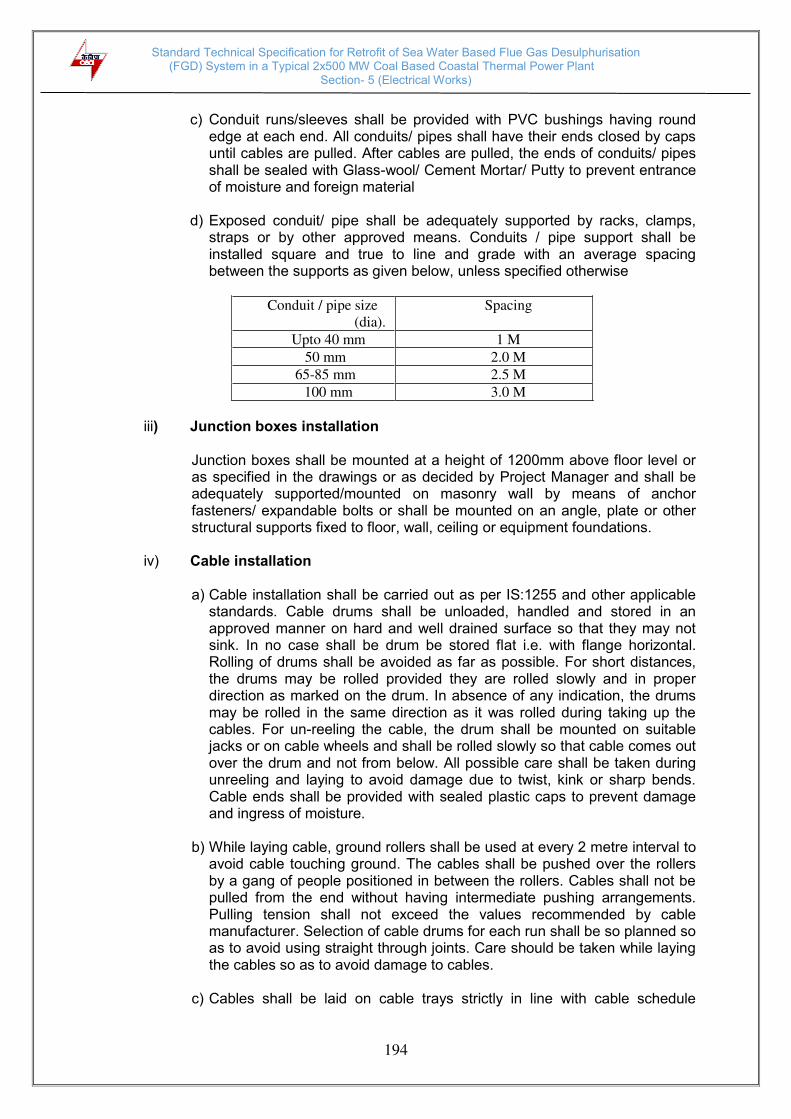
Standard Technical Specification for Retrofit of Sea Water Based Flue Gas Desulphurisation (FGD) System in a Typical 2x500 MW Coal Based Coastal Thermal Power Plant
Section- 5 (Electrical Works)
194
c) Conduit runs/sleeves shall be provided with PVC bushings having round
edge at each end. All conduits/ pipes shall have their ends closed by caps until cables are pulled. After cables are pulled, the ends of conduits/ pipes shall be sealed with Glass-wool/ Cement Mortar/ Putty to prevent entrance of moisture and foreign material
d) Exposed conduit/ pipe shall be adequately supported by racks, clamps,
straps or by other approved means. Conduits / pipe support shall be installed square and true to line and grade with an average spacing between the supports as given below, unless specified otherwise
Conduit / pipe size
(dia). Spacing
Upto 40 mm 1 M 50 mm 2.0 M
65-85 mm 2.5 M 100 mm 3.0 M
iii) Junction boxes installation
Junction boxes shall be mounted at a height of 1200mm above floor level or as specified in the drawings or as decided by Project Manager and shall be adequately supported/mounted on masonry wall by means of anchor fasteners/ expandable bolts or shall be mounted on an angle, plate or other structural supports fixed to floor, wall, ceiling or equipment foundations.
iv) Cable installation
a) Cable installation shall be carried out as per IS:1255 and other applicable
standards. Cable drums shall be unloaded, handled and stored in an approved manner on hard and well drained surface so that they may not sink. In no case shall be drum be stored flat i.e. with flange horizontal. Rolling of drums shall be avoided as far as possible. For short distances, the drums may be rolled provided they are rolled slowly and in proper direction as marked on the drum. In absence of any indication, the drums may be rolled in the same direction as it was rolled during taking up the cables. For un-reeling the cable, the drum shall be mounted on suitable jacks or on cable wheels and shall be rolled slowly so that cable comes out over the drum and not from below. All possible care shall be taken during unreeling and laying to avoid damage due to twist, kink or sharp bends. Cable ends shall be provided with sealed plastic caps to prevent damage and ingress of moisture.
b) While laying cable, ground rollers shall be used at every 2 metre interval to
avoid cable touching ground. The cables shall be pushed over the rollers by a gang of people positioned in between the rollers. Cables shall not be pulled from the end without having intermediate pushing arrangements. Pulling tension shall not exceed the values recommended by cable manufacturer. Selection of cable drums for each run shall be so planned so as to avoid using straight through joints. Care should be taken while laying the cables so as to avoid damage to cables.
c) Cables shall be laid on cable trays strictly in line with cable schedule
Standard Technical Specification for Retrofit of Sea Water Based Flue Gas Desulphurisation (FGD) System in a Typical 2x500 MW Coal Based Coastal Thermal Power Plant
Section- 5 (Electrical Works)
195
furnished. d) Power and control cables shall be laid on separate tiers. The laying of
different voltage grade cables shall be on different tiers according to the voltage grade of the cables. In horizontal tray stacks, HT cables (11kV) shall be laid on topmost tier and cables of subsequent lower voltage grades on lower tiers of trays. Single core cable in trefoil formation shall be laid with a distance of four times the diameter of cable between trefoil center lines and clamped at every two metre. All multi-core cables shall be laid in touching formation. Power and control cables shall be secured fixed to trays/ support with self locking type nylon cable straps with de-interlocking facilities. For horizontal trays arrangements, multi-core power cables and control cables shall be secured at every five meter interval. For vertical tray arrangement, individual multi-core power cables and control cables shall be secured at every one meter by nylon cable strap. After completion of cable laying work in the particular vertical tray, all the control cables shall be binded to trays/ supports by aluminium strips at every five meter interval and at every bend.
e) Bending radii for cables shall be as per manufacturer’s recommendations
and IS:1255. f) Where cables cross roads/rail tracks, the cables shall be laid in hume pipe/
PVC pipe. g) Joints for less than 250 Meters run of cable shall not be permitted. h) In each cable run some extra length shall be kept at suitable point to
enable one LT (415V system) / two HT (11/6.6kV, 3.3kV) straight through joints to made, should the cable develop fault at a later stage. Control cable termination inside equipment enclosure shall have sufficient lengths so that shifting of termination in terminal blocks can be done without requiring any splicing.
i) Wherever few cables are branching out from main trunk route troughs shall
be used. j) The installation work shall be carried out in a neat workman like manner
and areas of work shall be cleaned of all scraps, water, etc. after the completion of work in each area every day. RCC/ Steel trench covers shall be replaced after the installation work in a particular area is completed or when further work is not likely to be taken up for some time.
k) Separation- At least 300mm clearance in horizontal configuration and
100mm in vertical configuration shall be provided between:
- HT power and LT power cables, - LT power and LT control/ instrumentation cables,
l) Segregation - Segregation means physical isolation to prevent fire jumping.
- All cables associated with the unit shall be segregated from cables of other units.
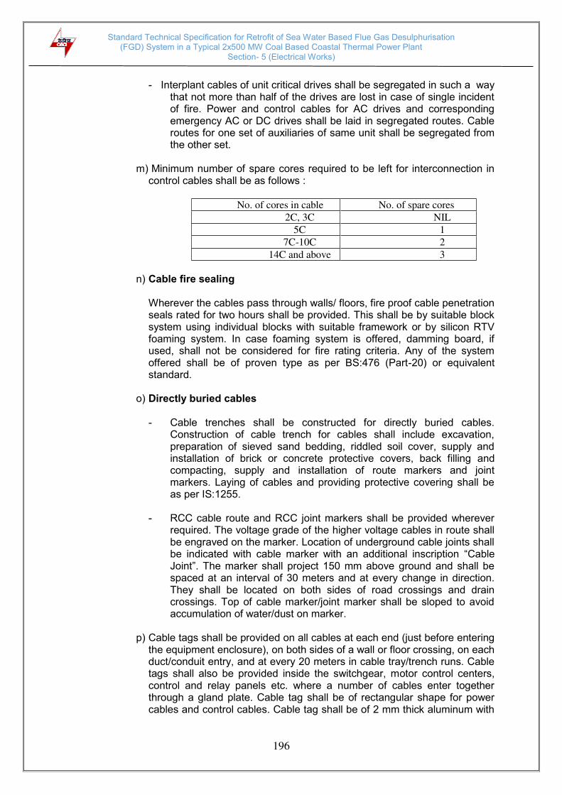
Standard Technical Specification for Retrofit of Sea Water Based Flue Gas Desulphurisation (FGD) System in a Typical 2x500 MW Coal Based Coastal Thermal Power Plant
Section- 5 (Electrical Works)
196
- Interplant cables of unit critical drives shall be segregated in such a way
that not more than half of the drives are lost in case of single incident of fire. Power and control cables for AC drives and corresponding emergency AC or DC drives shall be laid in segregated routes. Cable routes for one set of auxiliaries of same unit shall be segregated from the other set.
m) Minimum number of spare cores required to be left for interconnection in
control cables shall be as follows :
No. of cores in cable No. of spare cores 2C, 3C NIL
5C 1 7C-10C 2
14C and above 3 n) Cable fire sealing
Wherever the cables pass through walls/ floors, fire proof cable penetration seals rated for two hours shall be provided. This shall be by suitable block system using individual blocks with suitable framework or by silicon RTV foaming system. In case foaming system is offered, damming board, if used, shall not be considered for fire rating criteria. Any of the system offered shall be of proven type as per BS:476 (Part-20) or equivalent standard.
o) Directly buried cables
- Cable trenches shall be constructed for directly buried cables. Construction of cable trench for cables shall include excavation, preparation of sieved sand bedding, riddled soil cover, supply and installation of brick or concrete protective covers, back filling and compacting, supply and installation of route markers and joint markers. Laying of cables and providing protective covering shall be as per IS:1255.
- RCC cable route and RCC joint markers shall be provided wherever
required. The voltage grade of the higher voltage cables in route shall be engraved on the marker. Location of underground cable joints shall be indicated with cable marker with an additional inscription “Cable Joint”. The marker shall project 150 mm above ground and shall be spaced at an interval of 30 meters and at every change in direction. They shall be located on both sides of road crossings and drain crossings. Top of cable marker/joint marker shall be sloped to avoid accumulation of water/dust on marker.
p) Cable tags shall be provided on all cables at each end (just before entering
the equipment enclosure), on both sides of a wall or floor crossing, on each duct/conduit entry, and at every 20 meters in cable tray/trench runs. Cable tags shall also be provided inside the switchgear, motor control centers, control and relay panels etc. where a number of cables enter together through a gland plate. Cable tag shall be of rectangular shape for power cables and control cables. Cable tag shall be of 2 mm thick aluminum with

Standard Technical Specification for Retrofit of Sea Water Based Flue Gas Desulphurisation (FGD) System in a Typical 2x500 MW Coal Based Coastal Thermal Power Plant
Section- 5 (Electrical Works)
197
number punched on it and securely attached to the cable by not less than two turns of 20 SWG GI wire conforming to IS:280. Alternatively, cable tags made of nylon, cable marking ties of ‘TY-CAB’ or equivalent type with cable number heat stamped on the cable tags may also be provided.
q) While crossing the floors, un-armoured cables shall be protected in
conduits upto a height of 500 mm from floor level if not laid in tray.
v) Cable terminations and connections
a) The termination and connection of cables shall be done strictly in accordance with cable termination kit manufacturer instructions, drawings etc. Cable jointer shall be qualified to carryout satisfactory cable jointing/ termination.
b) Work shall include all clamps, fittings etc. and clamping, fitting, fixing,
plumbing, soldering, drilling, cutting, taping, preparation of cable end, crimping of lug, insulated sleeving over control cable lugs, heat shrinking (where applicable), connecting to cable terminal, shorting and grounding as required to complete the job.
c) The equipment will be generally provided with undrilled gland plates for
cables/ conduit entry. The Contractor shall be responsible for punching of gland plates, painting and touching up. Holes shall not be made by gas cutting. The holes shall be true in shape. All cable entry points shall be sealed and made vermin and dust proof. Unused openings shall be effectively sealed by 2mm thick aluminium sheets.
d) Control cable cores entering control panel/ switchgear/ MCCs etc. shall be
neatly bunched, clamped and tied with self locking type nylon cable ties with de interlocking facility to keep them in position.
e) The panels where a larger number of cables are to be terminated and
cable identification may be difficult, each core ferrule shall include the complete cable number as per the drawings. The ferrules shall be indelible interlocking type and shall fit tightly on cores. Spare cores shall have similarly ferrules with a suffix letter ‘S’ alongwith cable numbers and coiled up after end sealing.
f) All cable terminations shall be appropriately tightened to ensure secure
and reliable connections.
5.7.5 Earthing system
i) Earthing system shall be in strict accordance with IS:3043/ IEEE-80/ IEC and Indian Electricity Rules/ Acts.
Wherever existing main earthing system is not available, the main earthing system will be designed considering suitable corrosion allowance based on earthing conductor material and type of soil, for a service life of at least forty (40) years for maximum fault current or system fault current of 40kA whichever is higher for 1 second. The minimum rate of corrosion of earthing conductor shall be considered as 0.12mm per year while determining the conductor size.
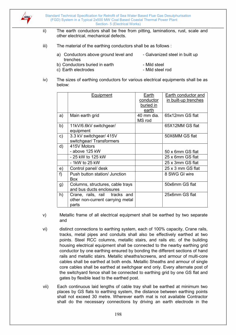
Standard Technical Specification for Retrofit of Sea Water Based Flue Gas Desulphurisation (FGD) System in a Typical 2x500 MW Coal Based Coastal Thermal Power Plant
Section- 5 (Electrical Works)
198
ii) The earth conductors shall be free from pitting, laminations, rust, scale and other electrical, mechanical defects.
iii) The material of the earthing conductors shall be as follows :
a) Conductors above ground level and - Galvanized steel in built up trenches
b) Conductors buried in earth - Mild steel c) Earth electrodes - Mild steel rod
iv) The sizes of earthing conductors for various electrical equipments shall be as
below:
Equipment Earth conductor buried in
earth
Earth conductor and in built-up trenches
a) Main earth grid 40 mm dia. MS rod
65x12mm GS flat
b) 11kV/6.6kV switchgear/ equipment
65X12MM GS flat
c) 3.3 kV switchgear/ 415V switchgear/ Transformers
50X6MM GS flat
d) 415V Motors - above 125 kW
50 x 6mm GS flat
- 25 kW to 125 kW 25 x 6mm GS flat
- 1kW to 25 kW 25 x 3mm GS flat
e) Control panel/ desk 25 x 3 mm GS flat
f) Push button station/ Junction Box
8 SWG GI wire
g) Columns, structures, cable trays and bus ducts enclosures
50x6mm GS flat
h) Crane, rails, rail tracks and other non-current carrying metal parts
25x6mm GS flat
v) Metallic frame of all electrical equipment shall be earthed by two separate
and
vi) distinct connections to earthing system, each of 100% capacity, Crane rails,
tracks, metal pipes and conduits shall also be effectively earthed at two
points. Steel RCC columns, metallic stairs, and rails etc. of the building
housing electrical equipment shall be connected to the nearby earthing grid
conductor by one earthing ensured by bonding the different sections of hand
rails and metallic stairs. Metallic sheaths/screens, and armour of multi-core
cables shall be earthed at both ends. Metallic Sheaths and armour of single
core cables shall be earthed at switchgear end only. Every alternate post of
the switchyard fence shall be connected to earthing grid by one GS flat and
gates by flexible lead to the earthed post.
vii) Each continuous laid lengths of cable tray shall be earthed at minimum two places by GS flats to earthing system, the distance between earthing points shall not exceed 30 metre. Wherever earth mat is not available Contractor shall do the necessary connections by driving an earth electrode in the

Standard Technical Specification for Retrofit of Sea Water Based Flue Gas Desulphurisation (FGD) System in a Typical 2x500 MW Coal Based Coastal Thermal Power Plant
Section- 5 (Electrical Works)
199
ground. viii) Neutral connections and metallic conduits/pipes shall not be used for the
equipment earthing. Lightning protection system down conductors shall not be connected to other earthing conductors above the ground level.
ix) Connections between earth leads and equipment shall normally be of bolted
type. Contact surfaces shall be thoroughly cleaned before connections. Equipment bolted connections after being tested and checked shall be painted with anti corrosive paint/compound.
x) Suitable earth risers shall be provided above finished floor/ground level, if the
equipment is not available at the time of laying of main earth conductor. xi) Connections between equipment earthing leads and between main earthing
conductors shall be of welded type. For rust protection the welds should be treated with red lead compound and afterwards thickly coated with bitumen compound. All welded connections shall be made by electric arc welding.
xii) Resistance of the joint shall not be more than the resistance of the equivalent
length of conductors. xiii) Earthing conductors along their run on columns, walls, etc. shall be supported
by suitable welding/ cleating at interval of 1000mm and 750mm respectively. xiv) Earth pit shall be constructed as per IS:3043. Electrodes shall be embedded
below permanent moisture level. Minimum spacing between electrodes shall be 600mm. Earth pits shall be treated with salt and charcoal if average resistance of soil is more than 20 ohm metre.
xv) Earthing conductor shall be buried at least 2000mm outside the fence of
electrical installations. Every alternate post of the fences and all gates shall be connected to earthing grid by one lead.
5.7.6 Lightning Protection System
i) All lightning protection installation work shall be in accordance with the Indian Electricity Rules and IS Code of Practice for the Protection of Buildings and allied Structures against Lightning (IS:2309).
ii) Lightning protection system shall comprise vertical air terminations, horizontal
air terminations, down conductors, test links and earth electrodes.
iii) Air terminations, down conductors and test links shall be of galvanized steel conductors and earth connection below ground level shall be of mild steel rod.
iv) For tall buildings and structures, early streamer emission (ESE) type air
terminal systems are preferred.
v) Lightning protection conductors/ air termination rods and circumferential bands provided at the top portion of chimney stack shall be lead coated in order to avoid melting by exposure to hot flue gases.

Standard Technical Specification for Retrofit of Sea Water Based Flue Gas Desulphurisation (FGD) System in a Typical 2x500 MW Coal Based Coastal Thermal Power Plant
Section- 5 (Electrical Works)
200
vi) Horizontal air termination flats provided on top of control building, pump houses and other buildings shall be laid such that no part of the roof shall be more than 9 meters
vii) Conductors of lightning protection system shall not be connected with
conductors of earthing system above ground level.
viii) Down conductors shall be cleated on outer side of building wall at 1000 mm interval or tack welded to outside of building columns at 1000 mm interval.
ix) Down conductors shall be connected to separate earth electrodes through
test points located at height of above 1000 mm above ground level. These earth electrodes shall in turn be connected to earth mat at two points.
x) Lightning protection conductors shall not pass through or run inside GI
conduits.
xi) All metallic equipments on roof and exposed steel works within the vicinity of 2000 mm from lightning protection conductors in air shall be bonded to conductors of lightning protection system.
xii) Lightning protection system shall have as few joints as possible and avoid
sharp bends. Down conductors shall have, as far as possible, no joint except at test point and end termination.
xiii) Termination at the metallic equipments on roof should be made by suitable
nuts, bolts, pressure washers and bitumen washers with good electrical conductivity.
xiv) All lightning protection conductors shall be exposed to atmosphere unless
specifically mentioned.
5.8 LIGHTING 5.8.1 Make of Equipment / Components
All components such as lighting fixtures, lighting/ welding branch boards/ Distribution boards, switches, sockets, MCBs, MCCBs etc. must be of standard reputed make. The bidder shall propose makes of the various components in his offer for proper assessment. The makes proposed by the bidder in his bid shall however not be binding on the purchaser and the same shall be finally decided during detailed engineering with a view to meet the specification requirements.
5.8.2 Normal Service Conditions
The equipment supplied by the contractor shall be suitable for installation in an area having hot and humid climate and dusty atmosphere.
5.8.3 Lighting System
i. A.C. Normal Lighting :
In this system, the lighting circuits would be fed on the normal A.C. supply available from the Main lighting boards. All the lighting fixtures connected to this system shall be ‘ON’ as long as the 415/240V normal supply is healthy.

Standard Technical Specification for Retrofit of Sea Water Based Flue Gas Desulphurisation (FGD) System in a Typical 2x500 MW Coal Based Coastal Thermal Power Plant
Section- 5 (Electrical Works)
201
ii. AC/DC Emergency lighting :
At strategic locations in the main building, control building, pump house viz. near entrance, stair-case landing, important control points etc. permanent type incandescent AC/DC lighting fixtures shall be provided to enable safe movement of operating personnel and access to important control points during station emergency involving total AC system failure.
5.8.4 Main Lighting Board (MLB)
The complete lighting of the FGD plant shall be met through 2 or 3 nos. Main Lighting Boards. Each main Lighting Board shall be having Dry type 415 V/ 415 V lighting transformer of adequate rating. The main lighting boards shall feed various lighting distribution boards to be located suitably near individual load centres. The incoming supply to Main Lighting Board shall be arranged from 415V Switchboard to be supplied by the bidder, through 1.1 kV grade armoured cable. MLBs shall be having MCCBs of adequate rating for incoming supply and out going feeder.
5.8.5 Lighting Distribution Board (LDB)
The outgoing feeders power from MLB shall be taken through stranded Aluminium conductor, PVC insulated, 1.1kV grade, armoured cable of appropriate size and shall be terminated on lighting distribution boards (LDB). The required number of LDB shall be wall mounting type having sheet metal enclosure, 3X63A copper bus bars and 63A Neutral terminal block. The incoming cables shall be terminated on 63A TPN switch and 4 nos. MCBs each
of 16A rating shall be provided on each of the three phases (i.e. total of 12 O/G
MCBs) for outgoing circuits. The minimum interrupting capacity of the miniature
circuit breaker (MCB) shall be 9kA rms. The LDB enclosure shall be duly earthed as
specified.
The LDBs shall be located near entry doors. The LDB door shall have a cut out for operating the MCBs. The cut out portion shall have a transparent plastic/acrylic cover for its protection against dust. The LDB shall be of dust proof design.
5.8.6 AC/DC Emergency Lighting Distribution Board (ELDB)
In order to provide emergency lighting during normal AC failure, an AC/DC emergency lighting distribution cabinet (ELDB) shall be provided which shall incorporate AC/DC change over scheme and have outgoing feeders meant to provide functional lighting in control rooms, stair cases, exit points and vital locations during black out.
5.8.7 Guidelines for Design of Lighting Distribution System
Indoor Areas
i. Working plane shall be assumed about 800 mm above the finished ground level.
ii. Fluorescent luminaries with pendant suspensions shall be installed 3.5 metre above the finished floor level.
iii. Maintenance factor shall be taken as 0.7. iv. Average illumination level shall be taken in the horizontal plane as specified.

Standard Technical Specification for Retrofit of Sea Water Based Flue Gas Desulphurisation (FGD) System in a Typical 2x500 MW Coal Based Coastal Thermal Power Plant
Section- 5 (Electrical Works)
202
Outdoor Areas:
i. Initial calculations shall be done by average illumination method with suitable coefficient of utilization which shall be then cross-checked/ verified for correctness and uniformity with sample calculations by ‘point by point’ calculation method.
ii Maintenance factor shall be taken as 0.6.
5.8.8 Illumination Level Design Factors and Type of Luminaires
The following table gives the desired average illumination level, recommended luminaire type, reflection factors and maintenance factors applicable to various rooms/ areas.
SN Area Average illumination level (Lux)
Reflection factors
floor/wall/ ceiling
Maintenance Factor (% )
Type of Luminaire as
given below or equivalent
1. Switchgear room
200 10/50/50 0.7 IRF 2X40 W
2. Office rooms w/o false ceiling with false ceiling
200
200
10/50/50 10/50/50
0.7
0.7
IRF 2 x 40 W RLF 2X40 W
3. Conference Room Library
300 10/50/50 0.7 IRF 2 x 40 W
4. Control room / DAS room
450 10/50/70 0.7 RLF 2 x 40 W
5. Control Equipment Room
300 10/50/50 0.7 RLF 2 x 40 W
6 Pump House
150 10/50/50 0.7 RLF 2 x 40 W or FPM – 125 W
7 Battery room
200 10/50/50 0.7 CPF (2 x 40 W)
8 Stair case, corridor, toilets, etc.
70 0.7 IF (1 x 40 W)
9 Out door areas / Street lighting and adjacent GTG areas
20
0.6
0.6
FLS – 400 W STS – 150 W
10 AC/DC Emergency lighting:- Control room, stair cases Exit points
Functional
--
BHI – 100 W

Standard Technical Specification for Retrofit of Sea Water Based Flue Gas Desulphurisation (FGD) System in a Typical 2x500 MW Coal Based Coastal Thermal Power Plant
Section- 5 (Electrical Works)
203
5.8.9 Description for each type of luminaire
All luminaire to be supplied complete with lamps, starting gear and all necessary accessories for mounting on ceiling/ poles/ false ceiling as required. Pendants/ brackets of suitable sizes shall be provided as required.
i. Type IRF (2 x 40 W)
Industrial type fluorescent tube fixtures with vitreous enameled reflector, channel housing containing vacuum filled polyester ballast and power factor improvement capacitors, 19 mm conduit entry, spring loaded rotor lamp holder, starters, complete with 2 x 40 W fluorescent tubes.
ii. Type IF (1 x 40 W) Similar to type IRF but without reflector and with 1 x 40 W fluorescent tube.
iii. Type BHI (100 W) Bulk head luminaire of cast aluminium body, finished in stove enamel, white inside, 19 m conduit entry, prismatic front glass, gasket, porcelain lamp holder complete with 100 W incandescent lamp.
iv. Type RLF (2 x 40 W)
Recessed type decorative luminaire without acrylic cover (as per TAC norms) with housing made of heavy gauge steel, stove enameled white inside with lid all around to enable flush mounting with false ceiling with opal acrylic diffuser complete with ballasts, capacitors, starters, rotor lamp holder and 2 x 40 W fluorescent tubes.
v. Type CPF (2 x 40 W)
Corrosion proof luminaire, cast aluminium control gear housing containing ballasts, starters, capacitors & terminal block. Structured on seamless heavy gauge aluminum pipes and cast aluminium end boxes incorporating specially designed vapour proof lamp holder complete with 2 x 40 W fluorescent tubes.
vi. Type FLS (400 W)
Flood lighting sodium vapour lamp luminaire (IP:55) heavy duty die cast aluminium housing finished in stove enamel with clear neat resistant flat toughened front glass with tropicalised gasket, anodized aluminum reflector, GI cradle, three plane focusing device, complete with starting/ control gear in a weather proof enclosure and a 400 W HPSV lamp. The beam angle shall be ±300.
vii. Type STS (150 W) Dust and weather proof (IP:55) sodium vapour lamp street lighting fixture comprising of cast aluminium housing accommodating all pre-wired control gear accessories, white stove enameled from inside deep drawn aluminum reflector, accommodating lamp holder with clear acrylic cover fixed by means of four toggles clamps complete with 150 W HPSV lamp.
viii. Type FPM (125 XW)

Standard Technical Specification for Retrofit of Sea Water Based Flue Gas Desulphurisation (FGD) System in a Typical 2x500 MW Coal Based Coastal Thermal Power Plant
Section- 5 (Electrical Works)
204
Flame proof mercury vapour lamp fixture for hazardous areas such as fuel oil pump house. Thermal shock proof well glass fixed in a canopy. Weatherproof construction suitable for indoor as well as outdoor. GI wire guard, porcelain lamp holder, control gear also housed in a heavy gauge gasket, flame proof enclosure complete with 125 W HPMV lamp.
5.8.10 Lighting Distribution System Design
i. While designing the protection of the circuit supplying the mercury and sodium vapor lamps, it shall be ensured that the circuit is not interrupted due to starting current.
ii. Distribution system shall be designed for 450C ambient for voltage drop at the end point limited to 5%.
iii. Distribution Boards / Cabinet shall be located as near as possible to the centre of the load which they are intended to supply.
iv. Each out going feeder of the lighting / power socket distribution board shall be loaded up to 70 to 80% the MCB rating.
v. The current rating of wires connected to the out going side of any MCB shall not be less than the MCB thermal rating. Similarly cables connected to MCCBs shall have current rating not less than the thermal current rating of its MCCB.
vi. As far as possible load shall be balanced on three phases of each lighting
Dist. cabinet.
vii. Separate MCB and sub-circuits from the LDB shall be utilized for luminaries and 15A power socket outlets.
viii. Lighting load on individual sub circuit emanating from LDB shall be restricted to 2 kW.
5.8.11 Emergency lighting Distribution system
The AC/ DC Emergency Lighting Distribution system :
i. The AC/DC emergency lighting distribution board shall be wall mounted type sheet metal enclosure similar to the normal LDB in general constructional features.
ii. It shall have the provision to receive two incoming supplies viz. 240V, 2 wire AC and 220V, 2 wire DC which shall terminate on a 2 wire, 240V Bus through MCCBs and changeover AC & DC contactors. Suitable number of outgoing feeders shall be tapped from the bus through 2 pole MCB of adequate thermal and short circuit rating.
iii. The automatic changeover scheme between AC and DC sources shall incorporate positive interlock to avoid paralleling of two power supplies. The auto changeover scheme shall be achieved using AC and DC voltage sensing relays. Lockable type auto/manual selector switch shall also be provided. Normally the AC contactor shall be ON. In case of AC failure it shall open

Standard Technical Specification for Retrofit of Sea Water Based Flue Gas Desulphurisation (FGD) System in a Typical 2x500 MW Coal Based Coastal Thermal Power Plant
Section- 5 (Electrical Works)
205
and DC contactor shall close. When the AC is restored, the DC contactor shall open and AC contactor shall reclose automatically.
5.8.12 Spare Feeders
Provision of at least 20% subjected to minimum of one spare outgoing feeder shall be kept on each Main Lighting Board and Lighting Distribution Board/ Cabinet.
5.8.13 Power Socket Outlets
All buildings/ rooms are to be equipped with 5A and 15 A utility power socket with individual control supply as required. 15A sockets shall be fed through independent circuits from the lighting distribution cabinets and that shall installed 250mm above floor level.
5.8.14 Welding outlet
A few welding outlets are to be provided in the power plant area as per the system requirement and these shall be directly feed from 415V switchboard. The welding outlets shall be of 63 A, 3 phase & neutral controlled by a switch suitable for indoor / outdoor duty as required. The plug tops shall be supplied loose and handed over separately. All three phase welding power outlets shall incorporate a fourth pin for earthing purpose and shall be fitted with a mechanical interlock which will prevent the plug being inserted or withdrawn while the switch is in “ON” position.
5.8.15 Drawings and Data
The bidder shall submit the following drawings/ data after award of contract for approval : - Lux level calculation for each area - Lighting fixtures layout drawing for each area - Single line diagram and GA drawing for MLB, LDB and ELDB - Key distribution diagram for lighting, power socket and welding system. - Typical voltage drop calculation for various application - Scheme drawings for AC / DC changeover - Leaflets .and instruction manual for all types of lighting fixtures etc.
5.8.16 Standards
The complete lighting equipment (lighting fixtures, Distribution boards, etc.) to be supplied by the tenderer shall conform to latest revision of I.S/ IEC. Bidder shall submit the type and routine test certificate as per relevant I.S. for approval.
5.9 DC SYSTEM
1. Each DC system shall be ungrounded (unless asked otherwise) and each system shall be provided with its own separate battery, 2x100% rating Float-cum-Boost charger, DC distribution boards and sub-distribution boards for meeting the 220V DC power supply for continuous and emergency DC power and control requirements, emergency lighting and AC power requirement (through inverter), if any.
Standard Technical Specification for Retrofit of Sea Water Based Flue Gas Desulphurisation (FGD) System in a Typical 2x500 MW Coal Based Coastal Thermal Power Plant
Section- 5 (Electrical Works)
206
2. Battery :
i. The battery shall be Lead acid (Plante) type or Ni-Cd pocket plate high discharge (KPH) type.
ii. The ampere-hour capacity of battery of each DC system shall be designed
to meet the duty cycle and loads associated with respect to that DC system for duration of one hour.
iii. Battery shall be designed for proper operation and to meet specified load
and their duty cycle under all ambient and site conditions specified elsewhere.
iv. Number of cells: 220V batteries shall have a minimum of 110 cells each. v. Nominal voltage : 220V DC for each DC system . vi. End voltage : End voltage of batteries at the end of duty cycle : not less
than 1.85V per cell for Lead-acid and 1.14V per cell for Ni-Cd type. vii. The bidder shall indicate in their bid the ampere-hour capacity of various
batteries at 10 hour rate of discharge for lead-acid and 5 hour rate of discharge for Ni-Cd battery at 270C envisaged by them.
viii. The battery shall preferably be arranged in single tier arrangement.
However, batteries having a complete cell weight less than 50kg could be located in the double tier arrangement. The battery racks shall be wood coated with acid resistant and flame resistant coating or mild steel racks, free standing type mounting on porcelain/ hard rubber/ PVC pads insulators/ high impact plastic insulators.
ix. Each battery should be provided with suitable moulded case circuit breaker
which shall be located adjoining the battery itself in a separate panel viz. battery panel. All the MCCBs will have adjustable Short circuit & Overload settings. The bidder will ensure proper coordinated settings from the charger board and beyond. All the DC motor feeders will also be provided with over load alarm. Suitable arrangement shall be provided to annunciate the tripping of breaker in battery panel as well as at remote control board.
3. Float-cum-Boost Chargers
i The Float (trickle) charger shall have a rating to need float charging load of the associated battery at the rate of 2 to 2.2V/ Cell for lead-acid and 1.4 to 1.42V/ cell for Ni-Cd and for meeting the constant DC loads to be fed from the DC system with an overall margin of 10%.
ii. The Boost (quick) charger shall have a rating to meet boost charging load,
equalising charging load of the associated battery at the rate of 1.5 to 2.75V / cell for lead-acid and 1.53 to 1.7V/ cell for Ni-Cd and current as recommended by the battery manufacturer and for simultaneously meeting the constant DC loads to be fed from the DC system with an overall margin of 10%. The quick chargers of the battery system shall also be suitable for routine testing of DC motors connected to the DC system.

Standard Technical Specification for Retrofit of Sea Water Based Flue Gas Desulphurisation (FGD) System in a Typical 2x500 MW Coal Based Coastal Thermal Power Plant
Section- 5 (Electrical Works)
207
iii. The trickle charger and quick charger shall also be capable of meeting
short time impulse loads of the associated DC systems. iv. DC output voltage variation for trickle chargers and quick chargers shall be
in accordance with requirements of the equipments offered but shall normally be 210 to 250V and 200 to 320V respectively.
v. The trickle chargers and quick chargers shall be of static type using silicon-controlled rectifiers with three-phase bridge circuit and ripple factors suiting the equipment offered but not exceeding 1% pk-pk without battery. This value of ripple factor shall not effect the performance of electronic and static equipment supplied by the bidder.
vi. Each trickle charger shall have an arrangement for automatic and normal
DC voltage regulation with selector switch for mode of operation. vii Each quick charger shall have normal voltage regulating system.
viii Voltage regulating system for trickle charger and quick charger shall be of ‘static’ type.
ix The automatic voltage regulator of trickle charger shall hold the DC voltage
constant from zero to full load but with a definite drop at load greater than full load so that such loads are transferred to the battery. The automatic voltage regulating system shall maintain DC voltage constant to the requirement of equipment offered but to a voltage not more than +1 % of the set value for a fluctuation of +10% in voltage and +5% in frequency in the AC input voltage for purpose of bid.
x. Each trickle charger and each quick charger panel shall be complete with
all necessary equipment and shall be subjected to purchaser’s approval. xi The rectifier assemblies shall be provided with all necessary protection
devices, which shall be subject to approval. xii Facia windows with indicating lamps and inscriptions shall be provided in
each charger panel for annunciations provided in each charger panel shall at least include the following:
AC supply failure
Battery protection operated
Surge circuit fuse failure
Charger trip
Rectifier fuse failure
Charger load limiter operated
Battery on boost Necessary potential free contacts for annunciating the above shall be
provided. xiii The transformers associated with trickle chargers and quick chargers shall
be air cooled type.

Standard Technical Specification for Retrofit of Sea Water Based Flue Gas Desulphurisation (FGD) System in a Typical 2x500 MW Coal Based Coastal Thermal Power Plant
Section- 5 (Electrical Works)
208
4. DC Distribution Boards
i. Each DC system shall be provided with suitable independent DC
Distribution Board to make available the DC power requirements. ii Each DC Distribution board shall have incoming supply arrangement from
the associated battery, trickle charger and quick charger and adequate number of outgoing feeders with 20% spare feeders suitably rated for various loads to be set by the DC system. No. of feeders / equipment including 20% spare feeders as required during engineering shall be deemed to be included in the quoted price.
DC Distribution arrangement shall be designed to provide duplicate DC
supply feeders for each load and system from separate sections. The DC motor load shall be fed from separate bus with isolation facility
from the main bus to facilitate testing of motors. iii Each DC Distribution board shall be provided with (i) earth fault detecting
relays which shall give alarm for earth fault in positive or negative of the system. (ii) voltage level indicating devices for annunciating ‘DC voltage low’ and ‘DC voltage high’ with additional initiating contacts for annunciating the same at control board (iii) voltmeter with selector switch to read voltages positive to earth, negative to earth and between positive and negative.
iv Various annunciations in DC Distribution Boards shall be by means of facia
windows with indicating lamps and inscriptions. v. Each incoming and outgoing feeder shall be provided with magnetic short
circuit protection having adjustable range of pick up current and time delay. In addition to the above, the feeder breakers for motors shall be provided with overload protection with suitable range.
vi Protection coordination: short circuit protection in various feeders of DC
system shall be coordinated so as to achieve selective tripping on fault on any feeder.
5. Battery Panels, Charger Panels and DC Distribution Boards
constructional features:
i. The boards shall be fully compartmentalized type i.e. each feeder equipment shall be accommodated in a separate module.
ii The DC boards shall have degree of protection as IP-52. The degree of
protection of charger board shall be IP-42. Panel of all the faces of the DC board shall be 2.0mm thick. The sheet steel thickness for charger panel shall be minimum 2.0mm.Removable gland plates of thickness 3mm (hot/cold rolled sheet steel) or 4 mm (non-magnetic material) shall be provided.
iii. The busbars shall be of high conductivity aluminium / electrolytic copper of
ample cross section, shall have adequate current rating and shall be without maximum short circuit stresses. The bus bars shall be insulated

Standard Technical Specification for Retrofit of Sea Water Based Flue Gas Desulphurisation (FGD) System in a Typical 2x500 MW Coal Based Coastal Thermal Power Plant
Section- 5 (Electrical Works)
209
and supported from the structure by means of durable non-hygroscopic, non-combustible and non trackingmaterial.The entire busbar system shall be insulated with PVC sleeves.
iv. DC Distribution arrangement, type, make, ratings and voltage ratings of
batteries, charges, DC Boards, circuit breakers, contactors, switches, relays, instruments etc. shall be subject to prior approval of the purchaser.
6. Tests
The bidder shall carry out all the tests on batteries, battery charger and DC board as per relevant standards and shall also carry out one hour rate of discharge test on the batteries. Test reports will be furnished for approval. Capacity test on each complete battery at 10hr rate of discharge for Lead acid battery and 5 hr rate of discharge for Ni-Cd battery shall be carried out at site after installation.
7. Drawings and Data : The following drawings shall be supplied by the
tenderer with his tender for each battery system.
i. General arrangement drawing of the cell.
ii. General arrangement drawing of battery stand.
ii. Layout drawing of the battery in the battery room with details of cell insulators/ stand insulators and end take off terminals of batteries.
iv. Charge and discharge performance curves of cells.
v. Schematic diagrams of charger panels.
vi. Control schemes and characteristic curves for voltage regulators of
charges.
vii. Schematic drawings for earth fault detection device and voltage level
indicating devices.
viii. Typical General arrangement drawings for each battery panel charger
panel and DC distribution Boards.
ix. Duty cycle for each battery system (load Vs time)
Standard Technical Specification for Retrofit of Sea Water Based Flue Gas Desulphurisation (FGD) System in a Typical 2x500 MW Coal Based Coastal Thermal Power Plant
Section- 6 (Control & Instrumentation Works)
210
SECTION 6
CONTROL & INSTRUMENTATION WORKS
6.0 TECHNICAL SPECIFICATION - C&I WORKS
6.1 GENERAL
6.1.1 General Requirements
i) The bidder shall provide all material, equipment and services so as to make a totally
integrated Instrumentation and Control System together with all accessories, auxiliaries
and associated equipment ensuring operability, maintainability and reliability. The
Instrumentation and Control System shall be consistent with modern power plant
practices and shall be in compliance with all applicable codes, standards, guides,
statutory regulations and safety requirements in force.
ii) The bidder shall also include in his proposal and shall furnish all equipment, devices
and services which may not be specifically stated in the specification but are needed for
completeness of the equipment/systems furnished by the bidder and for meeting the
intent and requirements of the specification.
iii) It may be noted that where equipment or system for the unit are described, same refer to
only one set per unit to be furnished by the contractor unless specifically indicated
otherwise. Where equipment or systems for plant common facilities are described, it
will be understood that the quantities described are the total quantities required.
6.1.2 Reliability and Availability
i) Each component and system offered by the bidder shall be of established reliability.
The minimum target reliability of each piece of equipment like each electronic
module/card, power supply, peripheral etc. shall be established by the bidder,
considering its failure rate/mean time between failures (MTBF), meantime to repair
(MTTR), such that the availability of the complete C&I system is assured for 99.7%.
ii) When more than one device uses the same measurement or control signal, the
transmitter and other components/ module shall be fully equipped to provide all signal
requirements. The system shall be arranged so that the failure of any monitoring device
or control components or spurious intermediate grounding in the signal path shall not
open the signal loop nor cause the loss or malfunction of signal to other devices using
the same signal.
iii) To ensure availability, adequate redundancy in system design shall be provided at
hardware, software and sensor level to satisfy the availability criteria as mentioned
above. For the protection system, independent sensing device shall be provided to
ensure adequate safety of plant equipment.
6.1.3 Standardisation and Uniformity of Hardware
To ensure smooth and optimal maintenance, easy interchangeability and efficient spare parts
management of various C&I instruments/equipment, the Bidder shall ensure that all
instruments/devices are of the same make, series and family of hardware to the extent
possible.

Standard Technical Specification for Retrofit of Sea Water Based Flue Gas Desulphurisation (FGD) System in a Typical 2x500 MW Coal Based Coastal Thermal Power Plant
Section- 6 (Control & Instrumentation Works)
211
6.1.4 Operability & Maintainability
i) The design of the control systems and related equipments shall adhere to the principle
of ‘Fail Safe’ operation wherever safety of personnel / plant equipment is involved.
‘Fail Safe’ operation signifies that the loss of signal or failure of any component shall
not cause a hazardous condition. However, it shall also be ensured that occurrence of
false trips are avoided / minimised.
The types of failure which shall be taken into account for ensuring operability of the
plant shall include but not be limited to:
a) Failure of sensor or transmitter,
b) Failure of main and/or redundant controller/other modules,
c) Loss of motive power to final control element,
d) Loss of control power,
e) Loss of instrument air.
ii) The choice of hardware shall also take into account sound maintainability principles
and techniques. The same shall include but shall not be limited to the following:
a) Standardization of parts.
b) Minimum use of special tools.
c) Grouping of functions.
d) Interchangeability.
e) Malfunction identification facility/self surveillance facility.
f) Easy modular replacement.
g) Fool proof design providing proper identification and other features to preclude
improper mounting and installation.
h) Appropriate derating of electronic components and parts.
iii) The equipment shall employ latest state of the art technology to guard against
obsolescence. In any case, bidder shall be required to ensure supply of spare parts for
15 years of the plant. In case, it is felt by the Bidder that certain
equipment/component is likely to become obsolete, the Bidder shall clearly bring out
the same in his bid and indicate steps proposed to deal with such obsolescence.
6.1.5 Control & Monitoring
PLC system based control, monitoring & operation shall be provided for the flue gas
desulphurization (FGD) system. Further, the FGD PLC shall be provided with softlink
interface through redundant fiber optic link to existing DDCMIS for required data
exchange, remote monitoring and control of FGD plant of each unit. In addition to
softlink interface, hardwired signal exchange between FGD PLC and DDCMIS like
bypass damper status, inlet and outlet gates status, ID Fans status, ESPs status,
Boiler Load Index (BLI), MFT etc. shall be provided on as required basis for
implementation of protections and interlocks. All required interfacing hardware and
software shall be provided by bidder.
6.1.6 Environmental Conditions
Instruments, devices and equipments for location in outdoors/ indoor/ air-conditioned areas
shall be designed to suit the coastal environment and conditions indicated below and shall
be suitable for continuous operation in the operating environment of a coal fired station and

Standard Technical Specification for Retrofit of Sea Water Based Flue Gas Desulphurisation (FGD) System in a Typical 2x500 MW Coal Based Coastal Thermal Power Plant
Section- 6 (Control & Instrumentation Works)
212
also during periods of air conditioning failure without any loss of function, or departure
from the specification requirements covered under this specification.
Ambient
temperature (outside cabinets)
Pressure Relative humidity
Atmosphere Required
protection
Class of
panels/
cabinets/ desks Outdoor Location
55 degree C max. Atmosphere 1 100 % Max.
Air (dirty) IP 55***
4 degree C min. Atmosphere 5 % min. Air (dirty) I IP 55***
Indoor Location
55 degree C max.
Atmosphere 95 %
Max. Air IP 54**
4 degree C min. Atmosphere 5 % min. Air IP 54**
Air Conditioned Areas 24 +/- 5 degree C
normal Atmosphere 95 % Max. Air IP 32
50 deg C max. * Atmosphere 5 %min. Air IP 32 * During air conditioning failure. ** For non-ventilated enclosures. For ventilated enclosures, protection class shall
be IP 42. ***With a suitable canopy at the top to prevent ingress of dripping water.. For PCs, OWS, EWS, Servers, Printers and other peripherals, maximum temperature limit
shall be 350 C.
6.2 PLC BASED CONTROL SYSTEM
6.2.1 General Requirements
i) Contractor shall provide complete and independent PLC based Control and
Instrumentation system with all accessories, auxiliaries and associated equipments
and cables for the safe, efficient and reliable operation of the FGD system.
ii) Bidder shall include in his proposal all instruments and devices, which are needed for
the completeness of the system. Same shall be subject to approval of the purchaser
during detailed engineering.
iii) All instruments and control equipments like primary and secondary instruments etc.
shall meet the requirements specified in sub-section on Measuring Instruments. In
addition, all electrical instrument devices like switches/transmitters/ controllers/
analysers/ solenoid valves which are located in the field/hazardous locations shall be
provided with explosion proof enclosure suitable for hazardous areas described in
National Electric Code (USA), Article 500, Class-I, Division-I. All field wiring
should be through conduits. All fittings, double compression type cable glands etc.
shall be strictly as per NEC recommendation article, 500 to 503.
iv) Contractor shall provide independent control systems for safe, efficient and reliable
operation of each of the plant auxiliary systems. The control system shall provide safe
operation under all plant disturbances and on component failure so that under no
condition the safety of plant, personnel or equipment is jeopardized. Control system
Standard Technical Specification for Retrofit of Sea Water Based Flue Gas Desulphurisation (FGD) System in a Typical 2x500 MW Coal Based Coastal Thermal Power Plant
Section- 6 (Control & Instrumentation Works)
213
shall be designed to prevent abnormal swings due to loss of Control System power
supply, failure of any Control System component, open circuit/short circuit,
instrument air supply failure etc. On any of these failures the controlled
equipment/parameter shall either remain in last position before failure or shall come
to fully open/close or on/off state as required for the safety of
plant/personnel/equipment and as finalised during detailed engineering. System shall
be designed such that there will be no upset when Power is restored.
v) ON/OFF control, indication, annunciation of incomers and bus-coupler are also to be
performed from contractor's control system for each of the above system as
applicable.
vi) The control system shall be located in air conditioned area. However, the control
system shall be designed to operate in non-air conditioned area also during air-
conditioning failure.
vii) Offered PLC systems shall be synchronised with existing main plant master clock
system. All necessary hardware and software along with convertors & special cables
from SNTP/IRIG-B ports on existing system shall be in Bidder's scope.
6.2.2 Programmable Logic Based Control System
i) PLC Processor
The processor unit shall be capable of executing the following functions:- a) Receiving binary and analog signals from the field and operator
initiated commands from OWS/ control panel.
b) Implementing all logic functions for control, protection and
annunciation of the equipment and systems.
c) Implementing modulating control function for certain application as
specified elsewhere in the specification.
d) Issuing control commands.
e) Providing supervisory information for alarm, various types of
displays, status information, trending, historical storage of data etc.
f) Performing self-monitoring and diagnostic functions.
ii) The controller shall provide all basic functions for binary gating operations,
modulating controls, storage, counting, timing, logging, transfer operations and
comparison functions.
iii) Each PLC unit shall be provided with two processors (Main processing unit and
memories) one for normal operation and one as hot standby. In case of failure of
working processor, there shall be an appropriate alarm and simultaneously the hot
standby processor shall take over the complete plant operation automatically. The
transfer from main processor to standby processor shall be totally bumpless and shall
not cause any plant disturbance whatsoever. In the event of both processors failing,
the system shall revert to fail safe mode. It shall be possible to keep any of the
processors as master and other as standby. The standby processor shall be updated in
line with the changes made in working processor. Power supply unit shall be hot
redundant for each CPU & I/O rack.

Standard Technical Specification for Retrofit of Sea Water Based Flue Gas Desulphurisation (FGD) System in a Typical 2x500 MW Coal Based Coastal Thermal Power Plant
Section- 6 (Control & Instrumentation Works)
214
iv) The memory shall be field expandable. The memory capacity shall be sufficient for
the complete system operation and have a capability for at least 20% expansion in
future. Programmed operating sequences and criteria shall be stored in non volatile
semi conductor memories like EPROM. All dynamic memories shall be provided
with buffer battery back up which shall be for at least 360 hours. The batteries shall
be lithium or Ni-Cd type.
v) The OWS shall perform control, monitoring and operation of all auxiliaries/ drives
interacting with PLC based control system. It shall basically perform the following
functions:
a) Operator interface for PLC based control system. Operator functions shall as
minimum include local/ remote selection, A/M selection, open/ close
operation, sequence auto, start/ stop selection, ON/OFF, bypassing criteria etc.
b) Supervisory functions like:- Mimic displays, which shall depict the process in graphical form and shall
cover all the process areas being monitored. Alarm monitoring/reporting, generation of logs, calculations, printing of logs
& reports etc.
c) Suitable Interface with stations wide LAN (in Purchaser’s Scope) for two-way
transfer of data.
vi) Programming station shall have access to the processor of the control system for
programming. Programming shall not require special computer skills. On the
programming console, it shall be possible to do the programming, self-diagnostics,
testing of sequence, simulation and any sequence modification. A forcing facility shall
be provided for changing the states of inputs and outputs, timers and flags to facilitate
fault finding and other testing requirements. It shall be possible to display the signal
flow during operation of the program. Programming shall be possible OFF line.
vii) Manual intervention shall be possible at any stage of operation. Protection commands
shall have priority over manual commands and manual commands shall prevail over
auto commands.
viii) All necessary software required for implementation of control logic, operator station
displays / logs, storage & retrieval and other functional requirement shall be provided.
The programs shall include high level languages as far as possible. The contractor
shall provide sufficient documentation and program listing so that it is possible for the
Purchaser to carry out modification at a later date.
ix) The Contractor shall provide all software required by the system for meeting the intent
and functional/parametric requirements of the specification.
a) Industry standard operating system like UNIX/ WINDOWS (Latest) etc. to
ensure openness and connectivity with other system in industry standard
protocols (TCP-IP/ OPC etc.) shall be provided. The system shall have user
oriented programming language & graphic user interface.
b) All system related software including Operating System, File management
software, screen editor, database management software. On line
diagnostics/debug software, peripheral drivers software and latest versions of
standard PC-based software and latest WINDOWS based packages etc. and any
other standard language offered shall be furnished as a minimum.

Standard Technical Specification for Retrofit of Sea Water Based Flue Gas Desulphurisation (FGD) System in a Typical 2x500 MW Coal Based Coastal Thermal Power Plant
Section- 6 (Control & Instrumentation Works)
215
c) All application software for PLC system functioning like input scanning,
acquisition, conditioning processing, control and communication and software
for operator interface of monitors, displays, trends, curves, bar charts etc.
Historical storage and retrieval utility, and alarm functions shall be provided.
d) The Contractor shall provide software locks and passwords to Purchaser’s
engineers at site for all operating & application software so that Purchaser’s
engineers can take backup of these software and are able to do modifications at
site.
6.2.3 Human Machine Interface System (HMIS) 6.2.3.1 General
i) Operator work station (OWS) shall perform control, monitoring and operation of all
auxiliaries/ drives interacting with PLC based control system. It shall be possible to
use the same as programming station of the PLC and the Human Machine Interface
System. It shall basically perform the following functions. In case the PC based
OWS can not be used as programming station of the PLC and the Human Machine
Interface System, then separate PC based programming station shall be provided.
ii) Operator shall be able to access all control/information related data under all
operating conditions including a single processor/computer failure in the HMIS.
iii) All frequently called important functions including major displays shall be assigned
to dedicated function keys on a soft keyboard for the convenience of the operator for
quick access to displays & other operator functions.
iv) The operator functions for each OWS shall as a minimum include Control System
operation (A/M selection, raise/lower, set point/bias change, on/off, open/close
operation, mode/device selection, bypassing criteria, sequence auto, start/stop
selection, drive auto selection, local-remote/other multi-position selection etc.);
alarm acknowledge; call all kind of displays, logs, summaries, calculation results,
etc.; printing of logs & reports; retrieval of historical data; and any other functions
required for smooth operation, control & management of information as
finalized during detailed engineering.
v) The display selection process shall be optimized so that the desired display can be
selected with the minimum no. of operations. Navigation from one display to any
other should be possible efficiently through paging soft keys as well as through
targets defined on the displays. There should be no limitation on number of such
targets.
vi) The system shall have built-in safety features that will allow/disallow certain
functions and entry fields within a function to be under password control to protect
against inadvertent and unauthorized use of these functions. Assignment of
allowable functions and entry fields shall be on the basis of user profile. The system
security shall contain various user levels with specific rights as finalised by the
Employer during detailed engineering. However, no. of user levels, no. of users in a
level and rights for each level shall be changeable by the programmer
(Administrator).

Standard Technical Specification for Retrofit of Sea Water Based Flue Gas Desulphurisation (FGD) System in a Typical 2x500 MW Coal Based Coastal Thermal Power Plant
Section- 6 (Control & Instrumentation Works)
216
vii) When any drive or sequence is being controlled from one OWS, the system shall
inhibit control access of the same drive or sequence from other OWS or Local
Control Panel.
6.2.3.2 Servers/ Programming station/operating work station/PC
The hardware of Servers/ Programming station/operating work station/PC shall conform to the following minimum requirements:
Sl. No.
Features Servers/ programming
station/ workstations for
information functions
Operator workstations/
PC
1 Processor Intel Xeon Six (6) Core 64 bit
Processor capable 3.6 GHz
with 16MB L3 cache memory
per processor, Dual
independent 1333 MHz system
bus (2 way SMF) or better.
64 bit/32 bit - On board
Intel – Xeon quad core,
3.46 GHz processor with
1066 MHz bus with Hyper
threading or higher.
2 Memory 64GB ECC DDR – 3, 800
SDRAM. 8 GB DDR3 RAM
3 Drives HDD – RAID 5 (1000 GB) Ultra
320 SCSI adaptors with
internal storage capacity 3.6
TB DVD/ CDROM – 24X CD– RW/DVD IDE combo USB – 4 ports DAT – 36 / 72 GB 2048 MB Graphic Accelerator
1 x 1000 GB IDE Hard
Disc Drive of 7200 RPM or
higher. 2048 MB Graphic
Accelerator.
4 Monitor (colour) LED based 24” sized
Monitors. with non-interfaced
refresh rate min. 75 Hz. Full
HD resolution 1920 X 1080,
256 colours with MRPII
compliant, viewing angle 178°
vertical & Horizontal and
fastest response time.
LED based 24” sized
Monitors. with non-
interfaced refresh rate min.
75 Hz. Full HD resolution
1920 X 1080, 256 colours
with MRPII compliant,
viewing angle 178° vertical
& horizontal and fastest
response time. 5 RAID SAS-channels, hardware
RAID level 5 implemented
6 Redundant hot swappable power-
supply
2 nos.
7 Removable bulk
storage drive (DVD) 6 GB (minimum)
8 Removable bulk
storage media for
above (with each
server/ work-station)
10 nos.
9 DVD R/W 16x or higher 16x or higher

Standard Technical Specification for Retrofit of Sea Water Based Flue Gas Desulphurisation (FGD) System in a Typical 2x500 MW Coal Based Coastal Thermal Power Plant
Section- 6 (Control & Instrumentation Works)
217
10
Power Supply
230 V AC UPS with 30 mins.
battery backup on machine
load and 10% design margin at
full load.
230 V AC UPS with 30
mins. battery backup on
machine load and 10%
design margin at full load.. 11 Keyboard ASCII ASCII 12 Pointing
Device Optical Mouse Optical Mouse
13 Accessories
Industrial grade furniture as
approved during detailed engineering
Industrial grade furniture as
approved during detailed
engineering 14 Software Latest & proven version of
Windows Operating system. General MS Windows latest,
MS- Office Professional,
Adobe Acrobat, anti-virus
software with IPS, etc.
Application engineering &
HMI software - to suit project
Specific requirement.
Latest & proven version of
Windows OS with
Multimedia. Third party
operating system, graphical
users interface and
software, if required. General MS Windows
latest, MS-Office
Professional, Adobe-
Acrobat, anti-virus software
with IPS, AutoCAD etc. Application engineering &
HMI software - to suit
project specific
requirement. 15 Additional general
purpose software
(for using over
network by servers/
workstations PCs)
Comprehensive disk maintenance utility for disk
clean sweep/ crash guard/
antivirus, etc. (like "Norton
System Works")
Comprehensive disk maintenance utility for disk
clean sweep/ crash guard/
antivirus, etc. (like "Norton
System Works")
The supervisory functions like log, calculations, shall be implemented in redundant
Server/Information workstation, so that no functions are lost due to a signal failure.
Individual Monitors shall be supplied for all stations.
6.2.3.3 Laptop
The laptop shall meet following minimum requirements:
Intel CentrinoTM Mobile Technology.
Intel Core – i7 Processor with 3.46 GHz, 4 MB L2 cache, 1066MHz.
FSB.
15” WXGA LED Screen with wide angle viewing.
1000 GB 7200 rpm HDD with shock absorber.
4 GB 800 MHz DDR3 SDRAM (slot for 1no. additional RAM slot should be provided)
1024 MB Graphic Accelerator
Latest & proven version of Windows OS with Multimedia
Slim type DVD-RW/DVD ROM combo drive.
Internal 10/100/1000Mbps Ethernet card
IEEE 802.11B connectivity port & IR port
2Nos. USB 3.0/2.0 ports & Wireless INTERNET & blue tooth interface
Standard Technical Specification for Retrofit of Sea Water Based Flue Gas Desulphurisation (FGD) System in a Typical 2x500 MW Coal Based Coastal Thermal Power Plant
Section- 6 (Control & Instrumentation Works)
218
External mouse connectivity and optical mouse
Minimum 8 hrs battery backup.
Recovery software tools.
Sound cards & internal speakers
General MS Windows latest, MS-Office Professional, Microsoft
Adobe Acrobat, anti-virus McAfee or equivalent, etc.
The Laptop will also be used as pluggable temporary programmer’s station and operator
station functionalities of the programming stations mentioned in the specifications shall be
provided (including requisite license).
6.2.3.4 Graphical Interface Unit
Minimum specifications of Graphical Interface unit shall be as follows:-
Sl. No. Features Description
1. Power supply (Redundant) 230 V AC from UPS/24 V DC as per
requirements.
2. Display Size 10.4-15” minimum. Actual size as per
owner’s approval.
3 Display Type Coloured, TFT high resolution screens
4. Protection class IP-55.
5 Keys Function keys and numeric keys
6 Functional requirements Ability to do programming. Graphics display including alarms and
operator guidance messages. 6.2.4 Input/ Output Modules
i) The PLC system should be designed according to the location of the input/output
cabinets as specified.
ii) Input Output modules, as required in the Control System for all types of field input
signals ( 4-20 mA, RTD, Thermocouple, non change over/change over type of contact
inputs etc.) and outputs from the control system (non change over/change over type
of contact, 24/48 VDC output signals for energising interface relays,4-20 mA output
etc.) are to be provided by the Contractor.
iii) Electrical isolation of 1.5 kV with optical couplers between the plant input/output
and controller shall be provided on the I/O cards. The isolation shall ensure that any
inadvertent voltage or voltage spikes (as may be encountered in a plant of this nature)
shall not damage or mal-operate the internal processing equipment.
a) The Input/output system shall facilitate modular expansion in fixed stages.
The individual input/output cards shall incorporate indications on the module
front panels for displaying individual signal status.
b) Individually fused output circuits with the blower fuse indicator shall be
provided. All input/output points shall be provided with status indicator.
Input circuits shall be provided with fuses preferably for each input,
alternatively suitable combination of inputs shall be done and provided with

Standard Technical Specification for Retrofit of Sea Water Based Flue Gas Desulphurisation (FGD) System in a Typical 2x500 MW Coal Based Coastal Thermal Power Plant
Section- 6 (Control & Instrumentation Works)
219
fuses such that for any fault, fuse failure shall affect the particular drive
system only without affecting other systems.
c) All input/output cards shall have quick disconnect terminations allowing for
card replacement without disconnection of external wiring and without
switching of power supply.
d) The Contractor shall provide the following monitoring features:
1. Power supply monitoring.
2. Contact bounce filtering.
3. Optical isolation between input and output signals with the internal circuits.
4. In case of power supply failure or hardware fault, the critical outputs shall
be automatically switched to the fail-safe mode. The fail-safe mode shall
be
intimated to the successful Contractor during detailed engineering.
e) Further, keying-in of individual wire connectors shall be provided to ensure
that only the correct card is plugged on the I/O module. It shall be possible to
remove I/O module without disconnecting wiring from field inputs or
outputs. There shall be atleast 20% spare capacity available on input, output
and memory modules, over and above the system requirement.
f) Binary Output modules shall be rated to switch ON/OFF coupling relays of
approx. 3 VA at 24 VDC. Analog ouput modules shall be able to drive a load
impedance of 500 Ohms minimum.
g) Output module shall be capable of switching ON/OFF inductive loads like
solenoid valves, auxiliary relays etc. through Inter‐posing relay.
h) Only one changeover contact shall be provided in MCC for control and
interlock requirement. Further multiplication, if required, shall be done by
the contractor in PLC system.
i) All input field interrogation voltage shall be 24V DC or 48 V DC.
j) In case of loss of I/O communication link with the main processing unit, the
I/O shall be able to go to predetermined fail safe mode (to be decided during
detailed engineering) with proper annunciation.
k) Contractor shall provide for 20% spare I/O modules in each system cabinet to
take care of any further addition.
l) Wiring Scheme for inputs to control system shall be as follows:
1. Input sensors used for interlock/protection shall be dual redundant. Each of the
redundant binary & analog inputs shall be wired to separate input modules.
These input modules shall be placed in different racks, which will have
separately fused power supply distribution. Implementation of multiple
measurement scheme of these inputs will be performed in the redundant
hardware. Loss of one input module shall not affect the signal to other modules.
Other channels of these modules can be used by other inputs of the same
functional group.

Standard Technical Specification for Retrofit of Sea Water Based Flue Gas Desulphurisation (FGD) System in a Typical 2x500 MW Coal Based Coastal Thermal Power Plant
Section- 6 (Control & Instrumentation Works)
220
2. The single (i.e. non-redundant) binary & analog signal required for control
purposes shall be wired as follows:
a) All single analog & binary inputs including the limit switches of
valves/dampers MCC/SWGR check-backs of all drives & information
related signals shall be wired to single (i.e. non-redundant) input modules.
b) The on-off status of HT drives etc., however, shall be wired to two separate
input modules.
3. Inputs and Outputs related to each of the redundant drives / equipments (e.g.
each of the 3x50 % drives, each of the storage vessel/sump/tank storing same
fluid, each of the streams and its related drives etc.) shall be wired to separate
input and output modules.
6.2.5 Data Communication System (DCS)
The DCS shall include a redundant System Bus with hot back-up and other applicable bus
systems like cubicle bus, local bus, I/O bus etc.
The DCS shall have the following minimum features : i) Redundant communication controllers shall be provided to handle the
communication between I/O Modules (including remote I/O) and PLCs and between
PLCs and operator work station.
ii) The design shall be such as to minimise interruption of signals. It shall ensure that a
single failure anywhere in the media shall cause no more than a single message to be
disrupted and that message shall automatically be retransmitted. Any failure or
physical removal of any station/module connected to the system bus shall not result
in loss of any communication function to and from any other station/module.
iii) If the system bus requires a master bus controller philosophy, it shall employ
redundant master bus controller with automatic switchover facility.
iv) Built-in diagnostics shall be provided for easy fault detection. Communication error
detection and correction facility shall be provided at all levels of communication.
Failure of one bus and changeover to the standby system bus shall be automatic and
completely bumpless and the same shall be suitably alarmed/ logged.
v) The design and installation of the system bus shall take care of the environmental
conditions as applicable.
vi) Data transmitting speed shall be sufficient to meet the responses of the system in
terms of displays, control etc. plus 25% spare capacity shall be available for future
expansion.
vii) Passive coaxial cables or fibre optic cables shall be employed. The Contractor shall furnish details regarding the communication system like
communication protocol, bus utilisation calculations etc.

Standard Technical Specification for Retrofit of Sea Water Based Flue Gas Desulphurisation (FGD) System in a Typical 2x500 MW Coal Based Coastal Thermal Power Plant
Section- 6 (Control & Instrumentation Works)
221
6.2.6 Control System Requirements
6.2.6.1 General requirements
i) The control system shall function reliably under the environmental
conditions as specified in this specification. It shall be immune from the
interferences resulting from disturbances in power supply feeders, signal
lines, inputs, outputs, etc. as experienced in a coal fired power station.
ii) The control system shall have on-line simulation and testing facility. Further, it
shall be possible to on-line configure and tune controllers through configuration
and tuning station for control system.
iii) The system shall have the flexibility to easily reconfigure any controller at any
time without requiring additional hardware or system wiring changes and without
disabling other devices from their normal operation mode. Modifications shall not
require switching off power to any part of the system.
iv) The executive programs for the controller modules shall be firmware based, which
shall be non-volatile and shall not be alterable except by replacement of parts. The
application programs for the functional controllers shall be software based and
shall be alterable through the configuration and tuning station for all configuration
and strategy changes, etc., and through the operator's console for set point/bias
changes, device selection, etc.
v) All the 100% hot/redundant backup controllers shall be identical in hardware and
software implementation to their corresponding main controllers and shall be able
to perform all its tasks. The backup controller shall track its corresponding main
controller. There shall be an automatic and bumpless switchover from the main
controller to its corresponding backup controller in case of main controller failure
and vice versa without resulting in any change in control status. In case of
switchover from main controller to the 100% hot backup controller, the back-up
controller shall work as the main controller.
vi) Facility shall also be provided for manual switchover from main to 100% hot
back-up controller and vice versa from the programmer's console.
vii) The control system hardware design shall be such that it is able to withstand power
line disturbances as per relevant standard.
viii) Functional grouping of various controllers shall be decided during detailed
engineering which shall be subject to purchaser's approval. For each of the
functional groups, separate sets of controllers, I/O modules, communication
controllers, power packs/ modules etc. shall be provided. Mixing of hardware of
two or more functional groups (FG) shall not be acceptable.
6.2.6.2 Binary controls/open loop control system (OLCS)
i) The OLCS shall include sequence control, interlock & protection for various plant
auxiliaries, valves, dampers, drives etc. The sequence control shall provide safe and
automatic startup and shutdown of plant and of plant items associated with a plant
group. The interlock and protection system shall ensure safe operation of plant/plant
items at all times and shall automatically shut down plant/plant items when unsafe
Standard Technical Specification for Retrofit of Sea Water Based Flue Gas Desulphurisation (FGD) System in a Typical 2x500 MW Coal Based Coastal Thermal Power Plant
Section- 6 (Control & Instrumentation Works)
222
conditions arise.
ii) The OLCS shall be arranged in the hierarchical control structure consisting of unit
level, group level, subgroup level & drive level (as applicable).
iii) It shall be possible to perform automatic unit startup & shutdown by issuing minimum
number of command from the OWS. Thus, the unit level shall control all the control
system blocks and issue appropriate startup and shutdown commands to various blocks
of control system.
iv) The group level shall control a set of functional sub-groups of drives. Appropriate start-
up and shut down commands shall be issued to the sub-group control and various
checkbacks shall be received from sub-groups or drives. Each sub-group shall execute
the sequential start-up and shut down programmes of a set of inter-related drives along
with system interlocks and protections associated with that sub-group as well as basic
interlocks and protections related to individual drive falling under that sub-group. The
drive level shall accept commands from the sub-groups, push buttons (wherever
provided), etc., and transmit them to the respective drive, after taking into account
various interlocks and protections and the safety of that particular drive.
v) A sequence shall be used to move a set of groups and sub-groups from an initial steady
state (for instance 'OFF') to a final steady state (for instance 'ON'). The sequence
initiating command for the unit and group level shall be issued from OWS.
vi) A sequence shall be made of steps. The steps shall be executed in predetermined order
according to logic criteria and monitoring time consisting of the interlock & protection
requirements and checkback of previous step which shall act as pre-conditions before
the sequence control can execute the command for that step.
vii) Each step shall have a "waiting time" implying that the subsequent step would not be
executed unless the specified time elapses. A monitoring time shall also be defined as
the maximum time required in executing the commands of any step and the time
required for appearance of check back signals. In case, this is not completed within the
specified time, a message shall be displayed and programme will not proceed further.
viii) Manual intervention shall be possible at any stage of operation and the sequence
control shall be able to continue at the correct point in the programme on return to
automatic control. Protection commands shall have priority over manual commands,
and manual commands shall prevail over auto commands.
ix) Open or close priority shall be selectable for each drive.
x) The sequence startup mode shall be of the following types.
a) Automatic Mode
In this mode of operation, the sequence shall progress without involving any
action from the operator. The sequence start/stop command shall be issued from
the operator station.
b) Semi-Automatic Mode
In this mode of operation, once the sequence is initiated, the step progressing
shall be displayed on the operator station. But the step execution command shall
be prevented and shall be sent by the operator via the keyboards. It shall be
possible to bypass and/ or simulate one or more criteria to enable the program to
proceed. This facility shall allow the program to be executed even if some criteria
Standard Technical Specification for Retrofit of Sea Water Based Flue Gas Desulphurisation (FGD) System in a Typical 2x500 MW Coal Based Coastal Thermal Power Plant
Section- 6 (Control & Instrumentation Works)
223
are not fulfilled because of defective switching device, etc., while the plant
condition is satisfactory. All the criteria bypassed shall be logged and displayed.
It shall be possible to put the system on the auto-mode after operating it on semi-
automatic mode for some steps or vice-versa, without disturbance to the sequence
operation.
c) Operator Test Mode
It shall be possible to use the sequential control in operator guide mode/ test
mode i.e. the complete system runs and receives input from the plant and the
individual push button stations (where provided)/ keyboards but its command
output is blocked. The whole programme, in this case shall run in manual mode.
This mode shall allow the operator to practice manual operation using step and
criteria indications. The actual protection should remain valid during this mode of
operation also.
xi) The sequence shall be started by putting the sequence on 'auto' and on receipt of 'start'
command from the OWS or from a higher level group/ protection action as defined.
The sequence shall then progress as per the defined logics. It should be possible to
select alternative operation in the same sequence depending on certain process/
equipment condition. Some step can be automatically bypassed also based on certain
process/ equipment condition. When the expected results of the sequence are reached
the sequence is considered as "End".
If during sequence initiation or sequence progressing or during normal running of the
drive, a shutdown criteria is present, the sequence shall be stopped and the shut down
sequence initiated.
xii) For the critical HT drives, the command shall be provided through redundant output
module and inputs (status, switchgear & process) shall be acquired through input
modules. The drive logic shall be implemented in the redundant controller.
xiii) The output modules shall have the feature that ensures that in case of failure, all the
outputs are driven to zero. The 24V DC command outputs to drives for on/open,
off/close shall be separate and independent and inverted outputs shall not be
employed. For inching type of drives, position transmitter power supply and
monitoring of position transmitter signal shall be provided.
xiv) The termination for open/ close command for the drive actuator shall be performed in
the actuators with integral starter specified elsewhere in the specification. However,
open/ close and disturbance status as a minimum shall be monitored in OLCS.
xv) The OLCS shall also include the control of electrical systems such as open/close or
on/off etc. of breakers of 11kV/ 6.6 kV/ 3.3 kV/ 415 V switchgears.
6.2.6.3 Analog controls/closed loop control system (CLCS)
i) The CLCS shall continuously act on valves, dampers or other mechanical devices
such as hydraulic couplings etc., which alter the plant operation conditions. The
controller capability shall, as a minimum, include (i) P, PI, PD and PID control
functions and their variations (ii) cascade control (iii) feed forward control (iv) On-
Off control, (v) Ratio and bias control, (vi) Logical operation .
ii) The loop reaction time (from change of output of the transmitter/temperature
element to the corresponding control command output) shall be within 500 milli
seconds. For binary control the response time shall be within 100 milli seconds only.

Standard Technical Specification for Retrofit of Sea Water Based Flue Gas Desulphurisation (FGD) System in a Typical 2x500 MW Coal Based Coastal Thermal Power Plant
Section- 6 (Control & Instrumentation Works)
224
iii) The control loop shall have enough flexibility and various features to perform feed
forwards, balancing of controller, increasing the response to achieve the desired
process parameter within prescribed time frame.
iv) The control system shall be bumplessly transferred to manual on the conditions of
control power supply failure, failure of redundant controllers, field input signal not
available, analog input exceeding preset value, etc.
v) Any switch over from auto to manual, manual to auto and switchover from OWS
operation to auto manual station operation and vice versa shall be bumpless and
without resulting in any change in the plant regulations and the same shall be
reported to the operator.
vi) Buffered analog output (positioning signal) of 4-20mA DC shall be provided from
CLCS to the respective E/P converters. For electrical actuators, pulse type output
(bound less control) shall be preferred. CLCS shall also provide all the necessary
outputs for indicators & recorders with output loop resistance of 500 ohms for each
channel of the output module.
vii) The system being supplied shall be such that when permissible limits are exceeded,
an automatic switchover from an operation governed by maximum efficiency, to an
operation governed by safety and availability is affected.
viii) For safety reasons, switchover logics associated with the modulating control loops,
shall be performed within the closed loop control equipment. Modulating control
loops shall be provided with standard features to interface overriding commands from
OLCS/Protection System like open, protection open etc.
ix) Time supervision facility shall be provided to monitor the final control element.
x) It shall be possible to block the controller output on a pre-programmed basis.
xi) All controllers shall be freely configurable with respect to requisite control
algorithms.
6.2.6.4 Wiring scheme for inputs to control system shall be as follows:
i) Input used for protection shall be dual redundant. Each of the redundant binary &
analog inputs shall be wired to separate input modules. These redundant modules
shall be placed in different racks, which will have separately fused power supply
distribution. Implementation of multiple measurement scheme of these inputs will
be performed in the redundant hardware. Loss of one input module shall not affect
the signal to other modules. Other channels of these modules can be used by other
inputs of the same functional group.
ii) The single binary and analog signals required for control purposes shall be wired as
follows:
a) The limit & torque switches and the MCC/ Switchgear check backs shall be
wired to drive control modules wherever provided. For the drives where drive
control modules are not provided, these signals shall be connected to input
module only.
b) Other single analog & binary inputs shall be wired to single input modules. The
Standard Technical Specification for Retrofit of Sea Water Based Flue Gas Desulphurisation (FGD) System in a Typical 2x500 MW Coal Based Coastal Thermal Power Plant
Section- 6 (Control & Instrumentation Works)
225
on-off status of HT drives etc., however, be wired to two input modules in
parallel.
iii) Inputs and outputs related to each of the redundant drives / equipment (e.g. each of
the 3x50 % drives, each of the storage vessel/sump/tank storing same fluid, each of
the streams and its related drives etc.) shall be wired to separate input and output
modules.
6.2.6.5 The signal conditioning functions like multiple measurement schemes, square root
extraction for flow signals, pressure and temperature compensation, limit value computation
can be performed either in the controllers or in signal conditioning and processing hardware
outside controllers.
6.2.6.6 The maximum number of inputs/outputs to be connected to each type of module shall be as
follows:
i) Analog input module - 16
ii) Analog output module - 16
iii) Binary input module - 32
iv) Binary output module - 32
v) Analog input & output (combined) - 16
vi) Binary input and output (combined) - 32
(Note: For binary inputs, one changeover contact is counted as 2 inputs)
Further, minimum 10% spare channels shall be kept for each type of the input/output
modules.
6.2.6.7 The following requirements shall be met for analog/binary input/output module:
a) Input filters to attenuate noise shall be provided.
b) All analog outputs shall be short circuit proof.
6.2.6.8 Any single sensor/transducer/transmitter failure alarm shall be provided on programmer
station OWS for all sensors/ transducers/ transmitters. Similarly, sensor break alarm for
thermocouples etc. shall also be displayed.
6.2.6.9 Programming functionalities
Programming of the PLC Processor / controller as well as programming of HMIS shall
be user friendly with graphical user interface and shall not require knowledge of any
specialized language. For example, the programming of PLC shall use either of the
following:- - Flow-chart or block logic representing the instructions graphically.
- Ladder diagram

Standard Technical Specification for Retrofit of Sea Water Based Flue Gas Desulphurisation (FGD) System in a Typical 2x500 MW Coal Based Coastal Thermal Power Plant
Section- 6 (Control & Instrumentation Works)
226
The programming of HMIS (like development and modification of data base, mimics,
logs / reports, HSR functionalities etc.) shall also be possible through user-friendly
menus etc. All programming functionalities shall be password protected to avoid unauthorised
modification.
6.2.6.10 Parametric requirements
The control system shall be designed such that under worst case loading conditions the
response time shall not be worst than the following:-
On/off Command - The response time for screen update after the execution
of the control command from the time the command is
issued (for example command to start a motor to the time
the screen is updated) shall be two seconds (excluding
the drive actuation time).
Adjustment Command - 0.5 to 1 second.
On screen Updating - 1 second.
All Control related displays - 1 second.
Bar Chart displays - 2 to 3 seconds.
Plant Mimic displays - 2 to 3 seconds.
Group review displays - 2 to 3 seconds.
X-T Plot Displays - 1 to 2 seconds.
Plant Summary Displays - 1 to 2 seconds.
Even under worst case loading condition of HMIS and system Bus, each HMIS processor
shall have 50 % spare time when measured over any one minute period and the system bus
shall have at least 50 % spare duty cycle.
6.2.6.11 Control cabinets/ panels/ desks
i) The cabinets shall be IP-32 protection class. The Contractor shall ensure that the
packaging density of equipment in these cabinets is not excessive and abnormal
temperature rise, above the cabinet temperature during normal operation or air-
conditioning failure, is prevented by careful design. This shall be demonstrated to the
Purchaser during the factory testing of the system. The Contractor shall ensure that
the temperature rise is limited to 10 deg. C above ambient and is well within the safe
limits for system components even under the worst condition as specified in Sub-
section-basic Design criteria and specification requirements for remote I/O cabinets.
Ventilation blowers shall be furnished as required by the equipment design and shall
be sound proof to the maximum feasible extent. If blowers are required for
satisfactory system operation, dual blowers with blower failure alarm shall be
provided in each cabinet with proper enclosure and details shall be furnished with
proposal. Suitable louvers with wire mesh shall be provided on the cabinet.
Standard Technical Specification for Retrofit of Sea Water Based Flue Gas Desulphurisation (FGD) System in a Typical 2x500 MW Coal Based Coastal Thermal Power Plant
Section- 6 (Control & Instrumentation Works)
227
ii) The cabinets shall be designed for front access to system modules and rear access to
wiring and shall be designed for bottom entry of the cables.
iii) The cabinets shall be totally enclosed, free standing type and shall be constructed
with minimum 2 mm thick steel plate frame and 1.6 mm thick CRCA steel sheet or as
per supplier's standard practice for similar applications, preferred height of the
cabinet is 2200 mm. The cabinets shall be equipped with full height front and rear
doors. The floor mounting arrangement for other cabinets shall be as required by the
Purchaser and shall be furnished by the Contractor during detailed engineering.
iv) Cabinet doors shall be hinged and shall have turned back edges and additional
braking where required ensuring rigidity. Hinges shall be of concealed type. Door
latches shall be of four-point type to assure tight closing. Detachable lifting eyes or
angles shall be furnished at the top of each separately shipped section and all
necessary provisions shall be made to facilitate handling without damage. Front and
rear doors shall be provided with locking arrangements with a master key for all
cabinets. If width of a cabinet is more than 800 mm, double doors shall be provided.
v) Two spray coats of inhibitive epoxy primer-surface shall be applied to all exterior
and interior surfaces. A minimum of 2 spray coats of final finish colour shall be
applied to all surfaces. The final finished thickness of paint film on steel shall not be
less than 65-75 micron for sheet thickness of 2 mm and 50 microns for sheet thickness
of 1.6 mm. The finish colors for exterior and interior surfaces shall conform to
following shades:
Exterior:- As per RAL 7032 or as finalised and specified during detailed engineering.
Interior:- Same as above.
Paint films which show sags, checks or other imperfections shall not be acceptable.
vi) Cabinets shall be designed for a grounded installation on the building structure. Any
isolation from the building ground which is required by equipment design shall be
provided internal to the cabinet.
vii) The mimic shall be configured on the OWS/ TFTs and it shall be possible to control,
monitor and operate the plant from the same.
viii) Ammeters will be provided on switchgear panel for all motors rated 30kW and above
and shall be suitable for 4-20 mA DC signals wired to Analog input cards of control
system.
ix) OWS (operator Work Station) of PLC shall be mounted on table type control desk to
house PC/ keyboards/ mouse etc. The profile and dimension shall be decided during
detailed engineering and shall be subject to Owner's approval.
x) The technical specification covering panel fabrication details, wiring and termination
details etc. shall be as described under Instrumentation Cables of this volume.
6.2.7 Annunciation System
i) Contractor shall provide OWS based annunciation system as integral part of control
system with audio alarm facility. Field contacts shall be acquired through PLC only.
The annunciation sequence logics shall be implemented as a part of PLC controllers.
ii) The annunciator sequence shall conform to ISA sequence ISA-2A. Alarm boxes shall
be provided in each display to alert the operator about an alarm when he is viewing
some other picture. The number of alarm boxes and the provision for original input
Standard Technical Specification for Retrofit of Sea Water Based Flue Gas Desulphurisation (FGD) System in a Typical 2x500 MW Coal Based Coastal Thermal Power Plant
Section- 6 (Control & Instrumentation Works)
228
will be on as required basis. However, the minimum number of alarm boxes shall be
25 nos.
6.2.8 Historical Storage and Retrieval System (HSRS)
i) The HSRS shall collect, store and process system data from MMIPIS data base. The
data shall be saved online on hard disk and automatically transferred to erasable
long term storage media once in every 24 hours periodically for long term storage.
Provision shall be made to notify the operator when hard disk is certain percentage
full. The disk capacity shall be sufficient to store at least seven days data.
ii) The data to be stored in the above system shall include alarm and event list, periodic
plant data, selected logs/reports. The data/information to be stored & frequency of
storage and retrieval shall be as finalised during detailed engineering. The system
shall provide user-friendly operator functions to retrieve the data from historical
storage. It shall be possible to retrieve the selected data on OWS or printer in form
of trend/report by specifying date, time & period. Further, suitable index
files/directories shall also be provided to facilitate the same. The logs/reports for at
least last seven (7) days shall be available on the disk.
iii) In addition to above, the system shall also have facility to store & retrieve important
plant data for a very long duration (plant life) on portable long term storage media).
These data will include any data from the database as well as processed/computed
data based various calculations/ transformation. The retrieved data from long term
storage media should be possible to be presented in form of alarms, logs, reports etc.
6.2.9 Printer
One number A4 size color laser printer and one number A3 sized dot matrix printer shall be
provided as a part of the supervisory system. It shall print out all alarm/trip conditions and
event changes in plant status along with date and time of occurrence. 5 set of print cartridges
shall be provided with each type of printer.
6.2.10 Furniture
Bidder shall provide following industrial grade furniture items as a minimum from reputed
manufacturers/suppliers meeting International Standards. The furniture shall be modular and
latest with ease of operational features. The furniture shall be modern, aesthetically
designed, modular, flexible, space saving and future safe. Each module shall have
transparent cover and adjustable partition. It shall have locking provision for security. The
components shall be suitable for integration/fabrication without any welding technology.
i) Work Station furniture Modular work station furniture, suitable for mounting servers & historians, programmer stations, PC based systems, printers (A4 laser) etc. is to be provided.
ii) Server Rack
Server rack, if applicable, shall be provided to mount programmer stations, PC based systems (of rack type and tower type), Mini UPS (if applicable) etc. Suitable arrangement for ventilation and cooling shall be built in.
iii) OWS/PC rack
OWS/PC rack shall be provided to mount CPUs of work stations/PCs of OWS etc. in Control Room.

Standard Technical Specification for Retrofit of Sea Water Based Flue Gas Desulphurisation (FGD) System in a Typical 2x500 MW Coal Based Coastal Thermal Power Plant
Section- 6 (Control & Instrumentation Works)
229
iv) Chairs Industry standard revolving chairs with wheels and with provision for adjustment of
height (hydraulically/gas lift) shall be provided for the operators, unit-in-charge, shift
in charge & other personnel in control room area & other rooms etc. These shall be
designed for sitting for long duration such that these are comfortable for the back.
Chair pedestal shall be made of 5mm thick MS plate covered with poly-propylene
cladding. Arm-rests in one piece shall be of poly-urethane and twin wheel castor of
glass filled nylon. The exact details shall be finalised & approved by Purchaser
during detailed engineering.
v) Tables Industry standard computer tables shall be provided & shall be as approved by Owner during detailed Engineering.
vi) Almirahs Minimum 4 nos. vertical Steel Almirahs shall be provided for keeping documents etc.
Final quantity shall be decided by owner during detailed engineering.
Thickness of steel almirah sheet shall be 18 gauges with neat finish. Tentative size of
Almirah shall be 78”(H) x 36”(W) x 19”(D). 4-5 mm thick Glass doors for each rack
shall be provided such that the documents are visible from outside. Minimum 5 no.
horizontal partition/rack shall be provided in the almirah. 3 point locking system shall
be provided. Size of the rack shall be sufficient to easily fit technical manuals. The
exact details shall be approved by owner during detailed engg. One uniform colour
shall be finalized during detailed engineering by owner.
vii) Keypad Keypads shall be provided for the storing of keys of relevant areas in the
respective control rooms
viii) Lockers Suitable lockers shall be provided in the room adjacent to the control room for
storing of personal articles of control room personnel & also for documents.
6.2.11 Software Documentation and Software Listings
i) All technical manuals, reference manuals, user’s guide etc., in English required for
modification/editing/addition/deletion of features in the software of the PLC System
shall be furnished. The Contractor shall furnish a comprehensive list of all
system/application software documentation after system finalisation for Purchaser’s
review and approval.
ii) All The software listings including Source code for application software, All special-
to-project data files etc. shall be submitted by the Contractor:
iii) Software Licenses
The Contractor shall provide software license for all software being used in
Contractor’s system. The software licenses shall be provided for the project (e.g.
organisation or site license) and shall not be hardware/machine-specific. That is, if
any hardware/machine is upgraded or changed, the same license shall hold good and
it shall not be necessary for Purchaser to seek a new license/renew license due to
upgradation/change of hardware/machine in PLC at site. All licenses shall be valid
for the continuous service life of the plant.
iv) Software Upgrades
Standard Technical Specification for Retrofit of Sea Water Based Flue Gas Desulphurisation (FGD) System in a Typical 2x500 MW Coal Based Coastal Thermal Power Plant
Section- 6 (Control & Instrumentation Works)
230
As a customer support, the Contractor shall periodically inform the designated officer
of the Purchaser about the software upgrades/new releases that would be taking place
after the system is commissioned so that if required, same can be procured &
implemented at site. The updated/upgraded version of any software shall be supplied
& installed by bidder free of cost for a period of three (3) years after warranty
period.
6.3 MEASURING INSTRUMENTS (PRIMARY AND SECONDARY)
6.3.1 General
i) Measuring instruments/equipment and subsystems offered by the bidder shall be from
reputed experienced manufacturers of specified type and range of equipment, whose
guaranteed and trouble free operation has been proven. Further, all instruments shall be
of proven reliability, accuracy, repeatability requiring a minimum of maintenance. They
shall comply with the acceptable international standards and shall be subject to
purchaser's approval. All instrumentation equipment and accessories under this
specification shall be furnished as per technical specifications, ranges, make/ numbers
as approved by the purchaser during detailed engineering.
ii) Every panel mounted instrument requiring power supply shall be provided with a pair
of easily replaceable glass cartridge fuses of suitable rating. Every instrument shall be
provided with a grounding terminal and shall be suitably connected to the panel
grounding bus.
iii) All local gauges as well as transmitters, sensors, and switches for parameters like
pressure, temperature, level, flow etc. as required for the safe and efficient operation
and maintenance as well as for operator and management information (including all
computation) of equipment under the scope of specification shall be provided.
iv) The necessary root valves, impulse piping, drain cocks, gauge-zeroing cocks, valve
manifolds and all the other accessories required for mounting/erection of these local
instruments shall be furnished, even if not specifically asked for, on as required basis.
The contacts of equipment mounted instruments, sensors, switches etc. for external
connection including spare contacts shall be wired out in flexible/rigid conduits, to
suitably located common junction boxes. The proposal shall include the necessary
cables, flexible conduits, junction boxes and accessories for the above purpose.
v) All field instruments shall be weatherproof, drip tight, dust tight and splash proof
suitable for use under outdoor ambient conditions prevalent in the subject plant. All
field-mounted instruments shall be mounted in suitable locations where maximum
accessibility for maintenance is achieved. The enclosures of all electronic instruments
shall conform to IP-65 unless otherwise specified.
vi) For all instruments envisaged for corrosive liquid applications, they shall be provided
with wetted parts made of Monel / Hastelloy C or any other material (if provenness
experience of the proposed material for such applications is established by Contractor).
vii) All instruments shall be provided with durable epoxy coating for housings and all
exposed surfaces of the instruments.
viii) All field instruments shall be weatherproof, drip tight, dust tight and splash proof
suitable for use under outdoor ambient conditions prevalent in the subject plant and
shall be mounted in suitable locations where maximum accessibility for maintenance is
achieved. The enclosures of all electronic instruments shall conform to IP-65 unless
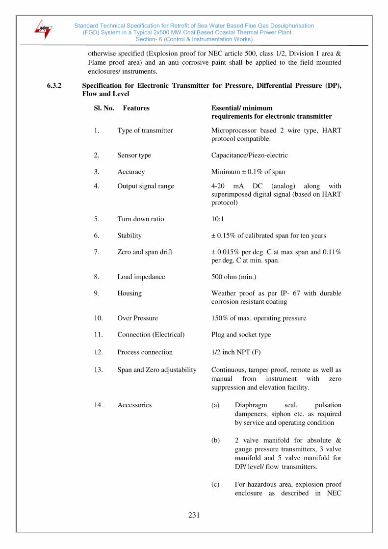
Standard Technical Specification for Retrofit of Sea Water Based Flue Gas Desulphurisation (FGD) System in a Typical 2x500 MW Coal Based Coastal Thermal Power Plant
Section- 6 (Control & Instrumentation Works)
231
otherwise specified (Explosion proof for NEC article 500, class 1/2, Division 1 area &
Flame proof area) and an anti corrosive paint shall be applied to the field mounted
enclosures/ instruments.
6.3.2 Specification for Electronic Transmitter for Pressure, Differential Pressure (DP),
Flow and Level
Sl. No. Features Essential/ minimum
requirements for electronic transmitter
1. Type of transmitter Microprocessor based 2 wire type, HART
protocol compatible.
2. Sensor type Capacitance/Piezo-electric
3. Accuracy Minimum ± 0.1% of span
4. Output signal range 4-20 mA DC (analog) along with
superimposed digital signal (based on HART
protocol)
5. Turn down ratio 10:1
6. Stability ± 0.15% of calibrated span for ten years
7. Zero and span drift ± 0.015% per deg. C at max span and 0.11%
per deg. C at min. span.
8. Load impedance 500 ohm (min.)
9. Housing Weather proof as per IP- 67 with durable
corrosion resistant coating
10. Over Pressure 150% of max. operating pressure
11. Connection (Electrical) Plug and socket type
12. Process connection 1/2 inch NPT (F)
13. Span and Zero adjustability Continuous, tamper proof, remote as well as
manual from instrument with zero
suppression and elevation facility.
14. Accessories (a) Diaphragm seal, pulsation
dampeners, siphon etc. as required
by service and operating condition
(b) 2 valve manifold for absolute &
gauge pressure transmitters, 3 valve
manifold and 5 valve manifold for
DP/ level/ flow transmitters.
(c) For hazardous area, explosion proof
enclosure as described in NEC

Standard Technical Specification for Retrofit of Sea Water Based Flue Gas Desulphurisation (FGD) System in a Typical 2x500 MW Coal Based Coastal Thermal Power Plant
Section- 6 (Control & Instrumentation Works)
232
article 500.
15. Diagnostics Self indicating feature
16. Power supply 24V DC ± 10%
17. Adjustment/ calibration/ Through Universal HART hand held
calibrators.
18. Response time Suitable to meet closed loop control reaction
time specified elsewhere
Notes
(i) In case it becomes necessary to use a DP transmitter for pressure
measurement then a 3 valve manifold should be used in place of 2 valve
manifold.
(ii) Where the process fluids are corrosive, viscous, solid bearing or slurry type,
diaphragm seals shall be provided. Parts below the diaphragm shall be
removable for cleaning. The entire volume above the diaphragm shall be
completely filled with an inert liquid suitable for the application.
6.3.3 Specification for Pressure Gauge, Differential Pressure Gauge, Temperature Gauge and
Level Gauge
Sl. No. Features Essential minimum requirements
Pr. Gauge/DP
Gauge/Draught
gauges
Temperature gauge Level Gauge
1 Sensing Element and
Material Bourdon for high
pressure,
Diaphragm/ Bellow
for Low pr. of SS
316
Bimetallic type for
below 450°C and
inert gas actuated for
above 450°C of SS
bulb and capillary
Tempered
toughened
Borosilicate gauge
glass steel armoured
reflex or transparent
type.
2 Body Material Die Cast Aluminum
with stoved enamel
black finish /SS316
Die Cast Aluminum
with stoved enamel
black finish /SS316
Forged carbon
steel/SS 304
3 Dial Size 150 mm with
toughened shatter
proof glass
150 mm with
toughened shatter
proof glass
Tubular covering
entire range
4 End Connection ½ inch NPT (M) ½” NPT (M) Process connection
as per ASME PTC
and drain/vent 15
NB
5 Accuracy +/- 1% span +/- 1% span +/- 2%
6 Scale Linear, 270° arc
graduated in metric
units
Linear, 270° arc
graduated in °C Linear vertical
7 Range Selection Cover 125% of
max. of scale Cover 125% of max.
of scale Cover 125% of max.
of scale

Standard Technical Specification for Retrofit of Sea Water Based Flue Gas Desulphurisation (FGD) System in a Typical 2x500 MW Coal Based Coastal Thermal Power Plant
Section- 6 (Control & Instrumentation Works)
233
8 Over range test Test pressure for the assembly shall be 1.5 to the maximum
design pressure at 38°C.
9 Housing Weather and dust
proof as per IP-65 Weather and dust
proof as per IP-65 CS/304 SS leak
proof.
10 Zero/span
Adjustment Provided Provided -
11 Identification Engraved with service legend or laminated phenolic name plate
12 Accessories Blow out Disc,
siphon, snubber,
pulsation dampener,
chemical seal (if
required by process)
gauge isolation
valve
SS316 Thermowell Gasket for all KEL-
F shield for
transparent type vent
and drain valves of
steel/SS as per CS/
alloy process
requirement.
13 Material of Bourdon/ movement
SS 316 SS 316
Notes:
(i) Length of gauge glass shall not be more than 1400 mm. If the vessel is
higher, multiple gauge glasses with 50 mm overlapping shall be provided.
(ii) Where the process fluids are corrosive, viscous, solid bearing or slurry type,
diaphragm seals shall be provided. Parts below the diaphragm shall be
removable for cleaning. The entire volume above the diaphragm shall be
completely filled with an inert liquid suitable for the application.
(iii) Float & Board type level gauges may also be acceptable as per process
requirement subject to approval of purchaser.
6.3.4 HART Hand Held Calibrator
Hand held calibrator shall be provided for adjustment/calibration/maintenance of the HART
compatible transmitters. The hand held calibrator shall be suitable for all types of transmitters
supplied in the package. If one type of hand held type calibrator is not suitable for
communicating with all types of transmitters then separate hand held calibrator will be
provided.
HART hand held calibrator shall be provided with following minimum accessories per set:-
i) Soft carrying case with adjustable shoulder straps & lead compartments.
ii) HART lead set.
iii) Rechargeable batteries.
iv) Battery charger.
v) Power adaptor.
vi) Universal plug kit for power adaptor.
vii) Load resistor.
viii) Interfacing cables of each type as per requirements.
ix) Protective boot.
x) Standard banana jack.
xi) Operation manual & software CD.
6.3.5 Temperature Elements and Accessories
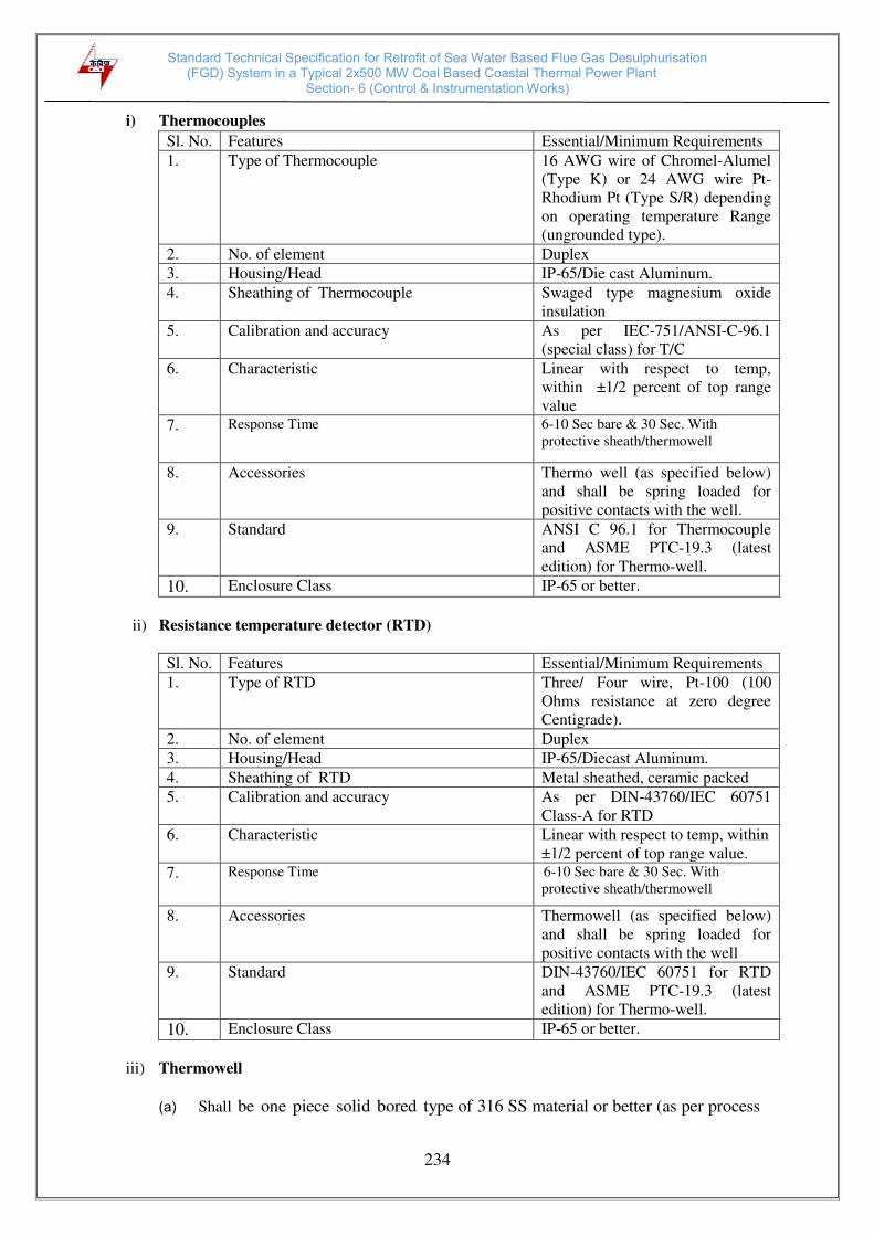
Standard Technical Specification for Retrofit of Sea Water Based Flue Gas Desulphurisation (FGD) System in a Typical 2x500 MW Coal Based Coastal Thermal Power Plant
Section- 6 (Control & Instrumentation Works)
234
i) Thermocouples
Sl. No. Features Essential/Minimum Requirements 1. Type of Thermocouple 16 AWG wire of Chromel-Alumel
(Type K) or 24 AWG wire Pt-
Rhodium Pt (Type S/R) depending
on operating temperature Range
(ungrounded type). 2. No. of element Duplex 3. Housing/Head IP-65/Die cast Aluminum. 4. Sheathing of Thermocouple Swaged type magnesium oxide
insulation 5. Calibration and accuracy As per IEC-751/ANSI-C-96.1
(special class) for T/C 6. Characteristic Linear with respect to temp,
within ±1/2 percent of top range
value 7. Response Time 6-10 Sec bare & 30 Sec. With
protective sheath/thermowell
8. Accessories Thermo well (as specified below)
and shall be spring loaded for
positive contacts with the well. 9. Standard ANSI C 96.1 for Thermocouple
and ASME PTC-19.3 (latest
edition) for Thermo-well.
10. Enclosure Class IP-65 or better.
ii) Resistance temperature detector (RTD)
Sl. No. Features Essential/Minimum Requirements 1. Type of RTD Three/ Four wire, Pt-100 (100
Ohms resistance at zero degree
Centigrade). 2. No. of element Duplex 3. Housing/Head IP-65/Diecast Aluminum. 4. Sheathing of RTD Metal sheathed, ceramic packed 5. Calibration and accuracy As per DIN-43760/IEC 60751
Class-A for RTD 6. Characteristic Linear with respect to temp, within
±1/2 percent of top range value. 7. Response Time 6-10 Sec bare & 30 Sec. With
protective sheath/thermowell
8. Accessories Thermowell (as specified below)
and shall be spring loaded for
positive contacts with the well 9. Standard DIN-43760/IEC 60751 for RTD
and ASME PTC-19.3 (latest
edition) for Thermo-well.
10. Enclosure Class IP-65 or better.
iii) Thermowell
(a) Shall be one piece solid bored type of 316 SS material or better (as per process

Standard Technical Specification for Retrofit of Sea Water Based Flue Gas Desulphurisation (FGD) System in a Typical 2x500 MW Coal Based Coastal Thermal Power Plant
Section- 6 (Control & Instrumentation Works)
235
requirement), of step-less tapered design. (As per ASME PTC 19.3 (Latest).
(b) For Air & Flue gas, 316 SS protecting tube with welded cap shall be provided.
6.3.6 Temperature transmitter
Following types of 2-wire temperature transmitter (directly powered from 4-20mA input
cards of PLC) shall be provided as per requirement of application. The temperature
transmitter shall be fully compatible with thermocouples and RTDs being provided by
the contractor. Temperature compensation of the thermocouples shall be performed in
the temperature transmitter itself.
a. Single Input Head mounted Temperature Transmitter
These shall be suitable for mounting in the head of temperature element itself. The
protection class of head of thermowell along with its plug-in connector shall be
min. IP65.
b. Single Input DIN-rail mounted Temperature Transmitter
These shall be especially designed for DIN-rail mounting in JBs. The specifications
of the JBs shall be same as indicated in Subsection-IV:I7 (INST CABLE) with
additional DIN-rails and IP 65 Protection class. This temperature transmitter shall
be the ones which are specially designed for DIN-rail mounting with IP 20
protection class. These shall have terminals for input/output provided on front side
when mounted on DIN-rail. Head mounted temperature transmitter with clamps to
make it suitable for DIN-rail mounting shall not be acceptable under this category.
c. Dual-input Temperature Transmitter with Indicator:
The dual-input TTs shall be suitable for mounting in enclosures/racks and shall be
provided with clamps. Indicator shall be provided with these transmitters. These
transmitters shall have bump less change over facility to second sensor in case first
sensor fails. This change-over is to be alarmed. Protection class shall be IP65
minimum.
d. Common requirements for each of the above type of temperature
transmitters:
Output : 2-wire (power supply from input card of Control
System) with 4-20mA output with superimposed
HART protocol signal.
Input : Same transmitter shall be capable to handle Pt- 100
RTD, Thermocouples -K&R types (input type to be
selectable at site through HART terminal)
Isolation : min. 500 V AC
EMC compatibility : as per EN 61326

Standard Technical Specification for Retrofit of Sea Water Based Flue Gas Desulphurisation (FGD) System in a Typical 2x500 MW Coal Based Coastal Thermal Power Plant
Section- 6 (Control & Instrumentation Works)
236
Operating ambient 0 to 85 deg C (without indicator)
temperature: 0 to 70 deg C (with indicator)
Power supply compatible with input module of Control System
Accessories Mounting arrangements including clamps etc.
Composite accuracy (a) For head mounted and DIN-rail mounted types:
RTD =<0.4% of 0-250 deg C span
T/C-K type =<0.4% of 0-600 deg C span
T/C-R type =<0.4% of 0-1000 deg C span
CJC accuracy (for thermocouples) shall be ≤ 1
0C
(b) For dual-input type:
RTD =<0.25% of 0-250 deg C span
T/C-K type =<0.2% of 0-600 deg C span
CJC accuracy (for thermocouples) shall be ≤ 10C
6.3.7 Specification for Flow Elements & Flow Meters
i) Orifice plate
Sr No. Features Essential/Minimum Requirements 1 Type Concentric as per ASME PTC-19.5 (Part-II), ISO 5167 2 Material 316 SS 3 Thickness 3 mm for main pipe diameter up to 300 mm and6 mm for
main pipe dia above300 mm. 4 Material of
branch pipe Same as main pipe
5 Root valve type Globe 6 Root valve
material 316 SS
7 Root valve size 1 / 2 inch or 1 inch (as applicable) 8 Impulse pipe of
same material up
to root valve
Required
9 Tapping Flanged weld neck or D & D/2 with 3 pairs of tapping (as
applicable). 10 Beta Ratio 0.34 to 0.7 11 Beta Ratio
calculation to be
submitted
Yes
12 Assembly drg.
and flow Vs DP
Curves
Yes
13 Accessories Root valves, flanges, Vent/drain hole (as required) Bidder shall submit certified flow calculation and differential pressure vs. flow curves for
each element for Owner's approval. Sizing calculation, precise flow calculation for all the
flow elements, fabrication and assembly drawings and installation drawings shall be
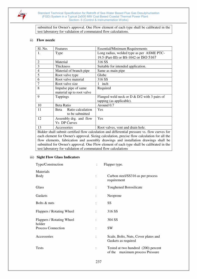
Standard Technical Specification for Retrofit of Sea Water Based Flue Gas Desulphurisation (FGD) System in a Typical 2x500 MW Coal Based Coastal Thermal Power Plant
Section- 6 (Control & Instrumentation Works)
237
submitted for Owner's approval. One Flow element of each type shall be calibrated in the
test laboratory for validation of commutated flow calculations.
ii) Flow nozzle
Sl. No. Features Essential/Minimum Requirements 1. Type Long radius, welded type as per ASME PTC-
19.5 (Part-III) or BS-1042 or ISO 5167 2 Material 316 SS 3 Thickness Suitable for intended application. 4 Material of branch pipe Same as main pipe 5 Root valve type Globe 6 Root valve material 316 SS 7 Root valve size 1 inch 8 Impulse pipe of same
material up to root valve Required
9 Tappings Flanged weld neck or D & D/2 with 3 pairs of
tapping (as applicable). 10 Beta Ratio Around 0.7 11 Beta Ratio calculation
to be submitted Yes
12 Assembly drg. and flow
Vs DP Curves Yes
13 Accessories Root valves, vent and drain hole. Bidder shall submit certified flow calculation and differential pressure vs. flow curves for
each element for Owner's approval. Sizing calculation, precise flow calculation for all the
flow elements, fabrication and assembly drawings and installation drawings shall be
submitted for Owner's approval. One Flow element of each type shall be calibrated in the
test laboratory for validation of commutated flow calculations
iii) Sight Flow Glass Indicators
Type/Construction : Flapper type.
Materials
Body : Carbon steel/SS316 as per process
requirement
Glass : Toughened Borosilicate
Gaskets : Neoprene
Bolts & nuts : SS
Flappers / Rotating Wheel : 316 SS
Flappers / Rotating Wheel : 304 SS
holder
Process Connection : SW
Accessories : Scale, Bolts, Nuts, Cover plates and
Gaskets as required
Tests : Tested at two hundred (200) percent
of the maximum process Pressure

Standard Technical Specification for Retrofit of Sea Water Based Flue Gas Desulphurisation (FGD) System in a Typical 2x500 MW Coal Based Coastal Thermal Power Plant
Section- 6 (Control & Instrumentation Works)
238
iv) Process Actuated Switches
Sr
No.
Features
Essential/Minimum Requirements Pressure/Draft
Switches/ DP
Switches
Temperature
switches
Level switches
1 Sensing Element
Piston actuated for
high pressure and
diaphragm or
bellows for low
pr./ vacuum
Vapor pressure
sensing, liquid
filled bellow
type with SS
bulb
and
capillary (10 m
minimum)
Float type for
applications as decided
by owner during detailed
engineering.
Capacitance/Conductivity
/Ultrasonic type for acid
and alkali application. RF/ Ultrasonic type for
other application.
2 Material of
sensing
element &
movement.
316 SS Bulb 316 SS/ capillary 304 SS
316 SS
3 End connection ½ inch NPT (F) ½ inch NPT (F) Manufacturer standard 4 Over range
proof pressure 150% of max.
design pr - 150% of max. design
pressure 5 Repeatability + 0.5% of full range 6 No. of contacts 2 Nos. +2NC. SPDT/ DPDT snap action dry contact. Auto reset with
internal adjustable snap action micro switch. 7 Rating of
contacts 60 V DC, 6 VA as per PLC requirement
8 Set point Provided over full range. Differential shall be adjustable. 9 Dead band
adjustment Adjustment upto 10% at set points.
10 Enclosure Die cast Aluminum with stoved enamel black finish/SS316, Weather
and dust proof as per IP-65. Epoxy/ PU painting shall be provided
for corrosive atmosphere. 11 Accessories Siphon, snubber,
chemical, pulsation
dampers as required
by process.
Thermo well of 316 SS and
packing glands
All mounting accessories
Notes:-
1) Where the process fluids are corrosive, viscous, solid bearing or slurry type, diaphragm
seals shall be provided. Parts below the diaphragm shall be removable for cleaning. The
entire volume above the diaphragm shall be completely filled with an inert liquid
suitable for the application.
2) Pressure / Diff Pressure switches for very low pressure / DP measurements can have
sensor material other than SS316 e.g. silicon etc., if the offered material is suitable for
that application and the offered product is standard product of the manufacturer for very
low pressure applications.
3) Repeatability can be upto +/-1% of full range in case of switches with diaphragm seals
or very low pressure/DP range.

Standard Technical Specification for Retrofit of Sea Water Based Flue Gas Desulphurisation (FGD) System in a Typical 2x500 MW Coal Based Coastal Thermal Power Plant
Section- 6 (Control & Instrumentation Works)
239
v) Conductivity Type Level Switch
Type : Conductivity discrimination.
Mounting : Flanged – on standpipe.
Probe MOC : Stainless steel with high purity ceramic.
Probe rating : > Maximum design pressure of vessel.
Input : Four independent channel with selectable switching
threshold for water conductivity.
Relay Output : Four isolated output relays for Hi,
Lo, Hi-Hi, Lo-Lo.
Contact type & rating : 2SPDT or 1 DPDT @ 5A 30V DC.
Power supply : Dual 230V AC, 50 Hz, 1Ph from UPS.
Enclosure : Corrosion resistant & wall mounting
type. IP-65 or better (Explosion proof
For NEC Class-1/2, Division 1 area)/ flame
proof (IEC-79.1, Part I). As applicable).
Accessories : i. PTFE cable from probe to
electronics unit. Electronic unit shall be
separate. Head mounted electronic unit is not
preferred.
ii. Mounting accessories
iii. standpipe
iv. Washer & gasket
Test pressure : Two times rated pressure
vi) Capacitance Type Level Switch
Type : Capacitance type
Probe : a) Rod or suspended electrode
b) Rope type probes may be used only
where required probe length is greater
than 3 meters.
Probe Mounting : Stainless steel 1-1/2 ANSI RF Flange / ¾“ NPT (M)
Material of construction : 316 SS
Insulation : PTFE Part/Full as per service.
Enclosure : Powder/Epoxy coated Die cast Aluminum.
with neoprene gasket conforming to IP-65.
(Explosion proof for NEC Class-1/2, Division 1
area)/ flame proof (IEC-79.1, Part I). As

Standard Technical Specification for Retrofit of Sea Water Based Flue Gas Desulphurisation (FGD) System in a Typical 2x500 MW Coal Based Coastal Thermal Power Plant
Section- 6 (Control & Instrumentation Works)
240
applicable).
Ambient temperature : 0-60 ºC.
Mounting : On Top
Supply voltage : 230V AC, 50Hz from UPS / 24V DC
Relay output : 2SPDT
Contact rating : 5A min. at 240V AC on resistive load
Response time : 100 m sec or better
Cable connection : Plug in type
Accessories : Counter flange, Cable gland, prefab cable and
stainless steel name plate engraved with
alpha-numeric.
6.3.8 Analysers
The following type of analyzers as required shall be provided:
i) Flue gas sulphur di- oxide analyzer (other than in CEMS)
ii) Sea water pH analyzer. iii) Sea water dissolved O2 analyser iv) Sea water conductivity analyser
6.3.8.1 Sulphur Dioxide (SO2) Analyser
Technical specification for SO2 analysers shall be as specified in Cl. No. 6.8 other than range
which shall be as per FGD system design and process parameters.
6.3.8.2 Sea water pH Analyser
S.No. Features Essential/Minimum Requirements 1 Output signals
Analog 4-20 mA DC galvanically isolated. If analyser provides
superimposed HART signal on 4-20 mA DC output, It
shall also be connected to PC based station. 2 Zero & span
Adjustment To be provided with range selection facility.
3 Ambient temp. 50°C 4 Indication Digital Alphanumeric Display. Display of reading in
engineering units shall be provided. 5 Enclosure
Type/Material Weather & Dust proof (IP 65) Die cast Aluminium/SS.
6 Type of Electronics
Microprocessor based with self- diagnostic feature.
10. Others i) All interconnection tubing and cabling between probe
and analyser/ analyser panel and cabling from analyser/
analyser panel are to be provided by the Bidder.
ii) All the calibration gases required for one year

Standard Technical Specification for Retrofit of Sea Water Based Flue Gas Desulphurisation (FGD) System in a Typical 2x500 MW Coal Based Coastal Thermal Power Plant
Section- 6 (Control & Instrumentation Works)
241
continuous operation shall be provided. The calibration
gas container material shall not contaminate the
calibration gas. 12 Compliance to
standards USEPA, TUV, MCERTS or equivalent standards.
13 Type of Technology
In situ type.
14 Type of pH
analyser : Cell - flow through
15 Accuracy : < ± 2 of reading
16 Range : 0 - 14 pH freely programmable
17 No. of steams : Single
18 Temp.
compensation : Automatic
6.3.8.3 Sea water dissolved O2 analyser
Direct insertion, insitu type analyser with an accuracy of +/- 1% FSD, repeatability of +/-
0.5 FSD, response time of 90% within 5 secs, auto and manual calibration having zirconia
probe +/-sensing element IP 54 or equivalent degree of protection for enclosure. Output
shall be isolated 4-20 mA DC linear signal. Accessories like back purge system shall be
provided. Protection tube shall be provided to prevent erosion of the probe.
6.3.8.4 Sea water conductivity analyser
Solid state/micro-processor based, single stream with an accuracy of +/-1 %FSD, auto
temperature compensation, auto calibration, zero check and integral indicator having flow
line (screwed) type cell. The response time shall be less than 1 sec for 90% of full scale
change and range of 0-1, 0-10, 0-100 micro Siemens/cm for specific conductivity and 0-1
micro Siemens/cm log scale for cation conductivity. Housing for cell and analyzer shall be
weather and waterproof. Output shall be isolated 4-20 mA DC linear signal. Dual channel
analyzer with independent output signal for each channel of measurement can be used (if
required).
6.3.9 Solenoid Valves
Solenoid valves shall fulfill the following requirements:
1. Type 2/3/4 way with body material of SS 316/Forged Brass and epoxy painting
(depending on the application subject to Owner’s approval during detailed Engg.).
Material of Wetted parts shall be SS316.
2. Power supply 110V/ 24V DC UPS.
3. Plug and socket electrical connection.
4. Insulation: Class ‘H’.
5. All solenoid shall be with, LED indication, surge suppression diode circuits.
Standard Technical Specification for Retrofit of Sea Water Based Flue Gas Desulphurisation (FGD) System in a Typical 2x500 MW Coal Based Coastal Thermal Power Plant
Section- 6 (Control & Instrumentation Works)
242
6.3.10 Electrical Actuators
i) The actuators shall have integral starters alongwith overload relays with built in SPP
(single phasing preventer). A 415, 3 phase 3 wire power supply shall be given to the
actuator from contractor’s switch board through a switch fuse unit. Control voltage
of the motor starter shall be 110 V AC / 24 V DC, derived suitably from 415V power
supply. In case supplier's standard control voltage for open/close contactors is 110V
AC, the same is acceptable if suitable opto - isolation circuit is provided with
coupling relays for 24 V DC command inputs.
ii) Open/close command termination logic with position and torque limit switches,
positioner circuit shall be suitably built in the PCB inside the actuator.
(a) For binary drive, open/close command and status thereof and disturbance
monitoring signal (common contact for overload, thermostat, control supply
failure, L/R selector switch at local, other protections operated) shall be
provided.
Interface with the control system shall be through hardwired signal only.
Interposing relays provided (with coil burden 2.5 VA) in the actuator shall be
energized to initiate opening and closing, by 24V DC signal from the external
control system.
(b) For modulating drive, the command to actuator shall be in form of 4-20mA
signal. The necessary positioning circuit and motor protection shall be
provided
(c) Open/close command termination logic shall be suitably built inside actuator.
iii) The actuators shall be rated for supply voltage & frequency: 415V +/- 10%, 3- phase,
3 wire 50Hz +/-5%. Sizing for open/close at rated speed against designed differential
pressure at 90% of rated voltage. For isolating service, three successive open-close
operations or 15 mins, whichever is higher. For regulating service, 150 starts per hour
or required cycles, whichever is higher.
iv) Four nos. (2 each in open and close position) position limit switches and two nos.
(one in open and other in close direction) torque switches each having two nos. NO
and two nos. NC contacts shall be provided. A single shaft shall actuate all contacts
of limit switches at each position.
v) It shall be possible to operate the actuator locally also. Lockable local/remote
selection shall be provided on the actuator
vi) Position Indicator shall be provided for 0 to 100% travel.
vii) Position Transmitter (for modulating/inching type) shall be provided as required it
shall be suitable for stabilized 4-20 mA signal, 2 wire inductive type, 24 volts DC
operated.
viii) Space heater of suitable rating shall be provided. The supply shall be derived from the
main power supply available in the actuator.
6.3.11 Vibration Monitoring System
i) Microprocessor based vibration monitoring system shall be provided for booster fans

Standard Technical Specification for Retrofit of Sea Water Based Flue Gas Desulphurisation (FGD) System in a Typical 2x500 MW Coal Based Coastal Thermal Power Plant
Section- 6 (Control & Instrumentation Works)
243
and other equipment (as required) operating on 11kV/ 6.6kV/ 3.3kv. The number of
bearing locations to be monitored on each equipment shall be as per requirements
finalized during detailed engineering but not less than 2 bearing locations (except for
vertical pumps for which one bearing location may be sufficient).
ii) The vibration monitoring system shall be furnished on a system basis including
vibration transducers with low noise flexible cables in flexible conduit, terminated in
local terminal boxes, necessary pre-amplifier/electronics mounted in local weather
proof boxes, vibration monitors, mounting racks and cabinets. The vibration
monitoring system shall include all power supplies, interconnecting cabling,
calibration equipment, indicators, integrating units, signal conditioning devices and
all other accessories required for monitoring of vibration at each point.
iii) Eddy current type proximity transducers shall be used. However, the finally selected
sensor type shall also depend on recommendation of the equipment manufacturer &
suitable for application requirement. Transducers shall be furnished in weatherproof
housing suitable for field conditions.
iv) Vibration monitoring system shall give buffered output of 4-20 mA DC for each point
monitored. The signal shall be suitable for use as an input to control system as well as
for analog recording & analysis, linear in proportion to vibration velocity as well as
displacement. Monitor shall provide vibration indication calibrated in velocity units
along with provisions of changing to displacement unit (field-programmable) for each
measurement point in both horizontal & vertical planes. For each vibration monitor,
two independent potential free contacts shall be made available for alarm & trip
purposes.
v) The vibration monitor racks with power supplies shall be mounted in a separate self
standing cabinet to be located in control room. The number of racks and power
supplies shall be such that on failure of a single power supply/module, not more than
four monitors shall be affected. The vibration monitoring cabinet shall be fed from
redundant UPS feeders with auto changeover scheme.
vi) The functional requirement for vibration monitoring system shall include but not be
limited to the following:
a) Vibration monitor front face status indications shall be available for indications of
healthy conditions of pick up circuit, monitor circuit and power supply. Also set
point indication with set point adjustment facility for setting alarm & trip levels
shall be provided.
b) The facility shall be available from front of mounting rack for functional checking
of monitors with inhibition of alarm and trip contact outputs during test. Alarm
inhibition shall also be provided during start-up.
vii) All vibration monitoring equipment shall be functionally tested for circuit continuity
and output response. All the components & interconnection cables shall be tested to
ensure compliance with the specification requirements and all other applicable codes
& standards.
In case it is the proven standard practice of a Bidder to provide vibration monitoring
TFTs instead of dedicated monitors with the signal conditioning equipment in control
equipment room, the same shall also be acceptable. However, all relevant functional
requirements detailed above shall be met and the system shall be subject to
Standard Technical Specification for Retrofit of Sea Water Based Flue Gas Desulphurisation (FGD) System in a Typical 2x500 MW Coal Based Coastal Thermal Power Plant
Section- 6 (Control & Instrumentation Works)
244
purchaser's approval.
viii) All vibration monitoring equipment shall be functionally tested for circuit continuity
and Vibration monitoring system shall comply the complete requirements as per API
670 – 5th edition or latest edition at the time of supply.
6.4 CONTROL VALVES, ACTUATORS AND ACCESSORIES
6.4.1 Control Valves
i) General Requirements
a) The control valves and accessories equipment furnished by the Bidder shall be
designed, constructed and tested in accordance with the latest applicable
requirements of code for pressure piping ANSI B 31.1, the ASME Boiler &
pressure vessel code, Indian Boiler Regulation (IBR), ISA and other standards
specified elsewhere as well as in accordance with all applicable requirements of
the Federal Occupational Safety and Health Standards, USA or acceptable equal
standards.
b) All the control valves and accessories offered by the Bidder, shall be from
reputed, experienced manufacturers of specified type and range of valves.
c) The valve materials shall be as suitable as per requirement for fluid to be handled.
ii) Control Valve Sizing and Construction
a) The design of all valve bodies shall meet the specification requirements and shall
conform to the requirements of ANSI (USA) for dimensions, material thickness
and material specification for their respective pressure classes.
b) The valve sizing shall be suitable for obtaining rated flow conditions with valve
opening at 70%- 80% of total valve stem travel and minimum flow conditions
with valve stem travel not less than 10% of total valve stem travel. All the
valves shall be capable of handling at least 120% of the required rated flow.
Further, the valve stem travel range from minimum flow condition to rated flow
condition shall not be less than 50% of the total valve stem travel. The sizing
shall be in accordance with the latest edition of ISA on control valves. While
deciding the size of valves, Bidder shall ensure that valves port outlet velocity
does not exceed 8 m/sec for liquid services, 150 m/sec. for steam services and
50% of sonic velocity for flashing services. Bidder shall furnish the sizing
calculations clearly indicating the outlet velocity achieved with the valve size
selected by him as well as noise calculations, which will be subject to Purchaser’s
approval during detailed engineering.
c) Control valves of steam and water applications shall be designed to prevent
cavitation, wire drawing, flashing on the downstream side of valve and
downstream piping. Thus for cavitation/flashing service, only valve with anti
cavitation trim shall be provided.
d) All control valves shall have leakage rate as per leakage Class-IV as minimum.
e) The control valve induced noise shall be limited to 85 dBA at 1 meter from the
valve surface under actual operating conditions. The noise abatement shall be

Standard Technical Specification for Retrofit of Sea Water Based Flue Gas Desulphurisation (FGD) System in a Typical 2x500 MW Coal Based Coastal Thermal Power Plant
Section- 6 (Control & Instrumentation Works)
245
achieved by valve body and trim design and not by use of silencers.
iii) Valve Construction
a) All valves shall be of globe body design & straightaway pattern with single or
double port unless other wise specified or as recommended by the manufacturer
as per process requirement.
b) Valves with high lift cage guided plugs & quick change trims shall be supplied
in case of globe type valves.
c) Cast iron valves are not acceptable.
d) Bonnet joints for all control valves shall be of the flanged and bolted type or
other construction acceptable to the Purchaser. Bonnet joints of the internal
threaded or union type will not be acceptable.
e) Plug shall be one-piece construction either cast, forged or machined from solid
bar stock. Plug shall be screwed and pinned to valve stems or shall be integral
with the valve stems.
f) All valves connected to vacuum on down stream side shall be provided with
packing suitable for vacuum applications (e.g. double vee type chevron
packing).
g) Valve characteristic shall match with the process characteristics.
h) Flanged valves shall be rated at no less than ANSI press class of 300 lbs.
iv) Valve Materials
The control valve body & trim material shall be generally as given below:
S.
No. Service Body material Trim material
1 Non-corrosive, non-flashing
and non-cavitation service.
Compatible
with piping
material
316 SS with stellite
faced guide posts and
bushings
2 Severe flashing/ cavitation
services. Alloy steel as
per ASTM-A
217 Gr.WC9
400 series SS or
equivalent to suit the
specific requirement
Note : Valve body rating shall meet the process pressure and temperature
requirement as per ANSI B16.34. However, Bidder may offer valves with body and
trim materials better than specified materials.
v) End Preparation
Valve body ends shall be either butt welded/socket welded, flanged (Rubber lined for
condensate service) or screwed as finalized during detailed engineering and as per
Purchaser’s approval. The welded ends wherever required shall be butt welded type
as per ANSI B 16.25 for control valves of sizes 65 mm and above. For valves size
50 mm and below welded ends shall be socket welded as per ANSI B 16.11 Flanged
ends wherever required shall be of ANSI pressure-temperature class equal to or
greater than that of control valve body.

Standard Technical Specification for Retrofit of Sea Water Based Flue Gas Desulphurisation (FGD) System in a Typical 2x500 MW Coal Based Coastal Thermal Power Plant
Section- 6 (Control & Instrumentation Works)
246
6.4.2 Valve Actuators
i) All Control Valves shall be furnished with Pneumatic Actuators. The Bidder shall be
responsible for proper selection and sizing of valve actuators in accordance with the
pressure drop and maximum shut off pressure and leakage class requirements. The
valve actuators shall be capable of operating at 60 deg C continuously.
ii) Valve actuators and stems shall be adequate to handle the unbalanced forces
occurring under the specified flow conditions or the maximum differential pressure
specified. An adequate allowance for stem force, at least 0.15 Kg/sq.cm. per linear
millimeter of seating surface, shall be provided in the selection of the actuator to
ensure tight seating unless otherwise specified.
iii) The travel time of the pneumatic actuators shall be as per process requirement.
6.4.3 Control Valve Accessory Devices
i) All pneumatic actuated control valve accessories such as air locks, handwheels/
hand-jacks, limit switches, pneumatic positioners, E/P Converters, diffusers, external
volume chambers, position transmitters (capacitance or resistance type only),
reversible pilot for positioners, tubing and air sets, solenoid valves and junction boxes
etc. shall be provided as per the requirements.
ii) Modulating valves shall be supplied with microprocessor based Smart Positioners
with IP-65 housing and having non-contact type position sensing with 4-20mA output
signal.
6.4.4 Tests All valves shall be tested in accordance with the quality assurance programme agreed
between the Purchaser and Contractor which shall meet the requirements of IBR (if
applicable) and other applicable codes mentioned elsewhere in the specifications. The tests
shall include but not be limited to the following:
i) Non destructive test as per ANSI B-16.34.
ii) Hydrostatic shell test in accordance with ANSI B 16.34 prior to seat leakage test.
iii) Valve closure test and seat leakage test in accordance with ANSI- B 16.34 and as per
the leakage class.
iv) Functional test: The fully assembled valves including actuators control devices and
accessories shall be functionally tested to demonstrate times from open to close
position.
v) CV test: CV test shall be carried out as type test on each size, type and design of the
valves as per ISA 75.02 standard and test report shall be furnished for Purchaser’s
approval (if valid type test is not available).
6.5 POWER SUPPLY SYSTEM
6.5.1 General
i) The Contractor shall furnish all the equipment and accessories required for
completeness of the power supply system whether these are specifically
mentioned herein or not. All the equipments and sub systems offered shall be from
Standard Technical Specification for Retrofit of Sea Water Based Flue Gas Desulphurisation (FGD) System in a Typical 2x500 MW Coal Based Coastal Thermal Power Plant
Section- 6 (Control & Instrumentation Works)
247
reputed experienced manufacturers. All system cabinets, enclosures, & distribution
boards shall be manufactured, assembled, wired and fully tested as a complete
assembly as per the requirements of this specification at the manufacturer’s works.
ii) The Contractor shall furnish all required equipment cubicles and wiring required
for conversion and/or stabilization of the power sources provided by the Employer
to all other levels which may be necessary for meeting the individual requirement
of equipment/system furnished by him including the panel/desk mounted equipment.
iii) Parallel redundant 230 V AC to 24 V DC convertor with automatic 50% load sharing &
125 % capacity shall be provided for 24 V DC power supply in each cubicle separately as
per requirements. The UPS power supply to Parallel redundant 230 V AC to 24 V DC
convertor shall be extended thru redundant UPS feeders. The system shall provide for 230
V AC/24 V DC convertor Fail alarm, 24 V DC under voltage alarm, 24 V DC over voltage
alarm etc.
6.5.2 Uninterruptible Power Supply (UPS) System
The UPS system shall have 2x100% parallel redundant chargers and inverters, 1x100%
battery bank, bypass line transformers and voltage stabiliser, static switch, manual bypass
switch, AC/DC distribution boards, other necessary protective devices and accessories and
shall meet the following requirements as a minimum.
i) The kVA rating of UPS shall be as required by expected loads and include 10% spare
capacity guaranteed at 50 deg C ambient. The UPS shall have an over load capacity of
125 % rated capacity for 10 minutes and 150 % rated capacity for 10 seconds. The
inverter shall have sufficient capability to clear fault in the maximum rated branch
circuit. The sizing of UPS shall be based on the power factor of the loads being fed
subject to a maximum of 0.8.
ii) Each of the two sets of 2x100% redundant chargers shall be sized to meet the 100%
UPS load plus recharge the fully discharged battery within 8 hours.
iii) The UPS battery shall have sufficient amp-hour capacity to supply 100% full load
current of UPS for 60 minutes. A drop of 4V from battery room to the inverter input
will be considered for design.
iv) The UPS system shall be capable of operating without D.C. battery in circuit under all
conditions of load and the performance of various components of UPS like inverter,
charger, static switch etc. shall be guaranteed without the battery in circuit.
v) The UPS system design shall ensure that in case of failure of mains input power supply
to one of the chargers, the other charger whose mains input power supply is healthy,
shall feed to one or both the inverters as the case may be as per manufacturer's standard
practice & continue to charge the D.C. battery at all load conditions. The Bidder should
note that this situation should not in any way lead to the discharge of the D.C. Battery.
6.5.3 Static Inverters
i) The static inverter shall be solid state type using proven pulse width modulation
(PWM)/quasi square wave/step wave technique. The inverter equipment shall include all
necessary circuitry and devices to conform to requirements like voltage regulation,
current limiting, wave shaping, transient recovery, automatic synchronization etc. The
steady state voltage regulation shall be +1% and transient voltage regulation (on
application/removal of 100% load) shall be +20%. Time to recover from transient to
Standard Technical Specification for Retrofit of Sea Water Based Flue Gas Desulphurisation (FGD) System in a Typical 2x500 MW Coal Based Coastal Thermal Power Plant
Section- 6 (Control & Instrumentation Works)
248
normal voltage shall not be more than 50 m sec. Frequency regulation for all conditions
of input supplies, loads and temperature occurring simultaneously or in any combination
shall be better than ± 0.5% (automatically controlled). The total harmonic content shall
be 5% maximum and content of any single harmonic shall be 3% maximum. The
inverter efficiency shall be at least 85% on full load and 80% on 50% load. The
synchronisation limit for maintenance of synchronisation between the inverter and
standby AC source shall be 48-52Hz, field adjustable in steps of 0.5 Hz.
ii) All necessary equipment shall be provided to protect the inverter against overload, short
circuit and 100% loss of load.
iii) Inverter equipment shall include all solid state circuitry and devices including stable
oscillator etc. to enable inverters to operate satisfactorily in parallel sharing mode each
inverter taking 50% load during normal operation. In case of failure of either inverter,
100% load shall automatically be transferred to healthy inverter without any break and
degradation in the quality of UPS output and disconnecting the faulty inverter
automatically.
iv) The inverter failure shall be alarmed and the healthy inverter shall get synchronizing
signal from the standby AC source and remain synchronized within the set limits. The
limits for the synchronisation between healthy inverter and standby AC source shall be
field adjustable.
v) On failure of both inverters, the loads shall be transferred to standby AC power without
a break if within synchronisation limits. However, such transfer shall be inhibited,
during operation of inverter on its internal oscillator, to standby AC source frequency
being beyond the synchronisation limits. Provision of asynchronous transfer with a break
in case of inverter being out of synchronisation limits shall also be there with standby
source.
6.5.4 Static Switch and Manual Bypass Switch
The static switch shall be provided to perform the function of transferring UPS loads
automatically without any break from (i) faulty inverter to standby AC source in case of
failure of both the inverters and (ii) from faulty inverter to standby AC source in case of
failure of both the inverters. Manual bypass switch shall be employed for isolating the UPS
during maintenance.
6.5.5 Step Down Transformer and Voltage Stabiliser
The transformer shall be of low impedance type and the rating shall be such that extremely
fast fault clearance is achieved even in the largest rated branch circuit. The overload capacity
of the transformer/stabilizer shall not be less than 300% for 200 ms. The stabilizer shall
employ silicon solid state circuitry and the output voltage regulation shall be ± 2%. The
efficiency of the stabiliser shall be 95% or better.
.
6.5.6 Distribution Board (ACDB)
The details of the AC distribution board, i.e. exact design, number of feeders etc. of the
2x100% ACDB shall be as finalised during detailed engineering and as approved by the
purchaser. However, 25% spare feeders (minimum one no.) with fuses for each rating shall be
provided.
Standard Technical Specification for Retrofit of Sea Water Based Flue Gas Desulphurisation (FGD) System in a Typical 2x500 MW Coal Based Coastal Thermal Power Plant
Section- 6 (Control & Instrumentation Works)
249
6.5.7 The UPS, system equipment and the complete system shall have surge withstanding
capability (SWC) to meet the requirements of ANSI C 37.90a – IEEE Standard 472 –1974.
UPS should be provided with Class C type surge protection device. The Class C type surge
arrester should be single MOV type, pluggable, should have fault indication and should
be tested as per IEC 61643-1 to withstand 40kA 8/20 µs pulse. The arresters should have
potential free contact to ensure maintainability.
6.5.8 One complete set of all accessories and devices required for maintenance and testing of
batteries shall be supplied and same shall include at least the following :
1 Hydrometer 5 Nos.
2 Set of hydrometer syringes suitable for the vent
holes in different cells
5 Nos.
3 Thermometer for measuring electrolyte temperature 5 Nos.
4 Specific gravity correction chart 5 Nos.
5 Wall mounting type holder made of teak wood for
hydrometer & thermometer 5 Nos.
6 Cell testing voltmeter (3-0-3 V) 5 Nos.
7 Alkali mixing jar 5 Nos.
8 Rubber apron 5 Nos.
9 Pair of rubber gloves 5 Nos.
10 Set of spanners 5 Nos.
11 No smoking notice for each battery room 2 Nos.
12 Goggles (industrial) 5 Nos.
13 Instruction card 10 Nos.
14 Minimum and maximum temperature indicator for
battery room 1 set
15 Cell lifting facility 1 No.
6.5.9 Battery Health Monitoring System (BHMS)
One set of Online Battery Health Monitoring System (BHMS) shall be provided to monitor
the health of UPS battery bank. The BHMS shall be microprocessor based intelligent system
capable of calculating the net charge of Battery bank, deterioration of batteries in battery bank
during the charge/discharge cycles and actual efficiency of the batteries. It shall continuously
monitor each cell in the battery bank to identify deterioration in the cell prior to failure.
6.5.10 Battery Racks Two tier battery racks made of steel and painted with anti- corrosive epoxy paint construction
in accordance with applicable codes and standard shall be provided. AISC specification shall
apply in the absence of another design specification.

Standard Technical Specification for Retrofit of Sea Water Based Flue Gas Desulphurisation (FGD) System in a Typical 2x500 MW Coal Based Coastal Thermal Power Plant
Section- 6 (Control & Instrumentation Works)
250
6.6 PROCESS CONNECTION PIPING
The bidder shall provide, install and test all required material for completeness of impulse
piping system, sample piping system and air piping system as per the requirements for the
connection of instruments and control equipment to the process and make the system
complete. The bidder shall furnish during detailed engineering all relevant drawings, material
and technical specifications of various items service wise for Purchaser's approval.
All materials supplied shall be suitable for intended service, process, operating conditions and
type of instruments used and shall fully conform to the requirements of this specification. The
material offered by the bidder shall be from reputed, proven manufacturer.
6.6.1 Impulse Piping, Tubing, Fittings, Valves and Valve Manifolds
i) All impulse pipes shall be of seamless type conforming to ANSI B36.10 for schedule
numbers, sizes and dimensions etc. The material of the impulse pipe shall be same as
that of main process pipe.
ii) Stainless steel tube shall be provided inside enclosures and racks from tee connection
to valve manifold and then to instrument. The material shall be ASTM A 213 TP
316L.
iii) All fittings shall be forged steel and shall conform to ANSI B16.11. The material of
forged tube fittings for shaped application (e.g. tee, elbow etc.) shall be ASTM A182
Gr. 316 H for high pressure/ temperature applications and ASTM A182 Gr. 316L for
other applications. The material for bar stock tube fitting (for straight application)
shall be 316 SS. Metal thickness in the fittings shall be adequate to provide actual
bursting strength equal to or greater than those of the impulse pipe or SS tube, with
which they are to be used.
iv) The source shut-off (primary process root valve) and blow down valve shall be of 1/2
inch size globe valve type for all applications except for air and flue gas service
wherein the source shut-off valve shall be 3/4 inch size gate valve to avoid frequent
chocking. The disc and seat ring materials of carbon steel and alloy steel valves shall
be ASTM A-105 and ASTM A-182, Gr. F22, hard faced with stellite (minimum
hardness - 350 BHN.) The surface finish of 16 RMS or greater is required in the area
of stem packing. The valve design shall be such that the seats can be re-conditioned
and stem and disc may be replaced without removing the valve body from the line.
v) The valve manifolds shall be of 316 stainless steel with pressure rating suitable for
intended application.
For Pressure/D.P gauges in fluid application two-way globe valve on each impulse
line to the instrument and in air/flue gas application two way gate valve on each
impulse line to the instrument shall be provided near the instrument. These shall be
in addition to the three way gauge cock provided alongwith the pressure/D.P gauges.
6.6.2 Sample Piping System
i) All sample pipings shall be 3/4" Nb seamless type of material ASTM A213 TP 316
H, conforming to ANSI B36.19. The schedule number shall be suitable for the
particular application.

Standard Technical Specification for Retrofit of Sea Water Based Flue Gas Desulphurisation (FGD) System in a Typical 2x500 MW Coal Based Coastal Thermal Power Plant
Section- 6 (Control & Instrumentation Works)
251
ii) All fittings shall be socket welding type and of material ASTMA182 F316H
conforming to ANSI B 16.11.
iii) Single and multi tubes shall run with the minimum number of changes in direction.
Suitable identification tags shall be provided for easy check up and for proper
connections.
iv) The valves to be used in sample piping shall be of globe type, forged construction and
stainless steel conforming to ASTM A182. The pressure and temperature ratings shall
be as per ANSI B16.34. The valve design shall be such that the seats can be re-
conditioned and stem and disc can be replaced without removing valve body from the
line.
6.6.3 Air Supply Piping
i) All pneumatic piping, fittings, valves, air filter cum regulator and other accessories
required for instrument air for the various pneumatic devices/ instruments shall be
provided.
This will include as a minimum air supply to pneumatically operated control valves,
actuators, instruments, continuous and intermittent purging requirements of Local
Instrument Enclosures (LIE) etc.
ii) For individual supply line and control signal line to control valve, 1/4 inch size light
drawn tempered copper tubing conforming to ASTM B75 shall be used. The
thickness of copper tubing shall not be less than 0.065 inch and shall be PVC coated.
The fittings to be used with copper tubes shall be of cast brass, screwed type.
iii) All other air supply lines of 1/2 inch to 2 inch shall be of carbon steel hot dipped
galvanized inside and outside as per IS-1239, heavy duty with threaded ends. The
threads shall be as per ASA B.2.1. Fittings material shall be of forged carbon steel
A234 Gr. WPB galvanized inside and outside, screwed as per ASA B2.1. Dimensions
of fittings shall be as per ASA B16.11 of rating 3000 lbs.
iv) For air supply to various devices mentioned above, the bidder shall provide 2 inch size GI pipe header(s) with isolation valve. From 2 inch header, 1 inch sub-header(s) shall be branched off at required locations with isolation valve. From 1 inch sub-header, branch line of 1/2 inch, with isolation valve shall be provided upto various devices. Similar system is to be followed for service air required for intermittent purging in the Local Instrument Enclosures (LIEs) etc.
v) Instrument air filter cum regulator set with mounting accessories shall be provided for
each pneumatic device requiring air supply. The filter regulators shall be suitable for
10 kg/ sq.cm max. inlet pressure. The filter shall be of size 5 microns and of material
sintered bronze. The air set shall have 2 inch size pressure gauge and built in filter
housing blowdown valve.
vi) All the isolation valves in the air supply line shall be gate valves as per ASTM B62
inside screw rising stem, screwed female ends as per ASA B2.1. Valve bonnet shall
be union type & trim material shall be stainless steel, body rating 150 pounds ASA.
The valve sizes shall be 1/2 inch to 2 inch.

Standard Technical Specification for Retrofit of Sea Water Based Flue Gas Desulphurisation (FGD) System in a Typical 2x500 MW Coal Based Coastal Thermal Power Plant
Section- 6 (Control & Instrumentation Works)
252
vii) Purge Air Connection for Air and Flue Gas Applications
a) The continuous purging with instrument air shall be done, for all air and flue gas
measurements excepting instrument air and service air instruments, at the process
source connection end. Necessary arrangements required for continuous purging
shall be provided inside all the air and flue gas enclosures.
b) For intermittent purging with service air, necessary arrangements inside all the air
and flue gas enclosures shall be provided. The SS three way valve provided in the
SS tubing shall be used for isolating the transmitter and connecting the service air
quick disconnect line.
6.6.4 Installation and Routing
6.6.4.1 Instrument Piping System
i) For steam and liquid measurements, the impulse pipe should preferably slope
downwards from source connection to instrument and instrument shall be installed
below the source point. If due to any reason instrument is installed above the source
point, the impulse pipe should slope upwards continuously and a 'pigtail' should be
provided at the instrument to assure a water seal for temperature protection. For
vacuum measurements instrument shall be installed above source point and impulse
pipe should slope upwards.
ii) Impulse piping for air and flue gas shall slope upwards and instrument shall be
installed above source point. If this requirement cannot be met special venting or
drain provision shall be provided with vent and drain lines alongwith isolation valves
and other accessories including drain pipes. This drain is to be connected to plant
drain through open funnel also.
iii) All impulse piping shall be installed to permit free movement due to thermal
expansion. Wherever required, expansion loops shall be provided. Expansion joints
shall be provided wherever required.
iv) Colour coding of all impulse pipes shall be done by the bidder in line with the colour
coding being followed for the parent pipes.
6.6.4.2 Instrument Air & Service Air Piping/ Tubing System
Instrument air and service air headers and their branches with all associated fittings and
accessories shall be provided for giving supply to all consumers, as per the requirements. Air
piping shall be installed always with a slope of over 1/100 to prevent accumulation of water
within the pipe.
Single and multi tubes shall run with the minimum number of changes in direction. Suitable
identification tags shall be provided for easy checkup and for connections.
6.6.5 Piping/ Tubing Support
Impulse piping and sample piping shall be supported at an interval not exceeding 1.5 meters.
Each pipe shall be supported individually using slotted angle mounted clamps with necessary
fixtures. Tubing shall run in proper perforated trays with proper cover. Tubing shall be
supported inside the trays by aluminium supports. Hangers and other fixtures required for

Standard Technical Specification for Retrofit of Sea Water Based Flue Gas Desulphurisation (FGD) System in a Typical 2x500 MW Coal Based Coastal Thermal Power Plant
Section- 6 (Control & Instrumentation Works)
253
support of piping and trays shall be provided, either by welding or by bolting on walls,
ceilings and structures. Hanger clamps and other fastening hardware shall be of corrosion
resistant metals and hot-dip galvanized.
6.6.6 Shop and Site Tests
i) General Requirements
The equipment and work performed shall be subject to shop and site test as per
approved quality assurance plan.
Hydrostatic and pneumatic tests shall be performed on all pipes, tubings and systems
and shall conform to ANSI B31.1.
ii) Hydrostatic Testing
All instrument piping/ tubing shall be hydrostatically tested upon completion of
erection. The test pressure shall be 1.5 times the maximum process pressure. The test
shall be performed either with the testing of associated process piping or without the
associated process piping (by closing the root valve. In both the cases the instrument
shall be isolated by closing the shut-off valve).
iii) Air Testing
All air headers & branch pipes shall be air tested by pressure decay method as per
ANSI B31.1. Flexible hoses and short signal tubing shall be tested at normal pressure
for leakage. Long signal tubing shall be tested by charging each tube with air at 2 kg/
sq. cm. through a bubbler sight glass.
6.7 FGD CONTROL DESK, SYSTEM CABINETS, LOCAL PANELS & TRANSMITTERS
ENCLOSURES/ RACKS
6.7.1 General
i) All control desks, panels, system cabinets, local panels and local instrument
enclosures, racks shall be furnished fully wired with necessary provision for
convenience outlets, internal lighting, grounding, ventilation, space heating, anti-
vibration pads, internal piping and accessories as per IS:5039-1969 as required for
completeness of the system.
ii) All panels, desks, cabinets shall be free standing type and have bottom entry for
cables unless otherwise specified. The bottom of desks, panels, cabinets, enclosures
shall be sealed with bottom plate, compression cable glands and fire proof sealing
material to prevent ingress of dust and propagation of fire.
iii) All electronic system cabinets shall be designed for 50 deg C operating under
maximum ambient temperature without air conditioning system in service. Further
cabinets, panels shall be so designed that temperature rise due to heat load does not
exceed 10 deg. C above ambient temperature under all operating conditions.
Necessary louvers, fans, limited packing density, adequate spacing between
instruments, devices etc. shall be provided to maintain temperature rise within
permissible limits.

Standard Technical Specification for Retrofit of Sea Water Based Flue Gas Desulphurisation (FGD) System in a Typical 2x500 MW Coal Based Coastal Thermal Power Plant
Section- 6 (Control & Instrumentation Works)
254
iv) Desk, panels, cabinets enclosures wiring and piping shall be arranged to enable the
removal of instruments and devices without unduly disturbing them.
v) All panels, desks, enclosures interiors shall be illuminated with rapid start fluorescent
strip fixtures with door actuated switches. Door switch terminals shall be shrouded.
All illuminated lights shall be provided with individual switch in parallel with door
switch.
vi) All panels, desks, cabinets shall be properly grounded. The grounding scheme shall
be as approved by the purchaser.
vii) Exterior steel surface shall be sand blasted, ground smooth, filled, primed, sanded and
smooth enamel painted to give a good finish subject to minimum paint thickness of
65-75 microns for sheet thickness of 3 mm and 50 microns for sheet thickness of
2mm. Minimum 2 coats of primer and two sprays of final finish colour shall be
applied to all surfaces.
6.7.2 FGD Control Desk
i) FGD control desk shall be free standing table top type with doors at the back and
shall be constructed of 3 mm thick CRCA steel plates. All operators TFTs &
keyboards shall be mounted on this desk. PA system hand-sets, telephone sets shall
also be mounted. Very few auto-manual stations & PB stations and lamps may also
be mounted on the control desk, if found necessary. The desk shall be arranged in an
continuous arc shape. The exact profile of the desk, dimension and the radius of
curvature shall also be finalised during detailed engineering stage.
ii) The exact dimensions, material, construction details etc. of Control Desks, panels etc.
shall be as per the actual requirement and shall be finalised during detailed
engineering. The general arrangement of the desks, panels shall also be finalised
during detailed engineering, subject to Purchaser’s approval.
iii) The bidder must pay particular attention in the positioning of desk mounted OWS in
relation to control room lighting in order to minimise reflections.
iv) For panels, desks mounted instruments/ devices, etc. which are to be powered from
UPS, all required conversion of interface equipment, accessories to make such
devices compatible with UPS supply shall be provided. All necessary hardware like
input switches, fuse unit for each feeder as well as switch fuse unit for each
instrument/ device on the power supply line shall be provided. From UPS, two
feeders shall be provided alongwith suitably rated MCB and provision of fast auto
changeover of UPS feeders. Power supply distribution scheme shall be as approved
by the purchaser during detailed engineering stage.
6.7.3 Cabinets, Enclosures, Panels
i) The cabinets, panels shall be provided with eye bolts for lifting.
ii) Sheet steel thickness for local panels, system cabinets shall not be less than 1.6 mm
unless otherwise specified.
iii) All panels, enclosures, system cabinets, marshalling cabinets shall be provided with a
minimum of 20% spare terminations and system cabinets shall be provided with spare
space for 20% additional modules fully wired with connectors etc. in excess of the

Standard Technical Specification for Retrofit of Sea Water Based Flue Gas Desulphurisation (FGD) System in a Typical 2x500 MW Coal Based Coastal Thermal Power Plant
Section- 6 (Control & Instrumentation Works)
255
total requirement of the system design when the cabinets are delivered. The spare
space capacity shall be distributed evenly throughout the cabinets.
6.7.4 Local Instrument Enclosure and Racks
i) The local instrument enclosures and racks shall be free standing type constructed of
suitable 3 mm thick channel frame of steel and shall be provided with a canopy to
protect the equipment mounted in racks from falling objects, water etc. The canopy
shall not be less than 3 mm thick steel, and extended beyond the ends of the rack.
Bulk heads, especially designed to provide isolation from process line vibration shall
be provided. Exact fabrication details shall be as finalised during detailed engineering
stage. The junction box for racks also shall conform to IP 55 protection class.
ii) Transmitters and switches, devices, etc. mounted in the field shall be suitably grouped
together and mounted in local instruments enclosures/ racks. These local instrument
enclosures and racks shall be furnished as per the actual requirements finalised during
detailed engineering stage. The exact grouping of instruments in a particular
instrument enclosure/instrument rack shall be as finalised during detailed engineering
stage subject to the purchaser's approval.
iii) The local instrument enclosures shall be constructed of 1.6 mm sheet plate and shall
be of modular construction with one or more modules and two end assemblies bolted
together to form an enclosure. Channel and frame shall be level
iv) 3 mm thick. Double inter locking doors shall be provided. The doors shall be the
three-point locking type constructed of not less than 1.6 mm thick steel. Doors shall
have concealed quick removal type pinned hinges and locking handles. Door locks
shall accept the same key. Gaskets shall be used between all mating sections to
achieve protection class of IP-55.
v) Vibration dampeners shall be installed for supporting each enclosure.
vi) The internal layout shall be such that the impulse piping/ blowdown lines are
accessible from back doors of the enclosure and the transmitters etc. are accessible
from front side for easy maintenance.
vii) Each transmitter enclosure housing instruments requiring purge air for continuous air
purging, shall be provided with common purge air header, redundant air filter
regulators of sufficient capacity, required pressure gauges, valves, fittings, SS
tubings and individual purge meters for each purge line etc. as required and indicated
in Instrument Installation drawings enclosed herewith.
viii) A 15 mm NB service air header shall be furnished in each enclosure housing
instruments requiring intermittent purging. The header shall be furnished complete
with a pressure regulating valve, pressure gauge, and quick disconnect connections. A
hose for connecting each header to the draft instrument line four- way valves shall be
furnished. The hose shall be self-storing nylon tubing having a burst pressure of 15
kg/sq.cm. The size of the hose shall be 1/2" minimum. The service air header shall
originate at a bulkhead penetration or fitting located on one of the bulkhead plates.
6.8 CONTINUOUS EMISSION MONITORING SYSTEM (CEMS)
6.8.1 Flue gas analyzers shall be provided for stack continuous emission monitoring system
(CEMS). The stack emission monitoring system comprising of carbon mono oxide, SOx

Standard Technical Specification for Retrofit of Sea Water Based Flue Gas Desulphurisation (FGD) System in a Typical 2x500 MW Coal Based Coastal Thermal Power Plant
Section- 6 (Control & Instrumentation Works)
256
/NOx, dust/opacity analyzer, stack gas flow & mercury analyzer. All gas analyzer signals
shall be connected to FGD PLC as well as to existing DDCMIS.
i) All flue gas analyzers at stack shall be located at an elevation or as per pollution
control board norms and shall be accessible for maintenance.
ii) All output signals of all stack monitoring analyzers shall be hardwired and connected
to FGD PLC as applicable for monitoring, archiving and report generation for
environmental monitoring authorities. The OWS shall be equipped/loaded with
necessary boiler/ stack emission monitoring system’s calculations and report
generation software packages for generation of report for submission to
environmental monitoring authorities.
iii) Each analyser shall be independent and shall not share power supply processor etc.
with other analyser except compressor for purging air. Separate compressor shall be
provided as a part of CEMS.
iv) In addition to continuous environment monitoring system, manual sampling provision
for flue gas monitoring should be provided as per latest Regulation of CPCB/SPCB in
the stack along with necessary provision of platform, lighting facility, safety rails and
ladders etc. complete in all respect.
v) The gas analyzers shall also follow the latest norms of Central Pollution Control
Board/ SPCB. The measurement shall also conform to EPA, TUV, MCERTS or
equivalents regulations.
vi) Power supply to CEMS shall be from FGD plant UPS only.
vii) Output of CO/ SOx & NOx/ CO2/ O2/ Dust monitors/ Stack flow analyser shall be
normalized for Temperature, Pressure, water vapour etc. This facility should be
available in the respective gas analyzer. All the CEMS parameters shall be reported
on dry basis.
viii) Measurement of NO and N02 shall be done. Total NOX values shall be reported as
N02 i.e. NOx = NO + N02 = NO X 1.53 + N02 = NOX as N02.
ix) Oxygen (02) measurement in stack emission based on Paramagnetic/ Zirconia type
instrument shall be provided by the Contractor for correction of S02, NOX and
Particulate matter value corresponding to the standard/reference 02.
x) C02 Measurement to prove correctness of dilution ratio shall be provided in case
dilution techniques are used.
xi) CEMS analysers for which dual ranges are specified shall be calibrated for range near
to operating process value.
xii) Offered CEMS should be capable of operating unattended over the prolonged period
of time.
xiv) Weather protection against direct sunlight, rains etc. for flow meter, local
display/local indicators shall be provided.
xv) The CEMS parameters shall be normalized for temperature, pressure, moisture
(applicable in case wet measurement techniques), etc. and this facility shall be
Standard Technical Specification for Retrofit of Sea Water Based Flue Gas Desulphurisation (FGD) System in a Typical 2x500 MW Coal Based Coastal Thermal Power Plant
Section- 6 (Control & Instrumentation Works)
257
available in the respective analysers. All the CEMS parameters shall be reported on
dry basis.
6.8.2 The CEMS shall comprise of following equipment for each unit:
i) SO2/NOx analyser
ii) CO analyser
iii) CO2 analyser
iv) O2 analyser
v) Flue gas flow meter
vi) Flue gas temperature measurement
vii) Stack opacity monitor
viii) Mercury analyser
The common requirements to be met for all types of analysers are as below. The specific
requirements to be met by each type of analyser are detailed in the subsequent clauses.
6.8.3 Common Requirements for all Analysers:
Sl. No. Features Essential/Minimum Requirements 1 Output signals
Analog 4-20 mA DC galvanically isolated.
Binary 2 NO + 2 NC for high alarm
2 Zero & span Adjustment
To be provided with range selection facility.
3 Ambient temp. 0° C to 50° C unless defined otherwise 4 Indication Digital Alphanumeric Display. Display of reading in
engineering units shall be provided. 5 Enclosure
Type/Material Enclosure of die cast aluminum/ SS with degree of
protection as:
IP-22 or better for analyser mounted inside analyser
panel.
IP-65 for all other analysers.
6 Type of Electronics
Microprocessor based with self diagnostic feature.
7 Digital Signal
transmission RS232/RS 485 Port Modbus Protocol/ Ethernet TCP/
IP protocol for communication of stack emission data to
CEMS OWS/ Employer’s cloud server/ CPCB server. 8 Calibration Auto & Manual (from Remote) with inbuilt zero and
calibration check capability. 9 Others i) All interconnection tubing and cabling between probe
and analyser/ analyser panel and cabling from analyser/
analyser panel to DCS.
ii) All the calibration gases required for one year
continuous operation shall be provided. The calibration
gas container material shall not contaminate the
calibration gas. 10 Location of
probes On stack at suitable elevation meeting CPCB/ SPCB
guidelines & requirements. Further, maintenance
platform, proper lighting, safety rail/stairs shall be
provided as per location of probe, and tapping point
shall be safely accessible for maintenance.
Standard Technical Specification for Retrofit of Sea Water Based Flue Gas Desulphurisation (FGD) System in a Typical 2x500 MW Coal Based Coastal Thermal Power Plant
Section- 6 (Control & Instrumentation Works)
258
11 Compliance to
standards USEPA, TUV, MCERTS or equivalent standards
12 Type of Technology
SO2/NOx: Hot-extractive sampling type/ Dilution
Extractive/ In- situ (Path) type CO: Hot-extractive sampling type/ Dilution
Extractive/ In-situ (Cross-duct) type. (can be
combined with SO2/NOx) CO2: Hot-extractive sampling type/ Dilution
Extractive/ In-situ (Cross-duct) type (can be
combined with CO or SO2/NOx above). O2: Heated type in-situ
Mercury (Hg) :- Extractive type
Stack Opacity: Extractive type with reheating or
dilution.
For Hot-extractive sampling type and Dilution extractive
type systems, the entire system including
analysers, sample handling/ conditioning system etc.
offered shall be sourced from/assembled at Original
Analyser manufacturer (OAM) works i.e., all
components involved shall be imported or sourced from
OAM only. Necessary documents shall be furnished
during detailed engineering in order to establish the
above requirement. 13 Contractual
conditions for CEMS
system
Warranty:- as per plant warranty period.
Comprehensive Annual Maintenance Contract1
(Purchaser to include in contract the requirement of complete maintenance of all hardware and software related to CEMS and free repair/replacement of all components/ cables/ equipment etc. and supply of
expendable items.)
Availability of valid data: AT least 90% of time during
warranty period. For this purpose, Bidder may
take necessary steps to ensure availability. 14 System capability Application software shall have the following
capabilities:- - Visualisation of acquired values of data from all
analysers - Average computation of data (programmable time
like 30min, 1 hour, 24 hours, 48 hours or 1 week) - Trend representation of raw, and averaged data (trend
time period shall be freely selectable) - Archiving in simple formats like MS Excel etc. - Alarm setting and annunciation - Calibration procedures
1 To be provided by purchaser in the contract

Standard Technical Specification for Retrofit of Sea Water Based Flue Gas Desulphurisation (FGD) System in a Typical 2x500 MW Coal Based Coastal Thermal Power Plant
Section- 6 (Control & Instrumentation Works)
259
- Normalisation of emission data - Annual cumulative mass of pollutants using flue gas
flow and emission values - Capabilities of comparison of data w.r.t. standard/
threshold values. - Providing remote access to calibration and
configuration. - Channel configuration for range, unit etc. - Data storage capacity. - Auto Report generation. - Diagnostics. - Data transmission. - All the necessary algorithms shall be provided to
achieve system capability.
6.8.4 Specific requirements for Hot-extractive sampling type SO2/NOx, CO2 & CO analysers:
Description SO2 Analyser and
NOx Analyser cum
monitor (combined)
CO2 Analyser CO Analyser
Type of Instrument Sampling type - Hot Extractive type
Hot-Extractive Hot-extractive type
Principle of Measurement
Radiation absorption NDIR absorption NDIR absorption
Measurement Range
0-250 ppm/ 0-1500ppm (selectable)
0 to 25%
(fully
selectable)
0-100 ppm to 0- 1000 ppm (Programmable)
Accuracy +/- 1% of F.S. +/-2% of measured value
+/- 2 % of F.S.
Linearity +/- 1% of F.S. +/- 1% of F.S. +/- 1% of F.S.
Repeatability < 1% of Span < 0.5% of Span < 1% of Span
Response time(up to
90% of full scale) < 5 seconds < 5 seconds < 5 seconds
Zero Drift < 1% span/week < 1% span/week < 2% span/week
Span Drift < 1% of measured
value/ week
< 1% of measured
value/ week < 1% of measured
value/ week
Operating Temperature
0-300 deg.C 0-300 deg.C 0-300 deg.C
Range
Filter Ceramic 3.5 micron Ceramic 3.5 micron
if extractive type Ceramic 3.5 Micron
Accessories for
purging system Purging system (Auto Scavenging facility)
Purging system (Auto Scavenging facility)
Purging system
(Auto Scavenging
facility)

Standard Technical Specification for Retrofit of Sea Water Based Flue Gas Desulphurisation (FGD) System in a Typical 2x500 MW Coal Based Coastal Thermal Power Plant
Section- 6 (Control & Instrumentation Works)
260
Temperature Temperature of the sample shall be controlled before analyser as per manufacturer’s standard.
Temperature of the sample shall be controlled before analyser as per manufacturer’s standard.
Temperature of the
sample shall be
controlled before analyser as per manufacturer’s standard.
6.8.5 Specific requirements for Dilution Extractive type SOx/NOx/CO2 & CO Analysers
The sampling system shall consist of Insitu dilution probe, dilution probe controller, sample
conditioning system like air drier and filters etc. and other accessories meeting the following
requirements as a minimum. All system components and accessories required for completion
of this system shall be furnished although these may not be individually specified herein.
Following are the minimum requirements:
i) Modular Electronic Design.
ii) Heatless Air dryer with inlet filter, chemical scrubbers to remove traces of
NOx/CO2/SO2 from air and accumulator.
iii) Self test facility with screen display.
iv) Protection of instrument in case ambient or surrounding temp going high beyond
stipulated limit.
v) The following are the minimum requirement for the probe:-
• Flange and counter flange for inserting probe
• Coarse and Fine filters
• Critical orifice
• Automatic blow back or purging facility
• SS316L probe material
vi) Further dilution probe controller shall be provided with the ability to control dilution
ratio.
vii) Unheated umbilical chord to be provided for transportation of the diluted sample,
zero air, vacuum pressure, and calibration gas. This chord has to be a single
bundle in FRLS PVC outer. The sample line has to be of PTFE.
vii) The dilution extractive system must have CO2 measurement facility to prove
the correctness of the selected dilution ratio.
The design of the Dilution Extractive type system shall be satisfying the following
requirements:
Description SO2 Analyser NOx Analyser CO2 Analyser CO Analyser
Principle of
measurement Pulsed/UV
Fluorescence technology.
Chemiluminescenc
e technology.
Gas Filter
correlation Gas Filter
Correlation
technology
Measurement Range
0-250 ppm/ 0-1500
ppm (selectable)
0-250ppm/ 0-1500
ppm (selectable)
0 to 25%
(fully
selectable)
0-100 ppm to 0-1000ppm
(Programmable)
Probe operating Temp
0-300 deg C 0-300 deg C 0-300 deg C 0-300 deg.C
Zero drift < 1 ppb/ day < 0.5 ppb/ day < =1 ppm/ day < 0.1 ppm/day

Standard Technical Specification for Retrofit of Sea Water Based Flue Gas Desulphurisation (FGD) System in a Typical 2x500 MW Coal Based Coastal Thermal Power Plant
Section- 6 (Control & Instrumentation Works)
261
Span drift +/- 1%F.S./ week +/- 1%F.S./ week +/- 2%F.S./
week +/- 1%F.S./
week
Lower detection limit.
<= 1.0 ppb <= 0.4 ppb <=1 ppm 0.05ppm
Response time(up to 95% of full scale)
100 sec. 60 sec. 90 seconds 60 seconds
Accuracy/Precision. +/- 1% +/- 1% +/- 1% +/- 1%
Linearity +/- 1% Full scale
+/- 1% Full scale
+/- 1.5% Full
scale +/- 1% of Full scale
Operating Temp for Analyser
5 deg.C - 40 deg.C
5 deg.C - 40 deg.C
5 deg.C - 40 deg.C
5 deg.- 40 deg.C
Repeatability < 1% of lowest
measurement
range
< 1% of lowest
measurement
range
< 1% of lowest
measurement
range
< 1% of lowest
measurement
range
6.8.6 Specific requirements for in-situ (Path) type SO2/NOx, CO2 & CO analysers :-
Description CO Analyser cum
monitor SO2/NOx Analyser
cum monitor CO2 Analyser cum
monitor
Principle of
Measurement IR absorption Differential Optical
Absorption
Spectroscopy
Differential Optical
Absorption
Spectroscopy
Measurement Range 0-100, 0-1000 ppm,
(programmable) 0-250 ppm/ 0- 1500ppm (selectable)
0- 25% (fully
selectable)
Accuracy <= 2% of measured
value <= 2% of measured
value <= 2% of measured
value
Linearity +/-1% of measurement
range +/-1% of measurement
range +/-1% of measurement
range
Repeatability < 1.0% of Span < 1.0% of Span < 1.0% of Span
Response time(up to
90% of full scale)
< 5 seconds < 5 seconds < 5 seconds
Zero Drift <1% span/week <1% span/week <1% span/week
Span Drift < 1% measured value /
week < 1% measured value /
week < 1% measured value /
week
Operating Temperature Range
0-300 deg. C 0 to 300 deg. C 0 to 300 deg. C
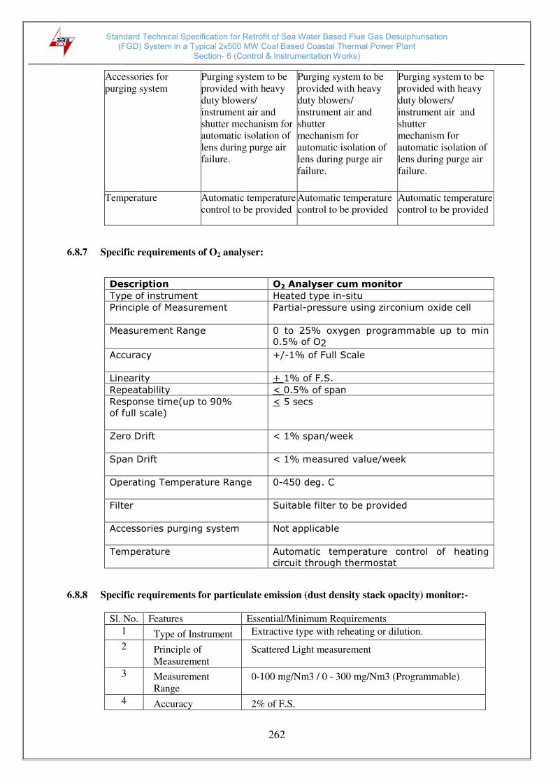
Standard Technical Specification for Retrofit of Sea Water Based Flue Gas Desulphurisation (FGD) System in a Typical 2x500 MW Coal Based Coastal Thermal Power Plant
Section- 6 (Control & Instrumentation Works)
262
Accessories for
purging system Purging system to be
provided with heavy
duty blowers/
instrument air and
shutter mechanism for
automatic isolation of
lens during purge air
failure.
Purging system to be
provided with heavy
duty blowers/
instrument air and
shutter mechanism for
automatic isolation of
lens during purge air
failure.
Purging system to be
provided with heavy
duty blowers/
instrument air and
shutter mechanism for
automatic isolation of
lens during purge air
failure.
Temperature Automatic temperature
control to be provided Automatic temperature
control to be provided Automatic temperature
control to be provided
6.8.7 Specific requirements of O2 analyser:
Description O2 Analyser cum monitor
Type of instrument Heated type in-situ
Principle of Measurement Partial-pressure using zirconium oxide cell
Measurement Range 0 to 25% oxygen programmable up to min 0.5% of O2
Accuracy +/-1% of Full Scale
Linearity + 1% of F.S.
Repeatability < 0.5% of span
Response time(up to 90%
of full scale)
< 5 secs
Zero Drift < 1% span/week
Span Drift < 1% measured value/week
Operating Temperature Range
0-450 deg. C
Filter Suitable filter to be provided
Accessories purging system
Not applicable
Temperature Automatic temperature control of heating
circuit through thermostat
6.8.8 Specific requirements for particulate emission (dust density stack opacity) monitor:-
Sl. No. Features Essential/Minimum Requirements 1 Type of Instrument Extractive type with reheating or dilution.
2 Principle of
Measurement Scattered Light measurement
3 Measurement
Range 0-100 mg/Nm3 / 0 - 300 mg/Nm3 (Programmable)
4 Accuracy 2% of F.S.

Standard Technical Specification for Retrofit of Sea Water Based Flue Gas Desulphurisation (FGD) System in a Typical 2x500 MW Coal Based Coastal Thermal Power Plant
Section- 6 (Control & Instrumentation Works)
263
5 Linearity +/- 1% of F.S. 6 Repeatability < 1% of Span 7 Minimum detection
limit
< 1% of lowest measurement range
8 Response time(up
to 90% of full
scale)
< 5 secs
9. Zero Drift < 1% span/week 10 Span Drift < 1% span/week 11 Operating
temperature range 0-300 deg. C
12 Filter To be provided 14 Accessories
purging system Purging system to be provided with heavy duty
blowers/ plant air and shutter mechanism for
automatic isolation of lens during purge air failure. 15 Temperature
compensation/
measurement
Temperature compensation to be provided.
Temperature measurement using thermocouple and
transmitter with a 4-20mA flue gas temp signal to
PLC to be provided in addition to Opacity monitor.
6.8.9 Specific requirements for continuous on- line mercury analyser:-
Sl. No. Features Essential/Minimum Requirements
1 Measurement Elemental, Ionic & Total mercury
Measurement
principle Atomic absorption spectrometry/ Atomic Fluorescence
spectrometry. 2 Measuring range 0–50 µg/Nm³ 3 Flue gas temperature 0–250°C minimum. Probe material shall be as approved
by owner. 4 Measuring outputs 2 x 0 / 4–20 mA, RS 232, RS 485 & Ethernet port 5 Digital outputs 4 relay outputs 6 Digital inputs 1 potential free outputs 7 Accuracy +/- 1% of Span or better 8 Minimum Detectable
limit < 1 µg/Nm³
9 Temporary change
of
sensitivity/Reference
point drift
< ± 2% of measuring range per month
10 Temporary change
of zero offset/Zero
Point drift
< ± 1.4% of measuring range per month, zero correction
(automatic)
11 Power supply 230 VAC, 50 Hz, from Plant UPS 12 Display LCD display 13 Special
Requirements Non Interference with So2, NOx, CO and any other
chemical components. 14
Bus Protocol MODBUS/TCP-IP protocol to be connected to CEMS
OWS. 15
Accessories Automatic purging system, Automatic dilution system,
Automatic calibration system, filters etc.

Standard Technical Specification for Retrofit of Sea Water Based Flue Gas Desulphurisation (FGD) System in a Typical 2x500 MW Coal Based Coastal Thermal Power Plant
Section- 6 (Control & Instrumentation Works)
264
16 Consumables For one year operations in addition to mandatory spares.
6.8.10 Ultrasonic Flow Meter for Flue Gas Flow in Stack:
Sl. No. Features Essential/Minimum Requirements
1 Type Transit- time Ultrasonic meter
2 Mounting Style Transducers on the duct/stack
3 Transducers Single pair of Corrosion resistant material to be
provided
4 Zero and Span
To be provided
5 Flow measurement Instantaneous Flow rate as well as totalized flow
6 Power supply
Distribution To be arranged by the Bidder.
7 Output: Analogue Binary
Communication ports
Isolated 4-20mA linear outputs to DDCMIS. RS232/ RS485/ Ethernet communication link
with MODBUS/OPC protocol/ Ethernet TCP/IP
protocol for bi-directional communication of
stack emission data to Employer's cloud
server.
Hand held terminal port
8 Display/Indication Flow meter with LCD screen backlight based local
display and keypad. If required, transmitter shall be
suitably located away from the sensor for better access
and visibility.
9 Recording /
Totalizing/Logging To be provided
10 Diagnostics False signal tolerance , power supply failure etc.
11 Protection class IP-65 or better, Weather protection against direct
sunlight, rain etc. for Flow meter and suitable for
Cooling water for Transducer
12 Ambient temperature -20 deg to +60 deg C
13 Accuracy <+/- 2% of span or better
14 Electrical connection Plug and socket
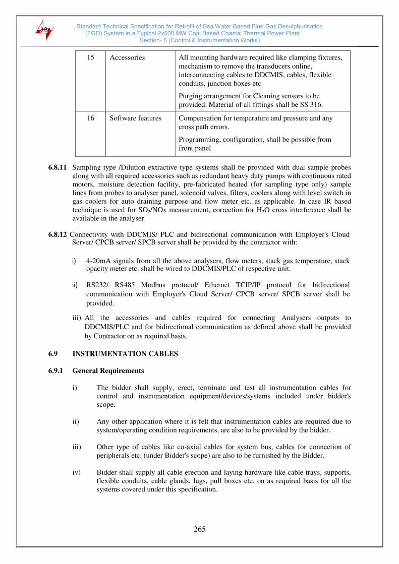
Standard Technical Specification for Retrofit of Sea Water Based Flue Gas Desulphurisation (FGD) System in a Typical 2x500 MW Coal Based Coastal Thermal Power Plant
Section- 6 (Control & Instrumentation Works)
265
15 Accessories All mounting hardware required like clamping fixtures,
mechanism to remove the transducers online,
interconnecting cables to DDCMIS, cables, flexible
conduits, junction boxes etc. Purging arrangement for Cleaning sensors to be
provided. Material of all fittings shall be SS 316.
16 Software features Compensation for temperature and pressure and any
cross path errors. Programming, configuration, shall be possible from
front panel.
6.8.11 Sampling type /Dilution extractive type systems shall be provided with dual sample probes
along with all required accessories such as redundant heavy duty pumps with continuous rated
motors, moisture detection facility, pre-fabricated heated (for sampling type only) sample
lines from probes to analyser panel, solenoid valves, filters, coolers along with level switch in
gas coolers for auto draining purpose and flow meter etc. as applicable. In case IR based
technique is used for SO2/NOx measurement, correction for H2O cross interference shall be
available in the analyser.
6.8.12 Connectivity with DDCMIS/ PLC and bidirectional communication with Employer's Cloud
Server/ CPCB server/ SPCB server shall be provided by the contractor with:
i) 4-20mA signals from all the above analysers, flow meters, stack gas temperature, stack opacity meter etc. shall be wired to DDCMIS/PLC of respective unit.
ii) RS232/ RS485 Modbus protocol/ Ethernet TCIP/IP protocol for bidirectional
communication with Employer's Cloud Server/ CPCB server/ SPCB server shall be
provided.
iii) All the accessories and cables required for connecting Analysers outputs to
DDCMIS/PLC and for bidirectional communication as defined above shall be provided
by Contractor on as required basis.
6.9 INSTRUMENTATION CABLES
6.9.1 General Requirements
i) The bidder shall supply, erect, terminate and test all instrumentation cables for
control and instrumentation equipment/devices/systems included under bidder's
scope.
ii) Any other application where it is felt that instrumentation cables are required due to
system/operating condition requirements, are also to be provided by the bidder.
iii) Other type of cables like co-axial cables for system bus, cables for connection of
peripherals etc. (under Bidder's scope) are also to be furnished by the Bidder.
iv) Bidder shall supply all cable erection and laying hardware like cable trays, supports,
flexible conduits, cable glands, lugs, pull boxes etc. on as required basis for all the
systems covered under this specification.

Standard Technical Specification for Retrofit of Sea Water Based Flue Gas Desulphurisation (FGD) System in a Typical 2x500 MW Coal Based Coastal Thermal Power Plant
Section- 6 (Control & Instrumentation Works)
266
6.9.2 Instrumentation Cable Specifications
i) All the instrumentation cables i.e. twisted and shielded multipair cables,
compensating cables, pre fabricated cables etc. shall be flame retardant low smoke
(FRLS) type. The Cables shall be provided in non returnable drums. The drum length
shall be 1000m (+/-5%) up to & including 8 pairs and 500 m (+/- 5%) above 8 pairs.
ii) Voltage grade of the instrumentation cables shall be 225V (peak value).
iii) All instrumentation cables covered in this specification shall comply with VDE 0815,
VDE 0207, Part 4, Part 5, Part 6, VDE 0816,VDE 0472, SEN 4241475, ANSI MC
96.1, IS-8784, IS-10810 (latest editions) and its amendments read alongwith this
specification.
iv) The conductor shall be of minimum 0.5 sq.mm size, high conductivity, multi-stranded
copper for all types of instrumentation cables.
v) The insulation of individual conductor shall be extruded PVC meeting the
requirements of VDE 0207 Part 4 compound Y I3. The outer sheath of
instrumentation cables shall be extruded PVC (compound YM1) as per VDE 0207
Part 5 and shall be of flame retardant low smoke (FRLS) type. The cable shall be
provided with marking including manufacturer's name, insulation material, conductor
size, no of pairs, voltage ratings, type of cable etc. Progressive sequential marking of
the length of the cable at every one meter & progressive markings to read 'FRLS' at
every 5 meters shall be provided on the outer sheath of all instrumentation cables.
Pairs of Cables shall be identified by colour coding & colour banding. The colour of
outer sheath shall be sky blue so that C&I cables are easily distinguished from other
cables.
Fillers in multiple conductor cables shall be flame retardant and moisture resistant.
Cable accessories such as harnessing components, markers, bedding, cable jointer,
binding tape etc. shall also have flame retardant quality.
vi) All instrumentation cables shall be provided with overall shielding. However
multipair cables carrying analog signals shall be provided with individual pair
shielding in addition to overall shielding. Shielding shall be of Aluminium-Mylar
tape with 100% coverage and with atleast 20% overlapping. The thickness of
individual pair shield shall be 28 micron (minimum) and that of overall shield shall
be 55 microns (minimum). Separate drain wires for individual pair shield (wherever
applicable) as well as overall shield shall be provided. Drain wire shall be of seven
(7) strand 20 AWG (0.51 sq. mm) tin coated copper conductor. Maximum lay of
individual twisted pair shall be 50 mm. Bidder to ensure that individual core diameter
shall be suitable for maxi-termi connection. Insulation thickness of individual core
shall be between 0.28 and 0.35 mm for 0.5 mm2 cables and 0.35 to 0.45 mm for 1.31
mm2 cables.
vii) The outer sheath of the instrumentation cables shall meet the following minimum
requirements:
(a) An oxygen index of not less than 29% and a temperature index of not less
than 250 deg. C as per ASTMD-2863.
(b) Maximum acid gas generation by weight as per IEC-754-I shall not be more
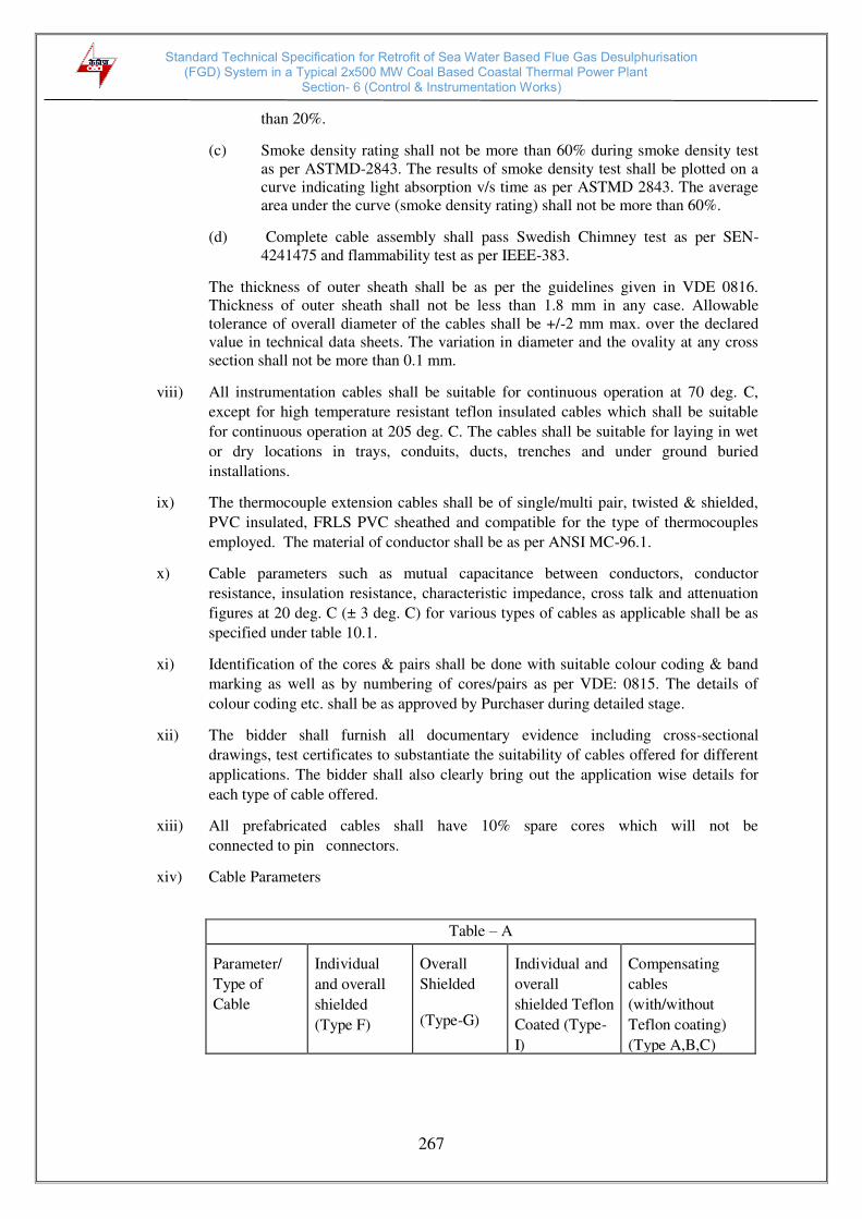
Standard Technical Specification for Retrofit of Sea Water Based Flue Gas Desulphurisation (FGD) System in a Typical 2x500 MW Coal Based Coastal Thermal Power Plant
Section- 6 (Control & Instrumentation Works)
267
than 20%.
(c) Smoke density rating shall not be more than 60% during smoke density test
as per ASTMD-2843. The results of smoke density test shall be plotted on a
curve indicating light absorption v/s time as per ASTMD 2843. The average
area under the curve (smoke density rating) shall not be more than 60%.
(d) Complete cable assembly shall pass Swedish Chimney test as per SEN-
4241475 and flammability test as per IEEE-383.
The thickness of outer sheath shall be as per the guidelines given in VDE 0816.
Thickness of outer sheath shall not be less than 1.8 mm in any case. Allowable
tolerance of overall diameter of the cables shall be +/-2 mm max. over the declared
value in technical data sheets. The variation in diameter and the ovality at any cross
section shall not be more than 0.1 mm.
viii) All instrumentation cables shall be suitable for continuous operation at 70 deg. C,
except for high temperature resistant teflon insulated cables which shall be suitable
for continuous operation at 205 deg. C. The cables shall be suitable for laying in wet
or dry locations in trays, conduits, ducts, trenches and under ground buried
installations.
ix) The thermocouple extension cables shall be of single/multi pair, twisted & shielded,
PVC insulated, FRLS PVC sheathed and compatible for the type of thermocouples
employed. The material of conductor shall be as per ANSI MC-96.1.
x) Cable parameters such as mutual capacitance between conductors, conductor
resistance, insulation resistance, characteristic impedance, cross talk and attenuation
figures at 20 deg. C (± 3 deg. C) for various types of cables as applicable shall be as
specified under table 10.1.
xi) Identification of the cores & pairs shall be done with suitable colour coding & band
marking as well as by numbering of cores/pairs as per VDE: 0815. The details of
colour coding etc. shall be as approved by Purchaser during detailed stage.
xii) The bidder shall furnish all documentary evidence including cross-sectional
drawings, test certificates to substantiate the suitability of cables offered for different
applications. The bidder shall also clearly bring out the application wise details for
each type of cable offered.
xiii) All prefabricated cables shall have 10% spare cores which will not be
connected to pin connectors.
xiv) Cable Parameters
Table – A Parameter/
Type of
Cable
Individual
and overall
shielded
(Type F)
Overall
Shielded (Type-G)
Individual and
overall
shielded Teflon
Coated (Type-
I)
Compensating
cables
(with/without
Teflon coating)
(Type A,B,C)

Standard Technical Specification for Retrofit of Sea Water Based Flue Gas Desulphurisation (FGD) System in a Typical 2x500 MW Coal Based Coastal Thermal Power Plant
Section- 6 (Control & Instrumentation Works)
268
Conductor
Resistance
(max.)
73.4 ohm/km
(loop)
73.4 ohm/km
(loop)
73.4 ohm/km
(loop)
Insulation
resistance
100 M
ohm/ km
100 M
ohm/ km
100 M ohm/
km
100 M ohm/ Km
Cross-Talk
figure at 0.8
kHz (min.)
60 dB
60 dB
60 dB
60 dB
Charact-
eristic
impedance
(max.)
320 ohm
340 ohm
320 ohm
Attenuatio
n at 1 kHz
(max.)
1.2 dB/km
1.2 dB/km
1.2 dB/km
xv) Description of various type of cables
Type
Conductor
Size
Description
F
0.5 mm2
Multi pair individual pair & overall shielded twisted
pair armored instrumentation cable (2/4/8/12/24/ 48
pair) for analog signals with stranded copper G
0.5 mm2
Multi pair overall shielded & twisted pair armored
instrumentation cable (2/4/8/12/24/48 pair) for
binary signals with stranded copper conductor. I
0.5 mm2
Type F/ Type G cable with heat resistant teflon
insulation & outer-sheath for high temperature
application.
Control Cable
1.5/2.5 mm2 Multicore having overall shielding & specification
similar to Instrumentation cable except insulation
thickness and voltage grade which shall be 1100 V. Std.
As per
specific
standard/
requirement
for each
application
Multi core/ Multi pair shielded cable for system
specific cables like System Bus cable, Bus
communications cable etc. as applicable.

Standard Technical Specification for Retrofit of Sea Water Based Flue Gas Desulphurisation (FGD) System in a Typical 2x500 MW Coal Based Coastal Thermal Power Plant
Section- 6 (Control & Instrumentation Works)
269
6.9.3 Instrumentation Cable Interconnection and Termination Philosophy
The cable interconnection philosophy to be adopted shall be such that extensive
grouping of signals by large scale use of field mounted Group JBs at strategic
locations (where large concentration of signals are available, e.g. switchgear) is done
and consequently cable with higher number of pairs are extensively used. The details of
termination to be followed are mentioned below.
Application Type Of Termination
Type Of Cable
FROM (A)
TO (B)
END A
END B
Valves/ Dampers
drives
(Integral
Junction
box)
Marshalling
cubicle/local group
JB/Termination/
Control Cabinets/
System Cabinets
Plug in
connector
Post
Mounted
Maxi
termi/ cage
clamp type.
G
Transmitters,
Integral Junction
box
Plug in
connector
Maxitermi/
cage clamp
(Rail
mounted)
type.
F
MCC/SWGR
Marshalling
Cubicle/local
group JB/
Termination/
Control cabinets/
system cabinets
Maxitermi/
cage clamp
(Rail
Mounted)
type.
Post mounted
Maxi
termi/
cage clamp
type.
G
Local
Junction box,
MCC/SWGR
Group JB
Maxitermi/
cage clamp
(Rail
Mounted)
type.
Maxitermi/
cage clamp
(Rail
mounted)
type.
G
Field
mounted
switches
Group JB
Maxitermi/
cage clamp
(Rail
Mounted)
type.
Maxitermi/c
age clamp
(Rail
mounted)
type.
G
Internal
Marshalling
Termination
of Cabinet
Electronic system
cabinet
Post
mounted
Maxi
termi/cage
clamp type.
Post
mounted
Maxi
termi/cage
clamp type.
F,G
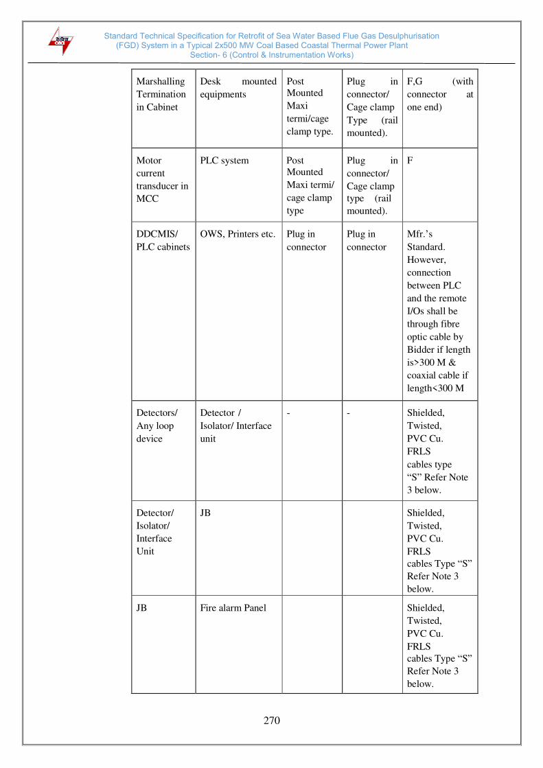
Standard Technical Specification for Retrofit of Sea Water Based Flue Gas Desulphurisation (FGD) System in a Typical 2x500 MW Coal Based Coastal Thermal Power Plant
Section- 6 (Control & Instrumentation Works)
270
Marshalling
Termination
in Cabinet
Desk mounted
equipments
Post Mounted
Maxi
termi/cage
clamp type.
Plug in
connector/
Cage clamp
Type (rail
mounted).
F,G (with
connector at
one end)
Motor
current
transducer in
MCC
PLC system
Post Mounted
Maxi termi/
cage clamp
type
Plug in
connector/
Cage clamp type (rail
mounted).
F
DDCMIS/
PLC cabinets
OWS, Printers etc.
Plug in
connector
Plug in
connector
Mfr.’s
Standard.
However,
connection
between PLC
and the remote
I/Os shall be
through fibre
optic cable by
Bidder if length
is>300 M &
coaxial cable if
length<300 M
Detectors/
Any loop
device
Detector /
Isolator/ Interface
unit
-
-
Shielded,
Twisted,
PVC Cu.
FRLS
cables type
“S” Refer Note
3 below.
Detector/
Isolator/
Interface
Unit
JB
Shielded,
Twisted,
PVC Cu.
FRLS cables Type “S” Refer Note 3
below. JB
Fire alarm Panel
Shielded,
Twisted,
PVC Cu.
FRLS cables Type “S” Refer Note 3
below.

Standard Technical Specification for Retrofit of Sea Water Based Flue Gas Desulphurisation (FGD) System in a Typical 2x500 MW Coal Based Coastal Thermal Power Plant
Section- 6 (Control & Instrumentation Works)
271
Notes:
1. 10% spare pair shall be provided for all cables having more than four pairs. 2. For analogue signals, individual pair shielding & overall shielding & for
Binary signals, only overall shielding of instrumentation cables shall be
provided.
3. Type “S” cable shall satisfy requirements of Article 760 NFPA 70.
4. Short term fire proof cables shall be Mineral insulated copper conductor
and copper sheathed type satisfying requirements of Fire resistance, safety in
the industrial application areas mentioned in the specification and also, shall
be approved by UL standards and certified by LPCB.
6.9.4 Fibre Optical Cables
i) Fiber Optic cable shall be 4/8/12 core, corrugated steel taped armoured, fully water
blocked with dielectric central member for outdoor/indoor application so as to
prevent any physical damage. The cable shall have multiple single-mode fibres as
required by the communications system so as to avoid the usage of any repeaters.
The core and cladding diameter shall be 9 +/- 1 micrometers and 125 +/- 1
micro- meters respectively. The outer sheath shall be Flame Retardant, UV
resistant properties and identified with the manufacturer’s name on it.
ii) The cable core shall have suitable characteristics and strengthening for prevention
of damage during pulling viz. Steel central member, Loose buffer tube design,
4 fibers per buffer tube (minimum), Interstices and buffer tubes duly filled. The
cable shall be suitable for a maximum tensile force of 2000 N during installation,
and once installed, a tensile force of 1000 N minimum. The compressive
strength of cable shall be 3000 N minimum. The operating temperature shall be
–20 deg C to 70 deg C. iii) All testing of the fiber optic cable being supplied shall be as per the relevant IEC,
EIA and other international standards. iv) Bidder to ensure that minimum hundred (100) percent cores are kept as spares in all
types of optical fibre cables.
6.9.5 Terminal Blocks
i) All terminal blocks shall be rail mounted/post mounted, cage clamp type/maxi-termi type
(MTP) with high quality non-flammable insulating material of melamine suitable for
working temperature of 105 deg. C. The terminal blocks in field mounted junction boxes,
CJC boxes, instrument enclosures/racks, etc., shall be suitable for cage clamp/ MTP
connections. The terminal blocks in Control Equipment Room
logic/termination/marshalling cubicles shall be suitable for post mounted maxi- termi/cage
clamp connection at the field input end. The terminal blocks for PLC input/output
connections from/to SWGR/MCC, Actuators with Integral Starter (for coupling relays and
check back signals of 11 kV and 3.3 kV auxiliaries, LT drives/valves &
dampers/solenoids, CT & VT, etc.) shall be provided with built in test and disconnect
facilities complete with plug, slide clamp, test socket, etc.

Standard Technical Specification for Retrofit of Sea Water Based Flue Gas Desulphurisation (FGD) System in a Typical 2x500 MW Coal Based Coastal Thermal Power Plant
Section- 6 (Control & Instrumentation Works)
272
ii) All the terminal blocks shall be provided complete with all required accessories including
assembly rail, locking pin and section, end brackets, partitions, small partitions, test plug
bolts and test plug (as specified above for SWGR connections) transparent covers, support
brackets, distance sleeves, warning label, marking, etc.
iii) The marking on terminal strips shall correspond to the terminal numbering on wiring
diagrams. At least 20% spare unused terminals shall be provided everywhere including
local junction boxes, instrument racks/enclosures, termination/marshalling cabinets, etc. All
terminal blocks shall be numbered for identification and grouped according to the function.
Engraved labels shall be provided on the terminal blocks.
iv) The terminal blocks shall be arranged with atleast 100 mm clearance between two sets of
terminal blocks and between terminal blocks and junction box walls.
6.9.6 Internal Panels/Cabinets/System Cabinets Wiring
i) Internal panel/cabinet wiring shall be of multistranded copper conductor with FRLS
PVC insulation without shield and outer sheath meeting the requirements of VDE
0815.
ii) Wiring to door mounted devices shall be done by 19 strand copper wire provided
with adequate loop lengths of hinge wire so that multiple door opening shall not
cause fatigue breaking of the conductor.
iii) All internal wires shall be provided with tag and identification nos. etched on tightly
fitted ferules at both ends in purchaser's approved format. All wires directly
connected to trip devices shall be distinguished by one additional red colour ferrule.
iv) All external connections shall be made with one wire per termination point. Wires
shall not be tapped or spliced between terminal points.
v) All floor slots of desk/panels/cabinets used for cable entrance shall be provided with
removable gasketed gland plates and sealing material. Split type grommets shall be
used for prefabricated cables.
vi) All the special tools as may be required for solderless connections shall be provided
by Bidder.
vii) Wire sizes to be utilised for internal wiring.
(a) Current (4-20 mA) : 0.5 sq.mm.
low voltage signals (48V)
(b) Ammeter/voltmeter circuit, : 1.5 sq.mm.
control switches etc. for
electrical system.
(c) Power supply and internal : 2.5 sq.mm. minimum
illumination
(shall be as per load
requirement.)
Standard Technical Specification for Retrofit of Sea Water Based Flue Gas Desulphurisation (FGD) System in a Typical 2x500 MW Coal Based Coastal Thermal Power Plant
Section- 6 (Control & Instrumentation Works)
273
6.9.7 Cable Installation and Routing
i) All cables assigned to a particular duct/conduit shall be grouped and pulled in
simultaneously using cable grips and suitable lubricants. Cables removed from one
duct/conduit shall not be reused without approval of Purchaser.
ii) Cables shall be segregated as per IEEE Std.-422. In vertically stacked trays, the
higher voltage cable shall be in higher position and instrumentation cable shall be in
bottom tier of the tray stack. The distance between instrumentation cables and those
of other systems shall be as follows :
a) from 11 kV/6.6 kV/3.3 kV tray system - 914 mm
b) from 415V tray system - 610 mm
c) from control cable tray system - 305 mm
iii) Cables shall terminate in the enclosure through cable glands. All cable glands shall be
properly gasketed. Fire proof sealing to prevent dust entry and propagation of fire
shall be provided for all floor slots used for cable entrance.
iv) All cables shall be identified by tag nos. provided in Purchaser's approved format at
both the ends as well as at an interval of 5 meters.
v) Line voltage drop due to high resistance splices, terminal contacts, insulation
resistance at terminal block, very long transmission line etc. shall be reduced as far as
practicable.
vi) The cables emanating from redundant equipment/devices shall be routed through
different routes.
6.9.8 Cable Laying and Accessories & Fittings
i) Bidder shall supply and install all cable accessories and fittings like cable glands,
grommets, lugs, termination kits etc. on as required basis.
ii) Cables shall be laid strictly in line with cable schedule.
iii) Indelible tags to be provided at all terminations, on both sides of wall or floor
crossing, on each conduit/duct/pipe entry/exit, and at every 20 m in cable trench/tray.
iv) Cable tray numbering and marking to be provided at every 10m and at each end of
cable way & branch connection.
v) Joints of cable shall not be permitted.
vi) Buried cable protection to be provided with concrete slabs; route markers at every 20
meters along the route & at every bend.
vii) At road crossings, cables to pass through buried high density PE pipes encased in RCC.
At least 300 mm clearance shall be provided each between HT Power & LT Power
cables and LT Power & LT control/instrumentation cables.
Spacing between cables of same voltage grade shall be in accordance with the derating
criteria adopted for cable sizing.

Standard Technical Specification for Retrofit of Sea Water Based Flue Gas Desulphurisation (FGD) System in a Typical 2x500 MW Coal Based Coastal Thermal Power Plant
Section- 6 (Control & Instrumentation Works)
274
viii) All cable associated with the unit shall be segregated from cables of other units.
Interplant cables of station auxiliaries and unit critical drives shall be segregated in such
a way that not more than half of the drives are lost in case of single incident of fire.
ix) All cables laid on trays shall be neatly dressed up & suitably clamped/tied to the
tray. For cables in trefoil formation, trefoil clamps shall be provided.
x) Optical Fibre Cables shall be buried in a separate trench approximately at 1 meter depth
& to be laid in 2” GI/ rodent proof HDPE conduits covered with sand, brick, and soil
along the pipe line route. For crossing roads, to be laid in GI/ rodent proof HDPE
conduits with sand filling at bottom and sand, soil filling at top with cement concrete.
xi) Bidder shall supply and install all cable accessories and fittings like Light Interface
Units, Surge suppressors, Opto isolators, Interface Converters, Fiber Optic Card Cage,
Fiber Optic Line Driver, Modem (for Optical Fiber Cables), cable glands, grommets,
lugs, termination kits etc. on as required basis. xii) Bidder shall furnish two completely new sets of cable termination kits like crimping
tools, maxi-termi/wire-wrap tools etc. which are required for maintenance of the system.
6.9.9 Field Mounted Local Junction Boxes
i) No. of ways
12/24/36/48/64/72/96/128 with 20% spare terminals.
ii) Material and
Thickness
4mm thick fibre glass reinforced polyester.
iii) Type Screwed at all four corners for door. Door handle shall be of SS.
Self locking with common key. Door gasket shall be of
synthetic rubber.
iv) Mounting clamps
and accessories Suitable for mounting on walls, columns, structures etc. The
brackets, bolts, nuts, screws, glands and lugs required for
erection shall be of brass, included in Bidders scope of supply.
v) Type of terminal
blocks Rail mounted maxi termi or cage-clamp type suitable for
conductor size upto 2.5 mm2. A M6 earthing stud shall be
provided. (vi) Protection Class IP:65 minimum
6.9.10 Conduits
All rigid conduits, couplings and elbows shall be hot dipped galvanised rigid mild steel in
accordance with IS:9357 Part-I (1980) and Part-II (1981). The conduit interior and exterior
surfaces shall have a continuous zinc coating with an overcoat of transparent enamel lacaner
or zinc chromate. Flexible conduit shall be heat resistant lead coated steel, water leak, fire and
rust proof. The temperature rating of flexible conduit shall be suitable for actual application.
6.10 TYPE TEST REQUIREMENTS
6.10.1 General Requirements
i) The Contractor shall furnish the type test reports of all type tests as per relevant
Standard Technical Specification for Retrofit of Sea Water Based Flue Gas Desulphurisation (FGD) System in a Typical 2x500 MW Coal Based Coastal Thermal Power Plant
Section- 6 (Control & Instrumentation Works)
275
standards and codes as well as other specific tests indicated in this specification. A
list of such tests are given for various equipment in subsequent table and under
the item Special Requirement for Solid State Equipments/ Systems. For the
balance equipment instrument, type tests may be conducted as per manufactures
standard or if required by relevant standard.
ii) Out of the tests listed, the Bidder/ sub-vendor/ manufacturer is required to
conduct certain type tests specifically for this contract (and witnessed by
Employer or his authorized representative) even if the same had been conducted
earlier, as clearly indicated subsequently against such tests.
iii) For the rest, submission of type test results and certificate shall be acceptable
provided.
a. The same has been carried out by the Bidder/ sub-vendor on exactly the
same model /rating of equipment.
b. There has been no change in the components from the offered equipment &
tested equipment.
c. The test has been carried out as per the latest standards alongwith
amendments as on the date of Bid opening but not more than five (5) year
back.
iv) In case the approved equipment is different from the one on which the type test
had been conducted earlier or any of the above grounds, then the tests have to be
repeated and the cost of such tests shall be borne by the Bidder/ sub-vendor
within the quoted price and no extra cost will be payable by the Employer on this
account.
6.10.2 Special Requirement for Solid State Equipment/ Systems
i) The minimum type test reports, over and above the requirements of above clause,
which are to be submitted for each of the major C&I systems Analyzer instruments,
various PLCs etc. shall be as indicated below:
a) Surge Protections for Solid State Equipment/ Systems
All solid state systems/ equipment shall be able to withstand the electrical noise
and surges as encountered in actual service conditions and inherent in a power
plant. All the solid state systems/ equipment shall be provided with all required
protections that needs the surge withstand capability as defined in ANSI
37.90a/ IEEE-472. Hence, all front end cards which receive external signals like
Analog input & output modules, Binary input & output modules etc. including
power supply, data highway, data links shall be provided with protections that
meets the surge withstand capability as defined in ANSI 37.90a/ IEEE-472.
Complete details of the features incorporated in electronics systems to meet
this requirement, the relevant tests carried out, the test certificates etc. shall be
submitted alongwith the proposal. As an alternative to above, suitable class of
IEC-60255-4 which is equivalent to ANSI 37.90a/ IEEE-472 may also be adopted

Standard Technical Specification for Retrofit of Sea Water Based Flue Gas Desulphurisation (FGD) System in a Typical 2x500 MW Coal Based Coastal Thermal Power Plant
Section- 6 (Control & Instrumentation Works)
276
for SWC test.
b) Dry Heat test as per IEC-68-2-2 or equivalent.
c) Damp Heat test as per IEC-68-2-3 or equivalent.
d) Vibration test as per IEC-68-2-6 or equivalent.
e) Electrostatic discharge tests as per IEC 61000-4-2 or equivalent.
f) Radio frequency immunity test as per EN 50082-2 or equivalent.
g) Electromagnetic immunity as per EN 61131-2 or equivalent.
h) Test listed at item no. v, vi, vii, above are applicable for front end cards only as
defined under item (i) above.
6.10.3 Type Test Requirement for C&I Systems
Sl. No. Item Test
Requirement
Standard Test To Be
Specifically
Conducted
Approval
Req. on Test
Certificate
Remarks
1 2 3 4 5 6 7 i) Elect. Metering
instruments As per standard
( col 4)
IS-1248 No Yes
ii) Electronic
transmitter As per standard
( col 4) BS-6447/
IEC-770
No Yes
iii) Dust emission
monitor Degree of
protection test IS-2147 No Yes
iv) Instrumentation
Cables- Twisted
& Shielded
Yes Yes
v) Pressure gauge Degree of
protection test
IS-2147 No No
Temp
interference
test
IS -3624 No No
vi) Temperature
gauge Degree of
protection test
IS-2147 No No
vii) Pressure & DP
switch Degree of
protection test IS-2147 No No
As per
standard (col 4)
BS 6134 No No
viii) Level switch Degree of IS-2147 No No

Standard Technical Specification for Retrofit of Sea Water Based Flue Gas Desulphurisation (FGD) System in a Typical 2x500 MW Coal Based Coastal Thermal Power Plant
Section- 6 (Control & Instrumentation Works)
277
protection test
ix) Conductivity
level switch Degree of
protection test
IS-2147 No Yes
x) Battery charger
(Including
chargers of UPS )
Degree of
protection test IS-2147 No Yes
Short circuit
current
capability
IEC-146-2 No Yes
Temp rise test
without
redundant
fans
Approved
procedure,
IEC 146-2
Yes Yes
SWC test Approved
procedure, No Yes
Efficiency/ PF IEC-146-
2,IEC146 Yes Yes
Audible noise
test IEC 146-2 No Yes
Fuse clearing
capability Approved
procedure No Yes
Relative
harmonic
content
Approved
procedure No Yes
Radio
interference IEC 146-4 No Yes
Over Load
test on
inverter &
charger.
Approved
procedure No Yes
Restart test IEC 146-2 No Yes
Output
voltage
tolerance
Approved
procedure No Yes
Output
voltage
harmonic
content
Approved
procedure No Yes
Insulation test IEC 146 No Yes
Load tests Approved
procedure Yes Yes
Preliminary
light load test IEC 146 No Yes
Current
division/
voltage
division
IEC 146-2 No Yes
xi) Battery As per
standard (col 4)
IEC-623 /
IS-10918
for Ni-Cd
IS-1652 for
Plate Lead
Acid IS-
No Yes

Standard Technical Specification for Retrofit of Sea Water Based Flue Gas Desulphurisation (FGD) System in a Typical 2x500 MW Coal Based Coastal Thermal Power Plant
Section- 6 (Control & Instrumentation Works)
278
1651 for
Lead Acid
xii) Control valves CV Test ISA 75.02
Yes* No
xiii) Voltage
stabilisers Over load test Approved
procedure No
Temp rise test
without
redundant
fans
Approved
procedure No
Input voltage
variation test
Approved
procedure No
xiv) Flow Nozzles &
Orifice plate
Calibration ASME
PTC, BS
1042
Yes* No
xv) PLCs All tests as
per IEC-1131 IEC-1131
xvi) LIE / LIR /
Junction Box Degree of
protection test IS-2147 Yes Yes
xvii) Flue gas O2
Analyser Degree of
protection test IS-2147 No Yes
xviii) Flue gas SO2
Analyser Degree of
protection test
IS-2147 No Yes
* In case valid type test certificate is not available.
6.11 SERVICES FOR ANALYSERS AND CEMS DURING DEFECT LIABILITY
PERIOD AND SUBSEQUENT ANNUAL MAINTENANCE SERVICE (AMS)
PERIOD
6.11.1 Services during Defect Liability/ Warranty Period
6.11.1.1 The Contractor shall provide an unlimited warranty on all equipments during the defect
liability/ warranty period. This warranty shall include repair, replacement, replenishment
of consumables (for reagents, calibration gases etc. as applicable) and correction of
identified discrepancies including Analysers, Sample Handling System, Transmitters, (as
applicable) etc. at no cost to the purchaser.
6.11.1.2 The Contractor shall provide warranty spares including components for each system
based on (and keeping adequate over margin) normally experienced failure rate.
Exhaustive list of all such items including their data sheets shall be submitted for
purchaser's review and approval during detail Engineering stage regarding adequacy of
the same. The warranty spares shall be dispatched by the Contractor along with the main
equipment consignment. However, for items which have a limited shelf life shall be
dispatched in a phased manner during the warranty period. Unused spares/consumables
shall be Contractor’s property after expiry of warranty period and shall be taken back.

Standard Technical Specification for Retrofit of Sea Water Based Flue Gas Desulphurisation (FGD) System in a Typical 2x500 MW Coal Based Coastal Thermal Power Plant
Section- 6 (Control & Instrumentation Works)
279
6.11.2 Services during Annual Maintenance Services (AMS) Period
6.11.2.1 The Contractor shall provide complete maintenance services for each System under
comprehensive annual maintenance service (AMS) for period of three (3) years after the
defect liability/ warranty period. The AMS shall cover total maintenance of all
Analysers, Sample Handling System, Transmitters etc. coming under the scope of each
system and shall include free repair/replacement of each items, replenishment of
consumables, correction of problems (if any) and supply of expendable items.
6.11.2.2 The Contractor shall provide a list of all required AMS spares which shall be finalized
along with datasheet during detail Engineering stage. These spares shall be dispatched by
the Contractor at the beginning of AMS on yearly requirement basis. However, for items
which have a limited shelf life shall be dispatched in a phased manner during the AMS
period.
6.11.3 Deputation of Engineer/ Technical Expert to the Site
6.11.3.1 The Contractor shall depute Engineer/ Technical Experts of the OAM (Original Analyser
Manufacturer)/ OEM (Original Equipment Manufacturer)/ OES (Original Equipment
supplier) for each of the above system at Site, who will be fully qualified to perform the
required duties, supervision of maintenance, repair etc. for a period of six month. The
purchaser shall give the contractor two weeks advance notice for start of deputation
period.
6.11.3.2 After expiry of above six month period, Technical expert for each system shall visit site
on monthly basis for monitoring the performance and rectify the problem (if any) for each
system for the remaining warranty period and during entire AMS period. In the event of
any malfunction/fault/failure in the system or any component thereof contractor shall
depute Technical expert of respective system to reach site within a reasonable time of call
raised by site during the remaining warranty period and entire AMS period.
Standard Technical Specification for Retrofit of Sea Water Based Flue Gas Desulphurisation (FGD) System in a Typical 2x500 MW Coal Based Coastal Thermal Power Plant
Section- 7 (Civil Works)
280
SECTION-7
CIVIL WORKS
7.0 TECHNICAL SPECIFICATION – CIVIL WORKS 7.1 GENERAL 7.1.1 The specification for civil works covers all the civil works required for
installation/ retrofitting of sea water based FGD plants inside the premises of existing thermal power plants. The specifications are intended for the general description of the work, materials quality and workmanship. The specifications are not, however, intended to cover the minute details.
Wherever references to Indian Standard Codes are made, they shall refer to the latest edition/ version of the same as exist one month before the due date of submission of tenders.
7.1.2 Nature of Work
The works to be performed under these specifications shall include complete design, preparation of construction drawings of civil structures including reinforcement details, bar bending schedule based on the drawings approved for construction, preparation of fabrication drawings of steel structures based on design/drawings and getting the same approved by the Purchaser and also execution of works including/providing all materials labour, scaffolding, power, fuel, construction equipment, tools and plants, supplies, transportation, storage supervision and all incidental implied or necessary for successful completion of the work including construction, supervision and in strict accordance with approved drawings and these specifications and with inspection and testing as per standards and schedule.
The work shall also involve the dismantling of existing R.C.C. foundation, pedestals, structures etc. without blasting/ disturbing the nearby foundations/ structures at the interface of existing power plant and proposed FGD plant or at any other place for accommodating the facilities of FGD plant. Dismantling works shall be done as per the strict instruction of the Purchaser.
The bidders are advised to visit the project site to acquaint themselves of the actual site conditions before submission of the bids.
7.1.3 Scheme
The proposed scheme and technical details of Sea Water based FGD system is described elsewhere in Technical specification.

Standard Technical Specification for Retrofit of Sea Water Based Flue Gas Desulphurisation (FGD) System in a Typical 2x500 MW Coal Based Coastal Thermal Power Plant
Section- 7 (Civil Works)
281
7.1.4 Layout and Levels
The layout and levels of all structures etc. shall be made by the Contractor at his own cost from the general grid of the plot and bench marks given by the purchaser and under no circumstances shall be removed or disturbed any permanent marks without approval of the purchaser.
7.1.5 Construction Method
The Bidder shall submit along with his offer drawings, Bar Chart, Construction Schedule, list of construction equipment’s and manpower to be deployed and a write-up to indicate broadly how he intends to execute the work. These shall form part of this tender.
7.2 BASIC DESIGN CRITERIA
7.2.1 Basis of Design
All structures will be designed for the following loads: - 7.2.1.1 Dead load: Self-weight of structures plus weight of machinery/ equipment.
7.2.1.2 Live load: The following live loads shall be adopted in addition to equipment
and machinery loads as per IS: 875 (latest revision) including up-to-date
amendments:
a) Roofs = 150 kg/m2, for accessible roof = 75 kg/m2, for inaccessible roof b) Office rooms = 250 kg/m2 c) Floors = 500 kg/m2 (Minimum) or as required from
operational & maintenance requirements whichever is Maintenance higher. d) Chequered plate floor = 500 kg/m2 e) Stairs & Balconies = 500 kg/m2 f) Platforms, walkways grating floors = 500 kg/m2
Any other load required for servicing, maintenance and erection shall be taken
in addition to above loads. Further, if erection load on any floor or part thereof is
more than the live load specified above, that floor including beams shall be
designed for the erection load.

Standard Technical Specification for Retrofit of Sea Water Based Flue Gas Desulphurisation (FGD) System in a Typical 2x500 MW Coal Based Coastal Thermal Power Plant
Section- 7 (Civil Works)
282
Note: No reduction in live loads due to number of floors shall be allowed in design.
7.2.1.3 Wind load: Wind loads on structures shall be calculated as per provisions of
IS-875 (Part-3) including up-to-date amendments.
7.2.1.4 Seismic load: Seismic load shall be calculated for analysis & design as
applicable by seismic coefficient/response spectrum method as per IS: 1893
(latest revision) including up-to-date amendments. The Importance factor for all
structures shall be taken as 1.50.
7.2.1.5 Dust load: All buildings and structures shall be designed for a dust load of 50 kg/m2.
7.2.1.6 Thrust load: All pipes and its foundation at bends shall be designed for thrust load as per latest edition of IS: 5330.
7.2.1.7 Impact load: The minimum impact factor to be used in design shall be as
follows:
(a) Crane Girder: As per IS: 875 or manufacturer’s
data. (b) Rotary equipment and reciprocating As per manufacturer’s equipment supported by steel or recommendations & IS: 2974. concrete structures (c) For pulley block 10% for manual and 25% for
electrical 7.2.1.8 Thermal load
Expansion & contraction due to changes in temperature of the materials of a structure shall be considered and adequate provision be made in the design for the effects produced. The maximum variation of temperature for location of building shall be obtained from the Indian Metrological Department for that particular locality. The co-efficient of expansion for steel shall be considered as 0.000012 per oC per meter and the coefficient of expansion for concrete shall be 0.00001 per oC per meter.
7.2.1.9 Surge loads
The surge effect of cranes in the lateral & longitudinal horizontal shall be considered as per manufacturer’s recommendations and relevant IS codes.
7.2.1.10 Loads on underground structures
The underground structures shall be designed for lateral thrust due to earth pressure, sub-soil water pressure (if any). In addition, a minimum surcharge

Standard Technical Specification for Retrofit of Sea Water Based Flue Gas Desulphurisation (FGD) System in a Typical 2x500 MW Coal Based Coastal Thermal Power Plant
Section- 7 (Civil Works)
283
load of 2.0 tons per m2 shall also be considered. The structures/foundations shall be checked for buoyancy effect due to sub-soil water table.
7.2.1.11 Increase in allowable stresses: While designing structures for wind and
seismic loads, the permissible stresses in materials and safe bearing capacity
of soils may be increased as allowed by relevant I.S. Codes.
7.2.2 Safe bearing capacity of soil: Before submitting the tender, the tenderer
should familiarize himself with the site conditions and shall satisfy himself
about nature of soil, bearing capacity etc. and furnish all-inclusive rates of
various items of work below ground level. The report of soil investigation of
existing power plant is available with the Purchaser, which can be seen
by the bidders with prior appointment. However, the contractor shall carry
out soil investigation after award of work for determining the safe bearing
capacity of the soil including sub-soil water level and for deciding the type of
foundations to be provided for various structures of FGD Plant.
7.2.3 The owner shall not, under any circumstances, pay any extra charge after the
acceptance of the contract, in case the contractor is found to have misjudged
the soil conditions including sub-soil water level at the site of work at a later
date.
7.2.4 DESIGN CRITERIA
7.2.4.1 The design of R.C.C. structures will be carried out as per code of practice for
plain and reinforced concrete for General Building Construction IS:456 (latest
edition). The design of liquid retaining R.C.C. structures shall be carried out as
per latest edition of IS: 3370 (Part I to IV).
7.2.4.2 The steel structures shall be designed and fabricated as per latest edition of IS:
800 entitled ‘Code of Practice for use of Structural Steel in General Building Construction’ and other relevant IS Standards.
7.2.4.3 The building shall conform to local by laws, rules and regulations for industrial
buildings and also to IS: 1256 (latest revision).
7.2.4.4 The machine foundations shall be designed in accordance with latest edition of
IS: 2974. The vibration isolation system may be provided for equipment as
specified elsewhere in the specifications.
7.2.4.5 The permissible settlement for foundations of FGD plant shall be as per
relevant IS codes and differential settlement shall be as per IS: 8009 unless
required otherwise by the manufacturer of any equipment.
7.2.4.6 All Control Room Buildings shall be air-conditioned and shall have provision for
false ceiling and anodized aluminum doors & windows. All windows in air
conditioned buildings shall be double glassed

Standard Technical Specification for Retrofit of Sea Water Based Flue Gas Desulphurisation (FGD) System in a Typical 2x500 MW Coal Based Coastal Thermal Power Plant
Section- 7 (Civil Works)
284
7.2.5 DESIGN CALCULATIONS AND DRAWINGS: All drawings and design
calculations (six sets) for civil & structural works shall be submitted by the
contractor for the approval of owner/Consultants. No construction shall
commence prior to approval of the relevant design and construction drawings.
7.2.6 AS MADE DRAWINGS
One set of tracing in linen, three sets of paper prints and soft copy in PDF format of all approved construction/ fabrication/ architectural drawings showing the work exactly as made shall be delivered to the owner/ consultant within one month of completion of the work at site.
7. 3 TECHNICAL SPECIFICATION FOR EARTH WORK
7.3.1 GENERAL
This shall include all works involved in excavation for all leads and lifts, dressing of soil, shoring, filling around foundations and trenches, carting of sand or good quality earth if required for filling, disposal of residual earth at a place as directed by the Purchaser. The contractor must satisfy himself of the character and volume of all works under this item and expected surface and/or sub-soil water to be encountered.
7.3.2 EXCAVATION
7.3.2.1 The contractor shall control the grading in the vicinity of all excavations so that
the surface of the ground will be properly sloped or diked to prevent surface
water from running into the excavated areas during construction.
7.3.2.2 Sides and bottoms of excavation shall be cut sharp and true to the slopes
indicated in the drawing. Under-cutting shall not be permitted. Earth side of
excavation shall not be used in lieu of formwork for placement of concrete
unless authorised in special cases, by the Purchaser where limitation of space
for larger excavation necessitates such a decision.
7.3.2.3 When machines are used for excavation, the last 300mm before reaching the
required level shall be excavated by hand or by such equipment that will leave
the soil at the required final level, in its natural condition. Similarly, excavation
by hand may be required close to existing installation.
7.3.2.4 Suitability for bearing of the bottoms of excavations shall be determined by the
Purchaser.
7.3.2.5 The bottoms of excavations shall be trimmed to the required levels and when
carried below such levels due to contractor's fault, the excess depth shall be
filled upto the required level at the Contractor's cost with cement concrete not
leaner than M-10 grade or richer as directed by the Purchaser in each
individual case.

Standard Technical Specification for Retrofit of Sea Water Based Flue Gas Desulphurisation (FGD) System in a Typical 2x500 MW Coal Based Coastal Thermal Power Plant
Section- 7 (Civil Works)
285
7.3.2.6 Excavated material shall be placed beyond 1.5m from the edge of the pit or
half the depth of the pit whichever is more or farther away if directed by the
Purchaser.
7.3.2.7 All excavations for installation of underground facilities such as piping, power
lines, ducts, drain lines, earthing mat etc. shall be open cuts.
7.3.2.8 Excavation for foundation where specified shall be carried out at least 100mm
below the bottom of structural concrete and then brought to the required level
by placing lean concrete of M-10 (1: 3: 6) with aggregates of 40mm maximum
nominal size.
7.3.2.9 For the purpose of excavation of earthwork, the term soil shall apply to all
kinds of soil containing any percentage of Kanker, moorum or/and shingle etc.
Any buried structures or foundations or reinforced/un-reinforced cement
concrete found at site during excavation shall also be removed/dismantled, if
required, without any extra cost to the purchaser.
7.3.3 DISPOSAL OF SURPLUS EARTH
The contractor shall arrange to transport the surplus excavated soil remaining after backfilling to the disposal place inside the project area, as directed by the Purchaser.
7.3.4 EXCAVATION BELOW WATER TABLE
7.3 4.1 The contractor shall acquaint himself with the existing water table condition at site before starting of work and shall make all requisite arrangements for dewatering like well-point system, boring of tube wells if required, installation of sump pumps etc.
7.3.4.2 The Contractor shall de-water and maintain the water table below the bottom
of the excavated level during excavation, concreting, water proofing treatment
and backfilling and shall continue the arrangements till the completion of all
works up to 1.0 m above the water table is achieved.
7.3.4.3 All costs for the ground water control for keeping the construction pits dry shall be included in the relevant excavation item except otherwise indicated.
7.3.5 BACKFILL 7.3.5.1 The Contractor shall furnish all labour, equipment and materials required for
complete performance of work in accordance with the drawings and as described herein.
7.3.5.2 After completion of foundation footings and wall and other constructions
below the elevation of the final grades and prior to backfilling, all forms,
temporary shoring, timber etc. shall be removed and the excavation cleaned
of all trash, debris and perishable materials.

Standard Technical Specification for Retrofit of Sea Water Based Flue Gas Desulphurisation (FGD) System in a Typical 2x500 MW Coal Based Coastal Thermal Power Plant
Section- 7 (Civil Works)
286
7.3.5.3 Backfilling shall be done with inorganic materials obtained from the excavation
or borrow pits, if suitable, and subject to the approval of the Purchaser.
7.3.5.4 Backfill shall be placed in horizontal layers not exceeding 20cm in thickness. Each layer shall be compacted with proper moisture content with such equipment as may be required to obtain a density requirement of at least 95% as per standard proctor test conforming to IS 2720.
7.3.5.6 Backfill adjacent to pipes shall be hand placed free from stones, concrete etc.
compacted uniformly on both sides of the pipe and where practicable to a
depth of 300mm over the top of pipes.
7.3.5.7 On completion of structures, the earth surrounding them shall be accurately
finished to the specified line and grade. Finished surface shall be free of
irregularities and separations and shall be within 50mm of the specified level.
7.3.6 EXCAVATION IN TRENCHES FOR PIPES, CABLES Excavation not exceeding 1.50 m or 10m2 in plan to any depth in trenches shall be described as trenches for pipes, cables etc. Returning, filling and ramming (after pipes and cables are laid) and removal of surplus soil shall from part of this work.
7.3.6.1 Width of Trench
For depth upto 1.0m, the width shall be arrived by adding 25cm to the external diameter of pipe (not socket). When pipe is laid on concrete bed/ cushioning layer, the width shall be pipe diameter plus 25 cm or the widths of concrete bed/ cushioning layer whichever is more. For depths exceeding 1.0m, an additional width of 5 cm/m depth for each side of trench shall be taken i.e. diameter of pipe + 25cm +(2 x 5) cm x depth in m. When more than one pipe, cable, conduit are laid, the diameter taken shall be the horizontal distance from outside to outside of outermost pipes, cable etc.
7.3.6.2 Bedding for pipe
The bedding surface shall provide firm foundation of uniform density throughout the length of the culvert, shall conform to the specified levels and grade, and shall be of one of the following two types as specified on the drawings:
(i) First class bedding:
Under first class bedding, the pipe shall be evenly bedded on a continuous layer of well compacted approved granular material, shaped concentrically to fit the lower part of the pipe exterior for at least ten per cent of its overall height or as otherwise shown on the drawings. The bedding material shall be well-graded sand or another granular material passing 4.75mm sieve. The
Standard Technical Specification for Retrofit of Sea Water Based Flue Gas Desulphurisation (FGD) System in a Typical 2x500 MW Coal Based Coastal Thermal Power Plant
Section- 7 (Civil Works)
287
thickness of the bedding layer shall be as shown on the drawings and in no case shall it be less than 75mm. (ii) Concrete cradle bedding:
When indicated on the drawings or directed by the Purchaser, the pipe shall be bedded in a cradle constructed of concrete having a mix not leaner M20.
7.3.6.3 Filling 7.3.6.3.1 Normally excavated earth shall be used for filling. In case earth contains
deleterious salts it shall not be used. Where excavated material is rock, the boulders shall be broken into pieces not bigger than 15 cm & mixed with fine materials of decomposed rock, murrum or earth as available to fill up voids.
7.3.6.3.2 Filling the trenches for pipes shall start after the joints of pipes etc. are tested
& passed. Where the trenches are excavated in soil, the filling shall be done with earth on the sides & top of pipes in layers not exceeding 20 cm watered & rammed and consolidated.
7.3.6.3.3 In case of excavation of trenches in rock the filling up to a depth of 30 cm
above the crown of the pipe shall be done with fine material such as earth, murrum or pulverized decomposed rock as available. The remaining depth shall be done with rock filling or boulders of size not exceeding 15cm.
7.3.6.4 Shoring & Timbering 7.3.6.4.1 All trenches exceeding 2.0m in depth shall be shored & timbered as
determined by the Purchaser. The above requirements do not apply in cases where the sides of the trenches are sloped up to 1.5 m above the bottom of the trench.
7.3.6.4.2 Approved quality SAL wood shall be used for shoring and timbering a trench. 7.3.7 MISCELLANEOUS 7.3.7.1 The Contractor shall take adequate safety measures around the excavated pit
by providing fencing and sufficient illumination with red lights during night to avoid accident in the excavated areas.
7.3.7.2 If any materials like steel pieces, parts of any equipment etc. are found during
excavation, the matter shall be brought to the notice of the Purchaser immediately and the same shall be deposited in the project’s store by the Contractor at his own cost. Any finds of archaeological interest such as relics of antiquity, coins, fossils or other articles of value shall be delivered.

Standard Technical Specification for Retrofit of Sea Water Based Flue Gas Desulphurisation (FGD) System in a Typical 2x500 MW Coal Based Coastal Thermal Power Plant
Section- 7 (Civil Works)
288
7.4 TECHNICAL SPECIFICATION FOR CEMENT CONCRETE
7.4.1 GENERAL REQUIREMENTS
This covers Cement Concrete, plain or reinforced for general use, and the requirements for concrete materials, their storage, grading, mix design, strength and quality requirements, pouring at all levels, reinforcements, protection, curing, form work, finishing, painting, admixtures, inserts and other miscellaneous works. The provision of the latest revision of IS:456 (latest edition) shall be complied with unless permitted otherwise.
7.4.2 MATERIALS 7.4.2.1 Cement
Cement used shall be ordinary Portland cement of 43 grade or 53 grades conforming to IS 8112 and IS 12269 (latest edition) or Portland pozzolana cement conforming to IS 1489 (latest edition) or Portland slag cement conforming to IS:455. Sulphate resistant cement conforming to IS: 12330 shall be used in concrete mixes when concrete is exposed to sulphate attack. Rapid hardening Portland cement can be used under special circumstances, if permitted by the Purchaser.
7.4.2.2 Aggregates
All aggregates shall conform to the provisions and tests methods of IS 383 (latest revision) and/or IS: 515 (latest revision). Samples of aggregates proposed to be used shall be submitted free of charge in sufficient quantities to the Purchaser with sieve analysis data for his approval. Approved samples will be reserved by him for his future reference.
7.4.2.3 Coarse Aggregates
The maximum size of coarse aggregate shall be as follows: For thin RCC members with very narrow shape : 10mm
For Reinforced Concrete including foundations : 20mm For ordinary Plain Concrete : 20mm For Lean Concrete : 40mm (max.)
Crushed aggregate shall be crushed rock. Grading of coarse aggregates for a particular size shall generally conform to relevant IS codes.
7.4.2.4 Fine aggregates (Sand)
Coarse and fine sand shall be well graded within the limits by weight as specified in IS: 383 (latest revision). Fineness modulus shall not vary by more than plus or minus 0.20 from that of the approved sample. Fineness modulus for sand should not be less than 2.5.
Standard Technical Specification for Retrofit of Sea Water Based Flue Gas Desulphurisation (FGD) System in a Typical 2x500 MW Coal Based Coastal Thermal Power Plant
Section- 7 (Civil Works)
289
Crushed stone sand or crushed gravel sand as per IS: 383 may be used where availability of river sand is scarce.
7.4.2.5 Admixtures
The use of admixtures in concrete for promoting workability, improving strength, entraining air or for any other purpose may be used only with the approval of the Purchaser. Addition of admixture should not reduce the specified strength of concrete in any case. The admixtures used shall conform to IS 9103 (latest edition). When two or more admixtures are used, their compatibility with the cement and aggregate should be tested. Also, to protect reinforcing and prestressing steel from corrosion, no calcium chloride or admixtures containing added chloride should be used.
7.4.2.6 Chloride Content
In case of chloride content greater than 0.6 % in soils, additional protection shall be provided by the use of chemically resistant stone facing or layer of plaster of paris covered with suitable fabric such as jutex.
7.4.2.7 As the chemicals in ground water are more than permissible limits the
following additional provisions for all foundations and sub-structures shall be
made:
-minimum grade of concrete shall be M30.
-Cement shall be Ordinary Portland Cement with C3A content from 5 to 8
percent / Portland slag cement confirming to IS 455 having more than 50%
slag.
-Minimum cement content shall be 370 kg/m3 and maximum free water-
cement ratio shall be 0.45 for foundation works.
7.4.2.8 “Very severe” exposure condition as per IS:456 (latest edition) to be
considered for mix design.
7.4.2.9 All foundations and surfaces of substructures coming in contact with earth shall be applied with Minimum two coats of hot bitumen of Industrial grade 85/25, conforming to IS: 702 (latest), mixed with 1% anti-stripping compound at the rate 1.7 Kg/ m2 (for sum of all coats).
7.4.3 Water
Water shall be clean, fresh and free from organic or other deleterious matters in solution or in suspension in such amounts that may impair the strength or durability of the concrete. Potable water is generally satisfactory. IS 3025 and IS 3550 (latest edition) may be followed for testing, if required. The permissible limit of solids shall be within limits corresponding to Table-I of IS: 456 (latest edition).

Standard Technical Specification for Retrofit of Sea Water Based Flue Gas Desulphurisation (FGD) System in a Typical 2x500 MW Coal Based Coastal Thermal Power Plant
Section- 7 (Civil Works)
290
7.4.4 Formwork Formwork shall be composed of steel and/or best quality shuttering wood of non-absorbent type. Hard woods shall be used as caps and wedges under or over posts. Plywood or equivalent shall be used where specified to obtain smooth surfaces for exposed concrete work. Struts shall generally be mild steel tubes and strong sal-ballahs 150mm in diameter or above. Bamboos, small diameter ballahs etc. shall not be used unless approved by the Purchaser in specified cases.
7.4.5 Storage of Materials
7.4.5.1 Storage of materials shall be as described in IS: 4082. All materials shall be so stored as to prevent deterioration or intrusion of foreign matter and to ensure the preservation of their quality and fitness for the work.
7.4.5.2 General storage shall be carried out by the Contractor in a manner affording
convenient access for identification and inspection at all items. The storage
facilities shall be subject to approval of the Purchaser.
7.4.6 Grade of Concrete 7.4.6.1 General
Concrete shall be design mix and in grades designated as M-15 and above as specified in IS 456 (latest edition) (latest edition). In case of liquid retaining structures, IS: 3370 (latest edition) shall be followed. Lean concrete shall be M-10 mix with aggregate of nominal size 40mm maximum or as indicated in drawings. Nominal mix is recommended only when accurate control is impracticable and not necessary.
7.4.6.2 Nominal mix concrete 7.4.6.2.1 If nominal mix concrete is allowed by the Purchaser, it shall be used only for
the concrete of grade lower than M-20. (Note: - As the grade of concrete is M-20 or more, only Design mix concrete may be used.)
7.4.6.2.2 Concrete mix proportions and minimum cement content for design mix
concrete shall be as per IS: 456 (latest edition). 7.4.6.2.3 If nominal mix concrete made in accordance with the proportions given in
Table-9 of IS: 456-2000 for a particular grade does not yield the specified strength and fails to satisfy the requirements of "Acceptance criteria for concrete" as specified under clause 16 of IS: 456 (latest edition), the cement content shall be increased as directed by the Purchaser to obtain a specified strength at no extra cost to the Purchaser.
7.4.6.3 Design mix concrete
7.4.6.3.1 Design mix concrete shall be used on all concrete works, except where specified otherwise. This for use in plain and reinforced concrete structures
Standard Technical Specification for Retrofit of Sea Water Based Flue Gas Desulphurisation (FGD) System in a Typical 2x500 MW Coal Based Coastal Thermal Power Plant
Section- 7 (Civil Works)
291
shall be for the environmental exposure conditions corresponding to type ‘very severe’ as per clause 8.2.2.1 [IS:456 (latest edition), table-3].
7.4.6.3.2 The minimum grade of concrete for plain concrete shall be M-20. The
minimum grade of reinforced cement concrete shall be M-35 for all
substructure and superstructure except that for equipment foundation or
water retaining structures where minimum grade of concrete is taken as M35.
7.4.6.3.3 Maximum Cement Content: Cement content not including fly ash and ground
granulated blast furnace slag in excess of 450 kg per cubic metre should not
be used unless special considerations have been given in design to increased
risk of cracking due to drying shrinkage.
7.4.6.3.4 The mix proportions for all grades of concrete shall be designed as per IS:
456 (latest edition).
7.4.7 Mixing and Placing of Concrete 7.4.7.1 General
Concrete shall not be placed in any unit of the work until after the forms, bracing, reinforcing steel and other preparations for casting have been approved by the Purchaser and approval given to proceed with the casting.
7.4.7.2 Mixing
7.4.7.2.1 Concrete shall be mixed till there is a uniform distribution of materials and shall be discharged completely before the mixer is recharged. Mixing shall be done in a mechanical mixer. The mixer shall be rotated at a speed recommended by the manufacturer and mixing shall be continued for at least two minutes after all materials are in the drum. For batches larger than 0.75 m3 mixing time shall be increased by 15 seconds for each additional 0.75 m3 or fraction thereof. All concrete shall be discharged within 3minutes after the introduction of mixing water to the cement and aggregates or the introduction of cement to the aggregate unless a different time is specified by the Purchaser.
7.4.7.2.2 All hardened concrete and foreign materials shall be removed from the inner
surfaces of mixing and conveying equipment. All conveyances, buggies and barrows shall be thoroughly cleaned at frequent intervals during the placing of concrete. Concrete shall be rapidly handled from the mixers to the place of final deposit and shall not be delivered by spout or trough nor dumped into carriers with a free fall from the mixer of more than 1.5 meter.
7.4.7.2.3 Each time the work stops, the mixer shall be thoroughly cleaned and when the next mixing commences, the first batch shall have 10% additional cement at no extra cost to the owner to allow for loss in the drum.
7.4.7.2.4 The workability of the concrete shall be checked at frequent intervals by
slump test, where facilities exist and if required by the Purchaser,

Standard Technical Specification for Retrofit of Sea Water Based Flue Gas Desulphurisation (FGD) System in a Typical 2x500 MW Coal Based Coastal Thermal Power Plant
Section- 7 (Civil Works)
292
alternatively the compacting factor test in accordance with IS: 1199 be carried out.
7.4.7.3 Transporting, placing, compacting & curing
7.4.7.3.1 Procedure for transporting, placing, compacting and curing shall conform to IS: 456 (latest edition). The placing of concrete shall be a continuous operation with no interruption in excess of 30 minutes between the placing of continuous portions of concrete.
7.4.7.3.2 Concrete shall not ordinarily be placed under water. In unavoidable cases,
such concreting shall be done only with, the specific approval of procedure
and application by the Purchaser. Additional cement shall be to the extent of
10% and relevant clauses of IS: 456 (latest edition) adhered to.
7.4.7.3.3 To secure maximum density and eliminate formation of all pockets, the
concrete shall be thoroughly vibrated by mechanical vibrator and worked
around all reinforcement, embedded facilities and into corners of forms during
and immediately after placing.
7.4.7.3.4 Retamping of concrete or mortar which has partially hardened shall not be
permitted.
7.3.7.3.5 Normally no concreting shall be done at night, however in case concreting
during night becomes necessary proper lighting arrangement shall be made
beforehand for concreting to continue at night.
7.4.8 Construction Joints
7.4.8.1 Construction joints must be approved before concrete is poured and shall comply with IS 11817 (latest edition).
7.4.8.2 Concreting shall be carried out continuously up to construction joints.
7.4.8.3 Construction joints shall be located at accessible locations to permit cleaning
out laitance, cement slurry and unsound concrete in order to create
rough/uneven surface.
7.4.8.4 At location of high Shear resistance, a shear key is to be provided.
7.4.8.5 The vertical construction joint in a RCC wall should be formed at pre-
determined position with a temporary particle board form work having suitable
openings for the continuity of reinforcement. This particle board shall be
removed after the concrete has set-in sufficiently to retain its verticality and
shape, before concreting is resumed in the adjacent portion.
7.4.8.6 Construction joint between floor and vertical wall of water tank shall be
provided with PVC water stops. Concurrence and approval of the Purchaser
will have to be obtained before providing such joints.

Standard Technical Specification for Retrofit of Sea Water Based Flue Gas Desulphurisation (FGD) System in a Typical 2x500 MW Coal Based Coastal Thermal Power Plant
Section- 7 (Civil Works)
293
7.4.9 Inserts
The embedded portion of all anchors, anchor bolts, inserts, pipe, conduit, sleeves, floor angles, frames, nosing bolts etc. shall be black without any coating or painting. All the inserts to be cast into the concrete shall be placed in correct position before pouring. Block-outs and openings shall be kept wherever required.
7.4.10 Cleaning and Finishing
Except where a special finish is called for, all exposed concrete shall be finished as follows:
7.4.10.1 All fins and other projections shall be neatly chipped, rubbed down and made
smooth; form oil shall be entirely removed by stiff fiber brushes. The use of
acid shall not be permitted. All exposed corners shall be slightly rounded or
chamfered. Air holes, cavities and similar imperfections shall be first
saturated with water and filled with a mortar mixture of the same composition
as that used in the concrete. After initial set of mortar, the surface shall be
rubbed down with burlap. A stucco coat shall be allowed to be applied to the
surfaces. The inside surfaces shall be ground smooth with carborundum
stone.
7.4.10.2 Except where a separate finish is to be applied, or where a trowel finish is
called for, horizontal concrete surfaces shall be floated with neat cement and
finished with steel troweled after achieving initial set to prevent excess fine
materials from working to the surface. The finish shall be brought to a smooth
dense surface free from defects and blemishes. No dry cement nor mixture
of dry cement and sand shall be done after the concrete is so hard that no
mortar accumulates on the trowel and a ringing sound is produced as the
trowel is drawn over the surface.
7.4.11 Curing
7.4.11.1 Unless otherwise specified all concrete shall be cured by keeping all exposed surfaces, edges and corners continuously moist for at least seven days for ordinary Portland cement after being placed, by spraying, ponding or covering with waterproof paper or moisture retaining fabric. In case where mineral admixtures or blended cements are used, minimum period of curing shall be increased to 10 days.
7.4.11.2 For the concrete containing, Portland Pozzolana cement, blended cement,
period of curing shall be extended to 14 days. 7.4.12 Form Work
7.4.12.1 Forms shall be true to the shape, lines and dimensions of the concrete work.
Reference shall be made to IS: 14687 regarding design, detailing etc. All
details of formwork, placing, tying etc. shall be subject to the approval of the
Purchaser.
Standard Technical Specification for Retrofit of Sea Water Based Flue Gas Desulphurisation (FGD) System in a Typical 2x500 MW Coal Based Coastal Thermal Power Plant
Section- 7 (Civil Works)
294
7.4.12.2 For concrete surfaces are to be finished smooth, the lining of forms shall be of smooth non-absorbent lining material. All edges of panels shall be square and straight in both directions, and all panels shall match perfectly in length, width and alignment as required.
7.4.12.3 All forms shall be thoroughly cleaned and sufficiently tight to prevent the loss of liquid from the concrete.
7.4.12.4 Form lumber may be reused, provided that it is true, unwarped, thoroughly clean and without broken or damaged edges and equal in use in every respect to a new lumber. All reform lumber shall have the contact surfaces recoiled or re-coated with an approved composition prior to usage.
7.4.12.5 Contractor shall keep an accurate record of the date on which the concrete is cast for each part of the work and the date upon which the formwork is removed.
7.4.12.6 In normal circumstances and where ordinary Portland cement is used and adequate curing is done, forms may generally be removed after the expiry of the followings:
a) Walls, columns and vertical faces 16 to 24 hrs. b) Slabs (props left under) 3 days c) Beam soffits (props left under) 7 days d) Removal of props under slabs:
Spanning upto 4.5m 7 days Spanning over 4.5m 14 days
e) Removal of props under beams & arches: Spanning upto 6m 14 days Spanning over 6m 21 days f) Cantilever slab 14 days
For cement other than Ordinary Portland cement, the stripping time required
as per 7.4.12.6 shall be suitably modified as per Purchaser instruction.
7.4.12.7 (i) Dimensional Tolerance for formwork:
The Tolerances on the shapes, lines and diversion are given below: a) Sectional dimensions of +12mm & -6mm. columns & beams.
Standard Technical Specification for Retrofit of Sea Water Based Flue Gas Desulphurisation (FGD) System in a Typical 2x500 MW Coal Based Coastal Thermal Power Plant
Section- 7 (Civil Works)
295
b) Plumb 3mm for every metre. Max. 10mm for the concrete structure. c) Levels & heights + 5mm before any deflection has taken
place. d) Unevenness of any surfaces + 3 mm e) Length and breadth + 12mm f) Diagonals + 15mm (ii) Dimensional Tolerance for setting out a) Building + 10mm b) Pipe and channels + 20mm
c) Underground lines, off shore + 100mm structures 7.4.13 Bending and Placing of Reinforcement
The reinforcements shall be bent and fixed in accordance with procedure specified in IS: 2502 (latest edition). Only fusion bonded epoxy coated bars shall be used for all buildings, structures and foundations. Plastic coated binding wire shall be used for epoxy coated bars.
7.4.14 Testing and Acceptance Criteria
7.4.14.1 General
The testing shall be carried out either at Purchaser's laboratory at site or at any other approved Government Laboratory in accordance with the relevant Indian Standards and as supplemented herein for the following items. The mould and material for cubes and cylinder shall be supplied by the Contractor, who shall also arrange to transport the cubes/cylinders to the laboratory at his cost. Samples should be taken in presence of the representative from the Owner and the Contractor. The contractor shall submit to the Purchaser the test results in triplicate within three days (3) after completion of test.
7.4.14.2 Cement
i) All deliveries of cement shall be accompanied by certified mill test report
and shall include all the physical and chemical properties as required by
relevant IS codes.
ii) The manufacturer’s test certificate will normally be accepted as proof of compliance with the specifications, but the Purchaser may order further
tests as specified in appropriate Indian standards.
iii) The information such as date of manufacture, date of original loading,
destinations enroute, intended date of delivery to site, shall be provided
for all cement shipments (either whole or part).

Standard Technical Specification for Retrofit of Sea Water Based Flue Gas Desulphurisation (FGD) System in a Typical 2x500 MW Coal Based Coastal Thermal Power Plant
Section- 7 (Civil Works)
296
7.4.14.3 Aggregates
The aggregates shall be tested as and when required by the Purchaser in accordance with IS: 2386 (Part-I to VIII). The aggregates shall comply with the requirements of IS-383 as far as possible preference shall be given to natural aggregates.
7.4.14.4 Water
Sampling and testing of water being used for concrete work as per IS: 3550 will be carried out at regular intervals and wherever directed by the Purchaser. The permissible limit for solids shall be as per Table-I of IS-456 (latest edition). Water used for mixing is also suitable for curing concrete however, they should not produce any objectionable stain. The pH value of water shall not be less than 6.
7.4.14.5 Admixtures
Tests for establishing the various properties of any admixtures which may be required to be added shall be carried out by the contractor free of charge to the owner. Admixture shall comply with IS-9103. Admixtures should not impair durability of concrete nor combine with constituent from harmful compounds nor increase the risk of corrosion. The workability, compressive strength and slump, loss of concrete with & without the use of admixtures shall be established during trial mix.
7.4.14.6 Concrete
i) The sampling of concrete, making the test specimen and testing
procedure etc. shall be in accordance with IS: 1119 and IS: 516. The size
of the specimen shall be 15cm cube. Normally only compression tests
shall be performed but under special circumstances the Purchaser may
require other tests to be performed in accordance with IS: 516.
ii) Procedure laid down otherwise in IS:456 (latest edition) shall be followed
for sampling and strength test of concrete.
iii) The acceptance criteria for the compressive strength shall be as per
clause 16 of IS:456 (latest edition).
iv) Concrete of each grade shall be assessed separately.
v) Concrete shall be assessed daily for compliance.
vi) Concrete is liable to be rejected if it is porous or honey combed its placing
has been interrupted without providing a proper construction joint; the
reinforcement has been displaced beyond the tolerances specified or
construction tolerances have not been met. However, the hardened
concrete may be accepted after carrying out suitable remedial measures
to the satisfaction of the Purchaser.

Standard Technical Specification for Retrofit of Sea Water Based Flue Gas Desulphurisation (FGD) System in a Typical 2x500 MW Coal Based Coastal Thermal Power Plant
Section- 7 (Civil Works)
297
vii) In case of doubt regarding the grade of concrete used, either due to poor
workmanship or based on the results of cube strength tests, compressive
strength tests of concrete on the basis of clause no.17.4 and/or load tests
as per clause 17.6 of IS:456 (latest edition) shall be carried out and on the
basis of result of such test structure shall be accepted or rejected by the
Purchaser.
viii) The entire cost of load testing shall be borne by the Contractor. If a portion
of the Structure is found to be unacceptable, it shall be dismantled and
replaced by a new structure as per specification. The entire cost of
dismantling and replacement and restoration of the site shall be borne by
the Contractor.
7.5 TECHNICAL SPECIFICATIONS FOR REINFORCEMENT 7.5.1 Reinforcement 7.5.1.1 Reinforcing steel shall be clean and free from loose mill scales, dust, loose
rust and coats of paints, oil, grease or other coatings, which may impair or reduce bond. It shall conform to the following:
(i) Mild steel & medium tensile steel bars shall conform to Grade-I of IS: 432
Part-1 (latest). (ii) High yield strength deformed corrosion resistant grade TMT steel bars of
grade Fe- 500. (iii) Structural steel conforming to Grade-A of IS: 2062 (latest). (iv) Hard-drawn steel wire fabric conforming to IS: 1566 (latest).
7.5.1.2 All steel reinforcements, including and above 6mm diameter shall necessarily
be of tested quality. The untested steel reinforcement shall not be allowed to be used.
7.5.1.3 Reinforcement accessories shall be furnished by the contractor. Binding wire
shall be plastic coated wire quality not less than No. 16 swg. (1.65mm dia). Bar support, chairs and bolsters as required and as approved by the Purchaser shall be sufficiently strong to support the steel reinforcement properly. The cost of all reinforcement accessories shall be included in the price bid.
7.5.1.4 Contractor shall fabricate and place reinforcement to shapes and dimensions,
as per IS: 2502 "Code of Practice for Bending and Fixing Bars for concrete Reinforcement" (latest) and as indicated in approved drawings of the contractor. The reinforcement shall be either plain corresponding to grade Fe– 250 for M.S. and Fe– 415, Fe500/Fe500D for HYSD bars or deformed steel bars conforming to relevant I.S. specifications. However, the minimum elongation for Fe– 415, Fe500/Fe500D shall be as per IS 1786.

Standard Technical Specification for Retrofit of Sea Water Based Flue Gas Desulphurisation (FGD) System in a Typical 2x500 MW Coal Based Coastal Thermal Power Plant
Section- 7 (Civil Works)
298
7.5.1.5 The contractor shall prepare bar bending schedule on the basis of the
approved drawings marked released for construction and submit the same for approval to the Purchaser. No work shall be commenced without the approval of the Schedule.
7.5.1.6 Any adjustments in reinforcement to suit field conditions and construction
joints other than shown on approved drawings shall be subject to approval of the Purchaser.
7.5.1.7 The contractor shall adhere strictly to requirements for concrete cover over
steel reinforcement, protection of bars for bonding with future extensions, columns, ties, splices, laps, spacer bars, temperature reinforcement, mesh reinforcement and other items in connection with proper placing.
7.5.1.8 Reinforcement shall be placed accurately, tied or welded securely at intersections
and splices and held in position with spacers or other approved supports during
concrete placement. The wire ends should point away from surface.
7.5.1.9 High yield strength deformed corrosion resistant grade TMT steel bars of
grade Fe- 500 shall be used.
7.5.1.10 Bonded epoxy coated reinforcement bars shall be used.
7.5.1.11 Plastic coated binding wire shall be used for epoxy coated bars.
7.5.1.12 Coated binding wire shall be incorporated into the spacer blocks to enable
them to be securely attached to the horizontal or vertical bars and the
contractor shall demonstrate both that the blocks are of requisite strength and
that the means of attachment to the reinforcement are adequate.
7.5.1.13 Binding wire shall be annealed iron wire quality not less than No. 16 swg
(1.65mm dia). Bar supports, chairs, spreaders, spacers and bolsters shall be
sufficiently heavy to support the reinforcement steel properly and shall be
approved by the Purchaser.
7.5.1.14 Each consignment of the reinforcement shall be accompanied by the test
certificate by the manufacturer showing that the steel has been tested and
analysed and that such tests and analysis comply in all respects with the
standards. Following tests shall be carried out on the reinforcement.
(i)Cast analysis (ii) Carbon equivalent value (iii) Tensile strength, yield stress, elongation (iv) Bend test (vi) Bond classification.
7.5.1.15 Epoxy coating of reinforcement
(a) The contractor shall furnish written certification from the coating applicator that the coated bars were cleaned, coated and tested in accordance with the requirement of the specifications of IS 13620. Test certificate for adhesion, coating thickness and continuity of coating shall be given for each batch of reinforcement.
Standard Technical Specification for Retrofit of Sea Water Based Flue Gas Desulphurisation (FGD) System in a Typical 2x500 MW Coal Based Coastal Thermal Power Plant
Section- 7 (Civil Works)
299
(b) Coating materials shall be heat cured epoxy resin powders applied by electrostatic spray process. The minimum thickness of coating shall be 250 micrometer.
(c) Reinforcement required to be bent shall be bent cold and in such a
manner and using plastic or rubber coated formers that there is no direct steel/rebar contact and that neither bar nor coating is in any way damaged, all in accordance with the recommendations of the coating factory and to the approval of Purchaser. After cutting and bending, each bar shall be thoroughly inspected and any damage be repaired. As a precaution, the external surfaces of all the bends and the last 100 mm end of each bar shall receive two coats of liquid repair epoxy material. All the repairs and precautionary coating shall be carried out by liquid repair epoxy material as per manufacturers’ specifications.
7.5.1.16 Rejection: The Purchaser at his discretion may order random testing of
reinforcement steel and in an event of any failed test may reject an entire lot notwithstanding the manufacturers or coating applicators certificates.
7.5.2 Erection of Steel Embedded Parts Including Anchor Bolts, Anchors,
Openings, Sleeves, Inserts and Other Built-In- Fixtures 7.5.2.1 For erection of steel embedded parts, the Contractors shall provide necessary
temporary bracing or supports to ensure proper installation of the materials. All
materials shall be erected in the true location, plumb and level as shown in the
drawing. The exposed surface of embedded steel parts like threads etc. shall
be protected from rusting and tempering.
7.5.2.2 The contractor shall provide openings, grooves, etc. in concrete work as
required for erection of equipment and structures.
7.5.2.3 The contractor shall erect all embedded parts in accordance with the
construction drawings and specifications including setting materials in concrete
or grouting pieces in place, furnishing all labour, scaffolding, tools and services
necessary for incidental to its transporting, unloading, storing, handling and
erection.
7.5.2.4 Exposed surface of embedded materials are to be painted with one coat of
approved anti-corrosive paint and/or bituminous paint without any extra cost to
the Purchaser.
7.6 TECHNICAL SPECIFICATION FOR BRICK MASONRY WORKS 7.6.1 General Requirements 7.6.1.1 Masonry products such as face bricks, common bricks and tiles shall be
products approved by the Purchaser. 7.6.1.2 All materials shall be delivered to the site, stored and handled so as to prevent
inclusion of foreign substances, damage by breakage, exposure to the weather

Standard Technical Specification for Retrofit of Sea Water Based Flue Gas Desulphurisation (FGD) System in a Typical 2x500 MW Coal Based Coastal Thermal Power Plant
Section- 7 (Civil Works)
300
and contact with the soil. Cementitious materials shall be delivered in unbroken containers or packages and stored in weatherproof enclosures.
7.6.2 Materials
7.6.2.1 Cement shall be ordinary portland cement of 43 grade or 53 grade conforming to IS 8112 and IS 12269 (latest edition) respectively or Portland Pozzolana cement conforming to IS 1409 (latest).
7.6.2.2. Water for mortar shall be clean and potable and free of salts, iron and
injurious amounts of organic matter.
7.6.2.3 Sand having fineness modulus not less than 2.25 shall conform to the requirements of IS: 650 (latest edition) The grading of sand for use in masonry mortar shall be as per IS: 2116 and IS: 383 (latest edition).
7.6.2.4 Common bricks and face bricks shall conform to the requirements of IS: 1077
(latest edition) and shall be of uniform colour, strength and size. Bricks shall not absorb more than 20% of their own dry weight when soaked in water.
7.6.2.5 Crushing strength of class designation 10 bricks and brick tiles shall not be less
than 100 kg/cm2. and of class designation 7.50 bricks not less than 75 kg/cm2. 7.6.2.6 Fly ash bricks shall be used to increase the fly ash utilization in line with
requirement of MoEF&CC notification in this regard. Fly Ash bricks requirements shall comply to IS: 12894 – 2002. The minimum average wet compressive strength of flyash bricks shall not be less than 7.5 N/mm2 and water absorption ratio shall not be more than 20% by weight after immersion in cold water for 24 hours.
7.6.2.7 Wall ties shall be 6mm mild steel "U" or "Z" shaped 50mm less in depth than
the width of the wall into which they are built, spaced 400mm centers vertically or provided at every fifth course.
7.6.2.8 Reinforcement for masonry walls wherever required shall be of mild steel 6mm
plain rods, welded/tied to the wall ties at every fifth course of brick work. 7.6.2.9 Samples of all materials shall be submitted for the approval of the Purchaser.
7.6.2.10 Mortar of specified proportions as shown in the drawings shall be mixed by volume
with just enough water added to produce a workable mixture. Only freshly prepared
mortar shall be used. Mortar shall conform the requirements of IS: 2250 (latest
edition).
7.6.3 Bonds and Coursing 7.6.3.1 All masonry walls shall be laid with horizontal courses level and true in English
bond. All masonry units shall be laid up in full beds of mortar with all units butted solidly against adjacent units with mortar in between.
7.6.3.2 All masonry units having appreciable water absorption potential shall be soaked
as per relevant IS code.

Standard Technical Specification for Retrofit of Sea Water Based Flue Gas Desulphurisation (FGD) System in a Typical 2x500 MW Coal Based Coastal Thermal Power Plant
Section- 7 (Civil Works)
301
7.6.3.3 Vertical surfaces of all masonry walls and partitions shall be plumb and true to
line on uneven surface with maximum total variation of 25mm in any plane or 12.5 mm in 5 meters.
7.6.3.4 Where two walls meet or intersect, the masonry course shall be carried up
together, bonding at least fifty percent of the units at the intersection. 7.6.4.5 Horizontal surfaces of masonry not being worked on shall be protected from
the natural elements by the use of non-staining waterproof coverings, properly secured in place.
7.6.3.6 Brick tiles where shown in drawings shall be laid with staggered vertical joints
and shall be bonded to the brick walls. 7.6.3.7 Masonry in contact with structural steel including beams and columns, shall be
anchored to the steel works as indicated in the drawings. 7.6.4 Built- In- Works 7.6.4.1 Built-in-works shall be carried out as per instructions communicated by the
Purchaser during or before the work is taken up. 7.6.4.2 Door frames shall be set plumb and accurately aligned and checked for proper
position 7.6.4.3 Anchors for door frames, copings, bonding walls to concrete and structural
steel and other anchors shall be securely and accurately located and installed. 7.6.4.4 Water-proofing membrane within masonry walls, where required shall be carefully
installed in accordance with the relevant section in these specifications.
7.6.4.5. Steel lintels and lintel plates shall be set over doors or other openings where required.
The lintels or lintel plates shall be set in cement mortar grout.
7.6.4.6 All structural steel members enclosed or in contact with masonry work shall be
water-proofed with a heavy coating of asphaltic mastic layer of approved quality.
7.6.5 Masonry Joints
7.6.5.1 All joints in masonry wall surfaces to receive cement plaster shall be raked out to a depth of 12mm to create mechanical bond for the plaster finish.
7.6.5.2 Joints in exterior walls to be left exposed shall be neatly tooled with a weathered
joint.
7.6.5.3 Where masonry comes in contact with door frames etc. the joints shall be 6mm wide and raked to a depth of 20mm for subsequent caulking.

Standard Technical Specification for Retrofit of Sea Water Based Flue Gas Desulphurisation (FGD) System in a Typical 2x500 MW Coal Based Coastal Thermal Power Plant
Section- 7 (Civil Works)
302
7.6.6 Cleaning 7.6.6.1 All exposed brickwork shall be scrubbed down with clean water and rinsed
thoroughly. 7.6.6.2 All work stained or discoloured during the process of cleaning shall be replaced
by the Contractor at his own expenses. 7.6.6.3 Green work shall be protected from the effects of sun, rain etc. by suitable
covering. All the masonry work shall be kept constantly moist on the faces for a period of seven days.
7.6.6.4 The contractor shall carry out all scaffolding and planking necessary for
efficient execution of work at all levels. 7.6.6.5 At the end of construction, the contractor shall ensure proper plugging of all
openings made for supporting the scaffolding. 7.7 TECHNICAL SPECIFICATIONS FOR DAMP PROOF COURSE
7.7.1 Cement Concrete Layer 7.7.1.1 This shall consist of cement concrete 1:2:4 (1 cement: 2 coarse sand: 4 stone
aggregate of 12.5mm nominal size) equivalent to grade M-15 of 50mm thickness.
7.7.1.2 The surface of the brick work shall be levelled and prepared before laying the
cement concrete. Edges of DPC shall be straight and even. The side shuttering shall consist of steel forms and shall be strongly and properly fixed so that it does not get disturbed during compaction and mortar does not leak through. The concrete mix shall be of workable consistency and dense. When the side shutterings are removed, the surface should come smooth without any honey combing.
7.7.2 Curing
The DPC shall be cured for at least 7 days after which it shall be allowed to dry.
7.7.3 Application of Hot Bitumen
Cement concrete shall be allowed to dry for 24 hours after curing and apply a coat of residual petroleum hot bitumen of grade VG-10 having penetration 80/100 of approved qualities at the rate of 1.7 kg/m2 over the dried surface of cement concrete properly cleaned with brushes and finally with a cloth soaked in Kerosene oil. The bitumen shall be applied uniformly so that no blank spaces are left anywhere.
7.8 TECHNICAL SPECIFICATIONS FOR PLASTERING AND POINTING 7.8.1 Plastering
Standard Technical Specification for Retrofit of Sea Water Based Flue Gas Desulphurisation (FGD) System in a Typical 2x500 MW Coal Based Coastal Thermal Power Plant
Section- 7 (Civil Works)
303
7.8.1.2 Materials
7.8.1.2.1 Cement shall be ordinary portland cement of 43 grade or 53 grade
conforming to, IS:8112 & IS:12269 (latest edition) respectively or Portland
Pozzolana cement conforming to IS:1489 (latest edition).
7.8.1.2.2 Water shall be clean, potable and free from salt, acid and injurious amounts
of organic matter.
7.8.1.2.3 Sand shall be clean, fine, sharp siliceous particles free from loam, clay, salts
and organic matter and shall conform to the requirement of IS: 1542 (Latest
edition) and shall be within limits of grading zone IV or zone V.
7.8.1.3 Mortar
Specified mortar shall be used. 7.8.1.4 Preparation of surfaces
Dust and mortar powder shall be brushed out of the joints. The surface shall be thoroughly washed with water, cleaned and kept wet before plastering is commenced.
7.8.1.5 Plastering process
7.8.1.5.1 Brick walls shall be provided with 12 mm thick plaster on even surface and
15mm thick plaster on rough face with 1:4 cement mortar (1 cement: 1
Coarse Sand & 3 Fine sand).
7.8.1.5.2 Plastering shall be started from the top & worked towards the ground. The
mortar shall be applied in uniform layers throughout the surface and neatly
worked over by wooden trimmers. The surface shall be made even and the
finishing completed within half an hour of the addition of the water to the dry
mortar.
7.8.1.5.3 All corners, angles and junctions shall be truly vertical or horizontal as the
case may be and shall be neatly finished. Rounding or corners and junctions
where required shall be done without any extra payment.
7.8.1.5.4 No portion of surface shall be left out initially to be patched up later on.
7.8.1.5.5 Any crack which may appear on the surface and all portions which sound
hollow whereas tapped or are found to be soft or otherwise defective, shall
be cut out & redone as directed by the Purchaser.
7.8.1.6 Curing
Curing shall be started as soon as the plaster has hardened sufficiently not to be injured. The plaster shall be kept wet for a period of at least 7 days. During this period, it shall be adequately protected from the sun, rain and other damages.

Standard Technical Specification for Retrofit of Sea Water Based Flue Gas Desulphurisation (FGD) System in a Typical 2x500 MW Coal Based Coastal Thermal Power Plant
Section- 7 (Civil Works)
304
7.8.2 Pointing 7.8.2.1 General
Pointing shall be of the type specified such as ‘flush’, ‘ruled’, ‘cut’, or ‘weather struck’ and ‘raised’ or ‘cut’ etc.
7.8.2.2 Process of pointing
7.8.2.2.1 All joints shall be raked to such a depth that the minimum depth of the new mortar measured from either the sunk surface of the finished pointing or from the edge of the brake shall not be less than 12mm. Mortar of specified mix only shall be used.
7.8.2.2.2 The mortar shall be pressed into the raked out joint with a pointing trowel
either flush, sunk or raised according to the type of pointing required. The
mortar shall not spread over the corner, edges, surfaces of the masonry. The
pointing shall then be finished with the proper tool as required for the
particular kind of pointing specified. The superfluous mortar shall then be cut
off from the edges of the lines and the surface of the masonry shall also be
cleaned off all mortar. The finish shall be such that the pointing is of exact
size and shape and edges shall be straight, neat and clean.
7.8.2.3 Curing
The pointing shall be kept wet for 7 days. During this period, it shall be suitably protected from all damages. The pointing lines shall be truly horizontal and vertical except where the joints are slanting as in Random Rubbles Masonry. Lines of joints from different directions shall meet neatly at the junctions instead of crossing beyond.
7.9 TECHNICAL SPECIFICATION FOR FLOORING 7.9.1 Concrete Floors 7.9.1.1 The concrete floors in the ground floor having earthen sub-grade but
excluding toilet rooms (Flooring of toilet rooms shall be with Vitrified Ceramic
Anti-skid tiles of approved size and make) shall comprise the following:
(i) 100mm thick sand filling. In case of weak soils, 200 mm compacted stone soling shall be provided.
(ii) 100mm thick cement concrete 1:3:6 (1 cement: 3 coarse sand and 6
graded stone aggregate 10mm & below). (iii) 38mm thick cement concrete 1:2:4 (1 cement: 2 coarse sand: & 4
graded stone aggregate 10mm and below). 7.9.1.2 The concrete floors in the intermediate floors of the building except toilet rooms
shall consist of:

Standard Technical Specification for Retrofit of Sea Water Based Flue Gas Desulphurisation (FGD) System in a Typical 2x500 MW Coal Based Coastal Thermal Power Plant
Section- 7 (Civil Works)
305
i) 38 mm thick C.C. 1:2:4 (1 cement: 2 coarse sand: 4 granite stone aggregate 10mm nominal gauge) with 20mm normal size.
ii) 12 mm thick surface hardening treatment, as per specification clause no.
7.9.2. 7.9.1.3 Materials
All materials such as cement, fine & coarse aggregates and water shall be as per standard already stipulated.
7.9.1.4 Sand filling under floors
Clean sand free from dust, organic matter and other foreign materials obtained locally and approved by the Purchaser shall only be used. The sand shall be laid, watered and compacted with hand rammers to the required level and slope. Crushed stone sand or crushed gravel sand as per IS: 383 may be used where availability of river sand is scarce.
7.9.1.5 Installation/ laying 7.9.1.5.1 For R.C.C. slabs which are to receive a separate topping the surface
treatment shall be as follows. When the structural slab has partially hardened so that it will not retain the impression of a broom it shall be brushed with steel bristle broom removing all laitance and scum. The brooming shall expose some of the aggregates and score the material to provide a mechanical bond for the topping material.
7.9.1.5.2 The mixed concrete of proper consistency shall be laid on cement concrete
sub-grade after cleaning the sub-grade of all dirt and loose material &
applying neat cement slurry of mix 1:1 (1 cement and 1 coarse sand).
7.9.1.5.3 The junction of floor and walls, floors and skirting shall be rounded off as
directed without any extra payment. The dado shall be of 21mm thick
cement mortar 1:3 (1 cement: 3 coarse sand) with a floating coat of neat
cement upto a 12.0 cm high. The finished surface shall be cured as per IS
specifications.
7.9.2 Floor Hardening Treatment
7.9.2.1 Materials
All materials such as cement, fine and coarse aggregates and water shall be as per standards already stipulated. Metallic hardener of approved quality only shall be used.
7.9.2.2 Application
7.9.2.2.1 A sub-grade 38mm thick of CC 1:2:4 (1 cement: 2 coarse sand: 4 Stone
aggregate 20mm nominal size) shall be laid in proper grade on which
hardening as specified herein shall be laid before the sub-grade sets.
Standard Technical Specification for Retrofit of Sea Water Based Flue Gas Desulphurisation (FGD) System in a Typical 2x500 MW Coal Based Coastal Thermal Power Plant
Section- 7 (Civil Works)
306
7.9.2.2.2 The surface hardening treatment to the flooring shall consist of laying a
12mm thick concrete of mix 1:2 (1 cement hardner mix and 2 stone
aggregate 6mm nominal size). The metallic/synthetic compound of approved
quality shall be mixed with cement in the ratio of 4:1 (4 cement and 1 metallic
hardener) by weight for preparing cement hardner mix. The ingredients shall
be mixed dry before water is added. All the operations described under
concrete floors shall be followed in laying the surface hardening treatment.
7.9.2.3 Curing
Curing shall commence only when the top layer has hardened minimum of ten days & should continue for minimum of ten days.
7.9.3 Acid/Alkali Resistant Flooring
7.9.3.1 General
This covers the requirements to complete the acid/alkali resistant floor laid over a uniform sub-grade of concrete 1:2:4 either of PCC or RCC to make the thickness of acid/alkali floor 100mm. Floor shall be provided with three coats of bituminous acid/chemical resisting paint. Over this, shall be provided 12mm thick chemical resisting bitumastic laid in 6mm layers. Floor and curb shall be covered by acid /alkali resisting bricks/tiles of 75mm/40 mm thickness. The joints, 6mm wide, which shall be raked for a depth of 20mm, shall be pointed with acid/alkali resisting cement mortar.
7.9.3.2 Materials
7.9.3.2.1 Bituminous acid resisting paint: The material shall be such a composition that it will meet the requirement of IS: 157 (latest edition). Material shall be tested as per standards prescribed in IS: 157. This is generally of heavy grade bituminous corrosion (acid/alkali) resisting paint. It shall have smooth and uniform consistency. Its drying time shall not be more than 8 hours. Its finish shall be smooth, glassy and elastic.
7.9.3.2.2 Acid/alkali resistant bitumastic:- Chemical resistant bitumastic shall
consist of an acid-proof inorganic filler and blended bitumen. Bitumen shall be of grade 90/15 and 15 conforming to IS: 702 (latest edition). This acid/alkali resistant bitumastic shall be solid at ordinary temperature. It shall become paste on heating and shall be troweled to concrete in 6mm layers. It shall be resistant to Acid/Alkali. It shall be non-porous and its density shall be about 2250 kg/Cu.m.
7.9.3.2.3 Acid/alkali resistant bricks and tiles
(a) Bricks: These bricks are made of raw materials, such as clay or shale of suitable composition with low lime and iron content, felsper, flint or sand and vitrified at high temperature in ceramic kilns. Finished brick when fractured shall appear fine-grained in texture, dense and homogenous. The brick shall be sound, true to shape, flat and free from flaws and other manufacturing defects affecting their utility. Bricks shall
Standard Technical Specification for Retrofit of Sea Water Based Flue Gas Desulphurisation (FGD) System in a Typical 2x500 MW Coal Based Coastal Thermal Power Plant
Section- 7 (Civil Works)
307
conform to Class-I of I.S. 4860 (latest) specifications for acid/alkali resistant bricks.
(b) Tiles:- Vitreous Ceramic tiles shall be made of materials like clay,
felspar quartz, tale and vitrified at high temperature in ceramic kilns and kept unglazed so as to prevent from slipperiness when laid on floor. Tiles shall conform to IS: 4457(latest edition).
7.9.3.2.4 Acid resistant mortar: - This shall be of silicate type mortar and resistant to
most acids except hydrofluoric and phosphoric acid. This is an intimate
mixture of chemically inert solid filler, a setting agent contained in filler and a
liquid silicate binder. When filler and binder are mixed at ordinary
temperature, a trowelable mortar is formed which hardens by chemical
reaction between the joint.
Mortar shall conform to IS: 4832 (Part-I) (latest edition). Its flexural strength (7 days) shall not be less than 35 kg/cm2. Its compression strength (7 days) shall not be less than 100 kg/cm2.
7.9.3.2.5 Acid/alkali resistant cement:- It shall be supplied in powder and syrup form
to meet the requirements of acid and alkali resistance. It shall be resistant to sulfuric acid, hydrochloric acid, sodiumhydroxide, calciumhydroxide and other chemicals. Its tensile strength shall not be less than 35 kg/cm2. Its compressive strength shall not be less than 140 kg/cm2 (7 days) and 350kg/cm2 (28 days). It shall meet the requirements of IS: 4832 Part-I and IS: 4443 (latest edition).
7.10 TECHNICAL SPECIFICATION FOR WATER PROOFING OF ROOFS
7.10.1 General
It covers all works for water proofing with Glass Fibre based Felt of type 2 and Grade-1 conforming to IS: 7193 –2013 with alternate layers of hot bitumen.
7.10.2 Specification
The minimum weight of glass fiber tissue shall be 40 gm/m2 and nominal thickness of 0.5 + 0.1 mm. Blown bitumen shall conform to IS 702:1988 or residual bitumen conforming to IS 73:1992 may be used as bonding material.
7.10.3 Application Application of Water Proofing Nine Course Extra Heavy Treatment.
i) Provide suitable slope on the roof (say 1 in 20) with PCC 1:2:4. Heat
insulation shall be provided wherever indicated.
ii) Clean the surface (to be made waterproof) with wire brush and plaster
with 12-mm thick cement mortar 1:4 (1 cement: 4 fine sand).

Standard Technical Specification for Retrofit of Sea Water Based Flue Gas Desulphurisation (FGD) System in a Typical 2x500 MW Coal Based Coastal Thermal Power Plant
Section- 7 (Civil Works)
308
iii) Clean the plastered surface and prime with bitumen primer at the rate of
0.4 kg/m2.
iv) Apply first coat of hot bitumen @ 1.2 kg/m2 (min) conforming to IS: 702.
v) Embed the first layer of glass fiber base felt Type-2 Grade-1.
vi) Apply second coat of hot bitumen @ 1.2 kg/m2 (min).
vii) Embed the second layer of glass fiber base felt type-2 Grade-1.
viii) Apply third coat of hot bitumen @ 1.2 kg/m2 (min).
ix) Embed the third layer of glass fiber base felt Type-2 Grade-1.
x) Apply fourth coat of hot bitumen @ 1.2 kg/m2 (min).
7.10.4 Surface Finish
The surface should be finished with brick tiles 40 mm thick laid in cement mortar 1:3 (1 cement :3 coarse sand).
7.10.5 Guarantee
A written guarantee for the water tightness shall be given for a minimum period of 10 years.
7.11 TECHNICAL SPECIFICATION FOR STEEL DOORS, PANEL DOORS,
STEEL WINDOWS, VENTILATORS AND ROLLING SHUTTERS 7.11.1 Steel Doors and Panel Doors 7.11.1.1 Steel doors 7.11.1.1.1 Materials
Steel sections used for fabrication of doors, windows, ventilators etc. shall be standard rolled sections specified in IS 1038 and IS: 1361. Steel sheets for frames, shutters etc. shall be of gauge mentioned in this specification. The hot rolled steel sections shall conform to IS:7452 (latest edition). Fire check doors shall conform to IS:3614 (latest edition). Hardware and fixtures of the best quality from approved manufacturers shall only be used.
7.11.1.1.2 Fabrication of door frames
Frames shall be fabricated as per IS: 4351 (Latest edition). They shall be mortised, reinforced, drilled and tapped for hinges and lock and bolt strikes. Where necessary frames shall be reinforced for door closer.
7.11.1.1.3 Fabrication of single sheet door shutters

Standard Technical Specification for Retrofit of Sea Water Based Flue Gas Desulphurisation (FGD) System in a Typical 2x500 MW Coal Based Coastal Thermal Power Plant
Section- 7 (Civil Works)
309
Single sheet doors shall be made from best quality 18-G mild steel sheets and shall present a flush surface on the outside. The inside shall be stiffened with semi-tubular edge and central stiffening rail which shall carry the lock and other fixtures.
Doors shall be mortised, reinforced, drilled and tapped in shop for hinges, locks and bolts. They shall also be reinforced for closer push-plates and other surface hardware where necessary. Any drilling and tapping required for surface hardware shall be done at site.
Wherever required provisions shall be made for fixing glazing, vision panels, etc., glazing moulding shall be 18 G steel and suitable for fixing 5.5mm glass. Paint for priming shall be formulated from basic lead sulphate paste in oil, and two coats of synthetic enamel paint shall be applied.
7.11.1.2 Panel doors
7.11.1.2.1 The panel (inserts) shall be 12mm thick solid board made out from
seasoned Deodar wood. 7.11.1.2.2 The stiles and rails of panel doors shall be made out of seasoned Deodar
wood. The size of stiles and rails, lock rails and bottom rails shall be 100 mm x 35mm. There should be two panels with center lock rail.
7.11.1.2.3 Fittings for fixtures for doors:
Except otherwise specified or indicated on the drawings, trim and finishes for fittings shall be as follows:
i) All exposed fittings (namely tower bolts, sliding bolts, butt hinges, door
handles and knobs), other than butts, hinges and door closer shall be of oxidised mild steel.
ii) Each door shall consist of following fittings:
a) For single shutter
1. Tower bolts = 2 Nos. 2. Sliding bolts = 1 No. 3. Door handles = 2 Nos.
b) For double shutter
1. Tower bolts = 3 Nos. 2. Sliding bolts = 1 No. 3. Door handles = 3 Nos.
Standard Technical Specification for Retrofit of Sea Water Based Flue Gas Desulphurisation (FGD) System in a Typical 2x500 MW Coal Based Coastal Thermal Power Plant
Section- 7 (Civil Works)
310
7.11.2 Steel Windows and Ventilators
7.11.2.1 Materials
i) Frames and sash for windows and ventilators shall be of standard rolled
steel sections for industrial buildings and shall conform in all respects to
requirements of IS Code 1361 (latest edition).
ii) The windows where openable shall be provided with cam handles 2
Nos., tower bolts 2 Nos. and stays 2 Nos. All these fittings shall be of
oxides of iron of appropriate size, quality and shall be subject to the
approval of the Purchaser.
iii) Windows locking operations, except as otherwise indicated, shall be by
means of cam handles of approved design and construction.
iv) All the windows and ventilators in the ground floor level shall be provided
with Grills of approved design.
7.11.2.2 Installation 7.11.2.2.1 Windows shall be set plumb and true, properly aligned and securely
anchored in place. 7.11.2.1.2 Ventilator where openable shall be correctly balanced with uniform tension to
hold ventilator in any open position and they shall be equipped with limit stop
and alignment guides as approved. All ventilators shall be correctly adjusted
before glazing and rechecked after glazing.
7.11.2.1.3 The contractor shall properly protect windows and ventilators during
construction and shall thoroughly clean all plaster, mortar or other foreign
material from them at the completion of all building operation.
7.11.2.1.4 All steel metal in windows and ventilators shall be given a priming coat of
red lead oxide and two coats of synthetic enamel paint of approved quality.
7.11.3 Glass and Glazing Work
7.11.3.1 Materials 7.11.3.1.1 Glass shall be of a quality of 4mm thickness 10 kg/m2 clear double strength
conforming to IS: 1761 (latest edition). 7.11.3.1.2 Glass on windows/ventilators shall be fixed with steel sections by counter
sunk screws. 7.11.3.1.3 Glazing compound shall be Silicon sealant, which shall be applied along
the periphery of the glass.

Standard Technical Specification for Retrofit of Sea Water Based Flue Gas Desulphurisation (FGD) System in a Typical 2x500 MW Coal Based Coastal Thermal Power Plant
Section- 7 (Civil Works)
311
7.11.4 Glazing works 7.11.4.1 The sizes of glass panels and proper edge clearance shall be determined by
measuring the actual unit to receive the glass.
7.11.4.2 The installed glass shall bear the manufacturer's label indicating the type,
thickness and quality of the applied materials. 7.11.4.3 Moveable sections shall be kept closed and locked until glazing compound
has sufficiently set. 7.11.4.4 Upon completion of the works, all glass surfaces shall be thoroughly cleared
of all labels, and other defacement. Cracked, broken and imperfect glass shall be replaced at no additional cost to the owner.
7.11.4.5 The glasses on all windows and ventilators shall be fixed in such a way that
the replacement can be done from inside of the buildings wherever they are provided.
7.11.5 Rolling Shutters
The rolling shutters shall be of mechanically/electrically operated type and shall be complete with hood, guides, springs, bearing etc. Suitable provisions for automatic tripping of motor/motors in case of jamming or over loading shall be provided. In case of electrically operated shutters, these shall also be capable of being operated mechanically by two men. Shutter shall conform to IS: 6248-1971 (latest edition).
7. 12 TECHNICAL SPECIFICATIONS FOR PLINTH PROTECTIONS
7.12.1 Materials 7.12.1.1 PCC (M-15) topping
After the sub-grade has been compacted thoroughly, PCC (M-15) topping shall be laid with thickness (75 mm) of cement concrete floors with a minimum outward slope of 1 in 48. The width of plinth protection shall be as per requirement or 600 mm, whichever is more.
7.12.1.2 Peripheral U-drain
The peripheral U-drain shall have a minimum depth of 200 mm at the beginning and width sufficient to carry the rainwater. It shall have suitable longitudinal slope and shall be properly linked to the nearest storm water drain. This drain shall have U-shaped bottom made of PCC (M-20). The side walls of the drain shall be of brick walls (II class) of suitable height and width in 1:6 cement mortar duly plastered exposed surfaces (15 mm thick) in 1:4 cement mortar.

Standard Technical Specification for Retrofit of Sea Water Based Flue Gas Desulphurisation (FGD) System in a Typical 2x500 MW Coal Based Coastal Thermal Power Plant
Section- 7 (Civil Works)
312
7.13 TECHNICAL SPECIFICATION FOR MISCELLANEOUS STEEL 7.13.1 Materials 7.13.1.1 Miscellaneous steel parts shall include all items such as anchor bolts, pipe
sleeves, puddle flange through floors and walls, equipment mounting plates/frames, steel pieces set in concrete for frames and support frames, concrete inserts, expansion bolts etc. Miscellaneous steel shall be furnished by the contractor, detailed and fabricated by him in accordance with the requirements as indicated in the detailed drawings.
7.14 TECHNICAL SPECIFICATION FOR PAINTING, ACRYLIC EMULSION
(INTERIOR)/ WEATHER PROOF ACRYLIC EMULSION (EXTERIOR) PAINT 7.14.1 The walls & ceiling shall be provided with Acrylic emulsion paint (interior) of
reputed make over prepared base. The outer face of building shall have weather proof acrylic (exterior) paint and also columns, beams, parapet and plastered area shall have weather proof acrylic emulsion (exterior) paint of approved colour and shades. Painting for all the steel structures shall meet the requirement of corrosively category C5M as per ISO 12944. The boundary wall shall be provided with weather proof acrylic emulsion (exterior) paint. All firefighting MS pipes shall have post office red colour paint.
7.14.1.1 Materials
The Acrylic interior emulsion and weather proof exterior acrylic emulsion paints shall be of superior quality. The material should be brought to site in sealed condition and stored properly. All paints and allied materials shall be of 1st quality manufactured by standard firms and meet the requirements of following Indian Standards for metallic surfaces and shall be of approved brands and manufacturer and of approved shade. a) Primer for Iron, steel etc. shall be conforming to IS: 2074. The primer shall be ready mixed primer. b) Synthetic enamel paint shall be conforming to, IS: 133 and IS: 2932 of approved quality.
7.14.1.2 Application
a) Acrylic interior emulsion/weather proof exterior acrylic emulsion:
Two to three coats shall be applied over a priming coat as detailed below: (i) Preparation of surface
For new work the surface shall be thoroughly cleaned of dust. In case of previously painted surface, it shall be thoroughly scraped to remove loose or flaking material, dust, grease and dirt. Ensure that the surface is free from fungus, algae and moisture. Treat the infected surface with a liberal coat of fungical solution, if required. Apply a coat of suitable cement primer solvent/water thinnable followed by wall putty of same make or wall cement putty, if required to level the dents and make surface uniform. Sand the surface with emery paper no. 180 and wipe clean. Apply another coat of primer and allow drying. Sand the surface gently with emery paper no. 320

Standard Technical Specification for Retrofit of Sea Water Based Flue Gas Desulphurisation (FGD) System in a Typical 2x500 MW Coal Based Coastal Thermal Power Plant
Section- 7 (Civil Works)
313
and wipe clean. For parapet walls and horizontal surface apply 3 coats on freshly plastered wall after necessary priming coats.
(ii) Priming coat
The priming coat shall be done with matching brand by thinning with 100% volume/weight with clean water followed by two coats of topcoat. Manufacturer guidelines may be followed.
(iii) Minimum time interval of at least 6 hours maximum upto 7 days shall be
allowed between successive coats to permit proper drying of preceding coat.
b) Painting (i) All rust & scale be removed by scrapping or by brushing with steel wire
brush. (ii) The primer coat shall be allowed to dry before painting is started. (iii) The putty around glass panes shall also be painted. (iv) The additional coats of paint etc. shall be provided if required for the
required finish. 7.14.2 Water Proof Cement Paint
7.14.2.1 Materials
Water proofing cement paint of approved quality and shade and conforming to IS 5410 shall be used in original. The cement paint shall be brought to site of work by contractor in sealed containers.
7.14.2.2 Preparation of surfaces
7.14.2.2.1 The surface shall be thoroughly cleaned of all water droppings, dust, foreign material, grease etc. by brushing and washing. All patches and cracks in the surface shall be repaired to make the surface smooth. The surface shall be wetted thoroughly with clean water before the application of paint.
7.14.2.2.2 To avoid cracking and flaking, working in the sunshine shall be avoided. In
dry weather, the surface after application shall be lightly sprayed with water
to keep the surface moist.
7.14.2.3 Application 7.14.2.3.1 The cement paint shall be mixed with water and prepared in accordance
with the manufacturer’s instructions. Only that much quantity of paint shall be mixed at a time which is sufficient for an hour’s work.
7.14.2.3.2 The paint shall then be applied on the surface by means of brushes in
horizontal and vertical strokes which together shall constitute one coat. Subsequent coats shall be applied after the previous one has set at least for 24 hours. Before application of second or subsequent coat the surface of the previous coat shall not be wetted.
Standard Technical Specification for Retrofit of Sea Water Based Flue Gas Desulphurisation (FGD) System in a Typical 2x500 MW Coal Based Coastal Thermal Power Plant
Section- 7 (Civil Works)
314
7.14.2.3.3 To avoid cracking and flaking, working in the sunshine may be avoided. In
dry weather the surface after application shall be lightly sprayed with water to
keep it wet.
7.14.3 Synthetic Enamel Paint
7.14.3.1 Materials The synthetic enamel paint shall conform to IS:2932 (latest edition) for exterior finish and IS:3537 (latest edition) for interior work.
7.14.3.2 Surface preparation 7.14.3.2.1 The surfaces to be painted shall be thoroughly brushed to remove
accumulated dust and all loose or powered material. A coat of ready mixed alkali resistant primer conforming to IS: 109 shall then be applied over the prepared surface. The next lay, a second but a slightly heavier coat of primer shall be applied.
7.14.3.2.2 Application
(a) UNDER COAT: One coat of specified ordinary paint corresponding to IS:2932 or IS:2933 (latest edition) suited to shed of top coat, shall be applied and rubbed with finest grade of wet abrasive to ensure smooth even surface.
(b) TOP COAT: Top finishing coat of synthetic enamel paint of desired shade
shall be applied after the under coat is thoroughly dry.
7.15 TECHNICAL SPECIFICATION FOR GROUTING 7.15.1 General
This the work of grouting of block outs, foundation bolt holes and space between bottom of base plate and top of foundation concrete and any other work required for grouting.
7.15.2 Materials 7.15.2.1 Cement: used shall be ordinary Portland cement 43 grade or 53 grade
conforming to IS:8112 and IS:12269 (latest edition) respectively issued by the Purchaser.
7.15.2.2 Sand shall conform to the stipulations contained in IS-383 (latest edition) and
shall have a fineness modulus not exceeding 3 and not less than 2.5.
7.15.2.3 Water shall be clean and fresh and shall be of potable quality.
7.15.2.4 Aluminum powder or anti-shrinkage admixture of standard brand from a
reputed manufacturer shall be used. Materials to be used shall be got
approved by the Purchaser prior to their use on work.
7.15.2.5 The blockouts and bolt holes which have to be grouted shall be cleaned
thoroughly by use of compressed air immediately before taking up the
grouting operation.

Standard Technical Specification for Retrofit of Sea Water Based Flue Gas Desulphurisation (FGD) System in a Typical 2x500 MW Coal Based Coastal Thermal Power Plant
Section- 7 (Civil Works)
315
7.15.2.6 Grouting shall be adopted for filling blockouts, foundation bolt holes and space between the underside of base plates and top of foundation concrete. Mortar made up of cement and sand in the proportion of 1:1 by weight and blended with aluminium powder (about 0.005% by weight of cement) or anti-shrinkage admixture in a suitable proportion to the cement mortar in accordance with the recommendation of the manufacturer and subject to the approval of Purchaser, shall be used.
7.15.2.7 Cement, sand and aluminium powder or approved anti-shrinkage admixture
shall first be blended thoroughly in the required proportion. The mortar shall
then be prepared by mixing with a quantity of water, which will produce a
sufficiently workable mix to enable complete and proper compaction of the
mortar.
7.16 TECHNICAL SPECIFICATION FOR SUPPLY, FABRICATION AND ERECTION OF STRUCTURAL STEEL
7.16.1 Design & Detailing
7.16.1.1 Structural steel design shall be carried out as per IS: 800.
7.16.1.2 Lateral forces along the length of building will be resisted by bracings. The
transverse lateral loads will be resisted by stiff jointed frame action.
Additional bracings or moment connection will be used to assure stability of
the structures.
7.16.1.3 Steel will conform to grade -A of IS: 2062 (latest) for rolled steel members or
plates upto 20mm thickness. For plates above 20mm thickness steel
conforming to grade -B (killed and normalized) of IS: 2062 shall be used
except for crane girders where grade- C (IS: 2062) steel shall be used. Steel
shall be procured from approved main producers.
7.16.1.4 Chequered plates shall conform to IS: 3502 and minimum thickness of
chequered plates for flooring, covers etc. shall be 6mm O/P.
7.16.1.5 Shop connections shall be welded and field connections will generally be
bolted unless specified otherwise. Field bolts wherever provided shall be high
tensile bolts of diameter 20mm or more. The bolted joints shall be designed
for friction type connection and the HT bolts shall be tightened to develop the
required pretension during their installation. Nominal connections in the field
like purlins, stairs etc. will be done by 16mm dia. M.S. black bolts (minimum
property class 4.6) conforming to IS: 1363. All removable type connection
shall be with bearing type HT bolts of grade 8.8.
7.16.1.6 For all field connections whether welded or bolted, 80% of the shop design
strength shall be considered.
7.16.1.7 Design of connection.
i) Connection of vertical bracings with connecting member and diagonal of
truss members shall be designed for full tension capacity of the member.
Standard Technical Specification for Retrofit of Sea Water Based Flue Gas Desulphurisation (FGD) System in a Typical 2x500 MW Coal Based Coastal Thermal Power Plant
Section- 7 (Civil Works)
316
ii) Size of fillet weld for flange to web connection for built up section shall be
as follows:
a) Full shear capacity or actual shear whichever is more for box section.
b) 80% of full shear (if indicated on drawing) or 0.5 times of the web
thickness whichever is more for I – section. The weld shall be double
fillet.
c) All welds shall be continuous. The minimum size of fillet weld shall
be 6mm.
d) Shear connection shall be designed for 75% of section strength or
actual shear for rolled sections and 80% of section strength or actual
shear whichever is higher for built up section or rolled section with
cover plates.
e) Moment connection between beam and column shall be designed for
100% of the moment capacity of the beam section.
iii) All butt welds shall be full penetration butt welds.
a) The connection between top flange and web of the crane girder shall
be full penetration butt weld and for bottom flange connection may be
fillet weld.
b) Connection of base plate and gusset members with columns shall be
done considering that the total load gets transferred through weld.
c) Splicing: All splicing shall be full strength. Field splicing shall be done
with web/flange cover plates. For exceptional cases the field splicing
shall be designed for 50% of load carried by cover plates and
remaining 50% of load through full penetration butt weld. Shop
splicing for all sections other than rolled sections shall be carried out
by full penetration butt welds with no cover plates. Splicing for all
rolled sections shall be carried out using web and flange cover plates.
7.16.2 Test at Works and Test Certificate
7.16.2.1 The contractor shall arrange for all materials procured by him to be tested as and when required and in the presence of the representative of Purchaser if so desired.
7.16.2.2 Test samples shall be cut out of the materials from the location indicated by
the Purchaser and samples shall be prepared in accordance with the
requirements of Indian Standard specification for conducting such tests. For
each set of tests three samples shall be taken for tensile strength test and
bend test.
7.16.2.3 Copies of all test certificates relating to materials procured by the Contractor
for the works shall be forwarded to the Purchaser.

Standard Technical Specification for Retrofit of Sea Water Based Flue Gas Desulphurisation (FGD) System in a Typical 2x500 MW Coal Based Coastal Thermal Power Plant
Section- 7 (Civil Works)
317
7.16.3 Fabrication 7.16.3.1 The fabrication works shall be carried out generally in accordance with IS: 800
as well as the stipulation contained in these specifications. All materials shall be completely fabricated at site/shop fabrication yard and finished with proper connection materials for ready assembly at erection site.
7.16.3.2 All steel materials shall be straight and free from bends or twists, if the
sections are distorted or twisted during transit, storage etc., they shall be straightened and/or flattened by straightening machine at ambient temperature though minor kinks or bends may be corrected by limited heating under careful supervision, without any extra cost to the Purchaser.
7.16.3.3 The permissible fabrication deviation/tolerances of structural steel work shall
be within the limits as mentioned in IS:7215 (latest edition). 7.16.4 Bending
The bending of plates and sections to specially required shapes shall be done either on appropriate machine or by angle smithy and black smithy work carried out manually on bending plate.
7.16.5 Cutting
Cutting may be effected by shearing, cropping, sawing or by gas cutting by mechanically controlled torch. Gas cutting by hand may only be used when specifically, authorised in writing by the Purchaser. The edges of all plates shall be perfectly straight and uniform throughout. Shearing, cropping and gas cutting shall be clean squares and free from distortion and burrs and should the Purchaser find it necessary, the edges shall be ground afterwards by the Contractor without any extra cost to the Purchaser.
7.16.6 Grinding
All the edges cut by flame shall be ground before they are welded. 7.16.7 Clearance
The erection clearances for cleated ends of members connecting steel to steel shall not be greater than 2mm at each end unless specifically approved by the Purchaser, in which case suitably designed seatings shall be provided.
7.16.8 Holes
7.16.8.1 Holes for bolts shall not be formed by a gas cutting process except in special
cases with specific permission of the Purchaser.
7.16.8.2 To facilitate grouting and escape of air holes shall be provided wherever
necessary in column bases.
7.16.8.3 Wherever a horizontal member is likely to collect water suitable holes for
drainage shall be provided.

Standard Technical Specification for Retrofit of Sea Water Based Flue Gas Desulphurisation (FGD) System in a Typical 2x500 MW Coal Based Coastal Thermal Power Plant
Section- 7 (Civil Works)
318
7.16.8.4 Contractor shall have to drill holes/setbacks for other works connected with
his works at no extra cost.
7.16.9 Notches
The ends of all joist, beams and girders shall be cut truly square unless required otherwise and joist flanges shall be neatly cut away or notched where necessary the notches being kept as small as possible. Corners of such notches in flange shall be shaped to a radius of 50mm.
7.16.10 Assembly
The component parts shall be assembled in such a manner that they are neither twisted nor otherwise damaged and shall be so prepared that the specified camber, if any, is provided. In order to minimise distortion in a member the component parts shall be positioned by using clamps, clips, dogs, jigs and other suitable means and fasteners (bolts and welds) shall be used in a balanced pattern. If the individual components are to be bolted, parallel and tapered drifts shall be used to align the parts so that the bolts can be accurately positioned.
7.16.11 Bolting
7.16.11.1 Every bolt shall be provided with a steel washer under the nut so that no part
of the threaded portion of the bolt is within the thickness of the parts bolted
together.
7.16.11.2 All bolts and nuts shall be of steel with well- formed hexagonal heads unless
specified otherwise forged from the solid and shall be dipped in hot boiled
linseed oil as soon as they are made. The nuts shall be good fit on the bolts
and two clear threads shall show through the nut when it has been finally
tightened up.
7.16.12 Stairs, Railing and Ladders
7.16.12.1 All stairs and intermediate landings shall be constructed to size, dimensions
and design, as indicated on the detailed drawings. Each stairway shall be
fabricated as a complete unit which shall include struts, hangers, posts,
cross bracing, cleats and accessories, as required for connection to
structural steel framing and concrete.
7.16.12.2 Gratings for stair treads and landings shall be of rectangular pattern to match
floor grating as specified.
7.16.12.3 Stair treads shall be furnished complete with punched and slotted carrier
plates attached ready to bolt to stair stringers tread shall be provided with an
approved type anti-slip nosing set flush with the stair tread.
7.16.12.4 Grating treads and gratings for landings of interior stairs shall be paint
finished as specified for floor gratings.

Standard Technical Specification for Retrofit of Sea Water Based Flue Gas Desulphurisation (FGD) System in a Typical 2x500 MW Coal Based Coastal Thermal Power Plant
Section- 7 (Civil Works)
319
7.16.12.5 G.I. pipe hand rails, as specified in detailed drawings, shall be assembled
with flush type fittings and welded joints, ground and polished smooth.
Railings shall be provided with all necessary fittings, posts, brackets bolts,
plates and similar accessories and shown on the approved drawings and as
required for proper installation.
7.16.12.6 Vertical ladders shall be as called for on the approved drawings. The ladders
shall be provided with support arms formed of bend steel plate or chip
angles. Where shown on the drawings, the ladders shall have loose neck
supports designed to form hand grabs and end brackets for fastening to
abutting construction. Maximum deviation in the linear dimensions of railing,
stairs and ladders from the approved dimensions shall not exceed 12 mm.
7.16.13 Foundation Bolts
7.16.13.1 Foundation bolts shall be embedded in first stage concrete. The bolts shall
preferably be provided in pipe sleeves permitting adjustments in the proper
alignment of these bolts to match holes in the column bases otherwise
templates shall be used for proper alignment of the bolt. The grouting shall
be carried out after second stage concrete.
7.16.13.2 The contractor shall be responsible for the correct alignment and leveling of
all steelwork on site and to ensure that the columns are in plumb. The
permissible erection tolerances for the structural members shall be as given
in the table below:
Table 7.1: Permissible Erection Deviation of Structural Steel
Sl. No
Type of structures & construction
Nature of deviations Value of deviation
1. Columns a) Shifting of columns axis with respect to marked axis (in the lower section).
b) Deviation of column axis from
vertical (in upper section). i) Heights of columns up to
10m ii) Height of column more than
10m. c) Deflection of column. d) Deviation of bearing surface of
col. from design level.
+ 5 mm 10mm 1/1000 of col. height but not more than 35 mm. +1/1000 of col. height but not more than 15 mm. + 5 mm.

Standard Technical Specification for Retrofit of Sea Water Based Flue Gas Desulphurisation (FGD) System in a Typical 2x500 MW Coal Based Coastal Thermal Power Plant
Section- 7 (Civil Works)
320
2. Trusses, collar beams, beams of purlins
a) Deviation in levels of supporting joints of trusses, joints of trusses and collar beams.
b) Deviation of upper chord (in the middle of span) from vertical planes, running through center of supports
c) Deflection of straight section of compression chord from the plane of truss, collar beam or girder.
d) Deviation in distance between purlins.
+ 20 mm 1/250 of structure height 1/1500 span but not more than 10 mm. +5 mm.
7.16.14 Fabrication Drawings
7.16.14.1 The fabrication works shall be started only after the fabrication drawings
showing complete details of each steel member, its joint/connection, weld
length, etc. are prepared and got approved by the Purchaser.
7.16.14.2 The fabrication drawings shall be based on the design drawings approved by
the Consultants and in accordance with IS: 800 (latest revision).
7.17 TECHNICAL SPECIFICATIONS FOR SAND FILLING
7.17.1 General Requirements 7. 17.1.1 Sand shall be clean and free from dust, organic and foreign matters subject to
approval of Purchaser. 7.17.1.2 The spaces for filling shall be cleaned of all debris, bricks bats etc. The filling
shall be done in layers not exceeding 15 cm each layer. Consolidation of each layer shall be done by flooding with water. The surface of the consolidated sand shall be dressed to required level or slope. Concreting of floor above sand filling shall not be started till the Purchaser has inspected and approved of the sand filling.
7.18 TECHNICAL SPECIFICATIONS FOR PIPES AND PIPE FITTINGS 7.18.1 General
This covers the installation of the various pipes, viz. (i) rain water pipes, (ii) water supply pipes and fittings (comprising of GI pipes and sockets, Brass fittings) (iii) cast iron and spun iron pipes and fittings, (iv) Stoneware pipes and (v) concrete pipes (vi) PVC pipes for catering to the requirements of internal and external arrangement for water supply and drainage in buildings/ structures as specified.

Standard Technical Specification for Retrofit of Sea Water Based Flue Gas Desulphurisation (FGD) System in a Typical 2x500 MW Coal Based Coastal Thermal Power Plant
Section- 7 (Civil Works)
321
7.18.2 Materials, Installation and Testing 7.18.2.1 All materials shall conform to the relevant IS specifications. Samples of all
materials, before actual use, shall be shown to the Purchaser and got approved by him.
7.18.2.2 Before installation of the pipes and their fittings the contractor shall submit his
plans and drawings for execution of the job, which shall be got approved by him. The installation procedure as prescribed in I.S. specification shall be followed. Rain water pipes shall have lead jointing.
7.18.2.3 Testing and commissioning
All pipes and their fittings installed shall be tested as per relevant IS specifications in the presence of Purchaser or his representative and the test results submitted to him for approval.
7.19 TECHNICAL SPECIFICATION FOR SANITARY FITTINGS
7.19.1 General Requirements
7.19.1.1 All the materials and fittings used shall be sourced from vendors approved by the Purchaser
7.19.1.2 Any damage caused to the building or to electric, sanitary, water supply or
other installations etc. either due to negligence on the part of the contractor
or due to actual requirements of the work, shall be made good and the
building or the installations shall be restored to its original condition by the
Contractor without any extra cost to the Purchaser.
7.19.2 Testing of Pipelines for Drainage and Sanitation
7.19.2.1 General guidance for the tests are given below
(a) Smoke test
All soil pipes, waste pipes and vent pipes and all other pipes when above ground shall be approved gas tight by a smoke test conducted under a pressure of 25 mm of water and maintained for 15 minutes after all trap seals have been filled with water. The smoke is produced by burning oily waste or tarpaper or similar material in the combustion chamber of a smoke machine. Chemical smokes are not satisfactory.
(b) Water test (cast iron pipes)
Cast iron pipes shall be subjected to a test pressure of at least 1.50 M head of water at the highest point of the section under test. The tolerance figure of two litters per centimeters of diameter per kilometer may be allowed during a period of 10 (ten) minutes. The test shall be carried out by suitably plugging the low end of the drain and the ends of connection, if any, and filling the system with water. A knuckle bend shall be temporarily jointed in at the top and at a sufficient length of the vertical

Standard Technical Specification for Retrofit of Sea Water Based Flue Gas Desulphurisation (FGD) System in a Typical 2x500 MW Coal Based Coastal Thermal Power Plant
Section- 7 (Civil Works)
322
pipe jointed to it so as to provide the required test head or the top end may be plugged with a connection to a hose ending in a tunnel which could be raised or lowered till the required head is obtained and fixed suitably for observation.
Subsidence of test water may be due to one or more of the following causes: i) absorption by pipes and joints/ ii) Seating of pipes or joints. iii) Leakage at Joints or from defective pipes. iv) Trapped air.
Allowance shall be made for by adding water until absorption has ceased and after which the test proper should commence. Any leakage and the defective part of the work shall be cut out and made good.
7.20 TECHNICAL SPECIFICATIONS FOR OPEN SURFACE DRAIN
The size of the drain as specified shall be the width of the drain at the top,
measured between the masonry walls. The drains shall be given, as far as
possible, uniform slope from the starting point to discharge point. The size
and slope of the drain shall be suitably designed and approved before
construction.
7.21 TECHNICAL SPECIFICATION FOR DEMOLITION & DISMANTLING WORK 7.21.1 General
All materials obtained from the demolition shall be the property of the owner unless otherwise specified.
7.21.2 Terminology
7.21.2.1 Dismantling
The term dismantling implies carefully separating the parts without damage & removing.
7.21.2.2 Demolition
The term Demolition implies breaking up. This shall consist of demolishing whole or part of work including all relevant items as specified or shown on the drawings.
7.21.3 Precautions
All demolition/dismantling work shall be carried out in conformance with the local safety regulations as per IS – 4130 and extreme caution being exercised to avoid damage to the work and the equipment, which is to be left intact. Necessary precautions shall be taken to keep the dust nuisance down.
7.22 TECHNICAL SPECIFICATIONS FOR VIBRATION ISOLATION SYSTEM
FOR MACHINE FOUNDATIONS (IF REQUIRED)
7.22.1 General

Standard Technical Specification for Retrofit of Sea Water Based Flue Gas Desulphurisation (FGD) System in a Typical 2x500 MW Coal Based Coastal Thermal Power Plant
Section- 7 (Civil Works)
323
7.22.1.1 Block Foundation/ Frame Foundation with Vibration isolation system may be
provided for HT voltage drives viz. booster fans, scrubber water pumps, oxidation blowers etc.
7.22.1.2 The vibration isolation system supplied should be of proven make. The bidder
should have designed spring supported machine foundations, manufactured, supplied and installed vibration isolation system consisting of steel helical spring units (conforming to DIN 2096 & DIN 2089) and viscous dampers (providing damping resistance in all three planes) for not less than 25 (twenty five) machine foundations of heavy rotating machine systems. All the foundation systems should be in successful operation (without replacement) for at least three years as on the date of bid opening.
7.22.1.3 Individual spring units supplied should have load carrying capacities ranging
from 100 KN to at least 1000 KN. The spring units have stiffness in both vertical and horizontal directions with the horizontal stiffness not less than 50% of vertical stiffness. The stiffness should be such that the vertical natural frequency of any spring unit at its rates load carrying capacity is not more than 3 Hz.
7.22.1.4 The damper units or spring-cum-damper units should be of viscous type
offering velocity proportional damping. The damper units should be suitable for temperatures ranging from 0 to 50o C. The damping resistance of individual damper units should be such that the designed damping can be provided using reasonable number of units. The bidder should be able to supply damper units with damping resistance ranging from 40 kN Sec/m to 750 kN Sec/m.
7.22.1.5 In case of elevated foundations such as pedestals/walls, the sizes of the
spring units, damper units and spring-cum-damper units should be such that groups of such units can be accommodated on the top of these pedestals/walls.
7.22.1.6 The bidder shall furnish information about the entire range of spring units,
damper units and spring-cum-damper units manufactured by him to enable the owner to do the engineering. The information to be furnished should include the load carrying capacity, stiffness (vertical & horizontal), damping resistance, and dimensions of spring and damper units.
7.22.2 Codes of Practice Standards
Latest revisions of the following codes shall be used for the design of the spring supported foundations:-
IS: 456 Code of practice for plain & reinforced concrete. IS: 2974 Code of practice for design & construction of machine foundations. IS: 1893 Criteria for earth quake resistant design of structures. DIN: 4024 Machine foundations: Flexible supporting structures for machine
with rotating masses.
Standard Technical Specification for Retrofit of Sea Water Based Flue Gas Desulphurisation (FGD) System in a Typical 2x500 MW Coal Based Coastal Thermal Power Plant
Section- 7 (Civil Works)
324
DIN: 2089 Helical compression springs out of round wire and rod: Calculation & design.
DIN: 2096 Helical compression springs out of round wire and rod: Quality requirements for hot formed compression springs.
VDI: 2056 Criteria for assessing Mechanical vibrations of machine. VDI: 2060 Criteria for assessing the state of balance of rotating rigid bodies.
7.22.3 Supporting Arrangement
The supporting arrangement for equipment shall consist of an RCC deck supported on vibration isolation system consisting of steel helical spring units and viscous dampers, which in turn shall be supported on RCC sub structure.
7.22.4 Equipment Supply
The equipment to be furnished for vibration isolation system shall comprise of the following:
a) Steel helical spring units and viscous damper alongwith viscous liquid
including associated auxiliaries for installation of the spring units and dampers like steel shims, adhesive pads, etc.
b) Frames for prestressing of spring elements. c) Suitable hydraulic jack system including electric pumps, high pressure
tubes etc. required for the installation, alignment etc. of the spring. One set of extra hydraulic jacks, and hand operated pumps shall also be provided.
d) Any other items which may be required for the complete installation for satisfactory commissioning of the spring system.
7.22.5 Documentation
The bidder shall furnish the following:
i) A comprehensive write-up for each foundation indicating manner and details of providing staging and shuttering for RCC deck including tolerances, clearances required etc. The manner of dismantling the staging the shuttering shall also be stipulated.
ii) Special requirements, if any, regarding concreting of the top iii) Complete step-by-step procedure covering the installation and
commissioning of the spring system. iv) Manuals for installation, commissioning, testing and maintenance of the
spring support system. v) A check list for conforming the readiness of the civil fronts for installation
of vibration isolation system and equipments required at each stage of installation.
vi) Bill of materials of various elements such ash spring units, viscous dampers, with their rating, stiffness etc. included in the supply
vii) Any other details which Owner/Consultant may consider necessary to facilitate design and construction of the foundations/structures.
Standard Technical Specification for Retrofit of Sea Water Based Flue Gas Desulphurisation (FGD) System in a Typical 2x500 MW Coal Based Coastal Thermal Power Plant
Section- 7 (Civil Works)
325
7.22.6 Packaging & Transportation
All the equipments shall be suitably protected, coated, covered or boxed and crated to prevent damage or deterioration during transit, handling and storage at site till the time of erection. While packing all the materials, the limitations from the point of view of availability of railway wagon sizes, in India should be taken into account. The contractor shall be responsible for any loss or damage during transportation, handling and storage due to improper packing.
7.22.7 Realignment of Spring System
If any realignment of the spring system is required to be done for aligning the shaft or for any other reasons during the first one year of operation from the date of commissioning the same shall be done by the contractor without any cost to the Purchaser.
7.22.8 Performance Guarantee
The contractor shall guarantee the performance of the vibration isolation system for 24 months from the date of commissioning of each machine which shall be termed as “Guarantee Period”.
7.22.9 Design Life of Foundation
The spring supported foundation shall be designed for a minimum operating life of 30 years.
7.23 TECHNICAL SPECIFICATION FOR PRE-CAST RCC SLABS 7.23.1 General
7.23.1.1 The precast ribbed slabs shall be manufactured at the project site for which
adequate area will be given free of charge. The contractor shall arrange at his own cost necessary sheds etc. for casting, arrange for necessary facilities during and after manufacture, provide the sufficient handling equipment for curing in curing tanks the cast pieces and for stacking.
7.23.1.2 Materials used shall conform to those for cement concrete described
elsewhere in this Section. 7.23.2 Concrete Mix
7.23.2.1 The concrete mix. shall conform to IS 456 (latest edition) for concrete. The compressive strength as measured by strength test at 28 days shall be as indicated on the drawings for different pieces of construction.
7.23.2.2 Aggregates shall be mixed by weight and the water cement ratio shall be
controlled so as to obtain the densest concrete and the strength required.

Standard Technical Specification for Retrofit of Sea Water Based Flue Gas Desulphurisation (FGD) System in a Typical 2x500 MW Coal Based Coastal Thermal Power Plant
Section- 7 (Civil Works)
326
7.23.2.3 The forms for the pre cast elements shall be made up of steel of sufficient
thickness so as to be rigid and obtain a smooth surface after the forms are
struck. The contractor shall submit detailed drawings of form work for the
approval of the Purchaser. Finishing with the cement mortar shall not be
allowed. Vibration shall be carried out with form vibrators mounted on to form
work. In addition, rodding shall be done to ensure that the concrete material
is evenly spread and fills all inaccessible regions. Nothing extra shall be
paid for form work.
7.23.2.4 Curing shall be carried out for a period of seven days from the day of
casting.
7.23.4 Bending and placing of reinforcement shall be as described for cement concrete elsewhere in this Section.
7.23.5 Fixing in Position of Structural Steel Embedments
Structural steel in the form of angles, flats etc. which shall be supplied, fabricated by the Purchaser within the project area shall be transported and embedded in position in various pre cast members to correct lines and levels by means of welding or otherwise as indicated in the detailed working drawings.
7.23.6 Sampling and Testing In Field
Refer specifications for concrete.
7.23.7 The Erection of Pre-Cast Slabs 7.23.7.1 The pre-cast slabs shall rest on the steel structure.
7.23.7.2 The pre-cast elements shall be welded in position to the structural steel by
means of matching pieces embedded already in the pre-cast element.
7.23.7.3 The space between adjacent pre cast slabs shall be filled with cement concrete of suitable grade (a grade higher than that of the pre-cast elements). The W/c ratio shall be kept to the minimum. It shall be as directed by the Purchaser.
7.23.7.4 After the erection of the pre-cast pieces at site, the hooks provided for lifting
purposes shall be cut flush to the surface of the slab.
7.24 TECHNICAL SPECIFICATION FOR METAL SHEET ROOFING, SIDE SHEETING AND ACCESSORIES
7.24.1 General
The work described herein shall cover providing and installing metal sheet roofing and cladding including translucent sheets and all accessories such as flashings, cappings, gutters, trims, supporting straps, brackets, foam fillers,

Standard Technical Specification for Retrofit of Sea Water Based Flue Gas Desulphurisation (FGD) System in a Typical 2x500 MW Coal Based Coastal Thermal Power Plant
Section- 7 (Civil Works)
327
sealants and the work shall be carried out strictly in accordance with this specification and applicable drawings.
7.24.2 Materials
Material for sheets and accessories shall strictly conform to BIS/ BS/ ASTM/ AS specifications as mentioned. Supplier shall furnish test certificates for verification of the same and shall make arrangements for inspection and marking of the materials at his works. Erection shall not be started before approval of materials including all accessories.
Length shall be such that numbers of joints are minimum. Wherever specified, to avoid longitudinal overlaps for larger span, sheets shall be of single length and shall be site formed.
7.24.3 Steel Roofing/Cladding Sheet
High tensile Galvalume (AZ 200 gsm) SMP colour coated (in approved colour) or equivalent profile shall be used. Total coat thickness (TCT) of sheets shall be minimum 0.55 mm with base metal thickness without any coating shall be minimum 0.50 mm with minimum yield stress 550MPa.
Galvalume sheets shall conform to AZ 200 gsm of AS 1397 or ASTM 792 with hot-dip metallic coating of 55% Al and 45% Zn alloy having total coating mass of min. 150 gms/m2 inclusive of both sides. The colour to be used for coating shall be as approved by the purchaser
7.24.4 Translucent Sheets
Skylights and Wall lights shall be made of translucent white acrylic modified, ultraviolet stabilised, fiberglass reinforced with minimum thickness of 2 mm and tensile strength of 10.3 kN/cm2. Translucent panels shall provide the same coverage as the panel width with length of 3600 mm. The translucent panels shall meet the light transmission value of 80%(+5%) according to ASTM D 1494.
7.24.5 Roof Extractors
Roof extractors shall be fixed in position as per approved drawings. The work shall include making required opening in the sheeting, fixing the extractors as per the manufacturer’s instructions with necessary fasteners. Lead fillers, felts or any other specified flashing shall be tucked into the sheeting. The lead flashings used shall be weighing not less than 30 kg/m2.
7.24.6 Accessories
Materials and coatings for ridge capping, barge capping, apron flashing,
cover flashing, monitors and expansion joints shall be manufactured out of
the same material as roofing / cladding sheets material and shall be shaped
to match sheet profile.

Standard Technical Specification for Retrofit of Sea Water Based Flue Gas Desulphurisation (FGD) System in a Typical 2x500 MW Coal Based Coastal Thermal Power Plant
Section- 7 (Civil Works)
328
7.25 TECHNICAL SPECIFICATION FOR G.I. ROOF & SIDE SHEETING AND ACCESSORIES
7.25.1 General This covers the general requirements for G.I. sheeting for roofing and side
cladding including all accessories and fixtures. 7.25.2 Materials 7.25.2.1Galvanised steel corrugated sheets shall be hot dipped galvanized conforming
to IS: 277 with a coating of grade 275. 7.25.2.2 The galvanized sheets shall be of the minimum thickness 0.63 mm and shall
be of approved quality and manufacture conforming to IS 277. 7.25.2.3 The sheets shall be free from cracks, pitting, blisters, split edges, twists,
laminations, scales and other surface defects. Sheets shall be clearly sheared and be free from twist or buckle and shall have uniform corrugations, true in depth and pitch parallel to the sides of the sheet. The galvanized coating shall be clean, bright, smooth and free from ungalvanised spots and other defects. The sheets supplied shall show no sign of rust or white powdery deposits on the surface.
7.25.3 Storage of Materials 7.25.3.1 Sheets shall be stacked to a height of not more than one metre on firm and
level ground, with timber or other packing beneath them.
7.25.3.2 Galvanised steel materials of same variety and size shall be stacked together. 7.25.3.3 All galvanized materials shall be protected from damage while stored on site
preferably in sheltered store. If they are to be placed in an exposed position, they shall be protected from damage by wind and rain by providing a suitable cover.
7.25.3.4 Contractor shall exercise great care in handing the sheets and accessories.
Damaged material shall not be stacked with sound materials. All damaged or rejected materials shall be removed from site immediately.
7.25.4 Laying
7.25.4.1 The sheets shall be laid on the purlins/other roof members and side girts as
indicated on the drawings or as instructed by Purchaser.
7.25.4.2 The maximum spacing of purlins shall be 2 m, 1.8 m and 1.6 m for sheets of
1.0mm, 0.8 mm and 0.63 mm thickness respectively.

Standard Technical Specification for Retrofit of Sea Water Based Flue Gas Desulphurisation (FGD) System in a Typical 2x500 MW Coal Based Coastal Thermal Power Plant
Section- 7 (Civil Works)
329
7.25.4.3 Before the actual laying of sheets is started, the purlin spacing and the length of the sheets shall be checked to ensure proper laps and the specified overhang at the eaves. The end lap of the sheets shall always fall over a purlin/side girt.
7.25.4.4 The bearing surface of all purlins/other roof members and side girts shall be in
one plane so that the sheets being fixed shall not be required to be forced down to rest on the purlins/side girts. The finished roof shall present a uniform slope and lines of corrugations shall be straight and true and the completed work shall present a neat and uniform appearance and be leak proof. For side sheeting, corrugation shall be vertical and in one plane.
7.25.4.5 The sheets shall be laid with a minimum lap of 150 mm at the ends and 2
ridges of corrugations at each side. In the case of roofs with a pitch flatter than 22 degrees or in the case of very exposed situations, minimum end laps shall be 200 mm. The side laps shall be laid on the side facing away from the prevailing monsoon winds. The minimum lap of sheets with ridges, hips and valleys shall be 200 mm measured at right angles to the line of ridge, hip or valley respectively. The free overhang of the sheets at the eves shall not exceed 300 mm.
7.25.4.6 The sheets shall be cut to suit the dimensions or shape of the roof, either
along their length or their width or in a slant across their lines of corrugations at hips and valleys. They shall be cut carefully with a straight edge and chiseled to give a smooth and straight finish. The corrugated galvanized sheets shall not generally be built into gables and parapets. They shall be bent up along their side edges close to the wall and the junction shall be protected by suitable flashing or by a projecting drip course covering the junction by at least 75 mm.
7.25.4.7 Where slopes of roofs are less than 22 degrees, sheets shall be joined
together at the side laps by galvanized iron seam bolts and nuts of size 25 mm x 6 mm, each bolt with a bitumen and G.I. limpet washer or with a G.I. limpet washer filled with white lead. The seam bolts shall be placed zigzag over the two overlapping corrugations at a spacing not exceeding 600 mm along each of the staggered rows.
7.25.4.8 All laps in G.I. sheets shall be painted with one coat of zinc rich primer and
two coats of approved paint before fixing in place. 7.25.5 Fixing
7.25.5.1 Sheets shall be secured to the purlins and other roof members by means of 8 mm diameter galvanised iron J or L hook bolts and nuts with bitumen and G.I. limpet washer or with a G.I. limpet washer filled with white lead, as directed by Purchaser. The grip of the hook bolt on the side of the purlin shall not be less than 25 mm. Each hook bolt shall have a bitumen washer and a galvanised iron washer placed over the sheet before the nut is screwed down from above. There shall be a minimum of three hook bolts placed at the ridges of corrugations in each sheet on every purlin and spacing shall not exceed 300 mm. Bitumen washer 35 mm in dia. and 1.5 mm thick shall be of approved manufacture. Each nut shall be screwed lightly at first. After 10 or more
Standard Technical Specification for Retrofit of Sea Water Based Flue Gas Desulphurisation (FGD) System in a Typical 2x500 MW Coal Based Coastal Thermal Power Plant
Section- 7 (Civil Works)
330
sheets are laid, the nuts shall be tightened to ensure a leak proof roof. The bolts shall be sufficiently long so that after fixing they project at least 12 mm above the top of their nuts.
7.25.5.2 Where sheets are laid on tubular purlins, the fixing bolt shall be designed to
encompass at least half the tube circumference and precautions should be taken to prevent its rotation.
7.25.5.3 Holes for hook bolts etc. shall be drilled and not punched in the ridges of the
corrugations in the exact positions to suit the purlins while the sheets are on the ground. The diameter of holes shall be 1.5 mm more than the diameter of the fixing bolts, while the holes in the washers shall be of the exact diameter of the hole bolts or the seam bolts. No hole shall be nearer than 40 mm to any edge of a sheet or an accessory. Sheets with holes drilled wrongly shall be rejected.
7.25.5.4 Direct fixing of sheets to drilled steel frame work or by stud welding or fixing by
coach screws shall not be permitted. 7.25.6 Galvanised Iron Accessories 7.25.6.1 Ridges and hips 7.25.6.1.1 Ridges and hips of corrugated galvanised roofs shall be covered with ridge
and hip sections of plain G.I. sheets with a minimum 200 mm lap on either side over the corrugated G.I. sheets. The end laps at the ridges and hips and between ridges and hips shall also not be less than 200 mm. The ridges and hips shall be of 600 mm overall width made from plain G.I. sheets, 0.6 mm or 0.8 mm thick, bent to shape and fixed as shown on the drawings.
7.25.6.1.2 Ridges and hips shall be fixed to the purlins below with the same 8 mm dia.
G.I. hook bolts and nuts and bitumen and G.I. limpet washers, which fix the sheets to the purlins. At least one of the fixing bolts shall pass through the end laps of ridges and hips, on either side. If this is not possible extra hook bolts shall be provided.
7.25.6.1.3 The end laps of ridges and hips shall be joined together by G.I. seam bolts
25 x 6 mm size each with a bitumen and G.I. limpet washer. There shall be at least two such bolts in each end lap.
7.25.6.1.4 The edges of the ridges ad hips shall be straight from end to end and their
surfaces shall be plane and parallel to the general plane of the roof. The ridges and hips shall fit in squarely on the sheets and shall be leak proof.
7.25.6.2 Valleys and flashings 7.25.6.2.1 Valleys shall be 900 mm wide overall made from plain G.I. sheet 1.6 mm
thick bent to shape and fixed as shown on the drawings or as directed by Purchaser. Laps with corrugated G.I. sheets shall not be less than 250 mm on either side. The end laps of valleys shall also not be less than 250 mm.

Standard Technical Specification for Retrofit of Sea Water Based Flue Gas Desulphurisation (FGD) System in a Typical 2x500 MW Coal Based Coastal Thermal Power Plant
Section- 7 (Civil Works)
331
7.25.6.2.2 Flashing shall be of 1.25 mm thick or 1.00 mm thick plain G.I. sheet having
400 mm overall width, bent to shape and fixed as shown on the drawings. They shall lap not less than 150 mm over the roofing sheets. The end laps between flashing pieces shall not be less than 250 mm.
7.25.6.2.3 Laying and fixing shall be as for Ridges and Hips. 7.26 TECHNICAL SPECIFICATION FOR ALUMINIUM DOORS, WINDOWS,
VENTILATORS & PARTITIONS 7.26.1 Materials 7.26.1.1 Aluminium alloy used in the manufacture of extruded sections for the
fabrication of doors, windows, ventilators shall conform to designation HE9-WP of IS:733.
7.26.1.2 Transparent sheet glass shall conform to the requirements of IS:2835. Wired
and figured glass shall be as per IS:5437. 7.26.1.3 Builder’s hardware of fittings & fixtures shall be from vendors approved by the
Purchaser. 7.26.2 Workmanship 7.26.2.1 The doors, windows, ventilators shall conform to the requirements of IS:1948.
Aluminium windows, shall conform to IS: 1949, if so specified. 7.26.2.2 All aluminium units shall be supplied with anodized finish. The minimum
anodic film thickness shall be 15 microns. 7.26.2.3 Doors, windows and ventilators shall be of an approved manufacture.
Fabrication of the units shall be with the extruded sections, cut to correct lengths, mitred and welded at the corners to a true right angle conforming to the requirements of IS:1948. Tolerance in overall dimensions shall be within + 1.5 mm. The frames and shutters shall be free from warp or buckle and shall be square and truly plane. Punching of holes, slots and other provisions to install fittings or fixtures later shall be made at the correct locations, as per the requirements.
7.26.2.4 Aluminium swing type doors, aluminium sliding windows, partitions shall be as
described in the item of work and/or bid drawings which indicates generally the arrangement along with the overall size of the various components and weight per running metre of the extruded sections to be adopted.
7.26.2.5 IS:1948 and IS:1949 referred to incorporate the sizes, shapes, thickness and
weight per running metre of extruded sections for the various components of the units. However, new sizes, shapes, thickness with modifications to suit snapfit glazing clips etc. are continuously being added by various leading manufacturers of extruded sections, which are available in the market. As
Standard Technical Specification for Retrofit of Sea Water Based Flue Gas Desulphurisation (FGD) System in a Typical 2x500 MW Coal Based Coastal Thermal Power Plant
Section- 7 (Civil Works)
332
such, the sections of the various components of the unit proposed by the Contractor will be reviewed by the Purchaser and will be accepted only if they are equal to or marginally more than that specified in the codes.
7.26.2.6 The framework of the partitions with mullions and transoms shall be with
anodized aluminum box sections of dimensions as per the item of work. Panels of double/single glazing shall be fixed as per details indicated in the drawing.
7.27 CHIMNEY
7.27.1 Design Criteria
The chimney shall be of RCC Construction comprising of two nos. of steel
flues, one for each unit supported from floor at appropriate levels starting
from topmost floor at 6m below the top of chimney. The support bracket
and bearing assembly shall be bolted to the locally thickened portion of
flue on the support platform with arrangement to cater for thermal
movement of flue element and enclosed by windshield of reinforced
concrete shell. Internal and external platforms shall be provided at
appropriate intervals and shall satisfy the requirements of high intensity
aviation obstruction lights as per IS 4998/I.C.A.O. regulations, and
aviation lights shall be provided at three levels at 1/3, 2/3 and at top of
Wind Shield.
Lightning protection, down conductors shall be provided as per Clause
no.12.2.3 of IS: 2309.
For chimney with brick lined flue, the thickness of brick wall is generally
230 mm & internal platforms shall be provided at 10m interval.
.
The chimney flues shall be made of mild steel with suitable lining or
complete flues shall be of fire retardant GRP/ FRP as described in
mechanical section of the specification with mineral wool insulation
secured by SS chicken wire mesh to insulate whole exterior of the flues.
The flues shall be supported from floor at elevation 6m below chimney top
and restrained laterally and also at several levels by access/ restrained
platforms. Corrosion allowance shall be considered over structural
considerations. The chimney roof shall be of reinforced concrete & with
provision for water/acid proofing by laying acid resistant tiles in acid
resistant mortar.
Provision of chimney ventilation and rack & pinion elevator in the chimney
is to be made. The rack & pinion elevator of load carrying capacity of
400kg, cabin floor size of approximately 1100mm x 1000mm and an
operating speed of 40m/min, shall be provided.
Standard Technical Specification for Retrofit of Sea Water Based Flue Gas Desulphurisation (FGD) System in a Typical 2x500 MW Coal Based Coastal Thermal Power Plant
Section- 7 (Civil Works)
333
Arrangements shall be provided for flue gas analysis/ measuring
instruments with necessary arrangement of earthing.
Opening in the Chimney shell shall be provided for duct work, access
door etc. The total plan area of openings at a particular section shall not
be more than 15% of plan area of concrete shell at that location. The
maximum width of opening shall be limited to an angle of not more than
30 degree subtended at center of concrete shell. The extra reinforcement
around opening shall be calculated as per the following criteria and
maximum reinforcement obtained out of the three criteria shall be
provided:
a) IS – 4998
b) ACI – 307
c) Reinforced concrete chimney and tower by Geoffrey M. Pinfold.
The value of k shall be taken as 0.11 as per data on page No. 186 of
reference at (c) above.
Minimum half the number of extra horizontal bars in shell around the
opening to continue for circle round both faces and both sides.
7.27.2 Materials
All material shall conform to relevant IS Codes or equivalent.
7.27.3 Platform supporting Structure
The floor supporting beams shall take support on shell by making a
pocket in the shell and Elastomeric bearings shall be provided below
supporting beams. The platforms shall be designed for the following
loads:
a) Dead Load
b) Live load on platforms during operation and maintenance (750
kg/m2) for chequered plate & 500 kg/m2 for platform supporting
beams.
c) Construction Loads of 750 kg/m2
d) Maximum deflection of platform beams shall be L/325.The Beams
will be epoxy painted and as such no corrosion is taken into
account.
7.27.4 Foundation
Foundation system shall be either bored cast in situ piles with pile cap or
raft foundation. Circular cap or Raft shall be provided. Reference shall be
made to CICIND Chimney book 2005. Design shall be based on working
stress/limit state method. Foundation will be designed for resultant forces
Standard Technical Specification for Retrofit of Sea Water Based Flue Gas Desulphurisation (FGD) System in a Typical 2x500 MW Coal Based Coastal Thermal Power Plant
Section- 7 (Civil Works)
334
calculated as per SRSS method of across wind and concurrent along
wind response.
7.27.5 Platforms
The spacing of external platform shall satisfy the requirement of aviation
warning lights as per IS: 4988, I.C.A.O regulations & instructions issued
by Director General of Civil Aviation. The minimum clear width shall be
1000 mm & minimum live load shall be 500 kg/m2.
At roof level and all platform levels on upper surface 35 mm thick acid
resistant tiles conforming to IS: 4457 over water proofing shall be
provided.
7.27.6 Roll up Door
A rolling steel chain operated door of 4.0 m x 5.0 m shall be installed at
base of shell for trucks access inside as per detail conforming to IS: 6248
“Metal Rolling Shutters & rolling grids.“
7.27.7 Personnel/ Access Doors
A Steel door of size 1000 mm x 2100 mm shall provide access at grade
level.
7.27.8 Hatch
A mild steel hatch shall be provided as an access to the roof of the
chimney. It shall be constructed of two outer sheets not less than 3mm
thick mild steel with Steel stiffeners and to withstand Live load of 300
kg/m2. Hatch shall be painted with acid and heat resistant epoxy paint on
both sides.
7.27.9 Elevator
Chimney Elevator within RCC shell with staircase shall be provided for
transportation of personnel and equipment.
7.27.10 Liner Hood /Cap
The Liner hood shall be fabricated from Cast iron or 10 mm thick stainless
steel plate. The liner hood is the first element exposed to plume
downwash.
7.27.11 Acid Collection Arrangement
Provision shall be made for collection of the condensate/ acidic water droplets depositing on cold surfaces during unit start- up condition etc. and for its proper disposal.

Standard Technical Specification for Retrofit of Sea Water Based Flue Gas Desulphurisation (FGD) System in a Typical 2x500 MW Coal Based Coastal Thermal Power Plant
Section- 7 (Civil Works)
335
7.27.12 Chimney Roof & Roof Drainage
The roof shall be of R.C.C. slab supported on MS beams. Roof shall be
sloped towards rainwater down take pipes for drainage within interior of
the shell.
7.27.13 Flue Support Arrangement
Flue shall be supported at platform levels. Alternatively, the flue shall be
of “Top Hung” type & supported from top. Support bracket and bearing assembly shall be bolted to the locally thickened portion of the flue & in
turn support the flue on the support platform. The arrangement shall cater
to thermal movement of flue elements.
7.27.14 Chimney Painting
The entire inside surface of shell for full height shall be painted with epoxy
phenolic based paint having total DFT not less than 220 microns. For
outside surface, the shell shall be painted top 50 m, with acid and heat
resistant paint in alternate bands of signal red and white colour. The
remaining portion on the outside surface with synthetic enamel paint in
alternative bands of signal red and white colour. The spacing and width of
bands shall be as per I.C.A.O. Guidelines.
7.27.15 Platform Supporting Structure
The floor supporting beams shall take support on shell by making a
pocket in the shell and elastomeric bearings shall be provided below
supporting beams.
7.27.16 Flue Ducts
Flue ducts shall be designed to protect the chimney shell from high
temperature, corrosive abrasive properties of the gases & from
weathering elements by means of aluminum cladding.
Resin bonded mineral wool insulation of density not less than 96 kg/m3
shall be laid in two layers composed of 40 mm & 25 mm thickness on
external surface of steel flue. The insulation shall be tightly secured to the
exterior surface of the liner by impaling them on studs welded to the
surface at 450 mm c/c both horizontally & vertically. The studs shall
extend minimum 25 mm beyond insulation and provided with circular or
square speed washers. 20 gauge stainless steel wire mesh with 25 mm
hexagonal pattern conforming to IS: 3150 shall be wrapped around with
minimum 150 mm overlap. The mesh shall be tied in place with 16 gauge
stainless steel wire at 300 mm centers.
Insulation for exposed portion of flue at top shall be 150 mm in 2 to 3
layers with minimum density of 200 kg/cu.m.

Standard Technical Specification for Retrofit of Sea Water Based Flue Gas Desulphurisation (FGD) System in a Typical 2x500 MW Coal Based Coastal Thermal Power Plant
Section- 7 (Civil Works)
336
7.27.17 Permissible Stresses for Chimney Shell
The stresses in steel reinforcement & concrete shall not exceed limits as per IS 4998: 2015. For Dead load + Wind load, the permissible stress in concrete shall not exceed 0.3fck where fck is the characteristic compressive strength of concrete.
7.27.18 General Design Criteria
1) The chimney flues shall be made of mild steel with suitable lining or
complete flues shall be of fire retardant GRP/ FRP as described in
mechanical section of the specification with mineral wool insulation
on outside secured by SS chicken wire mesh. The design of
chimney flues shall be dependent upon:
a. The flues shall be appropriately sized to ensure that the flue gas
exit velocity is of the order of 16- 18m/s at normal continuous
operating load for adequate dispersion of the flue gases in
atmosphere.
b. Topography of surrounding area
c. Height of adjacent buildings
d. Size of adjacent buildings.
e. The natural draught produced by chimney is dependent upon
height of chimney, temperature difference between flue gas &
external air.
f. Provision to be made for flue ducts to expand both
circumferentially and vertically without producing stress in
concrete chimney shell.
g. Thickness of flue duct shall be minimum 6 mm.
2) The concrete shell shall support platforms. The beam supporting the
platform shall be made to rest on shell by making a pocket in shell,
elastomeric bearing pads shall be provided below main girders &
steel-lead bearing for other beam.
3) Minimum shell thickness shall be 200 mm at top & 450 mm at
junction of shell with foundation junction.
4) The maximum deflection at top shall be limited to H/500 where H is
the height of chimney above grade level.
5) The lower values in the range of valves specified in IS-4998 for
dynamic modulus of elasticity shall be taken.
6) The static modulus of elasticity of concrete shall be 5000 √fck where
fck is the characteristic compressive strength of concrete.
7) The values specified in IS-4998 for dynamic modulus of elasticity
shall be taken.
8) The minimum vertical reinforcement shall be 0.3% of the concrete
area. Maximum spacing of vertical reinforcement in shell shall not be
more than 250 mm on each face. Vertical bars shall be uniformly
spaced and overlapping of bars shall be staggered vertically.
9) The minimum circumferential reinforcement shall be 0.2% of the
concrete area. The circumferential reinforcement in the top 3m of
the windshield shall be twice that required from design forces.
Standard Technical Specification for Retrofit of Sea Water Based Flue Gas Desulphurisation (FGD) System in a Typical 2x500 MW Coal Based Coastal Thermal Power Plant
Section- 7 (Civil Works)
337
Maximum spacing of circumferential reinforcement bars in shell shall
not be more than 200 mm on each face.
10) The clear cover to reinforcement shall be 50mm.
11) The design of the chimney shall be subject to approval of the
purchaser during detail engineering.
The final design shall be checked & verified by ‘Wind Tunnel Test’. Dynamic interference effects due to additional chimney(s) located in the area or in future expansion shall be determined along with the other topographical features of the local area through model test.
Internal platforms shall be of structural steel supported over RCC shell. A Structural steel staircase shall be provided to access platforms.
An opening in windshield at ground level shall be provided for installation
of flue with suitable door for access of personnel & trucks. Aviation
obstruction lighting for warning aircraft of chimney obstruction shall be
provided.
7.27.19 Basis of design
The reinforced concrete twin flue chimney shall be designed in
accordance with IS 4998: 2015 “Criteria for design of Reinforced concrete chimneys”. For items not covered in Indian standard, the CICIND Model
Code for Concrete Chimneys or ACI-307-1998 code “Design &
construction of reinforced concrete chimneys” shall be used.
The chimney shell shall be modeled as Beam elements made of annular
conical sections of appropriate diameter and thickness. Chimney
foundation shall be in concrete grade M-25 with minimum cement content
of 400 kg/cu.m & wind shield shall be grade M-30 with minimum cement
content of 425 kg/m3. The 43 Grade OPC shall be for concrete foundation
& shell.
7.27.20 Loading and their combinations
Dead load:- All permanent loads due to weight of chimney shell, internal
platforms and lining supported on them, ladders, flue ducts, staircase etc.
Imposed load:-
i) Imposed load on service platform around chimney shall be 500 kg/m2
& design live load shall be 750 kg/m2 during construction / erection.
ii) Imposed load from ducts joining the chimney shall also be
considered.
7.27.21 Analysis
Calculation of natural frequencies and mode shape shall be carried out.
For this purpose, chimney shaft shall be idealized as vertical cantilever
with limited masses at different nodes. These nodes shall be provided at

Standard Technical Specification for Retrofit of Sea Water Based Flue Gas Desulphurisation (FGD) System in a Typical 2x500 MW Coal Based Coastal Thermal Power Plant
Section- 7 (Civil Works)
338
each platform. Minimum five modes shall be considered for calculation of
natural frequency and amplitude.
Wind Loads: -
General:
Wind load shall be calculated as per clause 5.5 of IS 4998:2015 and IS
875 (Part3). Dynamic analysis shall be carried out and stability ensured
under such conditions.
a) Along Wind loads
The along wind loads and response of chimney shall be calculated as
per Gust Factor method as per clause 5.5.5 of IS 4998:2015.
b) Across Wind loads
The across wind loads and response of chimney shall be calculated
as per clause 5.5.7 of IS 4998:2015.
c) Circumferential Ring Moments due to Wind
The circumferential ring moments due to wind and wind effect on
chimney shall be calculated as per clause 5.5.11 of IS 4998:2015.
7.27.22 Component Design Criteria
The concrete shell shall be designed as per working stress method/limit
state method as per load combinations. The modular ratio shall be
calculated for the following load combinations as per Annex-B of IS:456
(latest edition).
(a) Dead loads
(b) Dead Load + Wind Load + loads due to temperature effects;
(c) Dead load +Earth Quake loads+ loads due to temperature effects; and
(d) Circumferential ring moments due to wind + due to temperature
effects.
Notes: -
1. Across wind loads shall be combined with co-existing along wind
loads. The combined bending moment at any section shall be taken
as resultant of across wind bending moments due to across wind
loads and co-existing mean along-wind bending moment using SRSS
method.
2. Design should also consider effects due to local loads, if any, on the
shell.
3. Secondary effects due to deflection shall be considered for one cycle.

Standard Technical Specification for Retrofit of Sea Water Based Flue Gas Desulphurisation (FGD) System in a Typical 2x500 MW Coal Based Coastal Thermal Power Plant
Section- 8 (List of Mandatory Spare Parts)
339
SECTION 8.0
LIST OF MANDATORY SPARE PARTS
8.0 LIST OF MANDATORY SPARE PARTS 8.1 Mechanical
Sl. No. Description Quantity
1. Gates/ Dampers in Flue Gas System
i) Seals 1 Set of each type (Set means complete replacement for one gate)
ii) Actuator 1 no. of each type
iii) Expansion joints 1 no. of each type and size
2. Booster Fans
i) Fan rotating element including impeller & shaft
1 Set
ii) Fan bearings 2 Sets
iii) Motor bearings 2 Sets
iv) Oil rings/seal/gaskets/packings/ bushes, metallic rings
4 Sets
v) Nuts and bolts 2 Sets
vi) Couplings between fan and motor 1 no.
vii) Lube oil system
a) Pump assembly 1 nos. of each type
b) Pressure regulator 2 nos.
c) Filters 4 Sets
d) Coupling for oil pump & motor 1 no.
e) Oil coolers 1 Set
3. Gas to Gas Heat Exchangers
i) GGH Electric Motor complete 1 no.
ii) Support Bearing 1 no.
iii) Guide Bearing 1 no.
iv) Lubricating oil system of support & Guide Bearings
a) Pump Assembly 1 no. of each type
b) Pump Motor 1 no. of each type
c) Pressure relief valve 1 no. of each type
d) Filters 2 nos. of each type
v) Pump motor Coupling 1 no. of each type
vi) Radial seals 1 set*
vii) Axial seals 1 set*
viii) Circumferential or bypass seals 1 set*

Standard Technical Specification for Retrofit of Sea Water Based Flue Gas Desulphurisation (FGD) System in a Typical 2x500 MW Coal Based Coastal Thermal Power Plant
Section- 8 (List of Mandatory Spare Parts)
340
ix) Rotor post seals 1 set*
x) Heating element 1 set*
xi) Air motor 1 nos.
xii) Speed reducer
a) Speed Reducer Gears, pinions & shaft
1 set*
b) speed reducer bearings 1 set*
c) Speed reducer seals & gaskets 1 set*
d) speed reducer clutch assembly 1 no.
xiii) Couplings with inserts & fasteners 1 nos.
xiv) Solenoid valves 2 nos.
xv) GGH cleaning device
a) Lance and nozzle 1 no.
b) Drive assembly including gearbox and motor
1no.
c) Pump assembly (if applicable) 1 no.
4. Sea Water scrubber system
i) Nozzles, as applicable 10% of total requirement for both the absorber
ii) Mist eliminator 10% of total requirement for both the absorber
iii) Mist eliminator wash nozzles 10% of total requirement for both the absorber
iv) Water distribution piping & other internals
10% as required for both the absorber
v) Lining 5 % as required for both the absorber
5. Vertical Sea Water Pumps
i) Impeller 1 set
ii) Pump shaft & line shafts 1 set
iii) Shaft sleeves alongwith bushes 2 sets
iv) Impeller/ casing wearing rings (as applicable)
1 set
v) Line shaft couplings 1 set
vi) Coupling between line shaft & head shaft
1 set
vii) Bushes for the coupling 1 set
viii) Gland packing 2 set
ix) Bearings for pump and motor 2 set
x) Thrust bearing 1 set
xi) Gaskets, O rings, seals etc. 2 set
xii) Nuts & Bolts 1 set

Standard Technical Specification for Retrofit of Sea Water Based Flue Gas Desulphurisation (FGD) System in a Typical 2x500 MW Coal Based Coastal Thermal Power Plant
Section- 8 (List of Mandatory Spare Parts)
341
6. Oxidation Air Blowers
i) Casing 2 Nos.
ii) Impeller with shaft and gear unit 1 Set
iii) Bearings for blower & motor 2 Sets.
iv) Filter 2 Sets
v) Oil seal 2 Nos.
vi) V- Belt, if applicable 2 Nos.
7. Oxidation Air Distributor
i) Distributor header 2 Nos.
ii) Nozzles for complete air distribution 2 Sets
8. Horizontal Centrifugal Pumps (for each type & size)
i) Impeller 1 No.
ii) Casing 1 No.
iii) Shaft 1 No.
iv) Shaft sleeves 1 Set
v) Impeller/ casing liner 1 No.
vi) Seals 1 Set
vii) Pump & motor bearing 2 Set
viii) Gear box 1 No.
ix) Pump- motor coupling 1 No.
9. Sump Pumps (for each type & size)
i) Impeller, with key and nut 1 No
ii) Suction bell with strainer 1 No.
iii) Bowl assembly 1 Set
iv) Pump shaft 1 Set
v) Pump & motor bearings 1 No of each size
vi) Oil seal 1 No of each size
10. Pipes and Fittings
i) Pipe 20% of total length requirement for the system
ii) pipe bends & fittings 4 Nos. for each type & size
11. Valves
i) Complete valves for each type and size 2 Sets
ii) Seat, disc, spindle with nut for each type and size
2 Sets
iii) Diaphragms for each type and size of diaphragm type valves
5 Sets
iv) Flaps of each type and size of non-return valves
1 Set
12. Hoists & Cranes
i) Long travel wheel 1 No.

Standard Technical Specification for Retrofit of Sea Water Based Flue Gas Desulphurisation (FGD) System in a Typical 2x500 MW Coal Based Coastal Thermal Power Plant
Section- 8 (List of Mandatory Spare Parts)
342
ii) Cross travel wheel 1 No.
iii) Bearings for each gear box 1 Set
iv) Bearings for long travel wheels 1 Set
v) Bearings for cross travel wheels 1 Set
vi) Oil seals for each gear box 1 Set
vii) Pins & rubber bushes for the flexible coupling for each motor
1 Set
viii) Wire rope for hoist 1 length
ix) Brake linings for all brakes 1 Set
x) Brake spring for all brakes 1 Set
xi) Thrusters with cups and seals for electro-hydraulic thruster brakes
1 Set
xii) Limit switches for all motions 1 Set
xiii) Contact for main and reversing contractors
1 Set
xiv) Carbon brushes and brush holders for all slip ring type motors
1 Set
xv) Solenoid coils for all the electro-mechanical brakes
1 Set
xvi) Make and trip coils 1 Set
xvii) Fuse links for each motor 1 Set
xviii) Overload relays 1 Set for each crane
xix) Push buttons 1 Set for each crane
xx) Indicating lamps 1 Set for each crane
13. Air Compressor
i) H.P. Stage – complete HP Stage assembly
1 Set of each type/rating
ii) L.P. Stage – Complete LP Stage assembly
1 Set of each type/rating
iii) Motor Bearings 2 Sets
iv) LP stage Gear and Pinion 1 Set
v) HP stage gear and Pinion 1 Set
vi) Air Intake Filter Element with Gaskets 4 Sets
vii) Oil Filter Element with Gaskets & Seals 4 Sets
viii) Safety Valve Springs and Gaskets for HP stage
1 Set
ix) Safety Valve Springs and Gaskets for LP stage
1 Set
x) Valves (within the compressor house with actuators)
2 nos. of each type/ratings/size
xi) Oil Pump/Motor
xii) Oil Pump and Motor complete assembly 1 Set
xiii) Pump impeller/rotor with shaft 1 Set
xiv) Set of bearings 2 Sets
xv) Set of Seals 2 Sets
xvi) Drain/Moisture Trap 2 Sets of each type/size
xvii) Oil Cooler Gaskets & Seals 2 Sets

Standard Technical Specification for Retrofit of Sea Water Based Flue Gas Desulphurisation (FGD) System in a Typical 2x500 MW Coal Based Coastal Thermal Power Plant
Section- 8 (List of Mandatory Spare Parts)
343
14. Air Drying Plant (Twin tower type ) for IA System (as applicable)
i) Pre filter element (ceramic candle or as applicable)
2 Sets
ii) After filter element (ceramic candle or as applicable)
2 Sets
iii) Heater element (if applicable) 1 Set
iv) Blower bearing (if applicable) 1 Set
v) Blower motor bearing (if applicable) 2 Sets
vi) Valves & valve actuators (pneumatic/ hydraulic)
2 Sets
vii) Heater coil for temperature stabilization (for HOC type) (as applicable)
2 Sets
15. Rotary Drum type Air Drying Plant for Instrument Air System (as applicable)
i) Drive assembly consisting of motor, gear boxes, drive shaft & coupling
1 Set
ii) Motor for air compressor 1 no.
16. Air Handling Unit
i) V-belts for AHU Blower 2 Sets
ii) AHU Blower bearing 1 Set
iii) Blower motor bearing 1 Set
iv) Filters at suction and discharge of all AHUs
25% of installed population
17. Unitary Air Filtration Unit
i) Supply Air fans
ii) V-belts for supply air fans 2 Sets
iii) Supply air fan bearings 1 Set
iv) UAF Pump
v) Pump bearings 1 Set
vi) Impeller for Pump 1 no.
vii) Pump Shaft 1 no.
viii) Shaft sleeves 1 Set
ix) Gland Packings for pumps 1 Set
x) Nylon Filter 1 Set
xi) Spray nozzles 5% of total population or 50 numbers whichever is higher
xii) Water strainer 1 no.
xiii) Brass suction screen/strainer for unitary air filtration tank.
1 Set
xiv) Motor for Centrifugal fan for UAF 1 no.
18. Goods Cum Passenger Elevators
i) Friction block 2 nos.

Standard Technical Specification for Retrofit of Sea Water Based Flue Gas Desulphurisation (FGD) System in a Typical 2x500 MW Coal Based Coastal Thermal Power Plant
Section- 8 (List of Mandatory Spare Parts)
344
ii) Guide roller of each type 20% of total population or 3 nos. whichever is higher
iii) Contactors of each type 2 nos.
iv) Control transformer 1 no. of each type
v) Time device 2 nos. of each type
vi) Rectifiers 2 nos. of each type
vii) Overcurrent relay 2 nos. of each type
viii) Auxiliary relay 2 nos. of each type
ix) Resistor 20% of the total population or 3 nos. whichever is maximum
x) Fuses of each rating 20% of the total population or 3 nos. whichever is maximum
xi) Limit switches of each type 3 nos. of each type
xii) Push button 2 nos. of each type
xiii) Contact device (if applicable) 2 nos. of each type
xiv) Brake motor 2 nos.
xv) Transmitters 2 nos. of each type
xvi) Switches of each type 2 nos.
xvii) Receiver 3 nos.
xviii) Bearings of each type & size 2 Nos.
xix) Roller of each type 3 nos.
xx) Bushings (for front door) 2 Sets
xxi) Brake
Fans 2 Nos.
Brake pads 2 Sets
Brake discs 2 Sets
Magnetic coils 2 Sets
xxii) Worm gear ’O’ ring, sealing rings 3 Sets
xxiii) Pinion 2 nos. of each type
xxiv) Elevator motor with VVVF drive 1 No.
19. Chimney Elevator
i) Brake Assembly complete 1 No.
ii) Gear Assembly complete 1 No.
iii) Limit Cams
a) Sensor 3 Nos.
b) Switch arm 3 Nos.
iv) Cab
a) Guide roller 100% of the total ones installed each type or min. 1 whichever is higher
b) Switch 3 Nos.
v) Sliding Door Rollers (if applicable) 4 Nos. each type
vi) Machinery
a) Guide roller 2 Nos.
b) Pinion 2 Nos.

Standard Technical Specification for Retrofit of Sea Water Based Flue Gas Desulphurisation (FGD) System in a Typical 2x500 MW Coal Based Coastal Thermal Power Plant
Section- 8 (List of Mandatory Spare Parts)
345
c) Rubber inserts (if applicable) 12 Nos.
d) Groove ring (if applicable) 6 Nos.
e) Brake motor 1 No.
vii) Cable Trolley bearing (if applicable) 3 Nos. of each type
viii) Electrical & C&I Equipment
a) Contractors 1 No. of each type
b) Auxiliary transformer 1 No.
c) Relays 1 No. of each type & rating
d) Switch 2 Nos. each type
e) Rectifier 3 Nos.
f) Limit Switch 3 Nos. each type
g) Transmitter (if applicable) 1 No. if applicable
h) Receiver (if applicable) 1 No. (if applicable)
i) Battery Charger 1 No.
j) Push Buttons 3 Nos. of each type
k) Timers 2 Nos. of each type & rating
l) Main drive motor 1 Set with control system
Fire protection and detection system spares
20. Deluge Valve Assemblies
i) Complete deluge valve assembly along with internals and accessories
10% or 1 No. of each type, class, size and model whichever is more
ii) Clapper assembly complete (consisting of clapper seat rubber, screws etc.)
10% or 1 No. of each type, class, size and model whichever is more
iii) Butterfly 10% or 1 No. of each type, class, size and model whichever is more
iv) Disc. (Butterfly) 10% or 1 No. of each type, class, size and model whichever is more
v) Stem for Butterfly Valve 10% or 1 No. of each type, class, size and model whichever is more
vi) Gasket for Butterfly Valve 10% or 1 No. of each type, class, size and model whichever is more
vii) Bushing/Bearing (butterfly valve) 10% or 1 No. of each type, class, size and model whichever is more
viii) Strainer elements with O-rings and stiffeners
10% or 1 No. of each type, class, size and model whichever is more
ix) Y-Type strainer 10% or 1 No. of each type, class, size and model whichever is more

Standard Technical Specification for Retrofit of Sea Water Based Flue Gas Desulphurisation (FGD) System in a Typical 2x500 MW Coal Based Coastal Thermal Power Plant
Section- 8 (List of Mandatory Spare Parts)
346
21. MVW Spray System
i) Spray Nozzles 10% or 10 No. of each type, class, size and model whichever is more
ii) QB Detectors 10% or 20 No. of each type, class, size and model whichever is more
22. HVW Spray System
i) Spray Nozzles 10% or 10 No. of each type, class, size and model whichever is more
ii) QB Detectors 10% or 20 No. of each type, class, size and model whichever is more
23. Fire Detectors
i) Multisensor detectors (Addressable) 10% or 10 No. of each type, class, size and model whichever is more
ii) Indicators assembly for smoke detectors provided in false ceiling (Response indicator)
10% or 10 No. of each type, class, size and model whichever is more
iii) LHS cable for conveyors 10% or 10 No. of each type, class, size and model whichever is more
Note: i) Wherever quantity of spares have been defined in percentage, the quantity shall
be rounded off to next higher integer in case of fractions. ii) Wherever quantity of spares has been defined in ‘Set’, it shall mean the quantity of
spares to be supplied for one complete replacement for one equipment. iii) In the case of spares offered in ‘Sets’, the details of each Set giving the number of
parts in the Set shall be clearly mentioned. iv) In case of any equipment being supplied is of different type/ design, the list of its
spares and there quantities to be supplied shall be as mutually agreed and approved by purchaser during detailed engineering.

Standard Technical Specification for Retrofit of Sea Water Based Flue Gas Desulphurisation (FGD) System in a Typical 2x500 MW Coal Based Coastal Thermal Power Plant
Section- 8 (List of Mandatory Spare Parts)
347
8.2 Electrical
Sl. No. Description Quantity
1 11/6.6/3.3 kV Switchgears
a) Breaker pole of each rating 1 Set
b) Spring charging motor complete of each type 1 No.
c) Shunt trip coil of each type 1 No.
d) Closing coil of each type 1 No.
e) Current transformer of each type 1 No.
f) Potential transformer of each type 1 No.
g) Protective relay of each type 1 No.
h) Anti-pumping relay of each type and rating 1 No.
i) Auxiliary relays of each type 1 No.
j) Lock out relays of each type 1 No.
k) Timers of each type 1 No.
l) Moving contact assembly of each installed rating 1 Set
m) Stationary (fixed) contact 1 Set
n) Bus seal-off bushings of each type 1 No.
o) Busbar support insulators 5% of total population
s) Control switches of each type 1 No.
t) Selector switches of each type 1 No.
u) Isolation switch for the control supply of each type
1 No.
v) Operating mechanism rod for each rating 1 No.
w) Set of gaskets of each rating 2 Sets
x) Ammeter of each type and range 1 No.
y) Voltmeter of each type and range 1 No.
z) Indicating lamps 10 Nos.
aa) Indicating lamp covers of all colours, lamp resistors and holders
10% of installed quantity
ab) Fuse base and holder of each type and rating of each type
1 Nos.
ac) Fuse of each rating of each type of each type 2 Nos.
ad) Maintenance tools and accessories for maintenance
1 Set
ae) Isolating contact (Fixed and moving) of each rating
1 Set
af) Terminal blocks 2 Nos.
ag) Contactors with HRC fuses of each type and rating
10%
ah) Auxiliary contactors of each type and rating 10%
ai) Control supply transformers of each type 1 No.
aj) Breaker Trolley with each panel 1 No.
2 11/ 6.6/ 3.3kV Segregated Phase Busducts
a) Bus insulators of each type and rating 2 Nos.
b) Set of seal-off bushings of each type and rating 1 Sets
c) Set of 3 phase, Aluminium flexibles 1 Sets

Standard Technical Specification for Retrofit of Sea Water Based Flue Gas Desulphurisation (FGD) System in a Typical 2x500 MW Coal Based Coastal Thermal Power Plant
Section- 8 (List of Mandatory Spare Parts)
348
d) Set of 3 phase, copper flexibles 1 Sets
e) Drain plug with cap 1 Nos.
f) Silica Gel Breathers 2 Nos.
g) Gaskets of each type (20 mtrs. Set) 1 Sets
h) Rubber bellows 1 Sets
i) Space heaters complete Set 1 Sets
3 415V Switchgear and non-segregated phase busduct, DC boards
3.1 415V Switchgear, DC boards
a) Breaker pole of each rating 1 Set
b) Spring charging motor complete of each type 1 No.
c) Shunt trip coil of each type 1 No.
d) Closing coil of each type 1 No.
e) Current transformer of each type & ratio of each type
1 No.
f) Potential transformer of each type & ratio of each type
1 No.
g) Protective relay of each type 1 No.
h) Anti-pumping relay of each type and rating 1 No.
i) Auxiliary relays of each type 1 No.
j) Lock out relays of each type 1 No.
k) Timers of each type 1 No.
l) Moving contact assembly of each installed rating 1 Set
m) Stationary (fixed) contact 1 Set
n) Bus seal-off bushings of each type 1 Nos.
o) Busbar support insulators 5% of total population
s) Control switches of each type 1 No.
t) Selector switches of each type 1 No.
u) Isolation switch for the control supply of each type
1 No.
v) Operating mechanism rod for each rating 1 No.
w) Set of gaskets of each rating 2 Sets
x) Ammeter of each type and range 1 No.
y) Voltmeter of each type and range 1 No.
z) Indicating lamps 10 Nos.
aa) Indicating lamp covers of all colours, lamp resistors and holders
10% of installed quantity
ab) Fuse base & holder of each type & rating of each type
1 No.
ac) Fuse of each rating of each type of each type 2 Nos.
ad) Maintenance tools and accessories for maintenance
1 Set
ae) Isolating contact (Fixed and moving) of each rating
1 Set
af) Terminal blocks 2 Nos.
ag) Contactors with HRC fuses of each type and rating
10%
ah) Auxiliary contactors of each type and rating 10%

Standard Technical Specification for Retrofit of Sea Water Based Flue Gas Desulphurisation (FGD) System in a Typical 2x500 MW Coal Based Coastal Thermal Power Plant
Section- 8 (List of Mandatory Spare Parts)
349
ai) Control supply transformers of each type 2 Nos.
3.2 415V Non-segregated phase busduct
a) Bus insulators of each type and rating 2 Nos.
b) Set of seal-off bushings of each type and rating 1 Set
c) Set of 3 phase, Aluminium flexibles 1 Set
d) Set of 3 phase, copper flexibles 1 Set
e) Silica Gel Breathers 2 Nos.
f) Gaskets of each type (20 mtrs. Set) 1 Set
h) Space heaters complete Set 2 Sets
3.3 Auxiliary Service Transformers
3.3.1 Oil filled type Transformer
a) HV, LV and Neutral bushing of each type and rating
1 Set
b) Winding temperature indicator for each rating of transformer
1 No.
c) Tap changer contacts for each rating of transformer
1 Set
d) Magnetic oil gauge/ oil level indicator with contacts for each rating of transformer
1 No.
e) Oil temperature indicator with contacts for each rating of transformer
1 No.
f) Buchholz Relay for each rating of transformer 1 No.
g) Float with contact for Buchholz Relay for each rating of transformer
1 No.
h) Set of gaskets (other than that with bushing) for each rating of transformer
1 No.
i) Set of valves for each rating of transformer 1 Set
j) Pressure relief device for each rating of transformer
1 No.
k) Neutral grounding resistor of each type and rating 1 No.
3.3.2 Dry Type Transformer
a) Limb of complete LT and HT of temperature sensing devices
1 Set
b) Bushing (in case of separate item on transformers offered) HV, LV and LV neutral
1 No.
3.4 Motors
3.4.1 11/ 6.6/ 3.3 kV Motors
a) Termination kits (if elastimold type) of each type 1 No.
b) Termination kits (end connection) 1 No.
c) Temperature indicators 1 No.
d) Vibration indicators 1 No.
e) Terminal box Teflon glands 1 No.
f) Phase segregated terminal boxes 1 No.
g) Heaters 1 Set
h) Couplings 1 No.

Standard Technical Specification for Retrofit of Sea Water Based Flue Gas Desulphurisation (FGD) System in a Typical 2x500 MW Coal Based Coastal Thermal Power Plant
Section- 8 (List of Mandatory Spare Parts)
350
i) Bearings (DE & NDE) for each type & rating of motors (if not specified under equipment spares)
1 Set
j) Motor of each type and rating 1 no. of each type and rating
3.4.2 415V Motors
a) Terminal plates for motors for each rating 1 No.
b) Heaters 2 Sets
c) Greasing arrangements for each type of motor 4 Sets
d) Motor of each type and rating 1 no. of each type and rating
e) Bearings (DE & NDE) for each type & rating of motor (if not specified under equipment spares)
5 Sets
3.5 Power and Control Cables
11/ 6.6/ 3.3kV grade power cables for each type and size
10% of installed quantity
1.1kV grade power and control cables for each type and size
10% of installed quantity
3.6 Battery
a) Battery cell 2 Nos.
b) Cell container of each type 2 Nos.
c) Level indicator 2 Nos.
d) Vent plugs 5 Nos.
e) Intercell connector 5 Nos.
f) Set of nuts, bolts and washer 5 Nos.
3.7 Battery Chargers : For float cum boost charger of batteries
a) Electronic Cards of each type and rating (with all components mounted)
1 Set
b) fuses of each type and rating 4 Nos.
c) SCR of each type and rating 2 Nos.
d) Blocking Diode of each type and rating 2 Sets
e) Potentiometer of each type and rating 2 Sets
Note: i) Wherever quantity of spares have been defined in percentage, the quantity shall
be rounded off to next higher integer in case of fractions. ii) Wherever quantity of spares has been defined in ‘Set’, it shall mean the quantity of
spares to be supplied for one complete replacement for one equipment. iii) In the case of spares offered in ‘Sets’, the details of each Set giving the number of
parts in the Set shall be clearly mentioned.

Standard Technical Specification for Retrofit of Sea Water Based Flue Gas Desulphurisation (FGD) System in a Typical 2x500 MW Coal Based Coastal Thermal Power Plant
Section- 8 (List of Mandatory Spare Parts)
351
8.3 CONTROL AND INSTRUMENTATION
1 Measuring Instruments
i) Electronic transmitters
a)
Transmitters of all types, ranges and model no. (for the measurement of Pressure, differential pressure flow, level, etc.)
10% or 2 no. of each type and model, whichever is more
b) Electronic cards / PCB’s for each type and model and model of transmitters
10% or 5 nos. of each type, whichever is more
ii) Temperature elements
a) RTDs* of each type & length 10% or 2 nos. whichever is more
b) Thermocouples of each type like K-type, R-type, metal etc. and length *
10% or 2 nos. whichever is more
c) Cold junction compensation boxes of each model
10% or 2 nos. whichever is more
d) Thermostatic units for each model of CJC box
10% or 2 nos. whichever is more
* (With head assembly, terminal block and nipple)
iii) Local Indicators like temperature, pressure, differential pressure, flow gauges and flow meters etc.,
5% or 1 no. of each make, model and type whichever is more (to be divided to various ranges in proportion to main of all make, model, type population)
iv) Process actuated switch devices Including all types of pressure, differential pressure, flow, temperature, differential temperature, level switch devices
5% or 1 no. of each type and model whichever is more
v) Level transmitters (displacer type)
Electronic cards / PCB’s of level transmitters
5% or 1 no. whichever is more for each type and model.
Level transmitters 5% or 1 no. of each type, displacer length and model whichever is more
vi) PD type flow transmitters 5% or 1 Set of each type and model whichever is more
2 Process Connection Piping (for impulse piping/tubing, sampling piping/tubing and air supply piping as applicable)
i) Valves of all types and models 10% or 2 no. of each type, class, size and model whichever is more
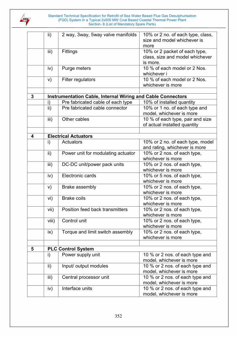
Standard Technical Specification for Retrofit of Sea Water Based Flue Gas Desulphurisation (FGD) System in a Typical 2x500 MW Coal Based Coastal Thermal Power Plant
Section- 8 (List of Mandatory Spare Parts)
352
ii) 2 way, 3way, 5way valve manifolds 10% or 2 no. of each type, class, size and model whichever is more
iii) Fittings 10% or 2 packet of each type, class, size and model whichever is more.
iv) Purge meters 10 % of each model or 2 Nos. whichever i
v) Filter regulators 10 % of each model or 2 Nos. whichever is more
3 Instrumentation Cable, Internal Wiring and Cable Connectors
i) Pre fabricated cable of each type 10% of installed quantity
ii) Pre fabricated cable connector 10% or 1 no. of each type and model, whichever is more
iii) Other cables 10 % of each type, pair and size of actual installed quantity
4 Electrical Actuators
i) Actuators 10% or 2 no. of each type, model and rating, whichever is more
ii) Power unit for modulating actuator 10% or 2 nos. of each type, whichever is more
iii) DC-DC unit/power pack units 10% or 2 nos. of each type, whichever is more
iv) Electronic cards 10% or 5 nos. of each type, whichever is more
v) Brake assembly 10% or 2 nos. of each type, whichever is more
vi) Brake coils 10% or 2 nos. of each type, whichever is more
vii) Position feed back transmitters 10% or 2 nos. of each type, whichever is more
viii) Control unit 10% or 2 nos. of each type, whichever is more
ix) Torque and limit switch assembly 10% or 2 nos. of each type, whichever is more
5 PLC Control System
i) Power supply unit 10 % or 2 nos. of each type and model, whichever is more
ii) Input/ output modules 10 % or 2 nos. of each type and model, whichever is more
iii) Central processor unit 10 % or 2 nos. of each type and model, whichever is more
iv)
Interface units 10 % or 2 nos. of each type and model, whichever is more
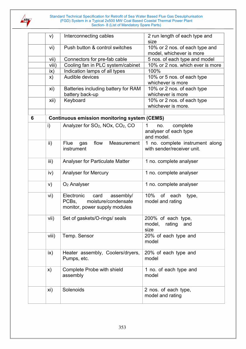
Standard Technical Specification for Retrofit of Sea Water Based Flue Gas Desulphurisation (FGD) System in a Typical 2x500 MW Coal Based Coastal Thermal Power Plant
Section- 8 (List of Mandatory Spare Parts)
353
v) Interconnecting cables 2 run length of each type and size
vi) Push button & control switches 10% or 2 nos. of each type and model, whichever is more
vii) Connectors for pre-fab cable 5 nos. of each type and model
viii) Cooling fan in PLC system/cabinet 10% or 2 nos. which ever is more
ix) Indication lamps of all types 100%
x) Audible devices 10% or 5 nos. of each type whichever is more
xi) Batteries including battery for RAM battery back-up
10% or 2 nos. of each type whichever is more
xii) Keyboard 10% or 2 nos. of each type whichever is more.
6 Continuous emission monitoring system (CEMS)
i) Analyzer for SO2, NOx, CO2, CO 1 no. complete analyser of each type and model.
ii) Flue gas flow Measurement instrument
1 no. complete instrument along with sender/receiver unit.
iii) Analyser for Particulate Matter 1 no. complete analyser
iv) Analyser for Mercury 1 no. complete analyser
v) O2 Analyser 1 no. complete analyser
vi) Electronic card assembly/ PCBs, moisture/condensate monitor, power supply modules
10% of each type, model and rating
vii) Set of gaskets/O-rings/ seals 200% of each type, model, rating and size
viii) Temp. Sensor 20% of each type and model
ix) Heater assembly, Coolers/dryers, Pumps, etc.
20% of each type and model
x) Complete Probe with shield assembly
1 no. of each type and model
xi) Solenoids 2 nos. of each type, model and rating

Standard Technical Specification for Retrofit of Sea Water Based Flue Gas Desulphurisation (FGD) System in a Typical 2x500 MW Coal Based Coastal Thermal Power Plant
Section- 8 (List of Mandatory Spare Parts)
354
xii) Filters, light source, sensor, detector, etc.
100% of each type, model and rating
xiii) Calibration gases, Calibration cell and other consumables for calibration: - of all types and ranges.
One year supply
xiv) Blower assembly 1 no. of each t e, size and Rating
xv) Analysers and associated items for other than CEMS
a) Analysers for S02, 02, pH 1 no. complete analyser of each type and model.
b) Set of gaskets/O-rings/ seals 200% of each type, model, rating and size
c) Heater assembly, Coolers/dryers, pumps
20% of each type and model
d) Filters, light source, sensor, detector, etc.
100% of each type, model and rating
e) Complete Probe with shield assembly (Not applicable for In situ- path)
1 no. of each type and model
f) Solenoids 2 nos. of each type, model and rating
g) Electronic card assembly/ PCBs, moisture/condensate monitor, power supply modules
10% of each type, model and rating
h) Calibration gases, Calibration cell and other consumables for calibration: - of all types and ranges.
One year supply
Note: i) Wherever quantity of spares have been defined in percentage, the quantity shall
be rounded off to next higher integer in case of fractions. ii) Wherever quantity of spares has been defined in ‘Set’, it shall mean the quantity of
spares to be supplied for one complete replacement for one equipment. iii) In the case of spares offered in ‘Sets’, the details of each Set giving the number of
parts in the Set shall be clearly mentioned.

Standard Technical Specification for Retrofit of Sea Water Based Flue Gas Desulphurisation (FGD) System in a Typical 2x500 MW Coal Based Coastal Thermal Power Plant
Section- 9 (Quality Assurance Plan)
355
SECTION 9.0
QUALITY ASSURANCE PLAN
9.0 QUALITY ASSURANCE PROGRAM
The testing and inspection requirements of major equipment of FGD system to be followed by the bidder over and above the respective code/ standard requirements are given hereunder:
9.1 MECHANICAL SYSTEMS 9.1.1 Flue Gas System
9.1.1.1 Booster fans
i) Rotor components shall be subjected to ultrasonic test at mill and magnetic particle examination/dye penetration examination after rough machining.
ii) Butt welds in rotor components shall be subjected to 100% UT and all welds shall be subjected to MPE or DPT after stress relieving.
iii) The rotor of fans shall be dynamically balanced to quality grade 6.3 of ISO 1940.
iv) Test for natural frequency and hardness of fan blades shall be carried out as per technical specification/ relevant standard.
v) Full range performance test shall be carried out on one fan as per BS 848, Part-1.
9.1.1.2 Thermal insulation
i) Thermal insulation
a) Pre-formed fibrous pipe insulation and LRB mattresses/ sections of
rock wool/ mineral wool from approved manufacturing sources conforming to and tested as per relevant standards shall be used.
b) For resin bonded mineral wool insulation, testing shall be carried
out as per IS: 8183. c) For resin bonded rock wool insulation, testing shall be carried out
as per IS: 9842. d) Type tests except thermal conductivity shall be regularly carried out
once in three months.
e) Type test for thermal conductivity shall be carried out by the manufacturer minimum once in six months. Thermal conductivity (K value) shall be measured in line with IS: 3346.
Standard Technical Specification for Retrofit of Sea Water Based Flue Gas Desulphurisation (FGD) System in a Typical 2x500 MW Coal Based Coastal Thermal Power Plant
Section- 9 (Quality Assurance Plan)
356
9.1.1.3 Dampers i) All the dampers shall be subjected to operational test/checks. ii) Gas tight dampers shall be subjected to shop leakage test to
demonstrate the guaranteed tightness (minimum one damper of each type and size offered).
iii) All dampers shall be checked for sealing dimensions to establish
guaranteed tightness.
9.1.1.4 Structure, Ducts, Hoppers
i) All materials shall be of tested quality and test certificates for chemical and mechanical properties as per relevant standard shall be provided. All plates above 40mm shall be 100% Ultrasonically tested.
ii) Visual inspection of all welds shall be performed in accordance with AWSDI .1.
iii) NDT requirements of structural steel welds shall be as under:
a) 100% RT/UT on butt-welds of plate thickness ≥ 32mm.
b) For plates of 25mm ≤ thickness<32mm: 10%RT and 100% MPI.
c) For plates of thickness <25mm: 10% MPI/LPI.
iv) Edge for shop and field weld shall be examined by MPI for plate thickness ≥ 32mm.
9.1.2 Gas to gas heater (GGH)
i) Forged shafts for GGH like stub shaft, main rotor forging, housing hub shall be subjected to 100% UT at mill and magnetic particle examination after machining.
ii) Critical welds of rotor post shall be subjected to radiographic examination.
iii) Trial run of GGH drive assembly (gear box+pinion+electric motor+ air motor) shall be carried out at shop.
9.1.3 Scrubber
9.1.3.1 Metal Structures
i) Only material which has been identified against mill sheet or test certificates shall be used for construction. Check testing shall be carried out in the absence of MTC. All plates above 40mm shall be 100% Ultrasonically tested.
ii) Visual inspection of all welds shall be performed in accordance with AWSDI .1.
Standard Technical Specification for Retrofit of Sea Water Based Flue Gas Desulphurisation (FGD) System in a Typical 2x500 MW Coal Based Coastal Thermal Power Plant
Section- 9 (Quality Assurance Plan)
357
iii) NDT requirements of structural steel welds shall be as under:
a) 100% RT/UT on butt-welds of plate thickness>= 32mm.
b) For plates of 25mm<=thickness<32mm-10%RT and 100% MPI.
c) For plates of thickness <25mm-10% MPI/LPI.
iv) Edge for shop and field weld shall be examined by MPI for plate thickness >= 32mm.
9.1.3.2 Spray Nozzles
i) Spray nozzles shall be tested for physical properties.
ii) Spray nozzles also shall be subjected to performance test.
9.1.3.3 Other Critical Equipment
Checks/ NDTs shall be done as per relevant Indian Standards or other applicable International Standards.
9.1.4 Sea water pumps
i) All materials shall be of tested quality and test certificates for chemical and mechanical properties as per relevant standard shall be provided.
ii) Shaft forgings and thrust bearing to be subjected to ultrasonic testing.
iii) DPT/ MPI to be done on machined shaft, impeller, castings, column
pipes, companion flanges and thrust bearing.
iv) RT to be done on impeller, column pipe discharge head assembly and
flanges.
v) Impeller and shaft to be dynamically balanced to ISO 1940 Gr.6.3.
vi) Casing shall be hydraulically tested at 150% of the shut-off head for 30 minutes. No leakage is allowed.
vii) All pumps to be performance tested as per Hydraulic Institute Standard/ Indian Standard. The performance test shall be conducted to verify output (flow) against total head, power input, efficiency and to establish the characteristic curves of the pump. The performance test shall also include check for noise, vibration level and bearing temperature rise.
Standard Technical Specification for Retrofit of Sea Water Based Flue Gas Desulphurisation (FGD) System in a Typical 2x500 MW Coal Based Coastal Thermal Power Plant
Section- 9 (Quality Assurance Plan)
358
9.1.5 Monorail and Hoists
9.1.5.1 Hooks
i) All tests including proof load test as per relevant IS shall be carried out.
ii) MPE or DPT shall be done after proof load test.
9.1.5.2 Steels castings
Steel castings shall be subjected to DPT on machined surface.
9.1.5.3 Forgings
i) All forgings (wheel, gears, pinions, axles, hooks and hook trunion) greater than or equal to 50mm diameter or thickness shall be subjected to ultrasonic testing.
ii) DPT or MPE shall be done after hard facing and machining.
9.1.5.4 Wire rope
Wire rope shall be tested as per relevant standard.
9.1.5.5 Electric hoists
All electric hoists shall be tested as per IS-3938 and chain pulley blocks shall be tested as per IS-3832.
9.1.6 Ventilation System
i) Fans
a) 20% DPT of welding on fan hub, blades, casing and impeller as applicable shall be carried out.
b) DPT of fan shafts shall be carried out after machining.
c) UT of fan shafts (diameter greater than or equal to 50mm) shall be carried out.
d) Rotating components of all fans shall be statically and dynamically balanced to ISO-1940 Gr. 6.3.
e) All centrifugal fans shall be subjected to run test as per manufacturer’s standard practice.
f) One fan of each type and size will be performance tested as per corresponding IS code for airflow, static pressure, total pressure, speed, efficiency, power consumption, noise, vibration and temperature rise.
ii) Piping, valves and fillings- Refer clause 9.1.9.4.

Standard Technical Specification for Retrofit of Sea Water Based Flue Gas Desulphurisation (FGD) System in a Typical 2x500 MW Coal Based Coastal Thermal Power Plant
Section- 9 (Quality Assurance Plan)
359
9.1.7 Packaged, split and window air conditioners
i) Compressor of packaged air conditioner (PAC) shall be tested as per relevant code/standard.
ii) PAC shall be subjected to production routine test in accordance with IS: 8148 for the following.
a) General running test.
b) Pressure or leakage test of refrigerant.
c) Insulation resistance test.
d) High voltage test.
e) Performance test on one PAC of each type/size at ambient condition to check for following:
DBT and WBT of supply and return air. Air flow Current, voltage measurement and power consumption Noise and vibration measurement
iii) Manufacturer’s standard test certificate or guarantee certificate shall be submitted for split and window air conditioners.
9.1.8 Elevators
i) The details of the checks to be carried out in the various equipment are to be submitted by the contractor for owner's approval. However, some indicative checks on different items are given below which should necessarily form part of the quality assurance plan to be agreed with the owner.
ii) All critical forgings shall be subjected to ultrasonic test to ensure free from internal defects in addition to check for chemical and mechanical properties.
iii) 10% of the welds selected at random shall be subject to DP test.
iv) All forged components shall be subjected to DPI/MPI after machining.
v) Gear Reducer shall be checked for gear ratio, backlash, contact pattern. No load shop trial run shall be conducted on gear boxes to check for oil leakage, temperature rise, noise and vibration.
vi) Buffer springs shall be subjected to load test as per relevant specifications. Material certificates for springs shall also be furnished
vii) All components prior to assembly shall be checked for dimensions.
Standard Technical Specification for Retrofit of Sea Water Based Flue Gas Desulphurisation (FGD) System in a Typical 2x500 MW Coal Based Coastal Thermal Power Plant
Section- 9 (Quality Assurance Plan)
360
viii) Car sling and car body in assembled condition shall be checked for position of all major components i.e. car sling, inside depth, width, height, positions of push box, indicator box lights, fans etc.
ix) Function test of Elevator assembly shall be carried out.
x) All electrical equipment shall be of proven quality.
xi) Galvanized components/parts shall be checked for weight of Zn coating, thickness of coating, uniformity of coating and adhesion test and visual examination as per IS 2633 and IS 2629.
9.1.9 Fire Detection & Protection System
i) Hydrant System: Shop Tests
a) Hydrant Valve:
All valves shall be hydro tested for body and seat.
Capacity test / flow check shall be done as per relevant standard.
b) Water Monitor, Hoses, Branch Pipes, Couplings and Nozzles:
All tests including hydraulic test shall be done as per relevant Indian/ International standard.
ii) High/ medium velocity water spray: shop tests
a) For Pipes, Fittings, Valves and specialties, requirements are indicated separately.
b) Deluge Valves and Spray Nozzles
All valves shall be hydro tested for body and seat.
Performance test / functional test of 'Deluge Valves' and 'Spray Nozzles' shall be carried out.
iii) Detectors: All 'Detectors' shall be tested as per relevant Indian / International Standards. Detectors shall also meet the requirements of UL / FM / LPC/VDS etc.
iv) Piping, valve and specialties
Refer clause 9.1.10.4.
v) Portable & mobile fire extinguishers
a. All fire extinguishers shall be tested as per relevant standard.

Standard Technical Specification for Retrofit of Sea Water Based Flue Gas Desulphurisation (FGD) System in a Typical 2x500 MW Coal Based Coastal Thermal Power Plant
Section- 9 (Quality Assurance Plan)
361
b. Performance / function test shall be carried out on sampling basis
as per relevant code / standard.
vi) Site tests.
a) Fire Extinguishers: A performance demonstration test at site of five (5) percent or one (1) number, whichever is higher, of each type and capacity of the extinguisher shall be carried out by the contractor. All consumables and replaceable items require for the contractor without any extra cost to employer would supply this test would be supplied by the Contractor without any extra cost to employer.
b) Piping Protection:
Thickness, Holiday by spark test, Adhesion test shall be carried out as per relevant standard.
Complete piping shall be Hydro pressure tested, at 1.5 X DP or 2 X MWP whichever is higher, before protection.
c) Welding of Pipes:
ERW Black / rolled welded:
- 100% DPT on root of butt and finish weld of butt and fillet.
- RT on 10% randomly selected joints shall be carried out (for underground piping).
9.1.10 Miscellaneous Equipment
9.1.10.1 Pressure Vessels
i) NDT on weld joint shall be as per respective code requirements or the minimum as specified below:
a) 100% DPT on root run of butt weld, nozzle welds and finished fillet welds.
b) 10% DPT on all finished butt welds.
c) 10% RT (covering all 'T'/cross joints) of butt welds.
ii) Butt welds of dished ends shall be stress relieved and subjected to 100%
RT.
iii) Each finished vessels shall be hydraulically tested to 150% of the design pressure for a duration of 30 minutes.
9.1.10.2 Tanks
i) All materials shall be of tested quality and test certificates for chemical and mechanical properties as per relevant standard shall be provided.
ii) Plates above 40 mm thickness shall be subject to 100% ultrasonic testing.

Standard Technical Specification for Retrofit of Sea Water Based Flue Gas Desulphurisation (FGD) System in a Typical 2x500 MW Coal Based Coastal Thermal Power Plant
Section- 9 (Quality Assurance Plan)
362
iii) Welding
a) Root run of butt welds shall be examined by 100% DPT or MPE. b) Butt welds, full penetration joints and nozzle welds shall be checked
by 100% RT and 100% MPE or DPT. c) Fillet welds shall be checked by 100% MPE or DPT.
iv) Rubber lining shall be subject to hardness and spark test, as applicable.
v) Visual check and dimensional measurement shall be carried out on the completed equipment.
vi) The fabricated tank shall be subject to water fill test to check for the leakage.
9.1.10.3 GRP/GRE Piping for Sea Water
9.1.10.3.1 The testing and quality inspection for GRP/ GRE pipe and piping materials
shall be carried at manufacturer’s works as per the approved quality assurance plan. The tests to be carried out, as a minimum, shall cover the following:
a) Raw materials
Raw materials for use in pipes covered in this specification shall be sampled and tested by the manufacturer prior to their use to ensure that they comply with the requirement of ASTM D 3517. The glass content in the GRP/GRE material used shall be determined in accordance with ASTM D2584 using ignition loss method.
b) Pipe stiffness
Samples of pipe shall be tested for compliance with the pipe stiffness in accordance with ASTM D2412, with the stiffness value rated at 3% deflection.
c) Load capacity (hoop and axial)
Tests will be performed in accordance with AWWA C950 and ASTM D3517 to check the load capacity (or strength) in both the hoop and axial directions.
d) Barcol hardness test
Barcol hardness tests will be conducted in accordance with ASTM D 2583. Pipes failing to reach the required level of cure will be rejected.
Standard Technical Specification for Retrofit of Sea Water Based Flue Gas Desulphurisation (FGD) System in a Typical 2x500 MW Coal Based Coastal Thermal Power Plant
Section- 9 (Quality Assurance Plan)
363
e) Critical dimensions
The pipes shall be measured for compliance with critical dimensions as specified in ASTM standards including diameter, thickness, end squareness and length. Measurements shall be made in accordance with ASTM D3567. Wall thickness should be measured as per ASTM D3567 once per every production lot.
f) Visual acceptance
Visual Inspection and classification of defects shall be carried out according to ASTM D2563 level III. The pipe should be free from all defects, including delamination, bubbles, pinholes, cracks, pits, blisters, foreign inclusions, and resin-starved areas. The pipe should be as uniform as commercially practicable in color, opacity, density and other physical properties.
9.1.10.3.2 Field Hydro Testing
a) Hydrostatic test of the GRP/ GRE pipe for the entire length or
on a segment of it shall be carried out to verify the hydraulic
sealing of the system at the testing pressure and its structural integrity.
b) The hydro testing of the piping system shall be carried out
before encasing or closing the trench covers. Permanent
flanged spool pieces should be provided at the start and end
point of the pipe to facilitate blinding of the line for hydro testing.
The joints should be visible in order to allow for the inspection, unless otherwise stated by Owner & their representative.
c) Hydrostatic testing shall be carried out at 1.5 times the design
pressure for a duration of minimum 2 hours after stabilization of
the test pressure. The contractor shall submit the detailed plan
indicating the methodology for hydro testing, blinding the ends,
air venting, supply of sea water, pressurizing and draining. The test procedure shall be subject to purchase’s approval.
d) The hydraulic testing shall be considered acceptable, if at the end of the 2 hours of testing, the following parameters are met:
During the period of the hydraulic test, the pressure stays stable.
No leakages are noticed in any point of the pipeline, or in the joints, or in the testing equipment.

Standard Technical Specification for Retrofit of Sea Water Based Flue Gas Desulphurisation (FGD) System in a Typical 2x500 MW Coal Based Coastal Thermal Power Plant
Section- 9 (Quality Assurance Plan)
364
e) In case of failure of the test, the reason for leakage shall be
examined. Any pipes found defective or leaking (except at the
butt joints) shall be replaced with a new one. Repair or patch
work on pipes shall not be acceptable. The pipeline shall then be tested again according to the approved test procedure.
9.1.10.4 Low Pressure Piping, Valves and Fittings etc. 9.1.10.4.1 Pipes, fittings
i) Tests shall be carried out on the materials on various components to establish their mechanical properties and chemical composition. Further, heat treatment shall be carried out for materials as required.
ii) Dye penetration test of welds of pipes and fittings (including welds of
rolled and welded pipes) shall be carried out. iii) All pipes and fittings shall be tested as per applicable codes/ standards
at manufacturer’s works.
9.1.10.4.2 Valves
i) Tests shall be carried out on the materials on various components to establish their mechanical properties and chemical composition. Further, heat treatment shall be carried out for materials as required.
ii) Shaft/ spindle of size ≥ 50 mm diameter shall be subjected to ultrasonic
test. iii) Machined surfaces of casing, disc and shaft shall be subjected to 100%
MPI or DPT as applicable.
iv) All valves shall be hydraulically tested for body, seat and back seat (wherever provided) at 1.5 times the maximum pressure to which respective valves can be subjected during plant operation. Valves shall be offered for hydro test in unpainted condition. Check valves shall also be tested for leak tightness test at 25% of the specified seat test pressure. For rubber lined valves, hydraulic test shall be carried out before rubber lining.
v) For butterfly valves, hydraulic test, seat and disc string test and proof of
design test (if not carried out earlier) shall be carried out in accordance with latest edition of AWWA-C-504 standard.
vi) Visual and dimensional check shall be carried out for all valves as per
relevant code/ approved drawing.
vii) Functional/ operational checks for and check for smooth opening and closing of the valves shall be carried out.

Standard Technical Specification for Retrofit of Sea Water Based Flue Gas Desulphurisation (FGD) System in a Typical 2x500 MW Coal Based Coastal Thermal Power Plant
Section- 9 (Quality Assurance Plan)
365
viii) Anti-corrosive protection shall be tested as per applicable code.
ix) Gate, globe and swing check valves a) Machined surfaces of castings and butt welds shall be subjected to
MPE or DPT. b) Blue matching, wear travel for gates, valves, pneumatic seat
leakage, reduced pressure test for check valves shall be done as per relevant standard.
x) Diaphragm valves a) Seat leakage test for actuator operated valves, shall be done with
by closing the valves with actuator. b) Tests on rubber parts per batch of rubber mix such as hardness,
adhesion, spark test, bleed test and flex test on diaphragm, type test for diaphragm for 50,000 cycles.
xi) Cast butterfly valves a) Machined surfaces of casing, disc and shaft shall be subjected to
MPE or DPT. b) Hydraulic test of body, seat and disc-strength shall be carried out
in accordance with governing design standard. Actuator operated valves shall be checked for seat leakage by closing the valves with actuator. Seat leakage test shall be carried out in both directions.
xii) Fabricated butterfly valves:
a) UT as per ASTM A-435 shall be carried out on plate material for
body and disc for plate thickness 25mm and above.
b) Machined surfaces of casing, disc and shaft shall be subjected to MPE or DPT.
c) Butt welds of thickness above 30mm on body and disc shall be
subject to 100% RT along with and post weld heat treatment for stress relieving.
d) Hydraulic test of body, seat and disc-strength shall be carried out
in accordance with governing design standard. Actuator operated
Standard Technical Specification for Retrofit of Sea Water Based Flue Gas Desulphurisation (FGD) System in a Typical 2x500 MW Coal Based Coastal Thermal Power Plant
Section- 9 (Quality Assurance Plan)
366
valves shall be checked for seat leakage by closing the valves with actuator. Seat leakage test shall be carried out in both directions.
xiii) Dual plate check valves: a) Dry cycle test (spring cycle test) for one lakh cycles shall be carried
out as a type test. If dry cycle test has been carried out earlier for same material & diameter, test report shall be submitted for review of the purchaser.
b) Machined surfaces of casing, disc and shaft shall be subjected to MPE or
DPT.
9.1.10.4.3 Rubber lining of pipes and valves i) For rubber lining, the following tests shall be carried out as per IS-4682
part-I or acceptable equivalent standard:
a) Adhesion test
b) Measurement of thickness
c) Shore hardness test
d) Visual examination and spark test at 5 kV/mm of thickness
e) The report of bleeding resistance test and ozone resistance test carried out on rubber material shall be furnished.
ii) Dimensional check shall be carried out as per relevant code/ approved
drawing. 9.1.10.4.4 Coating and wrapping of pipes
Spark test, adhesion test and material test for primer and enameled and coal tar tapes, as applicable, shall be carried out as per AWWA-C-203-91/ IS-10221/ IS 15337 as applicable.
9.1.10.4.5 Rubber expansion joints
i) Rubber compound test slab after valcanising shall be tested for tensile strength, elongation and shore hardness. Tests on rubber compound shall also include hydro stability test as per ASTM D-3137 and ozone resistance test as per ASTM D- 380.
ii) Fabric strength of synthetic fibre for reinforcement shall be checked, and test for rubber to fabric adhesion as per IS: 3400 or ASTM D- 413, rubber to metal adhesion as per IS 3100 or ASTM D-429 shall be carried out.
iii) All expansion joints in assembled condition shall be subjected to vacuum test at 730 mm Hg under conditions to ensure its suitability to withstand

Standard Technical Specification for Retrofit of Sea Water Based Flue Gas Desulphurisation (FGD) System in a Typical 2x500 MW Coal Based Coastal Thermal Power Plant
Section- 9 (Quality Assurance Plan)
367
deflection in each axial transverse and longitudinal direction. Duration of test shall be of minimum 10 minutes.
iv) All bare bellows shall be subjected to hydraulic pressure test in normal condition at twice the design pressure for a duration of 30 minutes. Additionally, all bare bellows shall be subjected to deflection tests under pressure, pressure being raised from zero to the design value in regular steps and deflection measured at each step.
v) All expansion joints in assembled condition along with control rod assembly shall be subjected to deflection test under design pressure.
vi) Either during the hydraulic test or during the vacuum test, change in circumference at the top position of the arch shall not exceed 1.5% of measured circumference at normal position.
vii) Twenty four (24) hours after the above tests, the permanent set (variation in dimensions with respect to its original dimension) shall be measured and recorded. The permanent set shall not be more than 0.5%.
viii) Life cycle test and burst test shall be carried out on bellows of each type, design and size.
9.1.10.5 Horizontal centrifugal pumps
i) Tests shall be carried out on the materials of the pumps to establish their properties, and chemical compositions.
ii) 100% DPT or MPE shall be carried out for the rotor and machined surfaces of casing and impellers.
iii) UT on pump shaft (diameter greater than or equal to 50mm), MPI or DPT on pump shaft and impeller after machining shall be carried out.
iv) All rotating components of the pumps shall be statically and dynamically balanced to ISO-1940 Gr. 6.3.
v) Assembly fit up check, and dimensional check shall be carried out for the completed pump assembly.
vi) Pump casings shall be subject to hydraulic test at 1.5 times the shut off pressure for a minimum duration of 30 minutes.
vii) All pumps to be performance tested as per Hydraulic Institute Standard/ Indian Standard. The performance test shall be conducted to verify output (flow) against total head, power input, efficiency and to establish the characteristic curves of the pump. The performance test shall also include check for noise, vibration level and bearing temperature rise.
viii) Pumps shall be subjected to strip down examination visually to check for mechanical damages after testing at shop in case abnormal noise level and/or excessive vibration are observed during the shop test.

Standard Technical Specification for Retrofit of Sea Water Based Flue Gas Desulphurisation (FGD) System in a Typical 2x500 MW Coal Based Coastal Thermal Power Plant
Section- 9 (Quality Assurance Plan)
368
9.1.10.6 Vertical pumps
i) All materials should be of tested quality and test certificates to be provided.
ii) Shaft forgings to be subjected to ultrasonic testing.
iii) DPT to be done on machined shaft and impeller.
iv) Impellers to be dynamically balanced to ISO 1940 Gr.6.3.
v) All pressure parts shall be hydraulically tested at 150% of the shut-off head for 30 minutes. No leakage is allowed.
vi) All pumps to be performance tested as per Hydraulic Institute Standard/ Indian Standard. The performance test shall be conducted to verify output (flow) against total head, power input, efficiency and to establish the characteristic curves of the pump. The performance test shall also include check for noise, vibration level and bearing temperature rise.
9.1.10.7 Blowers
i) Tests shall be carried out on the materials of the rotary blowers/ compressors to establish their properties, and chemical compositions.
ii) 100% DPT or MPE shall be carried out for the rotor and machined surfaces of casing and impellers.
iii) The shaft and impellers shall be dynamically balanced.
iv) Assembly fit up check, and dimensional check shall be carried out for the completed blower assembly.
v) The casing shall be subject to hydraulic test at 1.5 times the shut off design pressure.
vi) The blowers shall be performance tested as per relevant code/ standard.
9.1.10.8 Air Compressors
i) All pressure parts shall be hydraulically tested at not less than 150% of design pressure for a duration of 30 minutes prior to painting.
ii) All other parts including inter-connecting piping shall be hydraulically tested wherever possible, as per relevant codes.
iii) Ultrasonic testing shall be carried out on all forgings and rotor for dia 50mm and above. MPI/DPT shall be done on machined area of the components.
iv) During assembly all clearances and alignments shall also be checked
and recorded.
v) Rotor shall be statically and dynamically balanced.

Standard Technical Specification for Retrofit of Sea Water Based Flue Gas Desulphurisation (FGD) System in a Typical 2x500 MW Coal Based Coastal Thermal Power Plant
Section- 9 (Quality Assurance Plan)
369
vi) Performance test on the compressor shall be carried out in accordance
with ISO: 1217/Eq. The test shall also include demonstration of loading
and unloading mechanism (Capacity control) and operation of safety
valve. Power consumption at motor input terminal at rated capacity as
well as at fully unloaded condition of all the compressor shall be
measured.
vii) Vibration and Noise level measurement shall be done during shop
performance test.
viii) Air Receiver
a) Each finished vessel shall be hydraulically tested at 150% of the design pressure for a duration of 30 minutes
b) NDT on weld joints shall be as per respective code requirements or the minimum as specified below: 100% DPT on root run of butt welds 100% DPT on all finished butt welds and fillet welds 10% RT on butt welds which shall include all T-Joints
9.1.10.9 Hangers and Supports
i) All raw materials used shall have co-related mill test certificate meeting mandatory checks of material specification.
ii) Completed springs shall be tested for sagging test and load versus
deflection test. For diameter more than 25mm, MPE shall also be carried out.
iii) Butt welds of thickness 32mm and above shall be tested for UT, and for
butt welds of thickness less than 32mm MPE shall be done. Fillet welds shall be tested for MPE.
iii) Dampers with viscous fluids shall be checked for viscosity of liquid used,
damping resistance of the damper, stiffness of the damper etc.
iv) Turn-buckle, pipe clamps and hangers of thickness greater than 25mm shall be checked by MPE or DPT on bent portions.
v) One assembled hanger of each type and size in each lot shall be checked for variation in deflection and travel versus load test.
9.1.10.10 EOT Crane, Semi Gantry Crane and Hoists
i) Hooks
a) All tests including proof load test as per relevant IS/BS/DIN shall be carried out.
b) MPI/DPT shall be carried out after proof load test.

Standard Technical Specification for Retrofit of Sea Water Based Flue Gas Desulphurisation (FGD) System in a Typical 2x500 MW Coal Based Coastal Thermal Power Plant
Section- 9 (Quality Assurance Plan)
370
ii) Steel casting
DPT on machined surface shall be carried out.
iii) Girders, end carriage, crab, gear box and rope drum
a) The plates of thickness 25mm and above shall be ultrasonically tested.
b) NDT requirements on weldments shall be as follows:
Butt welds in tension:-100% RT and 100% DPT
Butt welds in compression:-10% RT and 100% DPT
Butt welds in rope drum:-100% RT an 100% DPT
Fillet welds:- 10% DPT
iv) Forging (wheel, gears, pinions, axle, hooks & hook trunion)
a) All forgings greater than or equal to 50 mm diameter or thickness shall be subjected to ultrasonic testing.
b) DPT/MPI shall be done after hardfacing and machined surfaces.
v) Wire rope shall be tested as per relevant standard.
vi) Reduction gears shall be tested for reduction ratio, backlash & contact pattern. Gear box shall be subjected to no-load run test to check for oil leakage, temperature rise, noise and vibration.
vii) The cranes shall be completely assembled at shop for final testing. All tests for dimension, deflection, load, overload, hoisting motion, cross travel etc. As per IS-3177 shall be carried out at shop.
viii) All electric hoists shall be tested as per IS-3938 and chain pulley blocks shall be tested as per IS-3832.
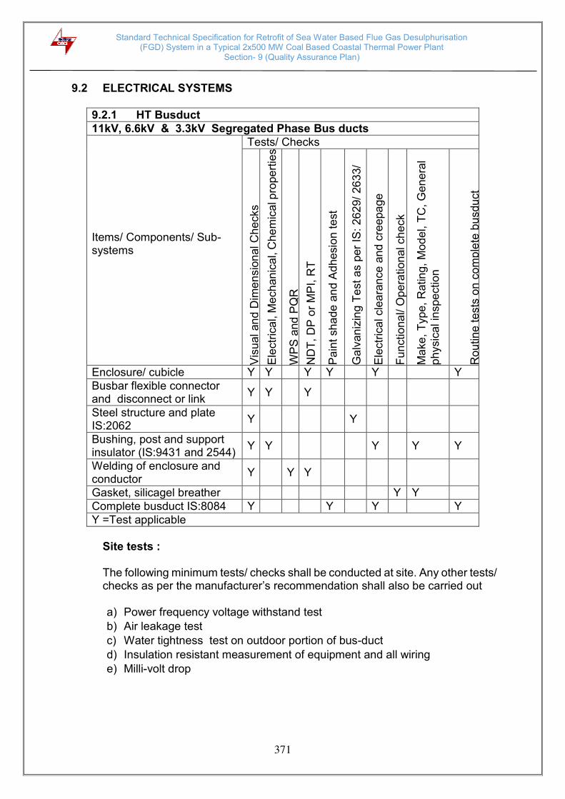
Standard Technical Specification for Retrofit of Sea Water Based Flue Gas Desulphurisation (FGD) System in a Typical 2x500 MW Coal Based Coastal Thermal Power Plant
Section- 9 (Quality Assurance Plan)
371
9.2 ELECTRICAL SYSTEMS
9.2.1 HT Busduct
11kV, 6.6kV & 3.3kV Segregated Phase Bus ducts
Items/ Components/ Sub-systems
Tests/ Checks
Vis
ua
l an
d D
ime
nsio
nal C
he
cks
Ele
ctr
ica
l, M
ech
an
ical, C
he
mic
al p
rope
rtie
s
WP
S a
nd
PQ
R
ND
T, D
P o
r M
PI,
RT
Pa
int
sha
de
an
d A
dhesio
n t
est
Ga
lvan
izin
g T
est a
s p
er
IS:
26
29/
26
33/
67
45
Ele
ctr
ica
l cle
ara
nce
and
cre
epa
ge
Fu
nctio
na
l/ O
pe
ration
al ch
eck
Ma
ke
, T
ype
, R
atin
g,
Mo
de
l, T
C, G
ene
ral
ph
ysic
al in
spe
ction
Rou
tin
e t
ests
on c
om
ple
te b
usdu
ct
Enclosure/ cubicle Y Y Y Y Y Y Busbar flexible connector and disconnect or link
Y Y Y
Steel structure and plate IS:2062
Y Y
Bushing, post and support insulator (IS:9431 and 2544)
Y Y Y Y Y
Welding of enclosure and conductor
Y Y Y
Gasket, silicagel breather Y Y Complete busduct IS:8084 Y Y Y Y Y =Test applicable
Site tests :
The following minimum tests/ checks shall be conducted at site. Any other tests/ checks as per the manufacturer’s recommendation shall also be carried out
a) Power frequency voltage withstand test
b) Air leakage test
c) Water tightness test on outdoor portion of bus-duct
d) Insulation resistant measurement of equipment and all wiring
e) Milli-volt drop
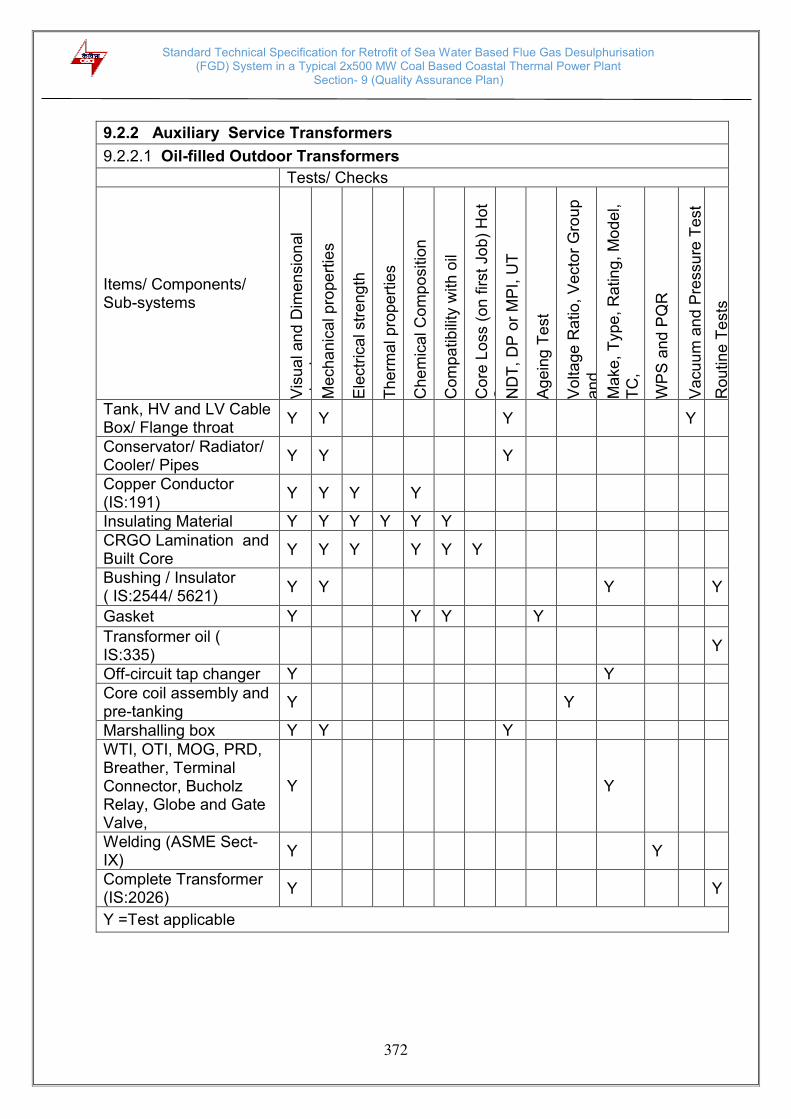
Standard Technical Specification for Retrofit of Sea Water Based Flue Gas Desulphurisation (FGD) System in a Typical 2x500 MW Coal Based Coastal Thermal Power Plant
Section- 9 (Quality Assurance Plan)
372
9.2.2 Auxiliary Service Transformers
9.2.2.1 Oil-filled Outdoor Transformers
Tests/ Checks
Items/ Components/ Sub-systems
Vis
ua
l an
d D
ime
nsio
nal
ch
ecks
Me
ch
an
ical p
rope
rtie
s
Ele
ctr
ica
l str
eng
th
Th
erm
al p
rope
rtie
s
Ch
em
ical C
om
po
sitio
n
Co
mpa
tib
ility
with
oil
Co
re L
oss (
on
first
Job)
Ho
t S
po
t N
DT
, D
P o
r M
PI,
UT
Ag
ein
g T
est
Vo
lta
ge
Ra
tio,
Ve
cto
r G
rou
p
an
d
Ma
ke
, T
ype
, R
atin
g,
Mo
de
l,
TC
, G
en
era
l ph
ysic
al I
nspectio
n.
WP
S a
nd
PQ
R
Va
cu
um
an
d P
ressu
re T
est
Ro
utin
e T
ests
Tank, HV and LV Cable Box/ Flange throat
Y Y Y Y
Conservator/ Radiator/ Cooler/ Pipes
Y Y Y
Copper Conductor (IS:191)
Y Y Y Y
Insulating Material Y Y Y Y Y Y CRGO Lamination and Built Core
Y Y Y Y Y Y
Bushing / Insulator ( IS:2544/ 5621)
Y Y Y Y
Gasket Y Y Y Y
Transformer oil ( IS:335)
Y
Off-circuit tap changer Y Y Core coil assembly and pre-tanking
Y Y
Marshalling box Y Y Y WTI, OTI, MOG, PRD, Breather, Terminal Connector, Bucholz Relay, Globe and Gate Valve,
Y Y
Welding (ASME Sect-IX)
Y Y
Complete Transformer (IS:2026)
Y Y
Y =Test applicable

Standard Technical Specification for Retrofit of Sea Water Based Flue Gas Desulphurisation (FGD) System in a Typical 2x500 MW Coal Based Coastal Thermal Power Plant
Section- 9 (Quality Assurance Plan)
373
9.2.2.2 Dry Type Indoor Transformers
Items/ Components/ Sub-systems
Tests/ Checks
Vis
ua
l an
d d
ime
nsio
nal ch
eck
Me
ch
an
ical p
rope
rtie
s
Ele
ctr
ica
l str
eng
th
Th
erm
al p
rope
rtie
s
Che
mic
al p
rope
rtie
s
Core
lo
ss (
on
first jo
b),
Ho
t
ND
T, D
P o
r M
PI
Vo
lta
ge
ra
tio,
ve
cto
r g
rou
p a
nd
p
ola
rity
M
ake
, T
ype
, R
atin
g,
Mo
de
l,
TC
, W
PS
and
PQ
R
Me
asu
rem
ent
of ca
pa
cita
nce
a
nd
tan
de
lta b
etw
ee
n w
indin
g
Rou
tin
e t
ests
Enclosure door, HV and LV Cable box/ Flange throat
Y Y Y
Copper conductor Y Y Y Y Insulating material Y Y Y CRGO lamination and built core
Y Y
Bushing/ Insulator ( IS:2544/ 5621)
Y Y Y
Gasket Y Y Y Off-circuit tap changer Y Y Core coil assembly Y Y Marshalling box Y WTI, Thermister, Terminal connector
Y Y
Welding Y Complete transformer (IS:11171)
Y Y Y
Y =Test applicable Site tests :
The following minimum tests/ checks shall be conducted at site. Any other tests/ checks as per the manufacturer’s recommendation shall also be carried out a) Dry out test b) Resistance measurement of windings c) Ratio test d) Vector group test e) Tap changer test f) Buchholz relay test g) Low oil level alarm. h) Temperature indicators i) Marshalling kiosk j) Protective relays
k) Magnetizing current

Standard Technical Specification for Retrofit of Sea Water Based Flue Gas Desulphurisation (FGD) System in a Typical 2x500 MW Coal Based Coastal Thermal Power Plant
Section- 9 (Quality Assurance Plan)
374
9.2.3 Motors
Item/ Components/ Sub-system
Tests/ Checks
Vis
ua
l
Dim
en
sio
na
l
Ma
ke
,Typ
e,R
atin
g,T
C,G
en
era
l p
hysic
al
Me
ch
an
ical,
Ch
em
ical p
rop
ert
ies
ND
T, D
P o
r M
PI,
UT
Me
tallo
gra
ph
y
Ele
ctr
ica
l ch
ara
cte
ristics
We
ldin
g/
Bra
zin
g (
WP
S/
PQ
R)
Hea
t tr
ea
tme
nt
Ma
gn
etic c
ha
racte
ristics
Hydra
ulic
, L
ea
k,
Pre
ssu
re t
est
Th
erm
al ch
ara
cte
ristics
Run
ou
t
Dyna
mic
ba
lan
cin
g
All
tests
as
pe
r IS
:32
5/ IS
:47
22/
IS:9
28
3
Vib
ratio
n
Ove
r sp
ee
d
Ta
n d
elta
, sh
aft v
olta
ge
and
po
larisa
tio
n
ind
ex te
st
Pa
int
shad
e,th
ickne
ss
& a
dh
esio
n
Plates for stator frame, end shield, spider etc.
Y Y Y Y Y Y
Shaft Y Y Y Y Y Y Y
Magnetic material Y Y Y Y Y Y Y
Rotor copper/ Aluminium
Y Y Y Y Y Y
Stator copper Y Y Y Y Y Y Y
SC ring Y Y Y Y Y Y Y Y
Insulating material Y Y Y Y Y
Tubes for cooler Y Y Y Y Y Y Y
Sleeve bearing Y Y Y Y Y Y Y
Stator, Rotor,Exciter coils
Y Y Y Y Y
Castings, stator frame, terminal box and bearing housing etc.
Y Y Y Y Y Y
Fabrication and machining of stator, rotor, terminal box
Y Y Y Y Y
Wound stator Y Y Y Y Rotor complete Y Y Y Y Y

Standard Technical Specification for Retrofit of Sea Water Based Flue Gas Desulphurisation (FGD) System in a Typical 2x500 MW Coal Based Coastal Thermal Power Plant
Section- 9 (Quality Assurance Plan)
375
Site Tests : The following minimum tests/ checks shall be conducted at site. Any other tests/ checks as per the manufacturer’s recommendation shall also be carried out. i) Measurement of vibration.
ii) Measurement of insulation resistance and polarization index
iii) Measurement of full load current.
iv) Test running of the motors, checking the temperature rise and identifying the hot spot etc.
.
Exciter,Stator, Rotor, Terminal Box assembly
Y Y Y
Accessories, RTD, BTD,CT, Brushes, Diodes, space heater, antifriction bearing, cable glands, lugs, gaskets etc.
Y Y Y
Complete motor (IS: 325/ IS:4722/ IS:9283)
Y Y Y Y Y Y Y1 Y
Y =Test applicable, Y1 = for 11kV and 3.3kV motors only Note
This is an indicative list of tests/ checks. The manufacture is to furnish the detailed Quality Plan indicating the practices and procedure followed along with relevant supporting documents during QP finalization. However, QP approval is not envisaged for 415V motors upto 50 kW.

Standard Technical Specification for Retrofit of Sea Water Based Flue Gas Desulphurisation (FGD) System in a Typical 2x500 MW Coal Based Coastal Thermal Power Plant
Section- 9 (Quality Assurance Plan)
376
9.2.4 11kV, 6.6kV and 3.3kV Switchgear (Table 1/2)
Items/ Components/ Sub-systems
Tests/ Checks
Ma
ke
, T
ype
, M
ode
l,
Ra
tin
g a
nd T
C
Ele
ctr
ica
l P
rope
rtie
s
Me
ch
an
ical p
rope
rtie
s
Che
mic
al p
rope
rtie
s
Dim
en
sio
ns a
nd
Fin
ish
Fu
nctio
na
l an
d o
pe
ratio
na
l fe
atu
res
Ite
m t
o c
on
form
to
re
leva
nt
Sta
nd
ard
s
Pre
tre
atm
en
t a
s p
er
IS 6
005
Pa
int
sha
de
, th
ickne
ss,
adh
esio
n a
nd
fin
ish
Fu
nctio
na
l C
he
cks
HV
a
nd
IR
Te
st
Deg
ree
of
Pro
tection
- R
ou
tin
e t
est
CB
Op
era
tio
n tim
ing
ch
eck
All
Ro
utin
e T
ests
as p
er
rele
va
nt
sta
nda
rds
Aluminum busbar material (IS: 5082)
Y Y Y Y Y Y
Copper busbar material (IS :613 )
Y Y Y Y Y Y
Bus bar support insulation (IS:9431)
Y Y Y Y Y Y
HT Circuit Breaker (IEC:56 )
Y Y Y Y Y Y Y
HT Contactors ( IS:9046 ) Y Y Y Y Y Y Protection and auxiliary relays (IS:3231/ 8686 )
Y Y Y Y Y Y
HT CT’s and PT’s (IS:2705/ 3156)
Y Y Y Y
HT Fuses ( IS:9385 ) Y Y Y Y Surge arrester ( IEC:99-4 ) Y Y Y Y LT Contactors ( IS:13947) Y Y Y Y Y Control and selector switches (IS:6875)
Y Y Y Y Y
Indicating meters (IS:1248) Y Y Y Y Y Y Indicating lamps (IS:13947) Y Y Y Y Y Push buttons (IS: 4794) Y Y Y Y Y Control transformer ( IS:12021 )
Y Y Y Y Y
LT fuses (IS:13703) Y Y Y Y Energy meters (IS:722 ) Y Y Y Y Y Transducers (IEC:60688) Y Y Y Y Y Y =Test applicable
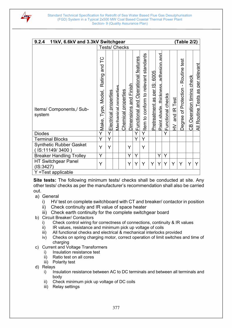
Standard Technical Specification for Retrofit of Sea Water Based Flue Gas Desulphurisation (FGD) System in a Typical 2x500 MW Coal Based Coastal Thermal Power Plant
Section- 9 (Quality Assurance Plan)
377
Site tests: The following minimum tests/ checks shall be conducted at site. Any other tests/ checks as per the manufacturer’s recommendation shall also be carried out. a) General
i) HV test on complete switchboard with CT and breaker/ contactor in position ii) Check continuity and IR value of space heater iii) Check earth continuity for the complete switchgear board
b) Circuit Breaker/ Contactors i) Check control wiring for correctness of connections, continuity & IR values ii) IR values, resistance and minimum pick up voltage of coils iii) All functional checks and electrical & mechanical interlocks provided iv) Checks on spring charging motor, correct operation of limit switches and time of
charging c) Current and Voltage Transformers
i) Insulation resistance test ii) Ratio test on all cores iii) Polarity test
d) Relays i) Insulation resistance between AC to DC terminals and between all terminals and
body ii) Check minimum pick up voltage of DC coils iii) Relay settings
9.2.4 11kV, 6.6kV and 3.3kV Switchgear (Table 2/2)
Items/ Components,/ Sub-system
Tests/ Checks
Ma
ke
, T
ype
, M
ode
l,
Ra
tin
g a
nd T
C
Ele
ctr
ica
l p
rope
rtie
s
Me
ch
an
ical p
rope
rtie
s
Che
mic
al p
rope
rtie
s
Dim
en
sio
ns a
nd
Fin
ish
Fu
nctio
na
l an
d O
pe
ratio
na
l fe
atu
res
Ite
m t
o c
on
form
to
re
leva
nt
sta
nd
ard
s
Pre
tre
atm
en
t a
s p
er
IS:
600
5
Pa
int
sha
de
, th
ickne
ss,
adh
esio
n a
nd
Fu
nctio
na
l che
cks
HV
a
nd
IR
Te
st
Deg
ree
of
Pro
tection
- R
ou
tin
e t
est
CB
Op
era
tio
n tim
ing
ch
eck
All
Ro
utin
e T
ests
as p
er
rele
va
nt
Diodes Y Y Y Y Y Terminal Blocks Y Y Y Y Synthetic Rubber Gasket ( IS:11149/ 3400 )
Y Y Y Y
Breaker Handling Trolley Y Y Y Y Y HT Switchgear Panel (IS:3427)
Y Y Y Y Y Y Y Y Y Y Y
Y =Test applicable

Standard Technical Specification for Retrofit of Sea Water Based Flue Gas Desulphurisation (FGD) System in a Typical 2x500 MW Coal Based Coastal Thermal Power Plant
Section- 9 (Quality Assurance Plan)
378
9.2.5 415V Switchgear and Busduct
9.2.5.1 415V Switchgear (Table 1/2) (MCC, PCC, ACDB, DCDB, Local push button station, Local motor starters)
Items/ Components/ Sub-system
Tests/ Checks
Ma
ke
, M
ode
l, T
ype
, R
atin
g a
nd T
C
Dim
en
sio
ns a
nd
Fin
ish
Ele
ctr
ica
l p
rope
rtie
s
Me
ch
an
ical p
rope
rtie
s
Che
mic
al p
rope
rtie
s
Fu
nctio
na
l an
d O
pe
ratio
na
l fe
atu
res
Ite
m t
o c
on
form
to
re
leva
nt
sta
nd
ard
s
Pre
tre
atm
en
t a
s p
er
IS 6
005
Pa
int
sha
de
, a
dhe
sio
n, th
ickne
ss
and
fin
ish
Fu
nctio
na
l che
cks
Mill
i-vo
lt d
rop
Te
st
IR –
HV
– I
R T
est
Deg
ree
of
pro
tection
Ro
utine
te
st
All
Ro
utin
e t
ests
as p
er
rele
va
nt
Sheet steel (IS:513) Y Y Y Y Y
Aluminum bus bar material (IS:5082)
Y Y Y Y Y Y
Copper bus bar material (IS:613)
Y Y Y Y Y Y
Support insulator (IS:943, IS:10912, IEC: 660 )
Y Y Y Y Y
Air circuit breaker (IS:13947)
Y Y Y Y Y Y Y
Energy meters ( IS:722 ) Y Y Y Y Y Y Power and auxiliary contactor (IS:13947)
Y Y Y Y Y
Protection and auxiliary relays (IS:3231)
Y Y Y Y Y Y
Control and selector switches (IS:6875)
Y Y Y Y Y
CT and VT (IS 2705/ 3156)
Y Y Y Y
MCCB ( IS:13947 ) Y Y Y Y Indicating meters (IS:1248) Y Y Y Y Y Y Indicating lamps (IS:13947) Y Y Y Y Y Air break switches ( IS:13947 )
Y Y Y Y Y
Control terminal blocks Y Y Y Y Y =Test applicable

Standard Technical Specification for Retrofit of Sea Water Based Flue Gas Desulphurisation (FGD) System in a Typical 2x500 MW Coal Based Coastal Thermal Power Plant
Section- 9 (Quality Assurance Plan)
379
9.2.5.1 415V Switchgear (Table 2/2) (MCC, PCC, ACDB, DCDB, Local push button station, Local motor
starters)
Items/ Components/ Sub-system
Tests/ Checks
Ma
ke
, M
ode
l, T
ype
, R
atin
g a
nd T
C
Dim
en
sio
ns a
nd
Fin
ish
Ele
ctr
ica
l p
rope
rtie
s
Me
ch
an
ical p
rope
rtie
s
Che
mic
al p
rope
rtie
s
Fu
nctio
na
l an
d O
pe
ratio
na
l F
ea
ture
s
Ite
m t
o c
on
form
to
re
leva
nt
sta
nd
ard
s
Pre
tre
atm
en
t a
s p
er
IS:
600
5
Pa
int S
had
e, A
dh
esio
n,
Th
ickne
ss a
nd
F
inis
h
Fu
nctio
na
l che
cks
Mill
i-vo
lt d
rop
Te
st
IR –
HV
– I
R T
est
Deg
ree
of
Pro
tection
- R
ou
tin
e t
est
All
Ro
utin
e t
ests
as p
er
rele
va
nt
sta
nda
rds a
nd
Fuse (IS:13703) Y Y Y Y Y Control transformer (IS:12021)
Y Y Y Y Y Y
Push Buttons (IS:4794)
Y Y Y Y Y
Transducer (IEC:60688)
Y Y Y Y Y Y
MCB (IS:8828) Y Y Y Y Y
Breaker handling trolley
Y Y Y Y Y Y
Synthetic rubber gasket (IS:11149)
Y Y Y Y Y
415V Switchgear (IS:8623 )
Y Y Y Y Y Y Y Y Y Y Y
Y =Test applicable

Standard Technical Specification for Retrofit of Sea Water Based Flue Gas Desulphurisation (FGD) System in a Typical 2x500 MW Coal Based Coastal Thermal Power Plant
Section- 9 (Quality Assurance Plan)
380
9.2.5.2 415V Busduct
Items/ Components
Tests/ Checks
Dim
en
sio
n a
nd
su
rfa
ce f
inis
h
Ma
ke
, T
yp
e,
Ratin
g a
nd
Te
st
ce
rtific
ate
Ele
ctr
ica
l p
rope
rtie
s
Me
ch
an
ical p
rope
rtie
s
Che
mic
al p
rope
rtie
s
Ite
m t
o c
on
form
to
re
leva
nt
IS
WP
S a
pp
rova
l, W
eld
er
qu
alif
icatio
n
We
ld q
ua
lity c
he
ck (
DP
te
st a
nd
X-r
ay)
Pa
int
sha
de
, T
hic
kne
ss,
Ad
he
sio
n a
nd
Tig
htn
ess
by to
rque
me
asu
rem
en
t
Ele
ctr
ica
l cle
ara
nce
s
Ga
lvan
izin
g t
est a
s p
er
IS 2
62
9/
26
33
IR –
HV
– I
R t
est
Ph
ase s
equ
en
ce
ch
eck
Deg
ree
of
pro
tection
rou
tin
e te
st
Aluminum sheets/ plates/ strips / flexibles/ tubes (IS:5082/ 737)
Y Y Y Y Y Y Y
CRCA flats/ ISMC (IS:2062)
Y Y Y Y Y
Neoprene/ synthetic rubber gaskets (IS:11149/ 3400)
Y Y Y Y
Rubber bellows (IS:3400)
Y Y Y Y
Support insulator (BS:2782, IEC:660, IS:10912 )
Y Y Y Y
Galvanized structure and GI earthing flat (IS:2629/ 2633/ 4749)
Y Y Y Y
Space heater and Thermostat
Y Y
LT busduct (IS:8623 Part 2)
Y Y Y Y Y Y Y Y Y Y Y
Y = Test applicable

Standard Technical Specification for Retrofit of Sea Water Based Flue Gas Desulphurisation (FGD) System in a Typical 2x500 MW Coal Based Coastal Thermal Power Plant
Section- 9 (Quality Assurance Plan)
381
Site tests :
The following minimum tests/ checks shall be conducted at site. Any other tests/ checks as per the manufacturer’s recommendation shall also be carried out.
a) General
i) HV test on complete switchboard with CT and breaker/ contactor in position ii) Check continuity and IR value of space heater iii) Check earth continuity for the complete switchgear board
b) Circuit Breaker/ Contactors i) Check control wiring for correctness of connections, continuity and IR
values ii) IR values, resistance and minimum pick up voltage of coils iii) All functional checks and electrical & mechanical interlocks provided iv) Checks on spring charging motor, correct operation of limit switches and
time of charging
c) Current and Voltage Transformers i) Insulation resistance test ii) Ratio test on all cores iii) Polarity test
d) Relays
i) Insulation resistance between AC to DC terminals and between all terminals and body
ii) Check minimum pick up voltage of DC coils iii) Relay settings
e) Bus duct
i) Power frequency voltage withstand test ii) Insulation resistant measurement of equipment and all wiring iii) Milli-volt drop test
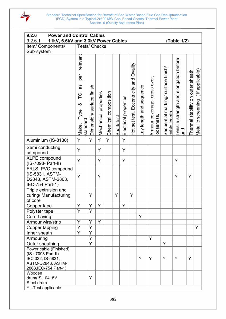
Standard Technical Specification for Retrofit of Sea Water Based Flue Gas Desulphurisation (FGD) System in a Typical 2x500 MW Coal Based Coastal Thermal Power Plant
Section- 9 (Quality Assurance Plan)
382
9.2.6 Power and Control Cables
9.2.6.1 11kV, 6.6kV and 3.3kV Power Cables (Table 1/2)
Item/ Components/ Sub-system
Tests/ Checks
Ma
ke
, T
ype
&
TC
a
s
pe
r re
leva
nt
sta
nda
rd
Dim
en
sio
n/
su
rfa
ce
fin
ish
Me
ch
an
ical p
rope
rtie
s
Che
mic
al co
mp
ositio
n
Sp
ark
te
st
Ele
ctr
ica
l p
rope
rtie
s
Hot
se
t te
st, E
ccen
tric
ity a
nd O
va
lity
La
y len
gth
and
seq
ue
nce
Arm
ou
r co
ve
rag
e,
cro
ss o
ve
r,
loo
se
ne
ss,
ga
p b
etw
ee
n tw
o w
ire
S
eq
ue
ntia
l m
ark
ing
/ su
rfa
ce
fin
ish/
ca
ble
len
gth
Te
nsile
str
eng
th a
nd
elo
nga
tio
n b
efo
re
an
d
aft
er
ag
ein
g o
n o
ute
r sh
ea
th a
nd
T
he
rma
l sta
bili
ty o
n o
ute
r sh
ea
th
Me
talli
c s
cre
en
ing
(
if a
pp
lica
ble
)
Aluminium (IS-8130) Y Y Y Y Y
Semi conducting compound
Y Y Y
XLPE compound (IS-7098- Part-II)
Y Y Y Y
FRLS PVC compound (IS-5831, ASTM-D2843, ASTM-2863, IEC-754 Part-1)
Y Y Y Y
Triple extrusion and curing/ Manufacturing of core
Y Y Y
Copper tape Y Y Y Y Polyster tape Y Y Core Laying Y Armour wire/strip Y Y Y Copper tapping Y Y Y Inner sheath Y Y Armouring Y Y Outer sheathing Y Y Power cable (Finished) (IS : 7098 Part-II) IEC:332, IS-5831, ASTM-D2843, ASTM-2863,IEC-754 Part-1)
Y Y Y Y Y
Wooden drum(IS:10418)/ Steel drum
Y
Y =Test applicable

Standard Technical Specification for Retrofit of Sea Water Based Flue Gas Desulphurisation (FGD) System in a Typical 2x500 MW Coal Based Coastal Thermal Power Plant
Section- 9 (Quality Assurance Plan)
383
9.2.6.1 11kV, 6.6kV and 3.3kV Power cables (Table 2/2)
Item/ Components/ Sub-system
Tests/ Checks
An
ti
term
ite
co
atin
g
on
w
oo
den
dru
ms
Con
str
uction
al
req
uire
me
nts
fe
atu
re
Rou
tin
e a
nd
acce
pta
nce
te
st a
s
pe
r re
levan
t s
tand
ard
an
d
sp
ecific
ation
FR
LS
te
sts
Aluminium (IS-8130) Semi conducting compound XLPE compound (IS-7098- Part-II)
FRLS PVC compound (IS-5831, ASTM-D2843, ASTM-2863, IEC-754 Part-1)
Y
Triple extrusion and curing/ Manufacturing of core Copper tape Polyster tape Core Laying Armour wire/strip Copper tapping Inner sheath Armouring Outer sheathing Power cable (Finished) (IS : 7098 Part-II) IEC: 332, IS-5831, ASTM-D2843, ASTM-2863,IEC-754 Part-1)
Y Y Y
Wooden drum(IS-10418) /Steel Drum Y Y Y =Test applicable Notes
1) Additional acceptance tests like FRLS, thermal stability, tensile strength and elongation after ageing shall be done on one sample/ lot
2) Length measurement/ surface finish/ eccentricity/ ovality shall be checked on one length/ size/ lot
3) Routine test shall be carried out on each drum length as per specifications.

Standard Technical Specification for Retrofit of Sea Water Based Flue Gas Desulphurisation (FGD) System in a Typical 2x500 MW Coal Based Coastal Thermal Power Plant
Section- 9 (Quality Assurance Plan)
384
9.2.6.2 1.1 kV PVC and XLPE cables (Table 1/2)
Item/ Components/ Sub-system
Tests/ Checks
Ma
ke
, T
yp
e &
TC
as p
er
rele
va
nt sta
nd
ard
Dim
en
sio
n/s
urf
ace
fin
ish
Me
ch
an
ica
l pro
pe
rtie
s
Ch
em
ical co
mp
ositio
n
Ele
ctr
ica
l p
rope
rtie
s
Sp
ark
te
st
Ho
t se
t te
st
(XL
PE
)
La
y len
gth
/ seq
uen
ce
Arm
ou
r co
ve
rag
e,
cro
ss o
ve
r, loo
se
ne
ss,
Ga
p b
etw
ee
n tw
o a
rmo
ur
wire
/ str
ip
Se
que
ntia
l m
ark
ing
/ su
rfa
ce
fin
ish/
cab
le
len
gth
Te
nsile
str
eng
th,
elo
nga
tio
n b
efo
re a
nd
a
fte
r ag
ein
g o
f in
su
latio
n a
nd o
ute
r
Th
erm
al sta
bili
ty o
f in
sula
tion a
nd
ou
ter
sh
ea
th
Aluminum (IS-8130) Y Y Y Y Y PVC compound (IS-5831) Y Y Y Y XLPE compound (IS-7098 Pt-I)
Y Y Y Y Y
FRLS PVC compound (IS-5831 ) ASTM-D-2843/ ASTM-D-2863 IEC-754 Part-I
Y Y Y Y
Extrusion & Curing/ manufacturing of core (PVC/XLPE)
Y Y Y Y
Core Laying Y
Armour wire/strip (IS-3975) Y Y Y PVC Inner sheath Y Y Armouring Y Y Outer sheath Y Y Finish cable (IS-1554 and 7098 – Part-1) ASTM-D-2843/ ASTM- D-2863 IEC-754 Part-I Swedish Chimney SS 4241475 for (F3 category) Flammability test IEC-332 Part –3 Cat-B
Y Y Y Y Y
Wooden drum (IS-10418) / Steel drum
Y
Y =Test applicable
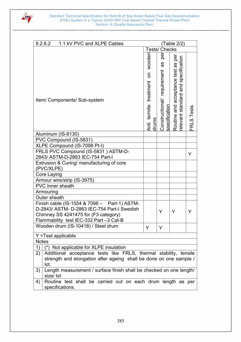
Standard Technical Specification for Retrofit of Sea Water Based Flue Gas Desulphurisation (FGD) System in a Typical 2x500 MW Coal Based Coastal Thermal Power Plant
Section- 9 (Quality Assurance Plan)
385
9.2.6.2 1.1 kV PVC and XLPE Cables (Table 2/2)
Item/ Components/ Sub-system
Tests/ Checks
An
ti
term
ite
tr
ea
tme
nt
on
wood
en
dru
ms
Con
str
uction
al/ re
qu
ire
me
nt
as pe
r sp
ecific
ation
Rou
tin
e a
nd
acce
pta
nce
te
st a
s p
er
re
leva
nt
sta
nd
ard
and
sp
ecific
ation
FR
LS
Te
sts
Aluminum (IS-8130) PVC Compound (IS-5831) XLPE Compound (IS-7098 Pt-I) FRLS PVC Compound (IS-5831 ) ASTM-D-2843/ ASTM-D-2863 IEC-754 Part-I
Y
Extrusion & Curing/ manufacturing of core (PVC/XLPE)
Core Laying Armour wire/strip (IS-3975) PVC Inner sheath Armouring Outer sheath Finish cable (IS-1554 & 7098 – Part-1) ASTM-D-2843/ ASTM- D-2863 IEC-754 Part-I Swedish Chimney SS 4241475 for (F3 category) Flammability test IEC-332 Part –3 Cat-B
Y
Y Y
Wooden drum (IS-10418) / Steel drum Y Y
Y =Test applicable Notes 1) (*) Not applicable for XLPE insulation 2) Additional acceptance tests like FRLS, thermal stability, tensile
strength and elongation after ageing shall be done on one sample / lot.
3) Length measurement / surface finish shall be checked on one length/ size/ lot
4) Routine test shall be carried out on each drum length as per specifications.
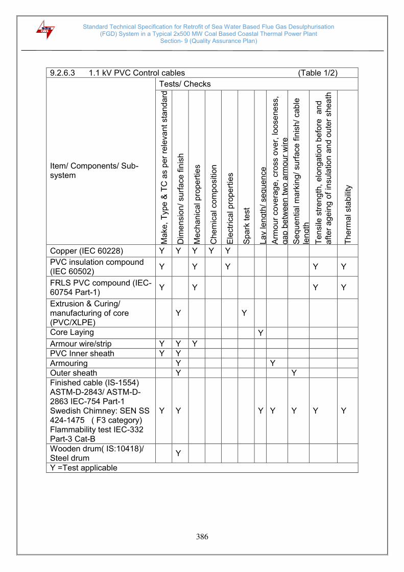
Standard Technical Specification for Retrofit of Sea Water Based Flue Gas Desulphurisation (FGD) System in a Typical 2x500 MW Coal Based Coastal Thermal Power Plant
Section- 9 (Quality Assurance Plan)
386
9.2.6.3 1.1 kV PVC Control cables (Table 1/2)
Item/ Components/ Sub-system
Tests/ Checks
Ma
ke
, T
ype
& T
C a
s p
er
rele
va
nt
sta
nd
ard
Dim
en
sio
n/
su
rfa
ce
fin
ish
Me
ch
an
ical p
rope
rtie
s
Ch
em
ical co
mp
ositio
n
Ele
ctr
ica
l p
rope
rtie
s
Sp
ark
te
st
La
y len
gth
/ seq
uen
ce
Arm
ou
r co
ve
rag
e,
cro
ss o
ve
r, loo
se
ne
ss,
ga
p b
etw
ee
n tw
o a
rmou
r w
ire
Se
que
ntia
l m
ark
ing
/ su
rfa
ce
fin
ish/
cab
le
len
gth
Te
nsile
str
eng
th,
elo
nga
tio
n b
efo
re a
nd
a
fte
r ag
ein
g o
f in
su
latio
n a
nd
ou
ter
sh
ea
th
Th
erm
al sta
bili
ty
Copper (IEC 60228) Y Y Y Y Y
PVC insulation compound (IEC 60502)
Y Y Y Y Y
FRLS PVC compound (IEC-60754 Part-1)
Y Y Y Y
Extrusion & Curing/ manufacturing of core (PVC/XLPE)
Y Y
Core Laying Y
Armour wire/strip Y Y Y PVC Inner sheath Y Y Armouring Y Y Outer sheath Y Y Finished cable (IS-1554) ASTM-D-2843/ ASTM-D-2863 IEC-754 Part-1 Swedish Chimney: SEN SS 424-1475 ( F3 category) Flammability test IEC-332 Part-3 Cat-B
Y Y Y Y Y Y Y
Wooden drum( IS:10418)/ Steel drum
Y
Y =Test applicable
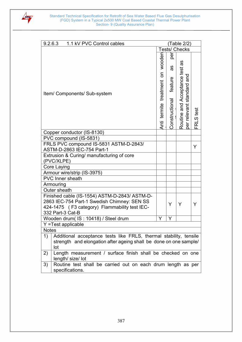
Standard Technical Specification for Retrofit of Sea Water Based Flue Gas Desulphurisation (FGD) System in a Typical 2x500 MW Coal Based Coastal Thermal Power Plant
Section- 9 (Quality Assurance Plan)
387
9.2.6.3 1.1 kV PVC Control cables (Table 2/2)
Item/ Components/ Sub-system
Tests/ Checks
An
ti te
rmite
tr
ea
tme
nt
on
w
oo
de
n
dru
ms
Con
str
uction
al
fea
ture
a
s
pe
r sp
ecific
ation
Rou
tin
e a
nd
Acce
pta
nce
te
st a
s
pe
r re
levan
t sta
nda
rd a
nd
sp
ecific
ation
FR
LS
te
st
Copper conductor (IS-8130) PVC compound (IS-5831) FRLS PVC compound IS-5831 ASTM-D-2843/ ASTM-D-2863 IEC-754 Part-1
Y
Extrusion & Curing/ manufacturing of core (PVC/XLPE)
Core Laying Armour wire/strip (IS-3975) PVC Inner sheath Armouring Outer sheath Finished cable (IS-1554) ASTM-D-2843/ ASTM-D-2863 IEC-754 Part-1 Swedish Chimney: SEN SS 424-1475 ( F3 category) Flammability test IEC-332 Part-3 Cat-B
Y Y Y
Wooden drum( IS : 10418) / Steel drum Y Y Y =Test applicable Notes 1) Additional acceptance tests like FRLS, thermal stability, tensile
strength and elongation after ageing shall be done on one sample/ lot
2) Length measurement / surface finish shall be checked on one length/ size/ lot
3) Routine test shall be carried out on each drum length as per specifications.

Standard Technical Specification for Retrofit of Sea Water Based Flue Gas Desulphurisation (FGD) System in a Typical 2x500 MW Coal Based Coastal Thermal Power Plant
Section- 9 (Quality Assurance Plan)
388
9.2.7 Installation of Cables, Earthing system and Lightning Protection system
Items/ Components/ Sub-systems
Tests/ Checks
Ma
ke
, T
ype
, M
ode
l,
Ra
tin
g a
nd T
C
Dim
en
sio
n
Pre
-tre
atm
ent
of sh
ee
t
Pa
int
sha
de
, p
ain
t th
ickn
ess, a
dhe
sio
n
IP p
rote
ction
Bo
ugh
t o
ut
item
s/
Bill
of
ma
teria
l
HV
an
d I
R
Ga
lvan
ize t
est
Fu
nctio
na
l te
st a
s p
er
sp
ecific
ation
Pro
of
loa
d
De
flection t
est
Co
nstr
uction
al fe
atu
re a
s p
er
sp
ecific
ation
All
Ro
utin
e a
nd
acce
pta
nce
te
sts
Ite
m c
onfo
rm t
o r
ele
van
t sta
nda
rd
Switch box/ Junction box/ Receptacles (IS-513, IS:5, IS:2629, IS:2633, IS:6745)
Y Y Y Y Y Y Y Y Y Y Y
Cable glands (BS:6121) Y Y Y Cable lug (IS:8309) Y Y Y Lighting wire (IS:694) Y Y Y Y Flexible conduits Y Y Y Y Conduits (Galvanize and Epoxy) IS:9537, IS:2629, IS:2633 and IS:6745
Y Y Y Y Y
RCC hume pipe (IS:458) Y Y Y Cable termination and Straight through joint (VDE-0278)
Y Y Y Y Y Y
Cable Trays, Flexible supports system and accessories IS:513, IS:2629, IS:2633 and IS:6745
Y Y Y Y Y Y Y Y Y
Trefoil clamp Y Y Y GI flats for earthing and lightning protection (IS:2062, IS:2629, IS:6745 and IS:2633)
Y Y Y Y Y
GI wire (IS-280) Y Y Y Y Y Y =Test applicable

Standard Technical Specification for Retrofit of Sea Water Based Flue Gas Desulphurisation (FGD) System in a Typical 2x500 MW Coal Based Coastal Thermal Power Plant
Section- 9 (Quality Assurance Plan)
389
Site tests :
The following minimum tests/ checks shall be conducted at site. Any other tests/ checks as per the manufacturer’s recommendation shall also be carried out i) Cables
a) Check for physical damage b) Check for insulation resistance before and after termination/
jointing. c) HT cables shall be pressure tested (test voltage as per IS:7098)
before commissioning d) Check of continuity of all cores of the cables. e) Check for correctness of all connections as per relevant wiring
diagrams. Any minor modification to the panel wiring like removing/ inserting, shorting, change in terminal connections, etc. shall be carried out
f) Check for correct polarity and phasing of cable connections g) Check for proper earth connections for cable glands, cable boxes,
cable armour, screens, etc. h) Check for provision of correct cable tags, core ferrules, tightness
of connections
ii) Cable trays/ supports and accessories a) Check for proper galvanizing/ painting and identification number
of the cable trays/ supports and accessories. b) Check for continuity of cable trays over the entire route. c) Check that all sharp corners, burrs, and waste materials have
been removed from the trays supports. d) Check for earth continuity and earth connection of cable trays
iii) Earthing and Lightning protection system
a) Earth continuity checks b) Earth resistance of the complete system as well as sub-system.

Standard Technical Specification for Retrofit of Sea Water Based Flue Gas Desulphurisation (FGD) System in a Typical 2x500 MW Coal Based Coastal Thermal Power Plant
Section- 9 (Quality Assurance Plan)
390
9.2.8 DC Storage Battery
9.2.8.1 Lead-Acid type battery
Item/ Components/ Sub-system
Tests/ Checks
Dim
en
sio
ns a
nd
fin
ish
Con
form
an
ce t
o r
ele
van
t d
raw
ing
Che
mic
al co
mp
ositio
n
Le
ad
co
atin
g th
ickne
ss
(min
imu
m 2
5 m
icro
ns,
IS:6
84
8 a
nd
Adh
esio
n c
he
ck
Con
form
an
ce t
o C
PW
D S
pe
cific
atio
n fo
r te
ak
woo
d
Pa
int p
roce
ss c
he
cks, p
ain
t sh
ade
, th
ickne
ss,
a
dhe
sio
n
an
d fin
ish
Con
str
uction
al re
qu
irem
en
ts a
s p
er
spe
cific
atio
n
Insu
latio
n R
esis
tan
ce
Ma
rkin
g (
Rou
tine
an
d A
cce
pta
nce t
est)
Che
ckin
g o
f p
ola
rity
an
d a
bse
nce
of
sho
rt
circu
it
(Ro
utin
e a
nd A
ccep
tance
te
st)
T
est
for
cap
acitie
s f
or
10
ho
urs
dis
cha
rge r
ate
a
lon
g
with
th
e t
est fo
r vo
ltage
du
ring
dis
cha
rge
(A
cce
pta
nce
te
st)
Container and Lids ( IS:1146)
Y Y
Vent plugs Y Y Sealing compound (IS:3116)
Y Y
Positive and Negative plates
Y Y
Separators ( IS:6071 )
Y Y
Electrolyte (water/ sulphuric acid ) (IS:1069/ 266)
Y Y
Inter-cell connectors and fasteners
Y Y Y
Battery stand Y Y Y Y Cell insulators Y Y Y Stack assembly Y Y Lead-Acid battery (IS:1652 )
Y Y Y Y Y
Y =Test applicable
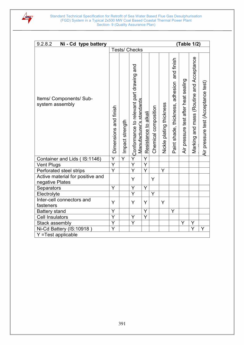
Standard Technical Specification for Retrofit of Sea Water Based Flue Gas Desulphurisation (FGD) System in a Typical 2x500 MW Coal Based Coastal Thermal Power Plant
Section- 9 (Quality Assurance Plan)
391
9.2.8.2 Ni - Cd type battery (Table 1/2)
Items/ Components/ Sub-system assembly
Tests/ Checks
Dim
en
sio
ns a
nd
fin
ish
Imp
act
str
en
gth
Con
form
an
ce t
o r
ele
van
t pa
rt d
raw
ing a
nd
M
anuf
actu
rer’s
sta
ndar
ds
Resis
tan
ce
to
alk
ali
Che
mic
al co
mp
ositio
n
Nic
kle
pla
ting
th
ickne
ss
Pa
int
sha
de
, th
ickne
ss,
adh
esio
n
an
d f
inis
h
Air p
ressu
re te
st a
fte
r h
ea
t se
alin
g
Ma
rkin
g a
nd
ma
ss (
Rou
tin
e a
nd A
ccep
tan
ce
te
st)
A
ir p
ressu
re te
st
(Accep
tan
ce te
st)
Container and Lids ( IS:1146) Y Y Y Y Vent Plugs Y Y Y Perforated steel strips Y Y Y Y Active material for positive and negative Plates
Y Y
Separators Y Y Y Electrolyte Y Y Inter-cell connectors and fasteners
Y Y Y Y
Battery stand Y Y Y Cell Insulators Y Y Y Stack assembly Y Y Y Y Ni-Cd Battery (IS:10918 ) Y Y Y Y =Test applicable

Standard Technical Specification for Retrofit of Sea Water Based Flue Gas Desulphurisation (FGD) System in a Typical 2x500 MW Coal Based Coastal Thermal Power Plant
Section- 9 (Quality Assurance Plan)
392
9.2.8.2 Ni- Cd type battery (Table 2/2)
Items/ Components/ Sub-system assembly
Tests/ Checks
Re
ten
tion
of
cha
rge
test
(Acce
pta
nce
te
st)
AH
te
st
(Acce
pta
nce t
est)
Insu
latio
n R
esis
tan
ce (
Acce
pta
nce
test)
Po
larity
an
d a
bsen
ce
of
sh
ort
circu
it
(Ro
utin
e a
nd A
ccep
tance
te
st)
Container and Lids ( IS:1146) Vent Plugs Perforated steel strips Active material for positive and negative Plates
Separators Electrolyte Inter-cell connectors and fasteners
Battery stand Cell Insulators Stack assembly Y Y Ni-Cd Battery (IS:10918 ) Y Y Y Y Y =Test applicable
Site tests :
The following minimum tests/ checks shall be conducted at site. Any other tests/ checks as per the manufacturer’s recommendation shall also be carried out.
i) Physical examination ii) Dimensions, mass and layout iii) Marking iv) Polarity and absence of short circuit. v) Insulation resistance vi) Ampere - hour capacity vii) Retention of charge viii) Air pressure test

Standard Technical Specification for Retrofit of Sea Water Based Flue Gas Desulphurisation (FGD) System in a Typical 2x500 MW Coal Based Coastal Thermal Power Plant
Section- 9 (Quality Assurance Plan)
393
9.2.9 Battery Charger
Item/ Components/ Sub-system
Tests/ Checks
Ma
ke
, M
ode
l, T
ype
, R
atin
g a
nd F
inis
h
Che
mic
al a
nd
Me
cha
nic
al te
sts
Sh
eet
ste
el p
retr
ea
tmen
t an
d p
ain
ting
Con
form
to r
ele
van
t sta
nda
rd
Dim
en
sio
na
l che
ck a
nd
pa
int
sha
de,
thic
kne
ss,
Com
ple
te p
hysic
al e
xam
ina
tio
n fo
r co
nstr
uction
al
fea
ture
s o
f b
att
ery
ch
arg
er
as p
er
Te
mp
era
ture
ris
e t
est
Dyna
mic
resp
on
se te
st
Rip
ple
co
nte
nt
test
, lo
ad
lim
ite
r a
nd
A
nn
un
cia
tor
and
A
VR
op
era
tion
te
st
Op
era
tion
al a
nd f
un
ctio
na
l ch
ecks
HV
an
d I
R t
est
Bu
rn-in t
est
at 5
00C
fo
r 4
8 h
rs
Deg
ree
of
pro
tection
test
.
Rectifier transformer (IS:2026) Y Y Y Y
Electronic components including potentiometer ( vernier type)
Y Y
PCB and electronic cards Y Y
19”standard racks for electronic card
Y Y
Control and selector switches (IS:6875)
Y Y Y
Indicating meters (IS:1248 ) Y Y Y Indicating lamps (IS:13947) Y Y Y Air break switches/ Fuses (IS:13947/13703)
Y Y Y
Control terminal blocks (IS:13947)
Y Y
Control transformer ( IS:12021) Y Y Y Push buttons ( IS:4794 ) Y Y Y MCB ( IS:8828) Y Y Y PVC insulated copper control wires (IS:694)
Y Y
Sheet steel ( IS:513 ) Y Y Y Y Synthetic rubber gaskets Y Y Y Annunciator Y Y Y Battery charger Y Y Y Y Y Y Y Y Y Y =Test applicable

Standard Technical Specification for Retrofit of Sea Water Based Flue Gas Desulphurisation (FGD) System in a Typical 2x500 MW Coal Based Coastal Thermal Power Plant
Section- 9 (Quality Assurance Plan)
394
Site tests : The following minimum tests/ checks shall be conducted at site. Any other tests/ checks as per the manufacturer’s recommendation shall also be carried out i) Complete physical examination ii) Checking of proper operation of annunciation system ii) Temperature rise test at full load iv) Insulation resistance test v) Automatic voltage regulator operation vi) Load limiter operation vii) Dynamic response test
9.2.10 VFD Module
Attributes/ Characteristics
Items/ Components/ Sub-system assembly
Visual & Dimensional checks
Make / Type/ Rating etc.
Final Inspection as per IS/ IEC
Remarks
HT Breaker (IEC-56)
Y Y Y
DC Reactor Y Y For details refer table for DC Reactor
Transformer Y Y For details refer table for Transformer
Motor Y Y For details refer separate table for Motor
VFD Panel Y Y For details refer table for VFD Panel
Note: 1) This is an indicative list of tests/checks. The manufacture is to furnish a
detailed Quality Plan indicating the practices & Procedure followed alongwith relevant supporting documents during QP finalization
2) Make of all major Bought-out Items will be subject to purchaser’s approval

Standard Technical Specification for Retrofit of Sea Water Based Flue Gas Desulphurisation (FGD) System in a Typical 2x500 MW Coal Based Coastal Thermal Power Plant
Section- 9 (Quality Assurance Plan)
395
9.2.11 Station Lighting
M
ake
, T
ype
, R
atin
g/
TC
Dim
en
sio
n
Pre
-tre
atm
ent
of sh
ee
t
Pa
int
sha
de
th
ickn
ess A
dh
esio
n
& F
inis
h
Ga
lvan
izatio
n T
ests
IP T
est
Bo
ugh
t-o
ut
ite
ms/ B
ill o
f
Ma
teria
l H
V &
IR
Fu
nctio
na
l che
ck a
s p
er
sp
ec.
Co
nstr
uction
al fe
atu
re a
s p
er
sp
ec.
Ro
utin
e t
ests
as p
er
rele
va
nt
sta
nda
rd &
sp
ec.
.
Acce
pta
nce t
ests
as p
er
rele
va
nt
sta
nd
ard
& s
pe
c.
Ite
m t
o c
on
form
to
re
leva
nt
sta
nda
rd
Luminaries (IS:10322
Pt.5 Sec.1 (Non-LED
type)
Y Y Y Y Y Y
Electronic Ballast Y Y Y Y
Lighting wire (IS:694) Y Y
Fans (IS:374) Y Y
Pole (IS:2713) Y Y Y Y Y
Lamps (IS:9800,
IS:9974) Y Y Y
Lighting Mast (with
raise & lower lantern
type)
Y Y Y Y Y Y
Wall mounted Lighting
Panel (IS:513, IS:5) Y Y Y Y Y Y Y Y Y Y Y Y
Switch Box/ Junction
Box/ Receptacles/ Local
Push Button Station/
Lighting Panel (IS:513,
2629, 2633, 4759,6745)
Y Y Y Y Y Y Y Y Y Y Y Y
Cable Gland (BS:6121) Y Y Y
Cable lug (IS:8309) Y Y Y
Flexible Conduit Y Y
Lighting Transformer
(IS:11171) Y Y Y
Epoxy & Galvanised
Conduit (IS:9537, 2629,
2633, 4759, 6745)
Y Y Y Y
Attributes / Characteristics Items/Components Sub Systems

Standard Technical Specification for Retrofit of Sea Water Based Flue Gas Desulphurisation (FGD) System in a Typical 2x500 MW Coal Based Coastal Thermal Power Plant
Section- 9 (Quality Assurance Plan)
396
9.2.12 Vibration Monitoring, Diagnostic and Analysis System
Attributes/ Characteristics Item
Lin
ea
rity
(R)
Fre
qu
en
cy R
espo
nse
(R)
Calib
ratio
n w
ith s
imu
late
d o
utp
ut.
(R)
Sp
ectr
um
(Ha
rmo
nic
An
aly
sis
(A
) Pre
dic
tive A
na
lysis
Fun
ctio
ns (
A)
Sto
rage
& C
om
pa
rative
ana
lysis
of
vib
ratio
n(A
) Ge
ne
ratio
n/a
na
lysis
of p
lots
(A
) Sim
ula
tion
te
st &
ge
nera
tio
n o
f op
era
tor
gu
idan
ce
(A
)
Vibration Monitoring System
Proximeter
Y Y
Accelerometer/ Velometer
Y Y
Monitor Y Y*
Overall System Y$ Y$ Y$ Y$ Y$
R-Routine Test A- Acceptance Test Y – Test applicable
Note: 1) – This is an indicative list of tests/checks. The manufacturer is to furnish a detailed quality plan indicating the Practices and Procedure adopted along with relevant supplying documents.
2)*- applicable for monitor electronics
3) $- Applicable as per the scope of work, To be tested for one unit in case of multiple units in a package.

Standard Technical Specification for Retrofit of Sea Water Based Flue Gas Desulphurisation (FGD) System in a Typical 2x500 MW Coal Based Coastal Thermal Power Plant
Section- 9 (Quality Assurance Plan)
397
9.2.13 Passenger cum Goods Elevator
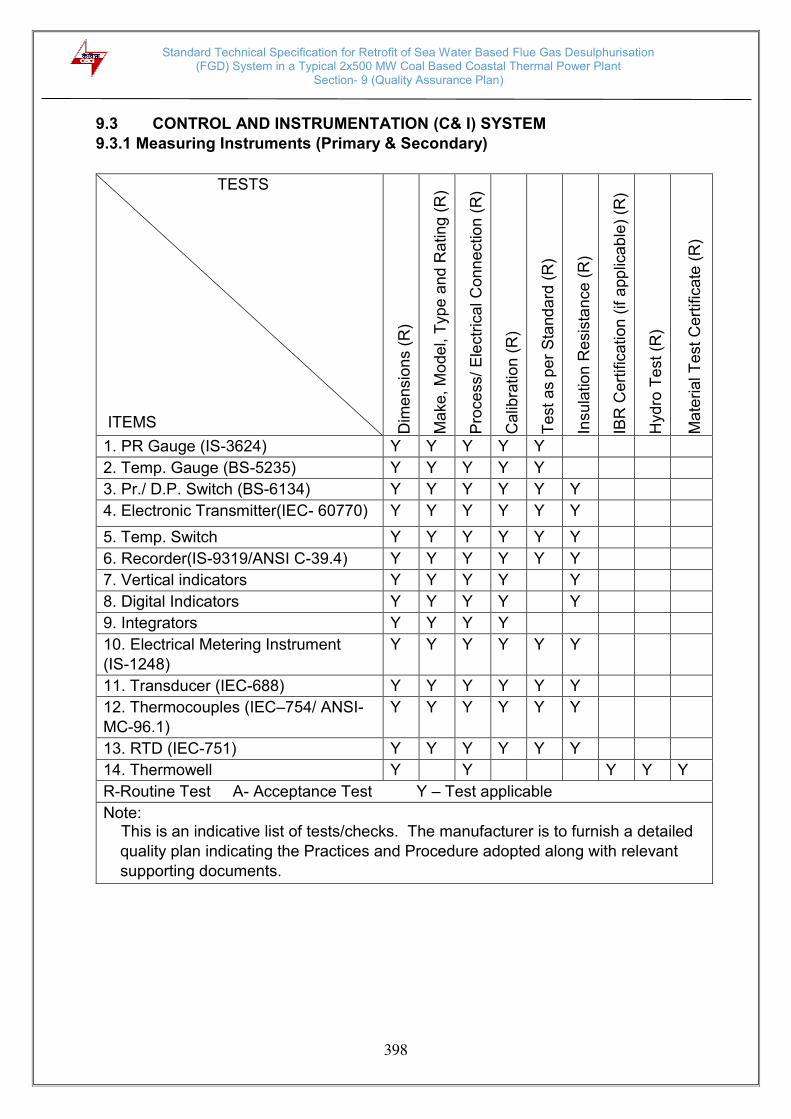
Standard Technical Specification for Retrofit of Sea Water Based Flue Gas Desulphurisation (FGD) System in a Typical 2x500 MW Coal Based Coastal Thermal Power Plant
Section- 9 (Quality Assurance Plan)
398
9.3 CONTROL AND INSTRUMENTATION (C& I) SYSTEM
9.3.1 Measuring Instruments (Primary & Secondary)
TESTS
ITEMS Dim
en
sio
ns (
R)
Ma
ke
, M
ode
l, T
ype
and
Ra
ting
(R
)
Pro
ce
ss/
Ele
ctr
ica
l C
on
ne
ctio
n (
R)
Calib
ratio
n (
R)
Te
st
as p
er
Sta
nd
ard
(R
)
Insu
latio
n R
esis
tan
ce (
R)
IBR
Cert
ific
ation (
if a
pp
lica
ble
) (R
)
Hydro
Te
st
(R)
Ma
teria
l T
est
Cert
ific
ate
(R
)
1. PR Gauge (IS-3624) Y Y Y Y Y
2. Temp. Gauge (BS-5235) Y Y Y Y Y
3. Pr./ D.P. Switch (BS-6134) Y Y Y Y Y Y
4. Electronic Transmitter(IEC- 60770) Y Y Y Y Y Y
5. Temp. Switch Y Y Y Y Y Y
6. Recorder(IS-9319/ANSI C-39.4) Y Y Y Y Y Y
7. Vertical indicators Y Y Y Y Y
8. Digital Indicators Y Y Y Y Y
9. Integrators Y Y Y Y
10. Electrical Metering Instrument
(IS-1248)
Y Y Y Y Y Y
11. Transducer (IEC-688) Y Y Y Y Y Y
12. Thermocouples (IEC–754/ ANSI-
MC-96.1)
Y Y Y Y Y Y
13. RTD (IEC-751) Y Y Y Y Y Y
14. Thermowell Y Y Y Y Y
R-Routine Test A- Acceptance Test Y – Test applicable
Note: This is an indicative list of tests/checks. The manufacturer is to furnish a detailed
quality plan indicating the Practices and Procedure adopted along with relevant
supporting documents.

Standard Technical Specification for Retrofit of Sea Water Based Flue Gas Desulphurisation (FGD) System in a Typical 2x500 MW Coal Based Coastal Thermal Power Plant
Section- 9 (Quality Assurance Plan)
399
TESTS
ITEMS Dim
en
sio
ns (
R)
Ma
ke
, M
ode
l, T
ype
and
Ra
ting
(R
)
Pro
ce
ss/
Ele
ctr
ica
l C
on
ne
ctio
n (
R)
Calib
ratio
n (
R)
Req
uire
me
nt a
s p
er
Sta
nda
rd (
R)
WP
S a
pp
rova
l (A
)
Non
-de
str
uctive
te
stin
g (
R)
Calc
ula
tion
fo
r a
ccu
racy
(R
)
Insu
latio
n R
esis
tan
ce (
R)
IBR
Cert
ific
ation (
as a
pp
lica
ble
) (R
)
Hyd
ro T
est
(R)
Ma
teria
l T
est
Cert
ific
ate
(R
)
15. Cold junction
compensation box
Y Y Y Y Y
16. Orifice plate (BS-1042) Y Y Y Y* Y Y ** Y** Y Y** Y
17. Flow nozzle (BS-1042) Y Y Y Y* Y Y Y Y Y Y
18. Impact head type element Y Y Y Y Y
19. Level transmitter/ float
type switch
Y Y Y Y Y Y Y Y
20. Analysers Y Y Y Y
21. Dust emission monitors Y Y Y Y
* Calibration to be carried out on one flow element of each type and size if calibration
carried out as type test same shall be repeated.
** if applicable
R-Routine Test A- Acceptance Test Y – Test applicable
Note: This is an indicative list of tests/checks. The manufacturer is to furnish a
detailed quality plan indicating the Practices and Procedure adopted along with relevant supporting documents.
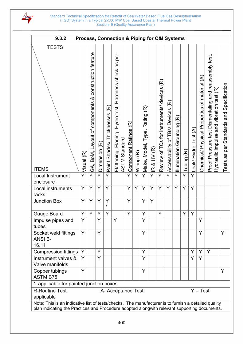
Standard Technical Specification for Retrofit of Sea Water Based Flue Gas Desulphurisation (FGD) System in a Typical 2x500 MW Coal Based Coastal Thermal Power Plant
Section- 9 (Quality Assurance Plan)
400
9.3.2 Process, Connection & Piping for C&I Systems
TESTS
ITEMS Vis
ua
l (R
)
GA
, B
oM
, L
ayo
ut o
f co
mp
on
en
ts &
co
nstr
uctio
n fe
atu
re
(R)
Dim
en
sio
n (
R)
Pa
int S
had
es/ T
hic
knesse
s (
R)
Fla
tte
nin
g,
Fla
riin
g,
Hyd
ro t
est, H
ard
ne
ss c
heck a
s p
er
AS
TM
Sta
nd
ard
Com
po
nen
t R
atin
gs (
R)
Wirin
g (
R)
Ma
ke
, M
ode
l, T
ype
, R
atin
g (
R)
IR &
HV
(R
)
Revie
w o
f T
Cs fo
r in
str
um
en
ts/ d
evic
es
(R)
Acce
ssa
bili
ty o
f T
Bs/ D
evic
es (
R)
Illu
min
atio
n G
rou
nd
ing (
R)
Tu
bin
g (
R)
Le
ak/ H
yd
ro T
est
(A
)
Che
mic
al/ P
hysic
al P
rop
ert
ies o
f m
ate
ria
l (A
)
Pro
of
Pre
ssu
re te
st
Dis
me
nta
ling a
nd
re
asse
mb
ly te
st,
Hydra
ulic
im
pu
lse a
nd
vib
ratio
n te
st
(R)
Te
sts
as p
er
Sta
nd
ard
s a
nd S
pe
cific
ation
Local Instrument
enclosure
Y Y Y Y Y Y Y Y Y Y Y Y Y
Local instruments
racks
Y Y Y Y Y Y Y Y Y Y Y Y Y
Junction Box Y Y Y Y
*
Y Y Y
Gauge Board Y Y Y Y Y Y Y Y Y
Impulse pipes and
tubes
Y Y Y Y Y
Socket weld fittings
ANSI B-
16.11
Y Y Y Y Y
Compression fittings Y Y Y Y Y Y
Instrument valves &
Valve manifolds
Y Y Y Y Y
Copper tubings
ASTM B75
Y Y Y
* applicable for painted junction boxes.
R-Routine Test A- Acceptance Test Y – Test
applicable
Note: This is an indicative list of tests/checks. The manufacturer is to furnish a detailed quality plan indicating the Practices and Procedure adopted alongwith relevant supporting documents.
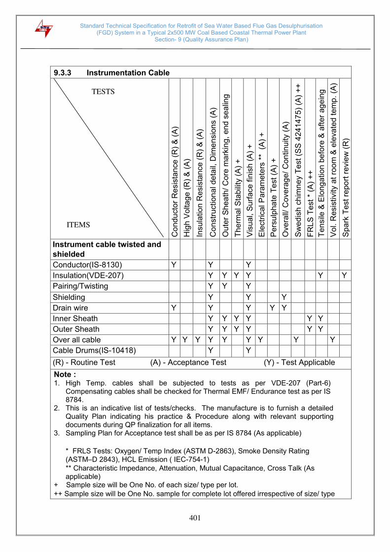
Standard Technical Specification for Retrofit of Sea Water Based Flue Gas Desulphurisation (FGD) System in a Typical 2x500 MW Coal Based Coastal Thermal Power Plant
Section- 9 (Quality Assurance Plan)
401
9.3.3 Instrumentation Cable
Co
nd
uct
or
Re
sis
tan
ce
(R
) &
(A
)
Hig
h V
olta
ge (
R)
& (
A)
Insu
latio
n R
esis
tan
ce (
R)
& (
A)
Co
nstr
uction
al de
tail,
Dim
en
sio
ns (
A)
Ou
ter
Sh
ea
th/ C
ore
ma
rkin
g,
en
d s
ea
ling
(A)
Th
erm
al S
tab
ility
(A
) +
Vis
ua
l, S
urf
ace f
inis
h (
A)
+
Ele
ctr
ica
l P
ara
mete
rs *
* (
A)
+
Pe
rsulp
ha
te T
est
(A)
+
Ove
rall/
Cove
rag
e/
Con
tin
uity (
A)
Sw
ed
ish c
him
ne
y T
est
(S
S 4
24
14
75
) (A
) +
+
FR
LS
Te
st
* (A
) +
+
Te
nsile
& E
long
ation
be
fore
& a
fte
r ag
ein
g
(A)
++
V
ol. R
esis
tivity a
t ro
om
& e
leva
ted
te
mp
. (A
)
++
S
pa
rk T
est re
po
rt r
evie
w (
R)
Instrument cable twisted and
shielded
Conductor(IS-8130) Y Y Y
Insulation(VDE-207) Y Y Y Y Y Y
Pairing/Twisting Y Y Y
Shielding Y Y Y
Drain wire Y Y Y Y Y
Inner Sheath Y Y Y Y Y Y
Outer Sheath Y Y Y Y Y Y
Over all cable Y Y Y Y Y Y Y Y Y
Cable Drums(IS-10418) Y Y
(R) - Routine Test (A) - Acceptance Test (Y) - Test Applicable
Note : 1. High Temp. cables shall be subjected to tests as per VDE-207 (Part-6)
Compensating cables shall be checked for Thermal EMF/ Endurance test as per IS 8784.
2. This is an indicative list of tests/checks. The manufacture is to furnish a detailed Quality Plan indicating his practice & Procedure along with relevant supporting documents during QP finalization for all items.
3. Sampling Plan for Acceptance test shall be as per IS 8784 (As applicable)
* FRLS Tests: Oxygen/ Temp Index (ASTM D-2863), Smoke Density Rating (ASTM–D 2843), HCL Emission ( IEC-754-1) ** Characteristic Impedance, Attenuation, Mutual Capacitance, Cross Talk (As applicable)
+ Sample size will be One No. of each size/ type per lot. ++ Sample size will be One No. sample for complete lot offered irrespective of size/ type
TESTS
ITEMS

Standard Technical Specification for Retrofit of Sea Water Based Flue Gas Desulphurisation (FGD) System in a Typical 2x500 MW Coal Based Coastal Thermal Power Plant
Section- 9 (Quality Assurance Plan)
402
9.3.4 Control Desk, PLC Panel, Smoke Detector, Fire Alarm & Control System
Vis
ua
l (R
)
GA
, B
oM
, L
ayo
ut o
f co
mp
on
en
ts (
R)
Dim
en
sio
n (
R)
Pa
int S
had
es/
Th
icknesse
s (
R)
Alig
nm
en
t o
f se
ctio
n (
R)
Com
po
nen
t R
atin
gs/ M
ake
/ T
ype
(R
)
Wirin
g (
R)
IR &
HV
(R
)
Revie
w o
f T
Cs fo
r in
str
um
en
ts/ d
evic
es/
Reco
rde
rs, in
dic
ato
rs/ o
sa
ic ite
ms/
Tra
nsd
uce
rs
(R)
Acce
ssa
bili
ty o
f T
Bs/ D
evic
es (
R)
Illu
min
atio
n (
R)
Fu
nctio
na
l C
he
ck
for
con
tro
l e
lem
en
t
Mim
ic (
R)
Te
st
as p
er
IEC
113
1 (
R)
*
Te
sts
as p
er
Sta
nd
ard
s (
R)
& (
A)
1. Control Desk Y Y Y Y Y Y Y Y Y Y Y Y Y
2. Annunciation/ Control/
PLC
Panel
Y Y Y Y Y Y Y Y Y Y Y Y
3.Smoke Detectors (UL-268,EN-54 PT-7), Heat Detectors( UL-521/ EN54 PT-5 ) Annunciation/ Control Panel (UL -864, EN-54, PT-
2)
Y
* Applicable for PLC
(R) - Routine Test (A) - Acceptance Test Y - Test Applicable
Note: This is an indicative list of test/ checks. The manufacturer is to furnish a
detailed quality plan indicating the Practice and Procedure alongwith relevant supporting documents.
TESTS ITEMS

Standard Technical Specification for Retrofit of Sea Water Based Flue Gas Desulphurisation (FGD) System in a Typical 2x500 MW Coal Based Coastal Thermal Power Plant
Section- 9 (Quality Assurance Plan)
403
9.3.5 Power Supply For C&I Systems (UPS/ Voltage Stabilizer)
Vis
ua
l/ D
ime
nsio
n/
Ratin
g/
Pa
int a
dhe
sio
n/
thic
kne
ss (
R)
Ge
ne
ral a
rra
nge
me
nt/ B
oM
/ M
ake
of
co
mp
one
nts
/ M
imic
(R
) E
ffic
ien
cy,
reg
ula
tio
n (
R)
Inp
ut
vo
ltag
e v
aria
tion
(A
)
Ou
tpu
t vo
ltage
& f
req
ue
ncy a
dj. r
ang
e (
A)
Pre
limin
ary
lig
ht
load
te
st
(R)
Lo
ad
tra
nsf
er
retr
an
sfe
r te
st
(R)
*
AC
inp
ut fa
ilure
and
re
turn
te
st (R
)
Pa
ralle
l o
pe
ration
an
d c
urr
en
t d
ivis
ion (
R)
Rela
tive
ha
rmo
nic
con
ten
t (R
)
Resta
rt w
ith
PR
I A
.C a
nd
ba
tte
ry (
se
pa
rate
ly)
(R)
Syste
m t
ran
sfe
r an
d r
etr
an
sfe
r (R
) *
Asyn
ch
ron
ou
s tra
nsfe
r (R
)
Rip
ple
co
nte
nt
(R)
Lo
ad
lim
ite
r o
pe
ratio
n (
R)
IR/
HV
(R
)
Te
sts
as p
er
Sta
nd
ard
s (
R)
& (
A)
UPS/Converter
(IEC-146 PT-4) Y Y Y Y Y Y Y Y Y Y Y Y Y Y Y Y Y
Voltage Stabiliser Y Y Y Y Y Y Y Y
Lead Acid Battery (Tubler)
IS:1651 Y
Lead Acid Battery (Plante)
IS:1652 Y
Nickel-Cadmium Battery
(IS: 10918/ IEC-623) Y
* Transfer time and Over shoot /under shoot during load & system transfer shall be
recorded
(R)-Routine Test (A)- Acceptance Test (Y) – Test
applicable
Note: This is an indicative list of tests/checks. The manufacturer is to furnish a
detailed quality plan indicating the Practices and Procedure adopted alongwith
relevant supporting documents.
TESTS
ITEMS

Standard Technical Specification for Retrofit of Sea Water Based Flue Gas Desulphurisation (FGD) System in a Typical 2x500 MW Coal Based Coastal Thermal Power Plant
Section- 9 (Quality Assurance Plan)
404
9.3.6 Control Valve Actuators and Accessories.
TESTS
Ma
ke
, M
od
el, T
ag
(R
)
Dim
en
sio
n (
R)
Su
rfa
ce f
inis
h (
R)
Hea
t tr
ea
tmen
t (R
)
Ma
teria
l te
st c
ert
ific
ate
s (
R)
IB
R c
ert
ific
ate
s (
R)
Hyd
rau
lic t
est (R
)
UT
/ ra
dio
gra
ph
y fo
r >
90
0lb
ra
tin
g (
R)
Mp
i/ d
p (
R)
Pre
ssu
re r
esis
tan
ce (
R)
Se
at le
aka
ge (
R)
Tim
ing
op
en
/ clo
se (
R)
Lin
ea
rity
/ h
yste
resis
(R
)
Fu
nction
al te
st,
re
vie
w f
or
ma
ke
and
TC
fo
r
acce
sso
rie
s (
R)
Control Valve and
Actuator
Overall Y Y Y Y Y Y Y Y Y
Body Y Y Y Y Y Y Y
Bonnet Y Y Y Y
Trim Y Y Y*
Pneumatic actuator Y Y Y
Electro pneumatic
positioner
Y Y
Y* - UT on spindle dia ≥ 40 mm.
(R) - Routine Test (A) - Acceptance Test (Y) - Test Applicable
NOTE : This is an indicative list of tests/checks. the manufacture is to furnish a detailed
quality plan indicating his practice & procedure along with relevant supporting documents during QP finalisation for all item.
ITEMS

Standard Technical Specification for Retrofit of Sea Water Based Flue Gas Desulphurisation (FGD) System in a Typical 2x500 MW Coal Based Coastal Thermal Power Plant
Section- 9 (Quality Assurance Plan)
405
9.3.7 Electrical Actuators with Integral Starters
Test/ Attributes
Characteristics
R
PM
(R
)
No
Loa
d c
urr
en
t (R
)
IR
& H
V T
est
(R)
Mo
un
ting
Dim
en
sio
n (
R)
All
rou
tine
te
st a
s p
er
Sta
nd
ard
& S
pe
cific
atio
n (
R)
Co
rre
ct
Pha
se
Se
qu
en
ce
(R
)
Op
era
tion
& s
ettin
g o
f lim
it s
witch
/ to
rqu
e s
witch
(R
)
Sta
ll to
rqu
e/
cu
rre
nt (R
)
Ha
nd
wh
ee
l op
era
tio
n/
Au
to d
e c
lutc
h f
un
ction
(A
)
Fu
nction
of A
ux.
lik
e p
ote
ntio
me
ter,
sp
ace
hea
ter
(R)
EP
T o
utp
ut
(R)
Gre
ase
lea
kag
e (
R)
Lo
ca
l/ R
em
ote
(o
pen
-sto
p-c
lose
) op
era
tio
n (
R),
Sa
fety
ch
eck
(Sin
gle
ph
asin
g,
Pha
se
co
rre
ctio
n,
Tripp
ing
etc
.) (
A)
Electrical Actuator
with Integral
Starters (IS:9334)
Motor Y Y Y Y Y
Final Testing Y Y Y Y Y Y Y Y Y Y Y Y Y
(R) - Routine Test (A) - Acceptance Test (Y) - Test Applicable
NOTE : This is an indicative list of tests/checks. The manufacturer is to furnish a
detailed quality plan indicating the practices & procedure along with relevant
supporting documents.
ITEMS/
COMPONE
NT/ SUB-
SYSTEM
ASSEMBL
Y/TESTIN

Standard Technical Specification for Retrofit of Sea Water Based Flue Gas Desulphurisation (FGD) System in a Typical 2x500 MW Coal Based Coastal Thermal Power Plant
Section- 9 (Quality Assurance Plan)
406
9.4 CIVIL WORKS
9.4.1 Sampling, Testing and Quality Assurance for Civil Works 9.4.1.1 General
i) This part of the specification covers the sampling, testing and quality
assurance requirement for all civil and structural works including
excavation and filling, cast in situ concrete and allied works,
fabrication and erection of structural steel works, masonry / sheeting
and allied works, finishing items, etc.
ii) The Contractor shall carry out all sampling and testing in accordance
with the relevant Indian standards and / or international standards
and this technical specification. Where no specific testing procedure
is mentioned, the tests shall be carried out as per the best prevalent
engineering practices and to the directions of the Purchaser. The
Contractor shall establish the QA&QC laboratory at site. All sampling
and all field tests shall be done in the presence of the Purchaser or
his authorised representative. The tests which cannot be carried out
in the field laboratory shall be done at a laboratory of repute such as
CSMRS, NCBM, IITs, National Test House, Kolkata etc. as agreed by
the Engineer. The cost of transportation and other associative cost
including the test charges shall be borne by the contractor and be shall
deem to be included in his contract price.
iii) The recommendations and suitability of material for concreting and
other building materials like brick, cement, aggregates etc., shall be
ascertained by contractor prior to start of work. Preliminary evaluation
of aggregate and its evaluation for potential alkali-aggregate reactivity
as per following shall be done:-
A. Evaluation of Aggregates:
To carry out different tests on coarse aggregate sample i.e.
specific gravity, water absorption, sieve analysis, deleterious
material; soundness, crushing value, impact value, abrasion
value, elongation index and flakiness index, as per IS: 2386. To carry out different tests on fine aggregate sample i.e.
specific gravity, water absorption, sieve analysis, soundness,
deleterious material, silt content, clay content and organic
impurities as per IS: 2386.
B. Evaluation of Aggregates for Potential Alkali-Aggregate
Reactivity:
To carry out petrographic analysis and accelerated Mortar bar Test

Standard Technical Specification for Retrofit of Sea Water Based Flue Gas Desulphurisation (FGD) System in a Typical 2x500 MW Coal Based Coastal Thermal Power Plant
Section- 9 (Quality Assurance Plan)
407
on aggregate samples (1N NaOH at 80 deg. Centigrade for 14
days as per ASTM 1260, or the method established/ developed
by CSMRS for 22days test.
All records shall be submitted, unless specified otherwise, as per the
format developed by the Contractor and approved by the Engineer.
iv) The Contractor shall enclose a comprehensive list of bought out
items (BOIs) envisaged in the contract for carrying out fabrication/
manufacturing/ erection/ construction/ commissioning activities,
procurement of forged, cast, semi-finished and finished
components/equipment etc. and shall indicate the names of reputed
manufacturers for each of them in their bid proposal.
v) The list of manufacturers / sub-vendors of each of the BOIs identified/
indicated by the Contractor shall be discussed/ reviewed by the
Purchaser during post bid discussions and the list of proposed
manufacturers / sub-vendors shall be agreed/ approved. The
Contractor’s proposal shall include vendor’s site facilities,
expertise, facilities established at the respective works, the process
capability, process stabilization, QC systems followed, experience list,
etc. along with his own technical evaluation for identified sub-
Contractors proposed. The formats for furnishing above details shall
be given to the Contractor at post bid discussion stage.
vi) Structural steel (plates and rolled sections i.e. channels, beams &
angles) and Reinforcement steel supply if in the scope of the contractor
shall be procured from Primary Steel Producers. Currently, Primary
Steel Producers acceptable are SAIL, JSW Steel Ltd, Jindal Steel &
Power, Tata steel Ltd. (for Reinforcement steel/TMT bars), RINL (for
long products/Rolled sections and Reinforcement steel/TMT bars),
Essar Steel India Ltd. (for Flat products/ Steel Plates), Electrosteel steel
Ltd. (for Reinforcement steel/TMT bars) and Monnet Ispat and Energy
Ltd. (for long products/Rolled sections and Reinforcement steel/TMT
bars). Subsequently, if any new Primary Steel Producer/s are proposed
during execution of contract, the same may be considered for
acceptance subject to approval of the Purchaser. Further, the specific
methodology to be followed for procurement of Structural Steel and
Reinforcement Bars through conversion route/BIS approved sources
route shall also be subject to approval of the Purchaser in advance.
vii) The Field Quality Plans shall detail out all the equipment, the quality
practices and procedures etc. to be followed by the Contractor’s “Site Quality Control Organization", during various stages of site activities
starting from receipt of materials/equipment at site.
Standard Technical Specification for Retrofit of Sea Water Based Flue Gas Desulphurisation (FGD) System in a Typical 2x500 MW Coal Based Coastal Thermal Power Plant
Section- 9 (Quality Assurance Plan)
408
The contractor shall furnish complete QA & QC programme (QAP) for the
work envisaged which may include the following :-
The organisation structure for the management and implementation of
the proposed Quality Assurance Programme.
Document Control system
The procedure for procurement of materials and source inspection.
System for site controls including process controls.
Control of non-conforming items and systems for corrective action
Inspection and test procedures for site activities
System for indication and appraisal of inspection status
System for maintenance of records
System for handling, storage and delivery.
Quality Plan detailing out quality practices and procedures, relevant
standards and acceptance levels for all types of work under the
scope of this contract.
Based on the schedule of work agreed with the Purchaser and the
approved FQP, the Contractor shall prepare a schedule of tests and
submit them to the Purchaser and organise to carry out the tests as
scheduled/ agreed.
viii) The contractor shall prepare and obtain approval of the Owner of the
Field Quality Plan (FQP) well before the start of the work. This FQP
shall cover for all the items / activities covered in the contract/schedule
of items and required for completion of the work.
ix) All materials / components and equipment covered under the scope
of work which are to be manufactured at shop/ factory of the vendor/
sub vendor shall be covered under a comprehensive quality assurance
program. Manufacturing Quality Plan (MQP) shall detail out all the
components and equipment, various test/inspection, to be carried out
as per the requirements of this specification and standards mentioned
therein.
x) All the equipment shall be duly calibrated by NABL/ NPL accredited
laboratories/accreditation agencies.
xi) The Contractor shall submit to the Purchaser Field Welding Schedule
for field welding activities, along with all supporting documents, like
welding procedures, heat treatment procedures, NDT procedures etc.
well in advance of erection work at site.

Standard Technical Specification for Retrofit of Sea Water Based Flue Gas Desulphurisation (FGD) System in a Typical 2x500 MW Coal Based Coastal Thermal Power Plant
Section- 9 (Quality Assurance Plan)
409
All welding and brazing shall be carried out as per procedure drawn
and qualified in accordance with requirements of ASME Section
IX/BS-4870 or other International equivalent standard acceptable to
the Purchaser. All welding/brazing procedures shall be submitted to
the Purchaser or its authorized representative for approval prior to
carrying out the welding/brazing.
No welding shall be carried out on cast iron components for repair.
xii) The Contractor shall associate themselves with the reputed
specialized blasting agency such as CMRI, NIRM for trials blasts,
design blasts, blasting pattern, monitoring of blast during the blasting
operations at site. All blasting work shall be done as per approved
blasting scheme/ design/ pattern in line with the technical
specification requirements and all statutory laws, rules, regulations,
relevant standards pertaining to the acquisition, transport, storage,
handling along with use of explosives shall be strictly followed by the
Contractor.
xiii) The Contractor shall install and operate equipments (such as tri-axial
seismograph) for continuous monitoring and control of blast induced
vibrations, noise level/ air pressure, dust, silica and noxious gases
during all blasting operations in line with the Technical Specification
requirements in association with the specialized blasting agency.
9.4.2 General QA Requirements 9.4.2.1 Storage and handling of common building materials
All materials shall be stacked and stored by the Contractor as per IS-4082
and as per the requirements specified in Purchaser Technical Specification.
9.4.2.2 Excavation and filling works
i) The contractor shall submit a work methodology covering various items
of works for all stages of excavation and filling works. This methodology
shall broadly include the quantity wise and classification wise
identification of source of excavation and filling, suitability tests as per
specification requirements, method of stockpiling, transportation,
placement, spreading, compaction, equipment, list of protocols, in-
situ tests, third party lab test if required, acceptance checks for final
clearance.
ii) Tolerance for finished surface level shall be within 20 mm of the level
shown in the drawing. For an unimportant area, tolerance up to +75mm
shall be acceptable at the discretion of the engineer. However, these
tolerances shall be applicable for localized areas only.
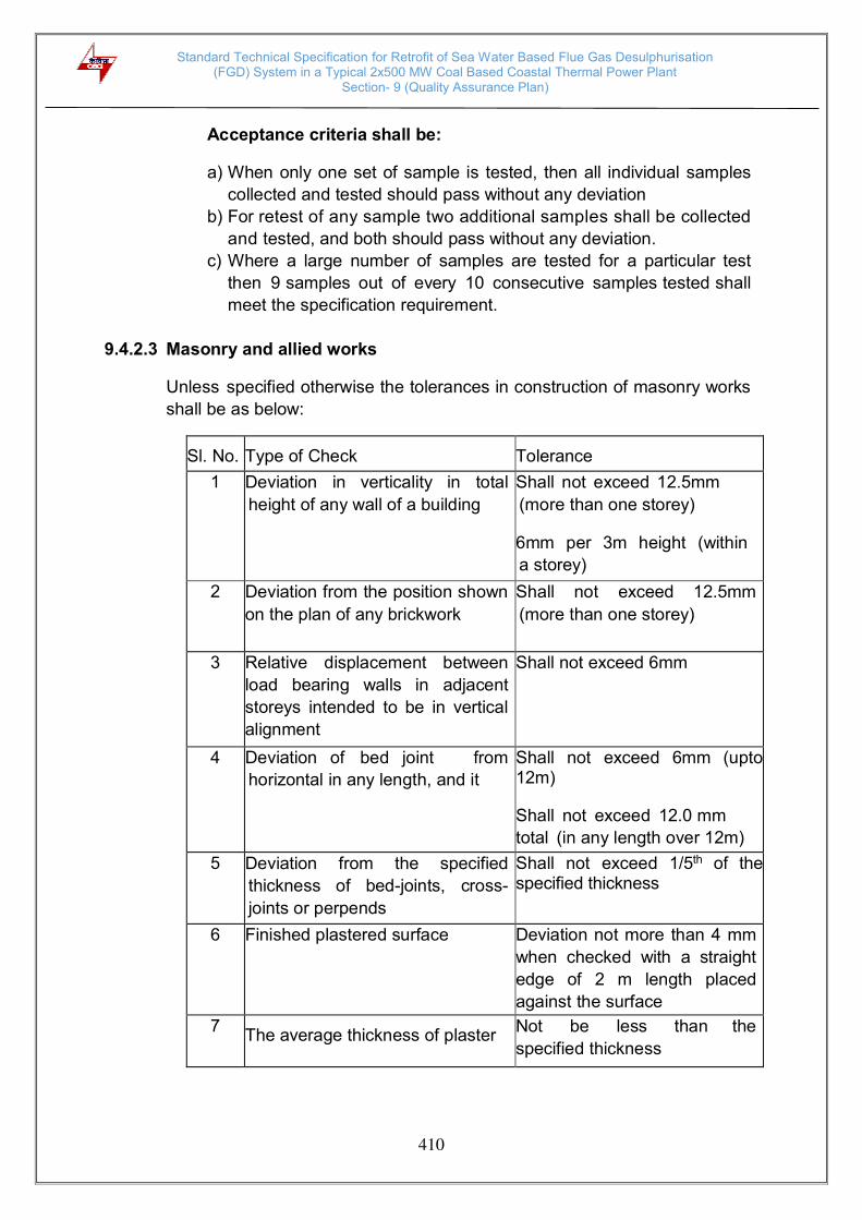
Standard Technical Specification for Retrofit of Sea Water Based Flue Gas Desulphurisation (FGD) System in a Typical 2x500 MW Coal Based Coastal Thermal Power Plant
Section- 9 (Quality Assurance Plan)
410
Acceptance criteria shall be:
a) When only one set of sample is tested, then all individual samples
collected and tested should pass without any deviation
b) For retest of any sample two additional samples shall be collected
and tested, and both should pass without any deviation.
c) Where a large number of samples are tested for a particular test
then 9 samples out of every 10 consecutive samples tested shall
meet the specification requirement.
9.4.2.3 Masonry and allied works
Unless specified otherwise the tolerances in construction of masonry works
shall be as below:
Sl. No.
Type of Check
Tolerance
1 Deviation in verticality in total
height of any wall of a building
Shall not exceed 12.5mm
(more than one storey) 6mm per 3m height (within
a storey)
2 Deviation from the position shown
on the plan of any brickwork
Shall not exceed 12.5mm
(more than one storey)
3 Relative displacement between
load bearing walls in adjacent
storeys intended to be in vertical
alignment
Shall not exceed 6mm
4 Deviation of bed joint from
horizontal in any length, and it
Shall not exceed 6mm (upto 12m) Shall not exceed 12.0 mm
total (in any length over 12m)
5 Deviation from the specified
thickness of bed-joints, cross-
joints or perpends
Shall not exceed 1/5th of the specified thickness
6 Finished plastered surface Deviation not more than 4 mm
when checked with a straight
edge of 2 m length placed
against the surface
7 The average thickness of plaster
Not be less than the
specified thickness
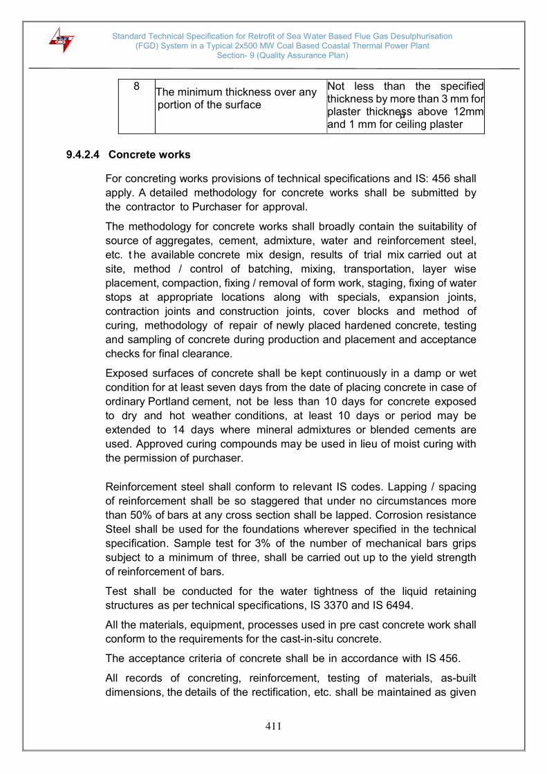
Standard Technical Specification for Retrofit of Sea Water Based Flue Gas Desulphurisation (FGD) System in a Typical 2x500 MW Coal Based Coastal Thermal Power Plant
Section- 9 (Quality Assurance Plan)
411
8 The minimum thickness over any portion of the surface
Not less than the specified thickness by more than 3 mm for plaster thickness above 12mm and 1 mm for ceiling plaster
9.4.2.4 Concrete works
For concreting works provisions of technical specifications and IS: 456 shall
apply. A detailed methodology for concrete works shall be submitted by
the contractor to Purchaser for approval.
The methodology for concrete works shall broadly contain the suitability of
source of aggregates, cement, admixture, water and reinforcement steel,
etc. t he available concrete mix design, results of trial mix carried out at
site, method / control of batching, mixing, transportation, layer wise
placement, compaction, fixing / removal of form work, staging, fixing of water
stops at appropriate locations along with specials, expansion joints,
contraction joints and construction joints, cover blocks and method of
curing, methodology of repair of newly placed hardened concrete, testing
and sampling of concrete during production and placement and acceptance
checks for final clearance.
Exposed surfaces of concrete shall be kept continuously in a damp or wet
condition for at least seven days from the date of placing concrete in case of
ordinary Portland cement, not be less than 10 days for concrete exposed
to dry and hot weather conditions, at least 10 days or period may be
extended to 14 days where mineral admixtures or blended cements are
used. Approved curing compounds may be used in lieu of moist curing with
the permission of purchaser.
Reinforcement steel shall conform to relevant IS codes. Lapping / spacing
of reinforcement shall be so staggered that under no circumstances more
than 50% of bars at any cross section shall be lapped. Corrosion resistance
Steel shall be used for the foundations wherever specified in the technical
specification. Sample test for 3% of the number of mechanical bars grips
subject to a minimum of three, shall be carried out up to the yield strength
of reinforcement of bars.
Test shall be conducted for the water tightness of the liquid retaining
structures as per technical specifications, IS 3370 and IS 6494.
All the materials, equipment, processes used in pre cast concrete work shall
conform to the requirements for the cast-in-situ concrete.
The acceptance criteria of concrete shall be in accordance with IS 456.
All records of concreting, reinforcement, testing of materials, as-built
dimensions, the details of the rectification, etc. shall be maintained as given

Standard Technical Specification for Retrofit of Sea Water Based Flue Gas Desulphurisation (FGD) System in a Typical 2x500 MW Coal Based Coastal Thermal Power Plant
Section- 9 (Quality Assurance Plan)
412
below. Four copies of such record in a bound form shall be submitted to
owner for their record and future reference.
i. Testing data / report of aggregates including petrographic
examination & potential reactivity of aggregate and repeated
temperature cycle tests wherever specified.
ii. Testing records of admixture as per IS-9103 / ASTM C494 including
third party test reports. iii. Approved scheme for concreting iv. Hourly records of concreting including pour card v. Protocol indicating the dimensional tolerance and details of inserts vi. Records giving the details of rectification giving the location of
grouting, the quantity of grout used at each location, type of grout used vii. Bar bending schedule viii. Location and details of mechanical anchoring used for reinforcement
ix. Protocol giving the details of checking of reinforcements before concreting and conformance to the reinforcement details as shown in the construction drawings
x. Photographs showing the areas where rectification works have been
carried out. Photographs should be taken before and after rectification xi. Temperature control record of concrete at the time of placement if
applicable. xii. Details of curing, staging and fixing / removal of formwork, checklist for
formwork as per IS 14687 including all machine foundations xiii. Batching Plant shall be calibrated regularly at least once in a 3
months. Computerized output shall be taken for each batch of production of concrete. Production and supply of concrete from batching plant shall conform to the provisions of IS 4926.
xiv. Dimensions (length, cross sectional dimensions, straightness,
squareness, and flatness) and tolerances for pre cast members as per
Technical Specification. Load test on Pre cast members (except pre-
cast tiles to be laid in the reservoir) shall be carried out @ 1% up to
1000 nos., @0.5% from more than 1000 nos. precast members of one
type. The load test shall be carried out as per the provisions of IS-456
and relevant IS code.

Standard Technical Specification for Retrofit of Sea Water Based Flue Gas Desulphurisation (FGD) System in a Typical 2x500 MW Coal Based Coastal Thermal Power Plant
Section- 9 (Quality Assurance Plan)
413
9.4.2.5 Structural steel work
For structural steel works provisions of technical specifications and IS:
800 shall apply. A detailed methodology for structural steel works shall be
submitted by the contractor to Purchaser for approval.
The contractor shall submit the welding procedures specification (WPS),
heat treatment procedures, NDT procedures etc. at least ninety days before
scheduled start of erection work at site. All welding and brazing shall be
submitted to the Purchaser and carried out as per procedure drawn and
qualified in accordance with requirements of ASME Section IX/BS-4870 or
other International equivalent standard acceptable to the Purchaser.
All brazers, welders and welding operators employed on any part of the contract either in the contractor’s / sub-contractor’s works or at site or elsewhere shall be qualified as per AWSD1.1/ASME Section-IX or BS-4871 or other equivalent International Standards acceptable to the Purchaser.
The records of welding procedure qualification and welder qualification test
results shall be furnished to the Purchaser for approval. However, where
required by the Purchaser, the tests shall be conducted in presence of
Purchaser / authorized representative.
No welding shall be carried out on cast iron components for repair. All
the heat treatment results shall be recorded on time temperature charts
and verified with recommended regimes.
All Non-destructive examination shall be performed in accordance with
written procedures as per International Standards and as mentioned
elsewhere in the technical specification. The NDT operator shall be qualified
as per SNT-TC-IA (of the American Society of non-destructive examination).
NDT shall be recorded in a report, which includes details of methods and
equipment used, result/evaluation, job data and identification of personnel
employed and details of co-relation of the test report with the job. The records
of RT (Films) and UT (inspection records or printed reports if possible) shall
be documented and produced to Purchaser.
Low hydrogen electrode (AWS E-7018) for welding of High/Medium tensile steel, for M.S (IS 2062 Gr. A/Gr. B, IS 8500) sections thickness above 20mm shall be used. Preheating and Post weld heat treatment requirements shall be complied as specified in the technical specification / approved WPS.
The requirements of pre-heating shall be as per relevant IS.
The following tests/ checks shall be carried out for structural steel works:

Standard Technical Specification for Retrofit of Sea Water Based Flue Gas Desulphurisation (FGD) System in a Typical 2x500 MW Coal Based Coastal Thermal Power Plant
Section- 9 (Quality Assurance Plan)
414
SL.
NO.
TESTS / CHECKS
QUANTUM / STANDARD
1 Physical and chemical properties of
material if supply in the scope of
contractor
As per relevant codes, review
of correlated mill test
certificates or check testing in
absence of MTC
2 Ultrasonic test on plates above 40mm
As per ASTM A435
3 Welding procedure & welders
qualification test
AWSD1.1/ASME Section-IX or
BS-4871 or other equivalent
International Standards
Fillet Weld
4 Macro-etch examination on
production test coupons for main
fillet welds
Minimum one joint per built up
beams, columns and crane
girder etc.
5 Tension member of crane girder
Dye penetration test on
25% weld length
6 All other fillet welds
DPT on 5% of weld length with
minimum 300mm at each
location Butt Weld
7 DPT
100% after back gouging on
all butt welds
8 Mechanical testing of production
test coupons
Minimum one joint per built
up beam, column and crane
girder. 9 Radiography test on butt welds (In case of failure of any welds in
SPOT/RT or UT the % of retesting
shall be doubled at that particular
location. Acceptance criteria of
NDT on welds shall be as per AWS
D1.1.
100% RT on butt welds of
tension flange (bottom flange)
of crane girders 10% RT weld length of each
welder on butt welds,

Standard Technical Specification for Retrofit of Sea Water Based Flue Gas Desulphurisation (FGD) System in a Typical 2x500 MW Coal Based Coastal Thermal Power Plant
Section- 9 (Quality Assurance Plan)
415
10 Ultrasonic testing on full
penetration welds (other than butt
welds)
100% UT on the web to
flange joint of crane girder 10% UT on other full
penetration joints
11 Control assembly check in shop
before erection
1st and further every 10th set
of identical structure
12 Dimensional tolerances during
fabrication and erection
as per IS-7215 and IS-12843
13 Surface Preparation and Paint
thickness
SA 2 1/2 , By elcometer
random after each coat, each
member
9.4.2.6 Painting works
Painting works shall be carried out as per the provisions of technical
specifications. A detailed methodology for painting works shall be
submitted by the contractor to Purchaser for approval.
The methodology for painting works shall broadly contain the source of
approved brand of paints, shot / sand blasting as specified, minimum
acceptable size of shot used for blasting, application of primer, intermediate
coat and final coat, experience of applicator, etc. testing of painting work and
acceptance checks for final clearance.
9.4.2.7 Sheeting works
All bought out items shall be procured from the manufacturer’s approved by engineer and tested as per relevant IS Codes/ Specification. Raw material
of colour coated sheets shall meet the chemical & physical properties as per
relevant standards / codes referred in the approved data sheet. It shall be
tested for colour match, bare metal thickness, weight of Z/AZ coating,
thickness of painting system, reverse impact, T-Bend adhesion, scratch
resistance, salt spray test for 1000 Hrs. and any other test / properties as
specified in the technical specifications. Colour coated sheets shall be
marked with video jet printing at the interval not more than 2m bearing
manufacturer’s name, date and time of manufacturing. Fasteners shall also be tested for 1000 Hrs. salt spray test as per the requirement of technical
specifications.
Bonded Mineral Wool Insulation shall meet the requirements of thickness,
density, thermal Conductivity, all other tests as per the technical
specifications and IS-8183.
Standard Technical Specification for Retrofit of Sea Water Based Flue Gas Desulphurisation (FGD) System in a Typical 2x500 MW Coal Based Coastal Thermal Power Plant
Section- 9 (Quality Assurance Plan)
416
For sheet installation no gas cut opening shall be allowed at the site,
whenever opening is specified these shall be properly cut in the factory and
shall be filled with lipping / flashing for true shape / dimension etc. The sheets/
packets shall be stacked neatly clear off the ground at an angle to the ground,
over a base pallet to provide drainage. Water / moisture should not be
allowed to stagnate on surface, or in between layers. This can damage the
coating, and cause corrosion.
9.4.2.7 Tile works
The contractor shall submit the work methodology which shall include
the type, grade and make of materials along with their technical data
sheets, details, etc., clearance from E-I-C regarding leak proofness and
damp proofness of parent concrete surface, surface preparation, the
procedure of application, curing, testing and acceptance.
The tests shall be carried out on acid resistant bricks / tile- water absorption,
compressive strength, resistance to acid, flexural strength, dimensions and
all other tests as per IS 4860 and IS 4457, bitumastic ready mixed paint
as per IS 158, bitumastic as per IS 9510, potassium silicate, resin type and
sulphur type mortars as per IS 4832, part I, II and III, surface preparation for
painting as per IS 2395, epoxy painting shall be carried for required coating
thickness and dry film thickness.
9.4.2.8 Fire proof doors
Fire Proof doors shall be tested for the requirements mentioned in the
Technical Specification. The type test of the doors shall be carried out at
CBRI Roorkee for minimum 2 hours fire rating and its Fabrication drawing
shall also be approved by CBRI, Roorkee. DFT of paint of Fire Proof Doors
and its fittings and fixtures as per BOQ shall be checked. The doors shall
be finished with suitable fire retardant painting system.
9.4.2.9 Water proofing
Water proofing shall be tested for water tightness by creating a pond of
water minimum 25 mm height on area of 6 m x 6 m, for the period of 48 hrs
on fully dried elastomeric membrane surfaces. Minimum 5% area of the roof
shall be subjected to water tightness test. Such test necessarily be
conducted on vulnerable areas like drain channel / drain head. No
dampness shall be visible on the underneath side of roof (i.e. ceiling),
parapet and well junctions etc. which have been subjected for testing.
The above testing shall be carried out prior to application of wearing course.

Standard Technical Specification for Retrofit of Sea Water Based Flue Gas Desulphurisation (FGD) System in a Typical 2x500 MW Coal Based Coastal Thermal Power Plant
Section- 9 (Quality Assurance Plan)
417
9.4.3 Piling Work (If Applicable)
A detailed methodology for piling works shall be submitted by the
contractor to Purchaser for approval. The methodology shall broadly contain
the method of boring, stability of bore hole, termination criteria, tests /
checks for termination level, fabrication of cage, cage lowering, concrete
batching / mixing, transportation, placing, recording of the time of
construction operations, method of conducting initial and routine load tests,
testing and sampling of concrete during production and placement and
acceptance checks on piles for final clearance.
The piling works shall be executed as per the technical specifications,
approved drawings, relevant codes / standards, FQP and BOQ. In addition
to the requirements of technical specifications, the following shall also be
ensured while execution of piling works:
a) Time gap between completion of pile boring and start of concreting
should be kept to the minimum. However, the maximum time gap shall
not be more than 6 hours.
b) Muck Debris should be removed from the pile bore by air lift
technique (by keeping the tremie & air pipe as close as to bottom of
pile bore) i.e. after completion of boring, after completion of SPT
(wherever applicable), after lowering reinforcement cage, but before
start of concreting.
c) Density of bentonite slurry shall be checked from the sample taken
from the bottom of pile bore (not at 1.0 m above the bottom of the pile
bore)
d) While lowering the R/F cage into the pile bore, two hooks shall always
be used to ensure balanced/symmetrical insertion of cage into the pile
bore.
e) Concrete cover blocks at the junction of two R/F cage shall be
ensured before lowering the second segment.
f) Surge concreting of about 1.0 cum shall be ensured at the start of
concreting (i.e. in the first pour), by suddenly allowing to fall through the
tremie pipe from the funnel. This will help in displacing left out
muck/debris in the pile bore (by the impact). g) Continuous feeding of concrete shall be ensured by deploying at least
two transit concrete mixers (if required to be deployed) and mixing
done through concrete batching plant (if deployed). Cold joints in the
pile shall be avoided. h) In a pile group, SPT shall be carried out at termination level in the pile,
taken up first.
Standard Technical Specification for Retrofit of Sea Water Based Flue Gas Desulphurisation (FGD) System in a Typical 2x500 MW Coal Based Coastal Thermal Power Plant
Section- 9 (Quality Assurance Plan)
418
i) Bentonite slurry circulation to be ensured from start of boring to start of
concreting. j) Properties of drilling mud shall be checked prior to commencement
of the piling work and thereafter, minimum once per week or as found
necessary by the engineer. One sample consisting of 3 specimens
shall be tested for the above. k) Low strain pile integrity test on all job piles and test piles shall be
conducted as specified in the Technical Specification. This test shall
be suitably used to identify the piles for routine tests. High Strain
dynamic test shall be done as per the technical specification. The
frequency of the test shall be as per the BOQ l) For Working Piles: Minimum one sample consisting of 6 test cubes
shall be made for first ten piles. Out of these 3 shall be tested for
7 days’ cube strength and 3 for 28 days cube strength. Minimum one
sample of 6 test cubes for every 25 nos. of piles shall be tested, out of
these 3 shall be tested for 7 days’ cube strength and 3 for 28 days’ cube
strength. 9.4.3.1 Pile load test
Pile load testing shall conform to the requirements of IS-2911 (Part IV)
and the technical specification. Initial load tests as specified in the contract
documents shall be conducted to assess the safe load carrying capacity of
pile before start of work. To verify the load carrying capacity of the working
piles, routine load test shall be conducted.
Pile load-testing procedure and the test setup / scheme shall be submitted
for approval of Purchaser.
All the gauges and instruments shall be calibrated before the start of the tests
on test piles and working piles and the calibration record shall be verified
before start of execution of the test. 9.4.4 Water Supply, Drainage & Sanitation
Material used for sanitary and plumbing fittings and fixtures shall conform to
and be tested as per the requirements of relevant IS Codes specified in
t echnical specification.
The obstructions in sewer lines shall be checked by inserting a smooth
ball, of diameter 13 mm less than the pipe bore at the high end of the
sewer or drain. If absence of any obstructions, such as yarn or mortar
projecting through the joints, ball shall roll down the invert of the pipe and
emerge at the lower end. The straightness shall be checked by means of a

Standard Technical Specification for Retrofit of Sea Water Based Flue Gas Desulphurisation (FGD) System in a Typical 2x500 MW Coal Based Coastal Thermal Power Plant
Section- 9 (Quality Assurance Plan)
419
mirror at one end of the line and lamp at the other. If the pipeline is straight,
the full circle of the light may be observed. The mirror will also indicate
obstruction in the barrel, if the pipeline is not straight.
The service pipes shall be slowly and carefully charged with water, allowing
all air to escape avoiding all shock or water hammer. The service pipe shall
then be inspected under test / working condition of pressure and flow, when
all draw-off taps are closed. The service pipes shall be checked for
satisfactory support and protection from damage, corrosion and frost. 9.4.5 Architectural & Misc. Works
Material used for sanitary and plumbing fittings and fixtures, floor finishes
and allied work shall conform and tested as per the requirements of relevant
IS Codes specified in Purchaser technical specification.
Fabricated item like metal doors, windows, ventilators, louvers, rolling
shutters and grills etc. shall be checked for correctness of locations and
smoothness of operation and fixtures. All controls and locking devices shall
give fault free performance. Door and window shutters shall operate without
jamming. The clearance at head and jamb for door shutters shall not exceed
1.5 mm. For double leaf doors, the gap at the meeting stiles shall not be
more than 2.5 mm.
Materials used in glass and glazing shall be procured from source
approved by Purchaser and shall conform to the requirements of the
Technical Specification and IS Codes.
False ceiling panels shall be best quality material in thickness and properties
called for in the specification / schedule of items. Material Test Certificate to
be submitted before bulk supply.
All bought items covered in the scope of contract shall be procured from
sources approved by Purchaser and shall conform to the requirements of
the technical specifications and referred standards /codes. 9.4.6 Pre Cast Concrete Works
i) All the materials used in Pre cast Concrete work shall be tested and
conform to the requirements of IS codes and Purchaser Tech.
Specification.
ii) Concrete mix for Pre cast members shall conform to IS-456-2000.
iii) All relevant QA requirements pertaining to cast in-situ concrete
shall be applicable.
iv) Load test on Pre cast members shall be carried out for the type of
members as decided by Purchaser Engineer as per IS-456-2000.
v) Pre Cast Concrete member shall be checked for dimensions (length,
cross sectional dimensions, straightness, squareness, and flatness)
and tolerances shall be as per Purchaser Technical Specification.

Standard Technical Specification for Retrofit of Sea Water Based Flue Gas Desulphurisation (FGD) System in a Typical 2x500 MW Coal Based Coastal Thermal Power Plant
Section- 10 (Annexures)
420
ANNEXURES1
Annexure- I
Typical Seawater Analysis Data
Parameter Units (mg/l as CaCO3
unless specified otherwise)
Calcium 1603
Magnesium 4395
Sodium 29843
Potassium 990
Heavy metals 3
Bicarbonate 100
Carbonate 20
Hydroxide Nil
Sulphate 3495
Chloride 33302
Fluoride 33
Nitrate & Nitrite 4
Temperature of condenser outlet sea water, 0C
40
Temperature of fresh sea water, 0C 33
pH 8.0
Turbidity, NTU 50
Total suspended solids, mg/1 3760
Total dissolved solids, mg/l 36834
Conductivity at 25 0C, S/cm 40600
Total silica, mg/l as SiO2 2
P- Alkalinity 10
M- Alkalinity 120
Total hardness 5998
To be provided by the purchaser.
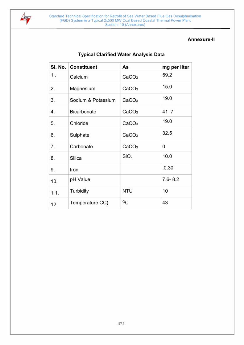
Standard Technical Specification for Retrofit of Sea Water Based Flue Gas Desulphurisation (FGD) System in a Typical 2x500 MW Coal Based Coastal Thermal Power Plant
Section- 10 (Annexures)
421
Annexure-II
Typical Clarified Water Analysis Data
Sl. No. Constituent As mg per liter
1 . Calcium CaCO3 59.2
2. Magnesium CaCO3 15.0
3. Sodium & Potassium CaCO3 19.0
4. Bicarbonate CaCO3 41 .7
5. Chloride CaCO3 19.0
6. Sulphate CaCO3 32.5
7. Carbonate CaCO3 0
8. Silica SiO2 10.0
9. Iron .0.30
10. pH Value 7.6- 8.2
1 1. Turbidity NTU 10
12. Temperature CC) OC 43
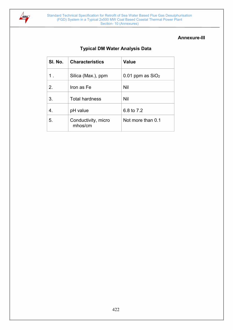
Standard Technical Specification for Retrofit of Sea Water Based Flue Gas Desulphurisation (FGD) System in a Typical 2x500 MW Coal Based Coastal Thermal Power Plant
Section- 10 (Annexures)
422
Annexure-III
Typical DM Water Analysis Data
Sl. No. Characteristics Value
1 . Silica (Max.), ppm 0.01 ppm as SiO2
2. Iron as Fe Nil
3. Total hardness Nil
4. pH value 6.8 to 7.2
5. Conductivity, micro mhos/cm
Not more than 0.1
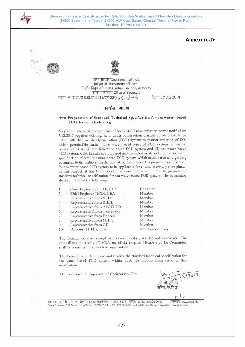
Standard Technical Specification for Retrofit of Sea Water Based Flue Gas Desulphurisation (FGD) System in a Typical 2x500 MW Coal Based Coastal Thermal Power Plant
Section- 10 (Annexures)
423
Annexure-IV

Standard Technical Specification for Retrofit of Sea Water Based Flue Gas Desulphurisation (FGD) System in a Typical 2x500 MW Coal Based Coastal Thermal Power Plant
Section- 10 (Annexures)
424
Annexure-V
Record notes of discussions of the 1st meeting of the committee for preparation of standard technical specification for retrofit of sea water based FGD system in coastal TPPs held on 29.08.2019 in CEA, New Delhi
List of Participants is enclosed as Annexure:
Chief Engineer (TE&TD) welcomed all the members of the committee and thanked them for their comprehensive review of the draft specification for retrofit of sea water based FGD plant for 2 x 500MW TPS. 1. Chief Engineer (TE&TD) appraised the committee members that the draft
resolutions on comments of NTPC, BHEL and Tata Power which were circulated among all committee members before the meeting will be taken up for discussions. Comments of GE Power and APGENCO, which were received later will be taken up separately.
2. Following issues were discussed in the meeting: a) It was decided to include gas to gas heat exchanger (GGH) as part of the
basic scheme as GGH in sea water based FGD system helps in reducing the
increase in outlet sea water temperature. Further, M/s Tata Power informed
that with GGH, temp. rise of sea water in scrubber shall be about 4- 5 deg C.
For this, the average temp. rise of outlet seawater is expected to be about 1.5
deg C. This cannot be mitigated by aeration in SWTP and will require addition
of fresh seawater or additional cooling channel. M/s GE to look into possible
option considering that they have vast experience of seawater FGD.
b) M/s NTPC suggested that the guaranteed leakage rate in GGH shall not
exceed 1.5 % of inlet flue gas flow rate in the range 50% to 100% MCR load.
c) Design and guarantee conditions- for dissolved oxygen to be mentioned as 3
mg/l or 40% saturation value whichever is higher (5 mg/l or 60% saturation
value whichever is higher for ecologically sensitive areas).
d) Scrubber MOC- RCC being the MOC being used mostly worldwide, it was
decided to keep only this option in specification. Further, process water tank
material was also finalized as RCC.
e) Sea water supply pumps – The MOC for sea water pumps was decided to be
mainly duplex SS and pumps to be forced water lubrication type using filtered
sea water.
f) Sea Water pipe material- Committee was of the view that options for sea
water pipe shall be GRP, MSRL with RCC casing of RCC duct.
g) FGD operation controls- M/s Tata suggested to give option in specification for
FGD control system as ‘from PLC in FGD control room with provision from DDCMIS and for control from DDCMIS with provision from FGD control room.’
h) M/s NTPC opined the unitised seawater pump house shall also be indicated
as option for sea water supply and same was agreed by committee to revise
specification accordingly.
Standard Technical Specification for Retrofit of Sea Water Based Flue Gas Desulphurisation (FGD) System in a Typical 2x500 MW Coal Based Coastal Thermal Power Plant
Section- 10 (Annexures)
425
i) Dilution basin- M/s Tata power indicated that mixing/ dilution shall be before
oxidation chambers, and specification shall be revised accordingly.
j) Location of blowers for oxidation- Committee agreed to revise specification to
indicate alternate location close to aeration basin for blowers alongwith in sea
water pump house
k) Chimney- members were of the view that with GGH wet chimney may not be
required and the technical description of new chimney shall be same as for
wet chimney except that condensate collection system shall not be required.
Further, option of individual chimney also to be considered.
l) Dampers- M/s Tata suggested bypass damper opening time shall be
indicated as within 10 seconds.
m) Booster fan casing material- M/s BHEL and GE suggested the MOC for fan
casing to be abrasion resistant, high BHN steel having thickness 8.0 mm
(min.) or mild steel of thickness 8 mm (min.) with liner of thickness 10 mm
(min.) or mild steel of 22 mm thickness.
n) M/s NTPC suggested that the value of guaranteed mist content in flue gas at
exit of scrubber shall be considered as maximum 20 mg/Nm3 in place of 100
mg/Nm3.
4. The committee members were requested to furnish following information/ data in line with the discussions held during meeting of the committee for revising the specification:
a) Performance Guarantee and Acceptance Test- The list/ set of correction curves applicable for PG test of FGD plant and that of GGH to be furnished by M/s GE.
b) Flue gas system and duct work-General- Velocity of flue gas in scrubber to be furnished by M/s GE.
c) MOC of major equipment of GGH to be furnished by M/s BHEL/GE/Tata. d) Sea water scrubbers- Specification for scrubber lining (type and thickness)
and internals to be furnished by M/s GE/ Tata. e) Mist elimination system- Observations, if any, on mist content of 20 mg/Nm3
for exit flue gas at scrubber outlet to be furnished by M/s GE. f) Sea Water pumps (Bearing life)- reference document for Bearing life for
cutless rubber bearing to be furnished by M/s Tata. g) C&I philosophy of FGD plant- Revised text for control of FGD system from
FGD control room and provision from DCS and vice versa to be provided by M/s Tata.
h) Fire protection system internal to scrubber- Text to be provided by M/s Tata i) QAP of EOT crane and revised text for painting to be furnished by NTPC.
The meeting ended with vote of thanks to the chair.
Standard Technical Specification for Retrofit of Sea Water Based Flue Gas Desulphurisation (FGD) System in a Typical 2x500 MW Coal Based Coastal Thermal Power Plant
Section- 10 (Annexures)
426
List of Participants of the 1st meeting of the committee for preparation of standard technical specification for retrofit of sea water based FGD system in coastal TPPs held on 29.08.2019 in CEA, New Delhi.
CEA
1. Dr. L. D. Papney , Chief Engineer (TE&TD)
2. Shri Hemraj Arora , Director (TE&TD)
3. Shri Rajesh Kohli , Deputy Director (TE&TD)
4. Shri Ajay Banode, Deputy Director(TCD)
5. Shri Deepak Raghuvans, Assistant Director-I(TCD)
M/s NTPC
1. Smt. S. Padmapriya, AGM(PE-Mech)
2. Shri Deepak, AGM(PE-Mech)
3. Shri Adarsh Agarwal, Manager(PE-Mech)
M/s BHEL
1. Shri G. Murali, GM (Mktg)
2. Shri R. S. Balaji, AGM(FGD)
3. Shri Nikhar Shukla, Sr. engr.(Mktg.)
M/s Tata Power
1. Shri Ramkrishna Gadre, Chief Engg.
2. Smt. Nandita Singh, Lead Advocacy
M/s GE POWER
1. Shri Venkatesh Rao, AQCS Leader
2. Shri Ajay Vajpeyi, AQCS Tendering