technical specification pc mill 55
TRANSCRIPT
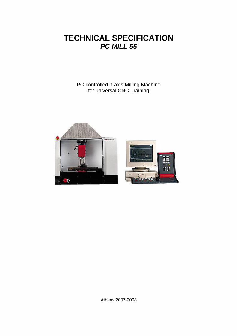
TECHNICAL SPECIFICATION PC MILL 55
PC-controlled 3-axis Milling Machine for universal CNC Training
Athens 2007-2008
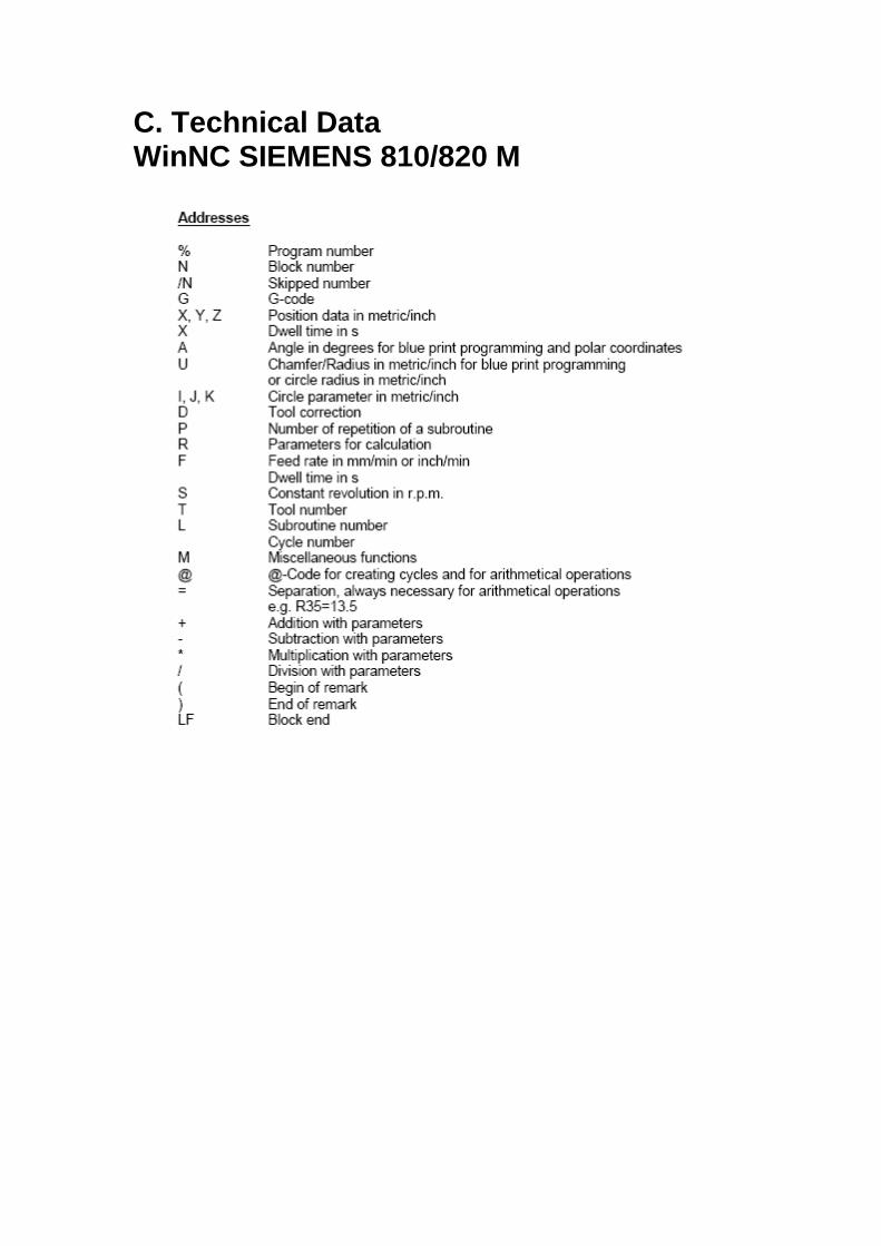
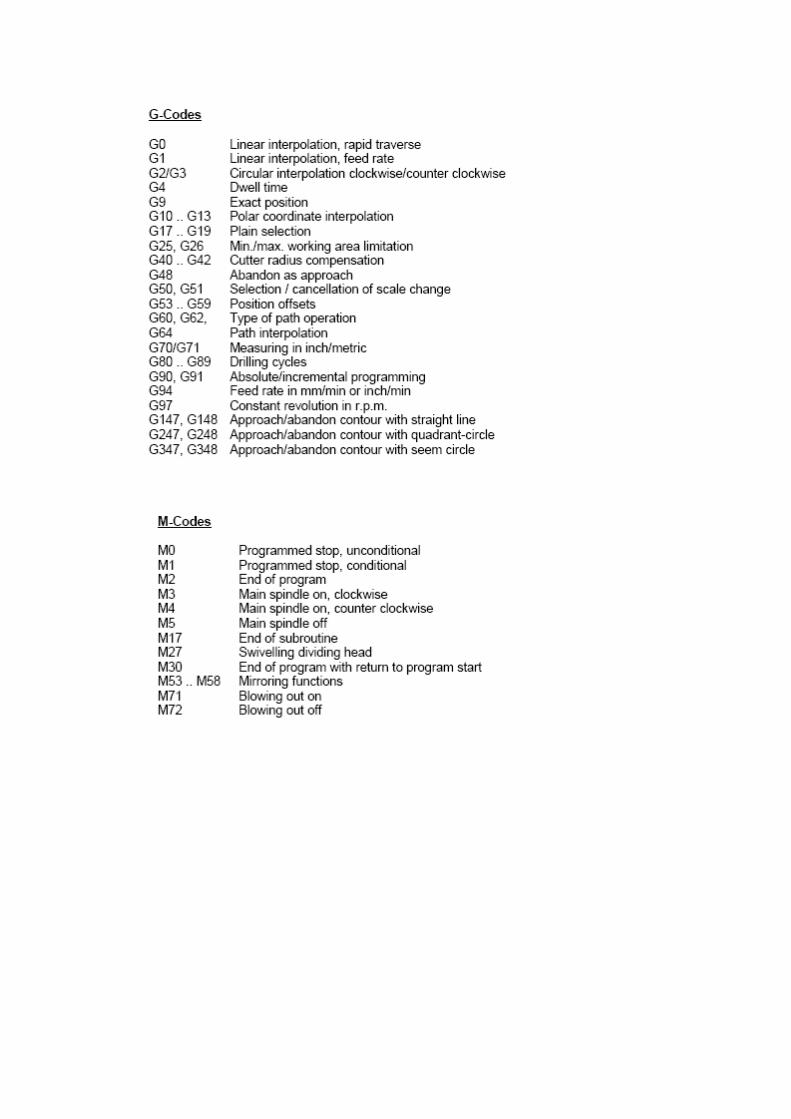
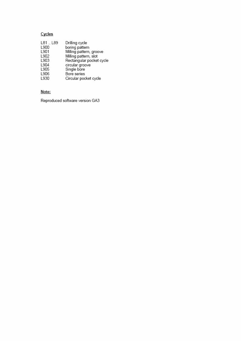
C. Technical Data WinNC SIEMENS 810/820 M
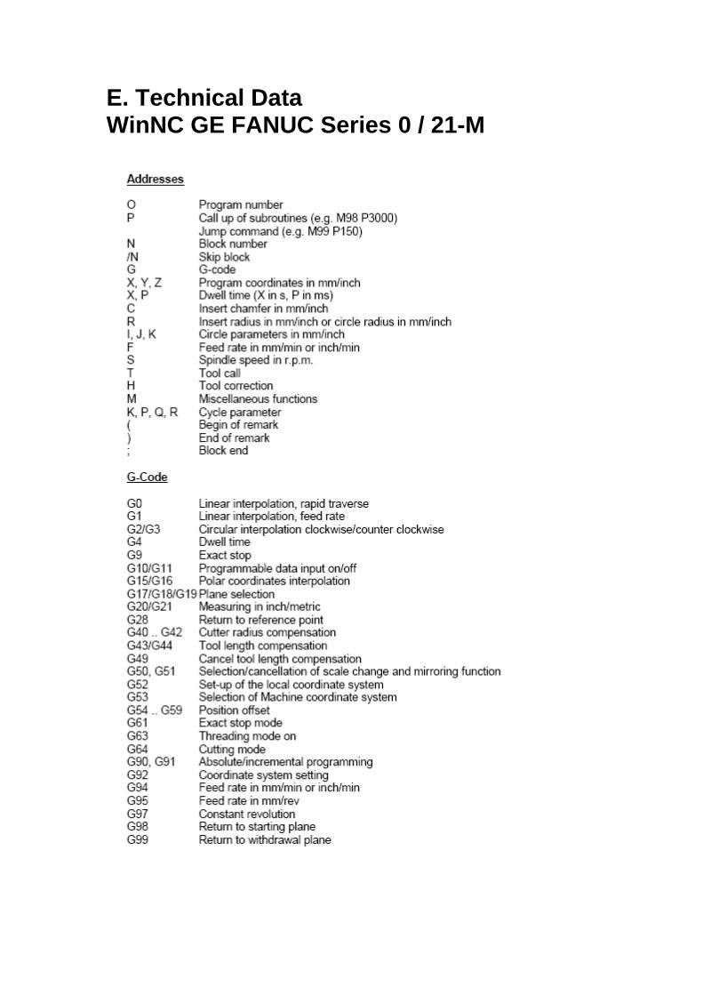
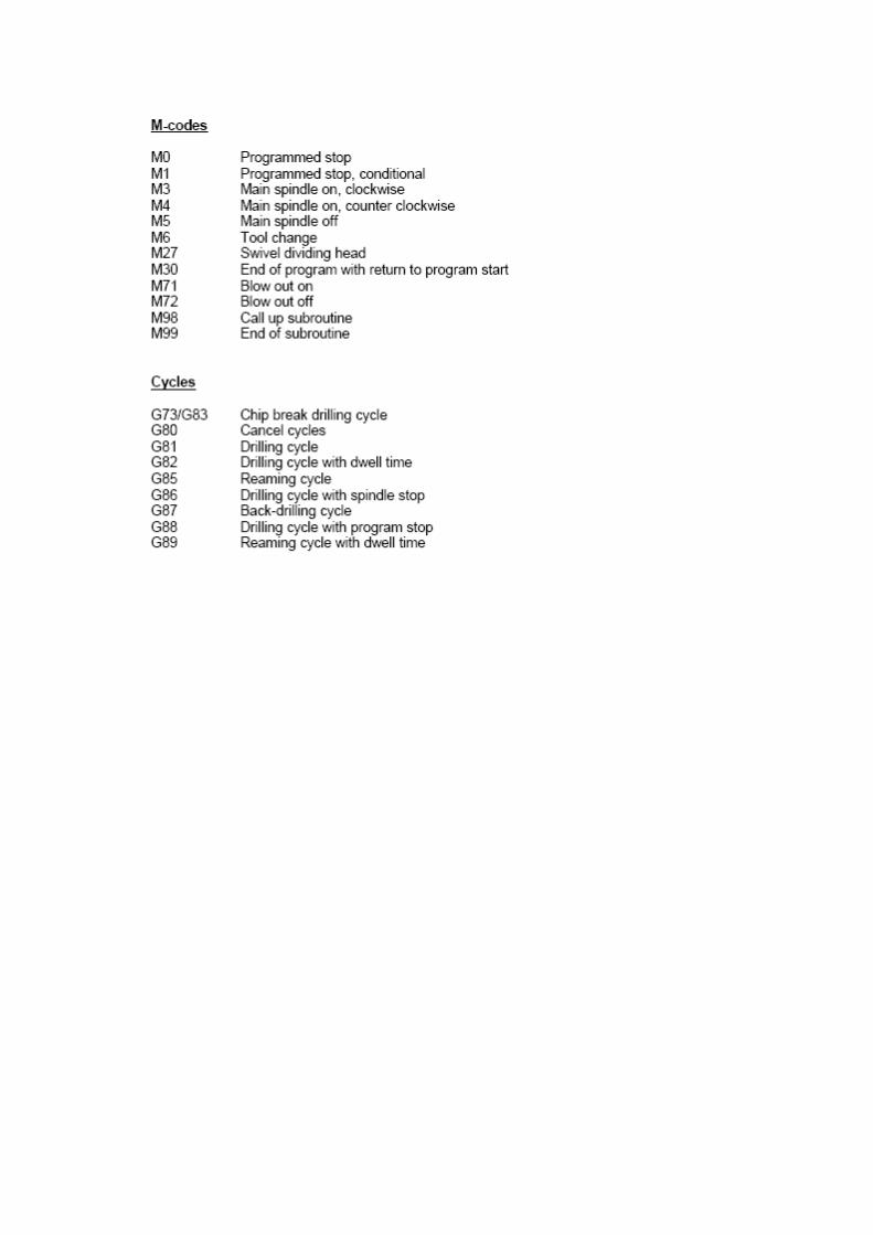
E. Technical Data WinNC GE FANUC Series 0 / 21-M
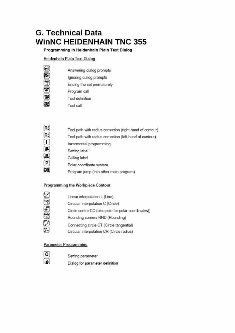
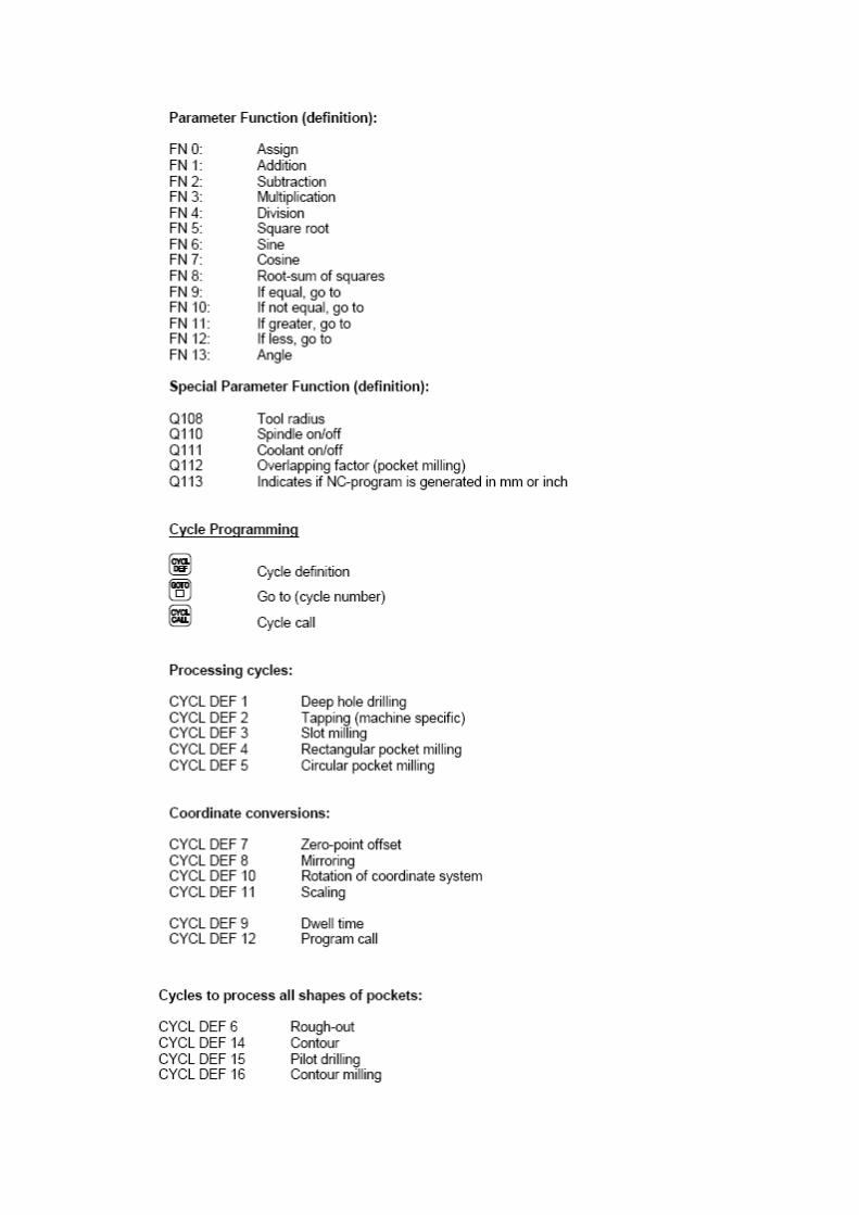
G. Technical Data WinNC HEIDENHAIN TNC 355
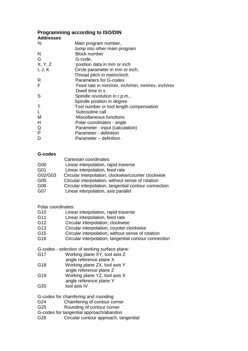
Programming according to ISO/DIN Addresses % Main program number, Jump into other main program N Block number G G-code, X, Y, Z position data in mm or inch I, J, K Circle parameter in mm or inch, Thread pitch in metric/inch R Parameters for G-codes F Feed rate in mm/min, inch/min, mm/rev, inch/rev Dwell time in s S Spindle revolution in r.p.m., Spindle position in degree T Tool number or tool length compensation L Subroutine call M Miscellaneous functions H Polar coordinates - angle Q Parameter - input (calculation) P Parameter - definition D Parameter – definition G-codes Cartesian coordinates: G00 Linear interpolation, rapid traverse G01 Linear interpolation, feed rate G02/G03 Circular interpolation, clockwise/counter clockwise G05 Circular interpolation, without sense of rotation G06 Circular interpolation, tangential contour connection G07 Linear interpolation, axis parallel Polar coordinates: G10 Linear interpolation, rapid traverse G11 Linear interpolation, feed rate G12 Circular interpolation, clockwise G13 Circular interpolation, counter clockwise G15 Circular interpolation, without sense of rotation G16 Circular interpolation, tangential contour connection G-codes - selection of working surface plane: G17 Working plane XY, tool axis Z angle reference plane X G18 Working plane ZX, tool axis Y angle reference plane Z G19 Working plane YZ, tool axis X angle reference plane Y G20 tool axis IV G-codes for chamfering and rounding G24 Chamfering of contour corner G25 Rounding of contour corner G-codes for tangential approach/abandon G26 Circular contour approach, tangential
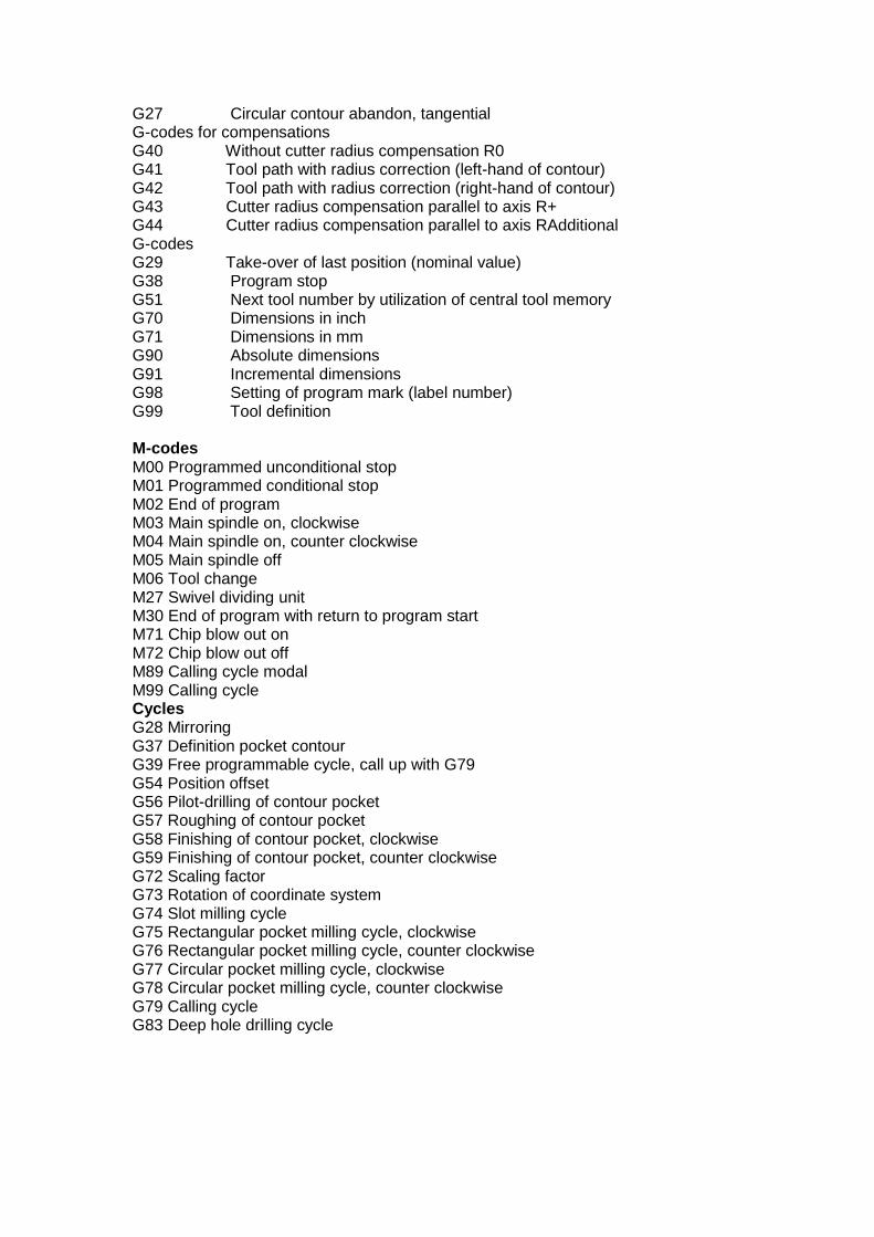
G27 Circular contour abandon, tangential G-codes for compensations G40 Without cutter radius compensation R0 G41 Tool path with radius correction (left-hand of contour) G42 Tool path with radius correction (right-hand of contour) G43 Cutter radius compensation parallel to axis R+ G44 Cutter radius compensation parallel to axis RAdditional G-codes G29 Take-over of last position (nominal value) G38 Program stop G51 Next tool number by utilization of central tool memory G70 Dimensions in inch G71 Dimensions in mm G90 Absolute dimensions G91 Incremental dimensions G98 Setting of program mark (label number) G99 Tool definition M-codes M00 Programmed unconditional stop M01 Programmed conditional stop M02 End of program M03 Main spindle on, clockwise M04 Main spindle on, counter clockwise M05 Main spindle off M06 Tool change M27 Swivel dividing unit M30 End of program with return to program start M71 Chip blow out on M72 Chip blow out off M89 Calling cycle modal M99 Calling cycle Cycles G28 Mirroring G37 Definition pocket contour G39 Free programmable cycle, call up with G79 G54 Position offset G56 Pilot-drilling of contour pocket G57 Roughing of contour pocket G58 Finishing of contour pocket, clockwise G59 Finishing of contour pocket, counter clockwise G72 Scaling factor G73 Rotation of coordinate system G74 Slot milling cycle G75 Rectangular pocket milling cycle, clockwise G76 Rectangular pocket milling cycle, counter clockwise G77 Circular pocket milling cycle, clockwise G78 Circular pocket milling cycle, counter clockwise G79 Calling cycle G83 Deep hole drilling cycle