box pc 820 / pc fi45 v2 - adegis
TRANSCRIPT
Contents
System Unit 1
Motherboard 2Keyboard Controller (PC FI45 V2) 3Direct Key Module (Optional for PC FI45 V2) 4
Bus Board 5Front Adapter Module(PC FI45 V2) 6Touch Screen (Optional for PC FI45 V2) 7
Display 8
CD ROM Drive 9
Power Supply 10
Connecting Cables 11
Appendix
ESD GuidelinesA
Glossary, Index
Edition 03/2001A5E00051531-03
Box PC 820PC FI45 V2
SIMATIC
Manual
Safety Guidelines
This manual contains notices which you should observe to ensure your own personal safety, aswell as to protect the product and connected equipment. These notices are highlighted in themanual by a warning triangle and are marked as follows according to the level of danger:
!Dangerindicates that death, severe personal injury or substantial property damage will result if proper pre-cautions are not taken.
!Warningindicates that death, severe personal injury or substantial property damage can result if properprecautions are not taken.
!Cautionindicates that minor personal injury or property damage can result if proper precautions are nottaken.
Note
draws your attention to particularly important information on the product, handling the product,or to a particular part of the documentation.
Qualified Personnel
Only qualified personnel should be allowed to install and work on this equipment. Qualifiedpersons are defined as persons who are authorized to commission, to ground, and to tag cir-cuits, equipment, and systems in accordance with established safety practices and standards.
Correct Usage
Note the following:
!Warning
This device and its components may only be used for the applications described in the catalog or the manual, and only
in connection with devices or components from other manufacturers which have been approved or recommended bySiemens.
This product can only function correctly and safely if it is transported, stored, set up, and installed correctly, and oper�
ated and maintained as recommended.
Trademarks
SIMATIC�, SIMATIC HMI � and SIMATIC NET� are registered trademarks of Siemens AG.
Third parties using for their own purposes any other names in this document which refer totrademarks might infringe upon the rights of the trademark owners.
We have checked the contents of this manual for agreement with thehardware and software described. Since deviations cannot be precludedentirely, we cannot guarantee full agreement. However, the data in thismanual are reviewed regularly and any necessary corrections included insubsequent editions. Suggestions for improvement are welcomed.
Subject to change without prior notice� Siemens AG 2000
Disclaimer of LiabilityCopyright � Siemens AG 2000 All rights reserved
The reproduction, transmission or use of this document or its contents isnot permitted without express written authority. Offenders will be liable fordamages. All rights, including rights created by patent grant or registrationof a utility model or design, are reserved.
Siemens AGBereich Automatisierungs� und AntriebstechnikGeschaeftsgebiet Industrie�AutomatisierungssystemePostfach 4848,�D�90327 Nuernberg
Siemens Aktiengesellschaft A5E00051531
iiiBox PC 820 / PC FI45 V2, ManualA5E00051531-03
Contents
1 System Unit 1-1. . . . . . . . . . . . . . . . . . . . . . . . . . . . . . . . . . . . . . . . . . . . . . . . . . . . . . . . . . . .
1.1 Technical Specifications 1-2. . . . . . . . . . . . . . . . . . . . . . . . . . . . . . . . . . . . . . . . . . 1.1.1 Device Models 1-2. . . . . . . . . . . . . . . . . . . . . . . . . . . . . . . . . . . . . . . . . . . . . . . . . . 1.1.2 Maximum Dimensions of Expansion Modules 1-4. . . . . . . . . . . . . . . . . . . . . . .
1.2 Power Requirements of the Components (Maximum Values) 1-6. . . . . . . . . .
1.3 Removing and Installing Components 1-7. . . . . . . . . . . . . . . . . . . . . . . . . . . . . . 1.3.1 Opening and Closing the Housing of the Box PC 820 1-9. . . . . . . . . . . . . . . . . 1.3.2 Lowering the PC FI45 V2 Housing Away from the Front Panel 1-11. . . . . . . . . 1.3.3 Removing the Housing of the PC FI45 V2 from the Front Panel 1-13. . . . . . . . 1.3.4 Opening and Closing the Housing of the PC FI45 V2 1-14. . . . . . . . . . . . . . . . . 1.3.5 Removing and Installing Expansion Modules 1-16. . . . . . . . . . . . . . . . . . . . . . . . 1.3.6 Removing and Installing the Power Supply Unit 1-18. . . . . . . . . . . . . . . . . . . . . . 1.3.7 Removing and Installing the Bus Board 1-20. . . . . . . . . . . . . . . . . . . . . . . . . . . . . 1.3.8 Removing and Installing the Fan 1-20. . . . . . . . . . . . . . . . . . . . . . . . . . . . . . . . . . 1.3.9 Removing and Installing a Floppy Disk Drive or CD-ROM Drive
for the Box PC 820 1-21. . . . . . . . . . . . . . . . . . . . . . . . . . . . . . . . . . . . . . . . . . . . . . 1.3.10 Removing and Installing a Floppy Disk Drive or CD-ROM Drive
for the PC FI45 V2 1-22. . . . . . . . . . . . . . . . . . . . . . . . . . . . . . . . . . . . . . . . . . . . . . 1.3.11 Removing and Installing the Hard Disk 1-23. . . . . . . . . . . . . . . . . . . . . . . . . . . . . 1.3.12 Removing and Installing the Motherboard 1-25. . . . . . . . . . . . . . . . . . . . . . . . . . . 1.3.13 Removing and Installing the Membrane Keyboard or Front Components
of the PC FI45 V2 1-26. . . . . . . . . . . . . . . . . . . . . . . . . . . . . . . . . . . . . . . . . . . . . . . 1.3.14 Removing and Installing the Keyboard Controller for the PC FI45 V2 1-27. . . 1.3.15 Removing and Installing the Inverter Module for the PC FI45 V2 1-27. . . . . . . 1.3.16 Removing and Installing the Display for the PC FI45 V2 1-28. . . . . . . . . . . . . . 1.3.17 Removing and Installing the Touch Pad for the PC FI45 V2 1-28. . . . . . . . . . . 1.3.18 Removing and Installing the Front Adapter Module for the PC FI45 V2 1-28. .
1.4 Connecting the MPI/DP Interface 1-29. . . . . . . . . . . . . . . . . . . . . . . . . . . . . . . . . .
1.5 Point-to-Point Connections 1-30. . . . . . . . . . . . . . . . . . . . . . . . . . . . . . . . . . . . . . .
1.6 Error Diagnostics 1-32. . . . . . . . . . . . . . . . . . . . . . . . . . . . . . . . . . . . . . . . . . . . . . . .
2 Motherboard 2-1. . . . . . . . . . . . . . . . . . . . . . . . . . . . . . . . . . . . . . . . . . . . . . . . . . . . . . . . . . .
2.1 Components and Interfaces 2-3. . . . . . . . . . . . . . . . . . . . . . . . . . . . . . . . . . . . . . .
2.2 Processor 2-4. . . . . . . . . . . . . . . . . . . . . . . . . . . . . . . . . . . . . . . . . . . . . . . . . . . . . .
2.3 Memory 2-5. . . . . . . . . . . . . . . . . . . . . . . . . . . . . . . . . . . . . . . . . . . . . . . . . . . . . . . .
2.4 VGA Onboard 2-6. . . . . . . . . . . . . . . . . . . . . . . . . . . . . . . . . . . . . . . . . . . . . . . . . .
2.5 Changing the Backup Battery 2-7. . . . . . . . . . . . . . . . . . . . . . . . . . . . . . . . . . . . .
2.6 Block Diagram of the Motherboard 2-8. . . . . . . . . . . . . . . . . . . . . . . . . . . . . . . . .
2.7 Hardware Ports 2-9. . . . . . . . . . . . . . . . . . . . . . . . . . . . . . . . . . . . . . . . . . . . . . . . .
ivBox PC 820 / PC FI45 V2, Manual
A5E00051531-03
2.8 Assignment of Connectors and Ports 2-12. . . . . . . . . . . . . . . . . . . . . . . . . . . . . . . 2.8.1 Assignment of the IDE Ports, X3 Secondary, X4 Primary 2-12. . . . . . . . . . . . . 2.8.2 Assignment of the EISA Riser X1 on the Motherboard 2-13. . . . . . . . . . . . . . . . 2.8.3 Battery Connection, X24 2-14. . . . . . . . . . . . . . . . . . . . . . . . . . . . . . . . . . . . . . . . . 2.8.4 Internal Keyboard / Mouse / Inverter Connection for FI45, X44 2-14. . . . . . . . 2.8.5 Direct Key Module (Internal Box) FI45, X45 2-15. . . . . . . . . . . . . . . . . . . . . . . . . 2.8.6 Internal Keyboard Connection for Box PC 820, X6 2-15. . . . . . . . . . . . . . . . . . . 2.8.7 Internal COM2 Interface, X911 2-16. . . . . . . . . . . . . . . . . . . . . . . . . . . . . . . . . . . . 2.8.8 Voltage Supply for CD-ROM Drive, X25 2-16. . . . . . . . . . . . . . . . . . . . . . . . . . . . 2.8.9 Setting the Power Supply for the Display, X408 2-16. . . . . . . . . . . . . . . . . . . . . . 2.8.10 CMOS (Universal) Interface for TFT Displays, X401 2-17. . . . . . . . . . . . . . . . . 2.8.11 LVDS Interface (Single Chip LVDS), X409 2-18. . . . . . . . . . . . . . . . . . . . . . . . . . 2.8.12 Selection of Display Type / Polarity of Backlight-On Signal (Switch S1) 2-18. 2.8.13 VGA 2-19. . . . . . . . . . . . . . . . . . . . . . . . . . . . . . . . . . . . . . . . . . . . . . . . . . . . . . . . . . . 2.8.14 PS/2 Mouse Connection, X7 2-20. . . . . . . . . . . . . . . . . . . . . . . . . . . . . . . . . . . . . . 2.8.15 Keyboard-Mouse Connection, X6 2-20. . . . . . . . . . . . . . . . . . . . . . . . . . . . . . . . . . 2.8.16 Assignment of the COM 1 Port, X10 2-21. . . . . . . . . . . . . . . . . . . . . . . . . . . . . . . 2.8.17 Gender Changer for COM1 2-21. . . . . . . . . . . . . . . . . . . . . . . . . . . . . . . . . . . . . . . 2.8.18 Assignment for the Floppy, X50 2-22. . . . . . . . . . . . . . . . . . . . . . . . . . . . . . . . . . . 2.8.19 Assignment of the COM 2 Port, X11 2-23. . . . . . . . . . . . . . . . . . . . . . . . . . . . . . . 2.8.20 Assignment of the Parallel Port, X9 2-24. . . . . . . . . . . . . . . . . . . . . . . . . . . . . . . . 2.8.21 Assignment of the PS/2 Power Connector, X80 2-25. . . . . . . . . . . . . . . . . . . . . . 2.8.22 Assignment of the PS/2 Power Connector, X90 2-25. . . . . . . . . . . . . . . . . . . . . . 2.8.23 Assignment of the PS/2 Power Connector, X100 2-25. . . . . . . . . . . . . . . . . . . . . 2.8.24 Assignment of the PS/2 Power Connector, X120 2-25. . . . . . . . . . . . . . . . . . . . . 2.8.25 Assignment of the Fan Supply, X26, X30 2-26. . . . . . . . . . . . . . . . . . . . . . . . . . . 2.8.26 Assignment of the MPI/DP D Sub-Socket Connector, X800 2-26. . . . . . . . . . . 2.8.27 Ethernet RJ45 Connection, X921 2-27. . . . . . . . . . . . . . . . . . . . . . . . . . . . . . . . . . 2.8.28 USB (two high current USB Interfaces Type A), X901 2-27. . . . . . . . . . . . . . . . 2.8.29 Description of the Switch Positions S2 (TTY, BIOS) 2-28. . . . . . . . . . . . . . . . . .
2.9 Interrupt Assignments 2-29. . . . . . . . . . . . . . . . . . . . . . . . . . . . . . . . . . . . . . . . . . . .
2.10 Hardware Addresses 2-30. . . . . . . . . . . . . . . . . . . . . . . . . . . . . . . . . . . . . . . . . . . . 2.10.1 I/O Address Assignment 2-30. . . . . . . . . . . . . . . . . . . . . . . . . . . . . . . . . . . . . . . . . 2.10.2 Assignment of the Memory Addresses 2-32. . . . . . . . . . . . . . . . . . . . . . . . . . . . .
2.11 Monitoring Functions 2-33. . . . . . . . . . . . . . . . . . . . . . . . . . . . . . . . . . . . . . . . . . . . . 2.11.1 Overview 2-33. . . . . . . . . . . . . . . . . . . . . . . . . . . . . . . . . . . . . . . . . . . . . . . . . . . . . . . 2.11.2 Status displays 2-33. . . . . . . . . . . . . . . . . . . . . . . . . . . . . . . . . . . . . . . . . . . . . . . . . . 2.11.3 Temperature Monitoring /Temperature Display and Fan Control 2-34. . . . . . . . 2.11.4 Watchdog (WD) 2-35. . . . . . . . . . . . . . . . . . . . . . . . . . . . . . . . . . . . . . . . . . . . . . . . . 2.11.5 SW Interfaces 2-35. . . . . . . . . . . . . . . . . . . . . . . . . . . . . . . . . . . . . . . . . . . . . . . . . .
2.12 Interrupt Assignment (Hardware) 2-36. . . . . . . . . . . . . . . . . . . . . . . . . . . . . . . . . .
2.13 DMA Channels 2-37. . . . . . . . . . . . . . . . . . . . . . . . . . . . . . . . . . . . . . . . . . . . . . . . . .
2.14 Changing the System Configuration with BIOS SETUP 2-38. . . . . . . . . . . . . . . 2.14.1 The Main Menu 2-41. . . . . . . . . . . . . . . . . . . . . . . . . . . . . . . . . . . . . . . . . . . . . . . . . 2.14.2 The Advanced Menu 2-51. . . . . . . . . . . . . . . . . . . . . . . . . . . . . . . . . . . . . . . . . . . . . 2.14.3 The Security Menu 2-57. . . . . . . . . . . . . . . . . . . . . . . . . . . . . . . . . . . . . . . . . . . . . . 2.14.4 The Power Menu 2-59. . . . . . . . . . . . . . . . . . . . . . . . . . . . . . . . . . . . . . . . . . . . . . . . 2.14.5 The Boot Sequence Menu 2-61. . . . . . . . . . . . . . . . . . . . . . . . . . . . . . . . . . . . . . . . 2.14.6 The System Version Menu 2-62. . . . . . . . . . . . . . . . . . . . . . . . . . . . . . . . . . . . . . . . 2.14.7 The Exit Menu 2-63. . . . . . . . . . . . . . . . . . . . . . . . . . . . . . . . . . . . . . . . . . . . . . . . . .
2.15 Diagnostic Messages (Port 80) 2-65. . . . . . . . . . . . . . . . . . . . . . . . . . . . . . . . . . . .
Contents

vBox PC 820 / PC FI45 V2, ManualA5E00051531-03
3 Keyboard Controller (PC FI45 V2) 3-1. . . . . . . . . . . . . . . . . . . . . . . . . . . . . . . . . . . . . . . .
3.1 Overview 3-2. . . . . . . . . . . . . . . . . . . . . . . . . . . . . . . . . . . . . . . . . . . . . . . . . . . . . . .
3.2 Syntax and Structure of the Configuration File 3-2. . . . . . . . . . . . . . . . . . . . . . . 3.2.1 Description of the Keywords 3-3. . . . . . . . . . . . . . . . . . . . . . . . . . . . . . . . . . . . . .
3.3 Connector Assignment of Keyboard Controller 3-11. . . . . . . . . . . . . . . . . . . . . .
3.4 Matrix Configuration PC FI45 3-15. . . . . . . . . . . . . . . . . . . . . . . . . . . . . . . . . . . . .
3.5 Configuration File for Keyboard Controller 3-16. . . . . . . . . . . . . . . . . . . . . . . . . .
4 Direct Key Module (Optional with PC FI45 V2) 4-1. . . . . . . . . . . . . . . . . . . . . . . . . . . . 4.1 General Information 4-2. . . . . . . . . . . . . . . . . . . . . . . . . . . . . . . . . . . . . . . . . . . . .
4.2 Functional Description 4-3. . . . . . . . . . . . . . . . . . . . . . . . . . . . . . . . . . . . . . . . . . .
4.3 Direct Key Module Ports 4-5. . . . . . . . . . . . . . . . . . . . . . . . . . . . . . . . . . . . . . . . .
4.4 Logical Organisation of Digital Inputs and Outputs 4-6. . . . . . . . . . . . . . . . . . .
4.5 Assignment of Direct Keys to Digital Inputs 4-6. . . . . . . . . . . . . . . . . . . . . . . . .
4.6 Description of Ports 4-7. . . . . . . . . . . . . . . . . . . . . . . . . . . . . . . . . . . . . . . . . . . . . . 4.6.1 Ports 4-7. . . . . . . . . . . . . . . . . . . . . . . . . . . . . . . . . . . . . . . . . . . . . . . . . . . . . . . . . . 4.6.2 Internal Ports 4-9. . . . . . . . . . . . . . . . . . . . . . . . . . . . . . . . . . . . . . . . . . . . . . . . . . .
4.7 Technical Specifications of Direct Key Modules 4-10. . . . . . . . . . . . . . . . . . . . . .
4.8 Optional Package for Direct Key Modules 4-11. . . . . . . . . . . . . . . . . . . . . . . . . . .
4.9 Assignment of Termination Module Terminals 4-12. . . . . . . . . . . . . . . . . . . . . . .
5 Bus Board 5-1. . . . . . . . . . . . . . . . . . . . . . . . . . . . . . . . . . . . . . . . . . . . . . . . . . . . . . . . . . . . .
5.1 Technical Specifications 5-2. . . . . . . . . . . . . . . . . . . . . . . . . . . . . . . . . . . . . . . . . .
5.2 Design and Mode of Operation 5-3. . . . . . . . . . . . . . . . . . . . . . . . . . . . . . . . . . . .
5.3 Pin Assignments 5-4. . . . . . . . . . . . . . . . . . . . . . . . . . . . . . . . . . . . . . . . . . . . . . . . 5.3.1 Interface to the Motherboard 5-4. . . . . . . . . . . . . . . . . . . . . . . . . . . . . . . . . . . . . . 5.3.2 ISA Slot Pin Assignment 5-5. . . . . . . . . . . . . . . . . . . . . . . . . . . . . . . . . . . . . . . . . 5.3.3 PCI Slot Pin Assignment 5-7. . . . . . . . . . . . . . . . . . . . . . . . . . . . . . . . . . . . . . . . . 5.3.4 External Voltage Supply 5-8. . . . . . . . . . . . . . . . . . . . . . . . . . . . . . . . . . . . . . . . . .
6 Front Adapter Module (PC FI45 V2) 6-1. . . . . . . . . . . . . . . . . . . . . . . . . . . . . . . . . . . . . .
6.1 Overview 6-2. . . . . . . . . . . . . . . . . . . . . . . . . . . . . . . . . . . . . . . . . . . . . . . . . . . . . . .
6.2 Pin Assignment 6-3. . . . . . . . . . . . . . . . . . . . . . . . . . . . . . . . . . . . . . . . . . . . . . . . .
7 Touch Screen (Optional with PC FI45 V2) 7-1. . . . . . . . . . . . . . . . . . . . . . . . . . . . . . . . .
7.1 General Information 7-2. . . . . . . . . . . . . . . . . . . . . . . . . . . . . . . . . . . . . . . . . . . . .
7.2 Installing the Drivers and Software 7-2. . . . . . . . . . . . . . . . . . . . . . . . . . . . . . . . .
7.3 Operation under MS-DOS 7-3. . . . . . . . . . . . . . . . . . . . . . . . . . . . . . . . . . . . . . . .
7.4 Installation under Windows 3.x 7-4. . . . . . . . . . . . . . . . . . . . . . . . . . . . . . . . . . . .
7.5 Installation under Windows 95 / Windows 98 7-5. . . . . . . . . . . . . . . . . . . . . . . .
7.6 Installation under Windows NT 7-7. . . . . . . . . . . . . . . . . . . . . . . . . . . . . . . . . . . .
7.7 Installation under Windows 2000 7-8. . . . . . . . . . . . . . . . . . . . . . . . . . . . . . . . . .
Contents
viBox PC 820 / PC FI45 V2, Manual
A5E00051531-03
8 Display 8-1. . . . . . . . . . . . . . . . . . . . . . . . . . . . . . . . . . . . . . . . . . . . . . . . . . . . . . . . . . . . . . . .
8.1 TFT Display (XGA) 8-2. . . . . . . . . . . . . . . . . . . . . . . . . . . . . . . . . . . . . . . . . . . . . .
9 CD-ROM Drive 9-1. . . . . . . . . . . . . . . . . . . . . . . . . . . . . . . . . . . . . . . . . . . . . . . . . . . . . . . . .
9.1 Functionality 9-2. . . . . . . . . . . . . . . . . . . . . . . . . . . . . . . . . . . . . . . . . . . . . . . . . . . .
10 Power Supply 10-1. . . . . . . . . . . . . . . . . . . . . . . . . . . . . . . . . . . . . . . . . . . . . . . . . . . . . . . . . .
10.1 Technical Specifications 10-2. . . . . . . . . . . . . . . . . . . . . . . . . . . . . . . . . . . . . . . . . .
11 Connecting Cables 11-1. . . . . . . . . . . . . . . . . . . . . . . . . . . . . . . . . . . . . . . . . . . . . . . . . . . . .
11.1 Connecting Cables 11-2. . . . . . . . . . . . . . . . . . . . . . . . . . . . . . . . . . . . . . . . . . . . . .
A Guidelines for Handling Electrostatically-Sensitive Devices (ESD) A-1. . . . . . . . .
A.1 What is ESD? A-2. . . . . . . . . . . . . . . . . . . . . . . . . . . . . . . . . . . . . . . . . . . . . . . . . . .
A.2 Electrostatic Charging of Persons A-3. . . . . . . . . . . . . . . . . . . . . . . . . . . . . . . . .
A.3 General Protective Measures Against Electrostatic Discharge Damage A-4.
Glossary Glossary-1. . . . . . . . . . . . . . . . . . . . . . . . . . . . . . . . . . . . . . . . . . . . . . . . . . . . . . . . . .
Index Index-1. . . . . . . . . . . . . . . . . . . . . . . . . . . . . . . . . . . . . . . . . . . . . . . . . . . . . . . . . . . . .
Contents
1-1Box PC 820 / PC FI45 V2, ManualA5E00051531-03
System Unit
Chapter Overview
Section Description Page
1.1 Technical Specifications 1-2
1.1.1 Device Models 1-2
1.1.2 Maximum Dimensions of Expansion Modules 1-4
1.2 Power Requirements of the Components (Maximum Values) 1-6
1.3 Removing and Installing Components 1-7
1.3.1 Opening and Closing the Housing of the Box PC 820 1-9
1.3.2 Lowering the PC FI45 V2 Housing Away from the Front Panel 1-11
1.3.3 Removing the Housing of the PC FI45 V2 from the Front Panel 1-13
1.3.4 Opening and Closing the Housing of the PC FI45 V2 1-14
1.3.5 Removing and Installing Expansion Modules 1-16
1.3.6 Removing and Installing the Power Supply Unit 1-18
1.3.7 Removing and Installing the Bus Board 1-20
1.3.8 Removing and Installing the Fan 1-20
1.3.9 Removing and Installing a Floppy Disk Drive or CD-ROM Drive forthe Box PC 820
1-21
1.3.10 Removing and Installing a Floppy Disk Drive or CD-ROM Drive forthe PC FI45 V2
1-22
1.3.11 Removing and Installing the Hard Disk 1-23
1.3.12 Removing and Installing the Motherboard 1-25
1.3.13 Removing and Installing the Membrane Keyboard or Front Compo-nents of the PC FI45 V2
1-26
1.3.14 Removing and Installing the Keyboard Controller for thePC FI45 V2
1-27
1.3.15 Removing and Installing the Inverter Module for the PC FI45 V2 1-27
1.3.16 Removing and Installing the Display for the PC FI45 V2 1-28
1.3.17 Removing and Installing the Touch Pad for the PC FI45 V2 1-28
1.3.18 Removing and Installing the Front Adapter Module for thePC FI45 V2
1-28
1.4 Connecting MPI/DP Interface 1-29
1.5 Point-to-Point Connections 1-30
1.6 Error Diagnostics 1-32
1
1-2Box PC 820 / PC FI45 V2, Manual
A5E00051531-03
1.1 Technical Specifications
1.1.1 Device Models
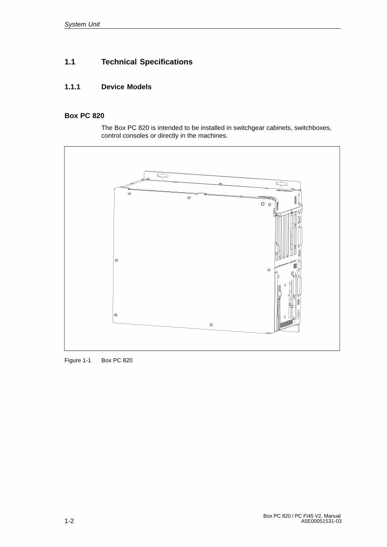
Box PC 820
The Box PC 820 is intended to be installed in switchgear cabinets, switchboxes,control consoles or directly in the machines.
Figure 1-1 Box PC 820
System Unit
1-3Box PC 820 / PC FI45 V2, ManualA5E00051531-03
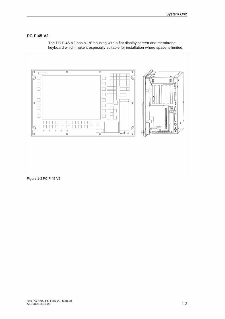
PC FI45 V2
The PC FI45 V2 has a 19” housing with a flat display screen and membranekeyboard which make it especially suitable for installation where space is limited.
Figure 1-2 PC FI45 V2
System Unit
1-4Box PC 820 / PC FI45 V2, Manual
A5E00051531-03
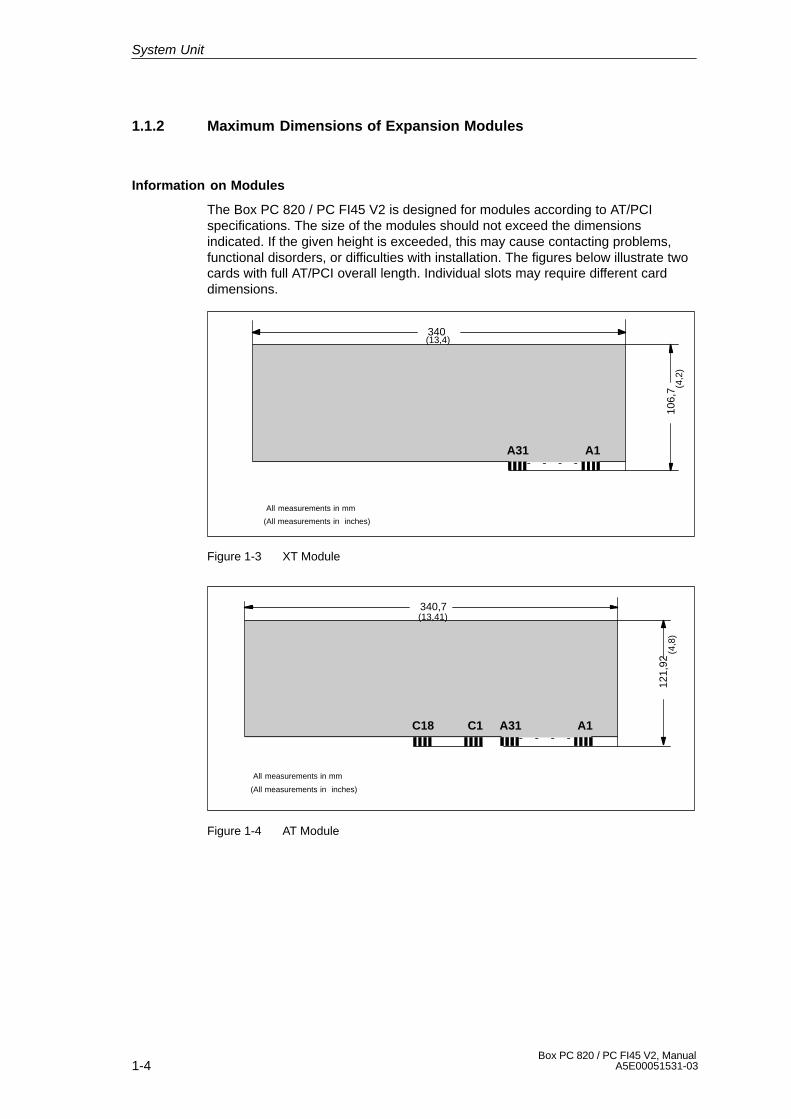
1.1.2 Maximum Dimensions of Expansion Modules
Information on Modules
The Box PC 820 / PC FI45 V2 is designed for modules according to AT/PCIspecifications. The size of the modules should not exceed the dimensionsindicated. If the given height is exceeded, this may cause contacting problems,functional disorders, or difficulties with installation. The figures below illustrate twocards with full AT/PCI overall length. Individual slots may require different carddimensions.
340
106,
7
A31 A1
All measurements in mm
(13,4)
(4,2
)
(All measurements in inches)
Figure 1-3 XT Module
340,7
121,
92
A31 A1C18 C1
(13,41)
(4,8
)
All measurements in mm
(All measurements in inches)
Figure 1-4 AT Module
System Unit
1-5Box PC 820 / PC FI45 V2, ManualA5E00051531-03
312
106,
68
8,19
(12,28)
(4,2
)
(0,3
2)
All measurements in mm
(All measurements in inches)
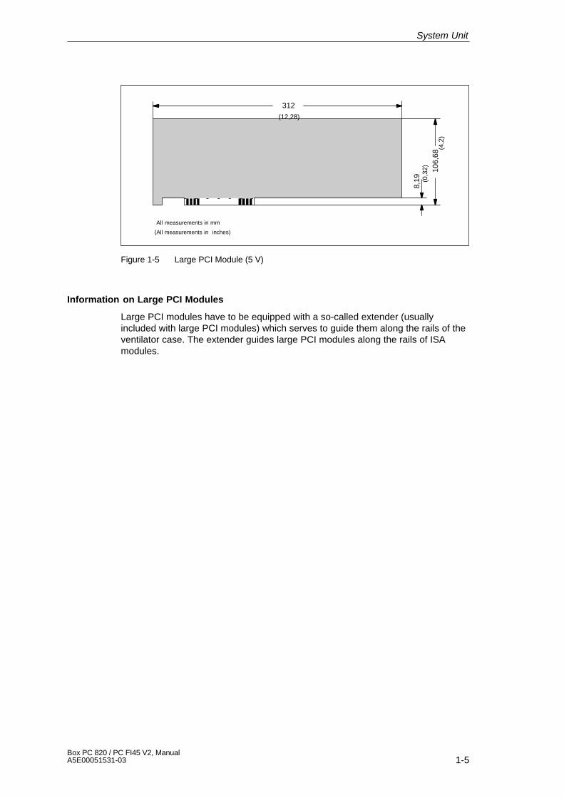
Figure 1-5 Large PCI Module (5 V)
Information on Large PCI Modules
Large PCI modules have to be equipped with a so-called extender (usuallyincluded with large PCI modules) which serves to guide them along the rails of theventilator case. The extender guides large PCI modules along the rails of ISAmodules.
System Unit

1-6Box PC 820 / PC FI45 V2, Manual
A5E00051531-03
1.2 Power Requirements of the Components (Maximum Values)
Basic System
Component Voltage
+5V +3.3V +12V –5V –12V AUX5V
Pentium III motherboard 8 A 1.5 A 0.1 A 0.01 A 0.02 A 0.05 A
Floppy disk drive 0.45 A
Hard disk 0.6 A 0.66 A
CD-ROM drive 0.7 A
Fan 0.3 A
Sum Box PC 820 (basic configu-ration)
9.75 A 1.5 A 1.06 A 0.01 A 0.02 A 0.05 A
Keyboard controller (only forPC FI45 V2)
0.15 A
Touch pad (only for PC FI45 V2) 0.05 A
TFT display (only for PC FI45 V2) 0.7 A
Inverter (incl. backlight, only for PCFI45 V2)
0.5 A
Sum Box PC 820 (max. for basicconfiguration)
9.95 A 2.2 A 1.56 A 0.01 A 0.02 A 0.05 A
ISA slots (sum for 3 slots) 5 A 2 A 0.3 A 0.3 A
PCI slots (sum for 3 slots) 5 A 2 A 0.2 A 0.2 A
Sum (max. for maximum confi-guration)
20 A 10 A 8 A 0.5 A 0.5 A 0.05 A
Options
Component Voltage
+5V +3.3V +12V –5V –2V AUX5V
WinAC FI Station Pro (SlotPLC) 0.35 A 1.3A
Direct key module 0.5 A
‘SafeCard’ monitoring module 0.35A 0.05 A
Restrictions on Power Supply
Due to thermal stress, the maximum capacity of the power supply is restricted to:
Power supply Restriction
Standard power supply (220 W) maximum load 150 W
System Unit
1-7Box PC 820 / PC FI45 V2, ManualA5E00051531-03
1.3 Removing and Installing Components
Prerequisites
The system unit is designed to enable any necessary maintenance work to becarried out quickly and at low cost.
!Warning
Please read the warnings at the front of the User’s Guide before you open thehousing of the system unit.
� Do not open the housing unless you need to install or remove components, orto replace the battery.
� Write down your configuration parameters before starting the procedure.
!Caution
Risk of damage to the unit!
Note that only qualified personnel should be allowed to work on the open unit, so thewarranty on the device is not affected. Authorized Siemens maintenance and repaircenters offer you a specialist maintenance service. The User’s Guide contains theaddresses.
!Caution
The electronic components of the printed boards are extremely sensitive toelectrostatic discharge. When handling the boards, you must take appropriatesafety precautions. These are set out in the guidelines for electrostaticallysensitive components (ESD guidelines) in the appendix of this manual and in theoperating instructions.
Limitation of Liability
All technical specifications and licenses apply only to expansion functionsapproved by Siemens. No liability can be assumed for functional constraintscaused by the use of devices and components of other manufacturers.
The following sign warns that electrostatically sensitive modules are present.Please read the ESD guidelines.
System Unit
1-8Box PC 820 / PC FI45 V2, Manual
A5E00051531-03
Before Opening the Unit
Before opening the unit, you should read the following rules carefully:
� Before you disconnect the power supply cable, discharge any electrostaticcharge on your body. You can do this by touching metallic parts, such asscrews, on the rear panel of the PG.
� Discharge any electrostatic charge from tools that you are using.
� Wear a grounding wrist strap if you are handling components.
� Leave components and modules in their packaging until you are ready to installthem.
� Disconnect the PC from its power supply before plugging in or removing anymodules or components.
� Touch components and modules only on their edges. Above all, do not touchthe connecting pins and printed conductors.
� Do not operate the PC with the cover open.
Tools
Use a suitable crosstip or TORX screwdriver to remove or install components.
System Unit

1-9Box PC 820 / PC FI45 V2, ManualA5E00051531-03
1.3.1 Opening and Closing the Housing of the Box PC 820
� Close the application you are using.
� Remove the diskette or CD-ROM from the drive.
� Pull out the power supply connector.
� Remove the PC from its support.
� Remove the seven screws on the rear housing plate.
Housing top plate
Fastening screws
Rear housing plate
Figure 1-6 Opening the Housing of the Box PC 820
System Unit

1-10Box PC 820 / PC FI45 V2, Manual
A5E00051531-03
When the rear housing plate is removed, you see the followingcomponents/function units:
– Power supply
– Floppy disk drive and CD-ROM drive
– Motherboard
– Bus board with expansion slots
– Fan
– Processor
– RAM memory module(s)
– Hard disk drive
Bus board with expansion slots
RAM memory moduleMotherboard
Power supply
Fan
Processor
Floppy disk drive and CD-ROM drive
Hard disk drive
Figure 1-7 Function Units when the Box PC 820 is Opened
System Unit
1-11Box PC 820 / PC FI45 V2, ManualA5E00051531-03
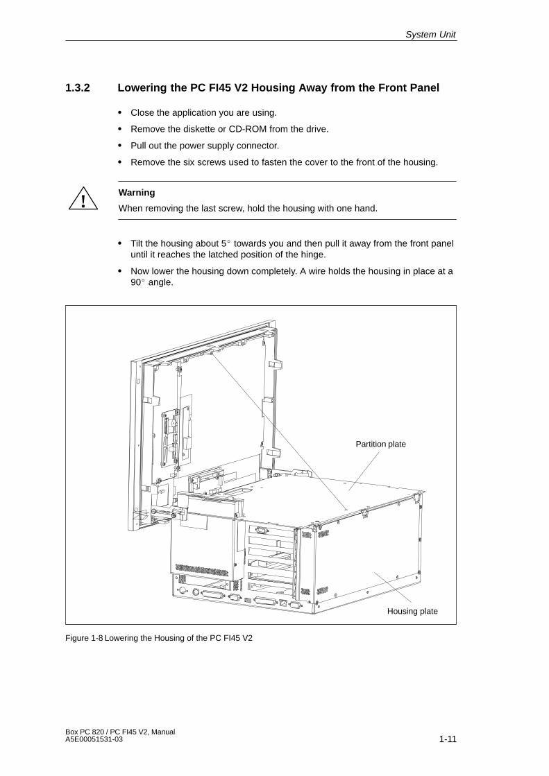
1.3.2 Lowering the PC FI45 V2 Housing Away from the Front Panel
� Close the application you are using.
� Remove the diskette or CD-ROM from the drive.
� Pull out the power supply connector.
� Remove the six screws used to fasten the cover to the front of the housing.
!Warning
When removing the last screw, hold the housing with one hand.
� Tilt the housing about 5� towards you and then pull it away from the front paneluntil it reaches the latched position of the hinge.
� Now lower the housing down completely. A wire holds the housing in place at a90� angle.
Partition plate
Housing plate
Figure 1-8 Lowering the Housing of the PC FI45 V2
System Unit
1-12Box PC 820 / PC FI45 V2, Manual
A5E00051531-03
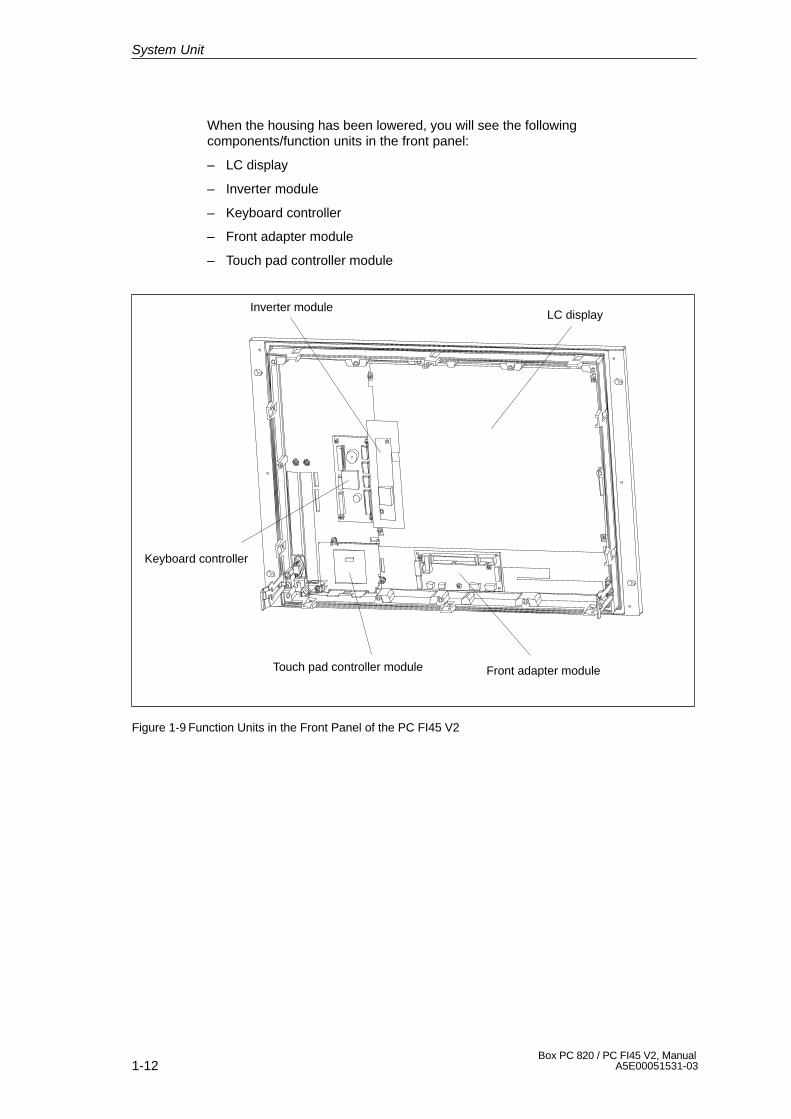
When the housing has been lowered, you will see the followingcomponents/function units in the front panel:
– LC display
– Inverter module
– Keyboard controller
– Front adapter module
– Touch pad controller module
LC display
Front adapter moduleTouch pad controller module
Keyboard controller
Inverter module
Figure 1-9 Function Units in the Front Panel of the PC FI45 V2
System Unit
1-13Box PC 820 / PC FI45 V2, ManualA5E00051531-03
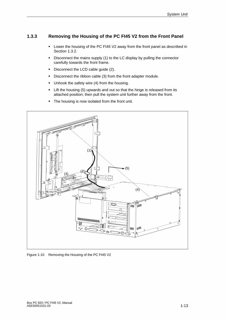
1.3.3 Removing the Housing of the PC FI45 V2 from the Front Panel
� Lower the housing of the PC FI45 V2 away from the front panel as described inSection 1.3.2.
� Disconnect the mains supply (1) to the LC display by pulling the connectorcarefully towards the front frame.
� Disconnect the LCD cable guide (2).
� Disconnect the ribbon cable (3) from the front adapter module.
� Unhook the safety wire (4) from the housing.
� Lift the housing (5) upwards and out so that the hinge is released from itsattached position; then pull the system unit further away from the front.
� The housing is now isolated from the front unit.
(4)
(5)
(1)
(3)(2)
Figure 1-10 Removing the Housing of the PC FI45 V2
System Unit
1-14Box PC 820 / PC FI45 V2, Manual
A5E00051531-03
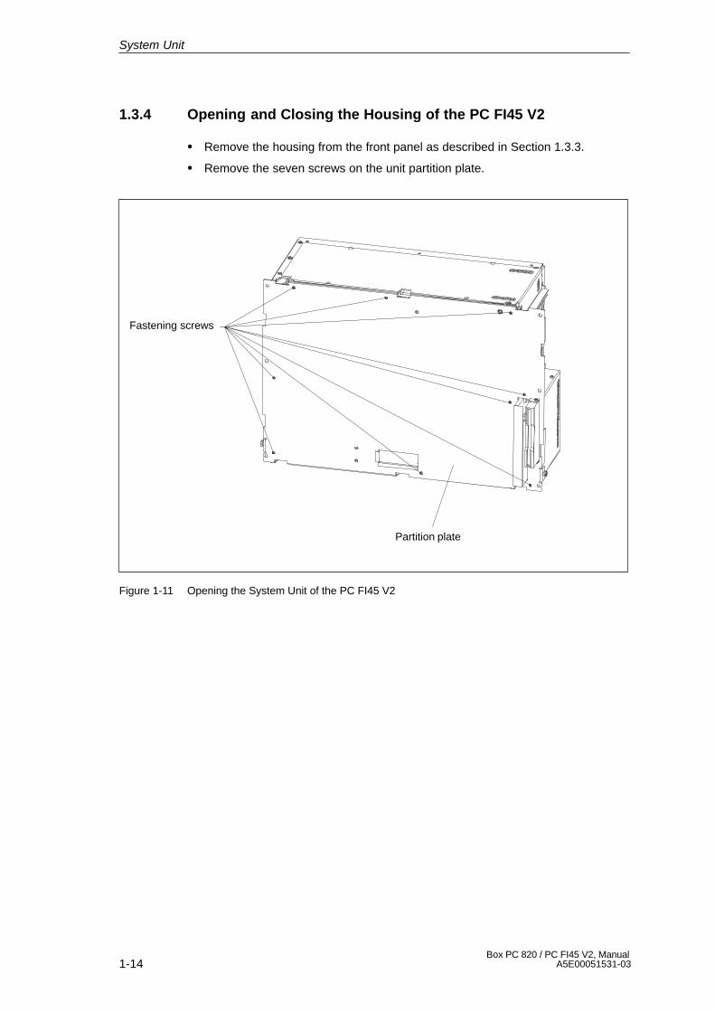
1.3.4 Opening and Closing the Housing of the PC FI45 V2
� Remove the housing from the front panel as described in Section 1.3.3.
� Remove the seven screws on the unit partition plate.
Partition plate
Fastening screws
Figure 1-11 Opening the System Unit of the PC FI45 V2
System Unit

1-15Box PC 820 / PC FI45 V2, ManualA5E00051531-03
When the partition plate is removed, you see the following components/functionunits:
– Power supply
– Floppy disk drive and CD-ROM drive
– Motherboard
– Bus board
– Fan
– Processor
– RAM memory module(s)
MotherboardRAM memory module
Fan
Processor
Power supply
Bus board
Floppy disk drive
CD-ROMdrive
Figure 1-12 Function Units when the PC FI45 V2 is Opened
System Unit
1-16Box PC 820 / PC FI45 V2, Manual
A5E00051531-03
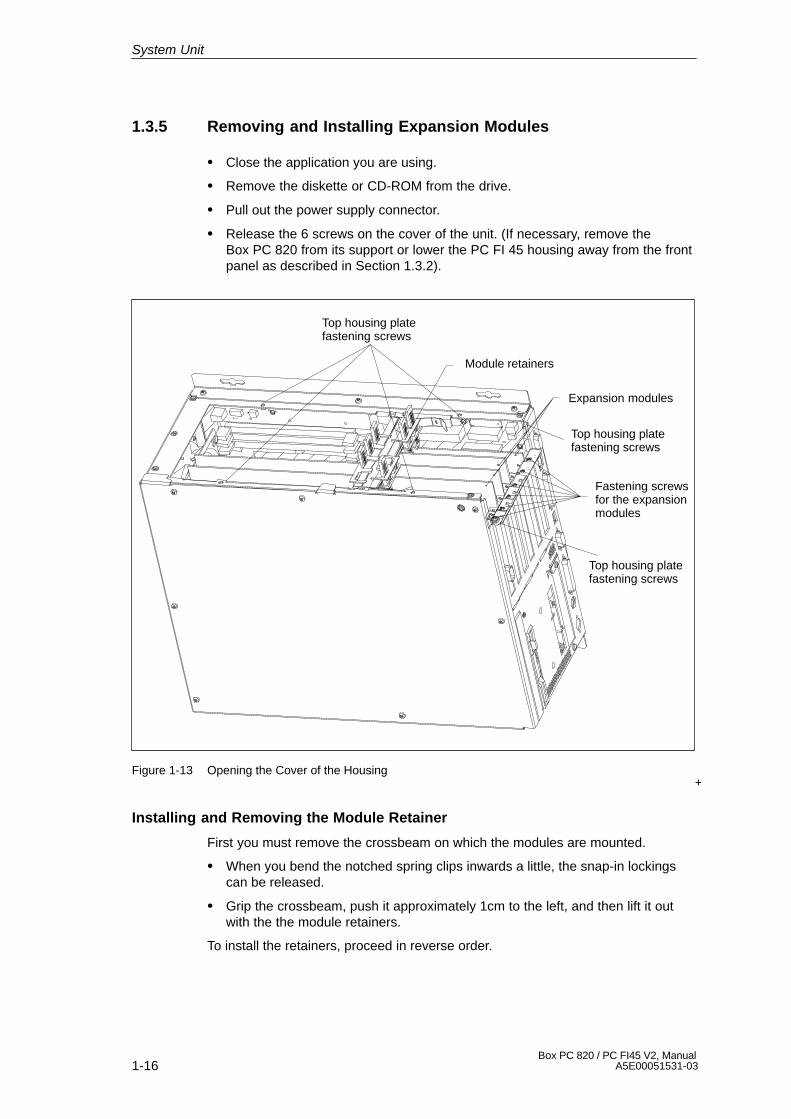
1.3.5 Removing and Installing Expansion Modules
� Close the application you are using.
� Remove the diskette or CD-ROM from the drive.
� Pull out the power supply connector.
� Release the 6 screws on the cover of the unit. (If necessary, remove theBox PC 820 from its support or lower the PC FI 45 housing away from the frontpanel as described in Section 1.3.2).
+
Expansion modules
Top housing platefastening screws
Fastening screwsfor the expansionmodules
Module retainers
Top housing platefastening screws
Top housing platefastening screws
Figure 1-13 Opening the Cover of the Housing
Installing and Removing the Module Retainer
First you must remove the crossbeam on which the modules are mounted.
� When you bend the notched spring clips inwards a little, the snap-in lockingscan be released.
� Grip the crossbeam, push it approximately 1cm to the left, and then lift it outwith the the module retainers.
To install the retainers, proceed in reverse order.
System Unit
1-17Box PC 820 / PC FI45 V2, ManualA5E00051531-03
Installing and Removing Expansion Modules
� Disconnect all mains connections to the module to be removed.
� Undo the screw which fastens the expansion module to the side of the systembox.
� Pull the module carefully out of the slot – without tilting it.
� Set the DIP switches and jumpers of the new module according to theappropriate module documentation.
To install the new module, proceed in reverse order. After installing/exchanging anexpansion module, the retainers may need to be readjusted. To do this, proceed asfollows:
Adjusting the Retainer
� Insert the sliding element at the top and push it down until it covers the module.Then guide the module into the notch.
!Caution
Do not exert pressure on the module. This means that you should not push downor force the retainers in any way.
� Detach the part of the sliding element which juts out by scratching a notch inthe top of the sliding element with a knife and then bending it over to break itoff.
System Unit
1-18Box PC 820 / PC FI45 V2, Manual
A5E00051531-03
1.3.6 Removing and Installing the Power Supply Unit
� Open the housing as described in Section 1.3.1 (Box PC 820) or Section 1.3.4(PC FI45 V2).
� Release the three screws with which the bent clips of the power supply supportare fastened to the housing.
� Pull the power supply unit and its support right out of the housing.
� Disconnect the cables from the motherboard, the hard disk, and the busexpansion unit, and write down their previous connections.
� Release the four screws with which the power supply support is attached to thepower supply unit.
To install the power supply unit, proceed in reverse order.
Changing the Supply Voltage
The standard power supply is for 115/230V networks. The voltage selection switchis located at the side of the housing below the ventilation slots.
You must ensure that the supply voltage set at the voltage selection switchcorresponds to the local supply voltage.
The voltage selection ist made automatically in wide range power supply units.
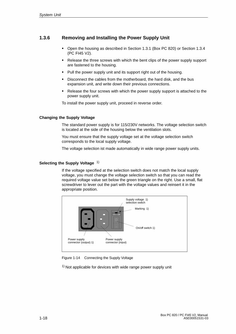
Selecting the Supply Voltage 1)
If the voltage specified at the selection switch does not match the local supplyvoltage, you must change the voltage selection switch so that you can read therequired voltage value set below the green triangle on the right. Use a small, flatscrewdriver to lever out the part with the voltage values and reinsert it in theappropriate position.
Power supplyconnector (output) 1)
Power supplyconnector (input)
On/off switch 1)
�
Supply voltage 1)selection switch
Marking 1)
Figure 1-14 Connecting the Supply Voltage
1) Not applicable for devices with wide range power supply unit
System Unit
1-19Box PC 820 / PC FI45 V2, ManualA5E00051531-03
!Caution
Damage may be caused to the device!
Operating the PC with the wrong supply voltage setting may damage the device.The same voltage is applied to the supply voltage output as to the supply voltageinput.
Please observe the specifications made by the monitor manufacturer whenoperating the monitor.
The following table lists the permissible input currents for the monitor:
Input voltage 120 V / 240 V ± 10%
Input current 8A / 4A
Output voltage Equal to input voltage
Max. output current 3A / 1.5A
!Caution
You must remove the power supply connector before changing the supply voltage.
Operating a power supply unit set to 115V in conjunction with a 230V network maycause serious damage to the PC.
System Unit
1-20Box PC 820 / PC FI45 V2, Manual
A5E00051531-03
1.3.7 Removing and Installing the Bus Board
� First remove all expansion modules as described in Section 1.3.5.
� Open the housing as described in Section 1.3.1 (Box PC 820) or Section 1.3.4(PC FI45 V2).
� Remove the power supply connection from the bus board.
� Release the two screws on the bus board.
� Lift the bus board out of the connector to the motherboard.
To install the bus board, proceed in reverse order.
1.3.8 Removing and Installing the Fan
� First remove all expansion modules as described in Section 1.3.5.
� Remove the power supply connection for the fan from the motherboard.
� The fan is fastened to the system unit with four plastic rivets. Remove theplastic rivets by pressing the pin out from behind.
� Take out the fan and the metal plate to which the guide rails are attached.
� Detach the plate with the guide rails by releasing the four plastic rivets.
To install the fan, proceed in reverse order.
System Unit

1-21Box PC 820 / PC FI45 V2, ManualA5E00051531-03
1.3.9 Removing and Installing a Floppy Disk Drive or CD-ROM Drivefor the Box PC 820
The floppy disk drive and the CD-ROM drive are fitted in a single support in thehousing.
� Open the housing as described in Section 1.3.1.
� Lay the housing face up on a flat surface.
� Remove the three screws with which the support is fastened to the housing.
� Disconnect the disk drive connection cables and lift the support carefully out ofthe housing.
!Caution
Before you remove the flexible cable from the floppy disk drive, you must firstrelease the interlock on the port.
� The floppy disk drive is fastened to the support with three screws. Removethese screws and pull the drive out of the support.
� The CD-ROM drive is fastened to the support with three screws. Remove thescrews and pull the drive out of the support.
To install the drives, proceed in reverse order.
Drive support Fastening screws for drive support
CD-ROMdrive
Floppy disk drive
Figure 1-15 Floppy Disk/CD-ROM Drive Support on the Box PC 820
Note
The floppy disk/CD support can also be installed in the housing at a 90� angle.This is necessary if the unit is installed with the network connection at the top. Thefloppy disk drive may not be operated with the opening for the diskettes face up orface down.
System Unit

1-22Box PC 820 / PC FI45 V2, Manual
A5E00051531-03
1.3.10 Removing and Installing a Floppy Disk Drive or CD-ROM Drivefor the PC FI45 V2
The floppy disk drive and the CD-ROM drive are fitted in a single support in thesystem housing.
� Open the housing as described in Section 1.3.4.
� Lay the housing on a flat surface with the opening face up.
� Raise the support approximately 1cm and lower it to one side of the housing.
� Remove the connecting cables.
!Caution
Before you remove the flexible cable from the floppy disk drive, you must firstrelease the interlock on the port.
� The floppy disk drive is fastened to the support with three screws. Remove thescrews and pull the drive out of the support.
� The CD-ROM drive is fastened to the support with two screws. Remove thescrews and pull the drive out of the support.
To install the drives, proceed in reverse order.
Fastening screws forfloppy disk drive
Fastening screws forCD-ROM drive
Figure 1-16 Floppy Disk/CD-ROM Drive Support for the PC FI45 V2
System Unit
1-23Box PC 820 / PC FI45 V2, ManualA5E00051531-03
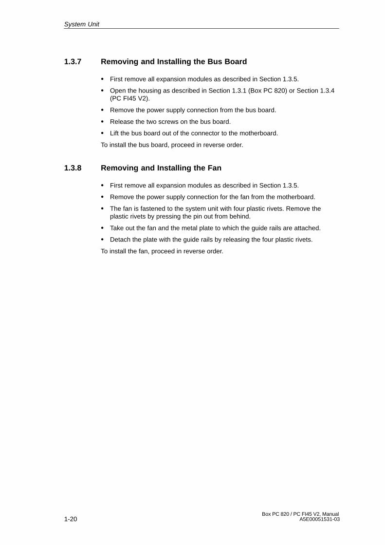
1.3.11 Removing and Installing the Hard Disk
� If you are using the Box PC 820, remove the floppy disk/CD-ROM drive supportas described in Section 1.3.9.
� If you are using the PC FI45 V2, lower the floppy disk/CD-ROM drive support toone side of the housing as described in Section 1.3.10.
� Remove the four screws with which the hard disk support is fastened to thehousing.
� Remove the disk drive connecting cables and lift the support carefully out of thehousing.
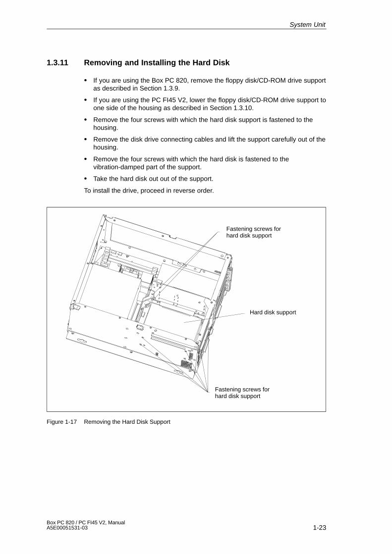
� Remove the four screws with which the hard disk is fastened to thevibration-damped part of the support.
� Take the hard disk out out of the support.
To install the drive, proceed in reverse order.
Hard disk support
Fastening screws forhard disk support
Fastening screws forhard disk support
Figure 1-17 Removing the Hard Disk Support
System Unit
1-24Box PC 820 / PC FI45 V2, Manual
A5E00051531-03
Hard disk support
Fastening screwsHard disk drive
Figure 1-18 Removing the Hard Disk Drive from the Support
System Unit
1-25Box PC 820 / PC FI45 V2, ManualA5E00051531-03
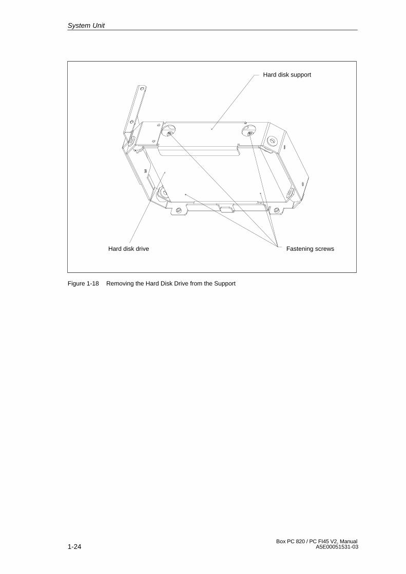
1.3.12 Removing and Installing the Motherboard
� Open the housing as described in Section 1.3.1 (Box PC 820) or Section 1.3.4(PC FI45 V2).
� Remove the power supply as described in Section 1.3.6.
� Remove the bus board as described in Section 1.3.7.
� Remove the fan as described in Section 1.3.8.
� Remove the support for the floppy disk drive and the CD-ROM drive asdescribed in Section 1.3.9 (Box PC 820) or Section 1.3.10 (PC FI45 V2).
� Remove the hard disk support as described in Section 1.3.11.
� The motherboard is fastened to the housing with seven screws and to the sideof the system unit with 10 hexagonal socket screws.
� Undo these socket screws and remove the motherboard.
To install the motherboard, proceed in reverse order. Tighten the 10 hexagonalsocket screws first.
Hexagonalsocket screws
Motherboard
Fasteningscrews
Figure 1-19 Removing the Motherboard
System Unit
1-26Box PC 820 / PC FI45 V2, Manual
A5E00051531-03
1.3.13 Removing and Installing the Membrane Keyboard or FrontComponents of the PC FI45 V2
After the device has been installed, the membrane keyboard or front componentscan be exchanged from the front. Proceed as follows:
� Close the application you are using.
� Open the cover of the disk drive and remove the diskette or CD-ROM.
� Pull out the mains connector.
� Remove the 10 screws with which the membrane keyboard is fastened to thefront frame.
� Grip the cover of the disk drive carefully and pull the membrane keyboardforwards and off.
!Caution
There is nothing to prevent the keyboard from falling.
� Unplug the 40-pin connector from the front adapter module and disconnect theinterface cable carefully from the display.
� Remove the membrane keyboard and the front components mounted on it.
To install the membrane keyboard, proceed in reverse order.
System Unit
1-27Box PC 820 / PC FI45 V2, ManualA5E00051531-03
1.3.14 Removing and Installing the Keyboard Controller for thePC FI45 V2
� Lower the housing of the PC FI45 V2 away from the front as described inSection 1.3.2 or remove the membrane keyboard as described in Section1.3.13.
� Remove the two screws and then remove the support with the inverter module.
� Remove the two connection cables for the membrane keyboard.
!Caution
Before you remove the membrane keyboard connecting cables, release the inter-locks on the ports so that the contacts of the connecting cables are not damaged.
� Before you unplug all the other connectors to the keyboard controller, writedown their arrangement.
� Remove the two remaining support screws; you can then lift out the keyboardcontroller board.
To install the keyboard controller, proceed in reverse order.
1.3.15 Removing and Installing the Inverter Module for the PC FI45 V2
� Lower the housing of the PC FI45 V2 away from the front panel as described inSection 1.3.2 or remove the membrane keyboard as described in Section1.3.13.
� Before you unplug all the inverter module connectors, write down theirarrangement.
� Remove the two inverter support screws and remove the support.
� The inverter module is fastened to the support with two plastic rivets. Removethe rivets, by pressing the pin out from behind.
To install the inverter module, proceed in reverse order.
!Caution
When installing the module, do not forget to place the insulating foil between theinverter module and the metal plate.
System Unit

1-28Box PC 820 / PC FI45 V2, Manual
A5E00051531-03
1.3.16 Removing and Installing the Display for the PC FI45 V2
� Lower the system box of the PC FI45 V2 away from the front panel asdescribed in Section 1.3.2 or remove the membrane keyboard as described inSection 1.3.13.
� Remove the two screws with which the support for the inverter module ismounted.
� Before you unplug all the connectors, write down their arrangement.
� Remove the display connector.
� Remove the four screws with which the display is secured and then remove thedisplay.
To install the display, proceed in reverse order.
1.3.17 Removing and Installing the Touch Pad for the PC FI45 V2
� Remove the membrane keyboard as described in Section 1.3.13.
� Remove the three touch pad module screws on the installation plate.
� Remove the installation plate and the copper-colored sheet-metal springunderneath.
� Take out the touch pad module and detach the flexible cord (contact side facesmodule).
To install the touch pad, proceed in reverse order.
1.3.18 Removing and Installing the Front Adapter Module for thePC FI45 V2
� Lower the housing of the PC FI45 V2 away from the front panel as described inSection 1.3.2, or remove the membrane keyboard as described in Section1.3.13.
� Before you unplug all the other connectors, write down their arrangement.
!Caution
Before you remove the membrane connecting cables, release the interlocks onthe ports so that the contacts of the connecting cables are not damaged.
� After removing the three screws; then you can remove the front adaptermodule.
To install the front adapter module, proceed in reverse order.
System Unit
1-29Box PC 820 / PC FI45 V2, ManualA5E00051531-03
1.4 Connecting the MPI/DP Interface
Connecting a PROFIBUS-DP Network via MPI/DP Interface
You can connect your IPC to PROFIBUS-DP networks via the optically isolated *)MPI/DP interface. The connection is established via SINEC L2 components forstationary links or via an MPI connecting cable with a length of 5 meters for non-stationary links (order no.: 6ES7001-0BF00-0AA0). SINEC L2 components andMPI connecting cables are not included with the IPC and have to be ordered sepa-rately. The MPI connecting cable (5m) can only be employed for data transfer ratesup to 187.5 Kbps.
To connect your IPC to a PROFIBUS-DP network, proceed as follows:
1. Switch off your IPC.
2. Plug the connecting cable (of the SINEC L2 components or the MPI connectingcable) into the MPI/DP socket connector of your IPC and tighten the connectorby means of screw-type locking.
3. Switch on your IPC.
!Caution
Risk of damage to the unit!
Before plugging in the connecting cables, you must discharge the electrostaticcharge of the cables and of your body by briefly touching a grounded object (ESDguideline).
PROFIBUS-DP Network
You can network up to 32 devices (PC, PG, PLC or DP components) via the MPI/DP interface in one segment. The interconnection to the PROFIBUS-DP segmentsis established via an optically isolated *) RS 458 port, which is part of the interface.
Interconnect several PROFIBUS-DP segments via a repeater.
The entire PROFIBUS-DP network has a maximum capacity of 127 stations. Thedata transfer rate of the MPI network is 187.5 Kbps. The data transfer rate that canbe achieved via MPI/DP interface in the PROFIBUS-DP network ranges from9.6 Kbps up to 12 Mbps.
Note
For further information on configuring a PROFIBUS-DP network please refer tothe “S7-300 Hardware Manual.
*) Optically isolated within SELV circuit
System Unit
1-30Box PC 820 / PC FI45 V2, Manual
A5E00051531-03
1.5 Point-to-Point Connections
Point-to-Point Connection
In this section, you will learn how to connect your device to a programming deviceor programmable controller using a point-to-point connection.
You can establish a point-to-point connection by connecting the SIMATIC PC to aprogramming device or a programmable controller via:
� A V.24 connection.
� A TTY connection.
Suggestions for Configuring TTY (20 mA) Interfaces
Reliable data transfer depends on several factors. The data transfer rate you canachieve depends on the distance, the type of cable, the type of interface and anyinterference present.
Rules
You can reduce interference by choosing the right transmission cable andconnecting it properly, and observing the following guidelines:
� Use a shielded cable with a low surge impedance (< 130 � / km) and lowcapacitance (< 90 pF/m). Twisted-pair cables enhance noise immunity due toinductance. A low surge impedance results in reduced voltage excursions andshorter charge reversal times. The larger the conductor cross-section, the lowerthe surge impedance for the same length of cable.
� The shorter the transmission link, the higher the maximum possible datatransfer rate.
� If there is an active sender and an active receiver at the same end of thetransmission link, the sequence of access priority to the transmission circuitmust be taken into account in order to achieve the longest possibletransmission link.
� Signal lines and power lines must not be run together. Signal lines must beinstalled as far away as possible from strong interference sources (for example, 400 V three-phase power cables).
� The active TTY interface with 12 V no-load voltage has been tested on a1000 m (3300 ft.) long cable at a transmission rate of 9600 bps in a normalnoisy environment (field strength < 3 V/m or 1 V/ft.). If a shielded LiYCY5x1x0.14 is used, reliable transmission is possible over a distance of up to1000 m (3300 ft.). The AS511 protocol (only one transmitter at a time) wasused for testing.
Note
The contaminating field of the interference source decreases exponentially withthe distance.
System Unit

1-31Box PC 820 / PC FI45 V2, ManualA5E00051531-03
Connecting the SIMATIC PC to S5 Programmable Controllers
You can connect the PC to a SIMATIC S5 programmable controller via theCOM1/TTY interface port.
Connect your SIMATIC PC to a SIMATIC S5 programmable controller as follows:
1. Switch off the PC.
2. Plug the cable into the COM1/V.24 PLC interface port.
!Caution
Risk of damage to the device!
The interface port may be damaged if you confuse the connections or use thewrong connecting cables. Make sure the TTY cable of the PC is plugged into theCOM1/TTY port and not into the LPT1 port.
Before plugging in the cables, you must discharge your body’s electrostatic chargeby briefly touching a grounded object (ESD guideline).
Use only the original cables to establish the connection to the programmablecontroller.
The PC and the programmable controller must be operated at the same protectiveground potential.
Connecting the SIMATIC PC via an Adapter
An adapter is available for connecting the programmable controller using olderstandard cables.
Interface Link Connecting Cable Adapter
6ES5 734-2BD20
TTY interfacePC to SIMATIC S5programmable
6ES5 731-1xxx015-pin
6ES5 731-6AG00
(COM1) controller 6ES5 731-0xxx025-pin
6ES5 731-6AG00
Higher Data Transfer Rates at Distances of up to 1000 m (3300 ft.)
In order to maintain a data transfer rate of 9600 bps up to a distance of over1000 m (3300 ft), the receiving diode is connected to ground (reference) via theconnecting cable. Cables of various lengths are available under the Order No.6ES5 734-2xxx0 (xxx stands for the length in meters).
System Unit

1-32Box PC 820 / PC FI45 V2, Manual
A5E00051531-03
1.6 Error Diagnostics
Error Cause Remedy
Power-ON LED does not lightup
� PC is switched off� Power supply is not properly
connected
� Check power supplyconnections, power cable andpower plug
The “Invalid configurationinformation... Press the F1 keyfor continue, F2 to run Setuputility” appears on the screen
� Incorrect configuration data� Buffer battery is low or
damaged
� Press “F2” key, check theconfiguration data in SETUP,enter any default values, andcheck error messages in thefirst SETUP menu
The “No boot device available”appears on the screen
� There is no boot diskette inthe drive
� Wrong hard disk drive set inSETUP
� Use the “Fixed disk function”in SETUP
“Keyboard stuck key failure”message appears
� A key has become blocked during the system keyboardselftest
� Check the keyboard� Restart the system
Booting of the PC aborted afterseveral beeps
� An error has occured duringthe system self-test
� Check the hardware
Every time a key is pressed, abeep is heard and no charac-ters appear
� Keyboard buffer overflow � <CTRL> <PAUSE>
Not-ready message whentrying to write to a diskette
� No diskette has been inserted� Diskette has not been
formatted
� Insert diskette� Format diskette
Write-protect error when tryingto write to a diskette
� Diskette write-protectactivated
� Write-protect hole open on3.5” diskette
� Cancel write protection
“EPROM TSR Interfacedisabled, check PowerManagement” message
� “Programming Interface” hasbeen disabled in SETUP
� Enable “ProgrammingInterface” in SETUP undersubmenu “FI Hardwareoptions”
COM1,COM2, LPT1 or MPI/DPdo not respond
� Ports have been disabled inSETUP
� Enable COM1,COM2, LPT1or MPI/DP in SETUP undersubmenu “FI HardwareOptions.”
<\> key labeling missing � No original keyboard � German keyboard: <ALTGr > < ß >, or <ALT> <9> <2>
� International keyboard:<ALT> <9> <2>
<\> key is not displayed � Wrong keyboard driver isbeing used
� Load correct keyboard driver� <ALT> <9> <2>
PS/2 port keyboard trackballdoes not function (FI45 V2)
� FI45 V2 PS/2 port does notsupport trackballs.
System Unit

2-1Box PC 820 / PC FI45 V2, ManualA5E00051531-03
Motherboard
Chapter Overview
Section Description Page
2.1 Components and Interfaces 2-3
2.2 Processor 2-4
2.3 Memory 2-5
2.4 VGA Onboard 2-6
2.5 Changing the Backup Battery 2-7
2.6 Block Diagram of the Motherboard 2-8
2.7 Hardware Ports 2-9
2.8 Assignment of Connectors and Ports 2-12
2.8.1 Assignment of the IDE Ports, X3 Secondary, X4 Primary 2-12
2.8.2 Assignment of the EISA Riser X1 on the Motherboard 2-13
2.8.3 Battery Connection, X24 2-14
2.8.4 Internal Keyboard / Mouse / Inverter Connection for FI45, X44 2-14
2.8.5 Direct Key Module (Internal Box) FI45, X45 2-15
2.8.6 Internal Keyboard Connection for Box PC 820, X6 2-15
2.8.7 Internal COM2 Interface, X911 2-16
2.8.8 Voltage Supply for CD-ROM Drive, X25 2-16
2.8.9 Setting the Power Supply for the Display, X408 2-16
2.8.10 CMOS (Universal) Interface for TFT Displays, X401 2-17
2.8.11 LVDS Interface (Single Chip LVDS), X409 2-18
2.8.12 Selection of Display Type / Polarity of Backlight-On Signal(Switch S1)
2-18
2.8.13 VGA 2-19
2.8.14 PS/2 Mouse Connection, X7 2-20
2.8.15 Keyboard-Mouse Connection, X6 2-20
2.8.16 Assignment of the COM 1 Port, X10 2-21
2.8.17 Gender Changer for COM1 2-21
2.8.18 Assignment for the Floppy, X50 2-22
2.8.19 Assignment of the COM 2 Port, X11 2-23
2.8.20 Assignment of the Parallel Port, X9 2-24
2
2-2Box PC 820 / PC FI45 V2, Manual
A5E00051531-03
Section PageDescription
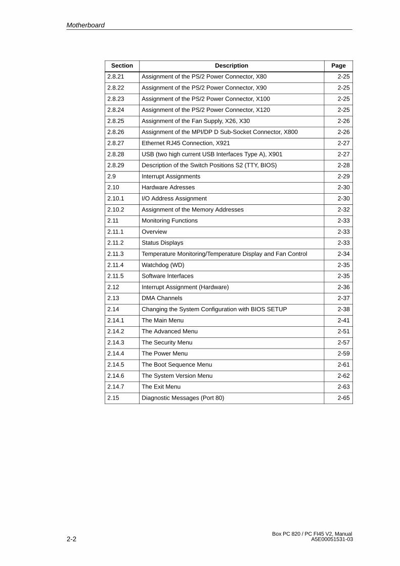
2.8.21 Assignment of the PS/2 Power Connector, X80 2-25
2.8.22 Assignment of the PS/2 Power Connector, X90 2-25
2.8.23 Assignment of the PS/2 Power Connector, X100 2-25
2.8.24 Assignment of the PS/2 Power Connector, X120 2-25
2.8.25 Assignment of the Fan Supply, X26, X30 2-26
2.8.26 Assignment of the MPI/DP D Sub-Socket Connector, X800 2-26
2.8.27 Ethernet RJ45 Connection, X921 2-27
2.8.28 USB (two high current USB Interfaces Type A), X901 2-27
2.8.29 Description of the Switch Positions S2 (TTY, BIOS) 2-28
2.9 Interrupt Assignments 2-29
2.10 Hardware Adresses 2-30
2.10.1 I/O Address Assignment 2-30
2.10.2 Assignment of the Memory Addresses 2-32
2.11 Monitoring Functions 2-33
2.11.1 Overview 2-33
2.11.2 Status Displays 2-33
2.11.3 Temperature Monitoring/Temperature Display and Fan Control 2-34
2.11.4 Watchdog (WD) 2-35
2.11.5 Software Interfaces 2-35
2.12 Interrupt Assignment (Hardware) 2-36
2.13 DMA Channels 2-37
2.14 Changing the System Configuration with BIOS SETUP 2-38
2.14.1 The Main Menu 2-41
2.14.2 The Advanced Menu 2-51
2.14.3 The Security Menu 2-57
2.14.4 The Power Menu 2-59
2.14.5 The Boot Sequence Menu 2-61
2.14.6 The System Version Menu 2-62
2.14.7 The Exit Menu 2-63
2.15 Diagnostic Messages (Port 80) 2-65
Motherboard
2-3Box PC 820 / PC FI45 V2, ManualA5E00051531-03
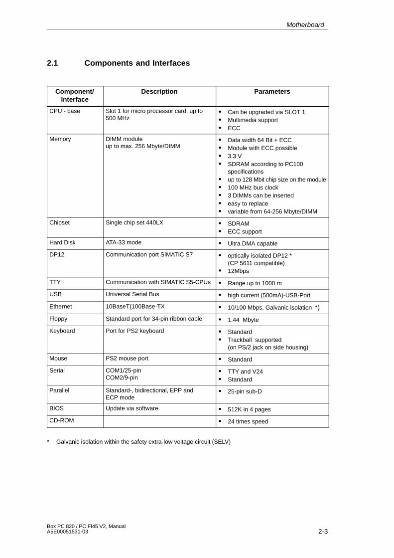
2.1 Components and Interfaces
Component/Interface
Description Parameters
CPU - base Slot 1 for micro processor card, up to500 MHz
� Can be upgraded via SLOT 1� Multimedia support� ECC
Memory DIMM moduleup to max. 256 Mbyte/DIMM
� Data width 64 Bit + ECC� Module with ECC possible� 3.3 V� SDRAM according to PC100
specifications� up to 128 Mbit chip size on the module� 100 MHz bus clock� 3 DIMMs can be inserted� easy to replace� variable from 64-256 Mbyte/DIMM
Chipset Single chip set 440LX � SDRAM� ECC support
Hard Disk ATA-33 mode � Ultra DMA capable
DP12 Communication port SIMATIC S7 � optically isolated DP12 *(CP 5611 compatible)
� 12Mbps
TTY Communication with SIMATIC S5-CPUs � Range up to 1000 m
USB Universal Serial Bus � high current (500mA)-USB-Port
Ethernet 10BaseT(100Base-TX � 10/100 Mbps, Galvanic isolation *)
Floppy Standard port for 34-pin ribbon cable � 1.44 Mbyte
Keyboard Port for PS2 keyboard � Standard� Trackball supported
(on PS/2 jack on side housing)
Mouse PS2 mouse port � Standard
Serial COM1/25-pinCOM2/9-pin
� TTY and V24� Standard
Parallel Standard-, bidirectional, EPP andECP mode
� 25-pin sub-D
BIOS Update via software � 512K in 4 pages
CD-ROM � 24 times speed
* Galvanic isolation within the safety extra-low voltage circuit (SELV)
Motherboard
2-4Box PC 820 / PC FI45 V2, Manual
A5E00051531-03
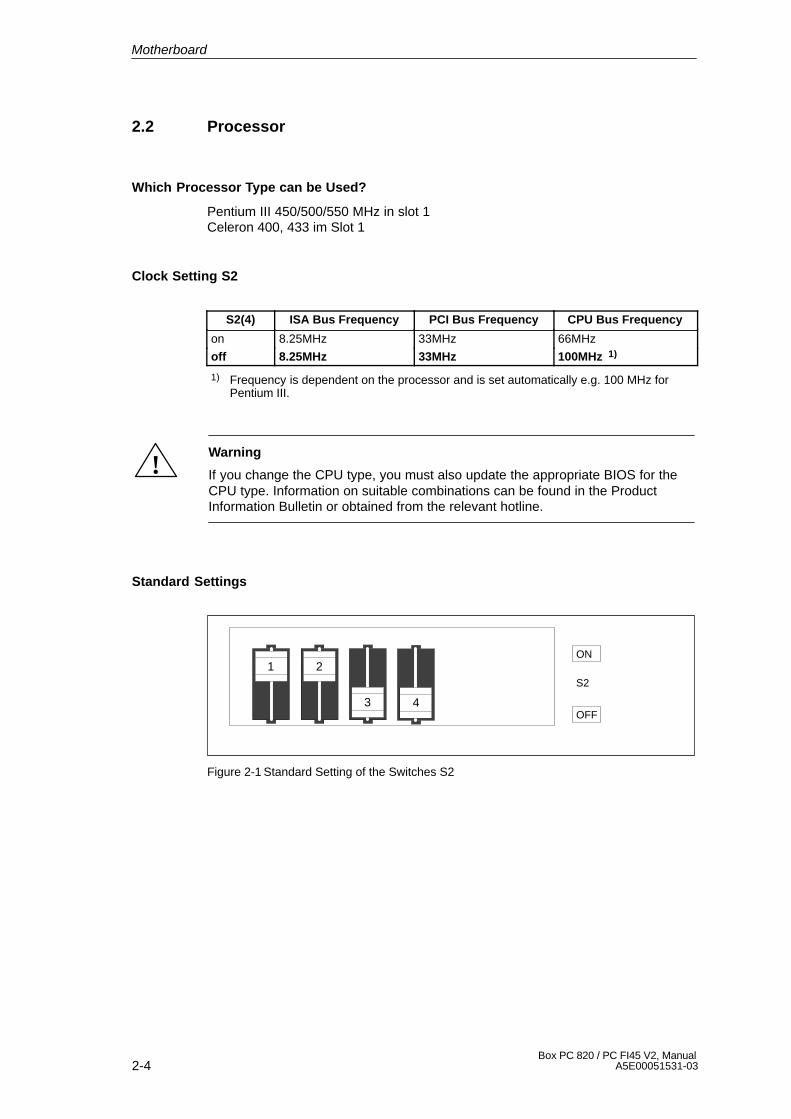
2.2 Processor
Which Processor Type can be Used?
Pentium III 450/500/550 MHz in slot 1Celeron 400, 433 im Slot 1
Clock Setting S2
S2(4) ISA Bus Frequency PCI Bus Frequency CPU Bus Frequency
on 8.25MHz 33MHz 66MHz
off 8.25MHz 33MHz 100MHz 1)
1) Frequency is dependent on the processor and is set automatically e.g. 100 MHz forPentium III.
!Warning
If you change the CPU type, you must also update the appropriate BIOS for theCPU type. Information on suitable combinations can be found in the ProductInformation Bulletin or obtained from the relevant hotline.
Standard Settings
1 2
3
ON
OFF
S2
4
Figure 2-1 Standard Setting of the Switches S2
Motherboard
2-5Box PC 820 / PC FI45 V2, ManualA5E00051531-03
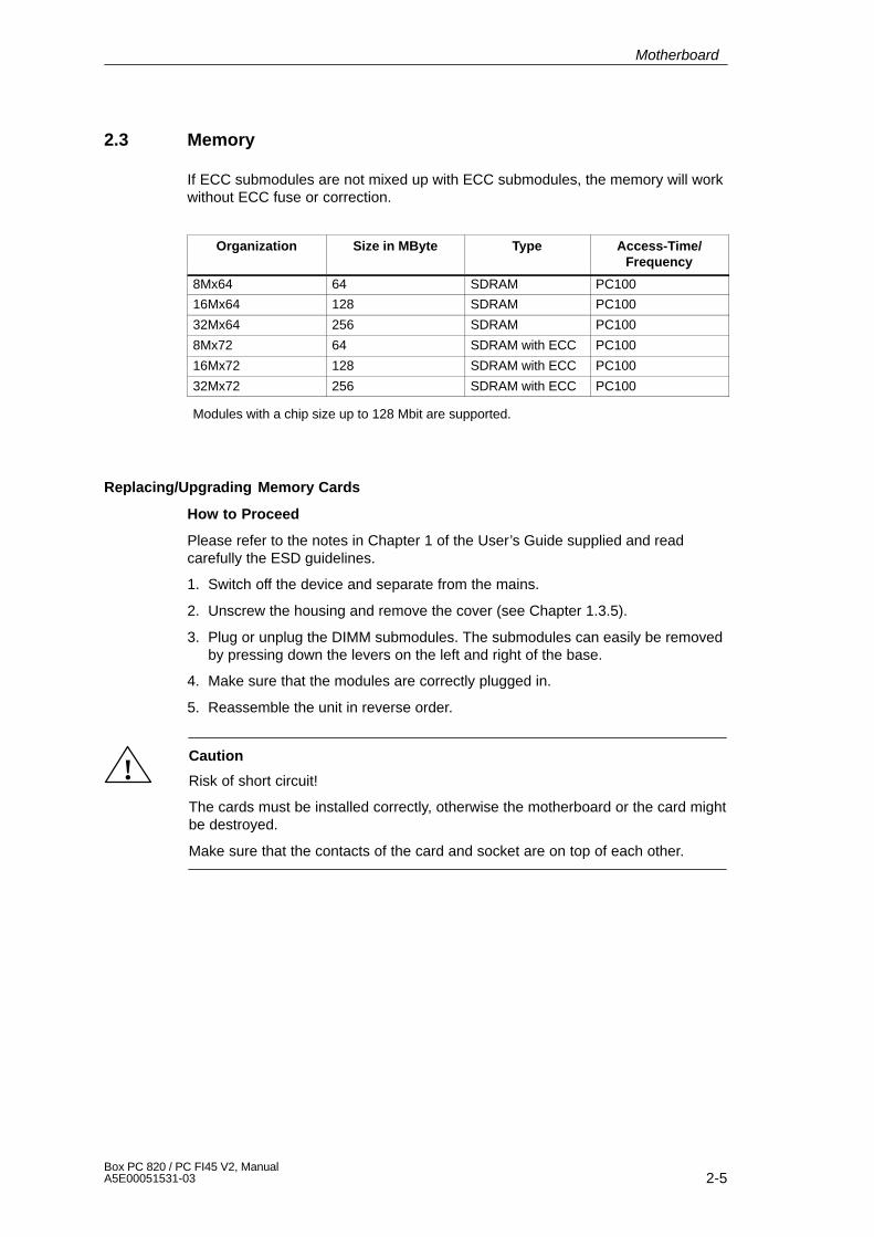
2.3 Memory
If ECC submodules are not mixed up with ECC submodules, the memory will workwithout ECC fuse or correction.
Organization Size in MByte Type Access-Time/Frequency
8Mx64 64 SDRAM PC100
16Mx64 128 SDRAM PC100
32Mx64 256 SDRAM PC100
8Mx72 64 SDRAM with ECC PC100
16Mx72 128 SDRAM with ECC PC100
32Mx72 256 SDRAM with ECC PC100
Modules with a chip size up to 128 Mbit are supported.
Replacing/Upgrading Memory Cards
How to Proceed
Please refer to the notes in Chapter 1 of the User’s Guide supplied and readcarefully the ESD guidelines.
1. Switch off the device and separate from the mains.
2. Unscrew the housing and remove the cover (see Chapter 1.3.5).
3. Plug or unplug the DIMM submodules. The submodules can easily be removedby pressing down the levers on the left and right of the base.
4. Make sure that the modules are correctly plugged in.
5. Reassemble the unit in reverse order.
!Caution
Risk of short circuit!
The cards must be installed correctly, otherwise the motherboard or the card mightbe destroyed.
Make sure that the contacts of the card and socket are on top of each other.
Motherboard
2-6Box PC 820 / PC FI45 V2, Manual
A5E00051531-03
2.4 VGA Onboard
Brief Description
The graphics interface module of the motherboard is a AGP implementation; thatis, the SVGA-LCD controller Chips and TE69000 is located on the board andconnected to the AGP bus. Its refresh memory has a backup capacity of 2 MBwhich cannot be upgraded.
Supported Resolutions
Two mode types are supported:
� standard modes and
� extended modes
Note
Some monitors do not support all modes. Your monitor automatically uses thehighest vertical scan frequency.
Motherboard
2-7Box PC 820 / PC FI45 V2, ManualA5E00051531-03
2.5 Changing the Backup Battery
Battery Power Supply for Real-Time Clock and Configuration
A backup battery powers the real-time clock even after the PC is switched off. Inaddition to the time of day, all information about the SIMATIC PC (configuration) isstored. If the backup battery fails or is removed, these data are lost.
Because of the clock’s low power consumption and the lithium battery’s highcapacity, the battery can provide backup power for the real-time clock for severalyears. Therefore, changing the battery is only seldom required.
Battery Voltage Too Low
If the battery voltage is too low, the current time setting is lost and a correctconfiguration can no longer be guaranteed.
Changing the Battery
In this case, you must replace the battery. The battery is located underneath thebus board.
To change the battery, proceed as follows:
1. Switch off your PC and unplug all connecting cables.
2. Open the housing as described in Section 1.
3. Remove the drive support and bus module.
4. Now replace the backup battery, which is attached to the motherboard by ashort length of a cable.
5. Reassemble drive support and bus module and close the unit.
!Caution
You may only replace the lithium battery with an identical battery or a battery typerecommended by the manufacturer.
Dispose of used batteries in keeping with local regulations (special waste). Ifreturned to the manufacturer, the battery materials can be recycled.
Resetting SETUP
After having changed the backup battery, you have to reset the configuration dataof your PC using the SETUP program.
Motherboard

2-8Box PC 820 / PC FI45 V2, Manual
A5E00051531-03
2.6 Block Diagram of the Motherboard
DIM
M S
ocke
t 0
6
4,12
8,25
6MB
3.3/
5 V
PC
I –B
US
32B
it D
aten
bus
gem
ultip
lext
mit
32B
it A
dres
sbus
(
33 M
Hz
Bus
takt
)
bus
mod
ule
Key
boar
dw
ith/w
ithou
t Tr
ackb
all
PS
/2
Mou
se
Com
mun
icat
ion
TT
Y/A
GM
odem
Prin
ter
Cen
tron
ics
CO
M2
RS
485
L2–D
P12
MB
/s
7515
0/15
4T
TL
TT
Y75
150/
154
RC
–Net
zpr
otec
tion
EP
P/E
CP
Pen
tium
IIIS
Lot
1
L2–C
ache
512K
HA
(0..3
1)H
D(0
..63)
+ E
CC
Cnt
l.
DC
/DC Vtt
= 1
,5V
5V
–>1,
5V
GTL
–Hos
t Bus
32
Bit
Adr
essb
us, 6
4 B
it D
aten
bus
+ E
CC
( 1
00M
Hz
Bus
takt
)
GT
L– P
ower
sup
ply
Term
inat
ion
Vol
tage
Vtt=
1,5V
DIM
M S
ocke
t 2
6
4,12
8,25
6MB
SD
RA
M
SD
RA
M
64 +
8(E
CC
)
DIM
M S
ocke
t 1
6
4,12
8,25
6MB
SD
RA
M
Pow
er–
Sup
ply
EC
C
EC
C
EC
C
12 x
100
MH
z
5V /
2,5V
14,3
198M
Hz
RISER
Soft On/Off
pote
ntia
lge
tren
nt
AS
PC
/2m
ax.
128k
Mem
ory
100
PQ
FP
+5V
+3.
3V
+12
V
–12V
–5V
’AB
T24
5
29F
040
BIO
S
512K
Byt
e
32 P
LCC
DC
/ D
C
Clo
cksy
nthe
size
rC
D93
18
1 sh
ared
ISA
PC
I
2 IS
A
+5V
AU
X
Mod
ul
3.5”
Flo
ppy
1.4
4 M
B
SD
RA
MC
lock
–B
uffe
r
LPT
1C
OM
1
Ultr
a–IO
FD
C37
B78
7
128
PQ
FP
5V33
MH
z
SA
(0:1
5),S
D(0
:7),
DR
Q/D
AC
K (0
:3),
BG
A 4
92
8244
3BX
440
BX
100
MH
z
100
MH
z
DC
/ D
CV
RM
– O
n B
oard
( U
CC
3588
)
48M
Hz(
US
B/A
SP
C )
[2]
100
/ 66
MH
z (
Hos
t/BX
)[4
]14
,318
MH
z (
OS
C )
[3]
33M
Hz
( P
CI
) [8
]
CY
2318
NZ
33 M
Hz 3,
3V
VC
C C
ore
2.0V
PC
I905
016
0 P
QF
P
5V
32K
Hz
3,6VP
rim.–
IDE
Sec
. ID
E
ATA
–33
har
d di
skC
D–R
OM
Bat
tery
32K
Hz
5 V
Loc
al –
BU
S 1
6Bit
Dat
enbu
s, C
hips
el.
( 8
MH
z B
usta
kt )
33M
Hz
33M
Hz
33M
Hz
Pag
e–S
elec
t f
ür 4
128
K–P
ages
US
B P
ort
setli
ch
Eth
erne
t10
BT
/100
BT
XR
J–45
BG
A 19
6
Fas
t E
ther
net
8255
9
3.3V
AU
X
66 M
Hz
3.3V
AG
P–B
us 3
2Bit
Dat
enbu
s ge
mul
tiple
xt m
it 32
Bit
Adr
essb
us
( 66
MH
z B
usta
kt )
5V IS
A–B
us 8
/16B
it D
aten
24B
it A
dres
sen
( 8
MH
z B
usta
kt )
14.3
18M
Hz
14.3
18 M
Hz
48 M
Hz
100
MH
z
100M
Hz
Mon
itorin
g fu
nctio
nsD
ispl
ay
Wat
chdo
g/Te
mpe
ratu
re
Wat
chdo
g–F
unkt
ion
Tem
pera
ture
Sen
sor
MA
X 1
617
Tem
pera
ture
sen
sors
CP
U
Dev
ice
PIIX
4ES
yste
mco
ntro
ller
Ech
tzei
tuhr
Sta
ndby
logi
c
BG
A 3
24
3,3V
33M
Hz
12
100
MH
z
2 P
CIex
t. X
GA
1280
x102
4x25
666
MH
z
VG
A-C
ontr
olle
r
3.3V
C&
T 6
90x0
2/4
MB
Vid
eo-M
emor
y in
tegr
ated
272
BG
A
C M O S40p
FI/
TF
T–D
islp
ay
XG
A –
Dis
pla
y
10
24
x7
68
LC
D
L V D S20p
US
B P
ort
Fro
ntst
ecke
r
Figure 2-2 Motherboard
Motherboard
2-9Box PC 820 / PC FI45 V2, ManualA5E00051531-03
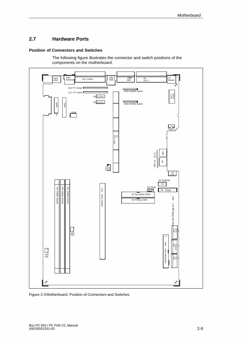
2.7 Hardware Ports
Position of Connectors and Switches
The following figure illustrates the connector and switch positions of thecomponents on the motherboard.
X921Ethernet X10 COM 1
X901USB
X18 TTY Empf. 1
1
X800MPI
X504 RS485 Hybrid
X9LPT 1
X7Mouse
X503 RS485 Hybrid1
1
X24
Battery
X6
Keyboard
1
X2
P3V
3
1X4 Primary EIDE
X1
PC
I / ISA
X21 D
IMM
–Socket
X19 D
IMM
–Socket
X20 D
IMM
–Socket
X12 S
lot1–Socket
X3 Secondary EIDE1
SV PSoff
X120
1 X50 1.44 M
B floppy disk drive
3P3V
X100
Pw
Good
X80
P5V
X90
P10
P8
P9
X26Fan
X30Fan
11
1
S2 1,2,3,4
X17 TTY Send.
X402VGA
S1 1,2,3,4
X40
9
X40
1
X66
X45DTM
X91
1C
om2
X5 Floppy
X44 front electronics
1X408
1
1
X25
Keyboard
FI 45
PC
820
SV CDROM
Figure 2-3 Motherboard: Position of Connectors and Switches
Motherboard
2-10Box PC 820 / PC FI45 V2, Manual
A5E00051531-03
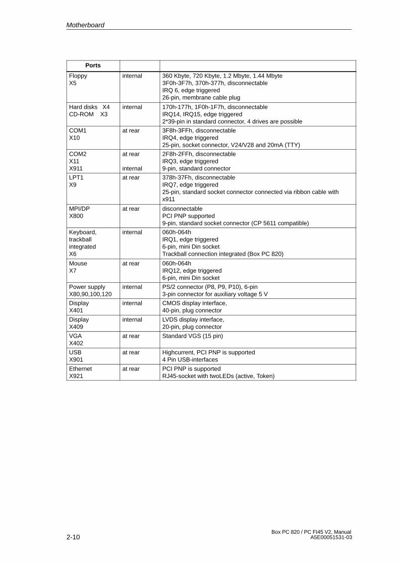
Ports
FloppyX5
internal 360 Kbyte, 720 Kbyte, 1.2 Mbyte, 1.44 Mbyte3F0h-3F7h, 370h-377h, disconnectableIRQ 6, edge triggered26-pin, membrane cable plug
Hard disks X4CD-ROM X3
internal 170h-177h, 1F0h-1F7h, disconnectableIRQ14, IRQ15, edge triggered2*39-pin in standard connector, 4 drives are possible
COM1X10
at rear 3F8h-3FFh, disconnectableIRQ4, edge triggered25-pin, socket connector, V24/V28 and 20mA (TTY)
COM2X11X911
at rear
internal
2F8h-2FFh, disconnectableIRQ3, edge triggered9-pin, standard connector
LPT1X9
at rear 378h-37Fh, disconnectableIRQ7, edge triggered25-pin, standard socket connector connected via ribbon cable withx911
MPI/DPX800
at rear disconnectablePCI PNP supported9-pin, standard socket connector (CP 5611 compatible)
Keyboard,trackballintegratedX6
internal 060h-064hIRQ1, edge triggered6-pin, mini Din socketTrackball connection integrated (Box PC 820)
MouseX7
at rear 060h-064hIRQ12, edge triggered6-pin, mini Din socket
Power supplyX80,90,100,120
internal PS/2 connector (P8, P9, P10), 6-pin3-pin connector for auxiliary voltage 5 V
DisplayX401
internal CMOS display interface, 40-pin, plug connector
DisplayX409
internal LVDS display interface, 20-pin, plug connector
VGAX402
at rear Standard VGS (15 pin)
USBX901
at rear Highcurrent, PCI PNP is supported4 Pin USB-interfaces
EthernetX921
at rear PCI PNP is supportedRJ45-socket with twoLEDs (active, Token)
Motherboard
2-11Box PC 820 / PC FI45 V2, ManualA5E00051531-03
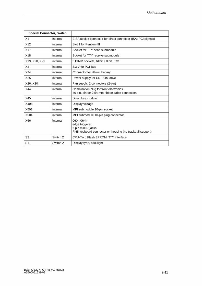
Special Connector, Switch
X1 internal EISA socket connector for direct connector (ISA; PCI signals)
X12 internal Slot 1 for Pentium III
X17 internal Socket for TTY send submodule
X18 internal Socket for TTY receive submodule
X19, X20, X21 internal 3 DIMM sockets, 64bit + 8 bit ECC
X2 internal 3,3 V for PCI-Bus
X24 internal Connector for lithium battery
X25 internal Power supply for CD-ROM drive
X26, X30 internal Fan supply, 2 connectors (2-pin)
X44 internal Combination plug for front electronics40 pin, pin for 2.54 mm ribbon cable connection
X45 internal Direct key module
X408 internal Display voltage
X503 internal MPI submodule 10-pin socket
X504 internal MPI submodule 10-pin plug connector
X66 internal 060h-064hedge triggered6 pin mini D-jacksFI45 keyboard connector on housing (no trackball support)
S2 Switch 2 CPU-Tact, Flash EPROM, TTY interface
S1 Switch 2 Display type, backlight
Motherboard

2-12Box PC 820 / PC FI45 V2, Manual
A5E00051531-03
2.8 Assignment of Connectors and Ports
2.8.1 Assignment of the IDE Ports, X3 Secondary, X4 Primary
Pin No. Description Pin No. Description
1 RSTDRV 21 PDREQ
2 Ground 22 Ground
3 D7 23 IOW_N
4 D8 24 Ground
5 D6 25 IOR_N
6 D9 26 Ground
7 D5 27 IORDY
8 D10 28 CS
9 D4 29 NC
10 D11 30 Ground
11 D3 31 ISAD7
12 D12 32 NC
13 D2 33 AD_1
14 D13 34 Reserved
15 D1 35 AD_0
16 D14 36 AD_2
17 D0 37 CS1_N
18 D15 38 CS3_N
19 Ground 39 HDACT_N
20 NC 40 Ground
Motherboard
2-13Box PC 820 / PC FI45 V2, ManualA5E00051531-03
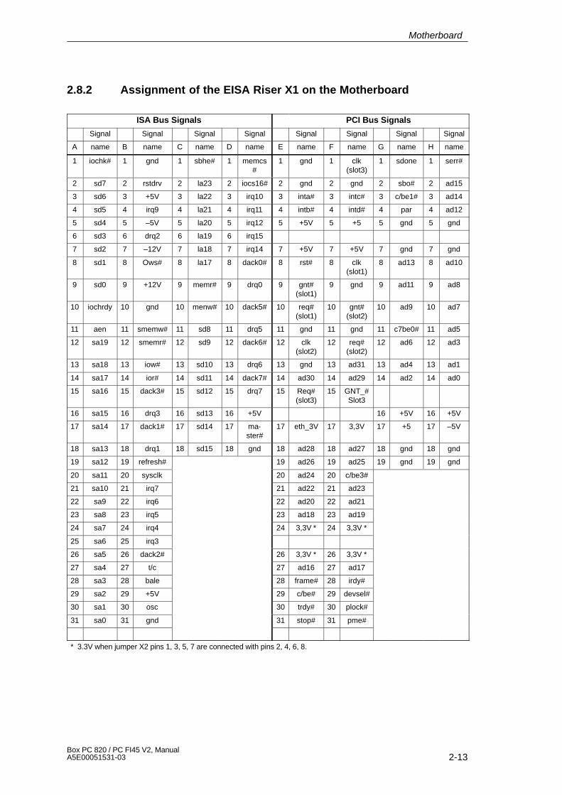
2.8.2 Assignment of the EISA Riser X1 on the Motherboard
ISA Bus Signals PCI Bus Signals
Signal Signal Signal Signal Signal Signal Signal Signal
A name B name C name D name E name F name G name H name
1 iochk# 1 gnd 1 sbhe# 1 memcs#
1 gnd 1 clk(slot3)
1 sdone 1 serr#
2 sd7 2 rstdrv 2 la23 2 iocs16# 2 gnd 2 gnd 2 sbo# 2 ad15
3 sd6 3 +5V 3 la22 3 irq10 3 inta# 3 intc# 3 c/be1# 3 ad14
4 sd5 4 irq9 4 la21 4 irq11 4 intb# 4 intd# 4 par 4 ad12
5 sd4 5 –5V 5 la20 5 irq12 5 +5V 5 +5 5 gnd 5 gnd
6 sd3 6 drq2 6 la19 6 irq15
7 sd2 7 –12V 7 la18 7 irq14 7 +5V 7 +5V 7 gnd 7 gnd
8 sd1 8 Ows# 8 la17 8 dack0# 8 rst# 8 clk(slot1)
8 ad13 8 ad10
9 sd0 9 +12V 9 memr# 9 drq0 9 gnt#(slot1)
9 gnd 9 ad11 9 ad8
10 iochrdy 10 gnd 10 menw# 10 dack5# 10 req#(slot1)
10 gnt#(slot2)
10 ad9 10 ad7
11 aen 11 smemw# 11 sd8 11 drq5 11 gnd 11 gnd 11 c7be0# 11 ad5
12 sa19 12 smemr# 12 sd9 12 dack6# 12 clk(slot2)
12 req#(slot2)
12 ad6 12 ad3
13 sa18 13 iow# 13 sd10 13 drq6 13 gnd 13 ad31 13 ad4 13 ad1
14 sa17 14 ior# 14 sd11 14 dack7# 14 ad30 14 ad29 14 ad2 14 ad0
15 sa16 15 dack3# 15 sd12 15 drq7 15 Req#(slot3)
15 GNT_#Slot3
16 sa15 16 drq3 16 sd13 16 +5V 16 +5V 16 +5V
17 sa14 17 dack1# 17 sd14 17 ma-ster#
17 eth_3V 17 3,3V 17 +5 17 –5V
18 sa13 18 drq1 18 sd15 18 gnd 18 ad28 18 ad27 18 gnd 18 gnd
19 sa12 19 refresh# 19 ad26 19 ad25 19 gnd 19 gnd
20 sa11 20 sysclk 20 ad24 20 c/be3#
21 sa10 21 irq7 21 ad22 21 ad23
22 sa9 22 irq6 22 ad20 22 ad21
23 sa8 23 irq5 23 ad18 23 ad19
24 sa7 24 irq4 24 3,3V * 24 3,3V *
25 sa6 25 irq3
26 sa5 26 dack2# 26 3,3V * 26 3,3V *
27 sa4 27 t/c 27 ad16 27 ad17
28 sa3 28 bale 28 frame# 28 irdy#
29 sa2 29 +5V 29 c/be# 29 devsel#
30 sa1 30 osc 30 trdy# 30 plock#
31 sa0 31 gnd 31 stop# 31 pme#
* 3.3V when jumper X2 pins 1, 3, 5, 7 are connected with pins 2, 4, 6, 8.
Motherboard
2-14Box PC 820 / PC FI45 V2, Manual
A5E00051531-03
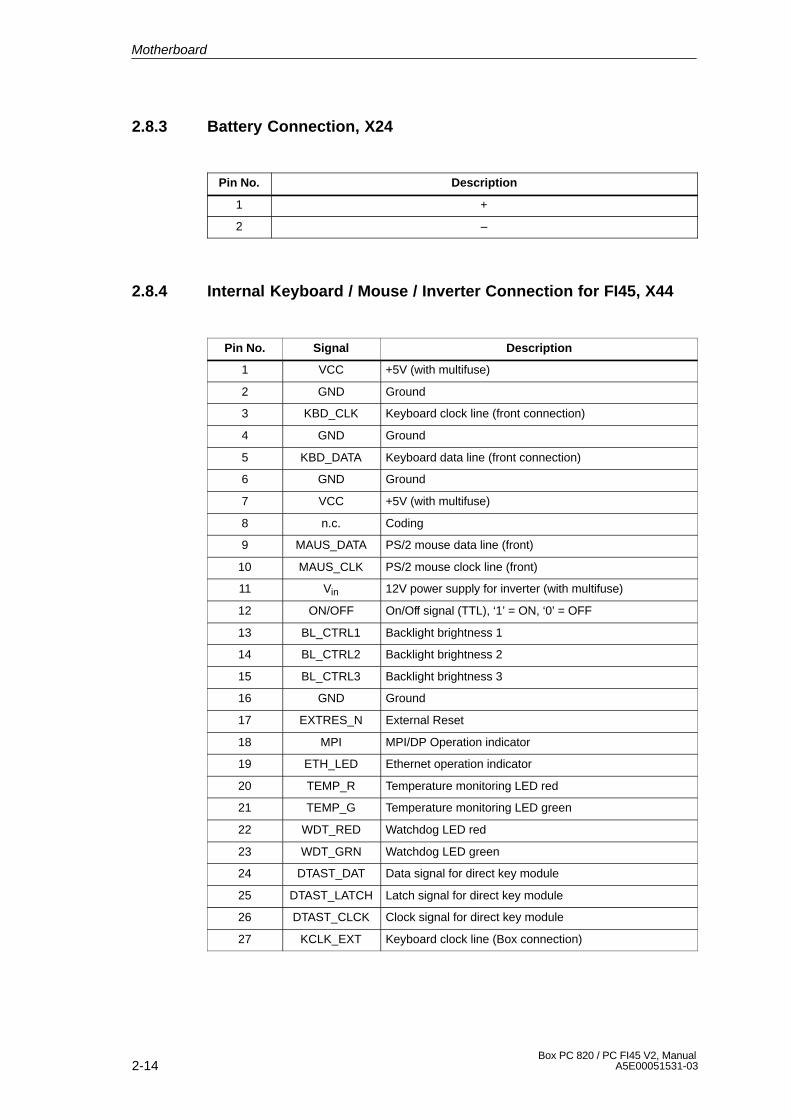
2.8.3 Battery Connection, X24
Pin No. Description
1 +
2 –
2.8.4 Internal Keyboard / Mouse / Inverter Connection for FI45, X44
Pin No. Signal Description
1 VCC +5V (with multifuse)
2 GND Ground
3 KBD_CLK Keyboard clock line (front connection)
4 GND Ground
5 KBD_DATA Keyboard data line (front connection)
6 GND Ground
7 VCC +5V (with multifuse)
8 n.c. Coding
9 MAUS_DATA PS/2 mouse data line (front)
10 MAUS_CLK PS/2 mouse clock line (front)
11 Vin 12V power supply for inverter (with multifuse)
12 ON/OFF On/Off signal (TTL), ‘1’ = ON, ‘0’ = OFF
13 BL_CTRL1 Backlight brightness 1
14 BL_CTRL2 Backlight brightness 2
15 BL_CTRL3 Backlight brightness 3
16 GND Ground
17 EXTRES_N External Reset
18 MPI MPI/DP Operation indicator
19 ETH_LED Ethernet operation indicator
20 TEMP_R Temperature monitoring LED red
21 TEMP_G Temperature monitoring LED green
22 WDT_RED Watchdog LED red
23 WDT_GRN Watchdog LED green
24 DTAST_DAT Data signal for direct key module
25 DTAST_LATCH Latch signal for direct key module
26 DTAST_CLCK Clock signal for direct key module
27 KCLK_EXT Keyboard clock line (Box connection)
Motherboard
2-15Box PC 820 / PC FI45 V2, ManualA5E00051531-03
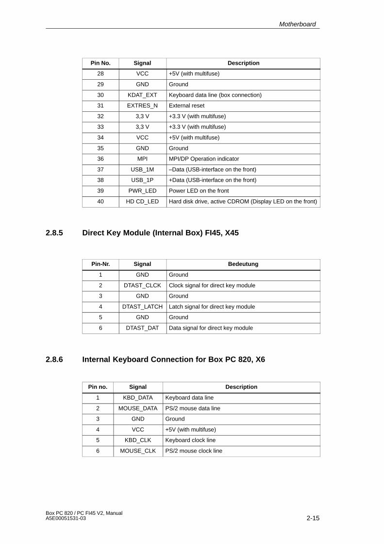
Pin No. DescriptionSignal
28 VCC +5V (with multifuse)
29 GND Ground
30 KDAT_EXT Keyboard data line (box connection)
31 EXTRES_N External reset
32 3,3 V +3.3 V (with multifuse)
33 3,3 V +3.3 V (with multifuse)
34 VCC +5V (with multifuse)
35 GND Ground
36 MPI MPI/DP Operation indicator
37 USB_1M –Data (USB-interface on the front)
38 USB_1P +Data (USB-interface on the front)
39 PWR_LED Power LED on the front
40 HD CD_LED Hard disk drive, active CDROM (Display LED on the front)
2.8.5 Direct Key Module (Internal Box) FI45, X45
Pin-Nr. Signal Bedeutung
1 GND Ground
2 DTAST_CLCK Clock signal for direct key module
3 GND Ground
4 DTAST_LATCH Latch signal for direct key module
5 GND Ground
6 DTAST_DAT Data signal for direct key module
2.8.6 Internal Keyboard Connection for Box PC 820, X6
Pin no. Signal Description
1 KBD_DATA Keyboard data line
2 MOUSE_DATA PS/2 mouse data line
3 GND Ground
4 VCC +5V (with multifuse)
5 KBD_CLK Keyboard clock line
6 MOUSE_CLK PS/2 mouse clock line
Motherboard
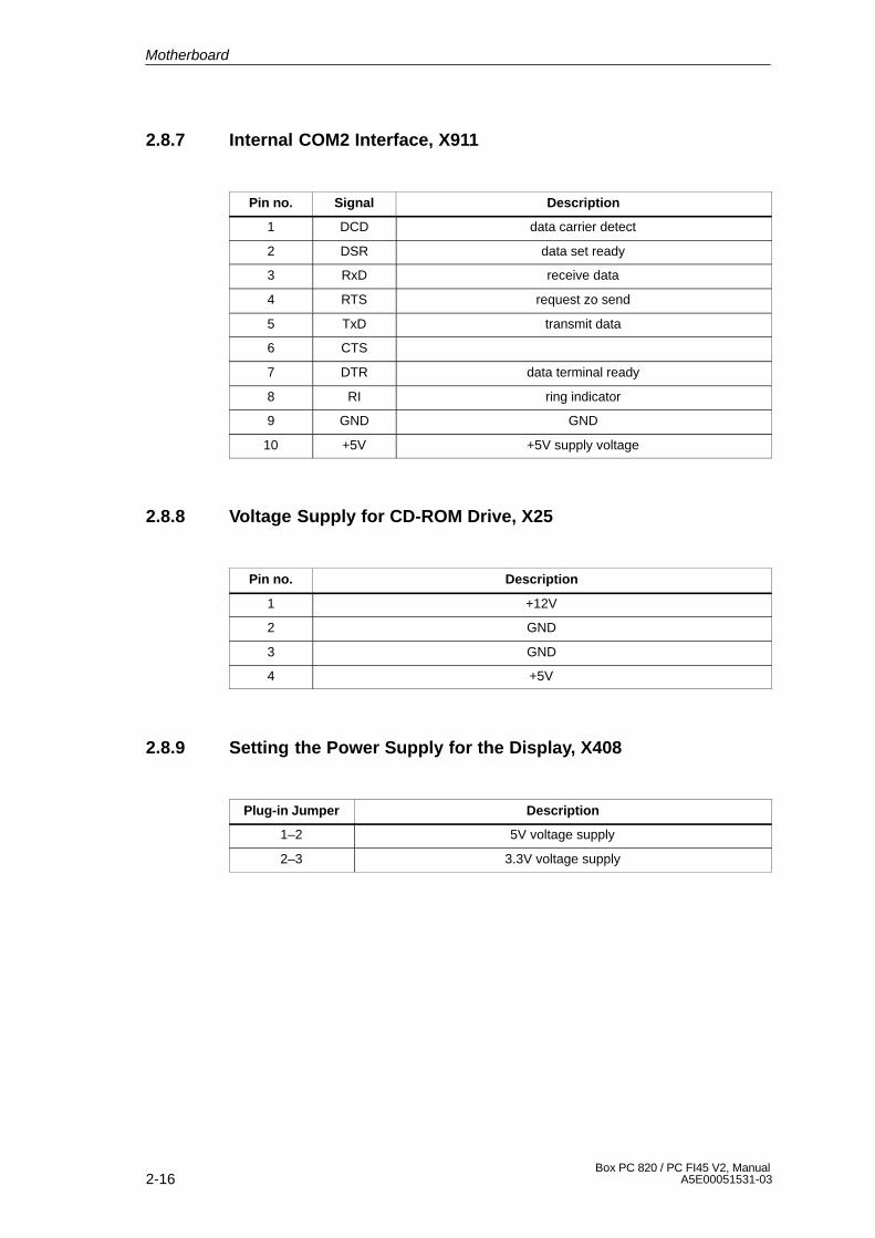
2-16Box PC 820 / PC FI45 V2, Manual
A5E00051531-03
2.8.7 Internal COM2 Interface, X911
Pin no. Signal Description
1 DCD data carrier detect
2 DSR data set ready
3 RxD receive data
4 RTS request zo send
5 TxD transmit data
6 CTS
7 DTR data terminal ready
8 RI ring indicator
9 GND GND
10 +5V +5V supply voltage
2.8.8 Voltage Supply for CD-ROM Drive, X25
Pin no. Description
1 +12V
2 GND
3 GND
4 +5V
2.8.9 Setting the Power Supply for the Display, X408
Plug-in Jumper Description
1–2 5V voltage supply
2–3 3.3V voltage supply
Motherboard
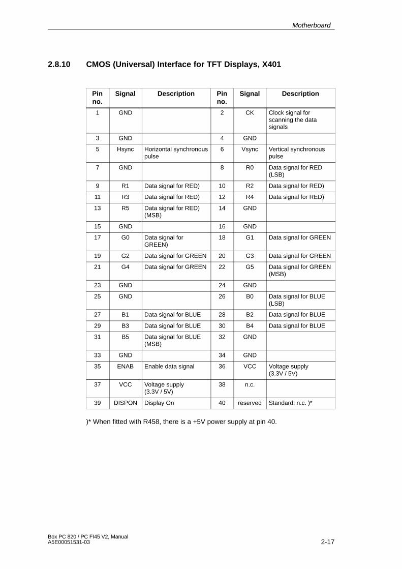
2-17Box PC 820 / PC FI45 V2, ManualA5E00051531-03
2.8.10 CMOS (Universal) Interface for TFT Displays, X401
Pinno.
Signal Description Pinno.
Signal Description
1 GND 2 CK Clock signal forscanning the datasignals
3 GND 4 GND
5 Hsync Horizontal synchronouspulse
6 Vsync Vertical synchronouspulse
7 GND 8 R0 Data signal for RED(LSB)
9 R1 Data signal for RED) 10 R2 Data signal for RED)
11 R3 Data signal for RED) 12 R4 Data signal for RED)
13 R5 Data signal for RED)(MSB)
14 GND
15 GND 16 GND
17 G0 Data signal forGREEN)
18 G1 Data signal for GREEN
19 G2 Data signal for GREEN 20 G3 Data signal for GREEN
21 G4 Data signal for GREEN 22 G5 Data signal for GREEN(MSB)
23 GND 24 GND
25 GND 26 B0 Data signal for BLUE(LSB)
27 B1 Data signal for BLUE 28 B2 Data signal for BLUE
29 B3 Data signal for BLUE 30 B4 Data signal for BLUE
31 B5 Data signal for BLUE(MSB)
32 GND
33 GND 34 GND
35 ENAB Enable data signal 36 VCC Voltage supply(3.3V / 5V)
37 VCC Voltage supply(3.3V / 5V)
38 n.c.
39 DISPON Display On 40 reserved Standard: n.c. )*
)* When fitted with R458, there is a +5V power supply at pin 40.
Motherboard

2-18Box PC 820 / PC FI45 V2, Manual
A5E00051531-03
2.8.11 LVDS Interface (Single Chip LVDS), X409
Pin no. Signal Description
1 VCC 3.3V / 5V voltage supply
2 VCC 3.3V / 5V voltage supply
3 GND GND
4 GND GND
5 RXIN0– LVDS input signal bit 0 (–)
6 RXIN0+ LVDS input signal bit 0 (+)
7 GND GND
8 RXIN1– LVDS input signal bit 1 (–)
9 RXIN1+ LVDS input signal bit 1 (+)
10 GND GND
11 RXIN2– LVDS input signal bit 2 (–)
12 RXIN2+ LVDS input signal bit 2 (+)
13 GND GND
14 RXCLKIN– LVDS clock signal (–)
15 RXCLKIN+ LVDS clock signal (+)
16 GND GND
17 Res. Not connected (reserved)
18 Res. Not connected (reserved)
19 GND GND
20 GND GND
2.8.12 Selection of Display Type / Polarity of Backlight-On Signal(Switch S1)
S1-4 S1-3 S1-2 S1-1 Display type
on on on reserved
on on off 1280 x 1024, TFT
on off on reserved
on off off reserved
off on on 640 x 480, TFT (Sharp)
off on off 640 x 480, TFT (non Sharp)
off off on 1024 x 768, TFT (standard setting)
off off off 800 x 600, TFT
Motherboard
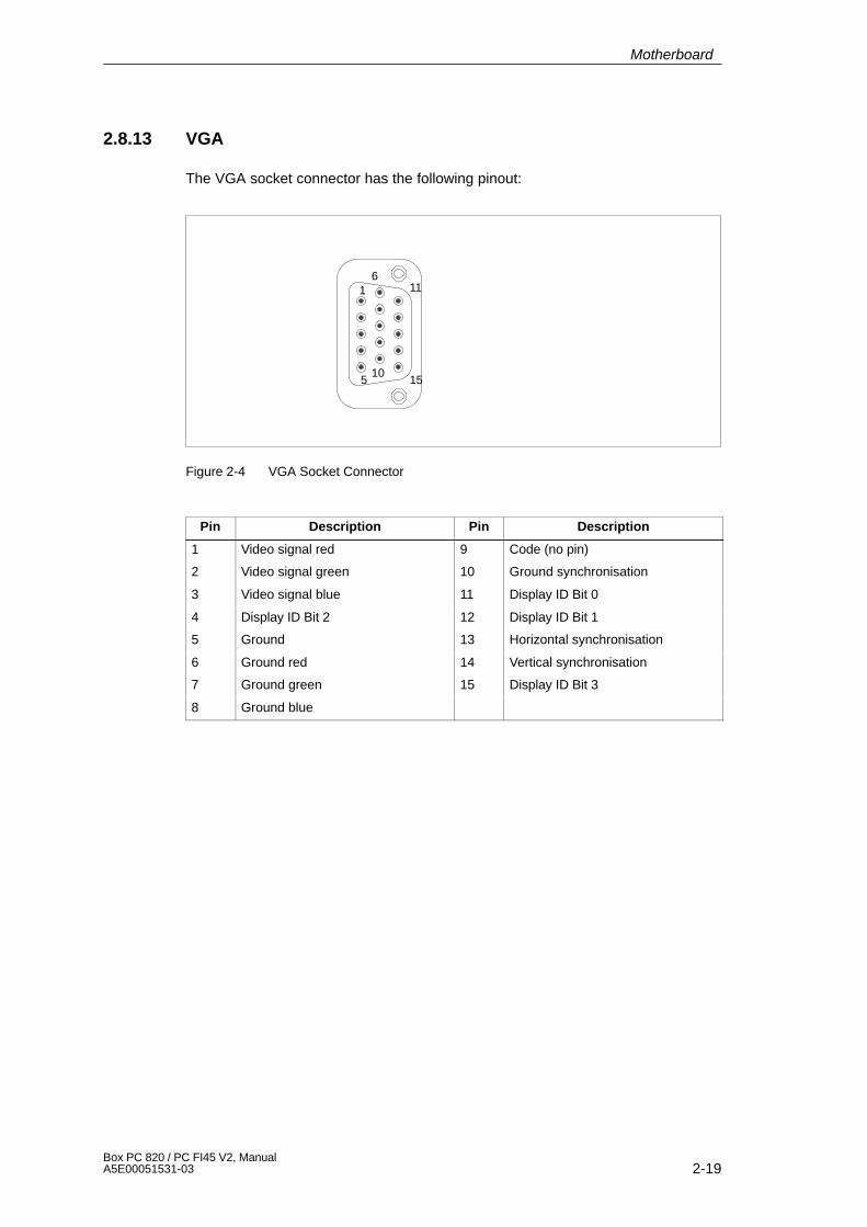
2-19Box PC 820 / PC FI45 V2, ManualA5E00051531-03
2.8.13 VGA
The VGA socket connector has the following pinout:
1
5
6
10
11
15
Figure 2-4 VGA Socket Connector
Pin Description Pin Description
1 Video signal red 9 Code (no pin)
2 Video signal green 10 Ground synchronisation
3 Video signal blue 11 Display ID Bit 0
4 Display ID Bit 2 12 Display ID Bit 1
5 Ground 13 Horizontal synchronisation
6 Ground red 14 Vertical synchronisation
7 Ground green 15 Display ID Bit 3
8 Ground blue
Motherboard
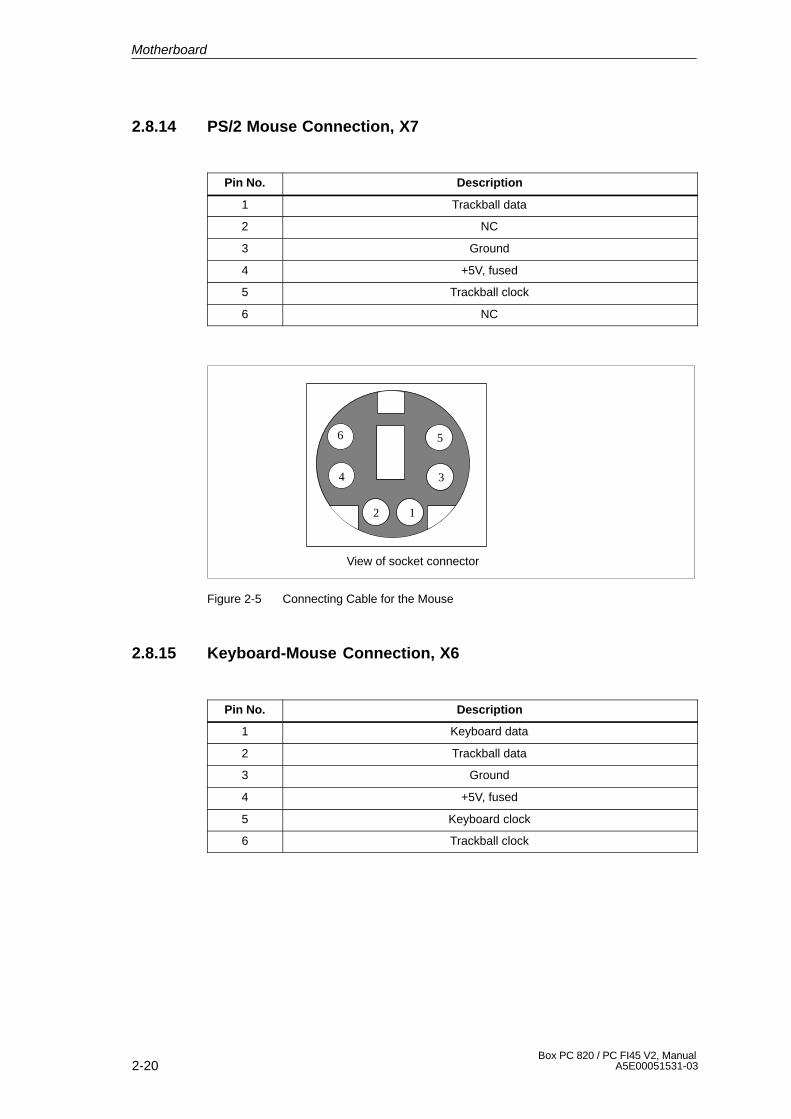
2-20Box PC 820 / PC FI45 V2, Manual
A5E00051531-03
2.8.14 PS/2 Mouse Connection, X7
Pin No. Description
1 Trackball data
2 NC
3 Ground
4 +5V, fused
5 Trackball clock
6 NC
View of socket connector
12
34
56
Figure 2-5 Connecting Cable for the Mouse
2.8.15 Keyboard-Mouse Connection, X6
Pin No. Description
1 Keyboard data
2 Trackball data
3 Ground
4 +5V, fused
5 Keyboard clock
6 Trackball clock
Motherboard
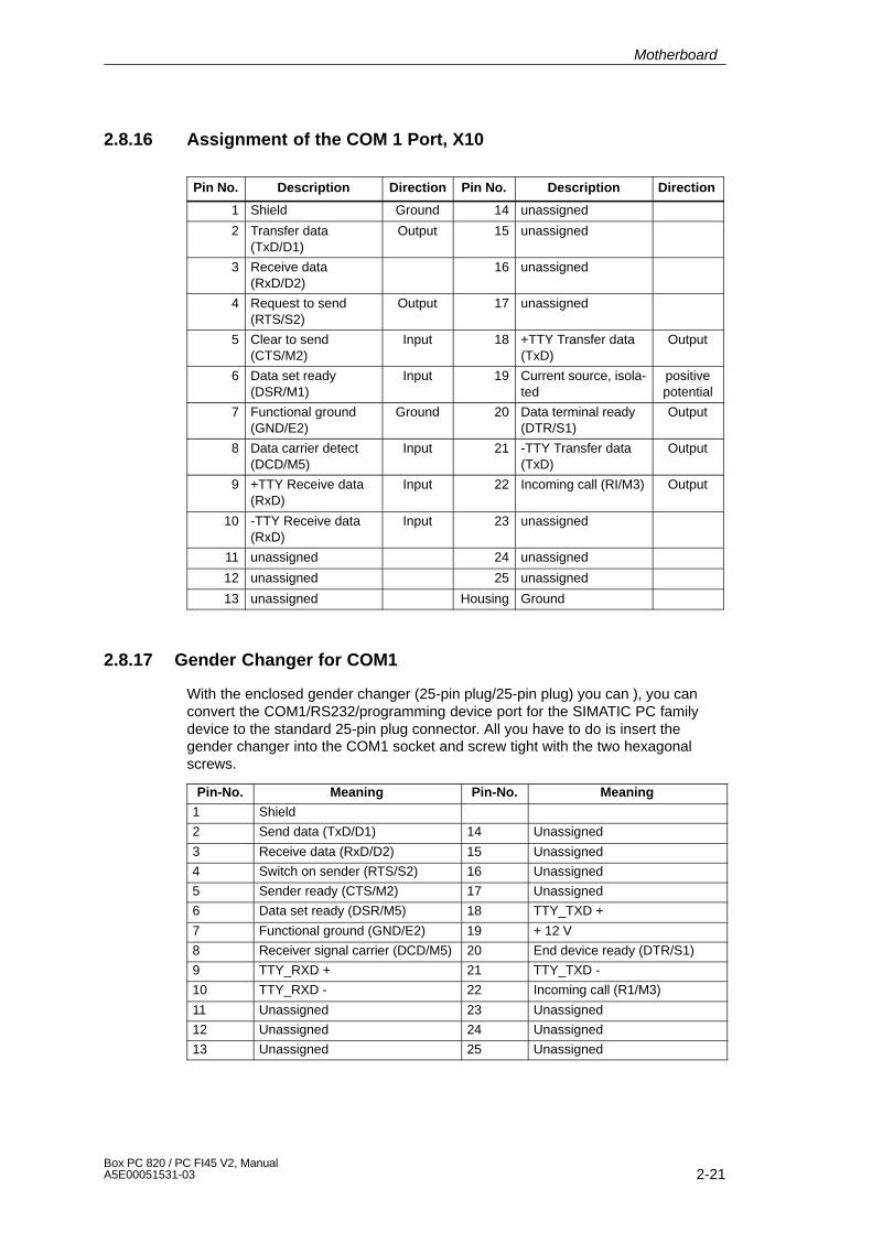
2-21Box PC 820 / PC FI45 V2, ManualA5E00051531-03
2.8.16 Assignment of the COM 1 Port, X10
Pin No. Description Direction Pin No. Description Direction
1 Shield Ground 14 unassigned
2 Transfer data (TxD/D1)
Output 15 unassigned
3 Receive data (RxD/D2)
16 unassigned
4 Request to send (RTS/S2)
Output 17 unassigned
5 Clear to send(CTS/M2)
Input 18 +TTY Transfer data(TxD)
Output
6 Data set ready (DSR/M1)
Input 19 Current source, isola-ted
positivepotential
7 Functional ground(GND/E2)
Ground 20 Data terminal ready(DTR/S1)
Output
8 Data carrier detect(DCD/M5)
Input 21 -TTY Transfer data(TxD)
Output
9 +TTY Receive data(RxD)
Input 22 Incoming call (RI/M3) Output
10 -TTY Receive data(RxD)
Input 23 unassigned
11 unassigned 24 unassigned
12 unassigned 25 unassigned
13 unassigned Housing Ground
2.8.17 Gender Changer for COM1
With the enclosed gender changer (25-pin plug/25-pin plug) you can ), you canconvert the COM1/RS232/programming device port for the SIMATIC PC familydevice to the standard 25-pin plug connector. All you have to do is insert thegender changer into the COM1 socket and screw tight with the two hexagonalscrews.
Pin-No. Meaning Pin-No. Meaning
1 Shield
2 Send data (TxD/D1) 14 Unassigned
3 Receive data (RxD/D2) 15 Unassigned
4 Switch on sender (RTS/S2) 16 Unassigned
5 Sender ready (CTS/M2) 17 Unassigned
6 Data set ready (DSR/M5) 18 TTY_TXD +
7 Functional ground (GND/E2) 19 + 12 V
8 Receiver signal carrier (DCD/M5) 20 End device ready (DTR/S1)
9 TTY_RXD + 21 TTY_TXD -
10 TTY_RXD - 22 Incoming call (R1/M3)
11 Unassigned 23 Unassigned
12 Unassigned 24 Unassigned
13 Unassigned 25 Unassigned
Motherboard

2-22Box PC 820 / PC FI45 V2, Manual
A5E00051531-03
2.8.18 Assignment for the Floppy, X50
Pin No. Description Pin No. Description
1 P5V 2 Index
3 P5V 4 DS_N0
5 P5V 6 DCHG_N
7 NC 8 NC
9 HDOUT 10 MOT_N0
11 HDIN 12 DIR_SL_N
13 NC 14 STEP_N
15 Ground 16 WR_DAT_N
17 Ground 18 WR_GAT_N
19 EDOUT 20 TRACK_N0
21 EDIN 22 WR_PRT_N
23 Ground 24 RD_DAT_N
25 Ground 26 SIDE_1_N
Motherboard
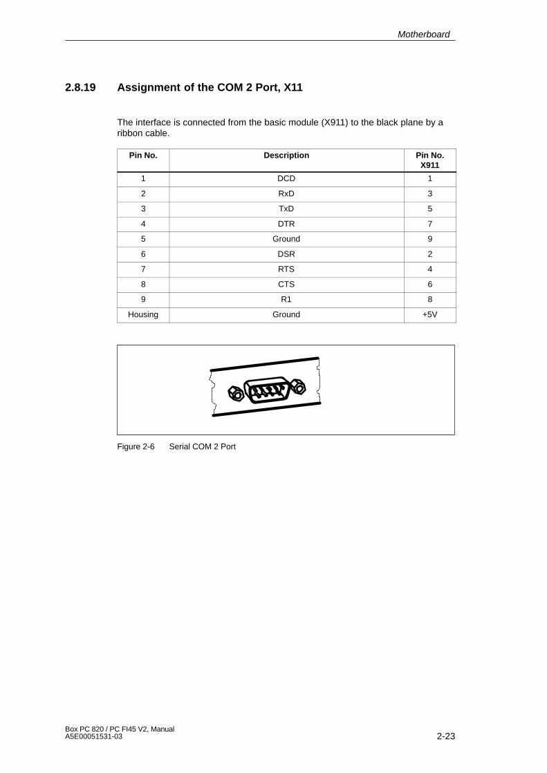
2-23Box PC 820 / PC FI45 V2, ManualA5E00051531-03
2.8.19 Assignment of the COM 2 Port, X11
The interface is connected from the basic module (X911) to the black plane by aribbon cable.
Pin No. Description Pin No.X911
1 DCD 1
2 RxD 3
3 TxD 5
4 DTR 7
5 Ground 9
6 DSR 2
7 RTS 4
8 CTS 6
9 R1 8
Housing Ground +5V
Figure 2-6 Serial COM 2 Port
Motherboard
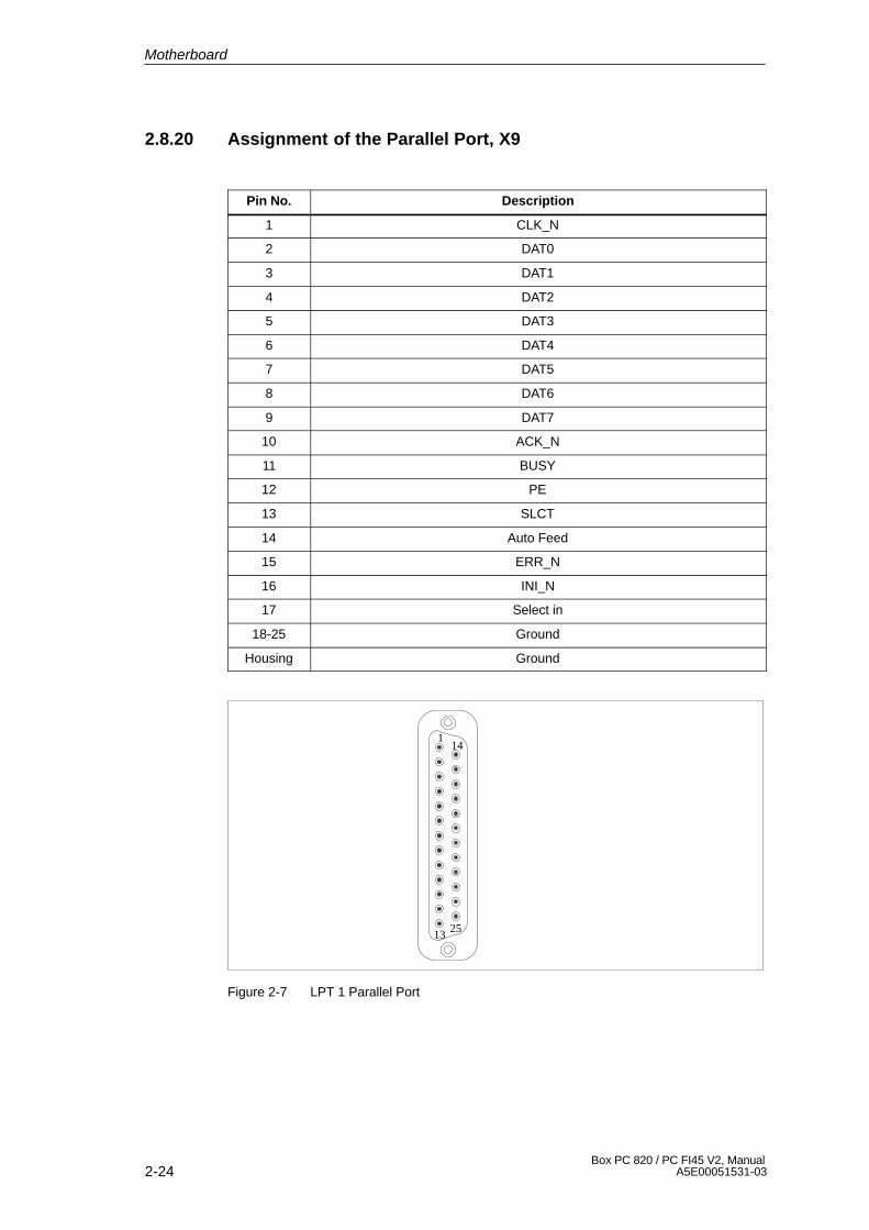
2-24Box PC 820 / PC FI45 V2, Manual
A5E00051531-03
2.8.20 Assignment of the Parallel Port, X9
Pin No. Description
1 CLK_N
2 DAT0
3 DAT1
4 DAT2
5 DAT3
6 DAT4
7 DAT5
8 DAT6
9 DAT7
10 ACK_N
11 BUSY
12 PE
13 SLCT
14 Auto Feed
15 ERR_N
16 INI_N
17 Select in
18-25 Ground
Housing Ground
1
13
14
25
Figure 2-7 LPT 1 Parallel Port
Motherboard
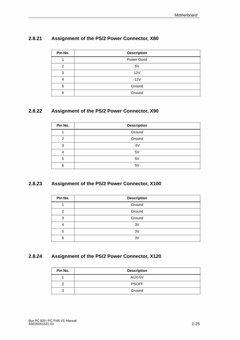
2-25Box PC 820 / PC FI45 V2, ManualA5E00051531-03
2.8.21 Assignment of the PS/2 Power Connector, X80
Pin No. Description
1 Power Good
2 5V
3 12V
4 -12V
5 Ground
6 Ground
2.8.22 Assignment of the PS/2 Power Connector, X90
Pin No. Description
1 Ground
2 Ground
3 -5V
4 5V
5 5V
6 5V
2.8.23 Assignment of the PS/2 Power Connector, X100
Pin No. Description
1 Ground
2 Ground
3 Ground
4 3V
5 3V
6 3V
2.8.24 Assignment of the PS/2 Power Connector, X120
Pin No. Description
1 AUX-5V
2 PSOFF
3 Ground
Motherboard
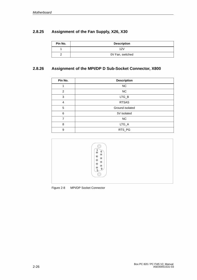
2-26Box PC 820 / PC FI45 V2, Manual
A5E00051531-03
2.8.25 Assignment of the Fan Supply, X26, X30
Pin No. Description
1 12V
2 0V Fan, switched
2.8.26 Assignment of the MPI/DP D Sub-Socket Connector, X800
Pin No. Description
1 NC
2 NC
3 LTG_B
4 RTSAS
5 Ground isolated
6 5V isolated
7 NC
8 LTG_A
9 RTS_PG
1
5
6
9
Figure 2-8 MPI/DP Socket Connector
Motherboard
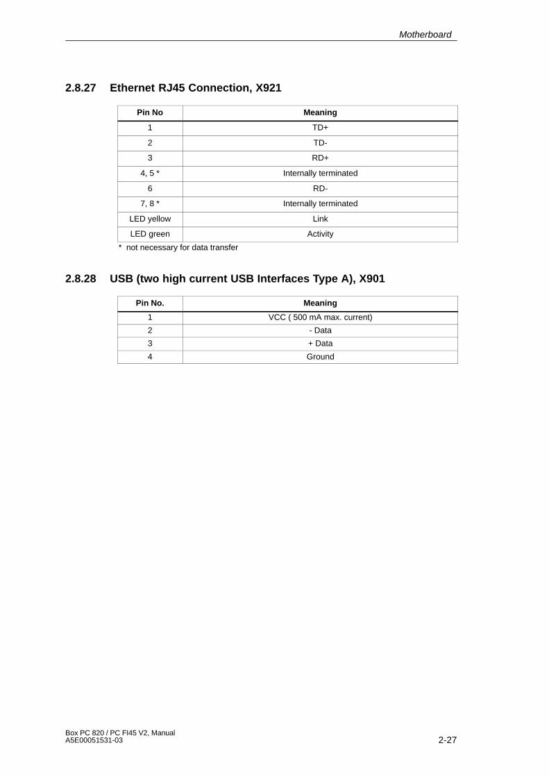
2-27Box PC 820 / PC FI45 V2, ManualA5E00051531-03
2.8.27 Ethernet RJ45 Connection, X921
Pin No Meaning
1 TD+
2 TD-
3 RD+
4, 5 * Internally terminated
6 RD-
7, 8 * Internally terminated
LED yellow Link
LED green Activity
* not necessary for data transfer
2.8.28 USB (two high current USB Interfaces Type A), X901
Pin No. Meaning
1 VCC ( 500 mA max. current)
2 - Data
3 + Data
4 Ground
Motherboard

2-28Box PC 820 / PC FI45 V2, Manual
A5E00051531-03
2.8.29 Description of the Switch Positions S2 (TTY, BIOS)
Switch Settings
The following switch settings are for your information only. They are set in the fac-tory and may not be changed.
x means that this switch is irrelevant for the funtion described.
BIOS Source File
S2 (3) Function
off Boot EPROM activated (standard setting)
on Boot EPROM not activated (boot module required)
TTY Setting S2
S2 (1) S2 (2) Function
on on active TTY interface (standard setting)
off x TTY transmit loop, isolated from power source(passive setting)
x off TTY receive loop, isolated from power source(passive setting)
Setting the Front Side Bus Frequency S2
S2(4) ISA Bus Frequency PCI Bus Frequency CPU Bus Frequency
on 8.25MHz 33MHz 66MHz
off 8.25MHz 33MHz 100MHz 1)
1) Frequency is dependent on the processor and is set automatically e.g. 100 MHz forPentium III.
Motherboard
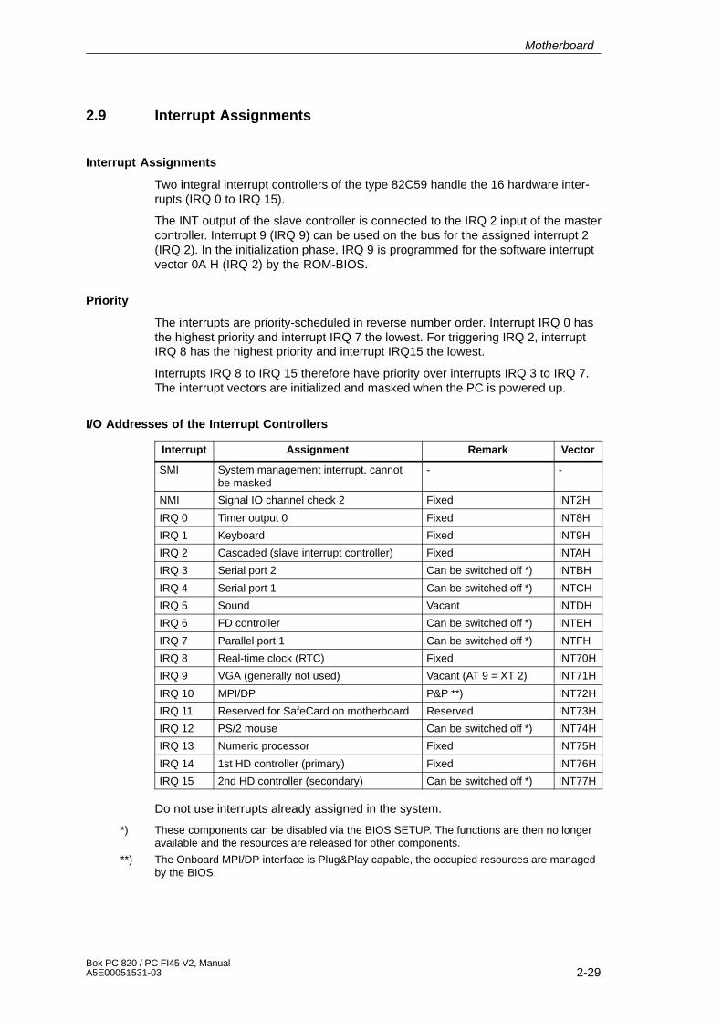
2-29Box PC 820 / PC FI45 V2, ManualA5E00051531-03
2.9 Interrupt Assignments
Interrupt Assignments
Two integral interrupt controllers of the type 82C59 handle the 16 hardware inter-rupts (IRQ 0 to IRQ 15).
The INT output of the slave controller is connected to the IRQ 2 input of the mastercontroller. Interrupt 9 (IRQ 9) can be used on the bus for the assigned interrupt 2(IRQ 2). In the initialization phase, IRQ 9 is programmed for the software interruptvector 0A H (IRQ 2) by the ROM-BIOS.
Priority
The interrupts are priority-scheduled in reverse number order. Interrupt IRQ 0 hasthe highest priority and interrupt IRQ 7 the lowest. For triggering IRQ 2, interruptIRQ 8 has the highest priority and interrupt IRQ15 the lowest.
Interrupts IRQ 8 to IRQ 15 therefore have priority over interrupts IRQ 3 to IRQ 7.The interrupt vectors are initialized and masked when the PC is powered up.
I/O Addresses of the Interrupt Controllers
Interrupt Assignment Remark Vector
SMI System management interrupt, cannotbe masked
- -
NMI Signal IO channel check 2 Fixed INT2H
IRQ 0 Timer output 0 Fixed INT8H
IRQ 1 Keyboard Fixed INT9H
IRQ 2 Cascaded (slave interrupt controller) Fixed INTAH
IRQ 3 Serial port 2 Can be switched off *) INTBH
IRQ 4 Serial port 1 Can be switched off *) INTCH
IRQ 5 Sound Vacant INTDH
IRQ 6 FD controller Can be switched off *) INTEH
IRQ 7 Parallel port 1 Can be switched off *) INTFH
IRQ 8 Real-time clock (RTC) Fixed INT70H
IRQ 9 VGA (generally not used) Vacant (AT 9 = XT 2) INT71H
IRQ 10 MPI/DP P&P **) INT72H
IRQ 11 Reserved for SafeCard on motherboard Reserved INT73H
IRQ 12 PS/2 mouse Can be switched off *) INT74H
IRQ 13 Numeric processor Fixed INT75H
IRQ 14 1st HD controller (primary) Fixed INT76H
IRQ 15 2nd HD controller (secondary) Can be switched off *) INT77H
Do not use interrupts already assigned in the system.
*) These components can be disabled via the BIOS SETUP. The functions are then no longeravailable and the resources are released for other components.
**) The Onboard MPI/DP interface is Plug&Play capable, the occupied resources are managedby the BIOS.
Motherboard
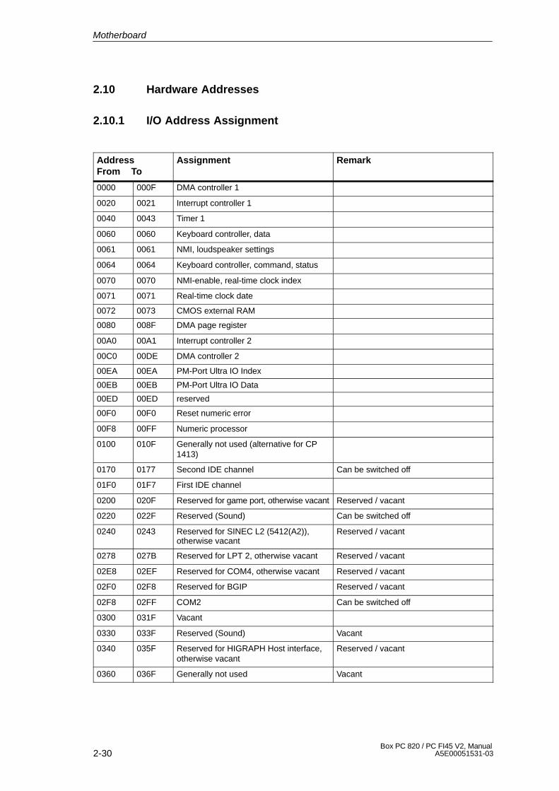
2-30Box PC 820 / PC FI45 V2, Manual
A5E00051531-03
2.10 Hardware Addresses
2.10.1 I/O Address Assignment
AddressFrom To
Assignment Remark
0000 000F DMA controller 1
0020 0021 Interrupt controller 1
0040 0043 Timer 1
0060 0060 Keyboard controller, data
0061 0061 NMI, loudspeaker settings
0064 0064 Keyboard controller, command, status
0070 0070 NMI-enable, real-time clock index
0071 0071 Real-time clock date
0072 0073 CMOS external RAM
0080 008F DMA page register
00A0 00A1 Interrupt controller 2
00C0 00DE DMA controller 2
00EA 00EA PM-Port Ultra IO Index
00EB 00EB PM-Port Ultra IO Data
00ED 00ED reserved
00F0 00F0 Reset numeric error
00F8 00FF Numeric processor
0100 010F Generally not used (alternative for CP1413)
0170 0177 Second IDE channel Can be switched off
01F0 01F7 First IDE channel
0200 020F Reserved for game port, otherwise vacant Reserved / vacant
0220 022F Reserved (Sound) Can be switched off
0240 0243 Reserved for SINEC L2 (5412(A2)),otherwise vacant
Reserved / vacant
0278 027B Reserved for LPT 2, otherwise vacant Reserved / vacant
02E8 02EF Reserved for COM4, otherwise vacant Reserved / vacant
02F0 02F8 Reserved for BGIP Reserved / vacant
02F8 02FF COM2 Can be switched off
0300 031F Vacant
0330 033F Reserved (Sound) Vacant
0340 035F Reserved for HIGRAPH Host interface,otherwise vacant
Reserved / vacant
0360 036F Generally not used Vacant
Motherboard

2-31Box PC 820 / PC FI45 V2, ManualA5E00051531-03
AddressFrom To
RemarkAssignment
0376 0376 Second IDE channel command Can be switched off
0377 0377 Second IDE channel status Can be switched off
0378 037F LPT 1 Can be switched off
0380 0387 Generally not used Vacant
0388 038C Sound synthesizer Can be switched off
03A0 03AF Generally not used Vacant
03B0 03BB Monochrome video or EGA/VGA
03BC 03BF Reserved for LPTn, otherwise vacant Reserved / vacant
03C0 03CF VGA control register
03D0 03DF CGA / VGA control register
03E8 03EF Reserved for COM 3, otherwise vacant Reserved / vacant
03F0 03F5 FD controller
03F6 03F6 First IDE channel, command
03F7 03F7 First IDE channel, status
03F8 03FF COM 1 Can be switched off
0390 0397 Reserved for SINEC H1 (CP1413),otherwise vacant
Reserved / vacant
0400 +LPT ECP LPT PCI BUS
0CF8 0CFB PCI config index PCI BUS
0CFC 0CFF PCI config data PCI BUS
FF00 FF07 IDE bus master register PCI BUS
1000 1037 Power management
1080 108F
10C0 10EF
Motherboard

2-32Box PC 820 / PC FI45 V2, Manual
A5E00051531-03
2.10.2 Assignment of the Memory Addresses
There are two kinds of address areas:
� Memory address area
� I/O address area.
Different read/write signals (I/O WR, I/O RD, MEMR, MEMW) are used toreference these areas. The following tables provide you with an overview of theaddress areas used. Please refer to the descriptions of the individual functionalgroups for more details.
FromAddress
To Address
Size Assignment Remark
0000 0000 0007 FFFF 512k Conventional system memory
0008 0000 0009 FBFF 127k Conventional system memoryextended
0009 FC00 0009 FFFF 1k Conventional system memoryextended BIOS data
000A 0000 000A FFFF 64k Graphics refresh memory VGA
000B 0000 000B 7FFF 32k SW graphics interface module Vacant
000B 8000 000B FFFF 32k Graphics refresh memory VGA/CGA
000C 0000 000D FFFF 148k VGA BIOS expansion andsystem resources. Theavailable area above 000C7FFF depends on the systemequipment.
VGA
000E 0000 000E BFFF 48k System BIOS
000E C000 000E CFFF 4k System BIOSBootMessageLogo
000E D000 000E DFFF 4k System BIOS Plug & Play Area
000E E000 000E FFFF 8k System BIOS Boot Block
000F 0000 000F FFFF 64k System BIOS
0010 0000 00EF FFFF 14M Extended system memory
00F0 0000 00FF FFFF 1M Extended system memory orMemory hole
Via BIOS SETUP
0100 0000 2FFF FFFF 768M Extended system memory
3000 0000 FFEF FFFF 4G-768M-1023k
PCI expansion; resources areassigned by the operatingsystem.
FFF0 0000 FFFD FFFF 1023k-128k ISA memory, reserved for dual-port RAM
Vacant
FFFE 0000 FFFF FFFF 128k Shadow of System BIOS (000E 0000 .. 000F FFFF)
Motherboard
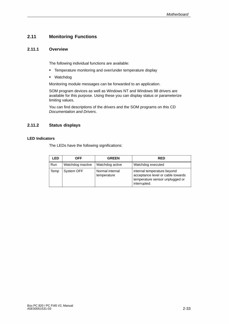
2-33Box PC 820 / PC FI45 V2, ManualA5E00051531-03
2.11 Monitoring Functions
2.11.1 Overview
The following individual functions are available:
� Temperature monitoring and over/under temperature display
� Watchdog
Monitoring module messages can be forwarded to an application.
SOM program devices as well as Windows NT and Windows 98 drivers areavailable for this purpose. Using these you can display status or parameterizelimiting values.
You can find descriptions of the drivers and the SOM programs on this CDDocumentation and Drivers.
2.11.2 Status displays
LED Indicators
The LEDs have the following significations:
LED OFF GREEN RED
Run Watchdog inactive Watchdog active Watchdog executed
Temp System OFF Normal internaltemperature
internal temperature beyondacceptance level or cable towardstemperature sensor unplugged orinterrupted.
Motherboard
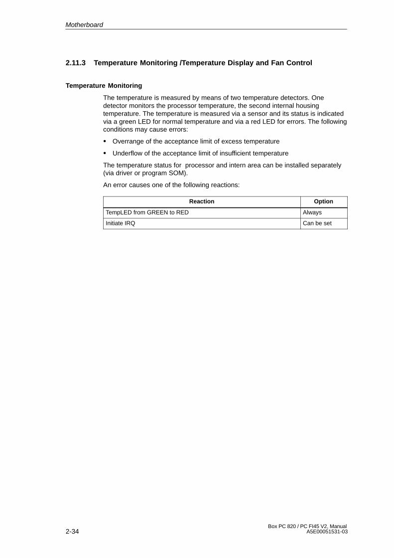
2-34Box PC 820 / PC FI45 V2, Manual
A5E00051531-03
2.11.3 Temperature Monitoring /Temperature Display and Fan Control
Temperature Monitoring
The temperature is measured by means of two temperature detectors. Onedetector monitors the processor temperature, the second internal housingtemperature. The temperature is measured via a sensor and its status is indicatedvia a green LED for normal temperature and via a red LED for errors. The followingconditions may cause errors:
� Overrange of the acceptance limit of excess temperature
� Underflow of the acceptance limit of insufficient temperature
The temperature status for processor and intern area can be installed separately(via driver or program SOM).
An error causes one of the following reactions:
Reaction Option
TempLED from GREEN to RED Always
Initiate IRQ Can be set
Motherboard
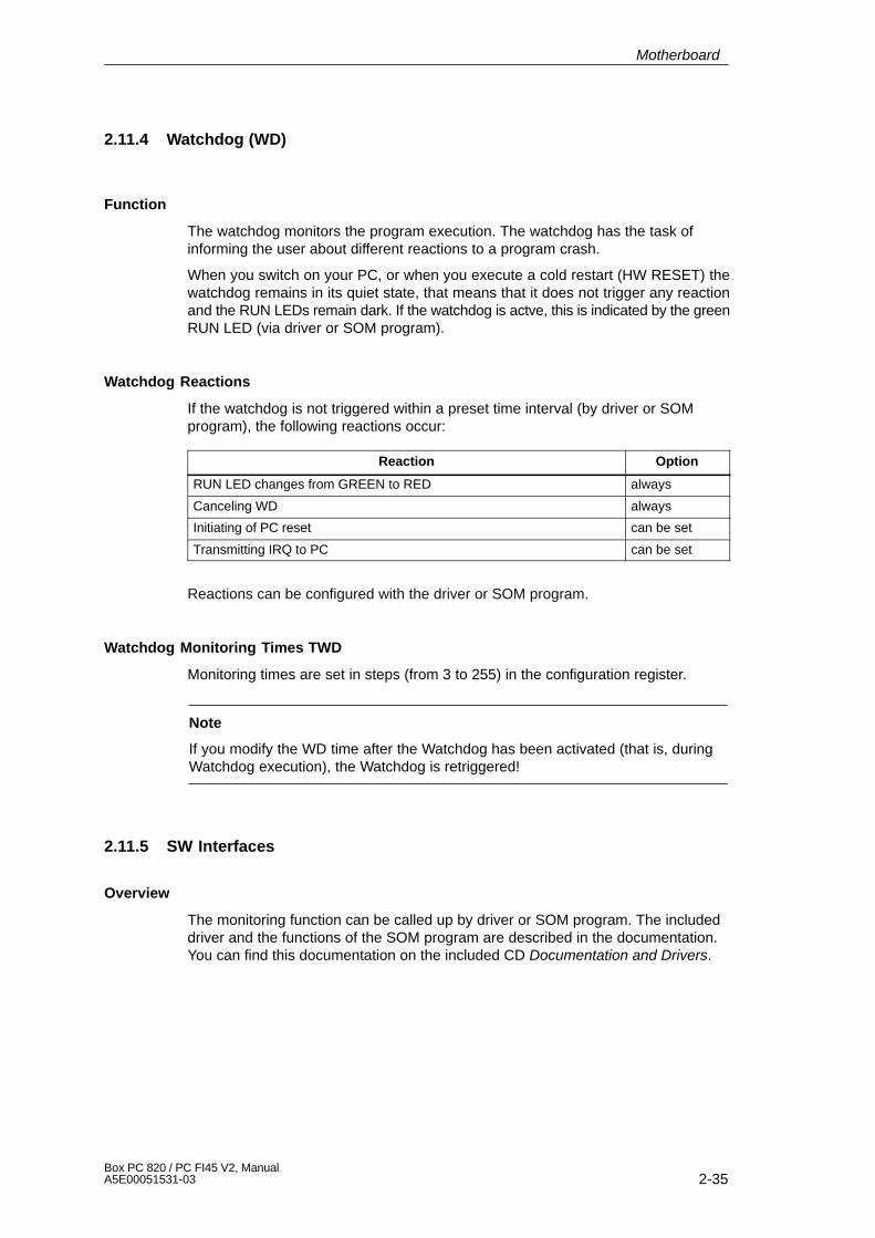
2-35Box PC 820 / PC FI45 V2, ManualA5E00051531-03
2.11.4 Watchdog (WD)
Function
The watchdog monitors the program execution. The watchdog has the task ofinforming the user about different reactions to a program crash.
When you switch on your PC, or when you execute a cold restart (HW RESET) thewatchdog remains in its quiet state, that means that it does not trigger any reactionand the RUN LEDs remain dark. If the watchdog is actve, this is indicated by the greenRUN LED (via driver or SOM program).
Watchdog Reactions
If the watchdog is not triggered within a preset time interval (by driver or SOMprogram), the following reactions occur:
Reaction Option
RUN LED changes from GREEN to RED always
Canceling WD always
Initiating of PC reset can be set
Transmitting IRQ to PC can be set
Reactions can be configured with the driver or SOM program.
Watchdog Monitoring Times TWD
Monitoring times are set in steps (from 3 to 255) in the configuration register.
Note
If you modify the WD time after the Watchdog has been activated (that is, duringWatchdog execution), the Watchdog is retriggered!
2.11.5 SW Interfaces
Overview
The monitoring function can be called up by driver or SOM program. The includeddriver and the functions of the SOM program are described in the documentation.You can find this documentation on the included CD Documentation and Drivers.
Motherboard
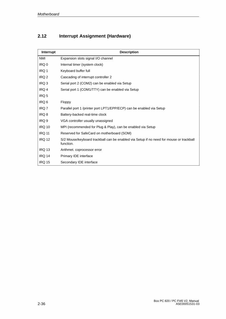
2-36Box PC 820 / PC FI45 V2, Manual
A5E00051531-03
2.12 Interrupt Assignment (Hardware)
Interrupt Description
NMI Expansion slots signal I/O channel
IRQ 0 Internal timer (system clock)
IRQ 1 Keyboard buffer full
IRQ 2 Cascading of interrupt controller 2
IRQ 3 Serial port 2 (COM2) can be enabled via Setup
IRQ 4 Serial port 1 (COM1/TTY) can be enabled via Setup
IRQ 5
IRQ 6 Floppy
IRQ 7 Parallel port 1 /printer port LPT1/EPP/ECP) can be enabled via Setup
IRQ 8 Battery-backed real-time clock
IRQ 9 VGA controller usually unassigned
IRQ 10 MPI (recommended for Plug & Play), can be enabled via Setup
IRQ 11 Reserved for SafeCard on motherboard (SOM)
IRQ 12 S/2 Mouse/keyboard trackball can be enabled via Setup if no need for mouse or trackballfunction.
IRQ 13 Arithmet. coprocessor error
IRQ 14 Primary IDE interface
IRQ 15 Secondary IDE interface
Motherboard
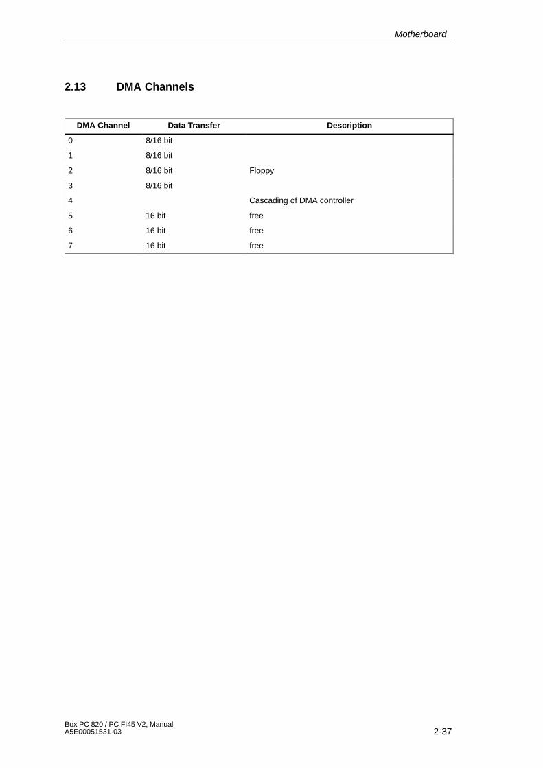
2-37Box PC 820 / PC FI45 V2, ManualA5E00051531-03
2.13 DMA Channels
DMA Channel Data Transfer Description
0 8/16 bit
1 8/16 bit
2 8/16 bit Floppy
3 8/16 bit
4 Cascading of DMA controller
5 16 bit free
6 16 bit free
7 16 bit free
Motherboard
2-38Box PC 820 / PC FI45 V2, Manual
A5E00051531-03
2.14 Changing the System Configuration with BIOS SETUP
Changing the Configuration
The configuration of your PC is set for working with the software supplied with theunit. You should only change the preset values if you have modified your PC in anyway, or if a fault occurs when the unit is powered up.
The changes you make will not become effective until the device is restarted.When you exit the setup program, the device is automatically rebooted.
SETUP Program
The SETUP program is in the ROM-BIOS. Information on the system configurationis stored in the battery-backed RAM of the PC.
You can use SETUP to set the hardware configuration (for example, type of harddisk) and define the system characteristics. You can also use SETUP to set thetime and date.
Incorrect SETUP Data
If incorrect SETUP data are recognized when booting the system, the BIOSprompts you to:
� Start SETUP by pressing F2 or
� Continue booting by pressing F1.
Starting SETUP
On completion of the startup test, the BIOS requests you to start the SETUPprogram with the following screen prompt:
PRESS < F2 > to enter SETUP
Start SETUP as follows:
1. Reset your PC (warm or cold restart).
2. Press the F2 key as long as the BIOS prompt is on the screen.
Default Setting
The F9 key or “Set Default Values” command in the exit menu sets the defaultparameters in the screen forms.
SETUP Menus
The various menus and submenus are listed on the following pages. You canobtain information on the SETUP entry selected from the Item Specific Help partof the relevant menu.
Motherboard
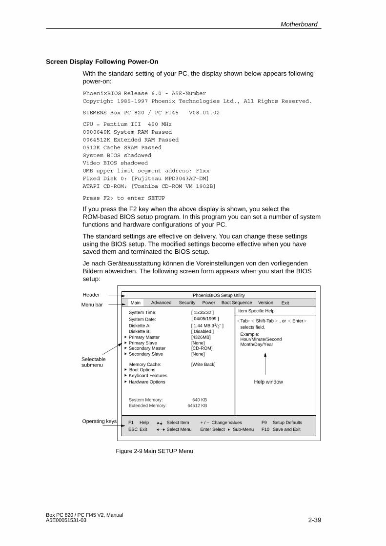
2-39Box PC 820 / PC FI45 V2, ManualA5E00051531-03
Screen Display Following Power-On
With the standard setting of your PC, the display shown below appears followingpower-on:
PhoenixBIOS Release 6.0 - A5E-Number
Copyright 1985-1997 Phoenix Technologies Ltd., All Rights Reserved.
SIEMENS Box PC 820 / PC FI45 V08.01.02
CPU = Pentium III 450 MHz
0000640K System RAM Passed
0064512K Extended RAM Passed
0512K Cache SRAM Passed
System BIOS shadowedVideo BIOS shadowed
UMB upper limit segment address: F1xx
Fixed Disk 0: [Fujitsau MPD3043AT–DM]
ATAPI CD-ROM: [Toshiba CD–ROM VM 1902B]
Press F2> to enter SETUP
If you press the F2 key when the above display is shown, you select theROM-based BIOS setup program. In this program you can set a number of systemfunctions and hardware configurations of your PC.
The standard settings are effective on delivery. You can change these settingsusing the BIOS setup. The modified settings become effective when you havesaved them and terminated the BIOS setup.
Je nach Geräteausstattung können die Voreinstellungen von den vorliegendenBildern abweichen. The following screen form appears when you start the BIOSsetup:
PhoenixBIOS Setup Utility
Item Specific HelpSystem Time:
F1
ESC
Help
Exit
TabSystem Date:
[ 15:35:32 ]
Select Item
Select Menu
+ / –
Enter Select
Change Values
Sub-Menu
F9
F10
Setup Defaults
Save and Exit
Shift-Tab Enter, orselects field.Diskette A: [ 1,44 MB 31/2” ]
Diskette B: [ Disabled ]Primary Master [4326MB]Primary Slave [None]
Memory Cache:Boot OptionsKeyboard Features
[Write Back]
Hardware Options
System Memory:Extended Memory:
Main Security Power VersionMenu bar
Operating keys
Help window
Selectablesubmenu
Advanced
Secondary Master [CD-ROM]Secondary Slave [None]
[ 04/05/1999 ]
640 KB64512 KB
Example:Hour/Minute/SecondMonth/Day/Year
ExitBoot Sequence
Header
Figure 2-9 Main SETUP Menu
Motherboard
2-40Box PC 820 / PC FI45 V2, Manual
A5E00051531-03
Menu Structure
The screen is divided into four parts. In the top part, you can select the menuforms [Main], [Advanced], [Security], [Power], [Boot Sequence], [Version], [Exit]. Inthe left of the center part you can select various settings or submenus. Brief helptexts appear on the right for the currently selected menu entry. The bottom partcontains information for operator inputs.
Yellow stars to the left of the interface designation (for example, Internal COM 1)indicate a resource conflict between the interfaces managed by the BIOS. In thiscase you should select the default settings (F9) or eliminate the conflict.
You can move between the menu forms using the cursor keys [←] and [→].
Menu Meaning
Main System functions are set here
Advanced An extended system configuration can be set here
Security Security functions are set here, for example, a password
Power Power saving functions can be selected here
Boot Sequence The order of possible bootable devices is determined here.
Version Device-specific information is displayed here
Exit Used for terminating and saving
ENTER Key
Press the Enter key to open a pop-down menu in which you can use the cursorkeys to move and make selections. To exit one of these menus, press either ESC(exit without changes) or Return (selected setting becomes effective when deviceis rebooted).
If a line is marked with a triangle it contains a submenu. You can exit a submenuby pressing ESC. The changes you have selected will become effective when thedevice is rebooted.
Motherboard
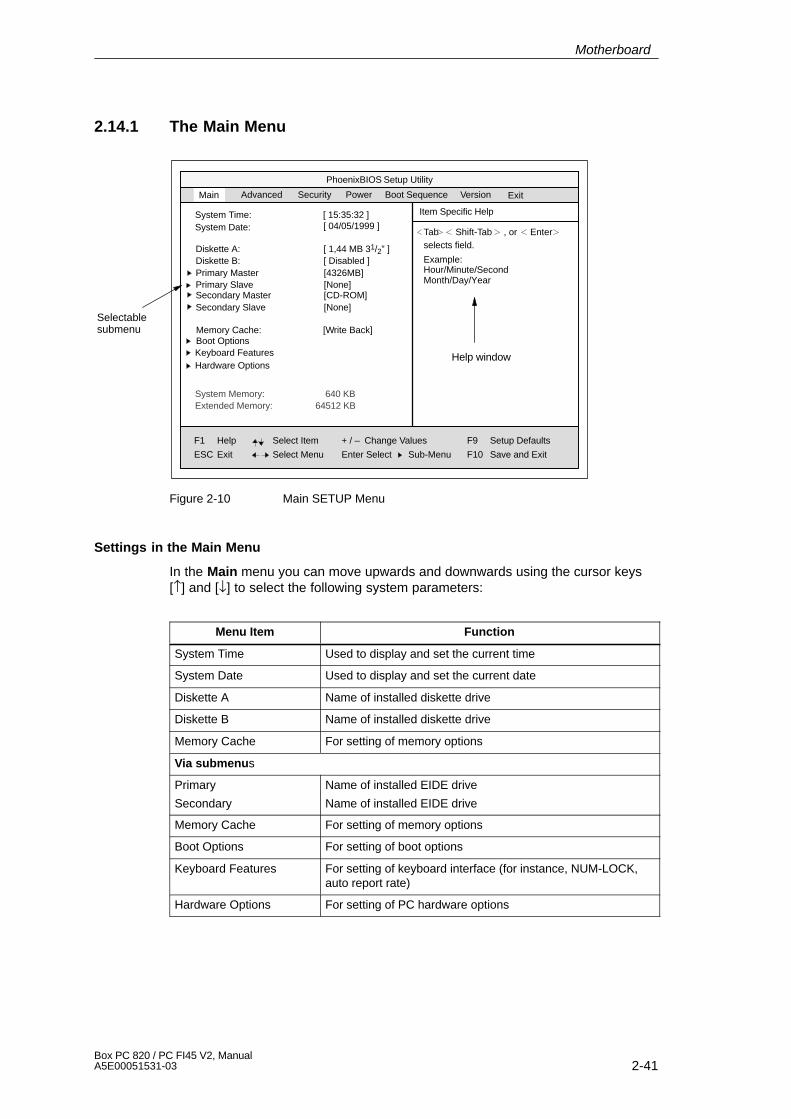
2-41Box PC 820 / PC FI45 V2, ManualA5E00051531-03
2.14.1 The Main Menu
PhoenixBIOS Setup Utility
Item Specific HelpSystem Time:
F1
ESC
Help
Exit
TabSystem Date:[ 15:35:32 ]
Select Item
Select Menu
+ / –
Enter Select
Change Values
Sub-Menu
F9
F10
Setup Defaults
Save and Exit
Shift-Tab Enter, orselects field.Diskette A: [ 1,44 MB 31/2” ]
Diskette B: [ Disabled ]Primary Master [4326MB]Primary Slave [None]
Memory Cache:Boot OptionsKeyboard Features
[Write Back]
Hardware Options
System Memory:Extended Memory:
Main Security Power Version
Help window
Selectablesubmenu
Advanced
Secondary Master [CD-ROM]Secondary Slave [None]
[ 04/05/1999 ]
640 KB64512 KB
Example:Hour/Minute/SecondMonth/Day/Year
ExitBoot Sequence
Figure 2-10 Main SETUP Menu
Settings in the Main Menu
In the Main menu you can move upwards and downwards using the cursor keys[↑] and [↓] to select the following system parameters:
Menu Item Function
System Time Used to display and set the current time
System Date Used to display and set the current date
Diskette A Name of installed diskette drive
Diskette B Name of installed diskette drive
Memory Cache For setting of memory options
Via submenus
Primary
Secondary
Name of installed EIDE drive
Name of installed EIDE drive
Memory Cache For setting of memory options
Boot Options For setting of boot options
Keyboard Features For setting of keyboard interface (for instance, NUM-LOCK,auto report rate)
Hardware Options For setting of PC hardware options
Motherboard

2-42Box PC 820 / PC FI45 V2, Manual
A5E00051531-03
System Time and System Date (Time and Date)
System Time and System Date indicate the current values. Once you haveselected the appropriate option, you can use the [+] and [-] keys to modify the timesetting
Hour:Minute:Second and the date
Month/Day/Year.
You can move between the entries in the date and time options (for example, fromhour to minute) using the tabulator key.
Diskette A/ Diskette B (Floppy Disk Drive)
The names of the installed diskette drives in the PC are set here. The followingentries are possible:
[Disabled] If a diskette drive is not fitted (standard setting for diskette drive B)
[360 Kbyte,5 1/4”]
[1.2 Mbyte,5 1/4”]
[720 Kbyte,3 1/2”]
[1.44 Mbyte, 3 1/2”] Standard setting for installed diskette drive A
[2.88 Mbyte, 3 1/2”]
Motherboard
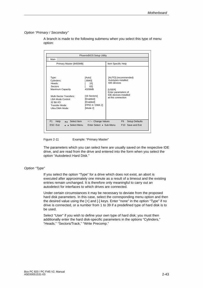
2-43Box PC 820 / PC FI45 V2, ManualA5E00051531-03
Option “Primary / Secondary”
A branch is made to the following submenu when you select this type of menuoption:
PhoenixBIOS Setup Utility
Item Specific Help
F1
ESC
Help
Exit
Select Item
Select Menu
+ / –
Enter Select
Change Values F9
F10
Setup Defaults
Save and ExitSub-Menu
Type:Cylinders:
[Auto]
Heads:SectorsMaximum Capacity
Main
Primary Master [8455MB]
Multi-Sector Transfers:LBA Mode Control:32 Bit I/O:Transfer Mode:
[ 8940][ 15][ 63]4326MB
[16 Sectors][Enabled][Enabled][FPIO 4 / DMA 2]
Ultra DMA Mode: [Mode 2]
[AUTO] (recommended)Autotypes installed IDE-devices
[USER]Enter parameters of IDE-devices installed at this connection
Figure 2-11 Example: “Primary Master”
The parameters which you can select here are usually saved on the respective IDEdrive, and are read from the drive and entered into the form when you select theoption “Autodetect Hard Disk.”
Option “Type”
If you select the option “Type” for a drive which does not exist, an abort isexecuted after approximately one minute as a result of a timeout and the existingentries remain unchanged. It is therefore only meaningful to carry out anautodetect for interfaces to which drives are connected.
Under certain circumstances it may be necessary to deviate from the proposedhard disk parameters. In this case, select the corresponding menu option and thenthe desired value using the [+] and [-] keys. Enter “none” in the option “Type” if nodrive is connected, or a number from 1 to 39 if a predefined type of hard disk is tobe used.
Select “User” if you wish to define your own type of hard disk; you must thenadditionally enter the hard disk-specific parameters in the options “Cylinders,”“Heads,” “Sectors/Track,” “Write Precomp.”
Motherboard

2-44Box PC 820 / PC FI45 V2, Manual
A5E00051531-03
Option “Multi-Sector Transfers”
The number of sectors which are transmitted per interrupt are transferred in theoption “Multi-Sector Transfers.” The value depends on the drive and should only beset using the autodetect function.
Disabled
2,4,6,8,16 sectors
Option “LBA Mode Control”
“Enabled” in the option “LBA Mode Control” (enabled, disabled) means that harddisk capacities greater than 528 MB are supported. The value depends on thedrive and should only be set using the autodetect function.
Option “32 Bit I/O”
The type of access to the drive is defined in the option “32 Bit I/O”:
Disabled 16-bit access
Enabled 32-bit access
Option “Transfer Mode” or Ultra DMA Mode
The interface transmission rate is set in the option “Transfer Mode.” The value de-pends on the drive and should only be set using the autodetect function.
You leave the submenu using the ESC key.
Motherboard
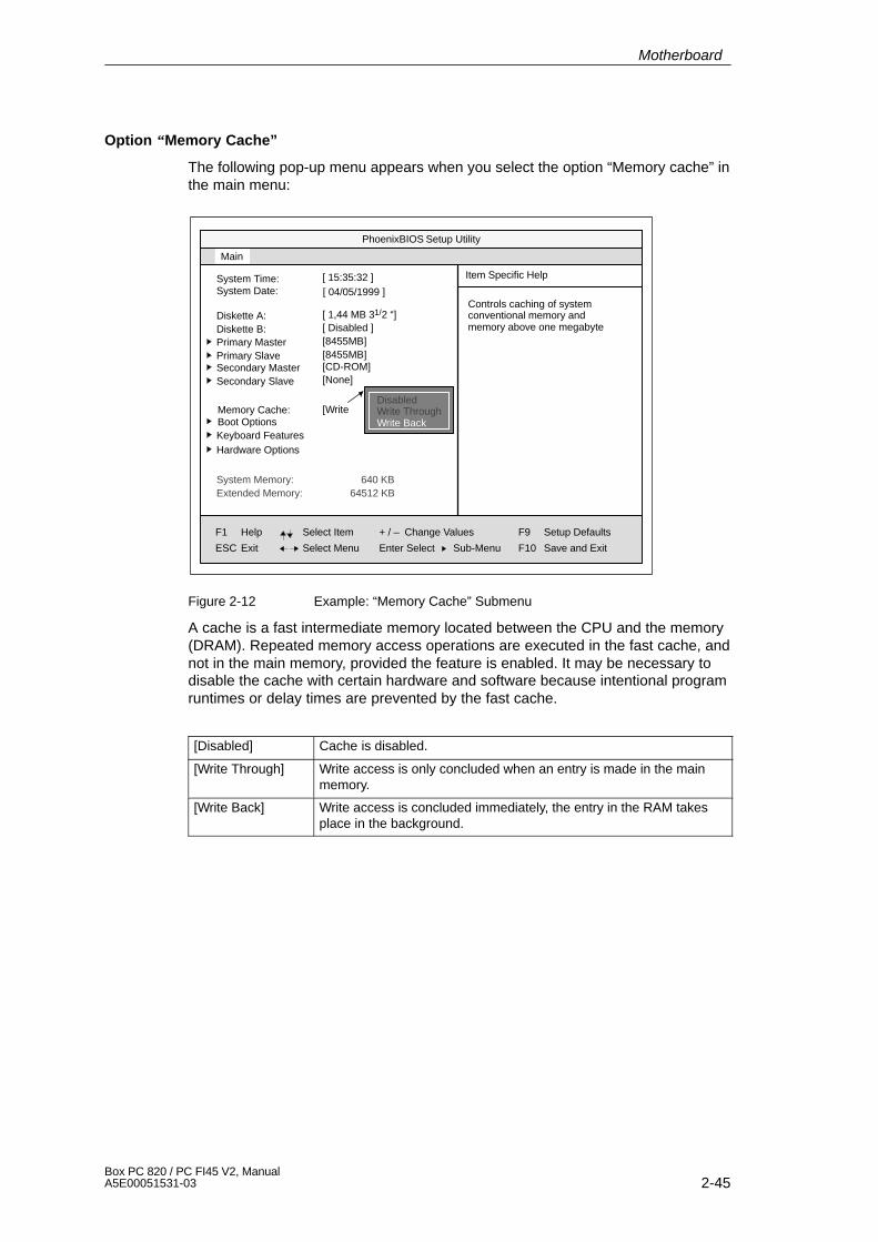
2-45Box PC 820 / PC FI45 V2, ManualA5E00051531-03
Option “Memory Cache”
The following pop-up menu appears when you select the option “Memory cache” inthe main menu:
PhoenixBIOS Setup Utility
Item Specific HelpSystem Time:
F1
ESC
Help
Exit
System Date:[ 15:35:32 ]
Select Item
Select Menu
+ / –
Enter Select
Change Values
Sub-Menu
F9
F10
Setup Defaults
Save and Exit
Diskette A: [ 1,44 MB 31/2 “]Diskette B: [ Disabled ]Primary Master [8455MB]Primary Slave [8455MB]
Memory Cache:Boot OptionsKeyboard Features
[Write
Hardware Options
System Memory:Extended Memory:
Main
Secondary Master [CD-ROM]Secondary Slave [None]
[ 04/05/1999 ]
640 KB64512 KB
Controls caching of systemconventional memory andmemory above one megabyte
DisabledWrite ThroughWrite Back
Figure 2-12 Example: “Memory Cache” Submenu
A cache is a fast intermediate memory located between the CPU and the memory(DRAM). Repeated memory access operations are executed in the fast cache, andnot in the main memory, provided the feature is enabled. It may be necessary todisable the cache with certain hardware and software because intentional programruntimes or delay times are prevented by the fast cache.
[Disabled] Cache is disabled.
[Write Through] Write access is only concluded when an entry is made in the mainmemory.
[Write Back] Write access is concluded immediately, the entry in the RAM takesplace in the background.
Motherboard
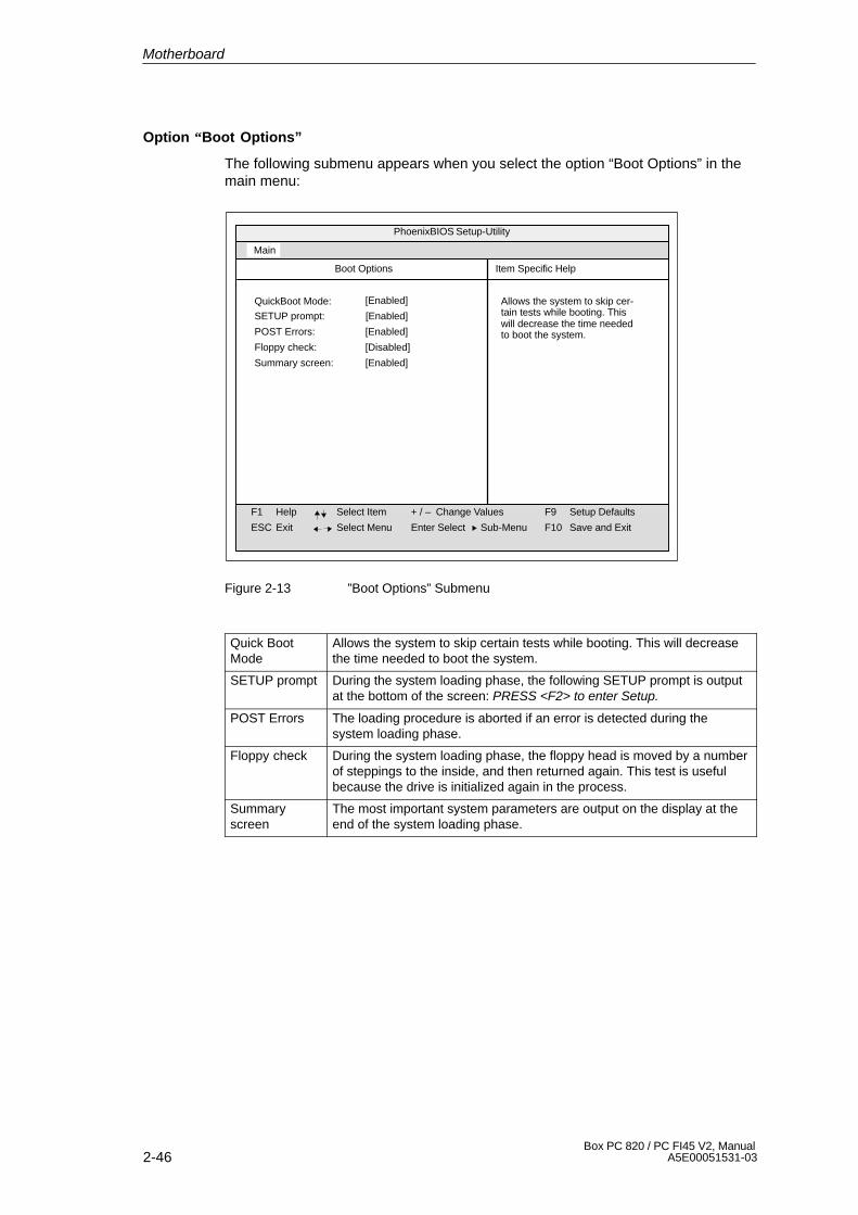
2-46Box PC 820 / PC FI45 V2, Manual
A5E00051531-03
Option “Boot Options”
The following submenu appears when you select the option “Boot Options” in themain menu:
PhoenixBIOS Setup-Utility
Item Specific Help
F1
ESC
Help
Exit
Select Item
Select Menu
+ / –
Enter Select
Change Values F9
F10
Setup Defaults
Save and ExitSub-Menu
QuickBoot Mode:
SETUP prompt: [Enabled]
Main
Boot Options
[Enabled] Allows the system to skip cer-tain tests while booting. Thiswill decrease the time neededto boot the system.POST Errors: [Enabled]
Floppy check: [Disabled]
Summary screen: [Enabled]
Figure 2-13 ”Boot Options” Submenu
Quick BootMode
Allows the system to skip certain tests while booting. This will decreasethe time needed to boot the system.
SETUP prompt During the system loading phase, the following SETUP prompt is outputat the bottom of the screen: PRESS <F2> to enter Setup.
POST Errors The loading procedure is aborted if an error is detected during thesystem loading phase.
Floppy check During the system loading phase, the floppy head is moved by a numberof steppings to the inside, and then returned again. This test is usefulbecause the drive is initialized again in the process.
Summaryscreen
The most important system parameters are output on the display at theend of the system loading phase.
Motherboard
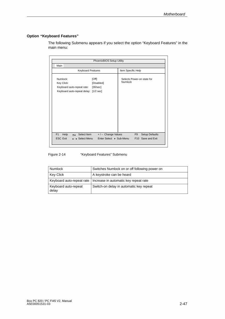
2-47Box PC 820 / PC FI45 V2, ManualA5E00051531-03
Option “Keyboard Features”
The following Submenu appears if you select the option “Keyboard Features” in themain menu:
PhoenixBIOS Setup Utility
Item Specific Help
F1
ESC
Help
Exit
Select Item
Select Menu
+ / –
Enter Select
Change Values F9
F10
Setup Defaults
Save and ExitSub-Menu
Numlock:
Key Click: [Disabled]
Main
Keyboard Features
[Off] Selects Power-on state forNumlock
Keyboard auto-repeat rate: [30/sec]
Keyboard auto-repeat delay: [1/2 sec]
Figure 2-14 “Keyboard Features” Submenu
Numlock Switches Numlock on or off following power on
Key Click A keystroke can be heard
Keyboard auto-repeat rate Increase in automatic key repeat rate
Keyboard auto-repeatdelay
Switch-on delay in automatic key repeat
Motherboard
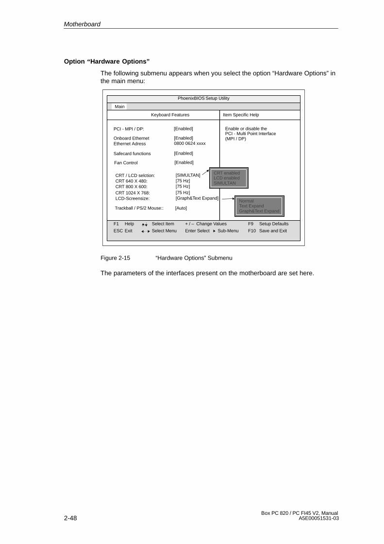
2-48Box PC 820 / PC FI45 V2, Manual
A5E00051531-03
Option “Hardware Options”
The following submenu appears when you select the option “Hardware Options” inthe main menu:
PhoenixBIOS Setup Utility
Item Specific Help
F1
ESC
Help
Exit
Select Item
Select Menu
+ / –
Enter Select
Change Values F9
F10
Setup Defaults
Save and ExitSub-Menu
Main
Keyboard Features
Enable or disable thePCI - Multi Point Interface (MPI / DP)
PCI - MPI / DP: [Enabled]
Fan Control [Enabled]
Onboard Ethernet [Enabled]Ethernet Adress 0800 0624 xxxx
Safecard functions [Enabled]
CRT / LCD selction: [SIMULTAN]CRT 640 X 480: [75 Hz]CRT 800 X 600: [75 Hz]CRT 1024 X 768: [75 Hz]LCD-Screensize: [Graph&Text Expand]
Trackball / PS/2 Mouse:: [Auto]
NormalText ExpandGraph&Text Expand
CRT enabledLCD enabledSIMULTAN
Figure 2-15 “Hardware Options” Submenu
The parameters of the interfaces present on the motherboard are set here.
Motherboard
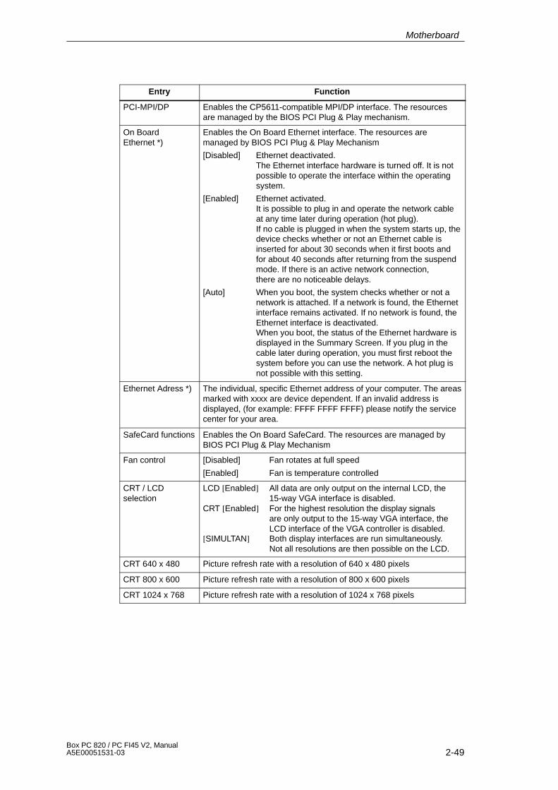
2-49Box PC 820 / PC FI45 V2, ManualA5E00051531-03
Entry Function
PCI-MPI/DP Enables the CP5611-compatible MPI/DP interface. The resourcesare managed by the BIOS PCI Plug & Play mechanism.
On Board Ethernet *)
Enables the On Board Ethernet interface. The resources aremanaged by BIOS PCI Plug & Play Mechanism
[Disabled] Ethernet deactivated.The Ethernet interface hardware is turned off. It is not possible to operate the interface within the operating system.
[Enabled] Ethernet activated.It is possible to plug in and operate the network cable at any time later during operation (hot plug).If no cable is plugged in when the system starts up, thedevice checks whether or not an Ethernet cable is inserted for about 30 seconds when it first boots and for about 40 seconds after returning from the suspend mode. If there is an active network connection, there are no noticeable delays.
[Auto] When you boot, the system checks whether or not a network is attached. If a network is found, the Ethernet interface remains activated. If no network is found, the Ethernet interface is deactivated.When you boot, the status of the Ethernet hardware is displayed in the Summary Screen. If you plug in the cable later during operation, you must first reboot the system before you can use the network. A hot plug is not possible with this setting.
Ethernet Adress *) The individual, specific Ethernet address of your computer. The areasmarked with xxxx are device dependent. If an invalid address isdisplayed, (for example: FFFF FFFF FFFF) please notify the servicecenter for your area.
SafeCard functions Enables the On Board SafeCard. The resources are managed byBIOS PCI Plug & Play Mechanism
Fan control [Disabled] Fan rotates at full speed
[Enabled] Fan is temperature controlled
CRT / LCDselection
LCD [Enabled] All data are only output on the internal LCD, the 15-way VGA interface is disabled.
CRT [Enabled] For the highest resolution the display signals are only output to the 15-way VGA interface, the LCD interface of the VGA controller is disabled.
[SIMULTAN] Both display interfaces are run simultaneously.Not all resolutions are then possible on the LCD.
CRT 640 x 480 Picture refresh rate with a resolution of 640 x 480 pixels
CRT 800 x 600 Picture refresh rate with a resolution of 800 x 600 pixels
CRT 1024 x 768 Picture refresh rate with a resolution of 1024 x 768 pixels
Motherboard
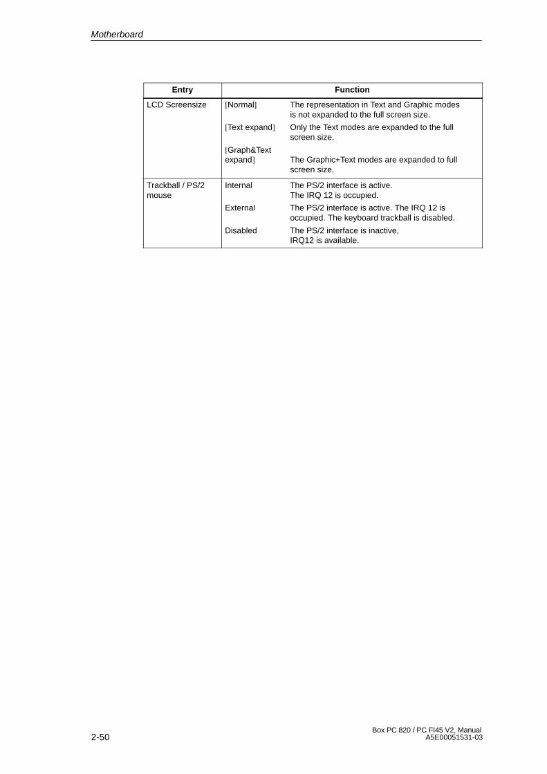
2-50Box PC 820 / PC FI45 V2, Manual
A5E00051531-03
Entry Function
LCD Screensize [Normal] The representation in Text and Graphic modes is not expanded to the full screen size.
[Text expand] Only the Text modes are expanded to the full screen size.
[Graph&Text expand] The Graphic+Text modes are expanded to full
screen size.
Trackball / PS/2mouse
Internal The PS/2 interface is active.The IRQ 12 is occupied.
External The PS/2 interface is active. The IRQ 12 is occupied. The keyboard trackball is disabled.
Disabled The PS/2 interface is inactive,IRQ12 is available.
Motherboard
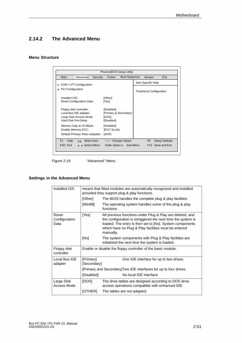
2-51Box PC 820 / PC FI45 V2, ManualA5E00051531-03
2.14.2 The Advanced Menu
Menu Structure
PhoenixBIOS Setup-Utility
Item Specific Help
F1
ESC
Help
Exit
Select Item
Select Menu
+ / –
Enter Select
Change Values F9
F10
Setup Defaults
Save and ExitSub-Menu
Main Security Power VersionAdvanced
Installed O/S: [Other]Reset Configuration Data: [Yes]
Local Bus IDE adapter:Floppy disk controller: [Disabled]
[Primary & Secondary]Large Disk Access Mode: [DOS]
Memory Gap at 15 Mbyte: [Disabled]
COM / LPT Configuration
PCI Configuration
Hard Disk Pre-Delay: [Disabled]
Default Primary Video adapater: [AGP]
ExitBoot Sequence
Peripheral Configuration
Enable Memory ECC: [ECC Scrub]
Figure 2-16 “Advanced” Menu
Settings in the Advanced Menu
Installed O/S means that fitted modules are automatically recognized and installedprovided they support plug & play functions.
[Other] The BIOS handles the complete plug & play facilities
[Win98] The operating system handles some of the plug & play functions
ResetConfigurationData
[Yes] All previous functions under Plug & Play are deleted, and the configuration is retriggered the next time the system is loaded. The entry is then set to [No]. System components which have no Plug & Play facilities must be entered manually.
[No] The system components with Plug & Play facilities areinitialized the next time the system is loaded.
Floppy diskcontroller
Enable or disable the floppy controller of the basic module.
Local Bus IDEadapter
[Primary] One IDE interface for up to two drives.[Secondary]
[Primary and Secondary]Two IDE interfaces for up to four drives.
[Disabled] No local IDE interface
Large DiskAccess Mode
[DOS] The drive tables are designed according to DOS drive access operations compatible with enhanced IDE.
[OTHER] The tables are not adapted.
Motherboard
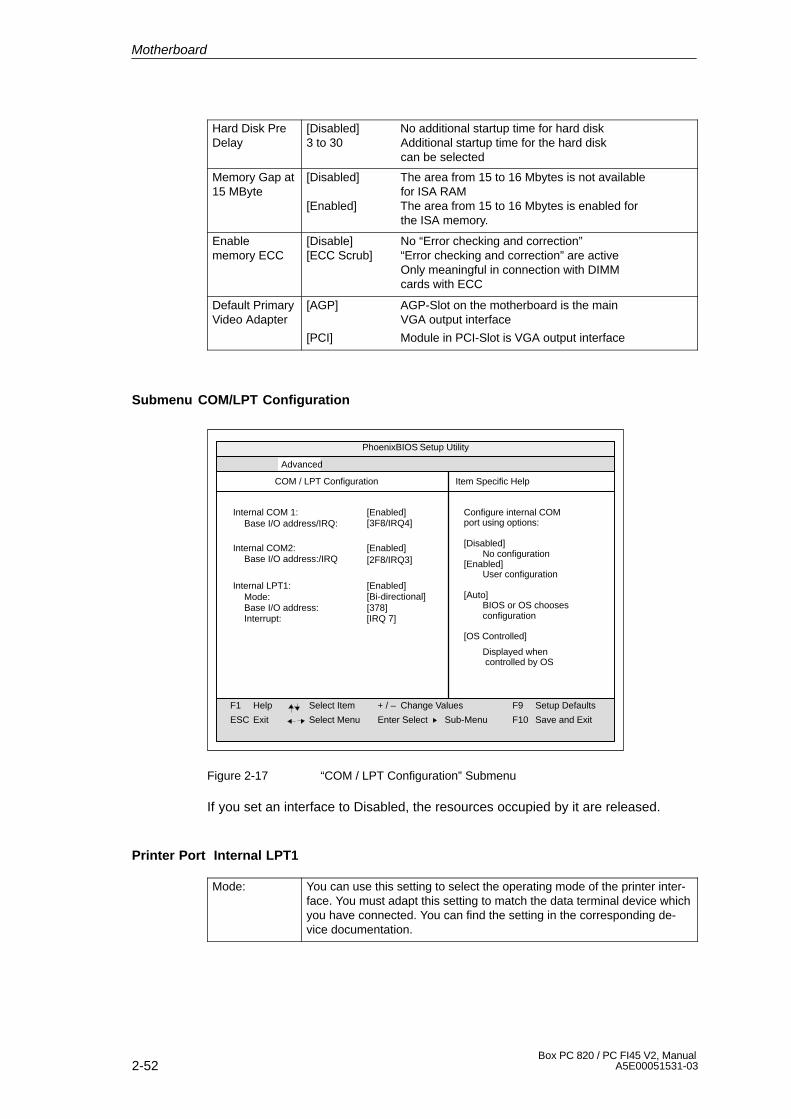
2-52Box PC 820 / PC FI45 V2, Manual
A5E00051531-03
Hard Disk PreDelay
[Disabled] No additional startup time for hard disk3 to 30 Additional startup time for the hard disk
can be selected
Memory Gap at15 MByte
[Disabled] The area from 15 to 16 Mbytes is not availablefor ISA RAM
[Enabled] The area from 15 to 16 Mbytes is enabled forthe ISA memory.
Enablememory ECC
[Disable] No “Error checking and correction”[ECC Scrub] “Error checking and correction” are active
Only meaningful in connection with DIMMcards with ECC
Default PrimaryVideo Adapter
[AGP] AGP-Slot on the motherboard is the main VGA output interface
[PCI] Module in PCI-Slot is VGA output interface
Submenu COM/LPT Configuration
PhoenixBIOS Setup Utility
Item Specific Help
F1
ESC
Help
Exit
Select Item
Select Menu
+ / –
Enter Select
Change Values F9
F10
Setup Defaults
Save and ExitSub-Menu
Advanced
Base I/O address/IRQ:[Enabled]Internal COM 1:
COM / LPT Configuration
Configure internal COMport using options:
[Disabled]No configuration
[Enabled]User configuration
[Auto]BIOS or OS choosesconfiguration
[OS Controlled]
Displayed when controlled by OS
Base I/O address:/IRQ[Enabled]Internal COM2:
Mode:[Enabled]
Base I/O address: [378]
Internal LPT1:
Interrupt: [IRQ 7]
[Bi-directional]
[2F8/IRQ3]
[3F8/IRQ4]
Figure 2-17 “COM / LPT Configuration” Submenu
If you set an interface to Disabled, the resources occupied by it are released.
Printer Port Internal LPT1
Mode: You can use this setting to select the operating mode of the printer inter-face. You must adapt this setting to match the data terminal device whichyou have connected. You can find the setting in the corresponding de-vice documentation.
Motherboard

2-53Box PC 820 / PC FI45 V2, ManualA5E00051531-03
Submenu PCI Configuration
PhoenixBIOS Setup Utility
Item Specific Help
F1
ESC
Help
Exit
Select Item
Select Menu
+ / –
Enter Select
Change Values F9
F10
Setup Defaults
Save and ExitSub-Menu
Advanced
PCI Configuration
Setup items for configuringthe specific PCI device
PCI Device, Slot #1PCI Device, Slot #2PCI Device, Slot #3
PCI/PNP ISA IRQ Resource Exclusion
PCI IRQ line 1:PCI IRQ line 2:PCI IRQ line 3:PCI IRQ line 4:
[Auto Select][Auto Select][Auto Select][Auto Select]
Figure 2-18 “PCI Configuration” Submenu
Motherboard

2-54Box PC 820 / PC FI45 V2, Manual
A5E00051531-03
Option “PCI Devices”
The following submenu appears when you select the option “PCI Devices” in theadvanced menu:
PhoenixBIOS Setup Utility.
Item Specific Help
F1
ESC
Help
Exit
Select Item
Select Menu
+ / –
Enter Select
Change Values F9
F10
Setup Defaults
Save and ExitSub-Menu
Advanced
Option Rom Scan [Enabled]Enable Master: [Enabled]
PCI Devices, Slot #1
Latency Timer: [0040h]
Initialize device expansionrom
Figure 2-19 ”PCI Devices, Slot #1” Submenu
Option ROMScan:
[Enabled] The ROM option of the PCI module (if present) is enabled.
[Disabled] The ROM option of a PCI module is disabled.
Enable Master: [Enabled] This slot can assume the PCI master function.[Disabled] This slot can only work as a PCI slave.
Latency Timer [Default] The number of active PCI clock cycles of themaster modules are determined by the module.
[0020H You can use these settings to set the maximumto number of active PCI clock cycles to the00E0H] chosen value.
Motherboard
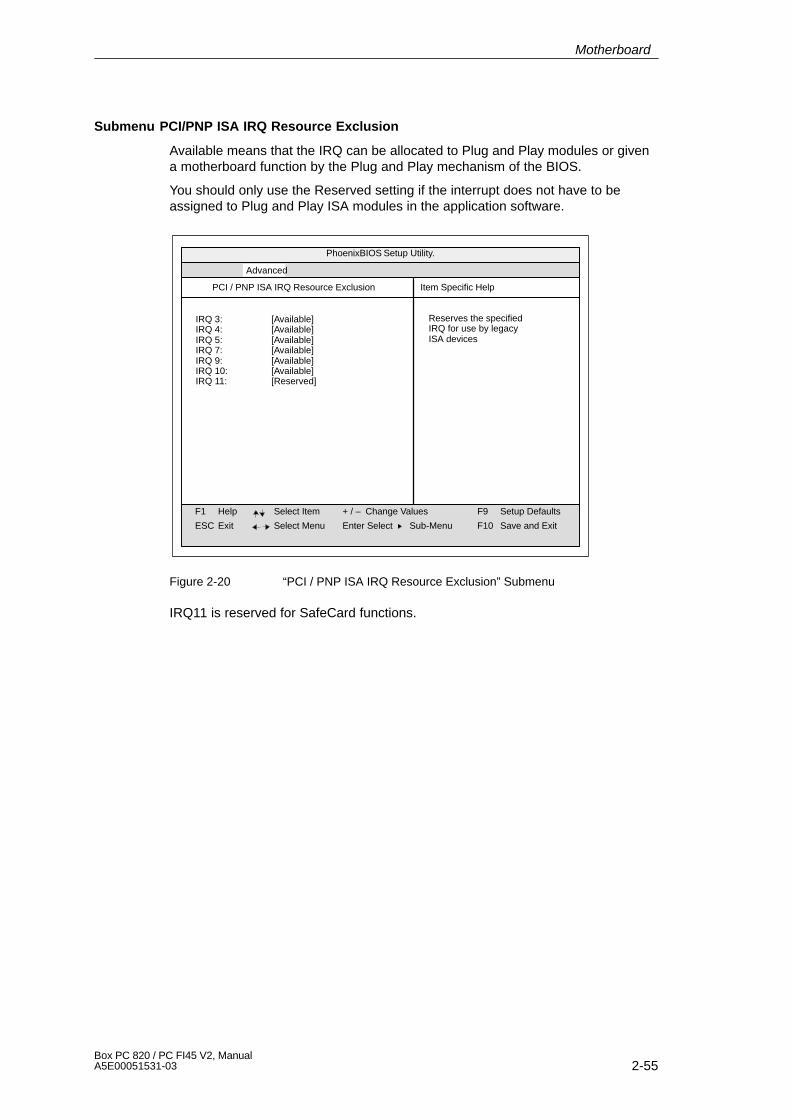
2-55Box PC 820 / PC FI45 V2, ManualA5E00051531-03
Submenu PCI/PNP ISA IRQ Resource Exclusion
Available means that the IRQ can be allocated to Plug and Play modules or givena motherboard function by the Plug and Play mechanism of the BIOS.
You should only use the Reserved setting if the interrupt does not have to beassigned to Plug and Play ISA modules in the application software.
PhoenixBIOS Setup Utility.
Item Specific Help
F1
ESC
Help
Exit
Select Item
Select Menu
+ / –
Enter Select
Change Values F9
F10
Setup Defaults
Save and ExitSub-Menu
Advanced
IRQ 3:IRQ 4:IRQ 5:IRQ 7:IRQ 9:IRQ 10:IRQ 11:
[Available][Available][Available][Available][Available][Available][Reserved]
PCI / PNP ISA IRQ Resource Exclusion
Reserves the specifiedIRQ for use by legacyISA devices
Figure 2-20 “PCI / PNP ISA IRQ Resource Exclusion” Submenu
IRQ11 is reserved for SafeCard functions.
Motherboard
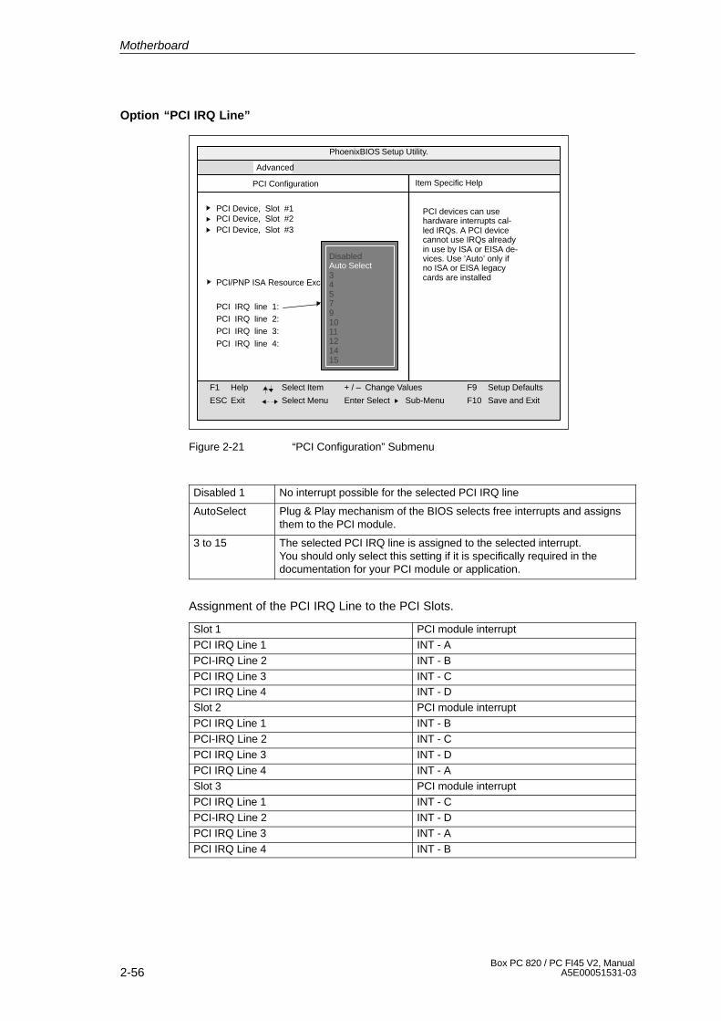
2-56Box PC 820 / PC FI45 V2, Manual
A5E00051531-03
Option “PCI IRQ Line”
PhoenixBIOS Setup Utility.
Item Specific Help
F1
ESC
Help
Exit
Select Item
Select Menu
+ / –
Enter Select
Change Values F9
F10
Setup Defaults
Save and ExitSub-Menu
Advanced
PCI Configuration
PCI devices can usehardware interrupts cal-led IRQs. A PCI devicecannot use IRQs alreadyin use by ISA or EISA de-vices. Use ’Auto’ only ifno ISA or EISA legacycards are installed
PCI IRQ line 1:PCI IRQ line 2:PCI IRQ line 3:
PCI IRQ line 4:
PCI Device, Slot #1PCI Device, Slot #2PCI Device, Slot #3
PCI/PNP ISA Resource Exclusion
DisabledAuto Select345791011121415
Figure 2-21 “PCI Configuration” Submenu
Disabled 1 No interrupt possible for the selected PCI IRQ line
AutoSelect Plug & Play mechanism of the BIOS selects free interrupts and assignsthem to the PCI module.
3 to 15 The selected PCI IRQ line is assigned to the selected interrupt.You should only select this setting if it is specifically required in thedocumentation for your PCI module or application.
Assignment of the PCI IRQ Line to the PCI Slots.
Slot 1 PCI module interruptPCI IRQ Line 1 INT - APCI-IRQ Line 2 INT - BPCI IRQ Line 3 INT - CPCI IRQ Line 4 INT - DSlot 2 PCI module interruptPCI IRQ Line 1 INT - BPCI-IRQ Line 2 INT - CPCI IRQ Line 3 INT - DPCI IRQ Line 4 INT - ASlot 3 PCI module interruptPCI IRQ Line 1 INT - CPCI-IRQ Line 2 INT - DPCI IRQ Line 3 INT - APCI IRQ Line 4 INT - B
Motherboard

2-57Box PC 820 / PC FI45 V2, ManualA5E00051531-03
2.14.3 The Security Menu
Summary
You can only edit the options enclosed in square brackets. Two passwords areassigned to protect your PC from unauthorized use. You can use the supervisorpassword to prevent use of diskettes for the normal user and to limit use of thehard disk.
PhoenixBIOS Setup-Utility
Item Specific Help
F1
ESC
Help
Exit
Select Item
Select Menu
+ / –
Enter Select
Change Values F9
F10
Setup Defaults
Save and ExitSub-Menu
Supervisor Password is DisabledUser Password is DisabledSet Supervisor PasswordSet User Password Enter
Enter
Password on boot: Disabled
Diskette access: SupervisorFixed disk boot sector: Normal
Main Security Power VersionAdvanced ExitBoot Sequence
Figure 2-22 “Security” Submenu
Motherboard
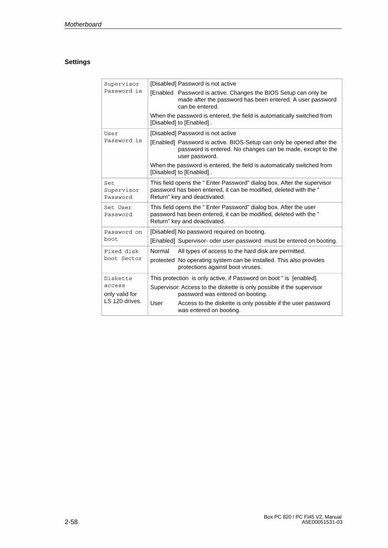
2-58Box PC 820 / PC FI45 V2, Manual
A5E00051531-03
Settings
SupervisorPassword is
[Disabled] Password is not active
[Enabled Password is active. Changes the BIOS Setup can only bemade after the password has been entered. A user passwordcan be entered.
When the password is entered, the field is automatically switched from[Disabled] to [Enabled] .
UserPassword is
[Disabled] Password is not active
[Enabled] Password is active. BIOS-Setup can only be opened after thepassword is entered. No changes can be made, except to theuser password.
When the password is entered, the field is automatically switched from[Disabled] to [Enabled] .
SetSupervisorPassword
This field opens the ” Enter Password” dialog box. After the supervisorpassword has been entered, it can be modified, deleted with the ”Return” key and deactivated.
Set UserPassword
This field opens the ” Enter Password” dialog box. After the userpassword has been entered, it can be modified, deleted with the ”Return” key and deactivated.
Password onboot
[Disabled] No password required on booting.
[Enabled] Supervisor- oder user-password must be entered on booting.
Fixed diskboot Sector
Normal All types of access to the hard disk are permitted.
protected No operating system can be installed. This also providesprotections against boot viruses.
Disketteaccess
only valid forLS 120 drives
This protection is only active, if Password on boot ” is [enabled].
Supervisor2 Access to the diskette is only possible if the supervisorpassword was entered on booting.
User Access to the diskette is only possible if the user passwordwas entered on booting.
Motherboard
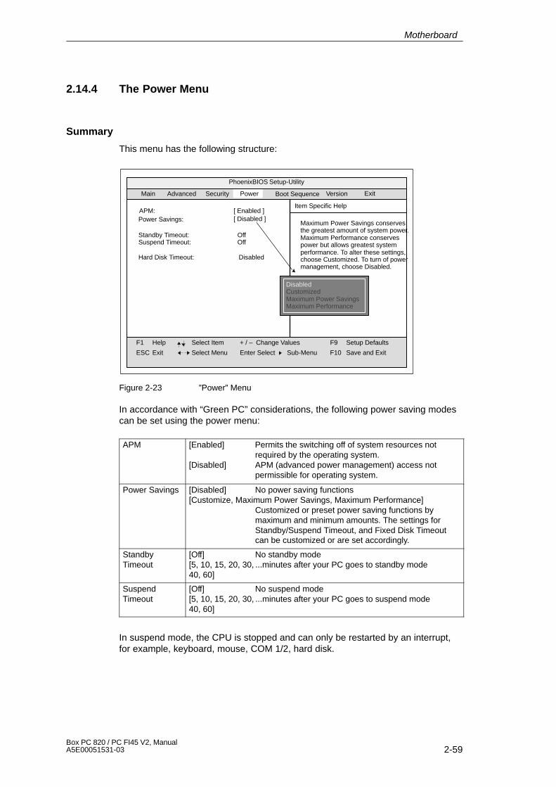
2-59Box PC 820 / PC FI45 V2, ManualA5E00051531-03
2.14.4 The Power Menu
Summary
This menu has the following structure:
PhoenixBIOS Setup-Utility
Item Specific Help
F1
ESC
Help
Exit
Select Item
Select Menu
+ / –
Enter Select
Change Values F9
F10
Setup Defaults
Save and Exit
Maximum Power Savings conservesthe greatest amount of system power.Maximum Performance conservespower but allows greatest systemperformance. To alter these settings,choose Customized. To turn of powermanagement, choose Disabled.
Sub-Menu
Power Savings:
Standby Timeout: OffSuspend Timeout: Off
Hard Disk Timeout: Disabled
Main
Security Power VersionAdvanced
DisabledCustomizedMaximum Power SavingsMaximum Performance
ExitBoot Sequence
APM: [ Enabled ][ Disabled ]
Figure 2-23 ”Power” Menu
In accordance with “Green PC” considerations, the following power saving modescan be set using the power menu:
APM [Enabled] Permits the switching off of system resources not required by the operating system.
[Disabled] APM (advanced power management) access not permissible for operating system.
Power Savings [Disabled] No power saving functions[Customize, Maximum Power Savings, Maximum Performance]
Customized or preset power saving functions by maximum and minimum amounts. The settings for Standby/Suspend Timeout, and Fixed Disk Timeout can be customized or are set accordingly.
StandbyTimeout
[Off] No standby mode[5, 10, 15, 20, 30, ...minutes after your PC goes to standby mode40, 60]
SuspendTimeout
[Off] No suspend mode[5, 10, 15, 20, 30, ...minutes after your PC goes to suspend mode40, 60]
In suspend mode, the CPU is stopped and can only be restarted by an interrupt,for example, keyboard, mouse, COM 1/2, hard disk.
Motherboard

2-60Box PC 820 / PC FI45 V2, Manual
A5E00051531-03
Hard DiskTimeout
[Disabled] Hard disks are not switched off.
[10, 15, 30, 60] Minutes after which the hard disk drive is switched off, provided it is not being accessed. If you attempt to access the hard disk after it has been switched off, there will be an access delay while the disk is run up again.
Motherboard
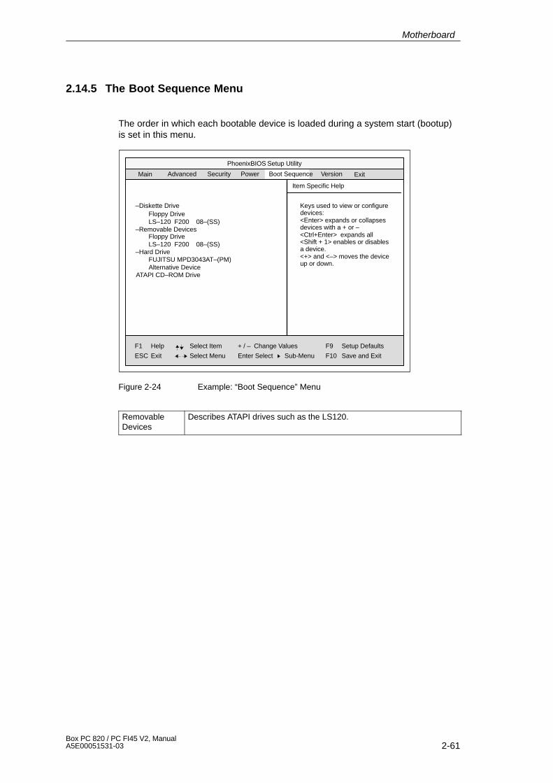
2-61Box PC 820 / PC FI45 V2, ManualA5E00051531-03
2.14.5 The Boot Sequence Menu
The order in which each bootable device is loaded during a system start (bootup)is set in this menu.
PhoenixBIOS Setup Utility
Item Specific Help
–Diskette Drive
F1
ESC
Help
Exit
Select Item
Select Menu
+ / –
Enter Select
Change Values
Sub-Menu
F9
F10
Setup Defaults
Save and Exit
Main Security Power VersionAdvanced ExitBoot Sequence
Floppy DriveLS–120 F200 08–(SS)
–Removable Devices
–Hard Drive
ATAPI CD–ROM Drive
Keys used to view or configuredevices:<Enter> expands or collapsesdevices with a + or – <Ctrl+Enter> expands all<Shift + 1> enables or disablesa device. <+> and <–> moves the deviceup or down.
Floppy DriveLS–120 F200 08–(SS)
FUJITSU MPD3043AT–(PM)Alternative Device
Figure 2-24 Example: “Boot Sequence” Menu
Removable Devices
Describes ATAPI drives such as the LS120.
Motherboard
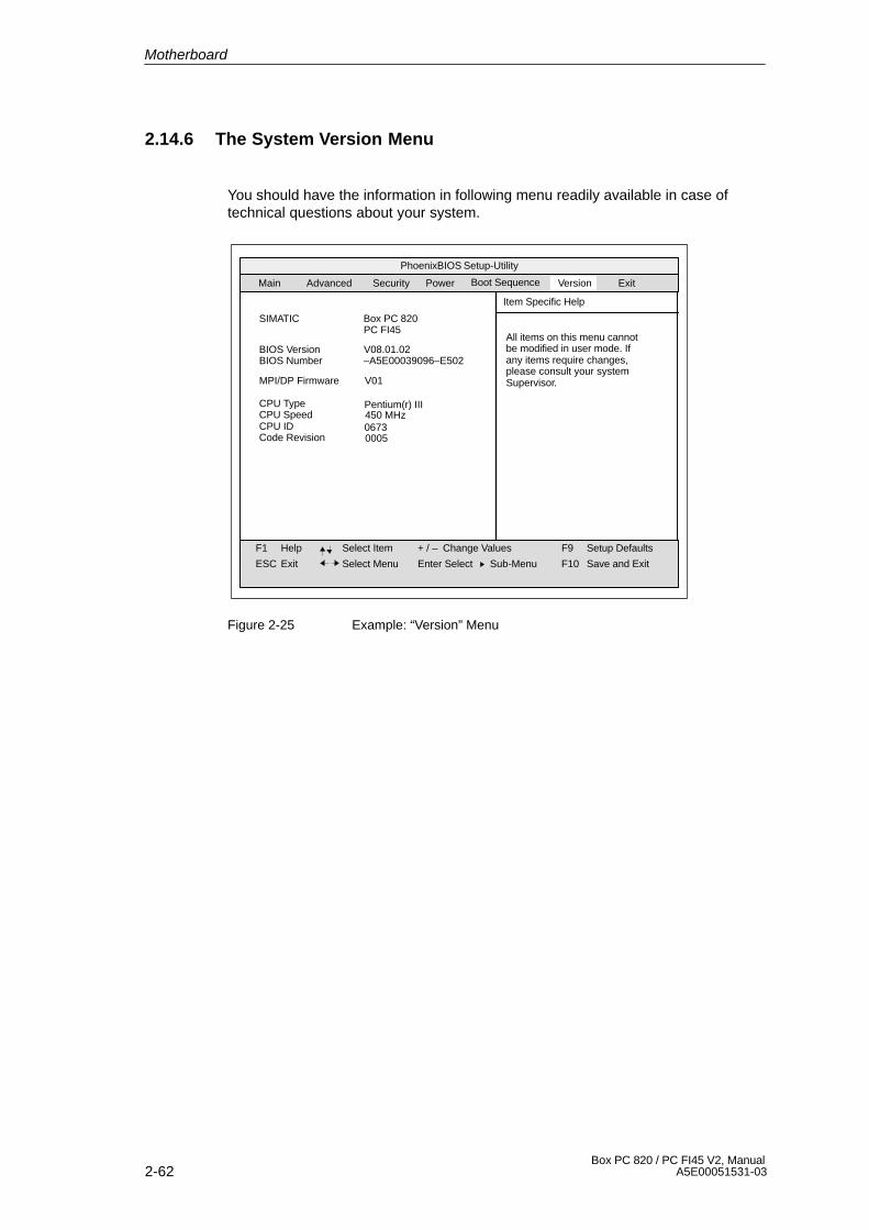
2-62Box PC 820 / PC FI45 V2, Manual
A5E00051531-03
2.14.6 The System Version Menu
You should have the information in following menu readily available in case oftechnical questions about your system.
PhoenixBIOS Setup-Utility
Item Specific Help
F1
ESC
Help
Exit
Select Item
Select Menu
+ / –
Enter Select
Change Values F9
F10
Setup Defaults
Save and ExitSub-Menu
SIMATIC Box PC 820PC FI45
BIOS Version V08.01.02BIOS Number
MPI/DP Firmware
–A5E00039096–E502
CPU Type Pentium(r) III450 MHzCPU Speed
Main Security Power VersionAdvanced Exit
V01
All items on this menu cannotbe modified in user mode. Ifany items require changes,please consult your systemSupervisor.
CPU ID 06730005Code Revision
Boot Sequence
Figure 2-25 Example: “Version” Menu
Motherboard

2-63Box PC 820 / PC FI45 V2, ManualA5E00051531-03
2.14.7 The Exit Menu
Summary
The setup program is always terminated using this menu.
PhoenixBIOS Setup-Utility
Item Specific Help
F1
ESC
Help
Exit
Select Item
Select Menu
+ / –
Enter Select
Change Values F9
F10
Setup Defaults
Save and Exit
Exit after writing all changed SETUPitem values to CMOS.
Sub-Menu
Save Changes & ExitExit Without Saving ChangesGet Default ValuesLoad Previous ValuesSave Changes
Main
Security Power VersionAdvanced ExitBoot Sequence
Figure 2-26 ”Exit” Menu
Save Changes& Exit
All changes are saved; a system restart is carried out with the newparameters.
Exit WithoutSavingChanges
All changes are rejected; a system restart is carried out with the oldparameters.
Set DefaultValues
All parameters are set to safe values.
Load PreviousValues
The last saved values are loaded again.
Save Changes Saving of all setup entries.
Motherboard
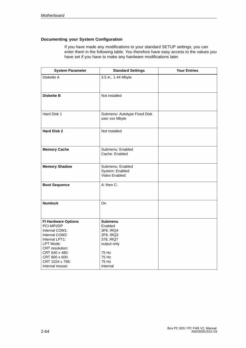
2-64Box PC 820 / PC FI45 V2, Manual
A5E00051531-03
Documenting your System Configuration
If you have made any modifications to your standard SETUP settings, you canenter them in the following table. You therefore have easy access to the values youhave set if you have to make any hardware modifications later.
System Parameter Standard Settings Your Entries
Diskette A 3.5 in., 1.44 Mbyte
Diskette B Not installed
Hard Disk 1 Submenu: Autotype Fixed Diskuser xxx Mbyte
Hard Disk 2 Not installed
Memory Cache Submenu: EnabledCache: Enabled
Memory Shadow Submenu: EnabledSystem: EnabledVideo Enabled:
Boot Sequence A: then C:
Numlock On
FI Hardware OptionsPCI-MPI/DPInternal COM1:Internal COM2:Internal LPT1:LPT Mode:CRT resolution:CRT 640 x 480:CRT 800 x 600:CRT 1024 x 768:Internal mouse:
SubmenuEnabled3F8, IRQ42F8, IRQ3378, IRQ7output only
75 Hz75 Hz75 HzInternal
Motherboard
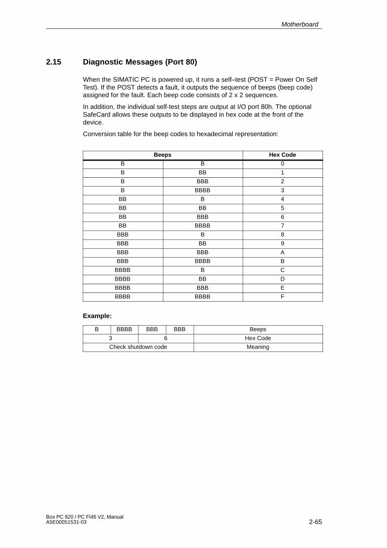
2-65Box PC 820 / PC FI45 V2, ManualA5E00051531-03
2.15 Diagnostic Messages (Port 80)
When the SIMATIC PC is powered up, it runs a self–test (POST = Power On SelfTest). If the POST detects a fault, it outputs the sequence of beeps (beep code)assigned for the fault. Each beep code consists of 2 x 2 sequences.
In addition, the individual self-test steps are output at I/O port 80h. The optionalSafeCard allows these outputs to be displayed in hex code at the front of thedevice.
Conversion table for the beep codes to hexadecimal representation:
Beeps Hex Code
B B 0
B BB 1
B BBB 2
B BBBB 3
BB B 4
BB BB 5
BB BBB 6
BB BBBB 7
BBB B 8
BBB BB 9
BBB BBB A
BBB BBBB B
BBBB B C
BBBB BB D
BBBB BBB E
BBBB BBBB F
Example:
B BBBB BBB BBB Beeps
3 6 Hex Code
Check shutdown code Meaning
Motherboard
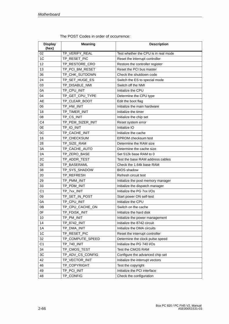
2-66Box PC 820 / PC FI45 V2, Manual
A5E00051531-03
The POST Codes in order of occurrence:
Display(hex)
Meaning Description
02 TP_VERIFY_REAL Test whether the CPU is in real mode
1C TP_RESET_PIC Reset the interrupt controller
12 TP_RESTORE_CRO Restore the controller register
13 TP_PCI_BM_RESET Reset the PCI bus master
36 TP_CHK_SUTDOWN Check the shutdown code
24 TP_SET_HUGE_ES Switch the ES to special mode
03 TP_DISABLE_NMI Switch off the NMI
0A TP_CPU_INIT Initialize the CPU
04 TP_GET_CPU_TYPE Determine the CPU type
AE TP_CLEAR_BOOT Edit the boot flag
06 TP_HW_INIT Initialize the main hardware
18 TP_TIMER_INIT Initialize the timer
08 TP_CS_INIT Initialize the chip set
C4 TP_PEM_SIZER_INIT Reset system error
0E TP_IO_INIT Initialize IO
0C TP_CACHE_INIT Initialize the cache
16 TP_CHECKSUM EPROM checksum test
28 TP_SIZE_RAM Determine the RAM size
3A TP_CACHE_AUTO Determine the cache size
2A TP_ZERO_BASE Set 512k base RAM to 0
2C TP_ADDR_TEST Test the base RAM address cables
2E TP_BASERAML Check the 1.64k base RAM
38 TP_SYS_SHADOW BIOS shadow
20 TP_REFRESH Refresh circuit test
29 TP_PMM_INIT Initialize the post memory manager
33 TP_PDM_INIT Initialize the dispatch manager
C1 TP_7xx_INIT Initialize the PG 7xx I/Os
09 TP_SET_IN_POST Start power ON self-test
0A TP_CPU_INIT Initialize the CPU
0B TP_CPU_CACHE_ON Switch on the cache
0F TP_FDISK_INIT Initialize the hard disk
10 TP_PM_INIT Initialize the power management
14 TP_8742_INIT Initialize the 8742 circuit
1A TP_DMA_INIT Initialize the DMA circuits
1C TP_RESET_PIC Reset the interrupt controller
32 TP_COMPUTE_SPEED Determine the clock pulse speed
C1 TP_740_INIT Initialize the PG 740 I/Os
34 TP_CMOS_TEST Test the CMOS RAM
3C TP_ADV_CS_CONFIG Configure the advanced chip set
42 TP_VECTOR_INIT Initialize the interrupt vectors
46 TP_COPYRIGHT Test the copyright
49 TP_PCI_INIT Initialize the PCI interface
48 TP_CONFIG Check the configuration
Motherboard

2-67Box PC 820 / PC FI45 V2, ManualA5E00051531-03
Display(hex)
DescriptionMeaning
4A TP_VIDEO Initialize the video interface
4C TP_VID_SHADOW Copy the video BIOS to RAM
24 TP_SET_HUGE_ES Switch the ES to special mode
22 TP_8742_TEST Test circuit 8742
52 TP_KB_TEST Keyboard available?
54 TP_KEY_CLICK Switch the keyboard click on/off
76 TP_KEYBOARD Check the keyboard
58 TP_HOT_INT Test for unexpected interrupts
4B TP_QUIETBOOT_START Switch off any boot messages
4E TP_CR_DISPLAY Display the copyright notice
50 TP_CPU_DISPLAY Display the CPU type
5A TP_DISPLAY_F2 Display the F2 message for “SETUP”
5B TP_CPU_CACHE_OFF Switch off the cache if applicable (SETUP setting)
5C TP_MEMORY_TEST Test the system memory
60 TP_EXT_MEMORY Test the extended memory
62 TP_EXT_ADDR Test the A20 address line
64 TP_USERPATCH1 Area for own initializations
66 TP_CACHE_ADVNCD Determine and enable the cache size
68 TP_CACHE_CONFIG Configure and test the cache
6A TP_DISP_CACHE Display the cache configuration
6C TP_DISP_SHADOWS Configuration and size of the shadow Display RAM
6E TP_DISP_NONDISP Display nondisposable segment
70 TP_ERROR_MSGS Display post error
72 TP_TEST_CONFIG Check SETUP irregularities
7C TP_HW_INTS Set the IRQ vectors
7E TP_COPROC Check whether the CO processor is present
96 TP_CLEAR_HUGE_ES Switch the ES back
80 TP_IO_BEFORE Disable IO circuits
88 TP_BIOS_INIT Initialize the BIOS data area
8A TP_INIT_EXT_BDA Initialize the external BIOS data area
85 TP_PCI_PCC Determine the PCI circuits
82 TP_RS232 Determine the serial interfaces
84 TP_LPT Determine the parallel interface
86 TP_IO_AFTER Reenable the IO circuits
83 TP_FDISK_CFG_IDE_CTRLR Configure the IDE controller
89 TP_ENABLE_NMI Enable the NMI
8C TP_FLOPPY Initialize the floppy controller
90 TP_FDISK Initialize the hard disk controller
8B TP_MOUSE Test the internal mouse interface
95 TP_CD Test the CP
92 TP_USERPATCH2 Area for own initializations
98 TP_ROM_SCAN Search for BIOS expansions
69 TP_PM_SETUP Initialize the power management
9E TP_IRQS Enable the hardware IRQ
Motherboard
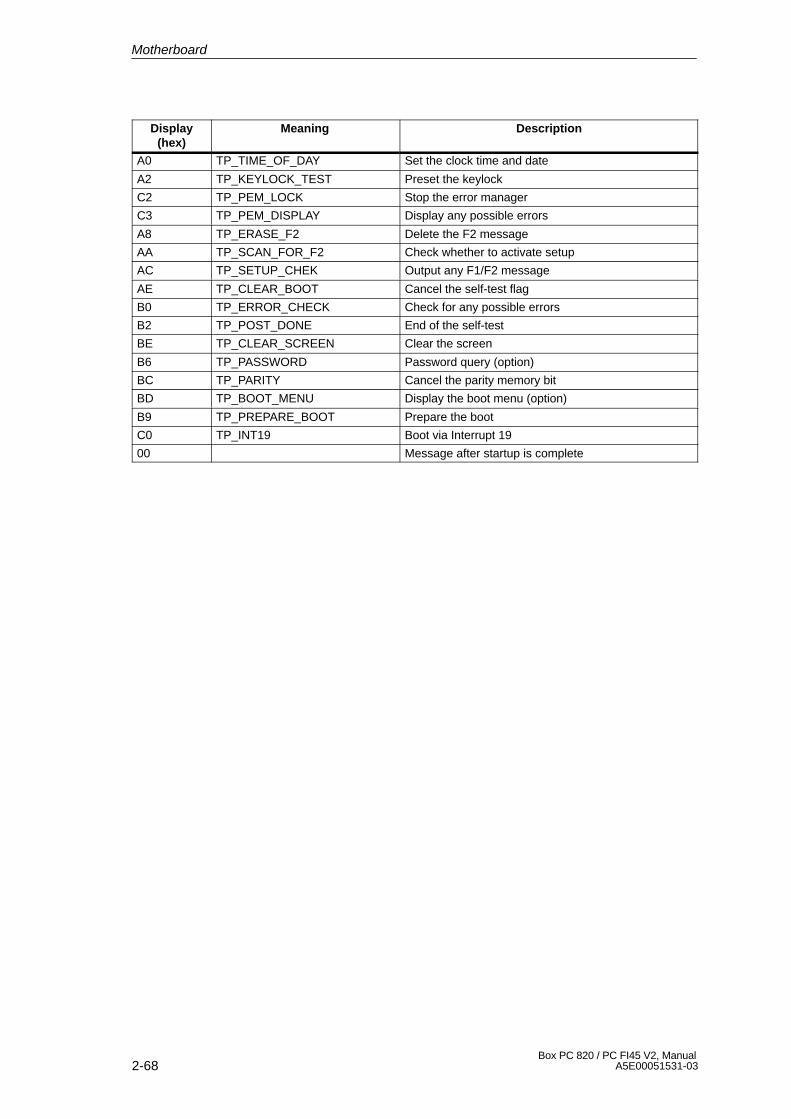
2-68Box PC 820 / PC FI45 V2, Manual
A5E00051531-03
Display(hex)
DescriptionMeaning
A0 TP_TIME_OF_DAY Set the clock time and date
A2 TP_KEYLOCK_TEST Preset the keylock
C2 TP_PEM_LOCK Stop the error manager
C3 TP_PEM_DISPLAY Display any possible errors
A8 TP_ERASE_F2 Delete the F2 message
AA TP_SCAN_FOR_F2 Check whether to activate setup
AC TP_SETUP_CHEK Output any F1/F2 message
AE TP_CLEAR_BOOT Cancel the self-test flag
B0 TP_ERROR_CHECK Check for any possible errors
B2 TP_POST_DONE End of the self-test
BE TP_CLEAR_SCREEN Clear the screen
B6 TP_PASSWORD Password query (option)
BC TP_PARITY Cancel the parity memory bit
BD TP_BOOT_MENU Display the boot menu (option)
B9 TP_PREPARE_BOOT Prepare the boot
C0 TP_INT19 Boot via Interrupt 19
00 Message after startup is complete
Motherboard

3-1Box PC 820 / PC FI45 V2, ManualA5E00051531-03
Keyboard Controller (PC FI45 V2)
Chapter Overview
Section Description Page
3.1 Overview 3-2
3.2 Syntax and Structure of the Configuration File 3-2
3.2.1 Description of the Keywords 3-3
3.3 Connector Assignment of Keyboard Controller 3-11
3.4 Matrix Configuration, PC FI45 V2 3-15
3.5 Configuration File for Keyboard Controller 3-16
3

3-2Box PC 820 / PC FI45 V2, Manual
A5E00051531-03
3.1 Overview
The keyboard controller checks the 10 x 8 keyboard matrix of the SIMATIC PC. Inthis matrix the functions of a standard AT keyboard can be assigned to any key. Anadditional standard AT-MF II keyboard can be connected (to the front or back ofthe unit).
The key assignment, which is exclusively determined by software, can be modifiedat any time without requiring any further technical means. Programming the isexecuted via the keyboard interface between PC and keyboard controller. Allsettings are saved in the controller integrated EEPROM. The controller is backedup by a hardware watchdog circuit.
The key assignment can be re-defined with the programming software (which isincluded with the PC).
The programming software is independent on the operating system. To carry outthe programming, you must first create a boot diskette. To do this, follow theinstructions in the CD Documentation and Drivers.
3.2 Syntax and Structure of the Configuration File
In order to assign parameters to the keyboard controller, you must first create aconfiguration file (text file). *.key must be selected as the file type. The easiestmethod is to copy and then adapt the configuration file for standard parameterassignment. A printout of this file can be found in Section 3.5.
The configuration file consists of lines of text. In order to set a particular function,you must enter a keyword followed by other parameters. The keyword must alwaysbe located at the beginning of a line. Any number of blanks can be enteredbetween the keyword and the parameters. It is also possible to enter space lines tomake the text easier to read. A comment is introduced by a ‘;’ and can begin at anyposition in the line.
Keyboard Controller (PC FI45 V2)
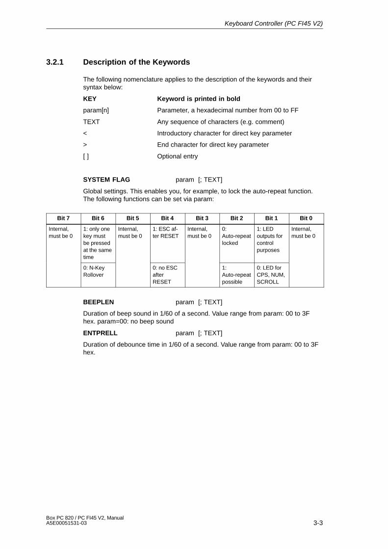
3-3Box PC 820 / PC FI45 V2, ManualA5E00051531-03
3.2.1 Description of the Keywords
The following nomenclature applies to the description of the keywords and theirsyntax below:
KEY Keyword is printed in bold
param[n] Parameter, a hexadecimal number from 00 to FF
TEXT Any sequence of characters (e.g. comment)
< Introductory character for direct key parameter
> End character for direct key parameter
[ ] Optional entry
SYSTEM FLAG param [; TEXT]
Global settings. This enables you, for example, to lock the auto-repeat function.The following functions can be set via param:
Bit 7 Bit 6 Bit 5 Bit 4 Bit 3 Bit 2 Bit 1 Bit 0
Internal,must be 0
1: only onekey mustbe pressedat the sametime
Internal,must be 0
1: ESC af-ter RESET
Internal,must be 0
0:Auto-repeatlocked
1: LEDoutputs forcontrolpurposes
Internal,must be 0
0: N-KeyRollover
0: no ESCafterRESET
1:Auto-repeatpossible
0: LED forCPS, NUM,SCROLL
BEEPLEN param [; TEXT]
Duration of beep sound in 1/60 of a second. Value range from param: 00 to 3Fhex. param=00: no beep sound
ENTPRELL param [; TEXT]
Duration of debounce time in 1/60 of a second. Value range from param: 00 to 3Fhex.
Keyboard Controller (PC FI45 V2)
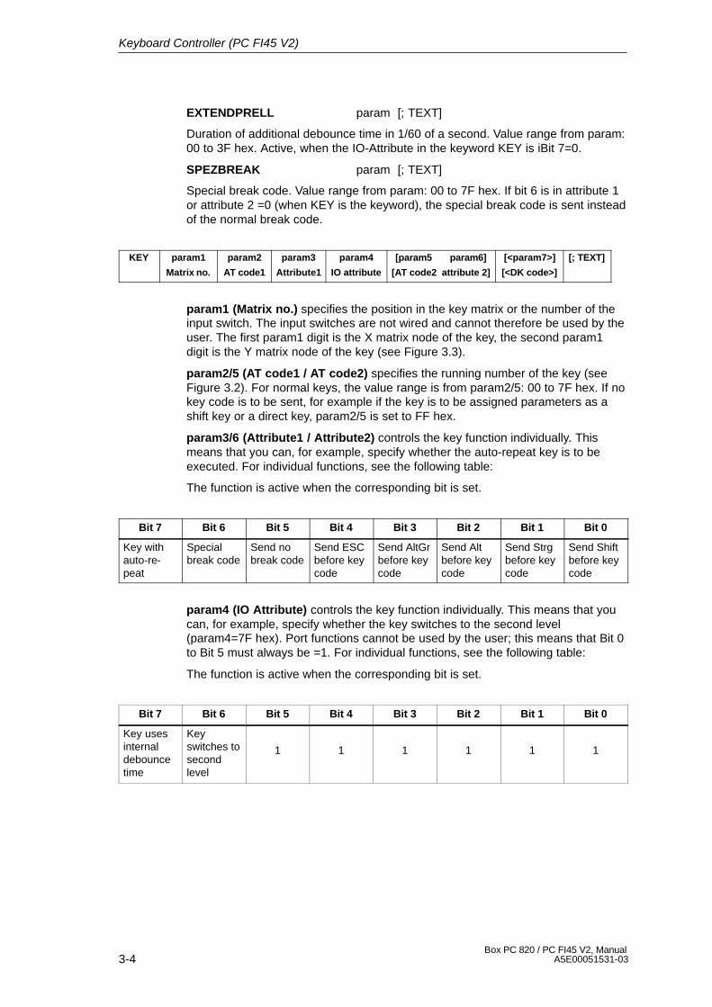
3-4Box PC 820 / PC FI45 V2, Manual
A5E00051531-03
EXTENDPRELL param [; TEXT]
Duration of additional debounce time in 1/60 of a second. Value range from param:00 to 3F hex. Active, when the IO-Attribute in the keyword KEY is iBit 7=0.
SPEZBREAK param [; TEXT]
Special break code. Value range from param: 00 to 7F hex. If bit 6 is in attribute 1or attribute 2 =0 (when KEY is the keyword), the special break code is sent insteadof the normal break code.
KEY param1
Matrix no.
param2
AT code1
param3
Attribute1
param4
IO attribute
[param5 param6]
[AT code2 attribute 2]
[<param7>]
[<DK code>]
[; TEXT]
param1 (Matrix no.) specifies the position in the key matrix or the number of theinput switch. The input switches are not wired and cannot therefore be used by theuser. The first param1 digit is the X matrix node of the key, the second param1digit is the Y matrix node of the key (see Figure 3.3).
param2/5 (AT code1 / AT code2) specifies the running number of the key (seeFigure 3.2). For normal keys, the value range is from param2/5: 00 to 7F hex. If nokey code is to be sent, for example if the key is to be assigned parameters as ashift key or a direct key, param2/5 is set to FF hex.
param3/6 (Attribute1 / Attribute2) controls the key function individually. Thismeans that you can, for example, specify whether the auto-repeat key is to beexecuted. For individual functions, see the following table:
The function is active when the corresponding bit is set.
Bit 7 Bit 6 Bit 5 Bit 4 Bit 3 Bit 2 Bit 1 Bit 0
Key withauto-re-peat
Specialbreak code
Send nobreak code
Send ESCbefore keycode
Send AltGrbefore keycode
Send Altbefore keycode
Send Strgbefore keycode
Send Shiftbefore keycode
param4 (IO Attribute) controls the key function individually. This means that youcan, for example, specify whether the key switches to the second level(param4=7F hex). Port functions cannot be used by the user; this means that Bit 0to Bit 5 must always be =1. For individual functions, see the following table:
The function is active when the corresponding bit is set.
Bit 7 Bit 6 Bit 5 Bit 4 Bit 3 Bit 2 Bit 1 Bit 0
Key usesinternaldebouncetime
Keyswitches tosecondlevel
1 1 1 1 1 1
Keyboard Controller (PC FI45 V2)
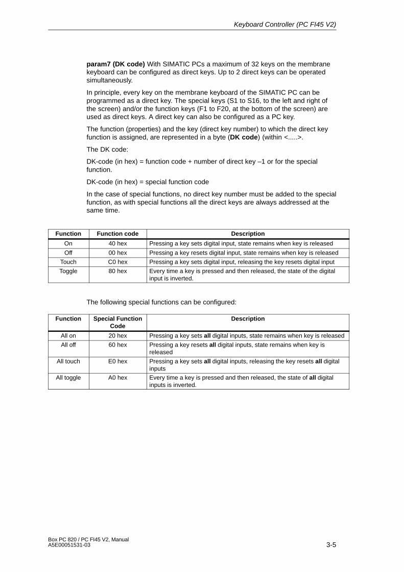
3-5Box PC 820 / PC FI45 V2, ManualA5E00051531-03
param7 (DK code) With SIMATIC PCs a maximum of 32 keys on the membranekeyboard can be configured as direct keys. Up to 2 direct keys can be operatedsimultaneously.
In principle, every key on the membrane keyboard of the SIMATIC PC can beprogrammed as a direct key. The special keys (S1 to S16, to the left and right ofthe screen) and/or the function keys (F1 to F20, at the bottom of the screen) areused as direct keys. A direct key can also be configured as a PC key.
The function (properties) and the key (direct key number) to which the direct keyfunction is assigned, are represented in a byte (DK code) (within <.....>.
The DK code:
DK-code (in hex) = function code + number of direct key –1 or for the specialfunction.
DK-code (in hex) = special function code
In the case of special functions, no direct key number must be added to the specialfunction, as with special functions all the direct keys are always addressed at thesame time.
Function Function code Description
On 40 hex Pressing a key sets digital input, state remains when key is released
Off 00 hex Pressing a key resets digital input, state remains when key is released
Touch C0 hex Pressing a key sets digital input, releasing the key resets digital input
Toggle 80 hex Every time a key is pressed and then released, the state of the digitalinput is inverted.
The following special functions can be configured:
Function Special FunctionCode
Description
All on 20 hex Pressing a key sets all digital inputs, state remains when key is released
All off 60 hex Pressing a key resets all digital inputs, state remains when key isreleased
All touch E0 hex Pressing a key sets all digital inputs, releasing the key resets all digitalinputs
All toggle A0 hex Every time a key is pressed and then released, the state of all digitalinputs is inverted.
Keyboard Controller (PC FI45 V2)
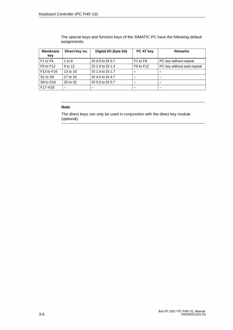
3-6Box PC 820 / PC FI45 V2, Manual
A5E00051531-03
The special keys and function keys of the SIMATIC PC have the following defaultassignments:
Membranekey
Direct key no. Digital I/O (byte bit) PC AT key Remarks
F1 to F8 1 to 8 DI 0.0 to DI 0.7 F1 to F8 PC key without-repeat
F9 to F12 9 to 12 DI 1.0 to DI 1.3 F9 to F12 PC key without auto-repeat
F13 to F16 13 to 16 DI 1.4 to DI 1.7 – –
S1 to S8 17 to 24 DI 4.0 to DI 4.7 – –
S9 to S16 25 to 32 DI 5.0 to DI 5.7 – –
F17–F20 – – – –
Note
The direct keys can only be used in conjunction with the direct key module(optional).
Keyboard Controller (PC FI45 V2)
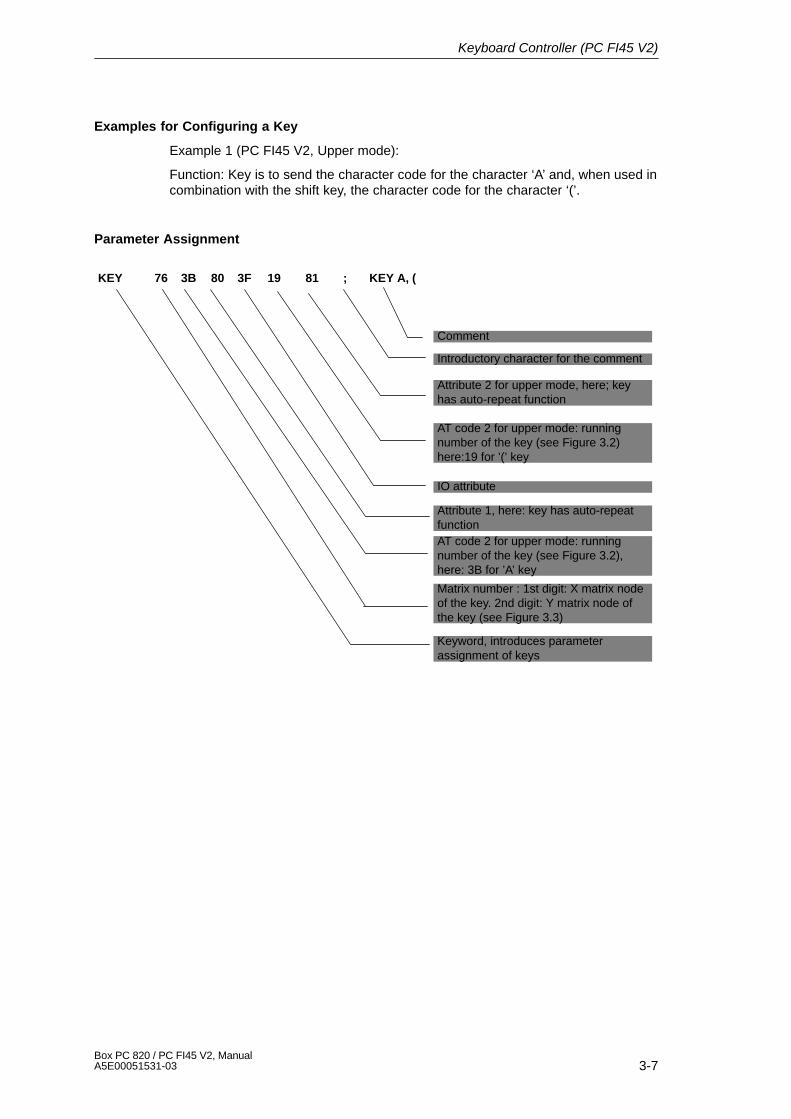
3-7Box PC 820 / PC FI45 V2, ManualA5E00051531-03
Examples for Configuring a Key
Example 1 (PC FI45 V2, Upper mode):
Function: Key is to send the character code for the character ‘A’ and, when used incombination with the shift key, the character code for the character ‘(’.
Parameter Assignment
KEY 76 3B 80 3F 19 81 ; KEY A, (
Comment
Introductory character for the comment
Attribute 2 for upper mode, here; keyhas auto-repeat function
AT code 2 for upper mode: runningnumber of the key (see Figure 3.2)here:19 for ’(’ key
IO attribute
Attribute 1, here: key has auto-repeatfunctionAT code 2 for upper mode: runningnumber of the key (see Figure 3.2),here: 3B for ’A’ key
Matrix number : 1st digit: X matrix nodeof the key. 2nd digit: Y matrix node ofthe key (see Figure 3.3)
Keyword, introduces parameterassignment of keys
Keyboard Controller (PC FI45 V2)
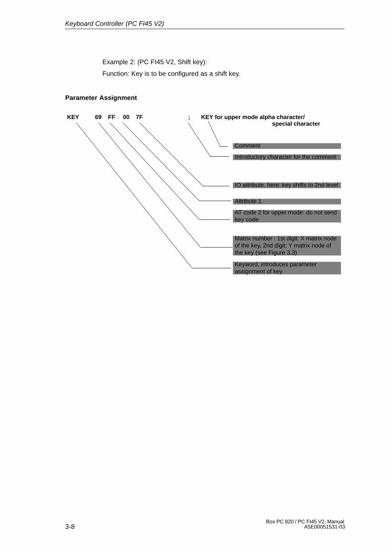
3-8Box PC 820 / PC FI45 V2, Manual
A5E00051531-03
Example 2: (PC FI45 V2, Shift key):
Function: Key is to be configured as a shift key.
Parameter Assignment
KEY 69 FF 00 7F ; KEY for upper mode alpha character/special character
Comment
Introductory character for the comment
IO attribute, here: key shifts to 2nd level
Attribute 1
AT code 2 for upper mode: do not sendkey code
Matrix number : 1st digit: X matrix nodeof the key, 2nd digit: Y matrix node ofthe key (see Figure 3.3)
Keyword, introduces parameterassignment of key
Keyboard Controller (PC FI45 V2)
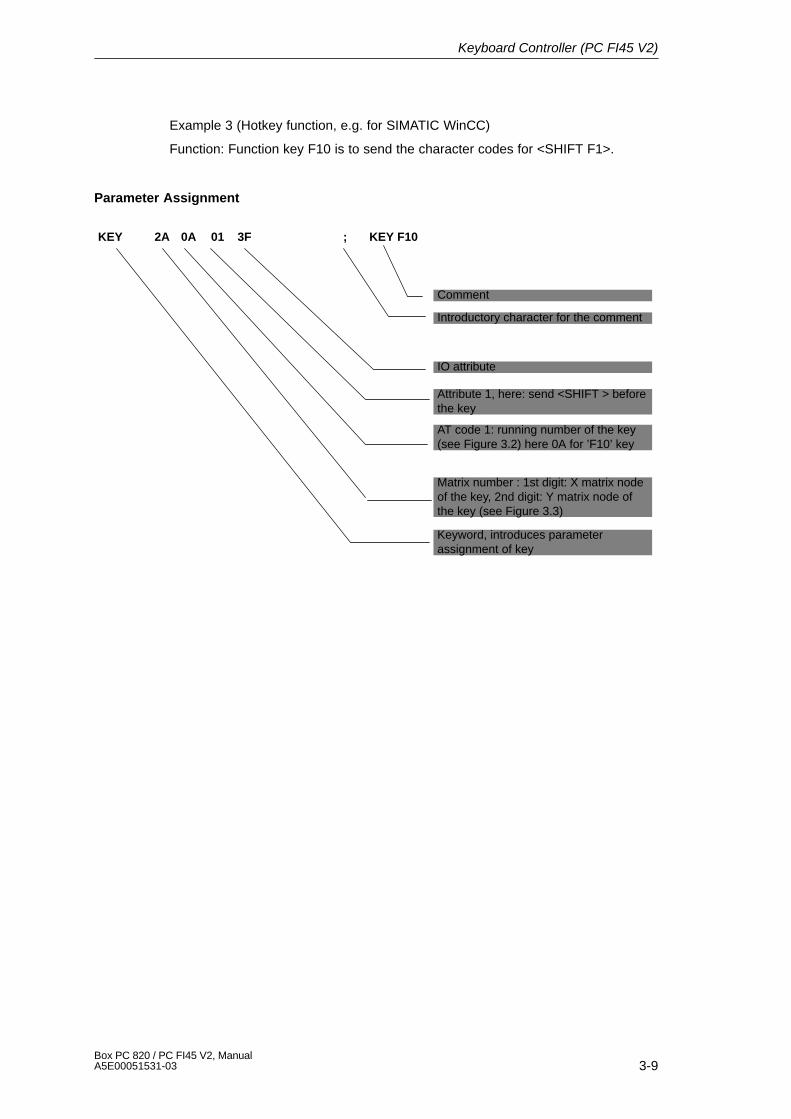
3-9Box PC 820 / PC FI45 V2, ManualA5E00051531-03
Example 3 (Hotkey function, e.g. for SIMATIC WinCC)
Function: Function key F10 is to send the character codes for <SHIFT F1>.
Parameter Assignment
KEY 2A 0A 01 3F ; KEY F10
Comment
Introductory character for the comment
IO attribute
Attribute 1, here: send <SHIFT > beforethe key
AT code 1: running number of the key(see Figure 3.2) here 0A for ’F10’ key
Matrix number : 1st digit: X matrix nodeof the key, 2nd digit: Y matrix node ofthe key (see Figure 3.3)
Keyword, introduces parameterassignment of key
Keyboard Controller (PC FI45 V2)
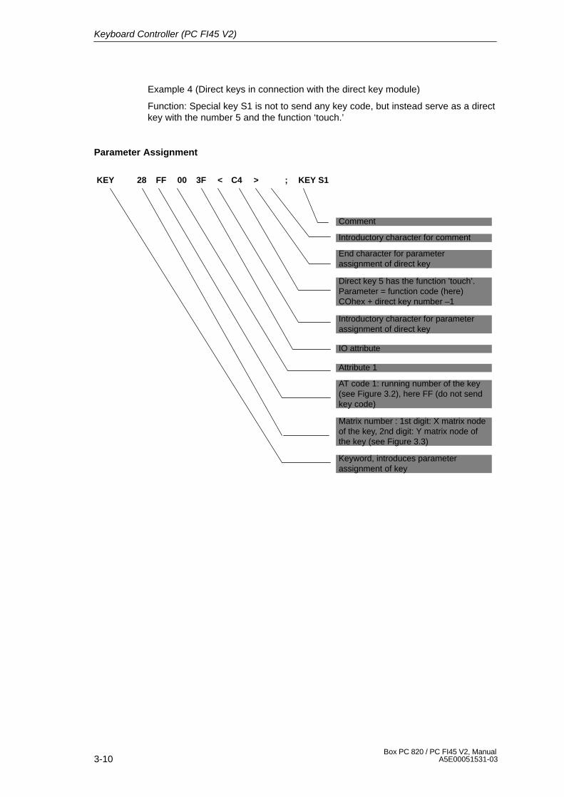
3-10Box PC 820 / PC FI45 V2, Manual
A5E00051531-03
Example 4 (Direct keys in connection with the direct key module)
Function: Special key S1 is not to send any key code, but instead serve as a directkey with the number 5 and the function ‘touch.’
Parameter Assignment
KEY 28 FF 00 3F < C4 > ; KEY S1
Comment
Introductory character for comment
Direct key 5 has the function ’touch’.Parameter = function code (here)COhex + direct key number –1
Introductory character for parameterassignment of direct key
IO attribute
Attribute 1
AT code 1: running number of the key(see Figure 3.2), here FF (do not sendkey code)
Matrix number : 1st digit: X matrix nodeof the key, 2nd digit: Y matrix node ofthe key (see Figure 3.3)
Keyword, introduces parameterassignment of key
End character for parameterassignment of direct key
Keyboard Controller (PC FI45 V2)
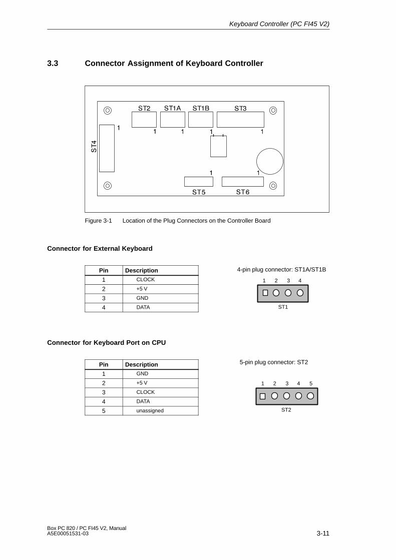
1 2 3 4
ST1
4-pin plug connector: ST1A/ST1B
1 2 3 4
ST2
5
5-pin plug connector: ST2
3-11Box PC 820 / PC FI45 V2, ManualA5E00051531-03
3.3 Connector Assignment of Keyboard Controller
Figure 3-1 Location of the Plug Connectors on the Controller Board
Connector for External Keyboard
Pin Description
1 CLOCK
2 +5 V
3 GND
4 DATA
Connector for Keyboard Port on CPU
Pin Description
1 GND
2 +5 V
3 CLOCK
4 DATA
5 unassigned
Keyboard Controller (PC FI45 V2)
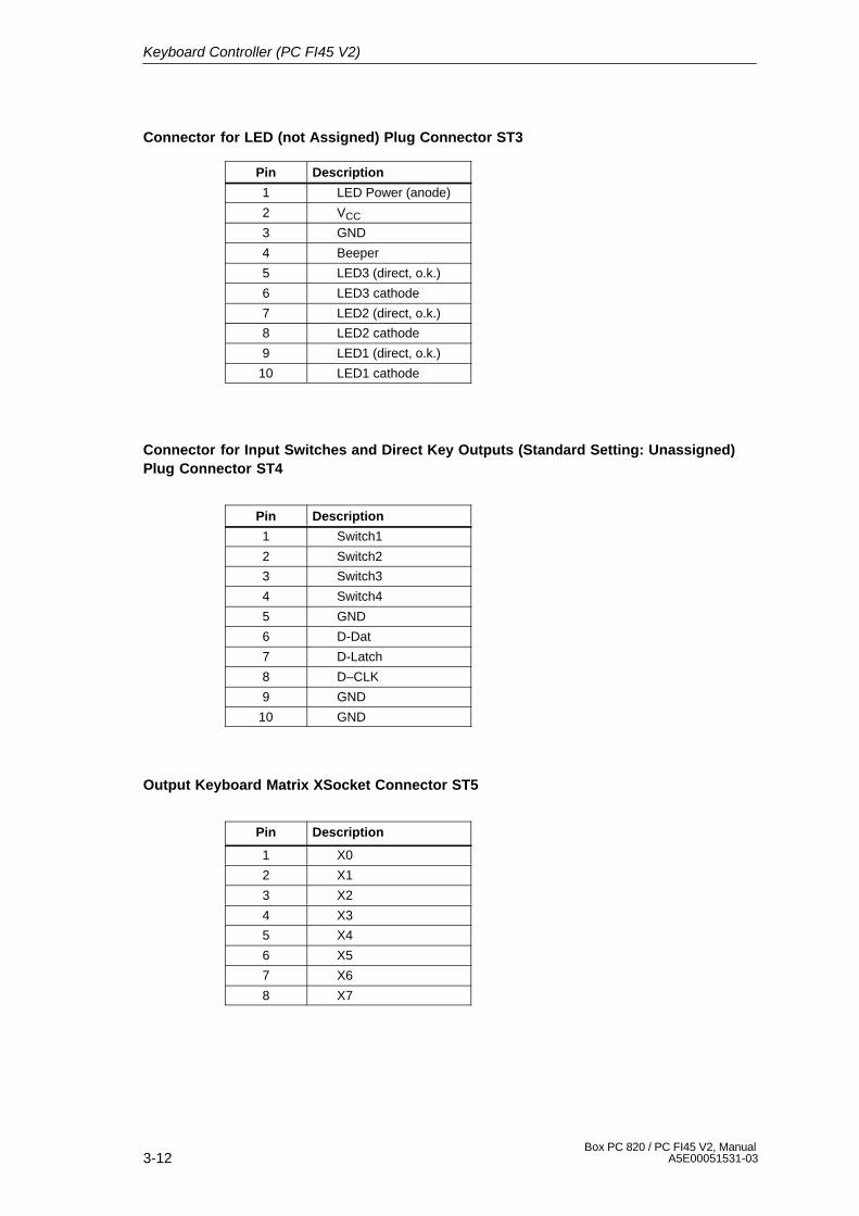
3-12Box PC 820 / PC FI45 V2, Manual
A5E00051531-03
Connector for LED (not Assigned) Plug Connector ST3
Pin Description
1 LED Power (anode)
2 VCC
3 GND
4 Beeper
5 LED3 (direct, o.k.)
6 LED3 cathode
7 LED2 (direct, o.k.)
8 LED2 cathode
9 LED1 (direct, o.k.)
10 LED1 cathode
Connector for Input Switches and Direct Key Outputs (Standard Setting: Unassigned)Plug Connector ST4
Pin Description
1 Switch1
2 Switch2
3 Switch3
4 Switch4
5 GND
6 D-Dat
7 D-Latch
8 D–CLK
9 GND
10 GND
Output Keyboard Matrix XSocket Connector ST5
Pin Description
1 X0
2 X1
3 X2
4 X3
5 X4
6 X5
7 X6
8 X7
Keyboard Controller (PC FI45 V2)
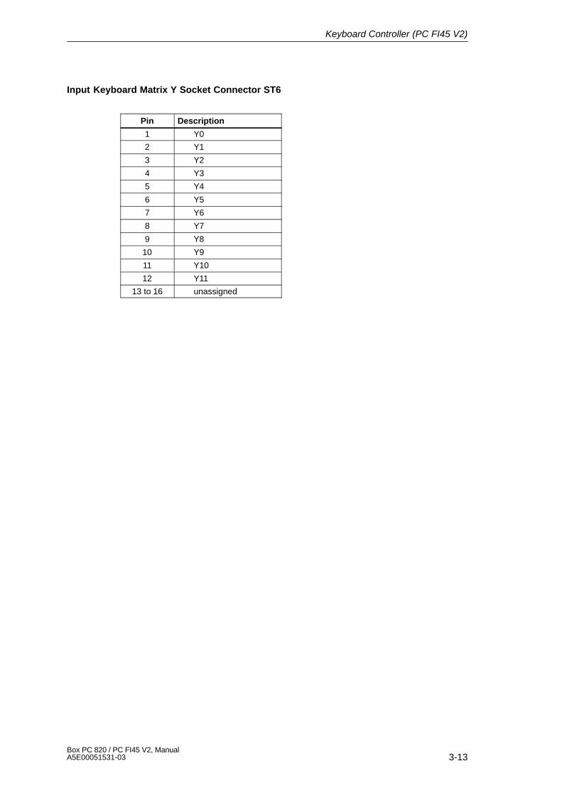
3-13Box PC 820 / PC FI45 V2, ManualA5E00051531-03
Input Keyboard Matrix Y Socket Connector ST6
Pin Description
1 Y0
2 Y1
3 Y2
4 Y3
5 Y4
6 Y5
7 Y6
8 Y7
9 Y8
10 Y9
11 Y10
12 Y11
13 to 16 unassigned
Keyboard Controller (PC FI45 V2)
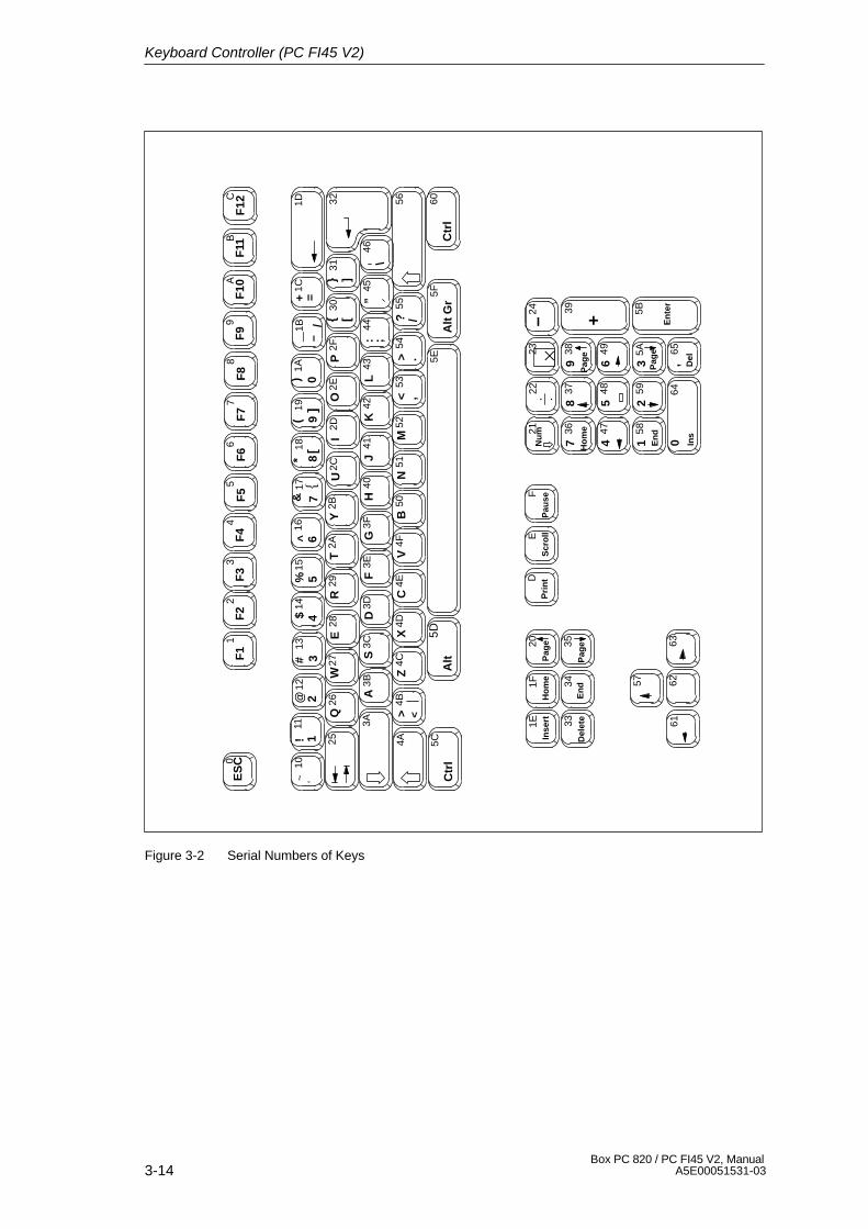
3-14Box PC 820 / PC FI45 V2, Manual
A5E00051531-03
I2D
O2E
P2F
U2C
R29
T2A
Y2B
E28
F2
F1
1F
33
F4
F5
5F
6F
77
F8
F9
9F
10F
11B
ES
C04
26
8A
!11
112
2$
133
144
%15
5&
166
177
(18
8)
199
=1A
0
?
1B1C
10
K42
L43
:44
J41
F3E
G3F
H40
D3D
3031
+
<53
>54
_
55M
52V
4FB
50N
51C
4E
–
56 60C
trl
5FA
lt G
r”45
46\
1D 32
5CC
trl
5DA
lt5E
Z4C
X4D
>4B
4A
3A
<
25
A3B
Q26
S3C
W27
@
Nu
m2122
23–
24
736
Ho
me
837
938
447
548
649
158
En
d2
593
5A
,65
Del�
64
+
39
Ins
0
57
6361
62E
nte
r
5B
35341F
1E 33
20H
om
e
En
d
Inse
rt
Del
ete
F12
C
Pag
e
Pag
eP
age
Pag
e
#
/
[]
{
. .
DP
rin
tE
Scr
oll
FP
ause
~ ‘^
*
{}
[]
;
/,
.
Figure 3-2 Serial Numbers of Keys
Keyboard Controller (PC FI45 V2)
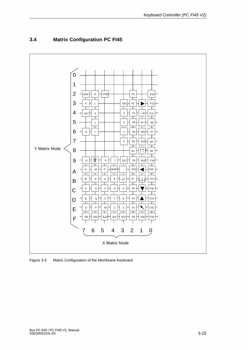
3-15Box PC 820 / PC FI45 V2, ManualA5E00051531-03
3.4 Matrix Configuration PC FI45
Y Matrix Node
A
B
C
D
E
F
25 34 17 6 0
ESC R CTRL F3 F13
F L F2 F12DEL
2 F1ALT K
J
A I
F11
5 S4 S8
1 S3 S7
4 S2 S6
INS
S14
S1 S5
G S S12 F9 F19S157
H T . F10 F20SHIFTM
B U 8N F7 F17
C V 0 F6 F169O
E X 6 F4 F14YQ
D W 3 F5 F15ZP
S9 S13 F8 F18S11S10 S16
�
�
�
�
�
�
���
���↵
X Matrix Node
0
1
2
3
4
5
6
7
8
9
Figure 3-3 Matrix Configuration of the Membrane Keyboard
Keyboard Controller (PC FI45 V2)
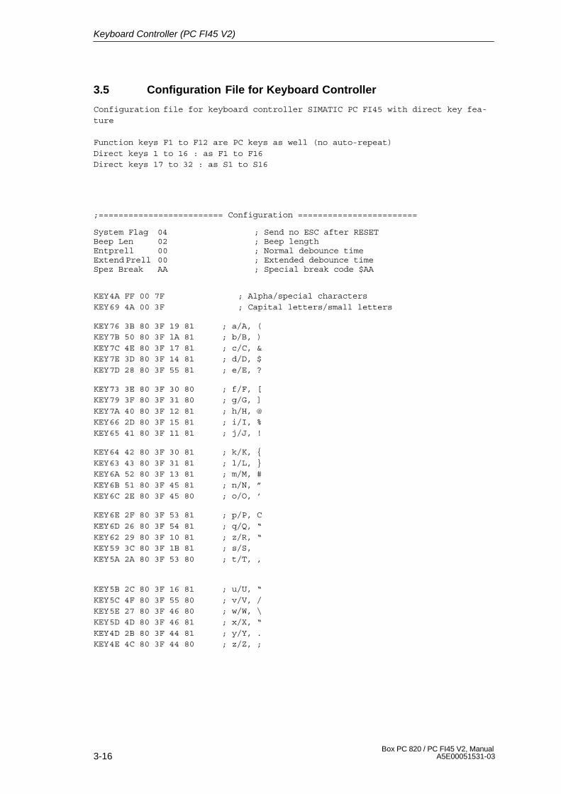
3-16Box PC 820 / PC FI45 V2, Manual
A5E00051531-03
3.5 Configuration File for Keyboard Controller
Configuration file for keyboard controller SIMATIC PC FI45 with direct key fea-ture
Function keys F1 to F12 are PC keys as well (no auto-repeat)Direct keys 1 to 16 : as F1 to F16Direct keys 17 to 32 : as S1 to S16
;========================= Configuration ========================
System Flag 04 ; Send no ESC after RESETBeep Len 02 ; Beep lengthEntprell 00 ; Normal debounce timeExtend Prell 00 ; Extended debounce time Spez Break AA ; Special break code $AA
KEY4A FF 00 7F ; Alpha/special charactersKEY69 4A 00 3F ; Capital letters/small letters
KEY76 3B 80 3F 19 81 ; a/A, (KEY7B 50 80 3F lA 81 ; b/B, )KEY7C 4E 80 3F 17 81 ; c/C, &KEY7E 3D 80 3F 14 81 ; d/D, $KEY7D 28 80 3F 55 81 ; e/E, ?
KEY73 3E 80 3F 30 80 ; f/F, [KEY79 3F 80 3F 31 80 ; g/G, ]KEY7A 40 80 3F 12 81 ; h/H, @KEY66 2D 80 3F 15 81 ; i/I, %KEY65 41 80 3F 11 81 ; j/J, !
KEY64 42 80 3F 30 81 ; k/K, {KEY63 43 80 3F 31 81 ; l/L, }KEY6A 52 80 3F 13 81 ; m/M, #KEY6B 51 80 3F 45 81 ; n/N, ”KEY6C 2E 80 3F 45 80 ; o/O, ’
KEY6E 2F 80 3F 53 81 ; p/P, CKEY6D 26 80 3F 54 81 ; q/Q, “KEY62 29 80 3F 10 81 ; z/R, “KEY59 3C 80 3F 1B 81 ; s/S, KEY5A 2A 80 3F 53 80 ; t/T, ,
KEY5B 2C 80 3F 16 81 ; u/U, “KEY5C 4F 80 3F 55 80 ; v/V, /KEY5E 27 80 3F 46 80 ; w/W, \KEY5D 4D 80 3F 46 81 ; x/X, “KEY4D 2B 80 3F 44 81 ; y/Y, .KEY4E 4C 80 3F 44 80 ; z/Z, ;
Keyboard Controller (PC FI45 V2)
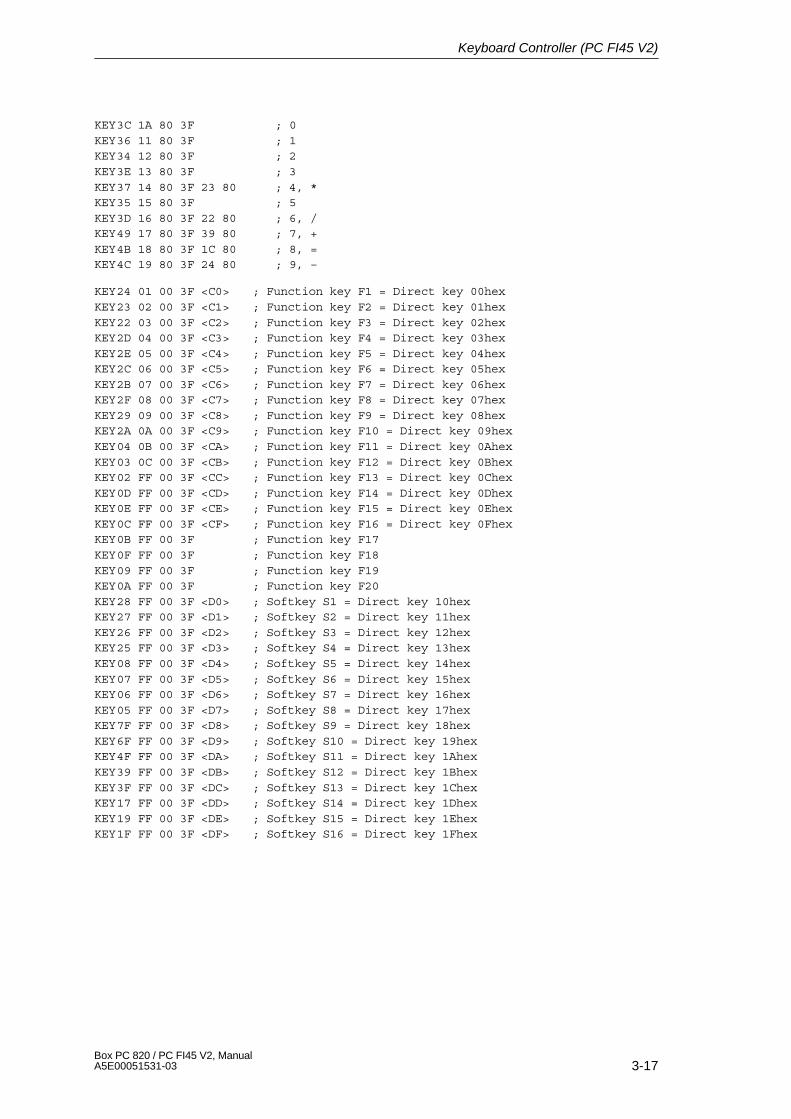
3-17Box PC 820 / PC FI45 V2, ManualA5E00051531-03
KEY3C 1A 80 3F ; 0KEY36 11 80 3F ; 1KEY34 12 80 3F ; 2KEY3E 13 80 3F ; 3KEY37 14 80 3F 23 80 ; 4, *KEY35 15 80 3F ; 5KEY3D 16 80 3F 22 80 ; 6, /KEY49 17 80 3F 39 80 ; 7, +KEY4B 18 80 3F 1C 80 ; 8, =KEY4C 19 80 3F 24 80 ; 9, –
KEY24 01 00 3F <C0> ; Function key F1 = Direct key 00hexKEY23 02 00 3F <C1> ; Function key F2 = Direct key 01hexKEY22 03 00 3F <C2> ; Function key F3 = Direct key 02hexKEY2D 04 00 3F <C3> ; Function key F4 = Direct key 03hexKEY2E 05 00 3F <C4> ; Function key F5 = Direct key 04hexKEY2C 06 00 3F <C5> ; Function key F6 = Direct key 05hexKEY2B 07 00 3F <C6> ; Function key F7 = Direct key 06hexKEY2F 08 00 3F <C7> ; Function key F8 = Direct key 07hexKEY29 09 00 3F <C8> ; Function key F9 = Direct key 08hexKEY2A 0A 00 3F <C9> ; Function key F10 = Direct key 09hexKEY04 0B 00 3F <CA> ; Function key F11 = Direct key 0AhexKEY03 0C 00 3F <CB> ; Function key F12 = Direct key 0BhexKEY02 FF 00 3F <CC> ; Function key F13 = Direct key 0ChexKEY0D FF 00 3F <CD> ; Function key F14 = Direct key 0DhexKEY0E FF 00 3F <CE> ; Function key F15 = Direct key 0EhexKEY0C FF 00 3F <CF> ; Function key F16 = Direct key 0FhexKEY0B FF 00 3F ; Function key F17KEY0F FF 00 3F ; Function key F18KEY09 FF 00 3F ; Function key F19KEY0A FF 00 3F ; Function key F20KEY28 FF 00 3F <D0> ; Softkey S1 = Direct key 10hexKEY27 FF 00 3F <D1> ; Softkey S2 = Direct key 11hexKEY26 FF 00 3F <D2> ; Softkey S3 = Direct key 12hexKEY25 FF 00 3F <D3> ; Softkey S4 = Direct key 13hexKEY08 FF 00 3F <D4> ; Softkey S5 = Direct key 14hexKEY07 FF 00 3F <D5> ; Softkey S6 = Direct key 15hexKEY06 FF 00 3F <D6> ; Softkey S7 = Direct key 16hexKEY05 FF 00 3F <D7> ; Softkey S8 = Direct key 17hexKEY7F FF 00 3F <D8> ; Softkey S9 = Direct key 18hexKEY6F FF 00 3F <D9> ; Softkey S10 = Direct key 19hexKEY4F FF 00 3F <DA> ; Softkey S11 = Direct key 1AhexKEY39 FF 00 3F <DB> ; Softkey S12 = Direct key 1BhexKEY3F FF 00 3F <DC> ; Softkey S13 = Direct key 1ChexKEY17 FF 00 3F <DD> ; Softkey S14 = Direct key 1DhexKEY19 FF 00 3F <DE> ; Softkey S15 = Direct key 1EhexKEY1F FF 00 3F <DF> ; Softkey S16 = Direct key 1Fhex
Keyboard Controller (PC FI45 V2)
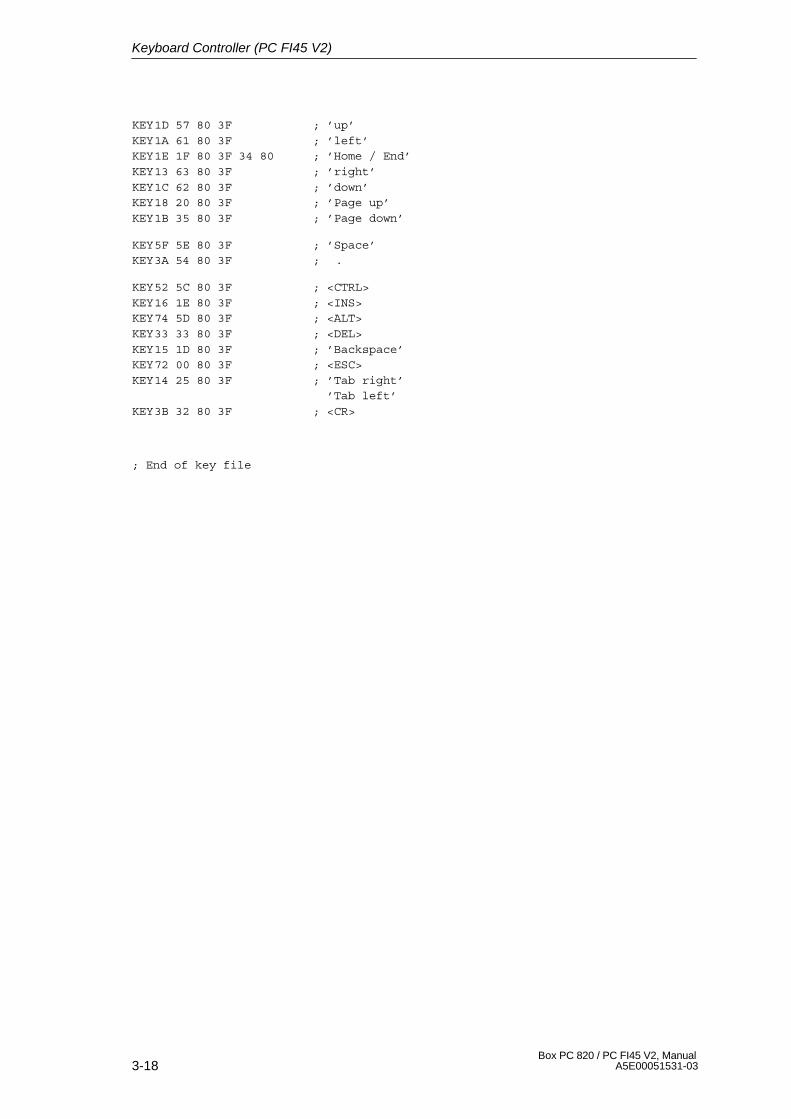
3-18Box PC 820 / PC FI45 V2, Manual
A5E00051531-03
KEY1D 57 80 3F ; ’up’KEY1A 61 80 3F ; ’left’KEY1E 1F 80 3F 34 80 ; ’Home / End’KEY13 63 80 3F ; ’right’KEY1C 62 80 3F ; ’down’KEY18 20 80 3F ; ’Page up’KEY1B 35 80 3F ; ’Page down’
KEY5F 5E 80 3F ; ’Space’KEY3A 54 80 3F ; .
KEY52 5C 80 3F ; <CTRL>KEY16 1E 80 3F ; <INS>KEY74 5D 80 3F ; <ALT>KEY33 33 80 3F ; <DEL>KEY15 1D 80 3F ; ’Backspace’KEY72 00 80 3F ; <ESC>KEY14 25 80 3F ; ’Tab right’
’Tab left’KEY3B 32 80 3F ; <CR>
; End of key file
Keyboard Controller (PC FI45 V2)
4-1Box PC 820 / PC FI45 V2, ManualA5E00051531-03
Direct Key Module (Optional withPC FI45 V2)
Chapter Overview
Section Description Page
4.1 General Information 4-2
4.2 Functional Description 4-3
4.3 Direct Key Module Ports 4-5
4.4 Logical Organisation of Digital Inputs and Outputs 4-6
4.5 Assignment of Direct Keys to Digital Inputs 4-6
4.6 Description of Ports 4-7
4.6.1 Ports 4-7
4.6.2 Internal Ports 4-9
4.7 Technical Specifications of Direct Key Modules 4-10
4.8 Optional Package for Direct Key Modules 4-11
4.9 Assignment of Termination Module Terminals 4-12
4
4-2Box PC 820 / PC FI45 V2, Manual
A5E00051531-03
4.1 General Information
As a plug-in board, the direct key module is designed to be implemented in theSIMATIC industrial PCs.
The module allows you to assign digital events to individual keys on the membranekeyboard. Thus the direct control of a PLC’s digital input becomes possible bypressing a key. As the module is configured as slave on the PROFIBUS, data canbe transferred via a standard field bus.
The direct key module enriches the SIMATIC Industrial PCs with the followingfunctions:
� The PROFIBUS scans up to 32 keys on the SIMATIC PC’s membranekeyboard as direct keys.
� An external panel with up to 16 additional keys can be connected, if necessary.
� 16 digital outputs to trigger check-back indicators of connected panels (PLC viaPROFIBUS DP) are provided.
� The PLC scans all direct keys via the PROFIBUS DP.
� The PROFIBUS DP port has been developed for transmission rates of 9.6 Kbps– 12 Mbps.
Direct Key Module (Optional with FI45)
4-3Box PC 820 / PC FI45 V2, ManualA5E00051531-03
4.2 Functional Description
The direct key module is employed to scan keys via the PROFIBUS DP within adefined time-slot pattern. The module as such is configured as a PROFIBUS normslave on PROFIBUS DP. PROFIBUS reaction time guarantees a scanning of thekeyboard within the time limit defined for PROFIBUS.
The direct key module always serves as a slave on the PROFIBUS DP. Triggeringor scanning the direct key module is always executed by a DP master, whichoperates the direct key modules via layer two of the seven-layer module. Afterhaving received a trouble-free PROFIBUS message, the direct key moduleindependently generates the requested response messages (acc. to DIN standardE19245 T3). Default setting of the slave provides the structuring of the digitalinputs and outputs as well as the data transfer modes. Data transfer to and fromthe direct key module is always consistent and determined by a default setting.
With this module it is possible to scan for 32 direct keys (assigned to the digitalinputs DI 0.0-0.7, DI 1.0-1.7, DI 4.0-4.7 and DI 5.0-5.7) as well as to scan for orcontrol 16 digital outputs (DO 0.0-0.7 and DO 1.0-1.7) with 24V/100mA and 16digital inputs (DI 2.0-2.7 and DI 3.0-3.7) with 24V levels via PROFIBUS DP.
The direct key module supports transmission rates of 9.6 Kbps to 12 Mbps.
To set the PROFIBUS address (node address) of the direct module via PROFIBUSuse either the ET200 hand held device or a programming device/PC (with anMPI-/DP port) with STEP 7 software installed (see Hardware Config) orCOMPROFIBUS software.
Once the PROFIBUS address (node address) is set, it is stored in the direct keymodule. Even after disconnecting your Industrial PC from the power supply, thesettings remain saved.
Note
On delivery, the PROFIBUS address (node address) is set to 126. A direct keymodule supplied with the default address 126 in accordance with DP regulations,can be assigned a different address by the user after installation. It is essentialthat this address setting is carried out because otherwise no data can beexchanged with the direct key module (DP nodes with the address 126 do not bydefinition participate in data exchange).
Direct Key Module (Optional with FI45)

4-4Box PC 820 / PC FI45 V2, Manual
A5E00051531-03
You do not need to open the device in order to set the address. The address of thedirect key module is set by the PROFIBUS. One of the following devices with DPaccess software must, however, be available:
� ET200 hand-held device,
� Programming device/PC with MPI-/DP port, or
� the SIMATIC PC, in which the direct key module but no SlotPLC is installed.
Either
� the STEP 7 software (Hardware Config.), or
� the COMPROFIBUS software
must be installed on the device.
To ensure that the address is set successfully, a point-to-point connection must becreated between the direct key module and the device being used. Some devicesare supplied with a suitable connection cable in the consignment.
PC with integrated SlotPLC (WinAC FI Station Pro):
The DP connection of the direct key module is linked to the SlotPLC inside thedevice. Before you can carry out the address setting, the SlotPLC must be clearedand reset. This isolates the SlotPLC from the DP bus. Connect the DP connection(9-pin D-sub socket) of the SlotPLC to the DP port of the device on which theaccess software is installed.
PC without integrated SlotPLC:
Connect the DP connection (9-pin D-sub socket) of the direct key module to theMPI-/DP port of the device on which the DP access software is installed. To dothis, you may have to remove the covering on the DP connection of the direct keymodule.
Use the STEP 7 software and proceed as follows:
� Start the SIMATIC Manager
� Select the function “Assign PROFIBUS Address” in the PLC menu of theSIMATIC Manager. The SIMATIC Manager then contacts the direct key module.A dialog box appears. This dialog box both displays the currently set address ofthe direct key module and allows you to enter a new address (1, 3 to 125).
� Set the required address. Once the new address has been set, it is stored inthe direct key module and is retained even after the power supply has beenswitched off.
� Close the SIMATIC Manager.
If you are using other PROFIBUS tools, you require the device database file (DDBfile). You can find this file on the CD Documentation and Drivers.
Direct Key Module (Optional with FI45)
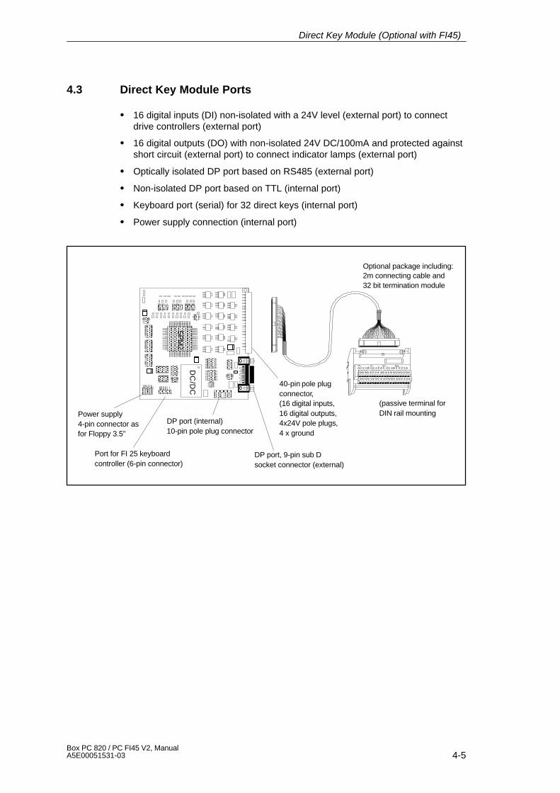
4-5Box PC 820 / PC FI45 V2, ManualA5E00051531-03
4.3 Direct Key Module Ports
� 16 digital inputs (DI) non-isolated with a 24V level (external port) to connectdrive controllers (external port)
� 16 digital outputs (DO) with non-isolated 24V DC/100mA and protected againstshort circuit (external port) to connect indicator lamps (external port)
� Optically isolated DP port based on RS485 (external port)
� Non-isolated DP port based on TTL (internal port)
� Keyboard port (serial) for 32 direct keys (internal port)
� Power supply connection (internal port)
40-pin pole plugconnector,(16 digital inputs,16 digital outputs,4x24V pole plugs,4 x ground
DP port, 9-pin sub Dsocket connector (external)
Power supply4-pin connector asfor Floppy 3.5”
Port for FI 25 keyboardcontroller (6-pin connector)
DP port (internal)10-pin pole plug connector
(passive terminal forDIN rail mounting
ÑÑÑÑ
U5 ÑÑÑÑ
DC
/DCÑÑ
ÑÑ
PAPF
PC
PG PD PH PI
PB
PE
ÑÑÑÑÑÑÑÑÑ
SP
M2
ÑÑÑÑ
ÑÑ
ÑÑÑÑ
ÑÑÑÑÑÑÑÑ
ÑÑÑÑÑ
ÑÑÑÑÑÑÑÑ
ÑÑÑÑÑÑÑÑ
ÑÑ
ÑÑ
Optional package including:2m connecting cable and32 bit termination module
Direct Key Module (Optional with FI45)

4-6Box PC 820 / PC FI45 V2, Manual
A5E00051531-03
4.4 Logical Organisation of Digital Inputs and Outputs
Due to the slave controller block used, the digital inputs DI 0.0 - 5.7 are defined asa block (permanently preset as slave). This block consists of 32 direct keys (DI0.0–0.7, DI 1.0–1.7, DI 4.0–4.7 and DI 5.0–5.7) of the SIMATIC PC membranekeyboard and 16 digital inputs of the external connector (40-pin plug connector) atthe rear sheet metal terminal of the direct key module (DI 2.0–2.7 and DI 3.0–3.7)
The digital outputs (DO 0.0 –0.7 and DO 1.0–1.7) are also defined as a block andcan be connected to the external connector (40-pin plug connector).
4.5 Assignment of Direct Keys to Digital Inputs
Direct key no. Digitalinput (DI)
SIMATIC PC )*function keys
Direct key no. Digitalinput (DI)
SIMATIC PC )*function keys
Direct key 1 DI 0.0 F1 Direct key 17 DI 4.0 S1
Direct key 2 DI 0.1 F2 Direct key 18 DI 4.1 S2
Direct key 3 DI 0.2 F3 Direct key 19 DI 4.2 S3
Direct key 4 DI 0.3 F4 Direct key 20 DI 4.3 S4
Direct key 5 DI 0.4 F5 Direct key 21 DI 4.4 S5
Direct key 6 DI 0.5 F6 Direct key 22 DI 4.5 S6
Direct key 7 DI 0.6 F7 Direct key 23 DI 4.6 S7
Direct key 8 DI 0.7 F8 Direct key 24 DI 4.7 S8
Direct key 9 DI 1.0 F9 Direct key 25 DI 5.0 S9
Direct key 10 DI 1.1 F10 Direct key 26 DI 5.1 S10
Direct key 11 DI 1.2 F11 Direct key 27 DI 5.2 S11
Direct key 12 DI 1.3 F12 Direct key 28 DI 5.3 S12
Direct key 13 DI 1.4 F13 Direct key 29 DI 5.4 S13
Direct key 14 DI 1.5 F14 Direct key 30 DI 5.5 S14
Direct key 15 DI 1.6 F15 Direct key 31 DI 5.6 S15
Direct key 16 DI 1.7 F16 Direct key 32 DI 5.7 S16
)* factory presetting
The direct key number is determined by the parameter assignment of the keyboardcontroller (see chapter ‘Keyboard Controller’) and can be modified at any time. Allsettings are stored in the keyboard controller and are saved even afterdisconnecting your PC from the power supply.
Direct Key Module (Optional with FI45)
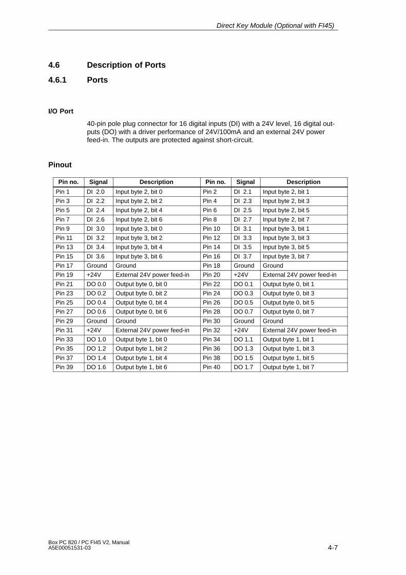
4-7Box PC 820 / PC FI45 V2, ManualA5E00051531-03
4.6 Description of Ports
4.6.1 Ports
I/O Port
40-pin pole plug connector for 16 digital inputs (DI) with a 24V level, 16 digital out-puts (DO) with a driver performance of 24V/100mA and an external 24V powerfeed-in. The outputs are protected against short-circuit.
Pinout
Pin no. Signal Description Pin no. Signal Description
Pin 1 DI 2.0 Input byte 2, bit 0 Pin 2 DI 2.1 Input byte 2, bit 1
Pin 3 DI 2.2 Input byte 2, bit 2 Pin 4 DI 2.3 Input byte 2, bit 3
Pin 5 DI 2.4 Input byte 2, bit 4 Pin 6 DI 2.5 Input byte 2, bit 5
Pin 7 DI 2.6 Input byte 2, bit 6 Pin 8 DI 2.7 Input byte 2, bit 7
Pin 9 DI 3.0 Input byte 3, bit 0 Pin 10 DI 3.1 Input byte 3, bit 1
Pin 11 DI 3.2 Input byte 3, bit 2 Pin 12 DI 3.3 Input byte 3, bit 3
Pin 13 DI 3.4 Input byte 3, bit 4 Pin 14 DI 3.5 Input byte 3, bit 5
Pin 15 DI 3.6 Input byte 3, bit 6 Pin 16 DI 3.7 Input byte 3, bit 7
Pin 17 Ground Ground Pin 18 Ground Ground
Pin 19 +24V External 24V power feed-in Pin 20 +24V External 24V power feed-in
Pin 21 DO 0.0 Output byte 0, bit 0 Pin 22 DO 0.1 Output byte 0, bit 1
Pin 23 DO 0.2 Output byte 0, bit 2 Pin 24 DO 0.3 Output byte 0, bit 3
Pin 25 DO 0.4 Output byte 0, bit 4 Pin 26 DO 0.5 Output byte 0, bit 5
Pin 27 DO 0.6 Output byte 0, bit 6 Pin 28 DO 0.7 Output byte 0, bit 7
Pin 29 Ground Ground Pin 30 Ground Ground
Pin 31 +24V External 24V power feed-in Pin 32 +24V External 24V power feed-in
Pin 33 DO 1.0 Output byte 1, bit 0 Pin 34 DO 1.1 Output byte 1, bit 1
Pin 35 DO 1.2 Output byte 1, bit 2 Pin 36 DO 1.3 Output byte 1, bit 3
Pin 37 DO 1.4 Output byte 1, bit 4 Pin 38 DO 1.5 Output byte 1, bit 5
Pin 39 DO 1.6 Output byte 1, bit 6 Pin 40 DO 1.7 Output byte 1, bit 7
Direct Key Module (Optional with FI45)
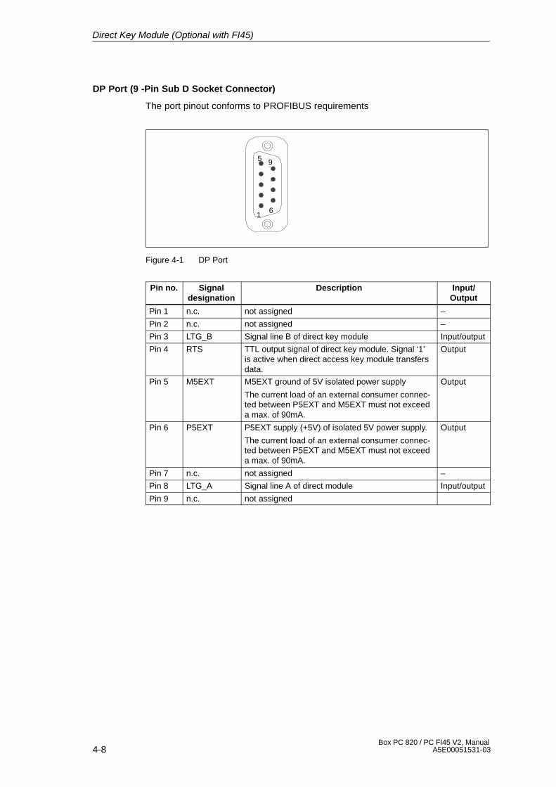
4-8Box PC 820 / PC FI45 V2, Manual
A5E00051531-03
DP Port (9 -Pin Sub D Socket Connector)
The port pinout conforms to PROFIBUS requirements
1
5
6
9
Figure 4-1 DP Port
Pin no. Signaldesignation
Description Input/Output
Pin 1 n.c. not assigned –
Pin 2 n.c. not assigned –
Pin 3 LTG_B Signal line B of direct key module Input/output
Pin 4 RTS TTL output signal of direct key module. Signal ‘1’is active when direct access key module transfersdata.
Output
Pin 5 M5EXT M5EXT ground of 5V isolated power supply
The current load of an external consumer connec-ted between P5EXT and M5EXT must not exceeda max. of 90mA.
Output
Pin 6 P5EXT P5EXT supply (+5V) of isolated 5V power supply.
The current load of an external consumer connec-ted between P5EXT and M5EXT must not exceeda max. of 90mA.
Output
Pin 7 n.c. not assigned –
Pin 8 LTG_A Signal line A of direct module Input/output
Pin 9 n.c. not assigned
Direct Key Module (Optional with FI45)
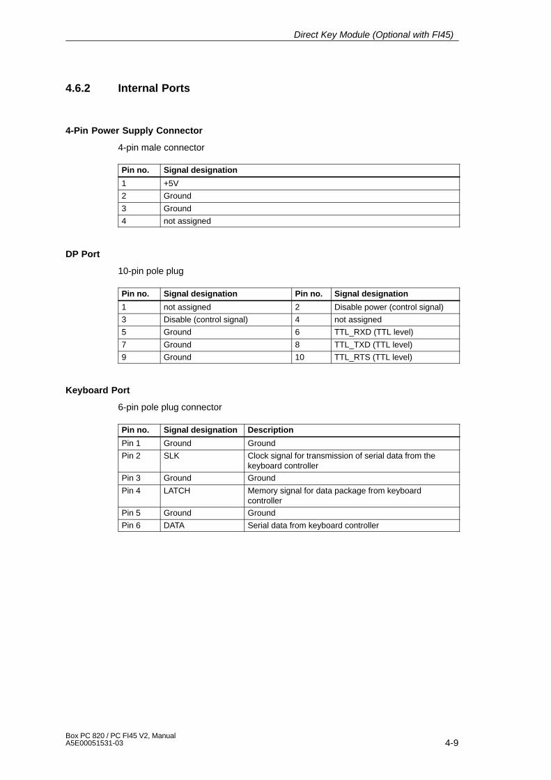
4-9Box PC 820 / PC FI45 V2, ManualA5E00051531-03
4.6.2 Internal Ports
4-Pin Power Supply Connector
4-pin male connector
Pin no. Signal designation
1 +5V
2 Ground
3 Ground
4 not assigned
DP Port
10-pin pole plug
Pin no. Signal designation Pin no. Signal designation
1 not assigned 2 Disable power (control signal)
3 Disable (control signal) 4 not assigned
5 Ground 6 TTL_RXD (TTL level)
7 Ground 8 TTL_TXD (TTL level)
9 Ground 10 TTL_RTS (TTL level)
Keyboard Port
6-pin pole plug connector
Pin no. Signal designation Description
Pin 1 Ground Ground
Pin 2 SLK Clock signal for transmission of serial data from thekeyboard controller
Pin 3 Ground Ground
Pin 4 LATCH Memory signal for data package from keyboardcontroller
Pin 5 Ground Ground
Pin 6 DATA Serial data from keyboard controller
Direct Key Module (Optional with FI45)
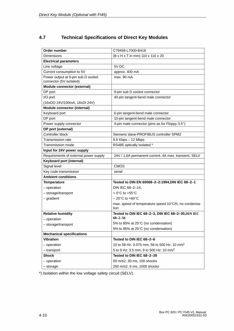
4-10Box PC 820 / PC FI45 V2, Manual
A5E00051531-03
4.7 Technical Specifications of Direct Key Modules
Order number C79458-L7000-B418
Dimensions (B x H x T in mm) 110 x 110 x 20
Electrical parameters
Line voltage 5V DC
Current consumption to 5V approx. 400 mA
Power output at 9-pin sub D socketconnector (5V isolated)
max. 90 mA
Module connector (external)
DP port 9-pin sub D socket connector
I/O port
(16xDO 24V/100mA, 16xDI 24V)
40-pin tangent-bend male connector
Module connector (internal)
Keyboard port 6-pin tangent-bend male connector
DP port 10-pin tangent-bend male connector
Power supply connector 4-pin male connector (pins as for Floppy 3.5’’)
DP port (external)
Controller block Siemens slave-PROFIBUS controller SPM2
Transmission rate 9.6 Kbps – 12 Mbps
Transmission mode RS485 optically isolated *
Input for 24V power supply
Requirements of external power supply 24V / 1,6A permanent current, 4A max. transient, SELV
Keyboard port (internal)
Signal level CMOS
Key code transmission serial
Ambient conditions
Temperature
– operation
– storage/transport
– gradient
Tested to DIN EN 60068–2–2:1994,DIN IEC 68–2–1
DIN IEC 68–2–14,
+ 0°C to +55°C– 20°C to +60°Cmax. speed of temperature speed 10°C/h, no condensa-tion
Relative humidity
– operation
– storage/transport
Tested to DIN IEC 68–2–3, DIN IEC 68–2–30,DIN IEC68–2–56
5% to 85% at 25°C (no condensation)
5% to 95% at 25°C (no condensation)
Mechanical specifications
Vibration
– operation
– transport
Tested to DIN IEC 68–2–6
10 to 58 Hz: 0.075 mm, 58 to 500 Hz: 10 m/s2
5 to 9 Hz: 3.5 mm, 9 to 500 Hz: 10 m/s2
Shock
– operation
– storage
Tested to DIN IEC 68–2–29
50 m/s2, 30 ms, 100 shocks
250 m/s2, 6 ms, 1000 shocks
*) Isolation within the low voltage safety circuit (SELV).
Direct Key Module (Optional with FI45)
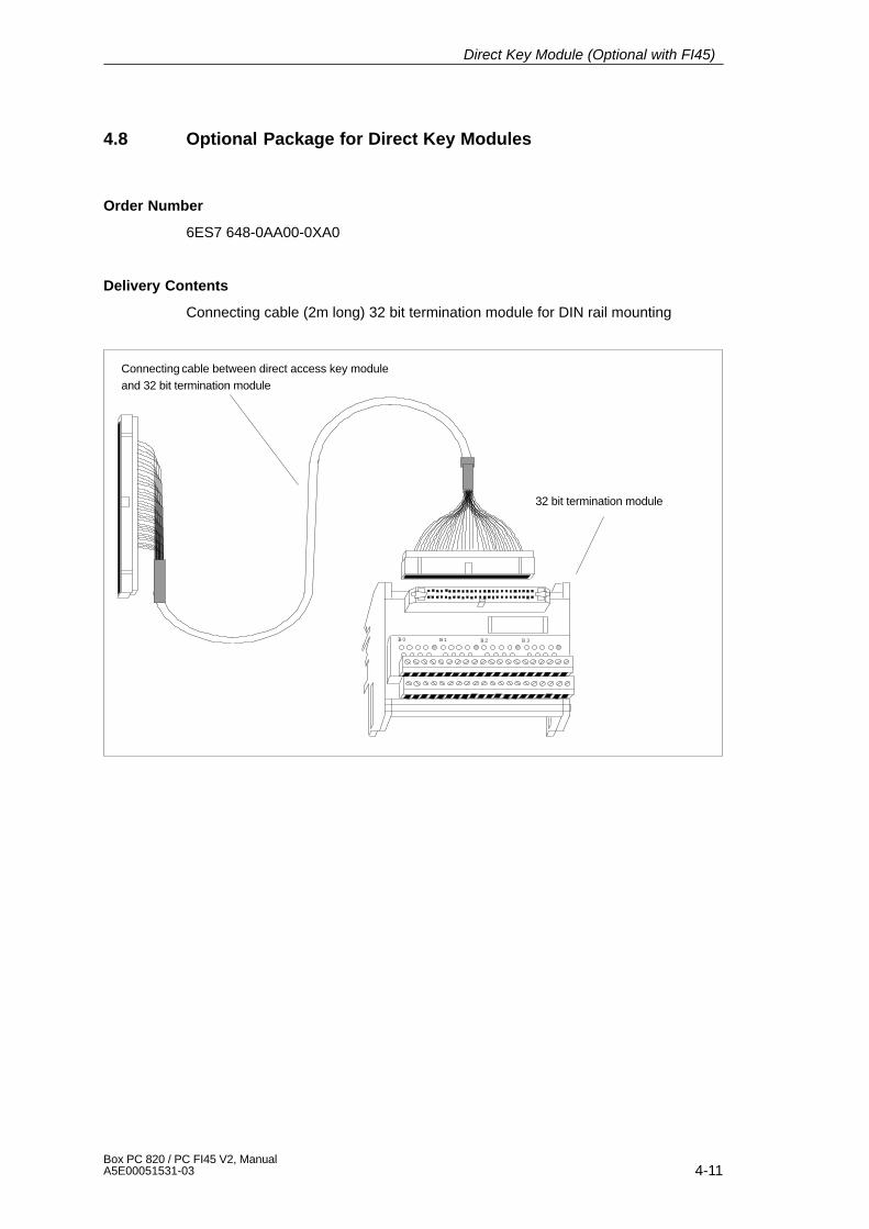
4-11Box PC 820 / PC FI45 V2, ManualA5E00051531-03
4.8 Optional Package for Direct Key Modules
Order Number
6ES7 648-0AA00-0XA0
Delivery Contents
Connecting cable (2m long) 32 bit termination module for DIN rail mounting
Connecting cable between direct access key moduleand 32 bit termination module
32 bit termination module
B1B0 B2 B3
Direct Key Module (Optional with FI45)
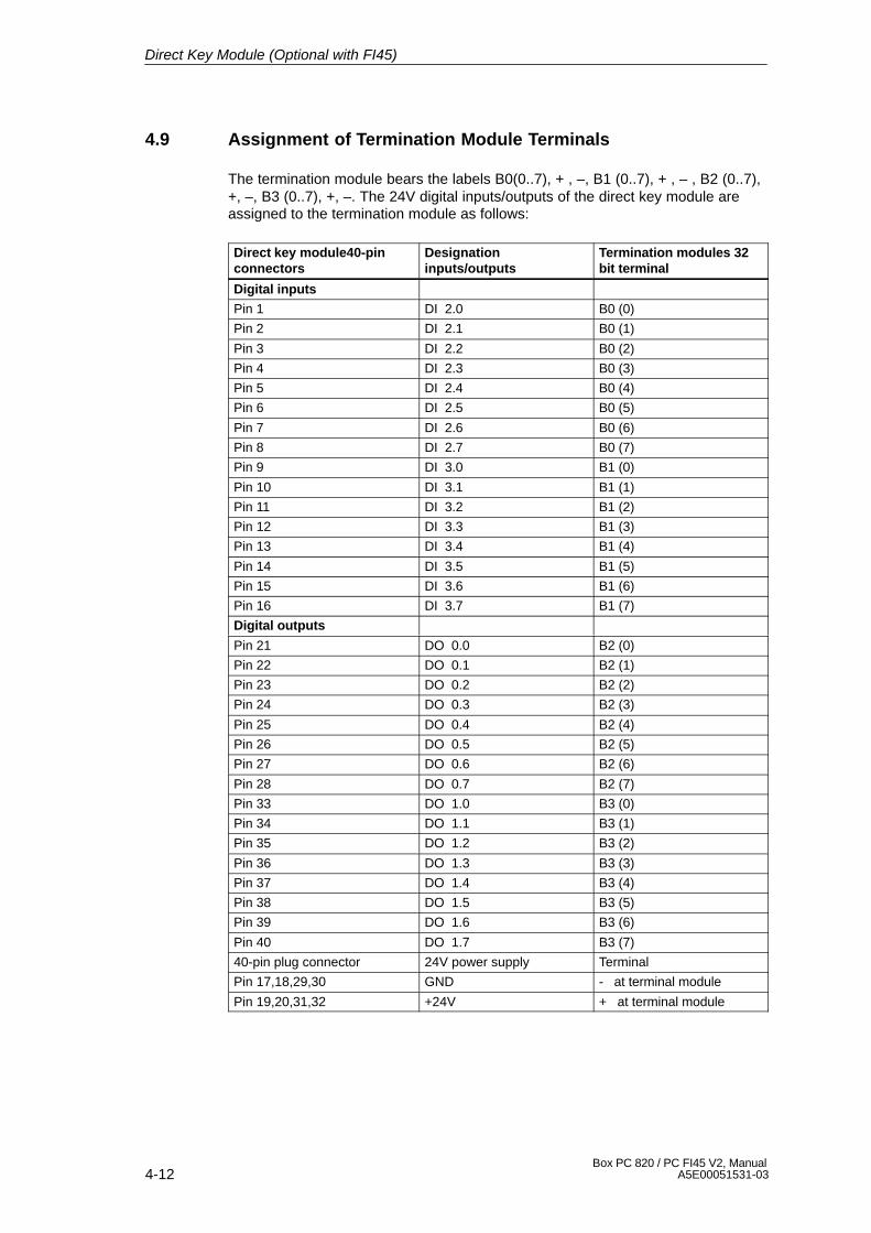
4-12Box PC 820 / PC FI45 V2, Manual
A5E00051531-03
4.9 Assignment of Termination Module Terminals
The termination module bears the labels B0(0..7), + , –, B1 (0..7), + , – , B2 (0..7),+, –, B3 (0..7), +, –. The 24V digital inputs/outputs of the direct key module areassigned to the termination module as follows:
Direct key module40-pinconnectors
Designationinputs/outputs
Termination modules 32bit terminal
Digital inputs
Pin 1 DI 2.0 B0 (0)
Pin 2 DI 2.1 B0 (1)
Pin 3 DI 2.2 B0 (2)
Pin 4 DI 2.3 B0 (3)
Pin 5 DI 2.4 B0 (4)
Pin 6 DI 2.5 B0 (5)
Pin 7 DI 2.6 B0 (6)
Pin 8 DI 2.7 B0 (7)
Pin 9 DI 3.0 B1 (0)
Pin 10 DI 3.1 B1 (1)
Pin 11 DI 3.2 B1 (2)
Pin 12 DI 3.3 B1 (3)
Pin 13 DI 3.4 B1 (4)
Pin 14 DI 3.5 B1 (5)
Pin 15 DI 3.6 B1 (6)
Pin 16 DI 3.7 B1 (7)
Digital outputs
Pin 21 DO 0.0 B2 (0)
Pin 22 DO 0.1 B2 (1)
Pin 23 DO 0.2 B2 (2)
Pin 24 DO 0.3 B2 (3)
Pin 25 DO 0.4 B2 (4)
Pin 26 DO 0.5 B2 (5)
Pin 27 DO 0.6 B2 (6)
Pin 28 DO 0.7 B2 (7)
Pin 33 DO 1.0 B3 (0)
Pin 34 DO 1.1 B3 (1)
Pin 35 DO 1.2 B3 (2)
Pin 36 DO 1.3 B3 (3)
Pin 37 DO 1.4 B3 (4)
Pin 38 DO 1.5 B3 (5)
Pin 39 DO 1.6 B3 (6)
Pin 40 DO 1.7 B3 (7)
40-pin plug connector 24V power supply Terminal
Pin 17,18,29,30 GND - at terminal module
Pin 19,20,31,32 +24V + at terminal module
Direct Key Module (Optional with FI45)

4-13Box PC 820 / PC FI45 V2, ManualA5E00051531-03
The termination modules power supply has to be connected to all terminals labeled+ or -. Terminals labeled + are connected to the +21V supply whereas terminalslabeled with - are connected to ground.
Note
The optional package contains a shielded connecting cable. The shield has to beconnected to the SIMATIC PC and grounded at the terminal block.
Direct Key Module (Optional with FI45)

4-14Box PC 820 / PC FI45 V2, Manual
A5E00051531-03
Direct Key Module (Optional with FI45)
5-1Box PC 820 / PC FI45 V2, ManualA5E00051531-03
Bus Board
Chapter Overview
Section Description Page
5.1 Technical Specifications 5-2
5.2 Design and Mode of Operation 5-3
5.3 Pin Assignments 5-4
5.3.1 Interface to the Motherboard 5-4
5.3.2 ISA Slot Pin Assignment 5-5
5.3.3 PCI Slot Pin Assignment 5-7
5.3.4 External Voltage Supply 5-8
5

5-2Box PC 820 / PC FI45 V2, Manual
A5E00051531-03
5.1 Technical Specifications
Slots 2 x PCI short (max. 175 mm)1x ISA short (max. 175 mm)1x ISA long1x shared ISA/PCI long
Ambient temperature during operation max. 60 �C
Dimensions L x W 150 x 160 mm
Mounting holes 3.2 mm
Bus Board
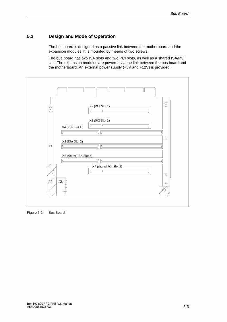
5-3Box PC 820 / PC FI45 V2, ManualA5E00051531-03
5.2 Design and Mode of Operation
The bus board is designed as a passive link between the motherboard and theexpansion modules. It is mounted by means of two screws.
The bus board has two ISA slots and two PCI slots, as well as a shared ISA/PCIslot. The expansion modules are powered via the link between the bus board andthe motherboard. An external power supply (+5V and +12V) is provided.
X8
X7 (shared PCI Slot 3)
X6 (shared ISA Slot 3)
X5 (ISA Slot 2)
X4 (ISA Slot 1)
X3 (PCI Slot 2)
X2 (PCI Slot 1)
Figure 5-1 Bus Board
Bus Board

5-4Box PC 820 / PC FI45 V2, Manual
A5E00051531-03
5.3 Pin Assignments
5.3.1 Interface to the Motherboard
The connection to the motherboard is established by a gold-plated connector. Allthe required bus signals (ISA and PCI) are present on this connector. The followingtable shows the pin assignments.
ISA bus signals PCI bus signals
Signal Signal Signal Signal Signal Signal Signal SignalA name B name C name D name E name F name G name H name
1 iochk# 1 gnd 1 sbhe# 1 memcs# 1 gnd 1 clk(slot3)
1 sdone 1 serr#
2 sd7 2 rstdrv 2 la23 2 iocs16# 2 gnd 2 gnd 2 sbo# 2 ad153 sd6 3 +5V 3 la22 3 irq10 3 inta# 3 intc# 3 c/be1# 3 ad144 sd5 4 irq9 4 la21 4 irq11 4 intb# 4 intd# 4 par 4 ad125 sd4 5 –5V 5 la20 5 irq12 5 +5V 5 +5 5 gnd 5 gnd6 sd3 6 drq2 6 la19 6 irq157 sd2 7 –12V 7 la18 7 irq14 7 +5V 7 +5V 7 gnd 7 gnd8 sd1 8 Ows# 8 la17 8 dack0# 8 rst# 8 clk
(slot1)8 ad13 8 ad10
9 sd0 9 +12V 9 memr# 9 drq0 9 gnt#(slot1)
9 gnd 9 ad11 9 ad8
10 iochrdy 10 gnd 10 menw#
10 dack5# 10 req#(slot1)
10 gnt#(slot2)
10 ad9 10 ad7
11 aen 11 smemw# 11 sd8 11 drq5 11 gnd 11 gnd 11 c7be0#
11 ad5
12 sa19 12 smemr# 12 sd9 12 dack6# 12 clk(slot2)
12 req#(slot2)
12 ad6 12 ad3
13 sa18 13 iow# 13 sd10 13 drq6 13 gnd 13 ad31 13 ad4 13 ad114 sa17 14 ior# 14 sd11 14 dack7# 14 ad30 14 ad29 14 ad2 14 ad015 sa16 15 dack3# 15 sd12 15 drq7 15 Req#
(slot3)15 GNT_
#Slot316 sa15 16 drq3 16 sd13 16 +5V 16 +5V 16 +5V17 sa14 17 dack1# 17 sd14 17 master# 17 NC 17 NC 17 +5 17 –5V18 sa13 18 drq1 18 sd15 18 gnd 18 ad28 18 ad27 18 gnd 18 gnd19 sa12 19 refresh# 19 ad26 19 ad25 19 gnd 19 gnd20 sa11 20 sysclk 20 ad24 20 c/be3#21 sa10 21 irq7 21 ad22 21 ad2322 sa9 22 irq6 22 ad20 22 ad2123 sa8 23 irq5 23 ad18 23 ad1924 sa7 24 irq4 24 NC 24 NC25 sa6 25 irq326 sa5 26 dack2# 26 NC 26 NC27 sa4 27 t/c 27 ad16 27 ad1728 sa3 28 bale 28 frame# 28 irdy#29 sa2 29 +5V 29 c/be# 29 dev-
sel#30 sa1 30 osc 30 trdy# 30 plock#31 sa0 31 gnd 31 stop# 31 perr#
Bus Board
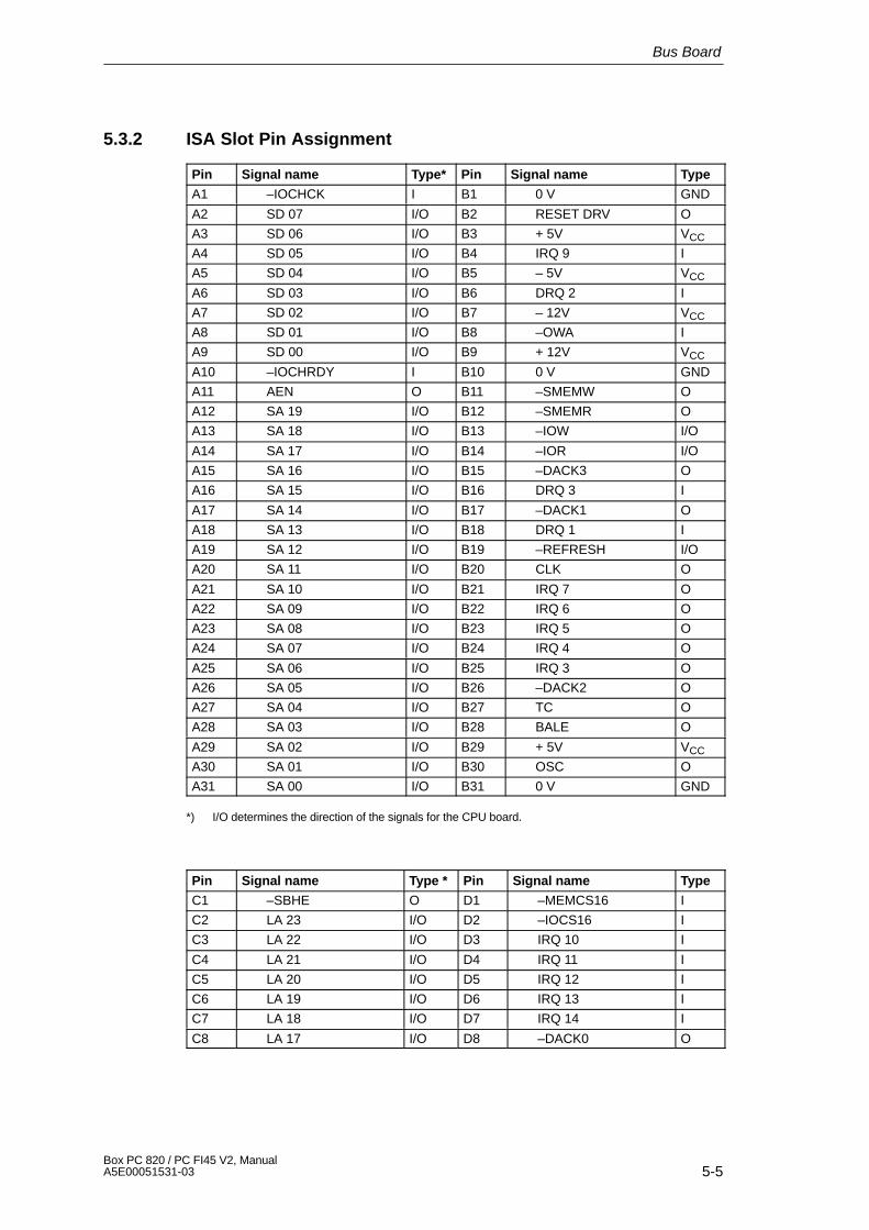
5-5Box PC 820 / PC FI45 V2, ManualA5E00051531-03
5.3.2 ISA Slot Pin Assignment
Pin Signal name Type* Pin Signal name Type
A1 –IOCHCK I B1 0 V GND
A2 SD 07 I/O B2 RESET DRV O
A3 SD 06 I/O B3 + 5V VCC
A4 SD 05 I/O B4 IRQ 9 I
A5 SD 04 I/O B5 – 5V VCC
A6 SD 03 I/O B6 DRQ 2 I
A7 SD 02 I/O B7 – 12V VCC
A8 SD 01 I/O B8 –OWA I
A9 SD 00 I/O B9 + 12V VCC
A10 –IOCHRDY I B10 0 V GND
A11 AEN O B11 –SMEMW O
A12 SA 19 I/O B12 –SMEMR O
A13 SA 18 I/O B13 –IOW I/O
A14 SA 17 I/O B14 –IOR I/O
A15 SA 16 I/O B15 –DACK3 O
A16 SA 15 I/O B16 DRQ 3 I
A17 SA 14 I/O B17 –DACK1 O
A18 SA 13 I/O B18 DRQ 1 I
A19 SA 12 I/O B19 –REFRESH I/O
A20 SA 11 I/O B20 CLK O
A21 SA 10 I/O B21 IRQ 7 O
A22 SA 09 I/O B22 IRQ 6 O
A23 SA 08 I/O B23 IRQ 5 O
A24 SA 07 I/O B24 IRQ 4 O
A25 SA 06 I/O B25 IRQ 3 O
A26 SA 05 I/O B26 –DACK2 O
A27 SA 04 I/O B27 TC O
A28 SA 03 I/O B28 BALE O
A29 SA 02 I/O B29 + 5V VCC
A30 SA 01 I/O B30 OSC O
A31 SA 00 I/O B31 0 V GND
*) I/O determines the direction of the signals for the CPU board.
Pin Signal name Type * Pin Signal name Type
C1 –SBHE O D1 –MEMCS16 I
C2 LA 23 I/O D2 –IOCS16 I
C3 LA 22 I/O D3 IRQ 10 I
C4 LA 21 I/O D4 IRQ 11 I
C5 LA 20 I/O D5 IRQ 12 I
C6 LA 19 I/O D6 IRQ 13 I
C7 LA 18 I/O D7 IRQ 14 I
C8 LA 17 I/O D8 –DACK0 O
Bus Board
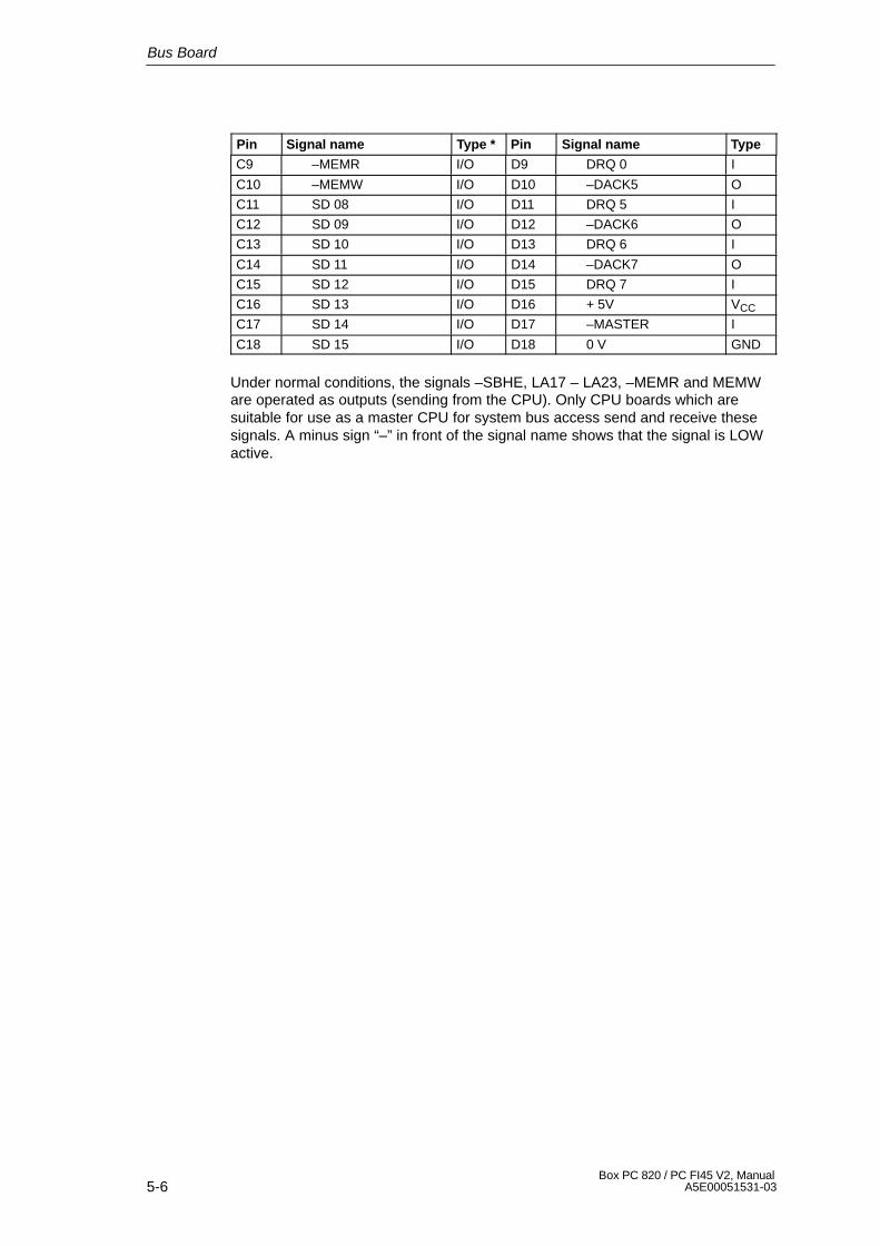
5-6Box PC 820 / PC FI45 V2, Manual
A5E00051531-03
Pin TypeSignal namePinType *Signal name
C9 –MEMR I/O D9 DRQ 0 I
C10 –MEMW I/O D10 –DACK5 O
C11 SD 08 I/O D11 DRQ 5 I
C12 SD 09 I/O D12 –DACK6 O
C13 SD 10 I/O D13 DRQ 6 I
C14 SD 11 I/O D14 –DACK7 O
C15 SD 12 I/O D15 DRQ 7 I
C16 SD 13 I/O D16 + 5V VCC
C17 SD 14 I/O D17 –MASTER I
C18 SD 15 I/O D18 0 V GND
Under normal conditions, the signals –SBHE, LA17 – LA23, –MEMR and MEMWare operated as outputs (sending from the CPU). Only CPU boards which aresuitable for use as a master CPU for system bus access send and receive thesesignals. A minus sign “–” in front of the signal name shows that the signal is LOWactive.
Bus Board
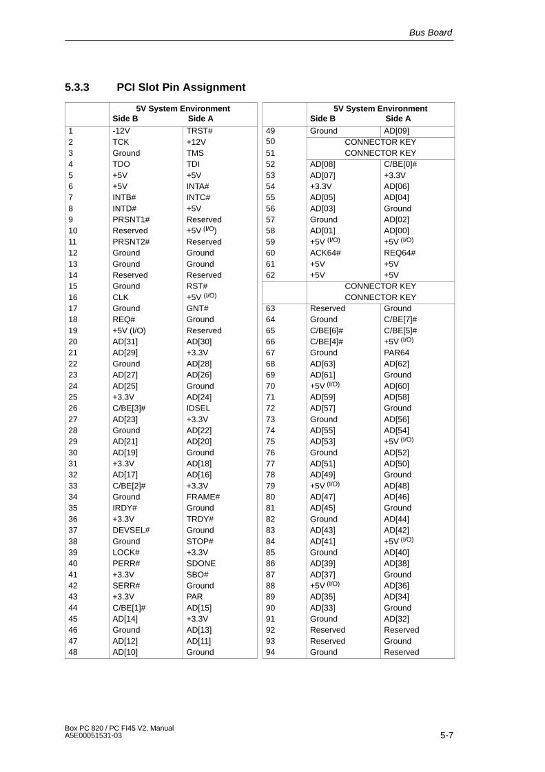
5-7Box PC 820 / PC FI45 V2, ManualA5E00051531-03
5.3.3 PCI Slot Pin Assignment
5V System EnvironmentSide B Side A
1 -12V TRST#2 TCK +12V3 Ground TMS4 TDO TDI5 +5V +5V6 +5V INTA#7 INTB# INTC#8 INTD# +5V9 PRSNT1# Reserved10 Reserved +5V (I/O)11 PRSNT2# Reserved12 Ground Ground13 Ground Ground14 Reserved Reserved15 Ground RST#16 CLK +5V (I/O)
17 Ground GNT#18 REQ# Ground19 +5V (I/O) Reserved20 AD[31] AD[30]21 AD[29] +3.3V22 Ground AD[28]23 AD[27] AD[26]24 AD[25] Ground25 +3.3V AD[24]26 C/BE[3]# IDSEL27 AD[23] +3.3V28 Ground AD[22]29 AD[21] AD[20]30 AD[19] Ground31 +3.3V AD[18]32 AD[17] AD[16]33 C/BE[2]# +3.3V34 Ground FRAME#35 IRDY# Ground36 +3.3V TRDY#37 DEVSEL# Ground38 Ground STOP#39 LOCK# +3.3V40 PERR# SDONE41 +3.3V SBO#42 SERR# Ground43 +3.3V PAR44 C/BE[1]# AD[15]45 AD[14] +3.3V46 Ground AD[13]47 AD[12] AD[11]48 AD[10] Ground
5V System EnvironmentSide B Side A
49 Ground AD[09]50 CONNECTOR KEY51 CONNECTOR KEY52 AD[08] C/BE[0]#53 AD[07] +3.3V54 +3.3V AD[06]55 AD[05] AD[04]56 AD[03] Ground57 Ground AD[02]58 AD[01] AD[00]59 +5V (I/O) +5V (I/O)
60 ACK64# REQ64#61 +5V +5V62 +5V +5V
CONNECTOR KEYCONNECTOR KEY
63 Reserved Ground64 Ground C/BE[7]#65 C/BE[6]# C/BE[5]#66 C/BE[4]# +5V (I/O)
67 Ground PAR6468 AD[63] AD[62]69 AD[61] Ground70 +5V (I/O) AD[60]71 AD[59] AD[58]72 AD[57] Ground73 Ground AD[56]74 AD[55] AD[54]75 AD[53] +5V (I/O)
76 Ground AD[52]77 AD[51] AD[50]78 AD[49] Ground79 +5V (I/O) AD[48]80 AD[47] AD[46]81 AD[45] Ground82 Ground AD[44]83 AD[43] AD[42]84 AD[41] +5V (I/O)
85 Ground AD[40]86 AD[39] AD[38]87 AD[37] Ground88 +5V (I/O) AD[36]89 AD[35] AD[34]90 AD[33] Ground91 Ground AD[32]92 Reserved Reserved93 Reserved Ground94 Ground Reserved
Bus Board
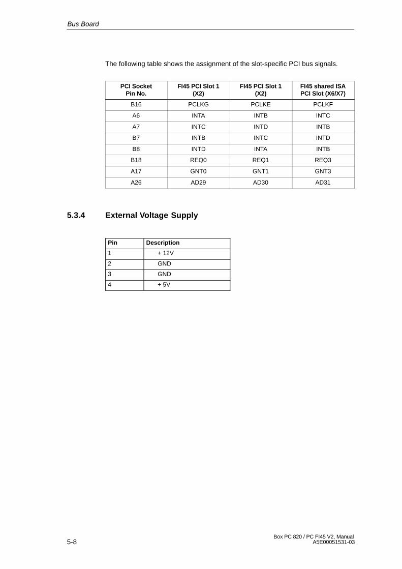
5-8Box PC 820 / PC FI45 V2, Manual
A5E00051531-03
The following table shows the assignment of the slot-specific PCI bus signals.
PCI SocketPin No.
FI45 PCI Slot 1(X2)
FI45 PCI Slot 1(X2)
FI45 shared ISAPCI Slot (X6/X7)
B16 PCLKG PCLKE PCLKF
A6 INTA INTB INTC
A7 INTC INTD INTB
B7 INTB INTC INTD
B8 INTD INTA INTB
B18 REQ0 REQ1 REQ3
A17 GNT0 GNT1 GNT3
A26 AD29 AD30 AD31
5.3.4 External Voltage Supply
Pin Description
1 + 12V
2 GND
3 GND
4 + 5V
Bus Board

6-1Box PC 820 / PC FI45 V2, ManualA5E00051531-03
Front Adapter Module (PC FI45 V2)
Chapter Overview
Section Description Page
6.1 Overview 6-2
6.2 Pin Assignment 6-3
6
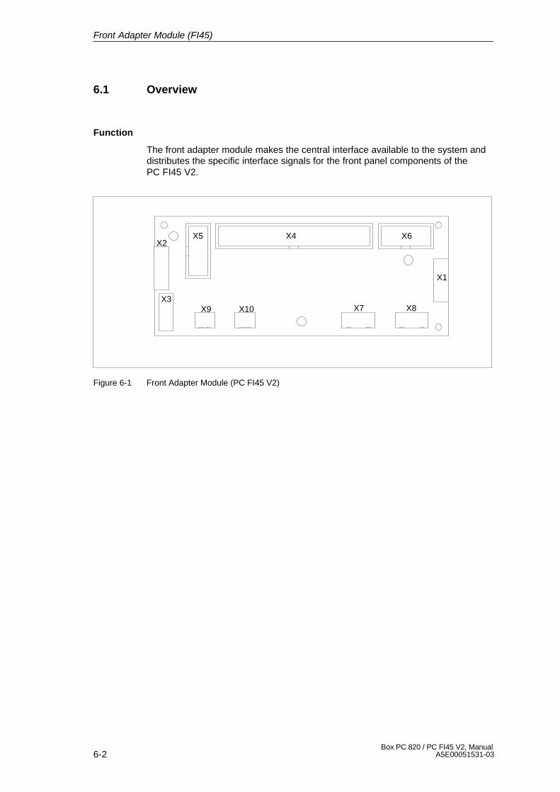
6-2Box PC 820 / PC FI45 V2, Manual
A5E00051531-03
6.1 Overview
Function
The front adapter module makes the central interface available to the system anddistributes the specific interface signals for the front panel components of thePC FI45 V2.
X4 X6X5X2
X3X9 X10 X7 X8
X1
Figure 6-1 Front Adapter Module (PC FI45 V2)
Front Adapter Module (FI45)

6-3Box PC 820 / PC FI45 V2, ManualA5E00051531-03
6.2 Pin Assignment
Socket Connector X1
Connection to the LEDs of the membrane keyboard.
Pin No. Connection to Signal Name Remarks
1 GND GND
2 X4-20 TEMP_R Red temperature LED
3 X4-21 TEMP_G Green temperature LED
4 X4-22 RUN_R Red RUN LED
5 X4-23 RUN_G Green RUN LED
6 X4-18, X4-36 DP_LED DP LED
7 X4-40 HD_LED HD LED
8 X4-23 RUN_G POWER LED
Socket Connector X2
Connection to the mouse buttons of the membrane keyboard.
Pin No. Connection to Signal Name Remarks
1 GND GND
2 X3-4 MOUSE_L Left mouse button
3 GND GND
4 GND GND
5 X3-5 MOUSE_R Right mouse button
6 GND GND
7 – – Not connected
8 – – Not connected
Socket Connector X3
Connection to the touch pad, inverse counting due to ribbon cable.
Pin No. Connection to Signal Name Remarks
1 – – Not connected
2 – – Not connected
3 GND GND
4 X2-2 MOUSE_L Left mouse button
5 X2-5 MOUSE_R Right mouse button
6 X4-10 MOUSE_CLK Touch pad mouse clock
7 X4-9 MOUSE_DAT Touch pad mouse data
8 P5V P5V
Front Adapter Module (FI45)

6-4Box PC 820 / PC FI45 V2, Manual
A5E00051531-03
Socket Connector X3
Connection to the Pentium III motherboard.
Pin No. Connection to Signal Name Remarks
1 1P5V 1P5V +5V via multifuse to motherboard
2 GND GND
3 X5-6 KBD_CLK_I Keyboard clock, connection tomotherboard
4 GND GND
5 X5-7 KBD_DAT_I Keyboard data, connection tomotherboard
6 GND GND
7 1P5V 1P5V +5V via multifuse to motherboard
8 – – Coding
9 X3-7 MOUSE_DAT Touch pad mouse data
10 X3-6 MOUSE_CLK Touch pad mouse clock
11 P12V P12V Power supply for inverter
12 X6-2 BL_ON Switch on signal for back light
13 X6-3 BL_CTRL_1 Brightness adjustment
14 X6-4 BL_CTRL_2 Brightness adjustment
15 X6-5 BL_CTRL_3 Brightness adjustment
16 GND GND
17 X9-1, X10-1, X4-31 RESET_N Reset signal (low active)
18 X1-6, X4-36 DP_LED
19 – – Not connected
20 X1-2 TEMP_R
21 X1-3 TEMP_G
22 X1-4 RUN_R
23 X1-5 RUN_G
24 X5-8 DTAST_DAT Direct keys data signal
25 X5-9 DTAST_LATCH Direct keys latch signal
26 X5-10 DTAST_CLK Direct keys clock signal
27 X5-1 KBD_CLK_E Keyboard clock, externalkeyboard
28 1P5V 1P5V +5V via multifuse to motherboard
29 GND GND
30 X5-4 KBD_DAT_E Keyboard data, externalkeyboard
31 X9-1, X10-1, X4-17 RESET_N Reset signal (low active)
32 – – Not connected
Front Adapter Module (FI45)
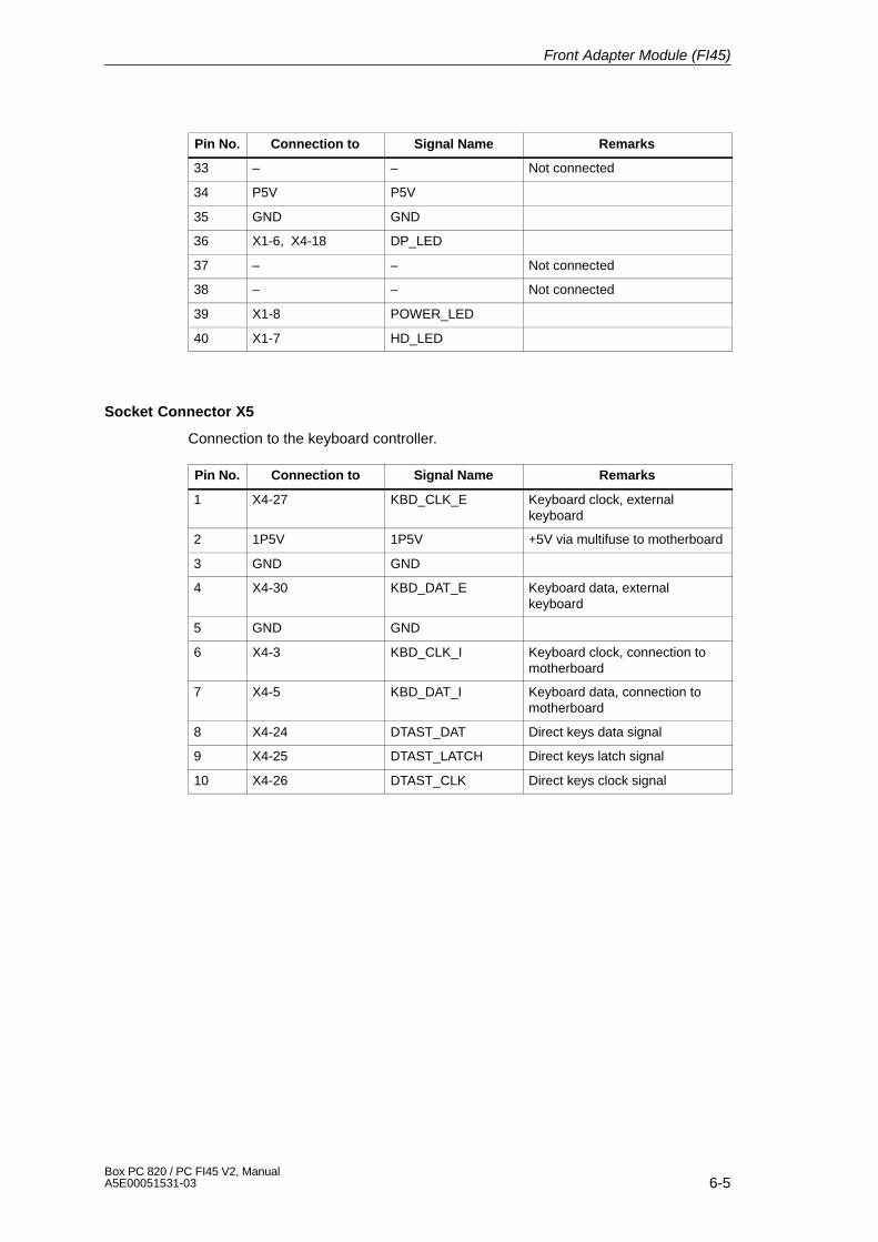
6-5Box PC 820 / PC FI45 V2, ManualA5E00051531-03
Pin No. RemarksSignal NameConnection to
33 – – Not connected
34 P5V P5V
35 GND GND
36 X1-6, X4-18 DP_LED
37 – – Not connected
38 – – Not connected
39 X1-8 POWER_LED
40 X1-7 HD_LED
Socket Connector X5
Connection to the keyboard controller.
Pin No. Connection to Signal Name Remarks
1 X4-27 KBD_CLK_E Keyboard clock, externalkeyboard
2 1P5V 1P5V +5V via multifuse to motherboard
3 GND GND
4 X4-30 KBD_DAT_E Keyboard data, externalkeyboard
5 GND GND
6 X4-3 KBD_CLK_I Keyboard clock, connection tomotherboard
7 X4-5 KBD_DAT_I Keyboard data, connection tomotherboard
8 X4-24 DTAST_DAT Direct keys data signal
9 X4-25 DTAST_LATCH Direct keys latch signal
10 X4-26 DTAST_CLK Direct keys clock signal
Front Adapter Module (FI45)

6-6Box PC 820 / PC FI45 V2, Manual
A5E00051531-03
Socket Connector X6
Connection to the inverter module.
Pin No. Connection to Signal Name Remarks
1 P12V P12V Power supply for inverter
2 X6-2 BL_ON Switch on signal for back light
3 X6-3 BL_CTRL_1 Brightness adjustment
4 X6-4 BL_CTRL_2 Brightness adjustment
5 X6-5 BL_CTRL_3 Brightness adjustment
6 GND GND
7 GND GND
8 P5V P5V
9 P5V P5V
10 P12V P12V
Socket Connector X7, X8
Voltage supply 5V/12V, not fitted.
Pin No. Connection to Signal Name Remarks
1 P12V P12V Derived from power supply toinverter
2 GND GND
3 GND GND
4 P5V P5V
Socket Connector X9
Connection for reset key.
Pin No. Connection to Signal Name Remarks
1 X10⁻¹, X4-17, X4-31 RESET- Reset signal (low active)
2 GND GND
Socket Connector X10
Connection for reset, not fitted.
Pin No. Connection to Signal Name Remarks
1 X9-1, X4-17, X4-31 RESET- Reset signal (low active)
2 GND GND
Front Adapter Module (FI45)
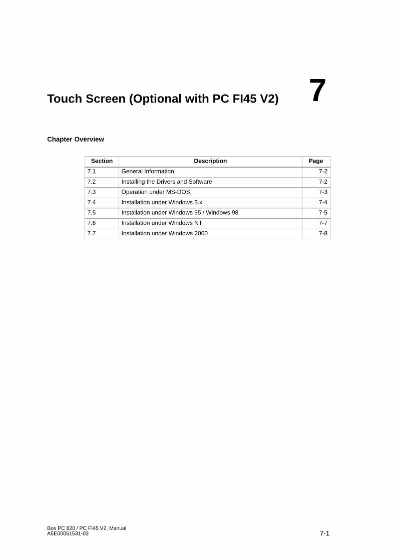
7-1Box PC 820 / PC FI45 V2, ManualA5E00051531-03
Touch Screen (Optional with PC FI45 V2)
Chapter Overview
Section Description Page
7.1 General Information 7-2
7.2 Installing the Drivers and Software 7-2
7.3 Operation under MS-DOS 7-3
7.4 Installation under Windows 3.x 7-4
7.5 Installation under Windows 95 / Windows 98 7-5
7.6 Installation under Windows NT 7-7
7.7 Installation under Windows 2000 7-8
7
7-2Box PC 820 / PC FI45 V2, Manual
A5E00051531-03
7.1 General Information
The touch screen consists of a pressure-sensitive resistance array that iscontinuously monitored by a controller. When the screen is touched, thecoordinates of the position affected are computed based on the screen resolutionused and forwarded to the controller. Since the touch screen function is based onresistance, users can operate it using an appropriate object such as the blunt endof a pen or pencil or when wearing gloves.
Note
Do not use pointed objects to operate the screen, since these can damage thepolyester membrane surface.
This screen surface is waterproof and can be cleaned with a mild, non-abrasivecleaner.
The touch screen system consists of the touch screen sensor and the touchscreen controller. The FI45 uses the built-in touch controller E271-2210 which isconnected to the RS232 interface of the basic module. The external cable (alreadyplugged in) connects the touch controller to the external COM2 port.
The plug-in jumpers on the mini circuit board of the touch controller are preset bythe manufacturer; these connections must not be changed.
There is no touch pad available for these devices. The necessary software foroperating the touch screeen is pre-installed.
The following section applies only to the first installation of your device.
7.2 Installing the Drivers and Software
Install the driver from the CD Documentation and Drivers supplied. Proceed asfollows:
1. Insert the CD.
2. Run start.exeAcrobat Reader is installed if necessary.
3. Navigate to the driver list (depending from language, operating system anddevice).
4. Install the desired driver in accordance with the entries in the driver list.
Touch Screen (Optional with PC FI45 V2)

7-3Box PC 820 / PC FI45 V2, ManualA5E00051531-03
7.3 Operation under MS-DOS
If you have already installed a DOS mouse driver (MOUSE.COM) for your mouse,you can continue to use it with the touch screen under DOS.
To install the software under MS-DOS, proceed as follows:
� Follow the user prompts and instructions that appear on the screen. You will beasked to choose between DOS Express, Windows Express or Selective. SelectDOS Express.
� You will then be asked to indicate what types of hardware are present. Selectthe serial port and then the COM2 port.
� The installation is complete when you are informed that Autoexec.bat has beenchanged and the previous batch file has been renamed to Autoexec.old.
Calibrating the Touch Screen
The touch screen must be calibrated after installation. To calibrate the screen,proceed as follows:
� Enter the command Go as soon as the installation is complete; then enter thecommand Elocalib.exe in the installation directory.
� Follow the instructions displayed on the screen and touch the appropriatelocations on the screen with a with a suitable object made of wood or plastic,such as the blunt end of a pen or pencil.
� Enter the command Elocalib –h to determine the additional parameters thatcan be used as options for the calibration.
� Restart the computer so that the calibration with take effect. If an installationdiskette is still in the drive, remove it first.
Demonstration Program for DOS
The demonstration program contains self-explanatory tasks and games that can becompleted or played by touching the screen. To use this program, proceed asfollows:
� Enter the command Elodemo.exe in the installation directory.
� Enter the command Elodemo –h to specify additional parameters for thisdemonstration program.
Touch Screen (Optional with PC FI45 V2)
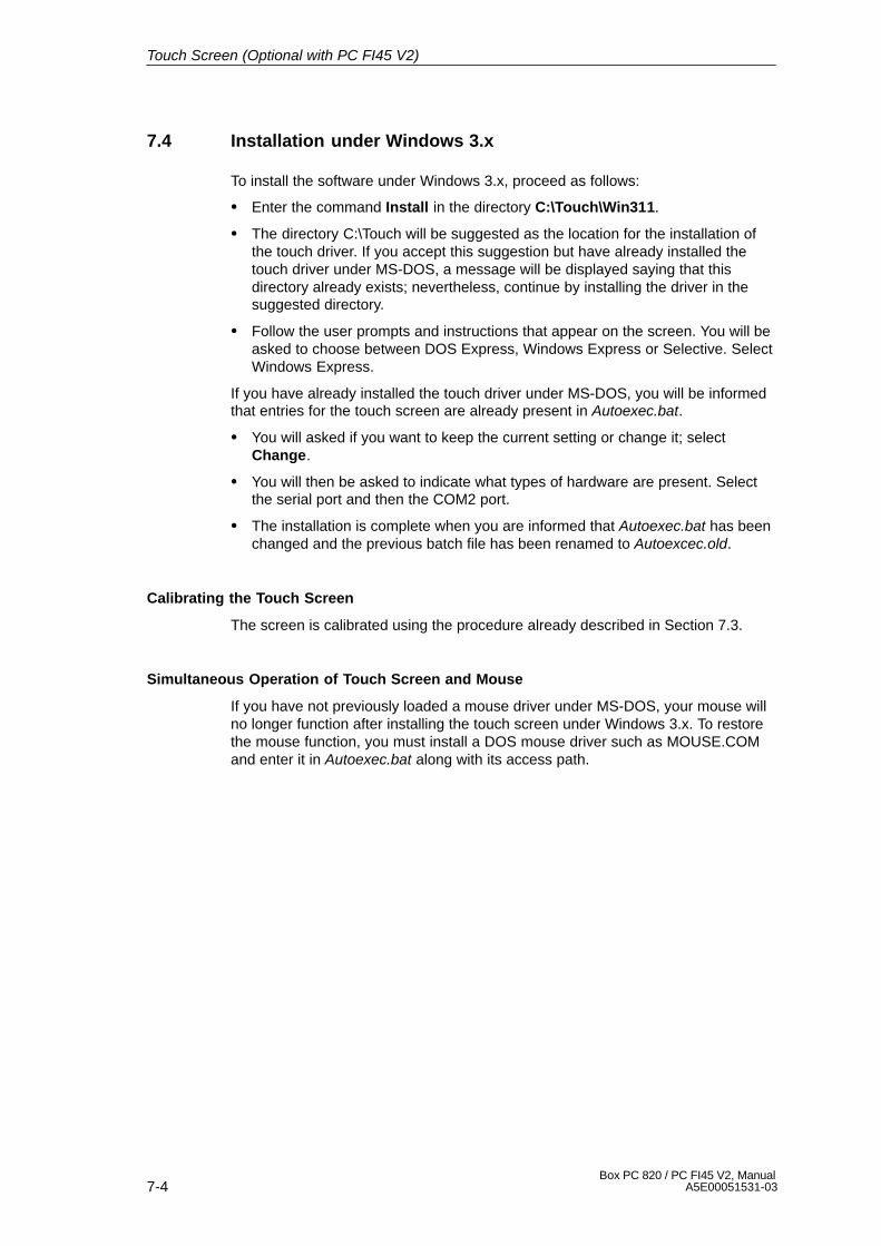
7-4Box PC 820 / PC FI45 V2, Manual
A5E00051531-03
7.4 Installation under Windows 3.x
To install the software under Windows 3.x, proceed as follows:
� Enter the command Install in the directory C:\Touch\Win311.
� The directory C:\Touch will be suggested as the location for the installation ofthe touch driver. If you accept this suggestion but have already installed thetouch driver under MS-DOS, a message will be displayed saying that thisdirectory already exists; nevertheless, continue by installing the driver in thesuggested directory.
� Follow the user prompts and instructions that appear on the screen. You will beasked to choose between DOS Express, Windows Express or Selective. SelectWindows Express.
If you have already installed the touch driver under MS-DOS, you will be informedthat entries for the touch screen are already present in Autoexec.bat.
� You will asked if you want to keep the current setting or change it; selectChange.
� You will then be asked to indicate what types of hardware are present. Selectthe serial port and then the COM2 port.
� The installation is complete when you are informed that Autoexec.bat has beenchanged and the previous batch file has been renamed to Autoexcec.old.
Calibrating the Touch Screen
The screen is calibrated using the procedure already described in Section 7.3.
Simultaneous Operation of Touch Screen and Mouse
If you have not previously loaded a mouse driver under MS-DOS, your mouse willno longer function after installing the touch screen under Windows 3.x. To restorethe mouse function, you must install a DOS mouse driver such as MOUSE.COMand enter it in Autoexec.bat along with its access path.
Touch Screen (Optional with PC FI45 V2)
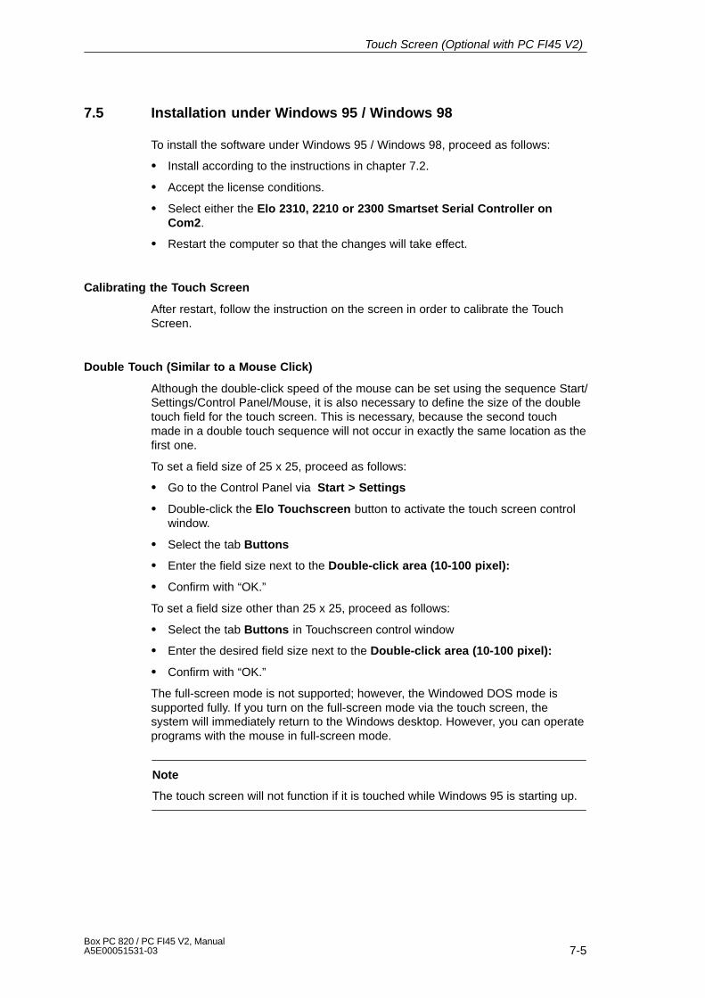
7-5Box PC 820 / PC FI45 V2, ManualA5E00051531-03
7.5 Installation under Windows 95 / Windows 98
To install the software under Windows 95 / Windows 98, proceed as follows:
� Install according to the instructions in chapter 7.2.
� Accept the license conditions.
� Select either the Elo 2310, 2210 or 2300 Smartset Serial Controller onCom2.
� Restart the computer so that the changes will take effect.
Calibrating the Touch Screen
After restart, follow the instruction on the screen in order to calibrate the TouchScreen.
Double Touch (Similar to a Mouse Click)
Although the double-click speed of the mouse can be set using the sequence Start/Settings/Control Panel/Mouse, it is also necessary to define the size of the doubletouch field for the touch screen. This is necessary, because the second touchmade in a double touch sequence will not occur in exactly the same location as thefirst one.
To set a field size of 25 x 25, proceed as follows:
� Go to the Control Panel via Start > Settings
� Double-click the Elo Touchscreen button to activate the touch screen controlwindow.
� Select the tab Buttons
� Enter the field size next to the Double-click area (10-100 pixel):
� Confirm with “OK.”
To set a field size other than 25 x 25, proceed as follows:
� Select the tab Buttons in Touchscreen control window
� Enter the desired field size next to the Double-click area (10-100 pixel):
� Confirm with “OK.”
The full-screen mode is not supported; however, the Windowed DOS mode issupported fully. If you turn on the full-screen mode via the touch screen, thesystem will immediately return to the Windows desktop. However, you can operateprograms with the mouse in full-screen mode.
Note
The touch screen will not function if it is touched while Windows 95 is starting up.
Touch Screen (Optional with PC FI45 V2)

7-6Box PC 820 / PC FI45 V2, Manual
A5E00051531-03
Removing the Mouse Pointer
If you want to remove the mouse pointer, proceed as follows:
� Select the tab Buttons in Touchscreen control window (see Double-Touch)
� Activate the Hide arrow mouse pointer control window
� Confirm with “OK.”
After this, the normal mouse pointer no longer appears, but all other pointerscontinue to function as before.
Tips for Touch Screen Applications
To facilitate windows operation with the touch screen, it is a good idea to increasethe window frame width in order to make changing the window size easier. Youcan use the menu command Display > Size in the Control Panel to change thewidth of the window frame.
The scroll bar can be operated as usual. You can scroll through some data fieldsby simply touching the screen within the field and then maintaining contact with itwhile dragging until you are outside the data field.
Touch the window maximizing button or double-click the window title bar tomaximize the window size. Similarly, you can double-touch the window title barto restore the window to its previous size.
Recalibrating the Touch Screen
� Go to the Control Panel via Start > Settings
� Double-click the Elo Touchscreen button to activate the touch screen controlwindow.
� Click the Calibrate button. Then touch each of the three targets that appear onthe screen as precisely as possible with an a suitable object made of wood orplastic, such as the blunt end of a pen or pencil.
� Confirm with “Yes” and “OK” to conclude the calibration procedure.
Touch Screen (Optional with PC FI45 V2)
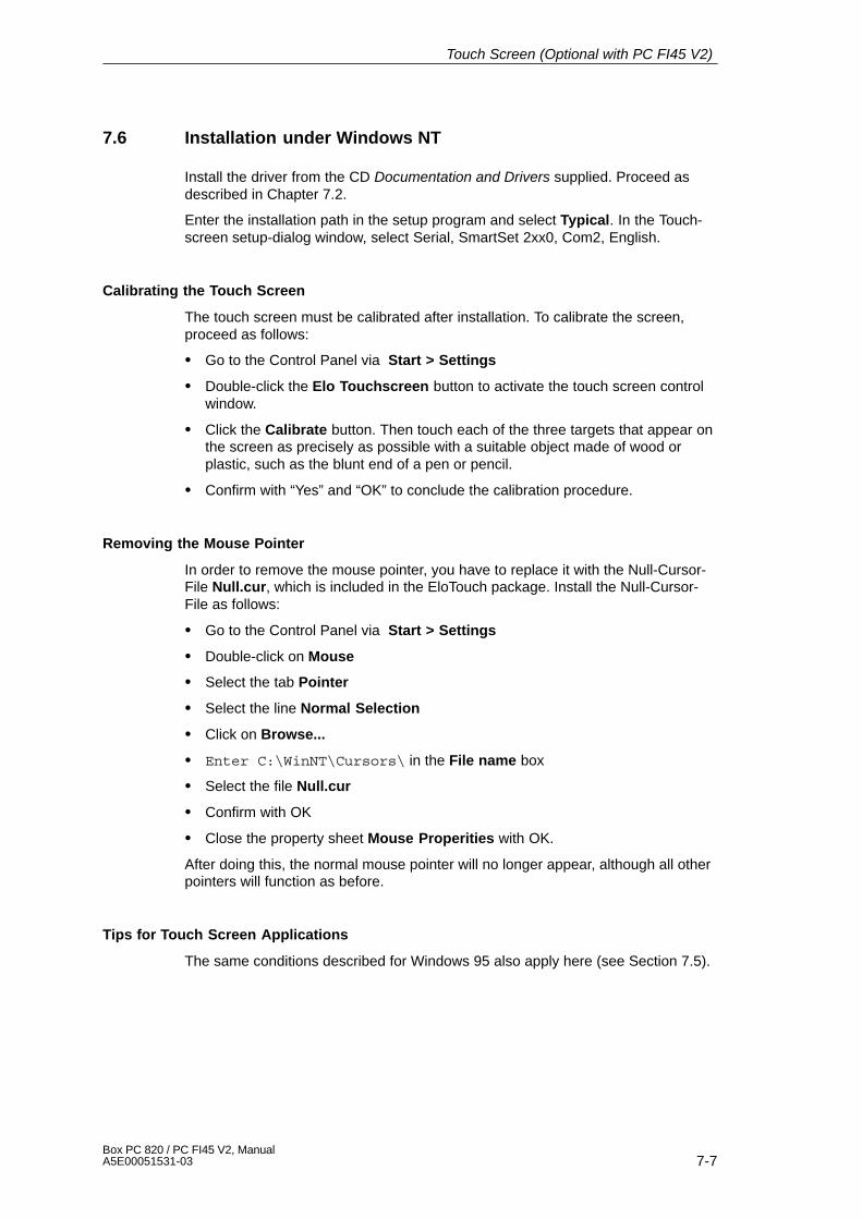
7-7Box PC 820 / PC FI45 V2, ManualA5E00051531-03
7.6 Installation under Windows NT
Install the driver from the CD Documentation and Drivers supplied. Proceed asdescribed in Chapter 7.2.
Enter the installation path in the setup program and select Typical. In the Touch-screen setup-dialog window, select Serial, SmartSet 2xx0, Com2, English.
Calibrating the Touch Screen
The touch screen must be calibrated after installation. To calibrate the screen,proceed as follows:
� Go to the Control Panel via Start > Settings
� Double-click the Elo Touchscreen button to activate the touch screen controlwindow.
� Click the Calibrate button. Then touch each of the three targets that appear onthe screen as precisely as possible with a suitable object made of wood orplastic, such as the blunt end of a pen or pencil.
� Confirm with “Yes” and “OK” to conclude the calibration procedure.
Removing the Mouse Pointer
In order to remove the mouse pointer, you have to replace it with the Null-Cursor-File Null.cur, which is included in the EloTouch package. Install the Null-Cursor-File as follows:
� Go to the Control Panel via Start > Settings
� Double-click on Mouse
� Select the tab Pointer
� Select the line Normal Selection
� Click on Browse...
� Enter C:\WinNT\Cursors\ in the File name box
� Select the file Null.cur
� Confirm with OK
� Close the property sheet Mouse Properities with OK.
After doing this, the normal mouse pointer will no longer appear, although all otherpointers will function as before.
Tips for Touch Screen Applications
The same conditions described for Windows 95 also apply here (see Section 7.5).
Touch Screen (Optional with PC FI45 V2)
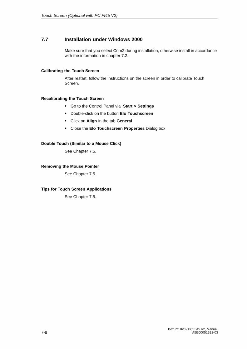
7-8Box PC 820 / PC FI45 V2, Manual
A5E00051531-03
7.7 Installation under Windows 2000
Make sure that you select Com2 during installation, otherwise install in accordancewith the information in chapter 7.2.
Calibrating the Touch Screen
After restart, follow the instructions on the screen in order to calibrate TouchScreen.
Recalibrating the Touch Screen
� Go to the Control Panel via Start > Settings
� Double-click on the button Elo Touchscreen
� Click on Align in the tab General
� Close the Elo Touchscreen Properties Dialog box
Double Touch (Similar to a Mouse Click)
See Chapter 7.5.
Removing the Mouse Pointer
See Chapter 7.5.
Tips for Touch Screen Applications
See Chapter 7.5.
Touch Screen (Optional with PC FI45 V2)
8-1Box PC 820 / PC FI45 V2, ManualA5E00051531-03
Display
Chapter Overview
Section Description Page
8.1 TFT Display (XGA) 8-2
8
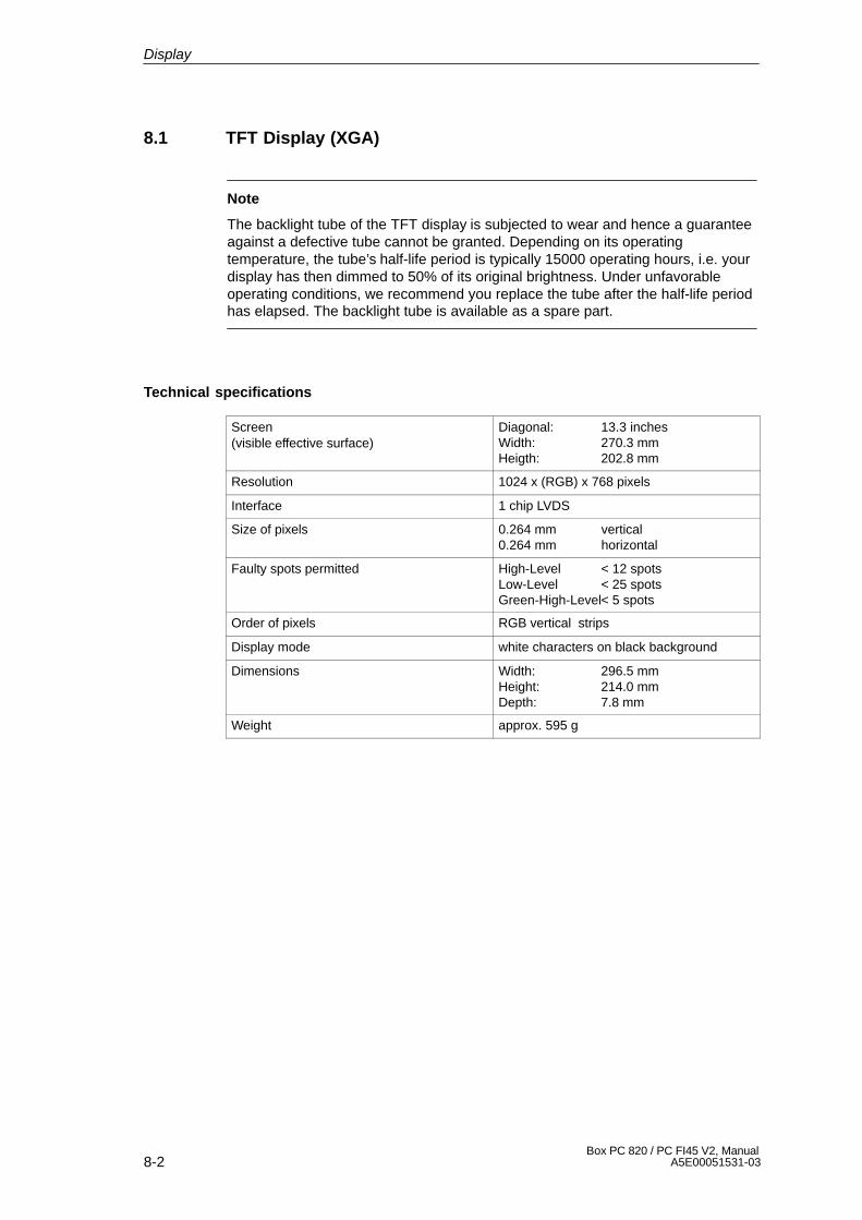
8-2Box PC 820 / PC FI45 V2, Manual
A5E00051531-03
8.1 TFT Display (XGA)
Note
The backlight tube of the TFT display is subjected to wear and hence a guaranteeagainst a defective tube cannot be granted. Depending on its operatingtemperature, the tube’s half-life period is typically 15000 operating hours, i.e. yourdisplay has then dimmed to 50% of its original brightness. Under unfavorableoperating conditions, we recommend you replace the tube after the half-life periodhas elapsed. The backlight tube is available as a spare part.
Technical specifications
Screen(visible effective surface)
Diagonal: 13.3 inchesWidth: 270.3 mmHeigth: 202.8 mm
Resolution 1024 x (RGB) x 768 pixels
Interface 1 chip LVDS
Size of pixels 0.264 mm vertical0.264 mm horizontal
Faulty spots permitted High-Level < 12 spotsLow-Level < 25 spotsGreen-High-Level< 5 spots
Order of pixels RGB vertical strips
Display mode white characters on black background
Dimensions Width: 296.5 mmHeight: 214.0 mmDepth: 7.8 mm
Weight approx. 595 g
Display
9-1Box PC 820 / PC FI45 V2, ManualA5E00051531-03
CD-ROM Drive
Chapter Overview
Section Description Page
9.1 Functionality 9-2
9
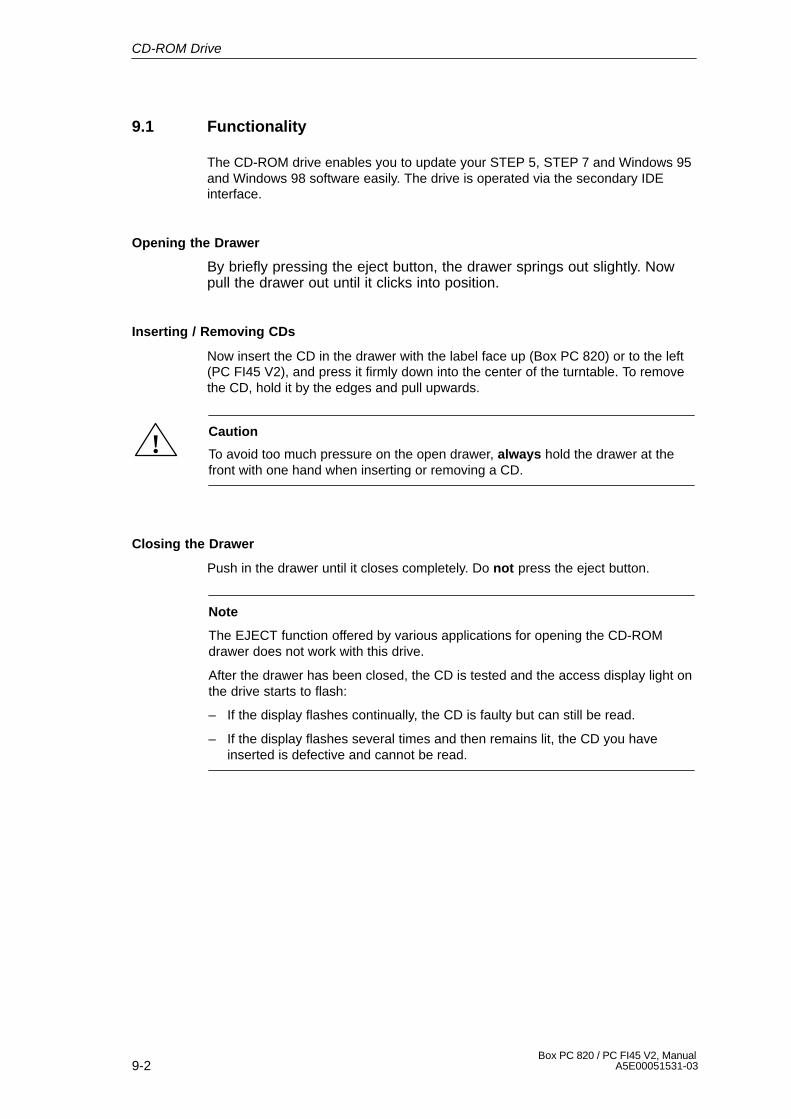
9-2Box PC 820 / PC FI45 V2, Manual
A5E00051531-03
9.1 Functionality
The CD-ROM drive enables you to update your STEP 5, STEP 7 and Windows 95and Windows 98 software easily. The drive is operated via the secondary IDEinterface.
Opening the Drawer
By briefly pressing the eject button, the drawer springs out slightly. Nowpull the drawer out until it clicks into position.
Inserting / Removing CDs
Now insert the CD in the drawer with the label face up (Box PC 820) or to the left(PC FI45 V2), and press it firmly down into the center of the turntable. To removethe CD, hold it by the edges and pull upwards.
!Caution
To avoid too much pressure on the open drawer, always hold the drawer at thefront with one hand when inserting or removing a CD.
Closing the Drawer
Push in the drawer until it closes completely. Do not press the eject button.
Note
The EJECT function offered by various applications for opening the CD-ROMdrawer does not work with this drive.
After the drawer has been closed, the CD is tested and the access display light onthe drive starts to flash:
– If the display flashes continually, the CD is faulty but can still be read.
– If the display flashes several times and then remains lit, the CD you haveinserted is defective and cannot be read.
CD-ROM Drive
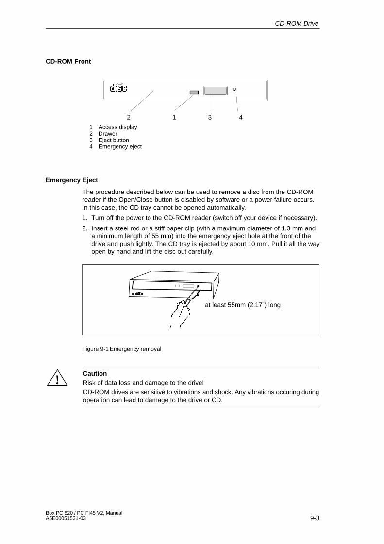
9-3Box PC 820 / PC FI45 V2, ManualA5E00051531-03
CD-ROM Front
12 3
1 Access display2 Drawer3 Eject button4 Emergency eject
4
Emergency Eject
The procedure described below can be used to remove a disc from the CD-ROMreader if the Open/Close button is disabled by software or a power failure occurs.In this case, the CD tray cannot be opened automatically.
1. Turn off the power to the CD-ROM reader (switch off your device if necessary).
2. Insert a steel rod or a stiff paper clip (with a maximum diameter of 1.3 mm anda minimum length of 55 mm) into the emergency eject hole at the front of thedrive and push lightly. The CD tray is ejected by about 10 mm. Pull it all the wayopen by hand and lift the disc out carefully.
at least 55mm (2.17”) long
Figure 9-1 Emergency removal
!CautionRisk of data loss and damage to the drive!
CD-ROM drives are sensitive to vibrations and shock. Any vibrations occuring duringoperation can lead to damage to the drive or CD.
CD-ROM Drive

9-4Box PC 820 / PC FI45 V2, Manual
A5E00051531-03
CD-ROM Drive
10-1Box PC 820 / PC FI45 V2, ManualA5E00051531-03
Power Supply
Chapter Overview
Section Description Page
10.1 Technical Specifications 10-2
10
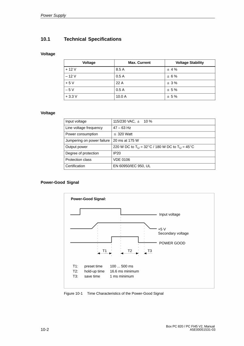
10-2Box PC 820 / PC FI45 V2, Manual
A5E00051531-03
10.1 Technical Specifications
Voltage
Voltage Max. Current Voltage Stability
+ 12 V 8.5 A � 4 %
– 12 V 0.5 A � 6 %
+ 5 V 22 A � 3 %
– 5 V 0.5 A � 5 %
+ 3.3 V 10.0 A � 5 %
Voltage
Input voltage 115/230 VAC, � 10 %
Line voltage frequency 47 – 63 Hz
Power consumption � 320 Watt
Jumpering on power failure 20 ms at 175 W
Output power 220 W DC to TU = 32�C / 180 W DC to TU = 45�C
Degree of protection IP20
Protection class VDE 0106
Certification EN 60950/IEC 950, UL
Power-Good Signal
T1 T2 T3
Power-Good Signal:
Input voltage
POWER GOOD
T1: preset time 100 ... 500 msT2: hold-up time 16.6 ms minimumT3: save time 1 ms minimum
+5 VSecondary voltage
Figure 10-1 Time Characteristics of the Power-Good Signal
Power Supply
11-1Box PC 820 / PC FI45 V2, ManualA5E00051531-03
Connecting Cables
Chapter Overview
Section Description Page
11.1 Connecting Cables 11-2
11
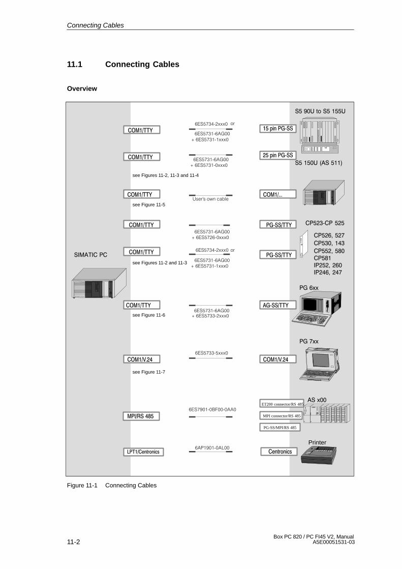
11-2Box PC 820 / PC FI45 V2, Manual
A5E00051531-03
11.1 Connecting Cables
Overview
������
������
������� ����
Printer
������������
����������
��������
��������������������������������
3"456��7
3"4568�/(
9'�563���� ���
3"4568�/(
#$���6��7
5:�����'$���
3���� ���
MPI connector/RS 485
PG-SS/MPI/RS 485
ET200 connector/RS 485
�����������
��� �������
�������������
���� �����������
���������������
�������������
������������� ��
3"456��7
3"456��7'$���6��7
4'&6;��():
��� ������
���
���������������
/:�����'$���3"456��7
�����������
���������������
�����������
���������������
3"456��7 3"456���������������� !�
�����������
���������������
�����������
���������������
see Figures 11-2, 11-3 and 11-4
see Figure 11-5
see Figures 11-2 and 11-3
see Figure 11-6
see Figure 11-7
3"456��7 '$���6��7
��
Figure 11-1 Connecting Cables
Connecting Cables
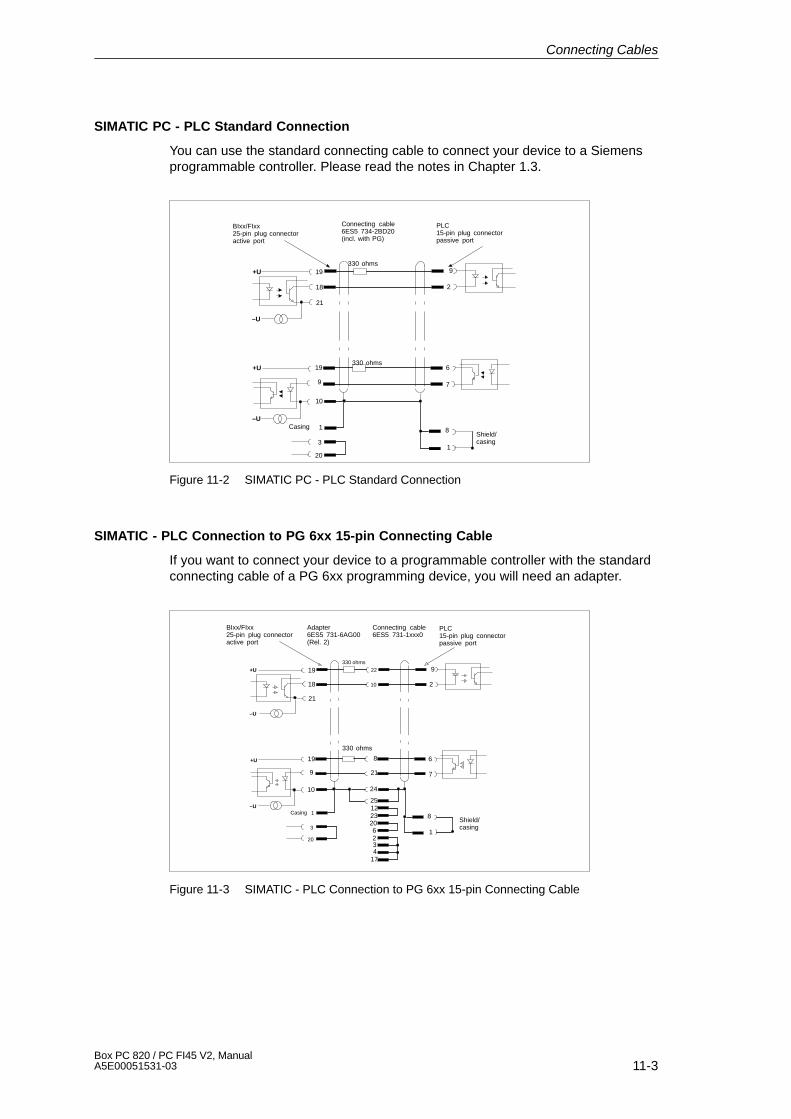
11-3Box PC 820 / PC FI45 V2, ManualA5E00051531-03
SIMATIC PC - PLC Standard Connection
You can use the standard connecting cable to connect your device to a Siemensprogrammable controller. Please read the notes in Chapter 1.3.
19
18
21
19
9
2
6
9
10
7
8
1
1
3
20
+U
–U
+U
–U
BIxx/FIxx25-pin plug connector active port
Connecting cable6ES5 734-2BD20(incl. with PG)
PLC15-pin plug connectorpassive port
330 ohms
330 ohms
CasingShield/casing
Figure 11-2 SIMATIC PC - PLC Standard Connection
SIMATIC - PLC Connection to PG 6xx 15-pin Connecting Cable
If you want to connect your device to a programmable controller with the standardconnecting cable of a PG 6xx programming device, you will need an adapter.
19
18
21
22
10
9
2
19 8 6
7219
10 24
251223206234
17
8
1
1
3
20
+U
–U
+U
–U
BIxx/FIxx25-pin plug connectoractive port
Adapter6ES5 731-6AG00(Rel. 2)
Connecting cable6ES5 731-1xxx0
PLC15-pin plug connectorpassive port
330 ohms
330 ohms
CasingShield/casing
Figure 11-3 SIMATIC - PLC Connection to PG 6xx 15-pin Connecting Cable
Connecting Cables
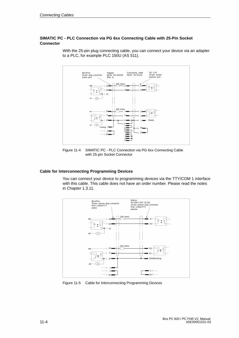
11-4Box PC 820 / PC FI45 V2, Manual
A5E00051531-03
SIMATIC PC - PLC Connection via PG 6xx Connecting Cable with 25-Pin SocketConnector
With the 25-pin plug connecting cable, you can connect your device via an adapterto a PLC, for example PLC 150U (AS 511).
19
18
21
22
10
9
819
21
19
1821
20
10
20
20
1
3
24
251223
6234
17
1
24
25
+U
+U
–U
–U
BIxx/FIxx25-pin plug connectoractive port
Adapter6ES5 731-6AG00(Rel. 2)
Connecting cable6ES5 731-0xxx0
S5, V.2425-pin socketpassive port
330 ohms
330 ohms
Shield
Casing
Figure 11-4 SIMATIC PC - PLC Connection via PG 6xx Connecting Cablewith 25-pin Socket Connector
Cable for Interconnecting Programming Devices
You can connect your device to programming devices via the TTY/COM 1 interfacewith this cable. This cable does not have an order number. Please read the notesin Chapter 1.3.11.
19
18
21
9
10
19 18
219
10
1
3
20 20
3
+U
–U
+U
–U
BIxx/FIxx25-pin cannon plug connectorPort: COM1/TTYactive
RI45xxPG 695 II (PC 16-20)25-pin cannon plug connectorPort: COM1/TTYpassive
330 ohms
330 ohms
Shield/casing
Figure 11-5 Cable for Interconnecting Programming Devices
Connecting Cables

11-5Box PC 820 / PC FI45 V2, ManualA5E00051531-03
SIMATIC PC - PG 6xx Connection to PLC-S5 Port
If you want to connect your device to the PLC-S5 port of a PG 6xx programmingdevice, you will need an adapter. In this case, the PC must be switched to active.Please read the notes on changing over the TTY/COM 1 port to active in Chapter1.3.
330 ohms
330 ohms
19
18
21
22
10
6
8
19
9
8
21
10
12
10 24
25122320623417
24
25
2
34
17
1
3
20
Casing
Casing
Shield/casing
GND
K3K2
K1
+U
–U
+U
–U
Adapter6ES5 731-6AG00(Rel. 2)
Connecting cable6ES5 733-2xxx0
PG 6xx25-pin cannon plug connectorwith S5/V.24 passive port
Rixx25-pin cannon plug connectorPort: COM1/TTYactive
Figure 11-6 SIMATIC PC - PG 6xx Connection to PLC-S5 Port
SIMATIC PC - PG 7xx Connection in V.24 Operation
With this connecting cable you can connect your device to any PG 7xx.
Casing Shield
Casing Casing
ShieldCasing 1
3
2
5
4
20
7
17
6
RxD
TxD
CTS
RTS
DTR
GHD
AKENI
DSR
2
3
4
5
6
7
20
TxD
RxD
RTS
CTS
DSR
GHD
DTR
2
3
4
5
6
7
20
1
3
2
5
4
20
7
17
6
25-pin 25-pinConnecting cable: 6ES5733-0BD20
Pay attention to the connecting polarities!
Figure 11-7 SIMATIC PC - PG 7xx Connection in V.24 Operation
Connecting Cables

11-6Box PC 820 / PC FI45 V2, Manual
A5E00051531-03
Connecting Cables
A-1Box PC 820 / PC FI45 V2, ManualA5E00051531-03
Guidelines for HandlingElectrostatically-Sensitive Devices (ESD)
Chapter Overview
Section Description Page
A.1 What is ESD? A-2
A.2 Electrostatic Charging of Persons A-3
A.3 General Protective Measures Against Electrostatic DischargeDamage
A-4
A
A-2Box PC 820 / PC FI45 V2, Manual
A5E00051531-03
A.1 What is ESD?
Definition
All electronic modules are equipped with large-scale integrated ICs or components.Due to their design, these electronic elements are very sensitive to overvoltagesand thus to any electrostatic discharge.
These Electrostatically-Sensitive Devices are commonly referred to by theabbreviation ESD.
Electrostatically-sensitive devices are labeled with the following symbol:
!Caution
Electrostatically-sensitive devices are subject to voltages that are far below thevoltage values that can still be perceived by human beings. These voltages arepresent if you touch a component or the electrical connections of a module withoutpreviously being electrostatically discharged. In most cases, the damage causedby an overvoltage is not immediately noticeable and results in total damage onlyafter a prolonged period of operation.
Guidelines for Handling Electrostatically-Sensitive Devices (ESD)
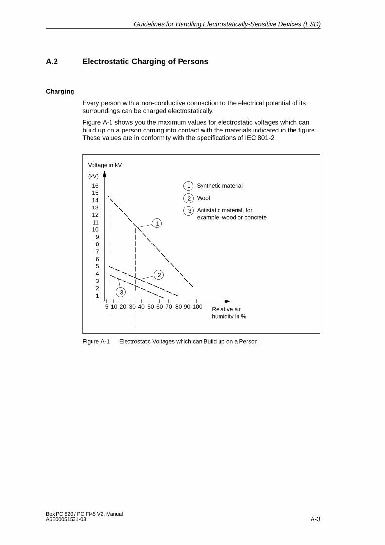
A-3Box PC 820 / PC FI45 V2, ManualA5E00051531-03
A.2 Electrostatic Charging of Persons
Charging
Every person with a non-conductive connection to the electrical potential of itssurroundings can be charged electrostatically.
Figure A-1 shows you the maximum values for electrostatic voltages which canbuild up on a person coming into contact with the materials indicated in the figure.These values are in conformity with the specifications of IEC 801-2.
Voltage in kV
123456789
10111213141516
(kV)
5 10 20 30 40 50 60 70 80 90 100 Relative airhumidity in %
1
3
1 Synthetic material
2 Wool
3 Antistatic material, forexample, wood or concrete
2
Figure A-1 Electrostatic Voltages which can Build up on a Person
Guidelines for Handling Electrostatically-Sensitive Devices (ESD)
A-4Box PC 820 / PC FI45 V2, Manual
A5E00051531-03
A.3 General Protective Measures Against Electrostatic DischargeDamage
Ensure Sufficient Grounding
Make sure that the personnel, working surfaces, and packaging are sufficientlygrounded when handling electrostatically-sensitive devices. You thus avoidelectrostatic charging.
Avoid Direct Contact
You should touch electrostatically-sensitive devices only if it is unavoidable(for example, during maintenance work). Hold modules without touching the pins ofcomponents or printed conductors. In this way, the discharged energy cannotaffect the sensitive devices.
If you have to carry out measurements on a module, you must discharge yourbody before you start the measurement by touching grounded metallic parts. Usegrounded measuring devices only.
Guidelines for Handling Electrostatically-Sensitive Devices (ESD)

Glossary-1Box PC 820 / PC FI45 V2, ManualA5E00051531-03
Glossary
What does this Chapter Contain?
This chapter contains a glossary in which you will find a list of the terminology usedin conjunction with the Siemens range of PCs and programming devices and abrief explanation of each of the terms.
Glossary-2Box PC 820 / PC FI45 V2, Manual
A5E00051531-03
A
Access Protection
Access to the programs and data of a programming device can be protected bypasswords.
Application
An application is a program which builds directly on, for example, the operatingsystem. Applications on your programming device are MS-DOS/Windows, theSTEP 5 Standard package, GRAPH 5 etc.
ASCII Editor
With an ASCII editor you can edit text files that are stored in ASCII code (AmericanStandard Code of Information Interchange).
B
Base Memory
The base memory is a part of the main memory. It is 640 Kbytes for all program-ming devices. The size is entered in the SETUP menu under the entry “BaseMemory” and is not changed even if the memory is extended.
Bps
The speed (in bits per second) with which information is transmitted over a datalink.
BIOS
BASIC Input Output System
Boot Diskette
A diskette which includes a boot sector, enabling it to load the operating systemfrom the diskette.
Booting
A loading operation which transfers the operating system to the main memory.
Glossaryx
Glossary-3Box PC 820 / PC FI45 V2, ManualA5E00051531-03
C
Cache
Fast intermediate memory between the work memory and the CPU.
CD ROM
(Compact Disc – Read Only Memory) Removable memory for large amounts ofdata.
Click
Pressing and immediately releasing the left mouse button; this selects objects ortrigger commands.
COM1 Port
The COM1 port is a serial V.24/modem interface. This interface is suitable forasynchronous data transmission. It can also be used to connect printers with aserial interface.
COM2 Port
The COM2 port is a serial V.24 interface which can be used to connect a mouse orother external devices (for example, printers).
Configuration Files
These are files which define the configuration after booting. Examples of such filesare CONFIG.SYS and AUTOEXEC.BAT and registry files.
Configuration Software
The configuration software brings the device configuration up to date whenmodules are installed. This is done either by copying the configuration files sup-plied with the module or by manual configuration.
Cursor
Pointer that shows the position on the screen at which the next entry will appear.
Cursor Control
Keypad on the keyboard for controlling the cursor.
Glossaryx
Glossary-4Box PC 820 / PC FI45 V2, Manual
A5E00051531-03
D
Device Configuration
The configuration of a programming device contains information on the hardwareand options of the device, such as memory configuration, drive types, monitor,network address etc. The data are stored in a configuration file and enable theoperating system to load the correct device drivers and assign the correct deviceparameters.
If changes are made to the hardware configuration, the user can change entries inthe configuration file using the SETUP program.
Diskette
The diskette (floppy disk) is an external direct access memory on which all types offiles and programs can be stored. The storage medium is a round magnetic disk ina plastic cover to protect it from getting scratched.
Disk Drive
The disk drive (floppy disk drive) is used to store programs and data on diskette(write access) or to load from diskette to the computer (read access).
Display
The monitor of the PG 740 PII.
Double-Click
Pressing and releasing the left mouse button very quickly twice in successionwithout moving the mouse. This action is normally to open an object or program.
Drives
Drives are used to hold rotating storage media (diskettes, hard disk, CDs).
Drivers
These are programs which are part of the operating system. They adapt the datafrom user programs to the specific formats required by the I/O devices such ashard disk, printers and monitors.
Glossaryx
Glossary-5Box PC 820 / PC FI45 V2, ManualA5E00051531-03
Drop-Down Menu
In graphics-supported programs, a menu line is positioned on the top edge of thescreen. The menu titles contained in this line can be set either as drop-down orpull-down menus. Drop-down menus “roll” down as soon as the mouse pointerpasses over a menu title. Pull-down menus only “roll” down when the menu title isclicked on. Different functions can then be called from these menus by moving themouse and clicking on an item in a menu.
E
EPROM/EEPROM Submodules
These are plug-in submodules with EPROM/EEPROM chips. S5 user programscan be stored on them. These programmed submodules are then plugged inspecially designed receptacles in the programmable controller.
Extended Memory
A memory extension can be installed in a programming device to increase the sizeof the memory.
Ethernet
Local network (bus structure) for text and data communication with a datatransmission rate of 10 Mbps.
F
File
A file is a collection of data under one name.
Formatting
Formatting divides the memory area on a magnetic data medium into tracks andsectors. Formatting deletes all the data on a data medium. Every data mediummust be formatted before it is used for the first time.
Function Keys
Function keys can be divided into two different types; the normal function keyswhich are assigned a particular function of the computer (for example, delete key),and programmable function keys (softkeys).
Glossaryx
Glossary-6Box PC 820 / PC FI45 V2, Manual
A5E00051531-03
H
Hard Copy
The output of the complete contents of the screen on a printer is called a hardcopy.
Hard Disk Drive
Hard disk drives (Winchester drives) are a form of magnetic disk memory wherethe magnetic disks are permanently built into the drive.
I
Interface
� An interface is the connection between individual hardware elements such asPLCs, programming devices, printers or monitors via physical connections(cables).
� An interface is also the connection between different programs, to enable themto work together.
Interface Module
Module used to connect the hardware I/O.
Interrupt
The interruption of program processing in the processor of a programmablecontroller by an interrupt event.
IRQ
Interrupt Request
ISA
Industrial Standard Architecture (bus for expansion module)
Glossaryx
Glossary-7Box PC 820 / PC FI45 V2, ManualA5E00051531-03
J
JEIDA
(Japanese Electronics Industry Development Association) Association of Japaneseelectronics manufacturers whose aim is to set up standards worldwide for theminiaturization and flexible application of PC expansion cards. Cooperates withPCMCIA.
K
Keyboard
The keyboard is the collection of keys which are used to input data, text,characters, letters, numbers, special characters and control commands in acomputer. The keyboard forms the input interface between the user and thecomputer.
I
LED
Light-emitting diode (for display and indicating purposes).
LPT1 Port
The LPT1 port (Centronics port) is a parallel interface that can be used to connecta printer.
LS 120 drive
The LS 120 drive is compatible with previous 3.5”-disk drives. With the LS 120drive, normal floppy disks (1.44Mbyte) as well as Superdisks with up to 120 Mbytecapacity can be used.
M
Main Memory
The main memory is the complete RAM memory of a programming device.
Glossaryx

Glossary-8Box PC 820 / PC FI45 V2, Manual
A5E00051531-03
Memory Card
Memory cards are memory for user programs and parameters in credit-card for-mat, for example, for programmable modules and CPs.
Modem
Communications device that enables a computer to send and receive data over atelephone line. Modulator and demodulator of a signal transmission facility. Itconverts the digital pulses from a computer into analog signals (and vice versa).
Module
Modules are boards (printed-circuit boards) which can be plugged into aprogrammable controller or programming device. They are available, for instance,as central controller modules, interface modules, or as mass memory modules.
Monitor
The monitor or screen is a visual display unit via which the programming devicecommunicates with the user.
Mother Board
The mother board is the core of the programming device. From here data areprocessed and stored, interfaces and device I/Os are controlled and managed.
Mouse
The mouse is an input device, with which the user inputs coordinates (x,y). Bymoving the mouse, the mouse pointer can be moved at will around the screen. Bypressing the left mouse button, the position is marked. The other mouse keys mayhave different assignments according to the application. With the mouse, objectscan be selected, menus processed and functions started.
Mouse Pointer
The mouse pointer is moved across the worktop (screen) by means of the mouse.The mouse pointer selects, for example, objects which are to be processed.
MPI/DP
The multipoint interface (MPI) is the programming device interface of SIMATIC S7.It enables access to programmable modules, text displays, and operator panelsfrom a central point. The stations on the MPI can communicate with each other.
Glossaryx

Glossary-9Box PC 820 / PC FI45 V2, ManualA5E00051531-03
MS-DOS
(Microsoft Disk Operating System) is one of the standard operating systems forpersonal computers. It is a single-user system.
Multipoint Interface
The multipoint interface (MPI) is the programming device interface of SIMATICS7/M7. It enables access to programmable modules, text displays, and operatorpanels from a central point. The stations on the MPI can communicate with eachother.
N
Network
Link between programming devices and programmable controllers by means ofinterface modules, physical cables, and the corresponding software to allow dataexchange between the devices.
O
Operating System
Collective term for all programs which, in conjunction with the hardware, controland monitor execution of the user programs, the distribution of resources amongthe individual user programs, and the maintenance of the operating mode (forexample, Windows 98).
P
Parallel Interface
Information is transmitted a byte at a time via a parallel interface (port). Thismeans that the transmission rate is very fast. The programming devices have aparallel interface (LPT) to connect a printer.
Password
See Access Protection
PC
Personal computer
Glossaryx
Glossary-10Box PC 820 / PC FI45 V2, Manual
A5E00051531-03
PCI
Peripheral Component Interconnect (fast expansion bus).
PCMCIA
(Personal Computer Memory Card International Association). Association of about450 computer companies with the aim of setting worldwide standards forminiaturizing PC expansion cards and making their use more flexible, offering themarket a basis for development. Cooperates with JEIDA.
PG
Programming device
PG Interface
The PG (programming device) interface is a serial port; it is located on a CPU, aCP/IP, or a coordinator module (PG-MUX) and is used to connect a programmingdevice. Some CPUs may have two PG interfaces as an option.
PIC
SIMATIC programmable controller
Programmable Controller
The programmable logical controllers (PLC) of the SIMATIC systems (S5 or S7)consist of a central controller, one or more CPUs, and various I/O modules.
Pull-Down Menu
See Drop-Down Menu
R
RAM
RAM (Random Access Memory) is a read/write memory in which every memorylocation can be addressed individually and its contents changed. RAM is used tostore data and programs.
Glossaryx
Glossary-11Box PC 820 / PC FI45 V2, ManualA5E00051531-03
ROM
ROM (Read Only Memory) is a memory in which every memory location can beaddressed individually. The stored programs and data are permanentlyprogrammed at the factory before delivery and are not lost in the event of a powerfailure.
RTC
Real-time clock
S
SCSI Interface
Small Computer System Interface. Interface for connecting SCSI devices (harddisk drives, CD-ROM drives).
Serial Interface
Data are transmitted one bit at a time via a serial interface (port); they are usedwhere large distances have to be covered using the minimum amount of cabling.
SETUP (BIOS Setup)
A program in which information about the device configuration (that is, theconfiguration of the programming device’s hardware) is defined. The deviceconfiguration of the programming device is preset with defaults. Changes must the-refore be entered in the SETUP if a memory extension, new modules, or a newdrive are added to the hardware configuration.
SIMATIC S5 Memory Submodule
Memory submodules for SIMATIC S5 that can be written with the programmer andinserted in an S5 programmable controller.
SIMATIC Memory Cards
Memory submodules in credit-card format for SIMATIC S5 and SIMATIC S7 whichare programmed with the PG 740 PII and can be plugged in an S5 or S7programmable controller.
SINEC L2 (PROFIBUS)
Bus system on the basis of the PROFIBUS standard. Components of the SIMATICS5 and S7 series (for example, programming device, programmable controller,remote I/O) can be networked directly using SINEC L2.
Glossaryx

Glossary-12Box PC 820 / PC FI45 V2, Manual
A5E00051531-03
SINEC H1(ETHERNET)
Bus system on the basis of the ETHERNET standard. Components of theSIMATIC S5 and S7 series (for example, programming device, programmablecontroller, remote I/O) can be networked directly using SINEC H1 interfacemodules.
Software
The collective term for all programs which are used on a computer. The operatingsystem and the user programs are part of the concept “software”.
STEP 5 Basic Package
This is a software package which represents the basis for all other STEP 5software packages. With the programmer (PG), this package is used to programPLCs in the SIMATIC S5 family. The language used is known as STEP 5.
STEP 7
Programming software for the creation of user programs for SIMATIC S7 control.
T
Text Cursor
The cursor shows where text may be entered, for example, in text editors and indialog windows. In many applications the position of the cursor can be changed bymoving and clicking the mouse pointer.
TFT Display
Thin-film-transistor color display
Trackball
The trackball is used as an input device for programs serviced by a mouse. On thePG 740 PIII, the trackball is integrated in the keyboard.
U
USB
Universal Serial Bus. Devices with USB interfaces can be connected to the USBinterface.
Glossaryx
Glossary-13Box PC 820 / PC FI45 V2, ManualA5E00051531-03
User Interface
The software-controlled menus and screens on the monitor through which the usercommunicates with the program.
User Program
A collection of all the instructions, declarations, and data for signal processing, bywhich a system (or process) is controlled or influenced. It is linked to aprogrammable module (for example, CPU, FM) and can be structured in smallerunits (blocks).
V
V.24 Interface
The V.24 interface is a standardized interface for data transmission. Printers,modems, and other hardware modules can be connected to a V.24 interface.
VGA
(Video Graphics Array)Color graphics control mode
W
Warm Restart
A warm restart is a restart after a program has been aborted. The operatingsystem is reloaded and restarted. A warm restart is performed with the keycombination CTRL+ALT+DEL.
Work Memory
The work memory is a RAM memory in the CPU which the processor accessesduring user program processing.
Write Protection
Write protection for files or diskettes
� Write protection for files; this type of write protection is stored in the computerand is allocated by the system manager.
� Diskette write protection; for 5 1/4 in. diskettes by blanking out the hole on theright-hand edge with an adhesive label, for 3 1/2 in. diskettes or EOD disks byopening the write protection hole.
Glossaryx

Glossary-14Box PC 820 / PC FI45 V2, Manual
A5E00051531-03
Glossaryx

Index-1Box PC 820 / PC FI45 V2, ManualA5E00051531-03
Index
AAddress areas, 2-32Assignment of connectors and ports,
2-12–2-28Assignment of direct keys to digital inputs,
4-6Assignment of terminals, 4-12AT module, 1-4
BBackup battery, changing, 2-7Battery type, 2-7Battery voltage, 2-7BEEPLEN, 3-3BIOS, 2-38Block diagram, motherboard, 2-8Boot Sequence, 2-61brief description, graphics interface module,
2-6Bus board
chapter overview, 5-1design, 5-3mode of operation, 5-3pin assignments, 5-4technical specifications, 5-2
CCalibrating, touch screen, 7-3, 7-4, 7-5, 7-7Chapter overview
bus board, 5-1display, 8-1hard disk drive, 9-1keyboard controller, 3-1motherboard, 2-1power supply, 10-1
chapter overview, Connecting Cables, 11-1
Componentsinstalling, 1-7power requirements, 1-6removing, 1-7
Configuration, 2-7Configuration file, keyboard controller, 3-16Connecting Cables, chapter overview, 11-1Connecting cables, 11-2Connecting the MPI/DP interface, 1-29Connection, 1-30Connector assignment, keyboard controller,
3-11Connectors, 2-9
DDescription of ports, 4-7diagnostic messages, 2-65Diagnostics, error, 1-32Direct key module, 4-2Direct key module ports, 4-5Display, chapter overview, 8-1DMA channels, 2-37Double touch, 7-5Drive LS 120, Glossary-7
EENTPRELL, 3-3Error diagnostics, 1-32ESD guidelines, 1-7Expansion module, dimensions, 1-4EXTENDPRELL, 3-4
Ffan control, 2-34Front adapter module, 6-2
Index-2Box PC 820 / PC FI45 V2, Manual
A5E00051531-03
GGender Changer, 2-21graphics interface module, brief description,
2-6
HHard disk drive, chapter overview, 9-1Hardware addresses, 2-30–2-32HW ports
connectors, 2-9switches, 2-9
II/O address area, 2-32Installing components, 1-7Interface, USB, Glossary-12Interrupt, 2-29Interrupt assignment (hardware), 2-36
KKeyboard controller
chapter overview, 3-1configuration file, 3-16connector assignment, 3-11
Keys, 3-14Keywords, 3-3
description, 3-3
LLiability
installing components, 1-7removing components, 1-7
line break monitoring, 2-34Lithium battery, 2-7Logical organisation of digital inputs and out-
puts, 4-6LS 120 drive, Glossary-7
MMain memory
replacing, 2-5upgrading, 2-5
Matrix configuration, 3-15Memory address area, 2-32
Memory cardreplacing, 2-5upgrading, 2-5
Module, note, 1-4Monitoring Functions, 2-33Motherboard
block diagram, 2-8chapter overview, 2-1
MPI/DP interface, connecting, 1-29
NNote
module, 1-4PCI module, large, 1-5
OOpening the unit, tools, 1-8Optional package for direct key module,
4-11Overview/Connecting cables, 11-2
PPCI module
large, 1-5small, 1-5
Power requirements, components, 1-6Power supply
chapter overview, 10-1restrictions, 1-6technical specifications, 10-2
Prerequisitesinstalling components, 1-7removing components, 1-7
Processor, 2-4PROFIBUS-DP network, 1-29
RReal-time clock, 2-7Removing components, 1-7Removing the mouse cursor, 7-6, 7-7resolution, standard modes, 2-6Restrictions, power supply, 1-6
Index
Index-3Box PC 820 / PC FI45 V2, ManualA5E00051531-03
SSETUP, 2-38SETUP program, 2-7SPEZBREAK, 3-4standard mode, resolution, 2-6SW-Schnittstellen, Leseregister, 2-35Switches, 2-9System configuration, 2-38, 2-64SYSTEM FLAG, 3-3
Ttemperature display, 2-34temperature monitoring, 2-34TFT display, 8-2Tools, opening the unit, 1-8Touch screen, 7-1
calibrating, 7-3, 7-4, 7-5, 7-7demonstration program, 7-3double touch, 7-5general information, 7-2Installation under MS-DOS, 7-3Installation under Windows 2000, 7-8Installation under Windows 3.x, 7-4Installation under Windows 95/98, 7-5Installation under Windows NT, 7-7removing the mouse cursor, 7-6
UUSB interface, Glossary-12
VVGA socket connector, 2-19
Wwatchdog
function, 2-35monitoring times, 2-35reactions, 2-35
XXT module, 1-4
Index

Index-4Box PC 820 / PC FI45 V2, Manual
A5E00051531-03
Index