control units and additional system components - adegis
TRANSCRIPT

Control Units and additional system
components
___________________
___________________
___________________
___________________
___________________
___________________
___________________
___________________
___________________
___________ ___________________
SINAMICS
S120 Control Units and additional system components
Manual
(GH1), 07/2016 6SL3097-4AH00-0BP6
Preface
Fundamental safety instructions
1
System overview 2
Control Units and operating elements
3
Option boards 4
Terminal Modules 5
Hub Modules 6
Voltage Sensing Module VSM10
7
Encoder system connection 8
Cabinet design and electromagnetic compatibility (EMC)
9
Appendix A
Siemens AG Division Digital Factory Postfach 48 48 90026 NÜRNBERG GERMANY
Document order number: 6SL3097-4AH00-0BP6 07/2016 Subject to change
Copyright © Siemens AG 2004 - 2016. All rights reserved
Legal information Warning notice system
This manual contains notices you have to observe in order to ensure your personal safety, as well as to prevent damage to property. The notices referring to your personal safety are highlighted in the manual by a safety alert symbol, notices referring only to property damage have no safety alert symbol. These notices shown below are graded according to the degree of danger.
DANGER indicates that death or severe personal injury will result if proper precautions are not taken.
WARNING indicates that death or severe personal injury may result if proper precautions are not taken.
CAUTION indicates that minor personal injury can result if proper precautions are not taken.
NOTICE indicates that property damage can result if proper precautions are not taken.
If more than one degree of danger is present, the warning notice representing the highest degree of danger will be used. A notice warning of injury to persons with a safety alert symbol may also include a warning relating to property damage.
Qualified Personnel The product/system described in this documentation may be operated only by personnel qualified for the specific task in accordance with the relevant documentation, in particular its warning notices and safety instructions. Qualified personnel are those who, based on their training and experience, are capable of identifying risks and avoiding potential hazards when working with these products/systems.
Proper use of Siemens products Note the following:
WARNING Siemens products may only be used for the applications described in the catalog and in the relevant technical documentation. If products and components from other manufacturers are used, these must be recommended or approved by Siemens. Proper transport, storage, installation, assembly, commissioning, operation and maintenance are required to ensure that the products operate safely and without any problems. The permissible ambient conditions must be complied with. The information in the relevant documentation must be observed.
Trademarks All names identified by ® are registered trademarks of Siemens AG. The remaining trademarks in this publication may be trademarks whose use by third parties for their own purposes could violate the rights of the owner.
Disclaimer of Liability We have reviewed the contents of this publication to ensure consistency with the hardware and software described. Since variance cannot be precluded entirely, we cannot guarantee full consistency. However, the information in this publication is reviewed regularly and any necessary corrections are included in subsequent editions.

Control Units and additional system components Manual, (GH1), 07/2016, 6SL3097-4AH00-0BP6 5
Preface
SINAMICS documentation The SINAMICS documentation is organized in the following categories:
General documentation/catalogs
User documentation
Manufacturer/service documentation
Additional information You can find information on the following topics at the following address (https://support.industry.siemens.com/cs/de/en/view/108993276):
Ordering documentation/overview of documentation
Additional links to download documents
Using documentation online (find and search in manuals/information)
Please send any questions about the technical documentation (e.g. suggestions for improvement, corrections) to the following e-mail address (mailto:[email protected]).
Siemens MySupport/Documentation At the following address (https://support.industry.siemens.com/My/ww/en/documentation), you can find information on how to create your own individual documentation based on Siemens' content, and adapt it for your own machine documentation.
Training At the following address (http://www.siemens.com/sitrain), you can find information about SITRAIN (Siemens training on products, systems and solutions for automation and drives).
FAQs You can find Frequently Asked Questions in the Service&Support pages under Product Support (https://support.industry.siemens.com/cs/de/en/ps/faq).
SINAMICS You can find information about SINAMICS at the following address (http://www.siemens.com/sinamics).
Preface
Control Units and additional system components 6 Manual, (GH1), 07/2016, 6SL3097-4AH00-0BP6
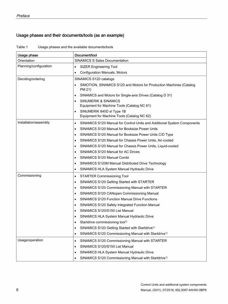
Usage phases and their documents/tools (as an example)
Table 1 Usage phases and the available documents/tools
Usage phase Document/tool Orientation SINAMICS S Sales Documentation Planning/configuration • SIZER Engineering Tool
• Configuration Manuals, Motors
Deciding/ordering SINAMICS S120 catalogs • SIMOTION, SINAMICS S120 and Motors for Production Machines (Catalog
PM 21) • SINAMICS and Motors for Single-axis Drives (Catalog D 31) • SINUMERIK & SINAMICS
Equipment for Machine Tools (Catalog NC 61) • SINUMERIK 840D sl Type 1B
Equipment for Machine Tools (Catalog NC 62)
Installation/assembly • SINAMICS S120 Manual for Control Units and Additional System Components • SINAMICS S120 Manual for Booksize Power Units • SINAMICS S120 Manual for Booksize Power Units C/D Type • SINAMICS S120 Manual for Chassis Power Units, Air-cooled • SINAMICS S120 Manual for Chassis Power Units, Liquid-cooled • SINAMICS S120 Manual for AC Drives • SINAMICS S120 Manual Combi • SINAMICS S120M Manual Distributed Drive Technology • SINAMICS HLA System Manual Hydraulic Drive
Commissioning • STARTER Commissioning Tool • SINAMICS S120 Getting Started with STARTER • SINAMICS S120 Commissioning Manual with STARTER • SINAMICS S120 CANopen Commissioning Manual • SINAMICS S120 Function Manual Drive Functions • SINAMICS S120 Safety Integrated Function Manual • SINAMICS S120/S150 List Manual • SINAMICS HLA System Manual Hydraulic Drive • Startdrive commissioning tool1) • SINAMICS S120 Getting Started with Startdrive1) • SINAMICS S120 Commissioning Manual with Startdrive1)
Usage/operation • SINAMICS S120 Commissioning Manual with STARTER • SINAMICS S120/S150 List Manual • SINAMICS HLA System Manual Hydraulic Drive • SINAMICS S120 Commissioning Manual with Startdrive1)
Preface
Control Units and additional system components Manual, (GH1), 07/2016, 6SL3097-4AH00-0BP6 7
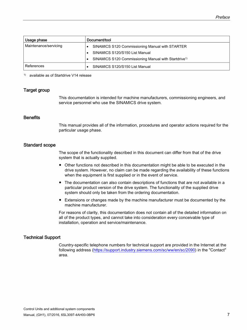
Usage phase Document/tool Maintenance/servicing • SINAMICS S120 Commissioning Manual with STARTER
• SINAMICS S120/S150 List Manual • SINAMICS S120 Commissioning Manual with Startdrive1)
References • SINAMICS S120/S150 List Manual
1) available as of Startdrive V14 release
Target group This documentation is intended for machine manufacturers, commissioning engineers, and service personnel who use the SINAMICS drive system.
Benefits This manual provides all of the information, procedures and operator actions required for the particular usage phase.
Standard scope The scope of the functionality described in this document can differ from that of the drive system that is actually supplied.
Other functions not described in this documentation might be able to be executed in the drive system. However, no claim can be made regarding the availability of these functions when the equipment is first supplied or in the event of service.
The documentation can also contain descriptions of functions that are not available in a particular product version of the drive system. The functionality of the supplied drive system should only be taken from the ordering documentation.
Extensions or changes made by the machine manufacturer must be documented by the machine manufacturer.
For reasons of clarity, this documentation does not contain all of the detailed information on all of the product types, and cannot take into consideration every conceivable type of installation, operation and service/maintenance.
Technical Support Country-specific telephone numbers for technical support are provided in the Internet at the following address (https://support.industry.siemens.com/sc/ww/en/sc/2090) in the "Contact" area.
Preface
Control Units and additional system components 8 Manual, (GH1), 07/2016, 6SL3097-4AH00-0BP6
Relevant directives and standards You can obtain an up-to-date list of currently certified components on request from your local Siemens office. If you have any questions relating to certifications that have not yet been completed, please ask your Siemens contact person.
Certificates for download
The certificates can be downloaded from the Internet:
Certificates (https://support.industry.siemens.com/cs/ww/de/ps/13206/cert)
EC Declaration of Conformity
You can find the EC Declaration of Conformity for the relevant directives as well as the relevant certificates, prototype test certificates, manufacturers declarations and test certificates for functions relating to functional safety ("Safety Integrated") on the Internet at the following address (https://support.industry.siemens.com/cs/ww/en/ps/13231/cert).
The following directives and standards are relevant for SINAMICS S devices:
European low-voltage directive
SINAMICS S devices fulfil the requirements stipulated in the Low-Voltage Directive 2014/35/EU, insofar as they are covered by the application area of this directive.
European machinery directive
SINAMICS S devices fulfil the requirements stipulated in the Low-Voltage Directive 2006/42/EU, insofar as they are covered by the application area of this directive.
However, the use of the SINAMICS S devices in a typical machine application has been fully assessed for compliance with the main regulations in this directive concerning health and safety.
European EMC Directive
SINAMICS S devices comply with the EMC Directive 2014/30/EU.
EMC requirements for South Korea
SINAMICS S devices with the KC marking on the rating plate satisfy the EMC requirements for South Korea.
Specification for semiconductor process equipment voltage drop immunity
SINAMICS S devices meet the requirements of standard SEMI F47-0706.
Eurasian conformity
SINAMICS S comply with the requirements of the Russia/Belarus/Kazakhstan customs union (EAC).
North American market
SINAMICS S devices provided with one of the test symbols displayed fulfil the requirements stipulated for the North American market as a component of drive applications.
Preface
Control Units and additional system components Manual, (GH1), 07/2016, 6SL3097-4AH00-0BP6 9
You can find the relevant certificates on the Internet pages of the certifiers:
For products with UL certificate (http://database.ul.com/cgi-bin/XYV/template/LISEXT/1FRAME/index.html)
For products with TÜV SÜD certificate (https://www.tuev-sued.de/industry_and_consumer_products/certificates)
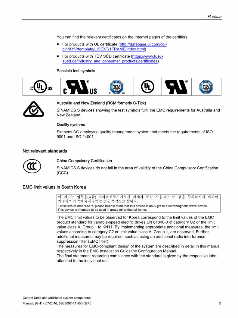
Possible test symbols
Australia and New Zealand (RCM formerly C-Tick)
SINAMICS S devices showing the test symbols fulfil the EMC requirements for Australia and New Zealand.
Quality systems
Siemens AG employs a quality management system that meets the requirements of ISO 9001 and ISO 14001.
Not relevant standards
China Compulsory Certification
SINAMICS S devices do not fall in the area of validity of the China Compulsory Certification (CCC).
EMC limit values in South Korea
The EMC limit values to be observed for Korea correspond to the limit values of the EMC product standard for variable-speed electric drives EN 61800-3 of category C2 or the limit value class A, Group 1 to KN11. By implementing appropriate additional measures, the limit values according to category C2 or limit value class A, Group 1, are observed. Further, additional measures may be required, such as using an additional radio interference suppression filter (EMC filter). The measures for EMC-compliant design of the system are described in detail in this manual respectively in the EMC Installation Guideline Configuration Manual. The final statement regarding compliance with the standard is given by the respective label attached to the individual unit.
Preface
Control Units and additional system components 10 Manual, (GH1), 07/2016, 6SL3097-4AH00-0BP6
Ensuring reliable operation The manual describes a desired state which, if maintained, ensures the required level of operational reliability and compliance with EMC limit values.
Should there be any deviation from the requirements in the manual, appropriate actions (e.g. measurements) must be taken to check/prove that the required level of operational reliability and compliance with EMC limit values are ensured.
Spare parts Spare parts are available on the Internet at the following address (https://www.automation.siemens.com/sow?sap-language=EN).
Product maintenance The components are subject to continuous further development within the scope of product maintenance (improvements to robustness, discontinuations of components, etc).
These further developments are "spare parts-compatible" and do not change the article number.
In the scope of such spare parts-compatible further developments, connector positions are sometimes changed slightly. This does not cause any problems with proper use of the components. Please take this fact into consideration in special installation situations (e.g. allow sufficient clearance for the cable length).
Use of third-party products This document contains recommendations relating to third-party products. Siemens accepts the fundamental suitability of these third-party products.
You can use equivalent products from other manufacturers.
Siemens does not accept any warranty for the properties of third-party products.
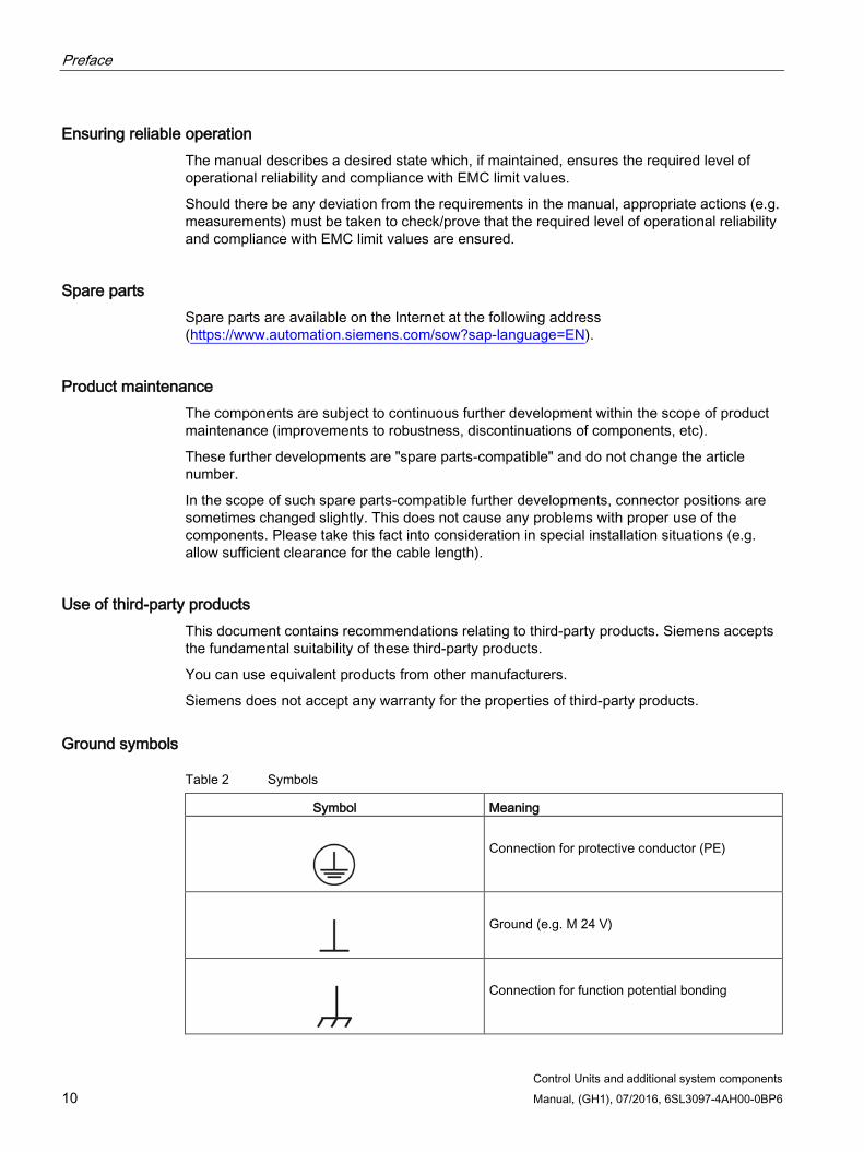
Ground symbols
Table 2 Symbols
Symbol Meaning
Connection for protective conductor (PE)
Ground (e.g. M 24 V)
Connection for function potential bonding
Control Units and additional system components Manual, (GH1), 07/2016, 6SL3097-4AH00-0BP6 11
Table of contents
Preface ................................................................................................................................................... 5
1 Fundamental safety instructions ............................................................................................................ 19
1.1 General safety instructions ..................................................................................................... 19
1.2 Safety instructions for electromagnetic fields (EMF) .............................................................. 23
1.3 Handling electrostatic sensitive devices (ESD) ...................................................................... 23
1.4 Industrial security .................................................................................................................... 24
1.5 Residual risks of power drive systems .................................................................................... 26
2 System overview ................................................................................................................................... 27
2.1 Field of application .................................................................................................................. 27
2.2 Platform Concept and Totally Integrated Automation ............................................................. 28
2.3 Introduction ............................................................................................................................. 30
2.4 SINAMICS S120 components ................................................................................................ 32
2.5 Power units ............................................................................................................................. 34
2.6 System data ............................................................................................................................ 35
2.7 Recycling and disposal ........................................................................................................... 37
3 Control Units and operating elements .................................................................................................... 39
3.1 Introduction ............................................................................................................................. 39
3.2 Safety instructions for Control Units ....................................................................................... 42
3.3 Control Unit CU320-2 PN (PROFINET) .................................................................................. 44 3.3.1 Description .............................................................................................................................. 44 3.3.2 Interface description ................................................................................................................ 45 3.3.2.1 Overview ................................................................................................................................. 45 3.3.2.2 X100-X103 DRIVE-CLiQ interfaces ........................................................................................ 47 3.3.2.3 X122 digital inputs/outputs ...................................................................................................... 48 3.3.2.4 X132 digital inputs/outputs ...................................................................................................... 50 3.3.2.5 X124 electronics power supply ............................................................................................... 52 3.3.2.6 X127 LAN (Ethernet)............................................................................................................... 52 3.3.2.7 X140 serial interface (RS232) ................................................................................................. 54 3.3.2.8 X150 P1/P2 PROFINET.......................................................................................................... 54 3.3.2.9 Measuring socket .................................................................................................................... 55 3.3.2.10 Buttons .................................................................................................................................... 55 3.3.2.11 Slot for memory card ............................................................................................................... 56 3.3.3 Connection example ............................................................................................................... 58 3.3.4 Meaning of the LEDs .............................................................................................................. 59 3.3.4.1 Description of the LED statuses ............................................................................................. 59 3.3.4.2 Behavior of the LEDs during booting ...................................................................................... 59 3.3.4.3 Behavior of the LEDs in the operating state ........................................................................... 60
Table of contents
Control Units and additional system components 12 Manual, (GH1), 07/2016, 6SL3097-4AH00-0BP6
3.3.5 Dimension drawing ................................................................................................................ 62 3.3.6 Technical data ........................................................................................................................ 62
3.4 Control Unit CU320-2 DP (PROFIBUS) ................................................................................. 63 3.4.1 Description ............................................................................................................................. 63 3.4.2 Interface description ............................................................................................................... 64 3.4.2.1 Overview ................................................................................................................................ 64 3.4.2.2 X100-X103 DRIVE-CLiQ interfaces ....................................................................................... 66 3.4.2.3 X122 digital inputs/outputs ..................................................................................................... 67 3.4.2.4 X132 digital inputs/outputs ..................................................................................................... 69 3.4.2.5 X124 electronics power supply .............................................................................................. 71 3.4.2.6 X126 PROFIBUS ................................................................................................................... 72 3.4.2.7 PROFIBUS address switch .................................................................................................... 73 3.4.2.8 X127 LAN (Ethernet) .............................................................................................................. 74 3.4.2.9 X140 serial interface (RS232) ................................................................................................ 75 3.4.2.10 Measuring socket ................................................................................................................... 75 3.4.2.11 Buttons ................................................................................................................................... 76 3.4.2.12 Slot for memory card .............................................................................................................. 76 3.4.3 Connection example .............................................................................................................. 78 3.4.4 Meaning of the LEDs ............................................................................................................. 79 3.4.4.1 Description of the LED statuses ............................................................................................. 79 3.4.4.2 Behavior of the LEDs during booting ..................................................................................... 79 3.4.4.3 Behavior of the LEDs in the operating state .......................................................................... 80 3.4.5 Dimension drawing ................................................................................................................ 82 3.4.6 Technical data ........................................................................................................................ 82
3.5 Mounting Control Units .......................................................................................................... 83 3.5.1 Mounting to a Line Module ..................................................................................................... 83 3.5.2 Mounting on the mounting surface......................................................................................... 85 3.5.3 Opening and removing the cover ........................................................................................... 86
3.6 Basic Operator Panel BOP20 ................................................................................................ 87 3.6.1 Description ............................................................................................................................. 87 3.6.2 Interface description ............................................................................................................... 87 3.6.3 Mounting at the Control Unit .................................................................................................. 90 3.6.4 Removal ................................................................................................................................. 91
4 Option boards ....................................................................................................................................... 93
4.1 Safety instructions for option boards...................................................................................... 93
4.2 CAN Communication Board CBC10 ...................................................................................... 93 4.2.1 Description ............................................................................................................................. 93 4.2.2 Interface description ............................................................................................................... 94 4.2.2.1 Overview ................................................................................................................................ 94 4.2.2.2 X451 CAN bus interface ........................................................................................................ 95 4.2.2.3 X452 CAN bus interface ........................................................................................................ 95 4.2.2.4 2-pin SMD DIL switch ............................................................................................................ 96 4.2.3 Meaning of the OPT LED on the Control Unit ........................................................................ 97 4.2.4 Installation .............................................................................................................................. 98 4.2.5 Technical data ........................................................................................................................ 98
4.3 Communication Board Ethernet CBE20 ................................................................................ 99 4.3.1 Description ............................................................................................................................. 99 4.3.2 Interface description ............................................................................................................... 99 4.3.2.1 Overview ................................................................................................................................ 99
Table of contents
Control Units and additional system components Manual, (GH1), 07/2016, 6SL3097-4AH00-0BP6 13
4.3.2.2 X1400 Ethernet interface ...................................................................................................... 100 4.3.3 Meaning of the LEDs ............................................................................................................ 100 4.3.4 Installation ............................................................................................................................. 103 4.3.5 Technical data ....................................................................................................................... 103
4.4 Terminal Board TB30 ............................................................................................................ 104 4.4.1 Description ............................................................................................................................ 104 4.4.2 Interface description .............................................................................................................. 104 4.4.2.1 Overview ............................................................................................................................... 104 4.4.2.2 X424 power supply, digital outputs ....................................................................................... 105 4.4.2.3 X481 digital inputs/outputs .................................................................................................... 106 4.4.2.4 X482 analog inputs/outputs .................................................................................................. 107 4.4.3 Meaning of the OPT LED on the Control Unit ...................................................................... 108 4.4.4 Connection example ............................................................................................................. 108 4.4.5 Installation ............................................................................................................................. 109 4.4.6 Shield support ....................................................................................................................... 110 4.4.7 Technical data ....................................................................................................................... 110
5 Terminal Modules ............................................................................................................................... 111
5.1 Safety instructions for Terminal Modules.............................................................................. 111
5.2 Terminal Module TM15 ......................................................................................................... 112 5.2.1 Description ............................................................................................................................ 112 5.2.2 Interface description .............................................................................................................. 113 5.2.2.1 Overview ............................................................................................................................... 113 5.2.2.2 X500/X501 DRIVE-CLiQ interfaces ...................................................................................... 114 5.2.2.3 X520 bidirectional digital inputs/outputs ............................................................................... 115 5.2.2.4 X521 bidirectional digital inputs/outputs ............................................................................... 115 5.2.2.5 X522 bidirectional digital inputs/outputs ............................................................................... 116 5.2.2.6 X524 Electronics power supply ............................................................................................. 116 5.2.3 Connection example ............................................................................................................. 117 5.2.4 Meaning of the LED .............................................................................................................. 118 5.2.5 Dimension drawing ............................................................................................................... 119 5.2.6 Mounting ............................................................................................................................... 120 5.2.7 Protective conductor connection and shield support ............................................................ 121 5.2.8 Connector coding .................................................................................................................. 122 5.2.9 Technical data ....................................................................................................................... 123
5.3 Terminal Module TM31 ......................................................................................................... 124 5.3.1 Description ............................................................................................................................ 124 5.3.2 Interface description .............................................................................................................. 125 5.3.2.1 Overview ............................................................................................................................... 125 5.3.2.2 X500/X501 DRIVE-CLiQ interfaces ...................................................................................... 126 5.3.2.3 X520 digital inputs ................................................................................................................. 126 5.3.2.4 X521 analog inputs ............................................................................................................... 127 5.3.2.5 S5 current/voltage changeover switch for analog inputs ...................................................... 128 5.3.2.6 X522 analog outputs/temperature sensor............................................................................. 129 5.3.2.7 X524 Electronics power supply ............................................................................................. 130 5.3.2.8 X530 digital inputs ................................................................................................................. 130 5.3.2.9 X540 auxiliary voltage for the digital inputs .......................................................................... 131 5.3.2.10 X541 bidirectional digital inputs/outputs ............................................................................... 132 5.3.2.11 X542 relay outputs ................................................................................................................ 133 5.3.3 Connection example ............................................................................................................. 134 5.3.4 Meaning of the LED .............................................................................................................. 135
Table of contents
Control Units and additional system components 14 Manual, (GH1), 07/2016, 6SL3097-4AH00-0BP6
5.3.5 Dimension drawing .............................................................................................................. 136 5.3.6 Installation ............................................................................................................................ 137 5.3.7 Protective conductor connection and shield support ........................................................... 138 5.3.8 Connector coding ................................................................................................................. 139 5.3.9 Technical data ...................................................................................................................... 140
5.4 Terminal Module TM41 ........................................................................................................ 140 5.4.1 Description ........................................................................................................................... 140 5.4.2 Interface description ............................................................................................................. 141 5.4.2.1 Overview .............................................................................................................................. 141 5.4.2.2 X500/X501 DRIVE-CLiQ interfaces ..................................................................................... 142 5.4.2.3 X524 electronics power supply ............................................................................................ 142 5.4.2.4 X520 encoder interface ........................................................................................................ 143 5.4.2.5 X521 bidirectional digital inputs/outputs .............................................................................. 144 5.4.2.6 X522 isolated digital inputs .................................................................................................. 145 5.4.2.7 X523 analog input ................................................................................................................ 146 5.4.3 Connection example ............................................................................................................ 147 5.4.4 Meaning of the LEDs ........................................................................................................... 148 5.4.5 Dimension drawing .............................................................................................................. 149 5.4.6 Installation ............................................................................................................................ 150 5.4.7 Protective conductor connection and shield support ........................................................... 151 5.4.8 Technical data ...................................................................................................................... 152
5.5 Terminal Module TM54F ...................................................................................................... 152 5.5.1 Description ........................................................................................................................... 152 5.5.2 Interface description ............................................................................................................. 154 5.5.2.1 Overview .............................................................................................................................. 154 5.5.2.2 X500/X501 DRIVE-CLiQ interfaces ..................................................................................... 155 5.5.2.3 X514 power supply for digital outputs and sensors ............................................................. 155 5.5.2.4 X520 sensor power supply ................................................................................................... 156 5.5.2.5 X521 fail-safe digital inputs and dynamically adjustable power supply ............................... 156 5.5.2.6 X522 fail-safe digital inputs .................................................................................................. 158 5.5.2.7 X523 fail-safe digital output .................................................................................................. 159 5.5.2.8 X524 electronics power supply ............................................................................................ 160 5.5.2.9 X525 fail-safe digital output .................................................................................................. 161 5.5.2.10 X531 fail-safe digital inputs and dynamically adjustable power supply ............................... 162 5.5.2.11 X532 fail-safe digital inputs .................................................................................................. 163 5.5.2.12 X533 fail-safe digital output .................................................................................................. 165 5.5.2.13 X535 fail-safe digital output .................................................................................................. 166 5.5.3 Connection example ............................................................................................................ 167 5.5.4 Meaning of the LEDs ........................................................................................................... 168 5.5.5 Dimension drawing .............................................................................................................. 170 5.5.6 Installation ............................................................................................................................ 171 5.5.7 Protective conductor connection and shield support ........................................................... 172 5.5.8 Technical data ...................................................................................................................... 173
5.6 Terminal Module TM120 ...................................................................................................... 173 5.6.1 Description ........................................................................................................................... 173 5.6.2 Interface description ............................................................................................................. 174 5.6.2.1 Overview .............................................................................................................................. 174 5.6.2.2 X500/X501 DRIVE-CLiQ interfaces ..................................................................................... 175 5.6.2.3 X521 temperature sensor input ............................................................................................ 175 5.6.2.4 X524 Electronics power supply ............................................................................................ 177 5.6.3 Connection examples .......................................................................................................... 178
Table of contents
Control Units and additional system components Manual, (GH1), 07/2016, 6SL3097-4AH00-0BP6 15
5.6.4 Meaning of the LED .............................................................................................................. 179 5.6.5 Dimension drawing ............................................................................................................... 180 5.6.6 Installation ............................................................................................................................. 181 5.6.7 Protective conductor connection and shield support ............................................................ 182 5.6.8 Technical data ....................................................................................................................... 183
5.7 Terminal Module TM150 ....................................................................................................... 183 5.7.1 Description ............................................................................................................................ 183 5.7.2 Interface description .............................................................................................................. 184 5.7.2.1 Overview ............................................................................................................................... 184 5.7.2.2 X500/X501 DRIVE-CLiQ interfaces ...................................................................................... 185 5.7.2.3 X524 Electronics power supply ............................................................................................. 185 5.7.2.4 X531-X536 temperature sensor inputs ................................................................................. 186 5.7.3 Connection examples ........................................................................................................... 188 5.7.4 Meaning of the LED .............................................................................................................. 190 5.7.5 Dimension drawing ............................................................................................................... 191 5.7.6 Installation ............................................................................................................................. 192 5.7.7 Protective conductor connection and shield support ............................................................ 193 5.7.8 Technical data ....................................................................................................................... 194
6 Hub Modules ....................................................................................................................................... 195
6.1 Safety instructions for Hub Modules ..................................................................................... 195
6.2 DRIVE-CLiQ Hub Module DMC20 ........................................................................................ 196 6.2.1 Description ............................................................................................................................ 196 6.2.2 Interface description .............................................................................................................. 197 6.2.2.1 Overview ............................................................................................................................... 197 6.2.2.2 X500-X505 DRIVE-CLiQ interfaces ...................................................................................... 198 6.2.2.3 X524 Electronics power supply ............................................................................................. 198 6.2.3 Meaning of the LED .............................................................................................................. 199 6.2.4 Dimension drawing ............................................................................................................... 200 6.2.5 Installation ............................................................................................................................. 201 6.2.6 Protective conductor connection and shield support ............................................................ 203 6.2.7 Technical data ....................................................................................................................... 204
6.3 DRIVE-CLiQ Hub Module External DME20 .......................................................................... 204 6.3.1 Description ............................................................................................................................ 204 6.3.2 Interface description .............................................................................................................. 205 6.3.2.1 Overview ............................................................................................................................... 205 6.3.2.2 X500-X505 DRIVE-CLiQ interfaces ...................................................................................... 206 6.3.2.3 X524 Electronics power supply ............................................................................................. 206 6.3.3 Dimension drawing ............................................................................................................... 208 6.3.4 Installation ............................................................................................................................. 209 6.3.5 Technical data ....................................................................................................................... 209 6.3.6 Specifications for use with UL approval ................................................................................ 210
7 Voltage Sensing Module VSM10 ......................................................................................................... 211
7.1 Description ............................................................................................................................ 211
7.2 Safety instructions for the Voltage Sensing Module (VSM10) .............................................. 212
7.3 Interface description .............................................................................................................. 214 7.3.1 Overview ............................................................................................................................... 214 7.3.2 X500 DRIVE-CLiQ interface ................................................................................................. 215 7.3.3 X520 analog inputs/temperature sensor ............................................................................... 216
Table of contents
Control Units and additional system components 16 Manual, (GH1), 07/2016, 6SL3097-4AH00-0BP6
7.3.4 X521 three-phase voltage sensing up to 100 V 3-ph. AC ................................................... 217 7.3.5 X522 three-phase voltage sensing up to 690 V 3-ph. AC ................................................... 218 7.3.6 X524 Electronics power supply ............................................................................................ 219 7.3.7 X530 neutral point grounding ............................................................................................... 219
7.4 Connection example ............................................................................................................ 220
7.5 Meaning of the LED ............................................................................................................. 221
7.6 Dimension drawing .............................................................................................................. 222
7.7 Installation ............................................................................................................................ 223
7.8 Protective conductor connection and shield support ........................................................... 224
7.9 Operation on an isolated-neutral system (IT system) .......................................................... 225
7.10 Technical data ...................................................................................................................... 225
7.11 Service and maintenance .................................................................................................... 226
8 Encoder system connection ................................................................................................................. 227
8.1 Introduction .......................................................................................................................... 227
8.2 Overview of Sensor Modules ............................................................................................... 228
8.3 Safety instructions for Sensor Modules and encoders ........................................................ 230
8.4 Sensor Module Cabinet-Mounted SMC10 ........................................................................... 232 8.4.1 Description ........................................................................................................................... 232 8.4.2 Interface description ............................................................................................................. 232 8.4.2.1 Overview .............................................................................................................................. 232 8.4.2.2 X500 DRIVE-CLiQ interface ................................................................................................ 233 8.4.2.3 X520 encoder system interface ........................................................................................... 234 8.4.2.4 X524 Electronics power supply ............................................................................................ 235 8.4.3 Connection example ............................................................................................................ 236 8.4.4 Meaning of the LED ............................................................................................................. 236 8.4.5 Dimension drawing .............................................................................................................. 237 8.4.6 Mounting .............................................................................................................................. 238 8.4.7 Technical data ...................................................................................................................... 239
8.5 Sensor Module Cabinet-Mounted SMC20 ........................................................................... 240 8.5.1 Description ........................................................................................................................... 240 8.5.2 Interface description ............................................................................................................. 241 8.5.2.1 Overview .............................................................................................................................. 241 8.5.2.2 X500 DRIVE-CLiQ interface ................................................................................................ 242 8.5.2.3 X520 encoder system interface ........................................................................................... 243 8.5.2.4 X524 Electronics power supply ............................................................................................ 244 8.5.3 Connection example ............................................................................................................ 245 8.5.4 Meaning of the LED ............................................................................................................. 245 8.5.5 Dimension drawing .............................................................................................................. 246 8.5.6 Mounting .............................................................................................................................. 247 8.5.7 Technical data ...................................................................................................................... 248
8.6 Sensor Module Cabinet-Mounted SMC30 ........................................................................... 249 8.6.1 Description ........................................................................................................................... 249 8.6.2 Interface description ............................................................................................................. 249 8.6.2.1 Overview .............................................................................................................................. 249 8.6.2.2 X500 DRIVE-CLiQ interface ................................................................................................ 250
Table of contents
Control Units and additional system components Manual, (GH1), 07/2016, 6SL3097-4AH00-0BP6 17
8.6.2.3 X520 encoder system interface ............................................................................................ 250 8.6.2.4 X521 / X531 alternative encoder system interface ............................................................... 252 8.6.2.5 X524 Electronics power supply ............................................................................................. 254 8.6.3 Connection examples ........................................................................................................... 254 8.6.4 Meaning of the LEDs ............................................................................................................ 256 8.6.5 Dimension drawing ............................................................................................................... 257 8.6.6 Mounting ............................................................................................................................... 258 8.6.7 Protective conductor connection and shield support ............................................................ 259 8.6.8 Technical data ....................................................................................................................... 259
8.7 Sensor Module Cabinet-Mounted SMC40 ............................................................................ 264 8.7.1 Description ............................................................................................................................ 264 8.7.2 Interface descriptions ............................................................................................................ 265 8.7.2.1 Overview ............................................................................................................................... 265 8.7.2.2 X500/1 and X500/2 DRIVE-CLiQ interfaces ......................................................................... 266 8.7.2.3 X520/1 and X520/2 encoder system interfaces .................................................................... 267 8.7.2.4 X524 Electronics power supply ............................................................................................. 268 8.7.3 Connection example ............................................................................................................. 269 8.7.4 Meaning of the LEDs ............................................................................................................ 270 8.7.5 Dimension drawing ............................................................................................................... 271 8.7.6 Installation ............................................................................................................................. 272 8.7.7 Technical data ....................................................................................................................... 273
8.8 Sensor Module External SME20 ........................................................................................... 274 8.8.1 Description ............................................................................................................................ 274 8.8.2 Interface description .............................................................................................................. 274 8.8.2.1 Overview ............................................................................................................................... 274 8.8.2.2 DRIVE-CLiQ interface ........................................................................................................... 275 8.8.2.3 Encoder system interface ..................................................................................................... 276 8.8.3 Connection example ............................................................................................................. 277 8.8.4 Dimension drawing ............................................................................................................... 277 8.8.5 Installation ............................................................................................................................. 278 8.8.6 Technical data ....................................................................................................................... 278
8.9 Sensor Module External SME25 ........................................................................................... 280 8.9.1 Description ............................................................................................................................ 280 8.9.2 Interface description .............................................................................................................. 280 8.9.2.1 Overview ............................................................................................................................... 280 8.9.2.2 DRIVE-CLiQ interface ........................................................................................................... 281 8.9.2.3 Encoder system interface ..................................................................................................... 282 8.9.3 Connection example ............................................................................................................. 282 8.9.4 Dimension drawing ............................................................................................................... 283 8.9.5 Installation ............................................................................................................................. 283 8.9.6 Technical data ....................................................................................................................... 284
8.10 Sensor Module External SME120 ......................................................................................... 286 8.10.1 Description ............................................................................................................................ 286 8.10.2 Safety instructions for Sensor Modules External .................................................................. 287 8.10.3 Interface description .............................................................................................................. 288 8.10.3.1 Overview ............................................................................................................................... 288 8.10.3.2 X100 encoder system interface ............................................................................................ 288 8.10.3.3 X200 thermistor sensor input ................................................................................................ 289 8.10.3.4 X300 hall sensor input .......................................................................................................... 290 8.10.3.5 X500 DRIVE-CLiQ interface ................................................................................................. 290
Table of contents
Control Units and additional system components 18 Manual, (GH1), 07/2016, 6SL3097-4AH00-0BP6
8.10.4 Connection examples .......................................................................................................... 291 8.10.5 Dimension drawing .............................................................................................................. 296 8.10.6 Installation ............................................................................................................................ 296 8.10.7 Technical data ...................................................................................................................... 297
8.11 Sensor Module External SME125 ........................................................................................ 299 8.11.1 Description ........................................................................................................................... 299 8.11.2 Safety instructions for Sensor Modules External ................................................................. 300 8.11.3 Interface description ............................................................................................................. 301 8.11.3.1 Overview .............................................................................................................................. 301 8.11.3.2 X100 encoder system interface ........................................................................................... 302 8.11.3.3 X200 thermistor sensor input ............................................................................................... 303 8.11.3.4 X500 DRIVE-CLiQ interface ................................................................................................ 304 8.11.4 Connection examples .......................................................................................................... 305 8.11.5 Dimension drawing .............................................................................................................. 310 8.11.6 Installation ............................................................................................................................ 310 8.11.7 Technical data ...................................................................................................................... 311
8.12 DRIVE-CLiQ encoder ........................................................................................................... 313 8.12.1 Description ........................................................................................................................... 313 8.12.2 Interface description ............................................................................................................. 313 8.12.2.1 Overview .............................................................................................................................. 313 8.12.2.2 DRIVE-CLiQ interface .......................................................................................................... 314 8.12.3 Dimension drawings ............................................................................................................. 314 8.12.4 Installation ............................................................................................................................ 316 8.12.5 Technical data ...................................................................................................................... 318
9 Cabinet design and electromagnetic compatibility (EMC) ..................................................................... 319
9.1 Tightening torques for screws and screw connections ........................................................ 319
9.2 Information on control cabinet installation and EMC ........................................................... 320
A Appendix ............................................................................................................................................. 321
A.1 List of abbreviations ............................................................................................................. 321
A.2 Spring-loaded terminals ....................................................................................................... 331
A.3 Screw terminals.................................................................................................................... 331
A.4 Cable lugs ............................................................................................................................ 333
A.5 Documentation overview ...................................................................................................... 334
Index ................................................................................................................................................... 335

Control Units and additional system components Manual, (GH1), 07/2016, 6SL3097-4AH00-0BP6 19
Fundamental safety instructions 1 1.1 General safety instructions
DANGER
Danger to life due to live parts and other energy sources
Death or serious injury can result when live parts are touched. • Only work on electrical devices when you are qualified for this job. • Always observe the country-specific safety rules.
Generally, six steps apply when establishing safety: 1. Prepare for shutdown and notify all those who will be affected by the procedure. 2. Disconnect the machine from the supply.
– Switch off the machine. – Wait until the discharge time specified on the warning labels has elapsed. – Check that it really is in a no-voltage condition, from phase conductor to phase
conductor and phase conductor to protective conductor. – Check whether the existing auxiliary supply circuits are de-energized. – Ensure that the motors cannot move.
3. Identify all other dangerous energy sources, e.g. compressed air, hydraulic systems, or water.
4. Isolate or neutralize all hazardous energy sources by closing switches, grounding or short-circuiting or closing valves, for example.
5. Secure the energy sources against switching on again. 6. Ensure that the correct machine is completely interlocked.
After you have completed the work, restore the operational readiness in the inverse sequence.
WARNING
Danger to life through a hazardous voltage when connecting an unsuitable power supply
Touching live components can result in death or severe injury. • Only use power supplies that provide SELV (Safety Extra Low Voltage) or PELV-
(Protective Extra Low Voltage) output voltages for all connections and terminals of the electronics modules.

Fundamental safety instructions 1.1 General safety instructions
Control Units and additional system components 20 Manual, (GH1), 07/2016, 6SL3097-4AH00-0BP6
WARNING
Danger to life when live parts are touched on damaged devices
Improper handling of devices can cause damage.
For damaged devices, hazardous voltages can be present at the enclosure or at exposed components; if touched, this can result in death or severe injury. • Ensure compliance with the limit values specified in the technical data during transport,
storage and operation. • Do not use any damaged devices.
WARNING
Danger to life through electric shock due to unconnected cable shields
Hazardous touch voltages can occur through capacitive cross-coupling due to unconnected cable shields. • As a minimum, connect cable shields and the conductors of power cables that are not
used (e.g. brake cores) at one end at the grounded housing potential.
WARNING
Danger to life due to electric shock when not grounded
For missing or incorrectly implemented protective conductor connection for devices with protection class I, high voltages can be present at open, exposed parts, which when touched, can result in death or severe injury. • Ground the device in compliance with the applicable regulations.
WARNING
Danger to life due to electric shock when opening plug connections in operation
When opening plug connections in operation, arcs can result in severe injury or death. • Only open plug connections when the equipment is in a no-voltage state, unless it has
been explicitly stated that they can be opened in operation.
Fundamental safety instructions 1.1 General safety instructions
Control Units and additional system components Manual, (GH1), 07/2016, 6SL3097-4AH00-0BP6 21
NOTICE
Material damage due to loose power connections
Insufficient tightening torques or vibrations can result in loose electrical connections. This can result in damage due to fire, device defects or malfunctions. • Tighten all power connections with the specified tightening torques, e.g. line supply
connection, motor connection, DC link connections. • Check all power connections at regular intervals. This applies in particular after
transport.
WARNING
Danger to life due to fire spreading if housing is inadequate
Fire and smoke development can cause severe personal injury or material damage. • Install devices without a protective housing in a metal control cabinet (or protect the
device by another equivalent measure) in such a way that contact with fire is prevented. • Ensure that smoke can only escape via controlled and monitored paths.
WARNING
Danger to life through unexpected movement of machines when using mobile wireless devices or mobile phones
Using mobile wireless devices or mobile phones with a transmit power > 1 W closer than approx. 2 m to the components may cause the devices to malfunction, influence the functional safety of machines therefore putting people at risk or causing material damage. • Switch the wireless devices or mobile phones off in the immediate vicinity of the
components.
WARNING
Danger to life due to the motor catching fire in the event of insulation overload
There is higher stress on the motor insulation through a ground fault in an IT system. If the insulation fails, it is possible that death or severe injury can occur as a result of smoke and fire. • Use a monitoring device that signals an insulation fault. • Correct the fault as quickly as possible so the motor insulation is not overloaded.
Fundamental safety instructions 1.1 General safety instructions
Control Units and additional system components 22 Manual, (GH1), 07/2016, 6SL3097-4AH00-0BP6
WARNING
Danger to life due to fire if overheating occurs because of insufficient ventilation clearances
Inadequate ventilation clearances can cause overheating of components with subsequent fire and smoke. This can cause severe injury or even death. This can also result in increased downtime and reduced service lives for devices/systems. • Ensure compliance with the specified minimum clearance as ventilation clearance for
the respective component.
WARNING
Danger of an accident occurring due to missing or illegible warning labels
Missing or illegible warning labels can result in accidents involving death or serious injury. • Check that the warning labels are complete based on the documentation. • Attach any missing warning labels to the components, in the national language if
necessary. • Replace illegible warning labels.
NOTICE
Device damage caused by incorrect voltage/insulation tests
Incorrect voltage/insulation tests can damage the device. • Before carrying out a voltage/insulation check of the system/machine, disconnect the
devices as all converters and motors have been subject to a high voltage test by the manufacturer, and therefore it is not necessary to perform an additional test within the system/machine.
WARNING
Danger to life when safety functions are inactive
Safety functions that are inactive or that have not been adjusted accordingly can cause operational faults on machines that could lead to serious injury or death. • Observe the information in the appropriate product documentation before
commissioning. • Carry out a safety inspection for functions relevant to safety on the entire system,
including all safety-related components. • Ensure that the safety functions used in your drives and automation tasks are adjusted
and activated through appropriate parameterizing. • Perform a function test. • Only put your plant into live operation once you have guaranteed that the functions
relevant to safety are running correctly.
Fundamental safety instructions 1.2 Safety instructions for electromagnetic fields (EMF)
Control Units and additional system components Manual, (GH1), 07/2016, 6SL3097-4AH00-0BP6 23
Note Important safety notices for Safety Integrated functions
If you want to use Safety Integrated functions, you must observe the safety notices in the Safety Integrated manuals.
1.2 Safety instructions for electromagnetic fields (EMF)
WARNING
Danger to life from electromagnetic fields
Electromagnetic fields (EMF) are generated by the operation of electrical power equipment such as transformers, converters or motors.
People with pacemakers or implants are at a special risk in the immediate vicinity of these devices/systems. • Ensure that the persons involved are the necessary distance away (minimum 2 m).
1.3 Handling electrostatic sensitive devices (ESD) Electrostatic sensitive devices (ESD) are individual components, integrated circuits, modules or devices that may be damaged by either electric fields or electrostatic discharge.
NOTICE
Damage through electric fields or electrostatic discharge
Electric fields or electrostatic discharge can cause malfunctions through damaged individual components, integrated circuits, modules or devices. • Only pack, store, transport and send electronic components, modules or devices in their
original packaging or in other suitable materials, e.g conductive foam rubber of aluminum foil.
• Only touch components, modules and devices when you are grounded by one of the following methods: – Wearing an ESD wrist strap – Wearing ESD shoes or ESD grounding straps in ESD areas with conductive flooring
• Only place electronic components, modules or devices on conductive surfaces (table with ESD surface, conductive ESD foam, ESD packaging, ESD transport container).
Fundamental safety instructions 1.4 Industrial security
Control Units and additional system components 24 Manual, (GH1), 07/2016, 6SL3097-4AH00-0BP6
1.4 Industrial security
Note Industrial security
Siemens provides products and solutions with industrial security functions that support the secure operation of plants, solutions, machines, equipment and/or networks. They are important components in a holistic industrial security concept. With this in mind, Siemens’ products and solutions undergo continuous development. Siemens recommends strongly that you regularly check for product updates.
For the secure operation of Siemens products and solutions, it is necessary to take suitable preventive action (e.g. cell protection concept) and integrate each component into a holistic, state-of-the-art industrial security concept. Third-party products that may be in use should also be considered. For more information about industrial security, visit this address (http://www.siemens.com/industrialsecurity).
To stay informed about product updates as they occur, sign up for a product-specific newsletter. For more information, visit this address (http://support.automation.siemens.com).
WARNING
Danger as a result of unsafe operating states resulting from software manipulation
Software manipulation (e.g. by viruses, Trojan horses, malware, worms) can cause unsafe operating states to develop in your installation which can result in death, severe injuries and/or material damage. • Keep the software up to date.
You will find relevant information and newsletters at this address (http://support.automation.siemens.com).
• Incorporate the automation and drive components into a holistic, state-of-the-art industrial security concept for the installation or machine. You will find further information at this address (http://www.siemens.com/industrialsecurity).
• Make sure that you include all installed products into the holistic industrial security concept.

Fundamental safety instructions 1.4 Industrial security
Control Units and additional system components Manual, (GH1), 07/2016, 6SL3097-4AH00-0BP6 25
WARNING
Danger to life due to software manipulation when using exchangeable storage media
Storing files onto exchangeable storage media amounts to an increased risk of infection, e.g. with viruses and malware. As a result of incorrect parameterization, machines can malfunction, which in turn can lead to injuries or death. • Protect files stored on exchangeable storage media from malicious software by taking
suitable protection measures, e.g. virus scanners.

Fundamental safety instructions 1.5 Residual risks of power drive systems
Control Units and additional system components 26 Manual, (GH1), 07/2016, 6SL3097-4AH00-0BP6
1.5 Residual risks of power drive systems When assessing the machine- or system-related risk in accordance with the respective local regulations (e.g., EC Machinery Directive), the machine manufacturer or system installer must take into account the following residual risks emanating from the control and drive components of a drive system:
1. Unintentional movements of driven machine or system components during commissioning, operation, maintenance, and repairs caused by, for example,
– Hardware and/or software errors in the sensors, control system, actuators, and cables and connections
– Response times of the control system and of the drive
– Operation and/or environmental conditions outside the specification
– Condensation/conductive contamination
– Parameterization, programming, cabling, and installation errors
– Use of wireless devices/mobile phones in the immediate vicinity of electronic components
– External influences/damage
– X-ray, ionizing radiation and cosmic radiation
2. Unusually high temperatures, including open flames, as well as emissions of light, noise, particles, gases, etc., can occur inside and outside the components under fault conditions caused by, for example:
– Component failure
– Software errors
– Operation and/or environmental conditions outside the specification
– External influences/damage
3. Hazardous shock voltages caused by, for example:
– Component failure
– Influence during electrostatic charging
– Induction of voltages in moving motors
– Operation and/or environmental conditions outside the specification
– Condensation/conductive contamination
– External influences/damage
4. Electrical, magnetic and electromagnetic fields generated in operation that can pose a risk to people with a pacemaker, implants or metal replacement joints, etc., if they are too close
5. Release of environmental pollutants or emissions as a result of improper operation of the system and/or failure to dispose of components safely and correctly
For more information about the residual risks of the drive system components, see the relevant sections in the technical user documentation.

Control Units and additional system components Manual, (GH1), 07/2016, 6SL3097-4AH00-0BP6 27
System overview 2 2.1 Field of application
SINAMICS is the family of drives from Siemens designed for machine and plant engineering applications. SINAMICS offers solutions for all drive tasks:
Simple pump and fan applications in the process industry.
Complex single drives in centrifuges, presses, extruders, elevators, as well as conveyor and transport systems
Drive line-ups in textile, plastic film, and paper machines as well as in rolling mill plants
High-precision servo drives in the manufacture of wind turbines
Highly dynamic servo drives for machine tools, as well as packaging and printing machines
Figure 2-1 SINAMICS applications
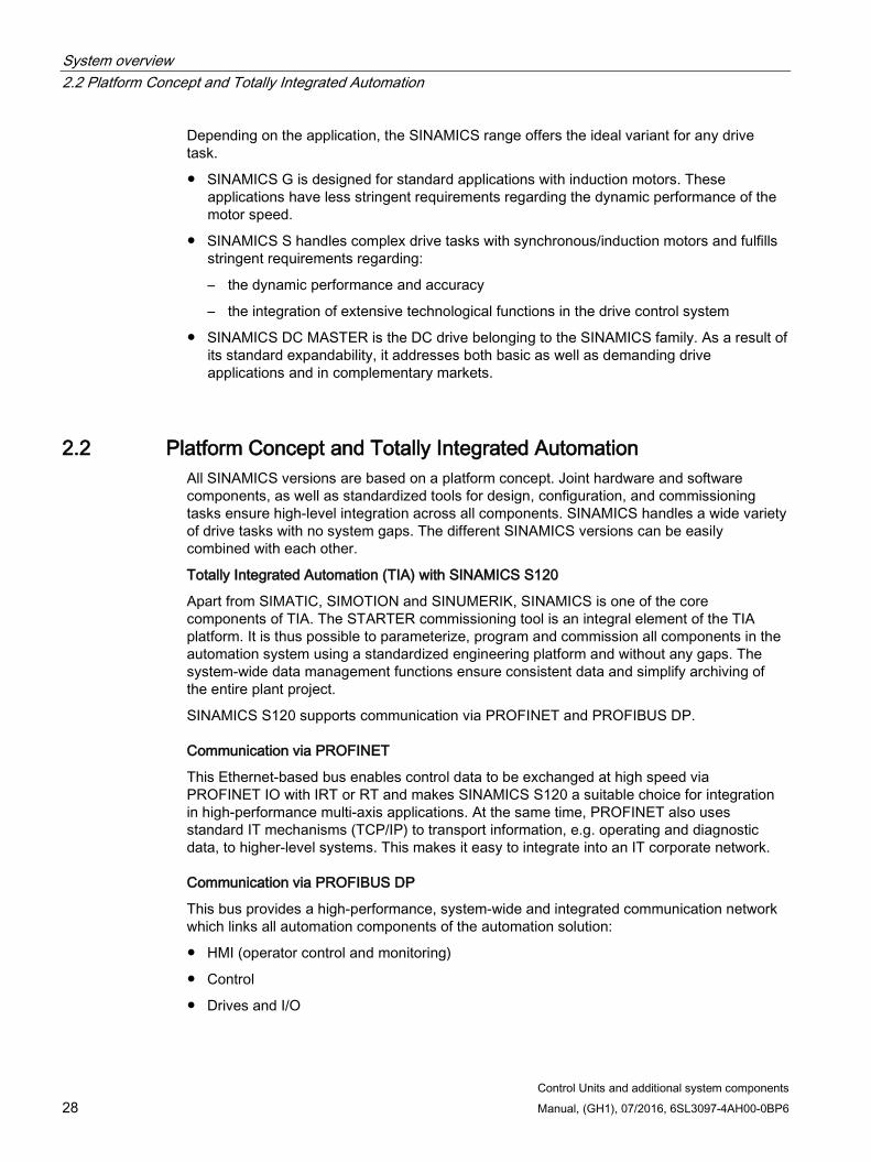
System overview 2.2 Platform Concept and Totally Integrated Automation
Control Units and additional system components 28 Manual, (GH1), 07/2016, 6SL3097-4AH00-0BP6
Depending on the application, the SINAMICS range offers the ideal variant for any drive task.
SINAMICS G is designed for standard applications with induction motors. These applications have less stringent requirements regarding the dynamic performance of the motor speed.
SINAMICS S handles complex drive tasks with synchronous/induction motors and fulfills stringent requirements regarding:
– the dynamic performance and accuracy
– the integration of extensive technological functions in the drive control system
SINAMICS DC MASTER is the DC drive belonging to the SINAMICS family. As a result of its standard expandability, it addresses both basic as well as demanding drive applications and in complementary markets.
2.2 Platform Concept and Totally Integrated Automation All SINAMICS versions are based on a platform concept. Joint hardware and software components, as well as standardized tools for design, configuration, and commissioning tasks ensure high-level integration across all components. SINAMICS handles a wide variety of drive tasks with no system gaps. The different SINAMICS versions can be easily combined with each other.
Totally Integrated Automation (TIA) with SINAMICS S120
Apart from SIMATIC, SIMOTION and SINUMERIK, SINAMICS is one of the core components of TIA. The STARTER commissioning tool is an integral element of the TIA platform. It is thus possible to parameterize, program and commission all components in the automation system using a standardized engineering platform and without any gaps. The system-wide data management functions ensure consistent data and simplify archiving of the entire plant project.
SINAMICS S120 supports communication via PROFINET and PROFIBUS DP.
Communication via PROFINET
This Ethernet-based bus enables control data to be exchanged at high speed via PROFINET IO with IRT or RT and makes SINAMICS S120 a suitable choice for integration in high-performance multi-axis applications. At the same time, PROFINET also uses standard IT mechanisms (TCP/IP) to transport information, e.g. operating and diagnostic data, to higher-level systems. This makes it easy to integrate into an IT corporate network.
Communication via PROFIBUS DP
This bus provides a high-performance, system-wide and integrated communication network which links all automation components of the automation solution:
HMI (operator control and monitoring)
Control
Drives and I/O
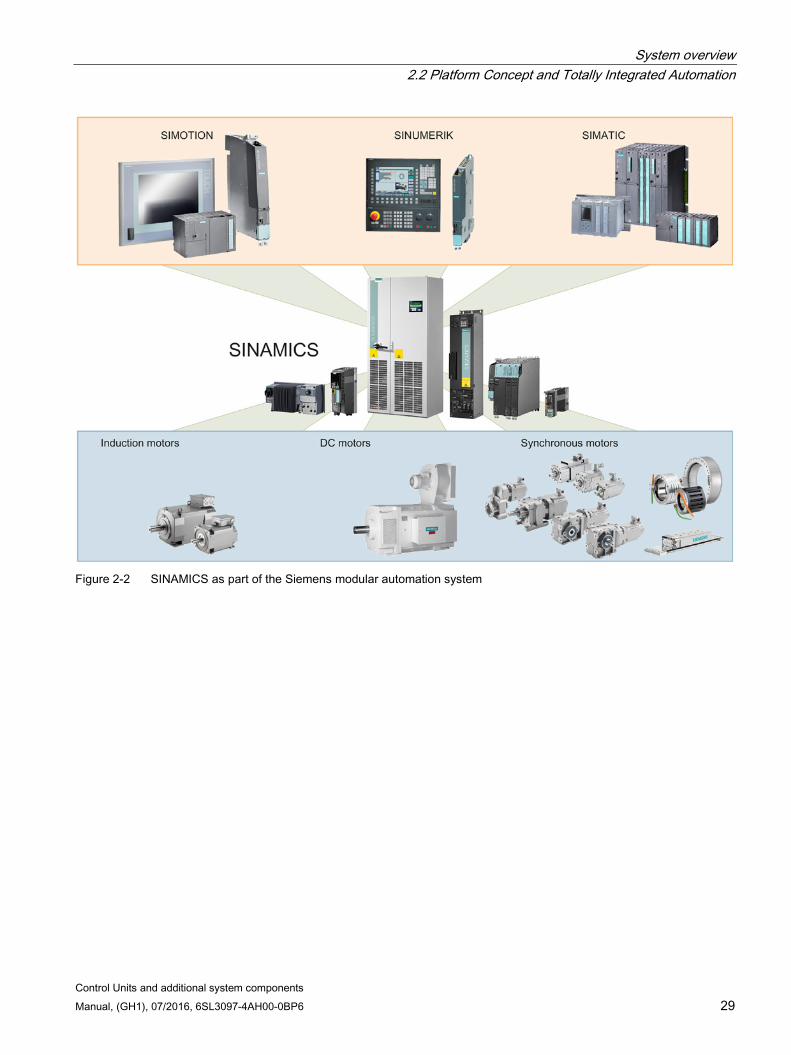
System overview 2.2 Platform Concept and Totally Integrated Automation
Control Units and additional system components Manual, (GH1), 07/2016, 6SL3097-4AH00-0BP6 29
Figure 2-2 SINAMICS as part of the Siemens modular automation system
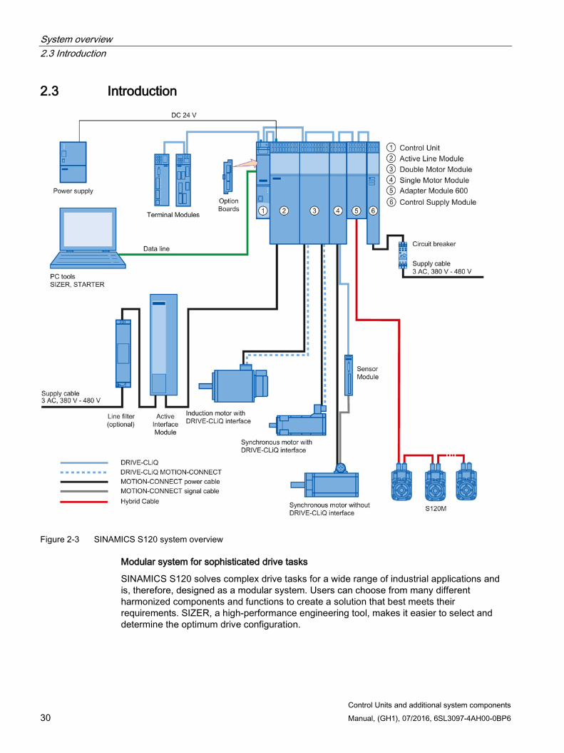
System overview 2.3 Introduction
Control Units and additional system components 30 Manual, (GH1), 07/2016, 6SL3097-4AH00-0BP6
2.3 Introduction
Figure 2-3 SINAMICS S120 system overview
Modular system for sophisticated drive tasks
SINAMICS S120 solves complex drive tasks for a wide range of industrial applications and is, therefore, designed as a modular system. Users can choose from many different harmonized components and functions to create a solution that best meets their requirements. SIZER, a high-performance engineering tool, makes it easier to select and determine the optimum drive configuration.

System overview 2.3 Introduction
Control Units and additional system components Manual, (GH1), 07/2016, 6SL3097-4AH00-0BP6 31
SINAMICS S120 is supplemented by a wide range of motors. Whether torque, synchronous or induction motors, whether rotating or linear motors, all of these motors are optimally supported by SINAMICS S120.
System architecture with a central Control Unit
On the SINAMICS S120, the drive intelligence is combined with closed-loop control functions into Control Units. These units are capable of controlling drives in the vector, servo and V/f modes. They also perform the speed and torque control functions plus other intelligent drive functions for all axes on the drive. Inter-axis connections can be established within a component and easily configured in the STARTER commissioning tool using a mouse.
Functions for higher efficiency
Basic functions: Speed control, torque control, positioning functions
Intelligent starting functions for independent restart after power supply interruption
BICO technology with interconnection of drive-related I/Os for easy adaptation of the drive system to its operating environment
Integrated safety functions for rational implementation of safety concepts
Regulated infeed/regenerative feedback functions for preventing undesirable reactions on the supply, allowing recovery of braking energy and ensuring greater stability against line fluctuations.
DRIVE-CLiQ – the digital interface between SINAMICS components
Most of the SINAMICS S120 components, including the motors and encoders, are connected to each other via the common DRIVE-CLiQ serial interface. The standardized cables and connectors reduce the variety of different parts and cut storage costs. Encoder evaluations for converting standard encoder signals to DRIVE-CLiQ are available for third-party motors or retrofit applications.
Electronic rating plates in all components
An important digital linkage element of the SINAMICS S120 drive system are the electronic type plates integrated in every component. They allow all drive components to be detected automatically via a DRIVE-CLiQ link. As a result, data does not have to be entered manually during commissioning or component replacement – helping to ensure that drives are commissioned more reliably.
The rating plate contains all the relevant technical data about that particular component. For motors, these are the parameters of the electrical equivalent circuit diagram and key values of the integrated motor encoder, for example.
In addition to the technical data, the type plate includes logistical data (manufacturer ID, article number and ID). Since this data can be called up electronically on site or remotely, all the components used in a machine can always be individually identified, which helps simplify servicing.
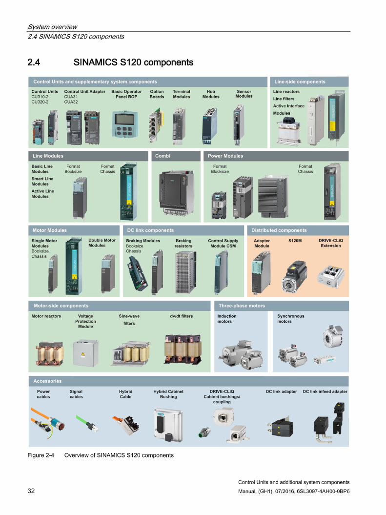
System overview 2.4 SINAMICS S120 components
Control Units and additional system components 32 Manual, (GH1), 07/2016, 6SL3097-4AH00-0BP6
2.4 SINAMICS S120 components
Figure 2-4 Overview of SINAMICS S120 components

System overview 2.4 SINAMICS S120 components
Control Units and additional system components Manual, (GH1), 07/2016, 6SL3097-4AH00-0BP6 33
System components
Line-side power components, such as fuses, contactors, reactors, and filters for switching the power supply and meeting EMC requirements.
Line Modules, which supply power centrally to the DC link
DC link components (optional), which stabilize the DC link voltage.
Motor Modules, which act as inverters, receive power from the DC link, and supply the connected motors
Power components on the motor side, such as reactors and Voltage Protection Modules, which allow output currents and output voltages to be reduced
To carry out the required functions, SINAMICS S120 is equipped with:
Control Units that process the drive and technological functions across all axes
Additional system components to expand the functionality and to handle various interfaces for encoders and process signals
SINAMICS S120 components are intended for installation in cabinets. They have the following features and characteristics:
Easy to handle, simple installation and wiring
Practical connection system, cable routing in accordance with EMC requirements
Standardized design, side-by-side mounting
Note Installation location in the cabinet
As a general rule, SINAMICS S120 components must be mounted vertically in the control cabinet. Other permissible installation locations are given in the descriptions for the individual components.
Booksize format
Booksize format units are optimized for multi-axis applications and are mounted adjacent to one another. The connection for the shared voltage-source DC link is an integral feature.
The booksize format offers various cooling options:
Internal air cooling
External air cooling
Cold plate cooling
Liquid Cooled

System overview 2.5 Power units
Control Units and additional system components 34 Manual, (GH1), 07/2016, 6SL3097-4AH00-0BP6
Booksize compact format
The booksize compact format combines all benefits of the booksize format and provides the same performance with an even smaller overall height. The booksize compact format is thus particularly well suited for integration into machines with high dynamic requirements and confined installation conditions.
The booksize compact format offers the following cooling options:
Internal air cooling
Cold plate cooling
2.5 Power units
Line Modules Generating a DC voltage for the DC link from the 3-phase line voltage.
Basic Line Modules Basic Line Modules generate an uncontrolled DC link voltage and are not capable of energy recovery.
Smart Line Modules Smart Line Modules generate an uncontrolled DC link voltage and are capable of energy recovery.
Active Line Modules Active Line Modules generate a controlled DC link voltage and are capable of energy recovery.
Motor Modules Convert energy from the DC link for the connected motors with variable voltage and variable frequency.
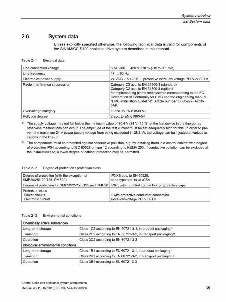
System overview 2.6 System data
Control Units and additional system components Manual, (GH1), 07/2016, 6SL3097-4AH00-0BP6 35
2.6 System data Unless explicitly specified otherwise, the following technical data is valid for components of the SINAMICS S120 booksize drive system described in this manual.
Table 2- 1 Electrical data
Line connection voltage 3 AC 380 … 480 V ±10 % (-15 % < 1 min) Line frequency 47 … 63 Hz Electronics power supply 24 VDC -15/+20% 1), protective extra low voltage PELV or SELV Radio interference suppression Category C3 acc. to EN 61800-3 (standard)
Category C2 acc. to EN 61800-3 (option) for implementing plants and systems corresponding to the EC Declaration of Conformity for EMC and the engineering manual "EMC installation guideline", Article number: 6FC5297-.AD30-0AP.
Overvoltage category III acc. to EN 61800-5-1 Pollution degree 2 acc. to EN 61800-52) 1) The supply voltage may not fall below the minimum value of 20.4 V (24 V -15 %) at the last device in the line-up, as
otherwise malfunctions can occur. The amplitude of the test current must be set adequately high for this. In order to pre-vent the maximum 24 V power supply voltage from being exceeded (= 28.8 V), the voltage can be injected at various lo-cations in the line-up.
2) The components must be protected against conductive pollution, e.g. by installing them in a control cabinet with degree of protection IP54 according to IEC 60529 or type 12 according to NEMA 250. If conductive pollution can be excluded at the installation site, a lower degree of cabinet protection may be permitted.
Table 2- 2 Degree of protection / protection class
Degree of protection (with the exception of SME20/25/120/125, DME20)
IPXXB acc. to EN 60529, open type acc. to UL/CSA
Degree of protection for SME20/25/120/125 and DME20 IP67, with mounted connectors or protective caps Protection class Power circuits Electronic circuits
I, with protective conductor connection extra-low-voltage PELV/SELV
Table 2- 3 Environmental conditions
Chemically active substances Long-term storage Class 1C2 according to EN 60721-3-1, in product packaging1) Transport Class 2C2 according to EN 60721-3-2, in transport packaging2) Operation Class 3C2 according to EN 60721-3-3 Biological environmental conditions Long-term storage Class 1B1 according to EN 60721-3-1, in product packaging1) Transport Class 2B1 according to EN 60721-3-2, in transport packaging2) Operation Class 3B1 according to EN 60721-3-3
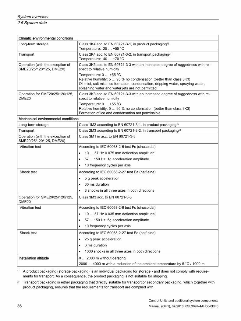
System overview 2.6 System data
Control Units and additional system components 36 Manual, (GH1), 07/2016, 6SL3097-4AH00-0BP6
Climatic environmental conditions Long-term storage Class 1K4 acc. to EN 60721-3-1, in product packaging1)
Temperature: -25 … +55 °C Transport Class 2K4 acc. to EN 60721-3-2, in transport packaging2)
Temperature: -40 … +70 °C Operation (with the exception of SME20/25/120/125, DME20)
Class 3K3 acc. to EN 60721-3-3 with an increased degree of ruggedness with re-spect to relative humidity Temperature: 0 … +55 °C Relative humidity: 5 … 95 % no condensation (better than class 3K3) Oil mist, salt mist, ice formation, condensation, dripping water, spraying water, splashing water and water jets are not permitted
Operation for SME20/25/120/125, DME20
Class 3K3 acc. to EN 60721-3-3 with an increased degree of ruggedness with re-spect to relative humidity Temperature: 0 … +55 °C Relative humidity: 5 … 95 % no condensation (better than class 3K3) Formation of ice and condensation not permissible
Mechanical environmental conditions Long-term storage Class 1M2 according to EN 60721-3-1, in product packaging1) Transport Class 2M3 according to EN 60721-3-2, in transport packaging2) Operation (with the exception of SME20/25/120/125, DME20)
Class 3M1 in acc. to EN 60721-3-3
Vibration test According to IEC 60068-2-6 test Fc (sinusoidal) • 10 … 57 Hz 0.075 mm deflection amplitude • 57 ... 150 Hz: 1g acceleration amplitude • 10 frequency cycles per axis
Shock test According to IEC 60068-2-27 test Ea (half-sine) • 5 g peak acceleration • 30 ms duration • 3 shocks in all three axes in both directions
Operation for SME20/25/120/125, DME20
Class 3M3 acc. to EN 60721-3-3
Vibration test According to IEC 60068-2-6 test Fc (sinusoidal) • 10 … 57 Hz 0.035 mm deflection amplitude • 57 ... 150 Hz: 5g acceleration amplitude • 10 frequency cycles per axis
Shock test According to IEC 60068-2-27 test Ea (half-sine) • 25 g peak acceleration • 6 ms duration • 1000 shocks in all three axes in both directions
Installation altitude 0 … 2000 m without derating 2000 … 4000 m with a reduction of the ambient temperature by 5 °C / 1000 m
1) A product packaging (storage packaging) is an individual packaging for storage - and does not comply with require-ments for transport. As a consequence, the product packaging is not suitable for shipping.
2) Transport packaging is either packaging that directly suitable for transport or secondary packaging, which together with product packaging, ensures that the requirements for transport are complied with.
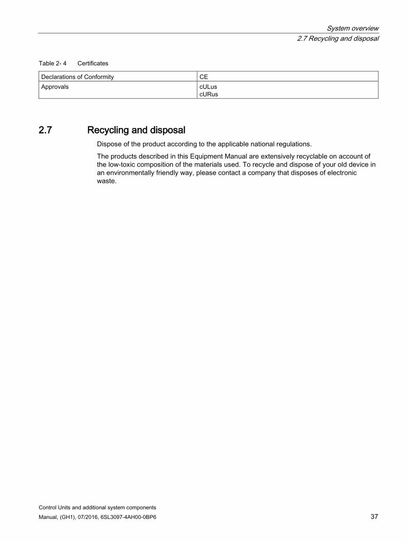
System overview 2.7 Recycling and disposal
Control Units and additional system components Manual, (GH1), 07/2016, 6SL3097-4AH00-0BP6 37
Table 2- 4 Certificates
Declarations of Conformity CE Approvals cULus
cURus
2.7 Recycling and disposal Dispose of the product according to the applicable national regulations.
The products described in this Equipment Manual are extensively recyclable on account of the low-toxic composition of the materials used. To recycle and dispose of your old device in an environmentally friendly way, please contact a company that disposes of electronic waste.

System overview 2.7 Recycling and disposal
Control Units and additional system components 38 Manual, (GH1), 07/2016, 6SL3097-4AH00-0BP6
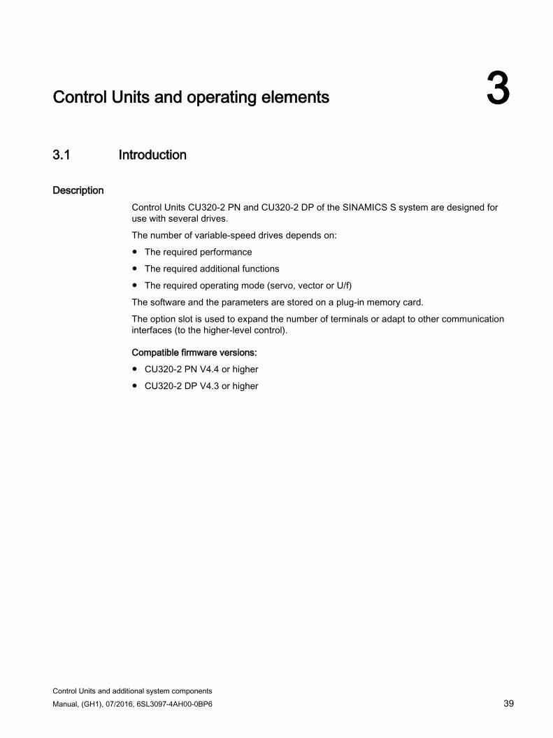
Control Units and additional system components Manual, (GH1), 07/2016, 6SL3097-4AH00-0BP6 39
Control Units and operating elements 3 3.1 Introduction
Description Control Units CU320-2 PN and CU320-2 DP of the SINAMICS S system are designed for use with several drives.
The number of variable-speed drives depends on:
The required performance
The required additional functions
The required operating mode (servo, vector or U/f)
The software and the parameters are stored on a plug-in memory card.
The option slot is used to expand the number of terminals or adapt to other communication interfaces (to the higher-level control).
Compatible firmware versions:
CU320-2 PN V4.4 or higher
CU320-2 DP V4.3 or higher
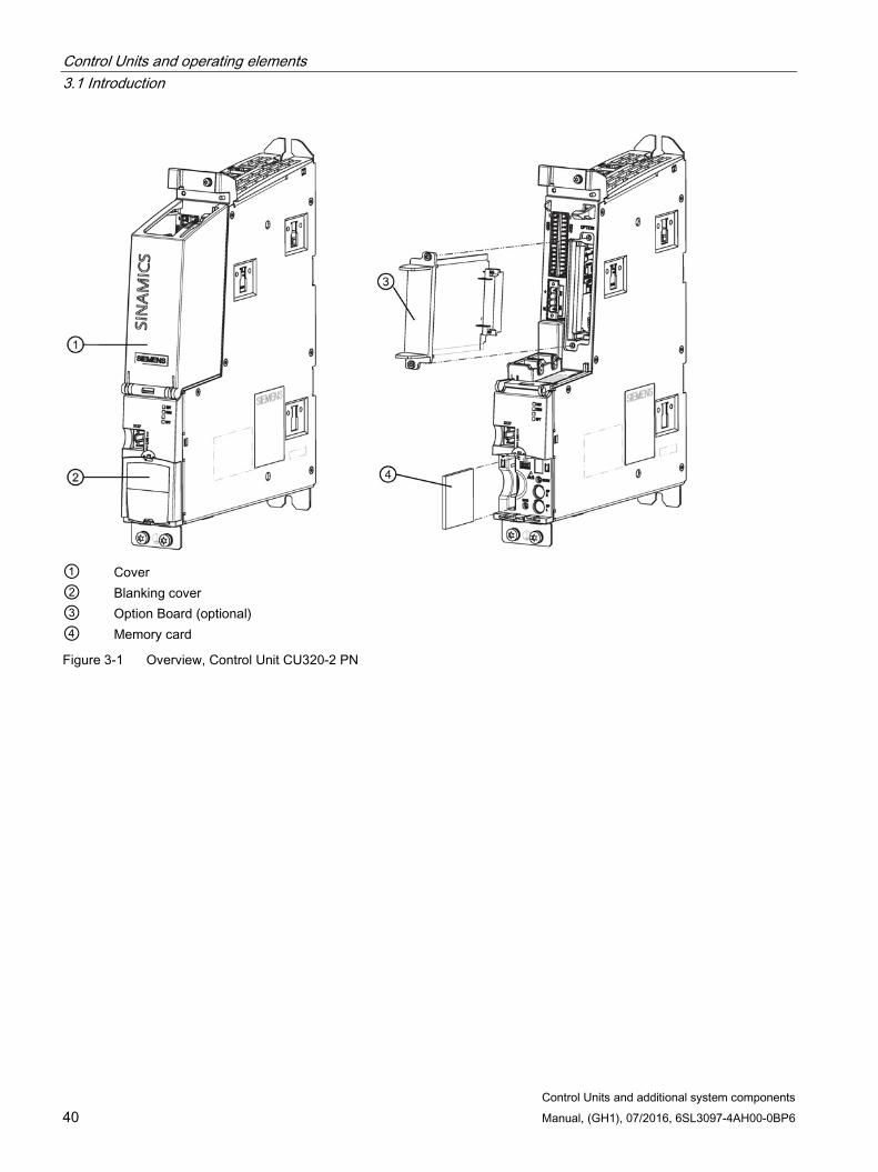
Control Units and operating elements 3.1 Introduction
Control Units and additional system components 40 Manual, (GH1), 07/2016, 6SL3097-4AH00-0BP6
① Cover ② Blanking cover ③ Option Board (optional) ④ Memory card
Figure 3-1 Overview, Control Unit CU320-2 PN
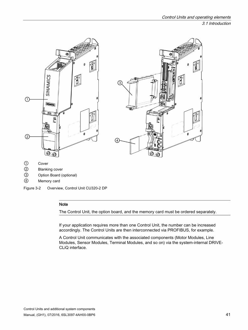
Control Units and operating elements 3.1 Introduction
Control Units and additional system components Manual, (GH1), 07/2016, 6SL3097-4AH00-0BP6 41
① Cover ② Blanking cover ③ Option Board (optional) ④ Memory card
Figure 3-2 Overview, Control Unit CU320-2 DP
Note
The Control Unit, the option board, and the memory card must be ordered separately.
If your application requires more than one Control Unit, the number can be increased accordingly. The Control Units are then interconnected via PROFIBUS, for example.
A Control Unit communicates with the associated components (Motor Modules, Line Modules, Sensor Modules, Terminal Modules, and so on) via the system-internal DRIVE-CLiQ interface.
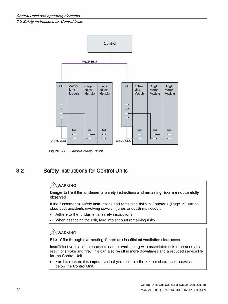
Control Units and operating elements 3.2 Safety instructions for Control Units
Control Units and additional system components 42 Manual, (GH1), 07/2016, 6SL3097-4AH00-0BP6
Figure 3-3 Sample configuration
3.2 Safety instructions for Control Units
WARNING
Danger to life if the fundamental safety instructions and remaining risks are not carefully observed
If the fundamental safety instructions and remaining risks in Chapter 1 (Page 19) are not observed, accidents involving severe injuries or death may occur. • Adhere to the fundamental safety instructions. • When assessing the risk, take into account remaining risks.
WARNING
Risk of fire through overheating if there are insufficient ventilation clearances
Insufficient ventilation clearances lead to overheating with associated risk to persons as a result of smoke and fire. This can also result in more downtimes and a reduced service life for the Control Unit. • For this reason, it is imperative that you maintain the 80 mm clearances above and
below the Control Unit.

Control Units and operating elements 3.2 Safety instructions for Control Units
Control Units and additional system components Manual, (GH1), 07/2016, 6SL3097-4AH00-0BP6 43
NOTICE
Risk of component destruction as a result of high leakage currents
The Control Unit or other PROFIBUS and/or PROFINET nodes can be destroyed, if significant discharge currents flow via the PROFIBUS or PROFINET cable. • A functional equipotential bonding conductor with a cross-section of at least 10 mm²
must be used between components in a system of a plant that are located at a distance from each other.
NOTICE
Malfunctions or damage to the option board by inserting and withdrawing in operation
Withdrawing and inserting the option board in operation can damage it or cause it to malfunction. • Only withdraw or insert the Option Board when the Control Unit is current-free.
NOTICE
Damage through use of incorrect DRIVE-CLiQ cables
Damage or malfunctions can occur on the devices or system when incorrect or unreleased DRIVE-CLiQ cables are used. • Only use suitable DRIVE-CLiQ cables that have been released by Siemens for the
respective application.
Note Malfunctions due to polluted DRIVE-CLiQ interfaces
Malfunctions can occur in the system through the use of polluted DRIVE-CLiQ interfaces. • Cover unused DRIVE-CLiQ interfaces with the supplied blanking covers.
Note Function equipotential bonding for distributed DRIVE-CLiQ nodes
Integrate all of the components that are connected via DRIVE-CLiQ in the functional equipotential bonding concept. The connection should be preferably established by mounting on metallic bare machine and plant components that are connected with one another using an equipotential bonding conductor. Alternatively, you can establish equipotential bonding using a conductor (min. 6 mm²), which as far as possible, is routed in parallel to the DRIVE-CLiQ cable. All distributed DRIVE-CLiQ nodes are involved, for example DME20, SME20, SME25, SME120, SME125 etc.
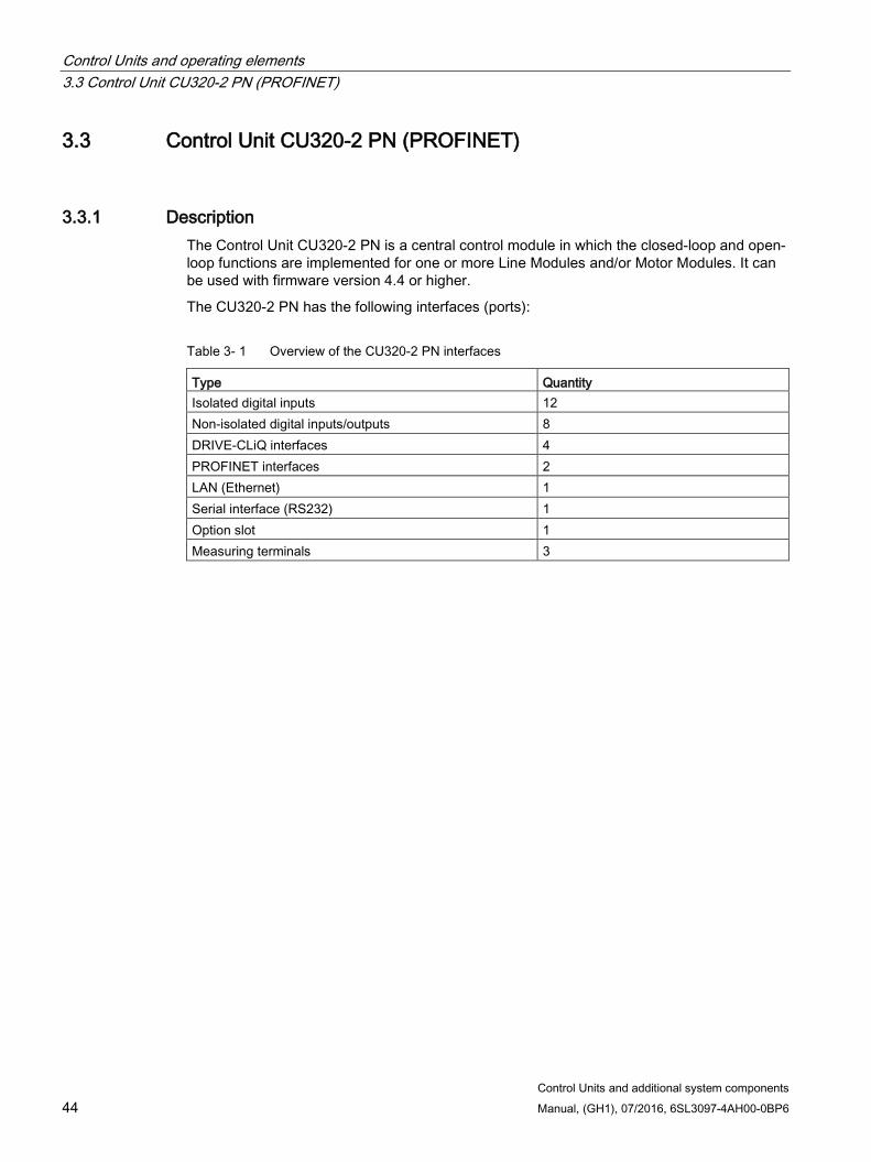
Control Units and operating elements 3.3 Control Unit CU320-2 PN (PROFINET)
Control Units and additional system components 44 Manual, (GH1), 07/2016, 6SL3097-4AH00-0BP6
3.3 Control Unit CU320-2 PN (PROFINET)
3.3.1 Description The Control Unit CU320-2 PN is a central control module in which the closed-loop and open-loop functions are implemented for one or more Line Modules and/or Motor Modules. It can be used with firmware version 4.4 or higher.
The CU320-2 PN has the following interfaces (ports):
Table 3- 1 Overview of the CU320-2 PN interfaces
Type Quantity Isolated digital inputs 12 Non-isolated digital inputs/outputs 8 DRIVE-CLiQ interfaces 4 PROFINET interfaces 2 LAN (Ethernet) 1 Serial interface (RS232) 1 Option slot 1 Measuring terminals 3
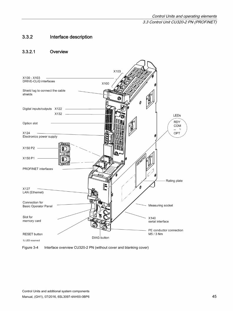
Control Units and operating elements 3.3 Control Unit CU320-2 PN (PROFINET)
Control Units and additional system components Manual, (GH1), 07/2016, 6SL3097-4AH00-0BP6 45
3.3.2 Interface description
3.3.2.1 Overview
Figure 3-4 Interface overview CU320-2 PN (without cover and blanking cover)
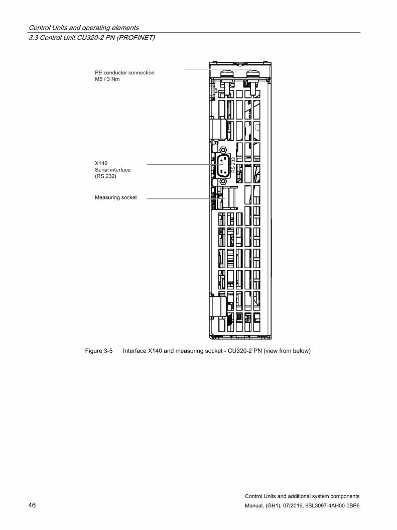
Control Units and operating elements 3.3 Control Unit CU320-2 PN (PROFINET)
Control Units and additional system components 46 Manual, (GH1), 07/2016, 6SL3097-4AH00-0BP6
Figure 3-5 Interface X140 and measuring socket - CU320-2 PN (view from below)
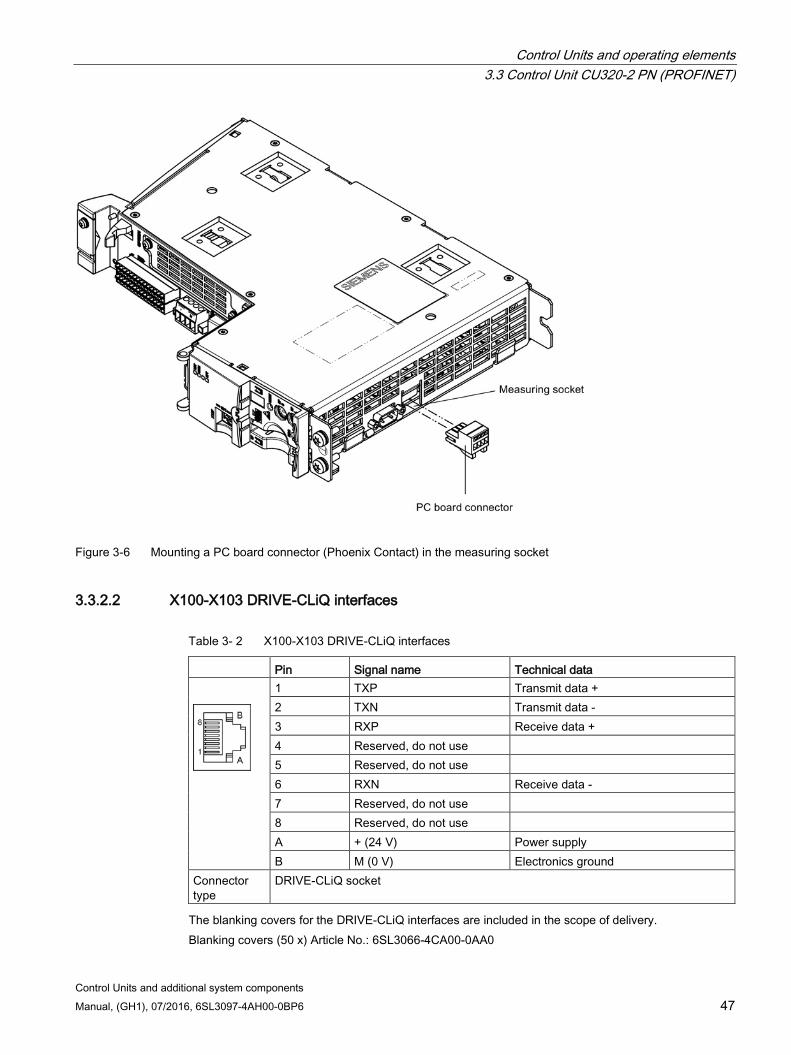
Control Units and operating elements 3.3 Control Unit CU320-2 PN (PROFINET)
Control Units and additional system components Manual, (GH1), 07/2016, 6SL3097-4AH00-0BP6 47
Figure 3-6 Mounting a PC board connector (Phoenix Contact) in the measuring socket
3.3.2.2 X100-X103 DRIVE-CLiQ interfaces
Table 3- 2 X100-X103 DRIVE-CLiQ interfaces
Pin Signal name Technical data
1 TXP Transmit data + 2 TXN Transmit data - 3 RXP Receive data + 4 Reserved, do not use 5 Reserved, do not use 6 RXN Receive data - 7 Reserved, do not use 8 Reserved, do not use A + (24 V) Power supply B M (0 V) Electronics ground
Connector type
DRIVE-CLiQ socket
The blanking covers for the DRIVE-CLiQ interfaces are included in the scope of delivery. Blanking covers (50 x) Article No.: 6SL3066-4CA00-0AA0
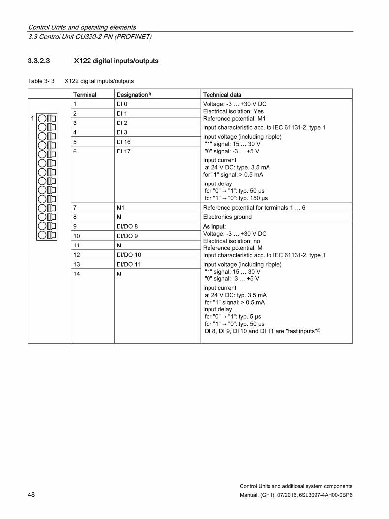
Control Units and operating elements 3.3 Control Unit CU320-2 PN (PROFINET)
Control Units and additional system components 48 Manual, (GH1), 07/2016, 6SL3097-4AH00-0BP6
3.3.2.3 X122 digital inputs/outputs
Table 3- 3 X122 digital inputs/outputs
Terminal Designation1) Technical data
1 DI 0 Voltage: -3 … +30 V DC Electrical isolation: Yes Reference potential: M1 Input characteristic acc. to IEC 61131-2, type 1 Input voltage (including ripple) "1" signal: 15 … 30 V "0" signal: -3 … +5 V Input current at 24 V DC: type. 3.5 mA for "1" signal: > 0.5 mA Input delay for "0" → "1": typ. 50 μs for "1" → "0": typ. 150 µs
2 DI 1 3 DI 2 4 DI 3 5 DI 16 6 DI 17
7 M1 Reference potential for terminals 1 … 6 8 M Electronics ground 9 DI/DO 8 As input:
Voltage: -3 … +30 V DC Electrical isolation: no Reference potential: M Input characteristic acc. to IEC 61131-2, type 1 Input voltage (including ripple) "1" signal: 15 … 30 V "0" signal: -3 … +5 V Input current at 24 V DC: typ. 3.5 mA for "1" signal: > 0.5 mA
Input delay for "0" → "1": typ. 5 μs for "1" → "0": typ. 50 μs DI 8, DI 9, DI 10 and DI 11 are "fast inputs"2)
10 DI/DO 9 11 M 12 DI/DO 10 13 DI/DO 11 14 M

Control Units and operating elements 3.3 Control Unit CU320-2 PN (PROFINET)
Control Units and additional system components Manual, (GH1), 07/2016, 6SL3097-4AH00-0BP6 49
Terminal Designation1) Technical data As output:
Voltage: 24 V DC Electrical isolation: no Reference potential: M Output voltage "1" signal, with load: > X124.+ -2 V Output current for each output: ≤ 0.5 A Sum of all four outputs: ≤ 2 A Residual current for "0" signal: < 0.5 mA Short-circuit protection, automatic restart after a short-circuit Load types: ohmic, capacitive, inductive Output delay3) for "0" → "1": typ. 150 μs / max. 400 μs (ohmic load) for "1" → "0": typ. 75 µs / max. 100 µs (ohmic load) Switching frequency for ohmic load: Max. 100 Hz For inductive load: Max. 0.5 Hz For lamp load: max. 10 Hz Lamp load: max. 5 W
Type: Spring-loaded terminal 3 (Page 331) 1) DI: digital input; DI/DO: bidirectional digital input/output; M: electronics ground; M1: reference potential
2) The rapid inputs can be used as probe inputs or as inputs for the external zero mark. 3) Data for: Vcc = 24 V; load 48 Ω; high ("1") = 90% Vout; low ("0") = 10% Vout
The maximum cable length that can be connected is 30 m.
Note Ensuring the function of digital inputs
An open input is interpreted as "low".
Terminal M1 must be connected so that the digital inputs (DI) can function.
This is achieved by using one of the following measures: 1. Providing the ground reference of the digital inputs 2. A jumper to terminal M
Note: This removes isolation for these digital inputs.
Note
If the 24 V supply is briefly interrupted, then the digital outputs are deactivated during this time.
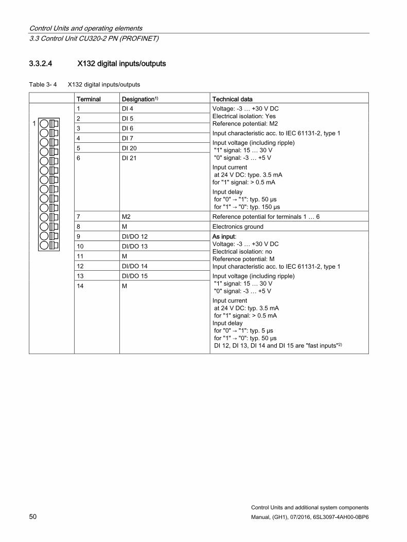
Control Units and operating elements 3.3 Control Unit CU320-2 PN (PROFINET)
Control Units and additional system components 50 Manual, (GH1), 07/2016, 6SL3097-4AH00-0BP6
3.3.2.4 X132 digital inputs/outputs
Table 3- 4 X132 digital inputs/outputs
Terminal Designation1) Technical data
1 DI 4 Voltage: -3 … +30 V DC Electrical isolation: Yes Reference potential: M2 Input characteristic acc. to IEC 61131-2, type 1 Input voltage (including ripple) "1" signal: 15 … 30 V "0" signal: -3 … +5 V Input current at 24 V DC: type. 3.5 mA for "1" signal: > 0.5 mA Input delay for "0" → "1": typ. 50 μs for "1" → "0": typ. 150 µs
2 DI 5 3 DI 6 4 DI 7 5 DI 20 6 DI 21
7 M2 Reference potential for terminals 1 … 6 8 M Electronics ground 9 DI/DO 12 As input:
Voltage: -3 … +30 V DC Electrical isolation: no Reference potential: M Input characteristic acc. to IEC 61131-2, type 1 Input voltage (including ripple) "1" signal: 15 … 30 V "0" signal: -3 … +5 V Input current at 24 V DC: typ. 3.5 mA for "1" signal: > 0.5 mA
Input delay for "0" → "1": typ. 5 μs for "1" → "0": typ. 50 μs DI 12, DI 13, DI 14 and DI 15 are "fast inputs"2)
10 DI/DO 13 11 M 12 DI/DO 14 13 DI/DO 15 14 M
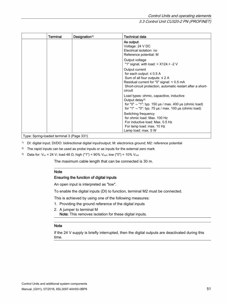
Control Units and operating elements 3.3 Control Unit CU320-2 PN (PROFINET)
Control Units and additional system components Manual, (GH1), 07/2016, 6SL3097-4AH00-0BP6 51
Terminal Designation1) Technical data As output:
Voltage: 24 V DC Electrical isolation: no Reference potential: M Output voltage "1" signal, with load: > X124.+ -2 V Output current for each output: ≤ 0.5 A Sum of all four outputs: ≤ 2 A Residual current for "0" signal: < 0.5 mA Short-circuit protection, automatic restart after a short-circuit Load types: ohmic, capacitive, inductive Output delay3) for "0" → "1": typ. 150 μs / max. 400 μs (ohmic load) for "1" → "0": typ. 75 µs / max. 100 µs (ohmic load) Switching frequency for ohmic load: Max. 100 Hz For inductive load: Max. 0.5 Hz For lamp load: max. 10 Hz Lamp load: max. 5 W
Type: Spring-loaded terminal 3 (Page 331) 1) DI: digital input; DI/DO: bidirectional digital input/output; M: electronics ground; M2: reference potential
2) The rapid inputs can be used as probe inputs or as inputs for the external zero mark 3) Data for: Vcc = 24 V; load 48 Ω; high ("1") = 90% Vout; low ("0") = 10% Vout
The maximum cable length that can be connected is 30 m.
Note Ensuring the function of digital inputs
An open input is interpreted as "low".
To enable the digital inputs (DI) to function, terminal M2 must be connected.
This is achieved by using one of the following measures: 1. Providing the ground reference of the digital inputs 2. A jumper to terminal M
Note: This removes isolation for these digital inputs.
Note
If the 24 V supply is briefly interrupted, then the digital outputs are deactivated during this time.
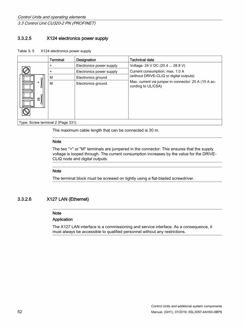
Control Units and operating elements 3.3 Control Unit CU320-2 PN (PROFINET)
Control Units and additional system components 52 Manual, (GH1), 07/2016, 6SL3097-4AH00-0BP6
3.3.2.5 X124 electronics power supply
Table 3- 5 X124 electronics power supply
Terminal Designation Technical data
+ Electronics power supply Voltage: 24 V DC (20.4 ... 28.8 V) Current consumption: max. 1.0 A (without DRIVE-CLiQ or digital outputs) Max. current via jumper in connector: 20 A (15 A ac-cording to UL/CSA)
+ Electronics power supply M Electronics ground M Electronics ground
Type: Screw terminal 2 (Page 331)
The maximum cable length that can be connected is 30 m.
Note
The two "+" or "M" terminals are jumpered in the connector. This ensures that the supply voltage is looped through. The current consumption increases by the value for the DRIVE-CLiQ node and digital outputs.
Note
The terminal block must be screwed on tightly using a flat-bladed screwdriver.
3.3.2.6 X127 LAN (Ethernet)
Note Application
The X127 LAN interface is a commissioning and service interface. As a consequence, it must always be accessible to qualified personnel without any restrictions.
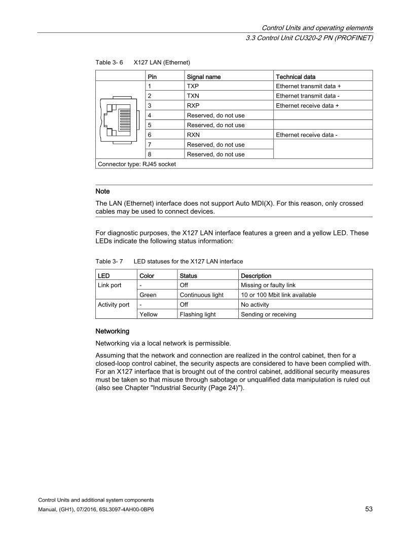
Control Units and operating elements 3.3 Control Unit CU320-2 PN (PROFINET)
Control Units and additional system components Manual, (GH1), 07/2016, 6SL3097-4AH00-0BP6 53
Table 3- 6 X127 LAN (Ethernet)
Pin Signal name Technical data
1 TXP Ethernet transmit data + 2 TXN Ethernet transmit data - 3 RXP Ethernet receive data + 4 Reserved, do not use 5 Reserved, do not use 6 RXN Ethernet receive data - 7 Reserved, do not use 8 Reserved, do not use
Connector type: RJ45 socket
Note
The LAN (Ethernet) interface does not support Auto MDI(X). For this reason, only crossed cables may be used to connect devices.
For diagnostic purposes, the X127 LAN interface features a green and a yellow LED. These LEDs indicate the following status information:
Table 3- 7 LED statuses for the X127 LAN interface
LED Color Status Description Link port - Off Missing or faulty link
Green Continuous light 10 or 100 Mbit link available Activity port - Off No activity
Yellow Flashing light Sending or receiving
Networking
Networking via a local network is permissible.
Assuming that the network and connection are realized in the control cabinet, then for a closed-loop control cabinet, the security aspects are considered to have been complied with. For an X127 interface that is brought out of the control cabinet, additional security measures must be taken so that misuse through sabotage or unqualified data manipulation is ruled out (also see Chapter "Industrial Security (Page 24)").
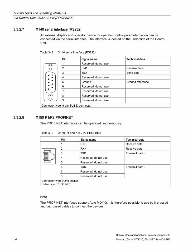
Control Units and operating elements 3.3 Control Unit CU320-2 PN (PROFINET)
Control Units and additional system components 54 Manual, (GH1), 07/2016, 6SL3097-4AH00-0BP6
3.3.2.7 X140 serial interface (RS232) An external display and operator device for operator control/parameterization can be connected via the serial interface. The interface is located on the underside of the Control Unit.
Table 3- 8 X140 serial interface (RS232)
Pin Signal name Technical data
1 Reserved, do not use 2 RxD Receive data 3 TxD Send data 4 Reserved, do not use 5 Ground Ground reference 6 Reserved, do not use 7 Reserved, do not use 8 Reserved, do not use 9 Reserved, do not use
Connector type: 9-pin SUB D connector
3.3.2.8 X150 P1/P2 PROFINET The PROFINET interfaces can be operated isochronously.
Table 3- 9 X150 P1 and X150 P2 PROFINET
Pin Signal name Technical data
1 RXP Receive data + 2 RXN Receive data - 3 TXP Transmit data + 4 Reserved, do not use 5 Reserved, do not use 6 TXN Transmit data - 7 Reserved, do not use 8 Reserved, do not use
Connector type: RJ45 socket Cable type: PROFINET
Note
The PROFINET interfaces support Auto MDI(X). It is therefore possible to use both crossed and uncrossed cables to connect the devices.
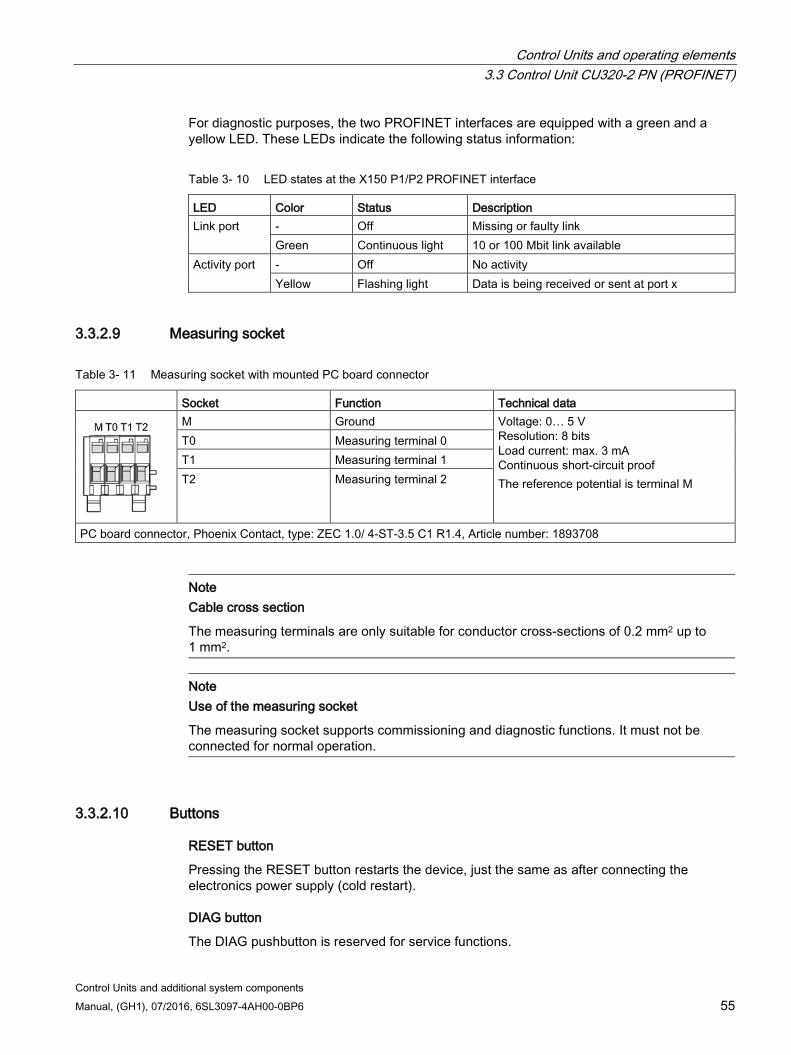
Control Units and operating elements 3.3 Control Unit CU320-2 PN (PROFINET)
Control Units and additional system components Manual, (GH1), 07/2016, 6SL3097-4AH00-0BP6 55
For diagnostic purposes, the two PROFINET interfaces are equipped with a green and a yellow LED. These LEDs indicate the following status information:
Table 3- 10 LED states at the X150 P1/P2 PROFINET interface
LED Color Status Description Link port - Off Missing or faulty link
Green Continuous light 10 or 100 Mbit link available Activity port - Off No activity
Yellow Flashing light Data is being received or sent at port x
3.3.2.9 Measuring socket
Table 3- 11 Measuring socket with mounted PC board connector
Socket Function Technical data
M Ground Voltage: 0… 5 V Resolution: 8 bits Load current: max. 3 mA Continuous short-circuit proof The reference potential is terminal M
T0 Measuring terminal 0 T1 Measuring terminal 1 T2 Measuring terminal 2
PC board connector, Phoenix Contact, type: ZEC 1.0/ 4-ST-3.5 C1 R1.4, Article number: 1893708
Note Cable cross section
The measuring terminals are only suitable for conductor cross-sections of 0.2 mm2 up to 1 mm2.
Note Use of the measuring socket
The measuring socket supports commissioning and diagnostic functions. It must not be connected for normal operation.
3.3.2.10 Buttons
RESET button
Pressing the RESET button restarts the device, just the same as after connecting the electronics power supply (cold restart).
DIAG button
The DIAG pushbutton is reserved for service functions.
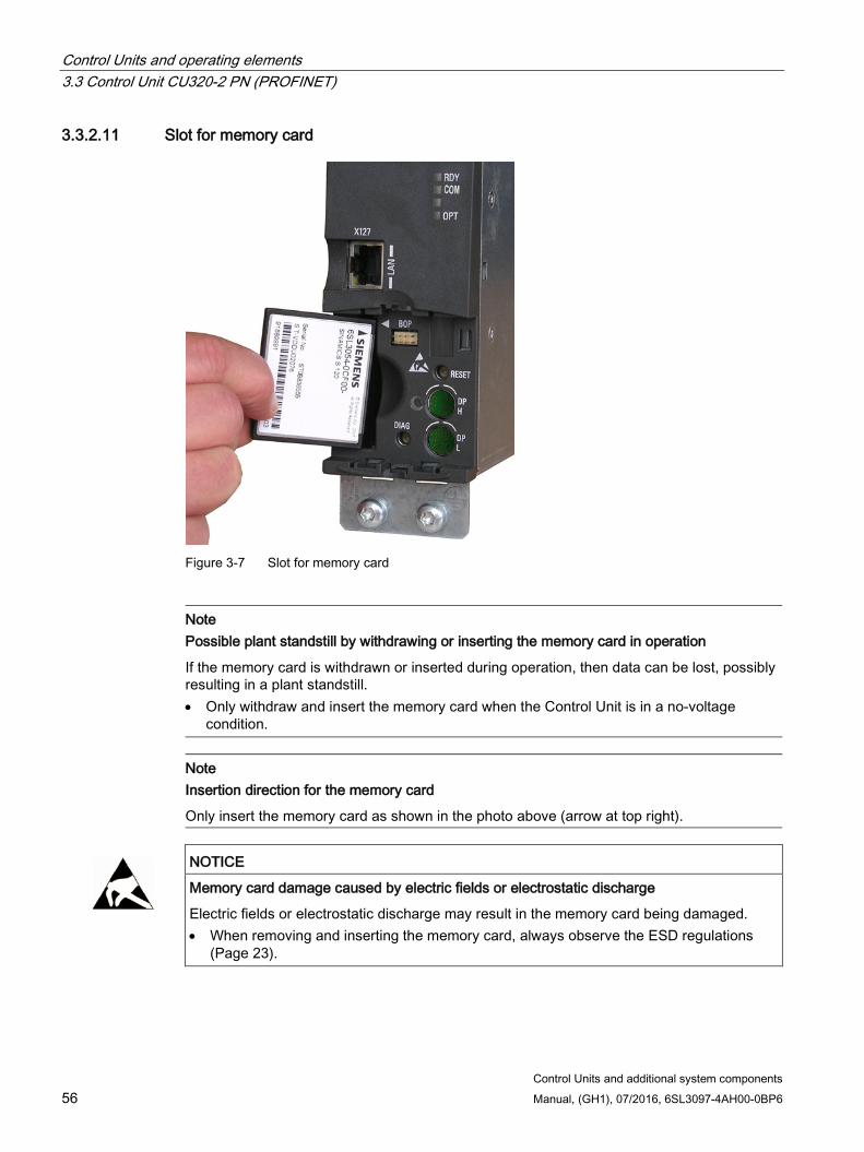
Control Units and operating elements 3.3 Control Unit CU320-2 PN (PROFINET)
Control Units and additional system components 56 Manual, (GH1), 07/2016, 6SL3097-4AH00-0BP6
3.3.2.11 Slot for memory card
Figure 3-7 Slot for memory card
Note Possible plant standstill by withdrawing or inserting the memory card in operation
If the memory card is withdrawn or inserted during operation, then data can be lost, possibly resulting in a plant standstill. • Only withdraw and insert the memory card when the Control Unit is in a no-voltage
condition.
Note Insertion direction for the memory card
Only insert the memory card as shown in the photo above (arrow at top right).
NOTICE
Memory card damage caused by electric fields or electrostatic discharge
Electric fields or electrostatic discharge may result in the memory card being damaged. • When removing and inserting the memory card, always observe the ESD regulations
(Page 23).

Control Units and operating elements 3.3 Control Unit CU320-2 PN (PROFINET)
Control Units and additional system components Manual, (GH1), 07/2016, 6SL3097-4AH00-0BP6 57
Note Possible data loss when returning the Control Unit with memory card
When returning a defective Control Unit for repair or testing, the data on the memory card (parameters, firmware, licenses, etc.) could be lost. • Do not return the memory card as well, but keep it in a safe place so that it can be
inserted in the replacement unit.
Note
Please note that only SIEMENS memory cards can be used to operate the Control Unit.
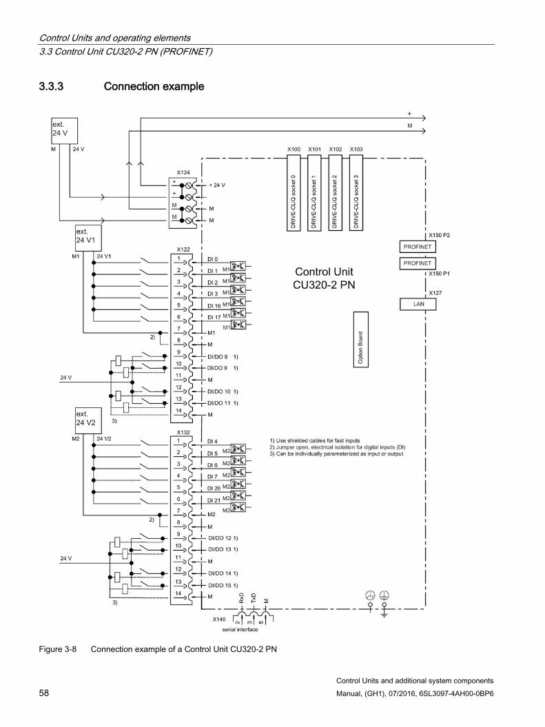
Control Units and operating elements 3.3 Control Unit CU320-2 PN (PROFINET)
Control Units and additional system components 58 Manual, (GH1), 07/2016, 6SL3097-4AH00-0BP6
3.3.3 Connection example
Figure 3-8 Connection example of a Control Unit CU320-2 PN

Control Units and operating elements 3.3 Control Unit CU320-2 PN (PROFINET)
Control Units and additional system components Manual, (GH1), 07/2016, 6SL3097-4AH00-0BP6 59
3.3.4 Meaning of the LEDs
3.3.4.1 Description of the LED statuses The different states during power-up and in operation are indicated by the LEDs on the Control Unit.
The duration of the individual statuses varies.
If an error occurs, the booting procedure is terminated and the cause is indicated accordingly via the LEDs.
Once the unit has successfully booted up, all the LEDs are switched off briefly.
Once the unit has booted up, the LEDs are controlled via the loaded software.
3.3.4.2 Behavior of the LEDs during booting
Table 3- 12 Load software
LED Status Comment RDY COM OPT Red Orange Orange Reset Hardware reset
RDY LED lights up red, all other LEDs light up orange
Red Red Off BIOS loaded – Red flash-ing light 2
Hz
Red Off BIOS error • Error occurred while loading the BIOS
Red flash-ing light 2
Hz
Red flash-ing light 2
Hz
Off File error • Memory card not inserted or defective • Software on memory card not present
or corrupted
Red Orange flashing
light
Off FW loading RDY LED lights up red, COM LED flashes orange without fixed frequency
Red Off Off FW loaded – Off Red Off FW checked
(no CRC error) –
Red flash-ing light 0.5
Hz
Red flash-ing light 0.5
Hz
Off FW checked (CRC error)
• CRC invalid
Table 3- 13 Firmware
LED Status Comment RDY COM OPT
Orange Off Off Initializing – Alternating Running See the table below
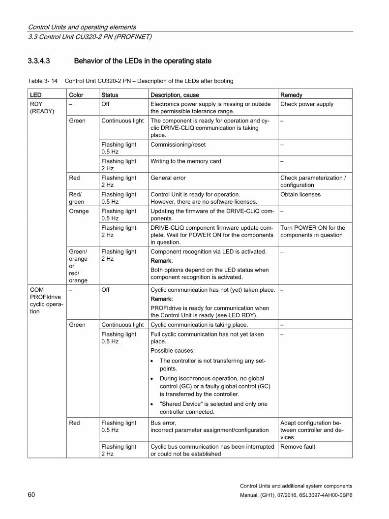
Control Units and operating elements 3.3 Control Unit CU320-2 PN (PROFINET)
Control Units and additional system components 60 Manual, (GH1), 07/2016, 6SL3097-4AH00-0BP6
3.3.4.3 Behavior of the LEDs in the operating state
Table 3- 14 Control Unit CU320-2 PN – Description of the LEDs after booting
LED Color Status Description, cause Remedy RDY (READY)
– Off Electronics power supply is missing or outside the permissible tolerance range.
Check power supply
Green Continuous light The component is ready for operation and cy-clic DRIVE-CLiQ communication is taking place.
–
Flashing light 0.5 Hz
Commissioning/reset –
Flashing light 2 Hz
Writing to the memory card –
Red Flashing light 2 Hz
General error Check parameterization / configuration
Red/ green
Flashing light 0.5 Hz
Control Unit is ready for operation. However, there are no software licenses.
Obtain licenses
Orange Flashing light 0.5 Hz
Updating the firmware of the DRIVE-CLiQ com-ponents
–
Flashing light 2 Hz
DRIVE-CLiQ component firmware update com-plete. Wait for POWER ON for the components in question.
Turn POWER ON for the components in question
Green/ orange or red/ orange
Flashing light 2 Hz
Component recognition via LED is activated. Remark: Both options depend on the LED status when component recognition is activated.
–
COM PROFIdrive cyclic opera-tion
– Off Cyclic communication has not (yet) taken place. Remark: PROFIdrive is ready for communication when the Control Unit is ready (see LED RDY).
–
Green Continuous light Cyclic communication is taking place. – Flashing light 0.5 Hz
Full cyclic communication has not yet taken place. Possible causes: • The controller is not transferring any set-
points. • During isochronous operation, no global
control (GC) or a faulty global control (GC) is transferred by the controller.
• "Shared Device" is selected and only one controller connected.
–
Red Flashing light 0.5 Hz
Bus error, incorrect parameter assignment/configuration
Adapt configuration be-tween controller and de-vices
Flashing light 2 Hz
Cyclic bus communication has been interrupted or could not be established
Remove fault
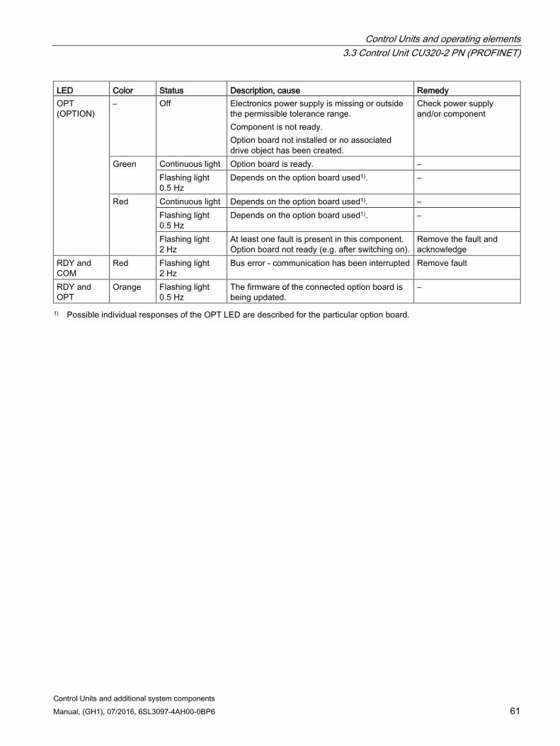
Control Units and operating elements 3.3 Control Unit CU320-2 PN (PROFINET)
Control Units and additional system components Manual, (GH1), 07/2016, 6SL3097-4AH00-0BP6 61
LED Color Status Description, cause Remedy OPT (OPTION)
– Off Electronics power supply is missing or outside the permissible tolerance range. Component is not ready. Option board not installed or no associated drive object has been created.
Check power supply and/or component
Green Continuous light Option board is ready. – Flashing light 0.5 Hz
Depends on the option board used1). –
Red Continuous light Depends on the option board used1). – Flashing light 0.5 Hz
Depends on the option board used1). –
Flashing light 2 Hz
At least one fault is present in this component. Option board not ready (e.g. after switching on).
Remove the fault and acknowledge
RDY and COM
Red Flashing light 2 Hz
Bus error - communication has been interrupted Remove fault
RDY and OPT
Orange Flashing light 0.5 Hz
The firmware of the connected option board is being updated.
–
1) Possible individual responses of the OPT LED are described for the particular option board.

Control Units and operating elements 3.3 Control Unit CU320-2 PN (PROFINET)
Control Units and additional system components 62 Manual, (GH1), 07/2016, 6SL3097-4AH00-0BP6
3.3.5 Dimension drawing
Figure 3-9 Dimension drawing of CU320-2 PN, all data in mm and (inches)
3.3.6 Technical data
Table 3- 15 Technical data
6SL3040-1MA01-0AA0 Unit Value Electronics power supply Voltage Current (without DRIVE-CLiQ and digital outputs) Power loss Total maximum permissible output currents Maximum DRIVE-CLiQ cable length
VDC ADC W A m
24 (20.4 … 28.8) 1.0 24 5.5 100
PE/ground connection At the housing with M5 screw
Control Units and operating elements 3.4 Control Unit CU320-2 DP (PROFIBUS)
Control Units and additional system components Manual, (GH1), 07/2016, 6SL3097-4AH00-0BP6 63
6SL3040-1MA01-0AA0 Unit Value Response time The response time of digital inputs/outputs depends on the
evaluation (refer to the function diagram). Additional information can be taken from the following ref-erences: Reference: /LH1/ SINAMICS S120/S150 List Manual, Chap-ter "Function diagrams/CU320-2 Input/Output terminals"
Weight kg 2.3
3.4 Control Unit CU320-2 DP (PROFIBUS)
3.4.1 Description The Control Unit CU320-2 DP is a central control module in which the closed-loop and open-loop functions are implemented for one or more Line Modules and/or Motor Modules. It can be used with firmware version 4.3 or higher.
The CU320-2 DP has the following interfaces (ports):
Table 3- 16 Overview of the CU320-2 DP interfaces
Type Quantity Isolated digital inputs 12 Non-isolated digital inputs/outputs 8 DRIVE-CLiQ interfaces 4 PROFIBUS interface 1 LAN (Ethernet) 1 Serial interface (RS232) 1 Option slot 1 Measuring terminals 3
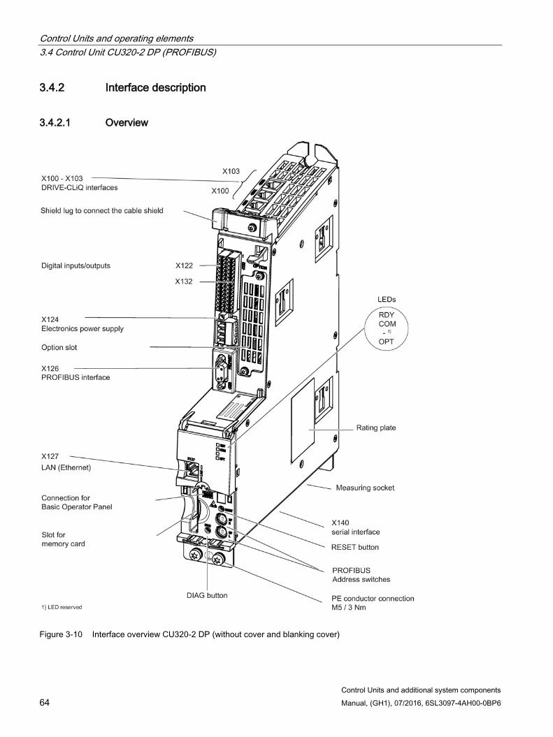
Control Units and operating elements 3.4 Control Unit CU320-2 DP (PROFIBUS)
Control Units and additional system components 64 Manual, (GH1), 07/2016, 6SL3097-4AH00-0BP6
3.4.2 Interface description
3.4.2.1 Overview
Figure 3-10 Interface overview CU320-2 DP (without cover and blanking cover)
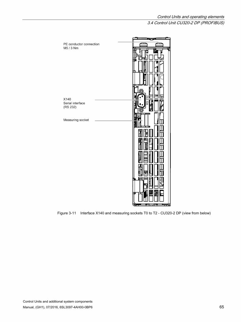
Control Units and operating elements 3.4 Control Unit CU320-2 DP (PROFIBUS)
Control Units and additional system components Manual, (GH1), 07/2016, 6SL3097-4AH00-0BP6 65
Figure 3-11 Interface X140 and measuring sockets T0 to T2 - CU320-2 DP (view from below)
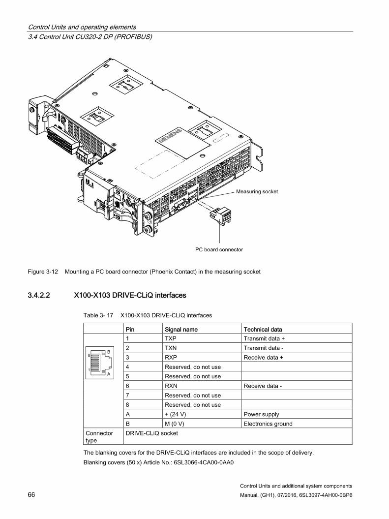
Control Units and operating elements 3.4 Control Unit CU320-2 DP (PROFIBUS)
Control Units and additional system components 66 Manual, (GH1), 07/2016, 6SL3097-4AH00-0BP6
Figure 3-12 Mounting a PC board connector (Phoenix Contact) in the measuring socket
3.4.2.2 X100-X103 DRIVE-CLiQ interfaces
Table 3- 17 X100-X103 DRIVE-CLiQ interfaces
Pin Signal name Technical data
1 TXP Transmit data + 2 TXN Transmit data - 3 RXP Receive data + 4 Reserved, do not use 5 Reserved, do not use 6 RXN Receive data - 7 Reserved, do not use 8 Reserved, do not use A + (24 V) Power supply B M (0 V) Electronics ground
Connector type
DRIVE-CLiQ socket
The blanking covers for the DRIVE-CLiQ interfaces are included in the scope of delivery. Blanking covers (50 x) Article No.: 6SL3066-4CA00-0AA0
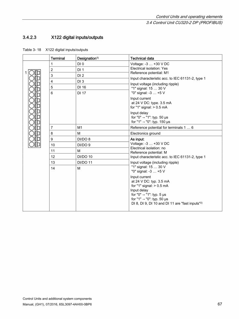
Control Units and operating elements 3.4 Control Unit CU320-2 DP (PROFIBUS)
Control Units and additional system components Manual, (GH1), 07/2016, 6SL3097-4AH00-0BP6 67
3.4.2.3 X122 digital inputs/outputs
Table 3- 18 X122 digital inputs/outputs
Terminal Designation1) Technical data
1 DI 0 Voltage: -3 … +30 V DC Electrical isolation: Yes Reference potential: M1 Input characteristic acc. to IEC 61131-2, type 1 Input voltage (including ripple) "1" signal: 15 … 30 V "0" signal: -3 … +5 V Input current at 24 V DC: type. 3.5 mA for "1" signal: > 0.5 mA Input delay for "0" → "1": typ. 50 μs for "1" → "0": typ. 150 µs
2 DI 1 3 DI 2 4 DI 3 5 DI 16 6 DI 17
7 M1 Reference potential for terminals 1 … 6 8 M Electronics ground 9 DI/DO 8 As input:
Voltage: -3 … +30 V DC Electrical isolation: no Reference potential: M Input characteristic acc. to IEC 61131-2, type 1 Input voltage (including ripple) "1" signal: 15 … 30 V "0" signal: -3 … +5 V Input current at 24 V DC: typ. 3.5 mA for "1" signal: > 0.5 mA
Input delay for "0" → "1": typ. 5 μs for "1" → "0": typ. 50 μs DI 8, DI 9, DI 10 and DI 11 are "fast inputs"2)
10 DI/DO 9 11 M 12 DI/DO 10 13 DI/DO 11 14 M
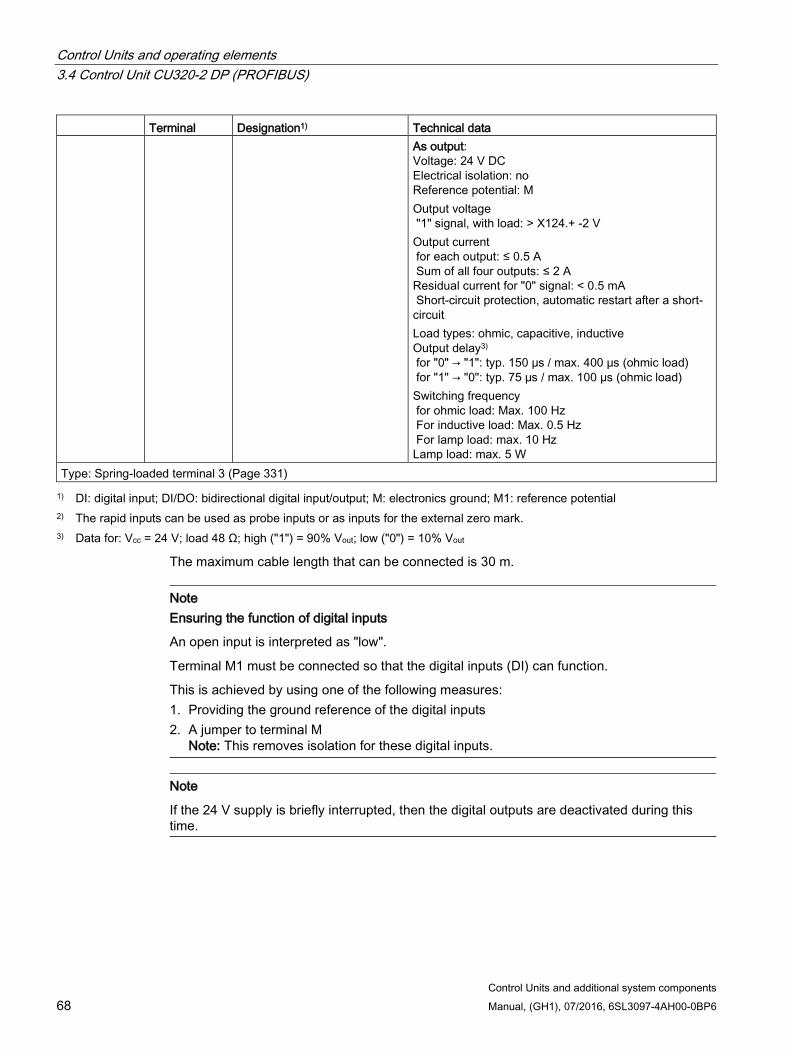
Control Units and operating elements 3.4 Control Unit CU320-2 DP (PROFIBUS)
Control Units and additional system components 68 Manual, (GH1), 07/2016, 6SL3097-4AH00-0BP6
Terminal Designation1) Technical data As output:
Voltage: 24 V DC Electrical isolation: no Reference potential: M Output voltage "1" signal, with load: > X124.+ -2 V Output current for each output: ≤ 0.5 A Sum of all four outputs: ≤ 2 A Residual current for "0" signal: < 0.5 mA Short-circuit protection, automatic restart after a short-circuit Load types: ohmic, capacitive, inductive Output delay3) for "0" → "1": typ. 150 μs / max. 400 μs (ohmic load) for "1" → "0": typ. 75 µs / max. 100 µs (ohmic load) Switching frequency for ohmic load: Max. 100 Hz For inductive load: Max. 0.5 Hz For lamp load: max. 10 Hz Lamp load: max. 5 W
Type: Spring-loaded terminal 3 (Page 331) 1) DI: digital input; DI/DO: bidirectional digital input/output; M: electronics ground; M1: reference potential
2) The rapid inputs can be used as probe inputs or as inputs for the external zero mark. 3) Data for: Vcc = 24 V; load 48 Ω; high ("1") = 90% Vout; low ("0") = 10% Vout
The maximum cable length that can be connected is 30 m.
Note Ensuring the function of digital inputs
An open input is interpreted as "low".
Terminal M1 must be connected so that the digital inputs (DI) can function.
This is achieved by using one of the following measures: 1. Providing the ground reference of the digital inputs 2. A jumper to terminal M
Note: This removes isolation for these digital inputs.
Note
If the 24 V supply is briefly interrupted, then the digital outputs are deactivated during this time.
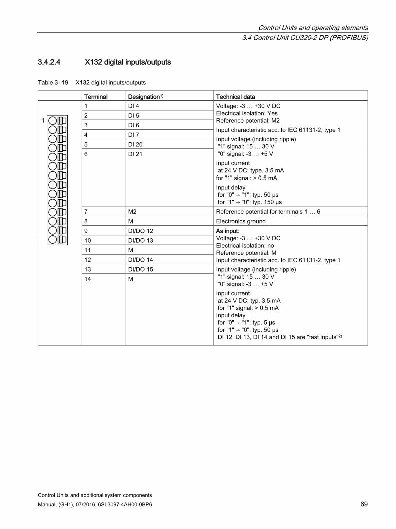
Control Units and operating elements 3.4 Control Unit CU320-2 DP (PROFIBUS)
Control Units and additional system components Manual, (GH1), 07/2016, 6SL3097-4AH00-0BP6 69
3.4.2.4 X132 digital inputs/outputs
Table 3- 19 X132 digital inputs/outputs
Terminal Designation1) Technical data
1 DI 4 Voltage: -3 … +30 V DC Electrical isolation: Yes Reference potential: M2 Input characteristic acc. to IEC 61131-2, type 1 Input voltage (including ripple) "1" signal: 15 … 30 V "0" signal: -3 … +5 V Input current at 24 V DC: type. 3.5 mA for "1" signal: > 0.5 mA Input delay for "0" → "1": typ. 50 μs for "1" → "0": typ. 150 µs
2 DI 5 3 DI 6 4 DI 7 5 DI 20 6 DI 21
7 M2 Reference potential for terminals 1 … 6 8 M Electronics ground 9 DI/DO 12 As input:
Voltage: -3 … +30 V DC Electrical isolation: no Reference potential: M Input characteristic acc. to IEC 61131-2, type 1 Input voltage (including ripple) "1" signal: 15 … 30 V "0" signal: -3 … +5 V Input current at 24 V DC: typ. 3.5 mA for "1" signal: > 0.5 mA
Input delay for "0" → "1": typ. 5 μs for "1" → "0": typ. 50 μs DI 12, DI 13, DI 14 and DI 15 are "fast inputs"2)
10 DI/DO 13 11 M 12 DI/DO 14 13 DI/DO 15 14 M
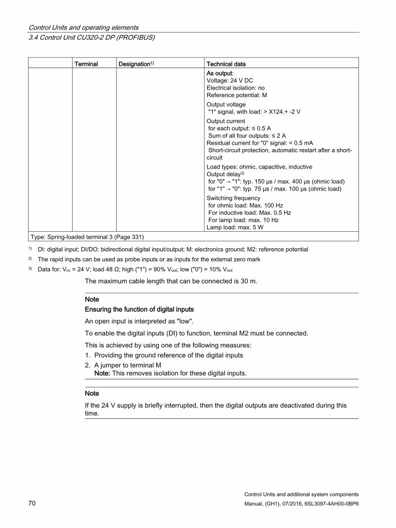
Control Units and operating elements 3.4 Control Unit CU320-2 DP (PROFIBUS)
Control Units and additional system components 70 Manual, (GH1), 07/2016, 6SL3097-4AH00-0BP6
Terminal Designation1) Technical data As output:
Voltage: 24 V DC Electrical isolation: no Reference potential: M Output voltage "1" signal, with load: > X124.+ -2 V Output current for each output: ≤ 0.5 A Sum of all four outputs: ≤ 2 A Residual current for "0" signal: < 0.5 mA Short-circuit protection, automatic restart after a short-circuit Load types: ohmic, capacitive, inductive Output delay3) for "0" → "1": typ. 150 μs / max. 400 μs (ohmic load) for "1" → "0": typ. 75 µs / max. 100 µs (ohmic load) Switching frequency for ohmic load: Max. 100 Hz For inductive load: Max. 0.5 Hz For lamp load: max. 10 Hz Lamp load: max. 5 W
Type: Spring-loaded terminal 3 (Page 331) 1) DI: digital input; DI/DO: bidirectional digital input/output; M: electronics ground; M2: reference potential
2) The rapid inputs can be used as probe inputs or as inputs for the external zero mark 3) Data for: Vcc = 24 V; load 48 Ω; high ("1") = 90% Vout; low ("0") = 10% Vout
The maximum cable length that can be connected is 30 m.
Note Ensuring the function of digital inputs
An open input is interpreted as "low".
To enable the digital inputs (DI) to function, terminal M2 must be connected.
This is achieved by using one of the following measures: 1. Providing the ground reference of the digital inputs 2. A jumper to terminal M
Note: This removes isolation for these digital inputs.
Note
If the 24 V supply is briefly interrupted, then the digital outputs are deactivated during this time.
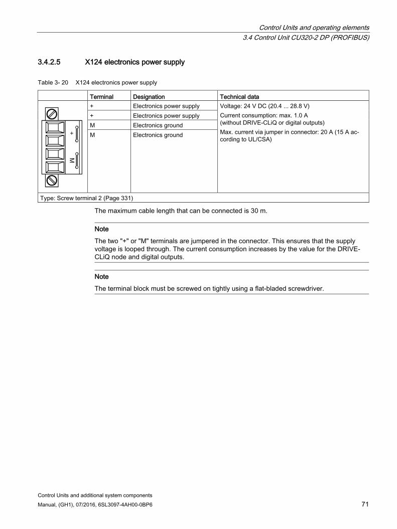
Control Units and operating elements 3.4 Control Unit CU320-2 DP (PROFIBUS)
Control Units and additional system components Manual, (GH1), 07/2016, 6SL3097-4AH00-0BP6 71
3.4.2.5 X124 electronics power supply
Table 3- 20 X124 electronics power supply
Terminal Designation Technical data
+ Electronics power supply Voltage: 24 V DC (20.4 ... 28.8 V) Current consumption: max. 1.0 A (without DRIVE-CLiQ or digital outputs) Max. current via jumper in connector: 20 A (15 A ac-cording to UL/CSA)
+ Electronics power supply M Electronics ground M Electronics ground
Type: Screw terminal 2 (Page 331)
The maximum cable length that can be connected is 30 m.
Note
The two "+" or "M" terminals are jumpered in the connector. This ensures that the supply voltage is looped through. The current consumption increases by the value for the DRIVE-CLiQ node and digital outputs.
Note
The terminal block must be screwed on tightly using a flat-bladed screwdriver.
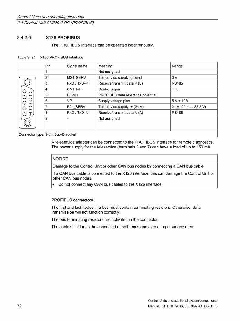
Control Units and operating elements 3.4 Control Unit CU320-2 DP (PROFIBUS)
Control Units and additional system components 72 Manual, (GH1), 07/2016, 6SL3097-4AH00-0BP6
3.4.2.6 X126 PROFIBUS The PROFIBUS interface can be operated isochronously.
Table 3- 21 X126 PROFIBUS interface
Pin Signal name Meaning Range
1 - Not assigned 2 M24_SERV Teleservice supply, ground 0 V 3 RxD / TxD–P Receive/transmit data P (B) RS485 4 CNTR–P Control signal TTL 5 DGND PROFIBUS data reference potential 6 VP Supply voltage plus 5 V ± 10% 7 P24_SERV Teleservice supply, + (24 V) 24 V (20.4 … 28.8 V) 8 RxD / TxD–N Receive/transmit data N (A) RS485 9 - Not assigned
Connector type: 9-pin Sub-D socket
A teleservice adapter can be connected to the PROFIBUS interface for remote diagnostics. The power supply for the teleservice (terminals 2 and 7) can have a load of up to 150 mA.
NOTICE
Damage to the Control Unit or other CAN bus nodes by connecting a CAN bus cable
If a CAN bus cable is connected to the X126 interface, this can damage the Control Unit or other CAN bus nodes. • Do not connect any CAN bus cables to the X126 interface.
PROFIBUS connectors
The first and last nodes in a bus must contain terminating resistors. Otherwise, data transmission will not function correctly.
The bus terminating resistors are activated in the connector.
The cable shield must be connected at both ends and over a large surface area.
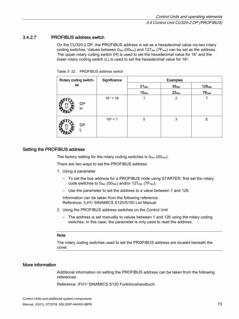
Control Units and operating elements 3.4 Control Unit CU320-2 DP (PROFIBUS)
Control Units and additional system components Manual, (GH1), 07/2016, 6SL3097-4AH00-0BP6 73
3.4.2.7 PROFIBUS address switch On the CU320-2 DP, the PROFIBUS address is set as a hexadecimal value via two rotary coding switches. Values between 0dec (00hex) and 127dec (7Fhex) can be set as the address. The upper rotary coding switch (H) is used to set the hexadecimal value for 161 and the lower rotary coding switch (L) is used to set the hexadecimal value for 160.
Table 3- 22 PROFIBUS address switch
Rotary coding switch-es
Significance Examples 21dec 35dec 126dec 15hex 23hex 7Ehex
161 = 16 1 2 7
160 = 1 5 3 E
Setting the PROFIBUS address The factory setting for the rotary coding switches is 0dec (00hex).
There are two ways to set the PROFIBUS address:
1. Using a parameter
– To set the bus address for a PROFIBUS node using STARTER, first set the rotary code switches to 0dec (00hex) and/or 127dec (7Fhex).
– Use the parameter to set the address to a value between 1 and 126.
Information can be taken from the following reference: Reference: /LH1/ SINAMICS S120/S150 List Manual
2. Using the PROFIBUS address switches on the Control Unit
– The address is set manually to values between 1 and 126 using the rotary coding switches. In this case, the parameter is only used to read the address.
Note
The rotary coding switches used to set the PROFIBUS address are located beneath the cover.
More information Additional information on setting the PROFIBUS address can be taken from the following references:
Reference: /FH1/ SINAMICS S120 Funktionshandbuch
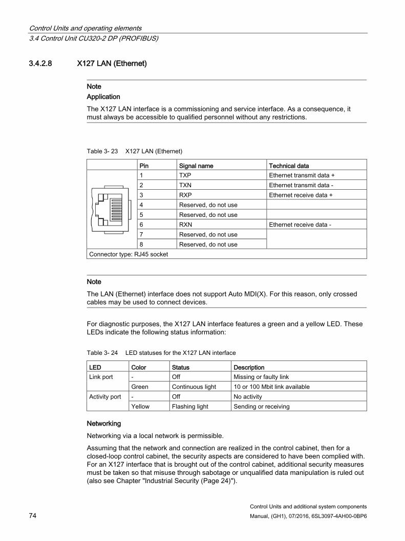
Control Units and operating elements 3.4 Control Unit CU320-2 DP (PROFIBUS)
Control Units and additional system components 74 Manual, (GH1), 07/2016, 6SL3097-4AH00-0BP6
3.4.2.8 X127 LAN (Ethernet)
Note Application
The X127 LAN interface is a commissioning and service interface. As a consequence, it must always be accessible to qualified personnel without any restrictions.
Table 3- 23 X127 LAN (Ethernet)
Pin Signal name Technical data
1 TXP Ethernet transmit data + 2 TXN Ethernet transmit data - 3 RXP Ethernet receive data + 4 Reserved, do not use 5 Reserved, do not use 6 RXN Ethernet receive data - 7 Reserved, do not use 8 Reserved, do not use
Connector type: RJ45 socket
Note
The LAN (Ethernet) interface does not support Auto MDI(X). For this reason, only crossed cables may be used to connect devices.
For diagnostic purposes, the X127 LAN interface features a green and a yellow LED. These LEDs indicate the following status information:
Table 3- 24 LED statuses for the X127 LAN interface
LED Color Status Description Link port - Off Missing or faulty link
Green Continuous light 10 or 100 Mbit link available Activity port - Off No activity
Yellow Flashing light Sending or receiving
Networking
Networking via a local network is permissible.
Assuming that the network and connection are realized in the control cabinet, then for a closed-loop control cabinet, the security aspects are considered to have been complied with. For an X127 interface that is brought out of the control cabinet, additional security measures must be taken so that misuse through sabotage or unqualified data manipulation is ruled out (also see Chapter "Industrial Security (Page 24)").
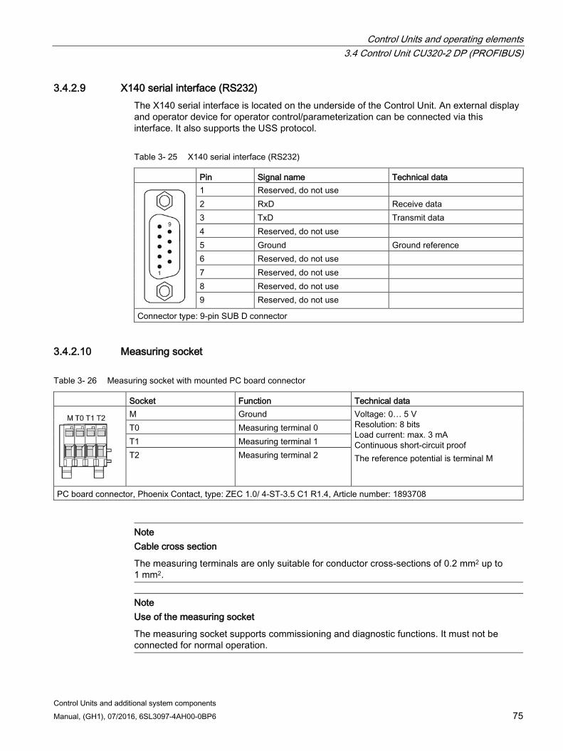
Control Units and operating elements 3.4 Control Unit CU320-2 DP (PROFIBUS)
Control Units and additional system components Manual, (GH1), 07/2016, 6SL3097-4AH00-0BP6 75
3.4.2.9 X140 serial interface (RS232) The X140 serial interface is located on the underside of the Control Unit. An external display and operator device for operator control/parameterization can be connected via this interface. It also supports the USS protocol.
Table 3- 25 X140 serial interface (RS232)
Pin Signal name Technical data
1 Reserved, do not use 2 RxD Receive data 3 TxD Transmit data 4 Reserved, do not use 5 Ground Ground reference 6 Reserved, do not use 7 Reserved, do not use 8 Reserved, do not use 9 Reserved, do not use
Connector type: 9-pin SUB D connector
3.4.2.10 Measuring socket
Table 3- 26 Measuring socket with mounted PC board connector
Socket Function Technical data
M Ground Voltage: 0… 5 V Resolution: 8 bits Load current: max. 3 mA Continuous short-circuit proof The reference potential is terminal M
T0 Measuring terminal 0 T1 Measuring terminal 1 T2 Measuring terminal 2
PC board connector, Phoenix Contact, type: ZEC 1.0/ 4-ST-3.5 C1 R1.4, Article number: 1893708
Note Cable cross section
The measuring terminals are only suitable for conductor cross-sections of 0.2 mm2 up to 1 mm2.
Note Use of the measuring socket
The measuring socket supports commissioning and diagnostic functions. It must not be connected for normal operation.
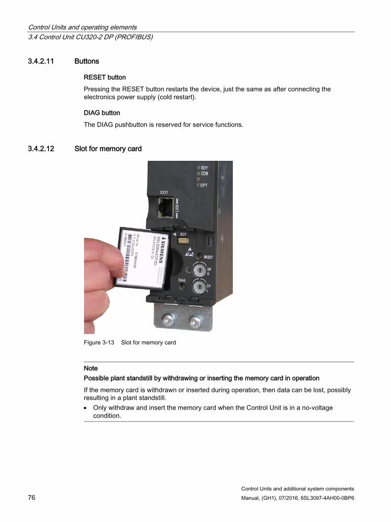
Control Units and operating elements 3.4 Control Unit CU320-2 DP (PROFIBUS)
Control Units and additional system components 76 Manual, (GH1), 07/2016, 6SL3097-4AH00-0BP6
3.4.2.11 Buttons
RESET button
Pressing the RESET button restarts the device, just the same as after connecting the electronics power supply (cold restart).
DIAG button
The DIAG pushbutton is reserved for service functions.
3.4.2.12 Slot for memory card
Figure 3-13 Slot for memory card
Note Possible plant standstill by withdrawing or inserting the memory card in operation
If the memory card is withdrawn or inserted during operation, then data can be lost, possibly resulting in a plant standstill. • Only withdraw and insert the memory card when the Control Unit is in a no-voltage
condition.

Control Units and operating elements 3.4 Control Unit CU320-2 DP (PROFIBUS)
Control Units and additional system components Manual, (GH1), 07/2016, 6SL3097-4AH00-0BP6 77
Note Insertion direction for the memory card
Only insert the memory card as shown in the photo above (arrow at top right).
NOTICE
Memory card damage caused by electric fields or electrostatic discharge
Electrical fields or electrostatic discharge may result in the memory card being damaged. • When removing and inserting the memory card, always observe the ESD regulations
(Page 23).
Note Possible data loss when returning the Control Unit with memory card
When returning a defective Control Unit for repair or testing, the data on the memory card (parameters, firmware, licenses, etc.) could be lost. • Do not return the memory card as well, but keep it in a safe place so that it can be
inserted in the replacement unit.
Note
Please note that only SIEMENS memory cards can be used to operate the Control Unit.
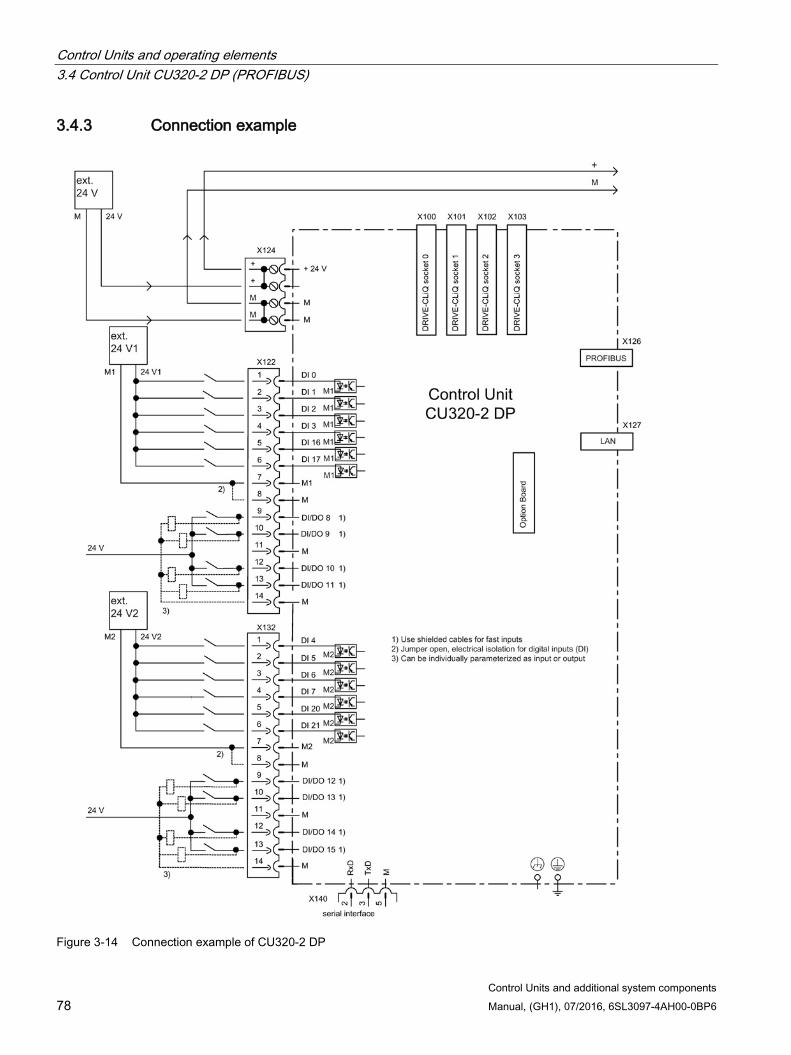
Control Units and operating elements 3.4 Control Unit CU320-2 DP (PROFIBUS)
Control Units and additional system components 78 Manual, (GH1), 07/2016, 6SL3097-4AH00-0BP6
3.4.3 Connection example
Figure 3-14 Connection example of CU320-2 DP
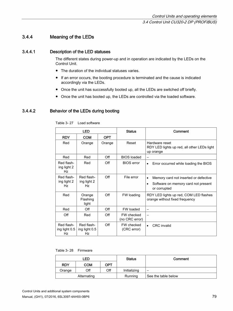
Control Units and operating elements 3.4 Control Unit CU320-2 DP (PROFIBUS)
Control Units and additional system components Manual, (GH1), 07/2016, 6SL3097-4AH00-0BP6 79
3.4.4 Meaning of the LEDs
3.4.4.1 Description of the LED statuses The different states during power-up and in operation are indicated by the LEDs on the Control Unit.
The duration of the individual statuses varies.
If an error occurs, the booting procedure is terminated and the cause is indicated accordingly via the LEDs.
Once the unit has successfully booted up, all the LEDs are switched off briefly.
Once the unit has booted up, the LEDs are controlled via the loaded software.
3.4.4.2 Behavior of the LEDs during booting
Table 3- 27 Load software
LED Status Comment RDY COM OPT Red Orange Orange Reset Hardware reset
RDY LED lights up red, all other LEDs light up orange
Red Red Off BIOS loaded – Red flash-ing light 2
Hz
Red Off BIOS error • Error occurred while loading the BIOS
Red flash-ing light 2
Hz
Red flash-ing light 2
Hz
Off File error • Memory card not inserted or defective • Software on memory card not present
or corrupted
Red Orange Flashing
light
Off FW loading RDY LED lights up red, COM LED flashes orange without fixed frequency
Red Off Off FW loaded – Off Red Off FW checked
(no CRC error) –
Red flash-ing light 0.5
Hz
Red flash-ing light 0.5
Hz
Off FW checked (CRC error)
• CRC invalid
Table 3- 28 Firmware
LED Status Comment RDY COM OPT
Orange Off Off Initializing – Alternating Running See the table below
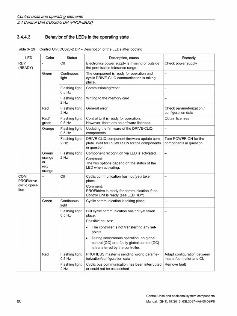
Control Units and operating elements 3.4 Control Unit CU320-2 DP (PROFIBUS)
Control Units and additional system components 80 Manual, (GH1), 07/2016, 6SL3097-4AH00-0BP6
3.4.4.3 Behavior of the LEDs in the operating state
Table 3- 29 Control Unit CU320-2 DP – Description of the LEDs after booting
LED Color Status Description, cause Remedy RDY (READY)
- Off Electronics power supply is missing or outside the permissible tolerance range.
Check power supply
Green Continuous light
The component is ready for operation and cyclic DRIVE-CLiQ communication is taking place.
–
Flashing light 0.5 Hz
Commissioning/reset –
Flashing light 2 Hz
Writing to the memory card –
Red Flashing light 2 Hz
General error Check parameterization / configuration data
Red/ green
Flashing light 0.5 Hz
Control Unit is ready for operation. However, there are no software licenses.
Obtain licenses
Orange Flashing light 0.5 Hz
Updating the firmware of the DRIVE-CLiQ components
–
Flashing light 2 Hz
DRIVE-CLiQ component firmware update com-plete. Wait for POWER ON for the components in question.
Turn POWER ON for the components in question
Green/ orange or red/ orange
Flashing light 2 Hz
Component recognition via LED is activated. Comment: The two options depend on the status of the LED when activating.
–
COM PROFIdrive cyclic opera-tion
– Off Cyclic communication has not (yet) taken place. Comment: PROFIdrive is ready for communication if the Control Unit is ready (see LED RDY).
–
Green Continuous light
Cyclic communication is taking place. –
Flashing light 0.5 Hz
Full cyclic communication has not yet taken place. Possible causes: • The controller is not transferring any set-
points. • During isochronous operation, no global
control (GC) or a faulty global control (GC) is transferred by the controller.
–
Red Flashing light 0.5 Hz
PROFIBUS master is sending wrong parame-terization/configuration data
Adapt configuration between master/controller and CU
Flashing light 2 Hz
Cyclic bus communication has been interrupted or could not be established
Remove fault
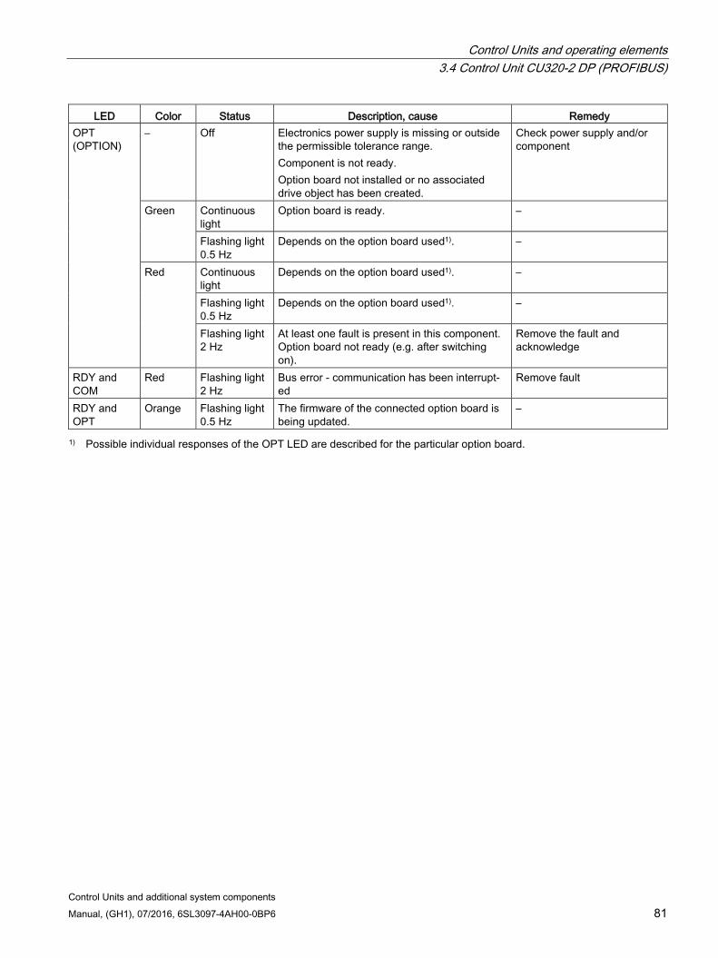
Control Units and operating elements 3.4 Control Unit CU320-2 DP (PROFIBUS)
Control Units and additional system components Manual, (GH1), 07/2016, 6SL3097-4AH00-0BP6 81
LED Color Status Description, cause Remedy OPT (OPTION)
– Off Electronics power supply is missing or outside the permissible tolerance range. Component is not ready. Option board not installed or no associated drive object has been created.
Check power supply and/or component
Green Continuous light
Option board is ready. –
Flashing light 0.5 Hz
Depends on the option board used1). –
Red
Continuous light
Depends on the option board used1). –
Flashing light 0.5 Hz
Depends on the option board used1). –
Flashing light 2 Hz
At least one fault is present in this component. Option board not ready (e.g. after switching on).
Remove the fault and acknowledge
RDY and COM
Red Flashing light 2 Hz
Bus error - communication has been interrupt-ed
Remove fault
RDY and OPT
Orange Flashing light 0.5 Hz
The firmware of the connected option board is being updated.
–
1) Possible individual responses of the OPT LED are described for the particular option board.
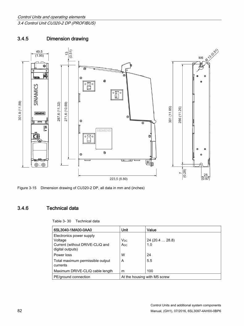
Control Units and operating elements 3.4 Control Unit CU320-2 DP (PROFIBUS)
Control Units and additional system components 82 Manual, (GH1), 07/2016, 6SL3097-4AH00-0BP6
3.4.5 Dimension drawing
Figure 3-15 Dimension drawing of CU320-2 DP, all data in mm and (inches)
3.4.6 Technical data
Table 3- 30 Technical data
6SL3040-1MA00-0AA0 Unit Value Electronics power supply Voltage Current (without DRIVE-CLiQ and digital outputs) Power loss Total maximum permissible output currents Maximum DRIVE-CLiQ cable length
VDC ADC W A m
24 (20.4 … 28.8) 1.0 24 5.5 100
PE/ground connection At the housing with M5 screw
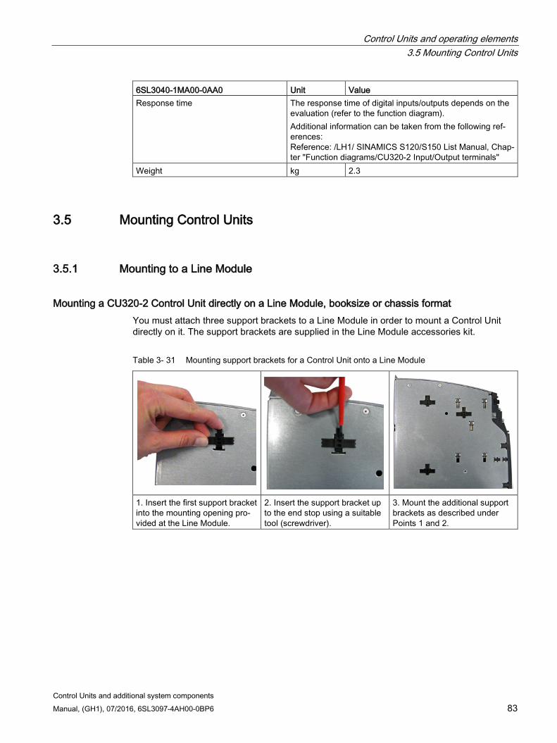
Control Units and operating elements 3.5 Mounting Control Units
Control Units and additional system components Manual, (GH1), 07/2016, 6SL3097-4AH00-0BP6 83
6SL3040-1MA00-0AA0 Unit Value Response time The response time of digital inputs/outputs depends on the
evaluation (refer to the function diagram). Additional information can be taken from the following ref-erences: Reference: /LH1/ SINAMICS S120/S150 List Manual, Chap-ter "Function diagrams/CU320-2 Input/Output terminals"
Weight kg 2.3
3.5 Mounting Control Units
3.5.1 Mounting to a Line Module
Mounting a CU320-2 Control Unit directly on a Line Module, booksize or chassis format You must attach three support brackets to a Line Module in order to mount a Control Unit directly on it. The support brackets are supplied in the Line Module accessories kit.
Table 3- 31 Mounting support brackets for a Control Unit onto a Line Module
1. Insert the first support bracket into the mounting opening pro-vided at the Line Module.
2. Insert the support bracket up to the end stop using a suitable tool (screwdriver).
3. Mount the additional support brackets as described under Points 1 and 2.
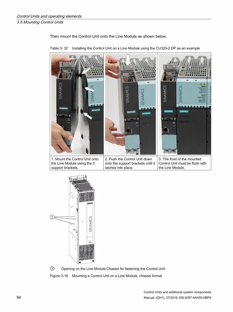
Control Units and operating elements 3.5 Mounting Control Units
Control Units and additional system components 84 Manual, (GH1), 07/2016, 6SL3097-4AH00-0BP6
Then mount the Control Unit onto the Line Module as shown below.
Table 3- 32 Installing the Control Unit on a Line Module using the CU320-2 DP as an example
1. Mount the Control Unit onto the Line Module using the 3 support brackets.
2. Push the Control Unit down onto the support brackets until it latches into place.
3. The front of the mounted Control Unit must be flush with the Line Module.
① Opening on the Line Module Chassis for fastening the Control Unit
Figure 3-16 Mounting a Control Unit on a Line Module, chassis format

Control Units and operating elements 3.5 Mounting Control Units
Control Units and additional system components Manual, (GH1), 07/2016, 6SL3097-4AH00-0BP6 85
3.5.2 Mounting on the mounting surface
Mounting a CU320-2 Control Unit directly onto a mounting surface Mount the fixing lug of the Control Unit on the mounting surface using M6 screws.
Tightening torque: 6 Nm
Mounting a CU320-2 Control Unit to a mounting surface using spacers To increase the mounting depth of the Control Unit to the 270 mm mounting depth of a Line Module in the booksize format, mount spacers (2 pieces: 6SL3064-1BB00-0AA0) as shown below to the Control Unit.
Tools required:
Torx screwdriver T10 for the screws (M3) of the spacer
① Spacer
Figure 3-17 CU320-2 with spacers for mounting on a mounting surface
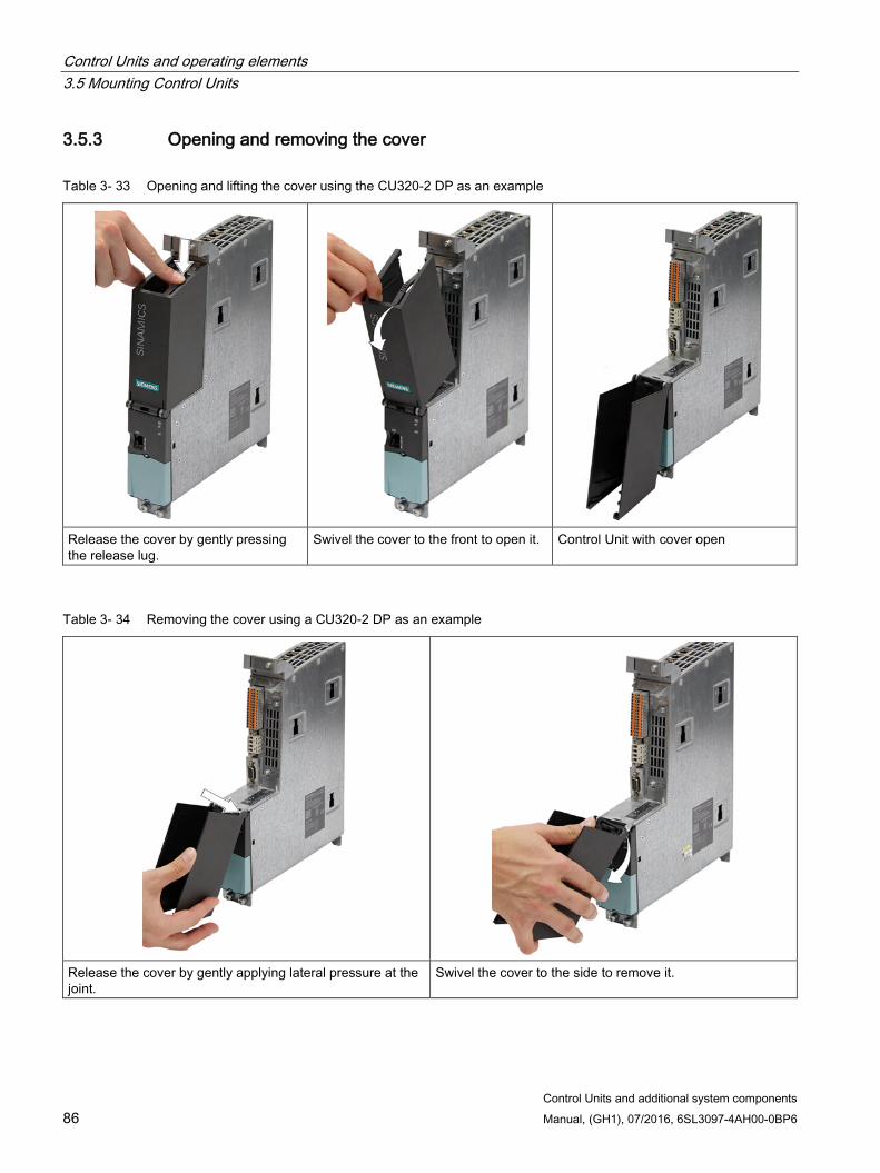
Control Units and operating elements 3.5 Mounting Control Units
Control Units and additional system components 86 Manual, (GH1), 07/2016, 6SL3097-4AH00-0BP6
3.5.3 Opening and removing the cover
Table 3- 33 Opening and lifting the cover using the CU320-2 DP as an example
Release the cover by gently pressing the release lug.
Swivel the cover to the front to open it. Control Unit with cover open
Table 3- 34 Removing the cover using a CU320-2 DP as an example
Release the cover by gently applying lateral pressure at the joint.
Swivel the cover to the side to remove it.
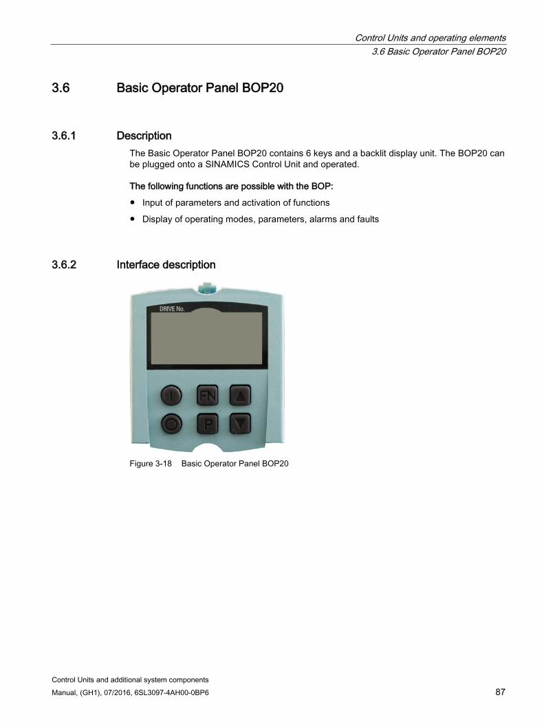
Control Units and operating elements 3.6 Basic Operator Panel BOP20
Control Units and additional system components Manual, (GH1), 07/2016, 6SL3097-4AH00-0BP6 87
3.6 Basic Operator Panel BOP20
3.6.1 Description The Basic Operator Panel BOP20 contains 6 keys and a backlit display unit. The BOP20 can be plugged onto a SINAMICS Control Unit and operated.
The following functions are possible with the BOP:
Input of parameters and activation of functions
Display of operating modes, parameters, alarms and faults
3.6.2 Interface description
Figure 3-18 Basic Operator Panel BOP20
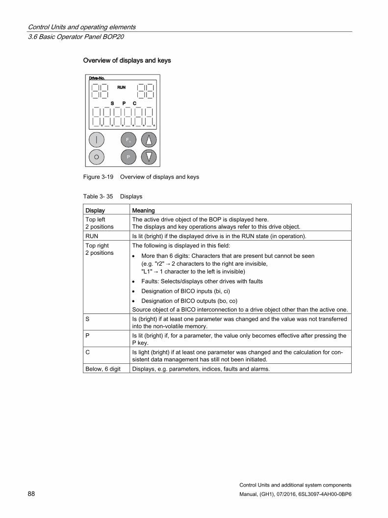
Control Units and operating elements 3.6 Basic Operator Panel BOP20
Control Units and additional system components 88 Manual, (GH1), 07/2016, 6SL3097-4AH00-0BP6
Overview of displays and keys
Figure 3-19 Overview of displays and keys
Table 3- 35 Displays
Display Meaning Top left 2 positions
The active drive object of the BOP is displayed here. The displays and key operations always refer to this drive object.
RUN Is lit (bright) if the displayed drive is in the RUN state (in operation). Top right 2 positions
The following is displayed in this field: • More than 6 digits: Characters that are present but cannot be seen
(e.g. "r2" → 2 characters to the right are invisible, "L1" → 1 character to the left is invisible)
• Faults: Selects/displays other drives with faults • Designation of BICO inputs (bi, ci) • Designation of BICO outputs (bo, co) Source object of a BICO interconnection to a drive object other than the active one.
S Is (bright) if at least one parameter was changed and the value was not transferred into the non-volatile memory.
P Is lit (bright) if, for a parameter, the value only becomes effective after pressing the P key.
C Is light (bright) if at least one parameter was changed and the calculation for con-sistent data management has still not been initiated.
Below, 6 digit Displays, e.g. parameters, indices, faults and alarms.
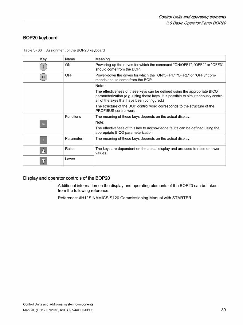
Control Units and operating elements 3.6 Basic Operator Panel BOP20
Control Units and additional system components Manual, (GH1), 07/2016, 6SL3097-4AH00-0BP6 89
BOP20 keyboard
Table 3- 36 Assignment of the BOP20 keyboard
Key Name Meaning
ON Powering-up the drives for which the command "ON/OFF1", "OFF2" or "OFF3"
should come from the BOP.
OFF Power-down the drives for which the "ON/OFF1," "OFF2," or "OFF3" com-
mands should come from the BOP. Note:
The effectiveness of these keys can be defined using the appropriate BICO parameterization (e.g. using these keys, it is possible to simultaneously control all of the axes that have been configured.) The structure of the BOP control word corresponds to the structure of the PROFIBUS control word.
Functions The meaning of these keys depends on the actual display. Note: The effectiveness of this key to acknowledge faults can be defined using the appropriate BICO parameterization.
Parameter The meaning of these keys depends on the actual display.
Raise The keys are dependent on the actual display and are used to raise or lower
values.
Lower
Display and operator controls of the BOP20 Additional information on the display and operating elements of the BOP20 can be taken from the following reference:
Reference: /IH1/ SINAMICS S120 Commissioning Manual with STARTER
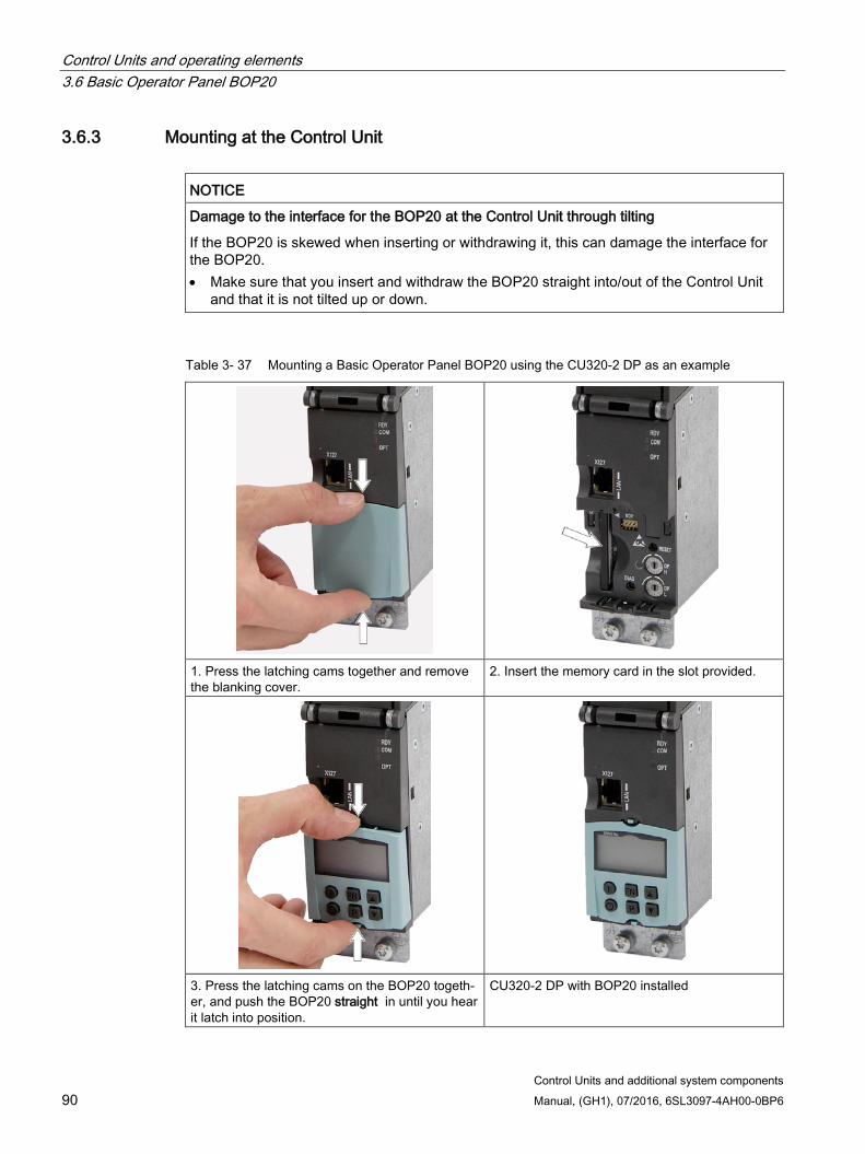
Control Units and operating elements 3.6 Basic Operator Panel BOP20
Control Units and additional system components 90 Manual, (GH1), 07/2016, 6SL3097-4AH00-0BP6
3.6.3 Mounting at the Control Unit
NOTICE
Damage to the interface for the BOP20 at the Control Unit through tilting
If the BOP20 is skewed when inserting or withdrawing it, this can damage the interface for the BOP20. • Make sure that you insert and withdraw the BOP20 straight into/out of the Control Unit
and that it is not tilted up or down.
Table 3- 37 Mounting a Basic Operator Panel BOP20 using the CU320-2 DP as an example
1. Press the latching cams together and remove the blanking cover.
2. Insert the memory card in the slot provided.
3. Press the latching cams on the BOP20 togeth-er, and push the BOP20 straight in until you hear it latch into position.
CU320-2 DP with BOP20 installed
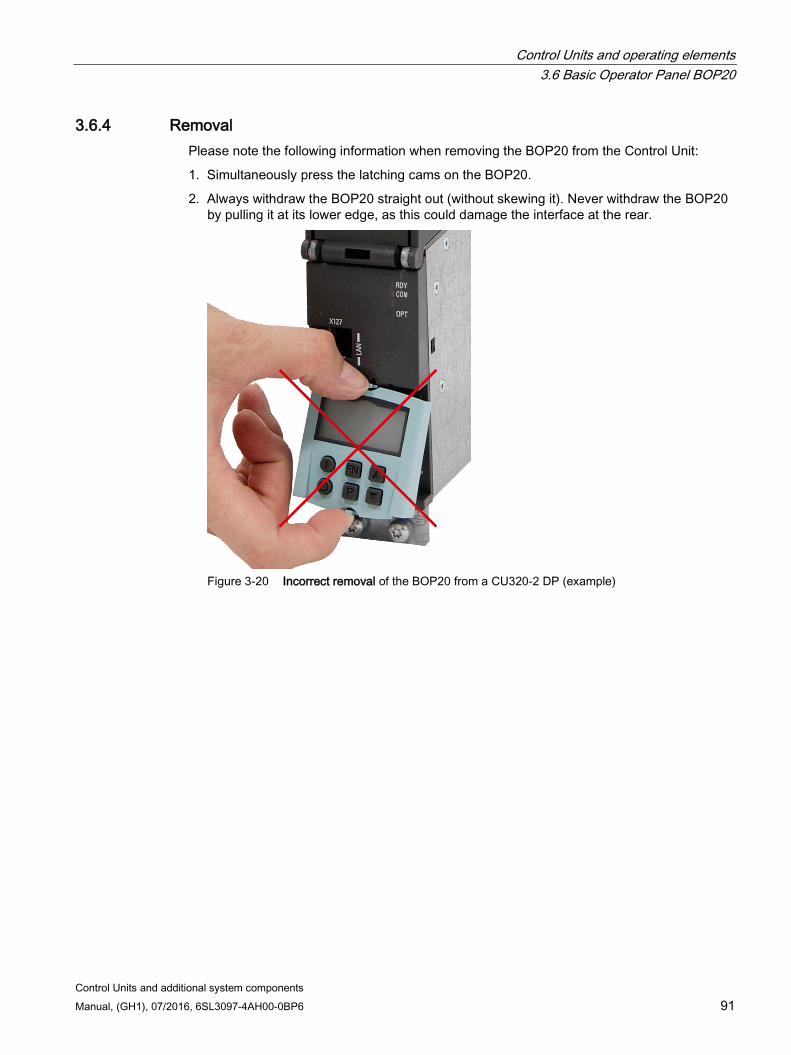
Control Units and operating elements 3.6 Basic Operator Panel BOP20
Control Units and additional system components Manual, (GH1), 07/2016, 6SL3097-4AH00-0BP6 91
3.6.4 Removal Please note the following information when removing the BOP20 from the Control Unit:
1. Simultaneously press the latching cams on the BOP20.
2. Always withdraw the BOP20 straight out (without skewing it). Never withdraw the BOP20 by pulling it at its lower edge, as this could damage the interface at the rear.
Figure 3-20 Incorrect removal of the BOP20 from a CU320-2 DP (example)

Control Units and operating elements 3.6 Basic Operator Panel BOP20
Control Units and additional system components 92 Manual, (GH1), 07/2016, 6SL3097-4AH00-0BP6

Control Units and additional system components Manual, (GH1), 07/2016, 6SL3097-4AH00-0BP6 93
Option boards 4 4.1 Safety instructions for option boards
WARNING
Danger to life if the fundamental safety instructions and remaining risks are not carefully observed
If the fundamental safety instructions and remaining risks in Chapter 1 (Page 19) are not observed, accidents involving severe injuries or death may occur. • Adhere to the fundamental safety instructions. • When assessing the risk, take into account remaining risks.
NOTICE
Damage or malfunctions to the Option Board by inserting and withdrawing in operation
Withdrawing and inserting Option Boards during operation can damage them or cause the Option Boards to malfunction. • Only withdraw or insert Option Boards when the Control Unit is in a current-free state.
4.2 CAN Communication Board CBC10
4.2.1 Description The Communication Board CAN CBC10 is a communication module for linking to the CAN bus. The Communication Board is inserted into the option slot on a Control Unit.
Were precise information on the function of the CBC10 can be taken from the following reference:
Reference: /IH2/ SINAMICS S120 CANopen Commissioning Manual
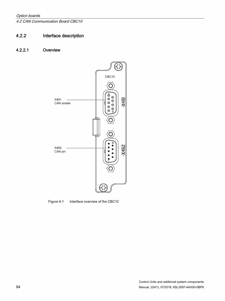
Option boards 4.2 CAN Communication Board CBC10
Control Units and additional system components 94 Manual, (GH1), 07/2016, 6SL3097-4AH00-0BP6
4.2.2 Interface description
4.2.2.1 Overview
Figure 4-1 Interface overview of the CBC10
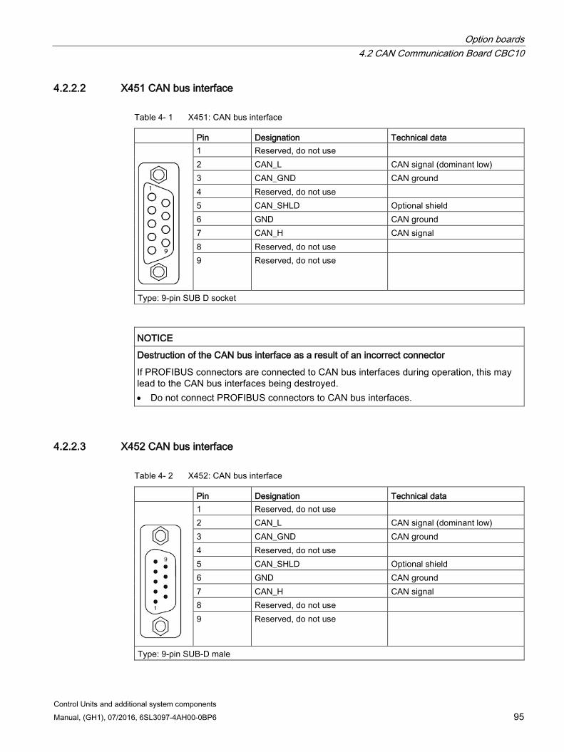
Option boards 4.2 CAN Communication Board CBC10
Control Units and additional system components Manual, (GH1), 07/2016, 6SL3097-4AH00-0BP6 95
4.2.2.2 X451 CAN bus interface
Table 4- 1 X451: CAN bus interface
Pin Designation Technical data
1 Reserved, do not use 2 CAN_L CAN signal (dominant low) 3 CAN_GND CAN ground 4 Reserved, do not use 5 CAN_SHLD Optional shield 6 GND CAN ground 7 CAN_H CAN signal 8 Reserved, do not use 9 Reserved, do not use
Type: 9-pin SUB D socket
NOTICE
Destruction of the CAN bus interface as a result of an incorrect connector
If PROFIBUS connectors are connected to CAN bus interfaces during operation, this may lead to the CAN bus interfaces being destroyed. • Do not connect PROFIBUS connectors to CAN bus interfaces.
4.2.2.3 X452 CAN bus interface
Table 4- 2 X452: CAN bus interface
Pin Designation Technical data
1 Reserved, do not use 2 CAN_L CAN signal (dominant low) 3 CAN_GND CAN ground 4 Reserved, do not use 5 CAN_SHLD Optional shield 6 GND CAN ground 7 CAN_H CAN signal 8 Reserved, do not use 9 Reserved, do not use
Type: 9-pin SUB-D male
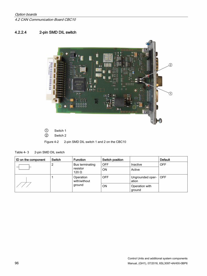
Option boards 4.2 CAN Communication Board CBC10
Control Units and additional system components 96 Manual, (GH1), 07/2016, 6SL3097-4AH00-0BP6
4.2.2.4 2-pin SMD DIL switch
① Switch 1 ② Switch 2
Figure 4-2 2-pin SMD DIL switch 1 and 2 on the CBC10
Table 4- 3 2-pin SMD DIL switch
ID on the component Switch Function Switch position Default
2 Bus terminating
resistor 120 Ω
OFF Inactive OFF ON Active
1 Operation with/without ground
OFF Ungrounded oper-ation
OFF
ON Operation with ground
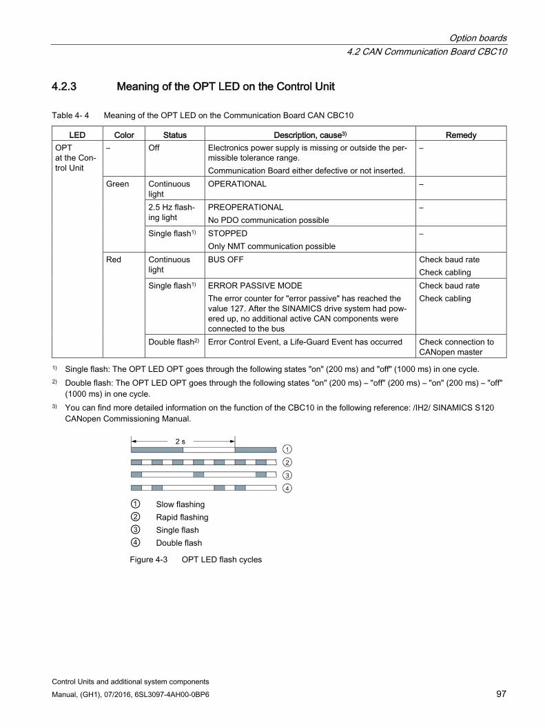
Option boards 4.2 CAN Communication Board CBC10
Control Units and additional system components Manual, (GH1), 07/2016, 6SL3097-4AH00-0BP6 97
4.2.3 Meaning of the OPT LED on the Control Unit
Table 4- 4 Meaning of the OPT LED on the Communication Board CAN CBC10
LED Color Status Description, cause3) Remedy OPT at the Con-trol Unit
– Off Electronics power supply is missing or outside the per-missible tolerance range. Communication Board either defective or not inserted.
–
Green Continuous light
OPERATIONAL –
2.5 Hz flash-ing light
PREOPERATIONAL No PDO communication possible
–
Single flash1) STOPPED Only NMT communication possible
–
Red Continuous light
BUS OFF Check baud rate Check cabling
Single flash1) ERROR PASSIVE MODE The error counter for "error passive" has reached the value 127. After the SINAMICS drive system had pow-ered up, no additional active CAN components were connected to the bus
Check baud rate Check cabling
Double flash2) Error Control Event, a Life-Guard Event has occurred Check connection to CANopen master
1) Single flash: The OPT LED OPT goes through the following states "on" (200 ms) and "off" (1000 ms) in one cycle. 2) Double flash: The OPT LED OPT goes through the following states "on" (200 ms) – "off" (200 ms) – "on" (200 ms) – "off"
(1000 ms) in one cycle. 3) You can find more detailed information on the function of the CBC10 in the following reference: /IH2/ SINAMICS S120
CANopen Commissioning Manual.
① Slow flashing ② Rapid flashing ③ Single flash ④ Double flash
Figure 4-3 OPT LED flash cycles
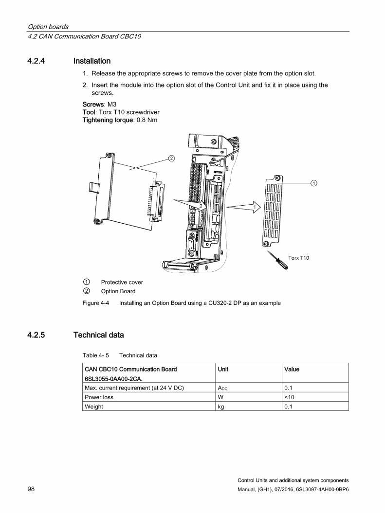
Option boards 4.2 CAN Communication Board CBC10
Control Units and additional system components 98 Manual, (GH1), 07/2016, 6SL3097-4AH00-0BP6
4.2.4 Installation 1. Release the appropriate screws to remove the cover plate from the option slot.
2. Insert the module into the option slot of the Control Unit and fix it in place using the screws.
Screws: M3 Tool: Torx T10 screwdriver Tightening torque: 0.8 Nm
① Protective cover ② Option Board
Figure 4-4 Installing an Option Board using a CU320-2 DP as an example
4.2.5 Technical data
Table 4- 5 Technical data
CAN CBC10 Communication Board 6SL3055-0AA00-2CA.
Unit Value
Max. current requirement (at 24 V DC) ADC 0.1 Power loss W <10 Weight kg 0.1
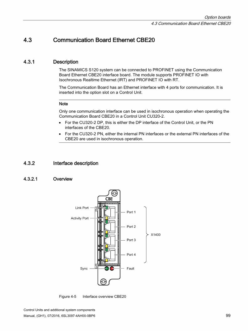
Option boards 4.3 Communication Board Ethernet CBE20
Control Units and additional system components Manual, (GH1), 07/2016, 6SL3097-4AH00-0BP6 99
4.3 Communication Board Ethernet CBE20
4.3.1 Description The SINAMICS S120 system can be connected to PROFINET using the Communication Board Ethernet CBE20 interface board. The module supports PROFINET IO with Isochronous Realtime Ethernet (IRT) and PROFINET IO with RT.
The Communication Board has an Ethernet interface with 4 ports for communication. It is inserted into the option slot on a Control Unit.
Note
Only one communication interface can be used in isochronous operation when operating the Communication Board CBE20 in a Control Unit CU320-2. • For the CU320-2 DP, this is either the DP interface of the Control Unit, or the PN
interfaces of the CBE20. • For the CU320-2 PN, either the internal PN interfaces or the external PN interfaces of the
CBE20 are used in isochronous operation.
4.3.2 Interface description
4.3.2.1 Overview
Figure 4-5 Interface overview CBE20
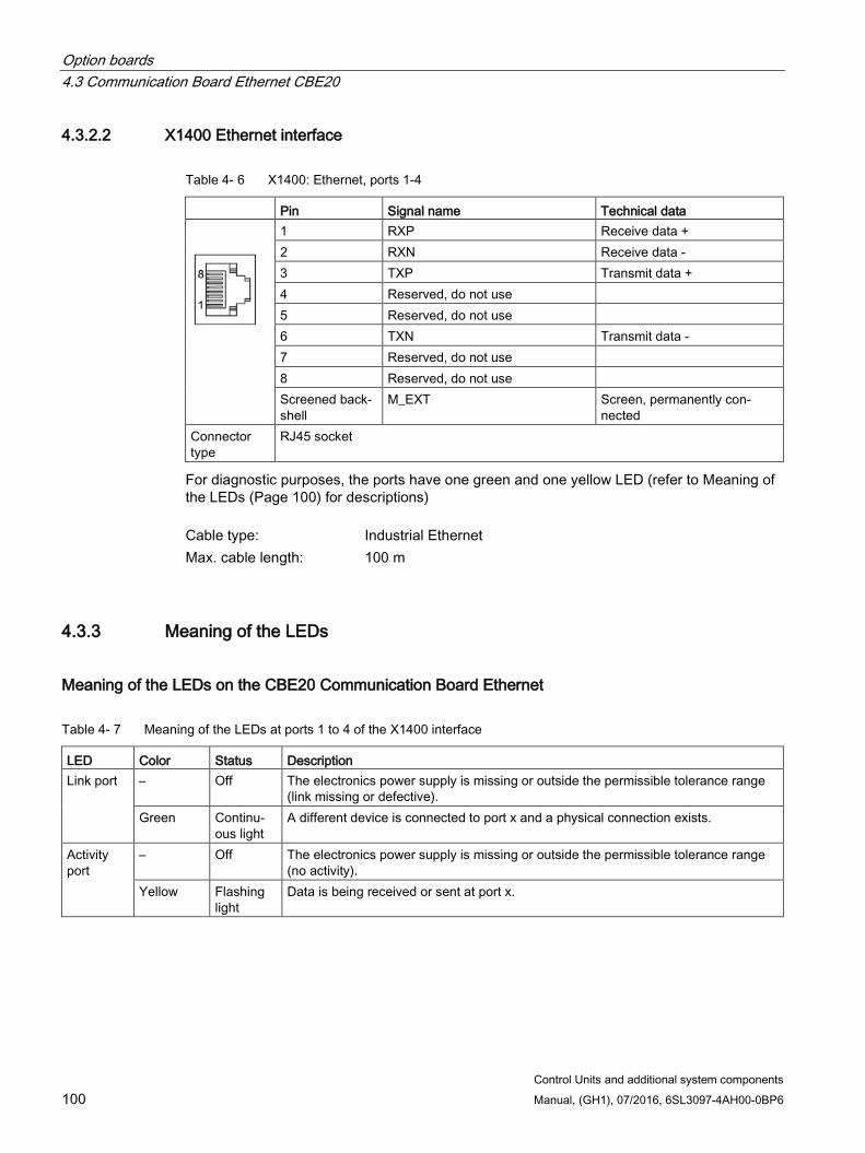
Option boards 4.3 Communication Board Ethernet CBE20
Control Units and additional system components 100 Manual, (GH1), 07/2016, 6SL3097-4AH00-0BP6
4.3.2.2 X1400 Ethernet interface
Table 4- 6 X1400: Ethernet, ports 1-4
Pin Signal name Technical data
1 RXP Receive data + 2 RXN Receive data - 3 TXP Transmit data + 4 Reserved, do not use 5 Reserved, do not use 6 TXN Transmit data - 7 Reserved, do not use 8 Reserved, do not use Screened back-shell
M_EXT Screen, permanently con-nected
Connector type
RJ45 socket
For diagnostic purposes, the ports have one green and one yellow LED (refer to Meaning of the LEDs (Page 100) for descriptions) Cable type: Industrial Ethernet Max. cable length: 100 m
4.3.3 Meaning of the LEDs
Meaning of the LEDs on the CBE20 Communication Board Ethernet
Table 4- 7 Meaning of the LEDs at ports 1 to 4 of the X1400 interface
LED Color Status Description Link port – Off The electronics power supply is missing or outside the permissible tolerance range
(link missing or defective). Green Continu-
ous light A different device is connected to port x and a physical connection exists.
Activity port
– Off The electronics power supply is missing or outside the permissible tolerance range (no activity).
Yellow Flashing light
Data is being received or sent at port x.
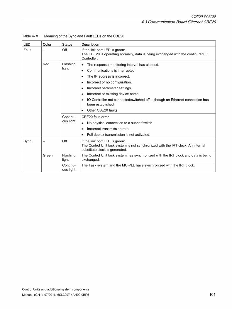
Option boards 4.3 Communication Board Ethernet CBE20
Control Units and additional system components Manual, (GH1), 07/2016, 6SL3097-4AH00-0BP6 101
Table 4- 8 Meaning of the Sync and Fault LEDs on the CBE20
LED Color Status Description Fault – Off If the link port LED is green:
The CBE20 is operating normally, data is being exchanged with the configured IO Controller.
Red Flashing light
• The response monitoring interval has elapsed. • Communications is interrupted. • The IP address is incorrect. • Incorrect or no configuration. • Incorrect parameter settings. • Incorrect or missing device name. • IO Controller not connected/switched off, although an Ethernet connection has
been established. • Other CBE20 faults
Continu-ous light
CBE20 fault error • No physical connection to a subnet/switch. • Incorrect transmission rate • Full duplex transmission is not activated.
Sync – Off If the link port LED is green: The Control Unit task system is not synchronized with the IRT clock. An internal substitute clock is generated.
Green Flashing light
The Control Unit task system has synchronized with the IRT clock and data is being exchanged.
Continu-ous light
The Task system and the MC-PLL have synchronized with the IRT clock.
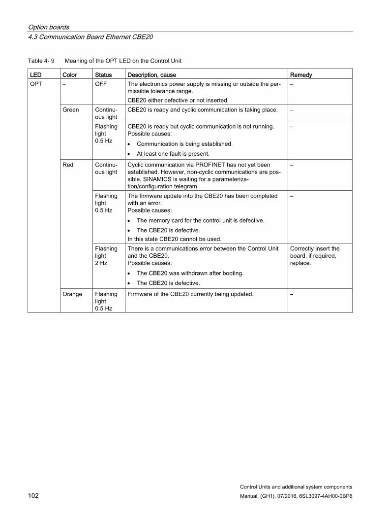
Option boards 4.3 Communication Board Ethernet CBE20
Control Units and additional system components 102 Manual, (GH1), 07/2016, 6SL3097-4AH00-0BP6
Table 4- 9 Meaning of the OPT LED on the Control Unit
LED Color Status Description, cause Remedy OPT – OFF The electronics power supply is missing or outside the per-
missible tolerance range. CBE20 either defective or not inserted.
–
Green Continu-ous light
CBE20 is ready and cyclic communication is taking place. –
Flashing light 0.5 Hz
CBE20 is ready but cyclic communication is not running. Possible causes: • Communication is being established. • At least one fault is present.
–
Red Continu-ous light
Cyclic communication via PROFINET has not yet been established. However, non-cyclic communications are pos-sible. SINAMICS is waiting for a parameteriza-tion/configuration telegram.
–
Flashing light 0.5 Hz
The firmware update into the CBE20 has been completed with an error. Possible causes: • The memory card for the control unit is defective. • The CBE20 is defective. In this state CBE20 cannot be used.
–
Flashing light 2 Hz
There is a communications error between the Control Unit and the CBE20. Possible causes: • The CBE20 was withdrawn after booting. • The CBE20 is defective.
Correctly insert the board, if required, replace.
Orange Flashing light 0.5 Hz
Firmware of the CBE20 currently being updated. –
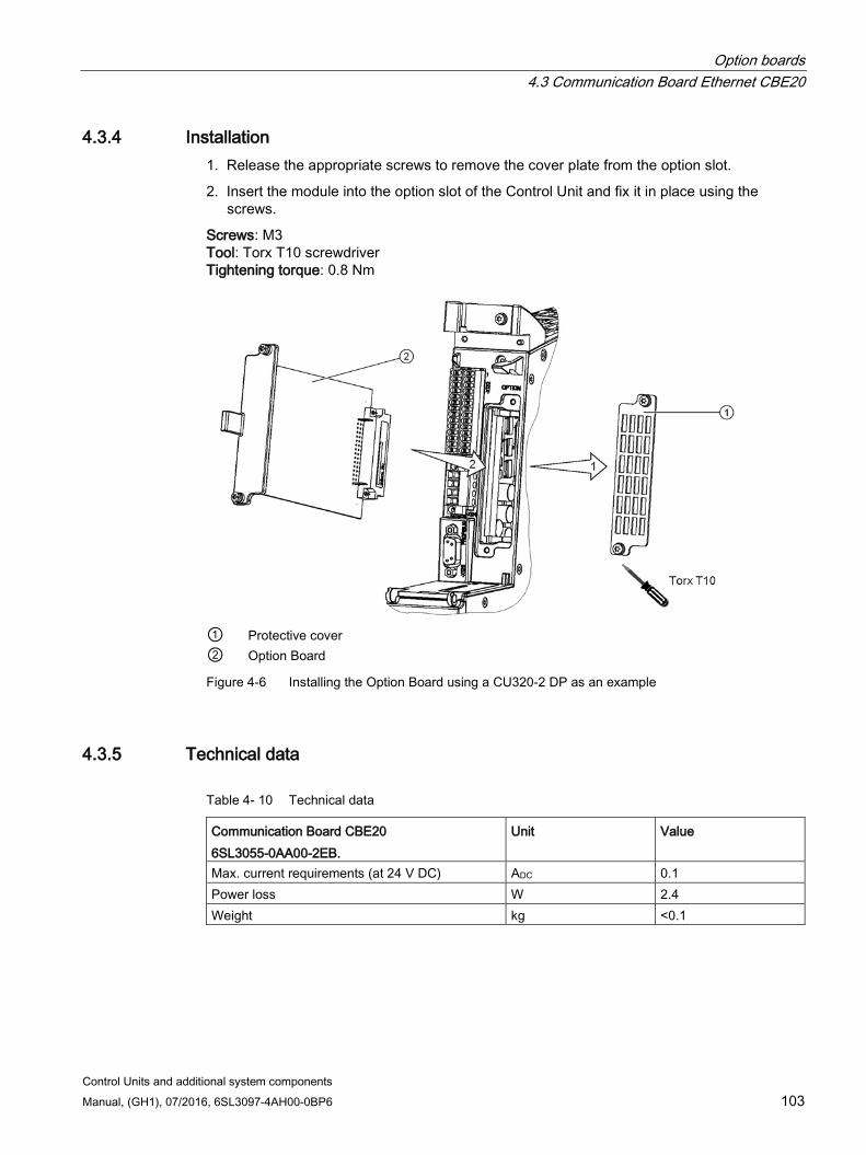
Option boards 4.3 Communication Board Ethernet CBE20
Control Units and additional system components Manual, (GH1), 07/2016, 6SL3097-4AH00-0BP6 103
4.3.4 Installation 1. Release the appropriate screws to remove the cover plate from the option slot.
2. Insert the module into the option slot of the Control Unit and fix it in place using the screws.
Screws: M3 Tool: Torx T10 screwdriver Tightening torque: 0.8 Nm
① Protective cover ② Option Board
Figure 4-6 Installing the Option Board using a CU320-2 DP as an example
4.3.5 Technical data
Table 4- 10 Technical data
Communication Board CBE20 6SL3055-0AA00-2EB.
Unit Value
Max. current requirements (at 24 V DC) ADC 0.1 Power loss W 2.4 Weight kg <0.1
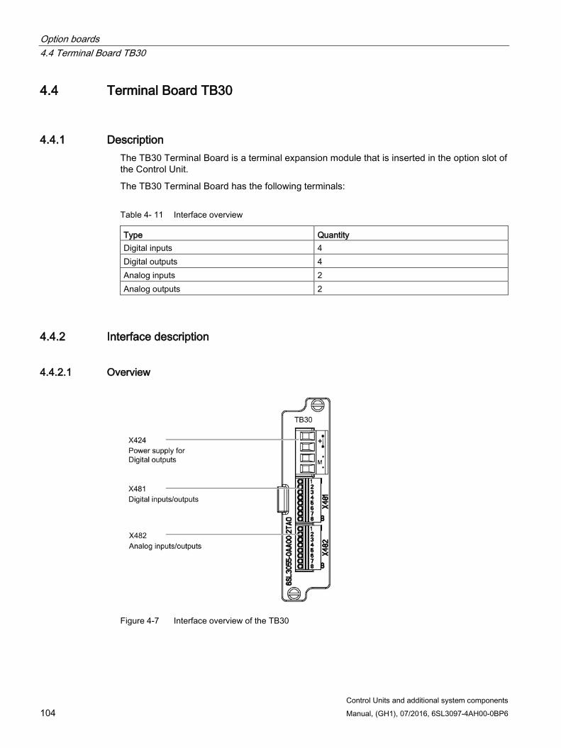
Option boards 4.4 Terminal Board TB30
Control Units and additional system components 104 Manual, (GH1), 07/2016, 6SL3097-4AH00-0BP6
4.4 Terminal Board TB30
4.4.1 Description The TB30 Terminal Board is a terminal expansion module that is inserted in the option slot of the Control Unit.
The TB30 Terminal Board has the following terminals:
Table 4- 11 Interface overview
Type Quantity Digital inputs 4 Digital outputs 4 Analog inputs 2 Analog outputs 2
4.4.2 Interface description
4.4.2.1 Overview
Figure 4-7 Interface overview of the TB30
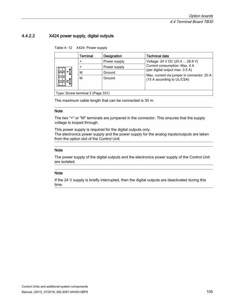
Option boards 4.4 Terminal Board TB30
Control Units and additional system components Manual, (GH1), 07/2016, 6SL3097-4AH00-0BP6 105
4.4.2.2 X424 power supply, digital outputs
Table 4- 12 X424: Power supply
Terminal Designation Technical data
+ Power supply Voltage: 24 V DC (20.4 ... 28.8 V) Current consumption: Max. 4 A (per digital output max. 0.5 A) Max. current via jumper in connector: 20 A (15 A according to UL/CSA)
+ Power supply M Ground M Ground
Type: Screw terminal 2 (Page 331)
The maximum cable length that can be connected is 30 m.
Note
The two "+" or "M" terminals are jumpered in the connector. This ensures that the supply voltage is looped through.
This power supply is required for the digital outputs only. The electronics power supply and the power supply for the analog inputs/outputs are taken from the option slot of the Control Unit.
Note
The power supply of the digital outputs and the electronics power supply of the Control Unit are isolated.
Note
If the 24 V supply is briefly interrupted, then the digital outputs are deactivated during this time.
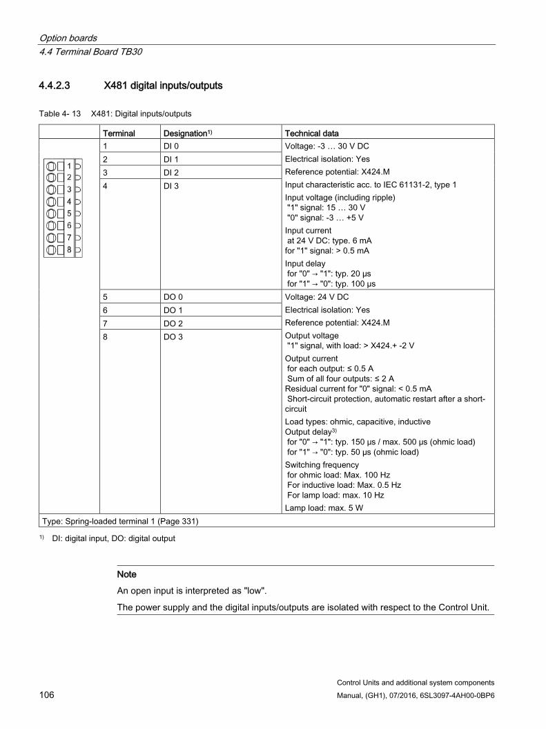
Option boards 4.4 Terminal Board TB30
Control Units and additional system components 106 Manual, (GH1), 07/2016, 6SL3097-4AH00-0BP6
4.4.2.3 X481 digital inputs/outputs
Table 4- 13 X481: Digital inputs/outputs
Terminal Designation1) Technical data
1 DI 0 Voltage: -3 … 30 V DC Electrical isolation: Yes Reference potential: X424.M Input characteristic acc. to IEC 61131-2, type 1 Input voltage (including ripple) "1" signal: 15 … 30 V "0" signal: -3 … +5 V Input current at 24 V DC: type. 6 mA for "1" signal: > 0.5 mA Input delay for "0" → "1": typ. 20 μs for "1" → "0": typ. 100 µs
2 DI 1 3 DI 2 4 DI 3
5 DO 0 Voltage: 24 V DC Electrical isolation: Yes Reference potential: X424.M Output voltage "1" signal, with load: > X424.+ -2 V Output current for each output: ≤ 0.5 A Sum of all four outputs: ≤ 2 A Residual current for "0" signal: < 0.5 mA Short-circuit protection, automatic restart after a short-circuit Load types: ohmic, capacitive, inductive Output delay3) for "0" → "1": typ. 150 μs / max. 500 μs (ohmic load) for "1" → "0": typ. 50 µs (ohmic load) Switching frequency for ohmic load: Max. 100 Hz For inductive load: Max. 0.5 Hz For lamp load: max. 10 Hz Lamp load: max. 5 W
6 DO 1 7 DO 2 8 DO 3
Type: Spring-loaded terminal 1 (Page 331) 1) DI: digital input, DO: digital output
Note
An open input is interpreted as "low".
The power supply and the digital inputs/outputs are isolated with respect to the Control Unit.
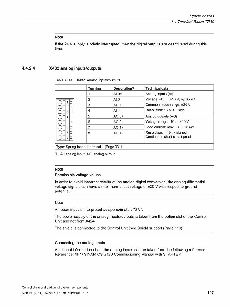
Option boards 4.4 Terminal Board TB30
Control Units and additional system components Manual, (GH1), 07/2016, 6SL3097-4AH00-0BP6 107
Note
If the 24 V supply is briefly interrupted, then the digital outputs are deactivated during this time.
4.4.2.4 X482 analog inputs/outputs
Table 4- 14 X482: Analog inputs/outputs
Terminal Designation1) Technical data
1 AI 0+ Analog inputs (AI) Voltage: -10 … +10 V; Ri: 65 kΩ Common mode range: ±30 V Resolution: 13 bits + sign
2 AI 0- 3 AI 1+ 4 AI 1- 5 AO 0+ Analog outputs (AO)
Voltage range: -10 … +10 V Load current: max. -3 … +3 mA Resolution: 11 bit + signed Continuous short-circuit proof
6 AO 0- 7 AO 1+ 8 AO 1-
Type: Spring-loaded terminal 1 (Page 331) 1) AI: analog input, AO: analog output
Note Permissible voltage values
In order to avoid incorrect results of the analog-digital conversion, the analog differential voltage signals can have a maximum offset voltage of ±30 V with respect to ground potential.
Note
An open input is interpreted as approximately "0 V".
The power supply of the analog inputs/outputs is taken from the option slot of the Control Unit and not from X424.
The shield is connected to the Control Unit (see Shield support (Page 110)).
Connecting the analog inputs
Additional information about the analog inputs can be taken from the following reference: Reference: /IH1/ SINAMICS S120 Commissioning Manual with STARTER
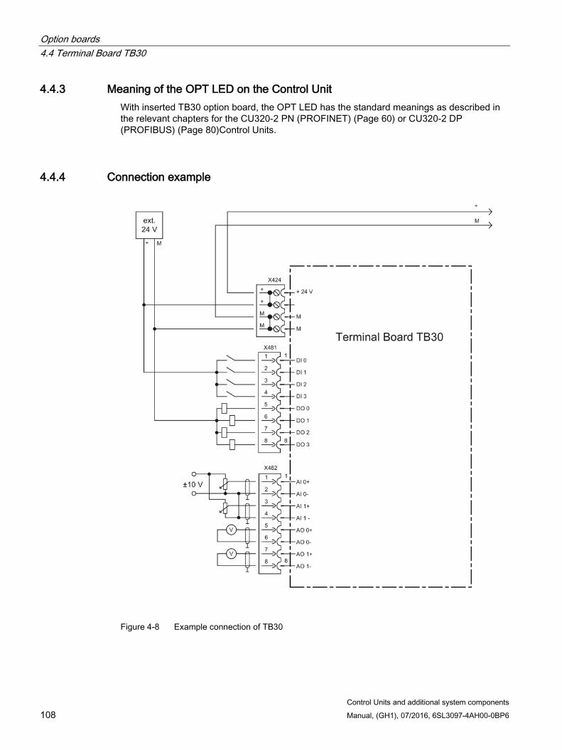
Option boards 4.4 Terminal Board TB30
Control Units and additional system components 108 Manual, (GH1), 07/2016, 6SL3097-4AH00-0BP6
4.4.3 Meaning of the OPT LED on the Control Unit With inserted TB30 option board, the OPT LED has the standard meanings as described in the relevant chapters for the CU320-2 PN (PROFINET) (Page 60) or CU320-2 DP (PROFIBUS) (Page 80)Control Units.
4.4.4 Connection example
Figure 4-8 Example connection of TB30
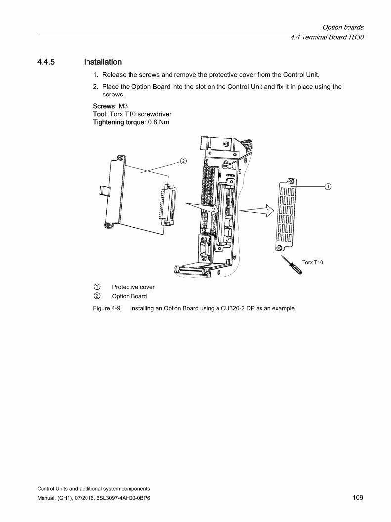
Option boards 4.4 Terminal Board TB30
Control Units and additional system components Manual, (GH1), 07/2016, 6SL3097-4AH00-0BP6 109
4.4.5 Installation 1. Release the screws and remove the protective cover from the Control Unit.
2. Place the Option Board into the slot on the Control Unit and fix it in place using the screws.
Screws: M3 Tool: Torx T10 screwdriver Tightening torque: 0.8 Nm
① Protective cover ② Option Board
Figure 4-9 Installing an Option Board using a CU320-2 DP as an example
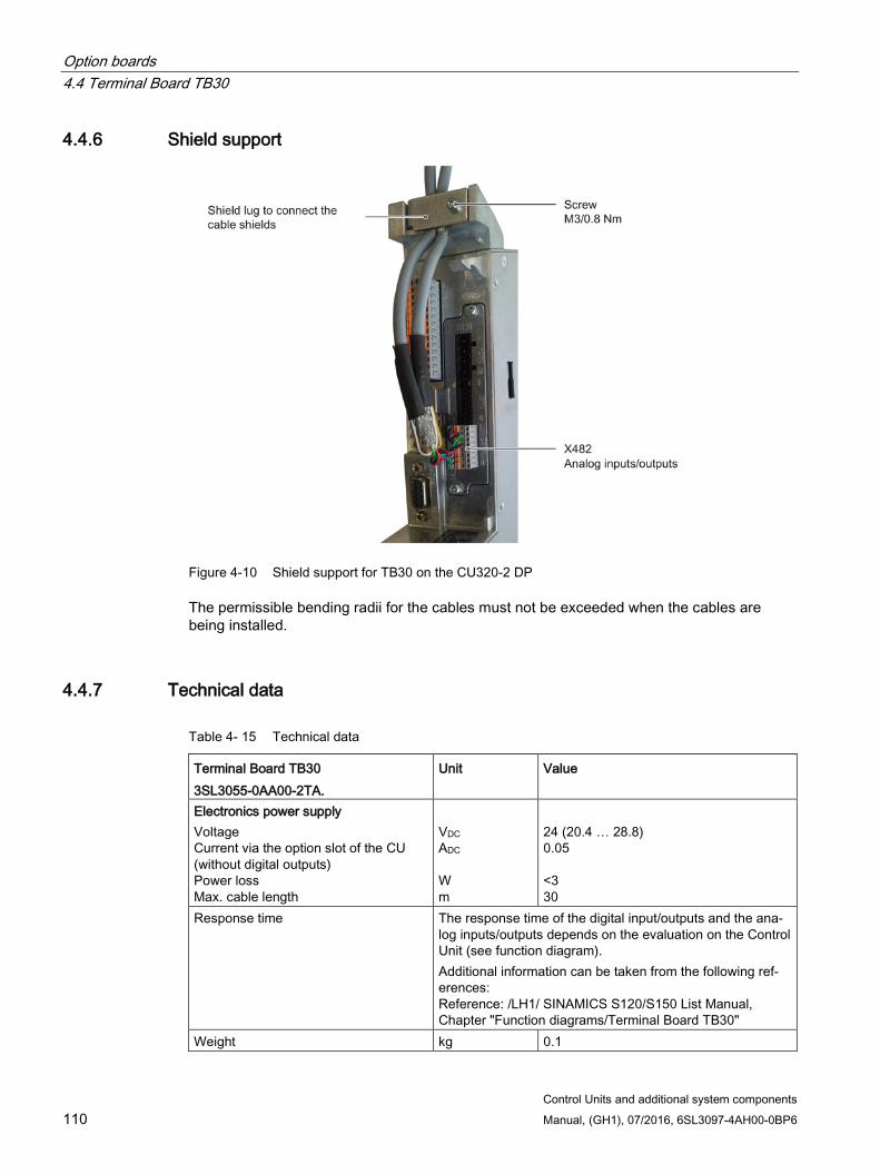
Option boards 4.4 Terminal Board TB30
Control Units and additional system components 110 Manual, (GH1), 07/2016, 6SL3097-4AH00-0BP6
4.4.6 Shield support
Figure 4-10 Shield support for TB30 on the CU320-2 DP
The permissible bending radii for the cables must not be exceeded when the cables are being installed.
4.4.7 Technical data
Table 4- 15 Technical data
Terminal Board TB30 3SL3055-0AA00-2TA.
Unit Value
Electronics power supply Voltage Current via the option slot of the CU (without digital outputs) Power loss Max. cable length
VDC ADC W m
24 (20.4 … 28.8) 0.05 <3 30
Response time The response time of the digital input/outputs and the ana-log inputs/outputs depends on the evaluation on the Control Unit (see function diagram). Additional information can be taken from the following ref-erences: Reference: /LH1/ SINAMICS S120/S150 List Manual, Chapter "Function diagrams/Terminal Board TB30"
Weight kg 0.1
Control Units and additional system components Manual, (GH1), 07/2016, 6SL3097-4AH00-0BP6 111
Terminal Modules 5 5.1 Safety instructions for Terminal Modules
WARNING
Danger to life if the fundamental safety instructions and remaining risks are not carefully observed
If the fundamental safety instructions and remaining risks in Chapter 1 (Page 19) are not observed, accidents involving severe injuries or death may occur. • Adhere to the fundamental safety instructions. • When assessing the risk, take into account remaining risks.
WARNING
Risk of fire through overheating if there are insufficient ventilation clearances
Insufficient ventilation clearances lead to overheating with associated risk to persons as a result of smoke and fire. This can also result in more downtimes and reduced service lives of the Terminal Module. • For this reason, it is imperative that you maintain the 50 mm clearances above and
below the Terminal Module.
NOTICE
Device failure as a result of unshielded or incorrectly routed cables to temperature sensors
Unshielded or incorrectly routed cables to temperature sensors can result in interference being coupled into the signal processing electronics from the power side. This can result in significant disturbance of all signals (fault messages) up to failure of individual components (destruction of the devices). • Only use shielded cables as temperature sensor cables. • If temperature sensor cables are routed together with the motor cable, use separately
shielded cables twisted in pairs. • Connect the cable shield at both ends to ground potential through a large surface area. • Recommendation: Use suitable Motion Connect cables.
Terminal Modules 5.2 Terminal Module TM15
Control Units and additional system components 112 Manual, (GH1), 07/2016, 6SL3097-4AH00-0BP6
NOTICE
Damage through use of incorrect DRIVE-CLiQ cables
Damage or malfunctions can occur on the devices or system when incorrect or unreleased DRIVE-CLiQ cables are used. • Only use suitable DRIVE-CLiQ cables that have been released by Siemens for the
respective application.
Note Malfunctions due to polluted DRIVE-CLiQ interfaces
Malfunctions can occur in the system through the use of polluted DRIVE-CLiQ interfaces. • Cover unused DRIVE-CLiQ interfaces with the supplied blanking covers.
Note Function equipotential bonding for distributed DRIVE-CLiQ nodes
Integrate all of the components that are connected via DRIVE-CLiQ in the functional equipotential bonding concept. The connection should be preferably established by mounting on metallic bare machine and plant components that are connected with one another using an equipotential bonding conductor. Alternatively, you can establish equipotential bonding using a conductor (min. 6 mm²), which as far as possible, is routed in parallel to the DRIVE-CLiQ cable. All distributed DRIVE-CLiQ nodes are involved, for example DME20, SME20, SME25, SME120, SME125 etc.
5.2 Terminal Module TM15
5.2.1 Description The Terminal Module TM15 is a terminal expansion for snapping on to an EN 60715 DIN rail. The TM15 can be used to increase the number of available digital inputs/outputs within a drive system.
Table 5- 1 Interface overview of the TM15
Type Quantity DRIVE-CLiQ interfaces 2 Bidirectional digital inputs/outputs 24
(isolation in 3 groups each with 8 DI/DO)
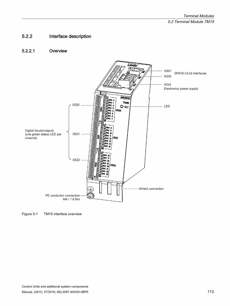
Terminal Modules 5.2 Terminal Module TM15
Control Units and additional system components Manual, (GH1), 07/2016, 6SL3097-4AH00-0BP6 113
5.2.2 Interface description
5.2.2.1 Overview
Figure 5-1 TM15 interface overview
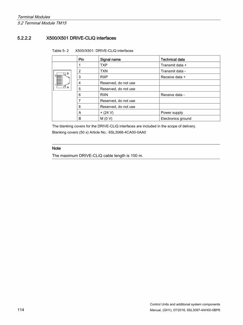
Terminal Modules 5.2 Terminal Module TM15
Control Units and additional system components 114 Manual, (GH1), 07/2016, 6SL3097-4AH00-0BP6
5.2.2.2 X500/X501 DRIVE-CLiQ interfaces
Table 5- 2 X500/X501: DRIVE-CLiQ interfaces
Pin Signal name Technical data
1 TXP Transmit data + 2 TXN Transmit data - 3 RXP Receive data + 4 Reserved, do not use 5 Reserved, do not use 6 RXN Receive data - 7 Reserved, do not use 8 Reserved, do not use A + (24 V) Power supply B M (0 V) Electronics ground
The blanking covers for the DRIVE-CLiQ interfaces are included in the scope of delivery. Blanking covers (50 x) Article No.: 6SL3066-4CA00-0AA0
Note
The maximum DRIVE-CLiQ cable length is 100 m.
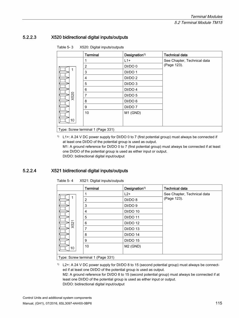
Terminal Modules 5.2 Terminal Module TM15
Control Units and additional system components Manual, (GH1), 07/2016, 6SL3097-4AH00-0BP6 115
5.2.2.3 X520 bidirectional digital inputs/outputs
Table 5- 3 X520: Digital inputs/outputs
Terminal Designation1) Technical data
1 L1+ See Chapter, Technical data (Page 123). 2 DI/DO 0
3 DI/DO 1 4 DI/DO 2 5 DI/DO 3 6 DI/DO 4 7 DI/DO 5 8 DI/DO 6 9 DI/DO 7 10 M1 (GND)
Type: Screw terminal 1 (Page 331) 1) L1+: A 24 V DC power supply for DI/DO 0 to 7 (first potential group) must always be connected if
at least one DI/DO of the potential group is used as output. M1: A ground reference for DI/DO 0 to 7 (first potential group) must always be connected if at least one DI/DO of the potential group is used as either input or output. DI/DO: bidirectional digital input/output
5.2.2.4 X521 bidirectional digital inputs/outputs
Table 5- 4 X521: Digital inputs/outputs
Terminal Designation1) Technical data
1 L2+ See Chapter, Technical data (Page 123). 2 DI/DO 8
3 DI/DO 9 4 DI/DO 10 5 DI/DO 11 6 DI/DO 12 7 DI/DO 13 8 DI/DO 14 9 DI/DO 15 10 M2 (GND)
Type: Screw terminal 1 (Page 331) 1) L2+: A 24 V DC power supply for DI/DO 8 to 15 (second potential group) must always be connect-
ed if at least one DI/DO of the potential group is used as output. M2: A ground reference for DI/DO 8 to 15 (second potential group) must always be connected if at least one DI/DO of the potential group is used as either input or output. DI/DO: bidirectional digital input/output
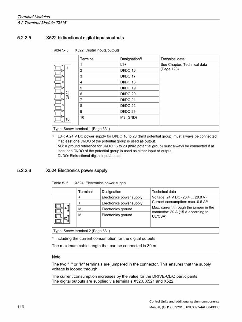
Terminal Modules 5.2 Terminal Module TM15
Control Units and additional system components 116 Manual, (GH1), 07/2016, 6SL3097-4AH00-0BP6
5.2.2.5 X522 bidirectional digital inputs/outputs
Table 5- 5 X522: Digital inputs/outputs
Terminal Designation1) Technical data
1 L3+ See Chapter, Technical data (Page 123). 2 DI/DO 16
3 DI/DO 17 4 DI/DO 18 5 DI/DO 19 6 DI/DO 20 7 DI/DO 21 8 DI/DO 22 9 DI/DO 23 10 M3 (GND)
Type: Screw terminal 1 (Page 331) 1) L3+: A 24 V DC power supply for DI/DO 16 to 23 (third potential group) must always be connected
if at least one DI/DO of the potential group is used as output. M3: A ground reference for DI/DO 16 to 23 (third potential group) must always be connected if at least one DI/DO of the potential group is used as either input or output. DI/DO: Bidirectional digital input/output
5.2.2.6 X524 Electronics power supply
Table 5- 6 X524: Electronics power supply
Terminal Designation Technical data
+ Electronics power supply Voltage: 24 V DC (20.4 ... 28.8 V) Current consumption: max. 0.6 A1) Max. current through the jumper in the connector: 20 A (15 A according to UL/CSA)
+ Electronics power supply M Electronics ground M Electronics ground
Type: Screw terminal 2 (Page 331)
1) Including the current consumption for the digital outputs
The maximum cable length that can be connected is 30 m.
Note
The two "+" or "M" terminals are jumpered in the connector. This ensures that the supply voltage is looped through.
The current consumption increases by the value for the DRIVE-CLiQ participants. The digital outputs are supplied via terminals X520, X521 and X522.
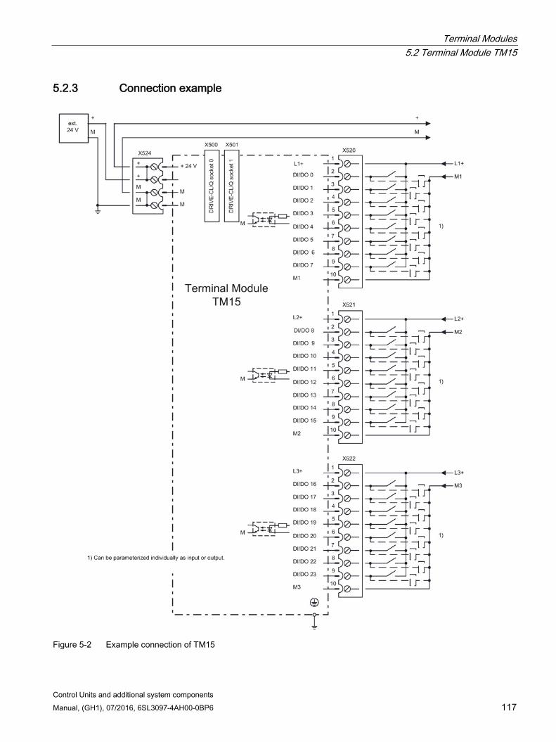
Terminal Modules 5.2 Terminal Module TM15
Control Units and additional system components Manual, (GH1), 07/2016, 6SL3097-4AH00-0BP6 117
5.2.3 Connection example
Figure 5-2 Example connection of TM15
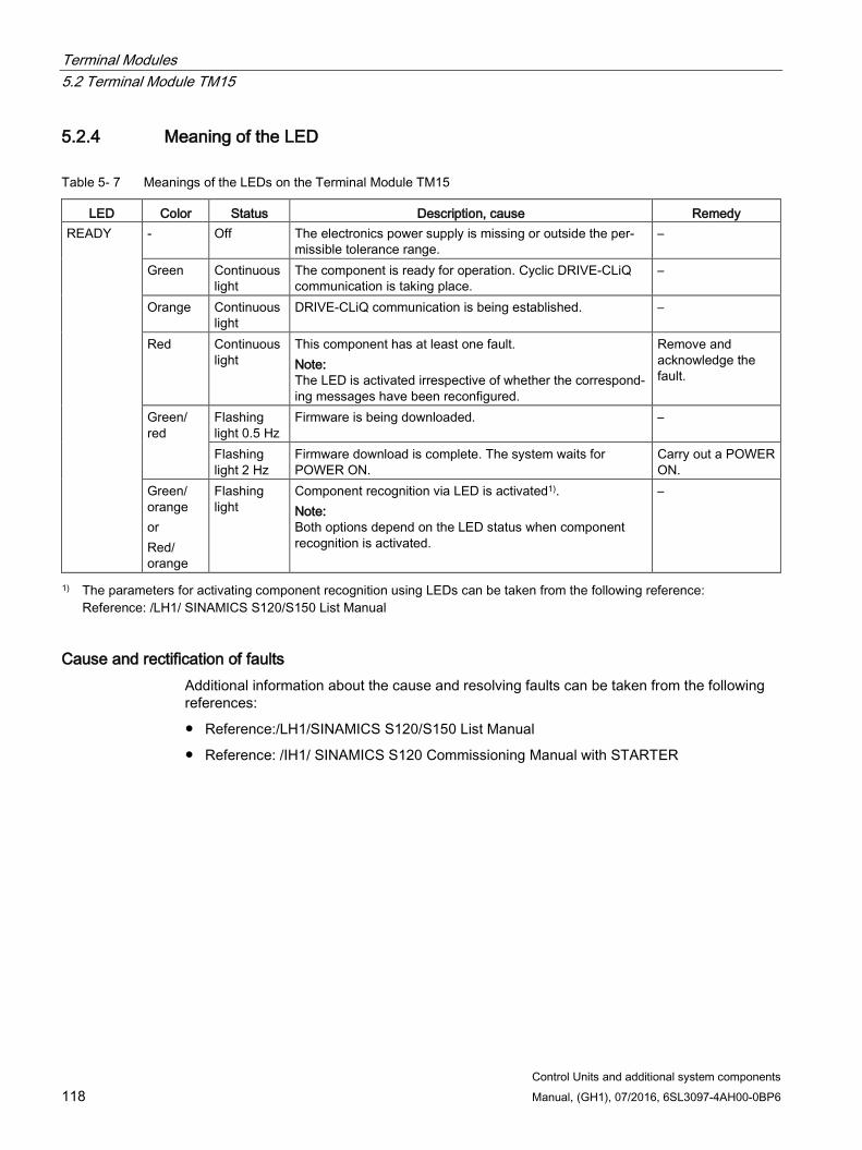
Terminal Modules 5.2 Terminal Module TM15
Control Units and additional system components 118 Manual, (GH1), 07/2016, 6SL3097-4AH00-0BP6
5.2.4 Meaning of the LED
Table 5- 7 Meanings of the LEDs on the Terminal Module TM15
LED Color Status Description, cause Remedy READY - Off The electronics power supply is missing or outside the per-
missible tolerance range. –
Green Continuous light
The component is ready for operation. Cyclic DRIVE-CLiQ communication is taking place.
–
Orange Continuous light
DRIVE-CLiQ communication is being established. –
Red Continuous light
This component has at least one fault. Note: The LED is activated irrespective of whether the correspond-ing messages have been reconfigured.
Remove and acknowledge the fault.
Green/ red
Flashing light 0.5 Hz
Firmware is being downloaded. –
Flashing light 2 Hz
Firmware download is complete. The system waits for POWER ON.
Carry out a POWER ON.
Green/ orange or Red/ orange
Flashing light
Component recognition via LED is activated1). Note: Both options depend on the LED status when component recognition is activated.
–
1) The parameters for activating component recognition using LEDs can be taken from the following reference: Reference: /LH1/ SINAMICS S120/S150 List Manual
Cause and rectification of faults Additional information about the cause and resolving faults can be taken from the following references:
Reference:/LH1/SINAMICS S120/S150 List Manual
Reference: /IH1/ SINAMICS S120 Commissioning Manual with STARTER
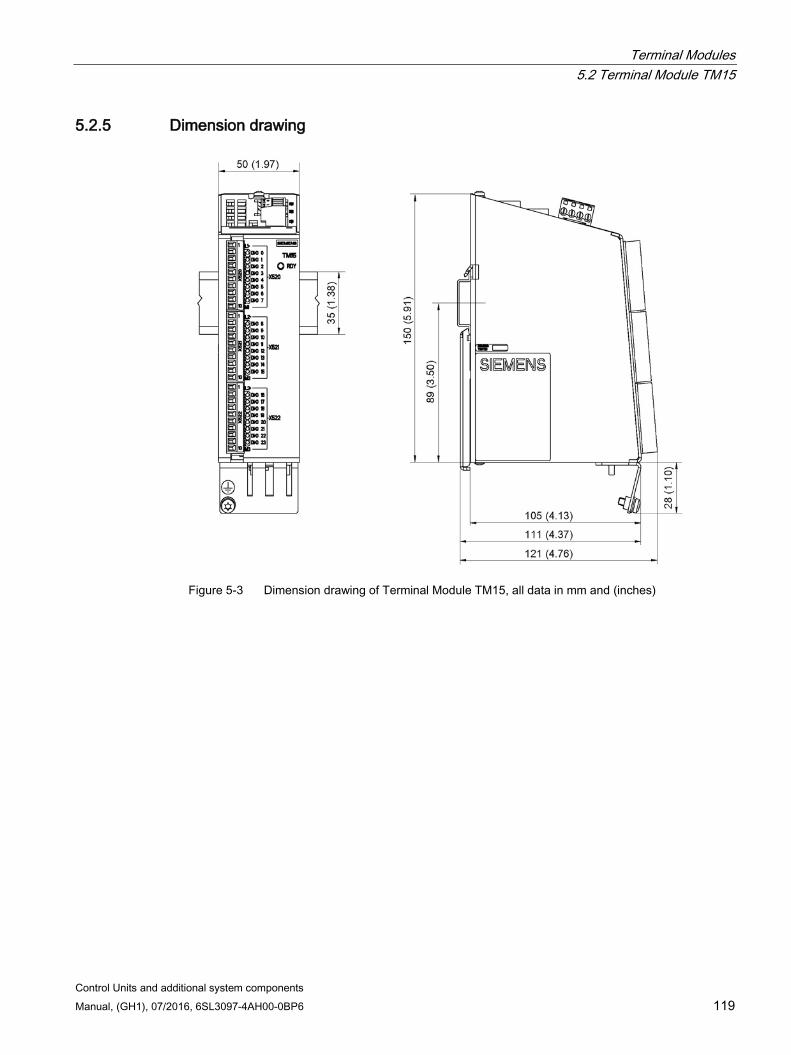
Terminal Modules 5.2 Terminal Module TM15
Control Units and additional system components Manual, (GH1), 07/2016, 6SL3097-4AH00-0BP6 119
5.2.5 Dimension drawing
Figure 5-3 Dimension drawing of Terminal Module TM15, all data in mm and (inches)
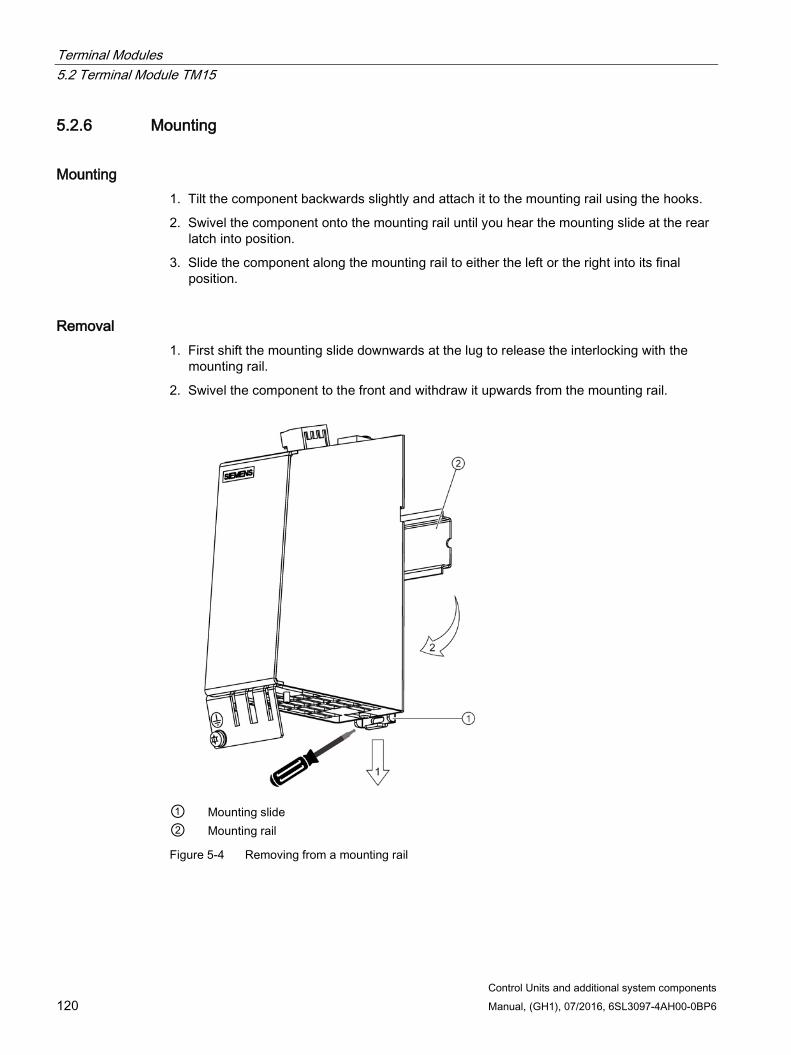
Terminal Modules 5.2 Terminal Module TM15
Control Units and additional system components 120 Manual, (GH1), 07/2016, 6SL3097-4AH00-0BP6
5.2.6 Mounting
Mounting 1. Tilt the component backwards slightly and attach it to the mounting rail using the hooks.
2. Swivel the component onto the mounting rail until you hear the mounting slide at the rear latch into position.
3. Slide the component along the mounting rail to either the left or the right into its final position.
Removal 1. First shift the mounting slide downwards at the lug to release the interlocking with the
mounting rail.
2. Swivel the component to the front and withdraw it upwards from the mounting rail.
① Mounting slide ② Mounting rail
Figure 5-4 Removing from a mounting rail
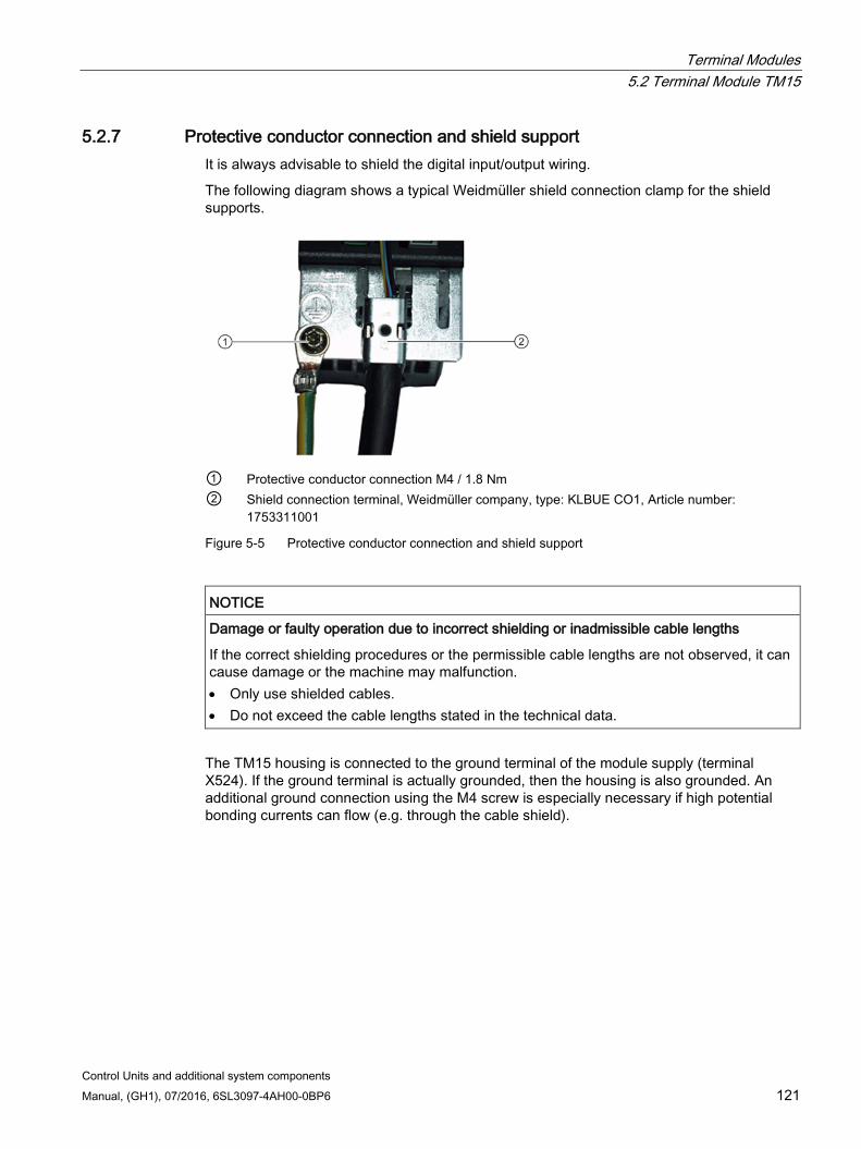
Terminal Modules 5.2 Terminal Module TM15
Control Units and additional system components Manual, (GH1), 07/2016, 6SL3097-4AH00-0BP6 121
5.2.7 Protective conductor connection and shield support It is always advisable to shield the digital input/output wiring.
The following diagram shows a typical Weidmüller shield connection clamp for the shield supports.
① Protective conductor connection M4 / 1.8 Nm ② Shield connection terminal, Weidmüller company, type: KLBUE CO1, Article number:
1753311001
Figure 5-5 Protective conductor connection and shield support
NOTICE
Damage or faulty operation due to incorrect shielding or inadmissible cable lengths
If the correct shielding procedures or the permissible cable lengths are not observed, it can cause damage or the machine may malfunction. • Only use shielded cables. • Do not exceed the cable lengths stated in the technical data.
The TM15 housing is connected to the ground terminal of the module supply (terminal X524). If the ground terminal is actually grounded, then the housing is also grounded. An additional ground connection using the M4 screw is especially necessary if high potential bonding currents can flow (e.g. through the cable shield).
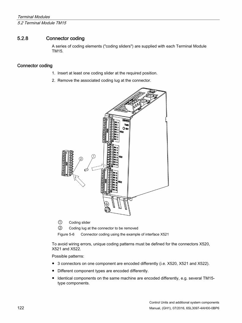
Terminal Modules 5.2 Terminal Module TM15
Control Units and additional system components 122 Manual, (GH1), 07/2016, 6SL3097-4AH00-0BP6
5.2.8 Connector coding A series of coding elements ("coding sliders") are supplied with each Terminal Module TM15.
Connector coding 1. Insert at least one coding slider at the required position.
2. Remove the associated coding lug at the connector.
① Coding slider ② Coding lug at the connector to be removed Figure 5-6 Connector coding using the example of interface X521
To avoid wiring errors, unique coding patterns must be defined for the connectors X520, X521 and X522.
Possible patterns:
3 connectors on one component are encoded differently (i.e. X520, X521 and X522).
Different component types are encoded differently.
Identical components on the same machine are encoded differently, e.g. several TM15-type components.
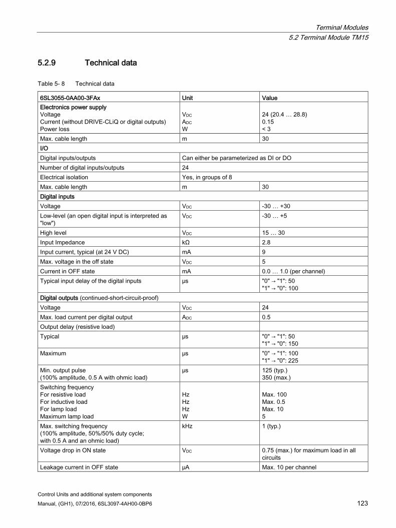
Terminal Modules 5.2 Terminal Module TM15
Control Units and additional system components Manual, (GH1), 07/2016, 6SL3097-4AH00-0BP6 123
5.2.9 Technical data
Table 5- 8 Technical data
6SL3055-0AA00-3FAx Unit Value Electronics power supply Voltage Current (without DRIVE-CLiQ or digital outputs) Power loss
VDC ADC W
24 (20.4 … 28.8) 0.15 < 3
Max. cable length m 30 I/O Digital inputs/outputs Can either be parameterized as DI or DO Number of digital inputs/outputs 24 Electrical isolation Yes, in groups of 8 Max. cable length m 30 Digital inputs Voltage VDC -30 … +30 Low-level (an open digital input is interpreted as "low")
VDC -30 … +5
High level VDC 15 … 30 Input Impedance kΩ 2.8 Input current, typical (at 24 V DC) mA 9 Max. voltage in the off state VDC 5 Current in OFF state mA 0.0 … 1.0 (per channel) Typical input delay of the digital inputs μs "0" → "1": 50
"1" → "0": 100 Digital outputs (continued-short-circuit-proof) Voltage VDC 24 Max. load current per digital output ADC 0.5 Output delay (resistive load) Typical μs "0" → "1": 50
"1" → "0": 150 Maximum μs "0" → "1": 100
"1" → "0": 225 Min. output pulse (100% amplitude, 0.5 A with ohmic load)
μs 125 (typ.) 350 (max.)
Switching frequency For resistive load For inductive load For lamp load Maximum lamp load
Hz Hz Hz W
Max. 100 Max. 0.5 Max. 10 5
Max. switching frequency (100% amplitude, 50%/50% duty cycle; with 0.5 A and an ohmic load)
kHz 1 (typ.)
Voltage drop in ON state VDC 0.75 (max.) for maximum load in all circuits
Leakage current in OFF state μA Max. 10 per channel
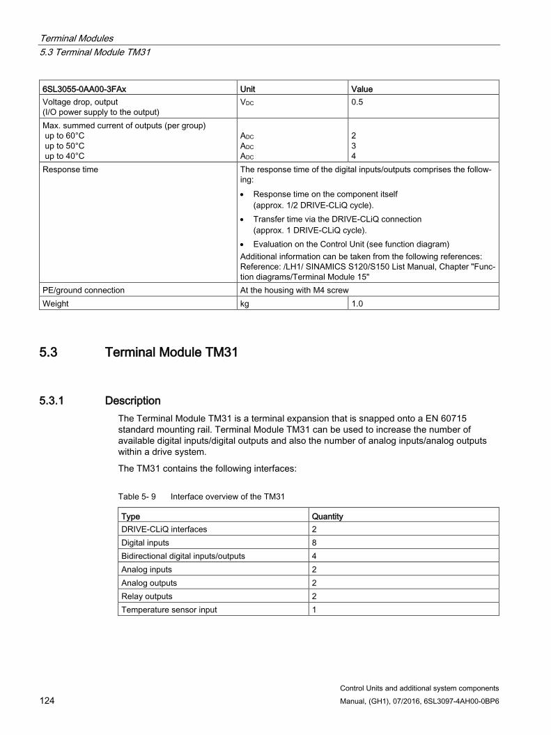
Terminal Modules 5.3 Terminal Module TM31
Control Units and additional system components 124 Manual, (GH1), 07/2016, 6SL3097-4AH00-0BP6
6SL3055-0AA00-3FAx Unit Value Voltage drop, output (I/O power supply to the output)
VDC 0.5
Max. summed current of outputs (per group) up to 60°C up to 50°C up to 40°C
ADC ADC ADC
2 3 4
Response time The response time of the digital inputs/outputs comprises the follow-ing: • Response time on the component itself
(approx. 1/2 DRIVE-CLiQ cycle). • Transfer time via the DRIVE-CLiQ connection
(approx. 1 DRIVE-CLiQ cycle). • Evaluation on the Control Unit (see function diagram) Additional information can be taken from the following references: Reference: /LH1/ SINAMICS S120/S150 List Manual, Chapter "Func-tion diagrams/Terminal Module 15"
PE/ground connection At the housing with M4 screw Weight kg 1.0
5.3 Terminal Module TM31
5.3.1 Description The Terminal Module TM31 is a terminal expansion that is snapped onto a EN 60715 standard mounting rail. Terminal Module TM31 can be used to increase the number of available digital inputs/digital outputs and also the number of analog inputs/analog outputs within a drive system.
The TM31 contains the following interfaces:
Table 5- 9 Interface overview of the TM31
Type Quantity DRIVE-CLiQ interfaces 2 Digital inputs 8 Bidirectional digital inputs/outputs 4 Analog inputs 2 Analog outputs 2 Relay outputs 2 Temperature sensor input 1
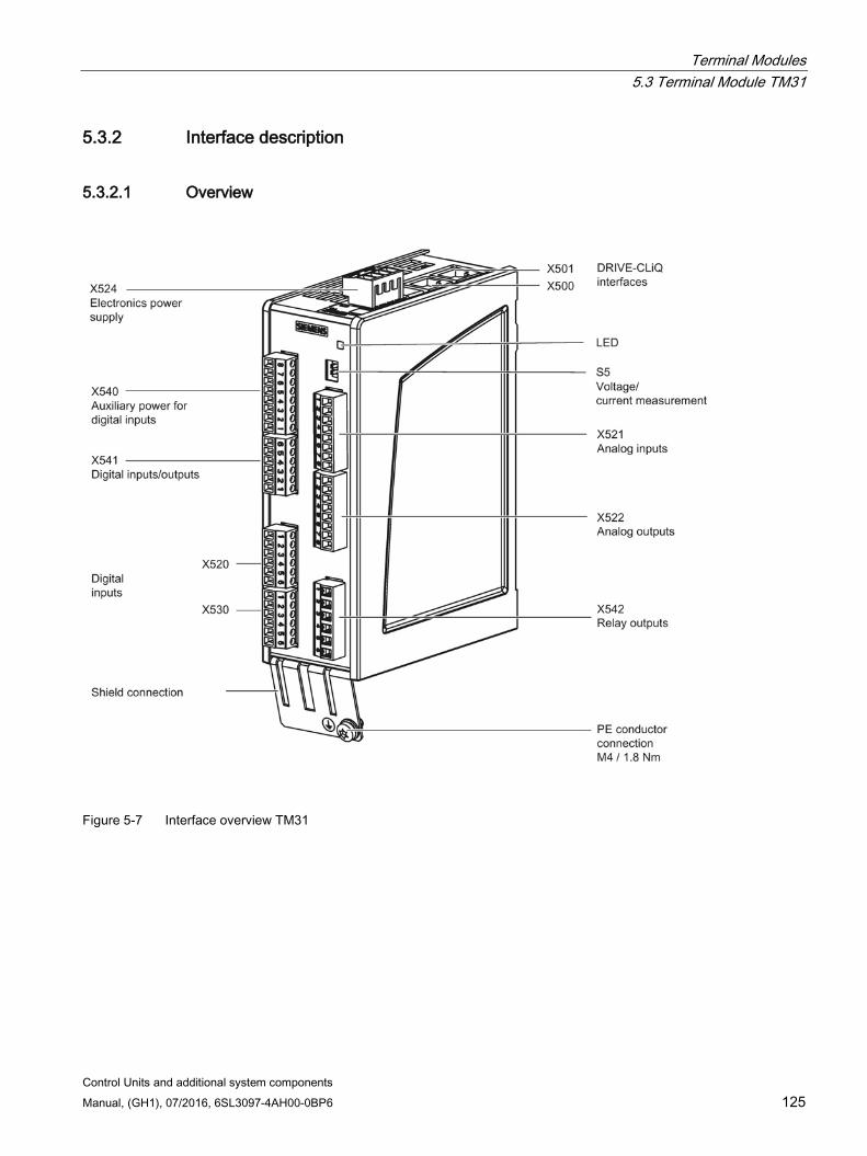
Terminal Modules 5.3 Terminal Module TM31
Control Units and additional system components Manual, (GH1), 07/2016, 6SL3097-4AH00-0BP6 125
5.3.2 Interface description
5.3.2.1 Overview
Figure 5-7 Interface overview TM31
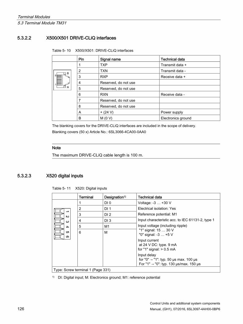
Terminal Modules 5.3 Terminal Module TM31
Control Units and additional system components 126 Manual, (GH1), 07/2016, 6SL3097-4AH00-0BP6
5.3.2.2 X500/X501 DRIVE-CLiQ interfaces
Table 5- 10 X500/X501: DRIVE-CLiQ interfaces
Pin Signal name Technical data
1 TXP Transmit data + 2 TXN Transmit data - 3 RXP Receive data + 4 Reserved, do not use 5 Reserved, do not use 6 RXN Receive data - 7 Reserved, do not use 8 Reserved, do not use A + (24 V) Power supply B M (0 V) Electronics ground
The blanking covers for the DRIVE-CLiQ interfaces are included in the scope of delivery. Blanking covers (50 x) Article No.: 6SL3066-4CA00-0AA0
Note
The maximum DRIVE-CLiQ cable length is 100 m.
5.3.2.3 X520 digital inputs
Table 5- 11 X520: Digital inputs
Terminal Designation1) Technical data
1 DI 0 Voltage: -3 … +30 V Electrical isolation: Yes Reference potential: M1 Input characteristic acc. to IEC 61131-2, type 1 Input voltage (including ripple) "1" signal: 15 … 30 V "0" signal: -3 … +5 V Input current at 24 V DC: type. 9 mA for "1" signal: > 0.5 mA Input delay for "0" → "1": typ. 50 µs max. 100 µs For "1" → "0": typ. 130 µs/max. 150 µs
2 DI 1 3 DI 2 4 DI 3 5 M1 6 M
Type: Screw terminal 1 (Page 331) 1) DI: Digital input; M: Electronics ground; M1: reference potential
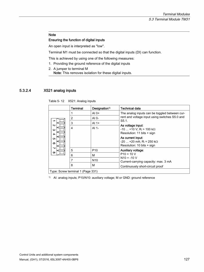
Terminal Modules 5.3 Terminal Module TM31
Control Units and additional system components Manual, (GH1), 07/2016, 6SL3097-4AH00-0BP6 127
Note
Ensuring the function of digital inputs
An open input is interpreted as "low".
Terminal M1 must be connected so that the digital inputs (DI) can function.
This is achieved by using one of the following measures: 1. Providing the ground reference of the digital inputs 2. A jumper to terminal M
Note: This removes isolation for these digital inputs.
5.3.2.4 X521 analog inputs
Table 5- 12 X521: Analog inputs
Terminal Designation1) Technical data
1 AI 0+ The analog inputs can be toggled between cur-rent and voltage input using switches S5.0 and S5.1. As voltage input: -10 ... +10 V; Ri > 100 kΩ Resolution: 11 bits + sign As current input: -20 ... +20 mA; Ri = 250 kΩ Resolution: 10 bits + sign
2 AI 0- 3 AI 1+ 4 AI 1-
5 P10 Auxiliary voltage: P10 = 10 V N10 = -10 V Current-carrying capacity: max. 3 mA Continuously short-circuit proof
6 M 7 N10 8 M
Type: Screw terminal 1 (Page 331) 1) AI: analog inputs; P10/N10: auxiliary voltage; M or GND: ground reference
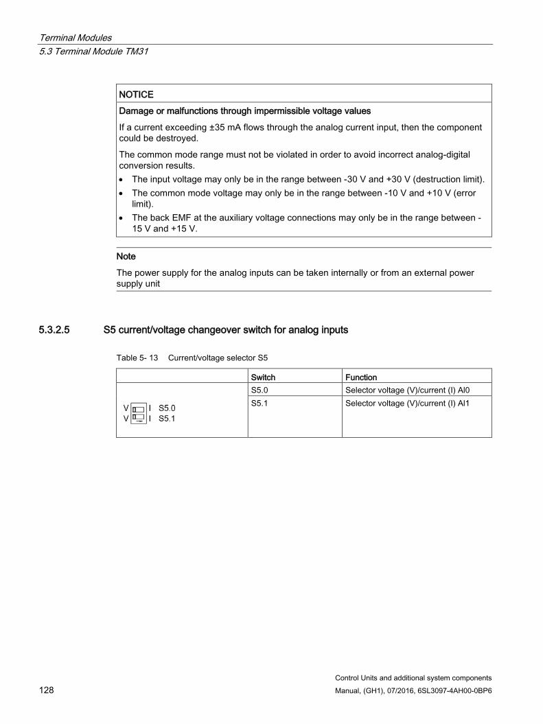
Terminal Modules 5.3 Terminal Module TM31
Control Units and additional system components 128 Manual, (GH1), 07/2016, 6SL3097-4AH00-0BP6
NOTICE
Damage or malfunctions through impermissible voltage values
If a current exceeding ±35 mA flows through the analog current input, then the component could be destroyed.
The common mode range must not be violated in order to avoid incorrect analog-digital conversion results. • The input voltage may only be in the range between -30 V and +30 V (destruction limit). • The common mode voltage may only be in the range between -10 V and +10 V (error
limit). • The back EMF at the auxiliary voltage connections may only be in the range between -
15 V and +15 V.
Note
The power supply for the analog inputs can be taken internally or from an external power supply unit
5.3.2.5 S5 current/voltage changeover switch for analog inputs
Table 5- 13 Current/voltage selector S5
Switch Function
S5.0 Selector voltage (V)/current (I) Al0 S5.1 Selector voltage (V)/current (I) Al1
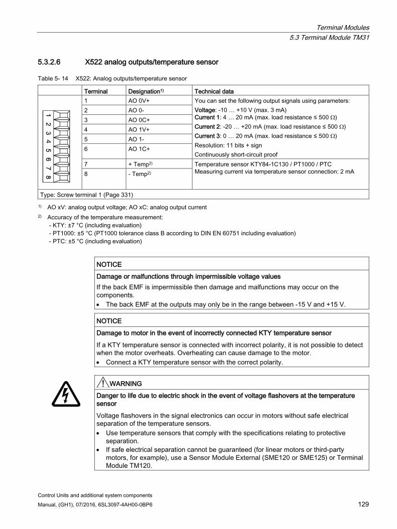
Terminal Modules 5.3 Terminal Module TM31
Control Units and additional system components Manual, (GH1), 07/2016, 6SL3097-4AH00-0BP6 129
5.3.2.6 X522 analog outputs/temperature sensor
Table 5- 14 X522: Analog outputs/temperature sensor
Terminal Designation1) Technical data
1 AO 0V+ You can set the following output signals using parameters: Voltage: -10 … +10 V (max. 3 mA) Current 1: 4 … 20 mA (max. load resistance ≤ 500 Ω) Current 2: -20 … +20 mA (max. load resistance ≤ 500 Ω) Current 3: 0 … 20 mA (max. load resistance ≤ 500 Ω) Resolution: 11 bits + sign Continuously short-circuit proof
2 AO 0- 3 AO 0C+ 4 AO 1V+ 5 AO 1- 6 AO 1C+
7 + Temp2) Temperature sensor KTY84-1C130 / PT1000 / PTC Measuring current via temperature sensor connection: 2 mA 8 - Temp2)
Type: Screw terminal 1 (Page 331) 1) AO xV: analog output voltage; AO xC: analog output current
2) Accuracy of the temperature measurement: - KTY: ±7 °C (including evaluation) - PT1000: ±5 °C (PT1000 tolerance class B according to DIN EN 60751 including evaluation) - PTC: ±5 °C (including evaluation)
NOTICE
Damage or malfunctions through impermissible voltage values If the back EMF is impermissible then damage and malfunctions may occur on the components. • The back EMF at the outputs may only be in the range between -15 V and +15 V.
NOTICE
Damage to motor in the event of incorrectly connected KTY temperature sensor
If a KTY temperature sensor is connected with incorrect polarity, it is not possible to detect when the motor overheats. Overheating can cause damage to the motor. • Connect a KTY temperature sensor with the correct polarity.
WARNING
Danger to life due to electric shock in the event of voltage flashovers at the temperature sensor
Voltage flashovers in the signal electronics can occur in motors without safe electrical separation of the temperature sensors. • Use temperature sensors that comply with the specifications relating to protective
separation. • If safe electrical separation cannot be guaranteed (for linear motors or third-party
motors, for example), use a Sensor Module External (SME120 or SME125) or Terminal Module TM120.
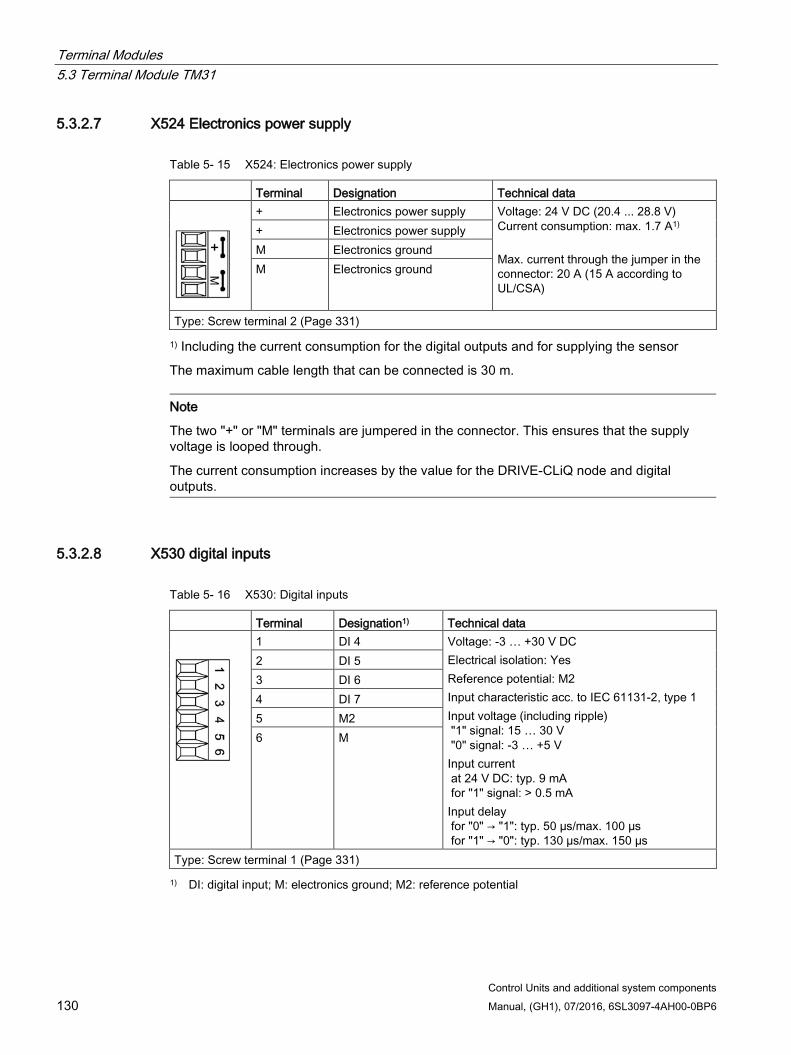
Terminal Modules 5.3 Terminal Module TM31
Control Units and additional system components 130 Manual, (GH1), 07/2016, 6SL3097-4AH00-0BP6
5.3.2.7 X524 Electronics power supply
Table 5- 15 X524: Electronics power supply
Terminal Designation Technical data
+ Electronics power supply Voltage: 24 V DC (20.4 ... 28.8 V) Current consumption: max. 1.7 A1) Max. current through the jumper in the connector: 20 A (15 A according to UL/CSA)
+ Electronics power supply M Electronics ground M Electronics ground
Type: Screw terminal 2 (Page 331)
1) Including the current consumption for the digital outputs and for supplying the sensor
The maximum cable length that can be connected is 30 m.
Note
The two "+" or "M" terminals are jumpered in the connector. This ensures that the supply voltage is looped through.
The current consumption increases by the value for the DRIVE-CLiQ node and digital outputs.
5.3.2.8 X530 digital inputs
Table 5- 16 X530: Digital inputs
Terminal Designation1) Technical data
1 DI 4 Voltage: -3 … +30 V DC Electrical isolation: Yes Reference potential: M2 Input characteristic acc. to IEC 61131-2, type 1 Input voltage (including ripple) "1" signal: 15 … 30 V "0" signal: -3 … +5 V Input current at 24 V DC: typ. 9 mA for "1" signal: > 0.5 mA Input delay for "0" → "1": typ. 50 µs/max. 100 µs for "1" → "0": typ. 130 µs/max. 150 µs
2 DI 5 3 DI 6 4 DI 7 5 M2 6 M
Type: Screw terminal 1 (Page 331) 1) DI: digital input; M: electronics ground; M2: reference potential

Terminal Modules 5.3 Terminal Module TM31
Control Units and additional system components Manual, (GH1), 07/2016, 6SL3097-4AH00-0BP6 131
Note
Ensuring the function of digital inputs
An open input is interpreted as "low".
To enable the digital inputs (DI) to function, terminal M2 must be connected.
This is achieved by using one of the following measures: 1. Providing the ground reference of the digital inputs 2. A jumper to terminal M
Note: This removes isolation for these digital inputs.
5.3.2.9 X540 auxiliary voltage for the digital inputs
Table 5- 17 X540: Auxiliary voltage for digital inputs
Terminal Designation Technical data
8 +24 V Voltage: +24 V DC Max. total load current of +24 V auxil-iary voltage for terminals X540 and X541 combined: 150 mA
7 +24 V 6 +24 V 5 +24 V 4 +24 V 3 +24 V 2 +24 V 1 +24 V
Type: Screw terminal 1 (Page 331)
Note
This voltage supply is only for powering the digital inputs.
Note
If the 24 V supply is briefly interrupted, the auxiliary voltage for the digital inputs is deactivated for this time.
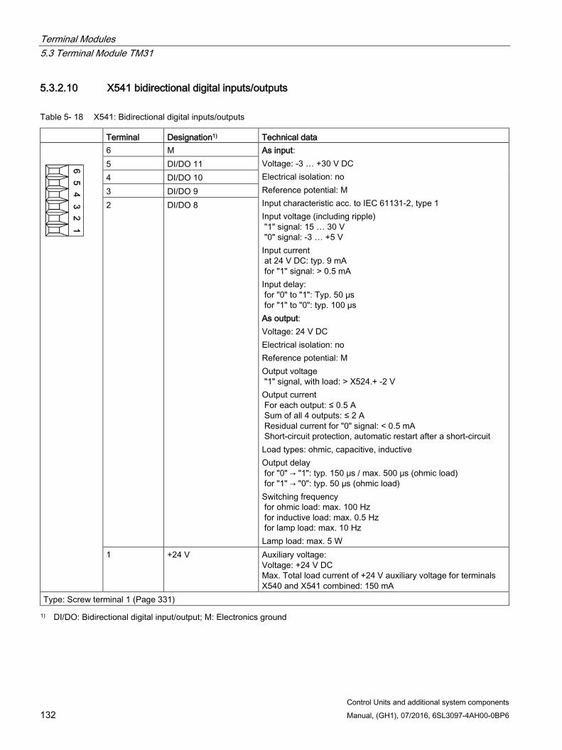
Terminal Modules 5.3 Terminal Module TM31
Control Units and additional system components 132 Manual, (GH1), 07/2016, 6SL3097-4AH00-0BP6
5.3.2.10 X541 bidirectional digital inputs/outputs
Table 5- 18 X541: Bidirectional digital inputs/outputs
Terminal Designation1) Technical data
6 M As input: Voltage: -3 … +30 V DC Electrical isolation: no Reference potential: M Input characteristic acc. to IEC 61131-2, type 1 Input voltage (including ripple) "1" signal: 15 … 30 V "0" signal: -3 … +5 V Input current at 24 V DC: typ. 9 mA for "1" signal: > 0.5 mA Input delay: for "0" to "1": Typ. 50 μs for "1" to "0": typ. 100 µs As output: Voltage: 24 V DC Electrical isolation: no Reference potential: M Output voltage "1" signal, with load: > X524.+ -2 V Output current For each output: ≤ 0.5 A Sum of all 4 outputs: ≤ 2 A Residual current for "0" signal: < 0.5 mA Short-circuit protection, automatic restart after a short-circuit Load types: ohmic, capacitive, inductive Output delay for "0" → "1": typ. 150 μs / max. 500 μs (ohmic load) for "1" → "0": typ. 50 µs (ohmic load) Switching frequency for ohmic load: max. 100 Hz for inductive load: max. 0.5 Hz for lamp load: max. 10 Hz Lamp load: max. 5 W
5 DI/DO 11 4 DI/DO 10 3 DI/DO 9 2 DI/DO 8
1 +24 V Auxiliary voltage: Voltage: +24 V DC Max. Total load current of +24 V auxiliary voltage for terminals X540 and X541 combined: 150 mA
Type: Screw terminal 1 (Page 331) 1) DI/DO: Bidirectional digital input/output; M: Electronics ground
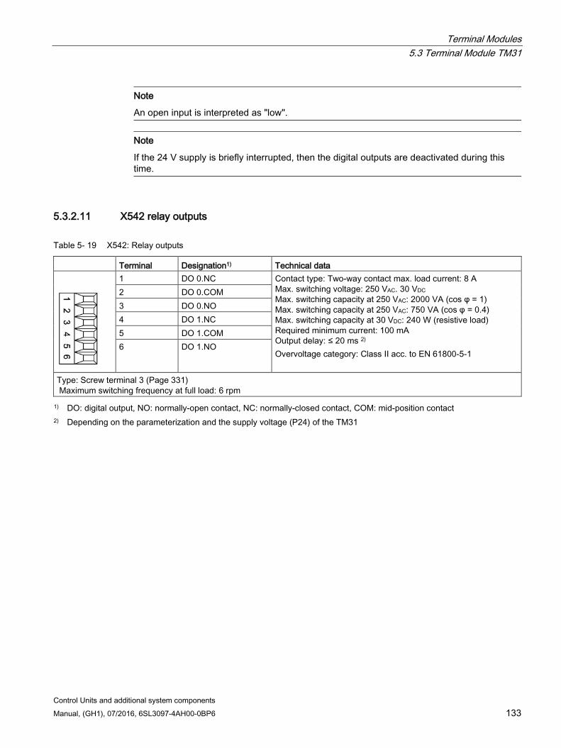
Terminal Modules 5.3 Terminal Module TM31
Control Units and additional system components Manual, (GH1), 07/2016, 6SL3097-4AH00-0BP6 133
Note
An open input is interpreted as "low".
Note
If the 24 V supply is briefly interrupted, then the digital outputs are deactivated during this time.
5.3.2.11 X542 relay outputs
Table 5- 19 X542: Relay outputs
Terminal Designation1) Technical data
1 DO 0.NC Contact type: Two-way contact max. load current: 8 A Max. switching voltage: 250 VAC. 30 VDC Max. switching capacity at 250 VAC: 2000 VA (cos φ = 1) Max. switching capacity at 250 VAC: 750 VA (cos φ = 0.4) Max. switching capacity at 30 VDC: 240 W (resistive load) Required minimum current: 100 mA Output delay: ≤ 20 ms 2) Overvoltage category: Class II acc. to EN 61800-5-1
2 DO 0.COM 3 DO 0.NO 4 DO 1.NC 5 DO 1.COM 6 DO 1.NO
Type: Screw terminal 3 (Page 331)
Maximum switching frequency at full load: 6 rpm 1) DO: digital output, NO: normally-open contact, NC: normally-closed contact, COM: mid-position contact
2) Depending on the parameterization and the supply voltage (P24) of the TM31
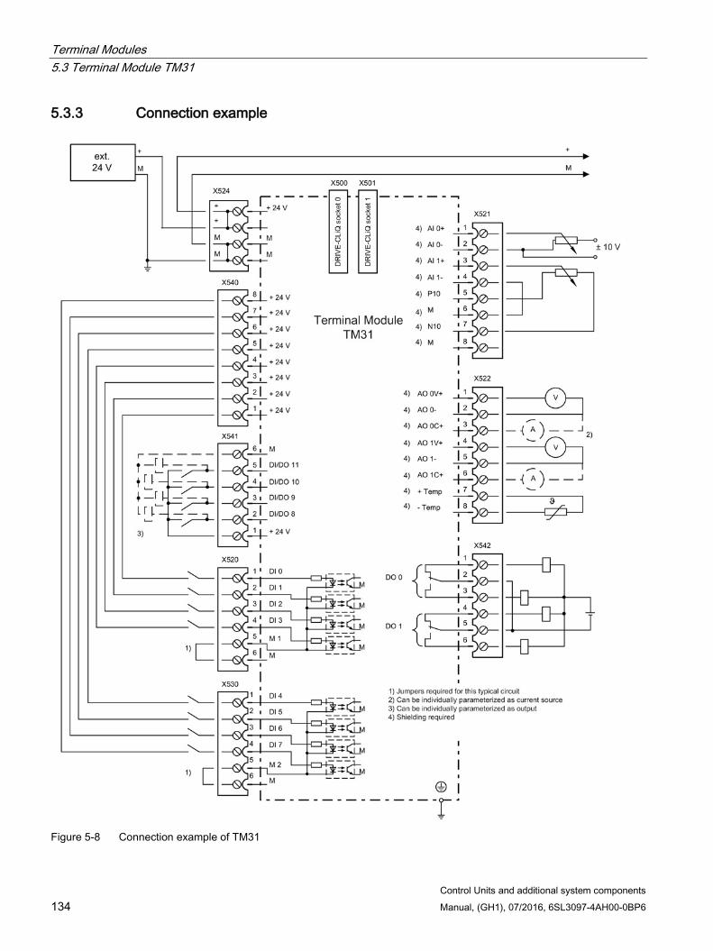
Terminal Modules 5.3 Terminal Module TM31
Control Units and additional system components 134 Manual, (GH1), 07/2016, 6SL3097-4AH00-0BP6
5.3.3 Connection example
Figure 5-8 Connection example of TM31

Terminal Modules 5.3 Terminal Module TM31
Control Units and additional system components Manual, (GH1), 07/2016, 6SL3097-4AH00-0BP6 135
5.3.4 Meaning of the LED
Table 5- 20 Meanings of the LEDs on the Terminal Module TM31
LED Color Status Description, cause Remedy READY - Off The electronics power supply is missing or outside the
permissible tolerance range. –
Green Continuous light
The component is ready for operation. Cyclic DRIVE-CLiQ communication is taking place.
–
Orange Continuous light
DRIVE-CLiQ communication is being established. –
Red Continuous light
This component has at least one fault. Note: The LED is activated irrespective of whether the corre-sponding messages have been reconfigured.
Remove and acknowledge the fault.
Green/ red
Flashing light 0.5 Hz
Firmware is being downloaded. –
Flashing light 2 Hz
Firmware download is complete. The system waits for POWER ON.
Carry out a POWER ON.
Green/ orange or Red/ orange
Flashing light
Component recognition via LED is activated1). Note: Both options depend on the LED status when component recognition is activated.
–
1) The parameters for activating component recognition using LEDs can be taken from the following reference: Reference: /LH1/ SINAMICS S120/S150 List Manual
Cause and rectification of faults Additional information about the cause and resolving faults can be taken from the following references:
Reference:/LH1/SINAMICS S120/S150 List Manual
Reference: /IH1/ SINAMICS S120 Commissioning Manual with STARTER
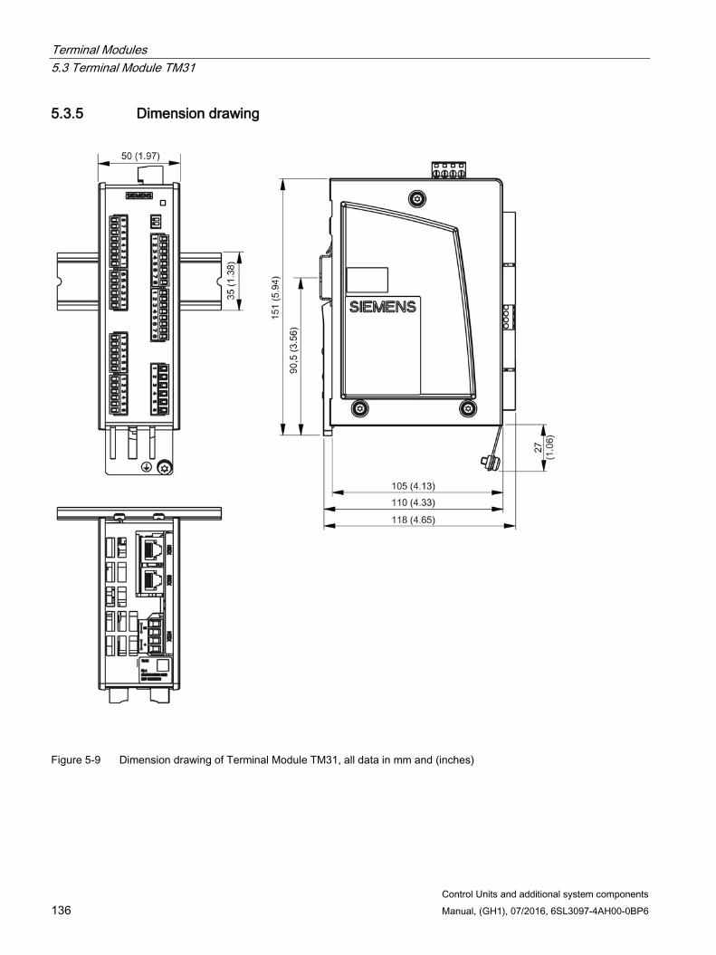
Terminal Modules 5.3 Terminal Module TM31
Control Units and additional system components 136 Manual, (GH1), 07/2016, 6SL3097-4AH00-0BP6
5.3.5 Dimension drawing
Figure 5-9 Dimension drawing of Terminal Module TM31, all data in mm and (inches)
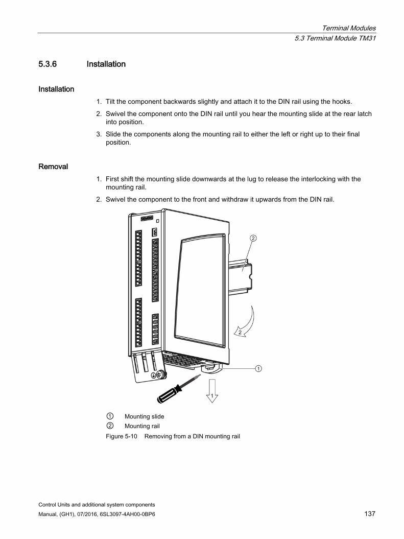
Terminal Modules 5.3 Terminal Module TM31
Control Units and additional system components Manual, (GH1), 07/2016, 6SL3097-4AH00-0BP6 137
5.3.6 Installation
Installation 1. Tilt the component backwards slightly and attach it to the DIN rail using the hooks.
2. Swivel the component onto the DIN rail until you hear the mounting slide at the rear latch into position.
3. Slide the components along the mounting rail to either the left or right up to their final position.
Removal 1. First shift the mounting slide downwards at the lug to release the interlocking with the
mounting rail.
2. Swivel the component to the front and withdraw it upwards from the DIN rail.
① ②
Mounting slide Mounting rail
Figure 5-10 Removing from a DIN mounting rail

Terminal Modules 5.3 Terminal Module TM31
Control Units and additional system components 138 Manual, (GH1), 07/2016, 6SL3097-4AH00-0BP6
5.3.7 Protective conductor connection and shield support It is always advisable to shield the digital input/output wiring.
The following diagram shows a typical Weidmüller shield connection clamp for the shield supports.
① Shield connection terminal, Weidmüller company, type: KLBUE CO1, Article number:
1753311001 ② Protective conductor connection M4 / 1.8 Nm
Figure 5-11 Protective conductor connection and shield support
NOTICE
Damage or faulty operation due to incorrect shielding or inadmissible cable lengths
If the correct shielding procedures or the permissible cable lengths are not observed, it can cause damage or the machine may malfunction. • Only use shielded cables. • Do not exceed the cable lengths stated in the technical data.
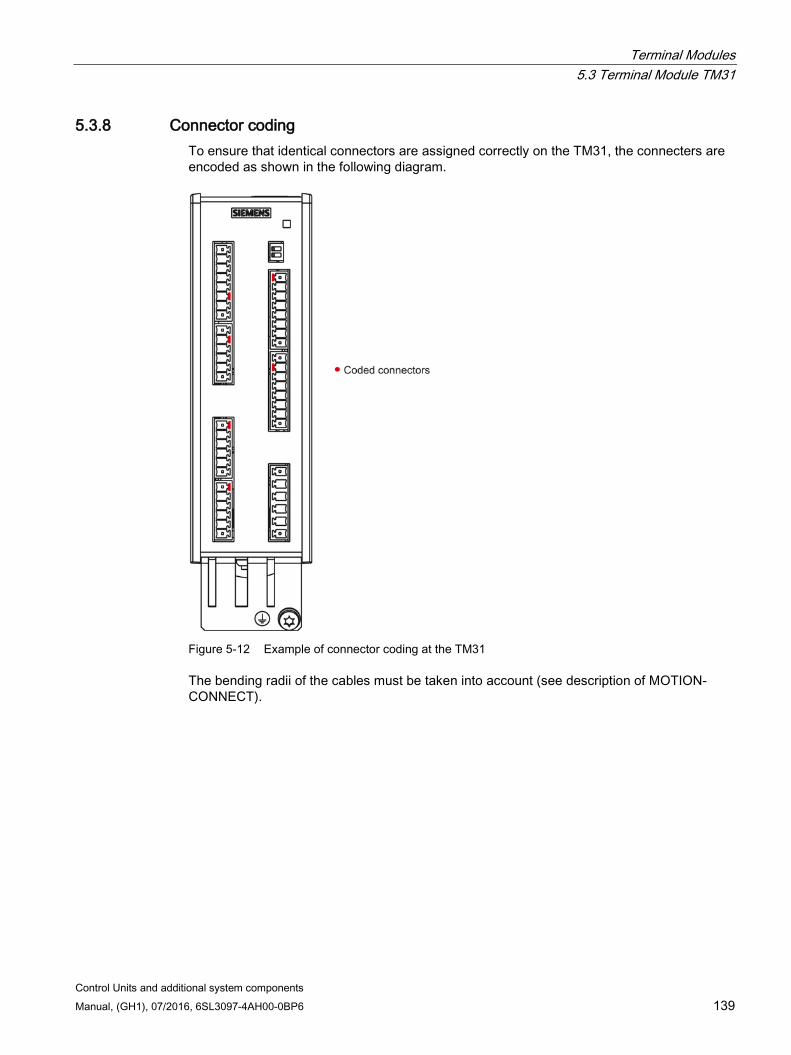
Terminal Modules 5.3 Terminal Module TM31
Control Units and additional system components Manual, (GH1), 07/2016, 6SL3097-4AH00-0BP6 139
5.3.8 Connector coding To ensure that identical connectors are assigned correctly on the TM31, the connecters are encoded as shown in the following diagram.
Figure 5-12 Example of connector coding at the TM31
The bending radii of the cables must be taken into account (see description of MOTION-CONNECT).
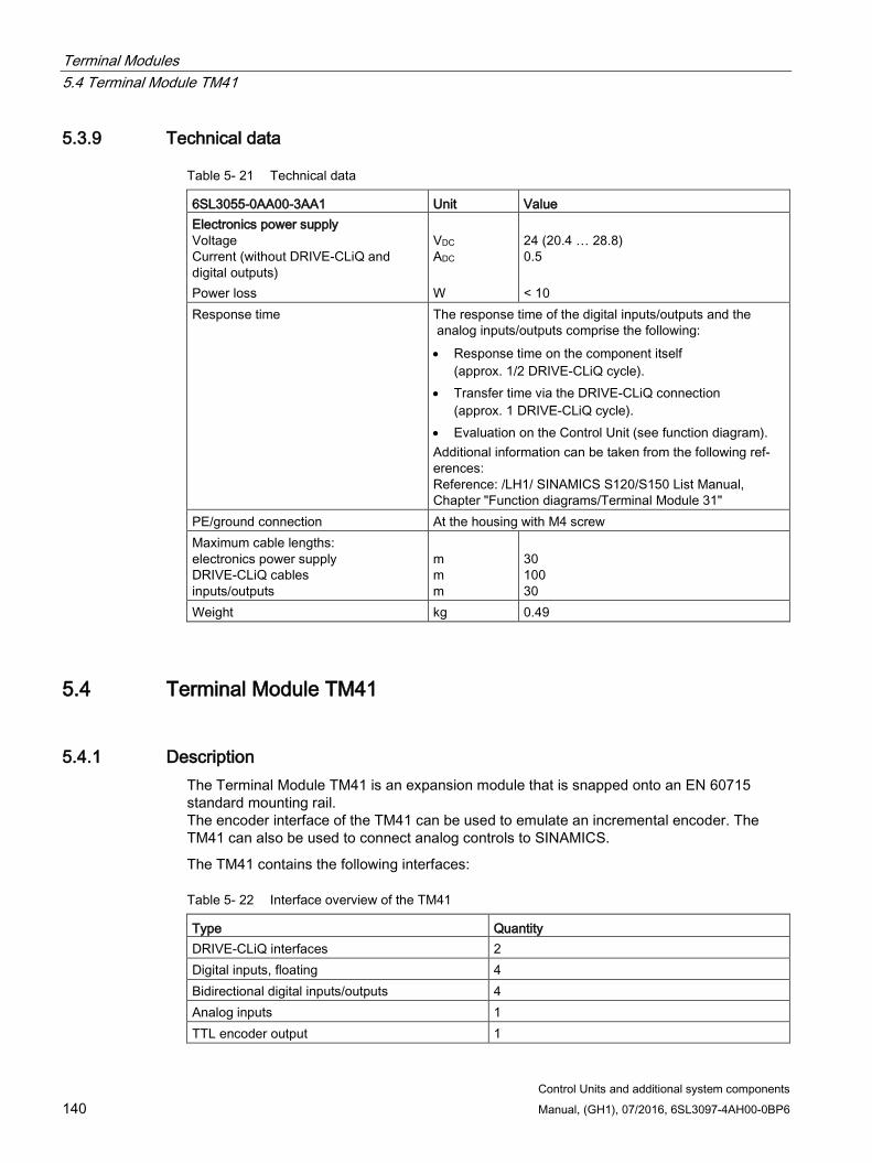
Terminal Modules 5.4 Terminal Module TM41
Control Units and additional system components 140 Manual, (GH1), 07/2016, 6SL3097-4AH00-0BP6
5.3.9 Technical data
Table 5- 21 Technical data
6SL3055-0AA00-3AA1 Unit Value Electronics power supply Voltage Current (without DRIVE-CLiQ and digital outputs) Power loss
VDC ADC W
24 (20.4 … 28.8) 0.5 < 10
Response time The response time of the digital inputs/outputs and the analog inputs/outputs comprise the following: • Response time on the component itself
(approx. 1/2 DRIVE-CLiQ cycle). • Transfer time via the DRIVE-CLiQ connection
(approx. 1 DRIVE-CLiQ cycle). • Evaluation on the Control Unit (see function diagram). Additional information can be taken from the following ref-erences: Reference: /LH1/ SINAMICS S120/S150 List Manual, Chapter "Function diagrams/Terminal Module 31"
PE/ground connection At the housing with M4 screw Maximum cable lengths: electronics power supply DRIVE-CLiQ cables inputs/outputs
m m m
30 100 30
Weight kg 0.49
5.4 Terminal Module TM41
5.4.1 Description The Terminal Module TM41 is an expansion module that is snapped onto an EN 60715 standard mounting rail. The encoder interface of the TM41 can be used to emulate an incremental encoder. The TM41 can also be used to connect analog controls to SINAMICS.
The TM41 contains the following interfaces:
Table 5- 22 Interface overview of the TM41
Type Quantity DRIVE-CLiQ interfaces 2 Digital inputs, floating 4 Bidirectional digital inputs/outputs 4 Analog inputs 1 TTL encoder output 1
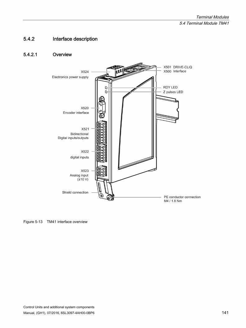
Terminal Modules 5.4 Terminal Module TM41
Control Units and additional system components Manual, (GH1), 07/2016, 6SL3097-4AH00-0BP6 141
5.4.2 Interface description
5.4.2.1 Overview
Figure 5-13 TM41 interface overview
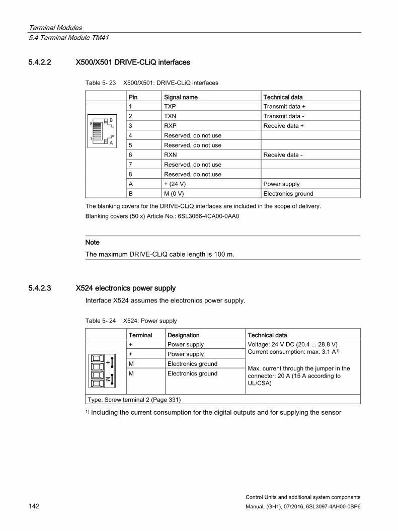
Terminal Modules 5.4 Terminal Module TM41
Control Units and additional system components 142 Manual, (GH1), 07/2016, 6SL3097-4AH00-0BP6
5.4.2.2 X500/X501 DRIVE-CLiQ interfaces
Table 5- 23 X500/X501: DRIVE-CLiQ interfaces
Pin Signal name Technical data
1 TXP Transmit data + 2 TXN Transmit data - 3 RXP Receive data + 4 Reserved, do not use 5 Reserved, do not use 6 RXN Receive data - 7 Reserved, do not use 8 Reserved, do not use A + (24 V) Power supply B M (0 V) Electronics ground
The blanking covers for the DRIVE-CLiQ interfaces are included in the scope of delivery. Blanking covers (50 x) Article No.: 6SL3066-4CA00-0AA0
Note
The maximum DRIVE-CLiQ cable length is 100 m.
5.4.2.3 X524 electronics power supply Interface X524 assumes the electronics power supply.
Table 5- 24 X524: Power supply
Terminal Designation Technical data
+ Power supply Voltage: 24 V DC (20.4 ... 28.8 V) Current consumption: max. 3.1 A1) Max. current through the jumper in the connector: 20 A (15 A according to UL/CSA)
+ Power supply M Electronics ground M Electronics ground
Type: Screw terminal 2 (Page 331)
1) Including the current consumption for the digital outputs and for supplying the sensor
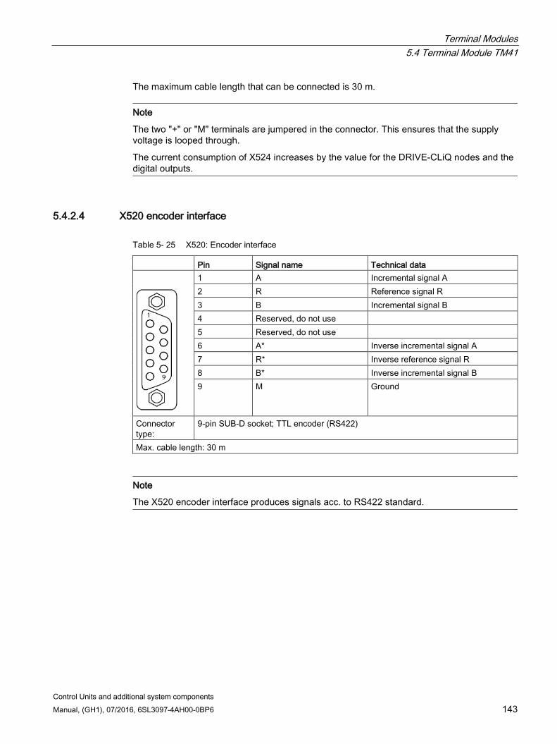
Terminal Modules 5.4 Terminal Module TM41
Control Units and additional system components Manual, (GH1), 07/2016, 6SL3097-4AH00-0BP6 143
The maximum cable length that can be connected is 30 m.
Note
The two "+" or "M" terminals are jumpered in the connector. This ensures that the supply voltage is looped through.
The current consumption of X524 increases by the value for the DRIVE-CLiQ nodes and the digital outputs.
5.4.2.4 X520 encoder interface
Table 5- 25 X520: Encoder interface
Pin Signal name Technical data
1 A Incremental signal A 2 R Reference signal R 3 B Incremental signal B 4 Reserved, do not use 5 Reserved, do not use 6 A* Inverse incremental signal A 7 R* Inverse reference signal R 8 B* Inverse incremental signal B 9 M Ground
Connector type:
9-pin SUB-D socket; TTL encoder (RS422)
Max. cable length: 30 m
Note
The X520 encoder interface produces signals acc. to RS422 standard.
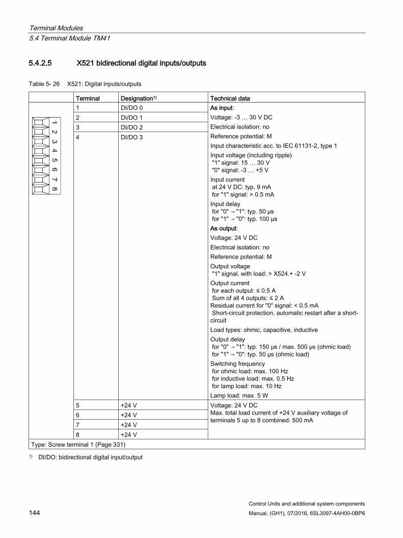
Terminal Modules 5.4 Terminal Module TM41
Control Units and additional system components 144 Manual, (GH1), 07/2016, 6SL3097-4AH00-0BP6
5.4.2.5 X521 bidirectional digital inputs/outputs
Table 5- 26 X521: Digital inputs/outputs
Terminal Designation1) Technical data
1 DI/DO 0 As input: Voltage: -3 … 30 V DC Electrical isolation: no Reference potential: M Input characteristic acc. to IEC 61131-2, type 1 Input voltage (including ripple) "1" signal: 15 … 30 V "0" signal: -3 … +5 V Input current at 24 V DC: typ. 9 mA for "1" signal: > 0.5 mA Input delay for "0" → "1": typ. 50 μs for "1" → "0": typ. 100 µs As output: Voltage: 24 V DC Electrical isolation: no Reference potential: M Output voltage "1" signal, with load: > X524.+ -2 V Output current for each output: ≤ 0.5 A Sum of all 4 outputs: ≤ 2 A Residual current for "0" signal: < 0.5 mA Short-circuit protection, automatic restart after a short-circuit Load types: ohmic, capacitive, inductive Output delay for "0" → "1": typ. 150 μs / max. 500 μs (ohmic load) for "1" → "0": typ. 50 µs (ohmic load) Switching frequency for ohmic load: max. 100 Hz for inductive load: max. 0.5 Hz for lamp load: max. 10 Hz Lamp load: max. 5 W
2 DI/DO 1 3 DI/DO 2 4 DI/DO 3
5 +24 V Voltage: 24 V DC Max. total load current of +24 V auxiliary voltage of terminals 5 up to 8 combined: 500 mA
6 +24 V 7 +24 V 8 +24 V
Type: Screw terminal 1 (Page 331) 1) DI/DO: bidirectional digital input/output
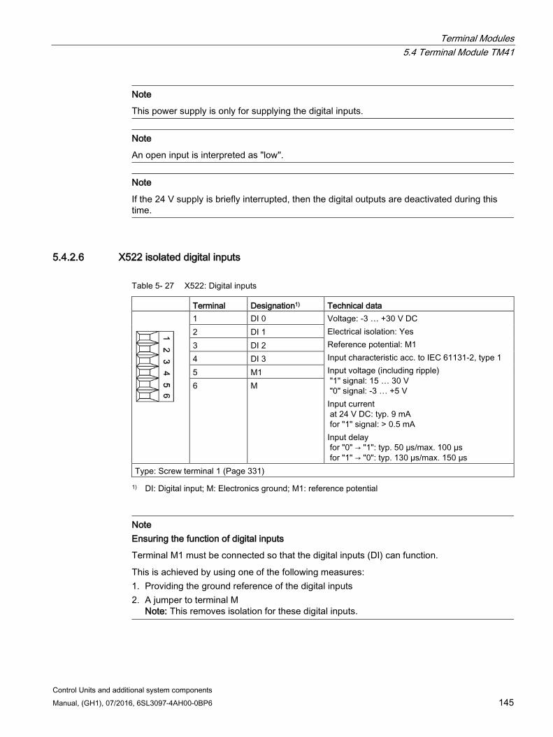
Terminal Modules 5.4 Terminal Module TM41
Control Units and additional system components Manual, (GH1), 07/2016, 6SL3097-4AH00-0BP6 145
Note
This power supply is only for supplying the digital inputs.
Note
An open input is interpreted as "low".
Note
If the 24 V supply is briefly interrupted, then the digital outputs are deactivated during this time.
5.4.2.6 X522 isolated digital inputs
Table 5- 27 X522: Digital inputs
Terminal Designation1) Technical data
1 DI 0 Voltage: -3 … +30 V DC Electrical isolation: Yes Reference potential: M1 Input characteristic acc. to IEC 61131-2, type 1 Input voltage (including ripple) "1" signal: 15 … 30 V "0" signal: -3 … +5 V Input current at 24 V DC: typ. 9 mA for "1" signal: > 0.5 mA Input delay for "0" → "1": typ. 50 µs/max. 100 µs for "1" → "0": typ. 130 µs/max. 150 µs
2 DI 1 3 DI 2 4 DI 3 5 M1 6 M
Type: Screw terminal 1 (Page 331) 1) DI: Digital input; M: Electronics ground; M1: reference potential
Note Ensuring the function of digital inputs
Terminal M1 must be connected so that the digital inputs (DI) can function.
This is achieved by using one of the following measures: 1. Providing the ground reference of the digital inputs 2. A jumper to terminal M
Note: This removes isolation for these digital inputs.
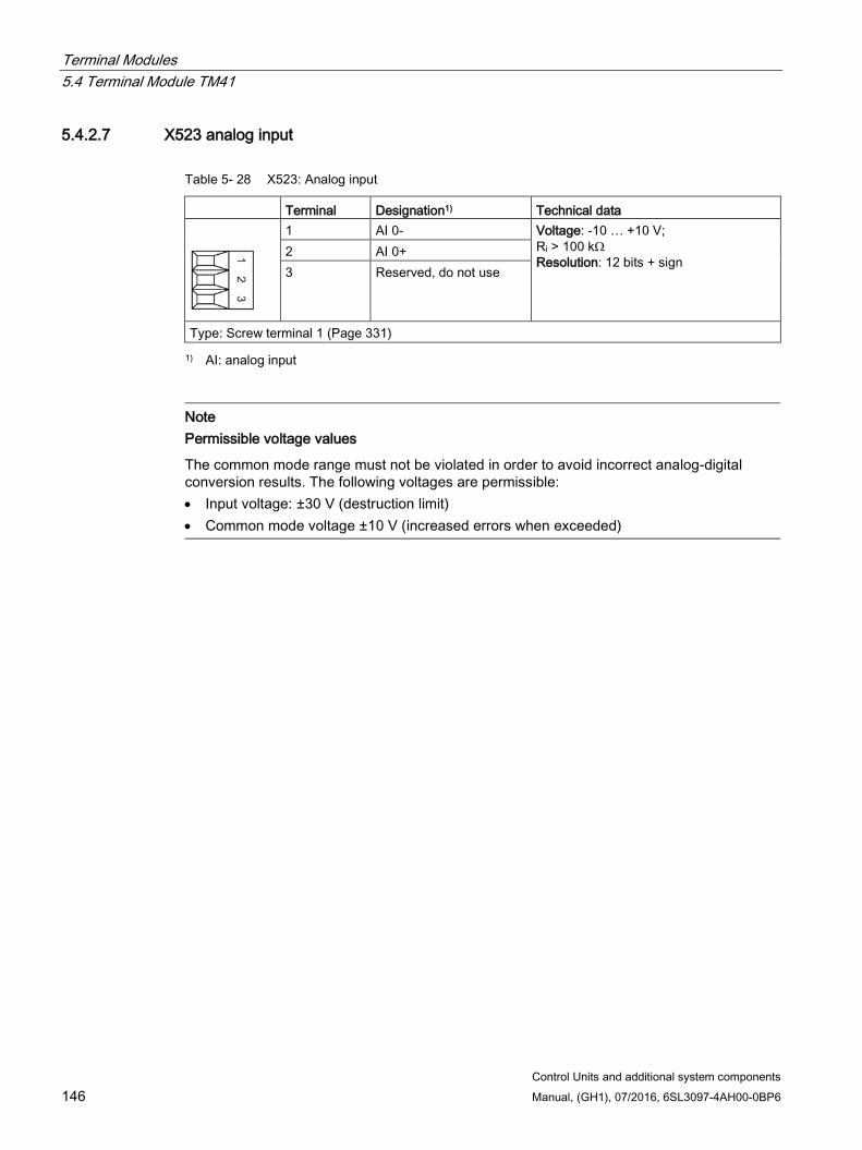
Terminal Modules 5.4 Terminal Module TM41
Control Units and additional system components 146 Manual, (GH1), 07/2016, 6SL3097-4AH00-0BP6
5.4.2.7 X523 analog input
Table 5- 28 X523: Analog input
Terminal Designation1) Technical data
1 AI 0- Voltage: -10 … +10 V; Ri > 100 kΩ Resolution: 12 bits + sign
2 AI 0+ 3 Reserved, do not use
Type: Screw terminal 1 (Page 331) 1) AI: analog input
Note Permissible voltage values
The common mode range must not be violated in order to avoid incorrect analog-digital conversion results. The following voltages are permissible: • Input voltage: ±30 V (destruction limit) • Common mode voltage ±10 V (increased errors when exceeded)
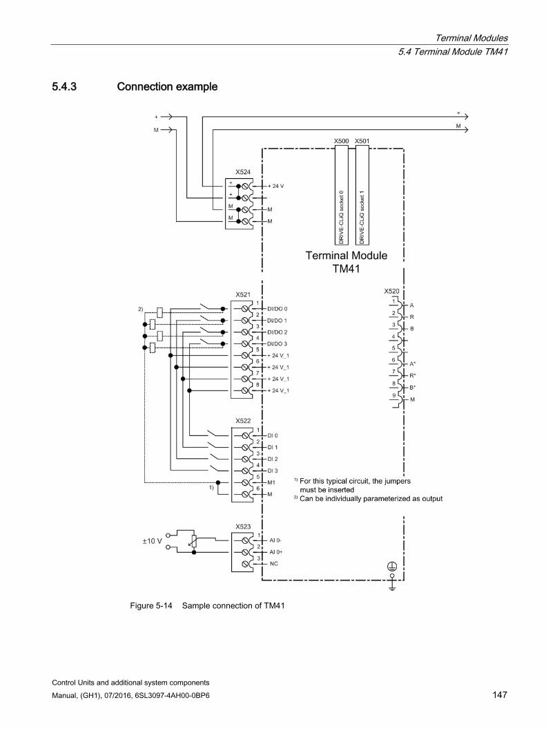
Terminal Modules 5.4 Terminal Module TM41
Control Units and additional system components Manual, (GH1), 07/2016, 6SL3097-4AH00-0BP6 147
5.4.3 Connection example
Figure 5-14 Sample connection of TM41
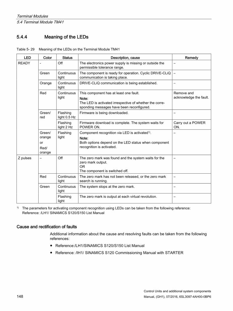
Terminal Modules 5.4 Terminal Module TM41
Control Units and additional system components 148 Manual, (GH1), 07/2016, 6SL3097-4AH00-0BP6
5.4.4 Meaning of the LEDs
Table 5- 29 Meaning of the LEDs on the Terminal Module TM41
LED Color Status Description, cause Remedy READY - Off The electronics power supply is missing or outside the
permissible tolerance range. –
Green Continuous light
The component is ready for operation. Cyclic DRIVE-CLiQ communication is taking place.
–
Orange Continuous light
DRIVE-CLiQ communication is being established. –
Red Continuous light
This component has at least one fault. Note: The LED is activated irrespective of whether the corre-sponding messages have been reconfigured.
Remove and acknowledge the fault.
Green/ red
Flashing light 0.5 Hz
Firmware is being downloaded. –
Flashing light 2 Hz
Firmware download is complete. The system waits for POWER ON.
Carry out a POWER ON.
Green/ orange or Red/ orange
Flashing light
Component recognition via LED is activated1). Note: Both options depend on the LED status when component recognition is activated.
–
Z pulses – Off The zero mark was found and the system waits for the zero mark output. OR The component is switched off.
–
Red Continuous light
The zero mark has not been released, or the zero mark search is running.
–
Green Continuous light
The system stops at the zero mark. –
Flashing light
The zero mark is output at each virtual revolution. –
1) The parameters for activating component recognition using LEDs can be taken from the following reference: Reference: /LH1/ SINAMICS S120/S150 List Manual
Cause and rectification of faults Additional information about the cause and resolving faults can be taken from the following references:
Reference:/LH1/SINAMICS S120/S150 List Manual
Reference: /IH1/ SINAMICS S120 Commissioning Manual with STARTER
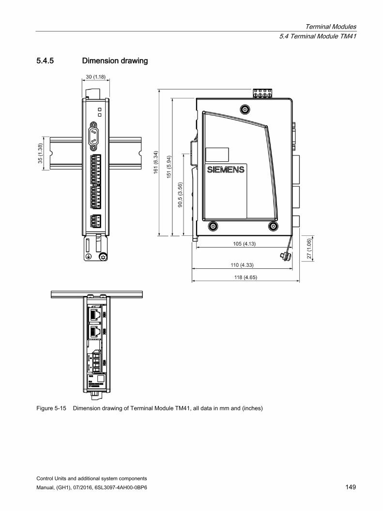
Terminal Modules 5.4 Terminal Module TM41
Control Units and additional system components Manual, (GH1), 07/2016, 6SL3097-4AH00-0BP6 149
5.4.5 Dimension drawing
Figure 5-15 Dimension drawing of Terminal Module TM41, all data in mm and (inches)
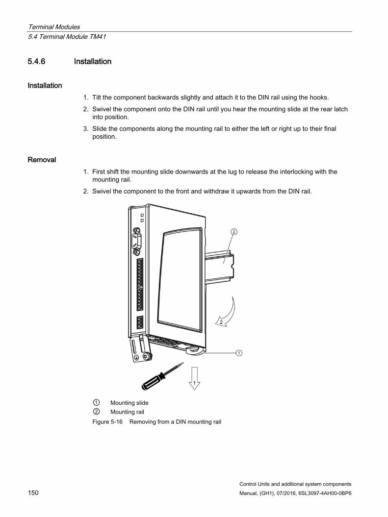
Terminal Modules 5.4 Terminal Module TM41
Control Units and additional system components 150 Manual, (GH1), 07/2016, 6SL3097-4AH00-0BP6
5.4.6 Installation
Installation 1. Tilt the component backwards slightly and attach it to the DIN rail using the hooks.
2. Swivel the component onto the DIN rail until you hear the mounting slide at the rear latch into position.
3. Slide the components along the mounting rail to either the left or right up to their final position.
Removal 1. First shift the mounting slide downwards at the lug to release the interlocking with the
mounting rail.
2. Swivel the component to the front and withdraw it upwards from the DIN rail.
① Mounting slide ② Mounting rail Figure 5-16 Removing from a DIN mounting rail
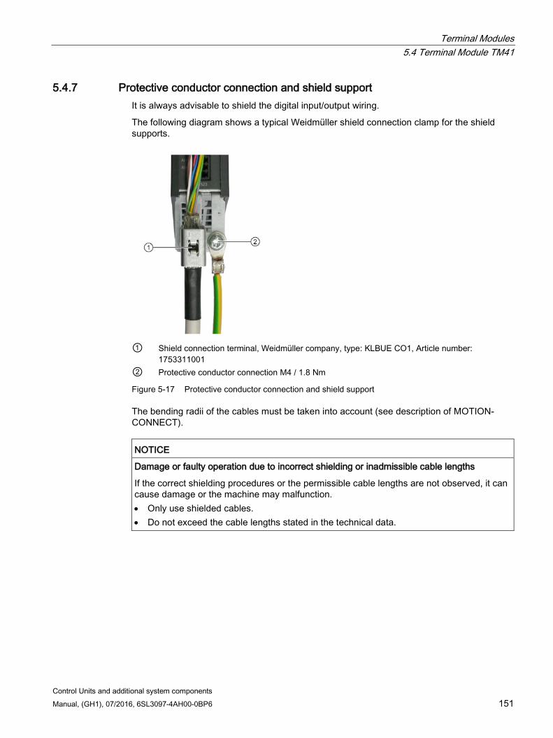
Terminal Modules 5.4 Terminal Module TM41
Control Units and additional system components Manual, (GH1), 07/2016, 6SL3097-4AH00-0BP6 151
5.4.7 Protective conductor connection and shield support It is always advisable to shield the digital input/output wiring.
The following diagram shows a typical Weidmüller shield connection clamp for the shield supports.
① Shield connection terminal, Weidmüller company, type: KLBUE CO1, Article number:
1753311001 ② Protective conductor connection M4 / 1.8 Nm
Figure 5-17 Protective conductor connection and shield support
The bending radii of the cables must be taken into account (see description of MOTION-CONNECT).
NOTICE
Damage or faulty operation due to incorrect shielding or inadmissible cable lengths
If the correct shielding procedures or the permissible cable lengths are not observed, it can cause damage or the machine may malfunction. • Only use shielded cables. • Do not exceed the cable lengths stated in the technical data.
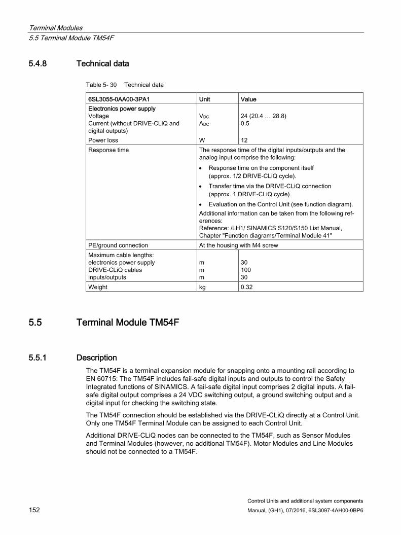
Terminal Modules 5.5 Terminal Module TM54F
Control Units and additional system components 152 Manual, (GH1), 07/2016, 6SL3097-4AH00-0BP6
5.4.8 Technical data
Table 5- 30 Technical data
6SL3055-0AA00-3PA1 Unit Value Electronics power supply Voltage Current (without DRIVE-CLiQ and digital outputs) Power loss
VDC ADC W
24 (20.4 … 28.8) 0.5 12
Response time The response time of the digital inputs/outputs and the analog input comprise the following: • Response time on the component itself
(approx. 1/2 DRIVE-CLiQ cycle). • Transfer time via the DRIVE-CLiQ connection
(approx. 1 DRIVE-CLiQ cycle). • Evaluation on the Control Unit (see function diagram). Additional information can be taken from the following ref-erences: Reference: /LH1/ SINAMICS S120/S150 List Manual, Chapter "Function diagrams/Terminal Module 41"
PE/ground connection At the housing with M4 screw Maximum cable lengths: electronics power supply DRIVE-CLiQ cables inputs/outputs
m m m
30 100 30
Weight kg 0.32
5.5 Terminal Module TM54F
5.5.1 Description The TM54F is a terminal expansion module for snapping onto a mounting rail according to EN 60715: The TM54F includes fail-safe digital inputs and outputs to control the Safety Integrated functions of SINAMICS. A fail-safe digital input comprises 2 digital inputs. A fail-safe digital output comprises a 24 VDC switching output, a ground switching output and a digital input for checking the switching state.
The TM54F connection should be established via the DRIVE-CLiQ directly at a Control Unit. Only one TM54F Terminal Module can be assigned to each Control Unit.
Additional DRIVE-CLiQ nodes can be connected to the TM54F, such as Sensor Modules and Terminal Modules (however, no additional TM54F). Motor Modules and Line Modules should not be connected to a TM54F.
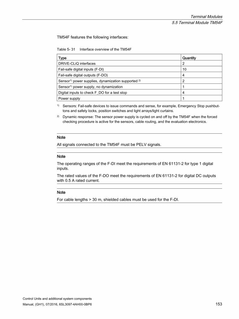
Terminal Modules 5.5 Terminal Module TM54F
Control Units and additional system components Manual, (GH1), 07/2016, 6SL3097-4AH00-0BP6 153
TM54F features the following interfaces:
Table 5- 31 Interface overview of the TM54F
Type Quantity DRIVE-CLiQ interfaces 2 Fail-safe digital inputs (F-DI) 10 Fail-safe digital outputs (F-DO) 4 Sensor1) power supplies, dynamization supported 2) 2 Sensor1) power supply, no dynamization 1 Digital inputs to check F_DO for a test stop 4 Power supply 1 1) Sensors: Fail-safe devices to issue commands and sense, for example, Emergency Stop pushbut-
tons and safety locks, position switches and light arrays/light curtains. 2) Dynamic response: The sensor power supply is cycled on and off by the TM54F when the forced
checking procedure is active for the sensors, cable routing, and the evaluation electronics.
Note
All signals connected to the TM54F must be PELV signals.
Note
The operating ranges of the F-DI meet the requirements of EN 61131-2 for type 1 digital inputs.
The rated values of the F-DO meet the requirements of EN 61131-2 for digital DC outputs with 0.5 A rated current.
Note
For cable lengths > 30 m, shielded cables must be used for the F-DI.
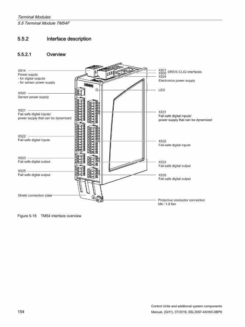
Terminal Modules 5.5 Terminal Module TM54F
Control Units and additional system components 154 Manual, (GH1), 07/2016, 6SL3097-4AH00-0BP6
5.5.2 Interface description
5.5.2.1 Overview
Figure 5-18 TM54 interface overview
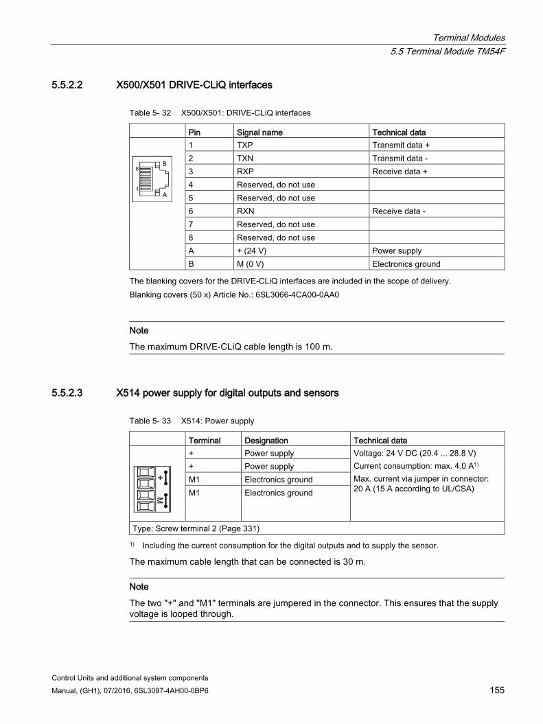
Terminal Modules 5.5 Terminal Module TM54F
Control Units and additional system components Manual, (GH1), 07/2016, 6SL3097-4AH00-0BP6 155
5.5.2.2 X500/X501 DRIVE-CLiQ interfaces
Table 5- 32 X500/X501: DRIVE-CLiQ interfaces
Pin Signal name Technical data
1 TXP Transmit data + 2 TXN Transmit data - 3 RXP Receive data + 4 Reserved, do not use 5 Reserved, do not use 6 RXN Receive data - 7 Reserved, do not use 8 Reserved, do not use A + (24 V) Power supply B M (0 V) Electronics ground
The blanking covers for the DRIVE-CLiQ interfaces are included in the scope of delivery. Blanking covers (50 x) Article No.: 6SL3066-4CA00-0AA0
Note
The maximum DRIVE-CLiQ cable length is 100 m.
5.5.2.3 X514 power supply for digital outputs and sensors
Table 5- 33 X514: Power supply
Terminal Designation Technical data
+ Power supply Voltage: 24 V DC (20.4 ... 28.8 V) Current consumption: max. 4.0 A1) Max. current via jumper in connector: 20 A (15 A according to UL/CSA)
+ Power supply M1 Electronics ground M1 Electronics ground
Type: Screw terminal 2 (Page 331) 1) Including the current consumption for the digital outputs and to supply the sensor.
The maximum cable length that can be connected is 30 m.
Note
The two "+" and "M1" terminals are jumpered in the connector. This ensures that the supply voltage is looped through.
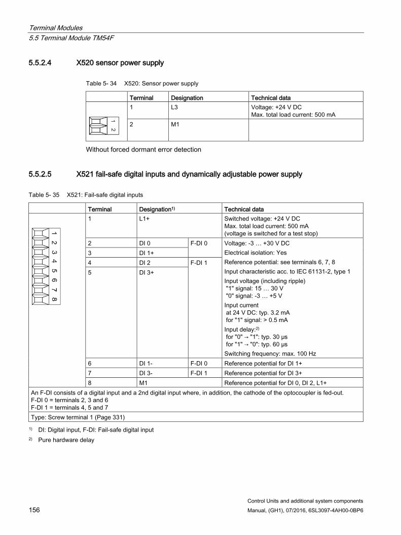
Terminal Modules 5.5 Terminal Module TM54F
Control Units and additional system components 156 Manual, (GH1), 07/2016, 6SL3097-4AH00-0BP6
5.5.2.4 X520 sensor power supply
Table 5- 34 X520: Sensor power supply
Terminal Designation Technical data
1 L3 Voltage: +24 V DC Max. total load current: 500 mA
2 M1
Without forced dormant error detection
5.5.2.5 X521 fail-safe digital inputs and dynamically adjustable power supply
Table 5- 35 X521: Fail-safe digital inputs
Terminal Designation1) Technical data
1 L1+ Switched voltage: +24 V DC Max. total load current: 500 mA (voltage is switched for a test stop)
2 DI 0 F-DI 0 Voltage: -3 … +30 V DC Electrical isolation: Yes Reference potential: see terminals 6, 7, 8 Input characteristic acc. to IEC 61131-2, type 1 Input voltage (including ripple) "1" signal: 15 … 30 V "0" signal: -3 … +5 V Input current at 24 V DC: typ. 3.2 mA for "1" signal: > 0.5 mA Input delay:2) for "0" → "1": typ. 30 μs for "1" → "0": typ. 60 µs Switching frequency: max. 100 Hz
3 DI 1+ 4 DI 2 F-DI 1 5 DI 3+
6 DI 1- F-DI 0 Reference potential for DI 1+ 7 DI 3- F-DI 1 Reference potential for DI 3+ 8 M1 Reference potential for DI 0, DI 2, L1+
An F-DI consists of a digital input and a 2nd digital input where, in addition, the cathode of the optocoupler is fed-out. F-DI 0 = terminals 2, 3 and 6 F-DI 1 = terminals 4, 5 and 7 Type: Screw terminal 1 (Page 331) 1) DI: Digital input, F-DI: Fail-safe digital input
2) Pure hardware delay
Terminal Modules 5.5 Terminal Module TM54F
Control Units and additional system components Manual, (GH1), 07/2016, 6SL3097-4AH00-0BP6 157
Note
Execution of a test stop
The test stop of the F-DI 0 to F-DI 4 can only be performed if the F-DI is supplied from L1+.
Note Ensuring the function of digital inputs
For the digital inputs DIx+ to function, the reference potential must be connected to input DIx- in each case.
This is achieved by using one of the following measures: 1. Providing the ground reference of the digital inputs 2. A jumper between DIx- and terminal M1
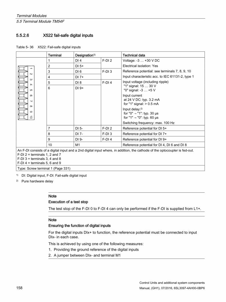
Terminal Modules 5.5 Terminal Module TM54F
Control Units and additional system components 158 Manual, (GH1), 07/2016, 6SL3097-4AH00-0BP6
5.5.2.6 X522 fail-safe digital inputs
Table 5- 36 X522: Fail-safe digital inputs
Terminal Designation1) Technical data
1 DI 4 F-DI 2 Voltage: -3 … +30 V DC Electrical isolation: Yes Reference potential: see terminals 7, 8, 9, 10 Input characteristic acc. to IEC 61131-2, type 1 Input voltage (including ripple) "1" signal: 15 … 30 V "0" signal: -3 … +5 V Input current at 24 V DC: typ. 3.2 mA for "1" signal: > 0.5 mA Input delay:2) for "0" → "1": typ. 30 μs for "1" → "0": typ. 60 µs Switching frequency: max. 100 Hz
2 DI 5+ 3 DI 6 F-DI 3 4 DI 7+ 5 DI 8 F-DI 4 6 DI 9+
7 DI 5- F-DI 2 Reference potential for DI 5+ 8 DI 7- F-DI 3 Reference potential for DI 7+ 9 DI 9- F-DI 4 Reference potential for DI 9+ 10 M1 Reference potential for DI 4, DI 6 and DI 8
An F-DI consists of a digital input and a 2nd digital input where, in addition, the cathode of the optocoupler is fed-out. F-DI 2 = terminals 1, 2 and 7 F-DI 3 = terminals 3, 4 and 8 F-DI 4 = terminals 5, 6 and 9 Type: Screw terminal 1 (Page 331) 1) DI: Digital input, F-DI: Fail-safe digital input
2) Pure hardware delay
Note Execution of a test stop
The test stop of the F-DI 0 to F-DI 4 can only be performed if the F-DI is supplied from L1+.
Note Ensuring the function of digital inputs
For the digital inputs DIx+ to function, the reference potential must be connected to input DIx- in each case.
This is achieved by using one of the following measures: 1. Providing the ground reference of the digital inputs 2. A jumper between DIx- and terminal M1
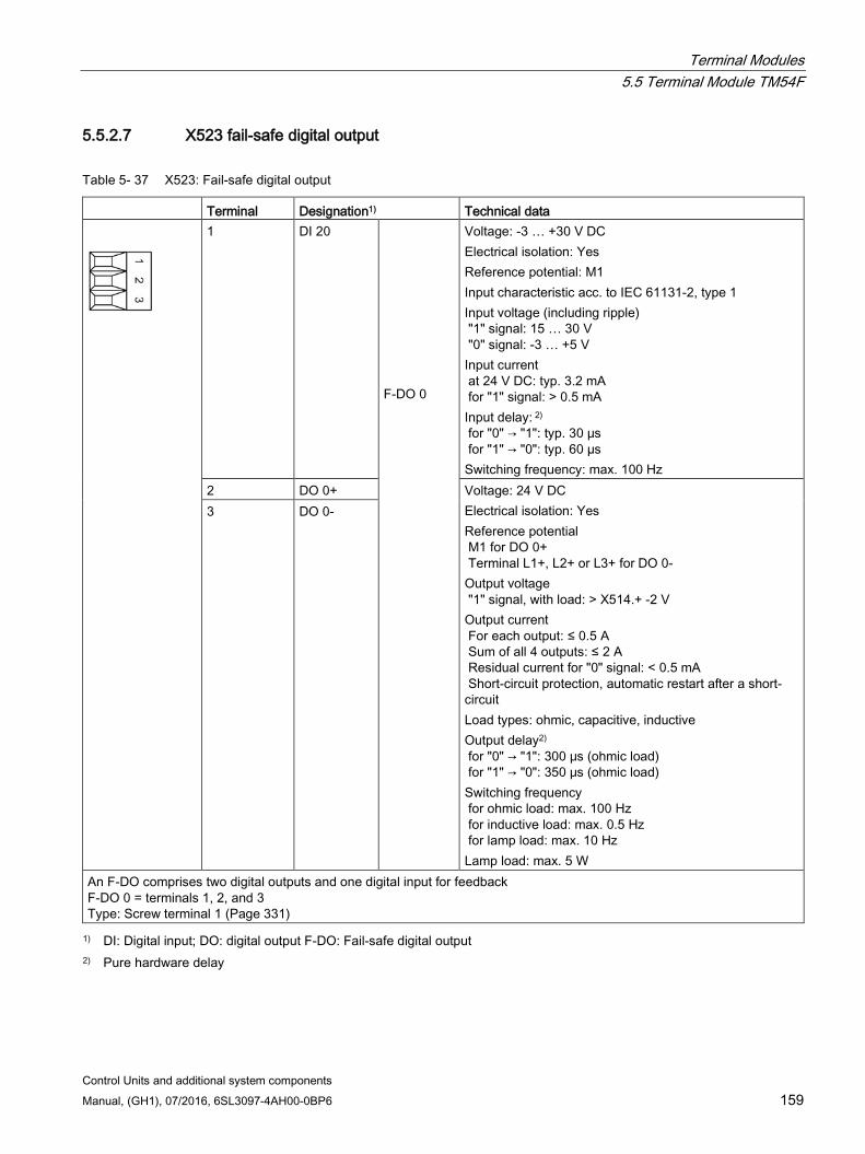
Terminal Modules 5.5 Terminal Module TM54F
Control Units and additional system components Manual, (GH1), 07/2016, 6SL3097-4AH00-0BP6 159
5.5.2.7 X523 fail-safe digital output
Table 5- 37 X523: Fail-safe digital output
Terminal Designation1) Technical data
1 DI 20 F-DO 0
Voltage: -3 … +30 V DC Electrical isolation: Yes Reference potential: M1 Input characteristic acc. to IEC 61131-2, type 1 Input voltage (including ripple) "1" signal: 15 … 30 V "0" signal: -3 … +5 V Input current at 24 V DC: typ. 3.2 mA for "1" signal: > 0.5 mA Input delay: 2) for "0" → "1": typ. 30 μs for "1" → "0": typ. 60 µs Switching frequency: max. 100 Hz
2 DO 0+ Voltage: 24 V DC Electrical isolation: Yes Reference potential M1 for DO 0+ Terminal L1+, L2+ or L3+ for DO 0- Output voltage "1" signal, with load: > X514.+ -2 V Output current For each output: ≤ 0.5 A Sum of all 4 outputs: ≤ 2 A Residual current for "0" signal: < 0.5 mA Short-circuit protection, automatic restart after a short-circuit Load types: ohmic, capacitive, inductive Output delay2) for "0" → "1": 300 μs (ohmic load) for "1" → "0": 350 μs (ohmic load) Switching frequency for ohmic load: max. 100 Hz for inductive load: max. 0.5 Hz for lamp load: max. 10 Hz Lamp load: max. 5 W
3 DO 0-
An F-DO comprises two digital outputs and one digital input for feedback F-DO 0 = terminals 1, 2, and 3 Type: Screw terminal 1 (Page 331) 1) DI: Digital input; DO: digital output F-DO: Fail-safe digital output
2) Pure hardware delay
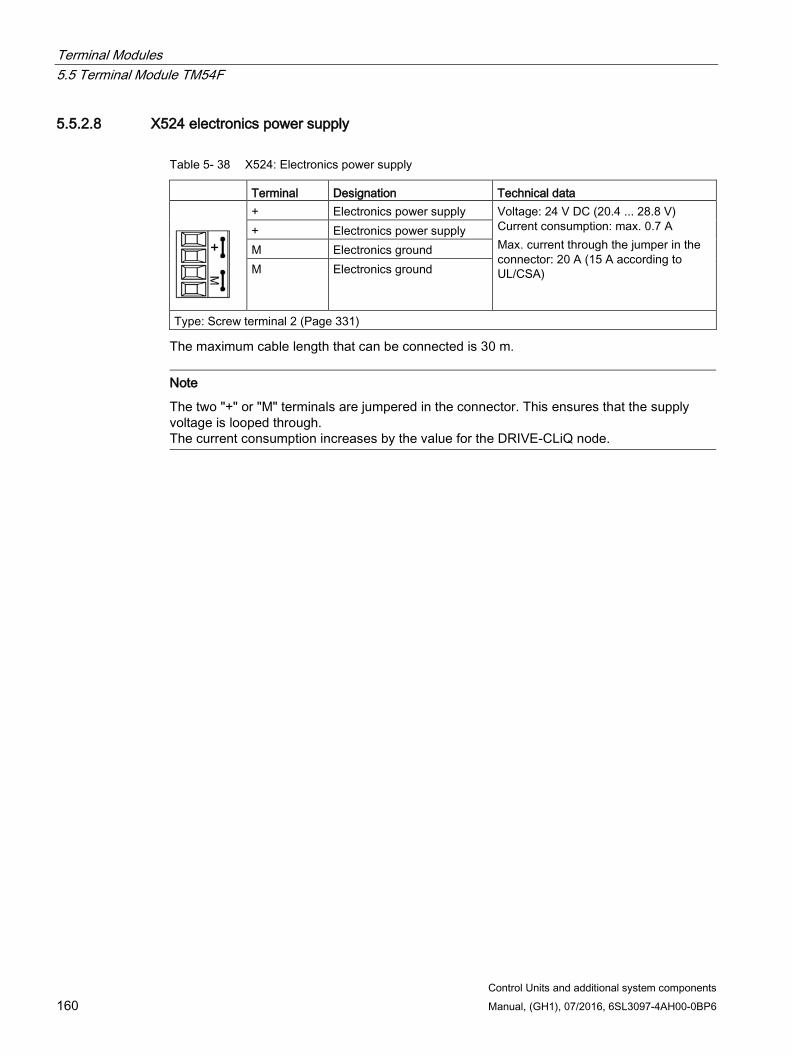
Terminal Modules 5.5 Terminal Module TM54F
Control Units and additional system components 160 Manual, (GH1), 07/2016, 6SL3097-4AH00-0BP6
5.5.2.8 X524 electronics power supply
Table 5- 38 X524: Electronics power supply
Terminal Designation Technical data
+ Electronics power supply Voltage: 24 V DC (20.4 ... 28.8 V) Current consumption: max. 0.7 A Max. current through the jumper in the connector: 20 A (15 A according to UL/CSA)
+ Electronics power supply M Electronics ground M Electronics ground
Type: Screw terminal 2 (Page 331)
The maximum cable length that can be connected is 30 m.
Note
The two "+" or "M" terminals are jumpered in the connector. This ensures that the supply voltage is looped through. The current consumption increases by the value for the DRIVE-CLiQ node.
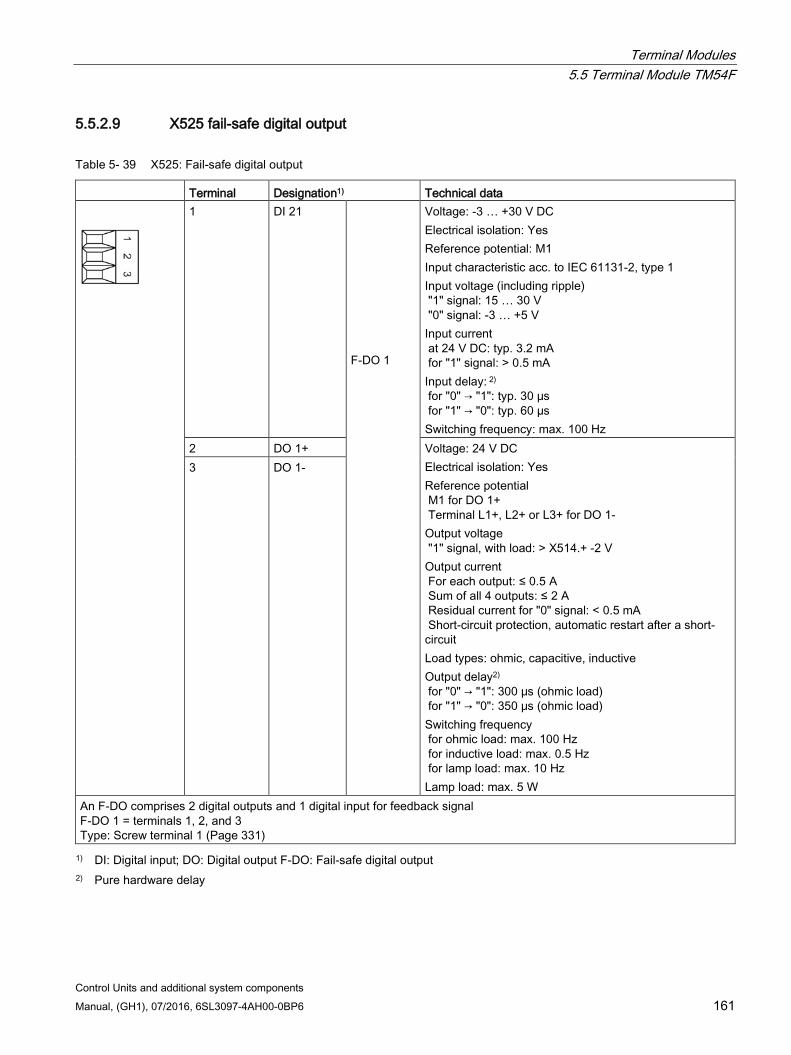
Terminal Modules 5.5 Terminal Module TM54F
Control Units and additional system components Manual, (GH1), 07/2016, 6SL3097-4AH00-0BP6 161
5.5.2.9 X525 fail-safe digital output
Table 5- 39 X525: Fail-safe digital output
Terminal Designation1) Technical data
1 DI 21 F-DO 1
Voltage: -3 … +30 V DC Electrical isolation: Yes Reference potential: M1 Input characteristic acc. to IEC 61131-2, type 1 Input voltage (including ripple) "1" signal: 15 … 30 V "0" signal: -3 … +5 V Input current at 24 V DC: typ. 3.2 mA for "1" signal: > 0.5 mA Input delay: 2) for "0" → "1": typ. 30 μs for "1" → "0": typ. 60 µs Switching frequency: max. 100 Hz
2 DO 1+ Voltage: 24 V DC Electrical isolation: Yes Reference potential M1 for DO 1+ Terminal L1+, L2+ or L3+ for DO 1- Output voltage "1" signal, with load: > X514.+ -2 V Output current For each output: ≤ 0.5 A Sum of all 4 outputs: ≤ 2 A Residual current for "0" signal: < 0.5 mA Short-circuit protection, automatic restart after a short-circuit Load types: ohmic, capacitive, inductive Output delay2) for "0" → "1": 300 μs (ohmic load) for "1" → "0": 350 μs (ohmic load) Switching frequency for ohmic load: max. 100 Hz for inductive load: max. 0.5 Hz for lamp load: max. 10 Hz Lamp load: max. 5 W
3 DO 1-
An F-DO comprises 2 digital outputs and 1 digital input for feedback signal F-DO 1 = terminals 1, 2, and 3 Type: Screw terminal 1 (Page 331) 1) DI: Digital input; DO: Digital output F-DO: Fail-safe digital output
2) Pure hardware delay
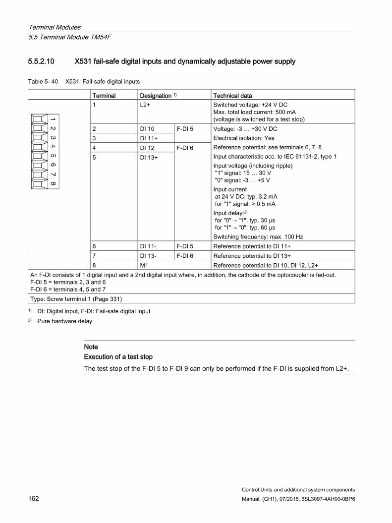
Terminal Modules 5.5 Terminal Module TM54F
Control Units and additional system components 162 Manual, (GH1), 07/2016, 6SL3097-4AH00-0BP6
5.5.2.10 X531 fail-safe digital inputs and dynamically adjustable power supply
Table 5- 40 X531: Fail-safe digital inputs
Terminal Designation 1) Technical data
1 L2+ Switched voltage: +24 V DC Max. total load current: 500 mA (voltage is switched for a test stop)
2 DI 10 F-DI 5 Voltage: -3 … +30 V DC Electrical isolation: Yes Reference potential: see terminals 6, 7, 8 Input characteristic acc. to IEC 61131-2, type 1 Input voltage (including ripple) "1" signal: 15 … 30 V "0" signal: -3 … +5 V Input current at 24 V DC: typ. 3.2 mA for "1" signal: > 0.5 mA Input delay:2) for "0" → "1": typ. 30 μs for "1" → "0": typ. 60 µs Switching frequency: max. 100 Hz
3 DI 11+ 4 DI 12 F-DI 6 5 DI 13+
6 DI 11- F-DI 5 Reference potential to DI 11+ 7 DI 13- F-DI 6 Reference potential to DI 13+ 8 M1 Reference potential to DI 10, DI 12, L2+
An F-DI consists of 1 digital input and a 2nd digital input where, in addition, the cathode of the optocoupler is fed-out. F-DI 5 = terminals 2, 3 and 6 F-DI 6 = terminals 4, 5 and 7 Type: Screw terminal 1 (Page 331) 1) DI: Digital input, F-DI: Fail-safe digital input
2) Pure hardware delay
Note Execution of a test stop
The test stop of the F-DI 5 to F-DI 9 can only be performed if the F-DI is supplied from L2+.
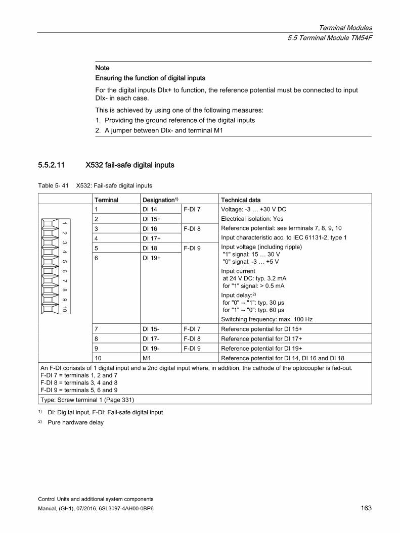
Terminal Modules 5.5 Terminal Module TM54F
Control Units and additional system components Manual, (GH1), 07/2016, 6SL3097-4AH00-0BP6 163
Note
Ensuring the function of digital inputs
For the digital inputs DIx+ to function, the reference potential must be connected to input DIx- in each case.
This is achieved by using one of the following measures: 1. Providing the ground reference of the digital inputs 2. A jumper between DIx- and terminal M1
5.5.2.11 X532 fail-safe digital inputs
Table 5- 41 X532: Fail-safe digital inputs
Terminal Designation1) Technical data
1 DI 14 F-DI 7 Voltage: -3 … +30 V DC Electrical isolation: Yes Reference potential: see terminals 7, 8, 9, 10 Input characteristic acc. to IEC 61131-2, type 1 Input voltage (including ripple) "1" signal: 15 … 30 V "0" signal: -3 … +5 V Input current at 24 V DC: typ. 3.2 mA for "1" signal: > 0.5 mA Input delay:2) for "0" → "1": typ. 30 μs for "1" → "0": typ. 60 µs Switching frequency: max. 100 Hz
2 DI 15+ 3 DI 16 F-DI 8 4 DI 17+ 5 DI 18 F-DI 9 6 DI 19+
7 DI 15- F-DI 7 Reference potential for DI 15+ 8 DI 17- F-DI 8 Reference potential for DI 17+ 9 DI 19- F-DI 9 Reference potential for DI 19+ 10 M1 Reference potential for DI 14, DI 16 and DI 18
An F-DI consists of 1 digital input and a 2nd digital input where, in addition, the cathode of the optocoupler is fed-out. F-DI 7 = terminals 1, 2 and 7 F-DI 8 = terminals 3, 4 and 8 F-DI 9 = terminals 5, 6 and 9 Type: Screw terminal 1 (Page 331) 1) DI: Digital input, F-DI: Fail-safe digital input
2) Pure hardware delay
Terminal Modules 5.5 Terminal Module TM54F
Control Units and additional system components 164 Manual, (GH1), 07/2016, 6SL3097-4AH00-0BP6
Note Execution of a test stop
The test stop of the F-DI 5 to F-DI 9 can only be performed if the F-DI is supplied from L2+.
Note Ensuring the function of digital inputs
For the digital inputs DIx+ to function, the reference potential must be connected to input DIx- in each case.
This is achieved by using one of the following measures: 1. Providing the ground reference of the digital inputs 2. A jumper between DIx- and terminal M1
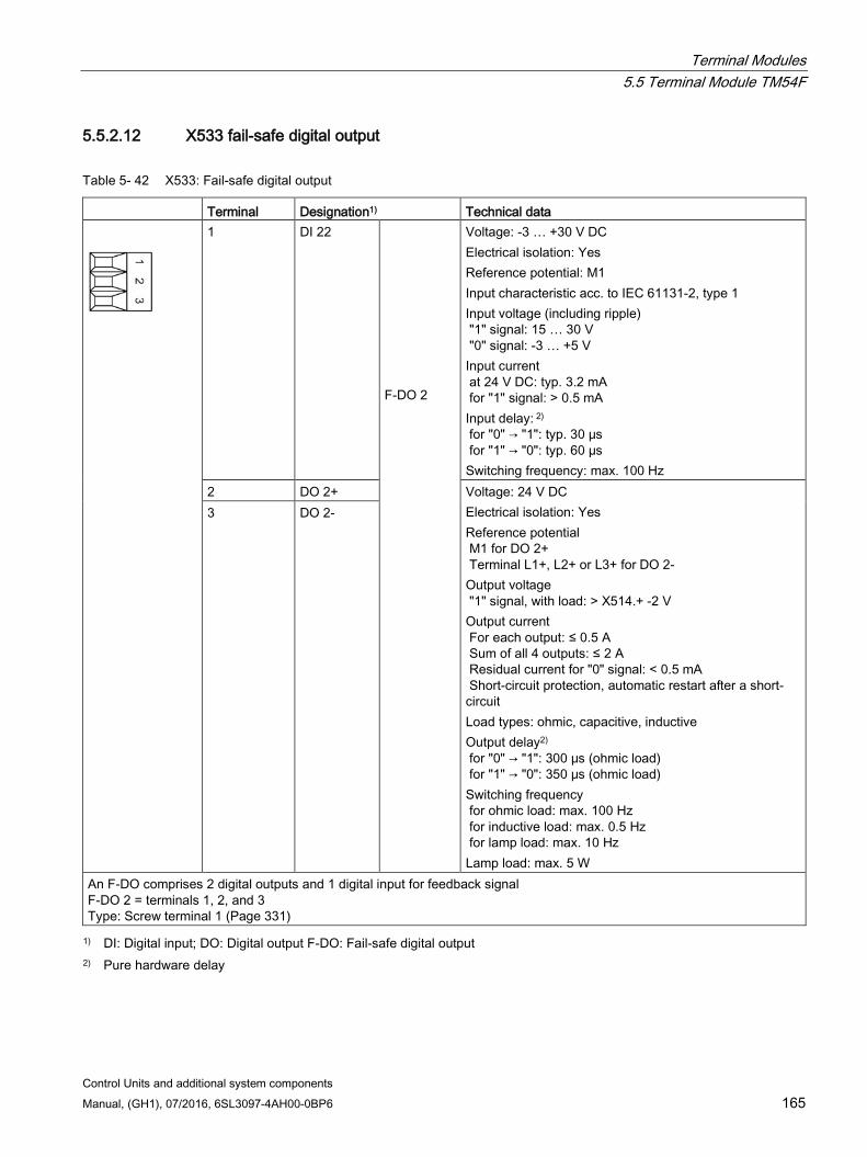
Terminal Modules 5.5 Terminal Module TM54F
Control Units and additional system components Manual, (GH1), 07/2016, 6SL3097-4AH00-0BP6 165
5.5.2.12 X533 fail-safe digital output
Table 5- 42 X533: Fail-safe digital output
Terminal Designation1) Technical data
1 DI 22 F-DO 2
Voltage: -3 … +30 V DC Electrical isolation: Yes Reference potential: M1 Input characteristic acc. to IEC 61131-2, type 1 Input voltage (including ripple) "1" signal: 15 … 30 V "0" signal: -3 … +5 V Input current at 24 V DC: typ. 3.2 mA for "1" signal: > 0.5 mA Input delay: 2) for "0" → "1": typ. 30 μs for "1" → "0": typ. 60 µs Switching frequency: max. 100 Hz
2 DO 2+ Voltage: 24 V DC Electrical isolation: Yes Reference potential M1 for DO 2+ Terminal L1+, L2+ or L3+ for DO 2- Output voltage "1" signal, with load: > X514.+ -2 V Output current For each output: ≤ 0.5 A Sum of all 4 outputs: ≤ 2 A Residual current for "0" signal: < 0.5 mA Short-circuit protection, automatic restart after a short-circuit Load types: ohmic, capacitive, inductive Output delay2) for "0" → "1": 300 μs (ohmic load) for "1" → "0": 350 μs (ohmic load) Switching frequency for ohmic load: max. 100 Hz for inductive load: max. 0.5 Hz for lamp load: max. 10 Hz Lamp load: max. 5 W
3 DO 2-
An F-DO comprises 2 digital outputs and 1 digital input for feedback signal F-DO 2 = terminals 1, 2, and 3 Type: Screw terminal 1 (Page 331) 1) DI: Digital input; DO: Digital output F-DO: Fail-safe digital output
2) Pure hardware delay
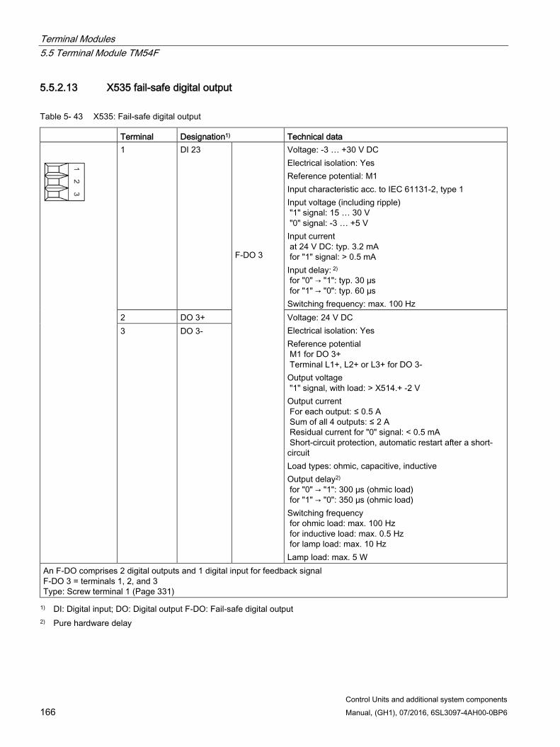
Terminal Modules 5.5 Terminal Module TM54F
Control Units and additional system components 166 Manual, (GH1), 07/2016, 6SL3097-4AH00-0BP6
5.5.2.13 X535 fail-safe digital output
Table 5- 43 X535: Fail-safe digital output
Terminal Designation1) Technical data
1 DI 23 F-DO 3
Voltage: -3 … +30 V DC Electrical isolation: Yes Reference potential: M1 Input characteristic acc. to IEC 61131-2, type 1 Input voltage (including ripple) "1" signal: 15 … 30 V "0" signal: -3 … +5 V Input current at 24 V DC: typ. 3.2 mA for "1" signal: > 0.5 mA Input delay: 2) for "0" → "1": typ. 30 μs for "1" → "0": typ. 60 µs Switching frequency: max. 100 Hz
2 DO 3+ Voltage: 24 V DC Electrical isolation: Yes Reference potential M1 for DO 3+ Terminal L1+, L2+ or L3+ for DO 3- Output voltage "1" signal, with load: > X514.+ -2 V Output current For each output: ≤ 0.5 A Sum of all 4 outputs: ≤ 2 A Residual current for "0" signal: < 0.5 mA Short-circuit protection, automatic restart after a short-circuit Load types: ohmic, capacitive, inductive Output delay2) for "0" → "1": 300 μs (ohmic load) for "1" → "0": 350 μs (ohmic load) Switching frequency for ohmic load: max. 100 Hz for inductive load: max. 0.5 Hz for lamp load: max. 10 Hz Lamp load: max. 5 W
3 DO 3-
An F-DO comprises 2 digital outputs and 1 digital input for feedback signal F-DO 3 = terminals 1, 2, and 3 Type: Screw terminal 1 (Page 331) 1) DI: Digital input; DO: Digital output F-DO: Fail-safe digital output
2) Pure hardware delay
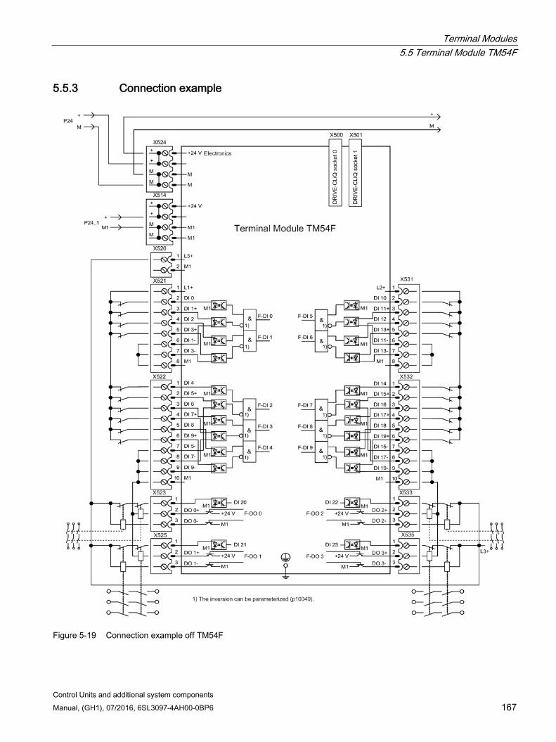
Terminal Modules 5.5 Terminal Module TM54F
Control Units and additional system components Manual, (GH1), 07/2016, 6SL3097-4AH00-0BP6 167
5.5.3 Connection example
Figure 5-19 Connection example off TM54F
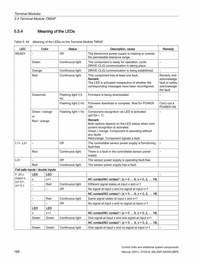
Terminal Modules 5.5 Terminal Module TM54F
Control Units and additional system components 168 Manual, (GH1), 07/2016, 6SL3097-4AH00-0BP6
5.5.4 Meaning of the LEDs
Table 5- 44 Meaning of the LEDs on the Terminal Module TM54F
LED Color Status Description, cause Remedy READY - Off The electronics power supply is missing or outside
the permissible tolerance range. –
Green Continuous light The component is ready for operation, cyclic DRIVE-CLiQ communication is taking place.
–
Orange Continuous light DRIVE-CLiQ communication is being established. – Red Continuous light This component has at least one fault.
Remark: The LED is activated irrespective of whether the corresponding messages have been reconfigured.
Remedy and acknowledge fault or safely acknowledge the fault
Green/red Flashing light 0.5 Hz
Firmware is being downloaded. –
Flashing light 2 Hz Firmware download is complete. Wait for POWER ON.
Carry out a POWER ON
Green / orange or Red / orange
Flashing light 1 Hz Component recognition via LED is activated (p0154 = 1). Remark: Both options depend on the LED status when com-ponent recognition is activated. Green / orange: Component is operating without any faults Red/orange: Component signals a fault
–
L1+, L2+ – Off The controllable sensor power supply is functioning fault-free.
–
Red Continuous light There is a fault in the controllable sensor power supply.
–
L3+ – Off The sensor power supply is operating fault-free. Red Continuous light The sensor power supply has a fault.
Fail-safe inputs / double inputs F_DI z (input x, (x+1)+, (x+1)-)
LED LED – x x+1 NC contact/NC contact1): (z = 0 … 9, x = 0, 2, … 18) – Red Continuous light Different signal states at input x and x+1 – – Off No signal at input x and no signal at input x+1 NC contact/NO contact1): (z = 0 … 9, x = 0, 2, … 18) – Red Continuous light Same signal states at input x and x+1 – – Off No signal at input x and no signal at input x+1 LED LED x x+1 NC contact/NC contact1): (z = 0 … 9, x = 0, 2, … 18) Green Green Continuous light One signal at input x and one signal at input x+1 NC contact/NO contact1): (z = 0 … 9, x = 0, 2, … 18) Green Green Continuous light One signal at input x and no signal at input x+1 –

Terminal Modules 5.5 Terminal Module TM54F
Control Units and additional system components Manual, (GH1), 07/2016, 6SL3097-4AH00-0BP6 169
LED Color Status Description, cause Remedy Single digital inputs, not fail-safe DI x
– Off No signal at digital input x (x = 20 ... 23) – Green Continuous light Signal at digital input x –
Fail-safe digital outputs with associated readback channel F_DO y (0+..3+, 0-..3-)
Green Continuous light Output y (y = 0 … 3) has an active signal –
Readback input DI 2y for output F_DO y (y = 0 ... 3) for test stop. The status of the LEDs also depends on the type of external circuit. DI 2y – Off One of the two output lines y+ or y- or both lines of
output y carry a signal –
Green Continuous light Both output lines y+ and y- carry no signal – 1) Inputs x+1 (DI 1+, 3+, .. 19+) can be individually set using a parameter
Additional information can be taken from the following reference: Reference: /LH1/ SINAMICS S120/S150 List Manual
Cause and rectification of faults Additional information about the cause and resolving faults can be taken from the following references:
Reference:/LH1/SINAMICS S120/S150 List Manual
Reference: /IH1/ SINAMICS S120 Commissioning Manual with STARTER
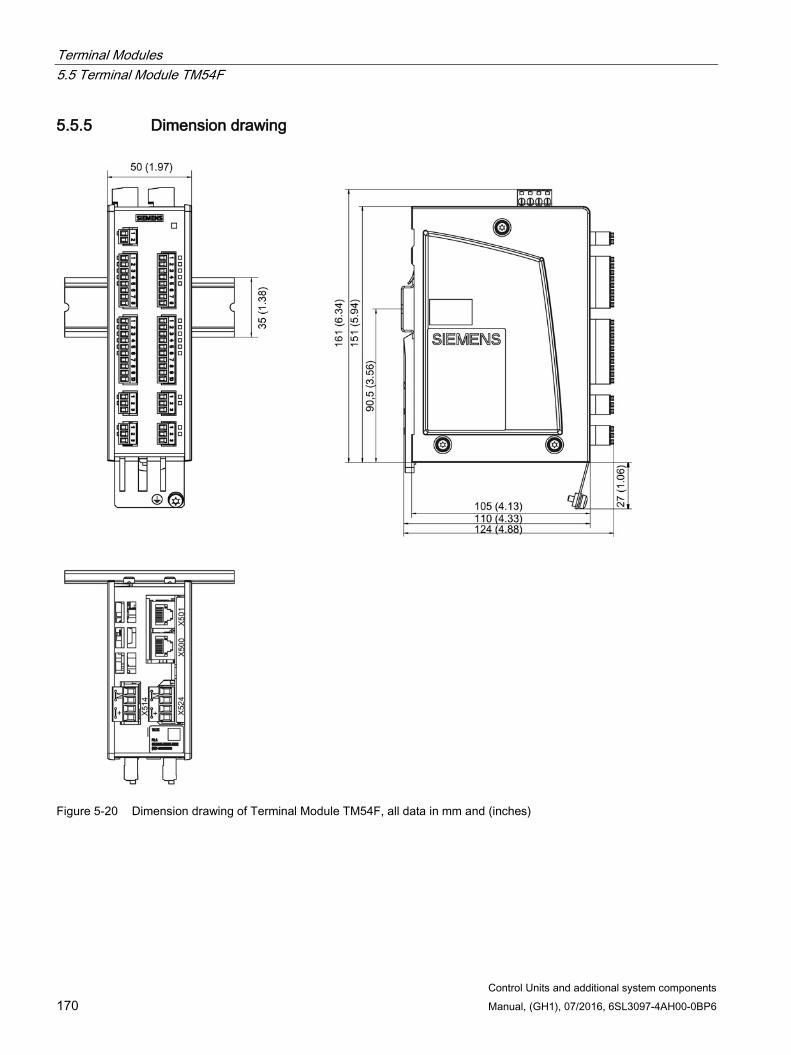
Terminal Modules 5.5 Terminal Module TM54F
Control Units and additional system components 170 Manual, (GH1), 07/2016, 6SL3097-4AH00-0BP6
5.5.5 Dimension drawing
Figure 5-20 Dimension drawing of Terminal Module TM54F, all data in mm and (inches)
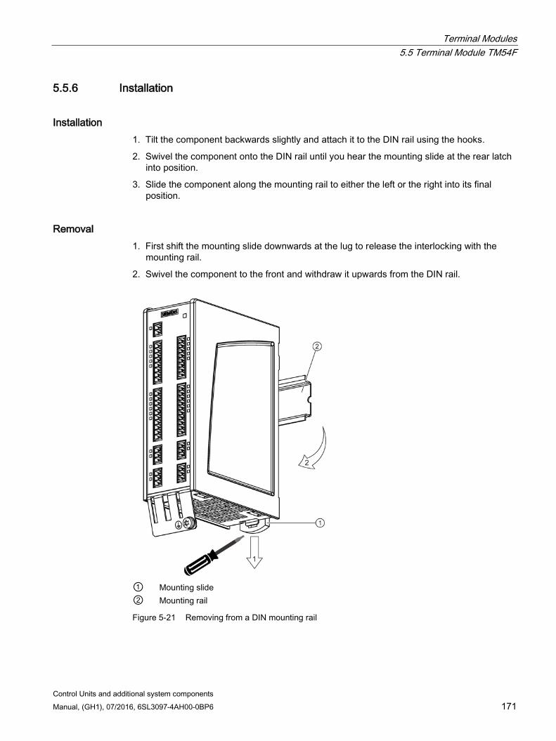
Terminal Modules 5.5 Terminal Module TM54F
Control Units and additional system components Manual, (GH1), 07/2016, 6SL3097-4AH00-0BP6 171
5.5.6 Installation
Installation 1. Tilt the component backwards slightly and attach it to the DIN rail using the hooks.
2. Swivel the component onto the DIN rail until you hear the mounting slide at the rear latch into position.
3. Slide the component along the mounting rail to either the left or the right into its final position.
Removal 1. First shift the mounting slide downwards at the lug to release the interlocking with the
mounting rail.
2. Swivel the component to the front and withdraw it upwards from the DIN rail.
① Mounting slide ② Mounting rail
Figure 5-21 Removing from a DIN mounting rail
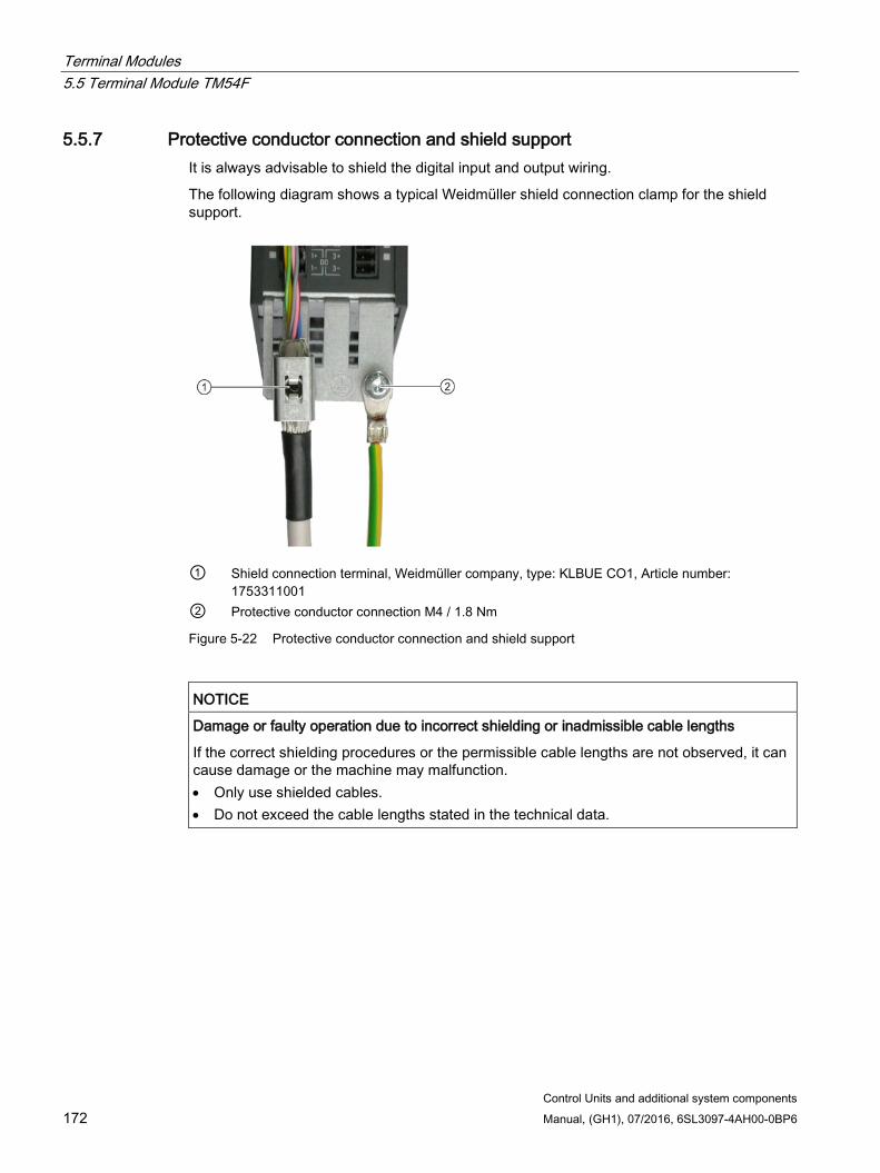
Terminal Modules 5.5 Terminal Module TM54F
Control Units and additional system components 172 Manual, (GH1), 07/2016, 6SL3097-4AH00-0BP6
5.5.7 Protective conductor connection and shield support It is always advisable to shield the digital input and output wiring.
The following diagram shows a typical Weidmüller shield connection clamp for the shield support.
① Shield connection terminal, Weidmüller company, type: KLBUE CO1, Article number:
1753311001 ② Protective conductor connection M4 / 1.8 Nm
Figure 5-22 Protective conductor connection and shield support
NOTICE
Damage or faulty operation due to incorrect shielding or inadmissible cable lengths
If the correct shielding procedures or the permissible cable lengths are not observed, it can cause damage or the machine may malfunction. • Only use shielded cables. • Do not exceed the cable lengths stated in the technical data.
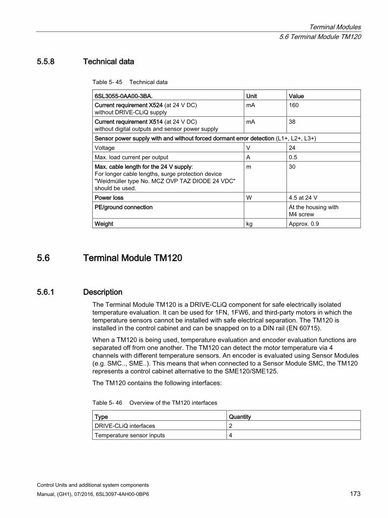
Terminal Modules 5.6 Terminal Module TM120
Control Units and additional system components Manual, (GH1), 07/2016, 6SL3097-4AH00-0BP6 173
5.5.8 Technical data
Table 5- 45 Technical data
6SL3055-0AA00-3BA. Unit Value Current requirement X524 (at 24 V DC) without DRIVE-CLiQ supply
mA 160
Current requirement X514 (at 24 V DC) without digital outputs and sensor power supply
mA 38
Sensor power supply with and without forced dormant error detection (L1+, L2+, L3+) Voltage V 24 Max. load current per output A 0.5 Max. cable length for the 24 V supply: For longer cable lengths, surge protection device "Weidmüller type No. MCZ OVP TAZ DIODE 24 VDC" should be used.
m 30
Power loss W 4.5 at 24 V PE/ground connection At the housing with
M4 screw Weight kg Approx. 0.9
5.6 Terminal Module TM120
5.6.1 Description The Terminal Module TM120 is a DRIVE-CLiQ component for safe electrically isolated temperature evaluation. It can be used for 1FN, 1FW6, and third-party motors in which the temperature sensors cannot be installed with safe electrical separation. The TM120 is installed in the control cabinet and can be snapped on to a DIN rail (EN 60715).
When a TM120 is being used, temperature evaluation and encoder evaluation functions are separated off from one another. The TM120 can detect the motor temperature via 4 channels with different temperature sensors. An encoder is evaluated using Sensor Modules (e.g. SMC.., SME..). This means that when connected to a Sensor Module SMC, the TM120 represents a control cabinet alternative to the SME120/SME125.
The TM120 contains the following interfaces:
Table 5- 46 Overview of the TM120 interfaces
Type Quantity DRIVE-CLiQ interfaces 2 Temperature sensor inputs 4
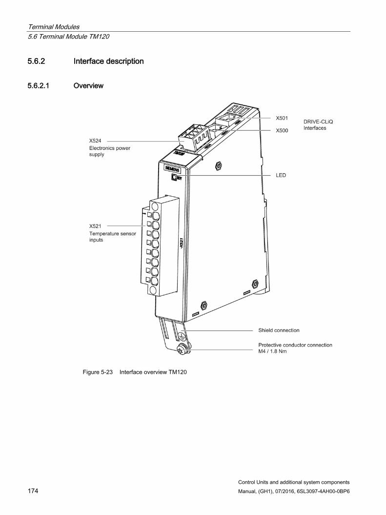
Terminal Modules 5.6 Terminal Module TM120
Control Units and additional system components 174 Manual, (GH1), 07/2016, 6SL3097-4AH00-0BP6
5.6.2 Interface description
5.6.2.1 Overview
Figure 5-23 Interface overview TM120
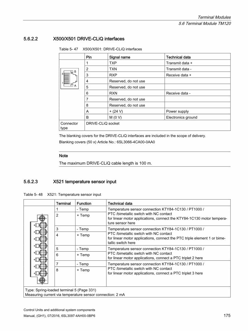
Terminal Modules 5.6 Terminal Module TM120
Control Units and additional system components Manual, (GH1), 07/2016, 6SL3097-4AH00-0BP6 175
5.6.2.2 X500/X501 DRIVE-CLiQ interfaces
Table 5- 47 X500/X501: DRIVE-CLiQ interfaces
Pin Signal name Technical data
1 TXP Transmit data + 2 TXN Transmit data - 3 RXP Receive data + 4 Reserved, do not use 5 Reserved, do not use 6 RXN Receive data - 7 Reserved, do not use 8 Reserved, do not use A + (24 V) Power supply B M (0 V) Electronics ground
Connector type
DRIVE-CLiQ socket
The blanking covers for the DRIVE-CLiQ interfaces are included in the scope of delivery. Blanking covers (50 x) Article No.: 6SL3066-4CA00-0AA0
Note
The maximum DRIVE-CLiQ cable length is 100 m.
5.6.2.3 X521 temperature sensor input
Table 5- 48 X521: Temperature sensor input
Terminal Function Technical data
1 - Temp Temperature sensor connection KTY84-1C130 / PT1000 / PTC /bimetallic switch with NC contact for linear motor applications, connect the KTY84-1C130 motor tempera-ture sensor here
2 + Temp
3 - Temp Temperature sensor connection KTY84-1C130 / PT1000 / PTC /bimetallic switch with NC contact for linear motor applications, connect the PTC triple element 1 or bime-tallic switch here
4 + Temp
5 - Temp Temperature sensor connection KTY84-1C130 / PT1000 / PTC /bimetallic switch with NC contact for linear motor applications, connect a PTC triplet 2 here
6 + Temp
7 - Temp Temperature sensor connection KTY84-1C130 / PT1000 / PTC /bimetallic switch with NC contact for linear motor applications, connect a PTC triplet 3 here
8 + Temp
Type: Spring-loaded terminal 5 (Page 331) Measuring current via temperature sensor connection: 2 mA
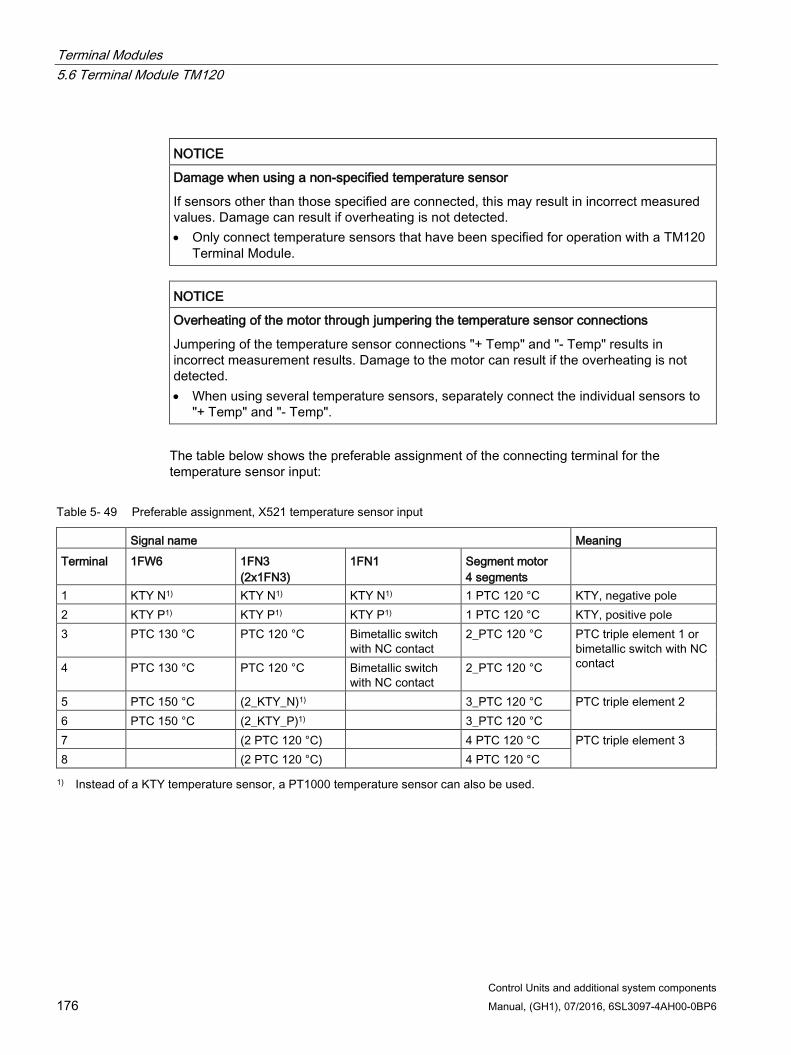
Terminal Modules 5.6 Terminal Module TM120
Control Units and additional system components 176 Manual, (GH1), 07/2016, 6SL3097-4AH00-0BP6
NOTICE
Damage when using a non-specified temperature sensor
If sensors other than those specified are connected, this may result in incorrect measured values. Damage can result if overheating is not detected. • Only connect temperature sensors that have been specified for operation with a TM120
Terminal Module.
NOTICE
Overheating of the motor through jumpering the temperature sensor connections
Jumpering of the temperature sensor connections "+ Temp" and "- Temp" results in incorrect measurement results. Damage to the motor can result if the overheating is not detected. • When using several temperature sensors, separately connect the individual sensors to
"+ Temp" and "- Temp".
The table below shows the preferable assignment of the connecting terminal for the temperature sensor input:
Table 5- 49 Preferable assignment, X521 temperature sensor input
Signal name Meaning Terminal 1FW6 1FN3
(2x1FN3) 1FN1 Segment motor
4 segments
1 KTY N1) KTY N1) KTY N1) 1 PTC 120 °C KTY, negative pole 2 KTY P1) KTY P1) KTY P1) 1 PTC 120 °C KTY, positive pole 3 PTC 130 °C PTC 120 °C Bimetallic switch
with NC contact 2_PTC 120 °C PTC triple element 1 or
bimetallic switch with NC contact 4 PTC 130 °C PTC 120 °C Bimetallic switch
with NC contact 2_PTC 120 °C
5 PTC 150 °C (2_KTY_N)1) 3_PTC 120 °C PTC triple element 2 6 PTC 150 °C (2_KTY_P)1) 3_PTC 120 °C 7 (2 PTC 120 °C) 4 PTC 120 °C PTC triple element 3 8 (2 PTC 120 °C) 4 PTC 120 °C 1) Instead of a KTY temperature sensor, a PT1000 temperature sensor can also be used.
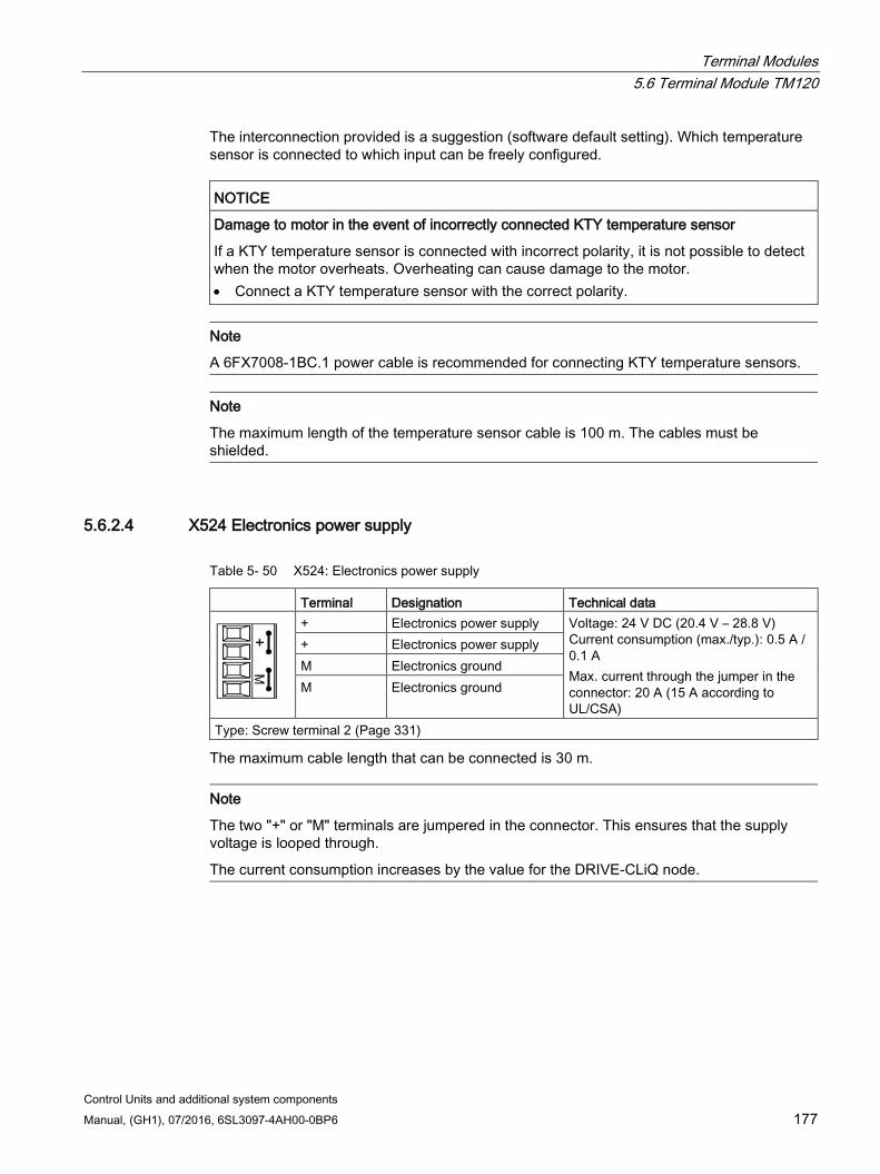
Terminal Modules 5.6 Terminal Module TM120
Control Units and additional system components Manual, (GH1), 07/2016, 6SL3097-4AH00-0BP6 177
The interconnection provided is a suggestion (software default setting). Which temperature sensor is connected to which input can be freely configured.
NOTICE
Damage to motor in the event of incorrectly connected KTY temperature sensor
If a KTY temperature sensor is connected with incorrect polarity, it is not possible to detect when the motor overheats. Overheating can cause damage to the motor. • Connect a KTY temperature sensor with the correct polarity.
Note
A 6FX7008-1BC.1 power cable is recommended for connecting KTY temperature sensors.
Note
The maximum length of the temperature sensor cable is 100 m. The cables must be shielded.
5.6.2.4 X524 Electronics power supply
Table 5- 50 X524: Electronics power supply
Terminal Designation Technical data
+ Electronics power supply Voltage: 24 V DC (20.4 V – 28.8 V) Current consumption (max./typ.): 0.5 A / 0.1 A Max. current through the jumper in the connector: 20 A (15 A according to UL/CSA)
+ Electronics power supply M Electronics ground M Electronics ground
Type: Screw terminal 2 (Page 331)
The maximum cable length that can be connected is 30 m.
Note
The two "+" or "M" terminals are jumpered in the connector. This ensures that the supply voltage is looped through.
The current consumption increases by the value for the DRIVE-CLiQ node.
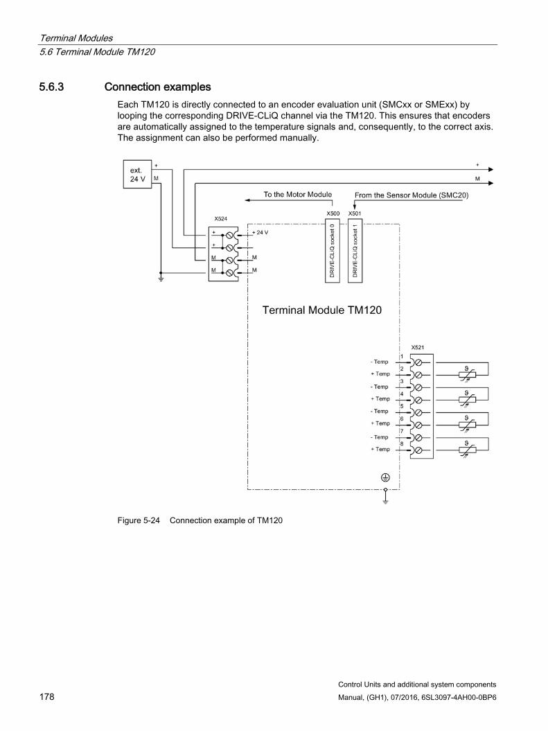
Terminal Modules 5.6 Terminal Module TM120
Control Units and additional system components 178 Manual, (GH1), 07/2016, 6SL3097-4AH00-0BP6
5.6.3 Connection examples Each TM120 is directly connected to an encoder evaluation unit (SMCxx or SMExx) by looping the corresponding DRIVE-CLiQ channel via the TM120. This ensures that encoders are automatically assigned to the temperature signals and, consequently, to the correct axis. The assignment can also be performed manually.
Figure 5-24 Connection example of TM120
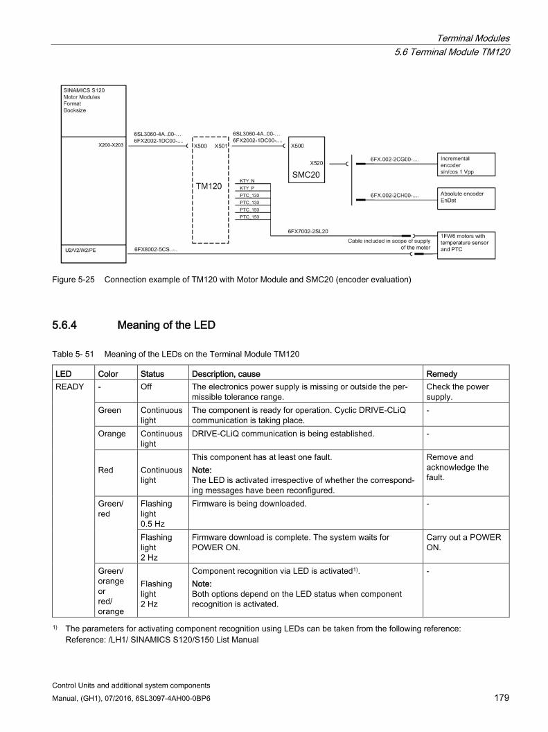
Terminal Modules 5.6 Terminal Module TM120
Control Units and additional system components Manual, (GH1), 07/2016, 6SL3097-4AH00-0BP6 179
Figure 5-25 Connection example of TM120 with Motor Module and SMC20 (encoder evaluation)
5.6.4 Meaning of the LED
Table 5- 51 Meaning of the LEDs on the Terminal Module TM120
LED Color Status Description, cause Remedy READY - Off The electronics power supply is missing or outside the per-
missible tolerance range. Check the power supply.
Green Continuous light
The component is ready for operation. Cyclic DRIVE-CLiQ communication is taking place.
-
Orange Continuous light
DRIVE-CLiQ communication is being established. -
Red
Continuous light
This component has at least one fault. Note: The LED is activated irrespective of whether the correspond-ing messages have been reconfigured.
Remove and acknowledge the fault.
Green/ red
Flashing light 0.5 Hz
Firmware is being downloaded. -
Flashing light 2 Hz
Firmware download is complete. The system waits for POWER ON.
Carry out a POWER ON.
Green/ orange or red/ orange
Flashing light 2 Hz
Component recognition via LED is activated1). Note: Both options depend on the LED status when component recognition is activated.
-
1) The parameters for activating component recognition using LEDs can be taken from the following reference: Reference: /LH1/ SINAMICS S120/S150 List Manual
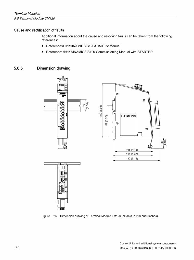
Terminal Modules 5.6 Terminal Module TM120
Control Units and additional system components 180 Manual, (GH1), 07/2016, 6SL3097-4AH00-0BP6
Cause and rectification of faults Additional information about the cause and resolving faults can be taken from the following references:
Reference:/LH1/SINAMICS S120/S150 List Manual
Reference: /IH1/ SINAMICS S120 Commissioning Manual with STARTER
5.6.5 Dimension drawing
Figure 5-26 Dimension drawing of Terminal Module TM120, all data in mm and (inches)
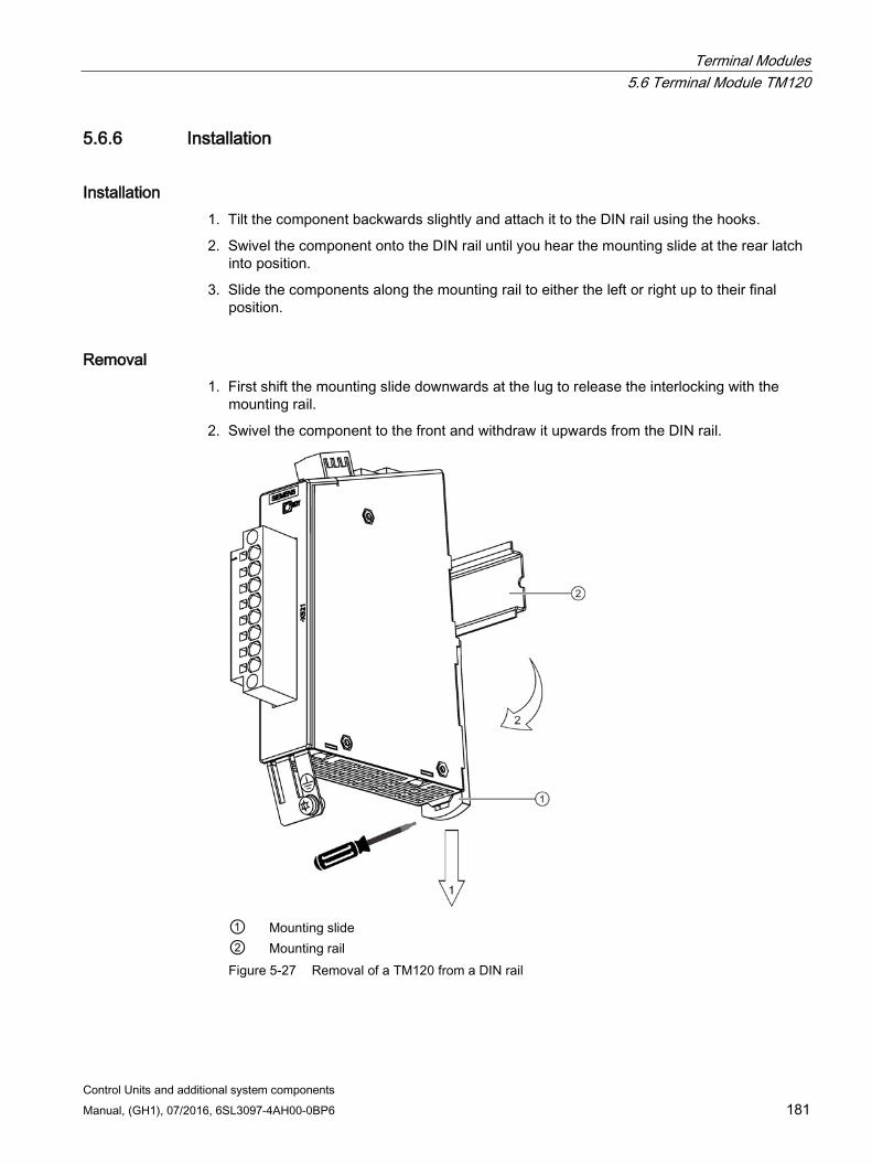
Terminal Modules 5.6 Terminal Module TM120
Control Units and additional system components Manual, (GH1), 07/2016, 6SL3097-4AH00-0BP6 181
5.6.6 Installation
Installation 1. Tilt the component backwards slightly and attach it to the DIN rail using the hooks.
2. Swivel the component onto the DIN rail until you hear the mounting slide at the rear latch into position.
3. Slide the components along the mounting rail to either the left or right up to their final position.
Removal 1. First shift the mounting slide downwards at the lug to release the interlocking with the
mounting rail.
2. Swivel the component to the front and withdraw it upwards from the DIN rail.
① Mounting slide ② Mounting rail Figure 5-27 Removal of a TM120 from a DIN rail
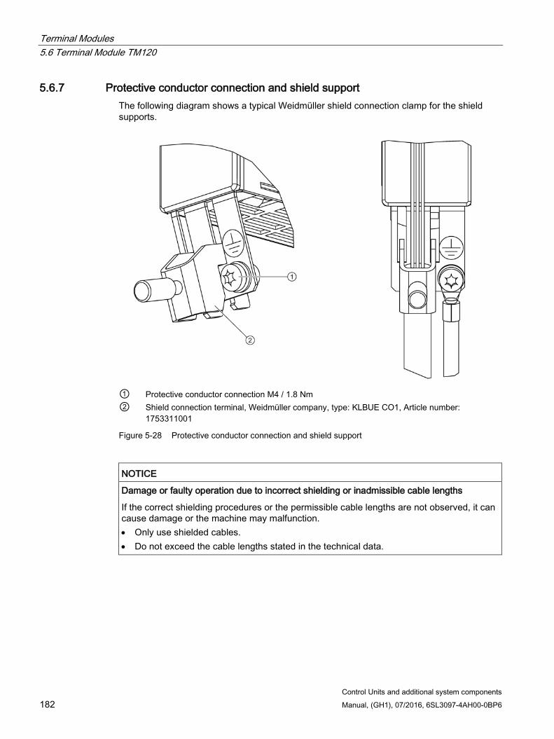
Terminal Modules 5.6 Terminal Module TM120
Control Units and additional system components 182 Manual, (GH1), 07/2016, 6SL3097-4AH00-0BP6
5.6.7 Protective conductor connection and shield support The following diagram shows a typical Weidmüller shield connection clamp for the shield supports.
① Protective conductor connection M4 / 1.8 Nm ② Shield connection terminal, Weidmüller company, type: KLBUE CO1, Article number:
1753311001
Figure 5-28 Protective conductor connection and shield support
NOTICE
Damage or faulty operation due to incorrect shielding or inadmissible cable lengths
If the correct shielding procedures or the permissible cable lengths are not observed, it can cause damage or the machine may malfunction. • Only use shielded cables. • Do not exceed the cable lengths stated in the technical data.
Terminal Modules 5.7 Terminal Module TM150
Control Units and additional system components Manual, (GH1), 07/2016, 6SL3097-4AH00-0BP6 183
5.6.8 Technical data
Table 5- 52 Technical data
6SL3055-0AA00-3KA. Unit Value Electronics power supply Voltage Current (without DRIVE-CLiQ) Power loss Maximum cable length
VDC ADC W m
24 (20.4 … 28.8) 0.20/0.1 (typ.) 2.4 (typ.) 30
PE/ground connection At the housing with M4 screw Weight kg 0.41
5.7 Terminal Module TM150
5.7.1 Description The terminal module TM150 is a DRIVE-CLiQ component for temperature evaluation. The temperature is measured in a temperature range from -99 °C to +250 °C for the following temperature sensors:
PT100 (with monitoring for wire breakage and short-circuit)
PT1000 (with monitoring for wire breakage and short-circuit)
KTY84 (with monitoring for wire breakage and short-circuit)
PTC (with short-circuit monitoring)
Bimetallic NC contact (without monitoring)
For the temperature sensor inputs, for each terminal block the evaluation can be parameterized for 1x2-wire, 2x2-wire, 3-wire or 4-wire. There is no galvanic isolation in the TM150.
The TM150 is mounted in the control cabinet and can be snapped on to a standard mounting rail (EN 60715).
The TM150 contains the following interfaces:
Table 5- 53 Overview of the TM150 interfaces
Type Quantity DRIVE-CLiQ interfaces 2 Temperature sensor inputs 12 Electronics power supply 1
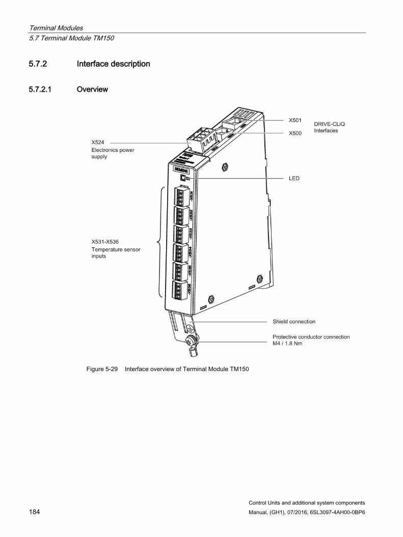
Terminal Modules 5.7 Terminal Module TM150
Control Units and additional system components 184 Manual, (GH1), 07/2016, 6SL3097-4AH00-0BP6
5.7.2 Interface description
5.7.2.1 Overview
Figure 5-29 Interface overview of Terminal Module TM150
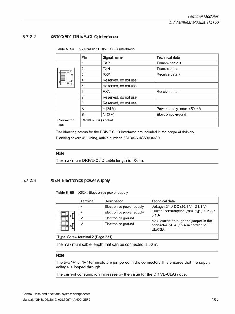
Terminal Modules 5.7 Terminal Module TM150
Control Units and additional system components Manual, (GH1), 07/2016, 6SL3097-4AH00-0BP6 185
5.7.2.2 X500/X501 DRIVE-CLiQ interfaces
Table 5- 54 X500/X501: DRIVE-CLiQ interfaces
Pin Signal name Technical data
1 TXP Transmit data + 2 TXN Transmit data - 3 RXP Receive data + 4 Reserved, do not use 5 Reserved, do not use 6 RXN Receive data - 7 Reserved, do not use 8 Reserved, do not use A + (24 V) Power supply, max. 450 mA B M (0 V) Electronics ground
Connector type
DRIVE-CLiQ socket
The blanking covers for the DRIVE-CLiQ interfaces are included in the scope of delivery. Blanking covers (50 units), article number: 6SL3066-4CA00-0AA0
Note
The maximum DRIVE-CLiQ cable length is 100 m.
5.7.2.3 X524 Electronics power supply
Table 5- 55 X524: Electronics power supply
Terminal Designation Technical data
+ Electronics power supply Voltage: 24 V DC (20.4 V – 28.8 V) Current consumption (max./typ.): 0.5 A / 0.1 A Max. current through the jumper in the connector: 20 A (15 A according to UL/CSA)
+ Electronics power supply M Electronics ground M Electronics ground
Type: Screw terminal 2 (Page 331)
The maximum cable length that can be connected is 30 m.
Note
The two "+" or "M" terminals are jumpered in the connector. This ensures that the supply voltage is looped through.
The current consumption increases by the value for the DRIVE-CLiQ node.
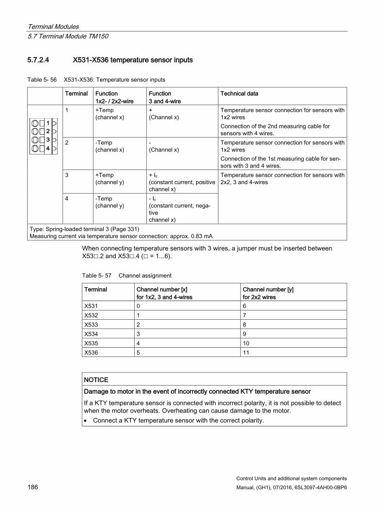
Terminal Modules 5.7 Terminal Module TM150
Control Units and additional system components 186 Manual, (GH1), 07/2016, 6SL3097-4AH00-0BP6
5.7.2.4 X531-X536 temperature sensor inputs
Table 5- 56 X531-X536: Temperature sensor inputs
Terminal Function 1x2- / 2x2-wire
Function 3 and 4-wire
Technical data
1 +Temp (channel x)
+ (Channel x)
Temperature sensor connection for sensors with 1x2 wires Connection of the 2nd measuring cable for sensors with 4 wires.
2 -Temp (channel x)
- (Channel x)
Temperature sensor connection for sensors with 1x2 wires Connection of the 1st measuring cable for sen-sors with 3 and 4 wires.
3 +Temp (channel y)
+ Ic (constant current, positive channel x)
Temperature sensor connection for sensors with 2x2, 3 and 4-wires
4 -Temp (channel y)
- Ic (constant current, nega-tive channel x)
Type: Spring-loaded terminal 3 (Page 331) Measuring current via temperature sensor connection: approx. 0.83 mA
When connecting temperature sensors with 3 wires, a jumper must be inserted between X53.2 and X53.4 ( = 1...6).
Table 5- 57 Channel assignment
Terminal Channel number [x] for 1x2, 3 and 4-wires
Channel number [y] for 2x2 wires
X531 0 6 X532 1 7 X533 2 8 X534 3 9 X535 4 10 X536 5 11
NOTICE
Damage to motor in the event of incorrectly connected KTY temperature sensor
If a KTY temperature sensor is connected with incorrect polarity, it is not possible to detect when the motor overheats. Overheating can cause damage to the motor. • Connect a KTY temperature sensor with the correct polarity.

Terminal Modules 5.7 Terminal Module TM150
Control Units and additional system components Manual, (GH1), 07/2016, 6SL3097-4AH00-0BP6 187
NOTICE
Overheating of the motor through jumpering the temperature sensor connections
Jumpering temperature sensor connections "+Temp" and "-Temp" results in incorrect measurement results. Damage to the motor can result if the overheating is not detected. • When using several temperature sensors, separately connect the individual sensors to
"+Temp" and "-Temp".
NOTICE
Device failure as a result of unshielded or incorrectly routed cables to temperature sensors
Unshielded or incorrectly routed cables to temperature sensors can result in interference being coupled into the signal processing electronics from the power side. This can result in significant disturbance of all signals (fault messages) up to failure of individual components (destruction of the devices). • Only use shielded cables as temperature sensor cables. • If temperature sensor cables are routed together with the motor cable, use separately
shielded cables twisted in pairs. • Connect the cable shield at both ends to ground potential through a large surface area. • Recommendation: Use suitable Motion Connect cables.
Note Incorrect temperature measured values as a result of cables with an excessively high resistance
An excessively long cable length or an excessively small cable cross-section can falsify the temperature measurement (for a PT100, 10 Ω cable resistance can falsify the measurement result by 10%). As a consequence, excessively high measured values are output, which could lead to the motor being unnecessarily tripped prematurely. • Use only cable lengths ≤ 300 m. • For cable lengths >100 m, use cables with a cross-section of ≥1 mm2.
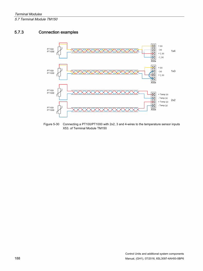
Terminal Modules 5.7 Terminal Module TM150
Control Units and additional system components 188 Manual, (GH1), 07/2016, 6SL3097-4AH00-0BP6
5.7.3 Connection examples
Figure 5-30 Connecting a PT100/PT1000 with 2x2, 3 and 4-wires to the temperature sensor inputs
X53. of Terminal Module TM150
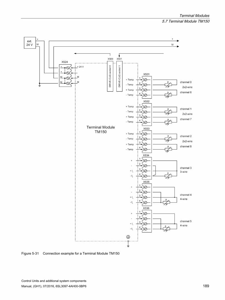
Terminal Modules 5.7 Terminal Module TM150
Control Units and additional system components Manual, (GH1), 07/2016, 6SL3097-4AH00-0BP6 189
Figure 5-31 Connection example for a Terminal Module TM150
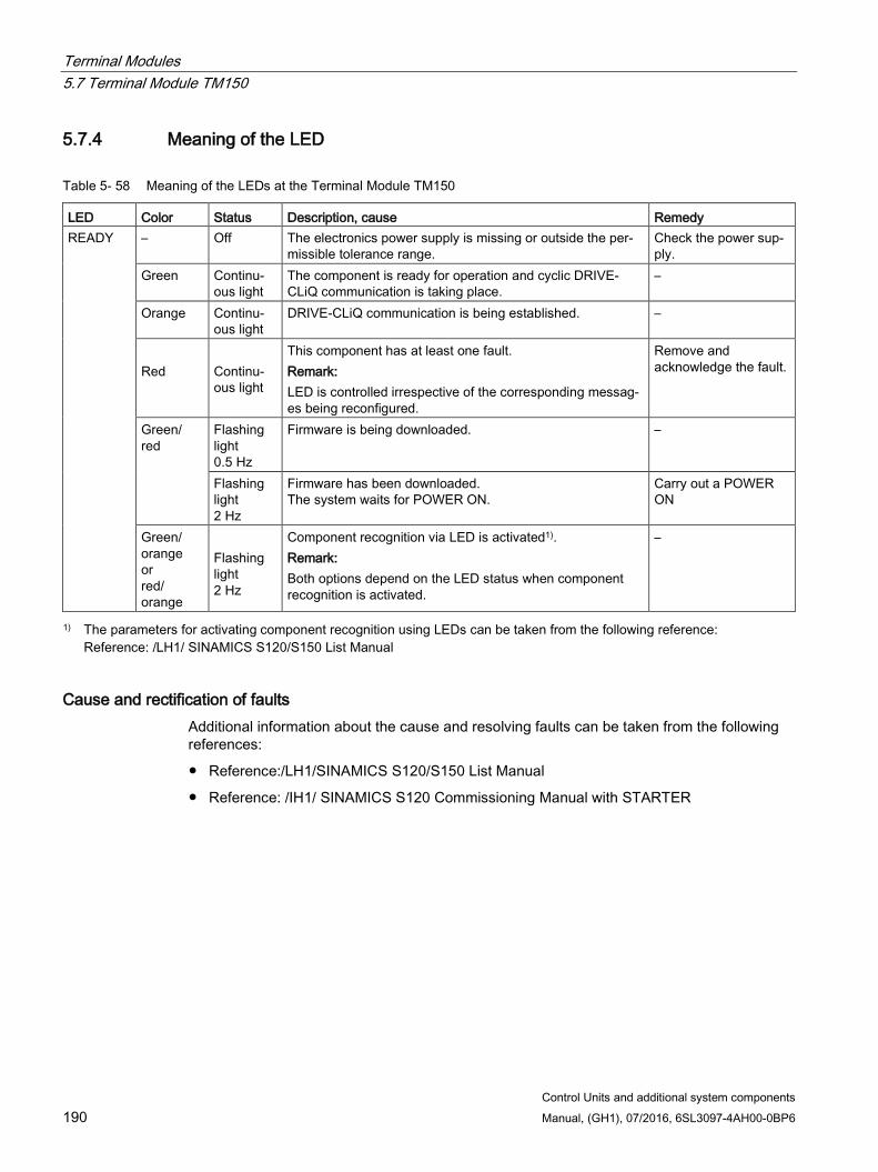
Terminal Modules 5.7 Terminal Module TM150
Control Units and additional system components 190 Manual, (GH1), 07/2016, 6SL3097-4AH00-0BP6
5.7.4 Meaning of the LED
Table 5- 58 Meaning of the LEDs at the Terminal Module TM150
LED Color Status Description, cause Remedy READY – Off The electronics power supply is missing or outside the per-
missible tolerance range. Check the power sup-ply.
Green Continu-ous light
The component is ready for operation and cyclic DRIVE-CLiQ communication is taking place.
–
Orange Continu-ous light
DRIVE-CLiQ communication is being established. –
Red
Continu-ous light
This component has at least one fault. Remark: LED is controlled irrespective of the corresponding messag-es being reconfigured.
Remove and acknowledge the fault.
Green/ red
Flashing light 0.5 Hz
Firmware is being downloaded. –
Flashing light 2 Hz
Firmware has been downloaded. The system waits for POWER ON.
Carry out a POWER ON
Green/ orange or red/ orange
Flashing light 2 Hz
Component recognition via LED is activated1). Remark: Both options depend on the LED status when component recognition is activated.
–
1) The parameters for activating component recognition using LEDs can be taken from the following reference: Reference: /LH1/ SINAMICS S120/S150 List Manual
Cause and rectification of faults Additional information about the cause and resolving faults can be taken from the following references:
Reference:/LH1/SINAMICS S120/S150 List Manual
Reference: /IH1/ SINAMICS S120 Commissioning Manual with STARTER
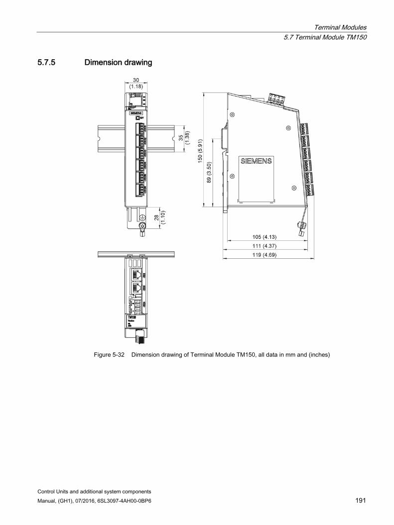
Terminal Modules 5.7 Terminal Module TM150
Control Units and additional system components Manual, (GH1), 07/2016, 6SL3097-4AH00-0BP6 191
5.7.5 Dimension drawing
Figure 5-32 Dimension drawing of Terminal Module TM150, all data in mm and (inches)
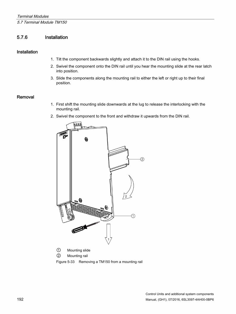
Terminal Modules 5.7 Terminal Module TM150
Control Units and additional system components 192 Manual, (GH1), 07/2016, 6SL3097-4AH00-0BP6
5.7.6 Installation
Installation 1. Tilt the component backwards slightly and attach it to the DIN rail using the hooks.
2. Swivel the component onto the DIN rail until you hear the mounting slide at the rear latch into position.
3. Slide the components along the mounting rail to either the left or right up to their final position.
Removal 1. First shift the mounting slide downwards at the lug to release the interlocking with the
mounting rail.
2. Swivel the component to the front and withdraw it upwards from the DIN rail.
① Mounting slide ② Mounting rail Figure 5-33 Removing a TM150 from a mounting rail
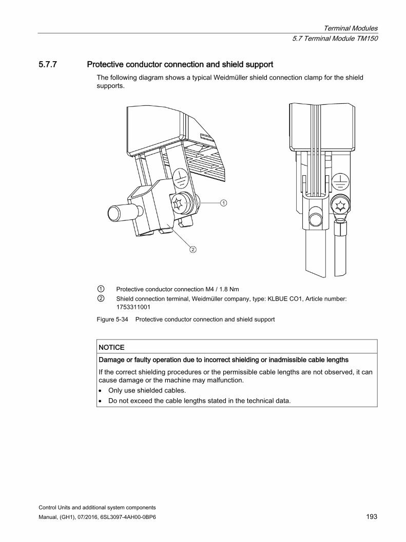
Terminal Modules 5.7 Terminal Module TM150
Control Units and additional system components Manual, (GH1), 07/2016, 6SL3097-4AH00-0BP6 193
5.7.7 Protective conductor connection and shield support The following diagram shows a typical Weidmüller shield connection clamp for the shield supports.
① Protective conductor connection M4 / 1.8 Nm ② Shield connection terminal, Weidmüller company, type: KLBUE CO1, Article number:
1753311001
Figure 5-34 Protective conductor connection and shield support
NOTICE
Damage or faulty operation due to incorrect shielding or inadmissible cable lengths
If the correct shielding procedures or the permissible cable lengths are not observed, it can cause damage or the machine may malfunction. • Only use shielded cables. • Do not exceed the cable lengths stated in the technical data.
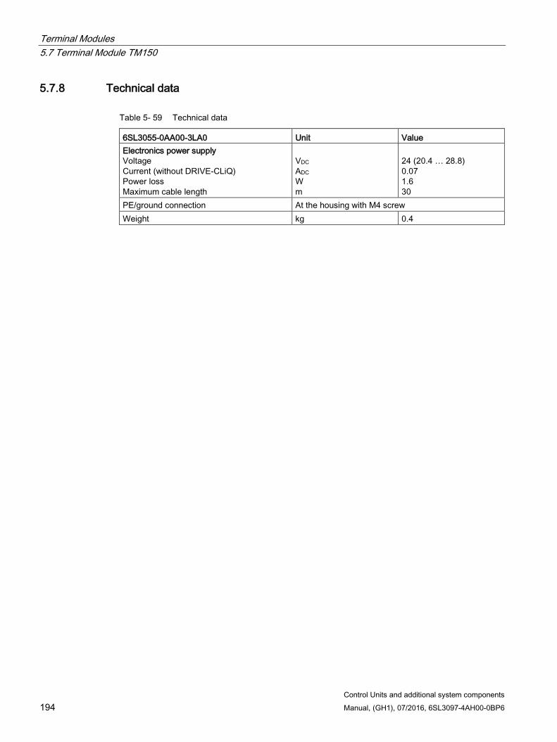
Terminal Modules 5.7 Terminal Module TM150
Control Units and additional system components 194 Manual, (GH1), 07/2016, 6SL3097-4AH00-0BP6
5.7.8 Technical data
Table 5- 59 Technical data
6SL3055-0AA00-3LA0 Unit Value Electronics power supply Voltage Current (without DRIVE-CLiQ) Power loss Maximum cable length
VDC ADC W m
24 (20.4 … 28.8) 0.07 1.6 30
PE/ground connection At the housing with M4 screw Weight kg 0.4
Control Units and additional system components Manual, (GH1), 07/2016, 6SL3097-4AH00-0BP6 195
Hub Modules 6 6.1 Safety instructions for Hub Modules
WARNING
Danger to life if the fundamental safety instructions and remaining risks are not carefully observed
If the fundamental safety instructions and remaining risks in Chapter 1 (Page 19) are not observed, accidents involving severe injuries or death may occur. • Adhere to the fundamental safety instructions. • When assessing the risk, take into account remaining risks.
NOTICE
Damage through use of incorrect DRIVE-CLiQ cables
Damage or malfunctions can occur on the devices or system when incorrect or unreleased DRIVE-CLiQ cables are used. • Only use suitable DRIVE-CLiQ cables that have been approved by Siemens for the
particular application.
Note Function equipotential bonding for distributed DRIVE-CLiQ nodes
Integrate all of the components that are connected via DRIVE-CLiQ in the functional equipotential bonding concept. The connection should be preferably established by mounting on metallic bare machine and plant components that are connected with one another using an equipotential bonding conductor. Alternatively, you can establish equipotential bonding using a conductor (min. 6 mm²), which as far as possible, is routed in parallel to the DRIVE-CLiQ cable. All distributed DRIVE-CLiQ nodes are involved, for example DME20, SME20, SME25, SME120, SME125 etc.
Note Malfunctions due to polluted DRIVE-CLiQ interfaces
Malfunctions can occur in the system through the use of polluted DRIVE-CLiQ interfaces. • Cover unused DRIVE-CLiQ interfaces with the supplied blanking covers.
Hub Modules 6.2 DRIVE-CLiQ Hub Module DMC20
Control Units and additional system components 196 Manual, (GH1), 07/2016, 6SL3097-4AH00-0BP6
6.2 DRIVE-CLiQ Hub Module DMC20
6.2.1 Description The DRIVE-CLiQ Hub Module DMC20 is an expansion module for snapping on to a standard mounting rail acc. to EN 60715. It is used to distribute a DRIVE-CLiQ line with a star-type topology. With the DMC20, an axis grouping can be expanded with 5 DRIVE-CLiQ sockets for additional subgroups.
The component is especially suitable for applications which require DRIVE-CLiQ nodes to be removed in groups, without interrupting the DRIVE-CLiQ line and, therefore, the data exchange process.
WARNING
Risk of fire through overheating if there are insufficient ventilation clearances
Insufficient ventilation clearances lead to overheating with associated risk to persons as a result of smoke and fire. This can also result in more downtimes and a reduced service life for the Hub Module. • For this reason, it is imperative that you maintain the 50 mm clearances above and
below the Hub Module.
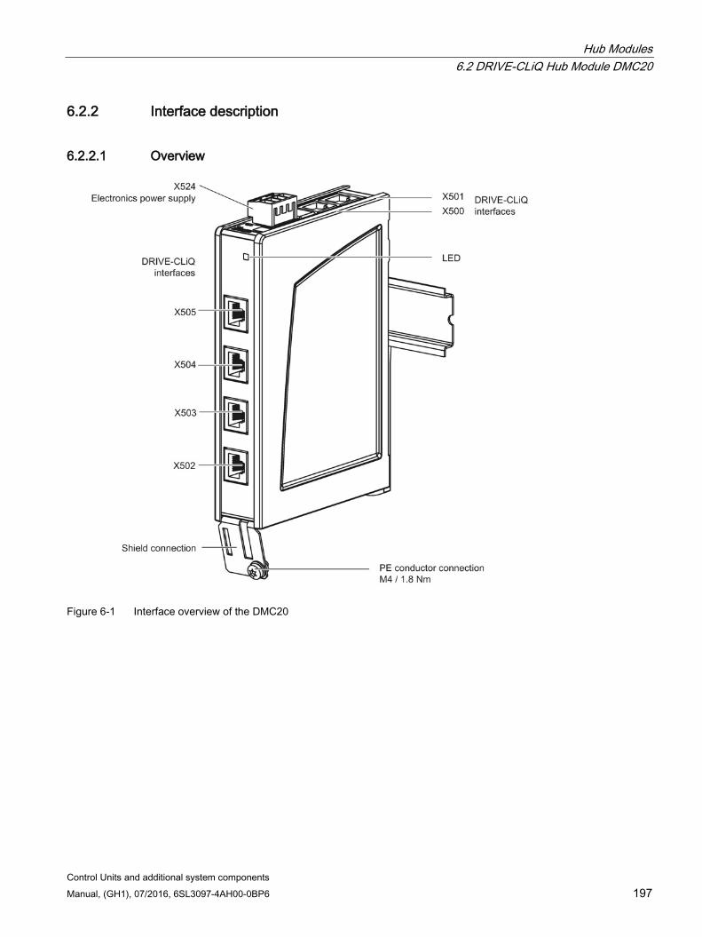
Hub Modules 6.2 DRIVE-CLiQ Hub Module DMC20
Control Units and additional system components Manual, (GH1), 07/2016, 6SL3097-4AH00-0BP6 197
6.2.2 Interface description
6.2.2.1 Overview
Figure 6-1 Interface overview of the DMC20
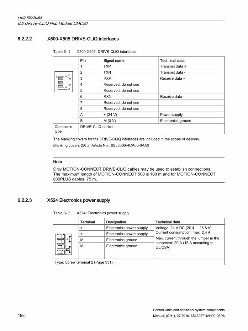
Hub Modules 6.2 DRIVE-CLiQ Hub Module DMC20
Control Units and additional system components 198 Manual, (GH1), 07/2016, 6SL3097-4AH00-0BP6
6.2.2.2 X500-X505 DRIVE-CLiQ interfaces
Table 6- 1 X500-X505: DRIVE-CLiQ interfaces
Pin Signal name Technical data
1 TXP Transmit data + 2 TXN Transmit data - 3 RXP Receive data + 4 Reserved, do not use 5 Reserved, do not use 6 RXN Receive data - 7 Reserved, do not use 8 Reserved, do not use A + (24 V) Power supply B M (0 V) Electronics ground
Connector type
DRIVE-CLiQ socket
The blanking covers for the DRIVE-CLiQ interfaces are included in the scope of delivery. Blanking covers (50 x) Article No.: 6SL3066-4CA00-0AA0
Note
Only MOTION-CONNECT DRIVE-CLiQ cables may be used to establish connections. The maximum length of MOTION-CONNECT 500 is 100 m and for MOTION-CONNECT 800PLUS cables, 75 m.
6.2.2.3 X524 Electronics power supply
Table 6- 2 X524: Electronics power supply
Terminal Designation Technical data
+ Electronics power supply Voltage: 24 V DC (20.4 ... 28.8 V) Current consumption: max. 2.4 A Max. current through the jumper in the connector: 20 A (15 A according to UL/CSA)
+ Electronics power supply M Electronics ground M Electronics ground
Type: Screw terminal 2 (Page 331)

Hub Modules 6.2 DRIVE-CLiQ Hub Module DMC20
Control Units and additional system components Manual, (GH1), 07/2016, 6SL3097-4AH00-0BP6 199
The maximum cable length that can be connected is 30 m.
Note
The two "+" or "M" terminals are jumpered in the connector. This ensures that the supply voltage is looped through.
The current consumption increases by the value for the DRIVE-CLiQ participants.
6.2.3 Meaning of the LED
Table 6- 3 Description of the LEDs on the DRIVE-CLiQ Hub Module DMC20
LED Color Status Description, cause Remedy READY – Off The electronics power supply is missing or outside the per-
missible tolerance range. –
Green Continu-ous light
The component is ready for operation. Cyclic DRIVE-CLiQ communication is taking place.
–
Orange Continu-ous light
DRIVE-CLiQ communication is being established. –
Red Continu-ous light
This component has at least one fault. Note: LED is controlled irrespective of the corresponding messag-es being reconfigured.
Remove and acknowledge the fault.
Green/red Flashing light 0.5 Hz
Firmware is being downloaded. –
Flashing light 2 Hz
Firmware download is complete. The system waits for POWER ON.
Carry out a POWER ON.
Green/ orange or Red/ orange
Flashing light
Component recognition via LED is activated (p0154 = 1). Note: Both options depend on the LED status when component recognition is activated.
–
Cause and rectification of faults Additional information about the cause and resolving faults can be taken from the following references:
Reference:/LH1/SINAMICS S120/S150 List Manual
Reference: /IH1/ SINAMICS S120 Commissioning Manual with STARTER
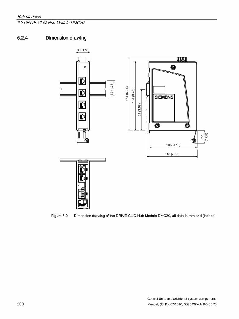
Hub Modules 6.2 DRIVE-CLiQ Hub Module DMC20
Control Units and additional system components 200 Manual, (GH1), 07/2016, 6SL3097-4AH00-0BP6
6.2.4 Dimension drawing
Figure 6-2 Dimension drawing of the DRIVE-CLiQ Hub Module DMC20, all data in mm and (inches)
Hub Modules 6.2 DRIVE-CLiQ Hub Module DMC20
Control Units and additional system components Manual, (GH1), 07/2016, 6SL3097-4AH00-0BP6 201
6.2.5 Installation
Installation 1. Tilt the component backwards slightly and attach it to the DIN rail using the hooks.
2. Swivel the component onto the DIN rail until you hear the mounting slide at the rear latch into position.
3. Slide the components along the mounting rail to either the left or right up to their final position.
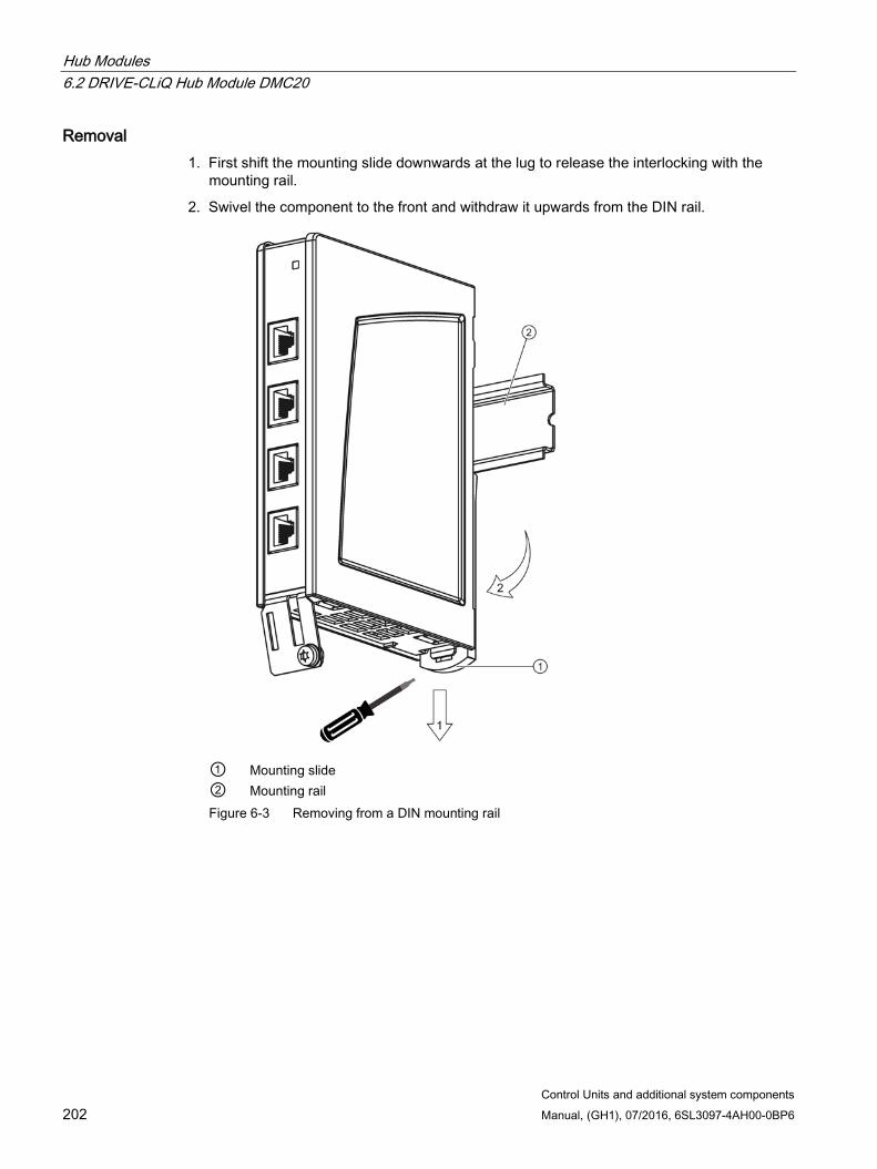
Hub Modules 6.2 DRIVE-CLiQ Hub Module DMC20
Control Units and additional system components 202 Manual, (GH1), 07/2016, 6SL3097-4AH00-0BP6
Removal 1. First shift the mounting slide downwards at the lug to release the interlocking with the
mounting rail.
2. Swivel the component to the front and withdraw it upwards from the DIN rail.
① Mounting slide ② Mounting rail Figure 6-3 Removing from a DIN mounting rail
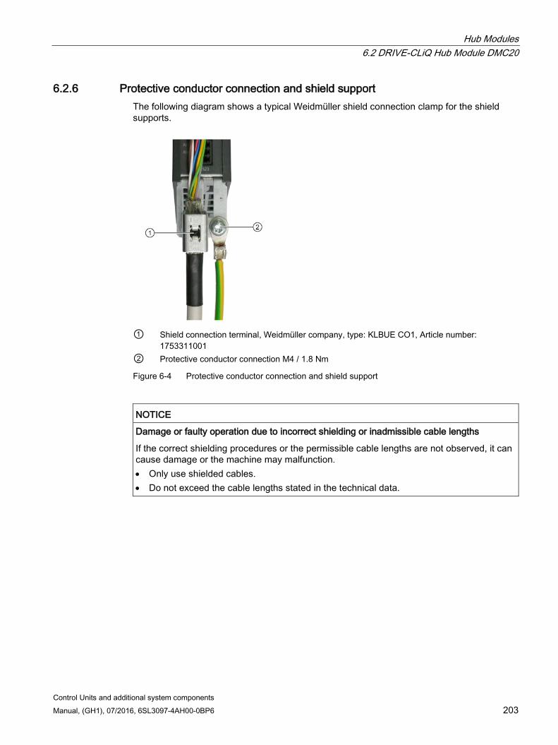
Hub Modules 6.2 DRIVE-CLiQ Hub Module DMC20
Control Units and additional system components Manual, (GH1), 07/2016, 6SL3097-4AH00-0BP6 203
6.2.6 Protective conductor connection and shield support The following diagram shows a typical Weidmüller shield connection clamp for the shield supports.
① Shield connection terminal, Weidmüller company, type: KLBUE CO1, Article number:
1753311001 ② Protective conductor connection M4 / 1.8 Nm
Figure 6-4 Protective conductor connection and shield support
NOTICE
Damage or faulty operation due to incorrect shielding or inadmissible cable lengths
If the correct shielding procedures or the permissible cable lengths are not observed, it can cause damage or the machine may malfunction. • Only use shielded cables. • Do not exceed the cable lengths stated in the technical data.
Hub Modules 6.3 DRIVE-CLiQ Hub Module External DME20
Control Units and additional system components 204 Manual, (GH1), 07/2016, 6SL3097-4AH00-0BP6
6.2.7 Technical data
Table 6- 4 Technical data of the DMC20
6SL3055-0AA00-6AA1 Unit Value Electronics power supply Voltage Current (without DRIVE-CLiQ node) Maximum cable length
VDC ADC m
24 V DC (20.4 ... 28.8) 0.15 30
PE/ground connection At the housing with M4 screw Weight kg 0.36
6.3 DRIVE-CLiQ Hub Module External DME20
6.3.1 Description The DRIVE-CLiQ Hub Module External DME20 is used to implement star-shaped distribution of a DRIVE-CLiQ line. With the DME20, an axis grouping can be expanded with 5 DRIVE-CLiQ sockets for additional subgroups.
The component has degree of protection IP67 and is especially suitable for applications which require DRIVE-CLiQ nodes to be removed in groups, without interrupting the DRIVE-CLiQ line and therefore the data exchange.
NOTICE
Damage due to leaking plug connections
If IP67 protection is not ensured, water or dirt can enter and lead to damage. • Ensure that all connectors are correctly screwed into place and appropriately locked.
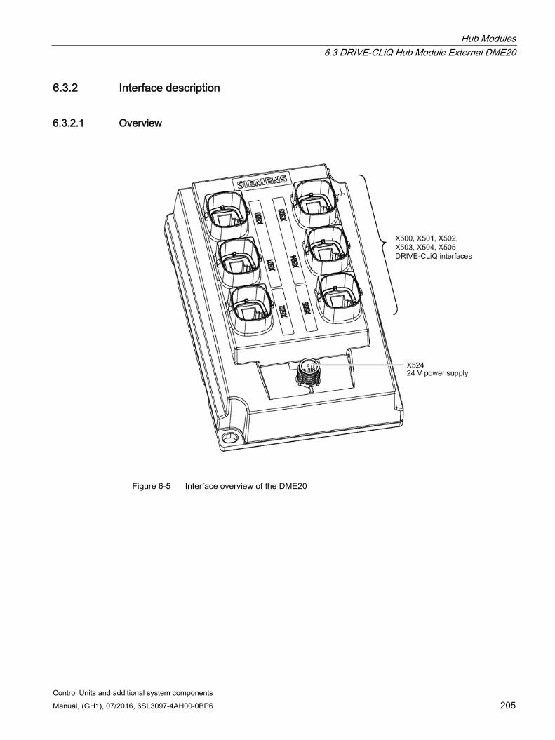
Hub Modules 6.3 DRIVE-CLiQ Hub Module External DME20
Control Units and additional system components Manual, (GH1), 07/2016, 6SL3097-4AH00-0BP6 205
6.3.2 Interface description
6.3.2.1 Overview
Figure 6-5 Interface overview of the DME20
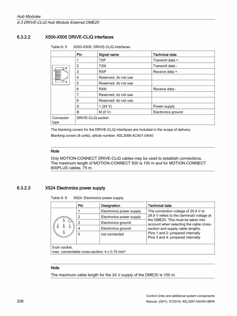
Hub Modules 6.3 DRIVE-CLiQ Hub Module External DME20
Control Units and additional system components 206 Manual, (GH1), 07/2016, 6SL3097-4AH00-0BP6
6.3.2.2 X500-X505 DRIVE-CLiQ interfaces
Table 6- 5 X500-X505: DRIVE-CLiQ interfaces
Pin Signal name Technical data
1 TXP Transmit data + 2 TXN Transmit data - 3 RXP Receive data + 4 Reserved, do not use 5 Reserved, do not use 6 RXN Receive data - 7 Reserved, do not use 8 Reserved, do not use A + (24 V) Power supply B M (0 V) Electronics ground
Connector type
DRIVE-CLiQ socket
The blanking covers for the DRIVE-CLiQ interfaces are included in the scope of delivery. Blanking covers (6 units), article number: 6SL3066-4CA01-0AA0
Note
Only MOTION-CONNECT DRIVE-CLiQ cables may be used to establish connections. The maximum length of MOTION-CONNECT 500 is 100 m and for MOTION-CONNECT 800PLUS cables, 75 m.
6.3.2.3 X524 Electronics power supply
Table 6- 6 X524: Electronics power supply
Pin Designation Technical data
1 Electronics power supply The connection voltage of 20.4 V to 28.8 V refers to the (terminal) voltage at the DME20. This must be taken into account when selecting the cable cross-section and supply cable lengths. Pins 1 and 2: jumpered internally Pins 3 and 4: jumpered internally
2 Electronics power supply 3 Electronics ground 4 Electronics ground 5 not connected
5-pin socket, max. connectable cross-section: 4 x 0.75 mm2
Note
The maximum cable length for the 24 V supply of the DME20 is 100 m.
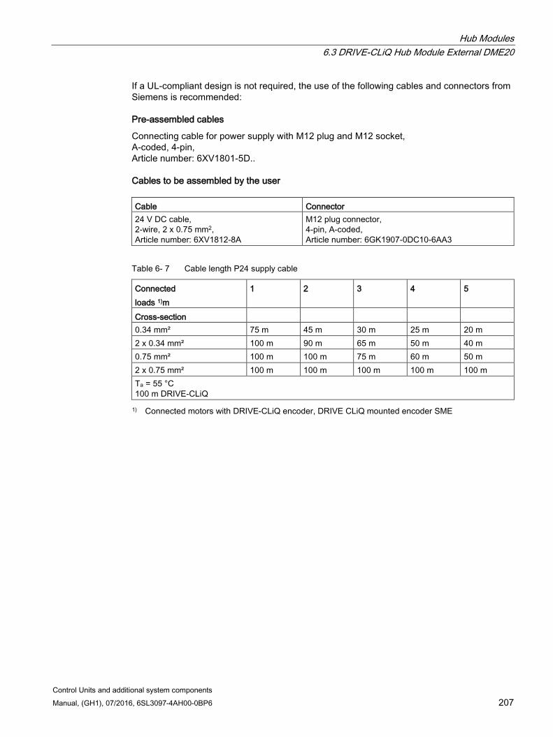
Hub Modules 6.3 DRIVE-CLiQ Hub Module External DME20
Control Units and additional system components Manual, (GH1), 07/2016, 6SL3097-4AH00-0BP6 207
If a UL-compliant design is not required, the use of the following cables and connectors from Siemens is recommended:
Pre-assembled cables
Connecting cable for power supply with M12 plug and M12 socket, A-coded, 4-pin, Article number: 6XV1801-5D..
Cables to be assembled by the user Cable Connector 24 V DC cable, 2-wire, 2 x 0.75 mm2, Article number: 6XV1812-8A
M12 plug connector, 4-pin, A-coded, Article number: 6GK1907-0DC10-6AA3
Table 6- 7 Cable length P24 supply cable
Connected loads 1)m
1 2 3 4 5
Cross-section 0.34 mm² 75 m 45 m 30 m 25 m 20 m 2 x 0.34 mm² 100 m 90 m 65 m 50 m 40 m 0.75 mm² 100 m 100 m 75 m 60 m 50 m 2 x 0.75 mm² 100 m 100 m 100 m 100 m 100 m Ta = 55 °C 100 m DRIVE-CLiQ 1) Connected motors with DRIVE-CLiQ encoder, DRIVE CLiQ mounted encoder SME
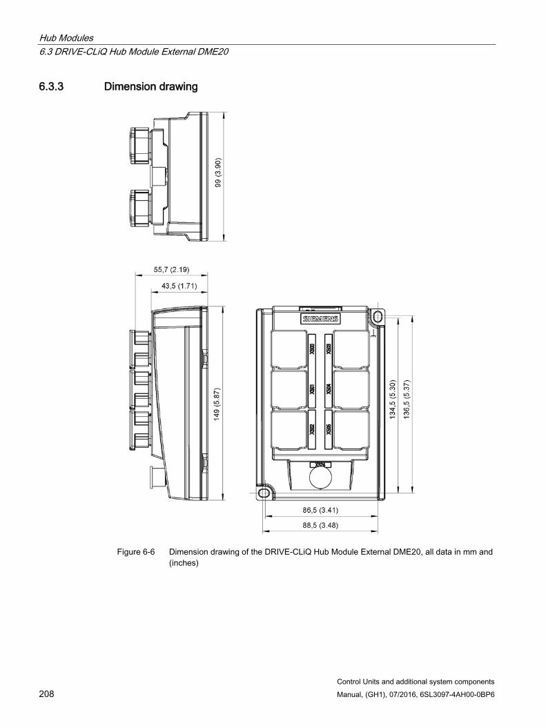
Hub Modules 6.3 DRIVE-CLiQ Hub Module External DME20
Control Units and additional system components 208 Manual, (GH1), 07/2016, 6SL3097-4AH00-0BP6
6.3.3 Dimension drawing
Figure 6-6 Dimension drawing of the DRIVE-CLiQ Hub Module External DME20, all data in mm and
(inches)
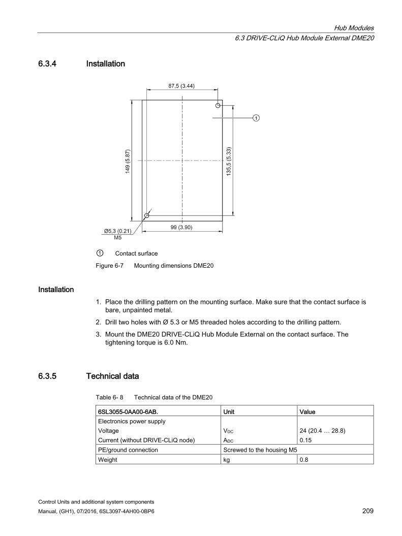
Hub Modules 6.3 DRIVE-CLiQ Hub Module External DME20
Control Units and additional system components Manual, (GH1), 07/2016, 6SL3097-4AH00-0BP6 209
6.3.4 Installation
① Contact surface
Figure 6-7 Mounting dimensions DME20
Installation 1. Place the drilling pattern on the mounting surface. Make sure that the contact surface is
bare, unpainted metal.
2. Drill two holes with Ø 5.3 or M5 threaded holes according to the drilling pattern.
3. Mount the DME20 DRIVE-CLiQ Hub Module External on the contact surface. The tightening torque is 6.0 Nm.
6.3.5 Technical data
Table 6- 8 Technical data of the DME20
6SL3055-0AA00-6AB. Unit Value Electronics power supply Voltage Current (without DRIVE-CLiQ node)
VDC ADC
24 (20.4 … 28.8) 0.15
PE/ground connection Screwed to the housing M5 Weight kg 0.8
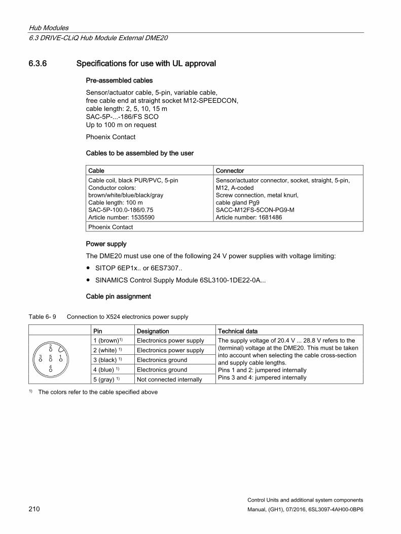
Hub Modules 6.3 DRIVE-CLiQ Hub Module External DME20
Control Units and additional system components 210 Manual, (GH1), 07/2016, 6SL3097-4AH00-0BP6
6.3.6 Specifications for use with UL approval
Pre-assembled cables
Sensor/actuator cable, 5-pin, variable cable, free cable end at straight socket M12-SPEEDCON, cable length: 2, 5, 10, 15 m SAC-5P-...-186/FS SCO Up to 100 m on request
Phoenix Contact
Cables to be assembled by the user Cable Connector Cable coil, black PUR/PVC, 5-pin Conductor colors: brown/white/blue/black/gray Cable length: 100 m SAC-5P-100.0-186/0.75 Article number: 1535590
Sensor/actuator connector, socket, straight, 5-pin, M12, A-coded Screw connection, metal knurl, cable gland Pg9 SACC-M12FS-5CON-PG9-M Article number: 1681486
Phoenix Contact
Power supply
The DME20 must use one of the following 24 V power supplies with voltage limiting:
SITOP 6EP1x.. or 6ES7307..
SINAMICS Control Supply Module 6SL3100-1DE22-0A...
Cable pin assignment
Table 6- 9 Connection to X524 electronics power supply
Pin Designation Technical data
1 (brown)1) Electronics power supply The supply voltage of 20.4 V ... 28.8 V refers to the (terminal) voltage at the DME20. This must be taken into account when selecting the cable cross-section and supply cable lengths. Pins 1 and 2: jumpered internally Pins 3 and 4: jumpered internally
2 (white) 1) Electronics power supply 3 (black) 1) Electronics ground 4 (blue) 1) Electronics ground 5 (gray) 1) Not connected internally
1) The colors refer to the cable specified above

Control Units and additional system components Manual, (GH1), 07/2016, 6SL3097-4AH00-0BP6 211
Voltage Sensing Module VSM10 7 7.1 Description
The Voltage Sensing Module VSM10 is an expansion module for snapping on to a standard mounting rail acc. to EN 60715. It is used to sense the actual value of a voltage. For example, it can be used to sense the three-phase line supply voltage, which is then provided to the closed-loop control. The phase differential voltage can be measured, either grounded (in the delivery state) or isolated.
The Voltage Sensing Module can be used for the following line types:
Up to 600 V 3-ph. AC for all line types
Up to 690 V 3-ph. AC for networks with grounded start point and IT networks
A 100 V 3-ph. AC input is available for transducer transformers. It is not permissible to use both voltage connections simultaneously!
For booksize units, these components can be optionally used to increase the degree of ruggedness against irregularities in the line supply.
A VSM is already integrated for Active Interface Modules Chassis and Smart Line Modules Chassis.
In addition to the voltage sensing, a temperature sensor can be connector to the VSM10 to thermally monitor the line reactor. Further, the functionality of the line filter can checked using two analog inputs. All data recorded are transferred to the higher-level system via DRIVE-CLiQ.
The Voltage Sensing Module achieves radio interference category C2 with limit classes A1 for interference voltage and A for emitted interference.
Table 7- 1 Interface overview of the VSM10
Type Quantity Analog inputs 2 Voltage connection (690 V) 1 (3-phase) Voltage connection (100 V) 1 (3-phase) Temperature sensor input (KTY/PT1000/PTC) 1 Neutral point grounding 1 DRIVE-CLiQ interface 1

Voltage Sensing Module VSM10 7.2 Safety instructions for the Voltage Sensing Module (VSM10)
Control Units and additional system components 212 Manual, (GH1), 07/2016, 6SL3097-4AH00-0BP6
7.2 Safety instructions for the Voltage Sensing Module (VSM10)
WARNING
Danger to life if the fundamental safety instructions and remaining risks are not carefully observed
If the fundamental safety instructions and remaining risks in Chapter 1 (Page 19) are not observed, accidents involving severe injuries or death may occur. • Adhere to the fundamental safety instructions. • When assessing the risk, take into account remaining risks.
WARNING
Risk of fire through overheating if there are insufficient ventilation clearances
Insufficient ventilation clearances lead to overheating with associated risk to persons as a result of smoke and fire. This can also result in more downtimes and reduced service lives of the Voltage Sensing Module. • For this reason, it is imperative that you maintain the 50 mm clearances above and
below the Voltage Sensing Module.
NOTICE
Destruction of the VSM10 as a result of voltage measurements incorrectly carried out
If the voltage measurement is carried out incorrectly, the VSM10 can be destroyed as a result of the high voltage stress across the insulating clearance. • When using long motor cables, it is not permissible that the output voltage of the Motor
Module is directly measured at the motor.
NOTICE
Destruction of the VSM10 as a result of a terminal assignment which is not permissible
The VSM10 has two terminal strips, X521 and X522, to sense the three-phase line supply voltage. A terminal assignment which is not permissible results in the module being destroyed. • Use just one of the two terminal strips. • Only connect voltages to terminal strip X521 up to a maximum 100 V (phase-to-phase)
via a transformer. • Only connect voltages to terminal strip X522 up to a maximum 690 V (phase-to-phase)
directly.
Voltage Sensing Module VSM10 7.2 Safety instructions for the Voltage Sensing Module (VSM10)
Control Units and additional system components Manual, (GH1), 07/2016, 6SL3097-4AH00-0BP6 213
NOTICE
Damage through use of incorrect DRIVE-CLiQ cables
Damage or malfunctions can occur on the devices or system when incorrect or unreleased DRIVE-CLiQ cables are used. • Only use suitable DRIVE-CLiQ cables that have been released by Siemens for the
respective application.
Note Function equipotential bonding for distributed DRIVE-CLiQ nodes
Integrate all of the components that are connected via DRIVE-CLiQ in the functional equipotential bonding concept. The connection should be preferably established by mounting on metallic bare machine and plant components that are connected with one another using an equipotential bonding conductor. Alternatively, you can establish equipotential bonding using a conductor (min. 6 mm²), which as far as possible, is routed in parallel to the DRIVE-CLiQ cable. All distributed DRIVE-CLiQ nodes are involved, for example DME20, SME20, SME25, SME120, SME125 etc.
Note Malfunctions due to polluted DRIVE-CLiQ interfaces
Malfunctions can occur in the system through the use of polluted DRIVE-CLiQ interfaces. • Cover unused DRIVE-CLiQ interfaces with the supplied blanking covers.
Note Malfunctions when using various generations of the VSM10 with parallel infeed
When connecting infeeds in parallel, only Voltage Sensing Modules of the same generation may be used (either 6SL3053-0AA00-3AA0 or 6SL3053-0AA00-3AA1), as otherwise malfunctions can occur. • Especially when replacing a VSM10 (Page 226)it is important that all of the other VSM10
connected in parallel are replaced.
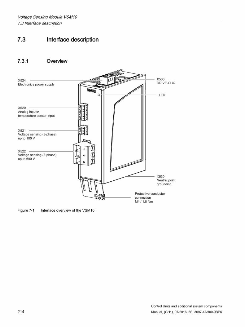
Voltage Sensing Module VSM10 7.3 Interface description
Control Units and additional system components 214 Manual, (GH1), 07/2016, 6SL3097-4AH00-0BP6
7.3 Interface description
7.3.1 Overview
Figure 7-1 Interface overview of the VSM10
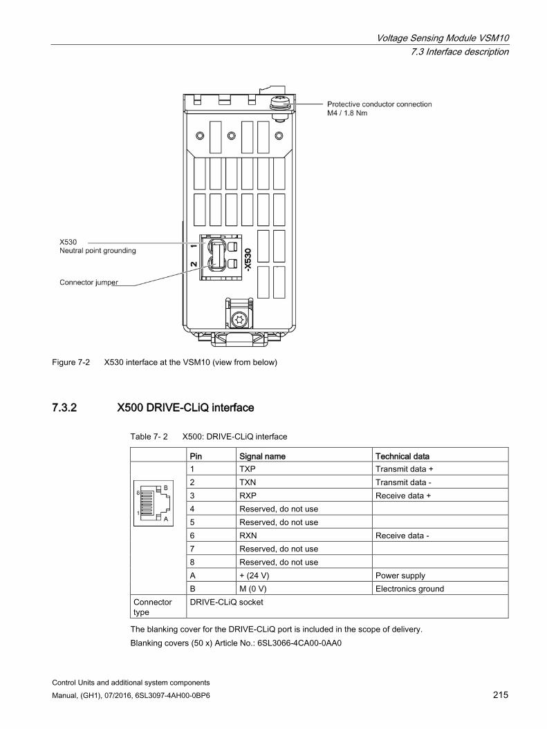
Voltage Sensing Module VSM10 7.3 Interface description
Control Units and additional system components Manual, (GH1), 07/2016, 6SL3097-4AH00-0BP6 215
Figure 7-2 X530 interface at the VSM10 (view from below)
7.3.2 X500 DRIVE-CLiQ interface
Table 7- 2 X500: DRIVE-CLiQ interface
Pin Signal name Technical data
1 TXP Transmit data + 2 TXN Transmit data - 3 RXP Receive data + 4 Reserved, do not use 5 Reserved, do not use 6 RXN Receive data - 7 Reserved, do not use 8 Reserved, do not use A + (24 V) Power supply B M (0 V) Electronics ground
Connector type
DRIVE-CLiQ socket
The blanking cover for the DRIVE-CLiQ port is included in the scope of delivery. Blanking covers (50 x) Article No.: 6SL3066-4CA00-0AA0
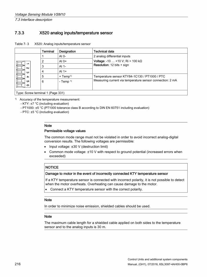
Voltage Sensing Module VSM10 7.3 Interface description
Control Units and additional system components 216 Manual, (GH1), 07/2016, 6SL3097-4AH00-0BP6
7.3.3 X520 analog inputs/temperature sensor
Table 7- 3 X520: Analog inputs/temperature sensor
Terminal Designation Technical data
1 AI 0- 2 analog differential inputs Voltage: -10 … +10 V; Ri > 100 kΩ Resolution: 12 bits + sign
2 AI 0+ 3 AI 1- 4 AI 1+ 5 + Temp1) Temperature sensor KTY84-1C130 / PT1000 / PTC
Measuring current via temperature sensor connection: 2 mA 6 - Temp 1)
Type: Screw terminal 1 (Page 331) 1) Accuracy of the temperature measurement:
- KTY: ±7 °C (including evaluation) - PT1000: ±5 °C (PT1000 tolerance class B according to DIN EN 60751 including evaluation) - PTC: ±5 °C (including evaluation)
Note Permissible voltage values
The common mode range must not be violated in order to avoid incorrect analog-digital conversion results. The following voltages are permissible: • Input voltage: ±30 V (destruction limit) • Common mode voltage: ±10 V with respect to ground potential (increased errors when
exceeded)
NOTICE
Damage to motor in the event of incorrectly connected KTY temperature sensor
If a KTY temperature sensor is connected with incorrect polarity, it is not possible to detect when the motor overheats. Overheating can cause damage to the motor. • Connect a KTY temperature sensor with the correct polarity.
Note
In order to minimize noise emission, shielded cables should be used.
Note
The maximum cable length for a shielded cable applied on both sides to the temperature sensor and to the analog inputs is 30 m.
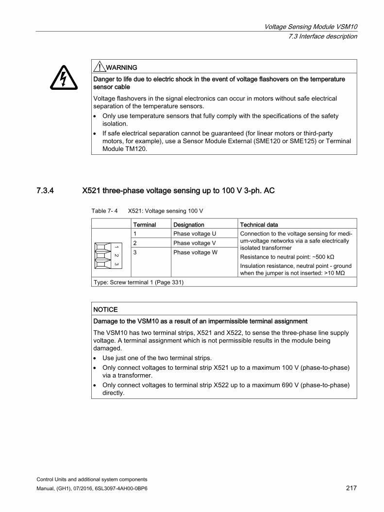
Voltage Sensing Module VSM10 7.3 Interface description
Control Units and additional system components Manual, (GH1), 07/2016, 6SL3097-4AH00-0BP6 217
WARNING
Danger to life due to electric shock in the event of voltage flashovers on the temperature sensor cable
Voltage flashovers in the signal electronics can occur in motors without safe electrical separation of the temperature sensors. • Only use temperature sensors that fully comply with the specifications of the safety
isolation. • If safe electrical separation cannot be guaranteed (for linear motors or third-party
motors, for example), use a Sensor Module External (SME120 or SME125) or Terminal Module TM120.
7.3.4 X521 three-phase voltage sensing up to 100 V 3-ph. AC
Table 7- 4 X521: Voltage sensing 100 V
Terminal Designation Technical data
1 Phase voltage U Connection to the voltage sensing for medi-um-voltage networks via a safe electrically isolated transformer Resistance to neutral point: ∼500 kΩ Insulation resistance, neutral point - ground when the jumper is not inserted: >10 MΩ
2 Phase voltage V 3 Phase voltage W
Type: Screw terminal 1 (Page 331)
NOTICE
Damage to the VSM10 as a result of an impermissible terminal assignment
The VSM10 has two terminal strips, X521 and X522, to sense the three-phase line supply voltage. A terminal assignment which is not permissible results in the module being damaged. • Use just one of the two terminal strips. • Only connect voltages to terminal strip X521 up to a maximum 100 V (phase-to-phase)
via a transformer. • Only connect voltages to terminal strip X522 up to a maximum 690 V (phase-to-phase)
directly.
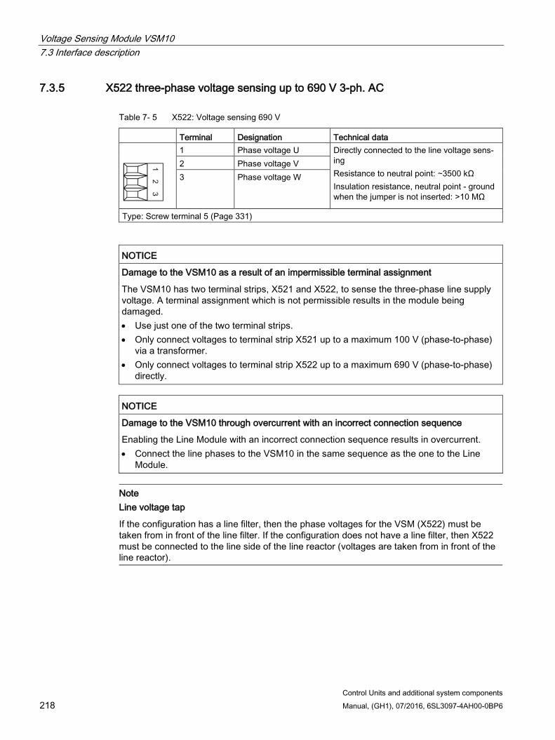
Voltage Sensing Module VSM10 7.3 Interface description
Control Units and additional system components 218 Manual, (GH1), 07/2016, 6SL3097-4AH00-0BP6
7.3.5 X522 three-phase voltage sensing up to 690 V 3-ph. AC
Table 7- 5 X522: Voltage sensing 690 V
Terminal Designation Technical data
1 Phase voltage U Directly connected to the line voltage sens-ing Resistance to neutral point: ∼3500 kΩ Insulation resistance, neutral point - ground when the jumper is not inserted: >10 MΩ
2 Phase voltage V 3 Phase voltage W
Type: Screw terminal 5 (Page 331)
NOTICE
Damage to the VSM10 as a result of an impermissible terminal assignment
The VSM10 has two terminal strips, X521 and X522, to sense the three-phase line supply voltage. A terminal assignment which is not permissible results in the module being damaged. • Use just one of the two terminal strips. • Only connect voltages to terminal strip X521 up to a maximum 100 V (phase-to-phase)
via a transformer. • Only connect voltages to terminal strip X522 up to a maximum 690 V (phase-to-phase)
directly.
NOTICE
Damage to the VSM10 through overcurrent with an incorrect connection sequence
Enabling the Line Module with an incorrect connection sequence results in overcurrent. • Connect the line phases to the VSM10 in the same sequence as the one to the Line
Module.
Note Line voltage tap
If the configuration has a line filter, then the phase voltages for the VSM (X522) must be taken from in front of the line filter. If the configuration does not have a line filter, then X522 must be connected to the line side of the line reactor (voltages are taken from in front of the line reactor).
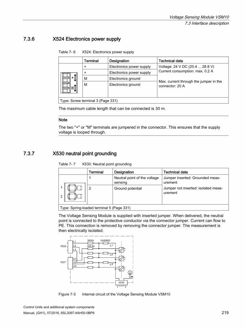
Voltage Sensing Module VSM10 7.3 Interface description
Control Units and additional system components Manual, (GH1), 07/2016, 6SL3097-4AH00-0BP6 219
7.3.6 X524 Electronics power supply
Table 7- 6 X524: Electronics power supply
Terminal Designation Technical data
+ Electronics power supply Voltage: 24 V DC (20.4 ... 28.8 V) Current consumption: max. 0.2 A Max. current through the jumper in the connector: 20 A
+ Electronics power supply M Electronics ground M Electronics ground
Type: Screw terminal 3 (Page 331)
The maximum cable length that can be connected is 30 m.
Note
The two "+" or "M" terminals are jumpered in the connector. This ensures that the supply voltage is looped through.
7.3.7 X530 neutral point grounding
Table 7- 7 X530: Neutral point grounding
Terminal Designation Technical data
1 Neutral point of the voltage sensing
Jumper inserted: Grounded meas-urement Jumper not inserted: isolated meas-urement
2 Ground potential
Type: Spring-loaded terminal 5 (Page 331)
The Voltage Sensing Module is supplied with inserted jumper. When delivered, the neutral point is connected to the protective conductor via the connector jumper. Current can flow to PE. This connection is removed by removing the connector jumper. The measurement is then electrically isolated.
Figure 7-3 Internal circuit of the Voltage Sensing Module VSM10
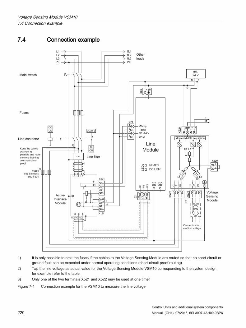
Voltage Sensing Module VSM10 7.4 Connection example
Control Units and additional system components 220 Manual, (GH1), 07/2016, 6SL3097-4AH00-0BP6
7.4 Connection example
1) It is only possible to omit the fuses if the cables to the Voltage Sensing Module are routed so that no short-circuit or
ground fault can be expected under normal operating conditions (short-circuit proof routing). 2) Tap the line voltage as actual value for the Voltage Sensing Module VSM10 corresponding to the system design,
for example refer to the table. 3) Only one of the two terminals X521 and X522 may be used at one time!
Figure 7-4 Connection example for the VSM10 to measure the line voltage

Voltage Sensing Module VSM10 7.5 Meaning of the LED
Control Units and additional system components Manual, (GH1), 07/2016, 6SL3097-4AH00-0BP6 221
Table 7- 8 Suggestions for terminals and cable lugs which can be used to connect a VSM10 to the line
Conductor cross-section Connection via For components Up to 6 mm2 Direct connection possible Smart Line Modules 5 kW and 10 kW 6 mm2 to 16 mm2 ST16-TWIN terminal blocks,
if required with a reducing jumper and ST4-TWIN or ST2.5-TWIN (Phoenix Contact company)
Active Line Modules 16 kW Smart Line Modules 16 kW Active Interface Module 16 kW
16 mm2 to 50 mm2 AGK10 UKH tap-off terminals with UKH terminals (Phoenix Contact company)
Active Line Modules 36 kW and 55 kW Smart Line Modules 36 kW and 55 kW Active Interface Module 36 kW and 55 kW
> 50 mm2 Ring cable lug without insulation (Page 333) 8 mm/2.5 mm2
Components with M8 connection bolts Active Line Modules 55 kW, 80 kW, and 120 kW Active Interface Module 80 kW and 120 kW
Intermediate high-current connector, type UHV (Phoenix Contact) and ring cable lug without insulation (Page 333) 8 mm/2.5 mm2
7.5 Meaning of the LED
Table 7- 9 Meanings of the LEDs on the Voltage Sensing Module VSM10
LED Color Status Description, cause Remedy READY – Off The electronics power supply is missing or outside the per-
missible tolerance range. –
Green Continuous light
The component is ready for operation. Cyclic DRIVE-CLiQ communication is taking place.
–
Orange Continuous light
DRIVE-CLiQ communication is being established. –
Red Continuous light
This component has at least one fault. Note: LED is controlled irrespective of the corresponding messag-es being reconfigured.
Remove and acknowledge the fault.
Green/red Flashing light 0.5 Hz
Firmware is being downloaded. –
Flashing light 2 Hz
Firmware download is complete. The system waits for POWER ON.
Carry out a POWER ON.
Green/ orange or Red/ orange
Flashing light
Detection of the component via LED is activated (p0144 = 1). Note: Both options depend on the LED status when component recognition is activated.
–
Cause and rectification of faults Additional information about the cause and resolving faults can be taken from the following references: Reference:/LH1/SINAMICS S120/S150 List Manual Reference: /IH1/ SINAMICS S120 Commissioning Manual with STARTER
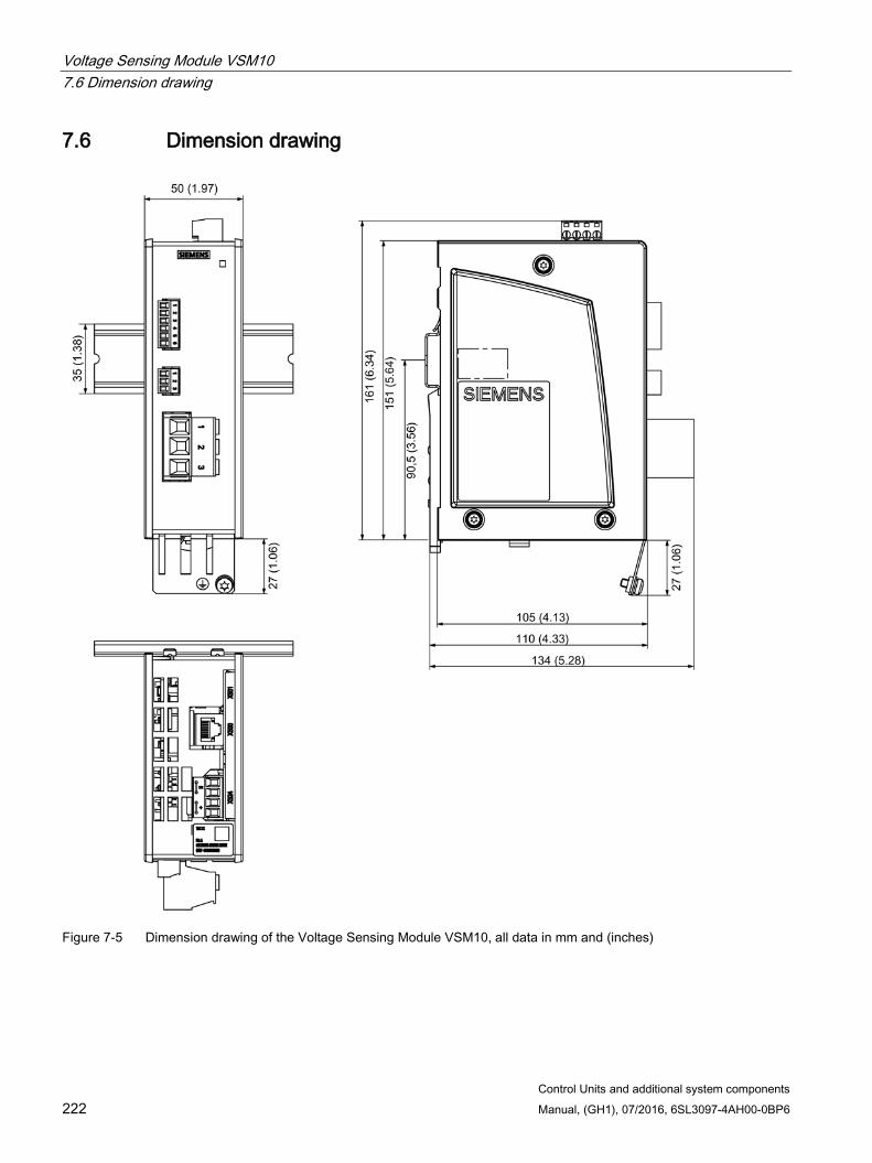
Voltage Sensing Module VSM10 7.6 Dimension drawing
Control Units and additional system components 222 Manual, (GH1), 07/2016, 6SL3097-4AH00-0BP6
7.6 Dimension drawing
Figure 7-5 Dimension drawing of the Voltage Sensing Module VSM10, all data in mm and (inches)
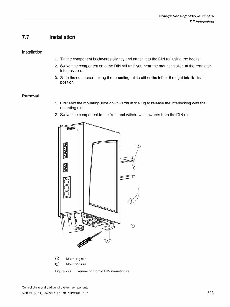
Voltage Sensing Module VSM10 7.7 Installation
Control Units and additional system components Manual, (GH1), 07/2016, 6SL3097-4AH00-0BP6 223
7.7 Installation
Installation 1. Tilt the component backwards slightly and attach it to the DIN rail using the hooks.
2. Swivel the component onto the DIN rail until you hear the mounting slide at the rear latch into position.
3. Slide the component along the mounting rail to either the left or the right into its final position.
Removal 1. First shift the mounting slide downwards at the lug to release the interlocking with the
mounting rail.
2. Swivel the component to the front and withdraw it upwards from the DIN rail.
① Mounting slide ② Mounting rail
Figure 7-6 Removing from a DIN mounting rail

Voltage Sensing Module VSM10 7.8 Protective conductor connection and shield support
Control Units and additional system components 224 Manual, (GH1), 07/2016, 6SL3097-4AH00-0BP6
7.8 Protective conductor connection and shield support The following shield connection clamps can be used on the bottom part of the component housing for shield connection of the analog inputs: Shield connection clamp Article No. Phoenix Contact SK8 3025163 Phoenix Contact SK14 3025176 Phoenix Contact SK20 3025189 Weidmüller KLBUE CO1 1753311001
The following pictures show the shield contacts with a shield connection clamp from Weidmüller.
① Protective conductor connection M4 / 1.8 Nm ② Shield connection terminal, Weidmüller company, type: KLBUE CO1, Article number:
1753311001
Figure 7-7 Protective conductor connection and shield support at the VSM10
NOTICE
Damage or faulty operation due to incorrect shielding or inadmissible cable lengths
If the correct shielding procedures or the permissible cable lengths are not observed, it can cause damage or the machine may malfunction. • Only use shielded cables. • Do not exceed the cable lengths stated in the technical data.
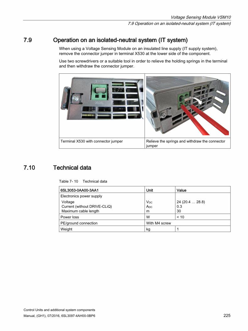
Voltage Sensing Module VSM10 7.9 Operation on an isolated-neutral system (IT system)
Control Units and additional system components Manual, (GH1), 07/2016, 6SL3097-4AH00-0BP6 225
7.9 Operation on an isolated-neutral system (IT system) When using a Voltage Sensing Module on an insulated line supply (IT supply system), remove the connector jumper in terminal X530 at the lower side of the component.
Use two screwdrivers or a suitable tool in order to relieve the holding springs in the terminal and then withdraw the connector jumper.
Terminal X530 with connector jumper Relieve the springs and withdraw the connector jumper
7.10 Technical data
Table 7- 10 Technical data
6SL3053-0AA00-3AA1 Unit Value Electronics power supply Voltage Current (without DRIVE-CLiQ) Maximum cable length
VDC ADC m
24 (20.4 … 28.8) 0.3 30
Power loss W < 10 PE/ground connection With M4 screw Weight kg 1
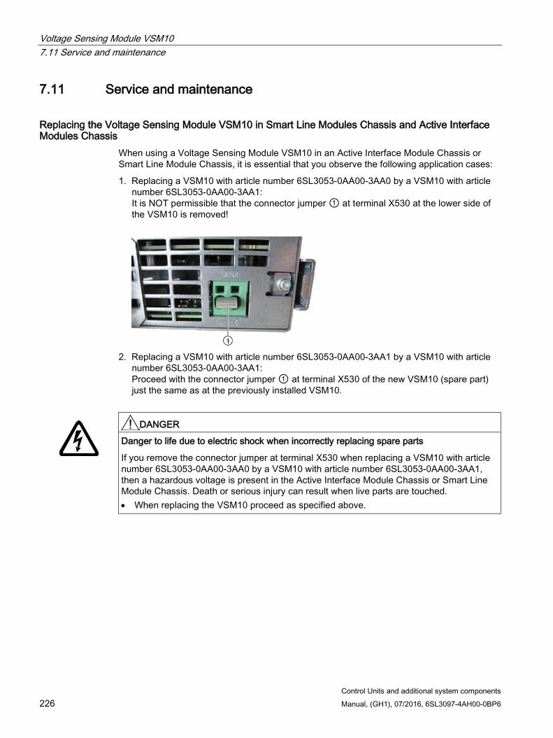
Voltage Sensing Module VSM10 7.11 Service and maintenance
Control Units and additional system components 226 Manual, (GH1), 07/2016, 6SL3097-4AH00-0BP6
7.11 Service and maintenance
Replacing the Voltage Sensing Module VSM10 in Smart Line Modules Chassis and Active Interface Modules Chassis
When using a Voltage Sensing Module VSM10 in an Active Interface Module Chassis or Smart Line Module Chassis, it is essential that you observe the following application cases:
1. Replacing a VSM10 with article number 6SL3053-0AA00-3AA0 by a VSM10 with article number 6SL3053-0AA00-3AA1: It is NOT permissible that the connector jumper ① at terminal X530 at the lower side of the VSM10 is removed!
2. Replacing a VSM10 with article number 6SL3053-0AA00-3AA1 by a VSM10 with article
number 6SL3053-0AA00-3AA1: Proceed with the connector jumper ① at terminal X530 of the new VSM10 (spare part) just the same as at the previously installed VSM10.
DANGER
Danger to life due to electric shock when incorrectly replacing spare parts
If you remove the connector jumper at terminal X530 when replacing a VSM10 with article number 6SL3053-0AA00-3AA0 by a VSM10 with article number 6SL3053-0AA00-3AA1, then a hazardous voltage is present in the Active Interface Module Chassis or Smart Line Module Chassis. Death or serious injury can result when live parts are touched. • When replacing the VSM10 proceed as specified above.
Control Units and additional system components Manual, (GH1), 07/2016, 6SL3097-4AH00-0BP6 227
Encoder system connection 8 8.1 Introduction
The encoder system should be connected to SINAMICS S120 via DRIVE-CLiQ.
Motors with DRIVE-CLiQ interfaces (e.g. synchronous motors 1FK7 and 1FT7, and induction motors 1PH7 and 1PH8) are designed for this purpose. These motors simplify commissioning and diagnostics because the motor and encoder type are identified automatically.
Motors and external encoders without DRIVE-CLiQ interface Motors without DRIVE-CLiQ interfaces, as well as external encoders without integrated DRIVE-CLiQ interface, must be connected via Sensor Modules to enable the encoder and temperature signals to be evaluated. Sensor Modules Cabinet-Mounted (SMC) are available for installation in control cabinets and Sensor Modules External (SME) for installation outside control cabinets.
If not otherwise specified, only one encoder system can be connected to each Sensor Module.
Motors and external encoders with DRIVE-CLiQ interface Motors with DRIVE-CLiQ interfaces can be connected to the associated Motor Module directly via the MOTION-CONNECT DRIVE-CLiQ cables available. The connection of the MOTION-CONNECT DRIVE-CLiQ cable at the motor has degree of protection IP67.
The DRIVE-CLiQ interface supplies the motor encoder via the integrated 24 V DC supply and transfers the motor encoder and temperature signals and the electronic rating plate data, such as a unique identification number, rated data (voltage, current, torque) directly to the Control Unit. Different encoder cables are therefore no longer required for the various encoder types, e.g. resolvers or absolute encoders. Wiring can be effected throughout with a MOTION-CONNECT DRIVE-CLiQ cable.
DRIVE-CLiQ encoder A DRIVE-CLiQ encoder is an absolute encoder with integrated DRIVE-CLiQ interface (see Chapter DRIVE-CLiQ encoder (Page 313)).
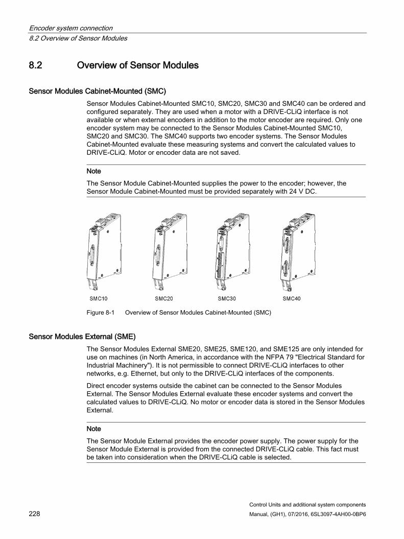
Encoder system connection 8.2 Overview of Sensor Modules
Control Units and additional system components 228 Manual, (GH1), 07/2016, 6SL3097-4AH00-0BP6
8.2 Overview of Sensor Modules
Sensor Modules Cabinet-Mounted (SMC) Sensor Modules Cabinet-Mounted SMC10, SMC20, SMC30 and SMC40 can be ordered and configured separately. They are used when a motor with a DRIVE-CLiQ interface is not available or when external encoders in addition to the motor encoder are required. Only one encoder system may be connected to the Sensor Modules Cabinet-Mounted SMC10, SMC20 and SMC30. The SMC40 supports two encoder systems. The Sensor Modules Cabinet-Mounted evaluate these measuring systems and convert the calculated values to DRIVE-CLiQ. Motor or encoder data are not saved.
Note
The Sensor Module Cabinet-Mounted supplies the power to the encoder; however, the Sensor Module Cabinet-Mounted must be provided separately with 24 V DC.
Figure 8-1 Overview of Sensor Modules Cabinet-Mounted (SMC)
Sensor Modules External (SME) The Sensor Modules External SME20, SME25, SME120, and SME125 are only intended for use on machines (in North America, in accordance with the NFPA 79 "Electrical Standard for Industrial Machinery"). It is not permissible to connect DRIVE-CLiQ interfaces to other networks, e.g. Ethernet, but only to the DRIVE-CLiQ interfaces of the components.
Direct encoder systems outside the cabinet can be connected to the Sensor Modules External. The Sensor Modules External evaluate these encoder systems and convert the calculated values to DRIVE-CLiQ. No motor or encoder data is stored in the Sensor Modules External.
Note
The Sensor Module External provides the encoder power supply. The power supply for the Sensor Module External is provided from the connected DRIVE-CLiQ cable. This fact must be taken into consideration when the DRIVE-CLiQ cable is selected.
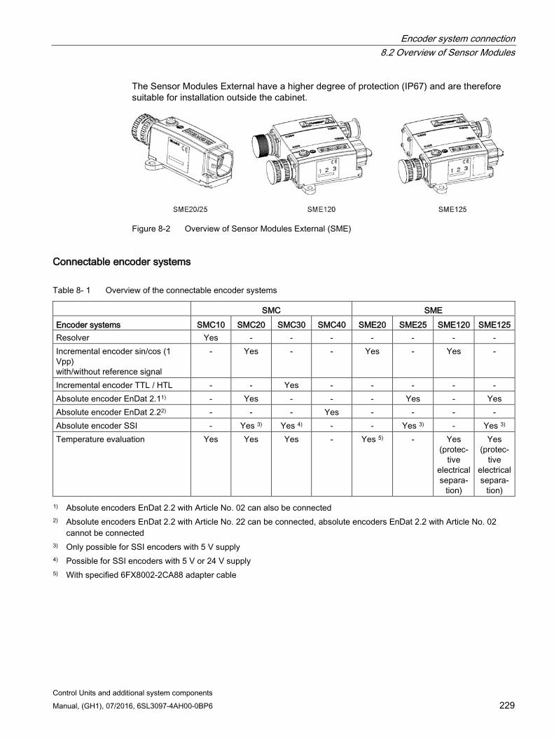
Encoder system connection 8.2 Overview of Sensor Modules
Control Units and additional system components Manual, (GH1), 07/2016, 6SL3097-4AH00-0BP6 229
The Sensor Modules External have a higher degree of protection (IP67) and are therefore suitable for installation outside the cabinet.
Figure 8-2 Overview of Sensor Modules External (SME)
Connectable encoder systems
Table 8- 1 Overview of the connectable encoder systems
SMC SME Encoder systems SMC10 SMC20 SMC30 SMC40 SME20 SME25 SME120 SME125 Resolver Yes - - - - - - - Incremental encoder sin/cos (1 Vpp) with/without reference signal
- Yes - - Yes - Yes -
Incremental encoder TTL / HTL - - Yes - - - - - Absolute encoder EnDat 2.11) - Yes - - - Yes - Yes Absolute encoder EnDat 2.22) - - - Yes - - - - Absolute encoder SSI - Yes 3) Yes 4) - - Yes 3) - Yes 3) Temperature evaluation Yes Yes Yes - Yes 5) - Yes
(protec-tive
electrical separa-
tion)
Yes (protec-
tive electrical separa-
tion) 1) Absolute encoders EnDat 2.2 with Article No. 02 can also be connected
2) Absolute encoders EnDat 2.2 with Article No. 22 can be connected, absolute encoders EnDat 2.2 with Article No. 02 cannot be connected
3) Only possible for SSI encoders with 5 V supply 4) Possible for SSI encoders with 5 V or 24 V supply 5) With specified 6FX8002-2CA88 adapter cable

Encoder system connection 8.3 Safety instructions for Sensor Modules and encoders
Control Units and additional system components 230 Manual, (GH1), 07/2016, 6SL3097-4AH00-0BP6
8.3 Safety instructions for Sensor Modules and encoders
WARNING
Danger to life if the fundamental safety instructions and remaining risks are not carefully observed
If the fundamental safety instructions and remaining risks in Chapter 1 (Page 19) are not observed, accidents involving severe injuries or death may occur. • Adhere to the fundamental safety instructions. • When assessing the risk, take into account remaining risks.
WARNING
Danger to life due to fire if overheating occurs because of insufficient ventilation clearances
Inadequate ventilation clearances can cause overheating of components with subsequent fire and smoke. This can cause severe injury or even death. This can also result in increased downtime and reduced service lives for devices/systems. • For this reason, it is imperative that you maintain the 50 mm clearances above and
below the Sensor Module Cabinet-Mounted.
Note Risk of encoder failures by encoder signal disturbances
Unfavorable material combinations generate static electricity between the belt pulley and the belt. This electrostatic charge (several kV) can discharge via the motor shaft and the encoder which leads to disturbance of the encoder signals (encoder error). • Use an antistatic version of the belt (special conductive polyurethane mixture).
WARNING
Danger to life due to electric shock when disconnecting and connecting encoder cables during operation
When opening plug connections in operation, arcs can result in severe injury or death. • Only disconnect or connect the encoder cables to Siemens motors in a voltage-free
state if hot-plugging has not been specifically released. When using direct measuring systems (third-party encoders), ask the manufacturer whether it is permissible to disconnect/connect under voltage.

Encoder system connection 8.3 Safety instructions for Sensor Modules and encoders
Control Units and additional system components Manual, (GH1), 07/2016, 6SL3097-4AH00-0BP6 231
NOTICE
Damage when connecting an impermissible number of encoder systems
If more than the maximum permissible number of encoder systems are connected to a Sensor Module, this will cause damage. • At a Sensor Module only connect the maximum permissible number of encoder
systems. – Sensor Modules SMC10, SMC20 and SMC30: Single-encoder system – Sensor Module SMC40: Two-encoder systems – Sensor Modules SMEx: Single-encoder system
Note Diminished level of interference immunity due to equalizing currents via the electronics ground
Ensure that there are no electrical connections between the encoder system housing and the signal cables, or the encoder system electronics.
If this is not carefully observed, under certain circumstances the system will not be able to reach the required interference immunity level (there is then a danger of equalization currents flowing through the electronics ground).
NOTICE
Damage through use of incorrect DRIVE-CLiQ cables
Damage or malfunctions can occur on the devices or system when incorrect or unreleased DRIVE-CLiQ cables are used. • Only use suitable DRIVE-CLiQ cables that have been released by Siemens for the
respective application.
Note Function equipotential bonding for distributed DRIVE-CLiQ nodes
Integrate all of the components that are connected via DRIVE-CLiQ in the functional equipotential bonding concept. The connection should be preferably established by mounting on metallic bare machine and plant components that are connected with one another using an equipotential bonding conductor. Alternatively, you can establish equipotential bonding using a conductor (min. 6 mm²), which as far as possible, is routed in parallel to the DRIVE-CLiQ cable. All distributed DRIVE-CLiQ nodes are involved, for example DME20, SME20, SME25, SME120, SME125 etc.
Note Malfunctions due to polluted DRIVE-CLiQ interfaces
Malfunctions can occur in the system through the use of polluted DRIVE-CLiQ interfaces. • Cover unused DRIVE-CLiQ interfaces with the supplied blanking covers.
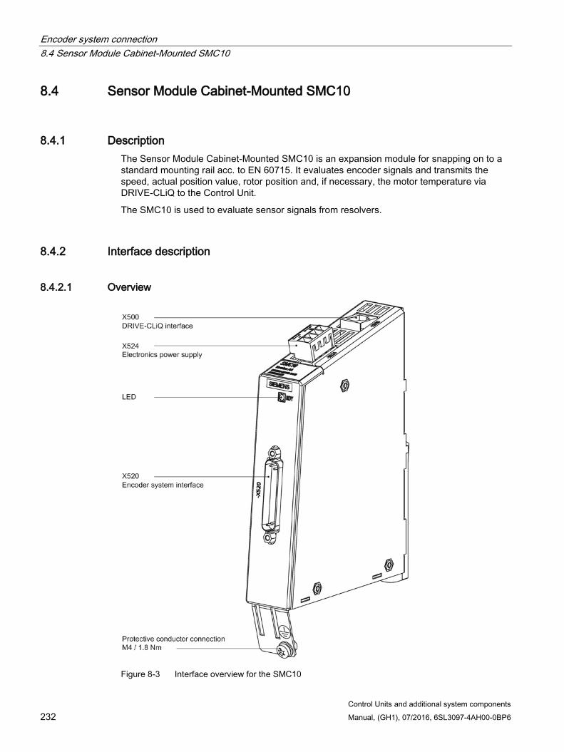
Encoder system connection 8.4 Sensor Module Cabinet-Mounted SMC10
Control Units and additional system components 232 Manual, (GH1), 07/2016, 6SL3097-4AH00-0BP6
8.4 Sensor Module Cabinet-Mounted SMC10
8.4.1 Description The Sensor Module Cabinet-Mounted SMC10 is an expansion module for snapping on to a standard mounting rail acc. to EN 60715. It evaluates encoder signals and transmits the speed, actual position value, rotor position and, if necessary, the motor temperature via DRIVE-CLiQ to the Control Unit.
The SMC10 is used to evaluate sensor signals from resolvers.
8.4.2 Interface description
8.4.2.1 Overview
Figure 8-3 Interface overview for the SMC10
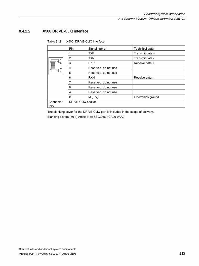
Encoder system connection 8.4 Sensor Module Cabinet-Mounted SMC10
Control Units and additional system components Manual, (GH1), 07/2016, 6SL3097-4AH00-0BP6 233
8.4.2.2 X500 DRIVE-CLiQ interface
Table 8- 2 X500: DRIVE-CLiQ interface
Pin Signal name Technical data
1 TXP Transmit data + 2 TXN Transmit data - 3 RXP Receive data + 4 Reserved, do not use 5 Reserved, do not use 6 RXN Receive data - 7 Reserved, do not use 8 Reserved, do not use A Reserved, do not use B M (0 V) Electronics ground
Connector type
DRIVE-CLiQ socket
The blanking cover for the DRIVE-CLiQ port is included in the scope of delivery. Blanking covers (50 x) Article No:: 6SL3066-4CA00-0AA0
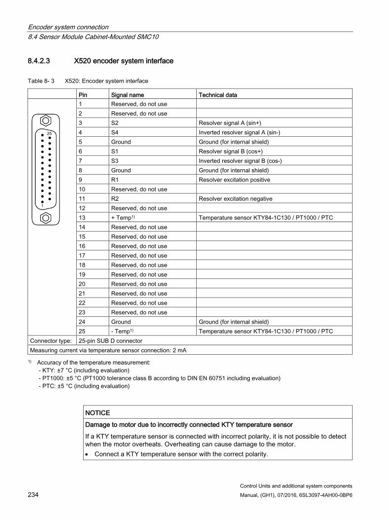
Encoder system connection 8.4 Sensor Module Cabinet-Mounted SMC10
Control Units and additional system components 234 Manual, (GH1), 07/2016, 6SL3097-4AH00-0BP6
8.4.2.3 X520 encoder system interface
Table 8- 3 X520: Encoder system interface
Pin Signal name Technical data
1 Reserved, do not use 2 Reserved, do not use 3 S2 Resolver signal A (sin+) 4 S4 Inverted resolver signal A (sin-) 5 Ground Ground (for internal shield) 6 S1 Resolver signal B (cos+) 7 S3 Inverted resolver signal B (cos-) 8 Ground Ground (for internal shield) 9 R1 Resolver excitation positive 10 Reserved, do not use 11 R2 Resolver excitation negative 12 Reserved, do not use 13 + Temp1) Temperature sensor KTY84-1C130 / PT1000 / PTC 14 Reserved, do not use 15 Reserved, do not use 16 Reserved, do not use 17 Reserved, do not use 18 Reserved, do not use 19 Reserved, do not use 20 Reserved, do not use 21 Reserved, do not use 22 Reserved, do not use 23 Reserved, do not use 24 Ground Ground (for internal shield) 25 - Temp1) Temperature sensor KTY84-1C130 / PT1000 / PTC
Connector type: 25-pin SUB D connector Measuring current via temperature sensor connection: 2 mA 1) Accuracy of the temperature measurement:
- KTY: ±7 °C (including evaluation) - PT1000: ±5 °C (PT1000 tolerance class B according to DIN EN 60751 including evaluation) - PTC: ±5 °C (including evaluation)
NOTICE
Damage to motor due to incorrectly connected KTY temperature sensor
If a KTY temperature sensor is connected with incorrect polarity, it is not possible to detect when the motor overheats. Overheating can cause damage to the motor. • Connect a KTY temperature sensor with the correct polarity.
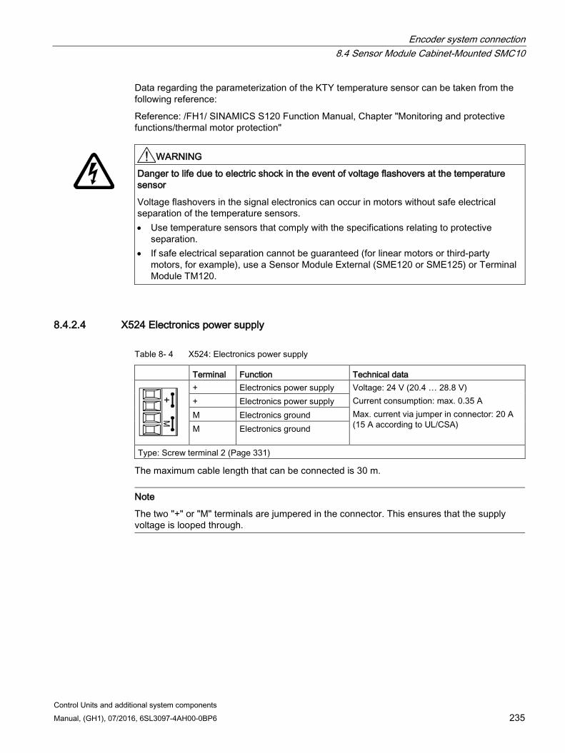
Encoder system connection 8.4 Sensor Module Cabinet-Mounted SMC10
Control Units and additional system components Manual, (GH1), 07/2016, 6SL3097-4AH00-0BP6 235
Data regarding the parameterization of the KTY temperature sensor can be taken from the following reference:
Reference: /FH1/ SINAMICS S120 Function Manual, Chapter "Monitoring and protective functions/thermal motor protection"
WARNING
Danger to life due to electric shock in the event of voltage flashovers at the temperature sensor
Voltage flashovers in the signal electronics can occur in motors without safe electrical separation of the temperature sensors. • Use temperature sensors that comply with the specifications relating to protective
separation. • If safe electrical separation cannot be guaranteed (for linear motors or third-party
motors, for example), use a Sensor Module External (SME120 or SME125) or Terminal Module TM120.
8.4.2.4 X524 Electronics power supply
Table 8- 4 X524: Electronics power supply
Terminal Function Technical data
+ Electronics power supply Voltage: 24 V (20.4 … 28.8 V) Current consumption: max. 0.35 A Max. current via jumper in connector: 20 A (15 A according to UL/CSA)
+ Electronics power supply M Electronics ground M Electronics ground
Type: Screw terminal 2 (Page 331)
The maximum cable length that can be connected is 30 m.
Note
The two "+" or "M" terminals are jumpered in the connector. This ensures that the supply voltage is looped through.
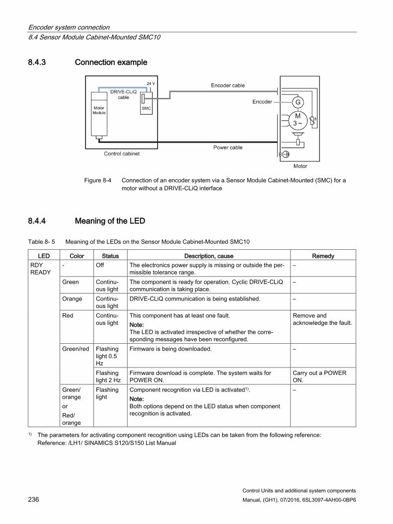
Encoder system connection 8.4 Sensor Module Cabinet-Mounted SMC10
Control Units and additional system components 236 Manual, (GH1), 07/2016, 6SL3097-4AH00-0BP6
8.4.3 Connection example
Figure 8-4 Connection of an encoder system via a Sensor Module Cabinet-Mounted (SMC) for a
motor without a DRIVE-CLiQ interface
8.4.4 Meaning of the LED
Table 8- 5 Meaning of the LEDs on the Sensor Module Cabinet-Mounted SMC10
LED Color Status Description, cause Remedy RDY READY
- Off The electronics power supply is missing or outside the per-missible tolerance range.
–
Green Continu-ous light
The component is ready for operation. Cyclic DRIVE-CLiQ communication is taking place.
–
Orange Continu-ous light
DRIVE-CLiQ communication is being established. –
Red Continu-ous light
This component has at least one fault. Note: The LED is activated irrespective of whether the corre-sponding messages have been reconfigured.
Remove and acknowledge the fault.
Green/red Flashing light 0.5 Hz
Firmware is being downloaded. –
Flashing light 2 Hz
Firmware download is complete. The system waits for POWER ON.
Carry out a POWER ON.
Green/ orange or Red/ orange
Flashing light
Component recognition via LED is activated1). Note: Both options depend on the LED status when component recognition is activated.
–
1) The parameters for activating component recognition using LEDs can be taken from the following reference: Reference: /LH1/ SINAMICS S120/S150 List Manual

Encoder system connection 8.4 Sensor Module Cabinet-Mounted SMC10
Control Units and additional system components Manual, (GH1), 07/2016, 6SL3097-4AH00-0BP6 237
Cause and rectification of faults Additional information about the cause and resolving faults can be taken from the following references:
Reference:/LH1/SINAMICS S120/S150 List Manual
Reference: /IH1/ SINAMICS S120 Commissioning Manual with STARTER
8.4.5 Dimension drawing
Figure 8-5 Dimension drawing of the Sensor Module Cabinet SMC10, all dimensions in mm and
(inches)

Encoder system connection 8.4 Sensor Module Cabinet-Mounted SMC10
Control Units and additional system components 238 Manual, (GH1), 07/2016, 6SL3097-4AH00-0BP6
8.4.6 Mounting
Installation 1. Tilt the component backwards slightly and attach it to the DIN rail using the hooks.
2. Swivel the component onto the DIN rail until you hear the mounting slide at the rear latch into position.
3. Slide the components along the mounting rail to either the left or right up to their final position.
Removal 1. First shift the mounting slide downwards at the lug to release the interlocking with the
mounting rail.
2. Swivel the component to the front and withdraw it upwards from the DIN rail.
① Mounting slide ② Mounting rail
Figure 8-6 Removing from a DIN mounting rail
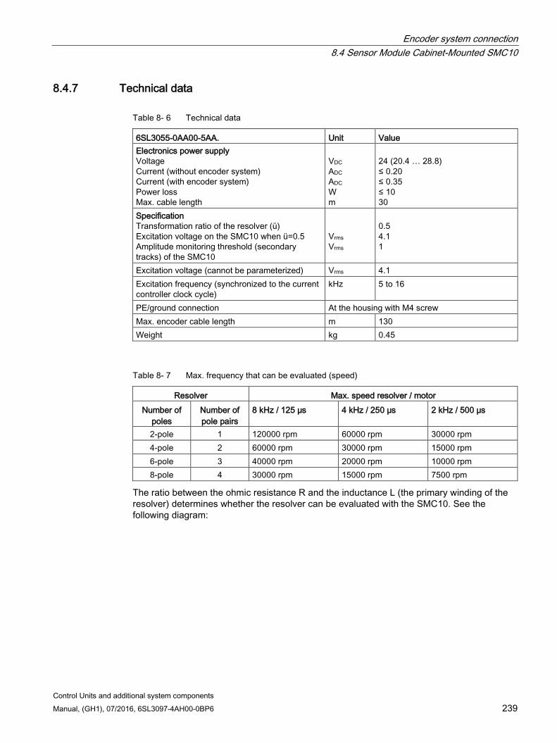
Encoder system connection 8.4 Sensor Module Cabinet-Mounted SMC10
Control Units and additional system components Manual, (GH1), 07/2016, 6SL3097-4AH00-0BP6 239
8.4.7 Technical data
Table 8- 6 Technical data
6SL3055-0AA00-5AA. Unit Value Electronics power supply Voltage Current (without encoder system) Current (with encoder system) Power loss Max. cable length
VDC ADC ADC W m
24 (20.4 … 28.8) ≤ 0.20 ≤ 0.35 ≤ 10 30
Specification Transformation ratio of the resolver (ü) Excitation voltage on the SMC10 when ü=0.5 Amplitude monitoring threshold (secondary tracks) of the SMC10
Vrms Vrms
0.5 4.1 1
Excitation voltage (cannot be parameterized) Vrms 4.1 Excitation frequency (synchronized to the current controller clock cycle)
kHz 5 to 16
PE/ground connection At the housing with M4 screw Max. encoder cable length m 130 Weight kg 0.45
Table 8- 7 Max. frequency that can be evaluated (speed)
Resolver Max. speed resolver / motor Number of
poles Number of pole pairs
8 kHz / 125 μs 4 kHz / 250 μs 2 kHz / 500 μs
2-pole 1 120000 rpm 60000 rpm 30000 rpm 4-pole 2 60000 rpm 30000 rpm 15000 rpm 6-pole 3 40000 rpm 20000 rpm 10000 rpm 8-pole 4 30000 rpm 15000 rpm 7500 rpm
The ratio between the ohmic resistance R and the inductance L (the primary winding of the resolver) determines whether the resolver can be evaluated with the SMC10. See the following diagram:
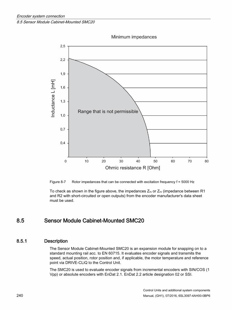
Encoder system connection 8.5 Sensor Module Cabinet-Mounted SMC20
Control Units and additional system components 240 Manual, (GH1), 07/2016, 6SL3097-4AH00-0BP6
Figure 8-7 Rotor impedances that can be connected with excitation frequency f = 5000 Hz
To check as shown in the figure above, the impedances Zrs or Zro (impedance between R1 and R2 with short-circuited or open outputs) from the encoder manufacturer's data sheet must be used.
8.5 Sensor Module Cabinet-Mounted SMC20
8.5.1 Description The Sensor Module Cabinet-Mounted SMC20 is an expansion module for snapping on to a standard mounting rail acc. to EN 60715. It evaluates encoder signals and transmits the speed, actual position, rotor position and, if applicable, the motor temperature and reference point via DRIVE-CLiQ to the Control Unit.
The SMC20 is used to evaluate encoder signals from incremental encoders with SIN/COS (1 Vpp) or absolute encoders with EnDat 2.1. EnDat 2.2 article designation 02 or SSI.
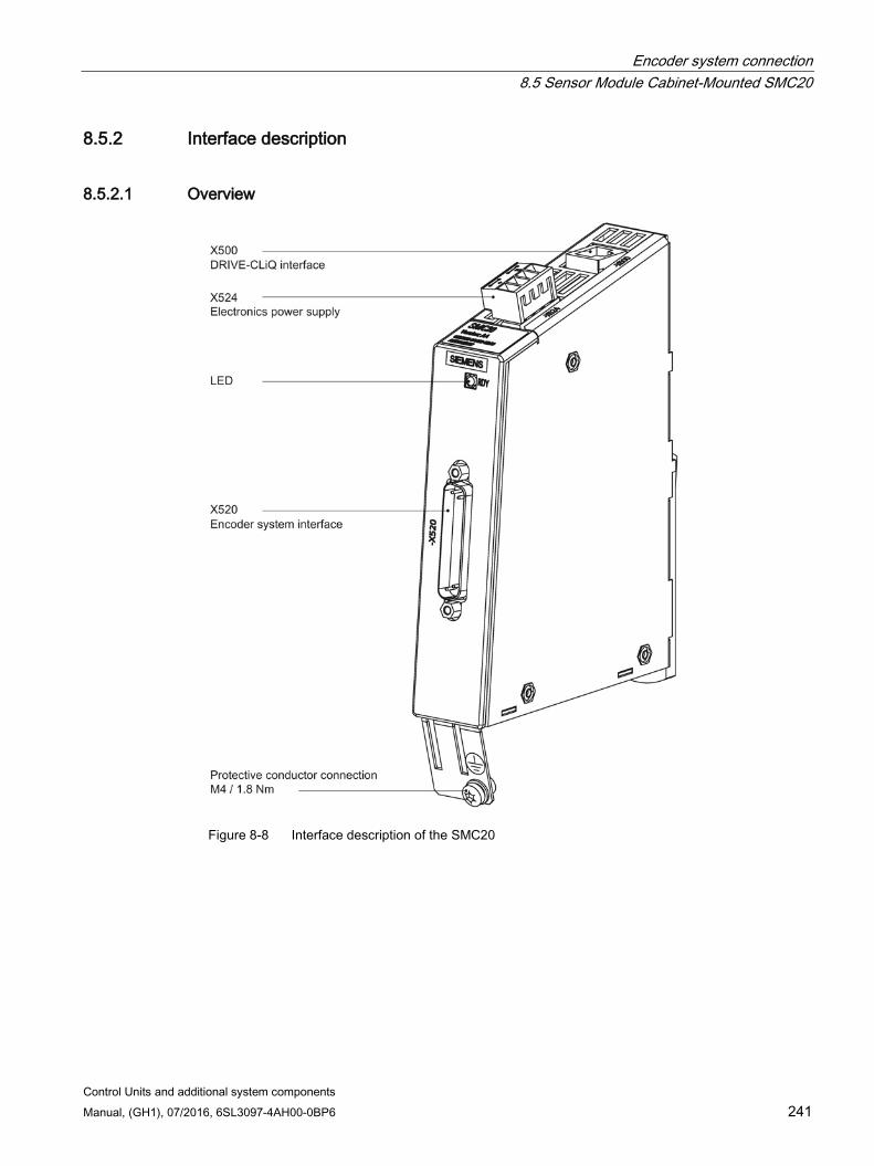
Encoder system connection 8.5 Sensor Module Cabinet-Mounted SMC20
Control Units and additional system components Manual, (GH1), 07/2016, 6SL3097-4AH00-0BP6 241
8.5.2 Interface description
8.5.2.1 Overview
Figure 8-8 Interface description of the SMC20
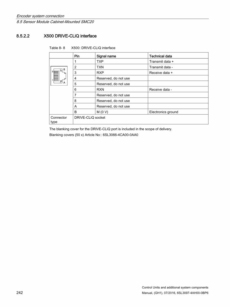
Encoder system connection 8.5 Sensor Module Cabinet-Mounted SMC20
Control Units and additional system components 242 Manual, (GH1), 07/2016, 6SL3097-4AH00-0BP6
8.5.2.2 X500 DRIVE-CLiQ interface
Table 8- 8 X500: DRIVE-CLiQ interface
Pin Signal name Technical data
1 TXP Transmit data + 2 TXN Transmit data - 3 RXP Receive data + 4 Reserved, do not use 5 Reserved, do not use 6 RXN Receive data - 7 Reserved, do not use 8 Reserved, do not use A Reserved, do not use B M (0 V) Electronics ground
Connector type
DRIVE-CLiQ socket
The blanking cover for the DRIVE-CLiQ port is included in the scope of delivery. Blanking covers (50 x) Article No:: 6SL3066-4CA00-0AA0
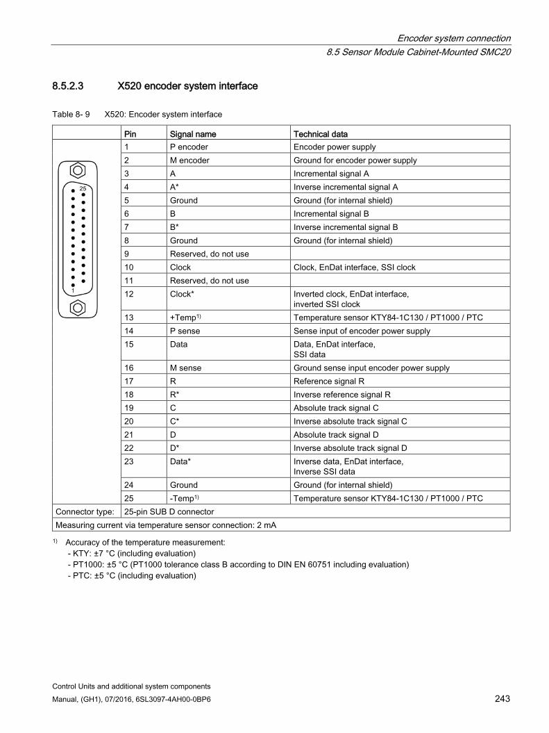
Encoder system connection 8.5 Sensor Module Cabinet-Mounted SMC20
Control Units and additional system components Manual, (GH1), 07/2016, 6SL3097-4AH00-0BP6 243
8.5.2.3 X520 encoder system interface
Table 8- 9 X520: Encoder system interface
Pin Signal name Technical data
1 P encoder Encoder power supply 2 M encoder Ground for encoder power supply 3 A Incremental signal A 4 A* Inverse incremental signal A 5 Ground Ground (for internal shield) 6 B Incremental signal B 7 B* Inverse incremental signal B 8 Ground Ground (for internal shield) 9 Reserved, do not use 10 Clock Clock, EnDat interface, SSI clock 11 Reserved, do not use 12 Clock*
Inverted clock, EnDat interface, inverted SSI clock
13 +Temp1) Temperature sensor KTY84-1C130 / PT1000 / PTC 14 P sense Sense input of encoder power supply 15 Data Data, EnDat interface,
SSI data 16 M sense Ground sense input encoder power supply 17 R Reference signal R 18 R* Inverse reference signal R 19 C Absolute track signal C 20 C* Inverse absolute track signal C 21 D Absolute track signal D 22 D* Inverse absolute track signal D 23 Data* Inverse data, EnDat interface,
Inverse SSI data 24 Ground Ground (for internal shield) 25 -Temp1) Temperature sensor KTY84-1C130 / PT1000 / PTC
Connector type: 25-pin SUB D connector Measuring current via temperature sensor connection: 2 mA 1) Accuracy of the temperature measurement:
- KTY: ±7 °C (including evaluation) - PT1000: ±5 °C (PT1000 tolerance class B according to DIN EN 60751 including evaluation) - PTC: ±5 °C (including evaluation)
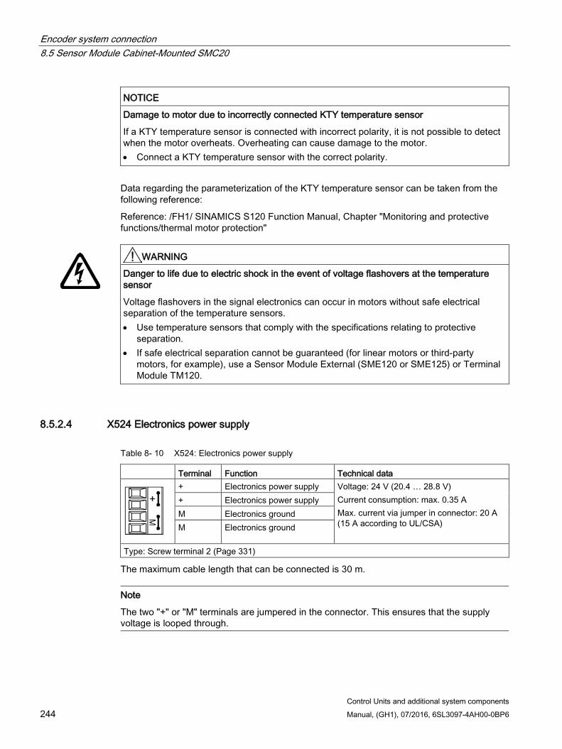
Encoder system connection 8.5 Sensor Module Cabinet-Mounted SMC20
Control Units and additional system components 244 Manual, (GH1), 07/2016, 6SL3097-4AH00-0BP6
NOTICE
Damage to motor due to incorrectly connected KTY temperature sensor
If a KTY temperature sensor is connected with incorrect polarity, it is not possible to detect when the motor overheats. Overheating can cause damage to the motor. • Connect a KTY temperature sensor with the correct polarity.
Data regarding the parameterization of the KTY temperature sensor can be taken from the following reference:
Reference: /FH1/ SINAMICS S120 Function Manual, Chapter "Monitoring and protective functions/thermal motor protection"
WARNING
Danger to life due to electric shock in the event of voltage flashovers at the temperature sensor
Voltage flashovers in the signal electronics can occur in motors without safe electrical separation of the temperature sensors. • Use temperature sensors that comply with the specifications relating to protective
separation. • If safe electrical separation cannot be guaranteed (for linear motors or third-party
motors, for example), use a Sensor Module External (SME120 or SME125) or Terminal Module TM120.
8.5.2.4 X524 Electronics power supply
Table 8- 10 X524: Electronics power supply
Terminal Function Technical data
+ Electronics power supply Voltage: 24 V (20.4 … 28.8 V) Current consumption: max. 0.35 A Max. current via jumper in connector: 20 A (15 A according to UL/CSA)
+ Electronics power supply M Electronics ground M Electronics ground
Type: Screw terminal 2 (Page 331)
The maximum cable length that can be connected is 30 m.
Note
The two "+" or "M" terminals are jumpered in the connector. This ensures that the supply voltage is looped through.
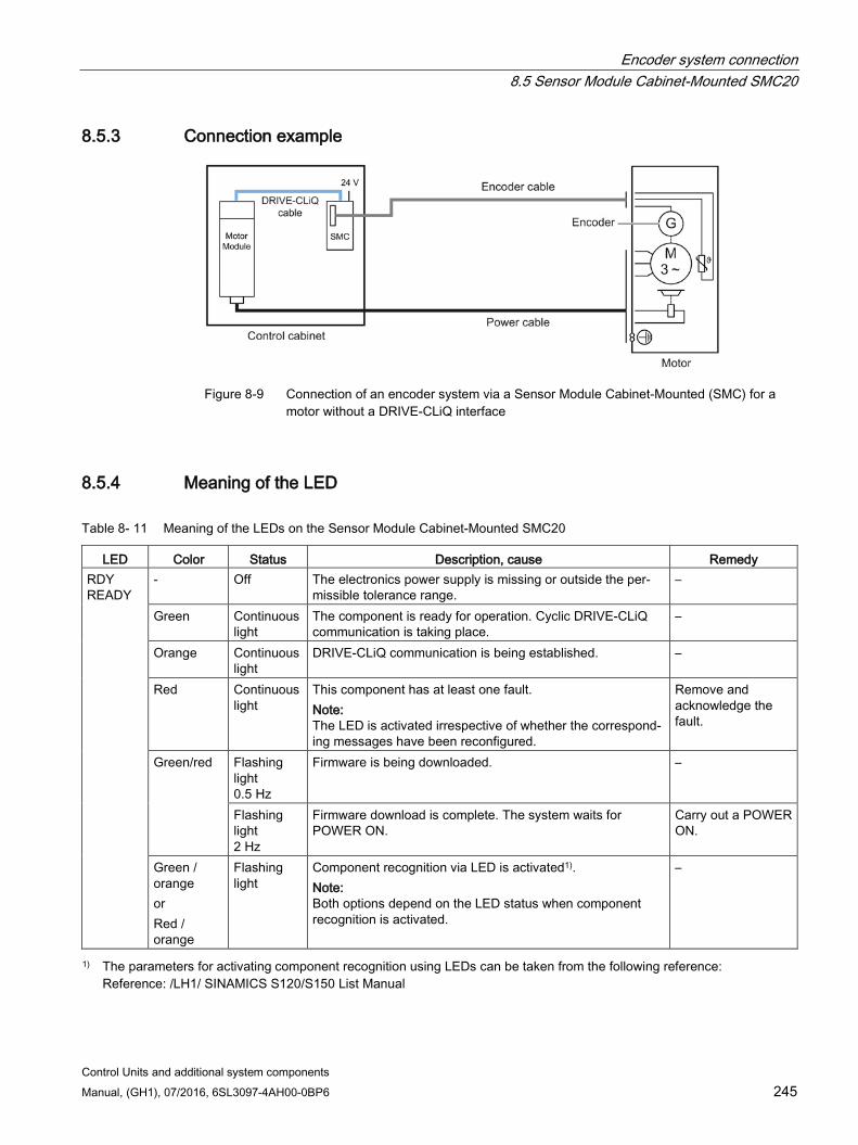
Encoder system connection 8.5 Sensor Module Cabinet-Mounted SMC20
Control Units and additional system components Manual, (GH1), 07/2016, 6SL3097-4AH00-0BP6 245
8.5.3 Connection example
Figure 8-9 Connection of an encoder system via a Sensor Module Cabinet-Mounted (SMC) for a
motor without a DRIVE-CLiQ interface
8.5.4 Meaning of the LED
Table 8- 11 Meaning of the LEDs on the Sensor Module Cabinet-Mounted SMC20
LED Color Status Description, cause Remedy RDY READY
- Off The electronics power supply is missing or outside the per-missible tolerance range.
–
Green Continuous light
The component is ready for operation. Cyclic DRIVE-CLiQ communication is taking place.
–
Orange Continuous light
DRIVE-CLiQ communication is being established. –
Red Continuous light
This component has at least one fault. Note: The LED is activated irrespective of whether the correspond-ing messages have been reconfigured.
Remove and acknowledge the fault.
Green/red Flashing light 0.5 Hz
Firmware is being downloaded. –
Flashing light 2 Hz
Firmware download is complete. The system waits for POWER ON.
Carry out a POWER ON.
Green / orange or Red / orange
Flashing light
Component recognition via LED is activated1). Note: Both options depend on the LED status when component recognition is activated.
–
1) The parameters for activating component recognition using LEDs can be taken from the following reference: Reference: /LH1/ SINAMICS S120/S150 List Manual
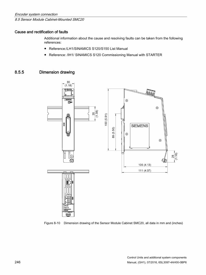
Encoder system connection 8.5 Sensor Module Cabinet-Mounted SMC20
Control Units and additional system components 246 Manual, (GH1), 07/2016, 6SL3097-4AH00-0BP6
Cause and rectification of faults Additional information about the cause and resolving faults can be taken from the following references:
Reference:/LH1/SINAMICS S120/S150 List Manual
Reference: /IH1/ SINAMICS S120 Commissioning Manual with STARTER
8.5.5 Dimension drawing
Figure 8-10 Dimension drawing of the Sensor Module Cabinet SMC20, all data in mm and (inches)
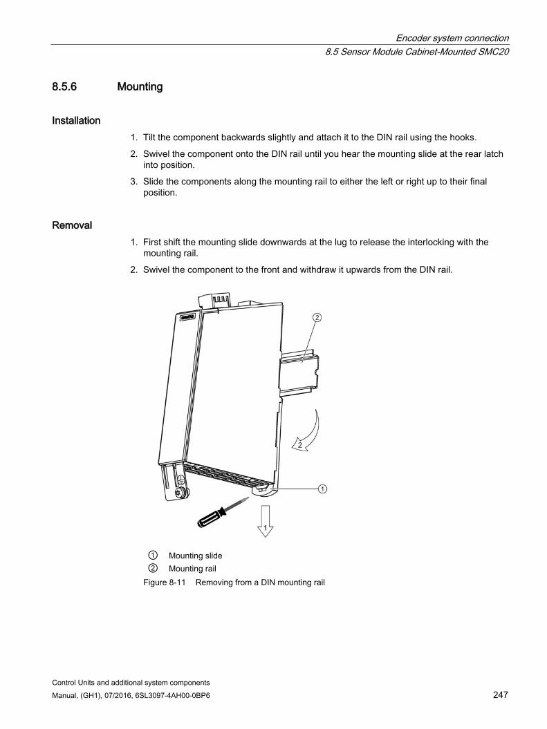
Encoder system connection 8.5 Sensor Module Cabinet-Mounted SMC20
Control Units and additional system components Manual, (GH1), 07/2016, 6SL3097-4AH00-0BP6 247
8.5.6 Mounting
Installation 1. Tilt the component backwards slightly and attach it to the DIN rail using the hooks.
2. Swivel the component onto the DIN rail until you hear the mounting slide at the rear latch into position.
3. Slide the components along the mounting rail to either the left or right up to their final position.
Removal 1. First shift the mounting slide downwards at the lug to release the interlocking with the
mounting rail.
2. Swivel the component to the front and withdraw it upwards from the DIN rail.
① Mounting slide ② Mounting rail
Figure 8-11 Removing from a DIN mounting rail
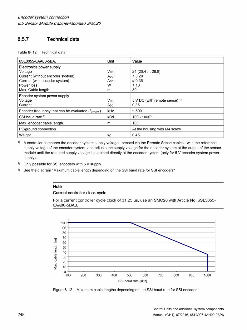
Encoder system connection 8.5 Sensor Module Cabinet-Mounted SMC20
Control Units and additional system components 248 Manual, (GH1), 07/2016, 6SL3097-4AH00-0BP6
8.5.7 Technical data
Table 8- 12 Technical data
6SL3055-0AA00-5BA. Unit Value Electronics power supply Voltage Current (without encoder system) Current (with encoder system) Power loss Max. Cable length
VDC ADC ADC W m
24 (20.4 … 28.8) ≤ 0.20 ≤ 0.35 ≤ 10 30
Encoder system power supply Voltage Current
VDC ADC
5 V DC (with remote sense) 1) 0.35
Encoder frequency that can be evaluated (fencoder) kHz ≤ 500 SSI baud rate 2) kBd 100 - 10003) Max. encoder cable length m 100 PE/ground connection At the housing with M4 screw Weight kg 0.45 1) A controller compares the encoder system supply voltage - sensed via the Remote Sense cables - with the reference
supply voltage of the encoder system, and adjusts the supply voltage for the encoder system at the output of the sensor module until the required supply voltage is obtained directly at the encoder system (only for 5 V encoder system power supply).
2) Only possible for SSI encoders with 5 V supply. 3) See the diagram "Maximum cable length depending on the SSI baud rate for SSI encoders"
Note Current controller clock cycle
For a current controller cycle clock of 31.25 µs, use an SMC20 with Article No. 6SL3055-0AA00-5BA3.
Figure 8-12 Maximum cable lengths depending on the SSI baud rate for SSI encoders
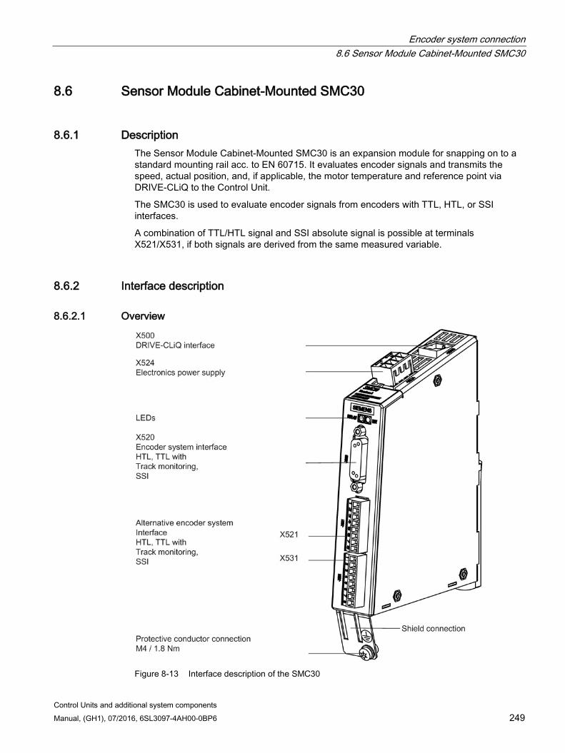
Encoder system connection 8.6 Sensor Module Cabinet-Mounted SMC30
Control Units and additional system components Manual, (GH1), 07/2016, 6SL3097-4AH00-0BP6 249
8.6 Sensor Module Cabinet-Mounted SMC30
8.6.1 Description The Sensor Module Cabinet-Mounted SMC30 is an expansion module for snapping on to a standard mounting rail acc. to EN 60715. It evaluates encoder signals and transmits the speed, actual position, and, if applicable, the motor temperature and reference point via DRIVE-CLiQ to the Control Unit.
The SMC30 is used to evaluate encoder signals from encoders with TTL, HTL, or SSI interfaces.
A combination of TTL/HTL signal and SSI absolute signal is possible at terminals X521/X531, if both signals are derived from the same measured variable.
8.6.2 Interface description
8.6.2.1 Overview
Figure 8-13 Interface description of the SMC30
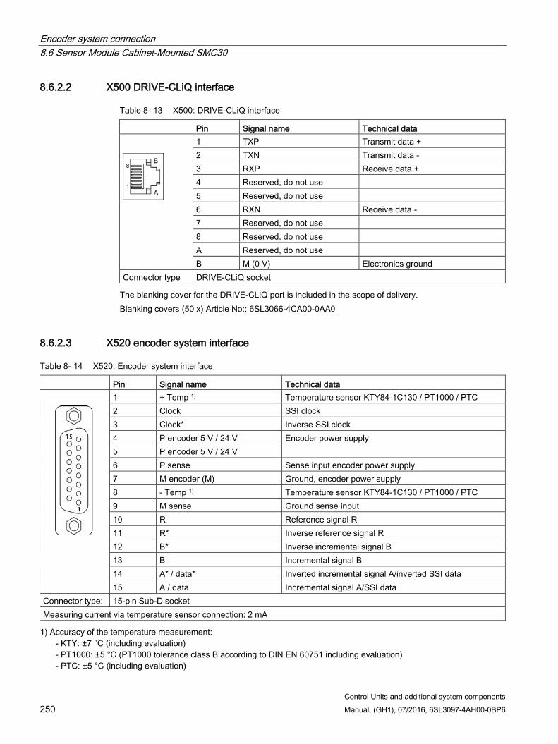
Encoder system connection 8.6 Sensor Module Cabinet-Mounted SMC30
Control Units and additional system components 250 Manual, (GH1), 07/2016, 6SL3097-4AH00-0BP6
8.6.2.2 X500 DRIVE-CLiQ interface
Table 8- 13 X500: DRIVE-CLiQ interface
Pin Signal name Technical data
1 TXP Transmit data + 2 TXN Transmit data - 3 RXP Receive data + 4 Reserved, do not use 5 Reserved, do not use 6 RXN Receive data - 7 Reserved, do not use 8 Reserved, do not use A Reserved, do not use B M (0 V) Electronics ground
Connector type DRIVE-CLiQ socket The blanking cover for the DRIVE-CLiQ port is included in the scope of delivery.
Blanking covers (50 x) Article No:: 6SL3066-4CA00-0AA0
8.6.2.3 X520 encoder system interface
Table 8- 14 X520: Encoder system interface
Pin Signal name Technical data
1 + Temp 1) Temperature sensor KTY84-1C130 / PT1000 / PTC 2 Clock SSI clock 3 Clock* Inverse SSI clock 4 P encoder 5 V / 24 V Encoder power supply 5 P encoder 5 V / 24 V 6 P sense Sense input encoder power supply 7 M encoder (M) Ground, encoder power supply 8 - Temp 1) Temperature sensor KTY84-1C130 / PT1000 / PTC 9 M sense Ground sense input 10 R Reference signal R 11 R* Inverse reference signal R 12 B* Inverse incremental signal B 13 B Incremental signal B 14 A* / data* Inverted incremental signal A/inverted SSI data 15 A / data Incremental signal A/SSI data
Connector type: 15-pin Sub-D socket Measuring current via temperature sensor connection: 2 mA 1) Accuracy of the temperature measurement:
- KTY: ±7 °C (including evaluation) - PT1000: ±5 °C (PT1000 tolerance class B according to DIN EN 60751 including evaluation) - PTC: ±5 °C (including evaluation)
Encoder system connection 8.6 Sensor Module Cabinet-Mounted SMC30
Control Units and additional system components Manual, (GH1), 07/2016, 6SL3097-4AH00-0BP6 251
NOTICE
Damage to the encoder due to incorrect supply voltage
The encoder supply can be parameterized to 5 V or 24 V. Incorrect parameter assignment can cause damage to the encoder. • Select the appropriate supply voltage.
NOTICE
Damage to motor in the event of incorrectly connected KTY temperature sensor
If a KTY temperature sensor is connected with incorrect polarity, it is not possible to detect when the motor overheats. Overheating can cause damage to the motor. • Connect a KTY temperature sensor with the correct polarity.
Data regarding the parameterization of the KTY temperature sensor can be taken from the following reference:
Reference: /FH1/ SINAMICS S120 Function Manual, Chapter "Monitoring and protective functions/thermal motor protection"
WARNING
Danger to life due to electric shock in the event of voltage flashovers at the temperature sensor
Voltage flashovers in the signal electronics can occur in motors without safe electrical separation of the temperature sensors. • Use temperature sensors that comply with the specifications relating to protective
separation. • If safe electrical separation cannot be guaranteed (for linear motors or third-party
motors, for example), use a Sensor Module External (SME120 or SME125) or Terminal Module TM120.
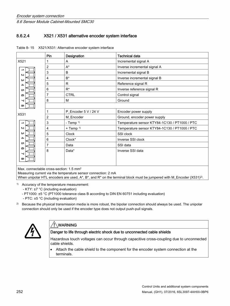
Encoder system connection 8.6 Sensor Module Cabinet-Mounted SMC30
Control Units and additional system components 252 Manual, (GH1), 07/2016, 6SL3097-4AH00-0BP6
8.6.2.4 X521 / X531 alternative encoder system interface
Table 8- 15 X521/X531: Alternative encoder system interface
Pin Designation Technical data X521
X531
1 A Incremental signal A 2 A* Inverse incremental signal A 3 B Incremental signal B 4 B* Inverse incremental signal B 5 R Reference signal R 6 R* Inverse reference signal R 7 CTRL Control signal 8 M Ground 1 P_Encoder 5 V / 24 V Encoder power supply 2 M_Encoder Ground, encoder power supply 3 - Temp 1) Temperature sensor KTY84-1C130 / PT1000 / PTC 4 + Temp 1) Temperature sensor KTY84-1C130 / PT1000 / PTC 5 Clock SSI clock 6 Clock* Inverse SSI clock 7 Data SSI data 8 Data* Inverse SSI data
Max. connectable cross-section: 1.5 mm2
Measuring current via the temperature sensor connection: 2 mA When unipolar HTL encoders are used, A*, B*, and R* on the terminal block must be jumpered with M_Encoder (X531)2). 1) Accuracy of the temperature measurement:
- KTY: ±7 °C (including evaluation) - PT1000: ±5 °C (PT1000 tolerance class B according to DIN EN 60751 including evaluation) - PTC: ±5 °C (including evaluation)
2) Because the physical transmission media is more robust, the bipolar connection should always be used. The unipolar connection should only be used if the encoder type does not output push-pull signals.
WARNING
Danger to life through electric shock due to unconnected cable shields
Hazardous touch voltages can occur through capacitive cross-coupling due to unconnected cable shields. • Attach the cable shield to the component for the encoder system connection at the
terminals.
Encoder system connection 8.6 Sensor Module Cabinet-Mounted SMC30
Control Units and additional system components Manual, (GH1), 07/2016, 6SL3097-4AH00-0BP6 253
Temperature sensor connection
NOTICE
Damage to motor in the event of incorrectly connected KTY temperature sensor
If a KTY temperature sensor is connected with incorrect polarity, it is not possible to detect when the motor overheats. Overheating can cause damage to the motor. • Connect a KTY temperature sensor with the correct polarity.
Data regarding the parameterization of the KTY temperature sensor can be taken from the following reference:
Reference: /FH1/ SINAMICS S120 Function Manual, Chapter "Monitoring and protective functions/thermal motor protection"
Note
The maximum length of the temperature sensor cable is 100 m. The cables must be shielded.
WARNING
Danger to life due to electric shock in the event of voltage flashovers at the temperature sensor
Voltage flashovers in the signal electronics can occur in motors without safe electrical separation of the temperature sensors. • Use temperature sensors that comply with the specifications regarding safe electrical
separation. • If safe electrical separation cannot be guaranteed (for linear motors or third-party
motors, for example), use a Sensor Module External (SME120 or SME125) or Terminal Module TM120.
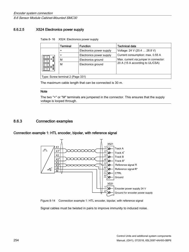
Encoder system connection 8.6 Sensor Module Cabinet-Mounted SMC30
Control Units and additional system components 254 Manual, (GH1), 07/2016, 6SL3097-4AH00-0BP6
8.6.2.5 X524 Electronics power supply
Table 8- 16 X524: Electronics power supply
Terminal Function Technical data
+ Electronics power supply Voltage: 24 V (20.4 … 28.8 V) Current consumption: max. 0.55 A Max. current via jumper in connector: 20 A (15 A according to UL/CSA)
+ Electronics power supply M Electronics ground M Electronics ground
Type: Screw terminal 2 (Page 331)
The maximum cable length that can be connected is 30 m.
Note
The two "+" or "M" terminals are jumpered in the connector. This ensures that the supply voltage is looped through.
8.6.3 Connection examples
Connection example 1: HTL encoder, bipolar, with reference signal
Figure 8-14 Connection example 1: HTL encoder, bipolar, with reference signal
Signal cables must be twisted in pairs to improve immunity to induced noise.
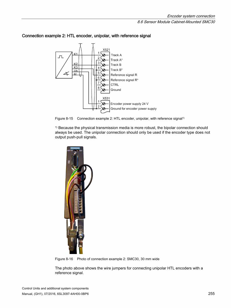
Encoder system connection 8.6 Sensor Module Cabinet-Mounted SMC30
Control Units and additional system components Manual, (GH1), 07/2016, 6SL3097-4AH00-0BP6 255
Connection example 2: HTL encoder, unipolar, with reference signal
Figure 8-15 Connection example 2: HTL encoder, unipolar, with reference signal1)
1) Because the physical transmission media is more robust, the bipolar connection should always be used. The unipolar connection should only be used if the encoder type does not output push-pull signals.
Figure 8-16 Photo of connection example 2: SMC30, 30 mm wide
The photo above shows the wire jumpers for connecting unipolar HTL encoders with a reference signal.
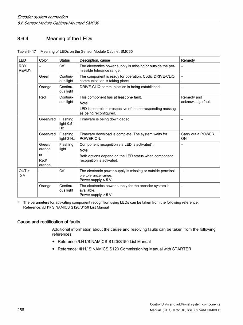
Encoder system connection 8.6 Sensor Module Cabinet-Mounted SMC30
Control Units and additional system components 256 Manual, (GH1), 07/2016, 6SL3097-4AH00-0BP6
8.6.4 Meaning of the LEDs
Table 8- 17 Meaning of LEDs on the Sensor Module Cabinet SMC30
LED Color Status Description, cause Remedy RDY READY
– Off The electronics power supply is missing or outside the per-missible tolerance range.
–
Green Continu-ous light
The component is ready for operation. Cyclic DRIVE-CLiQ communication is taking place.
–
Orange Continu-ous light
DRIVE-CLiQ communication is being established. –
Red Continu-ous light
This component has at least one fault. Note: LED is controlled irrespective of the corresponding messag-es being reconfigured.
Remedy and acknowledge fault
Green/red Flashing light 0.5 Hz
Firmware is being downloaded. –
Green/red Flashing light 2 Hz
Firmware download is complete. The system waits for POWER ON.
Carry out a POWER ON
Green/ orange or Red/ orange
Flashing light
Component recognition via LED is activated1). Note: Both options depend on the LED status when component recognition is activated.
–
OUT > 5 V
– Off The electronic power supply is missing or outside permissi-ble tolerance range. Power supply ≤ 5 V.
–
Orange Continu-ous light
The electronics power supply for the encoder system is available. Power supply > 5 V
–
1) The parameters for activating component recognition using LEDs can be taken from the following reference: Reference: /LH1/ SINAMICS S120/S150 List Manual
Cause and rectification of faults Additional information about the cause and resolving faults can be taken from the following references:
Reference:/LH1/SINAMICS S120/S150 List Manual
Reference: /IH1/ SINAMICS S120 Commissioning Manual with STARTER
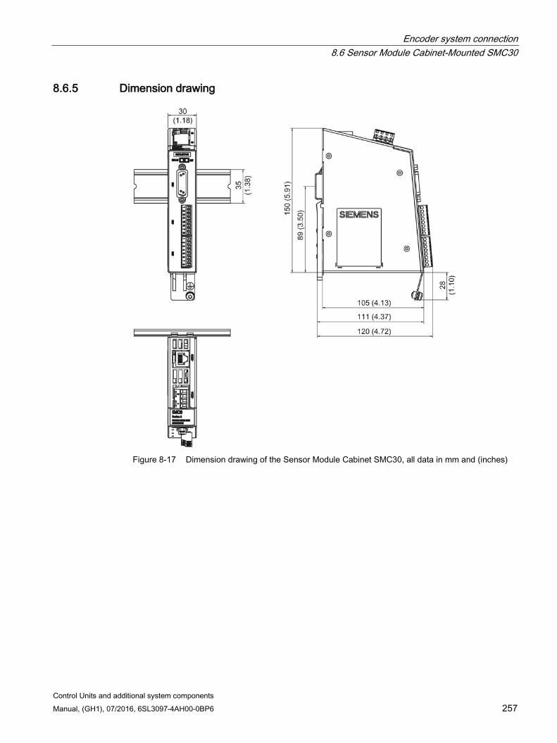
Encoder system connection 8.6 Sensor Module Cabinet-Mounted SMC30
Control Units and additional system components Manual, (GH1), 07/2016, 6SL3097-4AH00-0BP6 257
8.6.5 Dimension drawing
Figure 8-17 Dimension drawing of the Sensor Module Cabinet SMC30, all data in mm and (inches)

Encoder system connection 8.6 Sensor Module Cabinet-Mounted SMC30
Control Units and additional system components 258 Manual, (GH1), 07/2016, 6SL3097-4AH00-0BP6
8.6.6 Mounting
Installation 1. Tilt the component backwards slightly and attach it to the DIN rail using the hooks.
2. Swivel the component onto the DIN rail until you hear the mounting slide at the rear latch into position.
3. Slide the components along the mounting rail to either the left or right up to their final position.
Removal 1. First shift the mounting slide downwards at the lug to release the interlocking with the
mounting rail.
2. Swivel the component to the front and withdraw it upwards from the DIN rail.
① Mounting slide ② Mounting rail
Figure 8-18 Removing from a DIN mounting rail
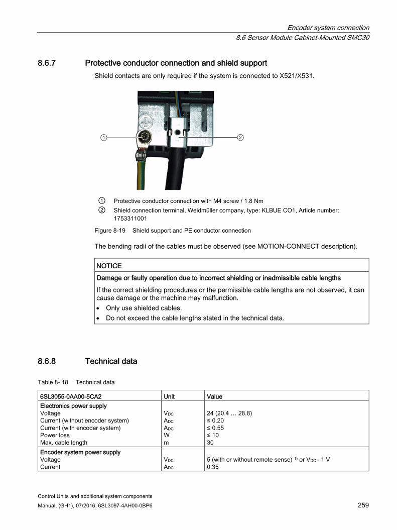
Encoder system connection 8.6 Sensor Module Cabinet-Mounted SMC30
Control Units and additional system components Manual, (GH1), 07/2016, 6SL3097-4AH00-0BP6 259
8.6.7 Protective conductor connection and shield support Shield contacts are only required if the system is connected to X521/X531.
① Protective conductor connection with M4 screw / 1.8 Nm ② Shield connection terminal, Weidmüller company, type: KLBUE CO1, Article number:
1753311001
Figure 8-19 Shield support and PE conductor connection
The bending radii of the cables must be observed (see MOTION-CONNECT description).
NOTICE
Damage or faulty operation due to incorrect shielding or inadmissible cable lengths
If the correct shielding procedures or the permissible cable lengths are not observed, it can cause damage or the machine may malfunction. • Only use shielded cables. • Do not exceed the cable lengths stated in the technical data.
8.6.8 Technical data
Table 8- 18 Technical data
6SL3055-0AA00-5CA2 Unit Value Electronics power supply Voltage Current (without encoder system) Current (with encoder system) Power loss Max. cable length
VDC ADC ADC W m
24 (20.4 … 28.8) ≤ 0.20 ≤ 0.55 ≤ 10 30
Encoder system power supply Voltage Current
VDC ADC
5 (with or without remote sense) 1) or VDC - 1 V 0.35
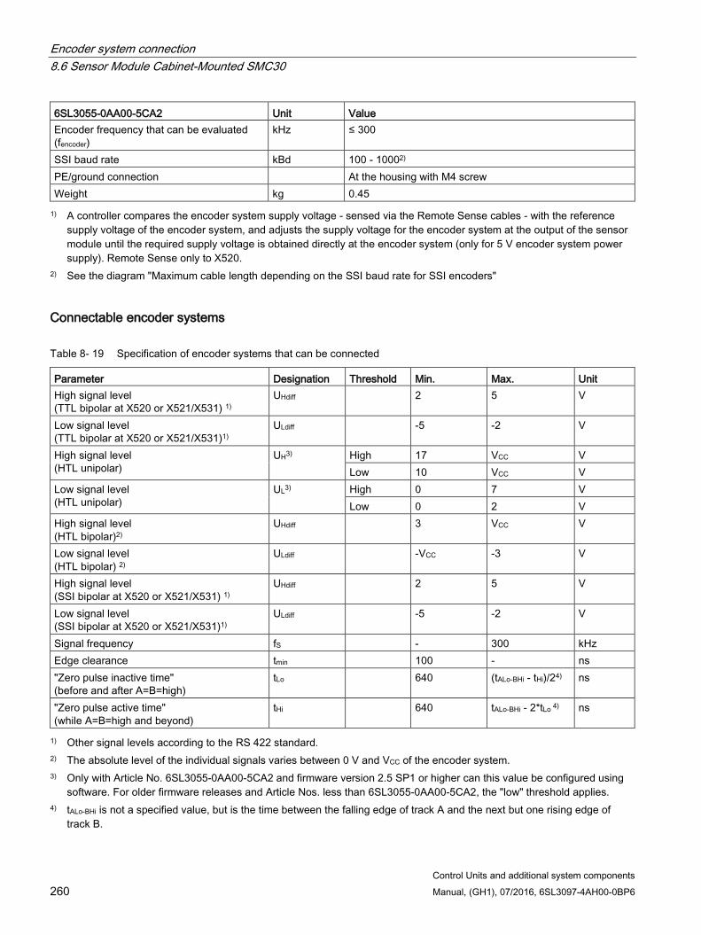
Encoder system connection 8.6 Sensor Module Cabinet-Mounted SMC30
Control Units and additional system components 260 Manual, (GH1), 07/2016, 6SL3097-4AH00-0BP6
6SL3055-0AA00-5CA2 Unit Value Encoder frequency that can be evaluated (fencoder)
kHz ≤ 300
SSI baud rate kBd 100 - 10002) PE/ground connection At the housing with M4 screw Weight kg 0.45 1) A controller compares the encoder system supply voltage - sensed via the Remote Sense cables - with the reference
supply voltage of the encoder system, and adjusts the supply voltage for the encoder system at the output of the sensor module until the required supply voltage is obtained directly at the encoder system (only for 5 V encoder system power supply). Remote Sense only to X520.
2) See the diagram "Maximum cable length depending on the SSI baud rate for SSI encoders"
Connectable encoder systems
Table 8- 19 Specification of encoder systems that can be connected
Parameter Designation Threshold Min. Max. Unit High signal level (TTL bipolar at X520 or X521/X531) 1)
UHdiff 2 5 V
Low signal level (TTL bipolar at X520 or X521/X531)1)
ULdiff -5 -2 V
High signal level (HTL unipolar)
UH3) High 17 VCC V Low 10 VCC V
Low signal level (HTL unipolar)
UL3) High 0 7 V Low 0 2 V
High signal level (HTL bipolar)2)
UHdiff 3 VCC V
Low signal level (HTL bipolar) 2)
ULdiff -VCC -3 V
High signal level (SSI bipolar at X520 or X521/X531) 1)
UHdiff 2 5 V
Low signal level (SSI bipolar at X520 or X521/X531)1)
ULdiff -5 -2 V
Signal frequency fS - 300 kHz Edge clearance tmin 100 - ns "Zero pulse inactive time" (before and after A=B=high)
tLo 640 (tALo-BHi - tHi)/24) ns
"Zero pulse active time" (while A=B=high and beyond)
tHi 640 tALo-BHi - 2*tLo 4) ns
1) Other signal levels according to the RS 422 standard. 2) The absolute level of the individual signals varies between 0 V and VCC of the encoder system. 3) Only with Article No. 6SL3055-0AA00-5CA2 and firmware version 2.5 SP1 or higher can this value be configured using
software. For older firmware releases and Article Nos. less than 6SL3055-0AA00-5CA2, the "low" threshold applies. 4) tALo-BHi is not a specified value, but is the time between the falling edge of track A and the next but one rising edge of
track B.

Encoder system connection 8.6 Sensor Module Cabinet-Mounted SMC30
Control Units and additional system components Manual, (GH1), 07/2016, 6SL3097-4AH00-0BP6 261
Table 8- 20 Encoders that can be connected
X520 (SUB-D)
X521 (terminal)
X531 (terminal)
Track monitoring
Remote Sense2)
HTL bipolar 24 V Yes Yes Yes no HTL unipolar 24 V 1) Yes Yes (however, a bipolar connec-
tion is recommended)1) no no
TTL bipolar 24 V Yes Yes Yes no TTL bipolar 5 V Yes Yes Yes At X520 SSI 24 V/5 V Yes Yes no no TTL unipolar no 1) Because the physical transmission media is more robust, the bipolar connection should always be used. The unipolar
connection should only be used if the encoder type does not output push-pull signals. 2) A controller compares the encoder system supply voltage - sensed via the Remote Sense cables - with the reference
supply voltage of the encoder system, and adjusts the supply voltage for the encoder system at the output of the sensor module until the required supply voltage is obtained directly at the encoder system (only for 5 V encoder system power supply).
Maximum encoder cable lengths
Table 8- 21 Maximum encoder cable length
Encoder type Maximum encoder cable length in m TTL1) 100 HTL unipolar2) 100 HTL bipolar 300 SSI 1003) 1) For TTL encoders at X520 → Remote Sense → 100 m
2) Because the physical transmission media is more robust, the bipolar connection should always be used. The unipolar connection should only be used if the encoder type does not output push-pull signals.
3) See the diagram "Maximum cable length depending on the SSI baud rate for SSI encoders"
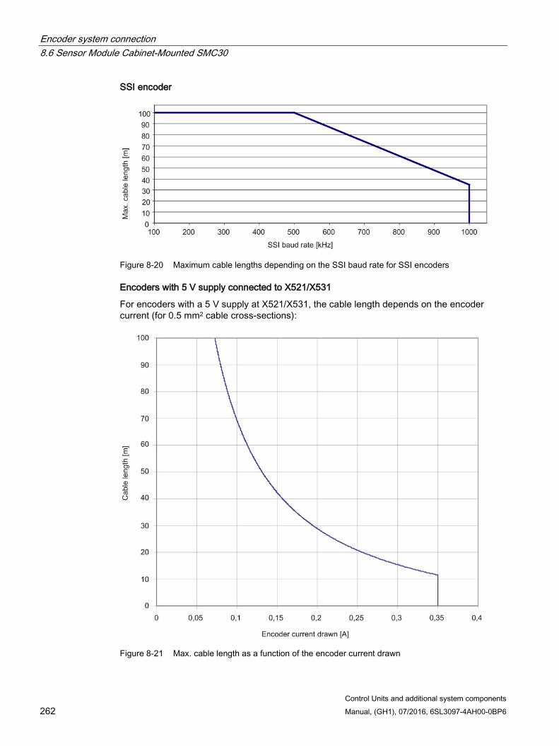
Encoder system connection 8.6 Sensor Module Cabinet-Mounted SMC30
Control Units and additional system components 262 Manual, (GH1), 07/2016, 6SL3097-4AH00-0BP6
SSI encoder
Figure 8-20 Maximum cable lengths depending on the SSI baud rate for SSI encoders
Encoders with 5 V supply connected to X521/X531
For encoders with a 5 V supply at X521/X531, the cable length depends on the encoder current (for 0.5 mm2 cable cross-sections):
Figure 8-21 Max. cable length as a function of the encoder current drawn
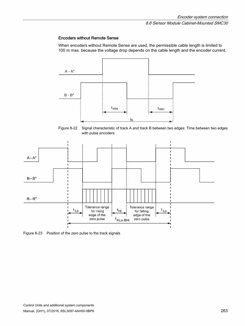
Encoder system connection 8.6 Sensor Module Cabinet-Mounted SMC30
Control Units and additional system components Manual, (GH1), 07/2016, 6SL3097-4AH00-0BP6 263
Encoders without Remote Sense
When encoders without Remote Sense are used, the permissible cable length is limited to 100 m max. because the voltage drop depends on the cable length and the encoder current.
Figure 8-22 Signal characteristic of track A and track B between two edges: Time between two edges
with pulse encoders
Figure 8-23 Position of the zero pulse to the track signals
Encoder system connection 8.7 Sensor Module Cabinet-Mounted SMC40
Control Units and additional system components 264 Manual, (GH1), 07/2016, 6SL3097-4AH00-0BP6
8.7 Sensor Module Cabinet-Mounted SMC40
8.7.1 Description The Sensor Module Cabinet-Mounted SMC40 is an expansion module for snapping on to a standard mounting rail acc. to EN 60715. It is used to convert encoder signals from absolute encoders with EnDat 2.2 Article No. 22 to DRIVE-CLiQ and send these to the Control Unit. At the SMC40, two encoder systems with EnDat 2.2 Article No. 22 can be connected, which, independent of one another, are converted over to two DRIVE-CLiQ encoder signals.
Note Permissible encoders • Only use absolute encoders EnDat 2.2 with Article No. 22. Do not connect an absolute
encoder EnDat 2.2 with Article N o. 02. • Only use absolute encoders (not incremental encoders) with software versions 4.5 and
4.6. • Do not use any battery-buffered encoders, such as e.g. Heidenhain EBI 1135.
Configuration and commissioning
To make sure that the Sensor Module Cabinet-Mounted SMC40 is integrated into the topology during first commissioning, you must absolutely observe the following connection conditions:
Connect at least one of the DRIVE-CLiQ interfaces X500/1 or X500/2 on the SMC40 using DRIVE-CLiQ.
Connect one EnDat encoder to the corresponding encoder interface X520/1 (to X500/1) or X520/2 (to X500/2).
Operate the SMC40 only in a star topology. The DRIVE-CLiQ sockets X500/1 and X500/2 can not be used for a series connection.
Note
The SMC40 will only be subsequently integrated into the actual topology if the DRIVE-CLiQ interfaces X500/. and the corresponding encoder interfaces X520/. are assigned. Without a connected encoder, it is not possible to subsequently integrate the SMC40 into the topology.
Temperature signals
If the EnDat2.2 encoder already evaluates the temperature, the temperature signals can be transferred through the SMC40 via DRIVE-CLiQ.
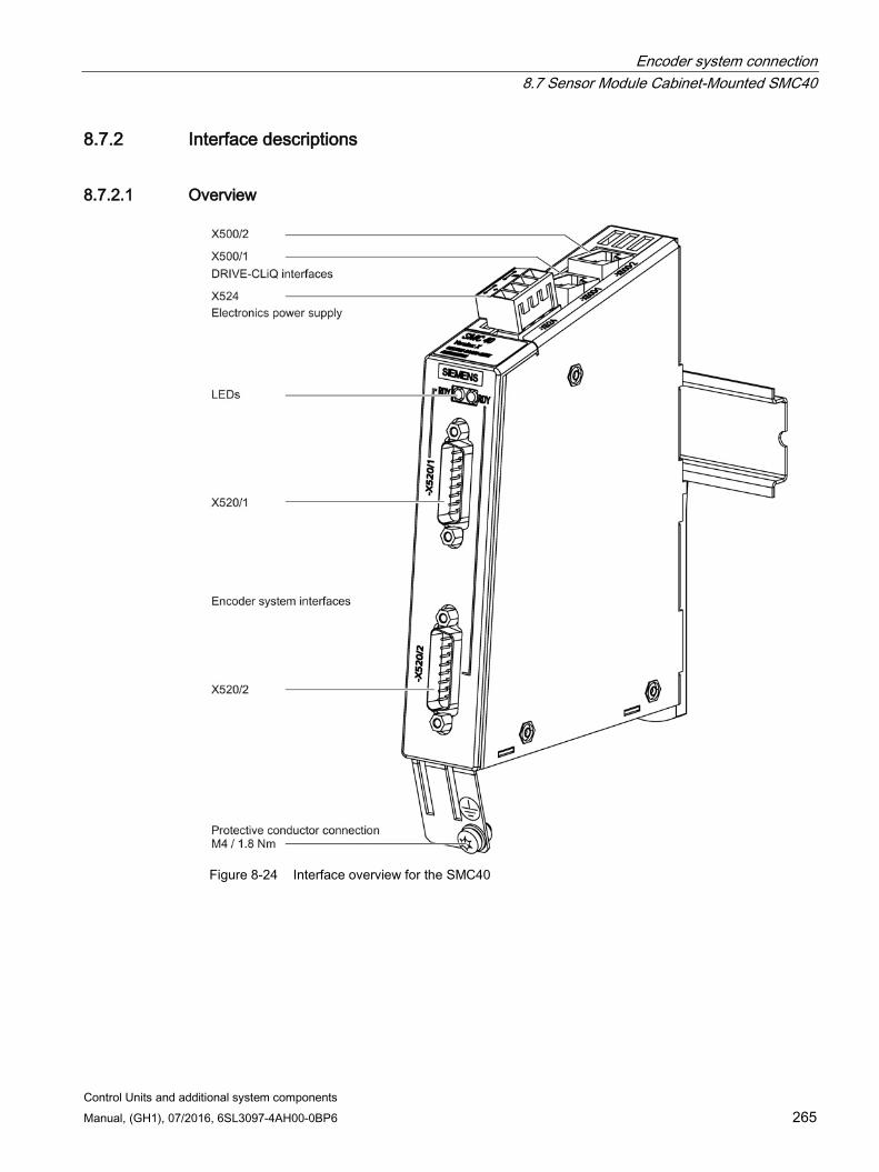
Encoder system connection 8.7 Sensor Module Cabinet-Mounted SMC40
Control Units and additional system components Manual, (GH1), 07/2016, 6SL3097-4AH00-0BP6 265
8.7.2 Interface descriptions
8.7.2.1 Overview
Figure 8-24 Interface overview for the SMC40
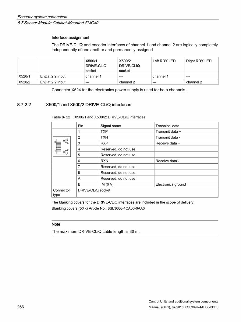
Encoder system connection 8.7 Sensor Module Cabinet-Mounted SMC40
Control Units and additional system components 266 Manual, (GH1), 07/2016, 6SL3097-4AH00-0BP6
Interface assignment
The DRIVE-CLiQ and encoder interfaces of channel 1 and channel 2 are logically completely independently of one another and permanently assigned.
X500/1
DRIVE-CLiQ socket
X500/2 DRIVE-CLiQ socket
Left RDY LED Right RDY LED
X520/1 EnDat 2.2 input channel 1 --- channel 1 --- X520/2 EnDat 2.2 input --- channel 2 --- channel 2
Connector X524 for the electronics power supply is used for both channels.
8.7.2.2 X500/1 and X500/2 DRIVE-CLiQ interfaces
Table 8- 22 X500/1 and X500/2: DRIVE-CLiQ interfaces
Pin Signal name Technical data
1 TXP Transmit data + 2 TXN Transmit data - 3 RXP Receive data + 4 Reserved, do not use 5 Reserved, do not use 6 RXN Receive data - 7 Reserved, do not use 8 Reserved, do not use A Reserved, do not use B M (0 V) Electronics ground
Connector type
DRIVE-CLiQ socket
The blanking covers for the DRIVE-CLiQ interfaces are included in the scope of delivery. Blanking covers (50 x) Article No.: 6SL3066-4CA00-0AA0
Note
The maximum DRIVE-CLiQ cable length is 30 m.
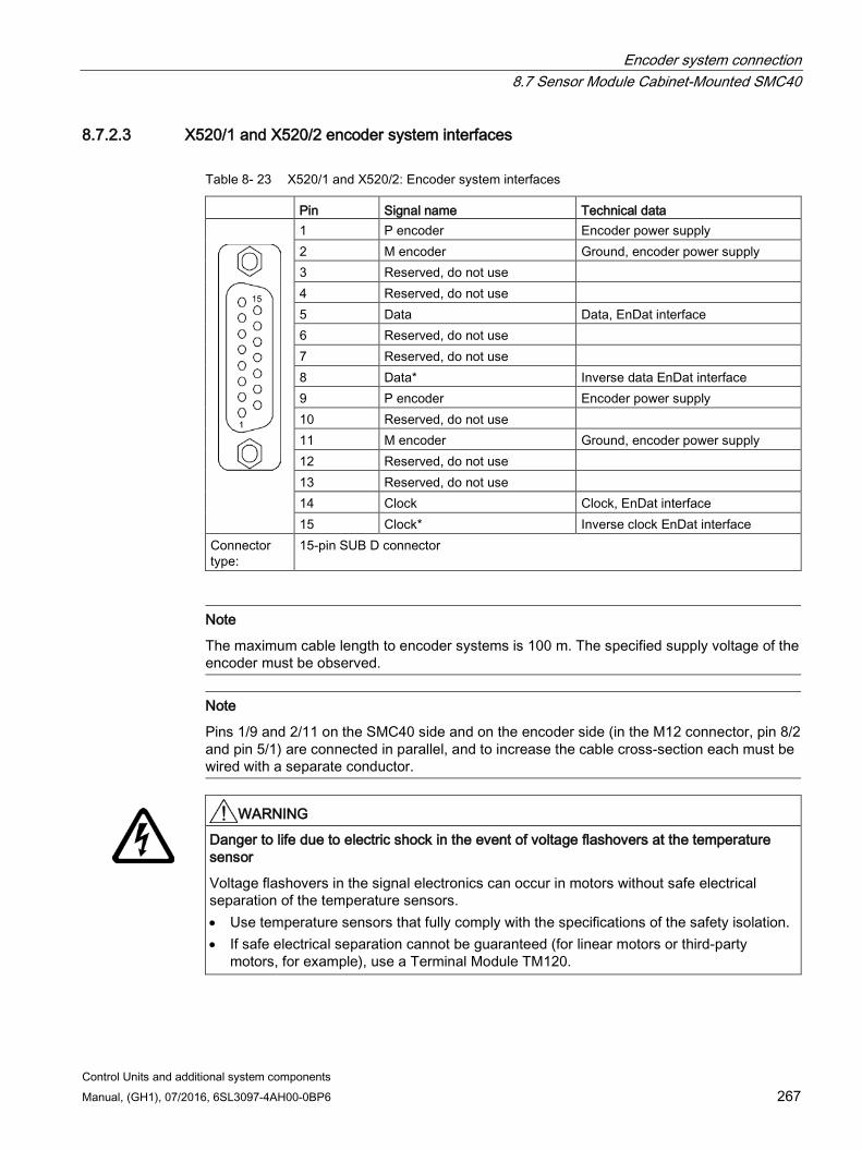
Encoder system connection 8.7 Sensor Module Cabinet-Mounted SMC40
Control Units and additional system components Manual, (GH1), 07/2016, 6SL3097-4AH00-0BP6 267
8.7.2.3 X520/1 and X520/2 encoder system interfaces
Table 8- 23 X520/1 and X520/2: Encoder system interfaces
Pin Signal name Technical data
1 P encoder Encoder power supply 2 M encoder Ground, encoder power supply 3 Reserved, do not use 4 Reserved, do not use 5 Data Data, EnDat interface 6 Reserved, do not use 7 Reserved, do not use 8 Data* Inverse data EnDat interface 9 P encoder Encoder power supply 10 Reserved, do not use 11 M encoder Ground, encoder power supply 12 Reserved, do not use 13 Reserved, do not use 14 Clock Clock, EnDat interface 15 Clock* Inverse clock EnDat interface
Connector type:
15-pin SUB D connector
Note
The maximum cable length to encoder systems is 100 m. The specified supply voltage of the encoder must be observed.
Note
Pins 1/9 and 2/11 on the SMC40 side and on the encoder side (in the M12 connector, pin 8/2 and pin 5/1) are connected in parallel, and to increase the cable cross-section each must be wired with a separate conductor.
WARNING
Danger to life due to electric shock in the event of voltage flashovers at the temperature sensor
Voltage flashovers in the signal electronics can occur in motors without safe electrical separation of the temperature sensors. • Use temperature sensors that fully comply with the specifications of the safety isolation. • If safe electrical separation cannot be guaranteed (for linear motors or third-party
motors, for example), use a Terminal Module TM120.
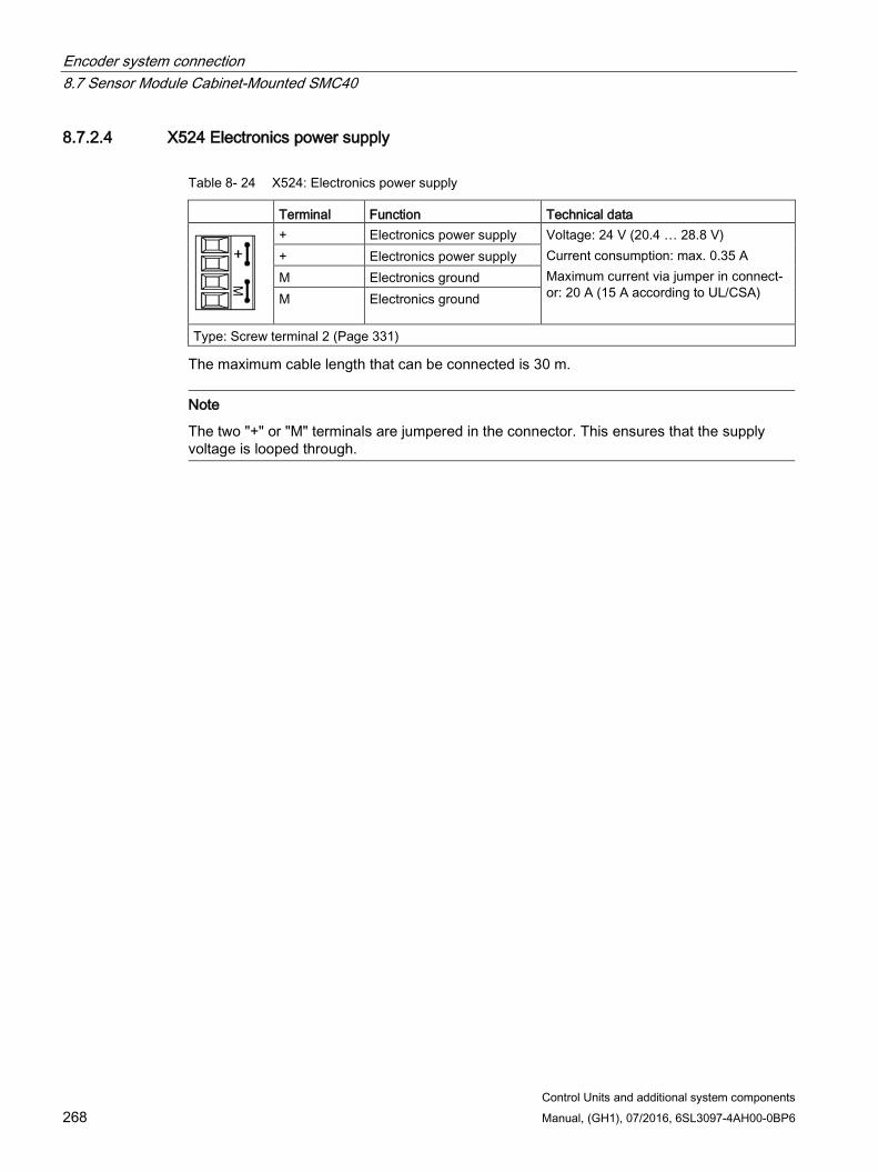
Encoder system connection 8.7 Sensor Module Cabinet-Mounted SMC40
Control Units and additional system components 268 Manual, (GH1), 07/2016, 6SL3097-4AH00-0BP6
8.7.2.4 X524 Electronics power supply
Table 8- 24 X524: Electronics power supply
Terminal Function Technical data
+ Electronics power supply Voltage: 24 V (20.4 … 28.8 V) Current consumption: max. 0.35 A Maximum current via jumper in connect-or: 20 A (15 A according to UL/CSA)
+ Electronics power supply M Electronics ground M Electronics ground
Type: Screw terminal 2 (Page 331)
The maximum cable length that can be connected is 30 m.
Note
The two "+" or "M" terminals are jumpered in the connector. This ensures that the supply voltage is looped through.
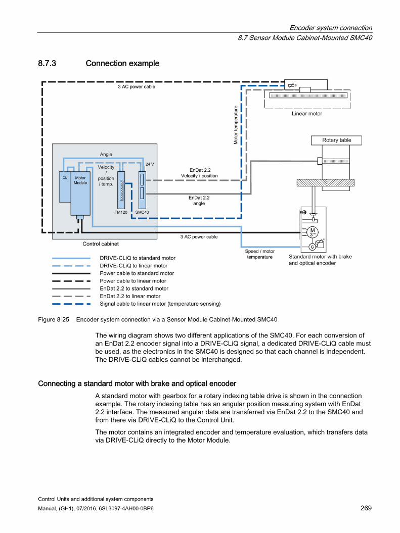
Encoder system connection 8.7 Sensor Module Cabinet-Mounted SMC40
Control Units and additional system components Manual, (GH1), 07/2016, 6SL3097-4AH00-0BP6 269
8.7.3 Connection example
Figure 8-25 Encoder system connection via a Sensor Module Cabinet-Mounted SMC40
The wiring diagram shows two different applications of the SMC40. For each conversion of an EnDat 2.2 encoder signal into a DRIVE-CLiQ signal, a dedicated DRIVE-CLiQ cable must be used, as the electronics in the SMC40 is designed so that each channel is independent. The DRIVE-CLiQ cables cannot be interchanged.
Connecting a standard motor with brake and optical encoder A standard motor with gearbox for a rotary indexing table drive is shown in the connection example. The rotary indexing table has an angular position measuring system with EnDat 2.2 interface. The measured angular data are transferred via EnDat 2.2 to the SMC40 and from there via DRIVE-CLiQ to the Control Unit.
The motor contains an integrated encoder and temperature evaluation, which transfers data via DRIVE-CLiQ directly to the Motor Module.
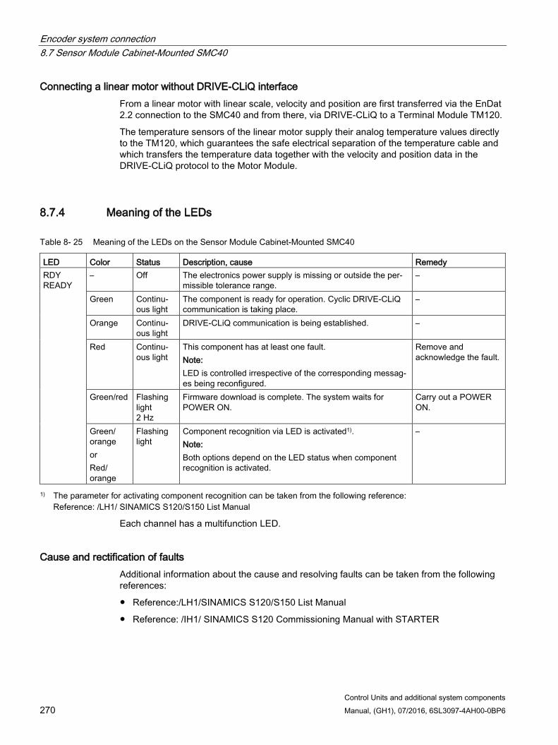
Encoder system connection 8.7 Sensor Module Cabinet-Mounted SMC40
Control Units and additional system components 270 Manual, (GH1), 07/2016, 6SL3097-4AH00-0BP6
Connecting a linear motor without DRIVE-CLiQ interface From a linear motor with linear scale, velocity and position are first transferred via the EnDat 2.2 connection to the SMC40 and from there, via DRIVE-CLiQ to a Terminal Module TM120.
The temperature sensors of the linear motor supply their analog temperature values directly to the TM120, which guarantees the safe electrical separation of the temperature cable and which transfers the temperature data together with the velocity and position data in the DRIVE-CLiQ protocol to the Motor Module.
8.7.4 Meaning of the LEDs
Table 8- 25 Meaning of the LEDs on the Sensor Module Cabinet-Mounted SMC40
LED Color Status Description, cause Remedy RDY READY
– Off The electronics power supply is missing or outside the per-missible tolerance range.
–
Green Continu-ous light
The component is ready for operation. Cyclic DRIVE-CLiQ communication is taking place.
–
Orange Continu-ous light
DRIVE-CLiQ communication is being established. –
Red Continu-ous light
This component has at least one fault. Note: LED is controlled irrespective of the corresponding messag-es being reconfigured.
Remove and acknowledge the fault.
Green/red Flashing light 2 Hz
Firmware download is complete. The system waits for POWER ON.
Carry out a POWER ON.
Green/ orange or Red/ orange
Flashing light
Component recognition via LED is activated1). Note: Both options depend on the LED status when component recognition is activated.
–
1) The parameter for activating component recognition can be taken from the following reference: Reference: /LH1/ SINAMICS S120/S150 List Manual
Each channel has a multifunction LED.
Cause and rectification of faults Additional information about the cause and resolving faults can be taken from the following references:
Reference:/LH1/SINAMICS S120/S150 List Manual
Reference: /IH1/ SINAMICS S120 Commissioning Manual with STARTER
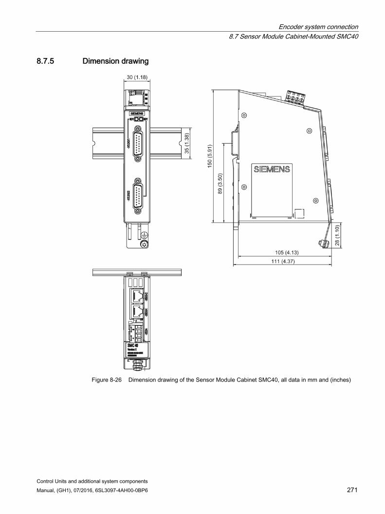
Encoder system connection 8.7 Sensor Module Cabinet-Mounted SMC40
Control Units and additional system components Manual, (GH1), 07/2016, 6SL3097-4AH00-0BP6 271
8.7.5 Dimension drawing
Figure 8-26 Dimension drawing of the Sensor Module Cabinet SMC40, all data in mm and (inches)

Encoder system connection 8.7 Sensor Module Cabinet-Mounted SMC40
Control Units and additional system components 272 Manual, (GH1), 07/2016, 6SL3097-4AH00-0BP6
8.7.6 Installation
Installation 1. Tilt the component backwards slightly and attach it to the DIN rail using the hooks.
2. Swivel the component onto the DIN rail until you hear the mounting slide at the rear latch into position.
3. Slide the components along the mounting rail to either the left or right up to their final position.
Removal 1. First shift the mounting slide downwards at the lug to release the interlocking with the
mounting rail.
2. Swivel the component to the front and withdraw it upwards from the DIN rail.
① Mounting slide ② Mounting rail
Figure 8-27 Removing from a DIN mounting rail
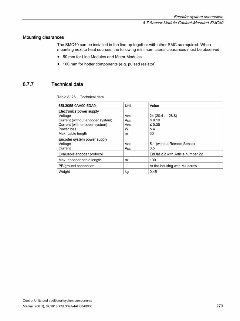
Encoder system connection 8.7 Sensor Module Cabinet-Mounted SMC40
Control Units and additional system components Manual, (GH1), 07/2016, 6SL3097-4AH00-0BP6 273
Mounting clearances The SMC40 can be installed in the line-up together with other SMC as required. When mounting next to heat sources, the following minimum lateral clearances must be observed:
50 mm for Line Modules and Motor Modules
100 mm for hotter components (e.g. pulsed resistor)
8.7.7 Technical data
Table 8- 26 Technical data
6SL3055-0AA00-5DA0 Unit Value Electronics power supply Voltage Current (without encoder system) Current (with encoder system) Power loss Max. cable length
VDC ADC ADC W m
24 (20.4 … 28.8) ≤ 0.10 ≤ 0.35 ≤ 4 30
Encoder system power supply Voltage Current
VDC ADC
5.1 (without Remote Sense) 0.5
Evaluable encoder protocol EnDat 2.2 with Article number 22 Max. encoder cable length m 100 PE/ground connection At the housing with M4 screw Weight kg 0.45
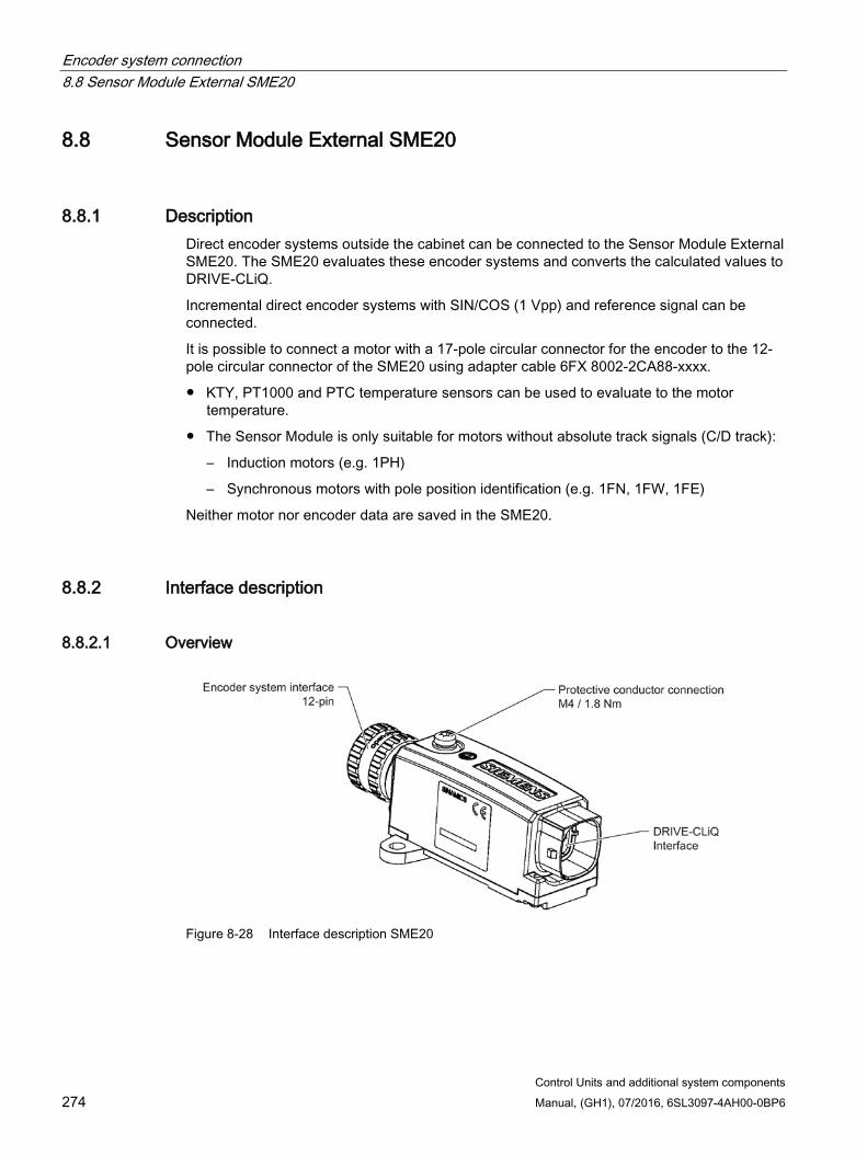
Encoder system connection 8.8 Sensor Module External SME20
Control Units and additional system components 274 Manual, (GH1), 07/2016, 6SL3097-4AH00-0BP6
8.8 Sensor Module External SME20
8.8.1 Description Direct encoder systems outside the cabinet can be connected to the Sensor Module External SME20. The SME20 evaluates these encoder systems and converts the calculated values to DRIVE-CLiQ.
Incremental direct encoder systems with SIN/COS (1 Vpp) and reference signal can be connected.
It is possible to connect a motor with a 17-pole circular connector for the encoder to the 12-pole circular connector of the SME20 using adapter cable 6FX 8002-2CA88-xxxx.
KTY, PT1000 and PTC temperature sensors can be used to evaluate to the motor temperature.
The Sensor Module is only suitable for motors without absolute track signals (C/D track):
– Induction motors (e.g. 1PH)
– Synchronous motors with pole position identification (e.g. 1FN, 1FW, 1FE)
Neither motor nor encoder data are saved in the SME20.
8.8.2 Interface description
8.8.2.1 Overview
Figure 8-28 Interface description SME20
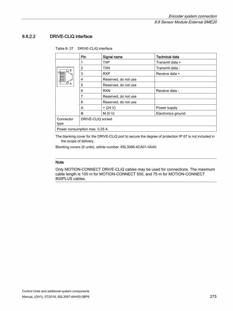
Encoder system connection 8.8 Sensor Module External SME20
Control Units and additional system components Manual, (GH1), 07/2016, 6SL3097-4AH00-0BP6 275
8.8.2.2 DRIVE-CLiQ interface
Table 8- 27 DRIVE-CLiQ interface
Pin Signal name Technical data
1 TXP Transmit data + 2 TXN Transmit data - 3 RXP Receive data + 4 Reserved, do not use 5 Reserved, do not use 6 RXN Receive data - 7 Reserved, do not use 8 Reserved, do not use A + (24 V) Power supply B M (0 V) Electronics ground
Connector type
DRIVE-CLiQ socket
Power consumption max. 0.25 A The blanking cover for the DRIVE-CLiQ port to secure the degree of protection IP 67 is not included in
the scope of delivery. Blanking covers (6 units), article number: 6SL3066-4CA01-0AA0
Note
Only MOTION-CONNECT DRIVE-CLiQ cables may be used for connections. The maximum cable length is 100 m for MOTION-CONNECT 500, and 75 m for MOTION-CONNECT 800PLUS cables.
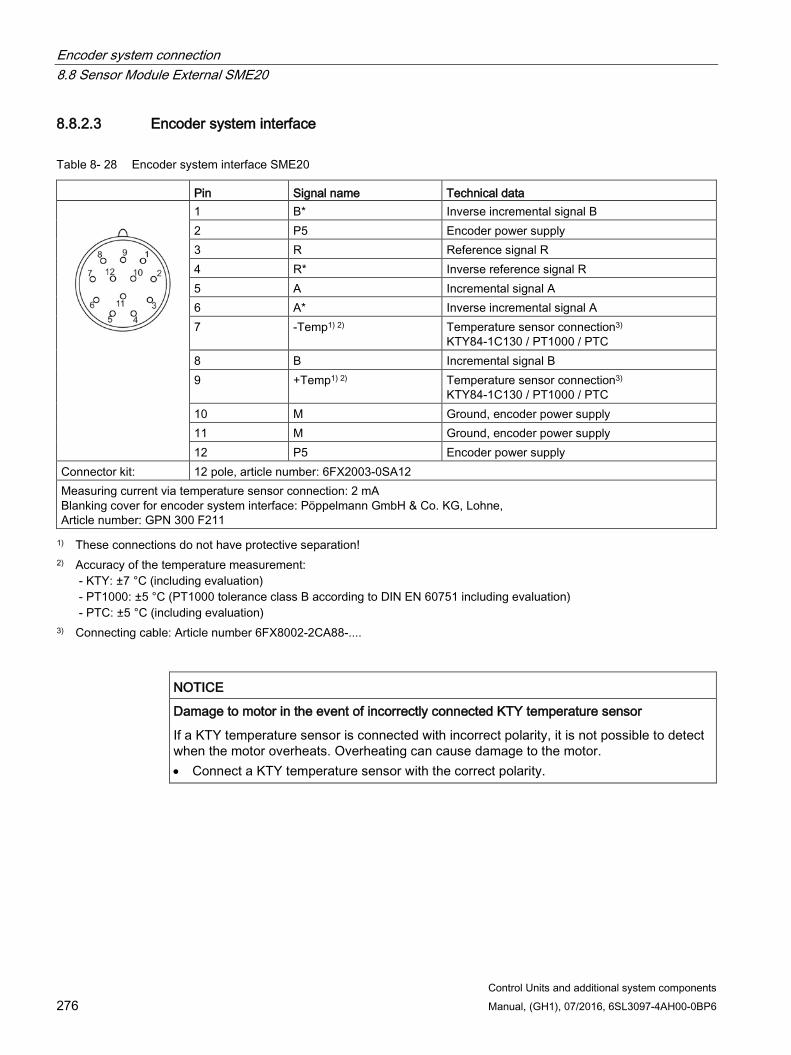
Encoder system connection 8.8 Sensor Module External SME20
Control Units and additional system components 276 Manual, (GH1), 07/2016, 6SL3097-4AH00-0BP6
8.8.2.3 Encoder system interface
Table 8- 28 Encoder system interface SME20
Pin Signal name Technical data
1 B* Inverse incremental signal B 2 P5 Encoder power supply 3 R Reference signal R 4 R* Inverse reference signal R 5 A Incremental signal A 6 A* Inverse incremental signal A 7 -Temp1) 2) Temperature sensor connection3)
KTY84-1C130 / PT1000 / PTC 8 B Incremental signal B 9 +Temp1) 2) Temperature sensor connection3)
KTY84-1C130 / PT1000 / PTC 10 M Ground, encoder power supply 11 M Ground, encoder power supply 12 P5 Encoder power supply
Connector kit: 12 pole, article number: 6FX2003-0SA12 Measuring current via temperature sensor connection: 2 mA Blanking cover for encoder system interface: Pöppelmann GmbH & Co. KG, Lohne, Article number: GPN 300 F211 1) These connections do not have protective separation!
2) Accuracy of the temperature measurement: - KTY: ±7 °C (including evaluation) - PT1000: ±5 °C (PT1000 tolerance class B according to DIN EN 60751 including evaluation) - PTC: ±5 °C (including evaluation)
3) Connecting cable: Article number 6FX8002-2CA88-....
NOTICE
Damage to motor in the event of incorrectly connected KTY temperature sensor
If a KTY temperature sensor is connected with incorrect polarity, it is not possible to detect when the motor overheats. Overheating can cause damage to the motor. • Connect a KTY temperature sensor with the correct polarity.
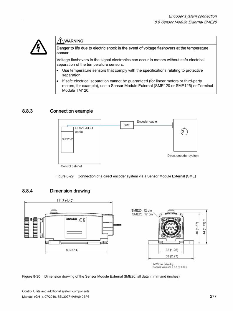
Encoder system connection 8.8 Sensor Module External SME20
Control Units and additional system components Manual, (GH1), 07/2016, 6SL3097-4AH00-0BP6 277
WARNING
Danger to life due to electric shock in the event of voltage flashovers at the temperature sensor
Voltage flashovers in the signal electronics can occur in motors without safe electrical separation of the temperature sensors. • Use temperature sensors that comply with the specifications relating to protective
separation. • If safe electrical separation cannot be guaranteed (for linear motors or third-party
motors, for example), use a Sensor Module External (SME120 or SME125) or Terminal Module TM120.
8.8.3 Connection example
Figure 8-29 Connection of a direct encoder system via a Sensor Module External (SME)
8.8.4 Dimension drawing
Figure 8-30 Dimension drawing of the Sensor Module External SME20, all data in mm and (inches)
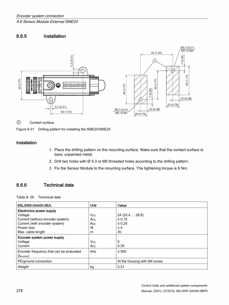
Encoder system connection 8.8 Sensor Module External SME20
Control Units and additional system components 278 Manual, (GH1), 07/2016, 6SL3097-4AH00-0BP6
8.8.5 Installation
① Contact surface
Figure 8-31 Drilling pattern for installing the SME20/SME25
Installation 1. Place the drilling pattern on the mounting surface. Make sure that the contact surface is
bare, unpainted metal.
2. Drill two holes with Ø 5.3 or M5 threaded holes according to the drilling pattern.
3. Fix the Sensor Module to the mounting surface. The tightening torque is 6 Nm.
8.8.6 Technical data
Table 8- 29 Technical data
6SL3055-0AA00-5EA. Unit Value Electronics power supply Voltage Current (without encoder system) Current (with encoder system) Power loss Max. cable length
VDC ADC ADC W m
24 (20.4 … 28.8) ≤ 0.15 ≤ 0.25 ≤ 4 30
Encoder system power supply Voltage Current
VDC ADC
5 0.35
Encoder frequency that can be evaluated (fencoder)
kHz ≤ 500
PE/ground connection At the housing with M4 screw Weight kg 0.31
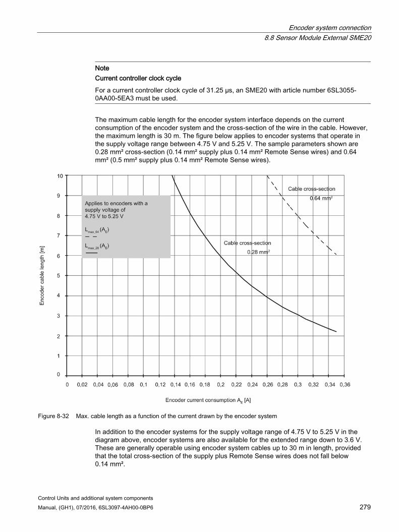
Encoder system connection 8.8 Sensor Module External SME20
Control Units and additional system components Manual, (GH1), 07/2016, 6SL3097-4AH00-0BP6 279
Note
Current controller clock cycle
For a current controller clock cycle of 31.25 µs, an SME20 with article number 6SL3055-0AA00-5EA3 must be used.
The maximum cable length for the encoder system interface depends on the current consumption of the encoder system and the cross-section of the wire in the cable. However, the maximum length is 30 m. The figure below applies to encoder systems that operate in the supply voltage range between 4.75 V and 5.25 V. The sample parameters shown are 0.28 mm² cross-section (0.14 mm² supply plus 0.14 mm² Remote Sense wires) and 0.64 mm² (0.5 mm² supply plus 0.14 mm² Remote Sense wires).
Figure 8-32 Max. cable length as a function of the current drawn by the encoder system
In addition to the encoder systems for the supply voltage range of 4.75 V to 5.25 V in the diagram above, encoder systems are also available for the extended range down to 3.6 V. These are generally operable using encoder system cables up to 30 m in length, provided that the total cross-section of the supply plus Remote Sense wires does not fall below 0.14 mm².
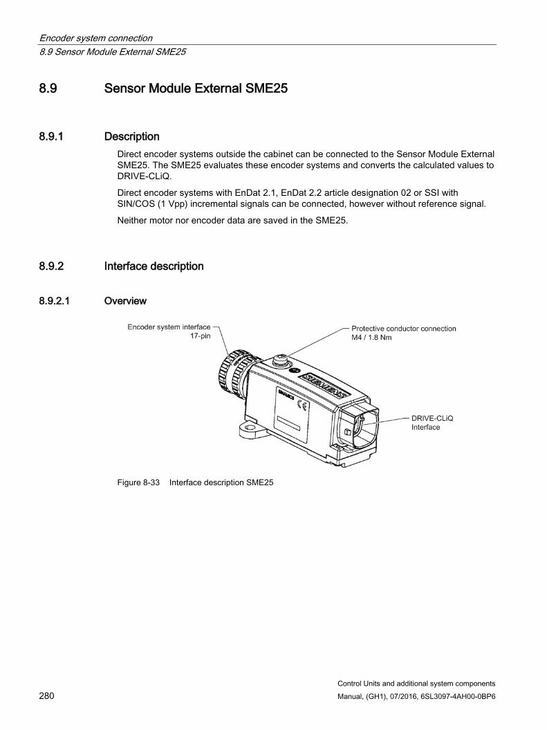
Encoder system connection 8.9 Sensor Module External SME25
Control Units and additional system components 280 Manual, (GH1), 07/2016, 6SL3097-4AH00-0BP6
8.9 Sensor Module External SME25
8.9.1 Description Direct encoder systems outside the cabinet can be connected to the Sensor Module External SME25. The SME25 evaluates these encoder systems and converts the calculated values to DRIVE-CLiQ.
Direct encoder systems with EnDat 2.1, EnDat 2.2 article designation 02 or SSI with SIN/COS (1 Vpp) incremental signals can be connected, however without reference signal.
Neither motor nor encoder data are saved in the SME25.
8.9.2 Interface description
8.9.2.1 Overview
Figure 8-33 Interface description SME25

Encoder system connection 8.9 Sensor Module External SME25
Control Units and additional system components Manual, (GH1), 07/2016, 6SL3097-4AH00-0BP6 281
8.9.2.2 DRIVE-CLiQ interface
Table 8- 30 DRIVE-CLiQ interface
Pin Signal name Technical data
1 TXP Transmit data + 2 TXN Transmit data - 3 RXP Receive data + 4 Reserved, do not use 5 Reserved, do not use 6 RXN Receive data - 7 Reserved, do not use 8 Reserved, do not use A + (24 V) Power supply B M (0 V) Electronics ground
Connector type
DRIVE-CLiQ socket
Power consumption max. 0.25 A The blanking cover for the DRIVE-CLiQ port to secure the degree of protection IP 67 is not included in
the scope of delivery. Blanking covers (6 units), article number: 6SL3066-4CA01-0AA0
Note
Only MOTION-CONNECT DRIVE-CLiQ cables may be used for connections. The maximum cable length is 100 m for MOTION-CONNECT 500, and 75 m for MOTION-CONNECT 800PLUS cables.
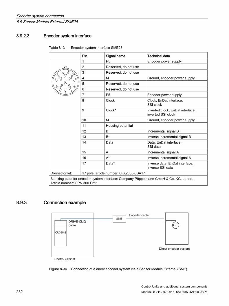
Encoder system connection 8.9 Sensor Module External SME25
Control Units and additional system components 282 Manual, (GH1), 07/2016, 6SL3097-4AH00-0BP6
8.9.2.3 Encoder system interface
Table 8- 31 Encoder system interface SME25
Pin Signal name Technical data
1 P5 Encoder power supply 2 Reserved, do not use 3 Reserved, do not use 4 M Ground, encoder power supply 5 Reserved, do not use 6 Reserved, do not use 7 P5 Encoder power supply 8 Clock Clock, EnDat interface,
SSI clock 9 Clock* Inverted clock, EnDat interface,
inverted SSI clock 10 M Ground, encoder power supply 11 Housing potential 12 B Incremental signal B 13 B* Inverse incremental signal B 14 Data Data, EnDat interface,
SSI data 15 A Incremental signal A 16 A* Inverse incremental signal A 17 Data* Inverse data, EnDat interface,
Inverse SSI data Connector kit: 17 pole, article number: 6FX2003-0SA17 Blanking plate for encoder system interface: Company Pöppelmann GmbH & Co. KG, Lohne, Article number: GPN 300 F211
8.9.3 Connection example
Figure 8-34 Connection of a direct encoder system via a Sensor Module External (SME)
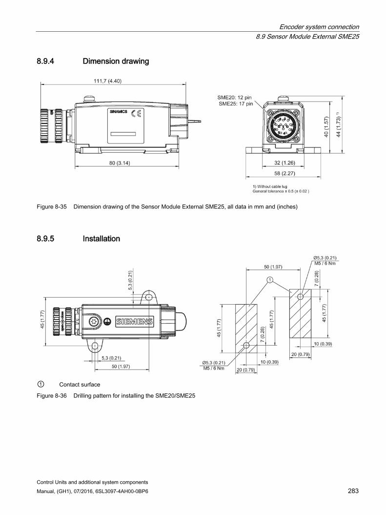
Encoder system connection 8.9 Sensor Module External SME25
Control Units and additional system components Manual, (GH1), 07/2016, 6SL3097-4AH00-0BP6 283
8.9.4 Dimension drawing
Figure 8-35 Dimension drawing of the Sensor Module External SME25, all data in mm and (inches)
8.9.5 Installation
① Contact surface
Figure 8-36 Drilling pattern for installing the SME20/SME25
Encoder system connection 8.9 Sensor Module External SME25
Control Units and additional system components 284 Manual, (GH1), 07/2016, 6SL3097-4AH00-0BP6
Installation 1. Place the drilling pattern on the mounting surface. Make sure that the contact surface is
bare, unpainted metal.
2. Drill two holes with Ø 5.3 or M5 threaded holes according to the drilling pattern.
3. Fix the Sensor Module to the mounting surface. The tightening torque is 6 Nm.
8.9.6 Technical data
Table 8- 32 Technical data
6SL3055-0AA00-5HA. Unit Value Electronics power supply Voltage Current (without encoder system) Current (with encoder system) Power loss Max. cable length
VDC ADC ADC W m
24 (20.4 … 28.8) ≤ 0.15 ≤ 0.25 ≤ 4 30
Encoder system power supply Voltage Current
VDC ADC
5 0.35
Encoder frequency that can be evaluated (fencoder)
kHz ≤ 500
SSI/EnDat baud rate kBd 100 PE/ground connection At the housing with M4 screw Weight kg 0.31
Note Current controller clock cycle
For a current controller clock cycle of 31.25 µs, an SME25 with article number 6SL3055-0AA00-5HA3 must be used.
The maximum cable length for the encoder system interface depends on the current consumption of the encoder system and the cross-section of the wire in the cable. However, the maximum length is 30 m. The figure below applies to encoder systems that operate in the supply voltage range between 4.75 V and 5.25 V. The sample parameters shown are 0.28 mm² cross-section (0.14 mm² supply plus 0.14 mm² Remote Sense wires) and 0.64 mm² (0.5 mm² supply plus 0.14 mm² Remote Sense wires).
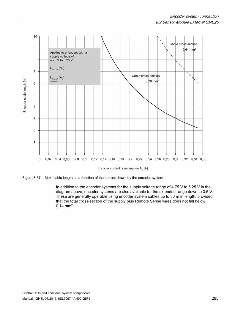
Encoder system connection 8.9 Sensor Module External SME25
Control Units and additional system components Manual, (GH1), 07/2016, 6SL3097-4AH00-0BP6 285
Figure 8-37 Max. cable length as a function of the current drawn by the encoder system
In addition to the encoder systems for the supply voltage range of 4.75 V to 5.25 V in the diagram above, encoder systems are also available for the extended range down to 3.6 V. These are generally operable using encoder system cables up to 30 m in length, provided that the total cross-section of the supply plus Remote Sense wires does not fall below 0.14 mm².
Encoder system connection 8.10 Sensor Module External SME120
Control Units and additional system components 286 Manual, (GH1), 07/2016, 6SL3097-4AH00-0BP6
8.10 Sensor Module External SME120
8.10.1 Description Direct encoder systems outside the cabinet can be connected to the Sensor Module External SME120. The SME120 evaluates these encoder systems and converts the calculated values to DRIVE-CLiQ. Neither motor nor encoder data are saved in the SME120. Incremental direct encoder systems with SIN/COS (1 Vpp) and reference signal can be connected.
An SME120 is always used when the temperature signals of the motors do not have protective separation or where this separation is not possible for certain reasons.
The SME120 is especially used for linear motor applications. A Hall sensor box can be connected to determine the commutation position of a linear motor.

Encoder system connection 8.10 Sensor Module External SME120
Control Units and additional system components Manual, (GH1), 07/2016, 6SL3097-4AH00-0BP6 287
8.10.2 Safety instructions for Sensor Modules External The safety instructions listed here apply specifically for the Sensor Modules External SME12..
Note
When handling/using a Sensor Module External, you must also observe the safety instructions for Sensor Modules as well as the safety instructions in Chapter 1 (Page 19).
A Sensor Module External SME12. is a device of safety class I.
WARNING
Death or severe injury can occur when an SME12. is incorrectly used and handled.
When an SME12. is incorrectly used and handled, protective devices can be disabled; which means that death or severe injury can occur when touching. • It is mandatory that you connect a protective conductor with a minimum cross-section of
2.5 mm2 in order to guarantee safe electrical separation. • In order to ensure degree of protection IP67, close all connections, even connections
that are not used, with connectors or suitable sealing caps. You must observe the specified torques.
• Before commissioning, always replace the plastic covers of connections X100 to X500 using the corresponding connectors, as otherwise the Sensor Modules External SME12. will not conform with degree of protection IP67.
• Under no circumstances open the Sensor Modules, as this can mean that they are no longer properly sealed! Only a certified SIEMENS service center should carry out repair and maintenance work.
• If it appears that the Sensor Module packaging has been damaged by water, do not commission the Sensor Module.
NOTICE
Damage caused by connecting a grounded encoder system power supply
The devices can be damaged by connecting encoder systems with grounded encoder system power supplies. • Only connect those encoder systems where the power supply is not grounded.
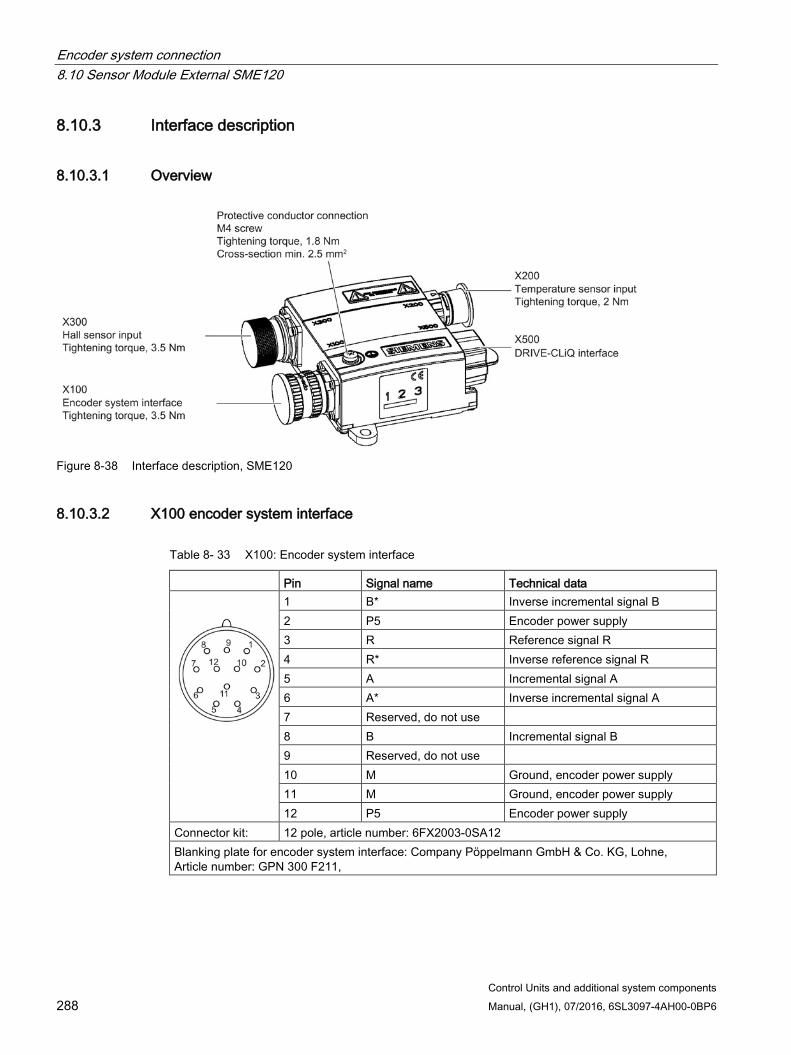
Encoder system connection 8.10 Sensor Module External SME120
Control Units and additional system components 288 Manual, (GH1), 07/2016, 6SL3097-4AH00-0BP6
8.10.3 Interface description
8.10.3.1 Overview
Figure 8-38 Interface description, SME120
8.10.3.2 X100 encoder system interface
Table 8- 33 X100: Encoder system interface
Pin Signal name Technical data
1 B* Inverse incremental signal B 2 P5 Encoder power supply 3 R Reference signal R 4 R* Inverse reference signal R 5 A Incremental signal A 6 A* Inverse incremental signal A 7 Reserved, do not use 8 B Incremental signal B 9 Reserved, do not use 10 M Ground, encoder power supply 11 M Ground, encoder power supply 12 P5 Encoder power supply
Connector kit: 12 pole, article number: 6FX2003-0SA12 Blanking plate for encoder system interface: Company Pöppelmann GmbH & Co. KG, Lohne, Article number: GPN 300 F211,

Encoder system connection 8.10 Sensor Module External SME120
Control Units and additional system components Manual, (GH1), 07/2016, 6SL3097-4AH00-0BP6 289
8.10.3.3 X200 thermistor sensor input
Table 8- 34 X200: Temperature sensor input
Pin Function Technical data
1 -Temp1) Temperature sensor connection KTY84-1C130 / PT1000 / PTC /bimetallic switch with NC contact for linear and torque motor applications, connect the KTY84-1C130 or PT1000 motor temperature sensor here
2 +Temp1)
3 +Temp1) Temperature sensor connection KTY84-1C130 / PT1000 / PTC /bimetallic switch with NC contact for linear and torque motor applications, connect the PTC triple element 1 or bimetallic switch here
4 -Temp1)
5 +Temp1) Temperature sensor connection KTY84-1C130 / PT1000 / PTC /bimetallic switch with NC contact for torque motor applications, connect a PTC triplet 2 here
6 -Temp1)
Connector kit: 6+1-pole, article number: 6FX2003-0SU07 Measuring current via temperature sensor connection: 2 mA 1) Accuracy of the temperature measurement:
- KTY: ±7 °C (including evaluation) - PT1000: ±5 °C (PT1000 tolerance class B according to DIN EN 60751 including evaluation) - PTC: ±5 °C (including evaluation)
NOTICE
Damage to motor in the event of incorrectly connected KTY temperature sensor
If a KTY temperature sensor is connected with incorrect polarity, it is not possible to detect when the motor overheats. Overheating can cause damage to the motor. • Connect a KTY temperature sensor with the correct polarity.
NOTICE
Overheating of the motor through jumpering the temperature sensor connections
Jumpering temperature sensor connections "+Temp" and "-Temp" results in incorrect measurement results. Damage to the motor can result if the overheating is not detected. • When using several temperature sensors, separately connect the individual sensors to
"+Temp" and "-Temp".
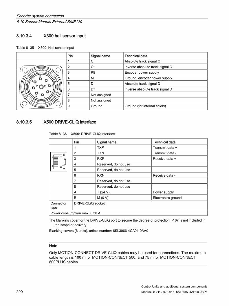
Encoder system connection 8.10 Sensor Module External SME120
Control Units and additional system components 290 Manual, (GH1), 07/2016, 6SL3097-4AH00-0BP6
8.10.3.4 X300 hall sensor input
Table 8- 35 X300: Hall sensor input
Pin Signal name Technical data
1 C Absolute track signal C 2 C* Inverse absolute track signal C 3 P5 Encoder power supply 4 M Ground, encoder power supply 5 D Absolute track signal D 6 D* Inverse absolute track signal D 7 Not assigned 8 Not assigned 9 Ground Ground (for internal shield)
8.10.3.5 X500 DRIVE-CLiQ interface
Table 8- 36 X500: DRIVE-CLiQ interface
Pin Signal name Technical data
1 TXP Transmit data + 2 TXN Transmit data - 3 RXP Receive data + 4 Reserved, do not use 5 Reserved, do not use 6 RXN Receive data - 7 Reserved, do not use 8 Reserved, do not use A + (24 V) Power supply B M (0 V) Electronics ground
Connector type
DRIVE-CLiQ socket
Power consumption max. 0.30 A The blanking cover for the DRIVE-CLiQ port to secure the degree of protection IP 67 is not included in
the scope of delivery. Blanking covers (6 units), article number: 6SL3066-4CA01-0AA0
Note
Only MOTION-CONNECT DRIVE-CLiQ cables may be used for connections. The maximum cable length is 100 m for MOTION-CONNECT 500, and 75 m for MOTION-CONNECT 800PLUS cables.

Encoder system connection 8.10 Sensor Module External SME120
Control Units and additional system components Manual, (GH1), 07/2016, 6SL3097-4AH00-0BP6 291
8.10.4 Connection examples
Figure 8-39 Connecting motor encoders via SME for motors without a DRIVE-CLiQ interface and molded connecting
cables with terminated cable ends
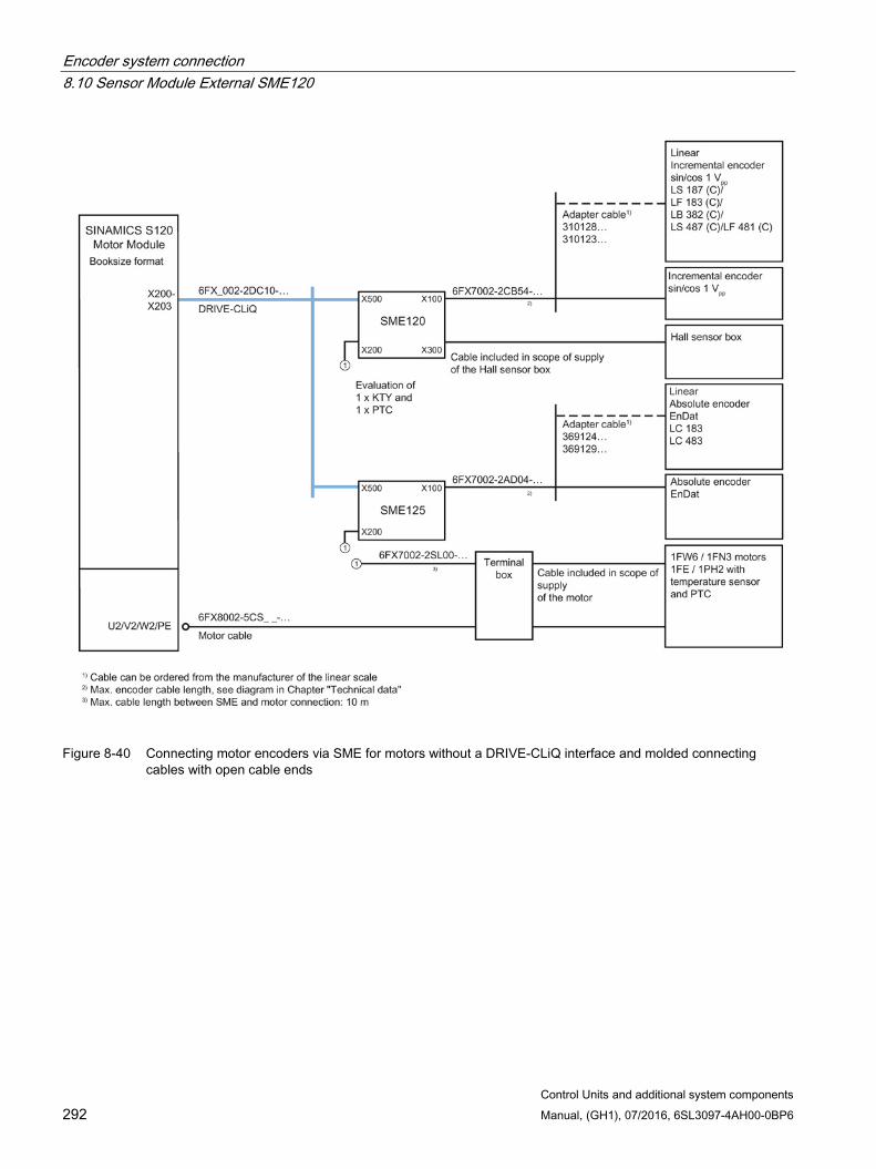
Encoder system connection 8.10 Sensor Module External SME120
Control Units and additional system components 292 Manual, (GH1), 07/2016, 6SL3097-4AH00-0BP6
Figure 8-40 Connecting motor encoders via SME for motors without a DRIVE-CLiQ interface and molded connecting
cables with open cable ends
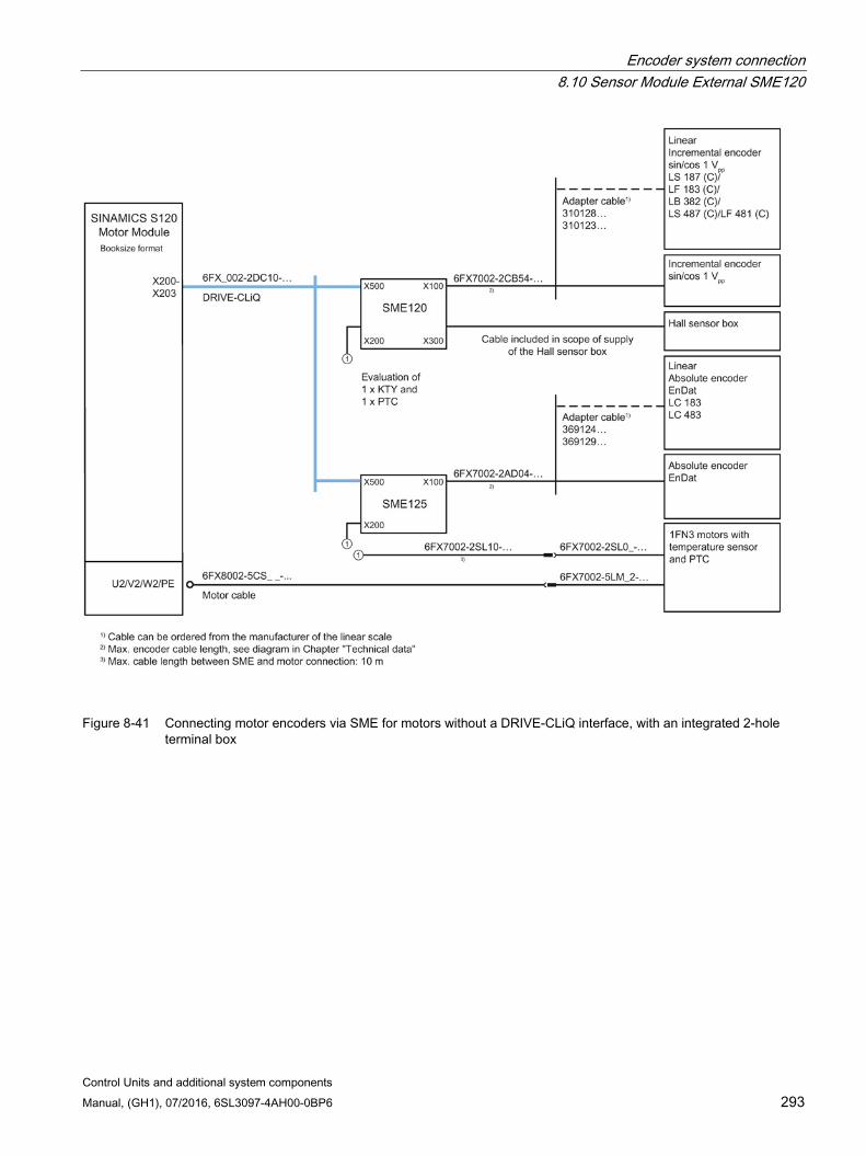
Encoder system connection 8.10 Sensor Module External SME120
Control Units and additional system components Manual, (GH1), 07/2016, 6SL3097-4AH00-0BP6 293
Figure 8-41 Connecting motor encoders via SME for motors without a DRIVE-CLiQ interface, with an integrated 2-hole
terminal box
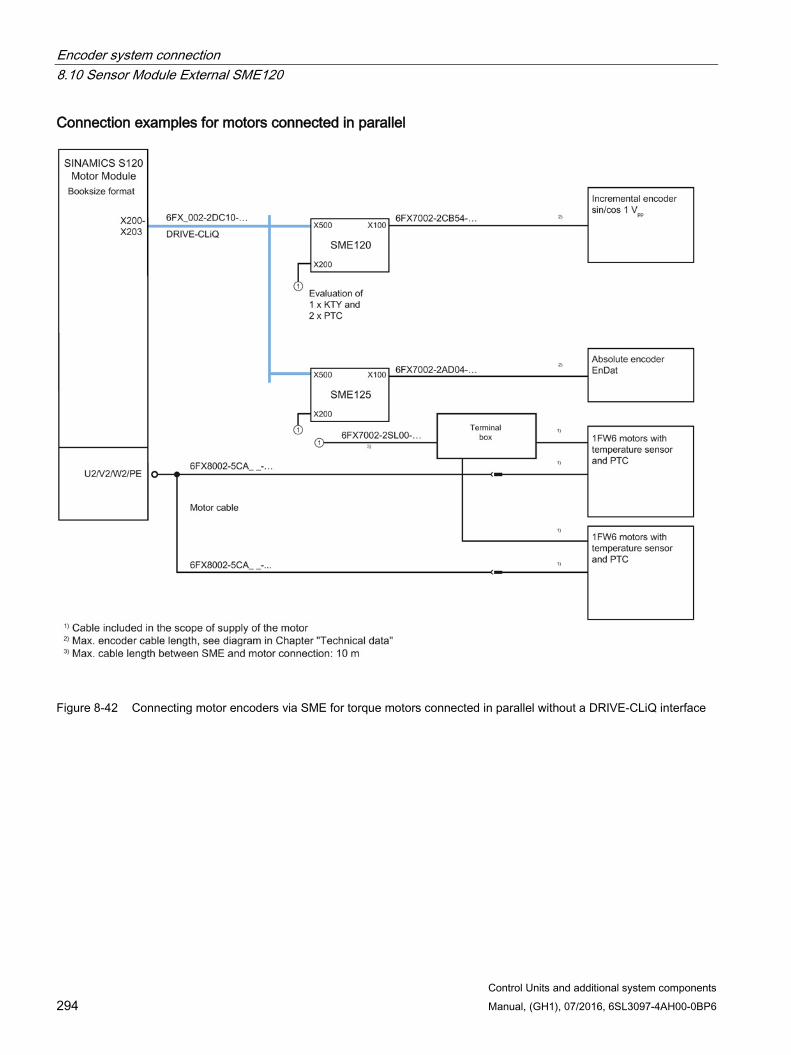
Encoder system connection 8.10 Sensor Module External SME120
Control Units and additional system components 294 Manual, (GH1), 07/2016, 6SL3097-4AH00-0BP6
Connection examples for motors connected in parallel
Figure 8-42 Connecting motor encoders via SME for torque motors connected in parallel without a DRIVE-CLiQ interface
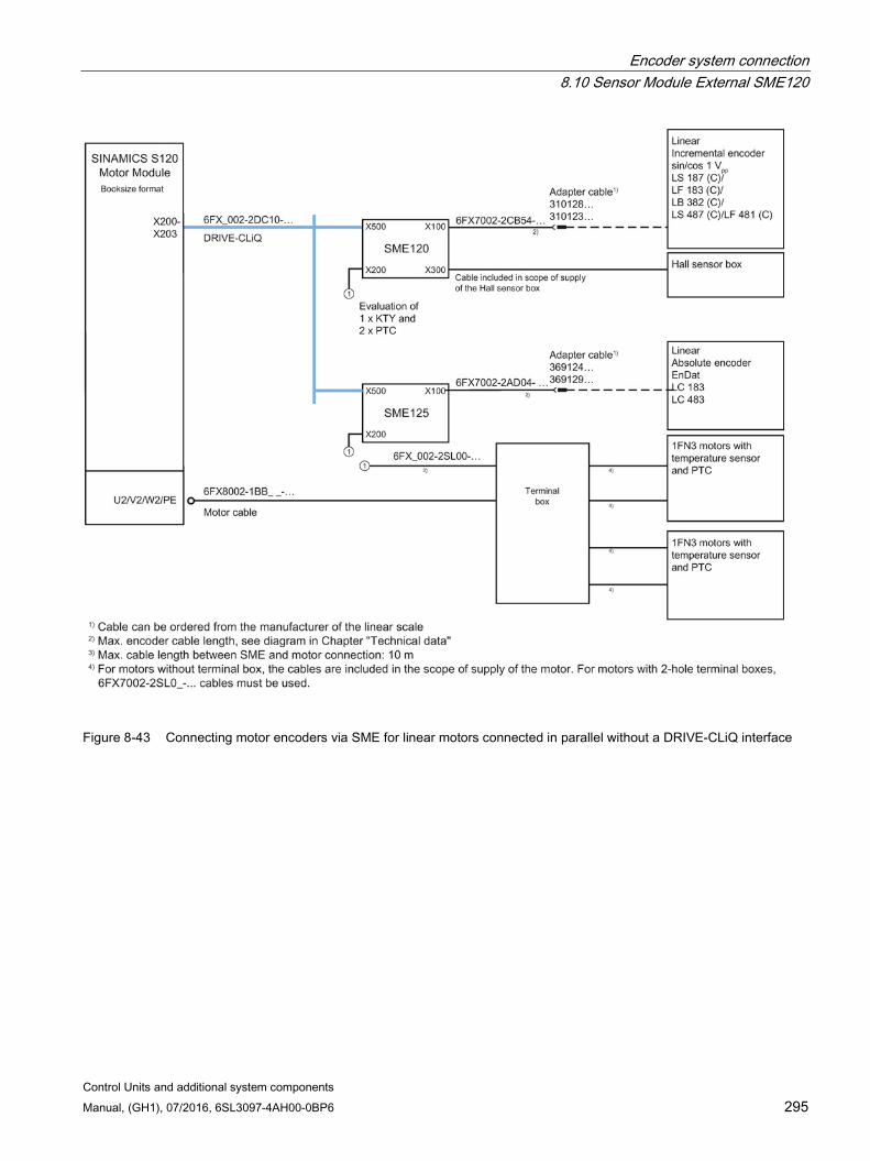
Encoder system connection 8.10 Sensor Module External SME120
Control Units and additional system components Manual, (GH1), 07/2016, 6SL3097-4AH00-0BP6 295
Figure 8-43 Connecting motor encoders via SME for linear motors connected in parallel without a DRIVE-CLiQ interface
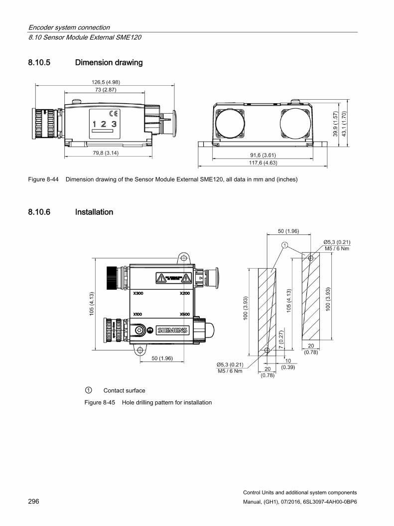
Encoder system connection 8.10 Sensor Module External SME120
Control Units and additional system components 296 Manual, (GH1), 07/2016, 6SL3097-4AH00-0BP6
8.10.5 Dimension drawing
Figure 8-44 Dimension drawing of the Sensor Module External SME120, all data in mm and (inches)
8.10.6 Installation
① Contact surface
Figure 8-45 Hole drilling pattern for installation
Encoder system connection 8.10 Sensor Module External SME120
Control Units and additional system components Manual, (GH1), 07/2016, 6SL3097-4AH00-0BP6 297
Installation 1. Place the drilling pattern on the mounting surface. Make sure that the contact surface is
bare, unpainted metal.
2. Drill two holes with Ø 5.3 or M5 threaded holes according to the drilling pattern.
3. Fix the Sensor Module to the mounting surface. The tightening torque is 6 Nm.
8.10.7 Technical data
Table 8- 37 Technical data
6SL3055-0AA00-5JA Unit Value Electronics power supply Voltage Current (without encoder system) Current (with encoder system) Power loss Max. cable length
VDC ADC ADC W m
24 (20.4 … 28.8) ≤ 0.20 ≤ 0.30 ≤ 4.5 30
Encoder system power supply Voltage Current
VDC ADC
5 0.35
Encoder frequency that can be evaluated (fencoder)
kHz ≤ 500
PE/ground connection At the housing with M4 screw Weight kg 0.7
Note Current controller clock cycle
For a current controller clock cycle of 31.25 µs, an SME120 with article number 6SL3055-0AA00-5JA3 must be used.
Note
In order to guarantee the degree of protection, all of the plug connectors must be correctly screwed into place and appropriately locked.
The maximum cable length for the encoder system interface depends on the current consumption of the encoder system and the cross-section of the wire in the cable. However, the maximum length is 30 m. The figure below applies to encoder systems that operate in the supply voltage range between 4.75 V and 5.25 V. The sample parameters shown are 0.28 mm² cross-section (0.14 mm² supply plus 0.14 mm² Remote Sense wires) and 0.64 mm² (0.5 mm² supply plus 0.14 mm² Remote Sense wires).

Encoder system connection 8.10 Sensor Module External SME120
Control Units and additional system components 298 Manual, (GH1), 07/2016, 6SL3097-4AH00-0BP6
Figure 8-46 Max. cable length as a function of the current drawn by the encoder system
In addition to the encoder systems for the supply voltage range of 4.75 V to 5.25 V in the diagram above, encoder systems are also available for the extended range down to 3.6 V. These are generally operable using encoder system cables up to 30 m in length, provided that the total cross-section of the supply plus Remote Sense wires does not fall below 0.14 mm².
Encoder system connection 8.11 Sensor Module External SME125
Control Units and additional system components Manual, (GH1), 07/2016, 6SL3097-4AH00-0BP6 299
8.11 Sensor Module External SME125
8.11.1 Description Direct encoder systems outside the cabinet can be connected to the Sensor Module External SME125. The SME125 evaluates these encoder systems and converts the calculated values to DRIVE-CLiQ.
The components are always used when the temperature signals of the motors do not have protective separation or where this separation is not possible for certain reasons. SME125 is mainly used in linear motor applications.
Direct encoder systems with EnDat 2.1, EnDat 2.2 article designation 02 or SSI with SIN/COS (1 Vpp) incremental signals can be connected, however without reference signal.
Neither motor nor encoder data are saved in the SME125.
Encoder system connection 8.11 Sensor Module External SME125
Control Units and additional system components 300 Manual, (GH1), 07/2016, 6SL3097-4AH00-0BP6
8.11.2 Safety instructions for Sensor Modules External The safety instructions listed here apply specifically for the Sensor Modules External SME12..
Note
When handling/using a Sensor Module External, you must also observe the safety instructions for Sensor Modules as well as the safety instructions in Chapter 1 (Page 19).
A Sensor Module External SME12. is a device of safety class I.
WARNING
Death or severe injury can occur when an SME12. is incorrectly used and handled.
When an SME12. is incorrectly used and handled, protective devices can be disabled; which means that death or severe injury can occur when touching. • It is mandatory that you connect a protective conductor with a minimum cross-section of
2.5 mm2 in order to guarantee safe electrical separation. • In order to ensure degree of protection IP67, close all connections, even connections
that are not used, with connectors or suitable sealing caps. You must observe the specified torques.
• Before commissioning, always replace the plastic covers of connections X100 to X500 using the corresponding connectors, as otherwise the Sensor Modules External SME12. will not conform with degree of protection IP67.
• Under no circumstances open the Sensor Modules, as this can mean that they are no longer properly sealed! Only a certified SIEMENS service center should carry out repair and maintenance work.
• If it appears that the Sensor Module packaging has been damaged by water, do not commission the Sensor Module.
NOTICE
Damage caused by connecting a grounded encoder system power supply
The devices can be damaged by connecting encoder systems with grounded encoder system power supplies. • Only connect those encoder systems where the power supply is not grounded.
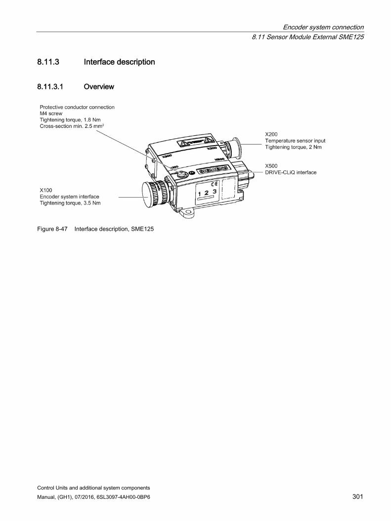
Encoder system connection 8.11 Sensor Module External SME125
Control Units and additional system components Manual, (GH1), 07/2016, 6SL3097-4AH00-0BP6 301
8.11.3 Interface description
8.11.3.1 Overview
Figure 8-47 Interface description, SME125
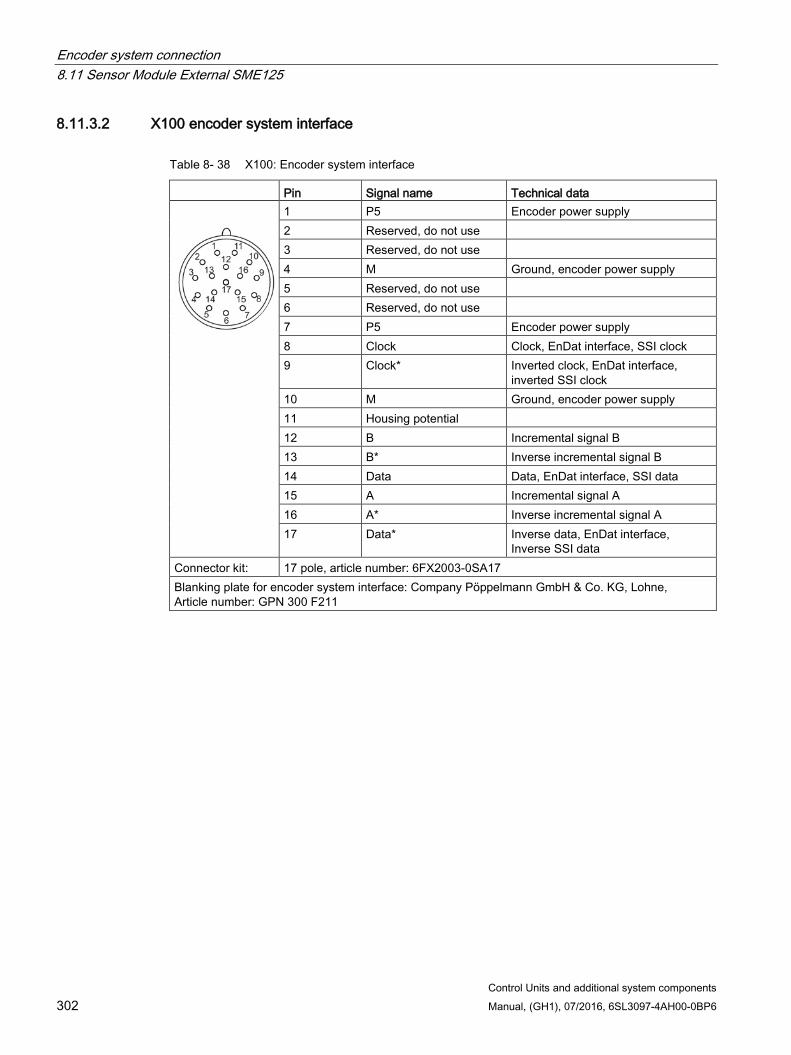
Encoder system connection 8.11 Sensor Module External SME125
Control Units and additional system components 302 Manual, (GH1), 07/2016, 6SL3097-4AH00-0BP6
8.11.3.2 X100 encoder system interface
Table 8- 38 X100: Encoder system interface
Pin Signal name Technical data
1 P5 Encoder power supply 2 Reserved, do not use 3 Reserved, do not use 4 M Ground, encoder power supply 5 Reserved, do not use 6 Reserved, do not use 7 P5 Encoder power supply 8 Clock Clock, EnDat interface, SSI clock 9 Clock* Inverted clock, EnDat interface,
inverted SSI clock 10 M Ground, encoder power supply 11 Housing potential 12 B Incremental signal B 13 B* Inverse incremental signal B 14 Data Data, EnDat interface, SSI data 15 A Incremental signal A 16 A* Inverse incremental signal A 17 Data* Inverse data, EnDat interface,
Inverse SSI data Connector kit: 17 pole, article number: 6FX2003-0SA17 Blanking plate for encoder system interface: Company Pöppelmann GmbH & Co. KG, Lohne, Article number: GPN 300 F211
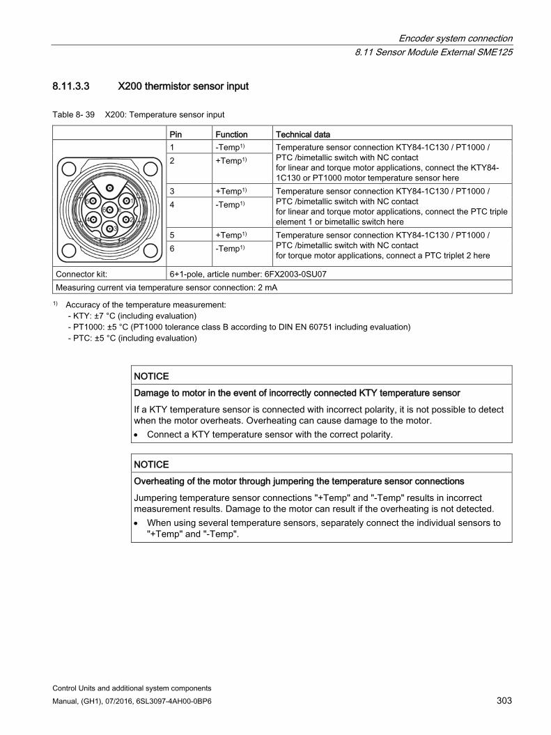
Encoder system connection 8.11 Sensor Module External SME125
Control Units and additional system components Manual, (GH1), 07/2016, 6SL3097-4AH00-0BP6 303
8.11.3.3 X200 thermistor sensor input
Table 8- 39 X200: Temperature sensor input
Pin Function Technical data
1 -Temp1) Temperature sensor connection KTY84-1C130 / PT1000 / PTC /bimetallic switch with NC contact for linear and torque motor applications, connect the KTY84-1C130 or PT1000 motor temperature sensor here
2 +Temp1)
3 +Temp1) Temperature sensor connection KTY84-1C130 / PT1000 / PTC /bimetallic switch with NC contact for linear and torque motor applications, connect the PTC triple element 1 or bimetallic switch here
4 -Temp1)
5 +Temp1) Temperature sensor connection KTY84-1C130 / PT1000 / PTC /bimetallic switch with NC contact for torque motor applications, connect a PTC triplet 2 here
6 -Temp1)
Connector kit: 6+1-pole, article number: 6FX2003-0SU07 Measuring current via temperature sensor connection: 2 mA 1) Accuracy of the temperature measurement:
- KTY: ±7 °C (including evaluation) - PT1000: ±5 °C (PT1000 tolerance class B according to DIN EN 60751 including evaluation) - PTC: ±5 °C (including evaluation)
NOTICE
Damage to motor in the event of incorrectly connected KTY temperature sensor
If a KTY temperature sensor is connected with incorrect polarity, it is not possible to detect when the motor overheats. Overheating can cause damage to the motor. • Connect a KTY temperature sensor with the correct polarity.
NOTICE
Overheating of the motor through jumpering the temperature sensor connections
Jumpering temperature sensor connections "+Temp" and "-Temp" results in incorrect measurement results. Damage to the motor can result if the overheating is not detected. • When using several temperature sensors, separately connect the individual sensors to
"+Temp" and "-Temp".
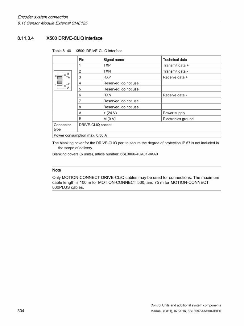
Encoder system connection 8.11 Sensor Module External SME125
Control Units and additional system components 304 Manual, (GH1), 07/2016, 6SL3097-4AH00-0BP6
8.11.3.4 X500 DRIVE-CLiQ interface
Table 8- 40 X500: DRIVE-CLiQ interface
Pin Signal name Technical data
1 TXP Transmit data + 2 TXN Transmit data - 3 RXP Receive data + 4 Reserved, do not use 5 Reserved, do not use 6 RXN Receive data - 7 Reserved, do not use 8 Reserved, do not use A + (24 V) Power supply B M (0 V) Electronics ground
Connector type
DRIVE-CLiQ socket
Power consumption max. 0.30 A The blanking cover for the DRIVE-CLiQ port to secure the degree of protection IP 67 is not included in
the scope of delivery. Blanking covers (6 units), article number: 6SL3066-4CA01-0AA0
Note
Only MOTION-CONNECT DRIVE-CLiQ cables may be used for connections. The maximum cable length is 100 m for MOTION-CONNECT 500, and 75 m for MOTION-CONNECT 800PLUS cables.
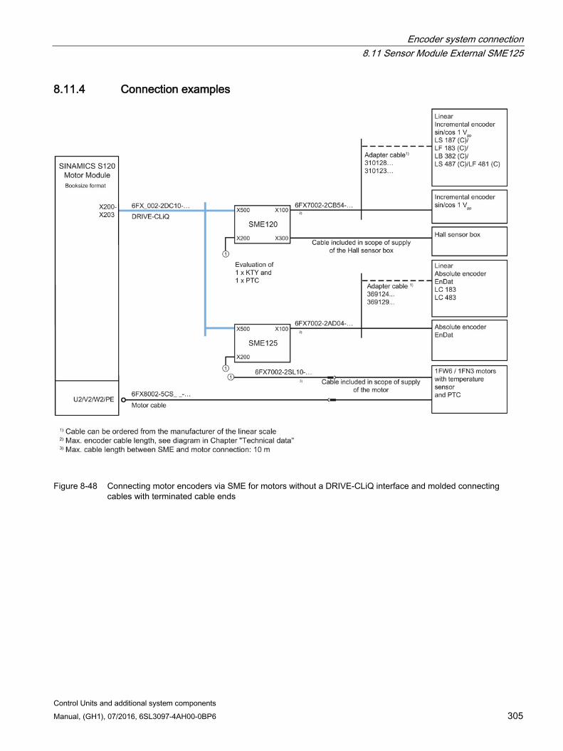
Encoder system connection 8.11 Sensor Module External SME125
Control Units and additional system components Manual, (GH1), 07/2016, 6SL3097-4AH00-0BP6 305
8.11.4 Connection examples
Figure 8-48 Connecting motor encoders via SME for motors without a DRIVE-CLiQ interface and molded connecting
cables with terminated cable ends
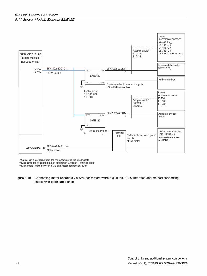
Encoder system connection 8.11 Sensor Module External SME125
Control Units and additional system components 306 Manual, (GH1), 07/2016, 6SL3097-4AH00-0BP6
Figure 8-49 Connecting motor encoders via SME for motors without a DRIVE-CLiQ interface and molded connecting
cables with open cable ends

Encoder system connection 8.11 Sensor Module External SME125
Control Units and additional system components Manual, (GH1), 07/2016, 6SL3097-4AH00-0BP6 307
Figure 8-50 Connecting motor encoders via SME for motors without a DRIVE-CLiQ interface, with an integrated 2-hole
terminal box
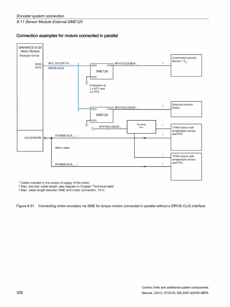
Encoder system connection 8.11 Sensor Module External SME125
Control Units and additional system components 308 Manual, (GH1), 07/2016, 6SL3097-4AH00-0BP6
Connection examples for motors connected in parallel
Figure 8-51 Connecting motor encoders via SME for torque motors connected in parallel without a DRIVE-CLiQ interface

Encoder system connection 8.11 Sensor Module External SME125
Control Units and additional system components Manual, (GH1), 07/2016, 6SL3097-4AH00-0BP6 309
Figure 8-52 Connecting motor encoders via SME for linear motors connected in parallel without a DRIVE-CLiQ interface
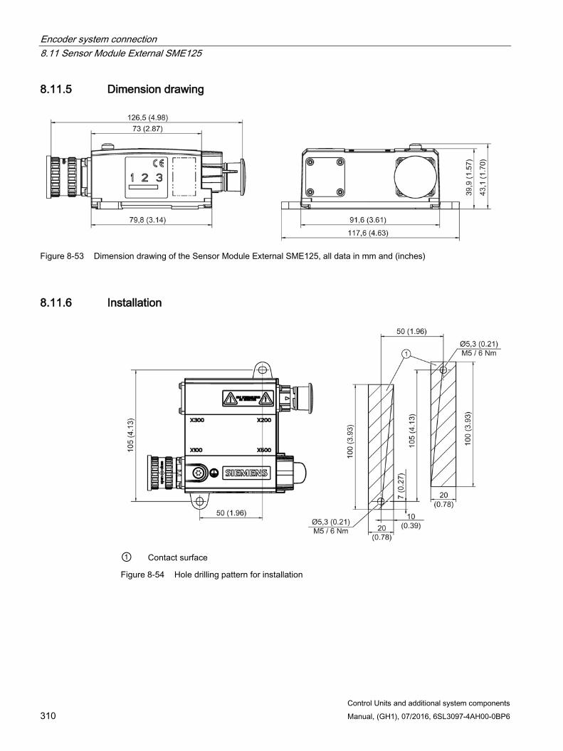
Encoder system connection 8.11 Sensor Module External SME125
Control Units and additional system components 310 Manual, (GH1), 07/2016, 6SL3097-4AH00-0BP6
8.11.5 Dimension drawing
Figure 8-53 Dimension drawing of the Sensor Module External SME125, all data in mm and (inches)
8.11.6 Installation
① Contact surface
Figure 8-54 Hole drilling pattern for installation
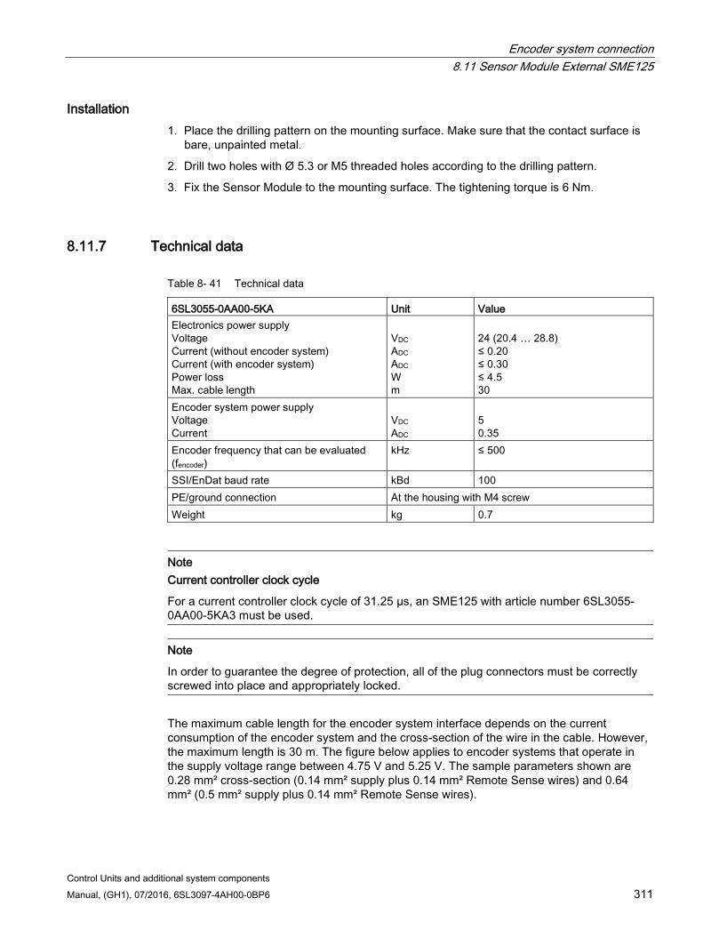
Encoder system connection 8.11 Sensor Module External SME125
Control Units and additional system components Manual, (GH1), 07/2016, 6SL3097-4AH00-0BP6 311
Installation 1. Place the drilling pattern on the mounting surface. Make sure that the contact surface is
bare, unpainted metal.
2. Drill two holes with Ø 5.3 or M5 threaded holes according to the drilling pattern.
3. Fix the Sensor Module to the mounting surface. The tightening torque is 6 Nm.
8.11.7 Technical data
Table 8- 41 Technical data
6SL3055-0AA00-5KA Unit Value Electronics power supply Voltage Current (without encoder system) Current (with encoder system) Power loss Max. cable length
VDC ADC ADC W m
24 (20.4 … 28.8) ≤ 0.20 ≤ 0.30 ≤ 4.5 30
Encoder system power supply Voltage Current
VDC ADC
5 0.35
Encoder frequency that can be evaluated (fencoder)
kHz ≤ 500
SSI/EnDat baud rate kBd 100 PE/ground connection At the housing with M4 screw Weight kg 0.7
Note Current controller clock cycle
For a current controller clock cycle of 31.25 µs, an SME125 with article number 6SL3055-0AA00-5KA3 must be used.
Note
In order to guarantee the degree of protection, all of the plug connectors must be correctly screwed into place and appropriately locked.
The maximum cable length for the encoder system interface depends on the current consumption of the encoder system and the cross-section of the wire in the cable. However, the maximum length is 30 m. The figure below applies to encoder systems that operate in the supply voltage range between 4.75 V and 5.25 V. The sample parameters shown are 0.28 mm² cross-section (0.14 mm² supply plus 0.14 mm² Remote Sense wires) and 0.64 mm² (0.5 mm² supply plus 0.14 mm² Remote Sense wires).
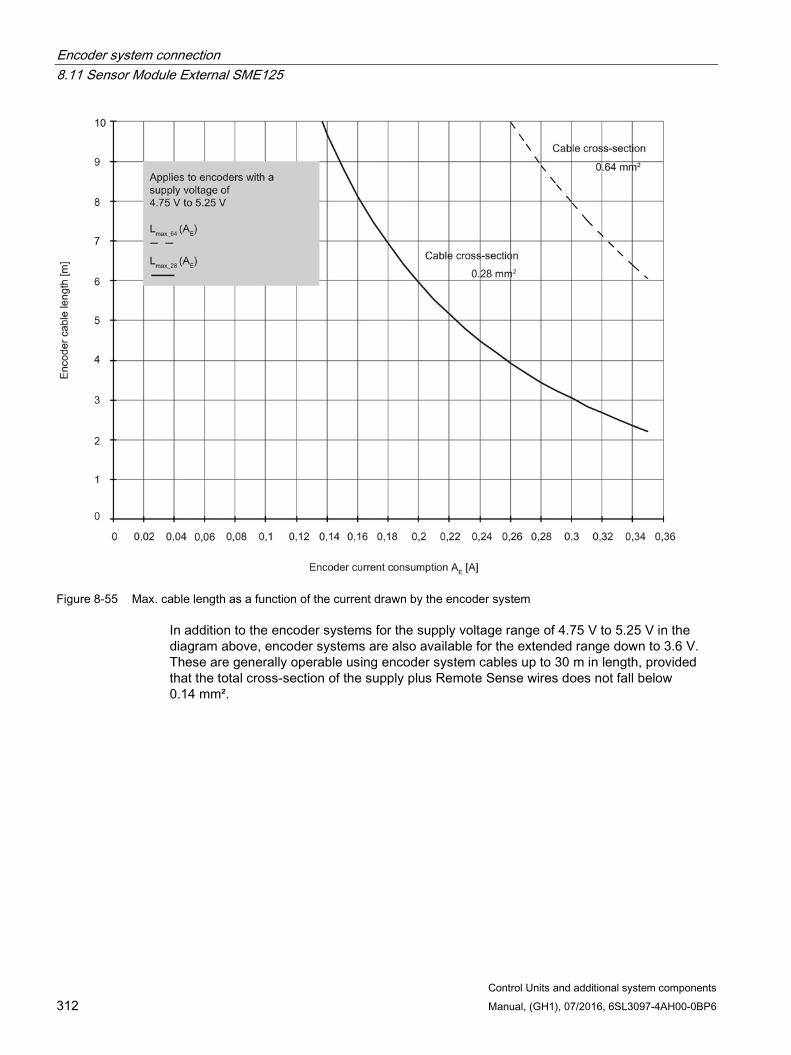
Encoder system connection 8.11 Sensor Module External SME125
Control Units and additional system components 312 Manual, (GH1), 07/2016, 6SL3097-4AH00-0BP6
Figure 8-55 Max. cable length as a function of the current drawn by the encoder system
In addition to the encoder systems for the supply voltage range of 4.75 V to 5.25 V in the diagram above, encoder systems are also available for the extended range down to 3.6 V. These are generally operable using encoder system cables up to 30 m in length, provided that the total cross-section of the supply plus Remote Sense wires does not fall below 0.14 mm².
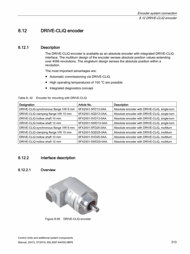
Encoder system connection 8.12 DRIVE-CLiQ encoder
Control Units and additional system components Manual, (GH1), 07/2016, 6SL3097-4AH00-0BP6 313
8.12 DRIVE-CLiQ encoder
8.12.1 Description The DRIVE-CLiQ encoder is available as an absolute encoder with integrated DRIVE-CLiQ interface. The multiturn design of the encoder senses absolute position values extending over 4096 revolutions. The singleturn design senses the absolute position within a revolution.
The most important advantages are:
Automatic commissioning via DRIVE-CLiQ
High operating temperatures of 100 °C are possible
Integrated diagnostics concept
Table 8- 42 Encoder for mounting with DRIVE-CLiQ
Designation Article No. Description DRIVE-CLiQ synchronous flange VW 6 mm 6FX2001-5FD13-0AA. Absolute encoder with DRIVE-CLiQ, single-turn DRIVE-CLiQ clamping flange VW 10 mm 6FX2001-5QD13-0AA. Absolute encoder with DRIVE-CLiQ, single-turn DRIVE-CLiQ hollow shaft 10 mm 6FX2001-5VD13-0AA. Absolute encoder with DRIVE-CLiQ, single-turn DRIVE-CLiQ hollow shaft 12 mm 6FX2001-5WD13-0AA. Absolute encoder with DRIVE-CLiQ, single-turn DRIVE-CLiQ synchronous flange VW 6 mm 6FX2001-5FD25-0AA. Absolute encoder with DRIVE-CLiQ, multiturn DRIVE-CLiQ clamping flange VW 10 mm 6FX2001-5QD25-0AA. Absolute encoder with DRIVE-CLiQ, multiturn DRIVE-CLiQ hollow shaft 10 mm 6FX2001-5VD25-0AA. Absolute encoder with DRIVE-CLiQ, multiturn DRIVE-CLiQ hollow shaft 12 mm 6FX2001-5WD25-0AA. Absolute encoder with DRIVE-CLiQ, multiturn
8.12.2 Interface description
8.12.2.1 Overview
Figure 8-56 DRIVE-CLiQ encoder
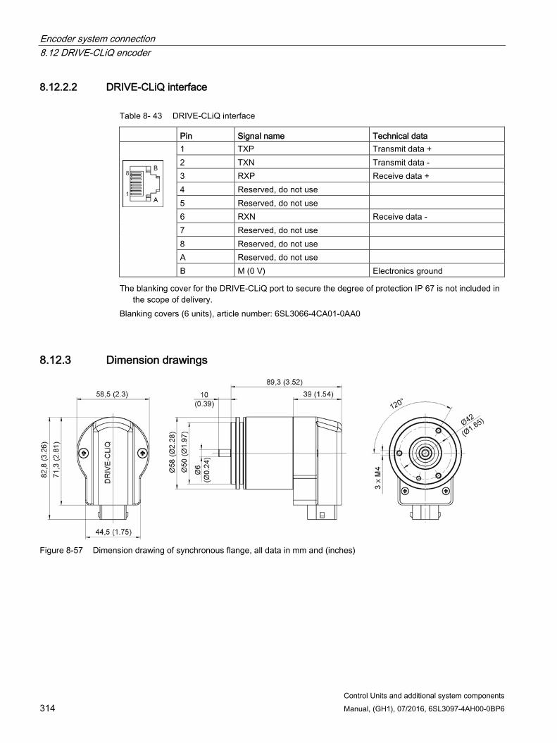
Encoder system connection 8.12 DRIVE-CLiQ encoder
Control Units and additional system components 314 Manual, (GH1), 07/2016, 6SL3097-4AH00-0BP6
8.12.2.2 DRIVE-CLiQ interface
Table 8- 43 DRIVE-CLiQ interface
Pin Signal name Technical data
1 TXP Transmit data + 2 TXN Transmit data - 3 RXP Receive data + 4 Reserved, do not use 5 Reserved, do not use 6 RXN Receive data - 7 Reserved, do not use 8 Reserved, do not use A Reserved, do not use B M (0 V) Electronics ground
The blanking cover for the DRIVE-CLiQ port to secure the degree of protection IP 67 is not included in the scope of delivery.
Blanking covers (6 units), article number: 6SL3066-4CA01-0AA0
8.12.3 Dimension drawings
Figure 8-57 Dimension drawing of synchronous flange, all data in mm and (inches)
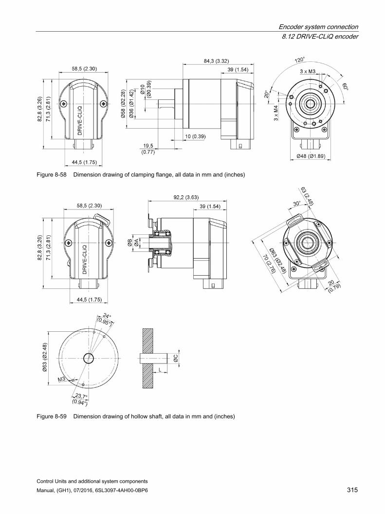
Encoder system connection 8.12 DRIVE-CLiQ encoder
Control Units and additional system components Manual, (GH1), 07/2016, 6SL3097-4AH00-0BP6 315
Figure 8-58 Dimension drawing of clamping flange, all data in mm and (inches)
Figure 8-59 Dimension drawing of hollow shaft, all data in mm and (inches)
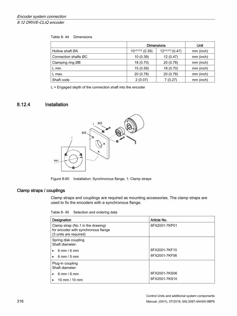
Encoder system connection 8.12 DRIVE-CLiQ encoder
Control Units and additional system components 316 Manual, (GH1), 07/2016, 6SL3097-4AH00-0BP6
Table 8- 44 Dimensions
Dimensions Unit Hollow shaft ØA 10+0.012 (0.39) 12+0.012 (0.47) mm (inch) Connection shafts ØC 10 (0.39) 12 (0.47) mm (inch) Clamping ring ØB 18 (0.70) 20 (0.78) mm (inch) L min. 15 (0.59) 18 (0.70) mm (inch) L max. 20 (0.78) 20 (0.78) mm (inch) Shaft code 2 (0.07) 7 (0.27) mm (inch) L = Engaged depth of the connection shaft into the encoder
8.12.4 Installation
Figure 8-60 Installation: Synchronous flange, 1: Clamp straps
Clamp straps / couplings Clamp straps and couplings are required as mounting accessories. The clamp straps are used to fix the encoders with a synchronous flange.
Table 8- 45 Selection and ordering data
Designation Article No. Clamp strap (No.1 in the drawing) for encoder with synchronous flange (3 units are required)
6FX2001-7KP01
Spring disk coupling Shaft diameter: • 6 mm / 6 mm • 6 mm / 5 mm
6FX2001-7KF10 6FX2001-7KF06
Plug-in coupling Shaft diameter: • 6 mm / 6 mm • 10 mm / 10 mm
6FX2001-7KS06 6FX2001-7KS10
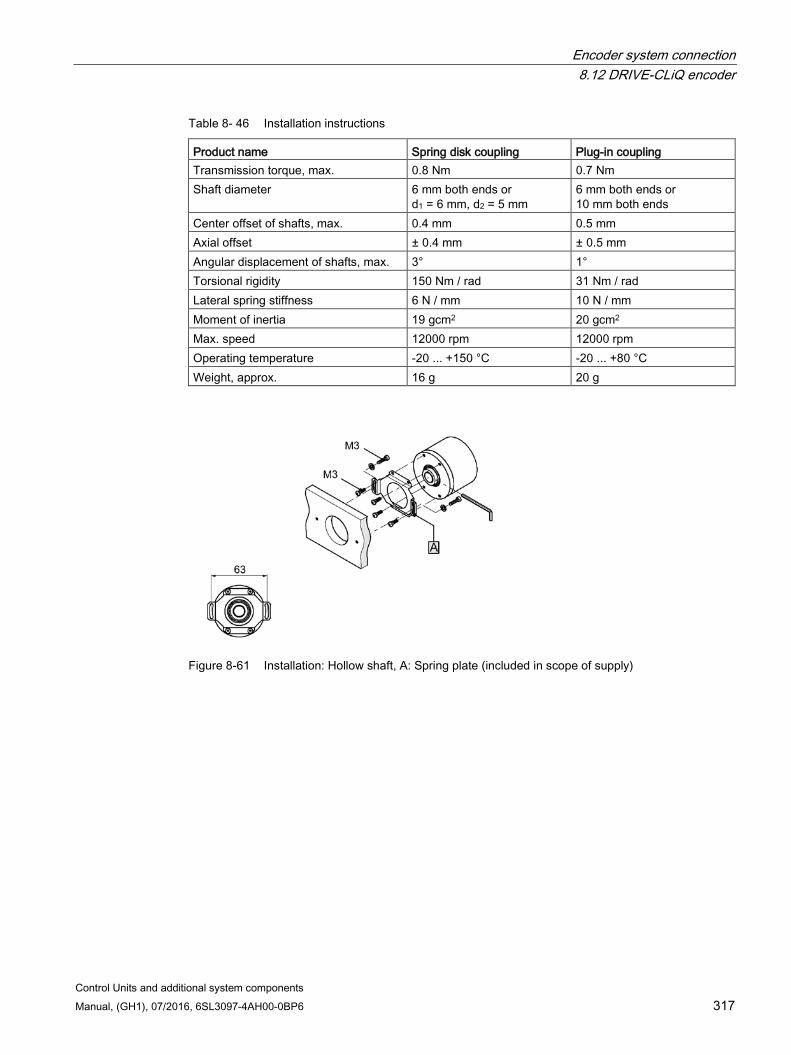
Encoder system connection 8.12 DRIVE-CLiQ encoder
Control Units and additional system components Manual, (GH1), 07/2016, 6SL3097-4AH00-0BP6 317
Table 8- 46 Installation instructions
Product name Spring disk coupling Plug-in coupling Transmission torque, max. 0.8 Nm 0.7 Nm Shaft diameter 6 mm both ends or
d1 = 6 mm, d2 = 5 mm 6 mm both ends or 10 mm both ends
Center offset of shafts, max. 0.4 mm 0.5 mm Axial offset ± 0.4 mm ± 0.5 mm Angular displacement of shafts, max. 3° 1° Torsional rigidity 150 Nm / rad 31 Nm / rad Lateral spring stiffness 6 N / mm 10 N / mm Moment of inertia 19 gcm2 20 gcm2 Max. speed 12000 rpm 12000 rpm Operating temperature -20 ... +150 °C -20 ... +80 °C Weight, approx. 16 g 20 g
Figure 8-61 Installation: Hollow shaft, A: Spring plate (included in scope of supply)
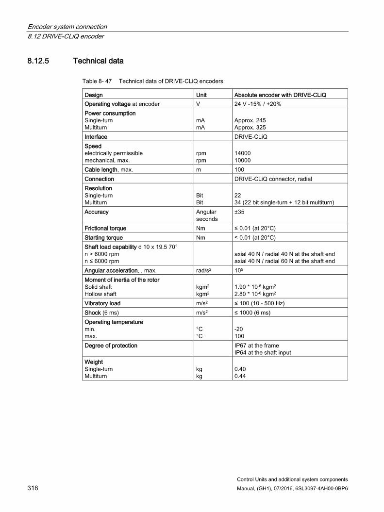
Encoder system connection 8.12 DRIVE-CLiQ encoder
Control Units and additional system components 318 Manual, (GH1), 07/2016, 6SL3097-4AH00-0BP6
8.12.5 Technical data
Table 8- 47 Technical data of DRIVE-CLiQ encoders
Design Unit Absolute encoder with DRIVE-CLiQ Operating voltage at encoder V 24 V -15% / +20% Power consumption Single-turn Multiturn
mA mA
Approx. 245 Approx. 325
Interface DRIVE-CLiQ Speed electrically permissible mechanical, max.
rpm
rpm
14000 10000
Cable length, max. m 100 Connection DRIVE-CLiQ connector, radial Resolution Single-turn Multiturn
Bit Bit
22 34 (22 bit single-turn + 12 bit multiturn)
Accuracy Angular seconds
±35
Frictional torque Nm ≤ 0.01 (at 20°C) Starting torque Nm ≤ 0.01 (at 20°C) Shaft load capability d 10 x 19.5 70° n > 6000 rpm n ≤ 6000 rpm
axial 40 N / radial 40 N at the shaft end axial 40 N / radial 60 N at the shaft end
Angular acceleration, , max. rad/s2 105 Moment of inertia of the rotor Solid shaft Hollow shaft
kgm2
kgm2
1.90 * 10-6 kgm2 2.80 * 10-6 kgm2
Vibratory load m/s2 ≤ 100 (10 - 500 Hz) Shock (6 ms) m/s2 ≤ 1000 (6 ms) Operating temperature min. max.
°C °C
-20 100
Degree of protection IP67 at the frame IP64 at the shaft input
Weight Single-turn Multiturn
kg kg
0.40 0.44

Control Units and additional system components Manual, (GH1), 07/2016, 6SL3097-4AH00-0BP6 319
Cabinet design and electromagnetic compatibility (EMC) 9 9.1 Tightening torques for screws and screw connections
For screws and screw connections of components that are described in this manual, the following tightening torques apply:
Table 9- 1 Tightening torques for ground connections, protective conductor screw connections and control cabinet installation
Thread Tightening torque in Nm M3 0.8 Nm M4 1.8 Nm M5 3.0 Nm M6 6.0 Nm M8 13.0 Nm M10 25.0 Nm Tolerance ––> 0 to +30 %
Deviating tightening torques
For screw terminals on components and for mounting individual components in the control cabinet, the following deviating tightening torques apply. The corresponding data are described in the following chapters:
Installation for SME20 (Page 278), SME25 (Page 283), SME120 (Page 296) and SME125 (Page 310)
Screw terminals (Page 331)
Cabinet design and electromagnetic compatibility (EMC) 9.2 Information on control cabinet installation and EMC
Control Units and additional system components 320 Manual, (GH1), 07/2016, 6SL3097-4AH00-0BP6
9.2 Information on control cabinet installation and EMC Information on control cabinet installation and electromagnetic compatibility (EMC), as well as on overcurrent and overvoltage protection, can be found in the following references:
Components in the booksize format: Reference: /GH2/ SINAMICS S120 Manual for Booksize Power Units
Components in the blocksize format: Reference: /GH6/ SINAMICS S120 Manual AC Drive
Components in the chassis format: Reference: /GH3/ SINAMICS S120 Manual Air-Cooled Chassis Power Units Reference: /GH7/ SINAMICS S120 Manual Liquid-Cooled Chassis Power Units
Requirements to implement EMC: Reference: /PH1/ Installation Guideline Configuration Manual / Basic system requirements (Article number 6FC5297-0AD30-0.P.)
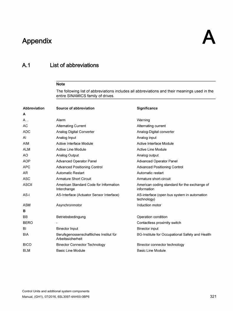
Control Units and additional system components Manual, (GH1), 07/2016, 6SL3097-4AH00-0BP6 321
Appendix A A.1 List of abbreviations
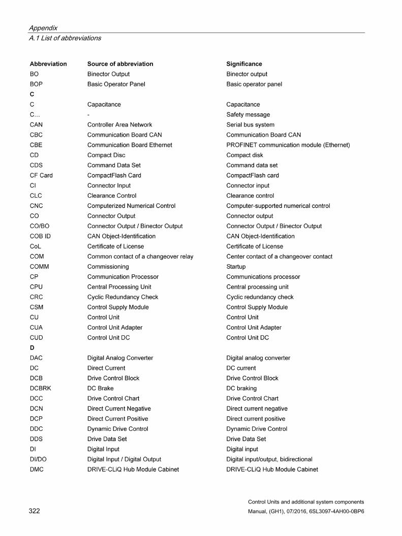
Appendix A.1 List of abbreviations
Control Units and additional system components 322 Manual, (GH1), 07/2016, 6SL3097-4AH00-0BP6
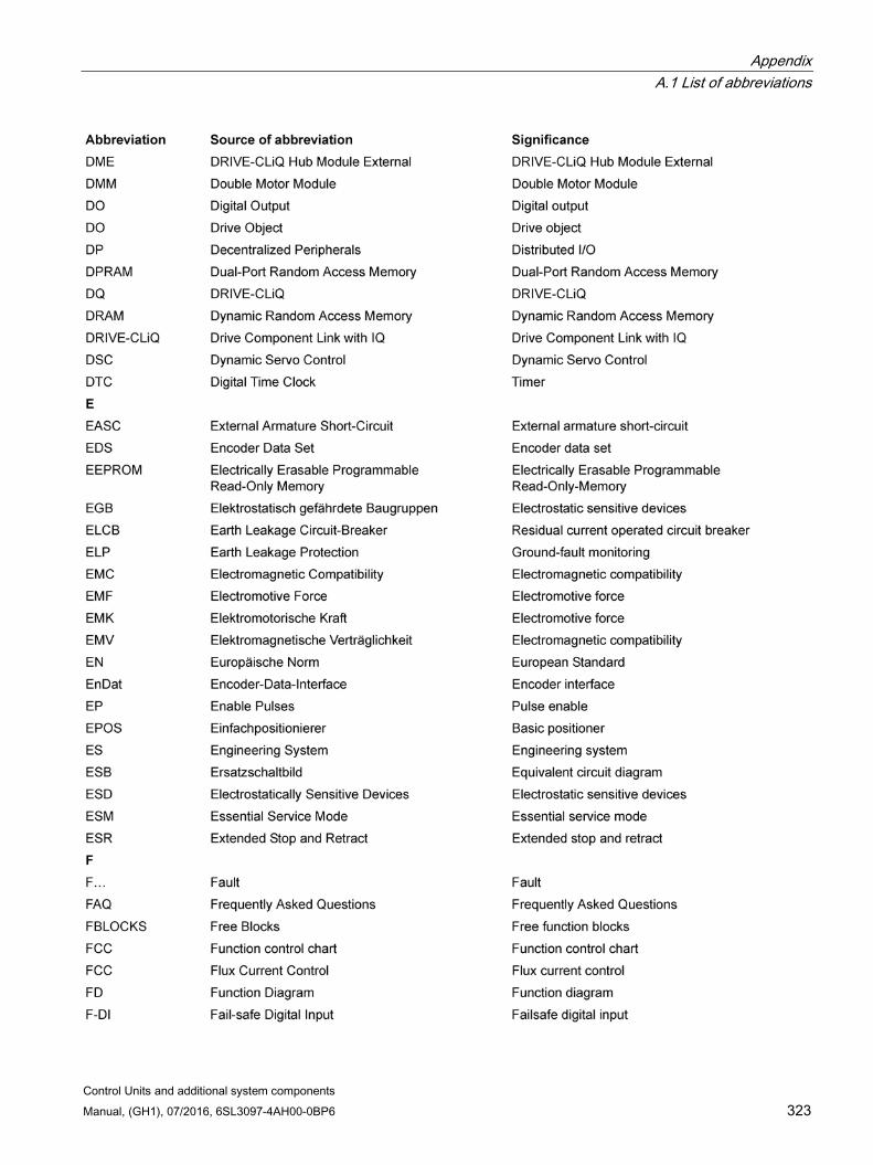
Appendix A.1 List of abbreviations
Control Units and additional system components Manual, (GH1), 07/2016, 6SL3097-4AH00-0BP6 323
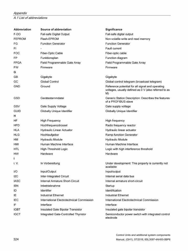
Appendix A.1 List of abbreviations
Control Units and additional system components 324 Manual, (GH1), 07/2016, 6SL3097-4AH00-0BP6
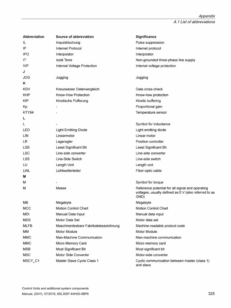
Appendix A.1 List of abbreviations
Control Units and additional system components Manual, (GH1), 07/2016, 6SL3097-4AH00-0BP6 325
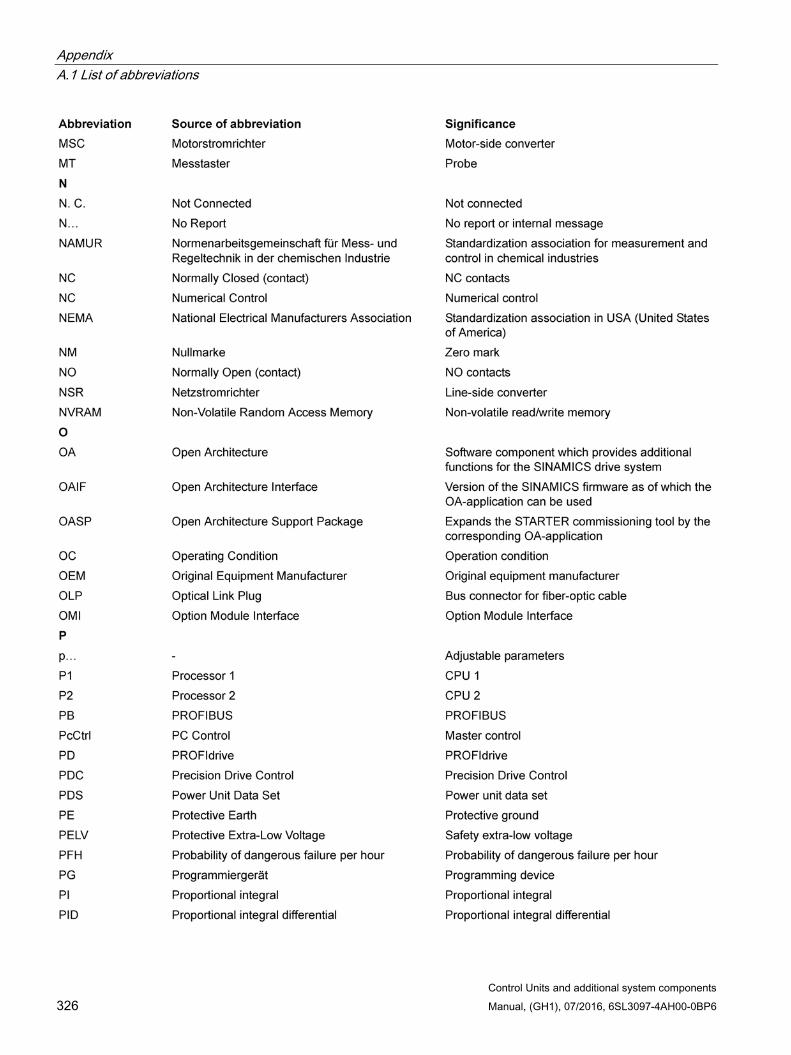
Appendix A.1 List of abbreviations
Control Units and additional system components 326 Manual, (GH1), 07/2016, 6SL3097-4AH00-0BP6
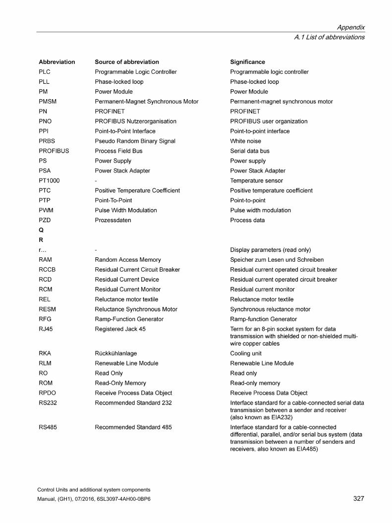
Appendix A.1 List of abbreviations
Control Units and additional system components Manual, (GH1), 07/2016, 6SL3097-4AH00-0BP6 327

Appendix A.1 List of abbreviations
Control Units and additional system components 328 Manual, (GH1), 07/2016, 6SL3097-4AH00-0BP6
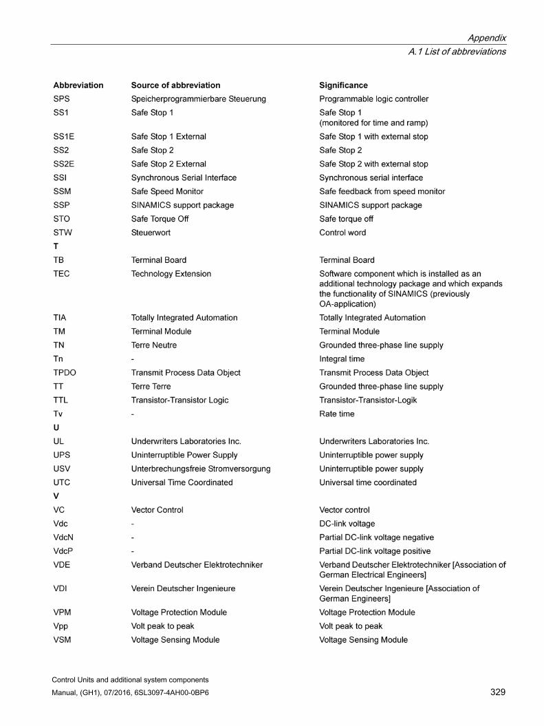
Appendix A.1 List of abbreviations
Control Units and additional system components Manual, (GH1), 07/2016, 6SL3097-4AH00-0BP6 329
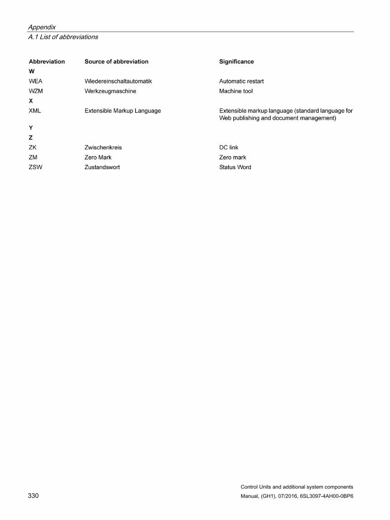
Appendix A.1 List of abbreviations
Control Units and additional system components 330 Manual, (GH1), 07/2016, 6SL3097-4AH00-0BP6

Appendix A.2 Spring-loaded terminals
Control Units and additional system components Manual, (GH1), 07/2016, 6SL3097-4AH00-0BP6 331
A.2 Spring-loaded terminals The type of spring-loaded terminal can be taken from the interface description of the particular component.
Table A- 1 Connectable conductor cross-sections for spring-loaded terminals
Spring-loaded terminal type 1 Connectable cable cross-
sections Rigid Flexible Flexible with end sleeve without plastic sleeve AWG/kcmil
0.14 … 0.5 mm2 0.14 … 0.5 mm2
0.25 … 0.5 mm2
26 … 20 Stripped length 8 mm
2 Connectable cable cross-sections
Flexible 0.08 … 2.5 mm2
Stripped length 8 … 9 mm 3 Connectable cable cross-
sections Rigid Flexible Flexible with end sleeve without plastic sleeve Flexible with end sleeve with plastic sleeve AWG/kcmil
0.2 … 1.5 mm2 0.2 … 1.5 mm2
0.25 … 1.5 mm2
0.25 … 0.75 mm2
24 … 16 Stripped length 10 mm
4 Connectable cable cross-sections
AWG
25 … 95 mm2 4 … 4/0
Stripped length 35 mm 5 Connectable cable cross-
sections Rigid Flexible Flexible with end sleeve without plastic sleeve Flexible with end sleeve with plastic sleeve AWG/kcmil
0.2 … 10 mm2 0.2 … 6 mm2
0.25 … 6 mm2
0.25 … 4 mm2
24 … 8 Stripped length 15 mm
A.3 Screw terminals The type of screw terminal can be taken from the interface description of the particular component.
Table A- 2 Connectable conductor cross-sections and tightening torques for screw terminals
Screw terminal type 1 Connectable cable cross-
sections Rigid, flexible With end sleeve, without plastic sleeve With end sleeve, with plastic sleeve
0.08 … 1.5 mm2
0.25 … 1.5 mm2
0.25 … 0.5 mm2 Stripped length 7 mm Tool Screwdriver 0.4 x 2.0 mm Tightening torque 0.22 … 0.25 Nm
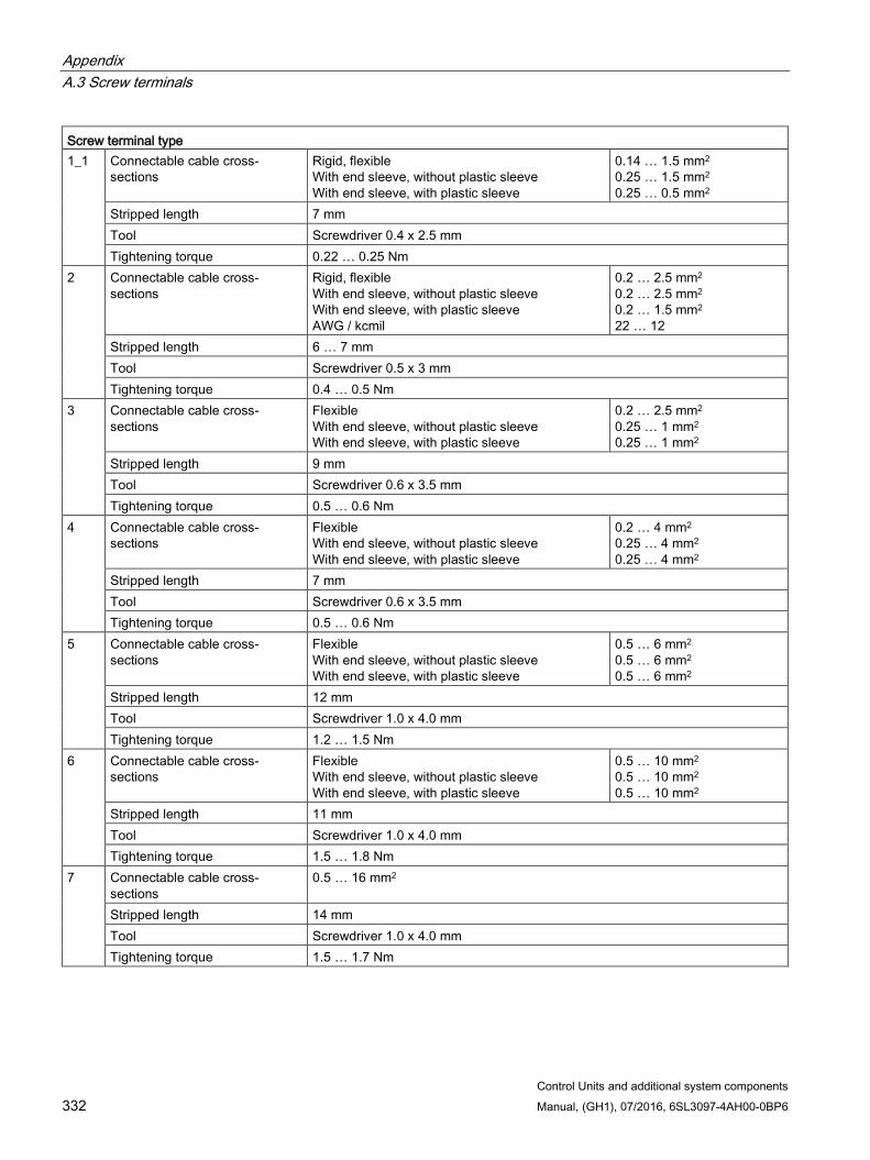
Appendix A.3 Screw terminals
Control Units and additional system components 332 Manual, (GH1), 07/2016, 6SL3097-4AH00-0BP6
Screw terminal type 1_1 Connectable cable cross-
sections Rigid, flexible With end sleeve, without plastic sleeve With end sleeve, with plastic sleeve
0.14 … 1.5 mm2
0.25 … 1.5 mm2
0.25 … 0.5 mm2 Stripped length 7 mm Tool Screwdriver 0.4 x 2.5 mm Tightening torque 0.22 … 0.25 Nm
2 Connectable cable cross-sections
Rigid, flexible With end sleeve, without plastic sleeve With end sleeve, with plastic sleeve AWG / kcmil
0.2 … 2.5 mm2
0.2 … 2.5 mm2
0.2 … 1.5 mm2
22 … 12 Stripped length 6 … 7 mm Tool Screwdriver 0.5 x 3 mm Tightening torque 0.4 … 0.5 Nm
3 Connectable cable cross-sections
Flexible With end sleeve, without plastic sleeve With end sleeve, with plastic sleeve
0.2 … 2.5 mm2 0.25 … 1 mm2 0.25 … 1 mm2
Stripped length 9 mm Tool Screwdriver 0.6 x 3.5 mm Tightening torque 0.5 … 0.6 Nm
4 Connectable cable cross-sections
Flexible With end sleeve, without plastic sleeve With end sleeve, with plastic sleeve
0.2 … 4 mm2
0.25 … 4 mm2
0.25 … 4 mm2 Stripped length 7 mm Tool Screwdriver 0.6 x 3.5 mm Tightening torque 0.5 … 0.6 Nm
5 Connectable cable cross-sections
Flexible With end sleeve, without plastic sleeve With end sleeve, with plastic sleeve
0.5 … 6 mm2
0.5 … 6 mm2
0.5 … 6 mm2 Stripped length 12 mm Tool Screwdriver 1.0 x 4.0 mm Tightening torque 1.2 … 1.5 Nm
6 Connectable cable cross-sections
Flexible With end sleeve, without plastic sleeve With end sleeve, with plastic sleeve
0.5 … 10 mm2
0.5 … 10 mm2
0.5 … 10 mm2 Stripped length 11 mm Tool Screwdriver 1.0 x 4.0 mm Tightening torque 1.5 … 1.8 Nm
7 Connectable cable cross-sections
0.5 … 16 mm2
Stripped length 14 mm Tool Screwdriver 1.0 x 4.0 mm Tightening torque 1.5 … 1.7 Nm
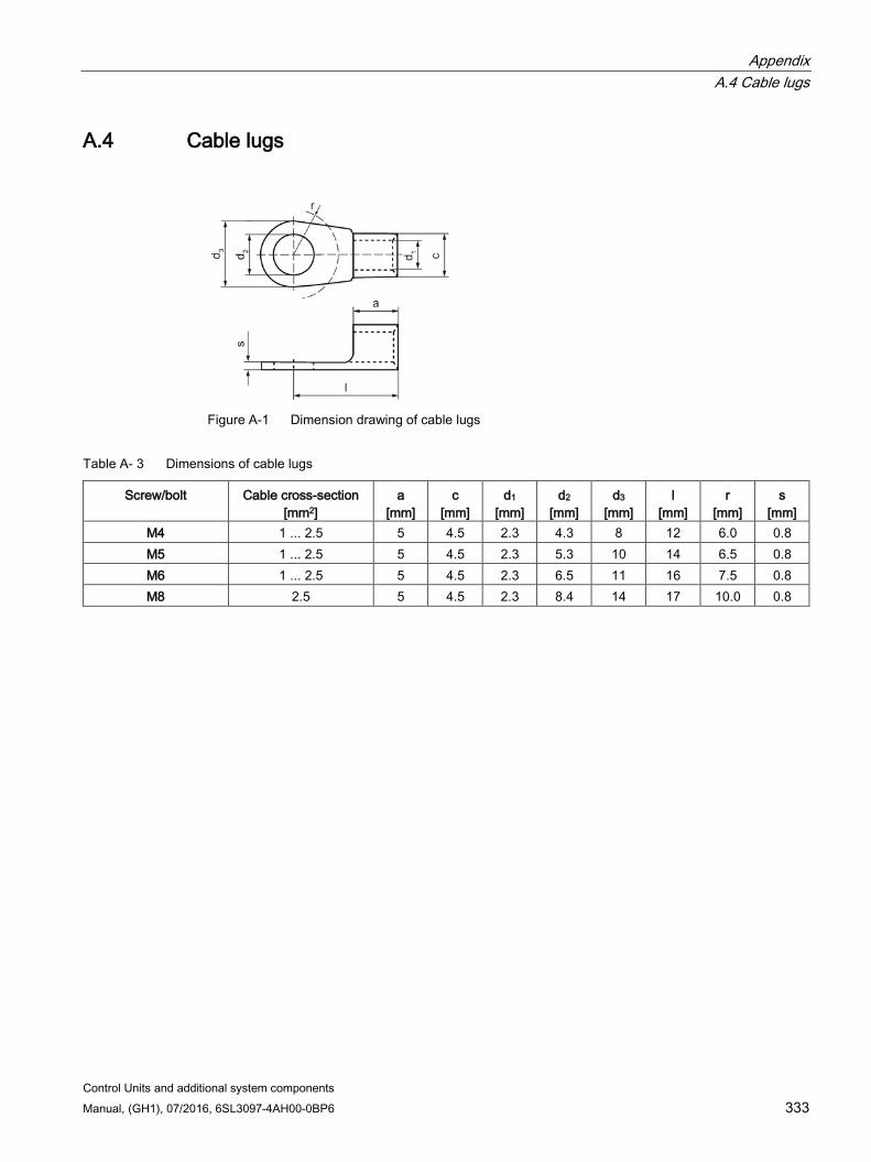
Appendix A.4 Cable lugs
Control Units and additional system components Manual, (GH1), 07/2016, 6SL3097-4AH00-0BP6 333
A.4 Cable lugs
Figure A-1 Dimension drawing of cable lugs
Table A- 3 Dimensions of cable lugs
Screw/bolt Cable cross-section [mm2]
a [mm]
c [mm]
d1
[mm] d2
[mm] d3
[mm] l
[mm] r
[mm] s
[mm] M4 1 ... 2.5 5 4.5 2.3 4.3 8 12 6.0 0.8 M5 1 ... 2.5 5 4.5 2.3 5.3 10 14 6.5 0.8 M6 1 ... 2.5 5 4.5 2.3 6.5 11 16 7.5 0.8 M8 2.5 5 4.5 2.3 8.4 14 17 10.0 0.8
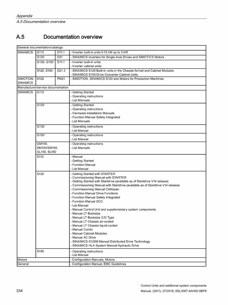
Appendix A.5 Documentation overview
Control Units and additional system components 334 Manual, (GH1), 07/2016, 6SL3097-4AH00-0BP6
A.5 Documentation overview
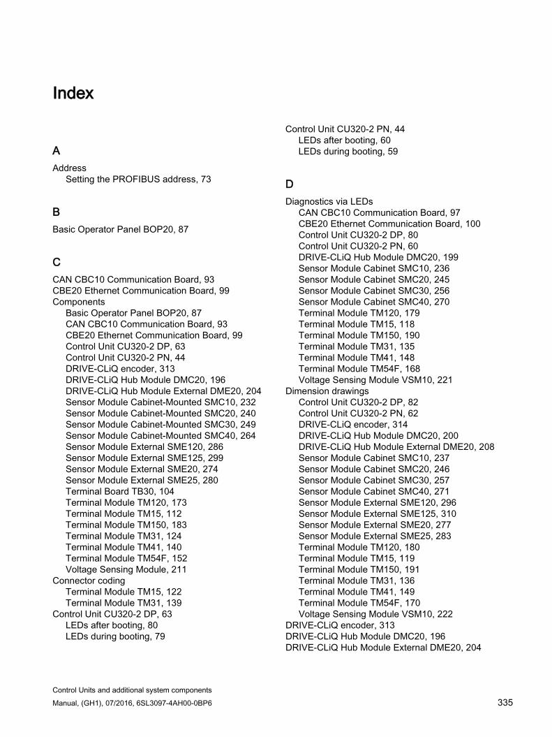
Control Units and additional system components Manual, (GH1), 07/2016, 6SL3097-4AH00-0BP6 335
Index
A Address
Setting the PROFIBUS address, 73
B Basic Operator Panel BOP20, 87
C CAN CBC10 Communication Board, 93 CBE20 Ethernet Communication Board, 99 Components
Basic Operator Panel BOP20, 87 CAN CBC10 Communication Board, 93 CBE20 Ethernet Communication Board, 99 Control Unit CU320-2 DP, 63 Control Unit CU320-2 PN, 44 DRIVE-CLiQ encoder, 313 DRIVE-CLiQ Hub Module DMC20, 196 DRIVE-CLiQ Hub Module External DME20, 204 Sensor Module Cabinet-Mounted SMC10, 232 Sensor Module Cabinet-Mounted SMC20, 240 Sensor Module Cabinet-Mounted SMC30, 249 Sensor Module Cabinet-Mounted SMC40, 264 Sensor Module External SME120, 286 Sensor Module External SME125, 299 Sensor Module External SME20, 274 Sensor Module External SME25, 280 Terminal Board TB30, 104 Terminal Module TM120, 173 Terminal Module TM15, 112 Terminal Module TM150, 183 Terminal Module TM31, 124 Terminal Module TM41, 140 Terminal Module TM54F, 152 Voltage Sensing Module, 211
Connector coding Terminal Module TM15, 122 Terminal Module TM31, 139
Control Unit CU320-2 DP, 63 LEDs after booting, 80 LEDs during booting, 79
Control Unit CU320-2 PN, 44 LEDs after booting, 60 LEDs during booting, 59
D Diagnostics via LEDs
CAN CBC10 Communication Board, 97 CBE20 Ethernet Communication Board, 100 Control Unit CU320-2 DP, 80 Control Unit CU320-2 PN, 60 DRIVE-CLiQ Hub Module DMC20, 199 Sensor Module Cabinet SMC10, 236 Sensor Module Cabinet SMC20, 245 Sensor Module Cabinet SMC30, 256 Sensor Module Cabinet SMC40, 270 Terminal Module TM120, 179 Terminal Module TM15, 118 Terminal Module TM150, 190 Terminal Module TM31, 135 Terminal Module TM41, 148 Terminal Module TM54F, 168 Voltage Sensing Module VSM10, 221
Dimension drawings Control Unit CU320-2 DP, 82 Control Unit CU320-2 PN, 62 DRIVE-CLiQ encoder, 314 DRIVE-CLiQ Hub Module DMC20, 200 DRIVE-CLiQ Hub Module External DME20, 208 Sensor Module Cabinet SMC10, 237 Sensor Module Cabinet SMC20, 246 Sensor Module Cabinet SMC30, 257 Sensor Module Cabinet SMC40, 271 Sensor Module External SME120, 296 Sensor Module External SME125, 310 Sensor Module External SME20, 277 Sensor Module External SME25, 283 Terminal Module TM120, 180 Terminal Module TM15, 119 Terminal Module TM150, 191 Terminal Module TM31, 136 Terminal Module TM41, 149 Terminal Module TM54F, 170 Voltage Sensing Module VSM10, 222
DRIVE-CLiQ encoder, 313 DRIVE-CLiQ Hub Module DMC20, 196 DRIVE-CLiQ Hub Module External DME20, 204

Index
Control Units and additional system components 336 Manual, (GH1), 07/2016, 6SL3097-4AH00-0BP6
F Field of application, 27
I Installation
Basic Operator Panel BOP20, 90 CBE20 Ethernet Communication Board, 103 Communication Board CBC10, 98 Control Unit CU320-2 DP/PN, 83 DRIVE-CLiQ encoder, 316 DRIVE-CLiQ Hub Module DMC20, 201 Sensor Module Cabinet, 238, 247, 258 Sensor Module External SME120, 296 Sensor Module External SME125, 310 Sensor Module External SME20/SME25, 278, 284 Sensor Modules Cabinet SMC40, 272 Terminal Board TB30, 109 Terminal Module TM120, 181 Terminal Module TM150, 192 Terminal Modules, 137, 150, 171 Voltage Sensing Module VSM10, 223
Interface descriptions Basic Operator Panel BOP20, 87 CAN CBC10 Communication Board, 94 CBE20 Ethernet Communication Board, 99 Control Unit CU320-2 DP, 64 Control Unit CU320-2 PN, 45 DRIVE-CLiQ Hub Module DMC20, 197 DRIVE-CLiQ Hub Module External DME20, 205 Sensor Module Cabinet SMC10, 232 Sensor Module Cabinet SMC20, 241 Sensor Module Cabinet SMC30, 249 Sensor Module Cabinet SMC40, 265 Sensor Module External SME120, 288 Sensor Module External SME125, 301 Sensor Module External SME20, 274 Sensor Module External SME25, 280 Terminal Board TB30, 104 Terminal Module TM120, 174 Terminal Module TM150, 184 Terminal Module TM31, 125 Terminal Module TM41, 141 Terminal Module TM54F, 154 Voltage Sensing Module VSM10, 214
Interface Descriptions Terminal Module TM15, 113
Introduction, 30
L LEDs
CAN CBC10 Communication Board, 97 CBE20 Ethernet Communication Board, 100 Control Unit CU320-2 DP, 80 Control Unit CU320-2 PN, 60 DRIVE-CLiQ Hub Module DMC20, 199 Sensor Module Cabinet SMC10, 236 Sensor Module Cabinet SMC20, 245 Sensor Module Cabinet SMC30, 256 Sensor Module Cabinet SMC40, 270 Terminal Module TM120, 179 Terminal Module TM15, 118 Terminal Module TM150, 190 Terminal Module TM31, 135 Terminal Module TM41, 148 Terminal Module TM54F, 168 Voltage Sensing Module VSM10, 221
M Mounting
Terminal Modules, 120
P Platform Concept, 28 PROFIBUS
Setting the address, 73 Protective conductor connection and shield support
DRIVE-CLiQ Hub Module DMC20, 203 Terminal Module TM120, 182 Terminal Module TM15, 121 Terminal Module TM150, 193 Terminal Module TM31, 138 Terminal Module TM41, 151 Terminal Module TM54F, 172 Voltage Sensing Module VSM10, 224
S Safety instructions
Control Units, 42 Hub Modules, 195 Option boards, 93 Sensor Module External, 287, 300 Sensor Modules and encoders, 230 Terminal Modules, 111 Voltage Sensing Modules VSM10, 212
Sensor Module Cabinet-Mounted SMC10, 232
Index
Control Units and additional system components Manual, (GH1), 07/2016, 6SL3097-4AH00-0BP6 337
Sensor Module Cabinet-Mounted SMC20, 240 Sensor Module Cabinet-Mounted SMC30, 249 Sensor Module Cabinet-Mounted SMC40, 264 Sensor Module External SME120, 286 Sensor Module External SME125, 299 Sensor Module External SME20, 274 Sensor Module External SME25, 280 Sensor Modules
Overview, 228 Specification of encoder systems and encoders
Sensor Module Cabinet SMC30, 260 Switches for PROFIBUS address, 73
T Technical data
CAN CBC10 Communication Board, 98 Control Unit CU320-2 DP, 82 Control Unit CU320-2 PN, 62 DRIVE-CLiQ encoder, 318 DRIVE-CLiQ Hub Module DMC20, 204 DRIVE-CLiQ Hub Module External DME20, 209 Electronics power supply, 35 Sensor Module Cabinet SMC10, 239 Sensor Module Cabinet SMC20, 248 Sensor Module Cabinet SMC30, 259 Sensor Module Cabinet SMC40, 273 Sensor Module External SME120, 297 Sensor Module External SME125, 311 Sensor Module External SME20, 278 Sensor Module External SME25, 284 Terminal Board TB30, 110 Terminal Module TM120, 183 Terminal Module TM15, 123 Terminal Module TM150, 194 Terminal Module TM31, 140 Terminal Module TM41, 152 Terminal Module TM54F, 173 Voltage Sensing Module VSM10, 225
Terminal Board TB30, 104 Terminal Module TM120, 173 Terminal Module TM15, 112 Terminal Module TM150, 183 Terminal Module TM31, 124 Terminal Module TM41, 140 Terminal Module TM54F, 152 Tightening torques, 319 Totally Integrated Automation, 28
V Voltage Sensing Module, 211