simatic net gprs/gsm-modem sinaut md740-1 - adegis
TRANSCRIPT
SIMATIC NET
GPRS/GSM-Modem SINAUT MD740-1
System manual
Preface, Contents
Introduction 1
The LEDs of the SINAUT MD740-1 2
Putting the device into operation 3
Configuration 4
Integrated website showing device and connection data 5
Firmware update and recovery 6
Technical Data 7
Glossary
C79000-G8976-C212
Release 11/2006
2
Safety Guidelines This manual contains notices you have to observe in order to ensure your personal safety, as well as to prevent damage to property. The notices referring to your personal safety are highlighted in the manual by a safety alert symbol, notices referring only to property damage have no safety alert symbol. These notices shown below are graded according to the degree of danger.
! Danger
indicates that death or severe personal injury will result if proper precautions are not taken
! Warning
indicates that death or severe personal injury may result if proper precautions are not taken.
! Caution
with a safety alert symbol, indicates that minor personal injury can result if proper precautions are not taken..
Caution
without a safety alert symbol, indicates that property damage can result if proper precautions are not taken.
Notice
indicates that an unintended result or situation can occur if the corresponding information is not taken into account.
If more than one degree of danger is present, the warning notice representing the highest degree of danger will be used. A notice warning of injury to persons with a safety alert symbol may also include a warning relating to property damage.
Qualified Personnel The device/system may only be set up and used in conjunction with this documentation. Commissioning and operation of a device/system may only be performed by qualified personnel. Within the context of the safety notes in this documentation qualified persons are defined as persons who are authorized to commission, ground and label devices, systems and circuits in accordance with established safety practices and standards.
Prescribed Usage Note the following:
! Warning
This device may only be used for the applications described in the catalog or the technical description and only in connection with devices or components from other manufacturers which have been approved or recommended by Siemens. Correct, reliable operation of the product requires proper transport, storage, positioning and assembly as well as careful operation and maintenance
Trademarks All names identified by ® are registered trademarks of the Siemens AG. The remaining trademarks in this publication may be trademarks whose use by third parties for their own purposes could violate the rights of the owner.
Disclaimer of Liability We have reviewed the contents of this publication to ensure consistency with the hardware and software described. Since variance cannot be precluded entirely, we cannot guarantee full consistency. However, the information in this publication is reviewed regularly and any necessary corrections are included in subsequent editions.
Siemens AG Automation and Drives Postfach 48 48 90437 NÜRNBERG GERMANY
Order No.: C79000-G8976-C212 Release 04/2006
Copyright © Siemens AG 2006 Technical data subject to change
SINAUT MD740-1 C79000-G8976-C212 3
General
The product MD740-1 complies with European standard EN60950, 05.2003, Safety of Information Technology Equipment. Read the installation instructions carefully before using the device. Keep the device away from children, especially small children. The device must not be installed or operated outdoors or at damp locations. Do not operate the device if the connecting leads or the device itself are damaged.
External power supply
Use only an external power supply which also complies with EN60950. The output voltage of the external power supply must not exceed 30V DC. The output of the external power supply must be short-circuit proof.
! Warning
The power supply unit to supply the SINAUT MD740-1 must comply with NEC Class 2 circuits as outlined in the National Electrical Code ® (ANSI/NFPA 70) only.
When connecting to a battery or accumulator, make sure that an all-pole circuit-breaker (main battery switch) with sufficient selectivity and a fuse with sufficient selectivity are provided between the device and the battery or accumulator (e.g. Pudenz FKS Fuse Set 32V, 3A, Order-No. 162.6185.430).
Please pay regard to section 7 Technical Data of the system manual, as well as the installation and utilisation regulations of the respective manufacturers of the power supply, the battery or the accumulator.
SIM card
To install the SIM card the device must be opened. Before opening the device, disconnect it from the supply voltage. Static charges can damage the device when it is open. Discharge the electric static of your body before opening the device. To do so, touch an earthed surface, e.g. the metal casing of the switch cabinet. Please pay regard to section 3.3 of this system manual.
Handling cables
Never pull a cable connector out of a socket by its cable, but pull on the connector itself. Cable connectors with screw fasteners (D-Sub) must always be screwed on tightly. Do not lay the cable over sharp corners and edges without edge protection. If necessary, provide sufficient strain relief for the cables.
For safety reasons, make sure that the bending radius of the cables is observed.
SINAUT MD740-1 4 C79000- G8976-C212
Failure to observe the bending radius of the antenna cable results in the deterioration of the system's transmission and reception properties. The minimum bending radius static must not fall below 5 times the cable diameter and dynamic below 15 times the cable diameter.
Radio device
! Warning
Never use the device in places where the operation of radio devices is prohibited. The device contains a radio transmitter which could in certain circumstances impair the functionality of electronic medical devices such as hearing aids or pacemakers. You can obtain advice from your physician or the manufacturer of such devices. To prevent data carriers from being demagnetised, do not keep disks, credit cards or other magnetic data carriers near the device.
Installing antennas
! Warning
The emission limits as recommended by the Commission on Radiological Protection (13/14 September 2001) must be observed.
Installing an external antenna
Caution
When installing an antenna outdoors it is essential that the antenna is fitted correctly by a qualified person. Lightning Protection Standard VDE V 0185 Sections 1 to 4, in its current version, and further standards must be observed.
Lightning protection category for buildings Caution
For outdoor installation, the antenna may be fitted only within the lightning protection zones O/E or 1. These lightning protection zones are prescribed by the lightning protection spherical radius.
SINAUT MD740-1 C79000-G8976-C212 5
The EMV lightning protection zone concept
Caution
The EMV lightning protection zone concept is to be observed. To avoid large induction loops a lightning protection equipotential bonding is to be used. If the antenna or antenna cable is installed near to the lightning protection system, the minimum distances to the lightning protection system must be observed. If this is not possible, insulated installation as described in VDE V 0185 Sections 1 to 4, in its current version, is essential.
FCC Part 15
This equipment has been tested and found to comply with the limits for a Class A digital device, pursuant to Part 15 of the FCC Rules. These limits are designed to provide reasonable protection against harmful interference in a residential installation. This equipment generates, uses and can radiate radio frequency energy and, if not installed and used in accordance with the instructions, may cause harmful interference to radio communications. However, there is no guarantee that interference will not occur in a particular installation. If this equipment does cause harmful interference to radio or television reception, which can be determined by turning the equipment off and on, the user is encouraged to try to correct the interference by one or more of the following measures:
• Reorient or relocate the receiving antenna.
• Increase the separation between the equipment and receiver.
• Connect the equipment into an outlet on a circuit different from that to which the receiver is connected.
• Consult the dealer / installer or an experienced radio/TV technician for help.
FCC Part 15.19
This device complies with Part 15 of the FCC Rules. Operation is subject to the following two conditions:
1. this device may not cause harmful interference, and
2. this device must accept any interference received, including interference that may cause undesired operation.
SINAUT MD740-1 6 C79000- G8976-C212
FCC Part 15.21
Modifications not expressly approved by this company could void the user's authority to operate the equipment.
Installation by qualified personnel only
You may only use the SINAUT MD740-1 with an antenna of the SINAUT MD740-1 accessory program.
The installation of the SINAUT MD740-1 and the antenna as well as servicing is to be performed by qualified technical personnel only. When servicing the antenna, or working at distances closer than those listed below, ensure the transmitter has been disabled.
RF Exposure mobile Caution
Typically, the antenna connected to the transmitter is an omni-directional antenna with 0dB gain. Using this antenna the total composite power in PCS mode is smaller than 1 watt ERP. The internal / external antennas used for this mobile transmitter must provide a separation distance of at least 20 cm from all persons and must not be co-located or operating in conjunction with any other antenna or transmitter."
Caution
This is a class A equipment. This equipment can disturb other electric equipment in living areas; in this case the operator can be demanded to carry out appropriate measures.
Caution: GPRS costs
Please note that data packets exchanged for setting up connections, reconnecting, connect attempts (e.g. Server switched off, wrong destination address, etc.) as well as keeping the connection alive are also subject to charge.
SINAUT MD740-1 C79000-G8976-C212 7
Firmware with Open Source GPL/LGPL
The firmware of SINAUT MD740-1 includes open Source Software under terms of GPL/LGPL. According to section 3b of GPL and of section 6b of LGPL we provide you the source code. Please write to
[email protected] [email protected]
Please enter 'Open Source MD740' as subject of your e-mail, that we can filter your e-mail easier. You will find a list of GPL/LGPL software in the readme file.
Firmware with OpenBSD
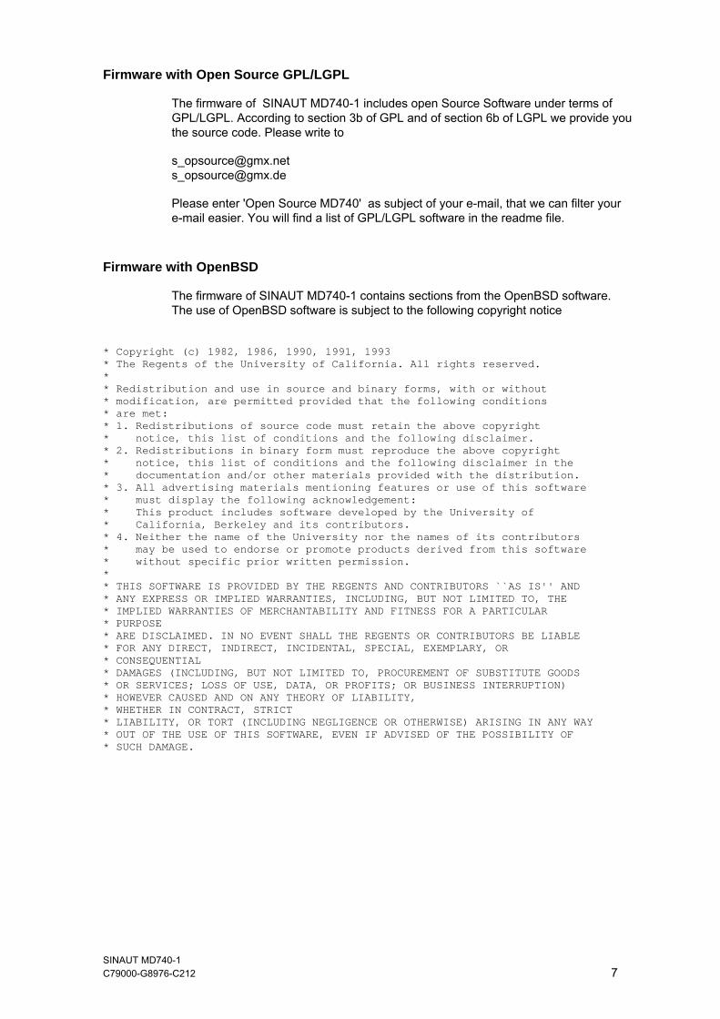
The firmware of SINAUT MD740-1 contains sections from the OpenBSD software. The use of OpenBSD software is subject to the following copyright notice
* Copyright (c) 1982, 1986, 1990, 1991, 1993 * The Regents of the University of California. All rights reserved. * * Redistribution and use in source and binary forms, with or without * modification, are permitted provided that the following conditions * are met: * 1. Redistributions of source code must retain the above copyright * notice, this list of conditions and the following disclaimer. * 2. Redistributions in binary form must reproduce the above copyright * notice, this list of conditions and the following disclaimer in the * documentation and/or other materials provided with the distribution. * 3. All advertising materials mentioning features or use of this software * must display the following acknowledgement: * This product includes software developed by the University of * California, Berkeley and its contributors. * 4. Neither the name of the University nor the names of its contributors * may be used to endorse or promote products derived from this software * without specific prior written permission. * * THIS SOFTWARE IS PROVIDED BY THE REGENTS AND CONTRIBUTORS ``AS IS'' AND * ANY EXPRESS OR IMPLIED WARRANTIES, INCLUDING, BUT NOT LIMITED TO, THE * IMPLIED WARRANTIES OF MERCHANTABILITY AND FITNESS FOR A PARTICULAR * PURPOSE * ARE DISCLAIMED. IN NO EVENT SHALL THE REGENTS OR CONTRIBUTORS BE LIABLE * FOR ANY DIRECT, INDIRECT, INCIDENTAL, SPECIAL, EXEMPLARY, OR * CONSEQUENTIAL * DAMAGES (INCLUDING, BUT NOT LIMITED TO, PROCUREMENT OF SUBSTITUTE GOODS * OR SERVICES; LOSS OF USE, DATA, OR PROFITS; OR BUSINESS INTERRUPTION) * HOWEVER CAUSED AND ON ANY THEORY OF LIABILITY, * WHETHER IN CONTRACT, STRICT * LIABILITY, OR TORT (INCLUDING NEGLIGENCE OR OTHERWISE) ARISING IN ANY WAY * OUT OF THE USE OF THIS SOFTWARE, EVEN IF ADVISED OF THE POSSIBILITY OF * SUCH DAMAGE.

SINAUT MD740-1 8 C79000- G8976-C212
Preface
Purpose of this documentation This documentation will support you on your way to successful application of GSM/GPRS modem SINAUT MD740-1. It will introduce you to the topic in clear and straightforward steps and provide you with an overview of the hardware of the SINAUT MD740-1 GSM/GPRS modem. This documentation will help you during installation and commissioning of SINAUT GSM/GPRS modem and explains the diagnostics and service options available.
Validity of the documentation This manual relates to the following product versions • GPRS/GSM modem MD740-1 hardware release 1.x
SIMATIC Technical Support You can contact Technical Support for all A&D products • Phone: +49 (0) 180 5050 222 • Fax: +49 (0) 180 5050 223 You will find further information on our Technical Support on the Web at http://www.siemens.com/automation/service
Service & Support on the Internet In addition to our documentation services, you can also make use of all our knowledge on the Internet: http://www.siemens.com/automation/service&support Here, you will find: • Up-to-date product information (Updates), FAQs (Frequently Asked
Questions), Downloads, Tips and Tricks. • The Newsletter keeps you constantly up to date with the latest
information on the products you use. • The Knowledge Manager will find the documents you need. • In the Forum, users and specialists exchange information and
experience. • You can find your local contact for Automation & Drives in our contacts
database. • You will find information on local service, repairs, spares and much more
under the rubric "Service". You will find the latest version of this documentation under the entry ID 22550242.
SINAUT MD740-1 C79000- G8976-C212 9
Preface
Do you still have questions relating to the use of the products described in the manual? If so, then please talk to your local Siemens contact. You will find the addresses in the following sources: • On the Internet at: http://www.siemens.com/automation/partner • On the Internet at http://www.siemens.com/simatic-net specifically for
SIMATIC NET products • In the catalog CA 01 • In the catalog IK PI specifically for SIMATIC NET products
SIMATIC training center To familiarize you with the systems and products, we offer a range of courses. Please contact your regional training center or the central training center in D-90327 Nuernberg. Phone: +49 (911) 895-3200 http://www.sitrain.com
SIMATIC NET training center For courses specifically on products from SIMATIC NET, please contact: SIEMENS AG Siemens AG, A&D Informations- und Trainings-Center Dynamostr. 4 D-68165 Mannheim Phone: +49 (621) 4 56-23 77 Fax: +49 (621) 4 56-32 68
SINAUT MD740-1 10 C79000- G8976-C212
Contents
1 Introduction................................................................................................................... 13
1.1 Survey................................................................................................................ 13 1.2 To be able to use the MD740-1... ...................................................................... 16 1.3 IP address of the remote site............................................................................. 17
2 The LEDs of the SINAUT MD740-1.............................................................................. 19 3 Putting the device into operation ............................................................................... 21
3.1 Connecting the device ....................................................................................... 22 3.2 Configuring the PIN ........................................................................................... 24 3.3 Inserting or changing the SIM Card................................................................... 25
4 Configuration ................................................................................................................ 31 4.1 Survey................................................................................................................ 31 4.2 Network menu.................................................................................................... 36 4.2.1 Network Local ............................................................................................... 36 4.2.2 Netzwork GPRS ............................................................................................ 38 4.2.3 Netzwork Status ............................................................................................ 40 4.3 Firewall menu .................................................................................................... 41 4.3.1 Firewall Incoming .......................................................................................... 42 4.3.2 Firewall Outgoing .......................................................................................... 44 4.3.3 Firewall Port Forwarding ............................................................................... 46 4.3.4 Firewall NAT.................................................................................................. 48 4.3.5 Firewall Extended Settings............................................................................ 50 4.3.6 Firewall Logs ................................................................................................. 52 4.4 VPN menu ......................................................................................................... 53 4.4.1 VPN connections ............................................................................................... 54 4.4.2 VPN Machine Certificate ............................................................................... 68 4.4.3 VPN Extended Settings................................................................................. 70 4.4.4 VPN L2TP ..................................................................................................... 72 4.4.5 VPN IPsec Status.......................................................................................... 73 4.4.6 VPN L2TP Status .......................................................................................... 75 4.4.7 VPN VPN Logs.............................................................................................. 76 4.5 Services menu ................................................................................................... 77 4.5.1 Services DNS................................................................................................ 77 4.5.2 Services DynDNS Monitoring........................................................................ 79 4.5.3 Services DynDNS Register ........................................................................... 80 4.5.4 Services DHCP ............................................................................................. 82 4.5.5 Services NTP ................................................................................................ 85 4.5.6 Services Remote Logging ............................................................................. 88 4.6 Access menu ..................................................................................................... 90 4.6.1 Access Passwords ........................................................................................ 90 4.6.2 Access Language.......................................................................................... 92 4.6.3 Access HTTPS.............................................................................................. 93 4.6.4 Access SSH .................................................................................................. 95 4.7 Features menu................................................................................................... 98 4.7.1 Features Install Update ................................................................................. 98
SINAUT MD740-1 C79000- G8976-C212 11
Contents
4.7.2 Features Update Server.............................................................................. 100 4.7.3 Features Software Informationen................................................................ 101 4.7.4 Features Hardware Informationen .............................................................. 102 4.8 Support menu .................................................................................................. 103 4.8.1 Support Snapshot ....................................................................................... 103 4.8.2 Support Status ............................................................................................ 104 4.9 System menu................................................................................................... 106 4.9.1 System Configuration Profiles..................................................................... 106 4.9.2 System Reboot............................................................................................ 109 4.9.3 System Logs ............................................................................................... 110 4.10 CIDR (Classless InterDomain Routing) ........................................................... 111 4.11 Network example diagram............................................................................... 112
5 Integrated website showing device and connection data of the modem module115 5.1 Accessing the modem module Web server locally via the service interface... 116 5.2 Accessing the Web server of the modem module locally via the application
interface (10/100 BASE-T connector).............................................................. 119 5.3 Accessing the Web Server of the modem module of the MD740-1 from a remote
computer via the GPRS network ..................................................................... 121 5.4 The website of the SINAUT MD740-1 ............................................................. 122
6 Firmware update and recovery ................................................................................. 127 6.1 Update of the firmware of the modem module ................................................ 127 6.2 Recovery: Loading factory defaults ................................................................. 128 6.3 Update the VPN firmware................................................................................ 128
7 Technical Data ............................................................................................................ 129 8 Glossary ...................................................................................................................... 133
SINAUT MD740-1 12 C79000- G8976-C212
Introduction 11.1 Survey
The device establishes secure IP data connections by radio via the GPRS (General Packet Radio Service) of a GSM network (Global System for Mobile Communication = mobile radio network).
Functions
To do so, the device combines the following functions:
● GPRS modem for flexible data communication via GPRS
● VPN router for secure data transfer via public networks (IPSec protocol, 3DES data encryption, AES encryption)
● Firewall for protection against unauthorised access. The dynamic packet filter inspects data packets using the source and destination address (stateful packet inspection) and blocks unwanted data traffic (anti-spoofing).
Configuration
The device is configured simply using a Web browser.
VPN features
● Protocol: IPsec (tunnel and transport mode)
● IPsec DES encryption at 56 Bit
● IPsec 3DES encryption at 168 Bit
● IPsec AES encryption at 128, 192 and 256 Bit
● Packet authentication: MD5, SHA-1
● Internet Key Exchange (IKE) with Main and Quick Mode
SINAUT MD740-1 C79000- G8976-C212 13
Introduction
SINAUT MD740-1 14 C79000- G8976-C212
● Authentication: Pre-Shared Key (PSK), X.509v3 certificates
● DynDNS
● NAT-T
Dead Peer Detection (DPD)
Firewall features
● Stateful Packet Inspection
● Anti-spoofing
● NAT (IP Masquerading)
● Port Forwarding
Other features
● DNS Cache
● DHCP Server
● NTP
● Remote Logging
Introduction
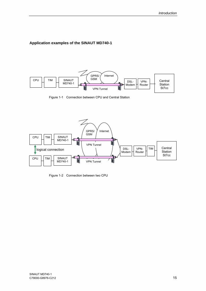
Application examples of the SINAUT MD740-1
Figure 1-1 Connection between CPU and Central Station
Figure 1-2 Connection between two CPU
TIM SINAUT MD740-1
GPRS/GSM
Internet
VPN Tunnel
VPN-Router
DSL-Modem
Central Station St7cc
CPU
logical connection
CPU TIM SINAUT MD740-1
DSL-Modem
VPN-Router
GPRS/GSM
Internet
VPN Tunnel
VPN Tunnel
TIM SINAUT MD740-1
TIM
CPU
Central Station St7cc
SINAUT MD740-1 C79000-G8976-C212 15
Introduction
SINAUT MD740-1 16 C79000- G8976-C212
1.2 To be able to use the MD740-1...
you require...
● a subscriber contract with a GSM network operator (e.g. T-Mobile, Vodafone, E-Plus, O2, Cingular) that supports GPRS
● release of the GPRS for the user in question by the network operator
Introduction
1.3 IP address of the remote site
In order that a MD740-1 can actively establish a VPN connection the remote site must have a fixed IP address (an IP address consists of a maximum of 4 numbers, separated by dots, which can each have up to three digits, e.g. 255.122.201.005). With many Internet Service Providers (ISPs), however, the IP addresses are assigned dynamically, i.e. the IP addresses of the computers or networks which have access to the Internet change. There are 3 ways of obtaining a fixed IP address:
● Fixed IP address via dedicated line to GPRS
● Fixed IP address via Internet service provider
● Fixed IP DNS name via DynDNS service
Fixed IP address via dedicated line to GPRS
The communication partner is connected to the GPRS network via a leased dedicated line. In this case it has normally been assigned a fixed IP address by the network operator.
Fixed IP address via Internet service provider
The communication partner can be accessed via the Internet and has been assigned a fixed IP address by the Internet service provider (the address can be applied for from some Internet service providers).
Fixed DNS name via DynDNS service
To solve the problem of dynamic IP address assignment, DynDNS services can be used. With this kind of service, the MD740-1, for example, or the remote computer, regardless of the dynamic IP address it currently possesses, is accessible via a fixed domain name. Each time the IP address changes, the MD740-1 or the remote computer reports the new IP address to the DynDNS server, so that the current IP address is always assigned to the domain name on the DNS server - see Glossary. But when there is a change of the IP address it might last a few minutes till 1 hour at most till the modem is obtainable again.
The use of a DynDNS service requires a contract with the provider concerned, e.g. DynDNS.org or DNS4BIZ.com.
SINAUT MD740-1 C79000-G8976-C212 17

Introduction
SINAUT MD740-1 18 C79000- G8976-C212
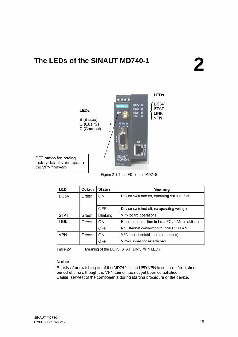
The LEDs of the SINAUT MD740-1 2
Figure 2-1 The LEDs of the MD740-1
LEDs DC5V STAT LINK VPN
LEDs S (Status) Q (Quality) C (Connect)
SET-button for loading factory defaults and update the VPN firmware
LED Colour Status Meaning DC5V Green ON
Device switched on, operating voltage is on
OFF Device switched off, no operating voltage
STAT Green Blinking VPN board operational
LINK Green ON Ethernet connection to local PC / LAN established
OFF No Ethernet connection to local PC / LAN
VPN Green ON VPN tunnel established (see notice)
OFF VPN-Tunnel not established
Table 2-1 Meaning of the DC5V, STAT, LINK, VPN LEDs
Notice
Shortly after switching on of the MD740-1, the LED VPN is set to on for a short period of time although the VPN tunnel has not yet been established. Cause: self-test of the components during starting procedure of the device.
SINAUT MD740-1 C79000- G8976-C212 19
The LEDs of the SINAUT MD740-1
SINAUT MD740-1 20 C79000- G8976-C212
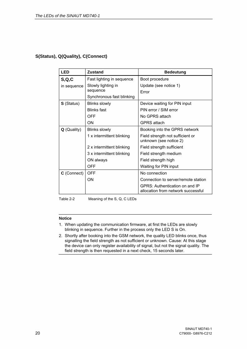
S(Status), Q(Quality), C(Connect)
LED Zustand Bedeutung
S,Q,C in sequence
Fast lighting in sequence Slowly lighting in sequence Synchronous fast blinking
Boot procedure Update (see notice 1) Error
S (Status) Blinks slowly Blinks fast OFF ON
Device waiting for PIN input PIN error / SIM error No GPRS attach GPRS attach
Q (Quality) Blinks slowly 1 x intermittent blinking 2 x intermittent blinking 3 x intermittent blinking ON always OFF
Booking into the GPRS network Field strength not sufficient or unknown (see notice 2) Field strength sufficient Field strength medium Field strength high Waiting for PIN input
C (Connect) OFF ON
No connection Connection to server/remote station GPRS: Authentication on and IP allocation from network successful
Table 2-2 Meaning of the S, Q, C LEDs
Notice
1. When updating the communication firmware, at first the LEDs are slowly blinking in sequence. Further in the process only the LED S is On.
2. Shortly after booking into the GSM network, the quality LED blinks once, thus signalling the field strength as not sufficient or unknown. Cause: At this stage the device can only register availability of signal, but not the signal quality. The field strength is then requested in a next check, 15 seconds later.
Putting the device into operation 3Survey
To put the device into operation, perform the following steps in the order given:
1. Connect the device (see Chapter3.1)
2. Configure the PIN (see Chapter 3.2) Notice
First tell the device the PIN of the SIM card. Then insert the SIM card. The device also supports SIM cards without a PIN. If your SIM card has no PIN you can also insert the SIM card before performing configuration.
3. Insert or change the SIM card (see Chapter 3.3)
Notice
The device must be switched off when you insert or remove the SIM card.
4. Perform further configuration (see Chapter 4)
SINAUT MD740-1 C79000- G8976-C212 21
Putting the device into operation
SINAUT MD740-1 22 C79000- G8976-C212
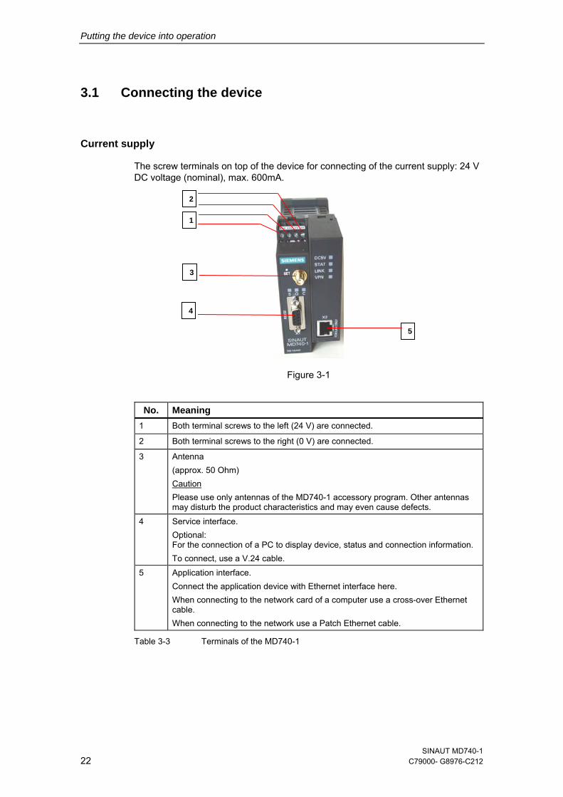
3.1 Connecting the device
Current supply
The screw terminals on top of the device for connecting of the current supply: 24 V DC voltage (nominal), max. 600mA.
Figure 3-1
2
1
3
5
4
No. Meaning 1 Both terminal screws to the left (24 V) are connected.
2 Both terminal screws to the right (0 V) are connected.
3 Antenna (approx. 50 Ohm) Caution Please use only antennas of the MD740-1 accessory program. Other antennas may disturb the product characteristics and may even cause defects.
4 Service interface. Optional: For the connection of a PC to display device, status and connection information. To connect, use a V.24 cable.
5 Application interface. Connect the application device with Ethernet interface here. When connecting to the network card of a computer use a cross-over Ethernet cable. When connecting to the network use a Patch Ethernet cable.
Table 3-3 Terminals of the MD740-1
Putting the device into operation
Switching the device on/off
The MD740-1 switches on as soon as the operating voltage is supplied (see chapter 3.1).
When the device is switched on the DC5V LED comes on first. If the device has a valid configuration and the SIM card is inserted the device automatically books into the GPRS network. When the LED C (CONNECT) comes on a GPRS connection has been established.
The device is designed in such a way that it can be left switched on permanently.
The devices switches off when disconnected from the supply voltage.
SINAUT MD740-1 C79000-G8976-C212 23
Putting the device into operation
SINAUT MD740-1 24 C79000- G8976-C212
3.2 Configuring the PIN
In order for the MD740-1 to be able to communicate via the GPRS network of your network operator you must tell the device the PIN (Personal Identification Number) of the SIM card. Then you can insert the SIM card into the device.
If your SIM card has no PIN, then configure any PIN, e. g. 0000.
To configure the PIN, proceed as follows:
1. Using your Web browser (e.g. MS Internet Explorer), establish a configuration connection with the MD740-1. To do this, follow the description in section 4.1.
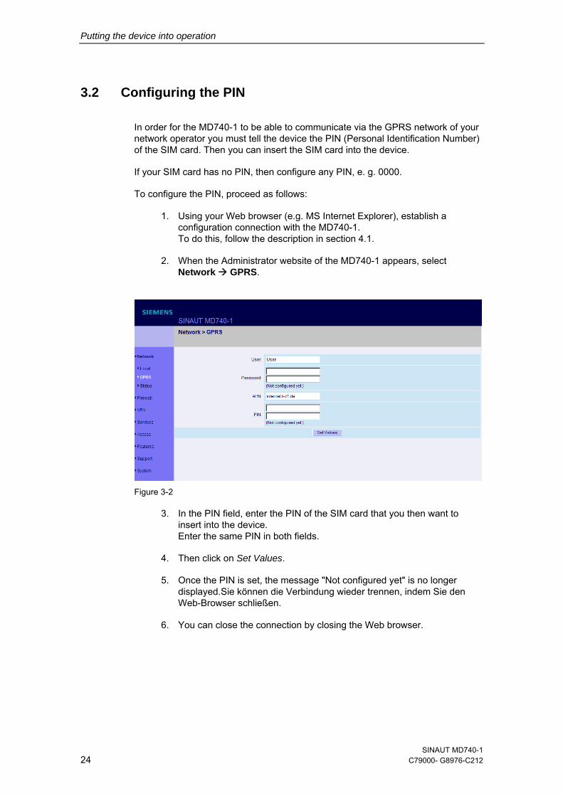
2. When the Administrator website of the MD740-1 appears, select Network GPRS.
Figure 3-2
3. In the PIN field, enter the PIN of the SIM card that you then want to insert into the device. Enter the same PIN in both fields.
4. Then click on Set Values.
5. Once the PIN is set, the message "Not configured yet" is no longer displayed.Sie können die Verbindung wieder trennen, indem Sie den Web-Browser schließen.
6. You can close the connection by closing the Web browser.
Putting the device into operation
3.3 Inserting or changing the SIM Card
Notice
The MD740-1 must be switched off when you insert or change the SIM card.
The MD740-1 must be opened to insert the SIM card.
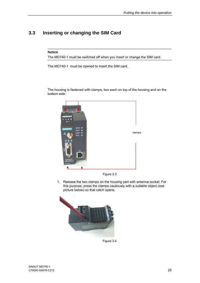
The housing is fastened with clamps, two each on top of the housing and on the bottom side.
clamps
Figure 3-3
1. Release the two clamps on the housing part with antenna socket. For this purpose, press the clamps cautiously with a suitable object (see picture below) so that catch opens.
Figure 3-4
SINAUT MD740-1 C79000-G8976-C212 25
Putting the device into operation
SINAUT MD740-1 26 C79000- G8976-C212
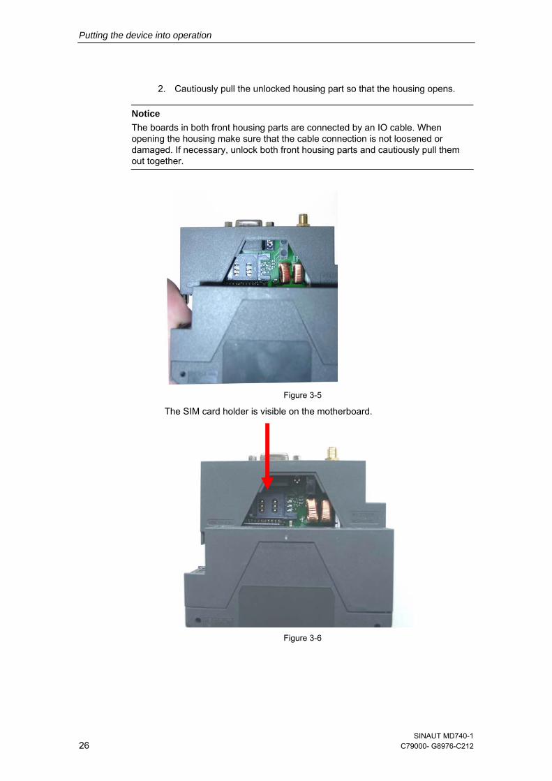
2. Cautiously pull the unlocked housing part so that the housing opens. Notice
The boards in both front housing parts are connected by an IO cable. When opening the housing make sure that the cable connection is not loosened or damaged. If necessary, unlock both front housing parts and cautiously pull them out together.
Figure 3-5
The SIM card holder is visible on the motherboard.
Figure 3-6
Putting the device into operation
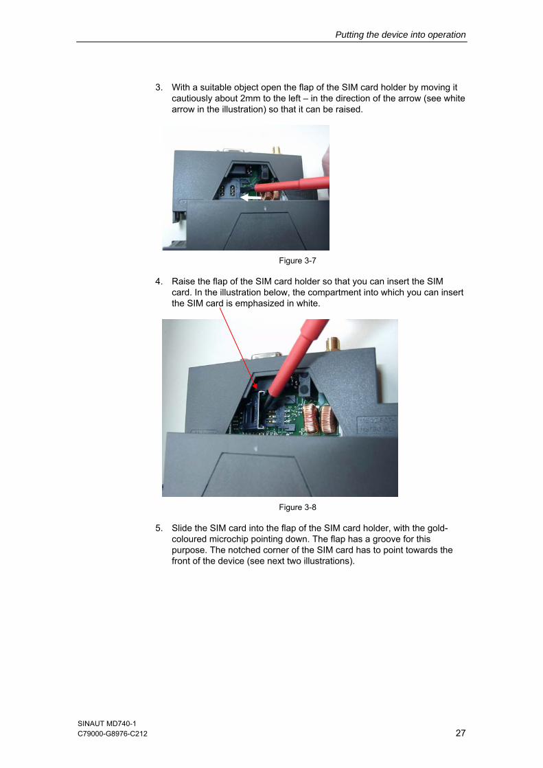
3. With a suitable object open the flap of the SIM card holder by moving it cautiously about 2mm to the left – in the direction of the arrow (see white arrow in the illustration) so that it can be raised.
Figure 3-7
4. Raise the flap of the SIM card holder so that you can insert the SIM card. In the illustration below, the compartment into which you can insert the SIM card is emphasized in white.
Figure 3-8
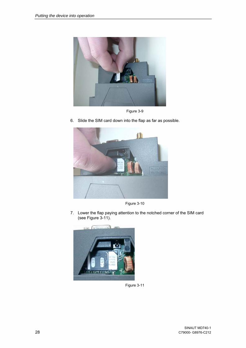
5. Slide the SIM card into the flap of the SIM card holder, with the gold-coloured microchip pointing down. The flap has a groove for this purpose. The notched corner of the SIM card has to point towards the front of the device (see next two illustrations).
SINAUT MD740-1 C79000-G8976-C212 27
Putting the device into operation
SINAUT MD740-1 28 C79000- G8976-C212
Figure 3-9
6. Slide the SIM card down into the flap as far as possible.
Figure 3-10
7. Lower the flap paying attention to the notched corner of the SIM card (see Figure 3-11).
Figure 3-11
Putting the device into operation
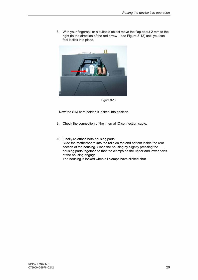
8. With your fingernail or a suitable object move the flap about 2 mm to the right (in the direction of the red arrow – see Figure 3-12) until you can feel it click into place.
Figure 3-12
Now the SIM card holder is locked into position.
9. Check the connection of the internal IO connection cable.
10. Finally re-attach both housing parts: Slide the motherboard into the rails on top and bottom inside the rear section of the housing. Close the housing by slightly pressing the housing parts together so that the clamps on the upper and lower parts of the housing engage. The housing is locked when all clamps have clicked shut.
SINAUT MD740-1 C79000-G8976-C212 29

Putting the device into operation
SINAUT MD740-1 30 C79000- G8976-C212
Configuration 44.1 Survey
The router-, VPN- and firewall functions are configured locally or remote via the website of the router-module.
Remote configuration
Remote configuration, that means configuration from a remote location, is possible only if the MD740-1 is configured for remote access (see page 93). In this case, proceed exactly as described as from section Establish configuration connection, page 32.
Local configuration
● The computer with which you are performing the configuration must either
– be connected direct to the Ethernet socket of the MD740-1 via cross-over network cable
– or it must have direct access via LAN to the MD740-1.
● The network adapter of the computer with which you are performing configuration must have the following TCP/IP configuration:
IP address: 192.168.1.2 Subnet mask: 255.255.255.0 Default gateway: 192.168.1.1 Preferred DNS server: address of the Domain Name Server
TCP/IP configuration of the network adapter under Windows XP or Windows 2000
1. Click on Start, Settings, Control Panel, Network Connections: right-click on the icon for LAN adapter and click on Properties in the context menu.
SINAUT MD740-1 C79000- G8976-C212 31
Configuration
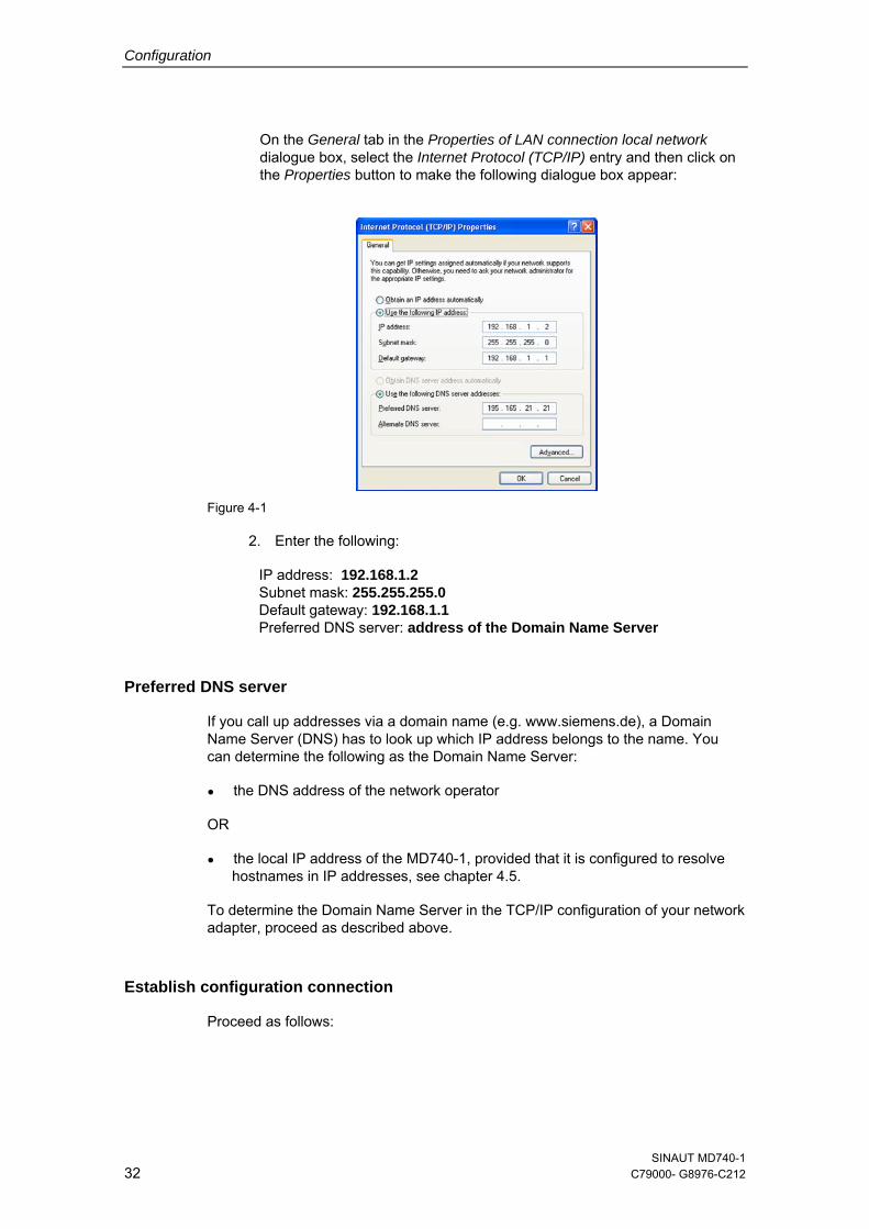
On the General tab in the Properties of LAN connection local network dialogue box, select the Internet Protocol (TCP/IP) entry and then click on the Properties button to make the following dialogue box appear:
Figure 4-1
2. Enter the following:
IP address: 192.168.1.2 Subnet mask: 255.255.255.0 Default gateway: 192.168.1.1 Preferred DNS server: address of the Domain Name Server
Preferred DNS server
If you call up addresses via a domain name (e.g. www.siemens.de), a Domain Name Server (DNS) has to look up which IP address belongs to the name. You can determine the following as the Domain Name Server:
● the DNS address of the network operator
OR
● the local IP address of the MD740-1, provided that it is configured to resolve hostnames in IP addresses, see chapter 4.5.
To determine the Domain Name Server in the TCP/IP configuration of your network adapter, proceed as described above.
Establish configuration connection
Proceed as follows:
SINAUT MD740-1 32 C79000- G8976-C212
Configuration
1. Start a Web browser.
(e.g. MS Internet Explorer from Version 5.0 or Netscape Communicator from Version 4.0; the Web browser must support SSL (i.e. https))
2. Make sure that the browser does not automatically dial up a connection when starting.
In MS Internet Explorer you make this setting as follows: menu Tools, Internet Options..., Connections tab: under Dial-up and Virtual Private Network settings, Never dial a connection must be activated.
3. In the address line of the browser, enter the full address of the MD740-1. In accordance with the default setting, this is:
https://192.168.1.1
Consequence: the security alert shown on the next page appears.
In case the Administrator website does not appear...
If the browser still tells you after several attempts that the page cannot be displayed, try the following:
● Check the hardware connection. To do so on a Windows computer, enter the following command via the DOS prompt (menu Start, Programs, Tools, Command Prompt):
ping 192.168.1.1
If there is no message about the reception of the 4 sent packets within the prescribed time, check the cable, the connections and the network card.
● Make sure that the browser does not use a proxy server.
In MS Internet Explorer (Version 6.0) you make this setting as follows: menu Tools, Internet Options..., Connections tab: under LAN Settings click on the Settings button, in the Settings for local area network (LAN) dialogue box make sure that the Use a proxy server for your LAN entry is not activated.
● If there are other LAN connections active on the computer, deactivate them for the duration of configuration. Under Windows menu Start, Settings, Control Panel, Network Connections / Network and Dial-up Connections right-click on the appropriate icon and select Deactivate in the context menu.
● Enter the address of the MD740-1 plus slash:
https://192.168.1.1/
When the connection is successfully established...
Following the successful establishment of the connection the following security alert appears:
SINAUT MD740-1 C79000-G8976-C212 33
Configuration
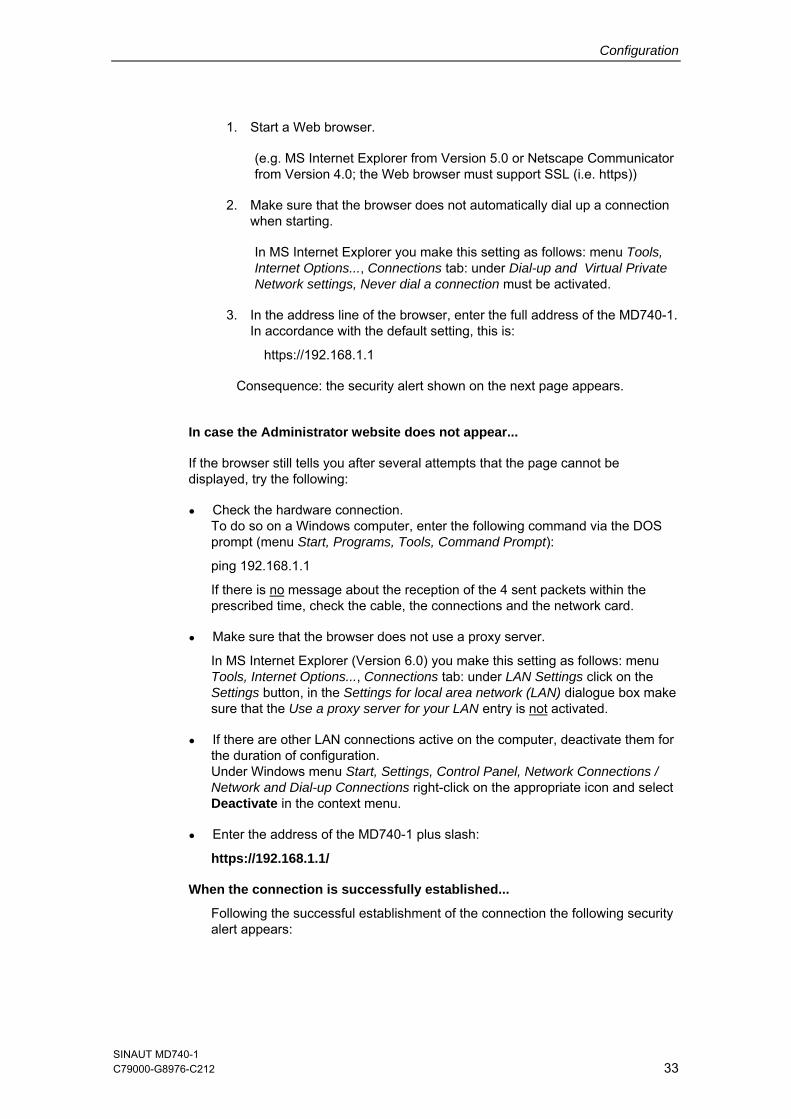
Figure 4-2
4. Acknowledge the security alert with Yes. Notice
As the device can only be administered via encrypted accesses it is supplied with a self-signed certificate. When the operating systems recognizes a certificate with an unknown signature, you get an security alert. You can view the certificate. The certificate must show that it is issued for the MD740-1. As the administrator website is addressed via an IP address and not via a name, the name in the certificate does not agree with the certificate.
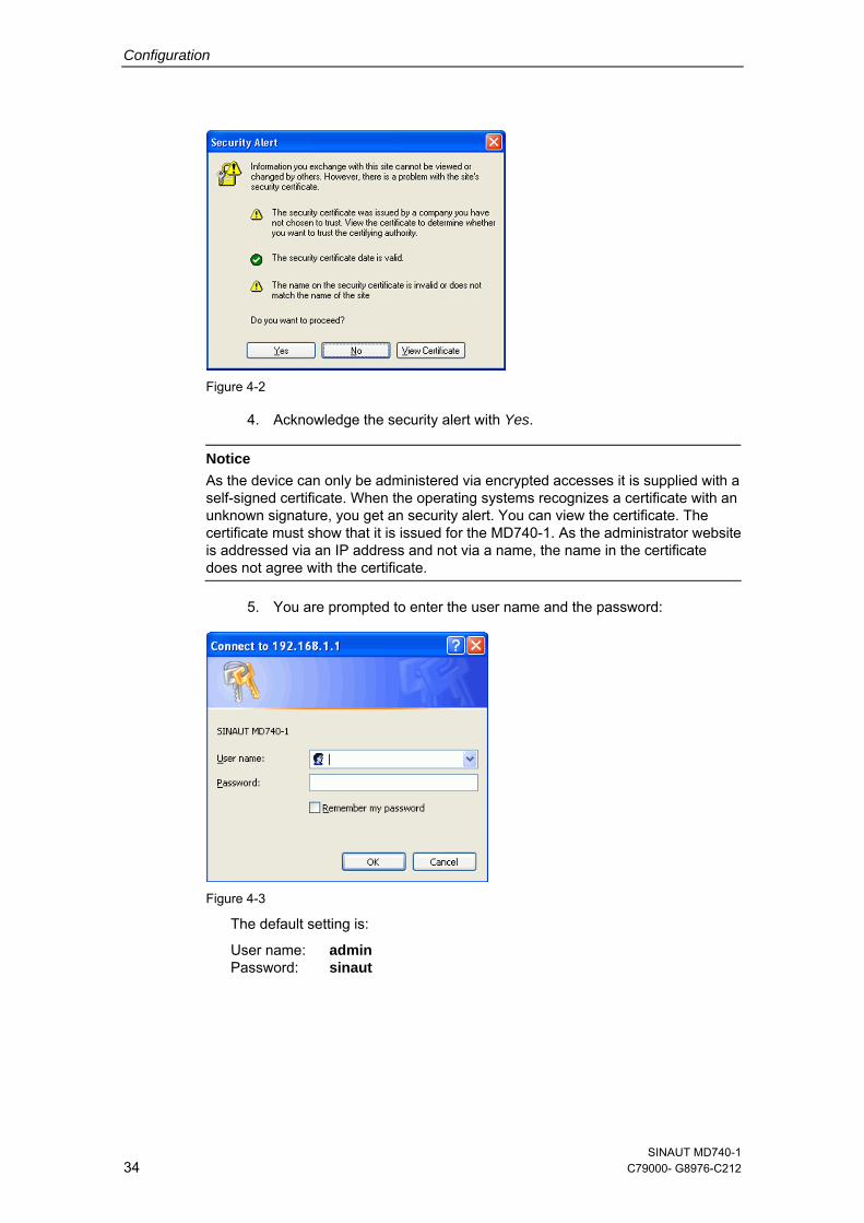
5. You are prompted to enter the user name and the password:
Figure 4-3
The default setting is:
User name: admin Password: sinaut
SINAUT MD740-1 34 C79000- G8976-C212
Configuration
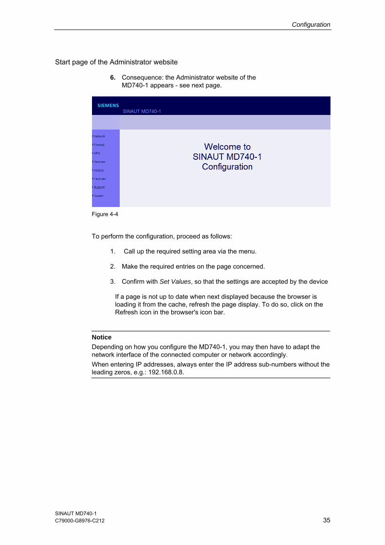
Start page of the Administrator website
6. Consequence: the Administrator website of the MD740-1 appears - see next page.
Figure 4-4
To perform the configuration, proceed as follows:
1. Call up the required setting area via the menu.
2. Make the required entries on the page concerned.
3. Confirm with Set Values, so that the settings are accepted by the device
If a page is not up to date when next displayed because the browser is loading it from the cache, refresh the page display. To do so, click on the Refresh icon in the browser's icon bar.
Notice
Depending on how you configure the MD740-1, you may then have to adapt the network interface of the connected computer or network accordingly. When entering IP addresses, always enter the IP address sub-numbers without the leading zeros, e.g.: 192.168.0.8.
SINAUT MD740-1 C79000-G8976-C212 35
Configuration
4.2 Network menu
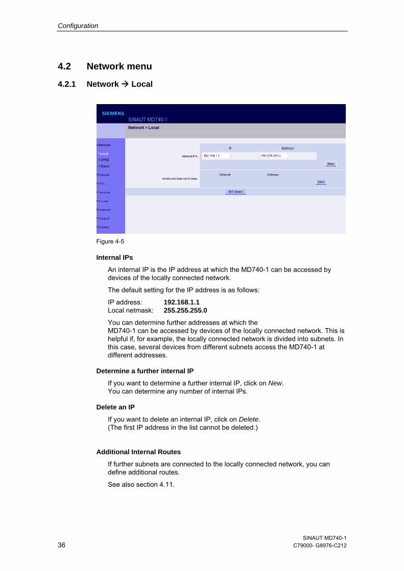
4.2.1 Network Local
Figure 4-5
Internal IPs
An internal IP is the IP address at which the MD740-1 can be accessed by devices of the locally connected network.
The default setting for the IP address is as follows:
IP address: 192.168.1.1 Local netmask: 255.255.255.0
You can determine further addresses at which the MD740-1 can be accessed by devices of the locally connected network. This is helpful if, for example, the locally connected network is divided into subnets. In this case, several devices from different subnets access the MD740-1 at different addresses.
Determine a further internal IP
If you want to determine a further internal IP, click on New. You can determine any number of internal IPs.
Delete an IP
If you want to delete an internal IP, click on Delete. (The first IP address in the list cannot be deleted.)
Additional Internal Routes
If further subnets are connected to the locally connected network, you can define additional routes.
See also section 4.11.
SINAUT MD740-1 36 C79000- G8976-C212
Configuration
If you want to determine a further route to a subnet, click on New.
Enter the following:
- the IP address of the subnet (network), and
- the IP address of the gateway via which the subnet is connected.
You can determine any number of internal routes.
If you want to delete an internal route, click on Delete.
SINAUT MD740-1 C79000-G8976-C212 37
Configuration
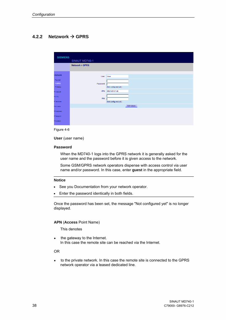
4.2.2 Netzwork GPRS
Figure 4-6
User (user name)
Password
When the MD740-1 logs into the GPRS network it is generally asked for the user name and the password before it is given access to the network.
Some GSM/GPRS network operators dispense with access control via user name and/or password. In this case, enter guest in the appropriate field.
Notice
• See you Documentation from your network operator.
• Enter the password identically in both fields.
Once the password has been set, the message "Not configured yet" is no longer displayed.
APN (Access Point Name)
This denotes
● the gateway to the Internet. In this case the remote site can be reached via the Internet.
OR
● to the private network. In this case the remote site is connected to the GPRS network operator via a leased dedicated line.
SINAUT MD740-1 38 C79000- G8976-C212
Configuration
Notice
• Internet APN: You will find the APN in the documentation or at the website of your GSM/GPRS network operator, or you can call the hotline and ask for it there.
• Private APN: You can obtain the access data from your network operator.
PIN of the SIM card inserted in the device
In order for the MD740-1 to be able to operate with the SIM card of your network operator you must tell the device the PIN (Personal Identification Number) of the SIM card, provided that the SIM card has a PIN. Only after this should you insert the SIM card into the switched off(!) device.
To do so, enter the PIN and click on Set Values.
If a PIN has been set, the message "Not configured yet" is no longer displayed.
Notice
• Enter the PIN identically in both fields.
• The entered PIN must tally with the PIN of the SIM card with which the device is to operate.
• You cannot change the PIN of the SIM card with this device.
SINAUT MD740-1 C79000-G8976-C212 39
Configuration
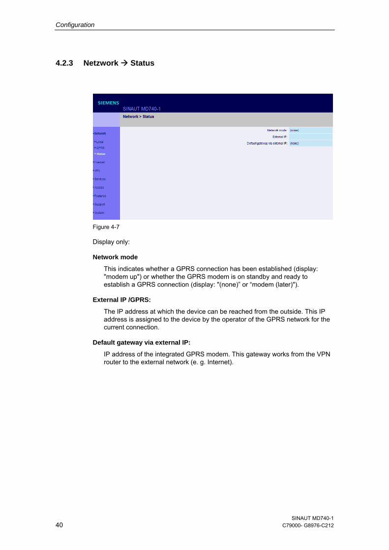
4.2.3 Netzwork Status
Figure 4-7
Display only:
Network mode
This indicates whether a GPRS connection has been established (display: "modem up") or whether the GPRS modem is on standby and ready to establish a GPRS connection (display: "(none)” or “modem (later)").
External IP /GPRS:
The IP address at which the device can be reached from the outside. This IP address is assigned to the device by the operator of the GPRS network for the current connection.
Default gateway via external IP:
IP address of the integrated GPRS modem. This gateway works from the VPN router to the external network (e. g. Internet).
SINAUT MD740-1 40 C79000- G8976-C212
Configuration
4.3 Firewall menu
The MD740-1 comes with a Stateful Packet Inspection Firewall.
Connection incoming:
You have to define the rules for incoming data. From these rules the rules for outgoing data follow logically and the device works according these rules. If the rules for incoming data are changed during a connection the old rules still work during this connection.
Connection outgoing:
You have to define the rules for outgoing data. From these rules the rules for incoming data follow logically and the device works according these rules. If the rules for outgoing data are changed during a connection the old rules still work during this connection.
Default firewall setting
All incoming connections are rejected (except VPN).
The data packets of all outgoing connections are rejected (except VPN and except connections to the integrated website which provides information about devices and connection data).
Notice
• VPN connections are not subject to the firewall rules determined under this menu item. You can determine firewall rules for each individual VPN connection under the menu VPN Connections.
• If several firewall rules have been set, they are scanned in the order of the entries from top to bottom until a suitable rule is found. This rule is then applied. Should there also be rules further down in the list which would be also suitable, they are ignored.
SINAUT MD740-1 C79000-G8976-C212 41
Configuration
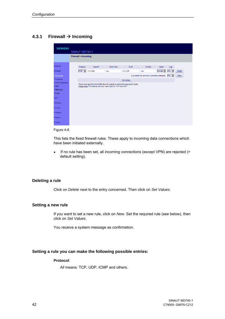
4.3.1 Firewall Incoming
Figure 4-8
This lists the fixed firewall rules. These apply to incoming data connections which have been initiated externally.
● If no rule has been set, all incoming connections (except VPN) are rejected (= default setting).
Deleting a rule
Click on Delete next to the entry concerned. Then click on Set Values.
Setting a new rule
If you want to set a new rule, click on New. Set the required rule (see below), then click on Set Values.
You receive a system message as confirmation.
Setting a rule you can make the following possible entries:
Protocol:
All means: TCP, UDP, ICMP and others.
SINAUT MD740-1 42 C79000- G8976-C212
Configuration
To / from IP:
0.0.0.0/0 means all addresses. To denote a range, use CIDR syntax – see section 4.10.
To / From Port: (is evaluated only with TCP and UDP protocols)
any means any port.
startport:endport (e.g. 110:120) denotes the port area.
Individual ports can be entered either with the port number or with the corresponding service name: (e.g. 110 for pop3 or pop3 for 110).
Action:
Accept means that the data packets may pass. Refuse means that the data packets are turned away so that the sender is informed of the refusal. Reject means that data packets are not allowed to pass. They are "swallowed" so that the sender is not informed of their whereabouts.
Log:
For each individual firewall rule you can determine whether, when the rule is applied,
- the event is to be logged - set Log to Yes
- or not - set Log to No (default setting)
Log entries for unknown connection attempts:
This logs all connection attempts which are not recorded by the prevalent rules.
SINAUT MD740-1 C79000-G8976-C212 43
Configuration
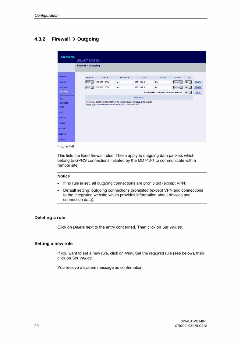
4.3.2 Firewall Outgoing
Figure 4-9
This lists the fixed firewall rules. These apply to outgoing data packets which belong to GPRS connections initiated by the MD740-1 to communicate with a remote site.
Notice
• If no rule is set, all outgoing connections are prohibited (except VPN). • Default setting: outgoing connections prohibited (except VPN and connections
to the integrated website which provides information about devices and connection data).
Deleting a rule
Click on Delete next to the entry concerned. Then click on Set Values.
Setting a new rule
If you want to set a new rule, click on New. Set the required rule (see below), then click on Set Values.
You receive a system message as confirmation.
SINAUT MD740-1 44 C79000- G8976-C212
Configuration
Setting a rule you can make the following possible entries:
Protocol:
All means: TCP, UDP, ICMP and others.
To / from IP:
0.0.0.0/0 means all addresses. To denote a range, use CIDR syntax – see section 4.10.
To / From Port: (is evaluated only with TCP and UDP protocols)
any means any port.
startport:endport (e.g. 110:120) denotes the port area.
Individual ports can be entered either with the port number or with the corresponding service name: (e.g. 110 for pop3 or pop3 for 110).
Action:
Accept means that the data packets may pass. Refuse means that the data packets are turned away so that the sender is informed of the refusal. Reject means that data packets are not allowed to pass. They are "swallowed" so that the sender is not informed of their whereabouts.
Log:
For each individual firewall rule you can determine whether, when the rule is applied,
- the event is to be logged - set Log to Yes
- or not - set Log to No (default setting)
Log entries for unknown connection attempts:
This logs all connection attempts which are not recorded by the prevalent rules.
SINAUT MD740-1 C79000-G8976-C212 45
Configuration
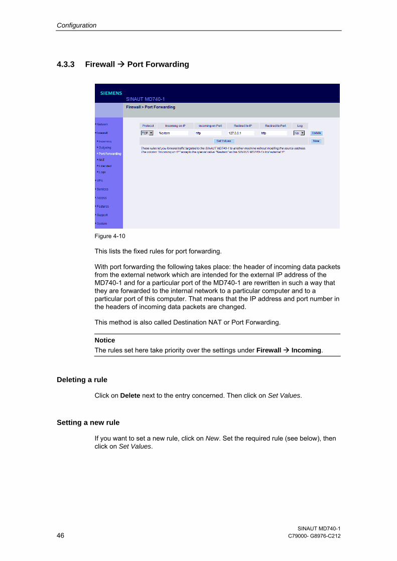
4.3.3 Firewall Port Forwarding
Figure 4-10
This lists the fixed rules for port forwarding.
With port forwarding the following takes place: the header of incoming data packets from the external network which are intended for the external IP address of the MD740-1 and for a particular port of the MD740-1 are rewritten in such a way that they are forwarded to the internal network to a particular computer and to a particular port of this computer. That means that the IP address and port number in the headers of incoming data packets are changed.
This method is also called Destination NAT or Port Forwarding. Notice
The rules set here take priority over the settings under Firewall Incoming.
Deleting a rule
Click on Delete next to the entry concerned. Then click on Set Values.
Setting a new rule
If you want to set a new rule, click on New. Set the required rule (see below), then click on Set Values.
SINAUT MD740-1 46 C79000- G8976-C212
Configuration
Setting a rule you can make the following possible entries:
Protocol
Here you enter the protocol to which the rule is to apply.
Incoming on IP
Here you enter the external IP address (or one of the external IP addresses) of the MD740-1.
OR
Should a dynamic change of the external IP address of the MD740-1 take place, so that it cannot be given, use the following variable: %extern.
The special value %extern refers to the first IP address in the list when using several static IP addresses for the external interface.
Incoming on Port
Original destination port that is given in incoming data packets.
Redirect to IP
Internal IP address to which the data packets are to be forwarded and to which the original destination addresses are rewritten.
Redirect to Port
Port to which the data packets are to be forwarded and to which the original destination addresses are rewritten.
You can make the following possible entries:
Port
You can only specify individual ports, either with the port number or with the corresponding service name: (e.g. 110 for pop3 or pop3 for 110).
Log
For each individual port forwarding rule you can determine whether, when the rule is applied,
- the event is to be logged - set Log to Yes
- or not - set Log to No (default setting).
SINAUT MD740-1 C79000-G8976-C212 47
Configuration
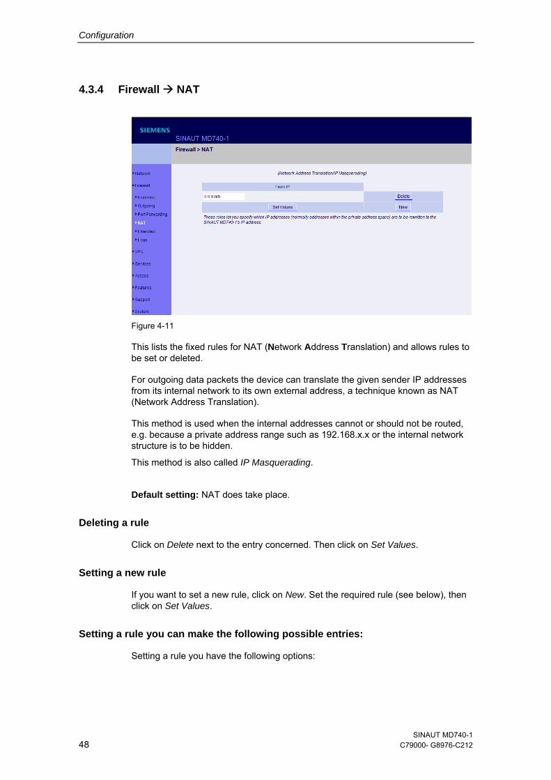
4.3.4 Firewall NAT
Figure 4-11
This lists the fixed rules for NAT (Network Address Translation) and allows rules to be set or deleted.
For outgoing data packets the device can translate the given sender IP addresses from its internal network to its own external address, a technique known as NAT (Network Address Translation).
This method is used when the internal addresses cannot or should not be routed, e.g. because a private address range such as 192.168.x.x or the internal network structure is to be hidden.
This method is also called IP Masquerading.
Default setting: NAT does take place.
Deleting a rule
Click on Delete next to the entry concerned. Then click on Set Values.
Setting a new rule
If you want to set a new rule, click on New. Set the required rule (see below), then click on Set Values.
Setting a rule you can make the following possible entries:
Setting a rule you have the following options:
SINAUT MD740-1 48 C79000- G8976-C212
Configuration
From IP
0.0.0.0/0 means all addresses, i.e. all internal IP addresses are subjected to the NAT procedure. To denote a range, use CIDR syntax – see section 4.10.
SINAUT MD740-1 C79000-G8976-C212 49
Configuration
4.3.5 Firewall Extended Settings
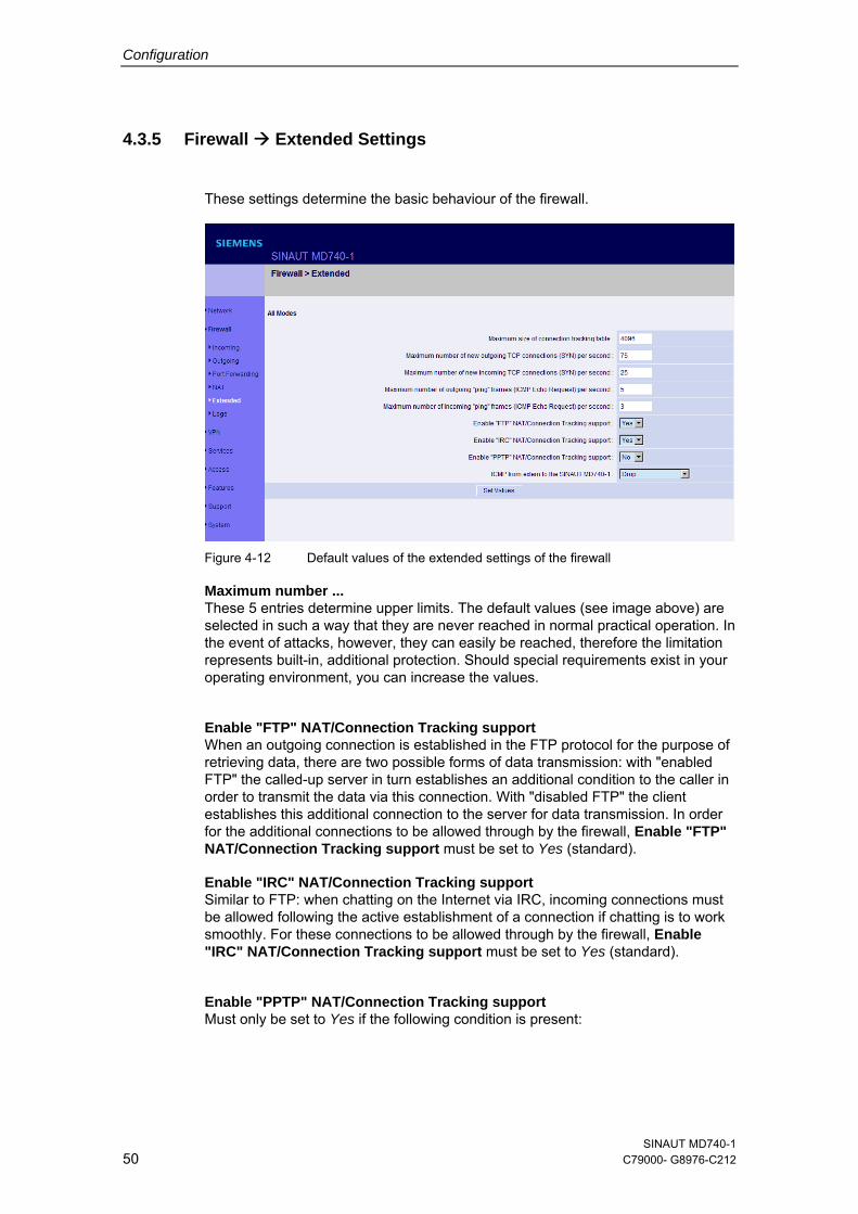
These settings determine the basic behaviour of the firewall.
Figure 4-12 Default values of the extended settings of the firewall
Maximum number ... These 5 entries determine upper limits. The default values (see image above) are selected in such a way that they are never reached in normal practical operation. In the event of attacks, however, they can easily be reached, therefore the limitation represents built-in, additional protection. Should special requirements exist in your operating environment, you can increase the values.
Enable "FTP" NAT/Connection Tracking support When an outgoing connection is established in the FTP protocol for the purpose of retrieving data, there are two possible forms of data transmission: with "enabled FTP" the called-up server in turn establishes an additional condition to the caller in order to transmit the data via this connection. With "disabled FTP" the client establishes this additional connection to the server for data transmission. In order for the additional connections to be allowed through by the firewall, Enable "FTP" NAT/Connection Tracking support must be set to Yes (standard).
Enable "IRC" NAT/Connection Tracking support Similar to FTP: when chatting on the Internet via IRC, incoming connections must be allowed following the active establishment of a connection if chatting is to work smoothly. For these connections to be allowed through by the firewall, Enable "IRC" NAT/Connection Tracking support must be set to Yes (standard).
Enable "PPTP" NAT/Connection Tracking support Must only be set to Yes if the following condition is present:
SINAUT MD740-1 50 C79000- G8976-C212
Configuration
A VPN connection using PPTP is to be established to an external computer from a local computer without the help of the MD740-1. The default setting of this switch is No.
ICMP from extern to the TAINY With this option you can influence behaviour when receiving ICMP messages which are sent from the external network to the MD740-1. You have the following possibilities:
● Reject: All ICMP messages sent to the MD740-1 are rejected.
● Accept ping: Only ping messages (ICMP type 8) sent to the MD740-1 are accepted.
● Accept all ICMPs: All types of ICMP messages sent to the MD740-1 are accepted.
SINAUT MD740-1 C79000-G8976-C212 51
Configuration
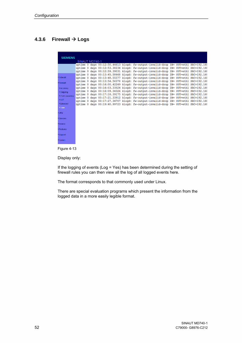
4.3.6 Firewall Logs
Figure 4-13
Display only:
If the logging of events (Log = Yes) has been determined during the setting of firewall rules you can then view all the log of all logged events here.
The format corresponds to that commonly used under Linux.
There are special evaluation programs which present the information from the logged data in a more easily legible format.
SINAUT MD740-1 52 C79000- G8976-C212
Configuration
4.4 VPN menu
The general prerequisite for a VPN connection is that the IP addresses of the VPN partners are known and accessible. See section 1.3.
In order for an IPSec connection to be established successfully the VPN remote site must support IPsec with the following configuration:
● Authentication via Pre-Shared Key (PSK) or X.509 certificates
● ESP
● Diffie-Hellman groups 2 or 5
● DES, 3DES or AES encryption
● MD5 or SHA-1 Hash algorithms
● Tunnel or transport mode
● Quick mode
● Main mode
● SA Lifetime (1 second to 24 hours)
If the remote site is a computer running under Windows 2000, the Microsoft Windows 2000 High Encryption Pack or at least Service Pack 2 must be installed.
If the remote site is behind a NAT router it must support NAT-T. Alternatively, the NAT router must recognise the IPsec protocol (IPsec/VPN Passthrough). In both cases, only IPsec tunnel connections are possible for technical reasons.
SINAUT MD740-1 C79000-G8976-C212 53
Configuration
4.4.1 VPN connections
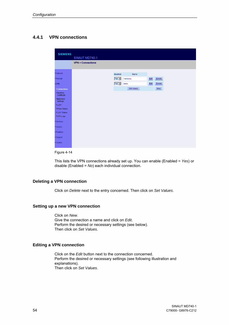
Figure 4-14
This lists the VPN connections already set up. You can enable (Enabled = Yes) or disable (Enabled = No) each individual connection.
Deleting a VPN connection
Click on Delete next to the entry concerned. Then click on Set Values.
Setting up a new VPN connection
Click on New. Give the connection a name and click on Edit. Perform the desired or necessary settings (see below). Then click on Set Values.
Editing a VPN connection
Click on the Edit button next to the connection concerned. Perform the desired or necessary settings (see following illustration and explanations). Then click on Set Values.
SINAUT MD740-1 54 C79000- G8976-C212

Configuration
Figure 4-15
A descriptive name for the connection
You can name or rename the connection as you wish.
Enabled
Determine whether the connection is to be enabled (= Yes) or not (= No).
SINAUT MD740-1 C79000-G8976-C212 55
Configuration
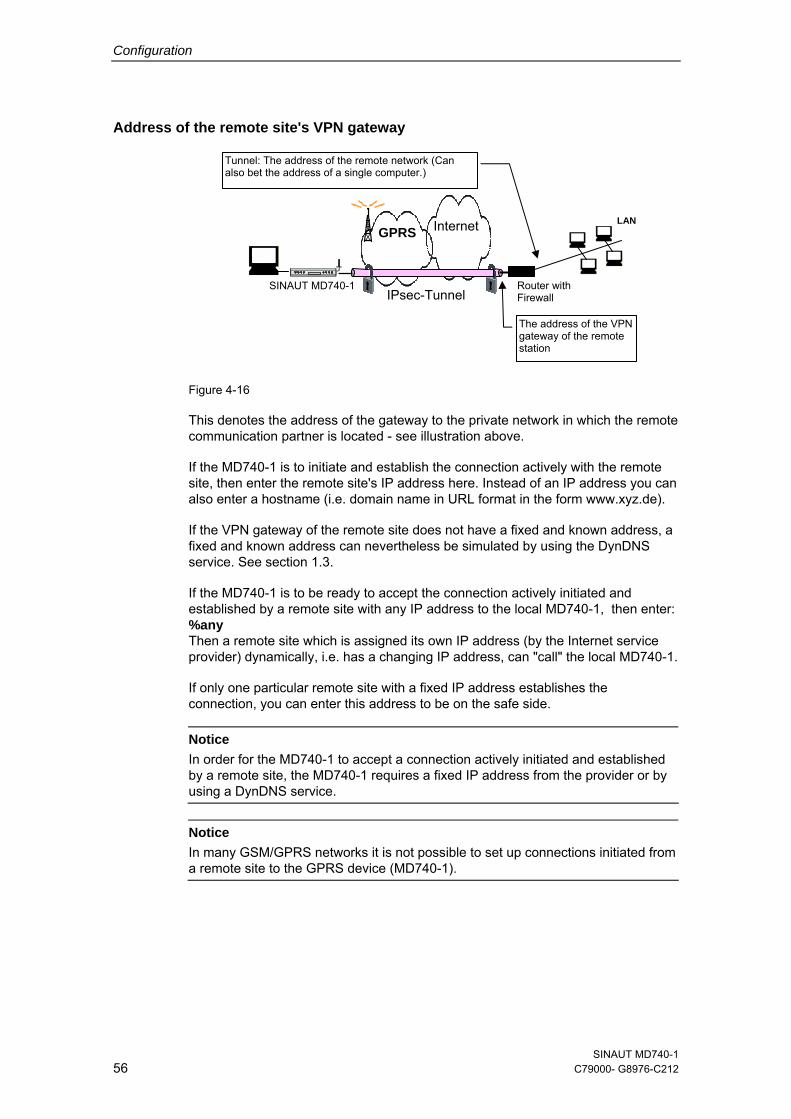
Address of the remote site's VPN gateway Figure 4-16
This denotes the address of the gateway to the private network in which the remote communication partner is located - see illustration above.
If the MD740-1 is to initiate and establish the connection actively with the remote site, then enter the remote site's IP address here. Instead of an IP address you can also enter a hostname (i.e. domain name in URL format in the form www.xyz.de).
If the VPN gateway of the remote site does not have a fixed and known address, a fixed and known address can nevertheless be simulated by using the DynDNS service. See section 1.3.
If the MD740-1 is to be ready to accept the connection actively initiated and established by a remote site with any IP address to the local MD740-1, then enter: %any Then a remote site which is assigned its own IP address (by the Internet service provider) dynamically, i.e. has a changing IP address, can "call" the local MD740-1.
If only one particular remote site with a fixed IP address establishes the connection, you can enter this address to be on the safe side.
Router with Firewall
LAN
SINAUT MD740-1
GPRS Internet
Tunnel: The address of the remote network (Can also bet the address of a single computer.)
IPsec-Tunnel
The address of the VPN gateway of the remote station
Notice In order for the MD740-1 to accept a connection actively initiated and established by a remote site, the MD740-1 requires a fixed IP address from the provider or by using a DynDNS service.
Notice In many GSM/GPRS networks it is not possible to set up connections initiated from a remote site to the GPRS device (MD740-1).
SINAUT MD740-1 56 C79000- G8976-C212
Configuration
Authentication method
There are 2 possibilities:
● X.509 Certificate
● Pre-Shared Key
X.509 Certificate
This method is supported by most newer IPSec implementations. The MD740-1 encrypts the authentication datagrams that it sends to the remote site - the "end of the tunnel" - with the remote site's public key (file name *.cer or *.pem). (You received this *.cer or *.pem file from the operator of the remote site, e.g. on a disk or by e-mail).
To make this public key available to the MD740-1, proceed as follows:
Prerequisite:
You have stored the *.cer or *.pem file on the locally connected computer.
1. Click on Configure. Consequence: The VPN > Connections > Connection xyz > X.509 Certificate screen appears. ("xyz" is the name of the connection concerned.)
2. Click on Browse... and select the file.
3. Click on Import.
After importing, the content of the new certificate is displayed – see following illustration. You will find an explanation of the displayed information in section 4.4.2.
SINAUT MD740-1 C79000-G8976-C212 57
Configuration
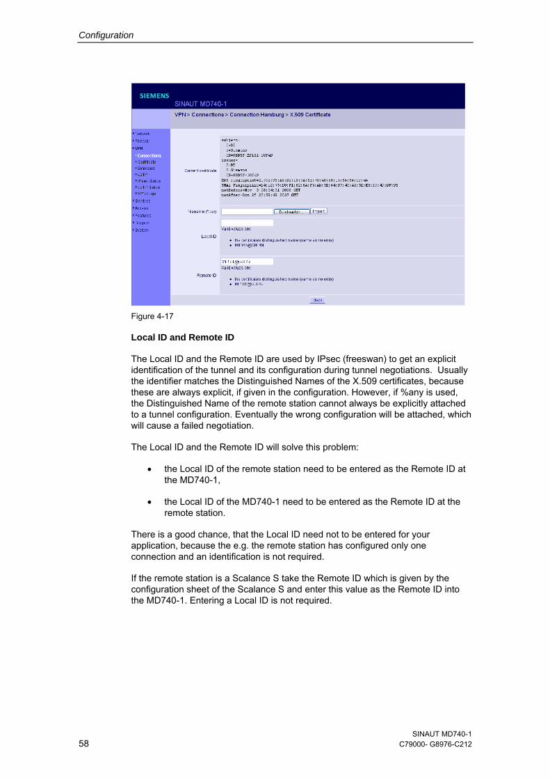
Figure 4-17
Local ID and Remote ID
The Local ID and the Remote ID are used by IPsec (freeswan) to get an explicit identification of the tunnel and its configuration during tunnel negotiations. Usually the identifier matches the Distinguished Names of the X.509 certificates, because these are always explicit, if given in the configuration. However, if %any is used, the Distinguished Name of the remote station cannot always be explicitly attached to a tunnel configuration. Eventually the wrong configuration will be attached, which will cause a failed negotiation.
The Local ID and the Remote ID will solve this problem:
• the Local ID of the remote station need to be entered as the Remote ID at the MD740-1,
• the Local ID of the MD740-1 need to be entered as the Remote ID at the remote station.
There is a good chance, that the Local ID need not to be entered for your application, because the e.g. the remote station has configured only one connection and an identification is not required.
If the remote station is a Scalance S take the Remote ID which is given by the configuration sheet of the Scalance S and enter this value as the Remote ID into the MD740-1. Entering a Local ID is not required.
SINAUT MD740-1 58 C79000- G8976-C212
Configuration
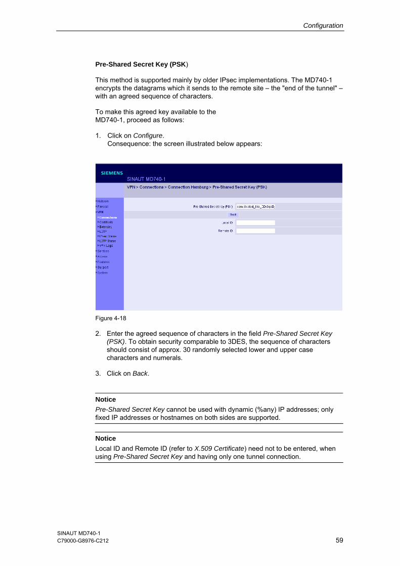
Pre-Shared Secret Key (PSK)
This method is supported mainly by older IPsec implementations. The MD740-1 encrypts the datagrams which it sends to the remote site – the "end of the tunnel" – with an agreed sequence of characters.
To make this agreed key available to the MD740-1, proceed as follows:
1. Click on Configure. Consequence: the screen illustrated below appears:
Figure 4-18
2. Enter the agreed sequence of characters in the field Pre-Shared Secret Key (PSK). To obtain security comparable to 3DES, the sequence of characters should consist of approx. 30 randomly selected lower and upper case characters and numerals.
3. Click on Back.
Notice
Pre-Shared Secret Key cannot be used with dynamic (%any) IP addresses; only fixed IP addresses or hostnames on both sides are supported.
Notice Local ID and Remote ID (refer to X.509 Certificate) need not to be entered, when using Pre-Shared Secret Key and having only one tunnel connection.
SINAUT MD740-1 C79000-G8976-C212 59
Configuration
Connection type
There are four options:
● Tunnel (network network)
● Transport (host host)
● Transport (L2TP Microsoft Windows)
● Transport (L2TP SSH Sentinel)
Tunnel (network network)
This connection type is suitable in every case and it is also the safest. In this mode the IP datagrams to be transferred are completely encrypted and sent with a new header to the remote site's VPN gateway, the "end of the tunnel". There the transferred datagrams are decrypted and the original datagrams retrieved from them. These can then be sent to the destination computer.
Transport (host host)
With this connection type only the data in the IP packets are encrypted. The IP header information is not encrypted.
Transport (L2TP Microsoft Windows)
If this connection is enabled on the remote computer, you should also set the MD740-1 to Transport (L2TP Microsoft Windows). The MD740-1 will then work accordingly. The L2TP/PPP protocol creates a tunnel within the IPsec Transport connection. The locally connected L2TP computer is assigned its IP address dynamically by the MD740-1.
If you select the connection type Transport (L2TP Microsoft Windows), set Perfect Forward Secrecy (PFS) to No. Also enable the L2TP server.
Notice
As soon as the IPsec/L2TP connection is started under Windows, a dialogue box appears, asking for the user name and login. You can enter anything here because authentication has already taken place via the X.509 certificates, so that the MD740-1 ignores these entries.
Transport (L2TP SSH Sentinel)
If this connection is enabled on the remote computer, you should also set the MD740-1 to Transport (L2TP SSH Sentinel). The MD740-1 will then work accordingly. The L2TP/PPP protocol creates a tunnel within the IPsec Transport connection. The locally connected L2TP computer is assigned its IP address dynamically by the MD740-1. Also enable the L2TP server.
SINAUT MD740-1 60 C79000- G8976-C212
Configuration
Connection startup There are 2 possibilities:
● Start the connection to the remote site
● Wait for the remote site
Start the connection to the remote site
In this case the local MD740-1 initiates the connection to the remote site. The fixed IP address of the remote site or its domain name must be entered in the Remote site's VPN gateway address field (see above).
Wait for the remote site
In this case the local MD740-1 is ready to accept the connection actively initiated and established by a remote site to the local MD740-1. %any can be entered in the Remote site's VPN gateway address field (see above).
If only one particular remote site with a fixed IP address establishes the connection, enter its IP address or host name to be on the safe side.
Notice
In order for a connection to the MD740-1 to be established, the MD740-1 requires a fixed IP address from the provider or by using a DynDNS service.
Notice
In many GSM/GPRS networks it is not possible to set up connections initiated from a remote site to the GPRS device (MD740-1).
SINAUT MD740-1 C79000-G8976-C212 61
Configuration
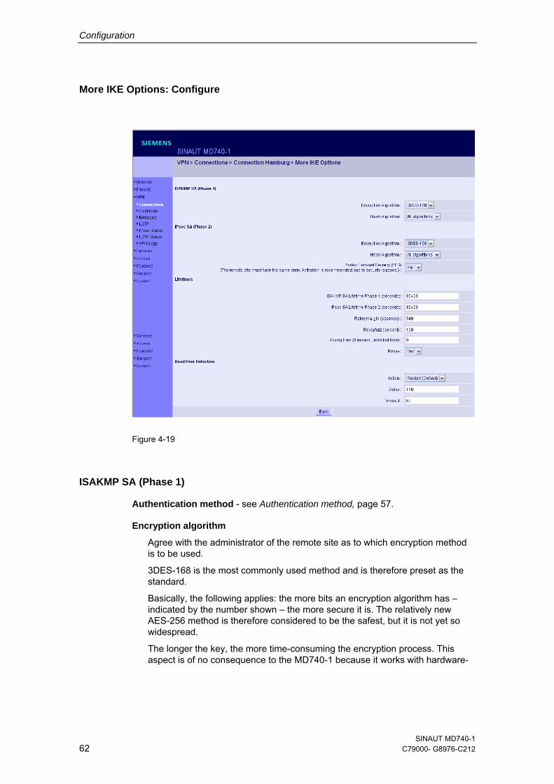
More IKE Options: Configure
Figure 4-19
ISAKMP SA (Phase 1)
Authentication method - see Authentication method, page 57.
Encryption algorithm
Agree with the administrator of the remote site as to which encryption method is to be used.
3DES-168 is the most commonly used method and is therefore preset as the standard.
Basically, the following applies: the more bits an encryption algorithm has – indicated by the number shown – the more secure it is. The relatively new AES-256 method is therefore considered to be the safest, but it is not yet so widespread.
The longer the key, the more time-consuming the encryption process. This aspect is of no consequence to the MD740-1 because it works with hardware-
SINAUT MD740-1 62 C79000- G8976-C212
Configuration
based encryption technology. Nevertheless, this aspect could be significant for the remote site.
The selectable algorithm marked "Zero" contains no encryption at all.
Checksum algorithm/Hash
Leave the setting on All algorithms. Then it makes no difference whether the remote site works with MD5 or SHA-1.
IPsec SA (Phase 2)
Unlike ISAKMP SA (Phase 1) (see above) the method for data exchange is determined here. This may differ from that of the Key Exchange, but not necessarily.
Encryption algorithm
See above.
Checksum algorithm/Hash
See above.
Perfect Forward Secrecy (PFS)
A method for the additional improvement of security during data transfer. With IPsec, the keys for data exchange are renewed at certain intervals. With PFS, new random numbers are negotiated with the remote site instead of deriving them from previously agreed random numbers.
Only if the remote site supports PFS, select Yes.
When selecting the connection type Transport (L2TP Microsoft Windows) set Perfect Forward Secrecy (PFS) to No.
Lifetimes
The keys of an IPsec connection are renewed after certain times so that it will be more effortful to try to attack an IPsec connection.
ISAKMP SA lifetime (seconds) The lifetime of keys (in seconds) that is agreed for the ISAKMP SA. The default value is 86400, that is 1 hour. The allowed maximum is 86400 seconds (= 24 hours).
IPsec SA lifetime (seconds) The lifetime of keys (in seconds) that is agreed for the IPsec SA. The default value is 86400, that is 8 hours. The allowed maximum is 86400 seconds (= 24 hours).
SINAUT MD740-1 C79000-G8976-C212 63
Configuration
Rekeymargin (seconds) The minimum time period in which a new key must be generated before the old keys get invalid. Default: 540 seconds (9 minutes).
Rekeyfuzz (per cent) The maximum in per cent by which the Rekey Margin is to be extended randomly. By this the key exchange between machines with many VPN connections running takes place too deferred. Default: 100 per cent.
Keying Trials (0 means unlimited) Number of trials that have to be done to agree with the remote site upon new keys. The value 0 means that the MD740-1 has to do an unlimited number of trials with the remote site in cases the MD740-1 is the initiator of the connections. The default value is 5.
Rekey (Yes / No) When Yes is set this side will try to agree with the remote site upon a new key when the old key has gone invalid.
Dead Peer Detection
If also the remote site supports the Dead Peer Detection (DPD) protocol both partners are able to recognize whether the IPsec connection is still valid or not and has to be reestablished in this case. Without DPD the devices, according to their configurations, have to wait till the end of the SA Lifetime. Or the connection must be initiated manually.
Action: Clear / Hold / Restart (Default) With Hold the device will try to reestablish the IPsec connection after the old one was declared as dead, but only, if the local network tries to send data to the remote station. With Restart the device will try to reestablish the IPsec connection after the old one was declared as dead irrespective of trials of the local network to send data. If Clear is set there will be no trial to reestablish the connection. Default: Hold.
Delay Period of time (in seconds) after which DPD inquiries are to be sent. With these inquiries it is examined whether the remote site is still available or not. Default: 300 seconds.
Timeout Period of time (in seconds) after which the connection to the remote site is to be declared as dead if there was no answer to the DPD inquiries. Default: 120 seconds.
SINAUT MD740-1 64 C79000- G8976-C212
Configuration
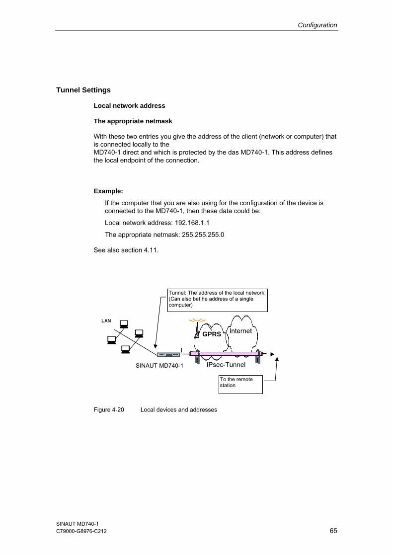
Tunnel Settings
Local network address
The appropriate netmask
With these two entries you give the address of the client (network or computer) that is connected locally to the MD740-1 direct and which is protected by the das MD740-1. This address defines the local endpoint of the connection.
Example:
If the computer that you are also using for the configuration of the device is connected to the MD740-1, then these data could be:
Local network address: 192.168.1.1
The appropriate netmask: 255.255.255.0
See also section 4.11.
Figure 4-20 Local devices and addresses
SINAUT MD740-1
GPRS InternetLAN
IPsec-Tunnel
To the remote station
Tunnel: The address of the local network. (Can also bet he address of a single computer)
SINAUT MD740-1 C79000-G8976-C212 65
Configuration
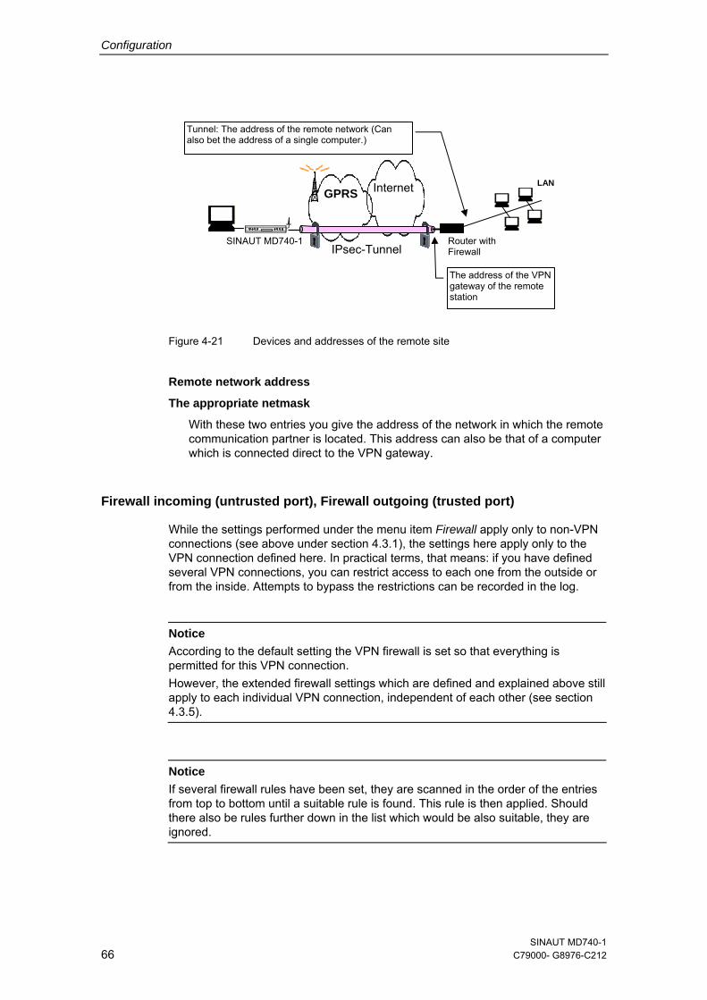
Figure 4-21 Devices and addresses of the remote site
Remote network address
The appropriate netmask
With these two entries you give the address of the network in which the remote communication partner is located. This address can also be that of a computer which is connected direct to the VPN gateway.
Firewall incoming (untrusted port), Firewall outgoing (trusted port)
While the settings performed under the menu item Firewall apply only to non-VPN connections (see above under section 4.3.1), the settings here apply only to the VPN connection defined here. In practical terms, that means: if you have defined several VPN connections, you can restrict access to each one from the outside or from the inside. Attempts to bypass the restrictions can be recorded in the log.
Router with Firewall
LAN
SINAUT MD740-1
GPRS Internet
Tunnel: The address of the remote network (Can also bet the address of a single computer.)
IPsec-Tunnel
The address of the VPN gateway of the remote station
Notice According to the default setting the VPN firewall is set so that everything is permitted for this VPN connection. However, the extended firewall settings which are defined and explained above still apply to each individual VPN connection, independent of each other (see section 4.3.5).
Notice
If several firewall rules have been set, they are scanned in the order of the entries from top to bottom until a suitable rule is found. This rule is then applied. Should there also be rules further down in the list which would be also suitable, they are ignored.
SINAUT MD740-1 66 C79000- G8976-C212
Configuration
Setting or deleting a firewall rule
To set or delete a firewall rule, proceed exactly as described above (see section 4.3.1 and 4.3.2.
As there, you can make the following possible entries:
Protocol:
All means: TCP, UDP, ICMP and others.
To / from IP:
0.0.0.0/0 means all addresses. To denote a range, use CIDR syntax – see section 4.10.
To / From Port: (is evaluated only with TCP and UDP protocols)
any means any port.
startport:endport (e.g. 110:120) denotes the port area.
Individual ports can be entered either with the port number or with the corresponding service name: (e.g. 110 for pop3 or pop3 for 110).
Action:
Accept means that the data packets may pass. Refuse means that the data packets are turned away so that the sender is informed of the refusal. Reject means that data packets are not allowed to pass. They are "swallowed" so that the sender is not informed of their whereabouts.
Log:
For each individual firewall rule you can determine whether, when the rule is applied,
- the event is to be logged - set Log to Yes
- or not - set Log to No (default setting)
Log entries for unknown connection attempts:
This logs all connection attempts which are not recorded by the prevalent rules.
If several firewall rules have been set, they are followed in the order of the entries.
SINAUT MD740-1 C79000-G8976-C212 67
Configuration
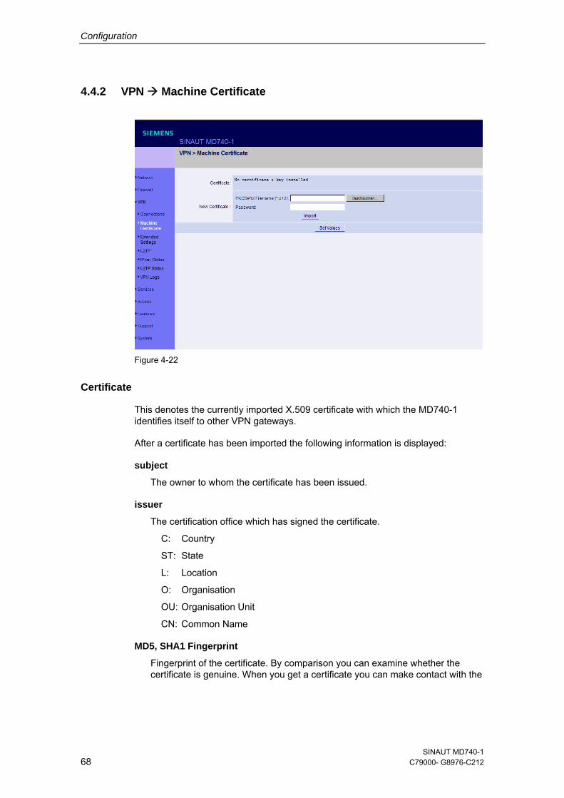
4.4.2 VPN Machine Certificate
Figure 4-22
Certificate
This denotes the currently imported X.509 certificate with which the MD740-1 identifies itself to other VPN gateways.
After a certificate has been imported the following information is displayed:
subject
The owner to whom the certificate has been issued.
issuer
The certification office which has signed the certificate.
C: Country
ST: State
L: Location
O: Organisation
OU: Organisation Unit
CN: Common Name
MD5, SHA1 Fingerprint
Fingerprint of the certificate. By comparison you can examine whether the certificate is genuine. When you get a certificate you can make contact with the
SINAUT MD740-1 68 C79000- G8976-C212

Configuration
party from which you got the certificate to compare the fingerprint with him. Windows displays the fingerprint in SHA1 format at this point.
notBefore, notAfter
Validity period of the certificate. Is ignored by the MD740-1 due to lack of an internal clock.
The imported certificate file (filename extension *.p12 or *.pfx) contains the information given above, as well the two keys: the public key for encryption, the private key for decryption. The appropriate public key can be assigned any number of connection partners, enabling them to send encrypted data.
In agreement with the remote site, the certificate must be made available to the operator of the remote site as a .cer or .pem file, e.g. handed over personally or by e-mail. If you do not have a secure mode of transfer, you should then compared the fingerprint displayed by the MD740-1 via a secure channel.
Only one certificate file (PKCS#12 file) can be imported into the device.
To important a (new) certificate, proceed as follows:
New certificate
Prerequisite: The certificate file (file name = *.p12 or *.pfx) is generated and stored on the connected computer.
1. Click on Browse... to select the file.
2. Enter the password with which the private key of the PKCS#12 file is protected in the field Password.
3. Click on Import.
4. Then click on Set Values.
SINAUT MD740-1 C79000-G8976-C212 69
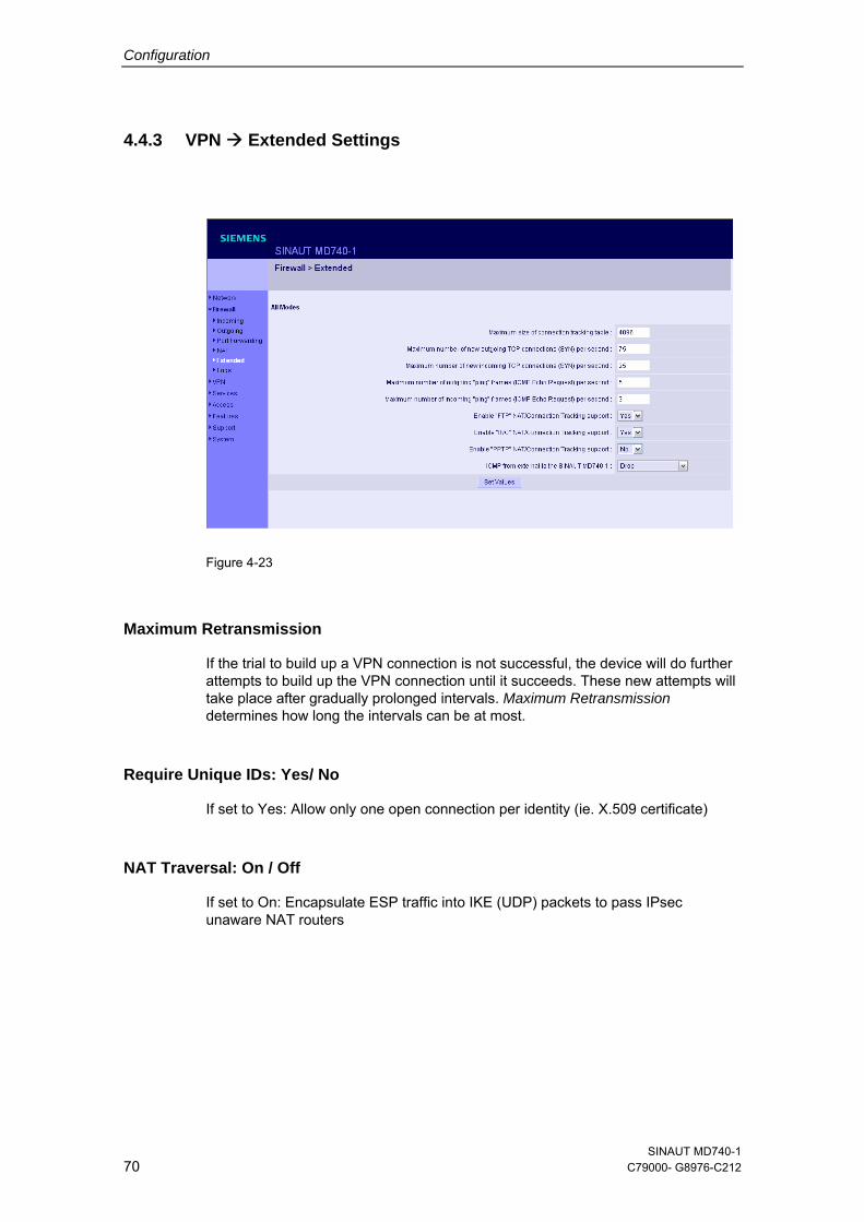
Configuration
4.4.3 VPN Extended Settings
Figure 4-23
Maximum Retransmission
If the trial to build up a VPN connection is not successful, the device will do further attempts to build up the VPN connection until it succeeds. These new attempts will take place after gradually prolonged intervals. Maximum Retransmission determines how long the intervals can be at most.
Require Unique IDs: Yes/ No
If set to Yes: Allow only one open connection per identity (ie. X.509 certificate)
NAT Traversal: On / Off
If set to On: Encapsulate ESP traffic into IKE (UDP) packets to pass IPsec unaware NAT routers
SINAUT MD740-1 70 C79000- G8976-C212
Configuration
Enable NAT-T Portfloating: On / Off
Some NAT routers fail to perform NAT originating from low UDP ports. This option moves IKE from UDP 500 to UDP 4500 if possible.
NAT-T Keepalive Interval
(In seconds, default is 300). Keepalives tell the NAT router not to close the connection during inactivity.
Force NAT-T Keepalive: Yes / No
If set to Yes: When negotiating the connection parameters the system insists to exchange NAT-T Keepalive packets during the connection.
Hide Type of Service (TOS) Bit: Yes / No
When set to Yes: The TOS bit will be cleared on IPsec output.
IPsec 0 MTU (default is 16260)
Reserved. Don’t change the value.
SINAUT MD740-1 C79000-G8976-C212 71
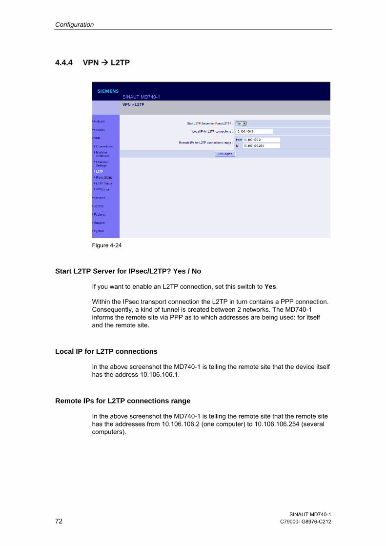
Configuration
4.4.4 VPN L2TP
Figure 4-24
Start L2TP Server for IPsec/L2TP? Yes / No
If you want to enable an L2TP connection, set this switch to Yes.
Within the IPsec transport connection the L2TP in turn contains a PPP connection. Consequently, a kind of tunnel is created between 2 networks. The MD740-1 informs the remote site via PPP as to which addresses are being used: for itself and the remote site.
Local IP for L2TP connections
In the above screenshot the MD740-1 is telling the remote site that the device itself has the address 10.106.106.1.
Remote IPs for L2TP connections range
In the above screenshot the MD740-1 is telling the remote site that the remote site has the addresses from 10.106.106.2 (one computer) to 10.106.106.254 (several computers).
SINAUT MD740-1 72 C79000- G8976-C212
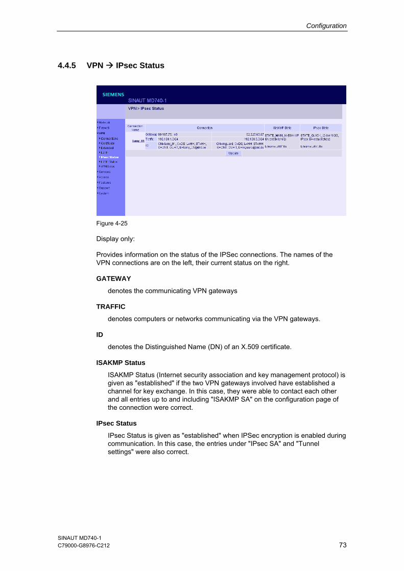
Configuration
4.4.5 VPN IPsec Status
Figure 4-25
Display only:
Provides information on the status of the IPSec connections. The names of the VPN connections are on the left, their current status on the right.
GATEWAY
denotes the communicating VPN gateways
TRAFFIC
denotes computers or networks communicating via the VPN gateways.
ID
denotes the Distinguished Name (DN) of an X.509 certificate.
ISAKMP Status
ISAKMP Status (Internet security association and key management protocol) is given as "established" if the two VPN gateways involved have established a channel for key exchange. In this case, they were able to contact each other and all entries up to and including "ISAKMP SA" on the configuration page of the connection were correct.
IPsec Status
IPsec Status is given as "established" when IPSec encryption is enabled during communication. In this case, the entries under "IPsec SA" and "Tunnel settings" were also correct.
SINAUT MD740-1 C79000-G8976-C212 73
Configuration
If there are problems, it is recommended to look at the VPN logs of the computer to which the connection was established, because the initiating computer receives no detailed error messages for security reasons.
The message
ISAKMP SA established, IPsec State: WAITING
means: Authentication was successful, but the other parameters were not correct. Does the connection type (tunnel, transport) correspond? If tunnel was selected, do the network areas on both sides correspond?
The message
IPsec State: IPsec SA established
means: The VPN has been successfully established and can be used. However, if this is not the case, then there are problems with the remote site's VPN gateway. In this case, tag the connection name and then click on Set Values to restart the connection.
SINAUT MD740-1 74 C79000- G8976-C212
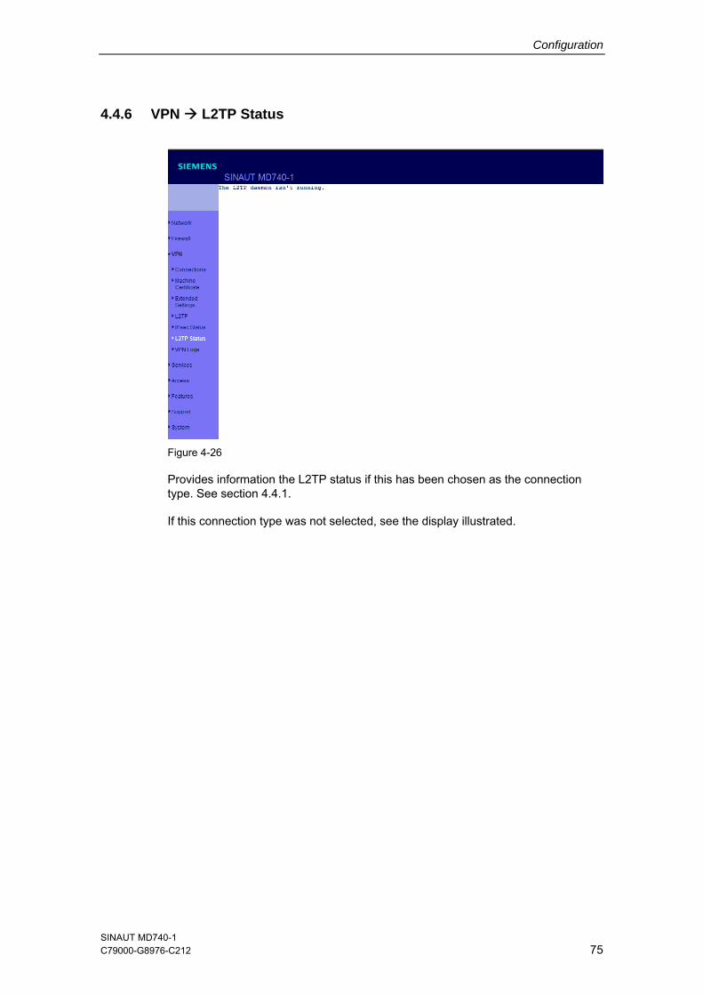
Configuration
4.4.6 VPN L2TP Status
Figure 4-26
Provides information the L2TP status if this has been chosen as the connection type. See section 4.4.1.
If this connection type was not selected, see the display illustrated.
SINAUT MD740-1 C79000-G8976-C212 75
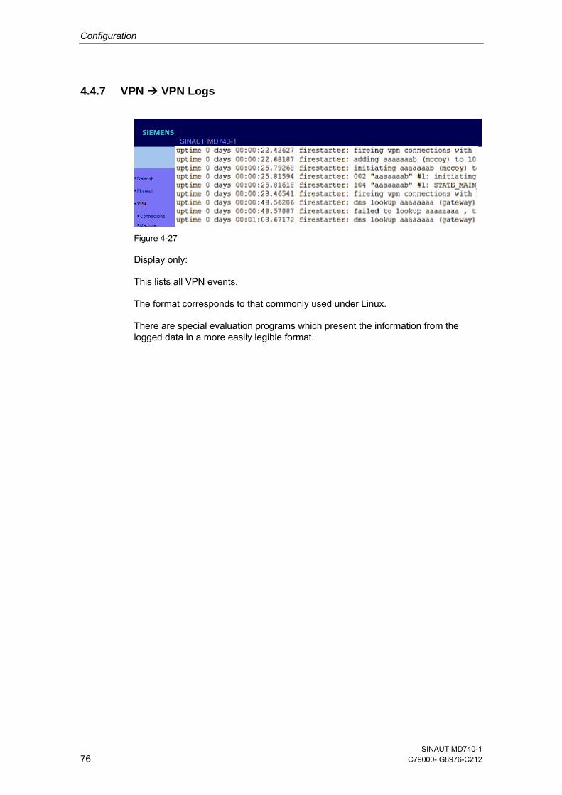
Configuration
4.4.7 VPN VPN Logs
Figure 4-27
Display only:
This lists all VPN events.
The format corresponds to that commonly used under Linux.
There are special evaluation programs which present the information from the logged data in a more easily legible format.
SINAUT MD740-1 76 C79000- G8976-C212
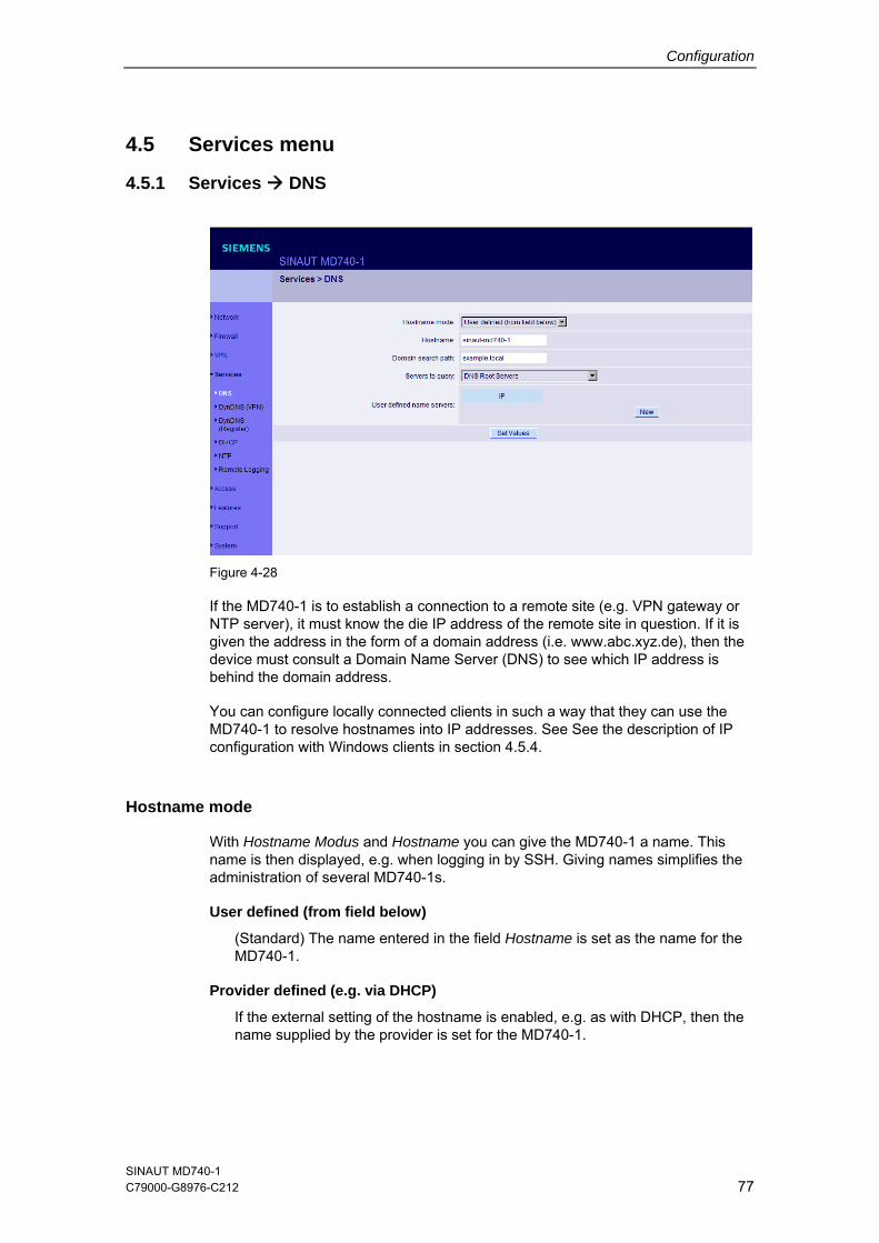
Configuration
4.5 Services menu
4.5.1 Services DNS
Figure 4-28
If the MD740-1 is to establish a connection to a remote site (e.g. VPN gateway or NTP server), it must know the die IP address of the remote site in question. If it is given the address in the form of a domain address (i.e. www.abc.xyz.de), then the device must consult a Domain Name Server (DNS) to see which IP address is behind the domain address.
You can configure locally connected clients in such a way that they can use the MD740-1 to resolve hostnames into IP addresses. See See the description of IP configuration with Windows clients in section 4.5.4.
Hostname mode
With Hostname Modus and Hostname you can give the MD740-1 a name. This name is then displayed, e.g. when logging in by SSH. Giving names simplifies the administration of several MD740-1s.
User defined (from field below)
(Standard) The name entered in the field Hostname is set as the name for the MD740-1.
Provider defined (e.g. via DHCP)
If the external setting of the hostname is enabled, e.g. as with DHCP, then the name supplied by the provider is set for the MD740-1.
SINAUT MD740-1 C79000-G8976-C212 77
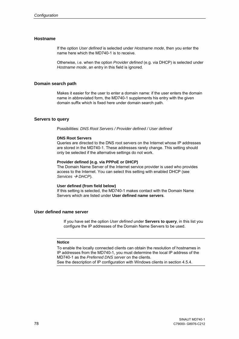
Configuration
Hostname
If the option User defined is selected under Hostname mode, then you enter the name here which the MD740-1 is to receive.
Otherwise, i.e. when the option Provider defined (e.g. via DHCP) is selected under Hostname mode, an entry in this field is ignored.
Domain search path
Makes it easier for the user to enter a domain name: if the user enters the domain name in abbreviated form, the MD740-1 supplements his entry with the given domain suffix which is fixed here under domain search path.
Servers to query
Possibilities: DNS Root Servers / Provider defined / User defined
DNS Root Servers Queries are directed to the DNS root servers on the Internet whose IP addresses are stored in the MD740-1. These addresses rarely change. This setting should only be selected if the alternative settings do not work.
Provider defined (e.g. via PPPoE or DHCP) The Domain Name Server of the Internet service provider is used who provides access to the Internet. You can select this setting with enabled DHCP (see Services DHCP).
User defined (from field below) If this setting is selected, the MD740-1 makes contact with the Domain Name Servers which are listed under User defined name servers.
User defined name server
If you have set the option User defined under Servers to query, in this list you configure the IP addresses of the Domain Name Servers to be used.
Notice
To enable the locally connected clients can obtain the resolution of hostnames in IP addresses from the MD740-1, you must determine the local IP address of the MD740-1 as the Preferred DNS server on the clients. See the description of IP configuration with Windows clients in section 4.5.4.
SINAUT MD740-1 78 C79000- G8976-C212
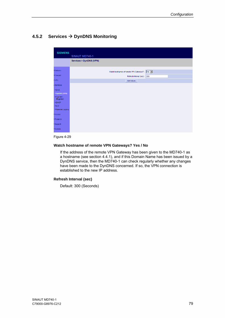
Configuration
4.5.2 Services DynDNS Monitoring
Figure 4-29
Watch hostname of remote VPN Gateways? Yes / No
If the address of the remote VPN Gateway has been given to the MD740-1 as a hostname (see section 4.4.1), and if this Domain Name has been issued by a DynDNS service, then the MD740-1 can check regularly whether any changes have been made to the DynDNS concerned. If so, the VPN connection is established to the new IP address.
Refresh Interval (sec)
Default: 300 (Seconds)
SINAUT MD740-1 C79000-G8976-C212 79
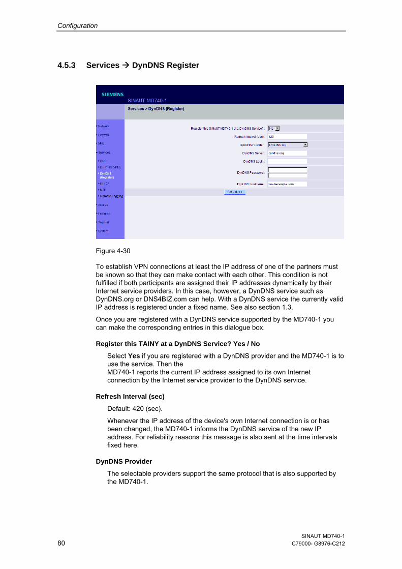
Configuration
4.5.3 Services DynDNS Register
Figure 4-30
To establish VPN connections at least the IP address of one of the partners must be known so that they can make contact with each other. This condition is not fulfilled if both participants are assigned their IP addresses dynamically by their Internet service providers. In this case, however, a DynDNS service such as DynDNS.org or DNS4BIZ.com can help. With a DynDNS service the currently valid IP address is registered under a fixed name. See also section 1.3.
Once you are registered with a DynDNS service supported by the MD740-1 you can make the corresponding entries in this dialogue box.
Register this TAINY at a DynDNS Service? Yes / No
Select Yes if you are registered with a DynDNS provider and the MD740-1 is to use the service. Then the MD740-1 reports the current IP address assigned to its own Internet connection by the Internet service provider to the DynDNS service.
Refresh Interval (sec)
Default: 420 (sec).
Whenever the IP address of the device's own Internet connection is or has been changed, the MD740-1 informs the DynDNS service of the new IP address. For reliability reasons this message is also sent at the time intervals fixed here.
DynDNS Provider
The selectable providers support the same protocol that is also supported by the MD740-1.
SINAUT MD740-1 80 C79000- G8976-C212
Configuration
Enter the name of the provider with whom you are registered, e.g. DynDNS.org
DynDNS Server
Name of the server of the DynDNS provider selected above, e.g. dyndns.org
DynDNS Login, DynDNS Password
Here you enter the user name and the password assigned to you by the DynDNS provider.
DynDNS Hostname
The hostname selected for this MD740-1 with the DynDNS service – provided that you use a DynDNS service and have given the appropriate details above.
SINAUT MD740-1 C79000-G8976-C212 81
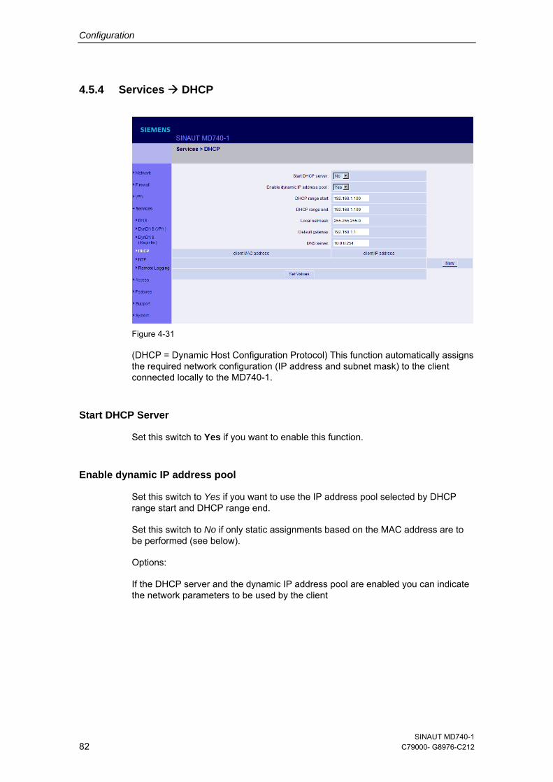
Configuration
4.5.4 Services DHCP
Figure 4-31
(DHCP = Dynamic Host Configuration Protocol) This function automatically assigns the required network configuration (IP address and subnet mask) to the client connected locally to the MD740-1.
Start DHCP Server
Set this switch to Yes if you want to enable this function.
Enable dynamic IP address pool
Set this switch to Yes if you want to use the IP address pool selected by DHCP range start and DHCP range end.
Set this switch to No if only static assignments based on the MAC address are to be performed (see below).
Options:
If the DHCP server and the dynamic IP address pool are enabled you can indicate the network parameters to be used by the client
SINAUT MD740-1 82 C79000- G8976-C212
Configuration
DHCP range start: DHCP range end:
Start and end of the address range from which the DHCP server of the MD740-1 is to assign IP addresses to the locally connected clients.
Local netmask: Default setting: 255.255.255.0
Default Gateway: Determines which IP address is to be used as the default gateway by the client. This is usually the local IP address of the MD740-1.
DNS Server: Determines from where clients receive resolution of hostnames in IP addresses. If the DNS services of the MD740-1 is enabled it can be the local IP address of the MD740-1.
Table 4-4
Client MAC address / client IP address
You can establish the MAC address of your client as follows:
Windows 95/98/ME: Start "winipcfg" in a DOS box. Windows NT/2000/XP: Start "ipconfig /all" in a prompt. The MAC address is displayed as a "physical address".
Linux: Call up "/sbin/ifconfig" or "ip link show" in a shell.
Delete address
Click on Delete next to the entry concerned, then Set Values.
Add address
If you want to add a new address, click on New.
Enter the address data (see below) and click on Set Values.
Enter:
Client MAC address The MAC address (without spaces or hyphens) of the client.
Client IP address The static IP that is to be assigned to the client's MAC address.
Notice
● The static assignments take priority over the dynamic IP address pool.
● Static assignments must not overlap with the dynamic IP address pool.
● An IP must not be used in several static assignments, otherwise this IP will be assigned to several MAC addresses.
● Only one DHCP server per subnet must be used.
● When you start the DHCP server of the MD740-1 you must configure the locally connected clients in such a way that they receive their IP addresses automatically (see below).
SINAUT MD740-1 C79000-G8976-C212 83
Configuration
IP configuration with Windows clients
Under Windows XP, click on Start, Control Panel, Network Connections: right-click on the LAN adapter icon and click on Properties in the context menu. On the General tab in the Properties of LAN connection local network dialogue box, tag the Internet Protocol (TCP/IP) entry under "This connection uses the following items" and then click on the Properties button.
In the dialogue box Properties of Internet Protocol (TCP/IP), make the required entries and settings.
SINAUT MD740-1 84 C79000- G8976-C212
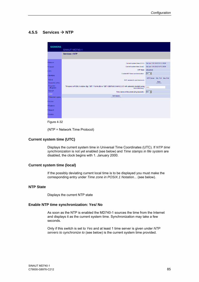
Configuration
4.5.5 Services NTP
Figure 4-32
(NTP = Network Time Protocol)
Current system time (UTC)
Displays the current system time in Universal Time Coordinates (UTC). If NTP time synchronization is not yet enabled (see below) and Time stamps in file system are disabled, the clock begins with 1. January 2000.
Current system time (local)
If the possibly deviating current local time is to be displayed you must make the corresponding entry under Time zone in POSIX.1 Notation... (see below).
NTP State
Displays the current NTP state
Enable NTP time synchronization: Yes/ No
As soon as the NTP is enabled the MD740-1 sources the time from the Internet and displays it as the current system time. Synchronization may take a few seconds.
Only if this switch is set to Yes and at least 1 time server is given under NTP servers to synchronize to (see below) is the current system time provided.
SINAUT MD740-1 C79000-G8976-C212 85
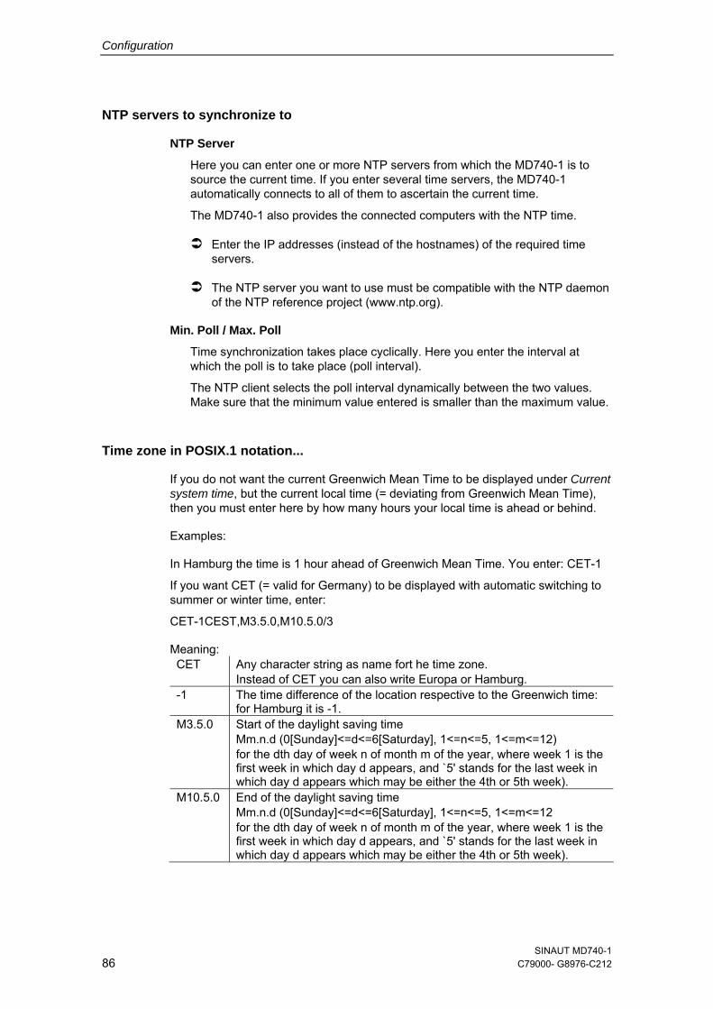
Configuration
NTP servers to synchronize to
NTP Server
Here you can enter one or more NTP servers from which the MD740-1 is to source the current time. If you enter several time servers, the MD740-1 automatically connects to all of them to ascertain the current time.
The MD740-1 also provides the connected computers with the NTP time.
Enter the IP addresses (instead of the hostnames) of the required time servers.
The NTP server you want to use must be compatible with the NTP daemon of the NTP reference project (www.ntp.org).
Min. Poll / Max. Poll
Time synchronization takes place cyclically. Here you enter the interval at which the poll is to take place (poll interval).
The NTP client selects the poll interval dynamically between the two values. Make sure that the minimum value entered is smaller than the maximum value.
Time zone in POSIX.1 notation...
If you do not want the current Greenwich Mean Time to be displayed under Current system time, but the current local time (= deviating from Greenwich Mean Time), then you must enter here by how many hours your local time is ahead or behind.
Examples:
In Hamburg the time is 1 hour ahead of Greenwich Mean Time. You enter: CET-1
If you want CET (= valid for Germany) to be displayed with automatic switching to summer or winter time, enter:
CET-1CEST,M3.5.0,M10.5.0/3
Meaning: CET Any character string as name fort he time zone.
Instead of CET you can also write Europa or Hamburg. -1 The time difference of the location respective to the Greenwich time:
for Hamburg it is -1. M3.5.0 Start of the daylight saving time
Mm.n.d (0[Sunday]<=d<=6[Saturday], 1<=n<=5, 1<=m<=12) for the dth day of week n of month m of the year, where week 1 is the first week in which day d appears, and `5' stands for the last week in which day d appears which may be either the 4th or 5th week).
M10.5.0 End of the daylight saving time Mm.n.d (0[Sunday]<=d<=6[Saturday], 1<=n<=5, 1<=m<=12 for the dth day of week n of month m of the year, where week 1 is the first week in which day d appears, and `5' stands for the last week in which day d appears which may be either the 4th or 5th week).
SINAUT MD740-1 86 C79000- G8976-C212
Configuration
/3 Hour when the daylight saving time ends: here 3 o’clock in the morning. When there is no entry 2 o’clock is used fort he time of change.
Time stamp in file system (2h granularity): Yes / No
If this switch is set to Yes, the MD740-1 writes the current system into its memory every 2 hours.
Consequence: If the MD740-1 is switched off and then back on, after being switched on a time in this 2-hour time window will be displayed and not a time on 1 January 2000.
SINAUT MD740-1 C79000-G8976-C212 87
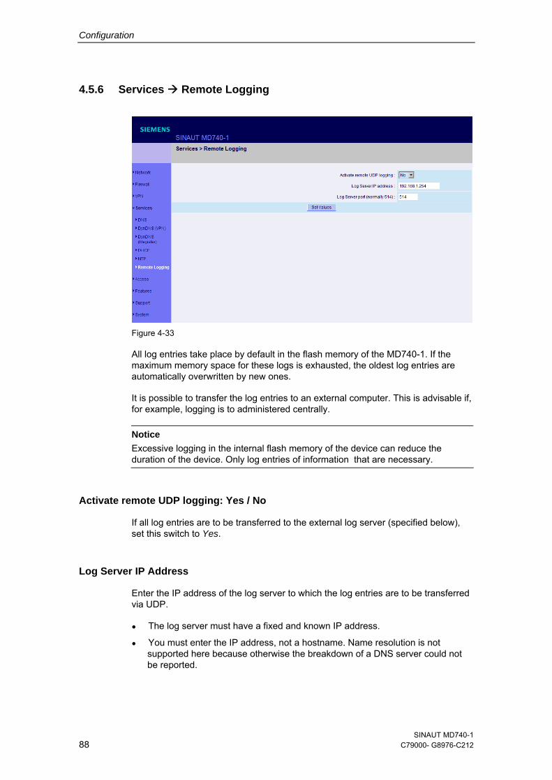
Configuration
4.5.6 Services Remote Logging
Figure 4-33
All log entries take place by default in the flash memory of the MD740-1. If the maximum memory space for these logs is exhausted, the oldest log entries are automatically overwritten by new ones.
It is possible to transfer the log entries to an external computer. This is advisable if, for example, logging is to administered centrally.
Notice Excessive logging in the internal flash memory of the device can reduce the duration of the device. Only log entries of information that are necessary.
Activate remote UDP logging: Yes / No
If all log entries are to be transferred to the external log server (specified below), set this switch to Yes.
Log Server IP Address
Enter the IP address of the log server to which the log entries are to be transferred via UDP.
● The log server must have a fixed and known IP address.
● You must enter the IP address, not a hostname. Name resolution is not supported here because otherwise the breakdown of a DNS server could not be reported.
SINAUT MD740-1 88 C79000- G8976-C212
Configuration
Log Server Port
Enter the port of the log server to which the log entries are to be transferred via UDP. Default: 514
SINAUT MD740-1 C79000-G8976-C212 89
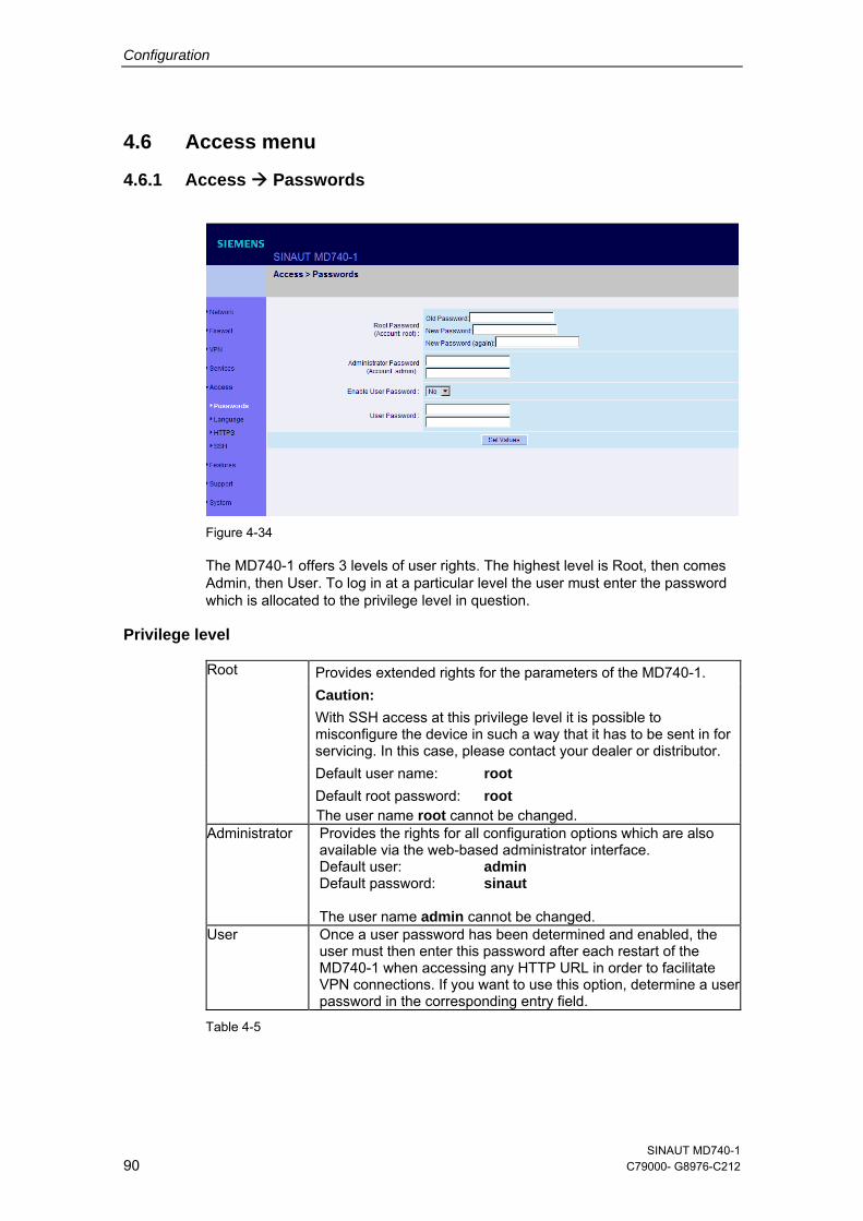
Configuration
4.6 Access menu
4.6.1 Access Passwords
Figure 4-34
The MD740-1 offers 3 levels of user rights. The highest level is Root, then comes Admin, then User. To log in at a particular level the user must enter the password which is allocated to the privilege level in question.
Privilege level Root Provides extended rights for the parameters of the MD740-1. Caution:
With SSH access at this privilege level it is possible to misconfigure the device in such a way that it has to be sent in for servicing. In this case, please contact your dealer or distributor.
Default user name: root Default root password: root The user name root cannot be changed.
Administrator Provides the rights for all configuration options which are also available via the web-based administrator interface. Default user: admin Default password: sinaut The user name admin cannot be changed.
User Once a user password has been determined and enabled, the user must then enter this password after each restart of the MD740-1 when accessing any HTTP URL in order to facilitate VPN connections. If you want to use this option, determine a user password in the corresponding entry field.
Table 4-5
SINAUT MD740-1 90 C79000- G8976-C212
Configuration
Root Password
Default setting: root
If you want to change the root password, enter the old password in the field Old Password, then enter the new password in the two fields below. (unalterable user name: root)
Administrator Password (Account: admin)
Default setting: sinaut (unalterable user name: admin)
Enable User Password: Yes / No
User password protection is switched off as default.
If a user password has been determined below, user password protection can be enabled or disabled with this switch.
User Password
No user password is preset as default. To determine one, enter the required password identically in each of the two entry fields.
SINAUT MD740-1 C79000-G8976-C212 91
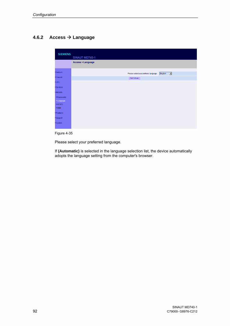
Configuration
4.6.2 Access Language
Figure 4-35
Please select your preferred language.
If (Automatic) is selected in the language selection list, the device automatically adopts the language setting from the computer's browser.
SINAUT MD740-1 92 C79000- G8976-C212
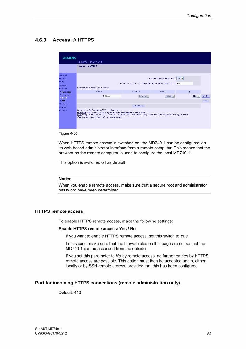
Configuration
4.6.3 Access HTTPS
Figure 4-36
When HTTPS remote access is switched on, the MD740-1 can be configured via its web-based administrator interface from a remote computer. This means that the browser on the remote computer is used to configure the local MD740-1.
This option is switched off as default
Notice
When you enable remote access, make sure that a secure root and administrator password have been determined.
HTTPS remote access
To enable HTTPS remote access, make the following settings:
Enable HTTPS remote access: Yes / No
If you want to enable HTTPS remote access, set this switch to Yes.
In this case, make sure that the firewall rules on this page are set so that the MD740-1 can be accessed from the outside.
If you set this parameter to No by remote access, no further entries by HTTPS remote access are possible. This option must then be accepted again, either locally or by SSH remote access, provided that this has been configured.
Port for incoming HTTPS connections (remote administration only)
Default: 443
SINAUT MD740-1 C79000-G8976-C212 93
Configuration
You can determine a different port.
If you have determined a different port, the remote site which makes the remote access must then give the port number after the IP address in the address information.
Example: If this MD740-1 can be reached via the Internet using the address 192.144.112.5, and if the port number 442 has been determined for remote access, then the following must be entered at the remote site in the web browser: 192.144.112.5:442
Firewall rules to accept HTTPS access
This lists the fixed firewall rules. They apply to the incoming data packet of a HTTPS remote access.
Delete rule
● Click on Delete next to the entry concerned.
Set new rule
1. If you want to set a new rule, click on New.
2. Set the required new rule (see below) and click on Set Values.
From IP
Here you enter the address(es) of the computer(s) which is/are allowed remote access. You can make the following possible entries:
IP address: 0.0.0.0/0 means all addresses. To denote a range, use CIDR syntax – see section 4.10.
Interface
extern (fixed)
Action
Possibilities: Accept / Refuse / Reject
Accept means that the data packets may pass.
Refuse means that the data packets are turned away so that the sender is informed of the refusal.
Reject means that data packets are not allowed to pass. They are swallowed so that the sender is not informed of their whereabouts.
Log
For each individual firewall rule you can determine whether, when the rule is applied, the event is to be logged - set Log to Yes
or not - set Log to No (default setting).
SINAUT MD740-1 94 C79000- G8976-C212
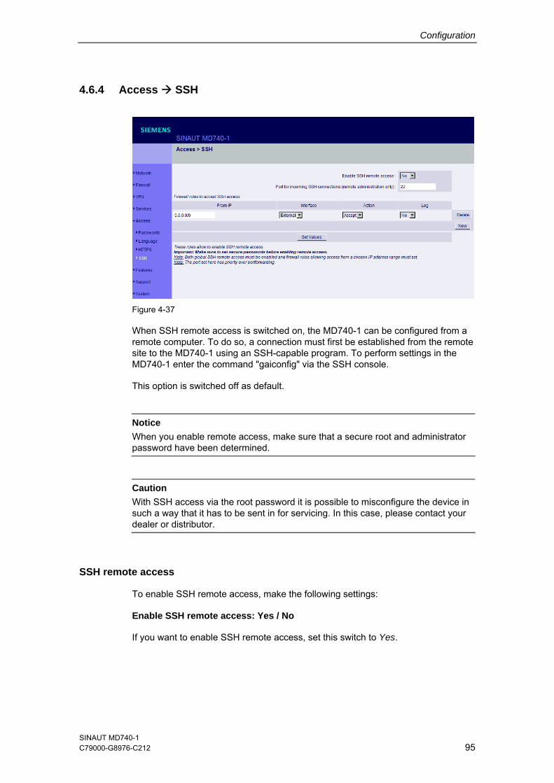
Configuration
4.6.4 Access SSH
Figure 4-37
When SSH remote access is switched on, the MD740-1 can be configured from a remote computer. To do so, a connection must first be established from the remote site to the MD740-1 using an SSH-capable program. To perform settings in the MD740-1 enter the command "gaiconfig" via the SSH console.
This option is switched off as default.
Notice
When you enable remote access, make sure that a secure root and administrator password have been determined.
Caution
With SSH access via the root password it is possible to misconfigure the device in such a way that it has to be sent in for servicing. In this case, please contact your dealer or distributor.
SSH remote access
To enable SSH remote access, make the following settings:
Enable SSH remote access: Yes / No
If you want to enable SSH remote access, set this switch to Yes.
SINAUT MD740-1 C79000-G8976-C212 95
Configuration
Notice In this case, make sure that the firewall rules on this page are set so that the MD740-1 can be accessed from the outside.
Port for incoming SSH connections (remote administration only)
Default: 22
You can determine a different port.
If you have determined a different port, the remote site which makes the remote access must then give the port number that is set here before the IP address in the address information.
Example: If this MD740-1 can be reached via the Internet using the address 192.144.112.5, and if a different port number has been set for remote access, then this number must be entered at the remote site in the SSH client (e.g. web browser), e.g.
ssh -p 22222 192.144.112.5
Firewall rules to accept SSH access
This lists the fixed firewall rules. They apply to the incoming data packet of a HTTPS remote access.
Delete rule
● Click on Delete next to the entry concerned.
Set new rule
1. If you want to set a new rule, click on New.
2. Set the required new rule (see below) and click on Set Values.
From IP
Here you enter the address(es) of the computer(s) which is/are allowed remote access. You can make the following possible entries:
IP address: 0.0.0.0/0 means all addresses. To denote a range, use CIDR syntax – see section 4.10.
Interface
extern (fixed)
Action
Possibilities: Accept / Refuse / Reject
SINAUT MD740-1 96 C79000- G8976-C212
Configuration
Accept means that the data packets may pass.
Refuse means that the data packets are turned away so that the sender is informed of the refusal.
Reject means that data packets are not allowed to pass. They are swallowed so that the sender is not informed of their whereabouts.
Log
For each individual firewall rule you can determine whether, when the rule is applied, the event is to be logged - set Log to Yes
or not - set Log to No (default setting).
SINAUT MD740-1 C79000-G8976-C212 97
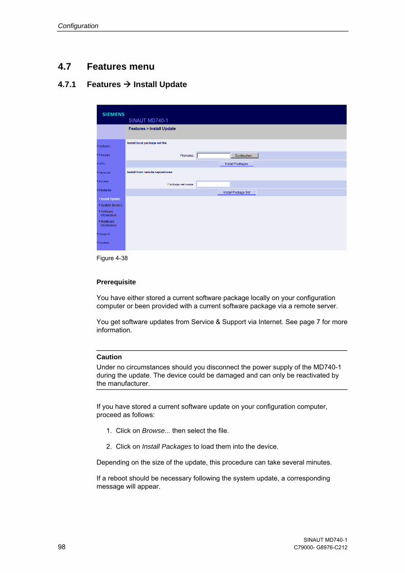
Configuration
4.7 Features menu
4.7.1 Features Install Update
Figure 4-38
Prerequisite
You have either stored a current software package locally on your configuration computer or been provided with a current software package via a remote server.
You get software updates from Service & Support via Internet. See page 7 for more information.
Caution
Under no circumstances should you disconnect the power supply of the MD740-1 during the update. The device could be damaged and can only be reactivated by the manufacturer.
If you have stored a current software update on your configuration computer, proceed as follows:
1. Click on Browse... then select the file.
2. Click on Install Packages to load them into the device.
Depending on the size of the update, this procedure can take several minutes.
If a reboot should be necessary following the system update, a corresponding message will appear.
SINAUT MD740-1 98 C79000- G8976-C212
Configuration
If you are provided with a current software update on a remote server, the server's address must be set - see Features Update Server.
Proceed as follows:
1. Write the filename in the entry field.
2. Click on Install Package Set to load it into the device.
Depending on the size of the update, this procedure can take several minutes.
If a reboot should be necessary following the system update, a corresponding message will appear.
SINAUT MD740-1 C79000-G8976-C212 99
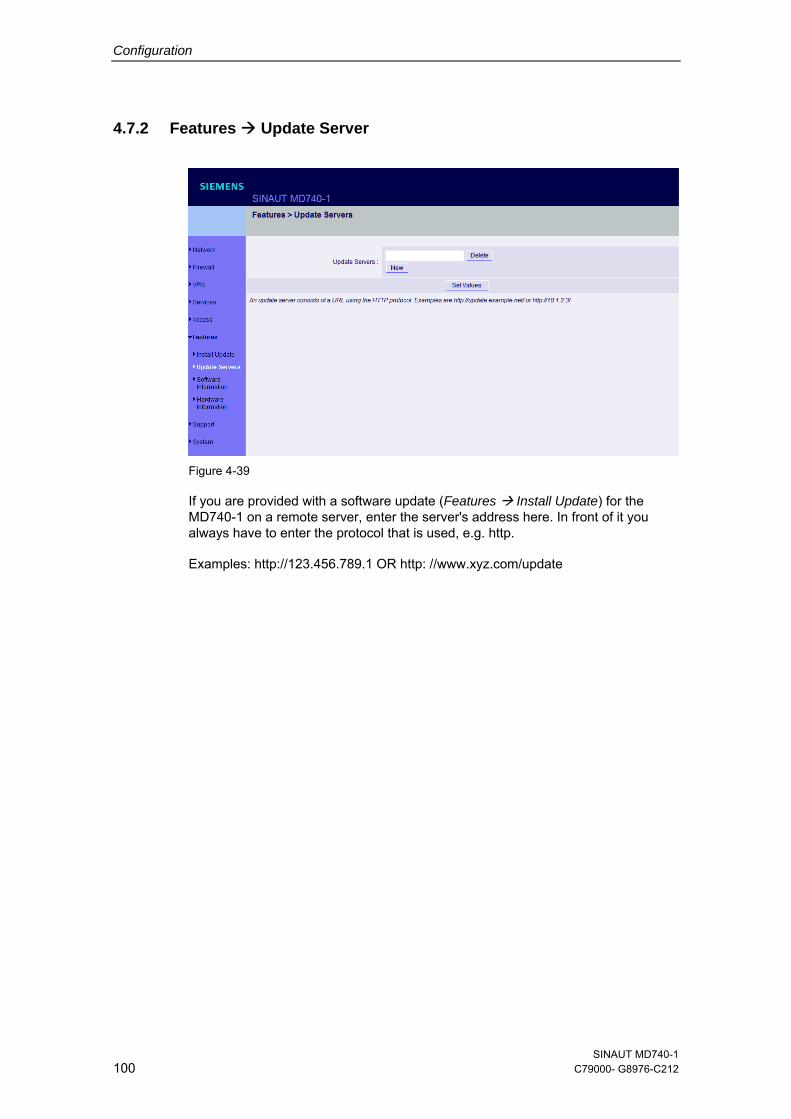
Configuration
4.7.2 Features Update Server
Figure 4-39
If you are provided with a software update (Features Install Update) for the MD740-1 on a remote server, enter the server's address here. In front of it you always have to enter the protocol that is used, e.g. http.
Examples: http://123.456.789.1 OR http: //www.xyz.com/update
SINAUT MD740-1 100 C79000- G8976-C212
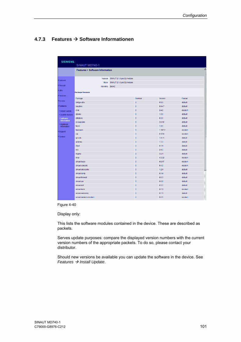
Configuration
4.7.3 Features Software Informationen
Figure 4-40
Display only:
This lists the software modules contained in the device. These are described as packets.
Serves update purposes: compare the displayed version numbers with the current version numbers of the appropriate packets. To do so, please contact your distributor.
Should new versions be available you can update the software in the device. See Features Install Update.
SINAUT MD740-1 C79000-G8976-C212 101
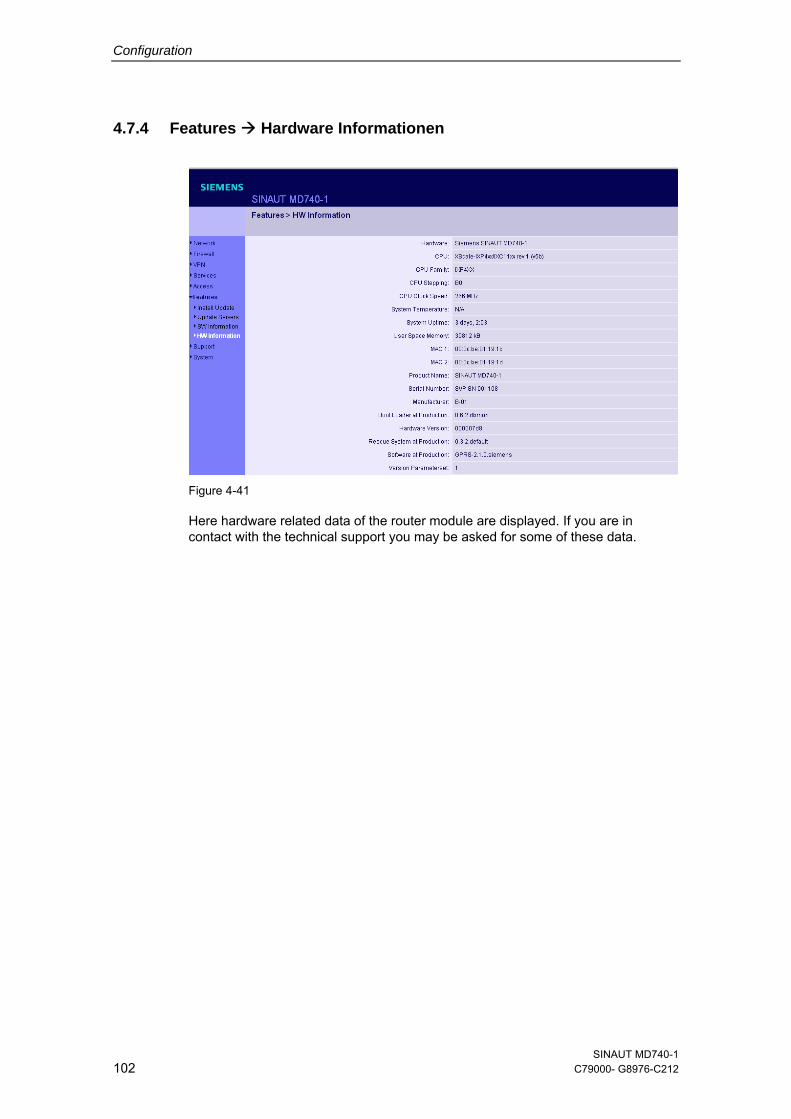
Configuration
4.7.4 Features Hardware Informationen
Figure 4-41
Here hardware related data of the router module are displayed. If you are in contact with the technical support you may be asked for some of these data.
SINAUT MD740-1 102 C79000- G8976-C212
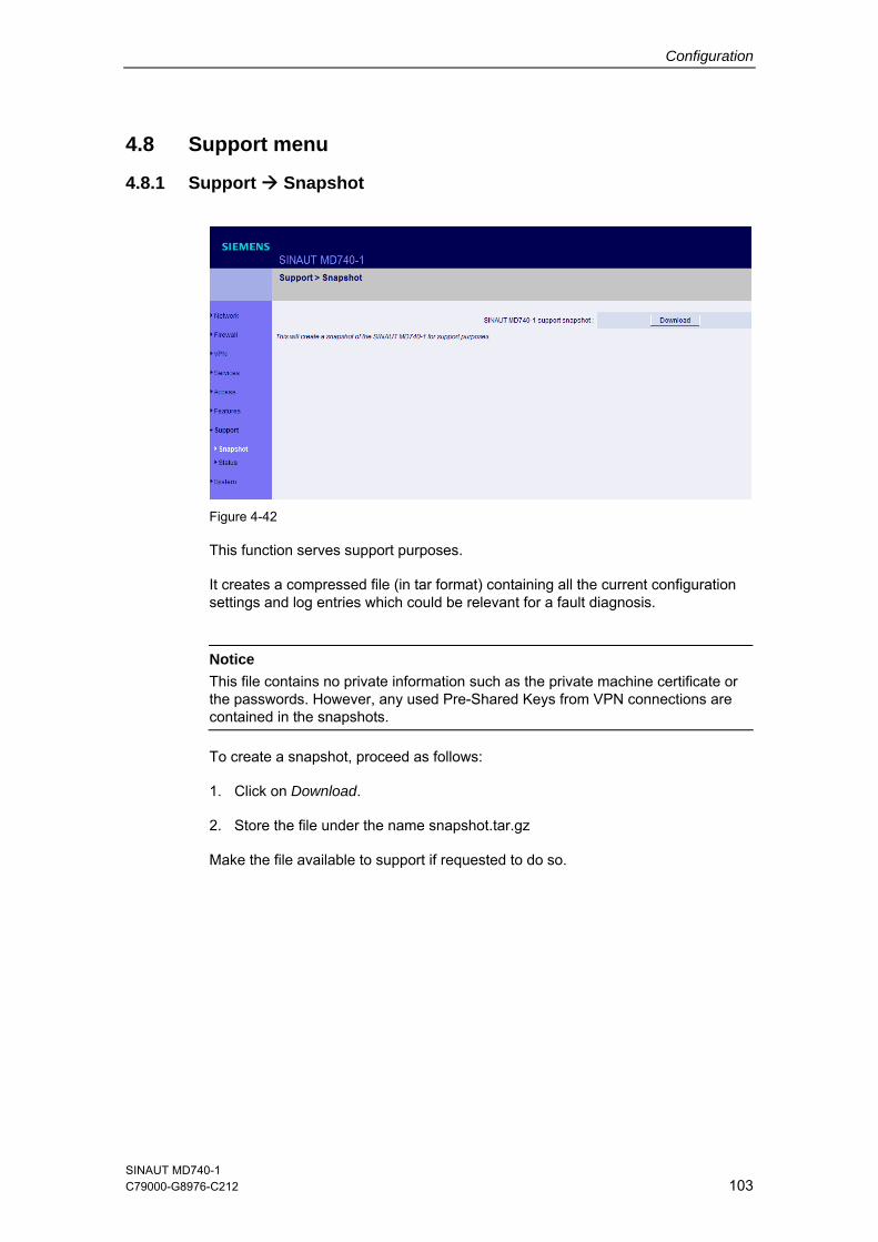
Configuration
4.8 Support menu
4.8.1 Support Snapshot
Figure 4-42
This function serves support purposes.
It creates a compressed file (in tar format) containing all the current configuration settings and log entries which could be relevant for a fault diagnosis.
Notice
This file contains no private information such as the private machine certificate or the passwords. However, any used Pre-Shared Keys from VPN connections are contained in the snapshots.
To create a snapshot, proceed as follows:
1. Click on Download.
2. Store the file under the name snapshot.tar.gz
Make the file available to support if requested to do so.
SINAUT MD740-1 C79000-G8976-C212 103
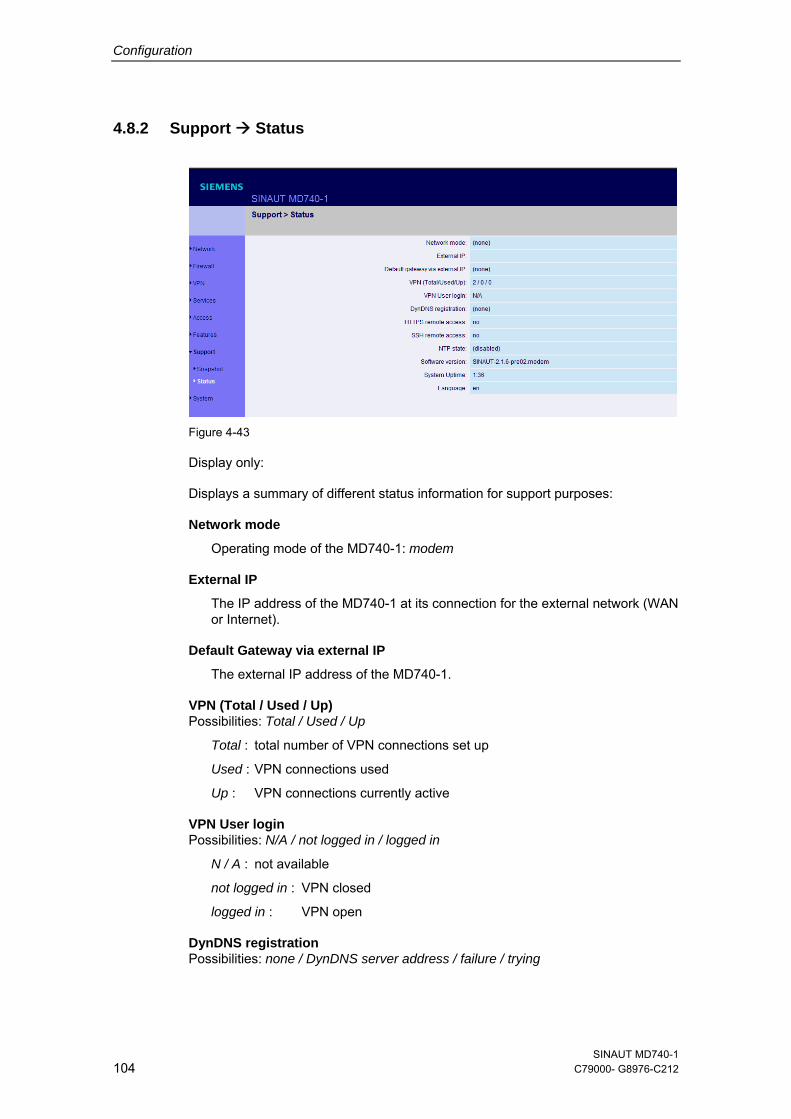
Configuration
4.8.2 Support Status
Figure 4-43
Display only:
Displays a summary of different status information for support purposes:
Network mode
Operating mode of the MD740-1: modem
External IP
The IP address of the MD740-1 at its connection for the external network (WAN or Internet).
Default Gateway via external IP
The external IP address of the MD740-1.
VPN (Total / Used / Up) Possibilities: Total / Used / Up
Total : total number of VPN connections set up
Used : VPN connections used
Up : VPN connections currently active
VPN User login Possibilities: N/A / not logged in / logged in
N / A : not available
not logged in : VPN closed
logged in : VPN open
DynDNS registration Possibilities: none / DynDNS server address / failure / trying
SINAUT MD740-1 104 C79000- G8976-C212
Configuration
none : no DynDNS server
DynDNS server address : address of the DynDNS server used by the MD740-1 to resolve hostnames
failure : the MD740-1 is trying unsuccessfully to connect to the DynDNS server.
trying : the MD740-1 is trying to connect to the DynDNS server.
HTTPS remote access Possibilities: no / yes
SSH remote access Possibilities: no / yes
NTP Status Possibilities: synchonized / not synchronized
synchronized : The MD740-1 is receiving the current time (Greenwich Mean Time) from a time server via the Network Time Protocol.
not synchronized : The MD740-1 is not connected to a time server and therefore cannot provide the current time.
Software version
Version of the software installed in the MD740-1
System uptime
Uptime since the last start-up of the MD740-1
Language
Language currently set
SINAUT MD740-1 C79000-G8976-C212 105
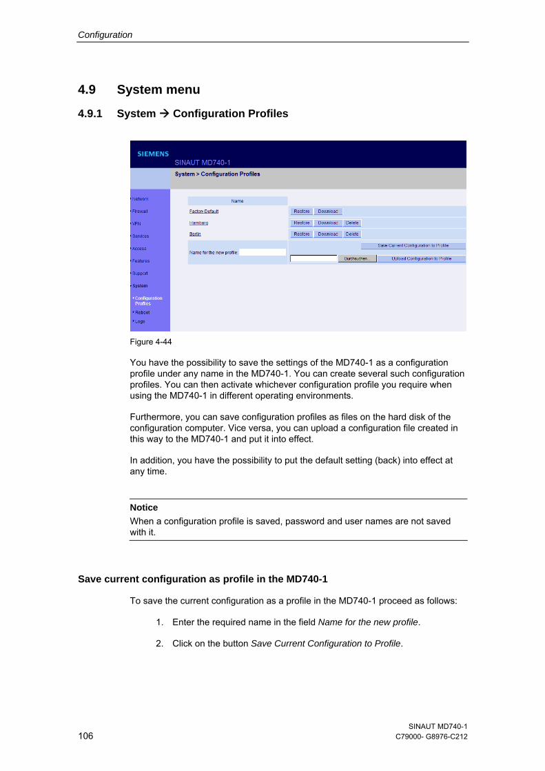
Configuration
4.9 System menu
4.9.1 System Configuration Profiles
Figure 4-44
You have the possibility to save the settings of the MD740-1 as a configuration profile under any name in the MD740-1. You can create several such configuration profiles. You can then activate whichever configuration profile you require when using the MD740-1 in different operating environments.
Furthermore, you can save configuration profiles as files on the hard disk of the configuration computer. Vice versa, you can upload a configuration file created in this way to the MD740-1 and put it into effect.
In addition, you have the possibility to put the default setting (back) into effect at any time.
Notice
When a configuration profile is saved, password and user names are not saved with it.
Save current configuration as profile in the MD740-1
To save the current configuration as a profile in the MD740-1 proceed as follows:
1. Enter the required name in the field Name for the new profile.
2. Click on the button Save Current Configuration to Profile.
SINAUT MD740-1 106 C79000- G8976-C212
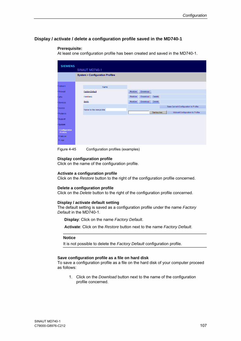
Configuration
Display / activate / delete a configuration profile saved in the MD740-1
Prerequisite: At least one configuration profile has been created and saved in the MD740-1.
Figure 4-45 Configuration profiles (examples)
Display configuration profile Click on the name of the configuration profile.
Activate a configuration profile Click on the Restore button to the right of the configuration profile concerned.
Delete a configuration profile Click on the Delete button to the right of the configuration profile concerned.
Display / activate default setting The default setting is saved as a configuration profile under the name Factory Default in the MD740-1.
Display: Click on the name Factory Default.
Activate: Click on the Restore button next to the name Factory Default. Notice
It is not possible to delete the Factory Default configuration profile.
Save configuration profile as a file on hard disk To save a configuration profile as a file on the hard disk of your computer proceed as follows:
1. Click on the Download button next to the name of the configuration profile concerned.
SINAUT MD740-1 C79000-G8976-C212 107
Configuration
2. In the dialogue box displayed, determine the file name and folder under/in which the configuration profile is to saved as a file. (You can give the file any name.)
Upload configuration profile from hard disk to the MD740-1
Prerequisite:
Following the procedure described above, you have saved a configuration profile as a file on the hard disk of the configuration computer.
Then proceed as follows:
1. In the field Name for the new profile, enter the name for the configuration profile to be uploaded.
2. Click on the Browse button and then select the file.
3. Click on the button Upload Configuration to Profile.
Consequence: the uploaded configuration is displayed in the list of configuration profiles.
If the uploaded configuration profile is to be activated, click on the Restore button next to the name.
SINAUT MD740-1 108 C79000- G8976-C212
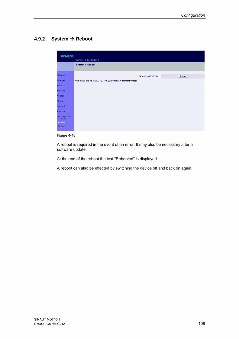
Configuration
4.9.2 System Reboot
Figure 4-46
A reboot is required in the event of an error. It may also be necessary after a software update.
At the end of the reboot the text "Rebooted" is displayed.
A reboot can also be effected by switching the device off and back on again.
SINAUT MD740-1 C79000-G8976-C212 109
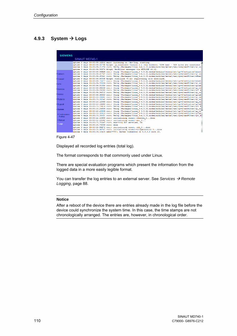
Configuration
4.9.3 System Logs
Figure 4-47
Displayed all recorded log entries (total log).
The format corresponds to that commonly used under Linux.
There are special evaluation programs which present the information from the logged data in a more easily legible format.
You can transfer the log entries to an external server. See Services Remote Logging, page 88.
Notice
After a reboot of the device there are entries already made in the log file before the device could synchronize the system time. In this case, the time stamps are not chronologically arranged. The entries are, however, in chronological order.
SINAUT MD740-1 110 C79000- G8976-C212
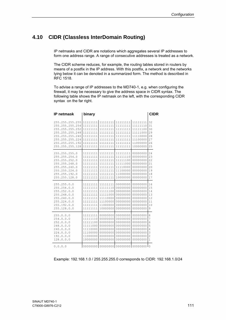
Configuration
4.10 CIDR (Classless InterDomain Routing)
IP netmasks and CIDR are notations which aggregates several IP addresses to form one address range. A range of consecutive addresses is treated as a network.
The CIDR scheme reduces, for example, the routing tables stored in routers by means of a postfix in the IP address. With this postfix, a network and the networks lying below it can be denoted in a summarized form. The method is described in RFC 1518.
To advise a range of IP addresses to the MD740-1, e.g. when configuring the firewall, it may be necessary to give the address space in CIDR syntax. The following table shows the IP netmask on the left, with the corresponding CIDR syntax on the far right.
IP netmask binary CIDR 255.255.255.255 11111111 11111111 11111111 11111111 32 255.255.255.254 11111111 11111111 11111111 11111110 31 255.255.255.252 11111111 11111111 11111111 11111100 30 255.255.255.248 11111111 11111111 11111111 11111000 29 255.255.255.240 11111111 11111111 11111111 11110000 28 255.255.255.224 11111111 11111111 11111111 11100000 27 255.255.255.192 11111111 11111111 11111111 11000000 26 255.255.255.128 11111111 11111111 11111111 10000000 25 255.255.255.0 11111111 11111111 11111111 00000000 24 255.255.254.0 11111111 11111111 11111110 00000000 23 255.255.252.0 11111111 11111111 11111100 00000000 22 255.255.248.0 11111111 11111111 11111000 00000000 21 255.255.240.0 11111111 11111111 11110000 00000000 20 255.255.224.0 11111111 11111111 11100000 00000000 19 255.255.192.0 11111111 11111111 11000000 00000000 18 255.255.128.0 11111111 11111111 10000000 00000000 17 255.255.0.0 11111111 11111111 00000000 00000000 16 255.254.0.0 11111111 11111110 00000000 00000000 15 255.252.0.0 11111111 11111100 00000000 00000000 14 255.248.0.0 11111111 11111000 00000000 00000000 13 255.240.0.0 11111111 11110000 00000000 00000000 12 255.224.0.0 11111111 11100000 00000000 00000000 11 255.192.0.0 11111111 11000000 00000000 00000000 10 255.128.0.0 11111111 10000000 00000000 00000000 9 255.0.0.0 11111111 00000000 00000000 00000000 8 254.0.0.0 11111110 00000000 00000000 00000000 7 252.0.0.0 11111100 00000000 00000000 00000000 6 248.0.0.0 11111000 00000000 00000000 00000000 5 240.0.0.0 11110000 00000000 00000000 00000000 4 224.0.0.0 11100000 00000000 00000000 00000000 3 192.0.0.0 11000000 00000000 00000000 00000000 2 128.0.0.0 10000000 00000000 00000000 00000000 1 0.0.0.0 00000000 00000000 00000000 00000000 0
Example: 192.168.1.0 / 255.255.255.0 corresponds to CIDR: 192.168.1.0/24
SINAUT MD740-1 C79000-G8976-C212 111
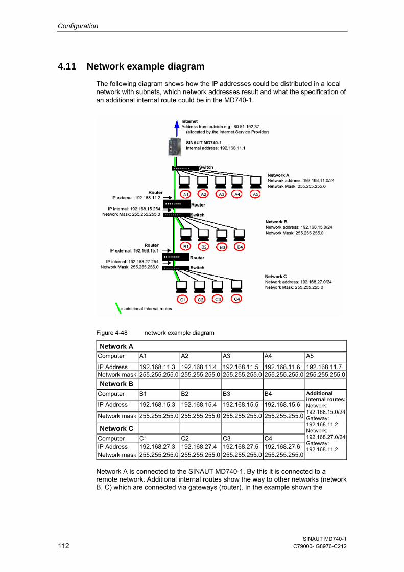
Configuration
4.11 Network example diagram The following diagram shows how the IP addresses could be distributed in a local network with subnets, which network addresses result and what the specification of an additional internal route could be in the MD740-1.
Figure 4-48 network example diagram
Network A Computer A1 A2 A3 A4 A5
IP Address 192.168.11.3 192.168.11.4 192.168.11.5 192.168.11.6 192.168.11.7 Network mask 255.255.255.0 255.255.255.0 255.255.255.0 255.255.255.0 255.255.255.0 Network B
Computer B1 B2 B3 B4
IP Address 192.168.15.3 192.168.15.4 192.168.15.5 192.168.15.6
Network mask 255.255.255.0 255.255.255.0 255.255.255.0 255.255.255.0
Network C Computer C1 C2 C3 C4 IP Address 192.168.27.3 192.168.27.4 192.168.27.5 192.168.27.6 Network mask 255.255.255.0 255.255.255.0 255.255.255.0 255.255.255.0
Additional internal routes:Network: 192.168.15.0/24Gateway: 192.168.11.2 Network: 192.168.27.0/24Gateway: 192.168.11.2
Network A is connected to the SINAUT MD740-1. By this it is connected to a remote network. Additional internal routes show the way to other networks (network B, C) which are connected via gateways (router). In the example shown the
SINAUT MD740-1 112 C79000- G8976-C212
Configuration
MD740-1 can reach the networks B and C by the gateway 192.168.11.2 and the network address 192.168.11.0/24.
SINAUT MD740-1 C79000-G8976-C212 113

Configuration
SINAUT MD740-1 114 C79000- G8976-C212
Integrated website showing device and connection data of the modem module 5
Introduction
The MD740-1 consists of two largely independent modules, the router module with the firewall and VPN functions and the GPRS modem module for the data communication via GPRS. Both modules have their own Web server for configuration and display purposes. The configuration and display opportunities of the Web-server of the router module are described in chapter 4. The Web server of the modem module shows a website that display device and connection data. This chapter is about the website of the GPRS modem, not of the VPN router.
There are different ways of accessing the website using a Web browser:
● locally via the service interface - see section 5.1
● locally via the application interface (10/100 BASE-T connector) - see section 5.2
● from a remote computer via the GPRS network (network-dependent) - see section 5.3.
SINAUT MD740-1 C79000- G8976-C212 115
Integrated website showing device and connection data of the modem module
5.1 Accessing the modem module Web server locally via the service interface
Via dial-up connection
To address the MD740-1 via its service interface the following conditions must be fulfilled:
● The computer you intend to use must be connected to the service interface of the MD740-1 via one of its COM ports.
● An appropriate dial-up connection must be set up on this computer (see below). This must contain the following data:
– the character string for dialling up the service interface: *98#
– user name and password: service in each case
– modem or device via which the connection is to be established: Default Modem 19200. The modem driver file must have been installed previously (see below).
Installing the modem for access to the service interface
To install the modem driver under Windows XP, proceed as follows. Installation under Windows 98 or Windows 2000 is done accordingly.
Hinweis
When using Windows 2000 or XP you must be registered as the administrator. In this case, make sure that no other modem drivers have been or are installed for the selected interface.
1. Click on Start, Control Panel so that the Control Panel dialogue box appears.
2. Switch to "Classic View ".
3. Double-click on the Phone and modem options icon.
4. In the Phone and modem options dialogue box, click on the Add... button in the Modems tab.
5. The Add New Hardware Wizard for the installation of a new modem appears. Follow the instructions of the Add New Hardware Assistant:
SINAUT MD740-1 116 C79000- G8976-C212
Integrated website showing device and connection data of the modem module
Notice
Determine that you will select the modem yourself, i.e. that automatic recognition does not take place.
When choosing the modem, select: Standard 19200 bps Modem
Creating the dial-up connection for the service interface
To create the dial-up connection for the service interface, proceed as follows:
Windows 2000:
1. Click on Start - Settings - Network and Dial-up connections - Make New Connection to launch the Network Connections Wizard.
2. Select Connect to the Internet, Set up my connection manually..., Connect using a dial-up modem.
Follow the instructions in the dialogue boxes. Notice
Make sure that no area codes or local access numbers are entered.
SINAUT MD740-1 C79000-G8976-C212 117
Integrated website showing device and connection data of the modem module
Windows XP:
1. Click on Start - Control Panel: in classic view, double-click on Network and Internet connections, then click on Create a New Connection to launch the New Connections Wizard.
2. Select Connect to the Internet, Set up my connection manually, Connect using a dial-up modem.
Follow the instructions in the dialogue boxes. Notice
Make sure that no area codes or local access numbers are entered.
Making a connection to the MD740-1 website
1. Double-click on the dial-up connection icon that has been created for the CSD dial-up. The Make a connection dialogue box appears. The user name and password are both: service
2. Click on Select.
Effect:
The computer is connected to the MD740-1 in such a way that the integrated Web server can be addressed.
3. Start your Web browser, e.g. MS Internet Explorer.
Enter the address of the internal website in the browser's address line. The address is:
http://192.168.0.8
Effect:
The start page of the website stored in the MD740-1 is displayed - see section 5.4.
4. Click on the hyperlink of the required HTML pages to view them.
5. Then close the dial-up connection.
Closing the service connection
In the Info section in the bottom right corner of the screen, right-click on the connection icon and then click on Close connection in the opened menu.
SINAUT MD740-1 118 C79000- G8976-C212
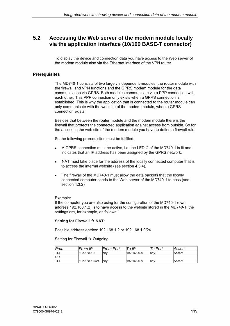
Integrated website showing device and connection data of the modem module
5.2 Accessing the Web server of the modem module locally via the application interface (10/100 BASE-T connector)
To display the device and connection data you have access to the Web server of the modem module also via the Ethernet interface of the VPN router.
Prerequisites
The MD740-1 consists of two largely independent modules: the router module with the firewall and VPN functions and the GPRS modem module for the data communication via GPRS. Both modules communicate via a PPP connection with each other. This PPP connection only exists when a GPRS connection is established. This is why the application that is connected to the router module can only communicate with the web site of the modem module, when a GPRS connection exists.
Besides that between the router module and the modem module there is the firewall that protects the connected application against access from outside. So for the access to the web site of the modem module you have to define a firewall rule.
So the following prerequisites must be fulfilled:
● A GPRS connection must be active, i.e. the LED C of the MD740-1 is lit and indicates that an IP address has been assigned by the GPRS network.
● NAT must take place for the address of the locally connected computer that is to access the internal website (see section 4.3.4).
● The firewall of the MD740-1 must allow the data packets that the locally connected computer sends to the Web server of the MD740-1 to pass (see section 4.3.2)
Example: If the computer you are also using for the configuration of the MD740-1 (own address 192.168.1.2) is to have access to the website stored in the MD740-1, the settings are, for example, as follows:
Setting for Firewall NAT:
Possible address entries: 192.168.1.2 or 192.168.1.0/24
Setting for Firewall Outgoing:
Prot. From IP From Port To IP To Port Action TCP 192.168.1.2 any 192.168.0.8 any Accept OR TCP 192.168.1.0/24 any 192.168.0.8 any Accept
SINAUT MD740-1 C79000-G8976-C212 119
Integrated website showing device and connection data of the modem module
Making a connection to the website of the modem module
1. Start your Web browser, e.g. MS Internet Explorer.
Enter the address of the internal website in the browser's address line. The address is:
http://192.168.0.8
Effect:
The start page of the website stored in the MD740-1 is displayed – see section 5.4.
2. Click on the hyperlink of the required HTML pages to view them.
SINAUT MD740-1 120 C79000- G8976-C212
Integrated website showing device and connection data of the modem module
5.3 Accessing the Web Server of the modem module of the MD740-1 from a remote computer via the GPRS network
Prerequisites
● Access is dependent on the configuration of the GPRS network and on how your LAN is linked to the GPRS.
● A GPRS connection to the remote MD740-1 must be active, i.e. the LED C of the MD740-1 is lit and indicates that an IP address has been assigned by the GPRS network.
Making a connection to the MD740-1 website
1. Start your Web browser, e.g. MS Internet Explorer.
Enter the external address of the MD740-1 in the browser's address line.
Effect:
The page with the device information is displayed - see section 5.4.
2. Click on the hyperlink of the required HTML pages to view them.
SINAUT MD740-1 C79000-G8976-C212 121
Integrated website showing device and connection data of the modem module
5.4 The website of the SINAUT MD740-1
To be able to view the website of the MD740-1 with a Web browser the appropriate preparatory measures must be taken, depending on whether you want to access the website with your Web browser
● locally via the service interface
● locally via the application interface (10/100 BASE-T connector)
OR
● from a remote computer via the GPRS network (network-dependent).
When you enter the address http://192.168.0.8 (or the external IP address of the device if you are accessing the website from a remote computer, see section 5.3) in your Web browser the website of the MD740-1 appears with Device Information.
By clicking on the appropriate hyperlink you can have the corresponding HTML page displayed in the browser.
SINAUT MD740-1 122 C79000- G8976-C212
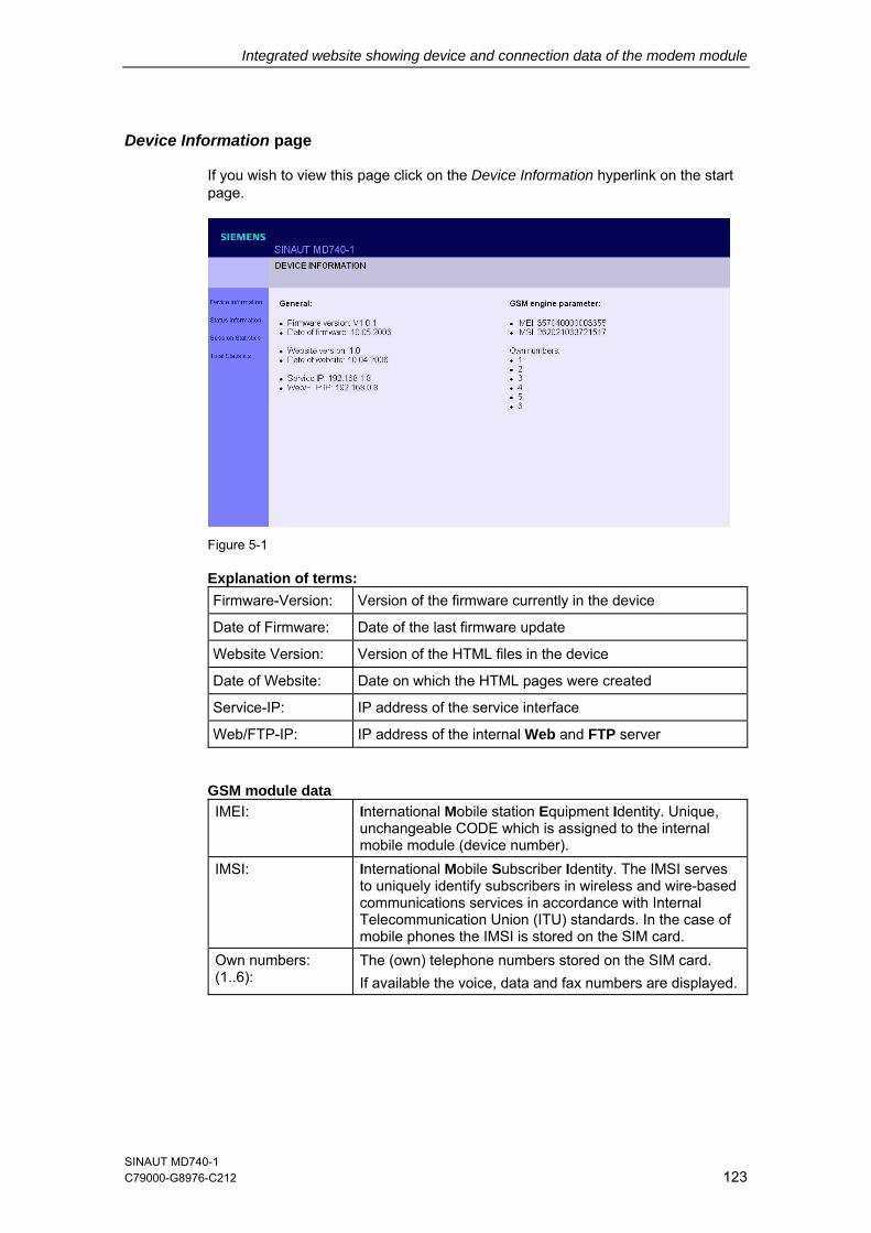
Integrated website showing device and connection data of the modem module
Device Information page
If you wish to view this page click on the Device Information hyperlink on the start page.
Figure 5-1
Explanation of terms: Firmware-Version: Version of the firmware currently in the device Date of Firmware: Date of the last firmware update Website Version: Version of the HTML files in the device Date of Website: Date on which the HTML pages were created Service-IP: IP address of the service interface Web/FTP-IP: IP address of the internal Web and FTP server
GSM module data IMEI: International Mobile station Equipment Identity. Unique,
unchangeable CODE which is assigned to the internal mobile module (device number).
IMSI: International Mobile Subscriber Identity. The IMSI serves to uniquely identify subscribers in wireless and wire-based communications services in accordance with Internal Telecommunication Union (ITU) standards. In the case of mobile phones the IMSI is stored on the SIM card.
Own numbers: (1..6):
The (own) telephone numbers stored on the SIM card. If available the voice, data and fax numbers are displayed.
SINAUT MD740-1 C79000-G8976-C212 123
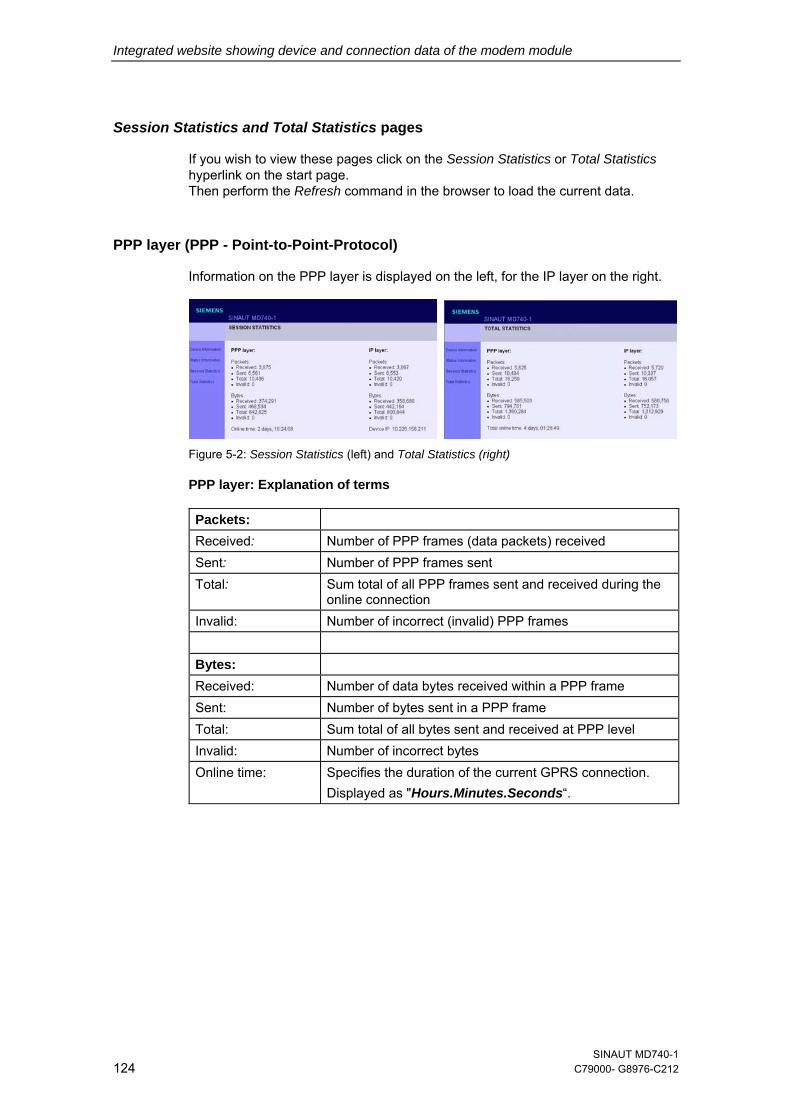
Integrated website showing device and connection data of the modem module
Session Statistics and Total Statistics pages
If you wish to view these pages click on the Session Statistics or Total Statistics hyperlink on the start page. Then perform the Refresh command in the browser to load the current data.
PPP layer (PPP - Point-to-Point-Protocol)
Information on the PPP layer is displayed on the left, for the IP layer on the right.
Figure 5-2: Session Statistics (left) and Total Statistics (right)
PPP layer: Explanation of terms
Packets: Received: Number of PPP frames (data packets) received Sent: Number of PPP frames sent Total: Sum total of all PPP frames sent and received during the
online connection Invalid: Number of incorrect (invalid) PPP frames Bytes: Received: Number of data bytes received within a PPP frame Sent: Number of bytes sent in a PPP frame Total: Sum total of all bytes sent and received at PPP level Invalid: Number of incorrect bytes Online time: Specifies the duration of the current GPRS connection.
Displayed as "Hours.Minutes.Seconds“.
SINAUT MD740-1 124 C79000- G8976-C212
Integrated website showing device and connection data of the modem module
IP layer (IP - Internet Protocol)
IP layer: Explanations of terms Packets: Received: Number of IP frames received Sent: Number of IP frames sent Total: Sum total of all IP packets sent and received during the
online connection Invalid: Number of incorrect (invalid) IP frames Bytes Received: Number of data bytes received within an IP frame Sent: Number of bytes sent in an IP frame Total: Sum total of all bytes sent and received at IP level during
the online connection Invalid: Number of incorrect bytes within an IP packet Device IP: The IP address which the MD740-1 has received from the
network provider on establishment of the connection into the GPRS network. This dynamic IP address is assigned to the device and is the IP address for incoming data packets. It can be assumed that the MD740-1 is (dynamically) assigned a different IP address by the provider each time it connects to the GPRS network.
SINAUT MD740-1 C79000-G8976-C212 125
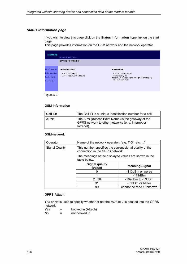
Integrated website showing device and connection data of the modem module
Status Information page
If you wish to view this page click on the Status Information hyperlink on the start page. This page provides information on the GSM network and the network operator.
Figure 5-3
GSM-Information
Cell ID: The Cell ID is a unique identification number for a cell. APN: The APN (Access Point Name) is the gateway of the
GPRS network to other networks (e. g. Internet or Intranet).
GSM-network
Operator Name of the network operator. (e.g. T-D1 etc. ...) Signal Quality This number specifies the current signal quality of the
connection in the GPRS network. The meanings of the displayed values are shown in the table below.
Signal quality (value) Meaning/Signal
0 -113dBm or worse 1 -111dBm 2...30 -109dBm to -53dBm 31 -51dBm or better 99 cannot be read / unknown
GPRS-Attach:
Yes or No is used to specify whether or not the MD740-1 is booked into the GPRS network. Yes = booked in (Attach) No = not booked in
SINAUT MD740-1 126 C79000- G8976-C212
Firmware update and recovery 66.1 Update of the firmware of the modem module
The modem module of the MD740-1 has an integrated FTP server (FTP = File Transfer Protocol). This can be used to load an update - if available - of the modem software into the MD740-1.
We recommend using an FTP program to establish a connection with the FTP server of the MD740-1.
Establishing an FTP connection
Prerequisites:
The firmware file is located on the service PC.
Proceed as follows:
1. To make a connection to the FTP server of the MD740-1, proceed exactly as when accessing the Web server
– locally via the service interface - see section 5.1
– locally via the application interface (10/100 BASE-T connector) - see section 5.2
– from a remote computer via the GPRS network (network-dependent) - see section 5.3.
2. Instead of a Web browser use the FTP program of the Windows operating system.
Click on Start, Run. Behind Open, enter: ftp 192.168.0.8 (or external IP address, see section 5.3) You will then be asked to enter the user name and the password.
User name: service
Password: service
SINAUT MD740-1 C79000- G8976-C212 127
Firmware update and recovery
3. When the connection has been established, you can start to upload the new firmware.
With Notepad (belongs to Windows) create a file with the name !cmdfile. The file name must not have any extension. The first line in this file is: STORE MD740-1.bin (when “MD740-1.bin” is the name of the new firmware file).
At the ftp>-prompt enter: put MD740-1.bin (when “MD740-1” is the name of the new firmware file). Press Enter.
Then at the ftp>-prompt enter: put !cmdfile Press Enter. After the firmware file and the !cmdfile file are successfully uploaded the device will start to install the new firmware. This process can last up to 10 minutes. After this the MD740-1 restarts.
4. Release the service connection. At the ftp>-prompt enter: quit Then press Enter. Then also tear down the network connection to the device. To do so right-click the icon in the Windows task bar.
6.2 Recovery: Loading factory defaults
If you do not have any access to the MD740-1 because the administration password is lost or the firewall rules are set in such a way that you can not configure the MD740-1 any longer you can use the SET-button to load the default settings of the MD740-1. The SET-button is located on the front of the device (see chapter 2).
Proceed as follows:
The power supply must be connected to the device. Press the SET-button (with a clip for example) till the Q-LED (the LED in the middle) lights up.
Result: All existing configuration settings are deleted.
6.3 Update the VPN firmware
The power supply must be connected to the device. Press the SET-button (with a clip for example) till the C-LED (the LED on the right) lights up. For further information call the hotline.
SINAUT MD740-1 128 C79000- G8976-C212
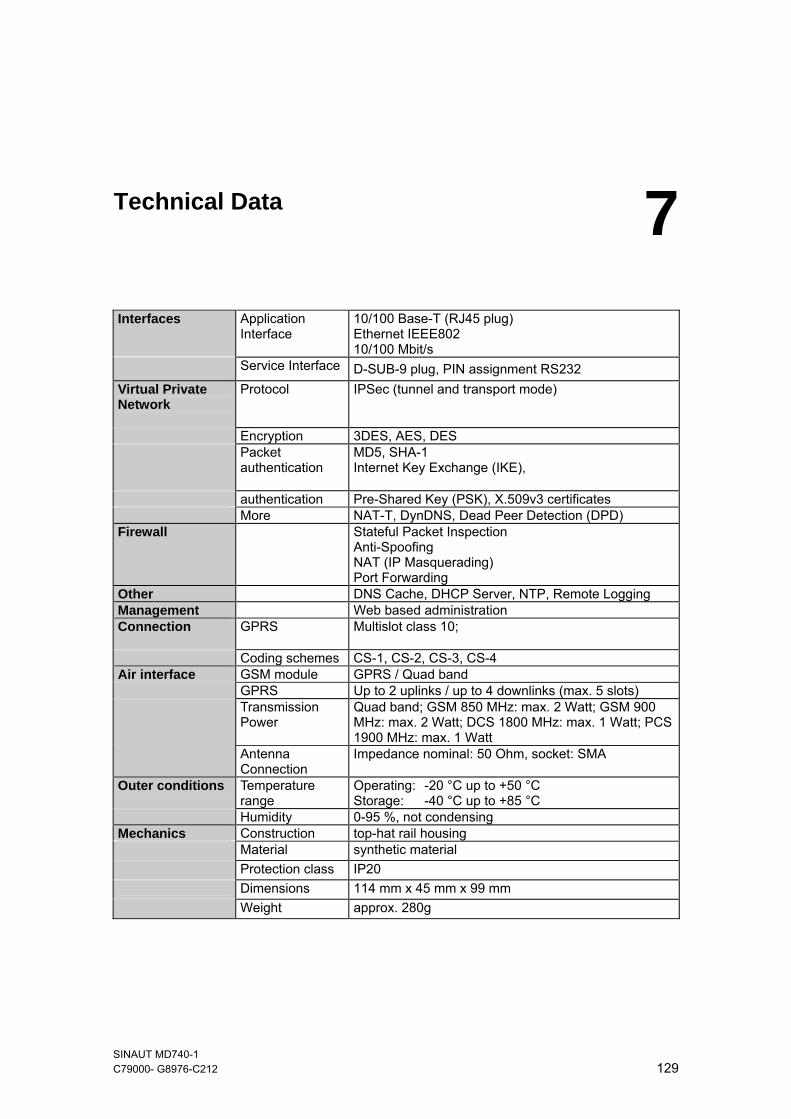
Technical Data 7 Interfaces Application
Interface 10/100 Base-T (RJ45 plug) Ethernet IEEE802 10/100 Mbit/s
Service Interface D-SUB-9 plug, PIN assignment RS232 Virtual Private Network
Protocol IPSec (tunnel and transport mode)
Encryption 3DES, AES, DES Packet
authentication
MD5, SHA-1 Internet Key Exchange (IKE),
authentication Pre-Shared Key (PSK), X.509v3 certificates More NAT-T, DynDNS, Dead Peer Detection (DPD) Firewall Stateful Packet Inspection
Anti-Spoofing NAT (IP Masquerading) Port Forwarding
Other DNS Cache, DHCP Server, NTP, Remote Logging Management Web based administration Connection GPRS Multislot class 10;
Coding schemes CS-1, CS-2, CS-3, CS-4 Air interface GSM module GPRS / Quad band GPRS Up to 2 uplinks / up to 4 downlinks (max. 5 slots) Transmission
Power Quad band; GSM 850 MHz: max. 2 Watt; GSM 900 MHz: max. 2 Watt; DCS 1800 MHz: max. 1 Watt; PCS 1900 MHz: max. 1 Watt
Antenna Connection
Impedance nominal: 50 Ohm, socket: SMA
Outer conditions Temperature range
Operating: -20 °C up to +50 °C Storage: -40 °C up to +85 °C
Humidity 0-95 %, not condensing Mechanics Construction top-hat rail housing Material synthetic material Protection class IP20 Dimensions 114 mm x 45 mm x 99 mm Weight approx. 280g
SINAUT MD740-1 C79000- G8976-C212 129
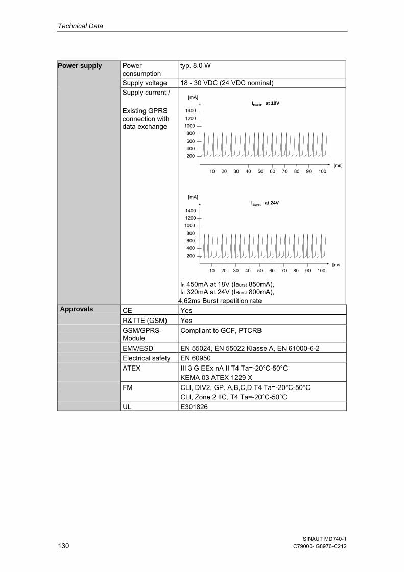
Technical Data
Power consumption
typ. 8.0 W
Supply voltage 18 - 30 VDC (24 VDC nominal)
Power supply
Supply current / Existing GPRS connection with data exchange
1000
200400600800
12001400
[mA]
[ms]10 20 30 40 50 7060 80 90 100
IBurst bei 18V
1000
200400600800
12001400
[mA]
[ms]10 20 30 40 50 7060 80 90 100
IBurst bei 24V
In 450mA at 18V (IBurst 850mA), In 320mA at 24V (IBurst 800mA),
4,62ms Burst repetition rate Approvals CE Yes R&TTE (GSM) Yes GSM/GPRS-
Module Compliant to GCF, PTCRB
EMV/ESD EN 55024, EN 55022 Klasse A, EN 61000-6-2 Electrical safety EN 60950 ATEX III 3 G EEx nA II T4 Ta=-20°C-50°C
KEMA 03 ATEX 1229 X FM
CLI, DIV2, GP. A,B,C,D T4 Ta=-20°C-50°C CLI, Zone 2 IIC, T4 Ta=-20°C-50°C
UL E301826
at
at
SINAUT MD740-1 130 C79000- G8976-C212
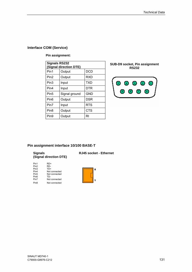
Technical Data
SINAUT MD740-1 C79000-G8976-C212 131
Interface COM (Service)
Pin assignment: Signals RS232 (Signal direction DTE) Pin1 Output DCD
Pin2 Output RXD
Pin3 Input TXD
Pin4 Input DTR
Pin5 Signal ground GND
Pin6 Output DSR
Pin7 Input RTS
Pin8 Output CTS
Pin9 Output RI
SUB-D9 socket, Pin assignment RS232
Pin assignment interface 10/100 BASE-T
Signals (Signal direction DTE)
RJ45 socket - Ethernet
Pin1 RD+ Pin2 RD- Pin3 TD+ Pin4 Not connected Pin5 Not connected Pin6 TD- Pin7 Not connected Pin8 Not connected
1
8
1
8
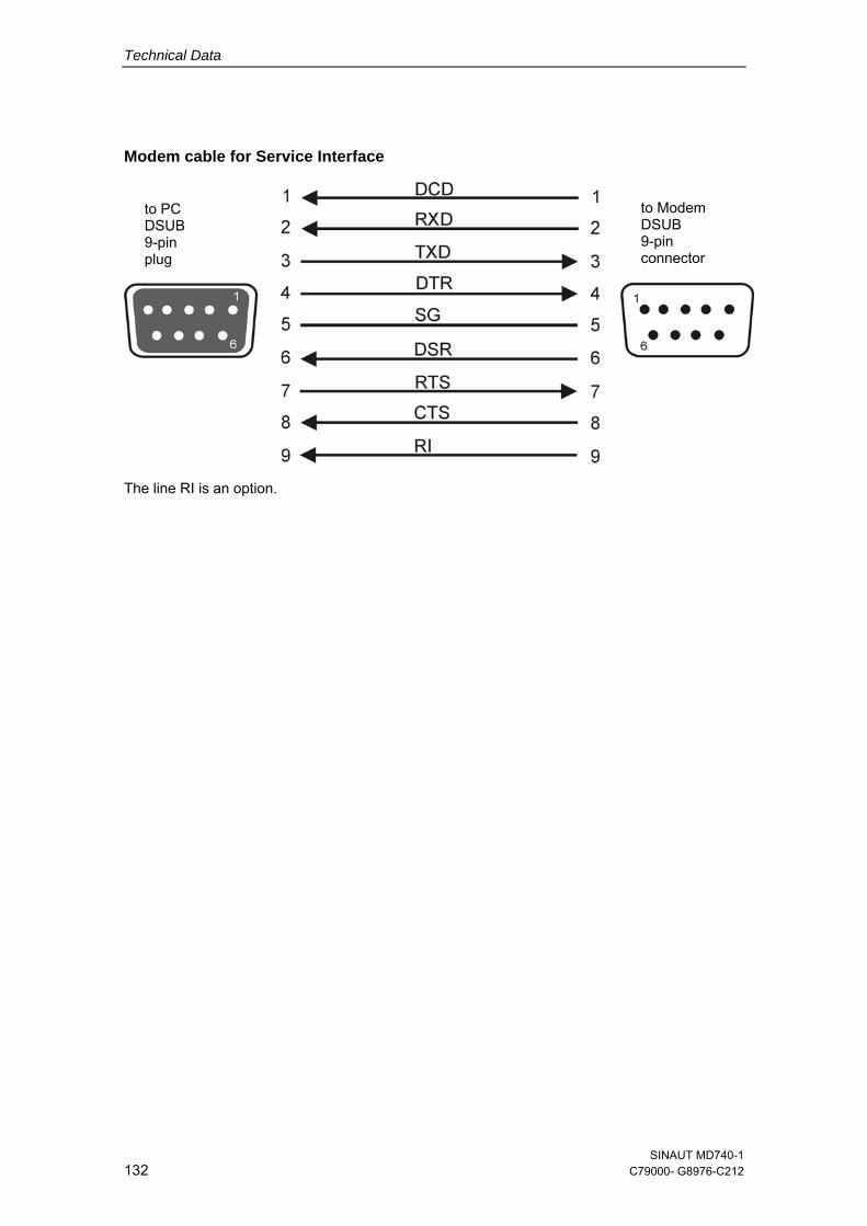
Technical Data
Modem cable for Service Interface
The line RI is an option.
to Modem DSUB 9-pin connector
to PC DSUB 9-pin plug
SINAUT MD740-1 132 C79000- G8976-C212
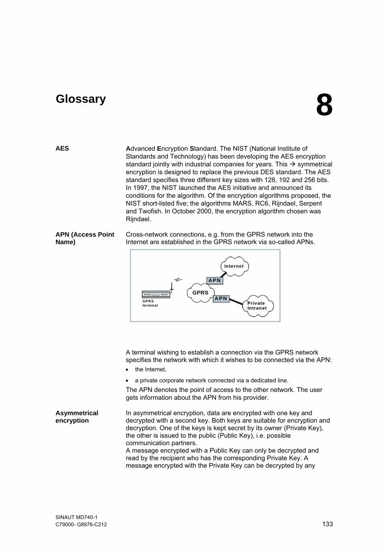
Glossary 8AES Advanced Encryption Standard. The NIST (National Institute of
Standards and Technology) has been developing the AES encryption standard jointly with industrial companies for years. This symmetrical encryption is designed to replace the previous DES standard. The AES standard specifies three different key sizes with 128, 192 and 256 bits. In 1997, the NIST launched the AES initiative and announced its conditions for the algorithm. Of the encryption algorithms proposed, the NIST short-listed five; the algorithms MARS, RC6, Rijndael, Serpent and Twofish. In October 2000, the encryption algorithm chosen was Rijndael.
APN (Access Point Name)
Cross-network connections, e.g. from the GPRS network into the Internet are established in the GPRS network via so-called APNs.
GPRSterminal
APN
APN
PrivateIntranet
Internet
A terminal wishing to establish a connection via the GPRS network specifies the network with which it wishes to be connected via the APN: • the Internet,
• a private corporate network connected via a dedicated line. The APN denotes the point of access to the other network. The user gets information about the APN from his provider.
Asymmetrical encryption
In asymmetrical encryption, data are encrypted with one key and decrypted with a second key. Both keys are suitable for encryption and decryption. One of the keys is kept secret by its owner (Private Key), the other is issued to the public (Public Key), i.e. possible communication partners. A message encrypted with a Public Key can only be decrypted and read by the recipient who has the corresponding Private Key. A message encrypted with the Private Key can be decrypted by any
SINAUT MD740-1 C79000- G8976-C212 133
Glossary
recipient who has the corresponding Public Key. Encryption with the Private Key shows that the message actually originates from the owner of the corresponding Public Key. We therefore speak of a digital signature. Asymmetrical encryption methods such as RSA are, however, slow and vulnerable to certain attacks, which is why they are often combined with a symmetrical method ( symmetrical encryption). On the other hand, concepts are also possible which avoid the complex administration of symmetrical keys.
Client / Server In a client/server environment a server is a program or computer which
receives and answers queries from the client program or client computer. In data communication the term client is also used for the computer which establishes a connection to a server (or host), i.e. the client is the calling computer and the server (or host) is the called computer.
Datagramm In the TCP/IP transfer protocol data are sent in the form of data packets
or datagrams. An IP datagram is structured as follows: - IP Header - TCP/UDP Header - Data (Payload) The IP header contains: - the IP address of the sender (source IP address) - the IP address of the recipient (destination IP address) - the protocol number of the protocol of the next highest protocol layer
(according to the OSI layer model) - the IP header checksum to check the integrity of the header upon
reception.
The TCP/UDP header contains the following information: - the port of the sender (source port) - the port of the recipient (destination port) - a checksum for the TCP header and some information from the IP
header (e.g. source and destination IP address) DES / 3DES The symmetrical encryption algorithm ( symmetrical encryption) DES,
originally developed by IBM and checked by the NSA, was determined in 1977 by the American National Bureau of Standards, the predecessor of today's National Institute of Standards and Technology (NIST), as the standard for American government institutions. As this was the first standardized encryption algorithm of all, it quickly established itself in industry and hence outside the USA. DES works with a key length of 56 bits, which is no longer considered secure due to the increase in computing power since 1977. 3DES is a variant of DES. It works with 3-times larger keys, i.e. 168 bits long. It is still considered secure today and is, among other things, also part of the IPsec standard.
SINAUT MD740-1 134 C79000- G8976-C212
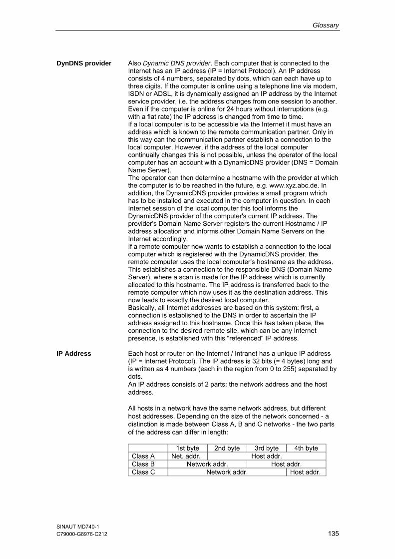
Glossary
DynDNS provider Also Dynamic DNS provider. Each computer that is connected to the Internet has an IP address (IP = Internet Protocol). An IP address consists of 4 numbers, separated by dots, which can each have up to three digits. If the computer is online using a telephone line via modem, ISDN or ADSL, it is dynamically assigned an IP address by the Internet service provider, i.e. the address changes from one session to another. Even if the computer is online for 24 hours without interruptions (e.g. with a flat rate) the IP address is changed from time to time. If a local computer is to be accessible via the Internet it must have an address which is known to the remote communication partner. Only in this way can the communication partner establish a connection to the local computer. However, if the address of the local computer continually changes this is not possible, unless the operator of the local computer has an account with a DynamicDNS provider (DNS = Domain Name Server). The operator can then determine a hostname with the provider at which the computer is to be reached in the future, e.g. www.xyz.abc.de. In addition, the DynamicDNS provider provides a small program which has to be installed and executed in the computer in question. In each Internet session of the local computer this tool informs the DynamicDNS provider of the computer's current IP address. The provider's Domain Name Server registers the current Hostname / IP address allocation and informs other Domain Name Servers on the Internet accordingly. If a remote computer now wants to establish a connection to the local computer which is registered with the DynamicDNS provider, the remote computer uses the local computer's hostname as the address. This establishes a connection to the responsible DNS (Domain Name Server), where a scan is made for the IP address which is currently allocated to this hostname. The IP address is transferred back to the remote computer which now uses it as the destination address. This now leads to exactly the desired local computer. Basically, all Internet addresses are based on this system: first, a connection is established to the DNS in order to ascertain the IP address assigned to this hostname. Once this has taken place, the connection to the desired remote site, which can be any Internet presence, is established with this "referenced" IP address.
IP Address Each host or router on the Internet / Intranet has a unique IP address
(IP = Internet Protocol). The IP address is 32 bits (= 4 bytes) long and is written as 4 numbers (each in the region from 0 to 255) separated by dots. An IP address consists of 2 parts: the network address and the host address. All hosts in a network have the same network address, but different host addresses. Depending on the size of the network concerned - a distinction is made between Class A, B and C networks - the two parts of the address can differ in length:
1st byte 2nd byte 3rd byte 4th byte Class A Net. addr. Host addr. Class B Network addr. Host addr. Class C Network addr. Host addr.
SINAUT MD740-1 C79000-G8976-C212 135
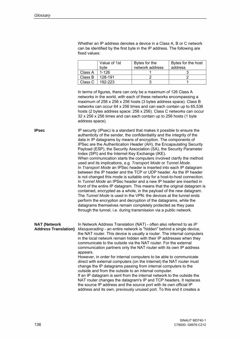
Glossary
Whether an IP address denotes a device in a Class A, B or C network can be identified by the first byte in the IP address. The following are fixed values:
Value of 1st byte
Bytes for the network address
Bytes for the host address
Class A 1-126 1 3 Class B 128-191 2 2 Class C 192-223 3 1
In terms of figures, there can only be a maximum of 126 Class A networks in the world, with each of these networks encompassing a maximum of 256 x 256 x 256 hosts (3 bytes address space). Class B networks can occur 64 x 256 times and can each contain up to 65,536 hosts (2 bytes address space: 256 x 256). Class C networks can occur 32 x 256 x 256 times and can each contain up to 256 hosts (1 byte address space).
IPsec IP security (IPsec) is a standard that makes it possible to ensure the
authenticity of the sender, the confidentiality and the integrity of the data in IP datagrams by means of encryption. The components of IPSec are the Authentication Header (AH), the Encapsulating Security Payload (ESP), the Security Association (SA), the Security Parameter Index (SPI) and the Internet Key Exchange (IKE). When communication starts the computers involved clarify the method used and its implications, e.g. Transport Mode or Tunnel Mode. In Transport Mode an IPSec header is inserted into each IP datagram between the IP header and the TCP or UDP header. As the IP header is not changed this mode is suitable only for a host-to-host connection. In Tunnel Mode an IPSec header and a new IP header are inserted in front of the entire IP datagram. This means that the original datagram is contained, encrypted as a whole, in the payload of the new datagram. The Tunnel Mode is used in the VPN: the devices at the tunnel ends perform the encryption and decryption of the datagrams, while the datagrams themselves remain completely protected as they pass through the tunnel, i.e. during transmission via a public network.
NAT (Network Address Translation)
In Network Address Translation (NAT) - often also referred to as IP Masquerading - an entire network is "hidden" behind a single device, the NAT router. This device is usually a router. The internal computers in the local network remain hidden with their IP addresses when they communicate to the outside via the NAT router. For the external communication partners only the NAT router with its own IP address appears. However, in order for internal computers to be able to communicate direct with external computers (on the Internet) the NAT router must change the IP datagrams passing from internal computers to the outside and from the outside to an internal computer. If an IP datagram is sent from the internal network to the outside the NAT router changes the datagram's IP and TCP headers. It replaces the source IP address and the source port with its own official IP address and its own, previously unused port. To this end it creates a
SINAUT MD740-1 136 C79000- G8976-C212
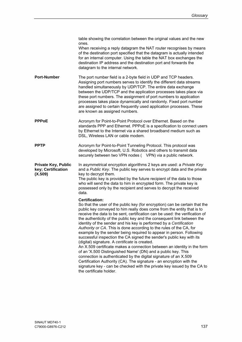
Glossary
table showing the correlation between the original values and the new ones. When receiving a reply datagram the NAT router recognises by means of the destination port specified that the datagram is actually intended for an internal computer. Using the table the NAT box exchanges the destination IP address and the destination port and forwards the datagram to the internal network.
Port-Number The port number field is a 2-byte field in UDP and TCP headers.
Assigning port numbers serves to identify the different data streams handled simultaneously by UDP/TCP. The entire data exchange between the UDP/TCP and the application processes takes place via these port numbers. The assignment of port numbers to application processes takes place dynamically and randomly. Fixed port number are assigned to certain frequently used application processes. These are known as assigned numbers.
PPPoE Acronym for Point-to-Point Protocol over Ethernet. Based on the standards PPP and Ethernet. PPPoE is a specification to connect users by Ethernet to the Internet via a shared broadband medium such as DSL, Wireless LAN or cable modem.
PPTP Acronym for Point-to-Point Tunneling Protocol. This protocol was developed by Microsoft, U.S. Robotics and others to transmit data securely between two VPN nodes (� VPN) via a public network.
Private Key, Public key; Certification (X.509)
In asymmetrical encryption algorithms 2 keys are used: a Private Key and a Public Key. The public key serves to encrypt data and the private key to decrypt them. The public key is provided by the future recipient of the data to those who will send the data to him in encrypted form. The private key is possessed only by the recipient and serves to decrypt the received data.
Certification: So that the user of the public key (for encryption) can be certain that the public key conveyed to him really does come from the entity that is to receive the data to be sent, certification can be used: the verification of the authenticity of the public key and the consequent link between the identity of the sender and his key is performed by a Certification Authority or CA. This is done according to the rules of the CA, for example by the sender being required to appear in person. Following successful inspection the CA signed the sender's public key with its (digital) signature. A certificate is created. An X.509 certificate makes a connection between an identity in the form of an 'X.500 Distinguished Name' (DN) and a public key. This connection is authenticated by the digital signature of an X.509 Certification Authority (CA). The signature - an encryption with the signature key - can be checked with the private key issued by the CA to the certificate holder.
SINAUT MD740-1 C79000-G8976-C212 137
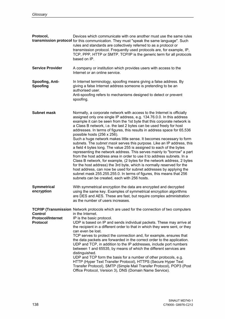
Glossary
Protocol, transmission protocol
Devices which communicate with one another must use the same rules for this communication. They must "speak the same language". Such rules and standards are collectively referred to as a protocol or transmission protocol. Frequently used protocols are, for example, IP, TCP, PPP, HTTP or SMTP. TCP/IP is the generic term for all protocols based on IP.
Service Provider A company or institution which provides users with access to the Internet or an online service.
Spoofing, Anti-Spoofing
In Internet terminology, spoofing means giving a false address. By giving a false Internet address someone is pretending to be an authorised user. Anti-spoofing refers to mechanisms designed to detect or prevent spoofing.
Subnet mask Normally, a corporate network with access to the Internet is officially
assigned only one single IP address, e.g. 134.76.0.0. In this address example it can be seen from the 1st byte that this corporate network is a Class B network, i.e. the last 2 bytes can be used freely for host addresses. In terms of figures, this results in address space for 65,536 possible hosts (256 x 256). Such a huge network makes little sense. It becomes necessary to form subnets. The subnet mask serves this purpose. Like an IP address, this a field 4 bytes long. The value 255 is assigned to each of the bytes representing the network address. This serves mainly to "borrow" a part from the host address area in order to use it to address subnets. In a Class B network, for example, (2 bytes for the network address, 2 bytes for the host address) the 3rd byte, which is normally reserved for the host address, can now be used for subnet addresses by applying the subnet mask 255.255.255.0. In terms of figures, this means that 256 subnets can be created, each with 256 hosts.
Symmetrical encryption
With symmetrical encryption the data are encrypted and decrypted using the same key. Examples of symmetrical encryption algorithms are DES and AES. These are fast, but require complex administration as the number of users increases.
TCP/IP (Transmission Control Protocol/Internet Protocol
Network protocols which are used for the connection of two computers in the Internet. IP is the basic protocol. UDP is based on IP and sends individual packets. These may arrive at the recipient in a different order to that in which they were sent, or they can even be lost. TCP serves to protect the connection and, for example, ensures that the data packets are forwarded in the correct order to the application. UDP and TCP, in addition to the IP addresses, include port numbers between 1 and 65535, by means of which the different services are distinguished. UDP and TCP form the basis for a number of other protocols, e.g. HTTP (Hyper Text Transfer Protocol), HTTPS (Secure Hyper Text Transfer Protocol), SMTP (Simple Mail Transfer Protocol), POP3 (Post Office Protocol, Version 3), DNS (Domain Name Service).
SINAUT MD740-1 138 C79000- G8976-C212
Glossary
ICMP is based on IP and contains control messages. SMTP is an e-mail protocol based on TCP. IKE is an IPsec protocol based on UDP. ESP is an IPsec protocol based on IP. On a Windows PC the WINSOCK.DLL (or WSOCK32.DLL) takes over the handling of both these protocols. ( datagram)
VPN (Virtual Private Network)
A Virtual Private Network (VPN) connects several separate private networks (subnets) via a public network, e.g. the Internet, to form a shared network. Confidentiality and authenticity are ensured by using cryptographic protocols. A VPN therefore provides an inexpensive alternative to dedicated lines when it comes to setting up a supraregional corporate network.
X.509 Certificate A kind of "seal" which proves the authenticity of a Public Key (
asymmetrical encryption) and appendant data. So that the user of the public key for encryption can be certain that the public key conveyed to him really does come from its issuer and hence from the entity that is to receive the data to be sent, certification can be used. This verification of the authenticity of the public key and the consequent link between the identity of the issuer and his key is performed by a Certification Authority or CA. This is done according to the rules of the CA, for example by the issuer of the public key being required to appear in person. Following successful inspection the CA signs the public key with its (digital) signature. A certificate is created. An X.509(v3) certificate therefore contains a public key, information about the key owner (given as Distinguished Name (DN)), permitted designated uses, etc. and the signature of the CA. The signature is created as follows: from the bit sequence of the public key, the data on its owner and other data, the CA creates an individual bit sequence which can be up to 160 bits long, the HASH value. This is encrypted by the CA using its private key and added to the certificate. Encryption with the CA's private key is proof of authenticity, i.e. the encrypted HASH character sequence is the digital signature of the CA. Should the data of the certificate be changed without authorization, the HASH value is no longer correct and the certificate then becomes worthless. The HASH value is also known as the fingerprint. As it is encrypted with the private key of the CA, anyone in possession of the corresponding public key can decrypt the bit sequence and thus check the authenticity of the fingerprint or signature in question. Involving certification authorities means that not every key owner needs to know the other one, but only the certification authority used. The additional key information also simplifies the administrability of the key.X.509 certificates are employed, e.g. in e-mail encryption, using S/MIME or IPsec.
SINAUT MD740-1 C79000-G8976-C212 139

Glossary
SINAUT MD740-1 140 C79000- G8976-C212