simotion d410-2 - adegis
TRANSCRIPT
SIMOTION
SIMOTION D410-2
Manual
Valid forSIMOTION D410-2 DP and D410-2 DP/PNas of version 5.2
03/2018A5E33446720B
Preface
Safety instructions 1
Description 2
Operator control (hardware) 3
Interfaces 4
Technical data 5
Dimension drawings 6
Spare parts / accessories 7
Standards and approvals A
ESD guidelines B
Legal informationWarning notice system
This manual contains notices you have to observe in order to ensure your personal safety, as well as to prevent damage to property. The notices referring to your personal safety are highlighted in the manual by a safety alert symbol, notices referring only to property damage have no safety alert symbol. These notices shown below are graded according to the degree of danger.
DANGERindicates that death or severe personal injury will result if proper precautions are not taken.
WARNINGindicates that death or severe personal injury may result if proper precautions are not taken.
CAUTIONindicates that minor personal injury can result if proper precautions are not taken.
NOTICEindicates that property damage can result if proper precautions are not taken.If more than one degree of danger is present, the warning notice representing the highest degree of danger will be used. A notice warning of injury to persons with a safety alert symbol may also include a warning relating to property damage.
Qualified PersonnelThe product/system described in this documentation may be operated only by personnel qualified for the specific task in accordance with the relevant documentation, in particular its warning notices and safety instructions. Qualified personnel are those who, based on their training and experience, are capable of identifying risks and avoiding potential hazards when working with these products/systems.
Proper use of Siemens productsNote the following:
WARNINGSiemens products may only be used for the applications described in the catalog and in the relevant technical documentation. If products and components from other manufacturers are used, these must be recommended or approved by Siemens. Proper transport, storage, installation, assembly, commissioning, operation and maintenance are required to ensure that the products operate safely and without any problems. The permissible ambient conditions must be complied with. The information in the relevant documentation must be observed.
TrademarksAll names identified by ® are registered trademarks of Siemens AG. The remaining trademarks in this publication may be trademarks whose use by third parties for their own purposes could violate the rights of the owner.
Disclaimer of LiabilityWe have reviewed the contents of this publication to ensure consistency with the hardware and software described. Since variance cannot be precluded entirely, we cannot guarantee full consistency. However, the information in this publication is reviewed regularly and any necessary corrections are included in subsequent editions.
Siemens AGDivision Digital FactoryPostfach 48 4890026 NÜRNBERGGERMANY
A5E33446720BⓅ 02/2018 Subject to change
Copyright © Siemens AG 2012 - 2018.All rights reserved
Preface
Contents of the Product ManualThis document is part of the SIMOTION D documentation package.
ScopeThe SIMOTION D410-2 Manual describes the SIMOTION D410‑2 DP and SIMOTION D410‑2 DP/PN control units.
Note
A separate SIMOTION D410 Manual is available for the SIMOTION D410 DP and SIMOTION D410 PN control units.
StandardsThe SIMOTION system was developed in accordance with ISO 9001 quality guidelines.
Sections in this manualThe following sections describe the purpose and the use of the manual:
● DescriptionThis section provides information pertaining to the SIMOTION system and its integration in the information landscape.
● Operator control (hardware)This section describes the operator control and display elements of the SIMOTION D410‑2.
● InterfacesThis section provides information about the interfaces, their pin assignments and application options.
● Technical dataThis section describes the properties and features of the SIMOTION D410‑2.
● Dimension drawings
● Spare parts / accessoriesThis section provides information about accessories and spare parts for the SIMOTION D410‑2.
● AppendixThis section provides information about the various standards, approvals and EMC directives that the device complies with.
● Index to locate information
SIMOTION D410-2Manual, 03/2018, A5E33446720B 3
SIMOTION DocumentationAn overview of the SIMOTION documentation can be found in the SIMOTION Documentation Overview document.
This documentation is included as electronic documentation in the scope of delivery of SIMOTION SCOUT. It comprises ten documentation packages.
The following documentation packages are available for SIMOTION product version V5.2:
● SIMOTION Engineering System Handling
● SIMOTION System and Function Descriptions
● SIMOTION Service and Diagnostics
● SIMOTION IT
● SIMOTION Programming
● SIMOTION Programming - References
● SIMOTION C
● SIMOTION P
● SIMOTION D
● SIMOTION Supplementary Documentation
Hotline and Internet addresses
SIMOTION at a glanceWe have compiled an overview page from our range of information about SIMOTION with the most important information on frequently asked topics - which can be opened with only one click.
Whether beginner or experienced SIMOTION user – the most important downloads, manuals, tutorials, FAQs, application examples, etc. can be found at
https://support.industry.siemens.com/cs/ww/en/view/109480700
Additional informationClick the following link to find information on the following topics:
● Documentation overview
● Additional links to download documents
● Using documentation online (find and search manuals/information)
https://support.industry.siemens.com/cs/ww/en/view/109479653
Preface
SIMOTION D410-24 Manual, 03/2018, A5E33446720B
My Documentation ManagerClick the following link for information on how to compile documentation individually on the basis of Siemens content and how to adapt it for the purpose of your own machine documentation:
https://support.industry.siemens.com/My/ww/en/documentation
TrainingClick the following link for information on SITRAIN - Siemens training courses for automation products, systems and solutions:
http://www.siemens.com/sitrain
FAQsFrequently Asked Questions can be found in SIMOTION Utilities & Applications, which are included in the scope of delivery of SIMOTION SCOUT, and in the Service&Support pages in Product Support:
https://support.industry.siemens.com/cs/de/en/ps/14505/faq
Technical supportCountry-specific telephone numbers for technical support are provided on the Internet under Contact:
https://support.industry.siemens.com/cs/ww/en/sc/2090
Disposal and recyclingSIMOTION D410-2 is an environmentally friendly product! It includes the following features:
● In spite of its excellent resistance to fire, the flame-resistant agent in the plastic used for the housing does not contain halogens.
● Identification of plastic materials in accordance with ISO 11469.
● Less material used because the unit is smaller and with fewer components thanks to integration in ASICs.
The disposal of the products described in this manual should be performed in compliance with the valid national regulations.
The products can be largely recycled owing to their low pollutant content. For environmentally friendly recycling and disposal of your old device, please contact a company certified for the disposal of electronic waste and dispose of the device in accordance with the regulations in your country.
If you have any further questions about disposal and recycling, please contact your local Siemens representative. Contact details can be found in our contacts database on the Internet at:
http://www.automation.siemens.com/partner
Preface
SIMOTION D410-2Manual, 03/2018, A5E33446720B 5
Further information / FAQsYou can find further information on this manual at the following FAQ:
https://support.industry.siemens.com/cs/ww/de/view/27585482
The following information sources are also available:
● SIMOTION Utilities & Applications: SIMOTION Utilities & Applications will be included in the SIMOTION SCOUT scope of delivery and, along with FAQs, also contain free utilities (e.g. calculation tools, optimization tools, etc.) as well as application examples (ready-to-apply solutions such as winders, cross cutters or handling)
● The latest SIMOTION FAQs at https://support.industry.siemens.com/cs/ww/de/ps/14505/faq
● SIMOTION SCOUT online help
● For additional documentation, see the Overview of SIMOTION documentation (separate document).
Preface
SIMOTION D410-26 Manual, 03/2018, A5E33446720B
Table of contents
Preface.........................................................................................................................................................3
1 Safety instructions......................................................................................................................................11
1.1 Fundamental safety instructions............................................................................................111.1.1 General safety instructions.....................................................................................................111.1.2 Safety instructions for electromagnetic fields (EMF)..............................................................141.1.3 Handling electrostatic sensitive devices (ESD)......................................................................141.1.4 Security information...............................................................................................................151.1.5 Danger to life due to software manipulation when using removable storage media..............151.1.6 Residual risks of power drive systems...................................................................................16
1.2 Specific safety information for SIMOTION D410-2................................................................17
2 Description..................................................................................................................................................19
2.1 System overview....................................................................................................................19
2.2 System components...............................................................................................................24
2.3 I/O integration.........................................................................................................................29
2.4 SIMOTION D410-2 DP representation...................................................................................30
2.5 SIMOTION D410-2 DP/PN drawing.......................................................................................32
2.6 Type plates.............................................................................................................................34
2.7 CompactFlash card................................................................................................................36
2.8 Data matrix code....................................................................................................................39
2.9 Licensing................................................................................................................................40
3 Operator control (hardware).......................................................................................................................41
3.1 Overview of operator control and display elements...............................................................41
3.2 Operator controls...................................................................................................................423.2.1 Service selector switch...........................................................................................................423.2.2 Mode selector switch..............................................................................................................433.2.3 DIAG button...........................................................................................................................453.2.4 RESET button........................................................................................................................463.2.5 Switch S5.0............................................................................................................................463.2.6 SIMOTION CompactFlash card.............................................................................................47
3.3 Error and status displays........................................................................................................48
4 Interfaces....................................................................................................................................................49
4.1 Overview of interfaces............................................................................................................49
4.2 DRIVE-CLiQ interface............................................................................................................50
4.3 PROFIBUS DP interfaces......................................................................................................53
4.4 PROFINET IO interface (SIMOTION D410-2 DP/PN only)....................................................55
SIMOTION D410-2Manual, 03/2018, A5E33446720B 7
4.5 Encoder interface (HTL/TTL/SSI)...........................................................................................58
4.6 Digital I/Os / temperature sensor / analog input.....................................................................614.6.1 Properties...............................................................................................................................614.6.2 Interface characteristics.........................................................................................................614.6.3 Interface assignment..............................................................................................................624.6.4 Use of the interfaces..............................................................................................................694.6.5 SIMOTION D410-2 DP connection examples........................................................................714.6.6 SIMOTION D410-2 DP/PN connection examples..................................................................75
4.7 Power supply..........................................................................................................................79
4.8 Ethernet interface...................................................................................................................81
4.9 Measuring sockets.................................................................................................................83
4.10 Power Module Interface.........................................................................................................84
5 Technical data............................................................................................................................................85
5.1 Shipping and storage conditions............................................................................................85
5.2 Ambient conditions.................................................................................................................86
5.3 System data, connection values, dimensions and weight......................................................89
5.4 Interfaces and performance features.....................................................................................915.4.1 PLC and motion control performance....................................................................................915.4.2 Communication......................................................................................................................915.4.3 Onboard I/Os..........................................................................................................................935.4.4 Onboard encoder interface....................................................................................................97
5.5 Clock......................................................................................................................................99
5.6 Certificates, approvals, declarations of conformity..............................................................100
6 Dimension drawings.................................................................................................................................101
6.1 SIMOTION D410-2 DP dimension drawing..........................................................................101
6.2 SIMOTION D410-2 DP/PN dimension drawing....................................................................103
6.3 Mounting plate dimension drawing.......................................................................................104
6.4 CAD data, dimension drawings, and circuit-diagram macros..............................................105
7 Spare parts / accessories.........................................................................................................................107
7.1 Available spare parts and accessories.................................................................................107
7.2 TM31 terminal module.........................................................................................................109
7.3 TM41 terminal module.........................................................................................................110
7.4 TM54F terminal module.......................................................................................................111
7.5 TM15 and TM17 High Feature terminal modules ................................................................113
7.6 CUA31/CUA32 control unit adapter.....................................................................................115
7.7 DMC20/DME20 DRIVE-CLiQ hub........................................................................................116
A Standards and approvals..........................................................................................................................117
A.1 General rules........................................................................................................................117
Table of contents
SIMOTION D410-28 Manual, 03/2018, A5E33446720B
A.2 Device-specific information..................................................................................................119
B ESD guidelines.........................................................................................................................................121
B.1 ESD definition......................................................................................................................121
B.2 Electrostatic charging of individuals.....................................................................................122
B.3 Basic measures for protection against discharge of static electricity...................................123
Index.........................................................................................................................................................125
Table of contents
SIMOTION D410-2Manual, 03/2018, A5E33446720B 9

Table of contents
SIMOTION D410-210 Manual, 03/2018, A5E33446720B
Safety instructions 11.1 Fundamental safety instructions
1.1.1 General safety instructions
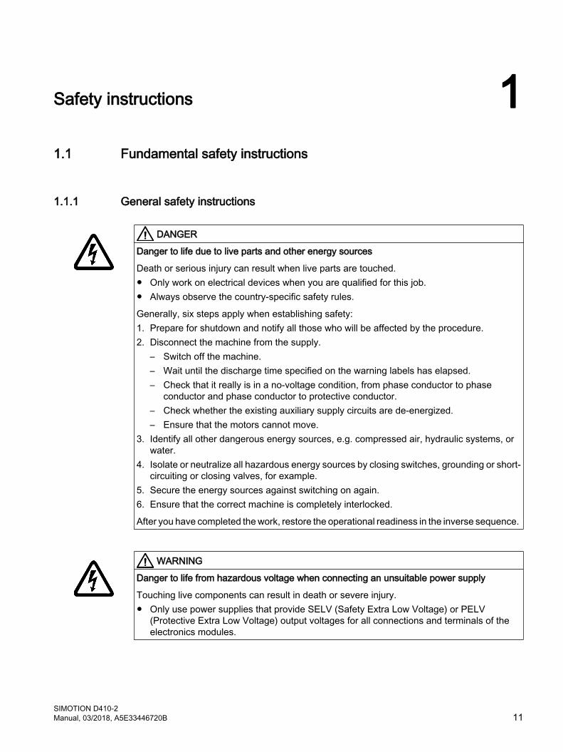
DANGER
Danger to life due to live parts and other energy sources
Death or serious injury can result when live parts are touched.● Only work on electrical devices when you are qualified for this job. ● Always observe the country-specific safety rules.
Generally, six steps apply when establishing safety: 1. Prepare for shutdown and notify all those who will be affected by the procedure.2. Disconnect the machine from the supply.
– Switch off the machine. – Wait until the discharge time specified on the warning labels has elapsed. – Check that it really is in a no-voltage condition, from phase conductor to phase
conductor and phase conductor to protective conductor.– Check whether the existing auxiliary supply circuits are de-energized.– Ensure that the motors cannot move.
3. Identify all other dangerous energy sources, e.g. compressed air, hydraulic systems, or water.
4. Isolate or neutralize all hazardous energy sources by closing switches, grounding or short-circuiting or closing valves, for example.
5. Secure the energy sources against switching on again. 6. Ensure that the correct machine is completely interlocked.
After you have completed the work, restore the operational readiness in the inverse sequence.
WARNING
Danger to life from hazardous voltage when connecting an unsuitable power supply
Touching live components can result in death or severe injury. ● Only use power supplies that provide SELV (Safety Extra Low Voltage) or PELV
(Protective Extra Low Voltage) output voltages for all connections and terminals of the electronics modules.
SIMOTION D410-2Manual, 03/2018, A5E33446720B 11
WARNING
Danger to life from touching live parts on damaged devices
Improper handling of devices can result in damage.
For damaged devices, hazardous voltages can be present at the enclosure or at exposed components; if touched, this can result in death or severe injury. ● Observe the limit values specified in the technical specifications during transport, storage,
and operation. ● Do not use damaged devices.
WARNING
Danger to life through electric shock due to unconnected cable shields
Hazardous touch voltages can occur through capacitive cross-coupling due to unconnected cable shields.● As a minimum, connect cable shields and the cores of power cables that are not used
(e.g. brake cores) at one end at the grounded housing potential.
WARNING
Danger to life due to electric shock when not grounded
For missing or incorrectly implemented protective conductor connection for devices with protection class I, high voltages can be present at open, exposed parts, which when touched, can result in death or severe injury.● Ground the device in compliance with the applicable regulations.
WARNING
Danger to life due to fire spreading if housing is inadequate
Fire and smoke development can cause severe personal injury or material damage. ● Install devices without a protective housing in a metal control cabinet (or protect the device
by another equivalent measure) in such a way that contact with fire inside and outside the device is prevented.
● Ensure that smoke can only escape via controlled and monitored paths.
Safety instructions1.1 Fundamental safety instructions
SIMOTION D410-212 Manual, 03/2018, A5E33446720B
WARNING
Danger to life from unexpected movement of machines when using mobile wireless devices or mobile phones
Using mobile radios or mobile phones with a transmit power > 1 W closer than approx. 2 m to the components may cause the devices to malfunction, influence the functional safety of machines therefore putting people at risk or causing material damage.● Switch off wireless devices or mobile phones in the immediate vicinity of the components.
WARNING
Danger to life due to fire if overheating occurs because of insufficient ventilation clearances
Inadequate ventilation clearances can cause overheating of components followed by fire and smoke development. This can cause death or serious injury. This can also result in increased downtime and reduced service life for devices/systems. ● Ensure compliance with the specified minimum clearance as ventilation clearance for the
respective component.
WARNING
Danger of an accident occurring due to missing or illegible warning labels
Missing or illegible warning labels can result in accidents involving death or serious injury. ● Check that the warning labels are complete based on the documentation.● Attach any missing warning labels to the components, in the national language if
necessary.● Replace illegible warning labels.
WARNING
Danger to life when safety functions are inactive
Safety functions that are inactive or that have not been adjusted accordingly can cause operational faults on machines that could lead to serious injury or death. ● Observe the information in the appropriate product documentation before commissioning.● Carry out a safety inspection for functions relevant to safety on the entire system, including
all safety-related components.● Ensure that the safety functions used in your drives and automation tasks are adjusted
and activated through appropriate parameterizing. ● Perform a function test.● Only put your plant into live operation once you have guaranteed that the functions relevant
to safety are running correctly.
Safety instructions1.1 Fundamental safety instructions
SIMOTION D410-2Manual, 03/2018, A5E33446720B 13
NoteImportant safety notices for safety functions
If you want to use safety functions, you must observe the safety notices in the safety manuals.
1.1.2 Safety instructions for electromagnetic fields (EMF)
WARNING
Danger to life from electromagnetic fields
Electromagnetic fields (EMF) are generated by the operation of electrical power equipment such as transformers, converters or motors.
People with pacemakers or implants are at a special risk in the immediate vicinity of these devices/systems.● Ensure that the persons involved are the necessary distance away (minimum 2 m).
1.1.3 Handling electrostatic sensitive devices (ESD)Electrostatic sensitive devices (ESD) are individual components, integrated circuits, modules or devices that may be damaged by either electric fields or electrostatic discharge.
NOTICE
Damage through electric fields or electrostatic discharge
Electric fields or electrostatic discharge can cause malfunctions through damaged individual components, integrated circuits, modules or devices.● Only pack, store, transport and send electronic components, modules or devices in their
original packaging or in other suitable materials, e.g conductive foam rubber of aluminum foil.
● Only touch components, modules and devices when you are grounded by one of the following methods:– Wearing an ESD wrist strap– Wearing ESD shoes or ESD grounding straps in ESD areas with conductive flooring
● Only place electronic components, modules or devices on conductive surfaces (table with ESD surface, conductive ESD foam, ESD packaging, ESD transport container).
Safety instructions1.1 Fundamental safety instructions
SIMOTION D410-214 Manual, 03/2018, A5E33446720B
1.1.4 Security informationSiemens provides products and solutions with industrial security functions that support the secure operation of plants, systems, machines and networks.
In order to protect plants, systems, machines and networks against cyber threats, it is necessary to implement – and continuously maintain – a holistic, state-of-the-art industrial security concept. Siemens' products and solutions constitute one element of such a concept.
Customers are responsible for preventing unauthorized access to their plants, systems, machines and networks. Such systems, machines and components should only be connected to an enterprise network or the internet if and to the extent such a connection is necessary and only when appropriate security measures (e.g. firewalls and/or network segmentation) are in place.
For additional information on industrial security measures that may be implemented, please visit (https://www.siemens.com/industrialsecurity).
Siemens' products and solutions undergo continuous development to make them more secure. Siemens strongly recommends that product updates are applied as soon as they are available and that the latest product versions are used. Use of product versions that are no longer supported, and failure to apply the latest updates may increase customers' exposure to cyber threats.
To stay informed about product updates, subscribe to the Siemens Industrial Security RSS Feed under (https://www.siemens.com/industrialsecurity).
1.1.5 Danger to life due to software manipulation when using removable storage media
WARNING
Danger to life due to software manipulation when using removable storage media
The storage of files on removable storage media involves a high risk of infection, e.g. via viruses or malware. Incorrect parameter assignment can cause machines to malfunction, which can lead to injuries or death.● Protect the files on removable storage media against harmful software through appropriate
protective measures, e.g. virus scanners.
Safety instructions1.1 Fundamental safety instructions
SIMOTION D410-2Manual, 03/2018, A5E33446720B 15
1.1.6 Residual risks of power drive systemsWhen performing the risk assessment for a machine or plant in accordance with the respective local regulations (e.g. EC Machinery Directive), the machine manufacturer or plant constructor must take into account the following residual risks associated with the control and drive components of a drive system:
1. Unintentional movements of driven machine or system components during commissioning, operation, maintenance and repairs caused by, for example:
– Hardware and/or software errors in the sensors, control system, actuators, and cables and connections
– Response times of the control system and of the drive
– Operation and/or environmental conditions outside the specification
– Condensation/conductive contamination
– Parameterization, programming, cabling, and installation errors
– Use of wireless devices / mobile phones in the immediate vicinity of electronic components
– External influences/damage
– X-rays, ionizing radiation and cosmic radiation
2. Unusually high temperatures, including open flames, as well as emissions of light, noise, particles, gases, etc., can occur inside and outside the components under fault conditions caused by, for example:
– Component failure
– Software errors
– Operation and/or environmental conditions outside the specification
– External influences/damage
3. Hazardous shock voltages caused by, for example:
– Component failure
– Influence during electrostatic charging
– Induction of voltages in moving motors
– Operation and/or environmental conditions outside the specification
– Condensation/conductive contamination
– External influences/damage
4. Electrical, magnetic and electromagnetic fields generated in operation that can pose a risk to people with a pacemaker, implants or metal replacement joints, etc., if they are too close
5. Release of environmental pollutants or emissions as a result of improper operation of the system and/or failure to dispose of components safely and correctly
For more information about the residual risks of the drive system components, see the relevant sections in the technical user documentation.
Safety instructions1.1 Fundamental safety instructions
SIMOTION D410-216 Manual, 03/2018, A5E33446720B
1.2 Specific safety information for SIMOTION D410-2Observe the following safety information when working with SIMOTION D410-2 and its components!
WARNING
Danger to life from hazardous voltage when connecting an unsuitable power supply
Only safety extra low voltage in accordance with EN/IEC 609501 may be connected at all connectors and terminals.
WARNING
Danger to life from unexpected movement of machines on automatic restart
An automatic restart can be programmed for SIMOTION controllers. When the power returns, the axes start automatically.
Make sure this presents no hazard to personnel or property.
NOTICE
Damage to the CompactFlash card from electrical fields or electrostatic discharge
The CompactFlash card is an ESD-sensitive component.
De-energize the SIMOTION D410‑2 device before inserting or removing the CompactFlash card. The SIMOTION D410‑2 is in a de-energized state when all the LEDs are OFF.
Comply with the ESD rules.
NOTICE
Overheating if ventilation clearances are too small
Insufficient ventilation clearances result in overheating and therefore in more failures and a shortened life of systems / devices.
Make sure the ventilation clearances of 50 mm are provided above and below the components. The ventilation openings may not be covered by connecting cables.
Safety instructions1.2 Specific safety information for SIMOTION D410-2
SIMOTION D410-2Manual, 03/2018, A5E33446720B 17

Safety instructions1.2 Specific safety information for SIMOTION D410-2
SIMOTION D410-218 Manual, 03/2018, A5E33446720B
Description 22.1 System overview
SIMOTION DSIMOTION D is a drive-based version of SIMOTION based on the SINAMICS S120 drive family.
With SIMOTION D, the SIMOTION PLC and motion control functionalities as well as the SINAMICS S120 drive software run on shared control hardware.
SIMOTION D is available in two versions:
● SIMOTION D410-2 is a compact Control Unit predestined for single-axis applications.
● SIMOTION D4x5-2 is a Control Unit for multi-axis applications in the SINAMICS S120 booksize format.The following performance variants of the SIMOTION D4x5-2 Control Units are offered:
Control Unit Performance variant Range of applicationsSIMOTION D425-2 BASIC performance For up to 16 axesSIMOTION D435-2 STANDARD performance For up to 32 axesSIMOTION D445-2 HIGH performance For up to 64 axesSIMOTION D455-2 ULTRA-HIGH performance For up to 128 axes or applications with very
short control cycles
Note
The SIMOTION D410-2 is described in this manual.
Separate manuals are available for the SIMOTION D4x5-2 and the SIMOTION D4x5 and SIMOTION D410 predecessor modules.
SIMOTION D is an integral part of the Totally Integrated Automation (TIA) concept. TIA is characterized by integrated data management, configuration, and communication for all products and systems. Thus, an extensive toolbox of automation modules is also available for the SIMOTION D410-2.
Note
In order to cover all variants of SIMOTION D in blocksize format, the product will be referred to as "D410-2". Specific product designations will be used for information that applies only to one product version, e.g. D410-2 DP/PN.
SIMOTION D410-2Manual, 03/2018, A5E33446720B 19
SIMOTION D410-2
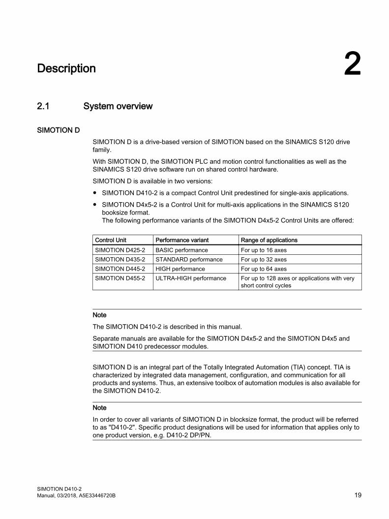
Figure 2-1 SIMOTION D410-2 DP (pictured on left), SIMOTION D410-2 DP/PN (pictured on right)
SIMOTION D410-2 is a compact Control Unit for single-axis applications.
The Control Unit is snapped directly on to the SINAMICS Power Module in blocksize format and has an integrated drive control for either one servo, one vector or one V/f axis.
SIMOTION D410-2 can be extended with additional SINAMICS S110/S120 control units (e.g. CU310‑2) and so can also be used for smaller multi-axis applications (e.g. with 2 - 3 axes).
Description2.1 System overview
SIMOTION D410-220 Manual, 03/2018, A5E33446720B
Example of a single-axis application
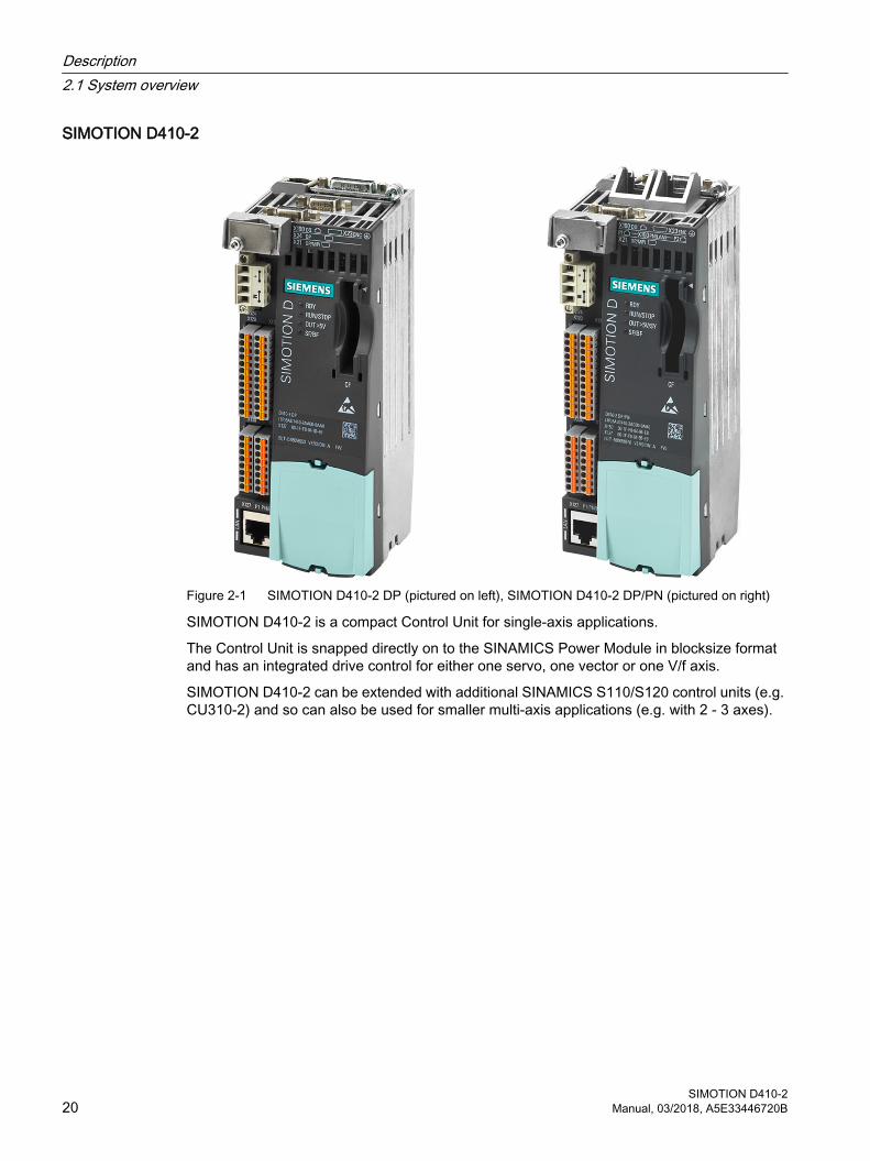
Figure 2-2 Application example with one axis
The example shows a single-axis application, consisting of a SIMOTION D410-2 (Control Unit) ① that is snapped directly on to the SINAMICS Power Module in blocksize format ②. The motors are supplied with power via the Power Module. The encoder is connected by means of DRIVE-CLiQ.
Example of a multi-axis application
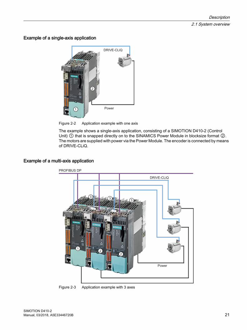
Figure 2-3 Application example with 3 axes
Description2.1 System overview
SIMOTION D410-2Manual, 03/2018, A5E33446720B 21
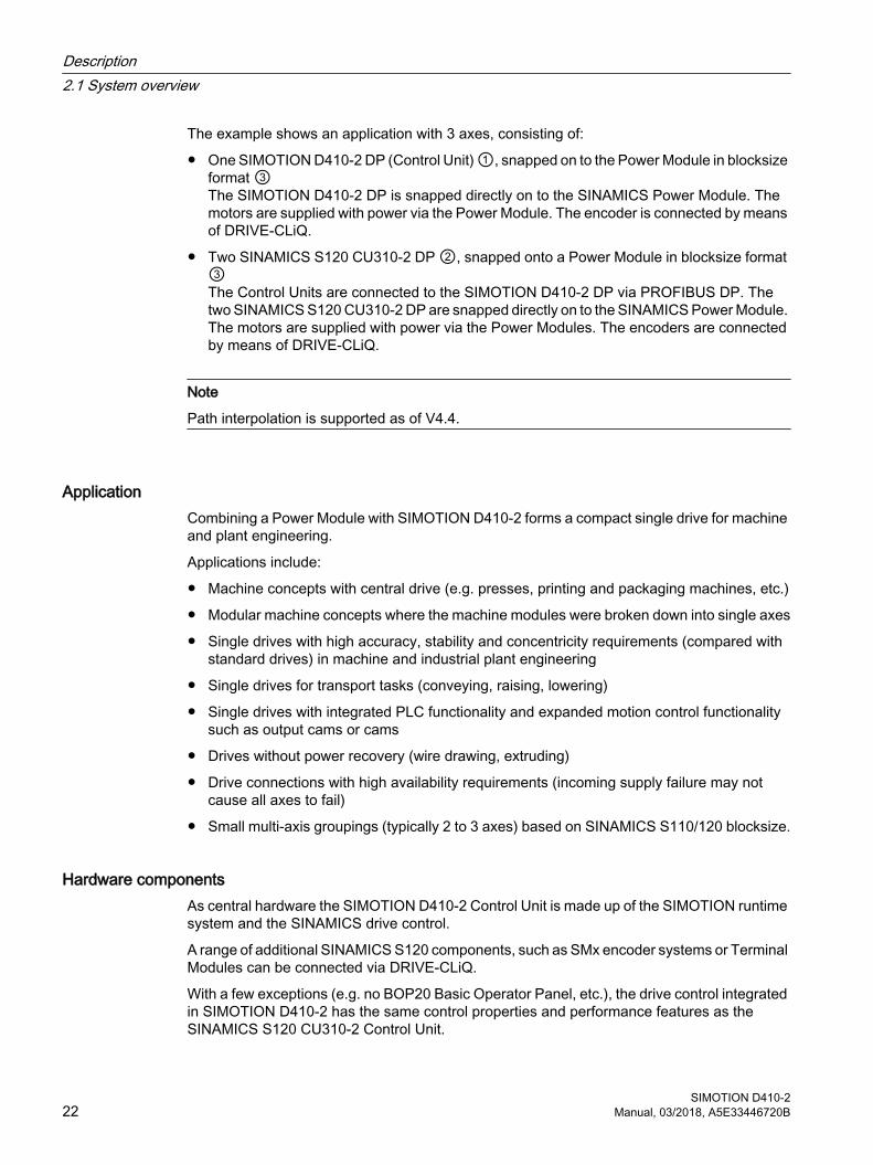
The example shows an application with 3 axes, consisting of:
● One SIMOTION D410-2 DP (Control Unit) ①, snapped on to the Power Module in blocksize format ③The SIMOTION D410-2 DP is snapped directly on to the SINAMICS Power Module. The motors are supplied with power via the Power Module. The encoder is connected by means of DRIVE-CLiQ.
● Two SINAMICS S120 CU310‑2 DP ②, snapped onto a Power Module in blocksize format ③The Control Units are connected to the SIMOTION D410-2 DP via PROFIBUS DP. The two SINAMICS S120 CU310‑2 DP are snapped directly on to the SINAMICS Power Module. The motors are supplied with power via the Power Modules. The encoders are connected by means of DRIVE-CLiQ.
Note
Path interpolation is supported as of V4.4.
ApplicationCombining a Power Module with SIMOTION D410-2 forms a compact single drive for machine and plant engineering.
Applications include:
● Machine concepts with central drive (e.g. presses, printing and packaging machines, etc.)
● Modular machine concepts where the machine modules were broken down into single axes
● Single drives with high accuracy, stability and concentricity requirements (compared with standard drives) in machine and industrial plant engineering
● Single drives for transport tasks (conveying, raising, lowering)
● Single drives with integrated PLC functionality and expanded motion control functionality such as output cams or cams
● Drives without power recovery (wire drawing, extruding)
● Drive connections with high availability requirements (incoming supply failure may not cause all axes to fail)
● Small multi-axis groupings (typically 2 to 3 axes) based on SINAMICS S110/120 blocksize.
Hardware componentsAs central hardware the SIMOTION D410-2 Control Unit is made up of the SIMOTION runtime system and the SINAMICS drive control.
A range of additional SINAMICS S120 components, such as SMx encoder systems or Terminal Modules can be connected via DRIVE‑CLiQ.
With a few exceptions (e.g. no BOP20 Basic Operator Panel, etc.), the drive control integrated in SIMOTION D410-2 has the same control properties and performance features as the SINAMICS S120 CU310-2 Control Unit.
Description2.1 System overview
SIMOTION D410-222 Manual, 03/2018, A5E33446720B
Extension of the drive computing performanceTo fully utilize the motion control performance of a SIMOTION D410-2 when required, the drive-side computing performance can be extended by connecting additional SINAMICS S/G Control Units (e.g. CU305, CU310‑2, CU320‑2, CU250S‑2, etc.) via PROFIBUS or PROFINET to the SIMOTION D410‑2.
Software componentsThe basic functionality of SIMOTION D is supplied on a CompactFlash card containing the following:
● The SIMOTION runtime system with the following functions:
– Freely programmable runtime system (IEC 61131)
– Various runtime levels (tasks)
– PLC and arithmetic functionality
– Motion control functions
– Communication functions
● The SINAMICS S120 drive control with the following functions:
– Closed-loop current and torque control
– Closed-loop speed control
Description2.1 System overview
SIMOTION D410-2Manual, 03/2018, A5E33446720B 23
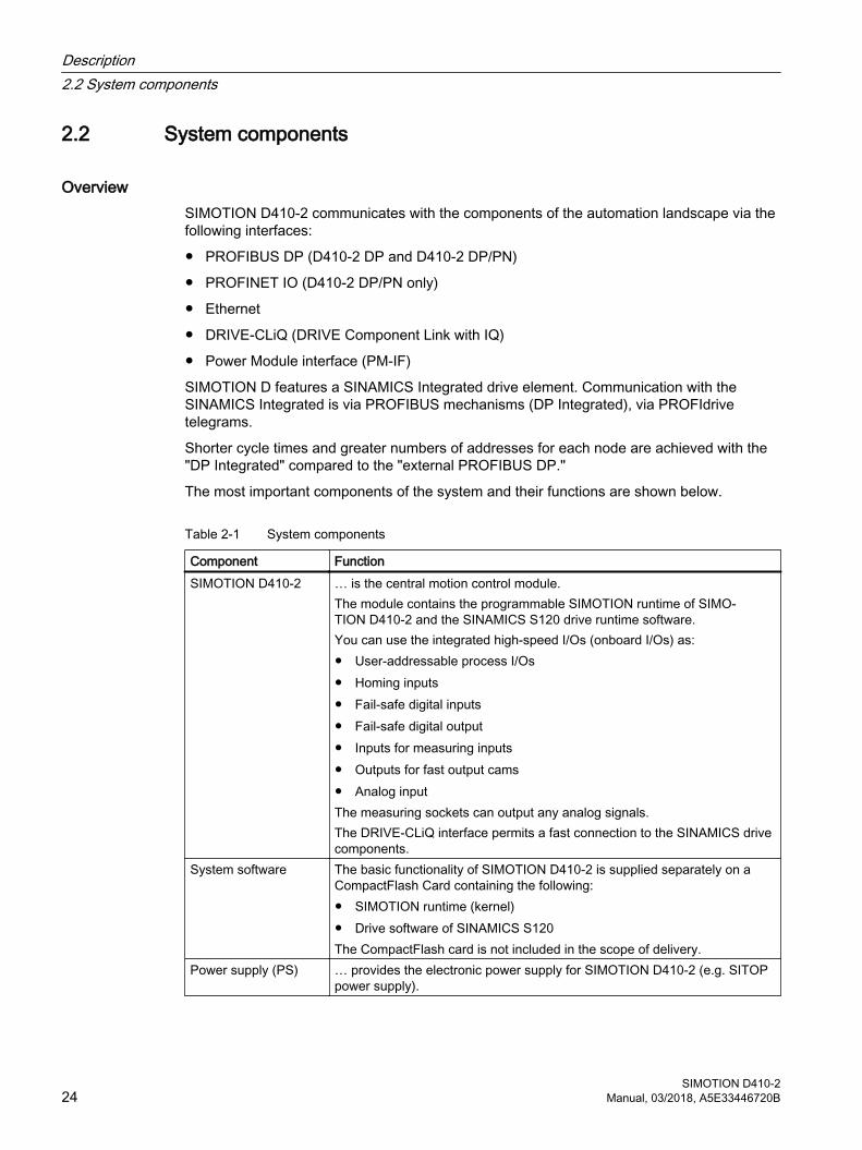
2.2 System components
OverviewSIMOTION D410-2 communicates with the components of the automation landscape via the following interfaces:
● PROFIBUS DP (D410-2 DP and D410-2 DP/PN)
● PROFINET IO (D410-2 DP/PN only)
● Ethernet
● DRIVE-CLiQ (DRIVE Component Link with IQ)
● Power Module interface (PM-IF)
SIMOTION D features a SINAMICS Integrated drive element. Communication with the SINAMICS Integrated is via PROFIBUS mechanisms (DP Integrated), via PROFIdrive telegrams.
Shorter cycle times and greater numbers of addresses for each node are achieved with the "DP Integrated" compared to the "external PROFIBUS DP."
The most important components of the system and their functions are shown below.
Table 2-1 System components
Component FunctionSIMOTION D410‑2 … is the central motion control module.
The module contains the programmable SIMOTION runtime of SIMO‐TION D410‑2 and the SINAMICS S120 drive runtime software.You can use the integrated high-speed I/Os (onboard I/Os) as:● User-addressable process I/Os● Homing inputs● Fail-safe digital inputs● Fail-safe digital output● Inputs for measuring inputs● Outputs for fast output cams● Analog inputThe measuring sockets can output any analog signals.The DRIVE-CLiQ interface permits a fast connection to the SINAMICS drive components.
System software The basic functionality of SIMOTION D410‑2 is supplied separately on a CompactFlash Card containing the following:● SIMOTION runtime (kernel)● Drive software of SINAMICS S120The CompactFlash card is not included in the scope of delivery.
Power supply (PS) … provides the electronic power supply for SIMOTION D410‑2 (e.g. SITOP power supply).
Description2.2 System components
SIMOTION D410-224 Manual, 03/2018, A5E33446720B
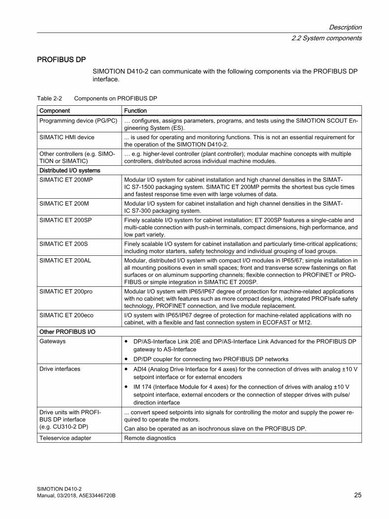
PROFIBUS DPSIMOTION D410-2 can communicate with the following components via the PROFIBUS DP interface.
Table 2-2 Components on PROFIBUS DP
Component FunctionProgramming device (PG/PC) … configures, assigns parameters, programs, and tests using the SIMOTION SCOUT En‐
gineering System (ES).SIMATIC HMI device ... is used for operating and monitoring functions. This is not an essential requirement for
the operation of the SIMOTION D410-2.Other controllers (e.g. SIMO‐TION or SIMATIC)
… e.g. higher-level controller (plant controller); modular machine concepts with multiple controllers, distributed across individual machine modules.
Distributed I/O systemsSIMATIC ET 200MP Modular I/O system for cabinet installation and high channel densities in the SIMAT‐
IC S7‑1500 packaging system. SIMATIC ET 200MP permits the shortest bus cycle times and fastest response time even with large volumes of data.
SIMATIC ET 200M Modular I/O system for cabinet installation and high channel densities in the SIMAT‐IC S7‑300 packaging system.
SIMATIC ET 200SP Finely scalable I/O system for cabinet installation; ET 200SP features a single-cable and multi-cable connection with push‑in terminals, compact dimensions, high performance, and low part variety.
SIMATIC ET 200S Finely scalable I/O system for cabinet installation and particularly time-critical applications; including motor starters, safety technology and individual grouping of load groups.
SIMATIC ET 200AL Modular, distributed I/O system with compact I/O modules in IP65/67; simple installation in all mounting positions even in small spaces; front and transverse screw fastenings on flat surfaces or on aluminum supporting channels; flexible connection to PROFINET or PRO‐FIBUS or simple integration in SIMATIC ET 200SP.
SIMATIC ET 200pro Modular I/O system with IP65/IP67 degree of protection for machine-related applications with no cabinet; with features such as more compact designs, integrated PROFIsafe safety technology, PROFINET connection, and live module replacement.
SIMATIC ET 200eco I/O system with IP65/IP67 degree of protection for machine-related applications with no cabinet, with a flexible and fast connection system in ECOFAST or M12.
Other PROFIBUS I/OGateways ● DP/AS-Interface Link 20E and DP/AS-Interface Link Advanced for the PROFIBUS DP
gateway to AS-Interface● DP/DP coupler for connecting two PROFIBUS DP networks
Drive interfaces ● ADI4 (Analog Drive Interface for 4 axes) for the connection of drives with analog ±10 V setpoint interface or for external encoders
● IM 174 (Interface Module for 4 axes) for the connection of drives with analog ±10 V setpoint interface, external encoders or the connection of stepper drives with pulse/direction interface
Drive units with PROFI‐BUS DP interface (e.g. CU310-2 DP)
... convert speed setpoints into signals for controlling the motor and supply the power re‐quired to operate the motors.Can also be operated as an isochronous slave on the PROFIBUS DP.
Teleservice adapter Remote diagnostics
Description2.2 System components
SIMOTION D410-2Manual, 03/2018, A5E33446720B 25
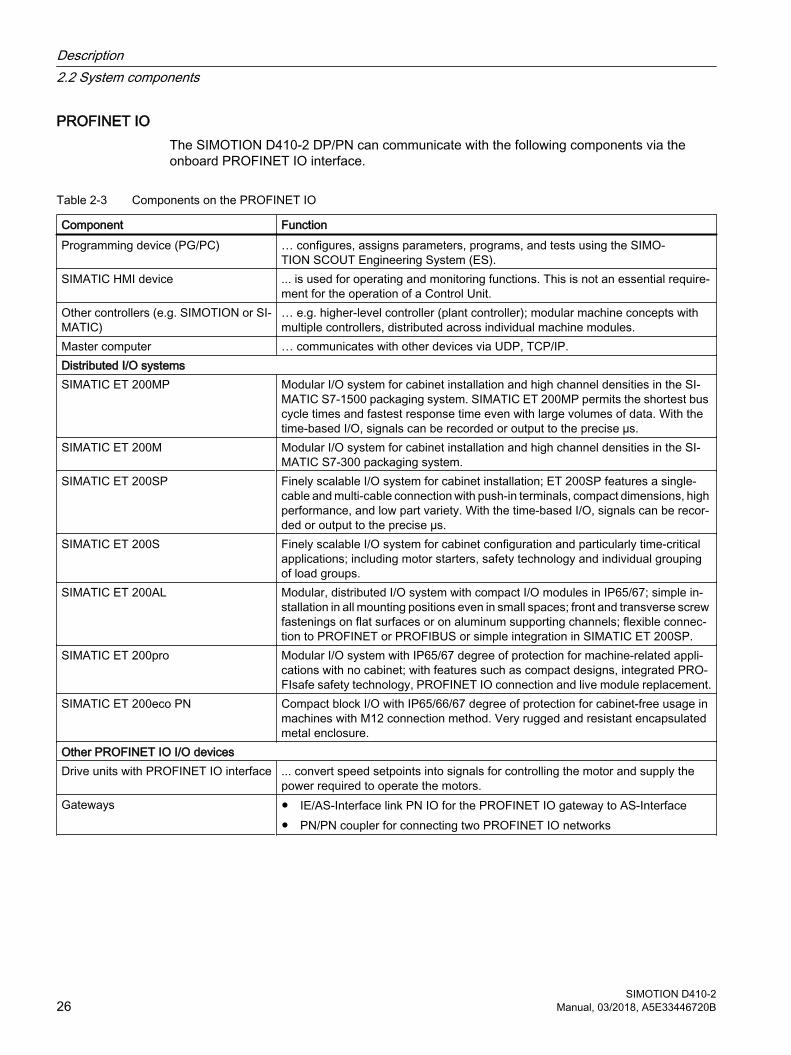
PROFINET IOThe SIMOTION D410‑2 DP/PN can communicate with the following components via the onboard PROFINET IO interface.
Table 2-3 Components on the PROFINET IO
Component Function Programming device (PG/PC) … configures, assigns parameters, programs, and tests using the SIMO‐
TION SCOUT Engineering System (ES).SIMATIC HMI device ... is used for operating and monitoring functions. This is not an essential require‐
ment for the operation of a Control Unit.Other controllers (e.g. SIMOTION or SI‐MATIC)
… e.g. higher-level controller (plant controller); modular machine concepts with multiple controllers, distributed across individual machine modules.
Master computer … communicates with other devices via UDP, TCP/IP.Distributed I/O systemsSIMATIC ET 200MP Modular I/O system for cabinet installation and high channel densities in the SI‐
MATIC S7‑1500 packaging system. SIMATIC ET 200MP permits the shortest bus cycle times and fastest response time even with large volumes of data. With the time-based I/O, signals can be recorded or output to the precise µs.
SIMATIC ET 200M Modular I/O system for cabinet installation and high channel densities in the SI‐MATIC S7-300 packaging system.
SIMATIC ET 200SP Finely scalable I/O system for cabinet installation; ET 200SP features a single-cable and multi-cable connection with push‑in terminals, compact dimensions, high performance, and low part variety. With the time-based I/O, signals can be recor‐ded or output to the precise µs.
SIMATIC ET 200S Finely scalable I/O system for cabinet configuration and particularly time-critical applications; including motor starters, safety technology and individual grouping of load groups.
SIMATIC ET 200AL Modular, distributed I/O system with compact I/O modules in IP65/67; simple in‐stallation in all mounting positions even in small spaces; front and transverse screw fastenings on flat surfaces or on aluminum supporting channels; flexible connec‐tion to PROFINET or PROFIBUS or simple integration in SIMATIC ET 200SP.
SIMATIC ET 200pro Modular I/O system with IP65/67 degree of protection for machine-related appli‐cations with no cabinet; with features such as compact designs, integrated PRO‐FIsafe safety technology, PROFINET IO connection and live module replacement.
SIMATIC ET 200eco PN Compact block I/O with IP65/66/67 degree of protection for cabinet-free usage in machines with M12 connection method. Very rugged and resistant encapsulated metal enclosure.
Other PROFINET IO I/O devicesDrive units with PROFINET IO interface ... convert speed setpoints into signals for controlling the motor and supply the
power required to operate the motors.Gateways ● IE/AS-Interface link PN IO for the PROFINET IO gateway to AS-Interface
● PN/PN coupler for connecting two PROFINET IO networks
Description2.2 System components
SIMOTION D410-226 Manual, 03/2018, A5E33446720B
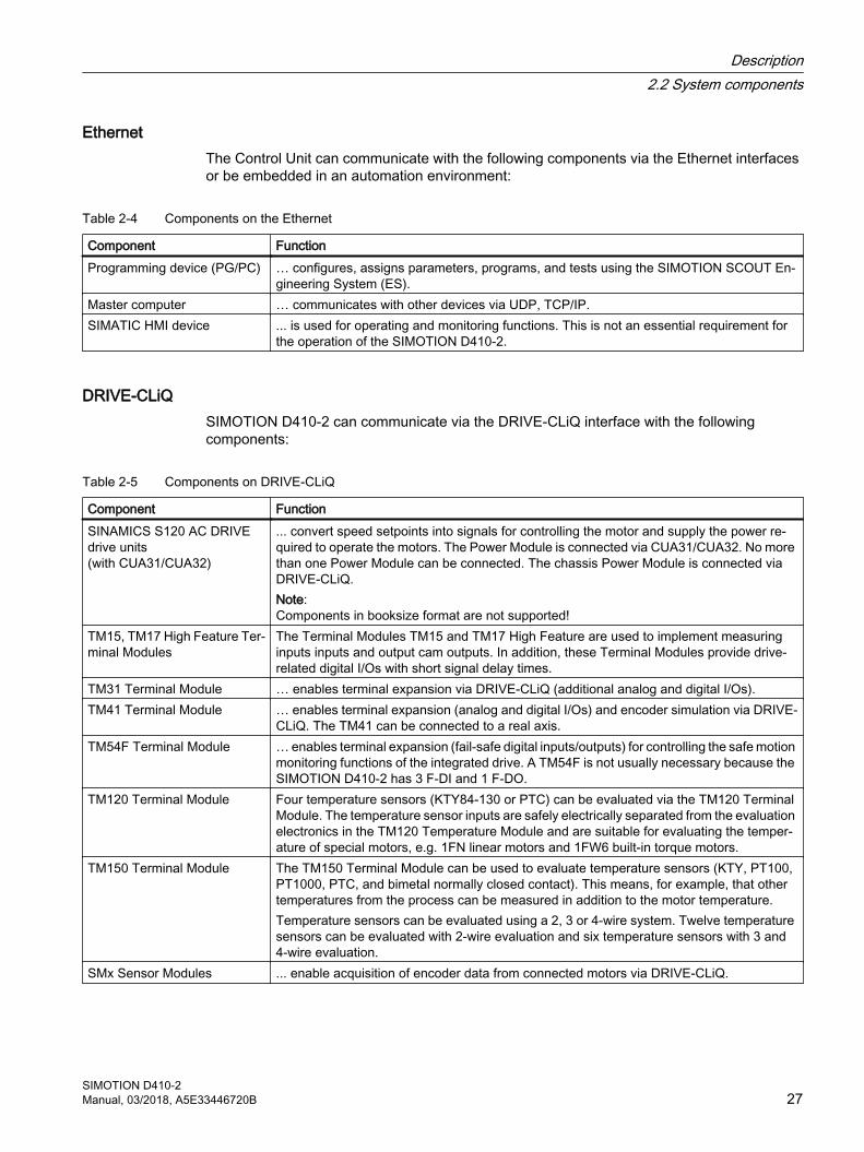
EthernetThe Control Unit can communicate with the following components via the Ethernet interfaces or be embedded in an automation environment:
Table 2-4 Components on the Ethernet
Component FunctionProgramming device (PG/PC) … configures, assigns parameters, programs, and tests using the SIMOTION SCOUT En‐
gineering System (ES).Master computer … communicates with other devices via UDP, TCP/IP.SIMATIC HMI device ... is used for operating and monitoring functions. This is not an essential requirement for
the operation of the SIMOTION D410‑2.
DRIVE-CLiQSIMOTION D410-2 can communicate via the DRIVE-CLiQ interface with the following components:
Table 2-5 Components on DRIVE-CLiQ
Component FunctionSINAMICS S120 AC DRIVE drive units (with CUA31/CUA32)
... convert speed setpoints into signals for controlling the motor and supply the power re‐quired to operate the motors. The Power Module is connected via CUA31/CUA32. No more than one Power Module can be connected. The chassis Power Module is connected via DRIVE-CLiQ.Note:Components in booksize format are not supported!
TM15, TM17 High Feature Ter‐minal Modules
The Terminal Modules TM15 and TM17 High Feature are used to implement measuring inputs inputs and output cam outputs. In addition, these Terminal Modules provide drive-related digital I/Os with short signal delay times.
TM31 Terminal Module … enables terminal expansion via DRIVE-CLiQ (additional analog and digital I/Os).TM41 Terminal Module … enables terminal expansion (analog and digital I/Os) and encoder simulation via DRIVE-
CLiQ. The TM41 can be connected to a real axis.TM54F Terminal Module … enables terminal expansion (fail-safe digital inputs/outputs) for controlling the safe motion
monitoring functions of the integrated drive. A TM54F is not usually necessary because the SIMOTION D410‑2 has 3 F‑DI and 1 F‑DO.
TM120 Terminal Module Four temperature sensors (KTY84‑130 or PTC) can be evaluated via the TM120 Terminal Module. The temperature sensor inputs are safely electrically separated from the evaluation electronics in the TM120 Temperature Module and are suitable for evaluating the temper‐ature of special motors, e.g. 1FN linear motors and 1FW6 built-in torque motors.
TM150 Terminal Module The TM150 Terminal Module can be used to evaluate temperature sensors (KTY, PT100, PT1000, PTC, and bimetal normally closed contact). This means, for example, that other temperatures from the process can be measured in addition to the motor temperature. Temperature sensors can be evaluated using a 2, 3 or 4‑wire system. Twelve temperature sensors can be evaluated with 2‑wire evaluation and six temperature sensors with 3 and 4‑wire evaluation.
SMx Sensor Modules ... enable acquisition of encoder data from connected motors via DRIVE-CLiQ.
Description2.2 System components
SIMOTION D410-2Manual, 03/2018, A5E33446720B 27
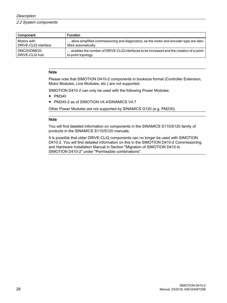
Component FunctionMotors with DRIVE-CLiQ interface
… allow simplified commissioning and diagnostics, as the motor and encoder type are iden‐tified automatically.
DMC20/DME20 DRIVE-CLiQ hub
… enables the number of DRIVE-CLiQ interfaces to be increased and the creation of a point-to-point topology.
Note
Please note that SIMOTION D410‑2 components in booksize format (Controller Extension, Motor Modules, Line Modules, etc.) are not supported.
SIMOTION D410‑2 can only be used with the following Power Modules:● PM340● PM240-2 as of SIMOTION V4.4/SINAMICS V4.7
Other Power Modules are not supported by SINAMICS G120 (e.g. PM230).
Note
You will find detailed information on components in the SINAMICS S110/S120 family of products in the SINAMICS S110/S120 manuals.
It is possible that older DRIVE‑CLiQ components can no longer be used with SIMOTION D410‑2. You will find detailed information on this in the SIMOTION D410‑2 Commissioning and Hardware Installation Manual in Section "Migration of SIMOTION D410 to SIMOTION D410‑2" under "Permissible combinations".
Description2.2 System components
SIMOTION D410-228 Manual, 03/2018, A5E33446720B

2.3 I/O integration
Note
Note that not all modules in the ET 200 I/O family are approved for SIMOTION. Moreover, system-related functional differences can come into play when these I/Os or I/O systems are used on SIMOTION vs. on SIMATIC. For example, special process-control functions (e.g. HART modules, etc.) are not supported by SIMOTION for the ET 200M distributed I/O system.
A detailed, regularly updated list of the I/O modules approved for use with SIMOTION, as well as notes on their use, can be found at Internet address (https://support.industry.siemens.com/cs/ww/en/view/11886029)
In addition to the I/O modules enabled for SIMOTION, in principle all certified standard PROFIBUS slaves (DP-V0/DP-V1/DP-V2) and PROFINET IO devices with RT and IRT real-time classes may be connected to SIMOTION D410-2. These modules are integrated using the GSD file (PROFIBUS) or GSDML file (PROFINET) provided by the relevant device manufacturer.
Note
Please note that in isolated cases, additional boundary conditions must be fulfilled in order to integrate a module into SIMOTION. Thus, a few modules require "driver blocks" , e.g. in the form of function blocks, that permit (or simplify) integration.
For modules enabled for SIMOTION (e.g. SIMATIC S7‑300 module FM 350‑1, etc.), these driver blocks are part of the SIMOTION SCOUT engineering system command library.
Description2.3 I/O integration
SIMOTION D410-2Manual, 03/2018, A5E33446720B 29
2.4 SIMOTION D410-2 DP representation
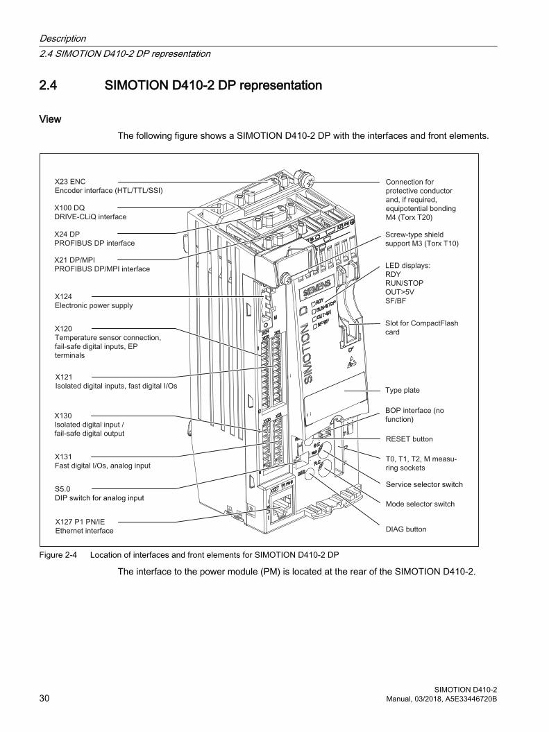
ViewThe following figure shows a SIMOTION D410-2 DP with the interfaces and front elements.
Figure 2-4 Location of interfaces and front elements for SIMOTION D410-2 DP
The interface to the power module (PM) is located at the rear of the SIMOTION D410-2.
Description2.4 SIMOTION D410-2 DP representation
SIMOTION D410-230 Manual, 03/2018, A5E33446720B
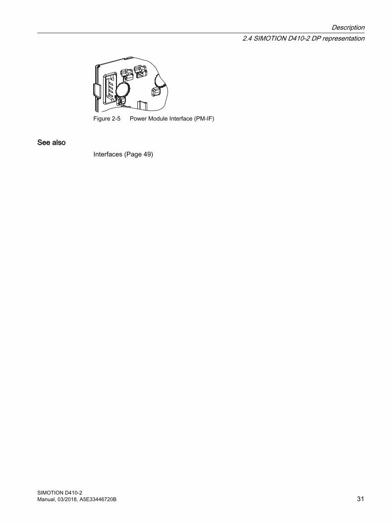
Figure 2-5 Power Module Interface (PM-IF)
See alsoInterfaces (Page 49)
Description2.4 SIMOTION D410-2 DP representation
SIMOTION D410-2Manual, 03/2018, A5E33446720B 31
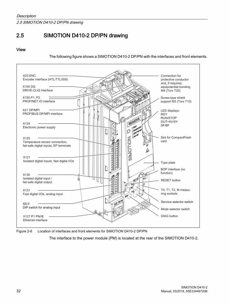
2.5 SIMOTION D410-2 DP/PN drawing
ViewThe following figure shows a SIMOTION D410-2 DP/PN with the interfaces and front elements.
Figure 2-6 Location of interfaces and front elements for SIMOTION D410-2 DP/PN
The interface to the power module (PM) is located at the rear of the SIMOTION D410-2.
Description2.5 SIMOTION D410-2 DP/PN drawing
SIMOTION D410-232 Manual, 03/2018, A5E33446720B

Figure 2-7 Power module interface (PM-IF)
See alsoInterfaces (Page 49)
Description2.5 SIMOTION D410-2 DP/PN drawing
SIMOTION D410-2Manual, 03/2018, A5E33446720B 33
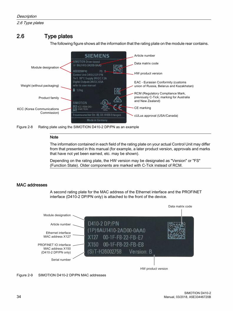
2.6 Type platesThe following figure shows all the information that the rating plate on the module rear contains.
Figure 2-8 Rating plate using the SIMOTION D410-2 DP/PN as an example
Note
The information contained in each field of the rating plate on your actual Control Unit may differ from that presented in this manual (for example, a later product version, approvals and marks that have not yet been earned, etc. may be shown).
Depending on the rating plate, the HW version may be designated as "Version" or "FS" (Function State). Older components are marked with C-Tick instead of RCM.
MAC addresses A second rating plate for the MAC address of the Ethernet interface and the PROFINET interface (D410‑2 DP/PN only) is attached to the front of the device.
Figure 2-9 SIMOTION D410‑2 DP/PN MAC addresses
Description2.6 Type plates
SIMOTION D410-234 Manual, 03/2018, A5E33446720B
Depending on the rating plate, the HW version may be designated as "Version" or "FS" (Function State).
Industry Online Support appWith our app, you have access to more than 300,000 documents.
Scan the data matrix code and display all the technical information on this product incl. graphic data (CAx data).
Link to the app: https://support.industry.siemens.com/sc/en/en/sc/2067
Description2.6 Type plates
SIMOTION D410-2Manual, 03/2018, A5E33446720B 35
2.7 CompactFlash card
PropertiesThe CF card is mandatory for operation of the SIMOTION D410‑2. The CF card must be ordered as a separate component; it is not included in the SIMOTION D410‑2 scope of delivery.
The SIMOTION Kernel (SIMOTION D410-2 firmware) and the software used to control the drives (SINAMICS firmware) are contained on the CF card.
The CF card is used for:
● Backing up the technology packages and user data (programs, configuration data, parameter assignments)
● Update (e.g. SIMOTION firmware update)
The licenses for the technology functions are linked to the serial number of the CF card. This means the CF card can be inserted in different SIMOTION D410‑2s without having to change the licenses.
The CF card is supplied in a bootable format with the latest SIMOTION Kernel and drive software.
CF cardCF cards with different storage capactities are available for SIMOTION D410‑2.
At the time for going to press, these were:
● 1 GB CF, article number 6AU1400-1PA23-0AA0
● 1 GB CF, article number 6AU1400-1PA22-0AA0
You will find detailed information on the compatibility relationships for the CF card, boot loader version, SIMOTION D hardware and SIMOTION firmware version in the software compatibility list. You can find this list both in the documentation that comes with the SIMOTION SCOUT DVD under \1_Important\Germany\Kompatibilitaet\… and on the Internet (https://support.industry.siemens.com/cs/ww/en/view/18857317).
Description2.7 CompactFlash card
SIMOTION D410-236 Manual, 03/2018, A5E33446720B
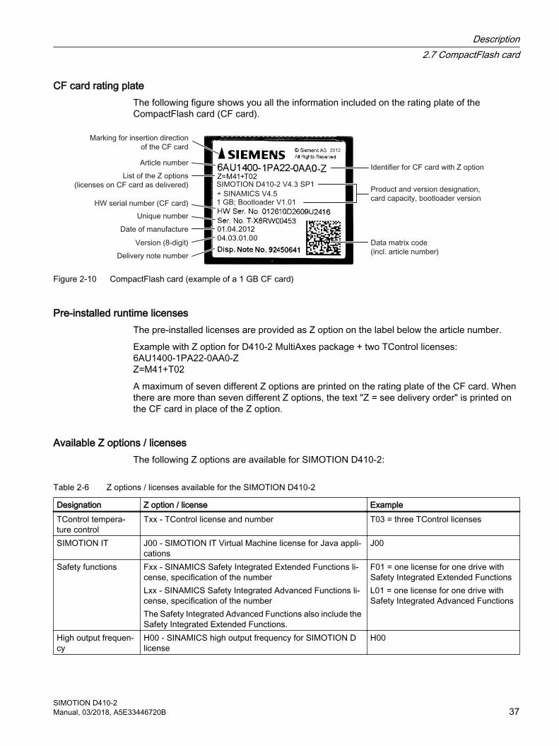
CF card rating plateThe following figure shows you all the information included on the rating plate of the CompactFlash card (CF card).
Figure 2-10 CompactFlash card (example of a 1 GB CF card)
Pre-installed runtime licensesThe pre-installed licenses are provided as Z option on the label below the article number.
Example with Z option for D410-2 MultiAxes package + two TControl licenses: 6AU1400-1PA22-0AA0-ZZ=M41+T02
A maximum of seven different Z options are printed on the rating plate of the CF card. When there are more than seven different Z options, the text "Z = see delivery order" is printed on the CF card in place of the Z option.
Available Z options / licensesThe following Z options are available for SIMOTION D410-2:
Table 2-6 Z options / licenses available for the SIMOTION D410-2
Designation Z option / license ExampleTControl tempera‐ture control
Txx - TControl license and number T03 = three TControl licenses
SIMOTION IT J00 - SIMOTION IT Virtual Machine license for Java appli‐cations
J00
Safety functions Fxx - SINAMICS Safety Integrated Extended Functions li‐cense, specification of the numberLxx - SINAMICS Safety Integrated Advanced Functions li‐cense, specification of the number The Safety Integrated Advanced Functions also include the Safety Integrated Extended Functions.
F01 = one license for one drive with Safety Integrated Extended FunctionsL01 = one license for one drive with Safety Integrated Advanced Functions
High output frequen‐cy
H00 - SINAMICS high output frequency for SIMOTION D license
H00
Description2.7 CompactFlash card
SIMOTION D410-2Manual, 03/2018, A5E33446720B 37
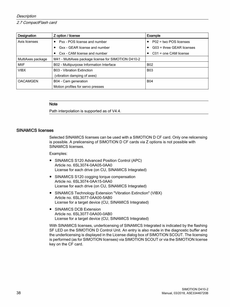
Designation Z option / license ExampleAxis licenses ● Pxx - POS license and number
● Gxx - GEAR license and number● Cxx - CAM license and number
● P02 = two POS licenses● G03 = three GEAR licenses● C01 = one CAM license
MultiAxes package M41 - MultiAxes package license for SIMOTION D410-2 MIIF B02 - Multipurpose Information Interface B02VIBX B03 - Vibration Extinction
(vibration damping of axes)B03
OACAMGEN B04 - Cam generationMotion profiles for servo presses
B04
Note
Path interpolation is supported as of V4.4.
SINAMICS licensesSelected SINAMICS licenses can be used with a SIMOTION D CF card. Only one relicensing is possible. A prelicensing of SIMOTION D CF cards via Z options is not possible with SINAMICS licenses.
Examples:
● SINAMICS S120 Advanced Position Control (APC) Article no. 6SL3074-0AA05-0AA0 License for each drive (on CU, SINAMICS Integrated)
● SINAMICS S120 cogging torque compensation Article no. 6SL3074-0AA15-0AA0 License for each drive (on CU, SINAMICS Integrated)
● SINAMICS Technology Extension "Vibration Extinction" (VIBX) Article no. 6SL3077-0AA00-5AB0 License for a target device (CU, SINAMICS Integrated)
● SINAMICS DCB Extension Article no. 6SL3077-0AA00-0AB0 License for a target device (CU, SINAMICS Integrated)
With SINAMICS licenses, underlicensing of SINAMICS Integrated is indicated by the flashing SF LED on the SIMOTION D Control Unit. An entry is also made in the diagnostic buffer and the underlicensing is displayed in the License dialog box of SIMOTION SCOUT. The licensing is performed (as for SIMOTION licenses) via SIMOTION SCOUT or via the SIMOTION license key on the CF card.
Description2.7 CompactFlash card
SIMOTION D410-238 Manual, 03/2018, A5E33446720B
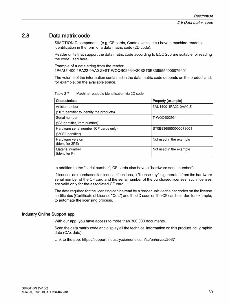
2.8 Data matrix codeSIMOTION D components (e.g. CF cards, Control Units, etc.) have a machine-readable identification in the form of a data matrix code (2D code).
Reader units that support the data matrix code according to ECC 200 are suitable for reading the code used here.
Example of a data string from the reader:1P6AU1400-1PA22-0AA0-Z+ST-WOQB02934+30SST0B8365550000079001
The volume of the information contained in the data matrix code depends on the product and, for example, on the available space.
Table 2-7 Machine-readable identification via 2D code
Characteristic Property (example)Article number("1P" identifier to identify the products)
6AU1400-1PA22-0AA0-Z
Serial number("S" identifier, item number)
T-WOQB02934
Hardware serial number (CF cards only)("30S" identifier)
ST0B8365550000079001
Hardware version(identifier 2PE)
Not used in the example
Material number(identifier P)
Not used in the example
In addition to the "serial number", CF cards also have a "hardware serial number".
If licenses are purchased for licensed functions, a "license key" is generated from the hardware serial number of the CF card and the serial number of the purchased licenses; such licenses are valid only for the associated CF card.
The data required for the licensing can be read by a reader unit via the bar codes on the license certificates (Certificate of License "CoL") and the 2D code on the CF card in order, for example, to automate the licensing process.
Industry Online Support appWith our app, you have access to more than 300,000 documents.
Scan the data matrix code and display all the technical information on this product incl. graphic data (CAx data).
Link to the app: https://support.industry.siemens.com/sc/en/en/sc/2067
Description2.8 Data matrix code
SIMOTION D410-2Manual, 03/2018, A5E33446720B 39
2.9 Licensing
SIMOTION D410-2 licensingSIMOTION D410-2 is a compact Control Unit predestined for single-axis applications. SIMOTION D410-2 has an integrated drive control for either a servo, a vector or a V/f axis. One real axis can be used without requiring a license for a SIMOTION D410-2. Speed-controlled axes and virtual axes never require a license.
SIMOTION D410-2 can be extended with additional SINAMICS S110/S120 Control Units (e.g. CU305) and so can also be used for smaller multi-axis applications (e.g. with 2 - 3 axes). These additional axes must be licensed with the single-axis licenses or the "D410‑2 MultiAxes Package". See Section CompactFlash card (Page 36).
The POS single-axis license is available if a POS axis has to be licensed; with GEAR/CAM or more than one POS license, it is better to use the D410‑2 MultiAxes Package.
Note
If you use more than one real axis with SIMOTION D410-2, you must license these additional axes. The axis license with the highest functionality is covered by the inclusive license (a real axis). The functionality has the following granularity: CAM > GEAR > POS.
Example:
You use two real axes: 1 POS, 1 CAM.Because the CAM license has a higher value, and so inclusive, you only need to purchase one POS license.
Licenses are required for runtime functions such as SIMOTION IT Virtual Machine. These licenses can be pre-installed on a CompactFlash card (CF card) or ordered separately.
Additional referencesFor more information about license management, see the SIMOTION SCOUT Configuration Manual. General information on the subject of licensing can be found in the SIMOTION PM 21 Catalog.
Description2.9 Licensing
SIMOTION D410-240 Manual, 03/2018, A5E33446720B
Operator control (hardware) 33.1 Overview of operator control and display elements
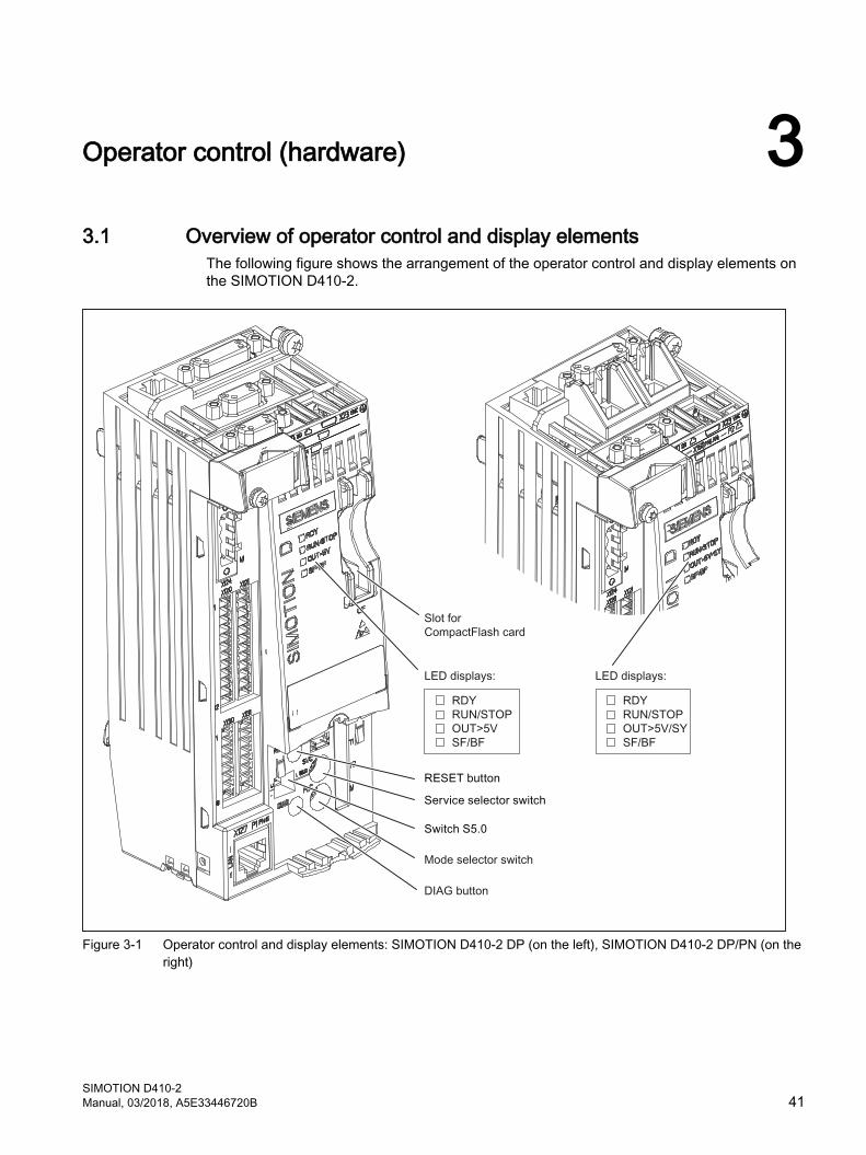
The following figure shows the arrangement of the operator control and display elements on the SIMOTION D410-2.
Figure 3-1 Operator control and display elements: SIMOTION D410-2 DP (on the left), SIMOTION D410-2 DP/PN (on the right)
SIMOTION D410-2Manual, 03/2018, A5E33446720B 41
3.2 Operator controls
3.2.1 Service selector switch
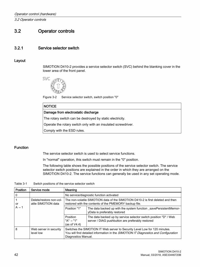
LayoutSIMOTION D410-2 provides a service selector switch (SVC) behind the blanking cover in the lower area of the front panel.
Figure 3-2 Service selector switch, switch position "0"
NOTICE
Damage from electrostatic discharge
The rotary switch can be destroyed by static electricity.
Operate the rotary switch only with an insulated screwdriver.
Comply with the ESD rules.
FunctionThe service selector switch is used to select service functions.
In "normal" operation, this switch must remain in the "0" position.
The following table shows the possible positions of the service selector switch. The service selector switch positions are explained in the order in which they are arranged on the SIMOTION D410-2. The service functions can generally be used in any set operating mode.
Table 3-1 Switch positions of the service selector switch
Position Service mode Meaning0 No service/diagnostic function activated1orA → 1
Delete/restore non-vol‐atile SIMOTION data
The non-volatile SIMOTION data of the SIMOTION D410‑2 is first deleted and then restored with the contents of the PMEMORY backup file.Position "1" The data backed up with the system function _savePersistentMemor‐
yData is preferably restoredPosition "A" → "1"(as of V4.4)
The data backed up by service selector switch position "D" / Web server / DIAG pushbutton are preferably restored
8 Web server in security level low
Switches the SIMOTION IT Web server to Security Level Low for 120 minutes.You will find detailed information in the SIMOTION IT Diagnostics and Configuration Diagnostics Manual.
Operator control (hardware)3.2 Operator controls
SIMOTION D410-242 Manual, 03/2018, A5E33446720B
Position Service mode MeaningB Downgrade
(Device Update Tool)SIMOTION D410‑2 Control Units and projects can be upgraded using upgrade data created previously. These upgrade data is generated with the Device Update Tool ("Project > Start Device Update Tool" menu in SIMOTION SCOUT).If the upgrade process fails to bring about the desired result, the upgrade can be re‐jected by means of the switch position. This will roll the system back to the previous configuration.
D Backup of diagnostic data and non-volatile SIMOTION data
The diagnostic data and non-volatile SIMOTION data can be backed up in STOP, STOPU, and RUN state. The advantage of backing up in RUN state is the availability of enhanced diagnostic information (via HTML pages) and TO alarm information.
Note
Alternatively, diagnostic data and non-volatile SIMOTION data can also be backed up via the DIAG button. See Section DIAG button (Page 45).
3.2.2 Mode selector switch
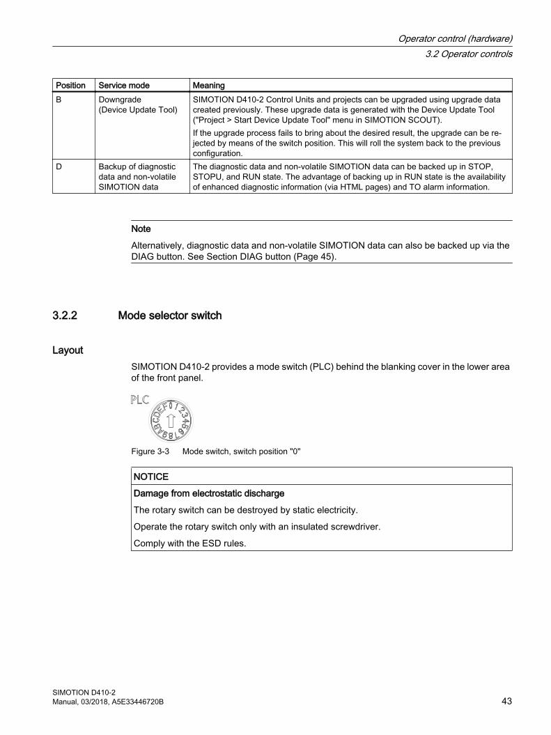
LayoutSIMOTION D410-2 provides a mode switch (PLC) behind the blanking cover in the lower area of the front panel.
Figure 3-3 Mode switch, switch position "0"
NOTICE
Damage from electrostatic discharge
The rotary switch can be destroyed by static electricity.
Operate the rotary switch only with an insulated screwdriver.
Comply with the ESD rules.
Operator control (hardware)3.2 Operator controls
SIMOTION D410-2Manual, 03/2018, A5E33446720B 43
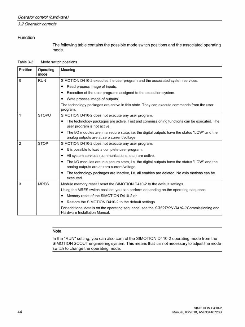
FunctionThe following table contains the possible mode switch positions and the associated operating mode.
Table 3-2 Mode switch positions
Position Operating mode
Meaning
0 RUN SIMOTION D410-2 executes the user program and the associated system services:● Read process image of inputs.● Execution of the user programs assigned to the execution system.● Write process image of outputs.The technology packages are active in this state. They can execute commands from the user program.
1 STOPU SIMOTION D410-2 does not execute any user program.● The technology packages are active. Test and commissioning functions can be executed. The
user program is not active.● The I/O modules are in a secure state, i.e. the digital outputs have the status "LOW" and the
analog outputs are at zero current/voltage.2 STOP SIMOTION D410-2 does not execute any user program.
● It is possible to load a complete user program.● All system services (communications, etc.) are active.● The I/O modules are in a secure state, i.e. the digital outputs have the status "LOW" and the
analog outputs are at zero current/voltage.● The technology packages are inactive, i.e. all enables are deleted. No axis motions can be
executed.3 MRES Module memory reset / reset the SIMOTION D410-2 to the default settings.
Using the MRES switch position, you can perform depending on the operating sequence● Memory reset of the SIMOTION D410-2 or● Restore the SIMOTION D410-2 to the default settings.For additional details on the operating sequence, see the SIMOTION D410-2 Commissioning and Hardware Installation Manual.
Note
In the "RUN" setting, you can also control the SIMOTION D410-2 operating mode from the SIMOTION SCOUT engineering system. This means that it is not necessary to adjust the mode switch to change the operating mode.
Operator control (hardware)3.2 Operator controls
SIMOTION D410-244 Manual, 03/2018, A5E33446720B
Additional referencesDetailed information
● For information on setting the operating modes, see the SIMOTION SCOUT Configuration Manual.
● For device upgrade (device update tool), see Upgrading SIMOTION Devices Operating Instructions.
3.2.3 DIAG button
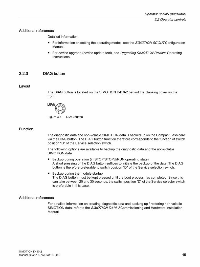
LayoutThe DIAG button is located on the SIMOTION D410‑2 behind the blanking cover on the front.
Figure 3-4 DIAG button
FunctionThe diagnostic data and non-volatile SIMOTION data is backed up on the CompactFlash card via the DIAG button. The DIAG button function therefore corresponds to the function of switch position "D" of the Service selection switch.
The following options are available to backup the diagnostic data and the non-volatile SIMOTION data:
● Backup during operation (in STOP/STOPU/RUN operating state)A short pressing of the DIAG button suffices to initiate the backup of the data. The DIAG button is therefore preferable to switch position "D" of the Service selection switch.
● Backup during the module startupThe DIAG button must be kept pressed until the boot process has completed. Since this can take between 20 and 30 seconds, the switch position "D" of the Service selector switch is preferable in this case.
Additional referencesFor detailed information on creating diagnostic data and backing up / restoring non-volatile SIMOTION data, refer to the SIMOTION D410-2 Commissioning and Hardware Installation Manual.
Operator control (hardware)3.2 Operator controls
SIMOTION D410-2Manual, 03/2018, A5E33446720B 45
3.2.4 RESET button
LayoutThe RESET button is located behind the blanking cover on the SIMOTION D410-2.
Figure 3-5 RESET button
FunctionThe entire system is reset when the RESET button is pressed and a new power-up of the system forced.
3.2.5 Switch S5.0
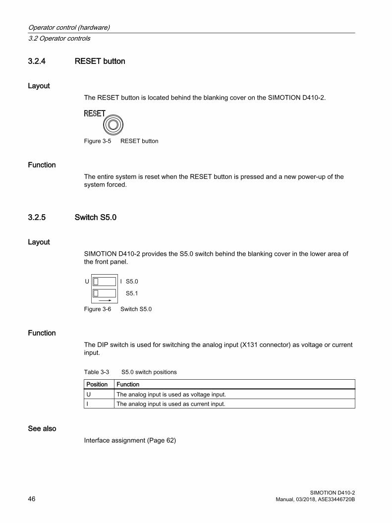
LayoutSIMOTION D410-2 provides the S5.0 switch behind the blanking cover in the lower area of the front panel.
Figure 3-6 Switch S5.0
FunctionThe DIP switch is used for switching the analog input (X131 connector) as voltage or current input.
Table 3-3 S5.0 switch positions
Position FunctionU The analog input is used as voltage input.I The analog input is used as current input.
See alsoInterface assignment (Page 62)
Operator control (hardware)3.2 Operator controls
SIMOTION D410-246 Manual, 03/2018, A5E33446720B
3.2.6 SIMOTION CompactFlash card
FunctionThe SIMOTION Kernel (SIMOTION D410-2 firmware) and the software used to control the drives (SINAMICS firmware) are contained on the CF card.
The CompactFlash card (CF card) is used to
● Backup technology packages and user data
● Update (e.g. SIMOTION firmware update)
Slot for CompactFlash cardThe CF card is inserted into the plug-in module over the blanking cover (see Overview of operator control and display elements (Page 41)).
NOTICE
Impermissible use of the CompactFlash card
The CF card of the SIMOTION D410-2 must not be used in a SIMOTION D410, D4x5 or D4x5-2!
NOTICE
Elektrostatisch gefährdete Bauelemente
The CompactFlash card is an ESD-sensitive component.
De-energize the SIMOTION D410‑2 device before inserting or removing the CompactFlash card. The SIMOTION D410‑2 is in a de-energized state when all the LEDs are OFF.
Comply with the ESD rules.
Additional informationFor more information on writing and formatting the CF card, see the SIMOTION D410-2 Commissioning Manual.
Operator control (hardware)3.2 Operator controls
SIMOTION D410-2Manual, 03/2018, A5E33446720B 47
3.3 Error and status displays
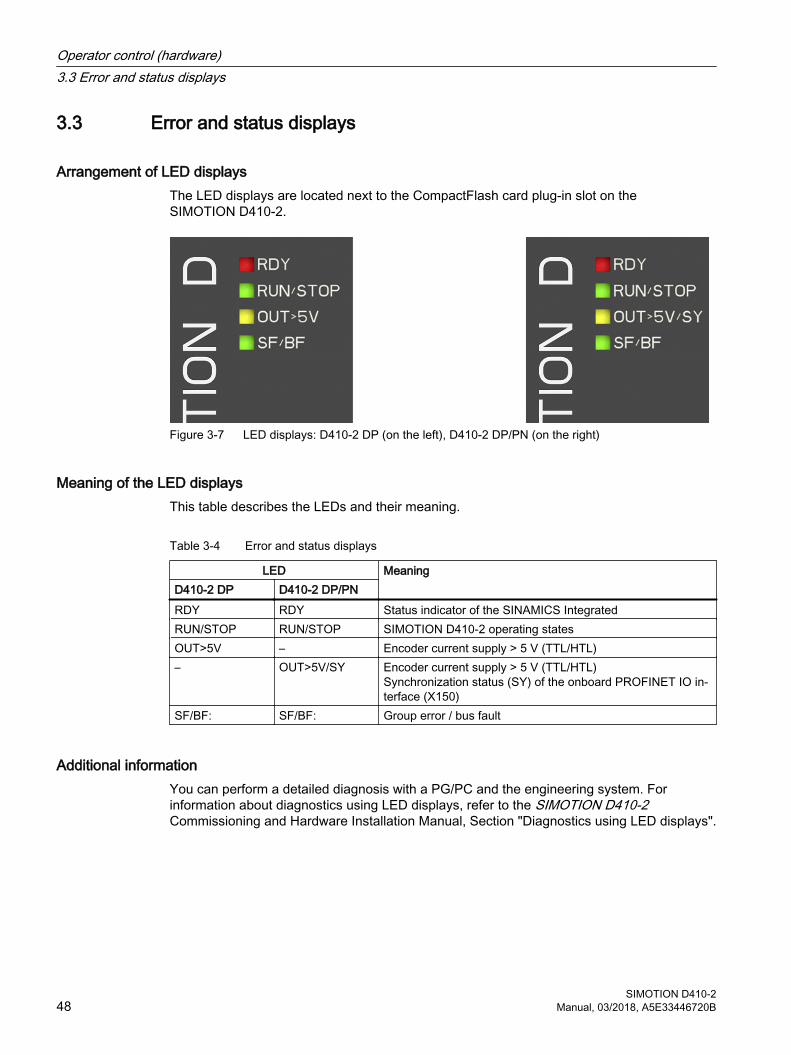
Arrangement of LED displaysThe LED displays are located next to the CompactFlash card plug-in slot on the SIMOTION D410-2.
Figure 3-7 LED displays: D410-2 DP (on the left), D410-2 DP/PN (on the right)
Meaning of the LED displaysThis table describes the LEDs and their meaning.
Table 3-4 Error and status displays
LED MeaningD410-2 DP D410-2 DP/PNRDY RDY Status indicator of the SINAMICS IntegratedRUN/STOP RUN/STOP SIMOTION D410-2 operating statesOUT>5V – Encoder current supply > 5 V (TTL/HTL)– OUT>5V/SY Encoder current supply > 5 V (TTL/HTL)
Synchronization status (SY) of the onboard PROFINET IO in‐terface (X150)
SF/BF: SF/BF: Group error / bus fault
Additional informationYou can perform a detailed diagnosis with a PG/PC and the engineering system. For information about diagnostics using LED displays, refer to the SIMOTION D410-2 Commissioning and Hardware Installation Manual, Section "Diagnostics using LED displays".
Operator control (hardware)3.3 Error and status displays
SIMOTION D410-248 Manual, 03/2018, A5E33446720B

Interfaces 44.1 Overview of interfaces
This section describes the interfaces of the SIMOTION D410‑2. Information on the arrangement of the interfaces on the module can be found in Sections SIMOTION D410-2 DP representation (Page 30) and SIMOTION D410-2 DP/PN drawing (Page 32).
Available interfaces
Table 4-1 Overview of available SIMOTION D410-2 interfaces
Interface Type Connector typeX100 DRIVE-CLiQ interface (DQ) 8-pin RJ45plus socket to connect DRIVE-
CLiQ nodesX21 PROFIBUS DP/MPI interface 9-pin SUB-D socket to connect to PRO‐
FIBUS DP or MPIX24 PROFIBUS DP interface
(SIMOTION D410‑2 DP only)9-pin SUB-D socket to connect to PRO‐FIBUS DP
X150 P1, P2 PROFINET IO interface(SIMOTION D410‑2 DP/PN only)
8-pin RJ45 socket to connect to PROFI‐NET IO
X23 Encoder interface (ENC) 15-pin SUB-D socket for connecting HTL, TTL and SSI encoders
X120 Temperature sensor connection, fail-safe digital inputs
12-pin spring-loaded terminal
X121 Isolated digital inputs, fast digital I/Os 12-pin spring-loaded terminalX130 Isolated digital input, fail-safe digital
output8-pin spring-loaded terminal
X131 Fast digital I/Os, analog input 8-pin spring-loaded terminalX124 Power supply connection 4-pin screw-type terminal connectionX127 P1 Ethernet interface (PN/IE) 8-pin RJ45 socket for Ethernet connec‐
tion (LAN)T0, T1, T2 and G Measuring sockets Sockets to output analog signalsPM-IF Power module interface 8-pin direct connector to connect to a
blocksize power module
Non-usable interfaces
Table 4-2 Overview of non-usable SIMOTION D410-2 interfaces
Interface Designation Connector typeInterface for BOP BOP 8-pin multipoint connector
SIMOTION D410-2Manual, 03/2018, A5E33446720B 49
4.2 DRIVE-CLiQ interface
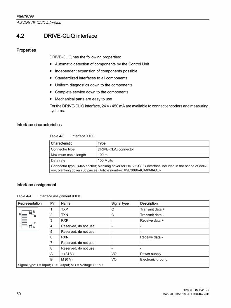
PropertiesDRIVE-CLiQ has the following properties:
● Automatic detection of components by the Control Unit
● Independent expansion of components possible
● Standardized interfaces to all components
● Uniform diagnostics down to the components
● Complete service down to the components
● Mechanical parts are easy to use
For the DRIVE-CLiQ interface, 24 V / 450 mA are available to connect encoders and measuring systems.
Interface characteristics
Table 4-3 Interface X100
Characteristic TypeConnector type DRIVE-CLiQ connectorMaximum cable length 100 mData rate 100 MbitsConnector type: RJ45 socket; blanking cover for DRIVE-CLiQ interface included in the scope of deliv‐ery; blanking cover (50 pieces) Article number: 6SL3066-4CA00-0AA0)
Interface assignment
Table 4-4 Interface assignment X100
Representation Pin Name Signal type Description1 TXP O Transmit data +2 TXN O Transmit data -3 RXP I Receive data +4 Reserved, do not use - -5 Reserved, do not use - -6 RXN I Receive data -7 Reserved, do not use - -8 Reserved, do not use - -A + (24 V) VO Power supplyB M (0 V) VO Electronic ground
Signal type: I = Input; O = Output; VO = Voltage Output
Interfaces4.2 DRIVE-CLiQ interface
SIMOTION D410-250 Manual, 03/2018, A5E33446720B
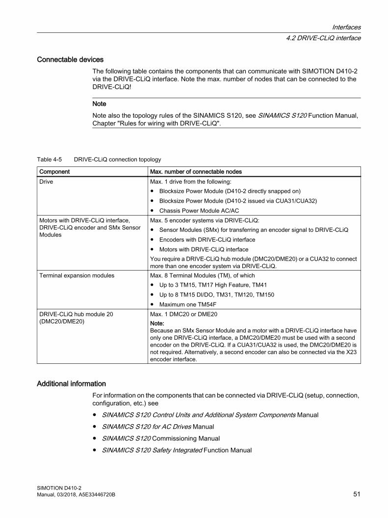
Connectable devices The following table contains the components that can communicate with SIMOTION D410-2 via the DRIVE-CLiQ interface. Note the max. number of nodes that can be connected to the DRIVE-CLiQ!
Note
Note also the topology rules of the SINAMICS S120, see SINAMICS S120 Function Manual, Chapter "Rules for wiring with DRIVE-CLiQ".
Table 4-5 DRIVE-CLiQ connection topology
Component Max. number of connectable nodesDrive Max. 1 drive from the following:
● Blocksize Power Module (D410-2 directly snapped on)● Blocksize Power Module (D410-2 issued via CUA31/CUA32)● Chassis Power Module AC/AC
Motors with DRIVE-CLiQ interface, DRIVE-CLiQ encoder and SMx Sensor Modules
Max. 5 encoder systems via DRIVE-CLiQ:● Sensor Modules (SMx) for transferring an encoder signal to DRIVE-CLiQ● Encoders with DRIVE-CLiQ interface● Motors with DRIVE-CLiQ interfaceYou require a DRIVE-CLiQ hub module (DMC20/DME20) or a CUA32 to connect more than one encoder system via DRIVE-CLiQ.
Terminal expansion modules Max. 8 Terminal Modules (TM), of which● Up to 3 TM15, TM17 High Feature, TM41● Up to 8 TM15 DI/DO, TM31, TM120, TM150● Maximum one TM54F
DRIVE-CLiQ hub module 20(DMC20/DME20)
Max. 1 DMC20 or DME20Note:Because an SMx Sensor Module and a motor with a DRIVE-CLiQ interface have only one DRIVE-CLiQ interface, a DMC20/DME20 must be used with a second encoder on the DRIVE-CLiQ. If a CUA31/CUA32 is used, the DMC20/DME20 is not required. Alternatively, a second encoder can also be connected via the X23 encoder interface.
Additional informationFor information on the components that can be connected via DRIVE-CLiQ (setup, connection, configuration, etc.) see
● SINAMICS S120 Control Units and Additional System Components Manual
● SINAMICS S120 for AC Drives Manual
● SINAMICS S120 Commissioning Manual
● SINAMICS S120 Safety Integrated Function Manual
Interfaces4.2 DRIVE-CLiQ interface
SIMOTION D410-2Manual, 03/2018, A5E33446720B 51

● TM15/TM17 High Feature SIMOTION Terminal Modules Commissioning Manual
● SIMOTION Terminal Modules TM15 / TM17 Manual
Interfaces4.2 DRIVE-CLiQ interface
SIMOTION D410-252 Manual, 03/2018, A5E33446720B

4.3 PROFIBUS DP interfaces
PropertiesSIMOTION D410-2 provides the following interfaces for connection on the PROFIBUS DP:
Table 4-6 SIMOTION D410-2 PROFIBUS interfaces
D410-2 DP D410-2 DP/PNPROFIBUS DP/MPI interface X21 X21PROFIBUS DP interface X24 –
The interfaces can be run asynchronously or isochronously, equidistant.
SIMOTION D410-2 includes master and I-slave functionality.
Interface characteristics
Table 4-7 X21 and X24 interfaces
Characteristics TypeConnector type 9-pin sub D socketCable type PROFIBUS cableMax. cable length 100 m at 12 Mbit/sMax. data rate 12 Mbit/s
Interface assignment X21
Table 4-8 PROFIBUS DP/MPI interface (X21)
Representation Pin Signal name Signal type
Meaning
1 - - Reserved, do not use2 M VO Ground to P24_SERV3 1RS_DP B RS-485 differential signal4 1RTS_DP O Request to send5 1M VO Ground to 1P56 1P5 VO 5 V power supply for bus terminal, external, short-circuit proof7 P24_SERV VO 24 V for teleservice, short-circuit proof, 150 mA maximum8 1XRS_DP B RS-485 differential signal9 - - Reserved, do not use
The 1P5 voltage is provided exclusively for the bus terminal. No OLPs are permitted.Signal type: VO = Voltage output (power supply); O = Output; B = Bidirectional
Interfaces4.3 PROFIBUS DP interfaces
SIMOTION D410-2Manual, 03/2018, A5E33446720B 53
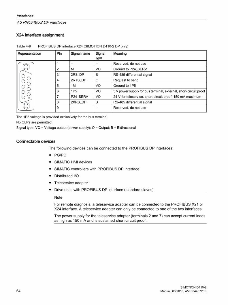
X24 interface assignment
Table 4-9 PROFIBUS DP interface X24 (SIMOTION D410‑2 DP only)
Representation Pin Signal name Signal type
Meaning
1 -- -- Reserved, do not use2 M VO Ground to P24_SERV3 2RS_DP B RS-485 differential signal4 2RTS_DP O Request to send5 1M VO Ground to 1P56 1P5 VO 5 V power supply for bus terminal, external, short-circuit proof7 P24_SERV VO 24 V for teleservice, short-circuit proof, 150 mA maximum8 2XRS_DP B RS-485 differential signal9 -- -- Reserved, do not use
The 1P5 voltage is provided exclusively for the bus terminal. No OLPs are permitted.Signal type: VO = Voltage output (power supply); O = Output; B = Bidirectional
Connectable devicesThe following devices can be connected to the PROFIBUS DP interfaces:
● PG/PC
● SIMATIC HMI devices
● SIMATIC controllers with PROFIBUS DP interface
● Distributed I/O
● Teleservice adapter
● Drive units with PROFIBUS DP interface (standard slaves)
Note
For remote diagnosis, a teleservice adapter can be connected to the PROFIBUS X21 or X24 interface. A teleservice adapter can only be connected to one of the two interfaces.
The power supply for the teleservice adapter (terminals 2 and 7) can accept current loads as high as 150 mA and is sustained short-circuit proof.
Interfaces4.3 PROFIBUS DP interfaces
SIMOTION D410-254 Manual, 03/2018, A5E33446720B
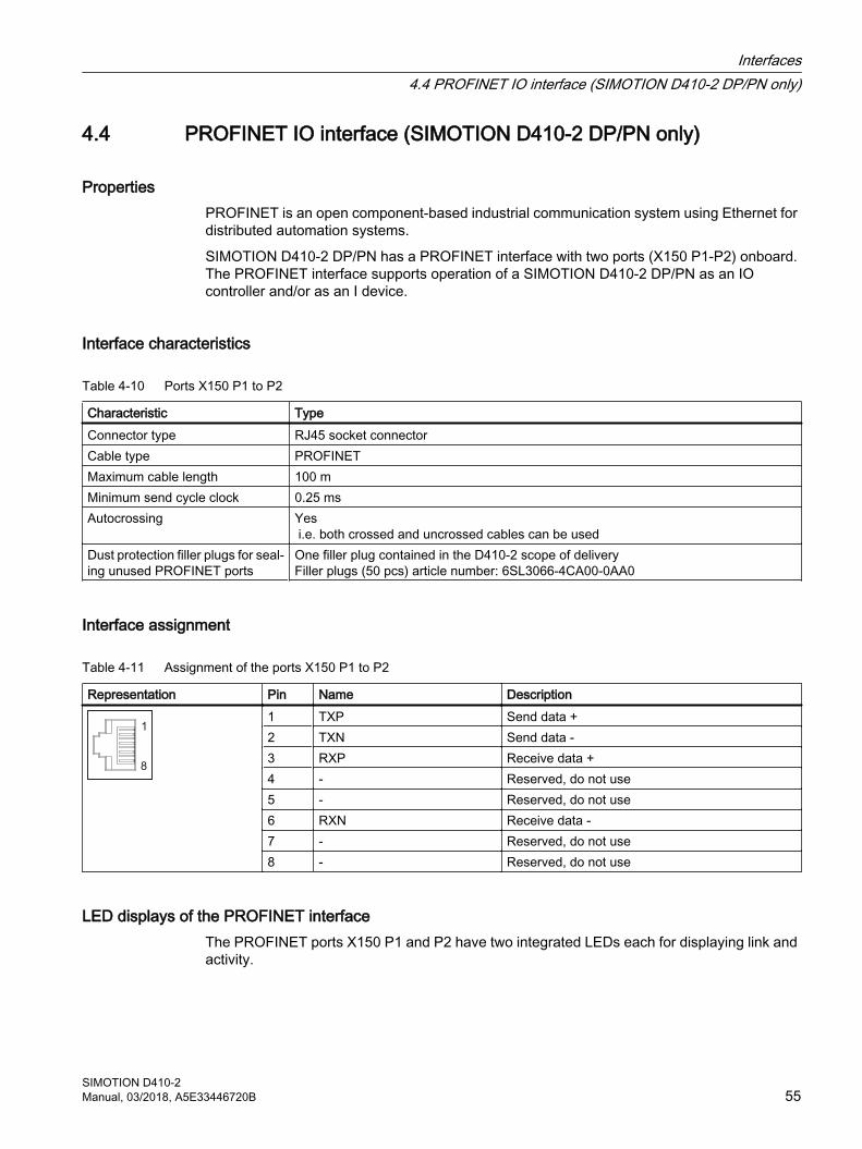
4.4 PROFINET IO interface (SIMOTION D410-2 DP/PN only)
PropertiesPROFINET is an open component-based industrial communication system using Ethernet for distributed automation systems.
SIMOTION D410‑2 DP/PN has a PROFINET interface with two ports (X150 P1-P2) onboard. The PROFINET interface supports operation of a SIMOTION D410‑2 DP/PN as an IO controller and/or as an I device.
Interface characteristics
Table 4-10 Ports X150 P1 to P2
Characteristic TypeConnector type RJ45 socket connectorCable type PROFINETMaximum cable length 100 mMinimum send cycle clock 0.25 msAutocrossing Yes
i.e. both crossed and uncrossed cables can be usedDust protection filler plugs for seal‐ing unused PROFINET ports
One filler plug contained in the D410‑2 scope of delivery Filler plugs (50 pcs) article number: 6SL3066‑4CA00‑0AA0
Interface assignment
Table 4-11 Assignment of the ports X150 P1 to P2
Representation Pin Name Description1 TXP Send data +2 TXN Send data -3 RXP Receive data +4 - Reserved, do not use5 - Reserved, do not use6 RXN Receive data -7 - Reserved, do not use8 - Reserved, do not use
LED displays of the PROFINET interfaceThe PROFINET ports X150 P1 and P2 have two integrated LEDs each for displaying link and activity.
Interfaces4.4 PROFINET IO interface (SIMOTION D410-2 DP/PN only)
SIMOTION D410-2Manual, 03/2018, A5E33446720B 55
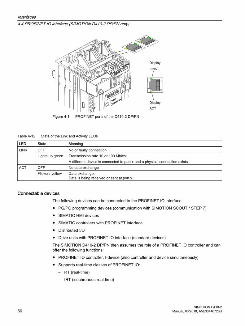
Figure 4-1 PROFINET ports of the D410-2 DP/PN
Table 4-12 State of the Link and Activity LEDs
LED State MeaningLINK OFF No or faulty connection
Lights up green Transmission rate 10 or 100 Mbit/s:A different device is connected to port x and a physical connection exists
ACT OFF No data exchangeFlickers yellow Data exchange:
Data is being received or sent at port x.
Connectable devicesThe following devices can be connected to the PROFINET IO interface:
● PG/PC programming devices (communication with SIMOTION SCOUT / STEP 7)
● SIMATIC HMI devices
● SIMATIC controllers with PROFINET interface
● Distributed I/O
● Drive units with PROFINET IO interface (standard devices)
The SIMOTION D410‑2 DP/PN then assumes the role of a PROFINET IO controller and can offer the following functions:
● PROFINET IO controller, I-device (also controller and device simultaneously)
● Supports real-time classes of PROFINET IO:
– RT (real-time)
– IRT (isochronous real-time)
Interfaces4.4 PROFINET IO interface (SIMOTION D410-2 DP/PN only)
SIMOTION D410-256 Manual, 03/2018, A5E33446720B
The following functions are also supported by Industrial Ethernet:
● Communication between SIMOTION and SIMATIC NET OPC. The "SIMATIC NET SOFTNET S7 (S7 OPC server)" software must be installed on the PG/PC for this function.
● Communication with other devices over TCP/IP or UDP communication
● IT communication (e.g. via SIMOTION IT OPC XML‑DA)
● Communication based on OPC UA (Unified Architecture)
For further information on the software packages, see the SIMOTION PM 21 Catalog.
Interfaces4.4 PROFINET IO interface (SIMOTION D410-2 DP/PN only)
SIMOTION D410-2Manual, 03/2018, A5E33446720B 57
4.5 Encoder interface (HTL/TTL/SSI)The HTL/TTL/SSI encoder interface is used to connect external encoders.
Interface characteristics
Table 4-13 Interface X23
Characteristic TypeEncoder interface ● TTL or HTL incremental encoders (with adjustable
parameters)● Absolute encoder SSI
Connector type 15-pin sub D connectorMeasuring current via temperature sensor connection
2 mA
NOTICE
Destruction of the encoder electronics
Operation of a 5 V encoder on the 24 V encoder supply may result in the destruction of its electronic components!
Make sure that you can operate the connected encoder on a 24 V power supply (e.g. HTL encoder). This setting can be set in the expert list of the drive in parameter p0400 and in the following parameters.
Interfaces4.5 Encoder interface (HTL/TTL/SSI)
SIMOTION D410-258 Manual, 03/2018, A5E33446720B
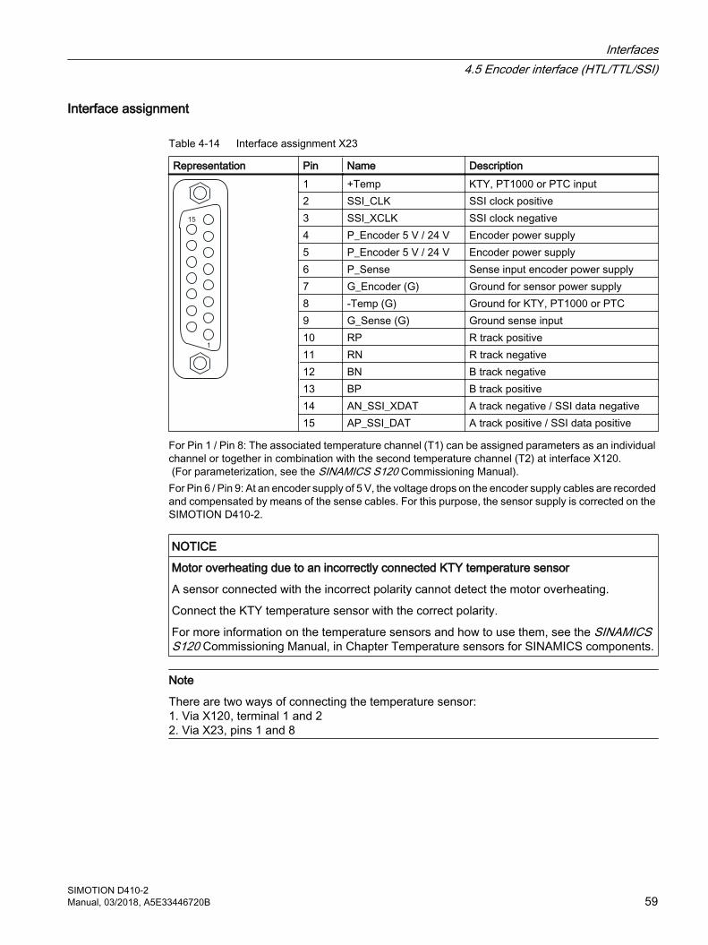
Interface assignment
Table 4-14 Interface assignment X23
Representation Pin Name Description1 +Temp KTY, PT1000 or PTC input2 SSI_CLK SSI clock positive3 SSI_XCLK SSI clock negative4 P_Encoder 5 V / 24 V Encoder power supply5 P_Encoder 5 V / 24 V Encoder power supply6 P_Sense Sense input encoder power supply7 G_Encoder (G) Ground for sensor power supply8 -Temp (G) Ground for KTY, PT1000 or PTC9 G_Sense (G) Ground sense input10 RP R track positive11 RN R track negative12 BN B track negative13 BP B track positive14 AN_SSI_XDAT A track negative / SSI data negative15 AP_SSI_DAT A track positive / SSI data positive
For Pin 1 / Pin 8: The associated temperature channel (T1) can be assigned parameters as an individual channel or together in combination with the second temperature channel (T2) at interface X120. (For parameterization, see the SINAMICS S120 Commissioning Manual).For Pin 6 / Pin 9: At an encoder supply of 5 V, the voltage drops on the encoder supply cables are recorded and compensated by means of the sense cables. For this purpose, the sensor supply is corrected on the SIMOTION D410-2.
NOTICE
Motor overheating due to an incorrectly connected KTY temperature sensor
A sensor connected with the incorrect polarity cannot detect the motor overheating.
Connect the KTY temperature sensor with the correct polarity.
For more information on the temperature sensors and how to use them, see the SINAMICS S120 Commissioning Manual, in Chapter Temperature sensors for SINAMICS components.
Note
There are two ways of connecting the temperature sensor:1. Via X120, terminal 1 and 22. Via X23, pins 1 and 8
Interfaces4.5 Encoder interface (HTL/TTL/SSI)
SIMOTION D410-2Manual, 03/2018, A5E33446720B 59
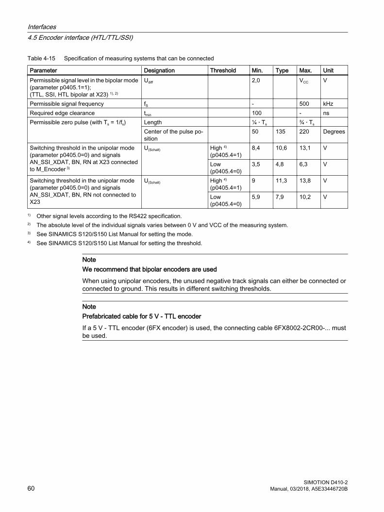
Table 4-15 Specification of measuring systems that can be connected
Parameter Designation Threshold Min. Type Max. UnitPermissible signal level in the bipolar mode (parameter p0405.1=1);(TTL, SSI, HTL bipolar at X23) 1), 2)
Udiff 2,0 VCC V
Permissible signal frequency fS - 500 kHzRequired edge clearance tmin 100 - nsPermissible zero pulse (with Ts = 1/fs) Length ¼ · Ts ¾ · Ts
Center of the pulse po‐sition
50 135 220 Degrees
Switching threshold in the unipolar mode (parameter p0405.0=0) and signals AN_SSI_XDAT, BN, RN at X23 connected to M_Encoder 3)
U(Schalt) High 4)
(p0405.4=1)8,4 10,6 13,1 V
Low(p0405.4=0)
3,5 4,8 6,3 V
Switching threshold in the unipolar mode (parameter p0405.0=0) and signals AN_SSI_XDAT, BN, RN not connected to X23
U(Schalt) High 4)
(p0405.4=1)9 11,3 13,8 V
Low(p0405.4=0)
5,9 7,9 10,2 V
1) Other signal levels according to the RS422 specification.2) The absolute level of the individual signals varies between 0 V and VCC of the measuring system.3) See SINAMICS S120/S150 List Manual for setting the mode.4) See SINAMICS S120/S150 List Manual for setting the threshold.
NoteWe recommend that bipolar encoders are used
When using unipolar encoders, the unused negative track signals can either be connected or connected to ground. This results in different switching thresholds.
NotePrefabricated cable for 5 V - TTL encoder
If a 5 V - TTL encoder (6FX encoder) is used, the connecting cable 6FX8002-2CR00-... must be used.
Interfaces4.5 Encoder interface (HTL/TTL/SSI)
SIMOTION D410-260 Manual, 03/2018, A5E33446720B
4.6 Digital I/Os / temperature sensor / analog input
4.6.1 PropertiesThe onboard I/Os (Onboard I/Os) of the SIMOTION D410-2 are assigned to the SINAMICS Integrated. An appropriate configuration allows the I/Os also to be used by SIMOTION.
Digital I/OsThe digital I/Os at the X120, X121 and X130, X131 connectors are provided for the connection of sensors and actuators.
Following types of digital I/Os are available on the SIMOTION D410-2:
● Three fail-safe electrically-isolated digital inputs (F-DI)(can be used alternatively as six standard digital inputs, DI 17 can also be used as EP terminal)
● One fail-safe electrically-isolated digital output (F-DO)(can be used alternatively as one standard digital output)
● Five electrically-isolated digital inputs (DI)
● Eight high-speed non-isolated digital I/Os (DI/DO)
Assignment of the I/Os to functions can be parameterized as required. Special functions (e.g. input of measuring input and output for output cam) can also be assigned to the I/Os.
Note
For optimal noise immunity of the digital inputs, the use of shielded cables is necessary if they are to be used as● Inputs of measuring inputs or● Inputs for equivalent zero mark
Analog inputThe analog input at connector X131 can be parameterized as voltage or current input.
Switching between the voltage or current input using a DIP switch, refer to Switch S5.0 (Page 46).
4.6.2 Interface characteristics
Table 4-16 Interface characteristics
Features TypeConnector type (X120, X121) 12-pin spring-loaded terminalConnector type (X130, X131) 8-pin spring-loaded terminal
Interfaces4.6 Digital I/Os / temperature sensor / analog input
SIMOTION D410-2Manual, 03/2018, A5E33446720B 61
Features TypeConnectable cable types and conductor cross-sec‐tions
Rigid 0.2 mm² … 1.5 mm² Flexible 0.2 mm² … 1.5 mm² Flexible, with wire-end ferrule without plastic
sleeve0.25 mm² … 1.5 mm²
Flexible, with wire-end ferrule with plastic sleeve
0.25 mm² … 0.75 mm²
AWG / kcmil 24 … 16Stripped length 10 mmTool Screwdriver 0.4 x 2.0 mmMax. cable length 30 m
Note
To prevent an incorrect connection, the X120, X121, X130 and X131 connectors are supplied coded. The terminal and pin numbers are also inscribed on the connectors.
4.6.3 Interface assignmentThe following tables contain the pin assignments of the onboard I/Os.
Interfaces4.6 Digital I/Os / temperature sensor / analog input
SIMOTION D410-262 Manual, 03/2018, A5E33446720B
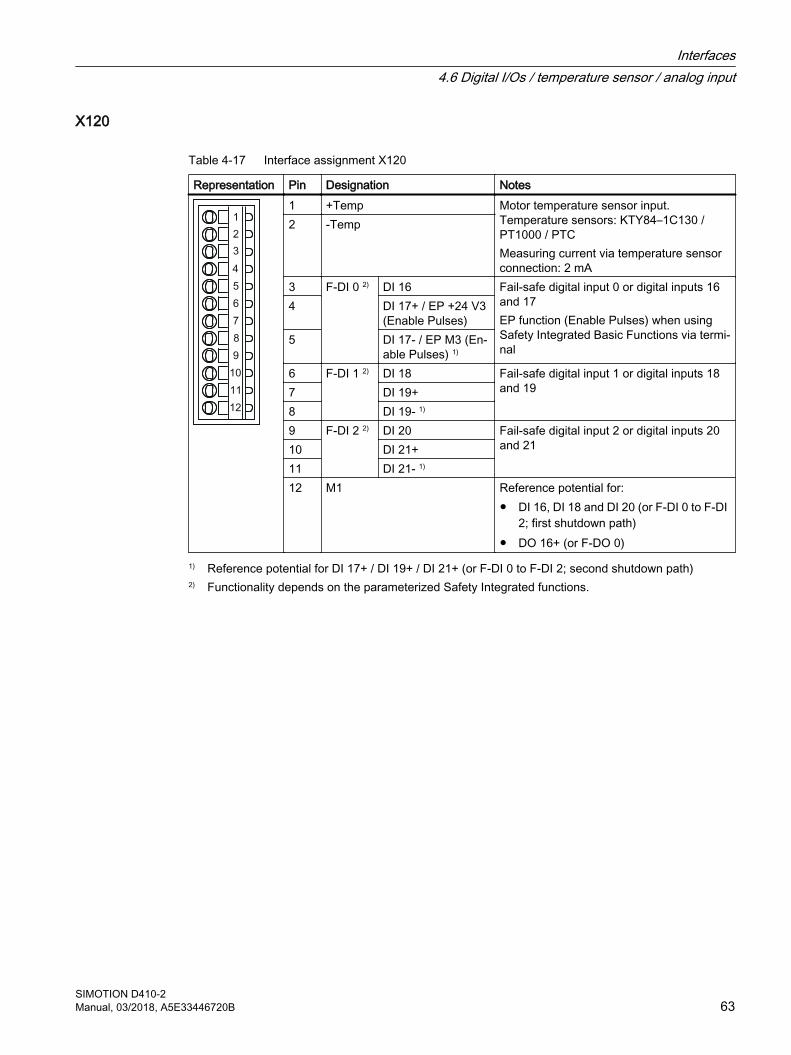
X120
Table 4-17 Interface assignment X120
Representation Pin Designation Notes1 +Temp Motor temperature sensor input.
Temperature sensors: KTY84–1C130 / PT1000 / PTCMeasuring current via temperature sensor connection: 2 mA
2 -Temp
3 F-DI 0 2) DI 16 Fail-safe digital input 0 or digital inputs 16 and 17EP function (Enable Pulses) when using Safety Integrated Basic Functions via termi‐nal
4 DI 17+ / EP +24 V3 (Enable Pulses)
5 DI 17- / EP M3 (En‐able Pulses) 1)
6 F-DI 1 2) DI 18 Fail-safe digital input 1 or digital inputs 18 and 197 DI 19+
8 DI 19- 1)
9 F-DI 2 2) DI 20 Fail-safe digital input 2 or digital inputs 20 and 2110 DI 21+
11 DI 21- 1)
12 M1 Reference potential for:● DI 16, DI 18 and DI 20 (or F-DI 0 to F-DI
2; first shutdown path)● DO 16+ (or F‑DO 0)
1) Reference potential for DI 17+ / DI 19+ / DI 21+ (or F-DI 0 to F-DI 2; second shutdown path)2) Functionality depends on the parameterized Safety Integrated functions.
Interfaces4.6 Digital I/Os / temperature sensor / analog input
SIMOTION D410-2Manual, 03/2018, A5E33446720B 63
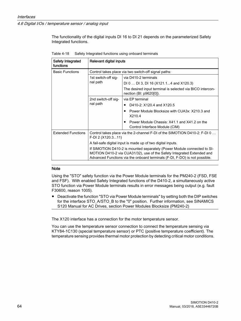
The functionality of the digital inputs DI 16 to DI 21 depends on the parameterized Safety Integrated functions.
Table 4-18 Safety Integrated functions using onboard terminals
Safety Integrated functions
Relevant digital inputs
Basic Functions Control takes place via two switch-off signal paths:1st switch-off sig‐nal path
via D410-2 terminalsDI 0 … DI 3, DI 16 (X121.1...4 and X120.3)The desired input terminal is selected via BICO intercon‐nection (BI: p9620[0]).
2nd switch-off sig‐nal path
via EP terminal● D410-2: X120.4 and X120.5● Power Module Blocksize with CUA3x: X210.3 and
X210.4● Power Module Chassis: X41.1 and X41.2 on the
Control Interface Module (CIM)Extended Functions Control takes place via the 2-channel F-DI of the SIMOTION D410‑2: F‑DI 0 …
F‑DI 2 (X120.3...11)A fail-safe digital input is made up of two digital inputs.If SIMOTION D410-2 is mounted separately (Power Module connected to SI‐MOTION D410-2 via CUA31/32), use of the Safety Integrated Extended and Advanced Functions via the onboard terminals (F-DI, F-DO) is not possible.
Note
Using the "STO" safety function via the Power Module terminals for the PM240-2 (FSD, FSE and FSF). With enabled Safety Integrated functions of the D410-2, a simultaneously active STO function via Power Module terminals results in error messages being output (e.g. fault F30600, reason 1005). ● Deactivate the function "STO via Power Module terminals" by setting both the DIP switches
for the interface STO_A/STO_B to the "0" position. Further information, see SINAMICS S120 Manual for AC Drives, section Power Modules Blocksize (PM240-2)
The X120 interface has a connection for the motor temperature sensor.
You can use the temperature sensor connection to connect the temperature sensing via KTY84‑1C130 (special temperature sensor) or PTC (positive temperature coefficient). The temperature sensing provides thermal motor protection by detecting critical motor conditions.
Interfaces4.6 Digital I/Os / temperature sensor / analog input
SIMOTION D410-264 Manual, 03/2018, A5E33446720B
For more information on "thermal motor protection", see the SINAMICS S120 Commissioning Manual.
NOTICE
Motor overheating due to an incorrectly connected KTY temperature sensor
A sensor connected with the incorrect polarity cannot detect the motor overheating.
Connect the KTY temperature sensor with the correct polarity.
For more information on the temperature sensors and how to use them, see the SINAMICS S120 Commissioning Manual, Section Temperature sensors for SINAMICS components.
The maximum length of the temperature sensor cable is 300 m. The cables must be shielded. For cable lengths >100 m, cables with a cross-section of ≥1 mm² must be used.
DANGER
Danger to life from electric shock due to insufficient safety isolation
Only temperature sensors that meet the safety isolation specifications stipulated in EN 61800-5-1 may be connected to terminals "+Temp" and "-Temp".
Use a Sensor Module External (SME120 or SME125) or Terminal Module TM120 if safe electrical separation cannot be guaranteed (for linear motors or third-party motors, for example).
Interfaces4.6 Digital I/Os / temperature sensor / analog input
SIMOTION D410-2Manual, 03/2018, A5E33446720B 65
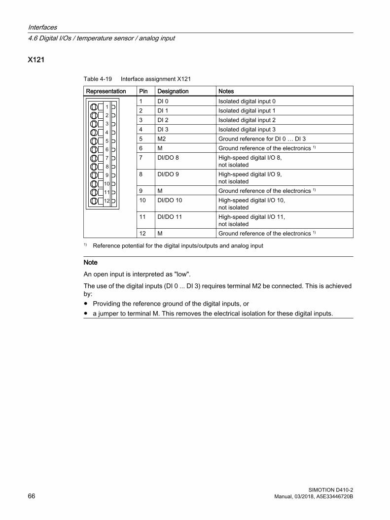
X121
Table 4-19 Interface assignment X121
Representation Pin Designation Notes1 DI 0 Isolated digital input 02 DI 1 Isolated digital input 13 DI 2 Isolated digital input 24 DI 3 Isolated digital input 35 M2 Ground reference for DI 0 … DI 36 M Ground reference of the electronics 1)
7 DI/DO 8 High-speed digital I/O 8, not isolated
8 DI/DO 9 High-speed digital I/O 9, not isolated
9 M Ground reference of the electronics 1)
10 DI/DO 10 High-speed digital I/O 10, not isolated
11 DI/DO 11 High-speed digital I/O 11, not isolated
12 M Ground reference of the electronics 1)
1) Reference potential for the digital inputs/outputs and analog input
Note
An open input is interpreted as "low".
The use of the digital inputs (DI 0 ... DI 3) requires terminal M2 be connected. This is achieved by:● Providing the reference ground of the digital inputs, or● a jumper to terminal M. This removes the electrical isolation for these digital inputs.
Interfaces4.6 Digital I/Os / temperature sensor / analog input
SIMOTION D410-266 Manual, 03/2018, A5E33446720B
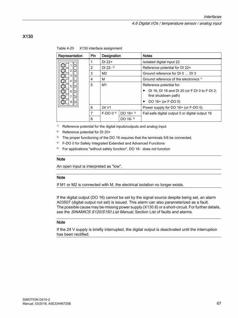
X130
Table 4-20 X130 interface assignment
Representation Pin Designation Notes1 DI 22+ Isolated digital input 222 DI 22- 2) Reference potential for DI 22+3 M2 Ground reference for DI 0 … DI 34 M Ground reference of the electronics 1)
5 M1 Reference potential for:● DI 16, DI 18 and DI 20 (or F-DI 0 to F-DI 2;
first shutdown path)● DO 16+ (or F‑DO 0)
6 24 V1 Power supply for DO 16+ (or F‑DO 0)7 F-DO 0 4) DO 16+ 3) Fail-safe digital output 0 or digital output 168 DO 16- 5)
1) Reference potential for the digital inputs/outputs and analog input2) Reference potential for DI 20+3) The proper functioning of the DO 16 requires that the terminals 5/6 be connected.4) F-DO 0 for Safety Integrated Extended and Advanced Functions5) For applications "without safety function", DO 16- does not function
Note
An open input is interpreted as "low".
Note
If M1 or M2 is connected with M, the electrical isolation no longer exists.
If the digital output (DO 16) cannot be set by the signal source despite being set, an alarm A03507 (digital output not set) is issued. This alarm can also parameterized as a fault.The possible cause may be missing power supply (X130.6) or a short-circuit. For further details, see the SINAMICS S120/S150 List Manual, Section List of faults and alarms.
Note
If the 24 V supply is briefly interrupted, the digital output is deactivated until the interruption has been rectified.
Interfaces4.6 Digital I/Os / temperature sensor / analog input
SIMOTION D410-2Manual, 03/2018, A5E33446720B 67
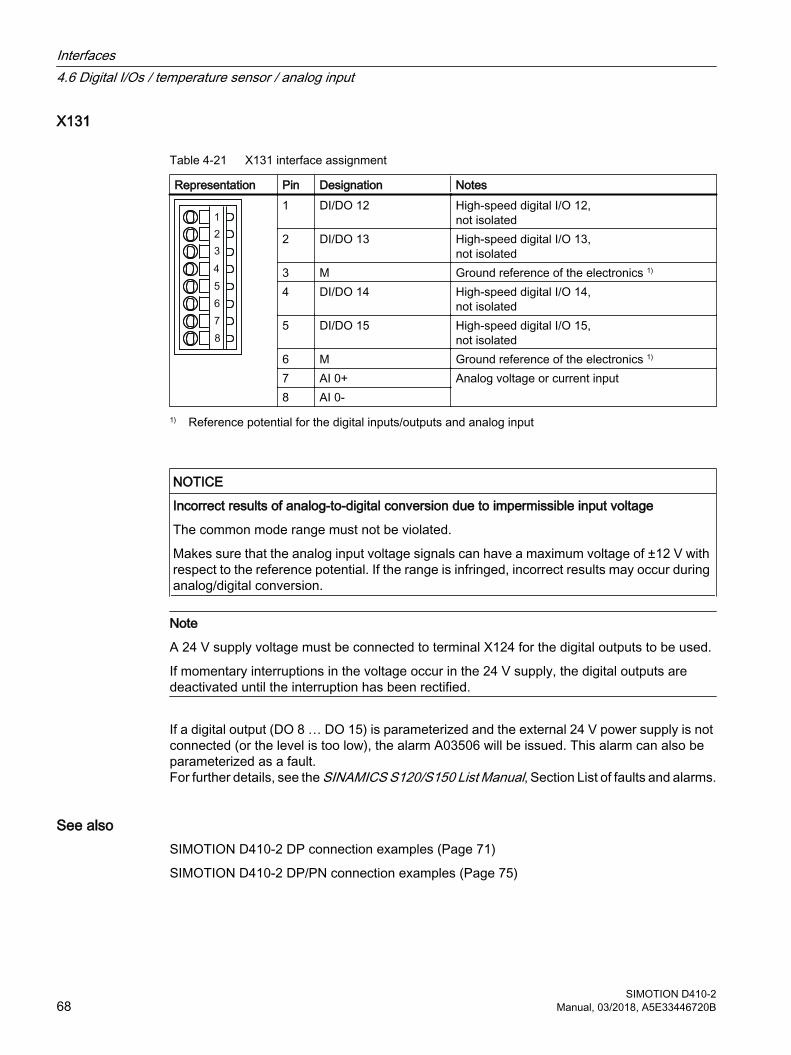
X131
Table 4-21 X131 interface assignment
Representation Pin Designation Notes1 DI/DO 12 High-speed digital I/O 12,
not isolated2 DI/DO 13 High-speed digital I/O 13,
not isolated3 M Ground reference of the electronics 1)
4 DI/DO 14 High-speed digital I/O 14, not isolated
5 DI/DO 15 High-speed digital I/O 15, not isolated
6 M Ground reference of the electronics 1)
7 AI 0+ Analog voltage or current input8 AI 0-
1) Reference potential for the digital inputs/outputs and analog input
NOTICE
Incorrect results of analog-to-digital conversion due to impermissible input voltage
The common mode range must not be violated.
Makes sure that the analog input voltage signals can have a maximum voltage of ±12 V with respect to the reference potential. If the range is infringed, incorrect results may occur during analog/digital conversion.
Note
A 24 V supply voltage must be connected to terminal X124 for the digital outputs to be used.
If momentary interruptions in the voltage occur in the 24 V supply, the digital outputs are deactivated until the interruption has been rectified.
If a digital output (DO 8 … DO 15) is parameterized and the external 24 V power supply is not connected (or the level is too low), the alarm A03506 will be issued. This alarm can also be parameterized as a fault.For further details, see the SINAMICS S120/S150 List Manual, Section List of faults and alarms.
See alsoSIMOTION D410-2 DP connection examples (Page 71)
SIMOTION D410-2 DP/PN connection examples (Page 75)
Interfaces4.6 Digital I/Os / temperature sensor / analog input
SIMOTION D410-268 Manual, 03/2018, A5E33446720B
4.6.4 Use of the interfaces
Fail-safe digital I/Os (F-DI/F-DO) The SIMOTION D410-2 provides three fail-safe isolated digital inputs (F-DI) and one fail-safe isolated digital output (F-DO):
● An F-DI consists of a digital input and a second digital input to which the cathode of the optocoupler is connected.Each of the F-DIs can also be used as two standard digital inputs, e.g. the use of the F-DI 0 as DI 16 and DI 17.
● The F-DO 0 can also used as a standard digital output.The F-DO 0 consists of a high-side switch and a low-side switch. For applications without the safety function, the high-side switch may be used as an additional digital output. The low-side switch is not available.
Note
The following safety functions are available for SIMOTION D410-2:● Safety Integrated Basic Functions via the EP terminals● Safety Integrated Extended and Advanced Functions via onboard I/Os (3 F-DI and 1 F-DO)● Safety Integrated Extended and Advanced Functions with TM54F● Safety Integrated Basic and Extended/Advanced Functions via secure communication from
"PROFIsafe on PROFIBUS"Control (F logic) is via a SIMATIC F-CPU which is connected to PROFIsafe via PROFIBUS (not SCOUT TIA).
● Safety Integrated Basic and Extended/Advanced Functions via secure communication from "PROFIsafe on PROFINET" (only for SIMOTION D410-2 DP/PN)Control (F logic) is via a SIMATIC F-CPU which is connected to PROFIsafe via PROFINET (e.g. an S7-1500 F-CPU).
For further information on Safety Integrated, see the SINAMICS S120 Safety Integrated Function Manual.
EP terminalThe pulse inhibit function (EP) is only available when Integrated Basic Functions are enabled.
Digital inputs (DI) The SIMOTION D410-2 provides five digital inputs (DI).
Interfaces4.6 Digital I/Os / temperature sensor / analog input
SIMOTION D410-2Manual, 03/2018, A5E33446720B 69
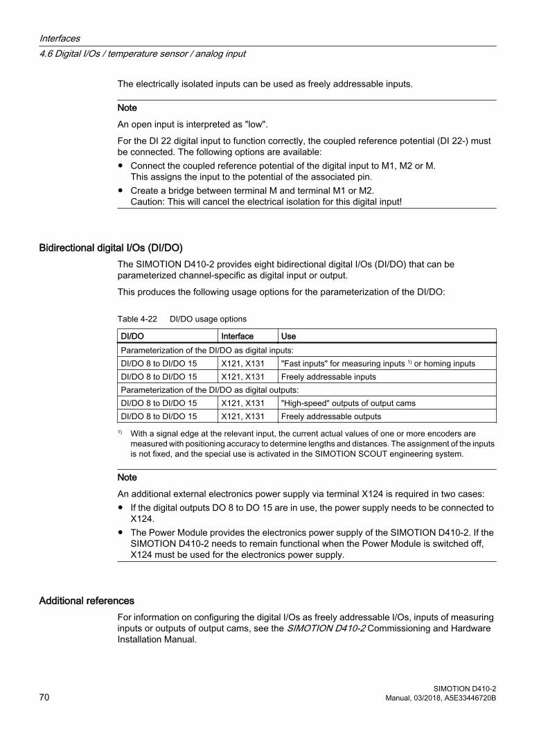
The electrically isolated inputs can be used as freely addressable inputs.
Note
An open input is interpreted as "low".
For the DI 22 digital input to function correctly, the coupled reference potential (DI 22-) must be connected. The following options are available:● Connect the coupled reference potential of the digital input to M1, M2 or M.
This assigns the input to the potential of the associated pin.● Create a bridge between terminal M and terminal M1 or M2.
Caution: This will cancel the electrical isolation for this digital input!
Bidirectional digital I/Os (DI/DO) The SIMOTION D410-2 provides eight bidirectional digital I/Os (DI/DO) that can be parameterized channel-specific as digital input or output.
This produces the following usage options for the parameterization of the DI/DO:
Table 4-22 DI/DO usage options
DI/DO Interface UseParameterization of the DI/DO as digital inputs:DI/DO 8 to DI/DO 15 X121, X131 "Fast inputs" for measuring inputs 1) or homing inputsDI/DO 8 to DI/DO 15 X121, X131 Freely addressable inputsParameterization of the DI/DO as digital outputs:DI/DO 8 to DI/DO 15 X121, X131 "High-speed" outputs of output camsDI/DO 8 to DI/DO 15 X121, X131 Freely addressable outputs
1) With a signal edge at the relevant input, the current actual values of one or more encoders are measured with positioning accuracy to determine lengths and distances. The assignment of the inputs is not fixed, and the special use is activated in the SIMOTION SCOUT engineering system.
Note
An additional external electronics power supply via terminal X124 is required in two cases:● If the digital outputs DO 8 to DO 15 are in use, the power supply needs to be connected to
X124.● The Power Module provides the electronics power supply of the SIMOTION D410-2. If the
SIMOTION D410-2 needs to remain functional when the Power Module is switched off, X124 must be used for the electronics power supply.
Additional referencesFor information on configuring the digital I/Os as freely addressable I/Os, inputs of measuring inputs or outputs of output cams, see the SIMOTION D410-2 Commissioning and Hardware Installation Manual.
Interfaces4.6 Digital I/Os / temperature sensor / analog input
SIMOTION D410-270 Manual, 03/2018, A5E33446720B
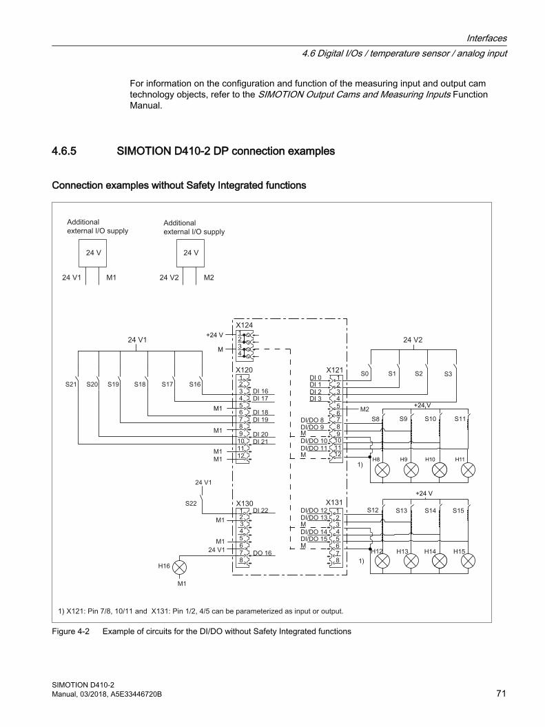
For information on the configuration and function of the measuring input and output cam technology objects, refer to the SIMOTION Output Cams and Measuring Inputs Function Manual.
4.6.5 SIMOTION D410-2 DP connection examples
Connection examples without Safety Integrated functions
M1
Figure 4-2 Example of circuits for the DI/DO without Safety Integrated functions
Interfaces4.6 Digital I/Os / temperature sensor / analog input
SIMOTION D410-2Manual, 03/2018, A5E33446720B 71
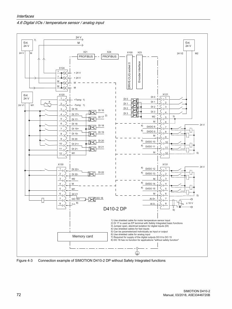
Figure 4-3 Connection example of SIMOTION D410-2 DP without Safety Integrated functions
Interfaces4.6 Digital I/Os / temperature sensor / analog input
SIMOTION D410-272 Manual, 03/2018, A5E33446720B
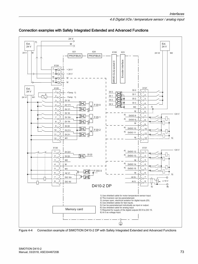
Connection examples with Safety Integrated Extended and Advanced Functions
Figure 4-4 Connection example of SIMOTION D410-2 DP with Safety Integrated Extended and Advanced Functions
Interfaces4.6 Digital I/Os / temperature sensor / analog input
SIMOTION D410-2Manual, 03/2018, A5E33446720B 73

S3S2S1S0
24 V1
M1
Figure 4-5 Example of circuits for the F-DI and F-DO with Safety Integrated Extended and Advanced Functions
Interfaces4.6 Digital I/Os / temperature sensor / analog input
SIMOTION D410-274 Manual, 03/2018, A5E33446720B
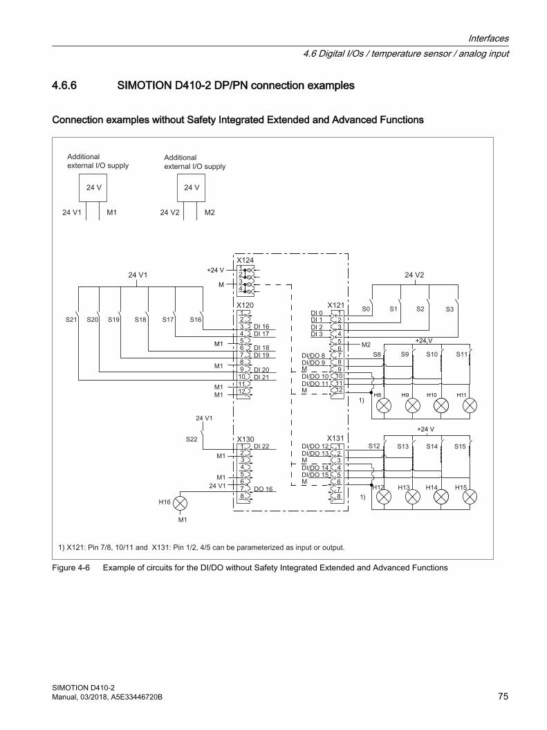
4.6.6 SIMOTION D410-2 DP/PN connection examples
Connection examples without Safety Integrated Extended and Advanced Functions
M1
Figure 4-6 Example of circuits for the DI/DO without Safety Integrated Extended and Advanced Functions
Interfaces4.6 Digital I/Os / temperature sensor / analog input
SIMOTION D410-2Manual, 03/2018, A5E33446720B 75
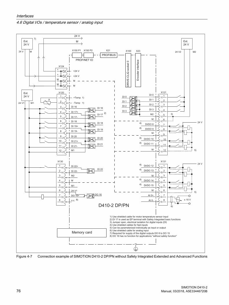
Figure 4-7 Connection example of SIMOTION D410-2 DP/PN without Safety Integrated Extended and Advanced Functions
Interfaces4.6 Digital I/Os / temperature sensor / analog input
SIMOTION D410-276 Manual, 03/2018, A5E33446720B
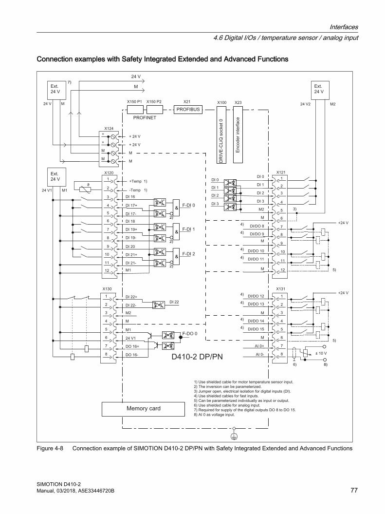
Connection examples with Safety Integrated Extended and Advanced Functions
Figure 4-8 Connection example of SIMOTION D410-2 DP/PN with Safety Integrated Extended and Advanced Functions
Interfaces4.6 Digital I/Os / temperature sensor / analog input
SIMOTION D410-2Manual, 03/2018, A5E33446720B 77
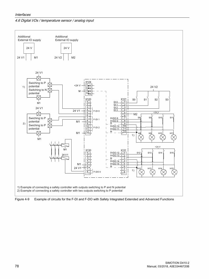
S3S2S1S0
24 V1
M1
Figure 4-9 Example of circuits for the F-DI and F-DO with Safety Integrated Extended and Advanced Functions
Interfaces4.6 Digital I/Os / temperature sensor / analog input
SIMOTION D410-278 Manual, 03/2018, A5E33446720B
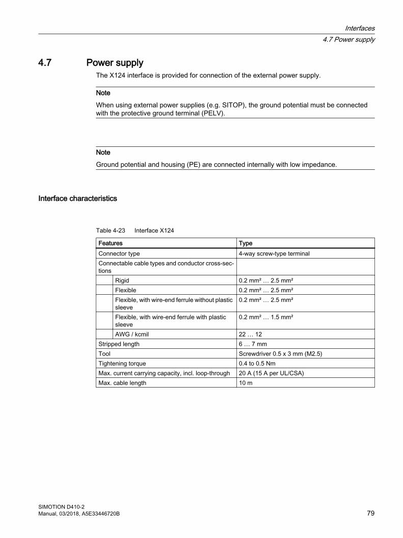
4.7 Power supplyThe X124 interface is provided for connection of the external power supply.
Note
When using external power supplies (e.g. SITOP), the ground potential must be connected with the protective ground terminal (PELV).
Note
Ground potential and housing (PE) are connected internally with low impedance.
Interface characteristics
Table 4-23 Interface X124
Features TypeConnector type 4-way screw-type terminalConnectable cable types and conductor cross-sec‐tions
Rigid 0.2 mm² … 2.5 mm² Flexible 0.2 mm² … 2.5 mm² Flexible, with wire-end ferrule without plastic
sleeve0.2 mm² … 2.5 mm²
Flexible, with wire-end ferrule with plastic sleeve
0.2 mm² … 1.5 mm²
AWG / kcmil 22 … 12Stripped length 6 … 7 mmTool Screwdriver 0.5 x 3 mm (M2.5)Tightening torque 0.4 to 0.5 NmMax. current carrying capacity, incl. loop-through 20 A (15 A per UL/CSA)Max. cable length 10 m
Interfaces4.7 Power supply
SIMOTION D410-2Manual, 03/2018, A5E33446720B 79
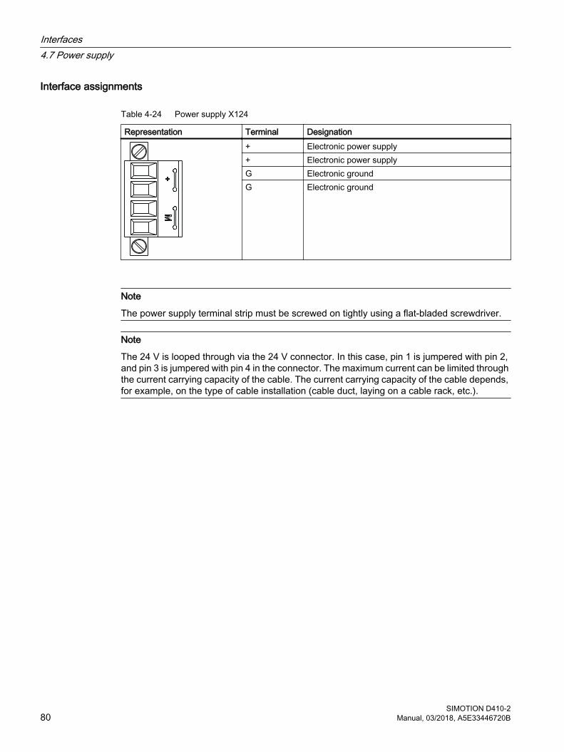
Interface assignments
Table 4-24 Power supply X124
Representation Terminal Designation+ Electronic power supply+ Electronic power supplyG Electronic groundG Electronic ground
Note
The power supply terminal strip must be screwed on tightly using a flat-bladed screwdriver.
Note
The 24 V is looped through via the 24 V connector. In this case, pin 1 is jumpered with pin 2, and pin 3 is jumpered with pin 4 in the connector. The maximum current can be limited through the current carrying capacity of the cable. The current carrying capacity of the cable depends, for example, on the type of cable installation (cable duct, laying on a cable rack, etc.).
Interfaces4.7 Power supply
SIMOTION D410-280 Manual, 03/2018, A5E33446720B
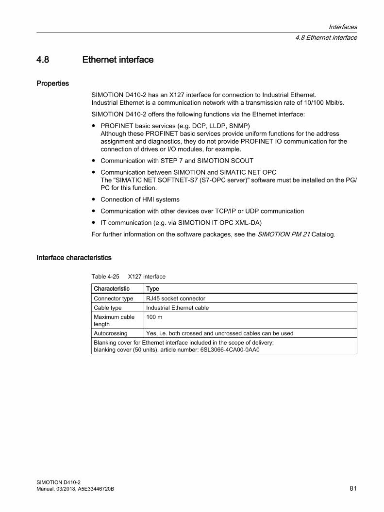
4.8 Ethernet interface
PropertiesSIMOTION D410-2 has an X127 interface for connection to Industrial Ethernet. Industrial Ethernet is a communication network with a transmission rate of 10/100 Mbit/s.
SIMOTION D410-2 offers the following functions via the Ethernet interface:
● PROFINET basic services (e.g. DCP, LLDP, SNMP)Although these PROFINET basic services provide uniform functions for the address assignment and diagnostics, they do not provide PROFINET IO communication for the connection of drives or I/O modules, for example.
● Communication with STEP 7 and SIMOTION SCOUT
● Communication between SIMOTION and SIMATIC NET OPCThe "SIMATIC NET SOFTNET-S7 (S7-OPC server)" software must be installed on the PG/PC for this function.
● Connection of HMI systems
● Communication with other devices over TCP/IP or UDP communication
● IT communication (e.g. via SIMOTION IT OPC XML‑DA)
For further information on the software packages, see the SIMOTION PM 21 Catalog.
Interface characteristics
Table 4-25 X127 interface
Characteristic TypeConnector type RJ45 socket connectorCable type Industrial Ethernet cableMaximum cable length
100 m
Autocrossing Yes, i.e. both crossed and uncrossed cables can be usedBlanking cover for Ethernet interface included in the scope of delivery;blanking cover (50 units), article number: 6SL3066‑4CA00‑0AA0
Interfaces4.8 Ethernet interface
SIMOTION D410-2Manual, 03/2018, A5E33446720B 81
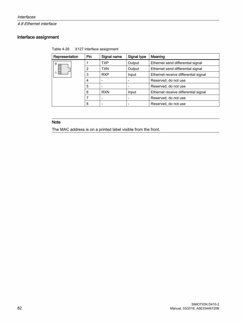
Interface assignment
Table 4-26 X127 interface assignment
Representation Pin Signal name Signal type Meaning1 TXP Output Ethernet send differential signal2 TXN Output Ethernet send differential signal3 RXP Input Ethernet receive differential signal4 - - Reserved, do not use5 - - Reserved, do not use6 RXN Input Ethernet receive differential signal7 - - Reserved, do not use8 - - Reserved, do not use
Note
The MAC address is on a printed label visible from the front.
Interfaces4.8 Ethernet interface
SIMOTION D410-282 Manual, 03/2018, A5E33446720B
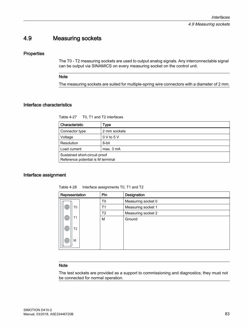
4.9 Measuring sockets
PropertiesThe T0 - T2 measuring sockets are used to output analog signals. Any interconnectable signal can be output via SINAMICS on every measuring socket on the control unit.
Note
The measuring sockets are suited for multiple-spring wire connectors with a diameter of 2 mm.
Interface characteristics
Table 4-27 T0, T1 and T2 interfaces
Characteristic TypeConnector type 2 mm socketsVoltage 0 V to 5 VResolution 8-bitLoad current max. 3 mASustained short-circuit proofReference potential is M terminal
Interface assignment
Table 4-28 Interface assignments T0, T1 and T2
Representation Pin DesignationT0 Measuring socket 0T1 Measuring socket 1T2 Measuring socket 2M Ground
Note
The test sockets are provided as a support to commissioning and diagnostics; they must not be connected for normal operation.
Interfaces4.9 Measuring sockets
SIMOTION D410-2Manual, 03/2018, A5E33446720B 83
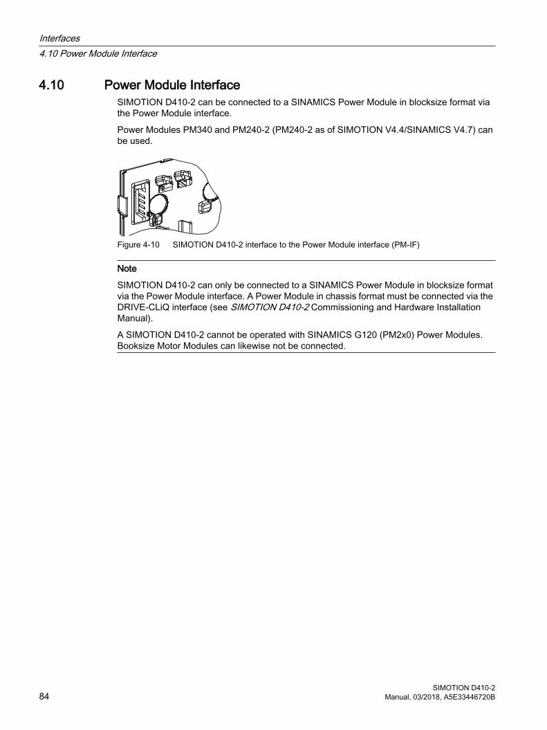
4.10 Power Module InterfaceSIMOTION D410-2 can be connected to a SINAMICS Power Module in blocksize format via the Power Module interface.
Power Modules PM340 and PM240‑2 (PM240‑2 as of SIMOTION V4.4/SINAMICS V4.7) can be used.
Figure 4-10 SIMOTION D410-2 interface to the Power Module interface (PM-IF)
Note
SIMOTION D410-2 can only be connected to a SINAMICS Power Module in blocksize format via the Power Module interface. A Power Module in chassis format must be connected via the DRIVE‑CLiQ interface (see SIMOTION D410-2 Commissioning and Hardware Installation Manual).
A SIMOTION D410-2 cannot be operated with SINAMICS G120 (PM2x0) Power Modules. Booksize Motor Modules can likewise not be connected.
Interfaces4.10 Power Module Interface
SIMOTION D410-284 Manual, 03/2018, A5E33446720B
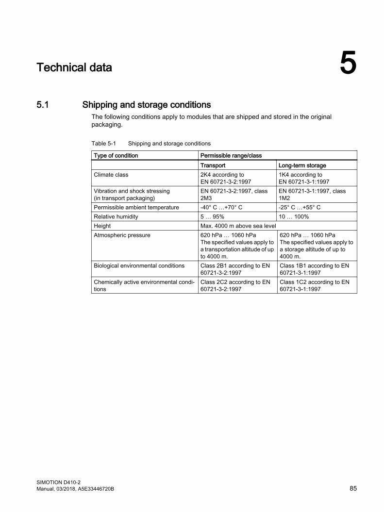
Technical data 55.1 Shipping and storage conditions
The following conditions apply to modules that are shipped and stored in the original packaging.
Table 5-1 Shipping and storage conditions
Type of condition Permissible range/class Transport Long-term storageClimate class 2K4 according to
EN 60721‑3‑2:19971K4 according to EN 60721‑3‑1:1997
Vibration and shock stressing(in transport packaging)
EN 60721‑3‑2:1997, class 2M3
EN 60721‑3‑1:1997, class 1M2
Permissible ambient temperature -40° C …+70° C -25° C …+55° CRelative humidity 5 … 95% 10 … 100%Height Max. 4000 m above sea levelAtmospheric pressure 620 hPa … 1060 hPa
The specified values apply to a transportation altitude of up to 4000 m.
620 hPa … 1060 hPa The specified values apply to a storage altitude of up to 4000 m.
Biological environmental conditions Class 2B1 according to EN 60721‑3‑2:1997
Class 1B1 according to EN 60721‑3‑1:1997
Chemically active environmental condi‐tions
Class 2C2 according to EN 60721‑3‑2:1997
Class 1C2 according to EN 60721‑3‑1:1997
SIMOTION D410-2Manual, 03/2018, A5E33446720B 85
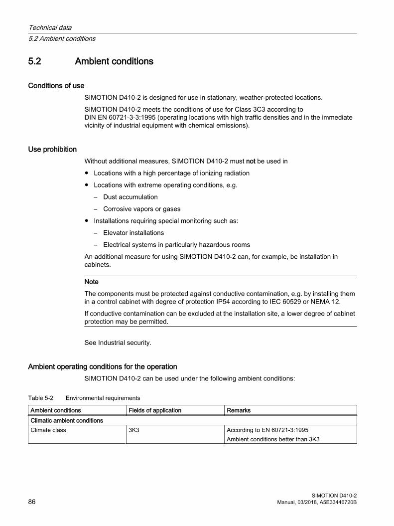
5.2 Ambient conditions
Conditions of useSIMOTION D410-2 is designed for use in stationary, weather-protected locations.
SIMOTION D410-2 meets the conditions of use for Class 3C3 according to DIN EN 60721‑3‑3:1995 (operating locations with high traffic densities and in the immediate vicinity of industrial equipment with chemical emissions).
Use prohibitionWithout additional measures, SIMOTION D410-2 must not be used in
● Locations with a high percentage of ionizing radiation
● Locations with extreme operating conditions, e.g.
– Dust accumulation
– Corrosive vapors or gases
● Installations requiring special monitoring such as:
– Elevator installations
– Electrical systems in particularly hazardous rooms
An additional measure for using SIMOTION D410-2 can, for example, be installation in cabinets.
Note
The components must be protected against conductive contamination, e.g. by installing them in a control cabinet with degree of protection IP54 according to IEC 60529 or NEMA 12.
If conductive contamination can be excluded at the installation site, a lower degree of cabinet protection may be permitted.
See Industrial security.
Ambient operating conditions for the operationSIMOTION D410-2 can be used under the following ambient conditions:
Table 5-2 Environmental requirements
Ambient conditions Fields of application RemarksClimatic ambient conditionsClimate class 3K3 According to EN 60721‑3:1995
Ambient conditions better than 3K3
Technical data5.2 Ambient conditions
SIMOTION D410-286 Manual, 03/2018, A5E33446720B
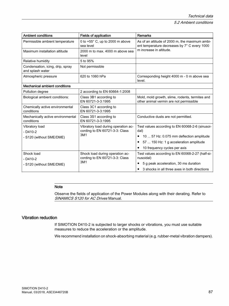
Ambient conditions Fields of application RemarksPermissible ambient temperature 0 to +55° C, up to 2000 m above
sea levelAs of an altitude of 2000 m, the maximum ambi‐ent temperature decreases by 7° C every 1000 m increase in altitude.Maximum installation altitude 2000 m to max. 4000 m above sea
levelRelative humidity 5 to 95% Condensation, icing, drip, spray and splash water
Not permissible
Atmospheric pressure 620 to 1060 hPa Corresponding height 4000 m ‑ 0 m above sea level.
Mechanical ambient conditionsPollution degree 2 according to EN 60664‑1:2008 Biological ambient conditions: Class 3B1 according to
EN 60721‑3‑3:1995Mold, mold growth, slime, rodents, termites and other animal vermin are not permissible
Chemically active environmental conditions
Class 3C1 according to EN 60721‑3‑3:1995
Mechanically active environmental conditions
Class 3S1 according to EN 60721‑3‑3:1995
Conductive dusts are not permitted.
Vibratory load- D410-2- S120 (without SME/DME)
Vibratory load during operation ac‐cording to EN 60721-3-3: Class 3M1
Test values according to EN 60068-2-6 (sinusoi‐dal)● 10 ... 57 Hz: 0.075 mm deflection amplitude● 57 ... 150 Hz: 1 g acceleration amplitude● 10 frequency cycles per axis
Shock load- D410-2- S120 (without SME/DME)
Shock load during operation ac‐cording to EN 60721-3-3: Class 3M1
Test values according to EN 60068-2-27 (half-si‐nusoidal)● 5 g peak acceleration, 30 ms duration● 3 shocks in all three axes in both directions
Note
Observe the fields of application of the Power Modules along with their derating. Refer to SINAMICS S120 for AC Drives Manual.
Vibration reductionIf SIMOTION D410-2 is subjected to larger shocks or vibrations, you must use suitable measures to reduce the acceleration or the amplitude.
We recommend installation on shock-absorbing material (e.g. rubber-metal vibration dampers).
Technical data5.2 Ambient conditions
SIMOTION D410-2Manual, 03/2018, A5E33446720B 87

Other data
Condition Field of applicationProtection against the ingress of foreign matter and water
IP20 degree of protection according to EN 60529
Class of protection Class 1 (with protective conductor system) and class 3 (PELV) according to EN 61800‑5‑1:2007
Technical data5.2 Ambient conditions
SIMOTION D410-288 Manual, 03/2018, A5E33446720B
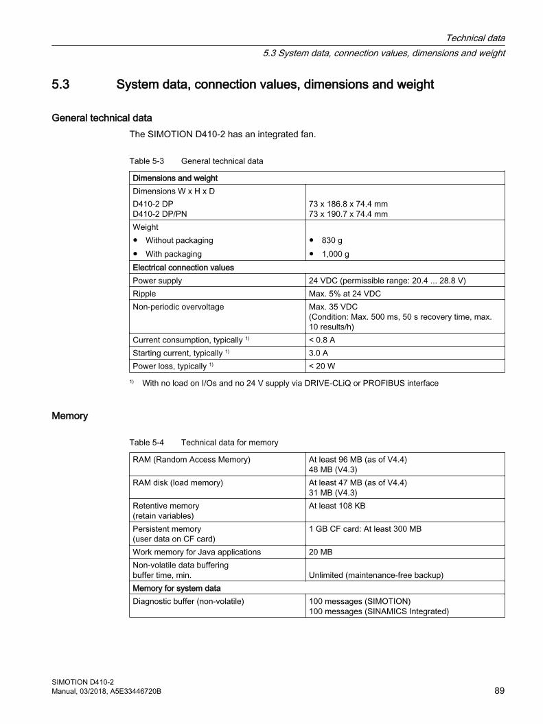
5.3 System data, connection values, dimensions and weight
General technical dataThe SIMOTION D410‑2 has an integrated fan.
Table 5-3 General technical data
Dimensions and weight Dimensions W x H x DD410-2 DPD410-2 DP/PN
73 x 186.8 x 74.4 mm73 x 190.7 x 74.4 mm
Weight● Without packaging● With packaging
● 830 g● 1,000 g
Electrical connection values Power supply 24 VDC (permissible range: 20.4 ... 28.8 V)Ripple Max. 5% at 24 VDCNon-periodic overvoltage Max. 35 VDC
(Condition: Max. 500 ms, 50 s recovery time, max. 10 results/h)
Current consumption, typically 1) < 0.8 AStarting current, typically 1) 3.0 APower loss, typically 1) < 20 W
1) With no load on I/Os and no 24 V supply via DRIVE‑CLiQ or PROFIBUS interface
Memory
Table 5-4 Technical data for memory
RAM (Random Access Memory) At least 96 MB (as of V4.4) 48 MB (V4.3)
RAM disk (load memory) At least 47 MB (as of V4.4) 31 MB (V4.3)
Retentive memory(retain variables)
At least 108 KB
Persistent memory (user data on CF card)
1 GB CF card: At least 300 MB
Work memory for Java applications 20 MBNon-volatile data bufferingbuffer time, min. Unlimited (maintenance-free backup)Memory for system data Diagnostic buffer (non-volatile) 100 messages (SIMOTION)
100 messages (SINAMICS Integrated)
Technical data5.3 System data, connection values, dimensions and weight
SIMOTION D410-2Manual, 03/2018, A5E33446720B 89
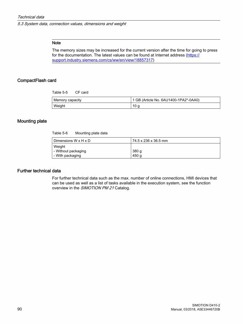
Note
The memory sizes may be increased for the current version after the time for going to press for the documentation. The latest values can be found at Internet address (https://support.industry.siemens.com/cs/ww/en/view/18857317)
CompactFlash card
Table 5-5 CF card
Memory capacity 1 GB (Article No. 6AU1400-1PA2*-0AA0)Weight 10 g
Mounting plate
Table 5-6 Mounting plate data
Dimensions W x H x D 74.5 x 236 x 36.5 mmWeight- Without packaging- With packaging
380 g450 g
Further technical dataFor further technical data such as the max. number of online connections, HMI devices that can be used as well as a list of tasks available in the execution system, see the function overview in the SIMOTION PM 21 Catalog.
Technical data5.3 System data, connection values, dimensions and weight
SIMOTION D410-290 Manual, 03/2018, A5E33446720B
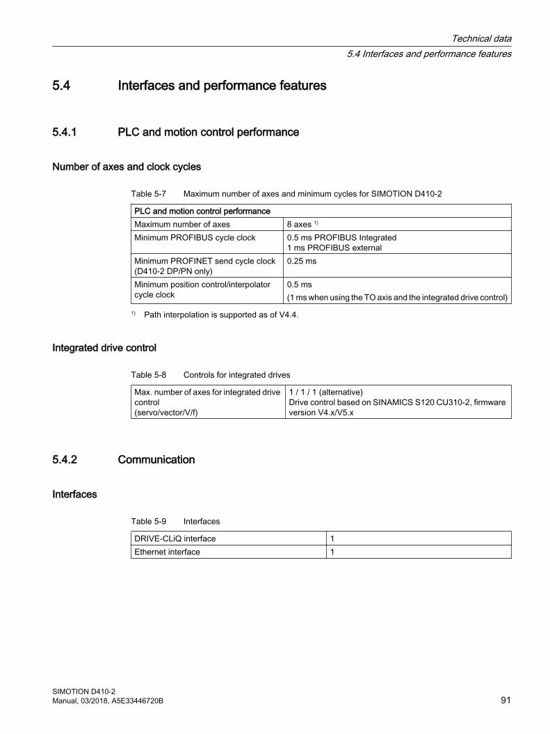
5.4 Interfaces and performance features
5.4.1 PLC and motion control performance
Number of axes and clock cycles
Table 5-7 Maximum number of axes and minimum cycles for SIMOTION D410-2
PLC and motion control performance Maximum number of axes 8 axes 1)
Minimum PROFIBUS cycle clock 0.5 ms PROFIBUS Integrated1 ms PROFIBUS external
Minimum PROFINET send cycle clock(D410-2 DP/PN only)
0.25 ms
Minimum position control/interpolator cycle clock
0.5 ms(1 ms when using the TO axis and the integrated drive control)
1) Path interpolation is supported as of V4.4.
Integrated drive control
Table 5-8 Controls for integrated drives
Max. number of axes for integrated drive control(servo/vector/V/f)
1 / 1 / 1 (alternative)Drive control based on SINAMICS S120 CU310-2, firmware version V4.x/V5.x
5.4.2 Communication
Interfaces
Table 5-9 Interfaces
DRIVE-CLiQ interface 1Ethernet interface 1
Technical data5.4 Interfaces and performance features
SIMOTION D410-2Manual, 03/2018, A5E33446720B 91
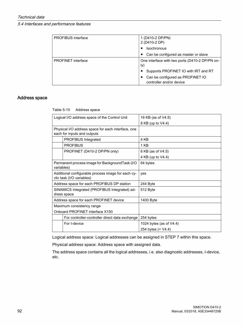
PROFIBUS interface 1 (D410‑2 DP/PN)2 (D410‑2 DP)● Isochronous● Can be configured as master or slave
PROFINET interface One interface with two ports (D410‑2 DP/PN on‐ly)● Supports PROFINET IO with IRT and RT● Can be configured as PROFINET IO
controller and/or device
Address space
Table 5-10 Address space
Logical I/O address space of the Control Unit 16 KB (as of V4.5) 8 KB (up to V4.4)
Physical I/O address space for each interface, one each for inputs and outputs
PROFIBUS Integrated 4 KB PROFIBUS 1 KB PROFINET (D410‑2 DP/PN only) 6 KB (as of V4.5)
4 KB (up to V4.4)Permanent process image for BackgroundTask (I/O variables)
64 bytes
Additional configurable process image for each cy‐clic task (I/O variables)
yes
Address space for each PROFIBUS DP station 244 ByteSINAMICS Integrated (PROFIBUS Integrated) ad‐dress space
512 Byte
Address space for each PROFINET device 1400 ByteMaximum consistency range Onboard PROFINET interface X150
For controller-controller direct data exchange 254 bytes For I-device 1024 bytes (as of V4.4)
254 bytes (< V4.4)
Logical address space: Logical addresses can be assigned in STEP 7 within this space.
Physical address space: Address space with assigned data.
The address space contains all the logical addresses, i.e. also diagnostic addresses, I-device, etc.
Technical data5.4 Interfaces and performance features
SIMOTION D410-292 Manual, 03/2018, A5E33446720B
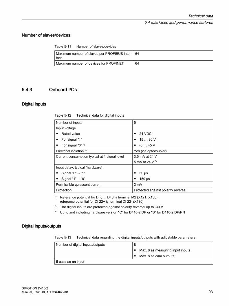
Number of slaves/devices
Table 5-11 Number of slaves/devices
Maximum number of slaves per PROFIBUS inter‐face
64
Maximum number of devices for PROFINET 64
5.4.3 Onboard I/Os
Digital inputs
Table 5-12 Technical data for digital inputs
Number of inputs 5Input voltage● Rated value● For signal "1"● For signal "0" 2)
● 24 VDC● 15 … 30 V● -3 … +5 V
Electrical isolation 1) Yes (via optocoupler)Current consumption typical at 1 signal level 3.5 mA at 24 V
5 mA at 24 V 3)
Input delay, typical (hardware)● Signal "0" → "1"● Signal "1" → "0"
● 50 μs● 150 μs
Permissible quiescent current 2 mAProtection Protected against polarity reversal
1) Reference potential for DI 0 ... DI 3 is terminal M2 (X121, X130), reference potential for DI 22+ is terminal DI 22- (X130)
2) The digital inputs are protected against polarity reversal up to -30 V3) Up to and including hardware version "C" for D410-2 DP or "B" for D410-2 DP/PN
Digital inputs/outputs
Table 5-13 Technical data regarding the digital inputs/outputs with adjustable parameters
Number of digital inputs/outputs 8● Max. 8 as measuring input inputs● Max. 8 as cam outputs
If used as an input
Technical data5.4 Interfaces and performance features
SIMOTION D410-2Manual, 03/2018, A5E33446720B 93
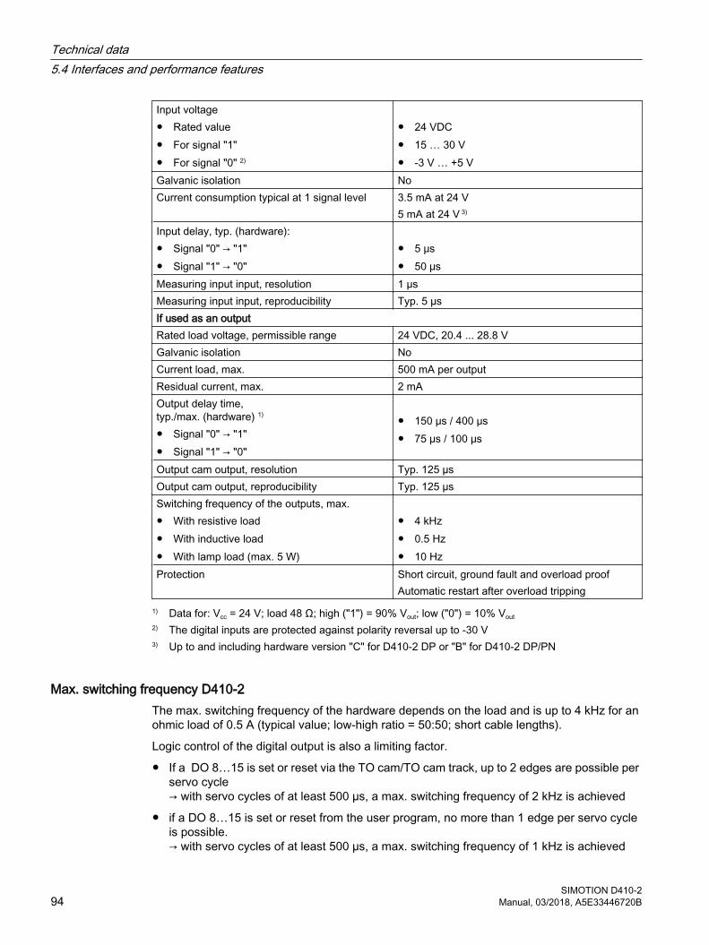
Input voltage● Rated value● For signal "1"● For signal "0" 2)
● 24 VDC● 15 … 30 V● -3 V … +5 V
Galvanic isolation NoCurrent consumption typical at 1 signal level 3.5 mA at 24 V
5 mA at 24 V 3)
Input delay, typ. (hardware):● Signal "0" → "1"● Signal "1" → "0"
● 5 μs● 50 μs
Measuring input input, resolution 1 µs Measuring input input, reproducibility Typ. 5 µsIf used as an outputRated load voltage, permissible range 24 VDC, 20.4 ... 28.8 VGalvanic isolation NoCurrent load, max. 500 mA per outputResidual current, max. 2 mAOutput delay time, typ./max. (hardware) 1)
● Signal "0" → "1"● Signal "1" → "0"
● 150 μs / 400 μs● 75 μs / 100 μs
Output cam output, resolution Typ. 125 µsOutput cam output, reproducibility Typ. 125 µsSwitching frequency of the outputs, max.● With resistive load● With inductive load● With lamp load (max. 5 W)
● 4 kHz● 0.5 Hz● 10 Hz
Protection Short circuit, ground fault and overload proofAutomatic restart after overload tripping
1) Data for: Vcc = 24 V; load 48 Ω; high ("1") = 90% Vout; low ("0") = 10% Vout2) The digital inputs are protected against polarity reversal up to -30 V3) Up to and including hardware version "C" for D410-2 DP or "B" for D410-2 DP/PN
Max. switching frequency D410‑2The max. switching frequency of the hardware depends on the load and is up to 4 kHz for an ohmic load of 0.5 A (typical value; low‑high ratio = 50:50; short cable lengths).
Logic control of the digital output is also a limiting factor.
● If a DO 8…15 is set or reset via the TO cam/TO cam track, up to 2 edges are possible per servo cycle→ with servo cycles of at least 500 µs, a max. switching frequency of 2 kHz is achieved
● if a DO 8…15 is set or reset from the user program, no more than 1 edge per servo cycle is possible.→ with servo cycles of at least 500 µs, a max. switching frequency of 1 kHz is achieved
Technical data5.4 Interfaces and performance features
SIMOTION D410-294 Manual, 03/2018, A5E33446720B
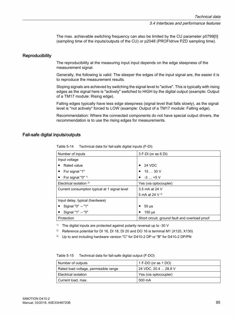
The max. achievable switching frequency can also be limited by the CU parameter p0799[0] (sampling time of the inputs/outputs of the CU) or p2048 (PROFIdrive PZD sampling time).
ReproducibilityThe reproducibility at the measuring input input depends on the edge steepness of the measurement signal.
Generally, the following is valid: The steeper the edges of the input signal are, the easier it is to reproduce the measurement results.
Sloping signals are achieved by switching the signal level to "active". This is typically with rising edges as the signal here is "actively" switched to HIGH by the digital output (example: Output of a TM17 module: Rising edge).
Falling edges typically have less edge steepness (signal level that falls slowly), as the signal level is "not actively" forced to LOW (example: Output of a TM17 module: Falling edge).
Recommendation: Where the connected components do not have special output drivers, the recommendation is to use the rising edges for measurements.
Fail-safe digital inputs/outputs
Table 5-14 Technical data for fail-safe digital inputs (F-DI)
Number of inputs 3 F-DI (or as 6 DI)Input voltage● Rated value● For signal "1"● For signal "0" 1)
● 24 VDC● 15 … 30 V● -3 … +5 V
Electrical isolation 2) Yes (via optocoupler)Current consumption typical at 1 signal level 3.5 mA at 24 V
5 mA at 24 V 3)
Input delay, typical (hardware)● Signal "0" → "1"● Signal "1" → "0"
● 50 μs● 150 μs
Protection Short circuit, ground fault and overload proof1) The digital inputs are protected against polarity reversal up to -30 V2) Reference potential for DI 16, DI 18, DI 20 and DO 16 is terminal M1 (X120, X130)3) Up to and including hardware version "C" for D410-2 DP or "B" for D410-2 DP/PN
Table 5-15 Technical data for fail-safe digital output (F‑DO)
Number of outputs 1 F-DO (or as 1 DO)Rated load voltage, permissible range 24 VDC, 20.4 ... 28.8 VElectrical isolation Yes (via optocoupler)Current load, max. 500 mA
Technical data5.4 Interfaces and performance features
SIMOTION D410-2Manual, 03/2018, A5E33446720B 95
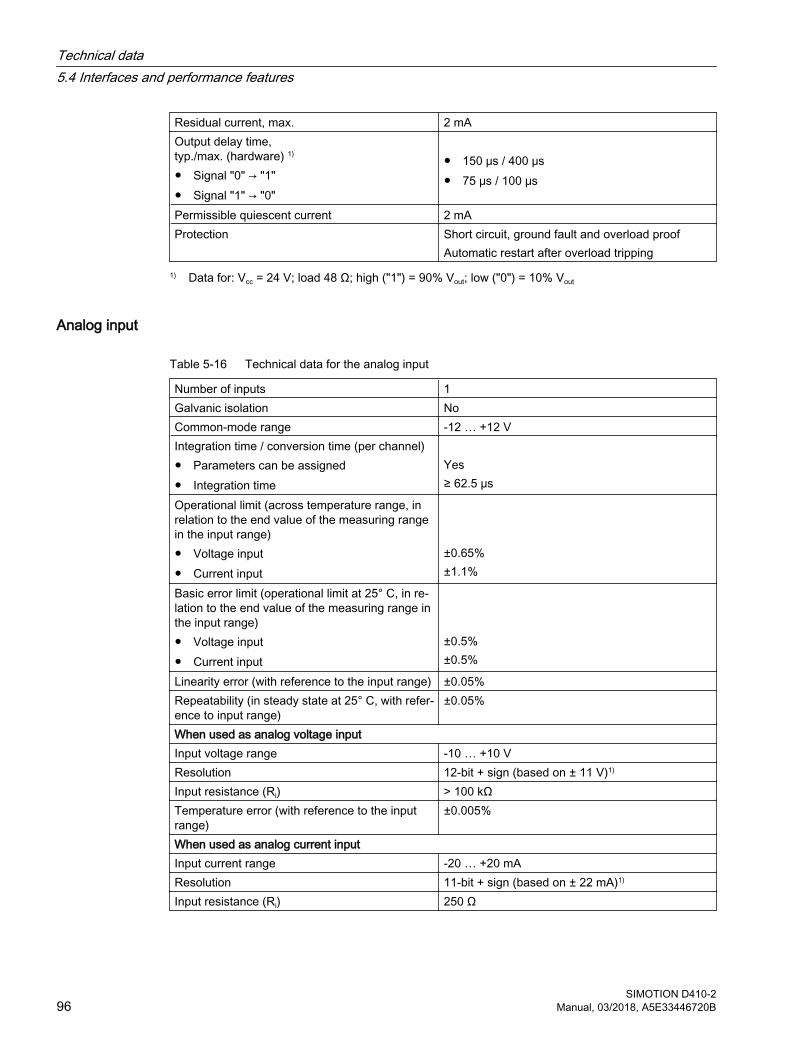
Residual current, max. 2 mAOutput delay time, typ./max. (hardware) 1)
● Signal "0" → "1"● Signal "1" → "0"
● 150 μs / 400 μs● 75 μs / 100 μs
Permissible quiescent current 2 mAProtection Short circuit, ground fault and overload proof
Automatic restart after overload tripping1) Data for: Vcc = 24 V; load 48 Ω; high ("1") = 90% Vout; low ("0") = 10% Vout
Analog input
Table 5-16 Technical data for the analog input
Number of inputs 1Galvanic isolation NoCommon-mode range -12 … +12 VIntegration time / conversion time (per channel)● Parameters can be assigned● Integration time
Yes≥ 62.5 µs
Operational limit (across temperature range, in relation to the end value of the measuring range in the input range)● Voltage input● Current input
±0.65%±1.1%
Basic error limit (operational limit at 25° C, in re‐lation to the end value of the measuring range in the input range)● Voltage input● Current input
±0.5%±0.5%
Linearity error (with reference to the input range) ±0.05%Repeatability (in steady state at 25° C, with refer‐ence to input range)
±0.05%
When used as analog voltage inputInput voltage range -10 … +10 VResolution 12-bit + sign (based on ± 11 V)1)
Input resistance (Ri) > 100 kΩTemperature error (with reference to the input range)
±0.005%
When used as analog current inputInput current range -20 … +20 mAResolution 11-bit + sign (based on ± 22 mA)1)
Input resistance (Ri) 250 Ω
Technical data5.4 Interfaces and performance features
SIMOTION D410-296 Manual, 03/2018, A5E33446720B
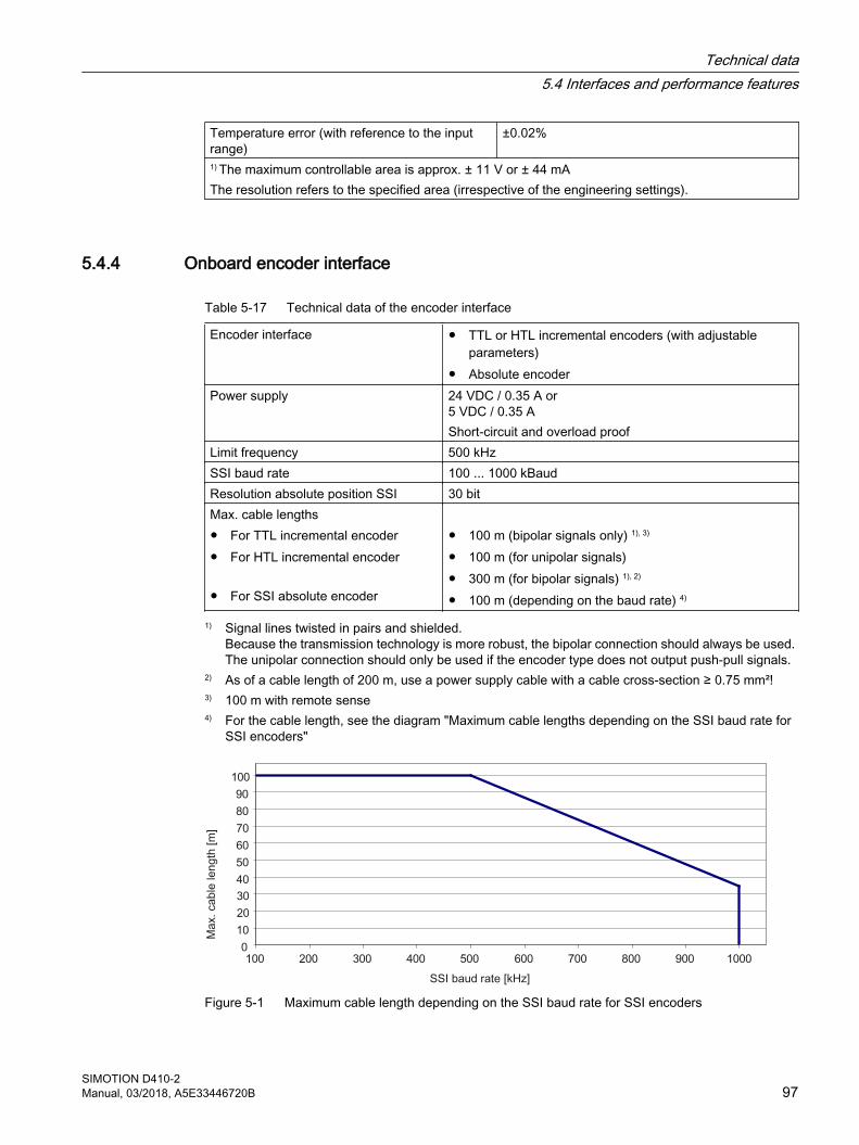
Temperature error (with reference to the input range)
±0.02%
1) The maximum controllable area is approx. ± 11 V or ± 44 mAThe resolution refers to the specified area (irrespective of the engineering settings).
5.4.4 Onboard encoder interface
Table 5-17 Technical data of the encoder interface
Encoder interface ● TTL or HTL incremental encoders (with adjustable parameters)
● Absolute encoderPower supply 24 VDC / 0.35 A or
5 VDC / 0.35 AShort-circuit and overload proof
Limit frequency 500 kHzSSI baud rate 100 ... 1000 kBaudResolution absolute position SSI 30 bitMax. cable lengths● For TTL incremental encoder● For HTL incremental encoder
● For SSI absolute encoder
● 100 m (bipolar signals only) 1), 3)
● 100 m (for unipolar signals)● 300 m (for bipolar signals) 1), 2)
● 100 m (depending on the baud rate) 4)
1) Signal lines twisted in pairs and shielded.Because the transmission technology is more robust, the bipolar connection should always be used. The unipolar connection should only be used if the encoder type does not output push-pull signals.
2) As of a cable length of 200 m, use a power supply cable with a cable cross-section ≥ 0.75 mm²!3) 100 m with remote sense4) For the cable length, see the diagram "Maximum cable lengths depending on the SSI baud rate for
SSI encoders"
Figure 5-1 Maximum cable length depending on the SSI baud rate for SSI encoders
Technical data5.4 Interfaces and performance features
SIMOTION D410-2Manual, 03/2018, A5E33446720B 97

Note
The CUA32 control unit adapter also provides an encoder interface for an HTL, TTL or SSI encoder.
The technical data of the CUA32 adapter module can be found in the SINAMICS S120 AC Drive Manual.
Technical data5.4 Interfaces and performance features
SIMOTION D410-298 Manual, 03/2018, A5E33446720B
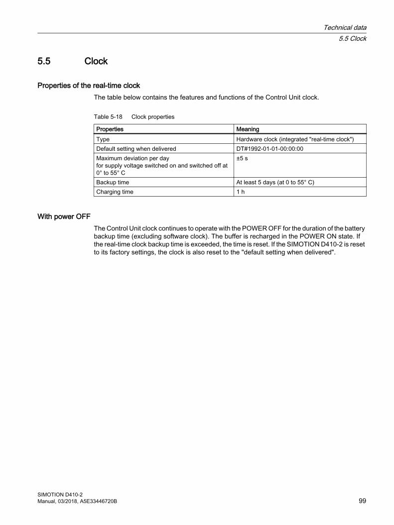
5.5 Clock
Properties of the real-time clockThe table below contains the features and functions of the Control Unit clock.
Table 5-18 Clock properties
Properties MeaningType Hardware clock (integrated "real-time clock")Default setting when delivered DT#1992-01-01-00:00:00Maximum deviation per dayfor supply voltage switched on and switched off at 0° to 55° C
±5 s
Backup time At least 5 days (at 0 to 55° C)Charging time 1 h
With power OFFThe Control Unit clock continues to operate with the POWER OFF for the duration of the battery backup time (excluding software clock). The buffer is recharged in the POWER ON state. If the real-time clock backup time is exceeded, the time is reset. If the SIMOTION D410-2 is reset to its factory settings, the clock is also reset to the "default setting when delivered".
Technical data5.5 Clock
SIMOTION D410-2Manual, 03/2018, A5E33446720B 99

5.6 Certificates, approvals, declarations of conformityYou can find an overview of the certifications available for the SIMOTION D410-2 in Appendix A (Page 117).
You can also find further information on the Internet at:
https://support.industry.siemens.com/cs/ww/en/ps/14513/cert
Technical data5.6 Certificates, approvals, declarations of conformity
SIMOTION D410-2100 Manual, 03/2018, A5E33446720B
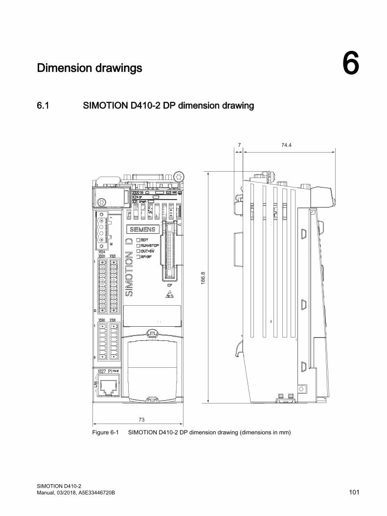
Dimension drawings 66.1 SIMOTION D410-2 DP dimension drawing
Figure 6-1 SIMOTION D410-2 DP dimension drawing (dimensions in mm)
SIMOTION D410-2Manual, 03/2018, A5E33446720B 101

NoteOverheating if ventilation clearances are too small
Insufficient ventilation clearances result in overheating and therefore in more failures and a shortened service life of the component.
Maintain 50 mm ventilation clearances above and below the component.
Dimension drawings6.1 SIMOTION D410-2 DP dimension drawing
SIMOTION D410-2102 Manual, 03/2018, A5E33446720B

6.2 SIMOTION D410-2 DP/PN dimension drawing
Figure 6-2 SIMOTION D410-2 DP/PN dimension drawing (dimensions in mm)
NoteOverheating if ventilation clearances are too small
Insufficient ventilation clearances result in overheating and therefore in more failures and a shortened service life of the component.
Maintain 50 mm ventilation clearances above and below the component.
Dimension drawings6.2 SIMOTION D410-2 DP/PN dimension drawing
SIMOTION D410-2Manual, 03/2018, A5E33446720B 103
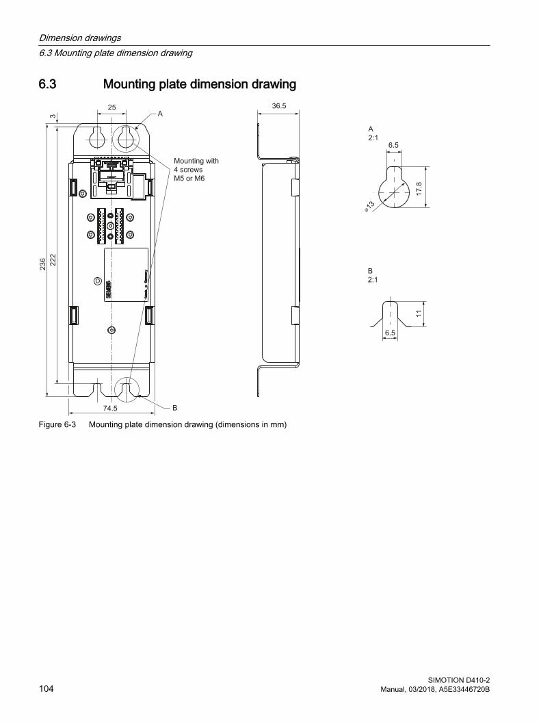
6.3 Mounting plate dimension drawing
Figure 6-3 Mounting plate dimension drawing (dimensions in mm)
Dimension drawings6.3 Mounting plate dimension drawing
SIMOTION D410-2104 Manual, 03/2018, A5E33446720B
6.4 CAD data, dimension drawings, and circuit-diagram macros
Dimension drawings and CAD dataDimension drawings, as well as 2D and 3D CAD data can be found:
● In the CAD Creator at the following Internet address (https://support.industry.siemens.com/cs/ww/en/view/30559271).
● In the DT Configurator of the Industry Mall (http://www.siemens.com/dt-configurator).
● Via CAx Download Manager (https://support.industry.siemens.com/my/ww/en/CAxOnline#CAxOnline).
Circuit-diagram macrosEPLAN circuit-diagram macros are available for the SIMOTION D410-2. The macros assist you when creating circuit diagrams.
The EPLAN circuit diagram macros can be ordered at the following Internet addresses:
● Drive Technology Configurator Industry Mall (http://www.siemens.com/dt-configurator)
● CAx Download Manager (https://support.industry.siemens.com/my/ww/en/CAxOnline#CAxOnline)
● Product support Support (https://support.industry.siemens.com/cs/ww/en/view/31622426)
Dimension drawings6.4 CAD data, dimension drawings, and circuit-diagram macros
SIMOTION D410-2Manual, 03/2018, A5E33446720B 105

Dimension drawings6.4 CAD data, dimension drawings, and circuit-diagram macros
SIMOTION D410-2106 Manual, 03/2018, A5E33446720B
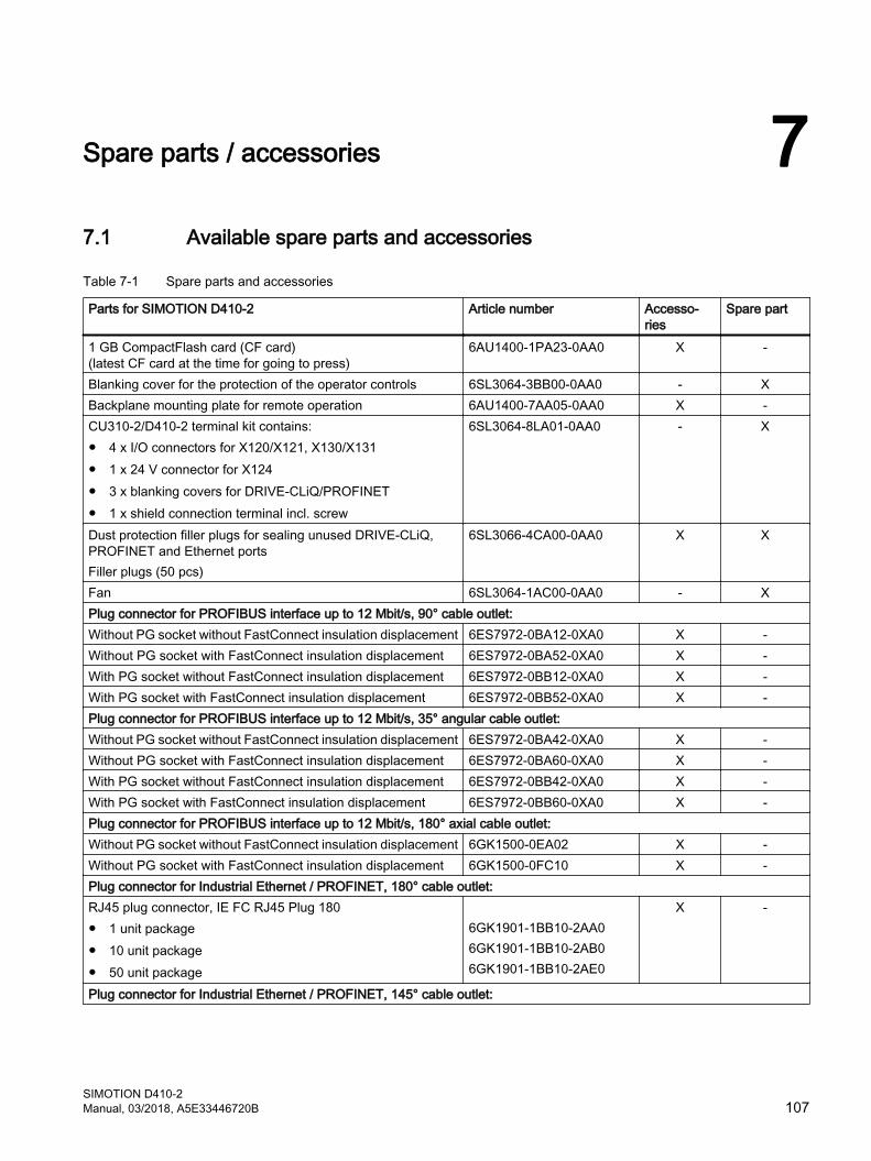
Spare parts / accessories 77.1 Available spare parts and accessories
Table 7-1 Spare parts and accessories
Parts for SIMOTION D410-2 Article number Accesso‐ries
Spare part
1 GB CompactFlash card (CF card)(latest CF card at the time for going to press)
6AU1400-1PA23-0AA0 X -
Blanking cover for the protection of the operator controls 6SL3064-3BB00-0AA0 - XBackplane mounting plate for remote operation 6AU1400-7AA05-0AA0 X -CU310-2/D410-2 terminal kit contains:● 4 x I/O connectors for X120/X121, X130/X131● 1 x 24 V connector for X124● 3 x blanking covers for DRIVE-CLiQ/PROFINET● 1 x shield connection terminal incl. screw
6SL3064-8LA01-0AA0 - X
Dust protection filler plugs for sealing unused DRIVE-CLiQ, PROFINET and Ethernet portsFiller plugs (50 pcs)
6SL3066-4CA00-0AA0 X X
Fan 6SL3064-1AC00-0AA0 - XPlug connector for PROFIBUS interface up to 12 Mbit/s, 90° cable outlet:Without PG socket without FastConnect insulation displacement 6ES7972-0BA12-0XA0 X -Without PG socket with FastConnect insulation displacement 6ES7972-0BA52-0XA0 X -With PG socket without FastConnect insulation displacement 6ES7972-0BB12-0XA0 X -With PG socket with FastConnect insulation displacement 6ES7972-0BB52-0XA0 X -Plug connector for PROFIBUS interface up to 12 Mbit/s, 35° angular cable outlet:Without PG socket without FastConnect insulation displacement 6ES7972-0BA42-0XA0 X -Without PG socket with FastConnect insulation displacement 6ES7972-0BA60-0XA0 X -With PG socket without FastConnect insulation displacement 6ES7972-0BB42-0XA0 X -With PG socket with FastConnect insulation displacement 6ES7972-0BB60-0XA0 X -Plug connector for PROFIBUS interface up to 12 Mbit/s, 180° axial cable outlet:Without PG socket without FastConnect insulation displacement 6GK1500-0EA02 X -Without PG socket with FastConnect insulation displacement 6GK1500-0FC10 X -Plug connector for Industrial Ethernet / PROFINET, 180° cable outlet:RJ45 plug connector, IE FC RJ45 Plug 180● 1 unit package● 10 unit package● 50 unit package
6GK1901-1BB10-2AA06GK1901-1BB10-2AB06GK1901-1BB10-2AE0
X -
Plug connector for Industrial Ethernet / PROFINET, 145° cable outlet:
SIMOTION D410-2Manual, 03/2018, A5E33446720B 107
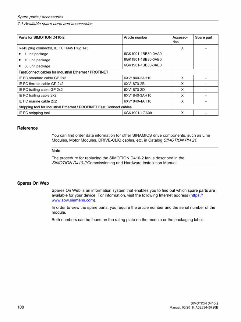
Parts for SIMOTION D410-2 Article number Accesso‐ries
Spare part
RJ45 plug connector, IE FC RJ45 Plug 145● 1 unit package● 10 unit package● 50 unit package
6GK1901-1BB30-0AA06GK1901-1BB30-0AB06GK1901-1BB30-0AE0
X -
FastConnect cables for Industrial Ethernet / PROFINETIE FC standard cable GP 2x2 6XV1840-2AH10 X -IE FC flexible cable GP 2x2 6XV1870-2B X -IE FC trailing cable GP 2x2 6XV1870-2D X -IE FC trailing cable 2x2 6XV1840-3AH10 X -IE FC marine cable 2x2 6XV1840-4AH10 X -Stripping tool for Industrial Ethernet / PROFINET Fast Connect cablesIE FC stripping tool 6GK1901-1GA00 X -
ReferenceYou can find order data information for other SINAMICS drive components, such as Line Modules, Motor Modules, DRIVE-CLiQ cables, etc. in Catalog SIMOTION PM 21.
Note
The procedure for replacing the SIMOTION D410‑2 fan is described in the SIMOTION D410‑2 Commissioning and Hardware Installation Manual.
Spares On WebSpares On Web is an information system that enables you to find out which spare parts are available for your device. For information, visit the following Internet address (https://www.sow.siemens.com).
In order to view the spare parts, you require the article number and the serial number of the module.
Both numbers can be found on the rating plate on the module or the packaging label.
Spare parts / accessories7.1 Available spare parts and accessories
SIMOTION D410-2108 Manual, 03/2018, A5E33446720B
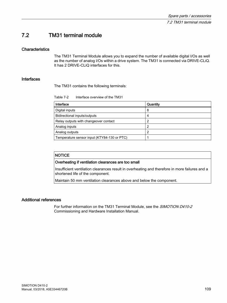
7.2 TM31 terminal module
CharacteristicsThe TM31 Terminal Module allows you to expand the number of available digital I/Os as well as the number of analog I/Os within a drive system. The TM31 is connected via DRIVE-CLiQ. It has 2 DRIVE-CLiQ interfaces for this.
InterfacesThe TM31 contains the following terminals:
Table 7-2 Interface overview of the TM31
Interface QuantityDigital inputs 8Bidirectional inputs/outputs 4Relay outputs with changeover contact 2Analog inputs 2Analog outputs 2Temperature sensor input (KTY84-130 or PTC) 1
NOTICE
Overheating if ventilation clearances are too small
Insufficient ventilation clearances result in overheating and therefore in more failures and a shortened life of the component.
Maintain 50 mm ventilation clearances above and below the component.
Additional referencesFor further information on the TM31 Terminal Module, see the SIMOTION D410-2 Commissioning and Hardware Installation Manual.
Spare parts / accessories7.2 TM31 terminal module
SIMOTION D410-2Manual, 03/2018, A5E33446720B 109
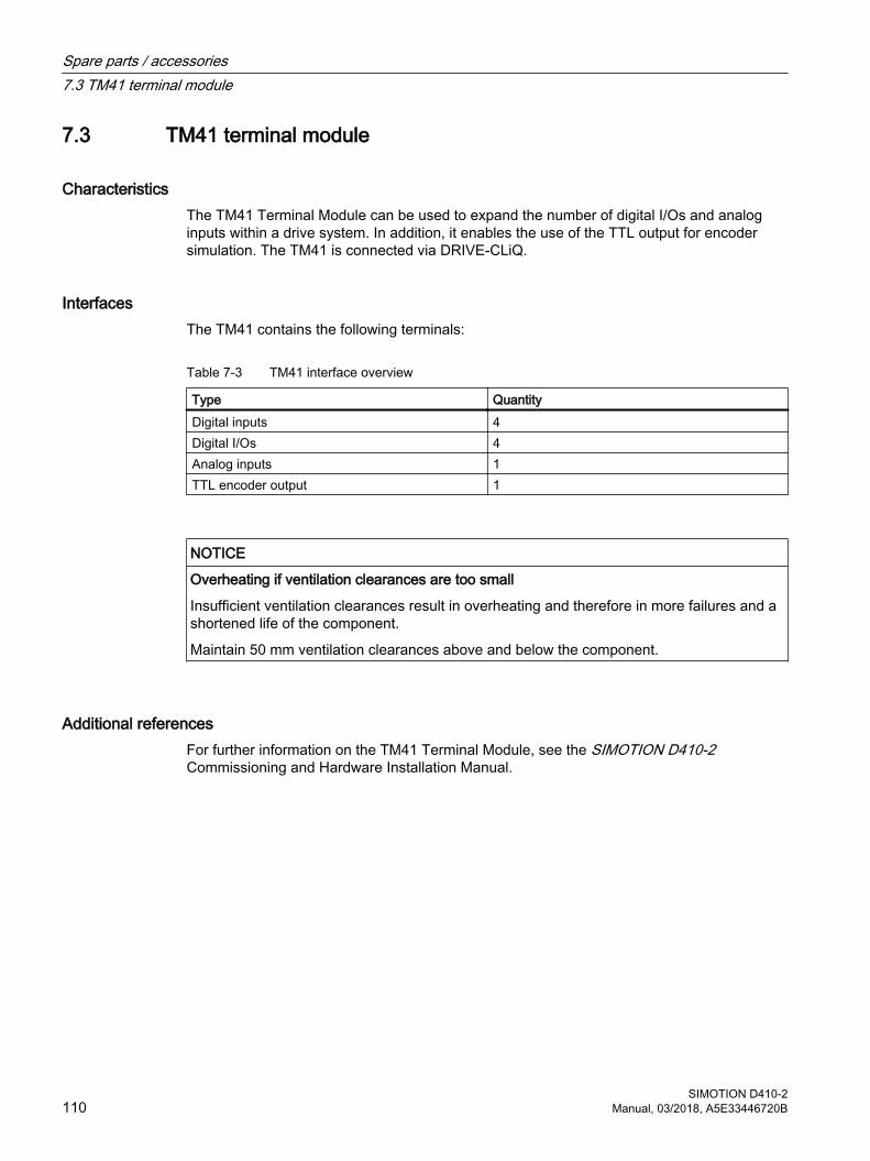
7.3 TM41 terminal module
CharacteristicsThe TM41 Terminal Module can be used to expand the number of digital I/Os and analog inputs within a drive system. In addition, it enables the use of the TTL output for encoder simulation. The TM41 is connected via DRIVE-CLiQ.
InterfacesThe TM41 contains the following terminals:
Table 7-3 TM41 interface overview
Type QuantityDigital inputs 4Digital I/Os 4Analog inputs 1TTL encoder output 1
NOTICE
Overheating if ventilation clearances are too small
Insufficient ventilation clearances result in overheating and therefore in more failures and a shortened life of the component.
Maintain 50 mm ventilation clearances above and below the component.
Additional referencesFor further information on the TM41 Terminal Module, see the SIMOTION D410-2 Commissioning and Hardware Installation Manual.
Spare parts / accessories7.3 TM41 terminal module
SIMOTION D410-2110 Manual, 03/2018, A5E33446720B
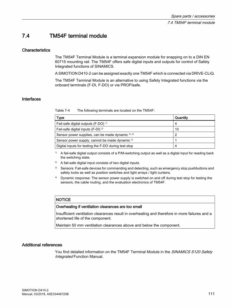
7.4 TM54F terminal module
CharacteristicsThe TM54F Terminal Module is a terminal expansion module for snapping on to a DIN EN 60715 mounting rail. The TM54F offers safe digital inputs and outputs for control of Safety Integrated functions of SINAMICS.
A SIMOTION D410‑2 can be assigned exactly one TM54F which is connected via DRIVE-CLiQ.
The TM54F Terminal Module is an alternative to using Safety Integrated functions via the onboard terminals (F‑DI, F‑DO) or via PROFIsafe.
Interfaces
Table 7-4 The following terminals are located on the TM54F:
Type QuantityFail-safe digital outputs (F‑DO) 1) 4Fail-safe digital inputs (F‑DI) 2) 10Sensor power supplies, can be made dynamic 3), 4) 2Sensor power supply, cannot be made dynamic 3) 1Digital inputs for testing the F‑DO during test stop 4
1) A fail-safe digital output consists of a P/M-switching output as well as a digital input for reading back the switching state.
2) A fail-safe digital input consists of two digital inputs.3) Sensors: Fail-safe devices for commanding and detecting, such as emergency stop pushbuttons and
safety locks as well as position switches and light arrays / light curtains.4) Dynamic response: The sensor power supply is switched on and off during test stop for testing the
sensors, the cable routing, and the evaluation electronics of TM54F.
NOTICE
Overheating if ventilation clearances are too small
Insufficient ventilation clearances result in overheating and therefore in more failures and a shortened life of the component.
Maintain 50 mm ventilation clearances above and below the component.
Additional referencesYou find detailed information on the TM54F Terminal Module in the SINAMICS S120 Safety Integrated Function Manual.
Spare parts / accessories7.4 TM54F terminal module
SIMOTION D410-2Manual, 03/2018, A5E33446720B 111

See alsoDRIVE-CLiQ interface (Page 50)
Spare parts / accessories7.4 TM54F terminal module
SIMOTION D410-2112 Manual, 03/2018, A5E33446720B
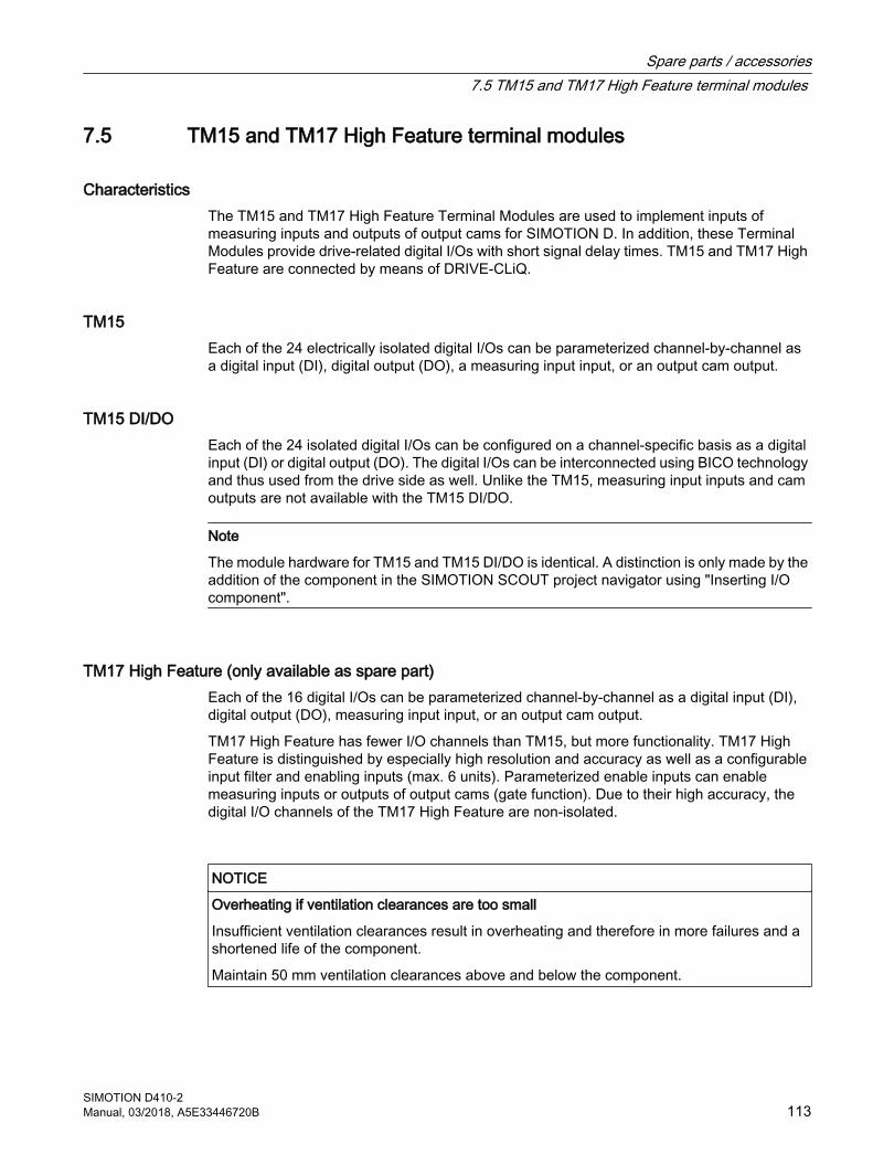
7.5 TM15 and TM17 High Feature terminal modules
CharacteristicsThe TM15 and TM17 High Feature Terminal Modules are used to implement inputs of measuring inputs and outputs of output cams for SIMOTION D. In addition, these Terminal Modules provide drive-related digital I/Os with short signal delay times. TM15 and TM17 High Feature are connected by means of DRIVE-CLiQ.
TM15Each of the 24 electrically isolated digital I/Os can be parameterized channel-by-channel as a digital input (DI), digital output (DO), a measuring input input, or an output cam output.
TM15 DI/DOEach of the 24 isolated digital I/Os can be configured on a channel-specific basis as a digital input (DI) or digital output (DO). The digital I/Os can be interconnected using BICO technology and thus used from the drive side as well. Unlike the TM15, measuring input inputs and cam outputs are not available with the TM15 DI/DO.
Note
The module hardware for TM15 and TM15 DI/DO is identical. A distinction is only made by the addition of the component in the SIMOTION SCOUT project navigator using "Inserting I/O component".
TM17 High Feature (only available as spare part)Each of the 16 digital I/Os can be parameterized channel-by-channel as a digital input (DI), digital output (DO), measuring input input, or an output cam output.
TM17 High Feature has fewer I/O channels than TM15, but more functionality. TM17 High Feature is distinguished by especially high resolution and accuracy as well as a configurable input filter and enabling inputs (max. 6 units). Parameterized enable inputs can enable measuring inputs or outputs of output cams (gate function). Due to their high accuracy, the digital I/O channels of the TM17 High Feature are non-isolated.
NOTICE
Overheating if ventilation clearances are too small
Insufficient ventilation clearances result in overheating and therefore in more failures and a shortened life of the component.
Maintain 50 mm ventilation clearances above and below the component.
Spare parts / accessories7.5 TM15 and TM17 High Feature terminal modules
SIMOTION D410-2Manual, 03/2018, A5E33446720B 113

Additional referencesDetailed information about the TM15 and TM17 High Feature can be found in the SIMOTION Terminal Modules TM15 / TM17 High Feature Commissioning Manual.
Spare parts / accessories7.5 TM15 and TM17 High Feature terminal modules
SIMOTION D410-2114 Manual, 03/2018, A5E33446720B
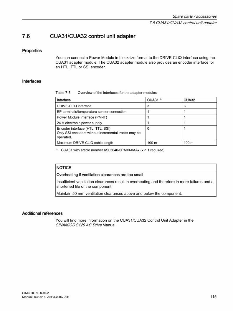
7.6 CUA31/CUA32 control unit adapter
PropertiesYou can connect a Power Module in blocksize format to the DRIVE-CLiQ interface using the CUA31 adapter module. The CUA32 adapter module also provides an encoder interface for an HTL, TTL or SSI encoder.
Interfaces
Table 7-5 Overview of the interfaces for the adapter modules
Interface CUA31 1) CUA32 DRIVE-CLiQ interface 3 3EP terminals/temperature sensor connection 1 1Power Module Interface (PM-IF) 1 124 V electronic power supply 1 1Encoder interface (HTL, TTL, SSI)Only SSI encoders without incremental tracks may be operated.
0 1
Maximum DRIVE-CLiQ cable length 100 m 100 m1) CUA31 with article number 6SL3040-0PA00-0AAx (x ≥ 1 required)
NOTICE
Overheating if ventilation clearances are too small
Insufficient ventilation clearances result in overheating and therefore in more failures and a shortened life of the component.
Maintain 50 mm ventilation clearances above and below the component.
Additional referencesYou will find more information on the CUA31/CUA32 Control Unit Adapter in the SINAMICS S120 AC Drive Manual.
Spare parts / accessories7.6 CUA31/CUA32 control unit adapter
SIMOTION D410-2Manual, 03/2018, A5E33446720B 115
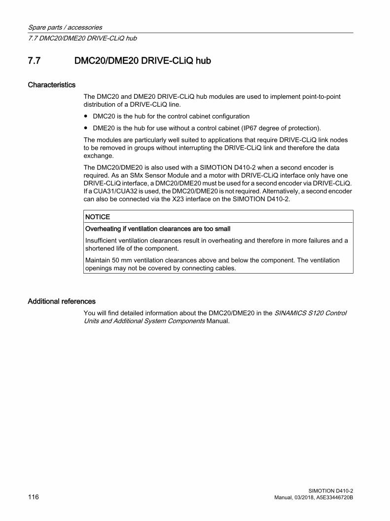
7.7 DMC20/DME20 DRIVE-CLiQ hub
CharacteristicsThe DMC20 and DME20 DRIVE‑CLiQ hub modules are used to implement point-to-point distribution of a DRIVE‑CLiQ line.
● DMC20 is the hub for the control cabinet configuration
● DME20 is the hub for use without a control cabinet (IP67 degree of protection).
The modules are particularly well suited to applications that require DRIVE-CLiQ link nodes to be removed in groups without interrupting the DRIVE-CLiQ link and therefore the data exchange.
The DMC20/DME20 is also used with a SIMOTION D410‑2 when a second encoder is required. As an SMx Sensor Module and a motor with DRIVE-CLiQ interface only have one DRIVE-CLiQ interface, a DMC20/DME20 must be used for a second encoder via DRIVE-CLiQ. If a CUA31/CUA32 is used, the DMC20/DME20 is not required. Alternatively, a second encoder can also be connected via the X23 interface on the SIMOTION D410‑2.
NOTICE
Overheating if ventilation clearances are too small
Insufficient ventilation clearances result in overheating and therefore in more failures and a shortened life of the component.
Maintain 50 mm ventilation clearances above and below the component. The ventilation openings may not be covered by connecting cables.
Additional referencesYou will find detailed information about the DMC20/DME20 in the SINAMICS S120 Control Units and Additional System Components Manual.
Spare parts / accessories7.7 DMC20/DME20 DRIVE-CLiQ hub
SIMOTION D410-2116 Manual, 03/2018, A5E33446720B
Standards and approvals AA.1 General rules
CE marking
Our products satisfy the requirements and protection objectives of the EC Directives and comply with the harmonized European standards (EN).
Electromagnetic compatibilityStandards for EMC are satisfied if the EMC Installation Guideline is observed.
SIMOTION products are designed for industrial use in accordance with product standard DIN EN 61800‑3, Category C2.
cULus approval
Listed component mark for United States and the Canada Underwriters Laboratories (UL) according to Standard UL 508, File E164110, File E115352, File E85972.
You can find further information on the respective device on the Internet at http://database.ul.com/cgi-bin/XYV/template/LISEXT/1FRAME/index.htm Enter the first seven characters of the article number at Keyword. Then click Search.
Korea certification
KC registration number: KCC-REM-S49-SIMOTIONNote that this device complies with limit class A with regard to the emission of radio frequency interference. This device can be used in all areas except residential areas.
Declaration of conformityThe current Declaration of conformity is available on the Internet at Declaration of conformity (https://support.industry.siemens.com/cs/ww/en/ps/14506/cert)).
SIMOTION D410-2Manual, 03/2018, A5E33446720B 117
Marking for Australia and New Zealand
SIMOTION D410-2 satisfies the requirement of the standard AS/NZS CISPR 16.
orMarking with RCM (Regulatory Compliance Mark) or C-Tick with older components.
Marking for the Eurasian customs union
EAC (Eurasian Conformity) Customs union of Russia, Belarus and Kazakhstan Declaration of conformity in accordance with the technical regulations of the customs union (TR CU).
Standards and approvalsA.1 General rules
SIMOTION D410-2118 Manual, 03/2018, A5E33446720B
A.2 Device-specific information
Note regarding SIMOTION D
Note
The product standard EN 61800-3 describes the EMC requirements placed on "Variable-speed drive systems". As such, it defines different limits depending on the location of the drive system.
SINAMICS S120 power units are designed for use in the second environment. The term second environment refers to all locations outside residential areas. These are basically industrial areas which are supplied from the medium-voltage line supply via their own transformers.
It is essential to follow the installation instructions in the SINAMICS S120 Manuals in order to ensure compliance with emitted interference and immunity values.
The same installation instructions apply for the SIMOTION D410-2 Control Unit as for the SINAMICS S120 CU310-2 Control Unit with regard to EMC.
For further information on this topic also refer to the SIMOTION PM 21 Catalog as well as the SINAMICS Function Manuals.
Standards and approvalsA.2 Device-specific information
SIMOTION D410-2Manual, 03/2018, A5E33446720B 119

Standards and approvalsA.2 Device-specific information
SIMOTION D410-2120 Manual, 03/2018, A5E33446720B
ESD guidelines BB.1 ESD definition
What does ESD mean? Electrostatic sensitive devices (ESDs) are individual components, integrated circuits, modules or devices that may be damaged by either electrostatic fields or electrostatic discharge.
NOTICE
Damage caused by electric fields or electrostatic discharge
Electric fields or electrostatic discharge can result in malfunctions as a result of damaged individual parts, integrated circuits, modules or devices.● Only pack, store, transport and send electronic components, modules or devices in their
original packaging or in other suitable materials, e.g conductive foam rubber or aluminum foil.
● Only touch components, modules and devices if you are first grounded by applying one of the following measures:– Wearing an ESD wrist strap– Wearing ESD shoes or ESD grounding straps in ESD areas with conductive flooring
● Only place electronic components, modules or devices on conductive surfaces (table with ESD surface, conductive ESD foam, ESD packaging, ESD transport container).
SIMOTION D410-2Manual, 03/2018, A5E33446720B 121
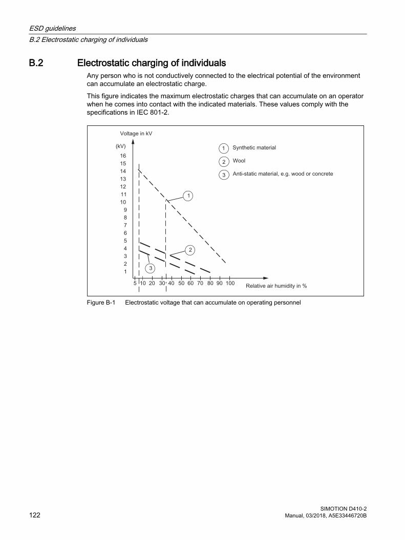
B.2 Electrostatic charging of individualsAny person who is not conductively connected to the electrical potential of the environment can accumulate an electrostatic charge.
This figure indicates the maximum electrostatic charges that can accumulate on an operator when he comes into contact with the indicated materials. These values comply with the specifications in IEC 801-2.
Figure B-1 Electrostatic voltage that can accumulate on operating personnel
ESD guidelinesB.2 Electrostatic charging of individuals
SIMOTION D410-2122 Manual, 03/2018, A5E33446720B
B.3 Basic measures for protection against discharge of static electricity
Ensure sufficient groundingWhen working with electrostatic sensitive devices, make sure that the you, your workstation, and the packaging are properly grounded. This prevents the accumulation of static electricity.
Avoid direct contactYou should only touch ESD components if unavoidable (for example, during maintenance work). When you touch modules, make sure that you do not touch either the pins on the modules or the printed conductors. If you follow these instructions, electrostatic discharge cannot reach or damage sensitive components.
If you have to take measurements on a module, make sure that you first discharge any static that may have accumulated in your body. To do this, touch a grounded metal object. Only use grounded measuring instruments.
ESD guidelinesB.3 Basic measures for protection against discharge of static electricity
SIMOTION D410-2Manual, 03/2018, A5E33446720B 123

ESD guidelinesB.3 Basic measures for protection against discharge of static electricity
SIMOTION D410-2124 Manual, 03/2018, A5E33446720B
Index
AAccessories, 107
CUA31/CUA32, 115DMC20 DRIVE-CLiQ hub module, 116DME20 DRIVE-CLiQ hub module, 116TM15, 113TM15 DI/DO, 113TM17 High Feature, 113TM31, 109TM41, 110TM54F, 111
Address space, 92Ambient conditions
Climatic, 86Mechanical, 86
Analog input, 61
BBackup
Non-volatile data, 89
CCAD data, 105CE marking, 117CF card
Slot, 47CF card, 37
Data matrix code, 39Licenses, 37Properties, 36Rating plate, 37Technical data, 90
Circuit-diagram macro, 105Clock, 99Component
on DRIVE-CLiQ, 27on Ethernet, 27on PROFIBUS, 25on PROFINET, 26
Conditions of use, 86Connection examples
with Safety Integrated Extended/Advanced Functions, 73, 77
without Safety Integrated Extended Functions, 75without Safety Integrated functions, 71
cULus approval, 117
DDeclaration of conformity, 117DIAG button, 45Diagnostic buffer, 89Digital I/Os, 61
Bidirectional, 70Connection examples, 75Fail-safe, 69
Digital inputs/outputsConnection examples, 71Technical data, 93
Dimension drawing, 105Mounting plate, 104SIMOTION D410-2 DP, 101SIMOTION D410-2 DP/PN, 103
Dimensions, 89Display elements, 41DMC20
Characteristics, 116DMC20 (hub)
Characteristics, 116DME20
Characteristics, 116DME20 hub
Characteristics, 116DRIVE-CLiQ
Connectable devices, 51Interface, 50Interface assignment, 50Interface characteristics, 50
EElectrical connection values, 89Electromagnetic compatibility, 117EMC directives, 117Encoder interface, 58
Interface assignment, 59Interface characteristics, 58
ESD guideline, 121Ethernet
Connectable devices, 81Interface, 81
SIMOTION D410-2Manual, 03/2018, A5E33446720B 125
GGuideline
ESD, 121
HHardware components, 22
II/O systems
PROFINET, 26Interface assignment
X120, 63X121, 66X130, 67X131, 68
Interfaces, 49Analog input (X131), 61Digital I/Os, 61DRIVE-CLiQ (X100), 50Encoder interface (X23), 58Ethernet (X127), 81Measuring socket, 83Power Module Interface, 84Power supply, 79PROFIBUS DP, 25, 53PROFINET, 26PROFINET IO, 55Temperature sensor connection (X120), 64
LLED displays, 48Licenses
Runtime, 37Licensing, 40
MMAC address, 34Measuring socket, 83Memory
SIMOTION D410-2, 89Mode switch, 43Mounting plate
Data, 90
OOperator controls, 41
DIAG button, 45Mode switch, 43RESET button, 46Service selector switch, 42Switch S5.0, 46
PPerformance
Motion Control, 91PLC, 91
PLC and motion controlSIMOTION D410-2 DP performance, 91SIMOTION D410-2 DP/PN performance, 91
Possible applications, 22PROFIBUS DP interface
Assignment, 53PROFINET IO interface
Assignment, 55
RRating plate
CF card, 37SIMOTION D410-2, 34
Real-time clock, 99References, 4RESET button, 46Runtime licenses, 37
SSafety instructions, 17Service selector switch, 42Shipping conditions, 85Software components, 23Spare parts, 107Storage conditions, 85
TTechnical data
Address space, 92Analog input, 96CF card, 90Clock, 99
Index
SIMOTION D410-2126 Manual, 03/2018, A5E33446720B
Communication, 91Digital inputs/outputs, 93Encoder interface, 97Mounting plate, 90SIMOTION D410-2 memory, 89
Temperature sensor connection, 64Terminal Module
TM15, 113TM15 DI/DO, 113TM17 High Feature, 113TM31, 109TM41, 110TM54F, 111
UUL certification, 117
WWeight, 89
Index
SIMOTION D410-2Manual, 03/2018, A5E33446720B 127

Index
SIMOTION D410-2128 Manual, 03/2018, A5E33446720B