sinamics g130 - adegis
TRANSCRIPT

Operating instructions · 03/2011
Chassis converter units 75 kW to 800 kW
SINAMICS G130
SINAMICS
s

Inverter chassis units
___________________
___________________
___________________
___________________
___________________
___________________
___________________
___________________
___________________
___________________
___________________
___________________
___________________
___________________
SINAMICS
SINAMICS G130 Inverter chassis units
Operating Instructions
Control version V4.4
03/2011 A5E00331449A
Preface
Safety information 1
Device overview 2
Mechanical installation 3
Electrical installation 4
Commissioning 5
Operation 6
Setpoint channel and closed-loop control
7
Output terminals 8
Functions, monitoring, and protective functions
9
Diagnosis / faults and alarms 10
Maintenance and servicing 11
Technical specifications 12
Appendix A
Legal information
Legal information Warning notice system
This manual contains notices you have to observe in order to ensure your personal safety, as well as to prevent damage to property. The notices referring to your personal safety are highlighted in the manual by a safety alert symbol, notices referring only to property damage have no safety alert symbol. These notices shown below are graded according to the degree of danger.
DANGER indicates that death or severe personal injury will result if proper precautions are not taken.
WARNING indicates that death or severe personal injury may result if proper precautions are not taken.
CAUTION with a safety alert symbol, indicates that minor personal injury can result if proper precautions are not taken.
CAUTION without a safety alert symbol, indicates that property damage can result if proper precautions are not taken.
NOTICE indicates that an unintended result or situation can occur if the relevant information is not taken into account.
If more than one degree of danger is present, the warning notice representing the highest degree of danger will be used. A notice warning of injury to persons with a safety alert symbol may also include a warning relating to property damage.
Qualified Personnel The product/system described in this documentation may be operated only by personnel qualified for the specific task in accordance with the relevant documentation, in particular its warning notices and safety instructions. Qualified personnel are those who, based on their training and experience, are capable of identifying risks and avoiding potential hazards when working with these products/systems.
Proper use of Siemens products Note the following:
WARNING Siemens products may only be used for the applications described in the catalog and in the relevant technical documentation. If products and components from other manufacturers are used, these must be recommended or approved by Siemens. Proper transport, storage, installation, assembly, commissioning, operation and maintenance are required to ensure that the products operate safely and without any problems. The permissible ambient conditions must be complied with. The information in the relevant documentation must be observed.
Trademarks All names identified by ® are registered trademarks of Siemens AG. The remaining trademarks in this publication may be trademarks whose use by third parties for their own purposes could violate the rights of the owner.
Disclaimer of Liability We have reviewed the contents of this publication to ensure consistency with the hardware and software described. Since variance cannot be precluded entirely, we cannot guarantee full consistency. However, the information in this publication is reviewed regularly and any necessary corrections are included in subsequent editions.
Siemens AG Industry Sector Postfach 48 48 90026 NÜRNBERG GERMANY
A5E00331449A 05/2011
Copyright © Siemens AG 2011. Technical data subject to change
Inverter chassis units Operating Instructions, 03/2011, A5E00331449A 3
Preface
User documentation
WARNING Before installing and commissioning the converter, make sure that you read all the safety notes and warnings carefully, including all the warning labels on the components. The warning labels must always be legible. Missing or damaged labels must be replaced.
Structure of this documentation The customer documentation comprises the following documents:
Converter Operating Instructions The Operating Instructions consist of the following sections:
– Device description
– Mechanical installation
– Electrical installation
– Commissioning guide
– Description of functions
– Maintenance instructions
– Technical specifications
Operating instructions of additional system components
– AOP30
– BOP20
– Line filter
– Line reactors
– Braking Modules and braking resistors
– Motor reactors
– Sine-wave filter
– dv/dt filter plus VPL
– TB30
– VSM10
– Cabinet design and EMC
– Line harmonics filter
Preface
Inverter chassis units 4 Operating Instructions, 03/2011, A5E00331449A
Basic function diagrams These provide an overview of the basic functions of the converter unit for simple applications.
List Manual The List Manual consists of the following sections:
– Parameter list
– Function diagrams
– Fault / warning list
Documentation for Drive Control Chart (DCC)
– Programming and Operating Manual: DCC Editor description
– Function Manual: Description of the standard DCC blocks
Technical support If you have any questions, please contact our hotline:
Time zone Europe/Africa
Phone +49 (0) 911 895 7222 Fax +49 (0) 911 895 7223 Internet http://www.siemens.com/automation/support-request
Time zone America Phone +1 423 262 2522 Fax +1 423 262 2200 Internet [email protected]
Time zone Asia/Pacific Phone +86 1064 757 575 Fax +86 1064 747 474 Internet [email protected]
Spare parts You will find spare parts on the Internet at: http://support.automation.siemens.com/WW/view/en/16612315.
Internet address Information about SINAMICS can be found on the Internet at the following address: http://www.siemens.com/sinamics
Inverter chassis units Operating Instructions, 03/2011, A5E00331449A 5
Table of contents
Preface ...................................................................................................................................................... 3
1 Safety information.................................................................................................................................... 11
1.1 Warnings ......................................................................................................................................11
1.2 Safety and operating instructions.................................................................................................12
1.3 Components that can be destroyed by electrostatic discharge (ESD) ........................................13
2 Device overview....................................................................................................................................... 17
2.1 Chapter content ...........................................................................................................................17
2.2 Overview of the chassis units ......................................................................................................18
2.3 Overview of the Power Modules ..................................................................................................19
2.4 Applications, features...................................................................................................................20 2.4.1 Applications..................................................................................................................................20 2.4.2 Features, quality, service .............................................................................................................20
2.5 Wiring principle.............................................................................................................................22
2.6 Type plate ....................................................................................................................................23
3 Mechanical installation............................................................................................................................. 25
3.1 Chapter content ...........................................................................................................................25
3.2 Transportation and storage..........................................................................................................26
3.3 Assembly......................................................................................................................................28 3.3.1 Requirements on the installation location ....................................................................................28 3.3.2 Unpacking ....................................................................................................................................29 3.3.3 Required tools ..............................................................................................................................29
3.4 Power Module ..............................................................................................................................29 3.4.1 Dimension drawings.....................................................................................................................30
3.5 Control Unit CU320-2...................................................................................................................35
3.6 TM31 Terminal Module ................................................................................................................37
3.7 SMC30 Sensor Module................................................................................................................38
4 Electrical installation ................................................................................................................................ 39
4.1 Chapter content ...........................................................................................................................39
4.2 Preparation...................................................................................................................................39
4.3 Important safety precautions........................................................................................................40
4.4 Introduction to EMC .....................................................................................................................41
4.5 EMC-compliant design.................................................................................................................43
4.6 Connection overview....................................................................................................................46
Table of contents
Inverter chassis units 6 Operating Instructions, 03/2011, A5E00331449A
4.7 Power connections...................................................................................................................... 50 4.7.1 Connection cross-sections, cable lengths................................................................................... 50 4.7.2 Connecting the motor and power cables .................................................................................... 51 4.7.3 DCPS, DCNS connection for a dV/dt filter with Voltage Peak Limiter ........................................ 52 4.7.4 Adjusting the fan voltage............................................................................................................. 52 4.7.5 Removing the connecting clip for the interference suppression capacitor for operation on
an ungrounded supply/IT system................................................................................................ 54
4.8 External 24 V DC supply ............................................................................................................. 58
4.9 DRIVE-CLiQ wiring diagram ....................................................................................................... 59
4.10 Signal connections ...................................................................................................................... 60 4.10.1 Power Module ............................................................................................................................. 60 4.10.2 Control Unit CU320-2 DP............................................................................................................ 63 4.10.3 Control Unit CU320-2 PN............................................................................................................ 77 4.10.4 TM31 Terminal Module ............................................................................................................... 89 4.10.5 Sensor Module Cabinet-Mounted SMC30 .................................................................................. 98 4.10.5.1 Description .................................................................................................................................. 98 4.10.5.2 Connection ................................................................................................................................ 102 4.10.5.3 Connection examples................................................................................................................ 105
5 Commissioning ...................................................................................................................................... 107
5.1 Chapter content......................................................................................................................... 107
5.2 STARTER commissioning tool.................................................................................................. 108 5.2.1 Installing STARTER .................................................................................................................. 109 5.2.2 The STARTER user interface ................................................................................................... 110
5.3 Procedure for commissioning via STARTER............................................................................ 111 5.3.1 Creating a project...................................................................................................................... 111 5.3.2 Configuring the drive unit .......................................................................................................... 118 5.3.3 Transferring the drive project .................................................................................................... 138 5.3.4 Commissioning with STARTER via Ethernet ............................................................................ 140
5.4 The AOP30 operator panel ....................................................................................................... 145
5.5 First commissioning with the AOP30 ........................................................................................ 146 5.5.1 First commissioning .................................................................................................................. 146 5.5.2 Basic commissioning................................................................................................................. 148
5.6 Status after commissioning....................................................................................................... 156
5.7 Parameter reset to factory settings ........................................................................................... 157
6 Operation............................................................................................................................................... 159
6.1 Chapter content......................................................................................................................... 159
6.2 General information about command and setpoint sources ..................................................... 160
6.3 Basic information about the drive system ................................................................................. 161 6.3.1 Parameters................................................................................................................................ 161 6.3.2 Drive objects ............................................................................................................................. 164 6.3.3 Data sets ................................................................................................................................... 165 6.3.4 BICO technology: interconnecting signals ................................................................................ 172
6.4 Command sources .................................................................................................................... 177 6.4.1 "PROFIdrive" default setting ..................................................................................................... 177
Table of contents
Inverter chassis units Operating Instructions, 03/2011, A5E00331449A 7
6.4.2 "TM31 terminals" default setting ................................................................................................179 6.4.3 "CU terminals" default setting ....................................................................................................181 6.4.4 "PROFIdrive+TM31" default setting...........................................................................................183
6.5 Setpoint sources ........................................................................................................................185 6.5.1 Analog inputs .............................................................................................................................185 6.5.2 Motorized potentiometer ............................................................................................................187 6.5.3 Fixed speed setpoints ................................................................................................................188
6.6 Communication according to PROFIdrive .................................................................................190 6.6.1 General information ...................................................................................................................190 6.6.2 Application classes ....................................................................................................................192 6.6.3 Cyclic communication ................................................................................................................197 6.6.3.1 Telegrams and process data .....................................................................................................197 6.6.3.2 Structure of the telegrams..........................................................................................................199 6.6.3.3 Overview of control words and setpoints ...................................................................................200 6.6.3.4 Overview of status words and actual values..............................................................................201 6.6.4 Acyclic communication...............................................................................................................201 6.6.4.1 Structure of requests and responses.........................................................................................203 6.6.4.2 Determining the drive object numbers .......................................................................................209 6.6.4.3 Example 1: Reading parameters ...............................................................................................209 6.6.4.4 Example 2: Writing parameters (multi-parameter request)........................................................211 6.6.5 Further information about PROFIdrive communication .............................................................215
6.7 Communication via PROFIBUS DP...........................................................................................216 6.7.1 PROFIBUS connection ..............................................................................................................216 6.7.2 Control via PROFIBUS ..............................................................................................................216 6.7.3 Monitoring: Telegram failure ......................................................................................................217 6.7.4 Further information about communication via PROFIBUS DP..................................................217
6.8 Communication via PROFINET IO ............................................................................................218 6.8.1 Communication Board Ethernet CBE20 ....................................................................................218 6.8.2 Activating online operation: STARTER via PROFINET IO ........................................................220 6.8.3 General information about PROFINET IO .................................................................................224 6.8.3.1 General information about PROFINET IO for SINAMICS .........................................................224 6.8.3.2 Real-time (RT) and isochronous real-time (IRT) communication ..............................................225 6.8.3.3 Addresses ..................................................................................................................................226 6.8.3.4 Data transmission ......................................................................................................................228 6.8.4 Further information about communication via PROFINET IO ...................................................228
6.9 Communication via SINAMICS Link ..........................................................................................229 6.9.1 Basic principles of SINAMICS Link............................................................................................229 6.9.2 Topology ....................................................................................................................................230 6.9.3 Configuring and commissioning.................................................................................................230 6.9.4 Example .....................................................................................................................................232 6.9.5 Diagnostics.................................................................................................................................235 6.9.6 Parameters.................................................................................................................................235
6.10 Parallel operation of communication interfaces.........................................................................236
6.11 Engineering Software Drive Control Chart (DCC) .....................................................................240
7 Setpoint channel and closed-loop control .............................................................................................. 241
7.1 Chapter content .........................................................................................................................241
7.2 Setpoint channel ........................................................................................................................242
Table of contents
Inverter chassis units 8 Operating Instructions, 03/2011, A5E00331449A
7.2.1 Setpoint addition ....................................................................................................................... 242 7.2.2 Direction reversal ...................................................................................................................... 243 7.2.3 Skip frequency bands and minimum speed.............................................................................. 244 7.2.4 Speed limitation......................................................................................................................... 245 7.2.5 Ramp-function generator .......................................................................................................... 246
7.3 V/f control .................................................................................................................................. 249 7.3.1 Voltage boost ............................................................................................................................ 252 7.3.2 Resonance damping ................................................................................................................. 256 7.3.3 Slip compensation..................................................................................................................... 257
7.4 Vector speed/torque control with/without encoder.................................................................... 258 7.4.1 Vector control without encoder ................................................................................................. 259 7.4.2 Vector control with encoder....................................................................................................... 264 7.4.3 Speed controller ........................................................................................................................ 265 7.4.3.1 Speed controller pre-control (integrated pre-control with balancing) ........................................ 268 7.4.3.2 Reference model....................................................................................................................... 271 7.4.3.3 Speed controller adaptation ...................................................................................................... 272 7.4.3.4 Droop Function.......................................................................................................................... 274 7.4.3.5 Open actual speed value .......................................................................................................... 275 7.4.4 Closed-loop torque control ........................................................................................................ 277 7.4.5 Torque limiting........................................................................................................................... 279 7.4.6 Permanent-magnet synchronous motors.................................................................................. 281
8 Output terminals .................................................................................................................................... 285
8.1 Chapter content......................................................................................................................... 285
8.2 TM31 analog outputs ................................................................................................................ 286 8.2.1 List of signals for the analog signals ......................................................................................... 287
8.3 TM31 digital outputs.................................................................................................................. 290
9 Functions, monitoring, and protective functions ..................................................................................... 293
9.1 Chapter content......................................................................................................................... 293
9.2 Drive functions .......................................................................................................................... 294 9.2.1 Motor identification and automatic speed controller optimization ............................................. 294 9.2.1.1 Standstill measurement............................................................................................................. 296 9.2.1.2 Rotating measurement and speed controller optimization........................................................ 299 9.2.2 Efficiency optimization............................................................................................................... 302 9.2.3 Fast magnetization for induction motors ................................................................................... 303 9.2.4 Vdc control ................................................................................................................................ 305 9.2.5 Automatic restart function ......................................................................................................... 310 9.2.6 Flying restart ............................................................................................................................. 314 9.2.6.1 Flying restart without encoder................................................................................................... 315 9.2.6.2 Flying restart with encoder ........................................................................................................ 316 9.2.6.3 Parameters................................................................................................................................ 317 9.2.7 Motor changeover/selection...................................................................................................... 318 9.2.7.1 Description ................................................................................................................................ 318 9.2.7.2 Example of changing over between two motors ....................................................................... 318 9.2.7.3 Function diagram ...................................................................................................................... 319 9.2.7.4 Parameters................................................................................................................................ 320 9.2.8 Friction characteristic curve ...................................................................................................... 320 9.2.9 Armature short-circuit braking, internal voltage protection, DC braking ................................... 322 9.2.9.1 General...................................................................................................................................... 322
Table of contents
Inverter chassis units Operating Instructions, 03/2011, A5E00331449A 9
9.2.9.2 External armature short-circuit braking......................................................................................323 9.2.9.3 Internal armature short-circuit braking .......................................................................................324 9.2.9.4 Internal voltage protection..........................................................................................................325 9.2.9.5 DC braking .................................................................................................................................326 9.2.10 Increasing the output frequency.................................................................................................328 9.2.10.1 Description .................................................................................................................................328 9.2.10.2 Default pulse frequencies ..........................................................................................................328 9.2.10.3 Increasing the pulse frequency..................................................................................................329 9.2.10.4 Maximum output frequency achieved by increasing the pulse frequency .................................330 9.2.10.5 Parameters.................................................................................................................................330 9.2.11 Pulse frequency wobbling ..........................................................................................................330 9.2.12 Runtime (operating hours counter) ............................................................................................332 9.2.13 Simulation operation ..................................................................................................................333 9.2.14 Direction reversal .......................................................................................................................334 9.2.15 Unit changeover.........................................................................................................................335 9.2.16 Derating behavior at increased pulse frequency .......................................................................337 9.2.17 Simple brake control ..................................................................................................................339 9.2.18 Energy saving indicator for pumps, fans, and compressors......................................................342
9.3 Extended functions ....................................................................................................................345 9.3.1 Technology controller.................................................................................................................345 9.3.2 Bypass function..........................................................................................................................348 9.3.2.1 Bypass with synchronizer with degree of overlapping (p1260 = 1) ...........................................349 9.3.2.2 Bypass with synchronizer without degree of overlapping (p1260 = 2) ......................................352 9.3.2.3 Bypass without synchronizer (p1260 = 3)..................................................................................354 9.3.2.4 Function diagram .......................................................................................................................355 9.3.2.5 Parameters.................................................................................................................................356 9.3.3 Extended brake control ..............................................................................................................357 9.3.4 Extended monitoring functions...................................................................................................361
9.4 Monitoring and protective functions ...........................................................................................364 9.4.1 Protecting power components ...................................................................................................364 9.4.2 Thermal monitoring and overload responses ............................................................................365 9.4.3 Block protection..........................................................................................................................367 9.4.4 Stall protection (only for vector control) .....................................................................................368 9.4.5 Thermal motor protection...........................................................................................................369 9.4.5.1 Description .................................................................................................................................369 9.4.5.2 Temperature sensor connection at the customer terminal block TM31.....................................369 9.4.5.3 Temperature sensor connection at a Sensor Module................................................................370 9.4.5.4 Temperature sensor connection directly at the Control Interface Module.................................370 9.4.5.5 Temperature sensor evaluation .................................................................................................371 9.4.5.6 Function diagram .......................................................................................................................372 9.4.5.7 Parameters.................................................................................................................................373
10 Diagnosis / faults and alarms................................................................................................................. 375
10.1 Chapter content .........................................................................................................................375
10.2 Diagnosis ...................................................................................................................................376 10.2.1 Diagnostics via LEDs .................................................................................................................376 10.2.2 Diagnostics via parameters........................................................................................................382 10.2.3 Indicating and rectifying faults....................................................................................................385
10.3 Overview of warnings and faults ................................................................................................386
10.4 Service and Support ..................................................................................................................386
Table of contents
Inverter chassis units 10 Operating Instructions, 03/2011, A5E00331449A
10.4.1 Spare parts................................................................................................................................ 387
11 Maintenance and servicing .................................................................................................................... 389
11.1 Chapter content......................................................................................................................... 389
11.2 Maintenance.............................................................................................................................. 390 11.2.1 Cleaning .................................................................................................................................... 390
11.3 Maintenance.............................................................................................................................. 391 11.3.1 Maintenance.............................................................................................................................. 391 11.3.2 Installation device...................................................................................................................... 392 11.3.3 Using crane lifting lugs to transport power blocks .................................................................... 393
11.4 Replacing components.............................................................................................................. 395 11.4.1 Replacing the Control Interface Module, frame size FX ........................................................... 396 11.4.2 Replacing the Control Interface Module, frame size GX........................................................... 398 11.4.3 Replacing the Control Interface Module, frame size HX........................................................... 400 11.4.4 Replacing the Control Interface Module, frame size JX............................................................ 402 11.4.5 Replacing the power block, frame size FX................................................................................ 404 11.4.6 Replacing the power block (frame size GX).............................................................................. 406 11.4.7 Replacing the power block (frame size HX).............................................................................. 408 11.4.8 Replacing the power block (frame size JX)............................................................................... 412 11.4.9 Replacing the fan, frame size FX.............................................................................................. 416 11.4.10 Replacing the fan (frame size GX)............................................................................................ 418 11.4.11 Replacing the fan (frame size HX) ............................................................................................ 420 11.4.12 Replacing the fan (frame size JX)............................................................................................. 424
11.5 Forming the DC link capacitors................................................................................................. 428
11.6 Messages after replacing DRIVE-CLiQ components................................................................ 429
11.7 Upgrading the chassis unit firmware......................................................................................... 430
12 Technical specifications......................................................................................................................... 431
12.1 Chapter content......................................................................................................................... 431
12.2 General specifications............................................................................................................... 432 12.2.1 Derating data............................................................................................................................. 434 12.2.2 Overload capability.................................................................................................................... 438
12.3 Technical specifications ............................................................................................................ 439 12.3.1 Power Module ........................................................................................................................... 440 12.3.2 Control Unit CU320-2 DP.......................................................................................................... 462 12.3.3 TM31 Terminal Module ............................................................................................................. 462 12.3.4 SMC30 Sensor Module ............................................................................................................. 464
A Appendix................................................................................................................................................ 465
A.1 List of abbreviations .................................................................................................................. 465
A.2 Parameter macros..................................................................................................................... 467
Index...................................................................................................................................................... 479
Inverter chassis units Operating Instructions, 03/2011, A5E00331449A 11
Safety information 11.1 Warnings
WARNING
Hazardous voltages are present when electrical equipment is in operation. Severe personal injury or substantial material damage may result if these warnings are not observed. Only qualified personnel are permitted to work on or around the equipment. This personnel must be thoroughly familiar with all the warnings and maintenance procedures described in these operating instructions. The successful and safe operation of this device is dependent on correct transport, proper storage and installation, as well as careful operation and maintenance. National safety guidelines must be observed.
DANGER
Five safety rules
When carrying out any kind of work on electrical devices, the "five safety rules" defined in EN 50110 must always be observed: 1. Disconnect the system. 2. Protect against reconnection. 3. Make sure that the equipment is de-energized. 4. Ground and short-circuit. 5. Cover or enclose adjacent components that are still live.
NOTICE For a UL-approved system use 60/75°C copper conductors only.
Safety information 1.2 Safety and operating instructions
Inverter chassis units 12 Operating Instructions, 03/2011, A5E00331449A
1.2 Safety and operating instructions
DANGER
This equipment is used in industrial high-voltage installations. During operation, this equipment contains rotating and live, bare parts. For this reason, they could cause severe injury or significant material damage if the required covers are removed, if they are used or operated incorrectly, or have not been properly maintained. When the machines are used in non-industrial areas, the installation location must be protected against unauthorized access (protective fencing, appropriate signs).
Prerequisites Those responsible for protecting the plant must ensure the following:
The basic planning work for the plant and the transport, assembly, installation, commissioning, maintenance, and repair work is carried out by qualified personnel and/or checked by experts responsible.
The operating manual and machine documentation are always available.
The technical specifications regarding the applicable installation, connection, environmental, and operating conditions are always observed.
The plant-specific assembly and safety guidelines are observed and personal protection equipment is used.
Unqualified personnel are forbidden from using these machines and working near them.
This operating manual is intended for qualified personnel and only contain information and notes relating to the intended purpose of the machines.
The operating manual and machine documentation are written in different languages as specified in the delivery contracts.
Note
We recommend engaging the support and services of your local Siemens service center for all planning, installation, commissioning and maintenance work.
Safety information 1.3 Components that can be destroyed by electrostatic discharge (ESD)
Inverter chassis units Operating Instructions, 03/2011, A5E00331449A 13
1.3 Components that can be destroyed by electrostatic discharge (ESD)
CAUTION The board contains components that can be destroyed by electrostatic discharge. These components can be easily destroyed if not handled properly. If you do have to use electronic boards, however, please observe the following: You should only touch electronic boards if absolutely necessary. When you touch boards, however, your body must be electrically discharged
beforehand. Boards must not come into contact with highly insulating materials (such as plastic
parts, insulated desktops, articles of clothing manufactured from man-made fibers). Boards must only be placed on conductive surfaces. Boards and components should only be stored and transported in conductive packaging
(such as metalized plastic boxes or metal containers). If the packaging material is not conductive, the boards must be wrapped with a
conductive packaging material (such as conductive foam rubber or household aluminum foil).
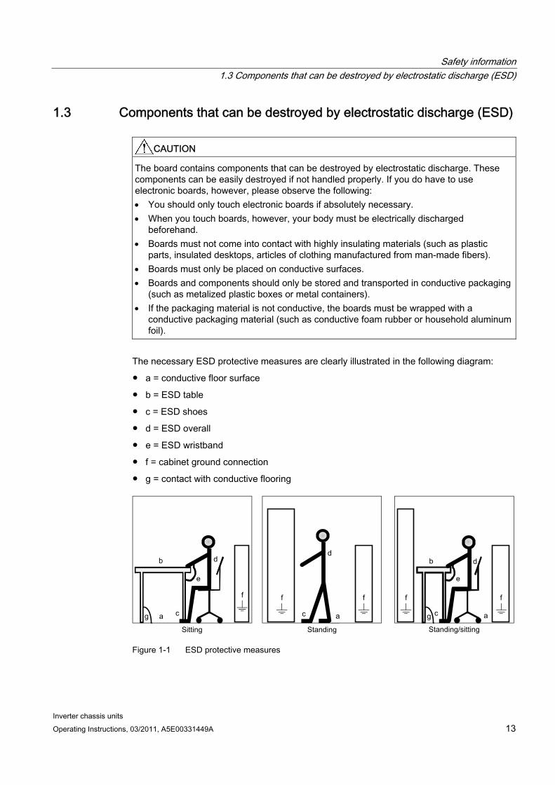
The necessary ESD protective measures are clearly illustrated in the following diagram:
a = conductive floor surface
b = ESD table
c = ESD shoes
d = ESD overall
e = ESD wristband
f = cabinet ground connection
g = contact with conductive flooring
g g a
b
e
d
c
d
a c
d b
c a
e
f f f f f
Figure 1-1 ESD protective measures
Safety information 1.3 Components that can be destroyed by electrostatic discharge (ESD)
Inverter chassis units 14 Operating Instructions, 03/2011, A5E00331449A
Residual risks of power drive systems When carrying out a risk assessment of the machine/plant in accordance with the EU Machinery Directive, the machine manufacturer/plant operator must consider the following residual risks associated with the control and drive components of a power drive system (PDS).
1. Unintentional movements of driven machine components during commissioning, operation, maintenance, and repairs caused by, for example:
– Hardware defects and/or software errors in the sensors, controllers, actuators, and connection technology
– Response times of the controller and drive
– Operating and/or ambient conditions not within the scope of the specification
– Parameterization, programming, cabling, and installation errors
– Use of radio devices / cellular phones in the immediate vicinity of the controller
– External influences / damage
2. Exceptional temperatures as well as emissions of light, noise, particles, or gas caused by, for example:
– Component malfunctions
– Software errors
– Operating and/or ambient conditions not within the scope of the specification
– External influences / damage
3. Hazardous shock voltages caused by, for example:
– Component malfunctions
– Influence of electrostatic charging
– Induction of voltages in moving motors
– Operating and/or ambient conditions not within the scope of the specification
– Condensation / conductive contamination
– External influences / damage
4. Electrical, magnetic and electromagnetic fields generated in operation that can pose a risk to people with a pacemaker, implants or metal replacement joints, etc. if they are too close.
5. Release of environmental pollutants or emissions as a result of improper operation of the system and/or failure to dispose of components safely and correctly.
For more information about residual risks of the Power Drive System components, see the relevant chapters in the technical user documentation.
Safety information 1.3 Components that can be destroyed by electrostatic discharge (ESD)
Inverter chassis units Operating Instructions, 03/2011, A5E00331449A 15
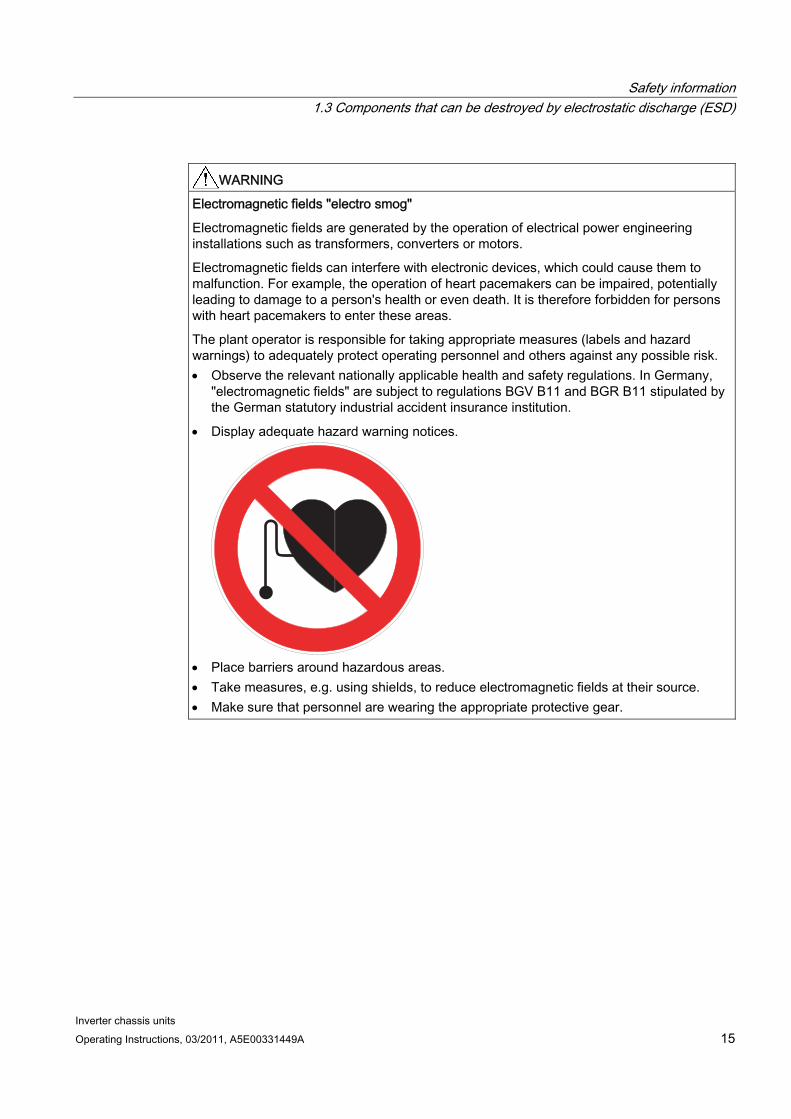
WARNING Electromagnetic fields "electro smog"
Electromagnetic fields are generated by the operation of electrical power engineering installations such as transformers, converters or motors.
Electromagnetic fields can interfere with electronic devices, which could cause them to malfunction. For example, the operation of heart pacemakers can be impaired, potentially leading to damage to a person's health or even death. It is therefore forbidden for persons with heart pacemakers to enter these areas.
The plant operator is responsible for taking appropriate measures (labels and hazard warnings) to adequately protect operating personnel and others against any possible risk. Observe the relevant nationally applicable health and safety regulations. In Germany,
"electromagnetic fields" are subject to regulations BGV B11 and BGR B11 stipulated by the German statutory industrial accident insurance institution.
Display adequate hazard warning notices.
Place barriers around hazardous areas. Take measures, e.g. using shields, to reduce electromagnetic fields at their source. Make sure that personnel are wearing the appropriate protective gear.

Safety information 1.3 Components that can be destroyed by electrostatic discharge (ESD)
Inverter chassis units 16 Operating Instructions, 03/2011, A5E00331449A

Inverter chassis units Operating Instructions, 03/2011, A5E00331449A 17
Device overview 22.1 Chapter content
This chapter provides information on the following:
Introduction to the chassis units
The main components and features of the chassis units
The chassis unit wiring
Explanation of the type plate
Device overview 2.2 Overview of the chassis units
Inverter chassis units 18 Operating Instructions, 03/2011, A5E00331449A
2.2 Overview of the chassis units
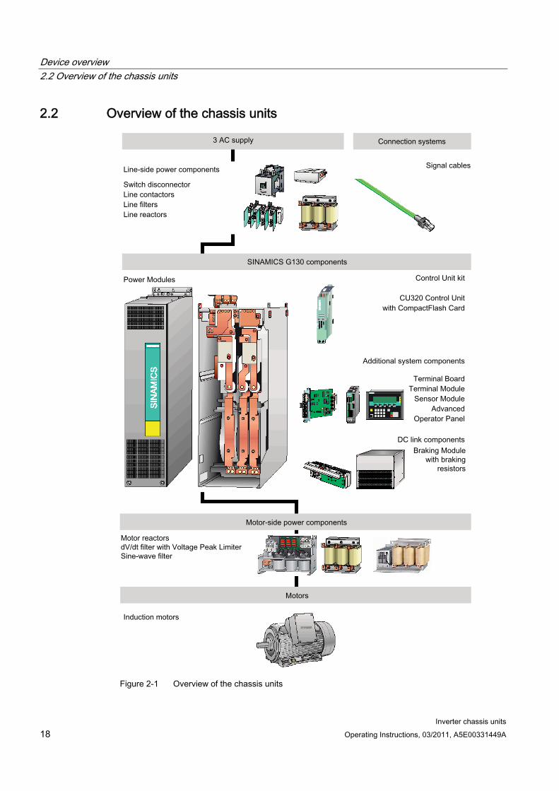
Figure 2-1 Overview of the chassis units
Device overview 2.3 Overview of the Power Modules
Inverter chassis units Operating Instructions, 03/2011, A5E00331449A 19
2.3 Overview of the Power Modules
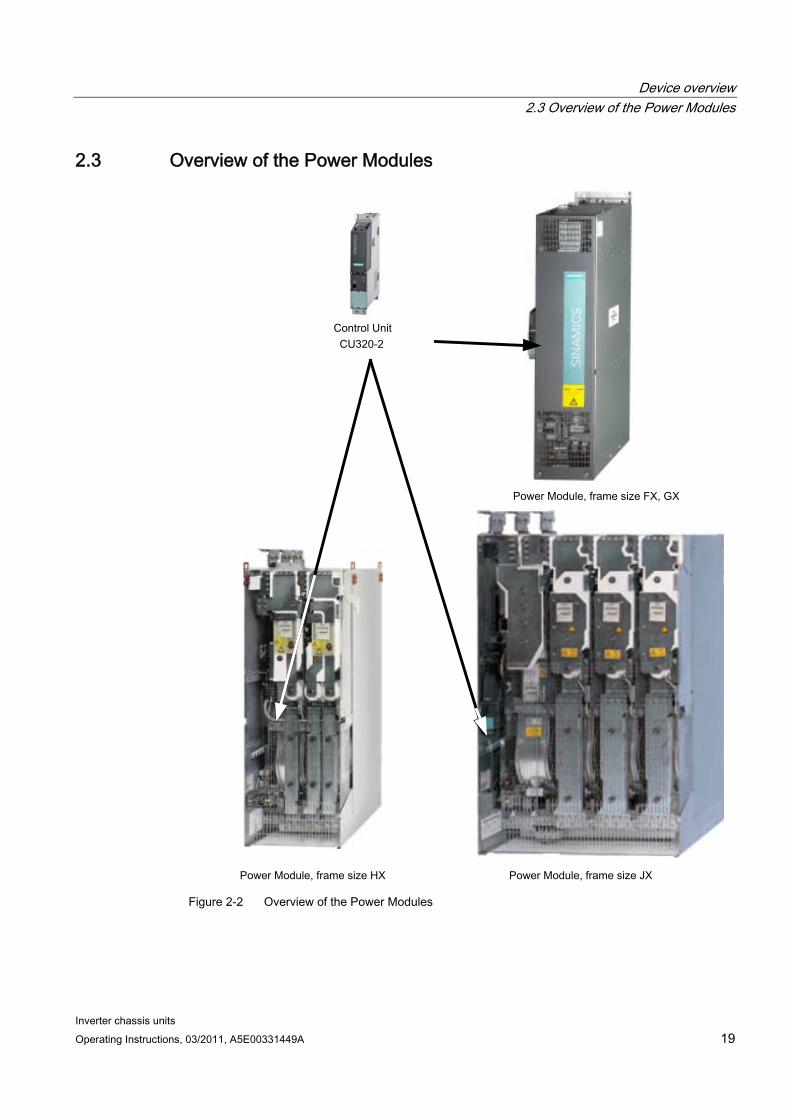
Figure 2-2 Overview of the Power Modules
Device overview 2.4 Applications, features
Inverter chassis units 20 Operating Instructions, 03/2011, A5E00331449A
2.4 Applications, features
2.4.1 Applications SINAMICS G130 chassis units are specially designed to meet the requirements of variable-speed drives with a quadratic and constant load characteristic, medium performance requirements, and no regenerative feedback.
As a result, SINAMICS G130 chassis units are a cost-effective drive solution for all types of industrial applications that involve moving, conveying, pumping, compressing, or extracting solids, liquids, or gases.
2.4.2 Features, quality, service
Features From configuration to operation, SINAMICS G130 built-in units are easy to use and offer the following benefits:
Compact, modular, service-friendly design.
Straightforward engineering and commissioning thanks to the support using SIZER and STARTER tools.
Ready to connect to facilitate the installation process.
Quick and easy commissioning thanks to practical menu guidance and integrated optimization routines.
Drive monitoring/diagnostics, commissioning and operation optionally realized using a user-friendly graphic operator panel with measured values displayed in plain text or in a quasi-analog bar display.
SINAMICS is an integral part of Totally Integrated Automation (TIA). The TIA concept offers an optimized range of products for automation and drive technology. This concept is characterized by planning / design, communication, and data management procedures that are consistent throughout the product range. SINAMICS is fully integrated in the TIA concept. Separate S7/PCS7 blocks and faceplates for WinCC are available.
Integration in SIMATIC H systems is possible via a Y link.
Drive Control Chart (DCC) Drive Control Chart (DCC) expands the facility for the simplest possible configuring of technological functions for the SINAMICS drive system. The block library encompasses a large selection of closed-loop, arithmetic and logic function blocks, as well as more comprehensive open-loop and closed-loop control functions. The user-friendly DCC editor enables easy graphical configuration and a clear representation of control loop structures as well as a high degree of reusability of existing diagrams. DCC is an add-on to the STARTER commissioning tool.

Device overview 2.4 Applications, features
Inverter chassis units Operating Instructions, 03/2011, A5E00331449A 21
Quality SINAMICS G130 built-in units are manufactured to meet high standards of quality and exacting demands.
This results in a high level of reliability, availability, and functionality for our products.
The development, design, and manufacturing processes, as well as order processing and the logistics supply center have been certified to DIN ISO 9001 by an independent authority.
Service Our worldwide sales and service network offers our customers consulting services tailored to their needs, provides support with planning and design, and offers a range of training courses.
For detailed contact information and the current link to our Internet pages, refer to chapter "Diagnosis / faults and alarms", section "Service and Support".
Device overview 2.5 Wiring principle
Inverter chassis units 22 Operating Instructions, 03/2011, A5E00331449A
2.5 Wiring principle
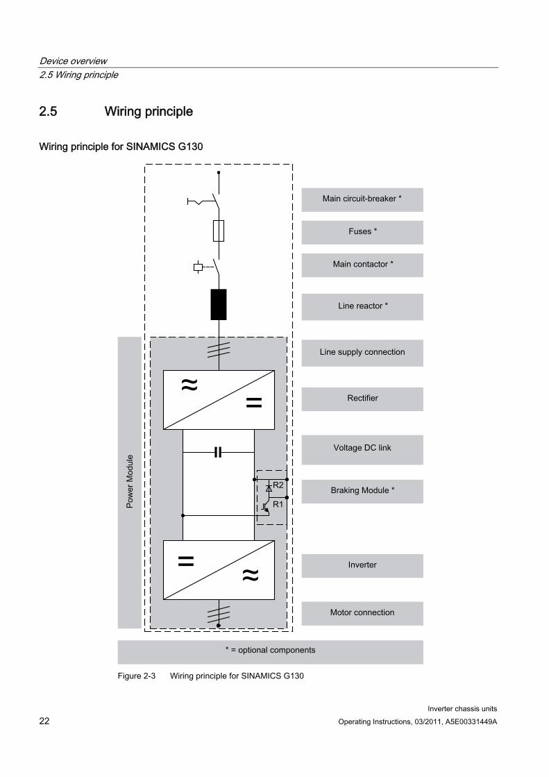
Wiring principle for SINAMICS G130
Figure 2-3 Wiring principle for SINAMICS G130
Device overview 2.6 Type plate
Inverter chassis units Operating Instructions, 03/2011, A5E00331449A 23
2.6 Type plate
Specifications on the type plate
s
SINAMICS G130
Input:Eingang:
Output:Ausgang:
S T -A92249742010001
Duty class:Bel – Klasse:
Temperature range :Temperaturbereich :
Degree of protection : Schutzart :
Order number:Bestellnummer :
Cooling method:Kühlart:
Serial number :Fabrik – Nummer:
Weight:Gewicht:
Version :Version :
-
V
380 480 AV 775
I
-
+ 0 + 40
4800 A
AF
kg
Made in EU (Germany)
745
294
°C
1P 6SL3310-1GE37-5AA3-Z
2PE D
IP00
-
3AC
3AC
FREQUENZUMRICHTER / AC DRIVE
Figure 2-4 Type plate of built-in unit
Device overview 2.6 Type plate
Inverter chassis units 24 Operating Instructions, 03/2011, A5E00331449A
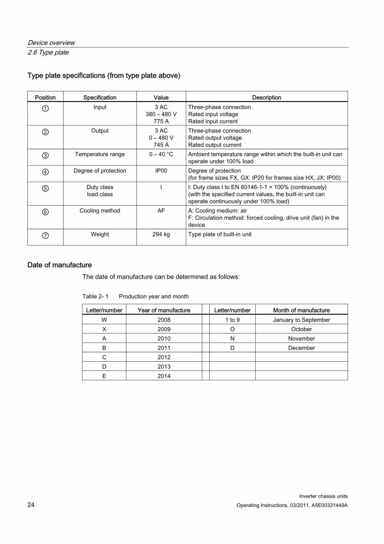
Type plate specifications (from type plate above)
Position Specification Value Description
① Input
3 AC 380 – 480 V
775 A
Three-phase connection Rated input voltage Rated input current
② Output
3 AC 0 – 480 V
745 A
Three-phase connection Rated output voltage Rated output current
③ Temperature range
0 – 40 °C Ambient temperature range within which the built-in unit can operate under 100% load
④ Degree of protection
IP00 Degree of protection (for frame sizes FX, GX: IP20 for frames size HX, JX: IP00)
⑤ Duty class load class
I I: Duty class I to EN 60146-1-1 = 100% (continuously) (with the specified current values, the built-in unit can operate continuously under 100% load)
⑥ Cooling method
AF A: Cooling medium: air F: Circulation method: forced cooling, drive unit (fan) in the device
⑦ Weight
294 kg Type plate of built-in unit
Date of manufacture The date of manufacture can be determined as follows:
Table 2- 1 Production year and month
Letter/number Year of manufacture Letter/number Month of manufacture W 2008 1 to 9 January to September X 2009 O October A 2010 N November B 2011 D December C 2012 D 2013 E 2014

Inverter chassis units Operating Instructions, 03/2011, A5E00331449A 25
Mechanical installation 33.1 Chapter content
This chapter provides information on the following:
The conditions for installing the chassis units and optional components.
The preparations for installing the chassis units and optional components.
Mechanical installation 3.2 Transportation and storage
Inverter chassis units 26 Operating Instructions, 03/2011, A5E00331449A
3.2 Transportation and storage
Transport
WARNING The following must be taken into account when the devices are transported: The devices are heavy and are usually top heavy. The center of gravity is marked on the
devices. Suitable hoisting gear operated by trained personnel is essential due to the weight of the
devices. The devices must only be transported in the upright position indicated. The devices
must not be transported upside down or horizontally. Serious injury or even death and substantial material damage can occur if the devices
are not lifted or transported properly.
Note Notes regarding transportation The devices are packaged by the manufacturer in accordance with the climatic conditions
and stress encountered during transit and in the recipient country. The notes on the packaging for transportation, storage, and proper handling must be
observed. For transportation using forklifts, the devices must be set down on a wooden pallet. When the devices are unpacked, they can be transported using the transport eyebolts
attached. The load must be distributed evenly. Chains attached to the transport eyebolts must only be loaded vertically from above. Heavy blows or impacts must be avoided during transit and when the devices are being set down, for example.
Permissible ambient temperatures: Ventilation: -25°C to +70°C, class 2K3 to IEC 60 721-3-2 Down to -40°C for max. 24 hours
Mechanical installation 3.2 Transportation and storage
Inverter chassis units Operating Instructions, 03/2011, A5E00331449A 27
Note Notes regarding damage in transit Carry out a thorough visual inspection of the device before accepting the delivery from
the transportation company. Ensure that you have received all the items specified on the delivery note. Notify the transportation company immediately of any missing components or damage. If you identify any hidden defects or damage, contact the transportation company
immediately and ask them to examine the device. If you fail to contact them immediately, you may lose your right to claim compensation for
the defects and damage. If necessary, you can request the support of your local Siemens office.
WARNING Damage in transit indicates that the device was subject to unreasonable stress. The electrical safety of the device can no longer be ensured.
Non-observance can result in death, severe personal injury or substantial property damage.
Storage The devices must be stored in clean, dry rooms. Temperatures between –25°C and +70°C are permissible. Temperature variations greater than 20 K per hour are not permitted.
If the device is stored for a prolonged period once unpacked, cover it or take other appropriate measures to ensure that it does not become dirty and that it is protected against environmental influences. If such measures are not taken, the warranty becomes invalid in the event of a claim for damages.
WARNING The device should not be stored for more than two years. If the device is stored for more than two years, the DC link capacitors of the devices must be reformed during commissioning.
The reforming procedure is described in "Maintenance and servicing”.
Mechanical installation 3.3 Assembly
Inverter chassis units 28 Operating Instructions, 03/2011, A5E00331449A
3.3 Assembly
WARNING To ensure that the devices operate safely and reliably, they must be properly installed and commissioned by qualified personnel, taking into account the warnings provided in these operating instructions.
In particular, the general and national installation and safety guidelines for high-voltage installations (e.g. VDE – the Union of German Technical Engineers) as well as the guidelines relating to the proper use of tools and personal protective equipment must be observed.
Death, serious injury, or substantial material damage can result if these factors are not taken into account.
3.3.1 Requirements on the installation location The built-in units are designed for installation in closed, electrical operating areas in compliance with EN 61800-5-1. A closed electrical operating area is a room or area containing electrical equipment that can be accessed by trained personnel only. Access is controlled by a door or other form of barrier that can be opened only by means of a key or other tool. The room or area is also clearly marked with appropriate warning notices.
The operating areas must be dry and free of dust. The air supplied must not contain any electrically conductive gas, vapors, or dust, which could impair operation. It may be necessary to filter the air supplied to the room where the equipment is installed.
The permissible values for climatic ambient conditions must be taken into account.
At temperatures > 40 °C (104 °F) and installation altitudes > 2000 m, the devices must be derated.
Built-in units with frame sizes FX and GX comply with degree of protection IP20; with frame sizes HX and JX, they comply with degree of protection IP00 to EN 60529.
Installation is realized in accordance with the dimension drawings supplied. The clearance between the top of the devices and the ceiling is also specified on the dimension drawings.
The cooling air for the power unit is drawn from the lower part of the device. The warmed air is expelled through the heat sink. When installing the device in cabinet units, you must ensure that suitable barriers are in place to ensure that the warmed air is not drawn back into the suction area of the heat sink.
According to EN 61800-3, the built-in unit is not suitable for use in low-voltage public networks that supply residential buildings. High-frequency interference may occur if it is used in this type of network. Through additional measures, for example the use of a line filter, the built-in unit can, however, also be used in the "First environment" in accordance with EN 61800-3 category C2.
Mechanical installation 3.4 Power Module
Inverter chassis units Operating Instructions, 03/2011, A5E00331449A 29
3.3.2 Unpacking Check the delivery against the delivery note to ensure that all the items have been delivered. Check that the devices are intact.
The packaging material must be disposed of in accordance with the applicable country-specific guidelines and rules.
3.3.3 Required tools To install the connections, you will require:
Spanner or socket spanner (w/f 10)
Spanner or socket spanner (w/f 13)
Spanner or socket spanner (w/f 16/17)
Spanner or socket spanner (w/f 18/19)
Hexagon-socket spanner (size 8)
Torque wrench from 5 Nm to 50 Nm
Screwdriver, size 2
Screwdriver Torx T20
Screwdriver Torx T30
A socket wrench kit with two long extensions is recommended.
3.4 Power Module
Description The Power Module is the power unit of an AC-AC converter. Line or motor-side components can be added to create a converter system. If required (e.g., for braking operation), a Braking Module can also be installed in the DC link of the converter. A slot is provided in the Power Module for this purpose.
The Power Module creates an output voltage with variable amplitude and frequency from a supply voltage with constant amplitude and frequency.
CAUTION The ventilation clearances above, below, and in front of the Power Module, which are specified in the dimension drawings, must be observed. If these clearances are not observed, this can result in a thermal overload of the Power Module.
Mechanical installation 3.4 Power Module
Inverter chassis units 30 Operating Instructions, 03/2011, A5E00331449A
3.4.1 Dimension drawings
Dimension drawing frame size FX
Table 3- 1 Dimension drawing frame size FX
Front view Side view
Mechanical installation 3.4 Power Module
Inverter chassis units Operating Instructions, 03/2011, A5E00331449A 31
Dimension drawing, frame size GX
Table 3- 2 Dimension drawing, frame size GX
Front view Side view
Mechanical installation 3.4 Power Module
Inverter chassis units 32 Operating Instructions, 03/2011, A5E00331449A
Dimension drawing (frame size HX)
Table 3- 3 Dimension drawing (frame size HX)
Side view Rear view
Mechanical installation 3.4 Power Module
Inverter chassis units Operating Instructions, 03/2011, A5E00331449A 33
Dimension drawing (frame size JX)
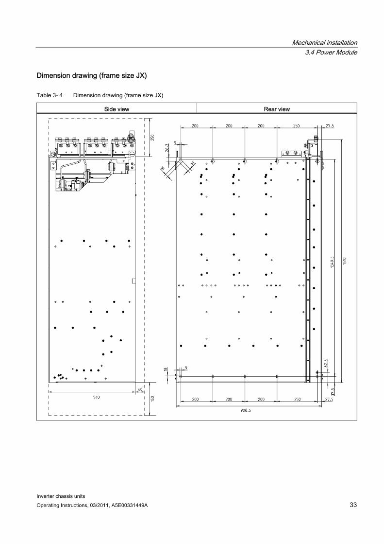
Table 3- 4 Dimension drawing (frame size JX)
Side view Rear view

Mechanical installation 3.4 Power Module
Inverter chassis units 34 Operating Instructions, 03/2011, A5E00331449A
WARNING The Power Modules can be lifted using the lifting eyebolts attached. A lifting harness with a vertical rope or chain must, however, be used. The device must not be lifted at an angle because this can damage the housing or connection busbars. Rope spreaders may have to be used.
WARNING For Power Modules of frame sizes HX and JX, the hoists must be removed once the devices have been installed.
Mechanical installation 3.5 Control Unit CU320-2
Inverter chassis units Operating Instructions, 03/2011, A5E00331449A 35
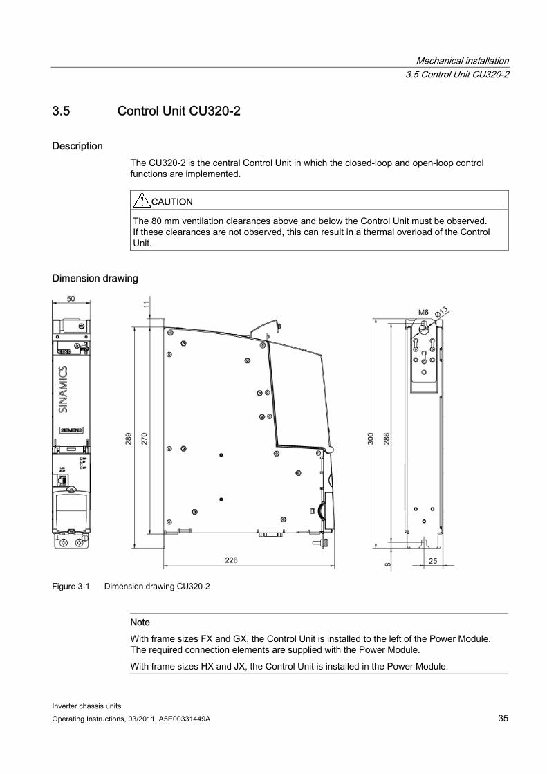
3.5 Control Unit CU320-2
Description The CU320-2 is the central Control Unit in which the closed-loop and open-loop control functions are implemented.
CAUTION The 80 mm ventilation clearances above and below the Control Unit must be observed. If these clearances are not observed, this can result in a thermal overload of the Control Unit.
Dimension drawing
Figure 3-1 Dimension drawing CU320-2
Note
With frame sizes FX and GX, the Control Unit is installed to the left of the Power Module. The required connection elements are supplied with the Power Module.
With frame sizes HX and JX, the Control Unit is installed in the Power Module.

Mechanical installation 3.5 Control Unit CU320-2
Inverter chassis units 36 Operating Instructions, 03/2011, A5E00331449A
Control Unit: CompactFlash card The CompactFlash card contains the control software and parameters.
Note
The CompactFlash card may only be inserted and removed when the Control Unit is disconnected from the power supply.
If it is inserted and removed when the power supply is connected, this can damage the CompactFlash card and/or result in data being lost.
Mechanical installation 3.6 TM31 Terminal Module
Inverter chassis units Operating Instructions, 03/2011, A5E00331449A 37
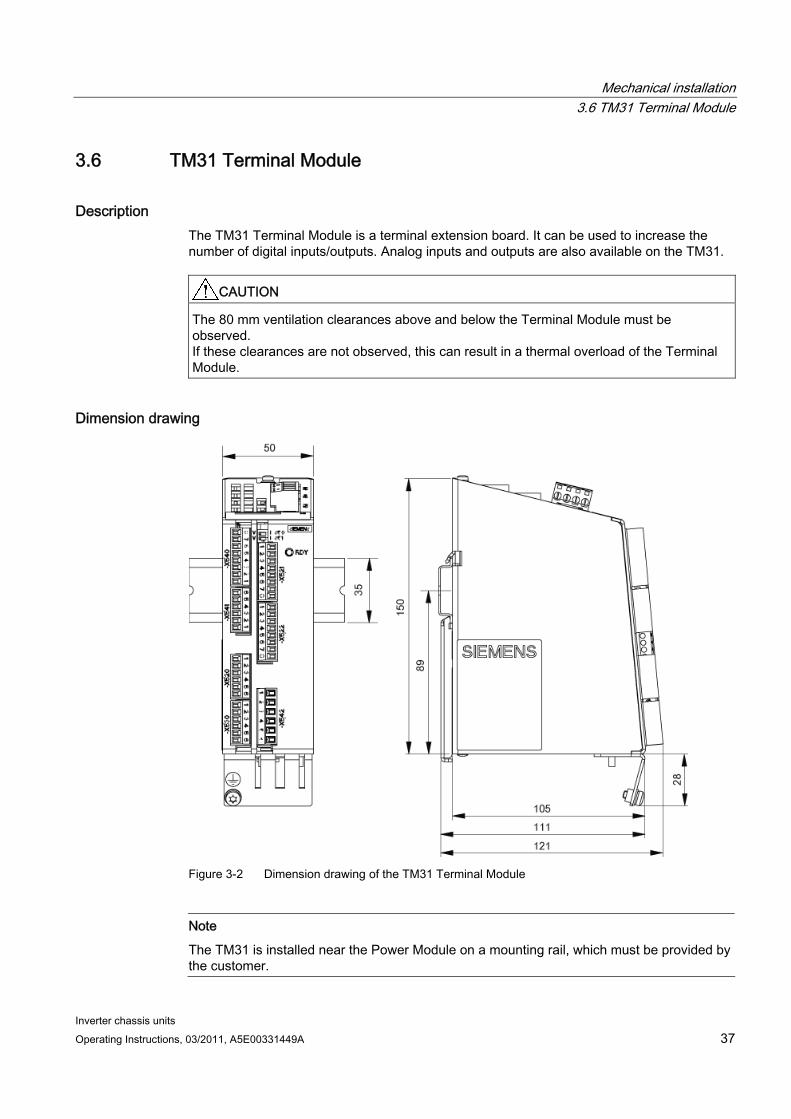
3.6 TM31 Terminal Module
Description The TM31 Terminal Module is a terminal extension board. It can be used to increase the number of digital inputs/outputs. Analog inputs and outputs are also available on the TM31.
CAUTION The 80 mm ventilation clearances above and below the Terminal Module must be observed. If these clearances are not observed, this can result in a thermal overload of the Terminal Module.
Dimension drawing
Figure 3-2 Dimension drawing of the TM31 Terminal Module
Note
The TM31 is installed near the Power Module on a mounting rail, which must be provided by the customer.
Mechanical installation 3.7 SMC30 Sensor Module
Inverter chassis units 38 Operating Instructions, 03/2011, A5E00331449A
3.7 SMC30 Sensor Module
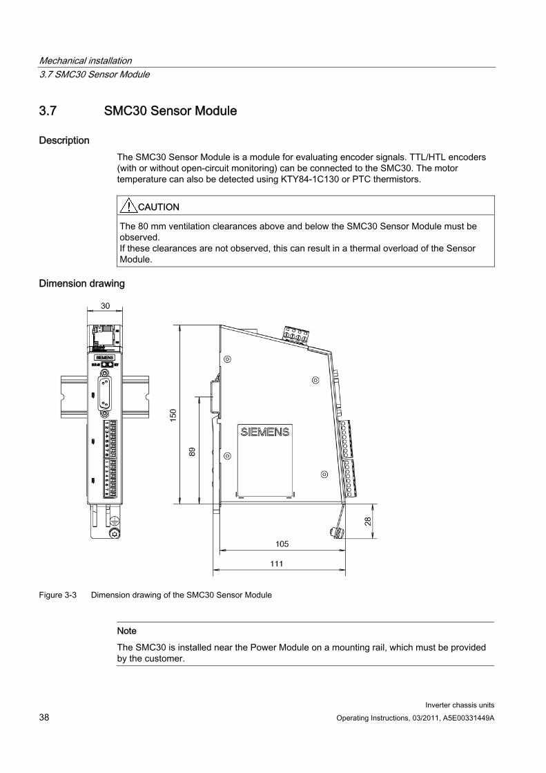
Description The SMC30 Sensor Module is a module for evaluating encoder signals. TTL/HTL encoders (with or without open-circuit monitoring) can be connected to the SMC30. The motor temperature can also be detected using KTY84-1C130 or PTC thermistors.
CAUTION The 80 mm ventilation clearances above and below the SMC30 Sensor Module must be observed. If these clearances are not observed, this can result in a thermal overload of the Sensor Module.
Dimension drawing
Figure 3-3 Dimension drawing of the SMC30 Sensor Module
Note
The SMC30 is installed near the Power Module on a mounting rail, which must be provided by the customer.
Inverter chassis units Operating Instructions, 03/2011, A5E00331449A 39
Electrical installation 44.1 Chapter content
This chapter provides information on the following:
Establishing the electrical connections for the Power Module, the CU320-2 Control Unit, and the optional TM31 Terminal Module and SMC30 Sensor Module.
Adjusting the fan voltage and the internal power supply in line with local conditions (supply voltage)
The interfaces for the CU320-2 Control Unit, TM31 Terminal Module, and SMC30 Sensor Module.
4.2 Preparation
Required tools To install the connections, you will require:
Spanner or socket spanner (w/f 10)
Spanner or socket spanner (w/f 13)
Spanner or socket spanner (w/f 16/17)
Spanner or socket spanner (w/f 18/19)
Hexagon-socket spanner (size 8)
Torque wrench up to 50 Nm
Screwdriver, size 2
Screwdriver Torx T20
Screwdriver Torx T30
Electrical installation 4.3 Important safety precautions
Inverter chassis units 40 Operating Instructions, 03/2011, A5E00331449A
4.3 Important safety precautions
WARNING
The built-in units are operated with high voltages. All connection procedures must be carried out when the cabinet is de-energized. All work on the device must be carried out by trained personnel only. Non-observance of these warning notices can result in death, severe personal injury or substantial property damage.
Work on an open device must be carried out with extreme caution because external supply voltages may be present. The power and control terminals may be live even when the motor is not running. Dangerously high voltage levels are still present in the device up to five minutes after it has been disconnected due to the DC link capacitors. For this reason, the unit should not be opened until a reasonable period of time has elapsed.
Reforming the DC link capacitors: The storage period should not exceed two years. If the device is stored for more than two years, the DC link capacitors of the devices must be reformed during commissioning. The reforming procedure is described in "Maintenance and Servicing”.
The operator is responsible for ensuring that the Power Module and other components are installed and connected in accordance with the recognized technical rules in the country of installation and applicable regional guidelines. Special attention should be paid to cable dimensioning, fuses, grounding, shutdown, disconnection, and overcurrent protection.
If an item of protective gear trips in a branch circuit, a fault current may have been disconnected. To reduce the risk of fire or an electric shock, the current-conducting parts and other components in the cabinet unit should be inspected and damaged parts replaced. When an item of protective gear trips, the cause of the trip must be identified and rectified.
Note
On systems with a grounded phase conductor and a line voltage >600 V AC, line-side components should be installed to limit overvoltages to overvoltage category II in accordance with IEC 61800-5--1.
CAUTION To ensure that the entire system functions properly, you are advised to use the original Siemens accessories.
Only original DRIVE-CLiQ cables may be used for wiring the DRIVE-CLiQ nodes.

Electrical installation 4.4 Introduction to EMC
Inverter chassis units Operating Instructions, 03/2011, A5E00331449A 41
4.4 Introduction to EMC
What is meant by EMC? Electromagnetic compatibility (EMC) describes the capability of an electrical device to function satisfactorily in an electromagnetic environment without itself causing interference unacceptable for other devices in the environment.
EMC therefore represents a quality feature for the
Internal noise immunity: Resistance to internal electrical disturbances
External noise immunity: resistance against external electromagnetic disturbances
Noise emission level: environmental effects caused by electromagnetic emissions
To ensure that the cabinet unit functions satisfactorily in the system, the environment subject to interference must not be neglected. For this reason, special requirements exist regarding the structure and the EMC of the system.
Operational reliability and noise immunity In order to achieve the greatest possible operational reliability and immunity to noise of a complete system (converter, automation, drive machines etc.), measures must be taken by the converter manufacturer and the user. Only when all these measures are fulfilled can the faultless functioning of the converter be guaranteed and the specified legal requirements (2004/108/EC) be met.
Electrical installation 4.4 Introduction to EMC
Inverter chassis units 42 Operating Instructions, 03/2011, A5E00331449A
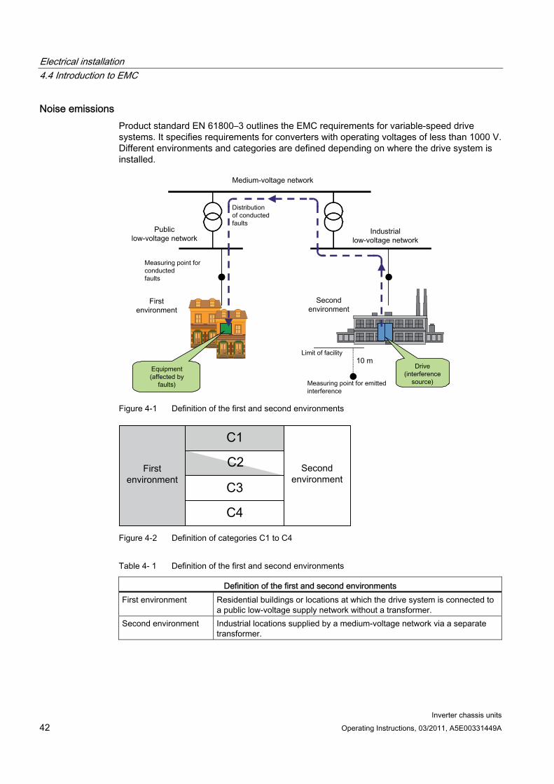
Noise emissions Product standard EN 61800–3 outlines the EMC requirements for variable-speed drive systems. It specifies requirements for converters with operating voltages of less than 1000 V. Different environments and categories are defined depending on where the drive system is installed.
Figure 4-1 Definition of the first and second environments
Figure 4-2 Definition of categories C1 to C4
Table 4- 1 Definition of the first and second environments
Definition of the first and second environments First environment Residential buildings or locations at which the drive system is connected to
a public low-voltage supply network without a transformer. Second environment Industrial locations supplied by a medium-voltage network via a separate
transformer.
Electrical installation 4.5 EMC-compliant design
Inverter chassis units Operating Instructions, 03/2011, A5E00331449A 43
Table 4- 2 Definition of categories C1 to C4
Definition of categories C1 to C4 Category C1 Rated voltage <1000 V; unrestricted use in the first environment. Category C2 Rated voltage for stationary drive systems <1000 V; for use in the second
environment. For use in the first environment only when sold and installed by skilled personnel.
Category C3 Rated voltage <1000 V; use in the second environment only. Category C4 Rated voltage ≥1000 V or for rated currents ≥ 400 A in complex systems in
the second environment.
4.5 EMC-compliant design The following section provides some basic information and guidelines that will help you comply with the EMC and CE guidelines.
cabinet assembly Connect painted or anodized metal components using toothed self-locking screws or
remove the insulating layer.
Use unpainted, de-oiled mounting plates.
Establish a central connection between ground and the protective conductor system (ground).
Shield gaps Bridge shield gaps (at terminals, circuit-breakers, contactors, and so on) with minimum
impedance and the greatest possible surface area.
Using large cross-sections Use underground and grounding cables with large cross-sections or, better still, with litz
wires or flexible cables.
Laying the motor supply cable separately The distance between the motor cable and signal cable should be > 20 cm. Do not lay
signal cables and motor cables in parallel to each other.
Laying the equipotential bonding cable It is recommended to lay the equipotential bonding cable parallel to the control lines with
a minimum cross-section of 16 mm2.
Electrical installation 4.5 EMC-compliant design
Inverter chassis units 44 Operating Instructions, 03/2011, A5E00331449A
Use anti-interference elements If relays, contactors, and inductive or capacitive loads are connected, the switching relays
or contactors must be provided with anti-interference elements.
Cable installation Cables that are subject to or sensitive to interference should be laid as far apart from
each other as possible.
All cables are to be laid as close as possible to grounded enclosure parts such as mounting plates or cabinet frames. This reduces both noise radiation and interference injection.
Reserve cores of signal and data cables must be grounded at both ends to achieve an additional shielding effect.
Long cables should be shortened or laid in noise resistant areas to avoid additional connecting points.
If it is impossible to avoid crossing cables, conductors or cables that carry signals of different classes must cross at right angles, especially if they carry sensitive signals that are subject to interference.
– Class 1: unshielded cables for ≤ 60 V DC unshielded cables for ≤ 25 V AC shielded analog signal cables shielded bus and data cables operator panel interfaces, incremental/absolute encoder lines
– Class 2: unshielded cables for > 60 V DC and ≤ 230 V DC unshielded cables for > 25 V AC and ≤ 230 V AC
– Class 3: unshielded cables for > 230 V AC/DC and ≤ 1000 V AC/DC
Shield connection Shields must not be used to conduct electricity. In other words, they must not
simultaneously act as neutral or PE conductors.
Apply the shield so that it covers the greatest possible surface area. You can use ground clamps, ground terminals, or ground screw connections.
Avoid extending the shield to the grounding point using a wire (pigtail) because this will reduce the effectiveness of the shield by up to 90%.
Attach the shield to a shield bar directly after the line inlet into the cabinet. Insulate the entire shielded cable and route the shield up to the device connection, but do not connect it again.
Electrical installation 4.5 EMC-compliant design
Inverter chassis units Operating Instructions, 03/2011, A5E00331449A 45
I/O interfacing Create a low-impedance ground connection for additional cabinets, system components,
and distributed devices with the largest possible cross-section (at least 16 mm²).
Ground unused lines at one end in the cabinet.
Choose the greatest possible clearance between the power and signal cables (at least 20 cm). The greater the distance over which the cables are routed in parallel, the greater the clearance must be. If a sufficient clearance cannot be maintained, you must install additional shields.
Avoid unnecessarily long cable loops.
Filtering cables Line supply cables and power supply cables for devices and modules may have to be
filtered in the cabinet to reduce incoming or outgoing disturbances.
To reduce emissions, the device is equipped with a radio interference suppression filter as standard (in accordance with the limit values defined in category C3). Optional filters can be fitted for use in the first environment (category C2).
Protective ground conductors According to EN 61800-5-1, Section. 6.3.6.7, the minimum cross-section of the protective
ground conductor must conform to the local safety regulations for protective ground conductors for equipment with a high leakage current.
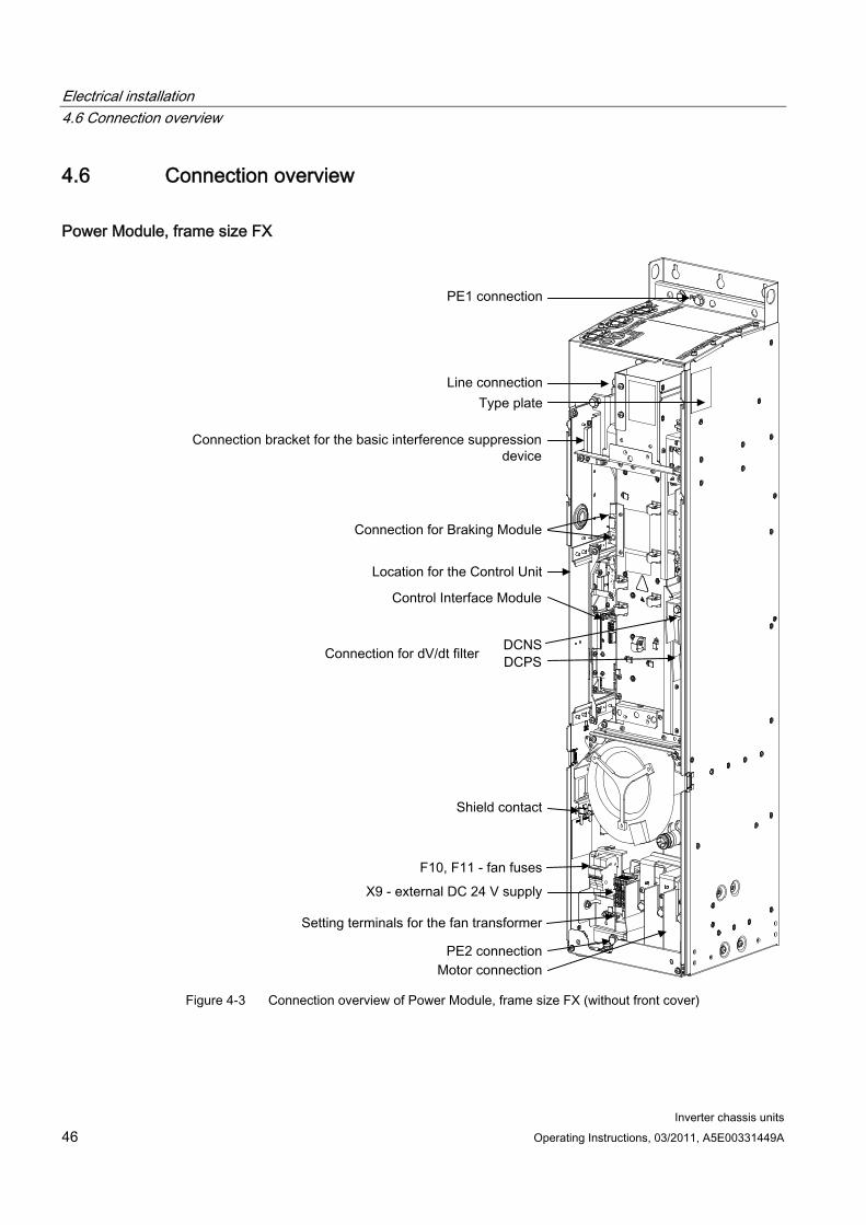
Electrical installation 4.6 Connection overview
Inverter chassis units 46 Operating Instructions, 03/2011, A5E00331449A
4.6 Connection overview
Power Module, frame size FX
Figure 4-3 Connection overview of Power Module, frame size FX (without front cover)
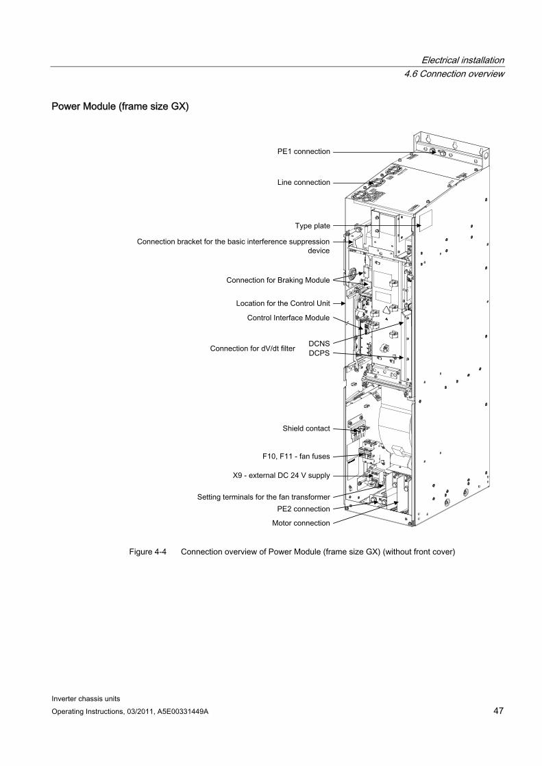
Electrical installation 4.6 Connection overview
Inverter chassis units Operating Instructions, 03/2011, A5E00331449A 47
Power Module (frame size GX)
Figure 4-4 Connection overview of Power Module (frame size GX) (without front cover)
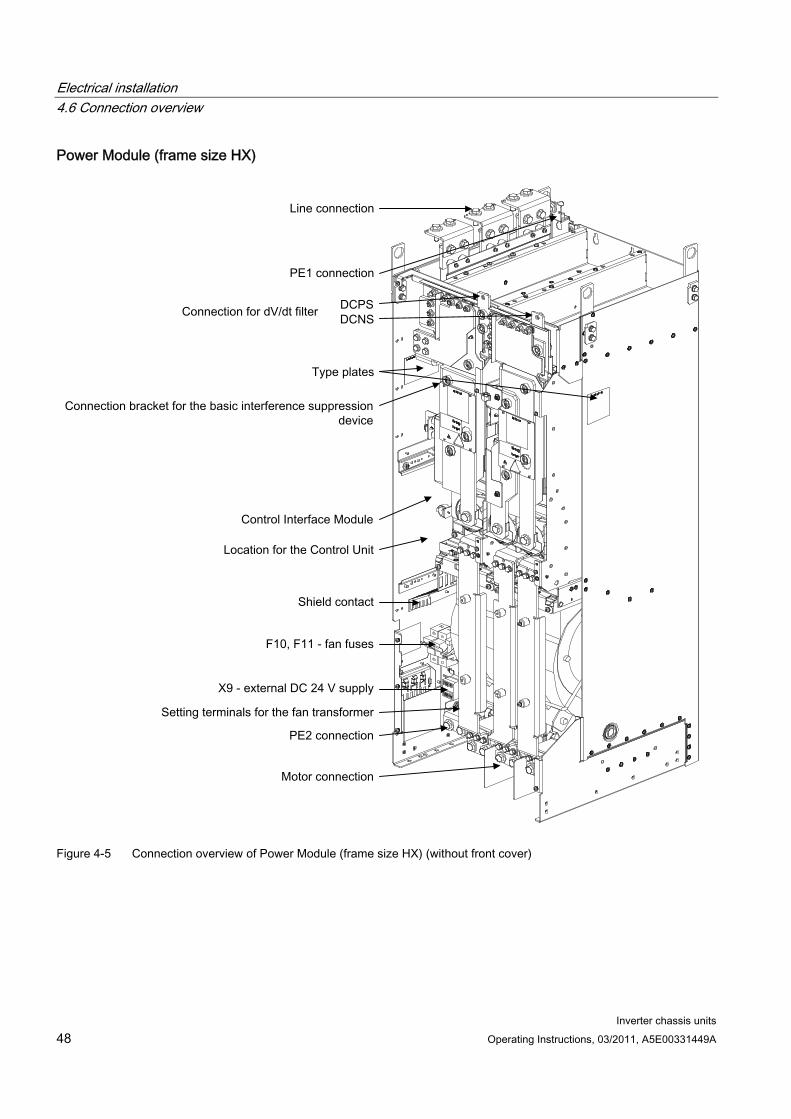
Electrical installation 4.6 Connection overview
Inverter chassis units 48 Operating Instructions, 03/2011, A5E00331449A
Power Module (frame size HX)
Figure 4-5 Connection overview of Power Module (frame size HX) (without front cover)
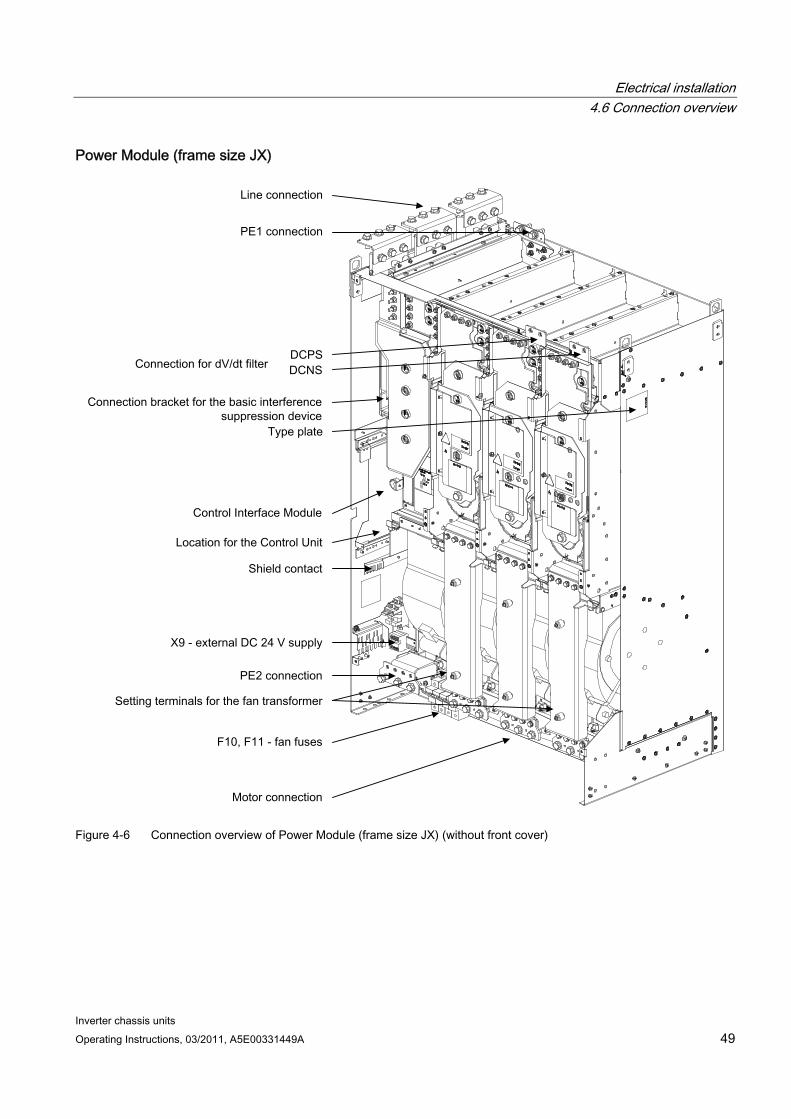
Electrical installation 4.6 Connection overview
Inverter chassis units Operating Instructions, 03/2011, A5E00331449A 49
Power Module (frame size JX)
Figure 4-6 Connection overview of Power Module (frame size JX) (without front cover)
Electrical installation 4.7 Power connections
Inverter chassis units 50 Operating Instructions, 03/2011, A5E00331449A
4.7 Power connections
WARNING Swapping the input and output terminals can destroy the device!
Swapping or short-circuiting the DC link terminals can destroy the device!
The contactor and relay operating coils that are connected to the same supply network as the device or are located near the device must be connected to overvoltage limiters (e.g. RC elements).
The device must not be operated via a ground-fault circuit interrupter (EN 61800-5-1).
4.7.1 Connection cross-sections, cable lengths
Connection cross-sections The connection cross-sections for the line connection, motor connection, and ground connection for your device are specified in the tables provided in the "Technical specifications" section.
Cable lengths The maximum permissible cable lengths are specified for standard cable types or cable types recommended by SIEMENS. Longer cables can only be used after consultation.
The listed cable length represents the actual distance between the converter and the motor, taking account factors such as parallel laying, current-carrying capacity, and the laying factor.
Unshielded cable (e.g. Protodur NYY): max. 450 m
Shielded cable (e.g., Protodur NYCWY, Protoflex EMV 3 Plus): max. 300 m.
Note
The cable lengths specified are also valid if a motor reactor is in use.
Note
The PROTOFLEX-EMV-3 PLUS shielded cable recommended by Siemens is the protective conductor and comprises three symmetrically-arranged protective conductors. The individual protective conductors must each be provided with cable eyes and be connected to ground. The cable also has a concentric flexible braided copper shield. To comply with EN 61800-3 regarding radio interference suppression, the shield must be grounded at both ends with the greatest possible surface area.
On the motor side, cable glands that contact the shield with the greatest possible surface area are recommended for the terminal boxes.
Electrical installation 4.7 Power connections
Inverter chassis units Operating Instructions, 03/2011, A5E00331449A 51
4.7.2 Connecting the motor and power cables
Connecting the motor and power cables on the Power Module 1. If necessary, remove the covers or front covers in front of the connection panel for motor
cables (terminals U2/T1, V2/T2, W2/T3; X2) and power cables (terminals U1/L1, V1/L2, W1/L3; X1).
2. Screw the protective earth (PE) into the appropriate terminal (with earth symbol) (50 Nm for M12) at the points provided in the cabinet.
3. Connect the line and motor cables to the terminals. Make sure that you connect the conductors in the correct sequence: U2/T1, V2/T2, W2/T3 and U1/L1, V1/L2, W1/L3!
CAUTION Tighten the screws with the appropriate torque (50 Nm for M12), otherwise the terminal contacts could catch fire during operation.
Note
The PE connection on the motor must be guided back directly to the Power Module and connected there.
Direction of motor rotation EN 60034-7 defines the two ends of an electric motor as follows:
D (Drive End): usually the drive end of the motor
N (Non-Drive End): usually the non-drive end of the motor
An electric motor rotates clockwise if the shaft rotates in the clockwise direction when viewing the D-end.
For electric motors with 2 shaft ends, the direction of rotation must be determined based on the shaft end specified as the drive end.
For clockwise rotation, the electric motor must be connected according to the following table.
Table 4- 3 Power Module and motor connection terminals
Power Module (connection terminals) Motor (connection terminals) U2/T1 U V2/T2 V W2/T3 W
In contrast to the connection for the clockwise phase sequence, two phases have to be reversed with a counter-clockwise phase sequence (looking at the drive shaft).
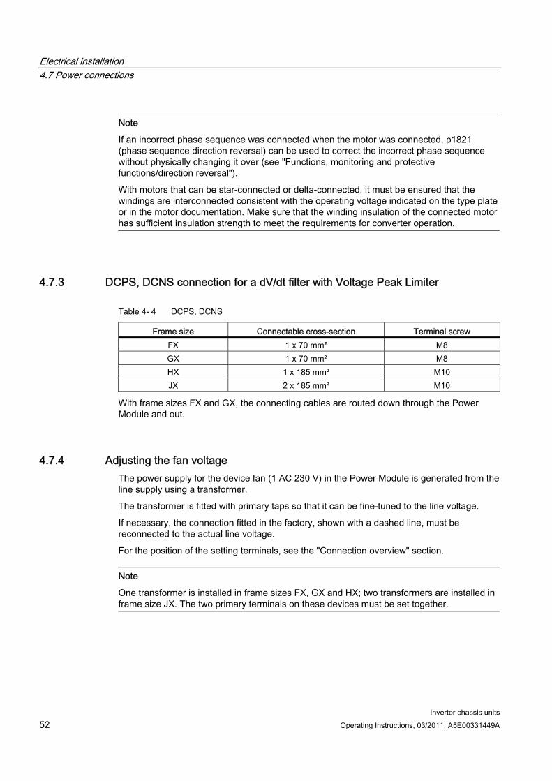
Electrical installation 4.7 Power connections
Inverter chassis units 52 Operating Instructions, 03/2011, A5E00331449A
Note
If an incorrect phase sequence was connected when the motor was connected, p1821 (phase sequence direction reversal) can be used to correct the incorrect phase sequence without physically changing it over (see "Functions, monitoring and protective functions/direction reversal").
With motors that can be star-connected or delta-connected, it must be ensured that the windings are interconnected consistent with the operating voltage indicated on the type plate or in the motor documentation. Make sure that the winding insulation of the connected motor has sufficient insulation strength to meet the requirements for converter operation.
4.7.3 DCPS, DCNS connection for a dV/dt filter with Voltage Peak Limiter
Table 4- 4 DCPS, DCNS
Frame size Connectable cross-section Terminal screw FX 1 x 70 mm² M8 GX 1 x 70 mm² M8 HX 1 x 185 mm² M10 JX 2 x 185 mm² M10
With frame sizes FX and GX, the connecting cables are routed down through the Power Module and out.
4.7.4 Adjusting the fan voltage The power supply for the device fan (1 AC 230 V) in the Power Module is generated from the line supply using a transformer.
The transformer is fitted with primary taps so that it can be fine-tuned to the line voltage.
If necessary, the connection fitted in the factory, shown with a dashed line, must be reconnected to the actual line voltage.
For the position of the setting terminals, see the "Connection overview" section.
Note
One transformer is installed in frame sizes FX, GX and HX; two transformers are installed in frame size JX. The two primary terminals on these devices must be set together.
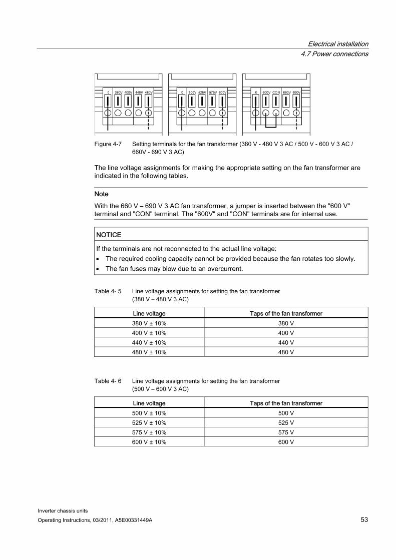
Electrical installation 4.7 Power connections
Inverter chassis units Operating Instructions, 03/2011, A5E00331449A 53
Figure 4-7 Setting terminals for the fan transformer (380 V - 480 V 3 AC / 500 V - 600 V 3 AC /
660V - 690 V 3 AC)
The line voltage assignments for making the appropriate setting on the fan transformer are indicated in the following tables.
Note
With the 660 V – 690 V 3 AC fan transformer, a jumper is inserted between the "600 V" terminal and "CON" terminal. The "600V" and "CON" terminals are for internal use.
NOTICE If the terminals are not reconnected to the actual line voltage: The required cooling capacity cannot be provided because the fan rotates too slowly. The fan fuses may blow due to an overcurrent.
Table 4- 5 Line voltage assignments for setting the fan transformer (380 V – 480 V 3 AC)
Line voltage Taps of the fan transformer 380 V ± 10% 380 V 400 V ± 10% 400 V 440 V ± 10% 440 V 480 V ± 10% 480 V
Table 4- 6 Line voltage assignments for setting the fan transformer (500 V – 600 V 3 AC)
Line voltage Taps of the fan transformer 500 V ± 10% 500 V 525 V ± 10% 525 V 575 V ± 10% 575 V 600 V ± 10% 600 V
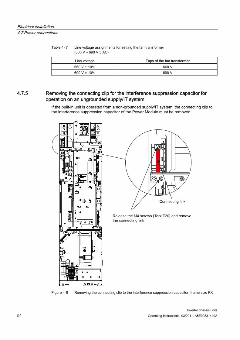
Electrical installation 4.7 Power connections
Inverter chassis units 54 Operating Instructions, 03/2011, A5E00331449A
Table 4- 7 Line voltage assignments for setting the fan transformer (660 V – 690 V 3 AC)
Line voltage Taps of the fan transformer 660 V ± 10% 660 V 690 V ± 10% 690 V
4.7.5 Removing the connecting clip for the interference suppression capacitor for operation on an ungrounded supply/IT system
If the built-in unit is operated from a non-grounded supply/IT system, the connecting clip to the interference suppression capacitor of the Power Module must be removed.
Figure 4-8 Removing the connecting clip to the interference suppression capacitor, frame size FX
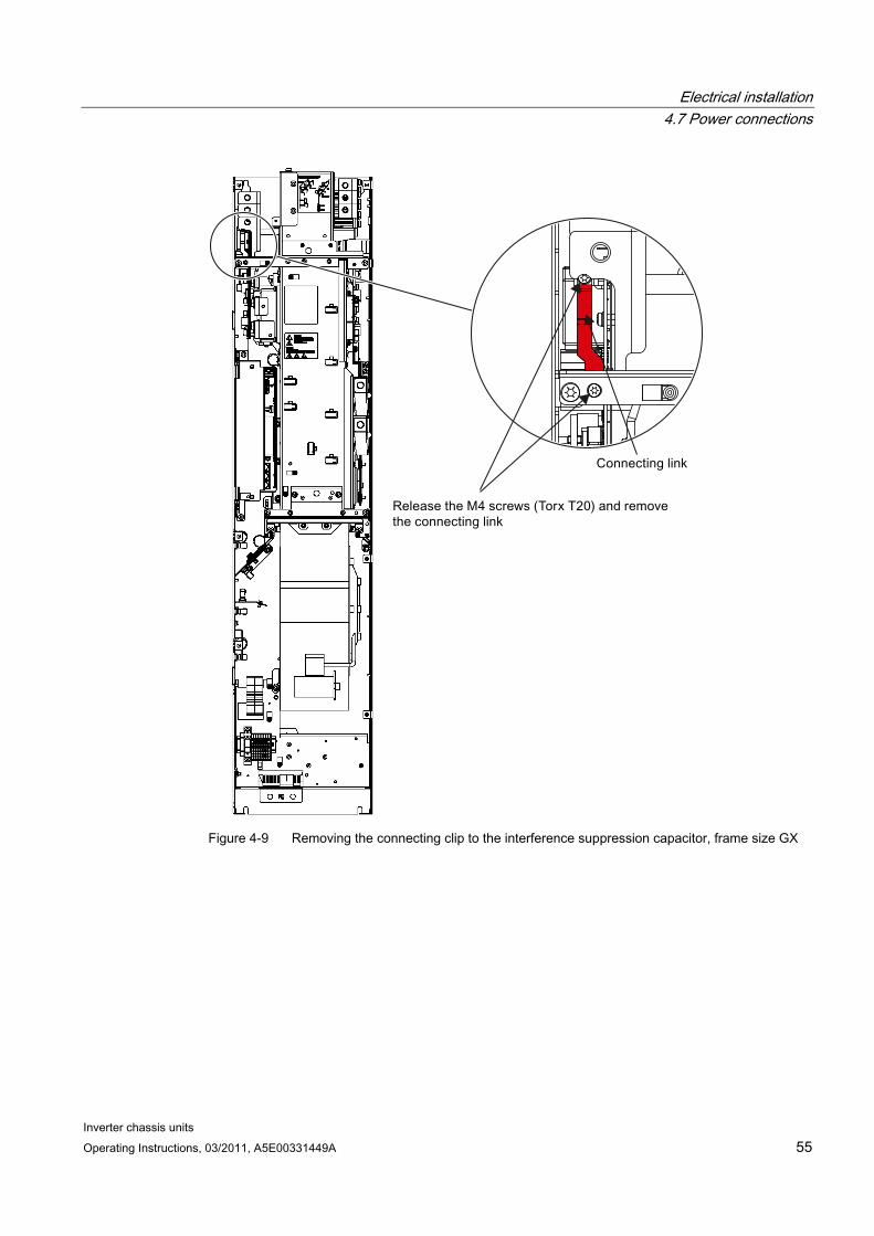
Electrical installation 4.7 Power connections
Inverter chassis units Operating Instructions, 03/2011, A5E00331449A 55
Figure 4-9 Removing the connecting clip to the interference suppression capacitor, frame size GX
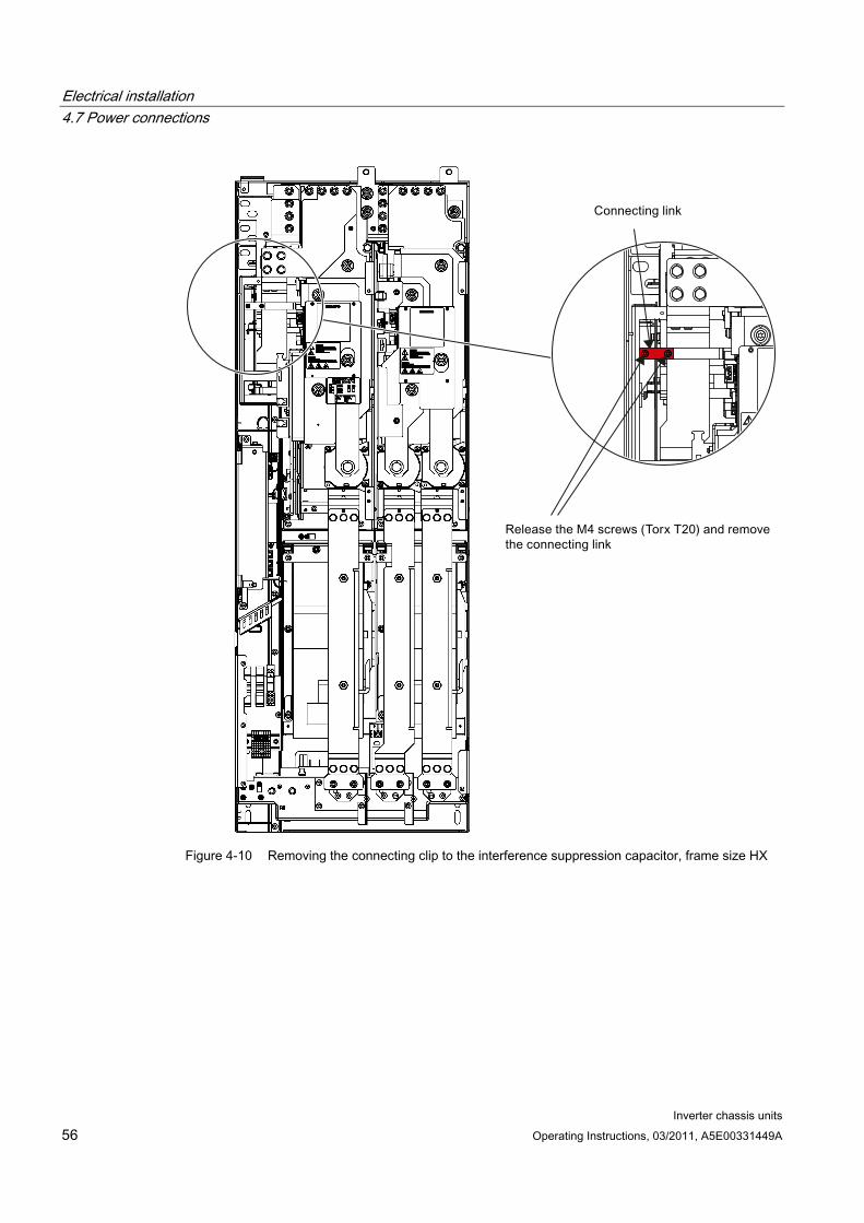
Electrical installation 4.7 Power connections
Inverter chassis units 56 Operating Instructions, 03/2011, A5E00331449A
Figure 4-10 Removing the connecting clip to the interference suppression capacitor, frame size HX
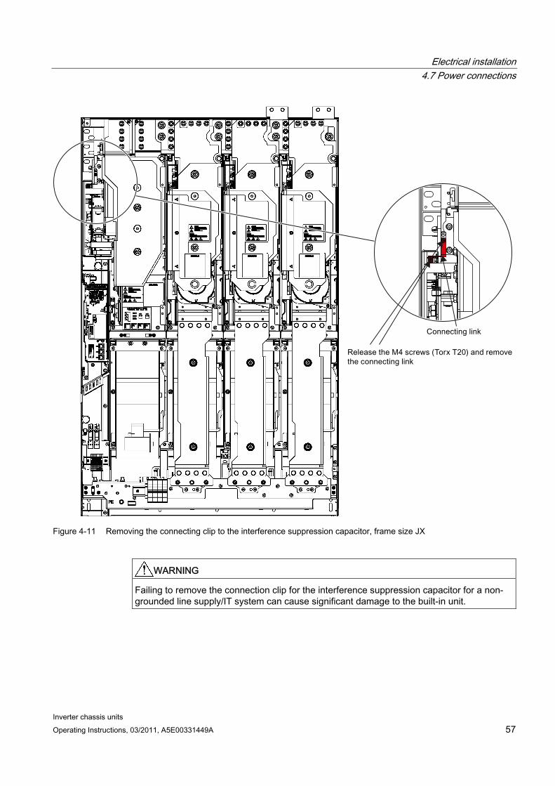
Electrical installation 4.7 Power connections
Inverter chassis units Operating Instructions, 03/2011, A5E00331449A 57
Figure 4-11 Removing the connecting clip to the interference suppression capacitor, frame size JX
WARNING Failing to remove the connection clip for the interference suppression capacitor for a non-grounded line supply/IT system can cause significant damage to the built-in unit.
Electrical installation 4.8 External 24 V DC supply
Inverter chassis units 58 Operating Instructions, 03/2011, A5E00331449A
4.8 External 24 V DC supply
Description An external 24 V DC supply is always recommended if communication and closed-loop control are to be independent of the supply system. An external auxiliary supply is particularly recommended for low-power lines susceptible to short-time voltage dips or power failures.
With an external supply independent of the main supply, warnings and fault messages may still be displayed on the operator panel and internal protection and monitoring devices if the main supply fails.
The power requirement is 4 A.
Connection Connect the external 24 V DC supply to terminals 1 (P 24 V) and 2 (Mext) of terminal block –X9 on the Power Module.
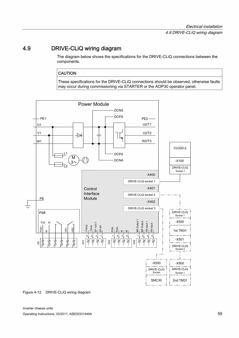
Electrical installation 4.9 DRIVE-CLiQ wiring diagram
Inverter chassis units Operating Instructions, 03/2011, A5E00331449A 59
4.9 DRIVE-CLiQ wiring diagram The diagram below shows the specifications for the DRIVE-CLiQ connections between the components.
CAUTION These specifications for the DRIVE-CLiQ connections should be observed, otherwise faults may occur during commissioning via STARTER or the AOP30 operator panel.
Figure 4-12 DRIVE-CLiQ wiring diagram
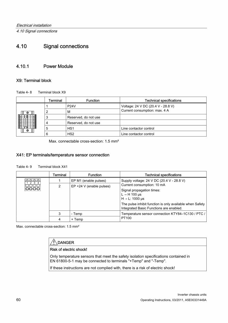
Electrical installation 4.10 Signal connections
Inverter chassis units 60 Operating Instructions, 03/2011, A5E00331449A
4.10 Signal connections
4.10.1 Power Module
X9: Terminal block
Table 4- 8 Terminal block X9
Terminal Function Technical specifications 1 P24V 2 M
Voltage: 24 V DC (20.4 V - 28.8 V) Current consumption: max. 4 A
3 Reserved, do not use 4 Reserved, do not use 5 HS1 Line contactor control
6 HS2 Line contactor control
Max. connectable cross-section: 1.5 mm²
X41: EP terminals/temperature sensor connection
Table 4- 9 Terminal block X41
Terminal Function Technical specifications 1 EP M1 (enable pulses) 2 EP +24 V (enable pulses)
Supply voltage: 24 V DC (20.4 V - 28.8 V) Current consumption: 10 mA Signal propagation times: L → H 100 μs H → L: 1000 μs The pulse inhibit function is only available when Safety Integrated Basic Functions are enabled.
3 - Temp
4 + Temp Temperature sensor connection KTY84–1C130 / PTC / PT100
Max. connectable cross-section: 1.5 mm²
DANGER Risk of electric shock!
Only temperature sensors that meet the safety isolation specifications contained in EN 61800-5-1 may be connected to terminals "+Temp" and "-Temp".
If these instructions are not complied with, there is a risk of electric shock!
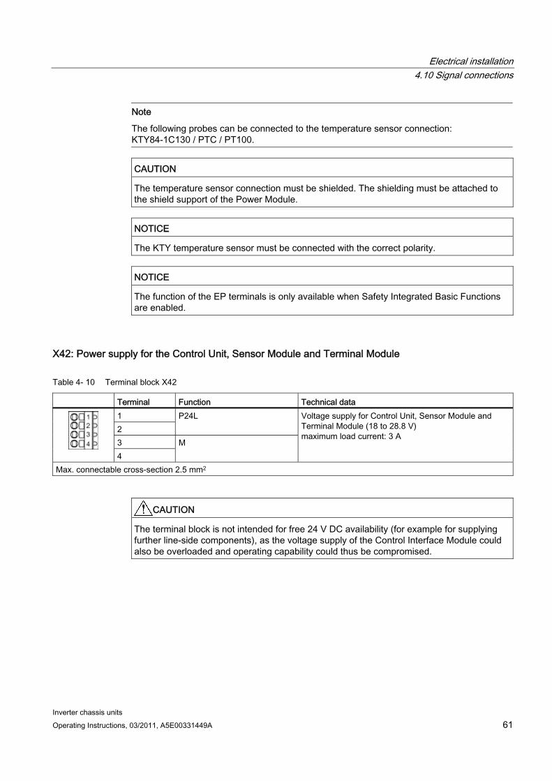
Electrical installation 4.10 Signal connections
Inverter chassis units Operating Instructions, 03/2011, A5E00331449A 61
Note
The following probes can be connected to the temperature sensor connection: KTY84-1C130 / PTC / PT100.
CAUTION The temperature sensor connection must be shielded. The shielding must be attached to the shield support of the Power Module.
NOTICE The KTY temperature sensor must be connected with the correct polarity.
NOTICE The function of the EP terminals is only available when Safety Integrated Basic Functions are enabled.
X42: Power supply for the Control Unit, Sensor Module and Terminal Module
Table 4- 10 Terminal block X42
Terminal Function Technical data 1 2
P24L
3 4
M
Voltage supply for Control Unit, Sensor Module and Terminal Module (18 to 28.8 V) maximum load current: 3 A
Max. connectable cross-section 2.5 mm2
CAUTION The terminal block is not intended for free 24 V DC availability (for example for supplying further line-side components), as the voltage supply of the Control Interface Module could also be overloaded and operating capability could thus be compromised.
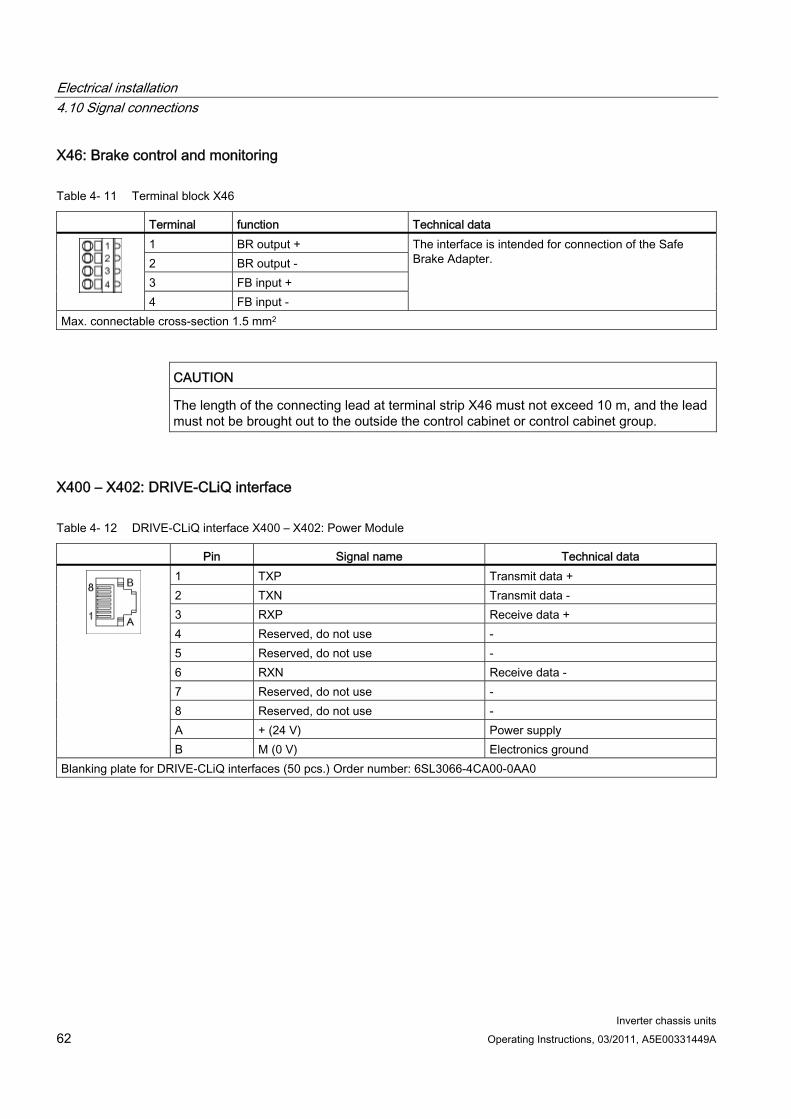
Electrical installation 4.10 Signal connections
Inverter chassis units 62 Operating Instructions, 03/2011, A5E00331449A
X46: Brake control and monitoring
Table 4- 11 Terminal block X46
Terminal function Technical data 1 BR output + 2 BR output - 3 FB input + 4 FB input -
The interface is intended for connection of the Safe Brake Adapter.
Max. connectable cross-section 1.5 mm2
CAUTION The length of the connecting lead at terminal strip X46 must not exceed 10 m, and the lead must not be brought out to the outside the control cabinet or control cabinet group.
X400 – X402: DRIVE-CLiQ interface
Table 4- 12 DRIVE-CLiQ interface X400 – X402: Power Module
Pin Signal name Technical data 1 TXP Transmit data + 2 TXN Transmit data - 3 RXP Receive data + 4 Reserved, do not use - 5 Reserved, do not use - 6 RXN Receive data - 7 Reserved, do not use - 8 Reserved, do not use - A + (24 V) Power supply
B M (0 V) Electronics ground Blanking plate for DRIVE-CLiQ interfaces (50 pcs.) Order number: 6SL3066-4CA00-0AA0
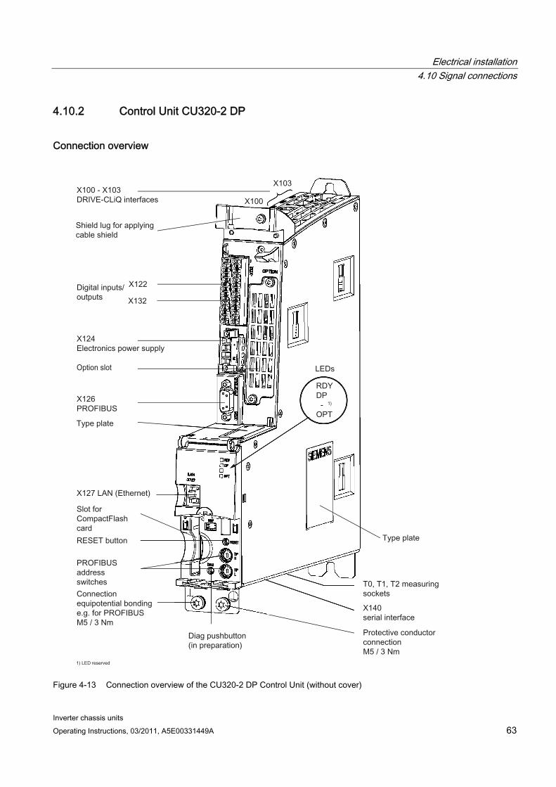
Electrical installation 4.10 Signal connections
Inverter chassis units Operating Instructions, 03/2011, A5E00331449A 63
4.10.2 Control Unit CU320-2 DP
Connection overview
Figure 4-13 Connection overview of the CU320-2 DP Control Unit (without cover)
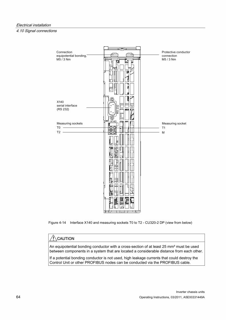
Electrical installation 4.10 Signal connections
Inverter chassis units 64 Operating Instructions, 03/2011, A5E00331449A
Figure 4-14 Interface X140 and measuring sockets T0 to T2 - CU320-2 DP (view from below)
CAUTION An equipotential bonding conductor with a cross-section of at least 25 mm² must be used between components in a system that are located a considerable distance from each other.
If a potential bonding conductor is not used, high leakage currents that could destroy the Control Unit or other PROFIBUS nodes can be conducted via the PROFIBUS cable.
Electrical installation 4.10 Signal connections
Inverter chassis units Operating Instructions, 03/2011, A5E00331449A 65
CAUTION The CompactFlash card may only be inserted or removed when the Control Unit is in a no-voltage condition.
If not observed, this can result in a loss of data during operation and possibly a plant standstill.
CAUTION The CompactFlash card is an electrostatic sensitive component. ESD regulations must be observed when inserting and removing the card.
CAUTION The Option Board may only be inserted and removed when the Control Unit and Option Board are disconnected from the power supply.
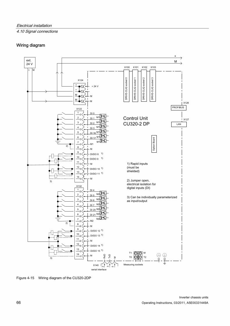
Electrical installation 4.10 Signal connections
Inverter chassis units 66 Operating Instructions, 03/2011, A5E00331449A
Wiring diagram
Figure 4-15 Wiring diagram of the CU320-2DP
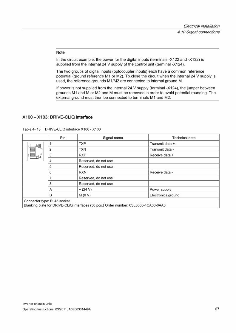
Electrical installation 4.10 Signal connections
Inverter chassis units Operating Instructions, 03/2011, A5E00331449A 67
Note
In the circuit example, the power for the digital inputs (terminals -X122 and -X132) is supplied from the internal 24 V supply of the control unit (terminal -X124).
The two groups of digital inputs (optocoupler inputs) each have a common reference potential (ground reference M1 or M2). To close the circuit when the internal 24 V supply is used, the reference grounds M1/M2 are connected to internal ground M.
If power is not supplied from the internal 24 V supply (terminal -X124), the jumper between grounds M1 and M or M2 and M must be removed in order to avoid potential rounding. The external ground must then be connected to terminals M1 and M2.
X100 – X103: DRIVE-CLiQ interface
Table 4- 13 DRIVE-CLiQ interface X100 - X103
Pin Signal name Technical data 1 TXP Transmit data + 2 TXN Transmit data - 3 RXP Receive data + 4 Reserved, do not use 5 Reserved, do not use 6 RXN Receive data - 7 Reserved, do not use 8 Reserved, do not use A + (24 V) Power supply
B M (0 V) Electronics ground Connector type: RJ45 socket Blanking plate for DRIVE-CLiQ interfaces (50 pcs.) Order number: 6SL3066-4CA00-0AA0

Electrical installation 4.10 Signal connections
Inverter chassis units 68 Operating Instructions, 03/2011, A5E00331449A
X122: Digital inputs/outputs
Table 4- 14 Terminal block X122
Pin Designation 1) Technical specifications 1 DI 0 2 DI 1 3 DI 2 4 DI 3 5 DI 16 6 DI 17
Voltage: -30 V to 30 V Typical current consumption: 9 mA at 24 V DC Electrical isolation: reference potential is terminal M1 Level (incl. ripple) High level: +15 V to +30 V Low level: -30 V to +5 V Input delay (typ.): L -> H: approx. 50 μs H -> L: approx. 150 μs
7 M1 Reference potential for terminals 1 to 6 8 M Ground 9 DI/DO 8 10 DI/DO 9 11 M 12 DI/DO 10 13 DI/DO 11
14 M
As input: Voltage: -30 V to 30 V Typical current consumption: 9 mA at 24 V DC Level (incl. ripple) High level: +15 V to +30 V Low level: -30 V to +5 V DI/DO 8, 9, 10, and 11 are "rapid inputs" 2) Input delay (typ.): L -> H: approx. 5 μs H -> L: approx. 50 μs As output: Voltage: 24 V DC Max. load current per output: 500 mA, continued-short-circuit-proof Output delay (typ./max.): 3) For "0" -> "1": 150 μs / 400 μs For 1" -> "0": 75 µs / 100 µs Switching frequency: For resistive load: Max. 100 Hz For inductive load: Max. 0.5 Hz For lamp load: Max. 10 Hz Maximum lamp load: 5 W
Max. connectable cross-section: 1.5 mm²
1) DI: digital input; DI/DO: Bidirectional digital input/output; M: Electronics ground M1: Ground reference 2) The rapid inputs can be used as probe inputs or as inputs for the external zero mark. 3) Data for: Vcc= 24 V; load 48 Ω; high ("1") = 90% Vout; low ("0") = 10% Vout
Note
If the 24 V supply is briefly interrupted, then the digital outputs are deactivated during this time.
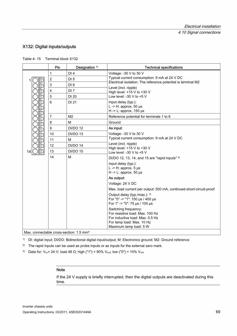
Electrical installation 4.10 Signal connections
Inverter chassis units Operating Instructions, 03/2011, A5E00331449A 69
X132: Digital inputs/outputs
Table 4- 15 Terminal block X132
Pin Designation 1) Technical specifications 1 DI 4 2 DI 5 3 DI 6 4 DI 7 5 DI 20 6 DI 21
Voltage: -30 V to 30 V Typical current consumption: 9 mA at 24 V DC Electrical isolation: The reference potential is terminal M2 Level (incl. ripple) High level: +15 V to +30 V Low level: -30 V to +5 V Input delay (typ.): L -> H: approx. 50 μs H -> L: approx. 150 μs
7 M2 Reference potential for terminals 1 to 6 8 M Ground 9 DI/DO 12 10 DI/DO 13 11 M 12 DI/DO 14 13 DI/DO 15
14 M
As input: Voltage: -30 V to 30 V Typical current consumption: 9 mA at 24 V DC Level (incl. ripple) High level: +15 V to +30 V Low level: -30 V to +5 V DI/DO 12, 13, 14, and 15 are "rapid inputs" 2) Input delay (typ.): L -> H: approx. 5 μs H -> L: approx. 50 μs As output: Voltage: 24 V DC Max. load current per output: 500 mA, continued-short-circuit-proof Output delay (typ./max.): 3) For "0" -> "1": 150 μs / 400 μs For 1" -> "0": 75 µs / 100 µs Switching frequency: For resistive load: Max. 100 Hz For inductive load: Max. 0.5 Hz For lamp load: Max. 10 Hz Maximum lamp load: 5 W
Max. connectable cross-section: 1.5 mm²
1) DI: digital input; DI/DO: Bidirectional digital input/output; M: Electronics ground; M2: Ground reference 2) The rapid inputs can be used as probe inputs or as inputs for the external zero mark. 3) Data for: Vcc= 24 V; load 48 Ω; high ("1") = 90% Vout; low ("0") = 10% Vout
Note
If the 24 V supply is briefly interrupted, then the digital outputs are deactivated during this time.
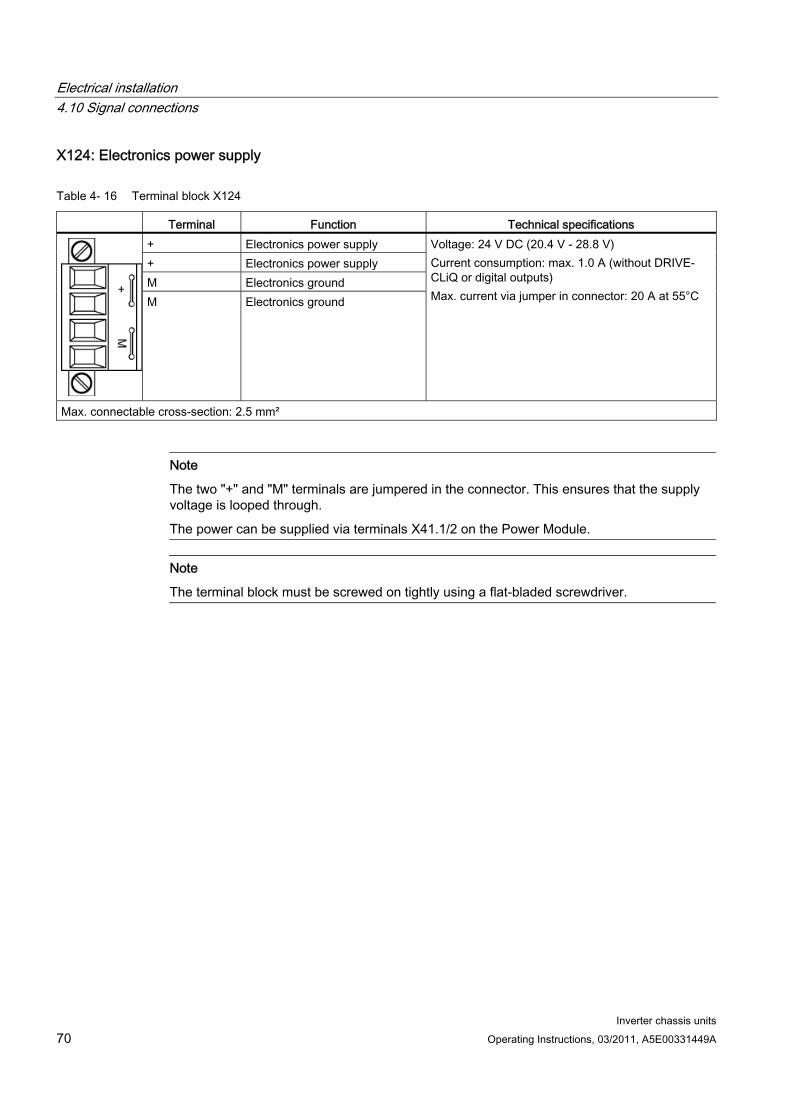
Electrical installation 4.10 Signal connections
Inverter chassis units 70 Operating Instructions, 03/2011, A5E00331449A
X124: Electronics power supply
Table 4- 16 Terminal block X124
Terminal Function Technical specifications + Electronics power supply + Electronics power supply M Electronics ground M Electronics ground
Voltage: 24 V DC (20.4 V - 28.8 V) Current consumption: max. 1.0 A (without DRIVE-CLiQ or digital outputs) Max. current via jumper in connector: 20 A at 55°C
Max. connectable cross-section: 2.5 mm²
Note
The two "+" and "M" terminals are jumpered in the connector. This ensures that the supply voltage is looped through.
The power can be supplied via terminals X41.1/2 on the Power Module.
Note
The terminal block must be screwed on tightly using a flat-bladed screwdriver.
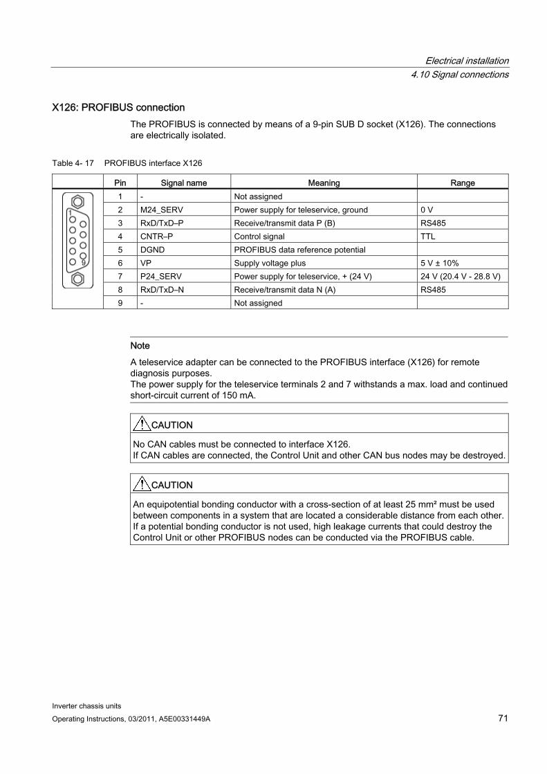
Electrical installation 4.10 Signal connections
Inverter chassis units Operating Instructions, 03/2011, A5E00331449A 71
X126: PROFIBUS connection The PROFIBUS is connected by means of a 9-pin SUB D socket (X126). The connections are electrically isolated.
Table 4- 17 PROFIBUS interface X126
Pin Signal name Meaning Range 1 - Not assigned 2 M24_SERV Power supply for teleservice, ground 0 V 3 RxD/TxD–P Receive/transmit data P (B) RS485 4 CNTR–P Control signal TTL 5 DGND PROFIBUS data reference potential 6 VP Supply voltage plus 5 V ± 10% 7 P24_SERV Power supply for teleservice, + (24 V) 24 V (20.4 V - 28.8 V) 8 RxD/TxD–N Receive/transmit data N (A) RS485
9 - Not assigned
Note
A teleservice adapter can be connected to the PROFIBUS interface (X126) for remote diagnosis purposes. The power supply for the teleservice terminals 2 and 7 withstands a max. load and continued short-circuit current of 150 mA.
CAUTION No CAN cables must be connected to interface X126. If CAN cables are connected, the Control Unit and other CAN bus nodes may be destroyed.
CAUTION An equipotential bonding conductor with a cross-section of at least 25 mm² must be used between components in a system that are located a considerable distance from each other. If a potential bonding conductor is not used, high leakage currents that could destroy the Control Unit or other PROFIBUS nodes can be conducted via the PROFIBUS cable.
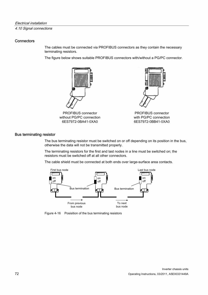
Electrical installation 4.10 Signal connections
Inverter chassis units 72 Operating Instructions, 03/2011, A5E00331449A
Connectors The cables must be connected via PROFIBUS connectors as they contain the necessary terminating resistors.
The figure below shows suitable PROFIBUS connectors with/without a PG/PC connector.
PROFIBUS connector without PG/PC connection
6ES7972-0BA41-0XA0
PROFIBUS connector with PG/PC connection 6ES7972-0BB41-0XA0
Bus terminating resistor The bus terminating resistor must be switched on or off depending on its position in the bus, otherwise the data will not be transmitted properly.
The terminating resistors for the first and last nodes in a line must be switched on; the resistors must be switched off at all other connectors.
The cable shield must be connected at both ends over large-surface area contacts.
Figure 4-16 Posisition of the bus terminating resistors

Electrical installation 4.10 Signal connections
Inverter chassis units Operating Instructions, 03/2011, A5E00331449A 73
PROFIBUS address switches The PROFIBUS address is set as a hexadecimal value via two rotary coding switches. Values between 0dec (00hex) and 127dec (7Fhex) can be set as the address. The upper rotary coding switch (H) is used to set the hexadecimal value for 161 and the lower rotary coding switch (L) is used to set the hexadecimal value for 160.
Table 4- 18 PROFIBUS address switches
Examples
21dec 35dec 126dec
Rotary coding switches Significance
15hex 23hex 7Ehex
161 = 16 1 2 7
160 = 1 5 3 E
Setting the PROFIBUS address The factory setting for the rotary coding switches is 0dec (00hex).
There are two ways to set the PROFIBUS address:
1. Via p0918
– To set the bus address for a PROFIBUS node using STARTER, first set the rotary code switches to 0dec (00hex) and 127dec (7Fhex).
– Then use parameter p0918 to set the address to a value between 1 and 126.
2. Via the PROFIBUS address switches on the Control Unit
– The address is set manually to values between 1 and 126 using the rotary coding switches. In this case, p0918 is only used to read the address.
The address switch is behind the blanking plate. The blanking plate is part of the scope of supply.
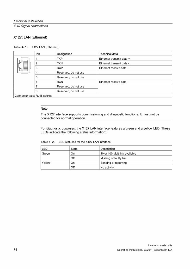
Electrical installation 4.10 Signal connections
Inverter chassis units 74 Operating Instructions, 03/2011, A5E00331449A
X127: LAN (Ethernet)
Table 4- 19 X127 LAN (Ethernet)
Pin Designation Technical data 1 TXP Ethernet transmit data + 2 TXN Ethernet transmit data - 3 RXP Ethernet receive data + 4 Reserved, do not use 5 Reserved, do not use 6 RXN Ethernet receive data - 7 Reserved, do not use
8 Reserved, do not use
Connector type: RJ45 socket
Note
The X127 interface supports commissioning and diagnostic functions. It must not be connected for normal operation.
For diagnostic purposes, the X127 LAN interface features a green and a yellow LED. These LEDs indicate the following status information:
Table 4- 20 LED statuses for the X127 LAN interface
LED State Description On 10 or 100 Mbit link available Green Off Missing or faulty link On Sending or receiving Yellow Off No activity
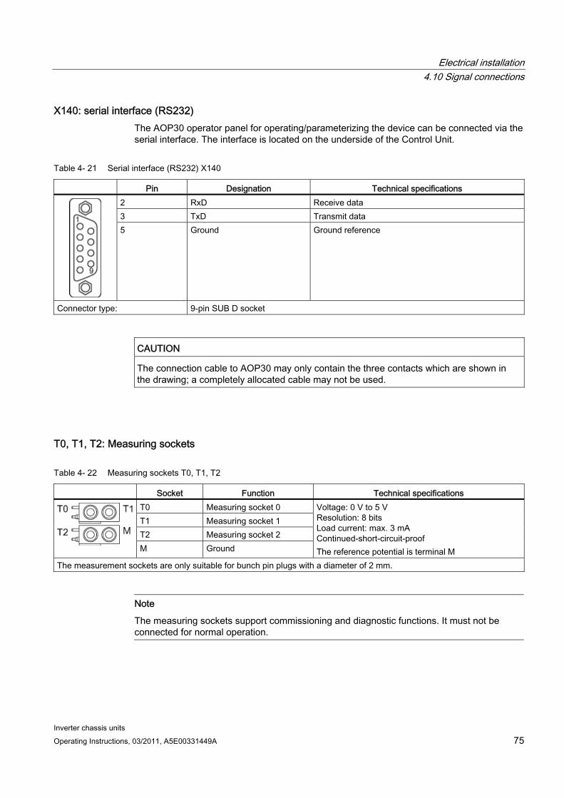
Electrical installation 4.10 Signal connections
Inverter chassis units Operating Instructions, 03/2011, A5E00331449A 75
X140: serial interface (RS232) The AOP30 operator panel for operating/parameterizing the device can be connected via the serial interface. The interface is located on the underside of the Control Unit.
Table 4- 21 Serial interface (RS232) X140
Pin Designation Technical specifications 2 RxD Receive data 3 TxD Transmit data
5 Ground Ground reference
Connector type: 9-pin SUB D socket
CAUTION The connection cable to AOP30 may only contain the three contacts which are shown in the drawing; a completely allocated cable may not be used.
T0, T1, T2: Measuring sockets
Table 4- 22 Measuring sockets T0, T1, T2
Socket Function Technical specifications T0 Measuring socket 0 T1 Measuring socket 1 T2 Measuring socket 2
M Ground
Voltage: 0 V to 5 V Resolution: 8 bits Load current: max. 3 mA Continued-short-circuit-proof The reference potential is terminal M
The measurement sockets are only suitable for bunch pin plugs with a diameter of 2 mm.
Note
The measuring sockets support commissioning and diagnostic functions. It must not be connected for normal operation.
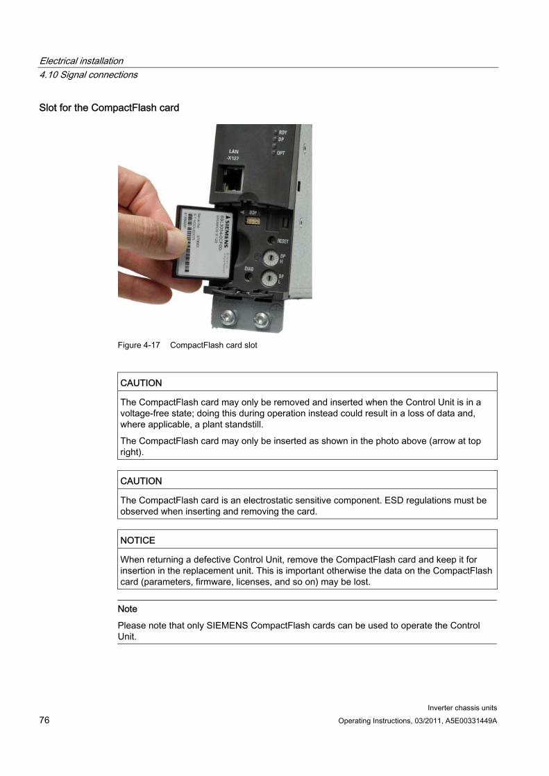
Electrical installation 4.10 Signal connections
Inverter chassis units 76 Operating Instructions, 03/2011, A5E00331449A
Slot for the CompactFlash card
Figure 4-17 CompactFlash card slot
CAUTION The CompactFlash card may only be removed and inserted when the Control Unit is in a voltage-free state; doing this during operation instead could result in a loss of data and, where applicable, a plant standstill.
The CompactFlash card may only be inserted as shown in the photo above (arrow at top right).
CAUTION The CompactFlash card is an electrostatic sensitive component. ESD regulations must be observed when inserting and removing the card.
NOTICE When returning a defective Control Unit, remove the CompactFlash card and keep it for insertion in the replacement unit. This is important otherwise the data on the CompactFlash card (parameters, firmware, licenses, and so on) may be lost.
Note
Please note that only SIEMENS CompactFlash cards can be used to operate the Control Unit.
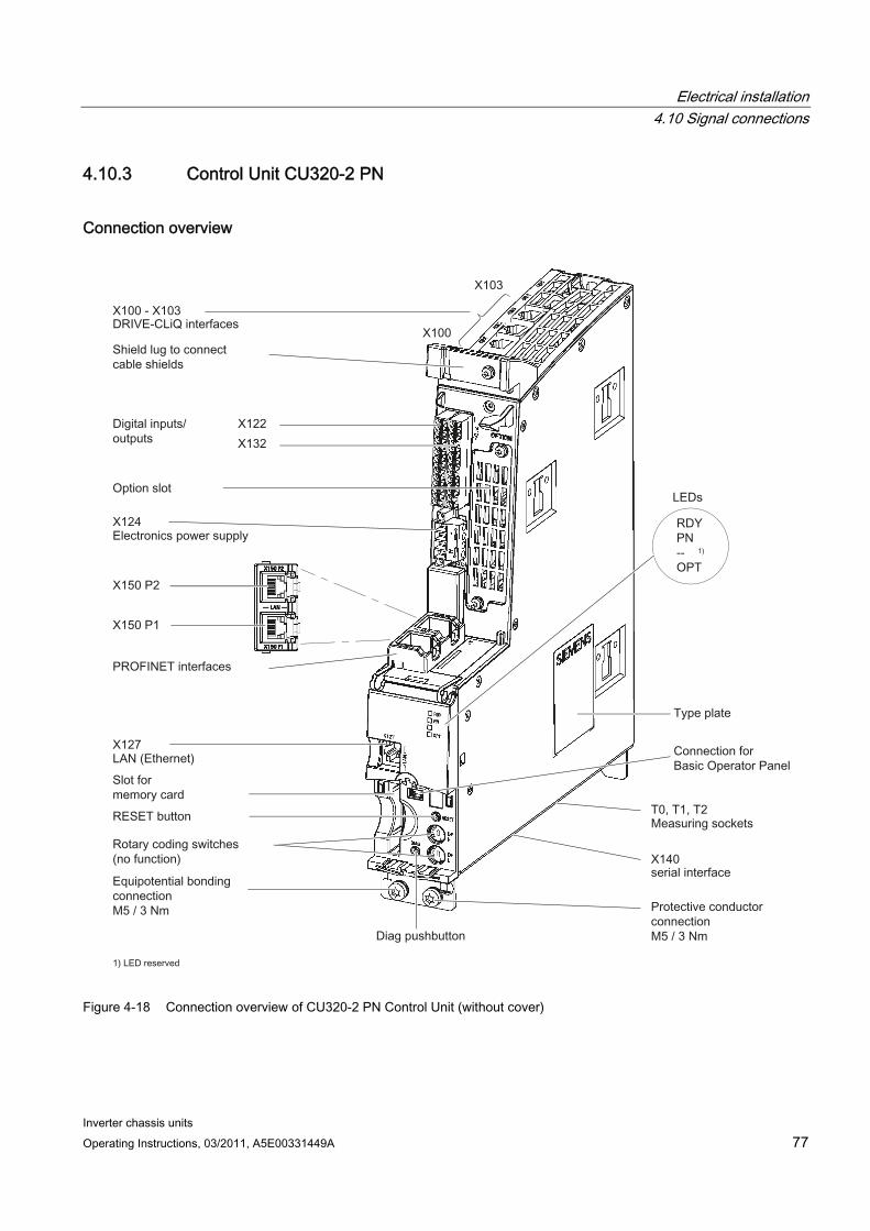
Electrical installation 4.10 Signal connections
Inverter chassis units Operating Instructions, 03/2011, A5E00331449A 77
4.10.3 Control Unit CU320-2 PN
Connection overview
Figure 4-18 Connection overview of CU320-2 PN Control Unit (without cover)
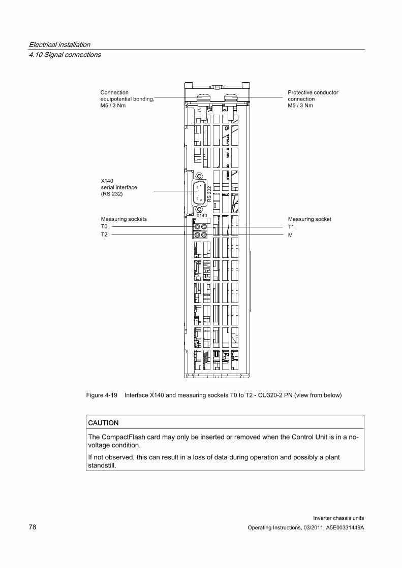
Electrical installation 4.10 Signal connections
Inverter chassis units 78 Operating Instructions, 03/2011, A5E00331449A
Figure 4-19 Interface X140 and measuring sockets T0 to T2 - CU320-2 PN (view from below)
CAUTION The CompactFlash card may only be inserted or removed when the Control Unit is in a no-voltage condition.
If not observed, this can result in a loss of data during operation and possibly a plant standstill.

Electrical installation 4.10 Signal connections
Inverter chassis units Operating Instructions, 03/2011, A5E00331449A 79
CAUTION The CompactFlash card is an electrostatic sensitive component. ESD regulations must be observed when inserting and removing the card.
CAUTION The Option Board may only be inserted and removed when the Control Unit and Option Board are disconnected from the power supply.
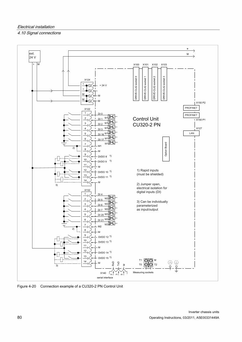
Electrical installation 4.10 Signal connections
Inverter chassis units 80 Operating Instructions, 03/2011, A5E00331449A
Figure 4-20 Connection example of a CU320-2 PN Control Unit

Electrical installation 4.10 Signal connections
Inverter chassis units Operating Instructions, 03/2011, A5E00331449A 81
Note
In the circuit example, the power for the digital inputs (terminals -X122 and -X132) is supplied from the internal 24 V supply of the control unit (terminal -X124).
The two groups of digital inputs (optocoupler inputs) each have a common reference potential (ground reference M1 or M2). To close the circuit when the internal 24 V supply is used, the reference grounds M1/M2 are connected to internal ground M.
If power is not supplied from the internal 24 V supply (terminal -X124), the jumper between grounds M1 and M or M2 and M must be removed in order to avoid potential rounding. The external ground must then be connected to terminals M1 and M2.
X100 – X103: DRIVE-CLiQ interface
Table 4- 23 DRIVE-CLiQ interface X100 - X103
Pin Signal name Technical data 1 TXP Transmit data + 2 TXN Transmit data - 3 RXP Receive data + 4 Reserved, do not use 5 Reserved, do not use 6 RXN Receive data - 7 Reserved, do not use 8 Reserved, do not use A + (24 V) Power supply
B M (0 V) Electronics ground Connector type: RJ45 socket Blanking plate for DRIVE-CLiQ interfaces (50 pcs.) Order number: 6SL3066-4CA00-0AA0

Electrical installation 4.10 Signal connections
Inverter chassis units 82 Operating Instructions, 03/2011, A5E00331449A
X122: Digital inputs/outputs
Table 4- 24 Terminal block X122
Pin Designation 1) Technical specifications 1 DI 0 2 DI 1 3 DI 2 4 DI 3 5 DI 16 6 DI 17
Voltage: -30 V to 30 V Typical current consumption: 9 mA at 24 V DC Electrical isolation: reference potential is terminal M1 Level (incl. ripple) High level: +15 V to +30 V Low level: -30 V to +5 V Input delay (typ.): L -> H: approx. 50 μs H -> L: approx. 150 μs
7 M1 Reference potential for terminals 1 to 6 8 M Ground 9 DI/DO 8 10 DI/DO 9 11 M 12 DI/DO 10 13 DI/DO 11
14 M
As input: Voltage: -30 V to 30 V Typical current consumption: 9 mA at 24 V DC Level (incl. ripple) High level: +15 V to +30 V Low level: -30 V to +5 V DI/DO 8, 9, 10, and 11 are "rapid inputs" 2) Input delay (typ.): L -> H: approx. 5 μs H -> L: approx. 50 μs As output: Voltage: 24 V DC Max. load current per output: 500 mA, continued-short-circuit-proof Output delay (typ./max.): 3) For "0" -> "1": 150 μs / 400 μs For 1" -> "0": 75 µs / 100 µs Switching frequency: For resistive load: Max. 100 Hz For inductive load: Max. 0.5 Hz For lamp load: Max. 10 Hz Maximum lamp load: 5 W
Max. connectable cross-section: 1.5 mm²
1) DI: digital input; DI/DO: Bidirectional digital input/output; M: Electronics ground M1: Ground reference 2) The rapid inputs can be used as probe inputs or as inputs for the external zero mark. 3) Data for: Vcc= 24 V; load 48 Ω; high ("1") = 90% Vout; low ("0") = 10% Vout
Note
If the 24 V supply is briefly interrupted, then the digital outputs are deactivated during this time.

Electrical installation 4.10 Signal connections
Inverter chassis units Operating Instructions, 03/2011, A5E00331449A 83
X132: Digital inputs/outputs
Table 4- 25 Terminal block X132
Pin Designation 1) Technical specifications 1 DI 4 2 DI 5 3 DI 6 4 DI 7 5 DI 20 6 DI 21
Voltage: -30 V to 30 V Typical current consumption: 9 mA at 24 V DC Electrical isolation: The reference potential is terminal M2 Level (incl. ripple) High level: +15 V to +30 V Low level: -30 V to +5 V Input delay (typ.): L -> H: approx. 50 μs H -> L: approx. 150 μs
7 M2 Reference potential for terminals 1 to 6 8 M Ground 9 DI/DO 12 10 DI/DO 13 11 M 12 DI/DO 14 13 DI/DO 15
14 M
As input: Voltage: -30 V to 30 V Typical current consumption: 9 mA at 24 V DC Level (incl. ripple) High level: +15 V to +30 V Low level: -30 V to +5 V DI/DO 12, 13, 14, and 15 are "rapid inputs" 2) Input delay (typ.): L -> H: approx. 5 μs H -> L: approx. 50 μs As output: Voltage: 24 V DC Max. load current per output: 500 mA, continued-short-circuit-proof Output delay (typ./max.): 3) For "0" -> "1": 150 μs / 400 μs For 1" -> "0": 75 µs / 100 µs Switching frequency: For resistive load: Max. 100 Hz For inductive load: Max. 0.5 Hz For lamp load: Max. 10 Hz Maximum lamp load: 5 W
Max. connectable cross-section: 1.5 mm²
1) DI: digital input; DI/DO: Bidirectional digital input/output; M: Electronics ground; M2: Ground reference 2) The rapid inputs can be used as probe inputs or as inputs for the external zero mark. 3) Data for: Vcc= 24 V; load 48 Ω; high ("1") = 90% Vout; low ("0") = 10% Vout
Note
If the 24 V supply is briefly interrupted, then the digital outputs are deactivated during this time.
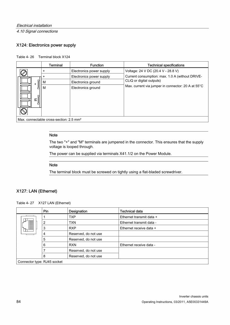
Electrical installation 4.10 Signal connections
Inverter chassis units 84 Operating Instructions, 03/2011, A5E00331449A
X124: Electronics power supply
Table 4- 26 Terminal block X124
Terminal Function Technical specifications + Electronics power supply + Electronics power supply M Electronics ground M Electronics ground
Voltage: 24 V DC (20.4 V - 28.8 V) Current consumption: max. 1.0 A (without DRIVE-CLiQ or digital outputs) Max. current via jumper in connector: 20 A at 55°C
Max. connectable cross-section: 2.5 mm²
Note
The two "+" and "M" terminals are jumpered in the connector. This ensures that the supply voltage is looped through.
The power can be supplied via terminals X41.1/2 on the Power Module.
Note
The terminal block must be screwed on tightly using a flat-bladed screwdriver.
X127: LAN (Ethernet)
Table 4- 27 X127 LAN (Ethernet)
Pin Designation Technical data 1 TXP Ethernet transmit data + 2 TXN Ethernet transmit data - 3 RXP Ethernet receive data + 4 Reserved, do not use 5 Reserved, do not use 6 RXN Ethernet receive data - 7 Reserved, do not use
8 Reserved, do not use
Connector type: RJ45 socket
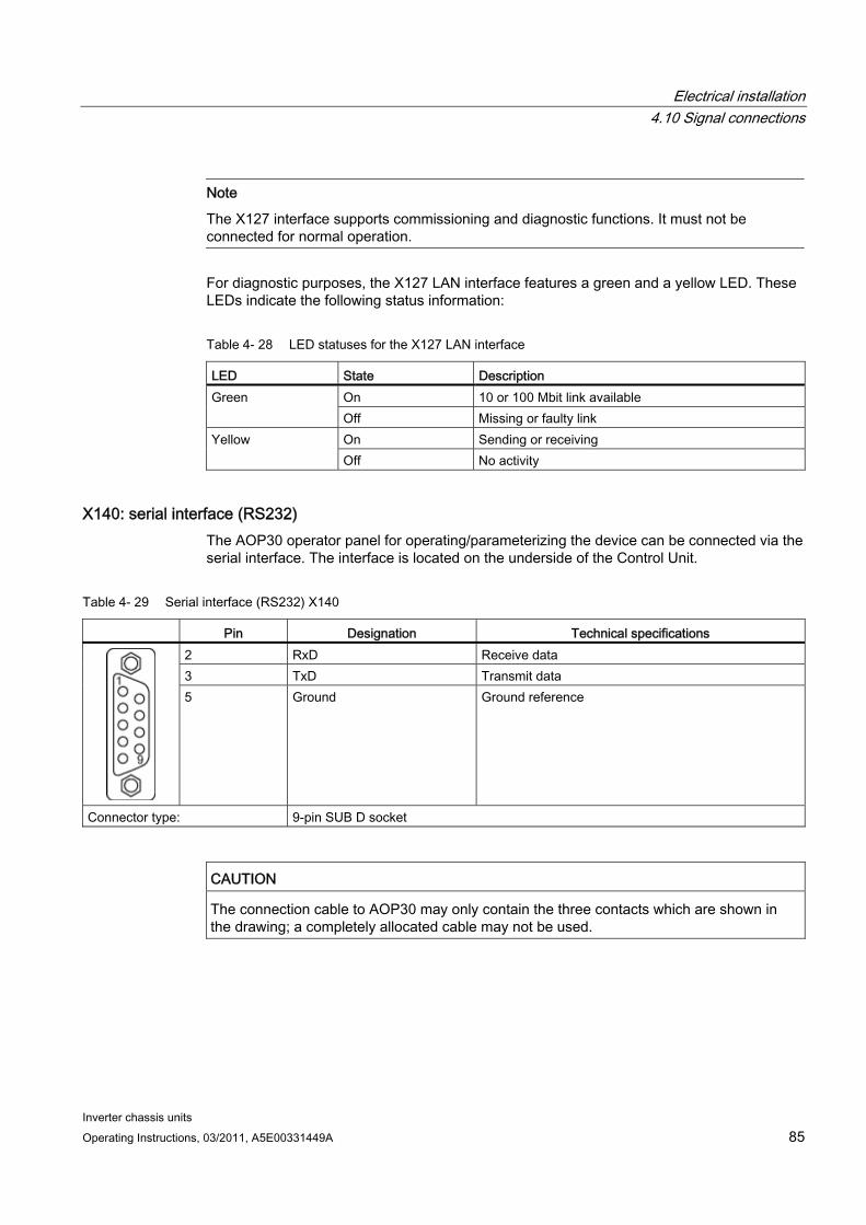
Electrical installation 4.10 Signal connections
Inverter chassis units Operating Instructions, 03/2011, A5E00331449A 85
Note
The X127 interface supports commissioning and diagnostic functions. It must not be connected for normal operation.
For diagnostic purposes, the X127 LAN interface features a green and a yellow LED. These LEDs indicate the following status information:
Table 4- 28 LED statuses for the X127 LAN interface
LED State Description On 10 or 100 Mbit link available Green Off Missing or faulty link On Sending or receiving Yellow Off No activity
X140: serial interface (RS232) The AOP30 operator panel for operating/parameterizing the device can be connected via the serial interface. The interface is located on the underside of the Control Unit.
Table 4- 29 Serial interface (RS232) X140
Pin Designation Technical specifications 2 RxD Receive data 3 TxD Transmit data
5 Ground Ground reference
Connector type: 9-pin SUB D socket
CAUTION The connection cable to AOP30 may only contain the three contacts which are shown in the drawing; a completely allocated cable may not be used.
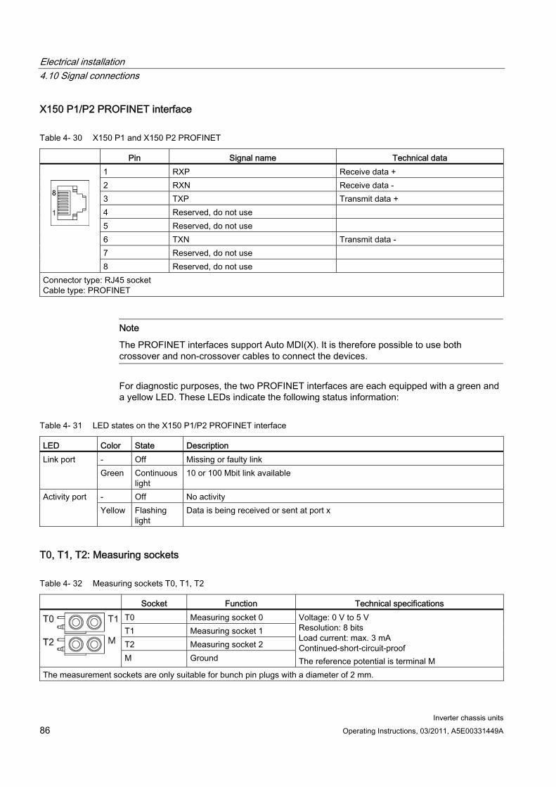
Electrical installation 4.10 Signal connections
Inverter chassis units 86 Operating Instructions, 03/2011, A5E00331449A
X150 P1/P2 PROFINET interface
Table 4- 30 X150 P1 and X150 P2 PROFINET
Pin Signal name Technical data 1 RXP Receive data + 2 RXN Receive data - 3 TXP Transmit data + 4 Reserved, do not use 5 Reserved, do not use 6 TXN Transmit data - 7 Reserved, do not use
8 Reserved, do not use Connector type: RJ45 socket Cable type: PROFINET
Note
The PROFINET interfaces support Auto MDI(X). It is therefore possible to use both crossover and non-crossover cables to connect the devices.
For diagnostic purposes, the two PROFINET interfaces are each equipped with a green and a yellow LED. These LEDs indicate the following status information:
Table 4- 31 LED states on the X150 P1/P2 PROFINET interface
LED Color State Description - Off Missing or faulty link Link port Green Continuous
light 10 or 100 Mbit link available
- Off No activity Activity port Yellow Flashing
light Data is being received or sent at port x
T0, T1, T2: Measuring sockets
Table 4- 32 Measuring sockets T0, T1, T2
Socket Function Technical specifications T0 Measuring socket 0 T1 Measuring socket 1 T2 Measuring socket 2
M Ground
Voltage: 0 V to 5 V Resolution: 8 bits Load current: max. 3 mA Continued-short-circuit-proof The reference potential is terminal M
The measurement sockets are only suitable for bunch pin plugs with a diameter of 2 mm.
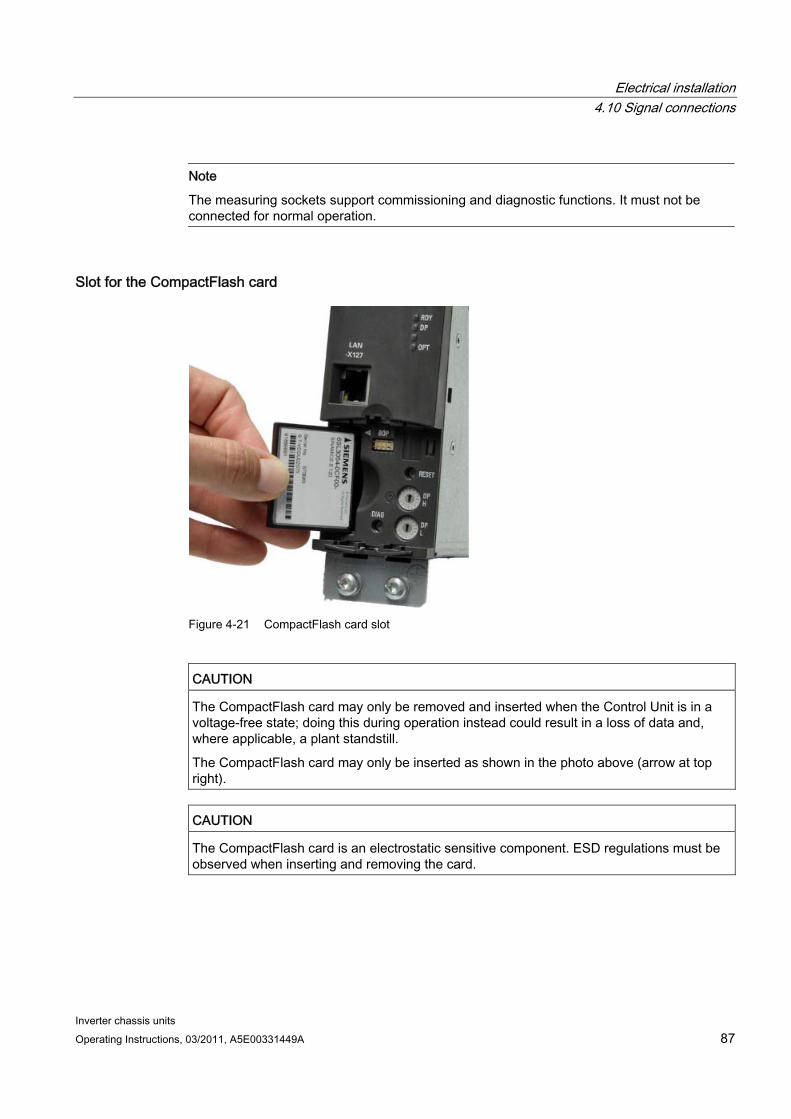
Electrical installation 4.10 Signal connections
Inverter chassis units Operating Instructions, 03/2011, A5E00331449A 87
Note
The measuring sockets support commissioning and diagnostic functions. It must not be connected for normal operation.
Slot for the CompactFlash card
Figure 4-21 CompactFlash card slot
CAUTION The CompactFlash card may only be removed and inserted when the Control Unit is in a voltage-free state; doing this during operation instead could result in a loss of data and, where applicable, a plant standstill.
The CompactFlash card may only be inserted as shown in the photo above (arrow at top right).
CAUTION The CompactFlash card is an electrostatic sensitive component. ESD regulations must be observed when inserting and removing the card.

Electrical installation 4.10 Signal connections
Inverter chassis units 88 Operating Instructions, 03/2011, A5E00331449A
NOTICE When returning a defective Control Unit, remove the CompactFlash card and keep it for insertion in the replacement unit. This is important otherwise the data on the CompactFlash card (parameters, firmware, licenses, and so on) may be lost.
Note
Please note that only SIEMENS CompactFlash cards can be used to operate the Control Unit.
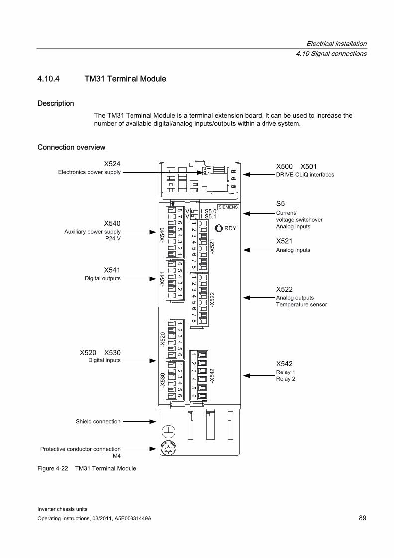
Electrical installation 4.10 Signal connections
Inverter chassis units Operating Instructions, 03/2011, A5E00331449A 89
4.10.4 TM31 Terminal Module
Description The TM31 Terminal Module is a terminal extension board. It can be used to increase the number of available digital/analog inputs/outputs within a drive system.
Connection overview
Figure 4-22 TM31 Terminal Module
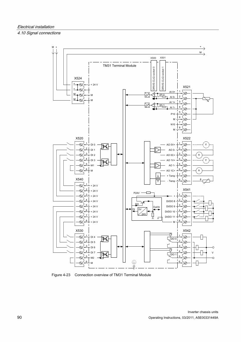
Electrical installation 4.10 Signal connections
Inverter chassis units 90 Operating Instructions, 03/2011, A5E00331449A
Figure 4-23 Connection overview of TM31 Terminal Module
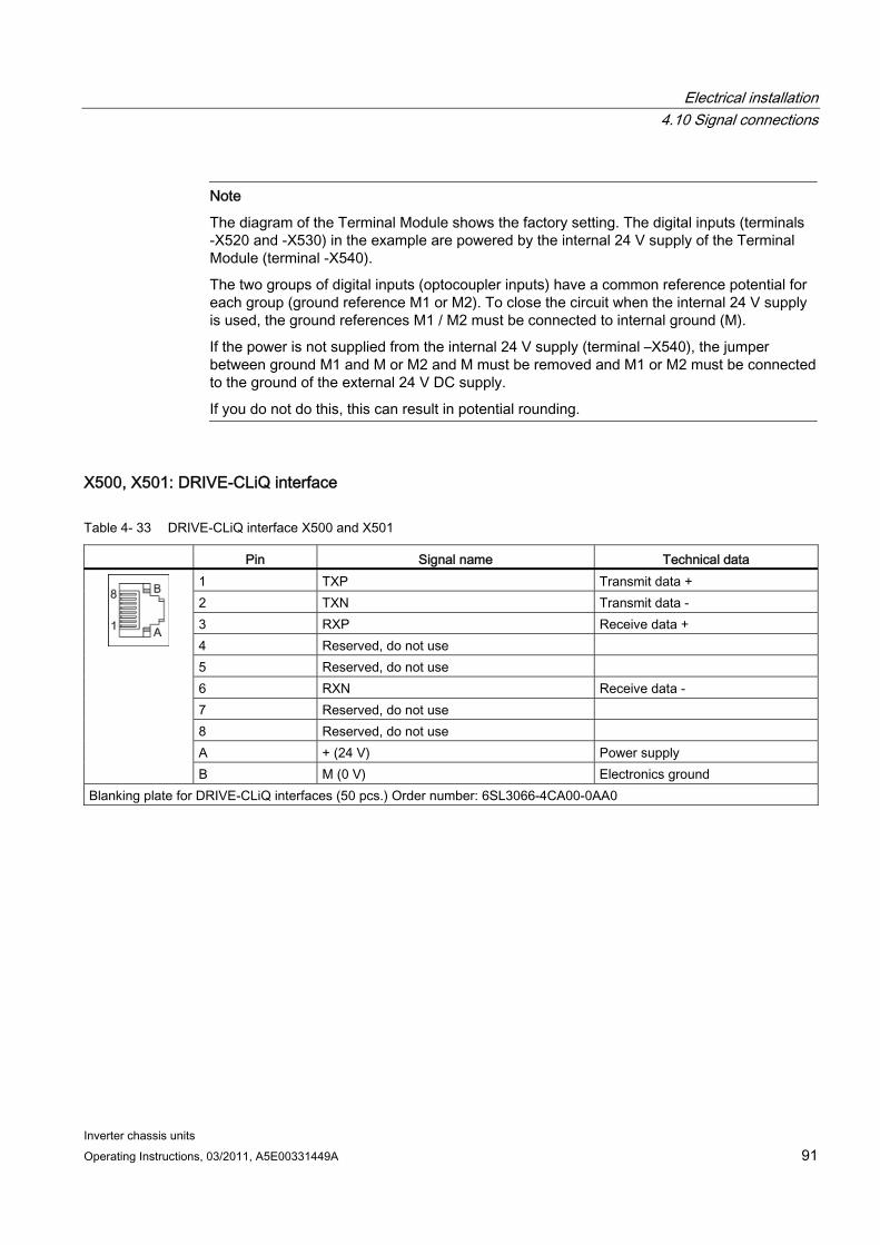
Electrical installation 4.10 Signal connections
Inverter chassis units Operating Instructions, 03/2011, A5E00331449A 91
Note
The diagram of the Terminal Module shows the factory setting. The digital inputs (terminals -X520 and -X530) in the example are powered by the internal 24 V supply of the Terminal Module (terminal -X540).
The two groups of digital inputs (optocoupler inputs) have a common reference potential for each group (ground reference M1 or M2). To close the circuit when the internal 24 V supply is used, the ground references M1 / M2 must be connected to internal ground (M).
If the power is not supplied from the internal 24 V supply (terminal –X540), the jumper between ground M1 and M or M2 and M must be removed and M1 or M2 must be connected to the ground of the external 24 V DC supply.
If you do not do this, this can result in potential rounding.
X500, X501: DRIVE-CLiQ interface
Table 4- 33 DRIVE-CLiQ interface X500 and X501
Pin Signal name Technical data 1 TXP Transmit data + 2 TXN Transmit data - 3 RXP Receive data + 4 Reserved, do not use 5 Reserved, do not use 6 RXN Receive data - 7 Reserved, do not use 8 Reserved, do not use A + (24 V) Power supply
B M (0 V) Electronics ground Blanking plate for DRIVE-CLiQ interfaces (50 pcs.) Order number: 6SL3066-4CA00-0AA0
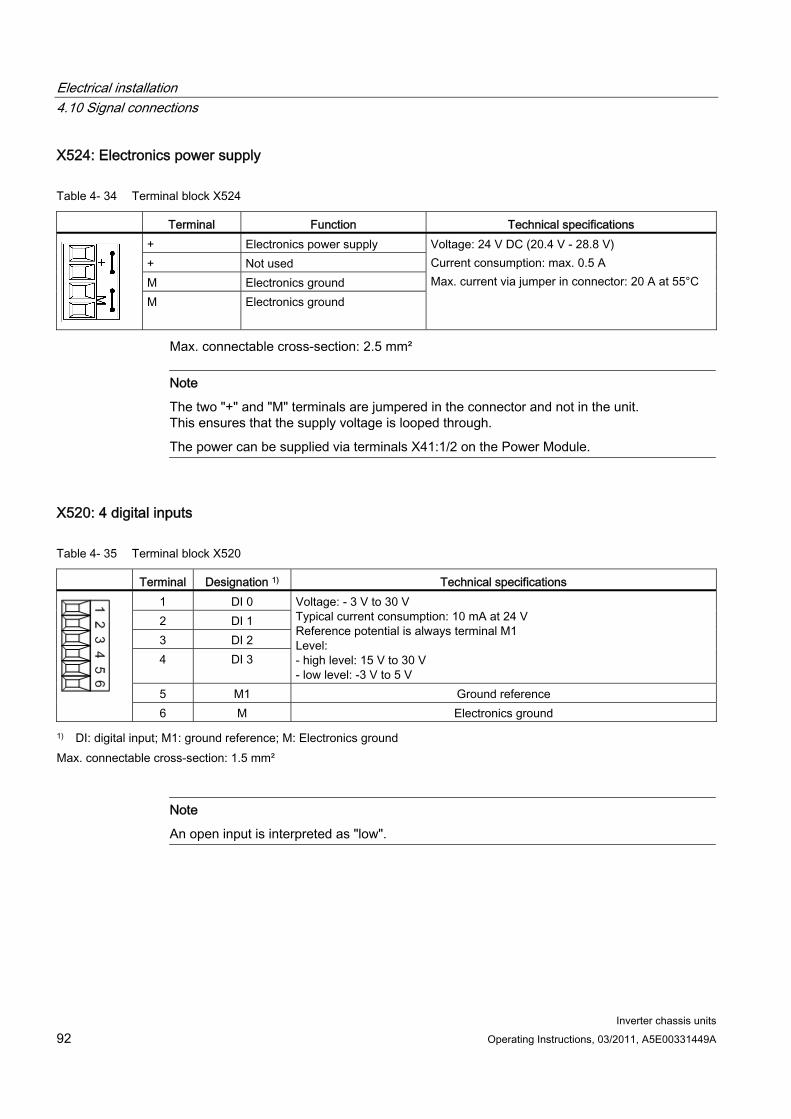
Electrical installation 4.10 Signal connections
Inverter chassis units 92 Operating Instructions, 03/2011, A5E00331449A
X524: Electronics power supply
Table 4- 34 Terminal block X524
Terminal Function Technical specifications + Electronics power supply + Not used M Electronics ground
M Electronics ground
Voltage: 24 V DC (20.4 V - 28.8 V) Current consumption: max. 0.5 A Max. current via jumper in connector: 20 A at 55°C
Max. connectable cross-section: 2.5 mm²
Note
The two "+" and "M" terminals are jumpered in the connector and not in the unit. This ensures that the supply voltage is looped through.
The power can be supplied via terminals X41:1/2 on the Power Module.
X520: 4 digital inputs
Table 4- 35 Terminal block X520
Terminal Designation 1) Technical specifications 1 DI 0 2 DI 1 3 DI 2 4 DI 3
Voltage: - 3 V to 30 V Typical current consumption: 10 mA at 24 V Reference potential is always terminal M1 Level: - high level: 15 V to 30 V - low level: -3 V to 5 V
5 M1 Ground reference
6 M Electronics ground
1) DI: digital input; M1: ground reference; M: Electronics ground Max. connectable cross-section: 1.5 mm²
Note
An open input is interpreted as "low".
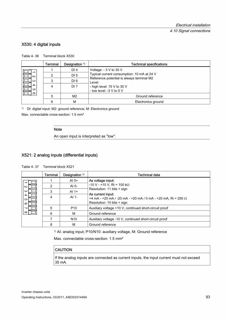
Electrical installation 4.10 Signal connections
Inverter chassis units Operating Instructions, 03/2011, A5E00331449A 93
X530: 4 digital inputs
Table 4- 36 Terminal block X530
Terminal Designation 1) Technical specifications 1 DI 4 2 DI 5 3 DI 6 4 DI 7
Voltage: - 3 V to 30 V Typical current consumption: 10 mA at 24 V Reference potential is always terminal M2 Level: - high level: 15 V to 30 V - low level: -3 V to 5 V
5 M2 Ground reference
6 M Electronics ground
1) DI: digital input; M2: ground reference; M: Electronics ground Max. connectable cross-section: 1.5 mm²
Note
An open input is interpreted as "low".
X521: 2 analog inputs (differential inputs)
Table 4- 37 Terminal block X521
Terminal Designation 1) Technical data 1 AI 0+ 2 AI 0- 3 AI 1+ 4 AI 1-
As voltage input: -10 V - +10 V, Ri = 100 kΩ Resolution: 11 bits + sign As current input: +4 mA - +20 mA / -20 mA - +20 mA / 0 mA - +20 mA, Ri = 250 Ω Resolution: 10 bits + sign
5 P10 Auxiliary voltage +10 V, continued short-circuit proof 6 M Ground reference 7 N10 Auxiliary voltage -10 V, continued short-circuit proof
8 M Ground reference
1) AI: analog input; P10/N10: auxiliary voltage, M: Ground reference
Max. connectable cross-section: 1.5 mm²
CAUTION If the analog inputs are connected as current inputs, the input current must not exceed 35 mA.
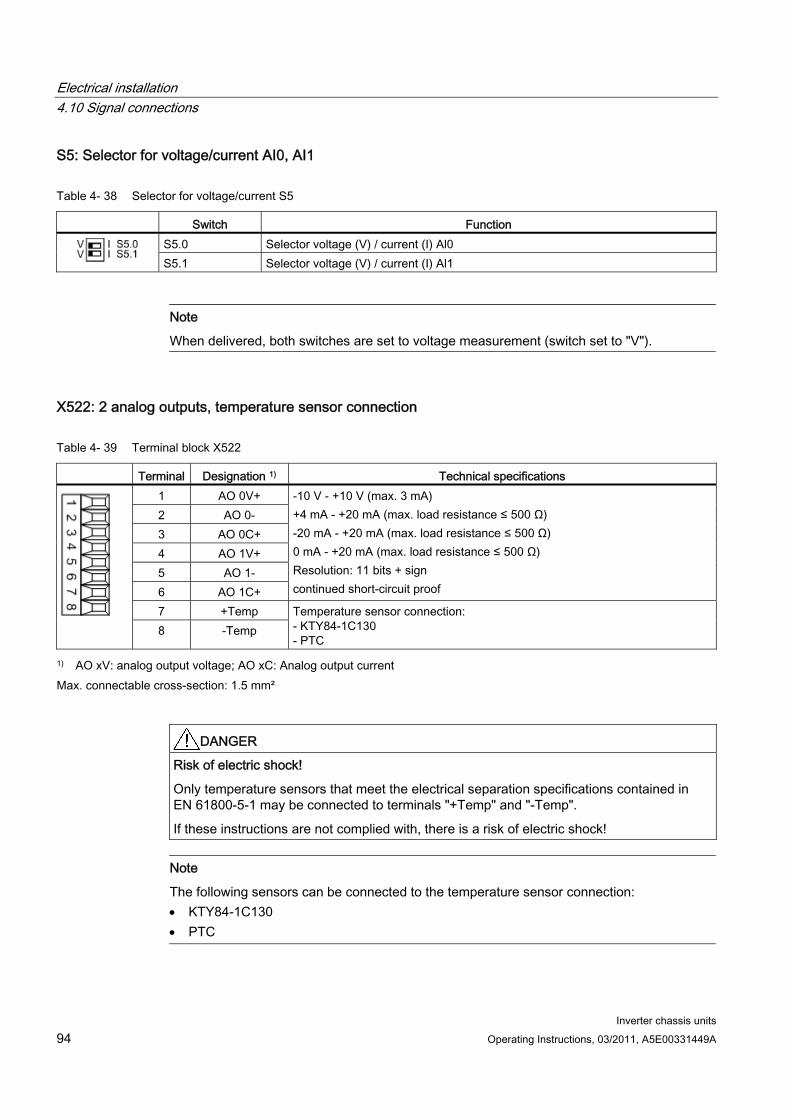
Electrical installation 4.10 Signal connections
Inverter chassis units 94 Operating Instructions, 03/2011, A5E00331449A
S5: Selector for voltage/current AI0, AI1
Table 4- 38 Selector for voltage/current S5
Switch Function S5.0 Selector voltage (V) / current (I) Al0
S5.1 Selector voltage (V) / current (I) Al1
Note
When delivered, both switches are set to voltage measurement (switch set to "V").
X522: 2 analog outputs, temperature sensor connection
Table 4- 39 Terminal block X522
Terminal Designation 1) Technical specifications 1 AO 0V+ 2 AO 0- 3 AO 0C+ 4 AO 1V+ 5 AO 1- 6 AO 1C+
-10 V - +10 V (max. 3 mA) +4 mA - +20 mA (max. load resistance ≤ 500 Ω) -20 mA - +20 mA (max. load resistance ≤ 500 Ω) 0 mA - +20 mA (max. load resistance ≤ 500 Ω) Resolution: 11 bits + sign continued short-circuit proof
7 +Temp 8 -Temp
Temperature sensor connection: - KTY84-1C130 - PTC
1) AO xV: analog output voltage; AO xC: Analog output current Max. connectable cross-section: 1.5 mm²
DANGER Risk of electric shock!
Only temperature sensors that meet the electrical separation specifications contained in EN 61800-5-1 may be connected to terminals "+Temp" and "-Temp".
If these instructions are not complied with, there is a risk of electric shock!
Note
The following sensors can be connected to the temperature sensor connection: KTY84-1C130 PTC
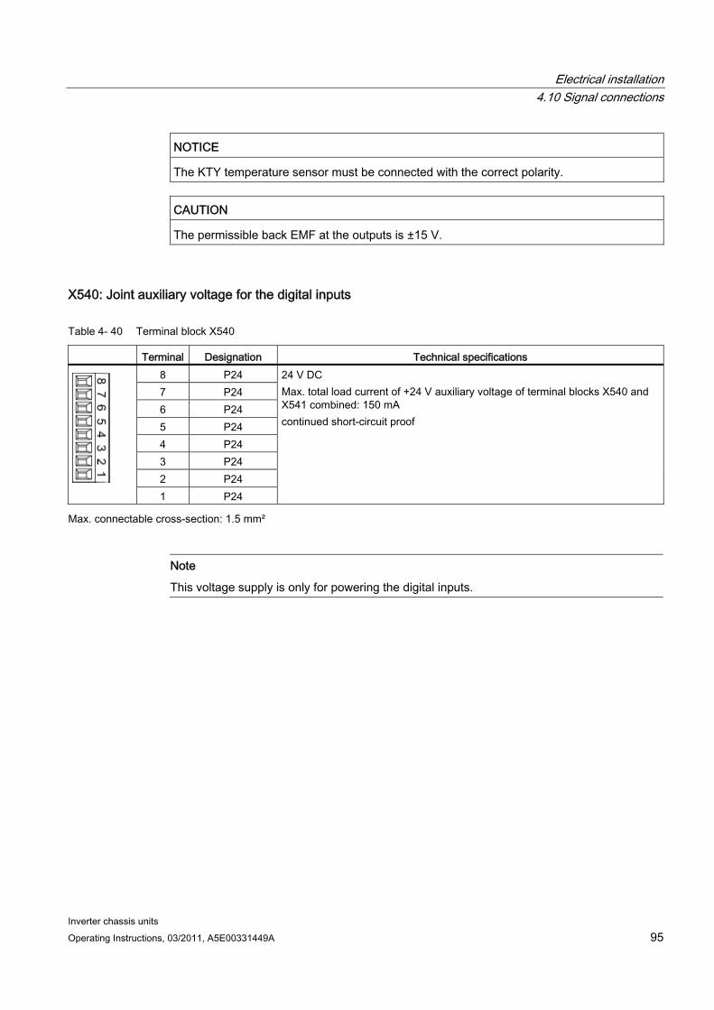
Electrical installation 4.10 Signal connections
Inverter chassis units Operating Instructions, 03/2011, A5E00331449A 95
NOTICE The KTY temperature sensor must be connected with the correct polarity.
CAUTION The permissible back EMF at the outputs is ±15 V.
X540: Joint auxiliary voltage for the digital inputs
Table 4- 40 Terminal block X540
Terminal Designation Technical specifications 8 P24 7 P24 6 P24 5 P24 4 P24 3 P24 2 P24 1 P24
24 V DC Max. total load current of +24 V auxiliary voltage of terminal blocks X540 and X541 combined: 150 mA continued short-circuit proof
Max. connectable cross-section: 1.5 mm²
Note
This voltage supply is only for powering the digital inputs.
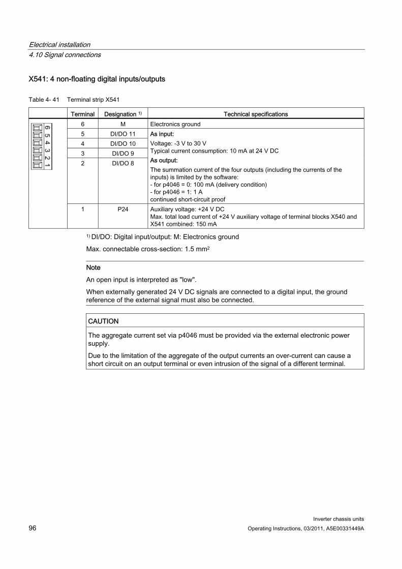
Electrical installation 4.10 Signal connections
Inverter chassis units 96 Operating Instructions, 03/2011, A5E00331449A
X541: 4 non-floating digital inputs/outputs
Table 4- 41 Terminal strip X541
Terminal Designation 1) Technical specifications 6 M Electronics ground 5 DI/DO 11 4 DI/DO 10 3 DI/DO 9 2 DI/DO 8
As input: Voltage: -3 V to 30 V Typical current consumption: 10 mA at 24 V DC As output: The summation current of the four outputs (including the currents of the inputs) is limited by the software: - for p4046 = 0: 100 mA (delivery condition) - for p4046 = 1: 1 A continued short-circuit proof
1 P24 Auxiliary voltage: +24 V DC Max. total load current of +24 V auxiliary voltage of terminal blocks X540 and X541 combined: 150 mA
1) DI/DO: Digital input/output: M: Electronics ground
Max. connectable cross-section: 1.5 mm2
Note
An open input is interpreted as "low".
When externally generated 24 V DC signals are connected to a digital input, the ground reference of the external signal must also be connected.
CAUTION The aggregate current set via p4046 must be provided via the external electronic power supply.
Due to the limitation of the aggregate of the output currents an over-current can cause a short circuit on an output terminal or even intrusion of the signal of a different terminal.
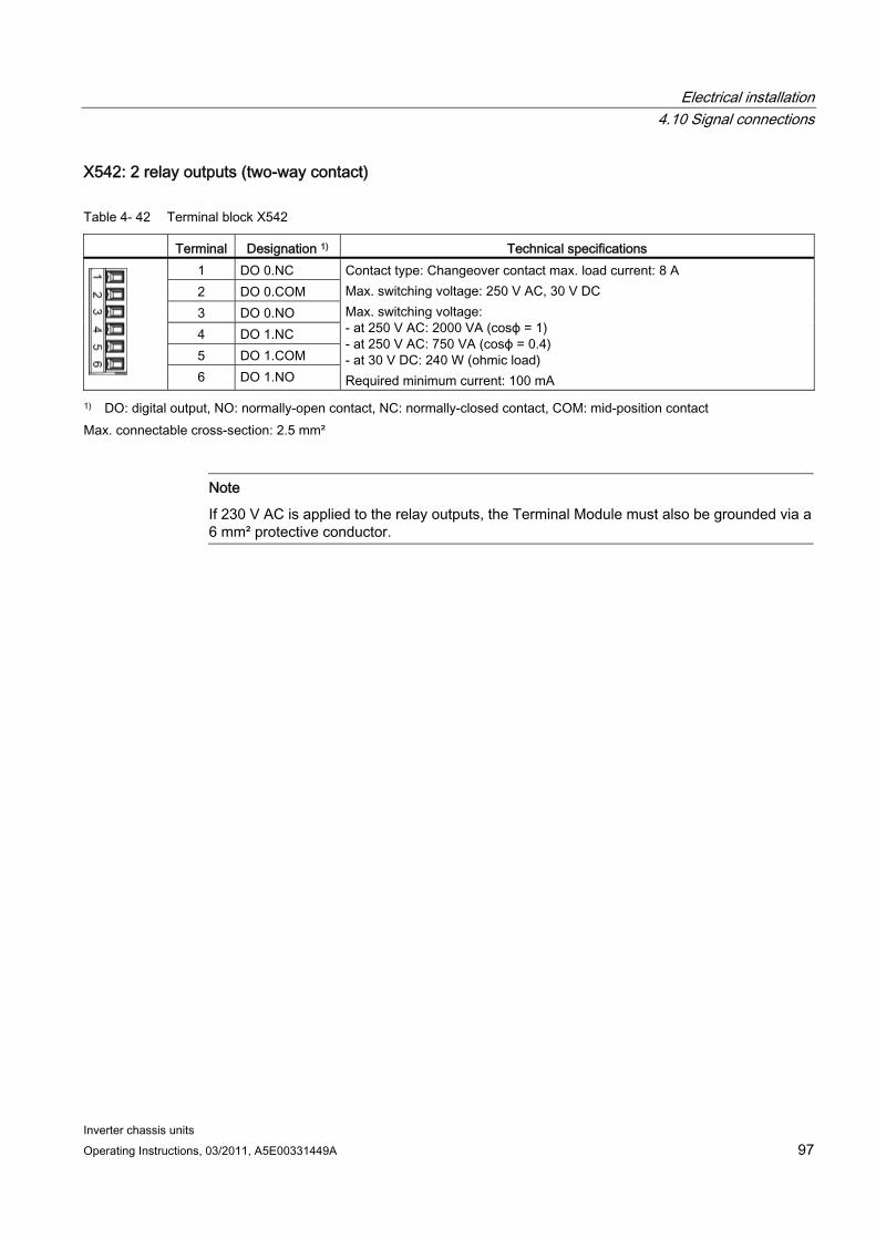
Electrical installation 4.10 Signal connections
Inverter chassis units Operating Instructions, 03/2011, A5E00331449A 97
X542: 2 relay outputs (two-way contact)
Table 4- 42 Terminal block X542
Terminal Designation 1) Technical specifications 1 DO 0.NC 2 DO 0.COM 3 DO 0.NO 4 DO 1.NC 5 DO 1.COM
6 DO 1.NO
Contact type: Changeover contact max. load current: 8 A Max. switching voltage: 250 V AC, 30 V DC Max. switching voltage: - at 250 V AC: 2000 VA (cosϕ = 1) - at 250 V AC: 750 VA (cosϕ = 0.4) - at 30 V DC: 240 W (ohmic load) Required minimum current: 100 mA
1) DO: digital output, NO: normally-open contact, NC: normally-closed contact, COM: mid-position contact Max. connectable cross-section: 2.5 mm²
Note
If 230 V AC is applied to the relay outputs, the Terminal Module must also be grounded via a 6 mm² protective conductor.
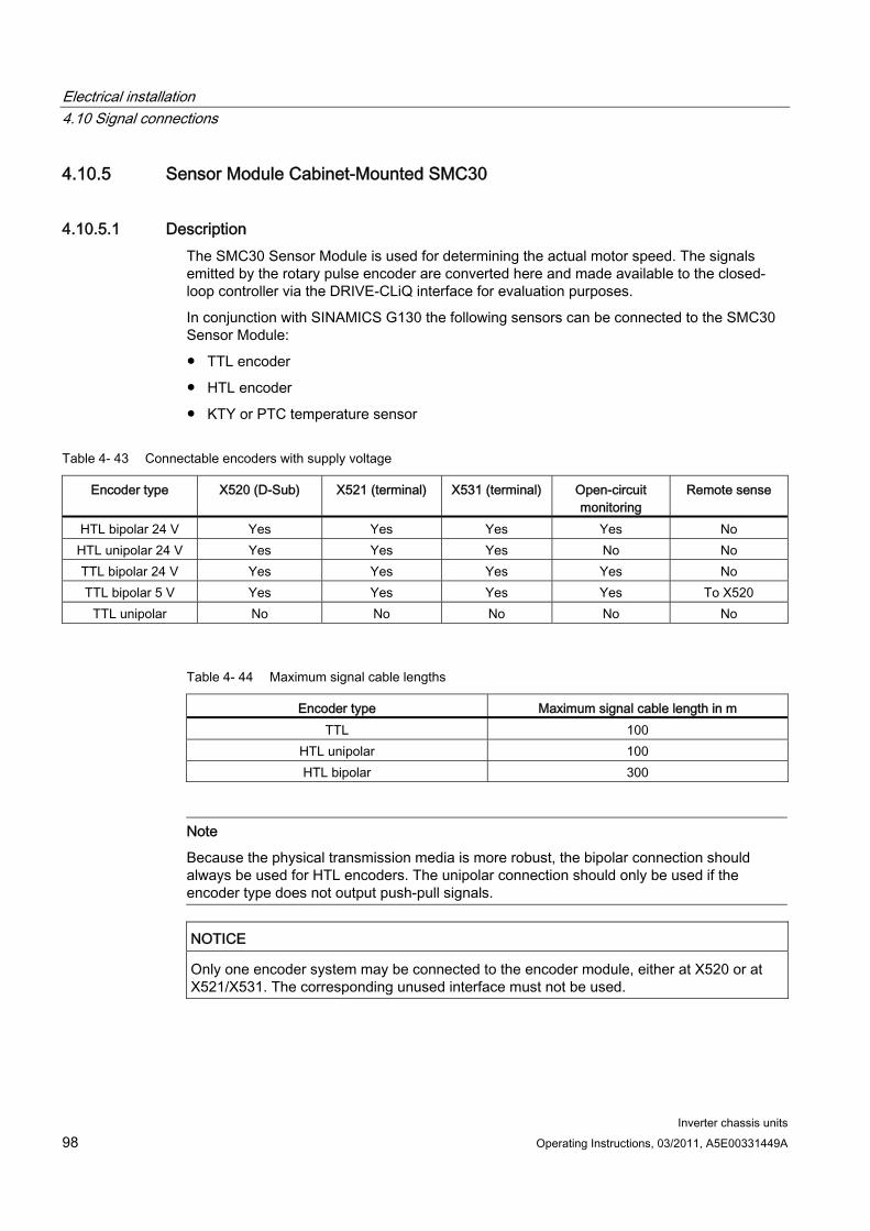
Electrical installation 4.10 Signal connections
Inverter chassis units 98 Operating Instructions, 03/2011, A5E00331449A
4.10.5 Sensor Module Cabinet-Mounted SMC30
4.10.5.1 Description The SMC30 Sensor Module is used for determining the actual motor speed. The signals emitted by the rotary pulse encoder are converted here and made available to the closed-loop controller via the DRIVE-CLiQ interface for evaluation purposes.
In conjunction with SINAMICS G130 the following sensors can be connected to the SMC30 Sensor Module:
TTL encoder
HTL encoder
KTY or PTC temperature sensor
Table 4- 43 Connectable encoders with supply voltage
Encoder type X520 (D-Sub) X521 (terminal) X531 (terminal) Open-circuit monitoring
Remote sense
HTL bipolar 24 V Yes Yes Yes Yes No HTL unipolar 24 V Yes Yes Yes No No TTL bipolar 24 V Yes Yes Yes Yes No TTL bipolar 5 V Yes Yes Yes Yes To X520
TTL unipolar No No No No No
Table 4- 44 Maximum signal cable lengths
Encoder type Maximum signal cable length in m TTL 100
HTL unipolar 100 HTL bipolar 300
Note
Because the physical transmission media is more robust, the bipolar connection should always be used for HTL encoders. The unipolar connection should only be used if the encoder type does not output push-pull signals.
NOTICE Only one encoder system may be connected to the encoder module, either at X520 or at X521/X531. The corresponding unused interface must not be used.
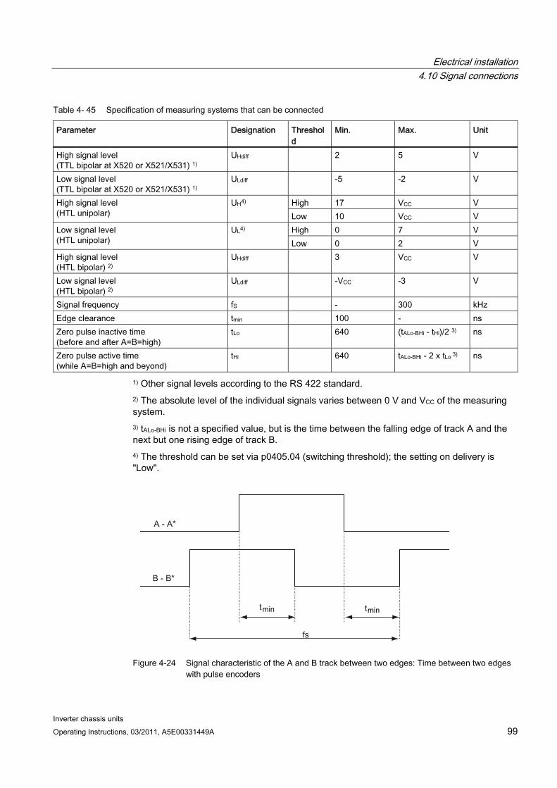
Electrical installation 4.10 Signal connections
Inverter chassis units Operating Instructions, 03/2011, A5E00331449A 99
Table 4- 45 Specification of measuring systems that can be connected
Parameter Designation Threshold
Min. Max. Unit
High signal level (TTL bipolar at X520 or X521/X531) 1)
UHdiff 2 5 V
Low signal level (TTL bipolar at X520 or X521/X531) 1)
ULdiff -5 -2 V
High 17 VCC V High signal level (HTL unipolar)
UH4) Low 10 VCC V High 0 7 V Low signal level
(HTL unipolar) UL4)
Low 0 2 V High signal level (HTL bipolar) 2)
UHdiff 3 VCC V
Low signal level (HTL bipolar) 2)
ULdiff -VCC -3 V
Signal frequency fS - 300 kHz Edge clearance tmin 100 - ns Zero pulse inactive time (before and after A=B=high)
tLo 640 (tALo-BHi - tHi)/2 3) ns
Zero pulse active time (while A=B=high and beyond)
tHi 640 tALo-BHi - 2 x tLo 3) ns
1) Other signal levels according to the RS 422 standard. 2) The absolute level of the individual signals varies between 0 V and VCC of the measuring system. 3) tALo-BHi is not a specified value, but is the time between the falling edge of track A and the next but one rising edge of track B. 4) The threshold can be set via p0405.04 (switching threshold); the setting on delivery is "Low".
Figure 4-24 Signal characteristic of the A and B track between two edges: Time between two edges
with pulse encoders
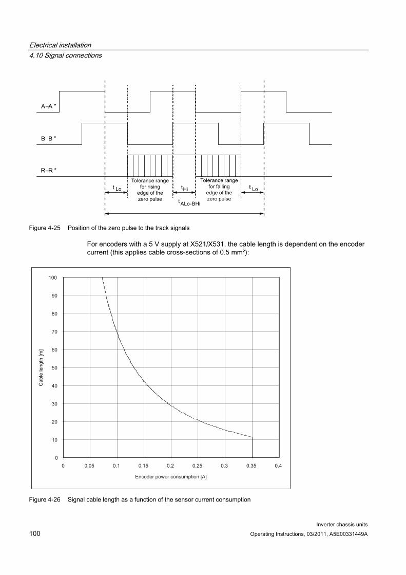
Electrical installation 4.10 Signal connections
Inverter chassis units 100 Operating Instructions, 03/2011, A5E00331449A
Figure 4-25 Position of the zero pulse to the track signals
For encoders with a 5 V supply at X521/X531, the cable length is dependent on the encoder current (this applies cable cross-sections of 0.5 mm²):
Figure 4-26 Signal cable length as a function of the sensor current consumption
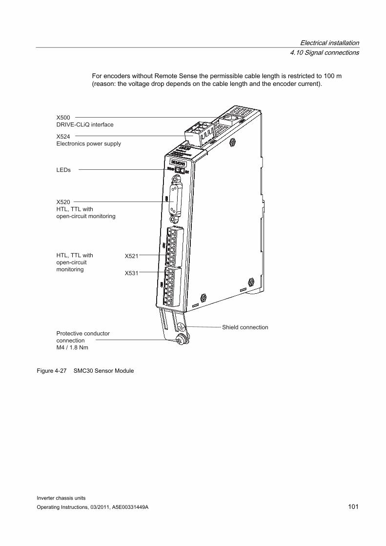
Electrical installation 4.10 Signal connections
Inverter chassis units Operating Instructions, 03/2011, A5E00331449A 101
For encoders without Remote Sense the permissible cable length is restricted to 100 m (reason: the voltage drop depends on the cable length and the encoder current).
Figure 4-27 SMC30 Sensor Module
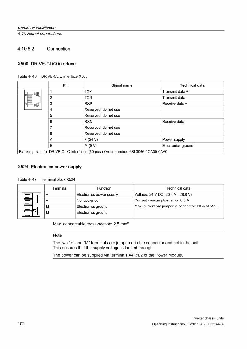
Electrical installation 4.10 Signal connections
Inverter chassis units 102 Operating Instructions, 03/2011, A5E00331449A
4.10.5.2 Connection
X500: DRIVE-CLiQ interface
Table 4- 46 DRIVE-CLiQ interface X500
Pin Signal name Technical data 1 TXP Transmit data + 2 TXN Transmit data - 3 RXP Receive data + 4 Reserved, do not use 5 Reserved, do not use 6 RXN Receive data - 7 Reserved, do not use 8 Reserved, do not use A + (24 V) Power supply
B M (0 V) Electronics ground Blanking plate for DRIVE-CLiQ interfaces (50 pcs.) Order number: 6SL3066-4CA00-0AA0
X524: Electronics power supply
Table 4- 47 Terminal block X524
Terminal Function Technical data + Electronics power supply + Not assigned M Electronics ground
M Electronics ground
Voltage: 24 V DC (20.4 V - 28.8 V) Current consumption: max. 0.5 A Max. current via jumper in connector: 20 A at 55° C
Max. connectable cross-section: 2.5 mm²
Note
The two "+" and "M" terminals are jumpered in the connector and not in the unit. This ensures that the supply voltage is looped through.
The power can be supplied via terminals X41:1/2 of the Power Module.
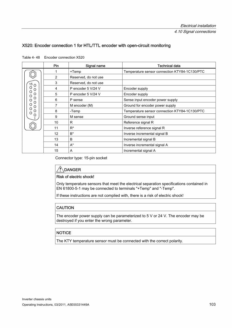
Electrical installation 4.10 Signal connections
Inverter chassis units Operating Instructions, 03/2011, A5E00331449A 103
X520: Encoder connection 1 for HTL/TTL encoder with open-circuit monitoring
Table 4- 48 Encoder connection X520
Pin Signal name Technical data 1 +Temp Temperature sensor connection KTY84-1C130/PTC 2 Reserved, do not use 3 Reserved, do not use 4 P encoder 5 V/24 V Encoder supply 5 P encoder 5 V/24 V Encoder supply 6 P sense Sense input encoder power supply 7 M encoder (M) Ground for encoder power supply 8 -Temp Temperature sensor connection KTY84-1C130/PTC 9 M sense Ground sense input 10 R Reference signal R 11 R* Inverse reference signal R 12 B* Inverse incremental signal B 13 B Incremental signal B 14 A* Inverse incremental signal A
15 A Incremental signal A
Connector type: 15-pin socket
DANGER Risk of electric shock!
Only temperature sensors that meet the electrical separation specifications contained in EN 61800-5-1 may be connected to terminals "+Temp" and "-Temp".
If these instructions are not complied with, there is a risk of electric shock!
CAUTION The encoder power supply can be parameterized to 5 V or 24 V. The encoder may be destroyed if you enter the wrong parameter.
NOTICE The KTY temperature sensor must be connected with the correct polarity.
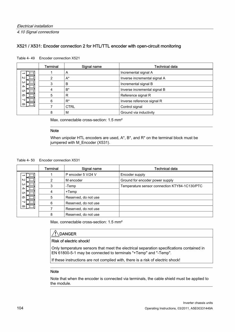
Electrical installation 4.10 Signal connections
Inverter chassis units 104 Operating Instructions, 03/2011, A5E00331449A
X521 / X531: Encoder connection 2 for HTL/TTL encoder with open-circuit monitoring
Table 4- 49 Encoder connection X521
Terminal Signal name Technical data 1 A Incremental signal A 2 A* Inverse incremental signal A 3 B Incremental signal B 4 B* Inverse incremental signal B 5 R Reference signal R 6 R* Inverse reference signal R 7 CTRL Control signal 8 M Ground via inductivity
Max. connectable cross-section: 1.5 mm²
Note
When unipolar HTL encoders are used, A*, B*, and R* on the terminal block must be jumpered with M_Encoder (X531).
Table 4- 50 Encoder connection X531
Terminal Signal name Technical data 1 P encoder 5 V/24 V Encoder supply 2 M encoder Ground for encoder power supply 3 -Temp 4 +Temp
Temperature sensor connection KTY84-1C130/PTC
5 Reserved, do not use 6 Reserved, do not use 7 Reserved, do not use 8 Reserved, do not use
Max. connectable cross-section: 1.5 mm²
DANGER Risk of electric shock!
Only temperature sensors that meet the electrical separation specifications contained in EN 61800-5-1 may be connected to terminals "+Temp" and "-Temp".
If these instructions are not complied with, there is a risk of electric shock!
Note
Note that when the encoder is connected via terminals, the cable shield must be applied to the module.
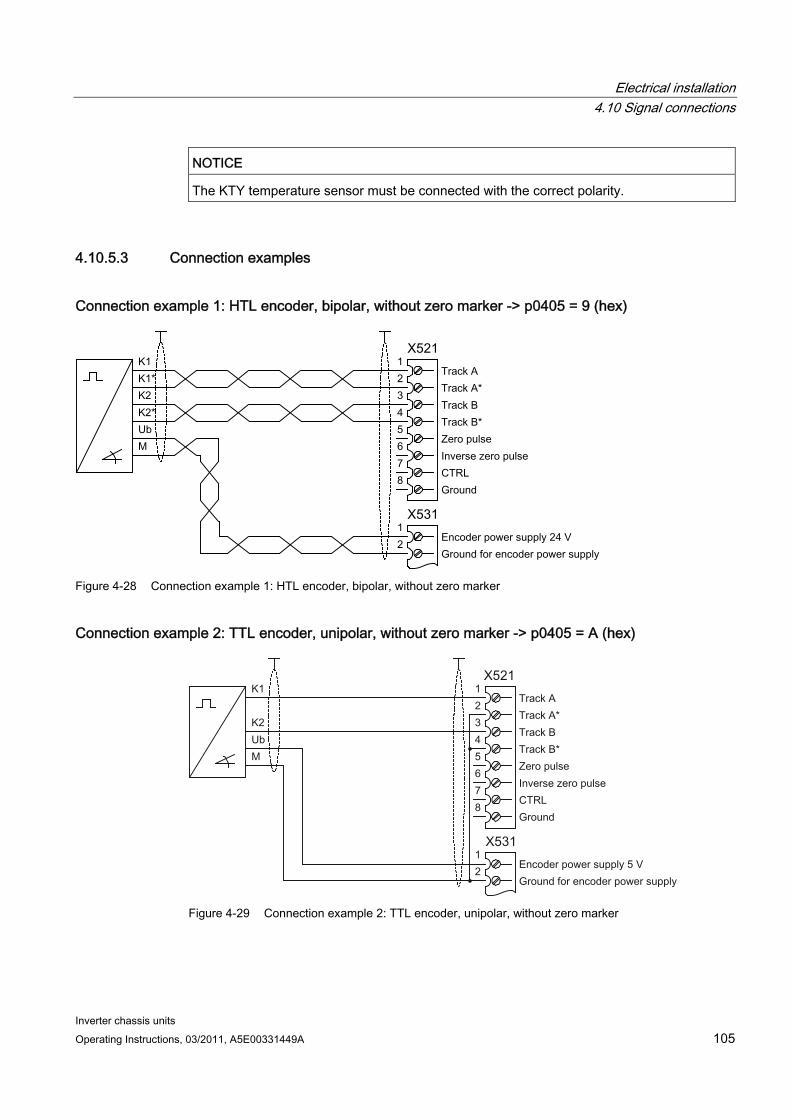
Electrical installation 4.10 Signal connections
Inverter chassis units Operating Instructions, 03/2011, A5E00331449A 105
NOTICE The KTY temperature sensor must be connected with the correct polarity.
4.10.5.3 Connection examples
Connection example 1: HTL encoder, bipolar, without zero marker -> p0405 = 9 (hex)
Figure 4-28 Connection example 1: HTL encoder, bipolar, without zero marker
Connection example 2: TTL encoder, unipolar, without zero marker -> p0405 = A (hex)
Figure 4-29 Connection example 2: TTL encoder, unipolar, without zero marker

Electrical installation 4.10 Signal connections
Inverter chassis units 106 Operating Instructions, 03/2011, A5E00331449A
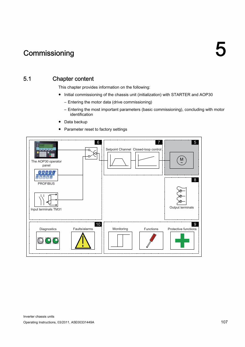
Inverter chassis units Operating Instructions, 03/2011, A5E00331449A 107
Commissioning 55.1 Chapter content
This chapter provides information on the following:
Initial commissioning of the chassis unit (initialization) with STARTER and AOP30
– Entering the motor data (drive commissioning)
– Entering the most important parameters (basic commissioning), concluding with motor identification
Data backup
Parameter reset to factory settings
M ~
5 7 6
8
9 10
Commissioning 5.2 STARTER commissioning tool
Inverter chassis units 108 Operating Instructions, 03/2011, A5E00331449A
Important information prior to commissioning The built-in unit offers a varying number of signal interconnections depending on the additional modules connected. For the converter control to be able to process the signals correctly, several software settings must be made.
During initial power-up of the Control Unit and during first commissioning, parameter macros are executed and the necessary settings made. The settings are documented in the Appendix.
After initial power-up, first commissioning, and also following a "Parameter reset to factory settings", individual parameter values deviate from the factory settings stated in the List Manual.
5.2 STARTER commissioning tool
Description You can use the STARTER commissioning tool to configure and commission SINAMICS drives and drive systems. The drive can be configured using the STARTER drive configuration wizard.
Note
This chapter shows you how to carry out commissioning using STARTER. STARTER features a comprehensive online help function, which provides detailed explanations of all the processes and available system settings. For this reason, this chapter only describes the individual commissioning steps.
Prerequisite: STARTER Version The following STARTER version is required for commissioning SINAMICS with firmware V4.4:
STARTER V4.2
Prerequisites for installing STARTER Hardware The following minimum requirements must be complied with:
PG or PC
Pentium III, at least 1 GHz, (> 1 GHz recommended)
1 GB work memory (2 GB recommended)
Screen resolution 1024×768 pixels, 16-bit color depth
Free hard disk space > 3 GB

Commissioning 5.2 STARTER commissioning tool
Inverter chassis units Operating Instructions, 03/2011, A5E00331449A 109
Software The following minimum prerequisites must be observed when using STARTER without an existing STEP-7 installation:
Microsoft Windows 2000 SP4 *)
Microsoft Windows 2003 Server SP2
Microsoft Windows 2008 Server
Microsoft Windows XP Professional SP2 *) and SP3
Microsoft Windows VISTA Business SP1 **)
Microsoft Windows VISTA Ultimate SP1 **)
Microsoft Windows 7 Professional (32-bit)
Microsoft Windows 7 Ultimate (32-bit)
Microsoft Internet Explorer V6.0 or higher *) Restricted test scope **) Significantly restricted test scope, i.e., installation at your own risk after acknowledging a corresponding warning message
STARTER setup is possible with native Windows XP versions with Asian languages only if the Windows XP or Windows 7 software is an MUI version.
Acrobat Reader V5.0 or higher is required to open the function diagrams in the online help.
Note
If STARTER is used in combination with other STEP7 components, the prerequisites for the S7 components shall apply.
5.2.1 Installing STARTER STARTER is installed using the "setup" file on the customer DVD supplied. When you double-click the "Setup" file, the installation Wizard guides you through the process of installing STARTER.
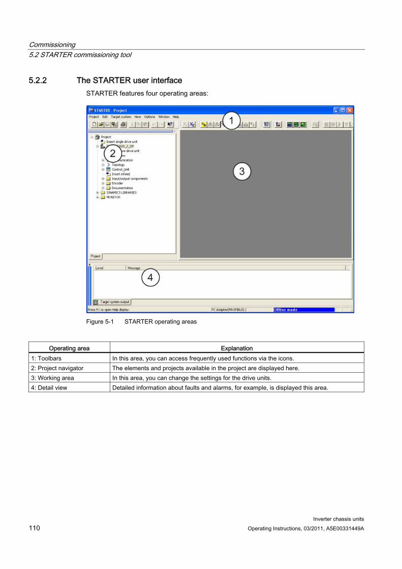
Commissioning 5.2 STARTER commissioning tool
Inverter chassis units 110 Operating Instructions, 03/2011, A5E00331449A
5.2.2 The STARTER user interface STARTER features four operating areas:
Figure 5-1 STARTER operating areas
Operating area Explanation
1: Toolbars In this area, you can access frequently used functions via the icons. 2: Project navigator The elements and projects available in the project are displayed here. 3: Working area In this area, you can change the settings for the drive units. 4: Detail view Detailed information about faults and alarms, for example, is displayed this area.
Commissioning 5.3 Procedure for commissioning via STARTER
Inverter chassis units Operating Instructions, 03/2011, A5E00331449A 111
5.3 Procedure for commissioning via STARTER
Basic procedure using STARTER STARTER uses a sequence of dialog screens for entering the required drive unit data.
NOTICE These dialog screens contain default settings, which you may have to change according to your application and configuration.
This is intentional because By taking time to consider what configuration data you enter, you can prevent inconsistencies between the project data and drive unit data (identifiable in online mode).
5.3.1 Creating a project Click the STARTER icon on the desktop, or select the menu command Start > SIMATIC > STEP 7 > STARTER in the Windows Start menu to open the STARTER commissioning tool.
The first time you run the software, the main screen (shown below) appears with the following windows:
STARTER Getting Started Drive Commissioning
STARTER Project Wizard
The commissioning steps are listed below as a numbered step sequence.
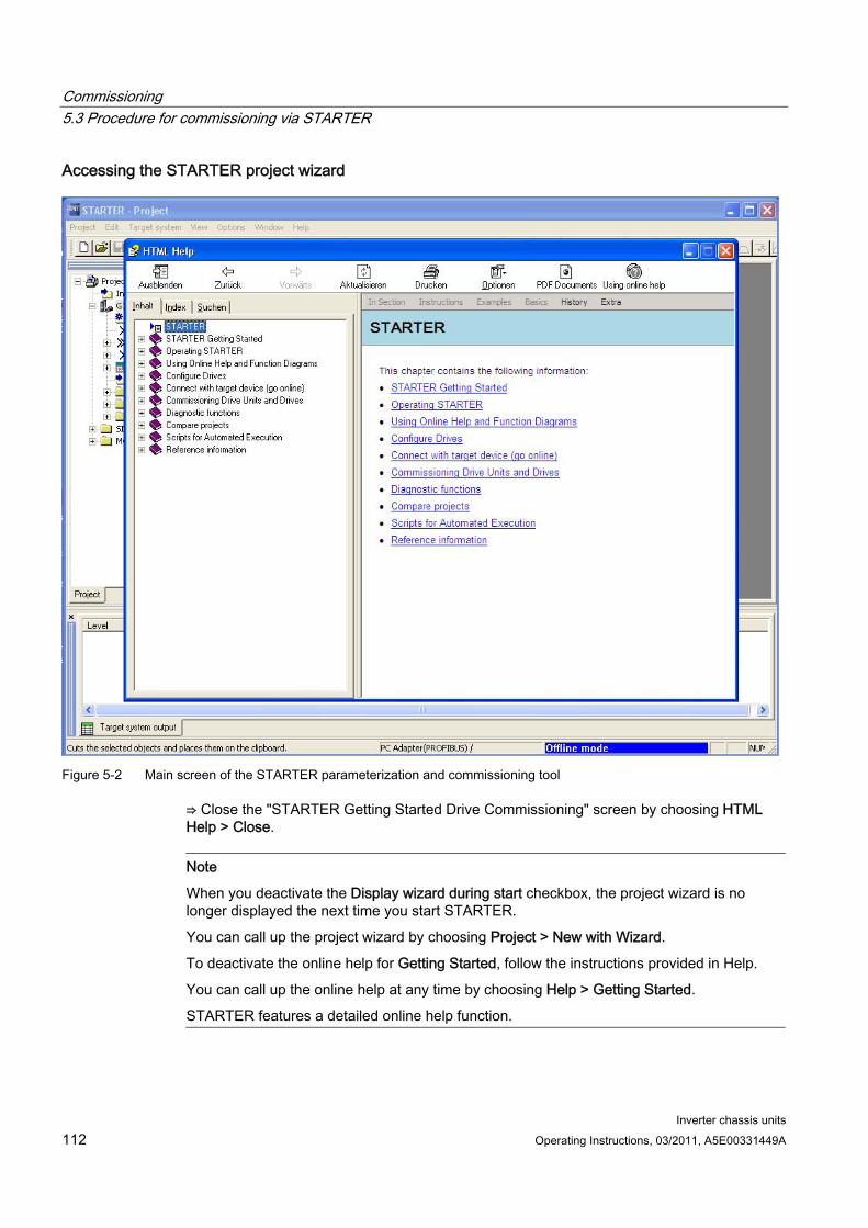
Commissioning 5.3 Procedure for commissioning via STARTER
Inverter chassis units 112 Operating Instructions, 03/2011, A5E00331449A
Accessing the STARTER project wizard
Figure 5-2 Main screen of the STARTER parameterization and commissioning tool
⇒ Close the "STARTER Getting Started Drive Commissioning" screen by choosing HTML Help > Close.
Note
When you deactivate the Display wizard during start checkbox, the project wizard is no longer displayed the next time you start STARTER.
You can call up the project wizard by choosing Project > New with Wizard.
To deactivate the online help for Getting Started, follow the instructions provided in Help.
You can call up the online help at any time by choosing Help > Getting Started.
STARTER features a detailed online help function.
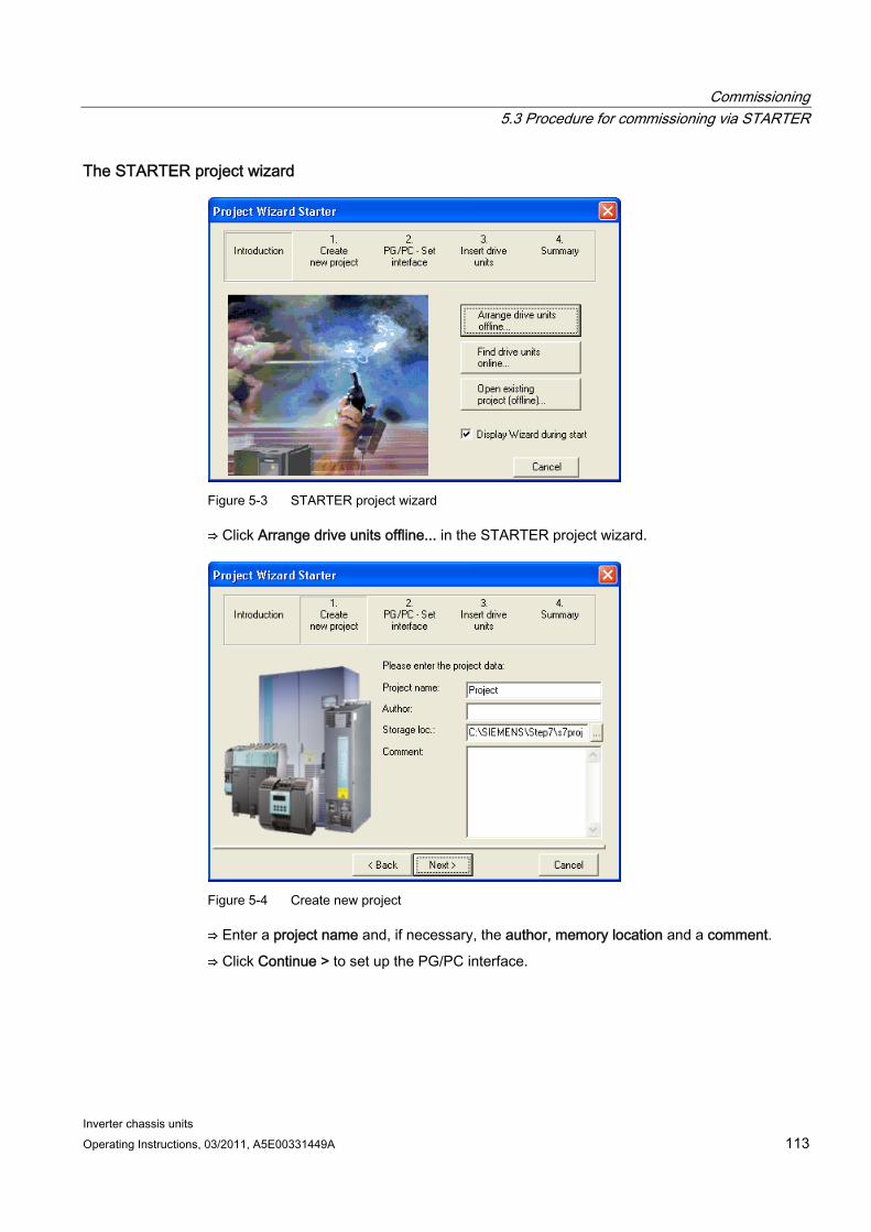
Commissioning 5.3 Procedure for commissioning via STARTER
Inverter chassis units Operating Instructions, 03/2011, A5E00331449A 113
The STARTER project wizard
Figure 5-3 STARTER project wizard
⇒ Click Arrange drive units offline... in the STARTER project wizard.
Figure 5-4 Create new project
⇒ Enter a project name and, if necessary, the author, memory location and a comment.
⇒ Click Continue > to set up the PG/PC interface.
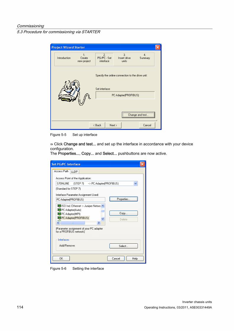
Commissioning 5.3 Procedure for commissioning via STARTER
Inverter chassis units 114 Operating Instructions, 03/2011, A5E00331449A
Figure 5-5 Set up interface
⇒ Click Change and test... and set up the interface in accordance with your device configuration. The Properties..., Copy... and Select... pushbuttons are now active.
Figure 5-6 Setting the interface
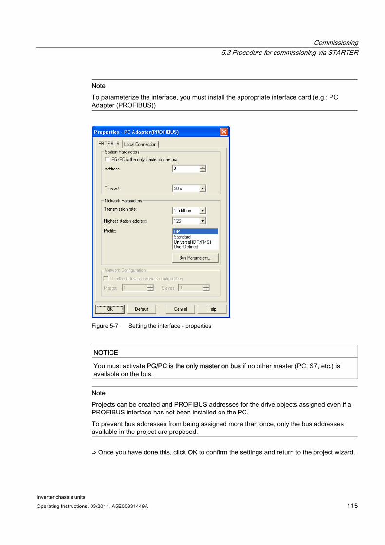
Commissioning 5.3 Procedure for commissioning via STARTER
Inverter chassis units Operating Instructions, 03/2011, A5E00331449A 115
Note
To parameterize the interface, you must install the appropriate interface card (e.g.: PC Adapter (PROFIBUS))
Figure 5-7 Setting the interface - properties
NOTICE You must activate PG/PC is the only master on bus if no other master (PC, S7, etc.) is available on the bus.
Note
Projects can be created and PROFIBUS addresses for the drive objects assigned even if a PROFIBUS interface has not been installed on the PC.
To prevent bus addresses from being assigned more than once, only the bus addresses available in the project are proposed.
⇒ Once you have done this, click OK to confirm the settings and return to the project wizard.
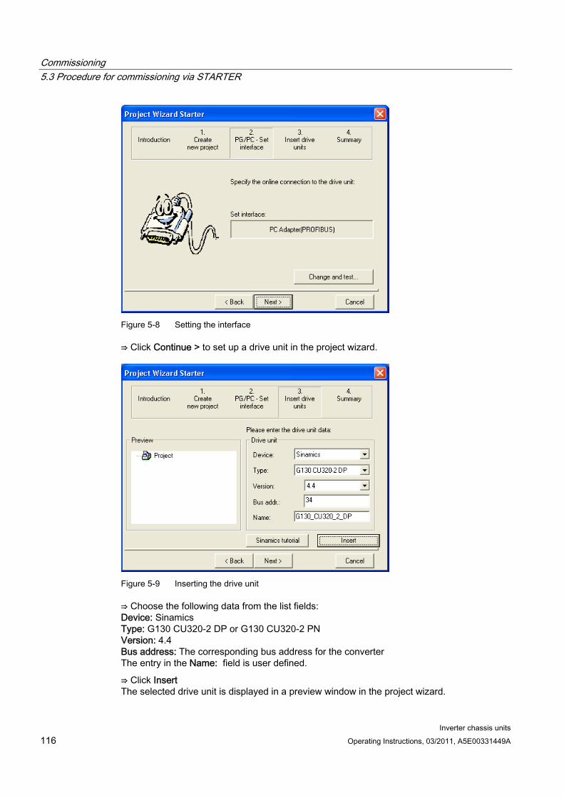
Commissioning 5.3 Procedure for commissioning via STARTER
Inverter chassis units 116 Operating Instructions, 03/2011, A5E00331449A
Figure 5-8 Setting the interface
⇒ Click Continue > to set up a drive unit in the project wizard.
Figure 5-9 Inserting the drive unit
⇒ Choose the following data from the list fields: Device: Sinamics Type: G130 CU320-2 DP or G130 CU320-2 PN Version: 4.4 Bus address: The corresponding bus address for the converter The entry in the Name: field is user defined.
⇒ Click Insert The selected drive unit is displayed in a preview window in the project wizard.
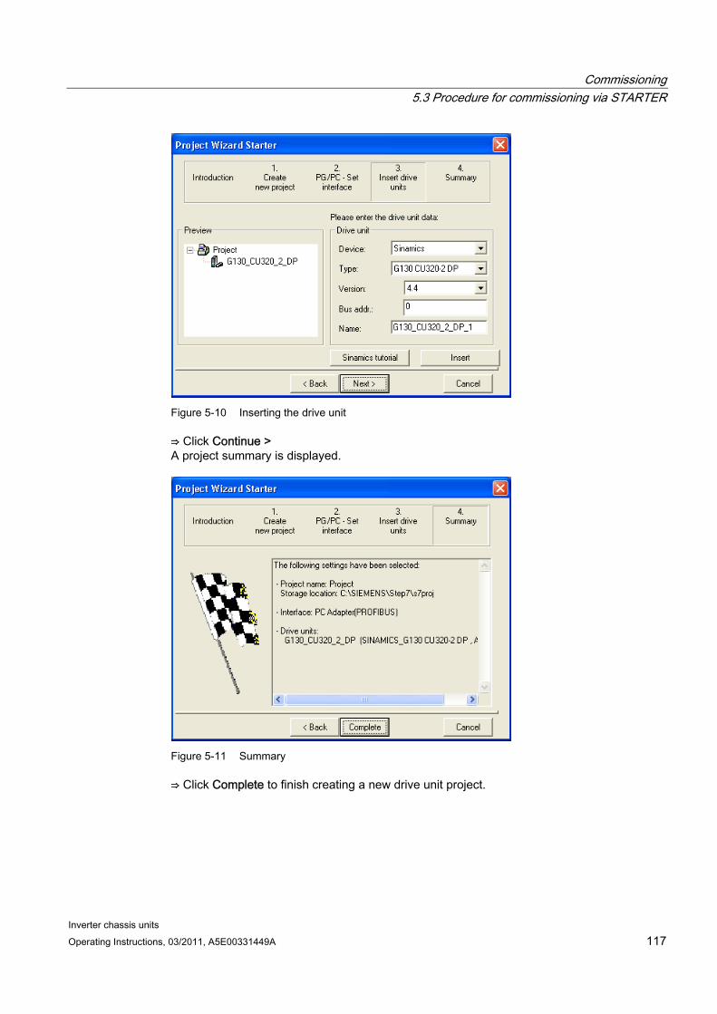
Commissioning 5.3 Procedure for commissioning via STARTER
Inverter chassis units Operating Instructions, 03/2011, A5E00331449A 117
Figure 5-10 Inserting the drive unit
⇒ Click Continue > A project summary is displayed.
Figure 5-11 Summary
⇒ Click Complete to finish creating a new drive unit project.
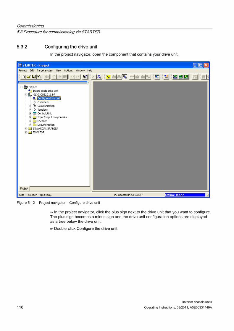
Commissioning 5.3 Procedure for commissioning via STARTER
Inverter chassis units 118 Operating Instructions, 03/2011, A5E00331449A
5.3.2 Configuring the drive unit In the project navigator, open the component that contains your drive unit.
Figure 5-12 Project navigator – Configure drive unit
⇒ In the project navigator, click the plus sign next to the drive unit that you want to configure. The plus sign becomes a minus sign and the drive unit configuration options are displayed as a tree below the drive unit.
⇒ Double-click Configure the drive unit.
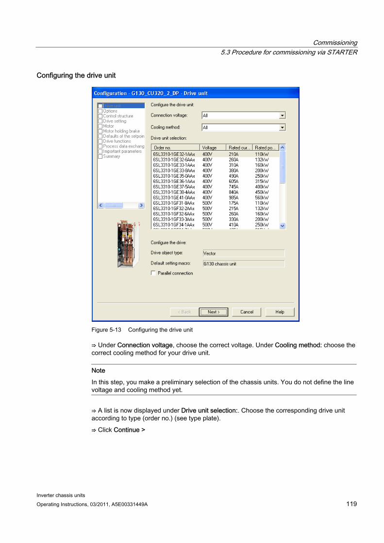
Commissioning 5.3 Procedure for commissioning via STARTER
Inverter chassis units Operating Instructions, 03/2011, A5E00331449A 119
Configuring the drive unit
Figure 5-13 Configuring the drive unit
⇒ Under Connection voltage, choose the correct voltage. Under Cooling method: choose the correct cooling method for your drive unit.
Note
In this step, you make a preliminary selection of the chassis units. You do not define the line voltage and cooling method yet.
⇒ A list is now displayed under Drive unit selection:. Choose the corresponding drive unit according to type (order no.) (see type plate).
⇒ Click Continue >
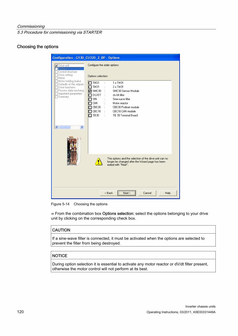
Commissioning 5.3 Procedure for commissioning via STARTER
Inverter chassis units 120 Operating Instructions, 03/2011, A5E00331449A
Choosing the options
Figure 5-14 Choosing the options
⇒ From the combination box Options selection: select the options belonging to your drive unit by clicking on the corresponding check box.
CAUTION If a sine-wave filter is connected, it must be activated when the options are selected to prevent the filter from being destroyed.
NOTICE During option selection it is essential to activate any motor reactor or dV/dt filter present, otherwise the motor control will not perform at its best.
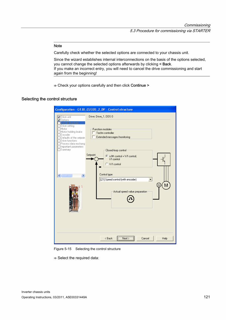
Commissioning 5.3 Procedure for commissioning via STARTER
Inverter chassis units Operating Instructions, 03/2011, A5E00331449A 121
Note
Carefully check whether the selected options are connected to your chassis unit.
Since the wizard establishes internal interconnections on the basis of the options selected, you cannot change the selected options afterwards by clicking < Back. If you make an incorrect entry, you will need to cancel the drive commissioning and start again from the beginning!
⇒ Check your options carefully and then click Continue >
Selecting the control structure
Figure 5-15 Selecting the control structure
⇒ Select the required data:

Commissioning 5.3 Procedure for commissioning via STARTER
Inverter chassis units 122 Operating Instructions, 03/2011, A5E00331449A
Function modules:
– Technology controller
– Extended messages/monitoring
Control method: choose one of the following open-loop/closed-loop control types:
– 0: V/f control with linear characteristic
– 1: V/f control with linear characteristic and FCC
– 2: V/f control with parabolic characteristic
– 3: V/f control with parameterizable characteristic
– 4: V/f control with linear characteristic and ECO
– 5: V/f control for drive requiring a precise frequency (e.g. textiles)
– 6: V/f control for drive requiring a precise frequency and FCC
– 7: V/f control with parabolic characteristic and ECO
– 15: Operation with braking resistor
– 18: I/f control with fixed current
– 19: V/f control with independent voltage setpoint
– 20: Speed control (without encoder)
– 21: Speed control (with encoder)
– 22: Torque control (without encoder)
– 23: Torque control (with encoder)
⇒ Click Continue >
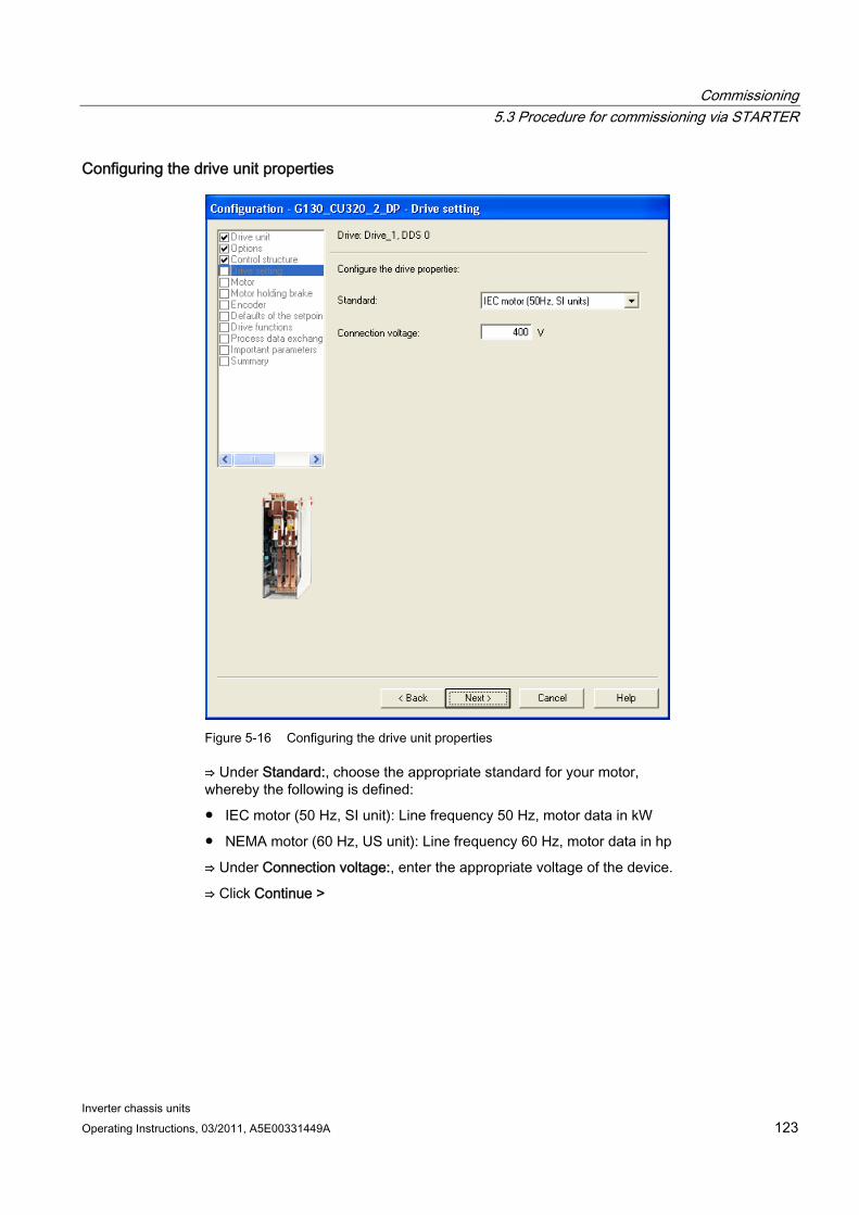
Commissioning 5.3 Procedure for commissioning via STARTER
Inverter chassis units Operating Instructions, 03/2011, A5E00331449A 123
Configuring the drive unit properties
Figure 5-16 Configuring the drive unit properties
⇒ Under Standard:, choose the appropriate standard for your motor, whereby the following is defined:
IEC motor (50 Hz, SI unit): Line frequency 50 Hz, motor data in kW
NEMA motor (60 Hz, US unit): Line frequency 60 Hz, motor data in hp
⇒ Under Connection voltage:, enter the appropriate voltage of the device.
⇒ Click Continue >
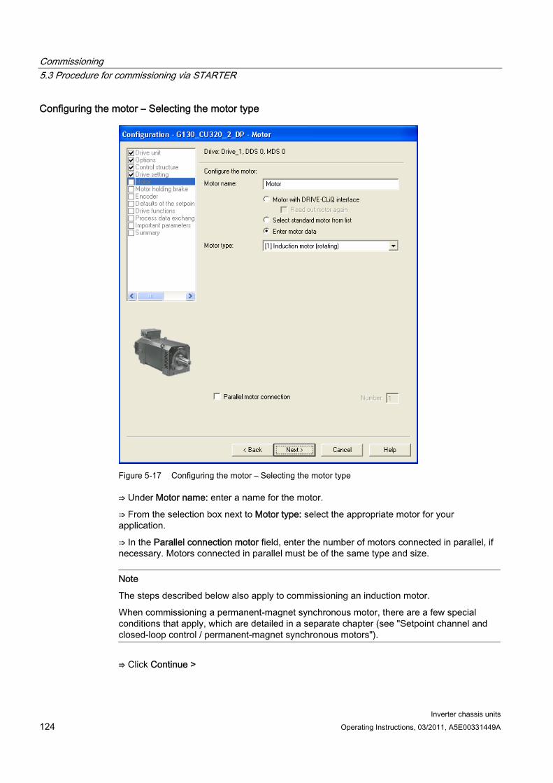
Commissioning 5.3 Procedure for commissioning via STARTER
Inverter chassis units 124 Operating Instructions, 03/2011, A5E00331449A
Configuring the motor – Selecting the motor type
Figure 5-17 Configuring the motor – Selecting the motor type
⇒ Under Motor name: enter a name for the motor.
⇒ From the selection box next to Motor type: select the appropriate motor for your application.
⇒ In the Parallel connection motor field, enter the number of motors connected in parallel, if necessary. Motors connected in parallel must be of the same type and size.
Note
The steps described below also apply to commissioning an induction motor.
When commissioning a permanent-magnet synchronous motor, there are a few special conditions that apply, which are detailed in a separate chapter (see "Setpoint channel and closed-loop control / permanent-magnet synchronous motors").
⇒ Click Continue >
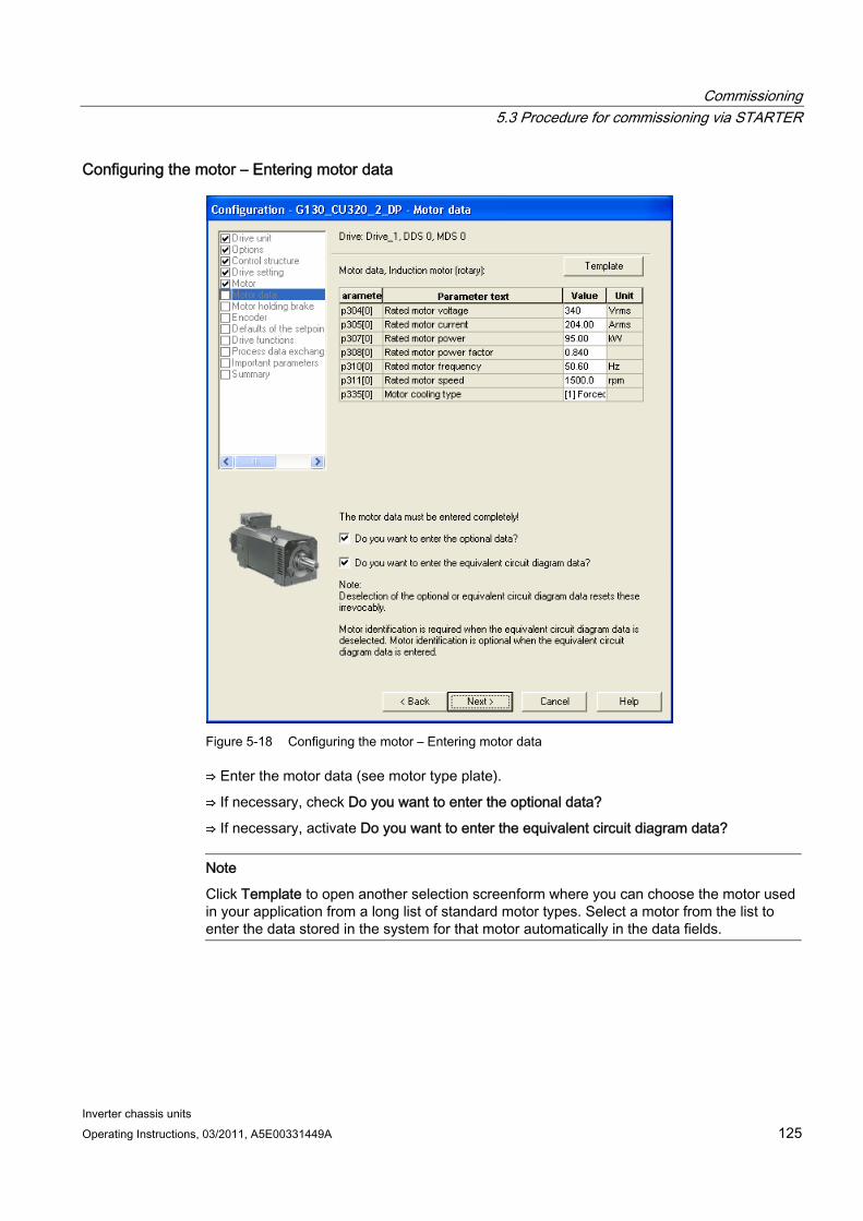
Commissioning 5.3 Procedure for commissioning via STARTER
Inverter chassis units Operating Instructions, 03/2011, A5E00331449A 125
Configuring the motor – Entering motor data
Figure 5-18 Configuring the motor – Entering motor data
⇒ Enter the motor data (see motor type plate).
⇒ If necessary, check Do you want to enter the optional data?
⇒ If necessary, activate Do you want to enter the equivalent circuit diagram data?
Note
Click Template to open another selection screenform where you can choose the motor used in your application from a long list of standard motor types. Select a motor from the list to enter the data stored in the system for that motor automatically in the data fields.
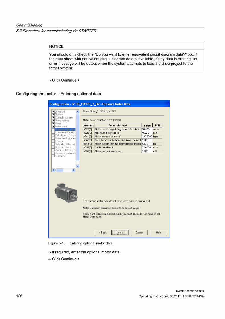
Commissioning 5.3 Procedure for commissioning via STARTER
Inverter chassis units 126 Operating Instructions, 03/2011, A5E00331449A
NOTICE You should only check the "Do you want to enter equivalent circuit diagram data?" box if the data sheet with equivalent circuit diagram data is available. If any data is missing, an error message will be output when the system attempts to load the drive project to the target system.
⇒ Click Continue >
Configuring the motor – Entering optional data
Figure 5-19 Entering optional motor data
⇒ If required, enter the optional motor data.
⇒ Click Continue >
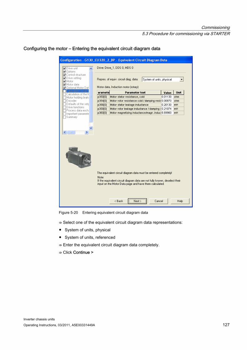
Commissioning 5.3 Procedure for commissioning via STARTER
Inverter chassis units Operating Instructions, 03/2011, A5E00331449A 127
Configuring the motor – Entering the equivalent circuit diagram data
Figure 5-20 Entering equivalent circuit diagram data
⇒ Select one of the equivalent circuit diagram data representations:
System of units, physical
System of units, referenced
⇒ Enter the equivalent circuit diagram data completely.
⇒ Click Continue >
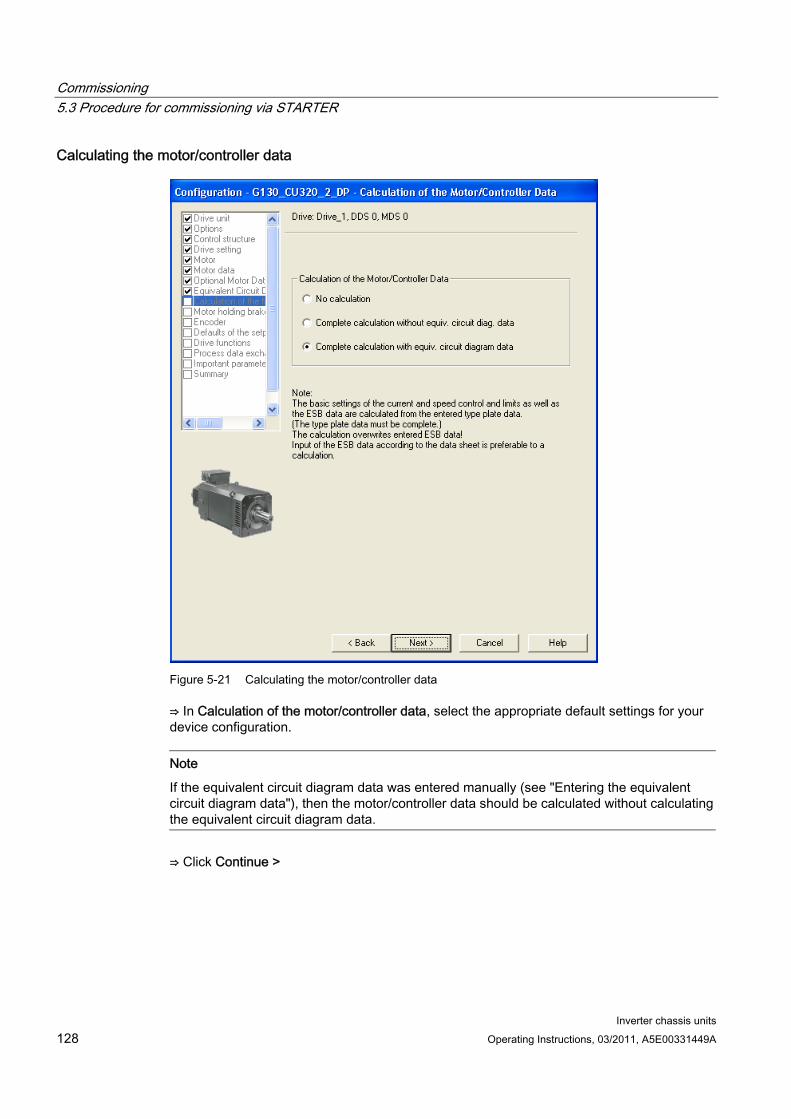
Commissioning 5.3 Procedure for commissioning via STARTER
Inverter chassis units 128 Operating Instructions, 03/2011, A5E00331449A
Calculating the motor/controller data
Figure 5-21 Calculating the motor/controller data
⇒ In Calculation of the motor/controller data, select the appropriate default settings for your device configuration.
Note
If the equivalent circuit diagram data was entered manually (see "Entering the equivalent circuit diagram data"), then the motor/controller data should be calculated without calculating the equivalent circuit diagram data.
⇒ Click Continue >
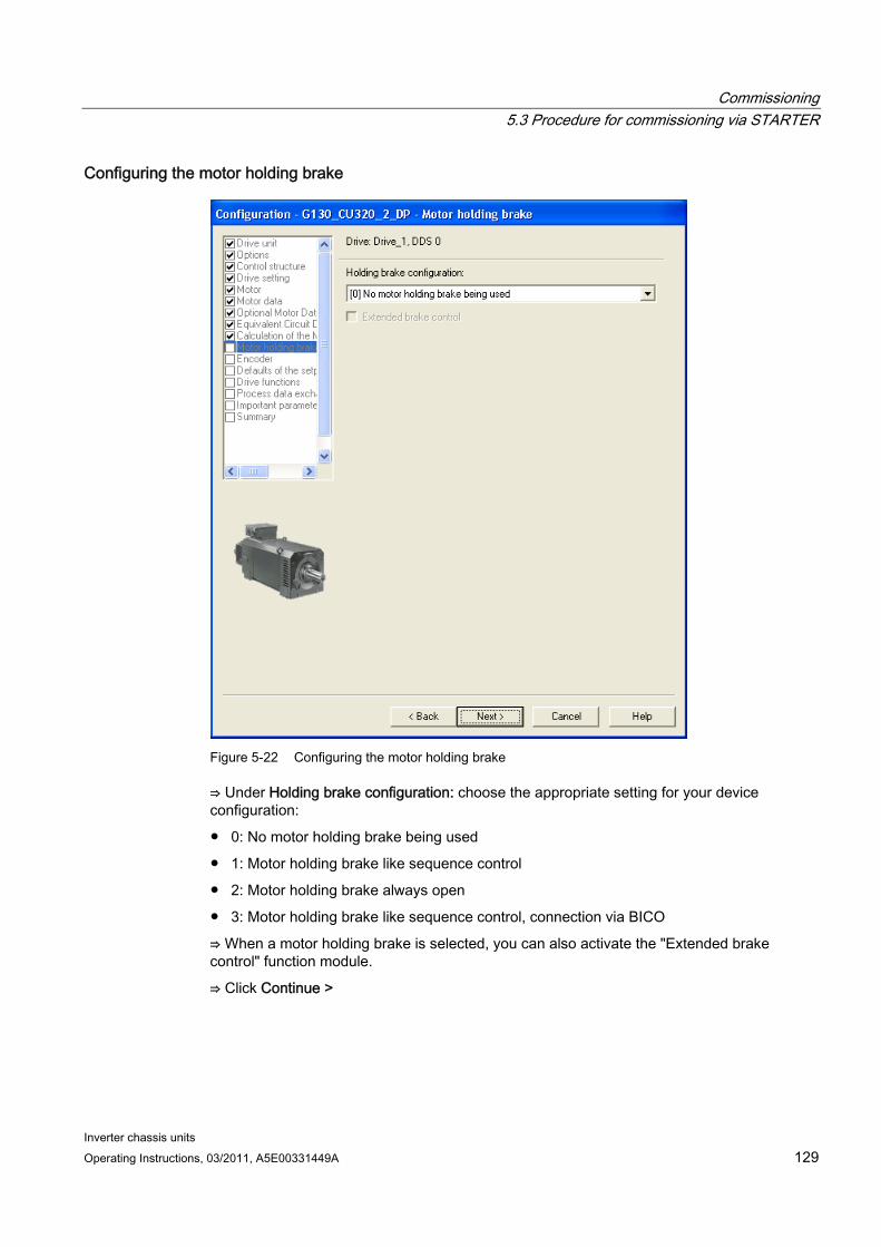
Commissioning 5.3 Procedure for commissioning via STARTER
Inverter chassis units Operating Instructions, 03/2011, A5E00331449A 129
Configuring the motor holding brake
Figure 5-22 Configuring the motor holding brake
⇒ Under Holding brake configuration: choose the appropriate setting for your device configuration:
0: No motor holding brake being used
1: Motor holding brake like sequence control
2: Motor holding brake always open
3: Motor holding brake like sequence control, connection via BICO
⇒ When a motor holding brake is selected, you can also activate the "Extended brake control" function module.
⇒ Click Continue >
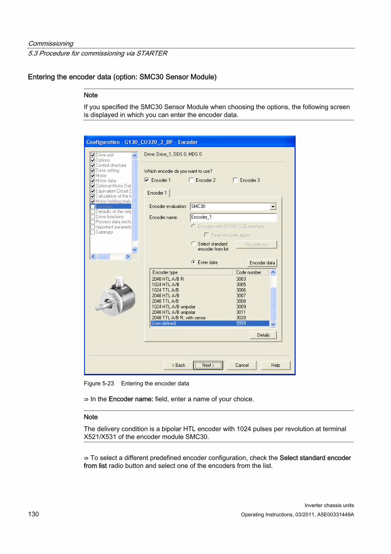
Commissioning 5.3 Procedure for commissioning via STARTER
Inverter chassis units 130 Operating Instructions, 03/2011, A5E00331449A
Entering the encoder data (option: SMC30 Sensor Module)
Note
If you specified the SMC30 Sensor Module when choosing the options, the following screen is displayed in which you can enter the encoder data.
Figure 5-23 Entering the encoder data
⇒ In the Encoder name: field, enter a name of your choice.
Note
The delivery condition is a bipolar HTL encoder with 1024 pulses per revolution at terminal X521/X531 of the encoder module SMC30.
⇒ To select a different predefined encoder configuration, check the Select standard encoder from list radio button and select one of the encoders from the list.
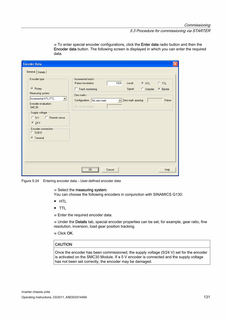
Commissioning 5.3 Procedure for commissioning via STARTER
Inverter chassis units Operating Instructions, 03/2011, A5E00331449A 131
⇒ To enter special encoder configurations, click the Enter data radio button and then the Encoder data button. The following screen is displayed in which you can enter the required data.
Figure 5-24 Entering encoder data – User-defined encoder data
⇒ Select the measuring system. You can choose the following encoders in conjunction with SINAMICS G130:
HTL
TTL
⇒ Enter the required encoder data.
⇒ Under the Details tab, special encoder properties can be set, for example, gear ratio, fine resolution, inversion, load gear position tracking.
⇒ Click OK.
CAUTION Once the encoder has been commissioned, the supply voltage (5/24 V) set for the encoder is activated on the SMC30 Module. If a 5 V encoder is connected and the supply voltage has not been set correctly, the encoder may be damaged.
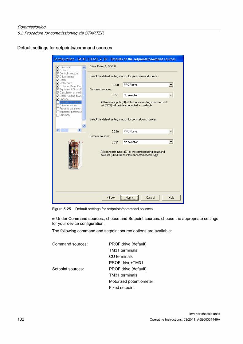
Commissioning 5.3 Procedure for commissioning via STARTER
Inverter chassis units 132 Operating Instructions, 03/2011, A5E00331449A
Default settings for setpoints/command sources
Figure 5-25 Default settings for setpoints/command sources
⇒ Under Command sources:, choose and Setpoint sources: choose the appropriate settings for your device configuration.
The following command and setpoint source options are available:
PROFIdrive (default) TM31 terminals CU terminals
Command sources:
PROFIdrive+TM31 PROFIdrive (default) TM31 terminals Motorized potentiometer
Setpoint sources:
Fixed setpoint
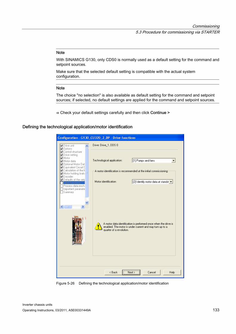
Commissioning 5.3 Procedure for commissioning via STARTER
Inverter chassis units Operating Instructions, 03/2011, A5E00331449A 133
Note
With SINAMICS G130, only CDS0 is normally used as a default setting for the command and setpoint sources.
Make sure that the selected default setting is compatible with the actual system configuration.
Note
The choice "no selection" is also available as default setting for the command and setpoint sources; if selected, no default settings are applied for the command and setpoint sources.
⇒ Check your default settings carefully and then click Continue >
Defining the technological application/motor identification
Figure 5-26 Defining the technological application/motor identification
Commissioning 5.3 Procedure for commissioning via STARTER
Inverter chassis units 134 Operating Instructions, 03/2011, A5E00331449A
⇒ Select the required data:
Technological application:
– "(0) Standard drive (VECTOR)" Edge modulation is not enabled. The dynamic voltage reserve is increased (10 V), which reduces the maximum output voltage.
– "(1) Pumps and fans"(default setting) Edge modulation is enabled. The dynamic voltage reserve is reduced (2 V), which increases the maximum output voltage.
– "(2) Sensorless control down to f = 0 (passive loads)" Closed-loop controlled operation down to zero speed is possible for passive loads. These include applications in which the load cannot produce a regenerative torque on startup and the motor comes to a standstill when pulses are inhibited.
Motor identification:
– (0): Disabled
– (1): Motor data identification at standstill and when the motor is rotating
– (2): Motor data identification at standstill
– (3): Motor data identification when the motor is rotating
Note
In many cases, "Motor data identification at standstill" is the correct selection for SINAMICS G130. "Motor data identification at standstill and when motor is running" is the recommended setting for closed-loop speed control with encoder; this measurement is normally performed for non-coupled machines.
DANGER When the rotating measurement is selected, the drive triggers movements in the motor that can reach the maximum motor speed. The EMERGENCY OFF functions must be fully operational during commissioning. To protect the machines and personnel, the relevant safety regulations must be observed.
⇒ Click Continue >
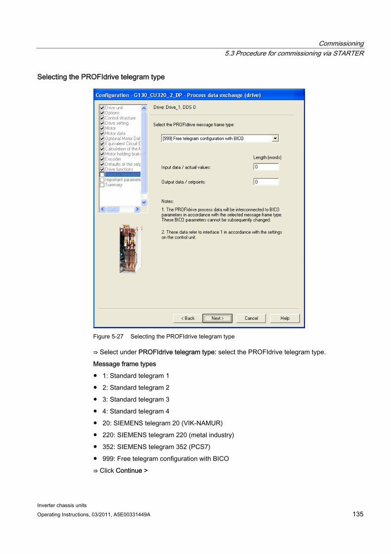
Commissioning 5.3 Procedure for commissioning via STARTER
Inverter chassis units Operating Instructions, 03/2011, A5E00331449A 135
Selecting the PROFIdrive telegram type
Figure 5-27 Selecting the PROFIdrive telegram type
⇒ Select under PROFIdrive telegram type: select the PROFIdrive telegram type.
Message frame types
1: Standard telegram 1
2: Standard telegram 2
3: Standard telegram 3
4: Standard telegram 4
20: SIEMENS telegram 20 (VIK-NAMUR)
220: SIEMENS telegram 220 (metal industry)
352: SIEMENS telegram 352 (PCS7)
999: Free telegram configuration with BICO
⇒ Click Continue >
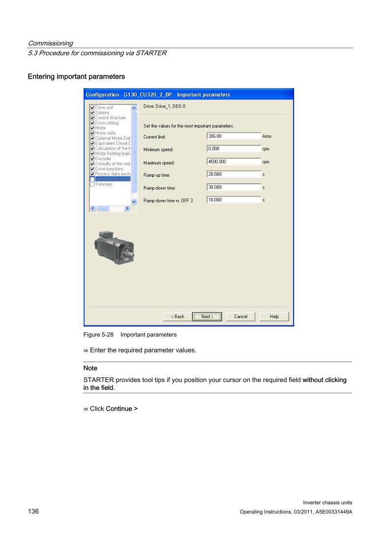
Commissioning 5.3 Procedure for commissioning via STARTER
Inverter chassis units 136 Operating Instructions, 03/2011, A5E00331449A
Entering important parameters
Figure 5-28 Important parameters
⇒ Enter the required parameter values.
Note
STARTER provides tool tips if you position your cursor on the required field without clicking in the field.
⇒ Click Continue >
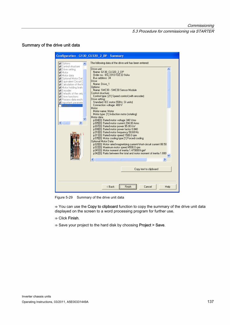
Commissioning 5.3 Procedure for commissioning via STARTER
Inverter chassis units Operating Instructions, 03/2011, A5E00331449A 137
Summary of the drive unit data
Figure 5-29 Summary of the drive unit data
⇒ You can use the Copy to clipboard function to copy the summary of the drive unit data displayed on the screen to a word processing program for further use.
⇒ Click Finish.
⇒ Save your project to the hard disk by choosing Project > Save.
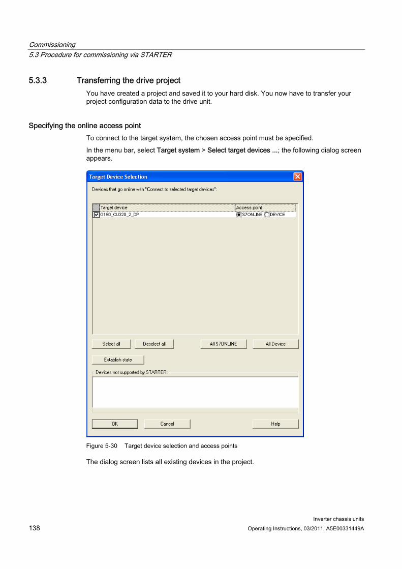
Commissioning 5.3 Procedure for commissioning via STARTER
Inverter chassis units 138 Operating Instructions, 03/2011, A5E00331449A
5.3.3 Transferring the drive project You have created a project and saved it to your hard disk. You now have to transfer your project configuration data to the drive unit.
Specifying the online access point To connect to the target system, the chosen access point must be specified.
In the menu bar, select Target system > Select target devices ...; the following dialog screen appears.
Figure 5-30 Target device selection and access points
The dialog screen lists all existing devices in the project.
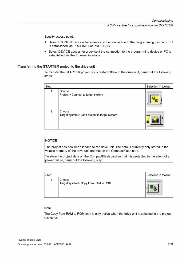
Commissioning 5.3 Procedure for commissioning via STARTER
Inverter chassis units Operating Instructions, 03/2011, A5E00331449A 139
Specify access point:
Select S7ONLINE access for a device, if the connection to the programming device or PC is established via PROFINET or PROFIBUS.
Select DEVICE access for a device if the connection to the programming device or PC is established via the Ethernet interface.
Transferring the STARTER project to the drive unit To transfer the STARTER project you created offline to the drive unit, carry out the following steps:
Step Selection in toolbar
1 Choose Project > Connect to target system
2 Choose
Target system > Load project to target system
NOTICE The project has now been loaded to the drive unit. The data is currently only stored in the volatile memory of the drive unit and not on the CompactFlash card.
To store the project data on the CompactFlash card so that it is protected in the event of a power failure, carry out the following step.
Step Selection in toolbar
3 Choose Target system > Copy from RAM to ROM
Note
The Copy from RAM to ROM icon is only active when the drive unit is selected in the project navigator.
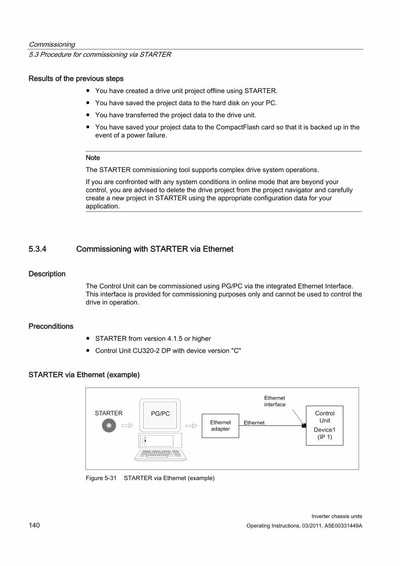
Commissioning 5.3 Procedure for commissioning via STARTER
Inverter chassis units 140 Operating Instructions, 03/2011, A5E00331449A
Results of the previous steps You have created a drive unit project offline using STARTER.
You have saved the project data to the hard disk on your PC.
You have transferred the project data to the drive unit.
You have saved your project data to the CompactFlash card so that it is backed up in the event of a power failure.
Note
The STARTER commissioning tool supports complex drive system operations.
If you are confronted with any system conditions in online mode that are beyond your control, you are advised to delete the drive project from the project navigator and carefully create a new project in STARTER using the appropriate configuration data for your application.
5.3.4 Commissioning with STARTER via Ethernet
Description The Control Unit can be commissioned using PG/PC via the integrated Ethernet Interface. This interface is provided for commissioning purposes only and cannot be used to control the drive in operation.
Preconditions STARTER from version 4.1.5 or higher
Control Unit CU320-2 DP with device version "C"
STARTER via Ethernet (example)
Figure 5-31 STARTER via Ethernet (example)
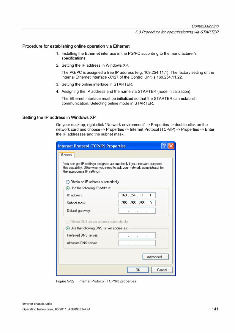
Commissioning 5.3 Procedure for commissioning via STARTER
Inverter chassis units Operating Instructions, 03/2011, A5E00331449A 141
Procedure for establishing online operation via Ethernet 1. Installing the Ethernet interface in the PG/PC according to the manufacturer's
specifications
2. Setting the IP address in Windows XP.
The PG/PC is assigned a free IP address (e.g. 169.254.11.1). The factory setting of the internal Ethernet interface -X127 of the Control Unit is 169.254.11.22.
3. Setting the online interface in STARTER.
4. Assigning the IP address and the name via STARTER (node initialization).
The Ethernet interface must be initialized so that the STARTER can establish communication. Selecting online mode in STARTER.
Setting the IP address in Windows XP On your desktop, right-click "Network environment" -> Properties -> double-click on the network card and choose -> Properties -> Internet Protocol (TCP/IP) -> Properties -> Enter the IP addresses and the subnet mask.
Figure 5-32 Internet Protocol (TCP/IP) properties
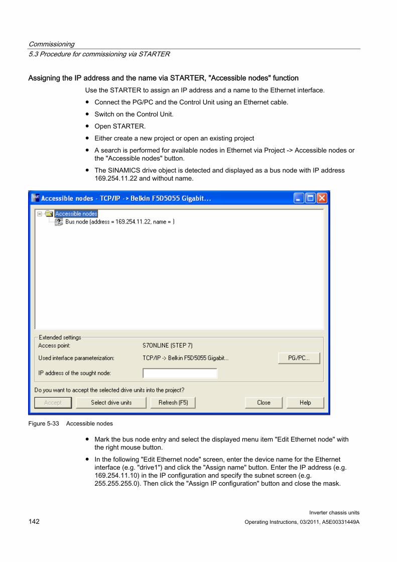
Commissioning 5.3 Procedure for commissioning via STARTER
Inverter chassis units 142 Operating Instructions, 03/2011, A5E00331449A
Assigning the IP address and the name via STARTER, "Accessible nodes" function Use the STARTER to assign an IP address and a name to the Ethernet interface.
Connect the PG/PC and the Control Unit using an Ethernet cable.
Switch on the Control Unit.
Open STARTER.
Either create a new project or open an existing project
A search is performed for available nodes in Ethernet via Project -> Accessible nodes or the "Accessible nodes" button.
The SINAMICS drive object is detected and displayed as a bus node with IP address 169.254.11.22 and without name.
Figure 5-33 Accessible nodes
Mark the bus node entry and select the displayed menu item "Edit Ethernet node" with the right mouse button.
In the following "Edit Ethernet node" screen, enter the device name for the Ethernet interface (e.g. "drive1") and click the "Assign name" button. Enter the IP address (e.g. 169.254.11.10) in the IP configuration and specify the subnet screen (e.g. 255.255.255.0). Then click the "Assign IP configuration" button and close the mask.
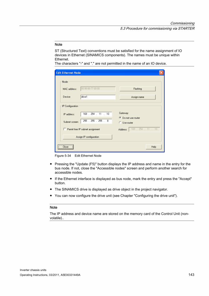
Commissioning 5.3 Procedure for commissioning via STARTER
Inverter chassis units Operating Instructions, 03/2011, A5E00331449A 143
Note
ST (Structured Text) conventions must be satisfied for the name assignment of IO devices in Ethernet (SINAMICS components). The names must be unique within Ethernet. The characters "-" and "." are not permitted in the name of an IO device.
Figure 5-34 Edit Ethernet Node
Pressing the "Update (F5)" button displays the IP address and name in the entry for the bus node. If not, close the "Accessible nodes" screen and perform another search for accessible nodes.
If the Ethernet interface is displayed as bus node, mark the entry and press the "Accept" button.
The SINAMICS drive is displayed as drive object in the project navigator.
You can now configure the drive unit (see Chapter "Configuring the drive unit").
Note
The IP address and device name are stored on the memory card of the Control Unit (non-volatile)..

Commissioning 5.3 Procedure for commissioning via STARTER
Inverter chassis units 144 Operating Instructions, 03/2011, A5E00331449A
Parameters Parameters can also be used to modify and/or display the properties of the Ethernet interface.
p8900 IE name of the station
p8901 IE IP address of the station
p8902 IE default gateway of station
p8903 IE subnet mask of station
p8904 IE DHCP mode
p8905 IE interface configuration
r8910 IE name of station active
r8911 IE IP address of station active
r8912 IE default gateway of station active
r8913 IE subnet mask of station active
r8914 IE DHCP mode of station active
r8915 IE MAC address of station
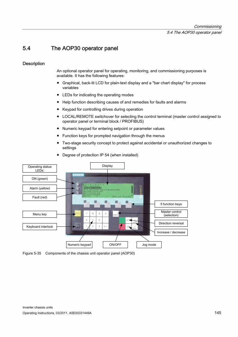
Commissioning 5.4 The AOP30 operator panel
Inverter chassis units Operating Instructions, 03/2011, A5E00331449A 145
5.4 The AOP30 operator panel
Description An optional operator panel for operating, monitoring, and commissioning purposes is available. It has the following features:
Graphical, back-lit LCD for plain-text display and a "bar chart display" for process variables
LEDs for indicating the operating modes
Help function describing causes of and remedies for faults and alarms
Keypad for controlling drives during operation
LOCAL/REMOTE switchover for selecting the control terminal (master control assigned to operator panel or terminal block / PROFIBUS)
Numeric keypad for entering setpoint or parameter values
Function keys for prompted navigation through the menus
Two-stage security concept to protect against accidental or unauthorized changes to settings
Degree of protection IP 54 (when installed)
Figure 5-35 Components of the chassis unit operator panel (AOP30)
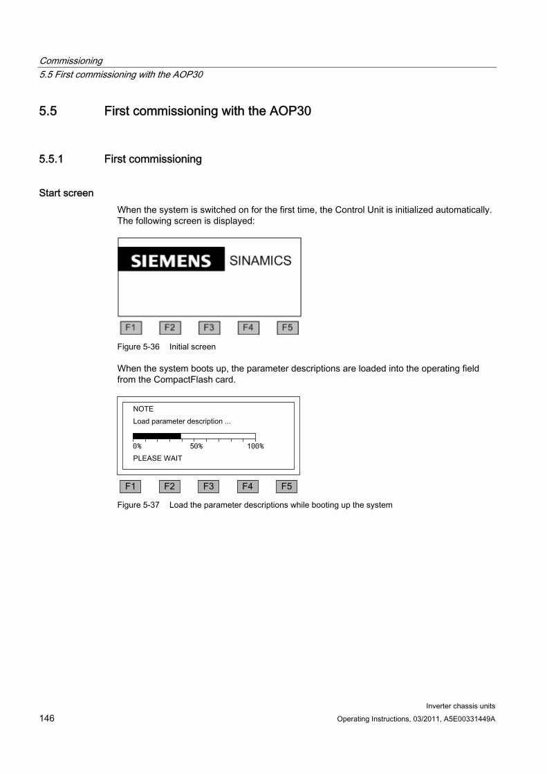
Commissioning 5.5 First commissioning with the AOP30
Inverter chassis units 146 Operating Instructions, 03/2011, A5E00331449A
5.5 First commissioning with the AOP30
5.5.1 First commissioning
Start screen When the system is switched on for the first time, the Control Unit is initialized automatically. The following screen is displayed:
Figure 5-36 Initial screen
When the system boots up, the parameter descriptions are loaded into the operating field from the CompactFlash card.
0% 50% 100%
Figure 5-37 Load the parameter descriptions while booting up the system
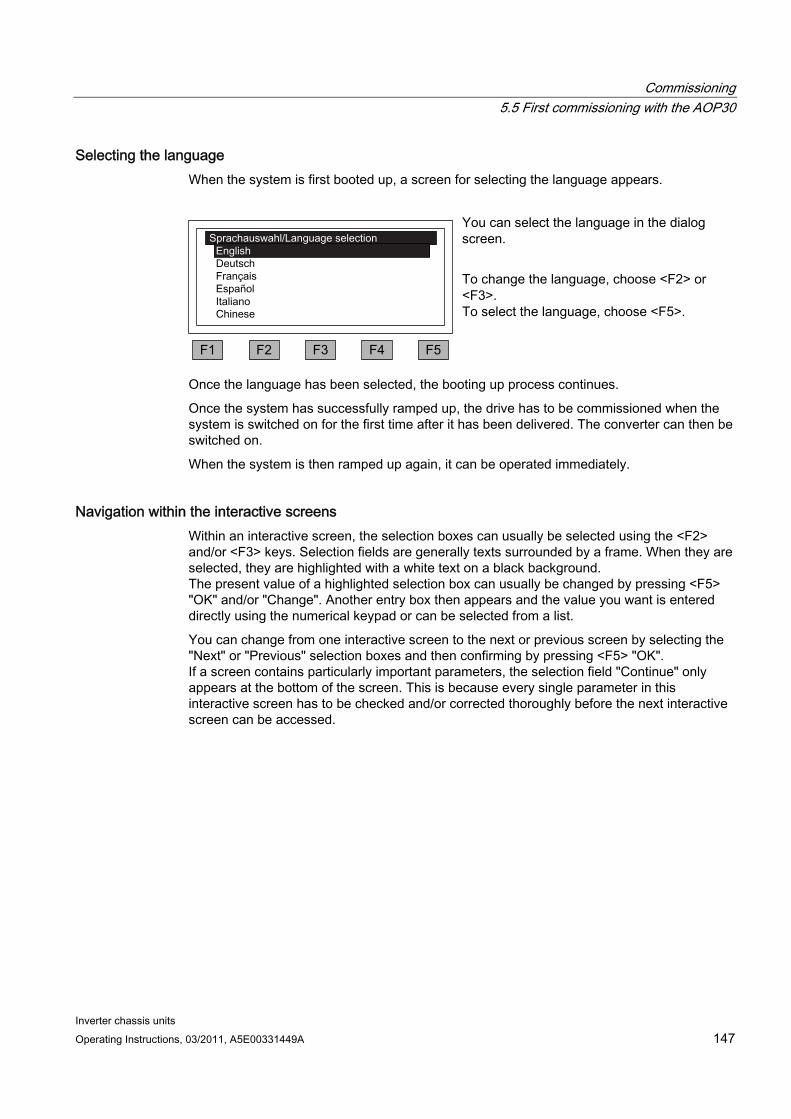
Commissioning 5.5 First commissioning with the AOP30
Inverter chassis units Operating Instructions, 03/2011, A5E00331449A 147
Selecting the language When the system is first booted up, a screen for selecting the language appears.
You can select the language in the dialog screen. To change the language, choose <F2> or <F3>. To select the language, choose <F5>.
Once the language has been selected, the booting up process continues.
Once the system has successfully ramped up, the drive has to be commissioned when the system is switched on for the first time after it has been delivered. The converter can then be switched on.
When the system is then ramped up again, it can be operated immediately.
Navigation within the interactive screens Within an interactive screen, the selection boxes can usually be selected using the <F2> and/or <F3> keys. Selection fields are generally texts surrounded by a frame. When they are selected, they are highlighted with a white text on a black background. The present value of a highlighted selection box can usually be changed by pressing <F5> "OK" and/or "Change". Another entry box then appears and the value you want is entered directly using the numerical keypad or can be selected from a list.
You can change from one interactive screen to the next or previous screen by selecting the "Next" or "Previous" selection boxes and then confirming by pressing <F5> "OK". If a screen contains particularly important parameters, the selection field "Continue" only appears at the bottom of the screen. This is because every single parameter in this interactive screen has to be checked and/or corrected thoroughly before the next interactive screen can be accessed.
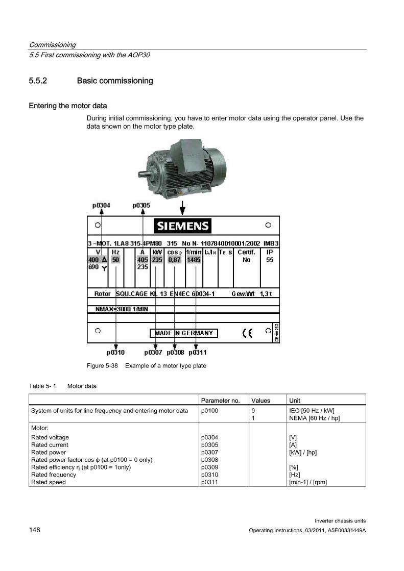
Commissioning 5.5 First commissioning with the AOP30
Inverter chassis units 148 Operating Instructions, 03/2011, A5E00331449A
5.5.2 Basic commissioning
Entering the motor data During initial commissioning, you have to enter motor data using the operator panel. Use the data shown on the motor type plate.
Figure 5-38 Example of a motor type plate
Table 5- 1 Motor data
Parameter no. Values Unit System of units for line frequency and entering motor data p0100 0
1 IEC [50 Hz / kW] NEMA [60 Hz / hp]
Motor: Rated voltage Rated current Rated power Rated power factor cos ϕ (at p0100 = 0 only) Rated efficiency η (at p0100 = 1only) Rated frequency Rated speed
p0304 p0305 p0307 p0308 p0309 p0310 p0311
[V] [A] [kW] / [hp] [%] [Hz] [min-1] / [rpm]
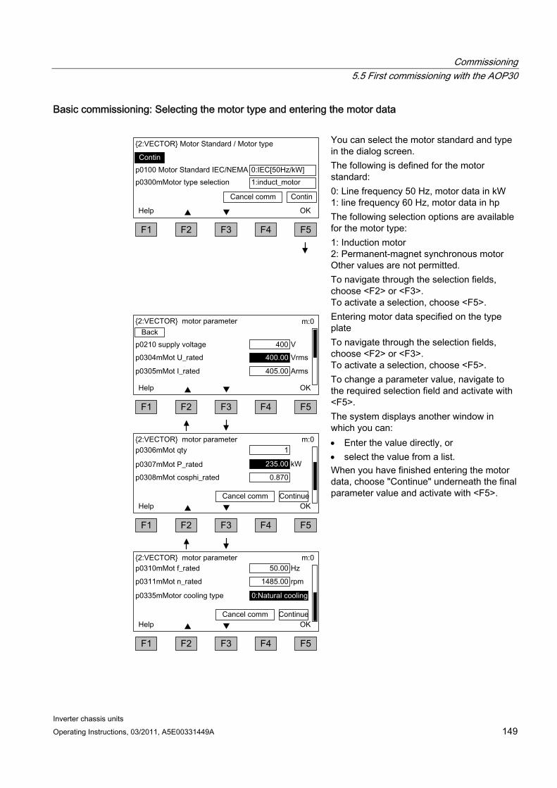
Commissioning 5.5 First commissioning with the AOP30
Inverter chassis units Operating Instructions, 03/2011, A5E00331449A 149
Basic commissioning: Selecting the motor type and entering the motor data
You can select the motor standard and type in the dialog screen. The following is defined for the motor standard: 0: Line frequency 50 Hz, motor data in kW 1: line frequency 60 Hz, motor data in hp The following selection options are available for the motor type: 1: Induction motor 2: Permanent-magnet synchronous motor Other values are not permitted. To navigate through the selection fields, choose <F2> or <F3>. To activate a selection, choose <F5>.
Entering motor data specified on the type plate To navigate through the selection fields, choose <F2> or <F3>. To activate a selection, choose <F5>. To change a parameter value, navigate to the required selection field and activate with <F5>. The system displays another window in which you can: Enter the value directly, or select the value from a list. When you have finished entering the motor data, choose "Continue" underneath the final parameter value and activate with <F5>.
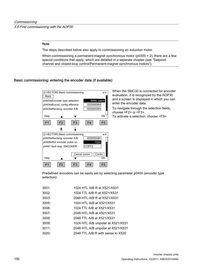
Commissioning 5.5 First commissioning with the AOP30
Inverter chassis units 150 Operating Instructions, 03/2011, A5E00331449A
Note
The steps described below also apply to commissioning an induction motor.
When commissioning a permanent-magnet synchronous motor (p0300 = 2), there are a few special conditions that apply, which are detailed in a separate chapter (see "Setpoint channel and closed-loop control/Permanent-magnet synchronous motors").
Basic commissioning: entering the encoder data (if available)
When the SMC30 is connected for encoder evaluation, it is recognized by the AOP30 and a screen is displayed in which you can enter the encoder data. To navigate through the selection fields, choose <F2> or <F3>. To activate a selection, choose <F5>.
Predefined encoders can be easily set by selecting parameter p0400 (encoder type selection):
3001: 1024 HTL A/B R at X521/X531 3002: 1024 TTL A/B R at X521/X531 3003: 2048 HTL A/B R at X521/X531 3005: 1024 HTL A/B at X521/X531 3006: 1024 TTL A/B at X521/X531 3007: 2048 HTL A/B at X521/X531 3008: 2048 TTL A/B at X521/X531 3009: 1024 HTL A/B unipolar at X521/X531 3011: 2048 HTL A/B unipolar at X521/X531 3020: 2048 TTL A/B R with sense to X520
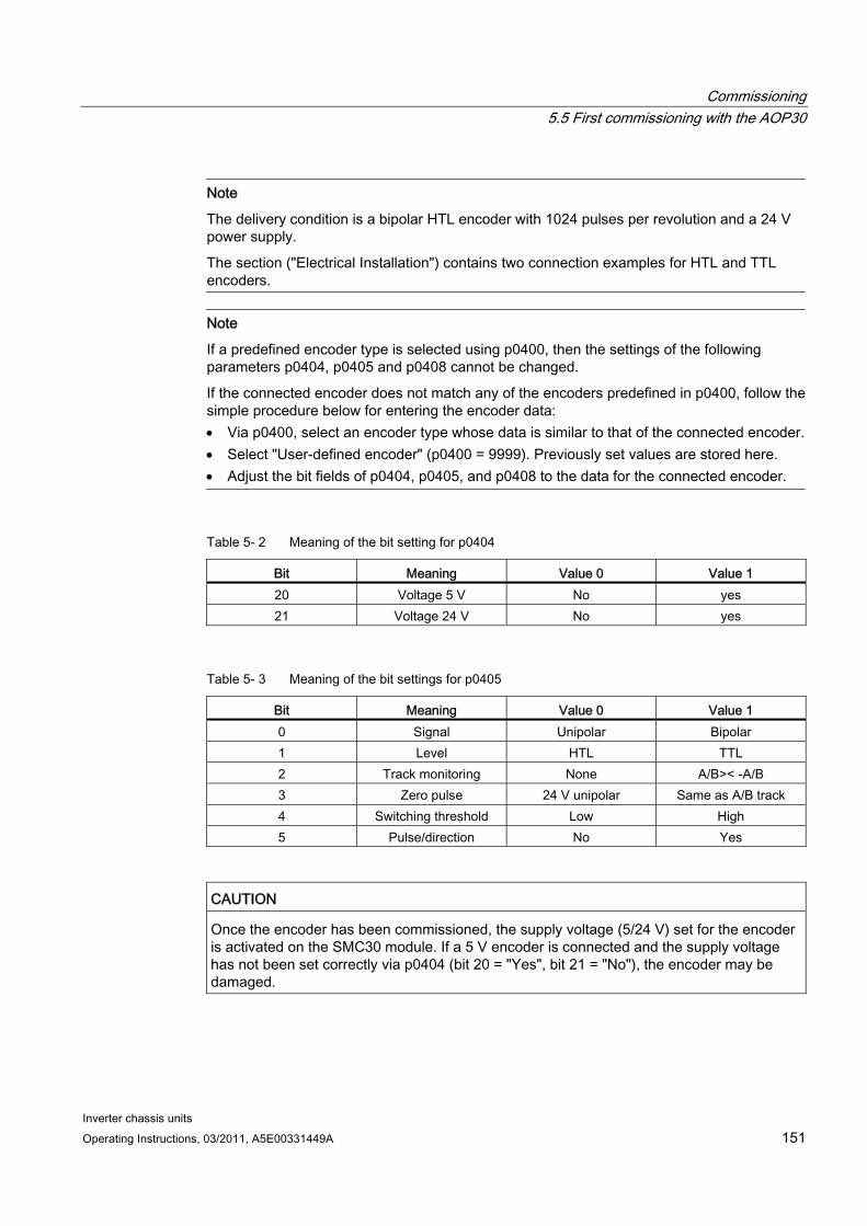
Commissioning 5.5 First commissioning with the AOP30
Inverter chassis units Operating Instructions, 03/2011, A5E00331449A 151
Note
The delivery condition is a bipolar HTL encoder with 1024 pulses per revolution and a 24 V power supply.
The section ("Electrical Installation") contains two connection examples for HTL and TTL encoders.
Note
If a predefined encoder type is selected using p0400, then the settings of the following parameters p0404, p0405 and p0408 cannot be changed.
If the connected encoder does not match any of the encoders predefined in p0400, follow the simple procedure below for entering the encoder data: Via p0400, select an encoder type whose data is similar to that of the connected encoder. Select "User-defined encoder" (p0400 = 9999). Previously set values are stored here. Adjust the bit fields of p0404, p0405, and p0408 to the data for the connected encoder.
Table 5- 2 Meaning of the bit setting for p0404
Bit Meaning Value 0 Value 1 20 Voltage 5 V No yes 21 Voltage 24 V No yes
Table 5- 3 Meaning of the bit settings for p0405
Bit Meaning Value 0 Value 1 0 Signal Unipolar Bipolar 1 Level HTL TTL 2 Track monitoring None A/B>< -A/B 3 Zero pulse 24 V unipolar Same as A/B track 4 Switching threshold Low High 5 Pulse/direction No Yes
CAUTION Once the encoder has been commissioned, the supply voltage (5/24 V) set for the encoder is activated on the SMC30 module. If a 5 V encoder is connected and the supply voltage has not been set correctly via p0404 (bit 20 = "Yes", bit 21 = "No"), the encoder may be damaged.
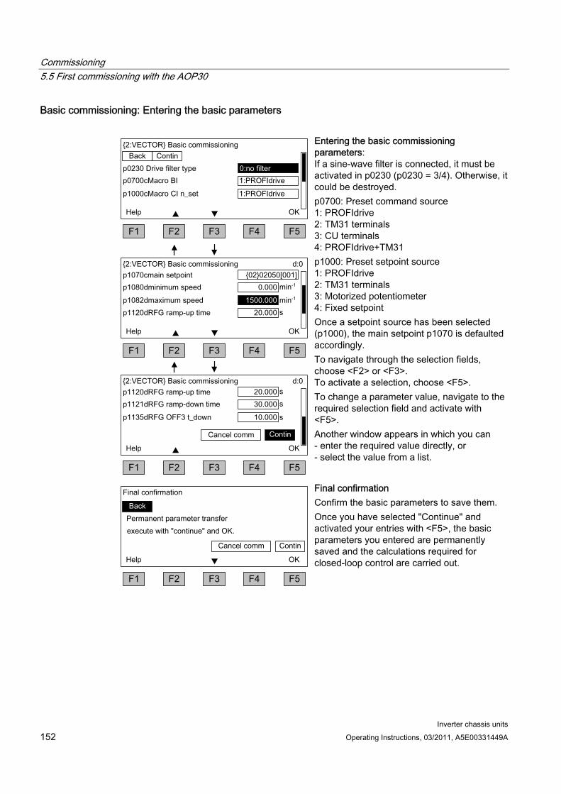
Commissioning 5.5 First commissioning with the AOP30
Inverter chassis units 152 Operating Instructions, 03/2011, A5E00331449A
Basic commissioning: Entering the basic parameters
Entering the basic commissioning parameters: If a sine-wave filter is connected, it must be activated in p0230 (p0230 = 3/4). Otherwise, it could be destroyed. p0700: Preset command source 1: PROFIdrive 2: TM31 terminals 3: CU terminals 4: PROFIdrive+TM31 p1000: Preset setpoint source 1: PROFIdrive 2: TM31 terminals 3: Motorized potentiometer 4: Fixed setpoint Once a setpoint source has been selected (p1000), the main setpoint p1070 is defaulted accordingly. To navigate through the selection fields, choose <F2> or <F3>. To activate a selection, choose <F5>. To change a parameter value, navigate to the required selection field and activate with <F5>. Another window appears in which you can - enter the required value directly, or - select the value from a list.
Final confirmation Confirm the basic parameters to save them. Once you have selected "Continue" and activated your entries with <F5>, the basic parameters you entered are permanently saved and the calculations required for closed-loop control are carried out.

Commissioning 5.5 First commissioning with the AOP30
Inverter chassis units Operating Instructions, 03/2011, A5E00331449A 153
NOTICE A filter on the motor side must be entered in p0230 (motor reactor: p0230 = 1, dV/dt-Filter compact plus Voltage Peak Limiter / dV/dt-Filter plus Voltage Peak Limiter: p0230 = 2, Siemens sine-wave filter: p0230 = 3, third-party sine-wave filter: p0230 = 4), otherwise motor control does not function properly.
Note
The choice "no selection" is also available as default setting for the command and setpoint sources; if selected, no default settings are applied for the command and setpoint sources.
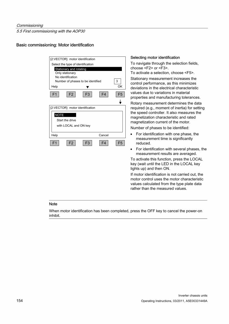
Commissioning 5.5 First commissioning with the AOP30
Inverter chassis units 154 Operating Instructions, 03/2011, A5E00331449A
Basic commissioning: Motor identification
Selecting motor identification To navigate through the selection fields, choose <F2> or <F3>. To activate a selection, choose <F5>. Stationary measurement increases the control performance, as this minimizes deviations in the electrical characteristic values due to variations in material properties and manufacturing tolerances. Rotary measurement determines the data required (e.g., moment of inertia) for setting the speed controller. It also measures the magnetization characteristic and rated magnetization current of the motor. Number of phases to be identified: For identification with one phase, the
measurement time is significantly reduced.
For identification with several phases, the measurement results are averaged.
To activate this function, press the LOCAL key (wait until the LED in the LOCAL key lights up) and then ON. If motor identification is not carried out, the motor control uses the motor characteristic values calculated from the type plate data rather than the measured values.
Note
When motor identification has been completed, press the OFF key to cancel the power-on inhibit.

Commissioning 5.5 First commissioning with the AOP30
Inverter chassis units Operating Instructions, 03/2011, A5E00331449A 155
DANGER When the rotating measurement is selected, the drive triggers movements in the motor that can reach the maximum motor speed. The EMERGENCY OFF functions must be fully operational during commissioning. To protect the machines and personnel, the relevant safety regulations must be observed.
Note
Make sure that the necessary enable signals have been assigned; otherwise motor identification cannot be carried out.
Note
If a fault is present when selecting the stationary or rotary measurement, motor identification cannot be carried out. To rectify the fault, you must choose "No identification" to close the screen, then eliminate the fault. After this, motor identification can be selected again via <MENU> - <Commissioning/service> - <Drive commissioning> - <Motor identification>.
Commissioning 5.6 Status after commissioning
Inverter chassis units 156 Operating Instructions, 03/2011, A5E00331449A
5.6 Status after commissioning
LOCAL mode (control via operator panel) You switch to LOCAL mode by pressing the "LOCAL/REMOTE" key.
Control (ON/OFF) is carried out via the "ON" and "OFF" keys.
You can specify the setpoint using the "increase" and "decrease" keys or by entering the appropriate numbers using the numeric keypad.
Analog outputs (for version with TM31) The actual speed (r0063) is output as a voltage output in the range 0 to 10 V at analog
output 0 (X522:1 and 2). 10 V is equal to the maximum speed in p1082.
The actual current value (r0068) is output as a voltage output in the range 0 to 10 V at analog output 1 (X522:4 and 5). 10 V corresponds to the current limit (p0640), which is set to 1.5 x the rated motor current (p0305).
Digital outputs (for version with TM31) The "enable pulses" signal is output at digital output 0 (X542:2 and 3).
The “no fault active” signal is output at digital output 1 (X542:5 and 6) (protection against wire breakage).
The "ready to start" signal is output at digital output 8 (X541:2).
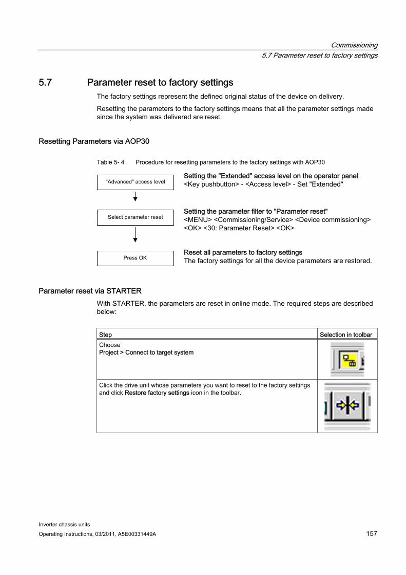
Commissioning 5.7 Parameter reset to factory settings
Inverter chassis units Operating Instructions, 03/2011, A5E00331449A 157
5.7 Parameter reset to factory settings The factory settings represent the defined original status of the device on delivery.
Resetting the parameters to the factory settings means that all the parameter settings made since the system was delivered are reset.
Resetting Parameters via AOP30
Table 5- 4 Procedure for resetting parameters to the factory settings with AOP30
Setting the "Extended" access level on the operator panel <Key pushbutton> - <Access level> - Set "Extended"
Setting the parameter filter to "Parameter reset" <MENU> <Commissioning/Service> <Device commissioning> <OK> <30: Parameter Reset> <OK>
Reset all parameters to factory settings The factory settings for all the device parameters are restored.
Parameter reset via STARTER With STARTER, the parameters are reset in online mode. The required steps are described below:
Step Selection in toolbar Choose Project > Connect to target system
Click the drive unit whose parameters you want to reset to the factory settings and click Restore factory settings icon in the toolbar.
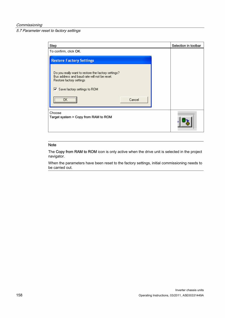
Commissioning 5.7 Parameter reset to factory settings
Inverter chassis units 158 Operating Instructions, 03/2011, A5E00331449A
Step Selection in toolbar To confirm, click OK.
Choose Target system > Copy from RAM to ROM
Note
The Copy from RAM to ROM icon is only active when the drive unit is selected in the project navigator.
When the parameters have been reset to the factory settings, initial commissioning needs to be carried out.
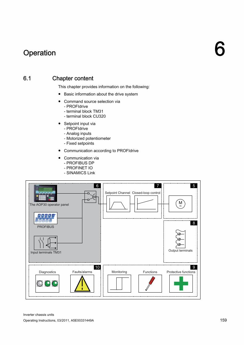
Inverter chassis units Operating Instructions, 03/2011, A5E00331449A 159
Operation 66.1 Chapter content
This chapter provides information on the following:
Basic information about the drive system
Command source selection via - PROFIdrive - terminal block TM31 - terminal block CU320
Setpoint input via - PROFIdrive - Analog inputs - Motorized potentiometer - Fixed setpoints
Communication according to PROFIdrive
Communication via - PROFIBUS DP - PROFINET IO - SINAMICS Link
M ~
5 7 6
8
9 10
Operation 6.2 General information about command and setpoint sources
Inverter chassis units 160 Operating Instructions, 03/2011, A5E00331449A
6.2 General information about command and setpoint sources
Description Four default settings are available for selecting the command sources and four for selecting the setpoint sources for the SINAMICS G130. The choice "no selection" is also available; if selected, no default settings are applied for the command and setpoint sources.
Command sources PROFIdrive
TM31 terminals
CU terminals
PROFIdrive+TM31
Setpoint sources PROFIdrive
Analog inputs
Motorized potentiometer
Fixed setpoints
The various assignments are explained in the following sections.
Note
Make sure that the default settings you choose during commissioning are compatible with the system configuration (for more information, see "Commissioning")
Function diagrams To supplement these operating instructions, the CD contains simplified function diagrams describing the operating principle of the SINAMICS G130. The diagrams are arranged in accordance with the chapters in the operating instructions. The page numbers (6xx) describe the functionality in the following chapter.
At certain points in this chapter, reference is made to function diagrams with a 4-digit number. These are stored on the CD in the "SINAMICS G130/G150 List Manual", which provides experienced users with detailed descriptions of all the functions.
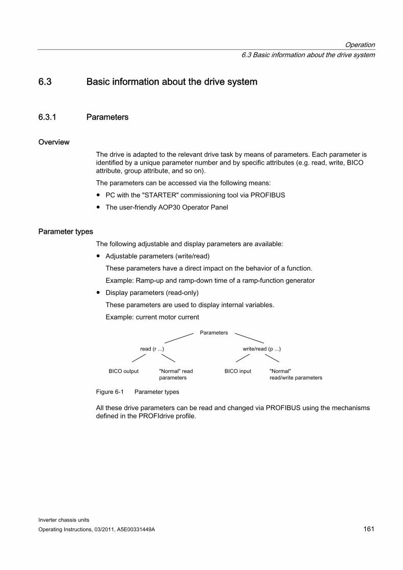
Operation 6.3 Basic information about the drive system
Inverter chassis units Operating Instructions, 03/2011, A5E00331449A 161
6.3 Basic information about the drive system
6.3.1 Parameters
Overview The drive is adapted to the relevant drive task by means of parameters. Each parameter is identified by a unique parameter number and by specific attributes (e.g. read, write, BICO attribute, group attribute, and so on).
The parameters can be accessed via the following means:
PC with the "STARTER" commissioning tool via PROFIBUS
The user-friendly AOP30 Operator Panel
Parameter types The following adjustable and display parameters are available:
Adjustable parameters (write/read)
These parameters have a direct impact on the behavior of a function.
Example: Ramp-up and ramp-down time of a ramp-function generator
Display parameters (read-only)
These parameters are used to display internal variables.
Example: current motor current
Figure 6-1 Parameter types
All these drive parameters can be read and changed via PROFIBUS using the mechanisms defined in the PROFIdrive profile.

Operation 6.3 Basic information about the drive system
Inverter chassis units 162 Operating Instructions, 03/2011, A5E00331449A
Parameter categories The parameters for the individual drive objects (see "Drive objects") are categorized according to data sets as follows (see "Operation/data sets"):
Data-set-independent parameters These parameters exist only once per drive object.
Data-set-dependent parameters These parameters can exist several times for each drive object and can be addressed via the parameter index for reading and writing. A distinction is made between various types of data set:
– CDS: Command data set By parameterizing several command data sets and switching between them, the drive can be operated with different pre-configured signal sources.
– DDS: Drive data set The drive data set contains the parameters for switching between different drive control configurations.
The CDS and DDS can be switched over during normal operation. Further types of data set also exist, however these can only be activated indirectly by means of a DDS changeover.
– EDS: encoder data set
– MDS: Motor data set
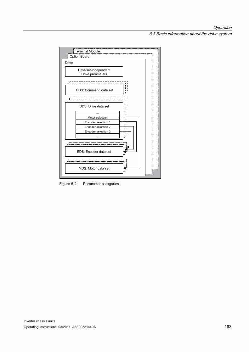
Operation 6.3 Basic information about the drive system
Inverter chassis units Operating Instructions, 03/2011, A5E00331449A 163
Figure 6-2 Parameter categories
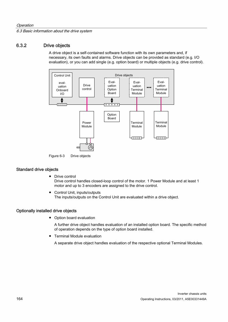
Operation 6.3 Basic information about the drive system
Inverter chassis units 164 Operating Instructions, 03/2011, A5E00331449A
6.3.2 Drive objects A drive object is a self-contained software function with its own parameters and, if necessary, its own faults and alarms. Drive objects can be provided as standard (e.g. I/O evaluation), or you can add single (e.g. option board) or multiple objects (e.g. drive control).
Figure 6-3 Drive objects
Standard drive objects Drive control
Drive control handles closed-loop control of the motor. 1 Power Module and at least 1 motor and up to 3 encoders are assigned to the drive control.
Control Unit, inputs/outputs The inputs/outputs on the Control Unit are evaluated within a drive object.
Optionally installed drive objects Option board evaluation
A further drive object handles evaluation of an installed option board. The specific method of operation depends on the type of option board installed.
Terminal Module evaluation
A separate drive object handles evaluation of the respective optional Terminal Modules.
Operation 6.3 Basic information about the drive system
Inverter chassis units Operating Instructions, 03/2011, A5E00331449A 165
Properties of a drive object Separate parameter space
Separate window in STARTER
Separate fault/alarm system
Separate PROFIdrive telegram for process data
Configuring drive objects When you commission the system for the first time using the STARTER tool, you will use configuration parameters to set up the software-based "drive objects" which are processed on the Control Unit. Various drive objects can be created within a Control Unit.
The drive objects are configurable function blocks and are used to execute specific drive functions.
If you need to configure additional drive objects or delete existing ones after initial commissioning, the drive system must be switched to configuration mode.
The parameters of a drive object cannot be accessed until the drive object has been configured and you have switched from configuration mode to parameterization mode.
Note
Each installed drive object is allocated a number between 0 and 63 during initial commissioning for unique identification.
Parameters p0101 Drive object numbers
r0102 Number of drive objects
p0107 Drive object type
p0108 Drive object configuration
6.3.3 Data sets
Description For many applications, it is beneficial if more than one parameter can be changed simultaneously by means of one external signal during operation/when the system is ready for operation.
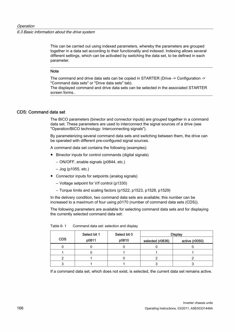
Operation 6.3 Basic information about the drive system
Inverter chassis units 166 Operating Instructions, 03/2011, A5E00331449A
This can be carried out using indexed parameters, whereby the parameters are grouped together in a data set according to their functionality and indexed. Indexing allows several different settings, which can be activated by switching the data set, to be defined in each parameter.
Note
The command and drive data sets can be copied in STARTER (Drive -> Configuration -> "Command data sets" or "Drive data sets" tab). The displayed command and drive data sets can be selected in the associated STARTER screen forms..
CDS: Command data set The BICO parameters (binector and connector inputs) are grouped together in a command data set. These parameters are used to interconnect the signal sources of a drive (see "Operation/BICO technology: Interconnecting signals").
By parameterizing several command data sets and switching between them, the drive can be operated with different pre-configured signal sources.
A command data set contains the following (examples):
Binector inputs for control commands (digital signals)
– ON/OFF, enable signals (p0844, etc.)
– Jog (p1055, etc.)
Connector inputs for setpoints (analog signals)
– Voltage setpoint for V/f control (p1330)
– Torque limits and scaling factors (p1522, p1523, p1528, p1529)
In the delivery condition, two command data sets are available; this number can be increased to a maximum of four using p0170 (number of command data sets (CDS)).
The following parameters are available for selecting command data sets and for displaying the currently selected command data set:
Table 6- 1 Command data set: selection and display
Display CDS
Select bit 1 p0811
Select bit 0 p0810 selected (r0836) active (r0050)
0 0 0 0 0 1 0 1 1 1 2 1 0 2 2 3 1 1 3 3
If a command data set, which does not exist, is selected, the current data set remains active.
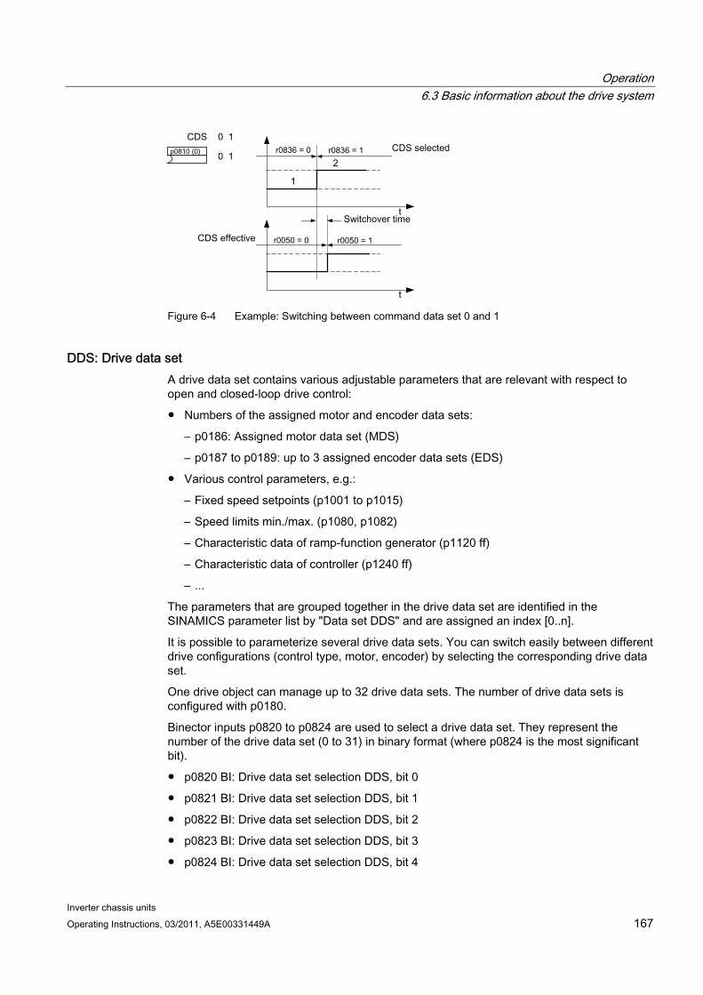
Operation 6.3 Basic information about the drive system
Inverter chassis units Operating Instructions, 03/2011, A5E00331449A 167
Figure 6-4 Example: Switching between command data set 0 and 1
DDS: Drive data set A drive data set contains various adjustable parameters that are relevant with respect to open and closed-loop drive control:
Numbers of the assigned motor and encoder data sets:
– p0186: Assigned motor data set (MDS)
– p0187 to p0189: up to 3 assigned encoder data sets (EDS)
Various control parameters, e.g.:
– Fixed speed setpoints (p1001 to p1015)
– Speed limits min./max. (p1080, p1082)
– Characteristic data of ramp-function generator (p1120 ff)
– Characteristic data of controller (p1240 ff)
– ...
The parameters that are grouped together in the drive data set are identified in the SINAMICS parameter list by "Data set DDS" and are assigned an index [0..n].
It is possible to parameterize several drive data sets. You can switch easily between different drive configurations (control type, motor, encoder) by selecting the corresponding drive data set.
One drive object can manage up to 32 drive data sets. The number of drive data sets is configured with p0180.
Binector inputs p0820 to p0824 are used to select a drive data set. They represent the number of the drive data set (0 to 31) in binary format (where p0824 is the most significant bit).
p0820 BI: Drive data set selection DDS, bit 0
p0821 BI: Drive data set selection DDS, bit 1
p0822 BI: Drive data set selection DDS, bit 2
p0823 BI: Drive data set selection DDS, bit 3
p0824 BI: Drive data set selection DDS, bit 4
Operation 6.3 Basic information about the drive system
Inverter chassis units 168 Operating Instructions, 03/2011, A5E00331449A
Supplementary conditions and recommendations
Recommendation for the number of DDS in a drive The number of DDS in a drive should correspond with the number of changeover options; in other words p0180 (DDS) ≥ p0130 (MDS).
Max. number of DDS for one drive object = 32 DDS
EDS: Encoder data set An encoder data set contains various adjustable parameters describing the connected encoder for the purpose of configuring the drive.
Adjustable parameters, e.g.:
– Encoder interface component number (p0141)
– Encoder component number (p0142)
– Encoder type selection (p0400)
The parameters that are grouped together in the encoder data set are identified in the SINAMICS parameter list by "Data set EDS" and are assigned an index [0..n].
A separate encoder data set is required for each encoder controlled by the Control Unit. Up to 3 encoder data sets are assigned to a drive data set via parameters p0187, p0188, and p0189.
An encoder data set can only be changed using a DDS changeover.
Each encoder may only be assigned to one drive and within a drive must - in each drive data set - either always be encoder 1, always encoder 2 or always encoder 3.
One application for the EDS changeover would be a power component with which several motors are operated in turn. A contactor circuit is used to changeover between these motors. Each of the motors can be equipped with an encoder or be operated without an encoder. Each encoder must be connected to its own SMx.
If encoder 1 (p0187) is changed over via DDS, then an MDS must also be changed over.
One drive object can manage up to 16 encoder data sets. The number of encoder data sets configured is specified in p0140.
When a drive data set is selected, the assigned encoder data sets are selected automatically.
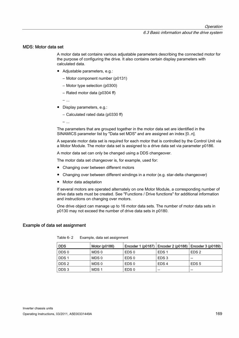
Operation 6.3 Basic information about the drive system
Inverter chassis units Operating Instructions, 03/2011, A5E00331449A 169
MDS: Motor data set A motor data set contains various adjustable parameters describing the connected motor for the purpose of configuring the drive. It also contains certain display parameters with calculated data.
Adjustable parameters, e.g.:
– Motor component number (p0131)
– Motor type selection (p0300)
– Rated motor data (p0304 ff)
– ...
Display parameters, e.g.:
– Calculated rated data (p0330 ff)
– ...
The parameters that are grouped together in the motor data set are identified in the SINAMICS parameter list by "Data set MDS" and are assigned an index [0..n].
A separate motor data set is required for each motor that is controlled by the Control Unit via a Motor Module. The motor data set is assigned to a drive data set via parameter p0186.
A motor data set can only be changed using a DDS changeover.
The motor data set changeover is, for example, used for:
Changing over between different motors
Changing over between different windings in a motor (e.g. star-delta changeover)
Motor data adaptation
If several motors are operated alternately on one Motor Module, a corresponding number of drive data sets must be created. See "Functions / Drive functions" for additional information and instructions on changing over motors.
One drive object can manage up to 16 motor data sets. The number of motor data sets in p0130 may not exceed the number of drive data sets in p0180.
Example of data set assignment
Table 6- 2 Example, data set assignment
DDS Motor (p0186) Encoder 1 (p0187) Encoder 2 (p0188) Encoder 3 (p0189)DDS 0 MDS 0 EDS 0 EDS 1 EDS 2 DDS 1 MDS 0 EDS 0 EDS 3 -- DDS 2 MDS 0 EDS 0 EDS 4 EDS 5 DDS 3 MDS 1 EDS 0 -- --
Operation 6.3 Basic information about the drive system
Inverter chassis units 170 Operating Instructions, 03/2011, A5E00331449A
Copying the command data set (CDS) Set parameter p0809 as follows:
1. p0809[0] = number of the command data set to be copied (source)
2. p0809[1] = number of the command data to which the data is to be copied (target)
3. p0809[2] = 1
Start copying.
Copying is finished when p0809[2] = 0.
Copying the drive data set (DDS) Set parameter p0819 as follows:
1. p0819[0] = Number of the drive data set to be copied (source)
2. p0819[1] = Number of the drive data set to which the data is to be copied (target)
3. p0819[2] = 1
Start copying.
Copying is finished when p0819[2] = 0.
Copy motor data set (MDS) Set parameter p0139 as follows:
1. p0139[0] = Number of the motor data set that is to be copied (source)
2. p0139[1] = Number of the motor data set which should be copied into (target)
3. p0139[2] = 1
Start copying.
Copying has been completed, if p0139[2] = 0.
Function diagram FP 8560 Command data sets (CDS) FP 8565 Drive data set (DDS) FP 8570 Encoder data set (EDS) FP 8575 Motor data sets (MDS)
Operation 6.3 Basic information about the drive system
Inverter chassis units Operating Instructions, 03/2011, A5E00331449A 171
Parameters p0120 Power Module data sets (PDS) number
p0130 Motor data sets (MDS) number
p0139[0...2] Copy motor data set (MDS)
p0140 Encoder data sets (EDS) number
p0170 Command data set (CDS) number
p0180 Drive data set (DDS) number
p0186 Assigned motor data set (MDS)
p0187[0...n] Encoder 1 encoder data set number
p0188[0...n] Encoder 2 encoder data set number
p0189[0...n] Encoder 3 encoder data set number
p0809 Copy command data set CDS
p0810 BI: Command data set selection CDS bit 0
p0811 BI: Command data set selection CDS bit 1
p0819[0...2] Copy drive data set DDS
p0820 BI: Drive data set selection, bit 0
p0821 BI: Drive data set selection, bit 1
p0822 BI: Drive data set selection, bit 2
p0823 BI: Drive data set selection, bit 3
p0824 BI: Drive data set selection, bit 4
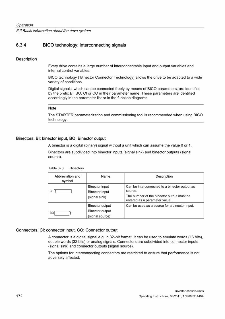
Operation 6.3 Basic information about the drive system
Inverter chassis units 172 Operating Instructions, 03/2011, A5E00331449A
6.3.4 BICO technology: interconnecting signals
Description Every drive contains a large number of interconnectable input and output variables and internal control variables.
BICO technology ( Binector Connector Technology) allows the drive to be adapted to a wide variety of conditions.
Digital signals, which can be connected freely by means of BICO parameters, are identified by the prefix BI, BO, CI or CO in their parameter name. These parameters are identified accordingly in the parameter list or in the function diagrams.
Note
The STARTER parameterization and commissioning tool is recommended when using BICO technology.
Binectors, BI: binector input, BO: Binector output A binector is a digital (binary) signal without a unit which can assume the value 0 or 1.
Binectors are subdivided into binector inputs (signal sink) and binector outputs (signal source).
Table 6- 3 Binectors
Abbreviation and symbol
Name Description
Binector input Binector Input (signal sink)
Can be interconnected to a binector output as source. The number of the binector output must be entered as a parameter value.
Binector output Binector output (signal source)
Can be used as a source for a binector input.
Connectors, CI: connector input, CO: Connector output A connector is a digital signal e.g. in 32–bit format. It can be used to emulate words (16 bits), double words (32 bits) or analog signals. Connectors are subdivided into connector inputs (signal sink) and connector outputs (signal source).
The options for interconnecting connectors are restricted to ensure that performance is not adversely affected.
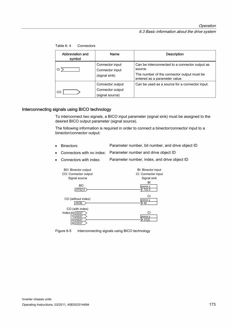
Operation 6.3 Basic information about the drive system
Inverter chassis units Operating Instructions, 03/2011, A5E00331449A 173
Table 6- 4 Connectors
Abbreviation and symbol
Name Description
Connector input Connector input (signal sink)
Can be interconnected to a connector output as source. The number of the connector output must be entered as a parameter value.
Connector output Connector output (signal source)
Can be used as a source for a connector input.
Interconnecting signals using BICO technology To interconnect two signals, a BICO input parameter (signal sink) must be assigned to the desired BICO output parameter (signal source).
The following information is required in order to connect a binector/connector input to a binector/connector output:
Binectors: Parameter number, bit number, and drive object ID
Connectors with no index: Parameter number and drive object ID
Connectors with index: Parameter number, index, and drive object ID
Figure 6-5 Interconnecting signals using BICO technology
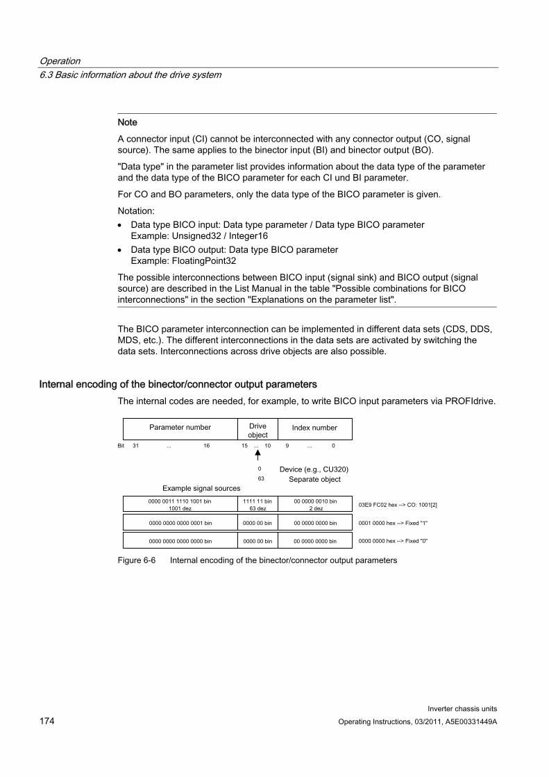
Operation 6.3 Basic information about the drive system
Inverter chassis units 174 Operating Instructions, 03/2011, A5E00331449A
Note
A connector input (CI) cannot be interconnected with any connector output (CO, signal source). The same applies to the binector input (BI) and binector output (BO).
"Data type" in the parameter list provides information about the data type of the parameter and the data type of the BICO parameter for each CI und BI parameter.
For CO and BO parameters, only the data type of the BICO parameter is given.
Notation: Data type BICO input: Data type parameter / Data type BICO parameter
Example: Unsigned32 / Integer16 Data type BICO output: Data type BICO parameter
Example: FloatingPoint32
The possible interconnections between BICO input (signal sink) and BICO output (signal source) are described in the List Manual in the table "Possible combinations for BICO interconnections" in the section "Explanations on the parameter list".
The BICO parameter interconnection can be implemented in different data sets (CDS, DDS, MDS, etc.). The different interconnections in the data sets are activated by switching the data sets. Interconnections across drive objects are also possible.
Internal encoding of the binector/connector output parameters The internal codes are needed, for example, to write BICO input parameters via PROFIdrive.
Figure 6-6 Internal encoding of the binector/connector output parameters
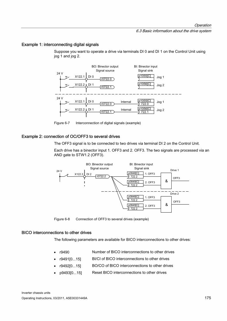
Operation 6.3 Basic information about the drive system
Inverter chassis units Operating Instructions, 03/2011, A5E00331449A 175
Example 1: interconnecting digital signals Suppose you want to operate a drive via terminals DI 0 and DI 1 on the Control Unit using jog 1 and jog 2.
Figure 6-7 Interconnection of digital signals (example)
Example 2: connection of OC/OFF3 to several drives The OFF3 signal is to be connected to two drives via terminal DI 2 on the Control Unit.
Each drive has a binector input 1. OFF3 and 2. OFF3. The two signals are processed via an AND gate to STW1.2 (OFF3).
Figure 6-8 Connection of OFF3 to several drives (example)
BICO interconnections to other drives The following parameters are available for BICO interconnections to other drives:
r9490 Number of BICO interconnections to other drives
r9491[0...15] BI/CI of BICO interconnections to other drives
r9492[0...15] BO/CO of BICO interconnections to other drives
p9493[0...15] Reset BICO interconnections to other drives

Operation 6.3 Basic information about the drive system
Inverter chassis units 176 Operating Instructions, 03/2011, A5E00331449A
Binector-connector converters and connector-binector converters Binector-connector converter
Several digital signals are converted to a 32-bit integer double word or to a 16-bit integer word.
p2080[0...15] BI: PROFIdrive PZD send bit-serial
Connector-binector converter
A 32-bit integer double word or a 16-bit integer word is converted to individual digital signals.
p2099[0...1] CI PROFIdrive PZD selection receive bit-serial
Fixed values for interconnection using BICO technology The following connector outputs are available for interconnecting any fixed value settings:
p2900[0...n] CO: Fixed value_%_1
p2901[0...n] CO: Fixed value_%_2
p2930[0...n] CO: Fixed Value_M_1
Example:
These parameters can be used to interconnect the scaling factor for the main setpoint or to interconnect an additional torque.
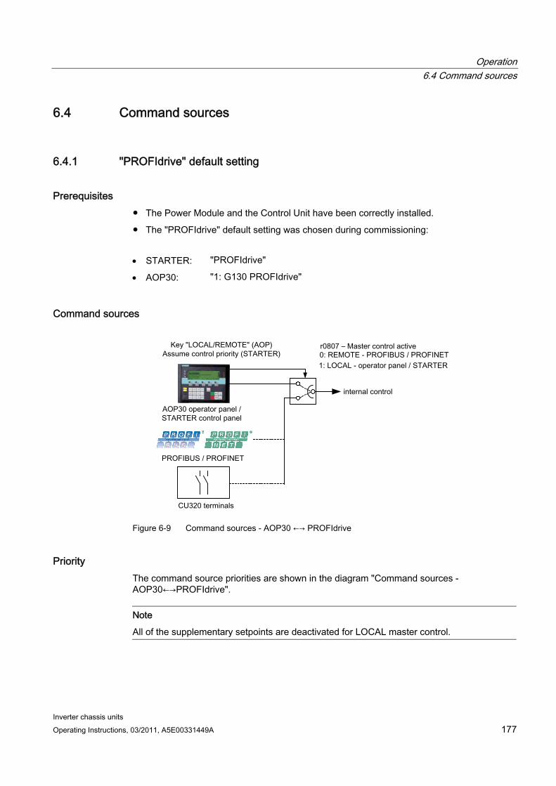
Operation 6.4 Command sources
Inverter chassis units Operating Instructions, 03/2011, A5E00331449A 177
6.4 Command sources
6.4.1 "PROFIdrive" default setting
Prerequisites The Power Module and the Control Unit have been correctly installed.
The "PROFIdrive" default setting was chosen during commissioning:
STARTER: "PROFIdrive"
AOP30: "1: G130 PROFIdrive"
Command sources
Figure 6-9 Command sources - AOP30 ←→ PROFIdrive
Priority The command source priorities are shown in the diagram "Command sources - AOP30←→PROFIdrive".
Note
All of the supplementary setpoints are deactivated for LOCAL master control.
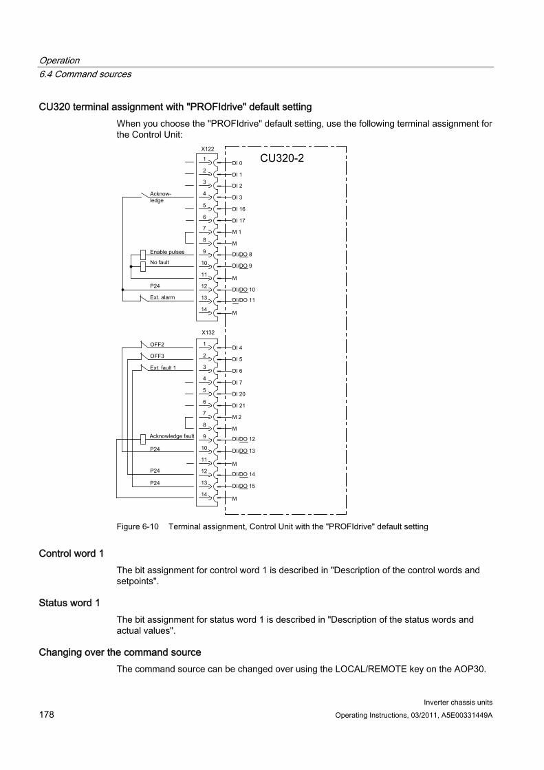
Operation 6.4 Command sources
Inverter chassis units 178 Operating Instructions, 03/2011, A5E00331449A
CU320 terminal assignment with "PROFIdrive" default setting When you choose the "PROFIdrive" default setting, use the following terminal assignment for the Control Unit:
Figure 6-10 Terminal assignment, Control Unit with the "PROFIdrive" default setting
Control word 1 The bit assignment for control word 1 is described in "Description of the control words and setpoints".
Status word 1 The bit assignment for status word 1 is described in "Description of the status words and actual values".
Changing over the command source The command source can be changed over using the LOCAL/REMOTE key on the AOP30.

Operation 6.4 Command sources
Inverter chassis units Operating Instructions, 03/2011, A5E00331449A 179
6.4.2 "TM31 terminals" default setting
Prerequisites The Power Module, Control Unit and TM31 have been correctly installed.
The "TM31 terminals" default setting was chosen during commissioning:
STARTER "TM31 terminals"
AOP30: "2: TM31 terminals
Command sources
Figure 6-11 Command sources AOP30 ←→ terminal TM31
Priority The command source priorities are shown in the diagram "Command sources AOP30 ←→ TM31 terminals".
Note
All of the supplementary setpoints are deactivated for LOCAL master control.
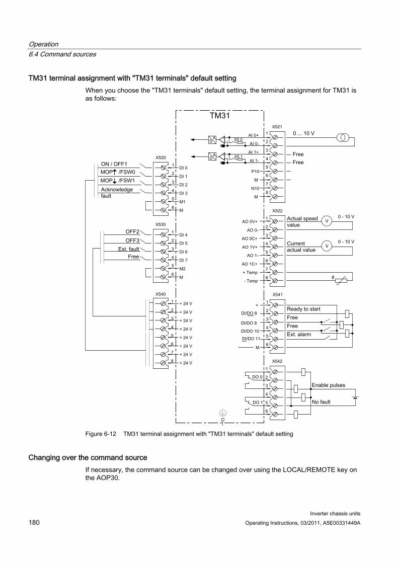
Operation 6.4 Command sources
Inverter chassis units 180 Operating Instructions, 03/2011, A5E00331449A
TM31 terminal assignment with "TM31 terminals" default setting When you choose the "TM31 terminals" default setting, the terminal assignment for TM31 is as follows:
Figure 6-12 TM31 terminal assignment with "TM31 terminals" default setting
Changing over the command source If necessary, the command source can be changed over using the LOCAL/REMOTE key on the AOP30.
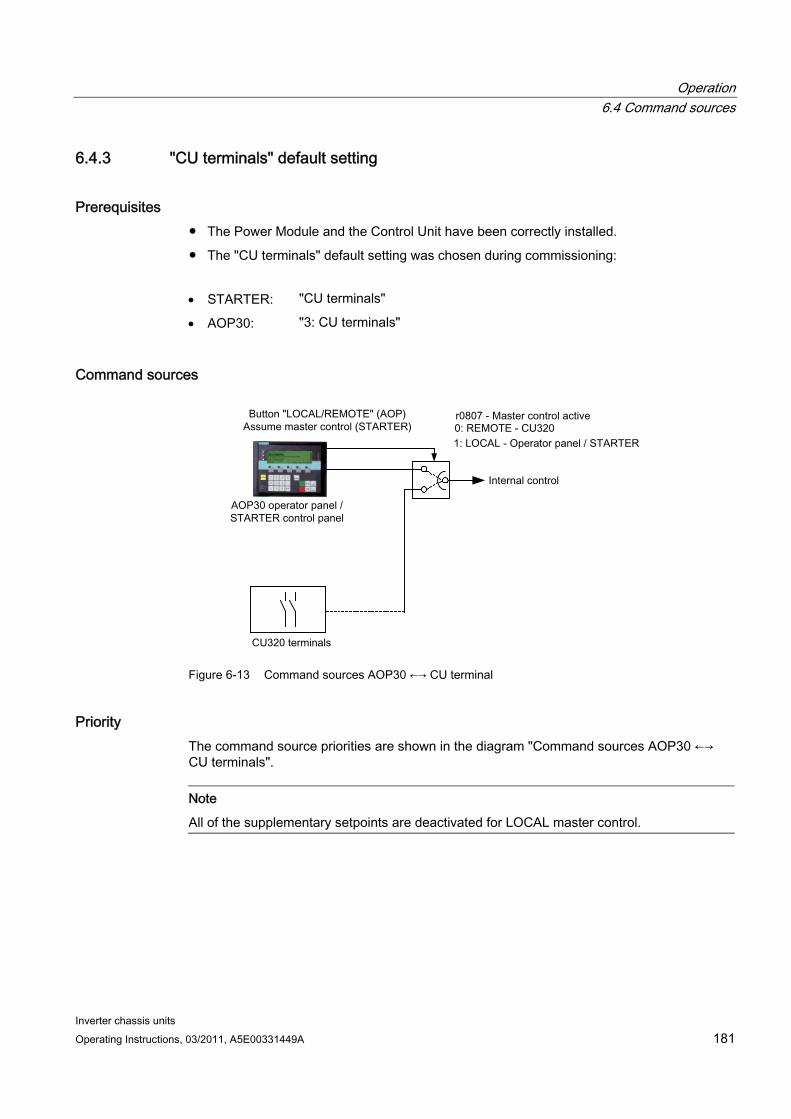
Operation 6.4 Command sources
Inverter chassis units Operating Instructions, 03/2011, A5E00331449A 181
6.4.3 "CU terminals" default setting
Prerequisites The Power Module and the Control Unit have been correctly installed.
The "CU terminals" default setting was chosen during commissioning:
STARTER: "CU terminals"
AOP30: "3: CU terminals"
Command sources
Figure 6-13 Command sources AOP30 ←→ CU terminal
Priority The command source priorities are shown in the diagram "Command sources AOP30 ←→ CU terminals".
Note
All of the supplementary setpoints are deactivated for LOCAL master control.
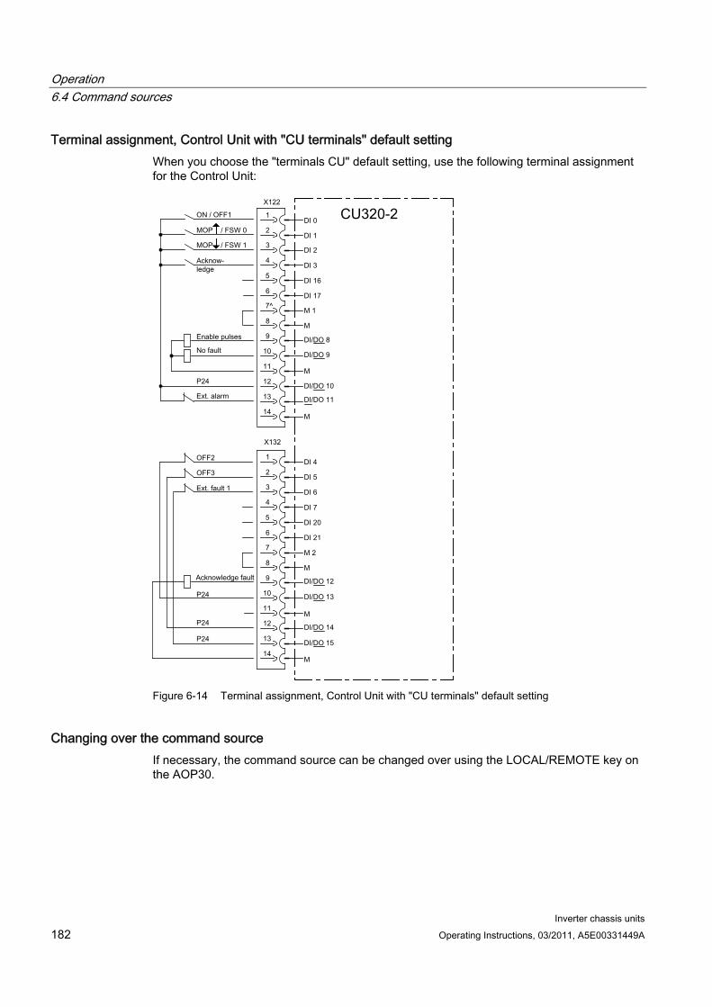
Operation 6.4 Command sources
Inverter chassis units 182 Operating Instructions, 03/2011, A5E00331449A
Terminal assignment, Control Unit with "CU terminals" default setting When you choose the "terminals CU" default setting, use the following terminal assignment for the Control Unit:
Figure 6-14 Terminal assignment, Control Unit with "CU terminals" default setting
Changing over the command source If necessary, the command source can be changed over using the LOCAL/REMOTE key on the AOP30.
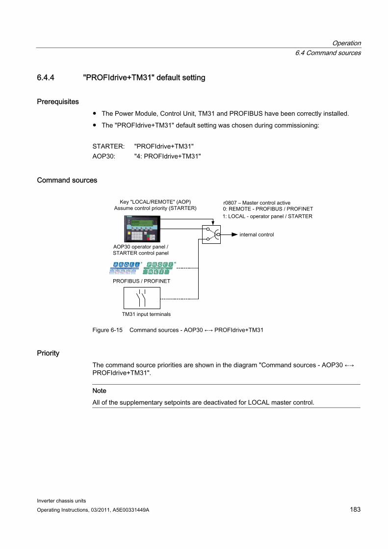
Operation 6.4 Command sources
Inverter chassis units Operating Instructions, 03/2011, A5E00331449A 183
6.4.4 "PROFIdrive+TM31" default setting
Prerequisites The Power Module, Control Unit, TM31 and PROFIBUS have been correctly installed.
The "PROFIdrive+TM31" default setting was chosen during commissioning:
STARTER: "PROFIdrive+TM31" AOP30: "4: PROFIdrive+TM31"
Command sources
Figure 6-15 Command sources - AOP30 ←→ PROFIdrive+TM31
Priority The command source priorities are shown in the diagram "Command sources - AOP30 ←→ PROFIdrive+TM31".
Note
All of the supplementary setpoints are deactivated for LOCAL master control.
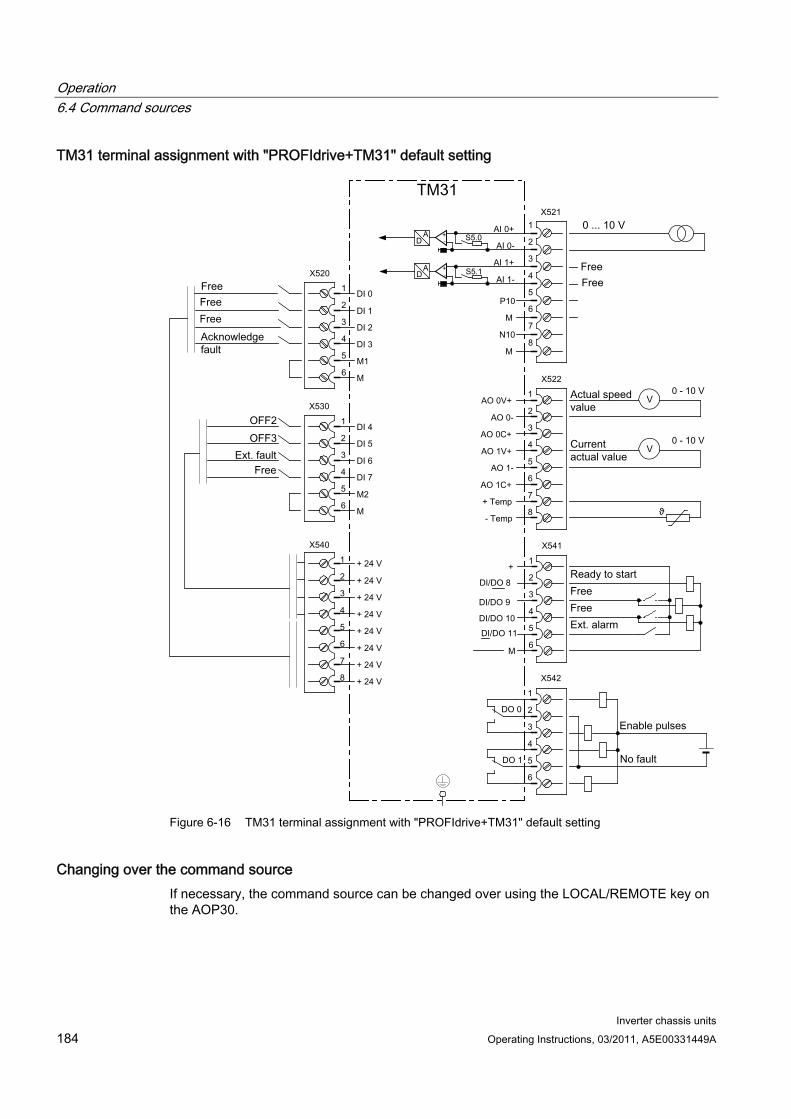
Operation 6.4 Command sources
Inverter chassis units 184 Operating Instructions, 03/2011, A5E00331449A
TM31 terminal assignment with "PROFIdrive+TM31" default setting
Figure 6-16 TM31 terminal assignment with "PROFIdrive+TM31" default setting
Changing over the command source If necessary, the command source can be changed over using the LOCAL/REMOTE key on the AOP30.
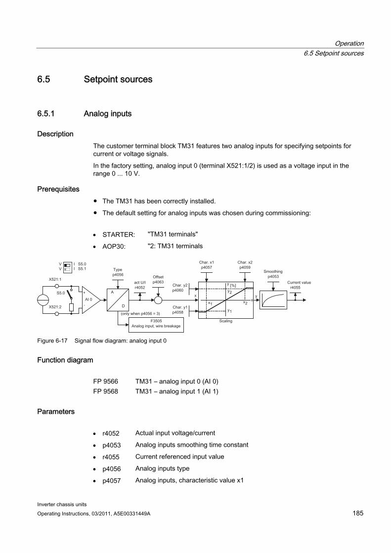
Operation 6.5 Setpoint sources
Inverter chassis units Operating Instructions, 03/2011, A5E00331449A 185
6.5 Setpoint sources
6.5.1 Analog inputs
Description The customer terminal block TM31 features two analog inputs for specifying setpoints for current or voltage signals.
In the factory setting, analog input 0 (terminal X521:1/2) is used as a voltage input in the range 0 ... 10 V.
Prerequisites The TM31 has been correctly installed.
The default setting for analog inputs was chosen during commissioning:
STARTER: "TM31 terminals"
AOP30: "2: TM31 terminals
Figure 6-17 Signal flow diagram: analog input 0
Function diagram FP 9566 TM31 – analog input 0 (AI 0) FP 9568 TM31 – analog input 1 (AI 1)
Parameters r4052 Actual input voltage/current
p4053 Analog inputs smoothing time constant
r4055 Current referenced input value
p4056 Analog inputs type
p4057 Analog inputs, characteristic value x1
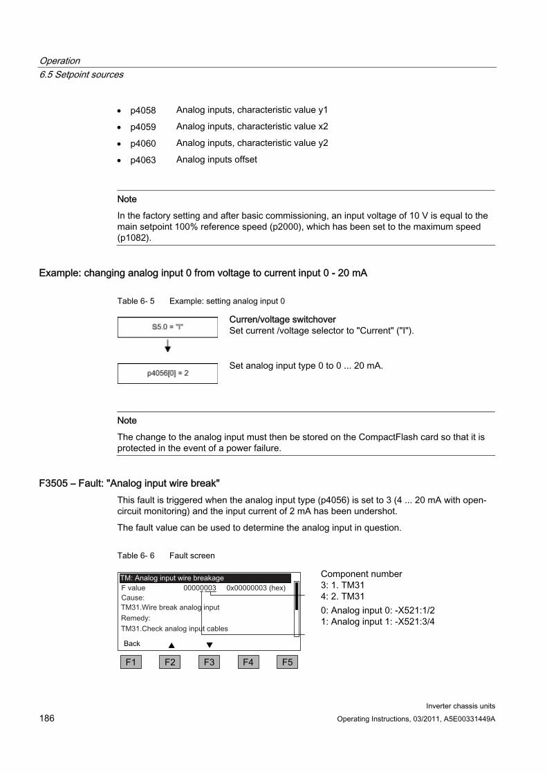
Operation 6.5 Setpoint sources
Inverter chassis units 186 Operating Instructions, 03/2011, A5E00331449A
p4058 Analog inputs, characteristic value y1
p4059 Analog inputs, characteristic value x2
p4060 Analog inputs, characteristic value y2
p4063 Analog inputs offset
Note
In the factory setting and after basic commissioning, an input voltage of 10 V is equal to the main setpoint 100% reference speed (p2000), which has been set to the maximum speed (p1082).
Example: changing analog input 0 from voltage to current input 0 - 20 mA
Table 6- 5 Example: setting analog input 0
Curren/voltage switchover Set current /voltage selector to "Current" ("I").
Set analog input type 0 to 0 ... 20 mA.
Note
The change to the analog input must then be stored on the CompactFlash card so that it is protected in the event of a power failure.
F3505 – Fault: "Analog input wire break" This fault is triggered when the analog input type (p4056) is set to 3 (4 ... 20 mA with open-circuit monitoring) and the input current of 2 mA has been undershot.
The fault value can be used to determine the analog input in question.
Table 6- 6 Fault screen
Component number 3: 1. TM31 4: 2. TM31
0: Analog input 0: -X521:1/2 1: Analog input 1: -X521:3/4
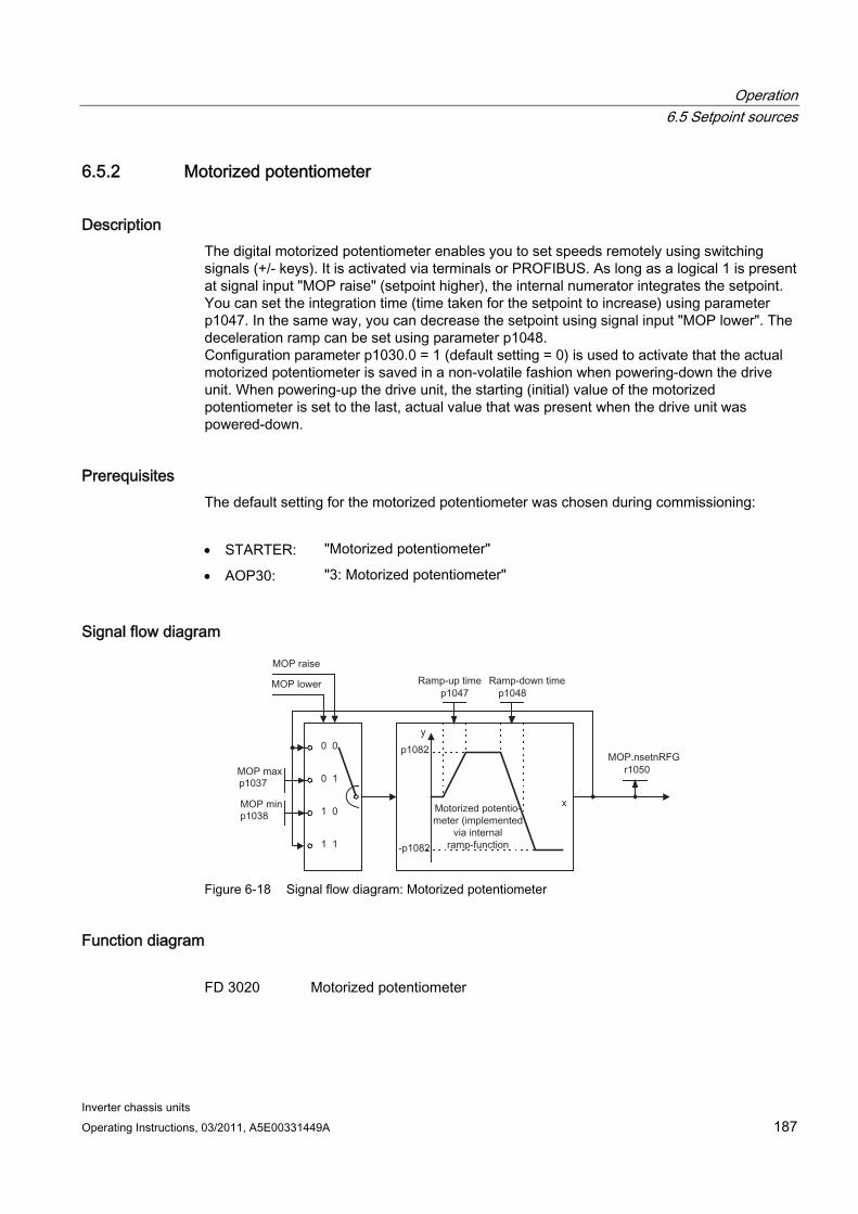
Operation 6.5 Setpoint sources
Inverter chassis units Operating Instructions, 03/2011, A5E00331449A 187
6.5.2 Motorized potentiometer
Description The digital motorized potentiometer enables you to set speeds remotely using switching signals (+/- keys). It is activated via terminals or PROFIBUS. As long as a logical 1 is present at signal input "MOP raise" (setpoint higher), the internal numerator integrates the setpoint. You can set the integration time (time taken for the setpoint to increase) using parameter p1047. In the same way, you can decrease the setpoint using signal input "MOP lower". The deceleration ramp can be set using parameter p1048. Configuration parameter p1030.0 = 1 (default setting = 0) is used to activate that the actual motorized potentiometer is saved in a non-volatile fashion when powering-down the drive unit. When powering-up the drive unit, the starting (initial) value of the motorized potentiometer is set to the last, actual value that was present when the drive unit was powered-down.
Prerequisites The default setting for the motorized potentiometer was chosen during commissioning:
STARTER: "Motorized potentiometer"
AOP30: "3: Motorized potentiometer"
Signal flow diagram
Figure 6-18 Signal flow diagram: Motorized potentiometer
Function diagram FD 3020 Motorized potentiometer
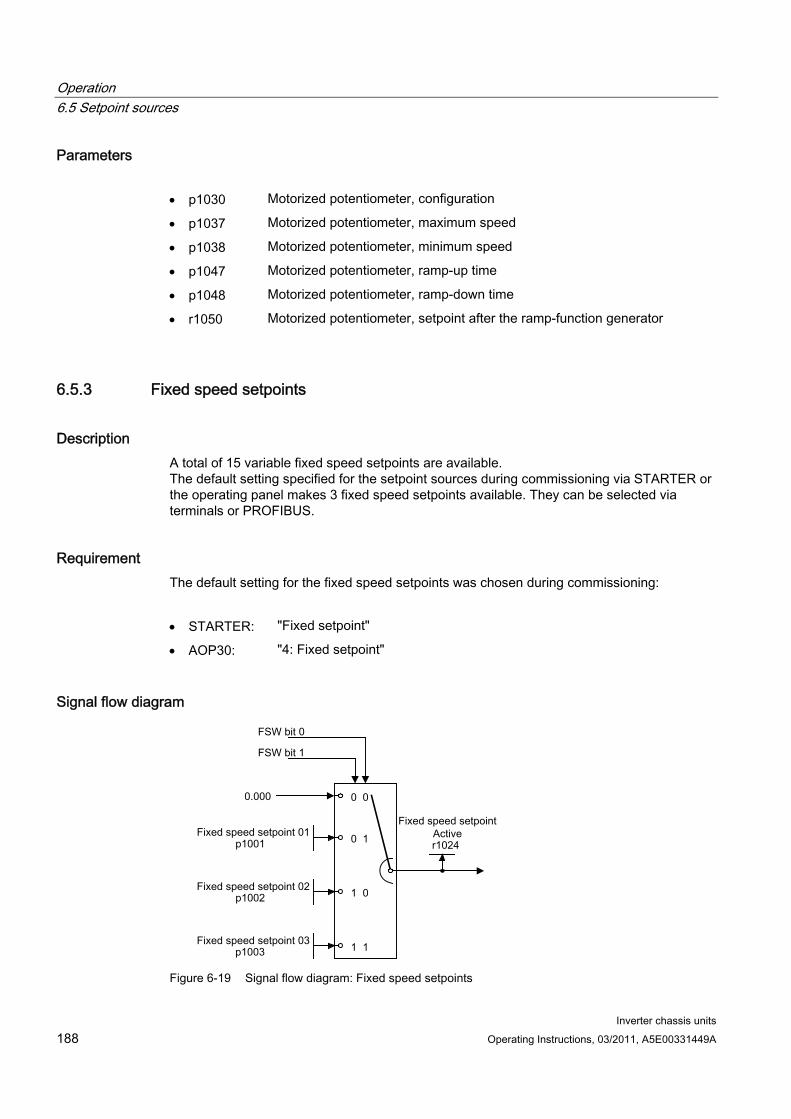
Operation 6.5 Setpoint sources
Inverter chassis units 188 Operating Instructions, 03/2011, A5E00331449A
Parameters p1030 Motorized potentiometer, configuration
p1037 Motorized potentiometer, maximum speed
p1038 Motorized potentiometer, minimum speed
p1047 Motorized potentiometer, ramp-up time
p1048 Motorized potentiometer, ramp-down time
r1050 Motorized potentiometer, setpoint after the ramp-function generator
6.5.3 Fixed speed setpoints
Description A total of 15 variable fixed speed setpoints are available. The default setting specified for the setpoint sources during commissioning via STARTER or the operating panel makes 3 fixed speed setpoints available. They can be selected via terminals or PROFIBUS.
Requirement The default setting for the fixed speed setpoints was chosen during commissioning:
STARTER: "Fixed setpoint"
AOP30: "4: Fixed setpoint"
Signal flow diagram
Figure 6-19 Signal flow diagram: Fixed speed setpoints

Operation 6.5 Setpoint sources
Inverter chassis units Operating Instructions, 03/2011, A5E00331449A 189
Function diagram FP 3010 Fixed speed setpoints
Parameter p1001 Fixed speed setpoint 01
p1002 Fixed speed setpoint 02
p1003 Fixed speed setpoint 03
r1024 Fixed speed setpoint effective
Note
Other fixed speed setpoints are available using p1004 to p1015. They can be selected using p1020 to p1023.

Operation 6.6 Communication according to PROFIdrive
Inverter chassis units 190 Operating Instructions, 03/2011, A5E00331449A
6.6 Communication according to PROFIdrive
6.6.1 General information PROFIdrive V4.1 is the PROFIBUS and PROFINET profile for drive technology with a wide range of applications in production and process automation.
PROFIdrive is independent of the bus system used (PROFIBUS, PROFINET).
Note
PROFINET for drive technology is standardized and described in the following document: PROFIBUS Profile PROFIdrive – Profile Drive Technology, Version V4.1, May 2006,
PROFIBUS User Organization e. V. Haid-und-Neu-Straße 7, D-76131 Karlsruhe, http://www.profibus.com Order Number 3.172, spec. Chp. 6
IEC 61800-7
Controller, Supervisor, and Drive Unit Properties of the Controller, Supervisor, and Drive Unit
Table 6- 7 Properties of the Controller, Supervisor, and Drive Unit
Properties Controller, Supervisor Drive Unit As bus node Active Passive Sending messages Permitted without external
request Only possible at the request of the controller
Receiving messages Possible with no restrictions Only receiving and acknowledging permitted
Controller (PROFIBUS: Master Class 1, PROFINET IO: IO controller)
This is typically a higher-level controller in which the automation program runs.
Example: SIMATIC S7 and SIMOTION
Supervisor (PROFIBUS: Master Class 2, PROFINET IO: IO Supervisor)
Devices for configuration, commissioning, and operator control and monitoring during bus operation. Devices that exchange data with drive units and controllers acylically only.
Examples: Programming devices, operator control and monitoring devices
Drive Unit (PROFIBUS: Slave, PROFINET IO: IO Device)
With reference to PROFIdrive, SINAMICS is a drive unit.

Operation 6.6 Communication according to PROFIdrive
Inverter chassis units Operating Instructions, 03/2011, A5E00331449A 191
Interface IF1 and IF2 The control unit can communicate via two different interfaces (IF1 and IF2).
Table 6- 8 Properties of IF1 and IF2
IF1 IF2 PROFIdrive Yes No Standard telegrams Yes No Isochronous mode Yes Yes DO types All All Can be used for PROFINET IO, PROFIBUS PROFINET IO, PROFIBUS,
CANopen Cyclic operation possible Yes Yes PROFIsafe possible Yes Yes
Note
For additional information on the IF1 and IF2 interfaces, see section "Parallel operation of communication interfaces".
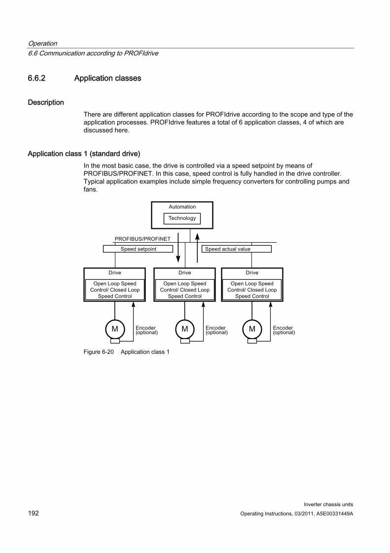
Operation 6.6 Communication according to PROFIdrive
Inverter chassis units 192 Operating Instructions, 03/2011, A5E00331449A
6.6.2 Application classes
Description There are different application classes for PROFIdrive according to the scope and type of the application processes. PROFIdrive features a total of 6 application classes, 4 of which are discussed here.
Application class 1 (standard drive) In the most basic case, the drive is controlled via a speed setpoint by means of PROFIBUS/PROFINET. In this case, speed control is fully handled in the drive controller. Typical application examples include simple frequency converters for controlling pumps and fans.
Figure 6-20 Application class 1
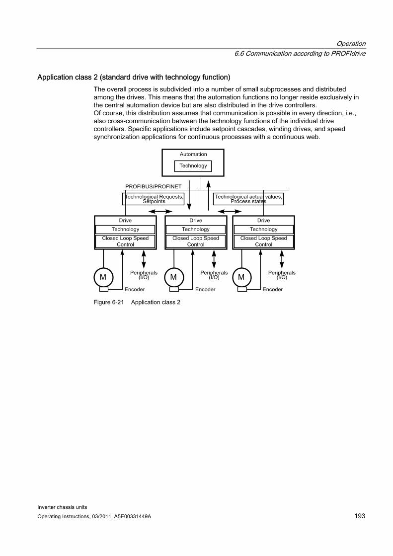
Operation 6.6 Communication according to PROFIdrive
Inverter chassis units Operating Instructions, 03/2011, A5E00331449A 193
Application class 2 (standard drive with technology function) The overall process is subdivided into a number of small subprocesses and distributed among the drives. This means that the automation functions no longer reside exclusively in the central automation device but are also distributed in the drive controllers. Of course, this distribution assumes that communication is possible in every direction, i.e., also cross-communication between the technology functions of the individual drive controllers. Specific applications include setpoint cascades, winding drives, and speed synchronization applications for continuous processes with a continuous web.
Figure 6-21 Application class 2
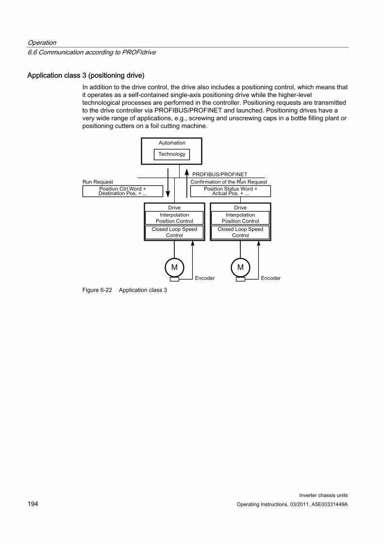
Operation 6.6 Communication according to PROFIdrive
Inverter chassis units 194 Operating Instructions, 03/2011, A5E00331449A
Application class 3 (positioning drive) In addition to the drive control, the drive also includes a positioning control, which means that it operates as a self-contained single-axis positioning drive while the higher-level technological processes are performed in the controller. Positioning requests are transmitted to the drive controller via PROFIBUS/PROFINET and launched. Positioning drives have a very wide range of applications, e.g., screwing and unscrewing caps in a bottle filling plant or positioning cutters on a foil cutting machine.
Figure 6-22 Application class 3
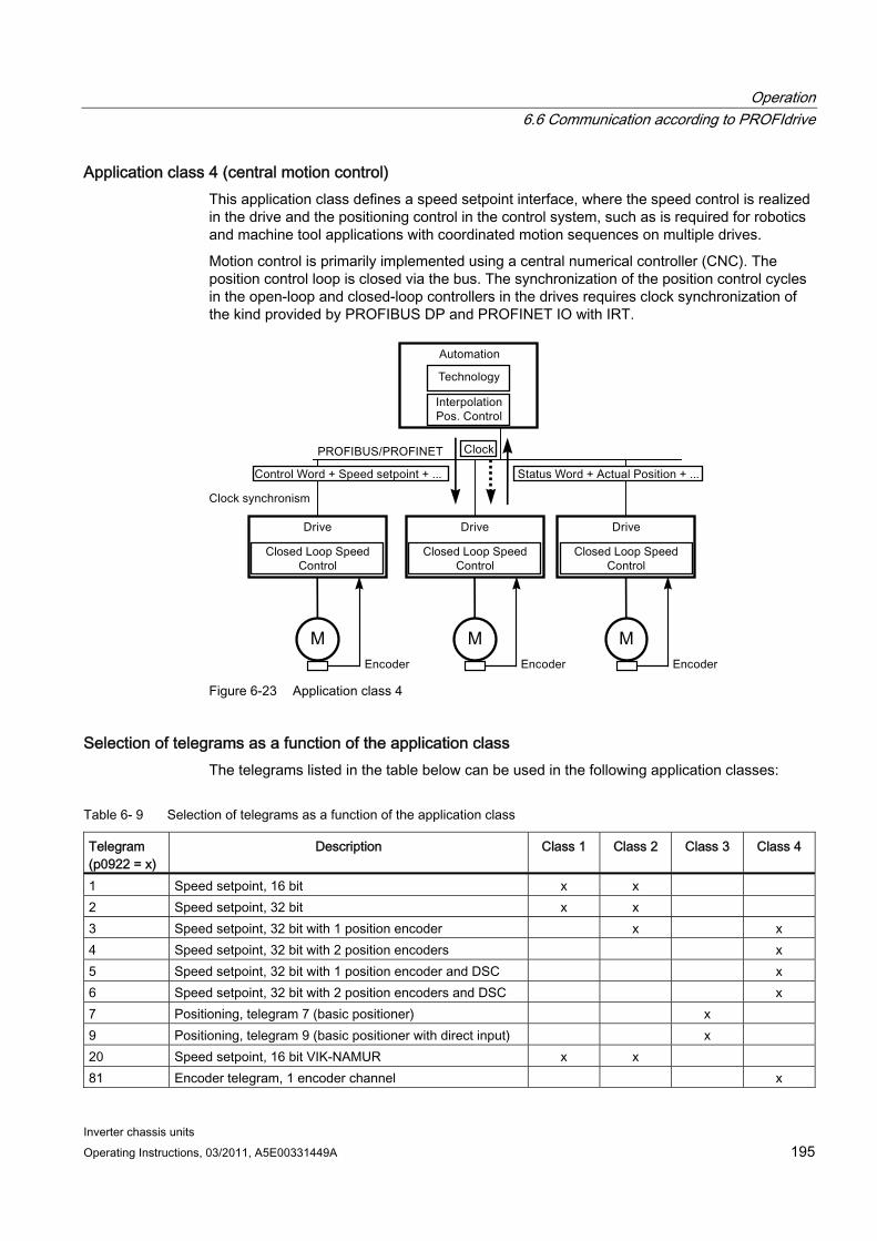
Operation 6.6 Communication according to PROFIdrive
Inverter chassis units Operating Instructions, 03/2011, A5E00331449A 195
Application class 4 (central motion control) This application class defines a speed setpoint interface, where the speed control is realized in the drive and the positioning control in the control system, such as is required for robotics and machine tool applications with coordinated motion sequences on multiple drives.
Motion control is primarily implemented using a central numerical controller (CNC). The position control loop is closed via the bus. The synchronization of the position control cycles in the open-loop and closed-loop controllers in the drives requires clock synchronization of the kind provided by PROFIBUS DP and PROFINET IO with IRT.
Figure 6-23 Application class 4
Selection of telegrams as a function of the application class The telegrams listed in the table below can be used in the following application classes:
Table 6- 9 Selection of telegrams as a function of the application class
Telegram (p0922 = x)
Description Class 1 Class 2 Class 3 Class 4
1 Speed setpoint, 16 bit x x 2 Speed setpoint, 32 bit x x 3 Speed setpoint, 32 bit with 1 position encoder x x 4 Speed setpoint, 32 bit with 2 position encoders x 5 Speed setpoint, 32 bit with 1 position encoder and DSC x 6 Speed setpoint, 32 bit with 2 position encoders and DSC x 7 Positioning, telegram 7 (basic positioner) x 9 Positioning, telegram 9 (basic positioner with direct input) x 20 Speed setpoint, 16 bit VIK-NAMUR x x 81 Encoder telegram, 1 encoder channel x
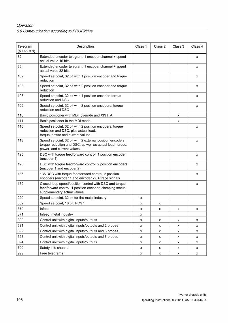
Operation 6.6 Communication according to PROFIdrive
Inverter chassis units 196 Operating Instructions, 03/2011, A5E00331449A
Telegram (p0922 = x)
Description Class 1 Class 2 Class 3 Class 4
82 Extended encoder telegram, 1 encoder channel + speed actual value 16 bits
x
83 Extended encoder telegram, 1 encoder channel + speed actual value 32 bits
x
102 Speed setpoint, 32 bit with 1 position encoder and torque reduction
x
103 Speed setpoint, 32 bit with 2 position encoder and torque reduction
x
105 Speed setpoint, 32 bit with 1 position encoder, torque reduction and DSC
x
106 Speed setpoint, 32 bit with 2 position encoders, torque reduction and DSC
x
110 Basic positioner with MDI, override and XIST_A x 111 Basic positioner in the MDI mode x 116 Speed setpoint, 32 bit with 2 position encoders, torque
reduction and DSC, plus actual load, torque, power and current values
x
118 Speed setpoint, 32 bit with 2 external position encoders, torque reduction and DSC, as well as actual load, torque, power, and current values
x
125 DSC with torque feedforward control, 1 position encoder (encoder 1)
x
126 DSC with torque feedforward control, 2 position encoders (encoder 1 and encoder 2)
x
136 136 DSC with torque feedforward control, 2 position encoders (encoder 1 and encoder 2), 4 trace signals
x
139 Closed-loop speed/position control with DSC and torque feedforward control, 1 position encoder, clamping status, supplementary actual values
x
220 Speed setpoint, 32 bit for the metal industry x 352 Speed setpoint, 16 bit, PCS7 x x 370 Infeed x x x x 371 Infeed, metal industry x 390 Control unit with digital inputs/outputs x x x x 391 Control unit with digital inputs/outputs and 2 probes x x x x 392 Control unit with digital inputs/outputs and 6 probes x x x x 393 Control unit with digital inputs/outputs and 8 probes x x x x 394 Control unit with digital inputs/outputs x x x x 700 Safety info channel x x x x 999 Free telegrams x x x x
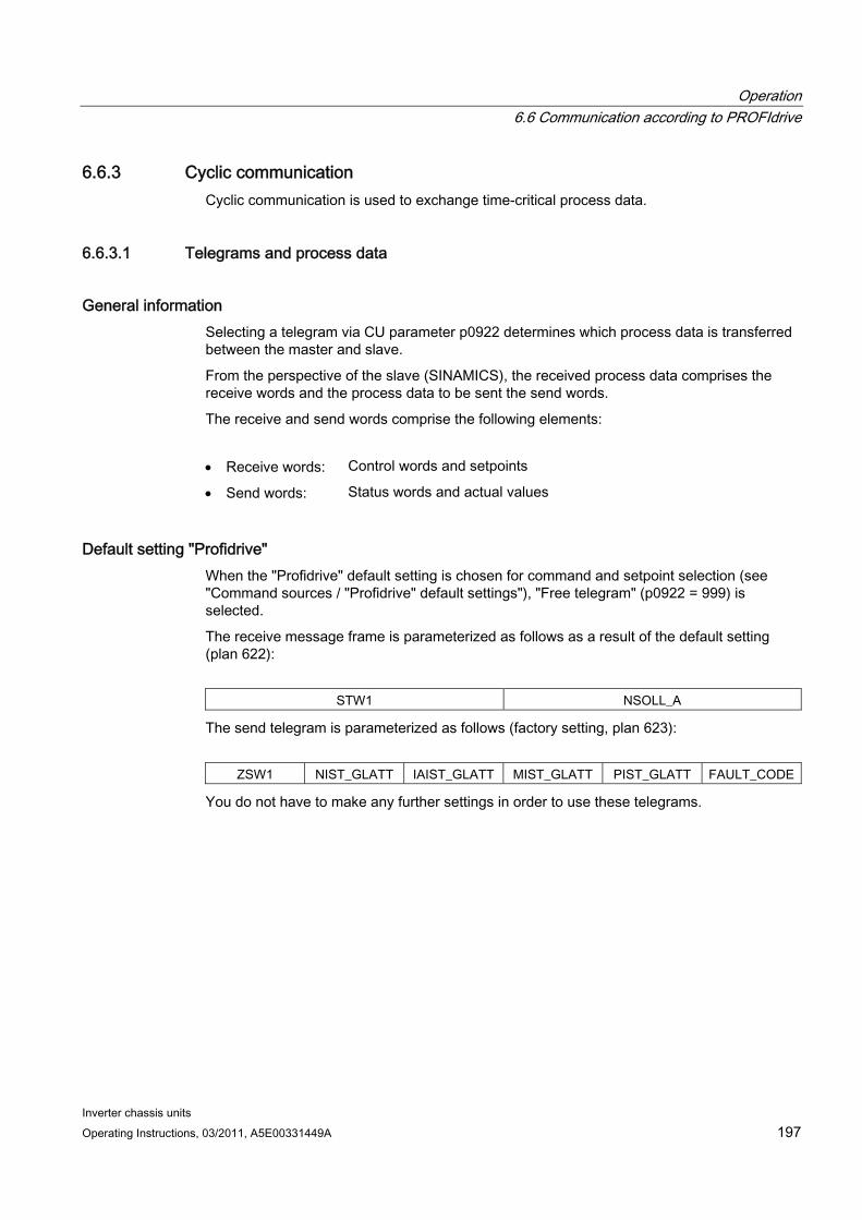
Operation 6.6 Communication according to PROFIdrive
Inverter chassis units Operating Instructions, 03/2011, A5E00331449A 197
6.6.3 Cyclic communication Cyclic communication is used to exchange time-critical process data.
6.6.3.1 Telegrams and process data
General information Selecting a telegram via CU parameter p0922 determines which process data is transferred between the master and slave.
From the perspective of the slave (SINAMICS), the received process data comprises the receive words and the process data to be sent the send words.
The receive and send words comprise the following elements:
Receive words: Control words and setpoints
Send words: Status words and actual values
Default setting "Profidrive" When the "Profidrive" default setting is chosen for command and setpoint selection (see "Command sources / "Profidrive" default settings"), "Free telegram" (p0922 = 999) is selected.
The receive message frame is parameterized as follows as a result of the default setting (plan 622):
STW1 NSOLL_A
The send telegram is parameterized as follows (factory setting, plan 623):
ZSW1 NIST_GLATT IAIST_GLATT MIST_GLATT PIST_GLATT FAULT_CODE
You do not have to make any further settings in order to use these telegrams.
Operation 6.6 Communication according to PROFIdrive
Inverter chassis units 198 Operating Instructions, 03/2011, A5E00331449A
User-defined telegram selection a. Standard telegrams
Standard telegrams are structured in accordance with PROFIdrive profile or internal company specifications. The internal process data links are established automatically in accordance with the telegram number setting in parameter p0922.
The following standard telegrams can be set via parameter p0922:
p0922 = 1 -> Speed setpoint, 16 bit
p0922 = 2 -> Speed setpoint, 32 bit
p0922 = 3 -> Speed setpoint 32 bit with 1 position controller
p0922 = 4 -> Speed setpoint 32 bit with 2 position controller
p0922 = 20 -> Speed setpoint, 16 bit VIK-NAMUR
p0922 = 352 -> Speed setpoint, 16-bit PCS7
Depending on the setting in p0922, the interface mode of the control and status word is automatically set:
p0922 = 1, 352, 999: STW 1/ZSW 1: Interface Mode SINAMICS / MICROMASTER, p2038 = 0
p0922 = 20: STW 1/ZSW 1: Interface Mode PROFIdrive VIK-NAMUR, p2038 = 2
b. Manufacturer-specific telegrams
The manufacturer-specific telegrams are structured in accordance with internal company specifications. The internal process data links are set up automatically in accordance with the telegram number setting.
The following vendor-specific telegrams can be set via p0922:
p0922 = 220 Speed setpoint 32 bit, metal industry
c. Free telegrams (p0922 = 999)
Send and receive telegrams can be configured as required by using BICO technology to interconnect the send and receive words. The default process data assigned under a) is retained during the changeover to p0922 = 999, although it can be changed or supplemented at any time.
To maintain compliance with the PROFIdrive profile, however, the following assignments should be retained:
Interconnect PZD receive word 1 as control word 1 (STW 1)
Interconnect PZD send word 1 as status word 1 (STW 1)
For more information about possible interconnections, see function diagrams FP2460 and FP2470 and the simplified diagrams 620 to 622.
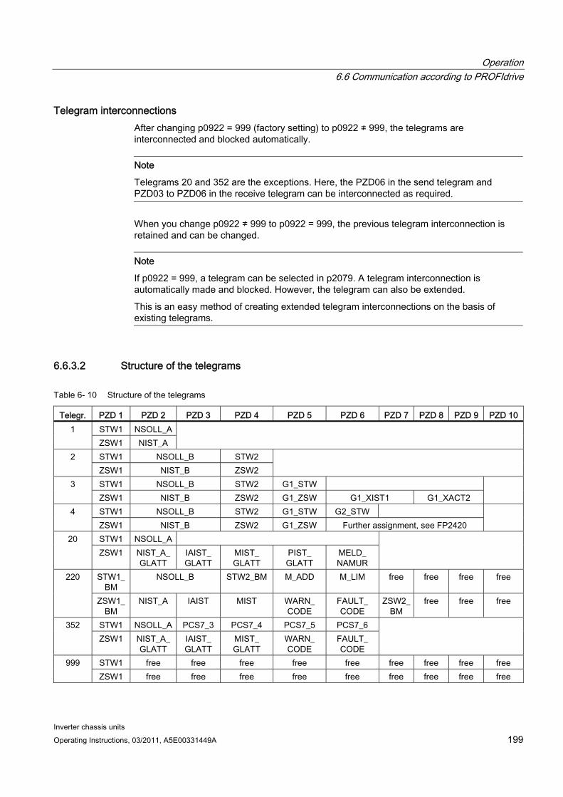
Operation 6.6 Communication according to PROFIdrive
Inverter chassis units Operating Instructions, 03/2011, A5E00331449A 199
Telegram interconnections After changing p0922 = 999 (factory setting) to p0922 ≠ 999, the telegrams are interconnected and blocked automatically.
Note
Telegrams 20 and 352 are the exceptions. Here, the PZD06 in the send telegram and PZD03 to PZD06 in the receive telegram can be interconnected as required.
When you change p0922 ≠ 999 to p0922 = 999, the previous telegram interconnection is retained and can be changed.
Note
If p0922 = 999, a telegram can be selected in p2079. A telegram interconnection is automatically made and blocked. However, the telegram can also be extended.
This is an easy method of creating extended telegram interconnections on the basis of existing telegrams.
6.6.3.2 Structure of the telegrams
Table 6- 10 Structure of the telegrams
Telegr. PZD 1 PZD 2 PZD 3 PZD 4 PZD 5 PZD 6 PZD 7 PZD 8 PZD 9 PZD 10 STW1 NSOLL_A1 ZSW1 NIST_A
STW1 NSOLL_B STW2 2 ZSW1 NIST_B ZSW2
STW1 NSOLL_B STW2 G1_STW 3 ZSW1 NIST_B ZSW2 G1_ZSW G1_XIST1 G1_XACT2
STW1 NSOLL_B STW2 G1_STW G2_STW 4 ZSW1 NIST_B ZSW2 G1_ZSW Further assignment, see FP2420
STW1 NSOLL_A 20 ZSW1 NIST_A_
GLATT IAIST_ GLATT
MIST_ GLATT
PIST_ GLATT
MELD_ NAMUR
STW1_ BM
NSOLL_B STW2_BM M_ADD M_LIM free free free free 220
ZSW1_ BM
NIST_A IAIST MIST WARN_ CODE
FAULT_ CODE
ZSW2_ BM
free free free
STW1 NSOLL_A PCS7_3 PCS7_4 PCS7_5 PCS7_6 352 ZSW1 NIST_A_
GLATT IAIST_ GLATT
MIST_ GLATT
WARN_ CODE
FAULT_ CODE
STW1 free free free free free free free free free 999 ZSW1 free free free free free free free free free
Operation 6.6 Communication according to PROFIdrive
Inverter chassis units 200 Operating Instructions, 03/2011, A5E00331449A
6.6.3.3 Overview of control words and setpoints
Table 6- 11 Overview of control words and setpoints
Abbreviation Description Parameters Function diagramSTW1 Control word 1 (interface mode
SINAMICS, p2038 = 0) See table "Control word 1 (interface mode
SINAMICS, p2038 = 0)" FP2442
STW1 Control word 1 (interface mode VIK-NAMUR, p2038 = 2)
See table "Control word 1 (interface mode VIK-NAMUR, p2038 = 2)"
FP2441
STW1_BM Control word 1, metal industry (interface mode SINAMICS, p2038 = 0)
See table "Control word 1, metal industry (interface mode SINAMICS, p2038 = 0)"
FP2425
STW2 Control word 2 (interface mode SINAMICS, p2038 = 0)
See table "Control word 2 (interface mode SINAMICS, p2038 = 0)"
FP2444
STW2_BM Control word 2, metal industry (interface mode SINAMICS, p2038 = 0)
See table "Control word 2, metal industry (interface mode SINAMICS, p2038 = 0)"
FP2426
NSOLL_A Speed setpoint A (16-bit) p1070 FP3030 NSOLL_B Speed setpoint B (32-bit) p1155 FP3080 PCS7_x PCS7-specific setpoints
Operation 6.6 Communication according to PROFIdrive
Inverter chassis units Operating Instructions, 03/2011, A5E00331449A 201
6.6.3.4 Overview of status words and actual values
Table 6- 12 Overview of status words and actual values
Abbreviation Description Parameters Function diagramZSW1 Status word 1 (interface mode
SINAMICS, p2038 = 0) See table "Status word 1 (interface
mode SINAMICS, p2038 = 0)" FP2452
ZSW1 Status word 1 (interface mode VIK-NAMUR, p2038 = 2)
See table "Status word 1 (interface mode VIK-NAMUR, p2038 = 2)"
FP2451
ZSW1_BM Status word 1, metal industry (interface mode SINAMICS, p2038 = 0)
See table "Status word 1, metal industry (interface mode SINAMICS, p2038 =
0)"
FP2428
ZSW2 Status word 2 (interface mode SINAMICS, p2038 = 0)
See table "Status word 2 (interface mode SINAMICS, p2038 = 0)"
FP2454
ZSW2_BM Status word 2, metal industry (interface mode SINAMICS, p2038 = 0)
See table "Status word 2, metal industry (interface mode SINAMICS, p2038 =
0)"
FP2429
NIST_A Speed setpoint A (16 bit) r0063[0] FP4715 NIST_B Speed setpoint B (32 bit) r0063 FP4710 IAIST Actual value of current r0068[0] FP6714 MIST Actual torque value r0080[0] FP6714 PIST Actual power value r0082[0] FP6714
NIST_GLATT Actual speed value smoothed r0063[1] FP4715 IAIST_GLATT Current actual value, smoothed r0068[1] FP6714 MIST_GLATT Torque actual value, smoothed r0080[1] FP6714 PIST_GLATT Power actual value, smoothed r0082[1] FP6714
MELD_NAMUR VIK-NAMUR message bit bar r3113, see table "NAMUR message bit bar"
--
WARN_CODE Alarm code r2132 FP8065 ERROR_CODE Error code r2131 FP8060
6.6.4 Acyclic communication Acyclic communication, as opposed to cyclic communication, means data is transferred only when an explicit request is made (e.g., in order to read and write parameters).
The "Read data record" and "Write data record" services are available for acyclic communication.
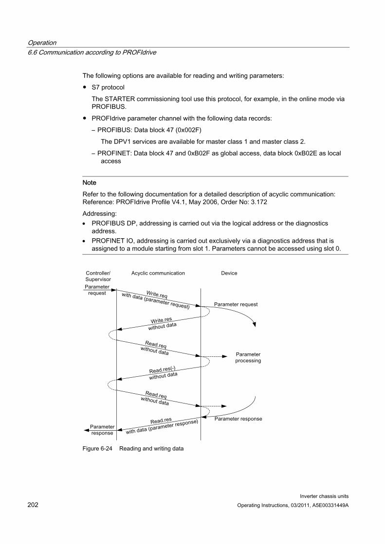
Operation 6.6 Communication according to PROFIdrive
Inverter chassis units 202 Operating Instructions, 03/2011, A5E00331449A
The following options are available for reading and writing parameters:
S7 protocol
The STARTER commissioning tool use this protocol, for example, in the online mode via PROFIBUS.
PROFIdrive parameter channel with the following data records:
– PROFIBUS: Data block 47 (0x002F)
The DPV1 services are available for master class 1 and master class 2.
– PROFINET: Data block 47 and 0xB02F as global access, data block 0xB02E as local access
Note
Refer to the following documentation for a detailed description of acyclic communication: Reference: PROFIdrive Profile V4.1, May 2006, Order No: 3.172
Addressing: PROFIBUS DP, addressing is carried out via the logical address or the diagnostics
address. PROFINET IO, addressing is carried out exclusively via a diagnostics address that is
assigned to a module starting from slot 1. Parameters cannot be accessed using slot 0.
Figure 6-24 Reading and writing data
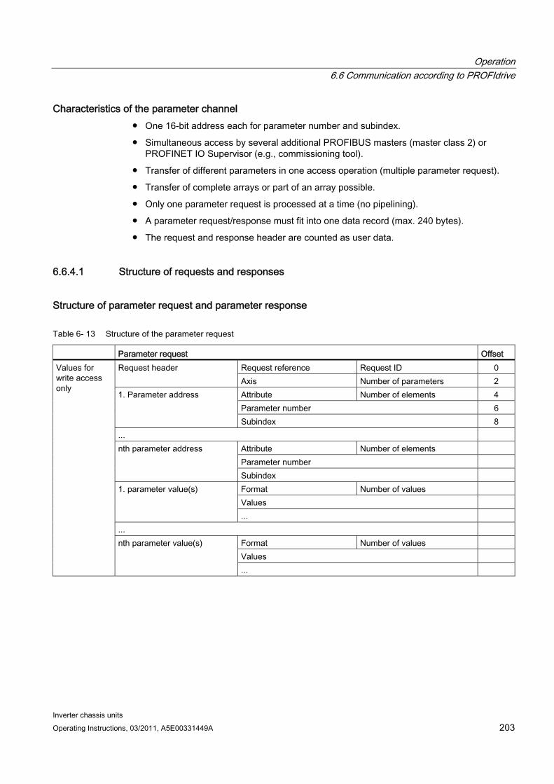
Operation 6.6 Communication according to PROFIdrive
Inverter chassis units Operating Instructions, 03/2011, A5E00331449A 203
Characteristics of the parameter channel One 16-bit address each for parameter number and subindex.
Simultaneous access by several additional PROFIBUS masters (master class 2) or PROFINET IO Supervisor (e.g., commissioning tool).
Transfer of different parameters in one access operation (multiple parameter request).
Transfer of complete arrays or part of an array possible.
Only one parameter request is processed at a time (no pipelining).
A parameter request/response must fit into one data record (max. 240 bytes).
The request and response header are counted as user data.
6.6.4.1 Structure of requests and responses
Structure of parameter request and parameter response
Table 6- 13 Structure of the parameter request
Parameter request Offset Request reference Request ID 0 Request header Axis Number of parameters 2 Attribute Number of elements 4 Parameter number 6
1. Parameter address
Subindex 8 ...
Attribute Number of elements Parameter number
nth parameter address
Subindex Format Number of values Values
1. parameter value(s)
... ...
Format Number of values Values
Values for write access only
nth parameter value(s)
...
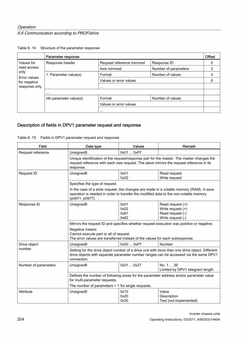
Operation 6.6 Communication according to PROFIdrive
Inverter chassis units 204 Operating Instructions, 03/2011, A5E00331449A
Table 6- 14 Structure of the parameter response
Parameter response Offset Request reference mirrored Response ID 0 Response header Axis mirrored Number of parameters 2 Format Number of values 4 Values or error values 6
1. Parameter value(s)
... ...
Format Number of values Values or error values
Values for read access only Error values for negative response only
nth parameter value(s)
...
Description of fields in DPV1 parameter request and response
Table 6- 15 Fields in DPV1 parameter request and response
Field Data type Values Remark Unsigned8 0x01 ... 0xFF Request reference Unique identification of the request/response pair for the master. The master changes the request reference with each new request. The slave mirrors the request reference in its response. Unsigned8 0x01
0x02 Read request Write request
Request ID
Specifies the type of request. In the case of a write request, the changes are made in a volatile memory (RAM). A save operation is needed in order to transfer the modified data to the non-volatile memory (p0971, p0977). Unsigned8 0x01
0x02 0x81 0x82
Read request (+) Write request (+) Read request (-) Write request (-)
Response ID
Mirrors the request ID and specifies whether request execution was positive or negative. Negative means: Cannot execute part or all of request. The error values are transferred instead of the values for each subresponse. Unsigned8 0x00 ... 0xFF Number Drive object
number Setting for the drive object number of a drive unit with more than one drive object. Different drive objects with separate parameter number ranges can be accessed via the same DPV1 connection. Unsigned8 0x01 ... 0x27 No. 1 ... 39
Limited by DPV1 telegram length Number of parameters
Defines the number of following areas for the parameter address and/or parameter value for multi-parameter requests. The number of parameters = 1 for single requests.
Attribute Unsigned8 0x10 0x20 0x30
Value Description Text (not implemented)
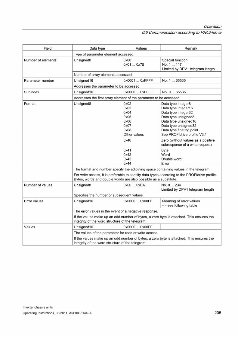
Operation 6.6 Communication according to PROFIdrive
Inverter chassis units Operating Instructions, 03/2011, A5E00331449A 205
Field Data type Values Remark Type of parameter element accessed. Unsigned8 0x00
0x01 ... 0x75 Special function No. 1 ... 117 Limited by DPV1 telegram length
Number of elements
Number of array elements accessed. Unsigned16 0x0001 ... 0xFFFF No. 1 ... 65535 Parameter number Addresses the parameter to be accessed. Unsigned16 0x0000 ... 0xFFFF No. 0 ... 65535 Subindex Addresses the first array element of the parameter to be accessed.
0x02 0x03 0x04 0x05 0x06 0x07 0x08 Other values
Data type integer8 Data type integer16 Data type integer32 Data type unsigned8 Data type unsigned16 Data type unsigned32 Data type floating point See PROFIdrive profile V3.1
Unsigned8
0x40 0x41 0x42 0x43 0x44
Zero (without values as a positive subresponse of a write request) Byte Word Double word Error
Format
The format and number specify the adjoining space containing values in the telegram. For write access, it is preferable to specify data types according to the PROFIdrive profile. Bytes, words and double words are also possible as a substitute. Unsigned8 0x00 ... 0xEA No. 0 ... 234
Limited by DPV1 telegram length Number of values
Specifies the number of subsequent values. Unsigned16 0x0000 ... 0x00FF Meaning of error values
--> see following table Error values
The error values in the event of a negative response. If the values make up an odd number of bytes, a zero byte is attached. This ensures the integrity of the word structure of the telegram. Unsigned16 0x0000 ... 0x00FF Values The values of the parameter for read or write access. If the values make up an odd number of bytes, a zero byte is attached. This ensures the integrity of the word structure of the telegram.
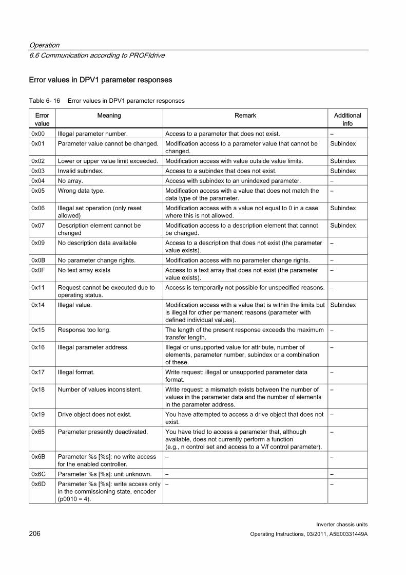
Operation 6.6 Communication according to PROFIdrive
Inverter chassis units 206 Operating Instructions, 03/2011, A5E00331449A
Error values in DPV1 parameter responses
Table 6- 16 Error values in DPV1 parameter responses
Error value
Meaning Remark Additional info
0x00 Illegal parameter number. Access to a parameter that does not exist. – 0x01 Parameter value cannot be changed. Modification access to a parameter value that cannot be
changed. Subindex
0x02 Lower or upper value limit exceeded. Modification access with value outside value limits. Subindex 0x03 Invalid subindex. Access to a subindex that does not exist. Subindex 0x04 No array. Access with subindex to an unindexed parameter. – 0x05 Wrong data type. Modification access with a value that does not match the
data type of the parameter. –
0x06 Illegal set operation (only reset allowed)
Modification access with a value not equal to 0 in a case where this is not allowed.
Subindex
0x07 Description element cannot be changed
Modification access to a description element that cannot be changed.
Subindex
0x09 No description data available Access to a description that does not exist (the parameter value exists).
–
0x0B No parameter change rights. Modification access with no parameter change rights. – 0x0F No text array exists Access to a text array that does not exist (the parameter
value exists). –
0x11 Request cannot be executed due to operating status.
Access is temporarily not possible for unspecified reasons. –
0x14 Illegal value. Modification access with a value that is within the limits but is illegal for other permanent reasons (parameter with defined individual values).
Subindex
0x15 Response too long. The length of the present response exceeds the maximum transfer length.
–
0x16 Illegal parameter address. Illegal or unsupported value for attribute, number of elements, parameter number, subindex or a combination of these.
–
0x17 Illegal format. Write request: illegal or unsupported parameter data format.
–
0x18 Number of values inconsistent. Write request: a mismatch exists between the number of values in the parameter data and the number of elements in the parameter address.
–
0x19 Drive object does not exist. You have attempted to access a drive object that does not exist.
–
0x65 Parameter presently deactivated. You have tried to access a parameter that, although available, does not currently perform a function (e.g., n control set and access to a V/f control parameter).
–
0x6B Parameter %s [%s]: no write access for the enabled controller.
– –
0x6C Parameter %s [%s]: unit unknown. – – 0x6D Parameter %s [%s]: write access only
in the commissioning state, encoder (p0010 = 4).
– –
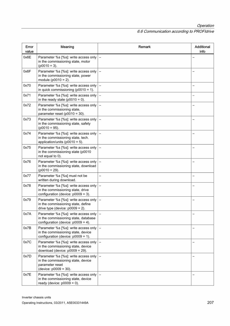
Operation 6.6 Communication according to PROFIdrive
Inverter chassis units Operating Instructions, 03/2011, A5E00331449A 207
Error value
Meaning Remark Additional info
0x6E Parameter %s [%s]: write access only in the commissioning state, motor (p0010 = 3).
– –
0x6F Parameter %s [%s]: write access only in the commissioning state, power module (p0010 = 2).
– –
0x70 Parameter %s [%s]: write access only in quick commissioning (p0010 = 1).
– –
0x71 Parameter %s [%s]: write access only in the ready state (p0010 = 0).
– –
0x72 Parameter %s [%s]: write access only in the commissioning state, parameter reset (p0010 = 30).
– –
0x73 Parameter %s [%s]: write access only in the commissioning state, safety (p0010 = 95).
– –
0x74 Parameter %s [%s]: write access only in the commissioning state, tech. application/units (p0010 = 5).
– –
0x75 Parameter %s [%s]: write access only in the commissioning state (p0010 not equal to 0).
– –
0x76 Parameter %s [%s]: write access only in the commissioning state, download (p0010 = 29).
– –
0x77 Parameter %s [%s] must not be written during download.
– –
0x78 Parameter %s [%s]: write access only in the commissioning state, drive configuration (device: p0009 = 3).
– –
0x79 Parameter %s [%s]: write access only in the commissioning state, define drive type (device: p0009 = 2).
– –
0x7A Parameter %s [%s]: write access only in the commissioning state, database configuration (device: p0009 = 4).
– –
0x7B Parameter %s [%s]: write access only in the commissioning state, device configuration (device: p0009 = 1).
– –
0x7C Parameter %s [%s]: write access only in the commissioning state, device download (device: p0009 = 29).
– –
0x7D Parameter %s [%s]: write access only in the commissioning state, device parameter reset (device: p0009 = 30).
– –
0x7E Parameter %s [%s]: write access only in the commissioning state, device ready (device: p0009 = 0).
– –
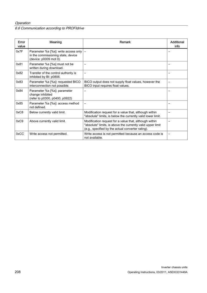
Operation 6.6 Communication according to PROFIdrive
Inverter chassis units 208 Operating Instructions, 03/2011, A5E00331449A
Error value
Meaning Remark Additional info
0x7F Parameter %s [%s]: write access only in the commissioning state, device (device: p0009 mot 0).
– –
0x81 Parameter %s [%s] must not be written during download.
– –
0x82 Transfer of the control authority is inhibited by BI: p0806.
– –
0x83 Parameter %s [%s]: requested BICO interconnection not possible.
BICO output does not supply float values, however the BICO input requires float values.
–
0x84 Parameter %s [%s]: parameter change inhibited (refer to p0300, p0400, p0922)
– –
0x85 Parameter %s [%s]: access method not defined.
– –
0xC8 Below currently valid limit. Modification request for a value that, although within "absolute" limits, is below the currently valid lower limit.
–
0xC9 Above currently valid limit. Modification request for a value that, although within "absolute" limits, is above the currently valid upper limit (e.g., specified by the actual converter rating).
–
0xCC Write access not permitted. Write access is not permitted because an access code is not available.
–
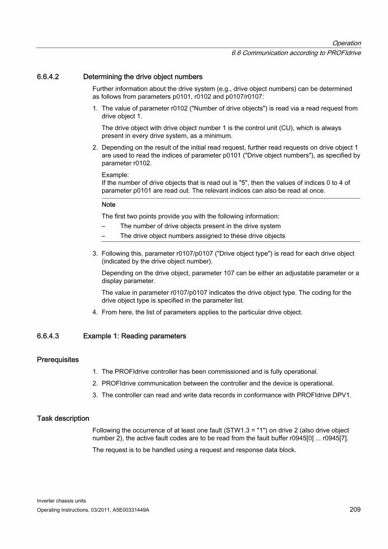
Operation 6.6 Communication according to PROFIdrive
Inverter chassis units Operating Instructions, 03/2011, A5E00331449A 209
6.6.4.2 Determining the drive object numbers Further information about the drive system (e.g., drive object numbers) can be determined as follows from parameters p0101, r0102 and p0107/r0107:
1. The value of parameter r0102 ("Number of drive objects") is read via a read request from drive object 1.
The drive object with drive object number 1 is the control unit (CU), which is always present in every drive system, as a minimum.
2. Depending on the result of the initial read request, further read requests on drive object 1 are used to read the indices of parameter p0101 ("Drive object numbers"), as specified by parameter r0102.
Example: If the number of drive objects that is read out is "5", then the values of indices 0 to 4 of parameter p0101 are read out. The relevant indices can also be read at once.
Note
The first two points provide you with the following information: – The number of drive objects present in the drive system – The drive object numbers assigned to these drive objects
3. Following this, parameter r0107/p0107 ("Drive object type") is read for each drive object (indicated by the drive object number).
Depending on the drive object, parameter 107 can be either an adjustable parameter or a display parameter.
The value in parameter r0107/p0107 indicates the drive object type. The coding for the drive object type is specified in the parameter list.
4. From here, the list of parameters applies to the particular drive object.
6.6.4.3 Example 1: Reading parameters
Prerequisites 1. The PROFIdrive controller has been commissioned and is fully operational.
2. PROFIdrive communication between the controller and the device is operational.
3. The controller can read and write data records in conformance with PROFIdrive DPV1.
Task description Following the occurrence of at least one fault (STW1.3 = "1") on drive 2 (also drive object number 2), the active fault codes are to be read from the fault buffer r0945[0] ... r0945[7].
The request is to be handled using a request and response data block.
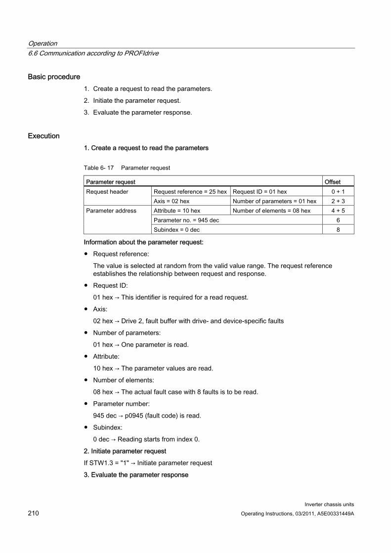
Operation 6.6 Communication according to PROFIdrive
Inverter chassis units 210 Operating Instructions, 03/2011, A5E00331449A
Basic procedure 1. Create a request to read the parameters.
2. Initiate the parameter request.
3. Evaluate the parameter response.
Execution 1. Create a request to read the parameters
Table 6- 17 Parameter request
Parameter request Offset Request reference = 25 hex Request ID = 01 hex 0 + 1 Request header Axis = 02 hex Number of parameters = 01 hex 2 + 3 Attribute = 10 hex Number of elements = 08 hex 4 + 5 Parameter no. = 945 dec 6
Parameter address
Subindex = 0 dec 8
Information about the parameter request:
Request reference:
The value is selected at random from the valid value range. The request reference establishes the relationship between request and response.
Request ID:
01 hex → This identifier is required for a read request.
Axis:
02 hex → Drive 2, fault buffer with drive- and device-specific faults
Number of parameters:
01 hex → One parameter is read.
Attribute:
10 hex → The parameter values are read.
Number of elements:
08 hex → The actual fault case with 8 faults is to be read.
Parameter number:
945 dec → p0945 (fault code) is read.
Subindex:
0 dec → Reading starts from index 0.
2. Initiate parameter request
If STW1.3 = "1" → Initiate parameter request
3. Evaluate the parameter response
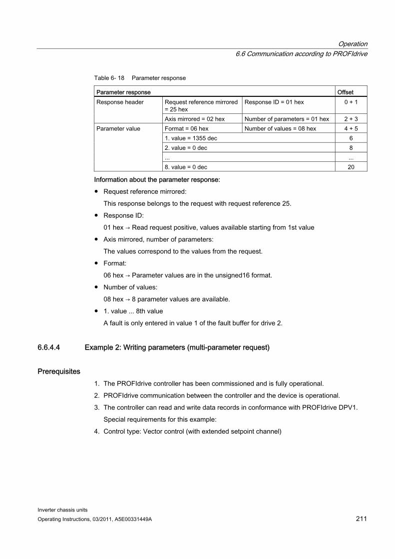
Operation 6.6 Communication according to PROFIdrive
Inverter chassis units Operating Instructions, 03/2011, A5E00331449A 211
Table 6- 18 Parameter response
Parameter response Offset Request reference mirrored = 25 hex
Response ID = 01 hex 0 + 1 Response header
Axis mirrored = 02 hex Number of parameters = 01 hex 2 + 3 Format = 06 hex Number of values = 08 hex 4 + 5 1. value = 1355 dec 6 2. value = 0 dec 8 ... ...
Parameter value
8. value = 0 dec 20
Information about the parameter response:
Request reference mirrored:
This response belongs to the request with request reference 25.
Response ID:
01 hex → Read request positive, values available starting from 1st value
Axis mirrored, number of parameters:
The values correspond to the values from the request.
Format:
06 hex → Parameter values are in the unsigned16 format.
Number of values:
08 hex → 8 parameter values are available.
1. value ... 8th value
A fault is only entered in value 1 of the fault buffer for drive 2.
6.6.4.4 Example 2: Writing parameters (multi-parameter request)
Prerequisites 1. The PROFIdrive controller has been commissioned and is fully operational.
2. PROFIdrive communication between the controller and the device is operational.
3. The controller can read and write data records in conformance with PROFIdrive DPV1.
Special requirements for this example:
4. Control type: Vector control (with extended setpoint channel)
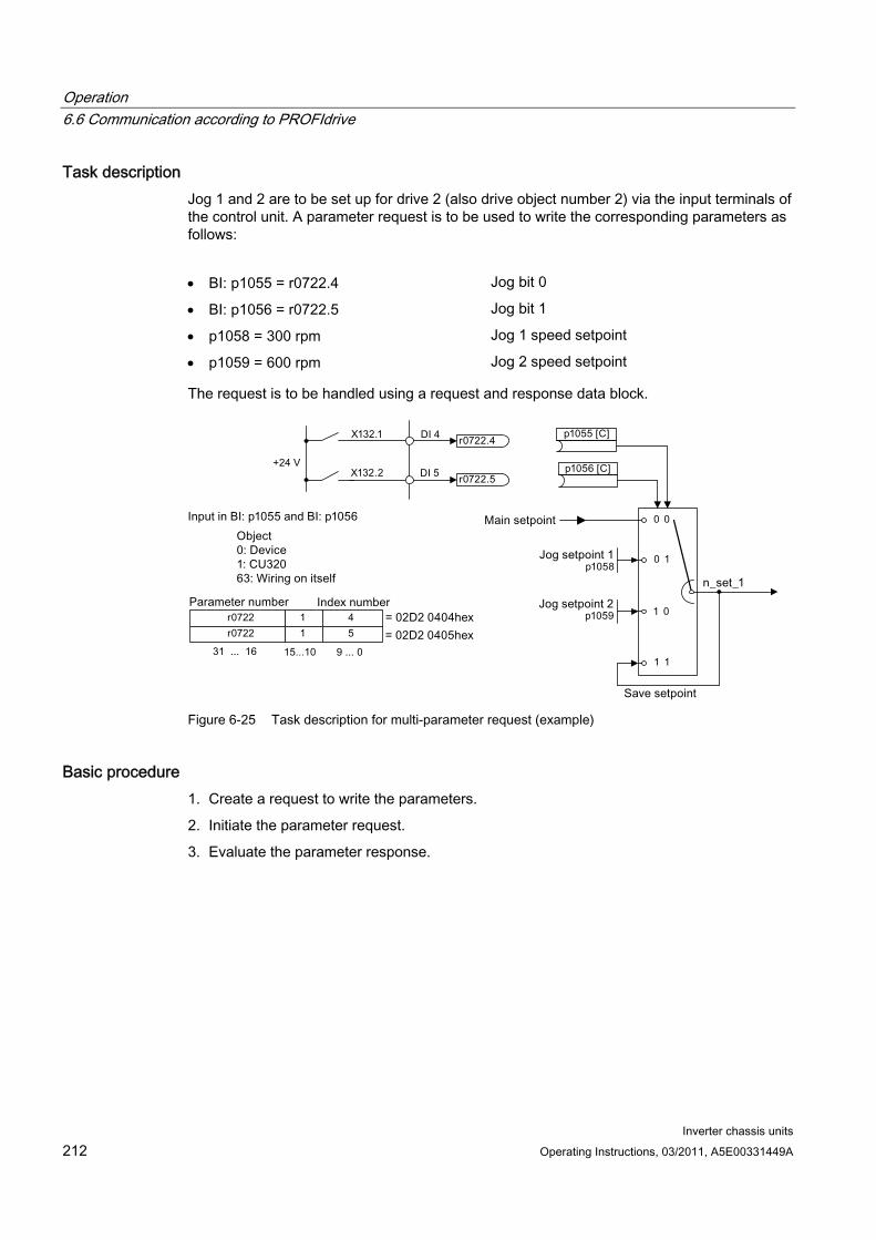
Operation 6.6 Communication according to PROFIdrive
Inverter chassis units 212 Operating Instructions, 03/2011, A5E00331449A
Task description Jog 1 and 2 are to be set up for drive 2 (also drive object number 2) via the input terminals of the control unit. A parameter request is to be used to write the corresponding parameters as follows:
BI: p1055 = r0722.4 Jog bit 0
BI: p1056 = r0722.5 Jog bit 1
p1058 = 300 rpm Jog 1 speed setpoint
p1059 = 600 rpm Jog 2 speed setpoint
The request is to be handled using a request and response data block.
Figure 6-25 Task description for multi-parameter request (example)
Basic procedure 1. Create a request to write the parameters.
2. Initiate the parameter request.
3. Evaluate the parameter response.
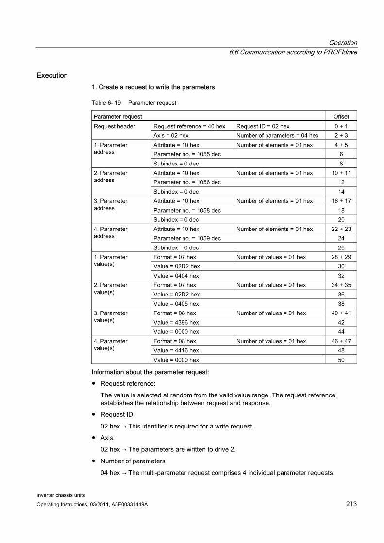
Operation 6.6 Communication according to PROFIdrive
Inverter chassis units Operating Instructions, 03/2011, A5E00331449A 213
Execution 1. Create a request to write the parameters
Table 6- 19 Parameter request
Parameter request Offset Request reference = 40 hex Request ID = 02 hex 0 + 1 Request header Axis = 02 hex Number of parameters = 04 hex 2 + 3 Attribute = 10 hex Number of elements = 01 hex 4 + 5 Parameter no. = 1055 dec 6
1. Parameter address
Subindex = 0 dec 8 Attribute = 10 hex Number of elements = 01 hex 10 + 11 Parameter no. = 1056 dec 12
2. Parameter address
Subindex = 0 dec 14 Attribute = 10 hex Number of elements = 01 hex 16 + 17 Parameter no. = 1058 dec 18
3. Parameter address
Subindex = 0 dec 20 Attribute = 10 hex Number of elements = 01 hex 22 + 23 Parameter no. = 1059 dec 24
4. Parameter address
Subindex = 0 dec 26 Format = 07 hex Number of values = 01 hex 28 + 29 Value = 02D2 hex 30
1. Parameter value(s)
Value = 0404 hex 32 Format = 07 hex Number of values = 01 hex 34 + 35 Value = 02D2 hex 36
2. Parameter value(s)
Value = 0405 hex 38 Format = 08 hex Number of values = 01 hex 40 + 41 Value = 4396 hex 42
3. Parameter value(s)
Value = 0000 hex 44 Format = 08 hex Number of values = 01 hex 46 + 47 Value = 4416 hex 48
4. Parameter value(s)
Value = 0000 hex 50
Information about the parameter request:
Request reference:
The value is selected at random from the valid value range. The request reference establishes the relationship between request and response.
Request ID:
02 hex → This identifier is required for a write request.
Axis:
02 hex → The parameters are written to drive 2.
Number of parameters
04 hex → The multi-parameter request comprises 4 individual parameter requests.
Operation 6.6 Communication according to PROFIdrive
Inverter chassis units 214 Operating Instructions, 03/2011, A5E00331449A
1st parameter address ... 4th parameter address
Attribute:
10 hex → The parameter values are to be written.
Number of elements
01 hex → 1 array element is written.
Parameter number
Specifies the number of the parameter to be written (p1055, p1056, p1058, p1059).
Subindex:
0 dec → ID of the first array element.
1st parameter value ... 4th parameter value
Format:
07 hex → Data type Unsigned32
08 hex → Data type FloatingPoint
Number of values:
01 hex → A value is written to each parameter in the specified format.
Value:
BICO input parameter: enter signal source
Adjustable parameter: enter value
2. Initiate parameter request
3. Evaluate the parameter response
Table 6- 20 Parameter response
Parameter response Offset Request reference mirrored = 40 hex Response ID = 02 hex 0 Response header Axis mirrored = 02 hex Number of parameters =
04 hex 2
Information about the parameter response:
Request reference mirrored:
This response belongs to the request with request reference 40.
Response ID:
02 hex → Write request positive
Axis mirrored:
02 hex → The value matches the value from the request.
Number of parameters:
04 hex → The value matches the value from the request.

Operation 6.6 Communication according to PROFIdrive
Inverter chassis units Operating Instructions, 03/2011, A5E00331449A 215
6.6.5 Further information about PROFIdrive communication
Further information about PROFIdrive communication For more information about PROFIdrive communication, refer to "PROFIdrive communication" in the accompanying "SINAMICS S120 Function Manual".
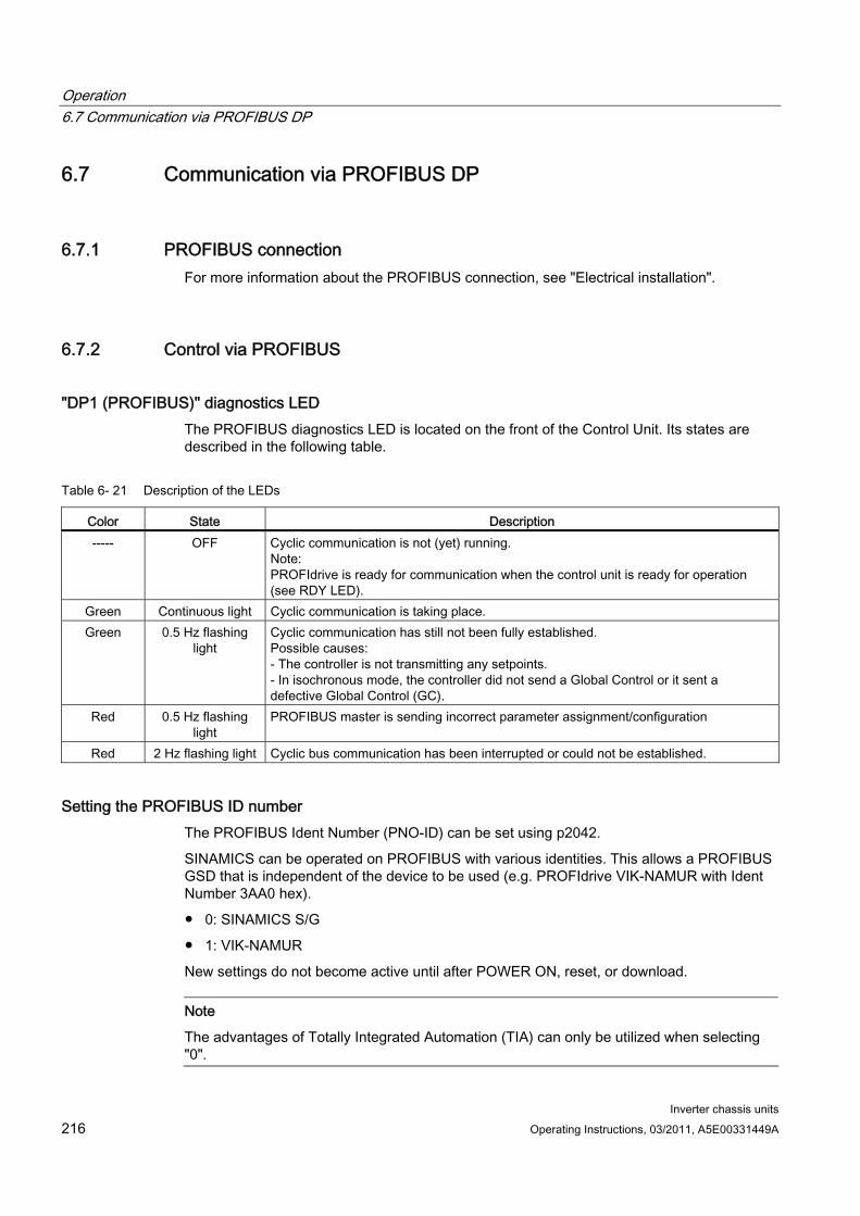
Operation 6.7 Communication via PROFIBUS DP
Inverter chassis units 216 Operating Instructions, 03/2011, A5E00331449A
6.7 Communication via PROFIBUS DP
6.7.1 PROFIBUS connection For more information about the PROFIBUS connection, see "Electrical installation".
6.7.2 Control via PROFIBUS
"DP1 (PROFIBUS)" diagnostics LED The PROFIBUS diagnostics LED is located on the front of the Control Unit. Its states are described in the following table.
Table 6- 21 Description of the LEDs
Color State Description ----- OFF Cyclic communication is not (yet) running.
Note: PROFIdrive is ready for communication when the control unit is ready for operation (see RDY LED).
Green Continuous light Cyclic communication is taking place. Green 0.5 Hz flashing
light Cyclic communication has still not been fully established. Possible causes: - The controller is not transmitting any setpoints. - In isochronous mode, the controller did not send a Global Control or it sent a defective Global Control (GC).
Red 0.5 Hz flashing light
PROFIBUS master is sending incorrect parameter assignment/configuration
Red 2 Hz flashing light Cyclic bus communication has been interrupted or could not be established.
Setting the PROFIBUS ID number The PROFIBUS Ident Number (PNO-ID) can be set using p2042.
SINAMICS can be operated on PROFIBUS with various identities. This allows a PROFIBUS GSD that is independent of the device to be used (e.g. PROFIdrive VIK-NAMUR with Ident Number 3AA0 hex).
0: SINAMICS S/G
1: VIK-NAMUR
New settings do not become active until after POWER ON, reset, or download.
Note
The advantages of Totally Integrated Automation (TIA) can only be utilized when selecting "0".
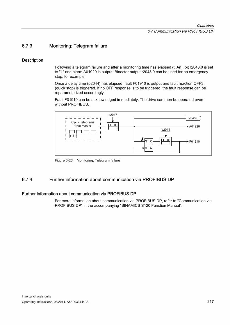
Operation 6.7 Communication via PROFIBUS DP
Inverter chassis units Operating Instructions, 03/2011, A5E00331449A 217
6.7.3 Monitoring: Telegram failure
Description Following a telegram failure and after a monitoring time has elapsed (t_An), bit r2043.0 is set to "1" and alarm A01920 is output. Binector output r2043.0 can be used for an emergency stop, for example.
Once a delay time (p2044) has elapsed, fault F01910 is output and fault reaction OFF3 (quick stop) is triggered. If no OFF response is to be triggered, the fault response can be reparameterized accordingly.
Fault F01910 can be acknowledged immediately. The drive can then be operated even without PROFIBUS.
Figure 6-26 Monitoring: Telegram failure
6.7.4 Further information about communication via PROFIBUS DP
Further information about communication via PROFIBUS DP For more information about communication via PROFIBUS DP, refer to "Communication via PROFIBUS DP" in the accompanying "SINAMICS S120 Function Manual".
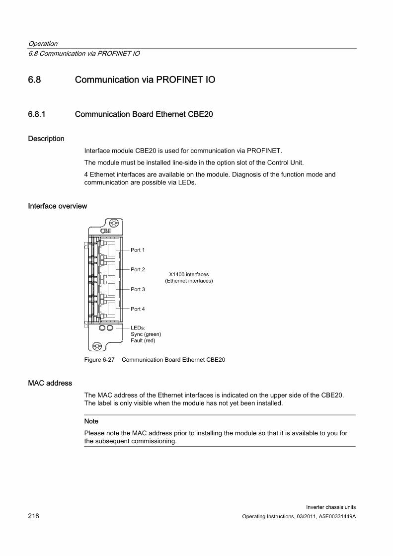
Operation 6.8 Communication via PROFINET IO
Inverter chassis units 218 Operating Instructions, 03/2011, A5E00331449A
6.8 Communication via PROFINET IO
6.8.1 Communication Board Ethernet CBE20
Description Interface module CBE20 is used for communication via PROFINET.
The module must be installed line-side in the option slot of the Control Unit.
4 Ethernet interfaces are available on the module. Diagnosis of the function mode and communication are possible via LEDs.
Interface overview
Figure 6-27 Communication Board Ethernet CBE20
MAC address The MAC address of the Ethernet interfaces is indicated on the upper side of the CBE20. The label is only visible when the module has not yet been installed.
Note
Please note the MAC address prior to installing the module so that it is available to you for the subsequent commissioning.
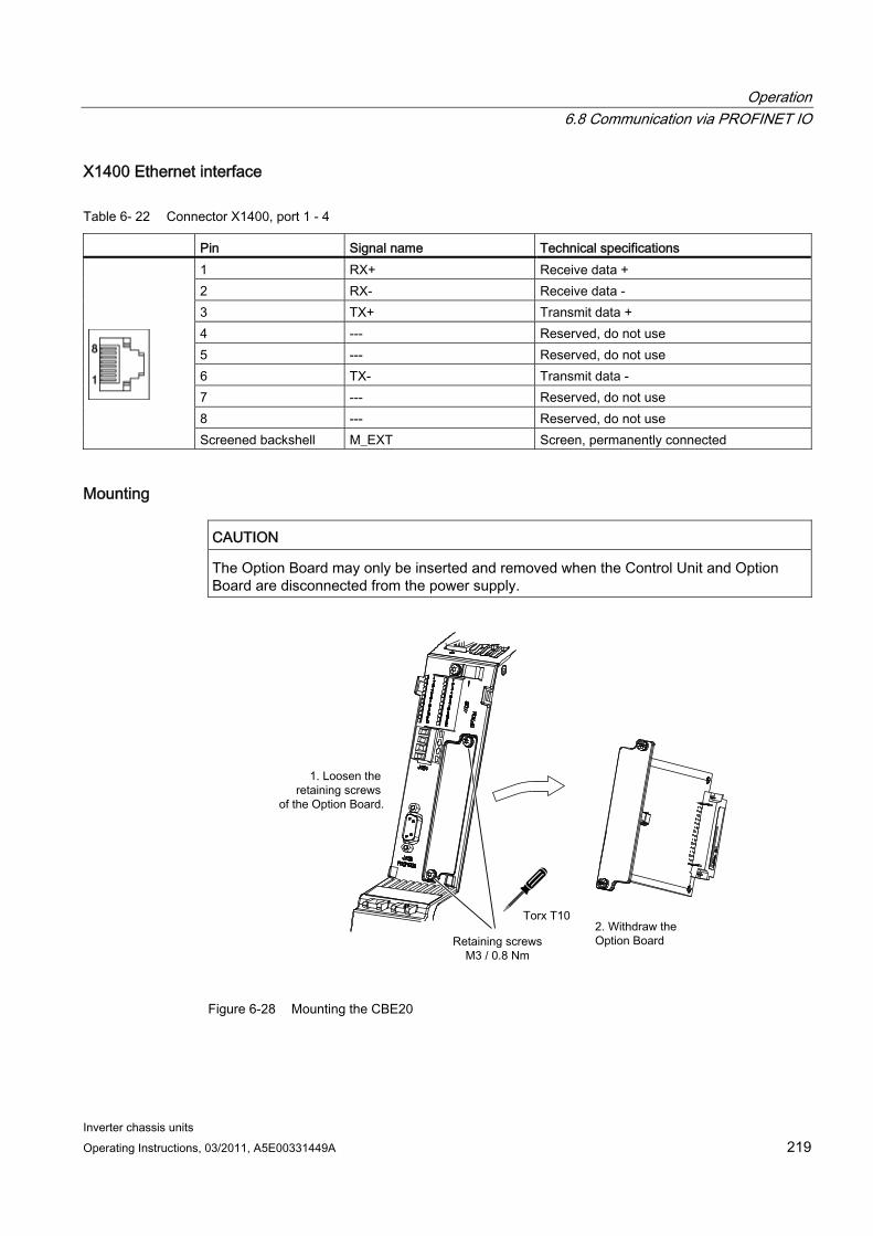
Operation 6.8 Communication via PROFINET IO
Inverter chassis units Operating Instructions, 03/2011, A5E00331449A 219
X1400 Ethernet interface
Table 6- 22 Connector X1400, port 1 - 4
Pin Signal name Technical specifications 1 RX+ Receive data + 2 RX- Receive data - 3 TX+ Transmit data + 4 --- Reserved, do not use 5 --- Reserved, do not use 6 TX- Transmit data - 7 --- Reserved, do not use 8 --- Reserved, do not use
Screened backshell M_EXT Screen, permanently connected
Mounting
CAUTION The Option Board may only be inserted and removed when the Control Unit and Option Board are disconnected from the power supply.
Figure 6-28 Mounting the CBE20
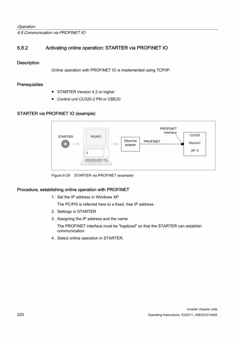
Operation 6.8 Communication via PROFINET IO
Inverter chassis units 220 Operating Instructions, 03/2011, A5E00331449A
6.8.2 Activating online operation: STARTER via PROFINET IO
Description Online operation with PROFINET IO is implemented using TCP/IP.
Prerequisites STARTER Version 4.2 or higher
Control unit CU320-2 PN or CBE20
STARTER via PROFINET IO (example)
Figure 6-29 STARTER via PROFINET (example)
Procedure, establishing online operation with PROFINET 1. Set the IP address in Windows XP
The PC/PG is referred here to a fixed, free IP address.
2. Settings in STARTER
3. Assigning the IP address and the name
The PROFINET interface must be "baptized" so that the STARTER can establish communication.
4. Select online operation in STARTER.
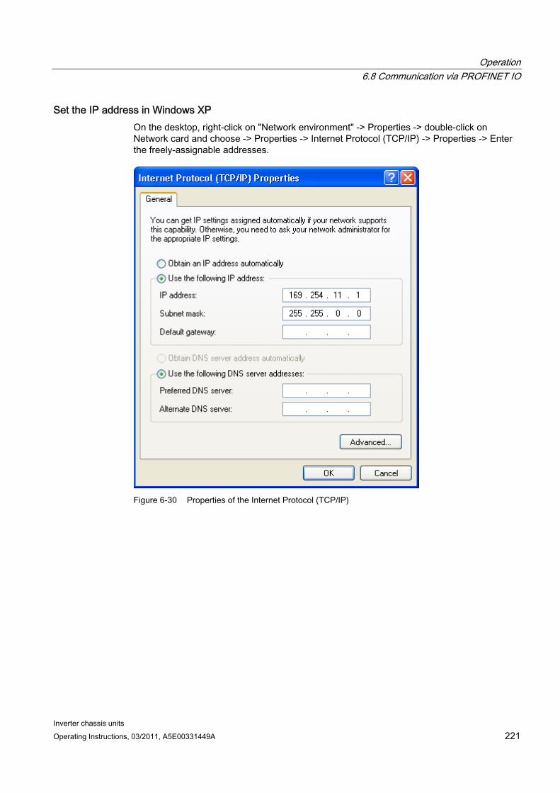
Operation 6.8 Communication via PROFINET IO
Inverter chassis units Operating Instructions, 03/2011, A5E00331449A 221
Set the IP address in Windows XP On the desktop, right-click on "Network environment" -> Properties -> double-click on Network card and choose -> Properties -> Internet Protocol (TCP/IP) -> Properties -> Enter the freely-assignable addresses.
Figure 6-30 Properties of the Internet Protocol (TCP/IP)
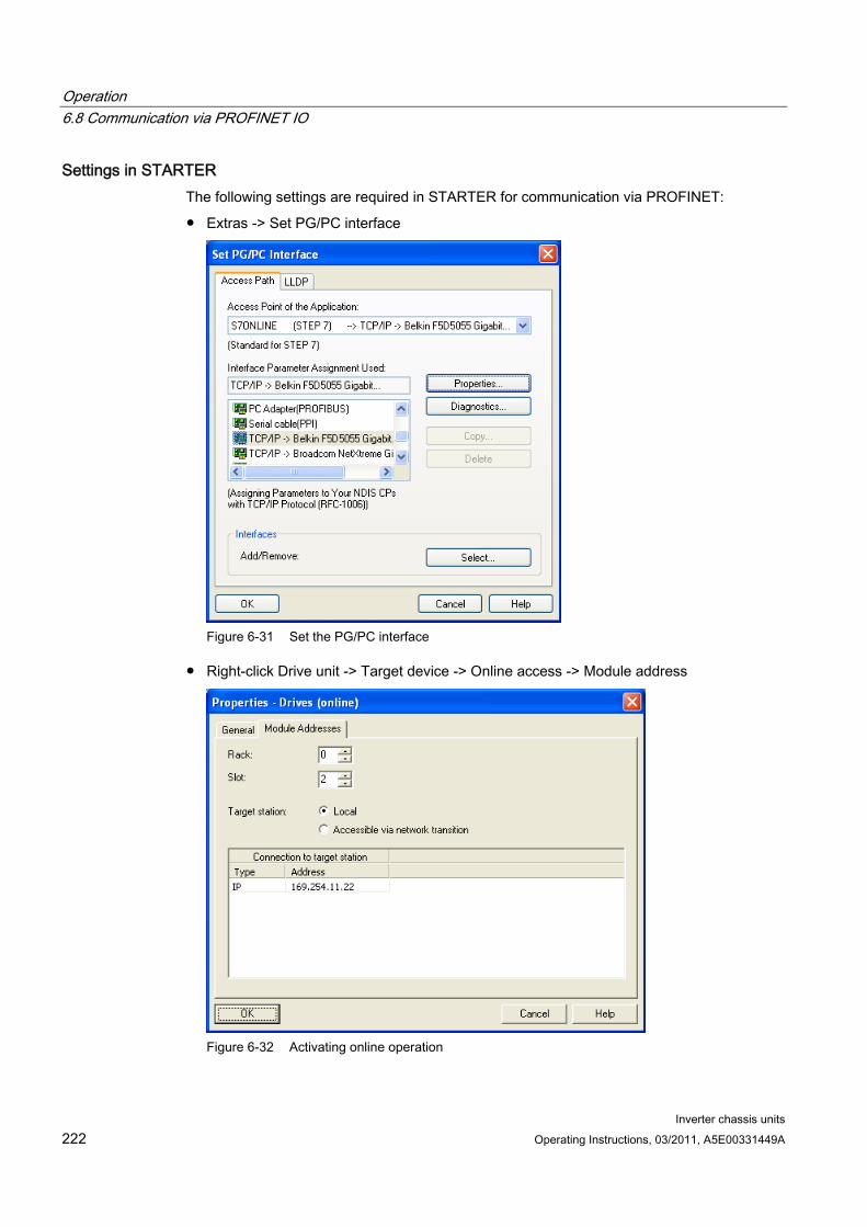
Operation 6.8 Communication via PROFINET IO
Inverter chassis units 222 Operating Instructions, 03/2011, A5E00331449A
Settings in STARTER The following settings are required in STARTER for communication via PROFINET:
Extras -> Set PG/PC interface
Figure 6-31 Set the PG/PC interface
Right-click Drive unit -> Target device -> Online access -> Module address
Figure 6-32 Activating online operation

Operation 6.8 Communication via PROFINET IO
Inverter chassis units Operating Instructions, 03/2011, A5E00331449A 223
Assigning the IP address and the name
Note
ST (Structured Text) conventions must be satisfied for the name assignment of IO devices in PROFINET (SINAMICS components). The names must be unique within PROFINET. The characters "-" and "." are not permitted in the name of an IO device.
"Accessible nodes" function
Use the STARTER to assign an IP address and a name to the PROFINET interface.
Connect the direct Ethernet cable from the PG/PC to the PROFINET interface.
Switch on the Control Unit.
Open STARTER.
A search is performed for available nodes in PROFINET via Project -> Accessible nodes or the "Accessible nodes" button.
The SINAMICS drive object is detected and displayed as a bus node with IP address 0.0.0.0 and without a name.
Mark the bus node entry and select the displayed menu item "Edit Ethernet node" with the right mouse button.
In the following "Edit Ethernet node" screen, enter the device name for the PROFINET interface and click the "Assign name" button. Enter the IP address (e.g. 169.254.11.22) in the IP configuration and specify the subnet screen (e.g. 255.255.0.0). Then click the "Assign IP configuration" button. Close the screen.
The "Update (F5)" button displays the IP address and name in the entry for the bus node. If not, close the "Accessible nodes" screen and perform another search for accessible nodes.
If the PROFINET interface is displayed as bus node, mark the entry and click the "Accept" button.
The SINAMICS drive is displayed as a drive object in the project tree.
Further configurations can be performed for the drive object.
Click "Connect to target system" and load the project to the Control Unit's memory card with Target system -> Load -> To target device.
Note
The IP address and device name for the Control Unit are stored on the memory card (non-volatile).
Operation 6.8 Communication via PROFINET IO
Inverter chassis units 224 Operating Instructions, 03/2011, A5E00331449A
6.8.3 General information about PROFINET IO
6.8.3.1 General information about PROFINET IO for SINAMICS
General information PROFINET IO is an open Industrial Ethernet standard for a wide range of production and process automation applications. PROFINET IO is based on Industrial Ethernet and observes TCP/IP and IT standards.
The following standards ensure open, multi-vendor systems:
International standard IEC 61158
PROFINET IO is optimized for high-speed, time-critical data communication at field level.
PROFINET Within the context of Totally Integrated Automation (TIA), PROFINET IO is the systematic development of the following systems:
PROFIBUS DP, the established field bus, and
Industrial Ethernet, the communications bus for the cell level.
Experience gained from both systems was and is being integrated into PROFINET IO. As an Ethernet-based automation standard defined by PROFIBUS International (PROFIBUS user organization), PROFINET IO is a manufacturer-independent communication and engineering model.
PROFINET IO defines every aspect of the data exchange between IO controllers (devices with so-called "master functionality" and the IO devices (those with so-called "slave functionality") as well as parameterization and diagnostic processes. An IO system is configured by virtually the same method used for PROFIBUS.
A PROFINET IO system is made up of the following devices:
The IO controller controls automation tasks.
An IO device is controlled and monitored by an IO controller. An IO device consists of several modules and submodules.
IO supervisor is an engineering tool typically based on a PC that is used to parameterize and diagnose individual IO devices (drive units).
IO devices: Drive units with PROFINET interface
SINAMICS G130 with CU320-2 DP and inserted CBE20
SINAMICS G130 with CU320-2 PN
With SINAMICS G130 and CBE20 or with CU320-2 PN, communication via PROFINET IO with RT is possible.
Operation 6.8 Communication via PROFINET IO
Inverter chassis units Operating Instructions, 03/2011, A5E00331449A 225
Note
PROFINET for drive technology is standardized and described in the following document:
PROFIBUS Profile PROFIdrive – Profile Drive Technology
Version V4.1, May 2006,
PROFIBUS User Organization e. V.
Haid-und-Neu-Straße 7,
D-76131 Karlsruhe
http://www.profibus.com,
Order Number 3.172, spec. Chp. 6 – IEC 61800-7
CAUTION The cyclic process data channel for PROFIBUS DP is initially deactivated for a CU320-2 DP and inserted CBE20. However, it can be activated again with parameter (p8839) (see "Parallel operation of communication interfaces").
6.8.3.2 Real-time (RT) and isochronous real-time (IRT) communication
Real-time communication When communication takes place via TCP/IP, the resultant transmission times may be too long and non-deterministic to meet production automation requirements. When communicating time-critical IO user data, PROFINET IO therefore uses its own real-time channel, rather than TCP/IP.
Determinism Determinism means that a system will react in a predictable ("deterministic") manner. With PROFINET IO, it is possible to precisely determine (predict) transmission times.
PROFINET IO with RT (Real Time) Real time means that a system processes external events over a defined period.
Process data and alarms are always transmitted in real time (RT) within the PROFINET IO system. RT communication provides the basis for data exchange with PROFINET IO. Real-time data are treated as a higher priority than TCP(UDP)/IP data. Transmission of time-critical data takes place at guaranteed time intervals.
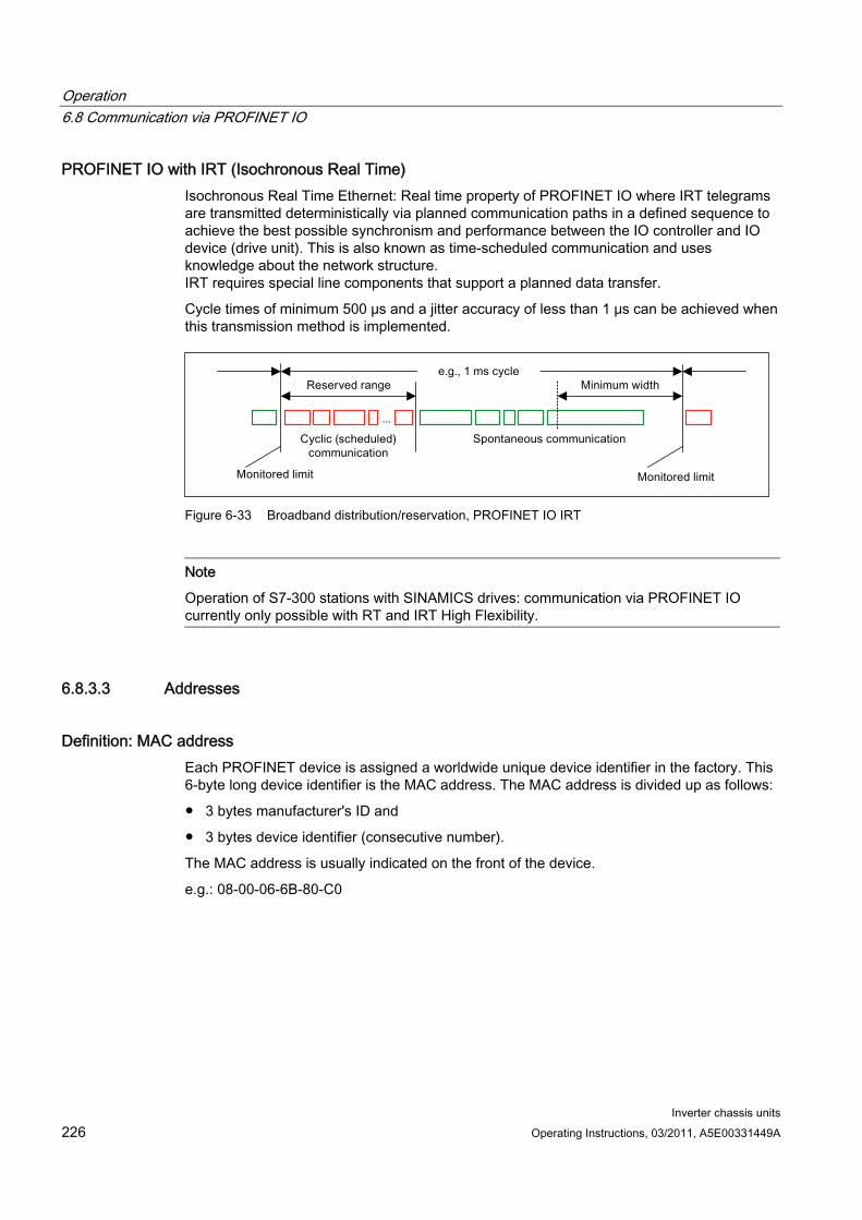
Operation 6.8 Communication via PROFINET IO
Inverter chassis units 226 Operating Instructions, 03/2011, A5E00331449A
PROFINET IO with IRT (Isochronous Real Time) Isochronous Real Time Ethernet: Real time property of PROFINET IO where IRT telegrams are transmitted deterministically via planned communication paths in a defined sequence to achieve the best possible synchronism and performance between the IO controller and IO device (drive unit). This is also known as time-scheduled communication and uses knowledge about the network structure. IRT requires special line components that support a planned data transfer.
Cycle times of minimum 500 μs and a jitter accuracy of less than 1 μs can be achieved when this transmission method is implemented.
Figure 6-33 Broadband distribution/reservation, PROFINET IO IRT
Note
Operation of S7-300 stations with SINAMICS drives: communication via PROFINET IO currently only possible with RT and IRT High Flexibility.
6.8.3.3 Addresses
Definition: MAC address Each PROFINET device is assigned a worldwide unique device identifier in the factory. This 6-byte long device identifier is the MAC address. The MAC address is divided up as follows:
3 bytes manufacturer's ID and
3 bytes device identifier (consecutive number).
The MAC address is usually indicated on the front of the device.
e.g.: 08-00-06-6B-80-C0
Operation 6.8 Communication via PROFINET IO
Inverter chassis units Operating Instructions, 03/2011, A5E00331449A 227
IP address To allow a PROFINET device to be addressed as a node on Industrial Ethernet, this device also requires an IP address that is unique within the network. The IP address is made up of 4 number blocks with a range of values from 0 through 255. The number blocks are separated by a period. The IP address is made up of the following sections:
The address of the (sub-) network and
The address of the node (generally called the host or network node)
IP address assignment The TCP/IP protocol is a prerequisite for establishing a connection and parameterization. This is the reason that an IP address is required.
The IP addresses of IO devices can be assigned by the IO controller and always have the same sub-network mask as the IO controller. In this case, the IP address is not stored permanently. The IP address entry is lost after POWER ON/OFF.
If the IP address is to be stored in a non-volatile memory, the address must be assigned using the Primary Setup Tool (PST) or STARTER.
This can also be carried out in HWConfig in STEP 7, where the function is called "Edit Ethernet node".
Note
If the network is part of an existing Ethernet company network, obtain the information (IP address) from your network administrator.
Device name (NameOfStation) When it is shipped, an IO device does not have a device name. An IO device can only be addressed by an IO controller, for example, for the transfer of project engineering data (including the IP address) during startup or for user data exchange in cyclic operation, after it has been assigned a device name with the IO supervisor.
NOTICE The device name must be saved in a non-volatile fashion either using the Primary Setup Tool (PST) or using HW Config from STEP 7.
Operation 6.8 Communication via PROFINET IO
Inverter chassis units 228 Operating Instructions, 03/2011, A5E00331449A
Replacing Control Unit (IO device) If the IP address and device name are stored in a non-volatile memory, this data is also forwarded with the memory card (CF card) of the Control Unit.
If a complete Control Unit needs to be replaced due to a device or module defect, the new Control Unit automatically parameterizes and configures using the data on the memory card. Following this, cyclic exchange of user data is restarted. The memory card allows module exchange without an IO supervisor when a fault occurs in a PROFINET device.
6.8.3.4 Data transmission
Features The Communication Board CBE20 supports:
IRT – isochronous real-time Ethernet
RT – real-time Ethernet
Standard Ethernet services (TCP/IP, LLDP, UDP and DCP)
PROFIdrive telegram for cyclic data transmission and non-cyclic services Telegrams to send and receive process data are available for each drive object of a drive unit with cyclic process data exchange. In addition to cyclic data transfer, acyclic services can also be used for parameterizing and configuring the drive. These acyclic services can be utilized by the IO supervisor or IO controller.
Sequence of drive objects in the data transfer The sequence of drive objects is displayed via a list in p0978[0...15] where it can also be changed.
Note
The sequence of drive objects in HW Config must be the same as that in the drive (p0978).
6.8.4 Further information about communication via PROFINET IO
Further information about communication via PROFINET IO For more information about PROFINET IO communication, refer to "PROFINET IO communication" in the accompanying "SINAMICS S120 Function Manual".
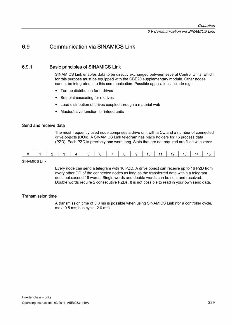
Operation 6.9 Communication via SINAMICS Link
Inverter chassis units Operating Instructions, 03/2011, A5E00331449A 229
6.9 Communication via SINAMICS Link
6.9.1 Basic principles of SINAMICS Link SINAMICS Link enables data to be directly exchanged between several Control Units, which for this purpose must be equipped with the CBE20 supplementary module. Other nodes cannot be integrated into this communication. Possible applications include e.g.:
Torque distribution for n drives
Setpoint cascading for n drives
Load distribution of drives coupled through a material web
Master/slave function for infeed units
Send and receive data The most frequently used node comprises a drive unit with a CU and a number of connected drive objects (DOs). A SINAMICS Link telegram has place holders for 16 process data (PZD). Each PZD is precisely one word long. Slots that are not required are filled with zeros
0 1 2 3 4 5 6 7 8 9 10 11 12 13 14 15
SINAMICS Link
Every node can send a telegram with 16 PZD. A drive object can receive up to 16 PZD from every other DO of the connected nodes as long as the transferred data within a telegram does not exceed 16 words. Single words and double words can be sent and received. Double words require 2 consecutive PZDs. It is not possible to read in your own send data.
Transmission time A transmission time of 3.0 ms is possible when using SINAMICS Link (for a controller cycle, max. 0.5 ms; bus cycle, 2.0 ms).
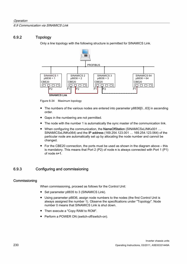
Operation 6.9 Communication via SINAMICS Link
Inverter chassis units 230 Operating Instructions, 03/2011, A5E00331449A
6.9.2 Topology Only a line topology with the following structure is permitted for SINAMICS Link.
Figure 6-34 Maximum topology
The numbers of the various nodes are entered into parameter p8836[0...63] in ascending order.
Gaps in the numbering are not permitted.
The node with the number 1 is automatically the sync master of the communication link.
When configuring the communication, the NameOfStation (SINAMICSxLINKx001 … SINAMICSxLINKx064) and the IP address (169.254.123.001 … 169.254.123.064) of the particular node are automatically set up by allocating the node number and cannot be changed.
For the CBE20 connection, the ports must be used as shown in the diagram above – this is mandatory. This means that Port 2 (P2) of node n is always connected with Port 1 (P1) of node n+1.
6.9.3 Configuring and commissioning
Commissioning When commissioning, proceed as follows for the Control Unit:
Set parameter p8835 to 3 (SINAMICS Link).
Using parameter p8836, assign node numbers to the nodes (the first Control Unit is always assigned the number 1). Observe the specifications under "Topology". Node number 0 means that SINAMICS Link is shut down.
Then execute a "Copy RAM to ROM".
Perform a POWER ON (switch-off/switch-on).
Operation 6.9 Communication via SINAMICS Link
Inverter chassis units Operating Instructions, 03/2011, A5E00331449A 231
Sending data Proceed as follows to send data:
In parameter p2051[x], for each drive object, define which data (PZDs) should be sent. p2061[x] must be used for double word quantities.
In parameter p8871, for each drive object, assign the send parameter to the send slot of its own node. Double words (e.g. 2+3) are assigned two consecutive send slots, e.g. p8871[1] = 2 and p8871[2] = 3.
Receiving data Proceed as follows to receive data:
Note
The first word of the receive data must be a control word, where bit 10 is set. If this is not the case, then you must deactivate the evaluation of bit 10 using p2037 = 2.
Received data are saved in parameter r2050[x]/r2060[x].
The address of the node from which the relevant PZD is to be read is defined in parameter p8872[0 … 15] (0 ≙ nothing is read in).
In parameter p8870[0 … 15], the PZD is defined which is read from the sent telegram and is to be stored in its own receive slot, r2050 for PZD or r2060 for double PZD (0 ≙ no PZD selected).
Note
For double words, 2 PZD must be read; e.g.: Read in a 32-bit setpoint, which is located on PZD 2+3 for node 5 and map this to PZD 2+3 of its own node: p8872[1] = 5, p8870[1] = 2, p8872[2] = 5, p8870[2] = 3
Activation To activate SINAMICS Link connections, perform a POWER ON for all nodes. The assignments of p2051[x]/2061[x] and the links of the read parameters r2050[x]/2060[x] can be changed without a POWER ON.
Settings for chassis units with rated pulse frequency 1.25 kHz For the following chassis units with a rated pulse frequency of 1.25 kHz, in addition parameter p0115[0] must be set from 400 µs to 250 µs or 500 µs:
380 - 480 V 3 AC: All chassis units with rated output current IN ≥ 605 A
500 - 600 V 3 AC: All chassis units
660 - 690 V 3 AC: All chassis units

Operation 6.9 Communication via SINAMICS Link
Inverter chassis units 232 Operating Instructions, 03/2011, A5E00331449A
Generally, the following conditions must be met:
1. r2064[1] bus cycle time (Tdp) must be an integer multiple of p0115[0] (current controller clock cycle).
2. r2064[2] master cycle time (Tmapc) must be an integer multiple of p0115[1] (speed controller cycle).
6.9.4 Example
Task Configure SINAMICS Link for two nodes (here, in example 2, SINAMICS S120) and transfer the following values:
Send data from node 1 to node 2
– r0898 CO/BO: Control word, drive object 1 (1 PZD), in the example PZD 1
– r0079 CO: Total torque setpoint (2 PZD), in the example PZD 2
– r1150 CO: Ramp-function generator speed setpoint at the output (2 PZD) in the example, PZD 3
Send data from node 2 to node 1
– r0899 CO/BO: Status word, drive object 1 (1 PZD), in the example, PZD 1
Procedure 1. For all nodes, set the SINAMICS Link mode:
p8835 = 3
2. Assign node numbers for the two devices:
– Node 1: p8836 = 1 and
– Node 2: p8836 = 2
3. Define the send data (node 1)
– For node 1/DO VECTOR, define the PZD to be sent: p2051.0 = Drive1:r0898, p2061.1 = Drive1:r0079, p2061.3 = Drive1:r1150
– Assign this PZD to the send buffer (p8871) of its own DO: p8871.0 = 1, p8871.1 = 2, p8871.2 = 3, p8871.3 = 4, p8871.4 = 5
This means that you have defined the position of the data in the 16-word telegram of the drive unit.
4. Define the send data (node 2)
– For node 2/DO VECTOR, define the PZD to be sent: p2051.0 = Drive1:r0898
– Assign this PZD 1 to send buffer 0 (p8871) of its own DO: p8871.0 = 1
Operation 6.9 Communication via SINAMICS Link
Inverter chassis units Operating Instructions, 03/2011, A5E00331449A 233
5. Define the receive data (node 1)
– Define that receive buffer 0 should be filled with data from node 2: p8872.0 = 2
– Define that PZD 1 of node 2 should be saved in this buffer: p8870.0 = 1
– r2050.0 now contains the value of PZD 1 of node 2.
6. Define the receive data (node 2)
– Define that receive buffers 0 to 4 should be filled with data from node 1: p8872.0 = 1, p8872.1 = 1, p8872.2 = 1, p8872.3 = 1, p8872.4 = 1
– Define that PZD 1, PZD 2 and PZD 3 of node 1 should be saved in these buffers: p8870.0 = 1, p8870.1 = 2, p8870.2 = 3, p8870.3 = 4, p8870.4 = 5
– r2050.0, r2060.1 and r2060.3 now contain the values from PZD 1, PZD 2 and PZD 3 of node 1.
7. For both nodes, perform a POWER ON in order to activate the SINAMICS Link connections.
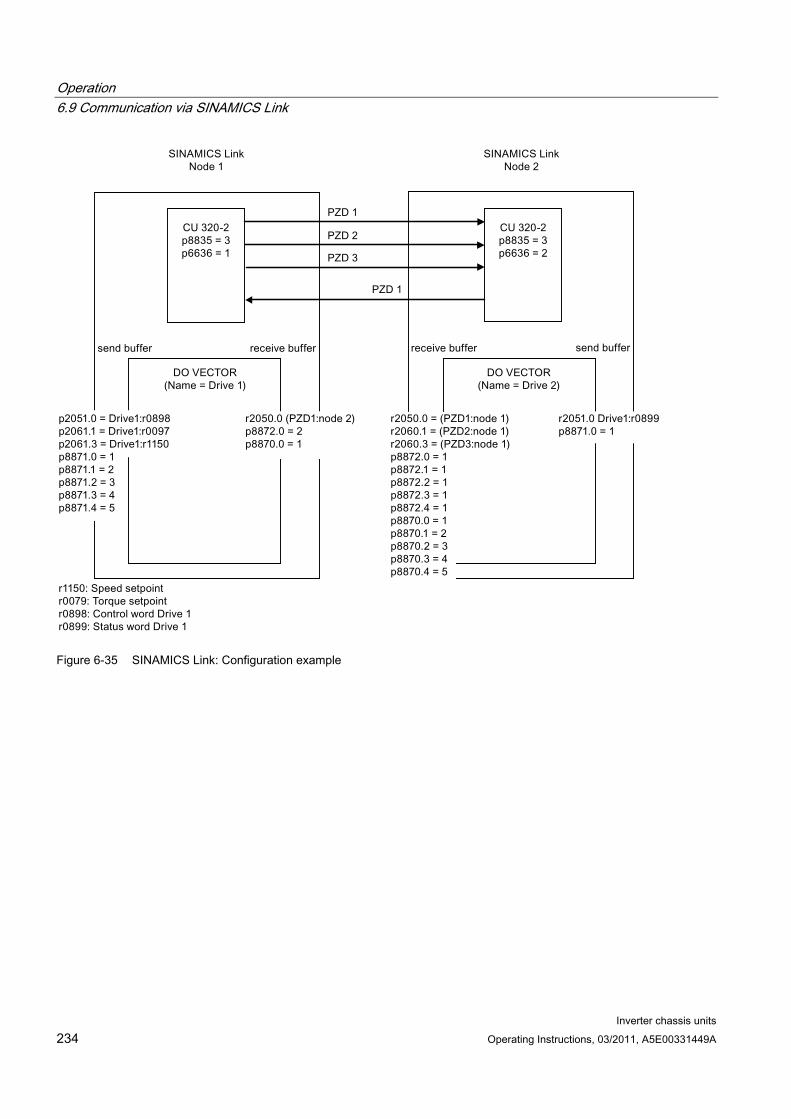
Operation 6.9 Communication via SINAMICS Link
Inverter chassis units 234 Operating Instructions, 03/2011, A5E00331449A
Figure 6-35 SINAMICS Link: Configuration example
Operation 6.9 Communication via SINAMICS Link
Inverter chassis units Operating Instructions, 03/2011, A5E00331449A 235
6.9.5 Diagnostics
Communication failure when booting or in cyclic operation If at least one sender does not correctly boot after commissioning or fails in cyclic operation, then alarm A50005 is output to the other nodes: "Sender was not found on the SINAMICS Link." The message contains the number of the faulted node. After you have resolved the fault at the node involved and the system has identified the node, the system automatically withdraws the alarm.
If several nodes are involved, the message occurs a multiple number of times consecutively with different node numbers. After you have resolved all of the faults, the system automatically withdraws the alarm.
When a node fails in cyclic operation, in addition to alarm A50005, fault F08501 is output: "COMM BOARD: Monitoring time, process data expired".
6.9.6 Parameters r2050[0...19] CO: IF1 PROFIdrive PZD receive word
p2051[0...14] CI: IF1 PROFIdrive PZD send word
r2060[0...18] CO: IF1 PROFIdrive PZD receive double word
p2061[0...26] CI: IF1 PROFIdrive PZD send double word
p8835 CBE20 firmware selection
p8836 SINAMICS Link address
p8870 SINAMICS Link telegram word PZD receive
p8871 SINAMICS Link telegram word PZD send
p8872 SINAMICS Link address PZD receive
Operation 6.10 Parallel operation of communication interfaces
Inverter chassis units 236 Operating Instructions, 03/2011, A5E00331449A
6.10 Parallel operation of communication interfaces
General information Cyclic process data (setpoints/actual values) are processed using interfaces IF1 and IF2. The following interfaces are used:
Onboard interfaces for PROFIBUS DP or PROFINET
An additional interface (COMM board) for PROFINET (CBE20) or CANopen (CBE10) as option
Parameter r8859 "COMM board identification data" can be used to determine whether a communication module is inserted in the option slot.
With parameter p8839, the parallel use of onboard interfaces and COMM board in the SINAMICS system is set and the functionality is assigned to interfaces IF1 and IF2.
For example, the following applications are conceivable:
PROFIBUS DP for drive control and PROFINET for the acquisition of actual values/measured values of the drive.
PROFIBUS DP for control and PROFINET for engineering only
Mixed mode with two masters (one for logic & coordination and one for technology)
SINAMICS Link via IF2 (CBE20); standard telegrams and PROFISafe via IF1
Operation of redundant communication interfaces
Assignment of communication interfaces to cyclic interfaces Two cyclic interfaces exist for setpoints and actual values, which differ by their parameter ranges used (BICO, etc.) and the usable functionalities. These two interfaces are designated IF1 (cyclic interface 1) and IF2 (cyclic interface 2).
Depending on their type (PROFIBUS DP, PROFINET or CANopen) the communication interfaces are assigned to one of the cyclic interfaces (IF1, IF2) by the factory setting of p8839.
For the parallel operation of the communication interfaces, the assignment to the cyclic interfaces can essentially be defined as required by the user parameterization.
Properties of the cyclic interfaces IF1 and IF2
The following table shows the different features of the two cyclic interfaces:
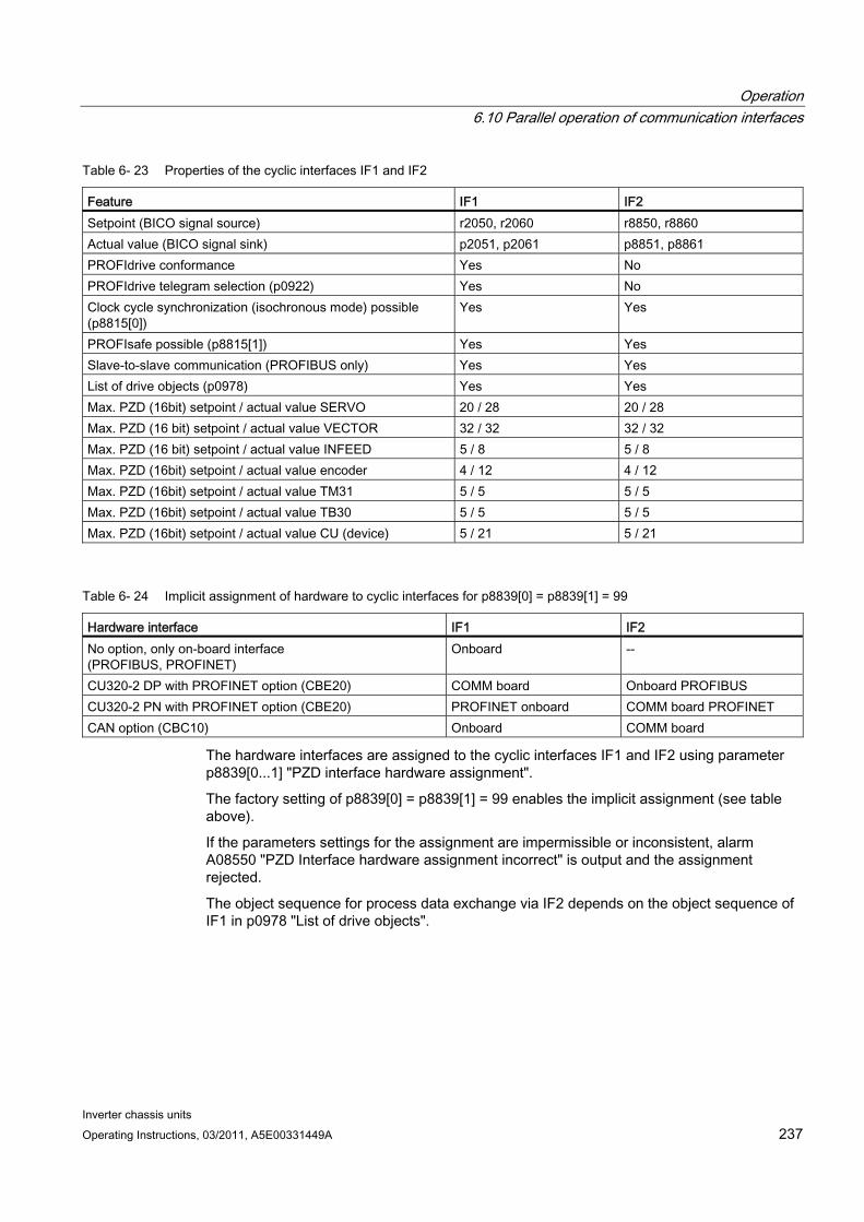
Operation 6.10 Parallel operation of communication interfaces
Inverter chassis units Operating Instructions, 03/2011, A5E00331449A 237
Table 6- 23 Properties of the cyclic interfaces IF1 and IF2
Feature IF1 IF2 Setpoint (BICO signal source) r2050, r2060 r8850, r8860 Actual value (BICO signal sink) p2051, p2061 p8851, p8861 PROFIdrive conformance Yes No PROFIdrive telegram selection (p0922) Yes No Clock cycle synchronization (isochronous mode) possible (p8815[0])
Yes Yes
PROFIsafe possible (p8815[1]) Yes Yes Slave-to-slave communication (PROFIBUS only) Yes Yes List of drive objects (p0978) Yes Yes Max. PZD (16bit) setpoint / actual value SERVO 20 / 28 20 / 28 Max. PZD (16 bit) setpoint / actual value VECTOR 32 / 32 32 / 32 Max. PZD (16 bit) setpoint / actual value INFEED 5 / 8 5 / 8 Max. PZD (16bit) setpoint / actual value encoder 4 / 12 4 / 12 Max. PZD (16bit) setpoint / actual value TM31 5 / 5 5 / 5 Max. PZD (16bit) setpoint / actual value TB30 5 / 5 5 / 5 Max. PZD (16bit) setpoint / actual value CU (device) 5 / 21 5 / 21
Table 6- 24 Implicit assignment of hardware to cyclic interfaces for p8839[0] = p8839[1] = 99
Hardware interface IF1 IF2 No option, only on-board interface (PROFIBUS, PROFINET)
Onboard --
CU320-2 DP with PROFINET option (CBE20) COMM board Onboard PROFIBUS CU320-2 PN with PROFINET option (CBE20) PROFINET onboard COMM board PROFINET CAN option (CBC10) Onboard COMM board
The hardware interfaces are assigned to the cyclic interfaces IF1 and IF2 using parameter p8839[0...1] "PZD interface hardware assignment".
The factory setting of p8839[0] = p8839[1] = 99 enables the implicit assignment (see table above).
If the parameters settings for the assignment are impermissible or inconsistent, alarm A08550 "PZD Interface hardware assignment incorrect" is output and the assignment rejected.
The object sequence for process data exchange via IF2 depends on the object sequence of IF1 in p0978 "List of drive objects".

Operation 6.10 Parallel operation of communication interfaces
Inverter chassis units 238 Operating Instructions, 03/2011, A5E00331449A
Parameters for IF2
The following parameters are responsible for the IF2, the meaning of "88xx" is identical to "20xx" of the IF1:
Receive and send process data: r8850, p8851, r8853, r8860, p8861, r8863
Diagnostic parameters: r8874, r8875, r8876
Binector-connector converter p8880, p8881, p8882, p8883, p8884, r8889
Connector-binector converter r8894, r8895, p8898, p8899
Note
It is not possible in the HW Config configuration tool to represent a PROFIBUS / PROFINET slave with two interfaces. In parallel operation, SINAMICS will therefore appear twice in the project or in two projects although there is only one physical device.
Isochronous mode, PROFIsafe and SINAMICS Link Isochronous applications can only be run via one of the two interfaces, IF1 or IF2. The interface for isochronous mode is set using parameter p8815[0].
Applications with PROFIsafe can only be run via one of the two interfaces IF1 or IF2. The interface for PROFIsafe is set using parameter p8815[1].
SINAMICS Link usually requires isochronous mode. If SINAMICS Link is running, PROFIsafe does not work at the interface involved. In this case, PROFIsafe is possible on the other Interface, but only without isochronous mode.
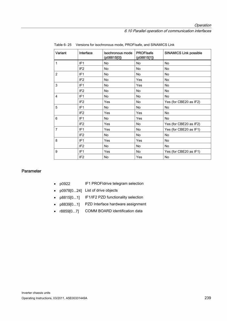
Operation 6.10 Parallel operation of communication interfaces
Inverter chassis units Operating Instructions, 03/2011, A5E00331449A 239
Table 6- 25 Versions for isochronous mode, PROFIsafe, and SINAMICS Link
Variant Interface Isochronous mode (p08815[0])
PROFIsafe (p08815[1])
SINAMICS Link possible
IF1 No No No 1 IF2 No No No IF1 No No No 2 IF2 No Yes No IF1 No Yes No 3 IF2 No No No IF1 No No No 4 IF2 Yes No Yes (for CBE20 as IF2) IF1 No No No 5 IF2 Yes Yes No IF1 No Yes No 6 IF2 Yes No Yes (for CBE20 as IF2) IF1 Yes No Yes (for CBE20 as IF1) 7 IF2 No No No IF1 Yes Yes No 8 IF2 No No No IF1 Yes No Yes (for CBE20 as IF1) 9 IF2 No Yes No
Parameter p0922 IF1 PROFIdrive telegram selection
p0978[0...24] List of drive objects
p8815[0...1] IF1/IF2 PZD functionality selection
p8839[0...1] PZD Interface hardware assignment
r8859[0...7] COMM BOARD identification data

Operation 6.11 Engineering Software Drive Control Chart (DCC)
Inverter chassis units 240 Operating Instructions, 03/2011, A5E00331449A
6.11 Engineering Software Drive Control Chart (DCC)
Graphical configuring and expansion of the device functionality by means of available closed-loop control, arithmetic, and logic function blocks
Drive Control Chart (DCC) expands the facility for the simplest possible configuring of technological functions for both the SIMOTION motion control system and the SINAMICS drive system. This provides the user with a new dimension of system adaptability for specific machine functions. DCC does not restrict the number of functions that can be used; the only restriction is the performance of the target platform.
The user-friendly DCC Editor enables easy graphical configuration and a clear representation of control loop structures as well as a high degree of reusability of existing diagrams.
The open-loop and closed-loop control functionality is defined by using multi-instance-enabled blocks (Drive Control Blocks (DCBs)) from a pre-defined library (DCB library) that are selected and graphically linked by dragging and dropping. Test and diagnostic functions allow verification of the program behavior, and troubleshooting in the event of a fault.
The block library encompasses a large selection of closed-loop, arithmetic and logic function blocks, as well as comprehensive open-loop and closed-loop control functions.
For combining, analyzing and acquiring binary signals, all commonly used logic functions are available for selection (AND, XOR, on/off delay, RS flipflop, counter, etc.). Numerous computation functions are available for monitoring and evaluating numerical variables; for example absolute value generation, division, min/max evaluation. Besides drive control functions, it is also a simple matter to configure axis winding functions, PI controllers, ramp-function generators, and wobble generators.
Almost unlimited programming of control structures is possible in conjunction with the SIMOTION motion control system. These can then be combined with other program sections to form an overall program.
Drive Control Chart for SINAMICS also provides a convenient basis for resolving drive-level open-loop and closed-loop control tasks directly in the drive. This results in further adaptability of SINAMICS for the task set. On-site processing in the drive supports modular machine concepts and results in increased overall machine performance.
Note
A detailed description of the DCC Editor and the available Drive Control Blocks is given in the relevant documentation. This documentation is available on the CD.
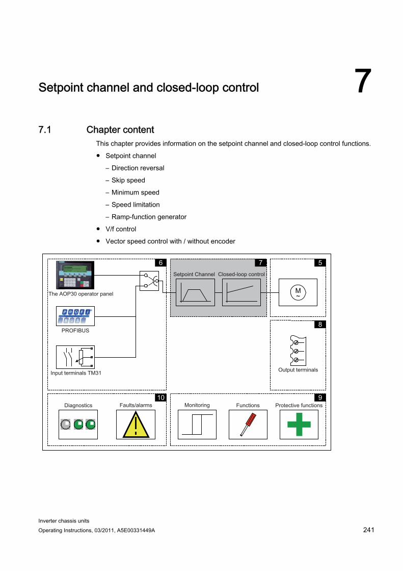
Inverter chassis units Operating Instructions, 03/2011, A5E00331449A 241
Setpoint channel and closed-loop control 77.1 Chapter content
This chapter provides information on the setpoint channel and closed-loop control functions.
Setpoint channel
– Direction reversal
– Skip speed
– Minimum speed
– Speed limitation
– Ramp-function generator
V/f control
Vector speed control with / without encoder
M ~
5 7 6
8
9 10

Setpoint channel and closed-loop control 7.2 Setpoint channel
Inverter chassis units 242 Operating Instructions, 03/2011, A5E00331449A
Function diagrams To supplement these operating instructions, the CD contains simplified function diagrams describing the operating principle. The diagrams are arranged in accordance with the chapters in the operating instructions. The page numbers (7xx) describe the functionality in the following chapter.
At certain points in this chapter, reference is made to function diagrams with a 4-digit number. These are stored on the documentation CD in the "SINAMICS G130/G150 List Manual", which provides experienced users with detailed descriptions of all the functions.
7.2 Setpoint channel
7.2.1 Setpoint addition
Description The supplementary setpoint can be used to enter correction values from higher-level closed-loop controls. This can be implemented using the summing point of the main/supplementary setpoint in the setpoint channel. Both variables are imported simultaneously via two separate or one setpoint source and added in the setpoint channel.
Function diagram FD 3030 Main/added setpoint, setpoint scaling, jogging
Parameters p1070 Main setpoint
p1071 Main setpoint scaling
r1073 Main setpoint effective
p1075 Supplementary setpoint
p1076 Supplementary setpoint scaling
r1077 Supplementary setpoint effective
r1078 Total setpoint effective
Setpoint channel and closed-loop control 7.2 Setpoint channel
Inverter chassis units Operating Instructions, 03/2011, A5E00331449A 243
7.2.2 Direction reversal
Description Due to the direction reversal in the setpoint channel the drive can be operated in both directions with the same setpoint polarity.
Use the p1110 or p1111 parameter to block negative or positive direction of rotation.
Note
If an incorrect rotating field was connected when the cables were installed, and the cabling cannot be changed, the rotating field can be corrected during drive commissioning via p1821 (rotating field direction reversal) to allow a direction reversal (see section "Direction reversal"). Modifying parameters p1821 produces a direction reversal of the motor and the encoder actual value without changing the setpoint.
Prerequisites Direction reversal is triggered:
via PROFIBUS by means of control word 1, bit 11
via the cabinet operator panel (LOCAL mode) with the "Direction reversal" key.
Note
Note that only one direction of rotation is enabled in the delivery condition when control is carried out via the AOP30.
Function diagram FP 3040 Direction of rotation limiting and direction of rotation changeover
Parameter p1110 BI: Inhibit negative direction
p1111 BI: Inhibit positive direction
p1113 BI: Setpoint inversion
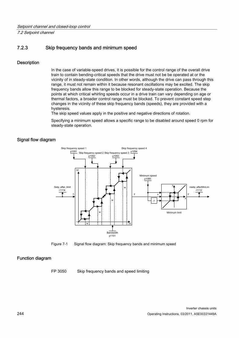
Setpoint channel and closed-loop control 7.2 Setpoint channel
Inverter chassis units 244 Operating Instructions, 03/2011, A5E00331449A
7.2.3 Skip frequency bands and minimum speed
Description In the case of variable-speed drives, it is possible for the control range of the overall drive train to contain bending-critical speeds that the drive must not be be operated at or the vicinity of in steady-state condition. In other words, although the drive can pass through this range, it must not remain within it because resonant oscillations may be excited. The skip frequency bands allow this range to be blocked for steady-state operation. Because the points at which critical whirling speeds occur in a drive train can vary depending on age or thermal factors, a broader control range must be blocked. To prevent constant speed step changes in the vicinity of these skip frequency bands (speeds), they are provided with a hysteresis. The skip speed values apply in the positive and negative directions of rotation.
Specifying a minimum speed allows a specific range to be disabled around speed 0 rpm for steady-state operation.
Signal flow diagram
Figure 7-1 Signal flow diagram: Skip frequency bands and minimum speed
Function diagram FP 3050 Skip frequency bands and speed limiting
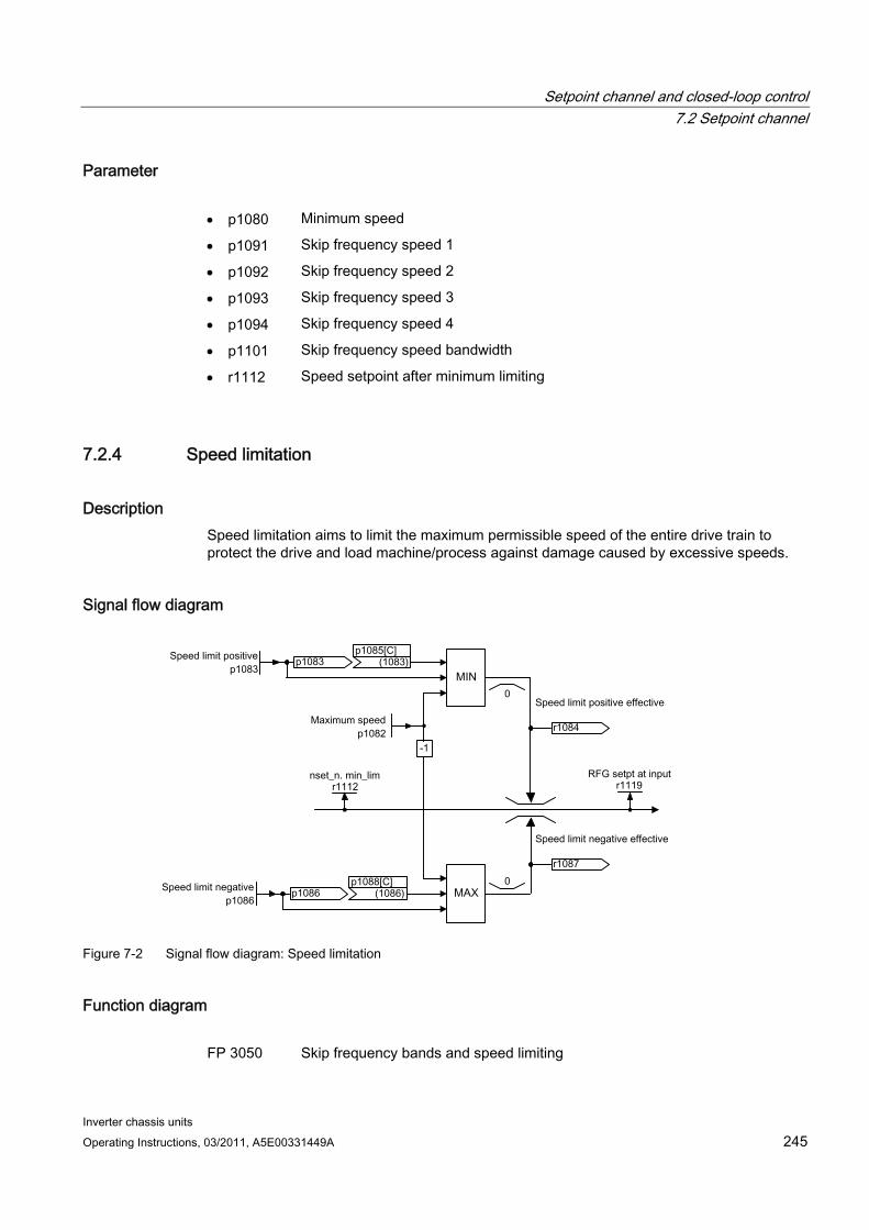
Setpoint channel and closed-loop control 7.2 Setpoint channel
Inverter chassis units Operating Instructions, 03/2011, A5E00331449A 245
Parameter p1080 Minimum speed
p1091 Skip frequency speed 1
p1092 Skip frequency speed 2
p1093 Skip frequency speed 3
p1094 Skip frequency speed 4
p1101 Skip frequency speed bandwidth
r1112 Speed setpoint after minimum limiting
7.2.4 Speed limitation
Description Speed limitation aims to limit the maximum permissible speed of the entire drive train to protect the drive and load machine/process against damage caused by excessive speeds.
Signal flow diagram
Figure 7-2 Signal flow diagram: Speed limitation
Function diagram FP 3050 Skip frequency bands and speed limiting
Setpoint channel and closed-loop control 7.2 Setpoint channel
Inverter chassis units 246 Operating Instructions, 03/2011, A5E00331449A
Parameters p1082 Maximum speed
p1083 CO: Speed limit in positive direction of rotation
r1084 CO: Speed limit positive effective
p1085 CI: Speed limit in positive direction of rotation
p1086 CO: Speed limit in negative direction of rotation
r1087 CO: Speed limit negative effective
p1088 CI: Speed limit in negative direction of rotation
r1119 CO: Ramp-function generator setpoint at the input
7.2.5 Ramp-function generator
Description The ramp-function generator limits the rate at which the setpoint changes when the drive is accelerating or decelerating. This prevents excessive setpoint step changes from damaging the drive train. Additional rounding times can also be set in the lower and upper speed ranges to improve control quality and prevent load surges, thereby protecting mechanical components, such as shafts and couplings.
The ramp-up and ramp-down times each refer to the maximum speed (p1082). The rounding times that can be set can prevent the actual speed value from being overshot when the setpoint is approached, thereby improving control quality.
Notice: if rounding times are too long, this can cause the setpoint to be overshot if the setpoint is reduced abruptly during ramp-up. Rounding is also effective in the zero crossover; in other words, when the direction is reversed, the ramp-function generator output is reduced to zero via initial rounding, the ramp-down time, and final rounding before the new, inverted setpoint is approached via start rounding, the ramp-up time, and end rounding. Rounding times that can be set separately are active in the event of a fast stop (OFF3). The actual ramp-up/ramp-down times increase with active rounding.
The rounding type can be set using p1134 and separately activated/deactivated using p1151.0 in the zero point.
Note
The effective ramp-up time increases when you enter initial and final rounding times.
Effective ramp-up time = p1120 + (0.5 x p1130) + (0.5 x p1131)
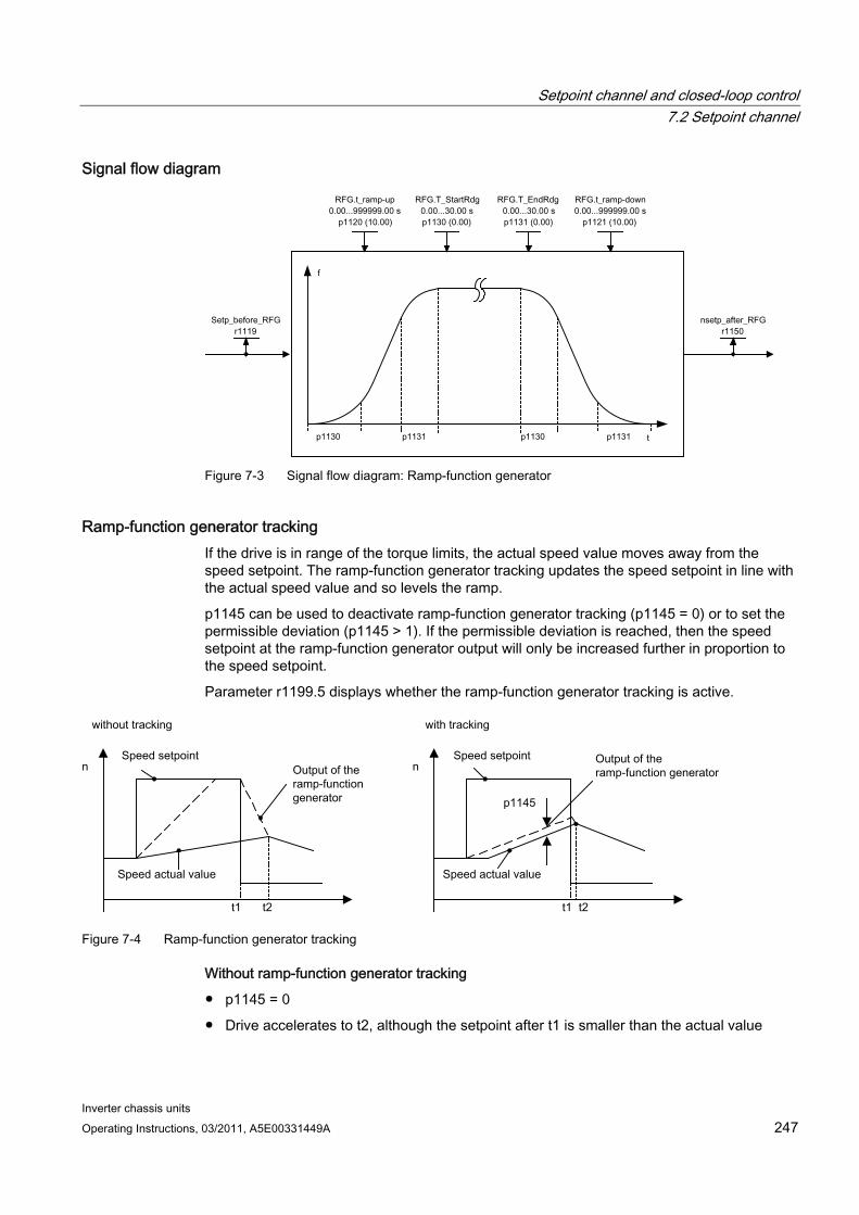
Setpoint channel and closed-loop control 7.2 Setpoint channel
Inverter chassis units Operating Instructions, 03/2011, A5E00331449A 247
Signal flow diagram
Figure 7-3 Signal flow diagram: Ramp-function generator
Ramp-function generator tracking If the drive is in range of the torque limits, the actual speed value moves away from the speed setpoint. The ramp-function generator tracking updates the speed setpoint in line with the actual speed value and so levels the ramp.
p1145 can be used to deactivate ramp-function generator tracking (p1145 = 0) or to set the permissible deviation (p1145 > 1). If the permissible deviation is reached, then the speed setpoint at the ramp-function generator output will only be increased further in proportion to the speed setpoint.
Parameter r1199.5 displays whether the ramp-function generator tracking is active.
Figure 7-4 Ramp-function generator tracking
Without ramp-function generator tracking
p1145 = 0
Drive accelerates to t2, although the setpoint after t1 is smaller than the actual value
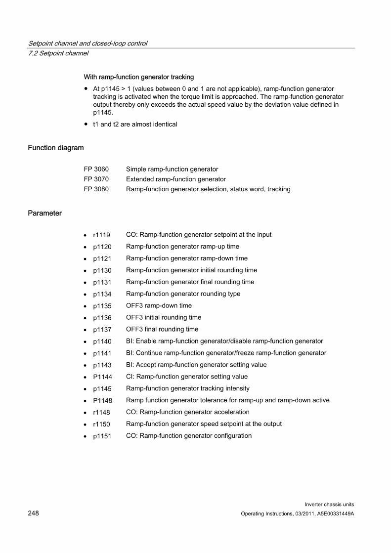
Setpoint channel and closed-loop control 7.2 Setpoint channel
Inverter chassis units 248 Operating Instructions, 03/2011, A5E00331449A
With ramp-function generator tracking
At p1145 > 1 (values between 0 and 1 are not applicable), ramp-function generator tracking is activated when the torque limit is approached. The ramp-function generator output thereby only exceeds the actual speed value by the deviation value defined in p1145.
t1 and t2 are almost identical
Function diagram FP 3060 Simple ramp-function generator FP 3070 Extended ramp-function generator FP 3080 Ramp-function generator selection, status word, tracking
Parameter r1119 CO: Ramp-function generator setpoint at the input
p1120 Ramp-function generator ramp-up time
p1121 Ramp-function generator ramp-down time
p1130 Ramp-function generator initial rounding time
p1131 Ramp-function generator final rounding time
p1134 Ramp-function generator rounding type
p1135 OFF3 ramp-down time
p1136 OFF3 initial rounding time
p1137 OFF3 final rounding time
p1140 BI: Enable ramp-function generator/disable ramp-function generator
p1141 BI: Continue ramp-function generator/freeze ramp-function generator
p1143 BI: Accept ramp-function generator setting value
P1144 CI: Ramp-function generator setting value
p1145 Ramp-function generator tracking intensity
P1148 Ramp function generator tolerance for ramp-up and ramp-down active
r1148 CO: Ramp-function generator acceleration
r1150 Ramp-function generator speed setpoint at the output
p1151 CO: Ramp-function generator configuration
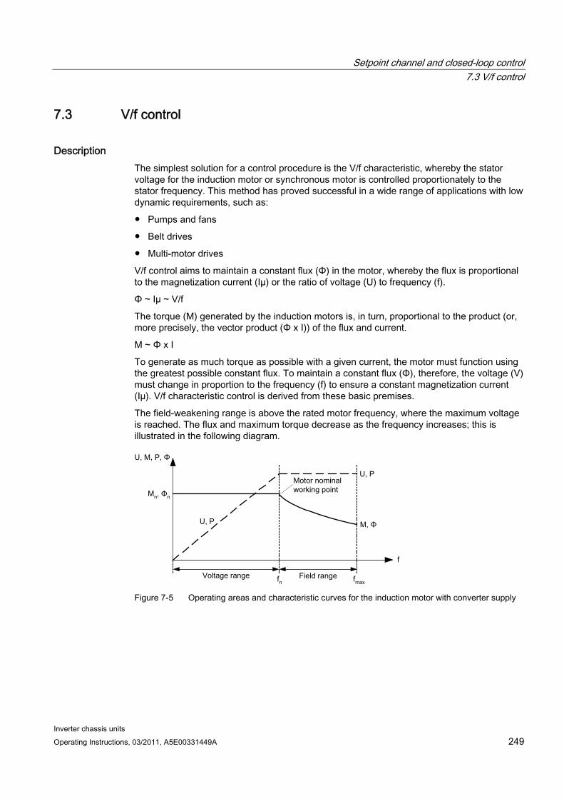
Setpoint channel and closed-loop control 7.3 V/f control
Inverter chassis units Operating Instructions, 03/2011, A5E00331449A 249
7.3 V/f control
Description The simplest solution for a control procedure is the V/f characteristic, whereby the stator voltage for the induction motor or synchronous motor is controlled proportionately to the stator frequency. This method has proved successful in a wide range of applications with low dynamic requirements, such as:
Pumps and fans
Belt drives
Multi-motor drives
V/f control aims to maintain a constant flux (Φ) in the motor, whereby the flux is proportional to the magnetization current (Iµ) or the ratio of voltage (U) to frequency (f).
Φ ~ Iµ ~ V/f
The torque (M) generated by the induction motors is, in turn, proportional to the product (or, more precisely, the vector product (Φ x I)) of the flux and current.
M ~ Φ x I
To generate as much torque as possible with a given current, the motor must function using the greatest possible constant flux. To maintain a constant flux (Φ), therefore, the voltage (V) must change in proportion to the frequency (f) to ensure a constant magnetization current (Iµ). V/f characteristic control is derived from these basic premises.
The field-weakening range is above the rated motor frequency, where the maximum voltage is reached. The flux and maximum torque decrease as the frequency increases; this is illustrated in the following diagram.
Figure 7-5 Operating areas and characteristic curves for the induction motor with converter supply
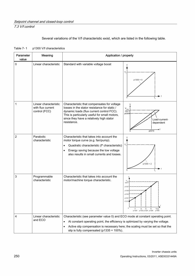
Setpoint channel and closed-loop control 7.3 V/f control
Inverter chassis units 250 Operating Instructions, 03/2011, A5E00331449A
Several variations of the V/f characteristic exist, which are listed in the following table.
Table 7- 1 p1300 V/f characteristics
Parameter value
Meaning Application / property
0 Linear characteristic Standard with variable voltage boost
Vn
0 fn
V
f
1 Linear characteristic with flux current control (FCC)
Characteristic that compensates for voltage losses in the stator resistance for static / dynamic loads (flux current control FCC). This is particularly useful for small motors, since they have a relatively high stator resistance.
2 Parabolic
characteristic Characteristic that takes into account the motor torque curve (e.g. fan/pump). Quadratic characteristic (f² characteristic) Energy saving because the low voltage
also results in small currents and losses.
Vn
0 fn
V
f
3 Programmable characteristic
Characteristic that takes into account the motor/machine torque characteristic. V
V
p1325
f1p1320
maxr0071
p1327
p1323
p1321
0 f2p1322
f3p1324
f4p1326
f
r1315
fmaxp1082
4 Linear characteristic and ECO
Characteristic (see parameter value 0) and ECO mode at constant operating point. At constant operating point, the efficiency is optimized by varying the voltage. Active slip compensation is necessary here; the scaling must be set so that the
slip is fully compensated (p1335 = 100%).
Setpoint channel and closed-loop control 7.3 V/f control
Inverter chassis units Operating Instructions, 03/2011, A5E00331449A 251
Parameter value
Meaning Application / property
5 Precise frequency drives (textiles)
Characteristic (see parameter value 0) that takes into account the specific technological features of an application (e.g. textile applications). The current limitation (Imax controller) only affects the output voltage and not the
output frequency. The slip compensation and resonance damping are disabled.
6 Precise frequency drives with flux current control (FCC)
Characteristic (see parameter value 1) that takes into account the specific technological features of an application (e.g. textile applications). The current limitation (Imax controller) only affects the output voltage and not the
output frequency. The slip compensation and resonance damping are disabled. Voltage losses in the stator resistance for static / dynamic loads are also compensated (flux current control, FCC). This is particularly useful for small motors, since they have a relatively high stator resistance.
7 Parabolic characteristic and ECO
Characteristic (see parameter value 1) and ECO mode at constant operating point. At constant operating point, the efficiency is optimized by varying the voltage. Active slip compensation is necessary here; the scaling must be set so that the
slip is fully compensated (p1335 = 100%).
19 Independent voltage setpoint
The user can define the output voltage of the Power Module independently of the frequency using BICO parameter p1330 via the interfaces (e.g., analog input AI0 of the TM31 –> p1330 = r4055[0]).
Function diagram FP 6300 V/f characteristic and voltage boost
Parameters p1300 Open-loop/closed-loop control operating mode
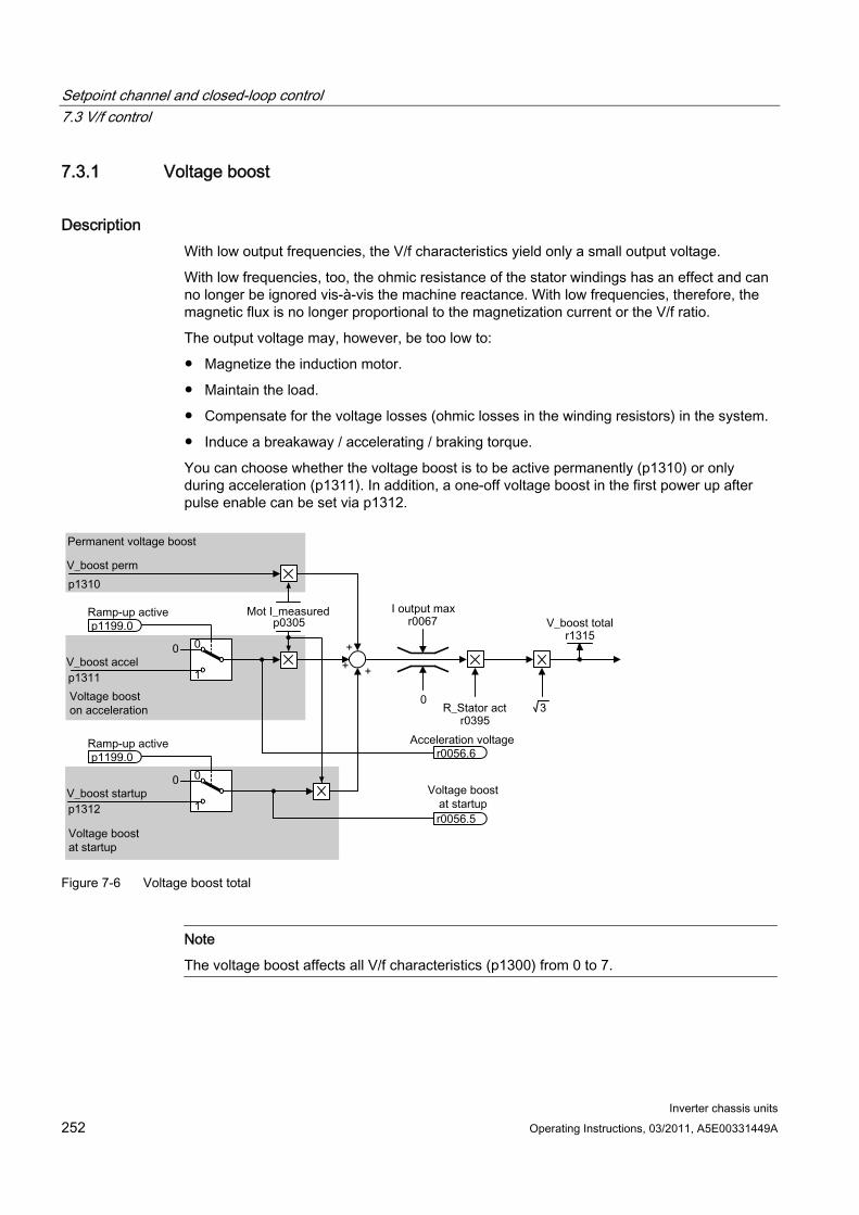
Setpoint channel and closed-loop control 7.3 V/f control
Inverter chassis units 252 Operating Instructions, 03/2011, A5E00331449A
7.3.1 Voltage boost
Description With low output frequencies, the V/f characteristics yield only a small output voltage.
With low frequencies, too, the ohmic resistance of the stator windings has an effect and can no longer be ignored vis-à-vis the machine reactance. With low frequencies, therefore, the magnetic flux is no longer proportional to the magnetization current or the V/f ratio.
The output voltage may, however, be too low to:
Magnetize the induction motor.
Maintain the load.
Compensate for the voltage losses (ohmic losses in the winding resistors) in the system.
Induce a breakaway / accelerating / braking torque.
You can choose whether the voltage boost is to be active permanently (p1310) or only during acceleration (p1311). In addition, a one-off voltage boost in the first power up after pulse enable can be set via p1312.
Figure 7-6 Voltage boost total
Note
The voltage boost affects all V/f characteristics (p1300) from 0 to 7.
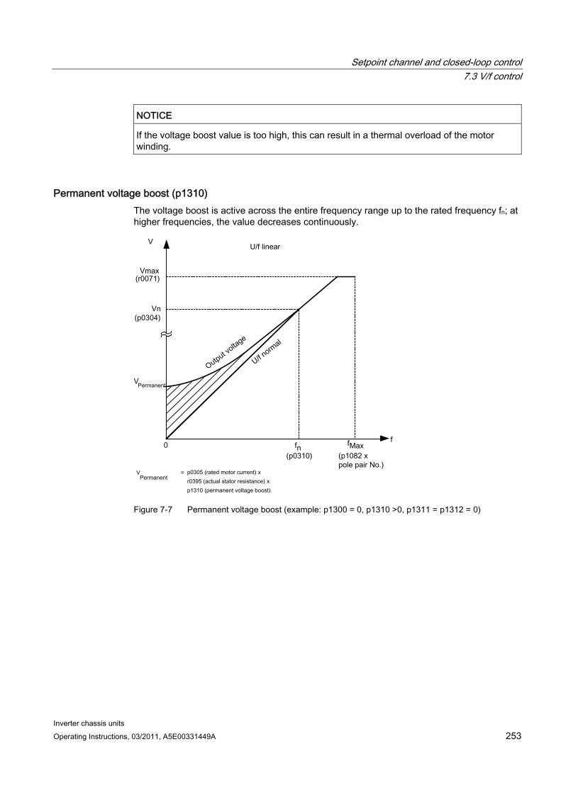
Setpoint channel and closed-loop control 7.3 V/f control
Inverter chassis units Operating Instructions, 03/2011, A5E00331449A 253
NOTICE If the voltage boost value is too high, this can result in a thermal overload of the motor winding.
Permanent voltage boost (p1310) The voltage boost is active across the entire frequency range up to the rated frequency fn; at higher frequencies, the value decreases continuously.
Figure 7-7 Permanent voltage boost (example: p1300 = 0, p1310 >0, p1311 = p1312 = 0)
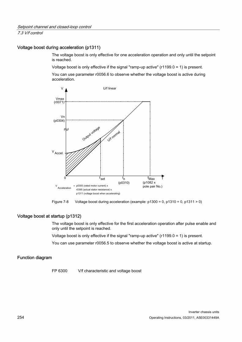
Setpoint channel and closed-loop control 7.3 V/f control
Inverter chassis units 254 Operating Instructions, 03/2011, A5E00331449A
Voltage boost during acceleration (p1311) The voltage boost is only effective for one acceleration operation and only until the setpoint is reached.
Voltage boost is only effective if the signal "ramp-up active" (r1199.0 = 1) is present.
You can use parameter r0056.6 to observe whether the voltage boost is active during acceleration.
Figure 7-8 Voltage boost during acceleration (example: p1300 = 0, p1310 = 0, p1311 > 0)
Voltage boost at startup (p1312) The voltage boost is only effective for the first acceleration operation after pulse enable and only until the setpoint is reached.
Voltage boost is only effective if the signal "ramp-up active" (r1199.0 = 1) is present.
You can use parameter r0056.5 to observe whether the voltage boost is active at startup.
Function diagram FP 6300 V/f characteristic and voltage boost

Setpoint channel and closed-loop control 7.3 V/f control
Inverter chassis units Operating Instructions, 03/2011, A5E00331449A 255
Parameters r0056.5 Voltage boost at startup active/inactive
r0056.6 Acceleration voltage active/inactive
p0304 Rated motor voltage
p0305 Rated motor current
r0395 Stator resistance, actual
p1310 Permanent voltage boost
p1311 Voltage boost during acceleration
p1312 Voltage boost at start up
r1315 Voltage boost total
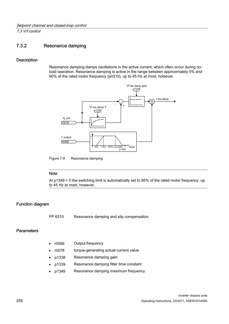
Setpoint channel and closed-loop control 7.3 V/f control
Inverter chassis units 256 Operating Instructions, 03/2011, A5E00331449A
7.3.2 Resonance damping
Description Resonance damping damps oscillations in the active current, which often occur during no-load operation. Resonance damping is active in the range between approximately 5% and 90% of the rated motor frequency (p0310), up to 45 Hz at most, however.
Figure 7-9 Resonance damping
Note
At p1349 = 0 the switching limit is automatically set to 95% of the rated motor frequency, up to 45 Hz at most, however.
Function diagram FP 6310 Resonance damping and slip compensation
Parameters r0066 Output frequency
r0078 torque-generating actual current value
p1338 Resonance damping gain
p1339 Resonance damping filter time constant
p1349 Resonance damping maximum frequency
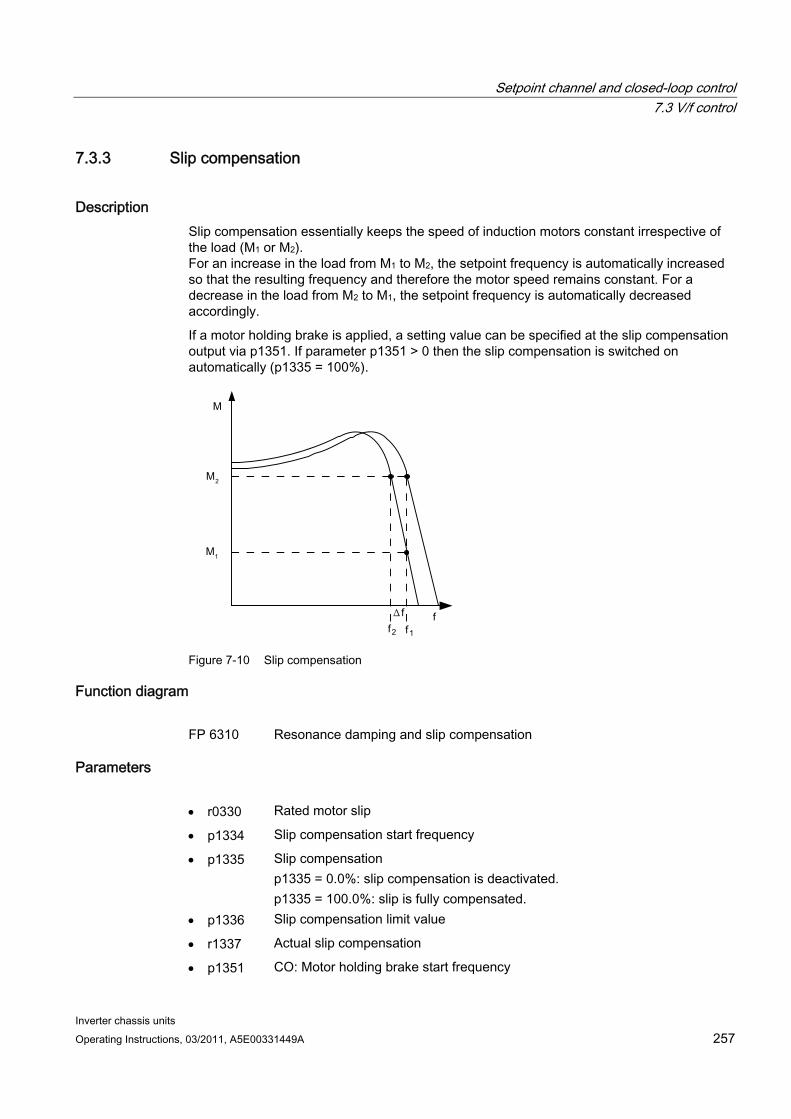
Setpoint channel and closed-loop control 7.3 V/f control
Inverter chassis units Operating Instructions, 03/2011, A5E00331449A 257
7.3.3 Slip compensation
Description Slip compensation essentially keeps the speed of induction motors constant irrespective of the load (M1 or M2). For an increase in the load from M1 to M2, the setpoint frequency is automatically increased so that the resulting frequency and therefore the motor speed remains constant. For a decrease in the load from M2 to M1, the setpoint frequency is automatically decreased accordingly.
If a motor holding brake is applied, a setting value can be specified at the slip compensation output via p1351. If parameter p1351 > 0 then the slip compensation is switched on automatically (p1335 = 100%).
Figure 7-10 Slip compensation
Function diagram FP 6310 Resonance damping and slip compensation
Parameters r0330 Rated motor slip
p1334 Slip compensation start frequency
p1335 Slip compensation p1335 = 0.0%: slip compensation is deactivated. p1335 = 100.0%: slip is fully compensated.
p1336 Slip compensation limit value
r1337 Actual slip compensation
p1351 CO: Motor holding brake start frequency
Setpoint channel and closed-loop control 7.4 Vector speed/torque control with/without encoder
Inverter chassis units 258 Operating Instructions, 03/2011, A5E00331449A
7.4 Vector speed/torque control with/without encoder
Description Compared with V/f control, vector control offers the following benefits:
Stability vis-à-vis load and setpoint changes
Short rise times with setpoint changes (–> better command behavior)
Short settling times with load changes (–> better disturbance characteristic)
Acceleration and braking are possible with maximum adjustable torque
Motor protection due to variable torque limitation in motor and regenerative mode
Drive and braking torque controlled independently of the speed
Maximum breakaway torque possible at speed 0
These benefits are available without speed feedback.
Vector control can be used with or without an encoder.
The following criteria indicate when an encoder is required:
Maximum speed accuracy requirements
Maximum dynamic response requirements
– Better command behavior
– Shortest settling times when disturbances occur
Torque control is required in a control range greater than 1:10
Allows a defined and/or variable torque for speeds below approx. 10% of the rated motor frequency (p0310) to be maintained.
A speed controller is normally always required for applications in which an unknown speed can represent a safety risk (where a load can be dropped, e.g. lifting gear, elevators, etc).
With regard to setpoint input, vector control is divided into:
Speed control
Torque/current control (in short: torque control)
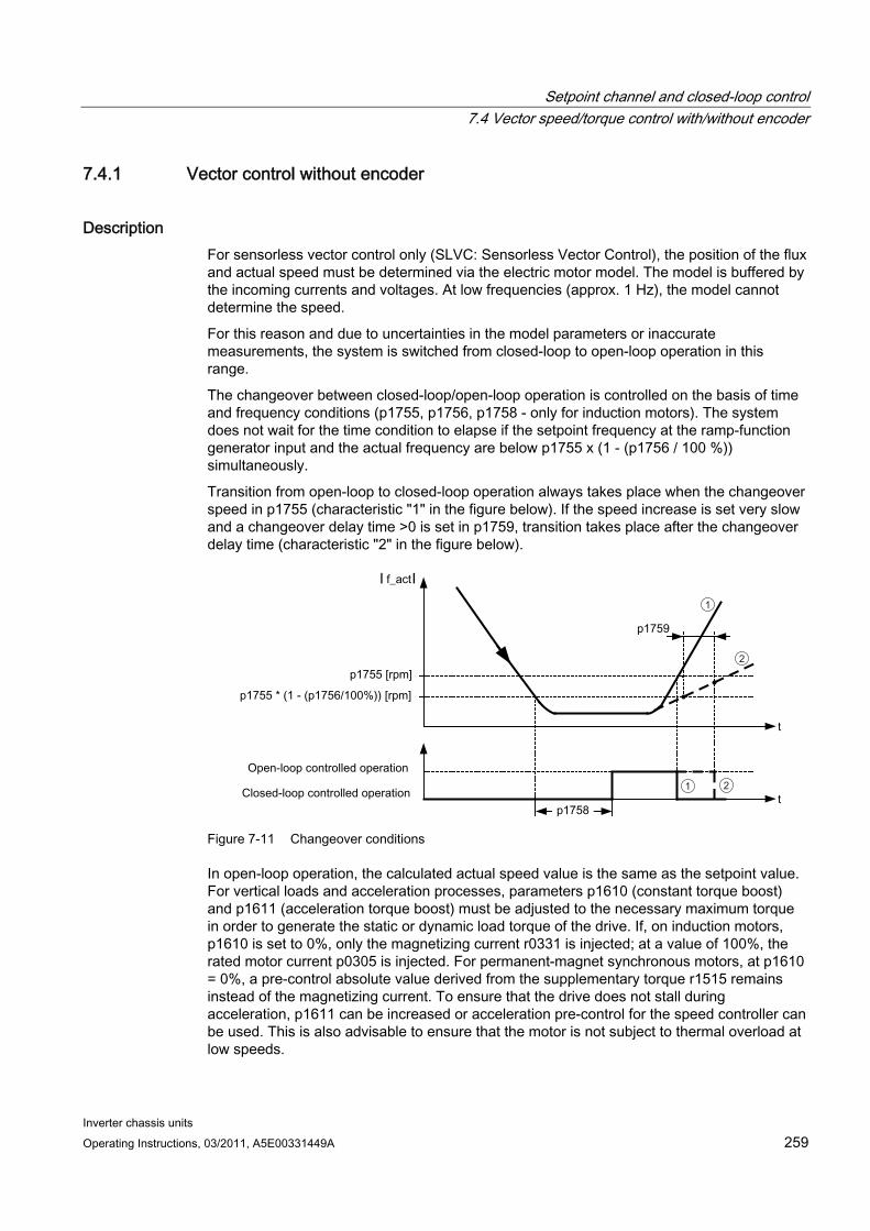
Setpoint channel and closed-loop control 7.4 Vector speed/torque control with/without encoder
Inverter chassis units Operating Instructions, 03/2011, A5E00331449A 259
7.4.1 Vector control without encoder
Description For sensorless vector control only (SLVC: Sensorless Vector Control), the position of the flux and actual speed must be determined via the electric motor model. The model is buffered by the incoming currents and voltages. At low frequencies (approx. 1 Hz), the model cannot determine the speed.
For this reason and due to uncertainties in the model parameters or inaccurate measurements, the system is switched from closed-loop to open-loop operation in this range.
The changeover between closed-loop/open-loop operation is controlled on the basis of time and frequency conditions (p1755, p1756, p1758 - only for induction motors). The system does not wait for the time condition to elapse if the setpoint frequency at the ramp-function generator input and the actual frequency are below p1755 x (1 - (p1756 / 100 %)) simultaneously.
Transition from open-loop to closed-loop operation always takes place when the changeover speed in p1755 (characteristic "1" in the figure below). If the speed increase is set very slow and a changeover delay time >0 is set in p1759, transition takes place after the changeover delay time (characteristic "2" in the figure below).
2
2
1
1
Figure 7-11 Changeover conditions
In open-loop operation, the calculated actual speed value is the same as the setpoint value. For vertical loads and acceleration processes, parameters p1610 (constant torque boost) and p1611 (acceleration torque boost) must be adjusted to the necessary maximum torque in order to generate the static or dynamic load torque of the drive. If, on induction motors, p1610 is set to 0%, only the magnetizing current r0331 is injected; at a value of 100%, the rated motor current p0305 is injected. For permanent-magnet synchronous motors, at p1610 = 0%, a pre-control absolute value derived from the supplementary torque r1515 remains instead of the magnetizing current. To ensure that the drive does not stall during acceleration, p1611 can be increased or acceleration pre-control for the speed controller can be used. This is also advisable to ensure that the motor is not subject to thermal overload at low speeds.
Setpoint channel and closed-loop control 7.4 Vector speed/torque control with/without encoder
Inverter chassis units 260 Operating Instructions, 03/2011, A5E00331449A
Vector control without a speed sensor has the following characteristics at low frequencies:
Closed-loop operation up to approx. 1 Hz output frequency
Starting in closed-loop operation (directly after the drive has been energized) (induction motors only)
Note
In this case, the speed setpoint upstream of the ramp-function generator must be greater than the changeover speed in p1755.
Closed-loop operation up to approx. 1 Hz (settable via parameter p1755) and the ability to start or reverse at 0 Hz directly in closed-loop operation (settable via parameter p1750) result in the following benefits:
No changeover required within closed-loop control (smooth operation, no dips in frequency).
Stationary speed–torque control up to approx. 1 Hz.
Note
When the motor is started or reversed in closed-loop control at 0 Hz, it is important to take into account that a switchover is made from closed-loop to open-loop control automatically if the system remains in the 0 Hz range for too long (> 2 s or > p1758, if p1758 > 2 s).
Closed-loop operation down to standstill for passive loads By restricting to a passive load at the starting point, it is possible to maintain stationary closed-loop operation down to zero frequency (standstill) without having to change over to open-loop operation.
Parameter p1750.2 must be set to 1.
Closed-loop control without changeover is restricted to applications with passive load: These include applications in which the load cannot produce a regenerative torque on startup and the motor comes to a standstill when pulses are inhibited; for example, moments of inertia, brakes, pumps, fans, centrifuges, extruders, etc.
Standstill of any duration is possible without holding current, only the motor magnetization current is impressed.
Steady-state regenerative operation at a frequency close to zero is not possible.
It is also possible to select sensorless control for passive loads during commissioning by setting p0500 = 2 (technology application = passive loads (for sensorless control down to f = 0)).
This function is activated automatically if quick commissioning is exited with p3900 > 0, or if automatic calculation is called (p0340 = 1, 3, 5 or p0578 = 1).
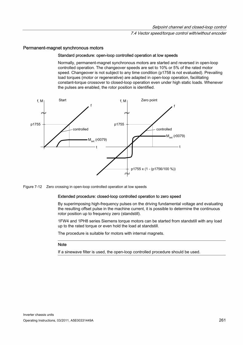
Setpoint channel and closed-loop control 7.4 Vector speed/torque control with/without encoder
Inverter chassis units Operating Instructions, 03/2011, A5E00331449A 261
Permanent-magnet synchronous motors Standard procedure: open-loop controlled operation at low speeds
Normally, permanent-magnet synchronous motors are started and reversed in open-loop controlled operation. The changeover speeds are set to 10% or 5% of the rated motor speed. Changeover is not subject to any time condition (p1758 is not evaluated). Prevailing load torques (motor or regenerative) are adapted in open-loop operation, facilitating constant-torque crossover to closed-loop operation even under high static loads. Whenever the pulses are enabled, the rotor position is identified.
Figure 7-12 Zero crossing in open-loop controlled operation at low speeds
Extended procedure: closed-loop controlled operation to zero speed
By superimposing high-frequency pulses on the driving fundamental voltage and evaluating the resulting offset pulse in the machine current, it is possible to determine the continuous rotor position up to frequency zero (standstill).
1FW4 and 1PH8 series Siemens torque motors can be started from standstill with any load up to the rated torque or even hold the load at standstill.
The procedure is suitable for motors with internal magnets.
Note
If a sinewave filter is used, the open-loop controlled procedure should be used.
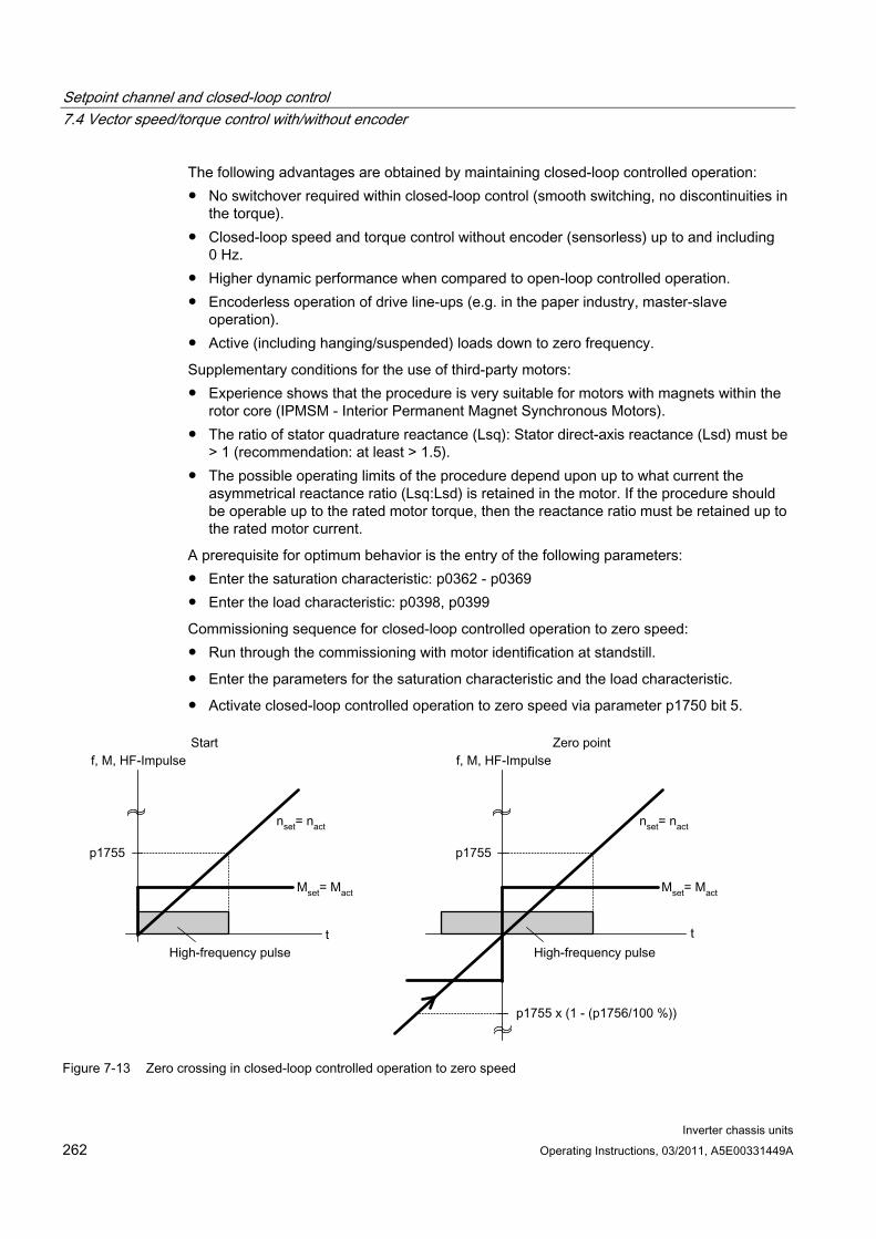
Setpoint channel and closed-loop control 7.4 Vector speed/torque control with/without encoder
Inverter chassis units 262 Operating Instructions, 03/2011, A5E00331449A
The following advantages are obtained by maintaining closed-loop controlled operation: No switchover required within closed-loop control (smooth switching, no discontinuities in
the torque). Closed-loop speed and torque control without encoder (sensorless) up to and including
0 Hz. Higher dynamic performance when compared to open-loop controlled operation. Encoderless operation of drive line-ups (e.g. in the paper industry, master-slave
operation). Active (including hanging/suspended) loads down to zero frequency.
Supplementary conditions for the use of third-party motors: Experience shows that the procedure is very suitable for motors with magnets within the
rotor core (IPMSM - Interior Permanent Magnet Synchronous Motors). The ratio of stator quadrature reactance (Lsq): Stator direct-axis reactance (Lsd) must be
> 1 (recommendation: at least > 1.5). The possible operating limits of the procedure depend upon up to what current the
asymmetrical reactance ratio (Lsq:Lsd) is retained in the motor. If the procedure should be operable up to the rated motor torque, then the reactance ratio must be retained up to the rated motor current.
A prerequisite for optimum behavior is the entry of the following parameters: Enter the saturation characteristic: p0362 - p0369 Enter the load characteristic: p0398, p0399
Commissioning sequence for closed-loop controlled operation to zero speed: Run through the commissioning with motor identification at standstill.
Enter the parameters for the saturation characteristic and the load characteristic.
Activate closed-loop controlled operation to zero speed via parameter p1750 bit 5.
Figure 7-13 Zero crossing in closed-loop controlled operation to zero speed
Setpoint channel and closed-loop control 7.4 Vector speed/torque control with/without encoder
Inverter chassis units Operating Instructions, 03/2011, A5E00331449A 263
Function diagram FP 6730 Interface to Motor Module (ASM), p0300 = 1) FP 6731 Interface to Motor Module (PEM), p0300 = 2)
Parameters p0305 Rated motor current
r0331 Motor magnetizing current/short-circuit current
p0362 ... p0365
Saturation characteristic flux 1 ... Saturation characteristic flux 4
p0366 ... p0369
Saturation characteristic I_mag 1 ... Saturation characteristic I_mag 4
p0398 Magnet angle. Decoupling (cross saturation) coefficient 1
p0398 Magnet angle. Decoupling (cross saturation) coefficient 3
p0500 Technology application
p0578 Calculating technology/unit-dependent parameters
p1605 Pulse technique pattern configuration
r1606 CO: Actual pulse technique pattern
p1607 Pulse technique stimulus
r1608 CO: Pulse technique answer
p1610 Torque setpoint static (SLVC)
p1611 Supplementary accelerating torque (SLVC)
p1750 Motor model configuration
p1755 Motor model changeover speed encoderless operation
p1756 Motor model changeover speed hysteresis
p1758 Motor model changeover delay time, closed/open-loop control
p1759 Motor model changeover delay time open/closed loop control
r1762.1 Motor model deviation component 1 - deviation model 2
p1798 Motor model pulse technique speed adaptation Kp
p1810.3 Modulator configuration - current measurement oversampling activated (for pulse technique PEM)
Setpoint channel and closed-loop control 7.4 Vector speed/torque control with/without encoder
Inverter chassis units 264 Operating Instructions, 03/2011, A5E00331449A
7.4.2 Vector control with encoder
Description Benefits of vector control with an encoder:
The speed can be controlled right down to 0 Hz (standstill)
Stable control response throughout the entire speed range
Allows a defined and/or variable torque for speeds below approx. 10 % of the rated motor speed to be maintained
Compared with speed control without an encoder, the dynamic response of drives with an encoder is significantly better because the speed is measured directly and integrated in the model created for the current components.
Motor model change A model change takes place between the current model and the observer model within the speed range p1752 x (100 % - p1756) and p1752. In the current-model range (i.e., at lower speeds), torque accuracy depends on whether thermal tracking of the rotor resistance is carried out correctly. In the observer-model range and at speeds of less than approx. 20% of the rated speed, torque accuracy depends primarily on whether thermal tracking of the stator resistance is carried out correctly. If the resistance of the supply cable is greater than 20% to 30 % of the total resistance, this should be entered in p0352 before motor data identification is carried out (p1900/p1910).
To deactivate thermal adaptation, set p0620 = 0. This may be necessary if adaptation cannot function accurately enough due to the following supplementary conditions: For example, if a KTY sensor is not used for temperature detection and the ambient temperatures fluctuate significantly or the overtemperatures of the motor (p0626 ... p0628) deviate significantly from the default settings due to the design of the motor.
Function diagram FP 4715 Actual speed value and rotor position measurement, motor encoder FP 6030 Speed setpoint, droop FP 6040 Speed controller FP 6050 Kp_n-/Tn_n adaptation FP 6060 Torque setpoint FP 6490 Speed control configuration
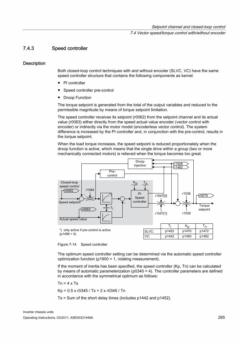
Setpoint channel and closed-loop control 7.4 Vector speed/torque control with/without encoder
Inverter chassis units Operating Instructions, 03/2011, A5E00331449A 265
7.4.3 Speed controller
Description Both closed-loop control techniques with and without encoder (SLVC, VC) have the same speed controller structure that contains the following components as kernel:
PI controller
Speed controller pre-control
Droop Function
The torque setpoint is generated from the total of the output variables and reduced to the permissible magnitude by means of torque setpoint limitation.
The speed controller receives its setpoint (r0062) from the setpoint channel and its actual value (r0063) either directly from the speed actual value encoder (vector control with encoder) or indirectly via the motor model (encoderless vector control). The system difference is increased by the PI controller and, in conjunction with the pre-control, results in the torque setpoint.
When the load torque increases, the speed setpoint is reduced proportionately when the droop function is active, which means that the single drive within a group (two or more mechanically connected motors) is relieved when the torque becomes too great.
Figure 7-14 Speed controller
The optimum speed controller setting can be determined via the automatic speed controller optimization function (p1900 = 1, rotating measurement).
If the moment of inertia has been specified, the speed controller (Kp, Tn) can be calculated by means of automatic parameterization (p0340 = 4). The controller parameters are defined in accordance with the symmetrical optimum as follows:
Tn = 4 x Ts
Kp = 0.5 x r0345 / Ts = 2 x r0345 / Tn
Ts = Sum of the short delay times (includes p1442 and p1452).
Setpoint channel and closed-loop control 7.4 Vector speed/torque control with/without encoder
Inverter chassis units 266 Operating Instructions, 03/2011, A5E00331449A
If vibrations occur with these settings, the speed controller gain (Kp) will need to be reduced manually. Actual-speed-value smoothing can also be increased (standard procedure for gearless or high-frequency torsion vibrations) and the controller calculation performed again because this value is also used to calculate Kp and Tn.
The following relationships apply for optimization:
If Kp is increased, the controller becomes faster, although overshoot is increased. However, signal ripples and vibrations in the speed control loop will increase.
Although reducing Tn will also speed up the controller, it will increase overshoot.
When setting speed control manually, you are advised to define the dynamic response via Kp (and actual-speed-value smoothing) first, so that the integral time can subsequently be reduced as much as possible. Please remember that closed-loop control must also remain stable in the field-weakening range.
To suppress any vibrations that occur in the speed controller, it is usually only necessary to increase the smoothing time in p1452 for operation without an encoder or p1442 for operation with an encoder, or reduce the controller gain.
The integral output of the speed controller can be monitored via r1482 and the limited controller output via r1508 (torque setpoint).
Note
In comparison with speed control with an encoder, the dynamic response of drives without an encoder is significantly reduced. The actual speed is derived by means of a model calculation based on the converter output variables for current and voltage that have a corresponding interference level. To this end, the actual speed must be adjusted by means of filter algorithms in the software.
Function diagram FP 6040 Speed controller
Parameter r0062 CO: Speed setpoint after the filter
r0063 CO: Actual speed value smoothed
p0340 Automatic calculation, control parameters
r0345 CO: Rated motor startup time
p1442 Speed-actual-value smoothing time (VC)
p1452 Speed-actual-value smoothing time (encoderless VC)
p1460 Speed controller P gain with encoder
p1462 Speed controller integral time with encoder
Setpoint channel and closed-loop control 7.4 Vector speed/torque control with/without encoder
Inverter chassis units Operating Instructions, 03/2011, A5E00331449A 267
p1470 Speed controller encoderless operation P gain
p1472 Speed controller encoderless operation integral time
r1482 CO: Torque output I speed controller
r1508 CO: Torque setpoint before supplementary torque
p1960 Speed controller optimization selection
Examples of speed controller settings A few examples of speed controller settings with vector control without encoders (p1300 = 20) are provided below. These should not be considered to be generally valid and must be checked in terms of the control response required.
Fans (large centrifugal masses) and pumps
Kp (p1470) = 2 … 10
Tn (p1472) = 250 … 500 ms
The Kp = 2 and Tn = 500 ms settings result in asymptotic approximation of the actual speed to the setpoint speed after a setpoint step change. During many simple control procedures, this is satisfactory for pumps and fans.
Stone mills, separators (large centrifugal masses)
Kp (p1470) = 12 … 20
Tn (p1472) = 500 … 1000 ms
Kneader drives
Kp (p1470) = 10
Tn (p1472) = 200 … 400 ms
Note
We recommend checking the effective speed control gain (r1468) during operation. If this value changes during operation, the Kp adaptation is being used (p1400.5 = 1). Kp adaptation can if necessary be deactivated or its behavior changed.
When operating with encoder (p1300 = 21)
A smoothing value for the actual speed value (p1442) = 5 … 20 ms ensures quieter operations for motors with gear units.
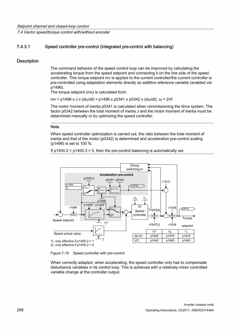
Setpoint channel and closed-loop control 7.4 Vector speed/torque control with/without encoder
Inverter chassis units 268 Operating Instructions, 03/2011, A5E00331449A
7.4.3.1 Speed controller pre-control (integrated pre-control with balancing)
Description The command behavior of the speed control loop can be improved by calculating the accelerating torque from the speed setpoint and connecting it on the line side of the speed controller. This torque setpoint mv is applied to the current controller/the current controller is pre-controlled using adaptation elements directly as additive reference variable (enabled via p1496). The torque setpoint (mv) is calculated from:
mv = p1496 x J x (dω/dt) = p1496 x p0341 x p0342 x (dω/dt), ω = 2πf
The motor moment of inertia p0341 is calculated when commissioning the drive system. The factor p0342 between the total moment of inertia J and the motor moment of inertia must be determined manually or by optimizing the speed controller.
Note
When speed controller optimization is carried out, the ratio between the total moment of inertia and that of the motor (p0342) is determined and acceleration pre-control scaling (p1496) is set to 100 %.
If p1400.2 = p1400.3 = 0, then the pre-control balancing is automatically set.
- -
+r 1547 [ 0 ]
r 1538
r 1547 [ 1 ] r 1539
r 1518
=0
>0
p 0341 p 0342
p 1496
SLVC : VC :
p 1452 p 1442
p 1470 p 1460
p 1472 p 1462
K p T n
K p T n
r 1084 r 0079
T i
T ) 2 i
T ) 2 i
0
1 p 1495
p1400.2
p 1428 1 ) p 1429 1 )
r 1515
Figure 7-15 Speed controller with pre-control
When correctly adapted, when accelerating, the speed controller only has to compensate disturbance variables in its control loop. This is achieved with a relatively minor controlled variable change at the controller output.
Setpoint channel and closed-loop control 7.4 Vector speed/torque control with/without encoder
Inverter chassis units Operating Instructions, 03/2011, A5E00331449A 269
The effect of the pre-control variable can be adapted according to the application using the weighting factor p1496. For p1496 = 100%, pre-control is calculated according to the motor and load moment of inertia (p0341, p0342). A balancing filter is used automatically to prevent the speed controller acting against the injected torque setpoint. The time constant of the balancing filter corresponds to the equivalent delay time of the speed control loop. Speed controller pre-control is correctly set (p1496 = 100%, calibration using p0342) if the I component of the speed controller (r1482) does not change while ramping-up or ramping-down in the range n > 20% x p0310. Thus, pre-control allows a new speed setpoint to be approached without overshoot (prerequisite: torque limiting does switch in and the moment of inertia remains constant).
If the speed controller is pre-controlled by means of injection, the speed setpoint (r0062) is delayed with the same smoothing time (p1442 or p1452) as the actual value (r1445). This ensures that no target/actual difference (r0064) occurs at the controller input during acceleration, which would be attributable solely to the signal propagation time.
When speed pre-control is activated, the speed setpoint must be specified continuously or without a higher interference level (avoids sudden torque changes). An appropriate signal can be generated by smoothing the speed setpoint or activating ramp-function generator rounding p1130 – p1131.
The startup time r0345 (Tstartup) is a measure for the total moment of inertia J of the machine and describes the time during which the unloaded drive can be accelerated with the rated motor torque r0333 (Mmot,rated) from standstill to the rated motor speed p0311 (nmot,rated).
r0345 = Tstartup = J x (2 x π x nmot,rated) / (60 x Mmot,rated) = p0341 x p0342 x (2 x π x p0311) / (60 x r0333)
The ramp-up and ramp-down times should always be set to values larger than the startup time.
Note
The ramp-up and ramp-down times (p1120; p1121) of the ramp-function generator in the setpoint channel should be set accordingly so that the motor speed can track the setpoint during acceleration and braking. This will optimize the function of speed controller pre-control.
Acceleration pre-control using a connector input (p1495) is activated by the parameter settings p1400.2 = 1 and p1400.3 = 0. p1428 (dead time) and p1429 (time constant) can be set for balancing purposes.
Function diagram FP 6031 Pre-control balancing reference/acceleration model

Setpoint channel and closed-loop control 7.4 Vector speed/torque control with/without encoder
Inverter chassis units 270 Operating Instructions, 03/2011, A5E00331449A
Parameter p0311 Rated motor speed
r0333 Rated motor torque
p0341 Motor moment of inertia
p0342 Ratio between the total and motor moment of inertia
r0345 Rated motor startup time
p1400.2 Acceleration pre-control source
p1428 Speed pre-control balancing dead time
p1429 Speed pre-control balancing time constant
p1496 Acceleration pre-control scaling
r1518 Acceleration torque
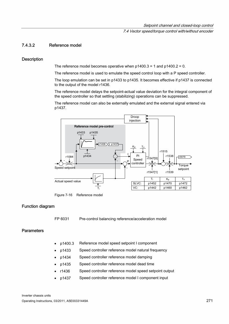
Setpoint channel and closed-loop control 7.4 Vector speed/torque control with/without encoder
Inverter chassis units Operating Instructions, 03/2011, A5E00331449A 271
7.4.3.2 Reference model
Description The reference model becomes operative when p1400.3 = 1 and p1400.2 = 0.
The reference model is used to emulate the speed control loop with a P speed controller.
The loop emulation can be set in p1433 to p1435. It becomes effective if p1437 is connected to the output of the model r1436.
The reference model delays the setpoint-actual value deviation for the integral component of the speed controller so that settling (stabilizing) operations can be suppressed.
The reference model can also be externally emulated and the external signal entered via p1437.
-
- r 1547 [ 0 ]
r 1538
r 1547 [ 1 ] r 1539
SLVC : VC :
p 1452 p 1442
p 1470 p 1460
p 1472 p 1462
K p T n
K p T n
r 1084 r 0079
T i
T i
p 1437 r 1436
r 1515
-
p 1433 p 1435
I
P
p 1434
Figure 7-16 Reference model
Function diagram FP 6031 Pre-control balancing reference/acceleration model
Parameters p1400.3 Reference model speed setpoint I component
p1433 Speed controller reference model natural frequency
p1434 Speed controller reference model damping
p1435 Speed controller reference model dead time
r1436 Speed controller reference model speed setpoint output
p1437 Speed controller reference model I component input
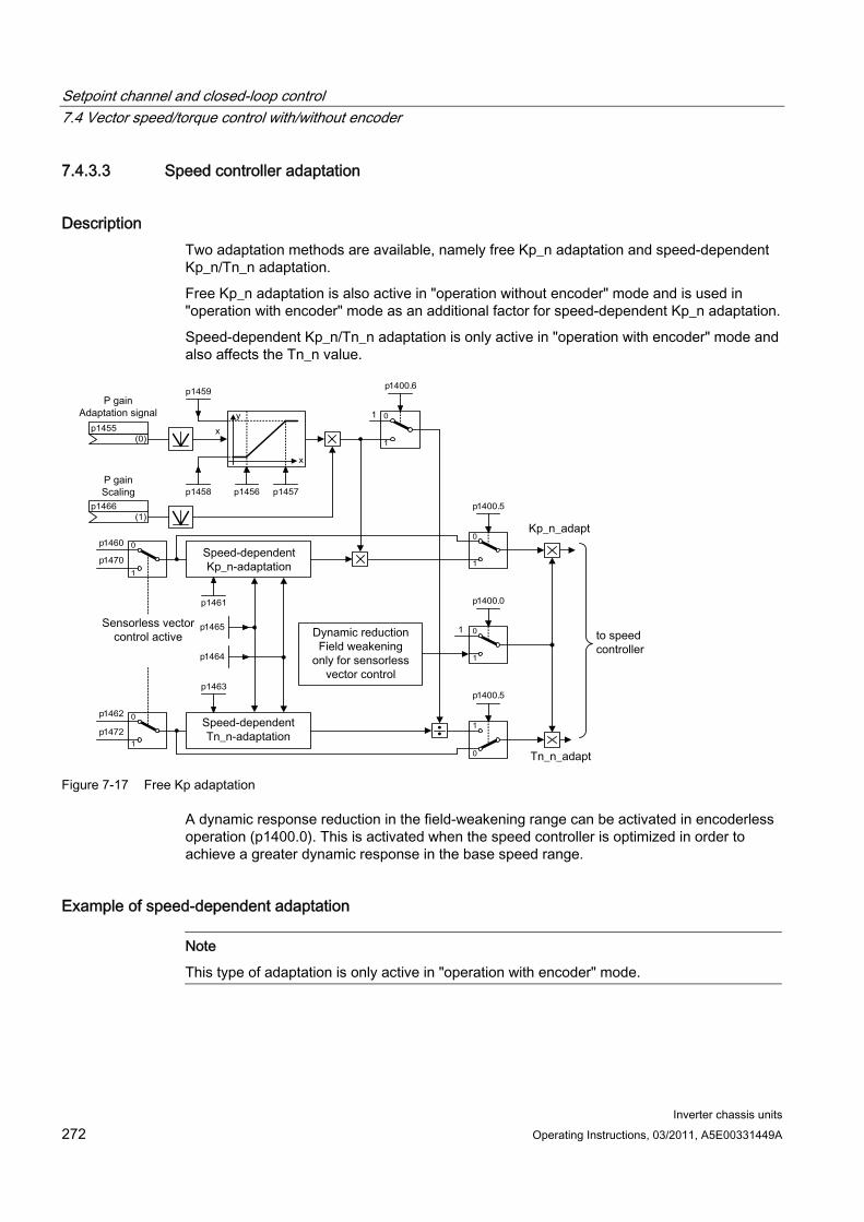
Setpoint channel and closed-loop control 7.4 Vector speed/torque control with/without encoder
Inverter chassis units 272 Operating Instructions, 03/2011, A5E00331449A
7.4.3.3 Speed controller adaptation
Description Two adaptation methods are available, namely free Kp_n adaptation and speed-dependent Kp_n/Tn_n adaptation.
Free Kp_n adaptation is also active in "operation without encoder" mode and is used in "operation with encoder" mode as an additional factor for speed-dependent Kp_n adaptation.
Speed-dependent Kp_n/Tn_n adaptation is only active in "operation with encoder" mode and also affects the Tn_n value.
p 1459
y
x
p 1456 p 1457
( 1 ) p 1466
( 0 ) p 1455
p 1458
x
p1400.0
1
0
1
0
1
0
p1400.6
p 1460
p 1470
p 1462
p 1472
1
01
1
p1464
p1465
p 1461
p 1463
1
0
p1400.5
0
1
p1400.5
Figure 7-17 Free Kp adaptation
A dynamic response reduction in the field-weakening range can be activated in encoderless operation (p1400.0). This is activated when the speed controller is optimized in order to achieve a greater dynamic response in the base speed range.
Example of speed-dependent adaptation
Note
This type of adaptation is only active in "operation with encoder" mode.
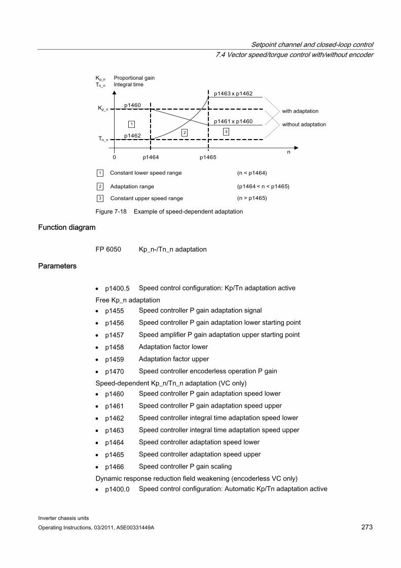
Setpoint channel and closed-loop control 7.4 Vector speed/torque control with/without encoder
Inverter chassis units Operating Instructions, 03/2011, A5E00331449A 273
K p _ n
T n _ n
p 1460
p 1462
p 1463 x p 1462
p 1461 x p 1460 1
2 3
1
2
3
(n < p1464)
(p1464 < n < p1465)
(n > p1465)
0 p 1464 p 1465 n
K p _ n T n _ n
Figure 7-18 Example of speed-dependent adaptation
Function diagram FP 6050 Kp_n-/Tn_n adaptation
Parameters p1400.5 Speed control configuration: Kp/Tn adaptation active
Free Kp_n adaptation p1455 Speed controller P gain adaptation signal
p1456 Speed controller P gain adaptation lower starting point
p1457 Speed amplifier P gain adaptation upper starting point
p1458 Adaptation factor lower
p1459 Adaptation factor upper
p1470 Speed controller encoderless operation P gain
Speed-dependent Kp_n/Tn_n adaptation (VC only) p1460 Speed controller P gain adaptation speed lower
p1461 Speed controller P gain adaptation speed upper
p1462 Speed controller integral time adaptation speed lower
p1463 Speed controller integral time adaptation speed upper
p1464 Speed controller adaptation speed lower
p1465 Speed controller adaptation speed upper
p1466 Speed controller P gain scaling
Dynamic response reduction field weakening (encoderless VC only) p1400.0 Speed control configuration: Automatic Kp/Tn adaptation active
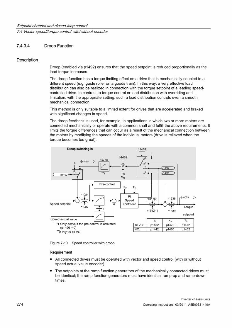
Setpoint channel and closed-loop control 7.4 Vector speed/torque control with/without encoder
Inverter chassis units 274 Operating Instructions, 03/2011, A5E00331449A
7.4.3.4 Droop Function
Description Droop (enabled via p1492) ensures that the speed setpoint is reduced proportionally as the load torque increases.
The droop function has a torque limiting effect on a drive that is mechanically coupled to a different speed (e.g. guide roller on a goods train). In this way, a very effective load distribution can also be realized in connection with the torque setpoint of a leading speed-controlled drive. In contrast to torque control or load distribution with overriding and limitation, with the appropriate setting, such a load distribution controls even a smooth mechanical connection.
This method is only suitable to a limited extent for drives that are accelerated and braked with significant changes in speed.
The droop feedback is used, for example, in applications in which two or more motors are connected mechanically or operate with a common shaft and fulfill the above requirements. It limits the torque differences that can occur as a result of the mechanical connection between the motors by modifying the speeds of the individual motors (drive is relieved when the torque becomes too great).
-
- r 1547 [ 0 ]
r 1547 [ 1 ]
0
2
1
3
0
0 1
0
r 1084
r 1087
r 1538
r 1539
p 1 4 8 9
p 1 4 8 8
r 1482
r 1490 150 ms
T i
K p
MN
nN
T n
*)
SLVC : VC :
p 1452 p 1442
p 1470 p 1460
p 1472 p 1462
T i K p T n *)
**)
r 0079
p 1492
r 1508
**)
Figure 7-19 Speed controller with droop
Requirement
All connected drives must be operated with vector and speed control (with or without speed actual value encoder).
The setpoints at the ramp function generators of the mechanically connected drives must be identical; the ramp function generators must have identical ramp-up and ramp-down times.
Setpoint channel and closed-loop control 7.4 Vector speed/torque control with/without encoder
Inverter chassis units Operating Instructions, 03/2011, A5E00331449A 275
Function diagram FP 6030 Speed setpoint, droop
Parameter r0079 Total speed setpoint
r1482 Speed controller I torque output
p1488 Droop input source
p1489 Droop feedback scaling
r1490 Droop feedback speed reduction
p1492 Droop feedback enable
r1508 Torque setpoint before supplementary torque
7.4.3.5 Open actual speed value
Description Via parameter p1440 (CI: speed controller, speed actual value) is the signal source for the speed actual value of the speed controller. The unsmoothed actual speed value r0063[0] has been preset as the signal source in the factory.
Depending on the machine, parameter p1440 can be used, for example, to switch on a filter in the actual value channel or feed in an external actual speed value.
Parameter r1443 is used to display the actual speed value present at p1440.
Note
When infeeding an external actual speed value, care should be taken that the monitoring functions continue to be derived from the motor model.
Behavior for speed control with an encoder (p1300 = 21) A motor encoder must always be available for the speed or position signal of the motor model (e.g. evaluation via SMC, see p0400). The actual speed of the motor (r0061) and the position information for synchronous motors still come from this motor encoder and are not influenced by the setting in p1440.
Interconnection of p1440: When interconnecting connector input p1440 with an external actual speed value, ensure the speed scaling is the same (p2000).
The external speed signal should correspond to the average speed of the motor encoder (r0061).
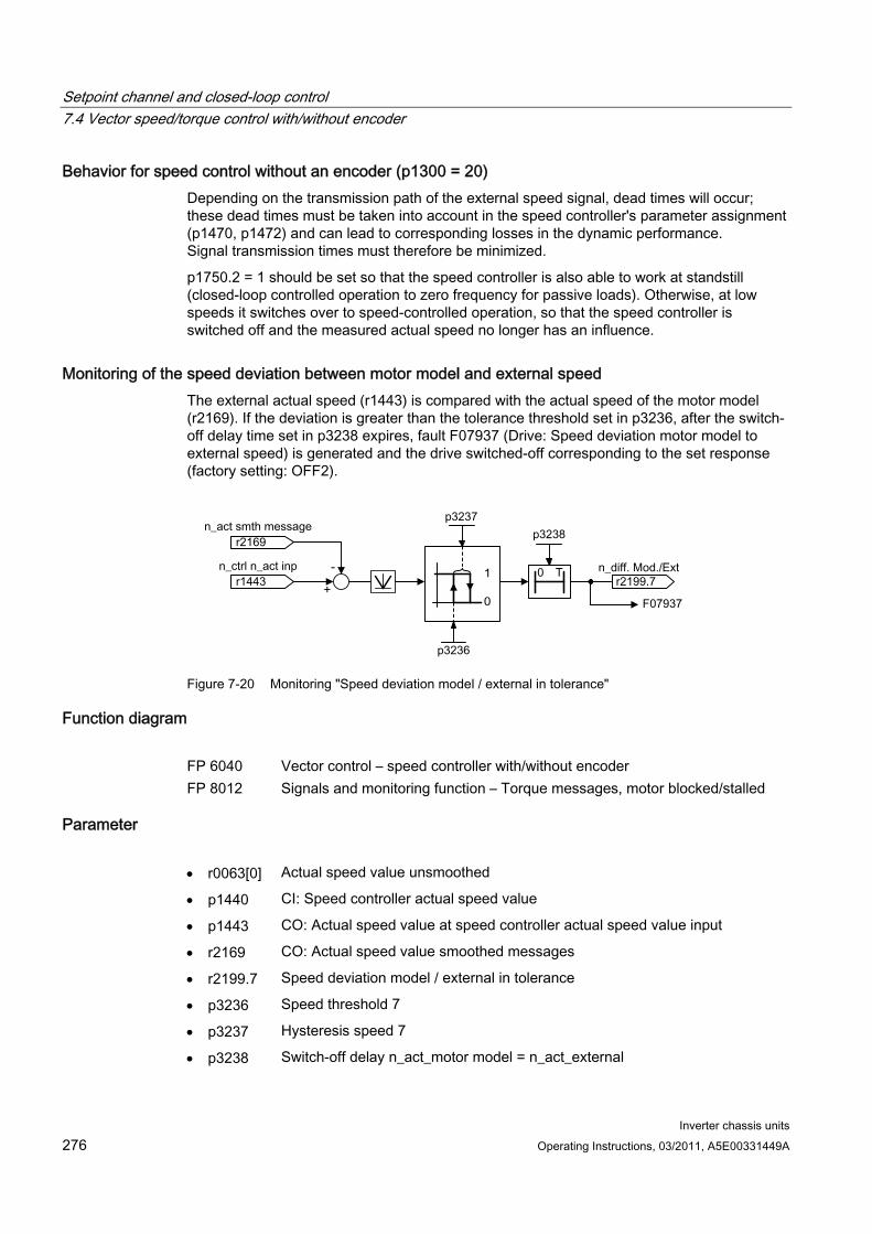
Setpoint channel and closed-loop control 7.4 Vector speed/torque control with/without encoder
Inverter chassis units 276 Operating Instructions, 03/2011, A5E00331449A
Behavior for speed control without an encoder (p1300 = 20) Depending on the transmission path of the external speed signal, dead times will occur; these dead times must be taken into account in the speed controller's parameter assignment (p1470, p1472) and can lead to corresponding losses in the dynamic performance. Signal transmission times must therefore be minimized.
p1750.2 = 1 should be set so that the speed controller is also able to work at standstill (closed-loop controlled operation to zero frequency for passive loads). Otherwise, at low speeds it switches over to speed-controlled operation, so that the speed controller is switched off and the measured actual speed no longer has an influence.
Monitoring of the speed deviation between motor model and external speed The external actual speed (r1443) is compared with the actual speed of the motor model (r2169). If the deviation is greater than the tolerance threshold set in p3236, after the switch-off delay time set in p3238 expires, fault F07937 (Drive: Speed deviation motor model to external speed) is generated and the drive switched-off corresponding to the set response (factory setting: OFF2).
Figure 7-20 Monitoring "Speed deviation model / external in tolerance"
Function diagram FP 6040 Vector control – speed controller with/without encoder FP 8012 Signals and monitoring function – Torque messages, motor blocked/stalled
Parameter r0063[0] Actual speed value unsmoothed
p1440 CI: Speed controller actual speed value
p1443 CO: Actual speed value at speed controller actual speed value input
r2169 CO: Actual speed value smoothed messages
r2199.7 Speed deviation model / external in tolerance
p3236 Speed threshold 7
p3237 Hysteresis speed 7
p3238 Switch-off delay n_act_motor model = n_act_external
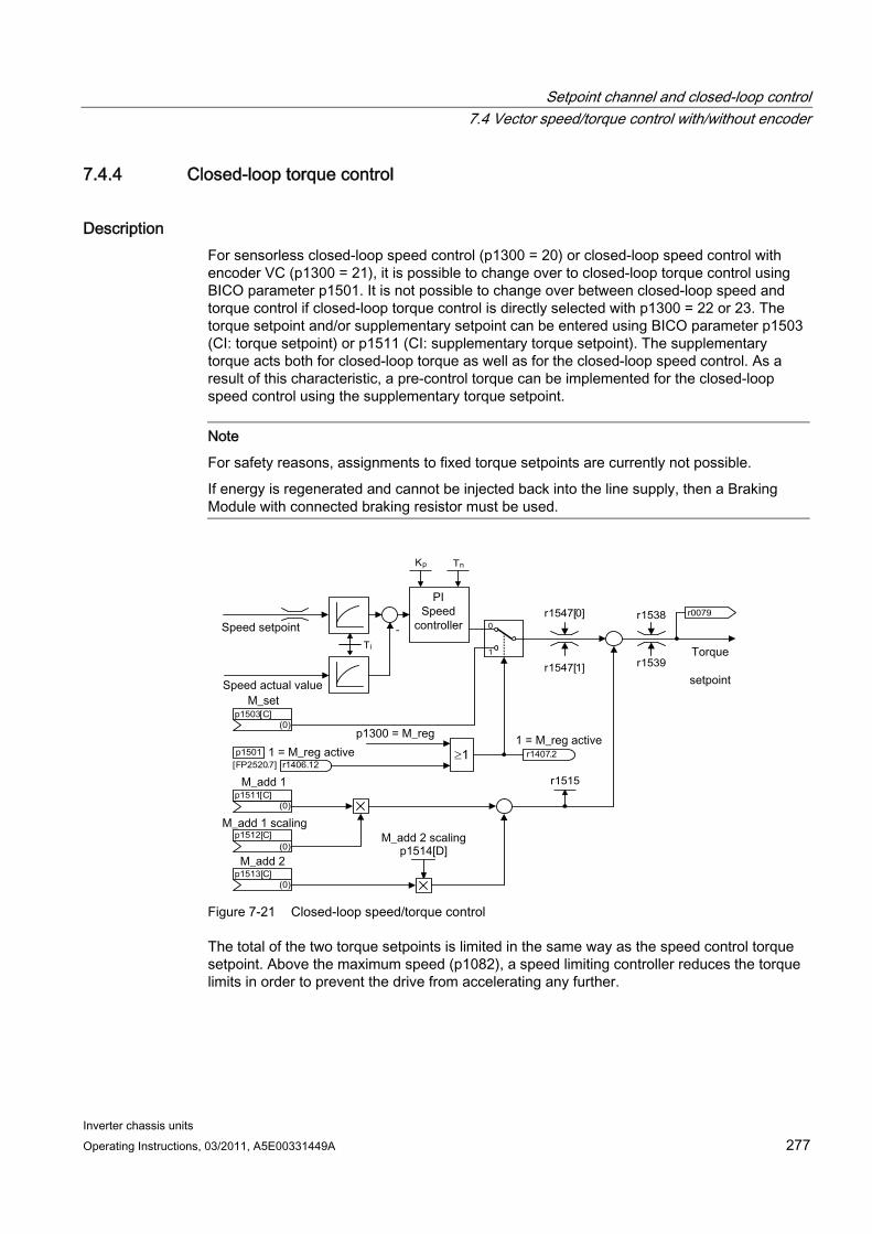
Setpoint channel and closed-loop control 7.4 Vector speed/torque control with/without encoder
Inverter chassis units Operating Instructions, 03/2011, A5E00331449A 277
7.4.4 Closed-loop torque control
Description For sensorless closed-loop speed control (p1300 = 20) or closed-loop speed control with encoder VC (p1300 = 21), it is possible to change over to closed-loop torque control using BICO parameter p1501. It is not possible to change over between closed-loop speed and torque control if closed-loop torque control is directly selected with p1300 = 22 or 23. The torque setpoint and/or supplementary setpoint can be entered using BICO parameter p1503 (CI: torque setpoint) or p1511 (CI: supplementary torque setpoint). The supplementary torque acts both for closed-loop torque as well as for the closed-loop speed control. As a result of this characteristic, a pre-control torque can be implemented for the closed-loop speed control using the supplementary torque setpoint.
Note
For safety reasons, assignments to fixed torque setpoints are currently not possible.
If energy is regenerated and cannot be injected back into the line supply, then a Braking Module with connected braking resistor must be used.
- 0
1
r 1547 [ 0 ] r 1538
r 1547 [ 1 ] r 1539
T i
K p T n
r 1515
r 0079
≥ 1
( 0 ) p 1512 [ C ]
( 0 ) p 1513 [ C ]
( 0 ) p 1511 [ C ]
( 0 ) p 1503 [ C ]
r 1406 . 12 [ FP 2520 . 7 ] p 1501 r 1407 . 2
Figure 7-21 Closed-loop speed/torque control
The total of the two torque setpoints is limited in the same way as the speed control torque setpoint. Above the maximum speed (p1082), a speed limiting controller reduces the torque limits in order to prevent the drive from accelerating any further.
Setpoint channel and closed-loop control 7.4 Vector speed/torque control with/without encoder
Inverter chassis units 278 Operating Instructions, 03/2011, A5E00331449A
A "real" closed-loop torque control (with a speed that automatically sets itself) is only possible in the closed-loop control range but not in the open-loop control range of the sensorless closed-loop vector control. In the open-loop controlled range, the torque setpoint changes the setpoint speed via a ramp-up integrator (integrating time ~ p1499 x p0341 x p0342). This is the reason that sensorless closed-loop torque control close to standstill is only suitable for applications that require an accelerating torque there and no load torque (e.g. traversing drives). Closed-loop torque control with encoder does not have this restriction.
OFF responses OFF1 and p1300 = 22, 23
– Response as for OFF2
OFF1, p1501 = "1" signal and p1300 ≠ 22, 23
– No separate braking response; the braking response is provided by a drive that specifies the torque.
– The pulses are inhibited when the brake application time (p1217) expires. Standstill is detected when the speed actual value of the speed threshold (p1226) is undershot or when the monitoring time (p1227) started when speed setpoint ≤ speed threshold (p1226) expires.
– Switching on inhibited is activated.
OFF2
– Immediate pulse suppression, the drive coasts to standstill.
– The motor brake (if parameterized) is closed immediately.
– Switching on inhibited is activated.
OFF3
– Switch to speed-controlled operation
– n_set = 0 is input immediately to brake the drive along the OFF3 deceleration ramp (p1135).
– When standstill is detected, the motor brake (if parameterized) is closed.
– The pulses are inhibited when the motor brake closing time (p1217) has elapsed. Standstill is detected when the speed actual value of the speed threshold (p1226) is undershot or when the monitoring time (p1227) started when speed setpoint ≤ speed threshold (p1226) expires.
– Switching on inhibited is activated.
Function diagram FP 6060 Torque setpoint
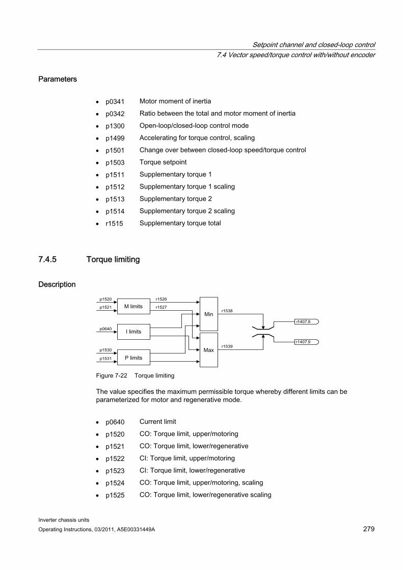
Setpoint channel and closed-loop control 7.4 Vector speed/torque control with/without encoder
Inverter chassis units Operating Instructions, 03/2011, A5E00331449A 279
Parameters p0341 Motor moment of inertia
p0342 Ratio between the total and motor moment of inertia
p1300 Open-loop/closed-loop control mode
p1499 Accelerating for torque control, scaling
p1501 Change over between closed-loop speed/torque control
p1503 Torque setpoint
p1511 Supplementary torque 1
p1512 Supplementary torque 1 scaling
p1513 Supplementary torque 2
p1514 Supplementary torque 2 scaling
r1515 Supplementary torque total
7.4.5 Torque limiting
Description
p 1520
p 1521
r 1526
r 1527
p 0640
p 1530
p 1531
r 1538
r 1539 r 1407 . 9
r 1407 . 8
Figure 7-22 Torque limiting
The value specifies the maximum permissible torque whereby different limits can be parameterized for motor and regenerative mode.
p0640 Current limit
p1520 CO: Torque limit, upper/motoring
p1521 CO: Torque limit, lower/regenerative
p1522 CI: Torque limit, upper/motoring
p1523 CI: Torque limit, lower/regenerative
p1524 CO: Torque limit, upper/motoring, scaling
p1525 CO: Torque limit, lower/regenerative scaling
Setpoint channel and closed-loop control 7.4 Vector speed/torque control with/without encoder
Inverter chassis units 280 Operating Instructions, 03/2011, A5E00331449A
p1530 Power limit, motoring
p1531 Power limit, regenerating
The currently active torque limit values are displayed in the following parameters:
r0067 Maximum drive output current
r1526 Torque limit, upper/motoring without offset
r1527 Torque limit, lower/regenerative without offset
All of the following limits act on the torque setpoint – that is either available at the speed controller output for closed-loop speed control or as torque input, for closed-loop torque control. The minimum or the maximum is used for the various limits. This minimum or maximum is cyclically calculated and is displayed in r1538 or r1539.
r1538 Upper effective torque limit
r1539 Lower effective torque limit
These cyclical values therefore limit the torque setpoint at the speed controller output/torque input or indicate the instantaneous max. possible torque. If the torque setpoint is limited, then this is displayed using parameter p1407.
r1407.8 Upper torque limit active
r1407.9 Lower torque limit active
Function diagram FP 6060 Torque setpoint FP 6630 Upper/lower torque limit FP 6640 Current/power/torque limits
Setpoint channel and closed-loop control 7.4 Vector speed/torque control with/without encoder
Inverter chassis units Operating Instructions, 03/2011, A5E00331449A 281
7.4.6 Permanent-magnet synchronous motors
Description Permanent-magnet synchronous motors without encoders are supported during operations without encoders.
Typical applications include direct drives with torque motors which are characterized by high torque at low speeds, e.g. Siemens complete torque motors of the 1FW3 series. When these drives are used, gear units and mechanical parts subject to wear can be dispensed with if the application allows this.
WARNING
As soon as the motor starts to rotate, a voltage is generated. When work is carried out on the converter, the motor must be safely disconnected. If this is not possible, the motor must be locked by a holding brake, for example.
Features Field weakening of up to approx. 1.2 x rated speed (depending on the supply voltage of
the converter and motor data, also see supplementary conditions)
Capture (only when using a VSM module to record the motor speed and phase angle (option K51))
Speed and torque control vector
V/f control for diagnostics vector
Motor identification
Speed controller optimization (rotary measurement)
Supplementary conditions Maximum speed or maximum torque depend on the converter output voltage available
and the back EMF of the motor (calculation specifications: EMF must not exceed Urated,
converter).
Calculating the maximum speed:
Depending on the terminal voltage and load cycle, the maximum torque can be taken
from the motor data sheets / configuration instructions.
No thermal model is available for the closed-loop control of a permanent-magnet synchronous motor. The motor can only be protected against overheating by using temperature sensors (PTC, KTY). To achieve a high level of torque accuracy, we recommend the use of a temperature sensor (KTY) to measure the motor temperature.
Setpoint channel and closed-loop control 7.4 Vector speed/torque control with/without encoder
Inverter chassis units 282 Operating Instructions, 03/2011, A5E00331449A
Commissioning The following sequence is recommended for commissioning:
Configure the drive
When the drive is being commissioned using STARTER or the AOP30 operator panel, the permanent-magnet synchronous motor must be selected. The motor data specified in the table below must then be entered. Finally, the motor identification routine and speed optimization (p1900) are activated. Encoder adjustment is activated automatically together with the motor identification routine.
Motor identification (standstill measurement, p1910)
Speed controller optimization (rotary measurement, p1960)
Motor data for permanent-magnet synchronous motors
Table 7- 2 Motor data type plate
Parameters Description Comment p0304 Rated motor voltage If this value is not known, the value "0" can also be
entered. Entering the correct value, however, means that the stator leakage inductance (p0356, p0357) can be calculated more accurately.
p0305 Rated motor current p0307 Rated motor power p0310 Rated motor frequency p0311 Rated motor speed p0314 Motor pole pair number If this value is not known, the value "0" can also be
entered. p0316 Motor torque constant If this value is not known, the value "0" can also be
entered.
If the torque constant kT is not stamped on the rating plate or specified in the data sheet, you can calculate this value from the rated motor data or from the stall current I0 and stall torque M0 as follows:
N N
N min s
N
N T I n 2
P 60 I M k
× × π
× = =
or
0
0 T I
M k =
The optional motor data can be entered if it is known. Otherwise, this data is estimated from the type plate data or determined by means of motor identification or speed controller optimization.
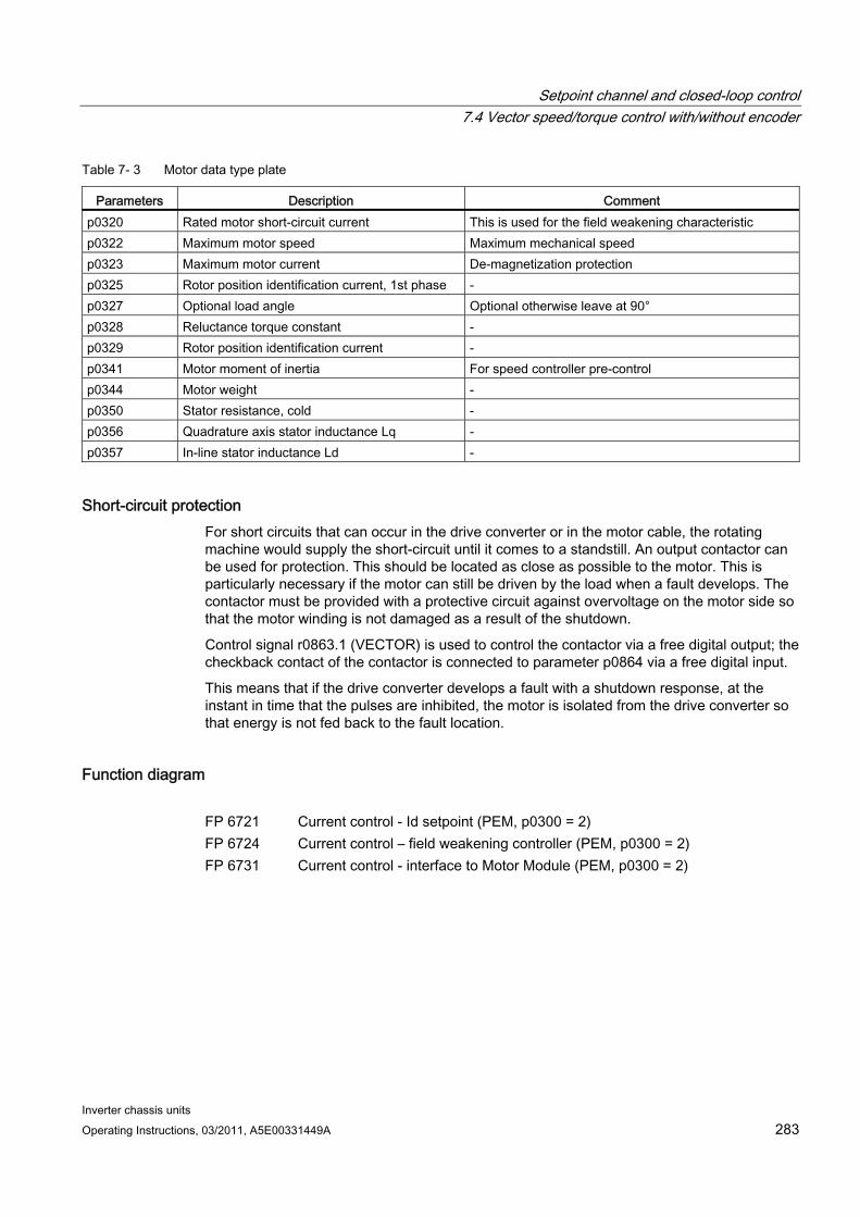
Setpoint channel and closed-loop control 7.4 Vector speed/torque control with/without encoder
Inverter chassis units Operating Instructions, 03/2011, A5E00331449A 283
Table 7- 3 Motor data type plate
Parameters Description Comment p0320 Rated motor short-circuit current This is used for the field weakening characteristic p0322 Maximum motor speed Maximum mechanical speed p0323 Maximum motor current De-magnetization protection p0325 Rotor position identification current, 1st phase - p0327 Optional load angle Optional otherwise leave at 90° p0328 Reluctance torque constant - p0329 Rotor position identification current - p0341 Motor moment of inertia For speed controller pre-control p0344 Motor weight - p0350 Stator resistance, cold - p0356 Quadrature axis stator inductance Lq - p0357 In-line stator inductance Ld -
Short-circuit protection For short circuits that can occur in the drive converter or in the motor cable, the rotating machine would supply the short-circuit until it comes to a standstill. An output contactor can be used for protection. This should be located as close as possible to the motor. This is particularly necessary if the motor can still be driven by the load when a fault develops. The contactor must be provided with a protective circuit against overvoltage on the motor side so that the motor winding is not damaged as a result of the shutdown.
Control signal r0863.1 (VECTOR) is used to control the contactor via a free digital output; the checkback contact of the contactor is connected to parameter p0864 via a free digital input.
This means that if the drive converter develops a fault with a shutdown response, at the instant in time that the pulses are inhibited, the motor is isolated from the drive converter so that energy is not fed back to the fault location.
Function diagram FP 6721 Current control - Id setpoint (PEM, p0300 = 2) FP 6724 Current control – field weakening controller (PEM, p0300 = 2) FP 6731 Current control - interface to Motor Module (PEM, p0300 = 2)

Setpoint channel and closed-loop control 7.4 Vector speed/torque control with/without encoder
Inverter chassis units 284 Operating Instructions, 03/2011, A5E00331449A
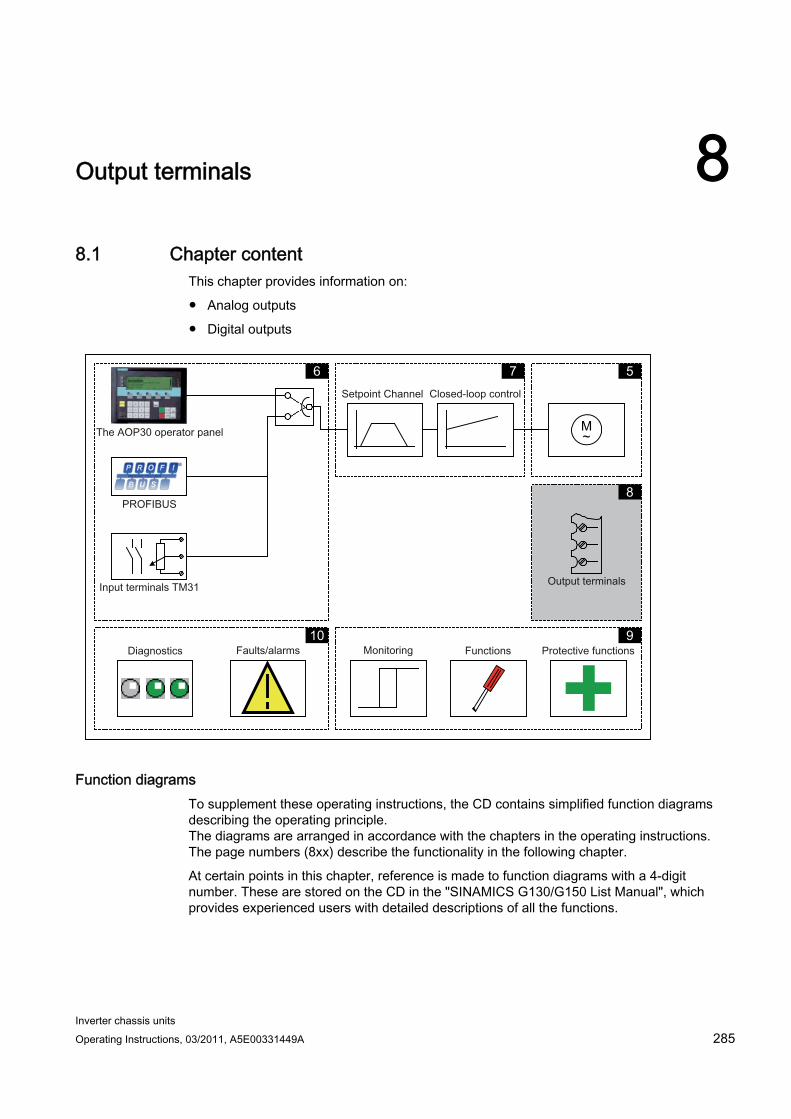
Inverter chassis units Operating Instructions, 03/2011, A5E00331449A 285
Output terminals 88.1 Chapter content
This chapter provides information on:
Analog outputs
Digital outputs
M ~
5 7 6
8
9 10
Function diagrams To supplement these operating instructions, the CD contains simplified function diagrams describing the operating principle. The diagrams are arranged in accordance with the chapters in the operating instructions. The page numbers (8xx) describe the functionality in the following chapter.
At certain points in this chapter, reference is made to function diagrams with a 4-digit number. These are stored on the CD in the "SINAMICS G130/G150 List Manual", which provides experienced users with detailed descriptions of all the functions.
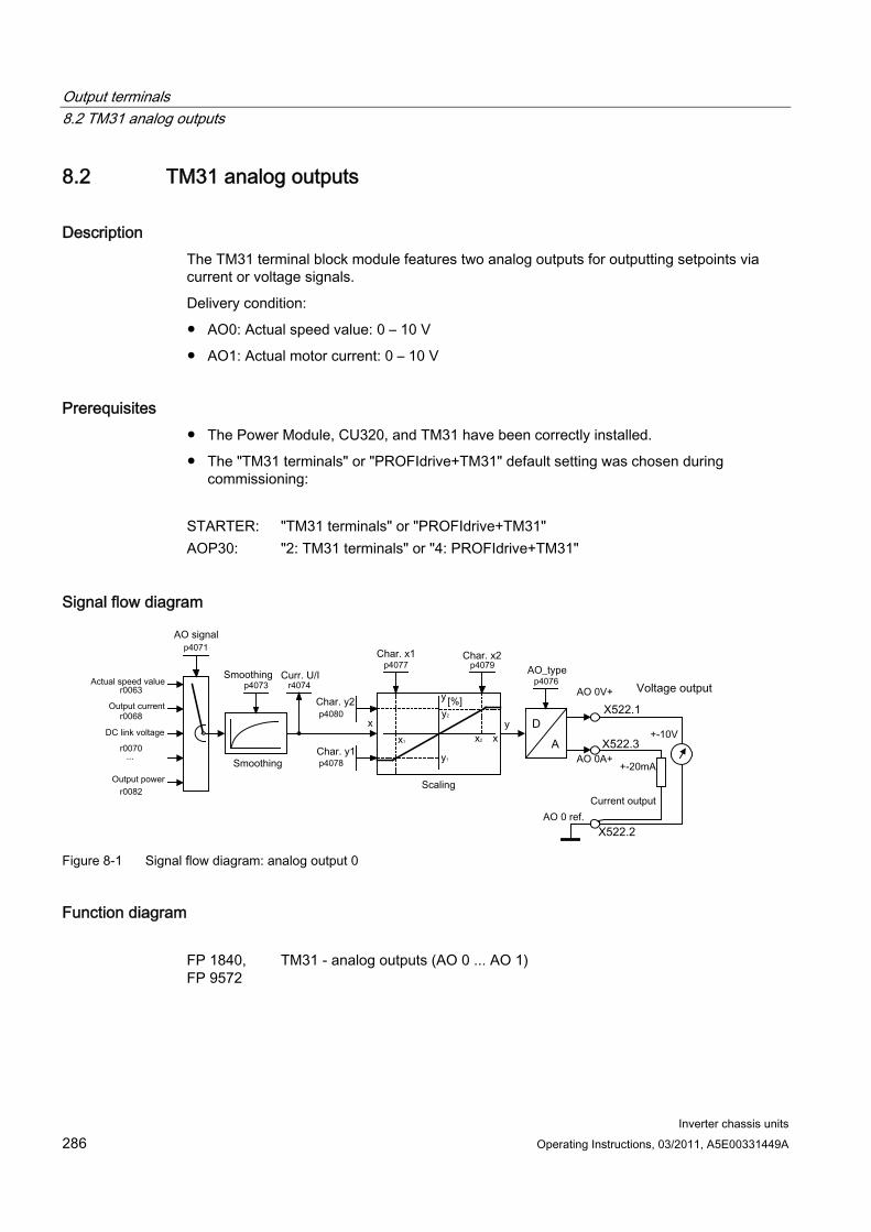
Output terminals 8.2 TM31 analog outputs
Inverter chassis units 286 Operating Instructions, 03/2011, A5E00331449A
8.2 TM31 analog outputs
Description The TM31 terminal block module features two analog outputs for outputting setpoints via current or voltage signals.
Delivery condition:
AO0: Actual speed value: 0 – 10 V
AO1: Actual motor current: 0 – 10 V
Prerequisites The Power Module, CU320, and TM31 have been correctly installed.
The "TM31 terminals" or "PROFIdrive+TM31" default setting was chosen during commissioning:
STARTER: "TM31 terminals" or "PROFIdrive+TM31" AOP30: "2: TM31 terminals" or "4: PROFIdrive+TM31"
Signal flow diagram
Figure 8-1 Signal flow diagram: analog output 0
Function diagram FP 1840, FP 9572
TM31 - analog outputs (AO 0 ... AO 1)
Output terminals 8.2 TM31 analog outputs
Inverter chassis units Operating Instructions, 03/2011, A5E00331449A 287
Parameters p4071 Analog outputs, signal source
p4073 Analog outputs, smoothing time constant
r4074 Analog outputs, actual output voltage/current
p4076 Analog outputs, type
p4077 Analog outputs, characteristic value x1
p4078 Analog outputs, characteristic value y1
p4079 Analog outputs, characteristic value x2
p4080 Analog outputs, characteristic value y2
8.2.1 List of signals for the analog signals
List of signals for the analog outputs
Table 8- 1 List of signals for the analog outputs
Signal Parameters Unit Scaling (100 %=...) See table below
Speed setpoint before the setpoint filter r0060 rpm p2000 Motor speed unsmoothed r0061 rpm p2000 Actual speed smoothed r0063 rpm p2000 Output frequency r0066 Hz Reference frequency Output current r0068 Aeff p2002 DC link voltage r0070 V p2001 Torque setpoint r0079 Nm p2003 Output power r0082 kW r2004 For diagnostic purposes Control deviation r0064 rpm p2000 Modulation depth r0074 % Reference modulation depth Torque-generating current setpoint r0077 A p2002 Torque-generating actual current r0078 A p2002 Flux setpoint r0083 % Reference flux Actual flux r0084 % Reference flux For further diagnostic purposes Speed controller output r1480 Nm p2003 I component of speed controller r1482 Nm p2003
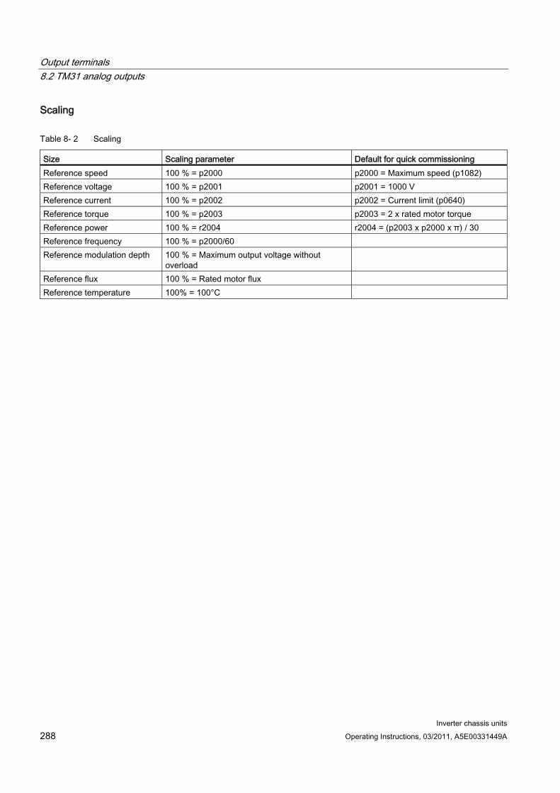
Output terminals 8.2 TM31 analog outputs
Inverter chassis units 288 Operating Instructions, 03/2011, A5E00331449A
Scaling
Table 8- 2 Scaling
Size Scaling parameter Default for quick commissioning Reference speed 100 % = p2000 p2000 = Maximum speed (p1082) Reference voltage 100 % = p2001 p2001 = 1000 V Reference current 100 % = p2002 p2002 = Current limit (p0640) Reference torque 100 % = p2003 p2003 = 2 x rated motor torque Reference power 100 % = r2004 r2004 = (p2003 x p2000 x π) / 30 Reference frequency 100 % = p2000/60 Reference modulation depth 100 % = Maximum output voltage without
overload
Reference flux 100 % = Rated motor flux Reference temperature 100% = 100°C
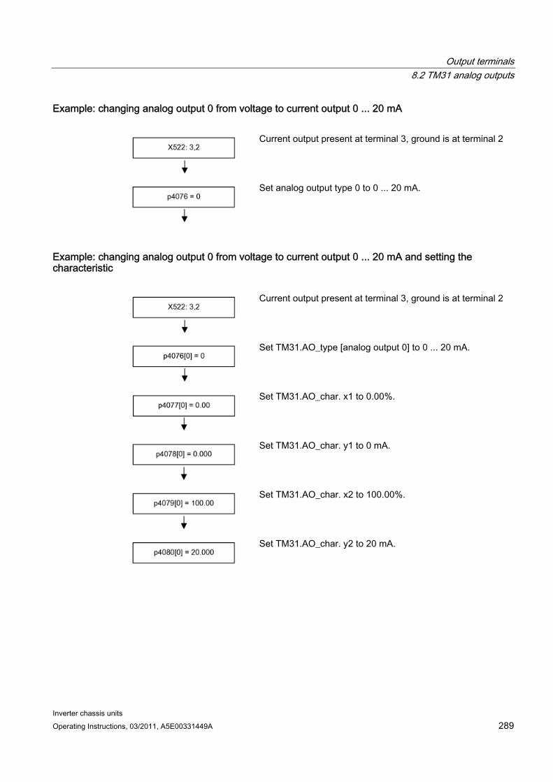
Output terminals 8.2 TM31 analog outputs
Inverter chassis units Operating Instructions, 03/2011, A5E00331449A 289
Example: changing analog output 0 from voltage to current output 0 ... 20 mA
Current output present at terminal 3, ground is at terminal 2
Set analog output type 0 to 0 ... 20 mA.
Example: changing analog output 0 from voltage to current output 0 ... 20 mA and setting the characteristic
Current output present at terminal 3, ground is at terminal 2
Set TM31.AO_type [analog output 0] to 0 ... 20 mA.
Set TM31.AO_char. x1 to 0.00%.
Set TM31.AO_char. y1 to 0 mA.
Set TM31.AO_char. x2 to 100.00%.
Set TM31.AO_char. y2 to 20 mA.
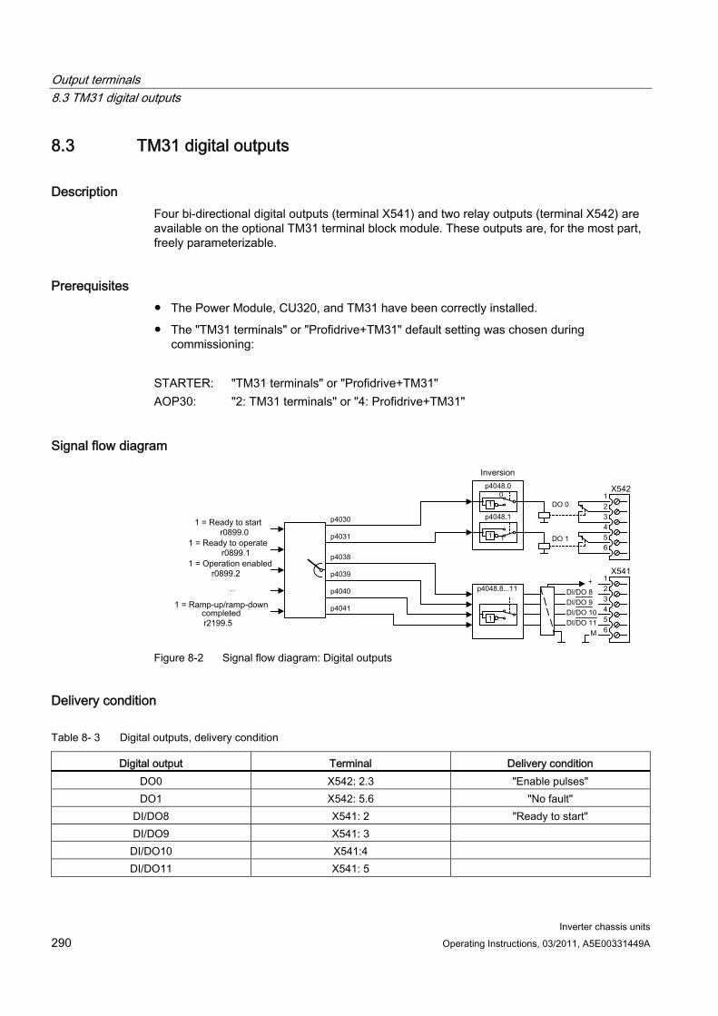
Output terminals 8.3 TM31 digital outputs
Inverter chassis units 290 Operating Instructions, 03/2011, A5E00331449A
8.3 TM31 digital outputs
Description Four bi-directional digital outputs (terminal X541) and two relay outputs (terminal X542) are available on the optional TM31 terminal block module. These outputs are, for the most part, freely parameterizable.
Prerequisites The Power Module, CU320, and TM31 have been correctly installed.
The "TM31 terminals" or "Profidrive+TM31" default setting was chosen during commissioning:
STARTER: "TM31 terminals" or "Profidrive+TM31" AOP30: "2: TM31 terminals" or "4: Profidrive+TM31"
Signal flow diagram
Figure 8-2 Signal flow diagram: Digital outputs
Delivery condition
Table 8- 3 Digital outputs, delivery condition
Digital output Terminal Delivery condition DO0 X542: 2.3 "Enable pulses" DO1 X542: 5.6 "No fault"
DI/DO8 X541: 2 "Ready to start" DI/DO9 X541: 3 DI/DO10 X541:4 DI/DO11 X541: 5
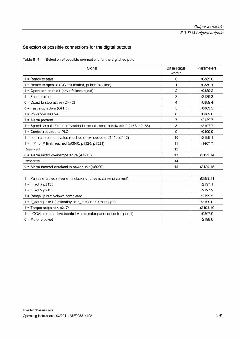
Output terminals 8.3 TM31 digital outputs
Inverter chassis units Operating Instructions, 03/2011, A5E00331449A 291
Selection of possible connections for the digital outputs
Table 8- 4 Selection of possible connections for the digital outputs
Signal Bit in status word 1
Parameters
1 = Ready to start 0 r0889.0 1 = Ready to operate (DC link loaded, pulses blocked) 1 r0889.1 1 = Operation enabled (drive follows n_set) 2 r0889.2 1 = Fault present 3 r2139.3 0 = Coast to stop active (OFF2) 4 r0889.4 0 = Fast stop active (OFF3) 5 r0889.5 1 = Power-on disable 6 r0889.6 1 = Alarm present 7 r2139.7 1 = Speed setpoint/actual deviation in the tolerance bandwidth (p2163, p2166) 8 r2197.7 1 = Control required to PLC 9 r0899.9 1 = f or n comparison value reached or exceeded (p2141, p2142) 10 r2199.1 1 = I, M, or P limit reached (p0640, p1520, p1521) 11 r1407.7 Reserved 12 0 = Alarm motor overtemperature (A7910) 13 r2129.14 Reserved 14 0 = Alarm thermal overload in power unit (A5000) 15 r2129.15 1 = Pulses enabled (inverter is clocking, drive is carrying current) r0899.11 1 = n_act ≤ p2155 r2197.1 1 = n_act > p2155 r2197.2 1 = Ramp-up/ramp-down completed r2199.5 1 = n_act < p2161 (preferably as n_min or n=0 message) r2199.0 1 = Torque setpoint < p2174 r2198.10 1 = LOCAL mode active (control via operator panel or control panel) r0807.0 0 = Motor blocked r2198.6

Output terminals 8.3 TM31 digital outputs
Inverter chassis units 292 Operating Instructions, 03/2011, A5E00331449A
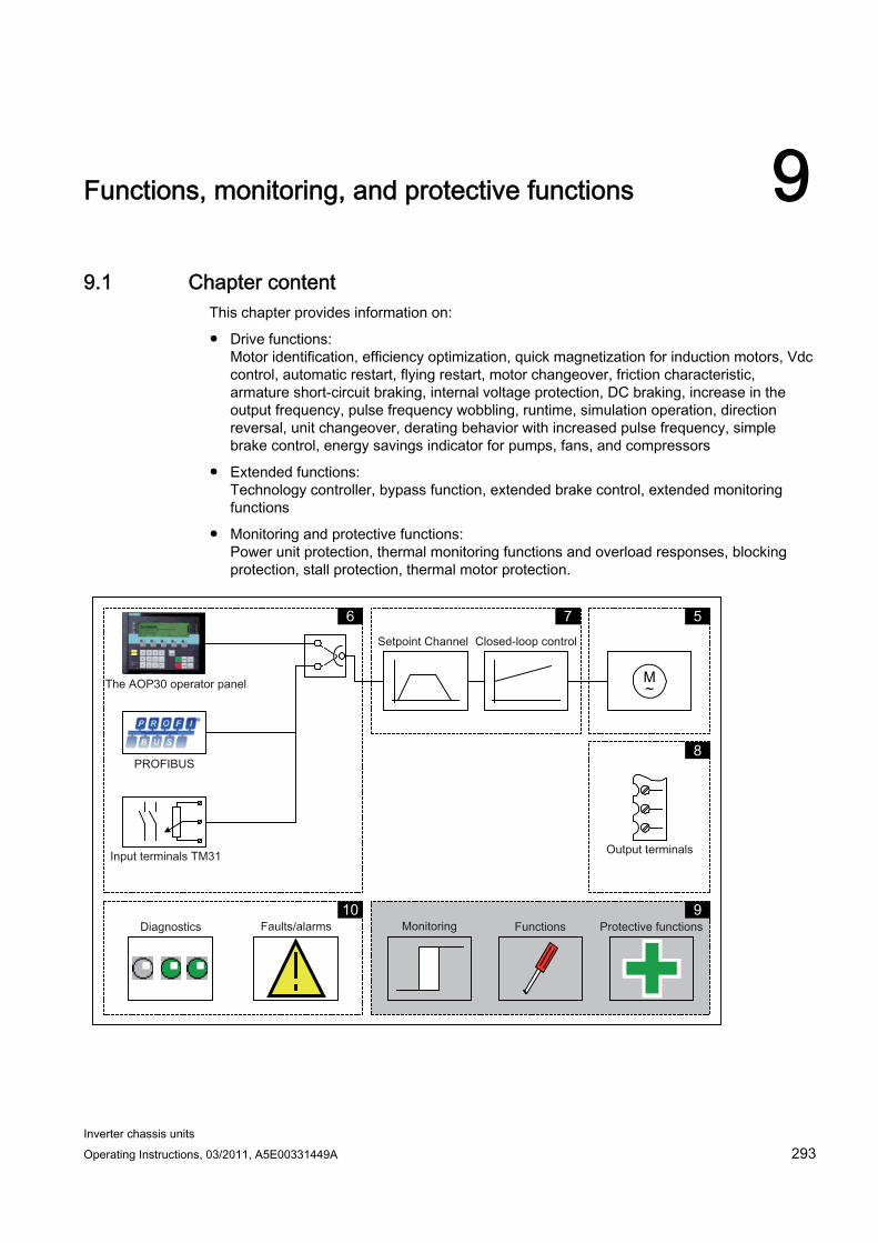
Inverter chassis units Operating Instructions, 03/2011, A5E00331449A 293
Functions, monitoring, and protective functions 99.1 Chapter content
This chapter provides information on:
Drive functions: Motor identification, efficiency optimization, quick magnetization for induction motors, Vdc control, automatic restart, flying restart, motor changeover, friction characteristic, armature short-circuit braking, internal voltage protection, DC braking, increase in the output frequency, pulse frequency wobbling, runtime, simulation operation, direction reversal, unit changeover, derating behavior with increased pulse frequency, simple brake control, energy savings indicator for pumps, fans, and compressors
Extended functions: Technology controller, bypass function, extended brake control, extended monitoring functions
Monitoring and protective functions: Power unit protection, thermal monitoring functions and overload responses, blocking protection, stall protection, thermal motor protection.
M ~
5 7 6
8
9 10
Functions, monitoring, and protective functions 9.2 Drive functions
Inverter chassis units 294 Operating Instructions, 03/2011, A5E00331449A
Function diagrams To supplement these operating instructions, the CD contains simplified function diagrams describing the operating principle. The diagrams are arranged in accordance with the chapters in the operating instructions. The page numbers (9xx) describe the functionality in the following chapter.
At certain points in this chapter, reference is made to function diagrams with a 4-digit number. These are stored on the CD in the "SINAMICS G130/G150 List Manual", which provides experienced users with detailed descriptions of all the functions.
9.2 Drive functions
9.2.1 Motor identification and automatic speed controller optimization
Description Two motor identification options, which are based on each other, are available:
Standstill measurement with p1910 (motor identification)
Rotating measurement with p1960 (speed controller optimization)
These can be selected more easily via p1900. p1900 = 2 selects the standstill measurement (motor not rotating). p1900 = 1 also activates the rotating measurement; setting p1910 = 1 and p1960 depending on the current control type (p1300).
Parameter p1960 is set depending on p1300 as follows:
p1960 = 1, if p1300 = 20 or 22 (encoderless control)
p1960 = 2, if p1300 = 21 or 23 (control with encoder)
The measurements parameterized using p1900 are started in the following sequence after the corresponding drive has been enabled:
Standstill (static) measurement - after the measurement has been completed, the pulses are inhibited and parameter p1910 is reset to 0.
Encoder adjustment - after the measurement has been completed, the pulses are inhibited and parameter p1990 is reset to 0.
Rotating measurement - after the measurement has been completed, the pulses are inhibited and parameter p1960 is reset to 0.
After all of the measurements activated using p1900 have been successfully completed, p1900 itself is set to 0.
Note
To set the new controller setting permanently, the data must be saved with p0977 or p0971 in a non-volatile memory.

Functions, monitoring, and protective functions 9.2 Drive functions
Inverter chassis units Operating Instructions, 03/2011, A5E00331449A 295
DANGER During motor identification, the drive might set the motor in motion.
The EMERGENCY OFF functions must be fully operational during commissioning. To protect the machines and personnel, the relevant safety regulations must be observed.
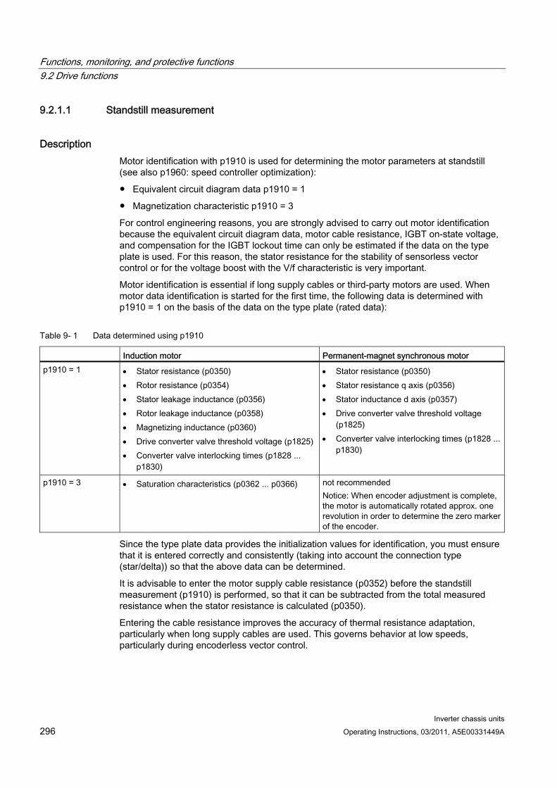
Functions, monitoring, and protective functions 9.2 Drive functions
Inverter chassis units 296 Operating Instructions, 03/2011, A5E00331449A
9.2.1.1 Standstill measurement
Description Motor identification with p1910 is used for determining the motor parameters at standstill (see also p1960: speed controller optimization):
Equivalent circuit diagram data p1910 = 1
Magnetization characteristic p1910 = 3
For control engineering reasons, you are strongly advised to carry out motor identification because the equivalent circuit diagram data, motor cable resistance, IGBT on-state voltage, and compensation for the IGBT lockout time can only be estimated if the data on the type plate is used. For this reason, the stator resistance for the stability of sensorless vector control or for the voltage boost with the V/f characteristic is very important.
Motor identification is essential if long supply cables or third-party motors are used. When motor data identification is started for the first time, the following data is determined with p1910 = 1 on the basis of the data on the type plate (rated data):
Table 9- 1 Data determined using p1910
Induction motor Permanent-magnet synchronous motor p1910 = 1 Stator resistance (p0350)
Rotor resistance (p0354) Stator leakage inductance (p0356) Rotor leakage inductance (p0358) Magnetizing inductance (p0360) Drive converter valve threshold voltage (p1825) Converter valve interlocking times (p1828 ...
p1830)
Stator resistance (p0350) Stator resistance q axis (p0356) Stator inductance d axis (p0357) Drive converter valve threshold voltage
(p1825) Converter valve interlocking times (p1828 ...
p1830)
p1910 = 3 Saturation characteristics (p0362 ... p0366) not recommended Notice: When encoder adjustment is complete, the motor is automatically rotated approx. one revolution in order to determine the zero marker of the encoder.
Since the type plate data provides the initialization values for identification, you must ensure that it is entered correctly and consistently (taking into account the connection type (star/delta)) so that the above data can be determined.
It is advisable to enter the motor supply cable resistance (p0352) before the standstill measurement (p1910) is performed, so that it can be subtracted from the total measured resistance when the stator resistance is calculated (p0350).
Entering the cable resistance improves the accuracy of thermal resistance adaptation, particularly when long supply cables are used. This governs behavior at low speeds, particularly during encoderless vector control.
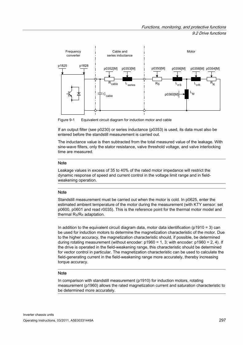
Functions, monitoring, and protective functions 9.2 Drive functions
Inverter chassis units Operating Instructions, 03/2011, A5E00331449A 297
Figure 9-1 Equivalent circuit diagram for induction motor and cable
If an output filter (see p0230) or series inductance (p0353) is used, its data must also be entered before the standstill measurement is carried out.
The inductance value is then subtracted from the total measured value of the leakage. With sine-wave filters, only the stator resistance, valve threshold voltage, and valve interlocking time are measured.
Note
Leakage values in excess of 35 to 40% of the rated motor impedance will restrict the dynamic response of speed and current control in the voltage limit range and in field-weakening operation.
Note
Standstill measurement must be carried out when the motor is cold. In p0625, enter the estimated ambient temperature of the motor during the measurement (with KTY sensor: set p0600, p0601 and read r0035). This is the reference point for the thermal motor model and thermal RS/RR adaptation.
In addition to the equivalent circuit diagram data, motor data identification (p1910 = 3) can be used for induction motors to determine the magnetization characteristic of the motor. Due to the higher accuracy, the magnetization characteristic should, if possible, be determined during rotating measurement (without encoder: p1960 = 1, 3; with encoder: p1960 = 2, 4). If the drive is operated in the field-weakening range, this characteristic should be determined for vector control in particular. The magnetization characteristic can be used to calculate the field-generating current in the field-weakening range more accurately, thereby increasing torque accuracy.
Note
In comparison with standstill measurement (p1910) for induction motors, rotating measurement (p1960) allows the rated magnetization current and saturation characteristic to be determined more accurately.
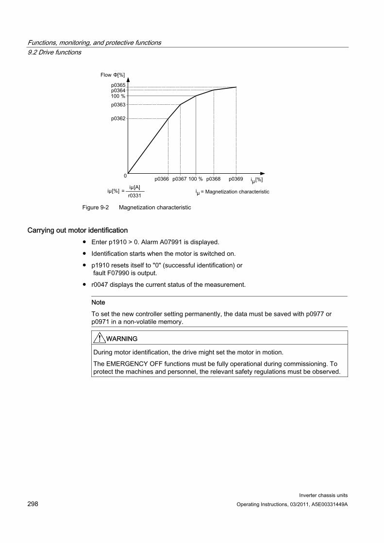
Functions, monitoring, and protective functions 9.2 Drive functions
Inverter chassis units 298 Operating Instructions, 03/2011, A5E00331449A
Figure 9-2 Magnetization characteristic
Carrying out motor identification Enter p1910 > 0. Alarm A07991 is displayed.
Identification starts when the motor is switched on.
p1910 resets itself to "0" (successful identification) or fault F07990 is output.
r0047 displays the current status of the measurement.
Note
To set the new controller setting permanently, the data must be saved with p0977 or p0971 in a non-volatile memory.
WARNING
During motor identification, the drive might set the motor in motion.
The EMERGENCY OFF functions must be fully operational during commissioning. To protect the machines and personnel, the relevant safety regulations must be observed.
Functions, monitoring, and protective functions 9.2 Drive functions
Inverter chassis units Operating Instructions, 03/2011, A5E00331449A 299
9.2.1.2 Rotating measurement and speed controller optimization
Description "Rotating measurement" can be activated via p1960 or p1900 = 1.
The main difference between rotating measurement and standstill measurement is speed control optimization, with which the drive's moment of inertia is ascertained and speed controller is set. On induction motors, the saturation characteristic and rated magnetization current are also measured.
If rotating measurement is not to be carried out at the speed set in p1965, this parameter can be changed before the measurement is started. Higher speeds are recommended.
The same applies to the speed in p1961, at which the saturation characteristic is determined and the encoder test is carried out.
The speed controller is set to the symmetrical optimum in accordance with dynamic factor p1967. p1967 must be set before the optimization run and only affects the calculation of the controller parameters.
If, during the measurement, it becomes clear that the the drive cannot operate in a stable manner with the specified dynamic factor or that the torque ripples are too great, the dynamic response is reduced automatically and the result displayed in r1968. The drive must also be checked to ensure that it is stable across the entire range. The dynamic response might need to be reduced or Kp/Tn adaptation for the speed controller parameterized accordingly.
When commissioning induction machines, you are advised to proceed as follows:
Before connecting the load, a complete "rotating measurement" (without encoder: p1960 = 1; with encoder: p1960 = 2) should be carried out. Since the induction machine is idling, you can expect highly accurate results for the saturation characteristic and the rated magnetization current.
When the load is connected, speed controller optimization should be repeated because the total moment of inertia has changed. This is realized by selecting parameter p1960 (without encoder: p1960 = 3; with encoder: p1960 = 4). During the speed optimization, the saturation characteristic recording is automatically deactivated in parameter p1959.
When permanent-magnet synchronous motors are commissioned, the speed controller should be optimized (p1960 = 2/4) when the load is connected.
Functions, monitoring, and protective functions 9.2 Drive functions
Inverter chassis units 300 Operating Instructions, 03/2011, A5E00331449A
Carrying out the rotating measurement (p1960 = 1, 2) The following measurements are carried out when the enable signals are set and a switch-on command is issued in accordance with the settings in p1959 and p1960.
Encoder test If a speed encoder is used, the direction of rotation and the pulse number are checked.
Only for induction motors:
– Measurement of the magnetization characteristic (p0362 to p0369)
– Measurement of the magnetization current (p0320) and determination of the offset voltage of the converter for offset compensation
– Measurement of the saturation of the leakage inductance and setting of the current controller adaptation (p0391…p0393) This is automatically activated with 1LA1 and 1LA8 motors (p0300 = 11, 18) (see p1959.5).
Speed controller optimization
– p1470 and p1472, if p1960 = 1 (encoderless operation)
– p1460 and p1462, if p1960 = 2 (operation with encoder)
– Kp adaptation switch-off
Acceleration pre-control setting (p1496)
Setting for ratio between the total moment of inertia and that of the motor (p0342)
Note
To set the new controller setting permanently, the data must be saved with p0977 or p0971 in a non-volatile memory.
DANGER During speed controller optimization, the drive triggers movements in the motor that can reach the maximum motor speed.
The EMERGENCY OFF functions must be fully operational during commissioning. To protect the machines and personnel, the relevant safety regulations must be observed.
Note
If speed controller optimization is carried out for operation with an encoder, the control mode will be changed over to encoderless speed control automatically, in order to be able to carry out the encoder test.
Functions, monitoring, and protective functions 9.2 Drive functions
Inverter chassis units Operating Instructions, 03/2011, A5E00331449A 301
Parameters r0047 Status identification
p1300 Open-loop/closed-loop control operating mode
p1900 Motor data identification and rotating measurement
p1959 Speed controller optimization configuration
p1960 Speed controller optimization selection
p1961 Saturation characteristic speed to determine
p1965 Speed controller optimization speed
p1967 Speed controller optimization dynamic factor
r1968 Speed controller optimization actual dynamic factor
r1969 Speed controller optimization inertia identified
r1973 Speed controller optimization encoder test pulse number determined
p1980 Pole position identification procedure
r3925 Identification complete indicator
r3927 MotId control word
r3928 Rotating measurement configuration
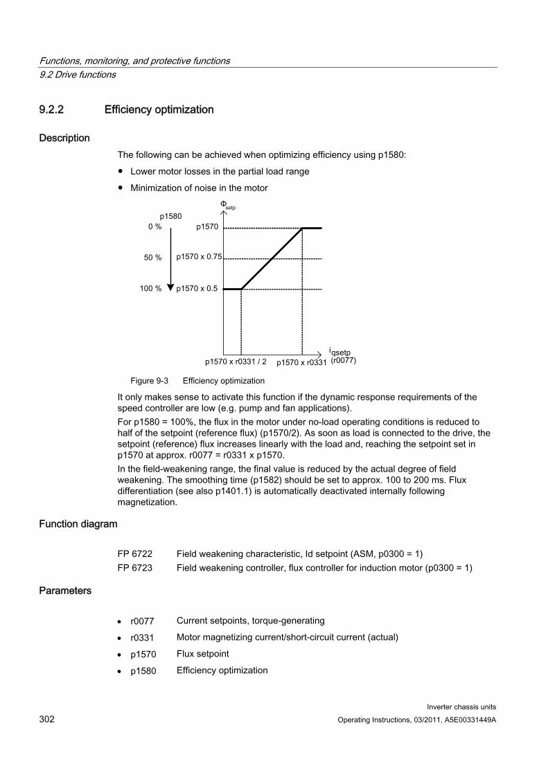
Functions, monitoring, and protective functions 9.2 Drive functions
Inverter chassis units 302 Operating Instructions, 03/2011, A5E00331449A
9.2.2 Efficiency optimization
Description The following can be achieved when optimizing efficiency using p1580:
Lower motor losses in the partial load range
Minimization of noise in the motor
Figure 9-3 Efficiency optimization
It only makes sense to activate this function if the dynamic response requirements of the speed controller are low (e.g. pump and fan applications). For p1580 = 100%, the flux in the motor under no-load operating conditions is reduced to half of the setpoint (reference flux) (p1570/2). As soon as load is connected to the drive, the setpoint (reference) flux increases linearly with the load and, reaching the setpoint set in p1570 at approx. r0077 = r0331 x p1570. In the field-weakening range, the final value is reduced by the actual degree of field weakening. The smoothing time (p1582) should be set to approx. 100 to 200 ms. Flux differentiation (see also p1401.1) is automatically deactivated internally following magnetization.
Function diagram FP 6722 Field weakening characteristic, Id setpoint (ASM, p0300 = 1) FP 6723 Field weakening controller, flux controller for induction motor (p0300 = 1)
Parameters r0077 Current setpoints, torque-generating
r0331 Motor magnetizing current/short-circuit current (actual)
p1570 Flux setpoint
p1580 Efficiency optimization
Functions, monitoring, and protective functions 9.2 Drive functions
Inverter chassis units Operating Instructions, 03/2011, A5E00331449A 303
9.2.3 Fast magnetization for induction motors
Description Fast magnetization for induction motors is used to reduce delay time during magnetization.
Features Rapid flux build-up by impressing a field-producing current at the current limit, which
considerably reduces the magnetization time.
If the "Flying restart" function is activated, the excitation build-up time set in p0346 is still used.
Commissioning Parameter setting p1401.6 = 1 is necessary to activate fast magnetization.
This setting initiates the following sequence during motor starting:
The field-producing current setpoint jumps to its limit value: 0.9*r0067 (Imax).
The flux increases as fast as physically possible with the specified current.
The flux setpoint r0083 is made to follow accordingly.
As soon as the flux threshold value programmed in p1573 is reached (min.: 10%, max. 200%, factory setting: 100%), excitation ceases and the speed setpoint is enabled. The flux threshold value must not be set too low for a large load because the torque-producing current is limited during magnetization.
Note
The flux threshold value set in parameter p1573 is effective only if the actual flux during magnetization reaches the value programmed in p1573 before the timer set in p0346 runs down.
The flux is increased further until the flux setpoint in p1570 has been reached.
The field-producing current setpoint is reduced by means of a flux controller with P gain (p1590) and the parameterized smoothing factor (p1616).
Functions, monitoring, and protective functions 9.2 Drive functions
Inverter chassis units 304 Operating Instructions, 03/2011, A5E00331449A
Notes When quick magnetization is selected (p1401.6 = 1), smooth starting is deactivated internally and alarm A07416 displayed.
When the stator resistance identification function is active (see p0621 "Identification of stator resistance after restart") is active, quick magnetization is deactivated internally and alarm A07416 displayed.
The parameter does not work when combined with the "flying restart" function (see p1200), i.e. flying restart is performed without quick magnetization.
Function diagram FP 6491 Flux control configuration FP 6722 Field weakening characteristic, Id setpoint (ASM, p0300 = 1) FP 6723 Field weakening controller, flux controller (ASM, p0300 = 1)
Parameter p0320 Motor rated magnetization current/short-circuit current
p0346 Motor excitation build-up time
p0621 Stator resistance identification after restart
p0640 Current limit
p1401 Flux control configuration
p1570 Flux setpoint
p1573 Flux threshold value magnetization
p1590 Flux controller P gain
p1616 Current setpoint smoothing time
Functions, monitoring, and protective functions 9.2 Drive functions
Inverter chassis units Operating Instructions, 03/2011, A5E00331449A 305
9.2.4 Vdc control
Description The “Vdc control” function can be activated using the appropriate measures if an overvoltage or undervoltage is present in the DC link.
Overvoltage in the DC link
– Typical cause: The drive is operating in regenerative mode and is supplying too much energy to the DC link.
– Remedy: Reduce the regenerative torque to maintain the DC link voltage within permissible limits.
Note
When switching off or during rapid load changes, if failure often arises and fault F30002 "DC link overvoltage" is reported, you may be able to improve the situation by increasing the gain factor for the Vdc controller p1250 (p1290), e.g. from "1.00" to "2.00".
Undervoltage in the DC link
– Typical cause: Failure of the supply voltage or supply for the DC link.
– Remedy: Specify a regenerative torque for the rotating drive to compensate the existing losses, thereby stabilizing the voltage in the DC link This process is known as kinetic buffering. Kinetic buffering is only possible as long as energy is generated by the movement of the drive.
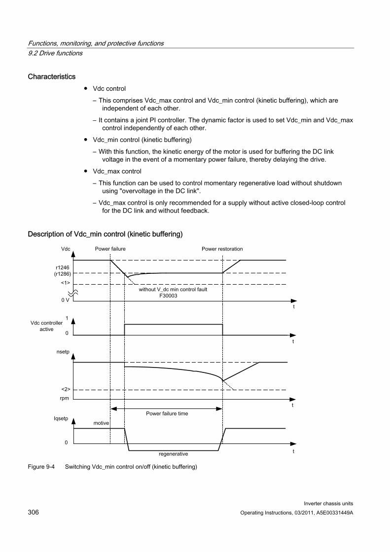
Functions, monitoring, and protective functions 9.2 Drive functions
Inverter chassis units 306 Operating Instructions, 03/2011, A5E00331449A
Characteristics Vdc control
– This comprises Vdc_max control and Vdc_min control (kinetic buffering), which are independent of each other.
– It contains a joint PI controller. The dynamic factor is used to set Vdc_min and Vdc_max control independently of each other.
Vdc_min control (kinetic buffering)
– With this function, the kinetic energy of the motor is used for buffering the DC link voltage in the event of a momentary power failure, thereby delaying the drive.
Vdc_max control
– This function can be used to control momentary regenerative load without shutdown using "overvoltage in the DC link".
– Vdc_max control is only recommended for a supply without active closed-loop control for the DC link and without feedback.
Description of Vdc_min control (kinetic buffering)
Figure 9-4 Switching Vdc_min control on/off (kinetic buffering)
Functions, monitoring, and protective functions 9.2 Drive functions
Inverter chassis units Operating Instructions, 03/2011, A5E00331449A 307
Note
Kinetic buffering must only be activated when the optional components (TM31, SMC30, VSM, etc.) are supplied by an external voltage source.
When Vdc_min control is enabled with p1240 = 2.3 (p1280), it is activated if the power fails when the Vdc_min switch-in level (r1246 (r1286)) is undershot. In general, the regenerative power (braking energy) of the drive machine generated when the motor speed is reduced is used to buffer the DC link voltage of the converter; in other words, when Vdc_min control is active, the motor speed no longer follows the main setpoint and can be reduced to zero. The SINAMICS system continues operating until the shutdown threshold of the DC link voltage is undershot (see "Switching Vdc_min control on/off" <1>).
Note
All parameter specifications in parentheses refer to V/f control.
V/f control The Vdc_min controller acts on the speed setpoint channel. When Vdc_min control is active, the drive setpoint speed is reduced so that the drive becomes regenerative.
Speed control The Vdc_min controller acts on the speed controller output and affects the torque-generating current setpoint. When Vdc_min control is active, the torque-generating current setpoint is reduced so that the drive becomes regenerative.
If the power fails, the DC link voltage decreases due to the lack of power from the supply system. When the DC link voltage threshold set via parameter p1245 (p1285) is reached, the Vdc_min controller is activated. Due to the PID properties of the controller, the motor speed is reduced to the extent that the regenerative drive energy maintains the DC link voltage at the level set in p1245 (p1285). The kinetic energy of the drive governs the dropout characteristic of the motor speed and, in turn, the buffering duration. In centrifugal mass drives (e.g. fans), buffering can last a few seconds. In drives with a low centrifugal mass (e.g. pumps), however, buffering can last just 100 – 200 ms. When the power is restored, the Vdc_min controller is deactivated and the drive is ramped up to its setpoint speed at the ramp-function generator ramp. Alarm A7402 (drive: DC link voltage minimum controller active) is issued while the Vdc_min controller is active.
If the drive can no longer generate any regenerative energy (because, for example, it is almost at a standstill), the DC link voltage continues to drop. If the minimum DC link voltage is undershot (see "Switching Vdc_min control on/off" <1>), the drive is switched off with fault F30003 (power unit: DC link undervoltage).
If a speed threshold set with parameter p1257 (p1297) for active Vdc_min control (see "Switching Vdc_min control on/off" <2>) is undershot, the drive is shut down with F7405 (drive: kinetic buffering minimum speed undershot).
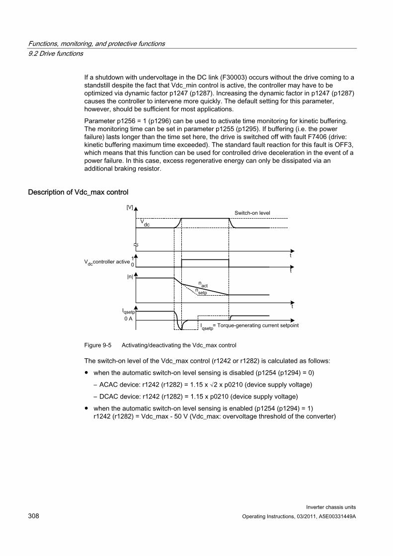
Functions, monitoring, and protective functions 9.2 Drive functions
Inverter chassis units 308 Operating Instructions, 03/2011, A5E00331449A
If a shutdown with undervoltage in the DC link (F30003) occurs without the drive coming to a standstill despite the fact that Vdc_min control is active, the controller may have to be optimized via dynamic factor p1247 (p1287). Increasing the dynamic factor in p1247 (p1287) causes the controller to intervene more quickly. The default setting for this parameter, however, should be sufficient for most applications.
Parameter p1256 = 1 (p1296) can be used to activate time monitoring for kinetic buffering. The monitoring time can be set in parameter p1255 (p1295). If buffering (i.e. the power failure) lasts longer than the time set here, the drive is switched off with fault F7406 (drive: kinetic buffering maximum time exceeded). The standard fault reaction for this fault is OFF3, which means that this function can be used for controlled drive deceleration in the event of a power failure. In this case, excess regenerative energy can only be dissipated via an additional braking resistor.
Description of Vdc_max control
Figure 9-5 Activating/deactivating the Vdc_max control
The switch-on level of the Vdc_max control (r1242 or r1282) is calculated as follows:
when the automatic switch-on level sensing is disabled (p1254 (p1294) = 0)
– ACAC device: r1242 (r1282) = 1.15 x √2 x p0210 (device supply voltage)
– DCAC device: r1242 (r1282) = 1.15 x p0210 (device supply voltage)
when the automatic switch-on level sensing is enabled (p1254 (p1294) = 1) r1242 (r1282) = Vdc_max - 50 V (Vdc_max: overvoltage threshold of the converter)
Functions, monitoring, and protective functions 9.2 Drive functions
Inverter chassis units Operating Instructions, 03/2011, A5E00331449A 309
Function diagram FP 6220 (FP 6320) Vdc_max controller and Vdc_min controller
Parameters p1240 (p1280) Vdc controller configuration
r1242 (r1282) Vdc_min controller switch-in level
p1243 (p1283) Vdc_max controller dynamic factor
p1245 (p1285) Vdc_min controller switch-in level
r1246 (r1286) Vdc_min controller switch-in level
p1247 (p1287) Vdc_min controller dynamic factor
(p1288) Vdc_max controller ramp-function generator feedback factor (V/f)
p1249 (p1289) Vdc_max controller speed threshold
p1250 (p1290) Vdc controller proportional gain
p1251 (p1291) Vdc controller integral action time
p1252 (p1292) Vdc controller derivative-action time
(p1293) Vdc_min controller output limit (V/f)
p1254 (p1294) Vdc_max controller automatic ON level detection
p1255 (p1295) Vdc_min controller time threshold
p1256 (p1296) Vdc_min controller response
p1257 (p1297) Vdc_min controller speed threshold
r1258 (r1298) Vdc controller output
Functions, monitoring, and protective functions 9.2 Drive functions
Inverter chassis units 310 Operating Instructions, 03/2011, A5E00331449A
9.2.5 Automatic restart function
Description The automatic restart function automatically restarts the cabinet unit after an undervoltage or a power failure. The alarms present are acknowledged and the drive is restarted automatically.
The drive can be restarted using:
The standard procedure starting from standstill, or
The flying restart function. For drives with low moments of inertia and load torques facilitating the stopping of the drive within a matter of seconds (e.g., pump drives with water gauges), starting from standstill is recommended.
Note
The flying restart function can also be activated for drives with large moments of inertia (such as fan drives). This enables you to switch to the motor that is still rotating.
WARNING If p1210 is set to values >1, the motor can be restarted automatically without the need to issue the ON command.
In the event of prolonged power failures and when the automatic restart function is activated (p1210 > 1), the drive may have been at a standstill for a long time and mistakenly considered to have been switched off.
For this reason, entering the area around the drive when it is in this condition can cause death, serious injury, or considerable material damage.
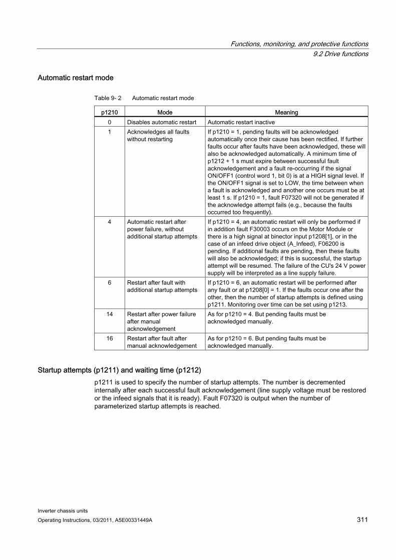
Functions, monitoring, and protective functions 9.2 Drive functions
Inverter chassis units Operating Instructions, 03/2011, A5E00331449A 311
Automatic restart mode
Table 9- 2 Automatic restart mode
p1210 Mode Meaning 0 Disables automatic restart Automatic restart inactive 1 Acknowledges all faults
without restarting If p1210 = 1, pending faults will be acknowledged automatically once their cause has been rectified. If further faults occur after faults have been acknowledged, these will also be acknowledged automatically. A minimum time of p1212 + 1 s must expire between successful fault acknowledgement and a fault re-occurring if the signal ON/OFF1 (control word 1, bit 0) is at a HIGH signal level. If the ON/OFF1 signal is set to LOW, the time between when a fault is acknowledged and another one occurs must be at least 1 s. If p1210 = 1, fault F07320 will not be generated if the acknowledge attempt fails (e.g., because the faults occurred too frequently).
4 Automatic restart after power failure, without additional startup attempts
If p1210 = 4, an automatic restart will only be performed if in addition fault F30003 occurs on the Motor Module or there is a high signal at binector input p1208[1], or in the case of an infeed drive object (A_Infeed), F06200 is pending. If additional faults are pending, then these faults will also be acknowledged; if this is successful, the startup attempt will be resumed. The failure of the CU's 24 V power supply will be interpreted as a line supply failure.
6 Restart after fault with additional startup attempts
If p1210 = 6, an automatic restart will be performed after any fault or at p1208[0] = 1. If the faults occur one after the other, then the number of startup attempts is defined using p1211. Monitoring over time can be set using p1213.
14 Restart after power failure after manual acknowledgement
As for p1210 = 4. But pending faults must be acknowledged manually.
16 Restart after fault after manual acknowledgement
As for p1210 = 6. But pending faults must be acknowledged manually.
Startup attempts (p1211) and waiting time (p1212) p1211 is used to specify the number of startup attempts. The number is decremented internally after each successful fault acknowledgement (line supply voltage must be restored or the infeed signals that it is ready). Fault F07320 is output when the number of parameterized startup attempts is reached.
Functions, monitoring, and protective functions 9.2 Drive functions
Inverter chassis units 312 Operating Instructions, 03/2011, A5E00331449A
If p1211 = x, x + 1 startup attempts will be made.
Note
A startup attempt starts immediately when the fault occurs.
The faults are acknowledged automatically at intervals of half the waiting time p1212.
Following successful acknowledgement and restoration of the voltage, the system is automatically powered up again.
The startup attempt has been completed successfully once the flying restart and magnetization of the motor (induction motor) has been completed (r0056.4 = 1) and one additional second has expired. The startup counter is not reset to the initial value p1211 until this point.
If additional faults occur between successful acknowledgement and the end of the startup attempt, then the startup counter, when it is acknowledged, is also decremented.
Automatic restart monitoring time (p1213) p1213[0] = Monitoring time for restart
The monitoring time starts when the faults are detected. If the automatic acknowledgements are not successful, the monitoring time will continue. If the drive has not successfully restarted by the time the monitoring time expires (flying restart and motor magnetization must have been completed: r0056.4 = 1), fault F07320 is output. Monitoring is deactivated by setting p1213 = 0.
If p1213 is set to a value lower than the sum of p1212, the magnetization time r0346 and the additional delay time due to flying restart, then fault F07320 will be generated on every restart attempt. If, for p1210 = 1, the time in p1213 is set to a value lower than p1212, then fault F07320 will also be generated on every restart attempt. The monitoring time must be extended if the faults that occur cannot be immediately and successfully acknowledged.
For p1210 = 14, 16 manual acknowledgement of the pending fault must take place within the time in p1213 index 0. Otherwise the fault F07320 is generated after the time set.
p1213[1] = Monitoring time for resetting the starting counter
The starting counter (see r1214) is only reset to starting value p1211 once the time in p1213 index[1] has expired after a successful restart. The delay time is not effective for error acknowledgment without an automatic restart (p1210 = 1). If the power supply fails (blackout), the wait time only starts once the power has been restored and the Control Unit is ramped up. The starting counter is reset to the starting value p1211, if F07320 occurred, the switch-on command is recalled and the fault acknowledged.
If starting value p1211 or mode p1210 is changed, the starting counter is immediately updated.
Functions, monitoring, and protective functions 9.2 Drive functions
Inverter chassis units Operating Instructions, 03/2011, A5E00331449A 313
Set fault number without automatic restart (p1206) Up to 10 fault numbers for which the automatic restart should not be effective can be selected via p1206[0...9].
The parameter is only effective if p1210 = 6 and p1210 = 16.
Parameters p1206 [0...9] Set fault number without automatic restart
p1210 Automatic restart mode
p1211 Automatic restart, start attempts
p1212 Automatic restart, delay time start attempts
p1213 Automatic restart monitoring time
r1214 Automatic restart status
Settings To prevent the motor from switching to phase opposition when the drive is being restarted, there is a delay while the motor demagnetizes (t = 2.3 x motor magnetization time constant). Once this time has elapsed, the inverter is enabled and the motor is supplied with power.
Functions, monitoring, and protective functions 9.2 Drive functions
Inverter chassis units 314 Operating Instructions, 03/2011, A5E00331449A
9.2.6 Flying restart
Description The "Flying restart" function (enabled via p1200) allows the converter to switch to a motor that is still rotating. Switching on the converter without the flying restart function would not allow any flux to build up in the motor while it is rotating. Since the motor cannot generate any torque without flux, this can cause it to switch off due to overcurrent (F07801).
The flying restart function first determines the speed of the drive with which V/f or vector control is initialized so that the converter and motor frequency can be synchronized.
During the standard start-up procedure for the converter, the motor must be at a standstill. The converter then accelerates the motor to the setpoint speed. In many cases, however, the motor is not at a standstill.
Two different situations are possible here:
The drive rotates as a result of external influences, such as water (pump drives) or air (fan drives). In this case, the drive can also rotate against the direction of rotation.
The drive rotates as a result of a previous shutdown (e.g. OFF 2 or a power failure). The drive slowly coasts to a standstill as a result of the kinetic energy stored in the drive train (example: induced-draft fan with a high moment of inertia and a steeply descending load characteristic in the lower speed range).
In accordance with the setting chosen (p1200), the flying restart function is activated in the following situations:
Once power has been restored and the automatic restart function is active
After a shutdown with the OFF2 command (pulse inhibit) when the automatic restart function is active
When the ON command is issued.
Note
The flying restart function must be used when the motor may still be running or is being driven by the load to prevent shutdowns due to overcurrent (F7801).
Note
If the value set for parameter p1203 (search speed factor) is higher, the search curve is flatter and, as a result, the search time is longer. A lower value has the opposite effect.
In motors with a low moment of inertia, the flying restart function can cause the drive to accelerate slightly.
In group drives, the flying restart function should not be activated due to the different coasting properties of the individual motors.
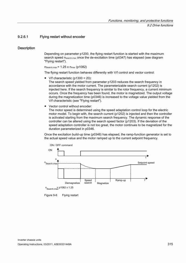
Functions, monitoring, and protective functions 9.2 Drive functions
Inverter chassis units Operating Instructions, 03/2011, A5E00331449A 315
9.2.6.1 Flying restart without encoder
Description Depending on parameter p1200, the flying restart function is started with the maximum search speed nsearch,max once the de-excitation time (p0347) has elapsed (see diagram "Flying restart").
nSearch,max = 1.25 x nmax (p1082)
The flying restart function behaves differently with V/f control and vector control:
V/f characteristic (p1300 < 20): The search speed yielded from parameter p1203 reduces the search frequency in accordance with the motor current. The parameterizable search current (p1202) is injected here. If the search frequency is similar to the rotor frequency, a current minimum occurs. Once the frequency has been found, the motor is magnetized. The output voltage during the magnetization time (p0346) is increased to the voltage value yielded from the V/f characteristic (see "Flying restart").
Vector control without encoder: The motor speed is determined using the speed adaptation control loop for the electric motor model. To begin with, the search current (p1202) is injected and then the controller is activated starting from the maximum search frequency. The dynamic response of the controller can be altered using the search speed factor (p1203). If the deviation of the speed adaptation controller is not too great, the motor continues to be magnetized for the duration parameterized in p0346.
Once the excitation build-up time (p0346) has elapsed, the ramp-function generator is set to the actual speed value and the motor ramped up to the current setpoint frequency.
Figure 9-6 Flying restart
Functions, monitoring, and protective functions 9.2 Drive functions
Inverter chassis units 316 Operating Instructions, 03/2011, A5E00331449A
WARNING When the flying restart (p1200) function is active, the drive may still be accelerated by the detection current despite the fact that it is at standstill and the setpoint is 0!
For this reason, entering the area around the drive when it is in this condition can cause death, serious injury, or considerable material damage.
Flying restart without encoder for long cables In the case of long motor cables, the procedure described above can lead to problems during a flying restart. In such cases, the following settings can improve the flying restart function:
Enter the cable resistance in parameter p0352 before motor data identification.
Set the parameter p1203 to at least 300%. With this setting, flying restart takes longer than for values below 300%.
Note
To optimize the flying restart, a trace recording should be used to check the function. If necessary, you can improve the result by making settings for parameters p1202 and p1203.
9.2.6.2 Flying restart with encoder
Description The flying restart function behaves differently with V/f control and vector control:
V/f characteristic (p1300 < 20): Flying restart without encoder (see "Flying restart without encoder")
Vector control with encoder: Since the speed is known from the start, the motor can be magnetized immediately at the appropriate frequency. The duration of magnetization is specified in p0346. Once the excitation build-up time has elapsed, the ramp-function generator is set to the actual speed value and the motor ramped up to the current setpoint speed.
WARNING
When the flying restart (p1200) function is active, the drive may still be accelerated by the detection current despite the fact that it is at standstill and the setpoint is 0.
For this reason, entering the area around the drive when it is in this condition can cause death, serious injury, or considerable material damage.
Functions, monitoring, and protective functions 9.2 Drive functions
Inverter chassis units Operating Instructions, 03/2011, A5E00331449A 317
9.2.6.3 Parameters p0352 Cable resistance
p1200 Flying restart operating mode
0: Flying restart inactive 1: Flying restart always active (start in setpoint direction) 2: Flying restart active after On, error, OFF2 (start in setpoint direction) 3: Flying restart active after error, OFF2 (start in setpoint direction) 4: Flying restart always active (start only in setpoint direction) 5: Flying restart active after On, error, OFF2 (start only in setpoint
direction) 6: Flying restart active after error, OFF2 (start only in setpoint direction)
p1202 Flying restart search current
p1203 Flying restart search speed factor
r1204 Flying restart, V/f control status
r1205 Flying restart, vector control status
Note
For p1200 = 1, 2, 3, the following applies: Search in both directions, start only in the setpoint direction.
For p1200 = 4, 5, 6, the following applies: Search only in the setpoint direction.
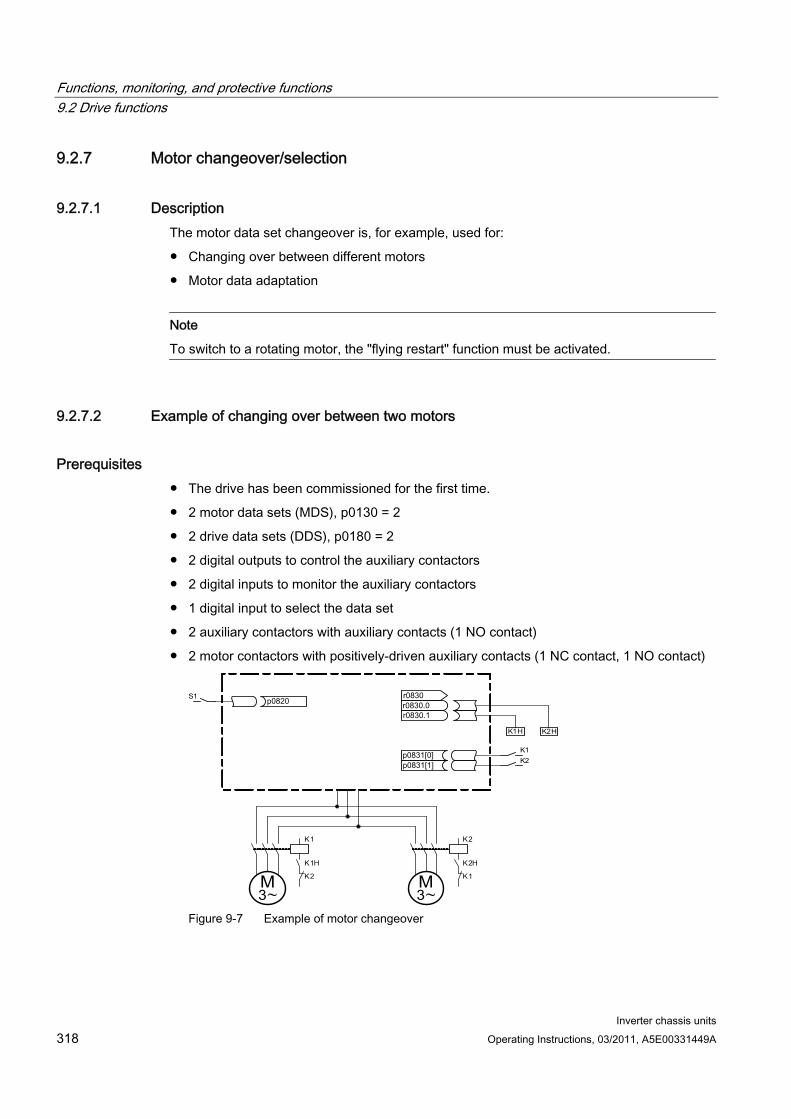
Functions, monitoring, and protective functions 9.2 Drive functions
Inverter chassis units 318 Operating Instructions, 03/2011, A5E00331449A
9.2.7 Motor changeover/selection
9.2.7.1 Description The motor data set changeover is, for example, used for:
Changing over between different motors
Motor data adaptation
Note
To switch to a rotating motor, the "flying restart" function must be activated.
9.2.7.2 Example of changing over between two motors
Prerequisites The drive has been commissioned for the first time.
2 motor data sets (MDS), p0130 = 2
2 drive data sets (DDS), p0180 = 2
2 digital outputs to control the auxiliary contactors
2 digital inputs to monitor the auxiliary contactors
1 digital input to select the data set
2 auxiliary contactors with auxiliary contacts (1 NO contact)
2 motor contactors with positively-driven auxiliary contacts (1 NC contact, 1 NO contact)
~ M 3
K 1
K 1 H
K 2
K 2
K 2 H
K 1
~ M 3
K 1 H K 2 H
K 1 K 2
S 1
Figure 9-7 Example of motor changeover
Functions, monitoring, and protective functions 9.2 Drive functions
Inverter chassis units Operating Instructions, 03/2011, A5E00331449A 319
Table 9- 3 Settings for the motor changeover example
Parameters Settings Comment p0130 2 Configure 2 MDS p0180 2 Configure 2 DDS p0186[0..1] 0, 1 The MDS are assigned to the DDS. p0820 Digital input, DDS selection p0821 to p0824 0
The digital input to change over the motor is selected via the DDS. Binary coding is used (p0820 = bit 0, etc.).
p0826[0..1] 1, 2 Different numbers mean different thermal models. p0827[0..1] 0, 1 The bits of r0830 are assigned to the MDSs. If p0827[0] = 0,
for example, bit r0830.0 is set via DDS0 when MDS0 is selected.
r0830.0 and r0830.1 Digital outputs, auxiliary contactors
The digital outputs for the auxiliary contactors are assigned to the bits.
p0831[0..1] Digital inputs, auxiliary contacts The digital inputs for the feedback signal of the motor contactors are assigned.
p0833.00 and .01 0, 0 The drive controls the contactor circuit and pulse inhibition.
Motor changeover sequence Pulse suppression:
The pulses are suppressed following the selection of a new drive data set using p0820 to p0824.
Open motor contactor: Motor contactor 1 is opened (r0830 = 0) and the status bit "Motor changeover active" (r0835.0) is set.
Change over drive data set: The requested data set is activated (r0051 = data set currently effective, r0837 = requested data set).
Energize motor contactor: After the feedback signal (motor contactor opened) from motor contactor 1, the appropriate bit of r0830 is set and motor contactor 2 is energized.
Enable pulses: After the feedback signal (motor contactor closed) from motor contactor 2, the bit "motor data set changeover active" (r0835.0) is reset and the pulses are enabled. The motor has now been changed over.
9.2.7.3 Function diagram FP 8565 Drive Data Set (DDS) FP 8575 Motor Data Sets (MDS)
Functions, monitoring, and protective functions 9.2 Drive functions
Inverter chassis units 320 Operating Instructions, 03/2011, A5E00331449A
9.2.7.4 Parameters r0051 Drive data set DDS effective
p0130 Motor data sets (MDS) number
p0180 Drive data set (DDS) number
p0186 Motor data sets (MDS) number
p0819[0...2] Copy drive data set DDS
p0820 BI: Drive data set selection DDS, bit 0
p0821 BI: Drive data set selection DDS, bit 1
p0822 BI: Drive data set selection DDS, bit 2
p0823 BI: Drive data set selection DDS, bit 3
p0824 BI: Drive data set selection DDS, bit 4
p0826 Motor changeover, motor number
p0827 Motor changeover status word bit number
p0828 Motor changeover, feedback signal
r0830 Motor changeover, status
p0831 Motor changeover, contactor feedback signal
p0833 Data set changeover configuration
9.2.8 Friction characteristic curve
Description The friction characteristic is used to compensate for the frictional torque of the motor and driven load. A friction characteristic allows the speed controller to be pre-controlled and improves the control response..
10 points along the characteristic are used for the friction characteristic. The coordinates of every interpolation point are defined by a speed parameter (p382x) and a torque parameter (p383x) (point 1 = p3820 and p3830).
Features There are 10 points along the characteristic to represent the friction characteristic.
An automatic function supports the friction characteristic plot.
A connector output (r3841) can be interconnected as friction torque (p1569).
The friction characteristic can be activated and de-activated (p3842).
Functions, monitoring, and protective functions 9.2 Drive functions
Inverter chassis units Operating Instructions, 03/2011, A5E00331449A 321
Commissioning Speeds for making measurements as a function of the maximum speed p1082 are pre-assigned in p382x when commissioning the drive system for the first time. These can be appropriately changed corresponding to the actual requirements.
The automatic friction characteristic plot can be activated using p3845. The characteristic is then plotted the next time that it is enabled.
The following settings are possible:
p3845 = 0 Friction characteristic plot de-activated
p3845 = 1 Friction characteristic plot activated, all directions The friction characteristic is plotted in both directions of rotation. The result of the positive and negative measurement is averaged and entered into p383x.
p3845 = 2 Friction characteristic plot activated, positive direction
p3845 = 3 Friction characteristic plot activated, negative direction
p3847 (friction characteristic plot warm-up period) can be used to set a time for the drive to warm up to the specified operating temperature. During this time, the drive is brought up to and kept at the greatest speed set for plotting the friction characteristic, so that the drive warms up to the operating temperature. Then measurement is started with the highest speed.
DANGER When the friction characteristic is plotted, the drive can cause the motor to move. As a result, the motor may reach maximum speed.
When commissioning the drive, the EMERGENCY STOP functions must function perfectly. To protect the machines and personnel, the relevant safety regulations must be observed.
Function diagram FP 7010 Friction characteristic curve
Functions, monitoring, and protective functions 9.2 Drive functions
Inverter chassis units 322 Operating Instructions, 03/2011, A5E00331449A
Parameter p3820 Friction characteristic, value n0
...
p3839 Friction characteristic, value M9
r3840 Friction characteristic status word
r3841 Friction characteristic, output
p3842 Activate friction characteristic
p3845 Activate friction characteristic plot
p3846 Friction characteristic plot ramp-up/ramp-down time
p3847 Friction characteristic plot warm-up period
9.2.9 Armature short-circuit braking, internal voltage protection, DC braking
9.2.9.1 General The "External armature short-circuit" function for permanent-magnet synchronous motors initiates an external contactor which short-circuits the motor via resistors when the pulses are canceled. This reduces the kinetic energy of the motor.
The "Internal armature short-circuit braking" function for permanent-magnet synchronous motors short-circuits a half-bridge in the power unit to control the motor power consumption, thus braking the motor.
The "Internal voltage protection" function for permanent-magnet synchronous motors protects the DC link capacitors when the pulses are cancelled by short-circuiting a half-bridge in the power unit.
The "DC braking" function for induction motors injects direct current into the motor, thus braking the motor.
Functions, monitoring, and protective functions 9.2 Drive functions
Inverter chassis units Operating Instructions, 03/2011, A5E00331449A 323
9.2.9.2 External armature short-circuit braking
Description External armature short-circuit braking is only available for synchronous motors. It is mainly required when braking in a hazardous situation, if controlled braking using the drive converter is no longer possible, (e.g. in the case of power failure, EMERGENCY OFF etc.) or if no regenerative infeed is used. In this case, the motor stator windings are short-circuited via external braking resistors. This means that an additional resistance is inserted in the motor circuit that supports reducing the kinetic energy of the motor. The external armature short-circuit is activated via p1231 = 1 (with contactor feedback signal) or p1231 = 2 (without contactor feedback signal). It is initiated when the pulses are canceled. This function controls an external contactor via output terminals, which then short-circuits the motor through resistors when the pulses are canceled. A permanent-magnet synchronous motor (p0300 = 2xx) is required in order to use the external armature short-circuit.
CAUTION Only short-circuit proof motors may be used, or suitable resistances must be used for short-circuiting the motor.
Note
In case of incorrect parameterization (e.g. induction motor and external armature short-circuit selected), the fault F07906 "Armature short-circuit / internal voltage protection: parameterization error" is generated.
Function diagram FP 7014 Technology functions - External armature short circuit
Parameters p0300: Mot type selection
p1230 BI: Armature short-circuit/DC brake activation
p1231 Armature short-circuit/DC brake configuration 1: External armature short-circuit with contactor feedback signal 2: External armature short-circuit without contactor feedback signal
p1235 BI: External armature short-circuit, contactor feedback signal
p1236 External armature short-circuit, contactor feedback signal monitoring time
p1237 External armature short-circuit, delay time when opening
r1238 CO: External armature short-circuit state
r1239 CO/BO: Armature short-circuit / DC brake status word
Functions, monitoring, and protective functions 9.2 Drive functions
Inverter chassis units 324 Operating Instructions, 03/2011, A5E00331449A
9.2.9.3 Internal armature short-circuit braking
Description Internal armature short-circuit braking is only available for synchronous motors. It is mainly required when braking in a hazardous situation, if controlled braking using the drive converter is no longer possible, (e.g. in the case of power failure, EMERGENCY OFF etc.) or if no regenerative infeed is used. In this case, the motor stator windings are short-circuited via a half-bridge in the power unit. This means that an additional resistance is inserted in the motor circuit that supports reducing the kinetic energy of the motor.
The internal armature short-circuit is configured p1231 = 4 and activated via p1230. It is initiated when the pulses are canceled.
A permanent-magnet synchronous motor (p0300 = 2xx) is required in order to use the internal armature short-circuit.
DANGER
When the armature short-circuit is active, after the pulses have been cancelled all the motor terminals are at half the DC-link potential.
CAUTION Only short-circuit proof motors may be used.
The Power Module / Motor Module must be designed to handle 1.8 times the short-circuit current of the motor.
Function diagram FP 7016 Technology functions - Internal armature short circuit
Parameters p0300: Mot type selection
p1230 BI: Armature short-circuit/DC brake activation
p1231 Armature short-circuit/DC brake configuration 4: Internal armature short-circuit/DC brake
r1239 CO/BO: Armature short-circuit / DC brake status word
Functions, monitoring, and protective functions 9.2 Drive functions
Inverter chassis units Operating Instructions, 03/2011, A5E00331449A 325
9.2.9.4 Internal voltage protection
Description The internal voltage protection prevents the DC link capacitance from being loaded into a field weakening operated motor if the energy regeneration capability from the source voltage is missing.
Depending on the DC link voltage, the Power Module / Motor Module automatically decides whether the armature short-circuit is to be engaged. In this case, the protection remains operative even if the DRIVE-CLiQ connection between the Control Unit and the Power Module / Motor Module is interrupted.
The internal armature short-circuit is configured and activated via p1231 = 3 and activated when a device-specific DC link voltage threshold is reached. It is initiated when the pulses are canceled.
A permanent-magnet synchronous motor (p0300 = 2xx) is required in order to use the internal voltage protection.
DANGER
When the internal voltage protection is active, after the pulses have been cancelled all the motor terminals are at half the DC-link potential.
CAUTION Only short-circuit proof motors may be used.
The Power Module / Motor Module must be designed to handle 1.8 times the short-circuit current of the motor.
The internal voltage protection function cannot be interrupted by a fault response. If an overcurrent occurs while internal voltage protection is active, the Power Module / Motor Module and/or the motor may sustain irreparable damage!
With the internal voltage protection active, the motor must not be powered by an external source for an extended period of time (e.g. by pulling loads or another coupled motor).
Note
In case of incorrect parameterization (e.g. induction motor and internal voltage protection selected), the fault F07906 "Armature short-circuit / internal voltage protection: parameterization error" is generated.
Parameters p0300: Mot type selection
p1231 Armature short-circuit/DC brake configuration 3: Internal voltage protection
Functions, monitoring, and protective functions 9.2 Drive functions
Inverter chassis units 326 Operating Instructions, 03/2011, A5E00331449A
9.2.9.5 DC braking
Description DC braking is only supported for induction motors. It is mainly required when braking in a hazardous situation, if controlled braking using the drive converter is no longer possible, (e.g. in the case of power failure, EMERGENCY OFF etc.) or if no regenerative infeed is used. .
The DC brake is activated via p1231 = 4 or via p1231 = 14. It can be triggered via an input signal p1230 (signal = 1) or a fault response.
Activation of the DC brake via input signal p1231 = 4
If the DC brake is activated by the digital input signal, the first step is that the pulses are blocked for the demagnetization time (p0347) of the motor in order to demagnetize the motor - the parameter p1234 (Speed at the start of DC braking) is ignored.
Then the braking current (p1232) is applied as long as the input is initiated in order to brake the motor or hold it at standstill.
p1231 = 14
The DC brake is released, if during operation a 1-signal is pending at the binector input p1230 and the actual speed is below the starting speed (p1234).
After the preceding demagnetization (p0347) of the motor for the period set in p1233, the braking current p1232 is applied and subsequently switched off automatically.
Cancellation of the input signal for DC braking
If the DC brake is removed, the drive returns to its selected operating mode.
The following applies:
With vector control (closed-loop controlled with or without encoder): The drive is synchronized with the motor frequency if the "Flying restart" function is activated, and then returns to closed-loop controlled mode. If the "Flying restart" function is not active, the drive can only be restarted from standstill without overcurrent fault.
In V/f mode: With the "Flying restart" function activated, the converter frequency is synchronized with the motor frequency, and the drive will then return to V/f mode. If the "Flying restart" function is not activated, the drive can only be restarted from standstill without overcurrent fault.
Functions, monitoring, and protective functions 9.2 Drive functions
Inverter chassis units Operating Instructions, 03/2011, A5E00331449A 327
DC brake as a fault response If the DC brake is activated as a fault response, the motor is initially braked in field-oriented mode along the braking ramp up to the threshold set in p1234 (DC brake starting speed). The slope of the ramp is identical with that of the OFF1 ramp (parameterized using p1082, p1121). Subsequently, the pulses are disabled for the period in p0347 (demagnetizing time) in order to demagnetize the motor. The DC braking will start for the duration set in p1233 (DC braking period).
If an encoder is present, braking will continue until the speed drops to below standstill threshold p1226.
If no encoder is present, only the period in p1233 is effective.
Function diagram FP 7017 Technology functions - DC braking
Parameters p0300: Mot type selection
p1226 Standstill recognition speed threshold
p1230 BI: Armature short-circuit/DC brake activation
p1231 Armature short-circuit/DC brake configuration 4: Internal armature short-circuit/DC brake 14: DC braking under starting speed
p1232 DC braking braking current
p1233 DC braking period
p1234 DC braking start speed
r1239 CO/BO: Armature short-circuit / DC brake status word
p1345 I_max voltage controller proportional gain
p1346 I_max voltage controller integral time
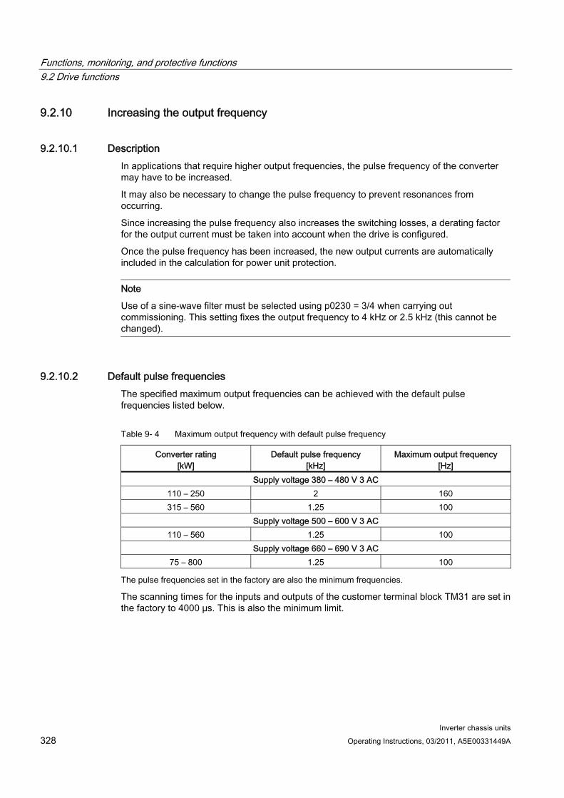
Functions, monitoring, and protective functions 9.2 Drive functions
Inverter chassis units 328 Operating Instructions, 03/2011, A5E00331449A
9.2.10 Increasing the output frequency
9.2.10.1 Description In applications that require higher output frequencies, the pulse frequency of the converter may have to be increased.
It may also be necessary to change the pulse frequency to prevent resonances from occurring.
Since increasing the pulse frequency also increases the switching losses, a derating factor for the output current must be taken into account when the drive is configured.
Once the pulse frequency has been increased, the new output currents are automatically included in the calculation for power unit protection.
Note
Use of a sine-wave filter must be selected using p0230 = 3/4 when carrying out commissioning. This setting fixes the output frequency to 4 kHz or 2.5 kHz (this cannot be changed).
9.2.10.2 Default pulse frequencies The specified maximum output frequencies can be achieved with the default pulse frequencies listed below.
Table 9- 4 Maximum output frequency with default pulse frequency
Converter rating [kW]
Default pulse frequency [kHz]
Maximum output frequency [Hz]
Supply voltage 380 – 480 V 3 AC 110 – 250 2 160 315 – 560 1.25 100
Supply voltage 500 – 600 V 3 AC 110 – 560 1.25 100
Supply voltage 660 – 690 V 3 AC 75 – 800 1.25 100
The pulse frequencies set in the factory are also the minimum frequencies.
The scanning times for the inputs and outputs of the customer terminal block TM31 are set in the factory to 4000 µs. This is also the minimum limit.
Functions, monitoring, and protective functions 9.2 Drive functions
Inverter chassis units Operating Instructions, 03/2011, A5E00331449A 329
9.2.10.3 Increasing the pulse frequency
Description The pulse frequency can be increased in a virtually continuously variable manner to between the value preassigned in the factory and the maximum pulse frequency which can be set.
Procedure Parameter p0009 on the Control Unit must be set to 3 "Basic drive configuration".
Parameter p0112 "Sampling times default setting p0115" of the DO VECTOR must be set to 0 "Expert".
Use p0113 to enter any pulse frequency between 1 kHz and 2 kHz. If a higher pulse frequency is to be set (e.g. 2.2 kHz), this value must be divided by 2 or by 4 to obtain a result between 1 kHz and 2 kHz (e.g. 2.2 kHz divided by 2 is 1.1 kHz).
Not all pulse frequencies are accepted in parameter p0113; in such cases, the alarm "Impermissible value" is output.
If the frequency entered in parameter p0113 is not accepted, parameter r0114[0] recommends a different frequency that can deviate from the entered pulse frequency by several Hertz. This frequency should be entered in p0113.
After entering the frequency in p0113, parameter p0009 on the Control Unit must be set to 0 "Ready" again.
The Control Unit re-initializes. After booting, the pulse frequencies recommended in r0114[i] (i = 1, 2, ...) can be entered in parameter p1800 "Pulse frequency" of the DO VECTOR.
NOTICE
The pulse frequency entered in p1800 must correspond precisely to the value given in r0114[i]; otherwise, the entry will be rejected.
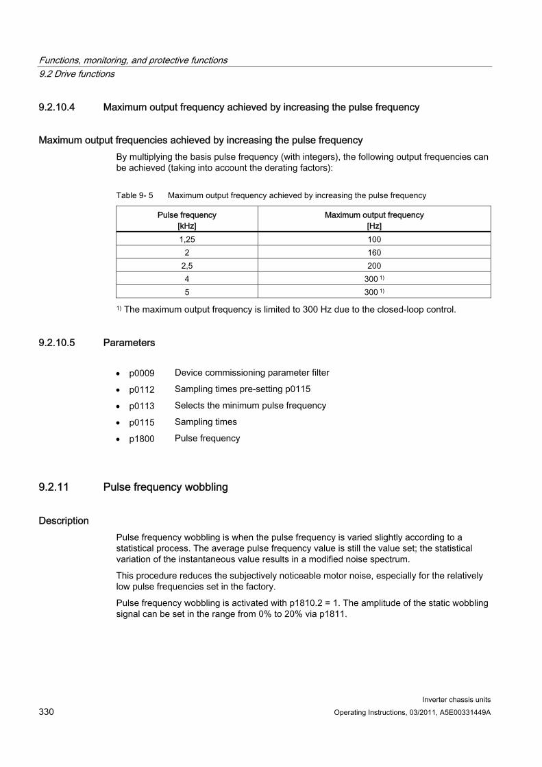
Functions, monitoring, and protective functions 9.2 Drive functions
Inverter chassis units 330 Operating Instructions, 03/2011, A5E00331449A
9.2.10.4 Maximum output frequency achieved by increasing the pulse frequency
Maximum output frequencies achieved by increasing the pulse frequency By multiplying the basis pulse frequency (with integers), the following output frequencies can be achieved (taking into account the derating factors):
Table 9- 5 Maximum output frequency achieved by increasing the pulse frequency
Pulse frequency [kHz]
Maximum output frequency [Hz]
1,25 100 2 160
2,5 200 4 300 1) 5 300 1)
1) The maximum output frequency is limited to 300 Hz due to the closed-loop control.
9.2.10.5 Parameters p0009 Device commissioning parameter filter
p0112 Sampling times pre-setting p0115
p0113 Selects the minimum pulse frequency
p0115 Sampling times
p1800 Pulse frequency
9.2.11 Pulse frequency wobbling
Description Pulse frequency wobbling is when the pulse frequency is varied slightly according to a statistical process. The average pulse frequency value is still the value set; the statistical variation of the instantaneous value results in a modified noise spectrum.
This procedure reduces the subjectively noticeable motor noise, especially for the relatively low pulse frequencies set in the factory.
Pulse frequency wobbling is activated with p1810.2 = 1. The amplitude of the static wobbling signal can be set in the range from 0% to 20% via p1811.
Functions, monitoring, and protective functions 9.2 Drive functions
Inverter chassis units Operating Instructions, 03/2011, A5E00331449A 331
Restrictions Pulse frequency wobbling can only be activated under the following conditions (p1810.2 =
1):
– The drive is pulse suppressed.
– p1800 < 2 x 1000 / p0115[0]
p1811 (Pulse frequency wobbling amplitude) can only be set under the following conditions:
– p1802.2 = 1
– p0230 (output filter) < 3 (no sine-wave filter)
When pulse frequency wobbling is activated and impulses are enabled, the maximum pulse frequency (p1800) can be set as follows:
– For p1811 = 0: p1800 ≤ 2 x 1000 / p0115[0]
– For p1811 > 0: p1800 ≤ 1000 / p0115[0]
When pulse frequency wobbling is activated and impulses are enabled, if the maximum pulse frequency (p1800) is set to be greater than 1000 / p0115[0], then p1811 is set to 0.
When pulse frequency wobbling is activated and impulses are suppressed, if the maximum pulse frequency (p1800) is set to be greater than 2 x 1000 / p0115[0], then p1811 and p1810.2 are set to 0.
Note
If pulse frequency wobbling is deactivated (p1810.2 = 0), then all the indices of parameter p1811 are set to 0.
Parameters p1800 Pulse frequency setpoint
p1810.2 Wobbling activated
p1811[D] Pulse frequency wobbling amplitude
Functions, monitoring, and protective functions 9.2 Drive functions
Inverter chassis units 332 Operating Instructions, 03/2011, A5E00331449A
9.2.12 Runtime (operating hours counter)
Total system runtime The entire system runtime is displayed in r2114 (Control Unit); it is made up of r2114[0] (milliseconds) and r2114[1] (days). Index 0 indicates the system runtime in milliseconds; after reaching 86.400.000 ms (24 hours), the value is reset. Index 1 indicates the system runtime in days.
The value is saved when the system is switched off. Once the drive unit has been switched on, the counter continues to run with the value that was saved the last time the drive was switched off.
Relative system runtime The relative system runtime since the last POWER ON is displayed in p0969 (Control Unit). The value is indicated in milliseconds and the counter overflows after 49 days.
Actual motor operating hours The motor operating hours counter p0650 (drive) resumes when the pulses are enabled. When the pulse enable is withdrawn, the counter is stopped and the value saved.
To store the value, you need a CONTROL UNIT with order number 6SL3040-....-0AA1 and version C or higher.
The counter is deactivated with p0651 = 0.
If the maintenance interval set in p0651 is reached, alarm A01590 is triggered. Once the motor has been maintained, the maintenance interval must be reset.
Operating hours counter for the fan The operating hours of the fan in the power unit are displayed in p0251 (drive).
The number of hours operated can only be reset to 0 in this parameter (e.g. after a fan has been replaced).
The service life of the fan is entered in p0252 (drive).
Alarm A30042 (service life of the fan reached or exceeded) is output when this figure is reached, and also 500 hours beforehand. Evaluation of the fault value in the alarm provides details of the cause of the alarm.
Monitoring is deactivated with p0252 = 0.
Functions, monitoring, and protective functions 9.2 Drive functions
Inverter chassis units Operating Instructions, 03/2011, A5E00331449A 333
9.2.13 Simulation operation
Description The simulation function is predominantly used to simulate the drive without a motor being connected and without a DC link voltage. In this case, it should be noted that the simulation mode can only be activated under an actual DC link voltage of 40 V. If the voltage lies above this threshold, the simulation mode is reset, and a fault message F07826 is issued.
Communications with a higher-level automation system can be tested using the simulation mode. If the drive is also to return actual values, note that it must be switched over to encoderless operation during simulation mode. This means that large parts of the SINAMICS software (e.g., software channel, sequence control, communications, technology function, etc.) can be tested in advance without requiring a motor.
Another application is to test the correct functioning of the Power Module. Especially for drive units with higher power ratings 75 kW (690 V) and 110 kW (400 V), after repairs, it is necessary to test the gating of the power semiconductors. This is done by injecting a low DC voltage as DC link voltage (e.g. 12 V). The drive unit is then powered-up and the pulses enabled. It must be possible to run through all of the pulse patterns of the gating unit software.
This means that the software must allow the pulses to be switched-in and various frequencies approached. If a speed encoder is not being used, then this is generally implemented using V/f control or sensorless closed-loop speed control.
Note
The following functions are de-activated in the simulation mode: – Motor data identification – Motor data identification, rotating without encoder – Pole position identification
No flying restart is carried-out for V/f control and sensorless closed-loop vector control.
Commissioning Simulation is activated using p1272 = 1; the following pre-requisites must be fulfilled:
The drive unit must have been commissioned for the first time (default: Standard induction motors).
The DC link voltage must lie below 40 V (observe the tolerance of the DC link voltage sensing).
Alarm A07825 (simulation mode activated) must be output during simulation operation.
Parameters p1272 Simulation operation
Functions, monitoring, and protective functions 9.2 Drive functions
Inverter chassis units 334 Operating Instructions, 03/2011, A5E00331449A
9.2.14 Direction reversal
Description The direction of rotation of the motor can be reversed using direction reversal via p1821 without having to change the motor rotating field by interchanging two phases on the motor and inverting the encoder signals using p0410.
Reversal via p1821 can be detected from the motor direction of rotation. The speed setpoint and actual value, torque setpoint and actual value remain unchanged, as does the relative position change.
A pulse inhibit must be set prior to attempting reversal.
Reversing can be set differently for each drive data set.
Note
When changing over the drive data set to differently set reversing and with pulse approval, fault F7434 is issued.
Reversing can be observed by checking parameters r0069 (phase currents) and r0089 (phase voltage). The absolute position reference is lost on reversal.
Function diagram FD 4704, 4715 Encoder evaluation FD 6730, 6731 Current control
Parameters r0069 Phase currents actual value
r0089 Phase voltage actual value
p1820 Reverse output phase sequence
p1821 Direction of rotation
Functions, monitoring, and protective functions 9.2 Drive functions
Inverter chassis units Operating Instructions, 03/2011, A5E00331449A 335
9.2.15 Unit changeover
Description Parameters and process variables for input and output can be switched to a suitable units system (SI units, US units or referenced variables (%)) with the help of the unit changeover function.
The following constraints apply to the unit changeover:
Unit changeover is only possible for the "VECTOR" drive object.
Parameters of the rating plate of the drive converter or the motor rating plate can be changed over between SI/US units; however, a per unit representation is not possible.
Once the changeover parameter has been changed, all parameters that are assigned to a unit group depending on this parameter are jointly changed over to the new unit.
A separate parameter is available for selecting technological units (p0595) for the representation of technological variables in the technology controller.
If a changeover is made to referenced variables and the reference variable is subsequently changed, the % value entered in a parameter will not change.
Example:
– With a reference speed of 1500 1/min, a fixed speed of 80 % corresponds to a value of 1200 1/min.
– If the reference speed is changed to 3000 1/min, the value of 80 % is retained and is now 2400 1/min.
Restrictions When a unit changeover occurs, rounding to the decimal places is carried out. This can
mean that the original value might change by up to one decimal place.
If a referenced form is selected and the reference parameters (e.g. p2000) are changed retrospectively, the physical significance of some of the control parameters is also adjusted, which can affect the control behavior.
If the reference variables (p2000 to p2007) are changed in the offline mode in STARTER, there is a risk that the parameter value ranges will be violated. In this case, appropriate fault messages will be displayed when the parameters are loaded to the drive unit.
Functions, monitoring, and protective functions 9.2 Drive functions
Inverter chassis units 336 Operating Instructions, 03/2011, A5E00331449A
Changing over the units The units can be changed over via the AOP30 and via STARTER.
Unit changeover via AOP30 is always carried out immediately. Once the corresponding parameters have been changed, the values affected are displayed in the new selected unit.
If STARTER is used, unit changeover can only take place in offline mode in the configuration screen of the corresponding drive object. The new units are not displayed until after the download ("Load project to target system") and subsequent upload ("Load project to PG") have been completed.
Unit groups Each parameter that can be switched is assigned to a unit group which can be switched within certain limits depending on the group.
This assignment and the units groups for each parameter appear in the parameter list in the SINAMICS List Manual.
The unit groups can be individually switched using 4 parameters (p0100, p0349, p0505 and p0595).
Parameters p0010 Commissioning parameter filter
p0100 IEC/NEMA mot stds
p0349 Selection of units system, motor equivalent circuit diagram data
p0505 Selection of units system
p0595 Selection of technological unit
p0596 Reference variable of technological unit
p2000 Reference frequency/speed
p2001 Reference voltage
p2002 Reference current
p2003 Reference torque
p2004 Reference power
p2005 Reference angle
p2007 Reference acceleration
Functions, monitoring, and protective functions 9.2 Drive functions
Inverter chassis units Operating Instructions, 03/2011, A5E00331449A 337
9.2.16 Derating behavior at increased pulse frequency
Description To reduce motor noise or to increase output frequency, the pulse frequency can be increased relative to the factory setting.
The increase in the pulse frequency normally results in a reduction of the maximum output current (see "Technical data/current derating depending on the pulse frequency").
When commissioning the converter the behavior at overload is adjusted in such a manner that the pulse frequency is variably reduced so that the required power can be obtained.
Characteristics:
The reaction to overload depends on the setting of parameter p0290:
– p0290 = 0: Reduce output current or output frequency
– p0290 = 1: No reduction, shutdown when overload threshold is reached
– p0290 = 2: Reduce the output current or output and pulse frequency (not using I²t).
– p0290 = 3: Reduce the pulse frequency (not using I²t)
For p0290 = 2 at overload first reduce the pulse frequency (and consequently the output frequency) until it has dropped to rated pulse frequency, then reduce the output frequency if overload continues to persist. The rated pulse frequency is half the inverse value of the current controller clock cycle: 0.5 x 1/p0115[0].
Reduction of the pulse frequency is executed in whole multiples based on the rated pulse frequency (5 kHz -> 2.5 kHz -> 1.25 kHz or 4 kHz -> 2 kHz).
After entering the maximum speed in p1082 the system automatically calculates whether the pulse frequency is sufficient for the entered maximum speed, if necessary the pulse frequency is increased automatically to a value that is necessary for this. At overload, then also for p0290 = 2 or 3, this new pulse frequency will no longer be underranged, the downstream reaction (reduce output voltage or switch off) will be triggered.
Exceptions:
With an activated sinus filter (p0230 = 3, 4), this behavior is not permitted because the factory set pulse frequency (2.5 kHz or 4 kHz) should not be changed through this measure. Consequently in this case the selection possibility for the parameter p0290 is limited to "0" and "1".
Activation of the variable pulse frequency At commissioning the parameter p 0290 is automatically set to the value "2". This activates pulse frequency reduction at overload.
Functions, monitoring, and protective functions 9.2 Drive functions
Inverter chassis units 338 Operating Instructions, 03/2011, A5E00331449A
Deactivation of the variable pulse frequency By changing the parameter p0290 to "0" or "1" the variable pulse frequency is deactivated.
Function diagram FP 8014 Signals and monitoring functions - thermal monitoring power unit
Parameter r0036 Power unit overload I2t
r0037 CO: Power unit temperatures
p0115 Sampling times for internal control loops
p0230 Drive filter type, motor side
p0290 Power unit overload response
p1082 Maximum speed
r2135.13 Fault thermal overload power unit
r2135.15 Thermal overload in power unit alarm
Functions, monitoring, and protective functions 9.2 Drive functions
Inverter chassis units Operating Instructions, 03/2011, A5E00331449A 339
9.2.17 Simple brake control
Description The "Simple brake control" is used exclusively for the control of holding brakes. The holding brake is used to secure drives against unwanted motion when deactivated.
The control command for releasing and applying the holding brake is transmitted directly to the converter via DRIVE-CLiQ from the control unit, which logically combines the signals with the system-internal processes and monitors these signals.
The converter then performs the action and controls the output for the holding brake appropriately. The operating principle of the holding brake can be configured using parameter p1215.
[rpm]
[rpm]
p1227
p1228
p1226
p1226
p1216 p1217
t
t
1
1
t
t
1
t
Figure 9-8 Sequence diagram, simple brake control
The start of the closing time for the brake depends on the expiration of the shorter of the two times p1227 (standstill detection monitoring time) and p1228 (pulse cancellation delay time).
WARNING The holding brake must not be used as a service brake.
When holding brakes are used, the special technological and machine-specific conditions and standards for ensuring personnel and machine safety must be observed.
The risks involved must also be evaluated, such as risks associated with suspended axes.
Functions, monitoring, and protective functions 9.2 Drive functions
Inverter chassis units 340 Operating Instructions, 03/2011, A5E00331449A
Features Automatic activation by means of sequence control
Standstill (zero-speed) monitoring
Forced brake release (p0855, p1215)
Application of brake for a 1 signal "unconditionally close holding brake" (p0858)
Application of brake after "Enable speed controller" signal has been canceled (p0856)
Signal connections The holding brake is controlled using free digital outputs on the Control Unit or the TM31 (for option G60). If necessary, control must be realized by means of a relay to connect a holding brake with higher voltage or with higher power demand.
For this, parameter p1215 must be set to "3" (motor holding brake the same as sequence control, connection via BICO) and the appropriate BICO parameters of the selected digital outputs must be interconnected.
Commissioning If p1215 is set to "0" (no brake available) during initial commissioning and a connected brake is recognized, simple brake control is activated automatically (p1215 = 1). In this case, fault F07935 "Motor holding brake detected" appears and must be acknowledged.
CAUTION If parameter p1215 is set to "0" (no brake available) when a brake is actually present, the drive operates against applied brake. This can destroy the brake.
Notes on setting the release (opening) time (p1216):
The release time (p1216) should be set longer than the actual release time of the holding brake. As a result, the drive will not accelerate when the brake is closed.
Notes for setting the closing time (p1217):
The closing time (p1217) should be set longer than the actual closing time of the holding brake. As a result, the pulses are suppressed only after the holding brake is closed.
If the closing time (p1217) is set too low compared to the actual closing time of the holding brake, the load may drop suddenly.
If the closing time (p1217) is set too high compared to the actual closing time of the holding brake, the controller acts against the holding brake and thus reduces its service life.
Functions, monitoring, and protective functions 9.2 Drive functions
Inverter chassis units Operating Instructions, 03/2011, A5E00331449A 341
Function diagram FP 2701 Simple brake control (r0108.14 = 0)
Parameter r0056.4 Magnetizing completed
r0060 CO: Speed setpoint before the setpoint filter
r0063[0...2] CO: Speed actual value
r0108.14 Extended brake control
p0855[C] BI: Unconditionally release holding brake
p0856 BI: Speed controller enabled
p0858 BI: Unconditionally apply holding brake
r0899.12 BO: Holding brake open
r0899.13 BO: Command, close holding brake
p1215 Motor holding brake configuration
p1216 Motor holding brake release time
p1217 Motor holding brake closing time
p1226 Threshold for standstill detection
p1227 Standstill detection monitoring time
p1228 Pulse suppression delay time
p1278 Brake control diagnostic evaluation
Functions, monitoring, and protective functions 9.2 Drive functions
Inverter chassis units 342 Operating Instructions, 03/2011, A5E00331449A
9.2.18 Energy saving indicator for pumps, fans, and compressors
Function of the energy savings indicator This function determines the amount of energy used by pumps, fans, and compressors and compares it with the interpolated energy requirement for similar equipment controlled using conventional throttle control. The amount of energy saved is calculated over the last 100 operating hours and is displayed in kWh. For an operating time of less than 100 hours, the potential energy-saving is interpolated up to 100 operating hours. The pump, fan, or compressor characteristic with the conventional throttle control is specified using 5 adjustable interpolation points.
Background In a conventionally controlled pump, fan or compressor, the flow rate of the medium is controlled using valves or throttles. In so doing, the machine runs constantly at the rated speed. The system efficiency decreases significantly if the flow rate is reduced by means of valves or throttles. The pressure in the system increases. The motor even consumes energy when the valves or throttles are completely closed, i.e., with flow rate Q = 0. In addition, undesirable process-related situations can occur; for example, cavitation in the pumps, fans, and compressors or increased temperature rise of pumps, fans, and compressors and the medium.
As a result of variable speed operation, a drive operating under partial load conditions consumes considerably less energy than with conventional process control using valves or throttles. This applies in particular for pumps, fans, and compressors with parabolic load characteristics. With SINAMICS, a closed-loop control of the flow rate or pressure is achieved by employing closed-loop speed control of the pump, fan or compressor. As a consequence, the plant or system is controlled close to its maximum efficiency over the complete operating range.
In comparison to pumps, fans, and compressors, machines with linear or constant load characteristic (e.g. conveyor drives or positive displacement pumps) have lower potential savings.
Energy saving by using a variable speed drive When a variable speed drive is used, the flow rate of the pump, fan, or compressor is controlled as a function of speed. The flow rate changes proportionally with the speed of the continuous-flow machine. Any existing valve or throttle remains open. Therefore, the equipment works close to optimum efficiency and consumes considerably less energy, particularly in the partial load range, than equipment controlled by means of valves or throttles.
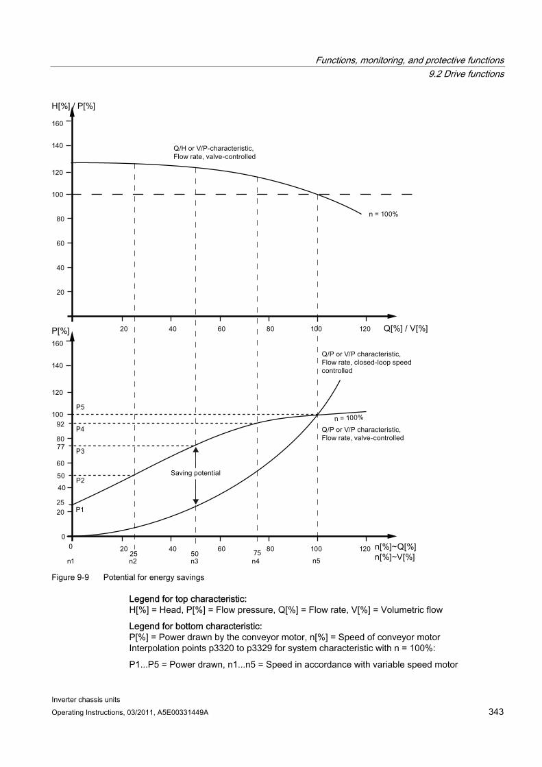
Functions, monitoring, and protective functions 9.2 Drive functions
Inverter chassis units Operating Instructions, 03/2011, A5E00331449A 343
Figure 9-9 Potential for energy savings
Legend for top characteristic: H[%] = Head, P[%] = Flow pressure, Q[%] = Flow rate, V[%] = Volumetric flow
Legend for bottom characteristic: P[%] = Power drawn by the conveyor motor, n[%] = Speed of conveyor motor Interpolation points p3320 to p3329 for system characteristic with n = 100%:
P1...P5 = Power drawn, n1...n5 = Speed in accordance with variable speed motor
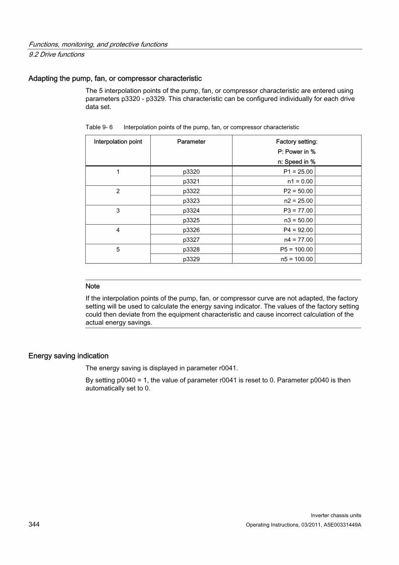
Functions, monitoring, and protective functions 9.2 Drive functions
Inverter chassis units 344 Operating Instructions, 03/2011, A5E00331449A
Adapting the pump, fan, or compressor characteristic The 5 interpolation points of the pump, fan, or compressor characteristic are entered using parameters p3320 - p3329. This characteristic can be configured individually for each drive data set.
Table 9- 6 Interpolation points of the pump, fan, or compressor characteristic
Interpolation point Parameter Factory setting: P: Power in % n: Speed in %
p3320 P1 = 25.00 1 p3321 n1 = 0.00 p3322 P2 = 50.00 2 p3323 n2 = 25.00 p3324 P3 = 77.00 3 p3325 n3 = 50.00 p3326 P4 = 92.00 4 p3327 n4 = 77.00 p3328 P5 = 100.00 5 p3329 n5 = 100.00
Note
If the interpolation points of the pump, fan, or compressor curve are not adapted, the factory setting will be used to calculate the energy saving indicator. The values of the factory setting could then deviate from the equipment characteristic and cause incorrect calculation of the actual energy savings.
Energy saving indication The energy saving is displayed in parameter r0041.
By setting p0040 = 1, the value of parameter r0041 is reset to 0. Parameter p0040 is then automatically set to 0.
Functions, monitoring, and protective functions 9.3 Extended functions
Inverter chassis units Operating Instructions, 03/2011, A5E00331449A 345
9.3 Extended functions
9.3.1 Technology controller
Description The "technology controller" function module allows simple control functions to be implemented, e.g.:
Liquid level control
Temperature control
Dancer position control
Pressure control
Flow control
Simple control without higher-level control
Tension control
The technology controller features:
Two scalable setpoints
Scalable output signal
Separate fixed values
Separate motorized potentiometer
The output limits can be activated and deactivated via the ramp-function generator.
The D component can be switched to the system deviation or actual value channel.
The motorized potentiometer of the technology controller is only active when the drive pulses are enabled.
The technology controller is designed as a PID controller, whereby the differentiator can be switched to the control deviation channel or the actual value channel (factory setting). The P, I, and D components can be set separately.
A value of 0 deactivates the corresponding component. Setpoints can be specified via two connector inputs. The setpoints can be scaled via parameters p2255 and p2256.
A ramp-function generator in the setpoint channel can be used to set the setpoint ramp-up/ramp-down time via parameters p2257 and p2258. The setpoint and actual value channel each have a smoothing element. The smoothing time can be set via parameters p2261 and p2265.
The setpoints can be specified via separate fixed setpoints (p2201 to p2215), the motorized potentiometer, or via the field bus (e.g. PROFIBUS).
Pre-control can be integrated via a connector input.
Functions, monitoring, and protective functions 9.3 Extended functions
Inverter chassis units 346 Operating Instructions, 03/2011, A5E00331449A
The output can be scaled via parameter p2295 and the control direction reversed. It can be limited via parameters p2291 and p2292 and interconnected as required via a connector output (r2294).
The actual value can be integrated, for example, via an analog input on the TM31.
If a PID controller has to be used for control reasons, the D component is switched to the setpoint/actual value difference (p2263 = 1) unlike in the factory setting. This is always necessary when the D component is to be effective, even if the reference variable changes. The D component can only be activated when p2274 > 0.
Note
With the entry "0" sec. as power up time or ramp-down time for the ramp function generator of the technology controller, the current values of the respective ramp function generator will be frozen.
Commissioning The "technology controller" function module can be activated by running the commissioning Wizard. Parameter r0108.16 indicates whether the function module has been activated.
Function diagram FD 7950 Technology controller – fixed values, binary selection FP 7951 Technology controller – fixed values, direct selection FD 7954 Technology controller – motorized potentiometer FD 7958 Technology controller – closed-loop controller
Example: liquid level control The objective here is to maintain a constant level in the container.
This is carried out by means of a variable-speed pump in conjunction with a sensor for measuring the level.
The level is determined via an analog input (e.g. AI0 TM31) and sent to the technology controller. The level setpoint is defined in a fixed setpoint. The resulting controlled variable is used as the setpoint for the speed controller.
In this example, a Terminal Module (TM31) is used.
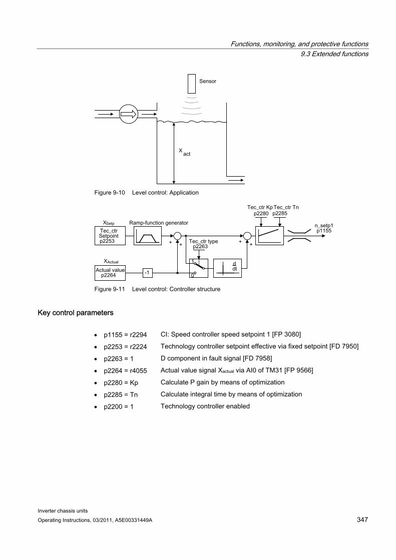
Functions, monitoring, and protective functions 9.3 Extended functions
Inverter chassis units Operating Instructions, 03/2011, A5E00331449A 347
Figure 9-10 Level control: Application
Figure 9-11 Level control: Controller structure
Key control parameters p1155 = r2294 CI: Speed controller speed setpoint 1 [FP 3080]
p2253 = r2224 Technology controller setpoint effective via fixed setpoint [FD 7950]
p2263 = 1 D component in fault signal [FD 7958]
p2264 = r4055 Actual value signal Xactual via AI0 of TM31 [FP 9566]
p2280 = Kp Calculate P gain by means of optimization
p2285 = Tn Calculate integral time by means of optimization
p2200 = 1 Technology controller enabled
Functions, monitoring, and protective functions 9.3 Extended functions
Inverter chassis units 348 Operating Instructions, 03/2011, A5E00331449A
9.3.2 Bypass function The bypass function uses digital converter outputs to activate two contactors and uses digital inputs to evaluate the contactor’s feedback (e.g. via TM31). This circuit allows the motor to be operated using the converter or directly on the supply line. The contactors are activated by the converter. The feedback signals for the contactor positions have to be returned to the converter.
The bypass circuit can be implemented in two ways:
without synchronizing the motor to the supply and
with synchronizing the motor to the supply.
The following applies to all bypass versions:
The bypass switch is also shut down when one of the "OFF2" or "OFF3" control word signals is canceled.
Exception: If necessary, the bypass switch can be interlocked by a higher-level controller such that the converter can be shut down completely (i.e. including the controller electronics) while the motor is operated on the supply. The protective interlocking must be implemented on the system side.
When the converter is started up again after POWER OFF, the status of the bypass contactors is evaluated. After powering up, the converter can thereby change straight into "Ready to start and bypass" status. This is only possible if the bypass is activated via a control signal, the control signal (p1266) is still present once the system has been ramped up, and the automatic restart function (p1200 = 4) is active.
Changing the converter into "Ready to start and bypass" status after powering up, is of a higher priority than switching back on automatically.
Monitoring of the motor temperatures using temperature sensors is active while the converter is in one of two statuses "Ready to start and bypass" or "Ready for operation and bypass".
The two motor contactors must be designed for switching under load.
Note
The examples contained in the following descriptions are only basic circuits designed to explain the basic function. The dimensions of specific circuit configurations (contactors, protective equipment) must be calculated for specific systems.
Prerequisites The bypass function is only available for sped control without encoders (p1300 = 20) or V/f- control (p1300 = 0...19) and when using an asynchronous motor.
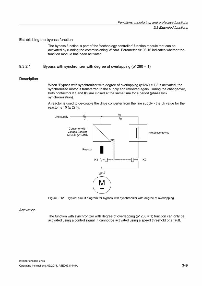
Functions, monitoring, and protective functions 9.3 Extended functions
Inverter chassis units Operating Instructions, 03/2011, A5E00331449A 349
Establishing the bypass function The bypass function is part of the "technology controller" function module that can be activated by running the commissioning Wizard. Parameter r0108.16 indicates whether the function module has been activated.
9.3.2.1 Bypass with synchronizer with degree of overlapping (p1260 = 1)
Description When “Bypass with synchronizer with degree of overlapping (p1260 = 1)” is activated, the synchronized motor is transferred to the supply and retrieved again. During the changeover, both contactors K1 and K2 are closed at the same time for a period (phase lock synchronization).
A reactor is used to de-couple the drive converter from the line supply - the uk value for the reactor is 10 (± 2) %.
M ~
K 1 K 2
Figure 9-12 Typical circuit diagram for bypass with synchronizer with degree of overlapping
Activation The function with synchronizer with degree of overlapping (p1260 = 1) function can only be activated using a control signal. It cannot be activated using a speed threshold or a fault.
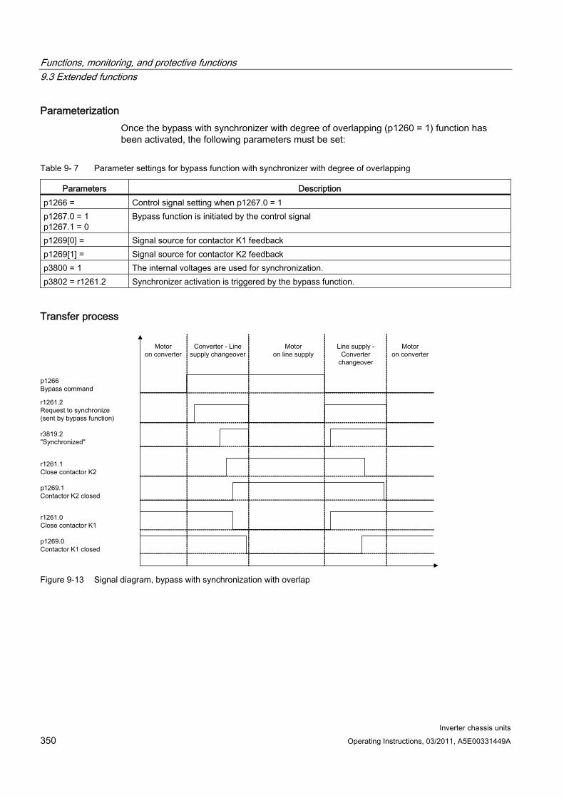
Functions, monitoring, and protective functions 9.3 Extended functions
Inverter chassis units 350 Operating Instructions, 03/2011, A5E00331449A
Parameterization Once the bypass with synchronizer with degree of overlapping (p1260 = 1) function has been activated, the following parameters must be set:
Table 9- 7 Parameter settings for bypass function with synchronizer with degree of overlapping
Parameters Description p1266 = Control signal setting when p1267.0 = 1 p1267.0 = 1 p1267.1 = 0
Bypass function is initiated by the control signal
p1269[0] = Signal source for contactor K1 feedback p1269[1] = Signal source for contactor K2 feedback p3800 = 1 The internal voltages are used for synchronization. p3802 = r1261.2 Synchronizer activation is triggered by the bypass function.
Transfer process
Figure 9-13 Signal diagram, bypass with synchronization with overlap
Functions, monitoring, and protective functions 9.3 Extended functions
Inverter chassis units Operating Instructions, 03/2011, A5E00331449A 351
Transfer of motor to line supply (contactors K1 and K2 are activated by the converter):
The initial state is as follows: Contactor K1 is closed, contactor K2 is open and the motor is fed from the converter.
The control bit "bypass command" (p1266) is set (e.g., by the higher-level automation).
The bypass function sets the control word bit "synchronizing" (r1261.2).
Since the bit is set while the converter is running, the "Transfer motor to line supply" synchronization process is started.
Once motor synchronization to line frequency, line voltage and line phasing is complete, the synchronization algorithm reports this state (r3819.2).
The bypass mechanism evaluates this signal and closes contactor K2 (r1261.1 = 1). The signal is evaluated internally - BICO wiring is not required.
After contactor K2 has fed back the "closed" state (r1269[1] = 1), contactor K1 is opened and the converter inhibits the pulses. The converter is in "Ready for operation and bypass" state.
If the On command is cancelled in this phase, the converter will change to "Ready to start and bypass" status. If the appropriate contactors are being used, the converter will be isolated from the line supply and the DC link discharged.
To transfer the motor back from the line supply, the sequence is simply reversed: At the start of the process, contactor K2 is closed and contactor K1 is open.
The "Command bypass" control bit is canceled (e.g., by the higher-level automation).
The bypass function sets the control word bit "synchronizing".
The pulses are enabled. Since "synchronizing" is set before "pulse enable", the converter interprets this as a command to retrieve the motor from the line supply.
Once converter synchronization to line frequency, line voltage and line phasing is complete, the synchronization algorithm reports this state.
The bypass mechanism evaluates this signal and closes contactor K1. The signal is evaluated internally - BICO wiring is not required.
Once contactor K1 has reported "closed" status, contactor K2 is opened and the motor returns to operation on the converter.
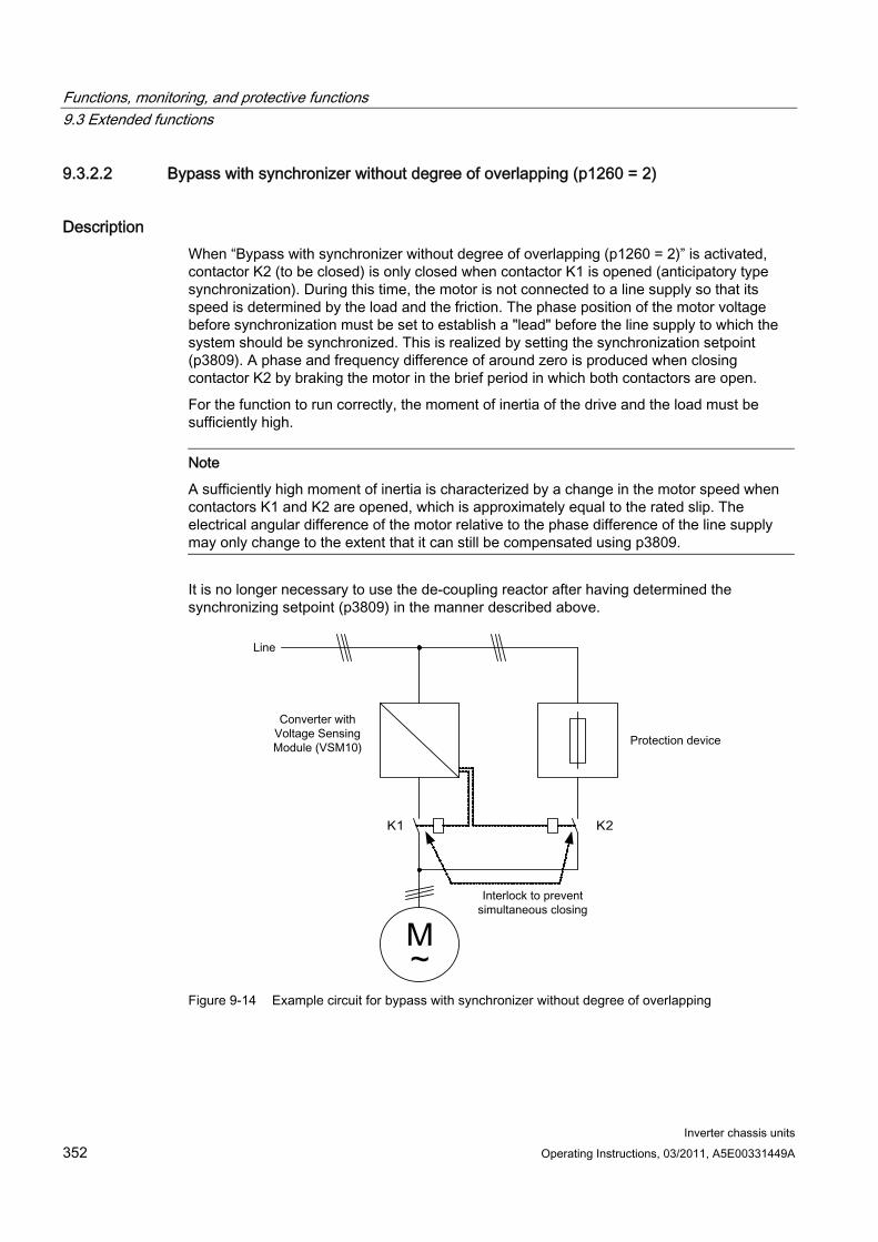
Functions, monitoring, and protective functions 9.3 Extended functions
Inverter chassis units 352 Operating Instructions, 03/2011, A5E00331449A
9.3.2.2 Bypass with synchronizer without degree of overlapping (p1260 = 2)
Description When “Bypass with synchronizer without degree of overlapping (p1260 = 2)” is activated, contactor K2 (to be closed) is only closed when contactor K1 is opened (anticipatory type synchronization). During this time, the motor is not connected to a line supply so that its speed is determined by the load and the friction. The phase position of the motor voltage before synchronization must be set to establish a "lead" before the line supply to which the system should be synchronized. This is realized by setting the synchronization setpoint (p3809). A phase and frequency difference of around zero is produced when closing contactor K2 by braking the motor in the brief period in which both contactors are open.
For the function to run correctly, the moment of inertia of the drive and the load must be sufficiently high.
Note
A sufficiently high moment of inertia is characterized by a change in the motor speed when contactors K1 and K2 are opened, which is approximately equal to the rated slip. The electrical angular difference of the motor relative to the phase difference of the line supply may only change to the extent that it can still be compensated using p3809.
It is no longer necessary to use the de-coupling reactor after having determined the synchronizing setpoint (p3809) in the manner described above.
M ~
K 1 K 2
Figure 9-14 Example circuit for bypass with synchronizer without degree of overlapping
Functions, monitoring, and protective functions 9.3 Extended functions
Inverter chassis units Operating Instructions, 03/2011, A5E00331449A 353
Activation The bypass with synchronizer without degree of overlapping (p1260 = 2) function can only be activated using a control signal. It cannot be activated using a speed threshold or a fault.
Parameterization Once the bypass with synchronizer without degree of overlapping (p1260 = 2) function has been activated, the following parameters must be set:
Table 9- 8 Parameter settings for bypass function with synchronizer without degree of overlapping
Parameter Description p1266 = Control signal setting when p1267.0 = 1 p1267.0 = 1 p1267.1 = 0
Bypass function is initiated by the control signal
p1269[0] = Signal source for contactor K1 feedback p1269[1] = Signal source for contactor K2 feedback p3800 = 1 The internal voltages are used for synchronization. p3802 = r1261.2 Synchronizer activation is triggered by the bypass function. p3809 = Setting the phase setpoint for synchronizing the drive to the line supply
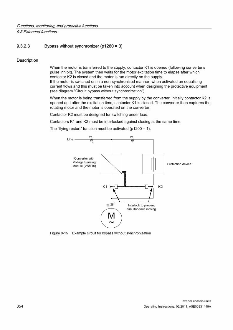
Functions, monitoring, and protective functions 9.3 Extended functions
Inverter chassis units 354 Operating Instructions, 03/2011, A5E00331449A
9.3.2.3 Bypass without synchronizer (p1260 = 3)
Description When the motor is transferred to the supply, contactor K1 is opened (following converter’s pulse inhibit). The system then waits for the motor excitation time to elapse after which contactor K2 is closed and the motor is run directly on the supply. If the motor is switched on in a non-synchronized manner, when activated an equalizing current flows and this must be taken into account when designing the protective equipment (see diagram "Circuit bypass without synchronization").
When the motor is being transferred from the supply by the converter, initially contactor K2 is opened and after the excitation time, contactor K1 is closed. The converter then captures the rotating motor and the motor is operated on the converter.
Contactor K2 must be designed for switching under load.
Contactors K1 and K2 must be interlocked against closing at the same time.
The "flying restart" function must be activated (p1200 = 1).
M ~
K 1 K 2
Figure 9-15 Example circuit for bypass without synchronization
Functions, monitoring, and protective functions 9.3 Extended functions
Inverter chassis units Operating Instructions, 03/2011, A5E00331449A 355
Activation The bypass with synchronizer (p1260 = 3) can be triggered by the following signals (p1267):
Bypass by means of control signal (p1267.0 = 1): The bypass can be activated by means of a digital signal (p1266) (e.g. from a higher-level automation system). If the digital signal is canceled, a changeover to converter operations is triggered once the debypass delay time (p1263) has expired.
Bypass at speed threshold (p1267.1 = 1): Once a certain speed is reached, the system switches to bypass (i.e. the converter is used as a start-up converter). The bypass cannot be connected until the speed setpoint is greater than the bypass speed threshold (p1265). The system reverts to converter mode when the setpoint (on the input of the ramp-function generator, r1119) falls below the bypass speed threshold (p1265). The setpoint > comparison value condition prevents the bypass from being reactivated straight away if the actual speed is still above the bypass speed threshold (p1265) after switching back to converter operations.
The bypass time, debypass time, bypass speed variables and the command source for changing over are set using parameters.
Parameterization Once the bypass without synchronizer (p1260 = 3) function has been activated, the following parameters must be set:
Table 9- 9 Parameter settings for bypass function with synchronizer without degree of overlapping
Parameter Description p1262 = Bypass dead time setting p1263 = Debypass dead time setting p1264 = Bypass delay time setting p1265 = Speed threshold setting when p1267.1 = 1 p1266 = Control signal setting when p1267.0 = 1 p1267.0 = p1267.1 =
Trigger signal setting for bypass function
p1269[1] = Signal source for contactor K2 feedback p3800 = 1 The internal voltages are used for synchronization. p3802 = r1261.2 Synchronizer activation is triggered by the bypass function. P1200 = 1 The "flying restart" function is always active.
9.3.2.4 Function diagram FP 7020 Synchronization
Functions, monitoring, and protective functions 9.3 Extended functions
Inverter chassis units 356 Operating Instructions, 03/2011, A5E00331449A
9.3.2.5 Parameters Bypass function
p1200 Flying restart operating mode
p1260 Bypass configuration
r1261 CO/BO: Bypass control/status word
p1262 Bypass dead time
p1263 Debypass delay time
p1264 Bypass delay time
p1265 Bypass speed threshold
p1266 BI: Bypass control command
p1267 Bypass changeover source configuration
p1268 BI: Bypass feedback signal synchronization completed
p1269 BI: Bypass switch feedback signal
p1274 BI: Bypass switch monitoring time
Synchronization
p3800 Sync–supply–drive activation
p3801 Sync–supply–drive drive object number
p3802 BI: Sync–supply–drive enable
r3803 CO/BO: Sync–supply–drive control word
r3804 CO: Sync–supply–drive target frequency
r3805 CO: Sync–supply–drive frequency difference
p3806 Sync–supply–drive frequency difference threshold
r3808 CO: Sync–supply–drive phase difference
p3809 Sync–supply–drive phase setpoint
p3811 Sync–supply–drive frequency limitation
r3812 CO: Sync–supply–drive correction frequency
p3813 Sync–supply–drive phase synchronism threshold
r3814 CO: Sync–supply–drive voltage difference
p3815 Sync–supply–drive voltage difference threshold
r3819 CO/BO: Sync–supply–drive status word
Functions, monitoring, and protective functions 9.3 Extended functions
Inverter chassis units Operating Instructions, 03/2011, A5E00331449A 357
9.3.3 Extended brake control
Description The "Extended brake control" function module allows complex braking control for motor holding brakes and holding brakes for example.
The brake is controlled as follows (the sequence reflects the priority):
Via parameter p1215
Via binector parameters p1219[0..3] and p0855
Via zero speed detection
Via a connector interconnection threshold value
Commissioning The "Extended brake control" function module can be activated by running the commissioning wizard. Parameter r0108.14 indicates whether the function module has been activated.
Parameter p1215 must be set to "3" and the brake controlled via a digital output (for example at the customer terminal block TM31).
Example 1: Starting against applied brake When the device is switched on, the setpoint is enabled immediately (if other enable signals are issued), even if the brake has not yet been released (p1152 = 1). The factory setting p1152 = r0899.15 must be separated here. The drive first establishes a torque against the applied brake. The brake is not released until the motor torque or current (p1220) has exceeded braking threshold 1 (p1221).
Depending on the type and design of the brake, the time required to completely release the brake differs. It must be taken into consideration that, once the braking threshold torque has been exceeded, the operation enable signal (p0899.2) is interrupted for the time interval that the brake is being released (p1216) to ensure that the motor current does not exceed the permissible limit values during this period and the motor torque generated does not damage the brake. Time interval p1216 must be set depending on the time the brake actually requires to release.
This configuration is used, for example, when the drive is connected to a belt that is under tension (loop accumulator in the steel industry).

Functions, monitoring, and protective functions 9.3 Extended functions
Inverter chassis units 358 Operating Instructions, 03/2011, A5E00331449A
Example 2: Emergency brake In the case of emergency braking, electrical and mechanical braking should be realized at precisely the same time. This can be achieved if OFF3 is used as a tripping signal for emergency braking:
p1219[0] = r0898.2 and p1275.00 = 1 (OFF3 to "apply brake immediately" and invert signal).
To prevent the converter working in opposition to the brake, the OFF3 ramp (p1135) should be set to 0 seconds. Any prevailing regenerative energy must be converted into heat via a braking resistor.
This is often used, for example, in calendar stacks, cutting tools, running gears, and presses.
Example 3: Service brake on crane drives For cranes with manual control, it is important that the drive responds immediately when the control lever is moved (master switch). To this end, the drive is powered up using the on command (p0840) (the pulses are enabled). Speed setpoint (p1142) and speed controller (p0856) are inhibited. The motor is magnetized. The magnetization time generally applicable for three-phase motors (1-2 seconds) is, therefore, eliminated.
Now, only the brake opening time will delay the motor starting to rotate following activation of the master switch. Movement of the master switch generates a "setpoint enable from the control" (bit interconnected with p1142, p1229.2, p1224.0). The speed controller is enabled immediately and the speed setpoint is enabled once the brake opening time (p1216) has elapsed. When the master switch is in the zero position, the speed setpoint is inhibited and the drive ramps down along the ramp-function generator's ramp-down ramp. The brake closes once the standstill limit (p1226) is undershot. Once the brake closing time (p1217) has elapsed, the speed controller is inhibited (the motor is no longer generating any force). Extended braking control is used with the modifications described below.
Figure 9-16 Example: Service brake on a crane drive
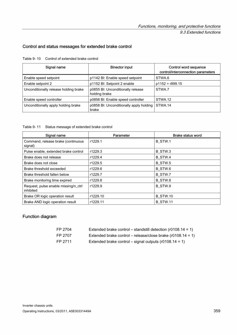
Functions, monitoring, and protective functions 9.3 Extended functions
Inverter chassis units Operating Instructions, 03/2011, A5E00331449A 359
Control and status messages for extended brake control
Table 9- 10 Control of extended brake control
Signal name Binector input Control word sequence control/interconnection parameters
Enable speed setpoint p1142 BI: Enable speed setpoint STWA.6 Enable setpoint 2 p1152 BI: Setpoint 2 enable p1152 = r899.15 Unconditionally release holding brake p0855 BI: Unconditionally release
holding brake STWA.7
Enable speed controller p0856 BI: Enable speed controller STWA.12 Unconditionally apply holding brake p0858 BI: Unconditionally apply holding
brake STWA.14
Table 9- 11 Status message of extended brake control
Signal name Parameter Brake status word Command, release brake (continuous signal)
r1229.1 B_STW.1
Pulse enable, extended brake control r1229.3 B_STW.3 Brake does not release r1229.4 B_STW.4 Brake does not close r1229.5 B_STW.5 Brake threshold exceeded r1229.6 B_STW.6 Brake threshold fallen below r1229.7 B_STW.7 Brake monitoring time expired r1229.8 B_STW.8 Request, pulse enable missing/n_ctrl inhibited
r1229.9 B_STW.9
Brake OR logic operation result r1229.10 B_STW.10 Brake AND logic operation result r1229.11 B_STW.11
Function diagram FP 2704 Extended brake control – standstill detection (r0108.14 = 1) FP 2707 Extended brake control – release/close brake (r0108.14 = 1) FP 2711 Extended brake control – signal outputs (r0108.14 = 1)
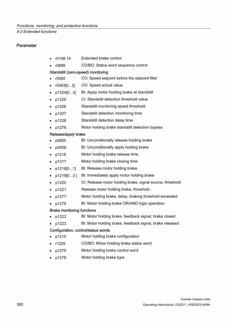
Functions, monitoring, and protective functions 9.3 Extended functions
Inverter chassis units 360 Operating Instructions, 03/2011, A5E00331449A
Parameter r0108.14 Extended brake control
r0899 CO/BO: Status word sequence control
Standstill (zero-speed) monitoring r0060 CO: Speed setpoint before the setpoint filter
r0063[0...2] CO: Speed actual value
p1224[0...3] BI: Apply motor holding brake at standstill
p1225 CI: Standstill detection threshold value
p1226 Standstill monitoring speed threshold
p1227 Standstill detection monitoring time
p1228 Standstill detection delay time
p1276 Motor holding brake standstill detection bypass
Release/apply brake p0855 BI: Unconditionally release holding brake
p0858 BI: Unconditionally apply holding brake
p1216 Motor holding brake release time
p1217 Motor holding brake closing time
p1218[0...1] BI: Release motor holding brake
p1219[0...3 ] BI: Immediately apply motor holding brake
p1220 CI: Release motor holding brake, signal source, threshold
p1221 Release motor holding brake, threshold
p1277 Motor holding brake, delay, braking threshold exceeded
p1279 BI: Motor holding brake OR/AND logic operation
Brake monitoring functions p1222 BI: Motor holding brake, feedback signal, brake closed
p1223 BI: Motor holding brake, feedback signal, brake released
Configuration, control/status words p1215 Motor holding brake configuration
r1229 CO/BO: Motor holding brake status word
p1275 Motor holding brake control word
p1278 Motor holding brake type

Functions, monitoring, and protective functions 9.3 Extended functions
Inverter chassis units Operating Instructions, 03/2011, A5E00331449A 361
9.3.4 Extended monitoring functions
Description The "extended monitoring functions" function module enables additional monitoring functions:
Speed setpoint monitoring: |n_set| ≤ p2161
Speed setpoint monitoring: n_set > 0
Load monitoring
Description of load monitoring This function monitors power transmission between the motor and the working machine. Typical applications include V-belts, flat belts, or chains that loop around the belt pulleys or cog wheels for drive and outgoing shafts and transfer the peripheral speeds and forces. Load monitoring can be used here to identify blockages in the working machine and interruptions to the power transmission. During load monitoring, the current speed/torque curve is compared with the programmed speed/torque curve (p2182 – p2190). If the current value is outside the programmed tolerance bandwidth, a fault or alarm is triggered depending on parameter p2181. The fault or alarm message can be delayed by means of parameter p2192 to prevent false alarms caused by brief transitional states.
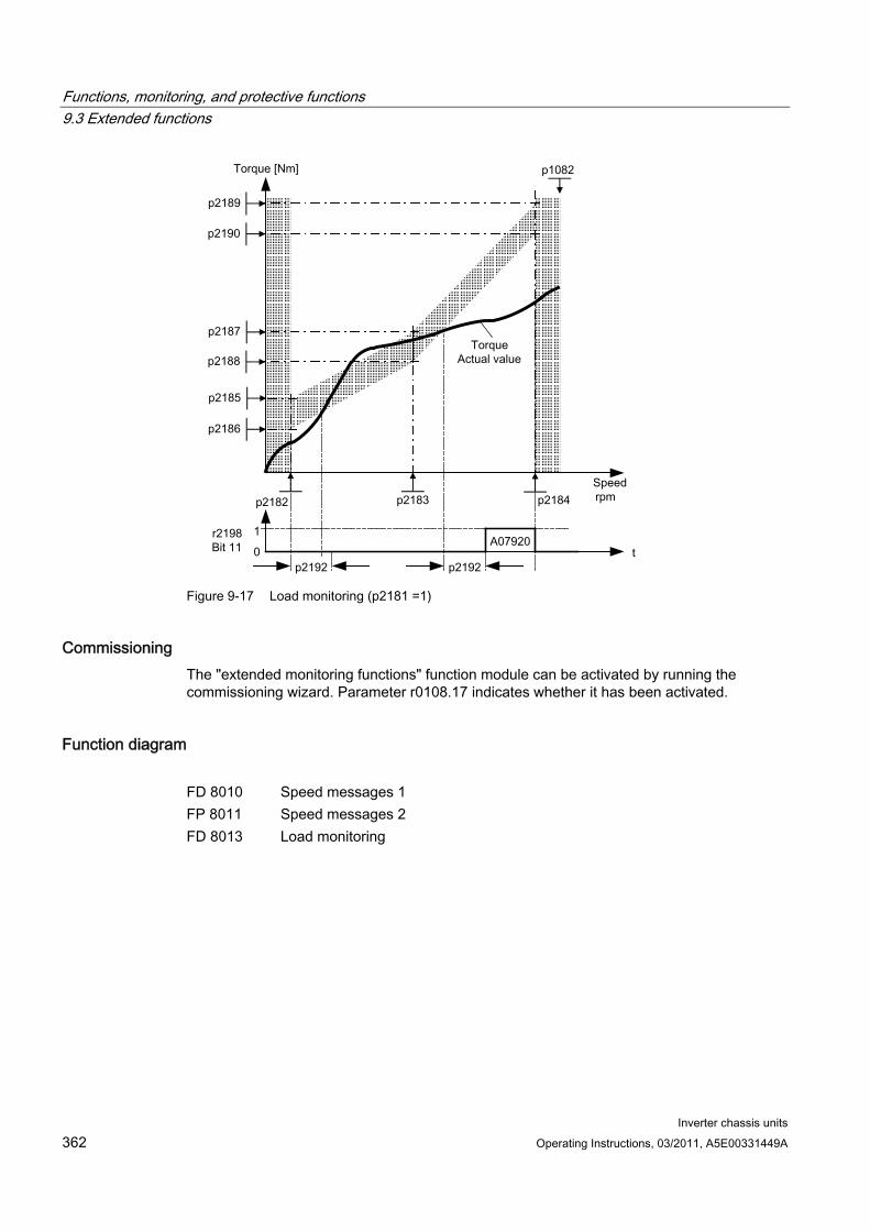
Functions, monitoring, and protective functions 9.3 Extended functions
Inverter chassis units 362 Operating Instructions, 03/2011, A5E00331449A
Figure 9-17 Load monitoring (p2181 =1)
Commissioning The "extended monitoring functions" function module can be activated by running the commissioning wizard. Parameter r0108.17 indicates whether it has been activated.
Function diagram FD 8010 Speed messages 1 FP 8011 Speed messages 2 FD 8013 Load monitoring
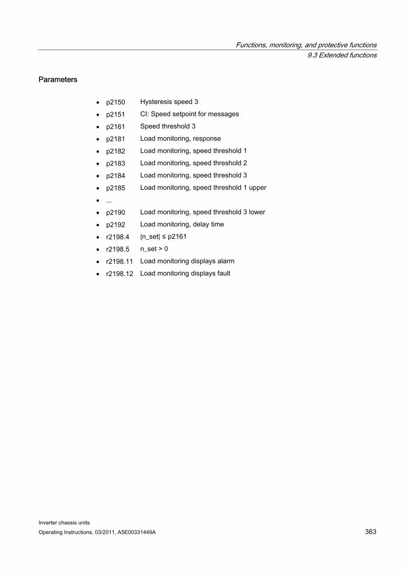
Functions, monitoring, and protective functions 9.3 Extended functions
Inverter chassis units Operating Instructions, 03/2011, A5E00331449A 363
Parameters p2150 Hysteresis speed 3
p2151 CI: Speed setpoint for messages
p2161 Speed threshold 3
p2181 Load monitoring, response
p2182 Load monitoring, speed threshold 1
p2183 Load monitoring, speed threshold 2
p2184 Load monitoring, speed threshold 3
p2185 Load monitoring, speed threshold 1 upper
...
p2190 Load monitoring, speed threshold 3 lower
p2192 Load monitoring, delay time
r2198.4 |n_set| ≤ p2161
r2198.5 n_set > 0
r2198.11 Load monitoring displays alarm
r2198.12 Load monitoring displays fault
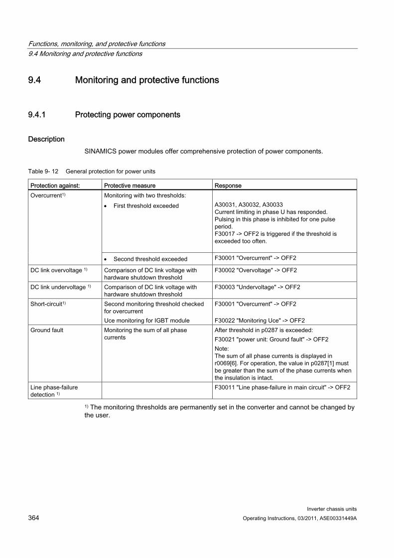
Functions, monitoring, and protective functions 9.4 Monitoring and protective functions
Inverter chassis units 364 Operating Instructions, 03/2011, A5E00331449A
9.4 Monitoring and protective functions
9.4.1 Protecting power components
Description SINAMICS power modules offer comprehensive protection of power components.
Table 9- 12 General protection for power units
Protection against: Protective measure Response Monitoring with two thresholds: First threshold exceeded
A30031, A30032, A30033 Current limiting in phase U has responded. Pulsing in this phase is inhibited for one pulse period. F30017 -> OFF2 is triggered if the threshold is exceeded too often.
Overcurrent1)
Second threshold exceeded F30001 "Overcurrent" -> OFF2
DC link overvoltage 1) Comparison of DC link voltage with hardware shutdown threshold
F30002 "Overvoltage" -> OFF2
DC link undervoltage 1) Comparison of DC link voltage with hardware shutdown threshold
F30003 "Undervoltage" -> OFF2
Short-circuit1) Second monitoring threshold checked for overcurrent Uce monitoring for IGBT module
F30001 "Overcurrent" -> OFF2 F30022 "Monitoring Uce" -> OFF2
Ground fault Monitoring the sum of all phase currents
After threshold in p0287 is exceeded: F30021 "power unit: Ground fault" -> OFF2 Note: The sum of all phase currents is displayed in r0069[6]. For operation, the value in p0287[1] must be greater than the sum of the phase currents when the insulation is intact.
Line phase-failure detection 1)
F30011 "Line phase-failure in main circuit" -> OFF2
1) The monitoring thresholds are permanently set in the converter and cannot be changed by the user.
Functions, monitoring, and protective functions 9.4 Monitoring and protective functions
Inverter chassis units Operating Instructions, 03/2011, A5E00331449A 365
9.4.2 Thermal monitoring and overload responses
Description The thermal power module monitor is responsible for identifying critical situations. Possible reactions can be assigned and used when alarm thresholds are exceeded to enable continued operation (e.g., with reduced power) and prevent immediate shutdown. The parameterization options, however, only enable intervention below the shutdown thresholds, which cannot be changed by the user.
The following thermal monitoring options are available:
i²t monitoring – A07805 – F30005 i²t monitoring is used to protect components that have a high thermal time constant compared with semi-conductors. Overload with regard to i²t is present when the converter load (r0036) is greater than 100% (load as a % of rated operation).
Heat sink temperature – A05000 – F30004 Used to monitor the temperature r0037[0] of the heat sinks on the power semiconductors (IGBT).
Chip temperature – A05001 – F30025 Significant temperature differences can occur between the barrier layer of the IGBT and the heatsink. The calculated barrier junction temperature is displayed in r0037[13...18]; the monitoring ensures that the specified maximum barrier junction temperature is not exceeded.
If an overload occurs with respect to any of these three monitoring functions, an alarm is first output. The alarm threshold p0294 (i²t monitoring) can be parameterized relative to the shutdown (trip) values.
Example The temperature difference between two sensors must not exceed 15 Kelvin (K); a temperature difference of 5 K is set for the temperature monitoring of the heat sink and the air intake. This means that 15 K or 5 K below the shutdown threshold an alarm is issued regarding the pending overtemperature. Parameter p0294 merely allows a change in the alarm threshold so that an alarm is received earlier and, if necessary, steps can be taken to intervene in the drive process (e.g., reduce the load, reduce the ambient temperature).
Functions, monitoring, and protective functions 9.4 Monitoring and protective functions
Inverter chassis units 366 Operating Instructions, 03/2011, A5E00331449A
Overload responses The power module responds with alarm A07805. The control unit initiates the responses assigned via p0290 at the same time that the alarm is issued. Possible responses include:
Reduction in pulse frequency (p0290 = 2, 3) This is a highly effective method of reducing losses in the power unit, since switching losses account for a high proportion of overall losses. In many applications, a temporary pulse frequency reduction in favor of maintaining the process can be tolerated. Disadvantage: The pulse frequency reduction increases the current ripple, which can cause increased torque ripple on the motor shaft (when moment of inertia is low) and increased noise level. Reducing the pulse frequency does not affect the dynamic response of the current control circuit, since the sampling time for the current control circuit remains constant.
Reducing the output frequency (p0290 = 0, 2) This variant is recommended when you do not need to reduce the pulse frequency or the pulse frequency has already been set to the lowest level. Further, the load should also have a characteristic similar to a fan, that is, a square law torque characteristic with decreasing speed. Reducing the output frequency has the effect of significantly reducing the converter output current which, in turn, reduces losses in the power unit.
No reduction (p0290 = 1) You should choose this option if it is neither possible to reduce the pulse frequency nor reduce the output current. The converter does not change its operating point once an alarm threshold has been overshot, which means that the drive can be operated until it reaches its shutdown values. Once the shutdown threshold is reached, the converter switches off with an "overtemperature" or "overload" fault. The time until shutdown, however, is not defined and depends on the degree of overload. Only the alarm threshold can be changed so that an alarm is received earlier and, if necessary, steps can be taken to intervene in the drive process (e.g., reduce the load, reduce the ambient temperature).
Function diagram FP 8014 Thermal monitoring, power unit
Parameter r0036 CO: Power module overload I2t
r0037 CO: Power module temperatures
p0290 Power unit overload response
r0293 CO: Power unit alarm threshold model temperature
p0294 Power module alarm I2t overload
r2135.13 Fault: thermal overload in power unit
r2135.15 Alarm: thermal overload in power unit
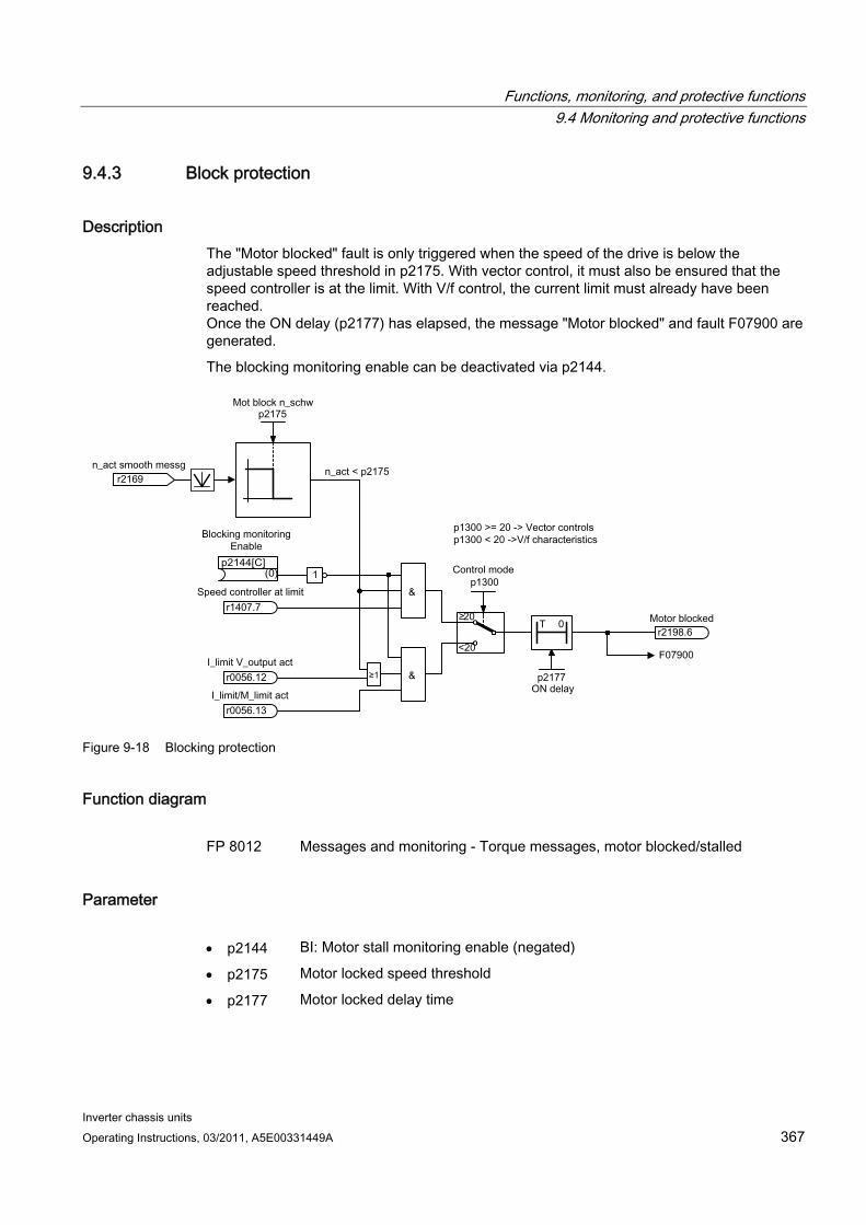
Functions, monitoring, and protective functions 9.4 Monitoring and protective functions
Inverter chassis units Operating Instructions, 03/2011, A5E00331449A 367
9.4.3 Block protection
Description The "Motor blocked" fault is only triggered when the speed of the drive is below the adjustable speed threshold in p2175. With vector control, it must also be ensured that the speed controller is at the limit. With V/f control, the current limit must already have been reached. Once the ON delay (p2177) has elapsed, the message "Motor blocked" and fault F07900 are generated.
The blocking monitoring enable can be deactivated via p2144.
Figure 9-18 Blocking protection
Function diagram FP 8012 Messages and monitoring - Torque messages, motor blocked/stalled
Parameter p2144 BI: Motor stall monitoring enable (negated)
p2175 Motor locked speed threshold
p2177 Motor locked delay time
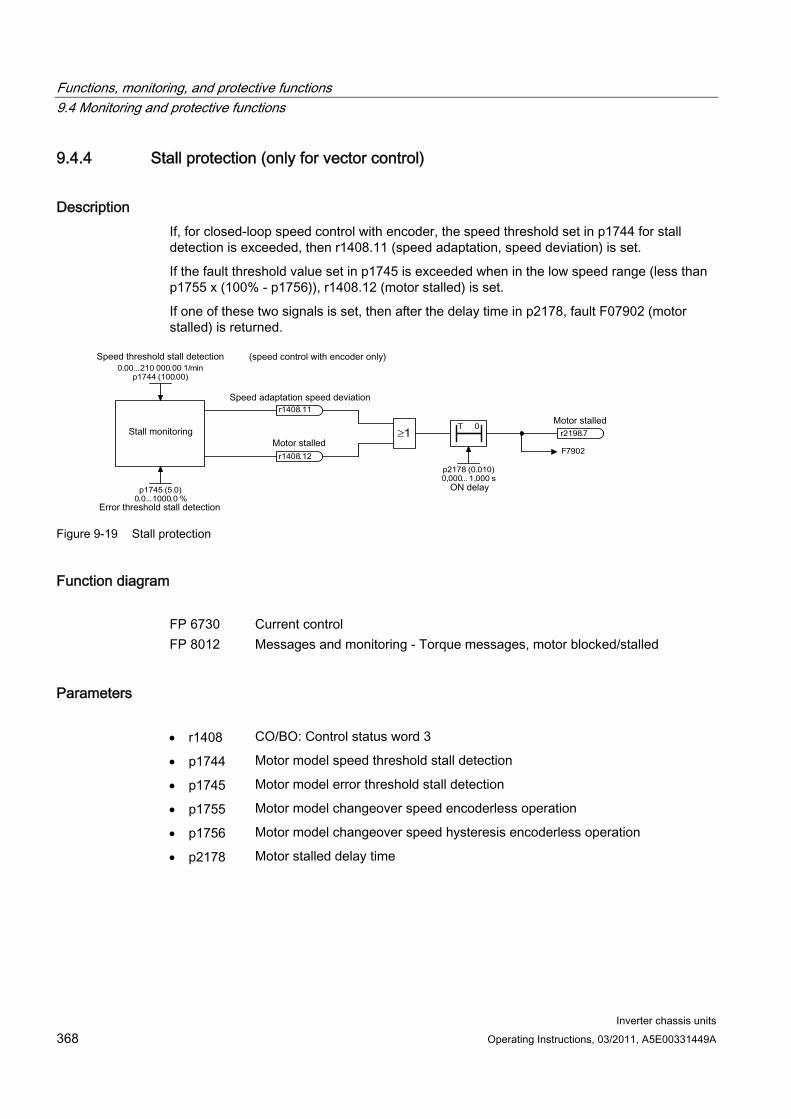
Functions, monitoring, and protective functions 9.4 Monitoring and protective functions
Inverter chassis units 368 Operating Instructions, 03/2011, A5E00331449A
9.4.4 Stall protection (only for vector control)
Description If, for closed-loop speed control with encoder, the speed threshold set in p1744 for stall detection is exceeded, then r1408.11 (speed adaptation, speed deviation) is set.
If the fault threshold value set in p1745 is exceeded when in the low speed range (less than p1755 x (100% - p1756)), r1408.12 (motor stalled) is set.
If one of these two signals is set, then after the delay time in p2178, fault F07902 (motor stalled) is returned.
T 0
F 7902
r 2198 . 7
p 2178 ( 0 . 010 ) 0 ,000... 1 ,000 s
≥ 1
r 1408 . 12
r 1408 . 11
0 . 00 ... 210 000 . 00 1 / min p 1744 ( 100 . 00 )
p 1745 ( 5 . 0 ) 0 . 0 ... 1000 . 0 %
Figure 9-19 Stall protection
Function diagram FP 6730 Current control FP 8012 Messages and monitoring - Torque messages, motor blocked/stalled
Parameters r1408 CO/BO: Control status word 3
p1744 Motor model speed threshold stall detection
p1745 Motor model error threshold stall detection
p1755 Motor model changeover speed encoderless operation
p1756 Motor model changeover speed hysteresis encoderless operation
p2178 Motor stalled delay time
Functions, monitoring, and protective functions 9.4 Monitoring and protective functions
Inverter chassis units Operating Instructions, 03/2011, A5E00331449A 369
9.4.5 Thermal motor protection
9.4.5.1 Description
Description The priority of thermal motor protection is to identify critical situations. Possible reactions can be assigned (p0610) and used when alarm thresholds are exceeded to enable continued operation (e.g., with reduced power) and prevent immediate shutdown.
Effective protection is also possible without a temperature sensor (p0600 = 0 or p4100 = 0). The temperatures of different motor components (stators, core, rotors) can be determined indirectly using a temperature model.
Connecting temperature sensors allows the motor temperature to be determined directly. In this way, accurate start temperatures are available immediately when the motor is switched on again or after a power failure.
9.4.5.2 Temperature sensor connection at the customer terminal block TM31
Temperature measurement via KTY The device is connected to terminals X522:7 (Temp+) and X522:8 (Temp-) on the customer terminal block (TM31) in the forward direction of the diode. The measured temperature is limited to between –140 °C and +188.6 °C and is available for further evaluation.
Activating the motor temperature measurement via the external sensor: p0600 = 10 If the customer terminal block TM31 is present and on completion of commissioning, the source for the external sensor is set to the customer terminal block (p0603 = TM31 r4105).
Set the KTY temperature sensor type: p4100 = 2
Temperature measurement via PTC The device is connected to terminal X522:7/8 at the customer terminal block (TM31). The threshold for switching to an alarm or fault is 1650 Ω. If the threshold is exceeded, the system switches internally from an artificially generated temperature value of -50 °C to +250 °C and makes it available for further evaluation.
Activating the motor temperature measurement via the external sensor: p0600 = 10 If the customer terminal block TM31 is present and on completion of commissioning, the source for the external sensor is set to the customer terminal block (p0603 = TM31 r4105).
Set the PTC temperature sensor type: p4100 = 1
Functions, monitoring, and protective functions 9.4 Monitoring and protective functions
Inverter chassis units 370 Operating Instructions, 03/2011, A5E00331449A
9.4.5.3 Temperature sensor connection at a Sensor Module
Temperature measurement via KTY The device is connected to the appropriate terminals Temp- and Temp+ on the Sensor Module in the forward direction of the diode (see corresponding section in chapter "Electrical installation").
Activate motor temperature measurement via encoder 1: p0600 = 1.
Set the KTY temperature sensor type: p0601 = 2
Temperature measurement via PTC The device is connected to the appropriate terminals Temp- and Temp+ on the Sensor Module (see corresponding section in chapter "Electrical installation"). The threshold for changing over to an alarm or fault is 1650 Ω.
Activate motor temperature measurement via encoder 1: p0600 = 1.
Set the PTC temperature sensor type: p0601 = 1
9.4.5.4 Temperature sensor connection directly at the Control Interface Module
Temperature measurement via KTY The device is connected to terminals X41:3 (Temp-) and X41:4 (Temp+) on the Control Interface Module in the forward direction of the diode.
Activate motor temperature measurement via Motor Module: p0600 = 11.
Set the KTY temperature sensor type: p0601 = 2
Temperature measurement via PTC The connection is made at the terminals X41:3 (Temp-) and X41:4 (Temp+) at the Control Interface Module. The threshold for changing over to an alarm or fault is 1650 Ω.
Activate motor temperature measurement via Motor Module: p0600 = 11.
Set the PTC temperature sensor type: p0601 = 1
Temperature measurement using the bimetal normally closed contact The connection is made at the terminals X41:3 (Temp-) and X41:4 (Temp+) at the Control Interface Module. The threshold for changing over to an alarm or fault is 100 Ω.
Activate motor temperature measurement via Motor Module: p0600 = 11.
Set the temperature sensor type bimetal normally closed contact: p0601 = 4
Functions, monitoring, and protective functions 9.4 Monitoring and protective functions
Inverter chassis units Operating Instructions, 03/2011, A5E00331449A 371
Temperature measurement via PT100 The connection is made at the terminals X41:3 (Temp-) and X41:4 (Temp+) at the Control Interface Module. p0624 can be used to set the temperature offset for the PT100 measured value.
Activate motor temperature measurement via Motor Module: p0600 = 11.
Set the PT100 temperature sensor type: p0601 = 5
9.4.5.5 Temperature sensor evaluation
Temperature measurement via KTY or PT100 When the alarm threshold is reached (set via p0604; delivery state after commissioning
120 °C), alarm A07910 is triggered.
Parameter p0610 can be used to set how the drive responds to the alarm triggered:
– 0: No response, only alarm, no reduction of I_max
– 1: Alarm and reduction of I_max and fault (F07011)
– 2: Alarm and fault (F07011), no reduction of I_max
When the fault threshold is reached (set via p0605, delivery state after commissioning 155 °C), fault F07011 is triggered in conjunction with the setting in p0610.
Temperature measurement via PTC or bimetallic normally closed contact Once the PTC or the bimetallic normally closed contact responds, alarm A07910 is
initiated.
Fault F07011 is triggered once the waiting time defined in p0606 has elapsed.
Sensor monitoring for wire breakage/short-circuit If the temperature of the motor temperature monitor is outside the range -140 °C to +250 °C, then the sensor cable is broken or has a short-circuit – and Alarm A07015 "Motor temperature sensor alarm" is triggered. Fault F07016 (“Drive: Motor temperature sensor fault”) is triggered once the waiting time defined in p0607 has elapsed.
Fault F07016 can be suppressed using p0607 = 0. If an induction motor is connected, the drive continues operating with the data calculated in the thermal motor model.
If the system detects that the motor temperature sensor set in p0600 is not connected, alarm A07820 "Temperature sensor not connected" is triggered.
Functions, monitoring, and protective functions 9.4 Monitoring and protective functions
Inverter chassis units 372 Operating Instructions, 03/2011, A5E00331449A
Thermal 3 mass model (for induction machines) For induction machines, the motor temperature is calculated using the thermal 3-mass model. This makes thermal motor protection possible – even for operation without temperature sensor or with the temperature sensor deactivated (p0600 = 0).
For operation with a KTY sensor, the calculated temperature value of the 3-mass model permanently tracks the measured temperature value. After the temperature sensor is switched off (p0600 = 0), the last temperature value continues to be used for calculation.
Thermal I2t motor model (for permanently excited synchronous machines) By using the thermal I2t motor model, the temperature rise of the motor windings as a result of dynamic motor loads is also determined in addition to data acquired using a temperature sensor.
If the thermal I2t motor model is activated via p0612.0 = 1, it calculates the motor load (r0034) from the following values:
Absolute value of the actual current, unsmoothed (r0068[0])
Motor stall current (p0318)
I2t motor model thermal time constant (p0611)
Measured motor temperature (r0035) or motor ambient temperature (p0625) for operation without temperature sensor
If the fault threshold is exceeded (set via p0605; delivery state after commissioning 155 °C), alarm A0712 "I2t motor model overtemperature" is triggered.
When the I2t motor model fault threshold is reached (p0615), fault F07011 is triggered in conjunction with the setting in p0610.
9.4.5.6 Function diagram FP 8016 Thermal monitoring motor FP 8017 Thermal I2t motor model (PEM, p0300 = 2xx) FP 9576 TM31 - temperature evaluation (KTY/PTC) FP 9577 TM31 - sensor monitoring (KTY/PTC)
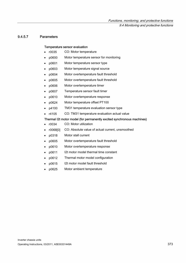
Functions, monitoring, and protective functions 9.4 Monitoring and protective functions
Inverter chassis units Operating Instructions, 03/2011, A5E00331449A 373
9.4.5.7 Parameters Temperature sensor evaluation r0035 CO: Motor temperature
p0600 Motor temperature sensor for monitoring
p0601 Motor temperature sensor type
p0603 Motor temperature signal source
p0604 Motor overtemperature fault threshold
p0605 Motor overtemperature fault threshold
p0606 Motor overtemperature timer
p0607 Temperature sensor fault timer
p0610 Motor overtemperature response
p0624 Motor temperature offset PT100
p4100 TM31 temperature evaluation sensor type
r4105 CO: TM31 temperature evaluation actual value
Thermal I2t motor model (for permanently excited synchronous machines) r0034 CO: Motor utilization
r0068[0] CO: Absolute value of actual current, unsmoothed
p0318 Motor stall current
p0605 Motor overtemperature fault threshold
p0610 Motor overtemperature response
p0611 I2t motor model thermal time constant
p0612 Thermal motor model configuration
p0615 I2t motor model fault threshold
p0625 Motor ambient temperature

Functions, monitoring, and protective functions 9.4 Monitoring and protective functions
Inverter chassis units 374 Operating Instructions, 03/2011, A5E00331449A
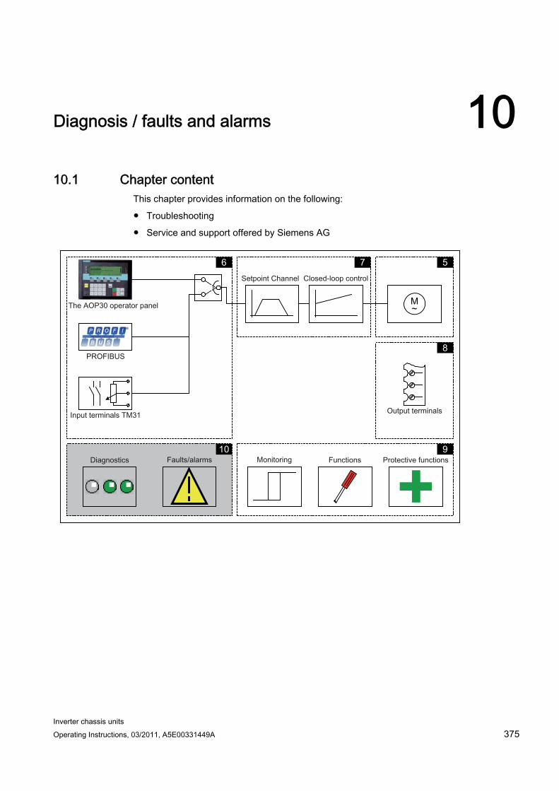
Inverter chassis units Operating Instructions, 03/2011, A5E00331449A 375
Diagnosis / faults and alarms 1010.1 Chapter content
This chapter provides information on the following:
Troubleshooting
Service and support offered by Siemens AG
M ~
5 7 6
8
9 10
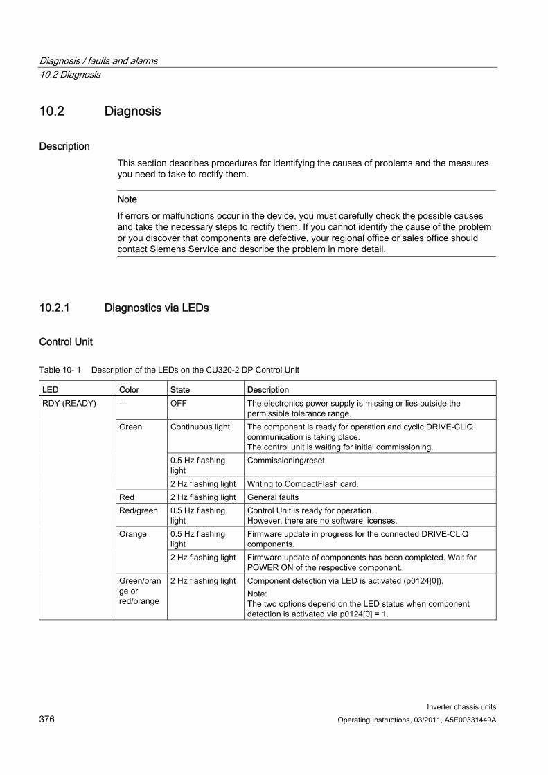
Diagnosis / faults and alarms 10.2 Diagnosis
Inverter chassis units 376 Operating Instructions, 03/2011, A5E00331449A
10.2 Diagnosis
Description This section describes procedures for identifying the causes of problems and the measures you need to take to rectify them.
Note
If errors or malfunctions occur in the device, you must carefully check the possible causes and take the necessary steps to rectify them. If you cannot identify the cause of the problem or you discover that components are defective, your regional office or sales office should contact Siemens Service and describe the problem in more detail.
10.2.1 Diagnostics via LEDs
Control Unit
Table 10- 1 Description of the LEDs on the CU320-2 DP Control Unit
LED Color State Description --- OFF The electronics power supply is missing or lies outside the
permissible tolerance range. Continuous light The component is ready for operation and cyclic DRIVE-CLiQ
communication is taking place. The control unit is waiting for initial commissioning.
0.5 Hz flashing light
Commissioning/reset
Green
2 Hz flashing light Writing to CompactFlash card. Red 2 Hz flashing light General faults Red/green 0.5 Hz flashing
light Control Unit is ready for operation. However, there are no software licenses.
0.5 Hz flashing light
Firmware update in progress for the connected DRIVE-CLiQ components.
Orange
2 Hz flashing light Firmware update of components has been completed. Wait for POWER ON of the respective component.
RDY (READY)
Green/orange or red/orange
2 Hz flashing light Component detection via LED is activated (p0124[0]). Note: The two options depend on the LED status when component detection is activated via p0124[0] = 1.
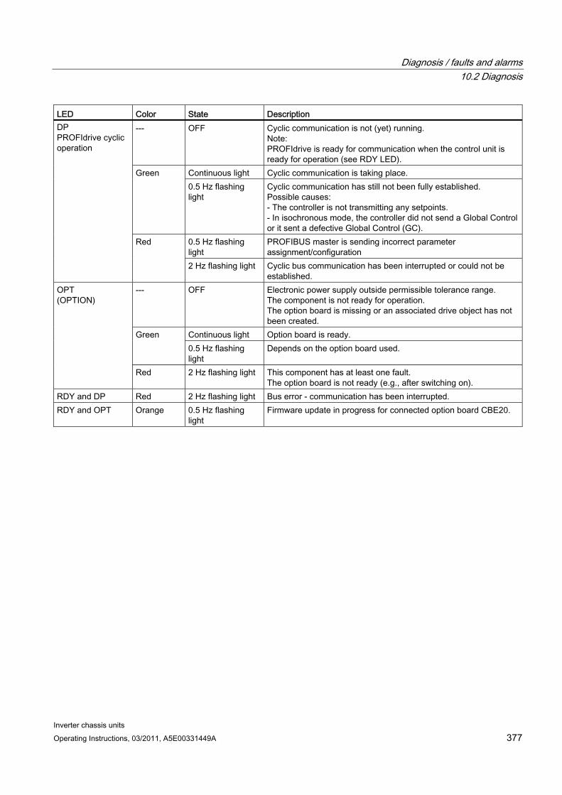
Diagnosis / faults and alarms 10.2 Diagnosis
Inverter chassis units Operating Instructions, 03/2011, A5E00331449A 377
LED Color State Description --- OFF Cyclic communication is not (yet) running.
Note: PROFIdrive is ready for communication when the control unit is ready for operation (see RDY LED).
Continuous light Cyclic communication is taking place. Green 0.5 Hz flashing light
Cyclic communication has still not been fully established. Possible causes: - The controller is not transmitting any setpoints. - In isochronous mode, the controller did not send a Global Control or it sent a defective Global Control (GC).
0.5 Hz flashing light
PROFIBUS master is sending incorrect parameter assignment/configuration
DP PROFIdrive cyclic operation
Red
2 Hz flashing light Cyclic bus communication has been interrupted or could not be established.
--- OFF Electronic power supply outside permissible tolerance range. The component is not ready for operation. The option board is missing or an associated drive object has not been created.
Continuous light Option board is ready. Green 0.5 Hz flashing light
Depends on the option board used.
OPT (OPTION)
Red 2 Hz flashing light This component has at least one fault. The option board is not ready (e.g., after switching on).
RDY and DP Red 2 Hz flashing light Bus error - communication has been interrupted. RDY and OPT Orange 0.5 Hz flashing
light Firmware update in progress for connected option board CBE20.
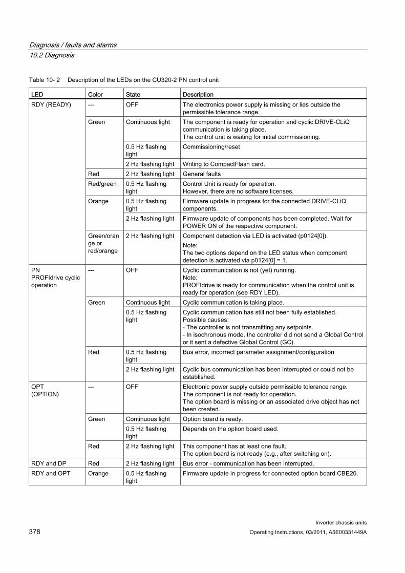
Diagnosis / faults and alarms 10.2 Diagnosis
Inverter chassis units 378 Operating Instructions, 03/2011, A5E00331449A
Table 10- 2 Description of the LEDs on the CU320-2 PN control unit
LED Color State Description --- OFF The electronics power supply is missing or lies outside the
permissible tolerance range. Continuous light The component is ready for operation and cyclic DRIVE-CLiQ
communication is taking place. The control unit is waiting for initial commissioning.
0.5 Hz flashing light
Commissioning/reset
Green
2 Hz flashing light Writing to CompactFlash card. Red 2 Hz flashing light General faults Red/green 0.5 Hz flashing
light Control Unit is ready for operation. However, there are no software licenses.
0.5 Hz flashing light
Firmware update in progress for the connected DRIVE-CLiQ components.
Orange
2 Hz flashing light Firmware update of components has been completed. Wait for POWER ON of the respective component.
RDY (READY)
Green/orange or red/orange
2 Hz flashing light Component detection via LED is activated (p0124[0]). Note: The two options depend on the LED status when component detection is activated via p0124[0] = 1.
--- OFF Cyclic communication is not (yet) running. Note: PROFIdrive is ready for communication when the control unit is ready for operation (see RDY LED).
Continuous light Cyclic communication is taking place. Green 0.5 Hz flashing light
Cyclic communication has still not been fully established. Possible causes: - The controller is not transmitting any setpoints. - In isochronous mode, the controller did not send a Global Control or it sent a defective Global Control (GC).
0.5 Hz flashing light
Bus error, incorrect parameter assignment/configuration
PN PROFIdrive cyclic operation
Red
2 Hz flashing light Cyclic bus communication has been interrupted or could not be established.
--- OFF Electronic power supply outside permissible tolerance range. The component is not ready for operation. The option board is missing or an associated drive object has not been created.
Continuous light Option board is ready. Green 0.5 Hz flashing light
Depends on the option board used.
OPT (OPTION)
Red 2 Hz flashing light This component has at least one fault. The option board is not ready (e.g., after switching on).
RDY and DP Red 2 Hz flashing light Bus error - communication has been interrupted. RDY and OPT Orange 0.5 Hz flashing
light Firmware update in progress for connected option board CBE20.
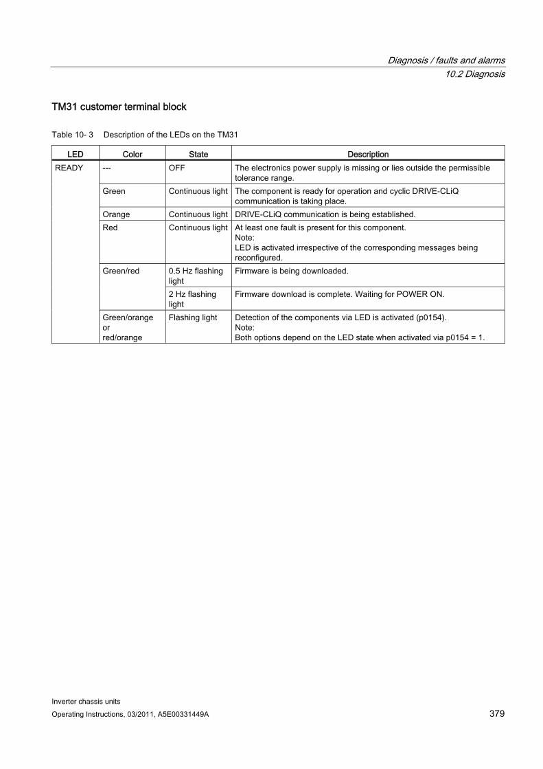
Diagnosis / faults and alarms 10.2 Diagnosis
Inverter chassis units Operating Instructions, 03/2011, A5E00331449A 379
TM31 customer terminal block
Table 10- 3 Description of the LEDs on the TM31
LED Color State Description --- OFF The electronics power supply is missing or lies outside the permissible
tolerance range. Green Continuous light The component is ready for operation and cyclic DRIVE-CLiQ
communication is taking place. Orange Continuous light DRIVE-CLiQ communication is being established. Red Continuous light At least one fault is present for this component.
Note: LED is activated irrespective of the corresponding messages being reconfigured.
0.5 Hz flashing light
Firmware is being downloaded. Green/red
2 Hz flashing light
Firmware download is complete. Waiting for POWER ON.
READY
Green/orange or red/orange
Flashing light Detection of the components via LED is activated (p0154). Note: Both options depend on the LED state when activated via p0154 = 1.
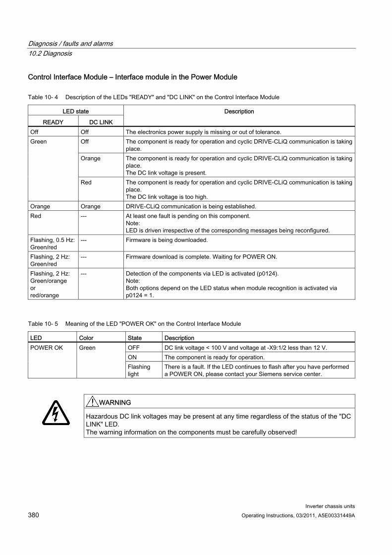
Diagnosis / faults and alarms 10.2 Diagnosis
Inverter chassis units 380 Operating Instructions, 03/2011, A5E00331449A
Control Interface Module – Interface module in the Power Module
Table 10- 4 Description of the LEDs "READY" and "DC LINK" on the Control Interface Module
LED state
READY DC LINK
Description
Off Off The electronics power supply is missing or out of tolerance. Off The component is ready for operation and cyclic DRIVE-CLiQ communication is taking
place. Orange The component is ready for operation and cyclic DRIVE-CLiQ communication is taking
place. The DC link voltage is present.
Green
Red The component is ready for operation and cyclic DRIVE-CLiQ communication is taking place. The DC link voltage is too high.
Orange Orange DRIVE-CLiQ communication is being established. Red --- At least one fault is pending on this component.
Note: LED is driven irrespective of the corresponding messages being reconfigured.
Flashing, 0.5 Hz: Green/red
--- Firmware is being downloaded.
Flashing, 2 Hz: Green/red
--- Firmware download is complete. Waiting for POWER ON.
Flashing, 2 Hz: Green/orange or red/orange
--- Detection of the components via LED is activated (p0124). Note: Both options depend on the LED status when module recognition is activated via p0124 = 1.
Table 10- 5 Meaning of the LED "POWER OK" on the Control Interface Module
LED Color State Description OFF DC link voltage < 100 V and voltage at -X9:1/2 less than 12 V. ON The component is ready for operation.
POWER OK Green
Flashing light
There is a fault. If the LED continues to flash after you have performed a POWER ON, please contact your Siemens service center.
WARNING
Hazardous DC link voltages may be present at any time regardless of the status of the "DC LINK" LED. The warning information on the components must be carefully observed!
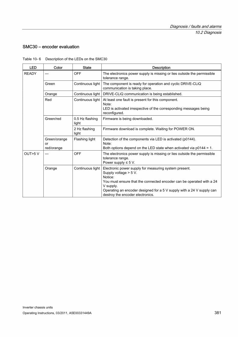
Diagnosis / faults and alarms 10.2 Diagnosis
Inverter chassis units Operating Instructions, 03/2011, A5E00331449A 381
SMC30 – encoder evaluation
Table 10- 6 Description of the LEDs on the SMC30
LED Color State Description --- OFF The electronics power supply is missing or lies outside the permissible
tolerance range. Green Continuous light The component is ready for operation and cyclic DRIVE-CLiQ
communication is taking place. Orange Continuous light DRIVE-CLiQ communication is being established. Red Continuous light At least one fault is present for this component.
Note: LED is activated irrespective of the corresponding messages being reconfigured.
0.5 Hz flashing light
Firmware is being downloaded. Green/red
2 Hz flashing light
Firmware download is complete. Waiting for POWER ON.
READY
Green/orange or red/orange
Flashing light Detection of the components via LED is activated (p0144). Note: Both options depend on the LED state when activated via p0144 = 1.
--- OFF The electronics power supply is missing or lies outside the permissible tolerance range. Power supply ≤ 5 V.
OUT>5 V
Orange Continuous light Electronic power supply for measuring system present. Supply voltage > 5 V. Notice: You must ensure that the connected encoder can be operated with a 24 V supply. Operating an encoder designed for a 5 V supply with a 24 V supply can destroy the encoder electronics.
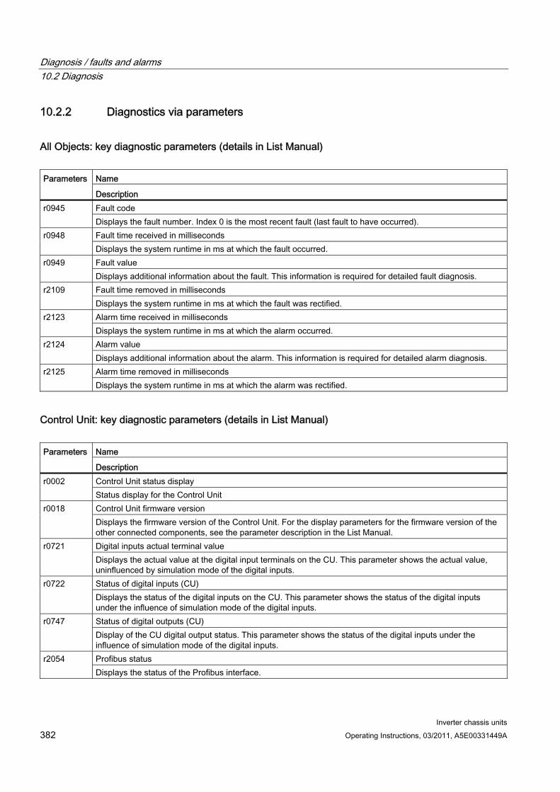
Diagnosis / faults and alarms 10.2 Diagnosis
Inverter chassis units 382 Operating Instructions, 03/2011, A5E00331449A
10.2.2 Diagnostics via parameters
All Objects: key diagnostic parameters (details in List Manual)
Name Parameters
Description Fault code r0945 Displays the fault number. Index 0 is the most recent fault (last fault to have occurred). Fault time received in milliseconds r0948 Displays the system runtime in ms at which the fault occurred. Fault value r0949 Displays additional information about the fault. This information is required for detailed fault diagnosis. Fault time removed in milliseconds r2109 Displays the system runtime in ms at which the fault was rectified. Alarm time received in milliseconds r2123 Displays the system runtime in ms at which the alarm occurred. Alarm value r2124 Displays additional information about the alarm. This information is required for detailed alarm diagnosis. Alarm time removed in milliseconds r2125 Displays the system runtime in ms at which the alarm was rectified.
Control Unit: key diagnostic parameters (details in List Manual)
Name Parameters
Description Control Unit status display r0002 Status display for the Control Unit Control Unit firmware version r0018 Displays the firmware version of the Control Unit. For the display parameters for the firmware version of the other connected components, see the parameter description in the List Manual. Digital inputs actual terminal value r0721 Displays the actual value at the digital input terminals on the CU. This parameter shows the actual value, uninfluenced by simulation mode of the digital inputs. Status of digital inputs (CU) r0722 Displays the status of the digital inputs on the CU. This parameter shows the status of the digital inputs under the influence of simulation mode of the digital inputs. Status of digital outputs (CU) r0747 Display of the CU digital output status. This parameter shows the status of the digital inputs under the influence of simulation mode of the digital inputs. Profibus status r2054 Displays the status of the Profibus interface.
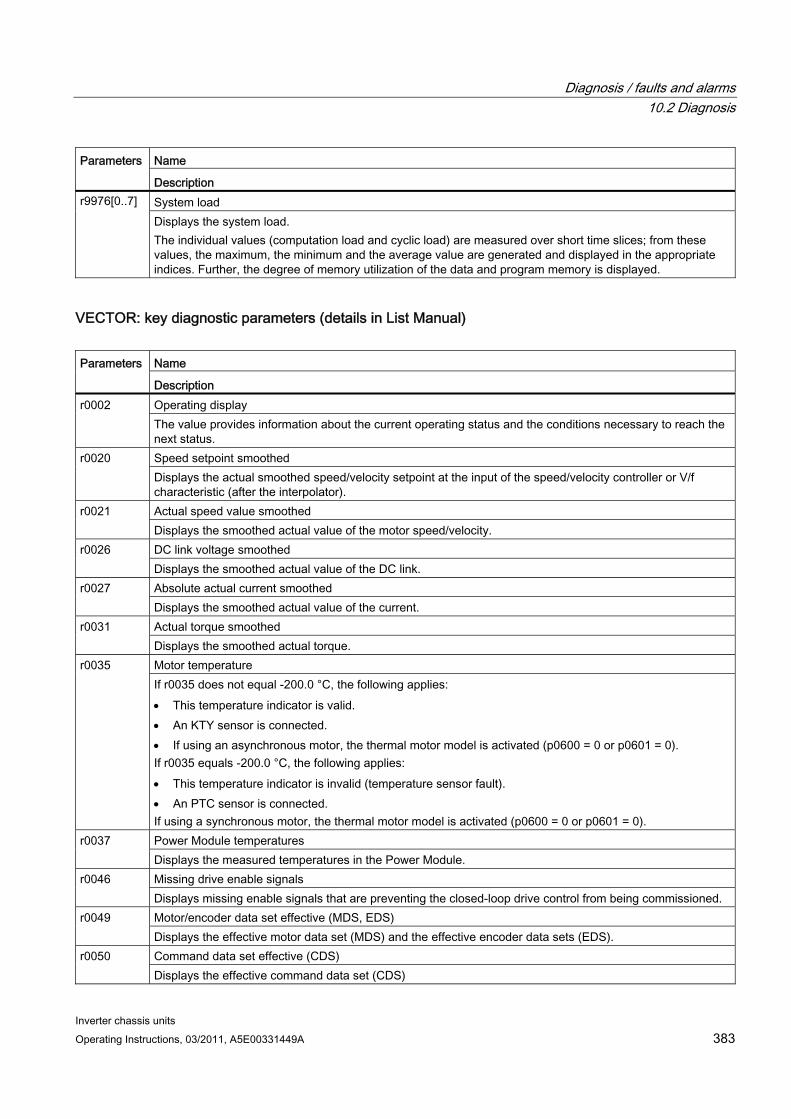
Diagnosis / faults and alarms 10.2 Diagnosis
Inverter chassis units Operating Instructions, 03/2011, A5E00331449A 383
Name Parameters
Description System load r9976[0..7] Displays the system load. The individual values (computation load and cyclic load) are measured over short time slices; from these values, the maximum, the minimum and the average value are generated and displayed in the appropriate indices. Further, the degree of memory utilization of the data and program memory is displayed.
VECTOR: key diagnostic parameters (details in List Manual)
Name Parameters
Description Operating display r0002 The value provides information about the current operating status and the conditions necessary to reach the next status. Speed setpoint smoothed r0020 Displays the actual smoothed speed/velocity setpoint at the input of the speed/velocity controller or V/f characteristic (after the interpolator). Actual speed value smoothed r0021 Displays the smoothed actual value of the motor speed/velocity. DC link voltage smoothed r0026 Displays the smoothed actual value of the DC link. Absolute actual current smoothed r0027 Displays the smoothed actual value of the current. Actual torque smoothed r0031 Displays the smoothed actual torque. Motor temperature r0035 If r0035 does not equal -200.0 °C, the following applies: This temperature indicator is valid. An KTY sensor is connected. If using an asynchronous motor, the thermal motor model is activated (p0600 = 0 or p0601 = 0). If r0035 equals -200.0 °C, the following applies: This temperature indicator is invalid (temperature sensor fault). An PTC sensor is connected. If using a synchronous motor, the thermal motor model is activated (p0600 = 0 or p0601 = 0). Power Module temperatures r0037 Displays the measured temperatures in the Power Module. Missing drive enable signals r0046 Displays missing enable signals that are preventing the closed-loop drive control from being commissioned. Motor/encoder data set effective (MDS, EDS) r0049 Displays the effective motor data set (MDS) and the effective encoder data sets (EDS). Command data set effective (CDS) r0050 Displays the effective command data set (CDS)

Diagnosis / faults and alarms 10.2 Diagnosis
Inverter chassis units 384 Operating Instructions, 03/2011, A5E00331449A
Name Parameters
Description Drive data set (DDS) effective r0051 Effective drive data set (DDS) display. Rated power module power r0206 Displays the rated power module power for various load duty cycles. Rated power module current r0207 Displays the rated power module power for various load duty cycles. Rated power module line supply voltage r0208 Displays the rated line supply voltage of the power module.
TM31: key diagnostic parameters (details in List Manual)
Name Parameters
Description TM31 operating display r0002 Operating display for terminal board 31 (TB31). Digital inputs actual terminal value r4021 Displays the actual value at the digital input terminals on the TM31. This parameter shows the actual value, uninfluenced by simulation mode of the digital inputs. Status of digital inputs r4022 Displays the status of the digital inputs on the TM31. This parameter shows the status of the digital inputs under the influence of simulation mode of the digital inputs. Status of digital outputs r4047 Displays the status of the TM31 digital outputs. Inversion via p4048 is taken into account.

Diagnosis / faults and alarms 10.2 Diagnosis
Inverter chassis units Operating Instructions, 03/2011, A5E00331449A 385
10.2.3 Indicating and rectifying faults The device features a wide range of functions that protect the drive against damage if a fault occurs (faults and alarms).
Indicating faults and alarms If a fault occurs, the drive displays the fault and/or alarm on the AOP30 operator panel. Faults are indicated by the red "FAULT" LED and a fault screen is automatically displayed. You can use the F1 Help function to call up information about the cause of the fault and how to remedy it. You can use F5 Ack. to acknowledge a stored fault.
Any alarms are displayed by the yellow flashing "ALARM" LED. The system also displays a note in the status bar providing information on the cause.
Every fault and alarm is entered in the fault/alarm buffer along with time the error occurred. The time stamp refers to the relative system time in milliseconds (r0969).
Activate the "Set date/time - AOP synchronization -> Drive" setting to date- and time-stamp errors on the AOP30.
What is a fault? A fault is a message from the drive indicating an error or other exceptional (unwanted) status. This could be caused by a fault within the converter or an external fault triggered, for example, from the winding temperature monitor for the induction motor. The faults are displayed and can be reported to a higher-level control system via PROFIdrive. In the delivery condition, the message "Drive fault" is also sent to a relay output. Once you have rectified the cause of the fault, you have to acknowledge the fault message.
What is an alarm? An alarm is the response to a fault condition identified by the drive. It does not result in the drive being switched off and does not have to be acknowledged. Alarms are "self acknowledging", that is, they are reset automatically when the cause of the alarm has been eliminated.
Diagnosis / faults and alarms 10.3 Overview of warnings and faults
Inverter chassis units 386 Operating Instructions, 03/2011, A5E00331449A
10.3 Overview of warnings and faults If a fault occurs, the drive indicates the fault and/or alarm. Faults and alarms are listed in a fault/alarm list, together with the following information:
Fault/alarm number
Standard drive response
Description of the possible cause of the fault/alarm
Description of the procedure for rectifying the problem
Standard fault acknowledgement after it has been rectified
Note
The list of faults and alarms is included on the CD.
It also contains descriptions of the responses (OFF1, OFF2, etc.).
10.4 Service and Support
Technical support We offer technical support in both German and English for deploying products, systems, and solutions in drive and automation technology.
In special cases, help is available from professional, trained, and experienced specialists via teleservice and video conferencing.
If you have any questions, please contact our hotline:
Time zone Europe/Africa
Phone +49 (0) 911 895 7222 Fax +49 (0) 911 895 7223 Internet http://www.siemens.com/automation/support-request
Time zone America Phone +1 423 262 2522 Fax +1 423 262 2200 Internet [email protected]
Time zone Asia/Pacific Phone +86 1064 757 575 Fax +86 1064 747 474 Internet [email protected]

Diagnosis / faults and alarms 10.4 Service and Support
Inverter chassis units Operating Instructions, 03/2011, A5E00331449A 387
10.4.1 Spare parts Ask your local Siemens office for details of spare parts available for your built-in unit.

Diagnosis / faults and alarms 10.4 Service and Support
Inverter chassis units 388 Operating Instructions, 03/2011, A5E00331449A
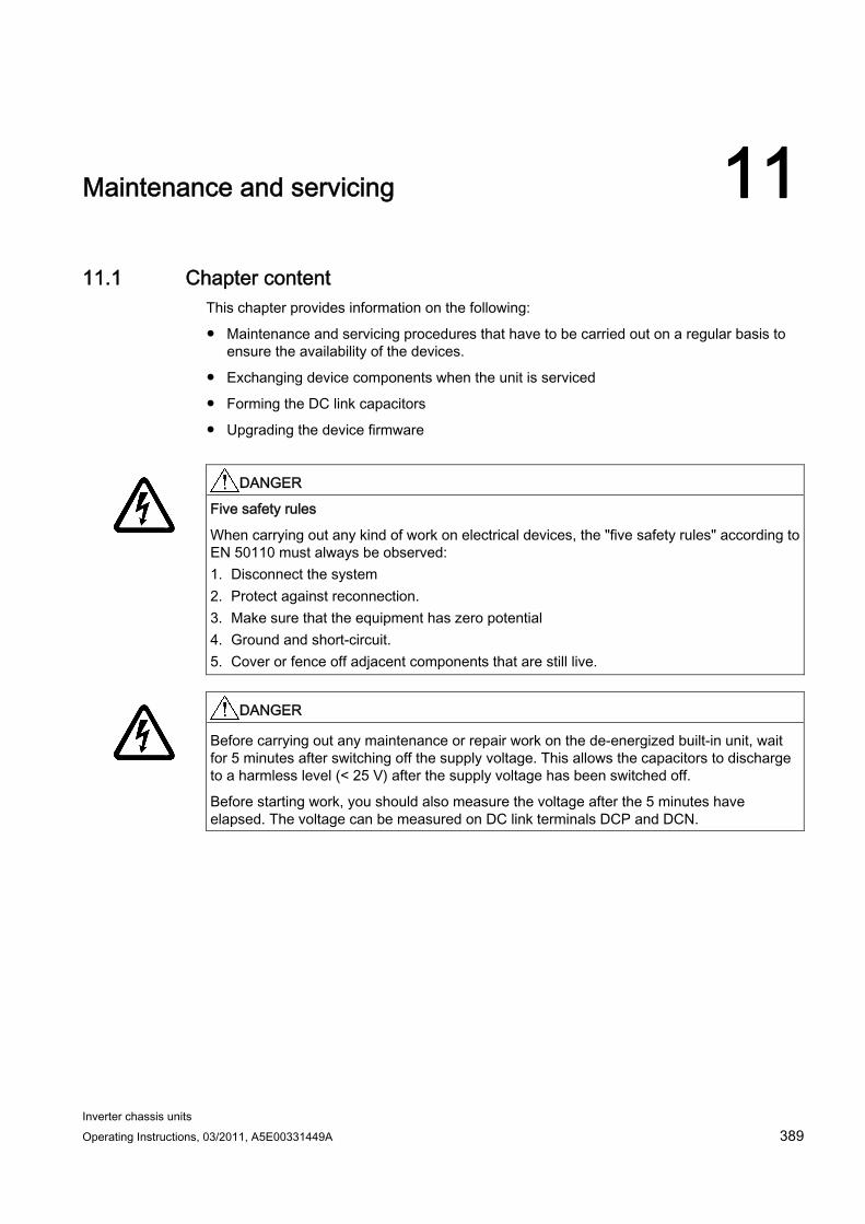
Inverter chassis units Operating Instructions, 03/2011, A5E00331449A 389
Maintenance and servicing 1111.1 Chapter content
This chapter provides information on the following:
Maintenance and servicing procedures that have to be carried out on a regular basis to ensure the availability of the devices.
Exchanging device components when the unit is serviced
Forming the DC link capacitors
Upgrading the device firmware
DANGER
Five safety rules
When carrying out any kind of work on electrical devices, the "five safety rules" according to EN 50110 must always be observed: 1. Disconnect the system 2. Protect against reconnection. 3. Make sure that the equipment has zero potential 4. Ground and short-circuit. 5. Cover or fence off adjacent components that are still live.
DANGER
Before carrying out any maintenance or repair work on the de-energized built-in unit, wait for 5 minutes after switching off the supply voltage. This allows the capacitors to discharge to a harmless level (< 25 V) after the supply voltage has been switched off.
Before starting work, you should also measure the voltage after the 5 minutes have elapsed. The voltage can be measured on DC link terminals DCP and DCN.
Maintenance and servicing 11.2 Maintenance
Inverter chassis units 390 Operating Instructions, 03/2011, A5E00331449A
11.2 Maintenance The chassis unit comprises mostly electronic components. Apart from the fan(s), the unit, therefore, contains hardly any components that are subject to wear or that require maintenance or servicing. The purpose of maintenance is to preserve the specified condition of the chassis unit. Dirt and contamination must be removed regularly and parts subject to wear replaced.
The following points must generally be observed.
11.2.1 Cleaning
Dust deposits Dust deposits inside the chassis unit must be removed at regular intervals (or at least once a year) by qualified personnel in line with the relevant safety regulations. The unit must be cleaned using a brush and vacuum cleaner, and dry compressed air (max. 1 bar) for areas that cannot be easily reached.
Ventilation When installing the devices in a cabinet, make sure that the cabinet ventilation slots are not obstructed. The fan must be checked to make sure that it is functioning correctly.
Cable and screw terminals Cable and screw terminals must be checked regularly to ensure that they are secure in position, and if necessary, retightened. Cabling must be checked for defects. Defective parts must be replaced immediately.
Note
The actual intervals at which maintenance procedures are to be performed depend on the installation conditions and the operating conditions.
Siemens offers its customers support in the form of a service contract. For further details, contact your regional office or sales office.
Maintenance and servicing 11.3 Maintenance
Inverter chassis units Operating Instructions, 03/2011, A5E00331449A 391
11.3 Maintenance
11.3.1 Maintenance Servicing involves activities and procedures for maintaining and restoring the specified condition of the device.
Required tools The following tools are required for replacing components:
Spanner or socket spanner (w/f 10)
Spanner or socket spanner (w/f 13)
Spanner or socket spanner (w/f 16/17)
Spanner or socket spanner (w/f 18/19)
Hexagon-socket spanner (size 8)
Torque wrench from 5 Nm to 50 Nm
Screwdriver size 1 / 2
Screwdriver Torx T20
Screwdriver Torx T30
Tightening torques for current-carrying parts When securing connections for current-conducting parts (DC link/motor connections, busbars), you must observe the following tightening torques.
Table 11- 1 Tightening torques for connecting current-carrying parts
Screw Torque M6 6 Nm M8 13 Nm
M10 25 Nm M12 50 Nm
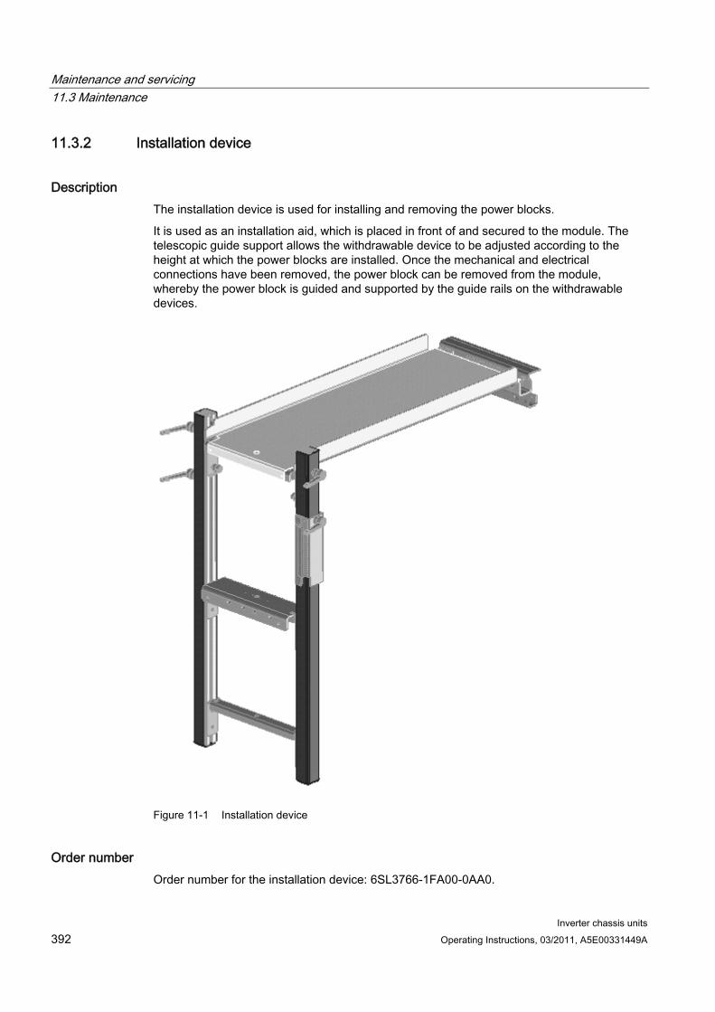
Maintenance and servicing 11.3 Maintenance
Inverter chassis units 392 Operating Instructions, 03/2011, A5E00331449A
11.3.2 Installation device
Description The installation device is used for installing and removing the power blocks.
It is used as an installation aid, which is placed in front of and secured to the module. The telescopic guide support allows the withdrawable device to be adjusted according to the height at which the power blocks are installed. Once the mechanical and electrical connections have been removed, the power block can be removed from the module, whereby the power block is guided and supported by the guide rails on the withdrawable devices.
Figure 11-1 Installation device
Order number Order number for the installation device: 6SL3766-1FA00-0AA0.
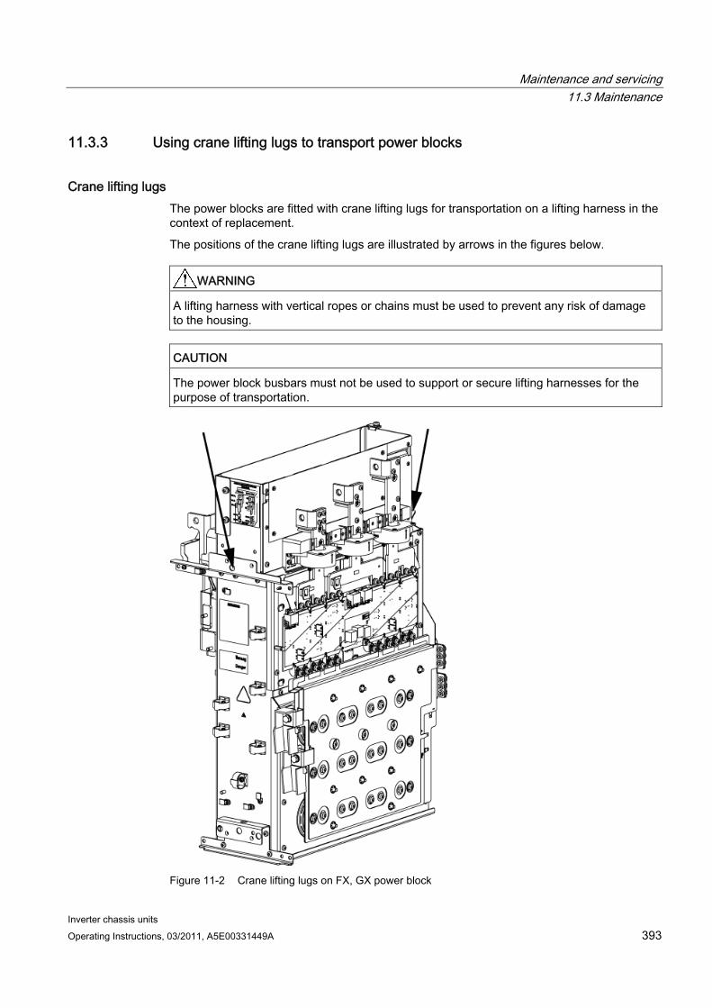
Maintenance and servicing 11.3 Maintenance
Inverter chassis units Operating Instructions, 03/2011, A5E00331449A 393
11.3.3 Using crane lifting lugs to transport power blocks
Crane lifting lugs The power blocks are fitted with crane lifting lugs for transportation on a lifting harness in the context of replacement.
The positions of the crane lifting lugs are illustrated by arrows in the figures below.
WARNING A lifting harness with vertical ropes or chains must be used to prevent any risk of damage to the housing.
CAUTION The power block busbars must not be used to support or secure lifting harnesses for the purpose of transportation.
Figure 11-2 Crane lifting lugs on FX, GX power block
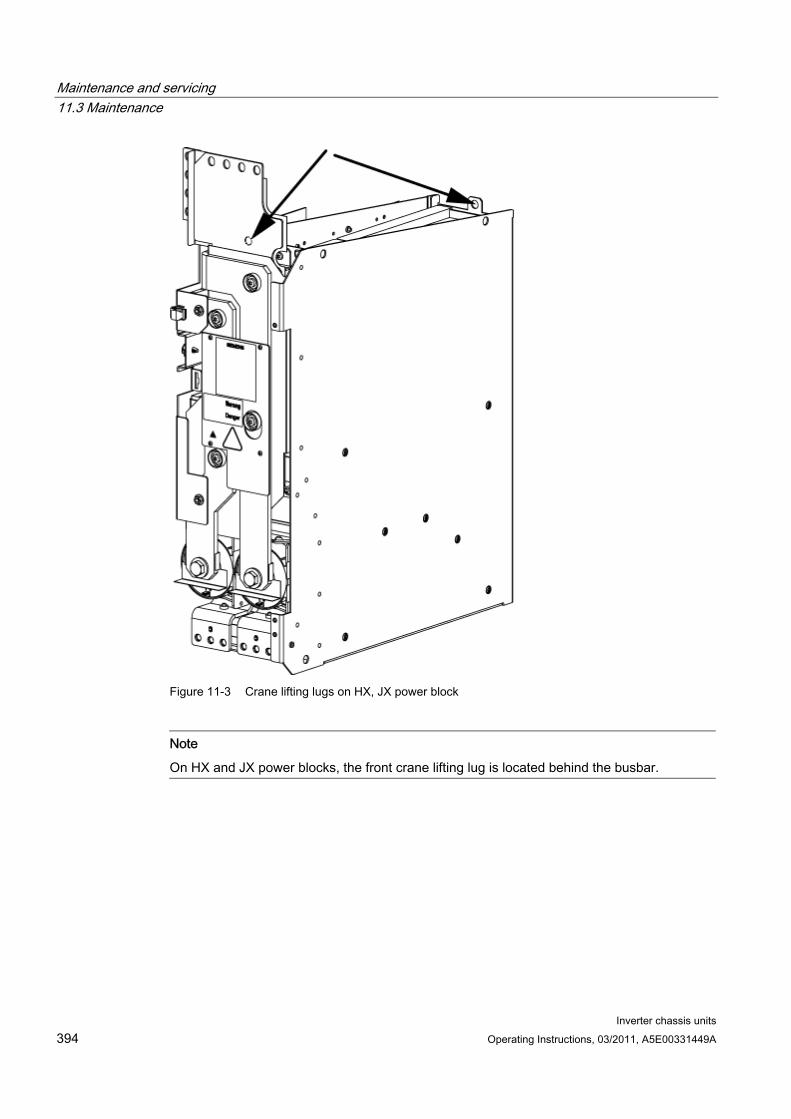
Maintenance and servicing 11.3 Maintenance
Inverter chassis units 394 Operating Instructions, 03/2011, A5E00331449A
Figure 11-3 Crane lifting lugs on HX, JX power block
Note
On HX and JX power blocks, the front crane lifting lug is located behind the busbar.
Maintenance and servicing 11.4 Replacing components
Inverter chassis units Operating Instructions, 03/2011, A5E00331449A 395
11.4 Replacing components
WARNING The following must be taken into account when the devices are transported: The devices are heavy or generally top heavy. The center of gravity is marked on the
devices. Due to their weight, the devices must be handled with care by trained personnel. Serious injury or even death and substantial material damage can occur if the devices
are not lifted or transported properly.
WARNING
The devices are operated with high voltages.
All connection work must be carried out when the cabinet is de-energized!
All work on the device must be carried out by trained personnel only. Non-observance of these warnings can result in death, serious personal injury, or substantial property damage.
Work on an open device must be carried out with extreme caution because external supply voltages may be present. The power and control terminals may be live even when the motor is not running.
Dangerously high voltage levels are still present in the device up to five minutes after it has been disconnected due to the DC link capacitors. For this reason, the unit should not be opened until a reasonable period of time has elapsed.
DANGER
Five safety rules
When carrying out any kind of work on electrical devices, the "five safety rules" according to EN 50110 must always be observed: 1. Disconnect the system 2. Protect against reconnection. 3. Make sure that the equipment has zero potential 4. Ground and short-circuit. 5. Cover or fence off adjacent components that are still live.
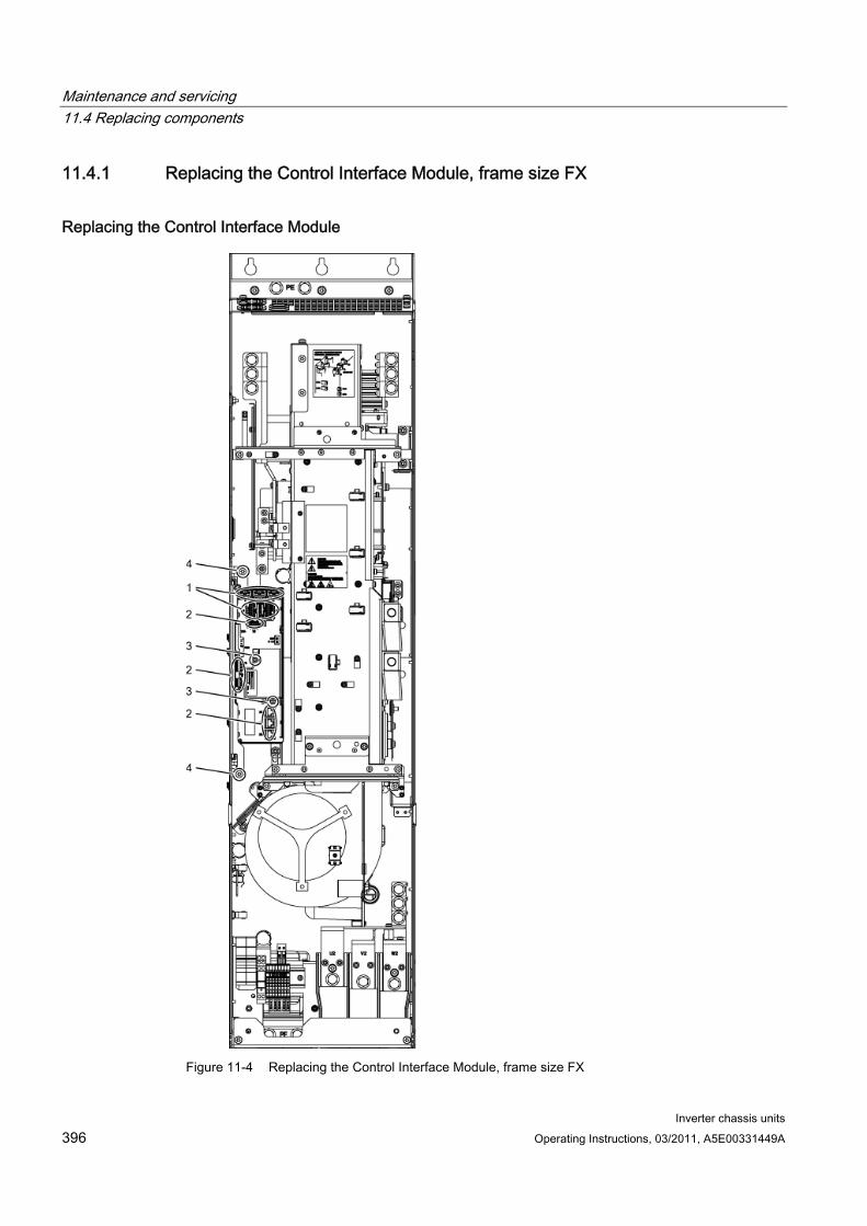
Maintenance and servicing 11.4 Replacing components
Inverter chassis units 396 Operating Instructions, 03/2011, A5E00331449A
11.4.1 Replacing the Control Interface Module, frame size FX
Replacing the Control Interface Module
Figure 11-4 Replacing the Control Interface Module, frame size FX

Maintenance and servicing 11.4 Replacing components
Inverter chassis units Operating Instructions, 03/2011, A5E00331449A 397
Preparatory steps Disconnect the built-in unit from the power supply.
Allow unimpeded access.
Remove the protective cover.
Removal steps The removal steps are numbered in accordance with the figure.
1. Disconnect the plug-in connections for the fiber-optic cables and signal cables (5 plugs).
2. Remove the DRIVE-CLiQ cables and connections on -X41, -X42, -X46 (6 plugs).
3. Take out the retaining screws for the IPD card (2 screws) and remove the IPD card from plug -X45 on the Control Interface Module.
4. Remove the retaining screws for the Control Interface Module (2 screws).
When removing the Control Interface Module, you have to disconnect 5 further plugs one after the other (2 at the top, 3 below).
CAUTION When removing the unit, ensure that you do not damage any signal cables.
Installation steps For installation, carry out the above steps in reverse order.
CAUTION The tightening torques specified in the table "Tightening torques for connecting current-conducting parts" must be observed.
Carefully establish the plug connections and then ensure that they are secure.
The fiber optic cable plugs must be remounted at their original slot. Fiber optic cables and sockets are accordingly labeled for correct assignment (U11, U21, U31).
The screw connections for the protective covers must only be tightened finger-tight.
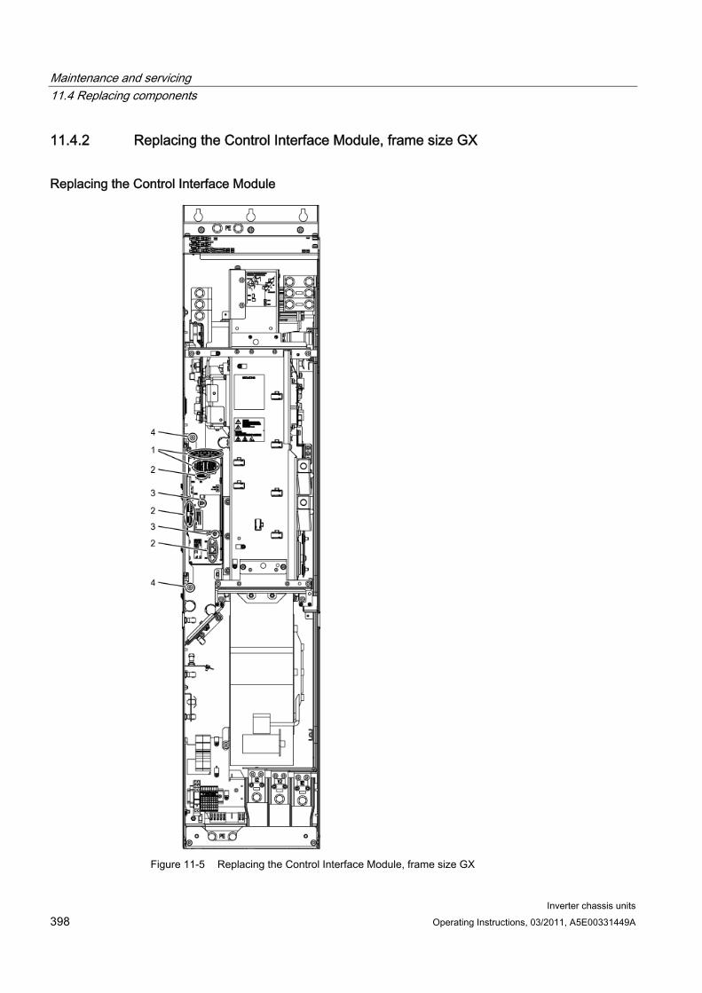
Maintenance and servicing 11.4 Replacing components
Inverter chassis units 398 Operating Instructions, 03/2011, A5E00331449A
11.4.2 Replacing the Control Interface Module, frame size GX
Replacing the Control Interface Module
Figure 11-5 Replacing the Control Interface Module, frame size GX

Maintenance and servicing 11.4 Replacing components
Inverter chassis units Operating Instructions, 03/2011, A5E00331449A 399
Preparatory steps Disconnect the built-in unit from the power supply.
Allow unimpeded access.
Remove the protective cover.
Removal steps The removal steps are numbered in accordance with the figure.
1. Disconnect the plug-in connections for the fiber-optic cables and signal cables (5 plugs).
2. Remove the DRIVE-CLiQ cables and connections on -X41, -X42, -X46 (6 plugs).
3. Take out the retaining screws for the IPD card (2 screws) and remove the IPD card from plug -X45 on the Control Interface Module.
4. Remove the retaining screws for the Control Interface Module (2 screws).
When removing the Control Interface Module, you have to disconnect 5 further plugs one after the other (2 at the top, 3 below).
CAUTION When removing the unit, ensure that you do not damage any signal cables.
Installation steps For installation, carry out the above steps in reverse order.
CAUTION The tightening torques specified in the table "Tightening torques for connecting current-conducting parts" must be observed.
Carefully establish the plug connections and then ensure that they are secure.
The fiber optic cable plugs must be remounted at their original slot. Fiber optic cables and sockets are accordingly labeled for correct assignment (U11, U21, U31).
The screw connections for the protective covers must only be tightened finger-tight.
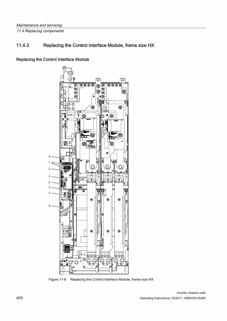
Maintenance and servicing 11.4 Replacing components
Inverter chassis units 400 Operating Instructions, 03/2011, A5E00331449A
11.4.3 Replacing the Control Interface Module, frame size HX
Replacing the Control Interface Module
Figure 11-6 Replacing the Control Interface Module, frame size HX
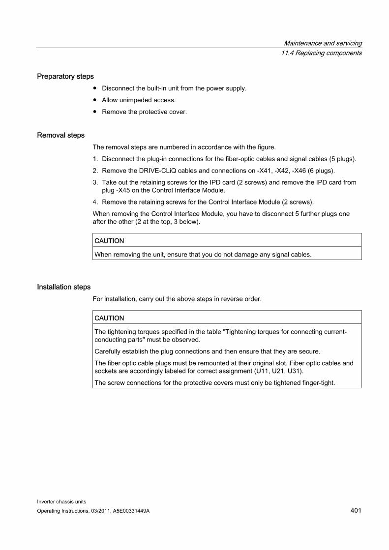
Maintenance and servicing 11.4 Replacing components
Inverter chassis units Operating Instructions, 03/2011, A5E00331449A 401
Preparatory steps Disconnect the built-in unit from the power supply.
Allow unimpeded access.
Remove the protective cover.
Removal steps The removal steps are numbered in accordance with the figure.
1. Disconnect the plug-in connections for the fiber-optic cables and signal cables (5 plugs).
2. Remove the DRIVE-CLiQ cables and connections on -X41, -X42, -X46 (6 plugs).
3. Take out the retaining screws for the IPD card (2 screws) and remove the IPD card from plug -X45 on the Control Interface Module.
4. Remove the retaining screws for the Control Interface Module (2 screws).
When removing the Control Interface Module, you have to disconnect 5 further plugs one after the other (2 at the top, 3 below).
CAUTION When removing the unit, ensure that you do not damage any signal cables.
Installation steps For installation, carry out the above steps in reverse order.
CAUTION The tightening torques specified in the table "Tightening torques for connecting current-conducting parts" must be observed.
Carefully establish the plug connections and then ensure that they are secure.
The fiber optic cable plugs must be remounted at their original slot. Fiber optic cables and sockets are accordingly labeled for correct assignment (U11, U21, U31).
The screw connections for the protective covers must only be tightened finger-tight.
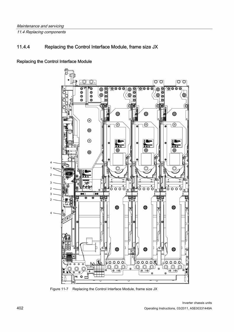
Maintenance and servicing 11.4 Replacing components
Inverter chassis units 402 Operating Instructions, 03/2011, A5E00331449A
11.4.4 Replacing the Control Interface Module, frame size JX
Replacing the Control Interface Module
Figure 11-7 Replacing the Control Interface Module, frame size JX

Maintenance and servicing 11.4 Replacing components
Inverter chassis units Operating Instructions, 03/2011, A5E00331449A 403
Preparatory steps Disconnect the built-in unit from the power supply.
Allow unimpeded access.
Remove the protective cover.
Removal steps The removal steps are numbered in accordance with the figure.
1. Disconnect the plug-in connections for the fiber-optic cables and signal cables (5 plugs).
2. Remove the DRIVE-CLiQ cables and connections on -X41, -X42, -X46 (6 plugs).
3. Take out the retaining screws for the IPD card (2 screws) and remove the IPD card from plug -X45 on the Control Interface Module.
4. Remove the retaining screws for the Control Interface Module (2 screws).
When removing the Control Interface Module, you have to disconnect 5 further plugs one after the other (2 at the top, 3 below).
CAUTION When removing the unit, ensure that you do not damage any signal cables.
Installation steps For installation, carry out the above steps in reverse order.
CAUTION The tightening torques specified in the table "Tightening torques for connecting current-conducting parts" must be observed.
Carefully establish the plug connections and then ensure that they are secure.
The fiber optic cable plugs must be remounted at their original slot. Fiber optic cables and sockets are accordingly labeled for correct assignment (U11, U21, U31).
The screw connections for the protective covers must only be tightened finger-tight.
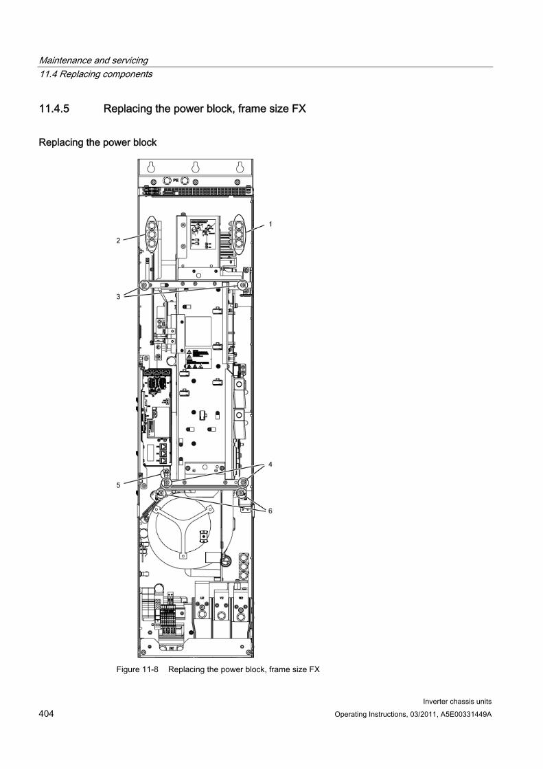
Maintenance and servicing 11.4 Replacing components
Inverter chassis units 404 Operating Instructions, 03/2011, A5E00331449A
11.4.5 Replacing the power block, frame size FX
Replacing the power block
Figure 11-8 Replacing the power block, frame size FX
Maintenance and servicing 11.4 Replacing components
Inverter chassis units Operating Instructions, 03/2011, A5E00331449A 405
Preparatory steps Disconnect the built-in unit from the power supply.
Allow unimpeded access to the power block.
Remove the protective cover.
Removing the Control Interface Module (see corresponding section)
Removal steps The removal steps are numbered in accordance with the figure.
1. Unscrew the connection to the outgoing motor section (3 screws).
2. Unscrew the connection to the line supply (3 screws).
3. Remove the retaining screws at the top (2 screws).
4. Remove the retaining screws at the bottom (2 screws).
5. Disconnect the plug for the thermocouple.
6. Unscrew the two retaining screws for the fan and attach the equipment for assembling the power block at this position.
You can now remove the power block.
CAUTION When removing the power block, ensure that you do not damage any signal cables.
Installation steps For installation, carry out the above steps in reverse order.
CAUTION The tightening torques specified in the table "Tightening torques for connecting current-conducting parts" must be observed.
Carefully establish the plug connections and then ensure that they are secure.
The screw connections for the protective covers must only be tightened finger-tight.

Maintenance and servicing 11.4 Replacing components
Inverter chassis units 406 Operating Instructions, 03/2011, A5E00331449A
11.4.6 Replacing the power block (frame size GX)
Replacing the power block
Figure 11-9 Replacing the power block, frame size GX

Maintenance and servicing 11.4 Replacing components
Inverter chassis units Operating Instructions, 03/2011, A5E00331449A 407
Preparatory steps Disconnect the built-in unit from the power supply.
Allow unimpeded access to the power block.
Remove the protective cover.
Removing the Control Interface Module (see corresponding section)
Removal steps The removal steps are numbered in accordance with the figure.
1. Unscrew the connection to the outgoing motor section (3 screws).
2. Unscrew the connection to the line supply (3 screws).
3. Remove the retaining screws at the top (2 screws).
4. Remove the retaining screws at the bottom (2 screws).
5. Disconnect the plug for the thermocouple.
6. Unscrew the two retaining screws for the fan and attach the equipment for assembling the power block at this position.
You can now remove the power block.
CAUTION When removing the power block, ensure that you do not damage any signal cables.
Installation steps For installation, carry out the above steps in reverse order.
CAUTION The tightening torques specified in the table "Tightening torques for connecting current-conducting parts" must be observed.
Carefully establish the plug connections and then ensure that they are secure.
The screw connections for the protective covers must only be tightened finger-tight.
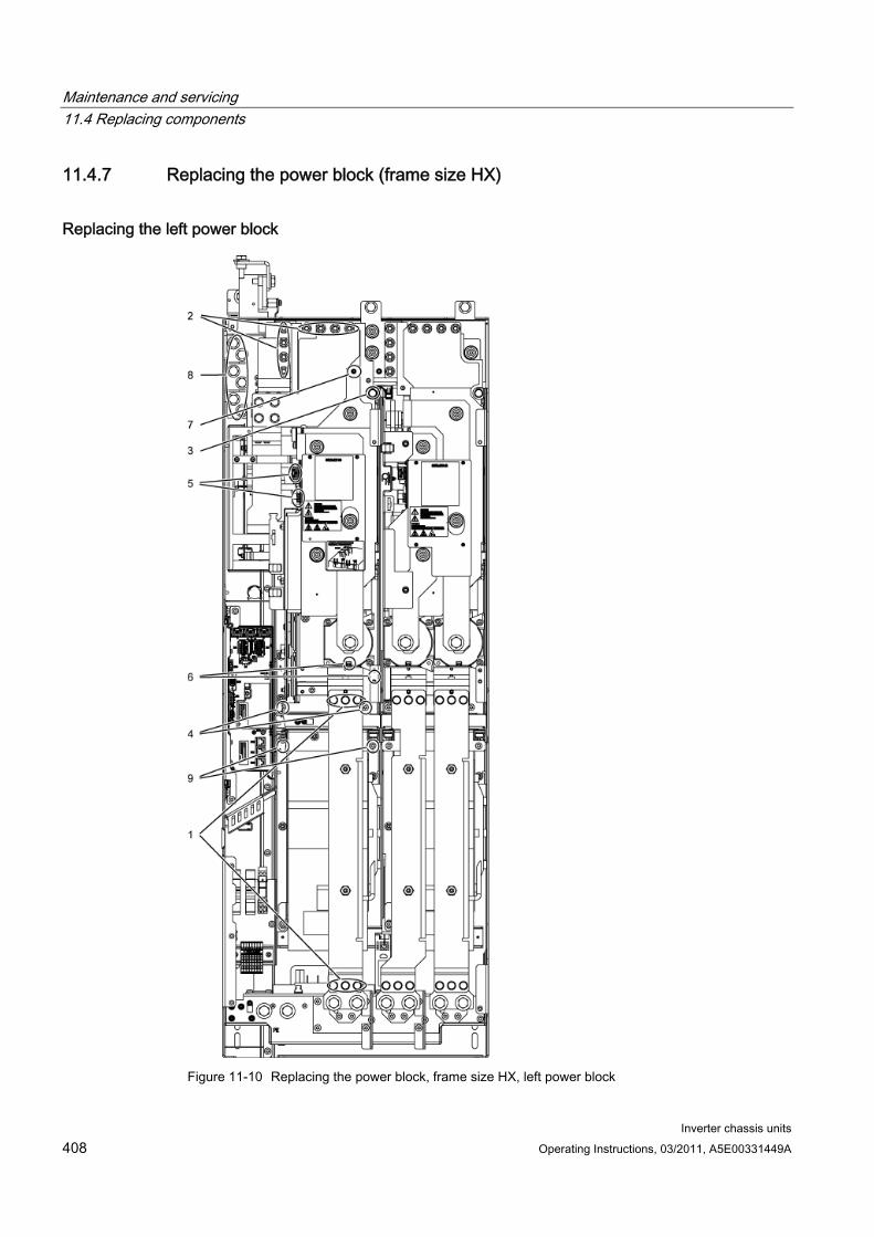
Maintenance and servicing 11.4 Replacing components
Inverter chassis units 408 Operating Instructions, 03/2011, A5E00331449A
11.4.7 Replacing the power block (frame size HX)
Replacing the left power block
Figure 11-10 Replacing the power block, frame size HX, left power block
Maintenance and servicing 11.4 Replacing components
Inverter chassis units Operating Instructions, 03/2011, A5E00331449A 409
Preparatory steps Disconnect the built-in unit from the power supply.
Allow unimpeded access to the power block.
Remove the protective cover.
Removal steps The removal steps are numbered in accordance with the figure.
1. Remove the busbar (6 screws).
2. Unscrew the connection to the DC link (8 nuts).
3. Remove the retaining screw at the top (1 screw).
4. Remove the retaining screws at the bottom (2 screws).
5. Disconnect the plug-in connections for the fiber-optic cables and signal cables (3 plugs).
6. Remove the connection for the current transformer and associated PE connection (1 plug).
7. Remove the connection for the DC link sensor (1 nut).
8. Remove the power connections (6 screws).
9. Unscrew the two retaining screws for the fan and attach the tool for de-installing the power block at this position.
You can now remove the power block.
CAUTION When removing the power block, ensure that you do not damage any signal cables.
Installation steps For installation, carry out the above steps in reverse order.
CAUTION The tightening torques specified in the table "Tightening torques for connecting current-conducting parts" must be observed.
Carefully establish the plug connections and then ensure that they are secure.
The screw connections for the protective covers must only be tightened finger-tight.
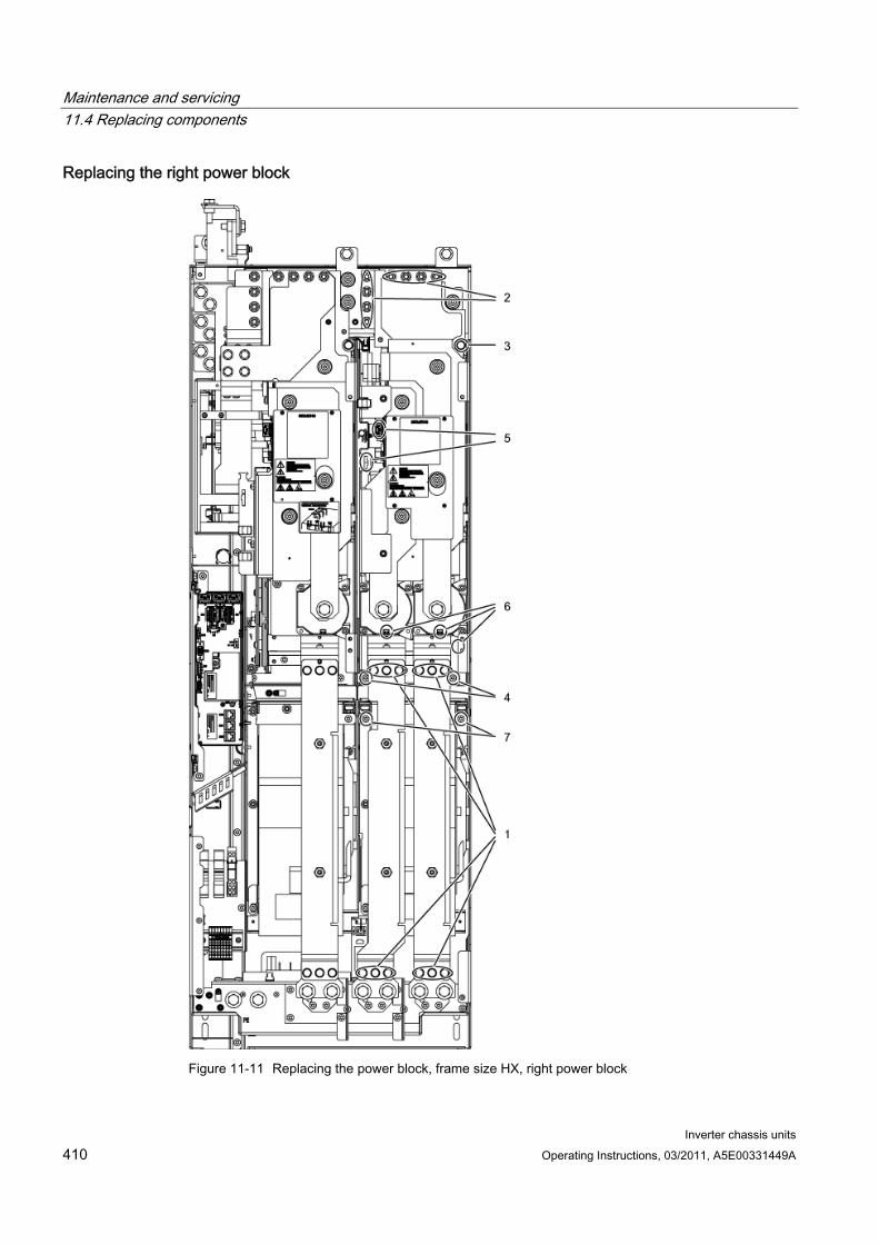
Maintenance and servicing 11.4 Replacing components
Inverter chassis units 410 Operating Instructions, 03/2011, A5E00331449A
Replacing the right power block
Figure 11-11 Replacing the power block, frame size HX, right power block
Maintenance and servicing 11.4 Replacing components
Inverter chassis units Operating Instructions, 03/2011, A5E00331449A 411
Preparatory steps Disconnect the built-in unit from the power supply.
Allow unimpeded access to the power block.
Remove the protective cover.
Removal steps The removal steps are numbered in accordance with the figure.
1. Remove the busbars (12 screws).
2. Unscrew the connection to the DC link (8 nuts).
3. Remove the retaining screw at the top (1 screw).
4. Remove the retaining screws at the bottom (2 screws).
5. Disconnect the plug-in connections for the fiber-optic cables and signal cables (3 plugs).
6. Remove the connection for the current transformer and associated PE connection (2 plugs).
7. Unscrew the two retaining screws for the fan and attach the tool for de-installing the power block at this position.
You can now remove the power block.
CAUTION When removing the power block, ensure that you do not damage any signal cables.
Installation steps For installation, carry out the above steps in reverse order.
CAUTION The tightening torques specified in the table "Tightening torques for connecting current-conducting parts" must be observed.
Carefully establish the plug connections and then ensure that they are secure.
The screw connections for the protective covers must only be tightened finger-tight.
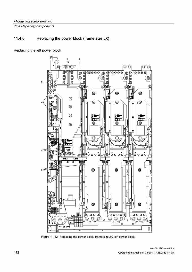
Maintenance and servicing 11.4 Replacing components
Inverter chassis units 412 Operating Instructions, 03/2011, A5E00331449A
11.4.8 Replacing the power block (frame size JX)
Replacing the left power block
Figure 11-12 Replacing the power block, frame size JX, left power block
Maintenance and servicing 11.4 Replacing components
Inverter chassis units Operating Instructions, 03/2011, A5E00331449A 413
Preparatory steps Disconnect the built-in unit from the power supply.
Allow unimpeded access to the power block.
Remove the protective cover.
Removal steps The removal steps are numbered in accordance with the figure.
1. Unscrew the connection to the DC link (8 nuts).
2. Remove the retaining screw at the top (1 screw).
3. Remove the retaining screws at the bottom (2 screws).
4. Disconnect the plug-in connections for the fiber-optic cables and signal cables (2 plugs).
5. Remove the connections to the mains supply (6 screws).
6. Unscrew the two retaining screws for the fan and attach the tool for de-installing the power block at this position.
You can now remove the power block.
CAUTION When removing the power block, ensure that you do not damage any signal cables.
Installation steps For installation, carry out the above steps in reverse order.
CAUTION The tightening torques specified in the table "Tightening torques for connecting current-conducting parts" must be observed.
Carefully establish the plug connections and then ensure that they are secure.
The screw connections for the protective covers must only be tightened finger-tight.
Maintenance and servicing 11.4 Replacing components
Inverter chassis units 414 Operating Instructions, 03/2011, A5E00331449A
Replacing the right power block
Figure 11-13 Replacing the power block, frame size JX, right power block

Maintenance and servicing 11.4 Replacing components
Inverter chassis units Operating Instructions, 03/2011, A5E00331449A 415
Preparatory steps Disconnect the built-in unit from the power supply.
Allow unimpeded access to the power block.
Remove the protective cover.
Removal steps The removal steps are numbered in accordance with the figure.
1. Remove the busbar (8 screws).
2. Unscrew the connection to the DC link (8 nuts).
3. Remove the retaining screw at the top (1 screw).
4. Remove the retaining screws at the bottom (2 screws).
5. Disconnect the plug-in connections for the fiber-optic cables and signal cables (2 plugs).
6. Remove the connection for the current transformer and associated PE connection (1 plug).
7. Unscrew the two retaining screws for the fan and attach the tool for de-installing the power block at this position.
You can now remove the power block.
CAUTION When removing the power block, ensure that you do not damage any signal cables.
Installation steps For installation, carry out the above steps in reverse order.
CAUTION The tightening torques specified in the table "Tightening torques for connecting current-conducting parts" must be observed.
Carefully establish the plug connections and then ensure that they are secure.
The screw connections for the protective covers must only be tightened finger-tight.
Maintenance and servicing 11.4 Replacing components
Inverter chassis units 416 Operating Instructions, 03/2011, A5E00331449A
11.4.9 Replacing the fan, frame size FX
Replacing the fan
Figure 11-14 Replacing the fan, frame size FX

Maintenance and servicing 11.4 Replacing components
Inverter chassis units Operating Instructions, 03/2011, A5E00331449A 417
Description The average service life of the device fans is 50,000 hours. In practice, however, the service life depends on other variables (e.g. ambient temperature, degree of cabinet protection, etc.) and, therefore, may deviate from this value.
The fans must be replaced in good time to maintain the availability of the cabinet unit.
Preparatory steps Disconnect the built-in unit from the power supply.
Allow unimpeded access.
Remove the protective cover
Removal steps The removal steps are numbered in accordance with the figure.
1. Remove the retaining screws for the fan (2 screws)
2. Disconnect the supply cables (1 x "L", 1 x "N")
You can now carefully remove the fan.
CAUTION When removing, ensure that you do not damage any signal cables.
Installation steps For installation, carry out the above steps in reverse order.
CAUTION The tightening torques specified in the table "Tightening torques for connecting current-conducting parts" must be observed.
Carefully insert the plug-in connections, and then check them for a secure fit.
The screw connections for the protective covers may only be tightened by hand.
Note
Following fan replacement, the operating hours counter of the fan should be reset via p0251 = 0.
Maintenance and servicing 11.4 Replacing components
Inverter chassis units 418 Operating Instructions, 03/2011, A5E00331449A
11.4.10 Replacing the fan (frame size GX)
Replacing the fan
Figure 11-15 Replacing the fan, frame size GX
Maintenance and servicing 11.4 Replacing components
Inverter chassis units Operating Instructions, 03/2011, A5E00331449A 419
Description The average service life of the device fans is 50,000 hours. In practice, however, the service life depends on other variables (e.g. ambient temperature, degree of cabinet protection, etc.) and, therefore, may deviate from this value.
The fans must be replaced in good time to ensure that the built-in unit is available.
Preparatory steps Disconnect the built-in unit from the power supply.
Allow unimpeded access.
Remove the protective cover
Removal steps The removal steps are numbered in accordance with the figure.
1. Remove the retaining screws for the fan (3 screws)
2. Disconnect the supply cables (1 x "L", 1 x "N")
You can now carefully remove the fan.
CAUTION When removing, ensure that you do not damage any signal cables.
Installation steps For installation, carry out the above steps in reverse order.
CAUTION The tightening torques specified in the table "Tightening torques for connecting current-conducting parts" must be observed.
Carefully insert the plug-in connections, and then check them for a secure fit.
The screw connections for the protective covers may only be tightened by hand.
Note
Following fan replacement, the operating hours counter of the fan should be reset via p0251 = 0.
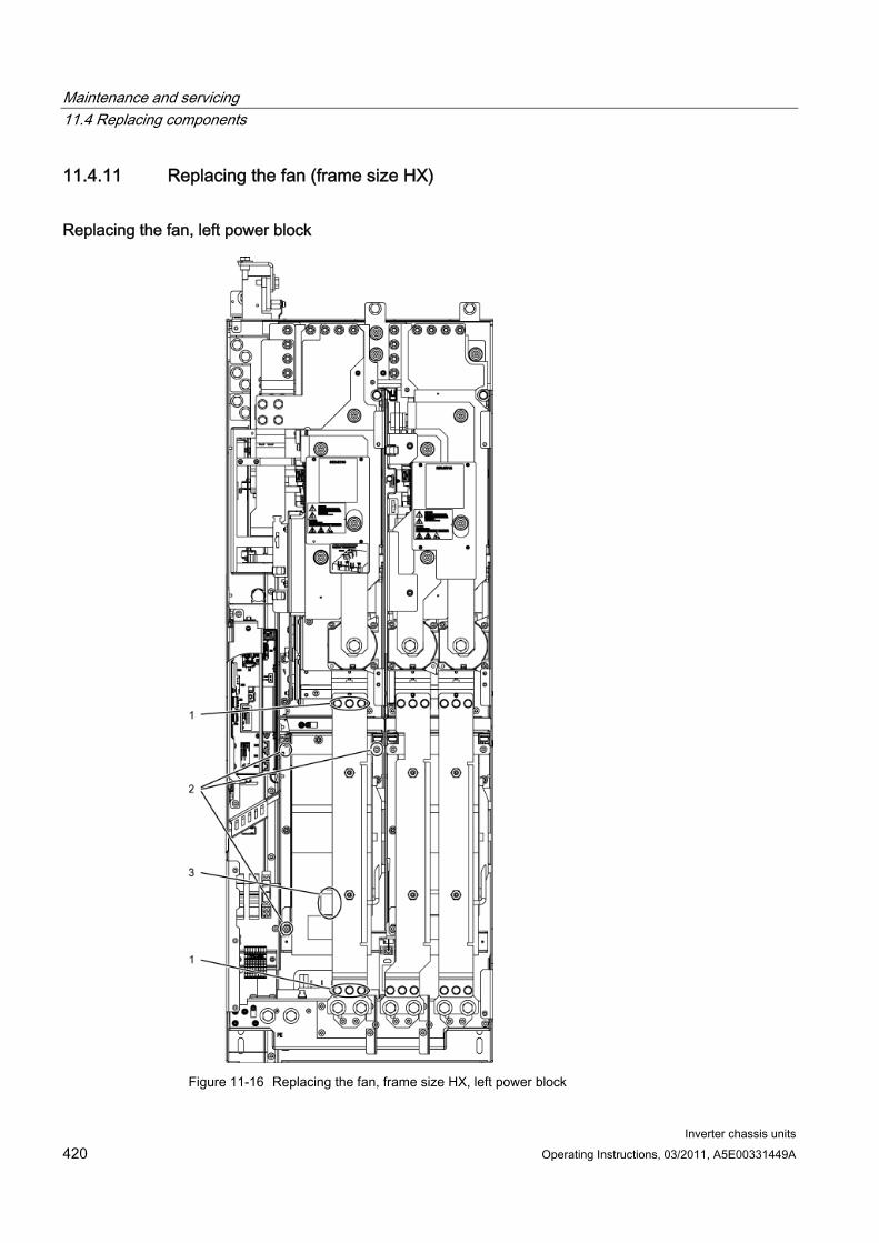
Maintenance and servicing 11.4 Replacing components
Inverter chassis units 420 Operating Instructions, 03/2011, A5E00331449A
11.4.11 Replacing the fan (frame size HX)
Replacing the fan, left power block
Figure 11-16 Replacing the fan, frame size HX, left power block

Maintenance and servicing 11.4 Replacing components
Inverter chassis units Operating Instructions, 03/2011, A5E00331449A 421
Description The average service life of the device fans is 50,000 hours. In practice, however, the service life depends on other variables (e.g. ambient temperature, degree of cabinet protection, etc.) and, therefore, may deviate from this value.
The fans must be replaced in good time to ensure that the built-in unit is available.
Preparatory steps Disconnect the built-in unit from the power supply.
Allow unimpeded access.
Remove the protective cover
Removal steps The removal steps are numbered in accordance with the figure.
1. Remove the copper bar (6 screws).
2. Remove the retaining screws for the fan (3 screws)
3. Disconnect the supply cables (1 x "L", 1 x "N")
You can now carefully remove the fan.
CAUTION When removing, ensure that you do not damage any signal cables.
Installation steps For installation, carry out the above steps in reverse order.
CAUTION The tightening torques specified in the table "Tightening torques for connecting current-conducting parts" must be observed.
Carefully insert the plug-in connections, and then check them for a secure fit.
The screw connections for the protective covers may only be tightened by hand.
Note
Following fan replacement, the operating hours counter of the fan should be reset via p0251 = 0.
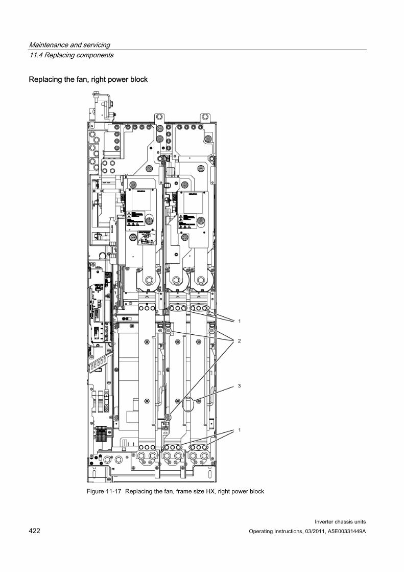
Maintenance and servicing 11.4 Replacing components
Inverter chassis units 422 Operating Instructions, 03/2011, A5E00331449A
Replacing the fan, right power block
Figure 11-17 Replacing the fan, frame size HX, right power block
Maintenance and servicing 11.4 Replacing components
Inverter chassis units Operating Instructions, 03/2011, A5E00331449A 423
Description The average service life of the device fans is 50,000 hours. In practice, however, the service life depends on other variables (e.g. ambient temperature, degree of cabinet protection, etc.) and, therefore, may deviate from this value.
The fans must be replaced in good time to ensure that the built-in unit is available.
Preparatory steps Disconnect the built-in unit from the power supply.
Allow unimpeded access.
Remove the protective cover
Removal steps The removal steps are numbered in accordance with the figure.
1. Remove the copper bar (12 screws).
2. Remove the retaining screws for the fan (3 screws)
3. Disconnect the supply cables (1 x "L", 1 x "N")
You can now carefully remove the fan.
CAUTION When removing, ensure that you do not damage any signal cables.
Installation steps For installation, carry out the above steps in reverse order.
CAUTION The tightening torques specified in the table "Tightening torques for connecting current-conducting parts" must be observed.
Carefully insert the plug-in connections, and then check them for a secure fit.
The screw connections for the protective covers may only be tightened by hand.
Note
Following fan replacement, the operating hours counter of the fan should be reset via p0251 = 0.
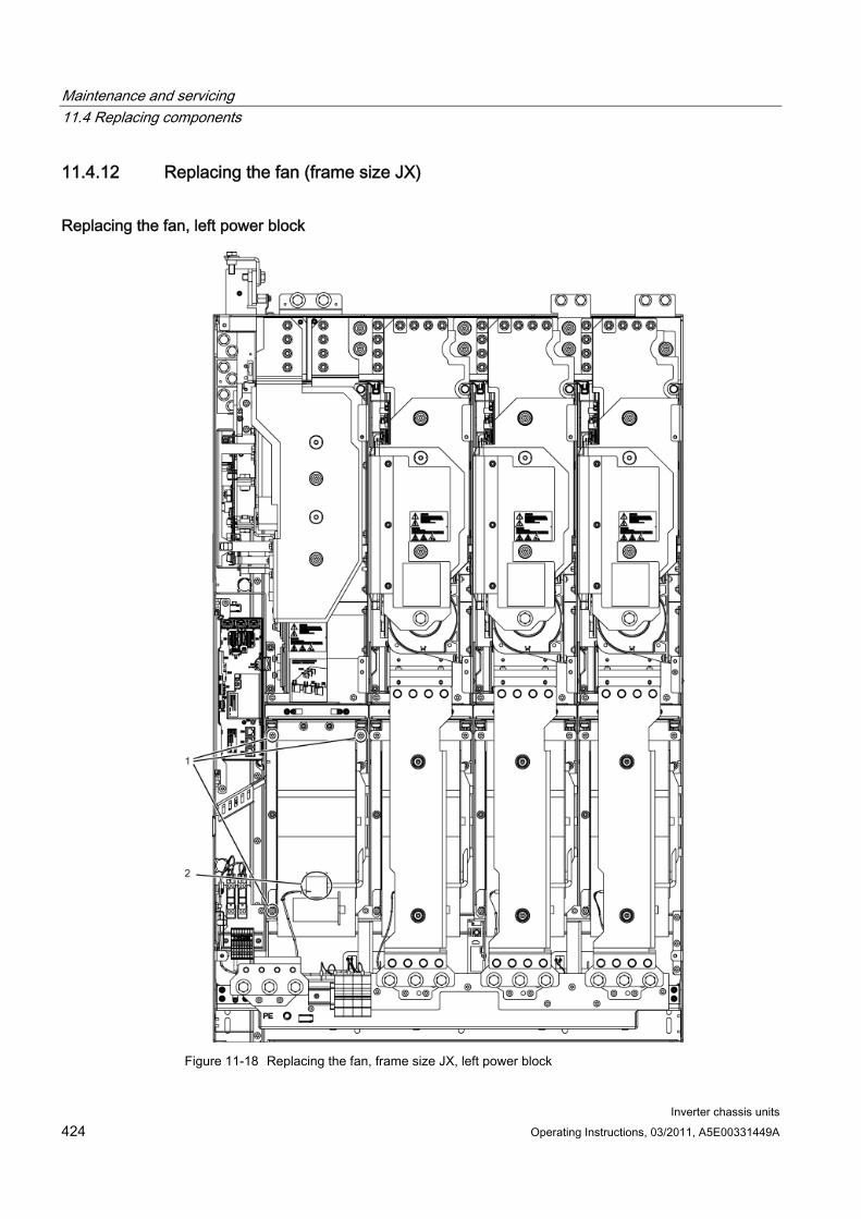
Maintenance and servicing 11.4 Replacing components
Inverter chassis units 424 Operating Instructions, 03/2011, A5E00331449A
11.4.12 Replacing the fan (frame size JX)
Replacing the fan, left power block
Figure 11-18 Replacing the fan, frame size JX, left power block
Maintenance and servicing 11.4 Replacing components
Inverter chassis units Operating Instructions, 03/2011, A5E00331449A 425
Description The average service life of the device fans is 50,000 hours. In practice, however, the service life depends on other variables (e.g. ambient temperature, degree of cabinet protection, etc.) and, therefore, may deviate from this value.
The fans must be replaced in good time to ensure that the built-in unit is available.
Preparatory steps Disconnect the built-in unit from the power supply.
Allow unimpeded access.
Remove the protective cover
Removal steps The removal steps are numbered in accordance with the figure.
1. Remove the retaining screws for the fan (3 screws)
2. Disconnect the supply cables (1 x "L", 1 x "N")
You can now carefully remove the fan.
CAUTION When removing, ensure that you do not damage any signal cables.
Installation steps For installation, carry out the above steps in reverse order.
CAUTION The tightening torques specified in the table "Tightening torques for connecting current-conducting parts" must be observed.
Carefully insert the plug-in connections, and then check them for a secure fit.
The screw connections for the protective covers may only be tightened by hand.
Note
Following fan replacement, the operating hours counter of the fan should be reset via p0251 = 0.
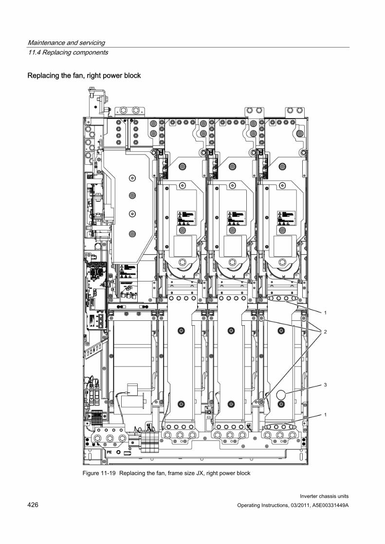
Maintenance and servicing 11.4 Replacing components
Inverter chassis units 426 Operating Instructions, 03/2011, A5E00331449A
Replacing the fan, right power block
Figure 11-19 Replacing the fan, frame size JX, right power block
Maintenance and servicing 11.4 Replacing components
Inverter chassis units Operating Instructions, 03/2011, A5E00331449A 427
Description The average service life of the device fans is 50,000 hours. In practice, however, the service life depends on other variables (e.g. ambient temperature, degree of cabinet protection, etc.) and, therefore, may deviate from this value.
The fans must be replaced in good time to ensure that the built-in unit is available.
Preparatory steps Disconnect the built-in unit from the power supply.
Allow unimpeded access.
Remove the protective cover
Removal steps The removal steps are numbered in accordance with the figure.
Remove the busbar (8 screws).
Remove the retaining screws for the fan (3 screws)
Disconnect the supply cables (1 x "L", 1 x "N")
You can now carefully remove the fan.
CAUTION When removing, ensure that you do not damage any signal cables.
Installation steps For installation, carry out the above steps in reverse order.
CAUTION The tightening torques specified in the table "Tightening torques for connecting current-conducting parts" must be observed.
Carefully insert the plug-in connections, and then check them for a secure fit.
The screw connections for the protective covers may only be tightened by hand.
Note
Following fan replacement, the operating hours counter of the fan should be reset via p0251 = 0.
Maintenance and servicing 11.5 Forming the DC link capacitors
Inverter chassis units 428 Operating Instructions, 03/2011, A5E00331449A
11.5 Forming the DC link capacitors
Description If the device is kept in storage for more than 2 years, the DC link capacitors have to be re-formed. If this is not done, the unit could be damaged when it is operated under load.
If the cabinet is commissioned within two years of its date of manufacture, the DC link capacitors do not need to be re-formed. The date of manufacture is indicated in the serial number on the type plate (see "Device Overview").
Note
It is important that the storage period is calculated from the date of manufacture and not from the date that the equipment was shipped.
Procedure The DC link capacitors are re-formed by applying the rated voltage without load for at least 30 minutes at room temperature.
Operation via PROFIBUS:
– Set bit 3 of control word 1 (operation enable) permanently to "0".
– Switch on the converter by means of an ON signal (bit 0 of the control word); all the other bits must be set in such a way that the converter can be operated.
– Once the delay time has elapsed, switch off the converter and restore the original PROFIBUS setting.
Operation via terminal block:
– Set p0852 to "0" (factory setting is "1").
– Switch on the converter (via digital input 0 on the customer terminal block).
– Once the delay time has elapsed, switch off the converter and restore the original setting for p0852.
Note
Reforming cannot be carried out in LOCAL mode via the AOP30.
Maintenance and servicing 11.6 Messages after replacing DRIVE-CLiQ components
Inverter chassis units Operating Instructions, 03/2011, A5E00331449A 429
11.6 Messages after replacing DRIVE-CLiQ components After DRIVE-CLiQ components are replaced (Control Interface Module, TM31, SMCxx) when service is required, generally no message is output after power-up, since an identical component is identified and accepted as component when the system boots.
The reason for this is that an identical component is detected and accepted as spare part when running-up. If, unexpectedly, a fault message of the "topology fault" category is displayed, then when replacing a component, one of the following faults/errors should have occurred:
A Control Interface Module with different firmware data was installed.
When connecting-up DRIVE-CLiQ cables, connections were interchanged.
Automatic firmware update As of firmware 2.5, an automatic firmware update can be carried out once the electronics have been powered up on replacement DRIVE-CLiQ components.
The following LEDs will flash slowly to indicate that an automatic firmware update is in progress: the "RDY" LED on the Control Unit (orange, 0.5 Hz) and an LED on the relevant DRIVE-CLiQ component (green/red, 0.5 Hz).
CAUTION
The drive converter must not be shut down during this process!
Once the automatic firmware update is complete, the "RDY" LED on the Control Unit will flash quickly (orange, 2 Hz) along with an LED on the relevant DRIVE-CLiQ component (green/red, 2 Hz).
To complete the automatic firmware update process, a POWER ON is required (switch the device off and back on again).
Maintenance and servicing 11.7 Upgrading the chassis unit firmware
Inverter chassis units 430 Operating Instructions, 03/2011, A5E00331449A
11.7 Upgrading the chassis unit firmware When you upgrade the built-in unit firmware (by installing a new CompactFlash Card with a new firmware version, for example), you might also have to upgrade the firmware for the DRIVE-CLiQ components in the built-in unit.
If the system detects that the firmware in the DRIVE-CLiQ components needs to be updated, it will trigger this process automatically when the automatic firmware update is performed.
Automatic firmware update sequence 1. During an automatic firmware update, the "RDY" LED on the Control Unit flashes slowly
(orange, 0.5 Hz).
2. The firmware update is performed automatically and in sequence on the DRIVE-CLiQ components; during the update process, an LED on the component whose firmware is being updated will flash slowly (green/red, 0.5 Hz).
3. Once the firmware update on an individual DRIVE-CLiQ component is complete, the LED on that component will flash quickly (green/red, 2 Hz).
4. Once the firmware update on all components is complete, the LED on the Control Unit will flash quickly (orange, 2 Hz).
5. To complete the automatic firmware update process, a POWER ON is required (switch the device off and back on again).
CAUTION The power supply to the components must not be interrupted while the firmware is being upgraded.
CAUTION New firmware should only be installed if there is a problem with the unit.

Inverter chassis units Operating Instructions, 03/2011, A5E00331449A 431
Technical specifications 1212.1 Chapter content
This chapter provides information on the following:
1. General and specific technical specifications for the devices.
2. Information on restrictions that apply when the devices are used in unfavorable ambient conditions (derating)
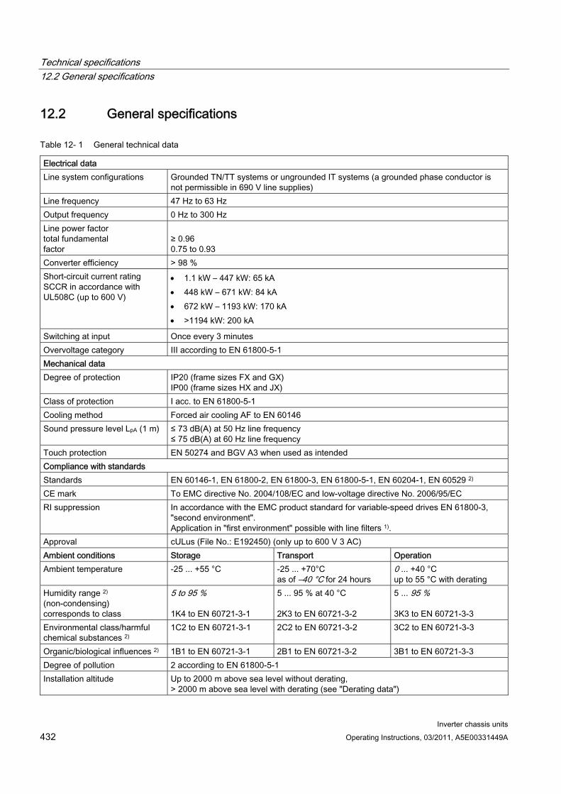
Technical specifications 12.2 General specifications
Inverter chassis units 432 Operating Instructions, 03/2011, A5E00331449A
12.2 General specifications
Table 12- 1 General technical data
Electrical data Line system configurations Grounded TN/TT systems or ungrounded IT systems (a grounded phase conductor is
not permissible in 690 V line supplies) Line frequency 47 Hz to 63 Hz Output frequency 0 Hz to 300 Hz Line power factor total fundamental factor
≥ 0.96 0.75 to 0.93
Converter efficiency > 98 % Short-circuit current rating SCCR in accordance with UL508C (up to 600 V)
1.1 kW – 447 kW: 65 kA 448 kW – 671 kW: 84 kA 672 kW – 1193 kW: 170 kA >1194 kW: 200 kA
Switching at input Once every 3 minutes Overvoltage category III according to EN 61800-5-1 Mechanical data Degree of protection IP20 (frame sizes FX and GX)
IP00 (frame sizes HX and JX) Class of protection I acc. to EN 61800-5-1 Cooling method Forced air cooling AF to EN 60146 Sound pressure level LpA (1 m) ≤ 73 dB(A) at 50 Hz line frequency
≤ 75 dB(A) at 60 Hz line frequency Touch protection EN 50274 and BGV A3 when used as intended Compliance with standards Standards EN 60146-1, EN 61800-2, EN 61800-3, EN 61800-5-1, EN 60204-1, EN 60529 2) CE mark To EMC directive No. 2004/108/EC and low-voltage directive No. 2006/95/EC RI suppression In accordance with the EMC product standard for variable-speed drives EN 61800-3,
"second environment". Application in "first environment" possible with line filters 1).
Approval cULus (File No.: E192450) (only up to 600 V 3 AC) Ambient conditions Storage Transport Operation Ambient temperature -25 ... +55 °C -25 ... +70°C
as of –40 °C for 24 hours 0 ... +40 °C up to 55 °C with derating
Humidity range 2) (non-condensing) corresponds to class
5 to 95 % 1K4 to EN 60721-3-1
5 ... 95 % at 40 °C 2K3 to EN 60721-3-2
5 ... 95 % 3K3 to EN 60721-3-3
Environmental class/harmful chemical substances 2)
1C2 to EN 60721-3-1 2C2 to EN 60721-3-2 3C2 to EN 60721-3-3
Organic/biological influences 2) 1B1 to EN 60721-3-1 2B1 to EN 60721-3-2 3B1 to EN 60721-3-3 Degree of pollution 2 according to EN 61800-5-1 Installation altitude Up to 2000 m above sea level without derating,
> 2000 m above sea level with derating (see "Derating data")

Technical specifications 12.2 General specifications
Inverter chassis units Operating Instructions, 03/2011, A5E00331449A 433
Mechanical strength Storage Transport Operation Vibrational load 2) - Displacement - Acceleration corresponds to class
1.5 mm at 5 to 9 Hz 5 m/s² at > 9 to 200 Hz 1M2 to EN 60721-3-1
3.1 mm at 5 ... 9 Hz 10 m/s² at > 9 ... 200 Hz 2M2 to EN 60721-3-2
0.075 mm at 10 ... 58 Hz 10 m/s² at >58 ... 200 Hz -
Shock load 2) - Acceleration corresponds to class
40 m/s² at 22 ms 1M2 to EN 60721-3-1
100 m/s² at 11 ms 2M2 to EN 60721-3-2
100 m/s² at 11 ms 3M4 to EN 60721-3-3
Deviations from the defined classes are shown in italics. 1) Applies to cable lengths of up to 100 m. 2) The EN standards specified are the European editions of the international IEC standards with the same designations.
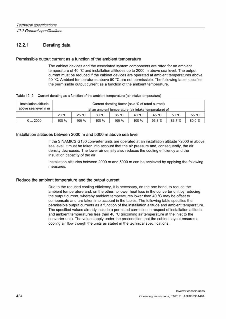
Technical specifications 12.2 General specifications
Inverter chassis units 434 Operating Instructions, 03/2011, A5E00331449A
12.2.1 Derating data
Permissible output current as a function of the ambient temperature The cabinet devices and the associated system components are rated for an ambient temperature of 40 °C and installation altitudes up to 2000 m above sea level. The output current must be reduced if the cabinet devices are operated at ambient temperatures above 40 °C. Ambient temperatures above 50 °C are not permissible. The following table specifies the permissible output current as a function of the ambient temperature.
Table 12- 2 Current derating as a function of the ambient temperature (air intake temperature)
Installation altitude above sea level in m
Current derating factor (as a % of rated current) at an ambient temperature (air intake temperature) of
20 °C 25 °C 30 °C 35 °C 40 °C 45 °C 50 °C 55 °C 0 ... 2000 100 % 100 % 100 % 100 % 100 % 93.3 % 86.7 % 80.0 %
Installation altitudes between 2000 m and 5000 m above sea level If the SINAMICS G130 converter units are operated at an installation altitude >2000 m above sea level, it must be taken into account that the air pressure and, consequently, the air density decreases. The lower air density also reduces the cooling efficiency and the insulation capacity of the air.
Installation altitudes between 2000 m and 5000 m can be achieved by applying the following measures.
Reduce the ambient temperature and the output current Due to the reduced cooling efficiency, it is necessary, on the one hand, to reduce the ambient temperature and, on the other, to lower heat loss in the converter unit by reducing the output current, whereby ambient temperatures lower than 40 °C may be offset to compensate and are taken into account in the tables. The following table specifies the permissible output currents as a function of the installation altitude and ambient temperature. The specified values already include a permitted correction in respect of installation altitude and ambient temperatures less than 40 °C (incoming air temperature at the inlet to the converter unit). The values apply under the precondition that the cabinet layout ensures a cooling air flow though the units as stated in the technical specifications.
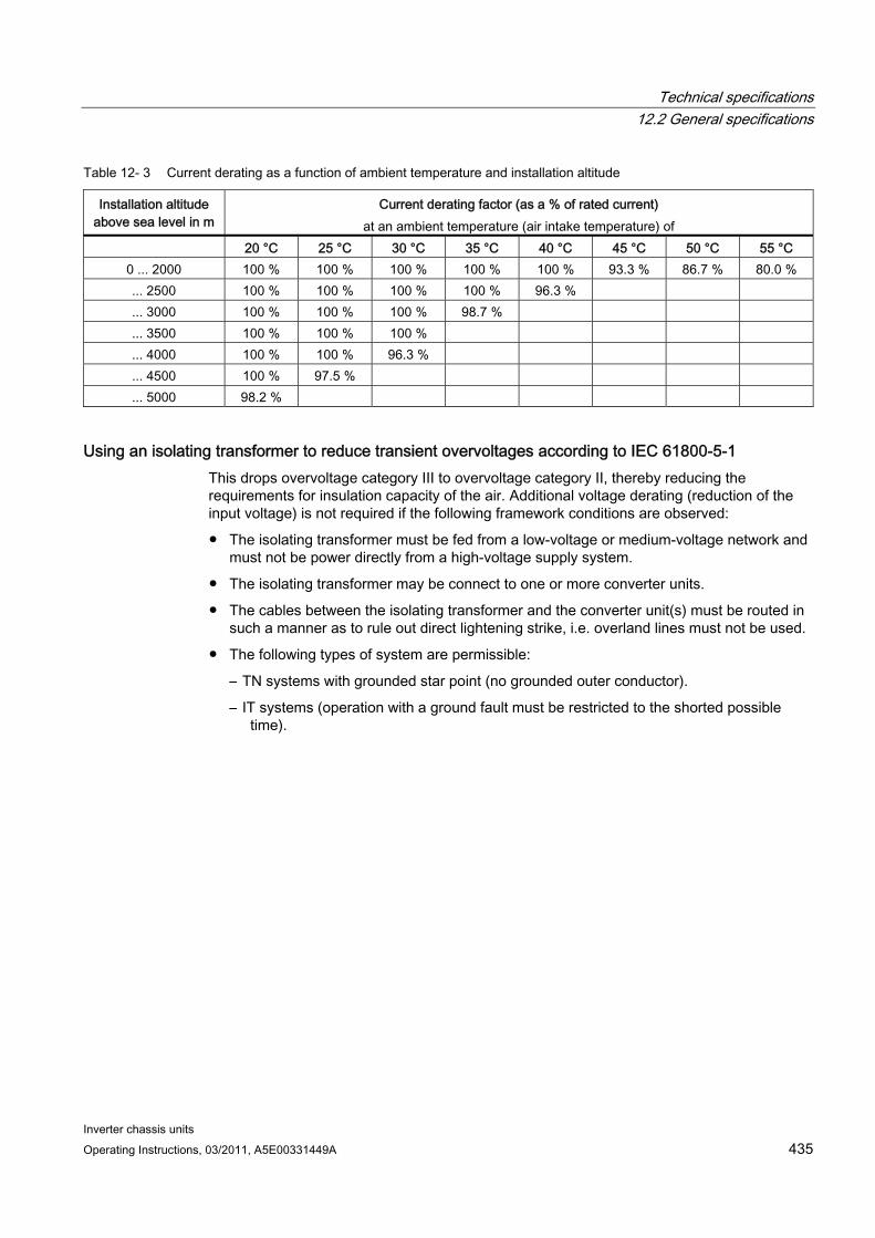
Technical specifications 12.2 General specifications
Inverter chassis units Operating Instructions, 03/2011, A5E00331449A 435
Table 12- 3 Current derating as a function of ambient temperature and installation altitude
Installation altitude above sea level in m
Current derating factor (as a % of rated current) at an ambient temperature (air intake temperature) of
20 °C 25 °C 30 °C 35 °C 40 °C 45 °C 50 °C 55 °C 0 ... 2000 100 % 100 % 100 % 100 % 100 % 93.3 % 86.7 % 80.0 % ... 2500 100 % 100 % 100 % 100 % 96.3 % ... 3000 100 % 100 % 100 % 98.7 % ... 3500 100 % 100 % 100 % ... 4000 100 % 100 % 96.3 % ... 4500 100 % 97.5 % ... 5000 98.2 %
Using an isolating transformer to reduce transient overvoltages according to IEC 61800-5-1 This drops overvoltage category III to overvoltage category II, thereby reducing the requirements for insulation capacity of the air. Additional voltage derating (reduction of the input voltage) is not required if the following framework conditions are observed:
The isolating transformer must be fed from a low-voltage or medium-voltage network and must not be power directly from a high-voltage supply system.
The isolating transformer may be connect to one or more converter units.
The cables between the isolating transformer and the converter unit(s) must be routed in such a manner as to rule out direct lightening strike, i.e. overland lines must not be used.
The following types of system are permissible:
– TN systems with grounded star point (no grounded outer conductor).
– IT systems (operation with a ground fault must be restricted to the shorted possible time).
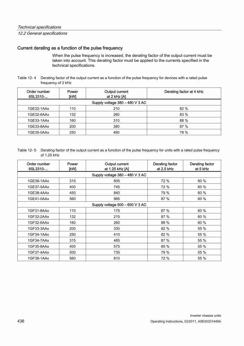
Technical specifications 12.2 General specifications
Inverter chassis units 436 Operating Instructions, 03/2011, A5E00331449A
Current derating as a function of the pulse frequency When the pulse frequency is increased, the derating factor of the output current must be taken into account. This derating factor must be applied to the currents specified in the technical specifications.
Table 12- 4 Derating factor of the output current as a function of the pulse frequency for devices with a rated pulse frequency of 2 kHz
Order number 6SL3310-...
Power [kW]
Output current at 2 kHz [A]
Derating factor at 4 kHz
Supply voltage 380 – 480 V 3 AC 1GE32-1AAx 110 210 82 % 1GE32-6AAx 132 260 83 % 1GE33-1AAx 160 310 88 % 1GE33-8AAx 200 380 87 % 1GE35-0AAx 250 490 78 %
Table 12- 5 Derating factor of the output current as a function of the pulse frequency for units with a rated pulse frequency of 1.25 kHz
Order number 6SL3310-...
Power [kW]
Output current at 1.25 kHz [A]
Derating factor at 2.5 kHz
Derating factor at 5 kHz
Supply voltage 380 – 480 V 3 AC 1GE36-1AAx 315 605 72 % 60 % 1GE37-5AAx 400 745 72 % 60 % 1GE38-4AAx 450 840 79 % 60 % 1GE41-0AAx 560 985 87 % 60 %
Supply voltage 500 – 600 V 3 AC 1GF31-8AAx 110 175 87 % 60 % 1GF32-2AAx 132 215 87 % 60 % 1GF32-6AAx 160 260 88 % 60 % 1GF33-3AAx 200 330 82 % 55 % 1GF34-1AAx 250 410 82 % 55 % 1GF34-7AAx 315 465 87 % 55 % 1GF35-8AAx 400 575 85 % 55 % 1GF37-4AAx 500 735 79 % 55 % 1GF38-1AAx 560 810 72 % 55 %
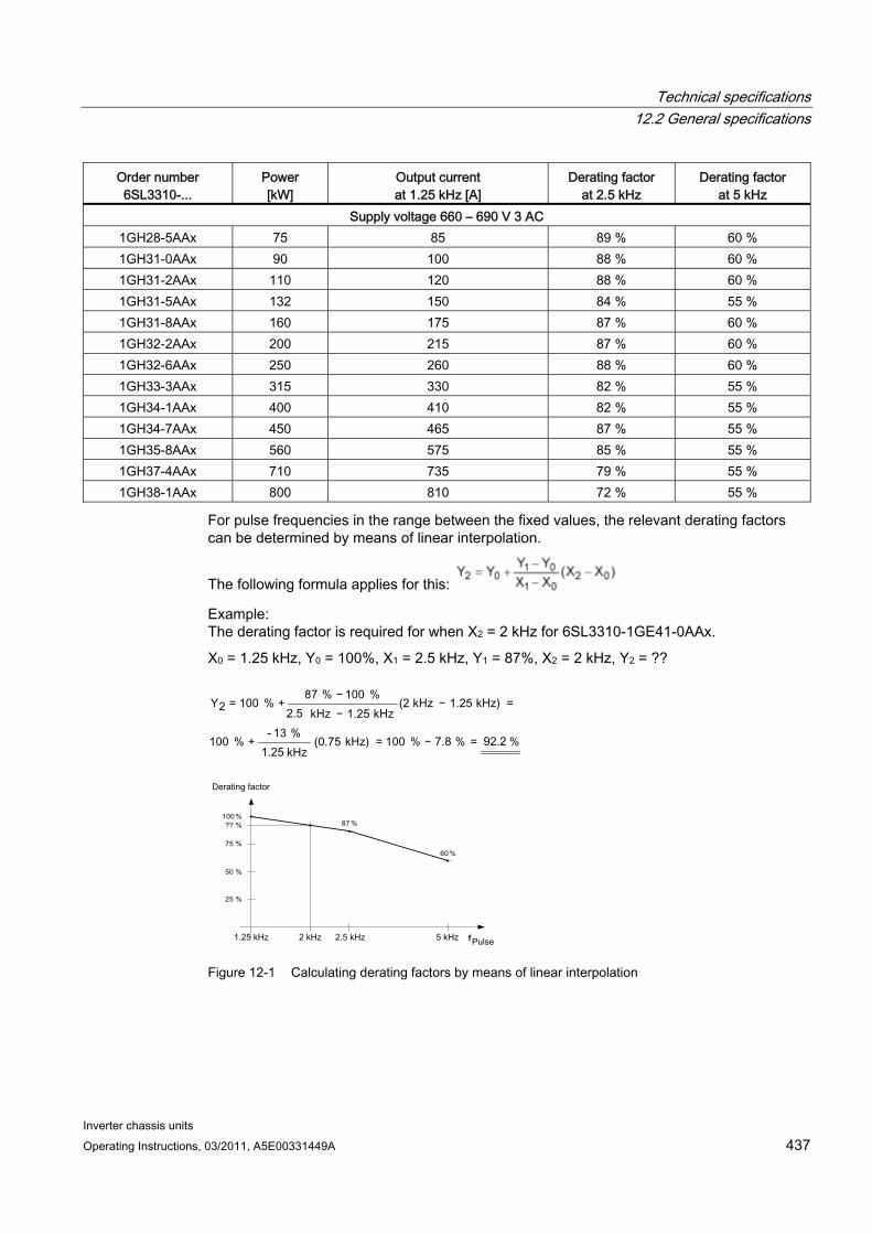
Technical specifications 12.2 General specifications
Inverter chassis units Operating Instructions, 03/2011, A5E00331449A 437
Order number 6SL3310-...
Power [kW]
Output current at 1.25 kHz [A]
Derating factor at 2.5 kHz
Derating factor at 5 kHz
Supply voltage 660 – 690 V 3 AC 1GH28-5AAx 75 85 89 % 60 % 1GH31-0AAx 90 100 88 % 60 % 1GH31-2AAx 110 120 88 % 60 % 1GH31-5AAx 132 150 84 % 55 % 1GH31-8AAx 160 175 87 % 60 % 1GH32-2AAx 200 215 87 % 60 % 1GH32-6AAx 250 260 88 % 60 % 1GH33-3AAx 315 330 82 % 55 % 1GH34-1AAx 400 410 82 % 55 % 1GH34-7AAx 450 465 87 % 55 % 1GH35-8AAx 560 575 85 % 55 % 1GH37-4AAx 710 735 79 % 55 % 1GH38-1AAx 800 810 72 % 55 %
For pulse frequencies in the range between the fixed values, the relevant derating factors can be determined by means of linear interpolation.
The following formula applies for this:
Example: The derating factor is required for when X2 = 2 kHz for 6SL3310-1GE41-0AAx.
X0 = 1.25 kHz, Y0 = 100%, X1 = 2.5 kHz, Y1 = 87%, X2 = 2 kHz, Y2 = ??
f
100 %
50 %
75 %
25 %
60 %
87 % ?? %
Figure 12-1 Calculating derating factors by means of linear interpolation
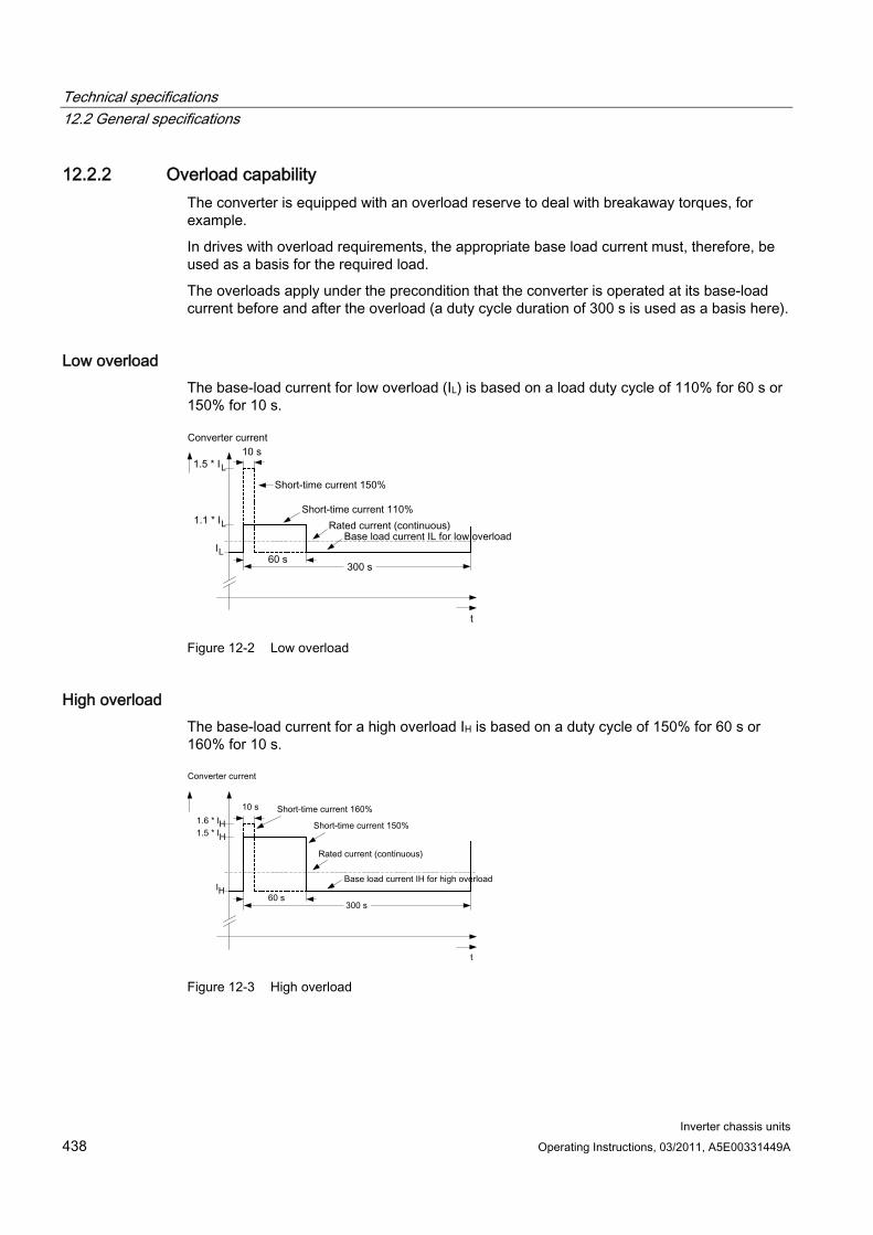
Technical specifications 12.2 General specifications
Inverter chassis units 438 Operating Instructions, 03/2011, A5E00331449A
12.2.2 Overload capability The converter is equipped with an overload reserve to deal with breakaway torques, for example.
In drives with overload requirements, the appropriate base load current must, therefore, be used as a basis for the required load.
The overloads apply under the precondition that the converter is operated at its base-load current before and after the overload (a duty cycle duration of 300 s is used as a basis here).
Low overload The base-load current for low overload (IL) is based on a load duty cycle of 110% for 60 s or 150% for 10 s.
Figure 12-2 Low overload
High overload The base-load current for a high overload IH is based on a duty cycle of 150% for 60 s or 160% for 10 s.
Figure 12-3 High overload
Technical specifications 12.3 Technical specifications
Inverter chassis units Operating Instructions, 03/2011, A5E00331449A 439
12.3 Technical specifications
Note
Current, voltage and power figures in these tables are rated values.
The cables to the device are protected by fuses of operating class gG.
The cable cross-sections have been determined for three-core copper cables routed horizontally in air at 40 °C ambient temperature (according to DIN VDE 0276-1000 and IEC 60364-5-52) with a permissible operating temperature of 70°C (e.g. Protodur NYY or NYCWY) and the recommended conductor protection according to DIN VDE 0100 section 430 and IEC 60364-4-43.
CAUTION When the conditions differ from the above stated (cable routing, cable grouping, ambient temperature), the following instructions for routing the cables must be taken into account:
The required cable cross-section depends on the amperage which flows through the cable. The permissible current loading of cables is defined, for example, in DIN VDE 0276-1000 and IEC 60364-5-52. It depends partly on ambient conditions such as temperature and partly on the type of routing. If the cables are routed individually, they will be cooled relatively well. If several cables are routed together, they may heat each other up. Please note the corresponding derating factors for these supplementary conditions in DIN VDE 0276-1000 and IEC 60364-5-52.
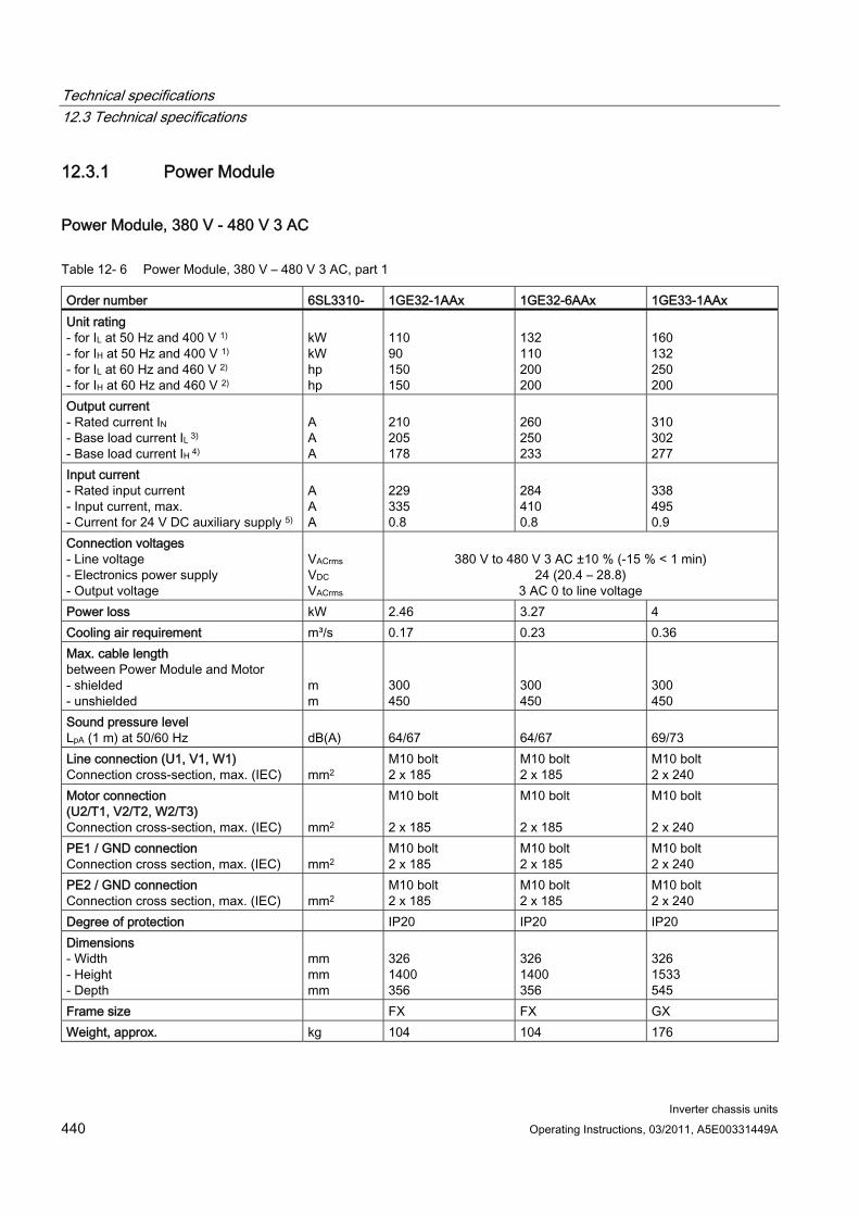
Technical specifications 12.3 Technical specifications
Inverter chassis units 440 Operating Instructions, 03/2011, A5E00331449A
12.3.1 Power Module
Power Module, 380 V - 480 V 3 AC
Table 12- 6 Power Module, 380 V – 480 V 3 AC, part 1
Order number 6SL3310- 1GE32-1AAx 1GE32-6AAx 1GE33-1AAx Unit rating - for IL at 50 Hz and 400 V 1) - for IH at 50 Hz and 400 V 1)
- for IL at 60 Hz and 460 V 2)
- for IH at 60 Hz and 460 V 2)
kW kW hp hp
110 90 150 150
132 110 200 200
160 132 250 200
Output current - Rated current IN - Base load current IL 3) - Base load current IH 4)
A A A
210 205 178
260 250 233
310 302 277
Input current - Rated input current - Input current, max. - Current for 24 V DC auxiliary supply 5)
A A A
229 335 0.8
284 410 0.8
338 495 0.9
Connection voltages - Line voltage - Electronics power supply - Output voltage
VACrms VDC VACrms
380 V to 480 V 3 AC ±10 % (-15 % < 1 min)
24 (20.4 – 28.8) 3 AC 0 to line voltage
Power loss kW 2.46 3.27 4 Cooling air requirement m³/s 0.17 0.23 0.36 Max. cable length between Power Module and Motor - shielded - unshielded
m m
300 450
300 450
300 450
Sound pressure level LpA (1 m) at 50/60 Hz
dB(A)
64/67
64/67
69/73
Line connection (U1, V1, W1) Connection cross-section, max. (IEC)
mm2
M10 bolt 2 x 185
M10 bolt 2 x 185
M10 bolt 2 x 240
Motor connection (U2/T1, V2/T2, W2/T3) Connection cross-section, max. (IEC)
mm2
M10 bolt 2 x 185
M10 bolt 2 x 185
M10 bolt 2 x 240
PE1 / GND connection Connection cross section, max. (IEC)
mm2
M10 bolt 2 x 185
M10 bolt 2 x 185
M10 bolt 2 x 240
PE2 / GND connection Connection cross section, max. (IEC)
mm2
M10 bolt 2 x 185
M10 bolt 2 x 185
M10 bolt 2 x 240
Degree of protection IP20 IP20 IP20 Dimensions - Width - Height - Depth
mm mm mm
326 1400 356
326 1400 356
326 1533 545
Frame size FX FX GX Weight, approx. kg 104 104 176

Technical specifications 12.3 Technical specifications
Inverter chassis units Operating Instructions, 03/2011, A5E00331449A 441
Order number 6SL3310- 1GE32-1AAx 1GE32-6AAx 1GE33-1AAx Recommended fuses - Line protection without semiconductor protection Rated current frame size to IEC 60269 - Line and semiconductor protection 6) Rated current Frame size to IEC 60269
A A
3NA3144 250 2 3NE1230-2 315 1
3NA3250 300 3 3NE1331-2 350 2
3NA3254 355 3 3NE1334-2 500 2
1) Rated output of a typ. 6-pole standard induction motor based on IL or IH at 400 V 3 AC 50 Hz. 2) Rated output of a typ. 6-pole standard induction motor based on IL or IH at 460 V 3 AC 60 Hz. 3) The base-load current IL is based on a duty cycle of 110% for 60 s or 150% for 10 s with a duty cycle duration of 300 s (see "Overload capability"). 4) The base-load current IH is based on a duty cycle of 150% for 60 s or 160% for 10 s with a duty cycle duration of 300 s (see "Overload capability"). 5) If the auxiliary supply is to be fed in separately from the load supply, e.g., if the control should be able to continue communication if the line voltage fails. 6) The types of protection specified here are mandatory for installing a UL-approved system.
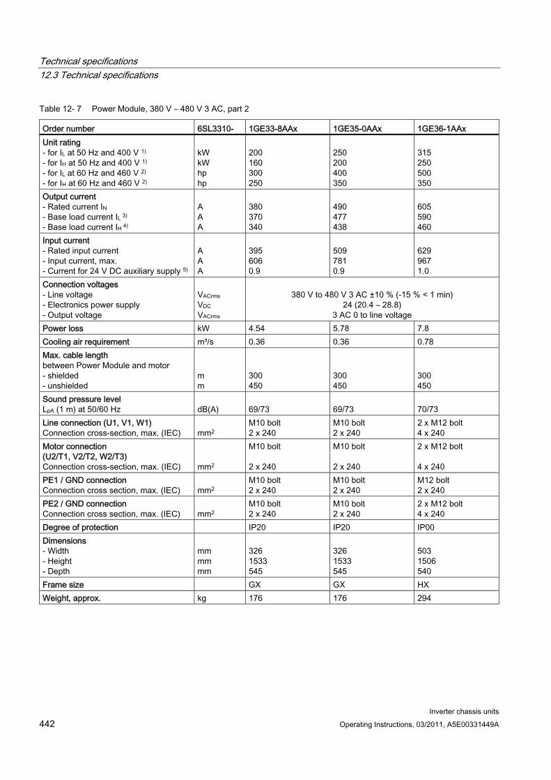
Technical specifications 12.3 Technical specifications
Inverter chassis units 442 Operating Instructions, 03/2011, A5E00331449A
Table 12- 7 Power Module, 380 V – 480 V 3 AC, part 2
Order number 6SL3310- 1GE33-8AAx 1GE35-0AAx 1GE36-1AAx Unit rating - for IL at 50 Hz and 400 V 1) - for IH at 50 Hz and 400 V 1)
- for IL at 60 Hz and 460 V 2)
- for IH at 60 Hz and 460 V 2)
kW kW hp hp
200 160 300 250
250 200 400 350
315 250 500 350
Output current - Rated current IN - Base load current IL 3) - Base load current IH 4)
A A A
380 370 340
490 477 438
605 590 460
Input current - Rated input current - Input current, max. - Current for 24 V DC auxiliary supply 5)
A A A
395 606 0.9
509 781 0.9
629 967 1.0
Connection voltages - Line voltage - Electronics power supply - Output voltage
VACrms VDC VACrms
380 V to 480 V 3 AC ±10 % (-15 % < 1 min)
24 (20.4 – 28.8) 3 AC 0 to line voltage
Power loss kW 4.54 5.78 7.8 Cooling air requirement m³/s 0.36 0.36 0.78 Max. cable length between Power Module and motor - shielded - unshielded
m m
300 450
300 450
300 450
Sound pressure level LpA (1 m) at 50/60 Hz
dB(A)
69/73
69/73
70/73
Line connection (U1, V1, W1) Connection cross-section, max. (IEC)
mm2
M10 bolt 2 x 240
M10 bolt 2 x 240
2 x M12 bolt 4 x 240
Motor connection (U2/T1, V2/T2, W2/T3) Connection cross-section, max. (IEC)
mm2
M10 bolt 2 x 240
M10 bolt 2 x 240
2 x M12 bolt 4 x 240
PE1 / GND connection Connection cross section, max. (IEC)
mm2
M10 bolt 2 x 240
M10 bolt 2 x 240
M12 bolt 2 x 240
PE2 / GND connection Connection cross section, max. (IEC)
mm2
M10 bolt 2 x 240
M10 bolt 2 x 240
2 x M12 bolt 4 x 240
Degree of protection IP20 IP20 IP00 Dimensions - Width - Height - Depth
mm mm mm
326 1533 545
326 1533 545
503 1506 540
Frame size GX GX HX Weight, approx. kg 176 176 294
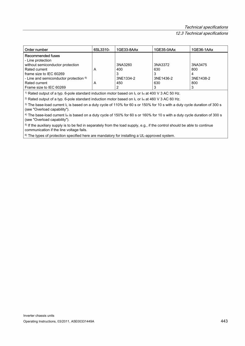
Technical specifications 12.3 Technical specifications
Inverter chassis units Operating Instructions, 03/2011, A5E00331449A 443
Order number 6SL3310- 1GE33-8AAx 1GE35-0AAx 1GE36-1AAx Recommended fuses - Line protection without semiconductor protection Rated current frame size to IEC 60269 - Line and semiconductor protection 6) Rated current Frame size to IEC 60269
A A
3NA3260 400 3 3NE1334-2 450 2
3NA3372 630 3 3NE1436-2 630 3
3NA3475 800 4 3NE1438-2 800 3
1) Rated output of a typ. 6-pole standard induction motor based on IL or IH at 400 V 3 AC 50 Hz. 2) Rated output of a typ. 6-pole standard induction motor based on IL or IH at 460 V 3 AC 60 Hz. 3) The base-load current IL is based on a duty cycle of 110% for 60 s or 150% for 10 s with a duty cycle duration of 300 s (see "Overload capability"). 4) The base-load current IH is based on a duty cycle of 150% for 60 s or 160% for 10 s with a duty cycle duration of 300 s (see "Overload capability"). 5) If the auxiliary supply is to be fed in separately from the load supply, e.g., if the control should be able to continue communication if the line voltage fails. 6) The types of protection specified here are mandatory for installing a UL-approved system.
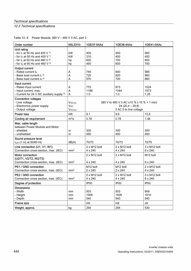
Technical specifications 12.3 Technical specifications
Inverter chassis units 444 Operating Instructions, 03/2011, A5E00331449A
Table 12- 8 Power Module, 380 V – 480 V 3 AC, part 3
Order number 6SL3310- 1GE37-5AAx 1GE38-4AAx 1GE41-0AAx Unit rating - for IL at 50 Hz and 400 V 1) - for IH at 50 Hz and 400 V 1)
- for IL at 60 Hz and 460 V 2)
- for IH at 60 Hz and 460 V 2)
kW kW hp hp
400 315 600 450
450 400 700 600
560 450 800 700
Output current - Rated current IN - Base load current IL 3) - Base load current IH 4)
A A A
745 725 570
840 820 700
985 960 860
Input current - Rated input current - Input current, max. - Current for 24 V DC auxiliary supply 5)
A A A
775 1188 1.0
873 1344 1.0
1024 1573 1.25
Connection voltages - Line voltage - Electronics power supply - Output voltage
VACrms VDC VACrms
380 V to 480 V 3 AC ±10 % (-15 % < 1 min)
24 (20.4 – 28.8) 3 AC 0 to line voltage
Power loss kW 9.1 9.6 13.8 Cooling air requirement m³/s 0.78 0.78 1.48 Max. cable length between Power Module and Motor - shielded - unshielded
m m
300 450
300 450
300 450
Sound pressure level LpA (1 m) at 50/60 Hz
dB(A)
70/73
70/73
72/75
Line connection (U1, V1, W1) Connection cross-section, max. (IEC)
mm2
2 x M12 bolt 4 x 240
2 x M12 bolt 4 x 240
3 x M12 bolt 6 x 240
Motor connection (U2/T1, V2/T2, W2/T3) Connection cross-section, max. (IEC)
mm2
2 x M12 bolt 4 x 240
2 x M12 bolt 4 x 240
M12 bolt 6 x 240
PE1 / GND connection Connection cross section, max. (IEC)
mm2
M12 bolt 2 x 240
M12 bolt 2 x 240
2 x M12 bolt 4 x 240
PE2 / GND connection Connection cross section, max. (IEC)
mm2
2 x M12 bolt 4 x 240
2 x M12 bolt 4 x 240
3 x M12 bolt 6 x 240
Degree of protection IP00 IP00 IP00 Dimensions - Width - Height - Depth
mm mm mm
503 1506 540
503 1506 540
909 1510 540
Frame size HX HX JX Weight, approx. kg 294 294 530

Technical specifications 12.3 Technical specifications
Inverter chassis units Operating Instructions, 03/2011, A5E00331449A 445
Order number 6SL3310- 1GE37-5AAx 1GE38-4AAx 1GE41-0AAx Recommended fuses - Line protection without semiconductor protection Rated current frame size to IEC 60269 - Line and semiconductor protection 6) Rated current Frame size to IEC 60269
A A
3NA3475 800 4 3NE1448-2 850 3
3NA3365 2 x 500 3 3NE1436-2 2 x 630 3
3NA3472 2 x 630 3 3NE1437-2 2 x 710 3
1) Rated output of a typ. 6-pole standard induction motor based on IL or IH at 400 V 3 AC 50 Hz. 2) Rated output of a typ. 6-pole standard induction motor based on IL or IH at 460 V 3 AC 60 Hz. 3) The base-load current IL is based on a duty cycle of 110% for 60 s or 150% for 10 s with a duty cycle duration of 300 s (see "Overload capability"). 4) The base-load current IH is based on a duty cycle of 150% for 60 s or 160% for 10 s with a duty cycle duration of 300 s (see "Overload capability"). 5) If the auxiliary supply is to be fed in separately from the load supply, e.g., if the control should be able to continue communication if the line voltage fails. 6) The types of protection specified here are mandatory for installing a UL-approved system.
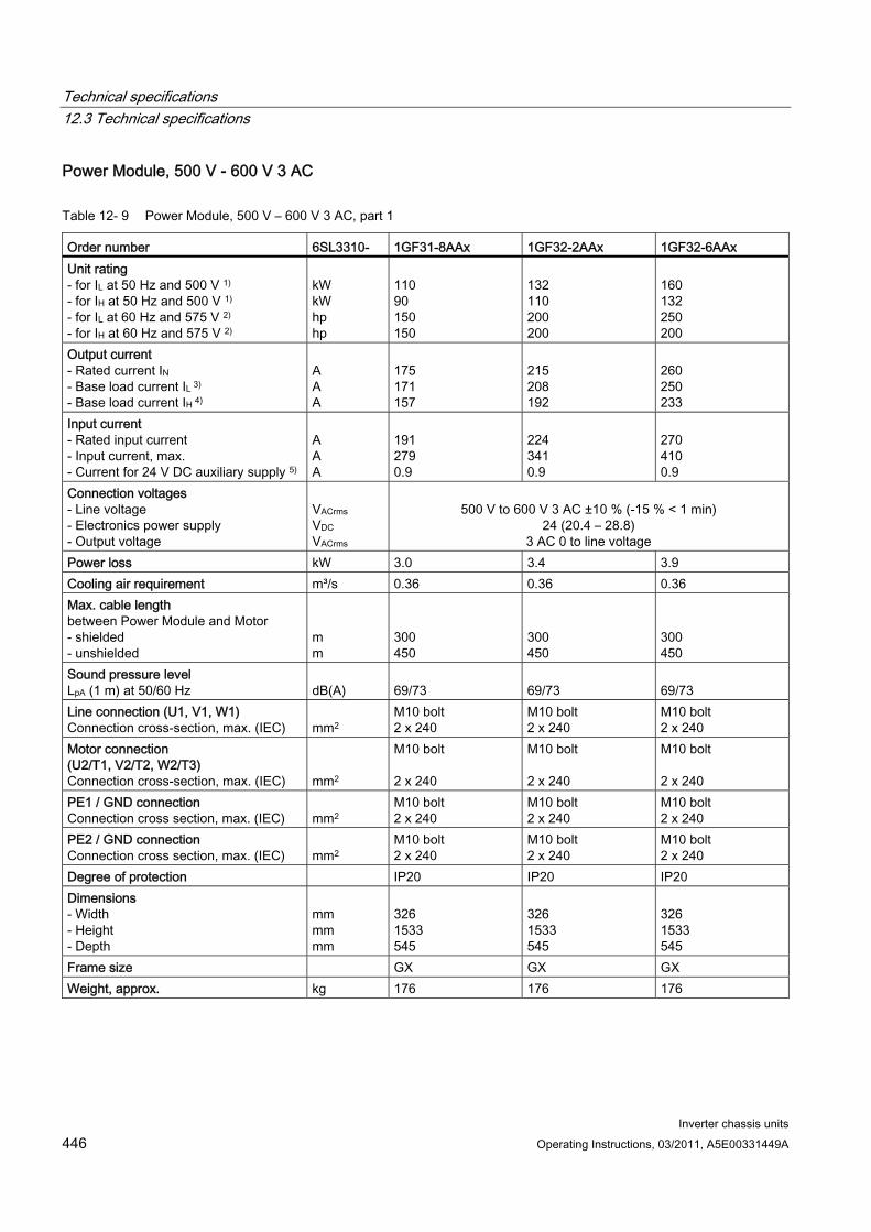
Technical specifications 12.3 Technical specifications
Inverter chassis units 446 Operating Instructions, 03/2011, A5E00331449A
Power Module, 500 V - 600 V 3 AC
Table 12- 9 Power Module, 500 V – 600 V 3 AC, part 1
Order number 6SL3310- 1GF31-8AAx 1GF32-2AAx 1GF32-6AAx Unit rating - for IL at 50 Hz and 500 V 1) - for IH at 50 Hz and 500 V 1)
- for IL at 60 Hz and 575 V 2)
- for IH at 60 Hz and 575 V 2)
kW kW hp hp
110 90 150 150
132 110 200 200
160 132 250 200
Output current - Rated current IN - Base load current IL 3) - Base load current IH 4)
A A A
175 171 157
215 208 192
260 250 233
Input current - Rated input current - Input current, max. - Current for 24 V DC auxiliary supply 5)
A A A
191 279 0.9
224 341 0.9
270 410 0.9
Connection voltages - Line voltage - Electronics power supply - Output voltage
VACrms VDC VACrms
500 V to 600 V 3 AC ±10 % (-15 % < 1 min)
24 (20.4 – 28.8) 3 AC 0 to line voltage
Power loss kW 3.0 3.4 3.9 Cooling air requirement m³/s 0.36 0.36 0.36 Max. cable length between Power Module and Motor - shielded - unshielded
m m
300 450
300 450
300 450
Sound pressure level LpA (1 m) at 50/60 Hz
dB(A)
69/73
69/73
69/73
Line connection (U1, V1, W1) Connection cross-section, max. (IEC)
mm2
M10 bolt 2 x 240
M10 bolt 2 x 240
M10 bolt 2 x 240
Motor connection (U2/T1, V2/T2, W2/T3) Connection cross-section, max. (IEC)
mm2
M10 bolt 2 x 240
M10 bolt 2 x 240
M10 bolt 2 x 240
PE1 / GND connection Connection cross section, max. (IEC)
mm2
M10 bolt 2 x 240
M10 bolt 2 x 240
M10 bolt 2 x 240
PE2 / GND connection Connection cross section, max. (IEC)
mm2
M10 bolt 2 x 240
M10 bolt 2 x 240
M10 bolt 2 x 240
Degree of protection IP20 IP20 IP20 Dimensions - Width - Height - Depth
mm mm mm
326 1533 545
326 1533 545
326 1533 545
Frame size GX GX GX Weight, approx. kg 176 176 176

Technical specifications 12.3 Technical specifications
Inverter chassis units Operating Instructions, 03/2011, A5E00331449A 447
Order number 6SL3310- 1GF31-8AAx 1GF32-2AAx 1GF32-6AAx Recommended fuses - Line protection without semiconductor protection Rated current frame size to IEC 60269 - Line and semiconductor protection 6) Rated current Frame size to IEC 60269
A A
3NA3244-6 250 2 3NE1227-2 250 1
3NA3252-6 315 2 3NE1230-2 315 1
3NA3354-6 355 3 3NE1331-2 350 2
1) Rated output of a typ. 6-pole standard induction motor based on IL or IH at 500 V 3 AC 50 Hz. 2) Rated output of a typ. 6-pole standard induction motor based on IL or IH at 575 V 3 AC 60 Hz. 3) The base-load current IL is based on a duty cycle of 110% for 60 s or 150% for 10 s with a duty cycle duration of 300 s (see "Overload capability"). 4) The base-load current IH is based on a duty cycle of 150% for 60 s or 160% for 10 s with a duty cycle duration of 300 s (see "Overload capability"). 5) If the auxiliary supply is to be fed in separately from the load supply, e.g., if the control should be able to continue communication if the line voltage fails. 6) The types of protection specified here are mandatory for installing a UL-approved system.
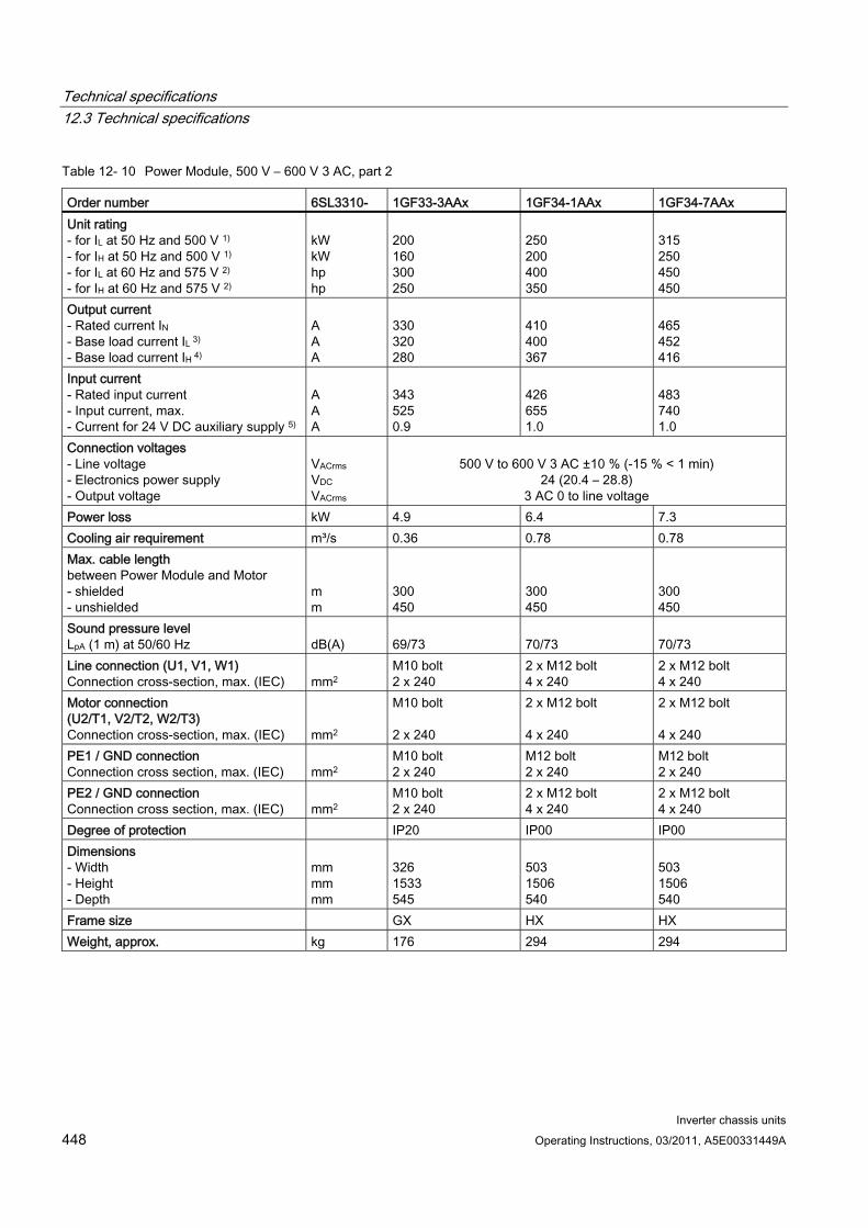
Technical specifications 12.3 Technical specifications
Inverter chassis units 448 Operating Instructions, 03/2011, A5E00331449A
Table 12- 10 Power Module, 500 V – 600 V 3 AC, part 2
Order number 6SL3310- 1GF33-3AAx 1GF34-1AAx 1GF34-7AAx Unit rating - for IL at 50 Hz and 500 V 1) - for IH at 50 Hz and 500 V 1)
- for IL at 60 Hz and 575 V 2)
- for IH at 60 Hz and 575 V 2)
kW kW hp hp
200 160 300 250
250 200 400 350
315 250 450 450
Output current - Rated current IN - Base load current IL 3) - Base load current IH 4)
A A A
330 320 280
410 400 367
465 452 416
Input current - Rated input current - Input current, max. - Current for 24 V DC auxiliary supply 5)
A A A
343 525 0.9
426 655 1.0
483 740 1.0
Connection voltages - Line voltage - Electronics power supply - Output voltage
VACrms VDC VACrms
500 V to 600 V 3 AC ±10 % (-15 % < 1 min)
24 (20.4 – 28.8) 3 AC 0 to line voltage
Power loss kW 4.9 6.4 7.3 Cooling air requirement m³/s 0.36 0.78 0.78 Max. cable length between Power Module and Motor - shielded - unshielded
m m
300 450
300 450
300 450
Sound pressure level LpA (1 m) at 50/60 Hz
dB(A)
69/73
70/73
70/73
Line connection (U1, V1, W1) Connection cross-section, max. (IEC)
mm2
M10 bolt 2 x 240
2 x M12 bolt 4 x 240
2 x M12 bolt 4 x 240
Motor connection (U2/T1, V2/T2, W2/T3) Connection cross-section, max. (IEC)
mm2
M10 bolt 2 x 240
2 x M12 bolt 4 x 240
2 x M12 bolt 4 x 240
PE1 / GND connection Connection cross section, max. (IEC)
mm2
M10 bolt 2 x 240
M12 bolt 2 x 240
M12 bolt 2 x 240
PE2 / GND connection Connection cross section, max. (IEC)
mm2
M10 bolt 2 x 240
2 x M12 bolt 4 x 240
2 x M12 bolt 4 x 240
Degree of protection IP20 IP00 IP00 Dimensions - Width - Height - Depth
mm mm mm
326 1533 545
503 1506 540
503 1506 540
Frame size GX HX HX Weight, approx. kg 176 294 294

Technical specifications 12.3 Technical specifications
Inverter chassis units Operating Instructions, 03/2011, A5E00331449A 449
Order number 6SL3310- 1GF33-3AAx 1GF34-1AAx 1GF34-7AAx Recommended fuses - Line protection without semiconductor protection Rated current frame size to IEC 60269 - Line and semiconductor protection 6) Rated current Frame size to IEC 60269
A A
3NA3365-6 500 3 3NE1334-2 500 2
3NA3365-6 500 3 3NE1334-2 500 2
3NA3252-6 2 x 315 2 3NE1435-2 560 3
1) Rated output of a typ. 6-pole standard induction motor based on IL or IH at 500 V 3 AC 50 Hz. 2) Rated output of a typ. 6-pole standard induction motor based on IL or IH at 575 V 3 AC 60 Hz. 3) The base-load current IL is based on a duty cycle of 110% for 60 s or 150% for 10 s with a duty cycle duration of 300 s (see "Overload capability"). 4) The base-load current IH is based on a duty cycle of 150% for 60 s or 160% for 10 s with a duty cycle duration of 300 s (see "Overload capability"). 5) If the auxiliary supply is to be fed in separately from the load supply, e.g., if the control should be able to continue communication if the line voltage fails. 6) The types of protection specified here are mandatory for installing a UL-approved system.
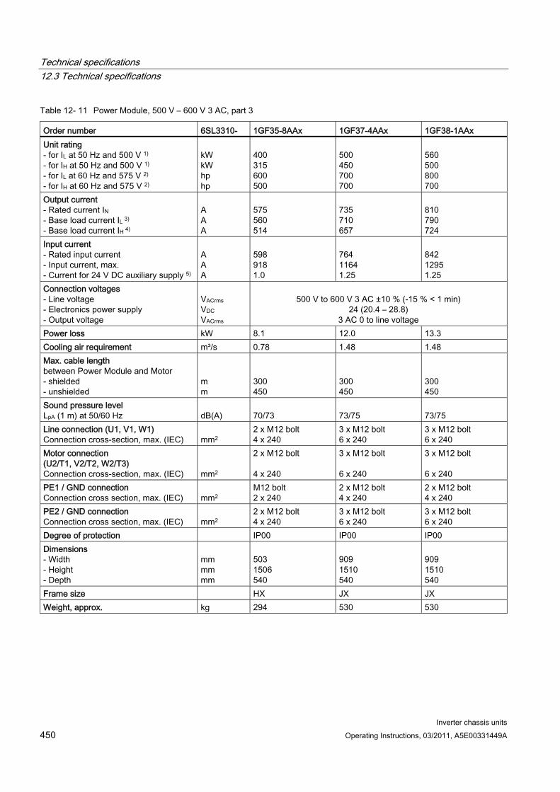
Technical specifications 12.3 Technical specifications
Inverter chassis units 450 Operating Instructions, 03/2011, A5E00331449A
Table 12- 11 Power Module, 500 V – 600 V 3 AC, part 3
Order number 6SL3310- 1GF35-8AAx 1GF37-4AAx 1GF38-1AAx Unit rating - for IL at 50 Hz and 500 V 1) - for IH at 50 Hz and 500 V 1)
- for IL at 60 Hz and 575 V 2)
- for IH at 60 Hz and 575 V 2)
kW kW hp hp
400 315 600 500
500 450 700 700
560 500 800 700
Output current - Rated current IN - Base load current IL 3) - Base load current IH 4)
A A A
575 560 514
735 710 657
810 790 724
Input current - Rated input current - Input current, max. - Current for 24 V DC auxiliary supply 5)
A A A
598 918 1.0
764 1164 1.25
842 1295 1.25
Connection voltages - Line voltage - Electronics power supply - Output voltage
VACrms VDC VACrms
500 V to 600 V 3 AC ±10 % (-15 % < 1 min)
24 (20.4 – 28.8) 3 AC 0 to line voltage
Power loss kW 8.1 12.0 13.3 Cooling air requirement m³/s 0.78 1.48 1.48 Max. cable length between Power Module and Motor - shielded - unshielded
m m
300 450
300 450
300 450
Sound pressure level LpA (1 m) at 50/60 Hz
dB(A)
70/73
73/75
73/75
Line connection (U1, V1, W1) Connection cross-section, max. (IEC)
mm2
2 x M12 bolt 4 x 240
3 x M12 bolt 6 x 240
3 x M12 bolt 6 x 240
Motor connection (U2/T1, V2/T2, W2/T3) Connection cross-section, max. (IEC)
mm2
2 x M12 bolt 4 x 240
3 x M12 bolt 6 x 240
3 x M12 bolt 6 x 240
PE1 / GND connection Connection cross section, max. (IEC)
mm2
M12 bolt 2 x 240
2 x M12 bolt 4 x 240
2 x M12 bolt 4 x 240
PE2 / GND connection Connection cross section, max. (IEC)
mm2
2 x M12 bolt 4 x 240
3 x M12 bolt 6 x 240
3 x M12 bolt 6 x 240
Degree of protection IP00 IP00 IP00 Dimensions - Width - Height - Depth
mm mm mm
503 1506 540
909 1510 540
909 1510 540
Frame size HX JX JX Weight, approx. kg 294 530 530

Technical specifications 12.3 Technical specifications
Inverter chassis units Operating Instructions, 03/2011, A5E00331449A 451
Order number 6SL3310- 1GF35-8AAx 1GF37-4AAx 1GF38-1AAx Recommended fuses - Line protection without semiconductor protection Rated current frame size to IEC 60269 - Line and semiconductor protection 6) Rated current Frame size to IEC 60269
A A
3NA3354-6 2 x 355 3 3NE1447-2 670 3
3NA3365-6 2 x 500 3 3NE1448-2 850 3
3NA3365-6 2 x 500 3 3NE1434-2 2 x 500 2
1) Rated output of a typ. 6-pole standard induction motor based on IL or IH at 500 V 3 AC 50 Hz. 2) Rated output of a typ. 6-pole standard induction motor based on IL or IH at 575 V 3 AC 60 Hz. 3) The base-load current IL is based on a duty cycle of 110% for 60 s or 150% for 10 s with a duty cycle duration of 300 s (see "Overload capability"). 4) The base-load current IH is based on a duty cycle of 150% for 60 s or 160% for 10 s with a duty cycle duration of 300 s (see "Overload capability"). 5) If the auxiliary supply is to be fed in separately from the load supply, e.g., if the control should be able to continue communication if the line voltage fails. 6) The types of protection specified here are mandatory for installing a UL-approved system.
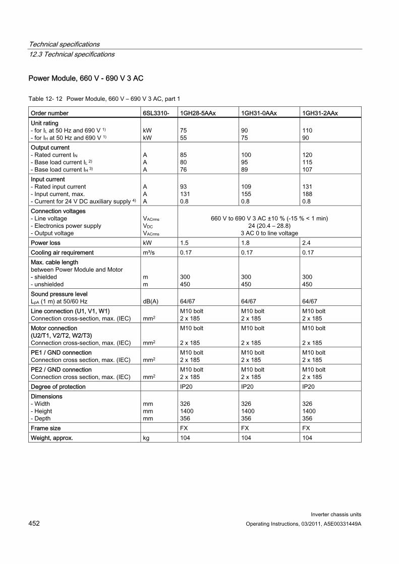
Technical specifications 12.3 Technical specifications
Inverter chassis units 452 Operating Instructions, 03/2011, A5E00331449A
Power Module, 660 V - 690 V 3 AC
Table 12- 12 Power Module, 660 V – 690 V 3 AC, part 1
Order number 6SL3310- 1GH28-5AAx 1GH31-0AAx 1GH31-2AAx Unit rating - for IL at 50 Hz and 690 V 1) - for IH at 50 Hz and 690 V 1)
kW kW
75 55
90 75
110 90
Output current - Rated current IN - Base load current IL 2) - Base load current IH 3)
A A A
85 80 76
100 95 89
120 115 107
Input current - Rated input current - Input current, max. - Current for 24 V DC auxiliary supply 4)
A A A
93 131 0.8
109 155 0.8
131 188 0.8
Connection voltages - Line voltage - Electronics power supply - Output voltage
VACrms VDC VACrms
660 V to 690 V 3 AC ±10 % (-15 % < 1 min)
24 (20.4 – 28.8) 3 AC 0 to line voltage
Power loss kW 1.5 1.8 2.4 Cooling air requirement m³/s 0.17 0.17 0.17 Max. cable length between Power Module and Motor - shielded - unshielded
m m
300 450
300 450
300 450
Sound pressure level LpA (1 m) at 50/60 Hz
dB(A)
64/67
64/67
64/67
Line connection (U1, V1, W1) Connection cross-section, max. (IEC)
mm2
M10 bolt 2 x 185
M10 bolt 2 x 185
M10 bolt 2 x 185
Motor connection (U2/T1, V2/T2, W2/T3) Connection cross-section, max. (IEC)
mm2
M10 bolt 2 x 185
M10 bolt 2 x 185
M10 bolt 2 x 185
PE1 / GND connection Connection cross section, max. (IEC)
mm2
M10 bolt 2 x 185
M10 bolt 2 x 185
M10 bolt 2 x 185
PE2 / GND connection Connection cross section, max. (IEC)
mm2
M10 bolt 2 x 185
M10 bolt 2 x 185
M10 bolt 2 x 185
Degree of protection IP20 IP20 IP20 Dimensions - Width - Height - Depth
mm mm mm
326 1400 356
326 1400 356
326 1400 356
Frame size FX FX FX Weight, approx. kg 104 104 104
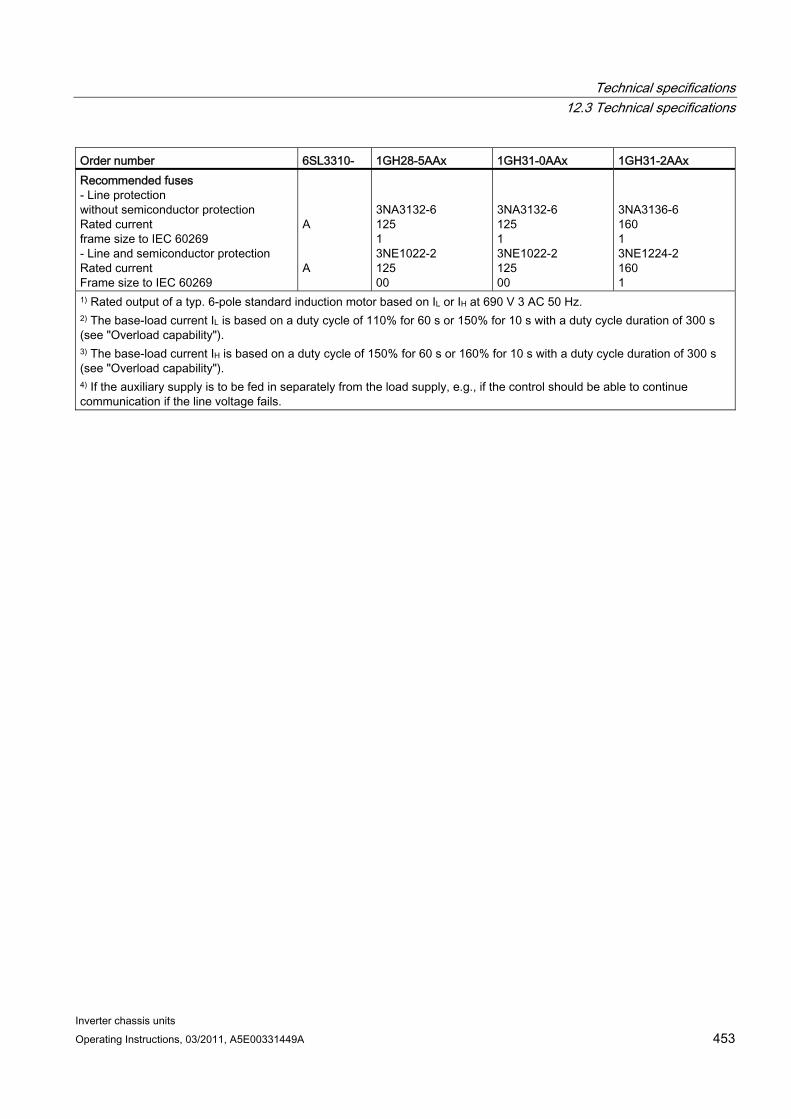
Technical specifications 12.3 Technical specifications
Inverter chassis units Operating Instructions, 03/2011, A5E00331449A 453
Order number 6SL3310- 1GH28-5AAx 1GH31-0AAx 1GH31-2AAx Recommended fuses - Line protection without semiconductor protection Rated current frame size to IEC 60269 - Line and semiconductor protection Rated current Frame size to IEC 60269
A A
3NA3132-6 125 1 3NE1022-2 125 00
3NA3132-6 125 1 3NE1022-2 125 00
3NA3136-6 160 1 3NE1224-2 160 1
1) Rated output of a typ. 6-pole standard induction motor based on IL or IH at 690 V 3 AC 50 Hz. 2) The base-load current IL is based on a duty cycle of 110% for 60 s or 150% for 10 s with a duty cycle duration of 300 s (see "Overload capability"). 3) The base-load current IH is based on a duty cycle of 150% for 60 s or 160% for 10 s with a duty cycle duration of 300 s (see "Overload capability"). 4) If the auxiliary supply is to be fed in separately from the load supply, e.g., if the control should be able to continue communication if the line voltage fails.
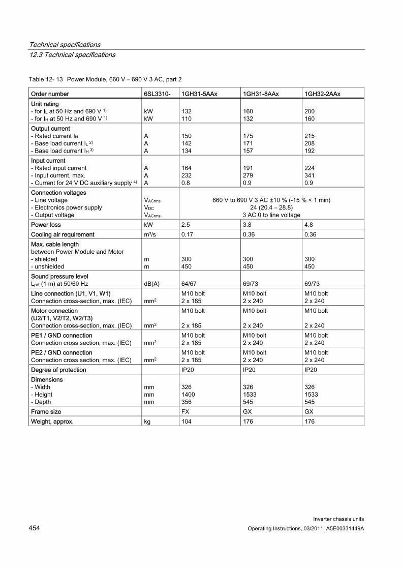
Technical specifications 12.3 Technical specifications
Inverter chassis units 454 Operating Instructions, 03/2011, A5E00331449A
Table 12- 13 Power Module, 660 V – 690 V 3 AC, part 2
Order number 6SL3310- 1GH31-5AAx 1GH31-8AAx 1GH32-2AAx Unit rating - for IL at 50 Hz and 690 V 1) - for IH at 50 Hz and 690 V 1)
kW kW
132 110
160 132
200 160
Output current - Rated current IN - Base load current IL 2) - Base load current IH 3)
A A A
150 142 134
175 171 157
215 208 192
Input current - Rated input current - Input current, max. - Current for 24 V DC auxiliary supply 4)
A A A
164 232 0.8
191 279 0.9
224 341 0.9
Connection voltages - Line voltage - Electronics power supply - Output voltage
VACrms VDC VACrms
660 V to 690 V 3 AC ±10 % (-15 % < 1 min)
24 (20.4 – 28.8) 3 AC 0 to line voltage
Power loss kW 2.5 3.8 4.8 Cooling air requirement m³/s 0.17 0.36 0.36 Max. cable length between Power Module and Motor - shielded - unshielded
m m
300 450
300 450
300 450
Sound pressure level LpA (1 m) at 50/60 Hz
dB(A)
64/67
69/73
69/73
Line connection (U1, V1, W1) Connection cross-section, max. (IEC)
mm2
M10 bolt 2 x 185
M10 bolt 2 x 240
M10 bolt 2 x 240
Motor connection (U2/T1, V2/T2, W2/T3) Connection cross-section, max. (IEC)
mm2
M10 bolt 2 x 185
M10 bolt 2 x 240
M10 bolt 2 x 240
PE1 / GND connection Connection cross section, max. (IEC)
mm2
M10 bolt 2 x 185
M10 bolt 2 x 240
M10 bolt 2 x 240
PE2 / GND connection Connection cross section, max. (IEC)
mm2
M10 bolt 2 x 185
M10 bolt 2 x 240
M10 bolt 2 x 240
Degree of protection IP20 IP20 IP20 Dimensions - Width - Height - Depth
mm mm mm
326 1400 356
326 1533 545
326 1533 545
Frame size FX GX GX Weight, approx. kg 104 176 176

Technical specifications 12.3 Technical specifications
Inverter chassis units Operating Instructions, 03/2011, A5E00331449A 455
Order number 6SL3310- 1GH31-5AAx 1GH31-8AAx 1GH32-2AAx Recommended fuses - Line protection without semiconductor protection Rated current frame size to IEC 60269 - Line and semiconductor protection Rated current Frame size to IEC 60269
A A
3NA3240-6 200 2 3NE1225-2 200 1
3NA3244-6 250 2 3NE1227-2 250 1
3NA3252-6 315 2 3NE1230-2 315 1
1) Rated output of a typ. 6-pole standard induction motor based on IL or IH at 690 V 3 AC 50 Hz. 2) The base-load current IL is based on a duty cycle of 110% for 60 s or 150% for 10 s with a duty cycle duration of 300 s (see "Overload capability"). 3) The base-load current IH is based on a duty cycle of 150% for 60 s or 160% for 10 s with a duty cycle duration of 300 s (see "Overload capability"). 4) If the auxiliary supply is to be fed in separately from the load supply, e.g., if the control should be able to continue communication if the line voltage fails.
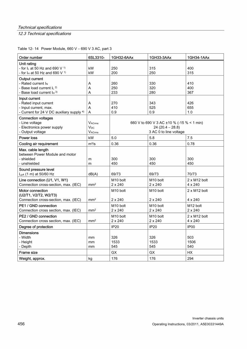
Technical specifications 12.3 Technical specifications
Inverter chassis units 456 Operating Instructions, 03/2011, A5E00331449A
Table 12- 14 Power Module, 660 V – 690 V 3 AC, part 3
Order number 6SL3310- 1GH32-6AAx 1GH33-3AAx 1GH34-1AAx Unit rating - for IL at 50 Hz and 690 V 1) - for IH at 50 Hz and 690 V 1)
kW kW
250 200
315 250
400 315
Output current - Rated current IN - Base load current IL 2) - Base load current IH 3)
A A A
260 250 233
330 320 280
410 400 367
Input current - Rated input current - Input current, max. - Current for 24 V DC auxiliary supply 4)
A A A
270 410 0.9
343 525 0.9
426 655 1.0
Connection voltages - Line voltage - Electronics power supply - Output voltage
VACrms VDC VACrms
660 V to 690 V 3 AC ±10 % (-15 % < 1 min)
24 (20.4 – 28.8) 3 AC 0 to line voltage
Power loss kW 5.0 5.8 7.5 Cooling air requirement m³/s 0.36 0.36 0.78 Max. cable length between Power Module and motor - shielded - unshielded
m m
300 450
300 450
300 450
Sound pressure level LpA (1 m) at 50/60 Hz
dB(A)
69/73
69/73
70/73
Line connection (U1, V1, W1) Connection cross-section, max. (IEC)
mm2
M10 bolt 2 x 240
M10 bolt 2 x 240
2 x M12 bolt 4 x 240
Motor connection (U2/T1, V2/T2, W2/T3) Connection cross-section, max. (IEC)
mm2
M10 bolt 2 x 240
M10 bolt 2 x 240
2 x M12 bolt 4 x 240
PE1 / GND connection Connection cross section, max. (IEC)
mm2
M10 bolt 2 x 240
M10 bolt 2 x 240
M12 bolt 2 x 240
PE2 / GND connection Connection cross section, max. (IEC)
mm2
M10 bolt 2 x 240
M10 bolt 2 x 240
2 x M12 bolt 4 x 240
Degree of protection IP20 IP20 IP00 Dimensions - Width - Height - Depth
mm mm mm
326 1533 545
326 1533 545
503 1506 540
Frame size GX GX HX Weight, approx. kg 176 176 294

Technical specifications 12.3 Technical specifications
Inverter chassis units Operating Instructions, 03/2011, A5E00331449A 457
Order number 6SL3310- 1GH32-6AAx 1GH33-3AAx 1GH34-1AAx Recommended fuses - Line protection without semiconductor protection Rated current frame size to IEC 60269 - Line and semiconductor protection Rated current Frame size to IEC 60269
A A
3NA3354-6 355 3 3NE1331-2 350 2
3NA3365-6 500 3 3NE1334-2 500 2
3NA3365-6 500 3 3NE1334-2 500 2
1) Rated output of a typ. 6-pole standard induction motor based on IL or IH at 690 V 3 AC 50 Hz. 2) The base-load current IL is based on a duty cycle of 110% for 60 s or 150% for 10 s with a duty cycle duration of 300 s (see "Overload capability"). 3) The base-load current IH is based on a duty cycle of 150% for 60 s or 160% for 10 s with a duty cycle duration of 300 s (see "Overload capability"). 4) If the auxiliary supply is to be fed in separately from the load supply, e.g., if the control should be able to continue communication if the line voltage fails.
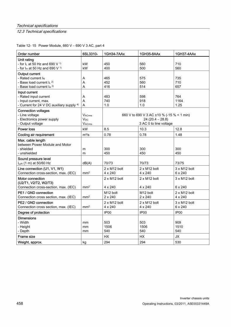
Technical specifications 12.3 Technical specifications
Inverter chassis units 458 Operating Instructions, 03/2011, A5E00331449A
Table 12- 15 Power Module, 660 V – 690 V 3 AC, part 4
Order number 6SL3310- 1GH34-7AAx 1GH35-8AAx 1GH37-4AAx Unit rating - for IL at 50 Hz and 690 V 1) - for IH at 50 Hz and 690 V 1)
kW kW
450 400
560 500
710 560
Output current - Rated current IN - Base load current IL 2) - Base load current IH 3)
A A A
465 452 416
575 560 514
735 710 657
Input current - Rated input current - Input current, max. - Current for 24 V DC auxiliary supply 4)
A A A
483 740 1.0
598 918 1.0
764 1164 1.25
Connection voltages - Line voltage - Electronics power supply - Output voltage
VACrms VDC VACrms
660 V to 690 V 3 AC ±10 % (-15 % < 1 min)
24 (20.4 – 28.8) 3 AC 0 to line voltage
Power loss kW 8.5 10.3 12.8 Cooling air requirement m³/s 0.78 0.78 1.48 Max. cable length between Power Module and Motor - shielded - unshielded
m m
300 450
300 450
300 450
Sound pressure level LpA (1 m) at 50/60 Hz
dB(A)
70/73
70/73
73/75
Line connection (U1, V1, W1) Connection cross-section, max. (IEC)
mm2
2 x M12 bolt 4 x 240
2 x M12 bolt 4 x 240
3 x M12 bolt 6 x 240
Motor connection (U2/T1, V2/T2, W2/T3) Connection cross-section, max. (IEC)
mm2
2 x M12 bolt 4 x 240
2 x M12 bolt 4 x 240
3 x M12 bolt 6 x 240
PE1 / GND connection Connection cross section, max. (IEC)
mm2
M12 bolt 2 x 240
M12 bolt 2 x 240
2 x M12 bolt 4 x 240
PE2 / GND connection Connection cross section, max. (IEC)
mm2
2 x M12 bolt 4 x 240
2 x M12 bolt 4 x 240
3 x M12 bolt 6 x 240
Degree of protection IP00 IP00 IP00 Dimensions - Width - Height - Depth
mm mm mm
503 1506 540
503 1506 540
909 1510 540
Frame size HX HX JX Weight, approx. kg 294 294 530

Technical specifications 12.3 Technical specifications
Inverter chassis units Operating Instructions, 03/2011, A5E00331449A 459
Order number 6SL3310- 1GH34-7AAx 1GH35-8AAx 1GH37-4AAx Recommended fuses - Line protection without semiconductor protection Rated current frame size to IEC 60269 - Line and semiconductor protection Rated current Frame size to IEC 60269
A A
3NA3252-6 2 x 315 2 3NE1435-2 560 3
3NA3354-6 2 x 355 3 3NE1447-2 670 3
3NA3365-6 2 x 500 3 3NE1448-2 850 3
1) Rated output of a typ. 6-pole standard induction motor based on IL or IH at 690 V 3 AC 50 Hz. 2) The base-load current IL is based on a duty cycle of 110% for 60 s or 150% for 10 s with a duty cycle duration of 300 s (see "Overload capability"). 3) The base-load current IH is based on a duty cycle of 150% for 60 s or 160% for 10 s with a duty cycle duration of 300 s (see "Overload capability"). 4) If the auxiliary supply is to be fed in separately from the load supply, e.g., if the control should be able to continue communication if the line voltage fails.
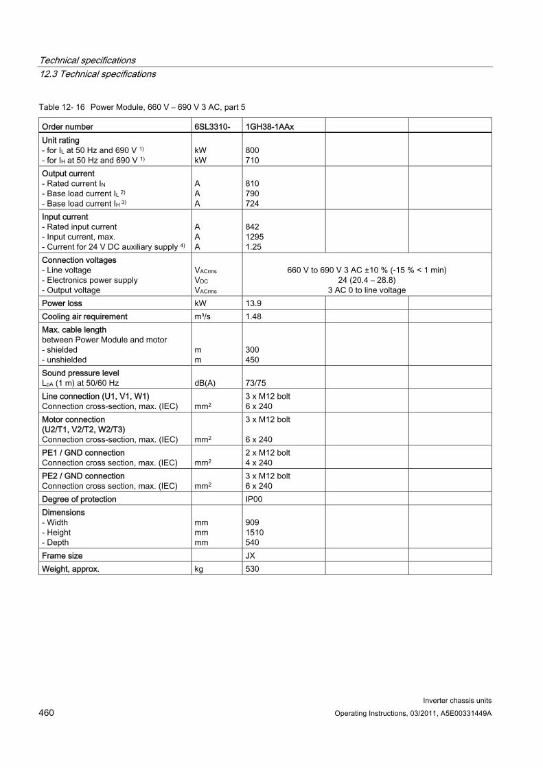
Technical specifications 12.3 Technical specifications
Inverter chassis units 460 Operating Instructions, 03/2011, A5E00331449A
Table 12- 16 Power Module, 660 V – 690 V 3 AC, part 5
Order number 6SL3310- 1GH38-1AAx Unit rating - for IL at 50 Hz and 690 V 1) - for IH at 50 Hz and 690 V 1)
kW kW
800 710
Output current - Rated current IN - Base load current IL 2) - Base load current IH 3)
A A A
810 790 724
Input current - Rated input current - Input current, max. - Current for 24 V DC auxiliary supply 4)
A A A
842 1295 1.25
Connection voltages - Line voltage - Electronics power supply - Output voltage
VACrms VDC VACrms
660 V to 690 V 3 AC ±10 % (-15 % < 1 min)
24 (20.4 – 28.8) 3 AC 0 to line voltage
Power loss kW 13.9 Cooling air requirement m³/s 1.48 Max. cable length between Power Module and motor - shielded - unshielded
m m
300 450
Sound pressure level LpA (1 m) at 50/60 Hz
dB(A)
73/75
Line connection (U1, V1, W1) Connection cross-section, max. (IEC)
mm2
3 x M12 bolt 6 x 240
Motor connection (U2/T1, V2/T2, W2/T3) Connection cross-section, max. (IEC)
mm2
3 x M12 bolt 6 x 240
PE1 / GND connection Connection cross section, max. (IEC)
mm2
2 x M12 bolt 4 x 240
PE2 / GND connection Connection cross section, max. (IEC)
mm2
3 x M12 bolt 6 x 240
Degree of protection IP00 Dimensions - Width - Height - Depth
mm mm mm
909 1510 540
Frame size JX Weight, approx. kg 530
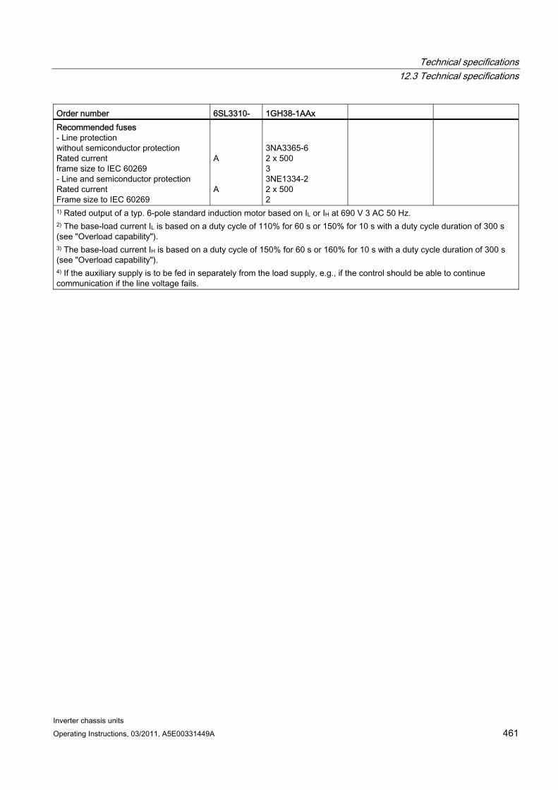
Technical specifications 12.3 Technical specifications
Inverter chassis units Operating Instructions, 03/2011, A5E00331449A 461
Order number 6SL3310- 1GH38-1AAx Recommended fuses - Line protection without semiconductor protection Rated current frame size to IEC 60269 - Line and semiconductor protection Rated current Frame size to IEC 60269
A A
3NA3365-6 2 x 500 3 3NE1334-2 2 x 500 2
1) Rated output of a typ. 6-pole standard induction motor based on IL or IH at 690 V 3 AC 50 Hz. 2) The base-load current IL is based on a duty cycle of 110% for 60 s or 150% for 10 s with a duty cycle duration of 300 s (see "Overload capability"). 3) The base-load current IH is based on a duty cycle of 150% for 60 s or 160% for 10 s with a duty cycle duration of 300 s (see "Overload capability"). 4) If the auxiliary supply is to be fed in separately from the load supply, e.g., if the control should be able to continue communication if the line voltage fails.
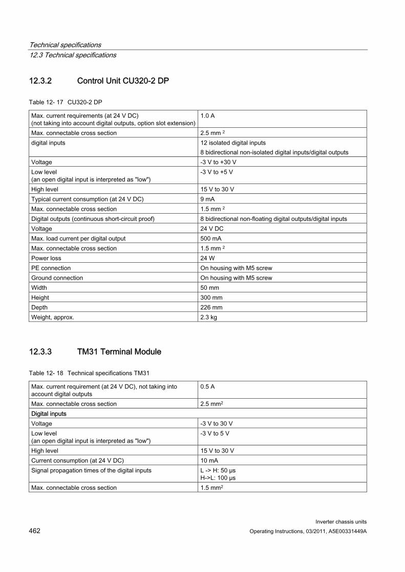
Technical specifications 12.3 Technical specifications
Inverter chassis units 462 Operating Instructions, 03/2011, A5E00331449A
12.3.2 Control Unit CU320-2 DP
Table 12- 17 CU320-2 DP
Max. current requirements (at 24 V DC) (not taking into account digital outputs, option slot extension)
1.0 A
Max. connectable cross section 2.5 mm 2 digital inputs 12 isolated digital inputs
8 bidirectional non-isolated digital inputs/digital outputs Voltage -3 V to +30 V Low level (an open digital input is interpreted as "low")
-3 V to +5 V
High level 15 V to 30 V Typical current consumption (at 24 V DC) 9 mA Max. connectable cross section 1.5 mm 2 Digital outputs (continuous short-circuit proof) 8 bidirectional non-floating digital outputs/digital inputs Voltage 24 V DC Max. load current per digital output 500 mA Max. connectable cross section 1.5 mm 2 Power loss 24 W PE connection On housing with M5 screw Ground connection On housing with M5 screw Width 50 mm Height 300 mm Depth 226 mm Weight, approx. 2.3 kg
12.3.3 TM31 Terminal Module
Table 12- 18 Technical specifications TM31
Max. current requirement (at 24 V DC), not taking into account digital outputs
0.5 A
Max. connectable cross section 2.5 mm2 Digital inputs Voltage -3 V to 30 V Low level (an open digital input is interpreted as "low")
-3 V to 5 V
High level 15 V to 30 V Current consumption (at 24 V DC) 10 mA Signal propagation times of the digital inputs L -> H: 50 µs
H->L: 100 µs Max. connectable cross section 1.5 mm2
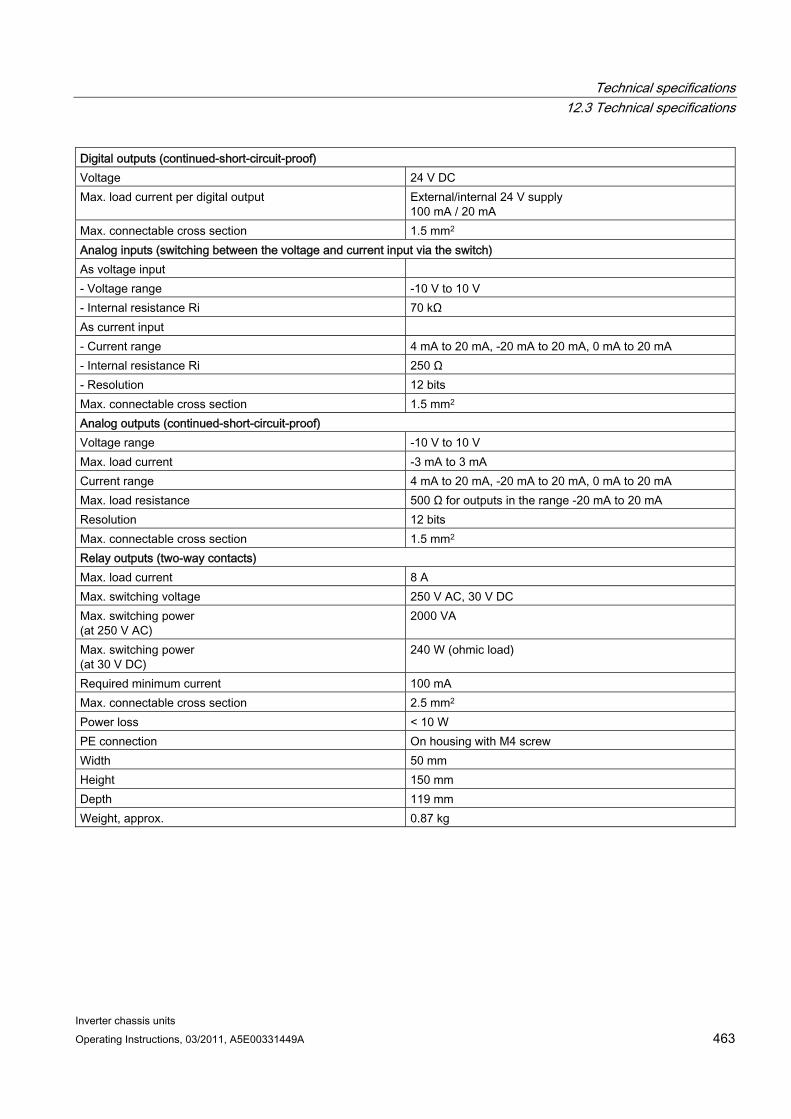
Technical specifications 12.3 Technical specifications
Inverter chassis units Operating Instructions, 03/2011, A5E00331449A 463
Digital outputs (continued-short-circuit-proof) Voltage 24 V DC Max. load current per digital output External/internal 24 V supply
100 mA / 20 mA Max. connectable cross section 1.5 mm2 Analog inputs (switching between the voltage and current input via the switch) As voltage input - Voltage range -10 V to 10 V - Internal resistance Ri 70 kΩ As current input - Current range 4 mA to 20 mA, -20 mA to 20 mA, 0 mA to 20 mA - Internal resistance Ri 250 Ω - Resolution 12 bits Max. connectable cross section 1.5 mm2 Analog outputs (continued-short-circuit-proof) Voltage range -10 V to 10 V Max. load current -3 mA to 3 mA Current range 4 mA to 20 mA, -20 mA to 20 mA, 0 mA to 20 mA Max. load resistance 500 Ω for outputs in the range -20 mA to 20 mA Resolution 12 bits Max. connectable cross section 1.5 mm2 Relay outputs (two-way contacts) Max. load current 8 A Max. switching voltage 250 V AC, 30 V DC Max. switching power (at 250 V AC)
2000 VA
Max. switching power (at 30 V DC)
240 W (ohmic load)
Required minimum current 100 mA Max. connectable cross section 2.5 mm2 Power loss < 10 W PE connection On housing with M4 screw Width 50 mm Height 150 mm Depth 119 mm Weight, approx. 0.87 kg

Technical specifications 12.3 Technical specifications
Inverter chassis units 464 Operating Instructions, 03/2011, A5E00331449A
12.3.4 SMC30 Sensor Module
Table 12- 19 Technical specifications SMC30
Electronics power supply Voltage 24 V DC (20.4 – 28.8) Current max. 0.6 A Max. ambient temperature up to an altitude of 2000 m 55 °C Note: As of an altitude of 2000 m, the max. ambient temperature decreases by 7°C every 1000 m. PE/ground connection On housing with M4/1.8 Nm screw Weight 0.45 kg
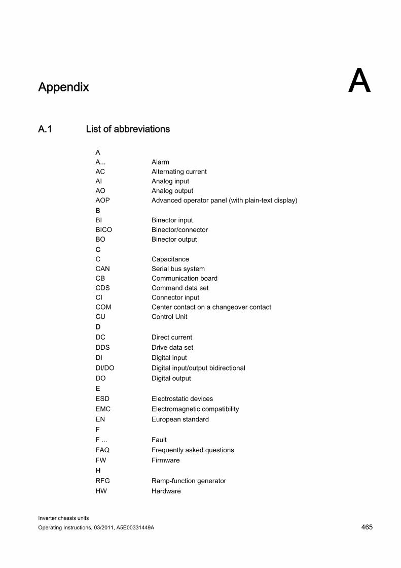
Inverter chassis units Operating Instructions, 03/2011, A5E00331449A 465
Appendix AA.1 List of abbreviations
A A... Alarm AC Alternating current AI Analog input AO Analog output AOP Advanced operator panel (with plain-text display) B BI Binector input BICO Binector/connector BO Binector output C C Capacitance CAN Serial bus system CB Communication board CDS Command data set CI Connector input COM Center contact on a changeover contact CU Control Unit D DC Direct current DDS Drive data set DI Digital input DI/DO Digital input/output bidirectional DO Digital output E ESD Electrostatic devices EMC Electromagnetic compatibility EN European standard F F ... Fault FAQ Frequently asked questions FW Firmware H RFG Ramp-function generator HW Hardware
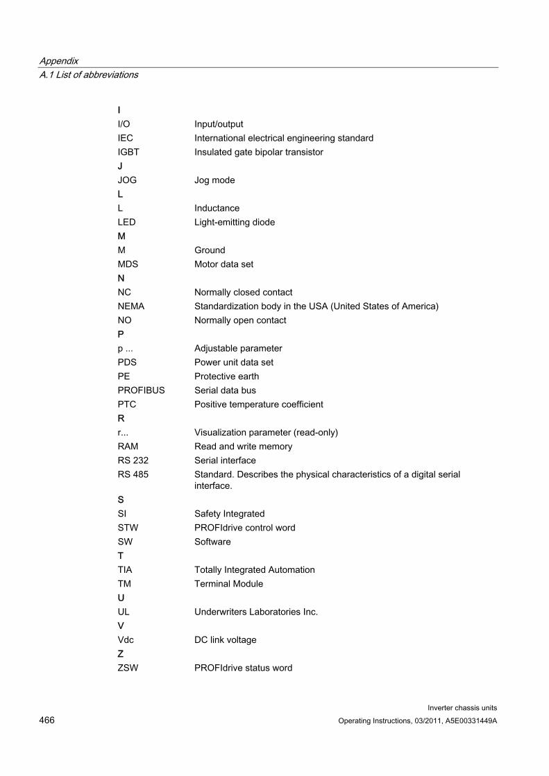
Appendix A.1 List of abbreviations
Inverter chassis units 466 Operating Instructions, 03/2011, A5E00331449A
I I/O Input/output IEC International electrical engineering standard IGBT Insulated gate bipolar transistor J JOG Jog mode L L Inductance LED Light-emitting diode M M Ground MDS Motor data set N NC Normally closed contact NEMA Standardization body in the USA (United States of America) NO Normally open contact P p ... Adjustable parameter PDS Power unit data set PE Protective earth PROFIBUS Serial data bus PTC Positive temperature coefficient R r... Visualization parameter (read-only) RAM Read and write memory RS 232 Serial interface RS 485 Standard. Describes the physical characteristics of a digital serial
interface. S SI Safety Integrated STW PROFIdrive control word SW Software T TIA Totally Integrated Automation TM Terminal Module U UL Underwriters Laboratories Inc. V Vdc DC link voltage Z ZSW PROFIdrive status word
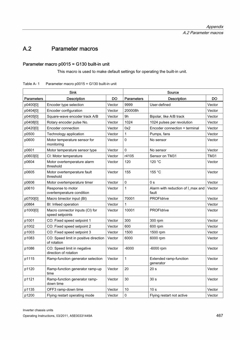
Appendix A.2 Parameter macros
Inverter chassis units Operating Instructions, 03/2011, A5E00331449A 467
A.2 Parameter macros
Parameter macro p0015 = G130 built-in unit This macro is used to make default settings for operating the built-in unit.
Table A- 1 Parameter macro p0015 = G130 built-in unit
Sink Source Parameters Description DO Parameters Description DO p0400[0] Encoder type selection Vector 9999 User-defined Vector p0404[0] Encoder configuration Vector 200008h Vector p0405[0] Square-wave encoder track A/B Vector 9h Bipolar, like A/B track Vector p0408[0] Rotary encoder pulse No. Vector 1024 1024 pulses per revolution Vector p0420[0] Encoder connection Vector 0x2 Encoder connection = terminal Vector p0500 Technology application Vector 1 Pumps, fans Vector p0600 Motor temperature sensor for
monitoring Vector 0 No sensor Vector
p0601 Motor temperature sensor type Vector 0 No sensor Vector p0603[0] CI: Motor temperature Vector r4105 Sensor on TM31 TM31 p0604 Motor overtemperature alarm
threshold Vector 120 120 °C Vector
p0605 Motor overtemperature fault threshold
Vector 155 155 °C Vector
p0606 Motor overtemperature timer Vector 0 0 s Vector p0610 Response to motor
overtemperature condition Vector 1 Alarm with reduction of I_max and
fault Vector
p0700[0] Macro binector input (BI) Vector 70001 PROFIdrive Vector p0864 BI: Infeed operation Vector 1 Vector p1000[0] Macro connector inputs (CI) for
speed setpoints Vector 10001 PROFIdrive Vector
p1001 CO: Fixed speed setpoint 1 Vector 300 300 rpm Vector p1002 CO: Fixed speed setpoint 2 Vector 600 600 rpm Vector p1003 CO: Fixed speed setpoint 3 Vector 1500 1500 rpm Vector p1083 CO: Speed limit in positive direction
of rotation Vector 6000 6000 rpm Vector
p1086 CO: Speed limit in negative direction of rotation
Vector -6000 -6000 rpm Vector
p1115 Ramp-function generator selection Vector 1 Extended ramp-function generator
Vector
p1120 Ramp-function generator ramp-up time
Vector 20 20 s Vector
p1121 Ramp-function generator ramp-down time
Vector 30 30 s Vector
p1135 OFF3 ramp-down time Vector 10 10 s Vector p1200 Flying restart operating mode Vector 0 Flying restart not active Vector
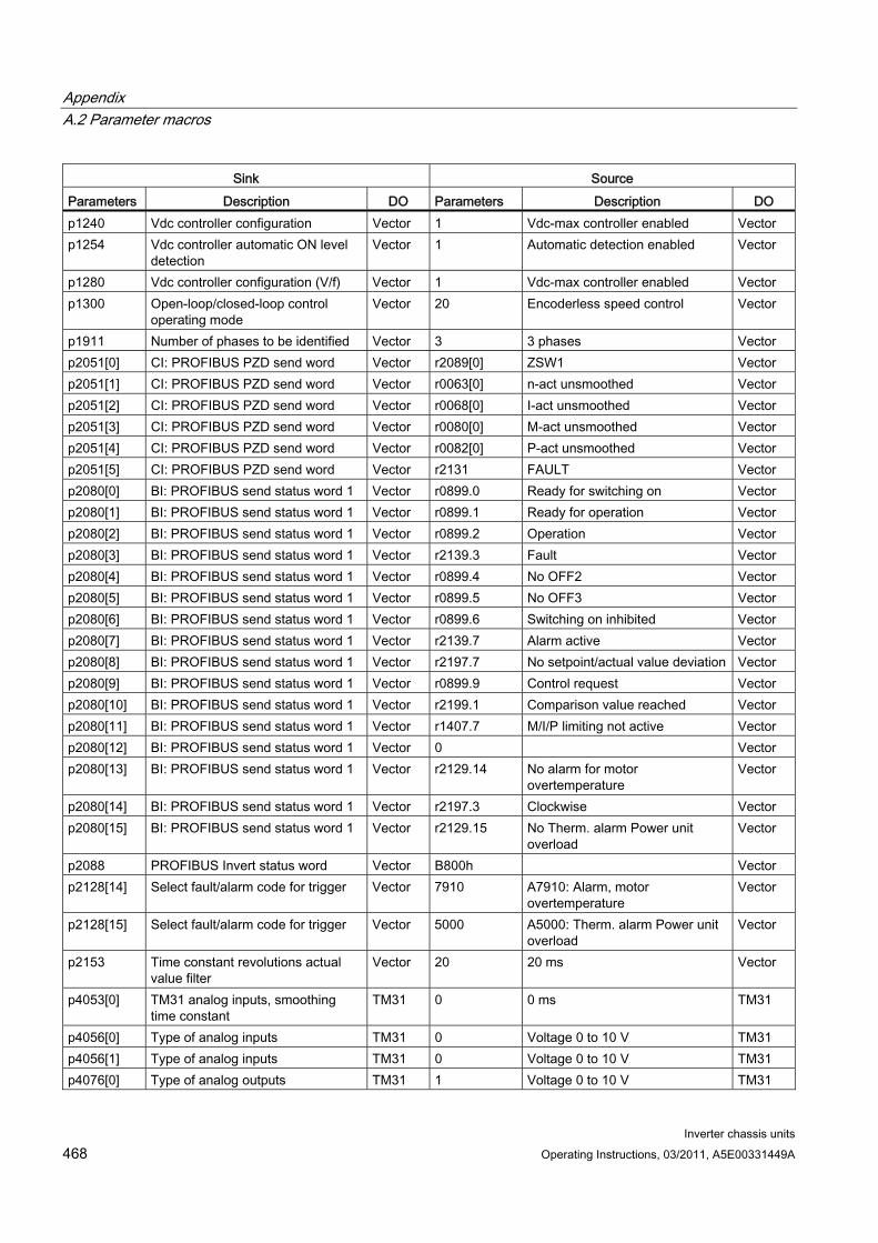
Appendix A.2 Parameter macros
Inverter chassis units 468 Operating Instructions, 03/2011, A5E00331449A
Sink Source Parameters Description DO Parameters Description DO p1240 Vdc controller configuration Vector 1 Vdc-max controller enabled Vector p1254 Vdc controller automatic ON level
detection Vector 1 Automatic detection enabled Vector
p1280 Vdc controller configuration (V/f) Vector 1 Vdc-max controller enabled Vector p1300 Open-loop/closed-loop control
operating mode Vector 20 Encoderless speed control Vector
p1911 Number of phases to be identified Vector 3 3 phases Vector p2051[0] CI: PROFIBUS PZD send word Vector r2089[0] ZSW1 Vector p2051[1] CI: PROFIBUS PZD send word Vector r0063[0] n-act unsmoothed Vector p2051[2] CI: PROFIBUS PZD send word Vector r0068[0] I-act unsmoothed Vector p2051[3] CI: PROFIBUS PZD send word Vector r0080[0] M-act unsmoothed Vector p2051[4] CI: PROFIBUS PZD send word Vector r0082[0] P-act unsmoothed Vector p2051[5] CI: PROFIBUS PZD send word Vector r2131 FAULT Vector p2080[0] BI: PROFIBUS send status word 1 Vector r0899.0 Ready for switching on Vector p2080[1] BI: PROFIBUS send status word 1 Vector r0899.1 Ready for operation Vector p2080[2] BI: PROFIBUS send status word 1 Vector r0899.2 Operation Vector p2080[3] BI: PROFIBUS send status word 1 Vector r2139.3 Fault Vector p2080[4] BI: PROFIBUS send status word 1 Vector r0899.4 No OFF2 Vector p2080[5] BI: PROFIBUS send status word 1 Vector r0899.5 No OFF3 Vector p2080[6] BI: PROFIBUS send status word 1 Vector r0899.6 Switching on inhibited Vector p2080[7] BI: PROFIBUS send status word 1 Vector r2139.7 Alarm active Vector p2080[8] BI: PROFIBUS send status word 1 Vector r2197.7 No setpoint/actual value deviation Vector p2080[9] BI: PROFIBUS send status word 1 Vector r0899.9 Control request Vector p2080[10] BI: PROFIBUS send status word 1 Vector r2199.1 Comparison value reached Vector p2080[11] BI: PROFIBUS send status word 1 Vector r1407.7 M/I/P limiting not active Vector p2080[12] BI: PROFIBUS send status word 1 Vector 0 Vector p2080[13] BI: PROFIBUS send status word 1 Vector r2129.14 No alarm for motor
overtemperature Vector
p2080[14] BI: PROFIBUS send status word 1 Vector r2197.3 Clockwise Vector p2080[15] BI: PROFIBUS send status word 1 Vector r2129.15 No Therm. alarm Power unit
overload Vector
p2088 PROFIBUS Invert status word Vector B800h Vector p2128[14] Select fault/alarm code for trigger Vector 7910 A7910: Alarm, motor
overtemperature Vector
p2128[15] Select fault/alarm code for trigger Vector 5000 A5000: Therm. alarm Power unit overload
Vector
p2153 Time constant revolutions actual value filter
Vector 20 20 ms Vector
p4053[0] TM31 analog inputs, smoothing time constant
TM31 0 0 ms TM31
p4056[0] Type of analog inputs TM31 0 Voltage 0 to 10 V TM31 p4056[1] Type of analog inputs TM31 0 Voltage 0 to 10 V TM31 p4076[0] Type of analog outputs TM31 1 Voltage 0 to 10 V TM31
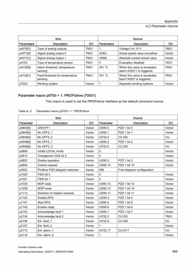
Appendix A.2 Parameter macros
Inverter chassis units Operating Instructions, 03/2011, A5E00331449A 469
Sink Source Parameters Description DO Parameters Description DO p4076[1] Type of analog outputs TM31 1 Voltage 0 to 10 V TM31 p4071[0] Signal analog output 0 TM31 r0063 Actual speed value smoothed Vector p4071[1] Signal analog output 1 TM31 r0068 Absolute current actual value Vector p4100 Type of temperature sensor TM31 0 Evaluation disabled TM31 p4102[0] Alarm threshold, temperature
sensing TM31 251 °C When this value is exceeded,
alarm A35211 is triggered. TM31
p4102[1] Fault threshold for temperature sensing
TM31 251 °C When this value is exceeded, fault F35207 is triggered.
TM31
p7003 Winding system Vector 1 Separate winding systems Vector
Parameter macro p0700 = 1: PROFIdrive (70001) This macro is used to set the PROFIdrive interface as the default command source.
Table A- 2 Parameter macro p0700 = 1: PROFIdrive
Sink Source Parameter Description DO Parameter Description DO p0840[0] ON/OFF1 Vector r2090.0 PZD 1 bit 0 Vector p0844[0] No OFF2_1 Vector r2090.1 PZD 1 bit 1 Vector p0845[0] No OFF2_2 Vector r0722.4 CU DI4 CU p0848[0] No OFF3_1 Vector r2090.2 PZD 1 bit 2 Vector p0849[0] No OFF3_2 Vector r0722.5 CU DI5 CU p0806 Inhibit LOCAL mode Vector 0 Vector p0810 Changeover CDS bit 0 Vector 0 Vector p0852 Enable operation Vector r2090.3 PZD 1 bit 3 Vector p0854 Control request Vector r2090.10 PZD 1 bit 10 Vector p0922 Profibus PZD telegram selection Vector 999 Free telegram configuration p1020 FSW bit 0 Vector 0 Vector p1021 FSW bit 1 Vector 0 Vector p1035 MOP raise Vector r2090.13 PZD 1 bit 13 Vector p1036 MOP lower Vector r2090.14 PZD 1 bit 14 Vector p1113 Direction of rotation reversal Vector r2090.11 PZD 1 bit 11 Vector p1140 Enable RFG Vector r2090.4 PZD 1 bit 4 Vector p1141 Start RFG Vector r2090.5 PZD 1 bit 5 Vector p1142 Enable nsetp Vector r2090.6 PZD 1 bit 6 Vector p2103 Acknowledge fault 1 Vector r2090.7 PZD 1 bit 7 Vector p2104 Acknowledge fault 2 Vector r0722.3 CU DI3 TM31 p2106 Ext. fault_1 Vector r0722.6 CU DI6 CU p2107 Ext. fault_2 Vector 1 Vector p2112 Ext. alarm_1 Vector r0722.11 CU DI11 CU p2116 Ext. alarm_2 Vector 1 Vector
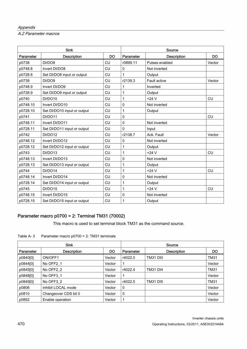
Appendix A.2 Parameter macros
Inverter chassis units 470 Operating Instructions, 03/2011, A5E00331449A
Sink Source Parameter Description DO Parameter Description DO p0738 DI/DO8 CU r0899.11 Pulses enabled Vector p0748.8 Invert DI/DO8 CU 0 Not inverted p0728.8 Set DI/DO8 input or output CU 1 Output p0739 DI/DO9 CU r2139.3 Fault active Vector p0748.9 Invert DI/DO9 CU 1 Inverted p0728.9 Set DI/DO9 input or output CU 1 Output p0740 DI/DO10 CU 1 +24 V CU p0748.10 Invert DI/DO10 CU 0 Not inverted p0728.10 Set DI/DO10 input or output CU 1 Output p0741 DI/DO11 CU 0 CU p0748.11 Invert DI/DO11 CU 0 Not inverted p0728.11 Set DI/DO11 input or output CU 0 Input p0742 DI/DO12 CU r2138.7 Ack. Fault Vector p0748.12 Invert DI/DO12 CU 0 Not inverted p0728.12 Set DI/DO12 input or output CU 1 Output p0743 DI/DO13 CU 1 +24 V CU p0748.13 Invert DI/DO13 CU 0 Not inverted p0728.13 Set DI/DO13 input or output CU 1 Output p0744 DI/DO14 CU 1 +24 V CU p0748.14 Invert DI/DO14 CU 0 Not inverted p0728.14 Set DI/DO14 input or output CU 1 Output p0745 DI/DO15 CU 1 +24 V CU p0748.15 Invert DI/DO15 CU 0 Not inverted p0728.15 Set DI/DO15 input or output CU 1 Output
Parameter macro p0700 = 2: Terminal TM31 (70002) This macro is used to set terminal block TM31 as the command source.
Table A- 3 Parameter macro p0700 = 2: TM31 terminals
Sink Source Parameter Description DO Parameter Description DO p0840[0] ON/OFF1 Vector r4022.0 TM31 DI0 TM31 p0844[0] No OFF2_1 Vector 1 Vector p0845[0] No OFF2_2 Vector r4022.4 TM31 DI4 TM31 p0848[0] No OFF3_1 Vector 1 Vector p0849[0] No OFF3_2 Vector r4022.5 TM31 DI5 TM31 p0806 Inhibit LOCAL mode Vector 0 Vector p0810 Changeover CDS bit 0 Vector 0 Vector p0852 Enable operation Vector 1 Vector
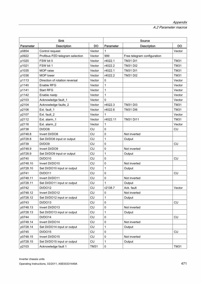
Appendix A.2 Parameter macros
Inverter chassis units Operating Instructions, 03/2011, A5E00331449A 471
Sink Source Parameter Description DO Parameter Description DO p0854 Control request Vector 1 Vector p0922 Profibus PZD telegram selection Vector 999 Free telegram configuration p1020 FSW bit 0 Vector r4022.1 TM31 DI1 TM31 p1021 FSW bit 1 Vector r4022.2 TM31 DI2 TM31 p1035 MOP raise Vector r4022.1 TM31 DI1 TM31 p1036 MOP lower Vector r4022.2 TM31 DI2 TM31 p1113 Direction of rotation reversal Vector 0 Vector p1140 Enable RFG Vector 1 Vector p1141 Start RFG Vector 1 Vector p1142 Enable nsetp Vector 1 Vector p2103 Acknowledge fault_1 Vector 0 Vector p2104 Acknowledge faults_2 Vector r4022.3 TM31 DI3 TM31 p2106 Ext. fault_1 Vector r4022.6 TM31 DI6 TM31 p2107 Ext. fault_2 Vector 1 Vector p2112 Ext. alarm_1 Vector r4022.11 TM31 DI11 TM31 p2116 Ext. alarm_2 Vector 1 Vector p0738 DI/DO8 CU 0 CU p0748.8 Invert DI/DO8 CU 0 Not inverted p0728.8 Set DI/DO8 input or output CU 1 Output p0739 DI/DO9 CU 0 CU p0748.9 Invert DI/DO9 CU 0 Not inverted p0728.9 Set DI/DO9 input or output CU 1 Output p0740 DI/DO10 CU 0 CU p0748.10 Invert DI/DO10 CU 0 Not inverted p0728.10 Set DI/DO10 input or output CU 1 Output p0741 DI/DO11 CU 0 CU p0748.11 Invert DI/DO11 CU 0 Not inverted p0728.11 Set DI/DO11 input or output CU 1 Output p0742 DI/DO12 CU r2138.7 Ack. fault Vector p0748.12 Invert DI/DO12 CU 0 Not inverted p0728.12 Set DI/DO12 input or output CU 1 Output p0743 DI/DO13 CU 0 CU p0748.13 Invert DI/DO13 CU 0 Not inverted p0728.13 Set DI/DO13 input or output CU 1 Output p0744 DI/DO14 CU 0 CU p0748.14 Invert DI/DO14 CU 0 Not inverted p0728.14 Set DI/DO14 input or output CU 1 Output p0745 DI/DO15 CU 0 CU p0748.15 Invert DI/DO15 CU 0 Not inverted p0728.15 Set DI/DO15 input or output CU 1 Output p2103 Acknowledge fault 1 TM31 0 TM31
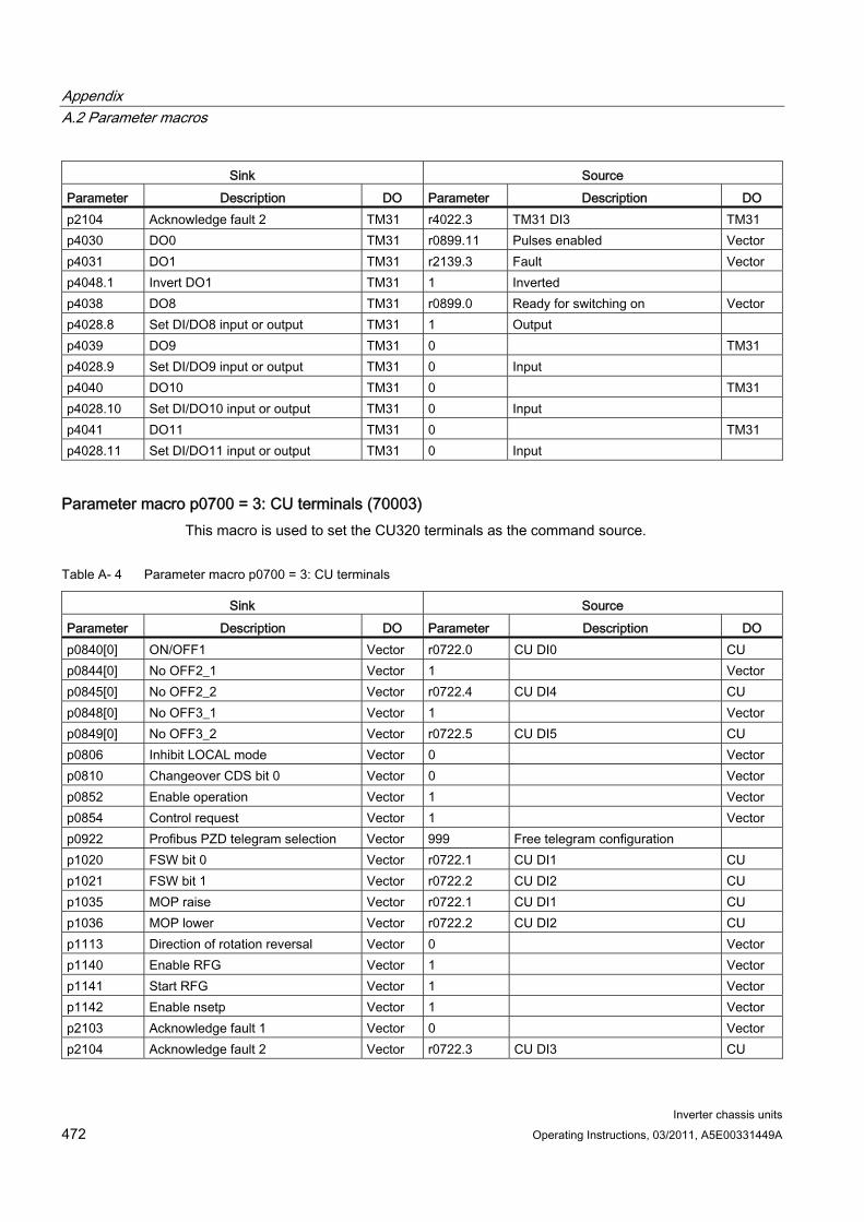
Appendix A.2 Parameter macros
Inverter chassis units 472 Operating Instructions, 03/2011, A5E00331449A
Sink Source Parameter Description DO Parameter Description DO p2104 Acknowledge fault 2 TM31 r4022.3 TM31 DI3 TM31 p4030 DO0 TM31 r0899.11 Pulses enabled Vector p4031 DO1 TM31 r2139.3 Fault Vector p4048.1 Invert DO1 TM31 1 Inverted p4038 DO8 TM31 r0899.0 Ready for switching on Vector p4028.8 Set DI/DO8 input or output TM31 1 Output p4039 DO9 TM31 0 TM31 p4028.9 Set DI/DO9 input or output TM31 0 Input p4040 DO10 TM31 0 TM31 p4028.10 Set DI/DO10 input or output TM31 0 Input p4041 DO11 TM31 0 TM31 p4028.11 Set DI/DO11 input or output TM31 0 Input
Parameter macro p0700 = 3: CU terminals (70003) This macro is used to set the CU320 terminals as the command source.
Table A- 4 Parameter macro p0700 = 3: CU terminals
Sink Source Parameter Description DO Parameter Description DO p0840[0] ON/OFF1 Vector r0722.0 CU DI0 CU p0844[0] No OFF2_1 Vector 1 Vector p0845[0] No OFF2_2 Vector r0722.4 CU DI4 CU p0848[0] No OFF3_1 Vector 1 Vector p0849[0] No OFF3_2 Vector r0722.5 CU DI5 CU p0806 Inhibit LOCAL mode Vector 0 Vector p0810 Changeover CDS bit 0 Vector 0 Vector p0852 Enable operation Vector 1 Vector p0854 Control request Vector 1 Vector p0922 Profibus PZD telegram selection Vector 999 Free telegram configuration p1020 FSW bit 0 Vector r0722.1 CU DI1 CU p1021 FSW bit 1 Vector r0722.2 CU DI2 CU p1035 MOP raise Vector r0722.1 CU DI1 CU p1036 MOP lower Vector r0722.2 CU DI2 CU p1113 Direction of rotation reversal Vector 0 Vector p1140 Enable RFG Vector 1 Vector p1141 Start RFG Vector 1 Vector p1142 Enable nsetp Vector 1 Vector p2103 Acknowledge fault 1 Vector 0 Vector p2104 Acknowledge fault 2 Vector r0722.3 CU DI3 CU
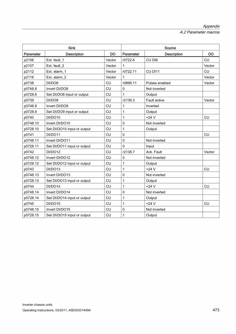
Appendix A.2 Parameter macros
Inverter chassis units Operating Instructions, 03/2011, A5E00331449A 473
Sink Source Parameter Description DO Parameter Description DO p2106 Ext. fault_1 Vector r0722.6 CU DI6 CU p2107 Ext. fault_2 Vector 1 Vector p2112 Ext. alarm_1 Vector r0722.11 CU DI11 CU p2116 Ext. alarm_2 Vector 1 Vector p0738 DI/DO8 CU r0899.11 Pulses enabled Vector p0748.8 Invert DI/DO8 CU 0 Not inverted p0728.8 Set DI/DO8 input or output CU 1 Output p0739 DI/DO9 CU r2139.3 Fault active Vector p0748.9 Invert DI/DO9 CU 1 Inverted p0728.9 Set DI/DO9 input or output CU 1 Output p0740 DI/DO10 CU 1 +24 V CU p0748.10 Invert DI/DO10 CU 0 Not inverted p0728.10 Set DI/DO10 input or output CU 1 Output p0741 DI/DO11 CU 0 CU p0748.11 Invert DI/DO11 CU 0 Not inverted p0728.11 Set DI/DO11 input or output CU 0 Input p0742 DI/DO12 CU r2138.7 Ack. Fault Vector p0748.12 Invert DI/DO12 CU 0 Not inverted p0728.12 Set DI/DO12 input or output CU 1 Output p0743 DI/DO13 CU 1 +24 V CU p0748.13 Invert DI/DO13 CU 0 Not inverted p0728.13 Set DI/DO13 input or output CU 1 Output p0744 DI/DO14 CU 1 +24 V CU p0748.14 Invert DI/DO14 CU 0 Not inverted p0728.14 Set DI/DO14 input or output CU 1 Output p0745 DI/DO15 CU 1 +24 V CU p0748.15 Invert DI/DO15 CU 0 Not inverted p0728.15 Set DI/DO15 input or output CU 1 Output
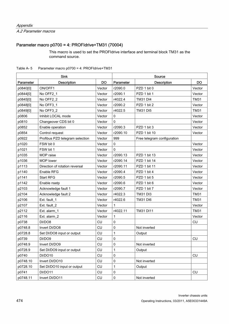
Appendix A.2 Parameter macros
Inverter chassis units 474 Operating Instructions, 03/2011, A5E00331449A
Parameter macro p0700 = 4: PROFIdrive+TM31 (70004) This macro is used to set the PROFIdrive interface and terminal block TM31 as the command source.
Table A- 5 Parameter macro p0700 = 4: PROFIdrive+TM31
Sink Source Parameter Description DO Parameter Description DO p0840[0] ON/OFF1 Vector r2090.0 PZD 1 bit 0 Vector p0844[0] No OFF2_1 Vector r2090.1 PZD 1 bit 1 Vector p0845[0] No OFF2_2 Vector r4022.4 TM31 DI4 TM31 p0848[0] No OFF3_1 Vector r2090.2 PZD 1 bit 2 Vector p0849[0] No OFF3_2 Vector r4022.5 TM31 DI5 TM31 p0806 Inhibit LOCAL mode Vector 0 Vector p0810 Changeover CDS bit 0 Vector 0 Vector p0852 Enable operation Vector r2090.3 PZD 1 bit 3 Vector p0854 Control request Vector r2090.10 PZD 1 bit 10 Vector p0922 Profibus PZD telegram selection Vector 999 Free telegram configuration p1020 FSW bit 0 Vector 0 Vector p1021 FSW bit 1 Vector 0 Vector p1035 MOP raise Vector r2090.13 PZD 1 bit 13 Vector p1036 MOP lower Vector r2090.14 PZD 1 bit 14 Vector p1113 Direction of rotation reversal Vector r2090.11 PZD 1 bit 11 Vector p1140 Enable RFG Vector r2090.4 PZD 1 bit 4 Vector p1141 Start RFG Vector r2090.5 PZD 1 bit 5 Vector p1142 Enable nsetp Vector r2090.6 PZD 1 bit 6 Vector p2103 Acknowledge fault 1 Vector r2090.7 PZD 1 bit 7 Vector p2104 Acknowledge fault 2 Vector r4022.3 TM31 DI3 TM31 p2106 Ext. fault_1 Vector r4022.6 TM31 DI6 TM31 p2107 Ext. fault_2 Vector 1 Vector p2112 Ext. alarm_1 Vector r4022.11 TM31 DI11 TM31 p2116 Ext. alarm_2 Vector 1 Vector p0738 DI/DO8 CU 0 CU p0748.8 Invert DI/DO8 CU 0 Not inverted p0728.8 Set DI/DO8 input or output CU 1 Output p0739 DI/DO9 CU 0 CU p0748.9 Invert DI/DO9 CU 0 Not inverted p0728.9 Set DI/DO9 input or output CU 1 Output p0740 DI/DO10 CU 0 CU p0748.10 Invert DI/DO10 CU 0 Not inverted p0728.10 Set DI/DO10 input or output CU 1 Output p0741 DI/DO11 CU 0 CU p0748.11 Invert DI/DO11 CU 0 Not inverted
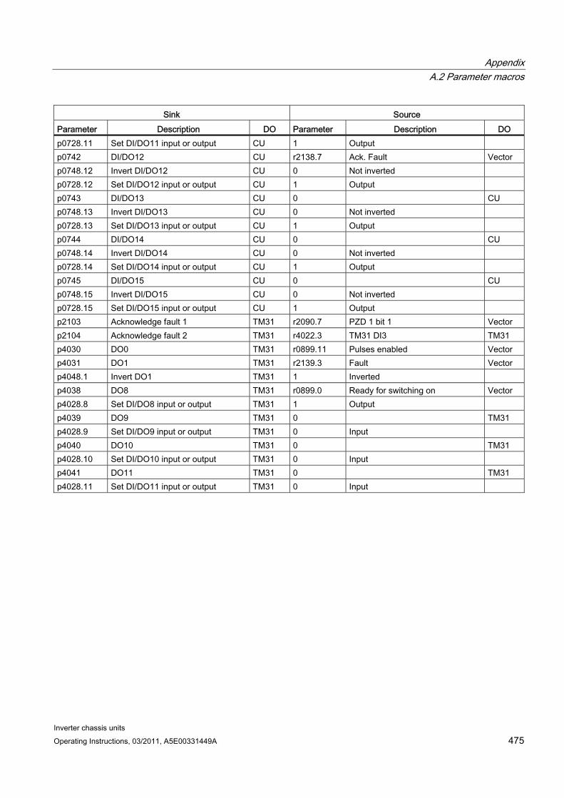
Appendix A.2 Parameter macros
Inverter chassis units Operating Instructions, 03/2011, A5E00331449A 475
Sink Source Parameter Description DO Parameter Description DO p0728.11 Set DI/DO11 input or output CU 1 Output p0742 DI/DO12 CU r2138.7 Ack. Fault Vector p0748.12 Invert DI/DO12 CU 0 Not inverted p0728.12 Set DI/DO12 input or output CU 1 Output p0743 DI/DO13 CU 0 CU p0748.13 Invert DI/DO13 CU 0 Not inverted p0728.13 Set DI/DO13 input or output CU 1 Output p0744 DI/DO14 CU 0 CU p0748.14 Invert DI/DO14 CU 0 Not inverted p0728.14 Set DI/DO14 input or output CU 1 Output p0745 DI/DO15 CU 0 CU p0748.15 Invert DI/DO15 CU 0 Not inverted p0728.15 Set DI/DO15 input or output CU 1 Output p2103 Acknowledge fault 1 TM31 r2090.7 PZD 1 bit 1 Vector p2104 Acknowledge fault 2 TM31 r4022.3 TM31 DI3 TM31 p4030 DO0 TM31 r0899.11 Pulses enabled Vector p4031 DO1 TM31 r2139.3 Fault Vector p4048.1 Invert DO1 TM31 1 Inverted p4038 DO8 TM31 r0899.0 Ready for switching on Vector p4028.8 Set DI/DO8 input or output TM31 1 Output p4039 DO9 TM31 0 TM31 p4028.9 Set DI/DO9 input or output TM31 0 Input p4040 DO10 TM31 0 TM31 p4028.10 Set DI/DO10 input or output TM31 0 Input p4041 DO11 TM31 0 TM31 p4028.11 Set DI/DO11 input or output TM31 0 Input
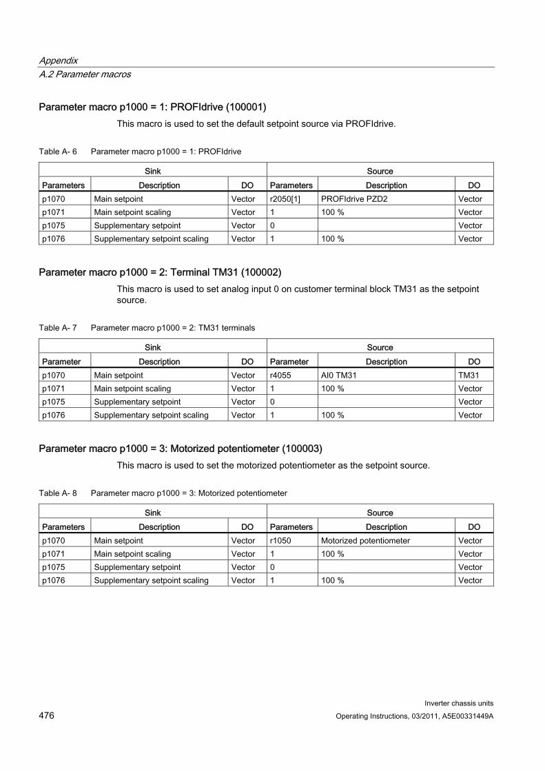
Appendix A.2 Parameter macros
Inverter chassis units 476 Operating Instructions, 03/2011, A5E00331449A
Parameter macro p1000 = 1: PROFIdrive (100001) This macro is used to set the default setpoint source via PROFIdrive.
Table A- 6 Parameter macro p1000 = 1: PROFIdrive
Sink Source Parameters Description DO Parameters Description DO p1070 Main setpoint Vector r2050[1] PROFIdrive PZD2 Vector p1071 Main setpoint scaling Vector 1 100 % Vector p1075 Supplementary setpoint Vector 0 Vector p1076 Supplementary setpoint scaling Vector 1 100 % Vector
Parameter macro p1000 = 2: Terminal TM31 (100002) This macro is used to set analog input 0 on customer terminal block TM31 as the setpoint source.
Table A- 7 Parameter macro p1000 = 2: TM31 terminals
Sink Source Parameter Description DO Parameter Description DO p1070 Main setpoint Vector r4055 AI0 TM31 TM31 p1071 Main setpoint scaling Vector 1 100 % Vector p1075 Supplementary setpoint Vector 0 Vector p1076 Supplementary setpoint scaling Vector 1 100 % Vector
Parameter macro p1000 = 3: Motorized potentiometer (100003) This macro is used to set the motorized potentiometer as the setpoint source.
Table A- 8 Parameter macro p1000 = 3: Motorized potentiometer
Sink Source Parameters Description DO Parameters Description DO p1070 Main setpoint Vector r1050 Motorized potentiometer Vector p1071 Main setpoint scaling Vector 1 100 % Vector p1075 Supplementary setpoint Vector 0 Vector p1076 Supplementary setpoint scaling Vector 1 100 % Vector
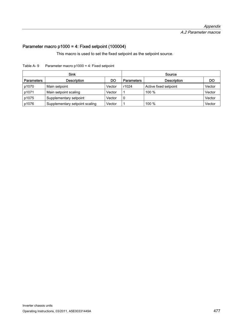
Appendix A.2 Parameter macros
Inverter chassis units Operating Instructions, 03/2011, A5E00331449A 477
Parameter macro p1000 = 4: Fixed setpoint (100004) This macro is used to set the fixed setpoint as the setpoint source.
Table A- 9 Parameter macro p1000 = 4: Fixed setpoint
Sink Source Parameters Description DO Parameters Description DO p1070 Main setpoint Vector r1024 Active fixed setpoint Vector p1071 Main setpoint scaling Vector 1 100 % Vector p1075 Supplementary setpoint Vector 0 Vector p1076 Supplementary setpoint scaling Vector 1 100 % Vector

Appendix A.2 Parameter macros
Inverter chassis units 478 Operating Instructions, 03/2011, A5E00331449A
Inverter chassis units Operating Instructions, 03/2011, A5E00331449A 479
Index
3 3-mass model, 372
A Acyclic communication, 201
Determining drive object numbers, 209 DPV1 parameter request and response, 204 Error values in DPV1 parameter responses, 206 Parameter request and parameter response, 203
Alarms, 386 Analog inputs, 93, 185 Analog outputs, 94, 286 AOP30, 145 Application classes, 192 Armature short-circuit brake
external, 323 Internal, 324
Automatic restart, 310 Automatic speed controller optimization, 294 Auxiliary supply, 58 Auxiliary Voltage, 95
B Basic commissioning
Enter the motor data, 149 Entering the basic parameters, 152 Motor identification, 154 Selecting the motor type, 149
Basic Commissioning Entering the encoder data., 150
Basic information BICO technology, 172 Binector input (BI), 172 Binector output (BO), 172 Command data set (CDS), 166 Connector input (CI), 172 Connector output (CO), 172 Copy motor data set (MDS), 170 Copying the command data set (CDS), 170 Copying the drive data set (DDS), 170 Data sets, 165 Drive data set (DDS), 167
Drive objects, 164 Encoder data set (EDS), 168 Interconnecting signals, 173 Motor data set (MDS), 169 Parameter, 161 Parameter categorization, 162 Parameter types, 161
Basic information about the drive system, 161 BICO technology, 172
Interconnecting signals, 173 Bimetallic normally closed contact, 371 Binector input (BI), 172 Binector output (BO), 172 Blocking protection, 367 brake control
Extended, 357 Simple, 339
Bypass Bypass with synchronizer with degree of overlapping, 349 Bypass with synchronizer without degree of overlapping, 352 Without synchronization, 354
Bypass function, 348
C Cable lengths, 50 CBE20, 218 CDS (command data set), 166
Copy, 170 Cleaning, 390 Closed-loop torque control, 277 Command data set, 166 Command sources
CU terminals, 181 General information, 160 PROFIdrive, 177 PROFIdrive+TM31, 183 TM31 terminals, 179
Communication via PROFIdrive, 190
Communication Board Ethernet CBE20 (Option G33), 218 Communication interfaces
Parallel operation, 236 CompactFlash card, 36
Slot, 76, 87
Index
Inverter chassis units 480 Operating Instructions, 03/2011, A5E00331449A
Connection cross-sections, 50 Connector input (CI), 172 Connector output (CO), 172 Control Interface Module
Frame size FX, replacement, 396 Frame size GX, replacement, 398 Frame size HX, replacement, 400 Frame size JX, replacement, 402
Control Unit CU320-2, 35 Control Unit CU320-2 DP, 63 Control Unit CU320-2 PN, 77 Control via PROFIBUS, 216 CU320-2 DP, 63 CU320-2 PN, 77 Cyclic communication, 197
D Data sets, 165 Data transfer
PROFINET, 228 Date of manufacture, 24 DC brake, 326 DCC, 20, 240 DCNS, 52 DCPS, 52 DCPS, DCNS connection for a dV/dt filter with Voltage Peak Limiter, 52 DDS (drive data set), 167
Copy, 170 Derating behavior at increased pulse frequency, 337 Derating data, 434
Current derating as a function of the pulse frequency, 436 Installation altitudes between 2000 m and 5000 m above sea level, 434 Permissible output current as a function of the ambient temperature, 434 Reduce the ambient temperature and the output current, 434 Using an isolating transformer, 435
Determining drive object numbers, 209 Determinism, 225 Diagnosis, 376
Parameters, 382 Diagnostics
LEDs, 376 Digital inputs, 92, 93 Digital inputs/outputs, 68, 69, 82, 83, 96 Digital outputs, 290 Dimension drawings
Control Unit CU320-2, 35
SMC30 Sensor Module, 38 TM31 Terminal Module, 37
Direction of motor rotation, 51 Direction reversal, 243, 334 DPV1 parameter request and response, 204 Drive Control Chart, 240 Drive Control Chart (DCC), 20 Drive data set, 167 Drive objects, 164 DRIVE-CLiQ interface, 67, 81, 91, 102 DRIVE-CLiQ wiring diagram, 59 Droop Function, 274
E EDS (encoder data set), 168 Efficiency optimization, 302 Electromagnetic compatibility
EMC compliant design, 43 Introduction, 41 Noise emissions, 42 Operational reliability and noise immunity, 41
Electronics power supply, 70, 84, 92 SMC30, 102
Encoder data set, 168 Energy-saving display, 342 Error values in DPV1 parameter responses, 206 Ethernet interface, 140, 219 Extended brake control, 357 Extended monitoring functions, 361 External 24 V DC supply, 58
F Factory setting, 157 Fan
Frame size FX, replacement, 416 Frame size GX, replacement, 418 Frame size HX, replacement, 420 Frame size JX, replacement, 424
Fan voltage, adjustment, 52 Fast magnetization, 303 Faults, 386 Faults and alarms, 386 Features, 20 Firmware update, 430 Firmware, upgrading, 430 Fixed setpoints, 188 Fixed speed setpoints, 188 Flying restart, 314
with encoder, 316
Index
Inverter chassis units Operating Instructions, 03/2011, A5E00331449A 481
without encoder, 315 Forming the DC link capacitors, 428 Friction characteristic curve, 320
G G33, 218
H High overload, 438 Hotline, 4
I I2t motor model, 372 IF1, 236 IF2, 236 Increasing the output frequency, 328 Installation device, 392 Installation location, 28 Internal voltage protection, 325 IO controller, 224 IO Device, 224 IO supervisor, 224 IT system, 54
K K50, 98 Kinetic buffering, 306 KTY, 371
L Load monitoring, 361 Low overload, 438
M Maintenance, 390, 391 Maintenance and servicing, 389 MDS (motor data set), 169
Copy, 170 Minimum speed, 244 Monitoring Functions, 364 Motor changeover/selection, 318 Motor data set, 169 Motor identification, 294
Motorized potentiometer, 187
N Non-grounded system, 54
O Online operation with STARTER, 220 open actual speed value, 275 Operating hours counters, 332 Operation on a non-grounded system, 54 Operator panel, 145 Output terminals, 285 Overload capability, 438 Overload responses, 365
P Parallel operation of communication interfaces, 236 Parameter request and parameter response, 203 Parameter reset, 157
Parameter reset via STARTER, 157 Resetting Parameters via AOP30, 157
Permanent-magnet synchronous motors, 281 Power block
Crane lifting lugs, 393 Frame size FX, replacement, 404 Frame size GX, replacement, 406 Frame size HX, replacement, 408 Frame size JX, replacement, 412
Power connections, 50 Connecting the motor and power cables, 51
Preparation Mechanical installation, 28
PROFIBUS Address switches, 73 Bus terminating resistor, 72 Connectors, 72 Setting the address, 73
PROFIBUS connection, 71 PROFIdrive, 190
Acyclic communication, 201 Application classes, 192 Controller, 190 Cyclic communication, 197 Drive Unit, 190 Supervisor, Drive Unit, 190
PROFINET Data transfer, 228
PROFINET interface, 86
Index
Inverter chassis units 482 Operating Instructions, 03/2011, A5E00331449A
PROFINET IO, 224 Addresses, 226 RT and IRT, 225
PROFINET IO with IRT, 226 PROFINET IO with RT, 225 Protecting power components, 364 Protective functions, 364 PT100, 371 PTC, 371 Pulse frequency wobbling, 330
Q Quality, 21
R Ramp-function generator, 246 Ramp-function generator tracking, 247 Real-time communication, 225 Reference model, 271 Relay outputs, 97 Removing the interference suppression capacitor, 54 Replacement
Control Interface Module, frame size FX, 396 Control Interface Module, frame size GX, 398 Control Interface Module, frame size HX, 400 Control Interface Module, frame size JX, 402 Crane lifting lugs, 393 Fan, frame size FX, 416 Fan, frame size GX, 418 Fan, frame size HX, 420 Fan, frame size JX, 424 Installation device, 392 Power block, frame size FX, 404 Power block, frame size GX, 406 Power block, frame size HX, 408 Power block, frame size JX, 412
Replacing Automatic firmware update, 429 Error messages, 429
Replacing components, 395 Residual risks, 14 Resonance damping, 256 Rotating measurement, 299 Runtime, 332
S S5 – Selector for voltage/current AI0, AI1, 94 Serial interface (RS232), 75, 85
Service, 21 Service and Support, 386 Setpoint addition, 242 Setpoint channel, 242 Setpoint sources, 185
Analog inputs, 185 Fixed speed setpoints, 188 General information, 160 Motorized potentiometer, 187
Signal connections, 60 Simple brake control, 339 Simulation operation, 333 Skip frequency bands, 244 Slip compensation, 257 SMC30, 98 SMC30 Sensor Module, 38 SMC30 Sensor Module Cabinet-Mounted (option K50), 98 SMC30:connection examples, 105 Speed controller, 265 Speed controller adaptation, 272 Speed controller optimization, 299 Speed controller pre-control, 268 Speed limitation, 245 Stall protection, 368 Standstill measurement, 296 STARTER, 108
Access point, 138 Commissioning, 111 Creating a project, 111 DEVICE, 139 Installation, 109 Online operation via PROFINET, 220 S7ONLINE, 139 Target device selection, 138 Transferring the drive project, 139 User interface, 110
STARTER via Ethernet, 140 Parameters, 144 Setting the IP Address of the drive, 142 Setting the IP address of the PC interface, 141
Storage, 27 Support, 4
T Technical data
General, 432 Technical specifications, 439
Power Module, 380 V – 480 V 3 AC, 440 Power Module, 500 V - 600 V 3 AC, 446
Technical support, 4
Index
Inverter chassis units Operating Instructions, 03/2011, A5E00331449A 483
Technology controller, 345 Telegram selection, user defined, 198 Telegrams and process data, 197 Temperature sensor, 94 Temperature sensor connection
Control Interface Module, 370 Sensor Module, 370 TM31, 369
Temperature sensor evaluation, 369 3-mass model, 372 Bimetallic normally closed contact, 371 I2t motor model, 372 KTY, 371 PT100, 371 PTC, 371 Wire-break monitoring, 371
Thermal monitoring, 365 Thermal motor protection, 369 TM31, 89
Connection overview, 90 TM31 (front view), 89 TM31 Terminal Module, 37, 89 Tool, 29, 39, 391 Torque limiting, 279 Transport, 26 Type plate, 23
Date of manufacture, 24
U Unit changeover, 335 Unpacking, 29
V V/f control, 249 Vdc control, 305 Vdc_max control, 308 Vdc_min control, 306 Vector control
sensorless, 259 with encoder, 264
Vector speed/torque control with/without encoder, 258 Voltage boost, 252
at startup, 254 During acceleration, 254 Permanent, 253
W Wire-break monitoring, 371
Wiring diagram DRIVE-CLiQ connections, 59
X X100, 67, 81 X101, 67, 81 X102, 67, 81 X103, 67, 81 X122, 68, 82 X124, 70, 84 X126, 71 X127, 74, 84 X132, 69, 83 X140, 75, 85 X1400, 219 X150, 86 X400, 62 X401, 62 X402, 62 X41, 60 X42, 61 X46, 62 X500, 91
SMC30, 102 X501, 91 X520, 92
SMC30, 103 X521, 93
SMC30, 104 X522, 94 X524, 92
SMC30, 102 X530, 93 X531
SMC30, 104 X540, 95 X541, 96 X542, 97 X9, 60

www.siemens.com/automation
Subject to change without prior notice© Siemens AG 2011
Siemens AGIndustry SectorDrive TechnologiesLarge DrivesPostfach 474390025 NUREMBERGGERMANY