siemens sinamics g120 faults and alarms - mro electric
TRANSCRIPT

Siemens Sinamics Manual Presented by:
MRO Electric and Supply – Your #1 source for Sinamics
Drives.
https://www.mroelectric.com/sinamics
Shop Sinamics Equipment Online
Toll Free
International
1-800-691-8511
1-919-650-2703
3-377© Siemens AG 2007 All Rights ReservedSINAMICS G120 Control Units CU240S, Edition 05/2007
Faults and Alarms 3Contents
3.1 Faults and Alarms – Overview 3-378
3.2 List of Fault and Alarm messages 3-379
Faults and Alarms
Faults and Alarms – Overview
3-378 © Siemens AG 2007 All Rights ReservedSINAMICS G120 Control Units CU240S, Edition 05/2007
3.1 Faults and Alarms – Overview
Fault messages
In the event of a failure, the inverter switches off.
Fault messages are stored in parameter r0947 under their code number (e.g. F0003 = 3). The associated error value is found in parameter r0949. The value 0 is entered if a fault has no error value. It is furthermore possible to read out the point in time that a fault occurred (r0948) and the number of fault messages (P0952) stored in Parameter r0947.
Alarm messages
Alarm messages are stored in parameter r2110 under their code number (e.g. A0503 = 503) and can be read out from there.
Note
To reset the fault, one of the methods listed below can be used:
1. Cycle the power to the drive
2. Press the - Button on the OP
3. Via a Digital Input
4. Via control word 1
List of Fault and Alarm messages
Faults and Alarms
3-379© Siemens AG 2007 All Rights ReservedSINAMICS G120 Control Units CU240S, Edition 05/2007
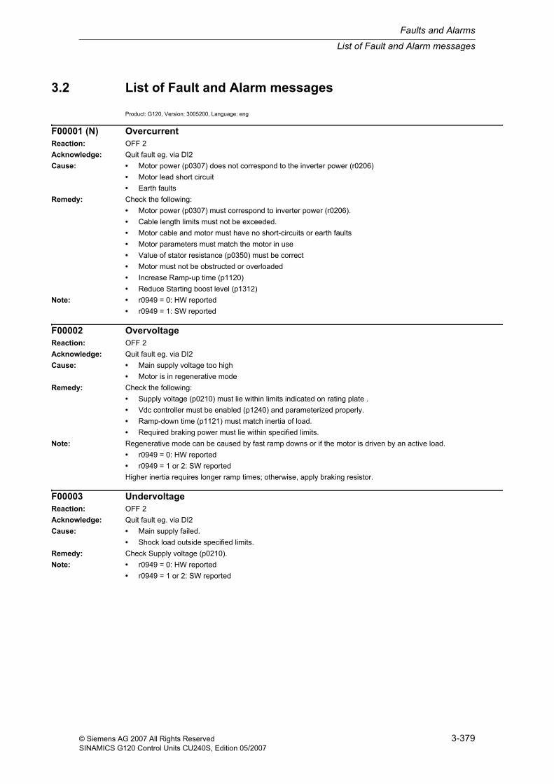
3.2 List of Fault and Alarm messages
Product: G120, Version: 3005200, Language: eng
F00001 (N) OvercurrentReaction: OFF 2Acknowledge: Quit fault eg. via DI2Cause: • Motor power (p0307) does not correspond to the inverter power (r0206)
• Motor lead short circuit• Earth faults
Remedy: Check the following:• Motor power (p0307) must correspond to inverter power (r0206).• Cable length limits must not be exceeded.• Motor cable and motor must have no short-circuits or earth faults• Motor parameters must match the motor in use• Value of stator resistance (p0350) must be correct• Motor must not be obstructed or overloaded• Increase Ramp-up time (p1120)• Reduce Starting boost level (p1312)
Note: • r0949 = 0: HW reported• r0949 = 1: SW reported
F00002 OvervoltageReaction: OFF 2Acknowledge: Quit fault eg. via DI2Cause: • Main supply voltage too high
• Motor is in regenerative modeRemedy: Check the following:
• Supply voltage (p0210) must lie within limits indicated on rating plate .• Vdc controller must be enabled (p1240) and parameterized properly.• Ramp-down time (p1121) must match inertia of load.• Required braking power must lie within specified limits.
Note: Regenerative mode can be caused by fast ramp downs or if the motor is driven by an active load.• r0949 = 0: HW reported• r0949 = 1 or 2: SW reportedHigher inertia requires longer ramp times; otherwise, apply braking resistor.
F00003 UndervoltageReaction: OFF 2Acknowledge: Quit fault eg. via DI2Cause: • Main supply failed.
• Shock load outside specified limits.Remedy: Check Supply voltage (p0210).Note: • r0949 = 0: HW reported
• r0949 = 1 or 2: SW reported
Faults and Alarms
List of Fault and Alarm messages
3-380 © Siemens AG 2007 All Rights ReservedSINAMICS G120 Control Units CU240S, Edition 05/2007
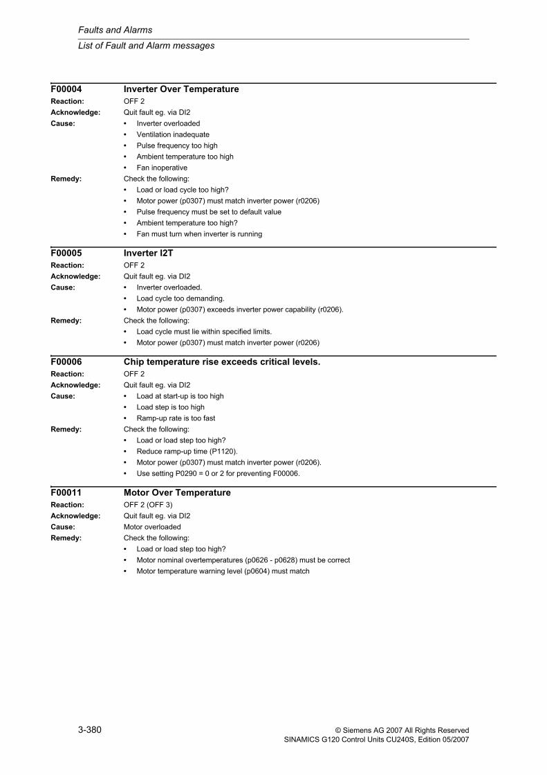
F00004 Inverter Over TemperatureReaction: OFF 2Acknowledge: Quit fault eg. via DI2Cause: • Inverter overloaded
• Ventilation inadequate• Pulse frequency too high• Ambient temperature too high• Fan inoperative
Remedy: Check the following:• Load or load cycle too high?• Motor power (p0307) must match inverter power (r0206)• Pulse frequency must be set to default value• Ambient temperature too high?• Fan must turn when inverter is running
F00005 Inverter I2TReaction: OFF 2Acknowledge: Quit fault eg. via DI2Cause: • Inverter overloaded.
• Load cycle too demanding.• Motor power (p0307) exceeds inverter power capability (r0206).
Remedy: Check the following:• Load cycle must lie within specified limits.• Motor power (p0307) must match inverter power (r0206)
F00006 Chip temperature rise exceeds critical levels.Reaction: OFF 2Acknowledge: Quit fault eg. via DI2Cause: • Load at start-up is too high
• Load step is too high• Ramp-up rate is too fast
Remedy: Check the following:• Load or load step too high?• Reduce ramp-up time (P1120).• Motor power (p0307) must match inverter power (r0206).• Use setting P0290 = 0 or 2 for preventing F00006.
F00011 Motor Over TemperatureReaction: OFF 2 (OFF 3)Acknowledge: Quit fault eg. via DI2Cause: Motor overloadedRemedy: Check the following:
• Load or load step too high?• Motor nominal overtemperatures (p0626 - p0628) must be correct• Motor temperature warning level (p0604) must match
List of Fault and Alarm messages
Faults and Alarms
3-381© Siemens AG 2007 All Rights ReservedSINAMICS G120 Control Units CU240S, Edition 05/2007
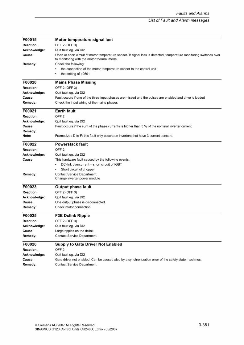
F00015 Motor temperature signal lostReaction: OFF 2 (OFF 3)Acknowledge: Quit fault eg. via DI2Cause: Open or short circuit of motor temperature sensor. If signal loss is detected, temperature monitoring switches over
to monitoring with the motor thermal model.Remedy: Check the following:
• the connection of the motor temperature sensor to the control unit• the setting of p0601
F00020 Mains Phase MissingReaction: OFF 2 (OFF 3)Acknowledge: Quit fault eg. via DI2Cause: Fault occurs if one of the three input phases are missed and the pulses are enabled and drive is loadedRemedy: Check the input wiring of the mains phases
F00021 Earth faultReaction: OFF 2Acknowledge: Quit fault eg. via DI2Cause: Fault occurs if the sum of the phase currents is higher than 5 % of the nominal inverter current.Remedy:Note: Framesizes D to F: this fault only occurs on inverters that have 3 current sensors.
F00022 Powerstack faultReaction: OFF 2Acknowledge: Quit fault eg. via DI2Cause: This hardware fault caused by the following events:
• DC-link overcurrent = short circuit of IGBT• Short circuit of chopper
Remedy: Contact Service Department.Change inverter power module
F00023 Output phase faultReaction: OFF 2 (OFF 3)Acknowledge: Quit fault eg. via DI2Cause: One output phase is disconnected.Remedy: Check motor connection.
F00025 F3E Dclink RippleReaction: OFF 2 (OFF 3)Acknowledge: Quit fault eg. via DI2Cause: Large ripples on the dclink.Remedy: Contact Service Department.
F00026 Supply to Gate Driver Not EnabledReaction: OFF 2Acknowledge: Quit fault eg. via DI2Cause: Gate driver not enabled. Can be caused also by a synchronization error of the safety state machines.Remedy: Contact Service Department.
Faults and Alarms
List of Fault and Alarm messages
3-382 © Siemens AG 2007 All Rights ReservedSINAMICS G120 Control Units CU240S, Edition 05/2007
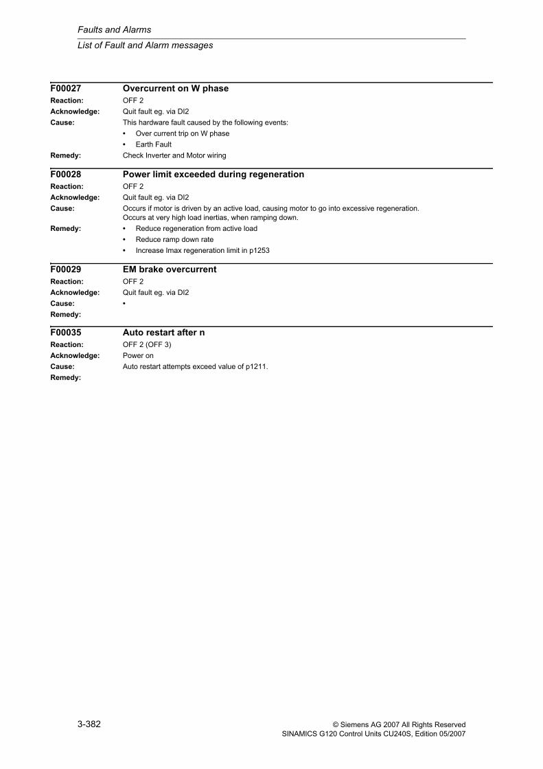
F00027 Overcurrent on W phaseReaction: OFF 2Acknowledge: Quit fault eg. via DI2Cause: This hardware fault caused by the following events:
• Over current trip on W phase• Earth Fault
Remedy: Check Inverter and Motor wiring
F00028 Power limit exceeded during regenerationReaction: OFF 2Acknowledge: Quit fault eg. via DI2Cause: Occurs if motor is driven by an active load, causing motor to go into excessive regeneration.
Occurs at very high load inertias, when ramping down.Remedy: • Reduce regeneration from active load
• Reduce ramp down rate• Increase Imax regeneration limit in p1253
F00029 EM brake overcurrentReaction: OFF 2Acknowledge: Quit fault eg. via DI2Cause: •Remedy:
F00035 Auto restart after nReaction: OFF 2 (OFF 3)Acknowledge: Power onCause: Auto restart attempts exceed value of p1211.Remedy:
List of Fault and Alarm messages
Faults and Alarms
3-383© Siemens AG 2007 All Rights ReservedSINAMICS G120 Control Units CU240S, Edition 05/2007
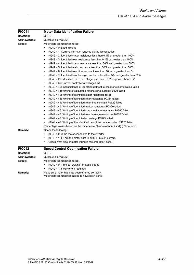
F00041 Motor Data Identification FailureReaction: OFF 2Acknowledge: Quit fault eg. via DI2Cause: Motor data identification failed.
• r0949 = 0: Load missing• r0949 = 1: Current limit level reached during identification.• r0949 = 2: Identified stator resistance less than 0.1% or greater than 100%.• r0949 = 3: Identified rotor resistance less than 0.1% or greater than 100%.• r0949 = 4: Identified stator reactance less than 50% and greater than 500%• r0949 = 5: Identified main reactance less than 50% and greater than 500%• r0949 = 6: Identified rotor time constant less than 10ms or greater than 5s• r0949 = 7: Identified total leakage reactance less than 5% and greater than 50%• r0949 = 20: Identified IGBT on-voltage less than 0.5 V or greater than 10 V• r0949 = 30: Current controller at voltage limit• r0949 = 40: Inconsistence of identified dataset, at least one identification failed• r0949 = 41: Writing of calculated magnetizing current P0320 failed• r0949 = 42: Writing of identified stator resistance failed• r0949 = 43: Writing of identified rotor resistance P0354 failed• r0949 = 44: Writing of identified rotor time constant P0622 failed• r0949 = 45: Writing of identified mutual reactance P0360 failed• r0949 = 46: Writing of identified stator leakage reactance P0356 failed• r0949 = 47: Writing of identified rotor leakage reactance P0358 failed• r0949 = 48: Writing of identified on voltage P1825 failed.• r0949 = 49: Writing of the identified dead time compensation P1828 failedPercentage values based on the impedance Zb = Vmot,nom / sqrt(3) / Imot,nom
Remedy: Check the following:• r0949 = 0: is the motor connected to the inverter.• r0949 = 1-49: are the motor data in p0304 - p0311 correct.• Check what type of motor wiring is required (star, delta).
F00042 Speed Control Optimisation FailureReaction: OFF 2Acknowledge: Quit fault eg. via DI2Cause: Motor data identification failed.
• r0949 = 0: Time out waiting for stable speed• r0949 = 1: Inconsistent readings
Remedy: Make sure motor has data been entered correctly.Motor data identification needs to have been done.
Faults and Alarms
List of Fault and Alarm messages
3-384 © Siemens AG 2007 All Rights ReservedSINAMICS G120 Control Units CU240S, Edition 05/2007
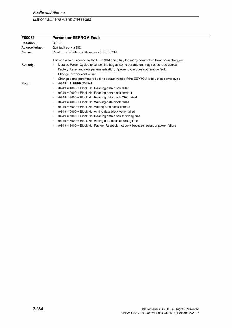
F00051 Parameter EEPROM FaultReaction: OFF 2Acknowledge: Quit fault eg. via DI2Cause: Read or write failure while access to EEPROM.
This can also be caused by the EEPROM being full, too many parameters have been changed.Remedy: • Must be Power Cycled to cancel this bug as some parameters may not be read correct.
• Factory Reset and new parameterization, if power cycle does not remove fault• Change inverter control unit• Change some parameters back to default values if the EEPROM is full, then power cycle
Note: • r0949 = 1: EEPROM Full• r0949 = 1000 + Block No: Reading data block failed• r0949 = 2000 + Block No: Reading data block timeout• r0949 = 3000 + Block No: Reading data block CRC failed• r0949 = 4000 + Block No: Wrinting data block failed• r0949 = 5000 + Block No: Writing data block timeout• r0949 = 6000 + Block No: writing data block verify failed• r0949 = 7000 + Block No: Reading data block at wrong time• r0949 = 8000 + Block No: writing data block at wrong time• r0949 = 9000 + Block No: Factory Reset did not work becuase restart or power failure
List of Fault and Alarm messages
Faults and Alarms
3-385© Siemens AG 2007 All Rights ReservedSINAMICS G120 Control Units CU240S, Edition 05/2007
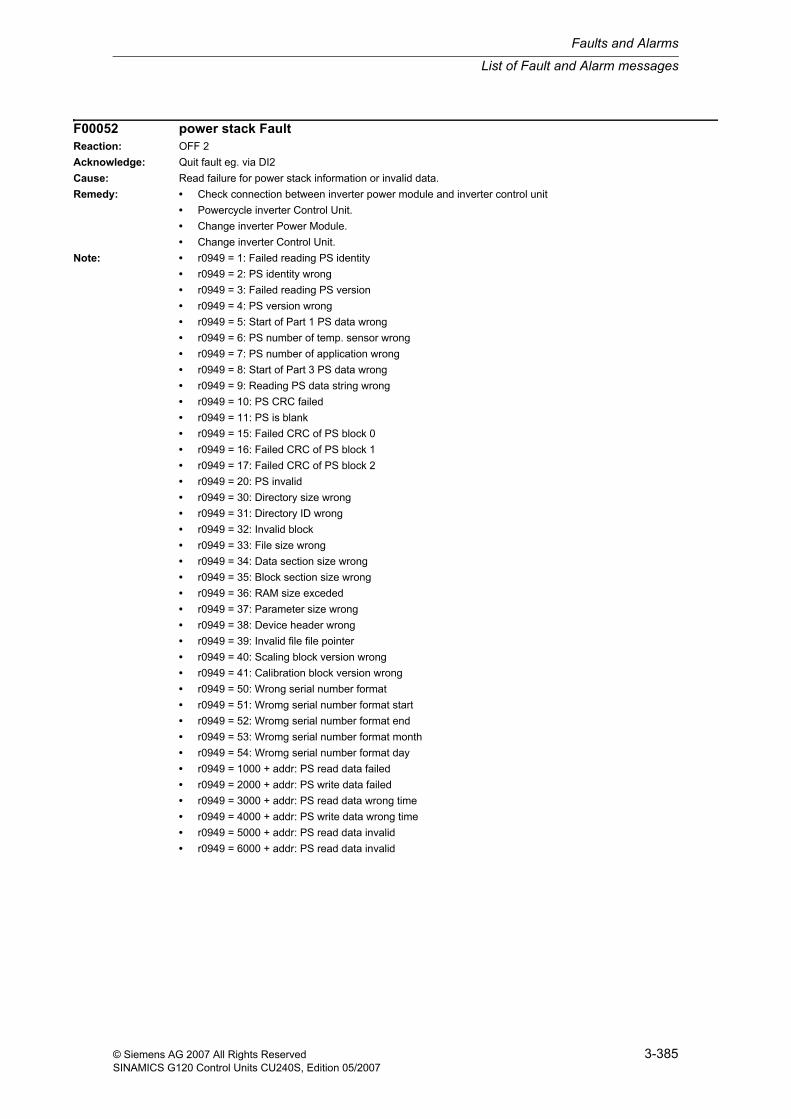
F00052 power stack FaultReaction: OFF 2Acknowledge: Quit fault eg. via DI2Cause: Read failure for power stack information or invalid data.Remedy: • Check connection between inverter power module and inverter control unit
• Powercycle inverter Control Unit.• Change inverter Power Module.• Change inverter Control Unit.
Note: • r0949 = 1: Failed reading PS identity• r0949 = 2: PS identity wrong• r0949 = 3: Failed reading PS version• r0949 = 4: PS version wrong• r0949 = 5: Start of Part 1 PS data wrong• r0949 = 6: PS number of temp. sensor wrong• r0949 = 7: PS number of application wrong• r0949 = 8: Start of Part 3 PS data wrong• r0949 = 9: Reading PS data string wrong• r0949 = 10: PS CRC failed• r0949 = 11: PS is blank• r0949 = 15: Failed CRC of PS block 0• r0949 = 16: Failed CRC of PS block 1• r0949 = 17: Failed CRC of PS block 2• r0949 = 20: PS invalid• r0949 = 30: Directory size wrong• r0949 = 31: Directory ID wrong• r0949 = 32: Invalid block• r0949 = 33: File size wrong• r0949 = 34: Data section size wrong• r0949 = 35: Block section size wrong• r0949 = 36: RAM size exceded• r0949 = 37: Parameter size wrong• r0949 = 38: Device header wrong• r0949 = 39: Invalid file file pointer• r0949 = 40: Scaling block version wrong• r0949 = 41: Calibration block version wrong• r0949 = 50: Wrong serial number format• r0949 = 51: Wromg serial number format start• r0949 = 52: Wromg serial number format end• r0949 = 53: Wromg serial number format month• r0949 = 54: Wromg serial number format day• r0949 = 1000 + addr: PS read data failed• r0949 = 2000 + addr: PS write data failed• r0949 = 3000 + addr: PS read data wrong time• r0949 = 4000 + addr: PS write data wrong time• r0949 = 5000 + addr: PS read data invalid• r0949 = 6000 + addr: PS read data invalid
Faults and Alarms
List of Fault and Alarm messages
3-386 © Siemens AG 2007 All Rights ReservedSINAMICS G120 Control Units CU240S, Edition 05/2007
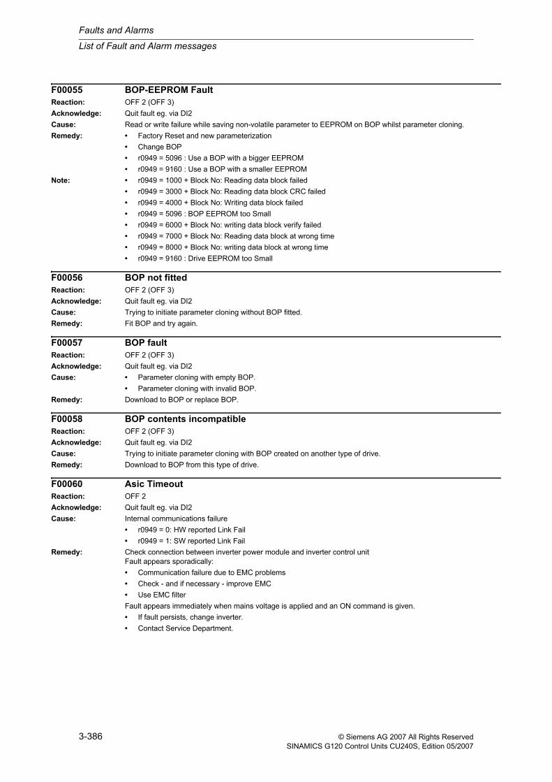
F00055 BOP-EEPROM FaultReaction: OFF 2 (OFF 3)Acknowledge: Quit fault eg. via DI2Cause: Read or write failure while saving non-volatile parameter to EEPROM on BOP whilst parameter cloning.Remedy: • Factory Reset and new parameterization
• Change BOP• r0949 = 5096 : Use a BOP with a bigger EEPROM• r0949 = 9160 : Use a BOP with a smaller EEPROM
Note: • r0949 = 1000 + Block No: Reading data block failed• r0949 = 3000 + Block No: Reading data block CRC failed• r0949 = 4000 + Block No: Writing data block failed• r0949 = 5096 : BOP EEPROM too Small• r0949 = 6000 + Block No: writing data block verify failed• r0949 = 7000 + Block No: Reading data block at wrong time• r0949 = 8000 + Block No: writing data block at wrong time• r0949 = 9160 : Drive EEPROM too Small
F00056 BOP not fittedReaction: OFF 2 (OFF 3)Acknowledge: Quit fault eg. via DI2Cause: Trying to initiate parameter cloning without BOP fitted.Remedy: Fit BOP and try again.
F00057 BOP faultReaction: OFF 2 (OFF 3)Acknowledge: Quit fault eg. via DI2Cause: • Parameter cloning with empty BOP.
• Parameter cloning with invalid BOP.Remedy: Download to BOP or replace BOP.
F00058 BOP contents incompatibleReaction: OFF 2 (OFF 3)Acknowledge: Quit fault eg. via DI2Cause: Trying to initiate parameter cloning with BOP created on another type of drive.Remedy: Download to BOP from this type of drive.
F00060 Asic TimeoutReaction: OFF 2Acknowledge: Quit fault eg. via DI2Cause: Internal communications failure
• r0949 = 0: HW reported Link Fail• r0949 = 1: SW reported Link Fail
Remedy: Check connection between inverter power module and inverter control unitFault appears sporadically:• Communication failure due to EMC problems• Check - and if necessary - improve EMC• Use EMC filterFault appears immediately when mains voltage is applied and an ON command is given.• If fault persists, change inverter.• Contact Service Department.
List of Fault and Alarm messages
Faults and Alarms
3-387© Siemens AG 2007 All Rights ReservedSINAMICS G120 Control Units CU240S, Edition 05/2007
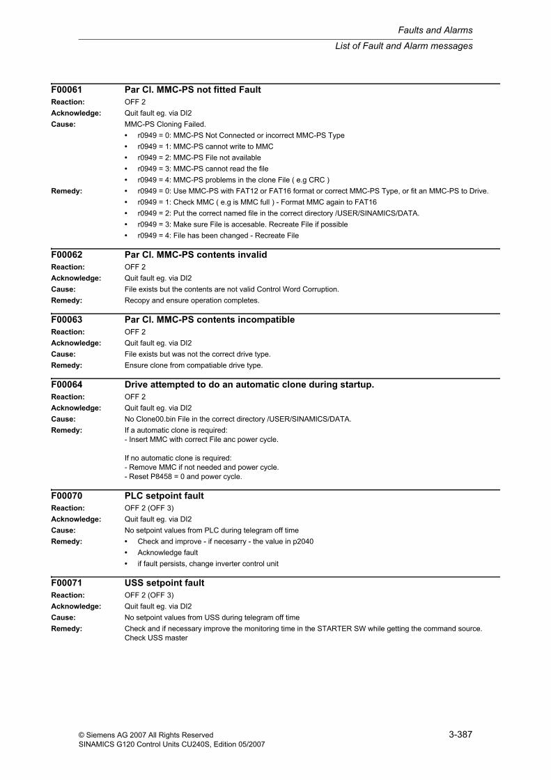
F00061 Par Cl. MMC-PS not fitted FaultReaction: OFF 2Acknowledge: Quit fault eg. via DI2Cause: MMC-PS Cloning Failed.
• r0949 = 0: MMC-PS Not Connected or incorrect MMC-PS Type• r0949 = 1: MMC-PS cannot write to MMC• r0949 = 2: MMC-PS File not available• r0949 = 3: MMC-PS cannot read the file• r0949 = 4: MMC-PS problems in the clone File ( e.g CRC )
Remedy: • r0949 = 0: Use MMC-PS with FAT12 or FAT16 format or correct MMC-PS Type, or fit an MMC-PS to Drive.• r0949 = 1: Check MMC ( e.g is MMC full ) - Format MMC again to FAT16• r0949 = 2: Put the correct named file in the correct directory /USER/SINAMICS/DATA.• r0949 = 3: Make sure File is accesable. Recreate File if possible• r0949 = 4: File has been changed - Recreate File
F00062 Par Cl. MMC-PS contents invalidReaction: OFF 2Acknowledge: Quit fault eg. via DI2Cause: File exists but the contents are not valid Control Word Corruption.Remedy: Recopy and ensure operation completes.
F00063 Par Cl. MMC-PS contents incompatibleReaction: OFF 2Acknowledge: Quit fault eg. via DI2Cause: File exists but was not the correct drive type.Remedy: Ensure clone from compatiable drive type.
F00064 Drive attempted to do an automatic clone during startup.Reaction: OFF 2Acknowledge: Quit fault eg. via DI2Cause: No Clone00.bin File in the correct directory /USER/SINAMICS/DATA.Remedy: If a automatic clone is required:
- Insert MMC with correct File anc power cycle.
If no automatic clone is required:- Remove MMC if not needed and power cycle.- Reset P8458 = 0 and power cycle.
F00070 PLC setpoint faultReaction: OFF 2 (OFF 3)Acknowledge: Quit fault eg. via DI2Cause: No setpoint values from PLC during telegram off timeRemedy: • Check and improve - if necesarry - the value in p2040
• Acknowledge fault• if fault persists, change inverter control unit
F00071 USS setpoint faultReaction: OFF 2 (OFF 3)Acknowledge: Quit fault eg. via DI2Cause: No setpoint values from USS during telegram off timeRemedy: Check and if necessary improve the monitoring time in the STARTER SW while getting the command source.
Check USS master
Faults and Alarms
List of Fault and Alarm messages
3-388 © Siemens AG 2007 All Rights ReservedSINAMICS G120 Control Units CU240S, Edition 05/2007
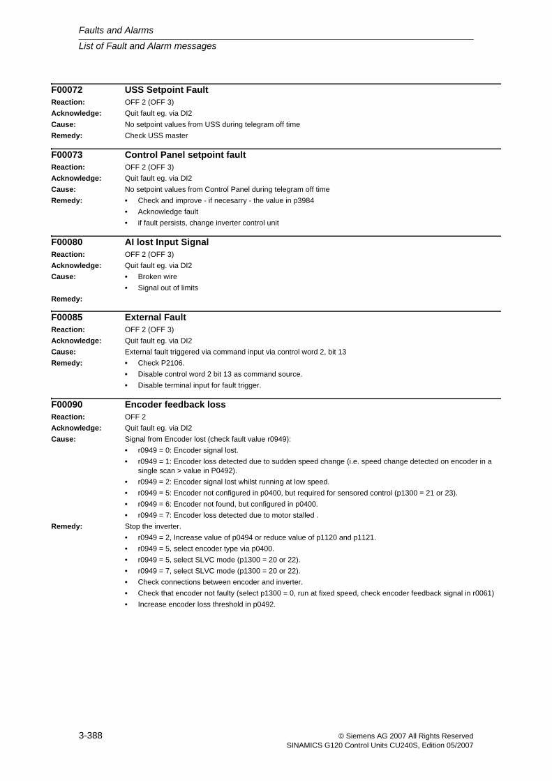
F00072 USS Setpoint FaultReaction: OFF 2 (OFF 3)Acknowledge: Quit fault eg. via DI2Cause: No setpoint values from USS during telegram off timeRemedy: Check USS master
F00073 Control Panel setpoint faultReaction: OFF 2 (OFF 3)Acknowledge: Quit fault eg. via DI2Cause: No setpoint values from Control Panel during telegram off timeRemedy: • Check and improve - if necesarry - the value in p3984
• Acknowledge fault• if fault persists, change inverter control unit
F00080 AI lost Input SignalReaction: OFF 2 (OFF 3)Acknowledge: Quit fault eg. via DI2Cause: • Broken wire
• Signal out of limitsRemedy:
F00085 External FaultReaction: OFF 2 (OFF 3)Acknowledge: Quit fault eg. via DI2Cause: External fault triggered via command input via control word 2, bit 13Remedy: • Check P2106.
• Disable control word 2 bit 13 as command source.• Disable terminal input for fault trigger.
F00090 Encoder feedback lossReaction: OFF 2Acknowledge: Quit fault eg. via DI2Cause: Signal from Encoder lost (check fault value r0949):
• r0949 = 0: Encoder signal lost.• r0949 = 1: Encoder loss detected due to sudden speed change (i.e. speed change detected on encoder in a
single scan > value in P0492).• r0949 = 2: Encoder signal lost whilst running at low speed.• r0949 = 5: Encoder not configured in p0400, but required for sensored control (p1300 = 21 or 23).• r0949 = 6: Encoder not found, but configured in p0400.• r0949 = 7: Encoder loss detected due to motor stalled .
Remedy: Stop the inverter.• r0949 = 2, Increase value of p0494 or reduce value of p1120 and p1121.• r0949 = 5, select encoder type via p0400.• r0949 = 5, select SLVC mode (p1300 = 20 or 22).• r0949 = 7, select SLVC mode (p1300 = 20 or 22).• Check connections between encoder and inverter.• Check that encoder not faulty (select p1300 = 0, run at fixed speed, check encoder feedback signal in r0061)• Increase encoder loss threshold in p0492.
List of Fault and Alarm messages
Faults and Alarms
3-389© Siemens AG 2007 All Rights ReservedSINAMICS G120 Control Units CU240S, Edition 05/2007
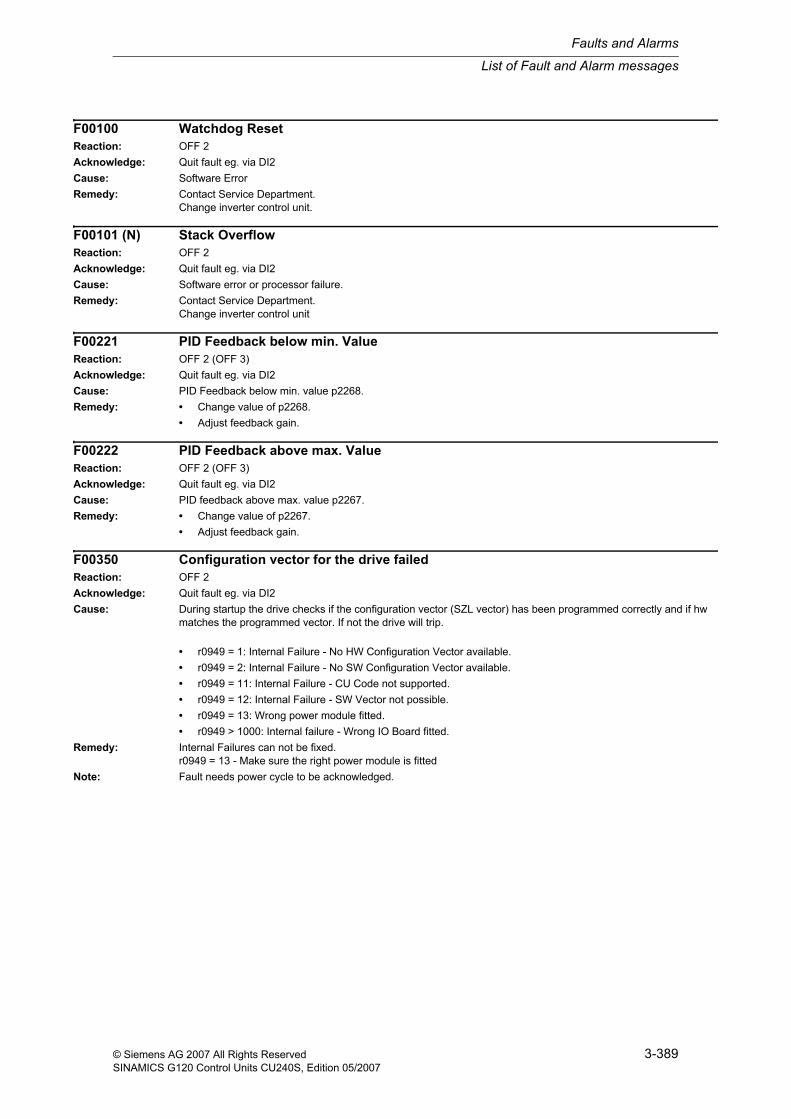
F00100 Watchdog ResetReaction: OFF 2Acknowledge: Quit fault eg. via DI2Cause: Software ErrorRemedy: Contact Service Department.
Change inverter control unit.
F00101 (N) Stack OverflowReaction: OFF 2Acknowledge: Quit fault eg. via DI2Cause: Software error or processor failure.Remedy: Contact Service Department.
Change inverter control unit
F00221 PID Feedback below min. ValueReaction: OFF 2 (OFF 3)Acknowledge: Quit fault eg. via DI2Cause: PID Feedback below min. value p2268.Remedy: • Change value of p2268.
• Adjust feedback gain.
F00222 PID Feedback above max. ValueReaction: OFF 2 (OFF 3)Acknowledge: Quit fault eg. via DI2Cause: PID feedback above max. value p2267.Remedy: • Change value of p2267.
• Adjust feedback gain.
F00350 Configuration vector for the drive failedReaction: OFF 2Acknowledge: Quit fault eg. via DI2Cause: During startup the drive checks if the configuration vector (SZL vector) has been programmed correctly and if hw
matches the programmed vector. If not the drive will trip.
• r0949 = 1: Internal Failure - No HW Configuration Vector available.• r0949 = 2: Internal Failure - No SW Configuration Vector available.• r0949 = 11: Internal Failure - CU Code not supported.• r0949 = 12: Internal Failure - SW Vector not possible.• r0949 = 13: Wrong power module fitted.• r0949 > 1000: Internal failure - Wrong IO Board fitted.
Remedy: Internal Failures can not be fixed.r0949 = 13 - Make sure the right power module is fitted
Note: Fault needs power cycle to be acknowledged.
Faults and Alarms
List of Fault and Alarm messages
3-390 © Siemens AG 2007 All Rights ReservedSINAMICS G120 Control Units CU240S, Edition 05/2007
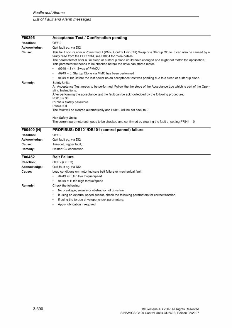
F00395 Acceptance Test / Confirmation pendingReaction: OFF 2Acknowledge: Quit fault eg. via DI2Cause: This fault occurs after a Powermodul (PM) / Control Unit (CU) Swap or a Startup Clone. It can also be caused by a
faulty read from the EEPROM, see F0051 for more details.The parameterset after a CU swap or a startup clone could have changed and might not match the application.This parameterset needs to be checked before the drive can start a motor.• r0949 = 3 / 4: Swap of PM/CU• r0949 = 5: Startup Clone via MMC has been performed• r0949 = 10: Before the last power up an acceptance test was pending due to a swap or a startup clone.
Remedy: Safety Units:An Acceptance Test needs to be performed. Follow the the steps of the Acceptance Log which is part of the Oper-ating Instructions.After performing the acceptance test the fault can be acknowledged by the following procedure:P0010 = 30P9761 = Safety passwordP7844 = 0The fault will be cleared automatically and P0010 will be set back to 0
Non Safety Units:The current parameterset needs to be checked and confirmed by clearing the fault or setting P7844 = 0.
F00400 (N) PROFIBUS: DS101/DB101 (control pannel) failure.Reaction: OFF 2Acknowledge: Quit fault eg. via DI2Cause: Timeout, trigger fault,...Remedy: Restart C2 connection.
F00452 Belt FailureReaction: OFF 2 (OFF 3)Acknowledge: Quit fault eg. via DI2Cause: Load conditions on motor indicate belt failure or mechanical fault.
• r0949 = 0: trip low torque/speed• r0949 = 1: trip high torque/speed
Remedy: Check the following:• No breakage, seizure or obstruction of drive train.• If using an external speed sensor, check the following parameters for correct function:• If using the torque envelope, check parameters:• Apply lubrication if required.
List of Fault and Alarm messages
Faults and Alarms
3-391© Siemens AG 2007 All Rights ReservedSINAMICS G120 Control Units CU240S, Edition 05/2007
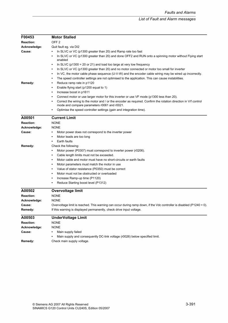
F00453 Motor StalledReaction: OFF 2Acknowledge: Quit fault eg. via DI2Cause: • In SLVC or VC (p1300 greater than 20) and Ramp rate too fast
• In SLVC or VC (p1300 greater than 20) and done OFF2 and RUN onto a spinning motor without Flying start enabled
• In SLVC (p1300 = 20 or 21) and load too large at very low frequency• In SLVC or VC (p1300 greater than 20) and no motor connected or motor too small for inverter• In VC, the motor cable phase sequence (U-V-W) and the encoder cable wiring may be wired up incorrectly.• The speed controller settings are not optimised to the application. This can cause instabilities.
Remedy: • Reduce ramp rate in p1120• Enable flying start (p1200 equal to 1)• Increase boost in p1611• Connect motor or use larger motor for this inverter or use VF mode (p1300 less than 20).• Correct the wiring to the motor and / or the encoder as required. Confirm the rotation direction in V/f control
mode and compare parameters r0061 and r0021.• Optimise the speed controller settings (gain and integration time).
A00501 Current LimitReaction: NONEAcknowledge: NONECause: • Motor power does not correspond to the inverter power
• Motor leads are too long• Earth faults
Remedy: Check the following:• Motor power (P0307) must correspond to inverter power (r0206).• Cable length limits must not be exceeded.• Motor cable and motor must have no short-circuits or earth faults• Motor parameters must match the motor in use• Value of stator resistance (P0350) must be correct• Motor must not be obstructed or overloaded• Increase Ramp-up time (P1120)• Reduce Starting boost level (P1312)
A00502 Overvoltage limitReaction: NONEAcknowledge: NONECause: Overvoltage limit is reached. This warning can occur during ramp down, if the Vdc controller is disabled (P1240 = 0).Remedy: If this warning is displayed permanently, check drive input voltage.
A00503 UnderVoltage LimitReaction: NONEAcknowledge: NONECause: • Main supply failed
• Main supply and consequently DC-link voltage (r0026) below specified limit.Remedy: Check main supply voltage.
Faults and Alarms
List of Fault and Alarm messages
3-392 © Siemens AG 2007 All Rights ReservedSINAMICS G120 Control Units CU240S, Edition 05/2007
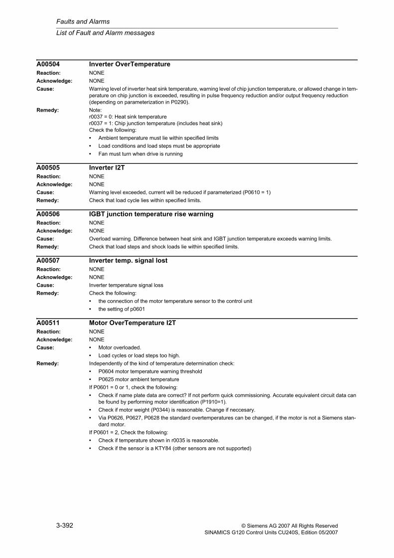
A00504 Inverter OverTemperatureReaction: NONEAcknowledge: NONECause: Warning level of inverter heat sink temperature, warning level of chip junction temperature, or allowed change in tem-
perature on chip junction is exceeded, resulting in pulse frequency reduction and/or output frequency reduction (depending on parameterization in P0290).
Remedy: Note:r0037 = 0: Heat sink temperaturer0037 = 1: Chip junction temperature (includes heat sink)Check the following:• Ambient temperature must lie within specified limits• Load conditions and load steps must be appropriate• Fan must turn when drive is running
A00505 Inverter I2TReaction: NONEAcknowledge: NONECause: Warning level exceeded, current will be reduced if parameterized (P0610 = 1)Remedy: Check that load cycle lies within specified limits.
A00506 IGBT junction temperature rise warningReaction: NONEAcknowledge: NONECause: Overload warning. Difference between heat sink and IGBT junction temperature exceeds warning limits.Remedy: Check that load steps and shock loads lie within specified limits.
A00507 Inverter temp. signal lostReaction: NONEAcknowledge: NONECause: Inverter temperature signal lossRemedy: Check the following:
• the connection of the motor temperature sensor to the control unit• the setting of p0601
A00511 Motor OverTemperature I2TReaction: NONEAcknowledge: NONECause: • Motor overloaded.
• Load cycles or load steps too high.Remedy: Independently of the kind of temperature determination check:
• P0604 motor temperature warning threshold• P0625 motor ambient temperatureIf P0601 = 0 or 1, check the following:• Check if name plate data are correct? If not perform quick commissioning. Accurate equivalent circuit data can
be found by performing motor identification (P1910=1).• Check if motor weight (P0344) is reasonable. Change if neccesary.• Via P0626, P0627, P0628 the standard overtemperatures can be changed, if the motor is not a Siemens stan-
dard motor.If P0601 = 2, Check the following:• Check if temperature shown in r0035 is reasonable.• Check if the sensor is a KTY84 (other sensors are not supported)
List of Fault and Alarm messages
Faults and Alarms
3-393© Siemens AG 2007 All Rights ReservedSINAMICS G120 Control Units CU240S, Edition 05/2007
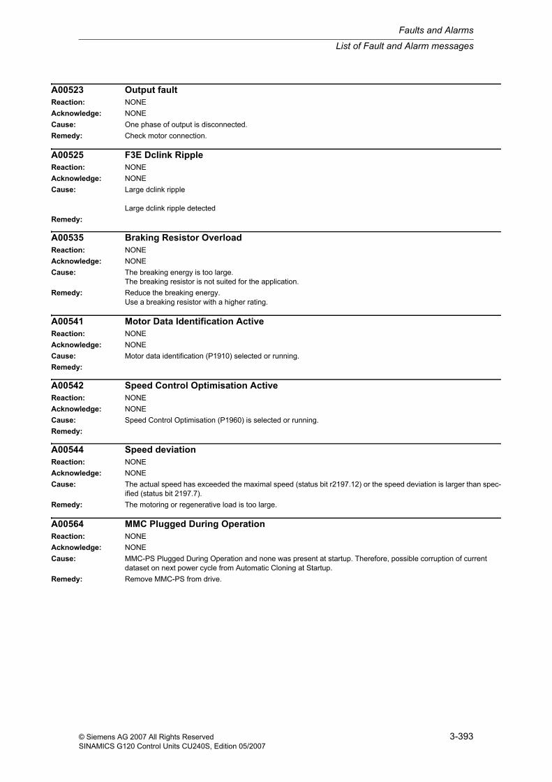
A00523 Output faultReaction: NONEAcknowledge: NONECause: One phase of output is disconnected.Remedy: Check motor connection.
A00525 F3E Dclink RippleReaction: NONEAcknowledge: NONECause: Large dclink ripple
Large dclink ripple detectedRemedy:
A00535 Braking Resistor OverloadReaction: NONEAcknowledge: NONECause: The breaking energy is too large.
The breaking resistor is not suited for the application.Remedy: Reduce the breaking energy.
Use a breaking resistor with a higher rating.
A00541 Motor Data Identification ActiveReaction: NONEAcknowledge: NONECause: Motor data identification (P1910) selected or running.Remedy:
A00542 Speed Control Optimisation ActiveReaction: NONEAcknowledge: NONECause: Speed Control Optimisation (P1960) is selected or running.Remedy:
A00544 Speed deviationReaction: NONEAcknowledge: NONECause: The actual speed has exceeded the maximal speed (status bit r2197.12) or the speed deviation is larger than spec-
ified (status bit 2197.7).Remedy: The motoring or regenerative load is too large.
A00564 MMC Plugged During OperationReaction: NONEAcknowledge: NONECause: MMC-PS Plugged During Operation and none was present at startup. Therefore, possible corruption of current
dataset on next power cycle from Automatic Cloning at Startup.Remedy: Remove MMC-PS from drive.
Faults and Alarms
List of Fault and Alarm messages
3-394 © Siemens AG 2007 All Rights ReservedSINAMICS G120 Control Units CU240S, Edition 05/2007
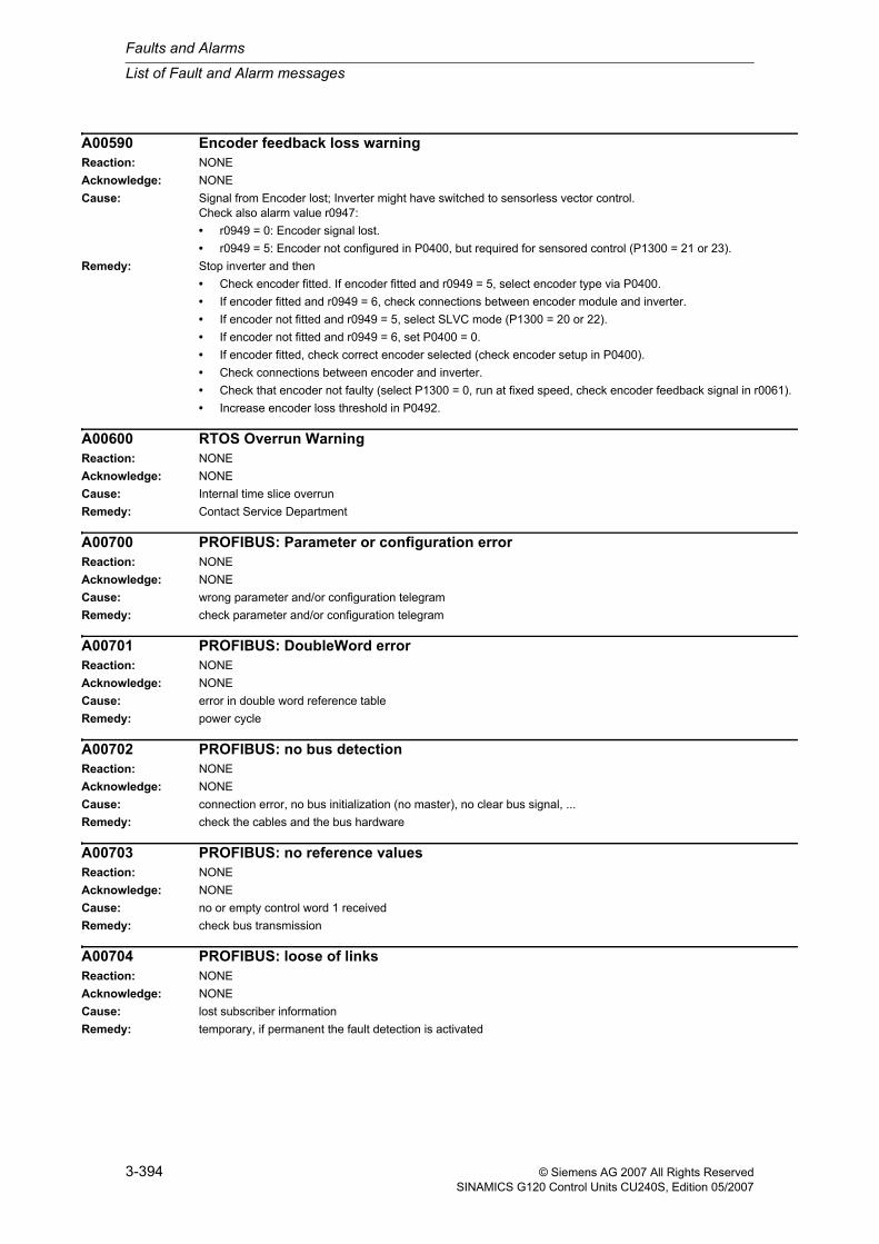
A00590 Encoder feedback loss warningReaction: NONEAcknowledge: NONECause: Signal from Encoder lost; Inverter might have switched to sensorless vector control.
Check also alarm value r0947:• r0949 = 0: Encoder signal lost.• r0949 = 5: Encoder not configured in P0400, but required for sensored control (P1300 = 21 or 23).
Remedy: Stop inverter and then• Check encoder fitted. If encoder fitted and r0949 = 5, select encoder type via P0400.• If encoder fitted and r0949 = 6, check connections between encoder module and inverter.• If encoder not fitted and r0949 = 5, select SLVC mode (P1300 = 20 or 22).• If encoder not fitted and r0949 = 6, set P0400 = 0.• If encoder fitted, check correct encoder selected (check encoder setup in P0400).• Check connections between encoder and inverter.• Check that encoder not faulty (select P1300 = 0, run at fixed speed, check encoder feedback signal in r0061).• Increase encoder loss threshold in P0492.
A00600 RTOS Overrun WarningReaction: NONEAcknowledge: NONECause: Internal time slice overrunRemedy: Contact Service Department
A00700 PROFIBUS: Parameter or configuration errorReaction: NONEAcknowledge: NONECause: wrong parameter and/or configuration telegramRemedy: check parameter and/or configuration telegram
A00701 PROFIBUS: DoubleWord errorReaction: NONEAcknowledge: NONECause: error in double word reference tableRemedy: power cycle
A00702 PROFIBUS: no bus detectionReaction: NONEAcknowledge: NONECause: connection error, no bus initialization (no master), no clear bus signal, ...Remedy: check the cables and the bus hardware
A00703 PROFIBUS: no reference valuesReaction: NONEAcknowledge: NONECause: no or empty control word 1 receivedRemedy: check bus transmission
A00704 PROFIBUS: loose of linksReaction: NONEAcknowledge: NONECause: lost subscriber informationRemedy: temporary, if permanent the fault detection is activated
List of Fault and Alarm messages
Faults and Alarms
3-395© Siemens AG 2007 All Rights ReservedSINAMICS G120 Control Units CU240S, Edition 05/2007
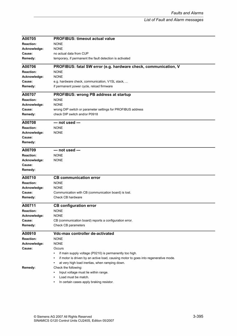
A00705 PROFIBUS: timeout actual valueReaction: NONEAcknowledge: NONECause: no actual data from CUPRemedy: temporary, if permanent the fault detection is activated
A00706 PROFIBUS: fatal SW error (e.g. hardware check, communication, VReaction: NONEAcknowledge: NONECause: e.g. hardware check, communication, V1SL stack, ...Remedy: if permanent power cycle, reload firmware
A00707 PROFIBUS: wrong PB address at startupReaction: NONEAcknowledge: NONECause: wrong DIP switch or parameter settings for PROFIBUS addressRemedy: check DIP switch and/or P0918
A00708 --- not used ---Reaction: NONEAcknowledge: NONECause:Remedy:
A00709 --- not used ---Reaction: NONEAcknowledge: NONECause:Remedy:
A00710 CB communication errorReaction: NONEAcknowledge: NONECause: Communication with CB (communication board) is lost.Remedy: Check CB hardware
A00711 CB configuration errorReaction: NONEAcknowledge: NONECause: CB (communication board) reports a configuration error.Remedy: Check CB parameters
A00910 Vdc-max controller de-activatedReaction: NONEAcknowledge: NONECause: Occurs
• if main supply voltage (P0210) is permanently too high.• if motor is driven by an active load, causing motor to goes into regenerative mode.• at very high load inertias, when ramping down.
Remedy: Check the following:• Input voltage must lie within range.• Load must be match.• In certain cases apply braking resistor.
Faults and Alarms
List of Fault and Alarm messages
3-396 © Siemens AG 2007 All Rights ReservedSINAMICS G120 Control Units CU240S, Edition 05/2007
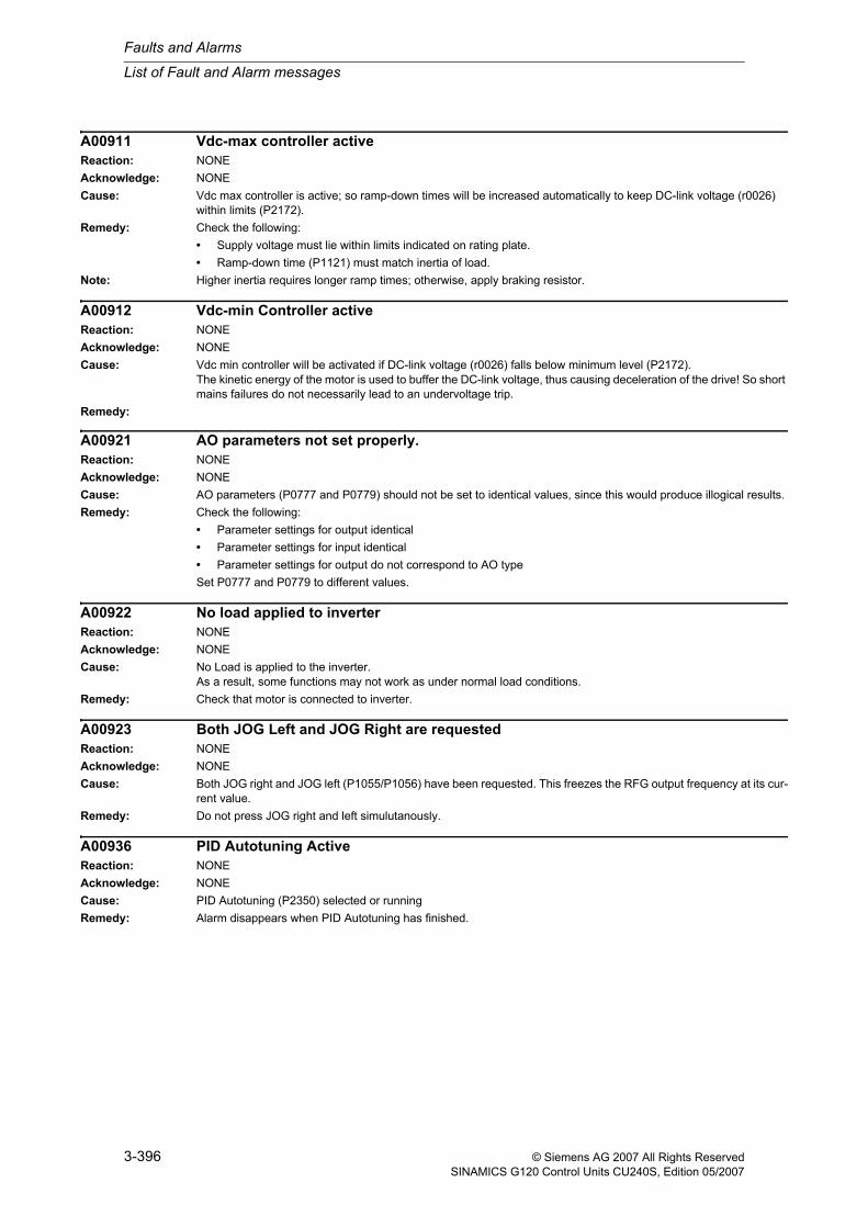
A00911 Vdc-max controller activeReaction: NONEAcknowledge: NONECause: Vdc max controller is active; so ramp-down times will be increased automatically to keep DC-link voltage (r0026)
within limits (P2172).Remedy: Check the following:
• Supply voltage must lie within limits indicated on rating plate.• Ramp-down time (P1121) must match inertia of load.
Note: Higher inertia requires longer ramp times; otherwise, apply braking resistor.
A00912 Vdc-min Controller activeReaction: NONEAcknowledge: NONECause: Vdc min controller will be activated if DC-link voltage (r0026) falls below minimum level (P2172).
The kinetic energy of the motor is used to buffer the DC-link voltage, thus causing deceleration of the drive! So short mains failures do not necessarily lead to an undervoltage trip.
Remedy:
A00921 AO parameters not set properly.Reaction: NONEAcknowledge: NONECause: AO parameters (P0777 and P0779) should not be set to identical values, since this would produce illogical results.Remedy: Check the following:
• Parameter settings for output identical• Parameter settings for input identical• Parameter settings for output do not correspond to AO typeSet P0777 and P0779 to different values.
A00922 No load applied to inverterReaction: NONEAcknowledge: NONECause: No Load is applied to the inverter.
As a result, some functions may not work as under normal load conditions.Remedy: Check that motor is connected to inverter.
A00923 Both JOG Left and JOG Right are requestedReaction: NONEAcknowledge: NONECause: Both JOG right and JOG left (P1055/P1056) have been requested. This freezes the RFG output frequency at its cur-
rent value.Remedy: Do not press JOG right and left simulutanously.
A00936 PID Autotuning ActiveReaction: NONEAcknowledge: NONECause: PID Autotuning (P2350) selected or runningRemedy: Alarm disappears when PID Autotuning has finished.
List of Fault and Alarm messages
Faults and Alarms
3-397© Siemens AG 2007 All Rights ReservedSINAMICS G120 Control Units CU240S, Edition 05/2007
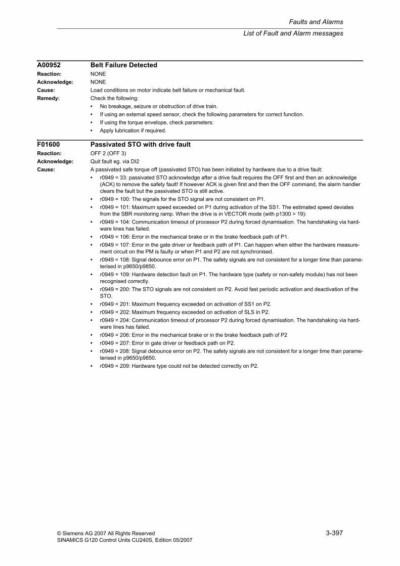
A00952 Belt Failure DetectedReaction: NONEAcknowledge: NONECause: Load conditions on motor indicate belt failure or mechanical fault.Remedy: Check the following:
• No breakage, seizure or obstruction of drive train.• If using an external speed sensor, check the following parameters for correct function.• If using the torque envelope, check parameters:• Apply lubrication if required.
F01600 Passivated STO with drive faultReaction: OFF 2 (OFF 3)Acknowledge: Quit fault eg. via DI2Cause: A passivated safe torque off (passivated STO) has been initiated by hardware due to a drive fault:
• r0949 = 33: passivated STO acknowledge after a drive fault requires the OFF first and then an acknowledge (ACK) to remove the safety fault! If however ACK is given first and then the OFF command, the alarm handler clears the fault but the passivated STO is still active.
• r0949 = 100: The signals for the STO signal are not consistent on P1.• r0949 = 101: Maximum speed exceeded on P1 during activation of the SS1. The estimated speed deviates
from the SBR monitoring ramp. When the drive is in VECTOR mode (with p1300 > 19):• r0949 = 104: Communication timeout of processor P2 during forced dynamisation. The handshaking via hard-
ware lines has failed.• r0949 = 106: Error in the mechanical brake or in the brake feedback path of P1.• r0949 = 107: Error in the gate driver or feedback path of P1. Can happen when either the hardware measure-
ment circuit on the PM is faulty or when P1 and P2 are not synchronised.• r0949 = 108: Signal debounce error on P1. The safety signals are not consistent for a longer time than parame-
terised in p9650/p9850.• r0949 = 109: Hardware detection fault on P1. The hardware type (safety or non-safety module) has not been
recognised correctly.• r0949 = 200: The STO signals are not consistent on P2. Avoid fast periodic activation and deactivation of the
STO.• r0949 = 201: Maximum frequency exceeded on activation of SS1 on P2.• r0949 = 202: Maximum frequency exceeded on activation of SLS in P2.• r0949 = 204: Communication timeout of processor P2 during forced dynamisation. The handshaking via hard-
ware lines has failed.• r0949 = 206: Error in the mechanical brake or in the brake feedback path of P2• r0949 = 207: Error in gate driver or feedback path on P2.• r0949 = 208: Signal debounce error on P2. The safety signals are not consistent for a longer time than parame-
terised in p9650/p9850.• r0949 = 209: Hardware type could not be detected correctly on P2.
Faults and Alarms
List of Fault and Alarm messages
3-398 © Siemens AG 2007 All Rights ReservedSINAMICS G120 Control Units CU240S, Edition 05/2007
Remedy: • r0949 = 100 or 200Increase the ramping times p1120/p1121 or the safety tolerance p9691/p9891,check the motor parameters (p0394 - p0311) or run the motor identification (p1910) again.Decrease the rate of switching the safety signals or lower the cycle time of the PLC.
• r0949 = 101 or 201Increase the ramping times p1120/p1121 or the safety tolerance p9691/p9891,check the motor parameters (p0394 - p0311) or run the motor identification (p1910) again.
• r0949 = 102 or 202Increase the ramping times (p1120, p1121) so that deviation between reference and actual frequency is mini-mized.Increase the safety tolerance p9691/p9891 or run the motor identification (p1910) again for better tuning of the observer and controllers.
• r0949 = 104 or 204Acknowledge the fault once morePower cycle the CU
• r0949 = 106 or 206Check connection with safe brake module and mechanical brakeCheck the 24 V power supply for safe brake module
• r0949 = 107 or 207Check connection between CU and power modulePower cycle the CU
• r0949 = , 108, or 208Decrease the rate of switching the safe digital inputs or increase debounce delay time p9650/p9850.
• r0949 = 109 or 209Power cycle the CUChange CU
List of Fault and Alarm messages
Faults and Alarms
3-399© Siemens AG 2007 All Rights ReservedSINAMICS G120 Control Units CU240S, Edition 05/2007
F01601 System startup errorReaction: OFF 2 (OFF 3)Acknowledge: Power onCause: System startup error. Error during the startup initialisation after a PowerCycle or HotSwap.
This error is critical and cannot be acknowledged. A restart (hotswap or power cycle) of the drive is required!
• r0949 = 0: Handshaking error on P1. Either an unexpected reboot by P1 or a synchronisation error during star-tup. Please power-cycle the inverter module again or perform a hotswap.
• r0949 = 1: Handshaking error on P2. Either a faulty reboot by P2 or a synchronisation error during startup. Please power-cycle the inverter module or perform a hotswap.
• r0949 = 100: Version error detected by P1. The safety version number is not identical on P1 and P2.• r0949 = 101: Startup semaphore is wrong on P1. Can happen if commissioning was not finished properly
before performing a power cycle. There might also be a problem of the EEPROM.• r0949 = 102: Error with semaphore on P1. The drive loads default parameters instead of the user settings.• r0949 = 103: Error with initial and first hardware type detection on P1. The hardware type (standard or safety
module) could not be identified. Either the control board is faulty or affected by EMC.• r0949 = 104: Timeout error on P1 while waiting for communication with P2.• r0949 = 105: Error on P1 during hardware exchange phase. Processors have not agreed on same type of hard-
ware platform.• r0949 = 106: Timeout error on P1 in hardware detection state. Handshaking with P2 failed.• r0949 = 107: Checksum error on P1. The safety parameters are not consistent in EEPROM.• r0949 = 108: Error on P1 during parameter transfer to P2. The correct safety parameters are not available on
P2 due to a communication problem.• r0949 = 109: Timeout error on P1 during parameter transfer to P2 due to different safety checksums on P1 and
P2. The parameter transfer to P2 has failed.• r0949 = 110: Timeout error on P1 during forced dynamisation and processor self test.• r0949 = 111: Timeout error on P1 when leaving the safety commissioning at startup.• r0949 = 112: Checksum error on P1 during processor initialisation.• r0949 = 200: Version error detected by P2. The safety version number (see r9770) is not identical on P1 and
P2.• r0949 = 201: Startup semaphore is wrong on P2. Can happen if commissioning was not finished properly
before performing a power cycle. There might also be a problem of the EEPROM.• r0949 = 202: Error with semaphore on P2. The drive loads default parameters instead of the user settings.• r0949 = 203: Error on P2 with initial and first hardware detection. The hardware type (standard or safety mod-
ule) could not be identified. Either the control board is faulty or affected by EMC.• r0949 = 204: Timeout error on P1 while waiting for communication with P2.• r0949 = 205: Error on P1 during hardware exchange phase. Processors have not agreed on same type of hard-
ware platform.• r0949 = 206: Timeout error on P2 during hardware detection. Handshaking with P1 failed.• r0949 = 207: Checksum error on P2. The safety parameters on P2 are not consistent.• r0949 = 208: Error on P2 during parameter transfer from P1. The safety parameters on P2 are not valid due to
a communication problem.• r0949 = 209: Timeout error on P2 during parameter transfer from P1. Possibly due to different checksums on
P1 and P2.• r0949 = 210: Timeout error on P2 in startup dynamisation phase. The communication failed.• r0949 = 211: Timeout error on P2 when leaving the initial safety commissioning.• r0949 = 212: Checksum error on P2 during processor initialisation.
Remedy: • Power-cycle CU (since fault F1601 cannot be acknowledged).• Make sure that CU is connected correctly to PM.• Reduce EMC.
Faults and Alarms
List of Fault and Alarm messages
3-400 © Siemens AG 2007 All Rights ReservedSINAMICS G120 Control Units CU240S, Edition 05/2007
F01610 EEPROM inconsistentReaction: OFF 2 (OFF 3)Acknowledge: Quit fault eg. via DI2Cause: EEPROM data inconsistency error:
• r0949 = 100: Safety parameters have not been written correctly to EEPROM on P1. Try to load parameters again.
• r0949 = 200: EEPROM data inconsistency error on P2.• r0949 =2011: Safety parameters have not been written correctly to EEPROM.
Remedy: Load safety parameters again.
F01611 Defect in cross comparis.Reaction: OFF 2 (OFF 3)Acknowledge: Quit fault eg. via DI2Cause: Data exchange error between processors:
• r0949 = 100: P2 has entered the safe torque off due to a drive fault on P2 or a subsequent fault of F1600/F1630• r0949 = 102: Dynamic checksums are different on P1. Cross comparison fault or problem with processor com-
munication.• r0949 = 103: Derived frequency is different on both processors. Cross comparison fault or problem with proces-
sor communication.• r0949 = 104: Frequency error on P1 caused by VFM.• r0949 = 201: Frequency check with error on P2.• r0949 = 202: Dynamic checksums are different on P2. Cross comparison fault or problem with processor com-
munication.Remedy: • Reduce EMC.
• Perform a forced dynamisation
F01612 Diff. in hardw. detectionReaction: OFF 2 (OFF 3)Acknowledge: Quit fault eg. via DI2Cause: The hardware (safety or non-safety hardware) could no be identified.
• r0949 = 100: Identification error during startup on P1.• r0949 = 101: Runtime detection error on P1.• r0949 = 102: Hardware or software configuration error on P1.• r0949 = 200: Startup error on P2.• r0949 = 201: Runtime detection error on P2.• r0949 = 202: Hardware or software configuration error on P2.
Remedy: • Inverter hardware is faulty or problem in processor communication. Perform a power cycle.
F01613 Maximum frequency exceededReaction: OFF 2 (OFF 3)Acknowledge: Quit fault eg. via DI2Cause: The maximum frequency has been exceeded.
• r0949 = 100: Frequency error on P1, maximum frequency exceeded.• r0949 = 200: Maximum frequency exceeded on P2.
Remedy: • Check application or increase safety threshold p9691/p9891.• See also remedies for F1614.
List of Fault and Alarm messages
Faults and Alarms
3-401© Siemens AG 2007 All Rights ReservedSINAMICS G120 Control Units CU240S, Edition 05/2007
F01614 Frequency consistency faultReaction: OFF 2 (OFF 3)Acknowledge: Quit fault eg. via DI2Cause: Error in frequency detection of the frequency estimation circuit (voltage frequency measurement (VFM) module):
• r0949 = 100: Difference in frequency comparison on P1.• r0949 = 101: VFM estimated frequency too high on P1.• r0949 = 102: VFM estimated frequency too low on P1.• r0949 = 103: Estimated frequency of VFM module was not detected on P1.• r0949 = 104: Error in cycle-time on P1.• r0949 = 200: Frequency deviation on P2.• r0949 = 201: VFM estimated frequency too high on P2.• r0949 = 202: VFM estimated frequency too low on P2.• r0949 = 203: Estimated VFM frequency was not detected on P2.• r0949 = 204: Error in cycle-time on P2.Error can occur with small ramping times. When the VC or SLVC mode is configured (see p1300) the cause can be the same as for fault F0453.
Remedy: • Increase ramping times p1120 and p1121.• Make sure that drive is not at current limit when starting.• See remedies for F0453.• Check hardware speed estimation circuit.
F01615 Error in hardw. environm.Reaction: OFF 2 (OFF 3)Acknowledge: Quit fault eg. via DI2Cause: • r0949 = 100: Error in supply voltage 3.3 V or 24 V on the control board.
• r0949 = 101: Temperature of control board exceeds the limits.Remedy: • r0949 = 100:
• Check supply voltage.• Reduce EMC.• r0949 = 101:• Check ambient temperature.
F01616 Processor selftest faultyReaction: OFF 2 (OFF 3)Acknowledge: Quit fault eg. via DI2Cause: The processor selftest has uncovered an error:
• r0949 = 100: General error on P1.• r0949 = 101: Error in RAM test on P1.• r0949 = 102: Error in ROM test on P1.• r0949 = 103: Error in processor function test on P1.• r0949 = 200: Error in processor self-test on P2.The selftest is started together with the forced dynamisation and must be enabled by setting p9601.1 and p9801.1.
Remedy: • Run self-test again (set bit 1 in p9601 and p9801 and enter the STO mode, then leave the STO mode again).
Faults and Alarms
List of Fault and Alarm messages
3-402 © Siemens AG 2007 All Rights ReservedSINAMICS G120 Control Units CU240S, Edition 05/2007
F01625 Consecutive no. incorr.Reaction: OFF 2 (OFF 3)Acknowledge: Quit fault eg. via DI2Cause: The consecutive counter checks the consistency of the communication between P1 and P2:
• r0949 = 100: The consecutive monitoring counter has an error on P1.• r0949 = 101: Processors are out of synchonism.• r0949 = 102: Processor communication has failed.• r0949 = 103: Processor communication has failed or processors are out of synchonism.• r0949 = 200: The consecutive counter has an error on P2.
Remedy: • Acknowledge safety fault.• Restart inverter module or check EMC levels on accumulated faults.
F01630 Safe Brake Control faultyReaction: OFF 2 (OFF 3)Acknowledge: Quit fault eg. via DI2Cause: An error has been detected with the brake feedback.
• r0949 = 0: Problem with the safe brake.• r0949 = 100: SB-Module: wire break detected or internal braketests failed during dynamisation.• r0949 = 200: Internal braketests failed during dynamisation.
Remedy: • Check the wiring of the brake module• Exchange brake module.
F01640 PROFIsafe Driver FaultReaction: OFF 2 (OFF 3)Acknowledge: Quit fault eg. via DI2Cause: An error has been detected with the PROFIsafe driver.
• r0949 = 102: A parameterisation error occured on P1. The parameters received from the bus are not correct. Check PROFIsafe parameters.
• r0949 = 103: A consecutive number error occured on P1. Current PROFIsafe message has a wrong sign of life.• r0949 = 104: A CRC error occured on P1. The PROFIsafe message checksum was incorrect.• r0949 = 105: A watchdog error occured on P1. PROFIsafe driver timed out.• r0949 = 106: Fail safe values are active on P1.• r0949 = 107: PROFIsafe default error on P1.• r0949 = 202: A parameterisation error occured on P2. The parameters received from the bus are not correct.
Check PROFIsafe parameters.• r0949 = 203: A consecutive number error occured on P2. Current PROFIsafe message has a wrong sign of life.• r0949 = 204: A CRC error occured on P2. The PROFIsafe message checksum was incorrect.• r0949 = 205: A watchdog error occured on P2. PROFIsafe driver timed out.• r0949 = 206: Fail safe values are active on P2.• r0949 = 207: PROFIsafe default error on P2.• r0949 = 208: PROFIsafe configuration error on P2. The drive configuration does not match the configuration
from the bus.Remedy: • Check all PROFIsafe settings (including your higher level failsafe control system).
• Acknowledge PROFIsafe fault.
List of Fault and Alarm messages
Faults and Alarms
3-403© Siemens AG 2007 All Rights ReservedSINAMICS G120 Control Units CU240S, Edition 05/2007
F01649 Internal software errorReaction: OFF 2 (OFF 3)Acknowledge: Quit fault eg. via DI2Cause: • r0949 = 1: Buffer overflow on checksum calculation for P1 parameter access functions.
• r0949 = 2: Buffer overflow on checksum calculation for P2 parameter access functions.• r0949 = 3: Endless safety loop on P1.• r0949 = 4: Endless safety loop on P2.• r0949 > 100: Signal an internal or unexpected software fault.Only for Siemens internal diagnostics.
Remedy: Contact hotline.
F01650 Fault in safety parametr.Reaction: OFF 2 (OFF 3)Acknowledge: Quit fault eg. via DI2Cause: Error during startup or safety commissioning/reset:
• r0949 = 0: Error during safety commissioning/reset.• r0949 = 1: Checksum error during safety commissioning or safety reset.• r0949 = 2: Error during internal parameter transfer.• r0949 = 3: Error finalizing the buffer transfer.• r0949 = 4: Failure during saving of parameters to EEPROM.• r0949 = 5: Error in safety parameter transfer during safety reset.• r0949 = 11: Communication channel between processors not ready.• r0949 =2000: Safety commissioning can only be finished by setting parameter p3900.
Remedy: • Perform safety commissioning.• Try leaving via p3900 = 11.
F01655 Fault at processor resetReaction: OFF 2 (OFF 3)Acknowledge: Quit fault eg. via DI2Cause: • r0949 = 100: Safety reset timeout on P1.
• r0949 = 200: Safety reset timeout on P2.Remedy: • Retrigger the safety reset (perform a hot swap of the inverter module).
F01659 Denial of paramet. changeReaction: OFF 2 (OFF 3)Acknowledge: Quit fault eg. via DI2Cause: A write request for one or more safety parameters was rejected:
• r0949 = 0: Problem during finalization of safety parameters. Drive has reloaded the old data.• r0949 = 1: Safety password not set correctly.• r0949 = 3: Tolerance too small (p9691 < p9690). Increase tolerance p9691!• r0949 = 203: Tolerance too small (p9891 < p9890). Increase tolerance!
Remedy: • Acknowledge fault and enter safety commissioning again. If not possible, leave the safety commissioning with p3900 = 11 and operate the drive with the old safety settings.
F01660 Wrong safety checksumReaction: OFF 2 (OFF 3)Acknowledge: Quit fault eg. via DI2Cause: • r0949 = 0: Attempt to leave safety commissioning with r9798 != p9799.
• r0949 = 1: Attempt to leave safety commissioning with r9898 != p9899.• r0949 = 2: Attempt to leave safety commissioning with r9798 != r9898.
Remedy: • Make sure that checksums in p9798 and p9898 are identical. If not, ensure that parametrisation is identical (p96xx = p98xx).
• Set checksum in p9799 or p9899 correctly.• If setting the checksums not successful, leave safety commissioning via p3900 = 11 (cancel commissioning).
Faults and Alarms
List of Fault and Alarm messages
3-404 © Siemens AG 2007 All Rights ReservedSINAMICS G120 Control Units CU240S, Edition 05/2007
A01690 Safety parameter changedReaction: NONEAcknowledge: NONECause: The warning indicates that at least one parameter has been changed in the safety commissioning or safety reset.Remedy: Finish safety commissioning by setting p3900 = 10 or p3900 = 11 or wait until safety reset is complete.
A01691 SLS signal inconsistencyReaction: NONEAcknowledge: NONECause: Problem with the consistency of the safety input signals. The drive reduces the frequency according to the settings
of the SS1.When zero frequency is reached, the passivated STO is entered and a drive fault is issued.
Remedy: Check consistency of safety input signals and acknowledge the following safe torque off due to a drive fault.
A01692 Speed for SLS exceededReaction: NONEAcknowledge: NONECause: a) Output frequency when entering the SLS is higher than p9690 and p9692 is configured to trigger a passivated
STO with a drive fault.b) Output frequency exceeds the SLS tolerance p9691.In both cases, the frequency is reduced according to the settings for the SS1, then the passivated STO state is entered and a fault is generated.
Remedy: ad a) Reduce speed before entering the SLS or change the setting in p9692.ad b) increase the tolerance in p9691/p9891 compared to p9690/p9890.In both cases the passivated STO will be entered once zero frequency is reached. Acknowledge the passivated STO and the drive fault.
A01696 Switch-on is inhibitedReaction: NONEAcknowledge: NONECause: Switching on of the drive not possible and the drive will therefore remain in the READY state (see r0002).Remedy: Check if a deactivated gate driver or the current safety mode (STO, SS1, SLS) is inhibiting the start. Check the inhibit
bit (r0052.6).
A01697 Wrong safety param. dataReaction: NONEAcknowledge: NONECause: Semaphore problem at startup. Cannot load last safety parameters. Loading default values instead.Remedy: Restart drive (perform power cycle) to load correct safety data.
A01698 Safety commis./reset act.Reaction: NONEAcknowledge: NONECause: The safety reset or the safety commissioning are currently active (selected via p0010 = 95).Remedy: Finish commissioning with p3900 = 10 (accept changed) or p3900 = 11 (discard changes) or wait until safety reset
is complete.
A01699 Forced dynamis. requiredReaction: NONEAcknowledge: NONECause: Dynamisation timer (see r9660) has expired. A new dynamisation test is required.Remedy: Select and then de-select STO (p9601.bit1 and p9801.bit1 must be set).