sinamics s120 getting started with startdrive - realpars
TRANSCRIPT

___________________
___________________
___________________
___________________
___________________
___________________
___________________
___________________
___________________
___________________
SINAMICS
S120 Getting Started with Startdrive
Getting Started
Valid as of: Firmware version 5.1, Startdrive V15
11/2017 6SL3097-4AG30-0BP0
Preface
Fundamental safety instructions
1
Overview 2
Startdrive commissioning tool
3
Fundamentals 4
Commissioning 5
Performing basic parameterization
6
Loading the project to the target device
7
Commissioning a drive 8
Appendix A
Siemens AG Division Digital Factory Postfach 48 48 90026 NÜRNBERG GERMANY
Document order number: 6SL3097-4AG30-0BP0 Ⓟ 12/2017 Subject to change
Copyright © Siemens AG 2017. All rights reserved
Legal information Warning notice system
This manual contains notices you have to observe in order to ensure your personal safety, as well as to prevent damage to property. The notices referring to your personal safety are highlighted in the manual by a safety alert symbol, notices referring only to property damage have no safety alert symbol. These notices shown below are graded according to the degree of danger.
DANGER indicates that death or severe personal injury will result if proper precautions are not taken.
WARNING indicates that death or severe personal injury may result if proper precautions are not taken.
CAUTION indicates that minor personal injury can result if proper precautions are not taken.
NOTICE indicates that property damage can result if proper precautions are not taken.
If more than one degree of danger is present, the warning notice representing the highest degree of danger will be used. A notice warning of injury to persons with a safety alert symbol may also include a warning relating to property damage.
Qualified Personnel The product/system described in this documentation may be operated only by personnel qualified for the specific task in accordance with the relevant documentation, in particular its warning notices and safety instructions. Qualified personnel are those who, based on their training and experience, are capable of identifying risks and avoiding potential hazards when working with these products/systems.
Proper use of Siemens products Note the following:
WARNING Siemens products may only be used for the applications described in the catalog and in the relevant technical documentation. If products and components from other manufacturers are used, these must be recommended or approved by Siemens. Proper transport, storage, installation, assembly, commissioning, operation and maintenance are required to ensure that the products operate safely and without any problems. The permissible ambient conditions must be complied with. The information in the relevant documentation must be observed.
Trademarks All names identified by ® are registered trademarks of Siemens AG. The remaining trademarks in this publication may be trademarks whose use by third parties for their own purposes could violate the rights of the owner.
Disclaimer of Liability We have reviewed the contents of this publication to ensure consistency with the hardware and software described. Since variance cannot be precluded entirely, we cannot guarantee full consistency. However, the information in this publication is reviewed regularly and any necessary corrections are included in subsequent editions.
Getting Started with Startdrive Getting Started, 11/2017, 6SL3097-4AG30-0BP0 5
Preface
SINAMICS documentation The SINAMICS documentation is organized in the following categories:
● General documentation/catalogs
● User documentation
● Manufacturer/service documentation
Additional information You can find information on the following topics at the following address (http://w3.siemens.com/mcms/mc-solutions/en/motion-control/support/technical-documentation/Pages/technical-documentation.aspx):
● Ordering documentation/overview of documentation
● Additional links to download documents
● Using documentation online (find and search in manuals/information)
Please send any questions about the technical documentation (e.g. suggestions for improvement, corrections) to the following e-mail address (mailto:[email protected]).
Siemens MySupport/Documentation At the following address (http://www.siemens.com/mdm), you can find information on how to create your own individual documentation based on Siemens' content, and adapt it for your own machine documentation.
Training At the following address (http://www.siemens.com/sitrain), you can find information about SITRAIN (Siemens training on products, systems and solutions for automation and drives).
FAQs You can find Frequently Asked Questions in the Service&Support pages under Product Support (https://support.industry.siemens.com/cs/de/en/ps/faq).
SINAMICS You can find information about SINAMICS at the following address (http://www.siemens.com/sinamics).
Preface
Getting Started with Startdrive 6 Getting Started, 11/2017, 6SL3097-4AG30-0BP0
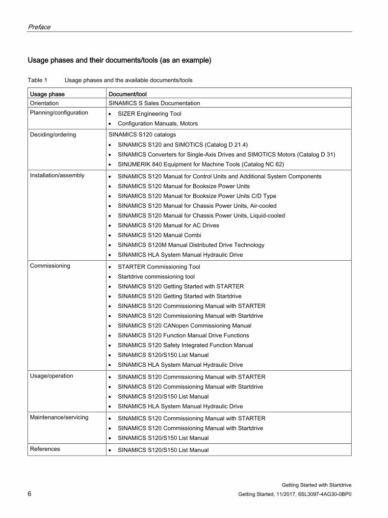
Usage phases and their documents/tools (as an example)
Table 1 Usage phases and the available documents/tools
Usage phase Document/tool Orientation SINAMICS S Sales Documentation Planning/configuration • SIZER Engineering Tool
• Configuration Manuals, Motors
Deciding/ordering SINAMICS S120 catalogs • SINAMICS S120 and SIMOTICS (Catalog D 21.4) • SINAMICS Converters for Single-Axis Drives and SIMOTICS Motors (Catalog D 31) • SINUMERIK 840 Equipment for Machine Tools (Catalog NC 62)
Installation/assembly • SINAMICS S120 Manual for Control Units and Additional System Components • SINAMICS S120 Manual for Booksize Power Units • SINAMICS S120 Manual for Booksize Power Units C/D Type • SINAMICS S120 Manual for Chassis Power Units, Air-cooled • SINAMICS S120 Manual for Chassis Power Units, Liquid-cooled • SINAMICS S120 Manual for AC Drives • SINAMICS S120 Manual Combi • SINAMICS S120M Manual Distributed Drive Technology • SINAMICS HLA System Manual Hydraulic Drive
Commissioning • STARTER Commissioning Tool • Startdrive commissioning tool • SINAMICS S120 Getting Started with STARTER • SINAMICS S120 Getting Started with Startdrive • SINAMICS S120 Commissioning Manual with STARTER • SINAMICS S120 Commissioning Manual with Startdrive • SINAMICS S120 CANopen Commissioning Manual • SINAMICS S120 Function Manual Drive Functions • SINAMICS S120 Safety Integrated Function Manual • SINAMICS S120/S150 List Manual • SINAMICS HLA System Manual Hydraulic Drive
Usage/operation • SINAMICS S120 Commissioning Manual with STARTER • SINAMICS S120 Commissioning Manual with Startdrive • SINAMICS S120/S150 List Manual • SINAMICS HLA System Manual Hydraulic Drive
Maintenance/servicing • SINAMICS S120 Commissioning Manual with STARTER • SINAMICS S120 Commissioning Manual with Startdrive • SINAMICS S120/S150 List Manual
References • SINAMICS S120/S150 List Manual
Preface
Getting Started with Startdrive Getting Started, 11/2017, 6SL3097-4AG30-0BP0 7
Target group This documentation is intended for machine manufacturers, commissioning engineers, and service personnel who use the SINAMICS drive system.
Benefits This manual provides all of the information, procedures and operator actions required for the particular usage phase.
Standard scope The scope of the functionality described in this document can differ from that of the drive system that is actually supplied.
● Other functions not described in this documentation might be able to be executed in the drive system. However, no claim can be made regarding the availability of these functions when the equipment is first supplied or in the event of service.
● The documentation can also contain descriptions of functions that are not available in a particular product version of the drive system. The functionality of the supplied drive system should only be taken from the ordering documentation.
● Extensions or changes made by the machine manufacturer must be documented by the machine manufacturer.
For reasons of clarity, this documentation does not contain all of the detailed information on all of the product types, and cannot take into consideration every conceivable type of installation, operation and service/maintenance.
Technical Support Country-specific telephone numbers for technical support are provided in the Internet at the following address (https://support.industry.siemens.com/sc/ww/en/sc/2090) in the "Contact" area.
Relevant directives and standards You can obtain an up-to-date list of currently certified components on request from your local Siemens office. If you have any questions relating to certifications that have not yet been completed, please ask your Siemens contact person.
Certificates for download
The certificates can be downloaded from the Internet:
Certificates (https://support.industry.siemens.com/cs/ww/de/ps/13206/cert)
EC Declaration of Conformity
You can find the EC Declaration of Conformity for the relevant directives as well as the relevant certificates, prototype test certificates, manufacturers declarations and test certificates for functions relating to functional safety ("Safety Integrated") on the Internet at the following address (https://support.industry.siemens.com/cs/ww/en/ps/13231/cert).
Preface
Getting Started with Startdrive 8 Getting Started, 11/2017, 6SL3097-4AG30-0BP0
The following directives and standards are relevant for SINAMICS S devices:
● European Low Voltage Directive
SINAMICS S devices fulfil the requirements stipulated in the Low-Voltage Directive 2014/35/EU, insofar as they are covered by the application area of this directive.
● European Machinery Directive
SINAMICS S devices fulfil the requirements stipulated in the Low-Voltage Directive 2006/42/EU, insofar as they are covered by the application area of this directive.
However, the use of the SINAMICS S devices in a typical machine application has been fully assessed for compliance with the main regulations in this directive concerning health and safety.
● Directive 2011/65/EU
SINAMICS S devices comply with the requirements of Directive 2011/65/EU on the restriction of the use of certain hazardous substances in electrical and electronic devices (RoHS II).
● European EMC Directive
SINAMICS S devices comply with the EMC Directive 2014/30/EU.
● EMC requirements for South Korea
SINAMICS S devices with the KC marking on the type plate satisfy the EMC requirements for South Korea.
● Eurasian conformity
SINAMICS S comply with the requirements of the Russia/Belarus/Kazakhstan customs union (EAC).
● North American market
SINAMICS S devices provided with one of the test symbols displayed fulfill the requirements stipulated for the North American market as a component of drive applications.
You can find the relevant certificates on the Internet pages of the certifier (http://database.ul.com/cgi-bin/XYV/template/LISEXT/1FRAME/index.html).
● Specification for semiconductor process equipment voltage drop immunity
SINAMICS S devices meet the requirements of standard SEMI F47-0706.
● Australia and New Zealand (RCM formerly C-Tick)
SINAMICS S devices showing the test symbols fulfill the EMC requirements for Australia and New Zealand.
● Quality systems
Siemens AG employs a quality management system that meets the requirements of ISO 9001 and ISO 14001.
Preface
Getting Started with Startdrive Getting Started, 11/2017, 6SL3097-4AG30-0BP0 9
Not relevant standards
China Compulsory Certification
SINAMICS S devices do not fall in the area of validity of the China Compulsory Certification (CCC).
EMC limit values in South Korea
The EMC limit values to be observed for Korea correspond to the limit values of the EMC product standard for variable-speed electric drives EN 61800-3 of category C2 or the limit value class A, Group 1 to KN11. By implementing appropriate additional measures, the limit values according to category C2 or limit value class A, Group 1, are observed. Further, additional measures may be required, such as using an additional radio interference suppression filter (EMC filter). The measures for EMC-compliant design of the system are described in detail in this manual respectively in the EMC Installation Guideline Configuration Manual. The final statement regarding compliance with the standard is given by the respective label attached to the individual unit.
Ensuring reliable operation The manual describes a desired state which, if maintained, ensures the required level of operational reliability and compliance with EMC limit values.
Should there be any deviation from the requirements in the manual, appropriate actions (e.g. measurements) must be taken to check/prove that the required level of operational reliability and compliance with EMC limit values are ensured.
Spare parts Spare parts are available on the Internet at the following address (https://www.automation.siemens.com/sow?sap-language=EN).
Product maintenance The components are subject to continuous further development within the scope of product maintenance (improvements to robustness, discontinuations of components, etc).
These further developments are "spare parts-compatible" and do not change the article number.
In the scope of such spare parts-compatible further developments, connector/connection positions are sometimes changed slightly. This does not cause any problems with proper use of the components. Please take this fact into consideration in special installation situations (e.g. allow sufficient clearance for the cable length).
Preface
Getting Started with Startdrive 10 Getting Started, 11/2017, 6SL3097-4AG30-0BP0
Use of third-party products This document contains recommendations relating to third-party products. Siemens accepts the fundamental suitability of these third-party products.
You can use equivalent products from other manufacturers.
Siemens does not accept any warranty for the properties of third-party products.
Ground symbols
Table 2 Symbols
Symbol Meaning
Connection for protective conductor
Ground (e.g. M 24 V)
Connection for function potential bonding
Preface
Getting Started with Startdrive Getting Started, 11/2017, 6SL3097-4AG30-0BP0 11
Notation The following notation and abbreviations are used in this documentation:
Notation for faults and alarms (examples): • F12345 Fault 12345
• A67890 Alarm 67890
• C23456 Safety message
Notation for parameters (examples): • p0918 Adjustable parameter 918
• r1024 Display parameter 1024
• p1070[1] Adjustable parameter 1070, index 1
• p2098[1].3 Adjustable parameter 2098, index 1 bit 3
• p0099[0...3] Adjustable parameter 99, indices 0 to 3
• r0945[2](3) Display parameter 945, index 2 of drive object 3
• p0795.4 Adjustable parameter 795, bit 4
Purpose of the document This documentation is aimed at beginners who want to find out more about the SINAMICS S120 drive system. The document offers a brief guide to commissioning a sample project with a simple SINAMICS S120 drive train (CU320-2 PN). By following the instructions in this document, a beginner will need only a few minutes to engineer and configure the sample project and start up the motor.
Use of OpenSSL This product contains software (https://www.openssl.org/) that has been developed by the OpenSSL project for use in the OpenSSL toolkit.
This product contains cryptographic software (mailto:[email protected]) created by Eric Young.
This product contains software (mailto:[email protected]) developed by Eric Young.

Preface
Getting Started with Startdrive 12 Getting Started, 11/2017, 6SL3097-4AG30-0BP0
Getting Started with Startdrive Getting Started, 11/2017, 6SL3097-4AG30-0BP0 13
Table of contents
Preface ................................................................................................................................................... 5
1 Fundamental safety instructions ............................................................................................................ 17
1.1 General safety instructions ..................................................................................................... 17
1.2 Equipment damage due to electric fields or electrostatic discharge ...................................... 22
1.3 Warranty and liability for application examples ...................................................................... 23
1.4 Industrial security .................................................................................................................... 24
1.5 Residual risks of power drive systems .................................................................................... 25
2 Overview............................................................................................................................................... 27
3 Startdrive commissioning tool ................................................................................................................ 29
3.1 Structure of the user interface ................................................................................................ 29 3.1.1 Project view for parameterizing the drive................................................................................ 29 3.1.2 Project navigation ................................................................................................................... 30
3.2 User interface - parameterization ........................................................................................... 31 3.2.1 Modules in the hardware catalog ............................................................................................ 31 3.2.2 Device view ............................................................................................................................. 33 3.2.3 Parameterization editor ........................................................................................................... 34 3.2.4 Function view .......................................................................................................................... 35 3.2.5 Parameter view ....................................................................................................................... 36 3.2.6 Inspector window .................................................................................................................... 38 3.2.7 Device configuration detection ................................................................................................ 40
3.3 User interface - Control panel ................................................................................................. 42
3.4 Information system - online help ............................................................................................. 43 3.4.1 General remarks on the information system ........................................................................... 43 3.4.2 Opening the information system ............................................................................................. 47
4 Fundamentals ....................................................................................................................................... 49
4.1 Requirements for commissioning ........................................................................................... 49
4.2 Safety instructions for commissioning .................................................................................... 50
4.3 BICO interconnections ............................................................................................................ 51 4.3.1 Binectors, Connectors............................................................................................................. 51 4.3.2 Interconnect BICO inputs ........................................................................................................ 53 4.3.3 Interconnecting BICO outputs ................................................................................................. 55
4.4 Comparing parameter settings ............................................................................................... 58
4.5 Permanently save the settings ................................................................................................ 60
4.6 Restoring factory settings ....................................................................................................... 61
4.7 Loading project data from a drive unit .................................................................................... 62
Table of contents
Getting Started with Startdrive 14 Getting Started, 11/2017, 6SL3097-4AG30-0BP0
5 Commissioning ..................................................................................................................................... 65
5.1 Call Startdrive ......................................................................................................................... 65
5.2 Commissioning workflow ....................................................................................................... 66
5.3 Check lists to commission SINAMICS S ................................................................................ 67
5.4 Creating a project offline in Startdrive .................................................................................... 70 5.4.1 Creating a new project ........................................................................................................... 70 5.4.1.1 Creating a new project (in the Portal view) ............................................................................ 70 5.4.1.2 Creating a new project (in the Project view) .......................................................................... 72 5.4.2 Inserting the drive unit offline ................................................................................................. 74 5.4.3 Inserting an infeed ................................................................................................................. 75 5.4.4 Inserting a Motor Module or Power Module ........................................................................... 80 5.4.4.1 Inserting and specifying a Motor Module ............................................................................... 81 5.4.4.2 Inserting and specifying a Power Module .............................................................................. 84 5.4.4.3 Making detailed settings ........................................................................................................ 86 5.4.4.4 Connecting several modules in parallel ................................................................................. 87 5.4.4.5 Changing the drive object type .............................................................................................. 89 5.4.5 Inserting a motor .................................................................................................................... 91 5.4.5.1 Inserting and specifying motors from the motor list ............................................................... 91 5.4.5.2 Inserting and specifying motors that are missing from the motor list ..................................... 94 5.4.6 Inserting measuring systems ................................................................................................. 97 5.4.6.1 Overview ................................................................................................................................ 97 5.4.6.2 Inserting an encoder .............................................................................................................. 98 5.4.7 Inserting additional system components .............................................................................. 102 5.4.7.1 Adding a CBE20 Communication Board .............................................................................. 102 5.4.7.2 Adding a Terminal Module ................................................................................................... 104 5.4.7.3 Adding a Terminal Board ..................................................................................................... 105 5.4.7.4 Adding the VSM10 Voltage Sensing Module ....................................................................... 107
5.5 Establishing an online connection to the drive unit .............................................................. 110 5.5.1 Overview .............................................................................................................................. 110 5.5.2 Using an online connection via the Ethernet interface ........................................................ 112
5.6 Alternatively: Creating a project with a device configuration derived from the hardware .... 115 5.6.1 Deriving the hardware device configuration ......................................................................... 115 5.6.2 Transferring the determined device configuration to Startdrive ........................................... 119 5.6.3 Revising the configuration .................................................................................................... 121
6 Performing basic parameterization ....................................................................................................... 123
6.1 Control Unit .......................................................................................................................... 123 6.1.1 Web server ........................................................................................................................... 123 6.1.1.1 Activating and configuring the web server ........................................................................... 123 6.1.1.2 Setting or changing web server user accounts .................................................................... 126 6.1.2 Configuring inputs/outputs of the Control Unit ..................................................................... 129 6.1.2.1 Isolated digital inputs ........................................................................................................... 129 6.1.2.2 Bidirectional digital inputs/outputs........................................................................................ 130 6.1.2.3 Measuring sockets ............................................................................................................... 131
Table of contents
Getting Started with Startdrive Getting Started, 11/2017, 6SL3097-4AG30-0BP0 15
6.2 Infeed unit ............................................................................................................................. 135 6.2.1 Overview ............................................................................................................................... 135 6.2.2 Function modules .................................................................................................................. 136 6.2.3 Line data / operating mode ................................................................................................... 138 6.2.4 Enable logic .......................................................................................................................... 140 6.2.5 Line contactor control............................................................................................................ 141
6.3 Drive axes ............................................................................................................................. 142 6.3.1 Servo drives .......................................................................................................................... 142 6.3.1.1 Overview ............................................................................................................................... 142 6.3.1.2 Function modules .................................................................................................................. 143 6.3.1.3 Control mode ........................................................................................................................ 144 6.3.1.4 Important parameters............................................................................................................ 145 6.3.1.5 Enable logic .......................................................................................................................... 146 6.3.2 Vector drives ......................................................................................................................... 148 6.3.2.1 Overview ............................................................................................................................... 148 6.3.2.2 Function modules .................................................................................................................. 149 6.3.2.3 Control mode ........................................................................................................................ 150 6.3.2.4 Important parameters............................................................................................................ 151 6.3.2.5 Drive settings ........................................................................................................................ 152 6.3.2.6 Enable logic .......................................................................................................................... 154
7 Loading the project to the target device ............................................................................................... 157
8 Commissioning a drive ........................................................................................................................ 159
8.1 Using the control panel ......................................................................................................... 159
8.2 Traversing the drive with speed specification ....................................................................... 162
A Appendix............................................................................................................................................. 163
A.1 List of abbreviations .............................................................................................................. 163
A.2 Documentation overview ...................................................................................................... 172
A.3 Shortcut menus and icons in Startdrive ................................................................................ 173 A.3.1 Function calls project view .................................................................................................... 173 A.3.1.1 Project navigation ................................................................................................................. 173 A.3.2 BICO interconnections .......................................................................................................... 174 A.3.3 Special elements in the screen forms ................................................................................... 174
Index................................................................................................................................................... 175

Table of contents
Getting Started with Startdrive 16 Getting Started, 11/2017, 6SL3097-4AG30-0BP0
Getting Started with Startdrive Getting Started, 11/2017, 6SL3097-4AG30-0BP0 17
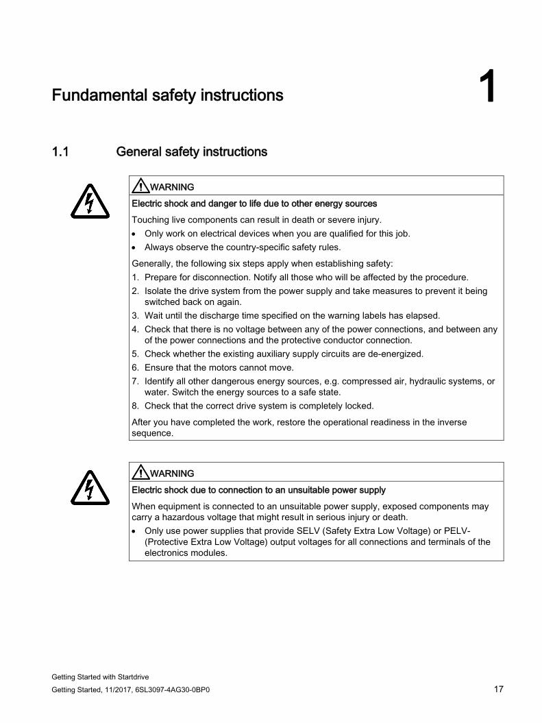
Fundamental safety instructions 1 1.1 General safety instructions
WARNING
Electric shock and danger to life due to other energy sources
Touching live components can result in death or severe injury. • Only work on electrical devices when you are qualified for this job. • Always observe the country-specific safety rules.
Generally, the following six steps apply when establishing safety: 1. Prepare for disconnection. Notify all those who will be affected by the procedure. 2. Isolate the drive system from the power supply and take measures to prevent it being
switched back on again. 3. Wait until the discharge time specified on the warning labels has elapsed. 4. Check that there is no voltage between any of the power connections, and between any
of the power connections and the protective conductor connection. 5. Check whether the existing auxiliary supply circuits are de-energized. 6. Ensure that the motors cannot move. 7. Identify all other dangerous energy sources, e.g. compressed air, hydraulic systems, or
water. Switch the energy sources to a safe state. 8. Check that the correct drive system is completely locked.
After you have completed the work, restore the operational readiness in the inverse sequence.
WARNING
Electric shock due to connection to an unsuitable power supply
When equipment is connected to an unsuitable power supply, exposed components may carry a hazardous voltage that might result in serious injury or death. • Only use power supplies that provide SELV (Safety Extra Low Voltage) or PELV-
(Protective Extra Low Voltage) output voltages for all connections and terminals of the electronics modules.
Fundamental safety instructions 1.1 General safety instructions
Getting Started with Startdrive 18 Getting Started, 11/2017, 6SL3097-4AG30-0BP0
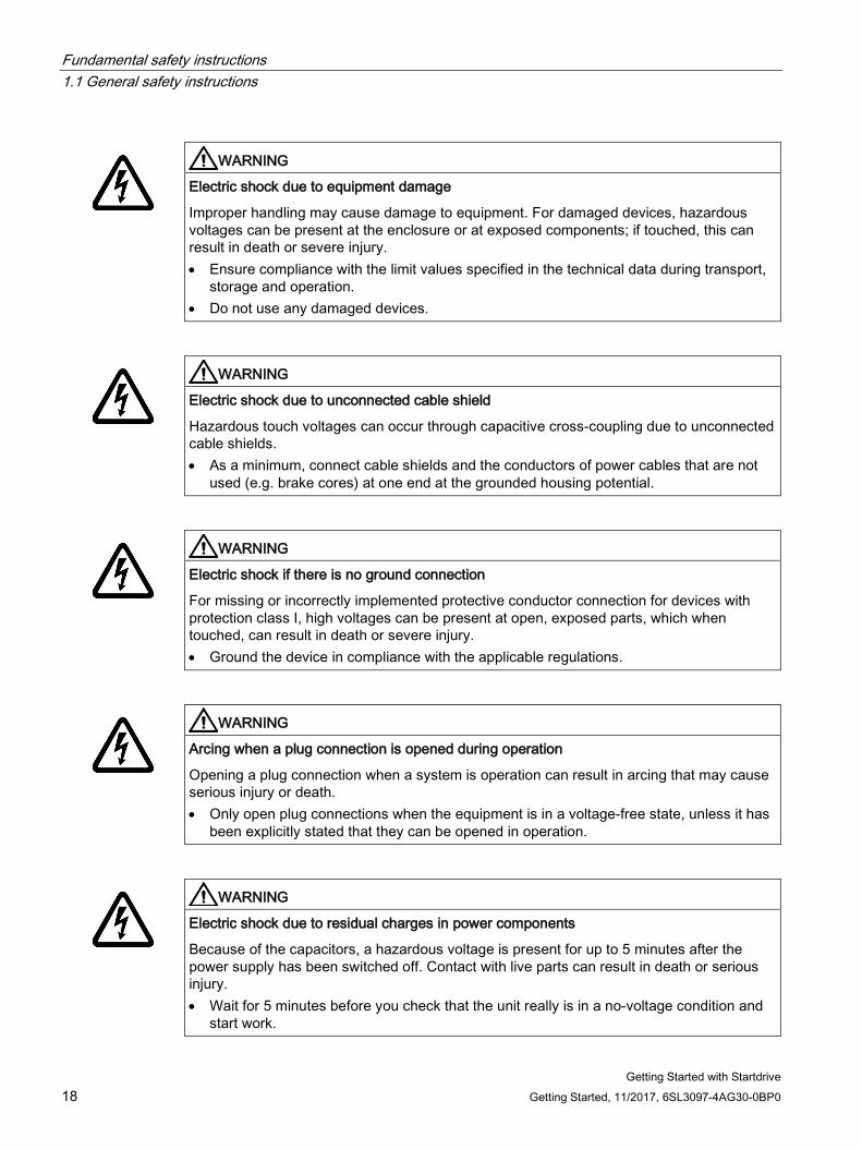
WARNING
Electric shock due to equipment damage
Improper handling may cause damage to equipment. For damaged devices, hazardous voltages can be present at the enclosure or at exposed components; if touched, this can result in death or severe injury. • Ensure compliance with the limit values specified in the technical data during transport,
storage and operation. • Do not use any damaged devices.
WARNING
Electric shock due to unconnected cable shield
Hazardous touch voltages can occur through capacitive cross-coupling due to unconnected cable shields. • As a minimum, connect cable shields and the conductors of power cables that are not
used (e.g. brake cores) at one end at the grounded housing potential.
WARNING
Electric shock if there is no ground connection
For missing or incorrectly implemented protective conductor connection for devices with protection class I, high voltages can be present at open, exposed parts, which when touched, can result in death or severe injury. • Ground the device in compliance with the applicable regulations.
WARNING
Arcing when a plug connection is opened during operation
Opening a plug connection when a system is operation can result in arcing that may cause serious injury or death. • Only open plug connections when the equipment is in a voltage-free state, unless it has
been explicitly stated that they can be opened in operation.
WARNING
Electric shock due to residual charges in power components
Because of the capacitors, a hazardous voltage is present for up to 5 minutes after the power supply has been switched off. Contact with live parts can result in death or serious injury. • Wait for 5 minutes before you check that the unit really is in a no-voltage condition and
start work.
Fundamental safety instructions 1.1 General safety instructions
Getting Started with Startdrive Getting Started, 11/2017, 6SL3097-4AG30-0BP0 19
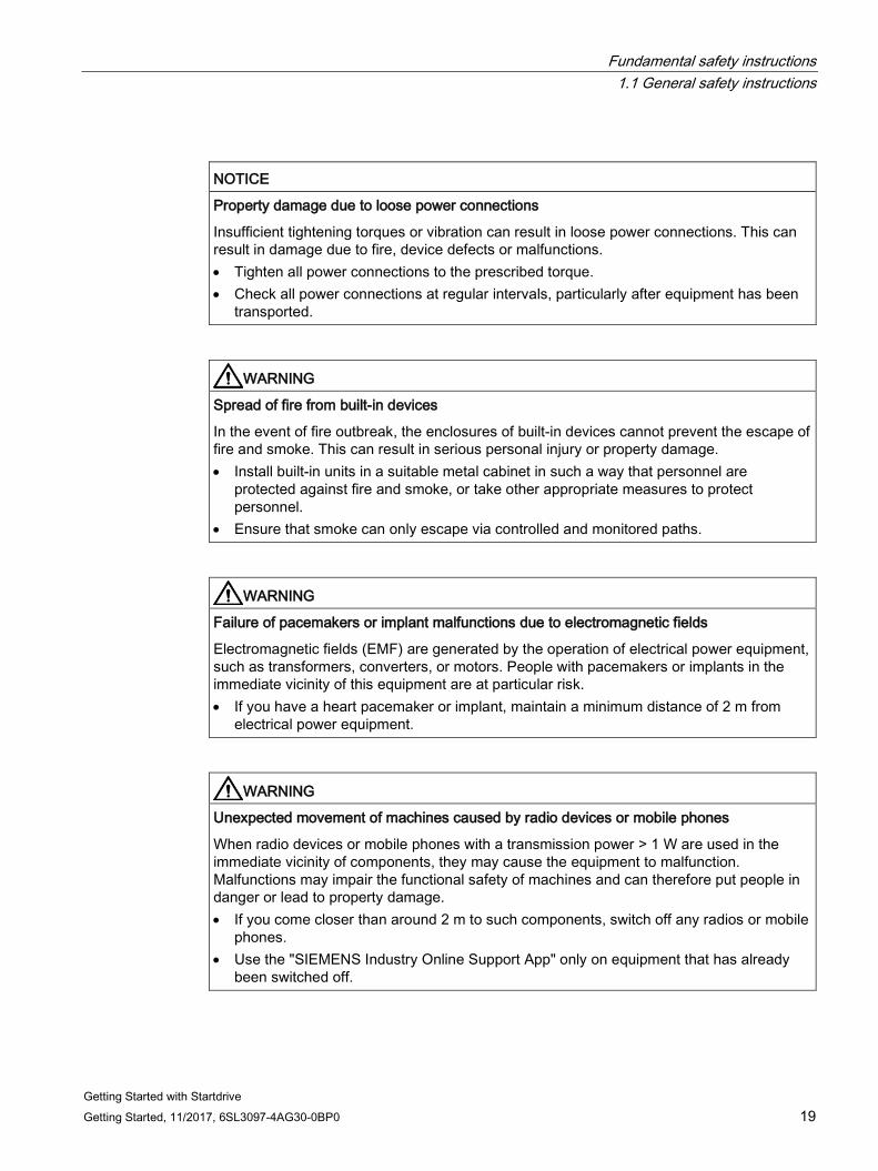
NOTICE
Property damage due to loose power connections
Insufficient tightening torques or vibration can result in loose power connections. This can result in damage due to fire, device defects or malfunctions. • Tighten all power connections to the prescribed torque. • Check all power connections at regular intervals, particularly after equipment has been
transported.
WARNING
Spread of fire from built-in devices
In the event of fire outbreak, the enclosures of built-in devices cannot prevent the escape of fire and smoke. This can result in serious personal injury or property damage. • Install built-in units in a suitable metal cabinet in such a way that personnel are
protected against fire and smoke, or take other appropriate measures to protect personnel.
• Ensure that smoke can only escape via controlled and monitored paths.
WARNING
Failure of pacemakers or implant malfunctions due to electromagnetic fields
Electromagnetic fields (EMF) are generated by the operation of electrical power equipment, such as transformers, converters, or motors. People with pacemakers or implants in the immediate vicinity of this equipment are at particular risk. • If you have a heart pacemaker or implant, maintain a minimum distance of 2 m from
electrical power equipment.
WARNING
Unexpected movement of machines caused by radio devices or mobile phones
When radio devices or mobile phones with a transmission power > 1 W are used in the immediate vicinity of components, they may cause the equipment to malfunction. Malfunctions may impair the functional safety of machines and can therefore put people in danger or lead to property damage. • If you come closer than around 2 m to such components, switch off any radios or mobile
phones. • Use the "SIEMENS Industry Online Support App" only on equipment that has already
been switched off.
Fundamental safety instructions 1.1 General safety instructions
Getting Started with Startdrive 20 Getting Started, 11/2017, 6SL3097-4AG30-0BP0
WARNING
Motor fire in the event of insulation overload
There is higher stress on the motor insulation through a ground fault in an IT system. If the insulation fails, it is possible that death or severe injury can occur as a result of smoke and fire. • Use a monitoring device that signals an insulation fault. • Correct the fault as quickly as possible so the motor insulation is not overloaded.
WARNING
Fire due to inadequate ventilation clearances
Inadequate ventilation clearances can cause overheating of components with subsequent fire and smoke. This can cause severe injury or even death. This can also result in increased downtime and reduced service lives for devices/systems. • Ensure compliance with the specified minimum clearance as ventilation clearance for
the respective component.
WARNING
Unrecognized dangers due to missing or illegible warning labels
Dangers might not be recognized if warning labels are missing or illegible. Unrecognized dangers may cause accidents resulting in serious injury or death. • Check that the warning labels are complete based on the documentation. • Attach any missing warning labels to the components, where necessary in the national
language. • Replace illegible warning labels.
NOTICE
Device damage caused by incorrect voltage/insulation tests
Incorrect voltage/insulation tests can damage the device. • Before carrying out a voltage/insulation check of the system/machine, disconnect the
devices as all converters and motors have been subject to a high voltage test by the manufacturer, and therefore it is not necessary to perform an additional test within the system/machine.
Fundamental safety instructions 1.1 General safety instructions
Getting Started with Startdrive Getting Started, 11/2017, 6SL3097-4AG30-0BP0 21
WARNING
Unexpected movement of machines caused by inactive safety functions
Inactive or non-adapted safety functions can trigger unexpected machine movements that may result in serious injury or death. • Observe the information in the appropriate product documentation before
commissioning. • Carry out a safety inspection for functions relevant to safety on the entire system,
including all safety-related components. • Ensure that the safety functions used in your drives and automation tasks are adjusted
and activated through appropriate parameterizing. • Perform a function test. • Only put your plant into live operation once you have guaranteed that the functions
relevant to safety are running correctly.
Note Important safety notices for Safety Integrated functions
If you want to use Safety Integrated functions, you must observe the safety notices in the Safety Integrated manuals.
WARNING
Malfunctions of the machine as a result of incorrect or changed parameter settings
As a result of incorrect or changed parameterization, machines can malfunction, which in turn can lead to injuries or death. • Protect the parameterization (parameter assignments) against unauthorized access. • Handle possible malfunctions by taking suitable measures, e.g. emergency stop or
emergency off.
Fundamental safety instructions 1.2 Equipment damage due to electric fields or electrostatic discharge
Getting Started with Startdrive 22 Getting Started, 11/2017, 6SL3097-4AG30-0BP0
1.2 Equipment damage due to electric fields or electrostatic discharge Electrostatic sensitive devices (ESD) are individual components, integrated circuits, modules or devices that may be damaged by either electric fields or electrostatic discharge.
NOTICE
Equipment damage due to electric fields or electrostatic discharge
Electric fields or electrostatic discharge can cause malfunctions through damaged individual components, integrated circuits, modules or devices. • Only pack, store, transport and send electronic components, modules or devices in their
original packaging or in other suitable materials, e.g conductive foam rubber of aluminum foil.
• Only touch components, modules and devices when you are grounded by one of the following methods: – Wearing an ESD wrist strap – Wearing ESD shoes or ESD grounding straps in ESD areas with conductive flooring
• Only place electronic components, modules or devices on conductive surfaces (table with ESD surface, conductive ESD foam, ESD packaging, ESD transport container).
Fundamental safety instructions 1.3 Warranty and liability for application examples
Getting Started with Startdrive Getting Started, 11/2017, 6SL3097-4AG30-0BP0 23
1.3 Warranty and liability for application examples The application examples are not binding and do not claim to be complete regarding configuration, equipment or any eventuality which may arise. The application examples do not represent specific customer solutions, but are only intended to provide support for typical tasks. You are responsible for the proper operation of the described products. These application examples do not relieve you of your responsibility for safe handling when using, installing, operating and maintaining the equipment.
Fundamental safety instructions 1.4 Industrial security
Getting Started with Startdrive 24 Getting Started, 11/2017, 6SL3097-4AG30-0BP0
1.4 Industrial security
Note Industrial security
Siemens provides products and solutions with industrial security functions that support the secure operation of plants, systems, machines and networks.
In order to protect plants, systems, machines and networks against cyber threats, it is necessary to implement – and continuously maintain – a holistic, state-of-the-art industrial security concept. Siemens products and solutions only represent one component of such a concept.
The customer is responsible for preventing unauthorized access to its plants, systems, machines and networks. Systems, machines and components should only be connected to the enterprise network or the internet if and to the extent necessary and with appropriate security measures (e.g. use of firewalls and network segmentation) in place.
Additionally, Siemens’ guidance on appropriate security measures should be taken into account. For more information about industrial security, please visit:
Industrial security (http://www.siemens.com/industrialsecurity).
Siemens’ products and solutions undergo continuous development to make them more secure. Siemens strongly recommends to apply product updates as soon as available and to always use the latest product versions. Use of product versions that are no longer supported, and failure to apply latest updates may increase customer’s exposure to cyber threats.
To stay informed about product updates, subscribe to the Siemens Industrial Security RSS Feed at:
Industrial security (http://www.siemens.com/industrialsecurity).
WARNING
Unsafe operating states resulting from software manipulation
Software manipulations (e.g. viruses, trojans, malware or worms) can cause unsafe operating states in your system that may lead to death, serious injury, and property damage. • Keep the software up to date. • Incorporate the automation and drive components into a holistic, state-of-the-art
industrial security concept for the installation or machine. • Make sure that you include all installed products into the holistic industrial security
concept. • Protect files stored on exchangeable storage media from malicious software by with
suitable protection measures, e.g. virus scanners.
Fundamental safety instructions 1.5 Residual risks of power drive systems
Getting Started with Startdrive Getting Started, 11/2017, 6SL3097-4AG30-0BP0 25
1.5 Residual risks of power drive systems When assessing the machine- or system-related risk in accordance with the respective local regulations (e.g., EC Machinery Directive), the machine manufacturer or system installer must take into account the following residual risks emanating from the control and drive components of a drive system:
1. Unintentional movements of driven machine or system components during commissioning, operation, maintenance, and repairs caused by, for example,
– Hardware and/or software errors in the sensors, control system, actuators, and cables and connections
– Response times of the control system and of the drive
– Operation and/or environmental conditions outside the specification
– Condensation/conductive contamination
– Parameterization, programming, cabling, and installation errors
– Use of wireless devices/mobile phones in the immediate vicinity of electronic components
– External influences/damage
– X-ray, ionizing radiation and cosmic radiation
2. Unusually high temperatures, including open flames, as well as emissions of light, noise, particles, gases, etc., can occur inside and outside the components under fault conditions caused by, for example:
– Component failure
– Software errors
– Operation and/or environmental conditions outside the specification
– External influences/damage
3. Hazardous shock voltages caused by, for example:
– Component failure
– Influence during electrostatic charging
– Induction of voltages in moving motors
– Operation and/or environmental conditions outside the specification
– Condensation/conductive contamination
– External influences/damage
Fundamental safety instructions 1.5 Residual risks of power drive systems
Getting Started with Startdrive 26 Getting Started, 11/2017, 6SL3097-4AG30-0BP0
4. Electrical, magnetic and electromagnetic fields generated in operation that can pose a risk to people with a pacemaker, implants or metal replacement joints, etc., if they are too close
5. Release of environmental pollutants or emissions as a result of improper operation of the system and/or failure to dispose of components safely and correctly
6. Influence of network-connected communication systems, e.g. ripple-control transmitters or data communication via the network
For more information about the residual risks of the drive system components, see the relevant sections in the technical user documentation.
Getting Started with Startdrive Getting Started, 11/2017, 6SL3097-4AG30-0BP0 27
Overview 2
This manual provides instructions on how to commission a simple SINAMICS S120.
To create a sample project the following points are explained:
1. Which hardware components do you need for the sample project?
2. How do you create a simple project in the Startdrive commissioning tool?
3. How do you configure a drive?
4. How do you put the drive into operation?

Overview
Getting Started with Startdrive 28 Getting Started, 11/2017, 6SL3097-4AG30-0BP0
Getting Started with Startdrive Getting Started, 11/2017, 6SL3097-4AG30-0BP0 29
Startdrive commissioning tool 3 3.1 Structure of the user interface
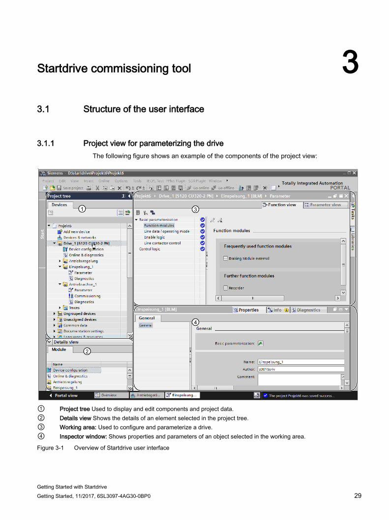
3.1.1 Project view for parameterizing the drive The following figure shows an example of the components of the project view:
① Project tree Used to display and edit components and project data. ② Details view Shows the details of an element selected in the project tree. ③ Working area: Used to configure and parameterize a drive. ④ Inspector window: Shows properties and parameters of an object selected in the working area.
Figure 3-1 Overview of Startdrive user interface
Startdrive commissioning tool 3.1 Structure of the user interface
Getting Started with Startdrive 30 Getting Started, 11/2017, 6SL3097-4AG30-0BP0
3.1.2 Project navigation
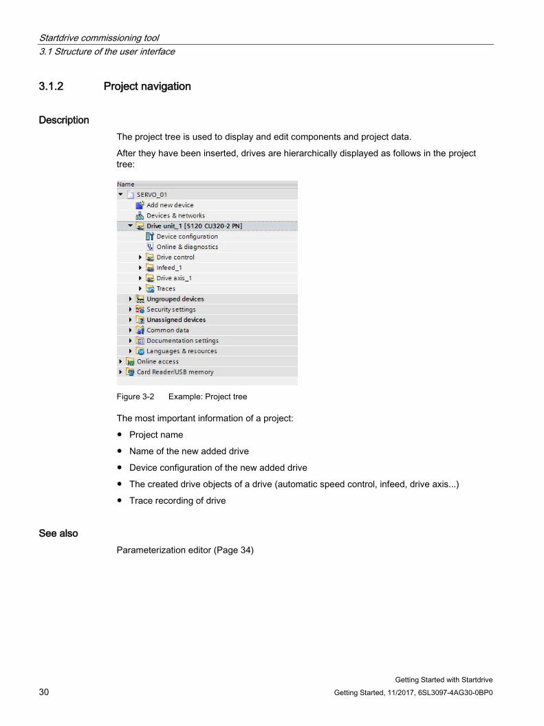
Description The project tree is used to display and edit components and project data.
After they have been inserted, drives are hierarchically displayed as follows in the project tree:
Figure 3-2 Example: Project tree
The most important information of a project:
● Project name
● Name of the new added drive
● Device configuration of the new added drive
● The created drive objects of a drive (automatic speed control, infeed, drive axis...)
● Trace recording of drive
See also Parameterization editor (Page 34)
Startdrive commissioning tool 3.2 User interface - parameterization
Getting Started with Startdrive Getting Started, 11/2017, 6SL3097-4AG30-0BP0 31
3.2 User interface - parameterization
3.2.1 Modules in the hardware catalog As soon as the device configuration is active, a hardware catalog can be displayed/hidden at the right-hand edge of the program window. The device configuration automatically becomes active as soon as a drive device was inserted. The required SINAMICS modules can be transferred from the hardware catalog into a project and specified.
For instance, you can insert an infeed unit from the hardware catalog (see Chapter "Inserting an infeed (Page 75)").
Startdrive commissioning tool 3.2 User interface - parameterization
Getting Started with Startdrive 32 Getting Started, 11/2017, 6SL3097-4AG30-0BP0
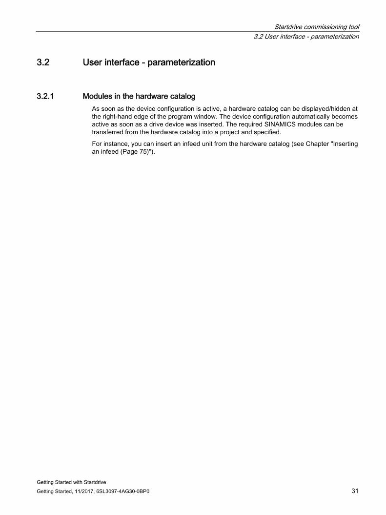
The SINAMICS modules are arranged as follows in the hardware catalog:
① Available Control Units of type SINAMICS CU320-2 ② Active, Basic and Smart Line Modules ③ Power Modules (chassis format) ④ Single Motor Modules and Double Motor Modules ⑤ The motors are sorted according to motor type and article number, and are displayed
with a core article number. Drive-CLiQ motors, Induction motors, Synchronous motors, Reluctance motors, Motor data input
⑥ Measuring systems (various encoders) ⑦ Supplementary system components (CB, TB, TM, VSM, etc.)
Figure 3-3 SINAMICS hardware components
Startdrive commissioning tool 3.2 User interface - parameterization
Getting Started with Startdrive Getting Started, 11/2017, 6SL3097-4AG30-0BP0 33
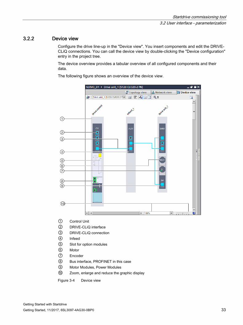
3.2.2 Device view Configure the drive line-up in the "Device view". You insert components and edit the DRIVE-CLiQ connections. You can call the device view by double-clicking the "Device configuration" entry in the project tree.
The device overview provides a tabular overview of all configured components and their data.
The following figure shows an overview of the device view.
① Control Unit ② DRIVE-CLiQ interface ③ DRIVE-CLiQ connection ④ Infeed ⑤ Slot for option modules ⑥ Motor ⑦ Encoder ⑧ Bus interface, PROFINET in this case ⑨ Motor Modules, Power Modules ⑩ Zoom, enlarge and reduce the graphic display
Figure 3-4 Device view
Startdrive commissioning tool 3.2 User interface - parameterization
Getting Started with Startdrive 34 Getting Started, 11/2017, 6SL3097-4AG30-0BP0
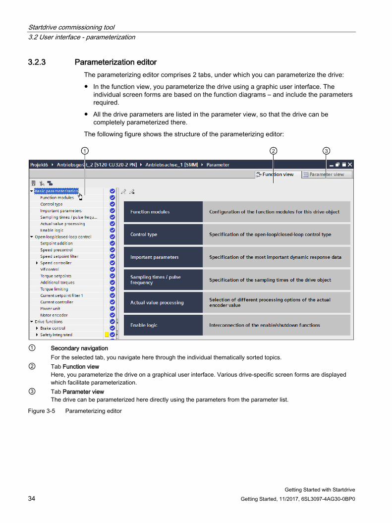
3.2.3 Parameterization editor The parameterizing editor comprises 2 tabs, under which you can parameterize the drive:
● In the function view, you parameterize the drive using a graphic user interface. The individual screen forms are based on the function diagrams – and include the parameters required.
● All the drive parameters are listed in the parameter view, so that the drive can be completely parameterized there.
The following figure shows the structure of the parameterizing editor:
① Secondary navigation
For the selected tab, you navigate here through the individual thematically sorted topics. ② Tab Function view
Here, you parameterize the drive on a graphical user interface. Various drive-specific screen forms are displayed which facilitate parameterization.
③ Tab Parameter view The drive can be parameterized here directly using the parameters from the parameter list.
Figure 3-5 Parameterizing editor
Startdrive commissioning tool 3.2 User interface - parameterization
Getting Started with Startdrive Getting Started, 11/2017, 6SL3097-4AG30-0BP0 35
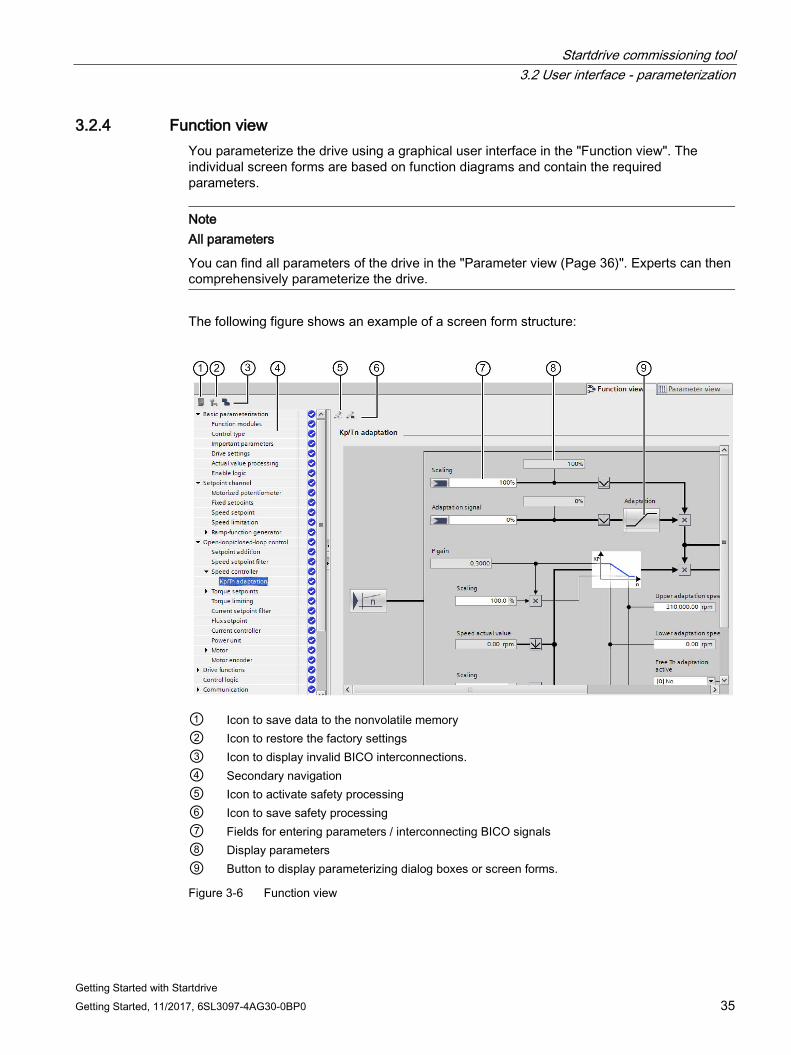
3.2.4 Function view You parameterize the drive using a graphical user interface in the "Function view". The individual screen forms are based on function diagrams and contain the required parameters.
Note All parameters
You can find all parameters of the drive in the "Parameter view (Page 36)". Experts can then comprehensively parameterize the drive.
The following figure shows an example of a screen form structure:
① Icon to save data to the nonvolatile memory ② Icon to restore the factory settings ③ Icon to display invalid BICO interconnections. ④ Secondary navigation ⑤ Icon to activate safety processing ⑥ Icon to save safety processing ⑦ Fields for entering parameters / interconnecting BICO signals ⑧ Display parameters ⑨ Button to display parameterizing dialog boxes or screen forms.
Figure 3-6 Function view
Startdrive commissioning tool 3.2 User interface - parameterization
Getting Started with Startdrive 36 Getting Started, 11/2017, 6SL3097-4AG30-0BP0
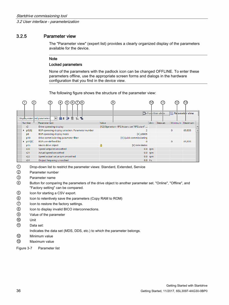
3.2.5 Parameter view The "Parameter view" (expert list) provides a clearly organized display of the parameters available for the device.
Note Locked parameters
None of the parameters with the padlock icon can be changed OFFLINE. To enter these parameters offline, use the appropriate screen forms and dialogs in the hardware configuration that you find in the device view.
The following figure shows the structure of the parameter view:
① Drop-down list to restrict the parameter views: Standard, Extended, Service ② Parameter number ③ Parameter name ④ Button for comparing the parameters of the drive object to another parameter set. "Online", "Offline", and
"Factory setting" can be compared. ⑤ Icon for starting a CSV export. ⑥ Icon to retentively save the parameters (Copy RAM to ROM) ⑦ Icon to restore the factory settings. ⑧ Icon to display invalid BICO interconnections. ⑨ Value of the parameter ⑩ Unit ⑪ Data set:
Indicates the data set (MDS, DDS, etc.) to which the parameter belongs. ⑫ Minimum value ⑬ Maximum value
Figure 3-7 Parameter list
Startdrive commissioning tool 3.2 User interface - parameterization
Getting Started with Startdrive Getting Started, 11/2017, 6SL3097-4AG30-0BP0 37
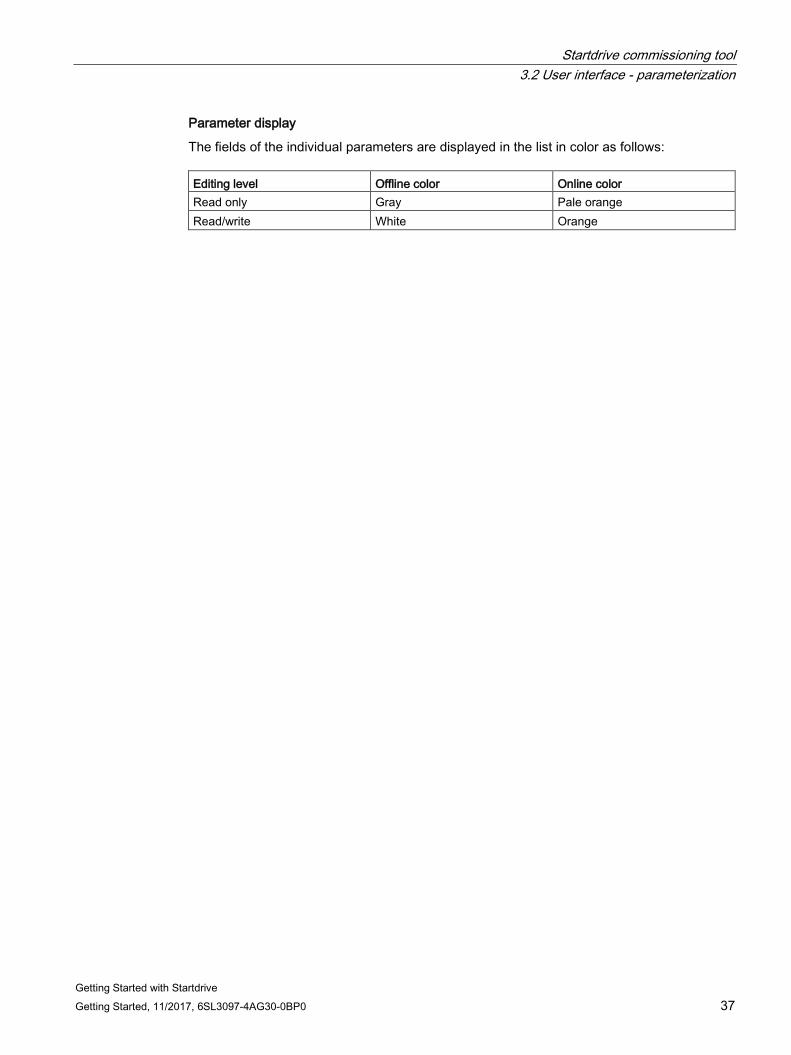
Parameter display
The fields of the individual parameters are displayed in the list in color as follows: Editing level Offline color Online color Read only Gray Pale orange Read/write White Orange
Startdrive commissioning tool 3.2 User interface - parameterization
Getting Started with Startdrive 38 Getting Started, 11/2017, 6SL3097-4AG30-0BP0
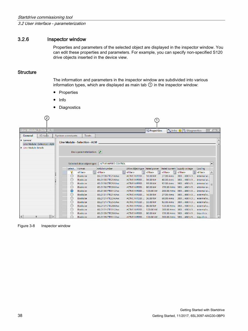
3.2.6 Inspector window Properties and parameters of the selected object are displayed in the inspector window. You can edit these properties and parameters. For example, you can specify non-specified S120 drive objects inserted in the device view.
Structure The information and parameters in the inspector window are subdivided into various information types, which are displayed as main tab ① in the inspector window:
● Properties
● Info
● Diagnostics
Figure 3-8 Inspector window
Startdrive commissioning tool 3.2 User interface - parameterization
Getting Started with Startdrive Getting Started, 11/2017, 6SL3097-4AG30-0BP0 39
Showing or enlarging the inspector window There are several options available for showing (hiding) the inspector window:
● Use the regular window icons (top right-hand side in the header of the window).
- or -
● Select a non-specified component in the device view and open the "Properties" shortcut menu.
The inspector window is displayed only partially in the Startdrive when called, due to lack of space. Display of the inspector window can be maximized (minimized) for specification of the components:
● To do so, double click on the header of the inspector window (gray bar).
Subdivision of the "Properties" area For each information type, there are additional subareas that can be displayed via secondary tabs ②.
The most important information type for SINAMICS S120 drives is the "Properties" area. The following secondary tabs are displayed in this area:
● General
Display of the properties and settings of the drive device, drive object, or the hardware component. Here you can enter the settings on the user interface. The secondary navigation is located in the left-hand part of the inspector window. Information and parameters are arranged there in the groups. When you click on the arrow icon at the left next to the group names, if subgroups exist then you can open the group. If you select a group or a subgroup, then the appropriate information and parameters are displayed in the right-hand part of the inspector window, where they can also be edited.
For S120 drives, mainly the drive objects used are specified (e.g. an infeed unit) using this subarea.
● I/O variables
Displaying I/O variables of the PLC. You can assign names to the variables, assign the variables user-defined variable tables from a drop-down list - and allocate comments to variables. The I/O variables are also listed in the PLC variable table.
● System constants
Display of the constants required by the system using the hardware identifiers of the modules. The system constants are also listed in the PLC variable table.
● Texts
Display of the reference language and the specification of the text source for project texts.
Startdrive commissioning tool 3.2 User interface - parameterization
Getting Started with Startdrive 40 Getting Started, 11/2017, 6SL3097-4AG30-0BP0
3.2.7 Device configuration detection The results of a detection run (of the device configuration) are listed in the dialog "Detection of the device configuration". All assignable components are listed in the table and are assigned as follows:
● Components are assigned to drive objects.
● Drive objects are assigned to drive units.
All components which could not be assigned to a module are deposited in the folder "Non-assignable components" (refer to Chapter "Deriving the hardware device configuration (Page 115)").
Startdrive commissioning tool 3.2 User interface - parameterization
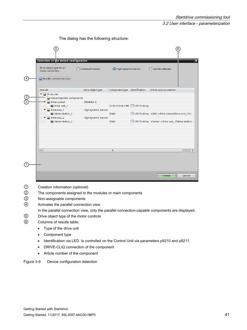
Getting Started with Startdrive Getting Started, 11/2017, 6SL3097-4AG30-0BP0 41
The dialog has the following structure:
① Creation information (optional) ② The components assigned to the modules or main components ③ Non-assignable components ④ Activates the parallel connection view.
In the parallel connection view, only the parallel connection-capable components are displayed. ⑤ Drive object type of the motor controls ⑥ Columns of results table:
• Type of the drive unit • Component type • Identification via LED. Is controlled on the Control Unit via parameters p9210 and p9211. • DRIVE-CLiQ connection of the component • Article number of the component
Figure 3-9 Device configuration detection
Startdrive commissioning tool 3.3 User interface - Control panel
Getting Started with Startdrive 42 Getting Started, 11/2017, 6SL3097-4AG30-0BP0
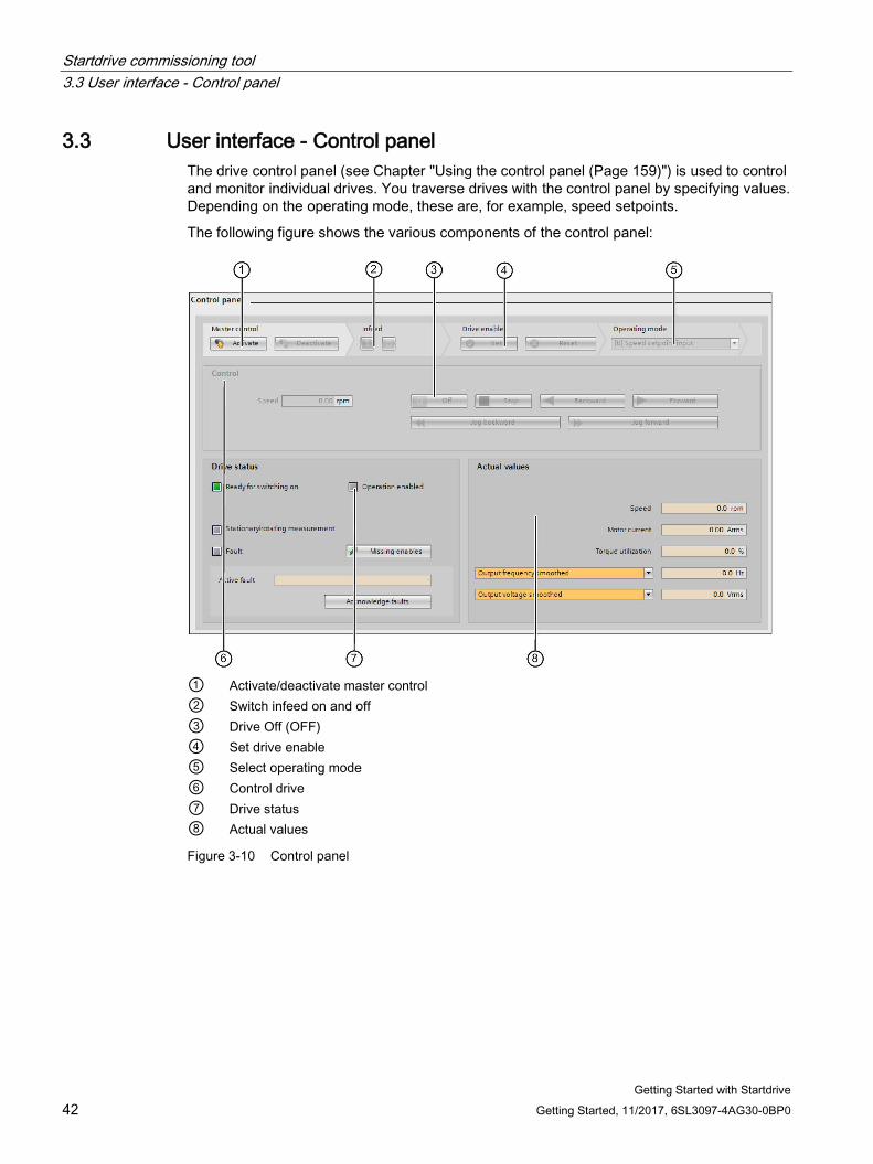
3.3 User interface - Control panel The drive control panel (see Chapter "Using the control panel (Page 159)") is used to control and monitor individual drives. You traverse drives with the control panel by specifying values. Depending on the operating mode, these are, for example, speed setpoints.
The following figure shows the various components of the control panel:
① Activate/deactivate master control ② Switch infeed on and off ③ Drive Off (OFF) ④ Set drive enable ⑤ Select operating mode ⑥ Control drive ⑦ Drive status ⑧ Actual values
Figure 3-10 Control panel
Startdrive commissioning tool 3.4 Information system - online help
Getting Started with Startdrive Getting Started, 11/2017, 6SL3097-4AG30-0BP0 43
3.4 Information system - online help
3.4.1 General remarks on the information system The information system of the Startdrive in TIA Portal helps you solve your problems and offers the required help topics at each step of the configuration.
While working with the program, you receive the following support:
● Information system with all background information, step-by-step instructions and examples required to work with Startdrive.
● Tooltips for information on elements of the user interface, for example text boxes, buttons and icons. Some of the tooltips are supplemented by cascades containing more precise information.
● Help on the current context, for example on menu commands when you press the <F1> key.
● Help regarding messages or diagnostics.
The most important information regarding the Startdrive information system is provided below. Additional information can be obtained directly in the Startdrive online help by entering the search term "Help on information system".
Startdrive commissioning tool 3.4 Information system - online help
Getting Started with Startdrive 44 Getting Started, 11/2017, 6SL3097-4AG30-0BP0
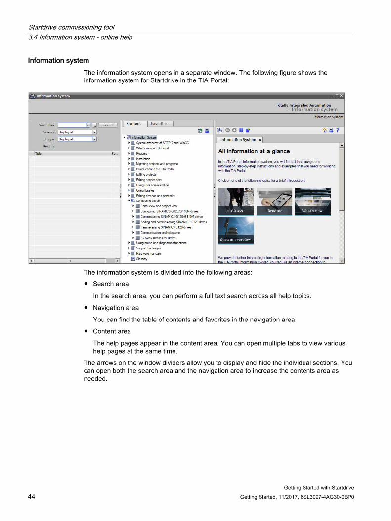
Information system The information system opens in a separate window. The following figure shows the information system for Startdrive in the TIA Portal:
The information system is divided into the following areas:
● Search area
In the search area, you can perform a full text search across all help topics.
● Navigation area
You can find the table of contents and favorites in the navigation area.
● Content area
The help pages appear in the content area. You can open multiple tabs to view various help pages at the same time.
The arrows on the window dividers allow you to display and hide the individual sections. You can open both the search area and the navigation area to increase the contents area as needed.
Startdrive commissioning tool 3.4 Information system - online help
Getting Started with Startdrive Getting Started, 11/2017, 6SL3097-4AG30-0BP0 45
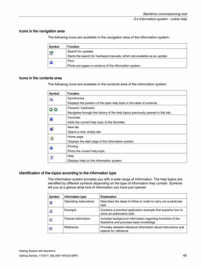
Icons in the navigation area The following icons are available in the navigation area of the information system: Symbol Function
Search for updates Starts the search for hardware manuals, which are available as an update.
Print Prints out pages or sections of the information system.
Icons in the contents area The following icons are available in the contents area of the information system: Symbol Function
Synchronize Displays the position of the open help topic in the table of contents.
Forward / backward Navigates through the history of the help topics previously opened in this tab.
Favorites Adds the current help topic to the favorites.
New tab Opens a new, empty tab.
Home page Displays the start page of the information system.
Printing Prints the current help topic.
Help Displays help on the information system.
Identification of the topics according to the information type The information system provides you with a wide range of information. The help topics are identified by different symbols depending on the type of information they contain. Symbols tell you at a glance what kind of information you have just opened. Symbol Information type Explanation
Operating instructions Describes the steps to follow in order to carry out a particular task.
Example Contains a practical application example that explains how to solve an automation task.
Factual information Includes background information regarding functions of the Startdrive and provides basic knowledge.
Reference Provides detailed reference information about instructions and objects for reference.
Startdrive commissioning tool 3.4 Information system - online help
Getting Started with Startdrive 46 Getting Started, 11/2017, 6SL3097-4AG30-0BP0
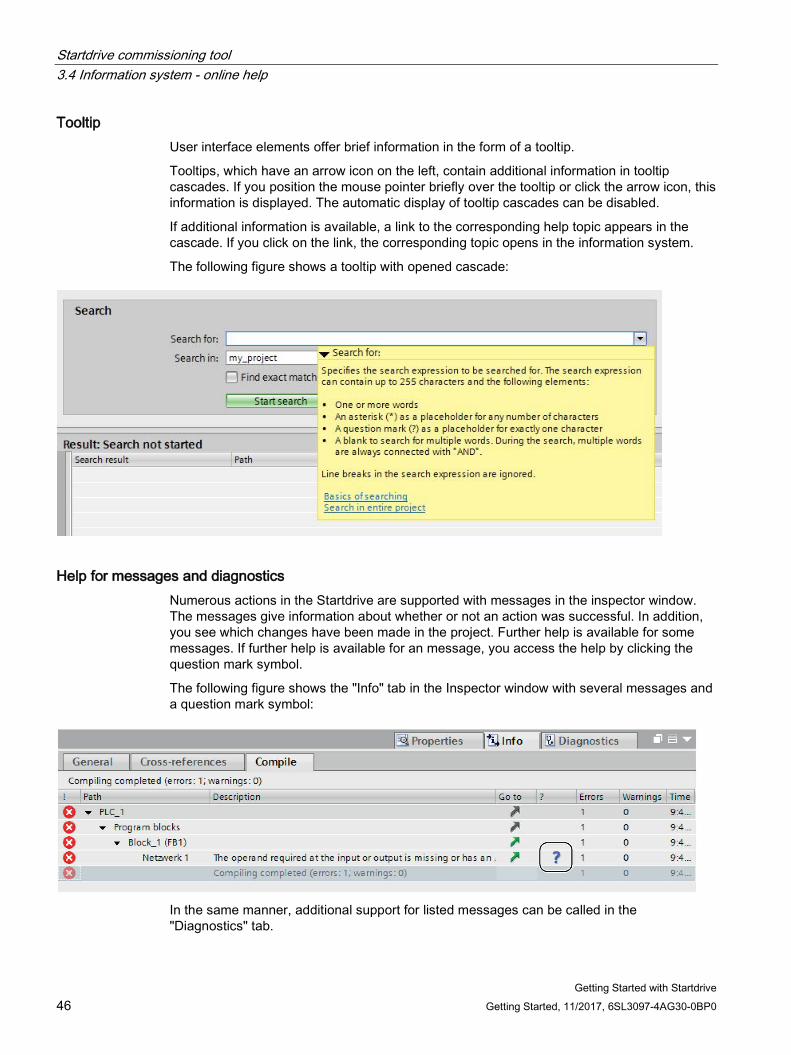
Tooltip User interface elements offer brief information in the form of a tooltip.
Tooltips, which have an arrow icon on the left, contain additional information in tooltip cascades. If you position the mouse pointer briefly over the tooltip or click the arrow icon, this information is displayed. The automatic display of tooltip cascades can be disabled.
If additional information is available, a link to the corresponding help topic appears in the cascade. If you click on the link, the corresponding topic opens in the information system.
The following figure shows a tooltip with opened cascade:
Help for messages and diagnostics Numerous actions in the Startdrive are supported with messages in the inspector window. The messages give information about whether or not an action was successful. In addition, you see which changes have been made in the project. Further help is available for some messages. If further help is available for an message, you access the help by clicking the question mark symbol.
The following figure shows the "Info" tab in the Inspector window with several messages and a question mark symbol:
In the same manner, additional support for listed messages can be called in the "Diagnostics" tab.
Startdrive commissioning tool 3.4 Information system - online help
Getting Started with Startdrive Getting Started, 11/2017, 6SL3097-4AG30-0BP0 47
3.4.2 Opening the information system
Opening the information system with the menu To access the information system on the home page, follow these steps:
1. Select "Display help" command from the "Help" menu.
The start page of the information system opens.
Opening the information system with <F1> To access the information system and help for the current context, proceed as follows:
1. Select an object for which you want to view the help, for example, a menu command or a program element.
2. Press <F1>.
The information system opens. If information on the current context is available, the appropriate topic appears. If no information on the current context is available, the home page of the information system is displayed.
Opening the information system via tooltip cascades To open the information system from a tooltip cascade, proceed as follows:
1. Move the mouse pointer over an object with a tooltip cascade.
The tooltip cascade opens. If additional information is available, the tooltip cascade contains links to the corresponding help topics.
2. Click on a link.
The information system opens and the additional help topic appears.
Opening help for error messages Numerous actions in the Startdrive are supported with messages in the inspector window. If help on such a message is available, a blue question mark appears behind the message.
To view the help for a message, follow these steps:
1. Display the Inspector window.
2. Click on the blue question mark behind a message.
The information system opens and the help error message appears. It contains an exact description of cause of the error and how to remedy it.

Startdrive commissioning tool 3.4 Information system - online help
Getting Started with Startdrive 48 Getting Started, 11/2017, 6SL3097-4AG30-0BP0
Getting Started with Startdrive Getting Started, 11/2017, 6SL3097-4AG30-0BP0 49
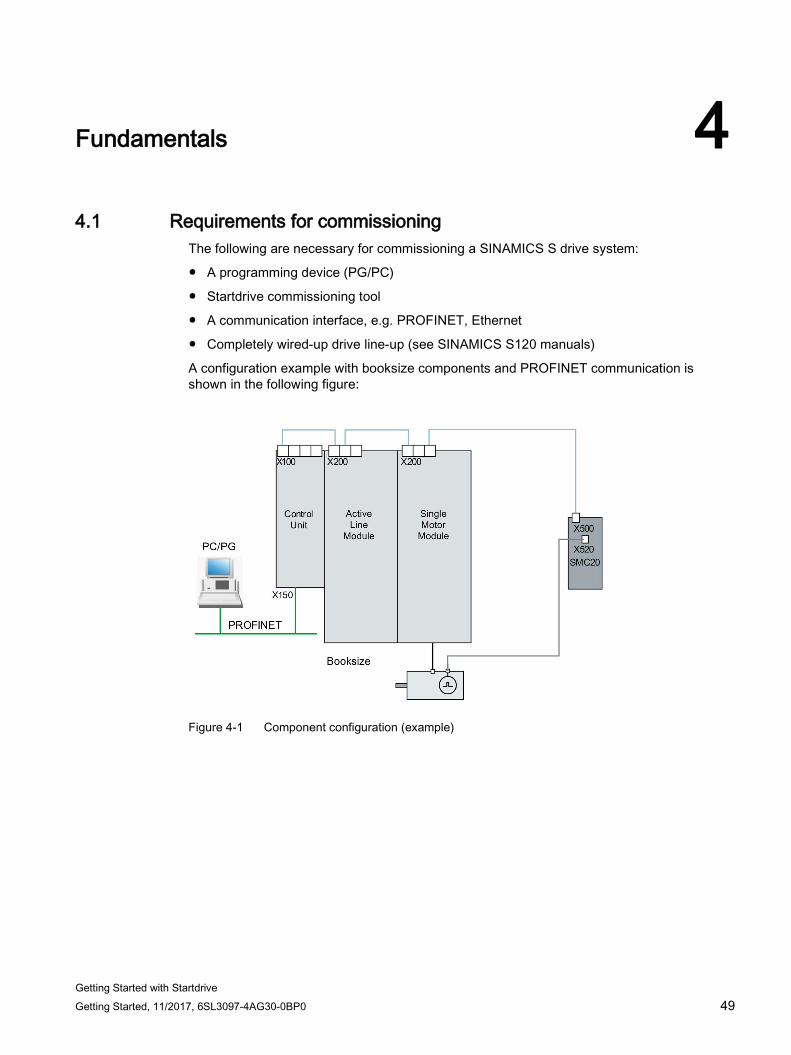
Fundamentals 4 4.1 Requirements for commissioning
The following are necessary for commissioning a SINAMICS S drive system:
● A programming device (PG/PC)
● Startdrive commissioning tool
● A communication interface, e.g. PROFINET, Ethernet
● Completely wired-up drive line-up (see SINAMICS S120 manuals)
A configuration example with booksize components and PROFINET communication is shown in the following figure:
Figure 4-1 Component configuration (example)
Fundamentals 4.2 Safety instructions for commissioning
Getting Started with Startdrive 50 Getting Started, 11/2017, 6SL3097-4AG30-0BP0
4.2 Safety instructions for commissioning
WARNING
Non-observance of the fundamental safety instructions and residual risks
The non-observance of the fundamental safety instructions and residual risks stated in Section 1 can result in accidents with severe injuries or death. • Adhere to the fundamental safety instructions. • When assessing the risk, take into account residual risks.
WARNING
Unexpected movement of the motor during motor data identification
Motor data identification causes movements of the drive, which can result in death, serious injury, or damage to property. • Ensure that nobody is in the danger zone and that the mechanical parts can move
freely. • Respond to possible malfunctions by applying suitable measures (e.g. EMERGENCY
STOP or EMERGENCY OFF).
WARNING
Non-observance of safety instructions and residual risks
If the safety instructions and residual risks are not observed in the associated hardware documentation, accidents involving severe injuries or death can occur. • Observe the safety instructions provided in the hardware documentation. • When assessing the risk, take into account residual risks.
Note
Please observe the installation guidelines and safety instructions in the SINAMICS S120 Manuals.
Fundamentals 4.3 BICO interconnections
Getting Started with Startdrive Getting Started, 11/2017, 6SL3097-4AG30-0BP0 51
4.3 BICO interconnections
4.3.1 Binectors, Connectors
Description Each drive unit contains a large number of connectable input and output variables and internal control variables.
BICO technology (Binector Connector technology) allows the drive to be adapted to a wide variety of requirements.
These parameters are identified accordingly in the parameter list or in the function diagrams.
Note Further information
Detailed information on BICO technology and BICO connections can be found in Section "Basics of the drive system" in the SINAMICS S120 Drive Functions Function Manual.
In Startdrive for S120, the parameterization is possible via:
● Parameter view
● Function view of a screen form
Fundamentals 4.3 BICO interconnections
Getting Started with Startdrive 52 Getting Started, 11/2017, 6SL3097-4AG30-0BP0
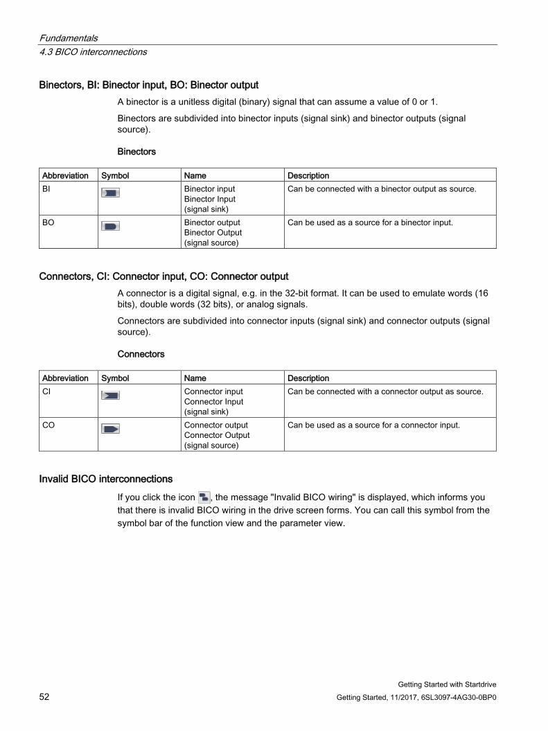
Binectors, BI: Binector input, BO: Binector output A binector is a unitless digital (binary) signal that can assume a value of 0 or 1.
Binectors are subdivided into binector inputs (signal sink) and binector outputs (signal source).
Binectors Abbreviation Symbol Name Description BI Binector input
Binector Input (signal sink)
Can be connected with a binector output as source.
BO Binector output Binector Output (signal source)
Can be used as a source for a binector input.
Connectors, CI: Connector input, CO: Connector output A connector is a digital signal, e.g. in the 32-bit format. It can be used to emulate words (16 bits), double words (32 bits), or analog signals.
Connectors are subdivided into connector inputs (signal sink) and connector outputs (signal source).
Connectors Abbreviation Symbol Name Description CI Connector input
Connector Input (signal sink)
Can be connected with a connector output as source.
CO Connector output Connector Output (signal source)
Can be used as a source for a connector input.
Invalid BICO interconnections
If you click the icon , the message "Invalid BICO wiring" is displayed, which informs you that there is invalid BICO wiring in the drive screen forms. You can call this symbol from the symbol bar of the function view and the parameter view.
Fundamentals 4.3 BICO interconnections
Getting Started with Startdrive Getting Started, 11/2017, 6SL3097-4AG30-0BP0 53
4.3.2 Interconnect BICO inputs Use a connection dialog to connect binector or connector inputs.
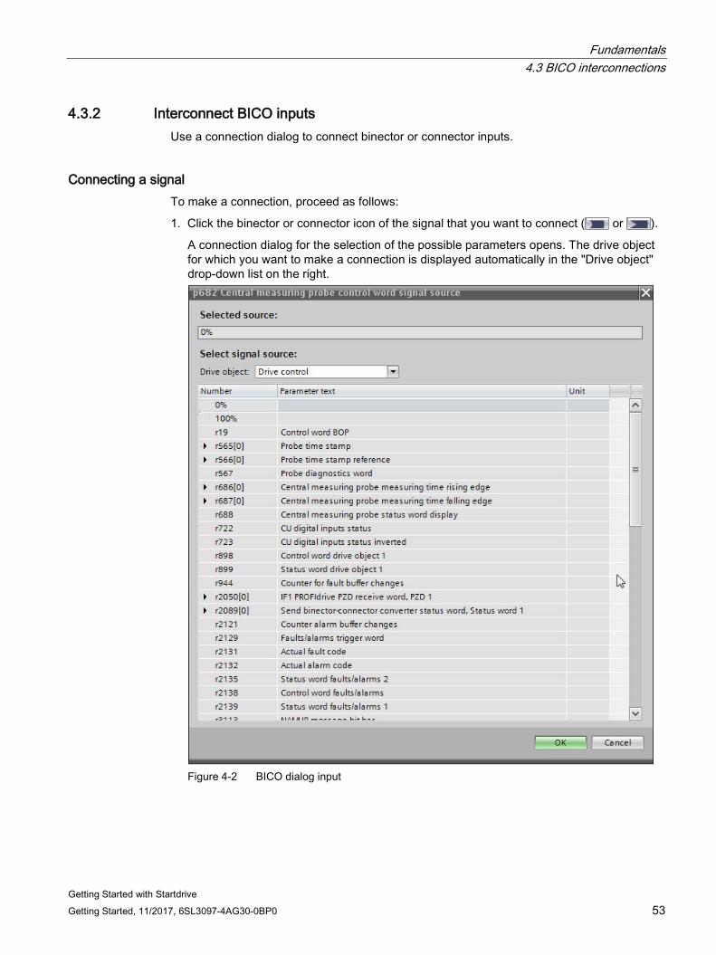
Connecting a signal To make a connection, proceed as follows:
1. Click the binector or connector icon of the signal that you want to connect ( or ).
A connection dialog for the selection of the possible parameters opens. The drive object for which you want to make a connection is displayed automatically in the "Drive object" drop-down list on the right.
Figure 4-2 BICO dialog input
Fundamentals 4.3 BICO interconnections
Getting Started with Startdrive 54 Getting Started, 11/2017, 6SL3097-4AG30-0BP0
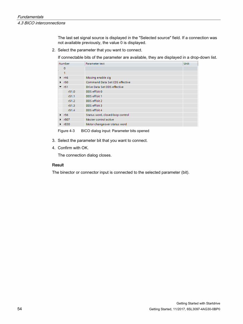
The last set signal source is displayed in the "Selected source" field. If a connection was not available previously, the value 0 is displayed.
2. Select the parameter that you want to connect.
If connectable bits of the parameter are available, they are displayed in a drop-down list.
Figure 4-3 BICO dialog input: Parameter bits opened
3. Select the parameter bit that you want to connect.
4. Confirm with OK.
The connection dialog closes.
Result
The binector or connector input is connected to the selected parameter (bit).
Fundamentals 4.3 BICO interconnections
Getting Started with Startdrive Getting Started, 11/2017, 6SL3097-4AG30-0BP0 55
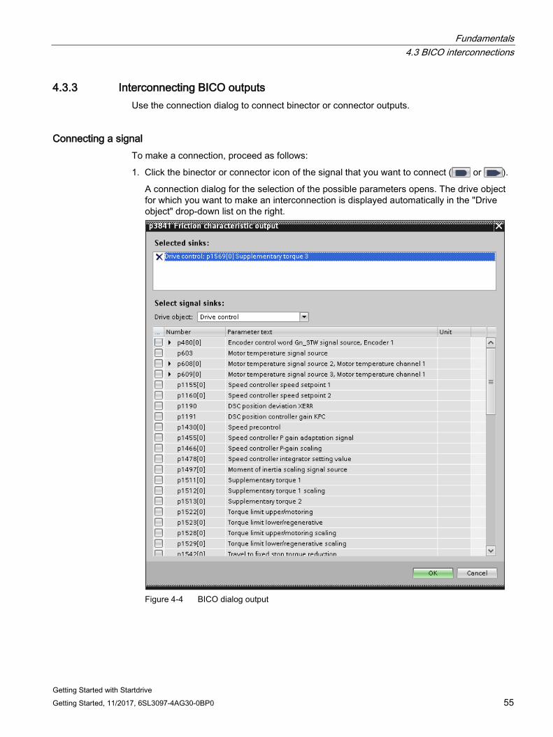
4.3.3 Interconnecting BICO outputs Use the connection dialog to connect binector or connector outputs.
Connecting a signal To make a connection, proceed as follows:
1. Click the binector or connector icon of the signal that you want to connect ( or ).
A connection dialog for the selection of the possible parameters opens. The drive object for which you want to make an interconnection is displayed automatically in the "Drive object" drop-down list on the right.
Figure 4-4 BICO dialog output
Fundamentals 4.3 BICO interconnections
Getting Started with Startdrive 56 Getting Started, 11/2017, 6SL3097-4AG30-0BP0
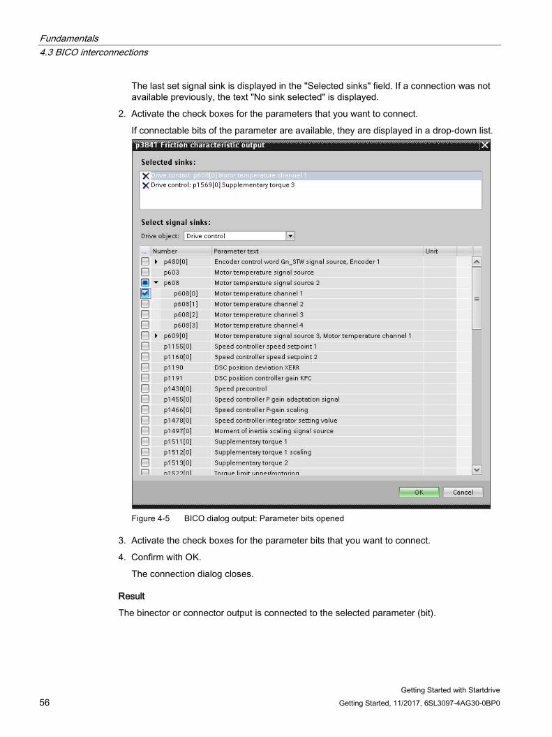
The last set signal sink is displayed in the "Selected sinks" field. If a connection was not available previously, the text "No sink selected" is displayed.
2. Activate the check boxes for the parameters that you want to connect.
If connectable bits of the parameter are available, they are displayed in a drop-down list.
Figure 4-5 BICO dialog output: Parameter bits opened
3. Activate the check boxes for the parameter bits that you want to connect.
4. Confirm with OK.
The connection dialog closes.
Result
The binector or connector output is connected to the selected parameter (bit).

Fundamentals 4.3 BICO interconnections
Getting Started with Startdrive Getting Started, 11/2017, 6SL3097-4AG30-0BP0 57
Multiple connections at outputs Several interconnections can be set simultaneously for a parameter, which for reasons of space however, cannot be displayed in the interconnections field. Clicking the icon next to the interconnection field opens a list, which shows all of the active parameter interconnections.
Fundamentals 4.4 Comparing parameter settings
Getting Started with Startdrive 58 Getting Started, 11/2017, 6SL3097-4AG30-0BP0
4.4 Comparing parameter settings The current parameter values of a drive object can be compared with another parameter set using the comparison function in the parameter view. The following comparisons are possible:
● Offline - Factory setting
● Online - Offline
● Online - Factory setting
Comparing parameters To compare the parameters of the drive object with another parameter set, proceed as follows:
1. Open the parameter view for the device whose parameters you want to compare.
2. Click the black arrow icon of the "Compare current parameters of this drive object with another data set" button.
A selection list containing the comparison options opens:
– Offline - Factory setting (default setting in offline mode)
– Online - Offline (default setting in online mode)
– Online - Factory setting
3. Select a comparison option.
The selected comparison option is executed as follows:
– The "Comparison" column is displayed.
– The comparison result of the selected comparison option is displayed by icons in the "Comparison" column.
Quick compare depends on parameterization mode:
1. Click the scales icon on the button.
Result:
– Offline mode: By default, the parameters are compared with the factory settings.
– Online mode: By default, the parameters are compared with the offline settings.
Fundamentals 4.4 Comparing parameter settings
Getting Started with Startdrive Getting Started, 11/2017, 6SL3097-4AG30-0BP0 59
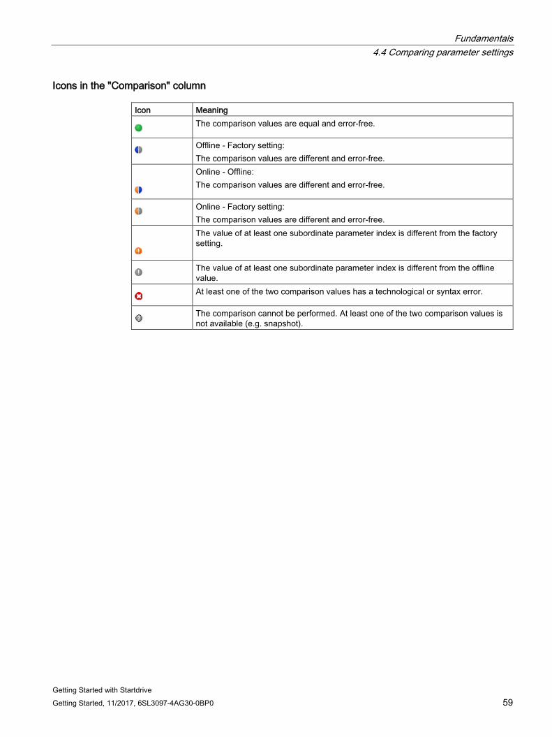
Icons in the "Comparison" column Icon Meaning
The comparison values are equal and error-free.
Offline - Factory setting: The comparison values are different and error-free.
Online - Offline: The comparison values are different and error-free.
Online - Factory setting: The comparison values are different and error-free.
The value of at least one subordinate parameter index is different from the factory setting.
The value of at least one subordinate parameter index is different from the offline value.
At least one of the two comparison values has a technological or syntax error.
The comparison cannot be performed. At least one of the two comparison values is not available (e.g. snapshot).
Fundamentals 4.5 Permanently save the settings
Getting Started with Startdrive 60 Getting Started, 11/2017, 6SL3097-4AG30-0BP0
4.5 Permanently save the settings
Saving configurations in the project In Startdrive, settings are predominantly made via screen forms. The complete project must be saved in order that the settings made are permanently active.
1. Click "Save project" in the toolbar.
- Or -
2. Select the "Project > Save" or "Project > Save as" menu.
Non-volatile saving to memory card The settings during parameterization are only saved volatile. They are lost when you switch off the drive unit.
Saving online data:
Click the icon in the function view of the active Startdrive project.
The current project settings are stored non-volatile on the memory card of the drive unit.
Saving offline data:
For storing in a power-independent manner, it is important that the settings made are not only saved in the project on the PC, but are also stored permanently on the memory card of the drive unit (also known as "Copy RAM to ROM"). An online connection must be established to the drive unit for this purpose.
1. Establish an online connection (Page 110) to your drive unit.
2. Load the project data in your drive unit(s).
Proceed as described in Chapter "Loading the project to the target device (Page 157)" for this purpose.
3. Click the icon in the function view of the active Startdrive project.
The current project settings are stored non-volatile on the memory card of the drive unit.

Fundamentals 4.6 Restoring factory settings
Getting Started with Startdrive Getting Started, 11/2017, 6SL3097-4AG30-0BP0 61
4.6 Restoring factory settings In online operation, you can restore the factory settings for the drive control.
1. Establish an online connection (Page 110) to your drive unit.
2. Click the icon in the function view of the active Startdrive project.
The factory settings are restored.
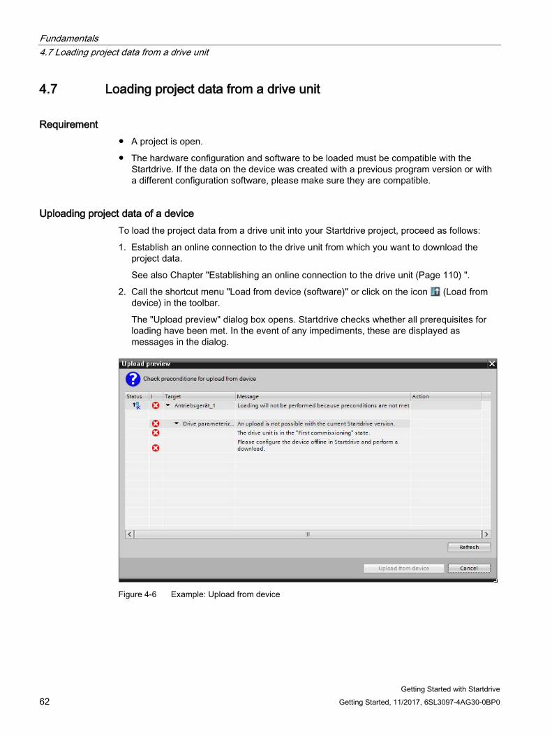
Fundamentals 4.7 Loading project data from a drive unit
Getting Started with Startdrive 62 Getting Started, 11/2017, 6SL3097-4AG30-0BP0
4.7 Loading project data from a drive unit
Requirement ● A project is open.
● The hardware configuration and software to be loaded must be compatible with the Startdrive. If the data on the device was created with a previous program version or with a different configuration software, please make sure they are compatible.
Uploading project data of a device To load the project data from a drive unit into your Startdrive project, proceed as follows:
1. Establish an online connection to the drive unit from which you want to download the project data.
See also Chapter "Establishing an online connection to the drive unit (Page 110) ".
2. Call the shortcut menu "Load from device (software)" or click on the icon (Load from device) in the toolbar.
The "Upload preview" dialog box opens. Startdrive checks whether all prerequisites for loading have been met. In the event of any impediments, these are displayed as messages in the dialog.
Figure 4-6 Example: Upload from device
Fundamentals 4.7 Loading project data from a drive unit
Getting Started with Startdrive Getting Started, 11/2017, 6SL3097-4AG30-0BP0 63
3. Check the alarms in the "Upload preview" dialog, and select the necessary actions in the "Action" column.
As soon as uploading becomes possible, the "Upload from device" button is enabled.
4. Click the "Upload from device" button.
The loading operation is performed.
Result
The project data has been loaded from the drive unit into your Startdrive project on the PC.

Fundamentals 4.7 Loading project data from a drive unit
Getting Started with Startdrive 64 Getting Started, 11/2017, 6SL3097-4AG30-0BP0
Getting Started with Startdrive Getting Started, 11/2017, 6SL3097-4AG30-0BP0 65
Commissioning 5 5.1 Call Startdrive
Note
The following procedure is based on the Windows 7 operating system. Operation can deviate slightly for other operating systems
Call the Startdrive application 1. Click on the Startdrive icon of your user interface.
- or -
2. Call the Startdrive via the Start menu on your PC.
Startdrive opens.
Commissioning 5.2 Commissioning workflow
Getting Started with Startdrive 66 Getting Started, 11/2017, 6SL3097-4AG30-0BP0
5.2 Commissioning workflow A drive can be commissioned in two ways:
● Create a project offline in Startdrive The components of the drive are combined offline in Startdrive.
● Create a project by reading out a device configuration The components of the drive are read-out online and supplemented offline when required.
Creating a project offline in Startdrive The following steps are required when commissioning a drive:
1. Create a project with Startdrive (Page 70).
2. Establish an online connection between Startdrive and the target device (Page 110).
3. Perform the basic parameterization of the drive units (Page 123).
4. Download the project to the target device (Page 157).
5. Commission the drive via the control panel (Page 159)
6. Result: The motor turns.
Creating a project by reading out a device configuration The following steps are necessary for commissioning a drive by reading out a device configuration:
1. Create a project with Startdrive (Page 70).
2. Optional: Establish an online connection between Startdrive and the target device (Page 110).
3. Determine the device configuration via an automatic configuration from the target device (Page 115).
4. Revise the determined device configuration in Startdrive (Page 119).
5. Perform the basic parameterization of the drive units (Page 123).
6. Download the project to the target device (Page 157).
7. Commission the drive via the control panel (Page 159)
8. Result: The motor turns.
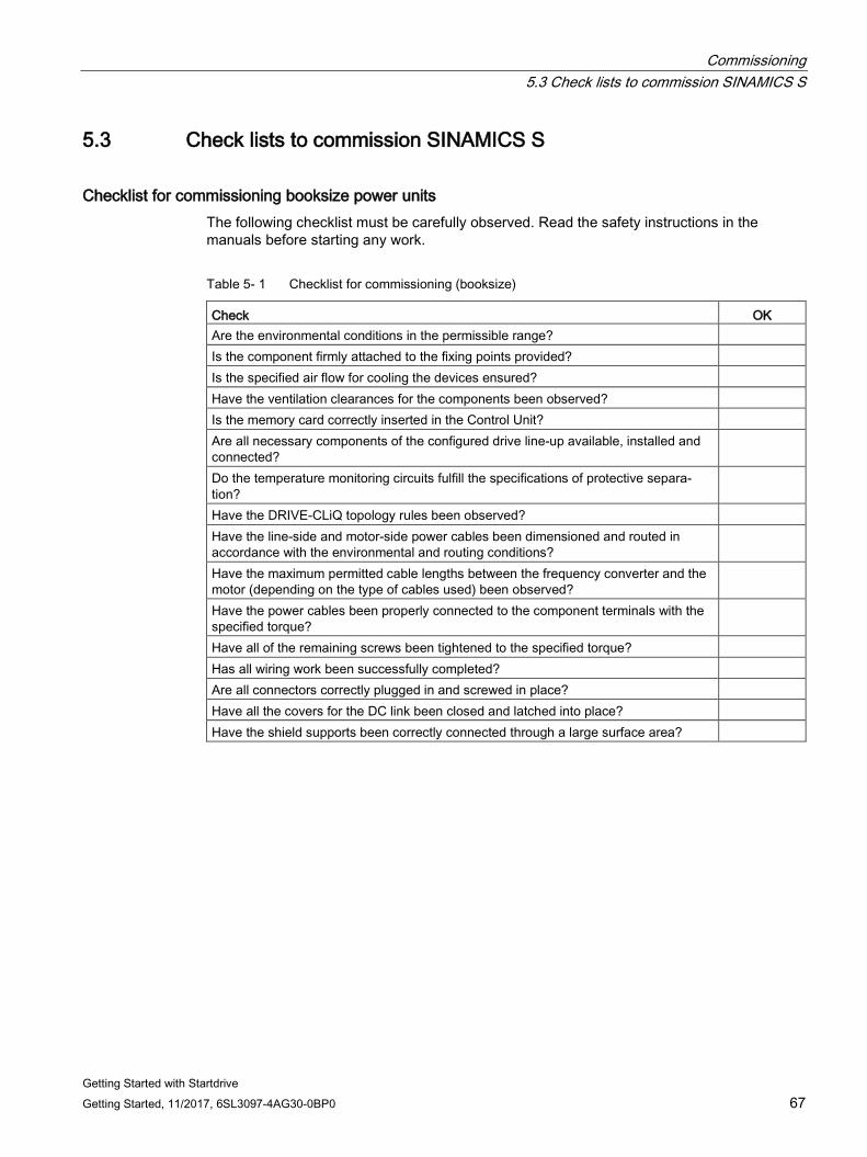
Commissioning 5.3 Check lists to commission SINAMICS S
Getting Started with Startdrive Getting Started, 11/2017, 6SL3097-4AG30-0BP0 67
5.3 Check lists to commission SINAMICS S
Checklist for commissioning booksize power units The following checklist must be carefully observed. Read the safety instructions in the manuals before starting any work.
Table 5- 1 Checklist for commissioning (booksize)
Check OK Are the environmental conditions in the permissible range? Is the component firmly attached to the fixing points provided? Is the specified air flow for cooling the devices ensured? Have the ventilation clearances for the components been observed? Is the memory card correctly inserted in the Control Unit? Are all necessary components of the configured drive line-up available, installed and connected?
Do the temperature monitoring circuits fulfill the specifications of protective separa-tion?
Have the DRIVE-CLiQ topology rules been observed? Have the line-side and motor-side power cables been dimensioned and routed in accordance with the environmental and routing conditions?
Have the maximum permitted cable lengths between the frequency converter and the motor (depending on the type of cables used) been observed?
Have the power cables been properly connected to the component terminals with the specified torque?
Have all of the remaining screws been tightened to the specified torque? Has all wiring work been successfully completed? Are all connectors correctly plugged in and screwed in place? Have all the covers for the DC link been closed and latched into place? Have the shield supports been correctly connected through a large surface area?
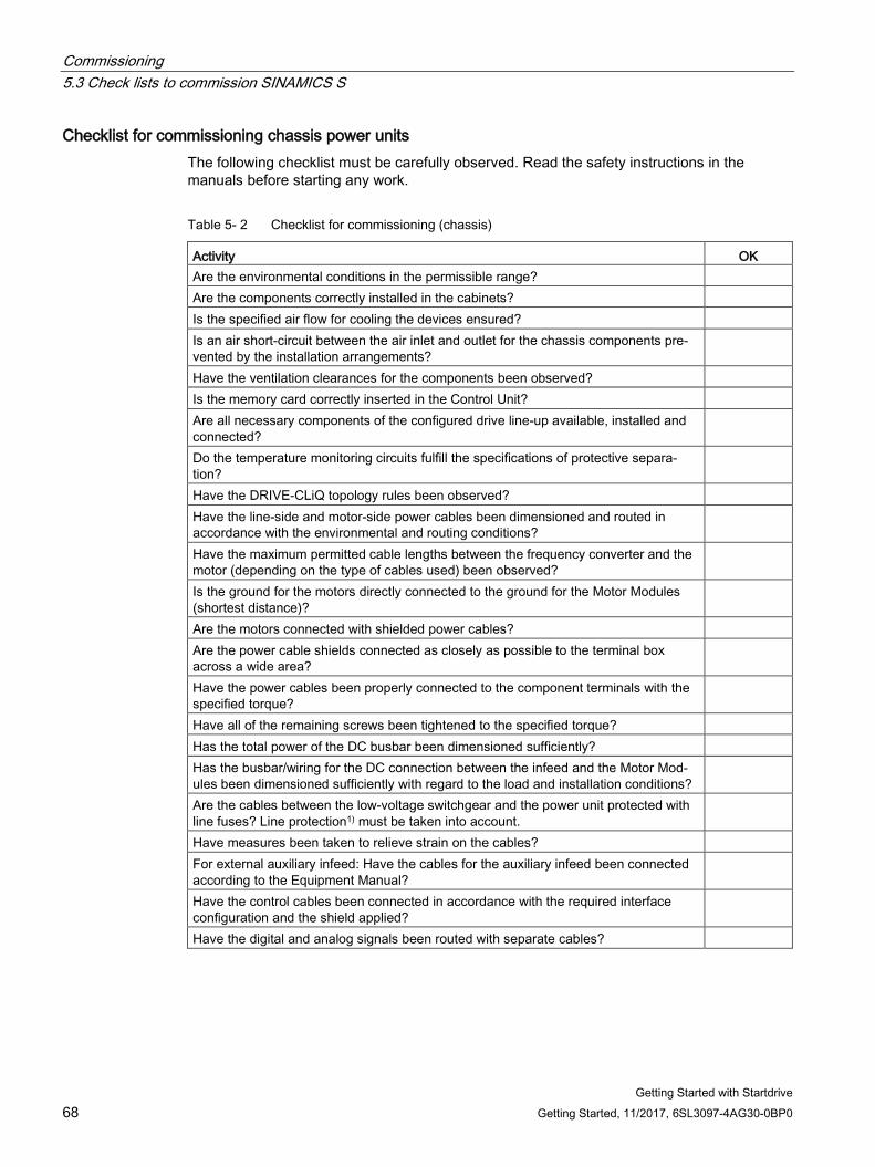
Commissioning 5.3 Check lists to commission SINAMICS S
Getting Started with Startdrive 68 Getting Started, 11/2017, 6SL3097-4AG30-0BP0
Checklist for commissioning chassis power units The following checklist must be carefully observed. Read the safety instructions in the manuals before starting any work.
Table 5- 2 Checklist for commissioning (chassis)
Activity OK Are the environmental conditions in the permissible range? Are the components correctly installed in the cabinets? Is the specified air flow for cooling the devices ensured? Is an air short-circuit between the air inlet and outlet for the chassis components pre-vented by the installation arrangements?
Have the ventilation clearances for the components been observed? Is the memory card correctly inserted in the Control Unit? Are all necessary components of the configured drive line-up available, installed and connected?
Do the temperature monitoring circuits fulfill the specifications of protective separa-tion?
Have the DRIVE-CLiQ topology rules been observed? Have the line-side and motor-side power cables been dimensioned and routed in accordance with the environmental and routing conditions?
Have the maximum permitted cable lengths between the frequency converter and the motor (depending on the type of cables used) been observed?
Is the ground for the motors directly connected to the ground for the Motor Modules (shortest distance)?
Are the motors connected with shielded power cables? Are the power cable shields connected as closely as possible to the terminal box across a wide area?
Have the power cables been properly connected to the component terminals with the specified torque?
Have all of the remaining screws been tightened to the specified torque? Has the total power of the DC busbar been dimensioned sufficiently? Has the busbar/wiring for the DC connection between the infeed and the Motor Mod-ules been dimensioned sufficiently with regard to the load and installation conditions?
Are the cables between the low-voltage switchgear and the power unit protected with line fuses? Line protection1) must be taken into account.
Have measures been taken to relieve strain on the cables? For external auxiliary infeed: Have the cables for the auxiliary infeed been connected according to the Equipment Manual?
Have the control cables been connected in accordance with the required interface configuration and the shield applied?
Have the digital and analog signals been routed with separate cables?
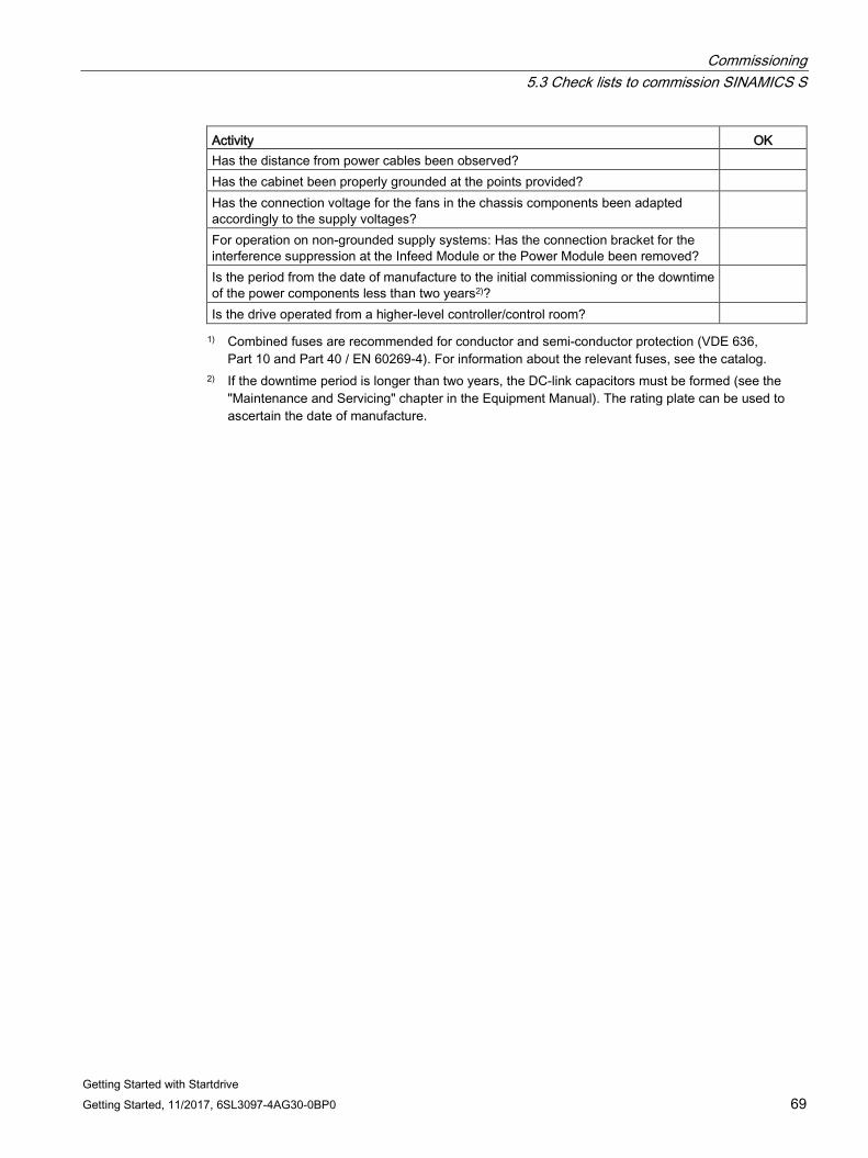
Commissioning 5.3 Check lists to commission SINAMICS S
Getting Started with Startdrive Getting Started, 11/2017, 6SL3097-4AG30-0BP0 69
Activity OK Has the distance from power cables been observed? Has the cabinet been properly grounded at the points provided? Has the connection voltage for the fans in the chassis components been adapted accordingly to the supply voltages?
For operation on non-grounded supply systems: Has the connection bracket for the interference suppression at the Infeed Module or the Power Module been removed?
Is the period from the date of manufacture to the initial commissioning or the downtime of the power components less than two years2)?
Is the drive operated from a higher-level controller/control room? 1) Combined fuses are recommended for conductor and semi-conductor protection (VDE 636,
Part 10 and Part 40 / EN 60269-4). For information about the relevant fuses, see the catalog. 2) If the downtime period is longer than two years, the DC-link capacitors must be formed (see the
"Maintenance and Servicing" chapter in the Equipment Manual). The rating plate can be used to ascertain the date of manufacture.
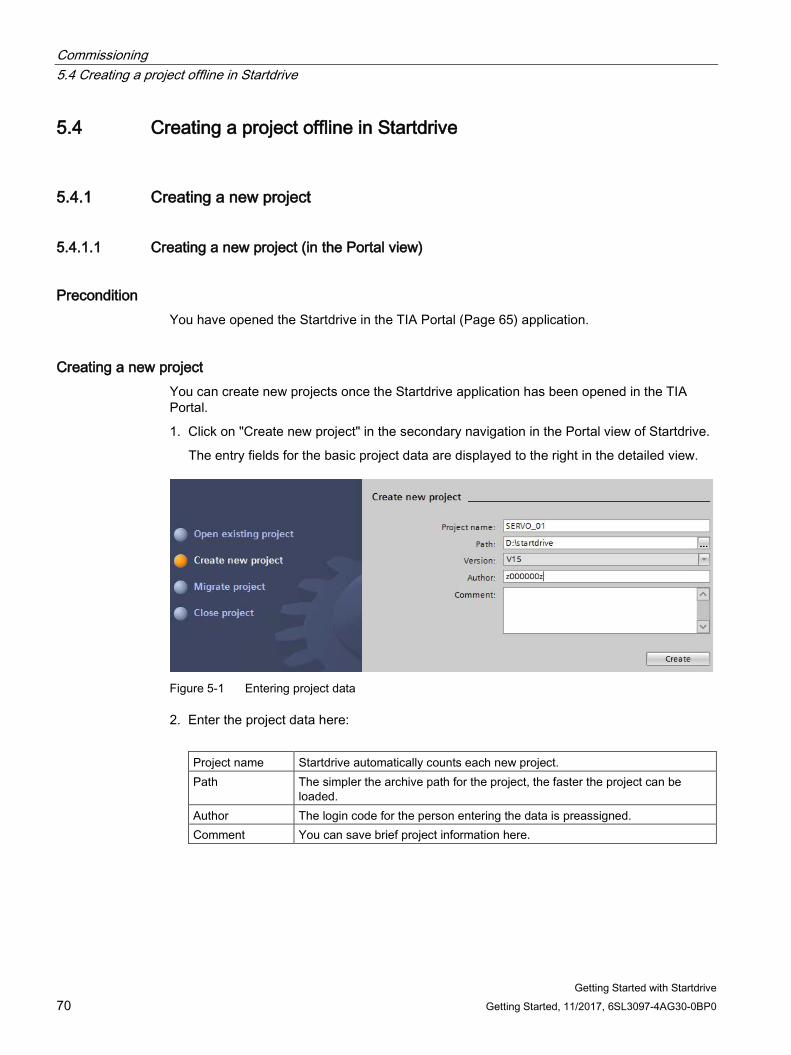
Commissioning 5.4 Creating a project offline in Startdrive
Getting Started with Startdrive 70 Getting Started, 11/2017, 6SL3097-4AG30-0BP0
5.4 Creating a project offline in Startdrive
5.4.1 Creating a new project
5.4.1.1 Creating a new project (in the Portal view)
Precondition You have opened the Startdrive in the TIA Portal (Page 65) application.
Creating a new project You can create new projects once the Startdrive application has been opened in the TIA Portal.
1. Click on "Create new project" in the secondary navigation in the Portal view of Startdrive.
The entry fields for the basic project data are displayed to the right in the detailed view.
Figure 5-1 Entering project data
2. Enter the project data here:
Project name Startdrive automatically counts each new project. Path The simpler the archive path for the project, the faster the project can be
loaded. Author The login code for the person entering the data is preassigned. Comment You can save brief project information here.
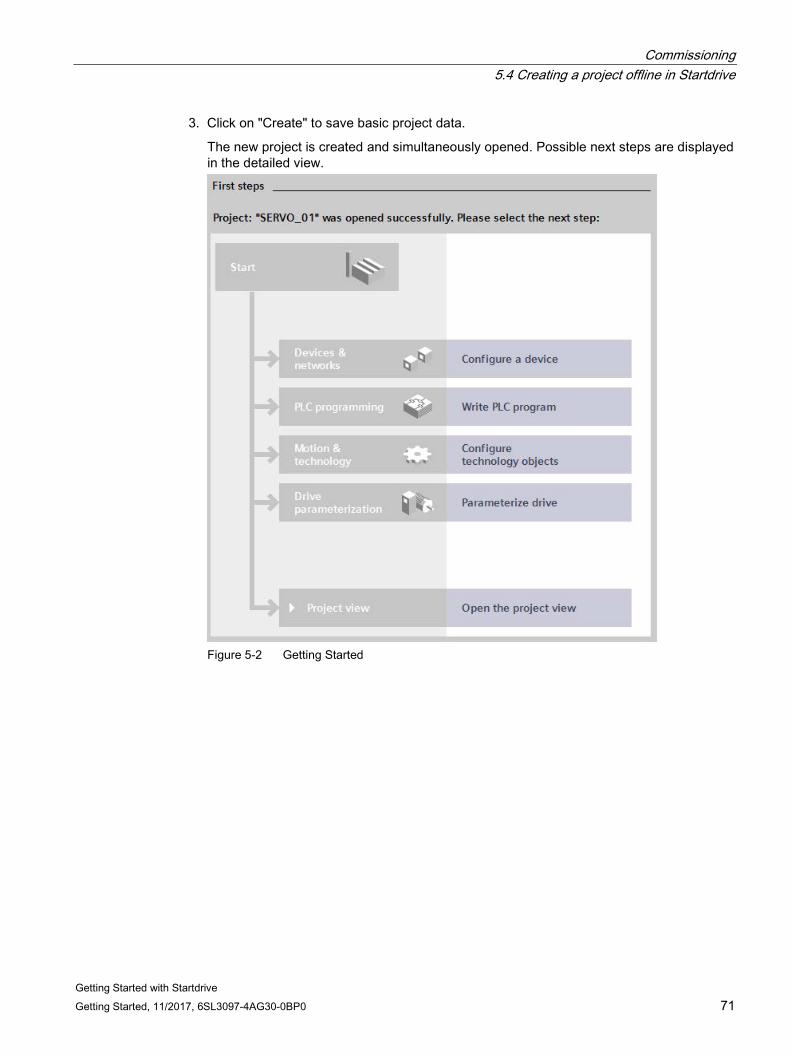
Commissioning 5.4 Creating a project offline in Startdrive
Getting Started with Startdrive Getting Started, 11/2017, 6SL3097-4AG30-0BP0 71
3. Click on "Create" to save basic project data.
The new project is created and simultaneously opened. Possible next steps are displayed in the detailed view.
Figure 5-2 Getting Started
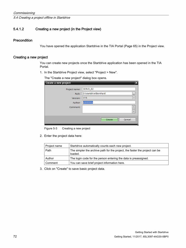
Commissioning 5.4 Creating a project offline in Startdrive
Getting Started with Startdrive 72 Getting Started, 11/2017, 6SL3097-4AG30-0BP0
5.4.1.2 Creating a new project (in the Project view)
Precondition You have opened the application Startdrive in the TIA Portal (Page 65) in the Project view.
Creating a new project You can create new projects once the Startdrive application has been opened in the TIA Portal.
1. In the Startdrive Project view, select "Project > New".
The "Create a new project" dialog box opens.
Figure 5-3 Creating a new project
2. Enter the project data here:
Project name Startdrive automatically counts each new project. Path The simpler the archive path for the project, the faster the project can be
loaded. Author The login code for the person entering the data is preassigned. Comment You can save brief project information here.
3. Click on "Create" to save basic project data.
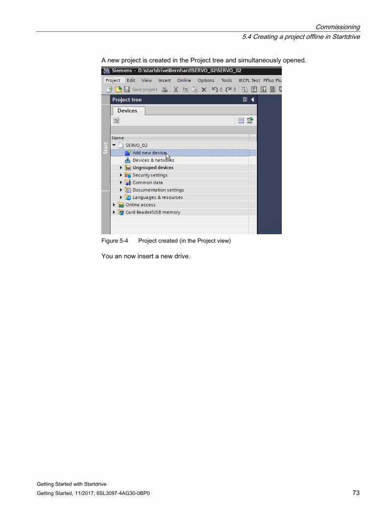
Commissioning 5.4 Creating a project offline in Startdrive
Getting Started with Startdrive Getting Started, 11/2017, 6SL3097-4AG30-0BP0 73
A new project is created in the Project tree and simultaneously opened.
Figure 5-4 Project created (in the Project view)
You an now insert a new drive.
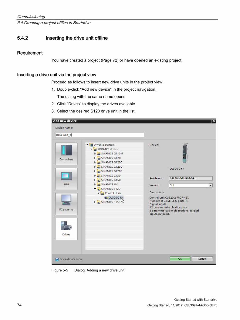
Commissioning 5.4 Creating a project offline in Startdrive
Getting Started with Startdrive 74 Getting Started, 11/2017, 6SL3097-4AG30-0BP0
5.4.2 Inserting the drive unit offline
Requirement You have created a project (Page 72) or have opened an existing project.
Inserting a drive unit via the project view Proceed as follows to insert new drive units in the project view:
1. Double-click "Add new device" in the project navigation.
The dialog with the same name opens.
2. Click "Drives" to display the drives available.
3. Select the desired S120 drive unit in the list.
Figure 5-5 Dialog: Adding a new drive unit
Commissioning 5.4 Creating a project offline in Startdrive
Getting Started with Startdrive Getting Started, 11/2017, 6SL3097-4AG30-0BP0 75
Ensure that the version number indicated on the right in the dialog correlates with the version number of your memory card on the drive unit. If the version numbers do not match, it will not be possible to go online later. On creation, the current firmware version is always suggested. If required, you can change the version number via the "Version" drop-down list.
4. When required, enter a different device name in the input field at the top left, and then click "OK".
If the "Open device view" checkbox is activated, the device view is opened automatically in Startdrive when creating the drive.
Result
The drive unit is inserted.
5.4.3 Inserting an infeed
Requirement You have created a project and inserted a drive.
Note Sequence
Generally, the infeed is inserted in the configuration immediately after the drive in the device view. In this case, the infeed is also automatically wired to the drive (X100).
You can also insert an infeed at a later point in time (for example, after the Motor Module). The infeed is then no longer automatically wired because the standard interface X100 intended for the infeed is already occupied (e.g. with the Motor Module).
In this case, the device configuration must be changed manually. You can wire the infeed manually to a free interface. You can also change the wiring of the drive object that is currently linked to X100 of the drive, to a different interface. X100 would then be free again and when the infeed is inserted, it is automatically linked to X100.
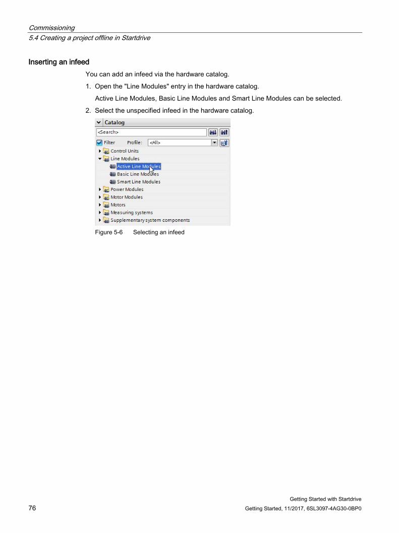
Commissioning 5.4 Creating a project offline in Startdrive
Getting Started with Startdrive 76 Getting Started, 11/2017, 6SL3097-4AG30-0BP0
Inserting an infeed You can add an infeed via the hardware catalog.
1. Open the "Line Modules" entry in the hardware catalog.
Active Line Modules, Basic Line Modules and Smart Line Modules can be selected.
2. Select the unspecified infeed in the hardware catalog.
Figure 5-6 Selecting an infeed
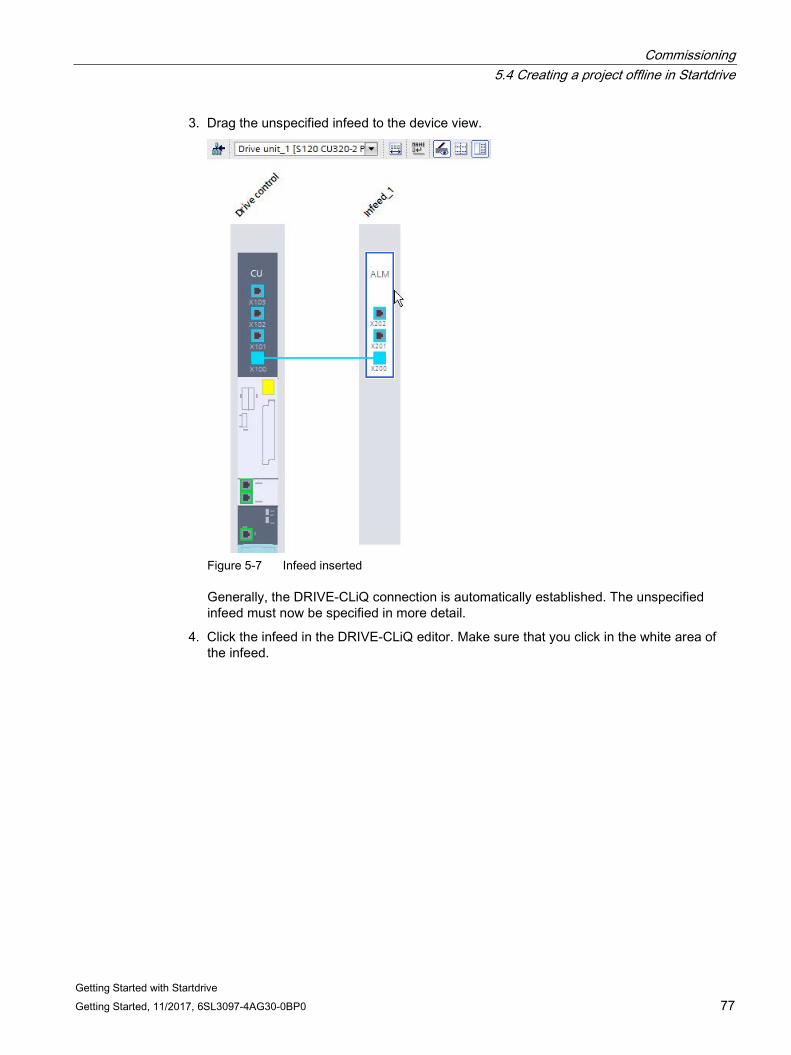
Commissioning 5.4 Creating a project offline in Startdrive
Getting Started with Startdrive Getting Started, 11/2017, 6SL3097-4AG30-0BP0 77
3. Drag the unspecified infeed to the device view.
Figure 5-7 Infeed inserted
Generally, the DRIVE-CLiQ connection is automatically established. The unspecified infeed must now be specified in more detail.
4. Click the infeed in the DRIVE-CLiQ editor. Make sure that you click in the white area of the infeed.
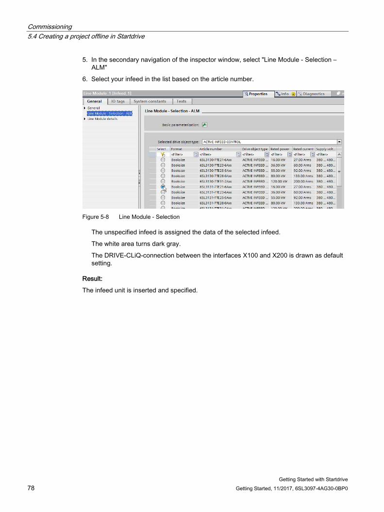
Commissioning 5.4 Creating a project offline in Startdrive
Getting Started with Startdrive 78 Getting Started, 11/2017, 6SL3097-4AG30-0BP0
5. In the secondary navigation of the inspector window, select "Line Module - Selection – ALM"
6. Select your infeed in the list based on the article number.
Figure 5-8 Line Module - Selection
The unspecified infeed is assigned the data of the selected infeed.
The white area turns dark gray.
The DRIVE-CLiQ-connection between the interfaces X100 and X200 is drawn as default setting.
Result:
The infeed unit is inserted and specified.
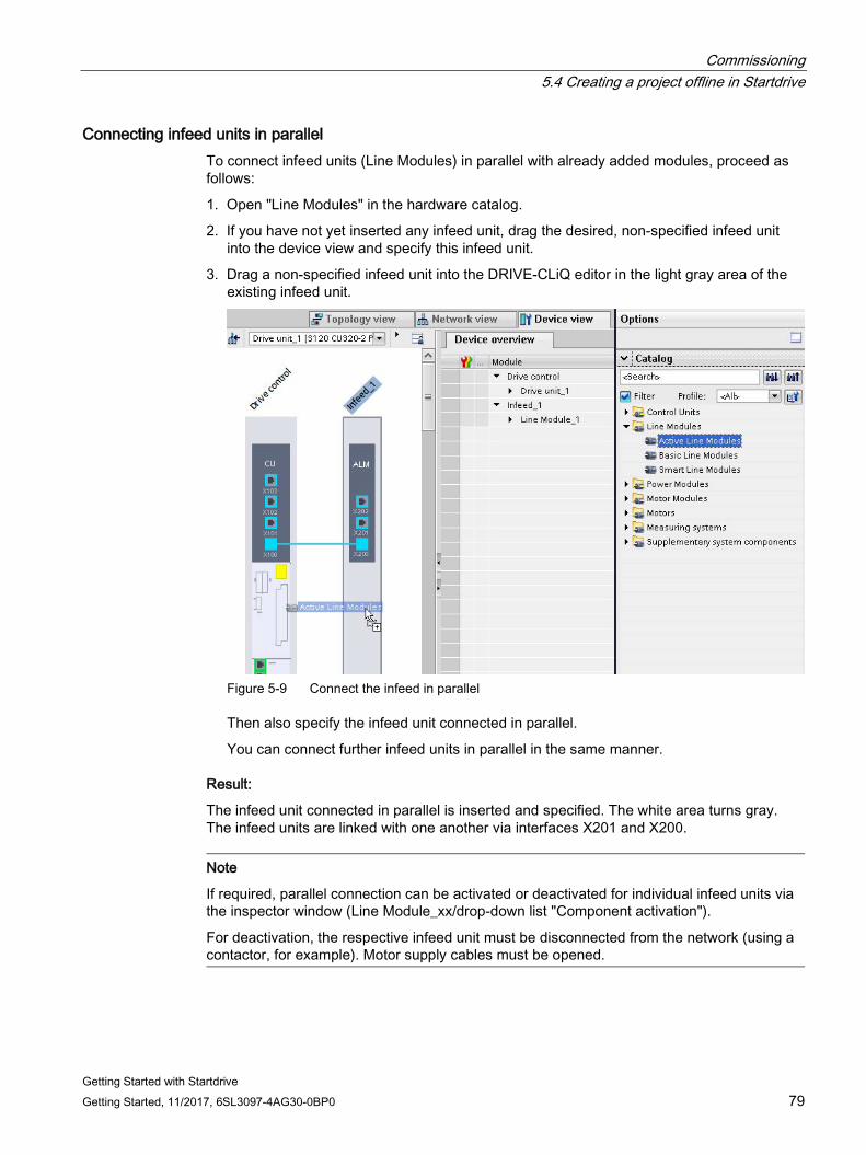
Commissioning 5.4 Creating a project offline in Startdrive
Getting Started with Startdrive Getting Started, 11/2017, 6SL3097-4AG30-0BP0 79
Connecting infeed units in parallel To connect infeed units (Line Modules) in parallel with already added modules, proceed as follows:
1. Open "Line Modules" in the hardware catalog.
2. If you have not yet inserted any infeed unit, drag the desired, non-specified infeed unit into the device view and specify this infeed unit.
3. Drag a non-specified infeed unit into the DRIVE-CLiQ editor in the light gray area of the existing infeed unit.
Figure 5-9 Connect the infeed in parallel
Then also specify the infeed unit connected in parallel.
You can connect further infeed units in parallel in the same manner.
Result:
The infeed unit connected in parallel is inserted and specified. The white area turns gray. The infeed units are linked with one another via interfaces X201 and X200.
Note
If required, parallel connection can be activated or deactivated for individual infeed units via the inspector window (Line Module_xx/drop-down list "Component activation").
For deactivation, the respective infeed unit must be disconnected from the network (using a contactor, for example). Motor supply cables must be opened.
Commissioning 5.4 Creating a project offline in Startdrive
Getting Started with Startdrive 80 Getting Started, 11/2017, 6SL3097-4AG30-0BP0
5.4.4 Inserting a Motor Module or Power Module When you create a Power Module or Motor Module, the "SERVO" drive object type (high dynamic drives) is active by default. However, if you are using the "VECTOR" drive object type (universal drives) in your hardware device configuration, you can change the type of the module in Startdrive. Many of the following settings depend on the set drive object type. Setting the correct type is therefore a prerequisite for all further settings during commissioning and further parameterization of the Power Module or Motor Module.
Note Revision of the device configuration for a subsequent change of the drive object type
Make sure that you first set the drive object type in the device configuration, and only then add and specify the motor, measuring systems or supplementary system components.
If you change the drive object type subsequently, there is a danger that the configuration of some components is lost and has to be repeated.
Preconditions ● A project has been created.
● The Control Unit is inserted in the device configuration.
● An infeed is inserted.
In case of doubt, you can also add the infeed at a later point in time. However, in this case, you must manually wire the "infeed" component with the other components.
Note
When you use Power Modules, it is usually possible to dispense with an infeed.
General The procedure for creating and configuring a device in the device configuration of Startdrive is almost identical for Motor Modules and Power Modules. The drive device configuration requires at least one of these modules.
These module types differ mainly by their applications:
● Motor Module: Single-axis and multiple-axis applications
● Power Module: Single-axis applications
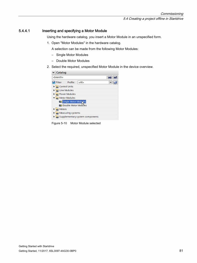
Commissioning 5.4 Creating a project offline in Startdrive
Getting Started with Startdrive Getting Started, 11/2017, 6SL3097-4AG30-0BP0 81
5.4.4.1 Inserting and specifying a Motor Module Using the hardware catalog, you insert a Motor Module in an unspecified form.
1. Open "Motor Modules" in the hardware catalog.
A selection can be made from the following Motor Modules:
– Single Motor Modules
– Double Motor Modules
2. Select the required, unspecified Motor Module in the device overview.
Figure 5-10 Motor Module selected
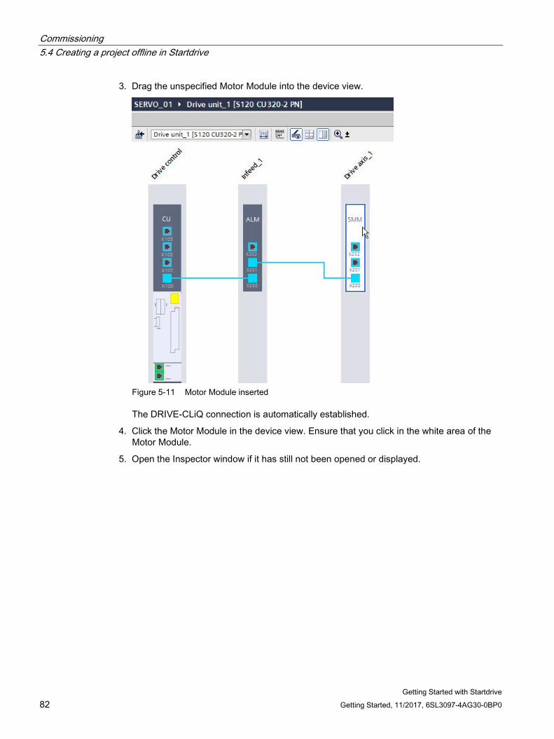
Commissioning 5.4 Creating a project offline in Startdrive
Getting Started with Startdrive 82 Getting Started, 11/2017, 6SL3097-4AG30-0BP0
3. Drag the unspecified Motor Module into the device view.
Figure 5-11 Motor Module inserted
The DRIVE-CLiQ connection is automatically established.
4. Click the Motor Module in the device view. Ensure that you click in the white area of the Motor Module.
5. Open the Inspector window if it has still not been opened or displayed.

Commissioning 5.4 Creating a project offline in Startdrive
Getting Started with Startdrive Getting Started, 11/2017, 6SL3097-4AG30-0BP0 83
6. In the secondary navigation of the inspector window, select "Motor Module - Selection - xxx".
Figure 5-12 Motor Module specified
All Motor Modules for the "SERVO" drive object type (default setting for first call) are displayed in the list. If you want to use drive objects of type "VECTOR", you must change the display of the list.
7. If you are using drive objects of type "VECTOR", select the "VECTOR" option in the "Selected drive object type" drop-down list.
A confirmation prompt appears as to whether you really want to change the drive object type.
8. Click "Yes" to confirm the prompt.
The list of Motor Modules is now refreshed. Only Motor Modules of type "VECTOR" are now available for selection. In the same way, the list can be changed back to modules of type "SERVO".
9. Select your Motor Module in the list based on the article number.
The data of the selected Motor Module are assigned to the unspecified Motor Module. The white area turns dark gray.
Result The Motor Module is inserted and specified.
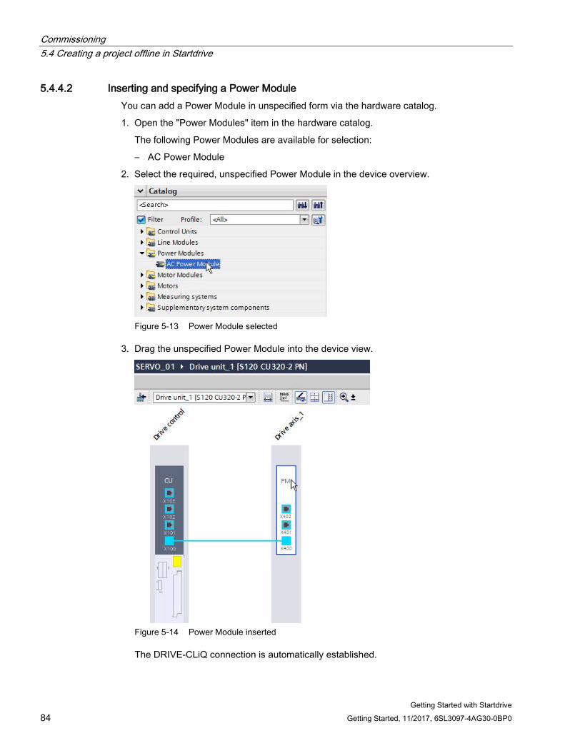
Commissioning 5.4 Creating a project offline in Startdrive
Getting Started with Startdrive 84 Getting Started, 11/2017, 6SL3097-4AG30-0BP0
5.4.4.2 Inserting and specifying a Power Module You can add a Power Module in unspecified form via the hardware catalog.
1. Open the "Power Modules" item in the hardware catalog.
The following Power Modules are available for selection:
– AC Power Module
2. Select the required, unspecified Power Module in the device overview.
Figure 5-13 Power Module selected
3. Drag the unspecified Power Module into the device view.
Figure 5-14 Power Module inserted
The DRIVE-CLiQ connection is automatically established.
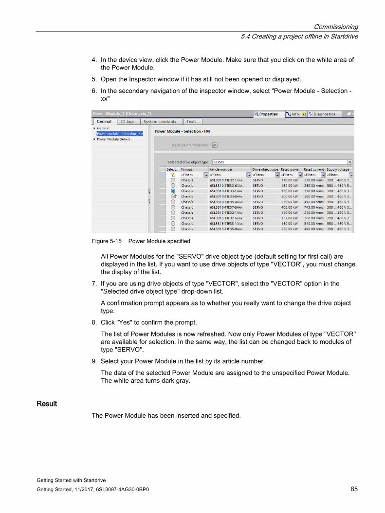
Commissioning 5.4 Creating a project offline in Startdrive
Getting Started with Startdrive Getting Started, 11/2017, 6SL3097-4AG30-0BP0 85
4. In the device view, click the Power Module. Make sure that you click on the white area of the Power Module.
5. Open the Inspector window if it has still not been opened or displayed.
6. In the secondary navigation of the inspector window, select "Power Module - Selection - xx"
Figure 5-15 Power Module specified
All Power Modules for the "SERVO" drive object type (default setting for first call) are displayed in the list. If you want to use drive objects of type "VECTOR", you must change the display of the list.
7. If you are using drive objects of type "VECTOR", select the "VECTOR" option in the "Selected drive object type" drop-down list.
A confirmation prompt appears as to whether you really want to change the drive object type.
8. Click "Yes" to confirm the prompt.
The list of Power Modules is now refreshed. Now only Power Modules of type "VECTOR" are available for selection. In the same way, the list can be changed back to modules of type "SERVO".
9. Select your Power Module in the list by its article number.
The data of the selected Power Module are assigned to the unspecified Power Module. The white area turns dark gray.
Result The Power Module has been inserted and specified.
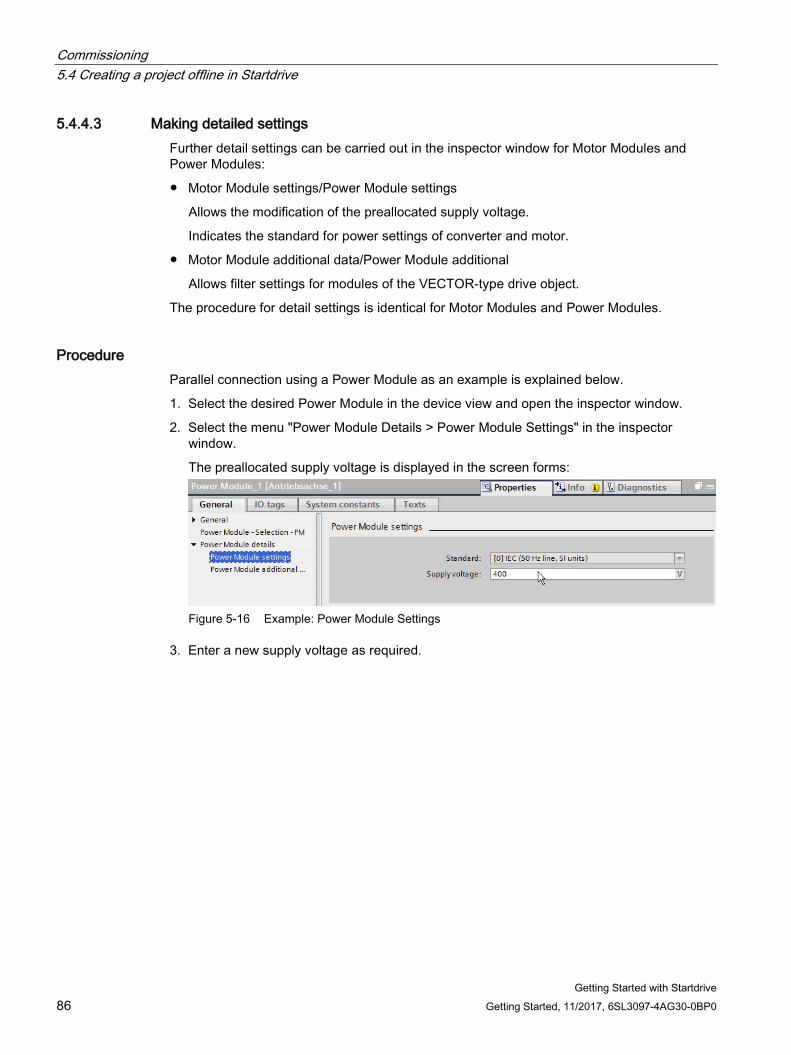
Commissioning 5.4 Creating a project offline in Startdrive
Getting Started with Startdrive 86 Getting Started, 11/2017, 6SL3097-4AG30-0BP0
5.4.4.3 Making detailed settings Further detail settings can be carried out in the inspector window for Motor Modules and Power Modules:
● Motor Module settings/Power Module settings
Allows the modification of the preallocated supply voltage.
Indicates the standard for power settings of converter and motor.
● Motor Module additional data/Power Module additional
Allows filter settings for modules of the VECTOR-type drive object.
The procedure for detail settings is identical for Motor Modules and Power Modules.
Procedure Parallel connection using a Power Module as an example is explained below.
1. Select the desired Power Module in the device view and open the inspector window.
2. Select the menu "Power Module Details > Power Module Settings" in the inspector window.
The preallocated supply voltage is displayed in the screen forms:
Figure 5-16 Example: Power Module Settings
3. Enter a new supply voltage as required.
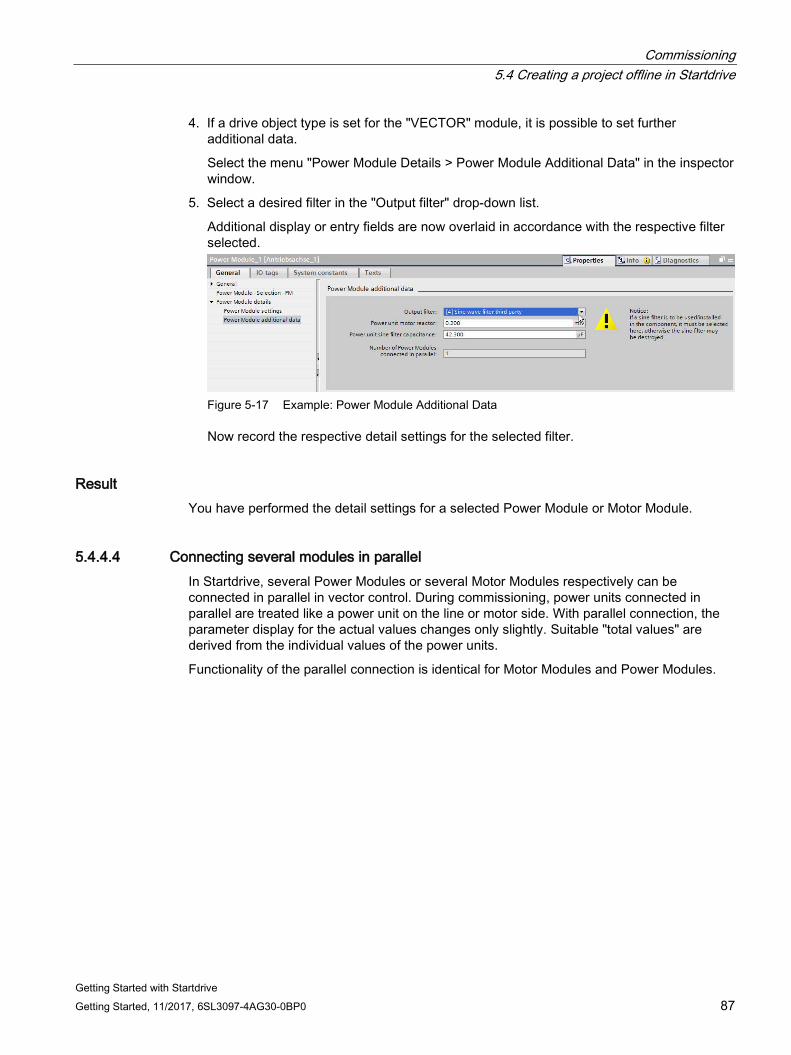
Commissioning 5.4 Creating a project offline in Startdrive
Getting Started with Startdrive Getting Started, 11/2017, 6SL3097-4AG30-0BP0 87
4. If a drive object type is set for the "VECTOR" module, it is possible to set further additional data.
Select the menu "Power Module Details > Power Module Additional Data" in the inspector window.
5. Select a desired filter in the "Output filter" drop-down list.
Additional display or entry fields are now overlaid in accordance with the respective filter selected.
Figure 5-17 Example: Power Module Additional Data
Now record the respective detail settings for the selected filter.
Result You have performed the detail settings for a selected Power Module or Motor Module.
5.4.4.4 Connecting several modules in parallel In Startdrive, several Power Modules or several Motor Modules respectively can be connected in parallel in vector control. During commissioning, power units connected in parallel are treated like a power unit on the line or motor side. With parallel connection, the parameter display for the actual values changes only slightly. Suitable "total values" are derived from the individual values of the power units.
Functionality of the parallel connection is identical for Motor Modules and Power Modules.
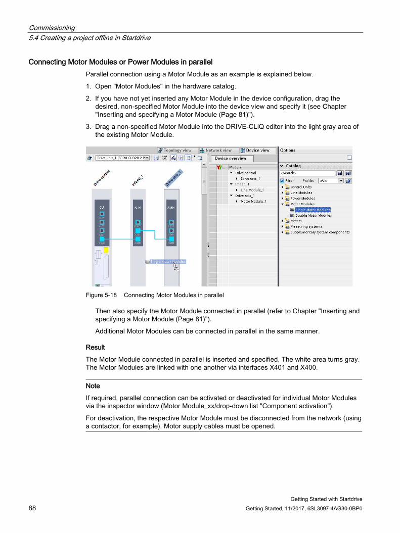
Commissioning 5.4 Creating a project offline in Startdrive
Getting Started with Startdrive 88 Getting Started, 11/2017, 6SL3097-4AG30-0BP0
Connecting Motor Modules or Power Modules in parallel Parallel connection using a Motor Module as an example is explained below.
1. Open "Motor Modules" in the hardware catalog.
2. If you have not yet inserted any Motor Module in the device configuration, drag the desired, non-specified Motor Module into the device view and specify it (see Chapter "Inserting and specifying a Motor Module (Page 81)").
3. Drag a non-specified Motor Module into the DRIVE-CLiQ editor into the light gray area of the existing Motor Module.
Figure 5-18 Connecting Motor Modules in parallel
Then also specify the Motor Module connected in parallel (refer to Chapter "Inserting and specifying a Motor Module (Page 81)").
Additional Motor Modules can be connected in parallel in the same manner.
Result
The Motor Module connected in parallel is inserted and specified. The white area turns gray. The Motor Modules are linked with one another via interfaces X401 and X400.
Note
If required, parallel connection can be activated or deactivated for individual Motor Modules via the inspector window (Motor Module_xx/drop-down list "Component activation").
For deactivation, the respective Motor Module must be disconnected from the network (using a contactor, for example). Motor supply cables must be opened.
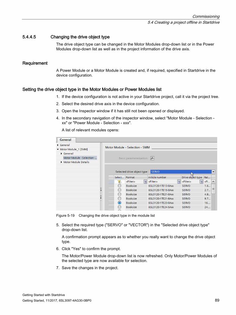
Commissioning 5.4 Creating a project offline in Startdrive
Getting Started with Startdrive Getting Started, 11/2017, 6SL3097-4AG30-0BP0 89
5.4.4.5 Changing the drive object type The drive object type can be changed in the Motor Modules drop-down list or in the Power Modules drop-down list as well as in the project information of the drive axis.
Requirement A Power Module or a Motor Module is created and, if required, specified in Startdrive in the device configuration.
Setting the drive object type in the Motor Modules or Power Modules list 1. If the device configuration is not active in your Startdrive project, call it via the project tree.
2. Select the desired drive axis in the device configuration.
3. Open the Inspector window if it has still not been opened or displayed.
4. In the secondary navigation of the inspector window, select "Motor Module - Selection - xx" or "Power Module - Selection - xxx".
A list of relevant modules opens:
Figure 5-19 Changing the drive object type in the module list
5. Select the required type ("SERVO" or "VECTOR") in the "Selected drive object type" drop-down list.
A confirmation prompt appears as to whether you really want to change the drive object type.
6. Click "Yes" to confirm the prompt.
The Motor/Power Module drop-down list is now refreshed. Only Motor/Power Modules of the selected type are now available for selection.
7. Save the changes in the project.
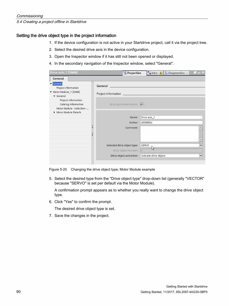
Commissioning 5.4 Creating a project offline in Startdrive
Getting Started with Startdrive 90 Getting Started, 11/2017, 6SL3097-4AG30-0BP0
Setting the drive object type in the project information 1. If the device configuration is not active in your Startdrive project, call it via the project tree.
2. Select the desired drive axis in the device configuration.
3. Open the Inspector window if it has still not been opened or displayed.
4. In the secondary navigation of the Inspector window, select "General".
Figure 5-20 Changing the drive object type; Motor Module example
5. Select the desired type from the "Drive object type" drop-down list (generally "VECTOR" because "SERVO" is set per default via the Motor Module).
A confirmation prompt appears as to whether you really want to change the drive object type.
6. Click "Yes" to confirm the prompt.
The desired drive object type is set.
7. Save the changes in the project.
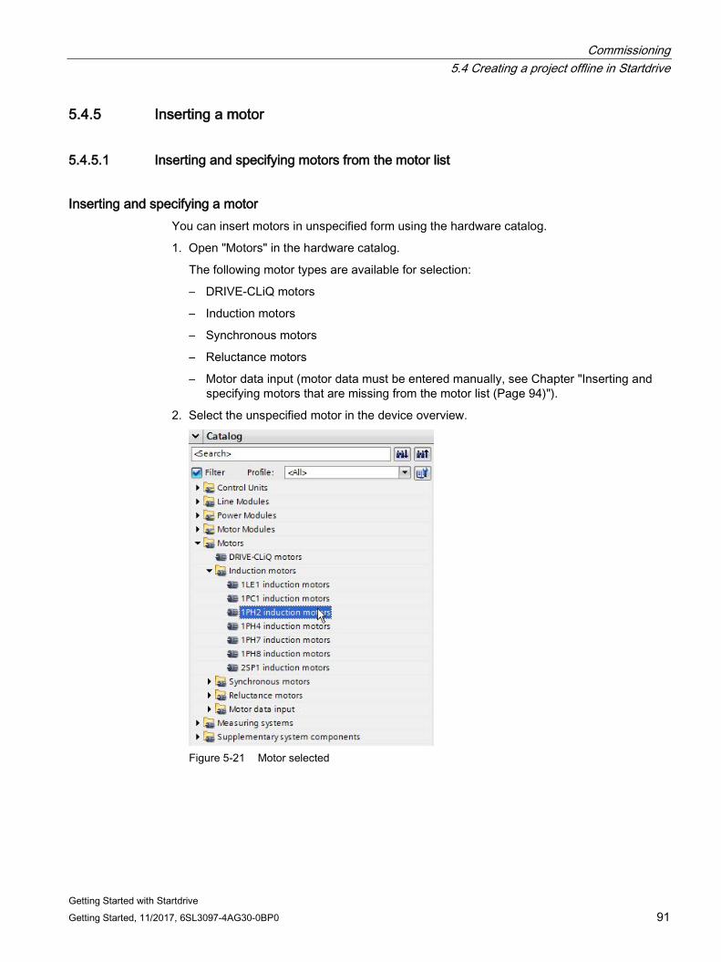
Commissioning 5.4 Creating a project offline in Startdrive
Getting Started with Startdrive Getting Started, 11/2017, 6SL3097-4AG30-0BP0 91
5.4.5 Inserting a motor
5.4.5.1 Inserting and specifying motors from the motor list
Inserting and specifying a motor You can insert motors in unspecified form using the hardware catalog.
1. Open "Motors" in the hardware catalog.
The following motor types are available for selection:
– DRIVE-CLiQ motors
– Induction motors
– Synchronous motors
– Reluctance motors
– Motor data input (motor data must be entered manually, see Chapter "Inserting and specifying motors that are missing from the motor list (Page 94)").
2. Select the unspecified motor in the device overview.
Figure 5-21 Motor selected
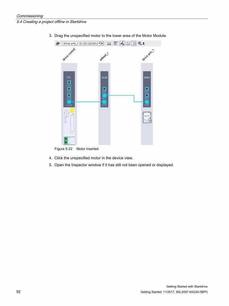
Commissioning 5.4 Creating a project offline in Startdrive
Getting Started with Startdrive 92 Getting Started, 11/2017, 6SL3097-4AG30-0BP0
3. Drag the unspecified motor to the lower area of the Motor Module.
Figure 5-22 Motor inserted
4. Click the unspecified motor in the device view.
5. Open the Inspector window if it has still not been opened or displayed.
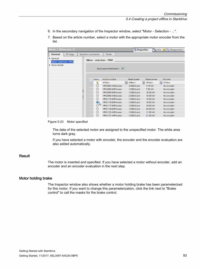
Commissioning 5.4 Creating a project offline in Startdrive
Getting Started with Startdrive Getting Started, 11/2017, 6SL3097-4AG30-0BP0 93
6. In the secondary navigation of the Inspector window, select "Motor - Selection - ...".
7. Based on the article number, select a motor with the appropriate motor encoder from the list.
Figure 5-23 Motor specified
The data of the selected motor are assigned to the unspecified motor. The white area turns dark gray.
If you have selected a motor with encoder, the encoder and the encoder evaluation are also added automatically.
Result The motor is inserted and specified. If you have selected a motor without encoder, add an encoder and an encoder evaluation in the next step.
Motor holding brake The Inspector window also shows whether a motor holding brake has been parameterized for this motor. If you want to change this parameterization, click the link next to "Brake control" to call the masks for the brake control.
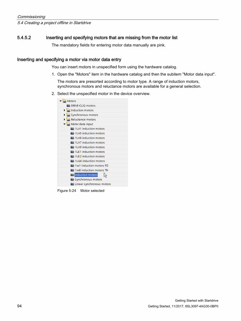
Commissioning 5.4 Creating a project offline in Startdrive
Getting Started with Startdrive 94 Getting Started, 11/2017, 6SL3097-4AG30-0BP0
5.4.5.2 Inserting and specifying motors that are missing from the motor list The mandatory fields for entering motor data manually are pink.
Inserting and specifying a motor via motor data entry You can insert motors in unspecified form using the hardware catalog.
1. Open the "Motors" item in the hardware catalog and then the subitem "Motor data input".
The motors are presorted according to motor type. A range of induction motors, synchronous motors and reluctance motors are available for a general selection.
2. Select the unspecified motor in the device overview.
Figure 5-24 Motor selected
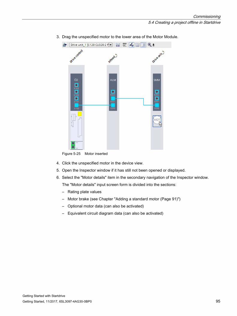
Commissioning 5.4 Creating a project offline in Startdrive
Getting Started with Startdrive Getting Started, 11/2017, 6SL3097-4AG30-0BP0 95
3. Drag the unspecified motor to the lower area of the Motor Module.
Figure 5-25 Motor inserted
4. Click the unspecified motor in the device view.
5. Open the Inspector window if it has still not been opened or displayed.
6. Select the "Motor details" item in the secondary navigation of the Inspector window.
The "Motor details" input screen form is divided into the sections:
– Rating plate values
– Motor brake (see Chapter "Adding a standard motor (Page 91)")
– Optional motor data (can also be activated)
– Equivalent circuit diagram data (can also be activated)
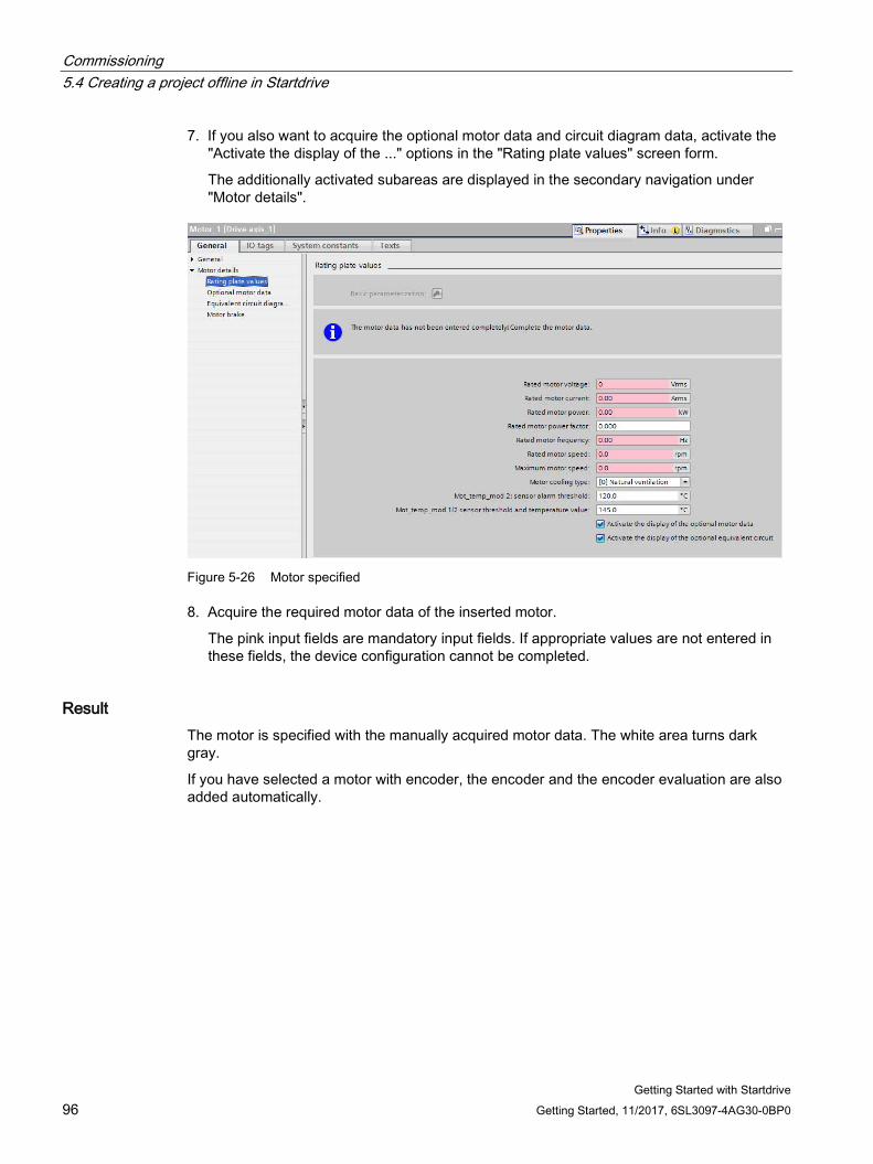
Commissioning 5.4 Creating a project offline in Startdrive
Getting Started with Startdrive 96 Getting Started, 11/2017, 6SL3097-4AG30-0BP0
7. If you also want to acquire the optional motor data and circuit diagram data, activate the "Activate the display of the ..." options in the "Rating plate values" screen form.
The additionally activated subareas are displayed in the secondary navigation under "Motor details".
Figure 5-26 Motor specified
8. Acquire the required motor data of the inserted motor.
The pink input fields are mandatory input fields. If appropriate values are not entered in these fields, the device configuration cannot be completed.
Result The motor is specified with the manually acquired motor data. The white area turns dark gray.
If you have selected a motor with encoder, the encoder and the encoder evaluation are also added automatically.
Commissioning 5.4 Creating a project offline in Startdrive
Getting Started with Startdrive Getting Started, 11/2017, 6SL3097-4AG30-0BP0 97
5.4.6 Inserting measuring systems
5.4.6.1 Overview
Definition For encoders, a distinction is made between two basic measuring system types:
● Motor encoders are normally mounted on the motor shaft so that motor motion (angle of rotation, rotor position, etc.) can be directly measured. Motor encoders supply the speed actual value that is incorporated in the closed-loop control (closed-loop speed and current control), so that for fast controllers, the actual speed value must also be supplied fast enough. This is the reason that high quality encoders must be used for motor encoders.
– Siemens motors that have already been configured are created in the device view with the matching encoder and the encoder evaluation.
– DRIVE-CLiQ motors are inserted together with an encoder. The drive and encoder parameters are transferred when you then load the configuration to the drive (download). The correct motor and encoder configuration are available offline in the project after an upload.
● Machine encoders are installed in the machine. Using machine encoders, for example, you synchronize the speed of a belt to another belt, or you determine the position of a workpiece. Basic, mounted encoders can be used in this case as these values are normally not required in a fast speed controller or current controller cycle.
Commissioning 5.4 Creating a project offline in Startdrive
Getting Started with Startdrive 98 Getting Started, 11/2017, 6SL3097-4AG30-0BP0
Available measuring systems (encoder) The following encoder types are supported in Startdrive:
● DRIVE-CLiQ encoder
These encoders are parameterized when downloading - and after an upload, are correctly displayed.
● SIN/COS encoders
Incremental encoders that supply a sinusoidal/cosinusoidal type signal are also available with SSI protocol.
● HTL/TTL encoders
Incremental encoders, which supply a square wave pattern, are also available with SSI protocol.
● Resolvers
Rotary position encoders.
● EnDat 2.1
Absolute encoders, which are controlled via the ENDAT 2.1 protocol.
● SSI encoder
Absolute encoders, which are controlled via the SSI protocol.
● Distance-coded zero marks Zero marks are used when homing is not possible or accepted.
Note Encoders from the hardware catalog
All of the encoders, which are listed in the hardware catalog, no longer have to be parameterized, as they are already preassigned the appropriate settings.
For user-defined encoders (third-party encoders), the parameters must be entered as subsequently described.
5.4.6.2 Inserting an encoder
Requirement ● A project has been created.
● The Control Unit is inserted in the device configuration.
● An infeed is inserted.
In case of doubt, you can also add the infeed at a later point in time. However, in this case, you must manually wire the "infeed" component with the other components.
● A Motor Module is inserted.
● A motor is inserted (optional).
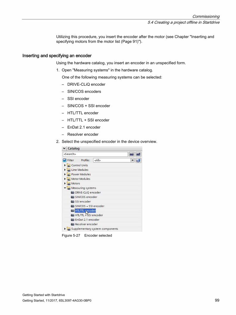
Commissioning 5.4 Creating a project offline in Startdrive
Getting Started with Startdrive Getting Started, 11/2017, 6SL3097-4AG30-0BP0 99
Utilizing this procedure, you insert the encoder after the motor (see Chapter "Inserting and specifying motors from the motor list (Page 91)").
Inserting and specifying an encoder Using the hardware catalog, you insert an encoder in an unspecified form.
1. Open "Measuring systems" in the hardware catalog.
One of the following measuring systems can be selected:
– DRIVE-CLiQ encoder
– SIN/COS encoders
– SSI encoder
– SIN/COS + SSI encoder
– HTL/TTL encoder
– HTL/TTL + SSI encoder
– EnDat 2.1 encoder
– Resolver encoder
2. Select the unspecified encoder in the device overview.
Figure 5-27 Encoder selected
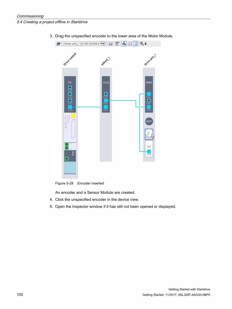
Commissioning 5.4 Creating a project offline in Startdrive
Getting Started with Startdrive 100 Getting Started, 11/2017, 6SL3097-4AG30-0BP0
3. Drag the unspecified encoder to the lower area of the Motor Module.
Figure 5-28 Encoder inserted
An encoder and a Sensor Module are created.
4. Click the unspecified encoder in the device view.
5. Open the Inspector window if it has still not been opened or displayed.
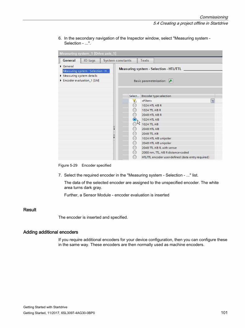
Commissioning 5.4 Creating a project offline in Startdrive
Getting Started with Startdrive Getting Started, 11/2017, 6SL3097-4AG30-0BP0 101
6. In the secondary navigation of the Inspector window, select "Measuring system - Selection - ...".
Figure 5-29 Encoder specified
7. Select the required encoder in the "Measuring system - Selection - ..." list.
The data of the selected encoder are assigned to the unspecified encoder. The white area turns dark gray.
Further, a Sensor Module - encoder evaluation is inserted
Result The encoder is inserted and specified.
Adding additional encoders If you require additional encoders for your device configuration, then you can configure these in the same way. These encoders are then normally used as machine encoders.

Commissioning 5.4 Creating a project offline in Startdrive
Getting Started with Startdrive 102 Getting Started, 11/2017, 6SL3097-4AG30-0BP0
5.4.7 Inserting additional system components Various system components can be inserted (additionally) in the device configuration of your drive:
● CBE20 Communication Board
● Terminal Module
● Terminal Board
● VSM10 Voltage Sensing Module
Since the handling of these system components differs when inserting, the insertion procedure is described separately in the following for each system component.
5.4.7.1 Adding a CBE20 Communication Board
Requirement ● A project has been created.
● A Control Unit is contained in the device configuration.
● No Terminal Board TB30 is contained in the device configuration.
TB30 and CBE20 cannot be created simultaneously in the device configuration.
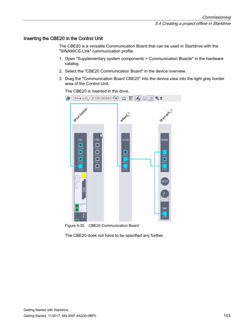
Commissioning 5.4 Creating a project offline in Startdrive
Getting Started with Startdrive Getting Started, 11/2017, 6SL3097-4AG30-0BP0 103
Inserting the CBE20 in the Control Unit The CBE20 is a versatile Communication Board that can be used in Startdrive with the "SINAMICS-Link" communication profile.
1. Open "Supplementary system components > Communication Boards" in the hardware catalog.
2. Select the "CBE20 Communication Board" in the device overview.
3. Drag the "Communication Board CBE20" into the device view into the light gray border area of the Control Unit.
The CBE20 is inserted in the drive.
Figure 5-30 CBE20 Communication Board
The CBE20 does not have to be specified any further.
Commissioning 5.4 Creating a project offline in Startdrive
Getting Started with Startdrive 104 Getting Started, 11/2017, 6SL3097-4AG30-0BP0
5.4.7.2 Adding a Terminal Module
Requirement ● A project has been created.
● A Control Unit is contained in the device configuration.
Adding Terminal Modules With Terminal Modules, you can expand the interfaces of the Control Unit. They are connected to the Control Unit via DRIVE-CLiQ. Terminal Modules do not have to be specified any further.
1. Open "Additional system components > Terminal Modules" in the hardware catalog.
The following Terminal Modules can be selected:
– Terminal Module TM15
– Terminal Module TM31
– Terminal Module TM41
– TM120 Terminal Module
– TM150 Terminal Module
2. Select the Terminal Module in the device overview.
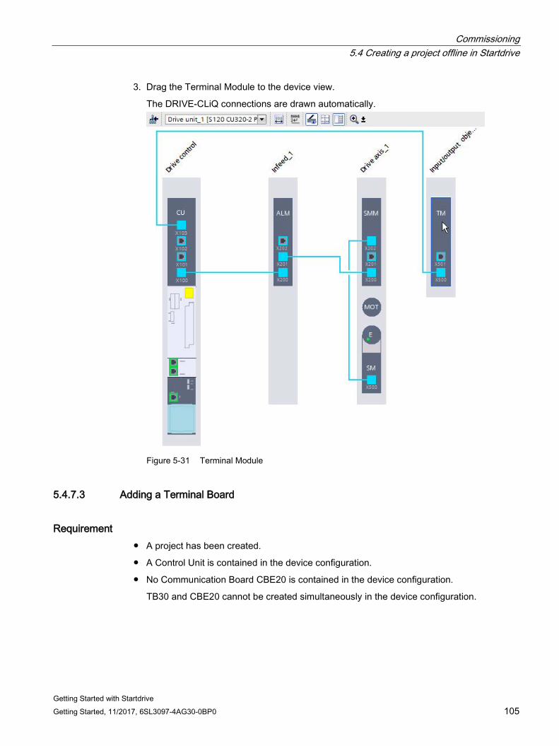
Commissioning 5.4 Creating a project offline in Startdrive
Getting Started with Startdrive Getting Started, 11/2017, 6SL3097-4AG30-0BP0 105
3. Drag the Terminal Module to the device view.
The DRIVE-CLiQ connections are drawn automatically.
Figure 5-31 Terminal Module
5.4.7.3 Adding a Terminal Board
Requirement ● A project has been created.
● A Control Unit is contained in the device configuration.
● No Communication Board CBE20 is contained in the device configuration.
TB30 and CBE20 cannot be created simultaneously in the device configuration.
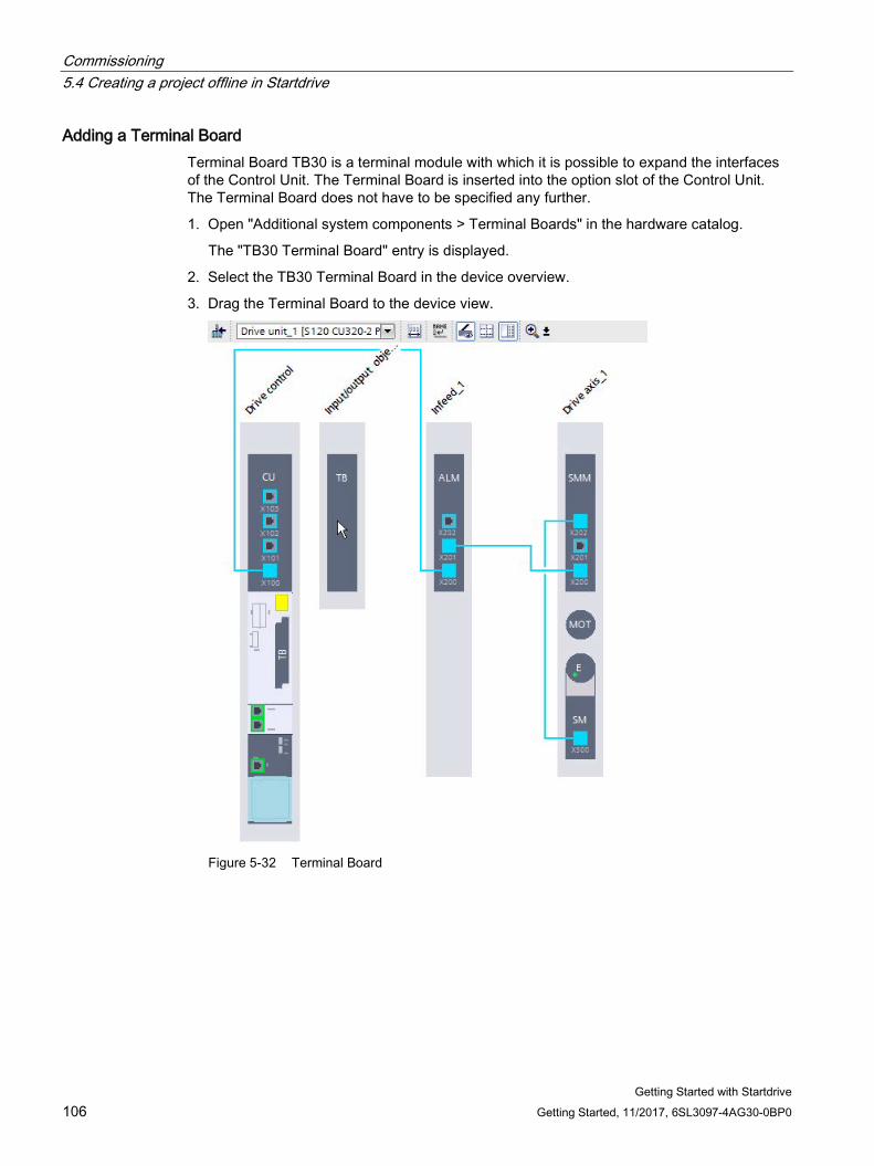
Commissioning 5.4 Creating a project offline in Startdrive
Getting Started with Startdrive 106 Getting Started, 11/2017, 6SL3097-4AG30-0BP0
Adding a Terminal Board Terminal Board TB30 is a terminal module with which it is possible to expand the interfaces of the Control Unit. The Terminal Board is inserted into the option slot of the Control Unit. The Terminal Board does not have to be specified any further.
1. Open "Additional system components > Terminal Boards" in the hardware catalog.
The "TB30 Terminal Board" entry is displayed.
2. Select the TB30 Terminal Board in the device overview.
3. Drag the Terminal Board to the device view.
Figure 5-32 Terminal Board
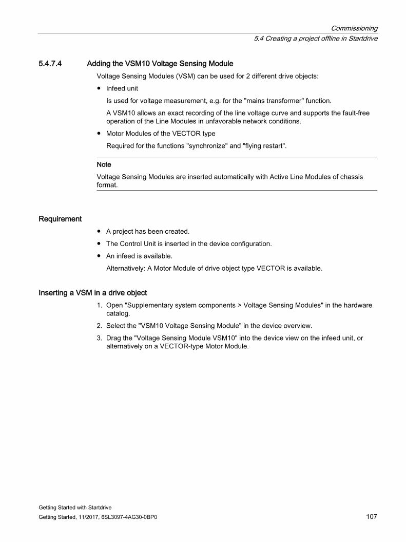
Commissioning 5.4 Creating a project offline in Startdrive
Getting Started with Startdrive Getting Started, 11/2017, 6SL3097-4AG30-0BP0 107
5.4.7.4 Adding the VSM10 Voltage Sensing Module Voltage Sensing Modules (VSM) can be used for 2 different drive objects:
● Infeed unit
Is used for voltage measurement, e.g. for the "mains transformer" function.
A VSM10 allows an exact recording of the line voltage curve and supports the fault-free operation of the Line Modules in unfavorable network conditions.
● Motor Modules of the VECTOR type
Required for the functions "synchronize" and "flying restart".
Note
Voltage Sensing Modules are inserted automatically with Active Line Modules of chassis format.
Requirement ● A project has been created.
● The Control Unit is inserted in the device configuration.
● An infeed is available.
Alternatively: A Motor Module of drive object type VECTOR is available.
Inserting a VSM in a drive object 1. Open "Supplementary system components > Voltage Sensing Modules" in the hardware
catalog.
2. Select the "VSM10 Voltage Sensing Module" in the device overview.
3. Drag the "Voltage Sensing Module VSM10" into the device view on the infeed unit, or alternatively on a VECTOR-type Motor Module.
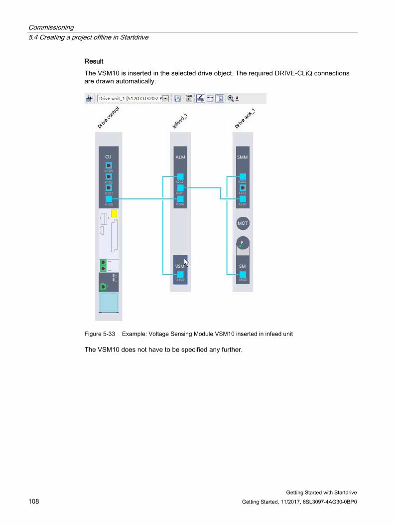
Commissioning 5.4 Creating a project offline in Startdrive
Getting Started with Startdrive 108 Getting Started, 11/2017, 6SL3097-4AG30-0BP0
Result
The VSM10 is inserted in the selected drive object. The required DRIVE-CLiQ connections are drawn automatically.
Figure 5-33 Example: Voltage Sensing Module VSM10 inserted in infeed unit
The VSM10 does not have to be specified any further.
Commissioning 5.4 Creating a project offline in Startdrive
Getting Started with Startdrive Getting Started, 11/2017, 6SL3097-4AG30-0BP0 109
Operation of several VSMs per Line Module You can add a total of up to three VSMs to each Line Module using drag and drop.
Note Activating the "Line transformer" function module
If you operate several VSMs on one Line Module, you must activate the "Line transformer" function module in the basic parameterization of the Line Module.
Note Deleting additional Voltage Sensing Modules
If you delete additional VSMs, you must deactivate the "Line transformer" function module in the basic parameterization. Otherwise the computing power of the Control Unit may be adversely affected.
Commissioning 5.5 Establishing an online connection to the drive unit
Getting Started with Startdrive 110 Getting Started, 11/2017, 6SL3097-4AG30-0BP0
5.5 Establishing an online connection to the drive unit
5.5.1 Overview
Interfaces for the online connection 2 interfaces are available for CU320-2 PN Control Units, via which you can go online with the drive:
● Ethernet commissioning interface X127
● PROFINET interface X150
The example given in this Getting Started section relates to interface X127.
First you connect your PC to the appropriate Control Unit interface.
IP addresses of the CU (hardware)
For X127, an IP address and a subnet mask have already been assigned on the Control Unit in the factory:
● IP address: 169.254.11.22
● Subnet mask: 255.255.0.0
IP addresses in the project
A CU320-2 PN is created with the following IP addresses in a project in TIA Portal:
The addresses correspond to the addresses that have already been assigned in the drive.
● IP address: 169.254.11.22
● Subnet mask: 255.255.0.0
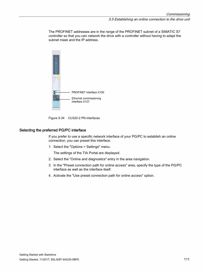
Commissioning 5.5 Establishing an online connection to the drive unit
Getting Started with Startdrive Getting Started, 11/2017, 6SL3097-4AG30-0BP0 111
The PROFINET addresses are in the range of the PROFINET subnet of a SIMATIC S7 controller so that you can network the drive with a controller without having to adapt the subnet mask and the IP address.
Figure 5-34 CU320-2 PN interfaces
Selecting the preferred PG/PC interface If you prefer to use a specific network interface of your PG/PC to establish an online connection, you can preset this interface.
1. Select the "Options > Settings" menu.
The settings of the TIA Portal are displayed.
2. Select the "Online and diagnostics" entry in the area navigation.
3. In the "Preset connection path for online access" area, specify the type of the PG/PC interface as well as the interface itself.
4. Activate the "Use preset connection path for online access" option.
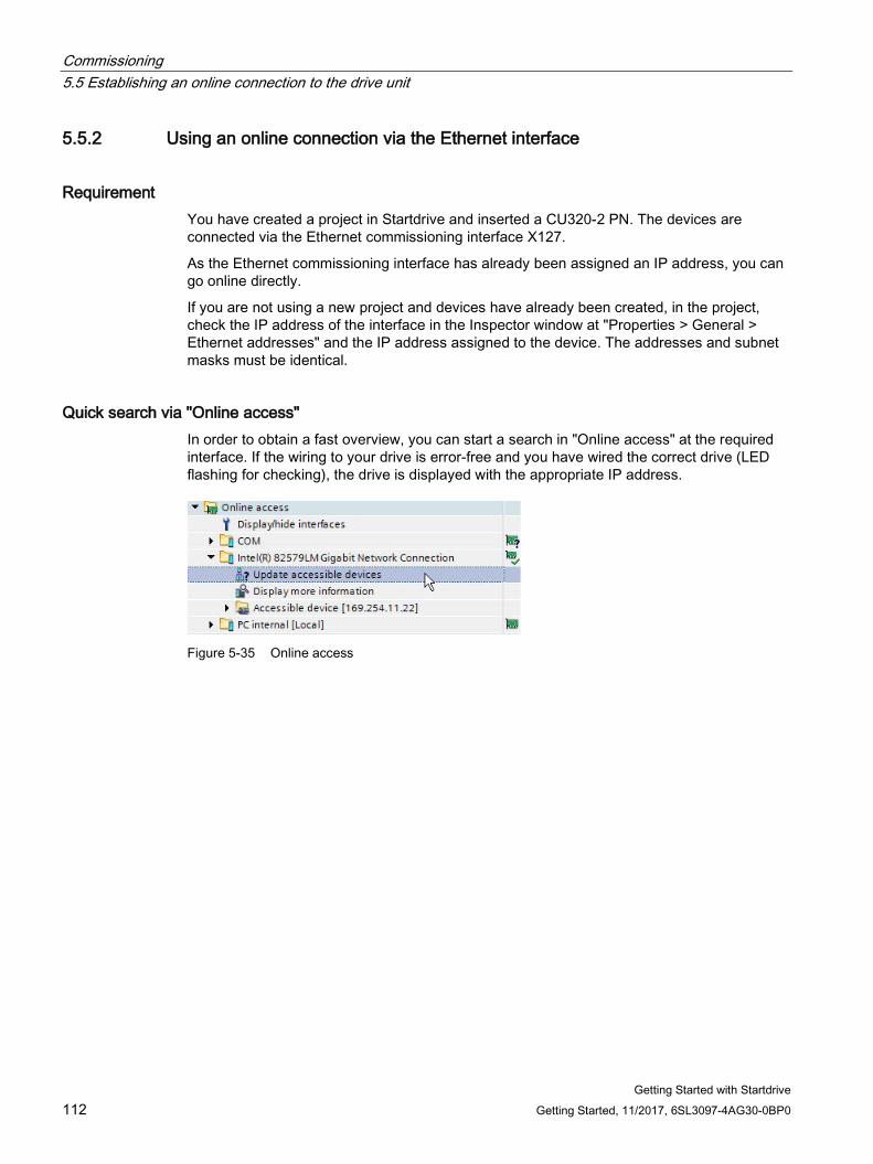
Commissioning 5.5 Establishing an online connection to the drive unit
Getting Started with Startdrive 112 Getting Started, 11/2017, 6SL3097-4AG30-0BP0
5.5.2 Using an online connection via the Ethernet interface
Requirement You have created a project in Startdrive and inserted a CU320-2 PN. The devices are connected via the Ethernet commissioning interface X127.
As the Ethernet commissioning interface has already been assigned an IP address, you can go online directly.
If you are not using a new project and devices have already been created, in the project, check the IP address of the interface in the Inspector window at "Properties > General > Ethernet addresses" and the IP address assigned to the device. The addresses and subnet masks must be identical.
Quick search via "Online access" In order to obtain a fast overview, you can start a search in "Online access" at the required interface. If the wiring to your drive is error-free and you have wired the correct drive (LED flashing for checking), the drive is displayed with the appropriate IP address.
Figure 5-35 Online access
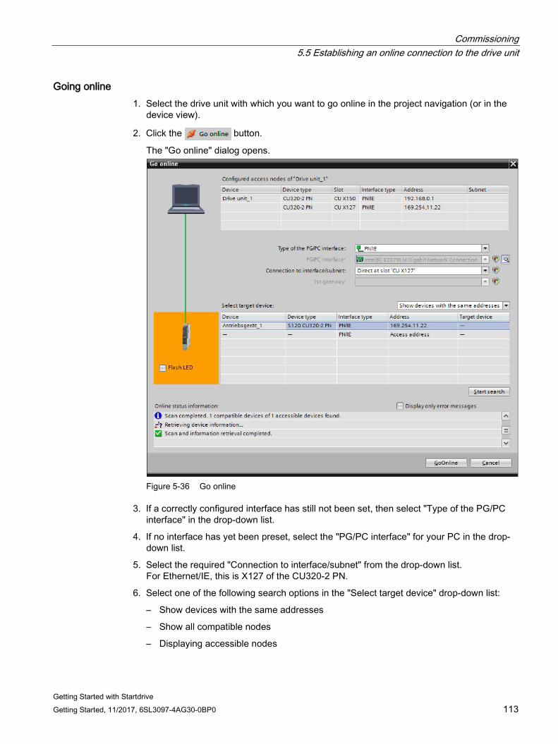
Commissioning 5.5 Establishing an online connection to the drive unit
Getting Started with Startdrive Getting Started, 11/2017, 6SL3097-4AG30-0BP0 113
Going online 1. Select the drive unit with which you want to go online in the project navigation (or in the
device view).
2. Click the button.
The "Go online" dialog opens.
Figure 5-36 Go online
3. If a correctly configured interface has still not been set, then select "Type of the PG/PC interface" in the drop-down list.
4. If no interface has yet been preset, select the "PG/PC interface" for your PC in the drop-down list.
5. Select the required "Connection to interface/subnet" from the drop-down list. For Ethernet/IE, this is X127 of the CU320-2 PN.
6. Select one of the following search options in the "Select target device" drop-down list:
– Show devices with the same addresses
– Show all compatible nodes
– Displaying accessible nodes
Commissioning 5.5 Establishing an online connection to the drive unit
Getting Started with Startdrive 114 Getting Started, 11/2017, 6SL3097-4AG30-0BP0
7. In order to search for the drive unit with the set parameters, click "Start search".
The devices that are found are displayed in the table of results.
8. Select your drive unit from the table.
9. To establish an online connection to the drive unit, click "Connect".
Result An online connection has been established between the PG/PC and the drive unit. The settings are used automatically the next time you go online and the "Go online" dialog is no longer displayed.
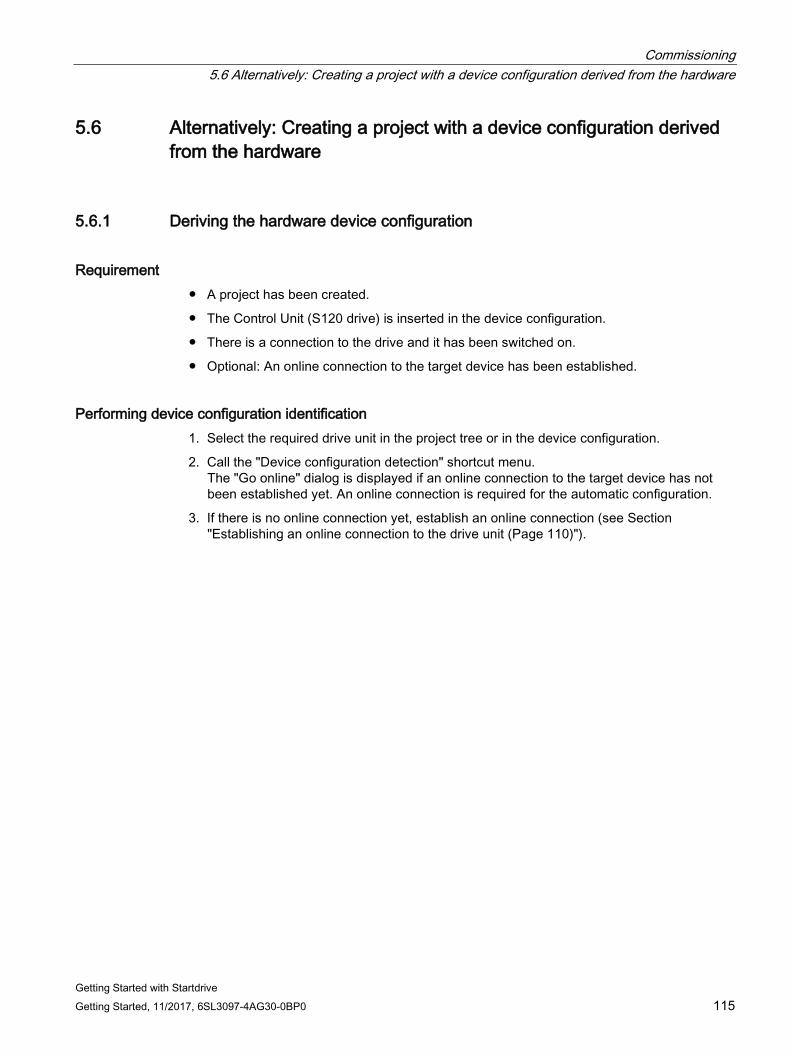
Commissioning 5.6 Alternatively: Creating a project with a device configuration derived from the hardware
Getting Started with Startdrive Getting Started, 11/2017, 6SL3097-4AG30-0BP0 115
5.6 Alternatively: Creating a project with a device configuration derived from the hardware
5.6.1 Deriving the hardware device configuration
Requirement ● A project has been created.
● The Control Unit (S120 drive) is inserted in the device configuration.
● There is a connection to the drive and it has been switched on.
● Optional: An online connection to the target device has been established.
Performing device configuration identification 1. Select the required drive unit in the project tree or in the device configuration.
2. Call the "Device configuration detection" shortcut menu. The "Go online" dialog is displayed if an online connection to the target device has not been established yet. An online connection is required for the automatic configuration.
3. If there is no online connection yet, establish an online connection (see Section "Establishing an online connection to the drive unit (Page 110)").
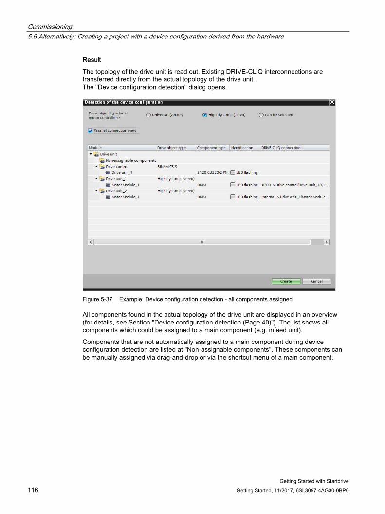
Commissioning 5.6 Alternatively: Creating a project with a device configuration derived from the hardware
Getting Started with Startdrive 116 Getting Started, 11/2017, 6SL3097-4AG30-0BP0
Result
The topology of the drive unit is read out. Existing DRIVE-CLiQ interconnections are transferred directly from the actual topology of the drive unit. The "Device configuration detection" dialog opens.
Figure 5-37 Example: Device configuration detection - all components assigned
All components found in the actual topology of the drive unit are displayed in an overview (for details, see Section "Device configuration detection (Page 40)"). The list shows all components which could be assigned to a main component (e.g. infeed unit).
Components that are not automatically assigned to a main component during device configuration detection are listed at "Non-assignable components". These components can be manually assigned via drag-and-drop or via the shortcut menu of a main component.
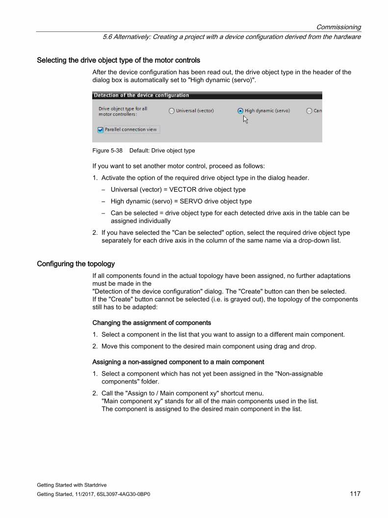
Commissioning 5.6 Alternatively: Creating a project with a device configuration derived from the hardware
Getting Started with Startdrive Getting Started, 11/2017, 6SL3097-4AG30-0BP0 117
Selecting the drive object type of the motor controls After the device configuration has been read out, the drive object type in the header of the dialog box is automatically set to "High dynamic (servo)".
Figure 5-38 Default: Drive object type
If you want to set another motor control, proceed as follows:
1. Activate the option of the required drive object type in the dialog header.
– Universal (vector) = VECTOR drive object type
– High dynamic (servo) = SERVO drive object type
– Can be selected = drive object type for each detected drive axis in the table can be assigned individually
2. If you have selected the "Can be selected" option, select the required drive object type separately for each drive axis in the column of the same name via a drop-down list.
Configuring the topology If all components found in the actual topology have been assigned, no further adaptations must be made in the "Detection of the device configuration" dialog. The "Create" button can then be selected. If the "Create" button cannot be selected (i.e. is grayed out), the topology of the components still has to be adapted:
Changing the assignment of components
1. Select a component in the list that you want to assign to a different main component.
2. Move this component to the desired main component using drag and drop.
Assigning a non-assigned component to a main component
1. Select a component which has not yet been assigned in the "Non-assignable components" folder.
2. Call the "Assign to / Main component xy" shortcut menu. "Main component xy" stands for all of the main components used in the list. The component is assigned to the desired main component in the list.
Commissioning 5.6 Alternatively: Creating a project with a device configuration derived from the hardware
Getting Started with Startdrive 118 Getting Started, 11/2017, 6SL3097-4AG30-0BP0
Deleting a component
1. Select the components which are to be deleted.
2. Call the "Delete" shortcut menu. The component is deleted.
Note
All components in the "Non-assignable components" folder prevent the creation of this read-out actual topology of the drive unit in the device configuration.
If individual components which have not yet been assigned cannot be assigned to a main component, delete the corresponding list entries in the "Non-assignable components" folder, in order that the remaining components can be adopted in the device configuration.
Renaming the component
1. Select the components which are to be renamed.
2. Call the "Rename" shortcut menu.
3. Enter a new name for the component.
Connecting components in parallel The parallel connection view supports you in the parallel connection of components.
1. Activate the "Parallel connection view" option.
The "Connect in parallel at" shortcut menu is now available (see Step 2).
2. The following options are available for connecting components in parallel:
– Drag and drop Drag the components that can be connected in parallel using drag and drop to connect them in parallel.
– Shortcut menu: Right-click the components to be connected in parallel. In the shortcut menu, the "Connect in parallel" menu item shows all the drive objects to which the selected component can be connected in parallel. The "All" item switches the selected power unit parallel to all connectable components.
Cancelling a parallel connection
You can cancel an existing parallel connection as follows:
1. Drag components to the higher-level drive unit using drag and drop. - Or -
2. Select a component connected in parallel and select the "Disconnect parallel connection" shortcut menu.
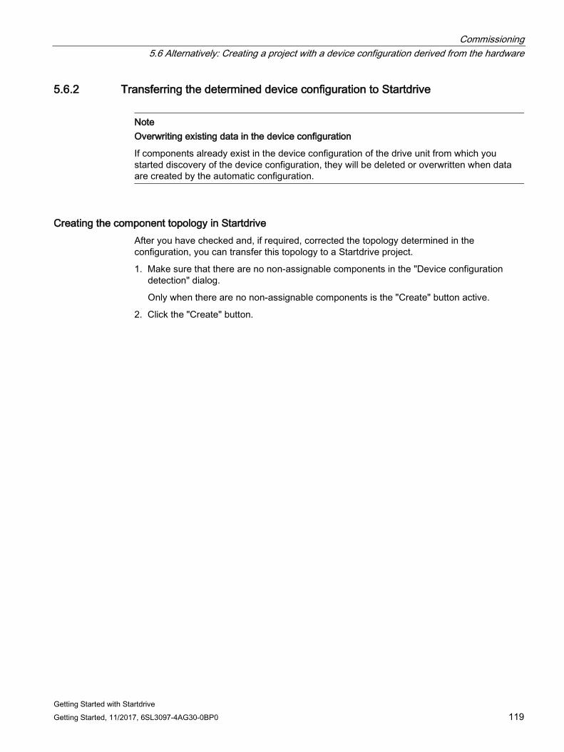
Commissioning 5.6 Alternatively: Creating a project with a device configuration derived from the hardware
Getting Started with Startdrive Getting Started, 11/2017, 6SL3097-4AG30-0BP0 119
5.6.2 Transferring the determined device configuration to Startdrive
Note Overwriting existing data in the device configuration
If components already exist in the device configuration of the drive unit from which you started discovery of the device configuration, they will be deleted or overwritten when data are created by the automatic configuration.
Creating the component topology in Startdrive After you have checked and, if required, corrected the topology determined in the configuration, you can transfer this topology to a Startdrive project.
1. Make sure that there are no non-assignable components in the "Device configuration detection" dialog.
Only when there are no non-assignable components is the "Create" button active.
2. Click the "Create" button.
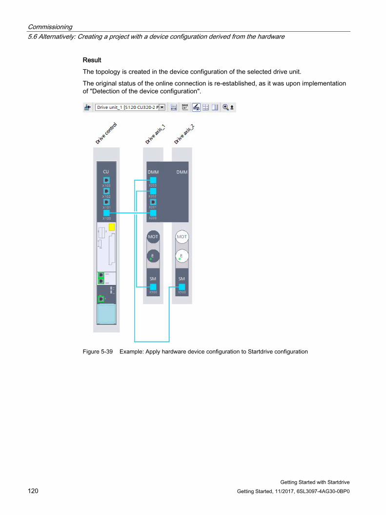
Commissioning 5.6 Alternatively: Creating a project with a device configuration derived from the hardware
Getting Started with Startdrive 120 Getting Started, 11/2017, 6SL3097-4AG30-0BP0
Result
The topology is created in the device configuration of the selected drive unit.
The original status of the online connection is re-established, as it was upon implementation of "Detection of the device configuration".
Figure 5-39 Example: Apply hardware device configuration to Startdrive configuration
Commissioning 5.6 Alternatively: Creating a project with a device configuration derived from the hardware
Getting Started with Startdrive Getting Started, 11/2017, 6SL3097-4AG30-0BP0 121
5.6.3 Revising the configuration Optimally, all components are transferred specified to the device configuration during an automatic configuration and do not have to be subsequently specified or supplemented. If this is the case, a message is shown in the message display that the automatic device configuration has been performed without error.
If, however, not all components of the drive could be read out by the automatic configuration, although they do exist physically, the components are created unspecified in the device view. The missing specification must therefore be added in the device configuration.
Specifying unspecified components To specify, proceed as follows:
1. Click in the inner white area of the unspecified component envelope.
The area is shown as selected.
2. Open the Inspector window if it has still not been opened or displayed.
3. In the secondary navigation of the Inspector window, select "... - Selection".
A selection of the available components is displayed on the right in "... - Selection".
4. Select the component.
Result
● The component is displayed in the device view as specified (the area now has a dark color). The data are displayed accordingly in the device overview.
● The data of the selected component unit were assigned to the unspecified component unit.

Commissioning 5.6 Alternatively: Creating a project with a device configuration derived from the hardware
Getting Started with Startdrive 122 Getting Started, 11/2017, 6SL3097-4AG30-0BP0
Getting Started with Startdrive Getting Started, 11/2017, 6SL3097-4AG30-0BP0 123
Performing basic parameterization 6 6.1 Control Unit
6.1.1 Web server
6.1.1.1 Activating and configuring the web server The web server provides information on a SINAMICS device via its web pages. Access is via an Internet browser. The information on the web pages is shown in German or English. For information about message texts, drive object states and parameter names, there is a language selection which allows the display to be switched over to the required language (German, English, Chinese, Italian, French, Spanish).
You configure the web server using a screen form.
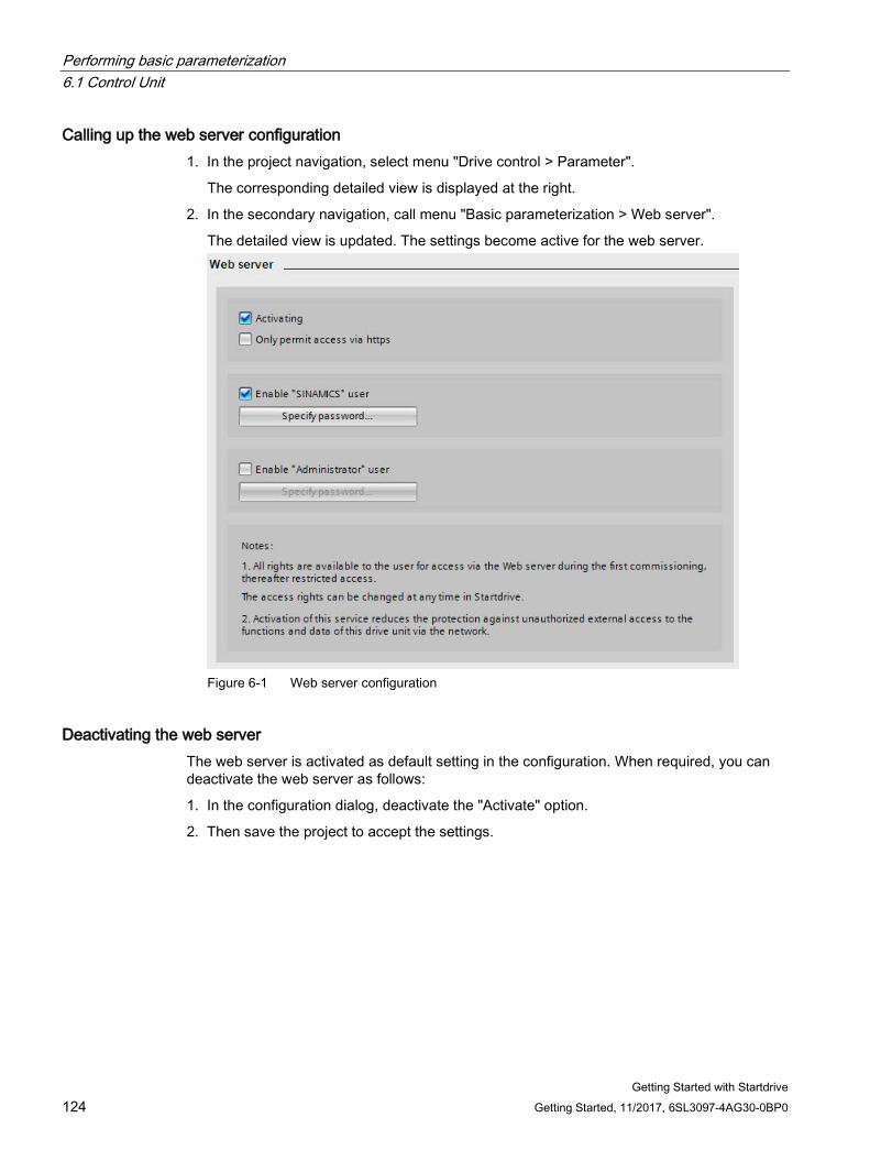
Performing basic parameterization 6.1 Control Unit
Getting Started with Startdrive 124 Getting Started, 11/2017, 6SL3097-4AG30-0BP0
Calling up the web server configuration 1. In the project navigation, select menu "Drive control > Parameter".
The corresponding detailed view is displayed at the right.
2. In the secondary navigation, call menu "Basic parameterization > Web server".
The detailed view is updated. The settings become active for the web server.
Figure 6-1 Web server configuration
Deactivating the web server The web server is activated as default setting in the configuration. When required, you can deactivate the web server as follows:
1. In the configuration dialog, deactivate the "Activate" option.
2. Then save the project to accept the settings.
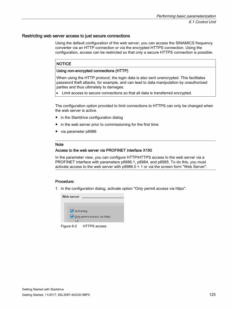
Performing basic parameterization 6.1 Control Unit
Getting Started with Startdrive Getting Started, 11/2017, 6SL3097-4AG30-0BP0 125
Restricting web server access to just secure connections Using the default configuration of the web server, you can access the SINAMICS frequency converter via an HTTP connection or via the encrypted HTTPS connection. Using the configuration, access can be restricted so that only a secure HTTPS connection is possible.
NOTICE
Using non-encrypted connections (HTTP)
When using the HTTP protocol, the login data is also sent unencrypted. This facilitates password theft attacks, for example, and can lead to data manipulation by unauthorized parties and thus ultimately to damages. • Limit access to secure connections so that all data is transferred encrypted.
The configuration option provided to limit connections to HTTPS can only be changed when the web server is active.
● in the Startdrive configuration dialog
● in the web server prior to commissioning for the first time
● via parameter p8986
Note Access to the web server via PROFINET interface X150
In the parameter view, you can configure HTTP/HTTPS access to the web server via a PROFINET interface with parameters p8986.1, p8984, and p8985. To do this, you must activate access to the web server with p8986.0 = 1 or via the screen form "Web Server".
Procedure:
1. In the configuration dialog, activate option "Only permit access via https".
Figure 6-2 HTTPS access
Performing basic parameterization 6.1 Control Unit
Getting Started with Startdrive 126 Getting Started, 11/2017, 6SL3097-4AG30-0BP0
6.1.1.2 Setting or changing web server user accounts For SINAMICS S120, the rights of both user accounts "SINAMICS" and "Administrator" are permanently defined and cannot be changed by users.
The user "Administrator" has full rights by default. However, the standard "SINAMICS" user only has restricted access rights.
You can make the following settings in Startdrive for the web server user accounts:
● Enable or disable user "SINAMICS" or user "Administrator"
● Set a password for user "SINAMICS" or user "Administrator"
● Change the password of user "SINAMICS" or user "Administrator"
● Delete the password of user "SINAMICS"
Default password settings after first commissioning
● SINAMICS: No password set
It is recommended that you assign a password. This must comprise at least 8 characters.
● Administrator: No password set
A password must be assigned for this user. This must comprise at least 8 characters.
Note Secure passwords
The password must include the following elements to provide protection against unauthorized access, e.g. unauthorized persons. • At least 8 characters • Uppercase as well as also lowercase letters • Numbers and special characters (e.g.: ?!%+ ...)
The password must not be used elsewhere.
Enabling users The "SINAMICS" user and the "Administrator" user can be enabled with their own specific rights. You can also set whether password protection will be active for the "SINAMICS" user.
To enable a user and activate a password, proceed as follows:
1. Activate the "Enable SINAMICS user" option.
And/Or
2. Activate the "Enable administrator user" option.
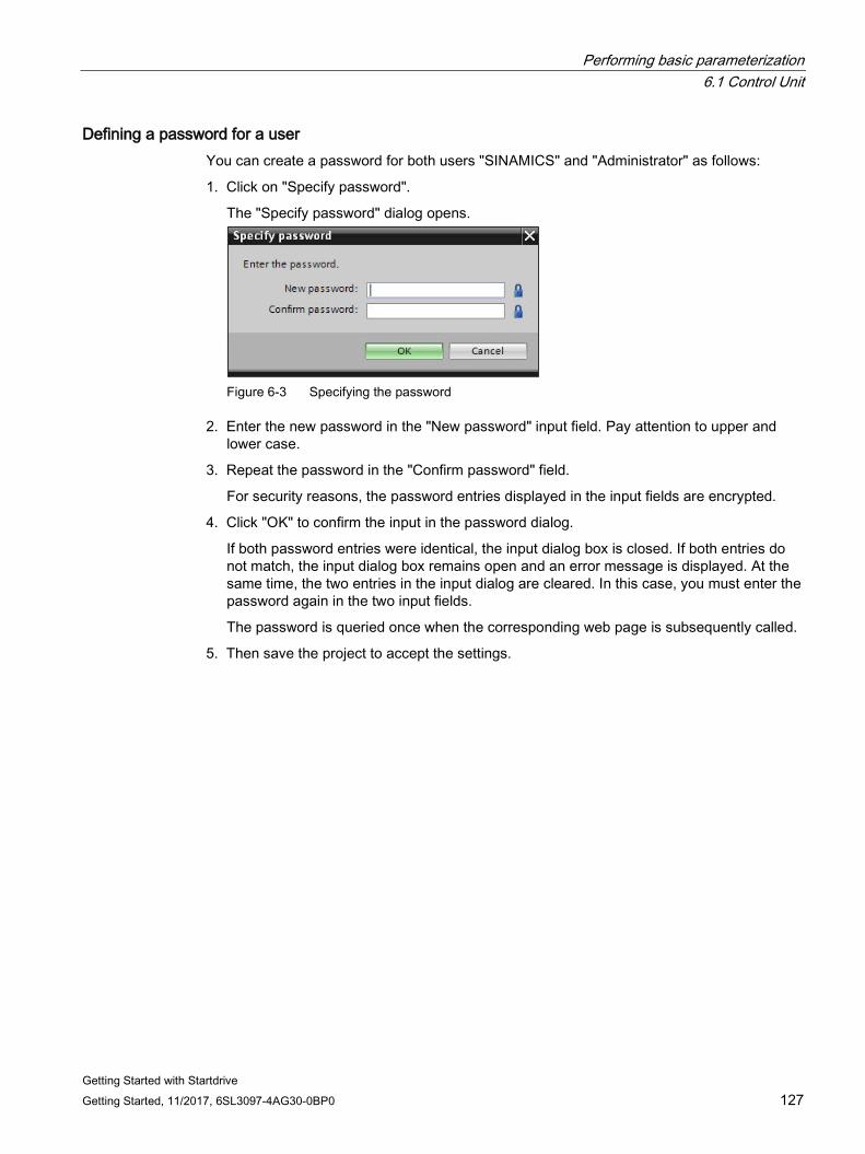
Performing basic parameterization 6.1 Control Unit
Getting Started with Startdrive Getting Started, 11/2017, 6SL3097-4AG30-0BP0 127
Defining a password for a user You can create a password for both users "SINAMICS" and "Administrator" as follows:
1. Click on "Specify password".
The "Specify password" dialog opens.
Figure 6-3 Specifying the password
2. Enter the new password in the "New password" input field. Pay attention to upper and lower case.
3. Repeat the password in the "Confirm password" field.
For security reasons, the password entries displayed in the input fields are encrypted.
4. Click "OK" to confirm the input in the password dialog.
If both password entries were identical, the input dialog box is closed. If both entries do not match, the input dialog box remains open and an error message is displayed. At the same time, the two entries in the input dialog are cleared. In this case, you must enter the password again in the two input fields.
The password is queried once when the corresponding web page is subsequently called.
5. Then save the project to accept the settings.
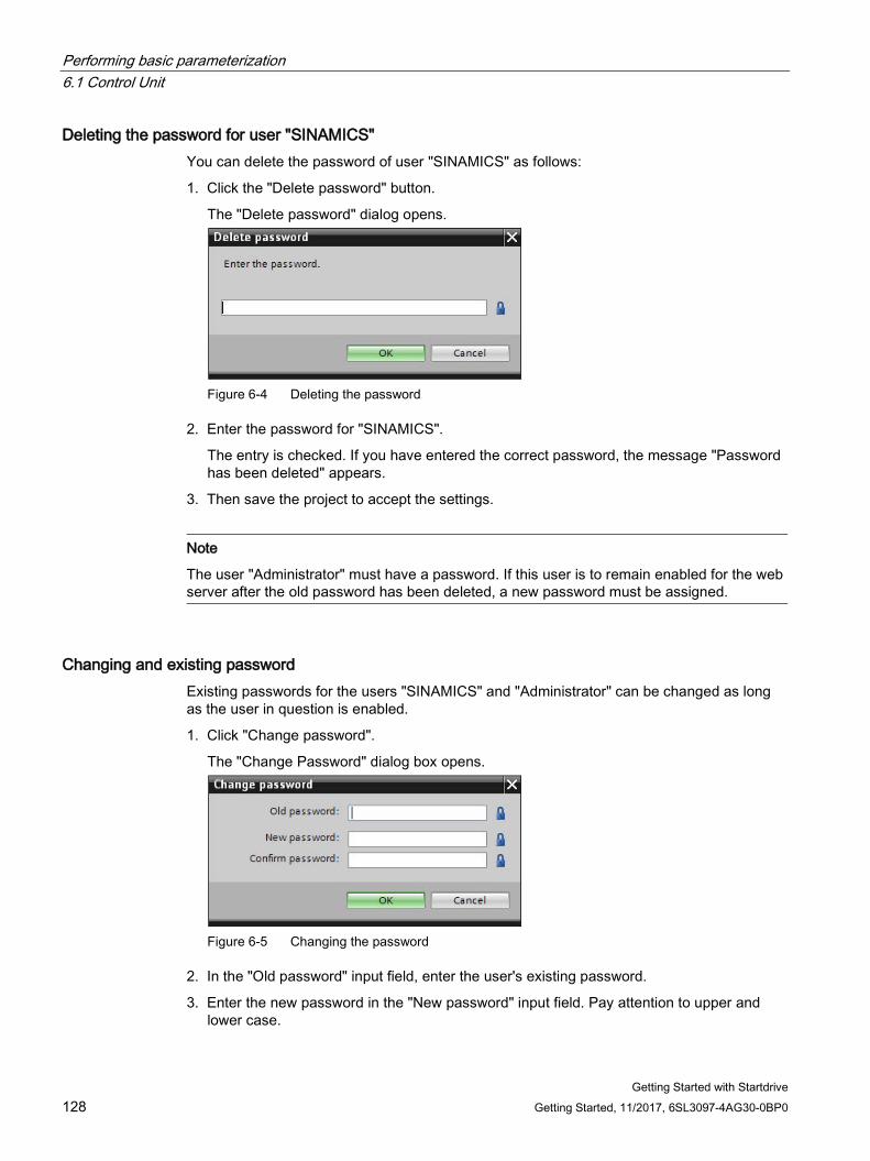
Performing basic parameterization 6.1 Control Unit
Getting Started with Startdrive 128 Getting Started, 11/2017, 6SL3097-4AG30-0BP0
Deleting the password for user "SINAMICS" You can delete the password of user "SINAMICS" as follows:
1. Click the "Delete password" button.
The "Delete password" dialog opens.
Figure 6-4 Deleting the password
2. Enter the password for "SINAMICS".
The entry is checked. If you have entered the correct password, the message "Password has been deleted" appears.
3. Then save the project to accept the settings.
Note
The user "Administrator" must have a password. If this user is to remain enabled for the web server after the old password has been deleted, a new password must be assigned.
Changing and existing password Existing passwords for the users "SINAMICS" and "Administrator" can be changed as long as the user in question is enabled.
1. Click "Change password".
The "Change Password" dialog box opens.
Figure 6-5 Changing the password
2. In the "Old password" input field, enter the user's existing password.
3. Enter the new password in the "New password" input field. Pay attention to upper and lower case.
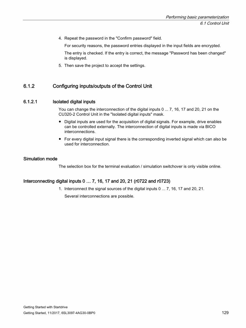
Performing basic parameterization 6.1 Control Unit
Getting Started with Startdrive Getting Started, 11/2017, 6SL3097-4AG30-0BP0 129
4. Repeat the password in the "Confirm password" field.
For security reasons, the password entries displayed in the input fields are encrypted.
The entry is checked. If the entry is correct, the message "Password has been changed" is displayed.
5. Then save the project to accept the settings.
6.1.2 Configuring inputs/outputs of the Control Unit
6.1.2.1 Isolated digital inputs You can change the interconnection of the digital inputs 0 ... 7, 16, 17 and 20, 21 on the CU320-2 Control Unit in the "Isolated digital inputs" mask.
● Digital inputs are used for the acquisition of digital signals. For example, drive enables can be controlled externally. The interconnection of digital inputs is made via BICO interconnections.
● For every digital input signal there is the corresponding inverted signal which can also be used for interconnection.
Simulation mode The selection box for the terminal evaluation / simulation switchover is only visible online.
Interconnecting digital inputs 0 … 7, 16, 17 and 20, 21 (r0722 and r0723) 1. Interconnect the signal sources of the digital inputs 0 ... 7, 16, 17 and 20, 21.
Several interconnections are possible.
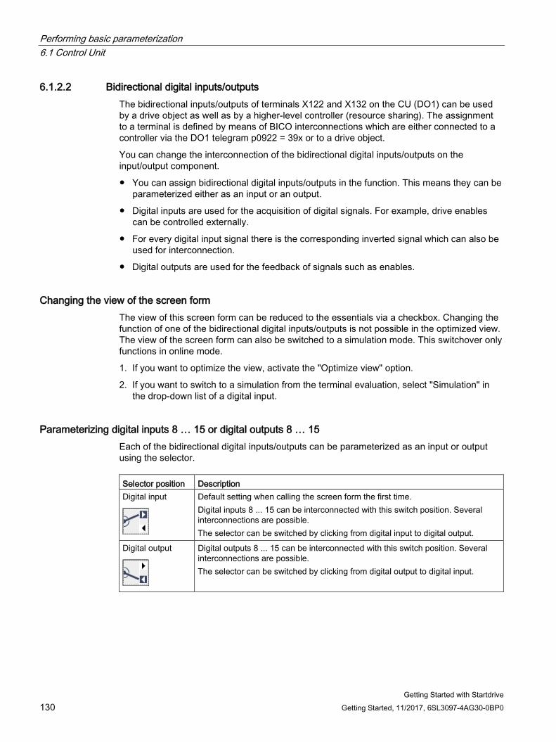
Performing basic parameterization 6.1 Control Unit
Getting Started with Startdrive 130 Getting Started, 11/2017, 6SL3097-4AG30-0BP0
6.1.2.2 Bidirectional digital inputs/outputs The bidirectional inputs/outputs of terminals X122 and X132 on the CU (DO1) can be used by a drive object as well as by a higher-level controller (resource sharing). The assignment to a terminal is defined by means of BICO interconnections which are either connected to a controller via the DO1 telegram p0922 = 39x or to a drive object.
You can change the interconnection of the bidirectional digital inputs/outputs on the input/output component.
● You can assign bidirectional digital inputs/outputs in the function. This means they can be parameterized either as an input or an output.
● Digital inputs are used for the acquisition of digital signals. For example, drive enables can be controlled externally.
● For every digital input signal there is the corresponding inverted signal which can also be used for interconnection.
● Digital outputs are used for the feedback of signals such as enables.
Changing the view of the screen form The view of this screen form can be reduced to the essentials via a checkbox. Changing the function of one of the bidirectional digital inputs/outputs is not possible in the optimized view. The view of the screen form can also be switched to a simulation mode. This switchover only functions in online mode.
1. If you want to optimize the view, activate the "Optimize view" option.
2. If you want to switch to a simulation from the terminal evaluation, select "Simulation" in the drop-down list of a digital input.
Parameterizing digital inputs 8 … 15 or digital outputs 8 … 15 Each of the bidirectional digital inputs/outputs can be parameterized as an input or output using the selector. Selector position Description Digital input
Default setting when calling the screen form the first time. Digital inputs 8 ... 15 can be interconnected with this switch position. Several interconnections are possible. The selector can be switched by clicking from digital input to digital output.
Digital output
Digital outputs 8 ... 15 can be interconnected with this switch position. Several interconnections are possible. The selector can be switched by clicking from digital output to digital input.
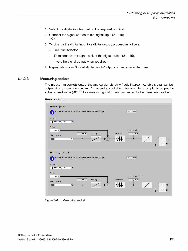
Performing basic parameterization 6.1 Control Unit
Getting Started with Startdrive Getting Started, 11/2017, 6SL3097-4AG30-0BP0 131
1. Select the digital input/output on the required terminal.
2. Connect the signal source of the digital input (8 ... 15). - Or -
3. To change the digital input to a digital output, proceed as follows:
– Click the selector.
– Then connect the signal sink of the digital output (8 ... 15).
– Invert the digital output when required.
4. Repeat steps 2 or 3 for all digital inputs/outputs of the required terminal.
6.1.2.3 Measuring sockets The measuring sockets output the analog signals. Any freely interconnectable signal can be output at any measuring socket. A measuring socket can be used, for example, to output the actual speed value (r0063) to a measuring instrument connected to the measuring socket.
Figure 6-6 Measuring socket
Performing basic parameterization 6.1 Control Unit
Getting Started with Startdrive 132 Getting Started, 11/2017, 6SL3097-4AG30-0BP0
Note Only for commissioning and service
The measuring sockets may only be used for commissioning and service purposes. The measurements may be performed only by appropriately trained skilled personnel.
Limitation on/off (p0784) With the "Limitation" drop-down list, select whether the output value of the measuring socket is to be restricted to the limit values of the characteristic curve for the required measuring socket.
1. Select one of the following settings in the "Limitation" drop-down list of a measuring socket:
– Limitation On
If signals are output outside the permissible measuring range, the signal is limited to 4.98 V or to 0 V.
– Limitation Off
The output of signals outside the permissible measuring range causes a signal overflow. In the event of an overflow, the signal jumps from 0 V to 4.98 V or from 4.98 to 0 V.
Select signal source for T0, T1 and T2 The signal to be output via a measuring socket is specified by interconnecting a signal source p0771[0...2].
Table 6- 1 Important measuring signals (examples):
r0060 CO: Speed setpoint before speed setpoint filter r0063 CO: Actual speed value r0069[0...2] CO: Actual phase currents value r0075 CO: Field-generating current setpoint r0076 CO: Actual field-generating current value r0077 CO: Torque-generating current setpoint r0078 CO: Actual torque-generating current value
1. Select the signal sources whose signal is to be output via the measuring socket for the respective measuring sockets T0, T1 and T2.
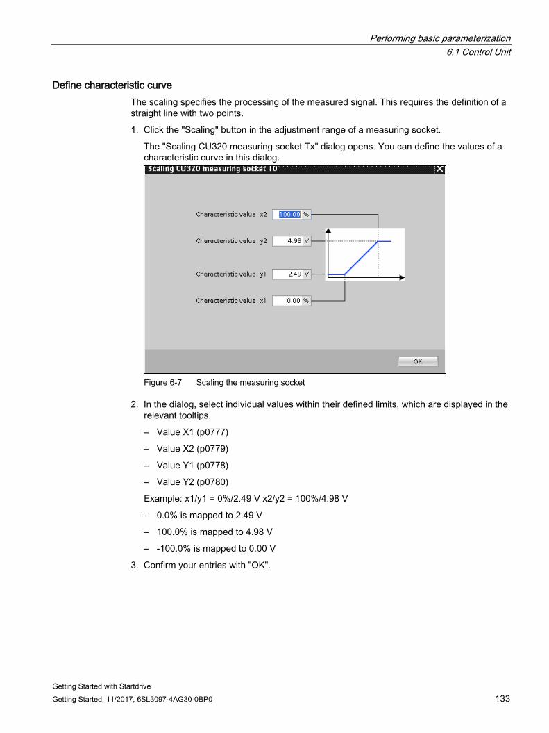
Performing basic parameterization 6.1 Control Unit
Getting Started with Startdrive Getting Started, 11/2017, 6SL3097-4AG30-0BP0 133
Define characteristic curve The scaling specifies the processing of the measured signal. This requires the definition of a straight line with two points.
1. Click the "Scaling" button in the adjustment range of a measuring socket.
The "Scaling CU320 measuring socket Tx" dialog opens. You can define the values of a characteristic curve in this dialog.
Figure 6-7 Scaling the measuring socket
2. In the dialog, select individual values within their defined limits, which are displayed in the relevant tooltips.
– Value X1 (p0777)
– Value X2 (p0779)
– Value Y1 (p0778)
– Value Y2 (p0780)
Example: x1/y1 = 0%/2.49 V x2/y2 = 100%/4.98 V
– 0.0% is mapped to 2.49 V
– 100.0% is mapped to 4.98 V
– -100.0% is mapped to 0.00 V
3. Confirm your entries with "OK".
Performing basic parameterization 6.1 Control Unit
Getting Started with Startdrive 134 Getting Started, 11/2017, 6SL3097-4AG30-0BP0
Define the offset (p0783) The offset is applied additively to the signal to be output. The signal to be output can thus be displayed within the measuring range.
1. Enter the required offset value in the "Offset" field for the relevant measuring socket.
Function diagrams (see SINAMICS S120/S150 List Manual) • 8134 Diagnostics - measuring sockets (T0, T1, T2)
Overview of important parameters (see SINAMICS S120/S150 List Manual) Adjustable parameters • p0771[0...2] CI: Measuring sockets signal source
• p0777[0...2] Measuring sockets characteristic curve value x1
• p0778[0...2] Measuring sockets characteristic curve value y1
• p0779[0...2] Measuring sockets characteristic curve value x2
• p0780[0...2] Measuring sockets characteristic curve value y2
• p0783[0...2] Measuring sockets offset
• p0784[0...2] Measuring sockets limitation on/off
Display parameters • r0772[0...2] Measuring sockets signal to be output
• r0774[0...2] Measuring sockets output voltage
• r0786[0...2] Measuring sockets scaling per volt
Performing basic parameterization 6.2 Infeed unit
Getting Started with Startdrive Getting Started, 11/2017, 6SL3097-4AG30-0BP0 135
6.2 Infeed unit
6.2.1 Overview
Infeed units (Line Modules) Line Modules contain the central line infeed for the DC link. Various Line Modules can be selected to address the various application profiles:
● Basic Line Modules (BLM)
● Smart Line Modules (SLM)
● Active Line Modules (ALM)
Basic parameterization of the infeed unit Define the following data in the basic parameterization of the infeed unit:
● Function modules
● Line data/operating mode
● Enable logic
● Line contactor control
Calling the screen form 1. In the project navigation, select menu "Infeed_x > Parameter".
The corresponding detailed view is displayed at the right.
2. In the secondary navigation, call menu "Basic parameterization > xxx" (xxx stands for the name of the particular detailed screen form).
The detailed view is updated.
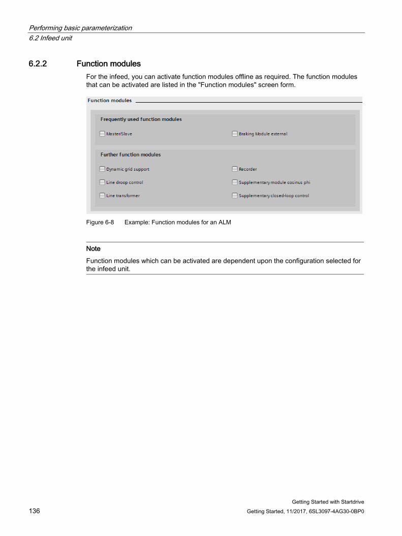
Performing basic parameterization 6.2 Infeed unit
Getting Started with Startdrive 136 Getting Started, 11/2017, 6SL3097-4AG30-0BP0
6.2.2 Function modules For the infeed, you can activate function modules offline as required. The function modules that can be activated are listed in the "Function modules" screen form.
Figure 6-8 Example: Function modules for an ALM
Note
Function modules which can be activated are dependent upon the configuration selected for the infeed unit.
Performing basic parameterization 6.2 Infeed unit
Getting Started with Startdrive Getting Started, 11/2017, 6SL3097-4AG30-0BP0 137
The function modules that can be used are presorted in two areas:
● Frequently used function modules
– Master/slave
Redundant operation of several ALMs on one DC link.
– External Braking Module
Control of an external Braking Module in order to be able to collect braking energy in the event of a power failure.
● Additional function modules
– Fault ride-through
For power generation applications in an interconnected system: Functions for fault ride-through and line monitoring (incl. active anti-islanding) according to power system guidelines.
– Line droop control; installation, synchronization and operation of stand-alone systems: Control of line frequency and line voltage in single operation or together with other generators.
– Line transformer
For power generation applications: Magnetization of a transformer to limit the inrush current when the line system is connected.
Compensation for direct current components and voltage drops on the transformer in conjunction with fault ride-through or line droop control.
– Recorder
Recording fault events
– Cosine Phi add-on module
Precise cos(Phi) determination based on fundamental current and voltage components with BICO-connectable input variables (in contrast to power factor r0038).
– Additional control
For applications with asymmetrical line voltages: A negative sequence system current controller is used to balance the line currents and reduce the DC-link ripple.
For applications with resonance effects in the current or the filter voltage (e.g. in systems with low short-circuit power rating): Freely parameterizable band-pass filters for resonance damping
Activating function modules 1. Activate the required function module by clicking the option.
Repeat this for all additional function modules that you wish to activate.
2. Save the project to backup the settings.
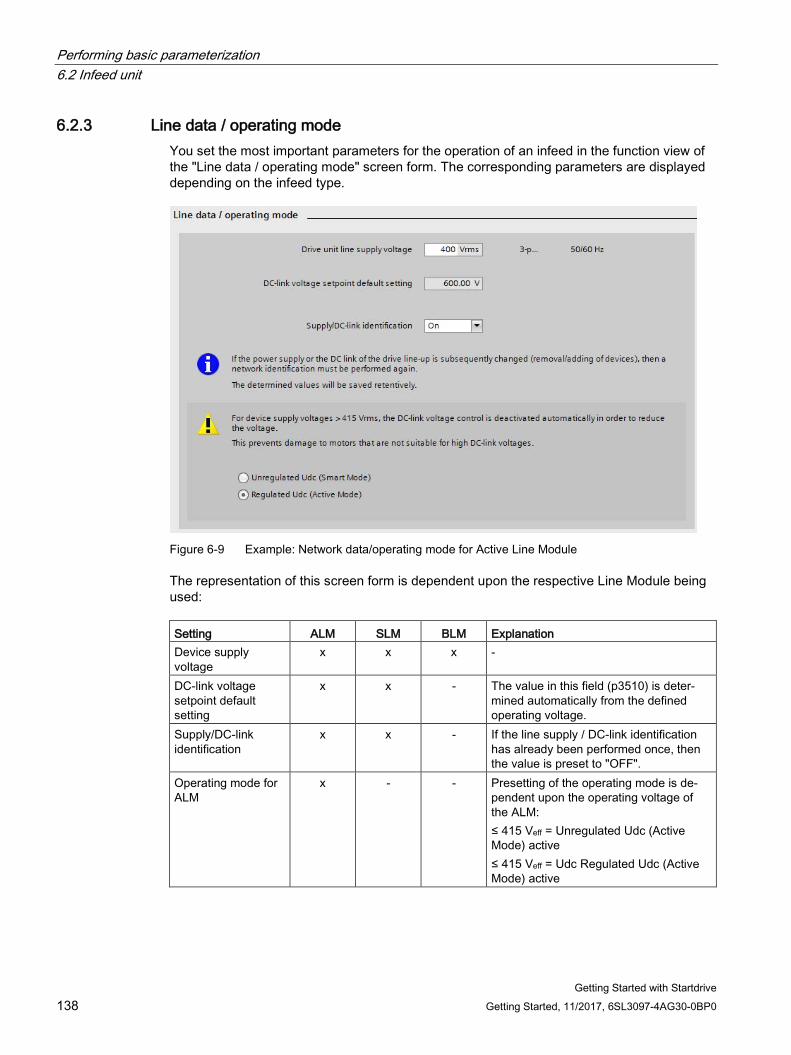
Performing basic parameterization 6.2 Infeed unit
Getting Started with Startdrive 138 Getting Started, 11/2017, 6SL3097-4AG30-0BP0
6.2.3 Line data / operating mode You set the most important parameters for the operation of an infeed in the function view of the "Line data / operating mode" screen form. The corresponding parameters are displayed depending on the infeed type.
Figure 6-9 Example: Network data/operating mode for Active Line Module
The representation of this screen form is dependent upon the respective Line Module being used: Setting ALM SLM BLM Explanation Device supply voltage
x x x -
DC-link voltage setpoint default setting
x x - The value in this field (p3510) is deter-mined automatically from the defined operating voltage.
Supply/DC-link identification
x x - If the line supply / DC-link identification has already been performed once, then the value is preset to "OFF".
Operating mode for ALM
x - - Presetting of the operating mode is de-pendent upon the operating voltage of the ALM: ≤ 415 Veff = Unregulated Udc (Active Mode) active ≤ 415 Veff = Udc Regulated Udc (Active Mode) active
Performing basic parameterization 6.2 Infeed unit
Getting Started with Startdrive Getting Started, 11/2017, 6SL3097-4AG30-0BP0 139
Setting the line data and operating mode The parameters in this screen form are assigned default values when creating the device.
1. Enter a value for the device supply voltage in the "Device supply voltage" field (p0210).
2. To activate the line/DC link identification, in the drop-down list "Supply/DC link identification", select option "On".
Selecting the operating mode for ALM The operating mode depends on the motor voltage.
Example: The DC-link voltage must be lower in the USA. For this reason, you can switch the mode of an Active Line Module in order to be able to use it as a Smart Line Module (Smart Mode). You can set the operating mode in this screen form for operating voltages greater than 415 Vrms (ALM).
1. Set one of the two operating modes:
– "Vdc non-regulated (Smart Mode)"
In Smart Mode, the regenerative capability is maintained, but this results in a lower DC-link voltage compared to Active Mode. The DC-link voltage depends on the current supply voltage.
– "Vdc regulated (Active Mode)"
In Active Mode, the DC-link voltage is regulated to a settable setpoint (p3510) to produce a sinusoidal supply current (cos φ = 1). The size of the reactive current is also regulated and can be set specifically.
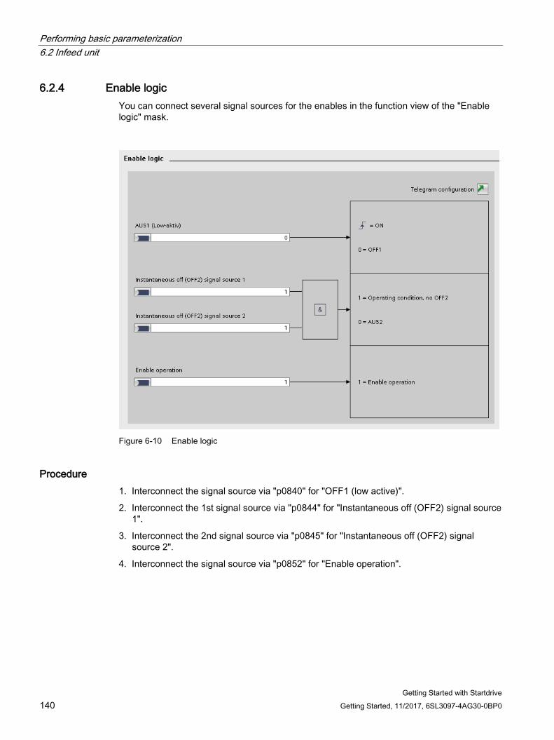
Performing basic parameterization 6.2 Infeed unit
Getting Started with Startdrive 140 Getting Started, 11/2017, 6SL3097-4AG30-0BP0
6.2.4 Enable logic You can connect several signal sources for the enables in the function view of the "Enable logic" mask.
Figure 6-10 Enable logic
Procedure 1. Interconnect the signal source via "p0840" for "OFF1 (low active)".
2. Interconnect the 1st signal source via "p0844" for "Instantaneous off (OFF2) signal source 1".
3. Interconnect the 2nd signal source via "p0845" for "Instantaneous off (OFF2) signal source 2".
4. Interconnect the signal source via "p0852" for "Enable operation".
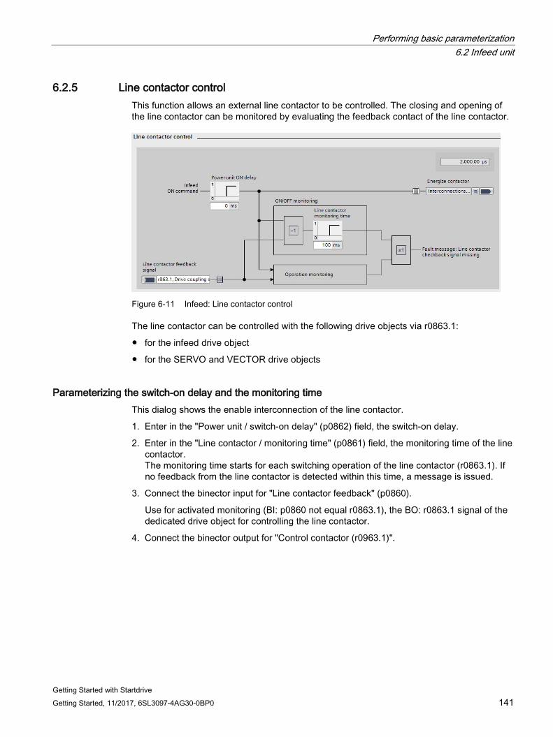
Performing basic parameterization 6.2 Infeed unit
Getting Started with Startdrive Getting Started, 11/2017, 6SL3097-4AG30-0BP0 141
6.2.5 Line contactor control This function allows an external line contactor to be controlled. The closing and opening of the line contactor can be monitored by evaluating the feedback contact of the line contactor.
Figure 6-11 Infeed: Line contactor control
The line contactor can be controlled with the following drive objects via r0863.1:
● for the infeed drive object
● for the SERVO and VECTOR drive objects
Parameterizing the switch-on delay and the monitoring time This dialog shows the enable interconnection of the line contactor.
1. Enter in the "Power unit / switch-on delay" (p0862) field, the switch-on delay.
2. Enter in the "Line contactor / monitoring time" (p0861) field, the monitoring time of the line contactor. The monitoring time starts for each switching operation of the line contactor (r0863.1). If no feedback from the line contactor is detected within this time, a message is issued.
3. Connect the binector input for "Line contactor feedback" (p0860).
Use for activated monitoring (BI: p0860 not equal r0863.1), the BO: r0863.1 signal of the dedicated drive object for controlling the line contactor.
4. Connect the binector output for "Control contactor (r0963.1)".
Performing basic parameterization 6.3 Drive axes
Getting Started with Startdrive 142 Getting Started, 11/2017, 6SL3097-4AG30-0BP0
6.3 Drive axes
6.3.1 Servo drives
6.3.1.1 Overview
Basic parameterization of the drive axes You can carry out basic parameterization for the following data of the drive axis/axes:
● Function modules
● Control mode
● Important parameters
● Sampling times/pulse frequency
● Enable logic
Calling the screen form 1. In the project navigation, select menu "Drive axis_x > Parameter".
The corresponding detailed view is displayed at the right.
2. In the secondary navigation, call menu "Basic parameterization > xxx" (xxx stands for the name of the particular detailed screen form).
The detailed view is updated.
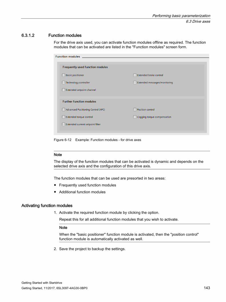
Performing basic parameterization 6.3 Drive axes
Getting Started with Startdrive Getting Started, 11/2017, 6SL3097-4AG30-0BP0 143
6.3.1.2 Function modules For the drive axis used, you can activate function modules offline as required. The function modules that can be activated are listed in the "Function modules" screen form.
Figure 6-12 Example: Function modules - for drive axes
Note
The display of the function modules that can be activated is dynamic and depends on the selected drive axis and the configuration of this drive axis.
The function modules that can be used are presorted in two areas:
● Frequently used function modules
● Additional function modules
Activating function modules 1. Activate the required function module by clicking the option.
Repeat this for all additional function modules that you wish to activate.
Note
When the "basic positioner" function module is activated, then the "position control" function module is automatically activated as well.
2. Save the project to backup the settings.
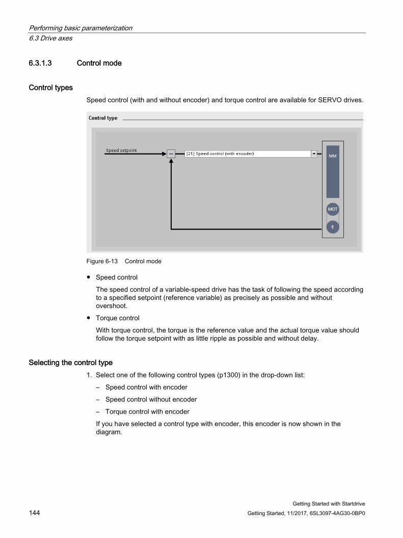
Performing basic parameterization 6.3 Drive axes
Getting Started with Startdrive 144 Getting Started, 11/2017, 6SL3097-4AG30-0BP0
6.3.1.3 Control mode
Control types Speed control (with and without encoder) and torque control are available for SERVO drives.
Figure 6-13 Control mode
● Speed control
The speed control of a variable-speed drive has the task of following the speed according to a specified setpoint (reference variable) as precisely as possible and without overshoot.
● Torque control
With torque control, the torque is the reference value and the actual torque value should follow the torque setpoint with as little ripple as possible and without delay.
Selecting the control type 1. Select one of the following control types (p1300) in the drop-down list:
– Speed control with encoder
– Speed control without encoder
– Torque control with encoder
If you have selected a control type with encoder, this encoder is now shown in the diagram.
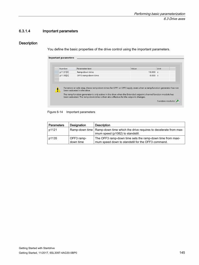
Performing basic parameterization 6.3 Drive axes
Getting Started with Startdrive Getting Started, 11/2017, 6SL3097-4AG30-0BP0 145
6.3.1.4 Important parameters
Description You define the basic properties of the drive control using the important parameters.
Figure 6-14 Important parameters
Parameters Designation Description p1121 Ramp-down time Ramp-down time which the drive requires to decelerate from max-
imum speed (p1082) to standstill. p1135 OFF3 ramp-
down time The OFF3 ramp-down time sets the ramp-down time from maxi-mum speed down to standstill for the OFF3 command.
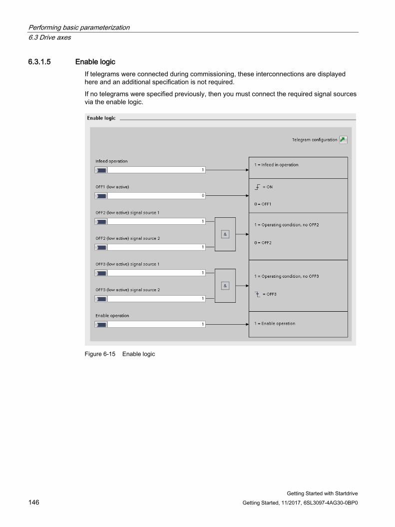
Performing basic parameterization 6.3 Drive axes
Getting Started with Startdrive 146 Getting Started, 11/2017, 6SL3097-4AG30-0BP0
6.3.1.5 Enable logic If telegrams were connected during commissioning, these interconnections are displayed here and an additional specification is not required.
If no telegrams were specified previously, then you must connect the required signal sources via the enable logic.
Figure 6-15 Enable logic

Performing basic parameterization 6.3 Drive axes
Getting Started with Startdrive Getting Started, 11/2017, 6SL3097-4AG30-0BP0 147
Connecting signal sources 1. Connect the signal source for the "Infeed operation" (p0864) command.
2. Connect the signal source for the "OFF1 (low active)" command (p0840).
This command corresponds to control word 1 bit 1 (STW1.1) in the PROFIdrive profile.
3. Connect the 1st signal source for the "OFF2 (low active) signal source 1" command (p0844).
This command corresponds to control word 1 bit 1 (STW1.1) in the PROFIdrive profile.
4. Connect the 2nd signal source for the "OFF2 (low active) signal source 2" command (p0845).
5. Connect the 1st signal source for the "OFF3 (low active) signal source 1" command (p0848).
This command corresponds to control word 1 bit 2 (STW1.2) in the PROFIdrive profile.
6. Connect the 2nd signal source for the "OFF3 (low active) signal source 2" command (p0849).
This command corresponds to control word 1 bit 2 (STW1.2) in the PROFIdrive profile.
7. Interconnect the signal source for the "Enable operation" command (p0852).
This command corresponds to control word 1 bit 3 (STW1.3) in the PROFIdrive profile.
Performing basic parameterization 6.3 Drive axes
Getting Started with Startdrive 148 Getting Started, 11/2017, 6SL3097-4AG30-0BP0
6.3.2 Vector drives
6.3.2.1 Overview
Basic parameterization of the drive axes You can carry out basic parameterization for the following data of the drive axis/axes:
● Function modules
● Control mode
● Important parameters
● Drive settings
● Enable logic
Calling the screen form 1. In the project navigation, select menu "Drive axis_x > Parameter".
The corresponding detailed view is displayed at the right.
2. In the secondary navigation, call menu "Basic parameterization > xxx" (xxx stands for the name of the particular detailed screen form).
The detailed view is updated.
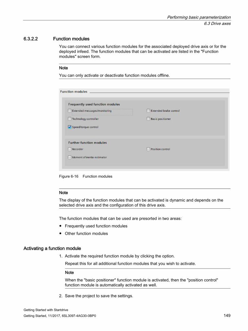
Performing basic parameterization 6.3 Drive axes
Getting Started with Startdrive Getting Started, 11/2017, 6SL3097-4AG30-0BP0 149
6.3.2.2 Function modules You can connect various function modules for the associated deployed drive axis or for the deployed infeed. The function modules that can be activated are listed in the "Function modules" screen form.
Note
You can only activate or deactivate function modules offline.
Figure 6-16 Function modules
Note
The display of the function modules that can be activated is dynamic and depends on the selected drive axis and the configuration of this drive axis.
The function modules that can be used are presorted in two areas:
● Frequently used function modules
● Other function modules
Activating a function module 1. Activate the required function module by clicking the option.
Repeat this for all additional function modules that you wish to activate.
Note
When the "basic positioner" function module is activated, then the "position control" function module is automatically activated as well.
2. Save the project to save the settings.
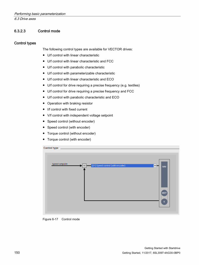
Performing basic parameterization 6.3 Drive axes
Getting Started with Startdrive 150 Getting Started, 11/2017, 6SL3097-4AG30-0BP0
6.3.2.3 Control mode
Control types The following control types are available for VECTOR drives:
● U/f control with linear characteristic
● U/f control with linear characteristic and FCC
● U/f control with parabolic characteristic
● U/f control with parameterizable characteristic
● U/f control with linear characteristic and ECO
● U/f control for drive requiring a precise frequency (e.g. textiles)
● U/f control for drive requiring a precise frequency and FCC
● U/f control with parabolic characteristic and ECO
● Operation with braking resistor
● I/f control with fixed current
● V/f control with independent voltage setpoint
● Speed control (without encoder)
● Speed control (with encoder)
● Torque control (without encoder)
● Torque control (with encoder)
Figure 6-17 Control mode
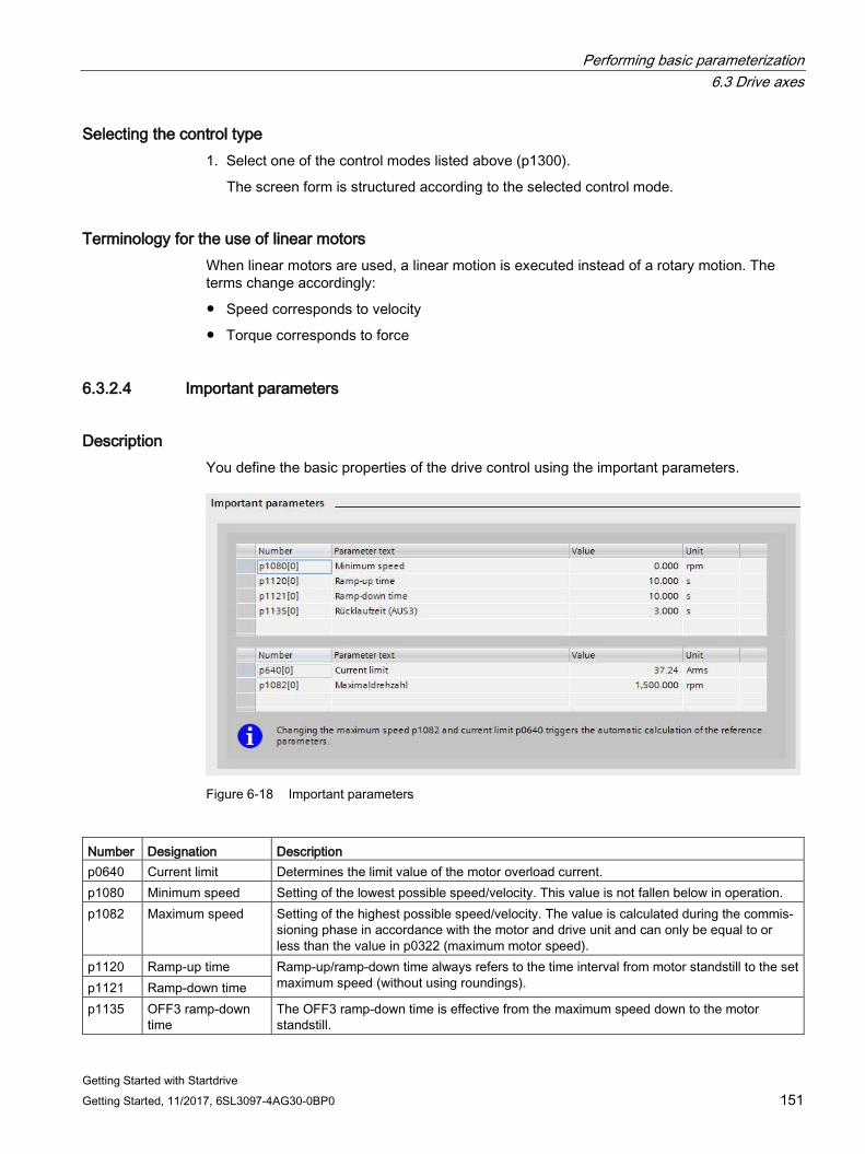
Performing basic parameterization 6.3 Drive axes
Getting Started with Startdrive Getting Started, 11/2017, 6SL3097-4AG30-0BP0 151
Selecting the control type 1. Select one of the control modes listed above (p1300).
The screen form is structured according to the selected control mode.
Terminology for the use of linear motors When linear motors are used, a linear motion is executed instead of a rotary motion. The terms change accordingly:
● Speed corresponds to velocity
● Torque corresponds to force
6.3.2.4 Important parameters
Description You define the basic properties of the drive control using the important parameters.
Figure 6-18 Important parameters
Number Designation Description p0640 Current limit Determines the limit value of the motor overload current. p1080 Minimum speed Setting of the lowest possible speed/velocity. This value is not fallen below in operation. p1082 Maximum speed Setting of the highest possible speed/velocity. The value is calculated during the commis-
sioning phase in accordance with the motor and drive unit and can only be equal to or less than the value in p0322 (maximum motor speed).
p1120 Ramp-up time Ramp-up/ramp-down time always refers to the time interval from motor standstill to the set maximum speed (without using roundings). p1121 Ramp-down time
p1135 OFF3 ramp-down time
The OFF3 ramp-down time is effective from the maximum speed down to the motor standstill.
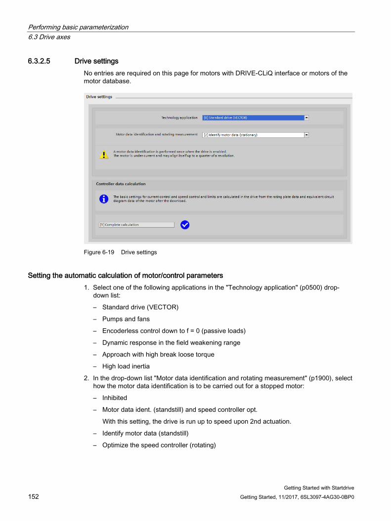
Performing basic parameterization 6.3 Drive axes
Getting Started with Startdrive 152 Getting Started, 11/2017, 6SL3097-4AG30-0BP0
6.3.2.5 Drive settings No entries are required on this page for motors with DRIVE-CLiQ interface or motors of the motor database.
Figure 6-19 Drive settings
Setting the automatic calculation of motor/control parameters 1. Select one of the following applications in the "Technology application" (p0500) drop-
down list:
– Standard drive (VECTOR)
– Pumps and fans
– Encoderless control down to f = 0 (passive loads)
– Dynamic response in the field weakening range
– Approach with high break loose torque
– High load inertia
2. In the drop-down list "Motor data identification and rotating measurement" (p1900), select how the motor data identification is to be carried out for a stopped motor:
– Inhibited
– Motor data ident. (standstill) and speed controller opt.
With this setting, the drive is run up to speed upon 2nd actuation.
– Identify motor data (standstill)
– Optimize the speed controller (rotating)
Performing basic parameterization 6.3 Drive axes
Getting Started with Startdrive Getting Started, 11/2017, 6SL3097-4AG30-0BP0 153
Setting the calculation of the controller data 1. Select one of the following options for the calculation of the controller data in the
"Calculation controller data" (p0340) drop-down list:
– No calculation
The motor data is not calculated. This is the default setting.
– Complete calculation
The equivalent circuit diagram data is also calculated using the motor data.
– Calculation without equivalent circuit diagram data
The equivalent circuit diagram data entered during the parameter assignment of the motor is not changed. The equivalent circuit diagram data is not calculated.
2. After the calculation type has been set (exception: "No calculation"), you can confirm the calculation if this has not been done already (red status symbol). To do this, click the "Confirm calculation" button.
The "Technology application" option is then disabled for the drive functions and the set application can no longer be changed. The disable can be cancelled via the "Enable" button. However, the calculation type must then be confirmed again.
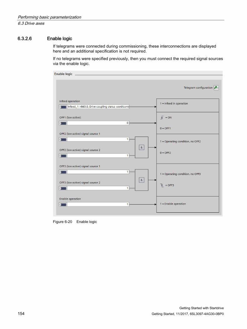
Performing basic parameterization 6.3 Drive axes
Getting Started with Startdrive 154 Getting Started, 11/2017, 6SL3097-4AG30-0BP0
6.3.2.6 Enable logic If telegrams were connected during commissioning, these interconnections are displayed here and an additional specification is not required.
If no telegrams were specified previously, then you must connect the required signal sources via the enable logic.
Figure 6-20 Enable logic
Performing basic parameterization 6.3 Drive axes
Getting Started with Startdrive Getting Started, 11/2017, 6SL3097-4AG30-0BP0 155
Interconnecting signal sources 1. Connect the signal source for the "Infeed operation" (p0864) command.
2. Connect the signal source for the "OFF1 (low active)" command (p0840).
This command corresponds to control word 1 bit 1 (STW1.1) in the PROFIdrive profile.
3. Connect the 1st signal source for the "OFF2 (low active) signal source 1" command (p0844).
This command corresponds to control word 1 bit 1 (STW1.1) in the PROFIdrive profile.
4. Connect the 2nd signal source for the "OFF2 (low active) signal source 2" command (p0845).
5. Connect the 1st signal source for the "OFF3 (low active) signal source 1" command (p0848).
This command corresponds to control word 1 bit 2 (STW1.2) in the PROFIdrive profile.
6. Connect the 2nd signal source for the "OFF3 (low active) signal source 2" command (p0849).
This command corresponds to control word 1 bit 2 (STW1.2) in the PROFIdrive profile.
7. Interconnect the signal source for the "Enable operation" command (p0852).
This command corresponds to control word 1 bit 3 (STW1.3) in the PROFIdrive profile.

Performing basic parameterization 6.3 Drive axes
Getting Started with Startdrive 156 Getting Started, 11/2017, 6SL3097-4AG30-0BP0
Getting Started with Startdrive Getting Started, 11/2017, 6SL3097-4AG30-0BP0 157
Loading the project to the target device 7
In order to set up your project, you need to load the project data you generated offline on the connected drive units. This project data is generated, for example when configuring hardware, networks, and connections or when programming the user program or when creating recipes.
Precondition ● The project data is consistent.
● Each drive unit to be loaded can be accessed online.
Perform download In order to execute this function in the online mode, the following operator actions are alternatively available:
1. Select one or more drive units in the project tree.
2. Open the shortcut menu "Load to device" or click on the icon (Load to device) in the toolbar.
– If you have already established an online connection, the "Load preview" dialog opens. This dialog displays alarms and proposes actions necessary for loading.
– If you have not yet established any online connection, the "Extended loading" dialog opens and you must first select the interfaces with which the online connection to the device should be established. You have the option of showing all compatible devices by selecting the corresponding option and clicking the "Start search" command.
See also Section "Establishing an online connection to the drive unit (Page 110) "
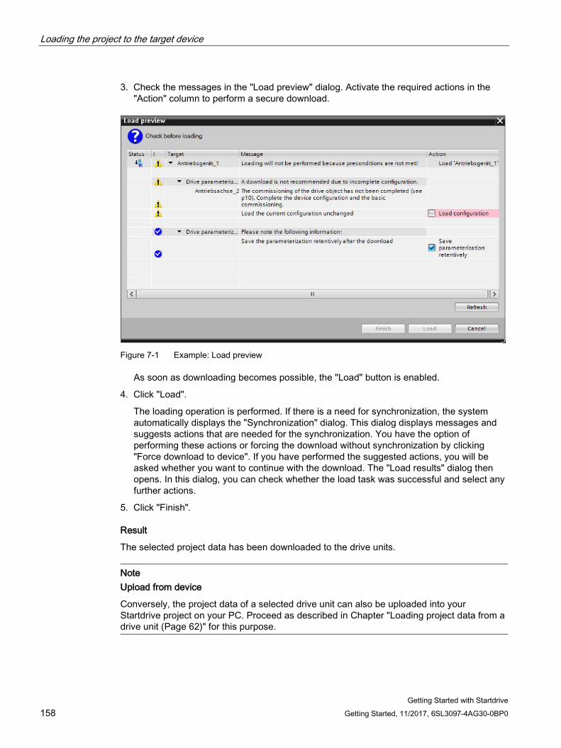
Loading the project to the target device
Getting Started with Startdrive 158 Getting Started, 11/2017, 6SL3097-4AG30-0BP0
3. Check the messages in the "Load preview" dialog. Activate the required actions in the "Action" column to perform a secure download.
Figure 7-1 Example: Load preview
As soon as downloading becomes possible, the "Load" button is enabled.
4. Click "Load".
The loading operation is performed. If there is a need for synchronization, the system automatically displays the "Synchronization" dialog. This dialog displays messages and suggests actions that are needed for the synchronization. You have the option of performing these actions or forcing the download without synchronization by clicking "Force download to device". If you have performed the suggested actions, you will be asked whether you want to continue with the download. The "Load results" dialog then opens. In this dialog, you can check whether the load task was successful and select any further actions.
5. Click "Finish".
Result
The selected project data has been downloaded to the drive units.
Note Upload from device
Conversely, the project data of a selected drive unit can also be uploaded into your Startdrive project on your PC. Proceed as described in Chapter "Loading project data from a drive unit (Page 62)" for this purpose.
Getting Started with Startdrive Getting Started, 11/2017, 6SL3097-4AG30-0BP0 159
Commissioning a drive 8 8.1 Using the control panel
Traverse the drive and test the settings that have already been made with the control panel (see also the overview in Section "Drive control panel (Page 42)").
WARNING
Non-observance of the safety instructions for the drive control panel
The safety shutdowns from the higher-level controller have no effect with this function. The "Stop with space bar" function is not guaranteed in all operating states. Incorrect operation by untrained personnel – without taking into account the appropriate safety instructions – can therefore result in death or severe injury. • Make sure that this function is only used for commissioning, diagnostic and service
purposes. • Make sure that this function is only used by trained and authorized skilled personnel. • Make sure that a hardware device is always available for the EMERGENCY OFF circuit.
Note Drive reacts immediately
Although all enables are removed before returning the master control, the setpoints and commands still come from the original parameterized sources after the master control is returned.
Requirement ● Startdrive is in the online mode (Page 110).
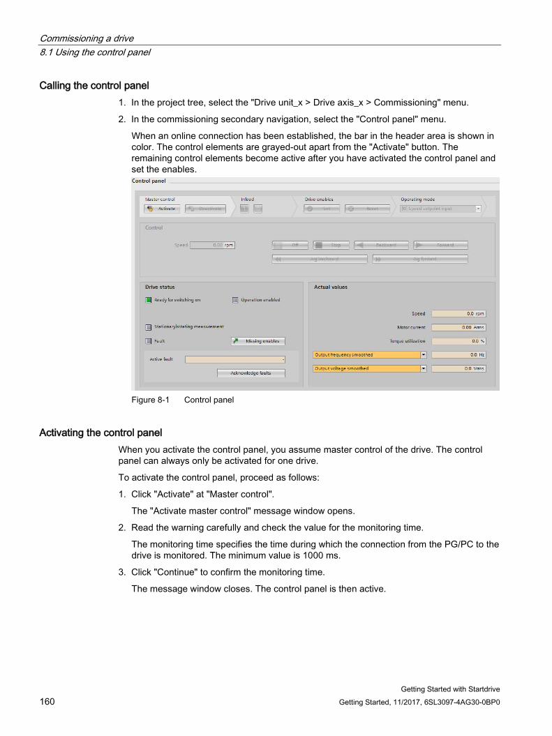
Commissioning a drive 8.1 Using the control panel
Getting Started with Startdrive 160 Getting Started, 11/2017, 6SL3097-4AG30-0BP0
Calling the control panel 1. In the project tree, select the "Drive unit_x > Drive axis_x > Commissioning" menu.
2. In the commissioning secondary navigation, select the "Control panel" menu.
When an online connection has been established, the bar in the header area is shown in color. The control elements are grayed-out apart from the "Activate" button. The remaining control elements become active after you have activated the control panel and set the enables.
Figure 8-1 Control panel
Activating the control panel When you activate the control panel, you assume master control of the drive. The control panel can always only be activated for one drive.
To activate the control panel, proceed as follows:
1. Click "Activate" at "Master control".
The "Activate master control" message window opens.
2. Read the warning carefully and check the value for the monitoring time.
The monitoring time specifies the time during which the connection from the PG/PC to the drive is monitored. The minimum value is 1000 ms.
3. Click "Continue" to confirm the monitoring time.
The message window closes. The control panel is then active.
Commissioning a drive 8.1 Using the control panel
Getting Started with Startdrive Getting Started, 11/2017, 6SL3097-4AG30-0BP0 161
Activating the infeed If an infeed is available in your drive, then the infeed must also be activated. If it is not activated, no further drive release can be set.
1. Click the "1" icon at "Infeed" to switch on the infeed.
Deactivating the control panel When you deactivate the control panel, you return the master control.
To deactivate the control panel, proceed as follows:
1. Click the "Off" button to switch off the drive.
This is a basic requirement for deactivating the control panel.
2. Click "Deactivate" at "Master control".
The grayed-out user interface of the control panel shows that the master control has been deactivated.
Setting the enable To set the required enable for the control panel, proceed as follows.
1. Click "Set" at "Drive enables".
Further areas of the control panel are activated.
2. Click "Acknowledge faults" to acknowledge the currently pending faults.
3. If you no longer require the enables, click "Reset" at "Drive enables".
Result You can now traverse the drive with the control panel. Enables and faults are displayed at "Drive status". In addition to "Active fault", the currently pending fault is displayed.
Commissioning a drive 8.2 Traversing the drive with speed specification
Getting Started with Startdrive 162 Getting Started, 11/2017, 6SL3097-4AG30-0BP0
8.2 Traversing the drive with speed specification After you have set the drive enables, in the "Control Panel" screen form specify the operating mode and switch on the motor.
Specifying the setpoint To specify the setpoint, proceed as follows:
1. In the "Operating Mode" drop-down list, select menu item "Speed setpoint specification".
2. Enter a speed setpoint in the "Speed" field with which the motor is to turn.
Once you have specified the speed setpoint, the drive is switched on as soon as you click one of the buttons "Start backward", "Start forward", "Jog forward" or "Jog backward" for the first time.
The motor does not accelerate until you click the "Backward" or "Forward" buttons.
– To rotate the motor backwards, click the "Backward" button.
– To rotate the motor forward, click the "Forward" button.
– Click the "Jog forward" button to inch the motor forward.
– Click the "Jog backward" button to inch the motor backward.
Note
Rotation through clicking
The motor continues to rotate while you keep the mouse clicked on the button. Traversing stops when you release the mouse button.
Stopping the drive 1. Click "Stop" to stop the drive.
2. Click the "Stop" button to switch off the drive.
Viewing actual values of the drive The current values of various parameters are displayed at "Actual values".
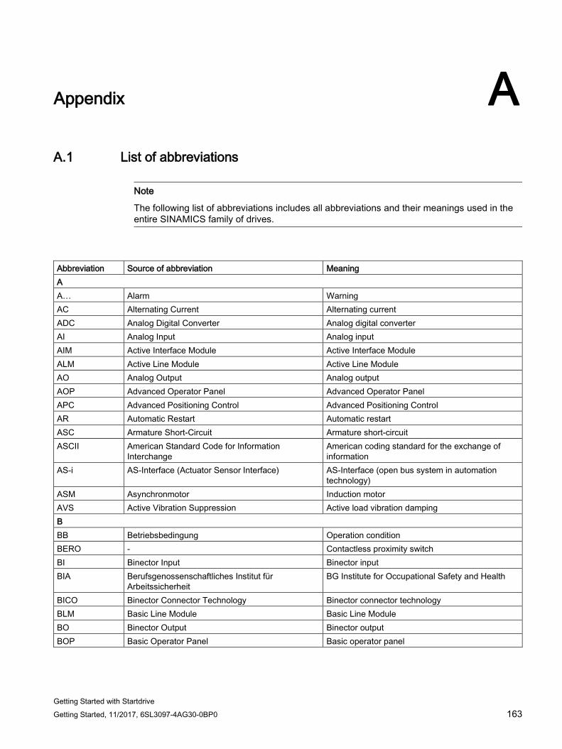
Getting Started with Startdrive Getting Started, 11/2017, 6SL3097-4AG30-0BP0 163
Appendix A A.1 List of abbreviations
Note
The following list of abbreviations includes all abbreviations and their meanings used in the entire SINAMICS family of drives.
Abbreviation Source of abbreviation Meaning A A… Alarm Warning AC Alternating Current Alternating current ADC Analog Digital Converter Analog digital converter AI Analog Input Analog input AIM Active Interface Module Active Interface Module ALM Active Line Module Active Line Module AO Analog Output Analog output AOP Advanced Operator Panel Advanced Operator Panel APC Advanced Positioning Control Advanced Positioning Control AR Automatic Restart Automatic restart ASC Armature Short-Circuit Armature short-circuit ASCII American Standard Code for Information
Interchange American coding standard for the exchange of information
AS-i AS-Interface (Actuator Sensor Interface) AS-Interface (open bus system in automation technology)
ASM Asynchronmotor Induction motor AVS Active Vibration Suppression Active load vibration damping B BB Betriebsbedingung Operation condition BERO - Contactless proximity switch BI Binector Input Binector input BIA Berufsgenossenschaftliches Institut für
Arbeitssicherheit BG Institute for Occupational Safety and Health
BICO Binector Connector Technology Binector connector technology BLM Basic Line Module Basic Line Module BO Binector Output Binector output BOP Basic Operator Panel Basic operator panel
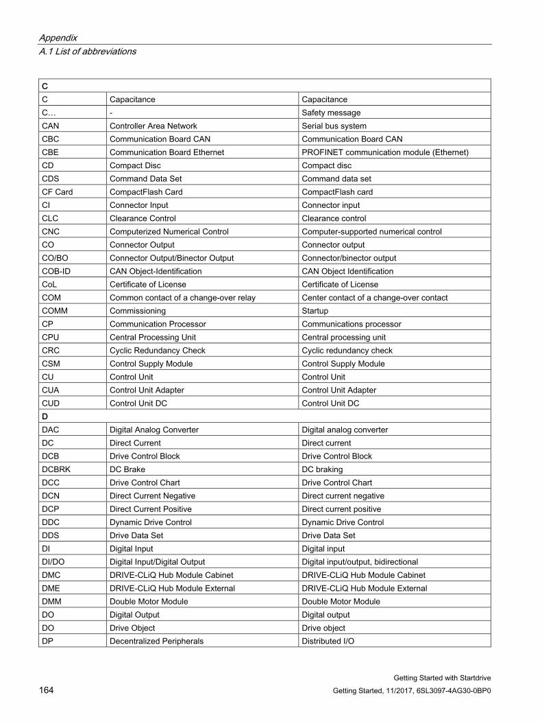
Appendix A.1 List of abbreviations
Getting Started with Startdrive 164 Getting Started, 11/2017, 6SL3097-4AG30-0BP0
C C Capacitance Capacitance C… - Safety message CAN Controller Area Network Serial bus system CBC Communication Board CAN Communication Board CAN CBE Communication Board Ethernet PROFINET communication module (Ethernet) CD Compact Disc Compact disc CDS Command Data Set Command data set CF Card CompactFlash Card CompactFlash card CI Connector Input Connector input CLC Clearance Control Clearance control CNC Computerized Numerical Control Computer-supported numerical control CO Connector Output Connector output CO/BO Connector Output/Binector Output Connector/binector output COB-ID CAN Object-Identification CAN Object Identification CoL Certificate of License Certificate of License COM Common contact of a change-over relay Center contact of a change-over contact COMM Commissioning Startup CP Communication Processor Communications processor CPU Central Processing Unit Central processing unit CRC Cyclic Redundancy Check Cyclic redundancy check CSM Control Supply Module Control Supply Module CU Control Unit Control Unit CUA Control Unit Adapter Control Unit Adapter CUD Control Unit DC Control Unit DC D DAC Digital Analog Converter Digital analog converter DC Direct Current Direct current DCB Drive Control Block Drive Control Block DCBRK DC Brake DC braking DCC Drive Control Chart Drive Control Chart DCN Direct Current Negative Direct current negative DCP Direct Current Positive Direct current positive DDC Dynamic Drive Control Dynamic Drive Control DDS Drive Data Set Drive Data Set DI Digital Input Digital input DI/DO Digital Input/Digital Output Digital input/output, bidirectional DMC DRIVE-CLiQ Hub Module Cabinet DRIVE-CLiQ Hub Module Cabinet DME DRIVE-CLiQ Hub Module External DRIVE-CLiQ Hub Module External DMM Double Motor Module Double Motor Module DO Digital Output Digital output DO Drive Object Drive object DP Decentralized Peripherals Distributed I/O
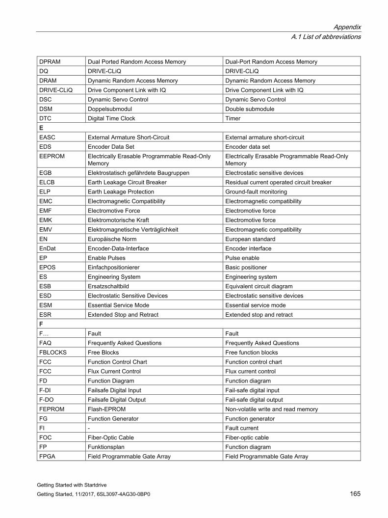
Appendix A.1 List of abbreviations
Getting Started with Startdrive Getting Started, 11/2017, 6SL3097-4AG30-0BP0 165
DPRAM Dual Ported Random Access Memory Dual-Port Random Access Memory DQ DRIVE-CLiQ DRIVE-CLiQ DRAM Dynamic Random Access Memory Dynamic Random Access Memory DRIVE-CLiQ Drive Component Link with IQ Drive Component Link with IQ DSC Dynamic Servo Control Dynamic Servo Control DSM Doppelsubmodul Double submodule DTC Digital Time Clock Timer E EASC External Armature Short-Circuit External armature short-circuit EDS Encoder Data Set Encoder data set EEPROM Electrically Erasable Programmable Read-Only
Memory Electrically Erasable Programmable Read-Only Memory
EGB Elektrostatisch gefährdete Baugruppen Electrostatic sensitive devices ELCB Earth Leakage Circuit Breaker Residual current operated circuit breaker ELP Earth Leakage Protection Ground-fault monitoring EMC Electromagnetic Compatibility Electromagnetic compatibility EMF Electromotive Force Electromotive force EMK Elektromotorische Kraft Electromotive force EMV Elektromagnetische Verträglichkeit Electromagnetic compatibility EN Europäische Norm European standard EnDat Encoder-Data-Interface Encoder interface EP Enable Pulses Pulse enable EPOS Einfachpositionierer Basic positioner ES Engineering System Engineering system ESB Ersatzschaltbild Equivalent circuit diagram ESD Electrostatic Sensitive Devices Electrostatic sensitive devices ESM Essential Service Mode Essential service mode ESR Extended Stop and Retract Extended stop and retract F F… Fault Fault FAQ Frequently Asked Questions Frequently Asked Questions FBLOCKS Free Blocks Free function blocks FCC Function Control Chart Function control chart FCC Flux Current Control Flux current control FD Function Diagram Function diagram F-DI Failsafe Digital Input Fail-safe digital input F-DO Failsafe Digital Output Fail-safe digital output FEPROM Flash-EPROM Non-volatile write and read memory FG Function Generator Function generator FI - Fault current FOC Fiber-Optic Cable Fiber-optic cable FP Funktionsplan Function diagram FPGA Field Programmable Gate Array Field Programmable Gate Array
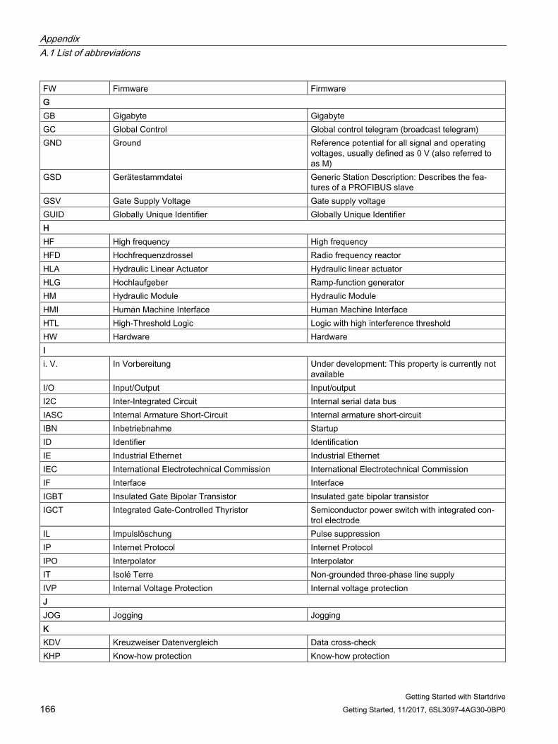
Appendix A.1 List of abbreviations
Getting Started with Startdrive 166 Getting Started, 11/2017, 6SL3097-4AG30-0BP0
FW Firmware Firmware G GB Gigabyte Gigabyte GC Global Control Global control telegram (broadcast telegram) GND Ground Reference potential for all signal and operating
voltages, usually defined as 0 V (also referred to as M)
GSD Gerätestammdatei Generic Station Description: Describes the fea-tures of a PROFIBUS slave
GSV Gate Supply Voltage Gate supply voltage GUID Globally Unique Identifier Globally Unique Identifier H HF High frequency High frequency HFD Hochfrequenzdrossel Radio frequency reactor HLA Hydraulic Linear Actuator Hydraulic linear actuator HLG Hochlaufgeber Ramp-function generator HM Hydraulic Module Hydraulic Module HMI Human Machine Interface Human Machine Interface HTL High-Threshold Logic Logic with high interference threshold HW Hardware Hardware I i. V. In Vorbereitung Under development: This property is currently not
available I/O Input/Output Input/output I2C Inter-Integrated Circuit Internal serial data bus IASC Internal Armature Short-Circuit Internal armature short-circuit IBN Inbetriebnahme Startup ID Identifier Identification IE Industrial Ethernet Industrial Ethernet IEC International Electrotechnical Commission International Electrotechnical Commission IF Interface Interface IGBT Insulated Gate Bipolar Transistor Insulated gate bipolar transistor IGCT Integrated Gate-Controlled Thyristor Semiconductor power switch with integrated con-
trol electrode IL Impulslöschung Pulse suppression IP Internet Protocol Internet Protocol IPO Interpolator Interpolator IT Isolé Terre Non-grounded three-phase line supply IVP Internal Voltage Protection Internal voltage protection J JOG Jogging Jogging K KDV Kreuzweiser Datenvergleich Data cross-check KHP Know-how protection Know-how protection
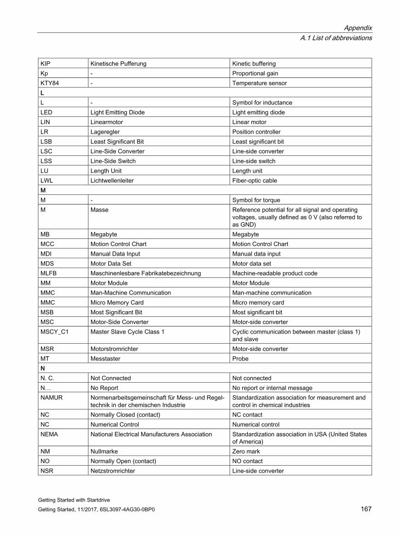
Appendix A.1 List of abbreviations
Getting Started with Startdrive Getting Started, 11/2017, 6SL3097-4AG30-0BP0 167
KIP Kinetische Pufferung Kinetic buffering Kp - Proportional gain KTY84 - Temperature sensor L L - Symbol for inductance LED Light Emitting Diode Light emitting diode LIN Linearmotor Linear motor LR Lageregler Position controller LSB Least Significant Bit Least significant bit LSC Line-Side Converter Line-side converter LSS Line-Side Switch Line-side switch LU Length Unit Length unit LWL Lichtwellenleiter Fiber-optic cable M M - Symbol for torque M Masse Reference potential for all signal and operating
voltages, usually defined as 0 V (also referred to as GND)
MB Megabyte Megabyte MCC Motion Control Chart Motion Control Chart MDI Manual Data Input Manual data input MDS Motor Data Set Motor data set MLFB Maschinenlesbare Fabrikatebezeichnung Machine-readable product code MM Motor Module Motor Module MMC Man-Machine Communication Man-machine communication MMC Micro Memory Card Micro memory card MSB Most Significant Bit Most significant bit MSC Motor-Side Converter Motor-side converter MSCY_C1 Master Slave Cycle Class 1 Cyclic communication between master (class 1)
and slave MSR Motorstromrichter Motor-side converter MT Messtaster Probe N N. C. Not Connected Not connected N… No Report No report or internal message NAMUR Normenarbeitsgemeinschaft für Mess- und Regel-
technik in der chemischen Industrie Standardization association for measurement and control in chemical industries
NC Normally Closed (contact) NC contact NC Numerical Control Numerical control NEMA National Electrical Manufacturers Association Standardization association in USA (United States
of America) NM Nullmarke Zero mark NO Normally Open (contact) NO contact NSR Netzstromrichter Line-side converter
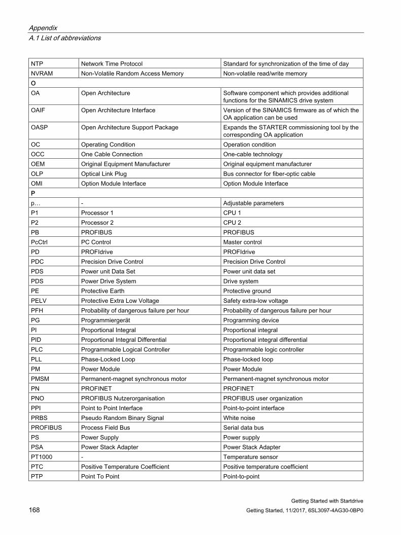
Appendix A.1 List of abbreviations
Getting Started with Startdrive 168 Getting Started, 11/2017, 6SL3097-4AG30-0BP0
NTP Network Time Protocol Standard for synchronization of the time of day NVRAM Non-Volatile Random Access Memory Non-volatile read/write memory O OA Open Architecture Software component which provides additional
functions for the SINAMICS drive system OAIF Open Architecture Interface Version of the SINAMICS firmware as of which the
OA application can be used OASP Open Architecture Support Package Expands the STARTER commissioning tool by the
corresponding OA application OC Operating Condition Operation condition OCC One Cable Connection One-cable technology OEM Original Equipment Manufacturer Original equipment manufacturer OLP Optical Link Plug Bus connector for fiber-optic cable OMI Option Module Interface Option Module Interface P p… - Adjustable parameters P1 Processor 1 CPU 1 P2 Processor 2 CPU 2 PB PROFIBUS PROFIBUS PcCtrl PC Control Master control PD PROFIdrive PROFIdrive PDC Precision Drive Control Precision Drive Control PDS Power unit Data Set Power unit data set PDS Power Drive System Drive system PE Protective Earth Protective ground PELV Protective Extra Low Voltage Safety extra-low voltage PFH Probability of dangerous failure per hour Probability of dangerous failure per hour PG Programmiergerät Programming device PI Proportional Integral Proportional integral PID Proportional Integral Differential Proportional integral differential PLC Programmable Logical Controller Programmable logic controller PLL Phase-Locked Loop Phase-locked loop PM Power Module Power Module PMSM Permanent-magnet synchronous motor Permanent-magnet synchronous motor PN PROFINET PROFINET PNO PROFIBUS Nutzerorganisation PROFIBUS user organization PPI Point to Point Interface Point-to-point interface PRBS Pseudo Random Binary Signal White noise PROFIBUS Process Field Bus Serial data bus PS Power Supply Power supply PSA Power Stack Adapter Power Stack Adapter PT1000 - Temperature sensor PTC Positive Temperature Coefficient Positive temperature coefficient PTP Point To Point Point-to-point
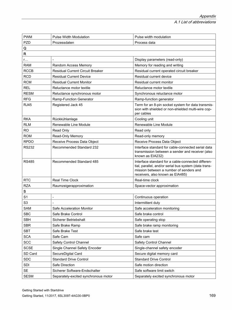
Appendix A.1 List of abbreviations
Getting Started with Startdrive Getting Started, 11/2017, 6SL3097-4AG30-0BP0 169
PWM Pulse Width Modulation Pulse width modulation PZD Prozessdaten Process data Q R r… - Display parameters (read-only) RAM Random Access Memory Memory for reading and writing RCCB Residual Current Circuit Breaker Residual current operated circuit breaker RCD Residual Current Device Residual current device RCM Residual Current Monitor Residual current monitor REL Reluctance motor textile Reluctance motor textile RESM Reluctance synchronous motor Synchronous reluctance motor RFG Ramp-Function Generator Ramp-function generator RJ45 Registered Jack 45 Term for an 8-pin socket system for data transmis-
sion with shielded or non-shielded multi-wire cop-per cables
RKA Rückkühlanlage Cooling unit RLM Renewable Line Module Renewable Line Module RO Read Only Read only ROM Read-Only Memory Read-only memory RPDO Receive Process Data Object Receive Process Data Object RS232 Recommended Standard 232 Interface standard for cable-connected serial data
transmission between a sender and receiver (also known as EIA232)
RS485 Recommended Standard 485 Interface standard for a cable-connected differen-tial, parallel, and/or serial bus system (data trans-mission between a number of senders and receivers, also known as EIA485)
RTC Real Time Clock Real-time clock RZA Raumzeigerapproximation Space-vector approximation S S1 - Continuous operation S3 - Intermittent duty SAM Safe Acceleration Monitor Safe acceleration monitoring SBC Safe Brake Control Safe brake control SBH Sicherer Betriebshalt Safe operating stop SBR Safe Brake Ramp Safe brake ramp monitoring SBT Safe Brake Test Safe brake test SCA Safe Cam Safe cam SCC Safety Control Channel Safety Control Channel SCSE Single Channel Safety Encoder Single-channel safety encoder SD Card SecureDigital Card Secure digital memory card SDC Standard Drive Control Standard Drive Control SDI Safe Direction Safe motion direction SE Sicherer Software-Endschalter Safe software limit switch SESM Separately-excited synchronous motor Separately excited synchronous motor
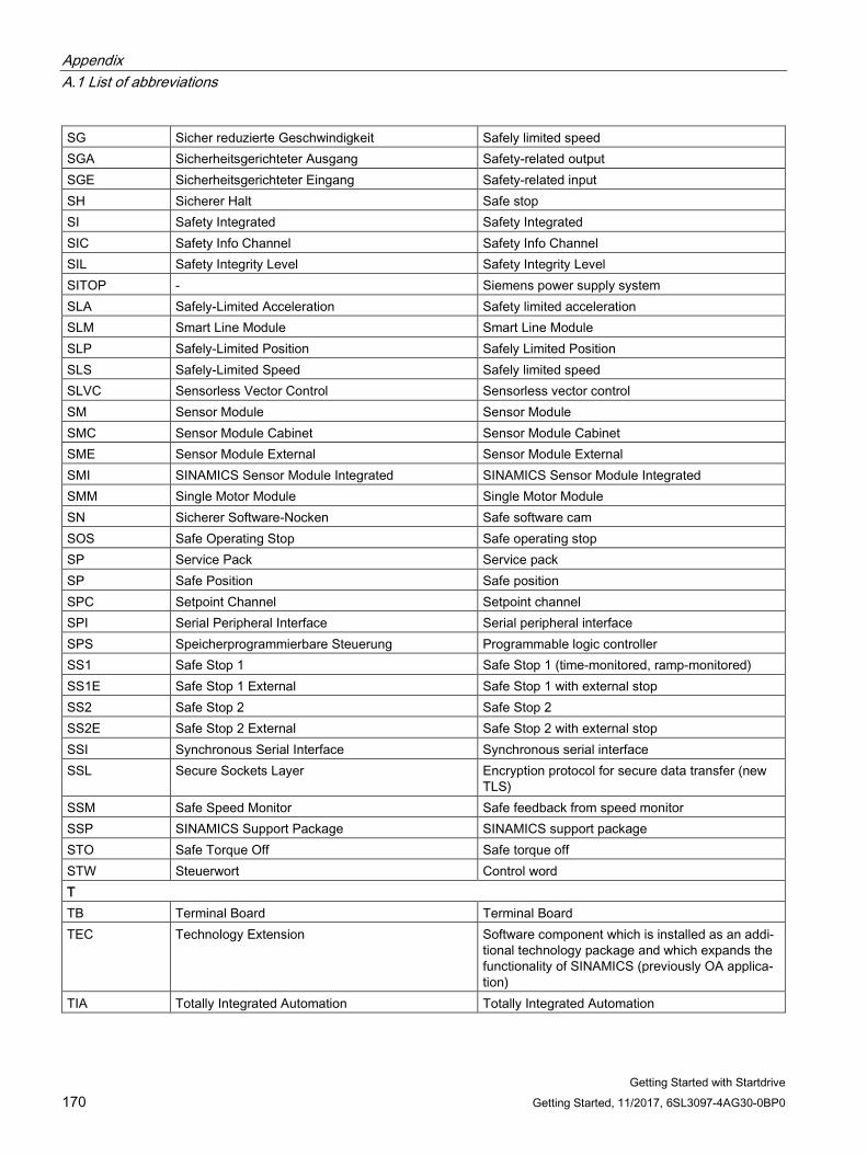
Appendix A.1 List of abbreviations
Getting Started with Startdrive 170 Getting Started, 11/2017, 6SL3097-4AG30-0BP0
SG Sicher reduzierte Geschwindigkeit Safely limited speed SGA Sicherheitsgerichteter Ausgang Safety-related output SGE Sicherheitsgerichteter Eingang Safety-related input SH Sicherer Halt Safe stop SI Safety Integrated Safety Integrated SIC Safety Info Channel Safety Info Channel SIL Safety Integrity Level Safety Integrity Level SITOP - Siemens power supply system SLA Safely-Limited Acceleration Safety limited acceleration SLM Smart Line Module Smart Line Module SLP Safely-Limited Position Safely Limited Position SLS Safely-Limited Speed Safely limited speed SLVC Sensorless Vector Control Sensorless vector control SM Sensor Module Sensor Module SMC Sensor Module Cabinet Sensor Module Cabinet SME Sensor Module External Sensor Module External SMI SINAMICS Sensor Module Integrated SINAMICS Sensor Module Integrated SMM Single Motor Module Single Motor Module SN Sicherer Software-Nocken Safe software cam SOS Safe Operating Stop Safe operating stop SP Service Pack Service pack SP Safe Position Safe position SPC Setpoint Channel Setpoint channel SPI Serial Peripheral Interface Serial peripheral interface SPS Speicherprogrammierbare Steuerung Programmable logic controller SS1 Safe Stop 1 Safe Stop 1 (time-monitored, ramp-monitored) SS1E Safe Stop 1 External Safe Stop 1 with external stop SS2 Safe Stop 2 Safe Stop 2 SS2E Safe Stop 2 External Safe Stop 2 with external stop SSI Synchronous Serial Interface Synchronous serial interface SSL Secure Sockets Layer Encryption protocol for secure data transfer (new
TLS) SSM Safe Speed Monitor Safe feedback from speed monitor SSP SINAMICS Support Package SINAMICS support package STO Safe Torque Off Safe torque off STW Steuerwort Control word T TB Terminal Board Terminal Board TEC Technology Extension Software component which is installed as an addi-
tional technology package and which expands the functionality of SINAMICS (previously OA applica-tion)
TIA Totally Integrated Automation Totally Integrated Automation
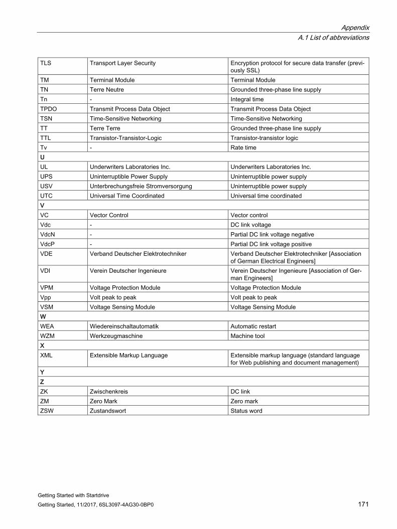
Appendix A.1 List of abbreviations
Getting Started with Startdrive Getting Started, 11/2017, 6SL3097-4AG30-0BP0 171
TLS Transport Layer Security Encryption protocol for secure data transfer (previ-ously SSL)
TM Terminal Module Terminal Module TN Terre Neutre Grounded three-phase line supply Tn - Integral time TPDO Transmit Process Data Object Transmit Process Data Object TSN Time-Sensitive Networking Time-Sensitive Networking TT Terre Terre Grounded three-phase line supply TTL Transistor-Transistor-Logic Transistor-transistor logic Tv - Rate time U UL Underwriters Laboratories Inc. Underwriters Laboratories Inc. UPS Uninterruptible Power Supply Uninterruptible power supply USV Unterbrechungsfreie Stromversorgung Uninterruptible power supply UTC Universal Time Coordinated Universal time coordinated V VC Vector Control Vector control Vdc - DC link voltage VdcN - Partial DC link voltage negative VdcP - Partial DC link voltage positive VDE Verband Deutscher Elektrotechniker Verband Deutscher Elektrotechniker [Association
of German Electrical Engineers] VDI Verein Deutscher Ingenieure Verein Deutscher Ingenieure [Association of Ger-
man Engineers] VPM Voltage Protection Module Voltage Protection Module Vpp Volt peak to peak Volt peak to peak VSM Voltage Sensing Module Voltage Sensing Module W WEA Wiedereinschaltautomatik Automatic restart WZM Werkzeugmaschine Machine tool X XML Extensible Markup Language Extensible markup language (standard language
for Web publishing and document management) Y Z ZK Zwischenkreis DC link ZM Zero Mark Zero mark ZSW Zustandswort Status word
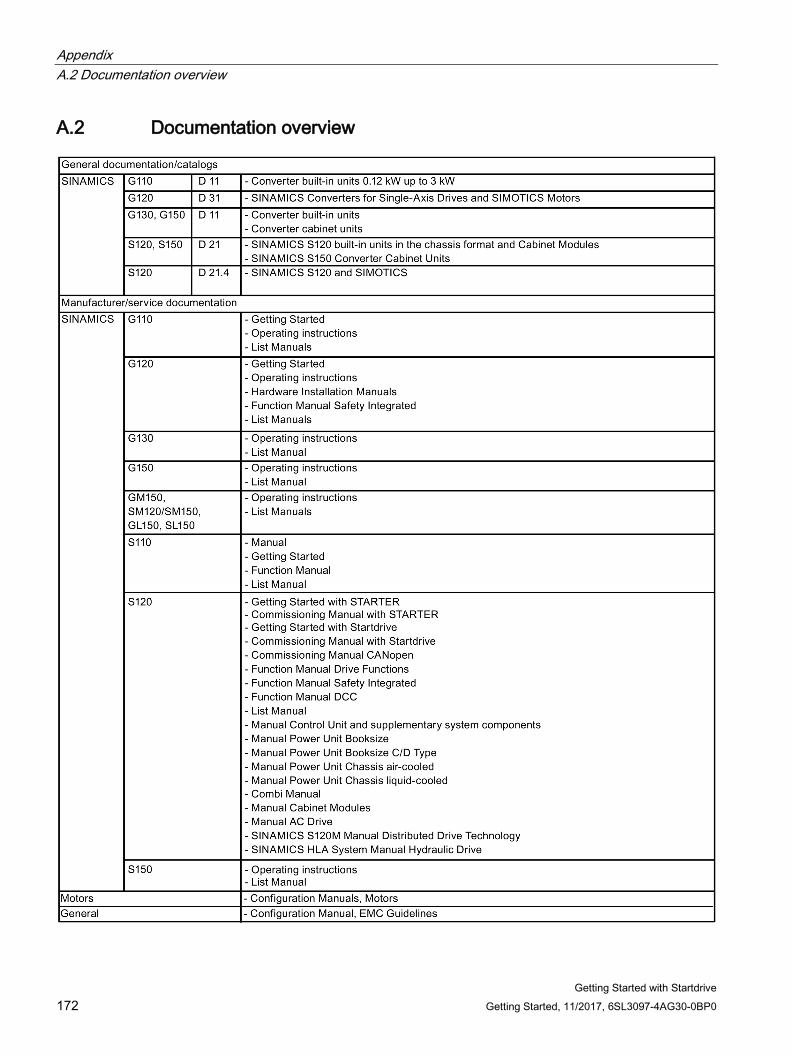
Appendix A.2 Documentation overview
Getting Started with Startdrive 172 Getting Started, 11/2017, 6SL3097-4AG30-0BP0
A.2 Documentation overview
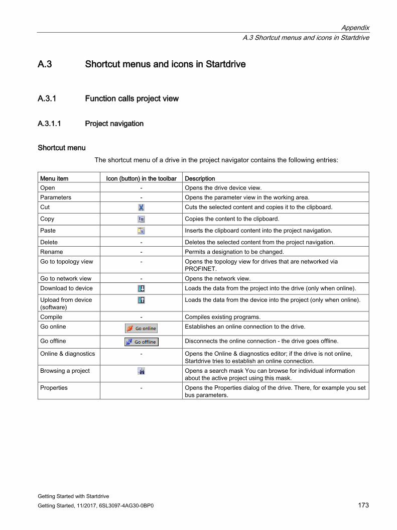
Appendix A.3 Shortcut menus and icons in Startdrive
Getting Started with Startdrive Getting Started, 11/2017, 6SL3097-4AG30-0BP0 173
A.3 Shortcut menus and icons in Startdrive
A.3.1 Function calls project view
A.3.1.1 Project navigation
Shortcut menu The shortcut menu of a drive in the project navigator contains the following entries:
Menu item Icon (button) in the toolbar Description Open - Opens the drive device view. Parameters - Opens the parameter view in the working area. Cut Cuts the selected content and copies it to the clipboard.
Copy Copies the content to the clipboard.
Paste Inserts the clipboard content into the project navigation.
Delete - Deletes the selected content from the project navigation. Rename - Permits a designation to be changed. Go to topology view - Opens the topology view for drives that are networked via
PROFINET. Go to network view - Opens the network view. Download to device Loads the data from the project into the drive (only when online).
Upload from device (software)
Loads the data from the device into the project (only when online).
Compile - Compiles existing programs. Go online
Establishes an online connection to the drive.
Go offline Disconnects the online connection - the drive goes offline.
Online & diagnostics - Opens the Online & diagnostics editor; if the drive is not online, Startdrive tries to establish an online connection.
Browsing a project Opens a search mask You can browse for individual information about the active project using this mask.
Properties - Opens the Properties dialog of the drive. There, for example you set bus parameters.
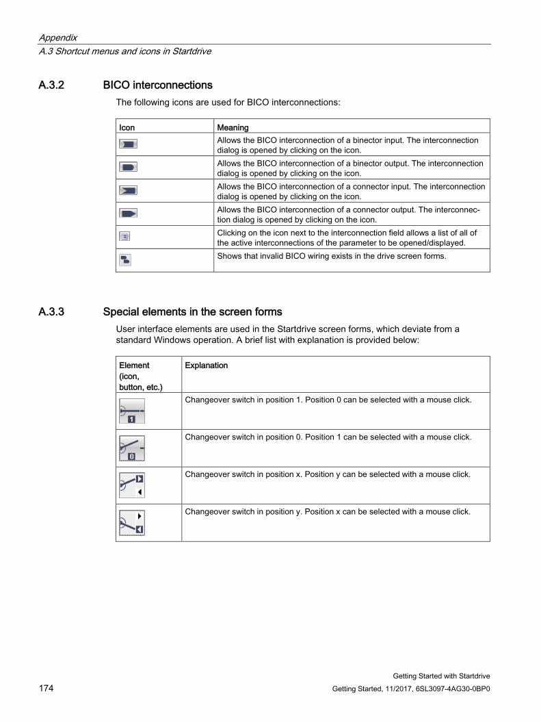
Appendix A.3 Shortcut menus and icons in Startdrive
Getting Started with Startdrive 174 Getting Started, 11/2017, 6SL3097-4AG30-0BP0
A.3.2 BICO interconnections The following icons are used for BICO interconnections: Icon Meaning
Allows the BICO interconnection of a binector input. The interconnection dialog is opened by clicking on the icon.
Allows the BICO interconnection of a binector output. The interconnection dialog is opened by clicking on the icon.
Allows the BICO interconnection of a connector input. The interconnection dialog is opened by clicking on the icon.
Allows the BICO interconnection of a connector output. The interconnec-tion dialog is opened by clicking on the icon.
Clicking on the icon next to the interconnection field allows a list of all of the active interconnections of the parameter to be opened/displayed.
Shows that invalid BICO wiring exists in the drive screen forms.
A.3.3 Special elements in the screen forms User interface elements are used in the Startdrive screen forms, which deviate from a standard Windows operation. A brief list with explanation is provided below: Element (icon, button, etc.)
Explanation
Changeover switch in position 1. Position 0 can be selected with a mouse click.
Changeover switch in position 0. Position 1 can be selected with a mouse click.
Changeover switch in position x. Position y can be selected with a mouse click.
Changeover switch in position y. Position x can be selected with a mouse click.
Getting Started with Startdrive Getting Started, 11/2017, 6SL3097-4AG30-0BP0 175
Index
A Activating the web server, 123 Active Line Module, 135 ALM, 135 Analog output, 131
B Basic Line Module, 135 Basic parameter assignment
Calculation of controller data (VECTOR), 152 Control (SERVO), 144 Control (VECTOR), 150 Enable logic (SERVO), 146 Function module (VECTOR), 149 Function modules (SERVO), 136 Important parameters (SERVO), 145 Line data / operating mode, 138
Basic parameterization Enable logic, 140 Enable logic (VECTOR), 154 Function modules (SERVO), 143 Important parameters (VECTOR), 151 Web server, 123
BICO icons Binector input, 174 Binector output, 174 Connector input, 174 Connector output, 174 Multiple interconnection, 174
Bidirectional digital inputs/outputs, 130 Binector, 52
Input, 51 Output, 51
BLM, 135 Booksize
Booksize power unit, 67
C Calculation of the controller data
VECTOR, 152 Changeover switch
Position 0, 174 Position 1, 174
Chassis, 68 Commissioning
Checklist booksize, 67 Checklist chassis, 68 Creating a Startdrive project, 70, 72 Deriving the hardware device configuration, 115 Inserting a motor, 91 Inserting a Motor Module, 80 Inserting a Power Module, 80 Inserting an encoder, 99 Inserting an infeed, 75 Inserting motors and acquiring specific motor data, 94 Inserting the drive unit offline, 74 Loading the project to the drive device, 157 Requirements for commissioning, 49 Sequence, 66
Configuration Saving, 60
Connector, 52 Input, 51 Output, 51
Control SERVO, 144 VECTOR, 150
Control panel, 42 Enable, 159 Speed specification, 162
Copy RAM to ROM, 60
D Device configuration detection, 40
Correcting the resulting topology, 117 Creating the determined topology in the Startdrive project, 119 Performing, 115 Revising, 121
Diagnostics, 38 Digital inputs, 129, 130 Digital outputs, 130 Drive control panel, 42 Drive object type
Setting, 89 Drive unit
Inserting offline, 74
Index
Getting Started with Startdrive 176 Getting Started, 11/2017, 6SL3097-4AG30-0BP0
E Enable logic
SERVO, 146 VECTOR, 154
Encoder Inserting, 99 Overview, 97
F Function modules
SERVO, 136, 143 VECTOR, 149
H Help
Components of the information system, 43 Help on messages, 46 Identification of help topics, 45 Tooltip, 46
I Important parameters
SERVO, 145 VECTOR, 151
infeed Inserting, 75
Infeed Basic parameter assignment, 138
Infeed units, 135 Info, 38 Information system
Components of the information system, 43 Help on messages, 46 Tooltip, 46
Inspector window, 38
L Line contactor control, 141 Line Modules, 135 Line protection, 68
Power unit, 68
M Measuring socket, 131
Measuring system Insert, 99 Overview, 97
Motor Inserting, 91
Motor Module, 80 Detailed settings, 86 Inserting, 80, 81
Motor Modules Connecting in parallel, 87
Motor temperature monitoring Motor temperature, 68
O Online connection
CU320-2PN, 110 With Ethernet interface, 112
Online help Open, 47
P Parallel connection
Motor Modules, 87 Power Modules, 87
Parameter comparison Offline - Factory setting, 58 Online - Factory setting, 58 Online - Offline, 58
Power Module, 80 Detailed settings, 86 Insert, 80 Inserting, 84
Power Modules Connecting in parallel, 87
Preparing for commissioning, 49 Project data
Download to drive units, 157 Loading from a drive unit, 62
Properties, 38
S Saving
Configuration, 60 Non-volatile, 60
Saving a project, 60 SERVO, 80 Setting
Drive object type, 89
Index
Getting Started with Startdrive Getting Started, 11/2017, 6SL3097-4AG30-0BP0 177
Settings Non-volatile backup on memory card, 60 Saving, 60
SLM, 135 Smart Line Module, 135 Startdrive
BICO connection, 51 Binector, 51 Calling, 65 Commissioning sequence, 66 Connector, 51 Creating a project, 70, 72 Device view, 33 Function view, 35 Interconnect BICO input, 53 Interconnect BICO output, 55 Modules in the the hardware catalog, 32 Parameter view, 36 Parameterizing editor, 34 Project tree, 30 Project view, 29
T Temperature monitoring
Temperature monitoring circuit, 68 Terminal Board
Insert, 106 Terminal Module
Insert, 104
U Uploading
From a drive unit, 62 Loading project data in the drive unit, 157
V VECTOR, 80